BUILD THIS HOME THERMOSTAT - World Radio History
100
Ra IO- FOCRO410XUVRSTIMELfgrA JULY 1980 OD GJ e Build an all -master home intercom system Designing small hi-fi speakers VMOS-is it the ideal transistor? All -in -one communications analyzer Expand your μP with a D/A converter Build a PLL function generator i BUILD THIS ENERGY -SAVING HOME THERMOSTAT www.americanradiohistory.com
-
Upload
khangminh22 -
Category
Documents
-
view
2 -
download
0
Transcript of BUILD THIS HOME THERMOSTAT - World Radio History

Ra IO- FOCRO410XUVRSTIMELfgrA
JULY 1980
OD GJ
e
Build an all -master home intercom system Designing small hi-fi speakers
VMOS-is it the ideal transistor? All -in -one communications analyzer
Expand your µP with a D/A converter Build a PLL function generator
i BUILD THIS ENERGY -SAVING
HOME THERMOSTAT www.americanradiohistory.com

70 Fulton Terr, New Haven, CT 06509 (203) 624-3103, TWX 710-465-1227 OTHER OFFICES San Francisco (415) 421-8872. TWX 910-372-7992
Europe Phone Saffron -Walden 0799-21682. TLX 817477 Caiada Len Finkler Ltd., Downsview. Ontario
The Thinking Cap.
Now you can check, sort and measure capacitance in less time, with more accuracy.
Forget what you know about cap meters. Our new Model 3001 Digital Capacitance Meter offers advantages worth thinking about.
It's more accurate. More rugged. With more features, more accessories. All in the first cap meter specifically designed for professional lab, test and production benches. All for just $275.*
As usual, we started where everyone else left off. Behind our 314 -digit LED display, you'll find a unique Dual Threshold circuit that boasts 0 1% accuracy** (that's 0.1 % of the reading-not of full scale). Nine overlapping ranges, up to .1999 Farad, with down to 1 pF resolution. Auto over- and under -
range indications. And the 3001 isn't fooled by dielectric absorption.
Our back panel is more intelligent, too. With an easy interface for remote display, sorting and control accessories. And a clever way of eliminat- ing battery problems-an AC cord.
We've put a lot of thought into our accesso- ries, of course. With a production test fixturè, aTi ri - Mode Comparator and a variety of test cables. Plus one of the best manuals in the business.
We can't tell you the whole story here. Call or write for details. Or better yet, order your Thinking Cap today.
Smarter tools for testing and design.
GLOBAL Call toll -free for details
SPECIALTIES 1-800-243-6077;ess
CORPORATION 'Suggested U S. resale Prices. specifications subject ID change without notice. © Copyright 1980 Global Specialties Corporation.
CIRCLE 5 ON FREE (INFORMATION CARD
www.americanradiohistory.com

Heart Computer Your heart can tell you three things that can help you live longer and stay healthier. The rest is up to you.
JS&A has never offered a pulse meter. And for good reason.
If you've ever used one, you'll quickly discover that your heart does not beat like a
clock. It's irregular. It might beat at 40 beats per minute for one instant and at 120 the next. Since most pulse meters measure each beat as it occurs, you never feel confident that you're getting a very good reading.
We also considered size. Each pulse meter we examined was large or cumbersome and awkward to carry or store.
WE WAITED We waited a few years. In the meantime, we
discovered three ways your heart (through your pulse) helps you monitor your health. Pulse Rate Your pulse rate can tell you if you are getting enough oxygen throughout your body. A high pulse rate indicates that your heart must pump faster to supply that oxygen and may indicate poor physical condition. Target Zone Your pulse can tell you if your heart is beating fast enough during exercise. There's an area called the "Target Zone." Below this level, you're not exercising hard enough to do your heart or respiratory system any good. Above this level, you can be dangerously over -exerting yourself. Cardiac Recovery Time The time it takes for your pulse rate to return to normal after you've exercised is the real measure of whether or not your exercise program is doing you any good. This time can be as healthy as one minute or as poor as several minutes.
The three things we learned convinced us that the ideal pulse meter must have the following features:
1. It must measure a series of heart beats and simultaneously compute the average to avoid the strange readings from irregular heart beats.
2. It must be small enough to use while exercising.
3. It should have a timing capability to determine the Cardiac Recovery Time.
It wasn't until a small Utah medical elec- tronic instrument company created what we feel not only provides the capabilities listed above, but excels in other areas too.
FITS ON FINGER The unit is called the Pulsetach, and it fits
right over your finger. It weighs less than an ounce and can be worn easily during most exercise programs.
The large liquid crystal display can easily be seen in normal room lighting or in bright sun- light, and because liquid crystal displays consume very little power, the readily -avail- able watch batteries will last for years. The Pulsetach automatically turns itself off in five minutes if you forget.
The heart of the system is a powerful micro-
computer CMOS semi -conductor integrated circuit that will take up to 4 pulse beats, compute an average pulse rate, and then flash that rate on the liquid crystal display.
FINGERTIP SCANNER The sensor consists of a Gallium Arsenide
infrared light -emitting diode which scans your fingertip hundreds of times a second to determine your pulse rate. This new system is
one of the most accurate and is also used in
sophisticated hospital systems. The unit also contains a quartz -controlled
timing circuit which will accurately time either your exercise period or your Cardiac Recovery Time. And you can switch back and forth between the pulse and chronograph mode while you are exercising.
We realize that the Pulsetach sounds like a very sophisticated unit. And it is. But as sophisticated as it is internally, it's an extreme- ly easy unit to operate. There are just two buttons to press which operate the pulse read- ing and the chronograph timing circuit. A third button engages the audio circuit.
The Pulsetach system fits comfortably on your finger while it monitors your heart and deter- mines your Cardiac Recovery Time.
HEAR YOUR PULSE The audio circuit simply beeps every time
your pulse beeps. This feature lets you mon- itor your pulse by hearing it as you run or exercise and it can be shut off by pressing the button a second time. The timing circuit is
quartz -controlled and extremely accurate. The Pulsetach not only has combined all of
the most advanced technology in an extremely small siize, but it costs less than many other systems lacking its advanced features.
The Pulsetach can be used for joggers, athletes, all forms of exercise and even cardiac recovery patients, as it operates quite effectively with pacemakers.
REAL WORKOUT We suggest you order a Pulsetach for our
30 -day no -obligation trial. When you receive your unit, give it a real workout. Notice how simple it is to operate and how easily you
The Pulsetach will shortly become the number one selling system of its type in the nation.
can read your pulse rate. Use it to stay in your Target Zone and to determine and then improve your Cardiac Recovery Time.
Monitor your Cardiac Recovery Time. Determine your Target Zone and see if you're really exercising in that area. Then use the Pulsetach to watch those important signs slowly improve thanks to the accuracy and information you get from the unit.
By knowing the important factors that help you monitor your health, you'll feel better, exercise more effectively, and many doctors feel you'll live longer.
TWO UNITS AVAILABLE To order your Pulsetach pulse meter, send
your check for $119.95 plus $2.50 postage and handling (Illinois residents add 6% sales tax) to the address below. (Allow 20 days for personal checks to clear.) Credit card buyers may call our toll -free number below.
You can also order the more expensive hospital unit that averages 16 beats and has all the features including the small size of the previous unit. It costs $169.95.
We'll send your Pulsetach pulse meter complete with 90 -day limited warranty and instructions which include information on determining your Target Zone, Cardiac Re- covery Time and other helpful information.
Then after your test, if you're not fully con- vinced that the Pulsetach is the best unit of its kind, the most convenient, and the greatest value, return it within 30 days for a prompt and courteous refund including the $2.50 charge for postage and handling. You can't lose.
Your Pulsetach is totally solid-state so service should never be required, but if it is, the manufacturer has a national service -by -mail facility backing each unit. JS&A is America's largest single source of space-age products- further assurance that your Pulsetach is
backed by a substantial company. We've waited an awful long time to jump into
the pulse monitoring field. But what a great entry. Order your Pulsetach at no obligation today.
o PRODUCTS THAT
® THINK Dept. R A One JS&A Plaza
Northbrook, 111.60062 (312) 564-7000 Call TOLL -FREE 800 323-6400 In Illinois Call (312) 564-7000
©JS&A Group, Inc.,1980
www.americanradiohistory.com

A LIFETIME GUARANTEE AND 11 OTHER REASONS TO BUY AN "OPTOELECTRONIO "FREQUE .ÇY... OU .TER._
1. SENSITIVITY: Superb amplifier circuitry with performance that can't be matched at twice the price. Average sensitivity of better than 15 mV from 10 Hz to 500 MHz on every model and better than 30 mV from 500 MHz to 1.1 GHz on the Series 8010A and 8013. 2. RESOLUTION: 0.1 Hz to 12 MHz, 1 Hz to 50 MHz, 10 Hz over 50 MHz. 3. ALL METAL CASES: Not only are the 7eavv gauge aluminum cases rugged and attractive, they provide the RF shielding and minimize RFI so necessary in many user environments. 4. EXTERNAL CLOCK INPUT/OUTPUT: Standarci on the 8010! 8013 series and optional on the 7010 series is a buffered 10 MHz ceck time base input/output port on the rear panel. Numerous uses include phase comparison of counter time base with WWVB (U.S. National Bureau of Standards). Stand- ardize calibration of all counters at a fac-lity with a common 10 MHz external clock signal, calibrate scopes and other test equipment with the output from precision time base in counter, etc., etc. 5. ACCURACY: A choice of precision to ultra precision time base oscilators. Our ± 1 PPM TCXO (temperature compen- sated xtal oscillator) and ± 0.1 PPM TCX0 are sealed units tested over 20-40°C. They contain voltage regulation circuitry for immunity to power variations in main instrument power supply, a 10 turn (50 PPM) calibration adjustment far easy. accurate setability and a heavily buffered output prevents circuir loads from affecting oscillator. Available in the 8010 and 8313 series is our new ultra precision micro power proportional oven oscillator. With ±.05 PPM typical stability over 10-45°C, this new time base incorporates all of the advantages of our TCXO's and virtually none of the disadvantages of the tradi- tional ovenized oscillator: Requires less than 4 in notes warm-up time, small physical size and has a peak current drain of less than 100 ma. 6. RAPID DISPLAY UPDATE: Internal housekeeping functions require only .2 seconds between any gate cr sample time
MODEL 7010A 6C0 MHz
SERIES 7010A
#7010A 600 MHz Counter . 1 PPM TCXO p7010.1A OPTIONS aT) H ,tang iR Bail nat shrir;ni NNi-Cad-701 NI -Cad Eatlery Pack & Charging
CIrcuury Ihsialied Inside Unit irEC-70 External Clock input/Output
SOO MI -12 Counter .0 .1 PPM TCXO $199 95 $249 95
$295
$19.95 $35.00
95
SERIES 8010A/8013
añ010s 48010 14 480 1(.1 'TrA a,3013 1
aß01::1:;
OPrION5
CLOCK SENSf7IVIT TADL
period. At a 1 second gate time the counter will dl- r.y a new count every 1.2 seconds, on a 10 second gate time a new count is displayed every 10.2 seconds. (10.2 seconds is the maximum time required between display updates for any resolution any model listed). 7. PORTABILITY: All models are delivered with a 115 VAC: adapter. a 12 VDC cord with plug and may be equipped with an optional ni -cad rechargeable battery pack installed within its case. The optional Ni -Cad pack may be recharged with 12 VOC or the AC adapter provided. 8. COMPACT SIZES: State -of -the -Art circuitry and external A adapters allowed design of compact easy to use and trans.p instruments. Series 8010/8013: 3' H x 7-112" W x 6.1/2" D Series 7010: 1-3/4'Hx 4.1!4" Wx5-1ï4"D 9. MADE IN U.S.A.: All models are designed and manufactured at our modern 13,000 square foot facility at Ft. Lauderdale, Florida. 10. CERTIFIED CALIBRATION: All models meet FCC specs for frecuency measurement and provided with each model is a certificate of NBS traceable calibration. 11. LIFE TIME GUARANTEE: Using the latest State -of -the -Art LSI circuitry, parts count is kept to a minimum and internal case temperature is only a few degrees above ambient resulting in long component life and reliable operation. (No custom IC's are used.) To demonstrate our confidence in these designs, all parts (excluding batteries) and service labor are 100''o guaranteed for life to the original purchaser. (Transportation expense not covered). 12. PRICE: Whether you choose a series 7010600 MHz counter or a series 8013 1.3 GHz instrument it will cornpe at twice its price for comparable quality and performanc
MODEL 8010A/8013 1.1 GHz
cxc nau ma
1.1 GH:Counier I PPM 1.1 GHz Cooaner -0 1 PPM TCxr
OS PPM 30Hí PPty TC:X ï ?OH.0 lei-ti,ìPPM 0...er
ICMi FREQUENCY COUNTER rrnw .0.#
S399-00 5450 00 '1,99.00 .$iä0.i)i) s99 Ofi
Optoelectronics inc Q 5821 N.E. 14th Avenue, Fort Lauderdaie, Florida 3333 ry 1-800-327-591 2
TEPMS Ord ers+aUS and Canada adds rdishipping hanjfinga; FROM FLORIDA (305)771-20E112 co. D. u'J _strOn ree $2.00. Fiorida orders add 4°, elate lar R-rsorra - , CI
www.americanradiohistory.com

Radio- Elecimnics Electronics publishers since 1908
THE MAGAZINE FOR NEW IDEAS IN ELECTRONICS
BUILD 43 ENVIRONMENTAL CONTROL CENTER Technology and Mother Nature work together to reduce home heating and cooling costs. Tom Stults
63 HOME INTERCOM SYSTEM Simple and inexpensive way to hear-and be heard- all through the house. David J. Sweeney
65 SYNTHESIZED FUNCTION GENERATOR Part 2-Complete construction details. A professional - quality tool for the experimenter or technician. Gary McClellan
TECHNOLOGY 4 LOOKING AHEAD Tomorrows news today. David Lachenbruch
16 SATELLITE TV NEWS The latest happenings in an exciting new industry. Gary H. Arlen
55 VMOS-A GIANT STEP TOWARD THE IDEAL The closest thing yet to the perfect transistor. Bill Roehr
73 NEW IDEAS A winning circuit application from our readers.
74 HOBBY CORNER More about tide clocks, and other items. Earl "Doc" Savage, K4SDS
VIDEO 48 COAX vs. TWIN -LEAD Shielded cable is better than twin -lead... or is it? James E. Kluge
81 SERVICE CLINIC Oscilloscopes simplify troubleshooting. Jack Darr
82 SERVICE QUESTIONS R -E s Service Editor solves technicians problems.
AUDIO 58 DESIGNING SMALL SPEAKER SYSTEMS Many factors must be weighed and balanced to obtain optimum performance. Len Feldman
70 R.E.A.L. SOUND LAB TESTS AUDIO CONTROL CIO EQUALIZER/ANALYZER Combination graphic equalizer and real-time analyzer rates excellent.
RADIO 78 COMMUNICATIONS CORNER The most comprehensive piece of test equipment we've seen yet. Herb Friedman
COMPUTERS 51 CONNECT A DiA CONVERTER Interfacing microprocessors to the analog world. Joseph J. Carr
EQUIPMENT REPORTS 26 Kikusai 5512A Oscilloscope
32 Doric 130-A Capacitance Meter
38 Mem-Explorer PET Computer Software
38 Radio Shack Quick Printer II
DEPARTMENTS 102 Advertising Index 14 Advertising Sales Offices 77 Computer Products 14 Editorial
103 Free Information Card
22 Letters
83 Market Center
76 New Products 36 Next Month
80 Radio Products 7 What's News
72 Correction
JULY 1980 Vol. 51 No. 7
ON THE COVER Sitting on the desk in front of the window is the thermostat portion of the Environmental Control System. This system connects to your heating, air conditioning and ventilating systems and controls their operation in accordance with inside and outside tempera- ture, and humidity. Energy savings of up to 20% can be realized with this system. Get started building yours today. The construction details starts on page 43.
2.0
'.8
1.6
1.4
1.2
1.0
0.8
0.6
0.4
0.2
0
0
DS' VC r -t ON
IDE AL
a
5 10 15 20
BIPOLAR: IB - BASE CURRENT - mA
VMOS DEVICES have near ideal characteristics. For the complete story on VMOS, turn to page 55.
25
COAX VS. TWINLEAD for your TV antenna. Shown above is one of 9 steps in making ideal coaxial connections. For the other 8 steps and the full story, turn to page 48.
Radio -Electronics, (ISSN 0033-7862) Published monthly by Gernsback Publications, Inc., 200 Park Avenue South. New York, NY 10003. Phone: 212-777-6400. Controlled Circulation Postage Paid at Concord. NH. One-year sub- scription rate: U.S.A. and U.S. posssessions. $13.00. Canada. $16.00. Other countries. $18.00. Single copies $1.25. 1980 by Gernsback Publications, Inc. All rights reserved. Printed in U.S.A.
Subscription Service: Mail all subscription orders, changes, correspondence and Postmaster Notices of undelivered copies (Form 3579) to Radio -Electronics Subscription Service, Box 2520, Boulder, CO 80322.
A stamped self-addressed envelope must accompany all submitted manuscripts and/or artwork or photographs if their return is desired should they be rejected. We disclaim any responsibility for the loss or damage of manuscripts and/or artwork or photographs while in our possession or otherwise.
As a service to readers, Radio -Electronics publishes available plans or information relating to newsworthy products, techniques and scientific and technological developments. Because of possible variances in the quality and condition of materials and workmanship used by readers, Radio -Electronics disclaims any responsibility for the sate and proper functioning of reader -built projects based upon or from plans or information published in this magazine.
www.americanradiohistory.com

looking ahead
Pioneer's videodisc plans: U.S. Pioneer is now in the process of entering the American videodisc player mar- ket with an optical player, designed to play the same DiscoVision discs as the Magnavox unit that is currently being sold in an increasing number of geographic re- gions. The principal difference between the Magnavox and Pioneer players is that the latter contains a digital keypad which permits the user to call up any one of the 54,000 frames on one side of a two-sided 60 -minute disc. The suggested list price of the Magnavox player is $775, of the Pioneer player $749, and a full -function wireless remote control for the latter is $50 extra. Like the Magna- vox player, Pioneer's will play one -hour -per -side discs, but without the random-access feature, as well as 30 - minute -per -side random-access discs. The first markets for the Pioneer player are Dallas -Fort Worth, Minneapo- lis -St. Paul, Syracuse NY, and Madison WI, with four additional markets scheduled to be added every 60-90 days. Pioneer's first major dealers are expected to be hi- fi retailers, and the company has formed a new subsidi- ary, Pioneer Artists, which will release videodiscs fea- turing stereophonic musical performances.
...and VHD makes 3: The third non -compatible videodisc system-JVC's VHD, or Video High Density, system (see Radio -Electronics, June 1980), now is scheduled for marketing in America, as a competitor to the Philips - MCA -Pioneer grooveless optical system and the RCA - Zenith -CBS grooved capacitance (SelectaVision) sys- tem. VHD is a grooveless capacitance system, combining some of the features of both of the others, but completely non -compatible with either.
JVC has signed an agreement with Thorn -EMI of U.K. for the latter to manufacture and market VHD. Thorn is a major British TV manufacturer and its subsidiary EMI is a worldwide record company whose American operation is Capitol Records. In addition, both JVC and its parent Matsushita Electric plan to make players for the system. In the United States, Matsushita's subsidiaries Panason- ic and Quasar, as well as JVC, are expected to market the system. In addition, JVC is seeking to make licensing arrangements with other uncommitted hardware and software manufacturers. JVC estimates that its system will be on the market around the end of 1981 and that players will cost in the neighborhood of $500. RCA has already announced that its players and discs will be in national distribution early next year at "under $500."
Videocassette duplicator: Videocassette programming is currently duplicated in real time, with banks of video recorders taping the output of a master player. Matsush- ita Electric is now demonstrating a high-speed video- cassette duplicator (which it calls VTP (for Videotape Printer), designed to turn out a two- or four-hour video- cassette program in four minutes. It uses the principle of contact printing and is completely automatic.
The master tape is coated with an iron -cobalt compo- sition with a high coercivity of 2,000 oersteds. It is re- corded with a "mirror image" of what is desired on the duplicated tape. For duplication, up to 12 VHS cassettes may be stacked in a loader. The cassette drops onto the
duplicator, the tape is extracted, cut from the leader, wound around a drum in contact with the master tape, where it is subjected to a 900 -oersted magnetic field. After the high-speed printing is accomplished, the re- corded tape is wound back into the cassette and the leader respliced to it, and it drops into a bin, the next tape from the hopper falling into place for duplication. Some tape duplicators are dubious of the high-speed printer because of cost-the printer itself costs $60,000, and the companion recorder (required to make the mas- ter tape) is $40,000.
20 -hour VCR here: The battle of recording time in home videocassette recorders is probably over-since very few people will need more than 20 hours. Sony has intro- duced a cassette changer for its current -model Betamax VCR's (it will also fit current Zenith units) which will auto- matically record, play, or rewind up to four cassettes completely unattended. It can be attached by anyone with a screwdriver-and just to make certain anyone can do it, Sony even includes the screwdriver. Sony recom- mends the Betastack for use with its SL -5600 program- mable VCR, which can be programmed to record over a two-week period. Using 5 -hour cassettes, Betastack makes it unnecessary to miss your favorite programs while you're on vacation. At presstime, Betastack was still unpriced, but a previously introduced three -cassette changer for older Sony models is $125.
Rear TV projectors: Compact, one-piece rear projec- tion systems, with the picture viewed on a translucent screen at the front of the cabinet, is the latest trend in giant -screen TV. It was started by General Electric two years ago, but the newer units are brighter and less direc- tional, using three projection tubes and improved screens. The first three -tube unit to be shown was made by Pro- jection Systems Inc. (PSI) and has a 50 -inch screen with a Sylvania remote -controlled VIR chassis. It sells for $3,100. Panasonic this fall will offer a three -tube rear - screen remote -controlled 45 -inch projection set at $3,299; Quasar is expected to have a similar unit. Late this year or early next, General Electric will offer a three -tube type, and Sylvania will field its own version of the PSI pro- jector.
Multicolored LED: Another development which could lead to flat -screen color TV is highlighted in an announce- ment from Sanyo that it has developed the first multi- colored light -emitting diode, which emits colors from red through green, including in-between hues. (The nearest thing to this available commercially is the bi polar LED, which actually contains two elements-one just for red and one for green. The LED is made to change color when polarity of the applied voltage reverses.) Made from phosphorized gallium, the new LED is claimed to have a life of "several tens of thousands of hours" and is scheduled for mass production this fall. Sanyo's next step is an LED capable of emitting TV's primary colors of red, blue, and green.
DAVID LACHENBRUCH CONTRIBUTING EDITOR
www.americanradiohistory.com

Facts from Fluke on low-cost DMM's
Three good reasons to buy your handheld DMM from Fluke.
Ask yourself what you're really looking for in a handheld DMM, and then take a good long look at ours.
CHOICES? The Fluke line of handheld DMM's now offers three clear performance choices. There's the 8022A Troubleshooter, a solid value for basic voltage/current/resistance measurements that offers 0.25% basic dc accuracy. The 8020A Analyst is the world's best-selling DMM and first to offer conductance for high -resistance measurements to 10,000 Megohms - now with accuracy improved to 0.1%. And the new 8024A Investigator, a powerful instrument also with 0.1% accuracy that boasts three unique capabilities: logic level/ continuity detection with an audible "beeper" for
ON> PEAK MOLO
instant continuity testing, and slow -speed logic checking, peak hold to lock onto elusive transient signals, and direct temperature readings to 1265°C via K -type thermocouples.
CONVENIENCE? Pick one up and you'll know what true one -hand operation means - tough, lightweight, palm -size packages designed with in -line push buttons for quick range and function changes.
RELIABILITY? Count on it. A substantial number of components are
used exclusively to insure reliability and
to guard -51 against
overloads.
A eA
e'_
Calibration is traceable directly to the National Bureau of Standards.
LOW COST? Compare these U.S. prices: $139 for the 8022A, $179 for the 8020A and $219 for the powerful 8024A.
Fluke standards of quality and customer service, of course, are uncompromising - for our line of handheld DMM's and all our products. For more facts call toll free 800-426-0361; use the coupon below; or contact your Fluke stocking distributor, sales office or representative.
FLUKE
IN THE U.S. AND NON - EUROPEAN COUNTRIES: John Fluke Mfg. Co., Inc. P.O. Box 43210 MS#2B Mountlake Terrace, WA 98043 (206) 774-2481 Telex: 152662
IN EUROPE: Fluke (Holland) B.V. P.O. Box 5053, 5004 EB Tilburg, The Netherlands (013) 673 973 TIx: 52237
D Please send all the facts on Fluke low-cost DMM's. Please have a salesman call.
Name
Title
Company
Address
Mail Stop
City State Zip
Tèlephone ( Ext.
For technical data circle no. 9 RE 7/80
www.americanradiohistory.com

Yamaha's PX-2 linear tracking turntable. A class of one.
Yamaha's new PX-2, the flagship of a remarkable new series of turntables from Yamaha, is destined to become the new standard of the audio industry. It is a masterpiece in the art of music reproduction. Totally in a dass by itself.
One of the major performance advancements on the PX-2 is Yamaha's unique optimum mass straight tonearm assembly. This design concept is Yamaha's direct challenge to the industry trend of low -mass tonearms. Among the most significant benefits of optimum mass is that it specifically addresses two of the most critical elements of music signal tonal quality- tonearm resonant frequency characteristics and high tracka- bility with a wide range of cartridges. Tonearm mass is such a critical element in sound reproduction (especially in the low and high frequency ranges) that Yamaha has designed this optimum mass tonearm to insure its resonance frequency is at the "least effect" point. (See graph.) As a further benefit, the vast majority of available cartridges can be effectively
matched with the Yamaha tonearm. Even MC types. But the optimum mass tonearm is only one factor that
puts the PX-2 in a dass by itself. There's much more. Like an extraordinary 80dB S/N ratio, with incredibly accurate tangential tracking-constantly monitored by an opto -electronic sensor. The PX-2 is also a study in durability with its solid, anti -resonant monolithic diecast aluminum base. And the com- bined effect of the hefty platter and the heavy-duty DC motor depresses wow and flutter to below 0.01%.
Yet with all this performance, the PX-2 is deceptively easy to operate. All the microprocessor -activated controls are easily accessible-without lifting the dustcover.
The balance of the turntables in our new line (the P-750, P-550, P-950 and P-350) all incorpor- ate this same op- timum mass tonearm philosophy. Each will set new stand- ards for performance per dollar invested.
Visit your local Yamaha Audio Specialty Dealer for a personal test of our remarkable
PX-2 and the other superb turntables in our new series. You'll hear music that's truly in a dass by itself.
For more information write us at Yamaha, Audio Division, P.O. Box 6600, Buena Park CA 90622. 'Yamaha cartridges shown (MC -1X and MC -7) on both models are optional.
CD YAMAHA CIRCLE 56 ON FREE INFORMATION CARD
www.americanradiohistory.com

what's news
Experiments with Teletext going on in Los Angeles
Public Television station KCET, Channel 28, is making experiments with Teletext, an information system using digital data that is tied in to home -television receivers. It is now being employed in a number of Euro- pean countries, supplying such data as stock prices, weather, airline schedules, and similar materials.
The digital data signals are transmitted on two lines in the vertical blanking interval and require special decoders attached to a standard TV receiver. The Teletext tests are part of an investigation sponsored by the Electronic Industries Association in the search for a potential standard for U.S. television broadcasting.
KCET is using the techniques of the Antiope Videotext Systems of Paris, France, and Washington, DC. Antiope in- cludes a wide character set that covers the Roman, Cyrillic (Slavic -language), and Ara- bic alphabets, and is compatible with both one-way (Teletext or Viewdata) and inter- active systems.
Thermostat and heat pump bring awards to Honeywell
Honeywell engineering teams won two of seven awards in the 1979 "Seven Wonders of Engineering" competition put on annual- ly by the Minnesota Society of Professional Engineers (MSPE).
The awards were won by the engineering teams who developed the world's first Mi- croelectronic T800 pushbutton -setback thermostat, and an advanced heat -pump logic center for improved control of the increasingly popular heat pumps for home heating and air conditioning.
Other awards in the Minnesota contest were won by: 3M, for an air cycle heat - pump solvent and heat -recovery system, and an E.O. sterilizer; Barr Engineering, for rehabilitation of the Lake Byllesby Dam; Minnesota Power and Light Co., for a fiber optic transmission system and the Minne- sota Department of Transportation, for the Blue Earth roadside rest area.
Open reel recording follows steady course
"Open reel is alive and well," says Steve Frederickson of 3M's Magnetic Audio/Vid- eo Products division. "Though the open - reel audiophiles represent less than five percent of the recording population, they influence all other tape users significantly," he states. "Audiophiles are the most de- manding of all recordists. The fact that they use open reel tapes when the quality of cassette recordings has improved to the point that most ears can't hear a difference is one indicator that the market will contin- ue to find ardent enthusiasts. We have indi- cated our confidence in this small, but important, market by building a tape that
meets the open -reel recordist's demanding requirements," Frederickson says. "The 'Scotch' Master XS open -reel tape intro- duced at the Winter Consumer Electronics Show was developed first for the profes- sional market and then adapted for the retail market."
There's no wild boom in install - your -own phones
The market for install -your -own tele- phones has been disappointing to retailer and manufacturer alike, reports Venture Development Corp., a Massachusetts con- sulting firm that has made a study of the subject. (See Radio -Electronics, Feb. 1980, page 6.)
Some of the disappointment is due to high expectations-some retailers appar- ently expected an explosive sales growth like that shown by CB and calculators in years past.
But the main reason phone owners are not rushing to buy additional phones, the study says, is that "three out of five people are satisfied with their present phone ser- vice and that's why they haven't purchased a telephone." Others are concerned about the phone company's possible reaction, or feel there would be service problems with individually -owned phones.
Probably the greatest drawback is lack of knowledge. Large numbers of people have no idea of what they can or cannot do about installing their own phones. (The problems are not always simple-for ex- ample people who have extra extension jacks can buy phones and plug them in without restrictions. But only the phone company can install the jacks.) About one - fifth of all the people interviewed believed that only the phone company has the right to put in extra phones.
Venture Development believes that with increase of knowledge, the market will expand, and that "for the 1980's, the future of retail phones is hardly bleak."
TV, record player imports dropped sharply in 1979
Imports of most consumer electronics products declined in 1979, the Electronic Industries Association reports. Color televi- sion dropped hardest, falling to 1,367,600 units, from 2,774,856 imported in 1978, a
decline of 50.7%. In the last quarter of 1979, color TV imports were off 62.6% from the same period in 1978. Black -and -white TV imports showed no significant change.
Imports of record players, record chang- ers, and turntables dropped 36.7% from the 1978 figures, and home radios declined 23.6%. Video tape recorder/player imports, on the other hand, increased 23% over 1978, to a total of 629,280 units.
Exports of entertainment band radios, audio and video tape equipment from the United States increased in 1979, but ex-
ports of television receivers, auto radios, and phonographs declined.
CBS will make videodiscs under SelectaVision license
CBS President John D. Backe and RCA Chairman Edgar H. Griffiths have con- firmed an agreement under which CBS is
licensed to manufacture videodiscs world- wide under the RCA SelectaVision patents. Developmental work on videodiscs is being carried out at the CBS Technology Center at Stamford, CT, CBS's advanced -re- search center.
The 12 -inch discs will furnish the viewer with two hours of program (1 hour per side). The SelectaVision discs will be on the mar- ket in the first quarter of 1981, Mr. Griffiths states.
Industry makes plans for the changeover to metric
Plans for converting to the metric system of measurements were analyzed and de- bated at the 6th Annual Conference of the American National Metric Council (ANMC) in San Francisco May 11-14. The ANMC is
a private nonprofit organization supported by more than 1700 companies, organiza- tions, and individuals. It was established in 1973 to serve as a planning forum for vol- untary conversion to the metric system.
Dr. Louis F. Polk, chairman of the U.S. Metric Board, described the plans of that agency for the years just ahead. ANMC president Charles Buckingham pointed out that American industry must act now to control the changeover to metric or be faced with increased costs and confusion. "Now, not later, is the time to plan and pre- pare for metric conversion," he said. "In- dustry must act to shape events, or it will be shaped by them."
Wisconsin researchers find arteriosclerosis detector
A device developed at the University of Wisconsin may be able to detect arterio- sclerosis (vulgarly called hardening of the arteries) in its early stages. Up to the pres- ent there has been no way of screening a
person for the condition (as there is for high blood pressure, for example) and it can go undetected until such serious complica- tions as stroke, senility, or heart attack result.
The instrument measures arterial com- pliance-how much the artery expands as
blood pulses through it-by changes in a
limb's electrical resistance. Hardened ar- teries are much less compliant than normal ones. Since blood is a good conductor, a
large increase in artery diameter at each pulse will create a greater change in the limb's resistance than if the artery cannot change its diameter greatly.
The Wisconsin device-which resembles continued on page 12
www.americanradiohistory.com

Microcomputers are here! Get in on the ground floor with NRI's new "at home" training
in computer technology. Only NRI Gives You "Hands-on" Experience as You Build Your Own
Designed -for -learning Microcomputer
OIGO READ LIMA OS +ANYSYgCC1 0208 ONO AES » RRf-WM IRON) WM* MO ONE MAO * N4 TRY AGAIN MOO REMO LOAA OS" DATA SNYIT->17 OOOO COMA 0700 REg RiADf > TRY RACt gl ONIO 88R MIT S( OELAY NAM 0000 UTA A OS <CNECR
/000 COMA 1100 BEOREAOE 12G0 GOA ALEGS . TURN C Up) STARLEDS 1100 RTS +RETt11 1500 REACT LOI.A FS. fUNCt
www.americanradiohistory.com

The microprocessor, that amaz- ing little chip which shrinks electronic
circuitry to microscopic size, has
changed the world of the computer with dramatic speed. Now, big -
performance computers are here in
compact sizes...priced to make them
practical for thousands of medium and small businesses, even homeowners and hobbyists.
Microcomputers are already
being put to work on jobs like inven-
tory control, payrolls, cost analysis, bill-
ing, and more. In homes, they're able
to handle budgets and tax records,
control environmental systems, index
recipes, even play sophisticated games.
And hobbyists across the country are
expanding the state of the art while
developing their own programs.
Become a Part of This Incredible World ...
Learn at Home in Your Spare Time NRI can give you the back-
ground you need to get into this boom-
ing new field. Microcomputers require
a new discipline, a broader viewpoint...
the ability to think in both hard- ware and software terms. And NRI's
new course in computer technology
is geared to bridge the gap.
You get a firm foundation of digital
theory while you get practical,
"hands-on" experience working with
the NRI Discovery Lab®, assembling
test instruments you keep, and even
building your own fully functional
microcomputer. Best of all, you do it at your own
convenience. You learn at home with
clearly written, "bite -size" lessons that carry you through the course in logical
progression. There's no need to go to
night school or quit your job...you progress at the pace that's most com-
fortable to you, backed by your per-
sonal NRI instructor and individual
counseling whenever you want it.
Assemble an Advanced Microcomputer with
Exclusive Designed -for - Learning Features Only NRI trains you with a mi-
crocomputer that's specifically designed
to teach you important principles as
you build it. This state-of-the-art unit performs every function of comparable commercial units, has capabilities well
beyond many. But each step of con-
struction provides specific training, reinforces theory to make it come
alive. And once you've finished,
your microcomputer is ready to go
to work for you. Or you can even sell
it commercially. You also assemble professional
test instruments for use in your train- ing. You get your own CMOS digital frequency counter and transistorized
volt -ohm meter to keep and use in
diagnosing problems and servicing
computers. Together with up-to-the-
minute lessons and NRI's 60 -plus years
of home study experience, you get the
most in training and value.
Other Courses in Today's Electronics
Even the servicing of home
entertainment equipment has taken quantum jumps forward. NRI keeps
you right up with the latest, with train- ing in stereo, video tape and disc
players, and the latest TVs. You even
build your own 25" diagonal color TV,
the only one complete with built-in digital clock, varactor tuning, and computer control that lets you program
an entire evening's entertainment. In
our complete communications course,
you learn to service two-way radio,
microwave transmitters, radar, AM and
FM transmitters, CB radio, paging
equipment, and more. And you build
your own 2 -meter transceiver or 40 -
channel CB while you learn.
Free 100 -Page Catalog No Salesman Will Call
Send the postage -paid card
today for your personal copy of the NRI
electronics course catalog. It shows all
the equipment, training kits, and complete lesson plans for these and many other courses. There's no obliga-
tion of any kind and no salesman will
ever bother you. Find out how you can learn new skills, keep up with technol-
ogy, advance your future with training for new opportunities. Get in on the
ground floor now! If card has been
removed, write to:
Ri rcG
raw-H
Schools McGill Continuing
I. Education Center
ll 3939 Wisconsin Ave.
is'Itrti d Washington, D.C. 20016
www.americanradiohistory.com

what's news continued from page 7
a blood -pressure sleeve-is in essence an AC ohmmeter. It sends a small alternating current through the limb, measures the voltage drop from one part of the limb to another, and displays it on a meter, which can be calibrated directly in ohms. A large change in resistance indicates a high value of compliance-a smaller change may indi- cate a greater or lesser degree of arterio- sclerosis.
The instrument-now in an early experi- mental stage-is undergoing tests. If it proves successful, it may become as stan- dard an item in doctors' offices as devices for measuring blood pressure.
Fivefold growth predicted in telecommunications
By the year 2000, the demand for tele- communications services will have in- creased five times, according to a study made by the Lewis Research Center of the National Aeronautics and Space Adminis- tration (NASA). At that time, one-fourth of all long-distance voice traffic (which will still make up the greater part of the increased services) may be carried by satellites.
The studies show that by the early 1990's long-distance telecommunications will have saturated the nation's existing do- mestic satellite capacity in the 4-6 and 11-14 GHz bands. To accommodate the rapid growth in demand, higher -capacity satellites operating in the 20-30 GHz band will be required. It is urgent to develop the technology needed to open that band for commercial use in a cost-effective and spectrum -conserving manner. The band has not been used in this country up to the present.
Recording system doubles dynamic range of discs
A new development in recording technol- ogy is claimed by dbx, Inc. of Newton, MA. In cutting the master disc for an album (from a digitally -recorded tape) the music signal is compressed linearly in decibels by 50% at all levels ("dbx encoded"). Play- back through a "dbx decoder" expands the signal to recreate the dynamic range of the original master tape. Thus the possible dynamic range of such a disc recording is doubled.
The decoder retails for a little over $100, and dbx-encoded records are already available, under the M&K Real Time label.
Biggest CB organization conquers financial crisis
REACT (Radio Emergency Associated Otizens Teams) International Inc. has over- come a serious potential operating deficit and ended the year 1979 with a surplus, the Board of Directors reported after its annual meeting. A combination of substantial cost reductions and emergency -fund contribu- tions from REACT teams and others turned
the situation around from that at August 1
(when it was estimated that the year-end deficit would be $34,000) and resulted in an operating surplus of about $17,000.
Simultaneously, REACT International launched its annual membership drive to recruit new teams and new members for 1980. As of January 20, the Board re- ported, the rate of registration was lagging well behind the previous year. This, the Board believes, was partly due to the dras- tic decline in the number of new CB licen- sees and partly to uncertainties about RE - ACT's future-uncertainties created by the financial crisis.
REACT International headquarters will continue operations with minimum staff and services throughout the first half of the year, unless and until team registration and new membership are substantially acceler- ated. Of the 1,688 teams, with a combined membership of 40,454, less than 50% had re -registered for 1980 by mid -January.
The Board meeting laid plans for the election of field members of the Board of Directors directly by the membership at the Annual Convention, and for a "REACT Forum" to be set up by the Teams via State Councils to develop additional training and operational programs. Those plans will be fully implemented at the 1980 REACT con- vention July 17-19 in Atlanta, GA.
Home heating system control varies boiler water heat
A new control system for hot water heat- ing systems uses an outdoor sensor to adjust boiler -water temperature in accor- dance with the outside temperature. Called Master Mind by its manufacturer, Sur- geonics, of Mount Kisco, NY, the system is described as a solid-state electronic com- puter that uses two sensors, one measur- ing the outside temperature and the other the temperature of the boiler water. The control unit, or "computer," compares these and sets boiler water temperature accordingly.
The advantage, the manufacturer ex- plains, is that by maintaining the water at the lowest desirable temperature the circu- lating time is increased, with a correspond- ing increase in system efficiency. The circu- lating water is held at the precise tempera- ture required to supply only the heat required to satisfy the room thermostat.
Other systems have used outside sen- sors, which have been valuable, especially where temperatures may drop rapidly in a short time. But in those systems the water temperature still rises to a fixed maximum and the water remains idle in the boiler, with continuous loss of heat, until the room thermostat calls for heat.
The Master Mind approach is claimed fuel savings of up to 15%, and to make the living space more comfortable by supplying a steadier and more even heat.
Nakamachi now making 15/16 IPS cassettes
SBI Publishers in Sound, makers of 15/16 IPS cassette books, has expressed "elation" at the announcement by Naka- machi that it is adopting the extended - time, long-playing cassette speed of 15/16 inches per second, and feels that the 15/16 IPS speed will become "the next industry standard for speech recording."
The lower speed, SBI says, will make it possible to put a book on three cassettes instead of the six needed at the older 1'/8 IPS speed. Further, there is a great advan- tage in recording speeches or public meet- ings, where a stop to change cassettes often loses important sentences.
SBI puts out between two and four of its books or "Sound Editions" per month, and sells a cassette machine with speeds of 15/16, 1'/s and a continuously variable speed feature. Sound Editions are sold by mail order, and a free catalog is available by writing to: SBI, Box 48, South Lee, MA 01260.
Orbital test satellite helps nuclear research
Marconi Communications Systems Ltd. hailed the recent inauguration of a satellite link between Switzerland and England en- thusiastically as "a new era in telecommu- nications technology."
An orbital test satellite was launched in May 1978, as part of the European Space Agency program of experiments leading to the launching of a series of communica- tions satellites during the early 1980's. This OTS is being used to link the European Nuclear Research Center in Geneva with the Rutherford Laboratories in England. Other European laboratories will be hooked up at a later date.
High energy nuclear accelerator re- search ("atom smashing"), Marconi ex- plains, involves vast quantities of highly complex data, and its exchange between laboratories is a real problem. The normal method is to send the tapes by courier. Now, using satellite transmission, the data can be exchanged between cooperating laboratories in less than two hours, and even the possibility of real-time remote participation in experiments exists for the future.
Reception is made simple with the novel Marconi 3 -meter data ground terminal. Its equipment occupies the same floor space as an ordinary filing cabinet and can be installed in a corner of the office. With the increasing use of computers in commercial operations, the time cannot be too far off, says Marconi, when commercial users will be offered communication facilities directly through a 3 -meter antenna on the roof, and their computers will be linked to one - another through the small and unobtrusive ground terminals.
12
www.americanradiohistory.com

Now Available For Faster, More Profitable Color TV Servicing!
V O L U IVI E 2 ... a new addition to the popular
RCA Technical Reference Library
A handy, binder -encased collection of RCA Workshop Manuals that give you step-by-step procedures for fast troubleshooting of the following RCA color TV chassis and related systems .. .
ColorTrak CTC 74/81/90 XL -100 CTC 85/86/87 XtendedLife CTC 93/99/101 ColorTrak Direct Address Tuning System Frequency Synthesis Tuning Systems .. .
Over 300 pages of time -saving service information ... equally useful as a
circuit-operation/troubleshooting bench reference or for chassis - familiarization training ... fully illustrated, with simplified schematics, block
diagrams, and chassis/circuit board photos that show component and test
point locations ... concise but thorough explanations of how circuits and
systems function ... step-by-step descriptions of troubleshooting procedures that isolate troubles in minimum time ... common trouble symptoms and their most probable causes
VOLUME 1 ... Available But Supply Limited! Covers RCA Color TV Chassis CTC 40 through CTC 78 .. .
over 400 pages of illustrated step-by-step troubleshooting procedures and service -oriented descriptions of circuit and system operation .. .
three-way indexed and tabbed for quick reference ... encased in a
durable 11"X111/2" looseleaf binder ... Only 524.95'
Technical Reference Library
Volume 2
ONLY $19.95" With the same easy -reference features you said you wanted, and got, in Volume 1 .. .
Durable 11"X111/2" looseleaf binder Three -Way Index Index Tabs
LIMITED -TIME BONUS OFFER! Free RCA ColorTrak Home Service Handbook...
Order Volume 1 or 2 or the complete two -volume RCA Technical Reference Library and, while the supply lasts, you'll receive at no additional cost the RCA ColorTrak Home Service Handbook .. .
covers in -home servicing of CTC 74/81 ... 114 pages of illustrated trouble symptoms and their most probable causes that can be corrected in the customer's home, including related adjustments .. .
in a durable 10"X 6" looseleaf binder . . a $4.95 value you receive FREE!
SPECIAL TWO -VOLUME PACKAGE OFFER! SAVE OVER 20% ...Order both
Volume 1 and 2 of the RCA Technical Reference Library now and you'll save over 20% of the combined single -volume prices ... plus you'll also receive the $4.95 RCA ColorTrak Home Service Handbook at no
additional cost ... a $49.85 service -information value for only $35.50.
Technical Reference Library Order Form - Please print clearly MAIL TO: RCA Technical Publications 1-450
600 North Sherman Drive
Indianapolis, IN 46201
Quantity
RC/1 FREE RCA COLORTRAK HOME SERVICE HANDBOOK INCLUDED
Volume 1 @ $24.95 each NAME
Volume 2 @ $19.95 each STREET ADDRESS r_ C
Two -Volume set @ $35.50' CITY STATE ZIP { is
TOTAL (ENCLOSE CHECK WITH ORDER) $ 111 Check here for free RCA Technical Publications Catalog 8007R ó 13
www.americanradiohistory.com

ditcria I AM Stereo
On April 9, the proverbial mountain moved. For it was on that day that the sleepy giant known as the FCC awoke for just an instant and the commission- ers decided to approve an AM stereo -broadcast system. Out of five possible systems, it is the Magnavox system that will become part of our everyday lives.
AM stereo did not just happen, or did it? In the 1950's, it was proposed that the FCC issue rules for broadcasting FM stereo, AM stereo, and for broad- casting the audio portion of television in stereo. Only FM stereo was approved and FM -stereo broadcasts began in 1961. At the time, the FCC felt that the AM radio industry was healthy while the FM radio industry was financially hungry. That's what prompted the approval of FM stereo. Also, the FCC felt that there was no real need for broadcasting the audio portion of TV in stereo. (The EIA currently has a committee considering systems for that purpose-but that's because the United States is so far behind in this area. Today, stereo is very much a part of television in Japan.)
Stereophonic broadcasting caused the FM radio industry to grow in leaps and bounds, at the expense of AM radio stations. That's part of what prompted the decision on April 9. The other half was the pressure that was being applied by the manufacturers of automotive sound equipment. They needed something to boost their sales.
Why the Magnavox system? Your guess is as good as mine. From a perfor- mance standpoint, there seem to be few differences among the various sys- tems. Actually, the decision of April 9 was merely a directive to the FCC's engineering staff to write a Report and Order selecting the Magnavox system. The Report and Order is to be issued nine weeks following the April 9 direc- tive, and it will try to justify the selection of the Magnavox system. Not that the Magnavox system is bad-it isn't; but the real reason for the selection will remain in the minds of the commissioners. One unsubstantiated rumor float- ing around Washington has it that the Magnavox system was the only system the commissioners could understand. In the interim, some of the proponents of the other systems are already talking about obtaining an injunction against the FCC decision.
The Report and Order will also outline an orderly implementation of the system. The manufacturers must be allowed enough time to design good receivers. If AM broadcasting starts from Day 1 (just as FM stereo did), then consumers will find themselves deluged with inferior receivers. Manufactur- ers and distributors will also find themselves buried in a lot of obsolete equipment. (Remember 23 -channel CB radios?) The EIA has recommended a delay of nine months before AM stereo broadcasting is permitted to begin. By the time you read this, the Report and Order will have already been issued. In the interim, I can only hope for the best.
There is one final caveat in all this. True high-fidelity requires an audio bandwidth of at least 15 kHz. Some AM broadcasters, however, are using only a very small portion of the audio bandwidth that is presently available to them. Adding a second channel will not automatically produce high-fidelity. If more broadcasters don't start transmitting better signals, and the manufac- turers don't start producing better receivers, we will have two channels of noise instead of one.
ART KLEIMAN Managing Editor
Radio - Electronics ®
Hugo Gernsback (1884-1967) founder M. Harvey Gernsback, editor -in -chief Larry Steckler, CET, publisher Arthur Kleiman, managing editor Robert F. Scott, CET, W2PWG,
technical editor
Josef Bernard, K2HUF, associate technical editor
Jack Darr, CET service editor Leonard Feldman
contributing high-fidelity editor Karl Savon, semiconductor editor Herb Freidman, communications editor David Lachenbruch, contributing editor Earl "Doc" Savage, K4SDS, hobby editor Ruby Yee, production manager
Robert A. W. Lowndes, production associate
Marie J. Stolfi, production assistant
Gabriele Margules, circulation director Arline R. Fishman,
advertising coordinator
Cover design by Louis G. Rubsamen Cover photo by Robert Lewis
Radio Electronics is indexed in Applied Science & Technology Index and Readers Guide to Periodical Literature.
Gernsback Publications, Inc. 200 Park Ave. S., New York, NY 10003 (212) 777-6400 President: M. Harvey Gernsback Vice President: Larry Steckler Secretary/Treasurer: Carol A. Gernsback
ADVERTISING SALES Larry Steckler Publisher
EAST Stanley Levitan Radio -Electronics 200 Park Ave. South New York, NY 10003 (212) 777-6400
MID WEST/Texas/Arkansas/Okla. Ralph Bergen The Ralph Bergen Co. 540 Frontage Road-Suite 361-A Northfield, Illinois 60093 (312) 446-1444
PACIFIC COAST Mountain States Jay Eisenberg J.E. Publishers Representative Co., 8732 Sunset Blvd., 4th Floor, Los Angeles, CA 90069 (213) 659-3810 San Francisco, CA 94124 (415) 864-3252
SOUTHEAST Paul McGinnis Paul McGinnis Company (212) 490-1021
www.americanradiohistory.com

COMPUTER BOOKS THAT TALK YOUR LANGUAGE ... FROM BEGINNER TO EXPERT.
Howard W. Sams is the source for the best and latest in computer technology. The world's leading authors. Clear, concise, easy -to -understand text. Fully illustrated for better comprehension. Actual programs for todays personal computers. Informative and entertaining. Titles for everyone.. . from the novice to the hobbyist to the expert.
THE STARTERS Entry-level books for the beginner can bring the novice up to a high level of knowledge quickly.
ElTHE HOWARD W. SAMS CRASH COURSE IN MICROCOMPUTERS The short-cut to understand microcom- puters. Spend a few hours with this self - instructional course and gain a working knowledge of all aspects of microcom- puters from fundamentals to operating systems, programming, peripheral equipment and much, much more. 264 pages. No. 21634. By Frenzel. $17.50.
ElMICROCOMPUTERS FOR BUSINESS APPLICATIONS A microcomputer expert_ discusses the benefits of microcomputer systems for small business owners. Explains types of microcomputers available, points out pit- falls to avoid, and defines computer - related terms in easy -to -understand Ian - ?gee. 256 pages. By Barden. No. 21583.
A GUIDEBOOK TO SMALL COMPUTERS If you are contemplating buying a small computer system for home or business, this book can save you time and trouble. Covers fundamentals of small computers including hardware and software. In- cludes information on manufacturers' warranties, service and a handy direc- tory of small computer manufacturers. By Barden. No. 21698. $5.95.
GETTING ACQUAINTED WITH MICROCOMPUTERS Provides a complete working knowledge of microcomputer organization, opera- tion, and programming. 288 pages. By
Frenzel. No. 21486. $8.95
FUNDAMENTALS OF DIGITAL COMPUTERS (2nd ED.) Unravels the mysteries of computers and programming. 320 pages. By Spencer. No. 21534. 59.95.
ERSINTRODUCTION TO MICROCOMPUT- FOR THE HAM SHACK
Gives the radio amateur an opportunity to be in the forefront of utilizing and de- veloping techniques in "corn-
puter ations." 96 pages. By Helms. No.
21681. 4.95.
LEARN ABOUT MICROCOMPUTERS, SAVE
10% ...AND GET A FREE GIFT!
THE COMPUTER PRIMER LIBRARY This 3 -volume "starter" library was selected for the novice who wants to learn about microcomputers. Concepts. Programming. Computer graphics. Lan- guages. Games. By Mitchell Waite and Michael Pardee-two of the leading authors in the field of computers. MICROCOMPUTER PRIMER -368 pages of up-to-date facts on microcomputers and computer concept. COMPUTER GRAPHICS PRIMER-Over 20 programs for creating your own video graphics (complex drawings, plans, maps, and schematics) on the new 6502 -based personal computers. BASIC PROGRAMMING PRIMER-Provides a working knowledge of BASIC, the most popular computer language today. Ex-
plains fundamentals, of BASIC, program control, organization, additional functions, variations, and includes a game program. 3 -VOLUME LIBRARY PACKAGE ONLY $30.47-Includes a FREE COPY of YOUR OWN COMPUTER-an introduction to home computers. No. 21706
THE PROGRAMMERS A computer is only as good as the software. Sams offers several books that explain programming and tell you how to develop, debug and test programs for your equipment.
13PROGRAMMING & INTERFACING THE
6502, WITH EXPERIMENTS Dr. De Jong has compiled 14 chapters of information and programs for 6502 -based microcomputer systems. Experiments and examples are written so that a KIM, AIM or SYM system may be used to reinforce the material in each chapter. 448 pages. By
De Jong. No. 21651. $11.95.
HOW TO PROGRAM AND INTERFACE THE 6800 Discusses the internal structure, instruction set, and programming techniques for the 6800. Experiments demonstrate "real world" applications. By Staugaard. 432 pages. No. 21684. $13.95.
DBUG: AN 8080 INTERPRETIVE DEBUGGER Covers program operation and how its applied to program development and testing. 112 pages. By Titus and Titus. No. 21536. $4.95.
6502 SOFTWARE DESIGN Tells how to program for the 6502 assembly language. 288 pages. By Scanlon. No. 21656. $10.50.
8080/8085 SOFTWARE DESIGN -2 VOLUMES
VOLUME 1 gives you an introduction to assembly language programming. 336
pages. By Titus, Larsen, Rony, & Titus. No.
21541.
VOLUME 2 is a unique, one -of -a -kind 0
computer science book for the design engineer. Written in Intel machine code. 352 pages. By Titus, Larsen, & Titus. No. 21615. $9.95. TWO -VOLUME SET No. 21659 ONLY $17.50
TEA AN 8080/8085 CO -RESIDENT EDITOR -ASSEMBLER. 256 pages. No 21628. By Titus. $8.95.
THE COMPUTER TECHNOLOGY LEADERS Even if you're an avid computer buff, rapidly changing technology makes it
difficult to stay current. Sams has a complete line of books and reference publications to help you keep abreast of the current state-of-the-art.
MICROCOMPUTER -ANALOG CONVERTER SOFTWARE & HARDWARE INTERFACING. Concepts and techniques of interfacing digital computers to analog devices. 288 pages. By Titus, Titus, Rony, & Larsen. No 21540. $9.50.
1_1TRS-80 INTERFACING.
192 pages. No. 21633. By Titus. $8.95.
INTERFACING & SCIENTIFIC DATA COMMUNICATIONS EXPERIMENTS. 160 pages. By Rony, Larsen, Titus, &Titus. No. 21546. $5.95.
MICROCOMPUTER INTERFACING WITH THE 8255 PPI CHIP. 224 pages. By Goldsbrough. No. 21614. $8.95.
Howard W. Sams & Co., Inc.
Z-80 MICROPROCESSOR PROGRAMMING & INTERFACING -2 VOLUMES. 800 pages. By Nichols, Nichols, & Rony. No. 21611. $21.95.
INTRODUCTORY EXPERIMENTS IN DIGITAL ELECTRONICS AND 8080A MICROCOMPUTER PROGRAMMING AND INTERFACING -2 VOLUMES. 912 pages. By Rony, Larsen, & Titus. No. 21552. $20.95.
A BEST-SELLER ... A TREMENDOUS VALUE! This is the most comprehensive reference available on all phases of computers and their applications. Contains over 22,000 definitions, acronyms, and abbreviations. 14 appendices. Hardbound. 944 pages. By Sippl & Sippl. No. 21632. $29.95.
COMPUTER DICTIONARY & HANDBOOK (3RD EDITION)
THE LOGIC COOKBOOKS LANCASTER'S COOKBOOK LIBRARY A famous resource for all electonics buffs who want to know what makes TTLs,
CMOS, and active filters cook-what they are, how they work and how to use them. By Don Lancaster, one of the most popular authors !N the electronics industry. TTL Cookbook No. 21035 $ 9.50 CMOS Cookbook No. 21398 $10.50 Active -Filter Cookbook No. 21168 $14.95
TOTAL LIST PRICE $34.95 Less 15% Discount 5.24
YOU PAY ONLY $29.71
ORDER SPECIAL LIBRARY PACKAGE NO. 21707 AND SAVE!
ORDER FORM HOWARD W. SAMS & CO., INC.
4300 West 62nd Street, RO. Box 7092 Indianapolis, Indiana 46206
(317) 298-5400 Indicate quantity in boxes above and complete ordering information below.
Sub Total
Add local sales tax where applicable
GRAND TOTAL
D PAYMENT ENCLOSED D CHECK MONEY ORDER D MASTER CHARGE D BANK AMERICARDMSA
Exp Date
Account No
Interbank No. (Master Charge only) Minimum Credit card purchase $10 AD020
Name (print)
Signature
Address
City State Zip
Prices subject to change without notice. All books available from Sams Distributors. Bookstores, and Computer Stores. Offer good in U.S. only. In Canada. contact Lenbrook Industries Ltd., Scarborough, M1H 1H5, Ontario, Canada.
www.americanradiohistory.com

SPACE taking shape SPACE, the first trade association created to represent the
interests of satellite earth -station users, is being organized. The letters stand for the Society for Private And Commerical Earth terminals, and the group's chairman, Eugene Martin, says that the organization will present the interests of individuals and companies when Congress, and other government agencies, begin to consider policies and rules for home TV reception via satellite. Initially SPACE will have four categories of member- ship: manufacturers, retailers/distributors, earth -station own- ers, and associates (which Martin describes as "anyone else" including consumers thinking about getting into satellite TV). SPACE got its start during the recent Satellite Private Terminal Seminar in Miami and is expected to hold another meeting during forthcoming symposiums of satellite users. For informa- tion about membership fees and other specifics, contact the group's office at 1521 0 Street NW, Washingtin DC 20005; telephone 202-387-1856.
Getting ready for DBS Enthusiasm about direct -to -home broadcasting satellites con-
tinues to grow, and indications now point toward widespread use of the $300, 3 -foot receivers within the decade. Such a system, which could offer 10 or more channels of programming, perhaps on a regionalized basis, would bypass the familiar set-up we have today: broadcast TV or cable TV. Channels would be devoted to movies, sports, teletext, education, and other programming. The envisioned DBS service would probably use the 12/14 GHz range and would be enormously expensive to start up-in the magnitude of half -a -billion to a billion dollars. In addition, there are a huge number of legal and policy hurdles ahead-ranging from questions about how DBS should be regulated to what kind of standards should be created for small -dish receivers.
A series of developments this spring indicate how optimistic people are becoming about DBS. The FCC's Network Inquiry task force published a sizable document outlining the policy issues that will affect DBS. Quick on the heels of that report, the National Academy of Sciences held a one -day symposium in Washington. The conference attracted nearly 500 experts, who discussed a framework for the development of Direct Broadcast- ing Satellites.
Meanwhile, plans for a DBS system were being drawn up by Comsat, which announced last summer that it wants to launch such an offering by 1983. (The Comsat plans suffered a set -back in April when Sears pulled out of a tentative partnership with Comsat which would have involved sales and installation of the small dishes; Comsat is looking for other partners in the retail/ electronics business.)
Most of the experts we talk to doubt whether Comsat's opti- mistic goal of 1983 is realistic. But they do believe that DBS will come into being by the late 1980's-if some roadblocks can be overcome. First among them is the 1983 Regional Administra- tive Radio Conference, which will decide Western Hemisphere spectrum allocations for DBS. Then comes the question of how to deal with those three-foot receivers. Several authorities emphasize the need to come up with technical standards that will hold up even as the technology itself moves beyond the current state-of-thp-art.
Of course there are drawbacks to a DBS system. As the FCC report noted, and many other experts echoed, DBS is not always the most efficient use of spectrum. The current set-up of fixed satellites which beam signals to earth terminals that then relay
them locally (via standard broadcasting, cable TV and other means) can provide four to ten times more channels. Further- more, the extraordinary high power needed to beam the DBS signals to those small dishes-even for a regionalized foot- print-will pose other RF interference problems. In addition, the existence of DBS creates a thirst to put very special -interest programming aboard (for example, educational shows or public service information) which will only be interesting to narrow audiences. That again is inefficient use of spectrum, critics point out. Similarly, no matter how many channels are available, they would all have to be served by similarly polarized channels from a single satellite or from co -located satellites broadcasting on different frequencies; the only alternatives are for users to buy more than one antenna or for someone to develop a cheap steer - able dish.
Most of the experts agree, though, that DBS is an idea whose time will come. The rapid acceptance of today's fixed satellite communications-and the eagerness of hobbyists and profes- sional organizations to have their own earth stations-proves that DBS will catch on, they point out.
Going up to 20/30 GHz Get ready to add the Ka -band to your satellite vocabulary. A
recent NASA study indicates that the growing demand for space communications by the year 2000 will necessitate opening up the Ka -band at 20/30 GHz for commercial services. The additional spectrum space would increase capacity by 50 to 100 times over the range of the widely used C -band (4/6 GHz). The NASA studies found that voice services (such as telephone and private line calling) will be the major factor in the booming use of satellites-but it also suggests that within 20 years at least half of all video communications beamed around the U.S. will travel via satellite. That will include private teleconferencing as well as broadcasting and cable TV programs. NASA's analysis of satellite usage indicates that by the early 1980's, the C -band and the Ku -band (14/12 GHz) will be completely filled. That is why NASA believes we should start looking at the Ka -band.
Newspapers via satellite TV isn't the only mass medium that has latched onto satellites
for speeding its material around the country. Starting in late summer, the New York Times will publish a Midwest edition in Chicago each day, with facsimile pages transmitted from the east coast to a printing plant in Chicago via a Westar II trans- ponder. For the Chicago edition, pages will be scanned by a laser in New York and transmitted to an existing plant in New Jer- sey; there the data will be compressed and beamed to the Chica- go downlink, where it will be reconstituted and laser masks etched to make offset printing plates.
Several other newspapers-notably the Wall Street Jour- nal-already use such satellite facsimile processes to rush page plates to regional printing plants. Time magazine recently started a similar venture to help speed production of its Hong Kong edition each week. And the American Newspaper Pub- lishers Association task force on satellite policy recently came up with a seven -point proposal which would enlarge the use of satellites for delivery of everything from wire service stories to classified ads.
GARY H. ARLEN
16
www.americanradiohistory.com

Heath makes the All -In -One Computer more versatile Many satisfied customers know Heath takes the risk out of buying a balanced computer system. With the Heathkit All -In One Compute_, you get 16K Random Access Memory (expandable to 4C), keyboard, video terminal and floppy disk system - together in one self-contained, com- pact unit - for up to hundreds of dollars less than comparable systems. Heath now makes the All -In -One Computer more versatile than ever! The new Heathkit H77 Floppy Disk System gives the All -In -One even more data storage and recall capac- ity. Combined, the All- In -One and H77 Floppy Disk give you up to 300K
.ytes of on-line data storage - enough to hold entire files. You can mount operating system and pro- gram disks at the same time, to make computing even faster. You can run programs written ill MICROSOFT' BASiCTM and As- sembly Languages, and all current software written for the popular Heathkit H8 Computer. Heath User's Group (HUG) will share with you a library of over 500 pro- grams to make your computer serve you in ways you never imagined. There's no better way to learn about computer systems - and save money - than by building one yourself.
Heathkìt SEND FOR FREE CATALOG
Write to: HEATH COMPANY, DEPARTMENT 020-674,
BENTON HARBOR, MI 49022
Concise, easy -to -follow Heathkit ci embly manuals show you the way, from start to finish. And a na- tknwide network of service centers protects your computer investment. Join the Heathkit computer family today - and pocket the savings! For complete details on Heathkit computer systems, as well as nearly 400 other electronic kits for your home, work or pleasure, send today for your free, value -packed Heathkit catalog. Or pick up your copy at the nearest Heathkit Electronic Center.
CIRCLE 30 ON FREE INFORMATION CARD
VISIT YOUR 1EATHKIT STORE In the U.S. and Canada, visit your nearby Heathkit Electronic Center where Heathkit products are also displayed. sold and serviced. See the white pages of your phone book. la the U.S., Heathkit Electronic Centers are units of Veritechrrology Electronics Corporation. CP-184
www.americanradiohistory.com

You gotta shop around.
When you do,you'll probably pick CIE. You can't afford to settle for
less when it comes to something like electronics training that could
affect your whole life.
www.americanradiohistory.com

When you shop around for tires, you look for a bargain.
After all, if it's the same brand, better price-why not save money?
Education's different. There's no such thing as "same brand!' No two schools are alike. And, once you've made your choice, the training you get stays with you for the rest of your life.
So, shop around for your training. Not for the bargain. For the best. Thorough, profes- sional training to help give you pride and confidence.
* * *
If you talked to some of our graduates, chances are you'd find a lot of them shopped around for their training. They pretty much knew what was available. And they picked CIE as number one.
Why you should shop around yourself.
We hope you'll shop around. Because, frankly, CIE isn't for everyone.
There are other options for the hobbyist. If you're the ambitious type-with serious career goals in electronics-take a close look at what we've planned for you at CIE.
What you should look for first.
Part of what makes elec- tronics so interesting is it's based on scientific discover- ies-on ideas! So the first thing to look for is a program that starts with ideas and builds on them!
That's what happens with CIE's Auto -Programmed® Lessons. Each lesson takes one or two principles and helps you master them-before you start using them!
How practical is the training?
This is the next big important question. After all, your career will be built on what you can do-and on how well you do it.
Here are ways some of CIE's trouble- shooting programs help you get your "hands-on" training...
With CIE's Personal Training Laboratory...
you learn and review the basics- perform dozens of experiments. Plus, you use a 3 -in -1 precision Multimeter to learn testing, checking, analyzing!
When you build your own 5 MHz Triggered -Sweep, Solid -State Oscilloscope you take your first real professional step. You use it as a doctor uses an X-ray machine- to "read" waveform patterns... lock them in...study, understand and interpret them!
When you get your Digital Learning Laboratory you'll be into digital theory-essential training today for anyone
who wants to keep pace with the state of the art of electronics in the eighties. With CIE's Digital Lab, you'll be applying in dozens of fascinating ways the theory you've learned. For example, you'll compare analog and digital devices. You'll learn to make binary to decimal conversions and to work with semiconductor devices and circuits. You'll see how digital equipment is vital in today's exciting, growing fields such as
security where digital theory provides the brains for space-age alarm and protective devices.
Of course, CIE offers even more
advanced training programs, too. But the
main point is simply this:
All this training takes effort. But you'll enjoy it. And it's a real plus for a troubleshooting career!
Do you prepare for your FCC License?
Avoid regrets later. Check this out before you enroll in any program.
For some troubleshooting jobs, you must have your FCC License. For others, employers often consider it a mark in your favor. Either way, it's government - certified proof of specific knowledge and skills!
More than half of CIE's courses prepare you for the government -administered FCC License exam. In continuing surveys, nearly 4 out of 5 CIE graduates who take the exam get their Licenses!
Shop around...but send for CIE's free school catalog first!
Mail the card. If it's gone, cut out and mail the coupon. If you prefer to write, mention the name and date of this magazine. We'll send you a copy of CIE's FREE school catalog-plus a complete package of independent home study information! For your convenience, we'll try to have a representative contact you to answer your questions. Mail the card or
coupon-or write: CIE, 1776 East 17th St., Cleveland, OH 44114.
r fllB BIM ii11filli Il CIE Cleveland Institute
of Electronics, Inc. 1776 East 17th Street, Cleveland, Ohio 44114
Accredited Member National Nome Study Council
YES...I'm shopping around for the right kind of career training in electronics troubleshooting-and CIE sounds well worth looking into. Please send me my FREE CIE school catalog-including details about troubleshooting courses- plus my FREE package of home study information! RE -91
Print Name
Address Apt
City
State Zip
Age Phone (area code)
Check box for G.I. Bill information: E Veteran Active Duty
Mail today!
www.americanradiohistory.com

The surprising leader.
LBO-508A/507A, 20 MHz dual or single trace-$835 or $610.
LBO -520, 30 MHz dual trace,
signal delay-$1100. It's easy to see why LEADER oscilloscopes
are now specified more than ever. More performance for less cost ... with immediate deliveries from over 100 stocking distributors ... and the industry's best two-year warranty backed by East and West Coast factory service depots.
For bench or field work, single and dual trace, there are 11 different models to choose from. All offer comprehensive triggering, TTL Z-axis, front -panel trace alignment, and human -engineered control layouts.
LBO -308S, 20 MHz dual trace, battery/ac
portable - $950.
LBO -514/513, 10 MHz dual or single trace, 1 mV-$645 or $495.
LBO -515B, 30 MHz dual trace,
delayed sweep-$1530. Call free (800) 645-5104 for 40 -page
catalog, evaluation units, and the name of your local distributor.
When Quality Counts
LEADER Instruments Corporation
380 Oser Avenue, Hauppauge, N.Y. 11787 (516) 231-6900.
Offices in Chicago, Los Angeles, Dallas.
CIRCLE 32 ON FREE INFORMATION CARD TO BE CONTACTED BY LOCAL DISTRIBUTOR
CB, AMATEUR or COMMERCIAL COMMUNICATIONS
Hustler has the antenna you're looking for! Mobile or base station. Whatever your needs, Hustler has the quality for exceptional mechanical and electrical performance. The result of unique engineering expertise and innovation, respected throughout the industry. For outstanding antenna quality, look to Hustler!
Clearly the choice of those who know quality
See your dealer or write:
3275 North B Ave Kissimmee. Florida 32741
8
CIRCLE 2 ON FREE INFORMATION CARD
Satellite Tv
Reprints To order your 36 -page booklet containing complete reprints of all seven articles in the series on Backyard Satellite TV Re: ceivers by Robert B. Cooper, Jr., complete the coupon below and enclose it with your check or money order for $6.00.
We will ship your reprint, post- paid in U.S. and Canada, within 6 weeks of receipt of your order. All others add $3. for postage. New York State residents must add 480 sales tax.
Radio -Electronics Satellite TV Reprints 45 East 17th Street New York, NY 10003
I want _ _ reprints @ $6.00 each, postpaid. I have enclosed $__ . NY State residents
must add 48c sales tax.
(Name)
(Street Address)
(City) (State) (ZiP),
/attars
DOPPLER RADAR In the June 1979 issue of Radio -Elec-
tronics, John W. Elkin's letter discussed a problem about Doppler radar. Because of the ambiguous results he arrived at, he questioned whether the velocity of light (c) was truly constant. In the October issue, Dr. H. Mark dealt with Elkin's question by explaining Elkin's ambiguous results in terms of the impossibility of simultaneity and the Lorenz -Fitzgerald contraction, as we understand them from relativity theory.
As Elkin's problem involved simulta- neous measurements and relative velocity, Dr. Mark's response was understandable. However, I believe that his response ig- nores Eklin's main error, namely, a miscon- ception of the Doppler effect. I hasten to add that there are probably thousands of ex -physics students who have the same misconception; I did, too, a decade or more ago.
Most of us were introduced to the Dop- pler effect in an undergraduate physics course, via the old train -whistle problem. To determine what frequency the station- ary observer hears, we are told to add the train velocity to the speed of sound, if the train is approaching; or to subtract the velocity from the speed of sound if the train is receding, and plug this value into a for- mula. Without further explanation from the instructor, or the text, it's only natural to conclude that the Doppler effect is caused by a change in the velocity of the waves, imparted by the velocity of the source.
I only recognized that as a misconception when I used it to understand the red shift, prime evidence for Hubble's expanding universe. With c constant, regardless of the velocity of the light source, or of the observer, it seemed to me that electromag- netic radiation could never display a Dop- pler shift. But that conclusion was ridicu- lous, on the face of it; so I sought a better understanding of the Doppler shift.
When I questioned several associates, I
found that my misconception was wide- spread. Finally, a friend called my attention to an explanation of the Doppler effect in The Encyclopedia of Physics that deals with the Doppler shift in terms of wavelength, X, instead of velocity. Considering the familiar equation f = cA it's apparent that either Ac or X will cause a Af.
With f and c constant, as each crest of the wave leaves the source moving at velocity v, the wavelength in the direction of v is = (c-v) T = c-v/f while in the oppo- site direction, X = c+v/f. In other words, the wavelength toward v shortens and lengthens in the opposite direction. The 1966 edition of the Encyclopedia contains a diagram that illustrates the principle very well.
Returning to Elkin and the train whistle, the foregoing indicates that there is no
continued on page 24
www.americanradiohistory.com

An in-depth look at the only"plug-in»remote control system
yo ver need for your home.
16 UNIT CODE KEYS
You're in control by remote control.
Simply plug in The Controller - and the BSR System X-10'modules, and control lights and appliances anywhere in the house by pressing a
few buttons. So it's easy to take control.
There's no end to all of the control you've got.
You can turn on the TV, radio or stereo in the morning to help you wake up without getting up from bed. Or at night, turn on the lights before going downstairs so you don't have to fumble in the dark. Turn off unnecessary lights and help get your electric bill under control. Or, dim the lights and save energy, too.
And when it's time to turn in, just push a button and turn everything off. And sleep soundly. But, if you hear a
strange noise in the middle of the night, you can press a button to turn on all the lights and scare the daylights out of an intruder.
The Controller is designed to control every room in the house.
By pressing the buttons on the Command Console keyboard, command signals are transmitted over
ON BRIGHT ALL LIGHTS ON
DIM ALL OFF OFF
existing household wiring to the module of your choice. The Lamp Module turns on, off or dims any incandescent lamp up to 300 watts. The Appliance Module turns appliances like TVs, window fans or stereos on and off. And the Wall Switch Module is designed to turn on, off or dim any light or lamp up to 500 watts normally operated by a wall switch.
There's even a Cordless Controller that transmits signals to an Ultrasonic Command Console from up to 30 feet away. So there's plenty of control for everyone.
Simplicity is built into the system.
No special wiring is needed. Simply plug The Controller Command Console into any wall outlet in any room of the house.
Then plug your lamps and appliances into the appropriate modules. Plug in
ADVANC ELECTRONIC 54 West 45 Street, New York, N.Y.10036 212-687-2224
FUNCTIONS: ON AND OFF
FUNCTIONS: ON, OFF, BRIGHTEN AND DIM
FUNCTIONS: ON, OFF, BRIGHTEN AND DIM
the modules. And you're ready to take control.
BSR X-10 SUPER SPECIAL DELUXE
ULTRASONIC CONSOLE REGULARLY $49.95 NOW $29.95
With the purchase of three or more modules
Modules normally $17.00 ea. Modules of your choice
3 for $47.95 6 for $83.95 Ultrasonic Hand Unit
Normally $24.95 Now $18.95 Please add $3.00 for shipping
TOLL FREE HOT LINE 800-223-0474
THE TIMERTM Automatically Programs Lights, Appliances. Just plug in The Timer and the BSR X-10 modules and you can pro- gram up to 8 lights and appliances to go On and Off up to twice a day. UL listed. $74.95 if purchased separately. if purchased with 3 or more modules $59.95
Available June 30, 1980
NEW
` C
o«:), o 23
www.americanradiohistory.com

LETTERS continued from page 22
need to assume that the wave velocities (c for electromagnetic waves, or 1100 ft/sec. for sound) changed. Then what are those velocities of (c±v) or (1100 ft./sec±v)? Actually, they are mathematical abstrac- tions, or devices, to simplify the calculation of the Doppler shift. In other words, they do not exist physically. A more "honest" (or at least less ambiguous) way of determining the Doppler shift would be to calculate the effect of the source or observer movement (v) upon the wavelength from the formulas given above, and then calculate f from
f_c or 1100ft/s. X
I hope that the above will clarify things for Elkin and induce educators to present the Doppler effect in a different manner. WILLIAM L. CLEMENTS, Webster, NY
SUPERBOARD CLUB As an owner of an Ohio Scientific Super -
board, I, like many thousands of others of my breed, am fed up with the lack of techni- cal information about the system. So I've decided to do something about it and pro- pose to head a Superboard Club.
The object will be to publish a newsletter every two months, containing programs, ideas, technical data, hints, and sugges- tions submitted by participating members. The club is to be non-profit, and exist as an information center for all who wish to join.
Anyone interested can obtain further in- formation by sending me a self-addressed business envelope and $1.00. C. BRIAN SMITH, Superboard Club, Box 55, Agincourt, Ontario, Canada MIS 3B4
ENERGY ALTERNATIVES The only negative comment I have to
make on my first issue of Radio -Electron- ics (December 1979) concerns the letter by Brad Brown. Apparently he has overlooked the obvious solution to the energy crisis. Don't just use tachyons ("supposedly exist in some other dimension") for information- processing and control of magnets. Why not build an interdimensional-reciprocal- frequency-downconverter. That device could bring those tachyons into our dimen- sion (3rd? 4th?) at an increased mass (in- finite) and reduced speed (warp factor 2), according to A. Einstein's equation E _ mc2.
Those very energetic particles could then be used to power a conventional steam tur- bine (Big Allis). The only problem would be to locate the microprocessor and EPROM for the turbine controller far enough away from the taychyon-H20 interface so that the stray U.V. won't erase the EPROM. (Maybe we could synthesize a 5th -dimensional ma- terial to absorb that radiation. Come on now-that letter might suffice in a pinch for an April issue, but don't let your letters department become a platform for quacks).
Speculation is fine as long as it is bounded by the confines of good science. Nuclear Physics, Particle Physics, Special Relativity, and Computer Science are all exciting fields and subjects for exciting
Five reasons why
base station antennas are
WORLD FAMOUS
Top Hat Static Ar -ester
5/8 Wave Design
f
i
1. Hy -Gain's pioneering innovations in CB base antenna design. This powerful 5/8 wave base station antenna design was an original Hy -Gain concept. Efficiency is increased substantially over conventional designs Furthermore, Hy -Gain's CB antennas are subjected to the same demand ng requirements established for amateur, military and commercial antennae.
2. The Exclusive Hy -Gain Beta Match. The Beta Match provides proper matching between feedline and antenna for optimum performance. The Beta Match also puts the antenna at dc ground, thus draining off precipitation static.
3. Taper Swaged Tubing. Hy -Gain uses taper swaged, heavy -gauge, aircraft quality, seamless aluminum tubing for all radiators and radials. This gives our collinears less wind loading and more stability than with most other designs available.
4 The Top Hat Static Arrester. Hy -Gain engineering expertise developed what we call the "Top Hat" Static Arrester. This wire configuration atop many of our base station antennas is designed to reduce precipitation static to an absolute minimum, resulting in crystal-clear, two-way communication.
5 Radial Plates. High wind survival and extra years of high performance are assured because of our rugged construction techniques. A good example of this is the machine -formed radial plates fitted to each Hy -Gain omnidirectional antenna. These precision plates hold the radials firmly in place, thus preventing them from loosening or even falling off.
TELEX® Iiq-quiin® TELEX COMMUNICATIONS, INC.
8601 Northeast Highway Six, Lincoln. NE 68505 U.S.A. Europe. 22, rue de la Légion -d'Honneur, 93200 St. Denis. France.
24
www.americanradiohistory.com

The world's most popular CB base antenna! Hy -Gain was the
first to design a 5/8 wave collinear antenna. It was the ultimate omni when we invented it and it still is.
Its impressive 5.3 dB gain in all directions has become the
industry standard that other 5/8 wave omnis are measured against.
The Penetrator's signal is compressed at the horizon for
extra power and distance because of its extra long 22' 9" (6.9m)
radiator length. Its unique top hat discharges static buildup to nearly
eliminate noise. This is not just another ground plane antenna; its
superb design and heavy-duty construction will handle 1500
watts of power with no problem because there are no power -
robbing loading coils to burn out.
This five -element yagi with 24' (7.3m) boom
delivers an amazing 1 2.5 dB forward gain with 31
dB front -to -back ratio. For long distance, high
powered action, this one has all other five -element
yagis beat. This famous Hy -Gain Long John can
handle 2000 watts of power with ease. Top quality materials and
exclusive Beta Match feedpoint system with
direct dc ground guarantees efficient
power transfer and increases your talk
power 18.4 times the normal output of
your radio.
Model 410 The Original Long John
Model 500 The Super Penetrator
5.3 dB gain 1 500 watts power handling capability Low signal-to-noise ratio Compressed signal for extra power
Model 473 CLR Il This is the most copied 5/8 wave colinear antenna on the market. The CLR II achieves a powerful, no-nonsense 4.2 dB gain at the horizon, and a big 500 watts of power handling capability. This is, by far, the best value in Base Station Antennas available today.
Model 54 SDB 6 -
Two 12' (3.7m) beam on a 1 4' (4.3m) cross boom for 1 2. dB forward gain.
speculation. Only-please let it be done by people who know what they are talking about.
Aside from that, I'm favorably impressed with your magazine.
P.S.: But now suppose you have two mini -black holes rotating at .5 times the speed of light, and you accelerate pow- dered 8080's just outside their Schwarz - child Radius, and . . .
DANIEL J. HURLEY, Franksville, WI
ROBOTICS I would like to compliment Mr. Weinstein
on his "android" articles in Radio -Elec- tronics (January and February 1980 is- sues). I have built (according to his defini- tion) one robot and two automatons. I find robotics (or cybernetics, andrionics, or whatever you want to call it) a fascinating hobby. After I finish high school, I plan to go to Stanford or MIT to study the subject further, and hope to make a career of it. I
have a TRS-80 computer and an IMSAI 8080 microcomputer. I also have a KIM -1
and a homebrew 8085 system for use on my automatons.
I found the articles to be quite inter- esting, especially since they included a dis- cussion of manipulator arms-something I
have not found in any of the robotics books I've seen. That's an important point since, as he said in the first part of the article, a useful robot must be able to manipulate external objects. For manipulator motors, one might contact Warner Electric Brake and Clutch Company, Beloit, WI 53511. They sell electromechanical linear actua- tors with movement ranges from four to twelve inches and load ratings from 250 to 1000 pounds. They can be ordered for operation from many AC and DC voltages, as well.
I hope that we'll see more such articles in
early issues of Radio -Electronics. W. M. RICHMAN II,
North Platte, NE
Mr. Richman's comments are very much appreciated. I'd like to discuss briefly two points he brings up.
First, since one of our stipulations for an android is that it be able to exist and func- tion harmoniously in a human environment, I would suggest a caveat on using the excellent Warner mechanism: While it's able to help the android reach many points in space, it can't easily accomplish a reach - around. For example: Let's say that the peanut -butter jar in your cupboard is be- hind the syrup bottle. Linear drives would find the latter a blockade in its attempts to reach the former, and we might wind up with a sticky, if not a sweet problem.
Second, I am now finishing my manu- script for a book -length version of my notes on android design for Hayden Books. It includes a much more detailed discussion of each of the subjects covered in the origi- nal Radio -Electronics articles, plus me- chanical drawings, examples, sources for parts, alternate approaches, and some of the necessary formulae for determining values and dimensions. The compendium will permit a determined reader to derive his own detailed plans with ease. This first of the android (versus robot) books should be available by 1981, if not sooner. MARTIN BRADLEY WEINSTEIN R -E
C
cc co o
25
www.americanradiohistory.com

equipment reports
Kikusui Model 5512A Oscilloscope
CIRCLE 101 ON FREE INFORMATION CARD
TODAY'S ELECTRONIC EQUIPMENT IS CREATING a demand for higher -quality test instruments than those that were once used in the service industry of years gone by. In keeping with that demand, Kikusui International Corp. (17121 South Central Avenue, Unit No. 2M, Carson, CA 90746) has introduced a new line of test equipment. One of them is the model 5512A oscilloscope.
One of the first observations made when the Kikusui 5512A was put into service was the ease of operation and the stability of the adjustments and the waveforms being moni- tored. The unit is housed in a handsome steel cabinet measuring 91/4 X 71/4 X 141/4 inches (242 X 184 X 370 mm) and weighing 171/2 pounds (8 kg). There is a handy bail -type stand attached to the bottom side of the cabinet that can be "flipped" to a locking position allowing the scope to be placed on the bench in a tilted position. In addition, for use with the unit in a portable location, there are feet at the rear of the cabinet making it possible to stand the instrument upright. Those feet are designed to do double duty since they are extra long and can be used as a cord storage reel when carry- ing the 5512A. For carrying there is a strap - type handle attached to the top of the cabinet. The balance is excellent and the grip is quite comfortable.
The 5512A can be used anywhere a DC- 15MHz dual -trace scope is needed. According to Kikusui's instruction book, it was designed for production -line use, maintenance, service, research and develppment use, and there is a place for it in many other applications. It is a natural for the consumer electronic service industry and even includes special markings for the TV vertical and horizontal frequencies on the timebase knob. In addition, it contains a sync separator for use when viewing composite video signals.
The high brightness 5.24 -inch (133mm) round CRT produces a bright, sharp waveform even at the fast -sweep speeds. There was a very slight change in brightness found when chang- ing from single to dual -trace modes. Terminals
are provided on the rear of the cabinet to inten- sity modulate (Z-axis) the CRT. The 5512A can be adjusted by internal taps to accept line voltages that may range from 90 volts to 264 volts. The line frequency is listed as 50/60 Hz and the power consumption is 30 VA.
Published specifications include a sensitivity of 5 mV -per -division from DC to 15 MHz and a maximum sweep speed of 100 nanoseconds - per -division (magnified). The vertical amplifi- ers actually operate from 5 mV -per -division to 10 V -per -division in a 1, 2, 5 sequence. The accuracy was found to be well within the ± 3% of indicated value when in the calibrated posi- tion. The risetime is approximately 23.3 ns according to the specifications and the cali- brated vertical sensitivity can be fully adjust- able if so desired. The shift in the baseline caused by range switching was found to be less than the 0.5 division specified.
A quick check of the Kikusui model 5512A scope reveals a well laid out front panel. Although somewhat different than most scopes on the market today, the layout is extremely easy to use once the positions of the controls are learned. The vertical adjustments are located to the upper right hand side of the panel. The Channel "A" vertical amplifer is at the top and Channel "B" is directly under that, near the horizontal centerline of the panel. Directly beneath these vertical controls can be found the timebase switch.
For ease of operation, all the variable/cali- brate controls are colored a bright red. All oth- er variable controls are finished in black. The front panel also includes the mode switches, the AC/DC/GND switches for the vertical in- puts, triggering switches and trigger -mode selectors. All of the latter are indicated by a blue color.
To overcome variations in the earth's mag- netic field, the 5512A makes use of an easily adjustable trace -rotation control. Selection of the chopped or alternate modes is accom- plished by the position of the timebase switch as is the sync separator for TV signals. Position controls to adjust the centering of the traces on the CRT and the switches that select the X -Y mode of operation are also located on the front panel. The CRT itself is masked by a rectangu- lar bezel that includes provisions for attaching a camera for waveform photography. There is an illuminated graticule that is divided into eight vertical segments and ten in the hori- zontal plane. In use, the timebase and vertical calibrations allow easy computation of voltage, frequency, and other information.
The timebase is completely adjustable to accommodate variations in time from 0.5 sec- ond -per -division to 0.5 ns-per-division. The timebase switch positions are arranged in a 1, 2, 5 sequence. Sweep magnification of 5 -times is available from a front -panel switch and there is a control that allows the sweep time to be adjustable by 2.5 times.
Although the maximum voltage to be ap- plied to various inputs is different for the
selected ranges, it is no lower than 400 volts (DC plus AC P -P) on the 20 mV range and under. All other ranges list a maximum of 600 volts (DC plus AC P -P). There is a 3 V P -P input for the z-axis required to blank the trace. The maximum allowable voltage at this point should not exceed 50 volts (DC plus AC P -P). The external trigger input should be limited to 100 volts maximum (DC plus AC P -P).
Input to the vertical amplifiers is accom- plished through BNC-type connectors on the front panel of the unit. There are two (2) low - capacitance (10:1) probes supplied and they are of the slim variety of present-day test probes. That feature makes them very handy to use on the smaller equipment found today. The probe has a built-in hook for ease of connection to the circuit under test. By making use of BNC connectors, the probes are simple and quick either to remove, install, or change to another type such as a demodulator, etc. The probes are frequency -compensated and such compensation is adjustable.
There is a most complete service manual combined with the operational instructions. You could use this manual as a course of instruction in the uses of dual -trace triggered - sweep scopes. The manual contains a wealth of information arranged in an easy -to -follow se- quence. For instance, one complete section deals with the determination of unknown fre- quencies by using Lissajou patterns. Phase dif- ference, overshoot, and ringing are just a few of the examples given in the manual. As for servicing of the unit itself, there is a surprise awaiting the technician who opens the manual to the schematic diagram. After being accus- tomed to finding entire schematics of such equipment as scopes reduced down to fit on one single page or less, it is a pleasure to find that the Kikusui model 5512A schematic dia- gram is reproduced on no less than four dou- ble -sized fold -out sheets. No squinting or microscopes are required to see the parts desig- nations. Certainly a fresh outlook.
Another portion of the operation manual is a complete calibration procedure to be used in periodic checking and also when some defect may require recalibration. That is another item often not fully covered in many scope docu- ments. Again, very refreshing.
In summary, using this scope was very enjoyable and it performed as the published claims would lead one to expect. Several hours of bench time during actual troubleshooting were logged using the 5512A. It can be pre- sumed that, within the limitations of the 15MHz response, there is little reason to believe anyone could be unhappy with the scope. Pricewise, the tag is competitive with other 15MHz scopes on the market. It should do an admirable job on the bench of a TV shop since it contains the sync separators for rock - steady waveforms. Other applications should be a snap for the Kikusui 5512A to handle. The Kikusui model 5512A sells for $795. R -E
continued on page 32
www.americanradiohistory.com

+'\IL3J11 äbS World's fastest troubleshooter
DMM SO UNIQUE... SO VERSATILE... O SUPERIOR WE WERE TEMPTED TO ALL IT SOMETHING ELSE
Webalieve the MX333, with lie VARI-PITCHTM and LOGI-TRAKTM
nctia-s tc be the neatest time sawirg tool in electronics today. It
as all the functions, ranges and accuracy you expect from the best long with the two additional Features which will save enormous
amounts Df -roubleshoct ng time. And the MX333's 20Q range gives you 13 miliohm resolution for those critical low resistance tests. Bath INCK series DMM's have 0.1 % basic accuracy plus a 10A range, plus the intelligent case styling that has the size of a hand held, but
the shake of a better idea. With eithe- unit you get more performance per dollar than with coT petit ve models. And the MX333 gives you
more, much more, than you ever thought possible! Effort cutting innove `ions that will save you hsurs by the second!
MOO 2K2 NCI. Mr: 2000KII 20Mn
200nv
Y
2`,a 29,9, 2, a.- .. .
Lesc 7,S7 29n .,c,..
-I- rut-- C-- --
t_-_
VARI -PITCH Ntt:just a beep... not just instant ohms. MX333's
VAFI-F'TCH audible tone changes frequency propor- tionate to the reading so you can l teralty troubleshoot by ear The higher the pitch, the higher the reading. No
need 'lc lake your eyes off the probe jr wait for a read-
out to settle. VARI -PITCH responds instantly, plopor- tionally and accura:.ely in all voltage, current, resistance and diode test ranges. It even provides analog -like audible response to variations fcr quick and easy adjustments and nulling.
LOGI-TRAK (5 nsec last) Combines the features of a high performance
logic prp'be and voltmeter in one c anvenient function. Use a -.y standard 10:1 high frequency scope probe to fine' h gn and low logic levels and positive or negative pul ses as narrow as 5 nsec without taki ig your es off the c r,ri:! The VARI -PINCH output tells i: all..1rd, un-
like orcinary logic probes, LOGI--F,AK spots cround shorts, supply shorts. cpens, marginal or amaiguous logic ;:ates and infrequent pulses i istantl ! Then.
witioit changing anything but the direction of your glare-, it's easy to verify actual vol:ace on tre Jigita reaicti !
UNIVERSAL SIZE AND SHAPE 47,333 and MX331 are the first d grtal multirneters
designed from the ground up for LCD :echnology. The
display's 45 ° argle is easy to read ai arty viewi 1ç pcint; tram directly above tc straight or. Pcvtered by a single 9 ' ol- 'pottery, their compact size an i unique shape make teem ideal for all portable apcli!arions
ho matter how you use a multimeter in your hard c lipped to your belt or on a she'', no other DMM
is 3s convenient as the Hickok M:<;.33 or 1,/1X,' 3- ! And, with vARI-PITCH, 'X333 is rea le put of s ght in
polio rn ance.
Fcr ar exciting demonstration i,cntact your nearby Hick:I' distribu:or. =or the name of your nearest dist- mbar call, toll free, 800-321-4&64
YI X333 $235.00
MX331 $1 79.00
7HE HIC<OK ELECTRC\L IN3TRLtVENT CO.
105'4 Dupont Avenue C1ewet3nd, Oho 44108 (216) 541-8060 T'NX: 81C-421-3286
CIRCLE 29 ON FREE INFO RNATIOM CARD
www.americanradiohistory.com

EQUIPMENT AND TRAINING NO OTHER SCHOOL CAN MATCH. NTS HOME TRAINING INVITES YOU TO EXPLORE MICROCOMPUTERS, DIGITAL SYSTEMS AND MORE, WITH STATE-OF--THE-ART EQUIPMENT YOU ASSEMBLE AND KEEP. Without question, microcomputers are the state of the art in electronics. And NTS is the only home study school that enables you to train for this booming field by working with your own production -model microcomputer.
We'll explain the principles of trouble- shooting and testing your microcomputer and, best of all, we'll show you how to program it to do what you want.
You'll use a digital multimeter, a digital logic probe and other sophisticated testing gear to learn how to localize problems and solve them.
We believe that training on production - model equipment, rather than home-made learning devices, makes home study more exciting and rele- vant.That's why you'll find such gear in all 14 of NTS's electronics programs.
For instance, to learn Color TV Servicing, you'll build and keep the 25 -inch (diagonal) NTS/HEATH digital color TV.
In Audio Electronics, you'll be able to assemble your own NTS/HEATH digital stereo receiver with 70 watts per channel.
But no matter which program you choose, NTS's Project Method of instruction helps you quickly acquire practical know-how.
Send for the full color catalog in the elec- tronics area of your choice-discover all the advantages of home study with NTS!
NTS also offers courses in Auto Mechanics, Air Conditioning and Home Appliances. Check card for more information.
1.
www.americanradiohistory.com

1. The NTS/Rockwell AIM 65 Microcomputer A single board unit
with on -board 20 column alphanumeric printer and 20 character display. A 6502 -based
unit 4K RAM, expandable. 2. The NTS/KIM-1 Microcomputer A single board unit with 6 digit
LED display and on -board 24 key hexadecimal calculator -type keyboard. A 6502 based
microcomputer with 1K RAM, expandable. 3. The NTS/HEATH H-89 Microcomputer
features floppy disk storage, "smart" video terminal, two Z80 micro- processors, 16K RAM memory, expand- able to 48K. 4. The NTS/HEATH GR -
2001 Digital Color TV (25" diagonal) features specialized AGC-SYNC muting, filtered color and new solid-state high voltage tripler rectifier.
r
Simulated TV Reception L
NATIONAL TECHNI'AL SCHOOLS TECHNICAL -TRADE TRAINING SINCE 1905
Resident and Home -Study Schools 4000 South Figueroa Si.. Los Angeles. Calif. 90037
NO OBLIGATION. NO SALESMAN WILL CALL. APPROVED FOR VETERAN TRAINING.
NATIONAL TECHNICAL SCHOOLS 4000 South Figueroa Street. Los Angeles, California 90037 Dept. 206-070
Please rush FREE color catalog on course checked below
MicroComputers/MicroProcessors ri Audio Electronics Communications Electronics Auto Mechanics
fl Digital Electronics i Air Conditioning Ci Color TV Servicing Home Appliances
NTS Training Programs in and
IndustrialElectronics ' OP
-I
Name Age
Address
Apt City
State Zip
Cl Check if interested in G.I. information. Check if interested ONLY in classroom training in Los Angeles,
s.
www.americanradiohistory.com

EQUIPMENT REPORTS continued from page 26
Doric Model 130-A Capacitance Meter
IT DOESN'T SEEM LONG AGO THAT THE BEST way to measure capacitance was with the time- honored bridge method. L -C bridges were readily available, many as kits, for the lab, test bench, or home experimenter. Those early instruments used headphones or a visual null indicator such as a meter or tuning eye to sig- nal the proper setting of the dial. They were reasonably accurate, but quite cumbersome.
Recently, there has been a revolution in test equipment. Large-scale IC's and digital read- outs have contributed to the reduction in size
and improved accuracy. Instruments that for- merly required large -volume cabinets have been replaced with pocketable instruments that provide equal or better performance and reliability.
One of the nicest capacitance meters we have yet seen is the model 130-A C -METER from Doric. Approximately 6 X 3 X 2 inches, the unit weights a scant 15 ounces. Four inter- nal AA cells guarantee at least a year of normal laboratory use-and that's enough to test over 20,000 capacitors!
Probably the most obvious feature of the C -Meter is its giant 3'/2 -digit LCD readout with 0.6 -inch -high characters. Contrast is ex- cellent, and there is no misinterpretation of a display like that. The instrument is activated by pressing a large pushbutton in the center of the panel.
There's Never A Dull Moment With One Of These On The Job
Keen enough to cut a human hair, tough enough to cut piano wire - cleanly, quickly, time after time, year after year. Cutting pliers by CHANNELLOCK. Hand honed, perfectly mated cutters scientifically heat treated to hold their edge. Precision made of highest grade forged steel. Beautiful high polished finish. Blue dipped plastic comfort grips. Quality in every detail (at no premium in price). CHANNELLOCK. Be sure that name is on the pliers you buy.
CHAN NEL LOCK CHANNELLOCK, INC. Meadville, Pennsylvania 16335
Meet The Rest Of The Family. Send For Free Catalog.
CIRCLE 6 ON FREE INFORMATION CARD
e
CIRCLE 102 ON FREE INFORMATION CARD
Also of considerable importance is the me- ter's autoranging feature. Unlike many com- petitive units that must be set manually for the correct range, the model 130A automatically displays the digital readout on any capacitance within its test range. A matching LED signals the correct multiplier.
Four multiplier ranges are used: mF (milli - farads), µF, nF, and pF. A floating decimal point places itself properly, depending upon the autorange selected. Ten ranges are auto- matically selected with full-scale readings from 200 pF to 200,000 µF. Resolution is to 0.1 pF or the lowest range.
The reading for each display goes to a maxi- mum value of 199.9 before switching to the next larger range.
The handsome gray -and -black -toned plastic case is impact resistant. A thpmbwheel capaci- tance offset control is used ,to zero the meter when test leads are used that introduce stray capacitance. Up to 15 picofarads of compensat- ing capacitance may be introduced, equalizing even the severest test lead loading.
Capacitor leads may be inserted into one of two test jacks. For assembly -line testing of taped rolls of capacitors, an accessory compo- nent clip is included that allows rapid checking of the capacitors without removing them. Leadless capacitors, or those with leads too large for insertion into the test terminals pro- vided, are tested by a clip -lead accessory (which is also provided.)
Sampling time is rapid. The first reading appears within half a second for capacitors of less than 200 microfarads; subsequent readings are presented every 600 milliseconds. Gradual- ly, the display rate decreases to once every five seconds with capacitances in the range of 200,000 microfarads.
Accuracy is within 0.1% (± 1 count) up to 200 microfarads, and ± 1% on higher ranges.
One of the criticisms often made of LCD instruments is their slow speed and limited ambient temperature applications. But to look at it realistically, we must remember that it is extremely unlikely that a user would be mak- ing capacitor measurements in an environment that would exceed the normal limits of the rec- ommended LCD operating range. In the case of the C -Meter, that range is 0° to 40°C. (32° to 102°F).
Although the literature which accompanied our sample unit did not refer to it, our model 130A was equiped with a power -supply jack on the side of the cabinet. It appeared that an external AC adaptor would disconnect the internal AA -cell supply and permit extended bench use of the instrument.
We decided to explore that unmentioned feature farther. We discovered that when a 6 - volt power supply was inserted into the jack the instrument came alive automatically, al- lowing rapid component testing in an assembly line without the necessity of depressing the test
continued on page 38
www.americanradiohistory.com

WHY CUT? WHY STRIP? WHY SLIT? WHY NOT..
JUST
traditional Wire -Wrapping
JUST WRAP Wire -Wrapping
O AWG 30 Wire
.025" Square Posts Daisy Chain or Point To Point
No Stripping or Slitting Required WRAP P TM...
Built In Cut Off Easy Loading of Wire
Available Wire Colors: Blue, White, Red & Yellow
WIRE
TOOL
JUST WRAP TOOL WITH ONE 50 FT ROLL OF WIRE COLOR PART NO. U.S. LIST PRICE
BLUE WHITE
YELLOW RED
JW 1 B
JW 1 W JW 1 Y JW 1 R
$14.95 14.95 14.95 14.95
REPLACEMENT ROLL OF WIRE 50 FT.
BLUE WHITE
YELLOW RED
R JW B R JW W R JW Y R JW R
$ 2.98 2.98 2.98 2.98
JUST WRAP -UNWRAPPING TOOL
JUW 1 $ 3.49
40( U.S.A.,FOREIGN PATENTS PENDING
r OK MACHINE & TOOL CORPORATION 3455 CONNER ST., BRONX, N.Y. 10475 (212) 994-6600/TELEX 125091
*MINIMUM BILLING $ 25.00/ADD SHIPPING CHARGE $ 2.00/NEW YORK CITY/STATE RESIDENTS ADD APPLICABLE TAX. ,:i
CIRCLE 34 ON FREE INFORMATION CARD
c- C r (O w o 33
www.americanradiohistory.com
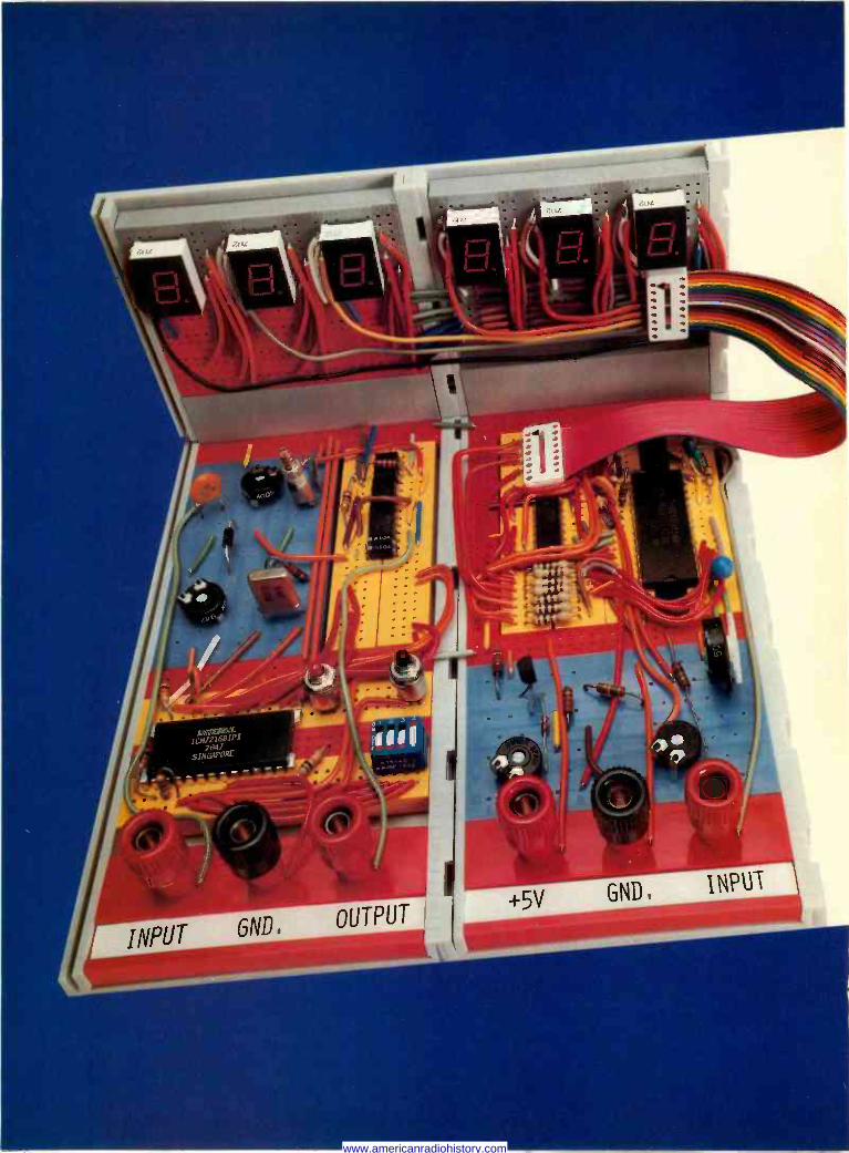
www.americanradiohistory.com

INTRODUCING THE NEW
HOBBY-KW SYSTEM.
HOB BYBLOX: The new modular circuit ui
building system designed especially
for electronic hobbyists. PostStrip.T
"professional" Tray Extender Clips. Modules
" rofessional priced fromTra$1.29 to $3.59.
Until now, hobbyists hads foro
buy iP are ed and letter -
there's
"p breadboards their projects
erless "professional" prices. But now All modules are color -keyed
and"pro brand new sold number indexed to make circuit building
payglox, a Hobby compatible with system that's not only even eaS1erBlox
system is breadboarding Y The Hobby -
economically priced but offers far more in your
he hobby DIPS of all sizes and a Simply
Pf lug o
At the core of the system are two starter acts,
component projects, packs, one for discrete rit projects. the other for integratedis Each comes with a number of Hobbánd
ox an
system modules project booklet which shows you
illustrated p how build ten projects with
step-by-step Either the existing modules of each pack.
starter pack is available for under $7.00.
You can add modules at any time to build
and on existing ones.
n The projects sys or
tem em includes 14 separate The Hobby- module packs that can be purchased
individually. Terminal Strip Pack,
Modules include Tray, us Strip, 3 x 16
Terminal Strip,on
St Discrete Component Strip,
Terminal Strip,
Tray Pack, Speaker L.E.D. Strip, Panel Pack,
Battery Holderr Pack, Binding k
Panel Pack,
advantages to t discrete components. components and interconnect
all components canu
wire. No soldering, be used again
How far can you go with the HobbBlox l the
system? Take a look at the e ample yourself. page to the left and see for
Then you'll know why
we say, "with Hobby-Blox,
our only limit is
your imagination!"
For a free catalog and the name of
lour nearest Hobby- dealer call Toll 8001 321 9668
Free.
Patents Pending 1980
A e
sown are current
U.S. resale.
A P PRODUCTS INCORPORATED 1359 West Jackson Street Painesville, Ohio 44077 (216) 354-2101
In Europe, contact A P PRODUCTS GmbH Baeumlesweg 21 D-7031 Weil 1 W. Germany
"1
,
CIRCLE 19 ON FREE INFORMATION CARD
www.americanradiohistory.com

4:C:bp(
BW -2630 Battery Tool
BW -2630 $19.85"" BT -30 $ 3.95"
BT- 2628 S 7.95
L
BW -2630 BATTERY TOOL The new BW -2630 is a revolutionary battery powered wire -wrapping tool. The tool operates on 2 standard "C" size NiCad batteries (not included) and accepts either of two specially designed bits. Bit model BT -30 is for wrapping 30 AWG wire onto .025" square pins ; BT -2628 wraps 26-28 AWG wire. Both produce the preferred "modified" wrap. Designed for the serious amateur, BW -2630 even includes both positive indexing and anti-overwrapping mechanisms - features usually found only in industrial tools costing five times as much. Pistol grip design and rugged ABS construction assure performance and durability. In stock at local electronic retailers or directly from
OK Machine & Tool Corporation 3455 Conner St., Bronx,N.Y. 10475 U.S.A.
Tel. (212) 994-6600 Telex 125091 'Minimum billings 525.00. add shipping charge 82.00 New York State residents add applicable tax
CIRCLE 38 ON FREE INFORMATION CARD
next month AUGUST 1980
Build The Unicorn 1 Robot
Part 1 of an 8 part construction series de- scribing how to build a versatile robot. This robot is fully mobile and can be built for un- der $400 complete with manipulator arms. Various levels of control and intelligence are described, including an on -board computer.
Six Instruments For Audio Testing
Construction details for 6 easy to build test instruments designed for the audio test bench. Useful for troubleshooting and for checking the performance of your hi-fi sys- tem.
$10 Digital Logic Probe A must for de -bugging and troubleshooting your digital projects. You can build this logic probe for just $10.
Servo -controlled Pick -Up Arm Unique pick-up arm design on JVC's new turntable let's you electrically adjust the damping characteristics and resonant fre- quency to match virtually any cartridge. Complete details on how it works and its performance.
Raceway Video Game After promising that this article will appear in this issue, a mess up forced us to post- pone it until next month. After you build this video game, you can pretend to be an Indy 500 race driver without ever leaving the comfort of your armchair.
PLUS:
Details On How To Align The Video -IF Section Of Your TV Receiver.
A Close Look At The Transport Mechanism Used in VHS Video Cassette Recorders.
Hobby Corner
Service Clinic More
www.americanradiohistory.com

$179
t ..
Seven functions dc voltage ac voltage dc current ac current resistance diode test conductance (1/R)
3' -digit resolution
0.1% basic dc accuracy
LCD display
Overload protection
Free case Two year parts and labor warranty
54 WE
Model 8022A: The Troubleshooter
$139
Model 8020A: fez The Analyst
O
TRIPLETT VIZ iRÓÏI
PHILIPS
LEADER HICKOK 0> Hitachi Zri-ison
FLUKE Non -Linear Systems
KEITHLEY
ÇATA PRECISION
FLUKE DIGITAL MULTIMETERS
Six functions 31/2 -digit resolJtion dc voltage ac voltage dc current ac current resistance diode test
NEW
0.25% basic dc accuracy
LCD display
Overload protection
Model 8024A: The Investigator
BIDATA PRECISION Model 938
0.1%, 31/2 -Digit, LCD DIGITAL CAPACITANCE
METER
$169
NEW $99
WIDE RANGING - from 199.9 pF full scale (0.1 pF resolution) up to 1999 yF full scale, in eight ranges.. .virtually every capacitance mill ever need to nleaaue.
FAST AND EASY TO USE - Direct reading. pushbutton ranges. Just plug in and read.
1)<CEPTIONALLY ACCURATE - provides ±0.1% basic accuracy.
TOUGH AND COMPACT - Buitt to take rough usage without loss of calibration accuracy. Fits and goes anywhere; takes very little bench space; &ways handy for quick capacitance checkout. matching. calbration, and tracking.
PORTABLE - Palm -sized, lightweight, operates up to approximately 200 hours on a single 9J alkaline battery.
EASY READING - big, clear. high -contrast 31/2 -digit LCD display. a lull 0.5" high, rwarlable anywhere.
VALUE PACKED - Outstanding measurement capability and dependability. Outperforms DC time -constant meters. and even bridges costing 2 to 5 times as much.
RELIABLE - warranteed for 2 full years.
KEITHLEY MODEL 130 DIGITAL MULTIMETER
DC VOLTAGE RANGE ACCURACY
200mV, 2V, 20V, 200V, 1000V -5%
AC VOLTAGE
200mV, 2V, 20V, 200V, 750V 1%
DC CURRENT
2mA, 20mA, 200mA, 2000mA, 10A 2% I
AC CURRENT
2mA, 20mA, 200mA, 2000mA, 10A 3%
RESISTANCE
200Q, 2kQ, 20kQ, 200kQ, 20MQ -5%
$219 New Portable Digital Capacitance Meter
Nine functions dc voltage ac voltage dc current ac current resistance diode test conductance (1/R) logic level and continuity detect
temperature (K -type thermocouple)
Peak hold on voltage and current functions
Selectable audible indicator for continuity or level detection
31/2 -digit resolution
0.1% basic dc accuracy
LCD display
Overload protection
Call For Our Price
V-151 15 MHz Single Trace
V-152 15 MHz Dual Trace
V-301 30 MHz Single Trace
V-302 30 MHz Dual Trace
V-5508 50 MHz Dual Trace,
Dual Time Base
Call For Special Intro Price Offer
THE TEST EQUIPMENT SPECIALISTS TOLL FREE HOT LINE
ADVA 800-223-0474 ST 45th STREET, NEW YORK, N.Y. 10036 212-687-2224E C
MODEL 820 Measures capicdance from 0. 1 pF to 1 Farad
Resolves to 0.1 pF
10 ranges for accuracy and resolution
4 digit easy -to -read LED display
0 5% accuracy
Special lead insertion lacks or banana jacks
Fuse protected
Uses either rechargeable or disposable batteries
Overrange indication
37
www.americanradiohistory.com

EQUIPMENT REPORTS Mem-Explorer Software continued from page 32
button. We can only assume that this worth- while feature was forgotten when the promo- tional literature was prepared, and are glad to be able to provide you with the information.
Battery replacement is quite simple. Four cabinet screws are removed, and the housing slides apart on rigid guides. The cabinet itself is very durable.
Internal circuitry is compact and built around a glass epoxy PC board which is wave soldered. Everything about the C -Meter boasts of high quality, and a 6 -month warranty backs it up. The model 130-A C -Meter sells for $325 from Doric Scientific, 3883 Ruffin Road, San Diego, CA 92123. R -E
For the PET Computer CIRCLE 103 ON FREE INFORMATION CARD
MEM-EXPLORER IS A BASIC COMPUTER PRO -
gram that is designed to open a "window" in the Commodore PET's memory. Its primary function is to examine memory contents by decoding the Memory words at selected loca- tions as ASCII characters, system commands, or BASIC keywords, constants, or indirect memory address references or links.
After loading and executing the program, a 4 -command menu is displayed: ADD FROM TAPE, CREATE TAPE, EXPLORE, STOP.
Typing E selects the EXPLORE mode. That mode requires a user choice between display of lower-case letters or reserved words. PET BA -
The
..+"" MORE k,
evx
...your Sprague distributor.
MORE r «
E'u`TORS
Sprague distributors have MORE to offer ... more component types, more styles, more ratings, more sizes, more quality, more value. Wth Sprague distributors, you save time by getting what you want when you want it, faster and easier.
For the name of your nearest Sprague distributor and a copy of Catalog C-622, write to:
Sprague Products Company Distributors' Division of the Sprague Electric Co. 81 Marshall Street North Adams, Mass. 01247.
Where MORE is more than a promise.
65.9138
SPRAGUE THE MARK OF RELIABILITY
a subsidiary of OK Technologies CIRCLE 4 ON FREE INFORMATION CARD
SIC stores multi -letter commands and key- words as single byte words. The user choice is necessary to resolve conflicts between identical codes used to represent lower case letters and reserved words.
Next, the program asks for the starting address of the memory area to be examined. Twenty rows of five columns of data then appear on the PET's CRT. The first column displays the memory location, the second col- umn lists the decimal equivalent of the binary contents of each location, and the third column displays the decoded ASCII characters or reserved words. The fourth column shows addresses calculated from each memory word and the following one, that are useful in inter- preting BASIC program links and pointers. Column five lists the decimal integer equiva- lents of the combination of each memory byte and the subsequent one.
After each 20 lines of data is printed, a new memory segment can be examined by entering a new start location, or -1 can be entered to return to the menu.
The additional menu -selected program rou- tines are used to prepare and load previously prepared cassette tapes, so that Mem-Explorer can be combined with user programs. Detailed instructions show how to carry out the combi- nation procedure. This special operation is required because Mem-Explorer and a second BASIC program cannot be simultaneously saved in PET memory by the conventional load method. Loading a second program normally overwrites the first.
A reprint of an article written by Roy Bus- diecker that reveals many of the program's "secrets" is included. Armed with some basic knowledge about the 6502 microprocessor and the supplied reprint, that program should give a good insight into some of the PET's inner mysteries. A few sessions with the program will provide an understanding of the way PET memory is organized, how real numbers, inte- gers, and characters are stored, and how the various pointers keep track of the program and data boundaries.
Mem-Explorer is $7.95 a copy from Micro Software Systems, P.O Box 1442, Wood- bridge, VA 22193. R -E
Radio Shack Quick Printer I!
CIRCLE 104 ON FREE INFORMATION CARD
ANYONE WHO HAS USED A COMPUTER FOR EVEN
a short period will appreciate the usefulness of a low-cost printer. It is a handy accessory for program documentation as well as recording printed output from the computer.
Printers come in a variety of sizes, formats, printing mechanism, and prices. At only $219, the Quick Printer // from Radio -Shack (One Tandy Center, Forth Worth, TX 76102) is certainly one of the least expensive.
This printer is a lightweight, measuring a continued on page 40
www.americanradiohistory.com

NOW AVAILABLE!
WATT WIZARD" POWER FACTOR CONTROLLER CUTS THE COST OF RUNNING ELECTRIC APPLIANCES BY AS MUCH AS 50% -- AND YOU CAN EVEN SEE THE SAVINGS!
For over a year now, in magazines and newspapers the world over, there have been enthusiastic write-ups on a remarkable new device that can cut your electric bill while helping the U.S. save huge quantities of fuel.
"The NASA/Nola power saver," wrote a Popular Science senior editor, "was developed by Frank Nola at NASA's George C. Marshall Flight Center as an offshoot of a program to reduce power consumption in spacecraft motors. Nola calls it a PFC - power -factor controller. I prefer to call it a power saver, however, because that's what it does."
NASA TESTED IT According to Clyde S. Jones of NASA,
"The device has been tested at Marshall Center on over 40 types of motors, with power savings ranging up to 60%, depending on the loading. The motors tested were both single-phase and three- phase, ranging from I H.P. to 5 H.P. Most motors will show up to 40 -to -50% savings when running lightly loaded or unloaded, and some will show 5 -to -7% savings at rated load."
NASA's Technical Support Package showed the test results and noted that "The Power Factor Controller applies to induction type electric motors - the most commonly used type in all major home appliances and the most common- ly used by industry."
HOW IT SAVES POWER Popular Electronics explained it this
way: "AC induction motors character- istically run at a nearly constant speed that's fixed by power -line frequency and independent of load and supply voltage. When heavily loaded, the motor draws line current that is nearly in phase with the applied voltage ... Under light load conditions, the motor develops less tor- que by allowing more lag between the voltage and current. This reduces the power factor while leaving the current essentially the same in magnitude.
"Though the low power factor means that conversion of electricity to mechanical power is small, the large cur- rent causes considerable (heat) losses in the supply lines and motor windings. This is what reduces efficiency.
"To minimize this waste, Nola's device monitors the motor's power factor and, when it detects light load conditions, it reduces the supply voltage ... The cur- rent, now more nearly in phase with the voltage, therefore does as much useful work as before, but it and the voltage are smaller, resulting in a net savings of electric power."
THE SAVINGS CAN ADD UP
Like everything else, the cost of elec- tric power keeps going up. Not only is the basic rate you pay going up, the power companies have now added on a "fuel adjustment" charge to help pay for running their generators. In 1980, 1981 and beyond, you'll pay more and more for the privilege of running your electric appliances.
IMwer10M MOTOR00OIIOMIiiI . Ils..wrow
National Aeronautics and Space Administration
Patent No. 4,052,648
Right now, the typical consumer pays about $8 per month to operate a 16.5 cu. ft. frost -free freezer ... $10 to run a 17.5 cu. ft. frost -free refrigerator ... $8.25 for an attic fan operating 12 hours a day ... and about $60 for an air conditioner used during summer months. It's not hard to figure out what you're paying per year just to run one of these appliances. And in many parts of the country, the cost is even higher.
That's why Nola's power saver can soon pay for itself, then start reducing your electric bills - the amount of sav- ings, of course, depending on which ap- pliance(s) you use it with.
There's just one catch. Until now, the device has not been available - except for industrial models prices at $80 or more.
INTRODUCING THE WATT WIZARD Cynex, an American manufacturer of
electrical and electronic products and a prime contractor for the U.S. Govern- ment, has been licensed by NASA to manufacture Frank Nola's power saver. Cynex calls it the Watt Wizard.
"The Watt Wizard," says Ray Beauchea, the firm's Marketing Director, "regulates the voltage fed into an induc- tion motor, reducing or boosting power as required, when loads go up or down. Simply stated, it makes motors run more efficiently, especially when idling. It reduces motor heat, affording longer motor life and reducing the amount of air conditioning required for cooling (rooms) in summer months. It saves elec- tric power, because kilowatt hours are greatly reduced. And it causes the motor to run quieter."
SIMPLE TO USE Cynex makes several models of the
Watt Wizard (all with solid state design), including the 110 V AC plug-in model we're offering. It's for single phase frac- tional H.P. motors (less than 1 H.P.) which is the type used in most made -for - the -home freezers, refrigerators, window and attic fans, swimming pool pumps,fur- nace fans, vacuum cleaners, sewing machines, power drills, etc.
Simply plug the Watt Wizard into any electric outlet, then plug the appliance into the Watt Wizard. There's no wiring required. Unlike some competitor's models (if and when available), the ap- pliance does not have to be turned on before being plugged into the power saver. You can leave the appliance - whether on or off - plugged into the Watt Wizard all the time. Or you can move the Watt Wizard to various loca- tions, depending on which appliance is being used. (Better yet, order several Watt Wizards.)
CIRCLE 54 ON FREE INFORMATION CARD
3
A C
OTHER MODELS AVAILABLE Air conditioners, washers and dryers
require wire -in model. If you lack mechanical skill, you probably need an electrician to install it. We also offer it in 220 VAC single or three-phase.
ADVANCE FEATURES The Watt Wizard also includes two more unique features. It's fused, so if you ac- cidently overload the device, it won't burn out. Just change the fuse, which is available at any auto supply store.
And the Watt Wizard features an LED readout, so you can actually tell, at any moment, exactly how much power you're saving - 10%, 20%, 30%, 40% or 50%.
There's a "Power On" light, too. And the Watt Wizard comes with the manufacturer's 1 -year limited warranty.
LOW COST - AND A TAX CREDIT We're offering the Watt Wizard for on-
ly $39.95, with Immediate delivery. Want two? Then it's just 637.95 each. Or splurge and get three at $34.95 each. Wire -in models for heavy duty motors are $6 more for each unit. Add just $2.50 postage/handling for each order (not each unit).
And next year, when you fill out your tax return, you can deduct a full 15% energy tax credit - for additional savings.
30 -DAY MONEY -BACK GUARANTEE Try the Watt Wizard for up to 30 days.
If not completely satisfied, return it (insured) for a full refund.
The sooner you send for the Watt Wizard, the more you can save on your electric bills. To order, send your check or money order to the address below. Or charge it to your Visa, MasterCharge, American Express or Carte Blanche credit card. If using your charge card, you can also order via our toll -free phone number:
800-257-7850 (In New Jersey, Call: 800-322-8650) N.J. residents, add 5% sales tax.
Or mall your order to:
Dept. RE, Lakewood Plaza Lakewood, N.J. 08701
mercuryjI The Imagination People®
c r-
ló m 0 39
www.americanradiohistory.com

EQUIPMENT REPORTS continued from page 38
scant 3'/t X 7 X 9 inches (approximate). It uses 23/i -inch wide aluminum -coated paper. Characters are actually burned onto the paper by an electric spark, reminiscent of the early Western Union drum facsimile machines; but unlike those earlier machines, this one pro- duces no permeating odor or smoke.
In operation, we noticed a moderate degree of electrical interference induced in nearby radio receiving equipment caused by the arcing of the print head on the paper. The characters are easy to read, and the character size may be increased by software instruction.
The Quick Printer II format provides 32 or 16 characters -per -line in a 5 X 7 dot matrix. Printing speed is rapid -64 characters per sec- ond, 120 lines per minute. Horizontal spacing is selectable-you may have either 18 or 9 characters per inch.
The life expectancy of the print head is ade- quate to anticipate some 30 million characters. Occasional cleaning of the print head is the only maintenance required; the mechanism itself requires no lubrication.
The character set provided is a modified subset of ASCII, with 96 characters in upper and lower case. Operating noise is quite tolera- ble. It must be remembered that a printer does not run constantly, so the occasional minor noise of the printer is hardly disruptive; as a matter of fact, it may be reassuring to the oper- ator to hear the busy little machine humming away as it obediently produces its copy!
Loading the paper roll is a snap-easy as loading a printing calculator or adding ma- chine. The roll of paper is long enough for many print operations before it is in need of
replacement. Two rolls of aluminized paper are provided with the Quick Printer II; replace- ment rolls are available from Radio Shack ($3.95 per 2 -roll set). As with adding ma- chines, a serrated cutting edge is used to tear the printed strip from the machine.
Inputs to the printer are switch -selectable. The unit connects directly into the card -edge bus of a TRS-80 level II, or the expansion interface, or serial interface. Another switch may be used to isolate the printer from the line (marked ON-LINE/BUSY/RESET). When switched ON LINE, the printer is ready to receive a print command. The RESET position clears the printer in case of an accidental han- gup in the loop.
The manufacturer recommends that the printer always be turned on before the key- board terminal, and off after it. That prevents any accidental erasure of the keyboard pro- gram or memory. A bright red LED signals the oN status of the printer.
A flat length of computer -type ribbon cable (supplied) is fitted with card -edge connectors to interconnect the printer and the keyboard terminal or interface. An automatic power -up message will be printed on the paper when the unit is switched on, informing the user that all systems are "go."
The Quick Printer II does not print isolated characters, only full line statements. (That's why it's called a line printer rather than a char- acter printer.) For long lines of print, automat- ic wrap -around assures continuation on the next line; no characters will be lost.
In the double -size mode, large characters will be printed at 16 characters per line. That feature is especially useful for titling purposes and column headings for lists. It is also possi- ble to down -shift to lower-case letters selec-
tively, using keyboard commands. The Quick Printer II can produce all ASCII
characters from hex 20 through hex 7F (deci- mal 32 through 127). That includes upper and lower case alphabet, all numerals, common punctuation marks, mathematical operands, and arrows, as well as a number of special graphics symbols.
The owner's manual supplied with the little printer is certainly adequate. A full schematic diagram is included, along with some basic maintenance suggestions. Operational hints are provided, as well as full instructions for the variety of applications available with the unit.
Naturally, aluminum -coated paper cannot be expected to provide the speed, contrast, or line size of an IBM printer. But then, it doesn't cost several thousand dollars, either! We were completely satisfied with the performance of this little line printer, and feel that it is realisti- cally priced. We think you will agree. R -E
C
t
THe. E "Isn't it more fun waking up by my strobe light than that old alarm clock, Pa?"
BUILD A MASTERPIECE OF SOUND
«
Ca
1011101118 ,m'+
_ ..
'eraNsss.%ï - / , .
Wersi has combined select features of the electronic music field, added its own creations and years of research by top engineers and musicians, to produce an incomparable line of organs.
Space-age technology. 'hue -to -life voic- ing with full drawbar system. Polyphonic
percussion and sustain. Wersi's famous string orchestra and bass guitar. Exclu- sive Sound Computer for 32-128 "One
Stop Sounds (total organ presets). Itansposer. And lots more.
Build your own masterpiece of 61 sound. No technical knowledge re- quired. Just follow the clearly illus-
trated. easy to understand instructions. Step by step. Choose from at least 10 models. (Also factory assembled.)
Send $6.00 with coupon for your Wersi Demo -Package (LP with 104 -page color catalog).
WERSI Wersi Electronics, Inc. Dept. 21 1720 Hempstead Road Lancaster, PA 17601
Wersi Organs A. Kits Dept. 21 14104 E. Firestone Blvd, Santa Fe Springs, CA 90670
Enclosed is $6.00 for my Demo -Package (LP with 104 -page color catalog.)
Name
Address
City State Zip
CIRCLE 18 ON FREE INFORMATION CARD
C.E.T. FOR TECHNICIANS WHO TAKE PRIDE
IN THEIR PROFESSION
CERTIFIED ELECTRONICS TECHNICIAN Certification is available in the following areas: AUDIO MATV COMMUNICATIONS MEDICAL INDUSTRIAL RADIO-TV
Write to: THE INTERNATIONAL SOCIETY OF CERTIFIED ELECTRONICS TECHNICIANS 2708 West Berry, Fort Worth, TX 76109
Please send me: -------_--_ Q Free booklet: CAREERS IN THE ELEC.
TRONICS INDUSTRY (a stamped self. addressed envelope is enclosed) Information about the CET Test.
Q A list of test administrators in my state/country.
Q I am already.a CET. Send me information about ISCET membership. CET No.
NAME
ADDRESS
are'
ZIP
STATE
PHONE ( f
www.americanradiohistory.com

Start Computing For Just $129.95 With An
8085 -Based Professional Computer Kit-
Explorer/85 100% compatible with all 8080A and 8085 software & development tools!
No matter what your future computing plans may be, Level "A "-at $129.95 -is your starting point.
Starting at just $129.95 for a Level "A" operating system,
you can now build the exact computer you want. Explorer/85 can be your beginner's system, OEM controller, or IBM - formatted 8" disk small business system... yet you're never
forced to spend a penny for a component or feature you don't want and you can expand in small, affordable steps!
Now, for just $129.95, you can own the first level of a fully expandable computer with professional capabilities -a com-
puter which features the advanced Intel 8085 cpu, thereby giving you immediate access to all software and development tools that exist for both the 8085 and its 8080A predecessor
(they are 100% software compatible) -a computer which
features onboard S-100 bus expansion -plus instant conver- sion to mass storage disk memory with either 5-1/4" diskettes
or standard IBM -formatted 8" disks. For just $129.95 (plus the cost of a power supply, keyboard/
terminal and RF modulator, if you don't have them already), Explorer/85 lets you begin computing on a significant level... applying the principles discussed in leading computer maga- zines. developing "state of the art" computer solutions for both the industrial and leisure environment.
Level "A" Specifications Explorer/85's Level "A" system features the advanced Intel
8085 cpu, an 8355 ROM with 2k deluxe monitor/operating system, and an 8155 ROM -I/O -all on a single motherboard with room for RAM/ROM/PROM/EPROM and 5-100 ex-
pansion, plus generous prototyping space. (Level "A" makes a perfect OEM controller for industrial
applications and is available In a special Hex Version which can be programmed using the Netronics Hex Keypad/ Display.)
PC Board: glass epoxy, plated through holes with solder mask
I/O: provisions for 25 -pin (DB25) connector for terminal
Level "A" at $129.95 Ls a serial I/O, which can also sup -
complete operating system, port a paper tape reader
perfect for beginners, hob- ...provision for 24 -pin DIP biests, or industrial con- socket for hex keyboard/dis- trolleruse. play...cassette tape recorder in- put...cassette tape recorder output ...cassette tape control output...speaker output... LED output indicator on SOD
(serial output) line...printer interface (less drivers)... total of four 8 -bit plus one 6 -bit I/O ports Crystal Frequency: 6.144
MHz Control Switches: reset and user (RST 7.5)
interrupt ...additional provisions for RST 5.5, 6.5 and TRAP interrupts onboard Counter/Timer: programmable, 14 -bit
binary System RAM: 256 bytes located at F800, ideal for smaller systems and for use as an isolated stack area in
expanded systems... RAM expandable to 64k via S-100 bus or 4K on motherboard.
System Monitor (Terminal Version): 2k bytes of deluxe
system monitor ROM located at F000 leaving 0000 free for user
RAM/ROM. Features include tape load with labeling ...tape dump with labeling...examine/change contents of memory
.insert data ...warm start ...examine and change all
registers... single step with register display at each break point, a debugging/training feature...go to execution address... move blocks of memory from one location to another... fill blocks of memory with a constant... display blocks of memory ...automatic baud rate selection... variable display line length control (1-255 characters/line)...channelized I/O monitor routine with 8 -bit parallel output for high speed printer... serial console in and console out channel so that monitor can
communicate with I/O ports. System Monitor (Hex Version): Tape load with labeling...
tape dump with labeling... examine/change contents of mem-
ory... insert data.. .warm start... examine and change all
FNetronics R&D Ltd.1,13ept. RE -7 333 Litchfield Road New Milford, CT 06776 Please send the items checked belo w-
Explorer/85 Level "A" Kit (ASCII Version), $129.95 plus $3 p&h. D Explorer/85 Level "A" Kit (Hex Version), $129.95 plus $3 p&h. D Bk Microsoft BASIC on cassette tape, $64.95 postpaid.
8k Microsoft BASIC in ROM Kit (requires Levels "B," "D," and "E"), $99.95 plus $2 p&h.
Level "B" (S-100) Kit, $49.95 plus $2 p&h.
Level "C" (S-100 6 -card expander) Kit, $39.95 plus $2 p&h.
Level "D" (4k RAM) Kit, $69.95 plus $2 p&h.
Level "E" (EPROM/ROM) Kit, $5.95 plus 504 p&h.
Deluxe Steel Cabinet for Explorer/ 85, 549.95 plus $3 p&h.
ASCII Keyboard/Computer Ter- minal Kit (features a full 128 character set, upper & lower case, full cursor con- trol, 75 ohm video output convertible to baudot output, selectable baud rate, RS232 -C or 20 ma. 1/0, 32 or 64 char- acter by 16 line formats, and can be used with either a CRT monitor or a TV set (if you have an RF modulator), $149.95 plus $2.50 p&h. L Hex Keypad/Display Kit, $69.95
plus $2 p&h. Deluxe Steel Cabinet for ASCII
Keyboard/Terminal, $19.95 plus $2.50 P&h.
Power Supply Kit (±8V fe 5 amps) in deluxe steel cabinet, $39.95 plus $2 p&h.
Gold Plated S-100 Bus Connectors, $4.85 each, postpaid.
RF Modulator Kit (allows you to use your TV set as a monitor), $8.95 postpaid.
16k RAM Kit (S-100 Board expands to 64k), $199.95 plus $2 p&h.
32k RAM Kit, $329.95 plus $2 p&h. 48K RAM Kit, $459.95 plus $2 p&h. 64k RAM Kit,4589.95 plus $2 p8th. 16k RAM Expansion Kit (to expand
any of the above up to 64k), 5139.95 plus $2 p&h each.
Intel 8085 cpu User's Manual, $7.50 postpaid.
Special Computer Grade Cassette Tapes, $1.90 each or 3 for SS, postpaid.
12" Video Monitor (10 MHz band- width), $139.95 plus $5 p&h.
North Star Double Density Floppy Disk Kit (One Drive) for Explorer/ 85 (includes 3 drive S-100 controller, DOS, and extended BASIC with per -
registers... single step with register display at each break point ...go to execution address. Level "A" in the Hex Version
makes a perfect controller for industrial applications and can
be programmed using the Netronics Hex Keypad/Display. Hex Keypad/Display Specifications Calculator type keypad with 24 system defined and 16 user defined keys. 6 digit calculator type display which displays full address plus data as well as
register and status information. Hex Keypad/Display.
Level "B" Specifications Level"B" provides the 5-100 signals plus buffers/drivers to
support up to six S-100 bus boards and includes: address
decoding for onboard 4k RAM expansion select -able in
4k blocks...address decoding for onboard 8k EPROM expan-
sion selectable in 8k blocks... address and data bus drivers for onboard expansion ...wait state generator (jumper selectable),
to allow the use of slower memories...two separate 5 volt regulators.
Level "C" Specifications Level "C" expands Explorer's motherboard with a card cage, allowing you to plug up to six S-100 cards directly into the motherboard. Both cage and
Explorer/85 with Level cards are neatly contained inside "C"card cage. Explorer's deluxe steel cabinet.
Level "C" includes a sheet metal superstructure, a 5 -card gold plated S-100 extension PC board which plugs into the mother- board. Just add required number of S-100 connectors
Level "D" Specifications Level "D" provides 4k or RAM, power supply regulation, filtering decoupling components and sockets to expand your Explorer/85 memory to 4k (plus the original 256 bytes located
in the 8155A). The static RAM can be located anywhere from 0000 to EFFF in 4k blocks.
Level "E" Specifications Level "E" adds sockets for 8k of EPROM to use the popular Intel 2716 or the TI 2516. It includes all sockets, power supply regulator, heat sink, filtering and decoupling components. Sockets may also be used for soon to be available RAM IC's (allowing for up to 12k of onboard RAM).
Order A Coordinated Explorer/65 Applications Pak! Experimenter's Pak (SAVE 512.50) -Buy Level "A" and Hex
Keypad/D-tsplay for $199.90 and get FREE Intel 8085 user's manual plus FREE postage & handling! Student Pak (SAVE 524.451 -Buy Level "A," ASCII Key- board/Computer Terminal, and Power Supply for $319.85 and get FREE RF Modulator plus FREE Intel 8085 user's manual plus FREE postage & handling! Engineering Pak (SAVE 541.00) -Buy Levels "A," "B," "C," "D," and "E" with Power Supply, ASCII Keyboard/ Computer Terminal, and six S-100 Bus Connectors for $514.75 and get 10 FREE computer grade cassette tapes plus FREE 8085 user's manual plus FREE postage & handling!
Business Pak (SAVE 589.95) -Buy Explorer/8S Levels "A," "B," and "C" (with cabinet), Power Supply, ASCII Key- board/Computer Terminal (with cabinet), 16k RAM, 12" Video Monitor, North Star 5-1/4" Disk Drive (includes North Star BASIC) with power supply and cabinet, all for just $1599.40 and get 10 FREE 5-1/4" minidiskettes ($49.95 value)
plus FREE 8085 user's manual plus FREE postage & handling!
Continental U.S.A. Credit Card Buyers Outside Connecticut
CALL TOLL FREE 800-243-7428 To Order From Connecticut Or For Technical
Assistance, Etc. Call (203) 354-9375 sonalized disk operating system -just plug it in and you're up and running!),' $699.95 plus $5 p&h. Power Supply Kit for North Star' Disk Drive, 539.95 plus $2 p&h.
Deluxe Case for North Star Disk I Drive, $39.95 plus 52 p&h.
Experimenter's Pak (see above), I 5199.90 postpaid. D Student Pak (see above), $319.851 postpaid.
Engineering Pak (see above), I $514.75 postpaid. 'Business Pak (see above), 51599.401 postpaid.
Total Enclosed $ (Conn. res. add sales tax) By-
Personal Check M.O./Cashier's Check Visa Master Charge
Signature Fxp Date Print Name
I
State Zip tin Send Me Information nn tttnJ
Acct 8
(Bank #----)
Address
City
I
By Netronics
ASCIIIBAUDOT, STAND ALONg
Computer Terminal
COMPLETE FOR ONLY .. .
$14995 The Netronics ASCII/BAUDOT Computer Terminal Kit is a
microprocessor -controlled, stand alone keyboard/terminal requring no computer memory or software. It allows the use of either a 64 or 32 character by 16 line professional display for- mat with selectable baud rate, RS232 -C or 20 ma. output, full cursor control and 75 ohm composite video output.
The keyboard follows the standard typewriter configuration and generates the entire 128 character ASCII upper/lower case
set with 96 printable characters. Features include onboard regulators, selectable parity, shift lock key, alpha lock jumper, a drive capability of one TTY load, and the ability to mate directly with almost any computer, including the new Ex- plorer/85 and ELF products by Netronics.
The Computer Terminal requires no I/O mapping and includes 1k of memory, character generator, 2 key rollover, processor controlled cursor control, parallel ASCII/BAUDOT to serial conversion and serial to video processing -fully crystal controlled for superb accuracy. PC boards are the highest quality glass epoxy for the ultimate in reliability and long life.
VIDEO DISPLAY SPECIFICATIONS The heart of the Netronics Computer Terminal is the micro-
processor -controlled Netronics Video Display Board (VID) which allows the terminal to utilize either a parallel ASCII or BAUDOT signal source. The VID converts the parallel data to serial data which is then formatted to either RS232 -C or 20 ma. current loop output, which can be connected to the serial I/O on your computer or other interface, i.e., Modem.
When connected to a computer, the computer must echo the character received. This data is received by the VID which processes the information, çonverting to data to video suitable to be displayed on a TV set (using an RF modulator) or on a
video monitor. The VID generates the cursor, horizontal and vertical sync pulses and performs the housekeeping relative to which character and where it is to be displayed on the screen.
Video Output: 1.5 P/P into 75 ohm (EIA RS -170) Baud Rate: 110 and 300 ASCII. Outputs: RS232 -C or 20 ma. current loop
ASCII Character Set: /28 printable characters-
agT58EyaayvtFl#oºo ,:ioº.[_x jt 1+'r`+s
!e*ii'Ì#, r/O1Z345Ó789i;(a?
EfOCDEFGH1J10`MMIStWYXY71\1"-
`abcdef ghi iklmnopgrstuwxyz{;}.1 BAUDOTCharacterSet:A BCDEFGHIJKLMNOPQ RSTUVWXYZ-?:'38#().,9014!57;2/68 Cursor Modes: Home, Backspace, Horizontal Tab, Line Feed, Vertical Tab, Carriage Return. Two special cursor sequences are provided for absolute and relative X -Y cursor addressing Cursor Control: Erase, End of Line, Erase of Screen, Form Feed, Delete Monitor Operation: 50 or 60Hz (jumper selectable.
Continental U.S.A. Credit Card Buyers Outside Connecticut
CALL TOLL FREE 800-243-7428 To Order From Connecticut Or For Technical r - Assistance, Etc. Call (203) 354-9375 1
Netronics R&D Ltd., Dept. RE -7 333 Litchfield Road, New Milford, CT 06776
Please send the items checked below- Netronics Stand Alone ASCII Keyboard/Computer Terminal Kit, $149.95 plus $3.00 postage & handling. Deluxe Steel Cabinet for Netronics Keyboard/Termi- nal In Blue/Black Finish, $19.95 plus $2.50 postage and handling. Video Display Board Kit alone (less keyboard), $89.95 plus $3 postage & handling. 12" Video Monitor (10 MHz bandwidth) frilly assem- bled and tested, $139.95 plus 55 postage and handling. RF Modulator Kit (to use your TV set for a monitor), $8.95 postpaid. 5 amp Power Supply Kit In Deluxe Steel Cabinet (±8VDC @ 5 amps, plus 6-8 VAC), $39.95 plus $2 postage & handling.
Total Enclosed (Conn. res. add sales tax) $
BY- Personal Check Cashiers Check/Money Order Visa Master Charge (Bank #----)
Acct 1
Signature Fxp Date
Print Name
Address
City
State Zip L ate Send Me More Information fflleJ CIRCLE 52 ON FREE INFORMATION CARD 41
www.americanradiohistory.com

The Professional's Choice Test equipment, prime grade original replace- ments, chemical tape heads ... and MORE!
A DIVISION OF ALLIANCE RESEARCH CORPORATION
7241 CANBY AVE. RESEDA, CALIFORNIA 91335
We feature only quality test equipment: Leader Instruments, Hitachi, Beckman. Hickok, and others.
17L Leader LB0515B
'141'}(' A.
61òEl
Hitachi V-302 Beckman 330 Hickok LX 304
SPECIAL OFFER A top quality 30 mhz, dual trace, trigged oscilloscope with 1 mV sensitivity and delay line FOR UNDER $800.00! (including 2 probes).
Limited to professional technicians, engineers, and members of the trade. Call in for details and complete specifications.
SHIPPED THE SAME DAY SHIPPED THE SAME DAY SENDUST ALLOY HEADS, Metal tape compatible! r' Standard configuration stereo:
$13.50 A52
Longer life. Best frequency response.
ELECTRONICS
TAPE HEADS P SENDUST ALLOY
AUTO REVERSE . HEADS
$20.00 ea.
PERMALLOY HEADS moss
Cassette stereo
$4.50 * ar
PERMALLOY AUTO REVERSE
HEADS
$7.00
HIGH QUALITY TEST CASSETTES PTC 1 Level Test (-10 dB)
PTC 2 S/N Ratio (0 dB)
PTC 3 Speed Test (3000 Hz) PTC 4 Head Alignment PTC 5 Frequency Response
CT 120 Torque Meter
PAue10NAL ® ® 4D ® Va di* a ORIGINAL JAPANESE REPLACEMENT PARTS IN STOCK!
AIR CORE INDUCTOR
(for crossover network)
20 AWG Wirel 28 mH 160
5 mH 1.86
1.0 mH
1.8 mH
25 mH
2.75
3.36
435
Build your own speaker system!
CROSS OVER NETWORKS
ONLY
$9.00 ea. 4 ohms or 8 ohms - Made with AIR CORE COILS or FERRITE CORE. Many to choose from. Example: NT406H crossover net- work: 100 watts input! 3 day, all air core construction for lowest distortion.
CRYSTALS
1-11 $3.50 ea.
12 -up $3.00 ea.
20 pF Load Impedance! 7.0025 MHZ
7.7975 MHZ
10240 MHZ
10.695 MHZ
11.1125 MHZ
11.2858 MHZ
11.3258 MHZ
11.2850 MHZ
11.2842 MHZ
11240 MHZ 11.730 MHZ
36.570 MHZ
NON POLARIZED ELECTROLYTIC CAPACITORS
For crossover use (axial lead)
uF/Y 1-11 uF/V I-11
1/100 .50 14/100 60
2.2/100 .50 16/100 .65
3.3/100 .55 22/100 .70
4.7/100 .55 33/100 .95
6.8/100 .55 47/100 1.20
8.0/100 .60 100/100 1.65 10/100 .60 150/100 2.55 12/100 .60 200/100 3.00
I.C.s - Prime Grade
These prices are for 1-11 qty! Call for better price quotes.
AN 306
AN 318
AN 7130
AN 7150
AN 7156N
BA 1310
BA 1320
DA 101
HA1366W
HA1368
HA1377A
HA1457
LA1368
LA1460
LA3155
LA3160
LA3201
LA4032P
LA4051P
LA4420
LA4430
LA5110
L81331
M53273
MB3705
MB3712
MB3756
MB8719
S -40W
S -60W
S-100WA
S -200W
SM5104
STK0029
STK0039
STK0050
516011
STK013
We sell exclusively to professionals and members of the trade. Minimum order $25.00. We pay shipping and insurance on pre -paid orders in the continental U.S.A.
C.O.D. orders, VISA/MasterCard welcome!
OCR Chroma OCR Servo Power Amp.
Power Amp. But. Amp.
PLL Demod.
PLL MP% Demod.
Delco DM98
Power Amp Power Amp 20 Watts Amp L M. Preamp
Chroma Processor
Deflection CKT
Equalizer Preamp Mini Preamp
3W Amp
2.5W Amp
5.5W Amp 4.5W Amp Regulator VIR Sig. Processor VCO for CB
4.5W Amp
50W Amp
SIL Regulator Programmable PLL
40W Amp
60W Amp 100W Amp
200W Amp PLL Circuit Darlington HYB
Darlington HYB
Darlington HYB
Hybrid 6.5W Amp Hybrid 15W Amp
12.00
9.00
3.00
3.25
4.00
3.50
3.50
7.00
280 2.80
490 1.80
3.50
4.50
1.80
1.60
CALL FOR PRICE
225 250 250 2.85
2.00
6.50
1.00
3.00
3.85
3.50
7.50
13.90
17.90
27.90
45.25
9.00
6.00
7.10
8.90
4.50
13.50
I.C.s - Prime Grade Continued
STK040
STK415
TA7109AP
TA7205AP
TA7217AP
TA7222P
TA7227P
TA7312P
TC9106P
UPC671C
UPC1181H
UPD857C
UPD858C
UPD2815
UPD2816
Dual 10W Amp 2 Ch. Hybrid Amp Amplifier BTL Amp
5.8W 4 ohms amp 5.8 Amp
BTL Amp
L.A. Preamp
C.B. PLL
Amp
BTL Amp Ham PLL
C.B. PLL
Freq. Synth. Freq. Synth.
12.00
9.00
5.00
2.50
425 3.80
7.00 CALL FOR PRICE
7.00
5.00
3.50
7.80
6.50
12.50
12.50
Plus more I.C.s at same low price.
Ask for our quantity discount!
"Our Service Makes
The Difference"
TRANSISTORS - Prime Grade These prices are for 1-11 qty'
2SA509
2SA606
2SA684
2SA699A
2SA912
2SA912
2SA917
2SA981
2SB471
2SB507
2SB555
258618
2SB681
2SB688
258700 2SB754
2SC281
2SC937
2SCt11t
2SC1209
25C1964
2SC1942
2SC2001
2SC2086
2SC3101A
2SC2103A
2SC2166
25091
25D425
2S0588
2S0712
2SD725
250870
2SD870
2S0903
MRF454
MRF455
MRF901
50
1.45
60
80
80 .80
1.80
B00
200 1.50
460 3.00
5.75
3.30
4.00
3.75
60
8.50
5.20
1.50
3.00
4.50
.50
60 11.95
15.00
200 1.90
3.50
3.00
120 6.50
7.50
7.50
6.50
22.00
15.95
3.20
PLUS MANY MORE'
TO ORDER, CALL TOLL -FREE: C8001423-5336 In Calif. (800) 382-3663
Local (213) 705-0022 Telex 181011
CIRCLE 40 ON FREE INFORMATION CARD
www.americanradiohistory.com

ENERGY SA V/NG
HOME THERMOSTAT TOM STULTS
THE RISING COST OF ENERGY USED TO SUP -
port home -heating and air-conditioning systems can be offset by using nature's own temperature cycles to supplement costly equipment operation. The house can be maintained at a chosen tempera- ture setting without involving sacrifices in comfort.
The outside temperature rises and falls from daytime to night because of solar heat. As long as the coolest nighttime temperature remains above the "com- fort" setting of your thermostat you must, of necessity, supply continuous air conditioning to your house. Generally, that only happens for six to eight weeks in
the summer, depending on where you live. On the majority of cooler days, the outside temperature will be lower than the inside "comfort" setting from some- time in the evening to well into the next morning.
But, even though it's getting cooler outside, the inside of the house can still be warming up! That is because the warmth of the sun on an outside wall
takes time to soak through the wall to the inside and while insulation can slow down the process, it can never stop it. How many times have you stepped outside on a cool fall evening and heard your air con- ditioner still running? It's obvious that, at times like this, we are unnecessarily cool- ing the house artificially (at great cost) when we could easily be using a limitless free source of energy, Mother Nature herself.
The expenses involved in heating and cooling a home have never been higher! This Environmental Control
Center could save you up to 20% in energy costs.
In cooler weather, the same principles apply in reverse. In the late fall and early spring the morning temperature will of- ten rise above the thermostat setting and fresh air can be used to warm the house.
That is the function of the Environ- mental Control Center-to furnish free cooling or heating whenever possible by using outside air.
Like large commercial systems that have been using fresh air to help in heat- ing and cooling for years, the Control Center can save an estimated 20% in
operating costs and energy every year.
Environmental Control Center The Control Center (Fig. 1) uses readi-
ly available IC's to do the switching and decoding needed to make the outside air available when required. Inside and out- side temperatures are monitored by a pair of thermistors and a difference amplifier and converted into a digital signal for decoding. The decoded signal controls the operation of the mechanical components of the heating/cooling system.
TO SYSTEM RETURNS (COMMON)
COMMON
- NC - NC - 24VAC
SYSTEM CONTROL TRANSFORMER
FAN 1- . COMMON
LOUVER COMMON
HEATER 1 -COMMON
HOT
A/C H COMMON
NEUTRAL
Fig. 1-BLOCK DIAGRAM of the Environmental Control Cente showing the input sensors at left and
the devices controlled at right. Note that the system may use either 24 or 117 VAC.
117VAC
4
THERMOSTAT (1 STAGE) 6
1
2
20
19
18 7 3
4 17
16 OUTDOOR THERMISTOR
CONTROL CENTER 15
INDOOR THERMISTOR
14
9 HUMIDISTAT
10 13
NOTE: COMMON MAY BE EITHER 24VAC OR 117VAC NEUTRAL 12
DEPENDING ON CONTROL CENTER 11
JUMPER SELECTION
www.americanradiohistory.com

FAN IN RY1 226R -1.5A1
SOLID-STATE RELAY (TOP VIEW)
1
R3
V1h 33012
COOL IN
R1
33012 HEAT IN =
D1
1N914
D2 +V
C7
1N914 t .01 j` 4 16 LL
2 12-
11..01
R2
3302
+5V
V -4
C4 7
R5 1.5K
C8
7447
01
2N3904
R4
1M 10K
13
6
INPUT o I5VDC
06 D7 15MA + 1N914 1 1N914 1
11 D5-1N914N
IC2 HUMIDISTAT
D4 HUM 1 1N914
9*DOm -4 1N914 C5T
13
C6r. .01
14
15
12
IC3
7445
7
o
01 INPUT RY2 OUTPUT
_+1 INPUT RY3 OUTPUT
4 +l INPUT
+5V
.01 OUTDOOR THERMISTOR 105001-C3
+V TH1
R6
10K 3
R7
10K
Cl = .01
INDOOR THERMISTOR 105001-C3 TH2
R8
1K
+V
1C4
4
R9
6
CA3130H
10K R10 ® Ti 500K
J 6.3V @
II
21.2A
l
WO6M
R11
VN 330K 6
C10 4.7µF
RECT 1
105
555
NC
1C1
7805
1
RY4 OUTPUT
+5V
IC2 I,01 GND TO 18
(ID FAN OUT
15 LOUVER OUT
14 HEAT OUT
- AIR CONDITIONER
AC OUT
INPUT o
(24 OR 117VAC)
o o p r +
a r a o 0 o
0
Fig. 2-SCHEMATIC DIAGRAM of Environmental Control Center. Circled numbers refer to Fig. 1. Solid-state relay is shown at lower right. Humidistat, HUM1, is located off PC board.
COMPLETED THERMOSTAT PC board. Socket at upper left is for plug to controller.
The schematic diagram of the control center is shown in Fig. 2. Thermistors TH1, TH2 and potentiometer R5 form a voltage divider that supplies a differential signal to the non -inverting input of the high -impedance amplifier, IC4. To cali- brate the input, place voltmeter probes on pins 2 and 6 of IC4 and, with the voltme- ter on its most sensitive scale, adjust resistor R5 until the voltmeter reads as near to zero volts as possible. In order to make that adjustment, submerge both sensors in a glass of water and wait until the reading on the voltmeter is stable. This will indicate that both sensors are at the same temperature and that R5 can be set accurately.
In practice, the resistance of the ther- mistor sensors will not change equally, producing a difference signal at the input
of IC4. That signal will be amplified and applied to the input of IC5, a timer con- nected as a Schmitt trigger with hystere- sis. Applied to pin 6 of IC5, 2/3 Va or more will cause pin 3, the output of the timer, to go low. A potential of 1 /3 Va or less at pin 2 will cause the output to go high. With the two inputs tied together, the timer has a dead band between 1 /3 and 2/3 where the timer will not switch. By adjusting the gain of the dif- ference amplifier IC4, the temperature difference required to switch the output of the sensor circuit can be changed. To make that adjustment, set R1O to center - travel and momentarily short sensor TH 1
at Control Center terminals 5 and 6, forc- ing IC5 to go low. Using an accurate thermometer, set up two glasses of water and cool one of them by 2°F with ice cubes. Remove the cubes when this dif- ference has been reached. Submerge TH1 in the cooler glass and TH2 in the warmer. Allow time for the temperature to stabilize. Adjust IC4 output (pin 6 to ground) to 1 /3 Va, the switching point of IC5. (It is not practical to measure that signal at the input of IC5 because of the time delay generated in R11 and C10.) This adjustment will set the temperature
TO O
CONTROL CENTER board. The solid-state re- lays must be adequately heat-sinkedl
switching difference at two degrees and, in addition, the dead band will prevent fast cycling when the temperature outside hovers around the switching point and a vagrant breeze or gust might cause the Control Center to switch back and forth unnecessarily.
Input decoding is accomplished by IC2 and IC3. With no input from the thermo- stat, pin 4 of IC2 will be low and will shut the system down. Either input (pin 1 or pin 2) will cause pin 4 to go high and turn on the system. Given 5 volts on pin 1, a heating command, the output will be low at pin 11. However, if TH1 is warm- er, pin 7 will be driven low by the temper-
www.americanradiohistory.com

+V
PARTS LIST Control Center
All resistors '/3 watt, 10% unless other- wise noted
R1 -R3-330 ohms R4, R6, R7, R9-10,000 ohms R5-1500 ohms, trimmer resistor, vertical
PC mount (Mallory MTC152L1 or equal) R8-1000 ohms R10-500,000 ohms, trimmer resistor, ver-
tical PC mount (Mallory MTC55L1 or equal)
R11-330,000 ohms C1-1000 µF, 25 volts, electrolytic C2 -C9, C11-.01 µF ceramic C10-4.7 µF, 16 volts, electrolytic D1 -D7 -1N914 Q1 -2N3904 RECT1-full-wave bridge rectifier, 600 Ply,
1.5 A, (General Instrument WO6M or equal)
IC1-7805 IC2-7447 IC3-7445 IC4-CA3130 IC5-555 TH1, TH2-thermistor, 5000 ohms
25°C, -4.4%, ±0.2°C, 0-70°C (Western 105001-C3, Fenwal UUA35J1, Yellow Springs Instruments 44007 or equal)
RY1-RY4-solid-state relay, (Sigma 226R- 1 -5A 1)
HUM1-humidistat, makes on increase in humidity (Honeywell H46E1013 or equal)
T1-power transformer, secondary 6.3 volts @ 1.2 amps (Radio Shack 273-050)
Heat sinks for RY1-RY4-Wakefield 291- 80ABC2 or similar for TO -3 devices.
Barrier strips -10 terminals on .375 -inch centers for PC mount.
The following parts are available from LSE, Box 392, Yukon, OK 73099: PC board $11.95, Sigma 226R -1-5A1 solid-state re- lay $12.89 each, thermistors $5.06 each, humidistat $41.16 each. Oklahoma resi- dents please include local sales taxes.
PARTS LIST Two -Stage Thermostat
All resistors '/2 watt, 10% unless other- wise noted
R1, R3-4700 ohms R2 -330K ohms R4, R5, R6-270 ohms R7-5000 ohm pot, linear taper R9, R11, R13, R15, R16, R18-470 ohms R10, R12, R14, R17-12,000 ohms C1-68 µF, electrolytic C2-4.7 µF, electrolytic 01, 02, Q4, Q6 -2N3905 03, Q5 -2N3904 ICI-SN741N IC2-LM339N TH1-thermistor, 5000 ohms @ 25°C,
-4.4%, +0.2°C, 0-70°C (Western IC5001-C3, Fenwal UUA35J1, Yellow Springs Instruments 44007 or equal)
S1-switch DPDT S2-switch SPST ouput connection-'/z 16 pin DIP socket D1, D2 -1N4001 The following parts are available from LSE, Box 392, Yukon, OK 73099: PC board $7.25, Sensor $5.06. Oklahoma residents please include local sales tax.
+v
+V
4 R2 TH1 330K ®IC500103
THERMISTOR
+v
'Cl
4 R1
4.7K
7
6
SN741N
COOL 1ST STAGE
COO L 2ND STAGE
+V
GNO
C2
4.7µF
R3
4.7K
R4
2702:
R5
27012
R9
47052 W R10 12K
Q1
2N3905
2ND STAGE COOL OUT
R11
47052
Wq R12 Q2
12K 2N3905
1/4
LM339N S1-bOoK-O +V FROM Sl -a
R6 27012
2
1/4 LM339N
5K
= R8
OUTPUT SOCKET
2.2K
HEAT 2ND STAGE
HEAT 1ST STAGE
FAN OUT
NC
a
R13 47012
2N3904
R14 12K
R15
47052
Q3
011N4001 N
R16 47012
2N3904
SI -a
+5V
R17 12K
R18 47012
Q5
H1N4001
1 COOL
o
1ST STAGE COOL OUTo
04 2N3905
1ST STAGE HEAT OUT
Q6
2N3905
2ND STAGE HEAT OUT
+5V TO THERM.
+ COOL SECTION
Cl 168µF
Sl-bOHEAT
SECTION S2
o o TO FAN OUT
Fig. 3-TWO-STAGE thermostat. See text and Figs. 1 & 4 for description and hookup information. Output socket and switches are shown in b and c. Switch S1 -b is shown twice.
TO TERMINAL 18, 5VDC GND ON CONTROL
CENTER
FROM STAGE 2
ON THERMOSTAT
117 VAC LINE OR 24 VAC
5VDC 15MA
1
SOLID STATE RELAY
2ND STAGE CONTROL RELAY
COIL
Fig. 4-ADDITIONAL RELAY hookup for 2 -stage system. Refer to text for details.
ature comparison circuit and the output will be routed to pin 9 instead, calling for fresh air. With 5 volts on pin 2, an air- conditioning command, pin 12 will go low unless TH2 is warmer, in which case the output will be low at pin 13, calling for fresh air.
The outputs of IC2 drive IC3, which can generate a high humidity over -ride in the fresh -air cooling cycle. The humidi- stat contacts close when the humidity rises above a certain level and should be
TO 117VAC NEUTRAL OR 24VAC COMMON
placed in the central system ductwork to monitor the humidity of the conditioned area. On a humid or rainy day, large amounts of moisture can be drawn into the house making it necessary for the next air-conditioning cycle to remove it and impairing efficiency. IC3 and the diodes D3, D4 and D5 make up a circuit that will cause the Control Center to switch from fresh -air cooling back to air conditioning when the humidity reaches a
predetermined level. A relative humidity of 50% is comfortable. The humidistat has no effect in the heating cycle.
IC3 drives solid-state relays which turn on the central -system equipment. Diodes D6 and D7 turn on the fan used with the fresh air system or the air conditioner, a
function that would be handled by the thermostat in a conventional system. The output relays, when properly heat sinked, will handle up to 7.5 amps, sufficient to handle a fan motor or a louver actuator. The output voltage of the relays can be either line voltage (117 VAC) or a con- trol voltage (24 VAC) depending on the position of jumpers provided for on the Control Center PCB. Before soldering in
those jumpers be sure to check the oper- ating voltage of your equipment.
c` r co co 0 45
www.americanradiohistory.com

i7 1/4 INCHES SOLID-STATE RELAYS
THE SIGMA 226R -1-5A1 SOLID-STATE relay specified is designed to use 5 volts DC to control a load with a nominal level of 120 volts RMS and a minimum of 80 volts RMS. For this reason, it would seem that this relay is not suitable for han- dling 24 -volt AC control relays in heating or cooling systems. How- ever, we have tested several of these relays and have found this type entirely satisfactory. With a 24 -volt AC control relay as a load, we found that the DC input turn - on voltage is the critical factor.
With 5 volts DC applied to the control pins, the solid-state relay dropped 1.1 volts in the load cir- cuit-insignificant as far as a 24 - volt AC control relay is concerned. With 4 volts DC control, the load voltage dropped 1.2 volts. When the control voltage was reduced to 2 volts DC, the relay dropped 5.7 volts in the load circuit and the load relay chattered. These read- ings were averaged from measure- ments made on several relays with digital VOM.
Two -stage controls are used in most commercial heating and cool- ing systems and can also be found in some residential installations. In some homes you may find single - stage cooling and two -stage heat- ing, or vice versa. You can tell a lot about the operation of your heating and cooling system by examining the thermostat. The operation and connections to the original -equip- ment thermostat can be identified as follows:
Terminal Function R 24VAC from control
transformer Y output to cooling
equipment W output to heater or
furnace G output to fan relay Y2 2nd stage cooling
output W2 2nd stage heat out-
put The universally followed wiring
color code for a single -stage heat- ing -cooling system is R-red, Y- yellow, W-white and G-green. There is no universal color code applied to either 2nd -stage heat or 2nd -stage cool. Examine the termi- nals on the original -equipment thermostat to see whether or not you require two stages when setting up the Control Center.
The thermostat A two -stage thermostat (see discussion
and explanatory information elsewhere in
Fig. 5-FOIL PATTERN for the Control Center. Drill corner pads for mounting holes.
+5VDC
FAN
HEAT
COOL
OUTDOC THERMISTO
INDO THERMISTO
HUMIDISTAr
5VDC GND
Q PR10. 24V 117V R Y4 J
R10
NOTE: RY1-RY4-J ARE JUMPERS TO SELECT CONTROL VOLTAGE
O VAC OMMON
FAN- A/C - HEAT LOUVER COMMON
24VAC
FAN OUT
LOUVER OUT
HEAT OUT
A/C OUT
HOT 117 VAC
NEUTRA 117 VAC
RECT 1
(LONGEST AC
LEAD) Fig. 6-PARTS LAYOUT for the Control Center. Outboard humidistat is connected to pads 9 and 10.
[4 4 INCHES
Fig. 7-TWO-STAGE thermostat board foil pattern. Actual board is four inches wide.
J.
of
www.americanradiohistory.com

TO R7
2N3904 AND
2N3905
Fig. 8-PARTS PLACEMENT DIAGRAM for the thermostat. Unmarked 8 -pin (or '/, 16 -pin) socket at lower right is for DIP plug connecting thermostat with the Control Center.
Resistor R2 and capacitor C2 generate a time delay to prevent short -cycling due to transient drafts at the thermostat.
IC2 is a four -level detector referenced by the voltage -divider string, R3 through R8. Resistors R4, R5, and R6 set the switching levels 2° apart. Assume that the system has been set in the heating mode by Si. At 4° below the level set by temperature -adjust pot, R7, no compara- tors will be tripped, and their collector outputs will be open. Transistors Q3 and Q5 will be biased on, turning on Q4 and Q6 to turn on the heat. The collector cur- rent of Q4 controls the first stage of the heating system through terminal 3 of the Control Center (Fig. 2) while Q6 is con- nected to the second stage of the heating system through a solid-state relay con- nected as in Fig. 4. The open -collector output. of IC2-c and IC2-d as well as the open contact of S1 -b will insure that Q1 and Q2 (air conditioning) are off. As the
WASTE AIR
1/4" COPPER TUBING FLARED ON END
EPDXY FILLER
BEAD THERMISTOR
SPAG HETTI PROTECTION FOR SOLDER CONNECTIONS AND LEAD INSULATION
TO CONTROL CENTER
Fig. 9-CUTAWAY DRAWING of thermistor probe. See text for construction details.
this story) is shown in Fig. 3. In it, anoth- er 5K thermistor, isolated from the switching circuits by follower amplifier ICI, is the temperature -sensing element.
WASTE AIR
FRESH AIR
ENERGY SAVING CYCLE
a
NORMAL CYCLE
b
FRESH AIR
Fig. 10-AIR FLOW through ventilation system during a) energy -saving cycle and b) during normal cycle. Rotatable damper determines whether air is recirculated or not.
house temperature rises to less than 4°, but more than 2°, below the set -point, IC2-a will switch low turning off Q5 and Q6. Stage -1 heat, will be turned on. A further increase in temperature will switch IC2-b low, turning Q3 and Q4 off-leaving all outputs off and the Con- trol Center in standby.
In the air-conditioning mode, an inside temperature 4° higher than the set -point will satisfy the inputs to IC2-c and IC2-d, turning on Q1 and Q2. Stage -1 and stage - 2 cooling will be turned on. As the tem- perature decreases, IC2-d will turn off leaving only stage -1 active, and with a further decrease, IC2-c will turn off leav- ing the Control Center in standby.
Construction The environmental control system is
constructed on two circuit boards. Figs. 5
and 6 show the foil pattern and parts placement for the control center, respec- tively. The electronic thermostat is on the smaller PC board. The foil pattern is in Fig. 7 and the parts placement guide in Fig. 8. The humidistat should be mounted in the system to monitor the humidity of the air supplied to the living area.
The two temperature sensors are easily assembled by flaring one end of a 4 -inch length of '/4 -inch copper tubing and em- bedding a 5K thermistor in epoxy com- pound as shown in Fig. 9. Use spaghetti (thin plastic tubing) to insulate the ther- mistor leads. Be sure to use enough epoxy compound to make the assembly com- pletely watertight and weatherproof.
Installation and operation Completely automatic operation of the
heating and cooling outputs may be se- lected by jumpers on the board which will bypass switch SI -b and route power -sup- ply voltage to both the heating and cool- ing outputs simultaneously. If that is done, S1 -a should be retained as a SPST switch to provide an off function.
Not all central air-conditioning units have two stages, and if yours doesn't, then eliminate Q1, Q5 and Q6 from the PC board, along with their supporting resis- tors. If your unit does have two stages, connect the output of the thermostat in the second stage to the control voltages of the central unit with an additional relay of the type used in the Control Center. (see Fig. 4)
The Control Center is easily compati- ble with the Educated Thermostat fea- tured in the July '79 issue of Radio - Electronics and the combination would result in an integrated system offering the highest possible efficiency and energy savings. Supply one side of the cold con- tacts in the Educated Thermostat with 5
volts from the Control Center and con- nect the other side of the contacts to the FAN, HEAT, and COOL inputs of the Con- trol Center. No ground from the Control
continued on page 82
c r cD 0o o
47
www.americanradiohistory.com

COAX vs. Coaxial cable costs more than ordinary 300 -ohm twin -
lead. It's advantages, though, can actually make it cheaper in the long run. This article explains why.
JAMES E. KLUGE*
WHENEVER YOU SEE A TECHNICIAN INSTALLING A MASTER antenna system, it seems he's always using coaxial cable. So-what's so great about coax? Before you try installing your own MATV (Master Antenna Tele Vision) system, learn a few basic facts about this increasingly popular means of running all types of signal around a house or a building.
Why use coaxial cable? The concept of coaxial cable is pretty simple. Coaxial cable
is merely two conductors, one inside the other. The outside conductor is cylindrical or tubular; the inside is conventional copper wire centered inside the tubular conductor by means of solid or foam -type plastic insulation. The entire assembly is then jacketed with a polyvinyl chloride (PVC) or poly- ethylene cover.
If you chopped off a short piece of common RG -59/U -type MATV cable, for instance, you would see a cylinder of PVC jacket material surrounding another cylinder of aluminum braid over another cylinder of aluminum foil bonded to a rela- tively thick cylinder of solid polyethylene or foam. Centered coaxially inside this cylinder of polyethylene would be a copper -clad, steel wire-known as the center conductor. Those coaxial cylindrical sections then extend for approxi- mately 1000 -ft. lengths as they are produced in factory runs.
In comparison, if you Idok at the familiar 300 -ohm twin - lead transmission line, you will observe two stranded -copper wires enclosed in solid polyethylene plastic insulation, sepa- rated by about a 1/4 -inch -wide web of the same plastic. Except for characteristic impedance and its fabrication, one is just a different configuration from the other, i.e. they perform ex- actly the same function. However, coaxial cable has several significant advantages over twin -lead that makes it especially useful for wiring MATV systems.
Probably, the biggest advantage that coax has over other transmission lines is its ability to exclude extraneous inter- fering signals (whose fields fill the air) from interfering with the signals carried by the cable. For example, if you've ever tried to watch a critical play during a football game on TV, as your wife starts up her sewing machine, vacuum cleaner, or
' Technical Editor, Winegard Company
electric mixer, you know how annoying electrical interference can be. Most brush -type electric motors generate electrical interference, as do poorly maintained automobile ignition systems, advertising signs, and some electrical equipment used in hospitals and doctors' offices.
The ability of coaxial cable to exclude such interference is inherent in its design. The outer metallic sheath or braid is at ground potential and simply shields the center conductor, which is carrying the TV signal, from those extraneous sig- nals and noise.
Differences in coax There are three common types of coaxial cable that you're
likely to encounter. All three have a tough, outer protective jacket of plastic, usually polyvinyl chloride (PVC). The principal differences among the three are in the sheath or outer conductor that lies just under the PVC jacket. Outer conductors are made of:
1. Aluminum foil plus either a braid or drain wires-those are probably the most common; used in MAN applications where movement and flexing is minimal.
2. Solid aluminum sheath; found on larger cables; gen- erally used for CAN trunk lines. Installed on poles or buried.
3. Copper braid; found on some MAN/CAN cables and commonly found on 50 -ohm communication cable; used in applications where flexing is frequent.
Inner conductors are generally copper, either solid or stranded. Some small drop cables (RG -59/U type) may use copper -coated solid steel conductors for reasons of strength and economy.
The insulating dielectric material separating the inner and outer conductor will be either solid polyethylene or, in low - loss cables, foam polyethylene. In larger, solid -sheath -type cables, the dielectric may be dry air or gas in which case the center conductor is supported by discs spaced periodically or by using a helical insulator inside the sheath.
In addition to excluding extraneous interfering signals, the advantages of coax cable are its ease of instállation, long life, and consistent performance. Because the outside conductor is always at ground potential and shields the inner conductor,
48
www.americanradiohistory.com

TWIN -LEAD the cable can be routed through metal ducting, conduit, or steel -and -aluminum window sash. In fact, the proximity of tools, machinery, or metal of any kind has little or no effect on the signal voltage being carried on the inside conductor. Excess cable lengths can also be conveniently coiled for storage without affecting the picture quality. Don't try any of the above with twin -lead!
Why coax is unaffected You see, the electric field that exists between the two con-
ductors when a signal voltage is present on the coax line is
wholly contained within the grounded shield (outer conduc- tor) while in twin -lead, the electric field not only surrounds both conductors but arches between them. Thus, any metal brought near the conductors or between them severely dis- torts the field and affects the waveform of the voltage on the line. It's no wonder when using twin -lead that coiling and/or close proximity to metal affects the picture. Likewise, short horizontal runs of twin -lead act as antennas; TV signals are induced in them and produce leading ghosts.
It's an easily overlooked fact that TV signals are hori- zontally polarized and that any horizontally oriented piece of wire having a length anywhere near a multiplè of a quarter - wavelength at the signal frequency will have the signal volt- age impressed on it. If that unshielded wire, twin -lead or otherwise, is connected to the antenna terminals of the TV set, it will produce a second image on the picture tube slightly ahead of the main image; i.e. a leading ghost. On coax, those stray fields can't do any harm.
Limitations of twin -lead Now, I don't mean to imply that there's anything wrong
with twin -lead. It is perfectly good transmission line, has been used successfully for decades, and companies are still manu- facturing and selling thousands of feet of it. The thing you must remember about twin -lead transmission line is that, like anything else, it has limitations. Properly installed out of the weather, in an area relatively free of electrical noise and strong signals, it does an excellent job. Those qualifica- tions restrict it to rural areas and experienced installers. However, the bulk of the installations are in or near metro- politan areas where the problems occur.
It's true that twin -lead has lower loss than, coax but not that much where you're dealing with less than 100 feet-ade- quate for most residential installations.
It's also true that foot -for -foot, it costs less but again, if you're paying someone to install it properly, there's an excel- lent chance that the additional cost of using coax will be
more than offset. by fewer hours required to install it. Labor costs these days significantly affect the bottom -line figúre on labor and materials contracts.
Tips on coax When running coax either from an antenna to the TV set or
interconnecting an MATV distribution system throughout a building, it's pretty hard to do anything wrong except through ignorance. So here are a few tips on how to avoid the com- mon pitfalls of installing coax.
First, you can run it just about anywhere you please, in-
doors or out, without fear of weather or deterioration. It holds up over a considerable number of years provided you follow some simple rules. Don't pinch or squeeze the coax. Any pressure exerted against it will cause the plastic to "flow" resulting in 'a deformity. Such deformities cause an abrupt change in the cable's characteristic impedance that will result in a portion of the signal voltage being reflected back toward the source. Strong reflections of that kind cause ghosts and smear.
Coax can be deformed by bending it too sharply, pinching it between wallboard and studs, closing a window or door against it, or stapling it too tight. Tight staples uniformily spaced at multiples of a wavelength (accumulative effect) may completely wipe out the picture.
Coax should not be bent sharply-a bend radius of ten times the cable diameter should be considered maximum. Staples should never penetrate the cable and should be loose enough to support the cable and hold it securely in place, but not compress it. You may tape it, tie it or wire it to vertical and horizontal supports; it may be run through pipe, air duct, conduit, or raceways. Excessive heat and/or water (or chemicals) may harm the cable if they deform or penetrate the dielectric material inside the shield. The possibility of corro- sion should always be avoided.
When cable is buried underground, moisture and corrosion are potential problems. A moisture -impervious jacket may be required. Above all, never allow a cut or break in the jacket to be below ground. Always make connections above ground, preferably in a weathertight enclosure inside a pedestal.
Connecting to coax When it comes time to make connections with coaxial
cable, put your soldering iron away. Heat will only damage or soften the plastic insulation. There is an accepted and fast technique for putting connectors on coaxial cable. It is 7 simple, reliable, and cost-effective. Connectors are usually included with equipment requiring them. It is just a matter of
49
www.americanradiohistory.com

installing them on the connecting cable. Putting a connector on coaxial cable can be fast and easy if
you learn the basic technique properly. Whether you use a knife, a stripping tool, or diagonal cutter, you can make good connections every time if you exercise care and knowhow. Choose your own tools but do a precise job. Failure to do so will cost you time and money. Trying to locate an intermittent or buried fault can be extremely time-consuming. Install the connectors properly and I doubt if you'll ever use 300 -ohm twin -lead again.
However, if I'm wrong and you're bent on using twin -lead, then use good twin -lead and be sure its carefully installed. You should consider several important variables to insure a proper and secure installation.
What is good twin -lead? First, good twin -lead should have at least No. 20 AWG con-
ductors. Twin -lead conductors usually consist of not one, but several smaller strands of wire twisted to make the equivalent wire size desired. Stranded conductors provide additional strength and flexibility to avoid breakage when the line is sharply bent or is whipped by strong winds.
Second, to provide a close 300 -ohm impedance match the conductors must be correctly spaced with high -quality dielec-
tric material. Spacing for No. 18 AWG conductors is approxi- mately 1/4 -inch in air. Flat twin -lead conductors are separated by a dielectric which is partly air and partly polyethylene. The polyethylene web increases the capacitance between conductors. This upsets the characteristic impedance so the conductor spacing is increased to return the capacitance value to what it would be if only air were present.
Spacing for two No. 20 AWG conductors in air would be 0.2 inch. When a polyethylene web is introduced the spacing increases to nearly 1/4 inch.
A third important feature of twin -lead is web -insulation thickness. Minimum insulation thickness should be 0.080 inch to provide the necessary insulation between conductors.
The web should also be made from 100 -percent poly- ethylene for lowest RF loss and to provide resistance to oxidation and weathering. Several manufacturers sell twin - lead designed specifically for outdoor use.
Where the line must carry UHF signals, we advise poly- ethylene -foam insulation to prevent high loss in damp or wet weather.
What about loss? There is no question that twin -lead has lower loss than
continued on page 72
9 STEPS TO MAKING IDEAL COAXIAL CONNECTIONS
STEP 1-CUT THE CABLE FLUSH. Strip the outer jacket off, then trim the dielectric by cutting partially through. Twist and pull off leaving a W minimum of exposed center conductor. Do not nick the center conductor! It helps to use the UT -5900 cable -stripping tool which does all those operations in one motion.
STEP 2-REMOVE ADDn1ONAL 3/16 -inch of the outer jacket Pull the braid away from the dielec- tric and fold back over the jacket. If there's any residue on the center conductor scrape off with non-metallic object, e.g. fingernail. Be careful not to damage the thin copper plating.
STEP 3-SLIDE THE FERRULE over the jacket. Slide the connector body between the braid and the dielectric. Trim off excess braid, or if desired, fold back over jacket so to be crimped between jacket and ferrule. That will help eliminate pos- sibility of braid or shield creeping back inside the jacket due to strain or temperature.
STEP 4-LOOK INTO END OF CONNECTOR to make sure that braid or aluminum foil does not touch (or has the possibility of touching) the center conductor. Shorting can result if either comes in contact with center conductor.
STEP 5-SLIDE FERRULE Just ahead of bulge in jacket caused by end of connector body. Close crimping tool around ferrule so as to crimp jacket and braid against connector body making correct crimp (see steps 8 and 9).
STEP 6-IN HOT WEATHER: Trim off center conductor leaving 3/16 -inch beyond the con- nector. The center conductor expands at higher temperatures. If a little extra is not provided, it may contract enough in the winter to create an open connection and result in loss of picture.
STEP 7-IN COLD WEATHER OR INDOORS: Trkn off center conductor leaving ft extended 1/16 - inch beyond the connector. (Use diagonal pliers for cutting center conductor.)
STEP 8-THE FERRULE PROPERLY CRIMPED using a crimping tool-do not use a pliers (cable not shown for clarity).
STEP 9-CHECK FERRULE for proper crimping. The ferrule on the right has been crimped cor- rectly. The ferrule on the left has been crimped incorrectly. (Cable not shown for clarity.)
www.americanradiohistory.com

o
IS MICROPROCESSORS MICROPROCESSORS MICROPROCESSORS MICROPRO n m
ó Connect A D/A Converter
Microprocessor -based projects must communicate with the outside world in analog terms. There are two
ways to interface digital -to -analog converters.
JOSEPH J. CARR
THE MICROPROCESSOR ALLOWS THE CONSTRUCTION OF SOME
very low-cost computer systems, intelligent devices, and projects. By itself, a typical microprocessor IC will not do very much. Almost all of those currently on the market re- quire some other IC's before they will "do their thing." Add a little bit of memory, and some input/output (I/O) capability, however, and the microprocessor becomes an intelligent controller.
The circuit designer has found and will continue to find many uses for the microprocessor. Whether it is in a com- puter programmed in BASIC or just as an IC in a larger non - computer product, the microprocessor will revolutionize the world around us.
The trouble is the microprocessor is a digital device while the world surrounding it is an analog one. Whether the micro- processor is part of a computer system or part of an intel- ligent product, many applications require interfacing it to analog signals. The hobbyist who wants to design and build a microprocessor -based project, will quickly discover that problem.
Interfacing a microprocessor to analog signals is a two-way affair-analog signals must be input to the microprocessor and the microprocessor must be capable of controlling analog signals. To input an analog signal, an analog -to-digital (A/D) converter is used. Interfacing an A/D converter to a micro- processor was covered in the June 1980 issue of Radio -Elec- tronics.
For a microprocessor to control analog functions, a digital - to -analog (D/A) converter is needed. A D/A converter will produce an analog current, or voltage, output that is propor- tional to the product of a reference current, or voltage, and a digital word. The digital word is applied by the microproces- sor IC or microcomputer.
But how does one go about interfacing a D/A converter to the microprocessor? It is all very well and good to talk about controlling an analog current or voltage with the computer, but what connections must be made? Also, what additional IC's or other hardware are needed? There are actually several different methods, but all of them are variations of only two basic schemes: I/O -based and memory mapped interfacing.
Direct I/O interface Perhaps the easiest interfacing task is one when we have a
microcomputer that provides I/O ports for our use. Many of the hobby and professional microcomputers provide unused I/O ports for the user to allocate as desired. In some com-
OUTPUT PORT
FIG. 1-A D/A CONVERTER can be conn rectly to the latched out-
put port of a microcomputer.
puters, such as those based on the S-100 bus, additional I/O ports can be accommodated merely by purchasing or building an additional I/O card. In those machines, it is easy to add on up to 256 additional ports, of which most people will only need a handful.
Figure 1 shows the inputs of a D/A converter directly to the output port of the microcomputer. This simple connec- tion would be used by those people who have an assembled machine, instead of a microprocessor. In that case, the I/O circuitry is already provided. It also assumes that the I/O
ports are latched. That means that the output port will retain the last valid data fed to it by the microprocessor IC, and will
hold it until updated data is provided. This is the scheme used by almost all hobbyist and professional microprocessor - based computers.
When using a scheme such as the one shown in Fig. 1, it is
necessary that any programs used to output data to the D/A converter initialize the output port first. It is usually required that the output port serving the D/A converter see all zeroes (00000000) or all ones (11111111) before it is used, and after it is finished being used. Otherwise, the last value applied to the
E 3 O 1:1
O C) m
cn
E C)
O
XJ O C) m
O fJ E C)
-a O
O o m
O u)
C)
O
O o rn (
gSM 51
,r www.americanradiohistory.com

BO
BI
B2
B3
B4
B5
B6
B7
D"A CONVERTER
IC2
74100
ICI
74100
m m m m m m
HIGH ORDER STROBE
m
LOW ORDER STROBE
DATA TRANSFER STROBE
FIG. 2-AN UNLATCHED OUTPUT PORT can be used by placing a latch between the output port and the D/A converter.
AO - Al - A2 - A3 - A4 - A5 - A6
A7 - ADDRESS DECODER
IORQ
DO
Dl
D2
D3
04
05 D6
D7
OUTPUT STROBE
ADDRESS STROBE OR
"SELECT"
D A CONVERTE H
74100
DATA TRANSFER STROBE
FIG. 3-INTERFACING TO A MICROPROCESSOR is accomplished by creating an output port.
port will be retained by the D/A converter. Whether ones or zeroes are used depends largely on the type of D/A converter and whether it wants to see zero or full scale values when not in use.
But what about the person who is using a microprocessor in a non -computer project, or a small-scale homebrew com- puter? Or the person who buys one of those "single -board computer" kits that have only a single I/O port that is being used for other purposes? Those people will have to create a latched output port by connecting the circuit shown in either Fig. 2 or Fig. 3.
The circuit of Fig. 2 is used when the output port exists. but is not latched. In this circuit, a quad latch (74100 IC) is used as an 8 -bit register. Note that several microprocessor manufacturers also offer I/O IC's, but for this application. the ordinary TTL 74100 device does just as well at a fraction of the cost.
The data at the outputs of the 74100 IC remains stable whenever the strobe lines are low. Recall that any latch cir- cuit is actually a special case of the type -D flip-flop (the clock lines of the type -D flip-flops are tied together to form a strobe line). When the strobe line is low, then the outputs retain the last valid data that existed when the strobe line was high. But when the strobe line is high, then the output lines will follow the input data.
The circuit of Fig. 2 is known as a double -buffered latch, and it is used when we are trying to interface with an existing microcomputer that has but one port available.
Bits BO-B3 are the data lines from the output port of the microcomputer. Bits B4 and B5 of the output port are used to strobe the two halves of IC I, while B7 is used to strobe IC2.
In this circuit, we are multiplexing the data. We load the high -order four bits by outputting them on B9-B3 and making B4 high. That will latch the high, order four bits into one half of IC 1. Next, we must output the low -order four bits on BO-B3, but in this case we make B5 high so that the data appearing on the four lines are latched into the other half of IC l .
When both halves of the 2 X 4 bit 74100 device have been loaded, and latched, then we must apply a data transfer strobe (i.e. make B7 high), so that the entire contents of ICI are transferred to IC2 at one time. When that is finished, the digital inputs to the D/A converter will see the entire word BO-B7-
After the data has been transferred to IC2, we are free to begin loading another word into ICI, if that is needed.
Note that this method is cumbersome and time-consuming. We are required to make three separate operations to affect the output of the D/A converter: load ICI -a, load IC I -b, and load IC2. That circuit would only be used with an unlatched output port.
If you are building from scratch, using a microprocessor, or if you are brave enough to pry into the innards of your microcomputer to get to the control signals from the micro- processor, then you might want to make use of the more efficient scheme shown in Fig. 3. We are still using I/O -based interface techniques, but are interfacing directly to the micro- processor instead of an I/O port.
Before you can interface directly with a microprocessor, however, you must be Familiar with the control signals gen- erated by the IC to control and direct I/O operations. Although the details vary from one device to another, there is a similarity between IC's. In this case. we are going to consider the Z-80 device.
In the Z-80 microprocessor, there is an IORQ (I/O ReQuest) terminal that will be forced low when an I/O operation is to take place, as commanded by the program instructions.
There are also separate read (M) and write (WR) lines. If the instruction given to the microprocessor is for an input operation, then the RD line will go low along with the IORQ line. But if the instruction calls for an output. then the WR lines goes low simultaneously with the IORQ. One reads from an input, and writes to an output.
A7
A6
A5
A4
A3
A2
Al
AO
7430
SELECT
SELECT
FIG. 4-AN ADDRESS DECODER is used to control the output port shown in Fig. 3.
www.americanradiohistory.com

12 -BIT D/A CONVERTER
LOWER BYTE OF
ADDRESS BUS
O N M a{ LL"> (O Q Q Q Q d Q Q Q
ADDRESS DECODER 17510
ADDRESS DECODER 17710
m m CO m m m CO m m CO m CO CO
WR
IORO
ADDRESS
DECODER 1761
IC3
7475
IC4
74100 y
DO
D1
D2
03
04 05
D6
D7
IC1
7475
1.2
74100
-+
FIG. 5 --INTERFACING 10- AND 12 -BIT D/A converters directly to a microprocessor.
The instruction that we are interested in using is an imme- diate output instruction. In the Z-80 instruction set there is an instruction of the form OUT n, A. That means that the con- tents of the accumulator are output to a device whose address code appears in the next byte. The code for that in- struction is D3 in hexadecimal, followed by the number of the device. The program code would look like this:
Location Byte 1 D3 2 (n)
During the execution of that instruction, the number of the output device being addressed (n) will appear on the lower eight bits of the sixteen -bit address bus.
There are two ways to use that instruction. One, of course, is to use one of the peripheral interface IC's made by various manufacturers. But that is costly. At the time of this writing. I priced one for the Z-80 at $15. The other is to use our old. and inexpensive, friend, the 74100, which is shown in Fig. 3.
Since the address is in an eight -bit form, we can select any of 256 different numbers (000 - 255) for an output device. For example, let us say that we want to use 17510 (AF16 in hexa- decimal) as the number of the output port assigned to the D/A converter. That means we will want that port active when the lower eight bits of the Z-80 address bus contains 10101111 (binary for AF16).
An address decoder (see Fig. 4) must be used so that the D/A converter will recognize only its own number (AF16). The 7430 used as the decoder is a NAND gate, so its output will remain high as long as any one of the eight input lines is low. A combination of inverters and straight wiring must be used that will make all inputs of the 7430 high when the binary word appearing on the address bus is 1010111 (ÁF16). For that address, only lines A4 and A6 must be inverted before being applied to the 7430 inputs. When the selected address appears on the address bus, the output of the 7430 will go low, so the output of the inverter following the 7430 will go high.
But we must also pay attention to the control signals; IORQ, WR. and RD. Those will tell us whether the operation is an input, output. or a non -I/O (in which case no action is to be taken, regardless of the number appearing on the address bus.) Since we are dealing with an output operation to a D/A converter, we will want to monitor the-ID-Wand WR lines. Those lines are from the microprocessor and are connected to the inputs of a two -input NOR gate. The output of the NOR
gate wil go high. forming an output strobe signal only when both the IORQ and WR signals are low.
The circuit of Fig. 4 is the address -decoder portion shown
in block diagram form in Fig. 3. The output strobe and the select signals are combined at the inputs of a NAND gate. When both of these signals are high, the output of the NAND
gate drops low, forcing the output of the inverter stage high. That action will cause the 74100 data latch to transfer the eight bits appearing on the Z-80 data bus to the D/A con- verter inputs.
Note that we can simplify this circuit even more if the assigned port number 17510 (AF 16) is used exclusively for output operations; e.g. there is no input port assigned to the number 175. We may then eliminate the WR signal. We would
then NOR together the select signal from the address decoder (Fig. 4) and the IORQ signal from the Z-80. Those signals would then strobe the 74100.
10 -bit and 12 -bit D/A's I he cost of D/A converters, in general, has come down a
great deal in only the past several years. Because of advances in IC technology, we can now buy an 8 -bit D/A converter of good quality for less than $10. 10 -bit and 12 -bit D/A con- verters can be purchased for less than $20, and even the best quality costs less than $100. The extra resolution afforded by the 10- and 12 -bit models makes them very attractive in many applications where the 8 -hit models are inadequate.
d w
2
MEMORY WRITE D/A CONVERTER
>>L ADDRESS SELECT
ADDRESS DECODER
74100
Q Q Q Q Q Q Q Q O O I O O O O
FIG. 6-MEMORY-MAPPED INTERFACING makes the D/A converter ap-
pear as a memory location to the microprocessor.
Fig. 5 shows one method for interfacing 10- and 12 -bit D/A converters to a microprocessor IC. Again, we are using the Z-80 as the example. The 8 -bit microprocessor can output only 8 bits at a time, because (of course) there are only 8 bits on the data bus. Once again, we must multiplex the data on
53
www.americanradiohistory.com

the data bus. To illustrate: Let's assign three output -port numbers, as
follows:
17510 (AF16): 17610 (6016):
17710 (B116):
lower eight bits of data tó D/A higher 2 bits, or 4 bits (depending on whether a 10- or 12 -bit D/A is used) of data to D/A. control of output latch
This circuit will first load the data into IC2, then load the remaining part of the data into ICI, and then simultaneously transfer the data in ICI and IC2 into IC3 and IC4, respectively. To do that job we need a program that does the following:
1. Loads the CPU accumulator with the lower eight bits of the 10- or 12 -bit word.
2. Outputs the lower eight bits to port 17510 (e.g. loads IC2).
3. Loads the CPU accumulator with the high order 2- or 4 -bits of the D/A word.
4. Outputs the contents of the accumulator on port 17610 (e.g. loads IC1).
5. Generates an output instruction to port 17710 to strobe the data in IC1/IC2 into IC3/IC4.
Memory mapping The use of input and output instructions is not always very
efficient. We can use memory -mapping techniques, however, to make better use of the CPU time. By considering the D/A converter as merely another slice of memory, we can use the data -movement instructions without first using an input/ output instruction.
Most hobby and professional microcomputers do not use more than 32K of memory. It is, then, common practice to assign locations in the upper (unused) 32K of the possible 64K to memory -mapped devices such as a D/A converter.
The idea in memory -mapped output is to assign a memory location to the D/A converter, and then use instructions that produce a memory -write operation to that location whenever we want to output a new value.
FIG. 7-CURRENT-TO-VOLTAGE converter is used with current -output D/A converters.
In the case of memory -mapping, we will use the WR and MREQ lines. The WR has already been described as going low when the CPU is writing data to someplace. The MREQ line is a memory -request control signal generated by the Z-80. When the instruction being executed calls for a read or a write memory operation, the MREQ lines goes low.
The circuit used (Fig. 6) is similar to that used in the I/O scheme discussed earlier. An address decoder (similar to Fig. 4), set for a location in the upper 32K of memory (i.e. using address lines A8 - A 15), generates a positive -going pulse whenever the correct address appears on the address bus.
Similarly, a NOR gate connected to monitor the WR and MREQlines will generate a positive -going pulse whenever the instruction being executed by the microprocessor is a memory -write operation.
The coincidence of the memory -write and address -select pulses forces the output of the NAND gate low, and the in- verter output HIGH. That condition will strobe the data ap- pearing on the data bus (DO - D7) into the 74100 and, there- fore, to the input of the D/A converter. This data is held on the outputs of the 74100 until another command is received.
If 10- or 12 -bit D/A converters are used instead, we would simply adapt a scheme similar to Fig. 5, only using the memory -control signal instead of the I/O control. Again, the data would be loaded into the latches serving the D/A con- verter in three cycles: the first 8 -bits, then the remaining 2- or 4 bits, and finally, the whole 10- or 12 -bits would be strobed into the output latch simultaneously. We would probably see fit to assign the two halves of the D/A converter to sequential memory locations.
Burr -Brown produces a product line called the MP -10 and MP -11 analog output modules. Those devices are memory - mapped D/A converters that are designed specifically for use with microprocessor IC's. The MP -10 works with the 8008, 8080, and Z-80 IC's, while the MP -11 works well with the 6502 and 6800 devices.
Output circuits Many of the lower cost, and most popular, IC D/A con-
verters on the market are current -output devices. This means that the analog output of the device is an electrical current. Unfortunately, most of the amplifiers, oscilloscopes, strip - chart recorders, and circuits that we would want to interface with the output of a D/A converter want to see a voltage, not a current!
The solution to that problem is to provide a current -to - voltage converter stage, such as the one shown in Fig. 7. Here, we use an operational amplifier to convert the output current (Is) to a voltage level. No input resistor to the op - amp is needed because the D/A converter is a high -impedance output device. The output voltage E. is given by:
Eo=IxR Select a value for resistor R that will produce the desired full- scale output voltage when the output current is full-scale. If that procedure produces an inverted output voltage, i.e. the wrong polarity, then follow that circuit with a unity -gain op - amp inverter circuit.
Another problem that might affect the output display is the step -function nature of the D/A converter output. The output levels can vary only by the amount produced by a change in the least significant bit applied to the digital inputs. If you program the D/A converter to produce a ramp output, i.e. a linearly rising voltage, and then examine the output voltage on an oscilloscope, you would find that it resembles not a ramp, but a staircase. If that is objectionable in any given application (it can be!), then it may be necessary to filter the output from the amplifier. One approach, of course, is simply to connect a capacitor across resistor R in Fig. 7. If the value of the capacitor is selected with care, then the desired filter- ing will be obtained. A somewhat more elegant approach, however, is to use an op -amp active filter. That will produce much better filtering action. R -E
O
'Tell me, dear, did you get the bonus you were promised?"
www.americanradiohistory.com

o
VMOS Steg
oward the Ideo BILL ROEHR
VMOS (VERTICAL MOS) TECHNOLOGY
offers the circuit designer an active de- vice with a combination of characteristics closer to the ideal than is found in any other device available. Since the de- velopment of planar technology in the early 1960's, the MOS type of field- effect transistor has revolutionized the integrated -circuit field, but discrete MOSFET devices have found wide use mainly as RF amplifiers and mixers. Conventional MOSFET's have a very high saturation resistance that makes them unsuitable for switching large amounts of current, and a square -law transfer characteristic that rules them out for linear audio or video applica- tions. The VMOS* field-effect transistor overcomes those serious FET limita- tions and presents a challenge to the bipolar transistor with the following array of impressive characteristics:
1. High input impedance-direct interface to CMOS and TTL.
2. Nanosecond switching time- no inherent time delay.
3. Low feedback capacitance. 4. No thermal runaway or second
breakdown. 5. High transconductance. 6. Linear transfer characteristics. 7. Low on -state voltage-no off-
set voltage.
One way to gain insight into the in- herent advantages of one type of active element over another in particular appli-
'The term VMOS is sometimes used to describe a V -grooved device used in integrated -circuit memories in which both source and drain con- tacts are on the top surface. As used here, VMOS
refers to the device's construction that causes current flow to be vertical, rather than horizon- tal as in standard FET's.
Ideal transistor characteristics are easily demonstrated- on paper. VMOS technology puts them on silicon.
cations is to compare the actual device to a theoretical ideal. In the following paragraphs, characteristics of the three kinds of transistors-bipolar, conven- tional MOSFET and VMOS-are com- pared to the ideal. Wherever practical, data on devices of comparable chip size are used. Two modes of transistor opera- tion must be considered-linear ampli- fication and switching. First, we'll dis- cuss linear applications.
The ideal linear device An ideal linear element can be defined
as one with constant gain-i.e., the re- lationship between a change of input signal and a change of output signal is
constant, regardless of the magnitude or frequency of the input signal or environmental changes such as tempera- ture. To minimize the number of ele- ments required for a given amplifica- tion, the gain should be high, but not so high that noise or spurious signals are troublesome.
Figure 1 shows transfer curves-the relationship between input and output-
a
b
INPUT CURRENT OR VOLTAGE
FIG. 1-TRANSFER CURVES for two types of ideal linear active devices.
r~ aW 1_ cc o cc O
8K
N K
7K
R=
5K
SLAi. Er AC un
L OA D LI NE A 4K
3K
2K
POUT - 1K
OUTPUT VOLTAGE
FIG. 2-OUTPUT CHARACTERISTIC of an Ideal
active linear device.
for the two types of ideal active devices. To minimize input -power requirements, the device should have a low -input im-
pedance if input current is the variable, or a high -input impedance if input voltage is varied. Assuming the transfer curve is
independent of output voltage, devices having the characteristics of either curve a or curve b are capable of linear amplification if the zero signal (quiescent) operating point is placed midway in the curve (Class A operation). For Class B
operation, devices having the char- acteristics of curve a simplify biasing requirements.
The output -characteristic curve show- ing the relationship between output cur- rent and voltage for one type of ideal device is found in Fig. 2. Output volt- age does not affect output current, ex-
cept at 0 volts. For high power effici- ency, a load line such as that shown in
Fig. 2 can be used to achieve voltage -
Reprinted from "Fairchild Journal of Semiconductor Progress." Vol. 7 No. 1
©Copyright 1979, Fairchild Camera & In-
strument Corp.
r,- www.americanradiohistory.com

output swings that are equal to the power -supply voltage.
To keep circuit behavior independent of frequency, the active device should be free of reactive effects or other sources of time or phase delay.
Actual linear devices Figure 3 shows typical static transfer
curves for a bipolar transistor, a stand- ard MOSFET and a VMOS FET, com- pared to the ideal linear device. The bipolar curve is the most non-linear. The current gain of a bipolar transistor can never be constant over its operating current and temperature range. It is ad -
20
1.8
16
1.4
12
10
08
06
04
02 o
0
S VCE
e e
2)V
IDE AL
e
1r`
5 10 15 20 25
BIPOLAR: 18 - BASE CURRENT - mA
0 2 4 6 8 10
PETS: VOS - GATE TO SOURCE VOLTAGE - VOLTS
FIG. 3 -STATIC TRANSFER CURVES shows comparison between available active semicon- ductor devices.
2.0
1.8
1.8
1.4
1.2
1.0
0.8
08
0.4
0.2
o
0 5 10 15 20 25 30 35 40 45 50
VCE- COLLECTOR -EMITTER VOLTAGE -VOLTS
a
VMOS T RA NSISTO R
2.0 FVN2
1.8
1.8
1.4
1.2
1.0
0.8
0.8
0.4
0.2
o o 6 10 15 20 25 30 35 40 45 50
V05 -DRAIN -TO -SOURCE VOLTAGE -VOLTS b
FIG. 4 -OUTPUT CHARACTERISTICS of a bipolar transistor Is shown in a, while a VMOS transistor is shown in b.
versely affected at low signal levels by surface and volume recombination, and at high current by loss of emitter effi- ciency, base -region current crowding and base -region conductivity modula- tion. Using bipolar transistors in high- fidelity amplifiers requires enormous amounts of local and overall negative feedback.
The MOSFET transfer curve in Fig. 3, obtained by scaling up the 2N4351 drain current by a factor of 200, is also non-linear. A characteristic of long - channel FET's is that the square root of output current is proportional to the gate voltage, which generates second - harmonic and intermodulation distor- tion. That problem, along with low gain, explains why FET's are rarely found in audio equipment. They are acceptable in push-pull applications, but push-pull is usually used only in power -output stages, above the current levels of con- ventional FET's.
The third transfer curve in Fig. 3 is for a Fairchild FVN2 VMOS transistor. Except for square -law curvature in the low -current region, it closely approxi- mates the ideal transfer curve b in Fig. I. An inherent property of short -chan- nel FET's (VMOS) is constant gain over most of the operating range; low distor- tion is an obvious benefit.
Static transfer curves are measured at a fixed output voltage. Figure 4 in- cludes the effect of output impedance by showing the output characteristics for a bipolar (Fig. 4-a) and a VMOS transistor (Fig. 4-b) of equal silicon area. The non-linearities previously mentioned are evident from the non- uniform spacing of the curves. In addi- tion, a region of gross non -linearity exists in the low -voltage areas (referred to as the saturation region in bipolar transistors and the ohmic region in FET's) where severe distortion results.
It is not apparent from Fig. 4 which device produces maximum output -volt- age swing without distortion. The VMOS device has a higher saturation region resistance, but the bipolar device
2.0
1.8
1.6
1.4
1.2
1.0
0.8
0.6
0.4
0.2
o
o
RL
2 4 6 8 10 12 14 16 18 20
BIPOLAR: 15 -BASE CURRENT -mA
0 1 2 3 4 5 6 7 8 9 10
VMOS: VOS -GATE TO SOURCE VOLTAGE -VOLTS
FIG. 5 -DYNAMIC TRANSFER CURVES of a VMOS and a bipolar transistor.
is plagued with a quasi -saturation region at higher current levels. Figure 5 shows the dynamic transfer curves obtained from Figs. 4-a and 4-b. Note that the maximum current available for either device is about 1.3 amps; however, the VMOS curve shows a region of very good linearity, while the bipolar is not linear at all.
No active device can fully meet the ideal requirement of a gain unaffected by frequency. In bipolar devices, fre- quency response is affected by a num- ber of factors -base transit time, col- lector depletion -layer transit time, and R -C time constants associated with emitter -base and collector -base capaci- tances. FET capacitances can be made much smaller than those of equivalent bipolar transistors, and all FET's are essentially free of other time delays.
Now let's discuss the various switch- ing applications.
The ideal switch The ideal switch has no power loss
when used to interrupt current through a load and no limitation upon repetition rate. That definition imposes three severe requirements:
1. When the device is fully satu- rated, no voltage exists across the device's terminals.
2. When cut-off no current flows through the load.
3. The transition between states must be performed without time delays.
An ideal device having the output characteristics shown in Fig. 2 meets the first two requirements. To fulfill the third requirement, the device must have no reactive effects or other sources of time delays. Also, as a general rule, the smaller the energy requirement to actuate the switch, the better -up to the point where system noise or spurious signals can cause erroneous actuation. Devices with the transfer curves shown in Fig. 1 can have a zero actuation energy, even though a finite control signal is required. The input impedance must be zero for a current -controlled device or infinite for a voltage -controlled device. A device having the character- istics of curve b (Fig. 1) would be preferable as a switch since it is cut off even when a residual signal from a preceding stage is present.
Actual switching devices The output characteristic curves of
Fig. 4 indicate how well solid-state de- vices approximate the ideal switch. At higher currents, the on -state voltage is higher for the VMOS transistor than for the bipolar. Although it is not evident from the figure. VMOS curves inter- sect the origin and do not exhibit the offset voltage characteristics of bipolar devices, making VMOS preferable at lower currents.
www.americanradiohistory.com

All types of silicon solid-state devices have satisfactorily low leakage currents compared to the load currents. How- ever, the leakage current in a bipolar flows out the base, thus requiring a low - impedance source or some means to re- verse bias the base to maintain the cut- off condition.
The VMOS transistor, an enhance- ment -mode device, remains cut-off even with a slight forward voltage present on the gate (see Fig. 3) and has excep- tionally low gate -leakage current, practi- cal for direct coupling to logic outputs and for use in high -impedance circuits.
Switching speed is directly related to the time delays and capacitances of the active element. A bipolar device not only has a frequency response limita- tion, but also a storage time that is often a microsecond or more in power transistors. Storage time limits switch- ing speed and makes it necessary to de- sign a "dead time" into the drive cir- cuits of power converters to avoid the excessive dissipation that occurs when a pair of devices in a push-pull circuit are on at the same time. All FET's are completely free of storage time and can switch an ampere in less than IO
nanoseconds when driven from low - impedance sources. Switching time in FET's is primarily determined by the rate at which the device capacitances can be charged. Turn -on time is only about I ns, the transit time of the car- riers in the channel.
VMOS technology To understand the fundamental char-
acteristics of VMOS transistors, it is necessary to examine VMOS construc- tion. Figure 6 shows cross sections of two types of VMOS FET's, a V -groove and a horizontal -channel. As in all MOSFET's, the FET is built in parallel with a bipolar transistor. In Fig. 6-a, the V -groove cut into the structure forms the MOSFET gate. In Fig. 6-b, the MOSFET gate is in a horizontal plane. The base of the bipolar is shorted to the emitter, keeping the bipolar in- active and stabilizing the threshold volt- age of the FET since the body region is not electrically floating.
For current flow in an N -channel de- vice (the V -groove VMOS shown in Fig. 6-a), the gate is made positive with respect to the source and body, causing electrons to be attracted into the P - region surface under the gate. Above a certain voltage the P -type silicon sur- face inverts, forming an N -type chan- nel and creating a low -resistance path from source to drain. Since the P -type body is made short to provide high gain, it cannot support significant vol- tage at the drain without punch -through occurring. The N -type epitaxial layer provides a sufficient depletion region for the drain -source voltage.
GATE CONTACT SOURCE CONTACT
SOURCE CONTACT
DRAIN REGION
SOURCE CONTACT
DRAIN CONTACT a
GATE - ---------
CHANNEL REGION
BODY REGION
N-(EPITAXIAL)
DRAIN REGION
P+ SUBSTRATE
RIVE
N DRAIN CONTACT
b
SiO2
SiO2
FIG. 6-CROSS-SECTIONAL VIEW of a V -groove VMOS transistor is shown in a, while a horizontal -
channel VMOS transistor is shown in b.
SOURCE CONTACT
N+
GATE CONTACT
CHANNEL REGION
P BODY REGION
DRAIN CONTACT
N+
SiO2
FIG. 7-N -CHANNEL MOSFET has channel region located directly under the top surface.
The P -channel horizontal channel VMOS shown in Fig. 6-b operates in a similar manner. In that structure, the channel is long enough to support the breakdown voltage without punch - through occurring, and the additional layer to accommodate the depletion region is not needed. However, be- cause of the longer channel, the device exhibits more of a square -law transfer curve than the V -groove VMOS FET. Since the drain occupies some area at the top surface, the design results in less current -handling per unit area than the V -groove design.
Figure 7 shows the horizontal con- struction of the conventional MOSFET. The N+ source and drain regions are simultaneously diffused into the P -type substrate and the channel region is on the top surface of the substrate. Al- though the structure is admirably suited for complex digital integrated -circuit applications, some undesirable char- acteristics make it less suited for linear and not at all suited for power applica- tions. The length of the channel in a conventional MOSFET is determined by the tolerances of the masks used to de- fine the source and drain patterns. Since
www.americanradiohistory.com

BASE CONTACT
1//
P
EMITTER CONTACT
N+ REGION EMITTER
BASE REGION
BASE CONTACT
Ig
N-(EPITAXIAL) EMITTER CURRENT DENSITY PROFILE
COLLECTOR REGION
l
N+ SUBSTRATE
COLLECTOR CONTACT
1
r
SiO2
FIG. 8-BIPOLAR POWER TRANSISTOR has non -uniform current distribution resulting from base current flow. those cannot be finely controlled, the channel must be relatively long. That results in a fairly low gain -per -unit -area, a high on -state resistance Rps (ON)' and a square -law transfer curve. In contrast, the channel in a VMOS is determined by diffusion, so that a short channel can be achieved (about 1/2 shorter), which increases gain, reduces Rps (0N ), and provides a linear transfer curve.
The double -diffused (DMOS) transis- tor process also produces a short -chan- nel FET by sequentially diffusing through the same opening in the oxide. Although that process produces an ex- ceptionally good small -signal device, the DMOS FET is still of horizontal construction. A serious limitation of any horizontal FET is that, since both source and drain are on the top surface, separated by the channel, the current - handling capability per unit of silicon area is low compared to that of a bipolar device. As a result, the horizontal FET structure is only practical in low -power applications.
VMOS construction also has a posi- tive effect on semiconductor longevity. If any part of the chip temperature ex- ceeds the critical intrinsic temperature, second -breakdown may occur, making the device incapable of supporting volt- age and usually resulting in destruction of the transistor. Although second - breakdown has been observed in MOS devices, the power levels required are extremely high compared to the power rating of the transistor. In contrast, second -breakdown is a basic limitation of bipolar transistors and is the primary factor in determining transistor power rating, especially at voltages close to the rated VCEO (sus As seen in Fig. 8, the base current flow in a bipolar is transverse to the main current flow in the base region, forward -biasing the edge of the emitter more than the center and resulting in the indicated current distribution. When a reverse -bias cur- rent is used to cause rapid turn-off, the bias causes current crowding in the center. Either situation results in local-
ized hot spots that can produce second - breakdown if a critical temperature is exceeded.
In a VMOS device, there is no mech- anism to cause current density non - uniformities. Tests indicate that VMOS power capability is determined essen- tially by thermal resistance.
Conclusion The ideal amplifer and the ideal switch
have many of the same characteristics- zero on -state voltage, high gain, and freedom from reactive effects. The device represented by curve b in Fig. 1
is preferable for a switch. In actual de- vices, VMOS power transistors are the closest electronic device to the ideal amplifier or the ideal switching device. They overcome the severe non-lin- earities and frequency and switching - speed limitations of the Dipolar device, as well as the poor linearity and high on -state voltage of conventional MOS- FET's. The only advantage of bipolar transistors is superiority in on -state voltage when used as a switch. In linear applications, however, the quasi -satura- tion region of bipolars limits load -line swings to about the same as VMOS. fhe VMOS construction results in higher gain than conventional MOS- FET's with less of a square -law char- acteristic problem, while eliminating the second -breakdown danger present with bipolar transistors.
Vertical MOS transistors can be pro- duced with two different construction techniques; one uses a V -groove, while the other is a variation of the DMOS process. The resulting transistors are quite similar; however, the V -groove technique allows better use of silicon area.
VMOS transistors, therefore, are very useful in power applications as switches and amplifiers. With designer consideration of VMOS high frequency characteristics and a few circuit restric- tions due to structure, VMOS transis- tors prove to be rugged devices. re- quiring simple circuitry. R -E
Thr 0
L J l'
L
D<
DESIG SMALL
LEONARD FELDMAN CONTRIBUTING HI-FI EDITOR
FASHIONS IN LOUDSPEAKERS. AS IN clothing, come and go. The age of the large floor -standing speaker enclosure was supplanted by the bookshelf speaker in the 1960's and early 1970's. only to appear again, in modified form, in more recent years. And all the while amplifier power requirements and trends vary to keep pace with the so- called efficiencies of each era's favorite crop of loudspeakers.
For any speaker system in which the diaphragm of the low -frequency driver acts directly upon the air without the aid of a horn, three basic quantities- enclosure volume, efficiency, and bass response-are interrelated in such a way that each can be traded off against the others. A requirement such as high efficiency, previously deemed important because of the use of low -powered vacuum -tube amplifiers, is no longer as important now that solid-state high- powered amplifiers at relatively low cost are available. The optimum design of a loudspeaker depends not only upon the total cost allowed for the amplifier/ speaker combination and the space available for the equipment, but also on the type of music to be reproduced, the maximum sound level required, the acoustics of the listening room, and the listening distance to the speaker.
During a recent visit to Great Britain, in connection with the Audio Engineer- ing Society Convention held there, several other audio journalists and I had the rare opportunity of visiting the speaker manufacturing and design facili- ties of KEF Electronics Limited.
It was during that visit that I was sup- plied with much of the information con- cerning speaker efficiency and enclosure design that forms the basis of this article, and I am grateful to the people at KEF for their assurance in reducing what is a very complex subject to a form that is more readily understood.
www.americanradiohistory.com

VING SPEAKER SYSTEMS
Efficiency and sensitivity Because the human ear is a pressure -
sensitive device. the output of a loud- speaker is generally specified as a
sound -pressure level (SPL) in decibels. measured at a given distance from the speaker, rather than as an acoustic power output in watts. The concept of efficiency is therefore often expressed by a sensitivity figure, usually quoted as the dB SPL produced at a distance of 1 meter on -axis, for an input power of 1
watt. Usually, the sensitivity is averaged
over the mid -frequency range. The efficiency curve (curve a) of Fig. 1
shows the relationship between mid - band efficiency and sensitivity for a
typical high -quality, high-fidelity loud- speaker system. Even though a speaker may have a relatively "flat" frequency response over its entire range in terms of sound pressure, its efficiency will not be uniform throughout its working range. Normally. if a flat pressure response over the whole frequency range of the speaker is the design goal, then the efficiency of the system at low frequencies may have to be twice as
great or more than the efficiency at mid -frequencies.
While the sensitivity of a loudspeaker is usually measured in free air or anechoic conditions (no echoes), for practical purposes it is necessary to relate that figure to results obtained in a
listening room. In an actual room, the reverberant sound has a predominant influence on the pressure level at the listening location. To determine proper- ly the amount of amplifier power re- quired, not only the distance from the speaker and maximum sound level, but also the cubic volume and sound absorp- tion of the room have to be considered. Curve b of Fig. 1 shows the approximate amplifier rating required for a maximum SPL of 96 dB at a distance of 2 meters
The smaller a speaker system, the more critical the factors involved in its design become. Some of the relationships
which must be considered are described here.
2.0 ,
1.0 .', 10ü2
50
20.20 R.P 20
010, 4qf
R Tb'C 10
b
Cy a tv e--
0.05
q Zl9s\ r Fqs
0.02 2
82 84 86 88 90 92 94
SENSITIVITY -dß (SPL AT 1 METER, 1 WATT)
FIG. 1-EFFICIENCY VS. SENSITIVITY in the midrange frequencies for a typical hi-fi loud- speaker system is shown by curve a. Sensiti- vity vs. required amplifier power for a maxi- mum SPL of 96 dB at 2 meters.
9(DAMPING C(ENCLOSURE
RESISTANCE) VOLUME)
200 Equivalent circuit analysis \i dhand sensitivity of a loudspeaker
s}stem is linked indirectly to efficiency in the pass region. Efficiency in the
hass region. in turn, is related to en- closure volume and a lower cutoff fre- quency. 'fhat three-wav relationship, which is similar far all types of loud- speakers in common use. can be illus-
s trated by analyzing the behavior of a
sealed enclosure-the so-called "infinite baffle" system. The efficiency and
pressure response of a loudspeaker at
the low end of the frequency range, where all the dimensions are small com- pared with the wavelength of the sound, are not too difficult to calculate. The acoustic impedance of the enclosure can be represented by a single constant while the diaphragm, moving as a
whole, can be treated as a combination of mass and compliance having the
radiation characteristics of a rigid piston mounted at the end of a long tube.
It is usual to represent the loudspeaker system at low frequencies by an equiv- alent electrical circuit. For that analysis. the most convenient form of the circuit is an electrical analog of the mechanical system, in which force is represented by voltage, velocity by current. mass by inductance. compliance by capaci- tance and damping by resistance. The circuit shown in Fig. 2 represents an
"infinite baffle" system treated in that way. Signal voltage E is the driving force produced by current flowing through the voice coil, and is therefore proportional to the flux density of the magnetic field in which the coil moves. Resistor R represents the damping effect of the circuit formed by the voice coil and the amplifier output. If, for simplicity, we assume that the stiffness of the suspension is small enough to be
neglected, that leaves only the stiffness due to the air trapped in the enclosure,
W
PROPORTIONAL TO
(FLUX OENSITY)2 L
(MASS OF VOICE COIL DIAPHRAGM AND AIR LOAD)
PROPORTIONAL TO FLUX DENSITY
E (RADIATION RESISTANCE) (FORCE ON PROPORTIONAL TO VOICE COIL}
(FREQUENCY)2
i(DIAPHRAGM VELOCITY)
a
FIG. 2-EQUIVALENT CIRCUIT of a speaker system. Each electrical component represents a mechanical property.
in a typical listening room. For rooms having a high degree of sound absorp- tion, more power would be required and vice versa. An increase of only 3
dB SPL would, of course, require a
doubling of amplifier power. With some small loudspeakers, the power indi- cated by using Fig. I may well be more than the speaker can safely handle. In such cases, the user must be content with either lower volume levels or a
reduce listening distance.
www.americanradiohistory.com

which is inversely proportional to the enclosure volume. The corresponding compliance, shown in the circuit as capacitor C, is therefore proportional to the enclosure volume.
Inductor L represents the mass of the voice coil and diaphragm, plus a small added mass that is part of the load im- posed by the outside air. That air load also includes a small resistive compo- nent-the radiation resistance, repre- sented by r. The power dissipated in that resistor is equal to the acoustic power output of the speaker. The value of r in that case is not constant but is proportional to the square of the fre- quency-a fact that has to be allowed for in calculating the response of the system-but it is too small to affect cur- rents and voltages in the rest of the cir- cuit. Finally, the velocity with which the diaphragm moves is represented by current I flowing through R,C, L, and r.
Given the values of E, R, C, L, and r, the low -frequency characteristics of the entire system can be calculated. It is also convenient to measure the response of an electrical simulation of the equiv- alent circuit to study the effect of vary- ing different circuit constants. Curve a in Fig. 3 was obtained in that way and shows the response of a closed -box loudspeaker with an internal volume of 30 liters, which was designed to give a filter characteristic having a nominal cut-off frequency, f3 (the frequency at which response is down 3 dB) of 50 Hz. The characteristic is of the form de -
70 5
60
50
40 J
30
20
10
b '----- /,;:-r .,
d
9 /P i
0.5
0.05
> z w
LL w
10Hz 20 50 100Hz 200 500Hz
FREQUENCY
RESPONSE OF INFINITE BAFFLE SPEAKER DESIGNED AS MAXIMALLY FLAT 2ND -ORDER HIGH-PASS FILTER. ENCLOSURE VOLUME = 30 LITERS, CUT-OFF FREQUENCY, f3 = 50Hz
ENCLOSURE VOLUME HALVED, ALL 'OTHER PARAMETERS THE SAME
ENCLOSURE VOLUME HALVED, MOVING MASS DOUBLED
ENCLOSURE VOLUME HALVED, MOVING MASS DOUBLED, FLUX DENSITY INCREASED ./T TIMES
FIG. 3-BASS RESPONSE of infinite -baffle speaker system. Curves show various effects of halving enclosure volume and altering var- ious other parameters in order to maintain original response.
scribed in filter theory as maximally flat; a smooth curve without peaks or ripples, in which attenuation within the passband is kept as small as possible down to f3.
By changing component values in the electrical analog a number of alterna- tive possibilities can be investigated. Would it be possible, for example, using the same diameter driver to achieve the same frequency response with only half the enclosure volume? Since L and C resonate at a frequency that is proportional to 1/J, simply halving C (enclosure volume equivalent) will increase the frequency by TT times. Curve h in Fig. 3 shows the re- sulting response. Frequency f3 is now 55 Hz and the response is underdamped, resulting in a broad peak in the response at around 100 Hz. One approach to re- storing the original frequency response
50 100Hz 200
FREQUENCY
5
0.5
500Hz
SAME AS FIG. 3
MOVING MASS INCREASED FOUR - - - TIMES, OTHER PARAMETERS UNCHANGED.
MOVING MASS INCREASED FOUR TIMES, FLUX DENSITY INCREASED NiTTIMES, CUT-OFF FREQUENCY, f3 HALVED.
FIG. 4-DOUBLING VOICE -COIL mass extends bass response of infinite -baffle speaker sys- tem but at the cost of sensitivity.
would be to restore the original re- sonance frequency by increasing the mass of the diaphragm and/or the voice coil so that L is doubled. But that change in itself will not be enough. The resulting characteristic shown in curve c of Fig. 3 has an even higher peak than before and, worse still, on the flat part of the curve (at frequencies at which C has no effect) doubling the value of L has halved the current I, so that the level in the passband of the filter has been reduced by 6 dB.
Since the reactive impedances of L and C have been doubled, the only way to approach the original response curve (curve a) is to double the resistance R so as to preserve the proper reactance/ resistance relationship. That can be done by increasing the flux density of
70
60
50
á 1- 40
2
30
20
10
c,
/ /..
/ J , / /b /
/ / /
/ e
10Hz 20 50 100Hz 200
FREQUENCY
5
0.5
500Hz
VE = 30 LITERS; f3 =50
- - - VE = 10 LITERS; f3 =74.7
VE = 100 LITERS; f3 =34.7
FIG. 5-CHANGING ENCLOSURE VOLUME while altering other parameters to maintain a constant efficiency results in a shift of the cut- off frequency.
7
60
50
30
20
10
4, c
_
/.« 10Hz 20
5
0.5
50 100Hz 200 500Hz
VE = 30 LITERS
VE = 10 LITERS - - VE = 100 LITERS
FIG. 6-MAINTAINING THE CUT-OFF FRE- QUENCY constant while changing the enclo- sure volume results in different efficiencies.
the magnet by a factor of tr Signal voltage E will then be increased in the same proportion, recovering 3 dB of the 6 dB loss in level. Curve d of Fig. 3 shows the net result. The original fre- quency response has been achieved with an enclosure of half the previous volume, but at the cost of a more ex- pensive magnet (for increased flux den- sity) and a loss of efficiency of 50% which would now require an amplifier having twice the power rating than before.
Now suppose we wanted to keep the original enclosure volume and the ori- ginal driver diameter but wanted to shift the whole frequency response curve down by one full octave, so that f3 is half its previous value. For con- venience, curve a of Fig. 3 has been
www.americanradiohistory.com

redrawn in Fig. 4. To extend response by an octave, the frequency of reso- nance between L and C must be halved, but since enclosure volume C is un- changed, the value of L will have to be multiplied by four, thereby reducing the level for the flat part of the re- sponse characteristic (curve b of Fig. 4) by 12 dB. Once again, this change in itself is not enough because at the new resonance frequency the reactances in the circuit are now twice what they were before, while the resistance is still the same, so that the system is now underdamped and the response curve is peaked. To restore the ori- ginal curve shape, the damping resis- tance R is doubled, as in the previous example, by increasing the flux density Mimes, recovering 3 dB of the 12 dB
loss in the process. In curve c of Fig. 4
we see the net result and conclude that the price we had to pay for reducing the cut-off frequency of the system is a net reduction of level of 9 dB, despite the use of a more expensive magnet for the driver. A 9 dB loss in level repre- sents an eight -fold loss in efficiency so that art amplifier having eight times the original power would be required for the same volume level.
A formula for efficiency The efficiency (n) of a speaker that
acts as a high-pass filter at low fre- quencies, is proportional to the inter- nal volume VE of the enclosure and to the cube of the cut-off frequency f3.
n = f33 X VEk The factor k depends upon the type
70
60
50 m
w 0 40
d 2
30
20
10 10Hz
5
0.5
0.05
i- U w U LT_
W
ca
W 0
d s
70
60
50
40
30
20
10 10Hz
5
0.5
0.05 e i; z
W
i / - b
it
b
i
i % i
20 50 100Hz 200
FREQUENCY
500Hz 20 50 100Hz 200 500Hz
FREQUENCY
f3 - 50Hz
- - - f3=74.7Hz
f3 = 34.7Hz
FIG. 7-MAINTAINING ENCLOSURE VOLUME constant while altering he cut-off frequency and designing for a maximally flat response.
70
60
m 50
w O
40
á
30
20
10
r ._ b
i i/ : /
..
c
i.
5
5
10Hz 20 50 100Hz 200 500Hz
FREQUENCY
OPTIMUM FLUX DENSITY FOR
MAXIMUM EFFICIENCY WITH MAXIMALLY FLAT RESPONSE CHARACTERISTIC --- FLUX DENSITY X.,/T
FLUX DENSITY X
FIG. 8-ALTERING FLUX DENSITY while main- taining other parameters constant.
INFINITE BAFFLE
VENTED ENCLOSURE OF SAME VOLUME
FIG. 9-INFINITE-BAFFLE enclosure vs. a vented enclosure of the same volume.
of filter network and upon whether the response takes the form of a gradual roll -off towards the bass, a maximally flat characteristic as shown in curve a of Fig. 3 or a peaked characteristic as shown in curve b of Fig. 3. In general high values of k (and hence high values of efficiency) are achieved at the cost of reduced bass, all other things being equal.
The relationships shown by the for- mula above are illustrated in syste- matic form in Figs. 5, 6, 7, and 8. In each of those figures, the reference curve is the same as that first shown in Fig. 3 (curve a) and represents the maximally flat response of an infinite baffle system with VE equal to 30 li-
ters and f3 equal to 50 Hz. Curve b of Fig. 5, for example, shows the effect of reducing the enclosure volume to 10 liters while altering the diaphragm/ voice coil mass and the magnet flux density by the amounts necessary to maintain the same efficiency and a flat frequency characteristic as before. Frequency f3 has gone up to 74.7 Hz. Curve b of Fig. 5, on the other hand,
70
60
50 ca
ó h 40 J
30
20
10
10Hz 20 50 100Hz 200 500Hz
FREQUENCY
INFINITE BAFFLE
VENT ADDED
VENT AREA DOUBLED
b
5
0.5
0.05 ae i
LT
Z U
FIG. 10-ADDING A VENT to an infinite -baffle enclosure does not result in greater efficiency.
shows the response when the enclo- sure volume is increased to 100 liters with the driver parameters again having been adjusted to provide the same efficiency and curve shape. Frequency f3 has now moved down to 34.7 Hz. A
comparison of curves b and c of Fig. 5
reveals, as expected from the formula, that the change in enclosure volume in a ratio of 1:10 corresponds to a change in f33 in the ratio of 74.73:34.73, or 10:1.
In Fig. 6, curves b and c show the effect of reducing the enclosure to 10
liters and increasing it to 100 liters while at the same time altering the driver parameters to give the same value of cut-off frequency f3 and the same general curve shape. The two extreme characteristics are separated in level by 10 dB (an efficiency dif- ference of 10 to I) as expected for a 10 -to- 1 increase or decrease in enclo- sure cubic volume, based on the for- mula shown earlier.
In Fig. 7, the enclosure volume is
kept constant at 30 liters, but the para- meters of the main driver are adjusted to give different values of f3 while re- taining the maximally flat overall re- sponse characteristic curves. Curves b and c are for cut-off frequencies of 74.7 and 34.7 Hz respectively. The 10
dB difference in level over the flat portions of the curves in each case represents a ten -to -one difference in sensitivity or efficiency.
Finally, Fig. 8 illustrates the impor- tance of magnetic flux density, both in relation to efficiency änd to frequency response of the system. Curve a repre- sents a condition in which the flux density is exactly sufficient to give a maximally flat characteristic. Curve b
shows the effect of increasing this value by tri times; the response flat- tens out at a 3 dB higher level, which corresponds to a doubling of effi-
www.americanradiohistory.com

ciency, but it also droops badly at the bass end. Curve c shows the opposite effect of reducing flux density to l/ err of its original value; the efficiency is now reduced by half, the system is underdamped and the response has a peak at 58 Hz.
Vented enclosures The basic efficiency formula shown
earlier applies to the vented type of speaker enclosure, which can be shown to act as a fourth -order high-pass filter. In the case of vented enclosures how- ever, the value of k is higher, because the loss incurred through impedance mismatch at the bass extremes can be made less than it is with sealed - box systems. As a result, all other things being equal, the efficiency of a vented enclosure is generally higher.
A comparison between the infinite baffle and vented loudspeaker of equal enclosure volume, each designed for maximum efficiency with maximally flat characteristics is shown in Fig. 9. Though the response outside the pass - band falls off more rapidly with the fourth -order filter design (curve b), that system has 5 dB greater output level within the passband or about three times the efficiency of the cor- responding "infinite baffle" design.
As KEF Electronics Limited point out in their study of efficiency and enclosure design, the high efficiency of a vented enclosure cannot be ob- tained simply by adding a vent to a system which has been optimized as an infinite baffle design. That is clearly demonstrated in Fig. 10, where the response of the infinite baffle design used in previous examples is shown in curve a, while curves b and c show some of the results obtained by intro- ducing vents of different areas. Curve b is for a system in which the reso- nant frequency of the vent and enclo- sure together was made equal to the resonant frequency of the driver in free air and approximates a maximally flat characteristic with f3 about 10% lower than in the comparable infinite baffle design. Note, however, that there is no increase in efficiency within the passband. In curve c, the vent area has been doubled and we begin to see the beginnings of a peak in the response but no improvement in efficiency. Clearly, to get any more out of this system a radical redesign would be necessary.
What has been said about vented enclosures applies in practice to so- called passive radiator designs in which a drone -cone or diaphragm takes the place of an actual open port or vent. Based upon what we have seen so far, one might expect the vented enclo- sure (or its passive radiator equivalent) to dominate the speaker marketplace. For small enclosures, however, the
effectiveness of a vented design is off- set by frictional losses, and there are practical dimensional obstacles to the use of passive radiator designs, so that most "bookshelf ' type loudspeakers remain sealed enclosure designs.
With large floor -standing models, too, a sealed box design is sometimes preferred, because at subsonic fre- quencies, the constraint imposed upon the driver diaphragm by the enclosed air reduces the degree of cone displace- ment that might be caused by record warp or amplifier DC offset (especial- ly if some of the newer DC -coupled amplifiers are used). Such subsonic ex- cursions, if excessive, produce audible levels of intermodulation distortion and might even damage the driver. Furthermore, it is often possible to raise the efficiency of an infinite baffle system so that it is equal, or nearly equal, to that of a corresponding ven- ted enclosure by introducing additional electrical components at the input to the loudspeaker. Because of the close electromagnetic coupling in the driver, those components become, in effect, an integral part of the mechanical sys- tem, converting the simple second - order filter circuit (infinite baffle) to a more complex filter form that can be designed to give a better match at the extreme bass end.
Summary To meet the demand for a response
characteristic that remains substan- tially flat down to the nominal bass cut-off frequency, the enclosure vol- ume for a given midband speaker effi- ciency has to be greater-or the ef- ficiency for a given sized enclosure has to be less-than with a system in which the response is allowed to droop at the bass end. Enclosure volume and efficiency are critically dependent upon the cut-off frequency. An exten- sion of the useful working range of a speaker by as little as one third of an octave (e.g. from 55 Hz to 43.6 Hz) would require either a doubling of en- closure volume or a reduction of effi- ciency by one half, or some combina- tion of both conditions.
While relative efficiencies and spea- ker sensitivities can be reliably pre- dicted using the analog circuitry de- scribed earlier, the subjective impres- sion of loudness produced by any loudspeaker depends upon the acous- tics of the listening room and cannot be judged from considerations of effi- ciency alone. In selecting a speaker system, therefore, whenever possible, subjective judgments should be made with the loudspeaker set up in the loca- tion where it is to be used and using program material of the type that will normally be played through it at maxi- mum desired loudness levels. R -E
DD
HOME INi DAVID J. SWEENEY
DOES YOUR FAMILY USE YOUR HOME intercom system? Or did interest in the little boxes disappear once the novelty had worn off? For the ordinary com- munications that are usually shouted around the home, the wired "all -call" system described here can actually be used with very little effort.
Although the system operates as an "all -call," the need for only a single two - conductor bus wire keeps the installa- tion simple and inexpensive. And the system is simple to operate: When Mom wants Junior, whether she's in the kitchen, basement, or wherever else there's an intercom unit installed. she presses the switch and speaks. Then Junior (wherever he is) hears the call, and presses the switch on a convenient unit to answer.
When someone presses a TALK switch the speaker's voice is transmitted to all other units. There's no need to find a correct channel or even to think about the system's operation. With no volume to set, no squelch to adjust, and no beeper to answer, the design offers no resistance to conversations, but instead offers convenience. The result's are re- duced walking and less shouting.
Another benefit of the construction technique is that each wall unit contains identical circuitry and can be connected at any point along the two -conductor wire. Additional units are easily added: maintenance is simple. If one unit fails the rest of the system continues to operate.
System description Integrated -circuit technology has
made amplifier gain and amplifier power inexpensive. The cost for a basic IC amplifier compares favorably with the cost of nuts and bolts! In the intercom system described here, a number of IC's form a system of distributed amplifiers. each with a speaker and a push -to -talk switch (there is no central amplifier). The power and signal input to all ampli- fiers is from a low -impedance two -con- ductor speaker wire (see Fig. 1) that runs through the house.
When any unit is switched to the TALK position by pressing the DPDT switch, the amplifier is turned around.
www.americanradiohistory.com

ERCOM SYSTEM An intercom in the home saves wasted steps and needless
shouting. This all -master intercom system has a simple amplifier in each station and uses 2 -conductor cable throughout.
The speaker becomes a microphone and the amplifier output drives the sig- nal -side of the two -conductor wire. The amplifier provides a low -impedance output with enough signal voltage to drive the inputs to the remaining ampli-
fiers. The output voltage is dissipated by an attenuator at the input of each amplifier. In parallel, the attenuators keep the signal wire at a low impedance to ground. Each attenuator includes a variable resistance. That screwdriver
'LISTEN'
IC "HELLO"
TALK'
+9 VOLTS
POWER SUPPLY
"HELLO!" --
TWO -CONDUCTOR SPEAKER WIRE
FIG. 1-ALL DISTRIBUTED INTERCOM wall units are normally in the LISTEN mode. Unit changes to
TALK mode when switch is depressed. TO IC1 PIN 14
Sl -a
TALK,
SP1
Z= 4S2
"SEE TEXT
LISTEN
\ SEC ó \ Z=4S2á
\
Re \ 1552` \
R3 35052
TAA621Al2
7
O b
PRI
Z = 500-100052
R1
220K
R4 R5
C3 - 5052 5052
100/25V 10
IC1
5
POWER (+9V)
Z 50/25V
C2 220/25V o TALK
+ \'O LISTEN S1 -b
:k 1.2K 1.2K
\=
SIGNAL
HOUSE l GROUND
\-
FIG. 2-HEART OF INTERCOM unit is linear -IC monolithic amplifier; works on 6-24 volt power supply.
m
adjustment sets the input to a com- fortable level for the IC.
Normal operation requires the user to press the switch and speak. There is
no need to move close to the speaker or to shout: the speaker/microphone sen- sitivity is more than adequate. If the caller decides to shout. the dynamic range of the complete loop from micro- phone to the outputs of the other units provides a very loud output with per- haps a slight loss of intelligibility.
The wall unit For such applications. special-pur-
pose speakers are available that can be used as a microphone. Those speakers are designed to generate high voltages to drive a long line. and are usually built with a 45 -ohm impedance. With this distributed amplifier design, however, the output is driven by an active cir- cuit, and special speakers are not re- quired. All components used in the wall unit are common, inexpensive. and readily available from supply houses.
The heart of the unit is the TAA62 I
linear integrated circuit (see Fig. 2).
That monolithic audio amplifier operates well on any supply voltage from 6 to 24. For this application a 9 -volt supply works well and no heat sink is required. (The power -amplifier IC is supplied with a heat sink and spacer bar as part of the mounting assembly. We recom- mend that you use those accessories and follow the mounting details shown in Fig. 3.-Editor)
Although the unit is basically an operational amplifier, bias centering is handled internally. The open -loop volt- age gain is on the order of 70 dB. which means that no preamplifier is needed. With a direct -coupled. high -input im- pedance. the overall frequency response compares favorably with that found in
TV receivers or table radios. Each unit draws about 20 mA. Batteries could be used to power the system if desired.
When someone speaks. transformer T I (Fig. 2) steps up the voltage from the speaker (which is now a microphone) to a usable level. The transformer is used
63
www.americanradiohistory.com

HEAT SINK Rth= 15°C/W
CONTACT (SILICON GREASE)
Rth 1°C/W
PC BOARD
FIG. 3-MOUNT the TAA621Al2 with spacer and heat sink for good mechanical stability and heat dissipation.
FIG. 4-CIRCUIT BOARD, speaker, and switch are set into wall on a piece of paneling, near a wall switch to connect to house ground.
FIG. 5-FOAM GRILLE CLOTH covers wall unit face, with the toggle switch available through a
small hole.
PARTS LIST (for each station) All resistors are 1/4 watt, unless otherwise noted
R1-220,000 ohms R2-1.2 ohms R3-350 ohms R4-Potentiometer, 50 ohms, 1/2 watt R5-50 ohms Re -15 ohms C1-0.01 pF, 25 volts C2-220 pF, 25 volts C3-100 pF, 25 volts C4-50 pF, 25 volts IC1-TAA621Al2 integrated audio ampli-
fier (SGS-ATES)
F1-1/4 amp fuse S1-DPDT spring -return rotary or lever
switch SP1-loudspeaker, 1 watt, 3.2 ohms, 3 -
inch diameter T1-miniature audio output transformer;
500-1000 ohms primary, 4 ohms second- ary
Note: The TAA621Al2 audio -amplifier IC can be ordered from Lorcor, 4 Lakeside Park, Wakefield Park, Wakefield, MA 01880 for $3.90 each including postage and handling.
117VAC
4 GENERAL-PURPOSE SILICON RECTIFIERS 50 PIV -1A OR BETTER
+9V .25 AMP
1000µF 12V
+9V
SUGGESTED AC POWER SUPPLY for he intercom system. Note that the transformer need not be center tapped. Rectifier diodes can be 1N4001 or higher value (1N4002/3/4, etc.)
in either the TALK mode or in the LISTEN mode. In the LISTEN mode, the input from the signal line is attenuated by R4 and R5.
The output (pin #1) is applied through Re to the speaker. Resistor Re provides the 16 -ohm output impedance for the IC. The impedance of the speaker is only 3.2 ohms, which is too low for the amplifier. Resistor Re also protects the IC in the event of shorted speaker leads.
Resistor R3 and capacitor C3 control the amplifier gain. The values shown provide a good frequency -gain char- acteristic. All other components are used to satisfy the IC operation. Pay close attention to C4. The power -supply line picks up noise because the im- pedance to ground is not low, and the noise must be bypassed by C4. The capacitor value of 50 pF is a minimum value; any smaller value could result in some static or hum when the unit is in the LISTEN mode. However, with a 50- pF capacitor. there should be no audible noise.
Installation The wall unit can either be mounted
directly in the wall (see Figs. 4 & 5) or in a box that hangs on the wall. In either case a two -conductor connector is recommended for the power and signal lines. The unit should be mounted near a light switch or receptacle for con- venient connection to the house ground. At the power supply, the house ground should be connected to the chassis and used as the negative power -supply return. The power supply should be fused at 1/4 amp or less. The schematic for a suitable power supply is shown in Fig. 6. The transformer should be any
FIG. 7-LAMP TIMER connected to 9 -volt power supply through a special timer socket turns system on and off as desired.
standard filament type that can supply 300 mA or more.
For pushbutton -free operation, a lamp timer (see Fig. 7) can be used to turn the system on in the morning and off in the evening. Here are some other use- ful options:
Individual power switches for bedrooms, since someone who is napping may not want to hear the all -call conversations.
A LED (Light -Emitting Diode pilot light. If a lamp timer is not used, an indicator may be neces- sary to show that the system is on or off. The LED with a series resistor should be connected across the input power after wall unit fuse F I .
When you decide on the unit location. keep in mind the possibility of feedback from one unit that is very close to an- other unit. If such a problem occurs. the attenuator in each unit can be ad- justed to prevent one unit's sound from feeding the mike input of another. However, unless the units are in the same room, that problem will probably not occur. R -E
64
www.americanradiohistory.com

_
MA/ Synthesized
SFG s,«.KE,:. LIN
R4OUfilKY
n' n` e' e'
0
Function Generator GARY McCLELLAN
LAST MONTH YOU STARTED OBTAINING
the parts and PC boards for the SFG. We hope that you were successful and are now ready to start building. The first thing to do is to "stuff" the two PC boards; then you wire the case. Take your
DISTORTION
(ONO
INPUT
(NOT
01
02
JUMPERS (2)
INPUT
R17
SINE LEVEL
ONO)
Part 2 -Here are complete instructions for building and using the Synthesized Function Generator.
time and this should be an easy project. Before starting with the construction,
first take a look at Figs. 5 and 6 which are the parts -placement diagram and photo of the analog board. Study the parts loca- tions carefully, then start construction of
\_\ , TO S7 -b
TO S7 -a *USE HEAT SINK
FIG. 5-PARTS PLACEMENT on the analog board. Don't overlook the jumpers, watch the polarity of
the electrolytic capacitors, and be sure that the semiconductors are properly oriented.
TO Ti
C6, C7
OUTPUT TO J1 DO
TO Ti
the analog board. Install an 8 -pin socket at the ICI, IC6 locations, a 14 -pin socket at 1C2, and a 16 -pin socket at IC3. Do not install the IC's themselves until after all
assembly has been completed. Next, install the voltage -regulator
FIG. 6-TOP VIEW of the analog board. Study this carefully before you begin "stuffing" the board. Note the heatsinks on IC7, ICB, 04 and 05.
IC's-IC4, IC5, IC7 and IC8. Note that heatsinks are required for IC7 and 8 only; they are small ones and mount directly on the board with the IC's. Now install the two jumpers in the lower left corner of the board. Those are the only jumpers to be installed. Continue by installing the electrolytic capacitors. Start with C8 and C9 (1000 µF), then move left and install CIO and CII (100 µF). Be sure to watch the polarity of those capacitors; for your convenience it is printed on the foil side of the PC board. Continue by installing Cl and C5 (47 µF); and, finally, install C12 (1 O. tantalum) next to C5.
www.americanradiohistory.com

JUMPERS ON REVERSE SIDE
TO J2
0 TO S1 -S3
COMMON
L K 0
ON ANALOG BOARD
TO S6
UNDER SOCKETS
(+5V) (GND) JUMPER
ON ANALOG BOARD
NOTE: TERMINALS MARKED 1 THROUGH 4 CONNECT TO S1 -S3. SEE FIG 13
FIG. 7-HOW PARTS ARE POSITIONED on the digital board. Follow text for wiring sequence for easier assembly. Don't forget the jumpers that are on the foil side of the board.
At this point you have the major com- ponents installed and should be able to see that the board has taken shape and looks like Fig. 6. Continue by installing diodes Dl-D4 (1N4004's) near the edge of the board, then install D5-D6 (1 N4148's) in the spaces near the center. After you finish, recheck the diodes for proper installation. Now the resistors can be installed. Start with R22, R23, R24 (10 ohms, '/2 watt), which mount in the center of the board; then jump left and install R19 and R21 (4.7K). Next, add R20 (2.2K) in the middle of the board. Go left still farther and install two 2.2K resistors at R14 and R15; then install pot R16 (500 ohm) and RI8.
Stop for a moment and check carefully to be sure that the resistors are in the proper places and all connections are sol- dered properly. Now move left across the board still farther and install R12, R4, and R5 (100K). Next, go down and install R1, R2, and R3 (10K). Continue with R6 (1K) and R7 (15K). Move left slightly and install R8 and R10 (1K). Move down and install R9 and R11 (15K). Then jump right and install pot R17 (50K). Finish up by installing R13 (2.7K), noting that it stretches between two widely separated points on the board. Use spaghetti tubing on the exposed leads to insure that there are no shorts with adjacent components.
Take a short breather and continue with the transistors. Install Q4 (2N2219) first, then slip a heatsink over the case. Now install Q5 (2N2905) and slip anoth-
FIG. 8-TOP VIEW of the digital board. The white pieces at bottom center and top right corner are metal mounting brackets.
er heatsink over the case. Be sure that the two sinks don't touch after they are installed. Then move to the left of the board and install Ql, Q2, and Q3. Note that the flat spot on each case faces to the top of the board. Complete construction by installing the remaining capacitors. Start at the right of the board with C6 and C7 (0.01 µF) which go between the diodes. Then go left and install C4 (0.1
Mylar) next to the 14 -pin IC socket. Move to the other side of the socket and install C2 (0.001 µF Mylar) and C3 (0.01 µF Mylar). Finish up the board by install- ing the IC's.
That completes the construction of the analog board. Be sure to check for proper parts placement and to be certain that all solder connections are good before going any farther. Make any corrections neces- sary, then set the board aside until later.
Wiring the digital board Now you can stuff the digital board.
First, refer to Fig. 7 for parts placement; start construction when you are reasona- bly familiar with that drawing. Position the board as shown with the large foil block in the top left-hand corner. Now you are all set to begin construction. Start with the wire jumpers on the component side. Note that there are a total of seven. Begin by installing the two in the IC10 and IC11 spots, noting that they run between the IC's and ground. It is impor- tant to install them now, as IC sockets will be installed over them shortly. Then move to the center of the board and install the two long jumpers as shown. They link the pin -11 terminals on IC13, IC14 and IC15, and are important. Next, go over to the left edge of the board and install the three jumpers next to IC's 17, 18 and 19. That takes care of the compo- nent side jumpers.
Now install the sockets. If desired, start by installing a 16 -pin unit at IC9, IC10, and IC11. Then move to the bot- tom center of the board and install the socket for IC12. Now install the remain- ing 16 -pin sockets at IC13, IC14, and IC15. Stop for a moment to recheck all solder connections (it's easy to miss one!), then continue with the 14 -pin sockets. Install one at IC16, IC17, IC18 and IC19. Recheck your solder connections and take a short breather.
The next step is to continue with the resistors. Note that most of them are of 100K value on this board. We'll get to them shortly, but first let's install R28 (22 megs) next to IC9. Then install R29 (1K) adjacent to it. Move up to the top of the board and install R26 (15K) on the other side of IC9, then go below it and install R25 (100 ohms). Install R36 (100K), then R37 (10K) next. Move down a little more and install R35 (47K) and R34 (100K), which are next to each other. Continue with R33 (100 ohms) and R31 (10K) which are at right angles to each other. Then install R30 (47 ohms) and R51 (15K) on either side of IC12. Use spaghetti tubing on R51 's leads to avoid shorts.
Stop for a moment and recheck all resistors for proper placement. Then con- tinue by starting at the top center of the board. Install 100K resistors in the fol- lowing places: R45, R48, R47, R50, R44, R43, R38, R41 and R40. Be sure not to miss soldering any of the leads. Then jump over IC15 and install the remaining 100K resistors at R39, R42, and R46. Finish up by installing a 15K resistor at R49 and trimpot R32. Be sure not to get the R46 and R49 positions mixed up! Take a breather and recheck your work, making any corrections necessary.
Resume construction by installing crystal XTAL1, next to IC9. Use the sol- dering iron sparingly to avoid overheating and damaging the crystal. Then install the diodes. Note the position of the banded ends as you install them. First, install D7 and D8 (1N4148) at the ends
www.americanradiohistory.com

FIG. 9-TWO DIAGRAMS showing placement of the jumpers on the foil side of the digital board. Flat, color -coded cable can be used for the jumpers.
of IC9, and move over to IC13. Then add D9 and D10 (1N4148) as shown. Move down to the bottom of the board and install Q6 (2N3906) with the flat spot in the case pointing to the left. At the same time, install R27 (270 ohms) next to Q6 if you haven't done so yet.
The last components to be installed are the capacitors, so start with C14 (10 pF) and C15 (39 pF) first. Then add C16 (0.1 µF) below them. Move to the bottom of the board and install C17 (47 µF), being sure to observe polarity. Now go to the top center of the board and install C13 (0.1 µF) next to IC13. Then move to the right and install C21 (0.068 µF Mylar). Next, install C20 (4.7 µF tantalum), being sure to watch the polarity. Move down farther and install C19 (47 µF tan- talum), watching the polarity. And final- ly, install C18 (0.047 /IF Mylar) as shown. That finishes the component in- stallation on the digital board. Stop and check your wiring carefully for bad solder joints, then correct any you find. Your
FIG. 10-FOIL SIDE of the digital board shows wire jumpers as they appear when formed from flat cable. digital board should now look like that in
Fig. 8. The remaining wiring on the digital
board consists of connecting some jump- ers on the foil side. Fig. 9 shows the details, so look it over first before starting the wiring. As you can see, the jumpers connect the "1", "2", "4", "8" inputs on IC13-1C15 to the inputs of gates IC16 and IC17. Use short pieces of ribbon cable for the connections. Start with the inputs off IC16, pins 2-5. Cut a short length of 4 -conductor cable and connect the ends as shown to IC15 first, then IC 16. Cut another piece of cable and con- nect it as shown between pins 2-5 of IC17 and the inputs of IC13. Finally, repeat the process with a short piece of cable between pins 9-12 of IC16. Finish up by checking for shorts, inserting the ICs. Compare your board with Fig. 10
then set the board aside temporarily.
Final assembly The last thing to do with the SFG is to
prepare the case and install the PC boards in it. The photos of the project readily show how this can be done. Start by pre- paring the cabinet (drilling the holes, painting, and labelling it) to suit your requirements or else to match the proto- type. Next, mount the front -panel devices like the switches, pots, and connector; then mount transformer T1, the fuse - holder, jack J2 and the switch on the back of the cabinet. Now you are all set to mount the analog and digital boards. Use 4-40 threaded '/4 -inch spacers to mount the analog board temporarily on the bot- tom of the cabinet; then mount the digital board "standing up" as shown in Fig. 12
using two aluminum "L" brackets and 4- 40 hardware to hold it in place. That should take care of the mechanical con- struction of the project.
The next thing to do is wire the boards together and to the components in the box. The drawing in Fig. 11 and photo in
Fig. 12 show how. To make working with the boards easier, push -on connectors were obtained from AMP Electric. How- ever, since those connectors aren't readily available, low-cost Molex connectors may be used instead. Start by wiring the pow- er connections first to T1, then continue by connecting the secondary leads to the analog board. Next, start wiring the front panel pots, connector, and switch to the board. Be sure to use shielded cable for the LEVEL pot to minimize noise pickup. Use subminiature coaxial cable such as RG -174 for the connections. Finally, con- nect the ground pad on the circuitboard to the case ground.
It is rather important to note that there is only one ground point in this project. Having several grounds might introduce noise in the output signal, so you don't have to make any more ground connec- tions other than this one. Next, the digital board is wired. A good place to start is by making the connections between it and the analog board-and that includes the lone ground connection as shown in Fig. 11. As you did for the LEVEL control, be
67
www.americanradiohistory.com

117VAC
J L TTL OUT
1 k H z O li
GEN
--0 0S6
iJ2
1MHz
100kHz
10 Hz
MSD
FRONT PANEL SWITCHES
LSO
S3
C
ore:o Ti S5 32VCT
F1
1/2 AMP cru> (
o O 1MHz IN
CJ 100kHz
C 101kHz
C1kHz
2
4 2
8
S2
C
2
4
C
S1 4
+5V
TO I C14
C (+5)
TO I C13
TO IC12
OUT `-v ' LED
DIGITAL BOARD
GND
fs
I I \\ _ SINE \ Cr OTRI
O SQUARE
L S7
\ SELECTOR
\
LEVEL R52 10K
5V
o Mh R54 R53 22K 47K
1M N
VCO
COAX
GND
RANGE SWITCHING
C C
C C
+5V
INPUT
GND
CC® ANALOG BOARD
OUTPUT
GND
SINE/TRIANGLE
SQUARE
INPUT
GNU
GND
y CUCC
F G. 11-FUNCTIONAL DIAGRAM shows how the boards connect togeth- er and to off -board components.
sure to use coax cable for the VCO line (pin "N"); that will reduce noise on the output signal. Note that the cable is grounded only at the digital board end; that minimizes noisy groundloops. The next step is to connect up the frequency switches. Tie all the "C" terminals to- gether with a piece of bus wire, and bring out a short piece of wire for connection to the + 5 -volt supply. Then get some 4 - conductor ribbon cable and cut it into three pieces of about 6 inches each. Sol- der the wires of each cable to the "1" "2" "4" "8" terminals on each switch deck. After that, connect each wire to the cor- responding pad near 1C13 -1C15 (74C 192) on the digital board. Finally, finish up the wiring by hooking up switch S7 and jack J2 on the rear panel. For a neater appearance you can use a short length of six -conductor ribbon cable for those connections. That takes care of the cabinet wiring. Be sure to give it a quick once-over to check for errors, and correct any you find.
At this point you are all set to try the project out, calibrate it, and then put it to good use.
Calibration To calibrate this project effectively,
and get maximum performance out of it, you'll need a few pieces of test equip- ment. At the least, obtain an oscilloscope with triggered sweep. A distortion ana -
FIG. 12-INTERIOR VIEW of the instrument shows how the boards and off -board parts are positioned.
lyzer (THD type) would be desirable for adjusting the sine distortion. However, you can do a good job with just the oscil- loscope.
Start calibration by setting the fre- quency switches for 010 (1 kHz), VERNI- ER OFF, and the selector for a sinewave. Connect the scope across the output jack and apply power to both the project and the scope. Moving inside the cabinet, carefully set all three pots to the center of their ranges.
Note that the ERROR light is out or possibly blinking very slowly. If it is blinking, adjust DAMPING pot R32 care- fully until it stops. When that light is out, the project is both working properly and in frequency calibration. If it won't go out, there's a problem and you should see
C
OUTPUT
J1
R58 1K
GND
1.8
1.8KK
R56 1K
VERNIER
the Troubleshooting section. Once that is taken care of, advance the LEVEL control and look at the sinewave on the scope. Next, adjust R16, DISTORTION, on the analog board until you get a smooth -look- ing sinewave. Expand the scope sweep to be sure that the top and bottom of the sinewave are nicely rounded. Then adjust the SINE LEVEL pot, R17, for maximum output without clipping (flattening). Back it off slightly to be safe. Now switch to the TRIANGLE position and note the peak -to -peak value of the waveform. Switch back to the SINE position and adjust R17 so that the peak values are approximately equal. That takes care of the sinewave calibration. If desired, switch to 99.9 kHz and then 100 Hz to check the quality of the waveform. A slight adjustment may be necessary to give good performance over the frequen- cy range. Or, better yet, connect a THD distortion analyzer and adjust for the low- est distortion.
The last adjustment is the DAMPING adjustment. You may already have per- formed that adjustment to extinguish the ERROR indicator, but let's do it right. Switch to 100 Hz and view the square - wave output. There may be a little side - to -side jitter on your triggered sweep oscilloscope. If so, slowly adjust R32 (DAMPING) until it stops or is at a mini- mum. Be sure not to go too far or the waveform will sweep violently back and
www.americanradiohistory.com

PARTS LIST
Resistors '/. watt, 5% unless otherwise noted
R1 -R3-10,000 ohms R4, R5, R12, R34, R36, R38 -R48, R50-
100,000 ohms R6, R8, R10, R29, R58-1000 ohms R7, R9, R11-15,000 ohms R13-2700 ohms R14, R15, R20-2200 ohms R16-500 ohm, trimmer pot R17-50,000 ohms, trimmer (Jim-pak 840-
50K or equal) R18-180 ohms R19, R21-4700 ohms R22 -R24-10 ohms, '/2 watt R25, R33-100 ohms R26, R49, R51-15,000 ohms R27-270 ohms R28-22 megohms R30-47 ohms R31, R37-10,000 ohms R32-500 ohm, trimmer pot R35, R53-47,000 ohms R52-10,000 ohms, linear -taper pot with
SPST switch R54-22,000 ohms R55, R57-1800 ohms R56-1000 ohms, linear -taper pot with
SPST switch Capacitors C1, C5, C17-47 µF, 6 volts, electrolytic,
PC mount C2-0.001 /IF, 100 volts, Mylar C3, C6, C7-0.01 µF, 100 volts, Mylar C4-0.1 µF, 50 volts, Mylar C8, C9-1000 µF, 25 volts, electrolytic, PC
mount
C10, C11-100 µF, 16 volts, electrolytic, PC mount
C12-1 µF, 16 volts, tantalum C13, C16-0.1 µF, 25 volts, ceramic disc C14- 10 pF mica C15-39 pF mica C18-0.047 µF, 100 volts, Mylar* C19-47 µF, 6 volts, tantalum* C20-4.7 µF, 6 volts, tantalum* C21-0.068 µF, 100 volts, Mylar* C22-47 pF ceramic disc *Do not substitute.
Semiconductors D1 -D4 -1N4004 D5 -D10 -1N4148 IC1-CA3240AE dual BiMOS op -amp IC2-CD4066 quad analog switch IC3-XR 2206 function generator (EXAR) IC4-7805 or LM340T-5 +5 -volt regulator IC5-7905 or LM320T-5 -5-volt regulator IC6-CA3100EM wideband op -amp IC7-7812 or LM340T-12 +12 -volt regula-
tor IC8-7912 or LM320-12 -12-volt regula-
tor IC9--CD4049 CMOS hex inverter IC10, IC11-CD4518 CMOS dual BCD up -
counter IC12-CD4046 CMOS Micropower phase -
locked loop IC13-1C15-MM74C192 CMOS BCD up/
down counter IC16, IC17-CD4002 dual 4 -input NOR
gates IC18-CD4023 CMOS triple 3 -input NAND
gates
IC19-CD4011 CMOS quad 2 -input NAND gates
Q1 -Q3, Q6 -2N3906 Q4 -2N2219 Q5 -2N2905 LED1-NSL5054 LED and holder Miscellaneous XTAL1-crystal, 1 MHz, 32 pF parallel
mode, HC -6/U case S1 -S3 -BCD thumbwheel switch (C&K
Type 332110000, Cherry Switch Type T35 -02A3 (Herbach & Rademan) or Un- imax Type SF -21X3 or equal approxi- mately $10.00 completely assembled.
S4, S5-SPST, on R52 and R56 S6 -rotary switch, 1 pole, 5 positions S7 -rotary switch, 2 poles, 3 positions T1 -power transformer, 32 volts, CT, 1
amp J1, J2-BNC connectors Fl -fuse, 0.5A with holder IC sockets: two 8 -pin, eight 16 -pin, five 14 -
pin Heatsinks: two TO -220, two TO -5 PC boards and plans are available. If desired, the plans can be ordered sepa- rately or combined with a set of boards. Here's how to order: SFG -1 complete set, $12.00 postpaid in U.S.A.
SFG -2 plans only, $5.00 postpaid in U.S.A. California residents add sales tax. For- eign residents add $3.00 for shipping and handling. No COD's or foreign currency, please. Order from Technico Services, PO Box 20HC, Orangehurst, Fullerton, CA 92633
forth. Back off on the pot and try again. After that adjustment is made at 100 Hz, switch to 99.9 kHz and repeat the pro- cess. A slight compromise may be neces- sary in order to get best results over the frequency range.
That completes calibration of the SFG, and it is now ready to use. If you have any problems with calibration, read over the next section on troubleshooting before going any farther.
Troubleshooting Servicing the SFG has been made easi-
er by several built-in features. For one thing, the board connections have been designed so that a wrong wiring connec- tion is less likely to damage parts. And, as a bonus, this project has built-in diagnos- tics! Since the diagnostics is the most important feature, let's discuss it. The front panel ERROR indicator will tell you if there are any problems. If it lights, the synthesizer loop is out of lock; and most likely the problem is on the digital board. So if you have problems and the indicator stays lit, check the digital board. On the other hand, if it goes out after a frequen- cy is selected, check the analog board. Now you know where to look for the trouble in a general way.
Finding the exact cause of the problem can be confusing if you have never worked with a synthesizer before. That is
because any defect in the loop circuitry will cause it to stop working. Here's an effective procedure to isolate the problem quickly. Only an oscilloscope and volt- meter are required for troubleshooting, although a frequency counter would be helpful to check the accuracy of the 1 -
MHz reference. Start troubleshooting by checking the power -supply voltages. Check the 12- and 5 -volt supplies on the analog board first, then check for +5 volts on the digital board. If those are OK, check to see that the digital board is
grounded, and that the analog board is
grounded to the case. In all likelihood, correcting any power -
supply defects will cause the project to begin normal operation. If not, connect the scope to the high end of the LEVEL
control and look at the output. You should be able to select sine, triangle and square waveforms. If the same signal isn't present on the output jack, troubleshoot everything after the LEVEL control. If there is no signal present, the ERROR indi- cator won't be lit. Turn to the digital board and use the scope to see if there is a
100 -Hz signal at pin 14 of ICI1 (CD4518) and going to pin 14 of IC l2 (CD4046). If not, check the IC9-12 cir- cuitry. Use a counter, if available, to veri- fy that the output of IC9 is 1 MHz.
Those checks will probably solve most of the tougher problems, if experience is
any indication. In the event you are still not getting results, check the perfor- mance of the function generator IC cir- cuitry on the analog board. That is easy to do, but requires an adjustable 1.5- to 4 -
volt DC power source and a few clip leads. Disconnect the VCO cable from point "N" on the digital board, and dis- connect the leads from "O", "K", and "L" as well. Ground point "L" with a cliplead, and ground the minus terminal of the power supply as well. Then set the supply voltage to zero, and connect the output terminal to point "N". If every- thing's working on the analog board, you should get an output as you adjust the power supply from about 1.5 volts to 4.0 volts. This indicates that there is a prob- lem on the digital board with IC 13-19, so check. On the other hand, if you can't get a signal out, check ICI -3. That takes care of troubleshooting.
Using the SFG
Putting the SFG to work on your test - bench is a snap. Just select the type of waveform to suit your job, and set the desired frequency on the switches. The ERROR indicator will blink a few times, and go out. Whenever that indicator is
out, you are locked on frequency, and are all set to do your job. Simply adjust the output level to suit your application. That's all there's to it! R -E
69
www.americanradiohistory.com

O
1
fin/ " n 0
CIRCLE 106 ON FREE INFORMATION CARD
GRAPHIC EQUALIZERS HAVE BECOME A VERY popular add-on component for stereo systems whose owners want to be able to compensate for minor frequency -response variations caused by other components in the system and for deviations from flat response (often ex- treme) caused by the acoustics of the listening room. Clearly, the greater the number of indi- vidual bands over which the user has control, the more accurately can he or she tailor the system response so that it is as close to "flat" at the listening chair as possible. Most popular graphic equalizers have settled for ten separate control bands, which come to one -per -octave of the audio range.
But what is the user to do once he or she gets the equalizer hooked into the rest of the stereo system (usually via the handy tape -monitor circuitry, or between preamp output and amp input, in the case of system comprised of sepa- rates?) Where do you set all those levers? Many users of equalizers, for want of an easy method of calibration, end up with sound that is more unbalanced and farther from being tru- ly "flat" than when they started. Wouldn't it be nice if someone came up with a graphic equalizer that, in addition to permitting oc- tave -by -octave tonal adjustment, allowed you to see exactly what overall response you are obtaining as you vary the controls?
Well, a company called Audio Control, located in Lynnwood, Washington, has done just that-and at a price that seems unbelieva- ble. Their model C-101, shown in Fig. 1, is a full ten -band equalizer, with separate controls for left and right stereo channel ganged close
Audio Control Model C101 Equalizer/Analyzer
to each other. So far, that's nothing special. But, over at the right of the panel is a display panel consisting of 90 red LED's and 11 green LED's plus an assortment of pushbutton switches that comprise a real-time audio ana- lyzer. Each vertical row of nine red LED's cor- responds to one of the octaves controlled by the equalizer. Also built into the model C-101 and accessible from the rear panel (see Fig. 2) is a pink -noise generator. Pink noise, for those who don't know, is random noise containing all frequencies of the audio spectrum, with equal noise -energy in each octave. Because of the
logarithmic nature of the audio spectrum, plot- ting the amplitude of a pink noise generator against a log -frequency scale should produce a random noise output that decreases in ampli- tude by 3 dB -per -octave. As you can see from Fig. 3, that's exactly what the pink -noise out -
MANUFACTURER'S PUBLISHED SPECIFICATIONS:
Distortion at 1V Output, 20 Hz to 20 kHz: 0.025%. Frequency Response: 3 Hz to 100 kHz, ± 0.75 dB. Hum and Noise (ref: 1.0 volt): 96 dB (A -weighted). Maximum Input and Output: 7.0 Volts. Input Impedance: 100K ohms. Out- put Impedance: 680 ohms. Center Frequencies: 32 Hz, 60 Hz, 120 Hz, 240 Hz, 480 Hz, 960 Hz, 1.9 kHz, 3.8 kHz, 7.7 kHz, 15.5 kHz. Control Range per Band: ± 15 dB. Control Bandwidth (Q): 2.5. Subsonic Filter Slope: 18 dB - per -octave. Subsonic Filter Cutoff: -3 dB at 20 Hz. Pink Noise Output Level: 100 mV (nominal). Pink Noise Output Impedance: 680 ohms. Dimen- sions: 19 X 31/4 X 81/2 inches deep. Net Weight: 73/4 lbs. Suggested Retail Price: $549.00
LEN FELDMAN CONTRIBUTING HI-FI EDITOR
RADIO -ELECTRONICS AUDIO LAB
OIJM) R
MODEL C-101 EQUALIZER/ANALYZER
EXCELLENT Copyright e Gernsback Publications Inc., 1979
put from the jack on the rear panel of the C-101 does.
Now, if this pink -noise source is connected to a high-level input in your hi-fi system, with the C-101 connected, the LED display will show the overall response, octave by octave, of the entire system. That's fine for making sure that the electronics of your stereo system are adjusted for flat response, but, as everyone knows, when the speakers reproduce those sounds and the room begins to play tricks with them, the response reaching your ears is sel- dom flat. Well, the usefulness of the C-101 is only beginning. With it, comes a calibrated electret microphone. When that mike is plugged into the back of the analyzer, it auto- matically switches over the LED display so that it now reads whatever the microphone hears. You simply set the mike up at your favorite listening spot, turn up the pink noise until the sounds from your speakers overcome the ambient noise in the room, and start adjust- ing the octave controls on the graphic equalizer section. The entire operation can be completed in a matter of minutes!
To make the job easy, the display section has several switches. There's a sensitivity switch that selects either 2 dB or 4 dB per LED. (It's wise to start equalizing with that switch set to 4 dB. Then, as you come close to flat response, you switch over to 2 dB per LED for final, fine adjusting.) Because pink noise is random in nature, and tends to fluctuate somewhat in amplitude of individual frequencies, there is a "slow" setting for the display, so that you can visually average out those rapid fluctuations.
Finally, when you've got the entire system properly equalized, you can press a button that converts the display to a sound -level meter than reads overall sound level over a range
www.americanradiohistory.com


IN O
Kieps 40 Kleps 30 Kleps 1
Kleps 10 - 20
Pruf 10
Clever Kieps Test probes designed by your needs - Push to seize, push to release (all Kieps spring loaded). Kleps 10. Boathook clamp 'grips wires, lugs, terminals. Accepts banana plug or bare wire lead. 43/4" long. Kleps 20. Same, but 7" long. Kleps 30. Completely flexible. Forked -tongue gripper. Ac- cepts banana plug or bare lead. 6" long. Kleps 40. Completely flexible. 3 -segment automatic collet firmly grips wire ends, PC -board terminals, connector pins. Accepts banana plug or plain wire. 61/4" long. Kleps 1. Economy kleps for light line work (not lab quality). Meshing claws. 42" long. Pruf 10. Versatile test prod. Solder connection. Molded phenolic. Doubles as scribing tool. "Bunch" pin fits banana lack. Phone tip. 51/2" long.
Write for complete catalog of - test probes, plugs, sockets, connect s, earphones, headsets, miniature components.
Available through your local edistributor, or write to:
131 Spencer Place, Mamaroneck, N.Y. 10543 In Canada: Rye Industries (Canada) Ltd. CIRCLE 28 ON FREE INFORMATION CARD
U T q I
RYE INDUSTRIES INC.
Stereo ... Eleven Bands Per Channel Extremely Low Noise & Distortion LED Peak Indicators Center Detent ("flat") sliders Built-in "record" Switching Line and Micro- phone Level Inputs/Outputs Regulated Power Supply Fully Guaranteed Horizontal or Vertical Cabinets Kit or
Fully Assembled Plus Much, Much More! Absolutely equals or exceeds overall performance and features of any graphic equalizer made today!
AARON-GAVIN INSTRUMENTS, INC. 17231 Corla Avenue Tustin, California 92680
Yes! I've enclosed $ RUSH me: send _assembled equalizers at$200.00, PP d
cabinet _ brochure __ __unm,emhled equalizer kits at $120.00, p.p.d. Horizontal (flat! D Vertical (up -right)
California residents include 6 sales tarn Visa & Master Charge orders accepted Name
Address Card No Exp. Bank City State Zip Date No
Dealer inquiries invited CIRCLE 3 ON FREE INFORMATION CARD
COAX vs TWIN -LEAD continued from page 50
coaxial cable as compared on the manufacturer's spec sheet. However, most installations are made when weather condi- tions are good (e.g., who wants to be on a roof during an electrical storm, rainy or sleeting conditions).
When the twin -lead becomes wet or covered with ice, the loss increases substantially, exceeding that of .even poor - quality coaxial cable. Have you ever returned to check recep- tion on a twin -lead system during inclement weather?
Coaxial -cable losses are not affected by water, ice or snow, or even being buried in the ground. A high -quality, low -loss coaxial cable has closed -cell construction that prevents the cable from drawing moisture.
The difference in loss between 50 feet of twin -lead and RG - 59/U foam -type cable is only about 1.2 dB-about 15 percent more.
If you should find that switching over from twin -lead to coax produces perceptible snow in the picture at the higher channels don't blame the coax for a bad picture. What it is telling you is that the signal voltage at the antenna is too weak and is marginal. What you need is an antenna preamp or a larger antenna. With such a marginal signal, even the twin -lead will produce snow if the weather becomes inclement.
Is twin -lead cheaper? If you think coax is too costly, don't forget to include, with
the twin -lead, the cost of standoffs, the time and expense of mounting them, twisting the twin -lead and routing it away from metal and conducting surfaces. The latter includes shake shingles, siding, and anything that will hold or absorb water. That is especially critical in high -humidity areas of the country.
There are dealers who offer only one installation price whether it's twin -lead or coax; That is an inducement to sell the customer on coax. As you might expect, the coax cable is slightly more costly, but the dealer knows that the installa- tion will cost less and therefore will be more profitable. How? Because, he is doing both the customer and himself a service by offering a longer -lasting, more professional instal- lation; and, he's sure that, if he's done everything right, there will be no costly callbacks-just referrals! R -E
000000PS! The diagram shown below is the corrected version of Fig. 5 that appeared on page 49 of the June 1980 issue of Radio - Electronics.
BATTERY
"THIS JUMPER ONLY IN THE GROUNDED -FIELD
FIG. 5-PARTS PLACEMENT GUIDE for the voltage regulator. Note that the Jumper between R7 and R9 is used only when the circuit is used with a grounded -field alternator. A Jumper must be installed between point "A" and point "B", "C", or "D", depending on the desired temperature coef- ficient.
www.americanradiohistory.com

new ideas
MUSIC MAKER
MY NEW IDEA IS A TONE SEQUENCER WITH a variable tempo. A 555 timer operated in an astable mode produces the tempo. The 555's output clocks a 7490 counter which then drives a 7442. The 7490 counts from 0 to 9 in binary and sequences the 7442 from 0 to 9. The 1 output of the 7442 goes low when its binary equivalent ap- pears at the 7442's input. The 7442's out- put goes through some tone resistors to another 555 which is the tone generator. Its output goes to an LM38O amplifier IC and to the speaker.
Here is a way you can choose a set of fixed tone resistors for the circuit. Con- nect one outer terminal of a 1000 -ohm potentiometer to ground. The center ter -
1K
>91-
e 100K 2
.01 µF
+5V
16
8
+5V
t5
10
1
8
555 TIMER
6 5 11
+5V
1 2 3 4 5 6 7 9 10
+5V
1
minal of the pot is connected to pin 1 of the 7442. Turn the circuit on and as soon as a tone appears, deactivate the 555 clock by disconnecting pin 14 of the 7490. If you deactivate the clock circuit as soon as the tone burst is heard you can then start the programming procedure. When a fixed tone is heard from the speaker, rotate the pot's shaft until the desired tone is heard. Then disconnect the pot from the circuit and measure the resis- tance with an ohmmeter. You can then replace the pot with a fixed resistor. You then repeat the procedure for the rest of the outputs of the 7442.
The original circuit (see Fig. 1) was breadboarded but any method of con- struction may be used to build a working device.-Mark Dittmar
10.0µF
LM380 AUDIO AMP
4 5 (
TONE RESISTORS
PIN 11
1 2 3 4 5 6 7 8 9
7442 BCD -TO -DECIMAL DECODER
C B A
12
11
13
8
14 15
12
A
7490 DECADE COUNTER
14
2
Fig. 1
+5V
8
555
TIMER
7
8St SPEAKER
TEMPO
100K
# 1K
6 - 1 2
i. 1 TO 01.(F
NEW IDEAS This column is devoted to new ideas,
circuits, device applications, construc- tion techniques, helpful hints, etc.
All published entries, upon publica- tion, will earn $25 plus a Circuit Board Holder, Standard Base and Tray Base Mount from Panavise Products, Inc.
(See photo below.) Selections will be made at the sole discretion of the edito- rial staff of Radio -Electronics.
J
\.
I agree to the above terms and grant Radio -Electronics Magazine the right to publish my idea. I declare that the attached idea is my own original materi- al and that its publication does not vio- late any other copyright. I also declare that this material had not been previ- ously published.
Title of Idea
Signature
Print Name Date
Street
City State ZIP
Mail your idea along with this coupon to:
New Ideas Radio -Electronics 200 Park Ave. South New York, NY 10003
www.americanradiohistory.com

hobby cornier
Tide clocks are more complex than anticipated, plus a look at new enclosures, a logic probe, and other tidbits.
EARL "DOC" SAVAGE, K4SDS, HOBBY EDITOR
YOU WILL RECALL THE SUGGESTIONS from Art Williams of North Carolina in this column that appeared in the March 1980 issue about the construction of a tide clock. Well, that one caused some interest, primarily because it can be built for much less than the cost of a commer- cial tide clock. However, there is a catch.
I must confess to being a landlubber but several of you opened my eyes to the very real complexities of tides. The value of a tide clock that runs at a constant rate depends upon where you live! In some places the tides are fairly regular- varying only a few minutes over a month's span. In others, the variation is quite great-hours. If you didn't know that, welcome to the club-now we both know better.
Jim Wamsley of New York sent along copies of the tide charts for three differ- ent locations covering several months. Now those pages of figures really were more than I could comprehend, so I wrote a simple program for my TRS-80 micro- computer to analyze and chart them. Voi- la!-there it was in a form that could be understood.
DAYS
FIG. 1
MEAN
Some of the variations were enormous. Fig. 1 is a fair approximation of one of the charts. The time differences varied around the mean in cycles. Furthermore, I found that though the curves were repetitive in each of the three coastal cities, there were great differences from one location to another. In one, the mag- nitude of the changes was much greater; in another, the curves were backwards!
In any case, predicting tides is not as cut-and-dried as I had thought. If you live in a place where the tides are pretty regu- lar, then our clock and the $75 commer- cial ones will do quite well. Others will need a rather complex circuit to stay within even 15 or 20 minutes of the actual tides.
Now there's a puzzle for you-a tide clock in which the rate variations are pro- grammable. Unfortunately, neither the shape nor the amplitude of the curves is constant. A variable clock without the programming feature might be just right for one coastal area and less than worth- less in another.
Of course, you can do the job with a computer but how about with a handful of IC's? What kind of a circuit have you developed or can you suggest?
Tool source Do you ever goof up a project (elec-
tronic or other) because you don't have the right tool for a certain task? I used to "make do" with the closest thing I could find-sometimes it worked and some- times it didn't. The basic problem was that I could easily find conventional tools in conventional sizes but special sizes or special tools were hard to locate. Then, I discovered Jensen.
Jensen Tools and Alloys (1230 South Priest Drive, Tempe, AZ 85281) has just about anything you can dream up and many tools you have never imagined. Just reading their catalog is an education in itself. Jensen seems to have an extremely wide selection of name -brand tools, un- usual tools for special applications, and imported tools.
Though specializing in tools and acces- sories for electronics, they offer others for a variety of types of work. If you need something special, the chances are that Jensen has it.
Neat cabinets PAC -TEC has come up with a great
line of molded plastic enclosures for elec- tronic applications. If you need a cabinet for your latest project, they have a wide variety of styles, types and sizes. A sam- pling is shown in Fig. 2.
The PAC -TEC cabinets have many interesting and useful features. For exam- ple, many models have boss patterns for mounting components and/or mounting rails and guides for PC boards.
I am sure that you, too, have suffered through the problem of finding an enclo- sure of just the right size for something you have built. If one of PAC-TEC's reg- ular sizes isn't right, there are models
FIG. 2
which are of adjustable size. That's right-adjustable! But make no mistake: Those aren't flimsy cabinets. Even the adjustable ones are firm and sturdy.
For information and the name of your nearest distributor, contact PAC -TEC, Enterprise and Executive Avenues, Phila- delphia, PA 19153.
Logic probe kit Recently I assembled and tested the
new logic -probe kit by Global Specialties Corp. (formerly Continental Specialties), 70 Fulton Terrace, New Haven, CT 06509. The LPK-1 is an inexpensive (about $20) test instrument for use with digital circuits. The LPK-1 is shown in Fig. 3.
FIG. 3
The probe has a number of valuable features: high input impedance; a stretch- er circuit to show very fast pulses, and a wide voltage range to accommodate most IC families. Such a probe is all but indis- pensible for building or trouble -shooting digital circuits. Three LED's (HI, Lo and PULSE) show the logic state of the point being monitored.
The kit, itself, is well designed and includes an unusually good assembly/ instruction manual. With care, even the outright beginner should have no trouble building the LPK-1 logic probe kit.
Breadboard accessories I am sure that you are familiar with
Global Specialties' solderless bread- boards. How about the new accessories to use with them?
The first is a pad of worksheets printed with the breadboard pattern. These can be used to plan how you will put a circuit on the breadboard and to record the cir-
74
www.americanradiohistory.com

cuit before you disassemble it. The second accessory is a pre -etched
and pre -drilled printed circuit board with a pattern matching the boards and work- sheets. Circuits can be transferred from the breadboard directly to a PC board for a finished product at a considerable sav- ing in time and trouble.
Ah! What will they think of next to make our "work" easier!!
Unusual parts The ETCO people have come out with
their largest catalog yet-issue "H." The especially interesting thing about
this company is the nature of their stock. Of course, they have a wide variety of the usual types of items. In addition, howev- er, ETCO specializes in manufacturers' surplus-finished items, sub -assemblies, and parts.
You can get the new catalog on request from ETCO Electronics, Dept. 113, Box 796, Plattsburgh, NY 12901. You never know what you may find on the next page.
Educational booklet A new edition of Radio Shack's "The
Science Fair Story of Electronics . . .
The Discovery That Changed the World!" is being distributed. Previous issues of this very popular educational comic book were used widely in schools
and other groups. The current issue is
quite well done and should prove even more useful.
Copies of this free booklet can be had from the nearest Radio Shack store. For an added bonus, there are some valuable coupons inside.
Letters I just finished answering a "pot" full of
your letters. They prove to me that you are designing and building and trouble- shooting.
Now, I don't mind hearing about your problems and on occasion, I may be able to help a little. I would like to hear about your successes, too. I'll be glad to pass along (and your fellow readers will be glad to see) your new circuits, unusual applications, construction and repair tricks, and so on.
By the way, Tom Faron told me that when his mystery -lights puzzle first ap- peared, he got a telephone call from an office full of engineers halfway across the country. Those guys wanted to tell him that there was no solution! I'll bet they learned something the following month- such is life! R -E
Help light the candle ofunderslandiny. Contact your local chapter of the Epilepsy Foundation of America. Or write Epilepsy. Washington. D.C. 200:36
l nr rporolony,A. hdr.nrr Nohow', Epifrpxyl.e.,,,
This is easy - anyone can solder
KESTERWIT
SOLDER H
Handymen! Hobbyists! DO-IT-YOURSELFERS! Let Kester Solder aid you in your home repairs or hgbbies. For that househo d
item that needs repairing -a radio, TV, model train, jewelry, appliances, minor electrical repairs, plumbing, etc. - Save money - repair it yourself. Soldering with Kester is a simple, inexpensive way to permanently join two metals.
When you Solder go "First Class" - use Kester Solder.
For valuable soldering information send self-addressed stamped envelope to Kester for a FREE Copy of "Soldering Simplified".
KESTER SOLDER Litton 4201 WRIGHTWOOD AVENUE/CHICAGO, ILLINOIS 60639
The newest in home computers, fine stereo components, color TV, HAM radio, precision test equipment, innovative electronics for the home-all in easy -to -build, money -saving kits.
If coupon is missing, write Heath Co., Dept. 020-672 Benton Harbor, MI 49022
Send to: Heath Co., Dept. 020-672 Benton Harbor, MI 49022
Send my free Heathkit Catalog now. I am not currently receiving your catalog.
Name
Address
City State
CL -724A Zip I
CIRCLE 24 ON FREE INFORMATION CARD CIRCLE 53 ON FREE INFORMATION CARD
www.americanradiohistory.com

Catch the fastest C -meter
under $2OO\th¢
autoranging B&K-PRECISION
830
Model 830 $199 Model 820 $140 (not shown)
B&K-PRECISION was the first company to offer a lab -quality capacitance meter for under $150, now we're first with auto - ranging for under $200. The new 830 is fast, accurate and built with famous B&K-PRECISION dependability.
The 830 offers features that are tough to match at any price, such as 0.1 pF reso- lution, large 31/2 -digit LCD display and fuse protection against charged capacitors. Basic accuracy is 0.2%, much greater than the tolerance of most capacitors. Measurement range extends to 199.9 mF
Simplicity of operation is another strong suit for the 830. For checks limited to a narrow value range, the "range hold" capability can lock the 830 onto one range -an added time saver. This feature, along with its fast reading time, makes the 830 especially valuable for incoming inspection applications.
For applications suited to manual ranging, B&K-PRECISION offers the LED readout 820 at an even lower cost.
With either B&K-PRECISION C -meter you can, measure unmarked capacitors... verify capacitor tolerance ... measure cable or switch capacitance... match capacitors for critical applications ... measure complex capacitor networks ...set trimmer capacitors.
For more information, contact your local distributor and see why B&K-PRECISION is now the leading supplier of digital capacitance meters.
PRfCISION DYNASCAN CORPORATION
6460 West Cortland Street Chicago, Illinois 60635 312/889-9087 Intl. 515.. 6460 W. Cortland St., Chicago, IL 60635 /
Canadian Sales; Atlas Electronics, Ontario J/ CIRCLE 37 ON FREE INFORMATION CARD
More information on new products is available. Use the Free Information Card inside the back cover.
DIGITAL MULTIMETERS, model WD -759 and model WD -758, are 31/2 -digit instruments with a choice of LCD or LED displays. The LCD model WD -759 indicates function as well as value on its display. Measurement ranges for both models are from 100 mV to 1000 VDC and up to 600 VAC.
CIRCLE 151 ON FREE INFORMATION CARD
The DMM's have an accuracy of 0.1%, input Impedance of 10 ohms, and can measure high or low power ohms on all resistance ranges. A 1
amp fuse, high -voltage probe, AC adaptor, and carrying case are supplied. Model WD -759 is $159 and Model WD -758ís $149.-VIZ Mfg. Co., 335 E. Price St., Philadelphia PA 19144.
PROTOTYPE BOARD, model CM -600, is de- signed for solderless construction of prototype circuits. The neoprene board measures 41/2 X 6 inches and has 2280 holes on .100 -inch centers. Components are easily mounted by inserting leads into holes, and interconnections can be made using No. 20 or No. 22 AWG wire jumpers. Components or leads are simply pulled out, mak- ing easy circuit changes possible. Accessory kit RW-50 contains 50 pieces of No. 20 AWG jumper
CIRCLE 152 ON FREE INFORMATION CARD
wires from '/2 inch to 4 Inches long. RW-50 is $2.95; CM -600 is $6.95.-O.K. Machine & Tool Corp., 3455 Conner St., Bronx, NY 10475.
BENCH -TOP VARIABLE TRANSFORMERS, models 3PN1510V and 3PN1520V, come equipped with integral voltmeter. Model 3PN1510V is rated at 15 amps, 0-140 volts AC output from 120 volts AC In. Model 3PN1520V can supply 9.5 amps, 0-280 volts AC from 240
CIRCLE 153 ON FREE INFORMATION CARD
volts AC line input. Each variable transformer features a built-in expanded -scale voltmeter; ventilated steel enclosure; three -conductor grounded plug; on -off switch; pilot lamp, and fused output circuit. Price for the 3PN1510V is $158 and for the 3PN1520V, $162.-Staco Ener- gy Products Co., 301 Gaddis Blvd., Dayton, OH 45403.
MODULAR TELEPHONE ACCESSORIES and free-standing rack display are intended for retail- ers of home -improvement products. Designed exclusively for the do-it-yourself market, the line features 10 items-from 25 -foot replacement cords with modular plugs to modular phone jacks and free -end phone hook-up wire in 50 -foot coils. Each accessory is available individually, or retail- ers can order an assortment with a free-standing display rack and sign. A free consumer booklet
GIHGLt 104 UN I-Htt INFUHMAIIUN CARD
with helpful information on planning and installing modular phone accessories is offered for display with the line.-GE Wiring Device Business De- partment, 95 Hathaway St., Providence, RI 02940. R -E
www.americanradiohistory.com

More information on computer products is available. Use the Free Information Card inside the back cover.
AUDIO -SPECTRUM ANALYZERS for the TRS-80 and Apple computers, the VTUO2 and A/B232 provide real-time video display of audio spectrum from 20 Hz to 20 kHz. The spectrum is divided into 31 third -octave bands making the device useful for both serious audiophile and profession- al use. The analyzers can be used for measuring sound and noise levels, for optimizing the equali- zation of audio systems and for speech and sound pattern recognition.
Each analyzer is designed to interface with its host computer with a minimum of fuss. The model VTUO2 plugs directly into the TRS-80 expansion port (and provides an equivalent port for further expansion), and the model Á/B232 goes into one of the Apple's card slots.
The AIB232 can make dynamic use of the color capabilities of the Apple since the color of each bar of the display is under software contrbl. One or several of the bars can change color in real time.
CIRCLE 121 ON FREE INFORMATION CARD
Because of the capabilities of the computers, great flexibility in the manipulation of the ana- lyzed data is permitted. Data can be stored and compared with past, future or other channel information. The software to run the analyzer is supplied in machine language but is accessed from BASIC. Three BASIC programs are provided with each unit: Interactive Operation, Minimal Operation and Self -Test. Because the machine - language program is callable from BASIC, the user can easily write his own programs tailored to his particular needs.
The VTUO2 for the TRS-80 lists for $595 and the A/B232for the Apple is $545. A similar unit for the PET, the THS224, is available for $595.- Eventide Clockworks, Inc., 265 W. 54th St., New York, NY 10019.
VOICE -RECOGNITION DEVICE, the TRS-80 VOXBOX, permits owners of TRS-80 computers to experiment with "voice recognition." The unit makes it possible to program the computer to respond to spoken words. Single words or phrases may be used to enter data, to control and instruct the TRS-80 without having to type on the keyboard.
The VOXBOXcan be programmed to recognize up to 32 words or phrases. The user decides what words are to be used and programs the computer to respond to them appropriately.
The VOXBOX is said to recognize correctly 85- 95% of the words used, provided that the user takes reasonable care in speaking clearly and distinctly. However, it is recommended that the unit be used primarily for entertainment and experimentation.
A Level II TRS-80 system with at least 16K of
CIRCLE 122 ON FREE INFORMATION CARD
RAM and cassette recorder are required to use the device. A machine language "driver" pro- gram and three demonstration programs, com- prehensive owner's manual and push -to -talk dy- namic microphone are supplied with the unit.
The TRS-80 VOXBOX is available for $169.95 from Radio Shack Computer Centers and partici- pating Radio Shack stores and dealers nation- wide.-Radio Shack, One Tandy Center, Fort Worth, TX 76102.
Z-80 BOARD for the Apple Il, the Z-80 SoftCard, allows Apple users to run software written for Z- 80 -based computers. In addition to the plug-in card, the SoftCard package includes CP/M and Microsoft Disk BASIC.
The package will run on any Apple, from the Apple II to the Apple II Plus with Language Card. No hardware or software modifications are needed to use the SoftCard and the user has the option of using either it or the Apple's own 6502 microprocessor.
The package requires an Apple II with at least 48K of RAM and a single -disc drive. Suggested retail price is $349.-Microsoft Consumer Prod- ucts, 10800 Northeast Eighth, Suite 507, Belle- vue, WA 98004.
CIRCLE 123 ON FREE INFORMATION CARD
ARITHMETIC PROCESSOR UNIT, model 7811B, enhances the mathematical capabilities of the Apple Il. The board, which plugs into one of the Apple il's expansion slots, executes all Applesoft mathematic functions, plus additional trig func-
CIRCLE 124 ON FREE INFORMATION CARD
tions not available in that language. The 7811B has a precision of 6.5 -plus significant digits and offers a range of approximately 10`-20. It is avail- able fully assembled and tested, with complete documentation. Price is $399.95.-California Computer Systems, 250 Caribbean Drive, Sun- nyvale, CA 94086. R -E
TrUMEm iui io Build the World Famous CHROMA -CHIME
KIT Give your friends a warm welcome. Yes, think how delighted and amazed they will be to hear the musical Chroma -Chime play when they press the front door bell!
The Chroma - Chime uses a microcomputer to play 24 well-known tunes Instead of the regular ding -dong bell or buzzer. This British designed unit uses a Texas Instruments TMS 1000 specially programmed with a complete repertoire of tunes built in. The kit is simplicity itself for ease of construction. Absolutely everything needed is supplied, including:
* Resistors, Capacitors, Diodes, Transistors, I.C. Socket and all hardware
* Texas Instruments TMS 1000 microcomputer
* Comprehensive kit manual with full circuit details
* Ready drilled and legended PCB Included
When built, simply substitute for your old door chime or bell, no additional wiring needed, can be operated either from a 16 volt AC transformer or from two regular 9 volt batteries.
Plays 24 -well-known tunes including: Star Spangled Banner William Tell Overture Greensleeves Mozart Sonata Oh come all ye faithful plus many other popular favourites.
* No previous microcomputer experience necessary
* All programming retained Is on chip ROM * Fully guaranteed.
TMS 1000 N-MP0027A Microcomputer chip available separately if required. Full 24 tune device supplied with data sheet and fully guaranteed only $12.50 incl. p & p.
To order, send either a personal check or money order, alternatively we can deduct from your Visa or Master Charge account.
Absolutely no risk, money back if not delighted. $39.95 inclusive of air mail, direct to the USA.
Delivery may take 14 to 28 days. Ordering from the UK is just like any other place in
the USA. 10,000's already sold!
rTo: CHROMATRONICS, RIVER WAY, HARLOW, ESSEX, ENGLAND.
IOur phone (01144) 279 418611
Please send me kits
NAME
0/0
II
ADDRESS ADDRESS
I enclose checks value $ R.E. 7. 80
or debit my Via/Master Charge account no:
ISignature Dealers note: Available in kit or ready built from:- Timely Products
LSales Inc Chicago Tel 13121 263 6231 1 77
www.americanradiohistory.com
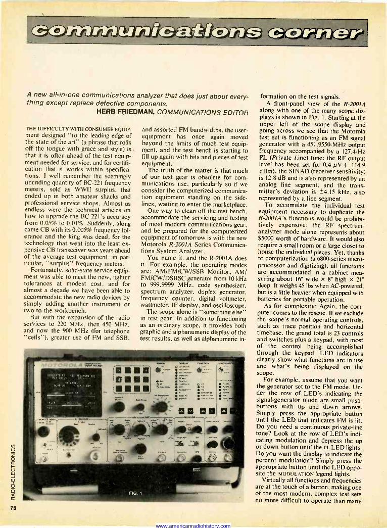
A new all -in -one communications analyzer that does just about every- thing except replace defective components.
HERB FRIEDMAN, COMMUNICATIONS EDITOR
THE DIFFICULTY WITH CONSUMER EQUIP - ment designed "to the leading edge of the state of the art" (a phrase that rolls off the tongue with grace and style) is that it is often ahead of the test equip- ment needed for service, and for certifi- cation that it works within specifica- tions. I well remember the seemingly unending quantity of BC -22I frequency meters, sold as WWII surplus, that ended up in both amateur shacks and professional service shops. Almost as endless were the technical articles on how to upgrade the BC -221's accuracy from 0.05% to 0.01%. Suddenly, along came CB with its 0.005% frequency tol- erance and the king was dead, for the technology that went into the least ex- pensive CB transceiver was years ahead of the average test equipment-in par- ticular, "surplus" frequency meters.
Fortunately, solid-state service equip- ment was able to meet the new, tighter tolerances at modest cost, and for almost a decade we have been able to accommodate the new radio devices by simply adding another instrument or two to the workbench.
But with the expansion of the radio services to 220 MHz, then 450 MHz, and now the 900 MHz (for telephone "cells"), greater use of FM and SSB,
U z o rr U w J w Ó o (r
78
and assorted FM bandwidths, the user - equipment has once again moved beyond the limits of much test equip- ment, and the test bench is starting to fill up again with bits and pieces of test equipment.
The truth of the matter is that much of our test gear is obsolete for com- munications use, particularly so if we consider the computerized communica- tion equipment standing on the side- lines, waiting to enter the marketplace.
One way to clean off the test bench, accommodate the servicing and testing of most modern communications gear, and be prepared for the computerized equipment of tomorrow is with the new Motorola R -2001A Series Communica- tions System Analyzer.
You name it, and the R-2001 A does it. For example, the operating modes are: AM/FM/CW/SSB Monitor, AM/ FM/CW/DSBSC generator from 10 kHz to 999.9999 MHz, code synthesizer, spectrum analyzer, duplex generator, frequency counter, digital voltmeter, wattmeter, IF display, and oscilloscope.
The scope alone is "something else" in test gear. In addition to functioning as an ordinary scope, it provides both graphic and alphanumeric display of the test results, as well as alphanumeric in-
formation on the test signals. A front -panel view of the R -2001A
along with one of the many scope dis- plays is shown in Fig. I. Starting at the upper left of the scope display and going across we see that the Motorola test set is functioning as an FM signal generator with a 451.9550 -MHz output frequency accompanied by a 127.4 -Hz PL (Private Line) tone: the RF output level has been set for 0.4 pV (-114.9 dBm), the SINAD (receiver sensitivity) is 12.8 dB and is also represented by an analog line segment, and the trans- mitter's deviation is ±4.15 kHz, also represented by a line segment.
To accumulate the individual test equipment necessary to duplicate the R-200IA's functions would be prohibi- tively expensive: the RF spectrum - analyzer mode alone represents about $5000 worth of hardware. It would also require a small room or a large closet to house the individual pieces. Yet, thanks to computerization (a 6800 -series micro- processor and digitizing), all functions are accommodated in a cabinet mea- suring about 16" wide x 8" high x 21" deep. It weighs 45 lbs when AC -powered, but is a little heavier when equipped with batteries for portable operation.
As for complexity: Again, the com- puter comes to the rescue. If we exclude the scope's normal operating controls, such as trace position and horizontal timebase, the grand total is 23 controls and switches plus a keypad, with most of the control being accomplished through the keypad. LED indicators clearly show what functions are in use and what's being displayed on the scope.
For example, assume that you want the generator set to the FM mode. Un- der the row of LED's indicating the signal -generator mode are small push- buttons with up and down arrows. Simply press the appropriate button until the LED that indicates FM is lit. Do you need a continuous private -line tone? Look at the row of LED's indi- cating modulation and depress the up or down button until the PL LED lights. Do you want the display to indicate the percent modulation? Simply press the appropriate button until the LED oppo- site the MODULATION legend lights.
Virtually all functions and frequencies are at the touch of a button, making one of the most modern, complex test sets no more difficult to operate than marry
www.americanradiohistory.com

Put Professional Knowledge and a
toys. (In fact, I know of some toys that are more difficult to get working.)
Now that we've touched on some of the most popular functions of the R-2O0IA it's time to go a little deeper into the nitty-gritty.
The oscillator can be set to within 100 -Hz resolution with an accuracy of ± 1 x 10⁻⁶ from 0°C to 55°C. If you need even greater accuracy, select a timebase housed in an oven. This type is available with an accuracy of ±5 x 10⁻⁸ over the same temperature range. (Warmup to ±5 x 10⁻⁷ of final fre- quency in 20 minutes.)
The oscillator's spurious output is better than 40 dB down, while harmonic attentuation is greater than 15 dB.
FM frequency deviation is 0 to 50 kHz peak, from 5 to 10 kHz. ± 1 dB, using internal, external, or microphone modulation or all simultaneously.
Amplitude modulation is 0 to 80% with ± 10% full scale readout accuracy, from 5 to 10 kHz, ± 1 dB, again with internal, external or microphone modes.
The carrier suppression of the DSBSC carrier output (1-500 MHz) is better than 25 dB.
The frequency range of the monitor mode is 1 to 999.9999 MHz, with 100 - Hz resolution. Accuracy is equal to that of the master oscillator timebase. Input sensitivity is 1.5 pV for 10 dB SINAD (±6 kHz modulation acceptance) and 7 pV for 10 dB SINAD (± 100 kHz modulation acceptance).
A built in RF -wattmeter covers 0.2 to 125 watts from 1 to 1000 MHz.
The code synthesizer generates fre- quencies from 50 Hz to 9.9999 kHz with a 0.1 -Hz resolution and an overall fre- quency accuracy and stability of 0.01%.
The spectrum analyzer's frequency range is 2 to 1000 MHz. with full-scale frequency dispersion adjustable between I and 10 MHz.
There are other goodies, too numer- ous to mention, including an adjustable frequency -offset duplex generator. Your best bet for additional information and in-depth coverage of the Communica- tions System Analyzer. giving many ideas on using the device for all com- munications equipment-CB, amateur, VHF/UHF-is Motorola's descriptive brochure, available from Motorola's Test Equipment Products Dept., 1313 E. Algonquin Rd.. Schaumburg, IL 601%. R -E
It's not what vuu t hink.
Help light the candle of'under:dum ing. Contact your local chapter lathe Epilepsy Foundation of America. ((r write Epilepsy. s1'ashingles. D.C. 20)S0.
Get A GNOME the original micro -synthesizer Every day more people discover that PAIA's GNOME is the most versatile, cost effective special effects device on the market today.
John Simonton's time-provsn design provides two envelope generators, VCA, VCO and VCF in a low cost, easy to use package. Use alone with it's built in ribbon controller or m -edify to use with guitar, electronic piano, pclytonic keyboards. etc.
The perfect introduction to electronic music and best of all, the Gnome is only $59.95 in
y to assemble kit form. Is it any wonder thousands?
Bird. UhlaWm City.OK 73118
1 Send GNOME MICRO- SYNTHESIZER Kit ($59.95 plus $2.00 postage)
I 1 GNOME MICRO -SYNTHESIZER (Fully Assembled) $100.00 plus $2 postage
I 1 Send FREE CATALOG
address adore
l(ce:keet71/4 city & te zrp
visa.
- _ mo ice_ card no. Dept. 1 R 140511343-96213
1020 W. Wilshire Bhd. Oklahoma City. OK 73116
CIRCLE 8 ON FREE INFORMATION CARD
COLLEGE DEGREE in your Electronics Career through
Earn Your
DEGREE by correspondence, while continuing your present job. No commuting to class. Study at your own pace. Learn from complete and explicit lesson materials, with additional assistance from our home -study instructors. Advance as fast as you wish, but take all the time you need to master each topic.
The Grantham electronics degree pro- gram begins with basics, leads first to the A.S.E.T. degree, and then to the B.S.E.T. degree. Our free bulletin gives complete details of the program itself, the degrees awarded, the requirements for each degree, and how to enroll. (We are located at 2500 S. LaCienega BI., Los Angeles, Calif.) Write to our mailing address shown below for Bulletin R-80 Grantham College of Engineering
P. 0. Box 35499 Los Angeles, California 90035
Worldwide Career Training thru Home Study
Nold evergthing! Get a #324 PanaVise Work Center. Here's everything you need to hold every- thing you work with ... in one money -saving package! Write for FREE catalog today.
2850 E. 29th St., Long Beach, CA 90806
Famous PanaVise standard base tilts, turns, rotates to exact work position.
6 -compartment Tray Base Mount with 6 anti -slip feet.
Self -centering wire and Solder Holder* attaches to unit.
*Solder wire and solder iron not included.
Adjustable Circuit Board Holder holds up to 10" board.
FREE 2 Nib Sponges with self -purging slits for easy cleaning.
CIRCLE 47 ON FREE INFORMATION CARD
Solder Iron Holder* with perfect angle for holding constant heat. Attaches to unit.
www.americanradiohistory.com

Want to cut out a career as a
two-way radio technician?
MTI offers the only training for professional FM two-way radio available. Qualified technicians are employed in government, in- dustry, and public service. But training is your key.
You could cut out a career as a two-way radio technician by cutting out this coupon. We'll send you information on how you can learn more about this spe- cialized field, at home.
Name
Address
City
State/Zip 83G
MT/ Mobile Training
Institute Box 735, Camp Hill, PA 17011-U.S.A.
Zoom mi,a ---as s's--i CIRCLE 41 ON FREE INFORMATION CARD
BIG 21/2"
.12:5 DISPLAY if }Lj'L i.; SOLID STATE
CLOCK/CALENDAR KIT 0101 Displays time of day, date or alternates between both automatically. May be connected to B ohm speaker for alarm clock. Operates from 120 VAC 60 Hz
$49.95 Oak case extra, $29.95
UNIVERSAL_; DESIGNER KIT 6100 tl1 Indispensable aid to digital IC design. 2 o y pushbuttons, 2 readouts, 4 switch outputs. 8 LEDs,
bv- 2generators, 2counters, 5V ...- supply pins. $49.95 n'' , Breadboard extra:' $59.95 assembled
14 s. 6101 Digital Logic Course $29.95
C4 r ASK FOR OUR FREE 8 -PAGE CATALOG
Offligil=CEMO = C »1
14905 N.E. 40111. Redmond. WA 98052 )206) 883-9200
0101 SOLID STATE CLOCK CALENDAR KIT $ 49.95 T 0101 OAK CASE FOR ABOVE 29.95 J 6100 UNIVERSAL DESIGNER KIT 49.95
6100 ASSEMBLED DESIGNER KIT 59.95 O OT 59S BREADBOARD 11.00
OT 595 BREADBOARD 2.50 T 6101 DIGITAL LOGIC COURSE 29.95
ADD $2.50 PER ORDER POSTAGE AND HANDLING.
NAME R-7
ADDRESS
CITY. ST, ZIP VISA
CARD NO ,. MSTR OHG
SIGNATURE J
More information on radio products is available. Use the Free Information Card inside the back cover. SCANNER, The Bearcat 300 Service Search, is a radio with over 2000 pre-programmed frequen- cies and offers 11 services, including police, fire, marine, ham, government, and business. By pushing a button, the radio will automatically search the actively assigned frequencies for the service selected. The scanner also has 50 user -
CIRCLE 111 ON FREE INFORMATION CARD
programmable channels. Frequencies are changed and stored by keyboard entry and can be in any combination from the seven VHF and UHF bands. Other features include HOLD, RESUME, and SPEED controls, search between frequenices, and a digital display that also shown time. Mea- sures 121/4" X 3'/8' X 7". Price is $499.95. -Electra Co., P.O. Box 29243, Cumberland, IN 46229.
ANTENNA SIGNAL BOOSTER, the Indy Long Ranger, is a solid-state system designed for CB radios. It operates by a preamp that boosts the receiving signal up to three times, giving an addi- tional three S units or more for AM or SSB. Tuned
CIRCLE 112 ON FREE INFORMATION CARD
to 27 MHz, it runs on positive or negative ground, and features an adjustable gain control. Comes complete with instructions and adhesive pad for installation. Suggested retail price is $19.95. -ESP Systems Development, Inc., 28189 Keh- rig Dr., Mt. Clemens, MI 48085.
AMATEUR RADIO SPEECH CLIPPER, model HDP-1220 BW, is designed for use with the Heath Company's SB -100/101/102 and HW-100/101
CIRCLE 50 ON FREE INFORMATION CARD
transceivers, and with the S8-400/401 transmit- ters. Average SSB output is increased by 66%-a little below full key -down CW output. Unlike some other speech clippers on the market, the HDP- 1220 installs in the IF strip of the rig to produce true RF processing. A specially -designed IC gives hard, symmetrical clipping, and a built-in SSB fil- ter keeps both audio and signal narrow and clean. The unit comes fully -assembled and can be installed in just 15 to 30 minutes using only three cables (supplied). No irreversible modifica- tions need be made to the rig. Price of the HDP- 1220 speech clipper is $149.95 fully assembled.
Heath Company, Benton Harbor, MI 49022.
AM/FM/CB ANTENNA, model TL -15, is a manu- ally -operated triway antenna designed to fit Gen- eral Motors and narrow -fender cars. The custom top -mount antenna has a 72 -inch cable and a single 42 -inch mast. Its top -loaded whip is easily removable for protection against theft. Sug- gested retail price for the TL -15 is $39.30. Harada
CIRCLE 113 ON FREE INFORMATION CARD
Industry of America, Inc., Dept. P, 1900 W. Arte- sia Blvd., Compton, CA 90220.
SATELLITE TV RECEIVER, model 4200, is a low- cost fully tunable receiver covering all channels from 3.7 to 4 GHz. It provides dual audio outputs of 6.2 to 6.8 MHz, with other outputs available. The unit features a built-in LNA power supply and is compatible with video monitor and VTR input.
CIRCLE 114 ON FREE INFORMATION CARD
Available in 1-9 quantities for $1,995; other quan- tity prices on request. -International Crystal Mfg. Co., Inc. 10 No. Lee, Oklahoma City, OK 73102. R -E
80 CIRCLE 46 ON FREE INFORMATION CARD
www.americanradiohistory.com

Use your oscilloscope for easier and faster troubleshooting JACK DARR, SERVICE EDITOR
THIS DEPARTMENT GETS A LOT OF MAIL
asking for help in locating faults in any- thing electronic. In our "armory" we have one instrument that can make find- ing those answers a lot easier: that is the oscilloscope. (Up to just a few years ago; it was the most bought and least used instrument in a shop. From a random sur- vey, I doubt if as much as 10% of the service technicians used the scopes they had!) Yet, it's the most versatile test instrument in the shop. Properly used, it can do almost anything. Many of us think it's hard to use; it is not. Let's have a look at a few typical jobs it does so well, and how easy they are to do.
What's the first question we ask our- selves when we begin a diagnosis? It should be "What is this not doing that it ought to be doing?" In all cases, that means that something in there is stopping a signal-keeping it from going through the circuitry and getting to the places it ought to be. It can be anything from a
sweep signal, to audio, IF, color-any- thing. What we must have is an instru- ment that will show us the signal and find out just how far it goes.
That instrument is the scope; it's the only tool that can do it. You can look at it and get an unmistakable answer. Other instruments may be reading hum, inter- ference, oscillation, etc., and make you think it is a signal. Not the scope; it shows you the signal, or just as important- shows you where it isn't. Find out where the signal stops and you have the one clue that will help you solve the problem.
In many cases, you must use the scope-in sync problems, for instance. Letters ask me "How can I solve this sync problem? I don't have a scope just a multimeter." The answer is "Only with great difficulty!" Meters are important: After you find the point of failure you use them to get more clues as to the exact nature of the fault. DC voltage, resistance readings, continuity, etc., are necessary, but you do not want to waste time making them at random. That isn't testing; that's just "poking at it!"
The scope is the major instrument for my favorite test -method. First, identify the faulty stage. Start at one end of it and go through it from input to output until you find where the signal stops. Just hit each test point with the scope probe and
IDEAL
BUT YOU MAY SEE THIS...
OR EVEN
n n n VIDEO!
THIS.,., 1LIA
FIG. 1
see what's there. It takes longer to identi- fy the test points than it does to make the tests.
Let's look at some actual cases where a scope provided the key to the problem. One very old symptom is "no video, but a good raster." The signal is being stopped dead somewhere in the signal -path. The best test for that is to check for the video signal at the video -detector output. If it's there, you have cleared all of the RF/IF stages and the AGC, in one jab! The problem is then in the video stages.
Another, and really annoying fault is feedback. The stock symptom of that is a whole lot of problems all at once-weak video, distortion, poor sync, lines and wiggles in the picture, and others. When you see something like that, start looking for something that is common to all of the
CLIPPING
V A A tCLIPPING
FIG. 2
affected stages. That is the DC power supply. Poor filtering can allow feedback between stages and cause all kinds of weird things. Here again, a "one -jab" test with the scope tells you. Just touch any of the B+ lines and look for any sign of a signal. You should see nothing but a nice straight line; if you see any signal at all- pulses, hash, or anything else-the filter circuits aren't doing the job. (See Fig. 1). Check the filter capacitors.
Speaking of testing filter and bypass capacitors, the scope makes a great in - circuit tester. Touch the scope probe to the terminals of a capacitor in the set while the set is in actual operation. That will catch bypass capacitors that aren't doing the job. Just check on the hot ter- minal; you should see no signals at all. Check every bypassed point; emitters, bottom ends of coupling transformer pri- maries, etc. That is very useful in color circuits!
SHARP PEAKS -NORMAL
FLATTENING OF PEAKS
THIS CAUSED BY OSCILLATOR TUBE! rr FIG. 3
Audio distortion can be tough, but a scope makes it easy. Feed in a known sig- nal, then just follow it through until you find the point where the distortion shows up. Distortion is a common problem in common -emitter amplifiers with a by- passed emitter resistor. Scope the emitter of the output transistor; there should be no signal here. If there is, the bypass capacitor is open and the resulting degen- eration upsets the stage. Clipping is an- other common problem. Follow the same test method. Feed in a signal at the proper level and trace until you find the stage
www.americanradiohistory.com

SERVICE CLINIC continued from page 81
that is clipping. If you have a function - generator with a triangle -wave output, try using it as the signal source. The sharp peaks will instantly show up any sign of clipping. (Fig. 2.)
Checking the output power of power amplifiers is easy. Feed in a signal and scope the output. Now, raise the volume until you see it start to clip. Back off until the clipping has disappeared, then read the P -P voltage. That can be converted to power using the formula: P = E X I. (Don't forget to convert P -P to RMS!)
Some really obscure problems are a cinch to isolate with a scope. One is creeping current in horizontal output stages (tube sets). Scope the grid drive and watch the waveform (See Fig. 3). The normal waveform has a sharp peak. You may see that peak start to flatten out as the tube warms up. The current rises in step with the flattening. The flat peak keeps the tube turned on for much too long, and raises the average current. That is caused by grid -emission in the tube.
The scope can be the most useful instrument on the bench. Get one-and use it. It's not at all hard; all you do is touch the probe to the point you want to check, and adjust the controls for a stable waveform. Some of the new DC -coupled scopes can be used as DC voltmeters although I'm not really too impressed with that application. I prefer to use a DC voltmeter.
I've always been an ardent advocate of using a scope. Try using yours for a while and I'm sure that you will become as strong an advocate as I am.
Correction In the April issue, I said that I couldn't
find an address for an old and reputable company, Dynaco. That much was true- I couldn't. However, I have had quite a few letters already from (rightfully) in- dignant readers, saying "Dynaco is not dead; they're alive and well, and living in Canton, MA 02021!" My apologies to all, and especially to the company who have been making very good hi-fi equipment for a long while. The correct address is "Dynaco, Inc., 110 Shawmut Road, Can- ton, MA 02021". This information is now in my files! R -E
service questions
TOUCH -PLATE SWITCH Someone has "worked" on this Pana-
sonic set before. Most of the damage is now cleared up, but that feather -touch switch puzzles me. It's been taken apart and I can't tell what's missing. I'm a little lost.-K.M., Pittsburgh, PA.
This is a "touch -plate" switch circuit. Just touch the switch and it turns on or off. So, all the switch has in it is a small metal blob or contact. This goes to an oscillator circuit, then to a waveshaper squaring amp, then to a trigger that turns on the switch transistor. This last stage is apparently a flip-flop. The first touch turns it on; the next touch turns it off.
Trace the circuit through from the oscillator, checking the pulses, DC volt- ages, etc. This is a rather unusual circuit, and I don't understand all of it. However, it should be fairly easy to check out. Look for open diodes, transistors, etc., plus bad solder joints!,
VERTICAL OUT The vertical sweep went out on this
Zenith 19FC45. Found that the picture tube was also out, too! Replaced all parts but I'm afraid to turn it on. Any advice?- G.A., Richmond Hill, NY.
One very good piece of advice! Find the 4 -legged capacitor on the collector of the horizontal output transistor, C229 -a and C229 -b, and change it! If this breaks down it can cause damage to the picture tube. Zenith distributors have an im- proved version of this capacitor and I would definitely recommend putting this in before you light the fire.
RED HOT DAMPER I'm up a tree! The damper tube in this
CTC-31 gets red hot. New damper tube, flyback, yoke, etc., didn't help. I've checked everything I can think of and no results, I even unhooked L29 from the cathode of the damper, and it still gets hot! Can you tell me what's going on here?-J.R., Detroit, ML
Red-hot with the cathode of the damp- er floating? Current has no place to go, or shouldn't have. Logical analysis says that the cathode of this tube is grounded somehow. If an ohmmeter shows no ground here, replace the damper socket. I suspect a carbon path or breakdown of the insulation between this socket pin and ground. Something is taking a lot of cur- rent here, and this is about the only thing you haven't tried. (Good luck!)
TAPE -PLAYER MOTOR HINT Ken Boren (who forgot to include his
address!) sends this one along, and it sounds good. He says that he was replac- ing motors in 8 -track tape units, because of excess slippage. Cleaned motors, put back together, and they did much better. Finally got a callback on one that had just been replaced.
Noticed that when the flywheel was taken off, the motor shaft looked very shi- ny and smooth; new motor's shaft was dull and rough looking. Got idea; sanded the old shaft till dull, put flywheel back, and it runs like a charm. Been working for a month or more!! So, look for pol- ished shafts and roughen them up and these things can be fixed a lot easier. R -E
HOME THERMOSTAT continued fron: page 47
t WASTE
AIR
WASTE AIR DAMPER
RETURN = PLENUM AIR =
RETURN AIR DAMPER
SUPPLY AIR
Fig. 11-ALTERNATE MEANS of air flow con- trol. It is important that dampers close tightly.
Center power supply will be needed. A special inlet must be added to your
heating/air-conditioning system to sup- ply the fresh air. That inlet should be placed under the eaves of the house so it will be shaded and not subject to the direct rays of the sun. The outside sensor should be installed near it. A filter grill, or at the minimum, a '/4 -inch screen grid cover, is advisable at the opening. Attic air should not be used because of the extreme temperatures encountered in the summer.
The fresh air should be ducted into the return air plenum to enable the central - system fan to distribute the air equally throughout the conditioned area. An out- let for the waste air should be provided for use in the fresh -air mode and the air should be exhausted into the attic to keep the attic temperature closer to inside tem- perature, thus reducing the heating and cooling load. Diagrams showing the two methods of feeding fresh air into the home's climate -controlled environment are in Figs. 10 and 11. The integrity of the fresh air duct and louvers is important in that, if air leakage occurs, the efficien- cy of the heating or cooling units will be impaired. Finally, remember that this system is not proportional and that a sim- ple open -close actuator will suffice. R -E
FRESH AIR DAMPER
% i FRESH
AIR -
Put your money where your Heart is.
American Heart Association
WE'RE FIGHTING FOR YOUR LIFE
www.americanradiohistory.com

market center
FREE KIT Catalog AUTORANGE DIGITAL CAP -METER KIT. Still the best for only $71.95
Phone 415-447-3433 Write or Phone for FREE CATALOG. Average 1 minute Saturday call is 21Ç.
DAGE
contains TEST & EXPERI- MENTER5
EQUIP.
SCIENTIFIC INSTRUMENTS BOX 1054R LIVERMORE CA 94550
PLANS & KITS ELECTRONIC organ kits. The ultimate design. Sounds like a pipe organ. Build it to sell or build it to keep. Models for churches, homes, clubs, pizza parlors. Send $2.00 for demo record and catalog. DEVTRONIX, Dept. 70, 6101 Warehouse Way, Sacramento, CA 95826
PRINTED circuit boards from sketch or artwork. Kit projects. Free details. DANOCINTHS INC., Box 261, Westland, MI 48185
SPEAKERS. Save 50%. Build your own speaker system. "Free catalog" write: MC GEE RADIO, RE 1901, McGee Street, Kansas City, MO 64108
SATELLITE TV antenna build for $300. Detailed plans $30. NUMAN ENTERPRIZES, Rt. 1, Box 357, Jonesboro, TE 37659
PROJECTION TV . . . Convert your TV to project 7 foot picture. Results equal to $2,500 projector. Total cost less than $20.00. Plans & lens $16.00. Illustrated information free. MACROCOMGJ, Washington Crossing, PA 18977
"PCB as low as 154 sq-in, free drilling, also PTH. INTERNATIONAL ENTERPRISE, 12507 Brent, Cerritos, CA 90701
...specialists in CCTV ATV Re rch and computer monitors!
Video monitors - color B/W TV Cameras, kits, parts i plans Video -to -RF modulators
Free catalog. Phone or write. (402) 981-3771
13 -RE Broadway Dakota City, NE. 68731
LED projects, bargraphs, VU, oscilloscopes, con- trollers, clocks, $3.50. EMERY ELECTRONIC EN- TERPRISES, 731 N. Olive, Anaheim, CA 92805
CB/HAM Circularly polarized beam antenna. Plans $4.00. Free catalog-plans/kits. PANAXIS, Box 130-F7, Paradise, CA 95969
AMATEUR radio books. Free catalog. SCELBI PUBLICATIONS, 20-R Hurlbut Street, Elmwood, CT 06110
EINSTEIN superCeded! Free! 408 Vermont, Day- tona, FL 32018
NEGATIVE ion generator: build with easy -to -get parts for less than kit prices! Complete plans $5.00. LUNATRIX, Box 891 -RE, Yucaipa, CA 92399
SATELLITE Television. Build your own satellite receiving station. Quick and easy to construct. For more information write: Robert Coleman, Rt. 3, Box 58-A, Travelers Rest, SC 29690
SECRET guide to computers. Free catalog. SCELBI PUBLICATIONS, 20-R Hurlbut Street, Elmwood, CT 06110
WHOLESALE TO DEALERS DEALERS: send letterhead for free wholesale pricelist of CB radio and scanner equipment. FOUR WHEELER COMMUNICATIONS, 10-R New Scotland Ave., Albany, N.Y. 12208 (518) 465-4711
CLASSIFIED COMMERCIAL RATE (for firms or individuals offering commercial products or ser- vices). $1.50 per word prepaid (no charge for zip code) . . . MINIMUM 15 WORDS. 5% discount for 6 issues, 10% for 12 issues within one year, if prepaid. NON-COMMERCIAL RATE (for individuals who want to buy or sell a personal item) 854 per word prepaid . . . no minimum. ONLY FIRST WORD AND NAME set in bold caps. Additional bold face (not available as all caps) at 106 per word. All copy subject to publisher's approval. ADVERTISEMENTS USING P.O. BOX ADDRESS WILL NOT BE ACCEPTED UNTIL ADVERTISER SUPPLIES PUBLISHER WITH PER- MANENT ADDRESS AND PHONE NUMBER. Copy to be in our hands on the 26th of the third month preceding the date of the issue (i.e., August issue closes May 26). When normal closing date falls on
Saturday, Sunday, or a holiday, issue closes on preceding working day.
HIGHLY ONE-MAN PROFITABLE
ELECTRONIC FACTORY Investment unnecessary, knowledge not re- quired, sales handled by professionals. Ideal home business. Write today for facts, Postcard will do. Barta-RE-E, Box 248, Walnut Creek, CA 94597.
BUSINESS OPPORTUNITIES MECHANICALLY inclined individuals desiring ownership of Small Electronics Manufacturing Business-without investment. Write: BUSINESS- ES, 92-R, Brighton 11th, Brooklyn, NY 11235
BOOKS "CRIME By Computer" $6.95. Postpaid -300 pages. COMP-U-TRONIX, Box 3401, Kent, WA 98031
WANTED ELECTRONIC products assembled. Company seeks contracts from manufacturers large and small. U.S. labor and knowhow isn't priced out of reach. Details write: PRODUCTION DEVELOP- MENT INC., 1320 Water St., Brownsville, PA 15417
EIMAC/Varian tubes 304TL, 4CX1000, etc. Also need 53, 6L6 metal, 7F7, 7C5. Ted Dames, W2KUW, 10 Schuyler Avenue, North Arlington, NJ 07032. (201) 998-4246, (800) 526-1270
PICTURE TUBE MACHINE We buy end sell NEW end USED CRT rebuilding machinery. COMPLETE TRAINING. Buy with CONFIDENCE from the ORIGINAL MFGR. For complete details send name, address, zip to LAKESIDE INDUSTRIES 9071 N. Elston A
Chicago, III. 60618 Phone: 312-583-6565
To run your own classified ad, put one word on each of the lines below and send this form along with your check for $1.50 per word (minimum 15 words) to:
Radio -Electronics, 200 Park Avenue South, N.Y., N.Y. 10003
ORDER FORM PLEASE INDICATE in which category of classified advertising you wish your ad to appear. For special headings, there is a surcharge of $10.
( ) Plans/Kits ( ) Business Opportunities ( ) For Sale ( ) Education/Instruction ( ) Wanted ( )
Special Category: $10
(PLEASE PRINT EACH WORD SEPARATELY, IN BLOCK LETTERS.)
1 2 3 4 5
6 7 8 9 10
11 12 13 14 15
16 17 18 19 20
21 22 23 24 25
26 27 28 29 30
31 32 33 34 35
PLEASE INCLUDE FOR OUR FILES YOUR PERMANENT ADDRESS AND PHONE NUMBER.
C-
o 83
www.americanradiohistory.com

SATELLITE TV FOR THE HOME
Our receiver lets you get over 75 channels of televi- sion directly from earth - orbiting cable TV satellites!: HBO, Showtime, super sta- tions, sports and movies from around the world.
Sick of Network TV? Buy Complete or
511atsa Build our kit and save! 2L.
Our 24 -channel receiver provides "studio quality" TV reception. Easy to install! Ultra low power con- sumption! Brilliant color! Works anywhere! FCC licensing no longer required. Order today!
Complete details covered in our Home Earth Sta - lion manual. Send $7.95 today (refundable against any purchase), or call:
24 -hour C.O.D. Hotline (305) 869-4283
SPACECOAST RESEARCH Dept. T, P.O. Box 442, Altamonte Springs, FL 32701
SATELLITE TELEVISION SATELLITE TV buyers guide. Exclusive compar- isons plus how to install your own saving big $. Worldwide movies, news, sports, religion, enter- tainment on your set. Well over 35 channels. Book guaranteed. US funds please. $12.95 post- paid or $14.95 First class (Airmail). REED PUBLI- CATIONS, Box 219-E, Maitland, FL 32751
SATELLITE television -satellite weatherfax. Will your receiving antenna clear local obstruc- tions? Get antenna aiming data for geostationa- ry satellites, custom computed for your latitude and longitude. Included Is chart of U.S. and Inter- national satellites around the globe and instruc- tions on how to find them in the sky. Send $5.00 to COMPUSAT, 643 South Route 83, Elmhurst, Illinois 60126.
ANTENNA azimuth and elevation for all Western Hemisphere geostationary satellites. $3.00 and your latitude and longitude. Free sample SASE. DAVID FREY, Box 2591, Satellite Beach, FL 32937
LNA GaAs FET's 45.00, duroid boards $10.00, parabolic dishes, bandpass filters, IF amps, de- modulators, IC's for Radio -Electronics satellite receiver. Connectors. We have parts and mod- ules or entire terminals. Send $4.00 (refundable) for information. EWG, 38005 Pueblo Rd, Hinkley, CA 92347
SATELLITE downconverter 3.7-4.2 6HZ in, 70 MHZ out. Commercial quality performance, pro- vision for onboard local osc. $75.00 includes PCB w/parts $1.00 brings manual, birkill LNA PCB chip caps sase NORMAN GILLASPIE, 2225 Sha- ron Rd, #224, Menlo Park, CA 94025
KEEP YOUR CARRIERS CRYSTAL CLEAR
The C-1000 gives you_ greater accuracy and wider fre- quency range than many frequency counters that cost much more' Accuràcy to .1 PPM 100001 %) from 0° to 40°C. Full frequency range from 10Hz to 1 GHz Rugged metal case. 8'7i digit resolution Selectable I. I and 10 second gate times. Standby feature a flows oven td remain ready $499" IBRIGHTELECTRONICS P O. Box 76972 Atlanta, Georgia 30328 Ordertoll'ree 800-241-3939 In Georgia call 404-257-1494
UNBELIEVABLE
s3.00 FOR sarti.
AM-FM-MUX
MADE BY THE AUTO RADIO SPECIALISTS!!
AUTOMATIC RADIO
Models May Vary
PUSH BUTTONS
I7O STERE 8-TRAK TAPE
BY POPULAR DEMAND! Delta is the first in the world o offer these new, first -grade stereo radios at surplus!!!
They axe 100% solid state AM-FM-MPX stereo radios & stereo 8 -track player. With knobs and 5 push buttons!
SM Fit Convert Your Car Into A Concert Hall! AUTOMATIC RADIO ---
PU. eur00as
$100 AMFM UNBELIEVABLE
5795R AUTO RADIO UNBE
FACTORY CLOSEOUTI One of America's lamest manufactur- ers of auto radios has given up. We've been fortunate in acquir- ing in production. These are AM -FM sets.... designed for newcars.
last auto rrs All are tested 100% operational and - come with knobs and push buttons. Ideal for installing in your auto, van, camper,boat, truck. NEWS ITEM! Auto hi-fi has become as sophisticated as home hifi - and nearly as expensive. You can spend $200 for simple components -which means hi-fi can be out of reach for many folks and 2nd cars. If you want hi-fi FM you can start with the purchase of a $100 radio for a mere 619.95....This price will not last long - order today while our limited supply lasts!
TOO GOOD TO BE TRUE! This sale is not a- vailable to the general public as they would sell out instantly. However, our loyal customers have the opportunity to scoop ups these new SURPLUS GEMS and save big dollars.
Delta No. Size Compare SALE 5801R 71/4 x 21/2 x 7Ve" $160.00 539.95* 5802R 74 x 2-5/16 x 7 $160.00 $39.95 5803R 7.3/8x3Wx6Va" $170.00 $44.501 5804R 7'/zx3-3/8x7'/" $170.00 644.501
Manual tuning. t Push buttons! Negative ground. 52/4" knob spacing.
MAIL-OSD>OR ADD8f88:
.e., FREE
rzo-PG.
7 l'I
( CATALOG
BABM0.M tit 1CAs0. f!-r mastn ckarge
CIRCLE 28 ON FREE INFORMATION CARD
ELECTRONICS 176 SECOND AVE. WALTHAM, MASS.
02154 Minimum Order $8.00
TEL. (617) 388-4705
AUTHORIZED TRS-80© DEALER A301
COMPUTER SPECIALISTS
Mallgelft immemair Up to
15% Discount on TRS-80's
26-1061 4K LEVEL I $424.00 26-1056 16K LEVEL 11 $715.00
1-800-841-0860 TOLL FREE
MICRO MANAGEMENT SYSTEMS, INC. Downtown Plaza Shopping Center
115 C. Second Ave.. S.W. Cairo. Georgia 31728
(912) 377-7120 Go. Phone No.
FOR SALE RADIO & TV tubes 490 each. One year guaran- teed. Plus many unusual electronic bargains. Free catalog. CORNELL, 4217-E University, San Diego, Calif. 92105
SCANNER/monitor accessories -kits and facto- ry assembled. Free catalog. CAPRI ELECTRON- ICS, Route 1R, Canon, GA 30520
FREE catalog, IC's, LED's, semi's, parts. CORO- NET ELECTRONICS, 649A Notre Dame W., Mon- treal, Que., Canada H3C 1H8. U.S. inquiries. RECONDITIONED test equipment. $1.00 for cat- alog. JAMES WALTER TEST EQUIPMENT, 2697 Nickel, San Pablo, CA 94806
SAVE up to 50% on name brand test equipment. Free catalog and price list. SALEN ELECTRON- ICS, Box 82-M, Skokie, IL 60077
VARACTOR television tuners. These are small high performance units with separate VHF and UHF tuners. With data, new $19.75 ppd. USA. L.R. DESIGN, Box 41, McMinnville, OR 97128
MINIATURE
3.513 M 735 pt
506
ADJUSTABLE CAPACITOR
ALCO HEAVY DUTY MINATURE SIZE TOGGLE Contacts amps ni 120 roc
. Contacts: solid silver S. P.D.T. Body Size: 9116" aia.
cylindrical body '/."high $1.50 each specify handle 'me
a a. ..awe Fiala... ' ar,Y32 auaM.q Bu.wy Bushing
pl ff1i dla.
"high
each specify value
SPRAGUE 100vdc $1-00
t 1e .,
600
nit d
,
VA 2.11/16" long 1" din. i-
r,,s. DUAL 501( SLIDE POT linear taper $1.50 each tl 1 HOUSE MARKED
DARLINGTON TRANSISTOR SPECIFY S AMPS 65
orPN 80 VOLT$
PNP nr 121ers lotto 75C each ilr 126 rer CASE
3lnch knobs
long 2'4 inch slide for slide pots 20s each
10 MEG .Standard a se" Long
25 For 55.004
POTS Th v, Watt Sae
Shaft y,,l T¶I
1 OHM 175 WATT WIREWOUNO RESISTOR
$1.75 each For$1.00 = 50K Kneel/ pot. 201
SLIDE POT 754 Each far Slide
audio taper late83" long. 1.118" dia.
---- 22144 EDGEBOARD CONNECTOR TIN SOLDERTAIL .156"x .200"
LARGE QUANTITIES AVAILABLE 11.35 each 10 for $12.60
e 3,1 /2 inch lang a 2-3/4 inch shoe
REED RELAYS 9-15 VOLT D.C. NORMALLY OPENED
CONTACTS: 1 amp max. switch -2 amp max. carry BODY SIZE: approx. 1 inch long V. inch high
S.P.S.T. 1500 ohm coil $1.15
PHOTO - FLASH CAPACITOR
1100 MFD 330 VOLTS
l' 33/4 ..x1 3/4.
$1.50 Each t_- each
D. P.S.T. 1200 ohm coil 3x5" OAKTRON SPEAK
Magnet 9
l( Jf, 8 OHM Impedance sT-' $1.30 each
3.P.S.T. 750 ohm coil j 51 50 each $2.50 each
ALL ELECTROAICS 905 S. Vermont Ave. SEND
Loa Angeles, CA 90006 1213) 3804000
Store 8 Warehouse Hours 9 AM 5 PM
Monday thru Friday Saturday
10 AM 3 PM
CORP. FOR OUR FREE CATALOG
TERMS Quantities Limited Min. Order 110.00
Add 52.00 Shipping USA Calif. Rea. Add 6 Prompt Shipping
CIRCLE 42 ON FREE INFORMATION CARD
www.americanradiohistory.com

ECG, RCA AND GE
SEMICONDUCTORS SOLVE SERVICE PROBLEMS.
11:4\411MICONDUCTORS
SOLVE THOSE SANK PROBLE
MUCH LESS.
Here's Proof! SAVE UP TO 40% ON 10 OR MORE OF THE SAME ITFM
EQUIV.
102A .4C
EQUIV.
131A .40
EQUIV.
171 2.25
EQUIV.
231 4.90
EQUIV.
298 1.10
EQUIV.
381 3.10
EQUIV.
720 1.50
EOUIV.
791 2.80
EQUIV.
975 1.60
EQUIV.
1036 3.20 s e Ai
103A .30 131ìA .40 176 1.30 233 .80 299 .75 382 1.00 721 3.80 793 3.20 978 1.60 1037 3.00
104 2.00 137A 40 176 1.10 234 .40 300 .70 383 1.10 722 1.50 801 2.00 987 1.40 1040 1.40
105 3.90 133A .40 177 .25 235 1.60 302 1.30 390 1.10 723 1.50 802 8.80 990 4.80 1041 1.20 2.40
106 .40 139A .40 180 4.60 236 1.80 306 1.30 391 1.10 724 2.80 803 8.80 992 1.80 1042 Equivalent to ECG 163A
107 .88 140A .40 181 3.40 237 2.40 307 .50 500A 12.40 725 1.50 804 2.90 1002 1.20 1043 3.90
108 109
1.20 .20
142A 143A
.40
.40 182 183
3.20 3.75
238 276
3.35 7.90
308 310
7.40 7.40
506 523
1.50 18.80
726 728
3.50 3.80
805 806
3.20 3.80
1003 1004
1.20 2.40
1045 2.60 1046 3.20 $3ä,0, I
110 .4B 144A 184 1.30 277 7.80 312 .60 525 1.35 729 4.20 807 3.20 1006 2.20 1049 3.90 ,n'
113 .51. 145A
.40 185 .90 279 7.40 313 .80 526A 18.80 731 1.50 814 4.00 1009 2.20 1050 2.00 T1Sa CASE
116 .20 1152
.40 1.30 186A .60 280 3.40 315 1.00 551 2.00 737 3.80 815 3.80 1010 2.20 1051 5.90
117 .28 - 153 187A .80 281 4.60 320 10.60 601 .30 738 4.80 818 3.80 1011 2.25 1052 1.00
118 .93 155
.90
2.90 190 1.80 282 2.00 321 3.50 605 1.65 739 3.20 823 1.20 1014 1.90 1053 2.70 Equivalent tz ECG 165
121 2.75 155 192 .45 283 4.60 323 2.20 612 .35 740A 2.60 824 2.50 1016 2.20 1054 1.70
123A 124
.35 2 00
t57 158
.60 1.50 193
195A .55
2.00 284 285
4.30 6.20
324 325
2.50 29.20
613 703A
.40 1.50
742
743
4.20 3.80
904 905
6.90 4.50
1019 1020
1.20 2.20
1055 2.70 1056 2.80 L,,, 740
125
126 20 .80
159
160
.40 1.10
1.80 196
197 1.30
1.50 287
289
.70
.60 333
334 19.00
19.00 708
709 1.50
1.50 744 746
5.20
3.80 912
917 2.40
3.20 1021
1024 2.20
4.20 1057 3.10
1058 1.95 I c'eem"°" aacAsE
127 295 161 1.20 198 1.50 290 .60 335 26.00 710 3.00 748 2.80 923 1.30 1025 5.90
128 1.40 162 4.60 199 291 1.30 336 26.00 712 2.25 749 2.90 925 7.80 1027 4.90 Many more
129 1.23 163A 4.60 220 .60
1.60 292 1.50 373 2.50 713 1.50 778A 1.80 941M .90 1028 10.40 items to Equivalent to ECG 238
130 1.33 165 3.35 221 1.40 293 1.00 374 2.60 714 2.80 780 3.20 955M 1.40 1029 2.60 choose from I 131
132 1 00
60 -166
167 1.45 1.45
222 229
1.60 .80
294 295
1.10 .60
375 376
1.50 2 25
715 718
3.20 1.50
783 788
2.60 1.50
966 973
1.30 1.80
1030 1032
3.60 2.90
but space does
not permit $745
OutputCASE
f ''¡¡
133 ED 118 1.45 230 4.60 297 1.00 380 3 00 719 1.50 790 2.80 9730 2.00 1035 4.60 listing them all. u
women' audio, Inc. Parts for the TV, Stereo & Communications World
639 Watervliet Avenue, Dayton, Ohio 45420
Call This Toll -Free 24 Hour Hot Line ALLORDERS
1-800-543-3528 sEWI U.P.S.
Ohio Watts 1-800-762-3418 ''4 HOURS.
c r-
(1)
o 85
CIRCLE 10 ON FREE INFORMATION CARD
www.americanradiohistory.com

FOR SALE RAW speakers and finished systems for Hi-Fi and Sound Reinforcement. Also cabinet plans, hard- ware, grille cloth, crossovers, microphones, ac- cessories, much more. Information -packed cata- log, $1.00. UNIVERSAL DISCOUNT SOUND, Dept. RE, 2243 Ringling Blvd, Sarasota, FL 33577
TOP quality components, bottom line prices. Enclosures, carbide drill bits, and much more. Stamp brings catalogue. MIDNIGHT ENGINEER- ING GROUP, P.O. Box 349, Galesburg, IL 61401
BOOKS learn electronics, lasers, robotics, com- puters, TV, solar, etc. Catalog 30e. DOT, 9719R Southwest Highway, Oaklawn, IL 60453
NICKEL cadmium cells, wet type, used, tested. 34AH $6.00ea. 22AH $5.00ea. JOE CONNER, 8346 Bagley, Ashley, MI 48806
CRYSTALS, monitor. Free frequency look up with order. Only $4.95 each plus .505 shipping/ order. Buy four get fifth free. List radio brand. ARNIE ELECTRONICS, 69 E. Northfield Rd., Liv- ingston, NJ 07039
TELEVISION downconverters 1.6-2.7 GHz $99.95 assembled. Details for stamp. GW ELEC- TRONICS, POB 688, Greenwood, IN 46142
"THE Intelligence Library" technical secrets. Books on Electronic Surveillance, Lock -Pick- ing, Demolitions, Covert Sciences, etc. One dol- lar. (refundable): MENTOR PUBLICATIONS, Dept. Z, 135-53 Northern Boulevard, Flushing, NY 11354
CABLE TV converters $39.95. Incredible 96 -page catalog free. ETCO, Box 762, Plattsburgh, NY 12901
TEST equipment, new and used. Catalog $1.00. PTI, Box 8756, White Bear Lake, MN 55110
LASER handbook with burning, cutting, Ruby Reds, Co's, complete plans, books, and parts. Send $4.00 to FAMCO, dept re, box 1902, Rochester, NH 03867
GOVERNMENT surplus receivers, transmitters, snooperscopes, parts, fantastic 72 page catalog 256. MESHNA, Nahant, Mass. 01908
PASS FCC EXAMS The Original FCC Tests-Answen exam manual that prepares you at home for FCC First and Second class Radiotelephone licenses. Newly wised multiple-ohoice exams cover all areas tested on the actual FCC exam. Plus "Self. Study" Ability Test. Proven! 59.95 postpaid. Moneyback Guarantee.
COmmA11D PRODUCTIOf1S f P.O. Box 26348 e
Ramo Engineering Ducron San Francisco, CA 94126 --
EDUCATION & INSTRUCTION UNIVERSITY degrees by mail! Bachelors, Mas- ters, Ph.D's . . Free revealing details. COUN- SELING, Box 317-RE7, Tustin, CA 92680
BROADCASTING! Start your own radio station at home, school, church! Become a DJ! Free infor- mation. "BROADCASTING", Box 130-F7, Para- dise, CA 95969
HOME study degree program in electronics engi- neering. 75 specialized courses also available. For information write: CIEE, P.O. Box 9196, Pitts- burgh, PA 15224
SAMS books -How to Buy and Use Minicomput- ers and Microcomputers $9.95, The Incredible Secret Money Machine $5.95, RVI, Box 1116, Waldorf, MD 20601
FREE microcomputer book catalog. SCELBI PUBLICATIONS, 20-R Hurlbut Street, Elmwood, CT 06110
HOW to do important mathematics with your scientific calculator? Differentiating . Inte- grating . . . Solving differential equations - Algorithms . Limits . Trigonometry . . . ?? "I'll show you how in just 10 days or money back!!! Order my giant new guidebook today -271 pages . . . quick . easy .
guaranteed . . . fun." Send $14.95 to PROFES- SOR McCARTY, Box 974-M, Laguna Beach, Cali- fornia 92652
8 Instruments in1 Out -of -Circuit Transistor
Analyzer Dynamic In -Cir- cuit Transistor & Radio Tester Signal Generator Signal Tracer Voltmeter Milliammeter Battery Tester Diode Checker
Model
If., Transistor Analyzer 212 Factory Wired & Tested - $35.98
Easy -to -Assemble Kit - $23.97
Now you can pinpoint defective transistors and their circuit troubles speedily with a single, feature -packed in- strument instead of a costly elaborate set-up. Perform- ance -proven by thousands! Checks all transistor types, hi or low power, for DC current gain (beta) to 200 in 3 ranges, and leakage.
Universal test socket accepts all base configurations. Identifies NPN or PNP transistors. Dynamically tests all transistors (oscillator check) and AF, IF, RF circuits.
No extemal power needed. Measures DC currents to 80 ma. Complete with test leads, instruction manual and transistor listing.
Write for FREE catalog of the world-famous EMC line of test instruments.
ELECTRONIC Emir. MEASUREMENTS CORP.
625 Broadway, New York, NY 10012
APPLE EXPANSION KIT
IOK Memory addon with
instructions
$4750
I.C. MFSTER
NEW
1980 $5495
video 10
LOGIC PROBE KIT
s1795
CIRUIT SPECIALS
74LS240 74LS241 74LS243 74LS244 74LS373 74LS374 74S138
2.25 2.25 2.25 2.25 2.55 2.55 3.95
r1:11:1111 '12900 Leedex Corp.
12" BLACK & WHITE LOW COST VIDEO MONI TOR
TRS 80 16 K Memory Add.On
SO" KIT With jumpers and
instructions CONCORD
8212 I/O PORT
2.95
8216 BUS DRIVER
$295
11024x8 EI
95
&DRDC TECHNOLOGY, INC.
8038C L VCO Waveform
w/sine
16BIT Microprocessor
COMPUTER COfY1POf1Ef1TS
1971 SOUTH STATE COLLEGE ANAHEIM, CA. 92806 SISA MASTERCHARCE MINIMUMORDER SIo00
(71.1)937-0637 CRICK 08410 ADD SI SO FOR FRI
NO COD We stak and sell over 11.000lipesol semi conduclois CAL RES ADO 6'
DUST COVERS
Apple Disk Apple Keyboard TRS-80 Keyboard TRS-80 Recorder TRS-80 Single Disk TRS-80 Double Disk TRS-80 Model Keyboard Pet Disk Pet Terminal/Comp Northstar Computer Soroc Terminal
3.75 8.75 7.75 3.75 3.75 6.75 7.75 7.75 15.75 11.75 10.75
ens singlet5V
2716 16 K EPROM
2495
21141 1024x4 Static RAM$ w
450 ns J4`ß
16K STEITIC R M\
S-100 MEMORY ADD-ON '* FULLY STATIC OPERATION A. USES 2114 TYPE STATIC RAMSMS
+8 VDC INPUT AT LESS THAN 2 AMPS ** BANK SELECT AVAILABLE BY BANK PORT AND BANK BYTE
** PHANTOM LINE CAPABILITY * ADDRESSABLE IN 4K BLOCKS IN 4K
INCREMENTS * LED INDICATORS FOR BOARD/BANK
** SOLDER MASK ON BOTH SIDES OF BOARD
ASSEMBLED & TESTED $ 249°°
California Computer Systems
CIRCLE 44 ON FREE INFORMATION CARD
www.americanradiohistory.com

MICROPROCESSOR CHIP SETS
Part No. Price Part No. Price Part No. Price
8080A $5.95 8085 11.95
8212 2.75
8214 3.95
8216 2.95
8224 3.45
8226 2.95
8228 4.96
8238 4.96
8251 6.95
8253 10.95
8255 6.96 8257
8259 12.95
6800 $6.50 6502 $9.95 6802 11.95 6504 9.95
6505 9.95 6810 3.75
6820 4.95 6520 6.95
6821 3.75 6522 9.95 I,
6850 3.95 6532 13.95
6852 3.75 6551 13.95,.
Memory' special I
to ss
Z8001 $195.00 16 Bit CPU with segmented address space to 8 Megabytes.
28002 $150.00 16 Bit CPU with non segmented address space to 64K bytes.
All Products Stocked in Depth Largest Zilog Inventory
780 -CPU 2.5 MHz $10.40 ='s 780A -CPU 4.0 MHz 12.05
Z60-PI0 2.5 MHz 6.65 E 280A -P10 40 MHz 8.00
Z80-CTC 2.5 MHz 6.65 ZBOACTC 4.0 MHz 8.00
?'1 780 -DMA 2.5 MHz $22.35 2805 -DMA 4.0 MHz 28.00
<í SCR's and TRIAC's .34 SCR 5 amp 400V 10.220 .97 SCR 8 amp 200V TO -220
1.09 SCR 12 amp 200V TO -220 .99 Triac 6 amp 200V TO -220 .95 Trac 8 amp 400V TO -220
1.45 Trac 12 amp 400V TO -220 1.45 Triac 16 amp 400V TO -220
C1oD TIC1168 TIC126B TIC 216B TIC226D TIC236D TIC 2460
Bi-Fet OP AMPS TLO6-CN 2.75 Quad low power TL081CP .49 J-FET input TL07' CP .59 Low noise TL082CP .99 Dual J-FET input TL072CP 1.19 Dual low noise TL084CN 1.95 Quad J-FET input TL07.CN 2.35 Quad low noise
of the
1980 IC MASTER over 2700 PAGES
Complete integrated circuit data selector. Master guide to the latest I.C.'s including microprocessors and consumer circuits. 45.000 device types listed. 5.000 new device types added. Complete new sec- tion on MPU boards 8 Systems.
Free Quarterly Updates Special $49.95
egieir
Al1Yi'r`reYYf iaarl ïií month EPROM'S C2708
16K MOS DYNAMIC RAM's (16 PIN)
416-3 (200ns) CERAMIC $6.95
1K BiPolar RAM (25ns) 93425APC/2511-1
$ 6.95
wrw eeee-aew-rwlL.dsAawle,aaw (Single 5V supply -Intel version) Special $18.95)
LINEAR I.C.'s
$8.95
LM301AN-8 .34 LM723CH .69 LM304CH .89 LM723CN-14 .49 LM307N-8 .29 LM725CN-8 1.25 LM308N-8 .89 LM733CN-14 1.59 LM308CH .95 LM739CN-14 1.29 LM309K 1.29 LM741CH .65 LM310HC 1.49 LM741CN-8 .44 LM311 N-8 .59 L114747CN-14 .59 LM317T 1.49 LM748CN-8 .39 (TO -2201 TBA810DAS 1.29 LM318N-8 1.45 LM 1458N-8 .49 LM318CH 1.75 LM1488N-14 .69 LM324N .59 LM1489N-14 .69 LM339N .59 LM3046N-14 .99 LM348N-14 .99 LM3302N-14 .55 LM358N-8 .79 LM3403N-14 .89 LM380N-14 1.19 LM3900N .49 LM555N-8 .49 LM4136N-14 .99 LM556N-14 .49 ULN2003AN .99
1Ke8450ns TMS2532 32)1 (4096 x 8) 450 ns TM52716 168 (2K x 8) 450 ns (3 power supplies) T.I. Version C2716/TMS2516 168. (2K x 8) 450 ns Extra
r_ ww eee nrM. w1e.
Z60-SI0/0 23 MHz 30.50 Z80A-510/0 4.0 MHz 36.70 780-$1011 2.5 MHz Z80A-SI0/1 4.0 MHz 44.10 Z80-510/2 2.5 MHz 36.00 780A-510/2 4.0 MHz 44.10
36.00
MOS MEMORIES MOS Static RAM's
Part No.
2102-35 1K (1K x 1) 35ONS 16 PIN P2111-45 1K (256 e 4) 450ns 1B PIN P2112.35 1K (256 x 4) 350ns 18 PIN 2114L Low Power 4K (1024 x 4) 300ns
MOS Dynamic RAM's TMS4060.30 4K (4K x 1) 300ns 22 PIN TMS4060-20 4K (4K x 1) 200ns 22 PIN
UART's AY5-1013A 0 to 40K BAUD 40 PIN AY3-1015 0 to 30K BAUD 40 PIN Single 5V supply
1K CMOS RAM 5101 1K (256 x 4) 450ns 22 PIN Low Power
4K CMOS RAM P4315-451. 4K (4K x 1) 450ns 18 PIN 14.95 P6504 13.95 4K (4K x 11 550ns 18 PIN 110MW P6514 16.95 4K (1K x 4) 450ns 18 PIN 110MW
SHIFT REGISTERS 3341APC FIFO 1 MHz 5.50 3342PC 64 Ba Shift Register 4.45 3347PC 80 Bit Shift Register 3.95
ECL RAM 10410ADC / H M2106 .Spacial 1.95 256 x 1 Gil Fully Decoded 15ns 16 PIN
Price
149
3 50
325
7.95
3 25
3.95
395
4.95
6.95
SUMMER 10°° qty discount on 100 pieces per device type loiter valid until August 31 1980)
SPECIAL "ACTIVE IS AGGRESSIVE"
-IN -LINE - LOW PROFILE - I.C. SOCKETS CONTACTS PRICE CONTACTS
8 PIN .07 22 PIN 14 PIN .11 24 PIN 16 PIN .13 28 PIN 18 PIN .17 40 PIN 20 PIN .19
LOWEST PRICES UNBEATABLE COSIBINION
ANYWHERE FOR THE HIGHEST QUALITY, AN SOCKET SALE
CMOS CD4000BE .19 CD4021BE .99 CD4046BE 1.25 CD4081BE .29 C04522BE 1.75 CD4001BE .19 CD4022BE 1.29 CD4047BE 1.25 CD4082BE .29 CD4526BE .99 CD4002BE .34 CD4023BE .39 CD4049BE .69 CD4085BE .79 CD4527BE 1.45 CD4006BE 1.29 CD4024BE .79 CD4050BE .69 CD4086BE .95 CD4528BE .99 CD40078E .29 CD4025BE .39 CD4051 BE .99 CD4093BE .79 CD4531 BE .99 CD4008BE .84 CD4026BE 1.79 CD4052BE 1.25 CD4099BE 1.75 CD4532BE 1.50 CD4009BE .39 CD4027BE .49 C04053BE 1.25 CD4104BE 2.95 CD4539BE 1.15 C04010BE .39 CD4028BE .89 CD40608E 1.99 CD4502BE 1.45 CD4543BE 1.65 CD4011 BE .49 CD4029BE 1.29 CD4066BE .89 CD4508BE 1.99 CD4553BE 3.95 CD4012BE .39 CD4030BE .79 CD4068BE .34 CD4510BE 1.25 CD4555BE .89 CD4013BE .39 CD4033BE 1.79 CD4069BE .34 CD4511BE .99 CD4556BE .89 CD4014BE .99 CD4034BE 2.99 CD4070BE .49 CD4512BE .99 CD4581BE 2.25 CD4015BE .99 CD4035BE 1.39 CD4071BE .39 CD4514BE 2.45 CD4582BE .99 CD4016BE .59 CD4040BE 1.89 CD4072BE .29 CD4515BE 2.45 CD4584BE .89 C04017BE 39 CD4041 BE 1.75 CD4073BE .54 CD4516BE 1.75 CD4585BE 1.50 CD4018BE 39 CD4042BE .89 CD4075BE .59 CD4518BE 1.25 CD4702BE 9.95 CD4019BE .89 CD4043BE .99 CD4076BE 1.29 CD4519BE .89 CD4724BE 1.95 CD4020BE 1.39 C04044BE .99 CD4078BE .45 CD4520BE 1.25
PRICE .21 .23 .27 .39
PLASTIC POWER TRANSISTORS
TIP29 .39 NPN 1 AM' 100V T1P30
TIP31 TIP32 TIP41 TIP42 TIP115 TIP120 TIP122 TIP125 TIP127 TIP2955 T1P3055 FT3055
.39 PNP 1 AM' 100V
.42 NPN 3 AM. 100V
.43 PNP 3 AM. 100V
.59 NPN 6 AMP 100V
.64 PNP 6 AM' 100V
.59 PNP 2AM' 60V
.64 NPN 5 AMP 60V
.74 NPN 5 AMP 100V
.74 PNP 5 AMP 60V
.85 PNP 5 AMP 100V
.83 PNP 15 AMP 60V
.70 NPN 15 AMP 80V
.59 NPN 10 AMP 60V
LED209 LED211 LED212
LED220 LED222 LED224
FND357 FND367
FND500 FND507 FND560
FND567
DL704 DL707 01.747
OPTO SALE L.E.D. LAMPS
T-1 3 mm Red T-1 3 mm Green T-1 3 mm Yellow
T-1% 5 mm Red T-1% 5 mm Gmen T-13 5 mm Yellow
.375"
.360"
.50T
.500'
.500"
.500-
.300"
.630"
DISPLAYS Common Cathode Common Cathode (high brightness) Common Cathode Common Anode Common Cathode (high brightness) Common Anode (high brightness) Common Cathode Common Anode Common Anode
.09
.19
.14
.11
.24
.16
.99 1.24
.99
.99 1.24
1.24
1.29 1.29 2.29
ISOLATORS ILD74 Dual Opto Isolator 1500V 1.29 IL074 Quad Opto isolator 1500V 3.95 MCT6 Dual Opto Isolator 1500V 1.29 TIL111 Opto Coupler 1500V .54 4N26 Opto Isolator 2500V .54 4N32 Opto Isolator 2500V .69 4N33 Opto Isolator 1500V .65 41936 Opto Isolator 2500V .79 4N37 Opto Isolator 1500V .85
74LS447N .59 BCD to 7 segment decoder/driver o/c
L J
ACtl1e lieElectronic
SP1Ps Corp.
P.O. BOX 1035 FRAMINGHAM, MASSACHUSETTS 01701 Over-the-counter sales. 12 Mercer Rd., Natick. Mass 01760 ,
Behind Zayres on Rte. 9 Telephone Orders 8 Enquiries (6171 879-0077
Massachusetts customers add 5 sales las
IN CANADA
5651 FERRIER ST. MONTREAL. QUEBEC HOP 265 Tela (510) 731-7441
4800 DUFFERIN ST. DOWNSVIEW. ONTARIO M3H 559 Tel 0161661-1115
MINIMUM ORDER 5/0.00 ADD 52.00 TO
COVER POSTAGE 8 HANDLING
Foreign customers please remit payment on an international bank draft or international postal money order in American dollars.
BAXTER CENTRE 1050 BAXTER ROAD OTTAWA ONTARIO K2C 3P2 Tel. 16131 820-9471
3070 KINGSWAY VANCOUVER. B.C. V5R 5J7 Tel 16041 438-3321
CHs°r,1x
masser charge
_ -e'
CIRCLE 22 ON FREE INFORMATION CARD
C
c0 co o
87
www.americanradiohistory.com

Make The Shack''- Your Parts Place! Low Prices and New Items Every Day
Speed Up Your Wiring with
This No -Strip Wrapping Tool!
1295 Pro -Quality Wiring
Quick -Wrap Tool'm is ideal for daisy chain or point-to-point wiring between std. 0.025" square wrapping posts. Cuts, strips, easy to load! 276-1572 12.95 30 -Gauge Kynar Wire. For above. 50 ft. spool. Red. 278-501 White. 278-502 Blue. 278-503
1 99 1 99 1 99
Project Case Only
Flip -Open Cover 2 99 With Panel
Easy -to -work reversible in- ner panel accepts a meter, switches or readouts. 51/2x33/ex2" 270-290
8 -Position DIP Switch, _
A
199 IN .
8 SPST sections. Fits stan- dard 16 -pin DIP socket. Ideal for digital and low current circuits 275-1301 1 99
299
Tricolor and Pulsing
© LEDs
Low 129 As
El Red on DC, green on re- verse DC, yellow on AC! 25 mA max. at 2.2VDC. T-13/4 case. 276-035 1 39 © Red. Built-in 3 Hz flasher! 20 mA max. at 5VDC. 276-034 1 29
Accurate Sensitive
VOM
2(,95
27 Ranges 30K Ohms/Volt
Ideal for testing solid-state circuits! 4" -wide color -coded, mirrored scale. Reads DC Volts: 0 to 0.3-1-3-10-30-100-300-1000. AC Volts: 0 to 10-30-100-300-1000. DC Current: 0 to 1004A- 3mA-30mA-300mA-10A. Resistance: 0 to 1K - 10K -1 Meg -10 Megft Decibels: - 10 to +62 in 5 ranges. Accuracy: ±3% DC, ±4% AC. 61/2x41/2x13/47 With 47" leads. Requires one 9V. one 'AA" batteries. 22-203 29.95
Alarm Clock/Thermometer Module User
Programmable 12 or 24 -Hour
Format!
2495 Bright 0.7" -tall LED readout displays 12/24 -hour time plus tem- perature in degrees C or F! 24 -hour alarm and snooze features. With complete data. 277-1006 24.95 Temp. Sensor IC. LM -334. 276-1734 1 99 Power Transformer. For above. 273-1530 4 99
12 -Hour Auto Clock Module
Reg. 21.95
21Ve 1695
1 :1 1 1 i / ! -I
For all 12V neg. ground vehicles. Mounts in dash or with case (below). Bright green display has automatic dimmer, leading zero blanking. With data. 277-1003 Sale 16.95 Pushbutton Switches. For above. 275-1547 Pkg. 5/2.49 Custom Case. 270-303 (Reg. 5.95) Sale 3.95
High Performance Op Amps
Low As
189 BIFET Design 0
LF353N. Dual. Low noise JFET in- puts, wide bandwidth. Fast 13V/µS slew rate. w 18V supply. 8 -pin DIP. 276-1715 1 89 e TL084C. Quad. 13V/µS slew rate.
18V supply. 14 -pin DIP. 276-1714 2 99
Engineer's Notebook of IC Circuits
199
Sold Only At Radio Shack This "must -have" sourcebook gives appli- cations and circuit examples for most pop- ular linear and digital ICs. 128 pages. 276-5001 1 99
Sound Generator IC
299
SN76477. Creates music and sound effects from phaser guns to steam wh sties! Line level audio output. Mi- croprocessor compatible. 28 -pin DIP. With data. 276-1765 2 99
Semiconductor Reference Handbook
Only
199
Cross reference/substitution listings for over 100,000 devices! Pin outs and data for transistors, ICs, diodes, SCRs, LEDs and more. 224 pages. 276-4003 1 99
NEW Mini DPDT Switches Low 99 Contacts Rated As I 6 Amps (á 125VAC
D DPDT Right Angle. Ideal for PC board mounting. On -Center Off -On contacts. 275-665 1 99 © DPDT. PC mtg. On -Center Off -On contacts. 275-668 2 19
DPDT. Solder lugs for panel mounting. On -None -On contacts. 275-669 2 29
WHY WAIT FOR MAIL ORDER DELIVERY? IN STOCK NOW AT OUR STORE NEAR YOU!
Prices may vary at individual stores and dealers
4" 120VAC Cooling Fan
1295 Very Quiet Operation
Ideal for cooling power supplies, Ham and hi-fi gear, computers and more! Delivers 70 CFM. Sealed bearings. Diecast venturi. U.L. recog- nized motor. Corrosion -resistant metal parts. Low power consumption-only 11 watts! 273-241 12.95
ftadio ThaeK A DIVISION OF TANDY CORPORATION FORT WORTH, TEXAS 76102
OVER 7000 LOCATIONS IN 40 COUNTRIES
CIRCLE 55 ON FREE INFORMATION CARD
www.americanradiohistory.com

DIGI-KEY CORPORATION
Quality Electronic Components
TOLL 1-800-346-5144' : FREE..., .K H, RESIDENT 218-681-6674=
DON'T FORGET OUR DISCOUNTS WHEN COMPARING PRICES
TEXAS INSTRUMENTS I.C. SOCKETS
1039eßTA1601PSOCKETS
=7 wp ws+WwSnw1e1ALTYS`rL+lww., ' 4NIIe
INI K .
h1.4d5 Nw.9911.3.ae.M.e n» .1116. ep_M,e+ e.0ó
k$p
iéw25 2.21 20.03
.m""aé,::..
.
10 2 65 24 DO
OOLDINLAY'80508* 3A11 r
WY. C.5...x..,.,.r0.41.114. 1 le 191
M. .is50i ii»..N1a_ewÌ5 00 1.:...
CO
2v3
ICVSn11W5rl.,1 .... 37
)Ì2 13 00
"1" 0.1.Yi;P'41111::.... 5.P1_54 4 M 43 CO
21 03,41.ee'.Y e6 e.16 77 00
wtlWllA/ Dfl/0(31m
..P.1114w
-el....i .::`:r..'0.'..
M...rawaloÁl.i..w K5~ellé.rrl47.pr«.il.
.+swl lrr.4+e+29.1 MOW 110111711.4.....
I.C.'S RESISTORS TRANSISTORS CAPACITORS DIODES I.C. SOCKETS & PINS SWITCHES
CLOCK MODULES OPTOELECTRONICS BREAD BOADING & TESTING DEVICES DRAFTING SUPPLIES
DATA BOOKS HEAT SINKS WIRE TOOLS ... AND MORE ... WRITE FOR FREE CATALOG
TIME -TEMPERATURE PROGRAMMABLE MODULE:
USER PR AMMABLEFB2
a Weewwµ.9n..e.9...9.mvr.ex4. x110 hww7uJwr o
FEATURES
nko 0,41 w.w
9 +snob.,on. .>..a77.a-.
1> ...m. d 4rww w ,..._.,...: rove,.. ,to
09.4,4 w 0..1.+r. w.5...d.w w w9 ro.wm.151.8
C.ry!. 12.1.4 aa
4.1n .auä oñ .,11.4r41
{ nH e..a1P =1z..r...T..c.1.5' .s4á
x°i,,rl:
.>. Y1.141 spw,dlre lot wi9ld.ruw..1. m
. 111.
5103 17071,==7.,410161 071,= 10161
urn li w. Went.a.v. ,ww 1. retch col ewoo
ad 10/37 tnopen
7MMAD 9.WAP
MOW 9.Y 1 1.11
]5 113 30.x ºi 1... "-
i ,eP.. _..w 4 NI :13
I3o °.ß:.áM i
20 64 00 12
IÁ
15
0010 INLAY We5 WRAP Wu (el 284.04644851116
111
49 10
.... `fD 21890
MOLEX I.0 SOCKE I PINS
TEXAS INSTRUMENTS GOLD EDGEBOARD CONNEC'!RS
21117 1111111 ggggggg` /94*r8y.
0* 6EA
841 O I4*B
(812 41 11.b44d8 .w 41160511a1..1ed.. C48.8.41611448 CA 715 88.
! *prim. ,.141. h9M/,4erIM.wePYe4,WP1. _Cwx42`.1.r rel. yrrrw...yr..1.... 31.5
THE "PROGRAMMABLE" CLOCK MODULES
USER PROGRAMMABLE FOR: 1,247.1.71,
.99.,. r..metmet..h...ae9rm w.1.....e.. :"r°ago lw eat .55n ww.mse.. W SA .....w
non or1V6rM
.YIm.'wM.r v.r oe. " .11.r
y.e. coo .717.3
700 lueJ 14
1144e18. 011.
144 141108.100"1.200" 1001302110 001.11488010
/30 C6-15 2.35 23.40 111.03 C313 2.37 21.70 17000
M:ómi óóóá
;425 MI 31.40 281.00 6.25 3.27 30.00 245.00
60 C1.30 1.14 MOO 311.011 CS30 3.75 34.40 281.00 1511 C6-31 CM7
C6-13 «m w aern 43.36 1.93 43.40 37100 C5-36 1.31 39.40 324.00
4 41. C6.43 19/91 C.9 1 éi.w 4y1
N/100 C6.50 601
M0La5.r4.rPMa411a31.a0 =x Ì 10 423 10
NBI411M.128'..2f0' P00890A9000NNeC,081 4444. A84.
C4-15 2.73 25.00 203.00 0.15 2.40 MOO 115.00 C4.18 2.07 27.70 213.00 C148 7.67 N.50 200.00 C4-20 3.74 29.70 243.00 MN 2.85 N.10 214.00 nn 5 OD 77M 223.00 C4-23 3010 35.110
5'" 5e:ó0 äx 22
3.39 31.10 231.00 C4.28 111 37.70 .69 3300 277.00
C4 -3I C.35 5.01 13.el 376.00 0.33 11.50 41.10 1311.12010.70
333.00 C13-31 1.03. 37.10 304.00
CM 5.10 1101113 383.00 0.36 4.. 41.80 347.00 C4-40 5.64 51.70 423.00 0. 5.04 46.20 178720 C.1-41 55.10 4c7.00 0-44 3.49 50.30 417.00
ip4*023P iim.1 .w1.u11v111se for WA1023 5i4W..C. IP95
..6r.. Sr.l.n.. 116m. 4 393
am %.51/13102311 á 9 101311 Iq1 1,N69 10.H 1023C Cow.. ex4w11.r.5102$.111
e
51r1.14r.w.1 13.93 51 2017 +ñ wrñ:r1.. P.C.
7.93 ox1
/...07.761.41020112p`"''510>a` .. só wMr11../n1..wwo1Ñ
mbmwr s03_N
16.1021111i rICl6nrió.4.,141020Cr..n 44.
DG-CCK Kll
12 VD( -I ea 9r Or,
V4* or 0811
L6..+
'' 8 21411
w.elr4 r 1._ 1
1t1{o. 500I1 LP 24'
INTEGRATED CIRfU ITS . I 71,800 u N191 ,a0 cM05 1 I 1 c. ,
" 1401N 7401 74031 )4055
4051 71064 .11
4075 1
740611 71094 /111 7411 71134 A: 71155 .B'
741_1 ,1 711)H . 1
71204
74291 .3 742664 .3 74374 74301 .3. 14331 .3 74371 .11
71394 . 1
74.1311 7441 .7 744 74444
1... 744_1 1.. 74594 7151N .3.
745 74555 746064 .1 74701 '
7411 :4' 74134 747 74152 .6. 74164 74834 .8- 74854 .9- 748611 74899 1
74901 7491 74934 74934 74954 .71 74966 7410 7410_1
41215 .5 741x1 .71 741 41
741306 .8-
111417 1.1' 70451 .9
4147N I.7 411_1 I 11504 1.1
4151N .7 4151 .7 41555 1.21 11 551 lisos a524 .1 4161 61615 1,.
14161 .' 74161 .' 74168 .'.
11664 I -
741664 1.1: 41704 1.8
71171 I.3' 111755 .'
1175N ..
41764 .' 41701 '4 4181 1..1 41814 2... 418311,1. 41842 2. 41806 2 : 61891124 14191 1.0 141912 1.0 76931 1.0
741932 .9 11955 .9 11954 11181 .61 419 M .61 0994 11' 61994 IA' 12511 1 1
1 2855 3. 28513..
415744 4157_1 115435 415852 I
423994415934 .7
43510)1 .7 74431095 7+351131 .5. 74351131
. '
4351255
7451231 .7
15154 I..s
74131251 74151164 41313211 .9
74451361 .4' ä5138N .84 ä5139N 84 1131511 .32 4351531 .44 8351555 1. 4651554 .91
7 56Y .91 7481531 74351501 74451602 74351611 7+0.51634 7557634 1/351642 74132684 7551696 7532704 75517]4 7551755 74151751 7551904 7551112 4451931 551934 551966 501912 40221N 71553/73
ó
51
51
37
11 521904 .1'
15111 .1'
5x531 ..
Ñ525J04 5x5811 .V 71276_1 .
74077914 .7 4LM03N 1..
1143191 1.1 41529311 1 1
140.53531 1. .
7403535 1.44 74411654 4L516_14336 .
74/53681 :10 423861 .55 1115671 2. 59
.109511 1.76 :115951 1.76 :12931 1.76 :115991 1.76
16C(1
A7ÌÌC0A183711[011
350108 A00370102 0410340083 OAC08091 1744.531414 655M911
1C 1155
17a"1 '45i8 7452874 74539_1
7iS57aMr4 7455714
3355 93410PC
A2235714 4M5a.805s
e;5111
2.49 NM 117
i4 CI -10 3 18
4v. m óä 1.49 30 M 412.00 45M 371.00
SO
82 4>e é.b ó7.00.
5% CARBON FILM RESISTORS Y. WATT E ire R" M
W 5 fach al 11/.73 eon. 5
RS125 wmaá. au..g:..i.°s.1.u3R 2°.1"6'
59.90
,5225 4 ' 59.90
H/ WAttRESISTORterIENTS ÍRS15o ::mä.ÿ,ló.wl.,,I3:i1wW'P.; . 2.59.90
I n 0 wa,. u w tw::ó°. . $9.00
CALL OR WRITS FOR YOUR --
DIGI-KEY CATAL T
FREE CATALOG
Digi-key Stocks
The Entire
AP Products Line
STRANDED HOOK UP WIRE #PVC 150/1813... /'ñ' 604! 2.80/10011.257500
2.80/1811.25/58
HARDWAPE 2-56 . J.' i.W
4
i8 .:''p5°pi 4-40/2 15(11W ' -99/C 6-3a
y1/
6
5yg0E19Wyy....- /C
] 5634E13642 . TIC 4-lf25l'M5
C 232104W50.
2 L00W63151 1,25/ NO. 4LO(1WAS2D 1.00/C 440. 61.007W355 1.00/C N0. 8100{11691E1 1.008
HANDLING CHARGES
$ 0.00.59.99 .... Add 52.00 S 10.00.525.00.. Add 50.75 S 25.00-549.99 . Add 50.50 5 50.00-599.99 . Add S0.25 9100.00 0 Up ... No Charge
TJ
83/352
816
áá
á
1049 8.33 2.2
12.7 210 140 2.75
2.75 5.74 5.71 1.90
6ii 9.,7 6.75
25.00
001 .31
I1 0
á .6 4 1..: 5 1...
Ì 1.4:
4 1...
9 .
4015
4028
4030 4034
40450 .1
1042 1013 4044 4046
10141
4049 4050 4051 4052 405 4060 4066 406940ro
4071
.400Ì5
4076 4081 4089 1009
4503 510 511
5151
515 516 518 Si,
Sn s26
s28 723 724
40106 40140 40161 40162 401. 40114 40175 40192
b35
1.30 1.14 1.34
94 30
l'
7
º4
8
1.1' 1.19 1.54
35
1.1'
37 2.I
1. a.l.
1
i
5
61
19 19 10 19
75031 .35
75044 .35 150_1 .35 75105 .3s 15155 .90 7401 .35 74[3011 .35 78321 .35 11G34 1.03 15494 1.28 71C13N .72 11055 .48 757611 .)2 74034 ,.51 740654 .51 758_1 .6 71C9011 1.14 7591 1.14 4057 1.30
7 107228 7401 781 12281
á15(Ì573P}a
1ä16121s' 11(1625189 71016351/9 740 74064251316 )4(1655819 781728182 78174886 751751u6 751925458 751934K:3B 751951#.!19 7822116490 74C9O111MB
á4C 890911 26 1u914M!50 141923e6lFo 189299+990 740251M10 74(920 409475IDo 1592ä1I40
511 .69 e5
800094 .69
806011 8080614 82124 822.
244
035104 03531 03565 035 N 013IIN
1NI
IIN
a
)
s
15 10
3
32
ea
a
a
82
40
796 1.. 1.39
11
:794
13104 1.90 14564 .4* 139_1 .94
2.35 1.15
3.64 1.10
1.+s
18006 1.75 407N 1.15
181x14 6.21 1430N I.75
144911 2.58 1T5 1.57
H 2.5 1M í.5
3064
9054
'111
5s6Ó1
1091
áÁ3Ó1 7411 74701 82 )401 .70 7805(1 1.10 18050 1.3 78060 I. á
i81OCT i:a7 7812CT 1.2 8150 1.Y
578180.T 1.2 5)8T40 1.2 51505,40 A'
3478304Al2 A 0478309 4 42 . 297841040 1- 5783I280 1' U27215Á2 .4- Lemma W79 06Po(1
1.
779180' .] 79150 .1 7934(7 .1
1.0
83 1 95 3.75
6451 )5151N 151531 154534
isai9514'11
736534 751934 754955
ro 1.W 1.H I. 1.
1.82
.69
n 65
65 45 65
1 -KEY CO R, ION -
1ó. 3.15 3 t5
59148
SILICON TRANSISTORS PANASC-IC 414CTROL!, -_ CAPACI7nºc
Z113p5$ 180 16.50 150.00 1x001. 1NJPo1 20 1.79 16.25 146.25
1NJ906 20 1.79 16.25 116.25
28N1a4 11 1.93 12.50 151.50
11N1xe 22 2.01 18.25 16/.25 ]44401 21 1.91 11.50 151.50
3N103 21 1.93 11.50 151.50 34410 30 2.70 24.38 219.. 3e087 24 2.20 20.00 180.00 2945089 14 2.20 20.00 180.00 245210 'Z7 4.4* n.50 28.50 24515) 54 4.86 43.88 394.88 93991A .>B 3.42 30.88 277.88 01N10 30 312 30.88 271.4* 929345* 47 3.69 33.32 259.81 9211510 38 313 30.88 211.88 M 1x 55 1 17 13.+8 122.50 1102.25
"../ 8172 74 6.80 60.13 541.13
MNI82 74 6.48 58.50 526.50 443439 56 4.80 40.00 40341 .. 6.12 55.25 49725 MEJ70 .89 8.01 72.32 650.82 MIFJ» ' 1.10 9.90 84.34 801.38 MIE520. .M 7.74 69.88 618.88 MIF521 .81 7.74 69.88 628.88
IAIE703... 1.12 10.17 91.62 826.31 411712.. ..
__. ]. 6.M 60.13 511.13 MF721 .)4 6.M ..I3 641.13 2500 101 9.09 82.01 728.51 /83192 54 1.95 45.00 405.00 4P522218 21 1.93 11.50 157.50
18523694424 2.39 39.00 140.00 NP529a,41 24 2.20 20.00 180.00 4P62352 23 2.U7 1875 169.00 NK3J93 21 1.93 11.50 157.50 483391 24 2.2020.00 180.00 I4P73395 al 2.20 70.40 180.00. 481563 21 1.93 17.50 157.50 214713565 11 1.93 11.50 151.50 6yil6J8A... 21 1.93 17.57 157.50 0073401 21 1.93 11.50 157,50
4P5J643 .. 11 1.93 17.50 157.57 405918 .n 1.98 I7.4* I4*.4* 664930 YI 1.93 11.50 137.50 6545A1] 27 2.48 22.50 20a.50' 105/12 IB 8.40 15.00 630.00 igt 17 1 12 10.4* 91.00 819.00 iP170 1 17 10.73 97300 832.50 iql n 1 51 13.2'0 110.00 99000 iq117 1 51 13.20 110.00 990.00 7g131 .............x n 70.4* I4*.. leve.50 2P135 2 37 20.88 14*.50 1416.50 13579( 81 6.90 57.51 511.50 7/138 81 6.90 51.50 517.50 1331( 98 8.40 70.00 430.00
1/1330 102 8.70 7230 65250 7116)0 81 6.00 57.50 517.50 T/P62C... 81 6.90 7 1 517.50
WIRE WRAPPING WIRE
PRECUT - PRE STRIPPED
or W66 W.., a. 4_6-3019.2511)10569 50 Know pow KsN o 1 0.461.61
30.71. 0'Fí. 3- .91 h6 ,
2.
2. 2.
1.00
°` mbWowa., .,, We x19.11 W... e' D.wd.1.g1.... .... ..
1.71
D g -Key Means pua 19y Products, Toll Fr W-tt P- t . ' 1d _ 1
Panasonic Trimmer Potentiometers
PANASONIC TRIMMER POTENTIOME'ERS
4.e. 8491 44.2
ebil .73
14353 10333 1.311 MAN 1106.54
10613 110623 1/0635
ROAM
32
10 141
2 40 04 o7 40 11. 160 CO
71.00 2100
21.00 160 03
160 00
PLISSE T MIN1600 METALLIZED POI CAPACITORS
18 1 SO
30121 0176.1 022740. 2
DOUBLE DIGIT DISCOUNTS SAVE YOU EVEN MORE! VOLUME GCOUNT4 1411401.1140013801
Items 4.'1,2211.hó1ó
v 27< 54418N.41x 7811. 39 19101 al 65141.14165 11696 4104
OPPI7 l4e r94en dxw1. TMa ,67
dems nis 8A. Nr5 11. 9w,Auw,l9a e
A67 De 42,4..9 Shary W
4191 ShppMq 997 ,95M.nce 19 sea
V 5 A oM C9n97. when <nw4sarr9myn,es 2966..
VOLUME DISCOUNT
S 0.00599.99 NET
S 100.005249.99. less 102. S 250.005499.99 . Less 15.. S 500.00.5999.99 . Less 20's 51000.00 6 Up .... Less 25.6
Orders Accepted 6r Phone or Moll
2114e4C8 5A COD Om. ß
Me Order e., 677,77. Weer eer NIA ,... se7ol 1218n81.6071
DIGI-KEY CORPORATION
Quality Electronic Components P.O. Boo 677 SEdeE Elm Ftl0b MN 56701 (2111 611.6674
OP 7230V
30, 72 ICOV
STER
1/ WATT 2ENER DIODES Rs22d-9:0N11e15t3
11152418428
903442547 4 458154 56246!66 85247847V 525248®. _1w 8 065251
8432 145 525188 114.525 324
85757
FOW 4* aM .47/ 1;
iI á i.ó 68.53
2.21504 12 1.03 8.53 3.31504 12 1.03 8.5' 4.7/354 12 1.03 8.5. 1.7/504 13 1.09 9,4* 10/164 12 1.01 8.53 10/254 12 1.03 8.57 10/354 13 1.09
.Cr 10/504 IS 1.25 1014 12116V.... 13 109 9.94
13 1.09 9.19 18 1.48 12.33
9 1.64 13.65 14 .16 9.60 13 1.14 9.18
ái61 13.40 1.72 11.a
13 1.11 9.22 15 1.25 10.42 15 1.Y5 10.42
22 1.4* 21 1.73 11s244.31
15 1.25 20.42
25I359 n/58 33I164 DI3 33/504 47/18 0/164 47/25 271359 17/511V 1p3p2¡/729
100/a5- i 4Ái 31400 100/354 n 1.84 I5.2 100/58 33 1.87 33.40 .43 3.61 30.06 270/104 41 1.74 16.b .Ze a.31 W.50,
a70I16V n 1.4* 15.24 .31 z.65 270/257 xl 1.14 14.10 .19 ,.51 220/354 a 3.09 25.70 .49 .14 239/58
441
3499 52.59 .58 l.94 530/64 xl 1.71 14.48 .2B 1.a
233;12: 13.295 .32 x,65
3.57 339/3569 31 3.40 31.64 .b 4.a 33.18, 300/i5V 44 3.91 33.59 ,54 6.69 31.18 330/509 75 1.11 53.39 .73 '6.19 51.57
>0/6V 31 1.74 22.32 .32 3.65 n.05 410/104 32 2.. 22.32 .42 3.57 n.. IroI16V a 2.92 24.33 .47 4.02 33.17 670/259 3e 3.09 25.ro 54 4.72 39.25, 470/354 5) 1.4* 40.73 .ix 5.25 63.70 170/504 83 1.09 29.03 .4* 1.50 63.34 1000/14 34 1.84 23.66 .65 4.02 33.34 1000/104 37 3.10 25.80 .52 4.42 36.78 1000/164 44 3.75 32.23 .51 4.16 4013 1000/254 75 611 53.N .4* 6.64 ..99. 000/354 80 6.85 57.02 .94 7.61 66.48
2200/64 48 4.08 33.94 .57 4.86 2200/18 62 5.30 44.13 )1 6.32 51.64) 23901164 80 4.85 57.02 .e8 7.50 62.28) 2300125V...1.01 8.94 74.48 1.11 9.+5 78..1
3300/64 61 5.70 4119 .18 6.61 55.4* ]300/18 4* 6.. a.n .94 3.98 61.03 33001164...1.05 894 74.48 1.11 9.45 78.68
IAA 2 2.64 105.39 1.54 13.12 109.30 I.09 59.0.3 8.47 70.64,
e.65 70.25 1:42.12
103.75 114 .31 70.35 1.27 b.n 98.37 I.N
.99
4*.31 1.47 1
1.4* 1
1 N .It 110 .11 110 11.6 IJ 1.40 11.6 11 1.40 11.67 .D 1.40 11.e1 .20 1.69 14,0 .17 1.40 11.61' .17 1.40 11.67 .10 1.69
HU .2] 1.91 15.8
000/66 4701/104 947
1700/164...1 46 12.45
800/64 99.8.43 6800/104...1 38 11.81 6800/164.._ 10.000/64 ..1.38 11.81 10,000/18._
.20 1.69 .07 14
.21 1.74 14.49
.23 1.91 IS.BY
.26 2.24 19.60
.2ro3 1. ÌSl
.27 2.24 18.60
.39 157 21.35
.20 1.69 14.07,
.23 1.91 1187
.26 x.745
.31 2.6
.31 2.40
Ie:eO n.os 24.12
.33 1.91 15.87
.26 2.2+ 28.40
.31 3.65 28.05
.11 3.48 29.45
n.05 34.75' 31.441 41.10 19.50 n.05 x.40,
10.65 86 10.16 la 10.36 72..
1616.19 .15 1619
PANASONIC POLYESTER CAPACITORS a VD( Edo mop. 10-.. 101191,1.
Mr NO
1152
1272 1132 13.
1 73
1813
125
(Si
0017 .0313
11072
0033 033.
01
012
015
001
12
77 27
101 11«
134
1.17
131 /5
iN I.N
n. 110 29
110144
9.10 9 40 14.1
1.51 1034 16
21 12 2n 1910
1.17 1 17
1 17
1.17
r
PANASONIC METALLIZED POLTEST,R
CAPACITORS 250 110C 929, ee RANC
/0 1 64 1368
14 64 13 60 113.
27 21 11 15 170 5
52 4 43 N 93 332 3
PANASONIC RESIN DIPPED TANTALUM CAPACITORS
333 :11
:11115 '1
15 321
16
PANASONIC DISC
1141.Ket 1- 13141
3.21
POP 4 65
1.1120
NOMI
27143
413.11 317 13 01. 903 TV
SILICON DIOUES
SLIDE 52911(1165
581 .n z.0á11318.00Ì SPOT .22 2.00/10 10.00/C
1 23 200/10 19.0MC
W150 ISPE
.10 NW CM. nn 0.30 60111
0.1101 1.1 C41151 193n
22. .21 KM .71 NM
001101 0011.103
134132 0013.0
.72 001.13 131/82 [1103 01. 1022 0121. 01311 OKA. 0E472 01.0
01 1.110
51/01
5.7
.01
10/
5014
214
251
.74
.41
.84
116
4.20
419 4.20
1131
45.0
2300
35. 00
CIRCLE 35 ON FREE INFORMATION CARD 89
www.americanradiohistory.com

MINIATURE SCREWDRIVER
ïii[iitWa,,Ilúlilt --
RUGGED CONSTRUCTION 10005 OF USES - 1/e" TIP 2 /$1.00
MAGNETIC RETRIEVER TOOL
Picks up elusive metal parts or tools in hard -to-resch places.
EXTENDS TO 26%" - ROTATES 360° STRONG, LIFETIME MAGNET
M R T -2281 $3.95
CMG CONTINENTAL SPECIALTIES
LOGIC PROBE KIT
SPECIFICATIONS Input Impedance: 300,000 Ohms. Thresholds: "Lo" 30%Vcc - "Hi" 70%Vcc Maximum Speed: 300 nsec., 1.5MHz Input Protection: ±5OVDC continuous 117VAC for 15 sec. Power: 30mA @5V - 40mA @ 15V - 25V max. reverse voltage protected; 36" cable with color coded clips included. Operating Temp.: 0-50°C. Dimensions: 5.8L x 1,0W x 0,7D in. (147 x 25 x 18mm) Weight: 30 oz. (85 gm) LPK-1 $21.95/Kit
°I° 7,, Proto Clips
èIyÌÏI>/
14 PIN CLIP PC -14 16 -PIN CLIP PC.18 24 -PIN CLIP PC -24 .... $10.00 40 -PIN CLIP PC -40 - - . . $16.00
Proto Boards PB -6 $17.95 PB -100 19.95 PB -101 22.95 PB -102 26.95 PB -103 44.95 PB -104 55.95 PB -203 99.95 PB -203A 155.00 PB -203A -Kit . . 131.00
Jumbo 6 -Digit Clock Kitill w Four .630 -ht. and two .300"01.
common anode dIsplays Uses MM5314 clock chip Switches for hours, minutes end hold functions Hours easily viewable to 30 feet Simulated walnut case
+ 115 VAC operation 12 or 24 hour operation Includes all components, use and wall transformer
e Sizes 6e4 x 3014 x 1h.
JE747 $29.95
8080A 8212 8214 8216 8224 8228 8228 8238 8251
8253 8255
8257 8259
MICROPROCESSOR COMPONENTS a11864I601oo SUPPORT DEVICES
MICROPROCESSOR MANUALS CPU 5 /
95 M-280 User Manual B Bn InpuVOutput 3.25 M-CDP1802 User Manual Pnorry Interrupt Codrd 5.% M-2850 User Manual -Oredianal Bus Driver 3,49
Clock Generator/Omer 3 95 MM'a Bus [Inver 3.19 2513(2140) Charade, Geneutor(upper cam) System Controlbr/Bus Omer 4.95 2513(3021) Duman GMnlorlbe. ode) System Cor 5.95
Prop. Comm. 1//0(09517) 7.% 2518
$14.95 24.95 595 7 49
M('ó828 F1180 y Interrupt Cent/Ulm 12.95 MC683018 1024x8 Bit ROM (MC681.30-8) 14.95 5106850 Asyndtron000 Co nth. AMple, 7.w MC6852 Synchronous Sena Data Adept. 9.95 MC8880 0.800 bps Digital MODEM 12.95 MC6862 2400 bps Moduldor 14.95 MC6880A Guad 3 -Stab Bus. Trans. (MC8T28) 2.25
MCRDPMCtl9II CMP$--MItCFUAE[805 - 280(780C) CPU 2808(780-1) CPU COP1802 CRS 2650 MRS 6502 CPU 6035 8.80 MPU w/dock, RAM, 1/0 lines
PISOS CPU T959900,2 1641d MPS e/hardwara, multiply
8 AMde 49.95 MID RESI$1$R$
Dud 25 Bit Dynamic Dual 50 Bit Dynamic Dud 16 Bt Static Dud 100 Welk .50
Dud 64 Bit Accumulator 50 500/51290 DpaMc .89 1024 Dynamic 3.98 Her 32 98 Static 4.95 Dual 132 Bit Static 2.95 512 Static .99 1024 Dynamic Dual 256 811 Static Dual 250 Static Dual 240 ail Stag/ Ouad 80 Bit Slats
CIMrcM Generator
Prop. IMenel Timer 11.95 MM5230N 20411-Bit reed Only Memory
Prop. Pe t. 1/0 (PR) 9 w Prog. DMA Control 19.95
$tatlt Nog. Interrupt Control 11%1 111:111/61111111:111/61111SUPPORTMICAt
19.% 110301 102481 Dynamic
258
MC6800 MPS 2101(9101) 25604 Static MC6802CP MRS 048 Clock Me Ram
2102 102181 5988 MC681MR 128x8 Stark Ram 21102 102481 51.9, MC6821 Pnipr. Inter. Adel (MC6820)
2111(8111) 258x4 Stalk 2112 25684 Static MOB 2111 1024X4 Static 4500s
102484 Stage 450ns Mw power 102484 Static 300ne 1024x4 Static 300ns law power 25604 Static
' 18X4 Static 2564(1 Static instate 256x1 Static 49 Dyramb 16 pin
MM500H MM503N 01,150414
4195061.1
MM510H MM5016H 2504T 2518 2522 2524 2525 2527 2528 2529 2532
3341 7415670
Rio 4%4 Pegider Fie (TrlSme)
$13.95 15.% 19.95 19.95
11.95 19.95
19.95
1.50 50
50
2.95 2.95 4.00 4.00 2.95
6.95 249
04R1'$ 0,-5-1013 30K MUD 5.95
Function Generator Kit
Provides 3 basic waveforms: triangle and square wave. Freq. range from 1 Hz to 100K Hz. Output apli- tude from 0 volts to over r 6 volts (peak to peek). Uses a 12V supply or a .6V split sup- ply. Includes chip, P.C. Board, com- ponents & instruc- tions.
JE2206B . . ..$19.95
21141 2114-3 21141-3 5101 5280/2107 7489 745200 03421 UP0414
(8464022) UPD416 166 Dynamic 16 pin 250.4
(MK4118) TMS4044- 4K Static
4501 1&94045 1024x4 Static 2117 1636491 Dyramk 350ns
(h MM5262 216x1
nutted) Ilynamic
57.50 7.50 5.00
t9.% 9.95 10.95 1.95
PROWS
SIA9 .99
3.95 1.75 1.95 3.95 4.95 7.e
10.95 10.95 11.95
7.95 495 1.75 4.95 2.95 495
795
14.95
1495 9.95
4/1.00
1702A 2048 FAMOS 27113111701. 18K7 EPROM TMS2518 16K' EPROM (2716) 'Rewires single .511 mew nippy TMS2532 416X8 EPROM 2708 BK EPROM
2716 3.1 180" EPROM -Requires 3 voltages. -50..5V..120
5203 2048 FAMOS 6301-1(7611) 1024 Tribe* Bipolar 6330.1(78021 256 00en C 810081r 82523 3288 Open Collector 825115 4096 Bipolar 825123 3258 Instate 74186 512 TTL Open Collector 74188 256 TTL Open Collector 745287 1024 Static
DIGITAL THERMOMETER KIT
$5 95 59.95 24.95
89.95 10.95 29.95
14.95 3.49 2.95 3.95
19.95 3.95 9.95 3.95 295
Duel sensor.-awltching control for in door/outdoor or dual monitoring Continuous LED .8" ht. dlaplay
Range: -40°F to 199°F / -40°C to 100°C Accuracy: ±1 ° nominal
Set for Fahrenheit or Calslus reading Sim. walnut caw AC well adapter incl. Size: 3-1 /4"H x 6-5/8"W x 1.3/8"D
JE300 $39.95
The Incredible
"Pennywhistle 103"
$139.95 Kit Only De Panwotl,0e 103 is capable of recorang dala to and from audio tape without cntical speed regmrementº for the recorder and It is able to communicate 7irecth with
nclbe mi r modem and lernal for telephone "nammIng and corn unlcanons. In another modem bee of cnbca104100tments and is bath do non.Drecision eadIly available
pans Data trennmlesion Method :equency Shrh Keying lull duplex (half duplex
angel Maumum Dab Rate J(q gaud
45ynthrOneos Seral (return to man level required between each character).
Receive Channel Frequent., .2025 try for space'. 2225 Ha for man Transmit Channel Frequencies Sorrell selectable Low (normal) - 1070 space.
1270 man Hon - 025 space 2225 man Receive sensitivity 46 dbm atc0ust,calry couped Transmil Level 15 dbm nominalOm Adlustable Irom 6 m
to 20 Om Receive Frequency Tolerance Frequency reference automatically adlusls to
allow for+05101en between 1000 Hz and 2400 Hy 0101141 Dale Inlutas, EIA RS 232C or 20 mA current 100D 11,011ver is
and non Power Roommates 1 0 VAC,esingle phase ID Wans Phydce, All components mount on a single S by 9 -
ed nurses a VOM Audio oscnlato,
prated circuit Counterdand lorp0501100clope 10 aeon
Data Format
TRS-80 16K Conversion Kit
Expand your 4K TRS-80 System to 16K. Kit comes complete with:
8 each UPD416-1 116K Dynamic Rams 125ONS Documentation for conversion
TRS-16K $59.95
1 e JUST UlRAP'
30 AWG wire -025" square posts Daisy chain or Built-in cut off Kum -to -Point Includes 50 h -wire No stripping or slitting required - just wrap
win n No. Colo JW-1.8 Blue 514.95 JW-14 While 14.95 JW-1.Y Yellow 14.95 JW-1-R Red 14.95
JUST WRAP- Replacement Wire Pan No. Coa R-JW-B Blue 50 ft. roll $2.98 R-JW-W White 50 fn roll 2.98 R-JW-Y Yellow 50 fn roll 2.98 R -.1W -R Red 50 IS. roll 2,98
JUST U/RAP" Unwrap Tool $3.49
BBright .300 ht. comm. calh de display
Uses MM5314 clock chip Switches for hours, minutes
and hold modes Hrs. easily viewable to 20 ft. Simulated walnut case 115 VAC operation 12 or 24 hr. Operation Incl. all components, case & wall transformer
Siace: 6Y" x 3-1/8" x 1%"
6 -Digit Clock Kit $19.95 Regulated Power Supply
Uses LM309K. Heat sink '.--- provided. PC board con- - struction. Provides a solid 1 amp @ 5 volts. Can supply up to ±5V, ±9V and ±12V with JE205 Adapter. Includes compo- nents, hardware and instructions. Size: 3%" x 5" x 2"H
JE200 $14.95
a
ADAPTER BOARD Adapts to JE200-
±5V, ±9V and ±12V
DC/DC converter with +5V input. Toriodal hi -
speed switching XMFR. Short circuit protection. PC board construction. Piggy -back to JE 200 board. Size: 3''," x 2" x 9/16"H
JE205 $12.95
DESIGNERS' SERIES Blank Desk -Top Electronic Enclosures
CONSTRUCTION: The"DTE" Blank Desk Top Electronic Endo Maresare designed to blend and complement today's modern computer equipment and can be used in both industrial and home. The end pieces are precision molded with an internal slot (all around) to accept both top and bottom panels. The panels are then fastened to Id" thick tabs inside the end pieces to provide maximum rigidity to the enclosure. For ease of equipment servicing, the rear/ bottom panel slides back on dotted tracks while the rest of the enclosure remains in- tact. Different panel widths may be used while maintaining a common profile outline. The molded end pieces can alto be painted to match any panel color scheme.
High strength epoxy molded end pieces in mocha brown finish. Sliding rear/bottom panel for service and component ac cessibility. Top / bottom panels .080 thk alum. Alodine type 1200 finish (gold tint color) for best paint adhesion after modification. Vented top and bottom panels for cooling efficiency. Rigid construction provides unlimited applications.
Enclosure Model No.
DTE -8
DTE-11
DTE-14
Panel Width
8.00" 10.65" 14.00"
PRICE
$29.95 $32.95 $34.95
$10.00 Min. Order - U.S. Funds Only Spec Shea s - 25! Calif. Residents Add 6% Sales Tao 1980 Catalog Available - Send 41! stamp Postage -Add 5%plus$1 Insurance (if desired)
7-80
lameco ELECTRONICS
PHONE ORDERS
WELCOME (415) 592-8097
MAIL ORDER ELECTRONICS - WORLDWIDE 1355 SHOREWAY ROAD, BELMONT, CA 94002
PRICES SUBJECT TO CHANGE
CIRCLE 15 ON FREE INFORMATION CARD
C k Vacuum Vise Vacuum -baud light -duty
se for small components and assamblles. ABS con- struction. 115" law.. 114" travel.Can be permanently installed.
VV -1 $3.49 ADJUSTABLE WRENCH
_OJ V Two Sizes: 6" and 10"
Profesional Ouality Chrome Vanadium Steel
6"- AW-6 .. $4.95 10"- AW-10.. $6.95
JOYSTICK VIDEO CONTROLLER
IDEAL FOR ALL VIDEO GAMES OR REMOTE CON- TROL PROJECTS SMALL CASE SIZE: 1-1/2"H x 2.3/8"W x 4-6/16"L 2 MINIATURE POTENTIOMETERS -40K OHM EACH SPST PUSH BUTTON CONTROL 5 -WIRE CONNECTION CABLE -5 FEET LONG RUGGED PLASTIC CASE
JVC-40 $4.95 each.)
www.americanradiohistory.com

NEW NEW NEW NEW NEW NEW NEW NEW NEW NEW NEW
NEWINEW!NEWINEWINEW!NEWlNEWINEWINEWINEWINEWINEWINEWINEWINEW!NEWINEWINEW!NEWINEWINEWINEW NEW! NEVI EWINEWINEWINEWINEWINEW! NEWINEWINEWINEWINEWINEWI NEW! NEW NEW NEVI EW!NEWINEWINE E Ih- E EW!NEW!NEW NEW NEVI EW!NEW!NEW!N WI. NEW NEVI
NNEW EW NEN arreco EWINEWINEWIN
EWlNEWINEWIN NEWI NEV EWIN NEWEWINEWINEWI NEW ELECTRONICS EW! NEW! NEWI INE EW W Nt JEW
NEW Is . EWINEWINEWINEWINEWINEWINEW NEWINEW
NEW NEWI NEW! NEW! NEW! NEWINEWINEWINEWINEWINEWINEWINEWINEWINEW NEWINEW
GENERAL APPLICATIONS:
TO PROGRAM EPROMS 2704 and 2708.
DEVELOPMENTAL SYSTEM FOR MICRO- COMPUTER CIRCUITS
TO READ THE CONTENTS OF A PRE-PRO- GRAMMED EPROM.
TO COMPARE EPROMIS) FOR CONTENT DIFFERENCES
TO EMULATE A PROGRAMMED EPROM
TO STORE PROGRAM IN RAMS FOR ALTER- ATIONS
IEW! NEW! NEW tîJEW1 NEW! NEW
EWI NEW! NEW EWI NEW! NEW EW! NEW! NEW!
NEW! NEWINEW! NE W! NEW! NE W! N E WINE W! NEW! NEW! NEW! NEW! NEW!
JE608 PROGRAMMER 2704/2708 EPROM PROGRAMMER
3 separate Display Registers: 8 LED's for Hex Key entries, 10 LED's (2°-2s )
for Address Register and 8 LED's for Data Memory Register. The Data Memory Register displays the content of the EPROM.
Development of microprocessor systems by means of a ribbon cable from the programmer panel test socket to the EPROM socket on the microprocessor board.
Rapid checking verification of programmed data changes.
User may move data from a master to RAM's or write into RAM's with keyboard entries.
Allows manual stepping manipulation (up and down) at any address location.
Stand-alone EPROM Programmer consisting of: A 19 -key Hexadecimal Keyboard assembly, Programmer Board assembly with 4 power supplies and a LED/Test Socket Panel Board assembly. The Test Socket is zero force insertion type. Power requirements: 115VAC, 60Hz, 6W.
Compact desk -top enclosure: Color -coordinated designer's case with light tan panels and end pieces in molded mocha brown. Size: 3%"H x 11"W x 8%"D. Weight: 5 lbs. The JE608 EPROM Programmer is a completely self-contained unit which is
independent of computer control and requires no additional systems for its operations. The EPROM can be programmed from the Hexadecimal Keyboard or from a pre-programmed EPROM. The JE608 Programmer can emulate a
programmed EPROM by the use of its internal RAM circuits. This will allow the user to test or pretest a program, for a system, prior to programming a
chip. Any changes in the program can be entered directly into the memory circuits with the Hexadecimal Keyboard so that rewriting the entire program will not be necessary. The JE608 Programmer contains a Programmer/Board with 25 IC's and including power supplies of: -5V, +5V, +12V and +26V. The Hexadecimal Keyboard and LED/ Test Socket Panel board are separate assemblies within the system.
JE608 Kit $399.95 Assembled and tested $499.95
JE610 ASCII Encoded Keyboard Kit
The JE610 ASCII Keyboard Kit can be interfaced into most any computer system. The kit comes complete with an industrial grade keyboard switch assembly (62 -keys), IC's, sockets, connector, elec- tronic components and a double -sided printed wiring board. The keyboard assembly requires +5V @ 150mA and -12V @ 10mA for operation. Features: 60 keys generate the full 128 characters, upper and lower case ASCII set. Fully buffered. Two user -define keys pro- vided for custom applications. Caps lock for upper -case -only alpha characters. Utilizes a 2376 (40 -pin) encoder read-only memory chip. Outputs directly compatible with TTL/DTL or MOS logic arrays. Easy interfacing with a 16 -pin dip or 18 -pin edge connector.
JE610 ASCII Encoded Keyboard Kit only .. $79.95
Desk -Top Enclosure for JE610 ASCII Encoded Keyboard Kit
Compact desk -top enclosure: Color -coordinated designer's case with light tan aluminum panels and molded end pieces in mocha brown. Includes mounting hardware. Size: 3%"H x 147,"W x 81/4"D.
DTE-AK $49.95
SPECIAL: JE610/DTE-AK PURCHASED TOGETHER (Value $129.90) $124.95
JE600 Hexadecimal Encoder Kit
FULL 8 -BIT LATCHED OUTPUT 19 -KEY KEYBOARD
The JE600 Encoder Keyboard Kit provides two separate hexadecimal digits produced from sequential key entries to allow direct program- ming for 8 -bit microprocessor or 8 -bit memory circuits. Three addi- tional keys are provided for user operations with one having a bistable output available. The outputs are latched and monitored with 9 LED readouts. Also included is a key entry strobe. Features: Full 8 -bit latched output for microprocessor use. Three user -define keys with one being bistable operation. Debounce circuit provided for all 19 keys. 9 LED readouts to verify entries. Easy interfacing with standard 16 -pin IC connector. Only +5VDC required for operation.
J E600 Hexadecimal Board Kit only $59.95
Desk -Top Enclosure for JE600 Hexadecimal Keyboard Kit
Compact desk -top enclosure: Color -coordinated designer's case with light tan aluminum panels and molded end pieces in mocha brown. Includes mounting hardware. Size: 3' "H x 8%"W x 8'/."D.
DTE-HK $44.95
SPECIAL: JE600/DTE-HK PURCHASED TOGETHER (Value $104.90) $99.95
VIZ ELECTRONICS
AVAILABLE TODAY ONLY THROUGH JAMECO !
® $10.00 MINIMUM ORDER - U.S. FUNDS ONLY - CALIF. RESIDENTS ADD 6% SALES TAX - POSTAGE: ADD 5% PLUS $1.00 INSURANCE - 1980 CATALOG AVAILABLE (IF DESIRED SEND 41 -CENT STAMP TO:
1355 Shoreway Road Belmont, CA 94002 Phone orders welcome (415) 592-8097
7-80
CIRCLE 16 ON FREE INFORMATION CARD
www.americanradiohistory.com

INTERNATIONAL ELECTRONICS UNLIMITED
20 Y. DIS[OIJNT Take 20% Off
The Total Price Of Any Items Shown Below* 200 PC-SEMICON SPECIAL, assorted semi. of all types. Untested material, 1433001 $2.99 20 -MOTORS MOTORS, asstd. sizes speeds & types, 1.5-12 volts, 142551A( 2,99 200 -LONG LEAD DISCS, prime, marked caps, assorted material, 42598) 2.99 100 -PLASTIC TRANSISTORS, untested, TO -92, asst. types 142604) 2.99 50 -SLIDE SWITCHES, various shapes, sizes. and types, (42726) 2.99 75 -TRANSISTOR ELECTROLYTICS, epoxy encapsulated, asst. values, (02747( 2.99 250 -HALF WATTERS, 1004, color -coded resistors, asst. values, 143046) 2.99 25SLIDE VOLUME CONTROLS, various values & types, for Hi-Fi, etc. 1430571 2.99 50 -UPRIGHT ELECTROS, 100`", assorted values & yollages, marked, 143226) 2.99 20 -ROCKER SWITCHES, white rockers, OPDT, solder lugs, 125V 4A, 1#3302A) 2.99 50 -MINI POTS, pc style, single turn, assorted values, 143345) 2.99 20-JUM8O RED LEDS, 3V 10 mA, 100% good material, red dome lent, 1433691 2.99
3 -SOUND TRIGGERS, sound activated amp, SCR triggered, on 3" board,'(#3625) 2.99 50 -TRANSISTOR SOCKETS, assortment may include; TO.19,5,66,3, etc, (438451 2.99 100 -CABLE TIES, 4" non -slip white plastic, like Ty -wrap, (45218) 2.99 150-FEEDTHRU CAPS, assorted types & sizes, for RF, UHF, etc, 145660A( 2.99 250-'.e WATT RESISTORS, asstd. carbons, carbo-films, some 5%ers, (#5797A) 2.99 100-PLESSY CAPS, ceramic blocks in assorted sizes & vlaues, 1462211 2.99 30 -HOBBY LEDS, assorted types 8 colors, mostly dims, some good, 4622S1 2.99 100-TTLt. 7400 series, incl. gates, flip-flops, etc. untested, 146226) 2.99 30 -NE -2 BULBS, neon, for 110 VAC, requires resistor, (not incl.) I #26131 2.99
5 -BRASS LOCKS filth key, 1',' Joe, for doors- windows, ejc 146253) 2.99 250 -MOLES SOCKETS "on -a -strip' , make your own pc sot els, 1461SS1 2.99 150 -TERMINAL STRIPS, asst. screw and solder lug types, (462511 2,99 .SO -RCA PHONO PLUGS, popular audio/speaker plugs, 100% material, 103293) 299 25 -CRYSTALS, assorted types, some H6/U, some frequency marked, (463561 2.99 150 -SUBMINI IF TRANSFORMERS, asst. may include; osc. antenna, etc. 1462591 2.99 60 -SQUARE OHM RESISTORS, prime resistors, asst. values, grab 'em! 146261) 2.99 30 -MICRO MINI REED SWITCHES, 1" long, for alarms, relay systems, etc. 1462631 2.99 200 PC. -CAPACITOR SPECIAL, net. molars, poly., micas, etc. 100% good, (462641 2.99 20 -PUSHBUTTON ALARM SWITCH, SPOT, momentary, NC, w/hardware, 146267) 2.99 500' PC. -HARDWARE SURPRISE, l'appron) 1 Ib. asst. screws, washers, etc. 1462711 1.99 30-9V BATTERY CLIPS, snap connector, coded, insulated leads, 146286) 2.99 6 -WATCH GUTS, 54unction, LED style, assorted sizes, untested, 1462871 2.99 10 -HEAVY DUTY LINE CORDS, while, 2 rond. 6 ft. 16 gauge, 146292) 2.99 20 -SINGLE PIN LEDS, green, micro style, 3V 10mA, 100'-., (46293) 2,99 40-LED/TRANSISTOR SOCKETS, "snap -in", 3 pc leads, for TO-5,18,46,elc, 146297) 2.99 20d -PRE -FORMED 'A WAITERS, popular values, some S & 10 %ers, 146246) 2.99 50 -SCR. & TRIACS, assorted values, 10 Amp TO -220, untested, 1463371 2,99 1 -CB CONVERTER, receives CB on car radio, 12 VDC operation, 1451931 2.99 40 -EDGE CONNECTORS, asst. 4 & 6 pin, 2 -sided, pc leads, 1463641 2.99 20-6 CELL BATTERY HOLDERS, for AA size cells, 9V clip receptacle,(46386) 2.99 60 -THERMAL FUSES, break al 257 F. 14 gauge axial leads, 1463671 2.99 4-0.8" HOBBY READOUTS, 9 diviLoagele Corn. Cathode.. untested 1063041 2.99 25 -TINY SLIDE SWITCH, only 3/7" cube, SPOT, PC leads, (46385) 2.99 50-T0.5 TRIACS, 50.600 pry., 3 lead TO -5 cans, 6044+ yield, 146321) 2.99 30 -PLASTIC POWERS, 25 watt, npn & pnp, 50-200 bvcbo, TO -220, (46237) 2.99 100-2 WATT RESISTORS, assorted carbons, films, etc some 5%ers, 106238) 2.99 10-HOB13Y VOLTAGE REGULATORS, TO -3, assorted voltages, untested, 43330) 2.99 25 -MAGNETIC DISCS, Plastalloy 13/16 dia. x 1/8" discs, 1462941 2.99 150 -PLUGS 8 SOCKETS, assorted types & styles, wide variety, 143527) 2.99 15 -PA -263 PC BOARDS, for GE PA263 stereo amps, pre -etched, 142013) 2.99 40 -STEREO INDICATORS, tiny red 1.5V bulbs, for HI -Fl replacement, (462441 2.99 40-800V 1A RECTIFIERS, type 1N4006, epoxy, axial leads, (462451 2,99 4-24 500V BRIDGES, silicon, lull wave rectifiers, TO -5 case, 1#6240) 2,99 10 -QUAD PHONO JACKS, 4 RCA lacks on 2 s 1'I" Bakelite strip, 146249) 2.99 SO -MODULAR SWITCHES, by Centralab, "push -an" DPDT, 6PDT, etc., 1#315001 2.99 150"4000" RECTIFIERS, 1N4000 series, may Include; 50 to 1000V, 1#2417) 2,99 15-THUMBWHEEL TRIM POTS, snap -in type, assorted values, (46299) 2.99 150 -MICA CAPS, popular values by assorted manufacturers, 146265) 2,99 1-I.R. DIODE, 5-9 watts, helero -junction coax, for Pulse mode, 146445) 2.99 200-BULLPLATES, asst. resistor -capacitor networks, various values, (462821 2.99 150 -METAL CAN TRANSISTORS, asst. 2N O's in 10-5,1,18, some unmarked, (426031 2.99 24-1.M-3407 VOLTAGE REGULATORS, untested TO -220, may incl. 5-24V, 142635) ... ..., 2.99 150 -POLYSTYRENE CAPS, assorted types, styles, 8 sizes, all good, 142729) ..,. 2,99 100 -PLASTIC LENSO5. usorled stoles, 84 colors. (#6266) 2,99 250 -CERAMIC CAPS, asst. lubulars, NPO's, temp. coefficient, etc 105839) 2.99 60-THERMISTORS, various types & styles, neg. coefficient, 100%, 104009) 2,99 25 -IC SOCKETS, asst. 24,20, & 40 pin sockets on G-10 board, 146380) 2,99 25 -MINI PLUG & CABLE SETS, 3.5mm plug, 6' Insulated 2 cond. Jude, 46269) 2,99
_ 20 -RCA PHONO JACKS, popular HiFi jack on a Bakeltl strip, (462301 2.99 250 -PRE -FORMED DISCS, caps w/leads for PC use, mixed value., 1426051 2,99 50 -AXIAL ELECTROS, asst. values, volts, sizes, What a buy!, 143227) 2,99
,J 100 -METALLIC RESISTORS, mostly 'a waiters, asst. val. 1-5'e tot. 146200) 2,99 J 100 -POWERS POWERS, 3 to 7 watt power resistors, 146281) 2,99
:.I 15 -IGNITION SUPPRESSION CAPS, for auto radios, decks, etc, 0.5 ml (46224) 2,99 J 200 -COILS & CHOKES, asst. RF,OSC,IF, and peaking types, 146283) 2.99 :J 50 -POWER TAB TRANSISTORS, plastic NPN, TO -220, asst. types, unlesled, 1424251 2,99 _; 24 -SKINNY TRIM POTS, multi & single turn, asst. values & types, 146285) 2,99 iJ 30 -HOBBY OPTO COUPLERS, untested, mini DIP, 1300V isolation, 142629) 2,99 [J 10403053 HOBBY TRANSISTORS, manuf. fallout, TO -3, Utesl, (466241 2.99 100-DTL IC's, mostly dual IK flip flops, marked, 100% prime, 1464441 1,99
200 -ONE WATTERS, asst. 1W resistors, mostly carbons, some 5%ers, (462841 2.99 40 -INSTRUMENT KNOBS, for half round shafts, some w/pointers, 1464981 2,99 15 -LINE CORDS, heavy -duly, 18 gauge, 6', molded plug, 2-cond. (464991 1.99 10 -MICRO LED DISPLAYS, 4 tiny 0.1" digits, 12 pin, milplr, 145064) 2,99 15 -DIGIT READOUTS, flat pak w/bubble mag..120" high, 14 pin, 1455581 2,99 1105A SJM
OA DODSTaSs.s
ovratnienstu yloepse
san aso,r sanienlvelwes
(40%2 )ó..,m )
2.99 2.99
4-0.3" DIGITS ON A DIP, tom. cathode, mllpix, w/bubble mag. 4111871 2.99 6-8.1/2 DIGIT LED DISPLAY, 1/8" high digits, com. cathode, 2V, 25 mA 146009) 2.99 8 -INCANDESCENT READOUTS, asst, 5 & 6 voll, 5/16" high, corn. anode, 146645) 2.99 4-0.5" READOUTS, red END 507, common anode, PC leads, 7-seg. LED, 1#2950) 2.99 2 -RUBBER DUCKIE, scanner antenna, VHF -Hi, 1/8" threaded stud, 146137) 2,99 40.194148 SWITCHING DIODES, 4 riser. 100V, 10 mA, axial, 100%, 1466231 . 1,99 5 -SETS -COMPUTER TAPE HEADS, play/record & erase sels, digital appl. 146646) ...... .. 2,99 3 -SHIELDED AUDIO CABLES, 2 cond., with RCA plugs at each end, (464121 2.99 6-Y ADAPTER, shielded, 2 molorola plugs to 1 motorola jack, 1459741 200 -HI -QUALITY RESISTORS, asst. carbons, some metallic, some 5%ers, (46627) ... 40-RADIO/TV KNOBS, various styles, shapes, & colors, w & w/o shills, 1466281 .. 20 -PANEL SWITCHES, assorted rotary, micro, slide, etc. 146629) .... 30 -PAIRS -RCA PLUGS & JACKS, popular for Hi fi, speakers, etc. 1466301 100-19914 SWITCHING DIODES, 4 #sec. axial, glass, untested, (46632) 4.203055 NPN TRANSISTORS, 115 watts, 15 amps, 10-3, 100% material, 146633) 80 -UPRIGHT MYLAR CAPS, Incl. asst. epoxy, plastic, polystyrene, etc. 1466341 20-NE2 BULBS W/RESISTOR, neon, plugs right Into 110 VAC, (#6620) 100-1/2 WATT METAL FILM, asst. resstors, color -coded, axial leads, 146621) 100 -PREFORMED 1/4 WAITERS, assorted values, precut for PC apNl. 146622)
2.99 2.99 2.99 2.99 2.99 2.99 2.99 2.99 2.99 2.99 2.99 a
'ORDERING DEADLINE: September i, 1980 Discount To Be Taken BEFORE Postage Is Added.
SEND FOR FREE CATALO
POLY PAK/ P.O. BOX 942. R7
SOUTH LYNNFIELD, MASS. 01940
MOW CO ORDER Ws Nono, MASTERCMAR0E. VISA. check. and COD. Order by Phan or sii Minimum orde, SID
Please state Cat. Mo. & desunpion, name a mon11 #t maxane. POSTAGE: USA. add SO. CANADIAN. add SS. FOREIGN. add $10. US funds Excess returned . OPEN ACCOUNTS roust be I,sted S rale,i ,. Da.a Net JO S35Min,mum1 r'NOME. 611 24S 3020 C.0. D. ORDERS: Payment must be made in Cash. Postal Money Order, or Certified Check. COO ch will be added to the order.
/i
.4" ORANGE LED DISPLAY 7 segment RHD
MAN4610 - common anode MAN4640 - common cathode
.4" ORANGE overflow 0)
MAN4630 - common anode
51.19ea 10/57.95
25/017.50
100/565.00
0.89ea 10/$5.95
.3" RED LED DISPLAY 7 segment RHD
XAN72(MAN72 equfv) common anode
5.99ea 10/$7.95 25/$17.50 100/$65.70
1e87F7a METAL FILM RESISTORS
ea pk-10 pk-25 pk-100 R -OHM R860FY (RN60) kl% 50ppm/°C 1-999 .25 1.50 2.25 7.53 1/4w MIL -R-10509 250V/700C 1000- .25 1.25 2.10 7.25 138" dia X .355" long (body) 5000- .25 1.00 1.90 6.75
ALL STANDARD DECADE VALUES 10000- .25 .95 1.75 6.00 FROM l0ohm to 475K
JUMBO RED LED 10/51.00 .20" diffused
25/52.00 SUMS RED LED
.125" diffused 100/07.50
JUMBO GREEN LED .20" diffused
SUBMIN GREEN LED .125" diffused
LINEAR CIRCUITS 1/2 PRICE SALE RLG. SALL REG. SALE
LM30011 $.59 8.30 LM376CN 5.50 5.25 LM301CN .3.1 .16 LM)80-8 .90 .45 LM302R .59 .30 LM565k' 1.15 .5d LM307CK .37. .16 1,97099 .441 .20 I.M308H .79 .40 1,57330 .89 .45 LM308CN .79 .4U 1,57)95 .89 .45 1,53098 1.05 .53 L1'I748C0 .35 .18 LM310CN 1.07 .54 1,514145 1.25 .61 1.143115 .89 .45 LM18005 2.40 1.20 LM311CN .89 .45 75453C0 L53115 .149 .45 (35111) .35 1,3132214 .89 .45
' 754910 .75 1.8340T -6V 754925 .89 (7806) 1.19 60
DIODES
154148 400,,., 15/51.00 100/05.00 1144001 rectifier 12/51.00 100/57.00 154007 rectifier 10/01.00 100/59.00
REGULATED POWER SUPPLY
provides simultaneous outputs Of plus 8 minus 50, 120, 8 15V. uses 115/291,1CT transformer - lAnp total output. kit includes PC board (2 1/8" X.3 15/16"). all parts inc.! transformer. schematic 8 layout dwg.
S14.95ea 10-24 13.50ea 25- 12.50ea
CRYSTAL CONTROLLED TIME BASE KIT provides accurate 1 hz, 10 hz 8 60 hz double buffered outputs from 9VDC input. CMOS compatible. kit includes PC board, (1 5/8" X 3"). all parts (except battery), schematic, layout dwg, 8 instructions.
$15.50ea 10-24 13.75ea 25- 12.50ea
.18 38
.45
DIPSWITCH - 4 sw
8 pin DIP SPST
1-9 $1.65ea 10-24 1.55ea
25- 1.49ea
DIPSWITCH - 8 sw
16 pin DIP SPOT
1-9 $2.10ea 10-24 1.95ea 25- 1.85ea
7/51.00
25/$2.85
100/$9.75
.5" RED LED DISPLAY
7 segment RHO F9500 Common Cathode
S.89ee. 10/$7.75 25/517.00 100/562.00
I.C. SPECIALS 80385 1.55569 LMS67CN LM1-158CN LM55SCN XR320N
TRANSISTORS
82.75ea. .75ea. .95ºa. .45ea. .45ea. Anne.
203904 NPN T0-92 10/$1.'r 203906 PNP 10-92 25/13.0.-
100/S)'.
IC BREADBOARD
2 5/16" X 6 9/16" UNIVERSAL BREADBOARD
3 3/16" X 5 1/16" $1.15e. 10/$)0.00
100/$75.00
CLOCK CHIP 915375AÁ 4-6 digit 60hz 12hr alarm 24 pin
51.95 10/$17.50 100/$150.00
UART 16028 53.95ea 10/535,00 100/5275.00
Payment by check, M.O., UPS -COD, M/C or VISA. Add $1.00 shipping/handling in US, Canada 6 Mexico. Other countries $1.00 s 5% of order. California resident: add sales tax. Minimum order $10.00
INTERNATIONAL ELECTRONICS ENLIMITS:tl
225 Broadway Jackson Ca 95642 phone 209 223 3870
CIRCLE 45 ON FREE INFORMATION CARD
M ICA() ART
552 Summit Ave. Westfield, NJ. 07090
MOTION DETECTOR: Features include transpar- ent, optical IC completely assembled on circuit board with necessary capacitors. Extensive specs
and application notes included./$5.00
BRAND NEW ITEM FREQUENCY COUNTER CHIP
ICM 7225 IPL (40 pin), with on board dividers,
decoders/drivers. 18.95 -specs included CRYSTALS -3.579545 MHz 99e 6.0 MHz 2.95 SUBSCRIPTION TV EDUCATIONAL KIT
If there's a TV channel in your area which you cent tune to and get p. nseeing4pa83ul,ated
Son TVsoper
pul ca, chances are semi. Our signal. Now you can lino the are you r age Illustrated
manual contains a description of how such a system works and includes construction detaih for budding a circuit to restore the audio and video signals to their original slate. A great opportunity
Maaarn wi amore about TV broadcasting techniques.
512.00 PC project board._................................ 20.00 Brined and
manual Competewt.mud ................................ .
650000
JUMBO LED's Green, 7/1.00 -Yellow, 7/1.00 -Red, 10/1.00
100/13.00 100/13.00 100/9.00 MOUNTING CLIPS -12/1.00 7 SEG Displays (comp. grade)
/ 4-.6"/1.45 (specify ann. or cath.)
AM/FM RADIO CHI 94408) 2.00 or 3/5.00 Complete AM/FM IC -external IF required ZENER DIODES -20V 1 amp 10/1.00
DIPPED TANTALUMS .47 µf 35V (1" leads) 10/1.00
TV SATELLITE TRANSISTOR MRF 901 (prime) $4.50
SUPER SUB MINI LYTICS 1" rad. leads, b Nichicon)
10009f V (11/N" L X '4 75$ or 10/6.00 47 f 25V (%ú'L X 0/t" , 10/$1.00
4000 330V (photo flash or laser circuits)-2/1.00IN
LINEAR 1.143230 5.00 UA 1303
LM 30180 .33 LM 1305
1.50 1,w 3841 75 LM I304 .95
1.15
30íe .50 1/41307 .90 181007E .90
183868 95 1141310 1.75
118308 3 8 1.990 í188t 1391 1.550 LU310 85 111800 .25
LM3179 5.00 IM 1809 2.75
IM 32011.15 1.25
1181132288 1.75 1./.1320K-12 1.15 1.51 1830 1.50 1325 1.25 LM 1841 1.75 LM 325 1.85 1811 1.75 LE 3391 I.00 LM 1989 2.50 111340K-12 125 1142111 160 LM 341 P-12 125 11,12113 175
L1M 3343M
3.50 18Ltd 229917 i º40
Lie 3/7 2.00 LM 3046 1.10 1E383 115 183054 1.50
úE i 05 Lw 3065 1.50 LM 386 150 11,13367 2.50 LM 389 1.50 LM 3070 2.50 1M 390 1.95 1143071 2.00 LM746 250 LM3075LAI 2.75
7 " 39
ú8i 3ºóó 1íE
COMPUTER GRADE TWIST LOCKS 32000 50V (ideal for power supplies) 2.00
1000µf 505-1.001000µf 1955-2.00 DISCS -.001 IKV 25/1.00, .1 50V 15/1.00
HEAT SENSITIVE SWITCH -4/1.00 self contained unit opens at 150 C
9 DIGIT FLUORESCENT DISPLAY b NEC Y complete with driving Circuitry -2.50 EXTRA LOUD 9V BUZZER -3/2.00
WALL PLUG ADAPTER-5VDC @ 160ma-1.50
6.3V 1.2 Amp Transformer -1.75 MINI AUDIO TRANSFORMERS -3/1.00
DIGITAL MOTION/UNIT COUNTER MODULE (Fairchild) with large 4 digit display & specs -7.00
8035 Microprocessor, 17.00
INTERFACE CHIP -08243 16 line I/O extender for all single chip p Ps 5.75
Terms MICRO -MART accepts Visa, MC, and telephone COD'S. Foreign orders $50.00 minimum plus shipping -US funds only. Orders under $10.00 incude $2.00 for shipping/handling. All components guaranteed or money refunded. Immediate shipping. N.J. residents add 596 sales tax.
MICRO -MART 552 SUMMIT AVE., WESTFIELD, N.J. 07090 (201) 654-6008
CIRCLE 38 ON FREE INFORMATION CARD CIRCLE 49 ON FREE INFORMATION CARD
www.americanradiohistory.com

RAMSEY ELECTRONIC'S
PARTS WAREHOUSE We now have available a bunch of goodies too
good to bypass. Items are limited so order today
MINI KITS - YOU HAVE SEEN THESE BEFORE NOW HERE ARE OLD FAVORITE AND NEW ONES TOO.
GREAT FOR THAT AFTERNOON HOBBY.
FM MINI MIKE A super high performance FM wire- less mike kit! Transmits a stable signal up to 300 yards with excep- tional audio quality by means of its built in electret mike. Kit includes case, mike, on -off switch, antenna, battery and super instructions. This is the finest unit available.
FM -3 Kit $14.95 FM -3 Wired and Tested 19.95
FM Wireless Mike Kit
Transmits up to 300' to any FM broadcast ra- dio, uses any type of mike. Runs on 3 to 9V. Type FM -2 has added sensitive mike preamp stage.
FM -1 kit $3.95 FM -2 kit 54.95
1.. i
Uni I Timer Kit
Provides the basic parts and PC board required to provide a source of precision timing and pulse generation. Uses 555 timer IC and includes a range of parts for most timing needs.
UT -5 Kit $5.95
Color Organ
See music come alive! 3 different lights flicker with music. One light each for, high, mid -range and lows. Each indi- vidually adjust- able and drives up to 300 W. runs on 110 VAC.
Complete kit, ML -1
$8.95
Video Modulator Kit Converts any TV to vdeo monitor. Super stable. tunable over ,:h 4-6 Runs on 5- 15V, accepts std video signa Best unit on the market, Complete kit, VD -1 $7.95
Led Slinky Kit A great attention get- ter which alternately flashes 2 jumbo LEDs. Use for name badges, buttons, warning panel lights, anything! Runs on 3 to 15 volts.
Complete kit. BL -1 $2.95
Super Sleuth A super sensitive ampli- fier which will pick up a pin drop at 15 feet! Great for monitoring baby's room or as general pur- pose amplifier. Full 2 W rms output, runs on 6 to 15 volts, uses 8-45 ohm speaker. Complete kit, BN -9
$5.95
CP0.1 Runs on 3-12 Vdc 1 wall out. 1 KHZ good for CPO. Alarm. Audio Oscillator. Complete kit $2.95
Whisper Light Kit An interesting kit, small mike picks up sounds and converts them to light. The louder the sound, the brighter the light. Includes mike, controls up to 300 W, runs on 110 VAC.
Complete kit, WL -1
$6.95
Mad Blaster Kit
Produces LOUD ear shattering and attention getting siren like sound. Can supply up to 15 watts of obnoxious audio. Runs on 6-15 VDC
MB -1 Kit $4.95
Tone Decoder A complete tone deco- der on a single PC board. Features: 400- 5000 Hz adjustable range via 20 turn pot. voltage regu- lation. 567 IC. Useful for touch- tone burst detection. FSK, etc. Cart also be used as a stable tone encoder. Runs on 5 to 12 volts. Complete kit, TO -1 $5.95
Siren Kit Produces upward and downward wail characteristic of a police siren. 5 W peak audio output, runs on 3-15 volts, uses 3-45 ohm speaker. Complete kit, SM -3 $2.95
B0 Hz Time Bese Runs on 5-15 VOC Low current 12 5mal 1
rnenrrnOnth aC<urecy TB -7 Kit $5.50 TB -7 Asst' 59.95
PO BOX 10101 Rochester, NY 14610 716-381-7265
Call Your Phone Order in Today TERMS: Satisfaction guaranteed or money refunded COD add .S1 50 Minimum order 56 00 Orders under 510 00 add S 75 Add 5°'o for postage insurance. handling Overseas add 15°e NY residents add 7°%o tau
CLOCK KITS Your old favorites are here again. Over 7,000 Sold to Date Be one o1 the gang and order yours today!
Try your hand at building the finest looking clock on the market. Its satin finish anodized aluminum case looks great anywhere, while six .4" LED digits provide a highly readable display. This is a complete kit, no extras needed, and it only takes 1-2 hours to assemble. Your choice of case colors: silver, gold, black (specify). Clock kit, 12/24 hour, DC -5 $24.95 Clock with 10 min. ID timer, 12/24 hour, DC -10 $29.95 Alarm clock, 12 hour only, DC -8 $29.95 12V DC car clock, DC -7 $29.95
For wired and tested clocks add $10.00 to kit price. Specify 12 or 24 hr. format
Car Clock The UN -KIT, only 5 solder connections
2 02
Here's a super looking rugged and accurate auto clock which is a snap to build and install Clock movement is completely assembled - you only solder 3 wires and 2
switches takes about 15 minutest Display is bright green with automatic brightness control photocell - assures you of a highly readable display day or night Comes in a
satin finish anodized aluminum case which can be attached 5 different ways using2 sided tape Choice of silver black or gold cese (specify)
DC -3 kit. 12 hour format $22.95 DC -3 wired and tested $29.95
PARTS PARADE IC SPECIALS
301 324 380 555 556 565 566 567 741 1458 3900 39t4 8038
LINEAR f .35 le 81.50
$1.50 $ .45 11.00 $1.00 21.00 31.25
10/22.00 S .50 5 .50 $2.95 $2.95
READOUTS FNO 359 4" C C 81.00 FND 507/510 5"C A 1.00
MAN 72/HP7730 33"C A 1.00
HP 7651 43"0 A 2.00
TRANSISTORS 263904 NPN 15/81.00 263906 PNP 15/51,00 264403 PNP 1541.00 254410 NPN 18/81.00 254916 FET 4/51.00 285401 PNP 5181.00
286028 4151.00
253771 NPN Silicon 01.50 265179 UHF NPN 3/52.00 Power Tab NPN 40W 3/81.00 Power Tab PNP 40W 3/1.00
MPF 102/255464 8.50 NPN 3904 Typa 50/82.50 PIP 3906 Type 50/52.50 253055 3.50 252048 UJT 3/52.00
TTL 74S00 $ .40 7447 $ .65 7475 S .50 7490 S .50 74196 $1.35
SPECIAL
11C90 818.00 10116 $ 1.25 7208 517.50 7207A S 5.50 7216D $21.00 7107C $12.50 5314 5 2.95 5375AB/G S 2.95 7001 $ 6.50
FERRITE BEADS With into and specs 15151.00 6 Hole Balan Beads 5181.00
Sockets 8 Pin 10/52.00 14 Pin 10/52.00 16 Pin 10/52.00 24 Pin 4/52.00 28 Pin 41$2.00 40 Pin 3/52.00
Diodes 5.1 V Zener 20/51.00 1N914 Type 50/51.00 1KV 2Amp 8/51.00 100V 1Amp 15/$1.00
25 AMP 100V Bridge $1.50 each
Mini -Bridge 50V 1 AMP
2 for $1.00
Resistor Ass't Assortment of Popular values -'/. watt. Cut lead for PC mounting, W' center, 'h" leads. bag of 300 or more.
$1.50
Switches Mini toggle SPDT 31.00 Red Pushbuttons N O. 3/31.00
Earphones 3" leads. 8 ohm good for small tone
speakers. alarm clocks. etc 6 for $1.00
Mini Speaker Approa 2'52" diam Round type for radios mike etc 3 for $2.00
Crystals
3.579545 MHZ 10.00000 MHZ 5.248800 MHZ
$1.50 $5.00 55.00
AC Adapters Good for clocks nicad chargers,all 110 VAC plug one end 8.5 vdc @ 20 mA $1.00 16 vac @ 160mA $2.50 12 vac @ 250mA 83.00
Solid State B small buzzer 450 Hz. 86 dB. sound output on Sr?- vdc at 10-30 mA. TTL com.atible $1.50
Slug Tuned Coils Small 3/16" Hex Slugs to nod coil 3 turns. 10081.00
AC Outlet Panel Mount with Leads
4/$1.00
CAPACITORS TANTALUM ALUMINUM DISK CERAMIC Dipped Epoxy Electrolyte 01 16V disk 20/51.00 1.5 µF 25V 1/91.00 1000 uF 160 Radi I 8.50 1 16V IS/51.00 1.8 µF 25V 3,11.00 500 uF 20V Axial 8.60 001 16V 20181.00 22 µF 25V 5/91.05 150 uF 16v Axial /51,00 100pF 20101.00
10 uF 15V Radial 10/51.00 047 160 20/51.00
DC -DC Converter 05 vdc input prod -9 vdc @ 30ma 9 vdc produces -15 vdc @ 35ma $1.25
25K 20 Turn Trim Pot $1.00 1K 20 Tum Trim Pot 5 .50
Ceramic IF Filters MIM ceramic titters 7 KHz B. W. 465KHz 81.80 Be. iu Trimmer Cape 14 Sprague - 3-40 pf
Stable Polypropylene .50 ea.
Crystal Microphone Small 1" diameter '/." thick crystal mike cartridge 5.75
Coax Connector Chassis mount
BNC type $1.00
Mini RG -174 Coax 10 It- for $1.00
f Volt Battery Caps Nice quality clips 5 for 51.00 MM" Rubber Grommets 10 for 81.00
Pan sag Asst of chokes dis< caps tent resistors transistors diodes MICA Caps el am beg (100 pct $1.001g bag 1300 pc: $2.50
Connectors 6 pin type gold contacts for mA -1003 car clock module price .75 ea.
Ledo - your choice, please specify Mini Red, Jumbo Red, High !'density Red, Illuminator Red 8/$1 Mini Yellow, Jumbo Yellow, Jumbo Green 6/51
Veysctors Motorola MV 2209 30 PF Nominal cap 20-80 PF - Tunable range -
.50 each or 3/81.00
Calendar Alarm Clock The clock that's got it all: 6-.5" LEDs. 12/24 hour. snooze. 24 hour alarm. 4
year calendar. battery backup. and lots more. The super 7001 Chip is used. Size: 5x4x2 inches. Complete kit. less case (not available) DC -9 $34.95
Under Dash Car Clock 12/24 hour clock in a beautiful plastic case features
6 Jumbo RED LEDS. high accuracy 1001%). easy
3 wire hookup, display blanks with ignition. and
super instructions Optional dimmer etuomabcallu adjusts display t0 ambient light level
DC -t 1 clock with mtg bracket DMn dimmer adapte,
Add 51000 Assy and Test
$27.95 kit 52.50
Video Terminal A completely seil-comalned stand alone video terminal card Requires only an ASCII keyboard and TV
set to become a compiete terminal uni Features are s,ngie SV supply CTRL controlled sync and baud rates (to 96001 complete Computer and keyboard Control o1 Cursor Parity error control and display Accepts and generates serial ASCII plus parallel keyboard input The 6416 is 64 Char by 16 tines with scrolling upper and lower case (optional) and has RS -232 and 2oma loop ,nierb<es on board Oils
ncwde sockets and complete documentation RE 6416 terminal card kit (add 56000 for wired unit/ 5189.95 Lower Case option 913.95 Power Supply 914.95 RF Modulator kit 97.95
Audio Prescaler Make high resolution audio measurments, great for musical instrument tuning. PL tones, etc. Multiplies audio UP in frequency, selectable x10 or x100, gives .01 HZ resolution with 1 sec. gate time! High sensitivity of 25 mv, 1
meg input z and built-in filtering gives great performance. Runs on 9V battery, all CMOS. PS -2 kit $29.95 PS -2 wired S39.95
600 MHz Ik PRESCALER --a. Extend the range of your counter to 600 MHz. Works with all counters. Less than 150 my sensitivity. specify -
10or-100 Wired, tested, PS -1B $59.95 Kit, PS -1B $44.95
ter re meteor
30 Watt 2 mtr PWR AMP
Simple Class C power amp features 8 times power gain. 1 W in
for 8 out, 2 W in for 15 out, 4W in for30 out. Max output of 35 W,
incredible value, complete with all parts, less case and T -R relay.
PA -1, 30 W pwr amp kit $22.95 TR -1, RF sensed T -R relay kit 6.95
MRF-238 transistor as used in PA -1
8-10db gain 150 mhz $11.95
RF actuated relay senses RF (1W) and closes DPDT relay.
For RF sensed T -R relay TR -1 Kit $6.95
Power Supply Kit Complete triple regulated power supply provides variable 6 to 18 volts at
200 ma and 5 at 1 Amp. Excellent load regulation, good filtering and small size. Less transformers, requires 6.3 V
is 1 A and 24 VCT. Complete kit. PS-3LT $6.95
OP -AMP Spacial BI-FET LF 13741 - Direct pin for pin 741 compatible, but 500,000 MEG input z, super low 50 pa input current. low power drain
50 for only $9.00 10 for $2.00
78MG 79MG 723 309K 7805
$1.25 $1.25 5.50 $1.15 51.00
Regulators 7812 7815 7905 7912 7915
$1.00 51.00 $1.25 $1.25 $1.25
Shrink Tubing Nubs Nice precut pces of shrink size- 1" a v."
shrink to '4" Great for splices 50/51.00
Mini TO -92 Heat Sinks Thermalloy Brand S for $1.00 To -220 Heat Sinks 3 for 81.00
Opto Isolators - 4N28 type Opto Reflectors - Photo diode
Molex Pins Molex already precut in length o17 Perfect for 14 .in sockets. 20 ed. for $1.00
5.50 ea. + LED $1.00 ea.
CDS PholocNM Resistance varies with light. 250 ohms to over 3 meg 3 far $1.00
CIRCLE 13 ON FREE INFORMATION CARD
C r-
to co O
93
www.americanradiohistory.com

7400 5974009 19 59741239 59 SN7401N 22 574741259 .39 SN74029 22 5974128N 44 SN7403N 22 S11741289 59 5974049 22 59741329 .69 SN74059 23 5974136N .95 5974069 23 S9741399 95 597407N .23 59741419 69 S974089 .28 S9741429 295 597409N 23 S34741439 2.95 5674106 22 S9741449 2.95 5974119 29 59741459 .62 5974126 29 S9741479 1.95 S974139 39 S6741489 1.20 5974149 .59 0974150N .99 S674189 29 S9741519 67 SN7417N 29 S67415211 .67 SN7420N .22 S9741539 .67 5974216 .35 5974154N 1.19 $674226 .29 5674155N 82 5974239 .29 89741589 .89 S6742534 29 SN74157N 69 S974269 29 567415811 1.65 58474279 29 53474160N .95 5974299 .45 59741816 .95 5117430N .23 0847416251 .89 SN7432N .29 5974163N .87 5974379 29 5974164N .97 5974386 29 S9741859 .97 5674399 29 59741869 120 5974409 .24 S9741676 1.95 59744101 79 56741709 1.69 SN74429 57 59741725 595 91474439 .79 56741736 79 59744461 79 56741746 89 59744534 .79 SN74175N .89 5974486 .79 534741789 85 5974479 .59 59741776 .85 56744811 79 59741796 1.80 59745034 23 S9741809 .75 5974519 23 59741818 1.75 S974539 23 SN74182N .75 5674549 23 0674184N 1.95 5974596 29 S9741859 1.95 551746034 23 09741889 9.95 5974709 39 511741889 3.90 SN7472N .34 S8741909 1.15 597473N .38 59741919 1.15 5674749 36 59741929 .85 5974759 38 59741939 .85 5974788 .38 59741949 85 0974799 480 5974195N .85 5674809 59 59741969 85 5974819 1.10 567419734 .85 5974829 1.10 59741989 139 5674839 .55 59741999 1.39 5974859 .65 59742219 1.39 5974889 .39 S9742519 .95 53474899 1.75 06742739 1.05 5674909 39 59742799 .89 5674919 .85 59742839 2.15 5974929 .52 S9742849 390 5974939 49 59742859 3.90 5674989 .72 56742909 1.25 5974959 .65 5974298N .95 514749611 72 59743659 68 5974979 3.10 59743866 68 504741006 99 59743879 .79 59741078 32 51174368N 79 09741099 .53 59743909 1.90 S9741169 1.95 514743939 1.90 59741218 .29 59744909 1.90 SN74122N .39
C04000 CD4001 C04002 CD4006 CD4007
CD4009 CD4010 CD4011 CD4012 C04013 CD4014 C04015 CD4016 CD4017 004018 CD4019 CD4020 004021 004022 C04023 C04024 C04025 C04027 CD4028 CD4029 C04030 CD4031 004032 CD4034 004035 CD4037 CDa040 C04041 CD4042 004043 CD4044 CD4048 004047 004048 004049 CD4050 CD4051 C04052 C04053 054055 CD4056 C04059 C04060 CD4066 CD4089 CD4070 004071 004072 C04073 004075 0040713 CD4077 CD4078 C04081 C04062 004085 004089
CMOS .29 004093 .99 29 C134094 2.95 29 C134098 2.49
1.39 CD4099 2.25 29 MC14408 12.95
1.39 (4014409 12.95 .59 MC14410 12.95 59 MC14412 12.95 .29 MC14415 8.95 .29 MC14419 4.95 .49 0130501 .39
139 CD4502 1.85 1.39 004503 .89 .59 CD4505 8.95
1.19 C04506 75 1.19 004507 .95 .49 004508 3.95
1.19 CD4510 1.39 1.49 004511 139 129 004512 139 38 004515 3.95 79 CD4516 1.89 .38 004518 1.39 .79 C04520 139 .99 004555 4.95
1.29 CD4556 .99 .69 CD4586 2.25
325 74000 .39 2.15 74002 39 325 -74004 39 1.19 74008 49 195 74010 .49 1.29 74014 1.65 1.25 74020 .39
.99 74030 .39
.99 74032 .99
.99 74042 1.85 2.25 74048 239 1.25 74073 99 .69 74C74 9a 89 74085 249 .89 74069 4.95
1.10 74090 1.85 1.10 74093 1.85 1.10 74095 1.85 3.95 74C107 1.19 2.95 740151 249 9.95 740154 3.50 139 740157 2.10 .89 740180 2.39 35 740181 2.30 .89 740163 239 .35 740164 239 .35 740173 2.89 35 740174 275 .35 740175 275
129 740192 2.39 35 740193 239 35 740195 2.39 .35 740922 7.95 35 740923 6.95
1.95 MM80C95 1.50 2.95 MM80C97 1.25
74LS00 74LS00N 35 74151649 1.19 741501N 28 74LS185N 89 7415029 28 74151689 2.48 7415039 .28 7915188N 1.89 7415049 39 7415189N 189 7415059 .28 74151706 199 7415089 39 74151739 .89 7415099 39 7415174N .99 7415109 .28 74151756 99 741S11N 39 74151819 2.20 7415129 39 74101906 1.15 7415139 47 74151916 1.15 7415149 125 7015192N 98 7415159 39 74151939 .98 7415208 .26 74151949 1.15 7415219 38 74151959 .95 7415229 .3e 74101969 .89 741.5269 39 7415197N .89 741527N .39 74152219 1.49 7415289 .39 74152409 2.99 74153014 .28 74152419 2.49 7418329 39 74(52426 229 7418379 .79 74152436 229 7415389 39 74152449 295 7415409 26 74152459 8.95 741542N .79 7415247N 1.10 7415479 79 7415248N 1.10 741048N 79 7415249N 1.69 7415519 28 7415251N 1.79 7410549 35 74152539 98 7415558 35 7415257N 96 7415739 .45 7415258N .98 7418749 .59 7415259N 295 7415759 68 74152806 89 7415769 45 74152619 2.49 741878N .65 7415266N 59 74158396 .99 74152739 1.75 741.5859 1.19 74152759 4.40
BECKMAN Digital Multimeters
5100815 TECH 100 AND TECH 5IO
riMr p
AS LIE 83
°10000 ¿AL.k.e MN%
aeo9 Mobs- 05e TECH 110otsxr 0100 00,,7,.214 29,m2es pe 025% (arable,. iM TECH 300 1051, Nkxancye4Nnee mlMOns. 611 U0lsn' connote know a 1810mP cur aya TECH 300 0,91,1 Mullcneter.. 5100 TECH 310 Modal Munmleter 5130 00.201 VInM Carrying Cue.... 510 0G-202 Deluxe Cvnnng Cese. $24 IN,211 Hph 0014ge Prd6e.... $35. RP -221 RP Probe 535. 01231 AC Cunene Clamp. 542. 0Lß41 Deluxe Teel Leed 101 510. R-242 8801e Test Leads Se.
a pos.)
7415889 45 7418279N .59 74159011 .75 74152839 1.10 PROTECTION AGAINST 74159214 .75 7415290N 1.29 TRANSIENT OVER VOLTAGE 741593N 75 74152939 195 SAVINGS ON ENERGY COSTS 7415956 88 74152959 1.10 74LS989 98 7415298N 1.29 _....NURO£ONICS 74151079 .45 74153249 175 741510934 .45 74153479 1.95 741511214 .49 74183489 1.95 74151139 .49 74153529 185 7015114N .55 7415353N 1.65 74151226 .55 74153836 149 74151239 1.19 7415385N 99 74151249 1.35 7415366N 99 74181259 .89 7418387N 99 74151289 .89 74153889 99 74151329 .79 7415373N 275 74151369 .59 74153749 2.75 74151389 .89 7415375N .69 74151399 89 7415377N 1.95 74151459 125 7410385N 1.95 74151489 149 74153869 65 7415151N .79 7415390N 1.95 74151539 79 74153939 195 74151549 249 741539514 1.70 741515514 1.19 74153999 2.95 74151513N .99 74154249 295 7415157N .99 7415668N 175 74151589 .75 74186706 229 74151809 .98 8115959 1.95 7415181N 1.15 8110969 1.99 74151629 .98 811897N 199 7415163N .98 811.5989 199
LINEAR 78H05 5.95 788408 1.49 78M.G. 1.49 LM105M .99 1141084H 2.95 1.6130011 .79 1M301C9/H .35 13.13049 .98 11430511 .89 LM308H 325 1.1930706/H .29 LM30309/H .98 1.141309K 1.49 1.6131006 125 LM3110/0N/H .98 154312H 1.75 114317T 2.75 LM318C9/H 1.49 1.M3199M 125 13.43206-8X- 1.49
1.14320T -%X- 125 1.M320H-%X 125 114323K 4.95 1843249 1.25 LM339N .95 164340K -0X- 1.49 1.19340T -XX- 1.25 15434011-0%- 1.25 10.4344H 1.95 1613489 1.85 18.135809 98 LM360N 149 043729 1.95 1M3769 3.75 1543779 3.75 LM38009/N 125 114381N 179 1M3831 1.95 11.43869 1.49 1543876 1.49 1M3909 1.95 NE53157r 3.75 NE555V .39 NE556N .96 9E5617 1966 NE5826 7.95 NE56511/6 1.25 NE568HN 1.75 6E5879/H 150 NE592N 275 11470211 2.99 LM70911/H .29 1.M710N/H .98 LM7119M .39 1M7159 1.95 LM723N/H .75 1547356/H .98 LM7399 1.15 1.11/174109/H .33 LM74109-14 .19 LM74751/H .79 154748N/H 39 10/1760034 2.95 10.113109 1.90
11.914149 1.90 LM145809/N 49 MC14889 149 MC14899 1.49 15414989 .89 11415569 1.50 1M19009 .79 LM18206 .95 L91185014 .95 15418896 3.95 15421119 1.75 13429009 .99 1192901N 2.50 LM2917N 2.95 CA30137 2.29 CA30187 1.99 CA30217 3.49 CÁ30231 299 CA3035T 275 04.30391 1.49 CA30467 1.29 18430539 149 CA305984 3.25 CA30809 3.25 CA30629 4.95 1543065N 149 CA30809 1.29 CA308114 189 CA30829 1.69 0410R39 1.99 CA30869 1.29 0A30899 275 CA30986 2.49 0430979 1.99 CA71301 2.49 0431401 249 CA11469 2.49 043180T 149 cA31909 1.95 0434019 .69 MC34239 1.49 0.1C348011 395 9035249 395 CA38009 3.50 11039009 .59 18.139059 1.49 LM3909N 98 8041319 2.95 RC41389 1.10 R041519 4.50 R04194 4.95 R04195 4.40 LILN2001 1.25 ULN2003 1.50 5975450N .59 5975451N .49 514754529 .49 59754536 49 5675454N .49 SN7549134 .89 S9754929 89 S9754939 89 5575494N .89
RETAIL STORES OPEN MON -SAT STORE. 1310 "B" E. Edinger STORE 674 El Camino Real
St Santa Ana, CA 92705 222 Tustin, CA 92680 Showrooms, Retail, Warehouse Specializing in Systems
Id
POWER-BENTRY^' INTERCEPTOR 81.111084.188 socicer.
w la mug,
eeele Iwtn lea get. PP a a seem[ a eMrcl womb ePmv4 0.120
vaL seuieP,me w Hr Pewr ee 15e Mo most a e IOPt aN Slab mat O. PD McuEfiyzl amp ree stea -5xe1y 3150 empP 5498-Le4s Scow 2180
ADVANCED
PRODUCTS Apple II. 16K or Apple II. Plus $990
18K Apple Upgrade Kit $62.95
H. Speed Serial V0 017495 [envoi. Primer I/O. 199.95
0865 Dq-Sedo 334900 AOPIe Grapincs Tablet 795.00
Integer ROM Card Pluto Card
$175.00 21.95
A30105011 11 Finnan... 174.95 D.C. Hayes Modem H.... 34995 M 8 R Modulator .. 29.95 Apple Owl, mtrd X-10 System
18995 269.95
Disk II w/Contrawr 475.00 Dark 11 57500
Sanyo Cassette. 16K Upgrade KK
54.95 6295
Intro' 0.10 CaxrdHr 17995 Para) tang System ... 47500 Apple Radio Ca . 15900 All Music Syntta9281 25995 Pantie Primer Cam 165.00 8" Floppy Caerol« 350.00 16 Ch Analog Input 24995 Canmmran3a Cam.... 210.00 Heuristics Smartt 17900 2 Ch Analog Output 16495 Barseme Software Pkg.... 625.00 name + 169.00 13-1(ey Kayoed 119.95 Corms 10 Megabyte Dee Supertakes 27900 VlsrCac. 14995 462500 Celle, 25000
THE BONE FONE SKIERS
JOGGERS
SKATERS
CYCLERS
You must Ilea It and feel it
to believe i0
AM/FM stereo
5278898 and
fills your body
with SOUR
No earplugs
You wear i0
FLOPPY DISK DRIVES MC 661.5,: 40 tracks 279.00 Shugart 54400-514" 35tracks 295.00 Shugart 800/81316 8" 475.00 $iemene Shugart Compatible Mode
F0012060 429.00 PERSCI Modal 277 Dual 1195.00 WANGO/SIEMENS 555" Drive 290.00 MPI 852 51A" Duel 395.00 WANGO/SIEMENS 282 Dual 5u" 396.00 WANGO/SIEMENS e2 28040
JIIATARi®soo 8, 400 Personal Computer System
ATARI 800 $750.00 ATARI 400 $449.00
ATARI 800 Includes: Computer Console, BASIC Lang. Cartridge, Education System Master Cartridge, BASIC Language Programming Manual, 800 Operator's Manual w/Notebook, Atari 410 Program Recorder, 8K RAM Module, Power Supply, TV Switch Box.
Home Err 01he 599.00 Pale 46900 Rope* leemw 9900 Mon -MM News Emma" Syn. Mus Catnap 2800 ken BASIC Memtla Sa8we
0055
LM 50e asea4^' Mua Seow 99 Camer Cress Home invice
5500 200 400 4200 5500 4200 5500 55m
3500 3500 3500 3500 3500 3500 MOO 1500 3500 3500 3500 3500
3500 3500
Bw0c Elpse Bree Apere Y an el Anne Calla Goa 10 eASC P*4amrry BASIC Cure Propans eta ewer ex BAM Rea, Wale 165 BAM Merey Modle aas.
mA Damm
Mena, tasan NABPans C ns Pee
Cve. na9s
A %anal s4 Par
3500 3500 3500
1000 1900
000 225 LU
500
loop 1000 1800
TEXAS INSTRUMENTS INCORPORATED
99/4 PERSONAL COMPUTER Superior Color. Music, Sound and Graphics -and a 'Powerful Extended Resi All Built In.
11111
CF commodoremodor e DISCOUNT PRICES
LOW AS $77500 00Utdx 77500 202380 -Ca Pen Pus few 0000 2031.1629 975.00 2040 00/ MM as Mw 125000 2001-1680195 97500 Me IEEE Cat 1995 2001-3289 125000 IEEE to IEEE Gas 4995
71301.3240 no 121000 C29 Dana Caws On 0500 202280 -Ca 08 081. nee 795.00
MONITORS Sanyo 9" 3189.95 Sanyo 15" 279.00 Leerlex 12" 139.95 Motorola 17. High Resolution. 22 MHz, 0EM Model 4943000.340 219.00
Zenith 13" Color Monitor 499.00 MGA 13" Colo, TV 349.00 VAMP l9" Colo, Monito 576.00 VAMP 15 Color Monito, 449.00
ICOmp101l12 II lsq
Walt ice« c
`;F9ä24'5 aaer. .'.elUl... _..
MIM 04
crea 0- S174.95
Hoed
l
n $154.95 Filial .51.3 99814
ernwalel Mirs serpes aune wow I. rumor mew NINA 65 ,mom numonc89Xa Pa42 OSSIA We anion, 015 may osas 1..4
:. Texas Instruments LANGUAGE TRANSLATOR
THAT SPEAKS PEE Iai.is MIA 0451
Wlcha96 SI June 30.
The sakis first handheld 9ecimr00 translate t0 pr01w6e and dispay wads phrases art sentenses
SugpgPicea. BOSCO $21995
LANGUAGE MODULES 8006 ENGLISH SPANISH FRENCH GERMAN
$5495
1=SMcofirrINENTAL SPECIALTIES
1406 3001 Dipol Capacllánce Meter. ...275.00 Mew 333 Tr -Mode C3nparator 295.00 New LM -3 40 -channel Loge Monitor 585.00 N ew LM -I Logic Monitor 6000 Mee 1M-2 Logo Musl3 147.00 Mow 2001 Syreepabe FurcbmGenerator 18690 flax 5001 Universal Counter -Torar 360.00 New 0001650 MH2 Frequency Counter. 385.00 MAX -100 100 MHz Popabe Frequency Counter
14900 11-681 500 MHz Decade Peeswer. 7000 MAIHM 50 MHz Hardee Frequency Counter
7700 K AHN 550 MHz Hartgeld Frequency COXES
16500 MIW 4118 Rise Defecate 835.00 MN4 BFI Og0O Pulse 83.00 Logic Rites INN 6-1 Digital Leck Probe 5000 MW 111-2 Empty Logic Probe..... 28.00 MIN IF -3 High Speed Logic Probe 77.00 N eed
PPe ÓeLeek Rote Kit 2195
teeMW
LTFI.l74! 21
IngcalArwyas Kea...220/250
HOME BURGLAR ALARM
E , ̀.ó .. ACP PRICE ONLY
$189.00 No installation Protects a whole house Turns on lights automatically Powerful electric siren Exit and entry delay Battery back-up
The thermostat that uses microprocesi technology to save fuel and money.
PR06RAMMABLE r.1eeP,n TEMPERATURE
CONTROLLER
ACP PRICE
$69.95 A fully automatic electronic thermo- stat. Easy to install and operate. Compare the cost: TPI's temperature controller is the lowest priced elec- tronic thermostat on the market.
SINGLE BOARD COMPUTER SELECTION GUIDE BOARD PROCESSOR ACP PRICE ENCLOSURE KIM -1 6502 169.00 Add 29.95 SYM-1 6502 239.00 Add 39.95 Cromemco ZOO 409.00 N/A SD-SBC100 ZOO 239.00 N/A AIM 65 6502 375.00 Add 49.95 Cosmac Vip 1802 199.00 Inc.
P.O. Box 17329 Irvine, Calif. 92713 Direct Order Lines: (714) 558-8813 (800)'854-8230 or (800) 854-8241
FOR INTERNATIONAL ORDERS: 1401 E. Borchard (714) 953-0604 Santa Ana, CA92705 TWX: 910-595-1565
CIRCLE 7 ON FREE INFORMATION CARD
www.americanradiohistory.com

8K Static 16K Static 32K Static
ADVANCED COMPUTER
PRODUCTS J PG o Pv
STATIC RAM BARDS S-100 32K (uses 2114) ieAY bat ASSEMBLED Kit Vs"'r 450ns. 499.00 450ns. 469.00 250ns. 539.00 250ns. 499.00 Bare Board 49.95 Bare Board w/all parts less mem, 99.95
S-100 16K (S-100 Compatible) Low Power 2 MHz or 4 MHz Assembled & Tested
2 MHz..., $250.00 4 MHz ... .$265.00
WOW!
450 ns. 149.95 KIT 50ns. 250ns. 169.95 22250ns. 149.95
Bare PC Board w/Data $21.95 "SDecial Offer" Buy (4) 8K 450ns. Kits $117.00
125.95
The VISTA V-80 Disk Drive System
23% more storage capacIty (hen 1115.50 120 dey wsnanly 40 (rack paten at NO CHARGE
Shads dn. .ystem.. 395.00 Two drive ameem 170.05 Four &N O 1991001 81450.00 Two drive able.. 29.95 Four drive cable 8 39.95
C
THE VISTA V-200 FOR EXIDY Price'. Starting as 10.v as 51199.00
New 819.1 aM t.Mll 01ia eE91 614
1200 6.20 400 Ye 258e' 1199.00
V200122 600 2 Dn.e. 25 a 154900 Cowie Me
nos E-30 600 39.w 3215. 152400
San Heed
V200 0-02 12MEG 3Dme. 32a 199900 Goa Nb
APPLE/EXIDY/EXPANDO TRS 80 16K -UPGRADE KIT
$54.95 TRS-80/APPLE $54.95 MEMORY EXPANSION KITS,
4116's, 16K (200/250 ns.) 8 pca for $54.95
w/instructions & jumpers Call For Volume Pricing
* Special: TRS80 Schematic $ 4.95 * Expansion Interface Schematic $ 4.95 * Expansion Interface Connector 7.95
MORT KITS * Bank Selectable * Uses 4116 200 ns. * Write Protect yy* Power 8VDC, ±16VDC * Phantom NgwEe * Up to 4 MHz
Expando 64 Kit (4116) Assam. & Tested Add $50.1 16K $269.00 48K $435.00 32K $349.00 64K $505.00
HAZELTINE TERMINALS SALE $749.00
91351 1400 574900 MOM 1500 5108500 Model 1410.. $82500 WON 1510 5124500 Model 1420... $945.00 M0211520 $1495.66
UV 44 prom raser iiiitMo1ilI UV -11E $69.95 Holds 4 Eprom's at a time. Backed by 45 years experience. Model í527... $265.00
Prdessl1mal Inn Istral Mndel - _-
DC -500 HARD DISK INTERFACE AMC Apple u * clon.mw (8-100)DATA
SYSTEMS INC lb TRS So 1 Mere lee" DC.500 Carda - IRS 88 WM I.
MI 81811 WPM. -INIIM Ce0w4 150000 -MMeeCDC Hass 10MB8nse De5%Caroe.-TR990Mpak 1500% - Maas éYaxClm 0O5% Came -AppNII 150000
%-503 CadmM - 5100 .5%00
LOW COST FLOPPY DISK SUBSYSTEM
Shugart 801R Drives (2) VISTA Floppy Controller (S-100)
Case Power Supply & Cable CP/Ni Disk Operating System Assembled & Tested $1490.00
SAVE $300.00 ($1799.00 Value)
WATANABE MIPLOT ,
Mn Pen speed 50 mMMc. rem.. 10 mm lypally 05 mm, budEen6
eve chharactera es&4 agree 09 mean. abedlule draw, rwlee draw, alpha
°"="*"""'" 5,mae
INS STATIC RAM BOARDS 250 is 450 0s. 5209.00 $189.00 5449.00 $399.00 5729.00 $629.00
ANADEX PRINTER NEW APPLE 919111100
Model DP -8000 compact, Impact, parallel or serial. Sprocket feed, 80 cols, 84 lines/min., bi-directional. New only $875.00
DP-6000AP (for Apple)$875.00
,,tvSD SYSTEMS E /096BF
BOARDS KR
SBC 100 S.r9.e Gard Compute, 1250401 528500 50C 200 Sugle Bard Computer 14MHn 299.00 280 Sonar System slam we 8024 VeeO 0sclay Boera 33503 wise -ooze 11 325.00 (Karma PROM 11500 SD100 Compute, System w1840 - S0200 Compulso S1e1001 0/64« -
ASSEM S 349.00
399.00 449.00 459.00 429.00 225.00
6955.00 799500
6800 MICROMODULE PRICE LIST MODEL NO DESCRIPTION PRICE 96000 Single Bard Merocomputel $495.00 9609 Advanced Stogie Bd. Comp 168091 59500 9601 9602 9603 9604 9605 9610 9611 9612 961 9617 9620 9622
16 Sul Mother Board 175.00 Card Cage 7500 8 Slot Mother Board 100.00 Power Supply 27500 DC Input Power Supply 325.00 Utl11ty Preto Board 39.00 N.th Proc/Men,O7 Module 49500 Buffered 2111110 Rao Bard 49.00 32K EPROM/RAM Module 25000 EPROM Programming Head 25000 16 Channel Parallel I/O Module 295 00 Seerul-Parallel 1/0 Modle 32500
9 2J 166 $10110 RAM Module 47009 39500 9629 326 State RAM 45005 6%.00 9629A 32K $1910 RAM 200155 89500 9630 Card Extender 68.00 9640 Multiple Programmable T1mer 39500 %$50p 6 Due. Cnannel Dup Serail/OMod 39500 %55 In1811gen1 Tape Contraler 550.00 96103 32/32 I/O Module 27500 96702 Contact Closure Module 35000
UNPOPULATED BOARDS (Also Avaa6101
EMAKO-20.. Reg. $777.00 $599.00 UNBELIEVABLE!! 125 Cap% 601pm-Verbal Formal Unil - 96 Gnome. tern- Upper/Lows Cale. 4.5" to 9.5' Adjustable
80 C01/ 40 col double width ' Full 96 char. ASCII
EMAKO-22 $799.00 Prints a 132 col/line. Available with parallel or serial output et same price.
MIKA 20 $1280.00 927, 125 cps 136 characters/line Full 15- width. Super for business applications requiring large IBM format paper.
BASE II PRINTER 90 Column Impact Pate, a 80 Lees Per Minnte
5/230 VAC. 50 or 60 Hz.
72,8096120 or 132 Chada1c SsO.Teal SwN1cn " REG. 9349,00
ACP PRICE $575.00 Gption -M" Tonalnel Screen Bula,11920 Chart $9000 Opten "s' Hqh Speed Paar M-vulce O Grp6b 60.00 Opbn T Tractor Fwd 50.00
Z-80/2-8OA/8080 CPU BOARD * On board 2708 * 2708 included (45ons.) * Power on jump * completely socketed
Z-80 Assembled and Tested $185.00 Z-80 Kit $129.95 Z-80 Bare PC Board $ 34.95
* For 4MHz Speed Add $15.00 8080A Kit $ 99.95 8080A Assembled $149.95
S-100 MOTHERBOARD SPECIAL 8 slot expandable w/9 conn. reg $69.95 NOW $52.95
SIEMER'S FLOPPY Special buy while supply lasts. 8" Drive with Double - Density 90 Day Warranty
S ÉMÉÑS $429.00
SHUGART 801R
11470.00
ACOUSTIC NOVATION CAT' -00 0-300 Baud Bell 103 Answer, Originate $169.00
DATA BOOKS COMPUTER SOOKS 1950 IC Mader ... 59.95 IM.I MCS 80 Manuel 7 B6 NSC TTL Dal. 3.95 101al MCS 40 Mene. 495 NSC L1na. 4.95 AMD 8080A Manual 595 NSC Linear Ayo Nola 11. 3.95 0140 Seattle 0,2.bode.. 4,95 NSC CMOS 395 AMA MOS/LS! 0014 395 NSC sermon 395 911408/181 Dala 495 Intel 0020500k 750 HMa *nap D014600M... 4.95 10101 MCS 85 Manual 750 TI Linear Cored Data 390 Yu a OMOMIE .0011$ UM Intro to Mo. Vol. 0
,75 or
Miro to Mere Vol. I 7.75 02000 rogremane 775 5800 Progran0nrq 775 2610 Propamerp 7.75 Vol II Soma Real Madprdcmes w/.Mar 3080 27.50 Vol. III Some Rast Support Demos w/anar zees 18.50 Intro to M61o9 Vol. III 2590, 1650 S ALI DILTNMM 00599015 BOOKS BALE
Undersland.rq Computers.... -. 3K 795 50801.4.crcomputer Eacenmere 7396. 1195
Bea9.nne s Glossary & Dube 01111. 5.95 Peanut Butter & Jelly Guida toCompulero TK 8.85 8080 Mºcnlne Language Pro9ºmmeg T. 095 Horne Computers Vol I Hardweril 1111 95 Hoe Comcule Vol. II Software less 16 Horne n 95 Ser e.p Saune feL 895
RETAIL STORES OPEN MON -SAT
STORE 1310 "B" E. Edinger STORE 674 El Camino Real #1 Santa Ana, CA 92705 #2 Tustin, CA 92680
Showrooms, Retail, Warehouse Specializing in Systems
FIRST TO OFFER PRIME PRODUCTS TO THE HOBBYIST AT FAIR PRICES!
1. Proven Quality Factory tested products only.
2. Guaranteed Satisfaction 3. Over S1,000,000.00 Inventory
1980 CATALOG NOW AVAILABLE. Send $2.00 for your copy of the most complete catalog of computer products. A must for the serious computer user.
MICROPROCESSORS 28001 16 b6 to 810 5189.00 28002 15 dl to 646 149,00 280 10,7$ 2800 1450 F8 (38501 1695 2650 1695 C01802 13.95 80804 ...&50 80604.419H1 1985 SALE 8085 111.56 8005.1 14.95 2901 .. . 9.90 2901A 14,95 2903 4-01 SupeMice 2995 TMS9900JL 4995 CP1600 _. 39.95 6502 11.50 85024 .. 1e95 1096100 29.95 6600 11.76
19.95 1795 19.95 49.96 69.95 84.96 ise95
680082.0 MHz 6802P 8035 6755 8748
ÓB6
ADVANCED SUPPORT ÁM9511 Pith. Protesta ...17500 9512 Ave Processor 17500 9513 Unie Tlming 79.95 ÁM9517 DMA Controller 18.95 4149518Univers.lIMerIuel 18.96
Z-80 SUPPORT CHIPS Z80PI0 25 MHz 8.75 1804110 40 MHz 12.96 ZOOCTC 25 MHz 075 200007C 4.0 MHz 1296 $80,0240 25 MHz 29.96 Z80AOMA 4,0 MHz 38.96 250510/0 2.5 MHO 36.96 2804S10/0 4.0 MHZ 39.40 280510/1 2.5 MHz 35.96 280.510/1 4.0 MHz 39.40 ¿80510/2 2.5 MHz 36.95 280510/2 4.0 1900 39.40
8080/8085 SUPPORT 8155/81581/0 24.95 87551/0 with Epom 64.95 8202 Dyn. Ram Cor. 34.96 8205/745 138 Decoder 395 5212861100 275 5214 PrbrY Inc 5.25 5216 Bue deer 275 5224 Oak Gen.. 2 85 82244 1451 Nil .975 8226 Bus Dave, 3.95 8126 Bu. Dnve, 8228 Sys. Control 550 8238 Sys Cal..... 550 8251 Pr .110 .8.95 8253 Int. D . 16.95 m18. 8255 Prop. 9
8257 Prop.ess
I/O DMA 17.955
8275 Prop. Ar 5995 8275 CRT 5895 8278 Prop.. Nsyblm 1585
6800 SUPPORT CHIPS 8810128.8 Ram 475 8820 PIA 595 8821 PIA. 6.50 8828 Ne ey Ind 995 6834.1 512.8 Eprom 1695 8845/H046505 CRT Con! 39.95 8847 Color CRT. 9.95
6852 Serial Maples .595 6860 Modem.. 10.95 6862 ModuSlor 11 95 8871A10MMa OSC 25.95 6075. 8.25 6880 But diver 2.95 8066488 19.95 68047 ..24.95
1802 SUPPORT CHIPS 1821 500 25 RAM..... 25.00
18225CC32 é0ñA. 16
1852 CO 8 b9 1/0... 10.95 1654 Uan 10.95 1858 CD I/O 8 95 1857 CD 1/O 8.95 1861 ...12.95
6502 SUPPORT CHIPS 6520 PIA ..... 6522 Mult 6630002,003904,005 6532 8551
750 11.95
21.95 19.95 19.95
PROMS 2708 450 ns. 8.25 27086 650 rs. 7.50 17024 95 2732 74.95 2716.50 29.95 2716-5V. 12V. 2995 27585V 2995 520340 1395 520440 1495 IM 5610. 3.90 95LE 82933258 295 825115 512. 81051 16 95 825123 32.8. 90 825126 256 0 4 4.90 825129 256 r 41101 .4 .90 820130 51244 10C, o so 82523 .6 .95 525131 ..14.95 825137 14.95
NOTE. WE PROGRAM 980918
CHARACTER GEN. 251300115V Upper 950 2513-0051511 Lower.. ...1095 251300243 /501 Laver.... 1495 MCM6571 11.75 MCM8571S 11.75 94C096574 1950 MCM6575 14.50
DARTS/BAUD RATE 0616020150. 1201 3 95 975101315V.1201 495 Ay5101aÑ161215-1ON 695 4156)154/11563 1519 695
IMOMS
601115V. 1201 550 6102 7.95
1096403 8.95 2350 USRT 9 95 16715 Ames 2495 YU SS 90014411 11.95
02 4 95 0001941 995 COM 5018. 16.05
KEYSqARDENCODERB 4052376... .. 13 75 0093800. 1375 1100165. 995 740922 9.95 740923 .. 995
STATIC RAMS 124 2999 100
21102 45005 30 1.25 99 21102 25005. 159 1.55 1.15 2111 3.75 aas ass 2112.1 2.95 2.85 2.85 2101.1 290 270 255 9114L-250.140451 8.95 7.50 850 2114145010, 140451 550 5.25 4.75 4044 250 05 895 7.50 6.90 4044480m. 5.95 5.95 4.75 EMM42004 9.75 8.70 795 E8644402 7.95 7.26 825 EMM4804 1250 11.50 995 5101C -E 7.95 795 725 24109140/41 10.95 00.25 9.25 49409130/31 1295 11.95 1025 1101 1.95 1.75 125 P2125/93425 (45041 9.95 8.35 8.25 8508 1 K a 1 CMOS 795 7.95 7.25 85181K1 CMOS 795. 7.95 725 748189 64 bit Ram 3.95 325 2.50 21471ow P605r4K Sate 19.95 1825 1695
DYNAMIC RAMS 416/4116181((18 Pin) 875 002x464700 . 54.95 411580 Its PIN 895 405046 1 1 118 5501 495 408048 a 1 (22 Rn)
- - 4.95
A096 46 a 1 116 Ant 3 95 210446 a 1 416 P.e1. 475 4027 4K 4 1 118 Plnl 4 95 5281
196 646 1103 1:95 5262 96 4008L 4.95 5270 4.96 RAMS 6805.... 7.95 5250.4.95 8804..12
45 $ 175.00 8002.....190 5280 4 95
SOCKETS i wee WOO Lao,
am bho BOMart51 11n Gold
14 15 9
32 36
45 59
18 18
20 24
38 .59
62 84
20 22
29 24
69 79
99 1 10
24 28
38 43
.65 1.10
1.20 1.49
36 40
58 60
125 1.40
169 1.89
ZERO INSERTION FORCE 16 An 5550 .4 Pm 5750 40 Pm 510.25
LED READOUTS P.O M ii 0., Maya Oí001 300 Rb 0401. 000616 99
0L1á 300 Rep Calm mope 99
290051 351 AM Cam Calla M 0501 500 a n Cana Caal+11 99
0050315001 500 am Carm 04aa W 005015101 500 Nd Comm Mese 00500 500 Nd Cam Malte lilt
400530 500 Ges. Cann Canoe 110550 500
m Comm Gems
X000180% 9% RM Ca Gabs 058817610 600 Nd Cmm mofle 05082.7340 600 Re ed .1 3 15082.73% 600 Rad 0.1 501 600
4Á0517]I 300
RWeO
5Mode
1.308 270 a Pre. Oddly 01309 1 270 a Now. MOM Utl 270 Rad 4 1205deara,
4441100 yÁ110091 M113062 yÁ03063 24X3064 X,291051 Mm052 001005]
0013011 0013082 2400093 2413094
270 Nd Ate 601016 300 NM Cam 0,00 Rat DP
300 0M Caen Node ten De
300 Red á418d0 CA le Of 300 Red Comm catea 2q1 De
300 Can Conn Nade Rem OP
300 Grate Comm Mee len 27 300 Gen Dane CA Len DP
300 Gaon Comm canoa Rod OP
330 099 Cam Ama. Ree OP
300 Yob Car. Ana 090
300 Yea Oa. CA al OP
300 Yebw Gann Came R,X OP
59
99
9
lag '7s
5
2095 1895
5
95 1095
995 10
595 095 125 125 los 129 IW 199
100 W
PIO 210 210
IC SPECIAL PURCHASE LF 13508 JFET Analog Mun, 8 64 .8 .95 CM 7045 01005,01 SropW.Icn 2395
ICM 7205 CMOS LED SIopw.tchrfune, 19.95 10M 7207 Osadtor Com,aw 750 ICM 7208 Seven Dena Counter 18.95 ICM 7209 Clock Generator 6.95 CL 7107 3'v D.pl ND (LEDI 14.95 MC14433P 3'17 Dead ND Convener 13.95 CL 8211 Vona. LM 390N 04110110 Op Aude Amp 3/100 LM 1800N PLC FM Starelo 3/100 LM 18206 AM Rado 3/100 1M 1850N Ground Fall IC 3/100 LM 29006 Quad 4.9.141 2/1.00 LM 25101N IMMl Ou.0 Corneae. 211 00 LM 2917N Fred to Von Cony 2/1 99 4,33550 0550 45. 0191 OMM 24 95 00.5.310740MHz OVM 995 MEM 4963 Male, Smoke 0010010/ 1195 27508 32 4 8 Prom 11M 56001 295 GI ISM 6 channel Moalel 1 e9 ULN 20034 7 channel Omer 99 10146 16 0 1 ELL Ram 995 MCM 1450564 bet Seells Ram 695 7520/25 50 LM 377 125 1488/1489 2/1 99 LM 387. 1 25 19650140 It .3/199 LM 3302 311.99 74689 3/1.99 LM 4558 3/199 780056 6.95 RC 4136 2/1 99 0932310 95 RC 4131 2/1 99 MC1372 8.95 COM 5027 39.95
COM 5037 49.95
FLOPPY DISK I/O 177101 8' & Mmdbppy 24 95 uP4372 Nec Floppy 4995
781 Duel Floppy co 55 1791.01 Dual F000y 36.95 uPd7B5 Floppy _.. .......4995
A/D CONVERTERS 07008 bit Beery 13.50 8701 10 91 B0ary.... ...2200 8703 8 611 TS 13.50 9400 Volt to Frey Cons. 7.25 8750 3/s DNl BCO 1395 1408L68 bit ...3.95 1408198b1t ..5.95 DAC01 D to A ..595
TV CHIPS/SOUND 00385001 6 Games B/W 4.95 4938515 Color Convener 295 AY38603-1 Radrlce Game.. 895 ÁY38605'1 Werfero Gem ...CALL AV38606'1 Wepeoul Game ...9.50 4138607.1 S5e0l.rq 9e1015 895 0038910 Sound Generate .12.95 5N78477 01 Sound Generals.. 3.95 MI95320/21 TV Synch Gen ..9.95 M195369 Resaler .......3.95 091889 RF Maulela 3.95 MM57100 NSC Cas TV ....605 MM57104 Oak Gan. 3.75 RF Maulete w/Audo 8.95 MOR Modulator 2985
WAVEFORM GEN. 8038 Function Gen. .. ..3.95 91U024VCO .295 119568 VCO . 1.95 X112208 Furlc5on Generates 5.25
SHIFT REGISTERS 1648150011 0.125... 50 MM5056N Duel 256 295 MM N Dual 128 ...295 2510A Dual 100.. 1 95 26470.080 _. .4 .95
3351 40.9 FIFO 1795 3357 Oued 80 635 9403 16 r 4 FIFO 24.95 9408 10 RI Sequencer 995
CTS DIPSWITCHES CTS2092 175 CrS206-7 t 75 005208.4 175 0752064 1.95 0152095 175 CIS206'9 1.95 CTS208'8 1 75 015200-10 1.95
CONNECTORS (GOLD) 0825P deS2321 3 25 O 0253 Female.... 3.75 Hood 25 SW w/Hood. Sale... SI50 22/44 WAV, Sr. KIM 2.95 43/88 WM. 5/T, MOT _... .650 60/t OD 4t OSCaven0 sow ..4.96 50/1005-100 C011/11.0/1/1 .... 395
NAKED PC 240 049311104811. 434.95 50804 CPU 34 95 86 State RAM 1109091 2495 166 51115 RAM 121141. 2095 32K sus RAM (21141. 29.95
88 Eaom 127051 24.95 1702 Ewom Board. 300C 2708/2716 Epan (leap. 34.95 2708/2716 Ewan 3000 R51110e Clock 34.95 ACPProlo Bd 1314Conn.1 2795 Vector 8800 Prolo 22.20 Vector 8803 11 stot 9 95 ACP E.Ilender w/COMB 18.95 11200 Interlace ß5M1 3195 Parallel 11110 ce 155441. 3195 13 Slot MOtherBceb M'MCI 32.95 9501 MdMrB0rd05MCI 29.95 8 Slot Monet (expandable) 34 95 Pre -Tech Bare Bards. CALL
COMPUTER SPECIALS
DISCOUNTS! UST SALE
ÁMae II Rus w/16K 1195 990 PET 2001-165 995 895. Ensty Sorcerer
61 1099
Cra co nam Sys 111 6990 .8290 Horizon 1 0/32K CALL P510.1 Mrrwrpne 1995.1595. 1091 1620 0001180 3295.2895. Mea. DP 6000 995 875. CenlronrsMclO91 595 525. Soroc10 120 995 795 Telelype Model 43 13491150 Hiebt Pater 1085 899 011N01 0.9111001 795 735 Inlenue, II 895 784. Nan 800 999 150. Man 400 549 449. TI99/4 t 750.1099. Leedse 12' Momia 149. 139. Cw1rone. 737 995 899. Troncom 7.100 375 349 Tronara 0.200 595 525 Seny69-Mon,la 220. 169 Sanyo 15' Mentor 295 249 Ma 22 MHz Mon.la 296 219.
FREE CASSETTE wen
0á8e15 anaase y or Nan
400. leble Pro. gramme ame. worn 519.95
VISTA be VERBATIM DISKETTES $LM 1 CERTIFIED ERR011F511$
N rital. MIME awn. 14494E-1WI Pe
TYPE DESCMPTION PRICE/00M10
525-01 SOIT Seated TES 80 e% 52995 525.10 10 Hal Ned NS. We e6 2995 525.10 16 Nde Pe Achab 2995
IS 11401E MIa Nu50.111d'MNI Ive
080-01 San Second 401,x0 3695 540.10 10100 0. 40 Treks 3695 540.15 16 N0N led 40 Tracks 3695
4111008.514 50554 1156 MM 18541114 550-01 Son 5edessd 5A 450 MM 52 4995 550.10 10 lee Na 9401 0414200 4595 55016 16 Ode Mad Mad 4695
/13444 511NE-M91 MIa 555015 524.-01 Sm Sewed 116 % ea 4695
57710 10040620 850000 81 695 51716 16906441 Memos 4695
r IM 0E5E91 »MU 00900-01 Sot St. Owens 3740 4390 00800.32 32 Had Se* each 6159 4995 00802.01 Sot Dine Onsay 3140 5250 19850.01 541 Dole Seed Omble Remy 310e 6995
VOLUME DEALER PRICING AVAILABLE
P.O. Box 17329 Irvine, Calif. 92713 Direct Order Lines: (714) 558-8813 (800) 854-8230 or (800) 854-8241
CIRCLE 43 ON FREE INFORMATION CARD
SOCKET SPECIALS 14 PII Wren S 35 18 Pin 0Aw2C 40 18 Pen wive -21 55 20 Pe wÁ4^21 75 40 Pe w/4121 145 18Rn eft 15
22 Pe WI '15 Call for volume acme
TERMB: Usa check. M/C. VISA, AMES. 010. or COD COD redunes 2504 40005,1. Charge Oran pese .nclude exorwen dale Pa U.S. Funds. Orar by phone. mall Or
TWO( MINIMUM 510.00 Please .n.
dude maganne.ssue and no.
SHIPPING. SA as 520011 6nl 2 lbs For surface add 308 lo, add. Iwn an al le For add 708 for add.
al la FOREIGN Ace 100 peg and herean9. COOS S1 Medra Noll r nsae tot typos Some nerre
respond. es
.v le We re-
serve ..9111 to out quenl.11es, sana 0, uOwe to pecdusawul adder.
eesl ono, y very Iran S91411
da, We reserve the nerd0 su9ule
echoer
FOR INTERNATIONAL ORDERS: 1401 E. Borchard (714)953-0604 Santa Ana, CA 92705 TW X: 91 O-595-1565
C t-
1D co O
95
www.americanradiohistory.com

DON'T MISS THIS
SURPLUS
/Th l0 vp
"SELECTRIC" RS -232 TERMINALS Built by Dates or Dura for CARTERFONE, off -lease, 15" car- riage, self-contained power supply, solenoid drivers and RS -232 I/O, USED, "AS -IS" (may need some service). Incl.: Replacement line cord, schematics and some info. Unusual Bargain, Complete I/O typewriter, IBM Model 735 Printer (sorry, no choice of case style) Over 400 In Stock,.
BCD Code Selectric Terminal ONLY $469,00 Correspondence Code Selectrlc Terminal ONLY 5549.00
Printer Refurbishing !check-out, cleaning 8 adjustment) Add 080.00 Add =25.00 to Cover crate cast. Shipped via truck. collect.
12 -INCH VIDEO MONITORS 12" (diag.) screen, BNC, composite video input, contrast & brightness controls. Mid. by Motorola; rebuilt by OEM, then released. Features 80x24 character tuning, includes schematic & adjusting info.
Only 599.00 Model No. XM 35147
SURPLUS DAISY TERMINALS Diablo 1650 RS -232-C TERMINALS. Features: metal daisy wheel, 40 cps, 10 or 12 pitch, 88, 92, or 96 character wheels, 110, 300, 600 and 1200 Baud I/O, self -diagnostic. 256charac- ter buffer. Diablo (Zeros) quality, switch -selectable ASCII or IBM 2741 (correspondence) line protocol, 132 columns @10 CPI, 158 col's. @12 pitch. Best of ell, these are NEW 8 UNUSED! Hytype II mechanism.
Diablo 1650 RO Daisy Terminal Now Regularly Over $5.000.00 ONLY $3995.00
vs. Your M r S4r9e o
VISA 5r VISA
/IF -SHIPPING W. ship ell un114 awl 50 its no !ruck. C00. This mane you pay when your unit erriYe1
.''V :
1.T.'ti \}:".
- f 1 h} ~ <}{ r:
KSR DAISY TERMINALS Over 100 Sold! These exciting refurbished KSR terminals fea- ture the Diablo 1200 HYTYPE Daisy Wheel Printer, Self-con- tained keyboard, power supply, I/O interface board & e qual- ity drop -wing typing table with chrome legs & casters. Uses various plastic replaceable "daisy" wheels. Features include: 10 & 12 pitch, 6 & 8 vertical lines/inch. RS -232-C, 110. 150 & 300 Baud: 10, 15 & 30 cps, ASCII protocol, text and PLOT mode with 1/60" horiz. and 1/48" vert'l. spacing, keyboard or computer plotting. Includes pinfeed bidirectional platen for 15" paper, & unique case design for easy read -ability.
This Exciting Daisy Terminal le Only ....$1 650.00 Special 30 Day Warrantee, Price includes shipping crate
$ CFR Phone Orders are Welcome Quantities are Limited.
Prices are Subject to Change Associates, Inc.
Ni- lors N H 03858 (603)3132-5179
CIRCLE 48 ON FREE INFORMATION CARD
400010000 - .1100:l0000
Electricity from the sun. 5 Volt panel 1/4 amp $50 2.5 Volt panel V2 amp $40 GIANT 31/2 inch cell, delivers 1 amp $8.50 Above cell with special motor & prop, runs in sun $10.25
Computer video monitor chassis 9 inch, 12 volt used $50 Computer video monitor chassis 12 inch, new $60 Hy Gain CB chassis, trunk mount $9.00
Govt surplus walky talky, used cond. 47-55.4 me range. Ant. $5 each extra. With data.
$25 ea 2 for $45
AN/PRC-6
SEE IN THE DARKNESS IR viewer, portable, new with choice of one Iens...close up, telephoto or gen. purpose. Requires 6 volt DC btry. $250 PRINTER CENTRONICS #101 Visually OK, with head. Sold as is $400.00 Shipping extra on all merchandise
Meshna Inc., PO Box 62, E. Lynn, Mass. 01904
CIRCLE 23 ON FREE INFORMATION CARD
r C/MOS10100ECLAMMED) 4ml 4023
- 35 4006 - rag: - .16
4002 .36 4024 - n 4044 .40 74074 - .60 4001
1
4025 - 36 4071 3 C0 30 m
6 7. - 1 47 }) - .38l am 40a RI Me 46 50
40 B071 al . .38 7400 - .06 4010 .4$ 4021 74 4m .74 740151 - 1.75 4011 38 36 e0 4 1 740107 - 1,16 era .38 4034 216 411 .38 740150 - 1.44 4013 4 4036 97 4011 14 740151 - 1.a
44 411 4014 1.0 1a0 4516 1m 74C183-100 4016 100 4042 4 4510 '.m 740174 - 1.44 4 eM 401. 6 4 4520 00 746174 - 1.30
4017 101 4040 116 74000 4 740174-1.44 4015 JO 404$ 76 71000 27 740176-1.44 401$ 45 .740 - 4 740p n 740r1.2-1.10 4020 110 ml 1.112 rucia ,m 74070 - 1 40 4021 110 400 110 74010 D 74.01 - .60 4022 100 4040 1.10 74014 1.10 710002- .60
7.3 7I 740514 - 14
1474R82311NlEMA.- 114 TN* 400L- 306 I a6Re01 N.A. - 111 TMs 4M62e - 11 . 4 106THBTAIES/AT.ea- 133 20NS STATIC RAM 610 2611ND132ITs5- 210 0844- 2% 16T41TATIC Neel. - 115 525 116 2706I5 EFIOM N40 w - e136 05144 - 3 25 7M6N04NC0I75 DIN .IRA .38 05120- 2.96 37t5R41V0tTA0Es a452601- 3 06 I)161MN1 . IV 44.74 081m -3 45 x1561MaMl- W 0461012 van/ - 525 SIL11 WO. - 1.10 TRI6pM- 5.26 PUMA 4Kxl DM. - 346 MC9W- 29.95 MK4661F- la PT147eP9AT- e 110T1284.50TAM- 24 mom
11 TU 9CMONr9I, N.
21111274.a5/ATIC- 34 MM532 SYNC 001. 0.75 21111274 . a STATIC - 2 70 00n 7 76 21..193Ar.R0MNaMI- 5 52M l 06 M511027.315 .10YN14407251 355 5223 4.56 41611MnW41e0111 9.96 61w.5 638
411621M0DYN3mNS 60 061 695 520,210784kDYN RAM - 340
5130 - 274 en. - 807 - 2 25 1111 - 216 880 4m - 225 Ktl - 20 6634 225
PATEL'S DAC.08BC -8 bit DAC - $9.96
B" DISKETTES - HARD SECTOR $1.75.10/118.00
CRYSTALS 13.48 ea. 2.000 MHz 6.144MHe 4.00 MHz 8.000MHa 3.67LMHz 10.00 MHz 8.00 MHz 18.00 MHz 0.000 MHz 20.000 MHz
RIBBON CABLE FLAT( COLOR COOED;
230 WIRE 28acnd. .60/per foot 40 nand. -.75/per foot 50 cond. .01per foot
RS232 DB 25P nine $3 25 DB 255 CONNECTORS Hoops 61.50
64.5550
FCS 024 -4 der C.C. 6' display FND 603 C.C..e' END 610 C.A..5" DL -704.3' C.C.
LED READOUTS
15.56 DL -1071
.0 DL 747 C.A.. 5' 0 .8S HP3400.8' CA $ 85 HP3405. e- CC
I 75 $1.50 11 95 01 95
ferrets FOB Centrridge,Mass Send Check e Money Order
1nchrde Postage. Minimum
8alephone,C.D0 Purchase Order M Charge 420.0. Meamum Ma,I Order SS 00
PRINTED CIRCUIT BOARD
4' a 6' DOUBLE SIDED EPDXY BOARD 1118" thick $,60 se 5162.60
EPDXY glass vector board 1118" thick with 1110' spacing 414" x 814" 01.95
74.500 - .30 74515 - .40 745161 - 1.25 74502 - .30 74S32 - .40 745157 - 1.25 74506 - .45 745112 - .86 745158 - 1,25 74508 - .40 745153 - 1.10 745174 - 1.40 74511 - .35 745257 - 1.50
7 WATT LD 65 LASER DIODE IR 58.95 25 wan Infra Red Pulse ISO 2006 equiv.) Laser Diode ISpec sheet included) 524 96
MINIATURE MULTI -TURN TRIM POTS 100K , 5K, 10K, 20K, 250K, 1 Meg, S.75 each ...312.00
1.Y'7 - -
2N 5457 N FET 252846 UJT ER 900 TRIGGER DIODES 2N 6028 PROG. UJT
.45 e .4B 0 .45
4151.00 ... 5 .65
FP 100 PHOTO TRANS $ 50 RED, YELLOW, GREEN LARGE LED's. 2' 6161.00 RED/GREEN BIPOLAR LED's. 2" 6 .95 TIL-11BOPTO-ISOLATOR $ .75 IL -5 OPTO -ISOLATOR , / .80 1 WATT ZENERS: 3.3, 4.7, 5.1, 5.6, 8.1, 10,
12,16,1 B, a 22V 8161.00
ITL REED RELAY - 5PST6V 20. 01 00
Silicon Power Rectifiers PRV 1A 3A 12A 50A 125A 240A 100 .06 .14 .35 .90 .3.70 5.00 200 .07 .20 .40 1.30 4.26 6.50 400 .09 .26 .85 1.50 6.50 9.80 800 .11 .30 .80 2.00 8.60 12.60 800 .15 .36 1.00 2.50 10.50 18.50
7000 .20 .45 1.26 3.00 12.50 20.00
SILICON SOLAR CELLS 4' anew ,4V et 1 AMP $10.0 IN 414811N9141 15//11,00 .1 or .01 of 25V ceramic disc. upe. 1811,00,100//60.0
REGULATORS LM3171 02.50 340K-12,15or24V 11,60 32311 5V 3A 06.75 3401- 6, 6, 8,12,15, 79H 8KC 6V et 5A 05.95 18 or 24 V 11,30
i-6,12,a15VV $1.37 320M6 1 .75
LM306H ,75
Send 250 for our catalog featuring Transistors and Rectifiers
145 Hampshire St., Cambridge, Mass
TRANSISTOR SPECIALS 2181303 PNP GET05 251307 PNP GE TO 5
2N404 PNP GE T0 5
2N6233.NPN SNATCHING POWER MRF8004 R CB RF T,en.41o, NPN 2N3712T1PN Si TO -3 254908 PNP Si To -i. 255066 PNP Si 7062 25.13137 NPN Si RF .. .. 2N3B18 NPN SIT0IRF .. 251120 NPN Si T0.6 2N3787 NPN 51 TOM 2N2222 NPN 51 TO -11 .. 2N3040 NPN 51 TO -3 2N3904 NPN Si TO.82 25300 PNP SITO -92 .
2025280 NPN 5110.220 251309 PNP 81 70.6 .
TIP 318 NPN Si 10.220 TIP 328 PNP Si TO 220 ..
3.
5,
é2
00
00
95 75
0 0 00 55 0 Á
0
40
60
TTL IC SERIES 741- .17
74101 - .17 7150 - .17 1402 - .17 7472 - .36 7403 - .17 7473 - .35 7404 - .24 7474 - .42 7406 - .24 7476 - 4/ 7405 - 33 7471 - .4 7401 - .36 740 - .4
7405 37 7483 - 0 741 .24 7498 - .75 7110 .17 7486 - .42 7411 .22 740 - 1.0 7412 .22 740 - .50 7413 .42 7401 - .56 7414 .93 7483 - 50 7415 .33 7493 - .0 7417 .37 7480 - .0 7420 .17 7496 - .0 7425 .36 7498 - .30 7428 .33 74101- .36 7427 .98 74121 - .36 7430 .17 74123 - .98 7432 .27 74123 - .42 7437 .27 74125 - .4 7430 .27 74123 - .4 7440 .11 74148- .75 7441 .0 74140 - 1.10 7442 .0 7110- 1.10 7446 70 71161 - .115
7440 - 75 75163 - .40 7447 - .76 76184- 1.10
74156 74157 74150 74161 741 ea 74163 74184 74155 74166 74157 74170 74173 74174 74,75 74171 74177 7410 74181
74190 74161
74192 74193 74184 74195 74195 74157 74326 74340 74987 74388 75481 75462 5T913
.06
.40
120
.m
.ss 106 1.35 1.0 1.30
.48
.75 1.90 1.20 1.20 79 .78
.m
27 2.26
.80
t.ro 1,1 1.10
14 pin headers 3l$1.00
MM5387AA CLOCK CHIPS 95.95 MM5314 $4.75
NO.30 WIRE WRAP WIRE SINGLE STRAND 10' 01.40
ALCO MINIATURE TOGGLE SWITCHES MTA 106 SPOT 01.05 MTA 2080170T 11.70 MTA 21 P.DPOT CENTR OFF 11.86 MOO 21 P-DPDT CENTER OFF LEVER S ITCH 11.86
Full Wave Bridges 000 EICIEMEEI
PRV 100 200 400 600
DIP SOCKETS
8 PIN .17 14 PIN .20 16 PIN .22 18 PIN 25
22 PIN .30 24 PIN .35
28 PIN 40 40 PIN .60
SANKEN AUDIO POWER AMPS Si 1010 G10 WATTS 0 750 Si 1020G 20 WATTS $13.75 Si 1060 G 60 WATTS 926.90
TANTULUM CAPACITORS
.22UF 36 V
.47UF 35 V
.68UF35V 1UF35V 2.2UF 20V 3.3UF 20V
6/91.00 5/$1.00 5/01.00 5/11.00
51451.00 4/11.00
4.7UF 15V 6.8UF 30V 22UF25V 30ÚF 6V 33UF 20V 100ÚF 15V 150UF 16V
5/01,00 4/91.00
$ .40 5/01.00
$ .60 6 .70 $ .96
741$ SERIES
74601 741502 74 503 74í5M 74 5m 741505
1u5Ó
)41513
7¢513 741316
63502 741502 741536 141827 74.535 76.350 741513 741611 741.638 74Lsw
Zr ííí5s' í:i575 145571
7711.591 lusa 741.3107 7.15105
P 51íñ P11.5113
.9125
7415133 7415135 745151
p 7415156
m 11157 38 741310 33 74.10 36 14510
ÿ141S144 14LSt4 4$ >4L5174 38 74L5774
M 141,Stli a 7515176 m 1 181
m a 1010x42 ru.sxa 741507447
tae 1015261 74 701.5260
46 45
00 ib
lb
39 4 1.10
110 120 110 lx 144 fro ib 1m Ici Seo 115 1 15
00
1.10 1 20
1ó 266
1x60
140 1s
110
oD
Iss
75
SCR'S
81110 66 11352 lio44 613111
357 t 26 db - 1.76
n30í6 1..
5.0 74
51370 I m -20 M.x6U 4$ e6
6n5 566 - 1116
Ñ38 4$
>m 44
1116H 640
141CwV- 0 17.113101 10 458- 10
3m 4138 - 74 L5366 - 176 NEMO. - 20
18101C - 310
TRIACS
10 zoo 100
80
1.6A .4e .70
1.20
SA
0 .0
1.40 1.0
MLA
1.4o
1.0 2.10 3.0
110A
9.0 12,0 15.0
PRV 10 20 40 00
IA 46 84
1.30 2.00
l0A .0
1,30 1.0 2.75
IAA 1.0 2.10 3.10 4.30
SOLID STATE SALES P.O.(I) BOX 740 SOMERVILLE, MASS, 02143 TEL, 1617)547 7053
WE SHIP OVER 95% OF OUR ORDERS THE
DAY WE RECEIVE THEM
CIRCLE 14 ON FREE INFORMATION CARD
www.americanradiohistory.com

AVAILADLE NOW! ONLYS3.95 Add $1.00 for shipping
TRANSISTOR SUosTITUTION MANUAL
An invoIuoble Japonese ro lopatee subsn ninon guide for opproxirnorery 3000 rronusrors
' Covers the 25A 253 25C and 25D sexes
inrroducrion includes o guide ro undersrondorg Japanese rronssrors
JAPANESE
A 90 pope 8'i by 11 sofr
cove, boot.
PARTS PROCUREMENT PROBLEMS
FUJI-SVEA Has the Largest Inventory of Original Japanese Parts Anywhere
Seeking Original Japanese Replacement Parts for CB, TV and Stereo Repair Use? TYPE 25 -UP 10-24 1-9 TYPE
2SA 473 .45 .55 .60 2SB 346 25A 483 2.00 2.20 2.50 2SB 367 2SA 484 1.50 1.75 1.95 2513 3688 2SA 485 1.40 1.60 1.80 25B 379 2SA 489 1 10 1.25 1.40 258 381 2SA 490 70 .80 90 2SB 400 2SA 493 .45 .53 .59 2SB 405 25A 495 .30 35 40 2SB 407 2SA 496 50 .64 70 25B 415 2SA 497 1.00 1.20 1.30 2S8 434 2SA 505 .50 .64 70. 2S8 435 2SA 509 .30 35 40. 2S8 440 2SA 525 .50 .64 70 2SB 449 2SA 530 1.50 1.70 1.90 2SB 461 25A 537A L50 1.70 1.90 2SB 463 2SA 539 40. 45. .50 2SB 471 2SA 545 45. .53 59 25B 472 2SA 561 .30 35 40 258 473 254 562 .30 35. .40 2SB 474 2SA 564A .20 27 .30 2SB 48t* "
2SA 565 .70 .80 90 2S8 492 2SA 566 2.50 2 70 3.00 258 507 2SA 606 1.00 1.20 1 30 2513 509 2SA 607 1.10 1.25 140 258 511 25A 624 70. 80 .90 258 514 2SA 627 3 10 3.30 3.60 2SB 523 2SA 628 30. 35. 40 258 526C 254 634 40. .45 50. 2SB 527 25A 640 .30 .35 .40 2SB 5280 2SA 642 .30 .35 .40 258 529 254 643 30. .40 .45 2S8 530 2SA 653 1.90 2.10 2.40 2S8 531 264 659 35 .40 45 258 536 2SA 661 .50 .64 .70 2SB 537 254 663 3.65 3.80 4.20 2SB 539 2SA 666 .35 .40 .45 2513 541 2SA 671 .80 .90 1.00 258 554 2SA 672 .30 .35 .40 258 556 2SA 673 .35 .40 .45 2SB 557 2SA 678 .35 .40 .45 2SB 5618 2SA 679 4.20 4.40 4.90 2SB 564 254 680 4.20 4.40 4.90 2SB 595 2SA 682 .80 .90 1,00 . 2SB 596 2SA 683 10 75 '.40 988 600 2SA 684 35 40 ' 25C 183 2SA 695 40 53 ; '25C 184 2SA 697 .40 .83 .53 2SC 281 2SA 699A 50 .64 70 " 2SC 283 2SA 705 .40 .53 .59 2SC 284 2SA 706 .85 1.00 1.10 2SC 317 2SA 715 .60 .70 .80 2SC 352A 2SA 719 .30 s35 .40 2SC 353A 2SA 720 .30 .35 .40 2SC 367 2SA 721 .30 .35 .40 2SC 369 2SA 725 .30 .35 .40 2SC 370 2SA 726 .30 .35 .40 2SC 371 2SA 733 .20 .27 .30 2SC 372 2SA 738 .40 .53 .59 2SC 373 2SA 740 1.50 1.70 1.90 2SC 374 2SA 743A .86 1.00 1.10 2SC 375 2SA 744 4.20 4.40 4.90 2SC 377 2SA 7458 3.90 4.00 4.40 2SC 380 2SA 747 4.20 4.40 4.90 2SC 381 25A 748 70 .80 .90 2SC 382 2SA 750 .35 .40 .45 2SC 383 2SA 755 .80 .90 1.00 25C 387A 25A 756 2.30 2.40 2.65 2SC J88A 2SA 758 7.40 3.55 3.90 2SC 394 254 764 3.80 4.00 4.40 2SC 403 2SA 765 3.10 3.30 3 60 2SC 430 2SA 774 40 .45 50 2SC 054 2SA 777 .50 .64 70 25C 458 2SA 794A 60 70 .60 2SC 460 2SA 798 50 55 60 2SC 461 2SA 814 70 80 90 2SC 478 2SA 815 60 .70 80 2SC 481 2SA 816 50 64 70 2SC 482 2SA 818 70 80 90 2SC 484 2SA 837R 2.50 2.70 2.90 25C 485 2SA 8391 1.30 145 1.60 26C 486 2SA 908 8.60 8.80 9.80 25C 493 2SA 913 .70 .80 .90 26C 495 258 22 .30 .35 40 2SC 496 258 54 .20 27. .30 2SC 497 258 55 .40 .53 59 2 C 509 258 75 35 .40 45 i C 510 258 77 35 .40 45 I 6
515A 2S8 173 30. 35. 40 C 517 2SB 175 .20 .27 30 25C 535 2SB 176 30 35 40 25C 536 2SB 178 35 40 45 2SC 537 2S8 186 20 27. 30 25C 627 2SB 187 .20 27 30 2SC 631 288 202 1 10 1.20 1 30 26C 6325 25B 220 90 1 10 1 20 2SC 634A 258 303 .30 .36 .40 2SC 680 2SB 324 .30 .35 .40 25C 681A 258 337 1.40 1.00 1.80 2SC 684
PRICES MAY CHANGE WITHOUT NOTICE COD ORDERS WELCOMED
25 -UP 10-24 1-9 TYPE 25 -UP 10-24 19 TYPE 25 -UP 10-24 1-9 TYPE 25 -UP 10-24 1-9
.30 .35 40 2SC 693F 20 27 30 2SC 1226A 50 55 60 25D 234 .60 .70 .80
1.10 1.25 1.40 2SC 696 1.00 1.20 1 30 2SC 1237 1.80 2.00 2.25 2SD 235 .60 .70 .80 1.80 2.00 2.25 2SC 708 1.30 1 45 1 60 2SC 1239 2.20 2 70 290 2SD 261 .35 .40 .45
70 80 .90 2SC 710 20 27 30 25C 1279 50 55 .60 250 287 2.50 2.70 2.90 30 35 40 2SC 711 20 27 30 2SC 1306 1 30 1.45 1 60 2SD 300 4.50 5.00 5.60 30 35 40 2SC 712 20 27 30 2S0 1307 1 90 2.10 2.40 2SD 313 .60 .70 .80 30 35 40 2SC 715 30 35 40 2SC 1310 20 27 30 250 315 .60 .70 .80
80. 90 1.00 2 C 717 35 40 45 2SC 1312 20 27 30 2SD 325 60 70. .80
30 35 40 --,."2SC 727 1.00 120 1 30 2SC 1313G 20 27 30 2513 330 .60 .70 80
80 90 1 00 2SC 730 3.00 3.20 3.40 2SC 1316 4 20 4.40 4.90 2SD 350 3.80 4.00 4.40 90 1.10 1 2SC 731 2 50 2 70 2 90 2SC 1317 20 27 30 2SD 380 5.20 5.40 5.95 40. 53 _ 9 25C 732 20 27 30 2SC 1318 35 40 45 2S0 381 .85 1.00 1.10
1.30 1 45 '1'11.60 2SC 733 20 27 30 2SC 1325A 6.50 690 760 2SD 424 3.80 4.00 440 90 1.10 1.20 2SC 734 20 27 30 25C 1327 20 27 30 2SD 425 2 90 3.20 3.40 90 3.10 1.20 2SC 735 20 27 30 2SC 1330 50 55 60. 2S0 426 3.10 3 30 3.60
1.10 1.25 1 40 2SC 738 20 27 30 25C 1335 50 55 60 2SD 427 1.80 2.00 2.25 2.10. 2.50 2.80 2SC /56 1.50 80 2.00 25C 1342 45 53 59 2SD 525 .90 1.10 1.20 '..80 90 1.00 2SC 7565 1.50 1 80 2.00 251, 1344 45 53 59 2SD 526 60 .70 .80
:>0 80 90. 2SC 767 .35 .40 45 2SC 1358 4.20 4 40 4.90 25K 198L .50 .55 60.
: 90 1 10 1.20 2SC 772 30 35 .40 2SC 1359 .30 35 40 3SK 22Y 1.40 1.60 1 80 60 70 .80 2SC 773 35 40 45 2SC 1360 50 .55 .60 3SK 39 .90 1 10 120 80 .90 1.00 2SC 774 1 00 1 20 1.30 2SC 1362 .35 .40 45 3SK 40 .90 1 10 1.20
1 10 70
1.20 80
1 30 90
2SC 775 25C 776
1.40 2.00
1.60 2.20
1.80 2.50
2SC 1364 2SC 1377
.35 3.20
.40 3.40
45. 3.70
35K 41 3SK 45
/.30 30
11,;(0)
1 45 1.45
1.60 1.60
70. 90 2SC 777 3.00 3 25 3 50 25C 1383 30. 35 40. AN yypp3 1 40 1.60 1 80 70
.80 80 90 2SC 778 290 3.20 3.40 2SC 1384 35 40. 45 AN 2140 1 50 L70 1 90
70 .80 90 2SC 78t 1 90 2.10 2.40 2SC 7396 45. 53 59 AN 239 4.20 4.40 4.90
90 1 10 1 20 2SC 783 2 10 250 2.80 25C 1398 .70 BO 90 AN 247 2.50 2.70 3.00 70 80 90 25C 784 30 35 .40 ISC 1400 35 a0 OS AN 274 1.50 1.75 1.95
70 .80 .90 2SC 785 35 40 45 2SC 1402 3 00 3 20 3.40 AN 313 3.00 3.20 3.40 3.20 3.40 3.70 2SC 789 80 90 1.00 2SC 1403 3 20 3.40 3.70 AN 315 1.80 2.00 2.25 1.80 2.00 2.25 25C 790 80 90 1.00 2SC 1407 .50 55 60 BA 511A 1.80 2.00 2.25 1.00 1.20 1.30 2SC 793 2 00 2 20 2 50 25C 1419 60 .70 .80 BA 521 1.90 2.10 2.40 1.00 1.20 1.30 2SC 799 2.00 2 20 2 50 2SC 1444 1 60 1.80 2.00 HA 1151 1.50 1.75 1.95
3.20 3.40 3.70 2SC 828 .20 27 30. 2SC 1445 2 50 2.70 2.90 HA 1156W 1.60 1.80 2.00 3.20 3.40 3.70 2SC 829 .20 27 30. 2SC 1447 .60 .70 .80 HA 1306W 2.00 2.20 2.50 5.00 6.00 6.60 25C 830H 2.50 2 70 3.00 2SC 1448 70 .80 .90 HA 1339 2.50 2.70 3.00
3.20 3.40 3.70 25C 838 .35 .40 45 2SC 1449 60 .70 .80 HA 1339A 2.50 2.70 3.00
3.90 3.40 3.70 2SC 839 .30 .35 40 2SC 1451 1.00 1 10 1.20 HA 1342A 2.50 2.70 3.00 .35 .40 .45 2SC 853 80 90 2SC 1454 3.20 3.40 3.70 HA 1366W 2.50 2.70 3.00 40 .53 .59 2SC 867
.70 4.20 4.40 4.90 2SC 1475 80 90 1 00 HA 1366WR 2.50 2.70 3.00
1.10 1.40 1.50 2SC 867A 4.20 4.40 4.90 2SC 1478 .50 .55 60 LA 4031P 1.80 2.00 2.25 1.10 1.40 1,50 25C 870 .45 2SC 1509 50 .55 .60 LA 4032P 1.80 2.00 2.25 5.00 5.00 5.50 25C 871
.35 .40 .40 46 2SC 1567 60 .70 .80 LA 4051P 1.80 2.00 2.25
.40 .53 59 ' 2SC 895 .35
4.20 4 40 4 90 2SC 1567A .60 .70 80 LA 4400 1.90 2.10 2.40
40 .33 59 2SC 897 2.00 2.20 2 50 2SC 1584 6.00 6.30 7.00 LA 4400Y 2.00 2.20 2.50
30 35 .40 2SC 898 2.50 2.70 3.00 2SC 1586 6.50 6.90 7.60 LA 4420 2.00 2.20 2.50
.40 .53 .59 2$C 900 20 27 30 2SC 1624 .60 .70 80 LD 3001 2.00 2.20 2.50
.90 1.00 2SC 923 20 27 30 2SC 1626 60 .70 80 MS 1513L 2.00 2.20 2.50 .80
40 .53 .59 2SC 929 20 27 30 2SC 1628 60 70 80 STK 011 3.80 4.00 4.40
2.00 2 20 2.50 2SC 930 .20 27 30 2SC 1647 70 .80 90 STK 013 7.60 8.00 8.80 1 40 1.60 1 80 2SC 941 .20 27 .30 2SC 1667 3.00 3 20 3 40 STK 015 4.20 4.40 4.90
60 .70 .80 2SC 943 35 40 45 2SC 1669 .90 1.00 1 10 87K 435 4.50 5.00 5.60
.30 .35 .40 2SC 945 20 .27 30 25C 1674 30 35 40 STK 439 7.90 8.00 8.80
.20 27 30 2SC 959 1 00 1.20 1 30 2SC 1675 20 27 .30 TA 7045M 2.00 2.20 2.50
.35 40 2SC 971 70 80 .90 2SC 1678 1 10 1.25 1.40 TA 7055P 2.00 2.20 2.50 .30 20 .27 30 2SC 982 70 .80 90 2SC 1679 3.00 320 3.40 TA 7061AP .90 1.10 1.20
.20 .27 .30 2SC 983 50 .64 .70 2SC 1681 .30 35 .40 TA 7062P 1.10 1.25 1.40
30 .35 40 2SC 1000 .35 .40 45 2SC 1682 .30 .35 .40 TA 7203P 2.50 2.70 2.90
.30 .35 40 25C 1012 1.20 1 40 1 50 2SC 1684 .30 .35 .40 TA 7204P 2.00 2.20 2.50
.30 -35 40 2SC 1013 50 .64 70 2SC 1687 .40 .45 .50 TA 7205P 1.60 1.80 2.00 20 27 30 2SC 1014 .50 .64 70 2SC 1688 35 .40 .45 TA 7222P 3.40 3.55 3.90 .35 .40 45 2SC 1017 .80 90 1 00 2SC 1708 .30 .35 .40 TA 7310P 1.30 1.45 1.60 35 40 45 AC 1018 60 70 80 2SC 1728 .70 .80 90 TBA 810SH 1.90 2.10 2.40 35 40 45 2SC 1030 1 80 2 10 2.40 25C 1730 .45 .53 59 TC 5080P 5.00 5.20 5.80
35 .40 45 25C 1047 35 40 45 2SC 1756 50 .55 60 TC 5081P 3.00 3.20 3.40 40 53 .59 25G 1051 3 40 3.55 3 90 25C 1760 .70 .80 .90 TC 5082P 3.40 3.55 3.90
27 .30 2SC 1060 70 80 90 25C 1816 1.50 1.75 1.95 UHIC 001 4.20 4.40 4.90 .20 30 35 40 2SC 1061 70 80 90 2SC 1856 .45 53 .59 UHIC 002 4.20 4.40 4.90
.50 64 70 2SC 1076 30.00 35.00 3900 2SC 1885 45 53 .59 UHIC 003 4.20 4.40 4.90
.30 35 40 2SC 1079 3 40 3.55 3 90 2SC 1908 .30 35 .40 UHIC 004 4.20 4.40 4.90
20 27 30 2SC 1080 3 40 3 55 3 90 25C 1909 1.80 2.00 2.25 UHIC 005 4.20 4.40 4.90 35 40 45 2SC 1096 45 55 60 25C 1945 4.50 5.00 5.60 uPC 20C 2.10 2.50 2.80 35 40 45 2SC 1098 .50 64 70 2SC 1957 .60 .70 .80 uPC 563 1.90 2.10 2.40 60 70 80 2SC 1111 2 10 2 50 2.80 2SC 1969 3.60 4.00 4.40 uPC 575C2 1.30 1.45 1.60
1 30 1 40 1 50 25C 1114 4 20 4.40 4.90 2SC 1973 .70 .80 .90 uPC 576 1.90 2.10 2.40
1 10 1 25 1.40 2SC 1115 2.50 2.70 3 00 2SC 1975 1.30 1.70 1.90 uPC 592H .70 80 .90
1 30 1 40 1 50 2SC 1116 3.20 3.00 3.70 2SC 1978 540 6.00 6.60 uPC 1001H 1.90 2.10 2.40
1.30 1 40 1 50 2SC 1116A 3.40 3 55 3.90 2SC 2028 .50 .64 .70 uPC 1008C 4.20 4.40 4.90
1.30 1.40 1 50 25C 1124 80 90. 1.00 25C 2029 1.50 1.80 2.00 uPC 1020H 1.90 2.10 2.00
3.00 3 20 3.40 2SC 1 t 2! 80 90 1.00 25C 2074 .80 90 1.00 uPC 1025 1.90 2.10 240 55 60 2SC 1161 1 30 1 45 1.60 C .50 64 .70 uPC 1154 2.00 2.20 2.50 .45
45. 55 60 25C 1162 70 .80 90. 1 .90 1.10 1.20 uPC 1155 2.00 2.20 2.50
1 10 1 25 1 40 28C 1166 .20 .27 30. 92 1.80 2.00 2.25 uPC 1156 1.90 2.10 2.40
35. 40 45 20C 1167 3.80 4.00 440 ., 098 3.20 3.40 3.70 uPD 861 8.00 8.40 9 50
1 30 1 40 1 50 2SC 11708 3 80 4.00 4.40 2186 1.40 1.60 1.80 uPD 857 8.00 8.40 9.50 80 90 1 00 2SC 11728 3.20 3.60 3.95 2 72 50. .64 70. uPD 858 6.00 6.30 7.00
2 50 2 70 3 00 1SC 1173 50 .55 60 250 77 .35 .40 .45 PLL OIA 3.00 4.20 4.60 30. 35 .4C 2SC 1175 35 .40 45 250 90 1.30 145 ' 1.60 PLL 02A 5.00 5.20 5.90 30 35 40 2SC 1177 11 00 12.60 14.00 25D 91 1.30 1.45 1.60 PLL 03A 7.60 8.00 8.80
30 35 40 2SC 1189 1.00 1 10 1.20 250 92 1.30 1.45 1.60 C-3001 1.30 1.45 1.60
1 30 1 45 1.60 2SC 1209 30 35. 40 2S0 93 1.60 1.80 2.00 2SC F8 2.20 2 70 2.90
35 40 45 2SC 12110 .30 .35 40 2SD 118 2 90 3.20 3.40 4004 1.90 2.10 2.40
.35 40 45. 2SC 1212A 80 90 1.00 2S0 130 1 10 1.25 1.40 4005 2.00 2 20 2 50
35 40. 45 2SC 1213 .30 35 40 2SD 187 .35 40 .45 SG 613 6.90 8.50 6.90
1 90 2 10 2.40 2SC 1215 35 40 45 280 201 2.30 2.40 2.65 78L05 .90 1.00 1.10
3 00 3 25 3 50 2SC 1222 20 27 30 2SD 202 3.40 3.55 3.90 MPS U31 1.50 1.70 1.90
80 90 1 00 2SC 1226 50 55 60 2S0 218 2 50 2.70 3.00 SN 7400 .16 .17 .19
Minimum order 55 00 Ohio resldenta add 4'-, Wee It. Add S1 00 poelage end handling
Quantity discount prit.. Ask For Our Complete Price Llst Msnulacturer Inquldes Welcomed
All parts guaranteed against factory defect
TOLL FREE TELEPHONE Nationwide 800/421-2841
Ohio 800/421-2877 Hours Mon -Fri 10-7, Sat 11-5
Local 513,1874-0220
874-0223
IMMEDIATE DELIVERY WITHIN 48 HOURS
ON ALL TRANSISTORS IN STOCK
FUJI-SVEA ENTERPRISE a Dlwslon of Fuji Suea Incorporated
P.U. &n 40325 Cincinnati. Ohio 152111
Tole, 21-4732
CIRCLE 21 ON FREE INFORMATION CARD
www.americanradiohistory.com

100W CLASS A POWER AMP KIT
Dynamic Bias Class "A" circuit design makes this snit unique in its class. Crystal clear, 100 watts power output will satisfy the most picky fans. A per- fect combination with the TA -1020 low T.I.M. ste- reo pre -amp.
Specifications: Output power: 100W RMS into 8 -ohm
125W RMS into 4 -ohm Frequency response: 10Hz - 100 KHz T.H.D.: less than 0.008% S/N ratio: better than 80dB Input sensitivity: IV max. Power supply: ±40V @ 5 amp
TA -1000 KIT $51.95 Power
transformer $15.00 each
r- MARK IV 15 STEPS LED POWER LEVEL
INDICATOR KIT This new stereo level indicator kit consists of 36 4 - color LED (15 per channel) to indicate the sound level output of your amplifier from -36dB r +3dB. Comes with a well -designed silk screen printed plas- tic panel and has a selector switch to allow floating or gradual output indicating. Power supply is 6 12V D.C. with THG on board input sensitivity con- trols. This unit can work with any amplifier from 1W to 200W! Kit includes 70 pcs. driver transistors, 38 pcs. matched 4 -color LED, all other electronic compon- ents, -PC board and front panel.
MARK IV KIT $31.50
PROFESSIONAL 10 OCTAVE STEREO
GRAPHIC EQUALIZER!!
MIR Graphic equalizer have been used for years in sound studios and concert arenas but were too expensive to be considered for home use. Now we offer you the facility at an affordable price. This unit can extend your control of your Hi-Fi system by minimizing the non-linearities of the combined speaker/room sys- tem. Fantastic features as follows:
10 double slide controls for two channels Cut out rumble, surface noise and hiss Minimizes speaker/room non-linearities Frequency response from 30Hz to 16KHz 10 tone controls plus defeat, monitor and tape selector. Control range ± 12dB in 10 octaves (30Hz, 60Hz, 120Hz, 240Hz, 500Hz, 1KHz, 2KHz, 4KHz, 8KHz, 16KHz.) Operating voltage 117V 50/60Hz.
FACTORY ASSEMBLED UNIT, NOT A KIT SPECIAL PRICE $117.00 ea
SUB MINI SIZE FET CONDENSER MICROPHONE
Specification: Sensitivity: - 65dB ± 3db FEO. Response: 50 Hz 8 KHz Output Impedance: 1K ohm max. Polar Pattern: Omni -directional Power Supply: 1.5V 10V D.C. Sound Pressure Level: Max. 120d8 EM4RP $2.50 ea. or 2 for $4.50
NEW MARK III 9 Steps 4 Colors
LED VU Stereo level indicator kit with arc -shape display panel!!! This Mark Ill LED level indicator is a new design PC board with an arc -shape 4 colors LED dis- play (change color from red, yellow, green and the peak output indicated by rose). The power range is very large, from '-30dB to +5dB. The Mark Ill in- dicator is applicable to 1 watt - 200 watts amplifier operating voltage is 3V - 9V DC at max 400 MA. The circuit uses 10 LEDs per channel. It is very easy to connect to the amplifier. Just hook up with the speaker output!
IN KIT FORM $18.50
SOUND ACTIVATED DISCO LIGHT KIT
Latest design electronic color light organ, with both sound and line input, the three color lights (not in- cluded) will change colors with the rhythm of the music: controlled by 3 ranges, !ow, middle and high. Ideal for party, bar, or home entertainment. Max. con- trolled output 1000 watts per color (3 colors). Kit includes aluminum cabinet, all electronic parts. P.C. boar, and transfo er.
(Color Organ)
$45.50 per kit
TY-23 A
30W + 30W STEREO HYBRID AMPLIFIER KIT
it works in 12V DC as well! Kit includes 1 PC SANYO STK-043 stereo power amp. IC LM 1458 as pre amp, all other electronic parts, PC Board, all control
pots and special heat sink for hybrid. Power transformer not in- cluded. It produces ultra hi-fi output up to 60 watts (30 watts per channel) yet gives out less than 0.1% total har- monic distortion between 1OOMz and 10KHz.
BATTERY POWERED FLUORESCENT LANTERN
MODEL 888 R FEATURES Circuitry: designed for operation by high efficient, high power silicon transistor which enable illumination maintain in a standard level even the battery supply drops to a certain low voltage. 9" 6W cool/daylight miniature fluores- cent tube. 8 x 1.5V UM -1 (size D) dry cell battery. Easy sliding door for changing batteries.
$10.50 EA Stainless reflector with wide angle in- creasing lumination of the lantern.
$32.50 PER KIT
STEREO AMPLIFIER
COMPLETED UNIT - NOT A KITI OCL pre amp. & power stereo amp. with bass, mid- dle, treble 3 -way tone control. Fully assembled and tested, ready to work. Total harmonic distortion less than 0.5% at full power. Output maximum is 60 watts per channel at 89. Power supply is 24 - 36V AC or DC. Complete unit. Assembled $49.50 ea. Power transformer $ 8.50 ea.
5W AUDIO AMP KIT LM 380 with Volume Control
Power Suply 6 18V DC
ONLY $6.00 EACH
PROFESSIONAL PANEL METERS
A. 0-50UA 8.50 ea. B. 0-30VDC 8.50 ea. C. 0-50VDC 8.50 ea. D. 0-3ADC 9.00 ea. E. 0-100VDC 9.00 ea.
Type MU -52E All meters white face with black scales. Plastic cover.
SPECIAL 0.5" LED SALE
ALARM CLOCK MODULE ASSEMBLED! NOT A KIT!
Features: 4 digits 0.5" LED Displays 12 hours real time format 24 hours alarm audio output
59 min. countdown timer 10 min. snooze control.
ONLY $7.00 EACH
SPECIAL TRANSFORMER FOR CLOCK
(FREE)
DIGITAL AUTO SECURITY SYSTEM
4 DIGITS PERSONAL CODE!!
SPECIAL $19.95
proximity triggere voltage triggered mechanically triggered
This alarm protects you and itself! Entering pro- tected area will set it off, sounding your car horn or siren you add. Any change in voltage will also trigger the alarm into action. If cables within pas- senger compartment are cut, the unit protects itself by sounding the alarm. 3 -WAY PROTECTION!
All units factory assembled and tested - Not a kit!
A NEW LED ARRAY AND DRIVER FOR
LEVEL METERS This series covers a wide range of level indication uses, output and input voltage, time related change, temperature, light measurement and sound level. The problem of uneven brilliance often encountered with LED arrangements as well as design problems caused by using several units of varying size are substan- tially reduced. 12 LEDs in one bar:
LED ARRAY GL -112R3 Red, Red, Red GL -112N3 Green, Yellow, Red GL -112M2 Green, Green, Red GL -112G3 Green, Green, Green
ói 1.1111.114.011111
2.28"
$5.50 $6.50 $6.50 $6.50
LED DRIVERS 1R 2406G is an I.C. specially designed to drive. 12 LED. The number of LED is lineally illuminated ac- cording to the control voltage input terminal 21. Operating voltage is 9 12V D.C. $5.35 EACH
DUEL CHANNEL VU METER P.C. BOARD AVAILABLE AT $4.50 EA.
PROFESSIONAL FM WIRELESS MICROPHONE
TECT model WEM -16 is a factory assembled FM wire- less microphone powered by an AA size battery. Transmits in the range of 88-108MHz with 3 transis- tor circuits and an omni-directional electric condes - ser. Element built-in plastic tube type case; mike is 6'/4" long. With a standard FM radio, can be heard anywhere on a one -acre lot; sound quality was judged very good.
$16.50 m FLASHER LED
Unique design combines a jumbo red LED with an IC flasher chip in one package. Operates directly from 5V -7V DC. No dropping resistor neded. Pulse rate 3Hz @ 54 20mA.
2 for 52.20
BIPOLAR LED RED/GREEN 2 colors in one LED, green and red, changes color when reverse voltage supply. Amazing!
2 FOR $1.60
LCD CLOCK MODULE! 0.5" LCD 4 digits display X'tal controlled cir-
cuits D.C. powered (1.5V battery) 12 hr. or 24 hr. display 24 hr. alarm set 60 min. countdown timer
On board dual back-up lights Dual time zone dis- play Stop watch function.
NIC1200 (12 hr) $24.50 EA. NIC2400 (24 hr) $26.50 EA
WANT TO BUILD YOUR OWN BLACK MAGIC BOX ON TOP OF THE TV FOR
FIRST RUN MOVIES?
We have all the parts including hard to find UHF variactor tuners and P.C. board.
Call us for more information.
CIRCLE 11 ON FREE INFORMATION CARD
www.americanradiohistory.com

With Case Only $6.50 Per Kit
FLUORESCENT LIGHT DRIVER KIT
12V DC POWERED Lights up 8 -15 Watt Fluo- rescent Light Tubes. Ideal for camper, outdoor, auto or boat. Kit includes high volt- age coil, power transistor, heat sink, all other electro- nic parts and PC Board, light tube not included!
SUPER FM WIRELESS MIC KIT - MARK III
This new designed circuit uses high FED. FET transistors with 2 stages pre amp. Transmits FM Range (88- 120 MHz) up to 2 blocks away and with the ultra sensitive condenser microphone that comes with the kit. 3" allows you to pick up any sound within 15 ft. away! Kit includes all
FMC -105 electronic parts. OSC coils, and P.C.
$11.50 PER KIT Board. Power supply 9V D.C.
PRESS -A -LIGHT SELF GENERATED FLASHLIGHT EXCLUSIVE!! $3.95 ea Never worry about battery.
Model F-179 because it has norte! Easy
17) to carry in pocket and handy
to use. Ideal for emergency light. It generates its own
electricity by squeezing grip lever. Put one in your car.
boat, camper or home. You may need it some time!
r- BATTERIES PK/510.00
2 PKS/519.00
LLOSTRATEO LESS COVER
Output: 3.6 Volts @ 3.0 Amp/Hour. Consists of three each. 12 Volt "0" size Nickel Cadmium Cells stacked and plastic film encapsulated. Tabs are provided at each end for elec- trical connections. The individual cells can be cut apart if lesired. Rated recharge rate is 30 mA, 14-18 hours. Size' t'6 " dia. a 7" long. New. Shpg. Wt each pack, 1 lb.
NICKEL CADMIUM BATTERY
PACK
'D' SIZE
"C" SIZE BATTERY PACK ;áa_ 10 C size ni -cd battery in dng pack. gives out 12.5V D.C. 1.8 amp per hour. All fresh code, pull-out from
4 et moviecameras. Can be disconnec- r,ed to use as single c cells. Hard to find $15.00 per pack of 10 batteries
ELECTRONIC ALARM SIREN COMPLETE UNIT
1'7 Ideal for use as an Alarm Unit or hookup to your car back-up to make a reverse indicator. Light Output up to 130dB. Voltage sup -
AU -999 $7.50 ply 6 12V
ELECTRONIC DUAL SPEAKER PROTECTOR
Cut off when circuit is shorted or over load to protect your amplifier as well as your speakers. A must for OCL circuits.
KIT FORM
$8.75 EA.
"FISHER" 30 WATT STEREO AMP
kitMAIN AMP (15W x 2) Kit includes 2 pcs. Fisher PA
301 Hybrid IC all electronic parts with PC Board. Power supply ± 16V DC (not included). Power band with (KF 1d/d ± 3dB). Volt- age gain 33dB. 20Hz - 20KHz.
Super Buy
Only $18.50
UNIVERSAL PROJECT BOARD
All P.C. boards are made from high quality phenolic, predrilled in different patterns for different purpose. All boards 1/16" single sided copper. Hole spacing is
standard 0.1". Fits all kinds of I.C. transistors, capa- citors and resistors. Idealfor school projects, engineer- ing designs and prototyping.
SB072 CIRCUIT FIT
a
M-34 BEL 101
BEL101 S8072 M-34 CIRCUIT FIT BEL202 BEL -008
31/2"x6" 3Y2"x6"
3"x5" 3"x3'h" 3"x4"
2,...z51/2 "
BEL -008
á SUB MINIATURE TOGGLE SWITCH
SPST 2 FOR 2.80 SPDT 2 FOR 3.20
6 AMP 125V AC r NT
rTRANSFORMERS ALL 117 VOLT INPUT
' 30V 4 AMP $8.50 EA.
36V CT 3 AMP $10.50 EA.
48V CT 24V CT
18V CT 12V CT 6.3V
3 AMP 0.5 AMP
0.5 AMP 0.5 AMP 0.5 AMP
S10.50 EA. $3.00 EA.
$3.00 EA. $2.50 EA.
$2.00 EA.
deAC POWER SUPPLY Wall Type Transformer
121/ AC Output 200 MA $2.75 EA.
16V CT AC Output 100 MA $2.10 EA.
6V DC Output 120 MA $1.90 EA.
12V DC Output 100 MA $1.90 EA.
ULTRASONIC SWITCH KIT
4 Kit includes the Ultra Sonic Transducers, 2 PC Boards for transmitter and receiver. All electronic parts and instructions. Easy to build and a lot of uses such as remote control for TV, garage door, alarm system or counter. Unit operates by 9-12 DC. $13.50
COMPLETE TIME MODULE 0.3" digits LCD Clock Module with month and date, hour, minute and seconds. As
well as stop watch function!! Battery and back up light is with the module, Size of the module is 1" dia. Ideal for
use in auto panel, computer, instrument and many others! $8.95 EACH
SOUND ACTIVATED SWITCH All parts completed on a PC Board
1$46 SCR will turn on relay, buzzer or trigger other circuit for 2 - 10 sec. (adjustable). Ideal for use as door alarm, sound controlled toys and
BEL202 many other projects. Supply voltage
$1.75 ea. 4.5V 9V D.C. 2 for $3.00 51.75 EA. 51.75 EA. 51.75 EA. 51.25 EA. 51.25 EA. 51.25 EA.
PUSH-BUTTON SWITCH N/Open Contact
Color: Red, White, Blue, Green, Black 3/$1.00
N/Close also Available 506 each
LARGE QTY. AVAILABLE
HEAVY DUTY CLIP LEADS
10 pairs - 5 colors Alligator clips on a
22" long lead. Ideal for any testing.
$2.20/pack
REGULATED DUAL VOLTAGE SUPPLY KIT
±4 30V DC 800 MA adjustable, fully regulated by Fairchild 78MG and 79MG voltage regulator I.C.
Kit includes all electro- nic parts, filter capaci- tors, I.C., heat sinks and P.C. board.
$12.50 PER KIT
AA SIZE NI -CD SPECIAL SALE 4 FOR $5.00
RECHARGEABLE BATTERIES
LIMITED QUANTITY AVAILABLE
POCKET SIZE AM -FM RADIO
TR -945 with LED TUNING EYE
New design body with see
thru speaker grill.
SPECIAL PRICE $16.50 EACH
TR -945
POWER SUPPLY KIT 0-30V D.C. REGULATED
Uses UA723 and ZN3055 Power TR output can be adjusted from 0-30V. 2 AMP. Complete with PC
board and all electronic parts. Transformer for Power Supply, 2 AMP 24V x 2 $8.50
0-30 Power Supply $10.50 each
I.C. TEST CLIPS Same as theclips $2.75 With 20" Longg Leads
In Black and Red Colors per pair
SOUND GENERATOR I.C. Creates almost any type of sound - gun shot, ex- plosion, train, car crash, star war, birds, organ ext A built-in audio amplifier provides high level output. Operates from one 9V battery, 28 pin dip: we supply the datas. 52.90 EACH
ELECTRONIC SWITC KIT CONDENSER TYPE Touch On Touch Off uses 7473 I.C: and
12V relay
$5.50 each
1 WATT AUDIO AMPS All parts are pre -assembled on a / mini PC Board. Supply Voltage 6
9V D.C. SPECIAL PRICE $1.95 ea.
FM WIRELESS MIC KIT It is not a pack of cigarettes. It is a
new FM wireless mic kit! New de sign PC board fits into a plastic cigarette box (case included). Uses a condensor microphone to allow you to have a better response in sound pick-up. Transmits up to 350 ft.! With an LED indicator to signal the unit is on #FMM2 KIT FORM $7.95
LOW TIM DC STEREO PRE -AMP KIT TA -10 20
Incorporates brand-new D.C. design that gives a
frequency response from 0Hz - 100KHz ±0.5dB! Added features like tone defeat and loudness control let you tailor your own frequency supplies to eh -
minate power fluctuation! Specifications: T.H.D. less than .005% T.I.M. less than .005% Frequency response: DC to 100KHz ±0.5dß RIAA deviation: ±0.2dB S/N ratio: bet- ter than 70dB Sensitivity: Phono 2MV 47K/Aux. 100MV 100K Output level: 1.3V Max. output: 15V
Tone control: bass ±10dB @ 50Hz/treble ±10dB @ 15Hz Power supply: -±24 D.C. @ 0.5A Kit comes with regulated power supply, all you need is a 48V C.T. transformer @ 0.5A.
ONLY $44.50 X'former
$4.50 ea.
Mini size 1" x 3/4" x 3/4" Supply voltage 1.5V - 12V
\Ideal for Alarm or Tone Indicator
SOLID STATE ELECTRONIC BUZZER
rr:c
411k FORMULA INTERNATIONAL INC. ,-so SHIPPING AND HANDLING CHARGES Send 51 .00
.k>31IP u)Hrp
p / Io under SS(,a4eurenase O+er SSO Panne+e For Detailed
Ode al f. finaudae Mexico a Canada} 721SSS15y Catalogue
Meat ZIHS ab P°dnOrdOdAc1e Opt.d V.
i*S ANL Ya, sxC+.O
.D./Sion Hours t07 Mon. bru Sal. Sa
12003 CRENSHAW BLVD.. HAWTHORNS, CA 1oase PHONE:12131173.1121 (213107!-3102
CIRCLE 12 ON FREE INFORMATION CARD
C
m oo 0
99
www.americanradiohistory.com

-LOUSE p
NPN HIGH VOLTAGE 1.59 VCEO = 450 VDC IC = 3A (5A Peak)
FOR TV HORIZONTAL SECTIONS; HIGH VOLTAGE REGULATORS REPLACES: 2N5076, 2N5077, 2N5838. 2N5665, BDY94, BU126, 2SC2121, 2N5840, 2SC1046. 2N5466. TIP556 AND MANY OTHERS.
LM3046 (CA3046) Transistor Array 75 RCA 40430 400V 6A TRIAC TO -66 75 CA3086 RCA Transistor Array 80 LM567 Tone Decoder 99 CD4046 PLL CMOS 99 LM3302 Quad Comparator 89 2SC1849 High Freq NPN TO -92 6/1.00 MPS A20 NPN GEN PUR 8/1.00
Sound Effects Kit 17.50 T ne SE -01 Is a complete kit that contains all the pans to build a programmable sound effeCIS generator. Des g ed a o nd the new Troia Instruments 81475477 Sound Chip, the board provides banks of MINI DIP switches and pots to program the various com- binations of SLF Oscillator. VCO. Noise, One Shot. and Envelope Controls. A Quad Op Amp IC is used to Implement an Adjustable Pulse Genera- tor. Level Comparator and Multiplex Oscillator for even more versatility. The 3'," x 5" PC Board features a prototype area to allow for user added circuitry. Easily programmed to duplicate Et/ploalons, Phaaor Guns, Steam Trains, or almost an infinite number of ether sounds. The unit has a multiple of applications. The low price includes all parts,
assembly manual. pru4ramming charts. and detailed 75477 Chip speci- fications. It runs on a 9V battery (not included) On board 100MW amp will drive a small speaker directly. or the unit can be connected to your stereo with Incredible results! (Speaker not included)_
76177 CHIP IS INCLUDED. EXTRA CHIPS 3.10 EACH
517.50 LESS SPEAKER & BATTERY
SOUND EFFECTS GENERATOR BASIC KIl NOW CHANEY ELECTRONICS MAKES IT POSSIBLE TD BUILD YOUR OWN SOUND EFFECTS GENERATOR WITHOUT SPENDING A FORT UNE. WE SUPPLY YON
AND DRILLED CLASS I EPDXY PC BOARD WITH SCHEMATIC
TNE
I
76477 O
CHIP SAND LAYOU
AN
T INSTRUCTIONS. I IS BOARD MAKES IT SIMPLE TO BUILD A GENERATOR CAPABLE OF nASER SOUNDS, LOCOMOTIVE, SIRENS, AIRPLANES, CLOCKS, ETC.
DOER NOT REQUIRE DIP 6WITCHES OR IRERPEAPENBIvfi UNUSUAL COWONENTS. YOU SUPPLY ONLY A FEW STANDA
TRANSISTOR RESISTORS, CAP -
ORS, T YOS, ROTS, SPEAKER, 2142222 150505155 ASO 9V
Ilçy
BATTERY. BASIC IT CONTAINING :C`i
íI76477, PC BOARD C23683 7
ANA INSTRUCTIONS opAT 55.95
2112222 RASSISTOR FOR ABOVE .- EACH YOU AVE ALREADY PURCHASE° THE 1176477 HIP
A
YOU MAY BUY E PC BOARD AND I NETRUOTI ONS ONLY. C23685 84.00
StrobeTube & rigger ® LED Flasher
a Kit
'1.75
6VDC Xenon Flasher Kit
"."I vow 58.00
120 VAC Xenon Strobe Kit
$2.49
Digital '
.1
U° Counting O Module s
O
e>
-' ® Wheel of Oa Fortune
$7.550 izonnannonennuennuff an HIGH OUTPUT SILICON SOLAR CELLS
WE MOS STOCK A FULL LINE OF THESE HARD TO Flee CELLS WHICH CONVERT LIGHT DIRECTLY INTO ELECTRICITY. EACH CELL GENERATES APPROXImATELY 45 VOLT AND GENERATES CURRENT AS SHOwN BELOW. CONNECT CELLS IN SERIES FOR IN RE VOLTAGE AND CONNECT CELLS
ACLEL FOR MORE CURRENT. MANY OTHER TYPES ARE LISTED IN OUR CATALOG:
SIZE CURRENT 51OCK r PRICE 2" 1/4 CELL IOOMA C24154 61.75 2" 1/2 CELL 2505s C24155 $3.00 2^ WHOLE CELL 500nÁ C24156 55.50
®( 3^ 1/2 CELL 500MÁ C24I58 3" 1/3 CELL 300nÁ C24I57 $3.25
3" NHOLE ROLL 750n 024159
04 L 1.3 He's C24160 I RECHARGEABLE AA MICADS
USED -EXCELLENT CONDITION Ci4161 795
Minimum order $5.00 dir Please include S1 00 for postage CHANEY Visa, MC and COD accepted
electronics inc. Phone orders are welcome
P O BOX 27038, DENVER, CO 80227 1303) 781-5750
Send for our free giant catalog of unique items III
CIRCLE 25 ON FREE INFORMATION CARD
LONG PLAY ,P',/:,
to HOUR TAP RECORDER
Top quality AC -DC cassette - recorder, modified to provide 5 continuous hours of re- cording and playback of true - i111/
fidelity, distortion -free sound on each side of cassette for ®/IIII a total of 10 hours. Unit has -
many special built-in fea- tures. TDK D -C180 cassette supplied. ONLY $125.00*
PHONE RECORDING ADAPTE -
Record incoming and outgoing calls automatically with this all solid state unit connected to \fr your telephone jack and tape recorder. Starts recording when \I! I
phone is lifted. Stops when you hang up, making a permanent record. Easily installed. No monthly charges. `. FCC APPROVED $24.50* \
VOX VOICE ACTIVATED CONTROL SWITCH
Solid state. Self contained. Excel --tg ,.
lent adjustable sensitivity. Voices or other sounds activate and con- trol recorder. Uses recorder mike or remote mike.
2V4x1q x3/" $24.95*
Phone call Adapter $24.500, VOX $24.95*, C plus $1.00 ea. shipping & handling), 10 hr. Recorder $125.00' I" plus $4.00 shipping & handling). Cali- fornia residents add tax. Mail Order, VISA, M/C, cod's okay, quantity discounts available. Money back guar. Free data.
AMC SALES, Dept. 19 9335 Lubec St., Box 928 Downey, CA 90241, Phone (213) 869-8519
FREE INFORMATION CARD
T: e .: ei eeeON H8 MEMORY
:' 7 Limited quantity: 32K static RAM, kit form With all parts, documentation, mounting I; /: bracket, etc. Includes solder masked, fully
legended board for easy soldering. 32K kit: $549
THE ENHANCED/ADVANCED Z -80A S-100 CPU BOARD
Superior design in an IEEE -compatible board gives the power for future expansion as well as system flexibility. Includes all standard Z -80A features along with power on jump/clear, on -board fully maskable interrupts for interrupt -driven systems, selectable automatic wait state insertion, provision for adding up to 8K of on -board EROM, 4 MHz operation, IEEE compatible 16/24 bit extended addressing. $225 unklt, $295 assm, $395 CSC.
NEW! S-100 DUAL PROCESSOR CPU BOARD
The Dual Processor Board is here... and CPU boards will never be the same again. 8088 CPU gives true 16 bit power with a standard 8 bit S-100 bus; an 8085 gives compatibility with CP/M and 8080 soft- ware. Accesses up to 16 megabytes of memory, meets IEEE S-100 bus specs, runs 8085 and 8086 code In your existing mainframe as well as Microsoft 8086 BASIC and Sorcim PASCAL/MT',and runs at 5 MHz for speed as well as power. Introductory prices: $385 unkit', $495 assm, $595 CSC"
'sockets, bypass caps pre -soldered in place for easy assembly "qualified under our high -reliability Certified System Component program.
TERMS: Cal res add tax. Allow 5% for shipping, excess refunded. VISA'/Mastercard® orders 1525 min) call (415) 582.0838, 24 hrs. COD OK with street address for UPS. Prices good through cover month of magazine.
1701:01:Xi/1:111 GODBOUT ELECTRONICS
Bldg. 725, Oakland Airport, CA 94614 CIRCLE 33 ON FREE INFORMATION CARD
IULLEI EL liCilIMINICS G© nJX OOílS;. J
1(X // f1ro AY3-8910 PROGRAMMABLE SOUND GENERATOR
The AY3-8910 is a 40 pin LSI chip with three oscillators, th ree amplitude controls, programmable noise generator, three mixers, an envelope generator, and three D/A converters that are controlled by 8 BIT WORDS. No external pots or caps required. This chip hooked to an 8 bit microprocessor chip or Buss (8080, Z80, 6800 etc.) can be, software controlled to produce almost any sound. It will play three note chords, make bangs, whistles, sirens, gunshots, explosions, bleets, whines, or grunts. In addition, it has provisions to control its own memory chips with two 10 ports. The chip requires +5V @ 75ma and a standard TTL clock oscillator. A truly incredible circuit.
$14.95 W/Basic Spec Sheet (4 pages) 60 page manual with S-100 interface instructions and several programming examples, $3.00 extra.
TUNES SYNTHESIZER The AY3-1350 is a MOS microcomputer synthesizer of pre-programmed tunes for applications in toys, music boxes, and door chimes. The standard device has a set of 25 different popular and classical tunes. In addition there are 3 chimes making a total of 25 lunes.
FEATURES * Minimal external components o Automatic switch -off signal at end of tune for power saving + Envelope control to give organ or piano quality + Sequential tune mode e 4 door capability when used as door chime
Operation with tunes in external PROM if required (2708)
+ Single supply (.5v) Operation o Tunes include. STAR WARS, BEETHOVEN'S 9th a 5th, JINGLE
BELLS, YANKEE DOODLE, STAR SPANGLED BANNER. CLEMENTINE, GOD SAVE THE QUEEN, O SOLE MIO, WEST MINISTER AND DESCENDING OCTAVE CHIME PLUS MANY MORE!
WITH DETAILED SPECS AND INSTRUCTIONS $14.50
1/2W RESISTOR ASSORTMENT A good mix of 5% and 10% values in both full lead and PC lead devices. All new, first quality.
IAsst.l 200 pieces/2.00
7 WATT AUDIO AMP KIT SMALL. SINGLE HYBRID IC AND COMPONENTS FIT ON A 2" x 3" PC BOARD (INCLUDED) RUNS ON 12 VDC GREAT FOR ANY PROJECTTHAT NEEDS AN INEXPENSIVE AMP LESS THAN 3% THD @ 5 WATTS. COMPATIBLE WITH SE -01 SOUND KIT. $5.95
ULTRASONIC RELAY KIT INVISIBLE BEAM WORKS LIKE A PHOTO ELECTRIC EYE. USE UP TO 25 FT. APART. COMPLETE KIT. ALL PARTS & PC BOARDS. $21.50
THE PERFECT TRANSFORMER 117VAC primary. 12VAC secondary @ 200ma Great for all you CMOS, or low power TTL projects. PC board mount. 994 ea. 3/$2.50 Size: 1.5"W x 1.25" D x 1.25" H
PARTS TL490 Bar/Graph Driver 2.50 7805 5V 1A Regulator 99 78M05 'hA TO -5 Reg. 5v (Hse. k) 60 LM3911 Temp. Transducer 1.10 555 Timer IC 49 723 Voltage Reg. 14 Pin Dip 50 7812 1A 12V Reg. 99 2N6028 P.U.T. W/Specs 50 IL -1 Opto Isolator W/Specs 60 LM380 2W Audio IC W/Specs 50 LM377 Dual LM380 W/Specs 1.09 TIP -30 PNP Power TO -220 3/1.00 TIP -31B NPN Comp. to TIP -30 (Hse Cl 3/1.00
XAN SUPER DIGITS .6" JUMBO LED RED 6920 COMMON CATHODE
6640 COMMON ANODE /Q 7 SEGMENT NOW A SUPER READOUT AT A SUPER BUY! These are factory fresh prime LED readouts, not seconds or rejects as sold by others. Compare our price end send for yours today, but hurry, the supply is limited! SPECIFY: COMMON ANODE OR COMMON CATHODE
* NO C.O. D.'s * SEND CHECK M.O. OR CHARGE CARD NO. * PHONE ORDERS ACCEPTED ON
VISA AND MASTERCHARGE ONLY. (214) 278-3553
* ADD 5% FOR SHIPPING * TX. RES. ADD 5% STATE SALES TAX * FOREIGN ORDERS ADD 10% (EXCEPT CANADA)
(20D/o AIRMAIL) U.S. FUNDS ONLY. -, bee «sea!(.
www.americanradiohistory.com

iSIlIS EUENT , IPM QlESI
DEVItES, ONE LEPN TE CTS ODU . . ad PR a trothS this
1 merchandlsTO SIEEO .00 purchase oAU95
with á2O0
FREE 8 pc. 7001 Set (value $14. 1 r Logic Probe
Compact circuit powered Detects pulses as short as 50
p. sec DTI_ TTL HTL CMOS compatibility
$4495
Model LP -1
Function Generator Model01 Reqq..5185.95 $15795
Sine-. square- bungle- and separate TTL square wave output
100 MHz 8 -Digit Counter 20 Hz to 100 MHz range LED display
r
Model MA0100c S15Ó00$12750'
Preassembled Proto Boards
Model PB -104 - $4995 Fully assembled breadboard contains four OT -59S sockets. seven 01-598 bus strips and four 5 -way binding posts
123800
Proto Board with Built-in Power Supplies
Regulated Short -proof
Reg. $154.95
$12995 Model PB -203A
31/2 -Digit 0.1% Digital Capacitance Meter . 9 ranges from 1999 pF to 199.91. F
0.1% of reading accuracy Auto over and under range indication
Weller Xcelité
Attache Style Model TC100 ST
54;9 $29995 Service Master Model 99 -SM
5A% $4995
EDSYN SOLDAPULLTni Desoldering Tool$1695 --= Model 05017
tKPREC/SION
30 MHz Portable Frequency Counter Reg. 5130.00
$65/'
Model 1827
Model 3001 Reg 5190.00
$170
Portable Digital Capacitance Meter
Measures capacitance from O 1pF to 1 Farad Resolves to 0.1pF TO ranges for accuracy and resolution 4
digit easy -to -read LED display 0.5°ßo accuracy
:«PRECISION
; 1r..t1;1;NU;W(;ÿ
Model 820
31/2 -Digit DMM with LCD Readout
0.1°° DC accuracy 0.5' LCD display for high readability 100µA current range 100µV. 100nA. 0.01 it resolution Battery life of over 100 hours Shielded to
- '- stay accurate in RF fields
Model 2815 Low battery warning
Dual Trace 5" 30 MHz Triggered Scope
Rise time 11.7 nS or less . Built-in signal delay line Flat
response with smooth rolloh past 30 MHz 5mVrcm vertical sensitivity Probes included
Call for Discount Prices
Theemal-Spat $2995 Circuit Tester Finds faulty components
Model quickly and easily
5800
Econo-Lamp Spring balanced arms
Tension control knobs Baked
enamel finish Colors: Red. Yellow. Blue. Black. Oyster White. UL for 60W
Model XL -334A Si 695
HICKOK Digital CB In -Line Tester
Measures all 4
transmitter output characteristics. Frequency Power
SWR Modulation
Weller'Controlled Output Soldering' -- Model WTCPN
Station Reg 577 50
$5495
Magnifier Lamp Precision ground and polished magnification lens $89550 Model MG10A YY77
$16995 SPECIALS RCA -VIZ
e Super Chro-Bar l
Model WR 5386 Reg 5129 95
Model 388 $8995 1_ r
Portable VOM RC Circuit Box Multitester 36 resistors 115 rl
20 Sir VDC to tO Me) 18
10 KI! VAC 0.22
µtors (100 pf to
$1995 Reg. 549.95 $42. - Model VM520 includes test leads
CODE kPHONE
DEVICES Telephone Answering
MURAPHONE 1"141m-2'
Tele hone --" 1
System Motle11550 Model 1500 Cr,'' 1 " Automatic50almg Cr r J Reg 5399 95 Model 1400 e $7495,© $27995 $19995 $24995
___ GTE Flip -Phone`_ $3795
Model WC 412A
Model 479P
rDIGITAL MULTIMETERS
( 1234' I
Sinclair PDM 35 Reg S69 95
$4995
Beckman TECH 310 l-- 22 Mt! input resistance 10 Amp AC DC 1500V Overload
6KV Transient
(mnProtection 2 year
battery life
$140.
"-°c r v.l
RF Wide Band Signal Generator Model LSG -16
Solid state FET oscillator circuitry 100 kHz to 100 MHz freq. range 300 MHz on harmonics
Transistorized LCR
Bridge Model LCR-740
Highly accurate 3 digit readout Operates on one 9V battery or with AC
adapter Measures inductance. capacitance. resistance and loss factor
tläbsae
In -Dash Car Stereos 8 -Track Tape Player with AM/FM/MPX Radio $5250 Model C-777
Auto Reverse Cassette Tape
EN eiN Player with AM/FM/MPX Radio
IPA"' Model CAS -999 $7995
Cassette Tape Player with AM/FM/MPX Radio $5750 Model CAS -888
Stereo Power Booster;g;;ÿ, Model POW -40
40W stereo A . 20W per channel $2495 ''® Bass boost
Chess Challenger 7 7 levels of play
Model BBC
Reg. OHO 00
$7995 mrCnun g i v 1
CANON Calculator Portable Printer with
\Adding Machine Tape Model P10-0 \i" $69988
BSR X- 1 O Remote Control for Lights 8 Appliances
1 P. standard Starter Kit One II Standard Command Reg 587 95
The 2l lamp Modules One it, Appgance. $7950 yr Ultrasonic Starter Kit One ilt Deluxe Ultrason¢ Reg S112 95
Console One 1 Hand Held Remote Unit Two $91195 Modules One 1 ADpi once Und -.7.7
-a es$14.50 Standard Command Console $36.00 ,les514.50 ultrasonic coHáÓi°t$59.95 rules d Remote
353)
Simpson 61 Complete with nickel - cadmium batteries. AC
charger adapter tesi leads $14995
with Calibrated Variable Delay Model LBO -515A with probes
1 psec to 5 sec built-in delay
20 MHz Dual Trace Oscilloscope Model 100-5088 with probes
Call for Discount Prices
3-x 3-Way Speaker Model $1495 8P2000-69TR ea.
20 oz ceramic magnet
Miniature High Fidelity 3 -Way Stereo Speakers MINI speakers MAXI sound ,
Model HF
Die Cast Aluminum Long Throw Woofer Soh Dome Tweeter
Extended Midrange Speaker 80-20.000 Hz 50W. 8 ohms
Portable Oscilloscopes 15 Dual Trace Triggered Miniscope . co $38995s2, Model MS -215
15 MHz Triggered Miniscope Model MS -15 Reg S319.00$28995
30 MHz Dual Trace v
Triggered Miniscope Model MS -230 Reg 5559 00 $49995
Farmingdale, N.Y. 11735
855 Co ANO FOR SHIPPING COD's extra
Master Charge ANO INSURANCE to S 250.00 .
s 350 3.50
Bank CODard 5251 00 to 500.00 .
VISA 501.00 to 750.00 .
17.50 Ú 50
Money Order 761.00 to 1000 00 .
le Check
12.00 over 1000.00
reate sales tax
N.Y. State residents ad appropriate
TOLLE (800)645.9518 FREE
N.Y. State call (516) 752-0050
www.americanradiohistory.com

Package Offer ELECTRONIC TECHNICAL DATA Data Books Applications El Price Lists Cross References
only
$990 pplete
alckage
LOOK AT WHAT YOU'LL GET! role
Tules
Pages
1. Motorola Master Catalog 338
2. Motorola 1980 Price List 48
3. Motorola Voltage Regulator Handbook 202
4. Motorola MOS Cross -Reference Guide 4
5. NPC-Transistor Handbook 163
6. Signetics LS Guide 176
7. Ferranti Timer Application 16
8. Fujitsu -2716 Data Sheet 8
9. Silicon General-LM317 Data Sheet 4
10. Silicon General-LM323 Data Sheet 2
11. Silicon General -1980 Price list 12
12. Silicon General -Product Catalog 218
ATLANTA 3330 Pledmonl Rd. N.E.
Adents, Ga 30305 (444) 2111-7144
CULVER CITY 11080 Jefferson Blvd. Culver City. CA 90230
1113) 344-311E
SANTA ANA 1300 E. Ed,nger Ave.
Santa Ana. CA 92705 (114) 447.4.24
SUNNYVALE 1054 E. El Camino Reel
Sunnyvale. CA 94087 14441 2434111
PORTLAND 1125 N 82nd Ave. Penland. OR 97220
1543) 244.6441
Take Advantage
of This Offer
Today!!! ANCRONA
Sem C8 8 or Money Older To P.O. Box 2208R. Culver City, CA 90230. Cold ,udente add
8% sales lea Add SI 00 to coyer postage em handing.
Muter Charge end VISA welcome. Please «thee your
In1erb.1* number and eapne0on dale wlth ender.
PHONE ORDERS: (213) 641-4064
TUCSON 4518 E. Broadway Tucson AZ 85711
(442) 441.1344
HOUSTON 2649 nicM1mond
M.N. TX 77098 1nan, 31 E2r.14n
CIRCLE 51 ON FREE INFORMATION CARD
HIGH STABILITY CRYSTALS FOR FREQUENCY OR TIME USE THE BEST BUY JAN CRYSTALS
CB CB standard 2 meter Scanners Amateur Bands General
Communication Industry
- Marine VHF
master charge
easy to
charge Micro processor crystals
Send 10c for our latest catalog. Write or phone for more details.
Jan Crystals
JAN CRVSTRLS
I I
2400 Crystal Drive Ft. Myers, Florida 33907 all phones (813) 936-2397
CIRCLE 17 ON FREE INFORMATION CARD
ADVERTISING INDEX RADIO -ELECTRONICS does not assume any responsibility for errors that may appear in the index below.
Free Information Number Page 27
- 19
3
22
7,43
42
39
51
37
-
48
25
6
- CIE-Cleveland Institute of Electronics 18-21
- Command Productions 86
44 Concord -Computer Components 86
- Dage Scientific 83
28 Delta Electronics 84
- Deltroniks 102
35 Digi-Key 89
- EMC-Electronic Measurements 86
9 Fluke 5
- Fordham Radio Supply 101
11-12 Formula International 98-99
21 Fuji-Svea 97
5 Global Specialties Cover 2
33 Godbout Electronics 100
- Grantham College of Engineering 79
30,53 Heath 17,75
29 Hickok Electrical Instruments 27
2 Hustler, Inc 22
- ISCET 40
- Information Unlimited 102
45 International Electronics Unitd. 92
- JS&A 1
15-16 Jameco Electronics 90-91
17 Jan Crystal 102
24 Kester Solder 75
- Lakeside Industries 83
AMC Sales 100
ATV Research 83
AP Products, Inc. 34-35
Aaron -Gavin Instruments 72
Active Electronics 87
Advanced Computer Products 94-95
Advance Electronics 23,37
All Electronics 84
American Antenna Cover 4
Ancrona 102
B & K Precision Dynascan Corp 76
Karel Barta 83
Bright Electronics 84
Bullet Electronics 100
CFR Associates 96
Chaney Electronics 100
Channellock 32
Chromatronics 77
32 Leader 22
10 MCM Audio 85
41 MTI-Mobile Training Institute 80
54 Mercury International 39
23 Meshna 96
- Micro Management Systems 84
49 Micro Mart 92
- National Radio Institute (NRI)-Div. of McGraw Hill 8-11
- National Technical Schools 28-31
52 Netronics 41
34,36 O.K. Machine & Tool 33,36
20 Optoelectronics 2
40
8
46
47
Ora Electronics 42
PAIA 79
PacCom 80
Panavise 79
38 Poly Paks 92
- RCA 13
55 Radio Shack 88
13 Ramsey Electronics 93
26 Rye Industries 72
- Sabtronics Cover 3
Howard W. Sams 15
14 Solid State Sales 96
- Spacecoast Research 84
4 Sprague Products 38
- Telex Communications (Hy Gain) 24-25
18 Wersi Electronics 40
56 Yamaha 6
AMAZING ELECTRONIC PROJECTS and PRODUCTS: Lasers Super Powered, Burning Cutting, Rifle, Pistol. Pocket. See in Dark-Shotgun Directional Mike- Unscramblers-Giant Tesla-Stunwand-TV Disrupt- er-Energy Producing, Surveillance, Detection, Elec- trifying, Ultrasonic, CB, Auto and Mech. Devices, Hun- dreds More-All New Plus INFO UNLTD PARTS SER- VICE. Catalog S1. Information Unlimited, Dept. R8 Box 716 Amherst, N.N. 03031.
1. 5 Volt, 3 amp, Regulated Power Sup- ply. Great for TTL Projects $19.50 2. EMM 4200A, 4K Static RAMs, Ceramic A local memory boards manufacturer closed. We bought the new memory boards and took these 4200A static RAMs out. They are tested and 90 -day guaran- teed 100% good. Prime tested 4200A 4K RAMs $5.50 ea. 3. Super Sayer. Micro PD411, Ceramic 4K x 1 dynamic RAMs 8 for $10.00.
Win
DELTRONIKS 5151 BUFORD HIGHWAY .loo
ATLANTA, GA 30300 404-458-4690
www.americanradiohistory.com

Sabtronics gives you DMM and Frequency Counter kits with more features, better
performance and incredibly lower prices Model 2010A Bench/Portable DMM: $79.95 kit Features: 3 %z digit LED display 31 measurement ranges 6 -Functions 0.1% Basic DCV accuracy Touch -and -hold capability Hi -Lo Ohms 40 Hz to 40 kHz frequency response Auto Zero, Auto Polarity Overload protected Overrange indi- cation Single chip LSI logic Laser -trimmer re- sistor network and ultra -stable band -gap reference for better long term accuracy Built-in NiCd bat- tery charging circuit. Brief Specifications: DC Volts 100µV to 1000V in 5 ranges; AC Volts 100µV to 1000V in 5 ranges; DC Current 0.1µA to 10A in 6 ranges; AC Cur- rent 0.1µA to 10A in 6 ranges; Resistance 0.151 to 20M2 in 6 ranges; Diode Test Current 0.1µA to ImA in 3 ranges; Input impedance, 10MS2 on AC and DC volts; Power requirement, 4.5 to 6.5 VDC (4 "C" cells) or optional AC adapter/ charger.
Model 8610A Frequency Counter: $99.95 kit Features: 8 -digit LED display 10 Hz to 600 MHz guaranteed frequency range (5 Hz to 750 MHz typical) 3 Gate times 10 MHz TCXO Time base Auto decimal point Overflow indicator Leading zero blanking Resolution to 0.1 Hz Built-in charging circuit for NiCd batteries. Brief Specifications: Frequency Range, switch selectable, 10 MHz, 100MHz, 600 MHz Sensitiv- ity, ± 10mV RMS to 100 MHz, ± 50mV RMS, 100 MHz to 450 MHz; 90mV RMS 450 MHz to 600 MHz Impedance, 1 MSZ, 10 MHz and 100 MHz ranges; 502, 600 MHz range Gate time (switch selectable) 0.1 sec, 1 sec, 10 sec Temper- ature stability, 0.1 ppm/°C Ageing rate < ± 5 ppm/yr Accuracy, 1 ppm or 0.0001% Input protection, 150V RMS to 10 kHz (declining with frequency) Power Requirement, 4.5 to 6.5V DC @ 300mA (4 "C" cells) or optional AC adapter/ charger (7.5 to 9V DC @ 300mA).
Ordering information USA-Add $6.00 per kit for shipping & han- dling. Personal checks have to clear before goods are shipped (allow 2-3 weeks). For faster delivery send cashiers check or money order. 10% deposit for C.O.D. orders. Florida resi- dents add sales tax. OVERSEAS-Add $25.00 per kit for airmail delivery. Payment by bank draft in U.S. funds.
$ 79.95
$89.95
Model 2015A Bench/Portable DMM: $89.95 kit Same features and specifications as Model 2010A except with large, 0.5" LCD 31/2 digit display.
Optional Accessories: #AC -115, AC adapter/charger $7.95 #THP-20, Touch and Hold Probe $19.95 #NB -120 NiCd Battery Set $18.75
Also available Model 8110A, same as 8610A except maximum
frequency is 100MHz and without battery charging circuit: $69.95 kit
$99.95 (813) 623-2631
sabtronics L5' INTERNATIONAL INC
5309 N. 50th Street, M/S 35, Tampa, FL 33610
In Canada contact: Kumar & Co. Mississauga, Ont. Canada L5L 1H2
www.americanradiohistory.com

IF YOU OWN A RADIO, THIS MICROPHONE WILL LET YOU TRANSMIT FURTHER AND
CLEARER OR WE'LL GIVE a YOU YOUR MONEY 1
Ni V VV/ V Guaranteed to
out perform any míc on any radio!
. Sold exclusively by American
A speech processor microcircuit, de- signed by us, that eliminates splatter, boosts power and recharges its own bat- tery. A patented American invention made in an American town.
CHECK OUT THE EXCLUSIVE FEATURES!
CLIPS ANYWHERE PROCESSES SPEECH WITH COMPUTER CIRCUIT SOUND SENSITIVE 2 INCHES OR 2 FEET NOISE CANCELLING TWO MICS WITH ONE SWITCH FRESH CHARGE WITH NO BATTERIES
YOUR DOUBLE GUARANTEE
GUARANTEE I: The K40 Speech Processor is guaranteed to outperform any microphone it replaces or re- turn it for a complete and full refund within 7 days from the K40 Dealer that installed and tuned it.
GUARANTEE II: Unconditionally guaranteed for 12 months. Guaranteed against cracking, chipping, or rusting. Guaranteed against mechanical fail- ,ÿ; it ure. Guaranteed against electrical failure. No E:i
exclusions. No gimmicks. For a full 12 IA months.
4450 AMERICAN ANTENNA ELGIN, ILLINOIS 60120 i? COPYRIGHT AMERICAN ANTENNA
Dealers throughout the U.S. f? Canada.
Suggested Retail
CIRCLE 39 ON FREE INFORMATION CARD
www.americanradiohistory.com