South Texas Project, Units 1 and 2, Response to Requests for ...
125
Nuclear Operating Company South Texas Pro/•t Electrc GenrtiS Station P.. Box 289 Mdsworff Taws 77483 July 31, 2014 NOC-AE-14003135 10 CFR 54 File: G25 U. S. Nuclear Regulatory Commission Attention: Document Control Desk Washington, DC 20555-0001 South Texas Project Units 1 and 2 Docket Nos. STN 50-498, STN 50-499 Response to Requests for Additional Information for the Review of the South Texas Project, Units 1 and 2, License Renewal ADDlication - Set 26 (TAC Nos. ME4936 and ME4937) ý A A A References: 1. Letter from G. T. Powell, STP, to NRC Document Control Desk, "License Renewal Application", dated October 25, 2010 (NOC-AE-1 0002607) (ML103010257) 2. Letter from NRC to STP, "Requests for Additional Information for the Review of the South Texas Project, Units 1 and 2, License Renewal Application - Set 26", dated December 18, 2012, (TAC Nos. ME4936 and ME4937) (AE-NOC- 14002493) (ML12333A227) 3. Letter from D.W. Rencurrel, STP, to NRC Document Control Desk, "Supplement 2 to Request for NRC Staff to Suspend Safety Review of South Texas Project License Renewal Application", dated January 10, 2013, (TAC Nos. ME4936 and ME4937) (NOC-AE-13002943) (ML13024A413) 4. Letter from G.T. Powell, STP, to NRC Document Control Desk, "Response to Requests for Additional Information for the Review of the South Texas Project, Units 1 and 2, License Renewal Application - Set 26 Date Extension", dated March 20, 2014, (TAC Nos. ME4936 and ME4937) (NOC-AE-14003090) (ML14098A420) By Reference 1, STP Nuclear Operating Company (STP) submitted a License Renewal Application (LRA) for South Texas Project Units 1 and 2. By Reference 2, the NRC staff requested additional information for their review of the STP LRA. STP temporarily suspended license renewal activities and committed in Reference 3 to provide a response to Reference 2 by February 28, 2014. Reference 4 requested an additional date extension until July 31, 2014, for the Reference 2 submittal. STP's response to Reference 2 requests is provided in Enclosure 1 to this letter. Changes to LRA pages described in Enclosure 1 are depicted as line-in/line-out pages provided in Enclosure 2. STI: 33874692 A4q7
-
Upload
khangminh22 -
Category
Documents
-
view
0 -
download
0
Transcript of South Texas Project, Units 1 and 2, Response to Requests for ...

Nuclear Operating Company
South Texas Pro/•t Electrc GenrtiS Station P.. Box 289 Mdsworff Taws 77483
July 31, 2014NOC-AE-1400313510 CFR 54File: G25
U. S. Nuclear Regulatory CommissionAttention: Document Control DeskWashington, DC 20555-0001
South Texas ProjectUnits 1 and 2
Docket Nos. STN 50-498, STN 50-499Response to Requests for Additional Information for the
Review of the South Texas Project, Units 1 and 2,License Renewal ADDlication - Set 26 (TAC Nos. ME4936 and ME4937)
ý A A A
References: 1. Letter from G. T. Powell, STP, to NRC Document Control Desk, "LicenseRenewal Application", dated October 25, 2010 (NOC-AE-1 0002607)(ML103010257)
2. Letter from NRC to STP, "Requests for Additional Information for the Review ofthe South Texas Project, Units 1 and 2, License Renewal Application - Set26", dated December 18, 2012, (TAC Nos. ME4936 and ME4937) (AE-NOC-14002493) (ML12333A227)
3. Letter from D.W. Rencurrel, STP, to NRC Document Control Desk, "Supplement2 to Request for NRC Staff to Suspend Safety Review of South Texas ProjectLicense Renewal Application", dated January 10, 2013, (TAC Nos. ME4936 andME4937) (NOC-AE-13002943) (ML13024A413)
4. Letter from G.T. Powell, STP, to NRC Document Control Desk, "Response toRequests for Additional Information for the Review of the South Texas Project,Units 1 and 2, License Renewal Application - Set 26 Date Extension", datedMarch 20, 2014, (TAC Nos. ME4936 and ME4937) (NOC-AE-14003090)(ML14098A420)
By Reference 1, STP Nuclear Operating Company (STP) submitted a License RenewalApplication (LRA) for South Texas Project Units 1 and 2. By Reference 2, the NRC staffrequested additional information for their review of the STP LRA. STP temporarily suspendedlicense renewal activities and committed in Reference 3 to provide a response to Reference 2by February 28, 2014. Reference 4 requested an additional date extension until July 31, 2014,for the Reference 2 submittal. STP's response to Reference 2 requests is provided inEnclosure 1 to this letter. Changes to LRA pages described in Enclosure 1 are depicted asline-in/line-out pages provided in Enclosure 2.
STI: 33874692
A4q7

NOC-AE-14003135Page 2 of 3
There are two revised regulatory commitments, one deleted commitment,'and onecompleted regulatory commitment added to Table A4-1 of the LRA and are provided inEnclosure 3 to this letter. There are no other regulatory commitments in this letter.
Should you have any questions regarding this letter, please contact either Arden Aldridge,STP License Renewal Project Lead, at (361) 972-8243 or Rafael Gonzales, STP LicenseRenewal Project regulatory point-of-contact, at (361) 972-4779.
I declare under penalty of perjury that the foregoing is true and correct.
Executed on "7- 8/ -,20/1/Date
G. T. Powell
Site Vice President
RJG
Enclosures: 1. STP Response to Requests for Additional Information2. STP LRA Changes with Line-in/Line-out Annotations3. Regulatory Commitments
NOC-AE-14003135Page 3 of 3
cc:(paper copy)
(electronic copy)
Regional Administrator, Region IVU. S. Nuclear Regulatory Commission1600 East Lamar BoulevardArlington, Texas 76011-4511
Balwant K. SingalSenior Project ManagerU.S. Nuclear Regulatory CommissionOne White Flint North (MS 8B1)11555 Rockville PikeRockville, MD 20852
NRC Resident InspectorU. S. Nuclear Regulatory CommissionP. 0. Box 289, Mail Code: MNI16Wadsworth, TX 77483
C. M. CanadyCity of AustinElectric Utility Department721 Barton Springs RoadAustin, TX 78704
Jim CollinsCity of AustinElectric Utility Department721 Barton Springs RoadAustin, TX 78704
John W. DailyLicense Renewal Project Manager (Safety)U.S. Nuclear Regulatory CommissionOne White Flint North (MS 011-Fl)Washington, DC 20555-0001
Tam TranLicense Renewal Project Manager(Environmental)U. S. Nuclear Regulatory CommissionOne White Flint North (MS 011 F01)Washington, DC 20555-0001
A. H. Gutterman, EsquireMorgan, Lewis & Bockius, LLP
John RaganChris O'HaraJim von SuskilNRG South Texas LP
Kevin PolioCris EugsterL.D. BlaylockCity Public Service
Peter NemethCrain Caton & James, P.C.
C. MeleJohn WesterCity of Austin
Robert FreeTexas Department of State HealthServices
Richard A. RatliffTexas Department of State HealthServices
Balwant K. SingalJohn W. DailyTam TranU. S. Nuclear Regulatory Commission

Enclosure 1NOC-AE-14003135
Enclosure 1
STP Response to Requests for Additional Information
Attachment A: List of susceptible components, broken down by size
Attachment B: Calculation AES-C-1 964-4, "Evaluation of 6-Inch Flange Test", APTECHProject AES 93061964-1Q (June 3, 1994).
Attachment C: Table reflecting leaking components that have occurred since July 28,2011
Attachment D: CREE 12-29261-95, "STP evaluation methodology and associatedanalyses calculating the critical bending stresses for the four flaw cases"
Attachment E: Commitment No. 46, in response to RAI B2.1.37-4 Issue 5, Summary ofthe results of the leak rate analysis

Enclosure 1NOC-AE-14003135Page 1 of 98
SOUTH TEXAS PROJECT. UNITS I AND 2REQUEST FOR ADDITIONAL INFORMATION, SET 26
(TAC NOS. ME4936 AND ME4937)
RAI B2.1.37-5
Background:
The staff has completed its evaluation of the response to request for additionalinformation (RAI) B2.1.37-4 related to the Selective Leaching of Aluminum Bronze plant-specific aging management program (AMP). As a result of this review, there are severalopen questions.
Issue:
a) The wording of the commitments (i.e., 39, 44, and 45), the updated final safetyanalysis report (UFSAR) Supplement, and the aging management program (AMP) isnot clear in relation to testing and inspection of removed components (e.g.,Commitment No. 45, states that fracture toughness testing will be conducted but itdoes not discuss pressure and bend testing; Commitment Nos. 39 and 45, overlap intheir descriptions of examinations). The staff believes that the intent of the proposedtesting and inspections is as follows:
* Profile Exam (PE) -removed leaking components will be tested/inspected forchemical composition (including aluminum content), mechanical properties,microstructure, degree of dealloying and cracking in order to establish theprogression of dealloying, its impact on structural integrity, and to confirm theacceptability of using the existing correlation of observed outside diameter (OD)crack angle to project internal degradation.
" Analysis Confirmatory Test (ACT) -removed leaking components will be pressuretested and bend tested to confirm the results of the analytical methodology usedto demonstrate structural integrity. In addition, samples will be tested/inspectedfor chemical composition (including aluminum content), mechanical properties,microstructure, degree of dealloying, and cracking.
The staff recognizes that different terminology might be established for the abovetests and inspections in order to best communicate the program requirements.However, given the currently proposed language in the AMP, UFSAR Supplement,and Commitments, the staff does not believe that testing and inspectionrequirements will be correctly interpreted in the future.

Enclosure 1NOC-AE-14003135Page 2 of 98
Request:
a) Revise the AMP, UFSAR Supplement, and Commitments to clearly state the intent ofeach test and the parameters that will be inspected or tested.
STP Response:STP Program procedure OPGP04-ZA-0148 rev.0, "Aluminum Bronze Dealloying ManagementProgram" has been developed and includes the following flow chart documenting the EssentialCooling Water (ECW) Component Examinations and Testing:
ECW Component Examinations and Testing - Information Flow --+
<Test Sequence> Decision Point Data Collection Updates andEvaluations
Dataplot/Trending
"O
0
'115.
Penodic (Committed tosix month) system walkl-
down for visualinspection
In-service visual andnon-destructiveexaminations outside
Inenlsurface
Perform dye penetrant testor volumetricexaminations and recordflaw (crack) profile
Remove Coomponent frtest per schedule
Non-destructiveexaminationsInternal sutrfaexaminations
* Extent of internalsurface dealloying
* Nonl-destructive tests* Benld test
(component level)Proof test(Pneumatic)Proof tests (Hydrowith and withoutcrack)Non-destructiveexamination posthydro tests
Destructive testsYield and ultimatestrength testFracture toughnessExtent of dealloyingthrough wallthicknessBend test (three pointcoupon level)
* Materialexaminations
* Chemical analysis* Morphology (Micro-
structure)
Dellying No
Yes
Yes
crack length
Repair0 Replace
Component
OperabilityDetermination
Document general•Condition of internalsurfaces
Time versustest pressure
7andTime v/s testload7
Visibe
Document ýtReusnegative Dcmn eutresults
I out side netudn
Component Id andcrack length(s) orabsence of crack
Document genericimplications and safetyevaluation
Determine loadbearing capacity ofdealloyed componentper Ref.2Determine loadcarrying capacity perRef. 3 methodologyDetermine margin onoperation and design
Yield and UltimateStrengthFracture toughness-Dealloyed materialBending load/stress
Metallurgicalcontents andMicrographs
Record for RMS storage
Length parameter to beused for crack co-relation (outside toinside surfaces) Ref. 1,page 12 and Fig. 4-1
Licensing Implications
Record for RMS storage
Evaluate analyticalmodel and if warrantedfactor uniform axial andglobal bending stress(am and ob) that boundtest results (Ref 3, Eq. 6-2). For limit load caseadjust flow stress ol.
Record for RMS storage
* Plot & trend materialstrength as materialages
* Trend extent ofdimensionalaverage dealloyinglayered v/scomponent servicelife
* Document fracturetoughnessacceptance limits
* Plot bending loadsversus dimensionaldealloying depth
Plot and trendremainder aluminumversus extent ofdimensional dealloyingComparison ofmicrographs for unusualloss of dealloyingmetals as componentages
Be a Pressure ant c Sand test
7D yonayd t sochs
T C ore ct rispi c s
• aample suitability for ts

Enclosure 1NOC-AE-14003135Page 3 of 98
Flow Chart References:1. APTECH Project AES 93061964-1 Q, Document AES-C-1 964-5, titled 'Evaluation of the
Significance of Dealloying and Subsurface Cracks on Flaw Evaluation Method', dated1/23/1995; STP Record no. ST-7R-HS-090006, PFN M05.02.02
2. APTECH Project AES 93061964-1Q, Document AES-C-1964-4, titled 'Evaluation of 6-InchFlange Test', dated 6/3/1994; STP Record no. ST-7R-HS-090003, PFN M05.02.02
3. APTECH Project AES 93061964-1Q, Document AES-C-1964-1, titled 'Calculation of CriticalBending Stress for Dealloyed Aluminum-Bronze Castings in the ECW System', dated1/21/1994; STP Record no. ST-7R-HS-090002, PFN M05.02.02
LRA Appendices Al.37 and B2.1.37, Commitments 39, and 44 in Table A4.1, and LRA BasisDocument PSALBZ (B2.1.37) are revised to reflect the intent of each test as defined below:
Analysis Confirmatory Test (ACT) - Removed leaking components that are pressuretested and bend tested.
The ACT results (pressure and bending moment) support the analytical methodology. TheLinear Elastic Fracture Mechanics (LEFM)/Limit Load curves that provide the critical bendingstress are based on crack angle use in the correlation of outer diameter (OD) to internaldegradation (flaw/crack) angle for predicting internal degradation (APTECH Calc. AES-C-1 964-5). The ACT confirms that the analytical methodology used to calculate the load carryingcapacity and structural integrity of the leaking components is conservative.
Leaking components are removed and are non-destructively examined for the presence of anyvisual crack identifications (inside/outside surfaces). This Profile Examination (PE) is thenfollowed by destructive examinations for: microstructure; degree of dealloying (percentdealloying through component cross section); percent of dealloying through-wall thickness; andchemical composition (including aluminum content). When sufficient material is available for thepreparation of a test coupon, mechanical properties (ultimate strength, yield strength, and/orfracture toughness) are obtained. The PE results provide the physical, metallurgical andmechanical properties used to trend the progression of dealloying and to confirm theacceptability of using the existing correlation of observed OD crack angle as the means bywhich STP projects internal degradation.
Enclosure 2 provides the line-in/line-out revision to LRA Appendices A1.37 and B2.1.37.
Enclosure 3 provides the line-in/line-out revision to LRA Table A4-1 for LRA Commitments 39and 44 and completed LRA Commitment 46.
Issue:
b) Subsequent to the public meeting conducted on August 27, 2012, the staffdetermined that an additional 14 PEs and 8 ACTs would be required to establish areasonable basis that a susceptible component would be able to perform itsintended function throughout the period of extended operation (PEO). The additional14 PEs will result in a total of 22 PEs being conducted; including those conducted in1994 (reference AES-C-1964-5, "Evaluation of the Significance of Dealloying andSubsurface Cracks on Flaw Evaluation Method"). The staff's position is that theACTs should include a sufficiently wide range of component sizes and internal crackangles to validate the analytical methodology.

Enclosure 1NOC-AE-14003135Page 4 of 98
Specifically, a minimum of 3 component sizes, with 3 tests in each size, isrecommended. The staff recognizes that a six-inch fitting was subjected to an ACT in1994.
The number of tests described above is based on the test outcomes supportingcurrent design documents, such as calculation output curves that provide the criticalbending stress versus crack angle and the correlation of OD crack angle to internaldegradation. If any of these tests do not support the pertinent design outputdocuments, further testing will be required. This testing to establish reasonableassurance will have to be completed and submitted to the staff prior to issuance ofthe final SER.
The staff also believes that continuing confirmation testing will need to beconducted through the end of the PEO in order to either (a) demonstrate that thenature (e.g., plug-like versus layer-like) and rate of degradation continue as theyhave in the past and therefore can be managed by the program, or (b) demonstrate,through trending, the need to replace the susceptible components prior to signs ofexternal leakage. In its consideration of this continuing testing, the staff noted thelong period of time before the renewed license will expire, the importance of theessential cooling water system, and the fact that further degradation will continue tooccur. The staff's position is that, for PEs, 100% of leaking components should betested/inspected until the end of PEO. In regard to ACTs and following completion ofthe above-mentioned 9 ACTs, 20% of future leaking components should be testeduntil the end of PEO.
Request:
b) Amend the AMP, UFSAR Supplement, and Commitments to reflect the recommendednumber of continuing confirmation tests discussed above, or provide a statistical orengineering judgment basis for using an alternative number of tests.
STP Response:
As of February 2014, STP has performed the following additional tests:
* STP has removed 18 in-service cast components that are likely candidates fordealloying. These components were selected because 1) the same component inanother train had previously dealloyed; and 2) these components have higher potentialto crack (stress considerations). STP did not identify any new leaking components orleaking valves, during this scope of work.
* One leaking flange, previously identified at ECW cross connect piping (ACTs and PEsperformed)
* Twelve additional non-leaking components, selected based on a potential of findingdealloying (e.g., same component in a different train had dealloyed previously; located instagnant flow region). The degree of dealloying on the 12 additional non-leakingcomponents was determined to be insignificant based on 4 profile exams and visualexams of the inner and outer diameters.

Enclosure 1NOC-AE-14003135Page 5 of 98
" Performed 3 additional ACTs (total of 4 ACTs). These tests include: 2 - 4" valves, 1- 10"flange, and 1 - 6" flange (all tested in 1994).
* Performed 7 additional PE tests in 2013 (total of 15 PEs including 8 previous tests from1994).
* Performed 15 additional tensile tests from recently removed components (total of 22tensile tests including 7 previously conducted tests from 1994).
* Performed 14 additional Crack Tip Opening Displacement (CTOD) tests on the recentlyremoved components (total of 18 fracture toughness tests including 4 previouslyconducted CTODs from 1994).
The following graphs display material properties (ultimate strength, yield strength, and fracturetoughness), as trended from the above listed PE tests and pertinent STP observations.
Ultimate Tensile Strength Data for AI-Brz Castings at Room Temperature
120 1 1 T 1 T 1 I I I I
9!
Eo
110
100
90
80
70
60
50
40
30
i + i +
A Smal Bore Fittings (Bechtel 1988) (CA954)
* 8-inch Pump Shaft Casing Heat 24900 (CA954)
ol8-inch Pump Shaft Casing Heat 25838 (CA954)
i4-inch Valve EWFV-6936 (CA954)
04-inch Valve EWFV-6937 (CA954)
* 10xl0x6 Tee Piece #3 (CA952)
O 10xl0x6 Tee Piece #4 (CA952)
* 10x1Ox4 Tee (CA952),O
qA
0(i0
A_ _ _ _ _ _ ... A. _ _
20
10
00 10 20 30 40 50 60
Percent Dealloying, %DA70 80 90 10'
STP Observation:
The reduction in material strength is consistent with the earlier work and shows anasymptotic limit of 30 ksi, based on the regression analysis of the test data. This is thesame limit value assumed in the 1994 integrity assessment for the fully-dealloyed condition.

Enclosure 1NOC-AE-14003135Page 6 of 98
0.2% Offset Yield Strength Data for AI-Brz at Room Temperature
70
60
50(a
C?" 40
0
• 30
20
10
0
80
70
60
50
40
30
20
10
I I II& Small Bore Fitlings (Bechtel 1988) (CA954)
# 8-nch Pump Shaft Casing Heat 24900 (CA954)
o 8-inch Pump Shaft Casing Heat 25838 (CA954)
04-inch Valve EWFV-0936 (CA954)
-4-nch Valve EWFV-6937 CA954)
IIlbx0x6 Tee Piece #3 (CA952)
CI OxI xA Piece #4 (CA952)SIMOxx4 Tee (CA952)
., .-•
. . ...
0 10 20 30 40 50 60 70 80 90 100
Percent Dealloying, %DA
0.5% EUL Yield Strength Data for AI-Brz at Room Temperature
I I I7iS8-inch Puwp Shaft Casing Heal 24900 (CA954)
o 8-inch Pump Shaft Casing Heat 25838 (CA954)
114-inch Valve EWFV-6936 (CA954)
D4-Inch Valve EWFV-6937 (CA954)
•u10 x6 Tee Piece #3 (CA952)
- 1 Oxl0x6 Tee Piece #4 (CA952)
l 0xl0x4 Tee (CA952)
0 _
C4
C',
00 10 20 30 40 50 60
Percent Dealloying, %DA
70 80 90 100
STP Observation:
The trend in yield strength (approximately 28 Ksi) has been established, and has beendetermined to be consistent with that of the ultimate strength.

Enclosure 1NOC-AE-14003135Page 7 of 98
K-CTOD (Pmax Data) vs Percent Dealloylng on Uncracked Section(Properties Adjusted for Specimen %DA)
120 1 1 1 i9 Srmall-Bore Vaves (CA954)
110 * 84ndt Pipe Casing Heat 24900 (CA954) -
0 8-inch Pipe Casing Heat 25838 (CA954)
100 ___ A 4-inch EWFV6937 Inlet Flange (CA954) -
o 10x10x6 Tee Piece #4 (CA952)
90 A 1 10Ax6 Tee Piece #11 (CA952) -0 MUx10x4 Tee (CA952)
80 _ _....Regression Fit
70 '.-- + _
Z5
60FO 60
at 500
1-
4020
T*
4 + 4 ± 1 4 *1- I
I 4 -1- 4 4 -4- 4 4-
0 10 20 30 40 50 60 70 80 90 100
Percent Dealloying, %DA
STP Observation:
Fracture toughness of 65 ksi in112 for undealloyed material, as assumed in the originalintegrity assessment, remains valid.
For each of above material properties (ultimate, yield, and fracture toughness), a regressionanalysis was performed that determined the empirical correlation between the property anddimensional degree of dealloying in the test specimen. The resulting correlations provide thefollowing information:
1) Trending the mechanical properties for use in structural integrity calculations, and
2) The evaluation of the CTOD test data for establishing the trend in fracture toughness. Thetested material properties can then be used to support operability evaluations based onaverage degree of dimensional dealloying.
Where the degree of dealloying is indeterminate, STP will use material properties equivalent tothose that would be found if the component was, on average, 60% dealloyed. STP will continueadding test data, as it becomes available through destructive examinations, to update thematerial property charts and reassess the material properties against measured averagedegrees of dealloying.
Volumetric examinations and radiography of STP's leaking components has not identified aquantifiable boundary between dealloyed and undealloyed areas. This information is necessaryto determine internal flaw sizes and characterize the dealloying flaws; therefore, determiningthe size (length) of a potential internal flaw requires a correlation between OD crack angle and

Enclosure 1NOC-AE-1 4003135Page 8 of 98
internal degradation. The determined internal flaw length is used to confirm structural integrityto reasonably ensure that the ECW system remains Operable. Note that the internal dealloyingflaw lengths can only be verified by conducting destructive examinations of the components.
STP has proactively removed additional components using various risk ranking parameters anddid not identify any dealloyed components suitable for ACTs and PEs. Based on experience, itis unlikely STP will find the number of susceptible components desired by the NRC untilthrough-wall leakage is observed in the future. STP instead proposes an alternate that willestablish a reasonable basis upon which there can be confidence in the ability of susceptiblecomponents to perform their intended functions throughout the period of extended operation(PEO):
" STP will continue to perform ACTs and PEs on all identified leaking components until theNRC recommended additional 8 ACTs and 14 PEs are completed.
" If no leaking components are identified, STP will remove two cast components of differentsizes per unit during scheduled outages lasting more than 30 days. The component removalstrategy will be to remove a minimum of 3 component sizes with 3 tests in each componentsize plus one randomly selected component throughout the testing phase of this process.This will continue until the NRC recommended additional 8 ACTs and 14 PEs are completedor total of 20 additional components are removed from service for additional testing.
" STP will perform PEs on all leaking components until the end of PEO." In regard to ACTs, following completion of the above mentioned 9 ACTs and 21 PEs, 20%
of future leaking components will be tested until the end of PEO, unless results indicate alarger testing regiment is warranted.
" STP will continue updating material property regression graphs following the completion ofthe component PE where sufficient material was available to perform material propertiestesting.
The current collection of ACTs and PEs represents reasonable assurance that a susceptiblecomponent will perform its intended functions through the current license. This is based on:
1) Correlations used to determine internal crack sizes have remained valid for the recentlyremoved components for which additional ACTs were performed.
2) Review of the recent ACTs, PEs, and additional material property evaluations support theoriginal (1994) analysis and subsequent aging of the in-service material through 2013. Theresults of the ACTs (pressure and bending moment), to date, support the analyticalmethodology that determines components load carrying capacity is conservative and thatthe components have maintained their ASME code safety factors.
3) The analysis methodology conservatively treats through wall dealloyed flaws as potentialcracks, even though not all dealloyed locations are cracked i.e. no surface separation hasoccurred.
The proposed duration of ACTs and PEs, from the end of the current license through the end ofPEO, also represents a reasonable approach to manage the future aging effects. This isbecause testing provides for timely identification and a continuous evaluation of any emergentleaking components, thereby providing the means to ensure that any ongoing aging effectsrelated to dealloying do not adversely affect metallurgical properties or challenge the validity ofthe associated correlations.

Enclosure 1NOC-AE-14003135Page 9 of 98
LRA Appendices A1.37 and B2.1.37; Commitments 39 and 44 in Table A4.1 and LRA BasisDocument PSALBZ (82.1.37) are revised to reflect:
* 100% of leaking components shall have PEs performed until the end of PEO.* For ACTs, following completion of the above-mentioned 9 ACTs, 20% of all future leaking
components shall be tested until the end of PEO.
Enclosure 2 provides the line-in/line-out revision to LRA Appendices A1.37 and B2.1.37.
Enclosure 3 provides the line-in/line-out revision to LRA Table A4-1 for LRA Commitments 39and 44 and completed LRA Commitment 46.
Issue:
c) The RAI response did not address the minimum level of degradation (e.g., degree ofdealloying) that a component must exhibit in order to be used as an ACT specimen.The degree of dealloying in a tested component must be sufficient so that itsmaterial properties (e.g., fracture toughness, yield strength) are representative of anadvanced degree of dealloying. Therefore, some removed leaking components maynot be acceptable specimens for validating the analytical methodology. An examplewould be a specimen that has a very narrow angle of through-wall dealloying andminimal layer-type dealloying around the circumference.
Request:
c) State and justify the minimum level of degradation that a component must exhibit inorder to be used as an appropriate test specimen for ACTs.
STP Response:
The purpose of the ACT is to confirm that the analytical methodology conservatively predictsthe load carrying capacity of leaking components removed from service. Any component thatexperiences leakage is an appropriate test specimen for the ACT. STP is not excluding anyconditions from consideration, thus ensuring test results are relevant to all conditions.
Issue:
d) The response to RAI B2.1.37-4, Issue 3, "describe how the percentage of dealloying isidentified when testing specimens," does not account for areas where dealloying haspenetrated through-wall, but not progressed to completion (i.e., significant depletionof aluminum). While the AMP, UFSAR Supplement, and Commitments state thatsamples will be tested for chemical composition including aluminum, it is not clearhow this data will be used in conjunction with determining the degree of dealloying.
There are many references to 100-percent dealloyed tensile properties throughoutthe analyses credited by the program. It is not clear to the staff that the tensileproperties were obtained from specimens that were 100-percent dealloyed from botha dimensional (i.e., percent through-wall) and chemical composition basis (i.e.,aluminum depletion).

Enclosure 1NOC-AE-14003135Page 10 of 98
Table 2.5, "Tensile Test results on Dealloyed Samples of CA-954 Material fromFittings," of ST-HL-AE-2748, "Failure Analysis and Structural Integrity of LeakingSmall Bore Aluminum Bronze Cast Valve Bodies and Fittings in the ECW System,"provides a compilation of test sample tensile values and the percent dealloyed. Afootnote to the percent dealloyed column of this chart states, "based on SCM oftensile fracture surface." The staff does not know what "SCM" stands for, and noother criterion for the percent dealloyed values is stated in the document.
The staff believes that if the degraded components that are tested are not 100-percent dealloyed from both a dimensional and chemical composition basis, thematerial properties obtained from those tests may not represent the lowest possiblevalues.
Therefore, the program needs to state how partially dealloyed material property
results will be integrated into trending data.
Request:
d) State or provide the following:
* a description of "SCM testing," as referenced in Table 2.5 of ST-HL-AE-2748, andwhat criteria were used to establish the percent dealloyed from this testing.
* a copy of any other testing results that correlate tensile properties to percentdealloying based on both a dimensional (i.e., percent through-wall) and chemicalcomposition (i.e., aluminum depletion) basis, if available
" how the percentage of dealloying will be determined, from a dimensional andchemical composition basis, for testing that will be conducted in the future
* how partially dealloyed material properties will be integrated into trending data
STP Response:
The documentation of the material properties test reports is available for NRC review. Thesummary of the test results and responses to specific requests are provided in the bulletedresponses below.

Enclosure 1NOC-AE-14003135Page 11 of 98
Request:
a description of "SCM testing," as referenced in Table 2.5 of ST-HL-AE-2748, andwhat criteria were used to establish the percent dealloyed from this testing.
STP Response:
The description of "SCM testing" is provided in a footnote to the percent dealloyed column(Table 2.5) of ST-HL-AE-2748. The footnote refers to 100 percent dealloyed tensile propertiesas being the tensile strength of a specimen for which sectional-area measurement (SCM) afterbreak was observed to be 100 percent dealloyed from a dimensional aspect (i.e., percentthrough-wall). The description does not, in any manner, refer to chemical composition (i.e.,aluminum depletion). The footnote implies, that out of all specimens tested, only two werefound to have the entire cross sectional area dealloyed where the break occurred, while theother specimens had partial areas dealloyed. The percent dealloyed is the percentage of totalarea estimated as dealloyed area.
Request:
* a copy of any other testing results that correlate tensile properties to percentdealloying based on both a dimensional (i.e., percent through-wall) and chemicalcomposition (i.e., aluminum depletion) basis, if available
STP Response:
STP is not aware of any documented tests that have correlated tensile strength to percentdealloying based on both a dimensional and chemical composition. Tensile tests are performedper ASTM E8-01, "Standard Test Methods for Tension Testing of Metallic Materials," AmericanSociety for Testing and Materials, Vol.3.01, (2001). The tensile strength is then correlated todimensional degree of dealloying.
The Brookhaven National Laboratory has published a utility chemical analysis, documentingaluminum content in dealloyed materials. The chemical analysis was based on energy-dispersive spectroscopy (EDS), a semi-quantitative measurement that relied on spot samplingat the location of incident electron beam; therefore, the information was considered asqualitative, rather than quantitative. Due to spot sampling the depleted aluminum content mayvary along the dealloying path because of potential variation of crystallization and corrodingenvironment. For component integrity analysis it is more appropriate to use material strengthproperties of a composite section based on degree of dealloying across the cross section(dimensional dealloying) and not on chemical composition basis.
Enclosure 1NOC-AE-14003135Page 12 of 98
Request:
* how the percentage of dealloying will be determined, from a dimensional andchemical composition basis, for testing that will be conducted in the future
STP Response:
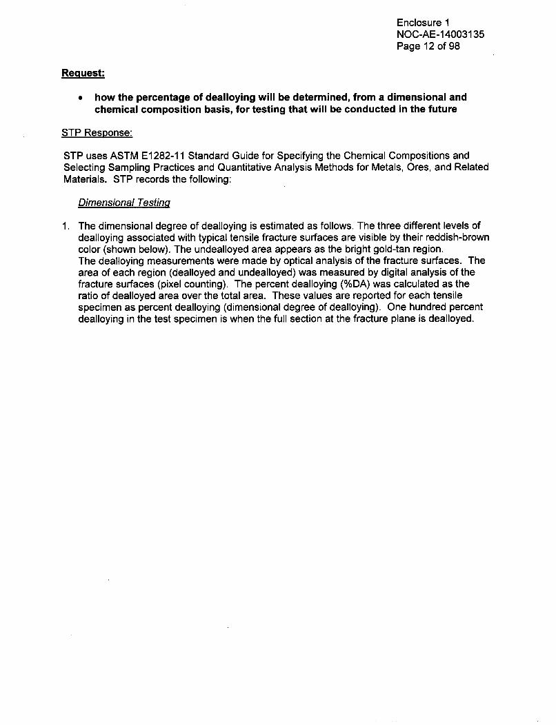
STP uses ASTM E1282-11 Standard Guide for Specifying the Chemical Compositions andSelecting Sampling Practices and Quantitative Analysis Methods for Metals, Ores, and RelatedMaterials. STP records the following:
Dimensional Testinq
1. The dimensional degree of dealloying is estimated as follows. The three different levels ofdealloying associated with typical tensile fracture surfaces are visible by their reddish-browncolor (shown below). The undealloyed area appears as the bright gold-tan region.The dealloying measurements were made by optical analysis of the fracture surfaces. Thearea of each region (dealloyed and undealloyed) was measured by digital analysis of thefracture surfaces (pixel counting). The percent dealloying (%DA) was calculated as theratio of dealloyed area over the total area. These values are reported for each tensilespecimen as percent dealloying (dimensional degree of dealloying). One hundred percentdealloying in the test specimen is when the full section at the fracture plane is dealloyed.

Enclosure 1NOC-AE-14003135Page 13 of 98
Fracture Surface Appearance for Various Amounts of Dealloyingin 0.35-inch Diameter Tensile Bars
a) Negligible Dealloying b) 15.9% Dealloying
c) 53% Dealloying
2. After completing the pixel counting activity, material strength properties (ksi) will berecorded and plotted on the y-axis; % dealloying (dimensional degree of dealloying) throughcomponent cross section will be plotted on the x-axis. Typical plots are shown in STPresponse 'b' above.

Enclosure 1NOC-AE-14003135Page 14 of 98
Chemical Testing
STP has tested some selected samples of fractured surfaces for aluminum content by percent(%) weight. These measurements are obtained by taking detailed surface area scans of 1 mm 2
in size along the linear traverses across the fracture surfaces using the Scanning ElectronMicroscope (SEM) and EDS. These scans included both dealloyed and undealloyed regions toobtain the distribution of Al, Fe, and Cu content within these regions.
STP observed that the transition from dealloyed to undealloyed AI-Brz is sharp and distinct, andvisible to the eye. It is evident from the figure below that the Al and Fe compositions along thefracture surface (Traverse 1) indicate a relatively uniform but reduced amount of both Al and Fewithin the dealloyed region from the ID surface to the maximum depth of dealloying. Beyondthat point, the compositions of Al and Fe exhibit a step increase in magnitude within theundealloyed AI-Brz material.
Similar surface scans on other samples have shown the same trend. Within the dealloyedregion, the distribution of depleted AL and Fe content is relatively uniform across the dealloyedregion returning to the bulk chemistry level a very short distance into the undealloyed region.
The uniform distribution behavior is observed through the thickness as well as cross-width ofthe samples. This indicates the fracture path is essentially fully dealloyed with respect to theloss in aluminum and iron of the transformed phases within the eutectoid. This supports STP'ssimple dimensional definition for the amount of dealloying for a given test specimen fracturesection based on an area ratio bases.
STP observations indicate that not all aluminum will deplete as components age.
Surface Area Scan - Traverse 110xlWx6-inch Tee CTOD Sample #11 Specimen SENB-2
18L
1- Fe16- -Al (CMTR)
- - Fe (CMTR)
14 -Dealloylng Depth
12 ._
CF 10 ____ ___ ________
0
8 7
0.0 0.1 0.2 0.3 0.4 0.5
Line Distance, sit
0.6 0.7 0.8 0.9 1.0

Enclosure 1NOC-AE-14003135Page 15 of 98
Request:
0 how partially dealloyed material properties will be integrated into trending data
STP Response:
STP is trending two yield strengths (0.2% Offset and 0.5% Elongation Under Load), ultimatestrength, and fracture toughness for various degrees of dealloying.
A regression analysis has been performed to determine an empirical correlation betweentensile properties and the fracture toughness with the amount of dealloying. The regressionanalyses also smoothed out scattered data to a trending curve (correlation). The extendedtrending curve is used to characterize the mechanical property in those instances where resultsfrom a physical test are not available.
Issue:
e) While the revised AMP, Enhancements, UFSAR Supplement, and Commitmentsdescribe acceptance criteria for tensile, yield and fracture toughness properties, theRAI response does not describe specific follow-on actions that would be taken Whenabnormal test or inspection results are obtained, beyond stating that results wouldbe trended, an engineering evaluation would be performed, or that the condition willbe documented in the corrective action program. The acceptability of the SelectiveLeaching of Aluminum Bronze plant-specific AMP will be based upon (a) eitherempirical testing results or attainment of dealloyed material properties to be used inrevised structural integrity analyses, and (b) the continuing demonstration of theability to detect aging using external visual inspections prior to the degradationadversely impacting the ability of a susceptible component to perform its intendedfunction. The staff notes the possibility that results of the tests and inspectionscould invalidate the analytical assumptions to such an extent that structural integritycould not be reasonably expected to be demonstrated for leaking components, orthat an in-situ leaking fitting could be found that cannot be shown to meet structuralintegrity requirements. In the latter case, given that there are approximately 300 othersusceptible components, it would be unreasonable to assume that only thiscomponent was not capable of meeting its intended function, and therefore the basisof the program (i.e., using external visual inspections to detect degradation prior toadversely impacting the ability of a susceptible component to perform its intendedfunction) would be invalidated. The staff requires further details to understand whatspecific actions will be taken for the following outcomes:
During a PE or ACT, a crack or degree of dealloying is discovered outside of thecurrent correlation as shown on page 12 of AES-C-1964-5. It is unclear to the staffwhether a new correlation curve will be developed and whether existing leakingcomponents will be reanalyzed with the new correlation. It is the staffs positionthat, given that the correlation of OD crack angle to projected internal degradationwill have been demonstrated to be nonconservative, some additional fittings willneed to be immediately examined, even though not leaking, to determine whetherthis was a one-off data point or whether there are many more susceptible fittingswhich have larger internal cracking or dealloying than would be projected fromobserving the through-wall indications on the OD.

Enclosure 1NOC-AE-14003135Page 16 of 98
An ACT test result yields a data point below the size-appropriate acceptancecurve (e.g., Figure 4-2, "Evaluation of Flange Bend Test Results," in AES-C-1964-6). It is unclear to the staff whether the analytical methodology will be revised toreflect the lower data point. For example, if it is suspected that the lower datapoint occurred because an appropriately low fracture toughness value was notused, it is unclear whether the fracture toughness value in the calculation wouldbe decreased until the curve is sufficiently shifted. Also, it is unclear whetherexisting leaking components will be reanalyzed with the revised methodology. Itis the staff's position that any existing leaking component should be considerednot capable of performing its intended function until the cause of the discrepancyis understood, a new analysis curve is developed, and any existing degradedcomponents are evaluated against the new analysis curve.
" The in-situ evaluation of a newly-discovered leaking fitting (i.e., the fitting has notyet been removed from service) results in a determination that the degradedcomponent is not operable. It is the staff's position that such a result invalidatesthe effectiveness of the program, since the program is based on the capability ofexternal visual examinations to manage aging prior to loss of intended function.Consequently, the staff believes that all susceptible fittings should be considerednot capable of performing their intended functions until a revised technical basisis established or the components are repaired or replaced.
" PE or ACT results demonstrate a trend where, due to continuing dealloying,tensile strength, yield strength, or fracture toughness properties are projected tobe below the acceptance criteria prior to the end of the PEO. It is the staff'sposition that the initial testing used to establish reasonable assurance and thecontinuing confirmatory testing can provide a timely projection of degradedmechanical properties, and all susceptible components should be repaired orreplaced prior to the as-found properties or the as-trended properties fall belowthe acceptance criteria.
* PE or ACT results demonstrate that layer-type dealloying is becomingpredominant over plug-type, such that it is no longer possible to project internaldegradation based on external observations. The staff recognizes that there issome level of layer dealloying occurring in most fittings, as illustrated in Figure 3-1, "Typical Dealloying/Cracking Cross Sections," of AES-C-1964-5. However, thethrough-wall dealloying of the samples inspected in 1994 demonstrated a plug-like nature and a correlation of OD crack angle to internal degradation was able tobe reasonably established. It is the staff's position that continued use of thecorrelation requires that a maximum percent of cross-sectional layer-typedealloying be established and justified as an acceptance criterion.
PE or ACT results demonstrate that cracking has extended into the un-dealloyedregion. AES-C-1964-5 sections 3.0, "Method of Approach," and 5.0, "Significanceof Part-Through Cracks," assume that cracking does not extend into the un-dealloyed portion of a component.

Enclosure 1NOC-AE-14003135Page 17 of 98
Although under this scenario the specific component that had cracking extendinginto the un-dealloyed portion would have already been replaced, anyone or moreof the hundreds of susceptible fittings could potentially have cracking of thisnature. It is the staff's position that all susceptible components should beconsidered not capable of performing their intended functions until the cause ofthe extended cracking is understood, a new analysis curve is developed, and theexisting degraded components are evaluated against the new analysis curve.
Request:
e) For the following test or inspection result outcome examples, state what specificactions would be taken and the basis for those actions. Amend the AMP, UFSARSupplement, and Commitments to state the specific actions for these examples:
During a PE or ACTT a crack or degree of dealloying is discovered outside of thecurrent correlation as shown on page 12 of AES-C-1964-5, "Evaluation of theSignificance of Dealloying and Subsurface Cracks on Flaw Evaluation Method," Inresponding to this scenario, include a statement of how many additional fittingswill be immediately examined, even though not leaking, to determine whether thisis a one-off data point or whether there are many more susceptible fittings whichhave larger internal cracking or dealloying than would be projected fromobserving the through-wall indications on the OD. If no additional fittings will beimmediately examined, state the basis for not conducting this expansion ofinspection scope.
* An ACT test result yields a data point below the size-appropriate acceptancecurve (e.g., Figure 4-2, "Evaluation of Flange Bend Test Results," in AES-C-1964-5)
The evaluation of a newly-discovered leaking fitting results in a determination thatthe degraded component would not have been operable (i.e., the local criticalbending stress is too high as compared to the observed external crack ordealloying angle).
* PE or ACT results demonstrate a trend where, due to continuing dealloying,tensile strength, yield strength, or fracture toughness properties are projected tobe below the acceptance criteria prior to the end of the PEO.
* PE or ACT results demonstrate that layer-type dealloying predominates over plug-type, such that it is no longer possible to project internal degradation based onexternal observations. In addition:
State the step-by-step process an examiner will use, when conducting profileexams to determine the transition point between layer-type and plug-typedealloying and thereby derives the internal dealloying angle.
ii. State the acceptance criterion for the maximum percent of cross-sectionallayer-type dealloying that will be allowed to occur within the use of the currentmethodology for determining the acceptability of a degraded component.

Enclosure 1NOC-AE-14003135Page 18 of 98
* PE or ACT results demonstrate that cracking has extended into the un-dealloyed
region.
STP Response:
The following actions outline the proposed approach for the overall strategic actions for test orinspection results:
STP will reevaluate operability determinations of all leaking components left in service, therebyassuring their structural integrity. These determinations will use the established materialstrengths limits.
STP will assess extent of condition for each case by:
1) immediate walkdown of all ECW systems in both units for identifying leaking components;2) increased frequency of monitoring based on severity of condition;3) implement periodic walkdowns;4) expanded scope of ACT and PE, and5) schedule repair and replacement activities, based upon the risk significance of thecomponent (but will not defer action beyond the next refueling outage into which it may bescheduled). The expanded scope for each case is further described under specific actionsconsidering severity of conditions identified.
The NRC staff is concerned that previous RAI responses did not adequately describe specificfollow-on actions that would be taken when test or inspection results outside of the acceptancecriteria are obtained. Due to the uncertainties associated with such hypothetical cases, STPprovided limited responses describing the process that would be followed (i.e., results trended;an engineering evaluation performed; the condition documented in the corrective actionprogram; and perform a deficiency-specific "Operational Decision-Making Issue" (ODMI)). AnODMI provides a method to document decisions considered in the disposition and handling ofconditions identified by the station. Subsequently, the staff has requested that STP not onlydescribe process steps that would be taken, but also to describe the specific actions that STPanticipates implementing. The process that is common to all actions is described below and isfollowed by potential deficiency-specific actions that pertain to the staff-described scenarios.
Process for Results Outside of Acceptance Criteria
For all scenarios, STP will use its corrective action program. Every deficiency will require animmediate determination of operability, an assessment of the extent of condition, and theperformance of an appropriate cause evaluation. Each activity will be conducted to assure thatthere is reasonable assurance that the station can continue to operate safety.
For all non-conforming ACTs and PEs conditions, STP will reevaluate the operability of allleaking components remaining in service; these re-evaluations will consider any new technicalimplications that are identified by the non-conforming test result. The overall structural integrityof ECW system and its ability to meet its intended design basis functions will be the primarycriteria in these re-evaluations.

Enclosure 1NOC-AE-1 4003135Page 19 of 98
If structural integrity cannot be demonstrated, STP will either repair or replace affectedcomponents; in all instances, compliance with the STP Technical Specifications will bemaintained.
Following are some of the typical steps that STP may implement as part of the ODM I.
- Document condition in Corrective Action Program. Where possible, includeacceptance criteria and severity of condition (see specific details below for Staffdescribed scenarios)
- Notify Control Room of identified condition(s)- Perform an Immediate Operability Determination- Enter Technical Specification, as required, if the ECW trains are determined to be
inoperable- Perform a Prompt Operability Determination, using assistance from the Engineering
organization- Implement immediate compensatory measures during any period of extended
evaluation. Such measures could include:o Operations would observe identified locations during each shift for potential
leakages.o System Engineers will immediately walk down all trains of the ECW system, in
both units.- Conduct an extent of condition evaluation and provide interim compensatory
measures beyond those noted above, based upon the specific technical implicationsof the deficiency
- Develop a plan for long-term corrective actions that include changes to long-termECW program and replacement of affected components.
STP would develop a deficiency-specific ODMI for these conditions, detailing specific steps,based on the severity and risk-significance of the conditions identified. Depending upon theseverity (material conditions/ASME Safety Factors, potential impacts on plant safety, andrisk significance), STP would remove additional components for further testing.
Request:
During a PE or ACT, a crack or degree of dealloying is discovered outside of thecurrent correlation as shown on page 12 of AES-C-1964-5, "Evaluation of theSignificance of Dealloying and Subsurface Cracks on Flaw Evaluation Method," Inresponding to this scenario, include a statement of how many additional fittings willbe immediately examined, even though not leaking, to determine whether this is aone-off data point or whether there are many more susceptible fittings which havelarger internal cracking or dealloying than would be projected from observing thethrough-wall indications on the (OD). If no additional fittings will be immediatelyexamined, state the basis for not conducting this expansion of inspection scope.

Enclosure 1NOC-AE-14003135Page 20 of 98
STP Response:
STP uses a correlation to size internal flaws/cracks that are not able to be measured usingvolumetric examinations. STP measures the internal flaw length following removal of thecomponent during PEs and compares it to the estimated ID crack length as originally estimatedusing the correlation. The average crack length is determined by averaging the measuredoutside and inside diameter lengths.
Acceptance Criteria:
1. Load Carrying Capacity: ACT results results show a higher load capacity than thepredicted load carrying capacity.
2. Determination of ID Crack Length: The measured ID crack length is less than 110% ofcorrelation estimated ID crack length.
If acceptance criterion are not met, the severity of the condition will be determined.
Severity of Condition:
The following ASME Section Xl Appendix H or C safety factors determine severitylevels. The safety factors are recalculated using.the average crack length to determineseverity.
Severity NormallUpset Emergency /Faulted Number ofLevel Condition Condition Additional Tests
II SF < 1.5 SF < 1.2 2 ACTs on sister componentfrom remaining trains5 PEs
I SF > 1.5 SF > 1.2 1 ACTsand and 3 PEs
SF < 2.77 SF < 1.39
If the recalculated safety factors are within the ASME Code allowed limits, no additionalactions are required other than precautionary actions intended to address the extent ofcondition as shown in the following Decision Flowcharts.

Enclosure 1NOC-AE-14003135Page 21 of 98
Exclusive OR
OR0
0 AND
Function

Enclosure 1NOC-AE-14003135Page 22 of 98
Follow Process
Path 'A' /
Common Steps (PO) Specific Steps
on Report
Room
mpt Operability Determinations (PE to
* Select 1 Additional Componentsfrom Sister Trains for 1 ACT and
sedial Measures as Recommended 3 PE
alkdwn y P ona wekl Bais Perform Causal Analysisalkdown by PE on a weekly Basis P 4- - 1 * Drive Closure to ODMI Tasks; 4( .....
tkdown of leaking components by PE Add additional Tasks As
Condition by PE Warrantedf Rondiir/Replace t b Evaluate additional Test Resultsate Repair/Replacement Rcmedn ute cin
endations by PE; Long term Recommending Further Actions
ndation to follow Causal Analysis
ed ODMI to Followion with Plant Personnel)
XOR
Update ECW Move toProgram Severity Level
II
Initiate ConditiNotify Control R
" Immediate/ProRecommend)
" Technical SpeciWarranted
* Implement Ren-ECWS W- Daily wa
- Apparen- Extent o
- Immedia
Recommerecomme
" Develop Detaile(PE in consultat

Enclosure 1NOC-AE-14003135Page 23 of 98
Notify ControlRoom PotentialEntry to Tech.
Spec.--
Notify ControlRoom For
Potential Entryto Tech. Spec.
4,* ECWS Operability Indeterminate. PE to Evaluate Operability of All
Leaking Components Left in Service* Notify Control Room if Component Determined Not Operable For
Tech. Spec. Required Action* Continue with Enhanced Monitoring BY Both PO and PE* Continue Monitoring of Leak Rate for all Leaking Components* Continue Implementation of ODMI Including
- Perform Causal Analysis
- Extent Of Condition- Additional ACT/PE Tests(All Sister Components (S Total) and Randomly Selected 3 AdditionalComponents. Minimum of 5 ACT plus 12 PE to be performed)
* Develop and Implement Long Term Corrective Actions- Update ECW Program-Update Co-relation-Update Analytical Model
- Update Material Properties- Systematic Replacement of Suspect Components- Relief Request
* - AMP/UFSAR Update

Enclosure 1NOC-AE-14003135Page 24 of 98
Request:
* An ACT test result yields a data point below the size-appropriate acceptance curve
(e.g., Figure 4-2, "Evaluation of Flange Bend Test Results," in AES-C-1964-5)
STP Response:
An ACT data point below the size-appropriate acceptance curve suggests either analyticalmethods over-predict the load carrying capacity or factors other than dealloying affect testresults. STP will perform a causal analyses to determine why the ACT yielded a data pointbelow the size-appropriate curve. STP will develop an ODMI with specific actions based onseverity of identified conditions. Additional ACTs and PEs may be required to determine ifreduced material strengths or the fracture -toughness appear to be the cause. The sistercomponents and one randomly selected component from the affected train (total of 6 additionalcomponents) will be tested. Additionally, STP will reevaluate operability determinations of allleaking components still in service.
Acceptance Criteria:
S
0
The ACT pressure > hydro test pressure (125% of Design Pressure ~ 150 psi)Bending load > 125% of applied loads (unintensified Eq. 9D ASME code stresses)
Severity of Condition:
The below listed criteria determines the severity levels.
Severity Criteria Number of Components to beLevel Tested
II The ACT pressure < hydro test pressure 5 ACTs sister component from(125% of Design Pressure - 150 psi) remaining trains
and 1 ACT randomly selectedBending load < 125% of applied loads component from affected train(unintensified Eq. 9D stresses 8 PEsThe ACT pressure < hydro test pressure 3 ACTs(125% of Design Pressure - 150 psi) 5 PEs
orBending load < 125% of applied loads(unintensified Eq. 9D stresses
Specific remedial measures are based on severity as recommended by the followingDecision Flowcharts.

Enclosure 1NOC-AE-14003135Page 25 of 98
Reevaluate Operability UsingMeasured Average CrackLength To Confirm ASME
Safety Factors
ýV

Enclosure 1NOC-AE-14003135Page 26 of 98
Follow Process
Path 'A'
AImplement ..... Implement
Initiate Condition Report iNotify Control Room
* Immediate/Prompt Operability Determinations (PE toRecommend) Select3AdditionalComponents
Technical Specification Entry Actions When from Sister Trains for 3 ACT andWarranted fro Sise rTanfo3ACad
Implement Remedial Measures as Recommended 5Perorm Causal Analysis
- ECWS Walkdown by PE on a weekly Basis PeDrive Closure to ODMI Tasks.
-Daily walkdown of leaking components byPO - - - Add additional Tasks Aspr CuebFEWrat
-Apparent Cause by PEWrane
-Extent of Condition by PEWarne
Immediate Repair/Replacement Evaluate additional Test Results
Recommendations by PE; Long term Recommending Further Actions
recommendation to follow Causal Analysis
Develop Detailed ODMI to Follow
(PE in consultation with Plant Personnel)
XOR
Update EC

Enclosure 1NOC-AE-14003135Page 27 of 98
Notify ControlRoom PotentialEntry to Tech.
Spec.--I-
Notify ControlRoom For
Potential Entryto Tech. Spec.
" ECWS Operability Indeterminate. PE to Evaluate Operability of All
Leaking Components Left in Service* Notify Control Room if Component Determined Not Operable For
Tech. Spec. Required Action" Continue with Enhanced Monitoring BY Both PO and PE" Continue Monitoring of Leak Rate for all Leaking Components* Continue Implementation of ODMI Including
- Perform Causal Analysis
- Extent Of Condition- Additional ACT/PE Tests(All Sister Components (5 Total) and Randomly Selected 1 Additional
Components. Minimum of 5 ACT plus 8 PE to be performed)* Develop and Implement Long Term Corrective Actions
- Update ECW Program-Update Co-relation-Update Analytical Model- Update Material Properties- Systematic Replacement of Suspect Components- Relief Request
* - AMP/UFSAR Update

Enclosure 1NOC-AE-14003135Page 28 of 98
Request:
The evaluation of a newly-discovered leaking fitting results in a determination thatthe degraded component would not have been operable (i.e., the local criticalbending stress is too high as compared to the observed external crack or dealloyingangle).
STP Response:
The structural integrity of the ECW system provides a safety-related design basis functions thatis paramount for the safe continued operation of both STP units. If structural integrity cannot bedemonstrated, STP will either repair or replace affected components.
Request:
* PE or ACT results demonstrate a trend where, due to continuing dealloying, tensilestrength, yield strength, or fracture toughness properties are projected to be belowthe acceptance criteria prior to the end of the PEO.
STP Response:
STP will monitor material properties of Aluminum Bronze coponents to ensure that they do notfall below the acceptance criteria prior to the end of the PEO, and will be trending theseproperties through the use of PEs. The PE data from all leaking dealloyed components will beadded to the trend projection curves using a regression methodology. The magnitude ofadverse trend is measurable and the updated properties will be used to estimate structuralintegrity of those affected components.
STP will monitor adverse trends and implement corrective measures (including replacement ofaffected components) before structural integrity of the ECW system is challenged. Thesemeasures include the following:
* Engineering evaluation of the remaining components determined to be at risk," Enhanced monitoring and non-destructive /or destructive examinations program,* Perform additional ACTs and PEs performed (approximately 5 ACTs and 18 PEs),* Updated critical bending stress curves found in AES-C-1964-1," Systematic replacement of components determined to be at risk,* PSALBZ "ECW Aging Management Program" reviewed and updated to incorporate
resulting information, and* Notification to the NRC of pertinent changes to ECW program.
Criteria Defining Adverse Trend:
A decrease of 100% dealloyed material strengths and fracture toughness by 15% will beconsidered an adverse trend. The 15% is selected because the estimated variation of yieldstrength from mean (based on 0.2% yield strength test data) is approximately 4.1 ksi. whichis equivalent to 15% of the lowest measured material strength.

Enclosure 1NOC-AE-14003135Page 29 of 98
Number of components to be tested:
3 ACTs and 12 PEs from randomly selected components will be performed. If these testsdemonstrate an adverse trend, an additional 5 ACTs and 18 PEs will be performed.
Severity of Condition:The deviation in the post-test material properties will determine severity levels.
Severity Acceptance Criteria Number of Probable ActionsLevel Components
to be Tested11 Continued deviation more 5 ACTs and - Enter Technical Specification.
than 15% from previously 18 PEs - Notify Control Room.measured properties (from randomly - Seek temporary relief from the NRC forseverity I tests) for 100% selected continued operation until root cause candealloyed material component be determined
from affectedtrain
More than 15% deviation 3 ACTs - Enter Technical Specification.from previously measured 12 PEs - Notify Control Room.properties for 100% - Seek temporary relief from the NRC fordealloyed material continued operation until root cause can
be determined.- Additionally tests are required to confirm
potential entry to Severity Level II
Specific remedial measures are based on severity as recommended by the followingDecision Flowchart.

Enclosure 1NOC-AE-14003135Page 30 of 98
Reevaluate OperabilityUsing Recently TestedMaterial Property ToConfirm ASME Safety
Factors
V

Enclosure 1NOC-AE-14003135Page 31 of 98
Follow ProcessPath 'A'
Common Steps " (P) """ Specific Steps
Initiate Condition ReportNotify Control RoomImmediate/Prompt Operability Determinations (PE toRecommend) * Select 3 Additional ComponentsTechnical Specification Entry Actions When from Sister Trains for 3 ACT andWarranted 12 PE
Implement Remedial Measures as Recommended 1 Perform Causal Analysis
- ECWS Walkdown by PE on a weekly Basis - - - . Drive Closure to ODMI Tasks;- Daily walkdown of leaking components byPO Drive Closureitional Tasks ; ....-Apparent Cause by PE AddaddiioalnT askd A
-Extent of Condition by PEWarne
immediate Repair/Replacement * Evaluate additional Test Results
Recommendations by PE; Long term Recommending Further Actionsrecommendation to follow Causal Analysis
Develop Detailed ODMI to Follow
(PE in consultation with Plant Personnel)
i

Enclosure 1NOC-AE-14003135Page 32 of 98
Notify ControlRoom PotentialEntry to Tech.
Spec.I-T -
" ECWS Operability Indeterminate. PE to Evaluate Operability of AllLeaking Components Left in Service
" Notify Control Room if Component Determined Not Operable ForTech. Spec. Required Action
* Continue with Enhanced Monitoring BY Both PO and PE" Continue Monitoring of Leak Rate for all Leaking Components" Continue Implementation of ODMI Including
- Perform Causal Analysis- Extent Of Condition- Additional ACT/PE Tests(All Sister Components (5 Total) and Randomly Selected 3 AdditionalComponents. Minimum of 5 ACTs plus 18 PE to be performed)- Develop and Implement Long Term Corrective Actions
- Update ECW Program-Update Co-relation-Update Analytical Model- Update Material Properties- Systematic Replacement of Suspect Components- Relief Request- AMP/UFSAR Update
9

Enclosure 1NOC-AE-14003135Page 33 of 98
Request:
* PE or ACT results demonstrate that layer-type dealloying predominates over plug-type, such that it is no longer possible to project internal degradation based onexternal observations. In addition:
L. State the step-by-step process an examiner will use, when conducting profileexams to determine the transition point between layer-type and plug-typedealloying and thereby derives the internal dealloying angle.
ii. State the acceptance criterion for the maximum percent of cross-sectionallayer-type dealloying that will be allowed to occur within the use of the currentmethodology for determining the acceptability of a degraded component.
Request:
* PE or ACT results demonstrate that layer-type dealloying predominates over plug-type, such that it is no longer possible to project internal degradation based onexternal observations.
STP Response:
The predominant type of dealloying observed is a combination of plug and layer dealloyingoccurring simultaneously. Exclusive layer type dealloying has not been observed becausewhen a component casting cools, the casting does not cool at a uniform rate. Therefore, thephase structure throughout the component body is not identical.
An "Operational Decision-Making Issue" will be developed to further investigate and implementcorrective measures for any component that demonstrates predominate layer-type dealloying.The investigation may require additional destructive examinations. Remedial measures mayinclude increased monitoring, or more frequent examinations to replacement effectedcomponents. The analytical methodology may also have to be reevaluated and updated asnecessary.
Request:
State the step-by-step process an examiner will use, when conducting profileexams to determine the transition point between layer-type and plug-typedealloying and thereby derives the internal dealloying angle.
STP Response:
The following provides the step-by-step process used to conduct a profile exam:* The component is sectioned at the plane of externally observed dealloying.* The sectioned surface is etched with Silver Nitrate solution, which distinguishes the
dealloyed areas.* The section is photographed for measuring subareas (manual or digital) of the
dealloyed sectional surfaces.

Enclosure 1NOC-AE-14003135Page 34 of 98
* The angle of the outside flaw along the OD is constructed from the measured lengthof the through-wall flaw.
* The angle for the extent of the internal flaw is determined where non de-alloyedmetal begins.
* For situations where some amount of layer dealloying exists at the through wallpenetration, then a transitional measurement for the internal flaw angle isdetermined at the point where the layer is approximately 50% of the wall thickness.
" The average flaw length is then determined by averaging the OD and internal flawangles.
Request:
ii. State the acceptance criterion for the maximum percent of cross-sectional layer-type dealloying that will be allowed to occur within the use of the currentmethodology for determining the acceptability of a degraded component.
STP Response:
The acceptance criterion for a dealloyed component is a component that does not leak. Non-leaking components average 60% through-wall thickness dealloying before leaking occurs. Thedistribution of sampled aluminum bronze fittings for STP Unit 1 is plotted in figure 2.5 (Ref. STPLetter to the NRC ST-HL-AE-2748 dated November 1, 1988, Attachment 2, Page 38 of 58). Allcomponents that were dealloyed more than 60% through their cross sections developed leaks.When the PE determines that average dealloyed wall thickness exceeds 60% and sufficientmaterial is available for preparation of a test coupon, mechanical properties will be obtained.The resulting test data will then determine impact on previously performed operability andpotential impact on the ECW program.
Request:
* PE or ACT results demonstrate that cracking has extended into the un-dealloyedregion.
STP Response:
The scenario assumes part of a circumferential crack is extending into undealloyed basematerial. The likely conditions that could cause crack tip to extend into undealloyed basematerial are as follows:
" Physical crack existed through dealloyed material,* The crack growth occurred through dealloyed material because of conducive environment
and/or applied loads, or* The crack now extends through undealloyed material mainly because of applied loading.
The crack may have penetrated through minimum required wall thickness resulting inexcessive primary membrane stresses and a potential to tear through the wall thickness.
The layered geometry of dealloying is not uniform through the component cross section.Dealloying without cracks has sufficient material strength to sustain applied loads.It is reasonable to conclude that the crack pre-existed in the component.

Enclosure 1NOC-AE-14003135Page 35 of 98
It is also reasonable to assume that a crack extending through base material will be limited to adeeply penetrated segment of dealloyed area and not through entire dealloyed cross section ofcomponent. The local leakage resulting from such crack will be identified through themonitoring program.
STP performs ACTs and PEs through the PEO allowing timely identifications andimplementations of corrective measures as follows:
" Engineering evaluation of the remaining components determined to be at risk," Enhanced monitoring, and destructive examination program,* Perform additional ACTs and PEs performed (Approximately 5 ACTs and 18 PEs),* Updated critical bending stress curves found in AES-C-1964-1,* Systematic replacement of components determined to be at risk.• PSALBZ "ECW Aging Management Program" reviewed and updated to incorporate
resulting information, and* Notification to the NRC of pertinent changes to ECW program.
Criteria Defining Adverse Trend:
One non-leaking component PE exhibiting all below listed characteristics:* Presence of layered dealloying throughout the circumference of component section.* Average thickness of layered dealloying exceeds 60% through wall thickness" Presence of circumferential crack in the dealloyed layer. Average crack angle (2E) to be
less than 70 degrees* Crack Depth penetrates undealloyed base material at least 20% of remainder
undealloyed thickness at crack tip location
Severity of Condition:
Crack penetration length will determine severity levels.
Severity Acceptance Criteria Number of Probable ActionLevel Components
to be Tested11 Length of ID crack 5 ACTs and - Enter Technical Specification
exceeds 70 degrees (20) 18 PEs - STP may seek temporary relief fromand has penetrated at randomly the NRC for continued operation untilleast 20% of base material selected root cause can be determined
componentfrom affectedtrain
Length of ID crack is NOT 3 ACTs - Enter Technical Specificationexceeding 70 degrees 12 PEs - Notify Control Room(2W) and penetration in - Seek temporary relief from the NRCbase material is less than for continued operation until root20% of base material cause can be determined
- Additionally tests are required toconfirm potential entry to SeverityLevel II
Specific remedial measures are based on severity as recommended by the followingDecision Flowcharts.

Enclosure 1NOC-AE-14003135Page 36 of 98
-A
XOR
Follow
Process Path'A'
Update ECWProgram Follow Prcs
Paths 'B'

Enclosure 1NOC-AE-14003135Page 37 of 98
Follow ProcessPath 'A'
- . Initiate Condition ReportNotify Control Room
* Immediate/Prompt Operability Determinations (PE toRecommend) Select 3 Additional Components
" Technical Specification Entry Actions When from Sister Trains for 3 ACT andWarranted fo Per T f
" Implement Remedial Measures as Recommended 12 FE)Perform Causal Analysis
- ECWS Walkdown by PE on a weekly Basis - - - - e Drive Closure to ODMI Tasks; ......-Daily walkdown of leaking components byPO Add additional Tasks As _UApparent Cause by PE WarrantedExtent of Condition by PE Evaluate additional Test Results
- Immediate Repair/ReplacementRecommendations by PE; Long term Recommending Further Actions
recommendation to follow Causal analysis
" Develop Detailed ODMI to Follow(PE in consultation with Plant Personnel)
XDR

Enclosure 1NOC-AE-14003135Page 38 of 98
Notify ControlRoom PotentialEntry to Tech.
Spec.--I-
ECWS Operability Indeterminate. PE to Evaluate Operability of AllLeaking Components Left in ServiceNotify Control Room if Component Determined Not Operable For
Tech. Spec. Required ActionContinue with Enhanced Monitoring BY Both PO and PEContinue Monitoring of Leak Rate for all Leaking Components
Continue Implementation of ODMI Including- Perform Causal Analysis- Extent Of Condition
- Additional ACT/PE Tests(All Sister Components (5 Total) and Randomly Selected 3 AdditionalComponents. Minimum of 5 ACTs plus 18 PE to be performed)- Develop and Implement Long Term Corrective Actions
- Update ECW Program-Update Co-relation-Update Analytical Model- Update Material Properties- Systematic Replacement of Suspect Components- Relief Request- AMP/UFSAR Update

Enclosure 1NOC-AE-14003135Page 39 of 98
Issue:
f) The staff has questions regarding how field observations of leaking degradedcomponents are used in conjunction with the analytical output of AES-C-1964-1,"Calculation of Critical Bending Stress for Dealloyed Aluminum-Bronze Castings inthe ECW System," and the existing pipe stress analyses in order to analyze forstructural integrity as it relates to the component performing its intended function. Inparticular, the staff has concerns related to:
In the correlation in AES-C-1964-5, the observed OD crack angle is used to derivean average through-wall dealloying angle. However, the critical bending stresscurves in AES-C-1964-1 use a crack angle, not an average through-wall dealloyingangle. The staff lacks sufficient information to be able to understand the linkbetween the correlation and its use in the critical bending stress curves. Note thatthe response to RAI B2.1.37-4, Enclosure 1, page 3 of 9, incorrectly characterizesthe correlation, "[t]he examination results were used to establish a correlationbetween length of a flaw on the outer diameter and the size of any internal crackand the extent of the dealloyed region of the component."
Also, it is not clear to the staff why an average angle would be used when Figures C-2200-1, "Flaw Characterization-Circumferential Flaws," and C-4310-1,"Circumferential Flaw Geometry," of ASME Code Section X1, and Figure 5-1,"Circumferential Flaw Geometry -Net Section Collapse Model," of AES-C-1964-1 usethe inside dimensions of the flaw.
The staff plotted the OD and inside diameter (ID) crack and dealloying angle datafrom Section 4.1, "Metallurgical Data," of AES-C-1964-5 (i.e., dealloyed OD vs.dealloyed ID and crack OD vs. crack ID). Two crack data points and three dealloyingdata points fell outside (nonconservative) of the correlation. If it is not appropriate touse an average through-wall dealloying angle, a new correlation using insidedimensions will need to be developed. The staff lacks sufficient information tounderstand whether such a new correlation could affect the structural integritydetermination of recently degraded components, and by extension, degradedcomponents discovered during the PEO.
" The wording of the response to part (e) of RAI B2.1.37-3 is not clear on whatminimum structural factor will be used for the normallupset conditions andemergency and faulted conditions.
" It is not clear to the staff how external dimensions of the indication are sized. Forexample, when an indication consists of a crack within a larger dealloyed region,it is not clear which feature is measured. Also, it is not clear how a singularrounded (surface) indication, or multiple in-line rounded (surface) indications, arecharacterized.

Enclosure 1NOC-AE-14003135Page 40 of 98
It would appear that, based on the external dimensions of the flaw, an averageflaw angle is developed based on the AES-C-1964-5 correlation and used as inputinto the critical bending stress analyses in AES-C-1964-1, regardless of whetherthe through-wall degradation is dealloying with no crack, a part-through crackwith dealloying, or through-wall crack with dealloying. However, the staff seeksconfirmation that this is correct. The responses to the scenario-based questionsin the request should resolve this issue
* Given the ambiguities between the calculations, it is not clear to the staff that thesteps in a structural integrity determination of a degraded susceptible aluminumbronze component in the essential service water system can be consistentlyperformed without a procedure. In addition to the ambiguities, based on plant-specific OE, consistent performance is also challenged since these evaluationsare conducted infrequently.
Request:
* State:
* Why an average through-wall dealloying angle is the output of the correlation inAES-C1964-5 rather than the inside wall dimension.
" How the correlation from AES-C-1964-5 will be modified if use of the averagedealloying angle is not appropriate. Additionally, reconsider the structuralintegrity evaluation for any degraded components discovered since 2011 andstate whether the components would still be considered to meet structuralintegrity criteria (using this modified correlation) and therefore would still becapable of performing their intended function with the new correlation.
" Whether the structural factor for the normal/upset conditions will always be atleast 2.77, and for emergency and faulted conditions at least 1.39. If not, statewhat the minimum structural factors would be and the basis for the values beingless than those stated in ASME Code Section XI.
" For the four scenarios of OD observed degradation below:
L. Four small rounded indications of through-wall dealloying located in acircumferential axis at 10:00, 11:00, 1:00, and 2:00 on a 10-inch flange.
ii. One indication at 10:00, one-half inch long, with what appears to berounded ends and no measurable width on a 4-inch flange.
iii. One "greenish" stain approximately 1/8 inch diameter at the 10:00 positionon a 6-inch flange.
iv. One crack-like indication, one-half inch long, within a larger greenish stainwith a circumferential length of one inch.

Enclosure 1NOC-AE-14003135Page 41 of 98
State:" the size of the OD flaw" the corresponding size of the internal flaw that would be used in the structural
integrity determination* which figure would be used from AES-C-1964-1* the stress component input values that would be utilized from the highest
stress location in the essential service water system with susceptiblecomponents for that size as obtained by the stress analyses on record andhow they would be combined in the structural integrity determination
* what structural factor will be used* the critical bending stress as derived from the figures in AES-C-1964-1
whether the component would be considered to be capable of meeting itsintended function
What site procedure provides step-by-step instructions for determining thestructural integrity of a degraded susceptible aluminum bronze component in theessential service water system? If no such procedure is currently used, state thebasis for why it is acceptable to have the staff completing the evaluation steps inthe absence of written instructions.
Request:
* Why an average through-wall dealloying angle is the output of the correlation in AES-C-1964-5 rather than the inside wall dimension.
STP Response:
The average through-wall dealloying angle is used to estimate flaw length. This approach iscomparable to one described in NRC GL 90-05 where flaw length is estimated at the requiredminimum thickness (tmin).
ASME Section Xl Appendix H, Figure H-2200-1 'Flaw Characterization - Circumferential Flaws'depicts flaw length 'T at front tip of the crack 'a' through thickness 't'. Note staff reference ASMESection Xl, Appendix C figure C-2200-1, 'Flaw Characterization-Circumferential Flaw' isidentical to Appendix H figure H-2200-1. ASME Section Xl, Appendix C, Figure C-4300-1,'Circumferential Flaw Geometry' has no specific length shown. The length 'T' is defined asgeneral flaw length dimension in a nomenclature of Appendix C.
Using the average through-wall angle provides an estimate of the through-wall flaw length usedin the analysis described in AES-C-1964-5. The critical bending stress curves developed in theAPTECH calculation AES-C-1964-1 provide a tabulated solution to limit load; additionally,fracture analysis equations are included for quick reference. The evaluating engineer is stillresponsible for determining appropriate crack angle (e/Tr), based on conditions observed in thefield.

Enclosure 1NOC-AE-14003135Page 42 of 98
Request:
How the correlation from AES-C-1964-5 will be modified if use of the averagedealloying angle is not appropriate. Additionally, reconsider the structural integrityevaluation for any degraded components discovered since 2011 and state whether thecomponents would still be considered to meet structural integrity criteria (using thismodified correlation) and therefore would still be capable of performing their intendedfunction with the new correlation.
STP Response:
Use of average through-wall angle is appropriate because it has provided adequate estimatesof flaw lengths to date. The correlation was based on test data gathered from previouslysectioned components, and is representative of the average through-wall angle describedpreviously.
STP identified OD and ID measured crack lengths from five additional components (1-24" and4-30" Diameter Pipe size). The existing correlations shown in Figure 4.1 in APTECH calculationAES-C-1 964-5 bound these five components. Additional information obtained from future PEswill be compared to Figure 4.1 "Correlation between through wall cracks and through walldealloying", found in AES-C-1964-5. When warranted, the correlation that bounds the PE datawill be updated.
Request:
* Whether the structural factor for the normal/upset conditions will always be at least2.77, and for emergency and faulted conditions at least 1.39. If not, state what theminimum structural factors would be and the basis for the values being less thanthose stated in ASME Code Section Xl.
STP Response:
The ASME Code Section XI structural factors for the normal/upset conditions (2.77) as well asthe emergency and faulted conditions (1.39) will be applied when determining operability forcomponents with dealloyed conditions. Whenever ASME Section XI structural factors can notbe met, a ODMI will be developed to address non-conforming condition using process similar toone described under issue 'e' above. ASME Section XI structural factors below 1.0 will requireimmediate repair or replacement of leaking component.
Request:
* For the four scenarios of OD observed degradation below:
L Four small rounded indications of through-wall dealloying located in acircumferential axis at 10:00, 11:00, 1:00, and 2:00 on a 10-inch flange.
ii. One indication at 10:00, one-half inch long, with what appears to be roundedends and no measurable width on a 4-inch flange.
Enclosure 1NOC-AE-14003135Page 43 of 98
iii. One "greenish" stain approximately 1/8 inch diameter at the 10:00 position on a6-inch flange.
iv. One crack-like indication, one-half inch long, within a larger greenish stain witha circumferential length of one inch.
STP Response:
Attachment D presents the methodology and a sample calculation that demonstrates howAPTECH calculation AES-C-1964-1 estimates critical bending stresses. The sample calculationis provided for Case i and includes all equations used. Following the same methodology, theresults of all four cases requested above are summarized in APTECH calculationAES-C-1964-1 Table 1, "Evaluation Summary". The information requested is organized bycolumns for each case.
(Note: The scope of the current version of the APTECH calculation is limited to commonlyobserved dealloying cases and pipe sizes 3 inches and larger.)
STP uses the ASME Code recommended methodology that include different acceptablevariations such as: when considering Case i, the four flaws could be analyzed in two differentways. First, the evaluation could treat them as four independent flaws; alternatively, they couldbe combined into two flaws by combining the data at positions 10 and 11, and 1 and 2. Thestation then calculates the neutral axis and critical bending stresses using equations publishedin the following references.
References:1. Failure Bending Moment for Pipe With an Arbitrary-Shaped Circumferential Flaw,
authored by Yinsheng Li, Kunio Hasegawa, Akira Shibuya, and Nathaniel Cofie.Published in a Journal of Pressure Vessel Technology dated August 2011, Volume133.
2. Prediction of Collapse Stress for Pipes With Arbitrary Multiple CircumferentialSurface Flaws, authored by Yinsheng Li, Kunio Hasegawa, Akira Shibuya, andNathaniel Cofie. Published in a Journal of Pressure Vessel Technology datedDecember 2010, Volume 132.
3. Net Section Plastic Collapse Analysis of Two-Layered Materials and Applications toWeld Overlay Design, authored by Arthur F. Deardorff, Nathaniel Cofie, David G.Dijamco, and Aparna Chintapali. Published ASME PVP 2006 Pressure Vessel andPiping Conference July 2006.
Issue:
g) The staff also seeks the following information to complete its evaluation of theproposed AMP:
" A list of the number of remaining susceptible components, broken down by size." A copy of AES-C-1964-4, "Evaluation of 6-Inch Flange Test," submitted on the
docket." An update on leaking components that have occurred since July 28, 2011, the last
entry in Table 1, "ECW De-Alloying Data," of the response to RAI B2.1.37-1.

Enclosure 1NOC-AE-14003135Page 44 of 98
" The results of the leak rate analysis stated in Commitment No. 46, in response toRAI B2.1.37-4 Issue 5.
" The "scope of program" and "parameters monitored or inspected" programelements of the Selective Leaching of Aluminum Bronze program state,"components greater than one inch will be replaced by the end of the subsequentrefueling outage." The staff noted that UFSAR Section 9A, "Assessment of thePotential Effects of Through-Wall Cracks in ECWS Piping," states, in part, thatrelief requests are submitted when leaks are identified except for, "leaks in lines 1inch or under which are exempt from ASME Code Section Xl replacement rules."The staff cannot find a basis for allowing one inch and under lines to have repairor replacement times extend beyond the subsequent refueling outage.
" Request:
g) Provide the following:
" A list of the number of remaining susceptible components broken down by size.This list is required for the staff to conduct an independent review of theanalytical output information in relation to flaw size tolerance.
" A copy of AES-C-1964-4, "Evaluation of 6-Inch Flange Test." This calculation willbe used by the staff as input to determine the acceptability of the proposed agingmanagement program and, therefore, should be on the docket.
" An update to Table 1 of the response to RAI B2.1.37-1 to reflect leakingcomponents that have occurred since July 28, 2011.
" The basis for why 1-inch and under lines are not replaced by the end of thesubsequent outage. Also, state the basis for why 1-inch and under lines can bedemonstrated to meet their intended function prior to replacement
STP Response:
" A listing of the number of susceptible components, collated by size, is provided asAttachment A.
" A copy of AES-C-1964-4, "Evaluation of 6-Inch Flange Test," Is provided as Attachment B.
" An update to Table 1 of the response to RAI B2.1.37-1, reflecting leaking components thathave occurred from July 28, 2011, through the end of 2013, is provided as Attachment C.
* The results of the leak rate analyses referenced in Commitment No. 46, in response to RAIB2.1.37-4 Issue 5, are provided as Attachment E.

Enclosure 1NOC-AE-14003135Page 45 of 98
UFSAR Section 9A, "Assessment of the Potential Effects of Through-Wall Cracks in ECWSPiping," states, in part, that relief requests are submitted when leaks are identified exceptfor, "leaks in lines 1 inch or under which are exempt from ASME Code Section Xlreplacement rules." Change Notice CN-3073 revised the UFSAR, removing the reliefrequest exemption for leaks in lines, 1" and below.
LRA Appendices A1.37 and B2.1.37, and LRA Basis Document PSALBZ (B2.1.37), arerevised to document that STP will replace leaking components by the next refueling outage.

Enclosure 1NOC-AE-1 4003135Page 46 of 98
Attachment A
List of the susceptible components, broken down by size.


Enclosure 1NOC-AE-14003135Page 48 of 98
Attachment B
Calculation AES-C-1964-4,"Evaluation of 6-Inch Flange Test,"
APTECH Project AES 93061964-1Q (June 3, 1994).

Enclosure 1NOC-AE-14003135Page 49 of 98
CALCULATION COVER SHEETS T- 7Z- W• -o 7ooo"pirki w,,cr ,- •> "?
Document No.: AES-C-1964-4 Client: Houston Lighting and Power Company
Title: Evaluation of 6-Inch Flange Test Project No.: AES 93061964-IQ
APTECH Office: Sunnyvale
Sheet No. 1 of 31
Purpose: The purpose of this calculation is to evaluate the pressure test and bend test data for a 6-inchaluminum-bronze cast flange.
Assumptionsc See Section 2.0 for major assumptions.
Results: The pressure test results indicate the flange was able to carry at least 4.4 times the designpressure in its degraded condition without failure. The bend test results indicate the bending stress to failthe flange was 23.3 ksi. This stress value exceeded the predicted critical bending stress calculated for theflange geometry. Therefore, the flaw evaluation method for calculated critical bending stress isconservative.
Prparcd Chocked VcfiIed ApprovedBy: By: By: By:
Revision Revision DescriptionNo.: Date: Date: Date: Data:
0 -Yin -- ^ _Z 'At/ _-SJ_
MAPT-11-curENOMRLMO GERVIOM W_
OAEI7REV. 908

Enclosure INOC-AE-14003135Page 50 of 98
ENGINEFRINQ 8M10VICE8 M4.
Made by: Date: Client:Document No.: AES-C-1964-4 e iL&P
Checked by: Date: Project No.:Tide: Evaluation of 6-Inch Flange Test , Mki• AES 93061964-10
Revision No.: Sheet No.:0 2 of 31
TABLE OF CONTENTS
Section Title Pape
1.0 INTRODUCTION 3
2.0 ASSUMPTIONS 4
3.0 SUMMARY OF TEST PROCEDURE 53.1 Test Geometry 53.2 Pressure Test Procedure 83.3 Bend Test Procedure 8
4.0 PRESSURE TEST RESULTS 10
5.0 BEND TEST RESULTS 13
6.0 COMPARISON OF CALCULATED AND MEASURED 18CRITICAL BENDING STRESS
6.1 Summary of Post Test Measurements 186.2 Calculated Critical Bending Stress 20
7.0 SUMMARY OF CONCLUSIONS 23
8.0 REFERENCES 24
APPENDIX A - Calculation of Critical Bending Stress for 256.Inch NPS Casting Under Pure Bending
QAE17REV. 9988

Enclosure 1NOC-AE-14003135Page 51 of 98
WA P'lrECW
Mae by- Dale. Client:Document No.: AES.C.1964-4 C ""711#3 HL&P
Chrckcd by, Date: Projec No.-Title: Evaluation of 6-Inch Flange Test tO ftllvf 1I AES 93061964.1Q
Revision No.: Sheet No.:0 3 of 31
1.0 INTRODUCTION
A 6-inch flange was pressure tested (hydrotest) and tested in three-point bending by HL&P to establish the
structural capacity of cast aluminum bronze (AI-Bionre) castings in a service-degraded condition. The flange
was previously removed from service due to dealloying and leakage from a through-wall crack. The
dealloying/crackingwas located at the weld region of the flange and ran circumferentially around the casting.
The pressure test was performed on a flange/pipe assembly. The flangepipe assembly was comprised of two
flanges bolted together with two short pipt segments that were capped at each end. The internal surface was
coated with a thin layer of Belzona to prevent the crack from leaking at low pressures. The flange/pipe
assembly was internally pressurized (hydrotested) until the flange leaked. The flange/pipe assembly was then
depressurized and loaded in three-point bending until failure. The purpose of this calculation is to evaluate
the test results and to compare the final failure bending load to the predicted failure load from the fracture
mechanics model developed for circumferentially flawed Al.Bronze castings (j).
The principal results of the test were recorded manually (2). Strain gage and pressure transducer data were
recorded electronically and stored on disk (2). Fabrication of the test assembly, installation of strain gages
and prcs3ure sensors, recording of signals, and testing wicm all piwfuormd by HL&P contract personnel.
QAE17REV. 9S8,

Enclosure 1NOC-AE-1 4003135Page 52 of 98
NRNPTG CHuENGINEERING SERVICE&, NO.
Mad b"y: Dale: Client:Document No.: AES-C-1964-4 A•-IV&/P& HLIP
Chocked by: Date: Project No.:Title: Evaluation of 6-Inch Flange Test I Mft/ql AES 93061964-_Q
Revision No.: Shoot No.:0 4 of 31
2.0 ASSUMPTIONS
The following assumptions are used in the evaluation of test results:
1. Beam theory was used to determine the bending moment and stress in the flange-pipe testassembly.
2. The different material properties between the steel and Al-Bronze segments of the flange-pipeassembly were ignored. These differences will have little or no effect on the stress determinationat the plane of interest.
3. In the evaluation of the bend test results, the effect of the part-through crack was conservativelyignored.
QAE17RIEV. 9Jsa

Enclosure 1NOC-AE-14003135Page 53 of 98
ENGINEERING SERVICES, INC.
Mab: Date: Client:Document No.: AES-C-19644 /eL&/9 JH A3 y1L&P
Checked by: Dale: Project No.:Title: Evaluation of 6-Inch Flange Test t 11 MW01 AES 93061964-IQ
Revision No.: Sheet No.:
0 5 of 31
3.0 SUMMARY OF TEST PROCEDURE
3.1 Test Geometry
The flange/pipe test specimen is schematically shown in Figure 3-1. The test flange was welded to an Al-Bronze pipe segment. A mating flange/pipe assembly was fabricated from an Al-Bronze flange and steel pipe
and bolted to the Al-Bronze flange-pipe assembly. Both pipe ends were capped to create a sealed assembly
for pressure testing. The overall length of the test assembly was approximately 55 inches. Fabrication of
flange-pipe assembly and test fixture hardware was performed by HL&P.
As a backup to the load measuring devices, strain gages were applied to the test pipe. All instrumentation
was installed and monitored by on-site personnel. Four axial gages (two at 0( and two at 181?) were applied
approximately 2 inches axially from the outboard weld edge. These four gages were wired in the bridge to
measure bending strain. The 1800 gage was at a circumferential location of approximately the center of the
circumferential crack. Later measurements on the failed flange (4) indicated the axial position of the bending
gages to be 3A5 inches from the crack plane cross section. A three element (axial, 450, hoop) rosette gage
was also applied approximately 4 inches from weld edge at 181r position. Later measurements on the failed
flange indicated the rosette to be 5.25 inches from the fracture plane.
The nominal dimensions for 6-inch NPS Schedule 40 pipe are given below:
D = 6,625 inchest = 0.280 inch& = 6.625/2 = 3.3125 inchesR, = R,- t = 3.3125 - 0.280 = 3.0325 inchesR = (R. + R0j2 = 3.1725 inchesRKt = 3.1725/0.28 = 11.33
QAE17REV. 9J88

Enclosure 1NOC-AE-14003135Page 54 of 98
IAPTSECH.ENGI&CMING ISERVICES, FaC
Made by: Date lient:Document No.: ABS-C-1964-4 ,z-/a.491i HN E P
Checked by: Date: Project No.:Tide: Evaluation of 6-Inch Flange Test .Ž-Om %S MI"1 ii AES 93061964-IQ
Revision No.:- Shcet No.:0 6 of 31
6 4AA -3 400us/8
ken.Ptr C L
4 ",t
zH eoaae
or 01•S. •-J
Figure 3-1 - Flange/Pipe Assembly.
QAEI7REV.. 9186

Enclosure 1NOC-AE-14003135Page 55 of 98
ENGINEEIRLIG S8tVICES, MN.Mad by: Date- Client:
Document No.: AES-C-1964-4 7V aClPChocked by: Date: Project No.:
Title: Evaluation of 6-Inch Flange Test i 10 M"11 AES 93061964-1QRevision No.: Sheet No.:
_______________________ 0 7 of 31
0*7Zs7-
te"7s Aq)
Figure 3-2 - Schematic Illustration of Bend Test Fixture.
QAEI7REV. 919t

Enclosure 1NOC-AE-14003135Page 56 of 98
EGIEI4PTECHrW)GItNEERMq 6nVIOES. INC.
Madebv Date.' Client:Document No.: AES-C-1964-4 r;* iH7iw7 7 CIent
Checed y: Dte; Project N4o.:Title: Evaluation of 6-Inch Flange Test _.4 .. J 5 il' 41 ABS 93061964-10
Revision No.: Sheet No.:0 8 of 31
The pipe perimeters along the OD and ID surfaces are:
Pop - nD n(6.625) - 20.813 Inches
piD a 2xR1 - 2n(3.0325) - 19.054 inches
3.2 Pressure Test Procedure
The pipe assembly was filled with water and then pressurized manually by a hand pump. The pump was an
AMETJK twin seal pressure pump Model T-1, Serial No. 92541 with a maximum pressure capacity of
15,000 psi (a). In addition to the pressure transducer, pressure was measured by a dial pressure gage which
was monitored by the pump operator. The pressure transducer output was recorded. The pressure was
increased in approximately 50 psig increments and held for approximately 15 seconds at each pressure plateau.
The test was terminated at 530 psig internal pressure when leakage occurred due to failure of the coating seal
and pressure could not be maintained by the pump. Strain and pressure gage values were recorded during
the test with a sample rate of five readings per second.
3.3 Bend Test Procedure
After the pressure test was completed, the pipe assembly was drained of water and placed in a three-point
bend fixure attached to a mechanical tension testing machine. A schematic of the test fixture is shown in
Figure 3.2. The fixture was constructed from wide flange steel beam and A516 Grade 70 steel plate. The
end brackets and center clevis were designed to allow free rotation of pipe ends. The maximum load capacity
of the machine is 120,000 lbs. The pipe assembly was mounted in the machine with the crack located on the
bottom side (maximum tension side). Measurements were made from the central load point to each end of
the pipe where the end plates make contact with the pipe (pinned-ends). After positioning the end plates,
C-clamps were fixed to the beam to prevent sliding. The beam was also clamped to the machine cross-head
to prevent slippage during the test. The load was controlled hydraulically by monitoring the dial gage. The
load was increased in approximately 5000 lb load increments until failure of the flange. The load on the dial
QAE•7RSV. 90~

Enclosure 1NOC-AE-14003135Page 57 of 98
IRI PTeiCHrENCr.ERING COWICK W
Made by: DAI Client:Document No.: AES-C-1964-4 &4-.•±.2±Ltf jL&
Checked by: Date: Project No.:Title: Evaluation of 6-Inch Flange Test I I WI AES 93061964-10
Revision No.: Sheet No.:0 9 of 31
gage was recorded manually at various times during the test. The maximum load was indicated by the
follower Indicator on the dial. Strain gage values were recorded during the test with a sample rate of five
readings per second.
QAE17REV. 9M88

Enclosure 1NOC-AE-14003135Page 58 of 98
ENlIWEERING 8EVZCESo I3.
Made. Date. Client:Document No.: AES-C-1964-4 _Iis,/9-_ 2 .,
Chocked by: Date: Project No.:Titl: Evaluation of 6-Inch Flange Test AV L Mii!1. AES 93061964-1Q
Revision No.: Shoot No.:0 10 of 31
4.0 PRESSURE TEST RESULTS
The pressure test assembly and instrumentation are shown in Figure 4-1. The pressure test data as recorded
by the pressure transducer are plotted in Figure 4.2 (1). The recorded data covers a period of time of
approximately eight minutes. Also shown in Figure 4-2 is the recorded hoop strain. In general, very good
agreement in the trend between hoop strain and internal pressure is observed. At approximately 390 psi,
small leakage was observed emanating from the crack (2) indicating rupture of the Internal coating. Pressure
was then increased until a maximum pressure of 530 psig was reached. Pressures higher than 530 psig could
not be maintained because pressure loss due to leakage exceeded manual pump pressure rate. Therefore,
the pressure integrity of the degraded flange is >530 psig. For a system design pressure of 120 psig and a
maximum operating pressure of 80 psig (a), the following margins on pressure are calculated:
Margin on design Z 530/120 a 44 times
Margin on operation > 530/80 - 6. times
QAE17REV. 91"

Enclosure 1NOC-AE-14003135Page 59 of 98
ENGIN~EERING SERVICES. HG
Made by: Data: Chient:Documnent No.: AES-C.1964-4 HL&P
checked Date: Project No.:Title: Evaluation of 6-Inch Flange Test .. LL 15(WI r '% AES 93061964-1Q
Revision No.: Sheet No.:_ 11 of 31
0
Figure 4-1 - Pressure Test Setup.
QAEI7REV. 9188

Enclosure 1NOC-AE-14003135Page 60 of 98
ENGCIEMMGOMM 8 U$. HO.
Mad ate:Client:Document No.: AES-C-1964-4 jqJfrŽ 9 HL&P
Checked by: Date: Project No.:
Title: Evaluation of 6-Inch Flange Test U I mi'tqj AES 93061964-1QRevision No.- Sheet No.:
0 12 of 31
aw
50
4300
W200
00 aO 200 300 400
TIME, (s)
Figure 4-2 - Flange Pressure Test Data.
5W0
QAEI7RV.FV 01M

Enclosure 1NOC-AE-14003135Page 61 of 98
EMAPTN IHSENGINEMSERVG •ICE%, IM.
Ma by Date," clent:Document No.: AES.C.1964-4 J.55*. HL&P
Cbecked by: Date: Project No.:Title: Evaluation of 6-Inch Flange Test -A |C )15 i ABS 93061964-IQ
Revision No.: Sheet No.:0 13 of 31
5.0 BEND TEST RESULTS
The flange-pipe assembly was loaded in three-point bending as shown in Figure 5-1. The crack was placed
on the tensile side of the assembly. The following critical lengths were measured prior to loading (2):
I I = Distance from center load point to left pin support - 25½ Inches
1,2 = Distance from center load point to right pin support = 24½ Inches
Lc = Distance from right pin support to cracked plane = 21% inches
The total length between pin supports (L) is L1 + L2 = 25½ + 24½ = 50 inches.
The test was photographed and video recorded by HL&P. The bend test assembly and loading frame are
shown in Figure 5-2. This photograph shows the flange/pipe under load during the performance of the test.
The bend test load versus time is shown in Figure 5-3. The loading rate was approximately 1000 lbs/min.
Also shown in Figure 5-3 is the bending strain recorded by the gages. In general, the trend of bending strainis in agreement with the indicated load. It is apparent that permanent plastic straining had occurred during
the test by the observation of negative strain near zero test load.
Several audible 'pops" were heard during the loading. The "popse that were noted during the test are shown
in Figure 5-3. The maximum load achieved during the test was 18,200 lbs. The load dropped off in a stable
manner after maximum load was reached. At a load of 2000 lbs, the crack had extended to about 3/4 of
circumference. Final flange separation did not occur until after the test was stopped and the pipe assembly
was being removed from the fixture.
0AE17REV. 9/M8

Enclosure 1NOC-AE-14003135Page 62 of 98
ENGINMME4 GUM=a WO.
Document No.: AES-C-1964-4
Title: Evaluation of 6-Inch Flange Test
P
L1
L2
= 25½ inches= 24½ inches= 21% inches= 1, + L, = 50 inches
Figure 5-1 - Pipe Assembly Loading.
QAE17REV. 9)8M

Enclosure 1NOC-AE-14003135Page 63 of 98
ENWI4ERIN. SE"vS•. M
Made by: DOw: lt:Document No- AES-C-1964-4 ActL ___P
Checked by: Date: Project No.:Tide: Evaluation of 6-Inch Flange Test ..... A Lbe Mt0"t'(q AES 93061964-lQ
Revision No.: Sheet No.:0 15 of 31
Figure 5-2 - Flange/Pipe Assembly During Testing.
'JAW'RSV. 9/18

I S
Enclosure 1NOC-AE-14003135Page 64 of 98
14APTICHrGINEIRING SGOVl•M. IN.
Made= by: Date- Client:Documnent No.: AES-C-.64-4 IHUP
Chocked by: Date: Project No.:Tide: Evaluation of 6-Inch Flange Test •[ tm flrC AES 93061964-1Q
'Revision No.: Sheet No.:0 16 of 31
20 1,B DATA LEGEND PW== 4sk
16
14 j
4
2STPAN
0
-2o 200 400 600
TIME, (s)800 1000 1200
Figure 5-3 - Flange Bend Test Data,
QAE17RE!V. 9M8

Enclosure 1NOC-AE-14003135Page 65 of 98
ENGINEERING SERVICE. M
Docamest No.: AES-C- 196"4 L'iv5/ HL&PChlacW by:. Dale: •MOMb.
11Ue; Evaluation of 6-Inch Flange Test . 15 Mf~ql AM 9061964-IQ
0 17 of 31
The maximum applied stress at the crack plane vbs calculated •hon the assernmby geometry and maximum load
eIploying beam theory (k). The moment at the location of the crack is:
M - K., 4 / L)
M - 18,200(25.50) (21.625) / 50 - 200,720 in4bs
The maidmum monun in the assembly acting directly under the load point is:
M -- PI Lj .I/L
M - 18,200(25.50) (24.50) / 50 - 227,410 in4bs
The noninal moment at the crack plane location is 201/227 or approximately 89% of the rnmadnuim nr in theassemby during testing
QAE17

Enclosure 1NOC-AE-14003135Page 66 of 98
ENGINEERING SERVICES. INC.
Made: Dae:. Client:Document No.: AES.C-1964.4 Act I AM H__
Checked by: Date: Project No.:Tide: Evaluation of 6-Inch Flange Test X \ hq1J AES 93061964-1Q
Revision No.: Sheet No.:on0 18 of 31
6.0 COMPARISON OF CALCULATED AND MEASURED CRITICAL BENDING STRESS
6.1 Summary of Post Test Measurements
The fracture surface of the failed flange section was examined by HL&P (4). The examination identified the
extent of deailoying as well as the location and size of cracks. The results of this examination are illustrated
in Figure 6-1. The section was dealloyed circumferentially to a depth from approximately 35% to 90% of the
wall thickness. TWo existing cracks were observed: a through-wall crack at 180( position and a part-through
crack at approximately 330'. With regard to the bend test, the part-through crack did not significantly affect
the structural bending capacity of the flange since it was located in the compresive region of the section.
From the angular position of the through-wall crack (20 where 0 Is defined as the half crack angle), the
following ID and OD surface lengths are computed:
top - (200D 1 360°) POD - ((210 - 155) 1 360] 20.813
4Do, - 3.18 inches
20o, - 55'
4C - (2eD / 360r) P. - [(225 - 145) / 360] 19.054
- 4.23 inches
201D - 80P
QAEI7RRV. 9/88

Enclosure INOC-AE-14003135Page 67 of 98
ENGINEERING SERVICES. INC.
by: D1ate-~ Ciliet:Document No.: AES-C-1964-4 L#,Lf2 HL&P
Checked by. Date: Project No.:Title: Evaluation of 6-Inch Flange Test \ 15 trM qj AES 93061964-IQ
Revision No.: Sheet No.:0 19 of 31
-iN- DWally1011 A Ctack
Figure 6-1 - Cross Sectional View of Fracture Surface Showing Dealloyed Regions and Cracking.
QAE17REV. 9/88

Enclosure 1NOC-AE-14003135Page 68 of 98
ENGINEERING SERVI •4 0.
Made Date: Client:Document No.: AES-C-1964-4. 4J /•j!L HL&P
Checked by:. Date: Project No.:Title: Evaluation of 6-Inch Flange Test ... Z I&MR114 AES 93061964-1Q
Revision No.: Sheol No.:0 20 of 31
The average crack length is:
, (3.18 4 4.23) / 2 - 3.71 inches
28,., - (55 +80)12 - 67.5P
6.2 Calculated Critical Bending Stress
The critical bending stress for Al-Bronze castings in the ECW system was previously determined for the
purpose of evaluating the safety margins of degraded castings (1). The calculated critical stress is compared
to the stress achieved in the flange bend test in order to ver4 the theoretical failure models. Since the bend
test was performed with no internal pressure, the calculations contained in Ref. I were revised to redefine
the axial pressure stress to zero. This revised calculation is given in Appendix A of this calculation.
The calculated critical bending stress for failure of the flange under pure bending is shown in Figure 6-2. The
critical bending stress for both limit load and fracture models are illustrated. This critical bending stress is
the elastically calculated stress based on the "uncracked" section properties of the flange-pipe that would fail
the casting with a given through-wall crack length, L In order to compare these model results with the results
of the bend test, the maximum moment from the test must be converted to an elastically equivalent bending
stress for the uncracked section.
The elastic stress computed at the crack plane (assuming crack is not present) is calculated from:
M/Z
Z - Section modulus 4 (Re -1,1) 1 R.
QAE17REV. 9/88

Enclosure 1NOC-AE-14003135Page 69 of 98
NRINAPTGECH..ENCIINE:ERING SEPVWIME. MN.
Made by. Date: Client:Document No.: AES.C-1964-4 77Ad, 1& 3 HL&P
Checked by: Date: Project No.:Title: Evaluation of 6-Inch Flange Test ABSA 18 Mf '11 -AES 93061964-1Q
Revision No.: Shlot No.:0 21 of 31
CRITICAL BENDING STRESS FOR THROUGH-WALL CRACKCAST FLANGE BEND TEST
80
70
60
40
30
0.00.0 0.1 02 03 0.4 0.5
Crack Angle, OftFigure 6.2 - Calculated Versus Measured Bend Test Results.
QA1SI7REV. 9)88

Enclosure 1NOC-AE-14003135Page 70 of 98
ENGINEERING 8EuVIOE. INo.
Mad .: Date: Client:Docunent No.: AES-C-1964-4 JU M1L/,t HL&P
Checked by: Date: Project No.;Title: Evaluation of 6-Inch Flange Test 4- Jj• IS Mr AES 93061964-1Q
Revision No.: Sheet No.:0 22 of 31
- '(3.31254 - 3.03254) / 3.3125 - 8.496 ins
Using the previously calculated moment at the plane of failure:
- 200,720 / 8.496 - 23,630 psi
Therefore, the maximum "elastiC' bending stress acting at the crack location is 23,630 psi.
This stress value is plotted in Figure 6-2 for the ID and OD surface flaw lengths (i.e., 20 = 80* and 55%
respectively). The test failure point fell within the range of the model predictions. It would be expected that
the actual behavior of the flange lay somewhere between the limit load and fracture model results given the
large amount of dealloying present (Figure 6-1). From the failure cross-section shown in Figure 6-1, the
average dealloying depth away from the cracks is between 50 to 70%. Even with this amount of dealloying,
the fracture stress was calculated to be (164 + 22.6)/2 = 19.5 ksi from Page 30 for an average crack angle
of 68W. Therefore, the fracture model margin in predicting this test is 23.63/19.5 or 1.21. The fracture model
is conservative even with 50 to 70% part-through dealloying. This result is possible because the fracture
conditions of the section wil] be controlled by the tougher (undealloyed) material.
Despite the excessive dealloying and somewhat irregular crack shape, the fracture model gave a conservative
estimate of the flange failure stress even when the OD surface length of the through-wall crack was used.
For this calculation, the test prediction is 23.63/22.6 = 1.05. Therefore, the model is conservative even with
subsurface cracks and dealloying to the extent shown in Figure 6-1.
QAE17REV. gig&

Enclosure 1NOC-AE-14003135Page 71 of 98
nG NPTECtQ84QMM"tI•8MWK=., I
Madei1by Date: Cliet:Document No- AES-C-19o44 IS/f4 l HL&P
Cecked b Date: Project No.Title: Evaluation of 6-Inch Flange Test .xLmAES 93o61964.lQ
Revision No.: Sheet No.:0 23 of 31
7.0 SUMMARY AND CONCLUSIONS
The following summary and conclusions are drawn from the flange test results and analysis:
1. The pressure integrity of the dealloyed/cracked flange exceeded 6.6 times maximum operatingpressure and 4.4 times design pressure of the ECW system.
2. The maximum load resisted by the flange-pipe assembly was 18,200 lbs. Ibis load was equivalentto a nominal bending stress of 23,630 psi in the pipe.
3. The calculated critical bending stress based on the fracture model was 16.4 to 22.6 ksl dependingon whether ID or OD surface flaw length is used to define through.wall crack angle.
4. Based on the above findings, the dealloyed/cracked flange exhibited significant structural integrity.The flaw evaluation method for computing critical bending stress is conservative.
QAE17REV. 9M88

Enclosure 1NOC-AE-14003135Page 72 of 98
E•NGINEIERM• SOEWKINCE.NO
Document No.: AES-C-1964.4 At I ClientChecke by: Dae:' Project No*:'
Title: Evaluation of 6-Inch Flange Test S\(-& t5 MM 41 AES 93061964-1Q[Revision No.: Sheet No.:0 24 of 31
8.0 REFERENCES
1. Document No. AES-C-1964-1, "Calculation of Critical Bending Stress for Dealloyed Castings in theECW System," APTECH Project AES 93061964-IQ (November 1993) (ICD 1-2).
2. Document No. AES-S-1964-1, "Flange Test Notes and Summary," APTECH ProjectAES 93061964-1Q(November 18, 1993)(ICD 1-4).
3. "Flange Test Raw Data and Summary Information,' HLI.P (November 18, 1993) (ECD E-26).4. Houston Lighting and Power Company Lab Report MT-4907 by W.FJ. Deeg, "Mappingof Dealloying
in Aluminum Bronze Pipe to Flange Weld Bend Test" (December 10, 1993) (ECD E-25).
5. Bechtel Calculation RC5401, "DGB ECW Return Lines, Trains A, B & C" (July 20, 1992) (ECD-5).
6. Roark, RJ., Formulas for Stress and Strain. 4th Edition, McGraw Hill (1965), Prob. 12 Pg. 106.
QAEI7/RtEV. 9/si

Enclosure 1NOC-AE-14003135Page 73 of 98
RNPTIECHrEN0114EERING $ERVIOES, RC,
M y Dat. Clie~nt:Document No.: AES-C-1964-4 IH,/L HT&P
Checked by: Dale: Project No.:Title: Evaluation of 6-Inch Flange Test 1 M" q4 ABS 93061964-IQ
Revision No.: Sheet No.:
0 25 of 31
Appendix A
CALCULATION OF CRITICAL BENDING STRESS FOR6-INCH NPS CASTING UNDER PURE BENDING
Al INTRODUCTION
The critical bending stress for combined pressure and bending loadings was previously determined for all
casting sizes in the ECW system (1). This appendix calculates the critical bending stress for zero pressure
(pure bending) for the 6-inch NPS case. The results of this calculation are used for comparison with
experimentally measured bending loads from the 6.inch flange test conducted by HL&P.
A2 LIMIT LOAD ANALYSIS
The limit load model and evaluation are discussed in Ref. 1. The flaw model geometry is shown in
Figure A-I. The governing equations for critical bending stress P, for pure bending case Is given by:
-P-1 [2 sing -sin 0] (A-Ia)
(A-lb)0 - 3 1-(0/h))
where,
Fl = Fow stress = 45 ksi (1)0 = Half through-wall crack angle3 = Angular position to neutral axis
QAEI7REV. 9/88

Enclosure 1NOC-AE-14003135Page 74 of 98
ENGINEERING SSVICES. INC.
Document No.: ABS-C-1964-4 'D!1 1 HLIPTitle: Evaluation of 6-Inch Flange Test Check edby: Da ABS 93061964-10
Revision No.: Sheet No.:0 26 of 31
t
Neutral axis
Figure A-I - Circumferential Flaw Geometry.
QAE17RBV. 9/88

Enclosure 1NOC-AE-14003135Page 75 of 98
Emt I WTCHrENOMNERING SERMCK• INC;.
Made by: ate* Client:Document No- AES-C-1964.4 94__. ___ HL .
Checked by: Date: Project No.:Title: Evaluation of 6-Inch Flange Test -. t-16. Z MA q AS 93061964-1Q
Revision No.: Sheet No.:0 27 of 31
Equation A-I was solved for a range of crack angles. The results for the critical bending stress for limit load
are shown in Table A-I. For the test flange, the OD crack angle is 5V:
- - 0.153
P,' - 42.4 ksi
For an ID crack angle of 80' as measure for the test flange:
0 a 8(r a 0.222ii 360'
1•- - 354 ksi
Therefore, the limit load model predicts a failure stress of 35A to 42.4 ksl for the flange bend test. This stress
represents a globally applied 'elastic4 stress based on gross section properties.
A3 FRACTURE ANALYSIS
The same basic flaw model shown in Figure 6-1 was used in the fracture assessment. The fracture condition
is given by:
K, - K'.
REV97REV. 9/88

Enclosure 1NOC-AE-14003135Page 76 of 98
ENIMPTICHENGIEEMN 6EMVICE% MN
Docunmnt No.: AES-C-1964-4 I a210 HL&PChecked by: Date: Project No.:
Title: Evaluation of 6-Inch Flange Test _V 18 m 41 AES 93061964-1QRevision No.: Sheet No.:
0 28 of 31
Table A-I
SUMMARY OF LIMIT LOAD RESULTS FOR PURE BENDINO(6-INCH NOMINAL PIPE SIZE)
Inut Parmnetme:
D. - 6.625 inR - Mean radius - 3.2725 inPN - Mean perimeler w 2hR - 29(3.1725) w 19.933 inI - 0.280 InRA - 11.93
o.ooi0.00$0.O0S0.0100.0150.0200.0250.0300.0400.0500.0600.0700,0800.0900.1000.1100.1200.1300.1400.3500.1530.2000-2220.2500.3000.3500.4000.4500.5000.5500.6000.7000.800
Crack Length (in)
0.0199aO.997
0.299003987049830.59800.79730.99671.19601.39531.59471.79401.99332-19272.39202,5913179072.990D3.04543.98674.42964.9834598006.97677.97348,97009.9667
10.963411.960013.953415.9467
a0.00310.01570.03140.04710.06280.07850.09420.12570.15710.18850.21990.25130.28270.31420.34560.37700.40840.43980.47120GA800.62830.69810.78540.94251.09961.25661.41371.57081.12791.88502.19912.5133
a1.56921.56291.55511.54721.53941.53151.52371,50801.49231.47651.46081445114294141371.39801382303666135091,33521.33081.25661.22171.17911.09961.02100.94250.86390.7854O.70690a62930L47120L3142
1.5724157871.5865159441.60221.61011.61791,63361.64931.66501.68081.69651.71221.72791.74361.75931.77501.7907ism"t.8l1g1.88501.9199196352.04202.1206219912.27772.35622.43472.51332.67042.8274
L22•57.20656.•4456.38955.93055.46955.00454.53653.59252.63851.67350.70049.72048.73247.73846.73845.73544.72843.71842.70742.42637.65335.42632.67727.87423.32719,10715.27311.8668.9156.4322.8350.867
QAE17REV. 9/88

Enclosure 1NOC-AE-14003135Page 77 of 98
ENGOIPERWOG 8EW]Ci, INC.
Made by: Date, Client:Document No.- AES-C-19644 ... A M_ _P
Checked by: Date: Noject No.:Titk: Evaluation of 6-Inch Flange Test R..MLon 15 mAA I AS 93061964NoQ
Revision No.- Sb02t No.:f..0 29 of 31
and from Ref. I for pure bending, the critical bending stress for fracture, V, is:
F, (n, 2)W'
where,
K4t+ = Fracture toughness = 65 ksi in"(l)I f Crack length at mean radius positionFý = Surface correction factor for global bending
The correction factor Fb is taken from Re. 1:
Fb - 1 +*A (o0t)" + *B (e/M)L' +. (8/n)"
(A-2)
(A-3)
where,
A, = -3.26543 + 1.52784 (R/t) - 0.072698 (R/t)2 + 0.0016011 (R/t)'Bb = 11.36322 - 3.91412 (R/t) + 0.18619 (Rft)2 - 0.004099 (R/t)9
Cb = -3.18609 + 3.84763 (R/t) - 0.18304 (R/t)' + 0.00403 (R/t)s
Equation A-2 was solved for a range of crack angles. The results for the critical bending stress for fracture
are shown in Table A-2. For the test flange, the OD crack angle is 550:
1 - 55- 0.153
o 22.6 ksi
For an ID crack angle of 80" as measured for the test flange:
QAE17REV. 9/88

Enclosure 1NOC-AE-14003135Page 78 of 98
EHGN4EERING SMO4ES. INM.Made : Date: Client:
Document No.: A•S-C-1964-44 j j,,/ HI..&PChecked by: Date: Project No.:
Title: Evaluation of 6-Inch Flange Test t aE, rI 't ABS 93061964-10Revision No.: Sheet No.:
0 30 of 31
8 8 0.222
- 16.4 ksi
Therefore, the fracture model predicts a failure stress of 16A to 22.6 ksi for the flange bend test. This stress
represents a globally applied "elastic" stress based on gross section properties.
QAEI7REV. 9M

Enclosure 1NOC-AE-14003135Page 79 of 98
S nIPTVCH.ENGINEERING 6E•IE INO.
Ma DDate- Client.
Document No- ABS-C-1964-4 _ _ 1_ 42_9_# Hu&PChecked by: Date: lPoject No.:
Tidle: Evaluation of 6-Inch Flange Test, iIS Vhit1 , AES 93061964-10Revision No.: Sheet No,:
0 31 of 31
Table A-2SUWARY OF FRACrURE RESULTS FOR PURE BENDING
(6.INCH NOMINAL PIPE SIZE)
D. - 6.625 in t - 0.280 inR - 3.125 In RAt - 11.33P1 - 19.933 in
A, - 7.0417E - o15.0449
, - 22,7727
Crak Length (in)Cr~d( Anglre OWh~ .... _ll - (am f F4 Mg~. &-b 6"OW
0.001 0.0199 0.0031 1.000 367.250.005 0.0997 0.0157 1.002 163.870.010 0.1993 0.0314 1.007 115.370.015 0.2990 0.0471 1.013 93.670.020 0.3987 0.0628 1.019 80.600.025 0.4983 0,0785 1.026 71.580.030 0.5980 0.0942 1.034 64.840.040 0.7973 .. 0.1257 1,052 55.220.050 0.9967 0,1571 1.071 48.510.060 1.1960 0.1885 1.091 43.450.070 1.3953 0.2199 1.113 39.450.080 1.5947 0.2513 1.135 36.170.090 1.7940 0.2827 1.159 33.420.100 1.9933 0.3142 1.182 31.070.110 11927 0.3456 1.207 29.030.120 ,3920 0.3770 1.231 27.230.130 2.5913 0.4084 1.256 25.640.140 17907 0.4398 1.282 24.220.150 2.9900 0.4712 1.308 22.940.153 3.0454 0.4800 1.315 22.60
0.200 3.9867 0.6233 1.442 18.010.222 4.4296 0.6981 1.505 16.37
0.250 4.9834 0,7854 1.588 14.630.300 5.9800 0.9425 1.752 12.100.350 6.9767 1.0996 1.945 10.090.400 7.9734 1.2566 1181 8.420.450 8.9700 1,4137 2.474 7.000.500 9.9667 1.5708 2.843 5.780.550 10.9w34 1.7279 3.307 4.740.600 11.9600 1.8850 3.888 3.860.700 13.9534 2.1991 5.491 2.530.800 15.9467 2.5133 7.855 1.65
OAR17REV. 9MS

Enclosure 1NOC-AE-14003135Page 80 of 98
Attachment C
Table reflecting leaking components that have occurred sinceJuly 28, 2011

Enclosure 1NOC-AE-14003135Page 81 of 98
TABLE I - ECW DATA Undated from July 28. 2011 - 2013No Date Component Metallurgical Exam Location Information without References
Type Information Metallurgical Exam Comments55 7-28-11 U2 Cast 1-EW-FV6936 Residue buildup at several CR 11-12309
Valve Body ECW 2B Return discrete spots on the valveHeader body at the Return HeaderBlowdown Valve machined inlet portion near
the flange.56 1-9-12 U2 4" Cast C2EWFV6937 Residue buildup indicative of CR 12-1044
valve body Return Header through-wall dealloyinq atBlowdown Valve Valve Body
57 6-12-12 U2 10" Cast 3R282TEW0274 Residue buildup indicative of CR 12-22876flanae Chiller ECW through-wall dealloyinq on
Cross-Tie valve the cross-tie side flangeflange
58 3-4-14 U1 1"-1/2" 3R281TEW0283 Discoloration spots at 9 CR 14-4206Root Valve CCW Pump o'clock and 2 o'clock on shopSocket Supplemental weldAdapter Cooler 11A
FI/FT high sideroot valve

Enclosure 1NOC-AE-14003135Page 82 of 98
Attachment D
CREE 12-29261-95, "STP evaluation methodology and associatedanalyses calculating the critical bending stresses for the four flaw
cases"
(FOR INFORMATION ONLY. THE CASES ANALYZED ARE HYPOTHETICAL IN NATURE ANDDO NOT REPRESENT ACTUAL PLANT CONDITIONS.)
The attached CREE provides a typical analytical methodology used by STP to evaluate thefour hypothethecal non-conforming conditions. It is not intended to be the bounding analyticalmethodology for evaluating all future potential non-conforming conditions.

Enclosure 1NOC-AE-14003135Page 83 of 98
O0GP04-ZA-0002, Condition Report Engineering Evaluation (CREE) Page 1 of 12
Rev. 19
Form 1 Engineering EvaluationCR Action #: 12-29261-95 CR Level: CNAQ-E DTL #1008468 except as noted below
CREE Type: r GENERAL Evaluation (See Addendum 2)
MATERIAL DEFICIENCY --- > (Classify) DEGRADED NONCONFORMING _ NEITHER(See Addendum 1) [DTL #10084891 [DTL #10084881
Aging ECO E RIS 2005-20 Issue 17 GL 86-10 Evaluation.[ FME(See Addendum 7) (See Addendum 8) (See Addendum 9) (See Addendum 10)
Problem Statement:
STP Nuclear Operating Company (STPNOC) submitted a License Renewal Application (LRA) for the South Texas ProjectUnits 1 and 2 via STPNOC letter dated October 25, 2010, from G.T. Powell to NRC Document Control Desk, "LicenseRenewal Application" (NOC-AE-10002607). Within NRC Letter dated December 18, 2012, "Requests for AdditionalInformation for the Review of the South Texas Project, Units 1 and 2, License Renewal Application - Set 26 (ST-AE-NOC-14002493) the NRC staff requested additional information for review of the STP LRA. Specifically, part "f' requests that STPidentify how field observations of leaking degraded components are used in conjunction with the analytical output of AES-C-1964-I, "Calculation of Critical Bending Stress for Dealloyed Aluminum-Bronze Castings in the ECW System," and theexisting pipe stress analyses in order to analyze for structural integrity as it relates to the component performing its intendedfunction. The staff described four flaw cases in the ECW System requiring STP methodology and estimations of the criticalbending stresses that STP will use in evaluating operability. The purpose of the .CREE is to document the STPNOC evaluationmethodology and associated analyses required to calculate the critical bending stresses used for the four flaw cases provided bythe NRC.
Conclusion:
See Table 1: Evaluation Summary (Pages 6 and 7) for the analyses results and responses in relation to the NRC staff describedfour flaw cases in the ECW System.
Additional Actions Required? V No r Yes If Yes, list CR Action #s N/A
Tod Maey ~ 0/,,/2qq eiTechnical "iew Required if SCAQ/CAQY,wit ..f ,
Preparer (Print/Sign) Date Technical Reviewer (Print in) Date
SW ~~ aah/A(Richard Kerse ILSupervisor (Prlnt/Sign) f Date
Manager Approval Required if SCAQ/CAQ-S
Other Reviewers (Print/Sign) Date Manager (Print/Sign/Title) Date
This form When complete, SHALL be retained.

Enclosure 1NOC-AE-14003135Page 84 of 98
OPGP04-ZA-0002, CREE # 12-29261-95 Page 2 of 12Rev. 19
Form 3 CREE Continuation Sheet
Background
STP Nuclear Operating Company (STPNOC) submitted a License Renewal Application (LRA) for the South Texas Project Units Iand 2 via STPNOC letter dated October 25, 2010, from G.T. Powell to NRC Document Control Desk, "License Renewal Application"(NOC-AE-10002607). Within NRC Letter dated December 18,2012, "Requests for Additional Information for the Review of theSouth Texas Project, Units I and 2, License Renewal Application - Set 26 (ST-AE-NOC-14002493) the NRC staff requestedadditional information for review of the STP LRA. Specifically, part "f' requests that STP identify how field observations of leakingdegraded components are used in conjunction with the analytical output of AES-C-1964-l," Calculation of Critical Bending Stress forDealloyed Aluminum-Bronze Castings in the ECW System," and the existing pipe stress analyses in order to analyze for structuralintegrity as it relates to the component performing its intended function. The staff described four flaw cases in the ECW Systemrequiring STP methodology and estimations of the critical bending stresses that STP will use in evaluating operability. The four flawcases/scenarios are described as follows:
i. Four small rounded indications of through-wall dealloying located in a circumferential axis at 10:00, 11:00, 1:00, and 2:00 ona 10-inch flange.
ii. One indication at 10:00, one-half inch long, with what appears to be rounded ends and no measurable width on a 4-inchflange.
iii. One "greenish" stain approximately 1/8 inch diameter at the 10:00 position on a 6-inch flange.iv. One crack-like indication, one-half inch long, within a larger greenish stain with a circumferential length of one inch.
The NRC staff requested that STP state the following for each of the aforementioned cases:
. The size of the OD (Outside Diameter) flaw.0 The corresponding size of the internal flaw that would be used in the structural integrity determination.0 Which figure would be used from AES-C-1964-1.0 The stress component input values that would be utilized from the highest stress location in the Essential Cooling Water
System (ECWS) with susceptible components for that size as obtained by the stress analyses on record and how they wouldbe combined in the structural integrity evaluation.
a What structural factor would be used0 The critical bending stress as derived from the figures in AES-C-1964-1 and whether the component would be considered to
be capable of meeting its intended function.
Evaluation
The four cases described above are evaluated in the following section. A spreadsheet has been developed to calculate the criticalbending stresses for both the limit load and fracture mechanisms (LEFM). Case i will be solved step by step to show the methodologywithin the spreadsheett-The-remaining cases are solved using the spreadsheet and are contained within Attachment 1.
Case "i)" described above requires evaluation of four small rounded indications of through-wall dealloying located in acircumferential axis at 10:00, 11:00, 1:00, and 2:00 on a 10-inch flange. Assuming each of the indications is approximately 1/8" long,the angular distance between the 10:00 and 11:00 flaw would be less than 30 degrees; this would also be true for the indications at the1:00 and 2:00 positions. For the indications between 11:00 and 1:00, the angular distance would be greater than 30 degrees. Giventhis, the flaw will be assumed as one large flaw with a length equivalent to the farthest extent of each flaw.
This form when complete, SHALL be retained.

Enclosure 1NOC-AE-14003135Page 85 of 98
Page 3 of 12I OPrP4-ZA-0002, iCREE # 12-29261-95Rev. 19
Form 3 CREE Continuation Sheet
The outside diameter length of the flaw is given by the following:
Outside Diameter Length (LOD) = Outside Radius (Ro) x Angular Distance (20)
LeO - (RO) (20) = (10.75/2)(120-)(ni/180-) = 11.257" Outside Diameter Flaw Length
Therefore, LOD is assumed to be approximately 11.75" to 12" for conservatism. The flange is modeled using piping properties.
Inputs:
NPS = 10" Nominal Component Size
t = 0.365" Piping Wall Thickness (Ref. 6)
D. = 10.75" Nominal Outside Piping Diameter (Ref. 6)
S, = 25 ksi Yield Stress (Ref. 3)
S 0 = 65 ksi Ultimate Stress (Ref. 3)
K~c = 65 ksi•in.. Fracture Toughness (Ref.. 3)
Analysis:
Ro = Da/2 = 10.75/2 = 5.375 in. Outside Radius
Rm = (D, - t)/2 = (10.75-0.365)/2 = 5.1925 in. Mean Radius
of = (Sy + SJ)/2 = (25+65)/2 = 45 ksi. Flow Stress
0. = Leo/Do = 12"/10.75" = 1.1163 radians Outside Diameter Flaw Half-Angle
20e = 2(0j)(180'/7c) = (2)().1163)(180/IM) = 127.91620 Outside Diameter Flaw Angle
Average and inside crack lengths are determined per Aptech provided relationships listed below (Ref. 4):
20d = 5(2 0j) 00 <20.< 8*
2 0d = 4 0
' 8° 5 200< 280
20A.= 20,+12° 20 > 280
20d = 2 00+12c = 127.91620 + 120= 139.91620 Flaw Angle at Mean Radius
d= (20d)(rd180')(1/2) = (139.9162°)(idi 80*)(1/2) = 1.2210 radians Flaw Half-Angle at Mean Radius
L = Od(D. - t) = (1.2210)(10.75-0.365) = 12.6801 in. Flaw Length at Mean Radius
a = U/2 = (12.6801)/(2) = 6.3400 in. Flaw Half-Length at Mean Radius
O/-n = 1.2210/ c = 0.3887 Unitless Crack Angle
This form when complete, SHALL be retained.

Enclosure 1NOC-AE-14003135Page 86 of 98
OPGPr4-ZA- CREE Cotia# 12-29261-95F Rev. 19 I Page 4 of 12 1
Form 3 CREE Continuation Sheet
Limit Load Analysis
P = 120 psig Design Pressure for ECW System (Ref. 6)
oa= (P*Do)/(4*t) (120*10.75)/(4*0.365) =883.562 psi = 0.8836 ksi Axial Membrane Stress (Ref. 3)
a3= (1- (;)-!-) (z/2)(1-0.3887-(0.8836/45) = 0.9295 radians Angular Position of Neutral Axis(')2 of
P'b= (2a/sn)(2sm(P)-sin(OD)) = ((2*45)/(n))*(2sin(0.9295)-sin(1.2210) = 18.9977 ksi Critical Bending Stress (LLPC)
Fracture Analysis
The linear elastic fracture mechanics analysis performed for a through wall circumferential crack where K1 applied stress intensityfactor is maintained below K1 c (fracture toughness of the base material). The fracture toughness used within Aptech Calculation AES-C-1964-1 is 65 ksijkin. The fracture mechanics equations listed below are taken from APTECH calculation AES-C-1964-1 (Ref. 3).
The free surface correction factors are functions that depend on crack angle, Oht, and casting geometry, RM_/t. For the range ofRmdt between 10 and 15, a simplified "curve fit" expression was developed from the work of Folias and Erdogan for short lengthcracks, and work from Sanders for long cracks is used.(2)
For uniaxial tension:
R•,•/t = (5.1925)/(0.365) = 14.22601
A,. = -2.02917+1.67763(R/t)-0.07987(R/t)2+0.00176(R/t)5
= -2.02917+1.67763( 14.22603)-0.07987(14.22603)'+0.00176(14.22603)3= 10.7399
B,,= 7.09987-4.42394(R/t)+0.21036(R/t)2 -0.00463(R/t)3
= 7.09987-4.42394(14.22603)+0.21036(14.22603)2_0.00463(14.22603)3= -26.5926
C. = 7.79661+5.16676(R/t)-0.24577(R/t)2 +0.00541(R/t)3
= 7.79661+5.16676(14.22603)-0.24577(14.22603)2+0.00541(14.22603) = 47.1359
F. = I+A.(O/n)1'5 +B .(Oh/) 2 "+C.(O/C)
3 "5
= 1+10.7399 (0.3887)l'-+-26.5926 (0.3887)25 +47.1359 (0.3887)3.5 = 2.8232
For Global Bending:
Ab = -3.26543+1.52784(R/t)-0.072698(R/t)2 +0.001601 l(R/t)
3
= -3.26543+1,52784(14.22603)-0.072698(14.22603)2+0.0016011(14.22603)s = 8.3667
Notes:
1. p is only valid for a/t = 1.0 (i.e. assumption is a through-wall crack) and (0+0) <5t.
2. The free surface correction factors used in this analysis are consistent with those contained in Ref. 3 Table 6-5.
This form when complete, SHALL be retained.

Enclosure 1NOC-AE-14003135Page 87 of 98
I
I OPGPr4-ZA-0002, CREE # 12-29261-95Rev. 19 Page 5 ofJ12]
Form 3 CREE Continuation Sheet
Bb= 11.36322-3.91412(R/t)+0.18619(R/t) 2- 0.004099(R/t)3
= 11.36322-3.91412(14.22603)+0.18619(14.22603)2- 0.004099(14.22603)3 =-18.4393
Cb = -3.18609+3.84763(Rit)-0.18304(R/t)2+0.00403(R/t) 3
= -3.18609+3.84763(14.22603)-0.18304(14.22603)2+0.00403(14.22603)3 = 26.1094Fb = l+Ab(O/t)+'+Bb(8/fl)2'+Cb(e/lt)3.
= 1+8.3667 (0.3887)"'+(-18.4393 (0.3887)2")+26.1094 (0.3887)3.1 = 2.2464
Ob = (KIC)/(Fb(na)"2) - O0(Fm/Fb)
= (6 5)/(2 .2 4 64 (706,3 4 )"') - (0.8836)(2.8232/2.2464) = 5.3730 ksi
Therefore, Fracture controls and the critical bending stress is 5.3730 ksi.
Conclusion
A summary of the critical bending stress analysis results and responses for the NRC questions given is given in Table 1: EvaluationSummary on the following pages.
Additional Required Actions
None.
References
**These reference numbers provided only correlate with the body of this CREE and do not apply to Table 1: Evaluation Summary.
1. STPNOC letter dated October 25, 2010, from G. T. Powell to NRC Document Control Desk, "License Renewal Application"(NOC-AE- 10002607) (ML 103010257)
2. NRC letter dated December 18, 2012, "Requests for Additional Information for the Review of the South Texas Project, Units Iand 2, License Renewal Application- Set 26 (TAC Nos. ME4936 and MB4937)"(ST-AE-NOC-14002493) (ML12333A227)
3. Document No. AES-C-1964-1, "Calculation of Critical Bending Stress for Dealloyed Aluminum Bronze Castings in the ECWSystem", APTECH Project AES 93061964-IQ, Revision 0, December 1993. STP STI: 1436366.
4. Document No. AES-C-1964-5, "Evaluation of the Significance of Dealloying and Subsurface Cracks on Flaw EvaluationMethod", APTECH Project AES 93061964-lQ, Revision 0, December 1994. STP STI: 30040905.
5. Notused.'6. 5L019PS0004, Specification for Criteria for Piping Design and Installation, Revision 24.
This form when complete, SHALL be retained.

Enclosure 1NOC-AE-14003135Page 88 of 98
CRIEEl12-29M]1 -955 Table 1: Evaluation Summon
•enfopewdt mg .. ve .e . th- et would be utlilzed.:from hthe teteeee l.t otion The critial bo•dineg eteet am "The atue ef the : of the Inke ttemte Cooeling = ; ee . detlved frem the fltm I ASS- "
Scemareo OD (Outeide intrnal flaw Whic igh fill- would be ted . ft-nm with saseqptflde What etreeterat C.-1964-1 end whther heIN.b lah)* that would be "o Wha fir-ate394-om weterthNumbee Dintaetg h ued dn the from AIRS-1964-I eonmte for that ie cl faor would be ued aompoeone would be conaidered Neart~urn-Od. Ift.. erutma obtained by ca tr•aalN pable of mwettp it, Intended
*t-ttar.1rclt.tegrtty on reerd and he,, they would teeetle.-. lution be comblned in thestrtrl
Wttl evoloftae, n
Sutltn: Gnus 1:One lonit flaw 12.68"
of 12" I
GJ•W•I. :Figuer 7-6 from APTECHoalculeoen AES-C-IT 964-1oeny be .e-d provided
Ieee. flaw fro. 10:00 to 2:00m - -ed
Option 1!
Ceitel bending ttree ea-i.glrge flaw from 10:00 to 2:00
poMiteo will be nppr.ietcly 5.3kei (-Ieln ed -e1-. U. 5.37 kti)
(tEJ•id - Centrois Bendieg Stroma;
rtii•atl boedietg -wm for I.LPCwas calcnlated te be epprounaietely
18.99 ksi) bed o. Fige 7-6reantod within Rofeeeere 1. STP
-e--erne the ceewponet will becapable of mootieg it. Lneuded
desige fOctie. de. to the frt thatno applied oompeeet
lree-MeIoading. were proeided.
I . The eiee of Intvel flawe. mdetreetined -igthe oorrenltion eqeeti- provded i. theAPTECH Celculetion AES-C- 19"4-5, R-. 0,peg. 12 f31.
2. The flew Imogt is oeuedd to the -eereet deimnlper IrWA-3200(a).
1.Deme t tNo. AES-C-1964-1,Ce3alethm.o. of Critical Bneding Street
for Dcallnyed Almlet BemeCeetinS. i. the ECW Sy-tee." Ite. 0.
Doemete 1993. STP STI: 1436366.2. Cols., Nethelel end ethee.'Tilero
lUe1leg fee Pipem with a. Arbiaery-
Sheped Cie uf-reeetiel Flew".3. ýfe., Nthanienl and othere.
Predietioc ef Collepe Sutro feePipee with Arbitrary MultipleCiumferial Surfae Flaw.".
4.Ne used.5. Docunent No. APS-C-l 964-5,
"Evluation of the Sigrtfien- orD-e1ein g and Subertahe CrackoFlaw Evel.Ution Method". APTECHProject AES 93061960-1Q. Roeleire 0,December 1994. STP PT[: 30040905.
T Q1n 2:Ordiee 2: 922ie-2: Ue eeeletiee teeheiques
Frer 1/8" to Peeeflaws of eoeened in Reth -rs 2 and" flewe pee peiely 3. The APTECO Ogew
ASME Section 1.25" Ione tch contined w =ithin RefroeXI, Panlmp1h apply only for single fl.w
IWA-3400 (b) I evltie- rnd eeoet heneed for thie option.
STP dece not tee the high-etsres lecetlen in the EM
Sy-e uen- ttt theeempenteperifi sree.. net veilehle.The cop.o.t. epe-ifi esaeuee.e inueoted bmr the applicablepipe etree calcul.ttioe at the nede
peiet(e) coerpending to thateetie/ol~eote where loadtombieodth i me peerfored pee
the applicabl. ASME Sectioe IIlequiet= . Per steucturmlntetgrity eeelysie, peier
me.h:e : and beedingetremeeperotod and evaluated perthe e.~t.ietn ten of ASKIE
AppMdi H or C.
For NeoeApetSmrl Conditions theetttetttel fae- thatwoeld he seed is 2.77
ed forleregery/Fa.lted
Seieer Ceeditions theetretere faetor thrtwoeld beed is 1.39
per Appendie CrAppendix St.
I. The anegeul peition of the nrtral e e 0) orebending neabo the ret retion it celzlted by
Qglten.2: eentthtog the indieidel impect ((X/t0)a ef-nhU.e toeehique contained wlthin flaw (LLPC only).Retrfc e. 2 and 3. APTECH 2. The time of iiternl flaw. m det.eeoid mro
flinem apply only for eitgle flaw the loeletion oltaeione povided in theealuatone and -ot be teed for AI ILCH Celculetion AS-C.196S4-5, Rae. 0,thi optLio. STP did not calculate paee 12 .f731,the critical beedeg -ero for thie 3. The flaw length is eended to the neerout deciml
npLion. pee IWA-3200(.).
Two fle.appcximetely3.0'! long ach
(Combineflawoat 10:00
end 1100
alo 1:00 end2:W postion)
One,n 3:Twe Ierge
flaw.Opptoeitely4.1" leng e. h
Otion 3:U. U.letlee Rehniqee
.e.. o d i. Refee e 2 and3. The AVTFPCH Oigroeenioed within Referene Iepply only for tingle flaweveletItn•1 d enot he
ae-d for this option.
tie. tetoiqe eoteiend withinltefee 2 and 3. APTECH
fig-e apply only for ciegle flawev0luetio- and canoet be need forthis option. STP did -t ahleelatcthe critical bercin
g terees for tide
option.
I. The. ngnl" psiti of'thee neuli (13) forbending ebout the net tootle. in elintnd bymming the individt imepact (E(W/t)0) feach
flaw (LLPC oely).2. The tive of i.ntel fgw. -edetroinoed esing
the • leot tion eqeeiee prmvided in theAPTECH Celelefon AES]--1964-5, R-e. 0,pnge 12of31.
3. The flew in.gth it weeded te the ne-ret decimealpe- IMA-3200a1).
This form when cmplelet. SHALL be roteined.

Enclosure 1NOC-AE-14003135Page 89 of 98
.- The val~huestha oidb rfeTh.rsize of dls o ofth from the highest stress cO.Fieia 'Me esitirsl headting Waes. as
The size of i nter Of the the lataotho Coalog Water " drived from the iflipart In AES-
Seokesai (OuidO thottwosidftob Which figure would be used Systema with suooeptible What setrutural C-1964-1 nd whether theN br Diameter) used th from AES-C-1964-S composutis for that size as factor would be used component would be eonsidersed .Notea/Comeets References
flaw structural obtained by the Wtrea aofssieo capable of ciethegs its Intendedfategrity on record and how they would function"
be combined is the structuralevaluation I Itegrtiy evaluatton I
SCitiulbendiogstromswiltbe t. The slzes of internl flaws er determined using I. Do mntNo. AES-C-1964-1,approximately 35.6 ksi (calculated the correlation equations provided in the "Cetoulation of Critical Bending
For Normal/tpdet vaele i1 35.62 hU.) (LEFM - APTECH Calcuiltion AES-C-1964-5, Rev. 0, Stress for Deolloyod AluminumService Conditions the Controls Bending Stress; critical page 12 of 31. Broeze Castings in the BCW System."
structural factor tUmt heading somas for LLPC wao 2. The flaw length is urooded to tie nearest decimal Draft Rv. 0, Drcember 1993.Component specific stress from would be used is 2.77 calculated to he approximately 46.4 per IWA-3200(a). 2. Not zd.
i. 0.5" 1.4881"the applicable pipe se aed for ksi) based on Figure 7-3 contained Docrent No. AES-C-1964-1,calculation A TES-CH1Br calculation at the node points) Emgency/Faulted in cerere i. STP essumes tie "Calculation of Critical Bondingclculatizo AcS-C-1964-1 oorreponding to that Service Conditioon the component will be capable of Stress for Deolloyod Aluminum
scctioo'clement. structuore factor that meeting its intended design Brmone Co•tings in the ECW System."would be uaed is 1.39 function due to the fact that no Rev. 0, December 1993. STP STi:
per Appendix C or applied component 1436366.Appendix H. strcsscac oodings wern provided. 4. Document No. AES-C-1964-5,
"Evaluation oftie Significalce ofDoelloying end Subsrotme Cmcs on
Critical bending nso will be I. The aimc of internal flowo are determined using Flow Evoluation Method", APTECH
For Normul/J~p.t appro.10orately 42.6 kai (calculato the correlation equations provided in ihe Project ABS 93061964-1 Q, Revision 0,Service Conditions the value is 42.69 kho) (LEFM - AlTECH Calcolatiot AES-C- 1964-5. Rev. 0, December 1994. STP STI: 30040905.stroctnaou thotor that Controls Bending Streas; critical page 12 o.31.
Comapoorot spenific o~s fro m would ho u at i0277 bending sess for LLPC was 2. The flaw length is rounded to the nearet decimal
tire epplicable pipe otresr calculated to be approximatoly 51.5 per IWA-3200(a).tih. 0.25" pipe Figure and for ksi) based on Figure 7C4 conained
caluaige7on A ES-C1964- aculaion at the anod. point(o) BEegroc ylulted hn booed 1. Fig ure - hecorresponding to that Service Conditions the m Reference I. STP capabes the
soctionclementL etructrol factor that comeponent will he cpablo ofwould be used is 1.39 meetong its intohded design
per Appendix C or foronin duo to the fon that noxH. applied component
Appodi stres/lodings were provided.
I. STP assumes flaw is on a 6" flange.
Critica] bending stress will be 2. The aizm of internal flows are determined usingthe orrelation equations provided in theFor •oreatlUpont approximotely 28.0 hai (calculated APTEFCH Calculation AES-C-1964-5, Rev. 0,
Service Conditions the value is 28.07 khi) (UEFM - pae 12 of 1 5.
ooControls Bending Stressa critical page 12 of3l.structural factor that 3. The flaw length is roueded to the Ioarnot decimal
Componet specific tome from would be used is 2.77 bending strs for LLPC was per IWA-3200(a).the applicoble pipe setres and for colvtatoed to be auppmnimatoly 46.4
iv. P 2.2148" Figura 74 from APTECH laoegeocy/Faltod hsi) based on Figure 7-4 containdcalculation AES-C-1964-l c onaeap od e point Ecg Co td in Rference 1. STP aessrro the
rocrrepooding tothat ServiceCooditions thosection/elemaet. stofctural factor that component will ho capable of
would be urod is 1.39 mreting its intended design
per Appendix C or function due to the fact that ao
iH. applied componentAppeadi . sarses/alloodings were provided.
This form when comiplete, SHALL be retained.

Enclosure 1NOC-AE-14003135Page 90 of 98
Attachment 1: Critical Bending Stress Analyses
This form when complete, SHALL be retained.

Enclosure 1NOC-AE-14003135Page 91 of 98
Page 9 of 12CREE 12-29261-95
CALCMULA1;ON OF CRITICAL BENDING STRESS FOR DEALLOYED ALUMINUM BRON7JI, CASTINGS
Casting Number
Weld Number
Single/Multiple Flaws
Crack Detected
Average Dealloying <601/o or Indeterminate
Piping Stress CalculationPipe Stress Node
FanDOa
Outside Diameter Flaw Length
Outside Diameter Flaw Half-Angle
Outside Diameter Flaw Angle
Flaw Angle at Mean Radius
Flaw Half-Angle at Mean Radius
Flaw Length at Mean RadiusFlaw Half-Length at Mean Radius
Unitless Flaw Angle at Mean Radius
ComEonent Geometr
Nominal Component Size
WallThickness
Nominal Outside Diameter
Outside Radius
Mean Radius
NPS = 1 in.
Do =10.75 in
Ro = 5.375. in.
RM- = 5.1925 in.
Leo=
LOD =0c=
20c
a•OD/7
121.1163
127.9162
139.91621.221012.68016.34000.3887
in.
radians
degrees
degrees
radians
in.
in.
Material Pronerties
Yield Stress
Ultimate StressFlow Stress
Fracture Toughness
Pressure Stress
Membrane Stress
Sy 25 ksiS. 65 6 ksi
Kfcý 4 kss
Gac = 0 65 kI]m.
U iUtLod Analysix
Angular Position of the Neutral Axis
Critical Bending Stress
Fracture Ansavsis
Free surface correction factor for uniform stress
Free surface correction factor for bending stress
Critical Bending Stress
0- 0.9295radasscmc. =118.997 ksl
Comments
Case i:Four small rounded indications of through walldealloyinglocated in a circumferential axis at 10:.00, 11:00, 1:00, and 2:00on a 10-inch flange. This evaluation assumes one large flawwith a length equivalent to the farthest extent of each flaw.
Ams=Bm=Cm=a
Fm=
Ai =
BB=Q3 =
Pa
Ub. =
10.7399-26.5926
47.1359
2.82328.3667
-18.439326.1094
2.24645.3730 ksi
Summar
Limit Load Critical Bending Stress
Fracture Critical Bending StressDominant Failure ModeControlling Critical Bending Stress
ObCLL=1897
LiJFR = FR5.3730~
This form when complete, SHALL be retained.

Enclosure 1NOC-AE-14003135Page 92 of 98
Page 10 of 12CREE 12-29261-95
CALCULATION OF: CRITICAL BENDING STRESS FOR DE4LOVED ALUMINUM BRON..• CASTINGS
F1gw Location hformation
Casting NumberWeld Number
Single/Multiple FlawsCrack DetectedAverage Dcalloying <60/o or IndeterminatePiping Stress CalculationPipe Stress Node
]Uawliata
Outside Diameter Flaw LengthOutside Diameter Flaw Half-AngleOutside Diameter Flaw AngleFlaw Angle at Mean RadiusFlaw Half-Angle at Moan RadiusFlaw Length at Mean RadiusFlaw Half-Length at Mean RadiusUnities s Flaw Angle at Mean Radius
Limit Load Analysis
Angular Position ofthe Neutral AxisCritical Bending Stress
Comoonent Geometry
Nominal Component Size
Wall Thickness
Nominal Outside Diameter
Outside Radius
Mean Radius
NPS= 4 in
[i= .237inDo = 4. InRo .2 n
Rm- .31 n
LouSc=
20c=
Soa
0.50.111112.732440.00000.34911.48810,74400.1111
in.
radians
degrees
degreesradians
in,
in,
Material Pronertdes
Yield StressUltimate StressFlow StressFracture Toughness
Pressure Stress
Membrane Stress
Sy = kslSu = 65.. ksi
of= 45. ksiKic 65 ks'in.
O= 0.5696 ks
0=1 1,3764 IradianscFbc=l 46.4182 ksi
Comments
Case ii:One indication at 10:00, one-half inch long, with whatappears to be rounded ends and no measurable width on a 4-inch flange.Fracture Anais
Free surface correction factor for uniform stress
Free surface correction factor for bending stressCritical Bending Stress
AM=Bm=
Cm=
FM=AB=B3 =
Ca=Fa=
Obo =
7.8788-19.040538.32091.23105.7599
-11.760819.54451.1739
35.6205 ksi
Summary
Limit Load Critical Bending StressFracture Critical Bending StressDominant Failure ModeControlling Critical Bending Stress
O'osLL=4618
crboF = 35620UWFR=LFR
35.20
This form when complete, SHALL be retained.

Enclosure 1NOC-AE-14003135Page 93 of 98
CREE 12-29261-95 Page II of 12
CALCULATION OF CRITICAL BENDING STRESS FOR DEALLOVED ALUMINUM BRONZE CASTINGS
FlawLAocatfon Information
Casting Number
Weld Number
Single/Multiple Flaws
Crack Detected
Average Dealloying <60
%/o or IndeterminatePiping Stress CalculationPipe Stress Node
Comnonent Geometry
Nominal Component Size
WallThickness
Nominal Outside Diameter
Outside RadiusMean Radius
NPS = ain.t = 0.8 in.
Do = 6.6a5_ in.
Ro =3 in.
RmLn- 3.1725 in.
Outside Diameter Flaw Length
Outside Diameter Flaw Half-Angle
Outside Diameter Flaw Angle
Flaw Anglo at Mean Radius
Flaw Half-Angle at Mean Radius
Flaw Length at Mean RadiusFlaw Half-Length at Mean RadiusUnitless Flaw Angle at Mean Radius
Umit Load Analysls
Angular Position of the Neutral AisCritical Bending Stress
Fracture Anavwis
Free surface correction factor for uniform stress
Free surface correction factor far bending stress
Critical Bending Stress
LOD =
Oc =
20c =
20D =
OD
Lnn=
0.25
0.0377
4.3242
21.6210
0.18871.1972
0.0601
in.
radians
degrees
degres
radiansaI.
in.
Material Proverties
Yield Stress
Ultimate Stress
Flow Stress
Fracture Toughness
Pressure Stess
Membrane Stress
Sy = 25 ksi
S.c =1 65 Ikgi~t
Kic M65jks'i~In
(m 0,7098 ke
F1= -7 radians Case iii:oba, =F-51. ks5 One "greenish" stain approximately 1/8" diameter at 10:00
position on a 6-inch flange.
AM=
BM=CM=
FM =An=
Ba =
Ca=
FB =
Ube =
9.2855-22.7542
42.65581.1188
7.0417
-15.0449
22.7727
1.091642.6966 ksi
Limit Load Critical Bending Stress
Fracture Critical Bending Stress
Dominant Failure ModeControlling Critical Bending Stress
ObrLL=F-51.1
OXF -141696
LUFR~l FRICniL. ý
This form when complete, SHALL be retained.

Enclosure 1NOC-AE-14003135Page 94 of 98
Page 12 of 12CREE 12-29261-95
CALCULATION OF CRITICAL BENDING STRESS FOR DEIL)UYED ALUMINUMBRONZE CASTINGS
Flaw Location Information
Casting Number
Weld Number
Single/Multiple Flaws
Crack Detected
Average Dealloying <60%/ or IndeterminatePiping Stress CalculationPipe Stress Node
Flaw~Dn
Outside Diameter Flaw Length
Outside Diameter Flaw Half-Angle
Outside Diameter Flaw Angle
Flaw Angle at Mean Radius
Flaw Half-Angle at Mean Radius
Flaw Length at Mean RadiusFlaw Half-Length at Mean RadiusUnitless Flaw Angle at Mean Radius
Component Geometry
Nominal Component Sire
Wall Thickness
Nominal Outside Diameter
Outside Radius
Mean Radius
Material Proerties
Yield Stress
Ultimate Stress
Flow Stress
Fracture Toughness
NPS = 6 in.S t - 0.8 n.
Do = 6.625. in.Ro = 3.12 n..
RMm = 3.17 in.
LOD =
ec=20c =20D -
On =
L=a =
1
0.150917.2968
40.0000• 0.3491
2.21481.1074
0.1111
in.
radians
degrees
degrees
radians
in.
in.
Sy = ksS& = 6... ksiof= kei
Kic =1 65 1 kli/in.
Onl 6.7098 lksi
Pressure Stress
Membrane Stress
Limt Load Analysis
Angular Position of the Neutral Aids
Critical Bending Stress
Fracture Anavs
Free surface correction factor for uniform stress
Free surface correction factor for bending stress
Critical Bending Stress
P = .31 rdinComments
Case ivMOne crack-like indication, one-half inch long, within a largergreenish stain with a circumferential length of one inch.
AM=
BM=
Ct=FM=
AB=Ba=Ca=
Fa =
Obo =
9.2855
-22.754242Z6558
1.26987.0417
-15.044922.7727
1.209328.0717 kit
Summary
Limit Load Critical Bending Stress
Fracture Critical Bending Stress
Dominant Failure ModeControlling Critical Bending Stress
Gbo.LL 633
LL/RJFR J28.71
This form when complete, SHALL be retained.

Enclosure 1NOC-AE-14003135Page 95 of 98
Attachment E
Commitment No. 46, in response to RAI B2.1.37-4 Issue 5
Summary of the results of the leak rate analysis
Excerpts taken from:(STP Calculation 14-EW-003, "Flood and Leak Rate Analysis for a
Circumferential Crack in Above Ground ECW Piping")

Enclosure 1NOC-AE-14003135Page 96 of 98
STP has administrative leakage limits of 8 GPM, 0.3375 GPM, and 2.3 GPM for the MechnicalAuxiliary Building (MAB), Standby Diesel Generator Buiding (SBDG), and the Essential CoolingWater Intake Structure (ECWIS) respectively. Therefore, the maximum total leakage at any timeis controlled at approximately 10.5 GPM assuming each of the supplied buildings has at leastone actively leaking component.
I"Flow requirements for tne suppiiea safety relatea equipment. unit 1 I rain A li ypical)Safety-Related TAG/TPNS 1' Design ECW piping Flow Safety Comments
Equipment Specified Flow Capacity factorFlow To Equipment (Flow
Requirement Inlet GPM Capacity -GPM (Ref. 4, (Ref. 3) Flow5, and 6)(3, Requirement)
Standby Diesel 3Q151MDG0134 560 GPM 572 GPM 12GPM Total ECW flowGenerator 6"EW1 125WT3 requirement
Inter-coolers @ 6.35 Ft per 1350 GPM @(Ref. 4) Second (FPS) 70' TDH
10"EWi 106WTStandby Diesel 3Q151MSA0134 628 GPM for 628 GPM 0 GPM,4 , 3
Generator Jacket Water 6"EW1 127WT3 CAPABLEAuxiliary Cooler @6.97 FPS SUPPLYING
Equipment 0 GPM(4) 1498GPM
Skid Coolers 298 GPM for 298 GPM(Ref. 4) Lube Oil 4"EW1129WT3
Cooler @ 7.51 FPSEssential 3V111VCH004 1100GPM 1100 GPM @ 0 GPM14' Tube Side HX
HVAC Chillers 7.05 FPS(300 Ton)
Component 3R201NHX101A 15000 GPM 15000 GPM 0 GPM141 Tube Side of HXCooling Water 30"EW1 102WT
Heat 3Exchanger @ 7.04 FPS
Component 3V101VAH001 36 GPM121 75 GPM 39 GPM per Tube Side HXCooling Water 3"EW1 113WT3 Design
Pump 40 to 50 @7.17 FPSSupplementary GPM per 25 GPM
Coolers procedure per procedureOPOP02-EW- OPOP02-EW-0001 0001
01)
(2)
(3)
(4)
All I JAi I VN numbers are reTerencea rrom Piping and Instrumentation Diagram (I-&lU)Drawing 5R289F05038, Sht. 1, Rev. 15.Specification for Safety Class Air Handling Units 3V259VS0005 for the HL&P STPEGS,Page 19, Item C7 for CCW Pumps. Note that normal operating procedure (OPOP02-EW-0001, Rev. 67, page 37 of 67), requires operation to set initial flow 40 to 50 GPMDesign Flows are referenced from respective DBD and/or from respective equipmentspecification documents.The network flow analysis suggests potential leakages could impact Standby DieselGenerator Auxiliary equipment (Jacket water and lube oil cooler) in the SBDG building,and the Essential HVAC Chiller (300T) and CCWHX in the MAB because estimated flowrequirements equals flow capacity (Flow Capacity - Flow requirement = 0 GPM).

Enclosure 1NOC-AE-14003135Page 97 of 98
The table above indicates that zero gallon flow safety margin exists for the Standby Diesel GeneratorAuxiliary equipment (Jacket water and lube oil cooler), Essential HVAC Chiller (300T) and CCWHX.Additional review of Hydraulic Network Analysis (Ref. MC-5812, Rev. 2) was performed to assurethat safety-related equipment with zero margins will not be deprived of cooling flow when ECWleakage is allowed. The Hydraulic Network Analysis was performed for:
1. Normal (two train in operation)2. Loss of Offsite Power (LOOP)3. Safety Injection (all three trains in operation).
The mode of operation assuming a single failure in one of the trains during a LOOP was alsoanalyzed. This case, however, assumed cross-tie operation during which 1330 GPM flow wassupplied to the cross train. The cross-tie feeding lowered actual ECW flow from a normal design flowof 15,000 GPM to 14,285 GPM. The Log Mean Temperature Difference between the ECW (tube sideof CCWHX) and CCW (shell side) using design temperature conditions will remain within designbound as long as the ECW inlet temperature remained less than 980 F. Thus, even at reduced ECWcooling flow, the design CCW heat load can be removed effectively. STP no longer uses cross tieoperation; therefore, there is some additional flow capacity margin not credited in this analysis. Theanalysis review concludes there is flow margin to account for leakage in the ECW system.
The cooling water supply to safety-related equipment has adequate flow margins assuring theirdesign bases functions with allowed loss of essential cooling water. For the remainder of the safety-related equipment, the flow capacity exceeds the design specified flow requirements by more thanthe 10.5 GPM maximum anticipated combined losses due to leakages.
STP has also estimated crack lengths that are likely to leak cooling water below the administrativelimit. For selected upstream components, crack lengths are estimated to limit leakage rate belowadministrative leakage limits. In order to minimize impact on the downstream safety-relatedequipment, STP will be monitoring leakage rate as well as length of the crack allowed while a leakingcomponent is in service. The table below summarizes analysis (PICEP) results.

Enclosure 1NOC-AE-14003135Page 98 of 98
Summary of Acceptable Leak Rates and Critical Crack Sizes(1 )Building ID Administrative Flooding Leak Rates Crack Size Pipe Size
Limits(2" Limits through (inches) Limiting EvaluatedCrack to Leakage Rate DiameterGPM below in Inches
(Dealloyed AdministrativeMaterial) Limit (Dealloyed
material)Mechanical 8 GPM over 7 8 GPM over 15 8 GPM over 7 7.9 Inch 30
Auxiliary days days days 6.4 Inch 14Building 7.24 inch 10
8.1 Inch 87.72 Inch 66.0 Inch 3
Stand-By- 0.3375 GPM 0.1575 GPM 0.3375 GPM 3.1239 Inch 8Diesel over 7 days over 30 days over 7 days
GeneratorBuilding
ECW Intake 2.3 GPM 545 GPM over 2.3 GPM over 3.018 Inch 24Structure over 7 days 1.44 hours 7 days I
1) These crack sizes are not intended to demonstrate structural integrity of the component andshall not be used for that purpose. It is to be used for estimating safety factor available for theobserved leakage rate to potential leak rate through the crack size. (For example, 6" long crack isrequired to attain leak rate of 8 gpm for a 3 inch pipe. The critical crack size at which pipe maycollapse is also approximately 6", therefore, to secure a safety factor of 2 one must not allowphysical crack longer than 3 inches.)2) Thirty days is assumed to restore make-up capability to the EC Pond after Design BasisAccident, while 7 days is assumed as sufficient time required establishing temporary pump facilityto drain leakages out of MAB, ECWIS, and DGB buildings. Administrative limits are determined tomaintain safety factors greater than 2 to flood limit.
Conclusion: The allowed loss of essential cooling water supply to the safety related equipment hasadequate flow margins assuring the design bases functions are met. Also the leakage rate and cracklengths will be monitored further assuring structural integrity of the ECWS components.

Enclosure 2NOC-AE-14003135
Enclosure 2
STP LRA Changes with Line-in/Line-out Annotations
List of Revised LRA Sections
RAI Affected LRA SectionB2.1.37-4 A1.37B2.1.37-4 B2.1.37

Enclosure 2NOC-AE-14003135Page 1 of 16
AI.37 SELECTIVE LEACHING OF ALUMINUM BRONZE
The Selective Leaching of Aluminum Bronze program manages loss of material due toselective leaching of aluminum bronze (copper alloy with greater than eight percent aluminum)components exposed to raw water within the scope of license renewal.
The Selective Leaching of Aluminum Bronze program is an existing program that isimplemented by STP procedure. The procedure directs that every six months (not to exceednine months), an inspection of all aluminum bronze components be completed.
STP has buried piping with less than eight percent aluminum content, and that is notsusceptible to dealloying. However, there are welds in which the filler metal is a copper alloywith greater than eight percent aluminum material. Therefore, the procedure directs that ayard walkdown be performed above the buried piping with aluminum bronze welds, from theintake structure to the unit and from the unit to the discharge structure to look for changes inground conditions that would indicate leakage. If a leak from below-grade weld is discoveredby surface water monitoring or during a buried ECW piping inspection, a section of eachleaking weld will be removed for destructive examination.
Aluminum bronze (copper alloy with greater than 8 percent aluminum) components which arefound to have indications of through-wall dealloying are evaluated, and scheduled forreplacement by the corrective action program. Components with indications of through-walldealloying, a..eoiatod with piping greator than one inch in diametor, will be replaced by theend of the Ree)d 8ig-outage.
Volumetric examinations of aluminum bronze material components that demonstrate externalleakage will be performed where the configuration supports this type of examination toconclude with reasonable assurance that cracks are not approaching a critical size.
Profile Examinations (PEs) will be performed on 100% of leaking components. The PEsconsists of non-destructive examination of the leaking component for the presence of anyvisual crack identifications (Inside/outside diameter) and destructive examinations formicrostructure, degree of dealloving. Percent of dealloying through wall thickness and chemicalcomposition (including aluminum content). When sufficient material is available for preparationof a test coupon, mechanical properties (ultimate strength, yield strength, and/or fracturetoughness) will be obtained.
Pressure tests and bending tests (i.e. Analysis Confirmatory Tests (ACTs)) will be performedon leaking components to obtain maximum pressure and bending moment. The ACTs confirmthat the analytical methodology used to calculate the load carrying capacity and structuralintegrity of the leak components is conservative.
ACTs will be performed on 100% of the leaking components until 3 confirmatory ACTs from 3different component sizes have been tested. Following the 9 confirmatory ACTs, 20% of allremoved leaking aluminum bronze components will be tested until the end of the Period ofExtended Operation.

Enclosure 2NOC-AE-14003135Page 2 of 16
If at least two leaking components are not identified two years prior to the end of each 10-yeartestinq interval, a risk-ranked approach based on those components most susceptible todegradation will be used to identify candidate components for removal, and PE and ACTtesting will be performed so at least two components are tested during the 10-year interval.
D~trijctk'r~ r~-imin~tion nf r~ich Ir~-ikinn comnnnrrnldetermnine the dogree of dealleying until 10 p~rcentsystem are examined. The degreo of dealloying an
romovod fromn service will be porfOrmned tooftosusceptiblo comnponents in the ECWV
d cracking will be trended by comparing•A
Metallugical testing of leaking aluminum bonzn• material components in the ECW syStemr•emomd from ill be pe•Ifored to update the sthmmmainertvnlesto•o
load carrying capacfity and to determnine the degree of dealleying by destructive examination.Metallurgic~al testing of the removed leaking coemponent will be perfoFrmed until at leaSt threedi•ff•ent size components of two samples each are tested, and at least nine total samples aretested. The metallurOGal testing will dfractue toughness testing of test samples thatinclude a cr.ackin the dealydmtra where sufficient sample siz supor bed_ tersting.Additionally, the samples will b-e te-ste-d for c~homical comporsition icungaluminum content,m•echanical properties (such as yield and ultimate tensile strengths) and mF:icr.trcture.Ultimate tensile strength will be trend-e-d and- comwpared to the acceptance criterion. Thedegree of dealleying and cracking will be trended by comparn eMmnainreutswt
previus eamination results.
Beginning 10 years prior to the period of extended operation; for eac-h 10- year interval, periodicmetallurgiGal testing-of aluminum bronze material Gcmp9nents will be peFrformedteUpdate thestructural integrity analyses, confiFrm lead•fcrryiRg capacity, .and deter•mine exent degree oedealloying. For each 10 year interval beginning 10 years prior to the period of e~denddoperatien, 20peFGrcenof leaking above ground components removed fromI service, but at leastone, will be tested every five years. Tonsile test samples fromn a removed component will betested to Onclude both leaking and noen leaking portions ef the component. if at least wleaking com~ponents are not identified two years prior to the end of each 10 year testingi nterval, a risk ranked approach based- on those components most susceptible to degradationwill be used to fiden~tify candidate components for removal and testing so at least twocomponents are tested during the 10 year nevl The sam ples will be tested for chemicalcomposition; including alumninum content, mnechanical properties (such as yield and ultimatetensile Strengtnsj and mIcreFstruerure. Thno samples will bo destructively eXamninedtdetermin.e the degree of dealleying and thepresten,,,,e o.f c-ra-cks. Ultimate strength, yieldstren-gth, and/or fracture tou-ghness UItimate tensile s•tength will be trended and compared tothe acceptance criterion. The degree of dealloying and cracking will be trended by comparingexamination results with previous examination results.
An engineering evaluation will be performed at the end of each PE and ACT teeti-e toconfirm the analytical methodology used to calculate the load carrying capacity and structuralintegrity of the leak components is conservative. deteFrmine if the sample size r iresadjustment based on the re6sut Of the testso.
The acceptance criterion for ultimate tensi•e strength and yield strength values of dealloyedaluminum bronze material is greater than or equal to 30 ksi.
Enclosure 2NOC-AE-14003135Page 3 of 16
The acceptance criterion for the fracture toughness is greater than or equal to 65 ksi in112 fornon-dealloyed aluminum bronze castings and at welded joints in the heat affected zones. Theacceptan~e critorion for yield strength iS equal to or greater th-an one half of the ultfimnateSt~eR§4h.
If a criterion is not met, the condition will be documented in the corrective action program toperform a structural integrity analysis to confirm that the load carrying capacity of the testedmaterial remains adequate to support the intended function of the ECW system through theperiod of extended operation.

Enclosure 2NOC-AE-14003135Page 4 of 16
B2.1.37 Selective Leaching of Aluminum Bronze
Program Description
The Selective Leaching of Aluminum Bronze program manages loss of material due toselective leaching for aluminum bronze (copper alloy with greater than eight percentaluminum) components exposed to raw water within the scope of license renewal. Thisplant-specific program will use requirements of the Selective Leaching of Materials program(B2.1.17) specifically relating to aluminum bronze components. The selective leaching ofaluminum bronze is applied in addition to the Open-Cycle Cooling Water program (B2.1.9).
The Selective Leaching of Aluminum Bronze program is an existing program that isimplemented by plant procedure. This procedure directs that every six months (not to exceednine months), an inspection of aluminum bronze (copper alloy with greater than eight percentaluminum) components be completed.
STP has buried copper piping with less than eight percent aluminum content that is notsusceptible to dealloying. However, there are welds in which the filler metal is copper alloywith greater than eight percent aluminum material. Therefore, the procedure directs that ayard walkdown be performed above the buried piping with aluminum bronze welds, from theintake structure to the unit and from the unit to the discharge structure to look for changes inground conditions that indicate leakage.
Aluminum bronze (copper alloy with greater than 8 percent aluminum) components which arefound to have indications of through-wall dealloying are evaluated, and scheduled forreplacement by the corrective action program. Components with indications of through-walldealloying, greater than one inch, will be replaced by the end of the next Fef-ueling-outage.Periodic destructive and non-destructive examinations of aluminum bronze materialcomponents will be performed to update the analytical methodology used to demonstratestructural integrity aialyeee confirm load carrying capacity, and determine etent degree ofdealloying.
Aging Management Program Elements
The results of an evaluation of each element against the 10 elements described in Appendix Aof NUREG-1 800, Standard Review Plan for Review of License Renewal Applications forNuclear Power Plants are provided below.
Scope of Program (Element 1)
The Selective Leaching of Aluminum Bronze program manages loss of material due toselective leaching for aluminum bronze (copper alloy with greater than eight percentaluminum) pumps, piping welds and valve bodies exposed to raw water within the scope oflicense renewal. These aluminum bronze (copper alloy with greater than eight percentaluminum) components with raw water internal environments are susceptible to loss of materialdue to selective leaching (dealloying).
STP has analyzed the effects of dealloying and found that the degradation is slow so that rapidor catastrophic failure is not a consideration.

Enclosure 2NOC-AE-14003135Page 5 of 16
A structural integrity analysis performed when dealloying was first identified confirmed that 100percent dealloyed aluminum bronze material retains sufficient load carrying capacity. Thisstructural integrity analysis determined that the leakage can be detected before the flawreaches a limiting size that would affect the intended functions of the essential cooling waterand essential cooling water screen wash system.Volumetri. examinations of aluminum bronze material components that demonstrtate etern.alleakage will be performned where the configuration suppef this typo of exua.mnin-ation Golr•.•,i•.o .wmmm •v ~vmmvm,,m-----------------------------vL---vL . .u~ -,vm~m~vL
D RturI.'t ... i,.,e.stil .. 6...• t.K, . L...G. a., not . ppFr,, .in " a GFITIcui 2e.,.
Destructive examination of each lcakin~i compoenet removed froM see~ice will be Performned 1÷,,• -- Zl__ pf'•|AI
OffeFtoRmine nS egree o:t GealIIYIng Uffili W percenI AT Mne s;uscrpjIjIoe comAponents !n Me vsystem are exam.;ied. The degree of deall.ying and cr.acking Will be t"e-ded by comparingexamfination results with previous examination results.
Metallurgical testing of leaking aluminum bronze mnaterial components in the ECGW smystemremoved fro Ae~cowll be performed to update the str-6-uctual inegrity analyses, to confFirmlead carrYing capacity and to deteFrmine the degree of dealleying by destructiVe examinRation.Metallugicaal testing of the removed leaking coemponent will be performsed until at least threedifferent size components of two samples each are tested, and at least n;ine totMal samnples, aretested. The mnetallurgical testing will include fracture toughness testing of test samples thatinclude a crack in the deallvyed material where sufficient sam;nple size supps bend testing.Additionally, the samples will be tested for chemical comnpoSition including aluminum1F content,mnechanical pFope~ter, (such as, yield and ultimate tensile strengths) and ~icroctructure-.Ultim~ate tensile stren~gth Will be tren~ded and co9mpared to the acceptance criterion. Degree Ofdealloying anid c~raking Will be trended by compain exmnation results With previouexamination results.
As pa~t of the testing descnribhed- above s aples fromn three aluminum bron~ze comAponentsremoved fro - erise.in 20-12 will bhe tested for chemicaal comAposition incGluding aluFmiumcon~tent, mnechanical P~prepties (such as yield an~d ultimate tensile Strengths) andmicreFstructureA. The -Alumnu bWW Frone samples, exposed to ECGW systemA raw water
envromet will come fromn a pump shaft line casing pipe and firomi twov small cast valvebodies. The pump shaft line casing pipe was remoeved fromA cervie in 2012 and the two smallcast valve bodies will be remoeved from _ eo. -_c in 2012. The components to be sampled halvebeen exposed to EGCW cycteR maw wator environment since the ECWGV systemA entered Seirec.Priority Will be given to selecting 100% dealleyrd component samples. STP w•illcmplete this,teSting prior to the end of 2012.
Beginning 10 years prior to the period of extended operation for each 10 year inter.'al, periodic.mnetallugical testing will be perforeFd- to confirmF that the lead carrying capaci4ty of ageddealleyed aluminum bronze mnaterial in the ECWA systemf remains adequate to suppo~teintended function of the sytmdrn'he period of extended qpopration. For each 10 yearinterval beginning 10 years prier to the period of extended operation, 20 percent of leaknabove ground components remoeved fromA cerise, but at least one, will be te-sted- evewy ivyears. Tensile test samples fromn a removed comRponent Will be tested to incl.ude both leakingand non leaking portions of the component.

Enclosure 2NOC-AE-14003135Page 6 of 16
if at loact two leaking components are not identified two yearS prior to the end of each 10 yeartesting interal, arick ranked approAch based on thso components most susceptible todogradation will be used to identify c_ AndVdato compoRnRet for romrmval and testing so at leastMeo components aro tested during the 10 year interyal. The componont will be Goctioned tosize the inside su.face flaws, if present, and... mapping of the dealleyed sufa, e areas fordoterm~ining the e~dent degrfee of the dealleying. The samples will be tested foFr chemicacomposition including alu miR Mnum- cntent, mecshanical PFpeopoier. (such as yield and ultimatetensile strengths) and m~icrostrcuroU~. Ultimate ten~sile strength will be trended and coemparedto the acceptance criterion. The degree of dealloying and c~racking will be trended by
compringexamnation results withprioseantoneul.
An engineering evaluation will be performl d atll tVhpe en, d of eaci h test to dete1rmvinei the samIplesiz reuirs ad~justment based on the results of the tests. The sturutural integrity analyses willbe udate as equired to validate adequate load carr,'ing capacity.
Plant procedure dierects that over; six months (net to exceed nine moneths) an inspection of allsusc~eptible alumilnuim. bronze (coepper alloy with greater than eight pe~rcent aluminum) aboveground components be completed to identify anY components that sh;ow evyfide~nce ofdoalloying. Aluminum bernze (copper alloy with greater than 8 percen~t alumfinumR) componentswhicsh are fu-nd- to h-ave indications of through wall deallcying are evaluated, and scheduledfor replasemnent by the corrective action program. ComAponents greater t-han onRe finch will bereplaced by the enRd of the subsequent refueling outage.
STP has buried copper alloy piping with less than eight percent aluminum that is notsusceptible to dealloying. However, there are welds in which the filler metal is copper alloywith greater than eight percent aluminum material. Therefore, the procedure directs that ayard walkdown be performed above the buried piping aluminum bronze welds, from the intakestructure to the unit and from the unit to the discharge structure to look for changes in groundconditions that indicate leakage. If leaking below-grade welds are discovered by surface watermonitoring or during a buried ECW piping inspection, a section of each leaking weld will beremoved for destructive examination.
Preventive Actions (Element 2)
The Selective Leaching of Aluminum Bronze program does not prevent degradation due toaging effects but provides for inspections to detect aging degradation prior to the loss ofintended functions, replacement of degraded components, and testing to confirm lead carryingcapacity of aged dealloyed aluminum bronze material .
The Open-Cycle Cooling Water program (132.1 .9) uses an oxidizing biocide treatment (sodiumhypochlorite and sodium bromide) to reduce the potential for microbiologically influencedcorrosion.
Parameters Monitored or Inspected (Element 3)
The Selective Leaching of Aluminum Bronze program includes visual inspections everysix months (not to exceed nine months) for dealloying in all susceptible aluminum bronze(copper alloy with greater than eight percent aluminum) components.

Enclosure 2NOC-AE-14003135Page 7 of 16
Upon discovery of visual evidence of througqh-wall dealloving. components are evaluatedagainst the analytical methodology used to calculate the load carrying capacity and structuralintegrity of the leak components to verify the continued use of the component until replaced.DUring these inspeptiens, if evidence of through wall deallying is diSc-•ered, the -omponent-arc evaluated- and scnheduled for replacaement by the correctfive action program. Components,greater than one incah, will be roplaccd by the end of the Re~d rofucling outage.
Every 6 months, a walkdown is performed above the buried essential cooling water pipingcontaining copper alloy welds with aluminum content greater than 8 percent. During thewalkdown of the buried essential cooling water piping, the ground is observed for conditionsthat would indicate leakage due to selective leaching. Whenever aluminum bronze materialsare exposed during inspection of the buried essential cooling water piping, the components areexamined for indications of selective leaching. If leaking below-grade welds are discovered bysurface water monitoring or during a buried ECW piping inspection, a section of each leakingweld will be removed for destructive examination.
Volumetric examinations of leaking aluminum bronze material components that demonstrateexternal leakage will be performed where the configuration supports this type of examination toconclude with reasonable assurance that cracks are not approaching a critical size.
Profile Examinations (PEs) will be performed on 100% of leaking components through the endof Period of Extended Operation. The PE consists of non-destructive examination of theleaking component for the presence of any visual crack identifications (inside/outside surfaces)and distractive examinations for microstructure, degree of dealloying., percent of dealloyingthrough wall thickness and chemical composition (including aluminum content). Whensufficient material is available for preparation of a test coupon, mechanical properties (e..qultimate strength, yield strength, and/or fracture toughness) will be obtained. The PE resultsprovide the physical, metallurgical and mechanical properties used to trend the progression ofdealloving and to confirm the acceptability of using the existing correlation of observed ODcrack angle as the means by which STP proiects internal degradation.
Pressure and bending moment tests (i.e. analysis Confirmatory Tests(ACTs)) will beperformed on leaking components to obtain pressure and bending moment. The ACTs will beused to confirm the analytical methodology used to calculate the load carryinq capacity andstructural integrity of the leaking components is conservative. .The ACT confirms that theanalytical methodology used to calculate the load carrying capacity and structural integrity ofthe leaking components is conservative.
ACTs will be performed on 100% of the leaking components until 3 confirmatory ACTs from 3different component sizes have been tested. Following the 9 confirmatory ACTs, 20% of allremoved leaking aluminum bronze components will have ACTs performed until the end of thePeriod of Extended Operation
If at least two leaking components are not identified two years prior to the end of each 10 yeartesting interval, a risk-ranked approach based on those components most susceptible tode-gradation will be used to identify candidate components for removal, and PE and ACTtestinq will be performed so at least two components are tested during the 10-year interval.

Enclosure 2NOC-AE-14003135Page 8 of 16
Detection of Aging Effects (Element 4)
The Selective Leaching of Aluminum Bronze program includes visual inspection of aluminumbronze (copper alloy with greater than eight percent aluminum) components to determine ifselective leaching of these components is occurring.
EvYer; six months6 (not to oXcoed nine months), an inspection of SUGceptiblo above grounaluminum beroze (copper alloy with greater than eight percent aluminum) componenteicom~pleted to identify any compn~en8ts that show evidence of doalloying. EvYer; 6 moneths, avall•dIvn is povlo rmed above the buried essential cooling water piping containing copper alloywelds with an AluminumR content greater than 8 percent. DuFrin the walkdowR, the coil isobascred to iden~tify condfition~s that mnay be an indication of leakage due to selective leaching9.V'.henever aluminum bGroze m~atterials are exposed during inspection of the buried essentialcooling water and ECWV sc-reen wash system piping, the componentS Jare exam~inedfoinRdications of selective leaching. if leaking below grade welds are discoereed. by su~face watermon9itoring Or during a buried ECWV pipin ispetion, a secation of each leaking we~ld w'ill be
.. n .~ A fn Alnr i4
, -+; .n4
nI. ii n,. ; i
Aluminum berone (copper alley with greater than 8 percent aluminum) comnponents which arcf- A nhiait #nin k( Vkm AaAAI r a fn +k ki ii Aa H, fi 1, +. r A Ait ekn- A It A fC1 ri W GI'WW r-I V 17MCP CP FULIM VVCX V CM,,77
replamement by the corrective actien •prgrmmm. Greplaced by the end of the next refuelfing outage.
vmpmnemtS, greater than one inch, will be
Volumetric examinations, when configuration allows, of aluminum bronze material componentsthat demonstrate external leakage will be used pe"..,edwhere4 te configuration. s.....this type of ex.am.ination to conclude with reasonable assurance that cracks are notapproaching a critical size.
The PE results provide the physical, metallurgical, and mechanical properties used to trend theprogression of dealloving and to confirm the acceptability of using the existing correlation ofobserved outside diameter (OD) crack angle to project internal degradation.
The ACTs are used to confirm the' analytical methodology used to calculate the load carryingcapacity and structural integrity of the leak components is conservative.Destructive exmnto feach leakin copnnt removed fromA sewrsie will be pe~feFmed toaetermnine the aegree OT aealleying uni auprcet or the SUscopmibc comIponents in the Fiuvvsystem are examined. The degree of dealleying and •craking Will be tRonded by coIngexamination results with previous examination results.
Metallur;gial testig of leaking aluminuml.;Fn bronze material compnemnts in the E=CA systemremvved froem sermice will be pevfG iied to update the struc tural integrity analyses, to cnifirmload caFmYing capacity and to determmine the degree of dealloyimg by des•trutiVe e•xam•ination.MetallUrmgical testing of the reFmoved leaking compnllent Will be peFvmmmmm-d until at IlaVst threedifmfervt size components of tvw samples each are tested, and at least nine total samples, aretested. The mvmetalFluri•a' testing will include fFa•ture toughnesms testing Of test sample thatinclude a crack in the deallmyed material where sufficiVent sample size supports bend testing.Additionally, the samples will be tested for chemical com.position iRcluding aluminum content,m~echanical properties, (such as, yield and ultimate tensile strengths) and mnicrostructure-.Ultimate tensile strength will be tPrnded and compared to the acceptance criterion.

Enclosure 2NOC-AE-14003135Page 9 of 16
Dogroc of dealleying and cr.acking will be trended bycomprn emnftionp rocul-tr, With
As pan•of the testing decriFbed above, i a imples fromA three AlumR*inu• m bnze compenenteremevd from Vvin 2012 wil1 be týeted for G, r.chemica tcmpiti A including aluminumcontent, Mochanical PFpeopoies (euczh as yield and ultimate tonsile stren~gths) andm'iGcrOetructuro. The aluminum bronze samples exporsed to EGW 6yctemA raW water
enionet will coem~e fromn a pump 6haft line casing pipe and fromA two sm-all c-ast v-alvebodice. The pump shaft line casing pipe Wac Frnemved- fromn Ser~icc in 2012 and the two em~ailc:at valve bodies will be removed f•ro . ..., o in 2012. The eam,• comrponent have been,exposed to ECW system raw water enViAronmet since the ECW system entered ,eerice.
Poity will be given to 6electing 100% dVallvyed co•mpo•nvent samples. STP will complete thistesting prior to the en~d of 2012.
Beginning 10 years6 prior to the period- of exten-ded operation forF eacanh 10 year intorwai, periodic.mnetallugic~al testing will be performePd- to- conAfirmR that the load carr,'ing capacity of ageddeallyed aluminum bronze material in the EWVV system romaine adequate to SUppolt theintended function of the system during the perFid of e)dended operation. For V-Ach I1 year,,teval beginning 10 years prior to the peried of evended operation, 20 percent of leak i-above groun~d components removed fromA 6ervhe, but at least one, will be tested oe; fiveyeaFr. Tensile test samples from a removed compo•nent will be tested to include both leakingan~d non leakin~g pGrtiO9R of thea com~ponent. If at leasit two; leaking components* arenoidentified Meo years prior to the end of eacsh 10 year testing interwal, a risk ranked approacbased on these components moest susceptible to degradatfion will be ursed to identify csandidatecompon~en~ts for remoeval and testing so at least two components are tested during the 10 yearS nterval. The component will bhe sec-tioned to soize the inside surfacae flaws, if present, andior tomnap the dealco surfac areas for determinfinig the extent degree of the dealloying.Thsamples will beP testePd- for chemical comRposition including alum~in;um content, m~echaniaffpropoies, (such as yield and ultimate tensile strengths) and mnic~rotruc~tur. Ultimate tensilestFeIgth will be trended and compared to the acceptance criterion;. The degree Of dIallcyingand c~raking will be trended by cOmprn examination results With previou exmiationFeeults.
An engineering evaluation will be performed at the end of each PE and ACTs testing interval toconfirm the analytical methodology used to calculate the load carrying capacity and structuralintegrity of the leak components is conservative, test to determlfine if the sample size reuieadjustment based o; the results of the tests.
The analytical methodology used to demonstrate structural integrity will be updated asrequired to confirm that ti-lvaidame-the adequate load carrying capacity of the aluminum bronzematerial is adequate oI sup1ort the inte V nded function of the ECW system throuIgh the period ofextended operation.
Monitoring and Trending (Element 5)
The degree of dealloying and cracking will be trended by comparing examination results withprevious examination results.

Enclosure 2NOC-AE-14003135Page 10 of 16
Ultimate strength, yield strength, and/or fracture toughness will be trended. The-+ltumatete•;Gie •t•regth rFeut1 rFrom the m 1etalurgi•sal aluminu1 bronze materiAl tpesing will bemonitored and trended. Trending provides monitoring of the degree of dealloying, the degreeof cracking, and-the ultimate tensile-strength, yield strength and fracture toughness for agingaluminum bronze material through the period of extended operation.
Upon completion of each test, the data trended will be evaluated against the acceptancecriteria, for ultimate tensile str•egth.
Acceptance Criteria (Element 6)
Dealloying of al-Ruminu bronze csomponents ic a well known phenomenon at S-TP. A4 long termAmpr...mont plan was, developed in May 1992. As -a res-ult of those analyses, alumi.n
bronze (copper alloys with greater than eight percen9t almnu)cmponents are visuallySinspected ee; sI months (not to emncemed nine months). Upon discoevery of visual evidencse ofthrough wall dealloying, components are evaluated, aid scheduled folr replaement by, he
crrective action programn. Components, greater than one inch, will be replaced by the end otthe nAe, refueling outage. .ue tothe sloAw nature of dallying, this replacrvement antor.
proVides reasonable assurance that the systems and compoenets within the scope of thisprogramn will continue to pe~fFRm their intended functions consistent with the current lien~singbasis for the period of extended operation.
The ASME Code Section Xl structural factors for the normal/uDset conditions (2.77) as well asthe emergency and faulted conditions (1.39) will be applied for acceptance of dealloyedconditions.
The acceptance criterion for ultimate tens ultimate strength and yield strength values ofdealloyed aluminum bronze material is greater than or equal to 30 ksi.
The acceptance criterion for the fracture toughness is greater than or equal to 65 ksi in1'2 fornon-dealloyed aluminum bronze castings and at welded joints in the heat affected zones.The accreptan-e- c-riterionR for yield strength is equal to or greater than one -half of the uldtimatestFength.
If an acceptance criterion is not met, the condition will be documented in the corrective actionprogram and te-pe-4teIm a structural integrity analysis will be performed to confirm that the loadcarrying capacity of the tested material remains adequate to support the intended function ofthe ECW System through the period of extended operation.
Corrective Actions (Element 7)
Upon discovery of visual evidence of through-wall dealloying, components are evaluatedagainst the analytical methodology used to calculate the load carrying capacity and structuralintegrity of the leak components, and components are scheduled for replacement by the nextoutage, and scheduled for replacement by the next outage.
When the ACT does not confirm the structural integrity analyses, STP follows its correctiveaction program as defined in the 10 CFR Part 50 Appendix B, to address emergent conditionsto assure continued safe operation of the units.

Enclosure 2NOC-AE-14003135Page 11 of 16
A Operational Decision-Making Issue (ODMI) detailing specific steps based on identifiedconditions will be developed. These steps include notifying the control room of the condition,initiating a condition report and performing field walkdowns to determine compensatory action.
STP site QA procedures, review and approval process, and administrative controls areimplemented in accordance with the requirements of 10 CFR 50 Appendix B and areacceptable in addressing corrective actions. The QA program includes elements of correctiveaction, and is applicable to the safety-related and nonsafety-related systems, structures andcomponents that are subject to aging management review.
Confirmation Process (Element 8)
STP site QA procedures, review and approval process, and administrative controls areimplemented in accordance with the requirements of 10 CFR 50 Appendix B and areacceptable in addressing confirmation processes and administrative controls. TheQA program includes elements of corrective action, and is applicable to the safety-related andnonsafety-related systems, structures and components that are subject to aging managementreview.
Administrative Controls (Element 9)
See Element 8.
Operating Experience (Element 10)
A review of the STP plant-specific operating experience indicates that macrofouling generalcorrosion erosion-corrosion, and through-wall dealloying have been observed in a ECWsystem components. STP has concluded that the through-wall dealloying degradation is slowin aluminum bronze cast components therefore rapid or catastrophic failure is not likely tooccur. STP has determined that the leakage can be detected before the flaw reaches a limitingsize that would affect the intended functions of the essential cooling water and essentialcooling water screen wash system. A long range improvement plan and engineeringevaluation were developed to deal with the dealloying of aluminum bronze components whendealloying has been identified. Based on these analyses, the approach has been to evaluatecomponents, and schedule replacement by the corrective action program. Co,,mponnt withi ndicatienseof through wall dealleying, aserocated with piping greater than onc finch in diameter,will be .. placod by the end of the nedt refueling outage. A monitoring and inspection programprovides confidence in the ability to detect the leakage.
Enhancements
Prior to the period of extended operation, the following enhancements will be implemented inthe following program elements:
Scopo of P4ogram (Eement 1)
Pro~edures Wwil be nRhManced to:

Enclosure 2NOC-AE-14003135Page 12 of 16
Perform. volumotric examinations o*f "luinu bronze material comp.nents thatdemonstrate e~deFnal leakage whero the configuration supports this type of eXamination toconcrlude wfith reasonable assuraneo that crac-ks- a;re not approaching -A critical si6ze-.
Pe•orm detructiVe e.xAm.A.toR of each le.king c.mponent removed from .... e t*odetermine th oge f dealleying until 10 percent of the 6usceptiblo components inthECWV systemA are oXamined. The degrop of dealleying and cracking will be trendod-by
compaing eamination results with previous examination results.
Prior to the period of extended operation, mnetallurgical testing of leaking aluminum bron;Zomnaterial components in the EGW systemA removed from RpcorPic will be perfoFrmed4toupdate the etructural integrity analyses, to confim lead carigcpct and to determinethe degree of deal.ying by destructive examinatio.Mea.. lteting of the rem
leaking component will be performned until at least three differenRt si~ze componentsm of twoesamplers each are tested, and at least nine total eamples are tested. The m~etallurgicatesting will include fracture toughness testing of test samplec that include a crack inthdealloyed material where sufficient sample size supports bend testing. Additionally, thesamples will be tested for chem~ical com~position; including aluFminumA content, m~echanicalproperties, (such ac yield and ultimate tensile strengths,) and m~icrostructuro. UlJtimattensile strength will be trend-ed- and comnpared to the accveptance criterion. The degree ofdealloying and cracking will be trendod by comparin exmiation results with previouemaminRation Fresults-.
As part of the testing descr.ibed above, test sox sam~ples from threez aluminnumA bFrozecomponents, re-moved- from spr~ce in; 2012 for chemicnnal co-m-position including alU~quminucontent, mnechanical propertice (such as yield and- ultmat tnile tegths,) andFiroGFMUStrutue. The aluminums bronze test samples exposed to ECWGV system raw waterenviFronment are to come fromA a pump shaft line casing pipe and fromn two Small cast valvebodies. The pump shaft line casing pipws emved from corviee in 2012 and the twosmall cast valve bodies W~i bermvdfo11roi 02 Priority shall begiven toselectin~g 100% dealleyed comAponent samples.
Beginning 10 years prior to the perio-d o-f exten-ded operation; for each 10 year ner'lperiodicsally test sample ofaoegrund ECWV system components removed fromA servicefor chemical copoito inldn g aluminum cBontent, m~echanic*al propertfies (such as yieldand ultimate tensile strengths) and mirsrcu e.Fr eac-h 1.0 year interyal beginning 10years6 prior to the period of extended operation, 20 percent of leaking coemponents,ramoved frmsri, but at leasit one, will be tested every' five years. Tensile testsamples fro a ?em d component shall be tested to include both leaking and nonýleaking portions of the comAponent. if at least two leaking components are noet identfetWo years prior to the end of eacsh 10 year testing interdal, a risk ranked approach will beused based- on tho-se co-mponents mest suscoptible to degradation to identify candidatesomponents for removal and testing so at least two com~pon~ents are tested during the 10year interval. The component wil! bhe scindto size the isid surface flaws., if present,andior mapping of the dealloyed 6urfacoa are-as for determ~ining the degree of thedealleying. The samnples will be tested foFr chemical composition including alumfinumcontent, mnechanical properties (such as yield and ultimate tensile strengths) andmniGroStructure.

Enclosure 2NOC-AE-14003135Page 13 of 16
Ultimate tensile strength will be teRndod and coempared to the acceptance criterion. Thedegree of deallmying and cra.cking wfill be trmeled by r,,cmring ex•amintion results with
viu examination resulta.
Performn an egnrig evaluation at the end OF e-ac-h test te determ~ine if the sample sizeraquires adljustment based en the results of the tests.PerfermA a structural integrity analysis to confirmA that the lead carr,'ing capacity of thtested mnaterial remains adequate to support the intended functfion of the ECWV systethrough the period of extended operation.
Parameters Monitored and Inspected (Element 3)
Procedures will be enhanced to:
Indicate that whenever aluminum bronze materials are exposed during inspection of theburied essential cooling water piping, the components are examined for indications ofselective leaching. If leaking below-grade welds are discovered by surface watermonitoring or during a buried ECW piping inspection, a section of each leaking weld will beremoved for destructive examination.
Perform volumetric examinations of leaking aluminum bronze material components thatdemonstrate external leakage where the configuration supports this type of examination toconclude with reasonable assurance that cracks are not approaching a critical size.
Perform Profile Examinations (PE) on 100% of leaking components. The PE consists ofnon-destructively examination of the leaking component for the presence of any visualcrack identifications (Inside/outside diameter) and distractive examinations formicrostructure, degree of dealloving, percent of dealloying through wall thickness andchemical composition (including aluminum content). When sufficient material is availablefor preparation of a test coupon, mechanical properties (ultimate strength, yield strength,and/or fracture toughness) will be obtained.
Perform pressure and bending tests (Analysis Confirmatory Tests) on leaking componentsto obtain maximum pressure and bending moment.
Require ACTs be performed on 100% of the leaking components until 3 confirmatory ACTsfrom 3 different component sizes have been tested. Following the 9 confirmatory ACTsthen 20% of all removed leaking aluminum bronze components will have ACTs performeduntil the end of the Period of Extended Operation.
Require at least two components be tested (PEs and ACTs) during the each 10-yearinterval. If at least two leaking components are not identified two years prior to the end ofeach 10 year testing interval, a risk-ranked approach based on those components mostsusceptible to degradation will be used to identify candidate components for removaltesting.

Enclosure 2NOC-AE-14003135Page 14 of 16
Detection of Aging Effects (Element 4)
Procedures will be enhanced to:
Indicate that whenever aluminum bronze materials are exposed during inspection of theburied essential cooling water piping, the components are examined for indications ofselective leaching. If leaking below-grade welds are discovered by surface watermonitoring or during a buried ECW piping inspection, a section of each leaking weld will beremoved for destructive examination.
Perform volumetric examinations of leaking aluminum bronze mateiiaI-components thatdemonstrate e.ternal leakage where the configuration supports this type of examination toconclude with reasonable assurance that cracks are not approaching a critical size.
rerrorm uoesrutwiv examination (9 4; -AA- 1 ]K-a K om !nen remoEVeO fromserwicc -IV
determnine the dcgroo of dealleying until 10 percen-t- of the cSusceptible components in h9GW system are examined. The degree of dealleying and cracking Will be trended-by
cmaig examination results with previous ex~aminRation results.
Meta•l•urgial testing of leaking alumninuMm. bhronz.i e material Gomp•onent in the E.W-=rA' System
removed fromA 6er~ice il be per Ifored to update the Strucua integrit analyses, toconfirmA lead caFF/ing capacity and to deteFrmine the degree of do. alleying by deStructiv eexamination. Metallurgfical testing Of the Frnemved leaking comnponen~t will be perforeduntil at least three different size components of two samples each are tested, and at leastnine total samples are tet-,ed. The metallUrgical testing will include fracture tough•ne
testing of test samploc that incGlude a crack in the dealleyod mnaterial where sufficient
camole size cUD e vt .ben tting Adiinalth aolcwl b vte o cei
...... s iz .. ... . . . b e n ... . .. . .. .. . A d ei e a i . . . . .. .. . 6,e .. . . .. b e .. . .... . . .. .. . ... ... ..... .com•po+ition includi'ng aluminum content, m"ec'hanical properties (such as yield and ultimatetensile strengths) and micros~twruture. Ultimate tensile ctrength will be trended andcompared to the acceptanceecriterion. The degree of dealloying and cracking will beternded b, oprn examination results with previou6 examination results.
As part of the testing described above, test sox sampleS from three aluminumA bFroz-ecomponents removead from PeA'ce nt :2012 for chemnical composition including alumiucontent, vmehanical prperties (such as yield and ultimate tensilestmRengths) and,.cr-- tu-u---e. The aluminum bronze test samples exposed to E-CW systemA raw water
envionmet are to come#frm a pump shaft lin asnpipe and fromn two sm~all cast valvebodies. The pump shaft line casing pipws emved fromn serMie in 2012 and the two
evmm•imi c 4v b|vu uvvv.icc mvv vemomvm| irm m~cr•v m inv|~ roiy ni egvnt
selecting 100% dealloyed component samples-
Beginning 10 years prior to the perioKd of extended operation foreach 10 year interFal--.. 'A
ouriooic~uiv tet~t ~imoie~ UT JDOVU urouno z~.vv evctom comoonents romovoo irom ~er:icor • i
for chemica l c o ncu alumninum coVntent, mAe•han••al prperties (such as yieldSltima s engths) and m•,icstruGtue. For each 10 year ,nter,.al beginning10years prert the period of extended operation, 20 percent of leaking components
remoed fom sr~i-,Wbt a;t least one, will be tested oveny five years. Tensile testsamples fro aeoed coemponent shall be tested to include both leaking and nonleaking portions of the component.
Enclosure 2NOC-AE-14003135Page 15 of 16
if at least tw:o leaking components are not identified two yoars prior to tho end of oach 10ye'ar testing interyaI, a rick ranked approach will bhe ussed- bhaed- on~ thosse componentsmoest susceptible to degradation to identify candidato coemponents, for Femeyal and tcstingeo at least two components are tested during the 10 year neF l The component will besectioned to- siu-ze the inside surf-ace flaws, if present, anR.dlor mapping of the doalloyedsurfacae areas for deteFrmining the degree of the dealleyfing. The samples will be tocted forchemical comFposition including aluminum content, mnechanical properties (such ae yieldand ultimate tensile 6trengths) and micrestructUre. Ultimate tensile Strength will beteRnded and compared to the acceptanco criterioen. The degree of dcalloyfing and crFackingwill be trendod by coemparfing examnination results With pre iou exam.ination resulte.Perform an engineering evaluation at the end of each PE and ACTs testing interval toconfirm the analytical methodology used to calculate the load carrying capacity andstructural integrity of the leak coml~onents is conservative, test to dete~rmine if thes soample
sire requr adjustment based on the results of the tests;.
Uodate the analytical methodolo-gy used to demonstrate Pe~fGFm-a structural integrityanalysis as required confirming te reiifiFFA that the load carrying capacity of the aluminumbronze material remains adequate to support the intended function of the ECW systemthrough the period of extended operation.
Monitoring and Trending (Element 5)
Procedures will be enhanced to:
Trend the degree of dealloying and cracking by comparing examination results withprevious examination results.
Trend ultimate tensile strength. yield strength, and/er fracture toughness results from themnetallurglical aluminum bronRze mnaterial PE testing.
Upen completion of each test, evaluate the data trended against the acceptance criteriafcr ultimate tensile strength.
Acceptance Criteria (Element 6)
Procedures will be enhanced to:
S~ecify the ASMVE Cede Section Xl structural factors for the normal/upset conditions (2.77)as well as the emergency and faulted conditions (1.39).
Specify the acceptance criteria e6Li4GF;--for ultimate tesilei estrength and yield strengthvalues of dealloyed aluminum bronze material is greater than or equal to 30 ksi.
Specify the acceptance criterion for fracture toughness is 65 ksi in 112 for non-dealloyedaluminum bronze castings and at welded joints in the heat affected zones.
Spec~ify the accGeptance criterion for yield strength is equal to or greater than one half otthe ultimate strength.

Enclosure 2NOC-AE-14003135Page 16 of 16
Initiate a corrective action document when the acceptance the criterion is not met.
Corrective Actions (Element 7)
Procedures will be enhanced to:
Specify that upon discovery of visual evidence of through-wall dealloving., components arescheduled for replacement by the next outage.
Specify that when the ACT does not confirm the structural integrity analyses, STP willfollow its corrective action program as defined in the 10 CFR 50 Appendix B, to addressemergent conditions to assure continued safe operation of the units. Specify that a ODMIdetailing specific steps based on identified conditions will be developed. These stepsinclude notifying the control room of the condition, initiating a condition report, andperforming field walkdowns to determine compensatory action.
Conclusion
The continued implementation of the Selective Leaching of Aluminum Bronze programprovides reasonable assurance that aging effects will be managed such that the systems andcomponents within the scope of this program will continue to perform their intended functionsconsistent with the current licensing basis for the period of extended operation.

Enclosure 3NOC-AE-14003135
Enclosure 3
Regulatory Commitments
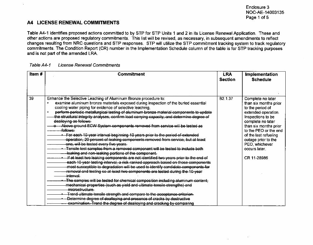
Enclosure 3NOC-AE-14003135Page 1 of 5
A4 LICENSE RENEWAL COMMITMENTS
Table A4-1 identifies proposed actions committed to by STP for STP Units 1 and 2 in its License Renewal Application. These andother actions are proposed regulatory commitments. This list will be revised, as necessary, in subsequent amendments to reflectchanges resulting from NRC questions and STP responses. STP will utilize the STP commitment tracking system to track regulatorycommitments. The Condition Report (CR) number in the Implementation Schedule column of the table is for STP tracking purposesand is not part of the amended LRA.
Table A4-1 License Renewal Commitments
Item # Commitment LRA ImplementationSection Schedule
39 Enhance the Selective Leaching of Aluminum Bronze procedure to: B2.1.37 Complete no later* examine aluminum bronze materials exposed during inspection of the buried essential than six months prior
cooling water piping for evidence of selective leaching, to the period of* perform periodic mnetallurgical tcsting of Wlmnm brone material components to Update extended operation.
the structur..al integrity analyses, confirm, load car./ing capacity, and determnine de gee of Inspections to bedeall'ying as follows; complete no lateroAboe ground . .. W System components re-mo.ved..... ... f . , o ....... ..... will be testcd as than six months prior
follow:': to the PEO or the end-Fo. each 10 year inte:..al beginning 10 yearFs prio to the perid• of eXn•de• d of the last refueling
operation, 20 percGent of leaking com~ponents- re-moepd- fromn scricc, but at least outage prior to theone, will be tested eve.. five years. PEO, whichever
. T-eAnie test samples from. a removed •omponent will be tested to includ: both occurs later.lea-;king and non leaking portions of the comAponent.
. If at least two leaking componenAts are no-t idePntifie-d bNO years prior to the end of CR 11-28986eacsh 109 year testing inteR'al, a risk ranked approach based nn thosea componentsMost susceptible to degadation will b-e u•sFe..d- to identity sandidate GomPonents for
re .m-oval an~d t~esting so at least two components; are tested- during the 10 year
. The samples will be tested for c-hemic-al coemposition including aluminum content,mnechanical properties (such as yield an~d ultimate tensile strengths) andm ricr es t-r --c-t --r e.
. TrFend ultimate tensile strength and comnpare to the acceptance criterion6..- Determine degree of dealleying and presenceP of c-rac~ks by destructive
_______ ~~examination. Trend the degree of dealloying and cracking by compariwng________________

Enclosure 3NOC-AE-14003135Page 2 of 5
Table A4-1 License Renewal Commitments
Commitment LRA ImplementationSection Schedule
eXamination results with previu e WmAtio resulIts.dr Penrifm ae engineering evaluation at the end of eah test to determine if the fample
d stt equi e sm a tmnt bsd on the resul of the tests.. The accseptanco criterion for ultimate tensilo strength value of aluminum bronze
material isgreaterF than o-r equal to 30 ksi. The acceptan~e c-riter-ion forF yieldstrength isequal to or greater than. one half of the ultimate strength.
. Initiate a correctie Ractio document when the acceptanre criterion is not Met.and, if a leak from below-grade welds is discovered by surface water monitoring orduring a buried ECW piping inspection, a section of each leaking weld will be removed fordestructive examination. ________________
Enhance the Selective Leachino of Aluminum Bronze orocedure to u~ndate the strictuiral B2.1.37integrity analyses, confirm load carrying capacity, and determine degree of dealloying asfollows:
* Perform volumetric examinations of leaking aluminum bronze components where theconfiguration supports this type of examination to conclude with reasonable assurance
July 31, 2014(revised per
NOC-AE-14003090)
CR 12-22150that cracks are not aooroachina a critical size.
* Perform Profile Examinations (PE) on 100% of leaking components. The PE consistsof non-destructive examination of the leaking component for the presence of any visualcrack identifications (Inside/outside surfaces) and distractive examinations formicrostructure, degree of dealloying, percent of dealloying through wall thickness andchemical composition (including aluminum content). When sufficient material isavailable for preparation of a test coupon, mechanical properties (ultimate strength,yield strenqth, and/or fracture toughness) will be obtained.
* Perform pressure and bending tests (Analysis Confirmatory Tests (ACTs) on leakingcomponents to obtain pressure and bending moment.
* Require ACTs be performed on 100% of the leaking components until 3 confirmatoryACTs from 3 different component sizes have been tested. Following the 9 confirmatoryACTs then 20% of all removed leaking aluminum bronze components will have ACTsperformed until the end of the Period of Extended Oneration
Require at least two components be tested (PEs and ACTs) during the each 10-yearinterval.

Enclosure 3NOC-AE-14003135Page 3 of 5
Table A4-1 License Renewal Commitments
Item # Commitment LRA ImplementationSection Schedule
If at least two leaking components are not identified two years prior to the end of each10 year testing interval, a risk-ranked approach based on those components mostsusceptible to degradation will be used to identify candidate components for removaltesting.
" Perform an engineering evaluation at the end of each PEs and ACTs testing interval toconfirm the analytical methodology used to calculate the load carrying capacity andstructural integrity of the leak components is conservative.
* Update the analytical methodology used to demonstrate structural integrity used todemonstrate structural integrity as required confirming that the load carrying capacity ofthe aluminum bronze material remains adequate to support the intended function of theECW system through the period of extended operation.
* Trend the degree of dealloying and cracking by comparing examination results withprevious examination results. Trend ultimate strength, yield strength, and/or fracturetoughness results from the PE testing.
* Upon completion of each test, incorporate new test data updating existing trend toevaluate impact on the acceptance criteria.
" Specify the ASME Code Section Xl structural factors for the normal/upset conditions(2.77) as well as the emergency and faulted conditions (1.39).
* Specify the acceptance criteria criterion for ultimate tensile strength and yield strengthvalues of dealloved aluminum bronze material is greater than or equal to 30 ksi.Specify the acceptance criterion for fracture toughness is 65 ksi in 1/2 for non-dealloyedaluminum bronze castings and at welded ioints in the heat affected zones.
* Initiate a corrective action document when the acceptance the criterion is not met.
* Specify that upon discovery of visual evidence of through-wall dealloving. componentsare scheduled for replacement by the next outage.
" Specify that when the ACTs does not confirm the structural integrity analyses,
o The corrective action program as defined in 10 CFR Part 50 Appendix B will befollowed to address emergent conditions to assure continued safe operation ofthe units.
____________ J
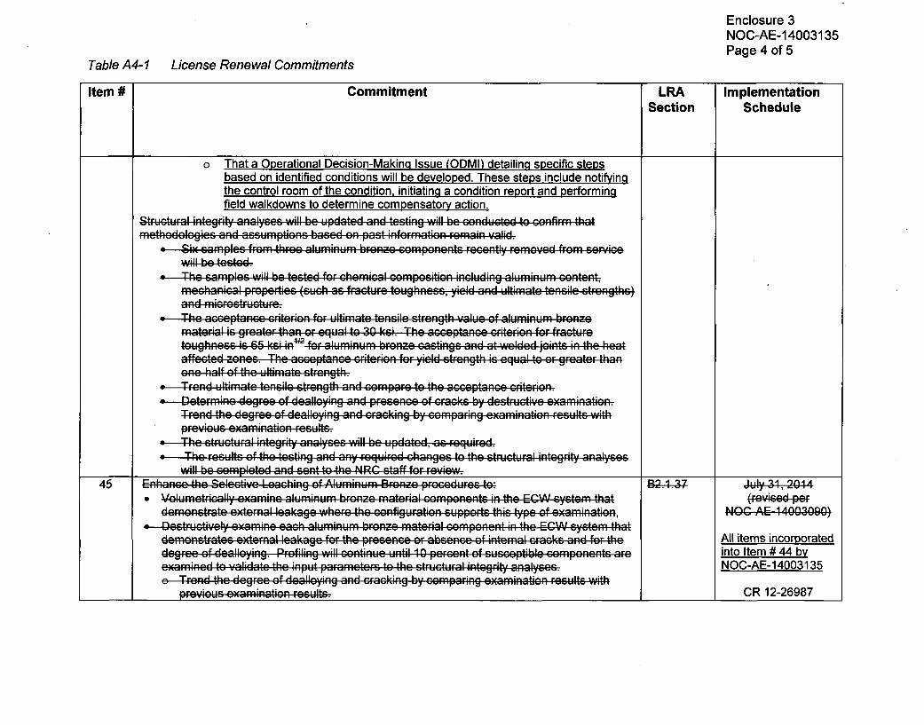
Enclosure 3NOC-AE-14003135Page 4 of 5
Table A4-1 License Renewal Commitments
Item # Commitment LRA ImplementationSection Schedule
o That a Operational Decision-Making Issue (ODMI) detailing specific stepsbased on identified conditions will be developed. These steps include notifyingthe control room of the condition, initiating a condition report and Performingfield walkdowns to determine compensatory action.
Structural integrity analyses will be updated and testing will be conducted to confirm thatmnethodologies and assumptions based on past informnation remnain valid.
" Six samples, fromn three aluminum bron~ze comnponents recently Fr~emved from serPoine
" The sam.ples will be tested- for, ch•m•ical compositioRn including aluminuAm c.ntent,mccrhanicral prope~ties (such as fracture toughness, yield And ultimFate tensile strengths)
" The acceptanae criterion fo-r u-ltima-te tPenSile strength value of aluminumF bFronePmnaterfial is greater than or equal to 30 ksi. The acceptance crFiterion for fracturetoughness is 65 " ks " in'fr f 'iRl442 aluminum hroQn.ze crsa-tinrgs a•nd at welded jo"ints in the heataffected zones. The acceptanGe criterion for yield strength is equal to or greater thanone half of the ultlimiate sotrength.
STrenRd ultimate tensile strength and compare to the accepta-ne criterion." -DetermFine degree of dealloyfing and peresnce of cr.acks by destructive examination.
Trend the degree of deall[ying an;d cracking by coma•ring evaminon rl esults with
previous exaination results-., The structuiral integriy analyses will be updated, as required." The results, of the testing and any required changes to the structural integrity analyses
will be completed and senit to the NRC staff4Gforeview. __________
45 Enhance the Selective Leaching of Alumninu'm. Bronz;e procedures to::) B2 74 j.Iy 3-1,204 4" Volumetrically exami~ne alumnfiFunu bronze imatperial componpents in the ECWV system that (Fevised-pef
demonstrate external leakage where the configuration suppets, this type of examnination, NOC AE 14003000)" Desrdrucntaively examnine each aluminum bronze mnaterial comnponent in the ECWV system that
demonstrates eXtern~al leakage for the presenae or absen~e of interal crFacks an~d for the All items incorporateddegree of dealleyfing. Profiling Will continue until 10 percent of susceptible comnponents are into Item # 44 byexmineRPd- to validate the input parame~ters to the structural integrity analyses.NC-E1035
eTrFend the degree of dealloying and cracking by coprigexmnkation results with____prvos examin~atfion resul-1ts. II CR 12-26987

Enclosure 3NOC-AE-14003135Page 5 of 5
Table A4-1 License Renewal Commitments
Item # Commitment LRA ImplementationSection Schedule
*Metallurgically test aluminum bronze m~aterial com~ponents in the ECWV systemn thatdemonstrate external leakage until the following population of components is tested:a At least threerp different size o; mpone.nts, of toe s'amples each are tested, and
At lePasot nine total samples are tested.Peorm.... f•racre -r -toug hness i testing of test samples that include-a Rack i the dealloyedmatferil .'whee s.ffiient sample size suppotw c bend testing.T4rener dt Ultimate tensile strength and comdpare to the acseptance citheron.
"Test samples forF chem~ical compositiNOn including almiumcotent, m~echaniapwl pebies (such as yield and ultimaut tensile strengths) oand migcra structpe.
t Determine the degee of dealloying by destructive examination.T A rend the degree of dealloying and cracking by comparig texamiRation results withprevios examination results.
4 Th acceptance c-rfite~rion for ultimate tensile strength value of alu.mOinum bronze mnaterial igirenatr than or equal to 30 ksi. The accoptance critelrio-n fo-r fract-ure toughness is, 6-5 ks~iin for al-uminum bronze c~astings and at welded joints inR t-heP lh.eat- affected zones. Theacceptance criterion for yield strength is equal to Or greater than one -Qhalf of the ultimatestrength7
* Perform anegneigevaluation at the end of eacoh tesot to- d-eterm~ine if the soample sizerequires adjustment based on the results of the tests.
aUpdate the structuWr-al integrit' analyses, as required to validate adequate loadcanig
46 Leak rates that could occur upstream of any individual component supplied by the ECW system N/A July 31. 2014will be determined to validate the maximum size flaw for which piping can still perform its by this Letterintended function. NOC-AE-14003135* A summary of the results of these leak rates will be provided to the NRC for review. CR 12-27257