Browns Ferry Nuclear Plant, Units 1, 2, and 3
28
Critical Energy Infrastructure Information Withhold from Public Disclosure Under 10 CFR 2.390 This letter is decontrolled when separated from Enclosures 1, 2, and 3 Tennessee Valley Authority, 1101 Market Street, Chattanooga, Tennessee 37402 CNL-17-015 January 20, 2017 10 CFR 50.90 ATTN: Document Control Desk U.S. Nuclear Regulatory Commission Washington, D.C. 20555-0001 Browns Ferry Nuclear Plant, Units 1, 2, and 3 Renewed Facility Operating License Nos. DPR-33, DPR-52, and DPR-68 NRC Docket Nos. 50-259, 50-260, and 50-296 Subject: Proposed Technical Specifications (TS) Change TS-505 - Request for License Amendments - Extended Power Uprate (EPU) - Supplement 36, Transmission System Update – Safety Aspects References: 1. Letter from TVA to NRC, CNL-15-169, "Proposed Technical Specifications (TS) Change TS-505 - Request for License Amendments - Extended Power Uprate (EPU)," dated September 21, 2015 (ML15282A152) 2. Letter from TVA to NRC, CNL-16-091, "Proposed Technical Specifications (TS) Change TS-505 - Request for License Amendments - Extended Power Uprate (EPU) - Supplement 18, Responses to Requests for Additional Information and Updates associated with Interconnection System Impact Study," dated May 27, 2016 (ML16197A563) 3. Letter from TVA to NRC, CNL-16-150, "Proposed Technical Specifications (TS) Change TS-505 - Request for License Amendments - Extended Power Uprate (EPU) - Supplement 31, Revised Responses to Requests for Additional Information," dated September 21, 2016 (ML16267A374) 4. Letter from TVA to NRC, CNL-16-169, "Proposed Technical Specifications (TS) Change TS-505 - Request for License Amendments - Extended Power Uprate (EPU) - Supplement 35, Consolidated Power Uprate Safety Analysis Report Revision," dated October 28, 2016 (ML16302A441)
-
Upload
khangminh22 -
Category
Documents
-
view
2 -
download
0
Transcript of Browns Ferry Nuclear Plant, Units 1, 2, and 3

Critical Energy Infrastructure Information Withhold from Public Disclosure Under 10 CFR 2.390
This letter is decontrolled when separated from Enclosures 1, 2, and 3
Tennessee Valley Authority, 1101 Market Street, Chattanooga, Tennessee 37402 CNL-17-015 January 20, 2017
10 CFR 50.90
ATTN: Document Control Desk U.S. Nuclear Regulatory Commission Washington, D.C. 20555-0001
Browns Ferry Nuclear Plant, Units 1, 2, and 3 Renewed Facility Operating License Nos. DPR-33, DPR-52, and DPR-68 NRC Docket Nos. 50-259, 50-260, and 50-296
Subject: Proposed Technical Specifications (TS) Change TS-505 - Request for
License Amendments - Extended Power Uprate (EPU) - Supplement 36, Transmission System Update – Safety Aspects
References: 1. Letter from TVA to NRC, CNL-15-169, "Proposed Technical
Specifications (TS) Change TS-505 - Request for License Amendments - Extended Power Uprate (EPU)," dated September 21, 2015 (ML15282A152)
2. Letter from TVA to NRC, CNL-16-091, "Proposed Technical
Specifications (TS) Change TS-505 - Request for License Amendments - Extended Power Uprate (EPU) - Supplement 18,
Responses to Requests for Additional Information and Updates associated with Interconnection System Impact Study," dated May 27, 2016 (ML16197A563)
3. Letter from TVA to NRC, CNL-16-150, "Proposed Technical
Specifications (TS) Change TS-505 - Request for License Amendments - Extended Power Uprate (EPU) - Supplement 31, Revised Responses to Requests for Additional Information," dated September 21, 2016 (ML16267A374)
4. Letter from TVA to NRC, CNL-16-169, "Proposed Technical
Specifications (TS) Change TS-505 - Request for License Amendments - Extended Power Uprate (EPU) - Supplement 35, Consolidated Power Uprate Safety Analysis Report Revision," dated October 28, 2016 (ML16302A441)

U.S. Nuclear Regulatory Commission CNL-17-015 Page 2 January 20, 2017 5. Letter from TVA to NRC, CNL-16-114, "Proposed Technical
Specifications (TS) Change TS-505 - Request for License Amendments - Extended Power Uprate (EPU) - Supplement 24, Response to Requests for Additional Information and Containment Accident Pressure Credit Elimination Update," dated August 3, 2016 (ML16216A699)
By the Reference 1 letter, Tennessee Valley Authority (TVA) submitted a license amendment request (LAR) for the Extended Power Uprate (EPU) of Browns Ferry Nuclear Plant (BFN) Units 1, 2 and 3. The proposed LAR modifies the renewed operating licenses to increase the maximum authorized core thermal power level from the current licensed thermal power of 3458 megawatts to 3952 megawatts. The Reference 2 letter supplemented the BFN EPU LAR and submitted Revision 1 of the interconnection System Impact Study (SIS). Revision 1 of the interconnection SIS identifies the need to replace six breaker failure relays, install 764 megavolt-ampere reactive (MVAR) capacitor banks in five locations throughout the TVA transmission system, and modify the excitation system of all three BFN main generators. The Reference 2 letter also provided associated updates to information previously submitted in the BFN EPU LAR, responses to Requests for Additional Information (RAIs), and updates to responses to RAIs. During the development of implementation guidance for the stability studies at EPU power levels, and subsequent to the submittal of the Reference 2 letter, an error was identified in generator field parameters used in the development of the interconnection SIS. This legacy error involved data contained in a recently updated generator performance computer code used by the original equipment manufacturer. This condition has been entered into the TVA Corrective Action Program. As a result of this error, the following changes to the information provided in Reference 2 letter are required. The static exciters described in BFN EPU LAR Supplement 18 will not be installed on
the BFN units. Instead, the existing exciters on the BFN units will each be modified to be self-excited using a shaft driven alternator. The existing exciters on the BFN units are bus-fed through transformers.
BFN EPU LAR Supplement 18 described installing 764 MVAR capacitor banks at five
substation locations. Instead, capacitor banks will be installed at four of the five identified substations. In addition, a static volt-ampere reactive (VAR) compensator will be installed at an existing substation near BFN. The combination of the static VAR compensator and the additional capacitor banks will provide a minimum reactive compensation of 764 MVAR.
This letter provides BFN EPU LAR Supplement 36. This supplement addresses the safety aspects associated with the above changes. Environmental aspects associated with the above changes will be submitted in a separate supplement (i.e., Supplement 37). Supplement 37 is expected to be submitted by February 3, 2017. Enclosure 1 of this letter provides Revision 3 of the interconnection SIS. Enclosure 1 supersedes and replaces the interconnection SIS submitted in Enclosure 3 of the Reference 3 letter, dated September 21, 2016.
U.S. Nuclear Regulatory Commission CNL-17-015 Page 3 January 20, 2017 Enclosure 2 of this letter provides the updated BFN EPU Transmission System Stability Evaluation (Revision 4) that has been revised to reflect the modifications resulting from the revised interconnection SIS provided in Enclosure 1 of this letter. The BFN EPU Transmission System Stability Evaluation study evaluates the effect of BFN operation at EPU conditions with respect to continued compliance with 10 CFR Part 50, Appendix A, General Design Criterion (GDC) 17, Electric Power Systems. Enclosure 2 supersedes and replaces the BFN EPU Transmission System Stability Evaluation submitted in Enclosure 4 of the Reference 3 letter, dated September 21, 2016. Enclosure 3 of this letter provides the updated response (Revision 2) to the NRC RAI EEEB-RAI 1. The update has been made to reflect the changes to the transmission system upgrades included in Revision 3 of the interconnection SIS. Enclosure 4 of this letter provides a public version of Revision 2 of NRC RAI EEEB-RAI 1 and updated response, with critical energy infrastructure information removed. Enclosures 3 and 4 of this letter supersede and replace the response to NRC RAI EEEB-RAI 1 submitted in Enclosures 3 and 4 of the Reference 2 letter, dated May 27, 2016. Enclosure 5 of this letter provides a revised addendum to the BFN EPU Probabilistic Risk Assessment (PRA). This revised addendum to the BFN EPU PRA addresses the impact of the main generator excitation system modification included in Revision 3 of the interconnection SIS. Enclosure 5 supersedes and replaces the PRA addendum submitted in Enclosure 7 of the Reference 2 letter, dated May 27, 2016. Enclosure 6 of this letter provides an update to the last paragraph of the Technical Evaluation subsection of Power Uprate Safety Analysis Report (PUSAR) (NEDC-33860P, Revision 1, and NEDO-33860, Revision 1) Section 2.5.1.2.2, which was provided in Enclosures 1 and 2 of the Reference 4 letter. This update to PUSAR Section 2.5.1.2.2 addresses the impact of the main generator excitation system modification included in Revision 3 of the interconnection System Impact Study. The information provided in Enclosure 6 to this letter supersedes and replaces the last paragraph of the Technical Evaluation subsection of PUSAR Section 2.5.1.2.2 submitted in Enclosures 1 and 2 of the Reference 4 letter. Enclosure 7 of this letter provides Revision 4 to the BFN EPU List and Status of Plant Modifications. The BFN EPU List and Status of Modifications is revised to reflect the main generator excitation system modification included in Revision 3 of the interconnection SIS and modifications that have been completed since the BFN EPU LAR was submitted. Enclosure 7 supersedes and replaces the BFN EPU List and Status of Modification submitted in Enclosure 5 of the Reference 5 letter, dated August 3, 2016. Enclosures 1, 2, and 3 contain critical energy infrastructure information that is considered sensitive, unclassified (non-safeguard) information. As a result, TVA requests that Enclosures 1, 2, and 3 be withheld from public disclosure in accordance with the provisions of 10 CFR 2.390(d)(1).
U.S. Nuclear Regulatory Commission CNL-17-015 Page 4 January 20, 2017
TVA has reviewed the information supporting a finding of no significant hazards consideration provided to the NRC in the Reference 1 letter. The supplemental information provided in this submittal does not affect the bases for concluding that the proposed license amendment does not involve a significant hazards consideration . Additionally, in accordance with 10 CFR 50.91 (b)(1 ), TVA is sending a copy of this letter, without the critical energy infrastructure information or proprietary information, to the Alabama State Department of Public Health.
There are no new regulatory commitments associated with this submittal. If there are any questions or if additional information is needed, please contact Mr. Edward D. Schrull at (423) 751-3850.
I declare under penalty of perjury that the foregoing is true and correct. Executed on the 20th day of January 2017.
J. Vic President, Nuclear Licensing
Enclosures:
cc:
1. Interconnection System Impact Study, Revision 3: Browns Ferry Nuclear Plant Extended Power Uprate (Critical Energy Infrastructure Information)
2. BFN EPU LAR, Attachment 43, Transmission System Stability Evaluation, Revision 4 (Critical Energy Infrastructure Information)
3. Response to NRC Request for Additional Information EEEB-RAI 1, Revision 2 (Critical Energy Infrastructure Information)
4. Response to NRC Request for Additional Information EEEB-RAI 1, Revision 2 (Without Critical Energy Infrastructure Information)
5. BFN EPU LAR, Attachment 44, Probabilistic Risk Assessment, Addendum (Revised)
6. Power Uprate Safety Analysis Report (PUSAR), Section 2.5.1 .2.2 Update 7. BFN EPU LAR, Attachment 47, List and Status of Plant Modifications,
Revision 4.
NRC Regional Administrator - Region II NRC Senior Resident Inspector - Browns Ferry Nuclear Plant State Health Officer, Alabama Department of Public Health (w/o Enclosures 1, 2,
and 3)

ENCLOSURE 4
Response to NRC Request for Additional Information EEEB-RAI 1, Revision 2
(Without Critical Energy Infrastructure Information)
EEEB RAI 1 Response, Revision 2
E3-1
EEEB-RAI-1
In Section 3.0 of Attachment 43, the licensee states:
The [TSS] study evaluated the performance of the 500 kV [kilovolt] and 161 kV offsite power systems during a DBE [design-basis event] under EPU [extended power uprate] conditions. Bus voltages observed during the simulation are compared to acceptance criteria to determine adequacy of the offsite power supply. The TSS considered a loss of the largest single supply to the grid, loss of the largest single load, loss of the nuclear unit, and loss of each bulk transmission line in the TVA transmission system, including all the lines coming into the BFN switchyard. The study used base cases from both 2015 (pre-EPU) and 2019 (post-EPU) to address the load flow analysis at EPU conditions.
A. Provide acceptable voltage range of BFN 500 kV and 161 kV offsite power acceptance criteria. Also, clarify whether the voltage criteria corresponding to post EPU conditions has been agreed upon by the transmission system operator.
B. Provide summary of cases studied with diagrams to verify that the voltage criteria is met under the following post-EPU conditions:
i. loss of the largest load (identify the load),
ii. loss of the largest generator (identify the generator), and
iii. loss of the most critical transmission line (identify the line).
TVA Response:
A. The 500 kV acceptance criteria are a minimum voltage of 495 kV with a maximum voltage drop from the pre-Loss of Coolant Accident (LOCA) to post LOCA requirement of 30 kV. Note that the 500 kV system is always considered to be the immediate source.
The 161 kV acceptance criteria are given below for both the immediate and delayed source.
161 kV Immediate Source Acceptance Criteria At T=0 to 2.5 seconds: Voltage ≥ 152 kV and Voltage Drop ≤ 10 kV with the associated load for the common service station transformer (CSST) primary winding (Pri) and the cooling tower transformer (TCT) secondary windings (Sec) as follows.
CSST A Load (Pri) CSST B Load (Pri) TCT 1 Load (Sec) TCT 2 Load (Sec) 22.8 +j23.3 16.3 +j8.9 32.1 +j20.9 34.1 +j20.5
At T=2.5 seconds and beyond: Voltage ≥ 159 kV and Voltage Drop ≤ 4 kV with the associated load of :
CSST A Load (Pri) CSST B Load (Pri) TCT 1 Load (Sec) TCT 2 Load (Sec) 25.6+j18.9 20.3+j15.3 32.1 +j20.9 34.1 +j20.5

EEEB RAI 1 Response, Revision 2
E3-2
161 kV Delayed Source Acceptance Criteria Voltage ≥ 157 kV with the associated load of:
CSST A Load (Pri) CSST B Load (Pri) TCT 1 Load (Sec) TCT 2 Load (Sec) 32.04+j16.74 32.04+j16.74 32.1 +j20.9 34.1 +j20.5
[JHB1]
TVA is the transmission system owner and operator. The Browns Ferry Nuclear Plant (BFN) 500 kV and 161 kV off-site power acceptance criteria are established by the Tennessee Valley Authority (TVA) Nuclear Power Group (NPG).[JHB2] The transmission system study (TSS) is performed by the TVA Interconnection Planning & Special Studies group within the Transmission Engineering organization. The acceptance criteria are provided as part of the Nuclear Power Interface Requirements (NPIRs) to the Transmission Planning and Reliability Analysis group for review, discussion, and acceptance as inputs for the Planning TSS.[JHB3] NPG obtained written acknowledgement from the Transmission Planning and Reliability Analysis group that the proposed NPIRs are acceptable for the TSS.[JHB4] The Transmission Planning and Reliability Analysis group is part of the Transmission Operations and Power Supply organization. Both the Transmission Engineering and Transmission Operations and Power Supply organizations are part of the TVA Transmission organization.
B. [JHB5]The following pre-event / LOCA scenarios were simulated to demonstrate compliance with 10 CFR Part 50, Appendix A, General Design Criteria (GDC) 17, Electric Power Systems.
i. An analysis was performed to determine the effect of the loss of the largest load (i.e., Trico Steel) from the grid in the region of BFN. The calculated 500 kV system voltage increased from 524.3 kV to 525.0 kV, and the 161 kV voltage at BFN increased from 164.1 kV to 166.6 kV after removing the load. The loss of the largest load was bounded by the effect of loss of the most critical transmission line.[JHB6]
ii. An analysis was performed to determine the effect of the loss of the largest generator (i.e., a single Cumberland Fossil Plant unit which generates 1,326 MWe) from the grid. In the one unit operation case (Unit 1 and Unit 3 off line pre-event), the voltage drop was determined to be 5.0 kV (i.e., less than the acceptance criteria of 30 kV) and the final voltage was 518.0 kV (i.e., greater than the acceptance criteria of 495 kV).[JHB7] [JHB8] The 161 kV voltage at BFN increased from 163.4 kV to 164.5 kV. The loss of the largest generator from the TVA grid was bounded by the case of loss of the most critical transmission line.[JHB9]
iii. Loss of the most critical transmission line was evaluated by removing each transmission line in the TVA system as a pre-event scenario, followed by the LOCA. Over 1,900 pre-event scenarios were considered, including all of TVA’s bulk transmission lines and transformers in the model. The most critical line was determined to be a pre-event dispatch of the Madison-Widows Creek 500 kV transmission line. In the one unit operation case (Unit 1 and Unit 3 off line pre-event), the voltage drop was determined to be 11.5 kV (i.e., less than the acceptance criteria of 30 kV), the minimum transient voltage was 506.4 kV, and the final voltage was 506.9 kV (i.e., greater than the
EEEB RAI 1 Response, Revision 2
E3-3
acceptance criteria of 495 kV).[JHB10] The simulation cases with noticeable effect or that involve transmission lines that directly connect with BFN are listed below. See Figure 1, Interconnection Map; Figure 2, Interconnection Arrangement; and Figure 3, BFN 161 kV Substation for transmission line orientation.
• Three Unit Operations: o All Ties Closed o BFN-Union 500 kV Transmission Line Out of Service o BFN-West Point 500 kV Transmission Line Out of Service o BFN-Madison 500 kV Transmission Line Out of Service o BFN-Trinity-1 500 kV Transmission Line Out of Service o BFN-Maury 500 kV Transmission Line Out of Service o BFN-Trinity 2 (Nucor) 500 kV Transmission Line Out of Service o BFN-Limestone 500 kV Transmission Line Out of Service o Madison-Widows Creek 500 kV Transmission Line Out of Service (most
limiting case) o BFN-Trinity 161 kV Transmission Line Out of Service o BFN-Athens 161 kV Transmission Line Out of Service o Trinity 500/161 kV Bank Out of Service
• Two Unit Operation (Unit 1 Offline Pre-event): The transmission line and capacitor
bank out of service scenarios above were repeated for two unit operation.
• One Unit Operation (Unit 1 and Unit 3 Offline Pre-event): The transmission line and capacitor bank out of service scenarios above were repeated for one unit operation.[JHB11]
div. The revised Interconnection System Impact Study (SIS), performed to satisfy North American Electric Reliability Corporation and Federal Energy Reliability Commission requirements, identified capital improvements required for the TVA transmission system. The revised Interconnection SIS identified upgrading six 500 kV breaker failure relays, installing a total of 764 MVAR capacitor banksreactive compensation (one static VAR compensator(SVC) and four capacitor banks) in five locations, and upgrading the BFN main generator excitation system for all three units. The six breaker failure relays are being installed to reduce the time required to clear a line fault via back-up protection in the event that the primary protection fails to clear the fault. A steady state load flow study is not impacted by the time required to clear a fault; therefore, the TSS results are not impacted by the replacement of the six breaker failure relays. The excitation system modifications mitigate a transient stability issue that could arise if a 3-phase fault develops while one of the four 500 kV lines specified in the Interconnection SIS is out of service and BFN is operating at EPU conditions. The main generator excitation system details are not modeled in the load flow simulation; therefore, these upgrades do not affect the TSS results. The five locations where capacitor banks are to be installed are distant from BFN and will not affect the offsite power supply. Capacitor banks are normally in the standby mode for contingencies near the banks. Capacitor banks have the effect of supporting the transmission system in their local area.The SVC significantly improves the 500 kV offsite power system shutdowns. The most

EEEB RAI 1 Response, Revision 2
E3-4
critical line was again determined to be a pre-event dispatch of the Madison-Widows Creek 500 kV transmission line. In the one unit operation case (Unit 1 and Unit 3 off line pre-event), the voltage drop was determined to be 2.6 kV (i.e., less than the acceptance criteria of 30 kV), the minimum transient voltage was 518.0 kV, and the final voltage was 518.1 kV (i.e., greater than the acceptance criteria of 495 kV). The 161 kV system also benefits from the SVC, although as expected due to the SVC’s location on the 500kV system, not as significantly as the 500kV scenarios. The four remaining capacitor banks are distant to the BFN offsite power system and do not impact the ability of the transmission system to supply offsite power to BFN.
EEEB RAI 1 Response, Revision 2
E3-5
Figure 1 - Interconnection Map
Legend: W. Point
Union
Maury
Most Critical Line
EEEB RAI 1 Response, Revision 2
E3-6
Figure 2 - Interconnection Arrangement

EEEB RAI 1 Response, Revision 2
E3-7
Figure 3 - BFN 161 kV Substation
Trinity 161-kV
BFN 161kV Capacitor
Bank Athens 161-kV
BFN CSST A &
BFN CT TR 1 BFN CSST B
& BFN CT TR 2
928
924

ENCLOSURE 5
BFN EPU LAR, Attachment 44, Probabilistic Risk Assessment, Addendum (Revised)
006024-CALC-02 Rev. 0 - BFN EPU LAR Attachment 44 Addendum (Revised)
Page 1 of 4
CONTENTS
1.0 EXECUTIVE SUMMARY ........................................................................... 2
2.0 INTRODUCTION ....................................................................................... 2
3.0 ANALYSIS ................................................................................................. 3
4.0 CONCLUSION ........................................................................................... 3
5.0 REFERENCES .......................................................................................... 4
006024-CALC-02 Rev. 0 - BFN EPU LAR Attachment 44 Addendum (Revised)
Page 2 of 4
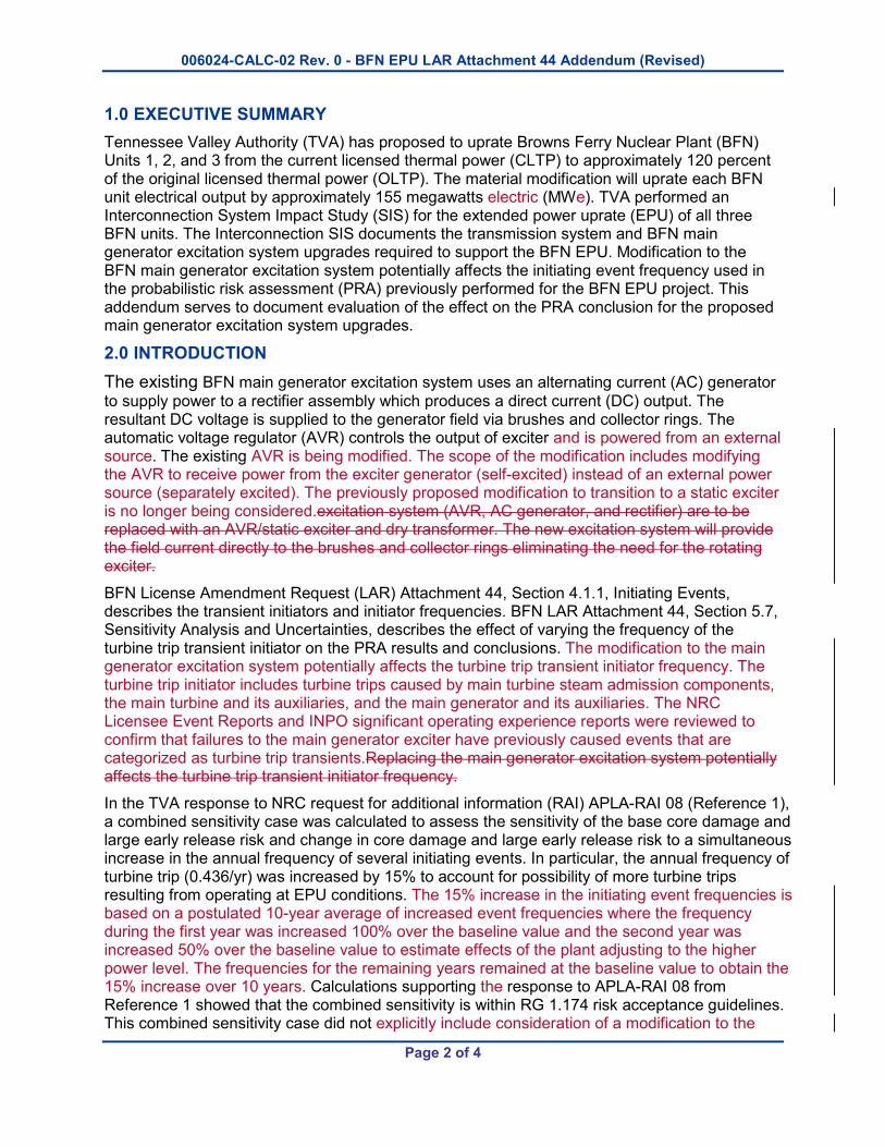
1.0 EXECUTIVE SUMMARY
Tennessee Valley Authority (TVA) has proposed to uprate Browns Ferry Nuclear Plant (BFN) Units 1, 2, and 3 from the current licensed thermal power (CLTP) to approximately 120 percent of the original licensed thermal power (OLTP). The material modification will uprate each BFN unit electrical output by approximately 155 megawatts electric (MWe). TVA performed an Interconnection System Impact Study (SIS) for the extended power uprate (EPU) of all three BFN units. The Interconnection SIS documents the transmission system and BFN main generator excitation system upgrades required to support the BFN EPU. Modification to the BFN main generator excitation system potentially affects the initiating event frequency used in the probabilistic risk assessment (PRA) previously performed for the BFN EPU project. This addendum serves to document evaluation of the effect on the PRA conclusion for the proposed main generator excitation system upgrades.
2.0 INTRODUCTION
The existing BFN main generator excitation system uses an alternating current (AC) generator
to supply power to a rectifier assembly which produces a direct current (DC) output. The resultant DC voltage is supplied to the generator field via brushes and collector rings. The automatic voltage regulator (AVR) controls the output of exciter and is powered from an external source. The existing AVR is being modified. The scope of the modification includes modifying the AVR to receive power from the exciter generator (self-excited) instead of an external power source (separately excited). The previously proposed modification to transition to a static exciter is no longer being considered.excitation system (AVR, AC generator, and rectifier) are to be replaced with an AVR/static exciter and dry transformer. The new excitation system will provide the field current directly to the brushes and collector rings eliminating the need for the rotating exciter.
BFN License Amendment Request (LAR) Attachment 44, Section 4.1.1, Initiating Events, describes the transient initiators and initiator frequencies. BFN LAR Attachment 44, Section 5.7, Sensitivity Analysis and Uncertainties, describes the effect of varying the frequency of the turbine trip transient initiator on the PRA results and conclusions. The modification to the main generator excitation system potentially affects the turbine trip transient initiator frequency. The turbine trip initiator includes turbine trips caused by main turbine steam admission components, the main turbine and its auxiliaries, and the main generator and its auxiliaries. The NRC Licensee Event Reports and INPO significant operating experience reports were reviewed to confirm that failures to the main generator exciter have previously caused events that are categorized as turbine trip transients.Replacing the main generator excitation system potentially affects the turbine trip transient initiator frequency.
In the TVA response to NRC request for additional information (RAI) APLA-RAI 08 (Reference 1), a combined sensitivity case was calculated to assess the sensitivity of the base core damage and large early release risk and change in core damage and large early release risk to a simultaneous increase in the annual frequency of several initiating events. In particular, the annual frequency of turbine trip (0.436/yr) was increased by 15% to account for possibility of more turbine trips resulting from operating at EPU conditions. The 15% increase in the initiating event frequencies is based on a postulated 10-year average of increased event frequencies where the frequency during the first year was increased 100% over the baseline value and the second year was increased 50% over the baseline value to estimate effects of the plant adjusting to the higher power level. The frequencies for the remaining years remained at the baseline value to obtain the 15% increase over 10 years. Calculations supporting the response to APLA-RAI 08 from Reference 1 showed that the combined sensitivity is within RG 1.174 risk acceptance guidelines. This combined sensitivity case did not explicitly include consideration of a modification to the
006024-CALC-02 Rev. 0 - BFN EPU LAR Attachment 44 Addendum (Revised)
Page 3 of 4
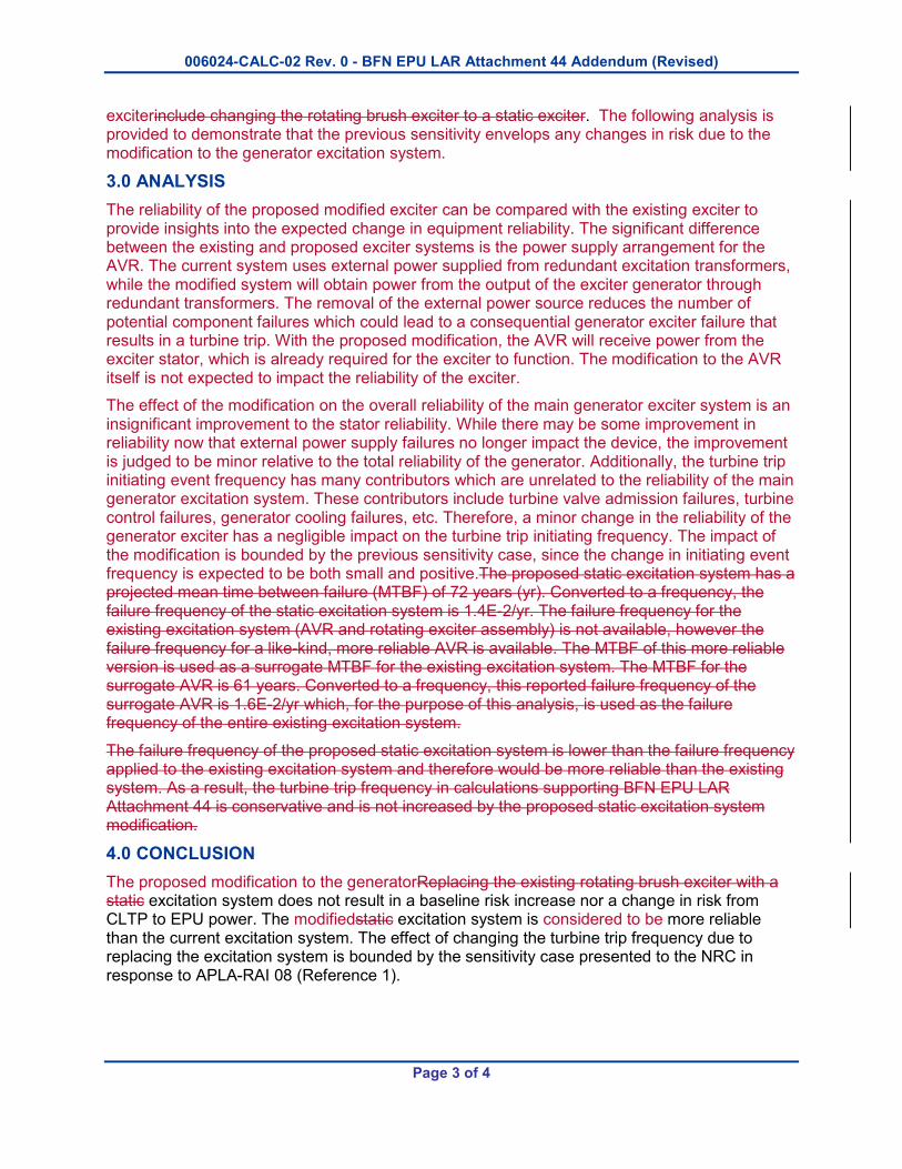
exciterinclude changing the rotating brush exciter to a static exciter. The following analysis is provided to demonstrate that the previous sensitivity envelops any changes in risk due to the modification to the generator excitation system.
3.0 ANALYSIS
The reliability of the proposed modified exciter can be compared with the existing exciter to provide insights into the expected change in equipment reliability. The significant difference between the existing and proposed exciter systems is the power supply arrangement for the AVR. The current system uses external power supplied from redundant excitation transformers, while the modified system will obtain power from the output of the exciter generator through redundant transformers. The removal of the external power source reduces the number of potential component failures which could lead to a consequential generator exciter failure that results in a turbine trip. With the proposed modification, the AVR will receive power from the exciter stator, which is already required for the exciter to function. The modification to the AVR itself is not expected to impact the reliability of the exciter.
The effect of the modification on the overall reliability of the main generator exciter system is an insignificant improvement to the stator reliability. While there may be some improvement in reliability now that external power supply failures no longer impact the device, the improvement is judged to be minor relative to the total reliability of the generator. Additionally, the turbine trip initiating event frequency has many contributors which are unrelated to the reliability of the main generator excitation system. These contributors include turbine valve admission failures, turbine control failures, generator cooling failures, etc. Therefore, a minor change in the reliability of the generator exciter has a negligible impact on the turbine trip initiating frequency. The impact of the modification is bounded by the previous sensitivity case, since the change in initiating event frequency is expected to be both small and positive.The proposed static excitation system has a projected mean time between failure (MTBF) of 72 years (yr). Converted to a frequency, the failure frequency of the static excitation system is 1.4E-2/yr. The failure frequency for the existing excitation system (AVR and rotating exciter assembly) is not available, however the failure frequency for a like-kind, more reliable AVR is available. The MTBF of this more reliable version is used as a surrogate MTBF for the existing excitation system. The MTBF for the surrogate AVR is 61 years. Converted to a frequency, this reported failure frequency of the surrogate AVR is 1.6E-2/yr which, for the purpose of this analysis, is used as the failure frequency of the entire existing excitation system.
The failure frequency of the proposed static excitation system is lower than the failure frequency applied to the existing excitation system and therefore would be more reliable than the existing system. As a result, the turbine trip frequency in calculations supporting BFN EPU LAR Attachment 44 is conservative and is not increased by the proposed static excitation system modification.
4.0 CONCLUSION
The proposed modification to the generatorReplacing the existing rotating brush exciter with a static excitation system does not result in a baseline risk increase nor a change in risk from CLTP to EPU power. The modifiedstatic excitation system is considered to be more reliable than the current excitation system. The effect of changing the turbine trip frequency due to replacing the excitation system is bounded by the sensitivity case presented to the NRC in response to APLA-RAI 08 (Reference 1).

006024-CALC-02 Rev. 0 - BFN EPU LAR Attachment 44 Addendum (Revised)
Page 4 of 4
5.0 REFERENCES
1. Letter from TVA to NRC, CNL-16-077, “Proposed Technical Specifications (TS) Change TS-505 – Request for License Amendments – Extended Power Uprate (EPU) – Supplement 14, Responses to Requests for Additional Information,” dated April 27, 2016 (ML16118A298)

ENCLOSURE 6
Power Uprate Safety Analysis Report (PUSAR), Section 2.5.1.2.2 Update
Replace the last paragraph of the Power Uprate Safety Analysis Report (PUSAR) (NEDC-33860P, Revision 1, and NEDO-33860, Revision 1), “Turbine-Generator,” “Technical Evaluation” section with the following insert: Insert 1 The main generator excitation systems that existed on all three units, were GE Alterrex Excitation systems. The energy for excitation of the generator field was derived from the turbine using a self-excited shaft driven alternator. The output of the alternator was rectified by a set of water cooled stationary diode bridges mounted in the doghouse of the generator. The resultant DC voltage was supplied to the generator field via brushes and collector rings. Between 2011 and 2013, TVA replaced the voltage regulators in the Alterrex Excitation systems with new ABB Unitrol 5000 automatic voltage regulators which were no longer fed by the Alterrex but rather were bus fed through auxiliary transformers. The Interconnection System Impact Study (SIS), performed for BFN at EPU conditions, determined that main generator stability issues exist for a 3-phase fault on one of several BFN transmission lines coincident with certain transmission lines already out of service (N-1-1 event). The present excitation system cannot raise the field voltage fast enough and high enough to prevent the main generator from becoming unstable during the N-1-1 event. To address the transient stability issue, BFN will modify the AVR and return the Alterrex system to a self-excited, shaft driven alternator. The AVR will be supplied power with exciter fed, redundant excitation transformers. In addition, a Static VAR Compensator (SVC) sized at +450 MVAR/-400 MVAR, will be installed at the Limestone sub-station. Additional computer simulations of the N-1-1 event for the SIS, with the modified excitation system and the new SVC modeled, have shown that the generators remain stable. Until the excitation systems can be modified and the SVC installed, administrative controls will be implemented to limit unit output whenever transmission system conditions exist that could make generator instabilities possible during an N-1-1 event. Once the excitation systems are modified and the SVC installed, the administrative controls will no longer be necessary. Use of administrative controls to prevent transient instabilities, prior to the excitation systems being modified and SVC installed, is allowed by North American Reliability Council (NERC) standards.

ENCLOSURE 7
BFN EPU LAR, Attachment 47, List and Status of Plant Modifications, Revision 4

Att 47-1
Browns Ferry Units 1, 2 and 3 EPU Modifications, Revision 43
The modifications required to support Extended Power Uprate (EPU) for Browns Ferry Nuclear Power Station (BFN) Units 1, 2 and 3 have been compiled and are shown in Table 1. The modifications reported as ‘Complete’ in Table 1 are fully implemented, for all other modifications a schedule for full implementation is provided. All EPU modifications, either completed or being prepared, are in accordance with the TVA Plant Modifications and Engineering Change Control process. Further evaluations may identify the need for additional modifications or obviate the need for some modifications. As such, Table 1 listings are not a formal commitment to implement the modifications exactly as described or per the proposed schedule. Additionally, various minor modifications and adjustments to plant equipment, which may be necessary, are not listed.

Att 47-2
Table 1: BFN EPU Planned Modifications and Current Schedule
Modification
Description
Scheduled Completion
(Note 1)
Replacement Steam Dryer
New steam dryers will be installed with increased structural design margin to accommodate EPU operation. • Replacement steam dryers are curved hood six-bank dryers analyzed
for fatigue resulting from flow induced vibration and hydrodynamic loads.
• Main steam line strain gages were previously installed to obtain measurements at CLTP conditions which were used to design the replacement steam dryers.
• New main steam line strain gages will be installed to replace the existing strain gages which have reached end of life to obtain measurements during power ascension testing of the replacement steam dryers.
Unit 1 – Fall 2018 Unit 2 – Spring 2019 Unit 3 – Spring 2018
Main Turbine Replace the High Pressure Turbine rotor. Incorporate GE's Advanced Design Steam Path which is designed for the increased flow associated with EPU. • Replace High Pressure Turbine diaphragms and rotor buckets. • Modify the cross around relief valves (CARVs) to permit increased set
pressure. • Replace and/or recalibrate Main Steam system flow and pressure
instruments.
Unit 1 – Fall 2018 Unit 2 – Spring 2019 Unit 3 – Spring 2018
Unit 1 – Complete Unit 2 – Complete Unit 3 – Complete
Unit 1 – Complete Unit 2 – Complete Unit 3 – Complete
Turbine Sealing Steam
Increase the size of the Steam Packing Unloader Valves (SPUVs) and associated piping to enable the turbine sealing system to accommodate EPU flow requirements. • Increase SPUVs and piping from 8-inch to 10-inch components. • Replace and rescale steam flow and steam pressure transmitters.
Unit 1 – Complete Unit 2 – Complete Unit 3 – Complete
Att 47-3
Modification
Description
Scheduled Completion
(Note 1)
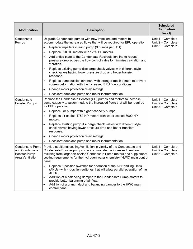
Condensate Pumps
Upgrade Condensate pumps with new impellers and motors to accommodate the increased flows that will be required for EPU operation. • Replace impellers in each pump (3 pumps per Unit). • Replace 900 HP motors with 1250 HP motors. • Add orifice plate to the Condensate Recirculation line to reduce
pressure drop across the flow control valve to minimize cavitation and vibration.
• Replace existing pump discharge check valves with different style check valves having lower pressure drop and better transient response.
• Replace pump suction strainers with stronger mesh screen to prevent screen deformation with the increased EPU flow conditions.
• Change motor protection relay settings. • Recalibrate/replace pump and motor instrumentation.
Unit 1 – Complete Unit 2 – Complete Unit 3 – Complete
Condensate Booster Pumps
Replace the Condensate Booster (CB) pumps and motors to increase pump capacity to accommodate the increased flows that will be required for EPU operation. • Replace CB pumps with higher capacity pumps. • Replace air-cooled 1750 HP motors with water-cooled 3000 HP
motors. • Replace existing pump discharge check valves with different style
check valves having lower pressure drop and better transient response.
• Change motor protection relay settings. • Recalibrate/replace pump and motor instrumentation.
Unit 1 – Complete Unit 2 – Complete Unit 3 – Complete
Condensate Pump and Condensate Booster Pump Area Ventilation
Provide additional cooling/ventilation in vicinity of the Condensate and Condensate Booster pumps to accommodate the increased heat load resulting from larger air-cooled Condensate Pump motors and supplement cooling requirements for the hydrogen water chemistry (HWC) main control panel. • Replace 3-position switches for operation of the Air Handling Units
(AHUs) with 4-position switches that will allow parallel operation of the AHUs.
• Addition of a balancing damper to the Condensate Pump motors to provide better balancing of air flow.
• Addition of a branch duct and balancing damper to the HWC main control panel.
Unit 1 – Complete Unit 2 – Complete Unit 3 – Complete
Att 47-4
Modification
Description
Scheduled Completion
(Note 1)
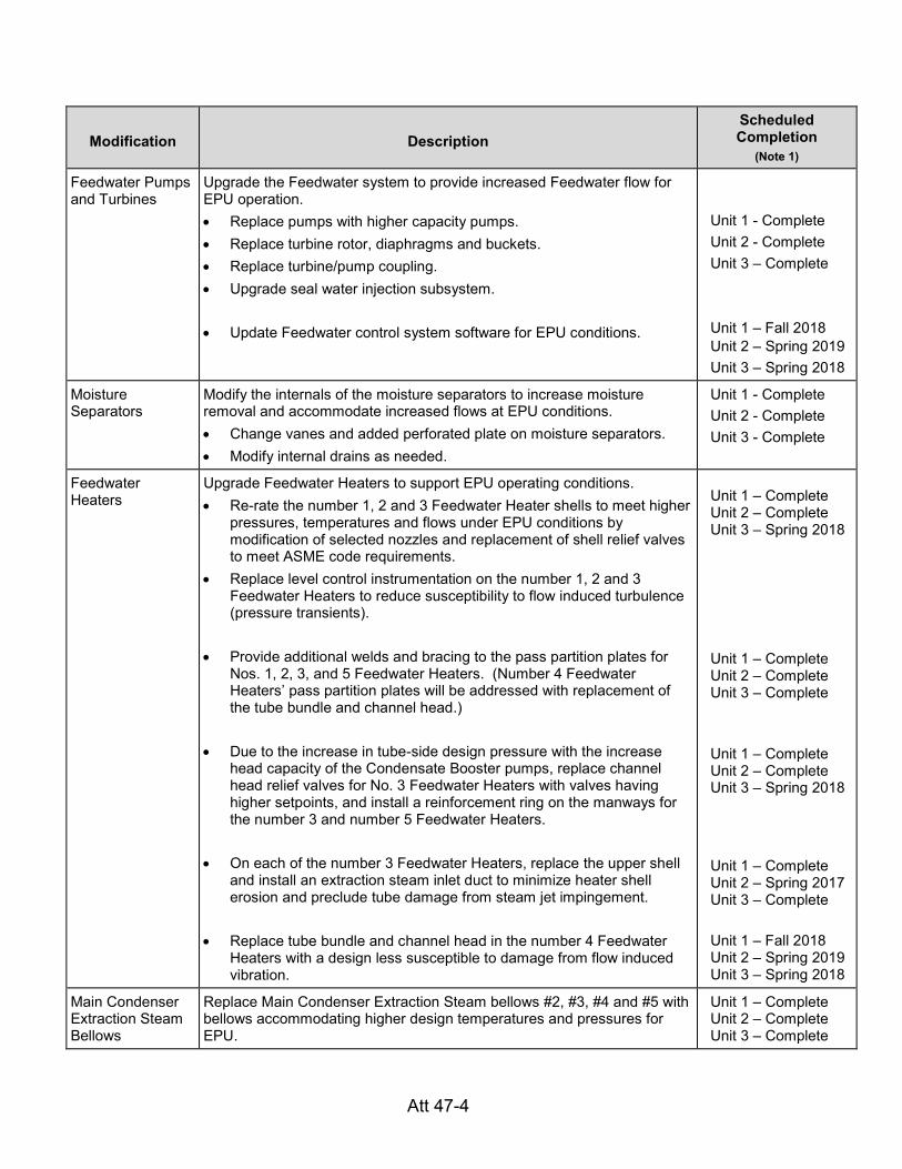
Feedwater Pumps and Turbines
Upgrade the Feedwater system to provide increased Feedwater flow for EPU operation. • Replace pumps with higher capacity pumps. • Replace turbine rotor, diaphragms and buckets. • Replace turbine/pump coupling. • Upgrade seal water injection subsystem.
• Update Feedwater control system software for EPU conditions.
Unit 1 - Complete Unit 2 - Complete Unit 3 – Complete Unit 1 – Fall 2018 Unit 2 – Spring 2019 Unit 3 – Spring 2018
Moisture Separators
Modify the internals of the moisture separators to increase moisture removal and accommodate increased flows at EPU conditions. • Change vanes and added perforated plate on moisture separators. • Modify internal drains as needed.
Unit 1 - Complete Unit 2 - Complete Unit 3 - Complete
Feedwater Heaters
Upgrade Feedwater Heaters to support EPU operating conditions. • Re-rate the number 1, 2 and 3 Feedwater Heater shells to meet higher
pressures, temperatures and flows under EPU conditions by modification of selected nozzles and replacement of shell relief valves to meet ASME code requirements.
• Replace level control instrumentation on the number 1, 2 and 3 Feedwater Heaters to reduce susceptibility to flow induced turbulence (pressure transients).
• Provide additional welds and bracing to the pass partition plates for Nos. 1, 2, 3, and 5 Feedwater Heaters. (Number 4 Feedwater Heaters’ pass partition plates will be addressed with replacement of the tube bundle and channel head.)
• Due to the increase in tube-side design pressure with the increase
head capacity of the Condensate Booster pumps, replace channel head relief valves for No. 3 Feedwater Heaters with valves having higher setpoints, and install a reinforcement ring on the manways for the number 3 and number 5 Feedwater Heaters.
• On each of the number 3 Feedwater Heaters, replace the upper shell and install an extraction steam inlet duct to minimize heater shell erosion and preclude tube damage from steam jet impingement.
• Replace tube bundle and channel head in the number 4 Feedwater Heaters with a design less susceptible to damage from flow induced vibration.
Unit 1 – Complete Unit 2 – Complete Unit 3 – Spring 2018
Unit 1 – Complete Unit 2 – Complete Unit 3 – Complete
Unit 1 – Complete Unit 2 – Complete Unit 3 – Spring 2018
Unit 1 – Complete Unit 2 – Spring 2017 Unit 3 – Complete Unit 1 – Fall 2018 Unit 2 – Spring 2019 Unit 3 – Spring 2018
Main Condenser Extraction Steam Bellows
Replace Main Condenser Extraction Steam bellows #2, #3, #4 and #5 with bellows accommodating higher design temperatures and pressures for EPU.
Unit 1 – Complete Unit 2 – Complete Unit 3 – Complete

Att 47-5
Modification
Description
Scheduled Completion
(Note 1)
Condensate Demineralizers
Install a 10th condensate demineralizer (and associated valves and controls) on each unit to accommodate the increased condensate flow associated with EPU operation.
Unit 1 - Complete Unit 2 - Complete Unit 3 - Complete
Steam Packing Exhauster Bypass
Increase the capacity of the steam packing exhauster bypass line to accommodate increased flow under EPU conditions. • Install larger piping and flow control valve.
Unit 1 - Complete Unit 2 - Complete Unit 3 - Complete
Torus Attached Piping
Modification to reinforce an existing pad at an ECCS ring header branch connection to address higher pipe stresses associated with EPU conditions. Required only on Units 2 and 3 as sufficient stress margin exists on Unit 1.
Unit 1 – N/A Unit 2 – Complete Unit 3 – Complete
Main Steam Supports
Modify one Unit 2 Main Steam pipe support due to increased loads resulting from turbine stop valve closure at EPU steam flow rates. All other existing Unit 2 Main Steam pipe supports, and all Main Steam pipe supports on Units 1 and 3, were determined to have sufficient design margin to accommodate the increased turbine stop valve closure loads.
Unit 1 – NA Unit 2 – Complete Unit 3 – NA
Reactor Recirculation Pumps & Motors
Upgrade the reactor recirculation system for EPU core flow operating conditions. • Perform analyses/evaluations to increase the design ratings for the
recirculation pumps and motors. • Upgrade the Variable Frequency Drive (VFD) control system. • Perform pump and motor instrumentation upgrades - jet pump head,
RCW flow, motor winding temperatures, VFD protective relay settings. • Revise Upper Power Runback setting for EPU conditions.
Unit 1 - Complete Unit 2 - Complete Unit 3 - Complete Unit 1 – Fall 2018 Unit 2 – Spring 2019 Unit 3 – Spring 2018
Jet Pump Sensing Line Clamps
Install jet pump sensing line clamps to reduce pipe vibration under EPU conditions.
Unit 1 - Complete Unit 2 - Complete Unit 3 - Complete
Main Generator System
Uprate main generator to 1330 MVA (Unit 1) / 1332 MVA (Units 2 & 3). • Install rewound stator to support higher generator output capacity. • Replace/modify stator water cooling (SWC) instruments and change
SWC flow, pressure, DP and temperature settings to support increased stator water cooling requirements.
Unit 1 - Complete Unit 2 - Spring 2019 Unit 3 - Complete
Main Generator Hydrogen Pressure
Increase generator hydrogen pressure from 65 psig to 75 psig to support EPU operation. • Change pressure regulating valve settings and pressure alarm setting. • Replace pressure switches as needed for new operating range. • Change generator field over-excitation relay settings. • Eliminate hydrogen flow integrator to mitigate hydrogen leakage.
Unit 1 – Fall 2018 Unit 2 – Spring 2019 Unit 3 – Spring 2018
Att 47-6
Modification
Description
Scheduled Completion
(Note 1)
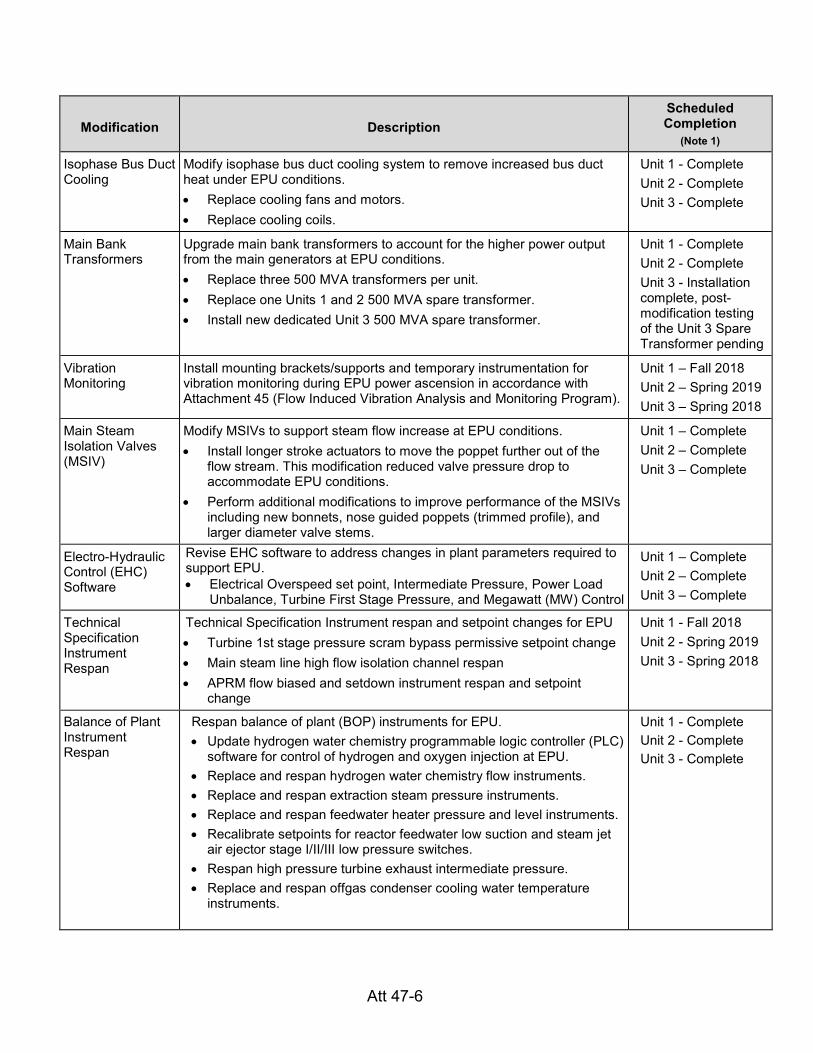
Isophase Bus Duct Cooling
Modify isophase bus duct cooling system to remove increased bus duct heat under EPU conditions. • Replace cooling fans and motors. • Replace cooling coils.
Unit 1 - Complete Unit 2 - Complete Unit 3 - Complete
Main Bank Transformers
Upgrade main bank transformers to account for the higher power output from the main generators at EPU conditions. • Replace three 500 MVA transformers per unit. • Replace one Units 1 and 2 500 MVA spare transformer. • Install new dedicated Unit 3 500 MVA spare transformer.
Unit 1 - Complete Unit 2 - Complete Unit 3 - Installation complete, post-modification testing of the Unit 3 Spare Transformer pending
Vibration Monitoring
Install mounting brackets/supports and temporary instrumentation for vibration monitoring during EPU power ascension in accordance with Attachment 45 (Flow Induced Vibration Analysis and Monitoring Program).
Unit 1 – Fall 2018 Unit 2 – Spring 2019 Unit 3 – Spring 2018
Main Steam Isolation Valves (MSIV)
Modify MSIVs to support steam flow increase at EPU conditions. • Install longer stroke actuators to move the poppet further out of the
flow stream. This modification reduced valve pressure drop to accommodate EPU conditions.
• Perform additional modifications to improve performance of the MSIVs including new bonnets, nose guided poppets (trimmed profile), and larger diameter valve stems.
Unit 1 – Complete Unit 2 – Complete Unit 3 – Complete
Electro-Hydraulic Control (EHC) Software
Revise EHC software to address changes in plant parameters required to support EPU. • Electrical Overspeed set point, Intermediate Pressure, Power Load
Unbalance, Turbine First Stage Pressure, and Megawatt (MW) Control
Unit 1 – Complete Unit 2 – Complete Unit 3 – Complete
Technical Specification Instrument Respan
Technical Specification Instrument respan and setpoint changes for EPU • Turbine 1st stage pressure scram bypass permissive setpoint change • Main steam line high flow isolation channel respan • APRM flow biased and setdown instrument respan and setpoint
change
Unit 1 - Fall 2018 Unit 2 - Spring 2019 Unit 3 - Spring 2018
Balance of Plant Instrument Respan
Respan balance of plant (BOP) instruments for EPU. • Update hydrogen water chemistry programmable logic controller (PLC)
software for control of hydrogen and oxygen injection at EPU. • Replace and respan hydrogen water chemistry flow instruments. • Replace and respan extraction steam pressure instruments. • Replace and respan feedwater heater pressure and level instruments. • Recalibrate setpoints for reactor feedwater low suction and steam jet
air ejector stage I/II/III low pressure switches. • Respan high pressure turbine exhaust intermediate pressure. • Replace and respan offgas condenser cooling water temperature
instruments.
Unit 1 - Complete Unit 2 - Complete Unit 3 - Complete
Att 47-7
Modification
Description
Scheduled Completion
(Note 1)
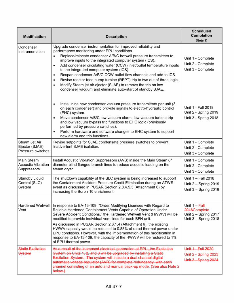
Condenser Instrumentation
Upgrade condenser instrumentation for improved reliability and performance monitoring under EPU conditions. • Replace/relocate condenser A/B/C hotwell pressure transmitters to
improve inputs to the integrated computer system (ICS). • Add condenser circulating water (CCW) inlet/outlet temperature inputs
to the integrated computer system (ICS). • Respan condenser A/B/C CCW outlet flow channels and add to ICS. • Revise reactor feed pump turbine (RFPT) trip to two out of three logic. • Modify Steam jet air ejector (SJAE) to remove the trip on low
condenser vacuum and eliminate auto-start of standby SJAE.
• Install nine new condenser vacuum pressure transmitters per unit (3
on each condenser) and provide signals to electro-hydraulic control (EHC) system.
• Move condenser A/B/C low vacuum alarm, low vacuum turbine trip and low vacuum bypass trip functions to EHC logic (previously performed by pressure switches).
• Perform hardware and software changes to EHC system to support new alarm and trip functions.
Unit 1 - Complete Unit 2 - Complete Unit 3 - Complete Unit 1 - Fall 2018 Unit 2 - Spring 2019 Unit 3 - Spring 2018
Steam Jet Air Ejector (SJAE) Pressure switches
Revise setpoints for SJAE condensate pressure switches to prevent inadvertent SJAE isolation.
Unit 1 - Complete Unit 2 - Complete Unit 3 - Complete
Main Steam Acoustic Vibration Suppressors
Install Acoustic Vibration Suppressors (AVS) inside the Main Steam 6" diameter blind flanged branch lines to reduce acoustic loading on the steam dryer.
Unit 1 - Complete Unit 2 - Complete Unit 3 - Complete
Standby Liquid Control (SLC) System
The shutdown capability of the SLC system is being increased to support the Containment Accident Pressure Credit Elimination during an ATWS event as discussed in PUSAR Section 2.8.4.5.3 (Attachment 6) by increasing the Boron-10 enrichment.
Unit 1 – Fall 2018 Unit 2 – Spring 2019 Unit 3 – Spring 2018
Hardened Wetwell Vent
In response to EA-13-109, “Order Modifying Licenses with Regard to Reliable Hardened Containment Vents Capable of Operation Under Severe Accident Conditions,” the Hardened Wetwell Vent (HWWV) will be modified to provide individual vent lines for each BFN unit. As discussed in PUSAR Section 2.6.1.4 (Attachment 6), the existing HWWV capacity would be reduced to 0.88% of rated thermal power under EPU conditions. However, with the implementation of this modification in response to EA-13-109, the capacity of the HWWV will be restored to 1% of EPU thermal power.
Unit 1 – Fall 2016Complete Unit 2 – Spring 2017 Unit 3 – Spring 2018
Static Excitation System
As a result of the increased electrical generation at EPU, the Excitation System on Units 1, 2, and 3 will be upgraded by installing a Static Excitation System. The system will include a dual channel digital automatic voltage regulator (AVR) for complete redundancy, with each channel consisting of an auto and manual back-up mode. (See also Note 2 below.)
Unit 1 - Fall 2020 Unit 2 - Spring 2023 Unit 3 - Spring 2024
mnwebb
Line
mnwebb
Line

Att 47-8
Modification
Description
Scheduled Completion
(Note 1)
Self-Excited Excitation System
To address a transient stability issue resulting from the increased electrical generation at EPU, the Excitation System on Units 1, 2, and 3 will be upgraded. The Alterrex excitation system will be returned to a self-excited, shaft driven alternator and the Automatic Voltage Regulator (AVR) will be modified. The AVR will be supplied power with exciter fed, redundant excitation transformers. (See also Note 2 below.)
Unit 1 - Fall 2020 Unit 2 - Spring 2021 Unit 3 - Spring 2020
Alternate Leakage Treatment Pathway
Provide a highly reliable Alternate Leakage Treatment Pathway that routes 99.5% of the leakage from the primary containment MSIVs directly to the condenser. The modification on each unit will include replacement of five motor operated valves on the Main Steam drain lines with air operated valves. Also, an additional Main Steam drain line valve will be installed, with an air operator, to address single failure criteria. All the new air operated valves will fail open on loss of electrical power or control air.
Unit 1 – Fall 2018 Unit 2 – Spring 2019 Unit 3 – Spring 2018
Notes: 1) The expected completion timeframes reported in Table 1 correspond to the following refuel outages: For
BFN Unit 1, Fall of 2016 is RFO-U1R11, Fall of 2018 is RFO-U1R12 and Fall of 2020 is RFO-U1R13. For BFN Unit 2, Spring of 2017 is RFO-U2R19, Spring of 2019 is RFO-U2R20 and Spring of 20212023 is RFO-U2R21U2R212. For BFN Unit 3, Spring of 2018 is RFO-U3R18 and Spring of 20202024 is RFO-U3R1921.
2) The Self-Excited Excitation SystemStatic Excitation System is not required to be installed prior to EPU
operation. During the interim period of EPU operation preceding installation of the Self-Excited Excitation SystemStatic Excitation System, transmission system grid stability will be maintained through use of a detailed temporary operating guide.
mnwebb
Line
mnwebb
Line
mnwebb
Line