
Hutchinson Island Plant Units 1 and 2 - Nuclear Regulatory ...
279
TABLE OF CONTENTS CHAPTER 11 RADIOACTIVE WASTE MANAGEMENT SYSTEM Section 11. 1 ll. 1. 1 11.1. 2 ll. l. 3 ll. 1. 4 11. 1. 5 ll. 1. 6 11. 2 Title SOURCE TERMS FISSION PRODUCTS CORROSION PRODUCTS TRITIUM PRODUCTION NITROGEN-16 PRODUCTION FUEL EXPERIENCE LEAKAGE SOURCES LI UID WASTE SYSTEMS ~Pa e lie l~l 11.1 1 11.1-6 11.1-7 11.1-7 11.1-12 11.1-12 11.2-1 ll. 2. 1 ll. 2. 2 11.2.2.1 ll. 2. 2. 2 11. 2. 3 11.2. 3.1 ll.2. 3.2 ll. 2.4 ll. 2. 5 11. 2. 6 11.2.7 11.2. 8 11. 3 11. 3. 1 11. 3. 2 DESIGN BASES SYSTEM DESCRIPTION Boron Recover S stem Li uid Waste S stem OPERATING PROCEDURES Boron Recover S stem Li uid Waste Processin PERFORMANCE TESTS ESTIMATED RELEASES RELEASE POINTS DILUTION FACTORS ESTIMATED DOSES GASEOUS WASTE SYSTEM DESIGN BASES SYSTEM DESCRIPTION 11.2-1 1112«1 11.2-1 1102-5 11.2-30 11.2-30 11.2-31 11.2-31 ~ 11.2-32 11.2-32 11.2-32 11.2-32 11.3-,1 11.3-1 1103-1
-
Upload
khangminh22 -
Category
Documents
-
view
0 -
download
0
Transcript of Hutchinson Island Plant Units 1 and 2 - Nuclear Regulatory ...

TABLE OF CONTENTS
CHAPTER 11
RADIOACTIVE WASTE MANAGEMENT SYSTEM
Section
11. 1
ll.1. 1
11.1. 2
ll.l. 3
ll.1. 4
11. 1. 5
ll.1. 6
11. 2
Title
SOURCE TERMS
FISSION PRODUCTS
CORROSION PRODUCTS
TRITIUM PRODUCTION
NITROGEN-16 PRODUCTION
FUEL EXPERIENCE
LEAKAGE SOURCES
LI UID WASTE SYSTEMS
~Pa e
lie l~l
11.1 1
11.1-6
11.1-7
11.1-7
11.1-12
11.1-12
11.2-1
ll.2. 1
ll.2. 2
11.2.2.1
ll.2. 2. 2
11. 2. 3
11.2. 3.1
ll.2. 3.2
ll.2.4
ll.2. 5
11. 2. 6
11.2.7
11.2. 8
11. 3
11. 3. 1
11. 3. 2
DESIGN BASES
SYSTEM DESCRIPTION
Boron Recover S stem
Li uid Waste S stem
OPERATING PROCEDURES
Boron Recover S stem
Li uid Waste Processin
PERFORMANCE TESTS
ESTIMATED RELEASES
RELEASE POINTS
DILUTION FACTORS
ESTIMATED DOSES
GASEOUS WASTE SYSTEM
DESIGN BASES
SYSTEM DESCRIPTION
11.2-1
1112«1
11.2-1
1102-5
11.2-30
11.2-30
11.2-31
11.2-31
~ 11.2-32
11.2-32
11.2-32
11.2-32
11.3-,1
11.3-1
1103-1

TABLE OF CONTENTS
Section
11.3.2.1
11. 3. 3
ll.3. 4
ll.3. 5
11. 3.6
11.3. 7
11. 3. 8
11.4
Title
Waste Gas Processin S stems
OPERATING PROCEDURE
PERFORMANCE TESTS
ESTIMATED RELEASES
RELEASE POINTS
DILUTION FACTORS
ESTIMATED DOSES
PROCESS AND EFFLUENT RADIOLOGICAL MONITORING
SYSTEMS
~Pa e
11.2-1
11.3-10
11.3-11
11.3-11
11.3-14
11.3-14
11.3-14
11.4-1
11.4.1
11. 4. 2
11.4.2.1
11.4.2. 2
11.4. 2. 3
11.4.2.4
11.4.2.5
11.4.2.6
11.4.3
11. 4. 3. 1
11.4. 3. 2
11.4. 3. 3
11.4.3.4
11.4. 3.5
11.4.3.6
11.4.3.7
11.4. 3. 8
.DESIGN BASES
CONTINUOUS MONITORING
Process Radiation Monitor
Gaseous Dischar e Monitor
Li uid Waste Dischar e Monitor
Steam Generator Blowdown Monitor
Condenser Air E'ector Monitor
Com onent Coolin Water Monitor
SAMPLING
Preconcentrator and Waste Filters
Flash Tank
Preconcentrator Ion Exchan er
Boric Acid Concentrator
Boric Acid Condensate Ion Exchan er
Boric Acid Condensate Tank
Circulatin Water Dischar e
Boric Acid Holdin Tank
11.4-1
11.4-2
11.4-2
11.4-4
11.4-5
11.4-7
11.4-8
11.4-9
11.4-9
11.4-14
11.4-15
11.4-15
11.4-17
11.4-18
11.4-18
11.4-18
11.4-19
Section
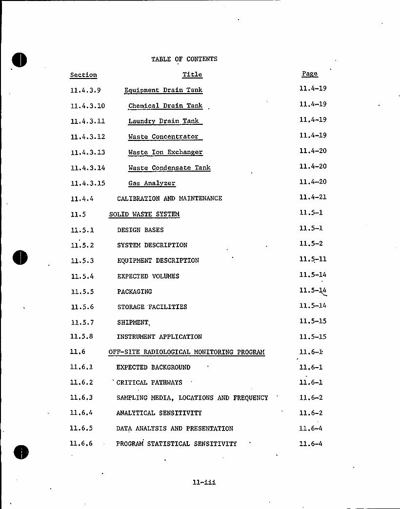
11.4.3.9
11.4.3.10
11.4.3.11
11.4.3.12
11.4.3.13
11.4.3.14
11.4.3.15
11.4.4
11.5
11. 5. 1
11.5. 2
11.5.3
11.5.4
11.5.5
11.5.6
11.5e7
11.5.8
11.6
11.6.1
11.6.2
11.6.3
11.6.4
11.6.5
11.6.6
TABLE OF CONTENTS
Title
E ui ment Drain Tank
Chemical Drain Tank
Laundr Drain Tank
Waste Concentrator
Waste Ion Exchan er
Waste Condensate Tank
Gas Anal zer
CALIBRATION AND MAINTENANCE
SOLID WASTE SYSTEM
DESIGN BASES
SYSTEM DESCRIPTION
EQUIPMENT DESCRIPTION
EXPECTED VOLUMES
PACKAGING
STORAGE 'FACILITIES
SHIPMENT,
INSTRUMENT APPLICATION
OFF-SITE RADIOLOGICAL MONITORING PROGRAM
EXPECTED BACKGROUND
CRITICAL PATHWAYS
SAMPLING MEDIA, LOCATIONS AND FREQUENCY
ANALYTICALSENSITIVITY
DATA ANALYSIS AND PRESENTATION
PROGRAM STATISTICAL SENSITIVITY
~Pa e
11.4-19
11.4-19
11.4-19
11.4-19
11.4-20
11.4-20
11.4»20
11.4-21
1105-1
11.5-1
11.5-2
11.5-11
11.5-14
11.5-14
11.5-14
11.5-15
11.5-15
11.6-1
11.6-1
11.6-1
11.6-2
11.6-2
11.6-4
11.6-4


LIST OF TABLES
Table
11.1-1
ll.1-2
11. 1-3
11. 1-4
11. 1-5
Title
Reactor Coolant Specific Activity
Bases for Reactor Coolant Radioactivity
Crud Specific Activity-Operating Reactors
Long-Lived Iostopes in Crud
Crud Core Residence Time and SpecificActivity
~Pa e
11.1-4
11.1-5
11.1-8
11.1-10
11.1-10
11. 1-6
ll.1-7
11. 2-1
ll.2-2
11.2-3
11. 2-4
Sources of Tritium Production
Nitrogen-16 Production Parameters
Sources and Volumes of Liquid Waste
Design Data for Boron Recovery SystemComponents
Boron Recovery System Process Flow Data
Expected Filter and Ion ExchangerPerformance
11.1-11
11.1-11
11.2-2
11.2-2
11.2-8
11.2-10
lle2-5 Boron Recovery System PerformanceData 11.2-11
11.2-6
lie 2-7
Boron RecoveryConcentrations
Boron RecoveryConcentrationsOperations
System Maximum NuclideDuring Normal Operations
System Maximum NuclideDuring Anticipated
11.2-12
11.2-14
11.2-8 Design Data for Liquid Waste SystemComponents 11.2-19
11.2-9
11.2-10
11.2-11
Liquid Waste System-Pressure,Temperature and Flow Data
Liquid Waste System Expected Performance
Liquid Waste System Normal ActivityDistribution
11.2-21
11.2-23
11.2-24

LIST OF TABLES (CONT'D)
Table
11.2-12
Title
Liquid Waste System AnticipatedOperational Occurrence ActivityDistribution
~Pa e
11.2-26
11.2-13 Assumptions Used in Calculating EstimatedNormal and Anticipated OperationalOccurrence Releases 11.2-28
11.2-14 Estimated Normal and Anticipated OperationalOccurrence Liquid Releases 11.2-34
11.2-15
11.3.1
11.3-2
11.3-3
11; 3-4
Offsite Doses Due to Plant Liquid Releases
Waste Gas System Flow Data Points
Component Data
Gas Collection Header Source PointsP
Estimated Normal and AnticipatedOperational Occurrence GaseousReleases a
1102-2
11.3-4
11.3-'8a
11.3-12
11.3-5
11.4-1
11.4-2
11.5-1
Process Radiation Monitors
Sample Locations and Analysis
11.4-6
11.4-12
Inputs to Solid Waste System Per CoreCycle Based on Continuous Operationwith 1 Percent Failed Fuel 11.5-1
Offsite Doses Due to Plant Gaseous Releases 11.3-15
11.5-2 Concentrator Bottoms Input Activity toSolid Waste System" Per Core Cycle 1 1 ~ 5 3
11. 5-3
11.5-4
Concentrator Bottoms Activity After90 Day Decay
Activity Buildup on Ion Exchange ResinsPer Core Cycle with 1 Percent Failed Fuel
11.5-4
11.5-7
11.5-5 Activity on Ion Exchanger Resins AfterDecay 11.5-8
11.5-6 Activity Buildup on Filter CartridgePer Core Cycle 11.5-9

LIST OF TABLES (CONT'D)
Title ~Pa e
Activity on Filter Cartridges AfterDecay
Design Data for Solid Waste Syst'mComponents
Instrument Application
11.5-M
11.5-16

LIST OF FIGURES
~Fi ere
ll.1-1
11 ~ 2-1
ll.2-2
ll.2-3
11.2-4
11. 2-5
11.3-1
Title
Escape Rate Coefficients
Waste Management System P&I Diagram
Boric Acid Concentrator Package
Waste Management System P&I Diagram
Waste Management System P&I Diagram
Site Plot Plan
Waste Management System P&I Diagram
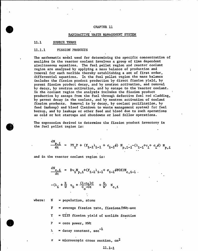
CHAPTER llRADIOACTIVE WASTE MANAGEMENT SYSTEM
11.1 SOURCE TERMS
ll.l.l PISSION PRODUCTS
The mathematic model used for determining the specific concentration ofnuclides in the reactor coolant involves a group of time dependentsimultaneous equations. The fuel pellet region and reactor coolantregion are analyzed by applying a mass balance of production andremoval for each nuclide thereby establishing a set of first order,differential equations. In the fuel pellet region the mass balanceincludes the fission product production by direct fission yield, byparent fission product decay, and by neutron activation, and removalby decay, by neutron activation, and by escape to the 'reactor coolant.In the coolant region the analysis includes the fission productproduction by escape from the fuel through defective fuel rod cladding,by parent decay in the coolant, and by neutron activation of coolantfission products. Removal is by decay, by coolant purification, byfeed (makeup) and bleed (letdown to waste management system) for fuelburnup, and by leakage or other feed and bleed due to such operationsas cold or hot startups and shutdowns or load follow operations.
The expression derived to determine the fission product inventory inthe fuel pellet region is:
dN
NYdf + (f >),< >+ c< >6} N <'>-(A< >+c<+ c S) N
and in the reactor coolant region is:
c 5. = Dc N +(f >), >+ cd >dFDR)NdN
dc i p,i i-1 i-1 i-17
(} +R +~(>-c )C +g)W i C-Ct W ci
where: N = population, atoms
F = average fission rate, fissions/MWt-sec
Y = U235 fission yield of nuclide fraction
P = core power, MWt
-1decay constant, sec
a = microscopic cross section, cm
11.1-1


2thermal neutron flux, neutrons/cm -sec-1~ escape rate coefficient, sec
FCS
branching fraction
time, sec
defective fuel rod cladding, fraction
core coolant volume to reactor coolant volume ratio
purification flow rate during power cycle, lbs/sec
reactor coolant mass during power cycle, lbs
~ resin efficiency of chemical and volume control system ionexchanger for a given nuclide, fraction
C0
~ initial boron concentration, ppm
~ boron reduction rate by feed and bleed, ppm/seccompensating for fuel burnup
leakage or other feed and bleed from reactor coolant lbs/sec
Subscripts
p, pellet region
c, core regionx 133
designates the nuclide parameters (i.e., 54 )Z133i-1 designates the parent nuclide parameters (i.e., 53 )
The model does not'nvolve the fuel plenum and gap region of the corebecause the escape rate coefficients represent the overall release fromthe fuel pellets to the reactor coolant. Plenum and gap regionactivities are calculated using diffusion theory as described in Section15.4. The productions terms involving the microscopic cross sectionare used only to produce Cs " from CS , the stable end product ofthe 133 chain. The removal term involving the microscopic cross sectionis used only with Xe135 and only in the pellet region because of insigni-ficant effects on other nuclides and in the coolant region.
The fission product'ctivity concentrations used as basic source termsare given in Table 11.1-1. The data used for these calculations aregiven in Table 11.1-2. The effects of expected plant operation as aresult of start-ups and shutdowns are simulated by using a constantliquid waste rate of 1.2 gpm or 617,000 gallons per year. The tritiumconcentration is based on no recycle of concentrator distillate.
11.1-2

,r
11

The primary factor in determining the fission product inventories isthe escape rate coefficient. This is an empirical coefficient whichwas derived from experiments. initiated by Bettis and performed in theNRX and MTR reactors.~ ~ The escape rate coefficients derived fromthese data are given in Table 11.1-2. The escape rate coefficientswere obtained from test rods which were operated at high linearheat rates. The linear heat rates were uniform over the test sectionswhich were 10.25 inches in length. The exact linear heat rates werenot precisely known but post-irradiation showed that some tests rodshad experienced centerline melting. Later tests were conducted in theNRX reactor to determine the effect of rod length on the release offission gases and iodines from defective fuel.< ~ A by-product ofthese experiments was the effect of linear heat rate on the escaperate coefficient. The escape rate coefficient for several nuclidesas a function of the linear heat rate is shown in Figure 11.1-1.Also shown in Figure ll.l-lare the escape rate coefficients usedfor noble gases and halogens. Since the average heat rate for afuel rod will be well below the crossover points in Figure 11.1-1,which is above 17 kilowatts per foot in each case, the presentlyused escape rate coefficients are conservative.
11. 1-3
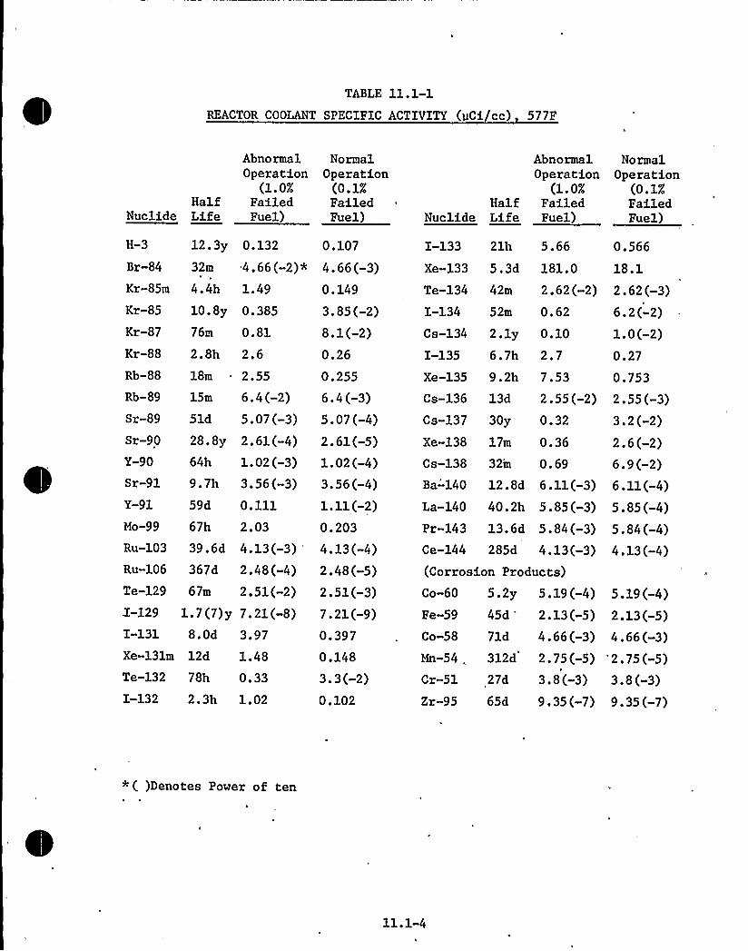
TABLE 11.1-1REACTOR COOLANT SPECIFIC ACTIVITY (gCi/cc) 577F
HalfNuclide Life
AbnormalOperation
(1.0%FailedFuel)
NormalOperation
(0.1%FailedFuel)
HalfNuclide Life
AbnormalOperation
(1.0%FailedFuel)
NormalOperation
(0.1%FailedFuel)
H-3
Br-84
12 'y32m
0.132 0.107
4.66(-2)* 4.66(-3)0.149
Kr-85
Kr-87
Kr-88
Rb-88
10.8y76m
0.385
0.81
2.8h 2.618m 2.55
3.85(-2)8.1(-2)0.26
0.255
Kr-85m 4.4h 1.49
Cs-134
I-1352.1y 0.10
6.7h 2.7Xe-135 9.2h 7.53
I-133 21h 5.66
Xe-133 5.3d 181.0
Te-134 42m 2.62(-2)I-134 52m 0.62
0.566
18.1
2.62(-3)6.2(-2)1. 0 (-2)0.27
0.753Rb-89 15m
Sr-89
Sr-90
Y-90
Sr-91
51d
28.8y64h
9.7h
6. 4 (-2)5.07(-3)2.61(-4)1.02(-3)3.56(-3)
Y-91
Mo-99
59d 0.111
67h 2.03RU-103 39.6dRU-106 367d
Te-129 67m
I-129I-131
1.7(7)y8.0d
Xe-131m 12d
4.13(-3)2.48(-4)2.51(-2)7.21(-8)3.97
1.48
I-132 2.3h 1.02
Te-132 78h 0.33
6. 4 (-3)5.07(-4)2.61(-5)1.02(-4)3.56(-4)1.11(-2)0.203
4.13(-4)2.48(-5)2.51(-3)7.21(-9)0.397
0.148
3.3(-2)0.102
Cs-136 13d 2.55(-2)Cs-137 30y 0.32
Xe-138 17m 0.36Cs-138 32m 0.69Ba-'140 12.8d 6.11(-3)La-140 40.2h 5.85(-3)Pr-143 13.6d 5.84(-3)Ce-144 285d 4.13(-3)(Corrosion Products)Co-60 5.2y 5.19(-4)Fe-59 45d 2.13(-5)Co-58 71d 4.66(»3)Mn-54, 312d 2.75(-5)Cr-51 27d 3.8(-3)Zr-95 65d 9.35(-7)
2.55(-3)3.2(-2)2.6(-2)6.9 (-2)6.11(-4)5. 85 (-4)5. 84 (-4)4.13(-4)
5.19(-4)2. 13 (-5)4.66 (-3)
'2.75(-5)3.8 (-3)9.35(-7)
*( )Denotes Power of ten
11.1-4


TABLE 11.1-2
BASES FOR REACTOR COOLANT RADIOACTIVITY
Core power level, Hwt
Fuel cycle full power days
Percent failed fuel
2700
357
1.0
CVCS purification ion exchangerdecontamination factor
Purification flow rate (CVCS purificationion exchanger), gpm
10
40
Effective purification flow rate for lithiumand cesium remova, gpm
-1Fission product es cape rate coe fficein ts, sec(Based, on centerline melting of fuel)
Noble gases
Halogens, Cs
Te, Mo.
All others
6.5 x 10
2.3 x 10
1.4 x 10
1.4 x 10
Feed and bleed liquid waste for fuelburnup, gal/yr 216,000
Other feed and bleed liquid waste,gal/yr
Thermal neutron flux, n/cm sec3
Reactor coolant volume, ft3
6170000
„,4.3 x 10
9662.
11.1-5
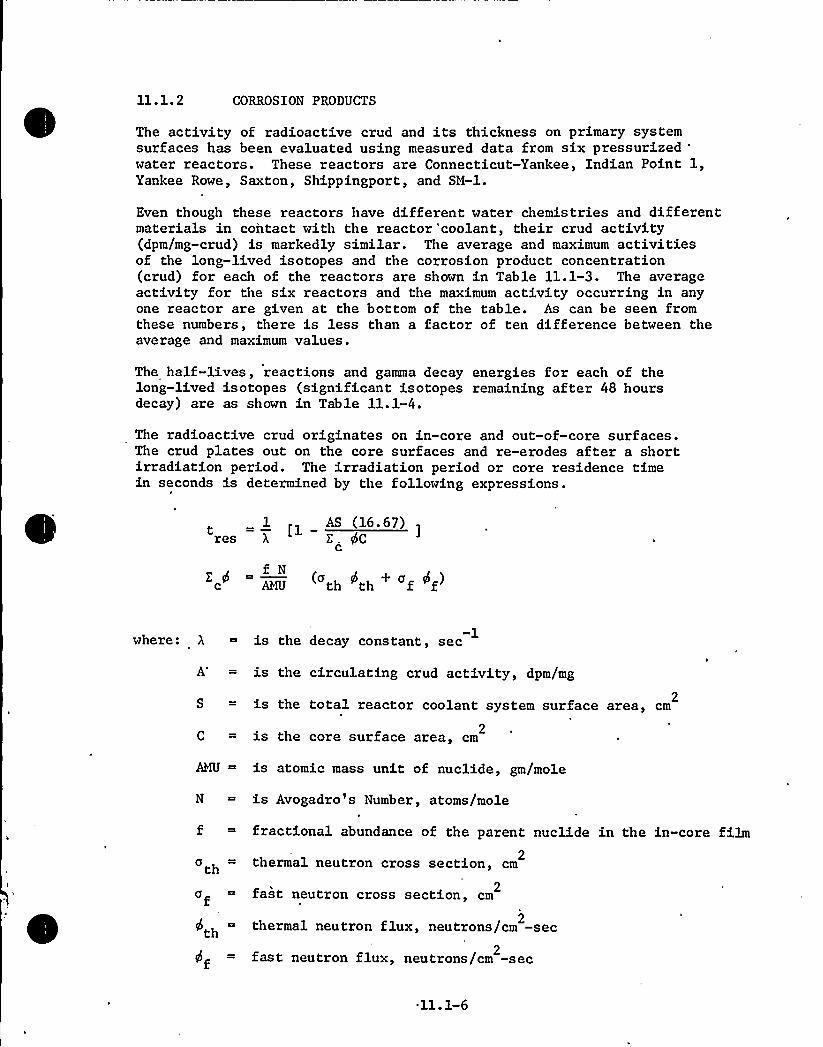
11.1.2 CORROSION PRODUCTS
The activity of radioactive crud and its thickness on primary systemsurfaces has been evaluated using measured data from six pressurized
'aterreactors. These reactors are Connecticut-Yankee, Indian Point 1,Yankee Rowe, Saxton, Shippingport, and SN-1.
Even though these reactors have different water chemistries and differentmaterials in contact with the reactor 'coolant, their crud activity(dpm/mg-crud) is markedly similar. The average and maximum activitiesof the long-lived isotopes and the corrosion product concentration(crud) for each of the reactors are shown in Table 11.1-3. The averageactivity for the six reactors and the maximum activity occurring in anyone reactor are given at the bottom of the table. As can be seen fromthese numbers, there is less than a factor of ten difference between theaverage and maximum values.
The half-lives, reactions and gamma decay energies for each of thelong-lived isotopes (significant isotopes remaining after 48 hoursdecay) are as shown in Table 11.1-4.
The radioactive crud originates on in-core and out-of-core surfaces.The crud plates out on the core surfaces and re-erodes after a shortirradiation period. The irradiation period or core residence timein seconds is determined by the following expressions.
1 AS (16.67)res X Z. 4Cc
( th <th + <f ~f)f N
-1where: A = is the decay constant, sec
is the circulating crud activity, dpm/mg
2is the total reactor coolant system surface area, cm
is the core surface area, cm2
N
tha f~th =
f
is atomic mass unit of nuclide, gm/mole
is Avogadro's Number, atoms/mole
fractional abundance of the parent nuclide in the in-core film
thermal neutron cross section, cm2
2fast neutron cross section, cm
thermal neutron flux, neutrons/cm -sec2
fast neutron flux, neutrons/cm -sec2
11.1-6

Residence time for each nuclide for each of the six reactors was evaluatedusing core and system parameters for each plant along with the maximum
activity given in Table 11.1-3 for any plant. The longest resultingresidence time for each nuclide is listed in Table 11.1-5. The maximum
crud specific activities (dpm/mg) for the various long-lived isotopes inthe crud are as shown in Table 11.1-5 based on maximum core residencetimes and parameters for the nuclear steam supply system (NSSS) .
The activity concentrations of the crud in the reactor coolant aredetermined by utilizing the maximum specific activities given in Table11.1-5 and the average crud concentration (56 ppb) identified in Table11.1-3. The crud activity is shown in Table ll.l-lalong with thefission production activity concentrations.
11.1.3 TRITIUM PRODUCTION
Tritium is produced in the coolant or enters the coolant from a numberof sources. One source is the fissioning of uranium within the fuelwhich yields tritium as a ternary fission .product. Since Zircaloyfuel cladding reacts with tritium to form zirconium hydride, no tritiumdiffuses through the cladding (3) (4). Therefore, the tritium releasedto the coolant from the fuel is only from defective fuel.
Tritium is also produced by the reaction of neutrons with boron in thecontrol element assemblies (CEA's). Data from operating plants usingB4C control rods indicates that no tritium is released from thecontrol rods. The tritium may combine with carbon to form hydrocarbonsand/or with lithium to form lithium hydride thereby preventing diffusionthrough the NiCiFe cladding. The low internal temperature of the B4Ccontrol rods may also prohibit tritium diffusion. To account for possiblecontrol rod cladding defects, it is assumed that one percent of thetritium produced in the CEA's is released to the coolant.
Major sources of tritium are the activation of boron, lithium, deuterium,and nitrogen within the reactor coolant. Boron in the form of boricacid is used in the coolant for reactivity control and is the major sourceof tritium. Lithium is produced in the coolant as a result of neutron-boron reaction. Lithium may be added as a pH control agent. The deuteriumis a natural constituent of water. Nitrogen may be present due toaeration of the coolant during shutdown and due to aerated makeup water.
Table 11.1-6 identifies the contribution of each source to the totaltritium concentration.
11.1.4,
NITROGEN-16 PRODUCTION
Nitrogen-16 is produced from the reaction of fast neutrons with oxygenforming Oxygen-17 which is very unstable and decays by emitting a protonthus forming Nitrogen-16. Nitrogen-16 has a half life of 7.35 secondsand emits a gamma ray of high energy 82 percent of the time. The gammaenergies are 6.13 and 7.10 Mev in a ratio of 12.5 to 1. The nitrogenactivity at the reactor vessel coolant outlet nozzles is 3.02 x 10"dpm/cm . The basis for this result is tabulated in Table 11.1-7. *3.
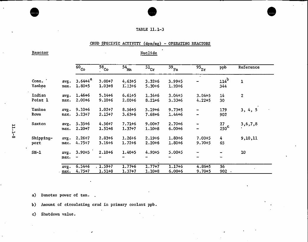
TABLE 11. 1-3
Reactor
CRUD SPECIFIC ACTIVITY (d m/m ) — OPERATING REACTORS
Nuclide
60 58Co 54Mn 51
Cr59
Fe95 Zr ppb Reference
Conn.Yankee
avg.max.
3.64+41.80+5
3.00+71.03+8
4.63+51.13+6
3.32+65.30+6
3.99+51.20+6
114 1344
IndianPoint 1
avg.max.
1.46+62.00+6
5.14+69.10+6
6. 61+52. 00+6
1.34+68. 21+6
3.04+53.33+6
3.04+54.22+5
1430
YankeeRowe
avg.max.
9.10+63.23+7
1.02+72.15+7
8.56+53.63+6
3. 19+67.68+6
9.73+51.44+6
179902
3, 4, 5
Saxton avg.max.
5.35+62.20+7
4. 56+71.51+8
7. 71+61.37+7
9.00+71.10+8
2. 70+66.00+6
27 3,6,7,8250
ICO Shipping-
portavg. 2.26+7 2.83+6 1.26+6max. 4.75+7 3.16+6 1.72+6
2.19+62.20+6
1. 80+61. 80+6
7.00+5 49.70+5 65
9,10,11
SM-1 avg. 3.90+5 2.10+6 1.40+5max+
4. 90+5 5. 00+5 10
avg. 6.54+6 . 1.59+7 1.77+6 1.77+7 1.17+6max. 4.75+7 1.51+8 1.37+7 1.10+8 6.00+6
4.86+5 569.70+5 902
a) Denotes power of ten.
b) Amount of circulating crud in primary coolant ppb.
c) Shutdown value.

LIST OF REFERENCES TO TABLE 11.1-3
Connecticut Yankee Monthly Operation Reports No. 68-2through No. 69-1.
Indian Point 1 Semi-Annual Operation Reports, 9/66 through3/68, Docket No. 50-3.
Corrosion Product Behavior in Stainless-Steel-Clad WaterReactor Systems, Nuclear Applications, Vol. 1, October 1965.
Chemical Evaluation of Yankee Core I Fuel Cladding CorrosionProducts, Picone L. F., Taylor G. R., August 1966, WCAP-6072.
Large Closed-Cycle Water Reactor Research and DevelopmentProgram, Progress Report 4/1/63 — 6/30/63, WCAP-3739.
Large Closed-Cycle Water Reactor Research and DevelopmentProgram, Progress Report 1/1/65 — 3/31/65, WCAP-3269-12.
The Saxton Chemical Shim Experiment, Weisman J., Bartnoff S.,July 1965, WCAP-3269-24.
Large Closed-Cycle Water Reactor Research and DevelopmentProgram, Progress Report 4/1/65 — 6/30/65, WCAP-3269-13.
Decontamination of the Shippingport Atomic Power Station, AbramsC.S., Salterelli E. A., January 1966, WAPD-299.
Boiling Water Reactor Technology, Status of the Art ReportVolume II, Water Chemistry and Corrosion, C. R. Breden, February1963, ANL-6562.
Radiation Buildup on Mechanisms and Thermal Barriers, E. Weingart,June 1963, WAPD-PWR-TE-145.
11.1-9

TABLE 11.1-4
IONG-LIVED ISOTOPES IN CRUD
Nuclide 1/2Parent Reaction e/dis E(Mev
60
58C
54Mn
51CCr
59F
95Z
5.28y
7ld314d
27.8d
45d
65d
59
Ni54
Fe
50Cr
58
94Zr
N,Y
N, P
N7 P
N, Y
N,
2.00
1.00
1.00
0. 10
1.00
2.00
1.25
0. 81
0.84
0.32
1.18
0. 75
TABLE 11.1-5
CRUD CORE RESIDENCE TIME AND SPECIFIC ACTIVITY
~Zsoeo e
60Co
58
54M
59F
51CCr
95ZZr
(b)res
300d
62d
74d
160d
44d
0.5d
Activit d m/m )
2.85 (+7)
2.56 (+8)
1.52 (+6)
1.18 (+6)
2.09 (+8)
5.11 (+4)
(a) Denotes power of ten.(b) Based en maximum crud activities from operating plants.(c) Based on maximum crud activity levels'nd parameters for
for this plant.
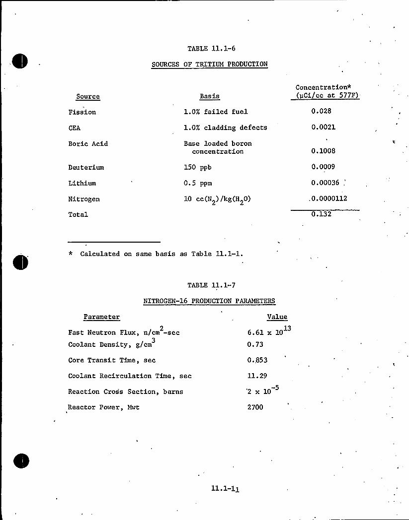
TABLE ll.1-6
SOURCES OF TRITIlM PRODUCTION
Source
Fission
CEA
Boric Acid
Deuterium
Lithium
Nitrogen
Total
Basis
l. 0% fai led fuel
1.0% cladding defects
Base loaded boronconcentration
150 ppb
0.5 ppm
10 cc(N2) /kg(H20)
Concentration*(pCi/cc at 577F)
0.028
0.0021
0.1008
0.0009
0.00036,"
,0.0000112
0.132
* Calculated on same basis as Table 11.1-1.
TABLE 11.1-7
NITROGEN-16 PRODUCTION PAKQKTERS
Parameter
2Fast Neutron Flux, n/cm -sec
Coolant Density, g/cm3
Core Transit Time, sec
Coolant Recirculation Time, sec
Reaction Cross Section, barns
Reactor Power, Mwt
Value
6.61 x 10
0.73
0 ..853
11.'29
"2x 10
2700

FUEL EXPERIENCE
Current operation of stainless steel clad fuel rods in the ConnecticutYankee reactor shows fuel failure rates on the order of 0.01 percent.Zircaloy-clad U02 fuel in the Obrigheim reactor in Germany sustained .
a fuel failure rate just over 0.1 percent in its first cycle; thishas fallen in the second cycle to essentially zero (<0.001 percent) .
The fuel failure rate in the Dresden 1 reactor over a nine-year periodhas averaged <O.l percent with the rate more recently being even lower.Fuel in the Mihama reactor in Japan and the Point Beach reactor hasexceeded the burnup at which failures in fuel of similar design wereobserved in Ginna, without exhibiting increases in coolant activity(indicative of fuel defects).
The fact that widespread defects in some reactors, associated withfuel clad contamination have now been recognized and correctivemeasures taken, provides further assurance that failures at thisfrequency from this cause will not occur in the future. Existinglicensing regulations limit coolant activity to that associated with1 percent failed fuel. Over the lifetime of an operating reactor,it is expected that coolant activity levels corresponding to 0.1percent failed fuel will predominate.
11.1.6 LEAKAGE SOURCES
There are several potential sources of leakage from the plant systemsthat can contribute to the total release to the environs. If leakageoccurs from systems containing reactor coolant, gaseous radioactivitycould be released via several pathways.
Normal leakage from the reactor coolant system exposed to the containmentatmosphere is expected to be 40 gallons per day or less. Nuclideactivities given in Table 11.1-1 are used as source terms. Underequilibrium conditions, 10 percent or less of the iodine and particulatesleaking into the containment remains in the atmosphere and is availablefor release. The other 90 percent of the iodine and particulate iseither plated out in the containment or remains in the liquids and iscollected in the containment sump. The annual average exposed leakageinto the reactor auxiliary building is expected to be 10 gallons perday or less. The specific activity of the leakage is indicated inTable 11.1-1 with 1 percent failed fuel. The reactor auxiliary building,turbine area and condenser air effector equipment airborne and particulateconcentrations are evaluated on the basis of 20 gallons per day primary-to-secondary estimated normal leakage and 120 gpd anticipated operationaloccurrence leakage with nuclide specific activities as identified inTable 11.1-1.
Means of detecting leakages are discussed in Section 5.2..4.
Estimated liquid and gaseous released due to leakage from various systemscontaining radioactivity are discussed in Sections 11.2.5 and 11.3.5,respectively.

REFERENCES FOR SECTION 11.1
J. D. Eichenberg, "Effects of Irradiation on Bulk U02", WAPD-183,October 1957.
G. M. Allison and H. K. Rae, "The Release of Fission Gases andIodines from Defective U02 Fuel Elements of Different Lengths",AECL-2206, June 1965.
James M. Smith, Jr. "The Significance of Tritium in WaterReactors", GE, APED, 9/19/67.
Joseph W. Ray et. al., "Investigation of Tritium Generation andRelease in PM Nuclear Power Plants", BMI-1787, 10/31/66.'

107
Xe, Kr VALUE
10-8I VALUE
Xe-133
Kr-89
'". 109
o
C)CD
10-10
cC
I-131
I-135
I-133
10-11
1 2 3 4 5 6 7 8 9 10
LINEAR HEAT RATE, kw/ft
FLORIDAPOWER 8 LIGHT CO.
Hutchinson Island PlantEscape Rate Coefficients
Figure
ll. 1-1

11.2 LI UID WASTE SYSTEMS
11.2.1 DESIGN BASES4
The boron recovery system and the liquid waste system (integral parts ofthe waste management system) are designed to:
a) process the various potentially radioactive liquid wastes such 'thatthe radioactivity release to the environs during normal operation willbe as low as practicable. The numerical design objectives for releasesduring normal operation are to limit average annual liquid activityrelease quantity to 5 Ci. and average annual activity release con-centration to 2 x 10 8 pCi/cc excluding tritium and dissolved fissionproduct gases.
b) Limit the annual average tritium discharge concentration to 5 x 10 ~
-6
pCi/cc in accordance with the proposed Appendix I to 10 CFR 50.
c) Limit releases due to anticipated operational occurrences within 10CFR 20 limits.
11.2.2 SYSTEM DESCRIPTION
Liquid waste influent to the waste management system, shown in Table 11.2-1is segregated by chemistry and/or probable source activity for more efficientprocessing. Tritiated, hydrogenated, borated reactor coolant quality wastesof potentially high activity are mainly processed in the boron recoverysystem. Aerated, chemically contaminated, and low activity liquid wastesare received and processed separately in the liquid waste system.Table 9.3-6 lists the drains routed to the drain tanks.
11.2.2.1 Boron Recove S stem
The major influent to the boron recovery system is reactor coolant from thechemical and volume control system letdown due to feed and bleedoperations for shutdown, startups, and boron dilution over core life.Reactor coolant quality water from valve and equipment leakoffs, drainsand relief valve within the containment are collected in the reactor draintank and subsequently processed by this system. Reactor coolant fromleakoffs and drains in the reactor auxiliary building are collected. in theequipment drain tank of the liquid waste
system.'he
boron recovery P6I diagrams are shown on Figures 11.2-1, 11.2-2, and11.2-3. The borated and hydrogenated water discharged by the reactor drainpumps or diverted by the chemical and volume control system volumecontrol tank diversion valve (V-2500) is sent to the flash tank wheredissolved hydrogen and fission gases are stripped by a counter currentflow of nitrogen gas from the liquid and discharged to the gas decay tanks.Hydrogen is stripped from the water so that an explosive gas mixturedoes not occur in subsequent process equipment. Use of nitrogencover gas in the holdup tanks provides additional protection. The nitrogenstripping medium maintains a slight overpressure in the flash tank to,prevent air in-leakage, thus precluding potential formation of an
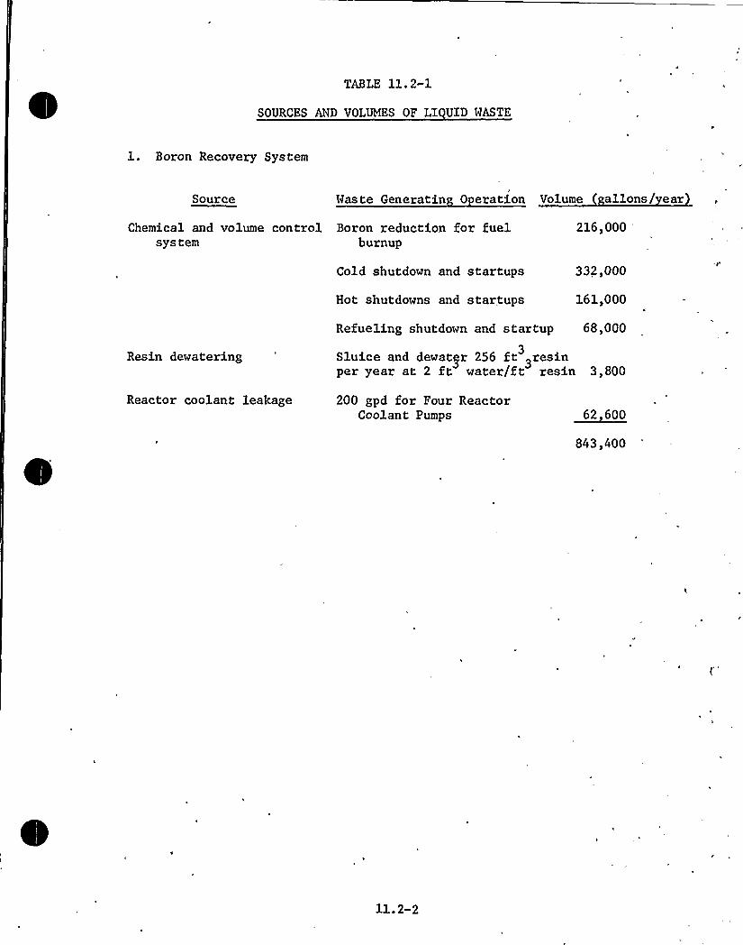
TABLE 11. 2-1
SOURCES AND VOLUMES OF LI UID WASTE
1. Boron Recovery System
Source Waste Generatin 0 eration Volume allons/ ear)
Chemical and volume control Boron reduction for fuelsystem burnup
216,000
Cold shutdown and startups 332,000
Hot shutdowns and startups 161,000
Resin dewatering
Refueling shutdown and startup 68,000
Sluice and dewatyr 256 ft 3resin3
per year at 2 ft water/f t resin 3,800
Reactor coolant leakage 200 gpd for Four ReactorCoolant Pumps 62 600
843,400
ll.2-2
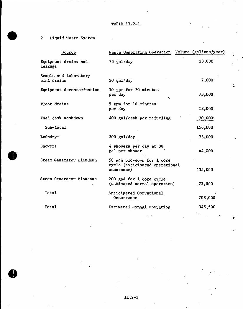
TABLE 11.2-1
2. Liquid Waste System
Source Waste Generatin 0 eration Volume ( allons/ ear)
Equipment drains andleakage
75 gal/day 28,000
Sample and laboratorysink drains 20 gal/day 7,000
Equipment decontamination 10 gpm for 20 minutesper day 73,000
Floor drains
Fuel cask washdown
Sub-total
Laundry"
Showers
Steam Generator Blowdown
5 gpm for 10 minutesper day
400 gal/cask per refueling
200 gal/day
4 showers per day at 30gal per shower
50 gph blowdown for 1 corecycle (anticipated operationaloccurance)
18,000
30 000
156,000
73,000
44,000
435,000
Steam Generator Blowdown 200 gpd for 1 core cycle(estimated normal operation) 72 500
Total
Total
Anticipated OperationalOccurrence
Estimated Normal Operation
708,000
345,500
11.2-3


explosive gas mixture in the flash tank. In the event of a high liquidlevel in the flash tank, the influent is automatically diverted to theholdup tanks. A low level in the flash tank stops the flash tank pumpsautomatically. The flash tank high and low pressure and level alarms areannunciated in the control room. A flow switch in the inlet line to theflash tank automatically opens the nitrogen supply valve and starts theflash tank pumps when water enters the tank. The degassed liquid isautomatically pumped from the flash tank to the holdup tanks. The holduptanks provide sufficient storage capacity to accumulate discharges untila sufficient volume is available for further processing on a batch basis.The radioactivity of the liquid is significantly reduced during storageby natural decay of the short half-lived radionuclides. During thisperiod any degassification and radioactive decay can be monitored by liquidsample analysis or periodic sampling of the tank gas space with the gasanalyzer. Air in-leakage to the holdup tanks is precluded by a nitrogenoverpressure maintained in the tanks. As the holdup tanks fill, nitrogenis displaced to other interconnected holdup tanks or to the gas collectionheader. The holdup tanks have high and low level and pressure alarms whichare annunciated in the control room. In the event process fluid has tobypass the flash tank due to malfunction of the flash tank controls orpumps, the stored liquid can be recirculated by the holdup drain orrecirculation pumps to the flash tank to remove any hydrogen once theflash tank returns to service. The holdup recirculation pump suppliesflushing water to the preconcentrator ion exchangers and spent resin tankduring resin sluice operations.
Normally, the contents of the holdup tanks are transferred to the boricacid concentrator through the preconcentrator filter and preconcentratorion exchanger. If necessary, the contents of one holdup tank may berecirculated through a preconcentrator filter and ion exchanger whilea second holdup tank contents are processed through the other precon-centrator filter and ion exchanger prior to discharge to the boricacid concentrators. The holdup pumps and holdup recirculation pump arestopped on low holdup tank level. The boric acid concentrators haveboth automatic sampling and local grab sample provisions to ensurecontrol of the effluent chemistry.. The boric acid concentrators providea level signal that, after the initial manual pump start, automaticallystarts and stops the holdup or holdup recirculation pump aligned toeither boric acid concentrator. The two boric acid concentrators havea very low usage factor (approximately 4 percent) and thus provide ahigh system reliability and availability.
The bottoms from each boric acid concentrator are pumped via the boricacid discharge strainer to the boric acid holding tank for temporarystorage and sampling. The recovered boric acid may then be returnedto the makeup tanks for recycle or discharged to the drumming stationfor ultimate offsite disposal, if recycle is not desired.
The concentrator distillate passes through one of the two boric acidcondensate ion exchangers to remove boron carryover and into one ofthe two boric acid condensate tanks. While one boric acid condensatetank is filling, the other is sampled and discharged. In the unlikelyevent that the contents of the tank do not meet the chemical orradioactivity limitations, the contents can be recycled to the holduptanks for further processing or recycled through the boric acid condensateion exchangers.
11.2-4

A local high and low level alarm is provided on the boric acid condensatetanks. The boric acid condensate pumps automatically stop on low waterlevel in the tanks.
Prior to controlled discharge of the treated liquid waste, the fluidmust be analyzed and its activity verified as acceptably low. Dischargeis accomplished through an effluent radiation monitor which records therelease activity level and automatically terminates discharge on highradiation. If reuse in the plant is desired, the fluid in analyzed foracceptability of both chemistry and activity.
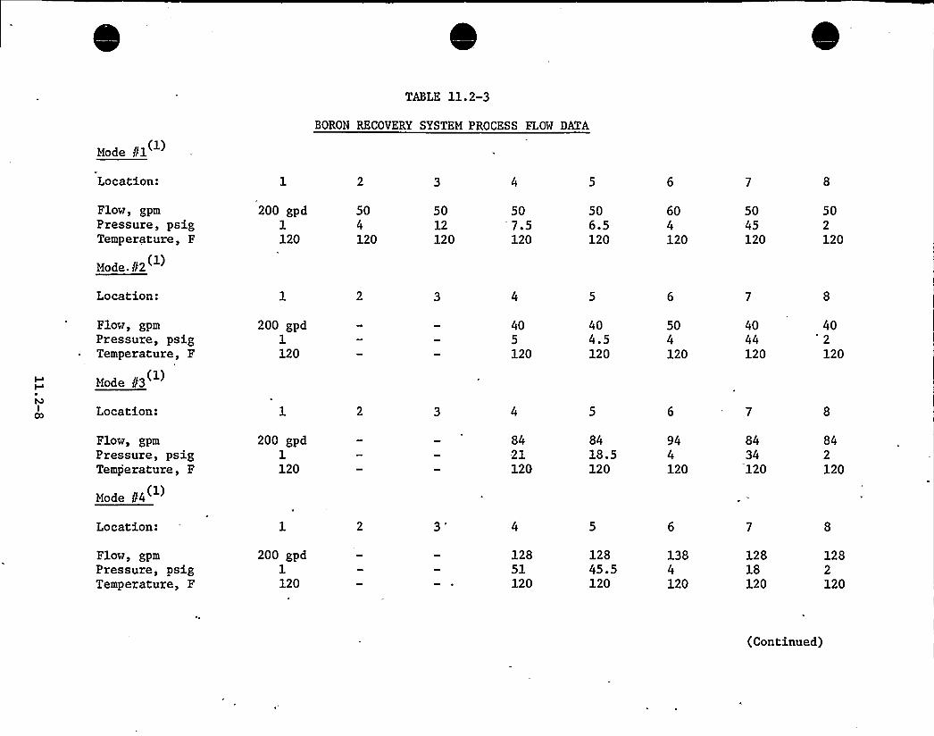
Design data for the major components are listed in Table 11.2-2. Flow,temperature, and pressure data are given in Table 11.2-3 with thelocations corresponding to process points on Figures 11.2-1, 11.2-2,11.2-3.
The nuclide concentrations for normal operation and for anticipatedoperational occurrences adjusted to 70F are indicated for selectedlocations in the chemical and volume control system gn'.Tables11.2-6 and 11.2-7, respectively. The selected locations are indicatedby the process points on Figures 11.2-1, 11.2-2, and 11.2-3. Normaloperation is defined as operating with 0.1 percent failed fuel, andanticipated operation all occurrences is defined as operation with 1percent failed fuel.
Analysis is made assuming that the activities in Table 11.1-1 exist inthe coolant upstream of the purification equipment in conjunction withthe expected equipment performance given in Table 11.2-4 and in Table11.2-5.
Systems similar in function and design to the boron recovery systemdescribed herein have been used successfully at plants such as ConnecticutYankee and Ginna. Even with si.gnificant coolant radioactivity at Ginna,releases have been controlled well within the 10 CFR 20 limits.All process components have been used extensively in the nuclear industryto remove radioactive contaminants from liquids. The performance ofprocess units used in the analysis is in agreement with general industryexperience.
11.2.2.2 Li uid Waste S stem
The liquid waste system is shown on Figure 11.2-4. Liquid waste includethose from the laboratory sink drains, decontamination area drains,floor drains, building sumps, laundry effluent, and contaminated showers.In the event of a primary-to-secondary leak, the steam generator blowdownis processed by this system. The wastes are segregated for batch processingby collection in the equipment drain tank, chemical drain tank, and laundrydrain tanks.
Low activity, aerated, and potentially dirty liquid drains and building sumpsdischarge to the equipment drain tank. Low activity chemical drains fromthe sampling system, decontamination drains, and chemical laboratory drains
11.2-5

TABLE 11.2-2
DESIGN DATA FOR BORON RECOVERY SYSTEM COMPONENTS
QuantityTypeDesign Pressure, psigDesign Temperature, FNormal Operating Pressure, psigNormal Operating Temperature, FResin Volume, ft3MaterialsASME Code, Section
Preconcentrator
2Deep Resin Bed1502004010032SS
VIII
Boric AcidCondensate
2Deep Resin Bed1502002512032SS
VIII
2.
I
Tanks
QuantityInternal Volume, galDesign Pressure, psigDesign Temperature, FNormal Operating Pressure, psigNormal Operating Temperature, FBlanket GasMaterialASME Code, Class or Division
ReactorDrain
11600
25'50
0.5120NitrogenSS
III,C
Flash
1400152500.5120NitrogenSS
III,C
~Holdu
440,000102400.5(psia)120Nitrogen
- SS
VIII,1
Boric AcidCondensate
2
7,300Atmos.250Atmos.120
SS
None
Boric AcidHoldin
12,400Atmos.200Atmos.150
SS
None
3. ~Pum a
Quantity-Full CapacityTypeDesign Pressure, psigDesign Temperature, F
Flash Tank
2Centrifugal
'50
200
Reactor Drain
2Centrifugal150200
Holdup Drain,Holdup Recir.Boric Acid Cond.
5Centrifugal150200
Boric AcidHoldin
2Centrifugal150200


TABLE 11.2-2 (Cont.)
3. ~P)s Flash Tank Reactor Drain
Holdup Drain,Holdup Recir.Boric Acid Cond.
Boric AcidHoldin
Design ConditionsFlow, gpmHead, ft
Wetted MaterialsSeal TypeMotor HorsepowerMotor Voltage,. voltASME Pump and Valve Code, Section
15051SS
Mechanical7.5460III,C
50140SS
Mechanical5460III,C
50140SS
Mechanical5460None
5096SS
Mechanical'5
460None
4. Filters Preconcentrator
I
I
QuantityType of ElementsRetention of 2 micron particles, %
Design Pressure, psigDesign Temperature, FDesign Flow, 'gpmMaterialASME Code, Section
2Replaceable Cartridge98150200100Stainless SteelVIII
5. Boric Acid Concentrator
QuantityDesign Pressure,
psig'esignTemperature, FDesign Flow, gpmCooling Water Flow Rate, gpm.Steam Required at 15 psig, lb/hrASME Code, Section
2802502065013,000VIII

~ '
Mode //1
TABLE 11.2-3
BORON RECOVERY SYSTEM PROCESS FLOW DATA
Location:
Flow, gpmPressure, psigTemperature, F
Mode /f2
200 gpd1120
504120
5012120
50'.5120
506.5120
604120
5045120
502120
Location:
Flow, gpmPressure, psigTemperature, F
Mode 83
200 gpd1120
405120
404.5120
504120
4044120
40'2120
Location:
Flow, gpmPressure, psigTemperature, F
Mode f34
200 gpd1120
8421120
8418.5120
944120
8434120
842120
Location:
Flow, gpmPressure, psigTemperature, F
200 gpd1120
12851120
12845.5120
1384120
12818120
1282120
(Continued)

Mode 85 (1)
TABLE 11.2-3 (Cont.)
Location: 12 13 14 15 16 17 18 19 20 21
Flow, gpm— Pressure, psig
Temperature, F
Mode 86
Location:
20 20 203 65 62120 120 120
9 10
20 0-1060 5120 -120
15a 16a
16-195120
16-19 502 4120 120
50 5060 10120 120
Flow, gpmPressure, psigTemperature, F
Mode 87
50 50 50 50 504 32 27 24 20120 120 120 120 120
Location: 22 23
-Flow, gpmPressure, psigTemperature, F
50 504 40150 150
NOTES:
(1) The modes of operation are defined as follows:
Mode No. Descri tion
12345
67
Processing RDT ContentsCVCS Normal purification VCT Diversion ProcessingCVCS Intermediate Purification VCT Diversion ProcessingCVCS Maximum Purification VCT Diversion ProcessingProcessing holdup tank contents via the boric acid
ConcentratorHoldup Tank Contents RecirculationPumping BAHT Contents to the BAMT in the CVCS.
(2) The pressureThe pressure
drop across the filters and ion exchangers willvary with loading.drops are typical.

TABLE 11.2-4
EXPECTED FILTER AND ION EXCHANGER PERFORMANCE
Chemical and VolumeControl S stem
Boron Recovery WasteProcessin S st'em
Nuclide Filter DF Ion Exchan er DF Filter DF Ion Exchan er DF
Br-84
Rb-88
Rb-89
Sr-89
Sr-90
Y-90
Sr-91
Y-91
Mo-99
Ru-103
Ru-106
Te-129
I-129I-131Te-132
I-132I-133Te-134
I-134Cs-134
I-135Cs-136
Cs-137
Cs-138
Ba-140
La-140
Pr-140
Ce-144
Co-60
Fe-59
Co-58
Mn-54
Cr-51
Zr-95
10
10
10
10
10
10
10
1
10
10
1
10
10
10
10
10
10
10
10
10
10
10
1
10
1
10
10
10
10
10
10
10
10
10
10
10
10
10
10
10
10
10
10
10
10
10
10
10
10
10
10,
10
10
10
10
10
10
11. 2-10

TABLE 11.2-5
BORON RECOVERY SYSTEM PERFORMANCE DATA
Flash Tank DF for Fission Gases
Boric Acid Concentrator
DF for Liquid (Influent to Distillate)DF for Fission Gases
2005
Holdup Tank Delay Factor, days
Annual System Condensate Discharged to GOD(1)
Volume, gal.Activity, Curies H-3
Dissolved Fission Product GasesAll Others
843,00033924,5000.89
Note: (1) The volume and activity values obtained are based on843,000 gals of waste to BMS with 1% failed fuel.


BORON RECOVERY SYSTEM BRS)
TABLE 11.2-6
MAXIMUMNUCLIDE CONCENTRATIONS (70F) DURING NORMAL OPERATIONS (uCi/cc)
Nuclide
H-3
Br-84
Kr-85m
Kr-85
Kr-87
Kr-88
Rb-88
Rb-89
Sr-89
SR-90
Y-90
CVCS 6BRS 1 CVCS 7
1. 22 (-1)1.12(-1)3.59(-1)3.52(-1)8.85(-3)7.00(-4)3.60(-2)1. 41(-4)
1.22(-1)1.12(-1)3.59(-1)3.52(-1)8. 85 (-1)7.00(-4)3.60(-2)1.41(-4)
1. 48 (-1) 1. 48 (-1)6. 43 (-3) 6. 43 (-3)2.05(-1) 2.05(-1)
CVCS 10BRS 23451.48(-1)6.43(-6)2. 05 (-1)1. 22 (-1)1.12(-1)3. 59 (-1)3.52(-1)8. 85 (-1)7.00(-6)3.60(-4)1.41(-4)
1.48(-1)6.43(-6)1.03(-1)6.10(-2)5.60(-2)1.80(-1)3.52(-1)8.85(-3)7.00(-6)3.60(-4)1.41(-4)
1. 48 (-1)
1.08(-2)
6. 00 (-6)3.60(-4)1.36(-5)
1.48(-1)
1.08(-2)
6.00(-7)3.60(-5)1.36(-6)
BRS 6 7 8 'RS 12,13,14 BRS 15
1.48(-1) 1.48(-1)
5.40(-3)
3.08(-5)1.80(-3)6.94(-5)
3.08(-9)1.80(-7)6. 94 (-9)
BRS 16 BRS 18 19 20 21
Sr-91
Y-91
Mo-99
RQ-103
RQ-106
Te-129
I-129I-131Xe-131m
Te-132
I-132
4.91(-4)1.53(-2)2.81(-1)5.71(-4)
4.91(-4)1.53(-2)2.81(-l)5.71('-4)
2.05(-1)4.55(-2)1.41(-1)
2.05(-1)4.55(-2)1.41(-1)-
3.42(-5) 3.42(-5) .
3. 46 (-3) 3. 46 (-3)9. 95 (-9) 9. 95 (-.9)
5.48(-1) 5.48(-1)
4.91(-6)1.53(-2)2.81(-1)5.71(-5)3.42(-6)3.46(-3)9.95(-12)5.48(-1)2.05(-1)4.55(-4)1.41(-1)
4.91(-6)1.53(-2)2.81(-1)5.71(-5)3.42(-6)3.46(-4)9.95(-12)5.48(-4)1.03(-1)4.55(-4)1.41(-4)
1.38(-2)2.90(-2)4.88(-5)3.36(-6)
1.38(-3)2.90(-3)4.88(-6)3.36(-6)
6.92(-2)1.45(-1)2.44(-4)1.68(-5)
6.92(-6)1.45(-5)2.44(-8)1.68(-9)
9.95(-11)2.53(-4)
9.95(-15)2.53(-7)
4.98(-.13) 4.98(-17)1.26(-5) 1. 26 (-9)
5.02(-2)6.68(-5)
5.02(-2)6.68(-6)
'0
3.34(-4)1.01(-2)3.34(-8)
9. 78 (-13) 9. 78 (-13) 4. 88 (-11) 4. 88 (-15)
*Numbers in ( ) are powers of ten.

TABLE 11.2-6
NuclideCVCS 6BRS 1
CVCS 10BRS 2345 BRS 6 7 S BRS 12 13 14 BRS 15 BRS 16 BRS 18 19 20 21
I-133Xr-133
Te-134
I-134
Cs-34
I-135
Xe-135
Cs-136
Cs-137
Xe-138
Cs-138
Ba-140
La-140
Pr-143
Ce-144
Co-60
Fe-59
Co-58
Mn-54
'r-51Zr-95
7. 83 (-1)2.50(+1)
3. 35 (-3)8.55(-2).3.38(-2)3.73(-1)1.04(0)4.56(-5)1.38(-1)4.98(-2)9.,53(-2)
8.44(-4)8.06(-4)8.06(-4)5.70(-4)7. 16 (-4)2.94(-5)6.41(-3)3.79(-5)5. 25 (-3)1.30(-6)
7.83(-1)2.50(+1)
3.35(-3)8.55(-2)3.38(-2)3,73(-1)1.04(0)4.56(-3)1.38(-1)4.98(-2)9.53(-2)8.44(-4)8.06(-4)8.06(-4)5.70(-4)7. 16 (-5)2. 94 (-6)6.41(-4)3.79(-6)5.25(-4)l. 30 (-7)
7. 83 (-4)2. 50 (+1)
3. 35 (-4)8. 55 (-5)3.38(-2)3.73(-4)1.04(0)4.56(-3)1.38(-1)4.98(-2)9.53(-2)8.44(-6)8.06(-5)8.06(-5)5.70(-5)7.16(-5)2.94(-6)6.41(-4)3.79(-6)5.25(-4)1.30(-7)
7.83(-4)1.25(+1)
3.35(-4)8. 55 (-5)3.38(-2)3.73(-4)5.20(-1)4.56(-3)1. 38(-1)
2.48(-2)9.53(-2)8.44(-6)8. 06 (-5)8.06(-5)5. 70 (-5)7. 16 (-5)2.94(-6)6.41(-4)3.79(-6)5.25(-4)1.30(-7)
6.29(-7)3.16(0)
3.38(-2)
0
2. 84 (-3)1.38(-1)
5.18(-6)1.94(-5)5.05(-5)5.45(-5)7.16(-5)2. 55 (-6)5.92(-4)3.71(-6)4.17(-4)1.18(-7)
6.29(-10)
3.16(0)
3.38(-4)
2. 84 (-3)1.38(-3)
5.18(-7)1.94(-6)5.05(-6)5.45(-6)7.16(-5)2.55(-6)5.92(-4)3.71(-6)4.17(-4)1.18(-7)
3. 14 (-8)
1.69(-2)
1.42(-3)6.93(-2)
2.60(-6)9.68(-5)2.56(-5)2. 72 (-5)3. 58 (-3)1.28(-4)2.96(-2)1.86(-4)2.10(-2)5.90(-6)
3. 14 (-12)6.37 (-
1.69(-6)
1.42(-7)6.93(-6)
2.60(-10)9.68(-9)2.56(-9)2.72(-9)3.58(-7)1.28(-8)2.96(-6)1.86(-8)2.10(-6)5.90(-10)
+Nuinbers in ( ) are powers of ten.

Cl
I
CVCO
CVI
CI
O Q O O Q
I
COCD
I
CDCO
COI
Ch
IA
I
00CO
COI
00
I
COCh
COI I I
O
I
C4CO
O O O O O O Q
I
COO
I
CO
I
Ch
I
CO00
I
CVCh
FlI
CV
I
CO
CV
I
COCh
I
CV
I
00
I
COCD
O O O O Q
I
Cl
I
Cl
CV
I
CO
Ch
CVI
CO
I
CD
C4
I
COCO
I
Ch
Ch
I
Cl
I
CO
ChI
ChCV
+
I
CVCO
I
COCl
O O O O O
I
CICD
I
Cl
CV
I
CO
I
CO
I
CD
I
COCO
I
CV
I
CVCD
I
CO
+
I
CO
IllI O I
Cv) CV 0O
0
I OO O
CO4 ~
CVO I
CO
CO
I
ClO
I
CI
I
Ch CO
I
Ch
Ch
I'0
Cl
I
Fl00
O RO
CV
I
CV00
I O OIllO CV
Ch
NO I
IVICO
~ ~
CO
I
CDQ
I
CD
O
CO
I I
Ch~ ~
Ch
I
CO IPjCD
N
I
CO
+
CV
OO
I
CO
CVI O O
IVI CVO cV
CV ChIll~ ~
CVI
CO
CO
I
CICl
I
CD
I
Ch CO
COI
Ch
Ch
COCI CO
CV+CD
CV
I
CO
CVI
'Cl
IllO cV
~~ ~
CV
OO I
Kl
I
Ill00
CO
I
CDCD
I
CD
ClCO
COI
Ch
COCl CO
+
8IA
I I I
CI
IClCh
I
ClI
p2
Ch
IM
IM
IH IM
Cvl
ICI

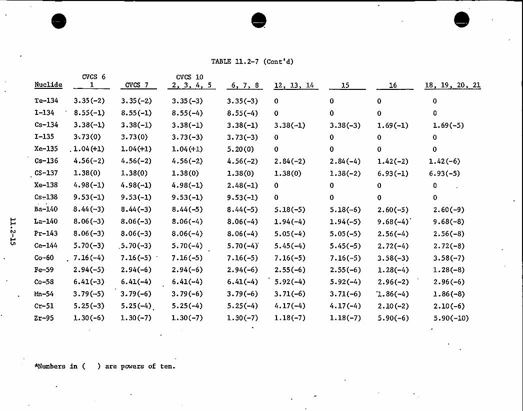
TABLE 11.2-7 (Cont'd)
Nuclide
Te-134
I-134
Cs-134
I-135
Xe-135
Cs-136
CS-137
Xe-138
Cs-.138
Ba-140
La-140
Pr-143
Ce-144
Co-60
Fe-59
Co-58
Mn-54
Cr-51
Zr-95
CVCS 61
3.35(-2)8. 55 (-1)3.38(-1)3; 73(0)
. 1.04(+1)
4.56(-2)1.38(0)4.98(-1)9.53(-l)8.44(-3)8.06(-3)8.06(-3)5.70(-3)7.16(-4)2.94(-5)6.41(-3)3.79(-5)5.25(-3)1.30(-6)
CVCS 7
3. 35 (-2.)
8. 55 (-1)3.38(-1)3. 73 (0)
1. 04 (+1)
4. 56 (-2)1.38(0)
4.98(-1)9.53(-1)8.44(-3)8.06(-3)8.06(-3)
.5. 70 (-3)7. 16 (-5)2.94(-6)6.41(-4)3.79(-6)5.25(-4)1.30(-7)
CVCS 102 3 4 5
3. 35 (-3)8.55(-4)3.38(-1)3.73(-3)1. 04 (+1)
4.56(-2)1.38(0)4.98(-1)9.53(-1)8.44(-5)8.06(-4)8.06(-4)5.70(-4)7.16(-5)2.94(-6)6.41(-4)3.79(-6)5.25(-4)1.30(-7)
3.35(-3)8.55(-4)3.38(-1)3.73(-3)5.20(0)
4.56(-2)1.38(0)
2.48(-1)9.53(-1)8.44(-5)8.06(-4)8.06(-4)
5.70(-4)'.16(-5)
2.94(-6)6.41(-4)3.79(-6)5.25(-4)1.30(-7)
3.38(-1)
2.84(-2)1.38(0)
5.18(-5)1.94(-4)5.05(-4)5.45(-4)7.16(-5)2.55(-6)5.92(-4)3.71(-6)4.17(-4)1.18(-7)
6 7 8 12 13 14 15 16
3.38(-3) 1.69(-1)
2.84(-4) 1.42(-2)1.38(-2) 6. 93 (-1)
5.18(-6)1. 94 (-5)5.05(-5)
2.60(-5)9. 68 (-4)2.56(-4)
5.45(-5) 2.72(-4)7.16(-5)2.55(-6)5.92(-4)
3.58(-3)1.28(-4)2. 96 (-2)
4.17(-4) 2.10(-2)1.18(-7) 5.90(-6)
3.71(-6) '1.86(-4)
18 19 20 21
1.69(-5)
1. 42 (-6)6.93(-5)
2.60(-9)9.68(-8)2. 56(-8)2.72(-8)3. 58(-7)1.28(-8)2.96(-6)1.86(-8)2.10(-6)'5.90(-10)
+Numbers in ( ) are papers of ten.

flow to the chemical drain tank. When a sufficient volume is collected inthe drain tanks, the contents are sampled and neutralized, if required,and then pumped through a filter to the waste concentrator. The
boric'cid
concentrators are available for processing liquid wastes if the .wasteconcentration is not available for service.
Concentrator bottoms are pumped to the drumming station which is describedin Section 1.5. The condensate (distillate) passes through the waste ionexchanger and is collected in the waste condensate tanks and monitoringfor radioactivity. In the unlikely event that discharge limitations cannot be met, the condensate can be recirculated through the waste ionexchanger, returned to the waste concentrator, or the holdup tanks inthe boron recovery system for further treatment. Normally at least oneholdup tank will be available for storage of waste condensate forreprocessing through a boric acid concentrator if necessary.
After the condensate activity has been determined to be sufficiently lowby sample analysis, the tanks are pumped out at a controlled rate to thecirculating water discharge. The activity of the discharge line effluentis monitored and recorded. Should the activity exceed the high set pointvalue, the discharge is automatically terminated.
The alundry wastes are collected in the laundry drain tanks and analyzedfor activity. Becasue of negligible activity levels, the laundry wasteis normally pumped from the tanks through a filter to the circulating waterdischarge via the radiation monitor mentioned above. The tank contentscan be processed in the waste concentrator prior to 'discharge if significantactivity is detected.
All tanks are equipped with level instrumentation with alarm and theirrespective pumps are tripped on low level signals.
All piping 2 1/2 inch and smaller is field run. Line sizes are shown onFigure 11.2-4.
Designed data for the ma)or components is given in Table 11.2-8. Flow,temperature, and pressure are given in Table 11.2-9 with the locationscorresponding to data points on Figure 11.2-4. Expected performanceof components are given in Table 11.2-10.
The nuclide concentrations adjusted to 70F for normal operation andanticipated operational occurrences are given in Tables 11.2-11and 11.2-12, respectively. The selected locations are indicated bythe process data points on Figure 11.2-4.
As indicated in Table 11.2-1, an estimated 156,000 gallons per year ofliquid wastes, exclusive of laundry wastes and steam generator blowdowneffluent, are processed in the liquid waste system. The activity ofthe aerated liquid wastes collected in the equipment drain tank andchemical train tank, in the absence of steam generator blowdown, isapproximately 1 percent of the reactor coolant activity, owing todilution from washdown and decontamination procedures.
11.2-16
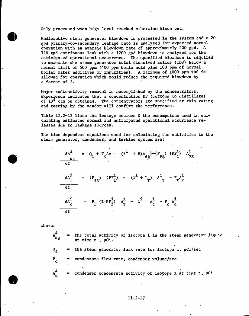
Only processed when high level reached otherwise blown out.
Radioactive steam generator blowdown is processed in the system and a 20gpd primary-to-secondary leakage rate is analyzed for expected normaloperation with an average blowdown rate of approximately 200 gpd. A120 gpd continuous leak with a 1200 gpd blowdown is analyzed for theanticipated operational occurrence. The specified blowdown is requiredto maintain the steam generator total dissolved solids (TDS) below anormal limit of 500 ppm (400 ppm boric acid plus 100 ppm of normalboiler water additives or impurities) . A maximum of 1000 ppm TDS isallowed for operation which would reduce the required blowdown bya factor of 2.
Moor radioactivity removal is accomplished by the concentrators.Experience indicates that a concentration DF (bottoms to distillate)of 10" can be obtained. The concentrators are specified at this ratingand testing by the vendor will confirm the performance.
Table 11.2-13 lists the leakage sources & the assumptions used in cal-culating estimated normal and anticipated operational occurrence re-leases due to leakage sources.
The time dependent equations used for calculating the activities in thesteam generator, condenser, and turbine system are:
dA ~ Qi+ F Ac — (X + B)A )-(F )'(PF ) A~S c sg sg i sg
dt
dA ~ (F ) (PF) — (A +L) A -FAdt
dA = F (1-PF ) A — X A — F Ac T 2 c c c
dt
where:
Asg
the total activity of isotope i in the steam generator liquidat time t, pCi.
Qi
Fc
the steam generator leak rate for isotope i, pCi/sec
condensate flow rate, condenser volume/sec
Ac condenser condensate activity of isotope i at time t, pCi
1102-17

'. i th -1decay constant for the i isotope, sec
B ~ steam generator blowdown rate, vol/sec
F steam generator flow rate, vol/secSg
PF steam generator partition factor for the i isotope.th1
L = the turbine system leakage rate, vol/sec
F
activity in =turbine steam for isotope i at time t, pCi
turbine flow rate, vol/sec
PF ~ condenser partition factor for isotope ii2
The above equations were solved for the equilibrium values of A
and A . The turbine system volume for this analysis in-c udes t5e steam generator steam space, piping between the steamgenerator and turbine steam space, and condenser steam space.Condenser activity is based on the condensate volume in the hot-well and the piping between the hotwell and steam generator.Steam generator activity is based on the liquid inventory of steamgenerator.
11.2-18

TABLE 11.2-8DESIGN DATA FOR LI UID WASTE SYSTEM COMPONENTS
Ion Exchan er Waste
QuantityTypeDesign Pressure, psigDesign Temperature, FNormal Operating Pressure, psigNormal Operating Temperature, FResin Volume, ft3hfaterialsASME Code
1Deep Resin Bed1502004012032SS
VIII
Tanks EquipmentDrain
ChemicalDrain
LaundryDrain
WasteCondensate
QuantityInternal Volume, gal.Design Pressure, psigDesign Temperature, FNormal Operating Pressure, psigNormal Operating Temperature, FMaterialASME Code, Division
11000Atmos.200Atmos.120SS
VIII, I (1)
11000Atmos.200Atmos.120SS
VIII, I (1)
21000Atmos.200Atmos.120SS
VIII, I (1)
21725Atmos.250Atmos.120SS
N.A.
~Pum s Equipment Drain, Chemical DrainLaundr Drain Waste Condensate
QuantityTypeDesign Pressure, psig.Design Temperature, FDesign Conditions
Flow, gpmHead, ft
Wetted MaterialsSeal TypeMotor HorsepowerMotor VoltageCode
6Cen trifugal150200
50140SS
Mechanical7.5460N.A.

TABLE 11.2-8
4. Filters
QuantityType of ElementsParticle RetentionDesign Pressure, psigDesign Temperature, FDesign Flow, gpmMaterialASME Code
5. Waste Concentrator
Waste
1Replaceable Cartridge25 micron, absolute15020050Stainless SteelVIII
~Laundr
1Replaceable Cartridge150 micron, nominal15020050Stainless SteelVIII
QuantityDesign Pressure, psigDesign Temperature, FDesign Flow, gpmCooling Water Flow Rate, gpmSteam Required at 15 psig, lb/hrASME Code
18025021301300VIII

TABLE 11.2-9
Ll UXD WASTE SYSTEM
PRESSURE TEMPERATURE AND FLOW DATA
Location
Pressure, psigTemperature, F
Flow, gpm
1 2
0.5 0.53 4 5 6 7 8 9
2.0 67 0.5 2.0 2.0 0.5 2.0
120 120 120 120 120 120 120 120 120
0.825 .912 7 2 .209 0 0 0.223 0
LocationPressure, psigTemperature, F
Flow, gpm 0 0 2 2 2 55 50
10 11 12 13 14 15 16
2.0 2.0 67 5 4 4 62
120 120 120 120 120 120 120
Mode 2
LocationPressure, psigTemperature, F
Flow, gpm
1 2 3
05 05 204 5 6 7 8 9
2.0 0.5 2.0 67 0.5 2.0
0.825 0.912 0 0 0.209 7 2 .223 0
120 120 120 120 120 120 120 120 120
LocationPressure, psigTemperature, F
Flow, gpm
10 11 12 13 14 15 = 16
2.0 2.0 67 5 4 62 62
120 120 120 120 120 '20 120 12
0 0 2 2 2 55 '0
11.2-21

TABLE 11.2-9
Mod 3
Location
Pressure (psig)Temperature F
Flow gpm
0.5 0.5 2.0 2.0 0.5 2.0 2.0 0.5 2.0
0.825 0.912 0 0 0.209 0 0 0.223 55
120 120 120 120 120 120 120 120 120
Location 10 11 12 13 14 15 16
Pressure psigTemperature, F
Flow, gpm
62 47 2.0 0 0 0 0
120 120 120 120 120 120 120
50 50 0 0 0 0 0
.(1) Mode 1 Processing equipment drain tank contents via the waste concentrator;discharging a waste condensate tank.
(2) Mode 2 Chemical drain tank contents via the waste concentrator; discharginga waste condensate tank.
(3) Mode 3 Discharging a laundry drain tank.
11.2-22

TABLE ll.2-10
LI UID WASTE SYSTEM EXPECTED PERFORMANCE
Ion Exchanger Decontamination Factor
Tritium, Corrosion productsAll Others
110
Filter Delay Factor
All Nuclides
Waste Concentrator Delay Factor
Holdup Time for Liquid Waste System, days
AnticipatedNormal
200
14.5
11.2-23

LI
TABLE 11.2-11
UID WASTE SYSTEM N019fAL ACTIVITY DISTRIBUTION (pCi/cc at 70F)
Location
H-3Br-84Kr 85mKr 85Kr 87Kr 88Rb 88Rb 89Sr 89Sr 90Y 90Sr 91Y 91.Mo 99RQ 103RQ 106Te 129I 129I 131Xe 131mTe 132I 132I 133Xe 133
. Te 134I 134Cs 134I 135Xe 135Cs 136Cs 137Xe 138Cs 138Ba 140La 140Pr 143Ce 144
2.47(-3)2.67(-7)0000
. 6.37(-6)1.33(-7)9.53(-6)6.02(-7)4.43(-7)2.78(-7)2.15(-4)9.13(-4)7.38(-6)5.73(-7)2.33(-7)1.67(-10)3.77(-3)0
'.66(-4)1.93(-5)9.20(-4)01.56(-7)4.92(-6)5.64(-4)1.48(-4)04.05 (-5)2.31(-3)03.08(-6)7.40(-6)1.72(-6)7.28(-6)9.53(-6)
1.48(-3)6.45(-5)00003.53(-3)8.86(-5)7.02(-6)3.61(-7)1.41(-6)4.93(-6)1.54(-4)2.81(-3)5. 72 (-6)3.44(-7)3.47(-5)1.00(-10)5.50(-3)04.57(-4)1.51(-3)7.84(-3)03.62(-5)8.59(-4)3.38(-4)3.74(-3)04.56(-5) ~
1.39(-3)09. 55(-4)8.45 (-6)8. 10 (-6)8.09(-6)5.72(-6)
3612
2. 21(-3)00000008.34(-6)5.39(-7)2.17(-7)6.73(-10)1.89(-4)4.65(-4)6.41(-6)5.08(-7)01.49(-10)2.86(-3)09.33(-5)07. 80 (-5)0005.02(-4)1.54(-8)03.29(-5)1.75(-3)006.01(-6)5.30(-7)5.96(-6)8.43(-6)
13
2.21(-3)00000001.67(-8)1.07(-9)4.34(-10)1.35(-12)3.78(-7)9.30(-7)1.28(-8)1.02(-9)02. 98 (-13)5.72(-6)01.87(-7)01.56(-7)0001. 01(-6)3.08(-11)0 ~
6.58(-8)3.53(-6)001.20(-8)1.06(-9)l.o9(-8)1.69(-8)
14
2.21(-3)00000001.67(-9)1.07(-10)4.34(-11)1.35(-13)3.78(-8)9.30(-8)1.28(-9)1.02(-10)02.98(-14)5.72(-7)01.87(-8)01.56 (-8)0001. 01(-7)3.08(-12)0
.6.58(-9)3. 53 (-7)00
'.20(-9)1.06(-10)1.19(-9)1.69(-9)
15
2.21(-3)00000001.57(-9)1.07(-10)1.35(-11)03.59(-8)3.05(-8)1.18(-9)1.01(-10)02.98(-14)3.88(-7)07.18(-9)04.43(-10)0001.01(-7)005.16(-9)3.53(-7)009. 40 (-10)1. 65 (-11)9.48(-10)1. 67 (-9)
21
2. 21(-3)00000001.67(-4)1.07(-5)4.34(-6)1.35(-8)3.78(-3)9.30(-3)1.29(-4)1.02(-5)02.98(-9)5.72(-2)01.87(-3)0
— 1.56(-3)0001.01(-2)3.08(-7)06.58(-4)3.53(-2001.20(-4)1.06(-5)1.19(-4)1.69(-4)
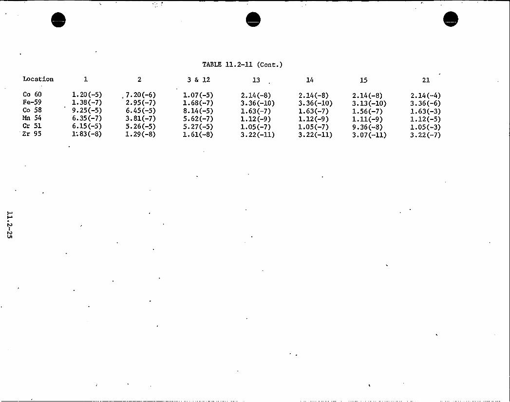
TABLE 11.2-11 (Cont.)
Location
Co 60Fe-59Co 58Mn 54Cr 51Zr 95
1.20(-5)1.38(-7)9.25(-5)6.35(-7)6.15(-5)1: 83 (-8)
, 7.20(-6)2.95(-7)6.45(-5)3.81(-7)5.26(-5)1.29(-8)
3&12
1.07(-5)1.68(-7)8.14(-5)5.62(-7)5.27(-5)1.61(-8)
13
2. 14 (-8)3.36(-10)1.63(-7)1.12(-9)1.05(-7)3.22(-11)
14
2.14(-8)3.36(-10)1.63(-7)1.12(-9)1.05(-7)3.22(-11)
15
2. 14 (-8)3. 13 (-10)1.56(-7)1.11(-9)9.36(-8)3.07(-11)
21
2. 14 (-4)3.36(-6)1.63(-3)1.12(-5)1.05(-3)3.22(-7)

TABLE 11.2-12
LI UID HASTE SYSTEM 'ANTICIPATED OPERATIONAL OCCURENCE ACTIVITY DISTRIBUTION (pCi/cc at 70F)
WMS Location
H-3Br 84Kr 85mKr 85Kr 87Kr 88Rb 88Rb 89Rb 89Sr 89Sr 90Y 90Sr 91Y 91Mo 99Ru 103Ru 106Te 129I 129I 131Xe 131mTe 132I 132I 133Xe 133Te 134I 134Cs 134I 135Xe 135Cs 136Cs 137Xe 138Cs 138Ba 140La 140Pr 143
1.83(-2)1.24(-5)00003. 82 (-4)3.82(-4)8.0(-6)5.72(-4)3.61(-5)2.66(-5)1.67(-5)1.29(-2)5.48(-2)4.43(-4)3.44(-5)1.40(-5)1.00(-8)2.26(-1)09.96(-3)1.16(-3)5.52(-2)09.33(-6)2.95(-4)3.38 (-2)8.85(-3)02.43(-3)1.38(-1)01.85(-4)4.44(-4)1.O3(-4)4.37(-4)
l. 83 (-3)6.4s(-4)00003. 53 (-2)3.53(-2)8. 86 (-4)7.02(-5)3.61(-6)1.41(-5)4.93(-5)1.S4(-3)2.81(-2)5. 72 (-5)3.44(-6)3.47(-4)1.00(-9)5.50(-2)04.57 (-3)1.51(-2)7.84(-2)03.62(-4)8.59(-3)3.38(-3)3.74(-2)04.56(-4)1.38(-2)09.55(-3)8.45(-s)8. 10 (-5)8.09(-5)
3 6 12
1.39(-2)000000004.34(-4)2.75(-5)1.80(-5)4.56(-6)9.85(-3)3.72(-2)3.35(-4)2.62(-5)07. 62 (-9)1.66(-1)06. 91(-3)6.49(-7)2.77(-2)0002. 58 (-2)1.37(-4)01.81(-3)1.02(-1)003.30(-4)6.44(-s)3.26(-4)
13
1.39(-2)000000008. 68 (-7)s.so(-8)3.60(-8)9.12(-9)1.97(-5)7.44(-5)6.70(-6)5.24(-7)01. 52(-11)3.32(-4)01.38(-5)1.30(-9)5.54(-5)000s.ls(-s)2.74(-7)03.62(-6)2.04(-4)006.60(-7)1.29(-7)6.52(-7)
14
1.39(-2)000000008.68(-8)5.50(-9)3.60(-9)9.12(-10)1.97(-6)7.44(-6)6.70(-7)5.24(-8)01.52(-12)3.32(-5)01.38(-6)1.30(-10)5.54(-6)0005.15(-6)2. 74 (-8)03.62(-7)2.o4(-s)006.60(-8)1.29(-8)6.52(-8)
15
1.39(-2)000000008.56(-8)5.50(-9)2.78(-9)1.64(-10)1.95(-6)5.80(-6)6.58(-7)5.24(-8)01.52(-12)3.04(-5)01.12(-6)9.44(-14)2.51(-6)0005.15(-6)2.28(-10)03.46(-7)2.o4(-s)006. 25 (-8)8.53(-9)6.19(-8)
21
1.39(-2)000000008.68(-3)5.50(-4)3.60(-4)9.12(-5)1.97(-1)7.44(-1)6.70(-2)5.24(-3)01.52(-7)3.32(0)01.38(-1)1.3o(-s)5.54(-1)0005.15(-1)2.74(-3)03.62(-2)2.04(0)006.60(-3)1.29(-3)6.52(-3)
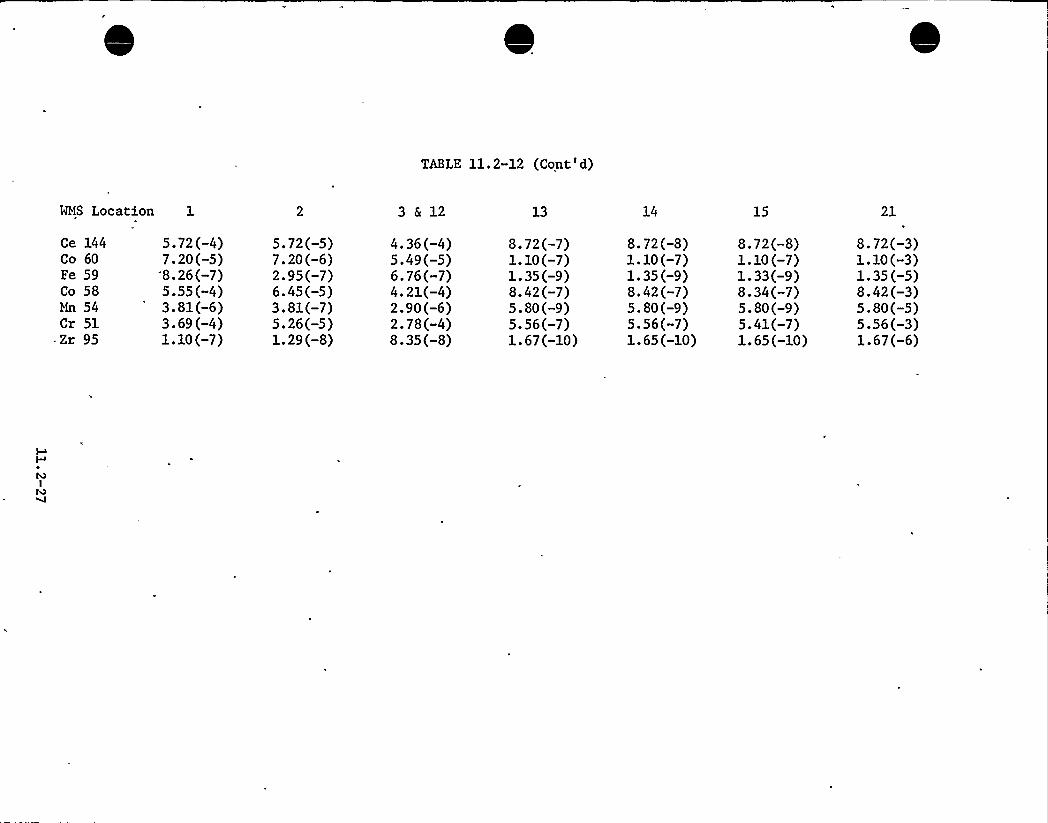
TABLE 11.2-12 (Cont'd)
WMS Location 1 3&12 14 15 21
Ce 144Co 60Fe 59Co 58Mn 54Cr 51
=Zr 95
5.72(-4)7.20(-5)8.26(-7)5.55(-4)3.81(-6)3.69(-4)1.10(-7)
5.72(-5)7.20(-6)2.95(-7)6.45(-5)3.81(-7)5.26(-5)1.29(-8)
4. 36 (-4)5.49(-5)6.76(-7)4.21(-4)2.90(-6)2.78(-4)8.35(-8)
8.72(-7)1.10(-7)1. 35 (-9)8.42(-7)5.80(-9)5.56(-7)1.67(-10)
8.72(-8)1.10(-7)1. 35 (-9)8.42(-7)5.80(-9)5.56(-7)1.65(-10)
8. 72 (-8)1. 10 (-7)1.33(-9)8.34(-7)5.80(-9)5.41(-7)1.65(-10)
8.72(-3)1.10(-3)1.35(-5)8.42(-3)5.80(-5)5.56(-3)1.67(-6)
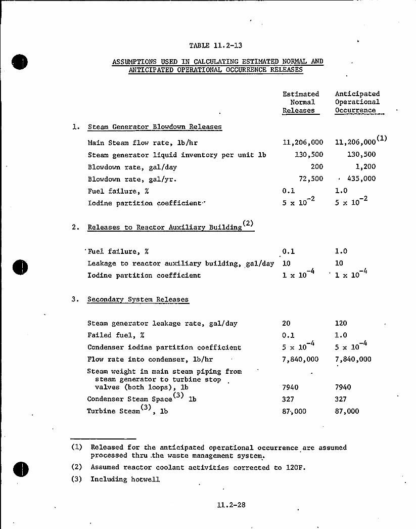
TABLE 11. 2-13
ASSUMPTIONS USED IN CALCULATING ESTIMATED NORMAL AND
ANTICIPATED OPERATIONAL OCCURRENCE RELEASES
EstimatedNormal
Releases
AnticipatedOperationalOccurrence
1. Steam Generator Blowdown Releases
Main Steam flow rate, lb/hrSteam generator liquid inventory per unit lbBlowdown rate, gal/dayBlowdown rate, gal/yr.Fuel failure,Iodine partition coefficient"
11,206,000
130,500
200
72,500
0.15 x 10
11,2061000
130,500
1,200~ 435,000
1.0
5 x 10
2. Releases to Reactor Auxiliar Buildin (2)
'uel failure, O.lLeakage to reactor auxiliary building, gal/day 10
-4Iodine partition coefficient 1 x 10
1.010
-41 x 10
3. Seconda S stem Releases
Steam generator leakage rate, gal/dayFailed fuel,Condenser iodine partition coefficientFlow rate into condenser, lb/hr
20
0.15 x 10
120
1.0
5 x 10
7,840,000 7,840,000Steam weight in main steam piping from
steam generator to turbine stopvalves (both loops), lb
Condenser Steam Space lb(3)
Turbine Steam, lb(3)
7940
327
87; 000
7940
327
87,000
(1) Released for the anticipated operational occurrence are assumedprocessed thru .the waste management system.
(2) Assumed reactor coolant activities corrected to 120F.
(3) Including hotwell
11.2-28

Table 11.2-13 (Continued)
Steam Generator Steam Space, lb(4)
Total Steam Space, lb9 500
104, 767
9 500
104,767
Condenser hotwell water weight, lbLiquid inventory between hotwell and
steam generator, lbSteam leakage to turbine building, lb/hrGland Steam Condenser flow rate, lb/hr
680,000
587,000
20
4602
680,000
587,000
20
4602
4. Containment Pur e S stem
Releases independent of % failed fuelReactor coolant system leak rate, lb/hrAirborne activity cleanup flow rate
, HEPA Filter Efficiency, % (5)Charcoal Filter Efficiency, % (5)
Organic IodineInorganic Iodine
Operating time of removal system after'hutdown,hr
Purge initiation after shutdown, hrPurge, flow ratePurge frequency, times/yr.Purge filter efficiencies,Iodine partition coefficient
50
20,000 cfm = .48 volume/hr.99.9
70
90
10
10
20,000 cfm = .48 volume/hr.
0.1
5. Li uid Waste S stem Releases
Miscellaneous waste, galLaundry and showers
156,000
117,000
(3) Including hotwell(4) Including piping(5) These valves were also used for the auxiliary building gaseous releases.
11.2-29

I
c> ~
Wl
4,g
r I'

ll.2. 3 OPERATING PROCEDURES
11.2.3.1 Boron Recove, S stem
Operating procedures for the boron recovery system are written to logicallyreflect the different monitoring and operating functions required of theplant operators. Procedures include the following.
a) Monitoring requirements of the flash tank pumps and control pumpsand procedures for valve lineup to the holdup tanks.
b) Monitoring requirements of reactor drain tank operations andprocedures for processing the tank contents through the flashtank to a holdup tank.
c) Monitoring and actions to be taken in the event of flash tankbypass operation to avoid explosive mixtures of hydrogen and airin the holdup tanks.
d) Monitoring requirements for the conditions of the four holduptanks and processing requirements for chemical and radioactivitysample analysis.
e) Procedures and valve lineups for processing a holdup tank contentsthrough a preconcentrator filter and ion exchanger back to the sameor different tank and processing sampling requirements.
Procedures and valve lineups for processing a holdup tank contentsthrough a preholdup filter and ion exchanger to either'or both ofthe boric acid concentrators. Operation of pump and concentratorinterlocks. Process sampling requirements.
g) Procedures for concentrator startup, steady state, shutdown, andlayup operations. Sampling requirements to confirm low carryoverand to confirm low carryover and to confirm proper operation ofboron concentration controls. Automatic and manual batch bottomsdischarge control procedures and heat tracing system operatingprocedures.
h) Monitoring requirements for the condensate tanks conditions andprocedures for valve lineups. Sampling and reprocessing procedures.
Operating procedures for the environmental discharge instrumentationand valves. The method for determining the discharge flow rate interms of radioactivity discharge limits.
Valve lineup procedures from the concentrators to the holding tankand sampling and transfer to the Chemical and Volume Control Systemor drumming station. Monitoring and operating requirements for theheat tracing system.
11.2-30

11.2.3.2 Li uid Waste S stem
Operating procedures for the liquid waste system include the following:
a) Procedures for equipment drain tank influent valve lineups,monitoring tank conditions, sampling, and valve lineups tothe waste concentrator or a boric acid concentrator.
b) Procedures for chemical drain tank influent valve lineups, monitoringtank conditions, sampling and valve lineup to the waste or a boricacid concentrator.
c) Procedures for laundry tank influent valve lineups, monitoringtank conditions, sampling, and valve lineup for discharge or tothe waste concentrator.
d) Procedures for waste concentrator startup, steady state, shutdownand layup operations. Sampling procedures to assure low carry-over and to monitor bottoms concentration. Heat tracing systemoperating procedures.
e) Monitoring requirements for waste condensate tank conditions, valvelineups, sampling, and reprocessing. Discharge is done underthe same procedure used for the boron recovery system.
11.2;4 PERFORMANCE TESTS
The boron recovery and liquid waste processing systems will be tested priorto initial power plant start-up to verify satisfactory flow characteristicsthrough the equipment, to demonstrate satisfactory performance of pumps andinstruments, to check for leak tightness of piping and equipment, and toverify proper operation controls. All piping and components are to bechecked to ensure that they are properly installed. All manual andautomatic valves are operated and checked for functionability. All alarmsare checked for operability and verification of locations. The concen-trators are tested for operation before. installation at the site andafter installation to assure proper integration with the system. Theboric acid and waste concentrators are shop tested prior to shipment todemonstrate compliance with performance objectives. During hot functionaltesting, the boron recovery system operation is integrated with thechemical and volume control system. The purpose of this test is to checkthe procedures and system components used for receiving and processingwaste water. Boric acid transfer operations and waste liquid disposalprocedures are tested.
During normal plant operation, periodic testing verifies that the systemcomponents are operating as designed. Filter performance is determinedby comparing the quantity of particulate from inlet and outlet samples.Filters are monitored for differential pressure and radiation level on aregular basis. Ion exchanger performance is determined by comparing thelevel of radioactivity from inlet and outlet samples. Xon exchangersare monitored for differential pressure and radiation level on a regular
11.2-31

basis. To ensure that the flash tank is performing adequately, a liquidsample from the influent and effluent can be obtained to verify thehydrogen stripping function of, the tank. When processing waste reactorcoolant, boric acid concentrator performance is determined by comparingthe concentration of boric acid from inlet, bottoms, and condensate samples.All liquid discharges to the environs are sampled for radioactivity beforedischarge. The discharge radiation monitor is calibrated on a regularbasis to assure accuracy.
11.2.5 ESTIMATED RELEASES
The expected liquid releases from the plant are summarized'y nuclide in Table11.2-14. The reactor coolant concentrations utilized from this evaluationare indicated in Table 11.1-1. The curies released from the boron recoveryand liquid waste systems are determined by multiplying the nuclide con-centrations in the boric acid and waste condensate tanks as shown inTables 11.2-6, 11.2-7, 11.2-11 and 11.2-12 by the waste processed througheach system. The waste schedule is shown in Table 11.2-1. TechnicalSpecifications for plant liquid releases are discussed in Section 16.3.9.
11.2.6 RELEASE POINTS
The only liquid release point from the waste management system to the environsis via the boric acid condensate or the waste condensate pumps discharge tothe circulating water discharge. Prior to discharge the contents of the tankto be discharged are sampled for chemical and radioactivi.ty concentrations.If the contents of the tank are found acceptable in terms of environmentaldischarge limits, the tank contents are discharged. A radiation monitoris provided in the discharge line to verify that the fluid discha'rge isbelow the applicable radioactivity limits. In the event that the dischargedactivity is unacceptable, the discharge monitor automatically terminatesdischarge operations. The discharge is located on the P & I diagram Figure11.2-3 and 11.2-4. Release points from the plant are shown on Figure 11.2-5.
11.2.7 DILUTION FACTORS
An average annual dilution factor of 1.73 x 10 is obtained in the5
circulating water discharge based on 513,000 gpm -flow in the dischargecanal and an average annual liquid effluent flow rate of 2.95 gpm fromthe boron recovery system and the liquid waste system. The dischargeand intake pipes are separated by 2300 feet of ocean shoreline whichresults in a neglible recirculation of discharged water.
11.2.8 ESTIMATED DOSES
None of the liquid releases from the plant result in doses via drinkingwater. The surrounding municipalities do not depend on the sea as asource of potable water. All local groundwater runoff is towards theocean which further diminishes the possibility contamination of drinkingwater.
11.2-32

The only applicable exposure pathway comes from the ingestion of foodsgrown in the seawater containing plant releases. The doses calculatedfrom this source follow the guidelines from "Statement on the Selectionof as Low as Practicable Design Objectives and Technical Specificationsfor the Operation of Light Water Cooled Nuclear Power Reactors," byCarl C. Gamertsfelder. The population density information used forthe calculations is from Section 2.1.3. The average daily consumptionstatistics used are taken from "Regional and Other Related Aspects ofShellfish Consumption — Some Preliminary Findings from the 1969 ConsumerPanel Survey," by Morton M. Miller and Darrel A. Nash.
Total fish consumption by the population was calculated on the basis ofthe total edible fish harvest in St. Lucie County for 1970. It was
assumed that 10 percent of the fish harvest came from waters containingplant effluent releases diluted to 5 percent of the concentration inthe discharge canal. No decay time was assumed.
The maximum dose to an individual and total dose to the general publicresulting from plant liquid releases are shown in Table 11.2-15. Dosesto the whole body and gastro-intestinal tra-t were calculated with thelargest dose occurring to the gastro-intestinal tract.
11.2-33

TABLE 11.2-14
EXPECTED LI UID'RELEASES FROM'THE'LI UID WASTE SYSTEM
Curies Released per YearNormal Operation Anticipated Operation
Nuclide (0.1% Failed Fuel) (1.0% Failed Fuel)
Activity in Circulating Water Discharge (pCi/cc)Normal Operation Anticipated Operation
(0;1% Failed Fuel) (1.0% Failed Fuel)
H-3Br-84Kr-85mKr-85Kr-87Kr-88Rb-88Rb-89Sr-89Sr-90Y-90Sr-91Y-91Mo-99Ru-103Ru-106Te-129I-129I-131Xe-131mTe-132I-132I-133Xe-133Te-134I-134Cs-134I-135Xe-135Cs-136Cs-137
Numbers in
2.26003.7400001.136.902.0902.114.607.555.60005.953.731.0108.902.37001.75003.405.28
are
(+2)*
(+1)
(-5)(-7)(-5)
(-2)(-2).(-5)(-6)
(-4)(+1)(-3)
(-7)(+3)
(-3)
(-4)(-3)
powers of ten
3.39 (+2)003.74 (+2)00002.80 (-4)1.79 (-5)2.70 (-4)02.16 (-1)4.74 (-1)4.85 (-4)6.67 (-5)006.74 (-2)3.72 (+2)1.27. (-2)05.76 (-3)2.37 (+4)002. 17 (-2)003.96 (-3)6.61 (-2)
2.2. (-7)003.67 (-8)00001. 12 (-14)6.80 (-16)2.04 (-14)02.07 (-11)4.50 (-11)7.44 (-14)5.50 (-15)005.84 (-13)3.65 (-8)1.00 (-12)0.
8.50 (-16)2.32 (-6)001.70 (-12)003 . 33 (-13)5.16 (-12)
3.32 (-7)003-67 (-7)00002.75 (-13)1.75 (-14)2.64 (-13)02.11 (-10)4.64 (-10)8.67 (-13)6.53 (-14)006.60 (-11)3.65 (-7)1.24 (-11)05.65 (-12)2.32 (-5)002.12 (-11)003.86 (-12)6.47 (-11)

TABLE 11.2-14
EXPECTED LI UID RELEASES FROM THE LI UID WASTE SYSTEM
Nuclide
Curies Released per YearNormal Operating Anticipated Operation
(0.1% Failed Fuel) (1.0% Failed Fuel)
Activity in Circulating Mater Discharge (pCi/cc)Normal Operation Anticipated Operation
(0.1% Failed Fuel) (1.0% Failed Fuel)
Xe-138Cs-138Ba-140,La-140Pr-143Ce-144Co-60Fe-59
.Co-58Mn-54Cr-51Zr-95
Total:Total:
Total:
009.39 (-6)2.99 (-6)7.89 (-5)8.72 (-5)1.10 (-3)1.13 (-5)9.08 (-3)5.71 (-5)5.91 (-3)1.79 (-6)
H-3 2.26 (+2)NobleGas 2.54 (+3)AllOthers
9.13 (-2)
002.30 (-4)4.90 (-5)9.24 (-4)1.04 (-3)1.12 (-3)1.14 (-5)9.25 (-3)5.83 (-5)6.00 (-3)1.83 (-6)
3.39 (+2)
2.45 (+4)
8.9 (-1)
009.08 (-15)2.95 (-15)7.78 (-14)8.54 (-14)1.08 (-12)1.11 (-14)8.89 (-12)5.59 (-14)5.79 (-12)1.75 (-15)
2.21 (-7)
2.39 (-6)
9.03 (-11)
002.26 (-13)4.79 (-14)9.03 (-13)1.02 (-12)1.10 (-12)1.12 (-14)9..05 (-12)5.70 (-14)5.87 (-12)1.78 (-15)
3.32 (-7)
3.32 (-7)
8. 66 (-10)
* Numbers in ( ) are powers of ten.

TABLE 11.2-14 (Continued)
EXPECTED LI UID RELEASES FROM THE LI UID WASTE SYSTEM
Turbine Buildin Floor Draina e
Nuclide
Curies Released Per YearNormal Operating Anticipated Operati,on
1.0% Failed Fuel
H-3Br-84Rb-88Rb-89Sr-89Sr-90Y-90Sr-91Y-91Mo-99Ru-103RU-106Te-129I-129I-131Te-132I-132I-133Te-134I-134Cs-134I-135Cs-136Cs-137Cs-138Ba-140La-140Pr-143Ce-144Co-60Fe-59Co-58Mn-54-Cr-51Zr-95
1.293.331.032.254.321.841.992.676.651.592.132.071.216.497.662.989.771.462.651.134.336.418.943.234.421.642.851.663.382.307.281.201.121.112.02
(-1)(-7)(-5)(-7)(-5)(-6)(-11)(-6)(-4)(-3)(-5)(-6)(-4)(-10)(-3)(-4)(-4)(-3)(-7)(-6)(-4)(-4)(-4)(-3)(-6)(-5)(-6)(-5)(-5)(-5)(-7)(-4)(-6)(-4)(-ll)
5.672.116.181.361.326.141.201.482.388.768.086.364.701.933.781.625.338.551.594.232.621.37
'8.638.552.997.801.627.541.051.384.371.047.026.661.22
(-1)(-5)(-4)(-5)(-4)(-5)(-10)(-4)(-2)(-2)(-4)(-5)(-3)(-8)(-1)(-1)(-2)(-2)(-5)(-4)(-2)(-2)(-6)(-2)(-4)(-4)(-4)(-4)(-3)(-4)(-6)(-3)(-6)(-4)(-10)
11.2-36

'TABLE 11.2-15
OFFSITE DOSES DUE TO PLANT
LI UID RELEASES
Normal~Oeration
AnticipatedOperationalOccurrence
Whole body dose due toingestion of seafood:
a) Maximum to individual
b) Total to population
0.26 mrem/yr
0.056 man-rem/yr
13.4 mrem/yr
2.9 man-rem/yr
Gastro-intestinal tractdose due to ingestionof seafood:
a) Maximum to individual
b) Total to population
1.8 mrem/yr
0.39 man-rem/yr
4.44 mrem/yr
0.96 man-rem/yr
11.2-37

vs i~I lw Cla vdt»vtsswlc/ /45wrr (4J)
/a/W JcsI «Ar 355 C(OC TDCICOP Prl IA/5 (5)
OI cyrcc JccvcAIA/lsrRcL/4/'VAJLDI
II W
L.wo-PLiC/ CD/V///stir V- (LATCC)5 WAI C'1'\
~TI4(4 il)
C/r 61 p h Srd ai OOO
~ Ai CCC
/PRIL TD /AOLODP TANA
~~/r~/V/ RAJ
)(IWA/.arlAAA//CC PCS SC'C.453
-l ti 55 (CC.pvvCc Jfcc.
vc wrr CLC-sci 4rirAcrr vstir
STOP /1 rh.y ~ h/4/hops ov c QA
~ ID/VLCVCL
LA1I ~ Ih3' 'CPI---J --5 L.
Aw .C/4 I
5/ cwscw~ 4/yc c
pv r pa pl&/Ao5/ cpc/ rowhrr/
ra 'latmtst-55 (Pt/ OVPASS TD
y1 oy r fvLcvfaI
5 wy ft)S.w l)
aO l
r~ i
yc (cc)
II VLI
/vw 441ICvyii 1 pa/va
5 5 )
Dl ~ 5l)
ra/ts ' srr)I I
$ wvctC ~
II
AAXCC/O Afsccc/rcac 4 troll/Lop
4 /O wadWri (CS)
Zww DS1
IA I~ 4 CS
)OPCA/ O// SCOW
ccosc o//«5/c>W
II
I SPO
Acct�)st
Les/v«/Vw/5 O/lLOw /LcvCL
va/o
PI
I
/CPS/OR COCKOV/'DWPCC«6 // rSratth/-/ /
ca CI-S»
IDli r~
ow4IS a
P( JSJI
LtP
II)YJ)hhw/rr 5
/WRK// va I
(cc)
IWI.CCC ) hSli
r
5 s5
Lvwlltt4rra. LIS
/ I /JI 4
%P «a/Idaprt /at
/o 5 ™ ICAIi wopIS va/I i
i ~ I/4
/vvo/hrop4 ww csr
c»(IOSCS r Ccl h'--r--
5 5I
VL~l/$tp~-at
vs vsDI/RDR v. (Lrrrs) JA/Rcrc r/r IAv/pr cltlip
DTTP O//w5 5-CS SI
APCC VA/vr/caves/I TJPatA/ I
I
ILO ~ /P
var/4 I Soa I'i vari/f.pos»
(Al1 PALS/4 I
1C r/// /4/vl C
J
A.WW CP/
IwvCtis~)JPACAJJ ~rls ~--~1A
~ .I/i VCvcc
/rwool I-
Jo \Ii4 raw
W seaI/Vh JSJ AWfil
RC At I/I/ P /4
CwrsRVC (IODKV LSvrrir
rp/r// /vrrf/v/orccfr/C/PDCP'r/CC rC/J
O /AO5/ AOS
7JwN s»
C /wvh/JC; ~B-- CNA(/I TAIVL
/I(PI/PS /~~i
j./vS/D
/ 4 ww /TPvtlat OW IICA/ /1)
rlww'
4'VC/CP
Divrl 55OC
sl lAS 6JATSC/rrcw~crp SS WC/A/A//l ~ Atw o svvrcosy ccccrvc5 t 4 c PURV ccarc/
u crw ~ IJAW/CA/SVA Cdc/CVAAS sr (5 h)i /Vc/Pr opc»
5/COPS
4/
/'T 4'I vr
JJ /vvwKJ)CSC o'wtct
4 Sow/JJSR/'PCC/C/oC /t 4 Iowa
Cc/Cvsvv 4Avc
wllr 4ilICP/Po/va/ Iw/cApclr/r Ai PCPrrr/sP
CfJ~CT~vr fov/Ava/vcyr
4
/or/PCSAA/ I/ /CC
Jhw rir I
1A
v 4 t soIS-~tt/
/x\wl(vsso) }C
pw/r 111
CSj.w WJC
h
Awr/.O/
SR/
~zC ~v«/rV
4'WP
4
)5 waRP
vie i
I roI
V41
Vlcwrtls
/DC CCAACCAVDAWAISPJ/rr/VCPA At
I awtl)1/
/also
Iap
NI
Vr h
Ca AWKStSVIISLPPVAI
PJvs AO
«w(CI )
' 4 'l4
rrw w(I4/IC)l
I
vs14/
ACS/r//'/5 I,
w
I ~ jI I 1B srto/4 v(IAprie)
4
v 4
Dwvr I/o
OPCO/PJI/4 JS)AAVVCC /5
vr/»
CrvvOJ
3-ww-SI4
~ varro4t
+SCOP/4CS
vrI~
1~vsi (55 )/IffCONCEP) H'A)PC
/OP( EffJIAPcfrfBS
PJR/C AI'/DOVACC vTCA
lps'ACK/SOIBP.aw 5'I
~vol )
wrfrc /4 rcccpsascipcac
(PSJ
v
lt ArwtliPIIAC AfilayJarwv
P)a) Iowa/P«<C ~ )
W ~
CI/5
(41 Ps\TOP/arsevtlaW
va I~ w/r Iia o Pr/CJC/O
OIC(A)t/tcDCPCC 14
co
PC JVT VIVT
rrvlr/'ID ro(CJ I h/voo/vc
4
i.V4 4
I.w/I CM I\
4 (vw Clt
Va/1
sir/ Vi/
I A641
I, o/AS ~ Cr
Va/ vs/ II4 hw I
AC/C /C/D(D OCASArr PAVKJ
Wil(yf )
Va '1
Aww SIT
4TVP/
~~
C
I I) a/Aot/5
DDrvcrs)ahrovaa
h 4 /i(CO)
«or Opr
)~sos
/ )wvcacjrwocat
Sory'sfI ~
I
rs jTall
5-w rriI4tl
PJ Ivai
ADTCSCA
//~Kris-PW-Ctt vs/st va lp
Irail 4
III
1 5
law/sar
chorovsrs/'vs
Dw/AKD
11rr/1DwwS
V ~ i'Iwysrr
3
Iia ~ 4 I
W I 1A~ «/I CAJP
v
o sr vvwww.p51Ihw Irc
I w» 543
~ J.v//4 COO
18
I wrr S/4
ow-rro
'ra 44P
lail I I.
4J4
~ /DOSS/ CD) 4
Cwwooo 1AOTt
3
I.w/4 (DJ
~ho sr/ vsrI w» Csa ~A
VJ lt
C WAt OJC
ralP
ra/5
~ h Sar COcia V"'IJwwt hh
8
t. /PC JV
~C~1
~ -'4IK
~ 4 a/i
Iwo/a// P
~Pw/I
t/4'OR
+$ WA
4
ral ~ II
I
1JI)I
SAV/L
I ~.t
vcr/la
/rc/TOTP J
5
/Aivrr LIO
~ Wor/ cir frI.Jrv-POPI'ww5tt I
O
iz»sssV //4
PCAS// TAIVAicI/ ~ I pr/wo)s rsroosro
/4/r i 4/ /var ts
CS
~I 5 ~
5iM\.,Al
rp QA
/Cf (O/vff)fT/J)OC tPAC TCCSO/I
rii4/I
tit
P
h l/3
s i Q /.wPKj-~vrr ) wl g 8
C)P(// I v IrS ™/ WW JO)
CT
/vtorp(SP
HITEIPC/A)~//5/ Pcrr)JPS
pwrt/ L
5$ O
4// AD/cd(rI
Ivsi v- j/Jv lsd)
oCwrP.w
CS
P. Plat/)
5 COCAI ALA//Vsr 4/C CCIAVACO II/V CVCLACIoc//I /JAAKit,CAO/I paivca Ala 4/r Avarvrodc)c
'A'AACCOP/ TAOL /S)OVI PAAAIL5 START( JIoprcyovpAwD Imp> lp lai /op Cc/K
AOL II/ct//JIJDIPOVIIALIAPAAL4IVIL;/LA/45, Sip/Are /Arovp /vrrp) orrrcypvp /44/ /cvvlcvlc1 )CJD RCCOTA/h/I W4S/I iW&APCAlCh'f
srrrclt 54 s Dht/viiva 5C /5547-C/O /4/ lotJI 5.
1. For Legend, Abbreviationsf.8 Symbols See Fig. 1.2-20
v/J 5 Tr ccr/ocyfs TcPVAIP1
4wir (5/) /VI DA/ (4C
ccfvvocvrrc/rye /fo(.p//p yRJJR'DPiro/Pvs/at. A '/I5~f55 «Al (A5)
FLORIDAPOWER & LIGHT CO.
Hutchinson Island Plant
I3-/( I
REF. DWG. No. E-19367-210-160, REV. 05
Figure11.2-1
I
Waste Man'agement System — P & I Diagram

r

%98' GCNC 8'N FRA TORIaaf . FXCHAh SSR 6'SH
U3C)
nCL
C)
CD
UQ)nQ)
CC2CD ~
S'TWAS
CO&az~sAre
RMH/
47 OCH
PRE'ON'GE'rVTRA TER/CPA" EXCh ANGE~
CO//DEiVSATE
BGRIC ACIDOh'CBVTRA TOR
PACKAGE /A
~/6
BORfC AC/004'CEA'TRA
7'ACKAGEl8
/ 'BOR IC ACIO Q7JVDEAISATE/OIV &(CHArV5'fg
~ ——HOL OUP PUMPS
GC5
CCG
B~/C A|"/D A($'Cf/AJ3CK8TH/IhffQ
BORIC ACrb CCWDEAJSATZle E'XGHgH'SF'
~ —HOLDUP PUP/PS
CC5'CW
(0C
I I
AVOCA'ORICAC/0 C7/SCHARGZE7Fj'A/NER
~ ~ ~ ~

croc/c 4l/OPJAVCCA//44/Dt /Irs
f/C?t/C /OC/OCCVVCC/rr/44/t>r IRONS
Si
DOCil«II41~V/I Oo
C rli/rill 44
// wv-rrtVi.« I ~ 154
VJ.« //5
4/?4//ll4
ratH V(ltlff) fr«» 545
444/4 Vfltrft)/CA/W c,
(C»4)
li//CACIDccr«cr/r/F/CSS/ FA'GW/I/Gcr/3
ricod V/CPTCC'//AIV «IVV>C/
js/st.rrf /7
Stet
~ c ~ C i/irl.«» 1/l
4
i/ ~ ic ~
V,» ttc/«Jst/4
VS\11 VCtcv
Vit
I iAII 1
r—-qII~
I1B
PSVSKJO
«PA/fV t/1
/)S~ Itllj.SSP TSS
C~frv
rI~
4t.
~ ~ ~
/j-»«ttf1'»» 145
«CAr TCA(CTO COIVCA'C4 Vc1
o«cV'l
I~I~If~ ~
//-/«»-rrs
Alf/4/'rile.
CC JS
/VSV CliR
Si
l «I«'145
-ico~ric (D'\) /
V4 44
it:.P».SJI
/C vrwTT/1
3
VJ r4
i4 t I)-»~?dc
/8
C ~VJ?4/r---~
CS
tr«» 51)
1A44)4ll
5 IVJ«141
Iv».15/
VJ?45Ic? ~j
VJ ~ 4
r-~ I
II J
~4
(II
Sr>P PV»PSO«COw CCTCC
)III
44D
1 «c«?4 ~
14S40
Pl
)vs«544
vc tttCS
/ rt.wrt. Vv
vc
/jvv»fit'c/Cr///C~/C)
CC)I/c)FvI/J/55/F RAPS
i/~rrr
/5).wr ?ter 1 4 444CA
/ «
ll J«ctPS
/C«JJl.ftf
IB
C))?I
/45 AJP
4.
r44sr/I/TW.?tC ~
I
Ivcc//iri4 ~ t«/vs//Pf 5
I
Ec?A/C /Ctd'/4/)cc)s/c)FP5PPF /res/I'8 csir
447 44
I".4X )
Tt.«» 511
CS
;.~» l
SSAJ
~ VJCVCSPC«cetic AsoSCV«cftv CCS/tcrv c««/ cAortlars ~
l. IIII
Vcci4 q4~I
rcII
i w» tct
55
f /«Jt
<YI // V Ci
II
r V/CS/PJI
I I c rI I I,
IE) I I
II I
I V4 ~I
5I Y
I ~ ~
I ~I
~I
k Jsr«ctt
2/
IIIIIII
//tC/CPC/D
~ ~ ~/fcr» It) ~
~ ~
llc ~V44/
~ ~~ ~
~ 4
vcite VJJ VJVJJ?it
V44~ \ ~Js
~ CDft «JPPSS
VJ~ ~ ~
~ ~ ~ ~ 4 ~~ ~
~ ~ ~ ~ ~ 4
S-VJV-SCOc3/)CW MD~
1
«40'/SC/////cGE
~
S~PA'/ V
~ PAJ/«vri /41 4» /4w»
ro vccsrfc)C»w I
rcr> 044(//-/d)
I
CSVJDC V DCAIiiPV»PSwAsrc co/toe«sATc pvvps
SO
rc <i JJ/« I«II?
ctccv/C r?C/OCOASCO>VTROTS?/f r)QTR/VCR'
~ ~ ~ ~
~ ~ ~
CC
krVAvtp/ctp pvtspfoci Jcrvcf«tc
4/PC«C /«terTCAcl«4 TodccitpicoAOOVC A«liiC51 TAJISccvsc
~ ~ ~ ~ ~
4/5 SI
cccccAr»f Atm crcrsvppcico w.rpCCC ~ Jtt
IVI «c«AIS
r /JVJVilr--QJIecezc
A'C/0//OLDIE/G/T/SA'A'tt
!
~)~ ~
ft Js»»tlj/»JR/sit) 1
I
~ ~ ~
VJ ~ I
I/I@IS I/SP J
'2 ~
~ rc» Ail
r ~ 4
VJJ4
~(~~ ~
V ~ 44
~ Tf/Kf~~rtc Ic'1
Rtrtf 1'Alf ~0«J V
v41
V44li/tpa.-wio
C>K(«rt tdc/vccc4cC»t JJ-?O
/ras«J?t (st/
~ ~
~ ~
~ ~
~ ~
~ ~
~ ~
~ ~ VJJ ~
1 4 ~/ct.c»544
~ ~ ~ ~ ~ ~ 4 4 ~
~ it JJA?C
~ /I»» Aicr 4
vi P t/4 /4/Ddl
r ~~ ~ ~ r
* Ir«r» Alt4 ~ 4»«//4'LA ~~ ~ ~ ~ ~ ~ ~ ~ 4 ~ ~ ~ ~ ~
~ ~
r44//v«44
ppois r(ltrgt) ~
Prrc 0 044(I ~»/ r/.~wr
SP»v/4j~/j.CASA
~ 1
~ ~ ~ ~ ~ ~ ~
~ ~ 4 ~ ~ ~ ~ ~lTP«»»II/ .
~ ~ ~ ~ ~ ~ ~ ~ ~ ~
4'i/ SAA.At/
/g«VAPACC
~ ~
//K»rst 44csr4 'occi
~ ~ ~ ~ ~ ~ Cii CDS/~ ~ ~ ~ ~ ~ ~
~ 1 44 It~ DTV»itiildSTATJ>CS
f»4141 t/C«lct
V r»««Ivc
~ ~ ~
«Pl (lrt)4/5/s»»tf
~ ~ ~ ~ ~ ~ ~ ~ ~ ~ ~ ~ IJJJOV ~ 1 4I 'll~A« ~
~ ~ ~
/8//~c'/c/o lk '4/'~ ~ ~ ~ ~ 4
i»rt fDi)
5„4cc pcpcc>c ts clr «per% cc«ss />Iv'if«vvl 5/ Clscclc cc455/p/c«rto/r
5, I STPC PCSC»S ACC SC/VPCDOIV CVCCSC5> PC PA«CCS CA 1/COCAC PP/VCC«As 4«PJ)vvt///proc OIv T«cct«rc 5C»w PA«CC
IC. /VOA'Poo/rr>«pc 1/4>re AIA«p cisf«r
S CCTS SCP Owrf Sntc/>CA>VJ?,/Ct./JA.
1. For Legend, Abbreviations, 8 Symbols See Fig. 1. 2-20~ li
I
/9-/g 3
REF. PWG. No. E-19367-210-161, REV. 05
FLORIDAPOWER 8, LIGHT CO.
Hutchinson Island PlantWaste Management System — P 8 I Diagram Figure
11.2-3'l

t

1j.«MT<USAMACE Si««'C ocswS
/AISE VACVCCEArtrt/ rAtrsc AOIPA/P ccochs//S
4 OVFF/JAIFAFAICOSoorhhdrts
Woo / oJSJffov/WN«vs/ Prl
r<OOM CICAAVS
Jv«MT<AtE/VEAI/CAF41 o<orp/5
4 AU«OCTPUMPS ~ oocAA//pccrfrp
~iMr
GCWcr.tc«c
Iorhi CSCJ
rsir /6 I5 it<st FM Fo cd/re IAVA/Eo~r/isI
II )
«
5 «JMJCPC 1CASA OCLCWIAMWLtor/
~ 1At/sc ivcoopt ocAAArsSA/CCUACOS RCL)NSUltP PUMPS
CCSFUELIM«OLrrd GLDGSUMO POMP
ILALPIOCTOrMMSVAIP PUP< P
«O ci Fri. Ao /Arcp/roorvcR vc Tn STEAN
COWOOIFSA/C
red)ACIASTP
CCJA'CEhlIHATORI
~ I
5LO
Virr'ICrtTAIMMC«tSl/ATP PUMP Pi 1 Pi
ssrrr5
Lo ~I.W«1«d
or(Mr(AILo/1<VSUMP AU«Fr 8
VC pr,Jidec
WAI Pdo (f<)Tt wo oro c/s)'Cr wv d Fr (4 S)'/I wr.ort (rrlTI ««D<d IGII'TI <h141 IGIIVS wMOIo(oirI WAt CC'
I WAI Cso(PIII WAI CSI /Pl) ~
Cd J I ID
CPPVMFr O<IW / «w-ASOr/I «M CSF tV<VJ«rs
CE Sir M«rlDcw«rrrwspo«pre<I6 itl~ 5 rwrcr
~ECJCAIJ/ TANK/A
PACh'AC<EAr««A<J
DI 5r~ ~
UCC/i 1 ««I CITS/4>FW
rhwr 41
I h«P4I r 4YCCAI'M
P'FMJ«5~I 1
'C3,I
««r Cd<J
I WN CSC /FJI/"PW-AJA (/P/f1 «W«PCJ(CFJJ/-/VAITAJJ/ir/IjPh<h«AJ//6/Ij-I<IV«/SF(/v/JJIW<WAJC(CJJJI«JAI&JJ(dJJ
J /hrM CJF/'GJJ/.Itsr Ctt (Jr 1r.wM.Cto (pr)
CA'FiVICAC
D@z/I/ TASA/K IA4 Wsr Ait
0
IAIWSA(T
I'r'I ~
I
II
Lo4 MA4t
«
rrr WWA 1v4 rlI
4.vprptlf.M«AVPi r«J 1st
V44 '4
VIr'I
n<i44
'4
p/-r«J-Art 'Ch
'Zo
lc L.4) lt
I W ~ ACI ripe«V44 4 ~
Ir««««<tl1A
/S.M«AirP VCT~
Tr«C«IDI
1
VsI««J I «wfrl r ««PMCO
ifwwwcrI
I ~
LSl Oror«S rstrCI CS(C
C ~As iS'r«M Arr (OI)f.llA.AW(os///.Ip<rtvtrcpcdr I
5~1 4 wsr AtoIo
VOFPO4rtt. «.Att
5rtr PAIASCW ctrVLCVCC,
2/S(//5 DPY ~ ii4DRiJ//I/ TAIA/KS
V<hin
rvrC~il«vsr ri<PC (v<<dr
stop rvrp4P o«r<ovi I 4
4CVEI. 4 Crtrp r«p«oOV LO«4 EvEC,
r«iCS
Jq ph«/.Arr /pt)r ~ A/SCwJSc-WAG stre (//JJ
v<rrl vi«scCS CSj.wr./pr
Oi1 «w pto
IN
JI.AMMtv
It/ PS Artor V«AC<h< 4CS
/5 w«MALT<CJ
4<AS'WAr/s/c) ~rir
~ Iv s vcr i<
7I rvM 1'rt CD5)
~I<r (SL)
O<OPPS //I
~ oi
OMO.AF/ / w«JTP/f.«WJ FC/ rws-11/
rr «o«AIG1(ifWMJ/4~FLIPS/EA iAOJIF///I/AOWP IA
if.WAFCIA /CCMVJt/
«<4 LluNORT DRDIF/ ous<DS
(I )5
/I.P««AttC//F/I/I/Ci//()Ars/AS/Ac)/A/P fA
« or« r«ir/ wv EJ/ //OJ
/-CJ Ir-o'««/ot rod> ~
r P«WTJ/CO/)= ...liJV/4/
JOCOWOG WrV FAM/
v< r
ir
Arh< DL'I JC
~vr/6«
C~~awr
I //
«/JAP w<o/JOCIC ACIDrocdrv PUMPS rrr wwsl «>1) /3f''
<I h5
'«L w«
41
ro r~vr D1)
4<i< II
V ~ I4
V4FS Fwisrc'rrcrtcstoc 2 IIE
1~ ~
v(4< 151)lrg wr COC
CMW 5
V« I««A<PI
qLL
1
M«Atd/Z
vs551
ICr /OPI CAEAAMGC v«trl I
4 «Fr/ '4
Cr CO' I 4WM lchVEC OAMGCt
Vw I tl
WM IOML'i(«ANGERltr~ iCI
PS ICM SAC«AMGEC«I I<
AS (CCIwr lo«r Clcvsrr/frtc TI<~ < rs
/o'5) J<<rto
Cr DFA/Ms (4) /7«4 cr t Ows L
Irsw«C<4
TA 4wor«AFC
h P<Ih
FIIIFfP fA~ I4/I-WM.APC-Q
Ad
<4vs Fr
I ~I//tt JWTCO+ VC$ SNTLSI
Ls I .WA«d
Aw«JtoWASTj
F~n.7 R XA
i rr sc vs o V
41ITP «M cts
IL
Vh 5 ~
Q PAADIJ v crI cpt«r rs
~ «PV Pls
rc5 g+. OMCUFSroc
SwrrrrdI/ CIWTArN(r«s '*~~<
Itrr»CCF.V<'\ r<IJ v(iptcgCMW
'-'I'riso«MI
//<Oh<OFF
rf w«i dlo
rl - P«D<
/J ««5 diOITc4
Art«'(4<It/IArr I~DA . Drsreidotrcw rcAOEA To~ 4 CPACIrLA/«idM<1/C OiSCMAACE
t«ittCF APO i4i5 PVAI C 1
G Acc PIITMG IICr SA/CTTDASID*LIKPLP411M $ 4t( GthrcrscoGM scvr/Oc Lo(14 Fhrwccs.
45EAC» LSCOL PA«CL AMS AMAAAMLAVCIAIOCOM Tr4
CONTROL COOM PAA'EL,t. /vcrocvwcwoc «IFCTE
AMVAGEMjlllT ocowrrvo sV~@ SEE OWG'S EJSSOT 5 /44,
i<i,/41
ICtsrr
I rvrlI /I.MWCIP4hrPIVOSS h«c 54 v< OEI/J//JINA
5TATIO/I
Qz
I rr Pis VP«M ttCvv««5tt
LC~ I
orwdr< I
i( r» PCS IrI I
I ~
~ I I~ ~
1 I 4I
II
Ir'«O»'A
Lt
/~t~c rWM Cdt/~J prrdr
IIIii««t«
4th 1
!.ij.«M.DS
)TASTE R)/vEE«hro A/O/.l
XA(4
WM FVA
C«CAAC'AILDF4 «SUPIG
IMWSA Ig.ho«d<4(
I wM Ct<
OM drr CD<)i/M 454 lo4I
swM Brs Cts)w«M dtt ((1) fA vc rht
Pclr II
v<I-«MJG
] For Legend Abbreviahons8,~Srnbols See Fig 1 2-20
p'p~iJ/
1 I; V<<44VI«r'1sw 4 prsrr
rr 4 'W L(trc
~ Ivc<
~v«T
C.«Mhcct(vsr
„cw+is/FO /r«o-to I
c@tr<«to rstCC« (1<I
4 wr«O<t iCC) ~ C«CMACPL,DF1/M SUPP
EE5//JAOOITIOAJ
TAIN K SA tsÃSTF/«h« Pir4 /4 J«wOC/ .««I.did
CO//(JF/I/SATDALAEL i«OOC
F/ oV/Pt I
zs (tr)PPPM VCIATCII
C vrIrk rrc<M v/IArl(I
I wv«S<P CrI + o/A/.«PJM Io
I
Aor S4t /Cs/5TATA'S w Al
/ WM.JJC~v
/-«M-O/4/+ VCP
CS
vc A
4 isdPFiVTRFS/A/TAA/KIA
/2-MV/dtd/vs IW«OIFJ«PM.Sst 22 CCOM V(IAIC/I P/« ,«
rite covccrv/L«PEP'FW
Ecc«hs«CCAP CllI« I t/O MW
S. TVM lsJ. Osrr ~ t/i fSl
ocr</6 Ac<F cohofrssrcJFLMC'AfArAA'GEAISt
WAI Od
COV< 4
//A«dtvvl sttr<rr/C</PCS 5 ««SIT slV<SS «1
/41 /PO /4'O
n4 «««t« VQTS
O«rst<SC1'err
hc'
VASIO Tl V(IATCCICM V
6 «ls
vstl
A/-«P«rcs
~ ~ I \I~PMV dcc
lj««<CIOtro rcs
rg.«~etc,w CJI
vVW
P«P«dt/ 44S44
t«VMOPtcwt v(IPTCc) AP<ILDSr
AIArrt~ 1othr«M<4
I ~ PA/rw1 lid//(ohio'I rOM
fAh««(IA)AMMD<rIzl
/5~ rhrh« C 4'4
J«M(s)/I'M'4tsDM<(SO V
««I.CSC rt «MCOvcrtT I ««ICI<J «M.CSJI
A'E 5I/h/ CEIVATERIN S
/O/rocOC//o
C ill/O'M«» I CVJ
JM«ttc t. MCCI
16V«'IIC wc 5 Sc EoNDE/v so TE /tctvr/IDr<«»< v(<trit)
CMW~Trt / J«4
I'Jt ' Fi ff'4CJOJ1 <ctt Ov T5IOE
S r~r COITTArrrdtv4 4
/3-SCQ
REF. DWG. No. E-19367-210-162, REV. 05(OUIPM(IIT
t M d<s Ocorw SUATPrcor v(IATCA)4 AT iv~T«ro«rt< FLORIDA
POWER 8 LIGHT CO.Hutchinson Island Plant
Waste Management System — P & I DiagramFigure11.2-4

n,

TO ATLANTICOCEAN
LIQUID RELEASETO DISCHARGE CANAL
I
SEALWELL
EL. -1'6COMP. COOLING
4. OF ROAD~ 3" WM A29
DIESEL GEN.BLDG.
FUEL HANDLINGBLDG. REACTOR AUX.
BLDG.3"-WMSPIP ING
REACTOR
BLDG.
PLANTVENT
t3KCh
CO
CONTROL" ROOM
STEAMGENERATORBLOWDOWN TANK
TURB. GEN. BLDG.
STEAM JET AND GLAND~ STEAM CONDENSERAIR EJECTORS
C.S.T.
FLORIDA POWER 6 LIGHT COMPANY
HUTCHINSON I SLAND PLANTUNITS 1 L 2
PLANT LIQUID AND
GASEOUS RELEASE POINTS
FIGURE 11.2-5

11.3 GASEOUS WASTE SYSTEM
11.3.1 DESIGN BASES
The gaseous waste system processes the vent gases from equipment locatedin the chemical and volume control system, waste management system andfuel pool system, such that the radioactive gaseous release to the environswill be as low as practicable. The numerical design objective for releasesduring normal operation is to limit the site boundary noble gas dose toless than 10 mrem/year and iodine-131 and particulate site boundaryconcentrations to 10 5 times 10 CFR 20 limits. Releases due to anticipatedoperational occurrences will be within 10 CFR 20 limits.
11.3.2 SYSTEM DESCRIPTION
11.3.2.1 Waste Gas Processin S stems
The principal flow paths of the waste gas system are shown on Figure11.3-1. Process flow and activity data are given in Table 11.3-1 andcomponent data in Table 11.3-2.
Plant gaseous releases come from the steam generator blowdown, reactorauxiliary building ventilation, turbine system Leakage, steam.jet air.ejectoroperation, gland steam condenser operation and containment purging inaddition to releases from the gas collection header and gas surgeheader. Releases resulting from blowdown, turbine leakage, the steamjet air ejector and gland steam condenser are based on equations (1)(2) and (3) in Section 11.2.2.2. Gland steam has the same activity asturbine steam. Releases from the reactor auxiliary building ventilationsystem are based on leakage of unprocessed reactor coolant at 120 F.Containment purging results in a constant release regardless of per-cent failed fuel since the airborne radioactivity removal system isoperated for as long as required to achieve the required activitylevel referred to in Section 12.2.
. 11. 3-1

TABLE 11.3-1
WASTE GAS SYSTEM FLOW DATA POINTS
Position No.
ANTICIPATED OPERATIONAL OCCURRENCE FOR 1% FAILED FUEL *
3 4 5
Flow, ft /yr3
Pressure, psigTemperature/F
Kr-85m ~. CiCC
Kr-85
Kr-87
Kr-88
Xe-131m "
Xe 133 u
Xe-135
Xe-138
I-129
I-131I-132
I-133
I-134
I-135
12,944
0.5-7
70-120
0.522
0.735
71.8
0.0062
8.04 (-12)3.42 (-3)
5.87 (-4)
100-500
0.5-770-120
1820
0.5-7
70-120
11.98
13.1
850.0
5.82 (-14)1. 143 (-5)
3.68 (-9)
10,310
0.5-7
70-120
8.02
5.86
4.36
13.9
8.5980.0
25.0
2.08
9.95 (-14)5.47 (-5)1.5 (-5)7.8 (-5)8.53 (-6)1.036 (-4)
25,650
0.5-770-120
2.54
l.41
1.318
4.48
2.58
325.0
16.0
0.576
4. 08 (-12)1.74 (-3)5.9 (-6)3.26 (-4)3.44 (-6)4.19 (-5)
50,724
0.5-7
70-120
2.92
2.47
1.55
5.10
3.7412.0
13.2
0.721
4.14 (-12)1.762 (-3)6.05 (-6)3.33 (-4)3.48 (-6)4.25 (-5)
*Concentrations of nuclides are reduced by a factor of 10 for the expected operation of 0.1% failed fuel.

TABLE 11.3-1
WASTE GAS SYSTEM FLOW DATA POINTS
Position No.
ANTICIPATED OPERATIONAL OCCURRENCE FOR 1% FAILED FUEL *
10 12
Flow, ft /yr3
Pressure, psigTemperature/F
Kr-85m p-CiCC
Kr-85
Kr-87
Kr-88
Xe-131m "
Xe-133
Xe-135
Xe-138
I-129
I-131
50,724
0.5-770-120
2.92
50. 724
10-16570-110
9.92
2.47
1.55
5.10
3.7
412.0
13.2
0.721
8.40
5.27
17.32
12.58
1400.0
44.8
2.45
4.14 (-12) 1.41 (-11)
1.762 (-3) 6.0 (-3)
50,724
10-165
80
8.36
2. 23
27.0
50,724
10
80
2.46
0.655
7.94
50,724
<0.180
2.46
0.655
7.94
395,660
<O.l70-120
3.72 (-3)
2.52 (-2)2.02 (-3)6.47 (-3)2.86. (-2)2.09
1.41 (-11) 4.14 (-12) 4.14 (-12)
1. 88 (-2)9.02 (-4)2.95 (-13)
4.54 (-4) 1.335 (-4) 1.335 (-4) 6.32 (-5)
I-132
I-133I-134
I-135
6.05 (-6)3.33 (-4)3.48 (-6)4.25 (-5)
2. 06 (-.5)
1.14 (-3)1.182 (-5)1.442 (-4)
2.72 (-6)1.41 (-5)1.592 (-6)6.72 (-6)
*Concentrations of nuclides are reduced by a factor of 10 for the expected operation of 0.1% failed fuel.


TABLE 11.3-2
COMPONENT DATA
1. Waste Gas Com ressor
Type Diaphragm Positive Displacement
Quantity
Capacity, SCFM
Discharge Pressure, psig
Codes
0-165
ASME P&V III for Nuclear Power Nov.1968 ASME Power Test Code PTC-9,Displacement Compressors, VacuumPumps and Blowers.
Materials
Design Temperature, F
Design Pressure, psig
2. Com ressor Aftercooler
Type
Quantity
Codes: Gas Side
Carbon Steel
150 — Inlet; 350 — Outlet
200
Shell and .Tube
2
ASME Boiler and Pressure VesselCode 1968 Section IIIUnfired Pressure Vessels, Class C
Shell Side
Materials
Section VIIIof above code
Carbon Steel
Discharge Temperature, F
3. Com ressor Inlet Filter
110
Type Stainless Steel Screen
Quantity
Rating
Clean Pressure Drop, psi 9 2 CFM
5 micron
0.3
Code ASME Boiler and Pressure VesselCode 1968 Section IIIUnfired Vessels, Class C
11.3«4

TABLE 11.3-2
Type Vertical
Quantity
Volume, ft3
Design Pressure, psig
Design Temperature, F
10
40
200
Code ASME Boiler and Pressure VesselCode 1968, Section III, Class C
Material Carbon Steel
5. Gas Deca Tank
Type Vertical
Quantity3
Volume, each, ft 144
Design Pressure, psig
Design Temperature, F
Codes
190
250
ASME Boiler and Pressure VesselCode 1968, Section III, Class C
Material Carbon Steel
11.3-5

Waste gas is collected from the various source components by threeheaders; containment vent header, gas surge header, and gas collectionheader. The containment vent .header receives hydrogenated potentiallyradioactive gas mixtures vented from the reactor drain tank, quenchtank, refueling failed fuel detector vent, and reactor vessel headvent within the containment and directs the gases to the gas surgeheader. Hydrogenated and potentially radioactive gases vented fromthe volume control tank, flash tank, and boric acid concentrators inthe reactor auxiliary building are also directed to the gas surge headeralong with the discharge gas from the gas analyzer. The vented gasesflow to the surge tank where they are collected prior to being compressed.The gases remain in the surge tank until removed by the waste gascompressors which are automatically controlled by pressure instrumen-tation located on the surge tank. The surge tank is equipped with adrain line to remove any water that accumulates in the tank due tocondensation. A level switch with a local alarm is on the surge tankindicates to the operator when the tank should be emptied.
Since the contents of the surge tank are expected to contain significantamounts of hydrogen, the gas is sampled frequently by the gas analyzerto determine the oxygen-hydrogen composition. If oxygen should increaseabove 2 percent by volume (2 percent by volume below allowable limit)an alarm is annunciated, and provisions are made to purge with nitrogen.A nitrogen line connected to the surge tank, and a pressure regulatingvalve in the line opens when pressure in the tank falls below 1.5 psigthereby maintaining a positive pressure above atmospheric and preventingair ingress.
The gases flow from the gas surge tank to a compressor where they arecompressed to 165 psig and cooled by an aftercooler prior to enteringthe gas decay tanks where the gases are held up for radioactive decay.Two compressors are available for transferring the gas to the gas decaytanks controlled by pressure instrumentation on the surge tank. Onecompressor starts when pressure in surge tank increases to 3 psig andstops when pressure falls to 1.5 psig. The second compressor starts at7 psig and stops at 5 psig.
Aftercoolers supplied with each gas compressor cool the compressed gasprior to entering the gas decay tanks. There are three gas decay tanks(each provided with a pressure indicator including local alarm andtemperature indicator) which receive the compressed gas from the wastegas compressors. The decay tanks have sufficient storage capacityfor an average 30 day holdup, and after radioactivity has decayed to anacceptable level which is consistent with the design objective and hasbeen verified by laboratory sample analysis, the gas is released to theenvironment via the plant vent at a controlled rate.
The fillprocedure for the decay tanks is to have only one tank linedup to the compressor discharge. When the pressure in the tank increasesto 165 psig the tank is isolated and manually switched over to anempty tank. The gaseous radioactivity in the filled isolated tank isallowed to decay for an average decay time of approximately 30 days.During this decay period the gas is periodically sampled and activitylevel determined. The sampling technique used prior to release ofgas and the continuous monitoring systems are further discussed inSection 11.4.3.
11.3-6

The following components are located in the discharge line from thegas decay tanks to the plant vent; a pressure reducing valve, pressureindicator, needle valve, pneumatic operated fail closed on-off valve, anin-line radiation monitor, and a gas flow meter.
Prior to release, the required flow rate is determined, and the set point on
the radiation monitor is established. Initially the discharge valvefrom the gas decay tank, needle valve and pneumatic operated valve areclosed. The on-off pneumatic operated valve is opened and placed inautomatic, and the discharge valve on the desired gas decay tanks isopened. The pressure reducing valve will automatically close whenpressure from the decay tank in excess of 10 psig is sensed at the pressurereducing valve outlet. The needle valve is then opened as required toestablish the desired flow rate to the plant vent, and the pressurereducing valve will open to maintain constant downstream pressure of 10
psig. The on-off pneumatic operated valve automatically closes on highradioactivity level thus terminating discharge flow. An alarm willannunciate this event in the control room. When discharge flowdecreases and the decay tank pressure decreases to approximately 10 psig,as noted by observing the gas flow meter and pressure indicator on thegas decay tank, the pressure reducing valve set point must be reducedto vent the tank down to atmospheric pressure.
The system flow paths and release points of the gases from the gasdecay tanks and gas collection header are indicated on Figure 11.3-1.The diagram also shows the only flow bypass line in the waste gas system.This line from the gas surge tank to the plant vent bypasses the wastegas compressor and gas decay tanks. This path is used to bypass compressorsand gas decay tanks when the air or nitrogen is purged from processequipment after initial plant startup or maintenance operations. Duringthese periods essentially no activity will be present in the gas streamsand it is unnecessary to route these gases to the gas decay tanks.A locked closed valve facilitates administrative control of this bypassline.
The waste gas system has connections for sampling the gas in the containmentvent header gas surge tank, and each gas decay tank. The gas to the gas surgeheader is primarily hydrogen, and a gas analyzer located in the sampling systemis used to monitor hydrogen and oxygen concentration. Connections areavailable in the sampling system as outlined in Section 11.4.3 fortaking a grab sample via gas analyzer to determine activity level priorto release.
The gas collection header collects the gases from primarily aerated ventsof process equipment in the waste management system, chemical andvolume control system, and fuel pool system. A listing of sources isgiven in Table 11.3-3. Because of the large volume of 'gas and the lowactivity level from the sources, the gases are routed directly to theplant vent. The gases and expected activities to the plant vent fromthe gas collection header are given in Table 11.3-1 at process datapoint No. 12. As a further check on activity from this source, theplant vent contains radioactivity monitors with alarms to indicateunexpected activity release.
11.3-7

TABLE 11.3-3
GAS COLLECTION HEADER SOURCE POINTS
1. Preconcentrator ion exchanger vent
2. Holdup tank vent
3. Boric acid condensate ion exchanger vent
4. Boric acid holding tank vent
5. Boric acid condensate tank vents
6. Waste ion exchanger
7. Equipment drain tank vent
8. Chemical drain tank vent
9. Laundry drain tank vents
10. Waste condensate tank vents
ll. Spent resin tank vent
12. Waste concentrator vent
13. CVCS ion exchanger vents
14. Fuel pool system ion exchanger vent
15. Boric acid makeup tank vents
16. Charging pump vents
17. Charging pump seal lubrication tank vents
18. Boric acid makeup pump vents
11.3-8

The hydrogen and nitrogen required for plant operations are also a part ofthis system and redundant supply headers for each gas are provided.Hydrogen gas is supplied to the volume control tank gas space to maintainthe desired concentration of reactor coolant dissolved hydrogen to suppressthe net decomposition of water in the reactor flux. Ilitrogen cover and/orpurge gas is provided to t'e holdup tanks, quench tank, reactor draintank, safety injection tanks, spent resin tank, and gas surge tank. Anitrogen stream is supplied to the flash tank for degassing liquid waste,and periodic purges with nitrogen are. provided as required for various wastemanagement system and chemical and volume control system components.The two gas supply systems include relief valves, regulators, andinstrumentation with alarms and valving to allow flexible operation. Alow pressure alarm indicates when the backup source should be placed inservice.
llew
3-9

11.3.3 OPERATING PROCEDURE
The waste gas system operating procedures include the following.
a) Tank purging and venting procedures for all tanks venting tothe waste gas system and for the tanks in the waste gas system.
b) Gas surge tank to gas decay tank valve and compressor lineupprocedures, requirements for .monitoring proper automatic oper-ation of the gas compressors, procedures for servicing thecompressors, filters, and after coolers.
c) Procedures for isolating a gas decay tank after filling andfor monitoring the contents during the decay period.
Procedures for setting the high trip set point on the dischargeradiation monitor, for lining up the valves for discharge, andfor determining the discharge flow rate and establishing it,monitoring requirements during the discharge period, procedureto reduce gas decay tank pressure to atmospheric at the end ofthe discharge period.
e) Procedures for draining water from the gas surge tank and thegas decay tanks.
Procedures for valve lineup, and establishing regulator setpoints and criteria for changing hydrogen gas cylinders.
g) Procedures for valve lineup and establishing regulator setpoints and criteria for changing nitrogen gas cylinder.
h) Procedures for gas analyser manual and automatic controlof sample point selection, procedures for obtaining a gassample in the sampling cylinder for laboratory analysisand for setting the sequential timer and for calibratingthe gas analyzers to assure representative automaticsampling.
11,3«10

11.3.4 PERFORMANCE TESTS
The gas compressors including suction filter and discharge aftercoolerare shop tested to assure pr'oper operation. The gas analyzer system isshop tested.
The system preoperational tests are as follows:
a) Instrumentation is checked for accuracy of readout and controland alarm set points;
b) Control valves are checked for proper operation and reliefand pressure regulation valve set points are confirmed;
c) Operation of the entire system is checked by supplying nitrogenfrom various points such as the reactor drain tank, and flashtank. Proper automatic operation of the compressors andcontrollability of discharge flow rate is verified;
d) Leak testing is done to assure negligible leakage.
During plant operation, periodic testing is done as follows:
a) The discharge radiation monitor is periodically calibratedwith standard radiation source;
b) The hydrogen and oxygen gas analyzers are periodically calibratedwith zero and upscale gases;
c) Process instrumentation is periodically calibrated.
11.3.5 ESTIMATED RELEASES
The estimated releases from the waste gas system in curies per year arelisted in Table 11.3-4. The source terms and assumptions used todetermine these releases are given in Section 11.3.2. All the noncondens-able gases in the condenser are released to the environment. The releasesfrom the auxiliary building are calculated by multiplying the leak ratefor auxiliary building equipment by the ventilation system filterefficiencies. The assumed leak rates and filter efficiencies are givenin Table 11.2-13.
During normal operation the expected activity releases from the plant isbased on a 0.1 percent failed fuel, while the anticipated operationaloccurrences are assumed at 1.0 percent failed fuel. The radioactivitythat is released from the failed fuel is reduced in concentration by theprocess equipment in the chemical and volume control system and wastemanagment system. For iodine, the purification and preconcentrator ionexchanger decontamination factor (DF) is 103, and a liquid to gas partitionfactor of 10 is used for the reactor drain tank, flash tank, holdup tank,4
equipment drain tank, and boric acid concentrator. Noble gases are stripped

TABLE 11.3-4
ESTIMATED NORMAL AND ANTICIPATED OPERATIONAL OCCURRENCE GASEOUS RELEASES (Curies er Year)
~1eoto e Gas Sur e HeaderEstimated AnticipatedNormal OperationalReleases Occurrence
Releases
'as Collection HeaderEstimated AnticipatedNormal OperationalReleases Occurrence
Releases
Steam GeneratorBlowdown Tank
Estimated AnticipatedNormal OperationalReleases Occurrence
Releases
ReactorAuxiliary Building
VentilationEstimated AnticipatedNormal OperationalReleases Occurrence
Releases
K85mKr
Kr-85Kr 87Kr-88I-129I-131Xe131
5'-'132I-133
~ Xe-133I-1341-135Xe-135Xe-138
0.03.52(2)0.00.05.94(-10)
9.38(1)4.0(-3)0.01.138(3)0.00.00.00.0
0.03.52'(3)0.0.0.05.94(-9)
9.38(2)4.0(-4)0.01.138(4)0.00.00.00.0
4. 15 (0)2.82(1)2.26(0)7.23(0)3.2(-10)1.25(-.3)3.198(3,)3.03(-3)1.571(-2)2.3304(3)1.78(-3)7.51(-3)
-2.10(1)1.0(0)
4.15 (1)2. 8191(2)2.26(1)7.23(1)3.2(-9)1.25(-2)3.1984(2)3.03(-2)1. 57 1(-1)2.33042(4)1.78(-2)7.51(-2)2.10(2)1.002(1)
2.06 (5)1.21(-S)1.05 (-5)3. 59 (»5)7. 9 (-10)1.55(-2)2.03 (-5)3.53(-3)3.53(-3)2.49(-3)1.75(-5)5.62(-4)4.22(-2)4,82(-6)
7 '2(-3)4.47 (-3)3.82(-3)1.31(-2)2.88(-7)5.65(0)?.49(-3)1.28(0)1.28(0)9.12(-1)6.38(-3)2.05(-1)1.54(+1)1.76(-3)
1. 65 (0)9.78(-1)8.95(-1)2.87(0)7.97(-12)4.39(-4)1.64(0)1.13(-4)6.26(-4)2.00(+2)1.10(-5)8.32(-4)8.32(0)2.87(-1)
1. 65 (1)4. 26 (0)8. 96 (0)2.87(1)7.97(-11)4.39(-3)1.64(l)1.13(-3)6.26(-3)2.00(+3)1.10(-4)8.32(-3)8.32(+1)2.87(0)

TABLE 11.3-4ESTIMATED NORMAL AND ANTICIPATED OPERATIONAL OCCURRENCE GASEOUS RELEASES (Curies er ear)
~Isoto eTurbine Building Leakage
from Seconda S stemSteam Jet Air
E ector Containment Pur e
Kr 85
Kr 85Kr 87
Kr 88
I 129
I 131Xe-131I-132I-133Xe--~33I-134I-135Xe-135ge-138
Es timatedNormalReleases
8.36 (-6)2. 17 (-6)4.51(-6)1.46(-5)3.21(-10)6.30(-3)3. 30 (-6)8. 88 (-4)1.42(-3)6.50(-4)7.03(-6)2.28(-4)8.64(-4)1.80(-6)
AnticipatedOperationalOccurrenceReleases
5.01(-4)1.30(-4)2. 70 (-4)8. 74 (-4)1.93(-8)3.78(-1)1.98(-4)5.33(-2)8.55(-2)3.91(-2)4. 23 (-4)1.37(-2)5.13(-2)1 ~ 10(-4)
Es tima'tedNormalReleases
3.28(0)8.52(0)1.77(0)5.71(0)1.27(-7)1.23(0)3. 27(0)2.46 (-1)2.60 (-1)4. 00 (+2)2.20(-3)4.50(-2)2.6(-1)7.4 (-1)
AnticipatedOperationalOccurrenceReleases
1.97(+2)5.11(+1)1.06(+2)3.43(+2)3.78(-6)7.41(+1)1. 96 (+2)1. 48(+1)l.68 (+1)2.40(+4)1.32 (-1)2. 68 (0)1.55(+1)4.45(+1)
EstimatedNormalReleases
7.42(-1)2.03(+1)2.99(-1)1.17(0)2.84(-9)2.84(-9)1.56(-1)3.40(-2)2.18(-1)2.18(-1)1. 67 (-2)1.00(-l)4.46(0)5.82(-2)
AnticipatedOperationalOccurrenceReleases
7. 42 (-1)2.03(+1)2. 99 (-1)1. 17 (0)2.84(0)2.84(-2)1.56(-1)3.40(-2)2.18(-1)2.18(-1)l. 67 (-2)1.00 (-1)4.46(0)5.82(-2)

by a factor of approximately 2 in the flash tank and 5 in the boric acidconcentrator. Activity will.also be reduced by natural decay due toresidence time in the reactor drain tank, holdup tank, and gas decaytanks.
11.3.6„
RELEASE POINTS
Release points to the plant vent from the gas decay tanks are indicatedon Figure 11.3-1. The gaseous effluents from the. reactor auxiliarybuilding 'ventilation system and containment purge system are also re-leased fr'om the vent. The plant vent is shown on reactor auxiliarybuilding general arrangement Figure 1.2-14, and on the ventilationsystems flow diagram, Figure 9.4-1. Steam generator blowdown isreleased to the blowdown tank in the reactor auxiliary building. Theblowdown tank is shown on peneral arrangement, Figures 1.2-15, andFigure 10.4-1. The air ejector releases are from the turbine area.The air ejectors are shown on Figures 1.2-5 and 10.1-3 flow diagram.All the release points are shown on the site plot plan (Figure 11.2-5).
11.3.7 DILUTIOH FACTORS
The value of X/Q used for the plant gaseous releases at the siteboundary is 1.73 x 10 6 sec/m which is based on the worst averageannual atmospheric dispersion condition as discussed in Sections 2.3.4and 2.3.5. Doses to the population at greater distances up to 50 milesare calculated using the worst average meteorological data~given inTable 2.3-69.
11.3.8 ESTIMATED DOSES
Doses received by the general public resulting from the'gaseousreleases, discussed above are listed in Table 11.3-5. The results arepresented for the maximum whole dose to an individual, the maximumthyroid dose to an individual, and the whole body and thyroid doses tothe population within a 50 mile radius of the plant. The man-rem dosesare calculated from population density data in Section 2.1.3.
11.3-14

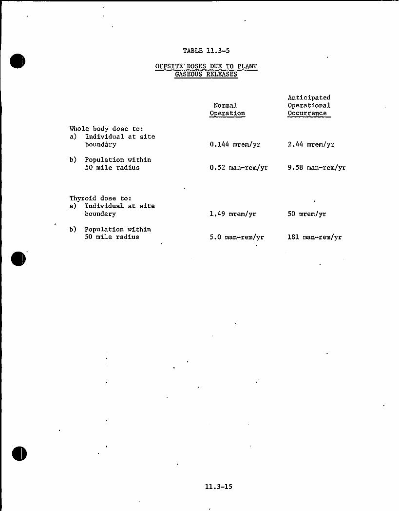
TABLE 11.3-5
OFFSITE'OSES DUE TO PLANTGASEOUS RELEASES
Normal~Oeraeion
AnticipatedOperationalOccurrence
Whole body dose to:a) Individual at site
boundary 0.144 mrem/yr 2.44 mrem/yr
b) Population within50 mile radius 0.52 man-rem/yr 9.58 man-rem/yr
Thyroid dose to:a) Individual at site
boundary 1.49 mrem/yr 50 mrem/yr
b) Population within50 mile radius 5.0 man-rem/yr 181 man-rem/yr
11.3-15

/Kot/rr /Hect r ewa/ttsar sp
V j.waco
cw 4rsoeorc AC/Dcsteecs///$ 5
clcrtrC rot 'D 3CcwTC/VrmrotAtd
-DSV
rCrro
vlIvc cz osis Ids~+ec tP +~ I
epo/prlo/r Jcaw.D 4
C ISC
I Pl5rw.d/O
Q tttcoet
7 aH Dtd stsv vorT/
Tdrret4
I Pto'dlcresswssl /Tp/ 1/
C
3rs I rervGI/er f.ww.rtd
I 4 Pc 1Crrrcdsc
I'wrcc4 5
Ceds/454ZYZIII Ic.tres-SSS
Dc Ts SS
I
/Doz //Tsl SDC
RW/CP/4 1/ T
o cecsvecorc /otccoporc, ctcrecroevCcrc v I sep.ddr/I~<roc cpvrrrAcct rcrtr ccrwrcc os/
Ist/s t
rtc /reJTreeeapA'rC
II/./VKPa/C
wwwtlc
CSPrvrsd/5
4$ //7/DC Cd//7/t///Perl/rSRIIIR~~~I~//ect/Dew CDVC/t//V/OCA/I
to[TT~4O
4 ~
ICIS
CIOIII51I 4~ 5 4
S -'4I
ro/4
I,/srSao $51
foOcl
cel lrsllTKKKIe
I wer-csd1 cs O
(cop
I/ reer/Hrp
ticr
4/4
IIII
e„l~IIo I ea
~'Io
%lesZ Io,
< IoZI 4OI)
alaI IeIII'rl
IIIIi
29F2WrI
TD C
aasts 1T4 rt/
Pwwccs
r4519
rewpl Csd
ZA
D41
Pcr j
4 eel4341
j.pwcp
PrI
5I
I.et/4 Crd
l
fcPT
rc
3DC
ww Crev4 1/
Poser crc
4SP
JB
)overTtrl
lww 44
I ww Ctf
fDDCj
V4/so
59
1459/
lcrp
/ /VIV4ro
p/IRI.D4$9
gciC.
rtvj/csr CcoÃrd/VP/r/I//~I~454/ pdrl ccr/trc /eccccd//
/retest/4
/T/rtd/V7dw/t
r wwdlr ddttrcrocrdcroe/cede/d/o/Cee /a/4
Ce/IC IC PC/Orect/C lls
III
1IIII
/WC Irl (ro r/441S)Ptrdacaedt
4/
(/IIGHVroctf) CCPttoH. oo
rtto
v 45
r5 awC41
lett/ ~ 1 9
pr
I
C
pawds\ Iw»dct ~tel
I'est ew 4rstlr Tct
l/I It41) /rot
OIIW&
s>crs
Certes
I/Iscpwsrv 155 I 4r
Icwawtel
T
4/rvKP /
4 4vrtPC
S/ Cdd'r re/eevfeeeo
P M /s'
st
rs lrr
~/ps
( /Reocoos
I Rett
/raeecrtcfVS 14 1
Vcr
twae OC ~
5/c I/Res
55 I '
K,455 ccvec
I-w I Drs
~~1/RK
7TR P
( wH [srf)
I1A I
I
L~R4 ice ww Csf
I pratssI I RC41
t w/sCTI
IIIIII
J
vc 54
IC (IIO//44/S)CC
S rrratcfpcc /rp ~ S/4~CC
4/lrl
coppsrcweD
vole/ /Cdvr Vrrrr
wrest/et pc
/cs(I .
cwH Csr/I.wwesc~ Order/CH
/I/A>IFc/A5$ CO/B%'FSiOA'S reww dss
«/4 tww
l2 p~r Sr/sr4/VPC ItCHV
S HH ddd
1. For Leaend .
Abbreviations',8, Symbols
See Fig. 1.2-20
cz 4octc /cd/o/sdrtr /toccromcbcev Scvcrcdc c oc/5 AftccSr/OVCDCCC jZ4//CC/ref/$5/AV//C/IIIC/dCCIIeCSV /PCcoe//Iocec/tccde//scvcc
C /ZICAOCVC/Oddc IIN7C'545/deer//cp/rcscl/vpeo
SCC 4 /t747 CIIOVCD//V+'
4
sr.tw-/7I Ccl
) trrr-/oo
I c<reresd»n +
4 rps
/. PH. nt
/.RH d/4
fwprpt
( 4/44TersPW /17
Ver
p.were-eot
co «1
l/Pl /od
Pt»5$ 4
- Prwgrc
/rett rs rso V4I ~IQ»
ct
Ts 15
I aw C 4
/r n Ts1/I 141 ~ srt It~ /Po
/C'YDROGCN 5IJD>I.Y
ICSI
v ww rsp }sI
V~rr/ (gt
III wH 155 I ~ )II H PlfIC51
+a rr/rw )w 'tl
~ 4 I~r Ott PelP~Rs/41m~Por I'44)
raw 441(asl/ve/w wot/ct);e d T t/553
wds55493«lsrt orttvrecrre /ICC ted
Ic/ CH /COPro
)'7™-V
a r per/S /OIrrrswtrp I/
Cstwc 1 II street ~'II.«». Ctt IPetVr. woe ~ Ctrl ~ IIs.aw CIIPPIV» ca cer Ccvs<a cet,d51
IICortT RH-Crt l «I
C Icos 1st/. NrJRO6F Se'JPPf 3 ww-drrCCI/
REF.
IS-/(S
DWG. No. E-19367-210-163, REV. 05
FLORIDAPOWER 8 LIGHT CO.
Hutchinson Island PlantWaste lNanagement System - P 8 I Diagram
Figure11.3-1


11.4 PROCESS AND EFFLUENT RADIOLOGICAL MONITORING SYSTEMS
11.4.1 DESIGN BASES
The process, efficient and area radiation monitoring systems aredesigned to warn of any radiation health violation which might develop,give early warnings of a malfunction which might lead to an unsafehealth condition or unit damages and provide continual indication andrecordings of radiation levels for normal operation, for anticipatedoperational occurrences and for a reasonable range of accident condi-tions. The system operates in conjunction with regular and specialradiation surveys and with chemical and radiochemical analyses performedby the plant staff to provide timely, adequate information for continuedsafe operation and for assurance that personnel exposure does not exceed10CFR20 guidelines.
Sampling systems, detectors, power supplies, ratemeters and recordersare designed to operate within the environmental conditions for thearea in which they are located.
11. 4-1

11.4.2 CONTINUOUS MONITORING
Table 11.4.1 lists the process radiation monitors.
11.4.2.1 Process Radiation Monitor
The primary purpose of the process radiatierr monitor isto alert plant operators to an increase in coolant radio-activity as quickly as possible. Such an increase in radio-activity would usually be caused by crud released in thereactor coolant system or chemical and volume control systemletdown line. However, an increase in specific fission pro-duct nuclide activity along with an increase in gross gammaactivity would be indicative of failed fuel cladding.
The monitor is located in the chemical and volume control systemletdown line in parallel with the purification filter butupstream of the ion exchangers. This location was selectedbecause a continuous sample at relatively low temperature andpressure can be conveniently obtained and the sample effluentcan be returned to the purification system without difficulty. Thislocation also provides an optimum compromise between a minimum samplelag time and the required delay time for sample background radio-activity decay. The time lag from the reactor coolant system to themonitor is sifficient for all operating conditions to permit N todecay to a low level that will not interfere with monitor readings.
Gross gamma activity concentration and the activity concentrationof a specific nuclide are monitored simultaneously. Iodine-135is the specific nuclide chosen for activity monitoring forseveral reasons.
First, it is a fission product that is found in relative abundancein the reactor coolant in the event of fuel cladding failure.It is released from defective fuel with relative ease and doesnot plate out on the system surfaces. Finally, Iodine-135 ischosen because its 1.28 Mev gamma can be readily monitored usingdiscrimination techniques, and its 6.7 hour half-life is longrelative to sample lag time but short enough to provide indicationof current fission product escape from the fuel. Some fissionproducts that would contribute to gross gamma level plate out onthe walls of the piping but since the gross gamma activity afterminimum lag time is dominated by gaseous fission product activity,the gross gamma reading will be representative.
The reactor coolant specific activities as measured by the processradiation monitor are listed in Table 11.1-1 at a coolant temp-erature of 577F. The normal operating temperature of the processradiation monitor is 120F. Therefore, the data in Table 11.1-1is increased'by the density ratio of 1.39 to obtain the actingseen by the monitor.
11.4-2
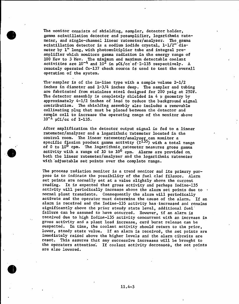
The monitor consists of shielding, sampler, detector holder,gamma scintillation detector and preamplifier, logarithmic rate-meter, and single-channel linear ratemeter/analyser. The gammascintillation detector is a sodium iodide crystal, 1-1/2" dia-meter by 1" long, with photomultiplier tube and integral pre-amplifier which monitors gamma radiation in the energy range of100 Kev to 3 Mev. The minimum and maximum detectable coolantactivities are 10 4 and 10 in pCi/cc of I-135 respectively. Aremotely operated Cs-137 check source is used to test the overalloperation of the system.
The" sampler is of the in-line type with a sample volume 2-1/2inches in diameter and 1-3/4 inches deep. The sampler and tubingare fabricated from stainless steel designed for 200 psig at 250F.The detector assembly is completely shielded in 4 p geometry byapproximately 4-1/2 inches of lead to reduce the background signalcontribution. The shielding assembly also includes a removablecollimating plug that must be placed between the detector andsample cell to increase the operating range of the monitor above10 pCi/cc of I-135.
After amplification the detector output signal is fed to a linearratemeter/analyzer and a logarithmic ratemeter located in thecontrol room. The linear ratemeter/analyzer can monitor aspecific fission product gamma activity (I ) with a total rangeof 0 to 10 cpm. The logarithmic ratemeter measures gross gammaactivity with a range of 10 to 10 cpm. Alarms are provided onboth the linear ratemeter/analyzer and the logarithmic ratemeterwith 'adjustable set points over the complete range.
The process radiation monitor is a trend monitor and its primary pur-pose is to indicate the possibility of the fuel clad filaure. Alarmset points are normally set at a value slightly above the currentreading. It is expected that gross activity and perhaps Iodine-135activity will periodically increase above the alarm set points due tonormal plant transients. Consequently the alarm will periodicallyactivate and the operator must determine the cause of the alarm. If analarm is received and the Iodine-135 activity has increased and remainssignificantly above the prior steady state level, additional
fuel'ailurecan be assumed to have occurred. However, if an alarm isreceived due to high Iodine-135 activity concurrent with an increase ingross activity and a plant load increase, curd burst release can besuspected. In time, the coolant activity should return to the prior,lower, steady state value. If an alarm is received, the set points areimmediately raised above the higher levels and the alarm circuits arereset. This assures that any successive increases will be brought tothe operators attention'. If coolant activity decreases, the set pointsare also lowered.
11.4-3


11.4.2.2 Gaseous Dischar e Honitor
The primary purpose of the gaseous waste discharge monitor is to continuouslymonitor and record all gaseous radioactivity released from the gas decaytanks and to prevent radioactivity in excess of applicable limits frombeing released to the environment.
This monitor is located in the waste management system in the gaseousdischarge line downstream of the gas decay'anks but upstream of theplant stack. Therefore monitoring is accomplished before the gases arediluted in the plant stack. The concentrations of radioactivity expectedto be released from the gas decay tanks are given in Table 11.3-1 underposition number 10.
The monitor measures gross gamma radioactivity. Even though some of thepartially volatile fission products (iodines) will adhere to the wallsof the piping and tanks this will not cause false low readings since theactivity actually being released is the only concern. Shielding isprovided with this monitor to minimize the effects of background radiation.
The monitor consists of an in-line sample detector assembly, shielding,check source, and logari,thmic rate meter and recorder. Flow through thesampler is 1 to 10 scfm and all parts in contact with the process gas arestainless steel.
The detector is a thin-wall Geiger-Huller tube which is shielded againstbackground gamma radiation for a minimum sensitivity of 2 x 10 pCi/ccof Xe133. The total detector range is 10-5 to 10-3 pCi/cc based. ondischarged activity of unknown identity. A collimating plug is used incon)unction with the detector and is used for range of 10 1 to 10 pCi/cc. Mithout the collimating plug detector range is 10 5 to 1.0 pCi/cc.The logarithmic rate meter receives the output signal from the detector.The range of rate meter is 10 to 106 counts per minute.
There are two separate calibration check sources for the monitor. Aremotely operated radiation check source can be exposed to the detectorto calibrate the activity range of the detector. An internallygenerated count rate signal is used to calibrate the logarithmic ratemeter.
The two pen horizontal strip chart recorder receives an elec'trical signalfrom the logarithmic rate meter and continuously records the gaseousradioactivity that is released from the plant. The gas discharge 'flowrate is measured by.a recorder in the control room.
The monitor has an alarm and trip system that is operated by thelogarithmic rate meter. The set point of the alarm and trip isadjustable over the full range of the rate meter. Prior to therelease of gaseous activity, a sample is taken for radioactiveanalysis as described in Section 11.4.3. Both gross and isotopicradioactivity analyses are performed to verify that the activityin the tank can be released to the environment without exceedingthe applicable limits. The alarm set point of the monitor isset slightly greater than the level determined by the grossgamma radioactivity analysis but below the applicable releaselimits.
11.4-4


If the activity should increase above the set point, an alarmis activated in the control room and valve V-6565 on Figure 11.3-1is tripped closed stopping discharge flow. The operator must thendetermine the cause of the alarm and trip . Another sample wouldbe taken for radioactivity analysis to determine if the alarmand trip were due to high activity or instrument mis-calibrationor malfunction. If high activity is the source of alarm, dis-charging from that particular gas decay tank must either be just-ified at a higher activity level or the contents must be allowedto decay for an additional time period. However, if radioact-ivity analysis is identical or slightly less than that found priorto initiating the gaseous discharge, the operator must recalibratethe, detector and logarithmic rate meter. The logarithmic ratemeter is calibrated by activating the internal count rate signalwhich is an internal component of the rate meter. If necessary,adjustments are made to the rate meter to coincide with the countrate signal. The rate meter is then turned to the detector read-ing and the standard check source is positioned in front of thedetector by activating the pushbutton on the rate meter controlpanel. Adjustments are made as required. If it has beenestablished that the alarm was caused by instrument malfunction,discharging can continue only after the malfunction has beenrectified.
11.4.2.3 Li uid Waste Dischar e Monitor
The primary purpose of the liquid waste discharge monitor is tocontinuously monitor and record the radioactivity (gross gamma)that is being discharged in the liquid waste being released to
'hecirculating water canal. The monitor will also terminate theliquid discharge from the plant if the radioactivity being releas-ed exceeds the monitor set point which is set below the applic-able activity release limits.
The monitor is located in the Waste Management System in thedischarge line to the circulating water canal. Monitoring beforedilution with circulating water allows greater accuracy ofmeasurement.
The monitor for this service measures gross gamma radioactivity.The expected concentrations of each nuclide for O.l percent and1.0 percent failed fuel conditions are given in Tables 11.2-6 and11.2-7, position 21, for boron recovery system releases andTables 11.2-11 and 11.2-12, position 15, for liquid waste systemreleases.
Since all the liquid discharge flow passes through the monitor,representative sampling is assured. If excessive radioactivityshould be deposited in the sampler, the sampler may be removedfor decontamination. Shielding is provided to reduce the effectof background radiation.
The monitor consists of an in-line sampler, detector assembly,shielding, check source, logarithmic ratemeter and recorder.Flow through the sampler is 10 to 50 gpm and all wetted partsare stainless steel.
11.4-5

0

TABLE 11.4-1
PROCESS RADIATION MONITORS
R-202 Chemical andVolume Con-trol SystemProcessRadiationMonitor
Channel MonitorMinimum
Gamma Scint- 10 4pCi/ccillation crys-tal with photo-multiplier tubeand integralpreamplifier
I-135
~Pen e Set Point
10 4.to Full Range10 pCi/cc
Maximum AreaRadiationLevel at Detector
5 mr/hr gammaCo-60
Remarks
The set point can be ad-justed as operationsdictate.
R-627 HasteManagementSystem LiquidEffluent
Gamma Scint- 5illation crys-tal with photo-multiplier tubeand integralpreamplifier
x 10-6>Ci/cc Cs-137 10-6 to Full Range10 lp Ci/cc
0.1 mr/hr gammaCo-60
The monitor is adjustedto a set point followingan isotopic analysis ofthe liquid waste to bedischarged. The monitorwill verify the analysisby alarming should the
. discharge activity exceedthe predetermined value.
R-628 WasteManagementSystemGasEffluent
Thin wallGeiger-Mullertube
2 x 10 pCi/cc Xe-133 10 to Full Range10+3pCi/cc
O.l mr/hr gammaCo-60
The monitor is adjustedto a set point followingan isotopic analysis ofthe gas to be discharged,The monitor will verifythe analysis by alarmingshould the dischargeactivity exceed thepredetermined value.
SteamGeneratorBlowdown
Gamma 1ScintillationCrystal withPhotomultiplierTube and IntegralPreamplifier
x 10 pCi/cc Cs-137 10 to Full Range-6 -6
10 lpCi/cc0.1 mr/hr gammaCo-60
(Remarks by EBASCO)

The monitor detector is a gamma scintillation crystal with photo-multiplier tube and integral preamplifier shielded against back-ground gamma radiation for a minimum detector sensitivity of 5 x10 pCi/cc of Cs-137. The operating range is 10 to 10 pCi/ccbased on discharged activity of unknown identity.
The logarithmic ratemeter receives the output signal from thedetector and has a range of 10 to 10 cpm. Ratemeter sensitivityis adjustable over the range of preamplifier output. Gammas withenergies in the ran'ge of 100 Kev to 3 Mev can be detected.
The. monitor contains two separate calibration check sources, re-motely operated radiation check source for calibrating the detect-or and an internally generated count rate signal for calibrating thelogarithmic rate meter. A two pen strip chart recorder receivesan electrical signal from the logarithmic rate meter and recordsthe liquid radioactivity that is released from the plant. Theliquid discharge flow rate is measured and is recorded in thecontrol
room.'f
the activity reaches the set point, an alarm is activated inthe control room and valves FCV-6627X and Y shown on Figure11.2-2 are tripped closed stopping discharge flow. The operatormust then determine the cause of the alarm and trip. Operatoractions would be the same as those described for the gaseousdischarge monitor.
11.4.2.4 Steam Generator Blowdown Monitor
The primary purpose of the steam generator blowdown radioactivitymonitors is to continuously monitor and record the gross gammaactivity discharged during blowdown of the steam generators.
One monitor is located in each blowdown samplh line upstream of. theblowdown line isolation valve.
The concentrations of the nuclides present in the stream generatorblowdown line are listed under WMS, location 1, of Tables 11.2-11 and11.2-12 for normal and anticipated operational occurrences, respectively.
One blow down monitoring system is provided for each steam generator.Each consists of a sampler, gamma scintillation detector assembly withan integral photomultiplier tube and preamplifier, shielding, checksource, logarithmic rate meter. One recorder serves both monitors.
The detector is a gamma scintillation crystal with photomultiplier tubeand integral preamplifier shielded against, background radiation for aminimum detector sensivity of 1.0 x 10 pCi/cc of Cs-137. The operatingrange is 10 6 to 10 pCi/cc based on discharged activity of unknownidentity.
11.4-7

The logarithmic ratemeter receives the output signal from the detectorand has a range of 10 to 10 cpm. The ratemeter sensitivity is adjust-able over the range of preamplifier output. Gammas with energies in therange of 100 Kev to 3 Mev can be detected.
'I
The monitor contains two separate calibration check sources, remotelyoperated radiation check source for calibrating the detector, andinternally generated count rate signal fog calibrating the logarithmicratemeter.
A two pen strip chart recorder in the control room receives electrical.signals from the two logarithmic ratemeters and records the radio-activity in the blowdown from each steam generator.
Each ratemeter activates a high radiation alarm in the control room andprovides a signal to trip closed the blowdown valves,- FCV-27, 28, 29, and30, on high radiation. The high radioactivity alarm set point is adjust-able over the full range of the ratemeter.
Since blowdown water normally contains no radioactivity and very lowchemical concentration, it is normally discharged directly to the circu-lation water canal. The blowdown radioactivity monitor alarm/trip setpoint is selected to.,assure that applicable discharge limits are notexceeded:
The monitor has an alarm and trip system controlled by thelogarithmic ratemeter. The high radioactivity set point isadjustable over the full range of the ratemeter. The setpoint is determined as a result of sample analysis prior tothe discharge of any fluid from the blowdown tank. The analysismust verify that the concentration of radioactivity to be dischargedis less than applicable release limits. The alarm and trip setpoint of the logarithmic ratemeter is set slightly above theactivity determined from the gross radioactivity analysis butbelow the applicable release limits.
The detector assembly and the logarithmi.c ratemeter may need to berecalibrated. The ratemeter is calibrated first by activating thecount rate signal which is an integral part of the ratemeter. Ifnecessary, adjustments are made to the ratemeter reading to coin-cide with the count rate signal. The ratemeter is then switchedto the detector and the standard check source is exposed to thedetector by activating the pushbutton on the ratemeter controlpanel. Adjustments are then made as required.
11.4.2.5 Condenser Air E ector Monitor
Activity levels are recorded in the control room and alarms annun-ciated when the activity level exceeds predetermined limLts. Thechannel consists of an off-line effluent sampler, a beta scintill-ation detector, a Cs-137 check source, a logarithmic ratemeter andpower supply. The detector assembly has an integral preamplifierwith a dynamic range of 25 and a voltage gain of 50. This dynamic
11.4-8

0

range allows resolution of pulses from 80 Kev to 2 Mev. Thesampler is shielded with 3" of lead. The detector has a plast'icscintillator, 2" diameter and approximately 10 mil thick, witha 10 stage photomultiplier. The operation limit for pressureis 50 psig and temperature limit 125 F. The ratemeter coversa range of 10-106 cpm with a meter accuracy of +2 percent fullscale. The channel activity level is recorded in the controlroom.
The ratemeter has lights to indicate the local indicator failureto indicate a high radiation level warning and to indicate a high-high radiatio'n alarm. A positive displacement, direct drive, dryvane 4 cfm pumping system is provided with this channel.
11.4.2.6 Com onent Coolin Water Monitor
The component cooling water monitors are designed to providean indication to operation personnel whenever the activityin the component cooling system reaches or. exceeds a preestablishedlevel above the normal radiation level.
Each monitor consists of a shielded sampler, detector holder, gamma
scintillation detector a Cs-137 check source, preamplifier and log-~ IIarithmic ratemeter. The gamma scintillation detector utilizes a 1-1/2
diameter, 1" thick sodium iodide crystal with a 10 stage photomultipliertube and integral preamplifier. The preamplifier has a dynamic rangewhich allows resolution of pulses from ranges of 80 Kev to 2 Mev. Theminimum and maximum detectable coolant activities to Cs-137 in 2 mr/hrbackground of 1.25 Mev gamma radiation incident on the detector shieldis 2.8 x 10 yCi/cc to 1.6 x 10 2 pCi/cc. The sampler is of the off-line type with a sample volume of 191 in 3. The sampler is providedwith 3" of lead shielding.
J
The detectors are located downstream of each of the component coolingsystem heat exchangers so that any possible release of radioactivityvia a tube leak is monitored. The ratemeter associated with thischannel is similar to the one described in 11.4.2.5. This channelis annunciated both locally and in the control room whenever anabnormal level of activity is detected. The effected heat exchangermay then be isolated and removed from service by closing isolationvalves.
The activity levels are recorded in control room. The alarm setpoints are set at a slightly higher radiation level than normallywould be expected.
11.4.3 SAMPLING
Periodic sampling is required for a performance check on some ofthe process equipment, and to alert the operator to any abnormalcondition that may be developing. The samples required are localliquid samples and gaseous samples taken directly by the gas analyzer.The location for these samples are as follows:
11.4-9


a) Local Li uid Sam les
b)
Flush tank influent and effluent
Preconcentrator filter influent and effluent
Preconcentrator ion exchanger influent and effluent
Boric acid concentrator distillate and bottoms
Boric acid condensate ion exchanger influent and effluent
Boric acid condensate tank recirculation
Boric acid holding tank recirculation
Equipment drain tank recirculation
Chemical drain tank recirculation
Laundry drain tank recirculation
Waste filter influent and effluent
Waste condensate tank recirculation
Waste ion exchanger discharge
Waste concentrator distillate and bottoms
Liquid effluent discharge to the circulating water canal
Gas Anal zer Sam les
Volume control tank
Flash tank
Holdup tank
Spent resin tank
Containment vent header
Gas surge tank
Gas decay tank
Additional samples are also taken at various strategic locationsin the plant but these sample stations are connected directlyto the sampling system and are discussed in Section 9.3.2.
t
The basis for selecting the above locations for sampling stationsis to check the performance of process equipment thus maintaining
11.4-10

e

the required chemistry throughout the'operating plant. Forliquid samples the expected composition of the nuclides takenat a specific point should be consistent with the specificactivities and decontamination factors as listed in Section11.2.
For all the liquid samples the analysis performed will det-ermine isotopic concentrations. The sample can also be usedfor a gross elemental analysis. The gaseous samples, however,are analyzed for gross concentration, as well as isotopicconcentrations. Gas samples to the gas analyzer are anal-yzed for gross oxygen and hydrogen concentrations and alarmswarn the operator if a potential explosive mixture exists atthe sample point. A connection of the discharge side ofthe gas analyzer is available for taking a grab sample forisotopic analysis.
The frequency of taking samples from the various locationsalong with the analysis to be performed is listed in Table11.4-2. The frequency of sampling for the gaseous content isused as a preliminary guide and may be increased or decreasedas operating personnel become more familiar with the plant ~

TABLE 11.4-2
SAMPLE LOCATIONS AND ANALYSIS
Sam le Location
Flash Tank
Sam le Anal sis ~Pre uenc
Influentand Effluent
Dissolved hydrogen andgaseous activity 2/year
Pre-Concentrator Filter
.Influentand Effluent
Suspended solids andsuspended solids activity 1/week
Pre-Concentrator IonExchanger
Influentand Effluent
Gross beta-gamma andlithium content 1/week
Boric Acid ConcentratorBottoms and Distillate
Boron content and grossbeta-gamma activity 2/batch*
Boric Acid CondensateIon Exchanger
Influentand Effluent
Boron content and grossbeta-gamma activity 3/year
Boric Acid CondensateRecirculation Isotopic
Prior to dischargecontent of tank
Discharge Line to theCirculating RaterDischarge Gross beta-gamma activity
During each boricacid tank dis-charge operation
Boric Acid HoldingTank
Boron content and grossbeta-gamma
Each time tankis emptied
Equipment DrainTank
Gross beta-gamma andboron content
Each time contents oftank are processed ordischarged to circulatingwater canal
Chemical Drain Tank Gross beta-gamma Each time contents of tankare processed or dis-charged to circulatingwater canal
* This frequency may be reduced as experience is'ained on theunits operation.
11.4-12

TABLE 11.4-2 (Cont.)
Sam le Location
Laundry Drain Tank
Sam le Anal sis
Gross beta-gamma
Fre<rFuenc r
Each time contentsof tank is dischargedto circulating watercanal
Waste Filter Influentand Effluent
Suspended solids andsuspended solids activity 1/week
Waste CondensateTank
Gross beta-gamma Each time contents oftank is discharged tocirculating water canal
Waste Ion Exchanger Boron content andGross beta-gamma 3/year
Waste ConcentratorDistillate and Bottoms
Boron content andgross beta-gamma 5/batch
GAS SAMPLES
Volume Control Tank Hydrogen, oxygen andisotopi.c analysis 1/week
Flash Tank
Holdup Tank
Spent Resin Tank
Containment Vent Header
Gas Surge Tank
Hydrogen, oxygen andisotopic analysis
Hydrogen and oxygen
Isotopic analysis
Isotopic analysis
Hydrogen, oxygen andisotopic analysis
2/year
2/year
1/year
5/year
1/day
Gas Decay Tank Hydrogen, oxygen, andisotopic analysis 1/week
11. 4-13

When obtaining local liquid samples, it is important to obtainrepresentative samples. All local sample points are taken from,vertically run pipe or from the top of horizontal run pipe. Thelocal sample lines are as short as possible and the samplingisolation valves are located as close to the source as possibleto limit the amount of purge water required before a represent-ative sample is obtained.
The sample line is connected by plastic'ubing to a 5 gallonpoly bottle which may be vented via a HEPA-charcoal filters, ifnecessary. After purging, the sample is collected in a smallpoly bottle by diverting the sample flow. After filling, thesample bottle is sealed and marked as to sample location and dateand time of sampling.
11.4.3.1 Preconcentrator and Waste Filters
The influent and effluent samples are periodically taken andanalyzed to ensure that the filters are removing suspended solids.A sample of suspended solids is obtained by filtering the liquidsample through a millipore filter. A count of filtered activity(gross count) is made and an analysis of crud weight is done byvisual comparison with a known standard or the sample is driedand weighed. Only the portion of activity in particulate formis of direct interest, but dissolved activity would also normallybe measured. Crud weight concentration at the filter inlets isnormally 10 to 20 ppb but could be much higher at times. Effluentactivity crud concentrations will normally be only a smallpercentage of influent values. The filters are normally changedon high radio-activity or high differential pressure. They arealso replaced if testing reveals low decontamination factor (DF).
The procedures and calculations for determining suspended solidsactivity and crud weight are as follows:
a) Determination
A sample aliquot is filtered onto a (0.45 micron) membranefilter paper. Depending on the expected concentration, theactual value is either determined by visual comparison witha known standard, or the sample is dried and weighed;
b) Limitations
The accuracy of these methods is dependent on the actualconcentration involved, the drying time, and weighingaccuracy.
c) Procedure
1) A specific procedure is used for the determination ofsuspended solids by actually weighing the sample. Ifthe sample to be analyzed contains radioactive sub-stances the appropriate precautions are observed.
11.4-14

The weight of particulate matter is adjusted for thedifference between final and initial weight of thetest filter as "weight of particulate matter" andrecorded.
2) An alternate procedure is used for the determinationof suspended solids by color comparison.
d) Calculations
1) S/S (ppm) ~ —x 1000W
V
where: S/S Suspended Solids
W = Weigh t of residue on filter paper
V Liters of sample
2) The concentration is obtained directly from the sgerg-brane filter comparison chart in ASTM D1888.
e) ReferenceASTM, D1888
11.4.3.2 Flash Tank
The influent and effluent samples are taken to verify the perfor-mance capability of the flash tank. Periodically, gas samples areautomatically taken from the holdup tanks which give indication'of flash tank performance during normal operation. An increase inhydrogen content in the holdup tank gas space indicates malfunctionof the flash tank. On increase in hydrogen content the flash tankcontrols would be checked and maintenance performed. If it isnecessary to continue processing letdown waste, the flash tankcan be bypassed by diverting the influent directly to the holduptanks. The contents of the holdup tanks can be recycled laterthrough the flash tank as operational conditions permit. The hydro-gen concentration in the influent is expected to be approximately10 to 35 cc (H2) /kg (H20) and the effluent is expected to be equalto or less than 5 cc (H2) /kg (H20). A typical procedure fortesting for dissolved hydrogen is described in ASTM E-260-65T.
11.4.3.3 Preconcentrator Ion Exchan er
Influent and effluent samples are taken to determine the ionexchanger decontamination factor and to determine performanceeffectiveness. The decontamination factor is determined bymeasuring the gross beta-,gamm'a activity of coolant entering theion exchanger and comparing it to the gross beta-gamma activityof coolant leaving the ion exchanger. Influent and effluent con-centrations by nuclide are identified in Table 11.2-3. Measurementsfor lithium content are also made. If lithium breakthrough shouldoccur, lithium will build up in the boric acid concentrate. Insuch a case the ion exchanger resin will be replaced on highlithium or high soluble .activity breakthrough. The proceduresused for lithium and decontamination tests are as follows:
l


Determination of Lithium in Water
a) DeterminationLithium standards and the sample are aspirated into aflame through which a beam of light of specific wave-length is passed. The amount of absorption that occursby the lithium atoms in the flame is related to theconcentration of lithium in the solution. By use of acurve of concentration versus absorbance based on knownstandards the concentration of the unknown sample canbe determined.
b) Limitations
In a water matrix of low dissolved solids (<1 percent) nointerferences are known. In higher concentrations of dis-solved solids the rate of aspiration will decrease as thepercent of dissolved solids increases and low results willbe obtained. To correct for high dissolved solids, stan-dards of the approximate salt concentration of the samplemay be prepared and run with the sample or the methodof addition may be analyzed.
The sensitivity for lithium is 0.03 ppm for 1 percent absorption.
Determination of gross beta-gamma activity in water.
a) Determination
The gross beta-gamma activity of the sample is measuredby evaporating a two milliliteraliquot 'in a metalplanchet and beginning a 5 minutes count 1 hour aftersample was obtained.
b) Limitations
Some volatile activities are lost through the heating-evaporation cycle. Al'so since this sample is countedin a G-M counter, a high counting rate sample maysuffer statistical counting losses due to the longdead time inherent in G-M counter.
c) Calculations Gross counts in cpm — BackgroundCount in c m
1) For results in dpm/cc = Effi f d i ~c m Sample iEfficiency of detector in . x in ccdpm Volume
2) For results in PCi'/cc =2 22 10
d m
pCiGross counts in c m— back round count in c m(Efficiency of detector in ~c m) sample volume in cc (2.22xl0 ~d
dpm pCi
11.4-16

0
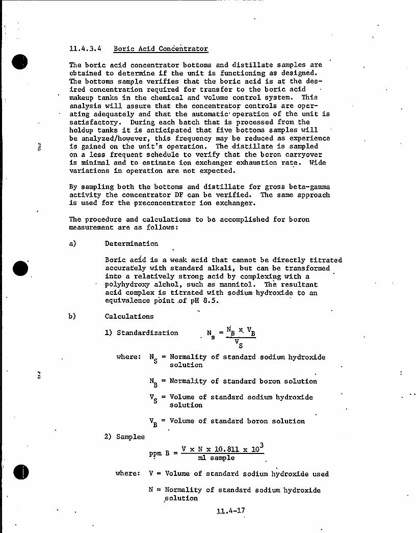
11.4.3.4 Boric Acid Concentrator
The boric acid concentrator bottoms and distillate samples areobtained to determine if the unit is functioning as designed.The bottoms sample verifies that the boric acid is at the des-ired concentration required for transfer to the boric acidmakeup tanks in the chemical and volume control system. Thisanalysis will assure that the concentrator controls are oper-ating adequately and that the automatic'peration of the unit issatisfactory. During each batch that is processed from theholdup tanks it is anticipated that five bottoms 'samples willbe analyzed/however, this frequency may be reduced as experienceis gained on the unit's operation. The distillate is sampledon a less frequent schedule to verify that the boron carryoveris minimal and to estimate ion exchanger exhaustion rate. Hidevariations in operation are not expected.
By sampling both the bottoms and distillate for gross beta-gammaactivity the concentrator DP can be verified. The same approachis used for the preconcentrator ion exchanger.
The procedure and calculations to be accomplished for boronmeasurement are as follows:
a) Determination
Boric acid is a weak acid that cannot be directly titratedaccurately with standard alkali, but can be transformedinto a relatively strong acid by complexing with apolyhydroxy alchol, such as mannitol. The resultantacid complex is titrated with sodium hydroxide to anequivalence point,of pH 8.5.
Calculations
1) Standardization N ~ NB x VB5
VS
where: N = Normality of standard sodium hydroxideS solution
N = Normality of standard boron solutionB
V Volume of standard sodium hydroxideS solution
2) Samples
V Volume of standard boron solutionB
V x N x 10.811 x 10³
ml sample
where: V = Volume of standard sodium hydroxide used
N = Normality of standard sodium hydroxide,solution
11.4-17


3) Accuracy of Method
The data given below illustrates the accuracy of themethod for determining boron concentration.
Concentration( m boron)
Standard Deviation(+ ppm boron)
50100200500
10002000
1.381.641.050.552.173. 93
11.4.3.5 Boric Acid Condensate Ion Exchan er
Influent and effluent samples are taken to determine the eff-ectiveness for boron removal and to verify the performancecapability. Liquid samples are taken from the boric acidcondensate tanks prior to discharge to the circulating waterdischarge, which would indicate functionability of the boricacid condensate ion exchangers. An increase in boron content oractivity would indicate malfunction of the ion exchanger. Theion exchanger is designed for long operation periods and anycarryover would be extremely infrequent. If high boron or highactivity breakthrough should occur the ion exchanger resin willbe replaced. The contents of the tank would then be recycledthrough the recharged ion exchanger prior to discharge, ifnecessary. The tests for boron content are the same as definedin Section 11.4.3.4 and the test for ion exchanger decontaminationfactor are indicated in Section 11.4.3.3.
11.4.3.6 Boric Acid Condensate Tank
The contents of the boric acid condensate tank are recirculated,a representative sample of the tank contents is obtained, and adetermination of the isotopic inventory is made. A sample isobtained by recycling the contents of the tank until a homo-geneous mixture is attained and then a sample is drawn offthe recirculation line. If the analysis indicates that releasecan be made within permissible limits, the quantity of activityto be released is recorded on the basis of liquid volume in thetank and its activity concentration. If release cannot be madewithin permissible limits, the waste is recycled for furtherprocessing. The concentrations of various nuclides are indicatedin Table 11.2-3. The method used for analysis is gamma spectrometryin accordance with ASTM D2459-69.
11.4.3.7 Circulatin Water .Dischar e
This sample point is located downstream of the process radiationmonitor. The purpose of obtaining the sample here is to provideverification that the process radiation monitor is functioningproperly. A gross-beta analysis similar to the procedures utilized
11.4-18


for determination of ion exchanger decontamination factor canbe followed. This measurement also serves as a redundant ver-ification of the isotopic analysis made in the boric acidcondensate tanks and the gross-beta analysis performed by theprocess radiation monitor. The concentrations by nuclidewould be the same as those in the boric acid condensate tanks.
11.4.3.8 Boric Acid Holdin Tank
A sample is obtained by recirculating the contents of thetank to achieve a homogeneous mixture prior to drawing offa sample in the recirculation line. The analytical techniqueto be employed will be identical to that for the boric acidconcentrator bottoms determination and is discussed in Section11.4.3.4. When concentration of boron matches that in theboric acid makeup tank the liquid can be transferred to themakeup tank, or if capacity is not available and boric acidis contaminated it can be pumped to the drumming station fordisposal. This station can also be used for taking a samplefor activity analysis.
11.4.3.9 E ui ment Drain Tank
A sample is obtained by recirculating the contents of the tankto achieve mixing prior to drawing off a sample. The sampleis to be analyzed for gross beta and boron content and analyticaltechniques are discussed in Section 11.4.3.3. The analyticalresults will determine if the liquid can be either processed bythe waste concentrator or boric acid concentrator, or if activityis below the release limits of 10CFR20 it can be directly dis-charged via the circulating water discharge.
11.4.3.10 Chemical Drain Tank
The contents of the chemical drain tank are recirculated toachieve mixing prior to drawing off a sample.
The only analysis that is required is a gross beta-gamma countand the technique to be employed is discussed in Section 11.4.3.3.for gross beta-gamma activity in water. The gross activity countwill determine if liquid can be discharged directly or if it .
should be processed in the waste concentrator.
11.4.3.11 Laundr Drain Tank"
The sampling and analytical techniques to be used for this tankis identical to that for the chemical drain tank. However theliquid from this tank is discharged directly to the circulatingwater canal after passing through a filter.11.4.3.12 Waste Concentrator
The bottoms and distillate of the waste concentrator are sampledfor boron content and gross beta-gamma count to check the per-
11.4-19


formance of the unit. The analytical techniques to be employedare given in Section 11.4.3.4 for boron analyses and Section11.4.3.3. for the gross beta-gamma count.
11.4.3. 13 Was te Ion Exchan er
The discharge of the waste ionfor boron and gross beta-gammaat the provided connection andemployed for boron is given in11.4.3.3 for gross beta-gamma.
exchanger is sampled and analyzedcount. The sample is drawn offthe analytical technique to beSection 11.4.3.4 and Section
The sample analyzed at this point along with the sample forthe distillate on the waste concentrator will determine theperformance of the ion exchanger.
11.4.3.14 Waste Condensate Tank
The contents of the waste condensate tank are recirculated toachieve mixing prior to sampling. The samples are analyzed fora gross beta-gamma count prior to discharging the contents tothe circulating water canal. However, if the count exceedsthe acceptable limit the liquid is pumped to the waste concen-trator or waste ion exchanger for additional processing. Theanalytical technique employed is discussed in Section 11.4.3.3.
A gas analyzer is used to determine the concentration of hydrogenand oxygen in the gas to be sampled from the various sources asgiven in Section 11.4.3. The gas analyzer has an automatic timingdevice that periodically samples the gas from the tanks and ventsby opening and closing appropriate solenoid valves. After thesystem is lined up to a particular sampling station and flow hasstarted, entrained water is removed from the sample by flowingthrough a water separator trap. The excess water is drained fromthe trap and sent to the equipme'nt drain tank, while the gas ispumped to a refrigeration unit where saturated water is removed.From the refrigeration unit the gas flows to the oxygen and hyd-rogen sensing devices, and then another pump is used to dischargethe gas to the gas surge header. The hydrogen and oxygen sensingelements are installed in parallel with a flow meter installedupstream of each sensor so that the operator can manually balancethe flow to each sensor. The readout signal from the sensor issent to a recorder where the oxygen and hydrogen concentrationsare recorded. If an explosive mixture is being approached thegas analyzer alarm will annunciate in the control room to alertthe operator that immediate action is required. The explosivemixture can be avoided by either purging or diluting withnitrogen.
Calibration gases for the gas analyzer are required. A zerogas (prepurified nitrogen) is required for the hydrogen andoxygen sensors and a span gas (45 percent hydrogen in nitrogen)
11.4-20


is required for the hydrogen sensor. These gases arerequired to periodically calibrate the instrument. Oil-freeair is required to purge the sensors prior to and aftercalibrating.
Sample connections are available in the system downstream ofthe pump that returns the gas to the gas surge header wherea sample container (1 liter) is attached- for taking a samplefor isotopic analysis. An option is available to the oper-ator for either bypassing the sensors to take the radioactivesample or the radioactive sample can be the same gas thathas passed through the sensors for the hydrogen and oxygendetermination.
11.4.4 CALIBRATION AND MAINTENANCE
All radiation monitoring systems are calibrated periodicallyon a schedule shown in Section 16.4 of the Technical Specifications.Any maintenance required will be conducted in accordance with theinstructions provided by the instrument manufacturer.
11.4-21
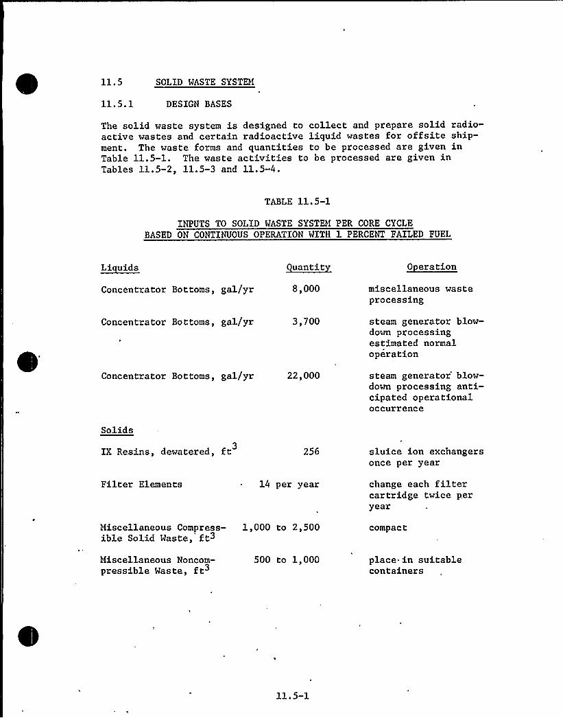
11.5 SOLID WASTE SYSTEM
11.5.1 DESIGN BASES
The solid waste system is designed to collect and prepare solid radio-active wastes and certain radioactive liquid wastes for offsite ship-ment. The waste forms and quantities to be processed are given inTable 11.5-1. The waste activities to be processed are given inTables 11.5-2, 11.5-3 and 11.5-4.
TABLE 11.5-1
INPUTS TO SOLID WASTE SYSTEM PER CORE CYCLEBASED ON CONTINUOUS OPERATION WITH 1 PERCENT FAILED FUEL
~Li uids
Concentrator Bottoms, gal/yr
~uantit
8,000
~Oatatiun
miscellaneous wasteprocessing
Concentrator Bottoms, gal/yr 3,700 steam generator blow-down processingestimated normaloperation
Concentrator Bottoms, gal/yr 22,000 steam generator'low-down processing anti-cipated operationaloccurrence
Solids
IX Resins, dewatered, ft3256 sluice ion exchangers
once per year
Filter Elements 14 per year change each filtercartridge twice peryear
~ifiscellaneous Compress- 1,000 to 2,500ible Solid Waste, ft3
compact
Hiscellaneous Noncom-pressible Waste, ft
500 to 1,000 place. in suitablecontainers
11.5-1

11.5.2 SYSTEM DESCRIPTION
The solid waste system is shown on Figure 11.2-4. Concentrate from .
the waste concentrator is pumped directly from the concentrator to thedrum fillstation. As shown on Figure 11.2-3, the boric acid concen-trator bottoms from either concentrator can be bypassed around theboric acid holding tank directly to the drumming station while theother boric acid concentrator bottoms are being processed through theboric acid holding tank. This bypass can be used to return re-concen-trated boric acid directly to the boric acid makeup tanks in the chem-ical and volume control system (CVCS) in the event of problems withthe holding tank, but the bypass will more likely be used when aboric acid concentrator is used for miscellaneous waste processingthereby avoiding contamination of the holding tank.
At the drumming station, the concentrate from either the waste concen-trator or one of the boric acid concentrators enters a shipping drumas described in Section 11.5.5. The liquid waste quantity from theconcentrators is based on processing the 156,000 gallons of miscell-aneous liquid waste per Table 11.2-1. This waste is concentrated bya minimum factor of approximately 20 resulting in approximately8,000 gallons or 1,000 cubic feet of concentrate to be solidified peryear. When mixed with cement and absorbents in the shipping drums,the shipped volume is approximately 2,400 cubic feet requiringapproximately 330-55-gallon drums.
Because most of the 156,000 gallons of water that enters the liquidwaste system is a result of decontamination operations, and floorwashdowns, the radioactivity is diluted significantly by uncontaminatedwash water. Consequently, the aerated waste influent activity isapproximately 1 percent of the reactor coolant activity.No credit is taken for activity removal by the waste filter in evaluat-ing concentrator bottoms activities. Except for tritium, the concen-trate activities are a factor of 20 above influent activities. Tritiumconcentration is one hundredth of Table 11.1-1. Steam generatorblowdown due to primary to secondary leakage is processed similarilyto liquid wastes. Approximately 3,700 gallons per year of waste con-centrator bottoms are generated as a result of a continuous 20 gpd.steam generator leak for normal operation (0.1 percent failed fuel).The shipped volume of solidified waste is approximately 1,100 ft3requiring 160-55-gallon drums. The anticipated operational occurrencewith a steam generator leak of 120 gpd results in approximately 22,000gal/yr of bottoms and 6,600 ft of solidified waste. Drumming stationinfluent activities from these sources are given on Table 11.5-2.Concentrator bottom activity after day decay period is shown onTable 11.5-3.
Packaging requirements based on these activities in concentratorbottoms quantities are defined in Section 11.5.5.
11.5-2

TABLE 13..5-2
CONCENTRATOR BOTTOMS INPUT ACTIVITY TO SOLID WASTE SYSTEM PER CORE CYCLE
Normal 0 eration Antici ated 0 erational Occurrences
NuclideWaste Concentration(pCi/cc at 70 F) Total Curies/ ear
Waste Concentration(pCi/cc at 70 F) Total Curies/ ear
'H-3Sr-89Sr-90Y-90Sr-91Y-91Mo-99Ru-103Ru-106I-129I-131Te-132I-133
, Cs-134I-135Cs-136Cs-137Ba-140La-140Pr-143Ce-144Co-60Fe-59.Co-58Mn-54Cr-51Zr-95
Total
2.21(-3)1.67(-4)1.07(-5)4. 34 (-6)1.35'(-8)3. 78 (-3)9.3 (-3)1.28(-4)1.02(-5)2.981(-9)5. 72 (-2)1. 87 (-3)1. 56 (-3)4. 1 (-3)3. 08 (-7)5.08(-4)1. 12 (-2)1.2 (-4)1. 06 (-5)1.19(-4)1.69(-4)2.14(-4)3.36(-6) .
1. 63 (-3)1.21(-5)1.05(-3)3.22(-7)
9.86(-2)7.45(-3)4.77(-4)1.94(-4)6.02(-7)1.69
.4155.71(-3)4.55 (-4)1.33(-7)2.558.34(-2)6.96(-2)
.1831.37(-5)2.27(-2)
.5005.35(-3)4.73(-4)5.31(-3)7.54(-3)9.54(-3)1.50(-4)7.27(-2)4.50(-4)4.68(-2)1.44(-5)
5.78
1. 39 (-2)8.68(-3)5.5 (-4)3.6 (-4)9.12(-5)1.97(-l)7. 44 (-1)6. 70 (-2)5. 24 (-3)1. 52 (-7)3.321.38(-1)5.54(-1)2.1 (-1)2. 74 (-3)2. 8 (-2)6. 54 (-1)6.6 (-3)1.29(-3)6.52(-3)8;72(-3)1.1 (-3)1.35(-5)8.42(-3)5.8 (-5)5.56(-3)1.67(-6)
1.60.998
6.33(-2)4.14(-2)1.05(-2)
22.6685.56
7.71.603
1.75(-5)382.80
15.8763.7124.15
.3153.22
75.21.759.148.750
1.003..127
1.55(-3).968
6.67(-3).639
1.23(-4)
689

TABLE 11.5-3
CONCENTRATOR BOTTOMS ACTIVITY AFTER 90-DAY DECAY
Nuclide
H-3
Sr-89
Sr-90
Y-91
Ru-103
Ru-106
I-129I-131Cs-134
Cs-136
C,s-137
Ba-140
Pr-143
Ce-144
Co-60
Fe-59
Co-58
Mn-54
Cr-51
Zr-95
Total
Normal Operation Curies
9. 71(-2)2. 17 (-3)4. 74 (-4)0.587
1.20(-3)3.84(-4)1. 33 (-7)1.10(-3)0. 168
1. 87 (-4)0.497
4.09 (-5)5. 60 (-5)6. 05 (-3)9. 24 (-3)3.75(-5)3.02(-2)3. 69 (-4)4. 64 (-3)~5.51 -6)1.38
Anticipated OperationalOccurrence Curies
1.575
0.291
6. 30 (-2)7.87
1.62
0.508
1. 75 (-5)0.165
22.2
2. 65 (-2)74. 8
5'. 80 (-3)7. 92 (-3)0.804
0.123
3.88(-4)0.402
5. 46 (-3)6. 34 (-2)4.71(-5)110
11. 5-4

The ion exchanger resin activity buildup is based on inlet activity con-centration in Table ll.l-l, the maximum removal of each nuclide for. eachprocess ion exchanger and the expected flow rate through each ion ex-changer. The chemical and volume control system purification ion ex-changer is assumed to continuously process 40 gpm letdown over the fullcore cycle after being used in the previous core cycle for lithiumremoval. The chemical and volume control system purification ion ex-changer used for lithium removal is assumed to process 40 gpm letdownover 20 percent of the core cycle which is the expected usage of theunit to control lithium concentration. The chemical and volume controlsystem deborating ion exchanger is assumed to process letdown over 2.4percent of the core cycle. This is the expected usage of the unit toremove the final 30 ppm of boron in the reactor coolant to compensatefor fuel burnup. Each of the two WMS preconcentrator ion exchangersare assumed to process one half of the 843,000 gallons of clean wasteper year. The waste was assumed to be letdown reactor coolant which hasalready passed through a chemical and volume control system ion ex-changer. The boric acid condensate and the waste ion exchangers willnot retain a significant amount of activity due to the very low con-centration of activity in the inlet process fluid. The fuel pool ionexchanger is assumed to remove the portion of reactor coolant systemend of life activity which enters the fuel pool water, assuming completemixing, after being diluted by the refueling water. The activities onthese ion exchangers by nuclide after one core cycle of operation with1 percent failed fuel (anticipated operational occurrence)are given inTable 11.5-4. Normal operation with 0.1 percent failed fuel would resultin 0.1 of the activity given for anticipated operational occurrence.Actually the chemical and volume control system purification bed acti-vities represent the curies accumulated in two years of operation withone percent failed fuel. During the first year of operation, the resinis gradually converted from the H-B03 form to the Li-B03 form as lithium,produced by the B10 (q, ~ ) Li7 reaction in the core, is controlled belowits upper concentration limit. During this time, monovalent cationssuch as cesium are removed by this bed from the coolant. By the endof one core cycle ( ~ 20 percent usage factor) this bed becomes saturatedwith lithium. Although the monovalent cations on the bed are retained,the bed loses capability to remove these cations from the coolant.When the bed is run continuously during the second core cycle, theactivities of Cs, Mo, and Y decrease due to radioactive decay.
Activities on the various ion exchange resin beds after six monthsand one year decay are shown on Table 11.5-5. Cesium-137 dominates theactivity that must be shipped, but without significant failed fuel,Co-60 would dominate. Assuming eight beds are disposed of per year(one purification, one deborating, two preconcentrator, two boric acidcondensate, one waste condensate, and one fuel pool purification) themixed activity would be about 23,000 Ci or 90 Ci/ft3. Packaging re-quirements for this activity concentration and resin quantity aredefined in Section 11.5.5.
11.5-5

Filter vessels used in removing particulates from process streams areinstalled behind labyrinthed'oncrete cubicles roofed over by a concreteslab. The roof slab is fitted with a removable concrete hatch. Holesin the hatch permit long handled tools to operate valves for drainingvessel and to undo head bolt nuts to permit vessel head to swing openin a vertical arc. A monorail system above the cubicle roof allows forremoving the hatch and setting it aside. Filters of high activity levelsrequire a shielding device simulating an inverted bell to be positionedover the opened hatch. A winch device and appropriate opening allowthe filter cartridge to be withdrawn from the filter vessel and into thecartridge (inverted bell) shield. The cartridge shield is replaced on atransport device and removed to the drumming area where the cartridge willbe prepared for disposal.
Low level activity cartridges-may be removed without the use of a cart-ridge shield. Upon removal through the hatch it would be deposited ina shipping container positioned to receive the filter. The containerwould then be removed to the drumming area for final preparation fordisposal.
The activity level on the filter elements is based on a conservativelyhigh inlet concentration, the maximum removal for each nuclide and theexpected flow rate through each unit. The purification filters 1A and1B are each assumed to process 40 gpm in series (1A upstream and 1Bdownstream of ion exchangers) continuously over the entire core cycle.The fuel pool purification filter is assumed to remove the portion ofreactor coolant system end of life activity which enters the fuel poolwater, assuming complete mixing, after being diluted by the refuelingwater. The waste management system waste filter and the laundry filterare not expected to retain a significant amount of activity due to thevery low concentration of activity in the inlet process fluid and thelow quantity of liquid each unit must process. Each of the two pre-concentrator filters are assumed to process one half of liquid wasteprocessed by the boron recovery system. This waste is assumed to bereactor coolant which has been processed by the chemical and volume controlsystem.
The activity on these filters after one core cycle with source activitiesequivalent to one percent failed fuel are given in Table 11.5-6. 'Thesesame filter activities after six months and one year decay 'are shownin Table 11.5-7. The total activity for a given filter may be dividedbetween a number of cartridges that could be packaged separately. Pack-aging requirements for filter cartridges based on the activities ofTable 11.5-7 are defined in Section 11.5.5.
Miscellaneous compressible solid waste such as contaminated clothing,plastic sheeting, and tape, accumulates as a result of health physicsand maintenance activities. Volumes before compression typically rangefrom 1000 to 2500 cubic feet per year at operating plants. Activitytypically ranges from 0.5 to 1 curie per year.
Noncompressible solid waste such as tools, contaminated equipment, typi-cally ranges from 500 to 1000 cubic feet per year as packaged. Activitytypically r'anges from 5 to 15 curies per year.
,11.5-6

TABLE 11.5-4
ACTIVITY BUILDUP ON ION EXCHANGE RESINS PER CORE CYCLEWITH 1% FAILED FUEL (CURIES(1)
Nuclide
Br-84Rb-88Rb-89Sr-89Sr-90Y-90Sr-91Y-91Mo-99Ru-103Ru-106Te-129I-129I-131Te-132I-132I-133Te-134I-134Cs-134I-135Cs-136Cs-137Cs-138Ba-140La-140Pr-143Ce-144FissionProductTotal
Cr-51Mn-54Co-58Fe-59Co-60Zr-95CorrosionProductTotalOverallTotal
CVCS (2)Purification
0.455140. 2911024.50.2150.65004506516.50.471.1 x 10-214,00043045.521500.3051040003303718.5001.3343.9532265
41,000 Ci(2)
6.00.30018.95.6 x 10. 2
8.303.49 x 10 3
32.6
41,000
CVCS
Deboratin
1.1 x 10 2
00000000001.11 x 10 2
5.24 x 10-6160.58.121.03527.2 x 10-30.2407.950000000
230 Ci
0.14400.45400.1990
0.797
231
10-610-610-8
9.1 x2.8 x5.8 x0.224.9 x1.08 x1.2 x2522. 50.133 ' x9.4 x2 ' x0.280.869.1 x4.3 x6.1 x2.0 x2006.6 x1.859256.5 x6.8 x7.9 x6.4 x0.53
10-210 2
10-5
10-210-410-7
10-410-210-410-4
10 3
10-210-410 310-2
1150 Ci (3)
1.1 x 10 2
03.5 x 10 2
01.3 x 10⁻²⁰
5.9 x 10⁻²
1150
WMS
Pre Conc. each)FPSPurification
5 11 x 10-21.663.44 x 10-20.4733.09 x 10 2
4 27 x 10-25.94 x 10 2
4.24 x 10 2
63.40.3732.54 x 10 2
6.34 x 10 2
7.92 x 10-629718.75.241673.92 x 10-21.1822233.52.4690.30.7860.4970.2580.3210.382
900 Ci
7.9 x 10 2
00.10701,3 x 10-20
0. 199
900
Notes: (1)
(2)(3)
Activity levels for normal operation (.1% failed fuel) would beO.l of the 1% failed fuel values.Based on operation for two core cycles. See Text.One-half of total.
11.5-7

TABLE 11.5-5
ACTIVITY ON ION EXCHANGER RESINS AFTER DECAY CURIES)
NuclideCVCS
PurificationCVCS
6 mo ~lrWMS
Pre Conc. (each)—6 mo ~lr
FPSPurification6 mo
Br-84Rb-88Rb-89Sr-89Sr-90Y-90Sr-90Y-91Mo-99RU-103Ru-106Te-129I-129I-131'e-132
I-132I-133Te-134I-134Cs-134I-135Cs-136Cs-137Cs-138Ba-140La-140Pr-143Ce-144FissionProductTotal
00
58. 50
2. 7411. 7
01. 10 (-2)2. 08 (-3)
0000'0
00
6.850
1. 16 (-2)8. 25
01. 10 (-2)
0000-00
3380 28500
2. 18 (-3)18,280
01. 72(-3)
03. 10 (-3)170
00
18,0400000
109
210900 21,000'
00 00 0
9.0 0.73624.2 24.0
000000000000
5.24(-6)2. 38 (-5)
00000000000000
000000000000
5.24(-6)
000
1.81(-2)~4.84(-2)
00
2.930
5.50(-3)2. 33 (-2)
02. 27 (-7)
000000
1690
1.51(-4)914
0000
0. 338
2;91(-5)5.24(-6) 1065
000
1.47 (-3)4. 78 (-2)
00
0. 3430
2.32(-4)1.65(-2)
02. 2 (-7)
000000
142.500
9040000
0.216
1050 280 250
0 00 00 0
3.88(-2) 3.17(-3)3.05(-2) 3.01(-2)
0 00 0
4.96(-3) 5.81(-4)0 0
1.57(-2) 6.65(-4) .
1.79(-2) 1.27(-2)0 0
7.92(-6) 7.92(-6)4.41(-5) 0
0 ~ 00 00 00 00 0
188 1590 0
1.16(-4) 089.4 88.4
0 02.52(-5) 0
0 03. 11 (-5) 00.245 0.157
Cr-51Mn-54Co-58Fe-59Co-60Zr-95CorrosionProductTotal
6. 3 (-2)0.203.18
07.77
0
ll.21
00.1330.534
07.28
0
7.95 0.264 0.187 1.22(-2)
1. 52 (-3) 0 00 0 0
7. 65 (-3) 1. 28 (-2) 00 0 0
0.186 0.174 1.22(-2)0 0 0
0000
1. 14 (-2)0
00
1. 8 (-2)0
1.22(-2)0
00
3. 05(-3)0
1. 14 (-2)0
1.14(-2) 3.02(-2) 1.45(-2)
Note: * denotes power of 10
11. 5-8

TABLE 11.5-6
ACTIVITY BUILDUP ON FILTER CARTRIDGE PER CORE CYCLE (CURIES)
Nuclide
1A 1B
CVCS Purification WMS Pre-Concentrator(each)
WMS FPSWaste Putiflcaticu
C0-60
Fe-59
Co-58
Mn-54
Cr-51
Z r-95
40.0 4.00 7.4(-2)*
0 .317
106.3
1.472
10.63
0 .1472
1.97(-l)
34.5 3.45 6.3(-2)
1 .98(-2) **
3 17( 2) **
7.33(-2)
6.05(-1)
4.46(-1)
Total 182 18.2 3.34(-1) 1.12
* () power of 10
** less than 10-2
11. 5-9

TABLE 11.5-7
ACTIVITY ON FILTER CARTRIDGES 'AFTER DECAY (CURIES)
Nuclide 1A 1B
WMS-PreConcentrator"(Each)
'MSWasteFPSPurification
6 mo ~lr 6 mo. ~lrCo-60
F e-59
C 0-58
Mn-54
C r-51Z r-95
37.4 35.0 3.74 3.5 6.92( 2)*1.90(-2)**17.9 3.00 1.79 0.330 3.32(-2)
0.98 0.655 9.8(-2)6.55( 2) **0.364 ** 3.64( 2)**2.82(-2)+*
6. 48 ( 2)'* **
**
6.86(-2) 6.42(-2)
1.02(-1) 1.71(-2)
****
Total 56.6 38.7 5.66 3.87 1.024(-1) 6.48(-2) *A ** 1. 706 (-1) 8. 13 (-2)
** less than 10* ( ) power of 10
11.5. 3 EOUIPHENT DESCRIPTION1
A data summary of the solid waste system components is given inTable 11.5-8.
Two drum rollers are used to roll the 55-gallon drums to mix cement andconcentrator bottoms. Cement is first added to the'rum in a predeter-mined amount based on the amount of concentrator bottoms to be added tothe drum. The concentrator bottoms are then added to the drum in anamount determined by concentrate activity level and shipping limita-tions. The cover is secured to the drum manually and placed on thehorizontal drum roller using a monorail chain hoist. After rolling forapproximately 15 to 30 minutes, the drum may be transferred for curing.After approximately 24 hours, the drum cover is removed and absorbentmaterial is added if necessary to absorb any free liquid. After thecover is replaced, the drum is transferred to storage (Section 11.5.6)for decay and ultimate offsite shipment. It is expected that two tofour 55-gallon drums could be filled per hour giving a capacity of 30to 80 gallons of concentrator bottoms per hour based on 20 gallons ofconcentrate per drum. Drum rollers for mixing radioactive liquidwaste and cement have been used at Connecticut Yankee without difficulty.
The spent resin tank can hold the equivalent of approximately eight toten beds of spent resin from the various plant ion exchangers, andtherefore, storage capacity in excess of one year is normally available.Higher activity resin will normally be sluiced to a shielded shippingcontainer, but sluicing to 55 gallon drums'is also possible. Approxi-mately 256 cubic feet per year of resin will be sluiced to the shippingcontainers at flow rates from 3 to 6 ft3/min. in a slurry containingapproximately 2 parts water to 1 part resin. Sluicing resin in thestated manner is typically done at operating nuclear power plants suchas Connecticut Yankee without difficulty.
To sluice resin from the spent resin tank, water from the holdup pumpsor reactor makeup water enters the tank through a bottom retentionscreen. The tank fills with water compressing any air in the tankforcing a water and resin slurry up the tank outlet line. The dischargepipe extends upward from near the tank bottom thus minimizing chancesof resin binding while allowing efficient removal of nearly all theresin from the tank. A conductance type level sensor allows levelto be monitored. The resin and water slurry enters the shipping con-tainer and the water is drawn off by the dewatering pump. The dewater-ing suction line is fitted with a disposable length of pipe attached toa filter element lying on the bottom of the container. The filterelement serves as a resin retention element preventing resin or loosenedcrud from leaving with the dewatering flow. The resin dewatering pumpis self priming and air drawn through the suction .piping during primingoperations is vented through a water trap to the equipment drain tank.Flush water is returned to the holdup tank.
Before sluicing resin from an ion exchanger to the speht resin tank,the tank is vented and partially drained of water by pumping to theholdup tanks. After resin is sluiced in, water is added at least above
r

the resin level and the vent valve is closed. A record is kept of allresin additions and discharges from the spent resin tank as a check on
resin inventory in the tank.
Fresh ion exchange resin is added to the various ion exchangers byconnecting the resin addition tank, essentially a funnel, to the resinfill flange and pouring the as-received resin directly into the ionexchanger vessel.
The waste baler employs a hydraulic ram to compact compressible solids.A volume reduction from five to ten is normally possible. The drums areloosely filled and placed into the baler, fastened in position, and theunit is sealed. An exhaust fan serves to exhaust any activity that may
be forced airborne by the bursting of plastic bags through a HEPA filterto the ventilation system. Waste material addition and compressionoperations may be repeated until the drum is essentially filled. Balersof this type have been used for this service in many nuclear installationswithout problems.
No special equipment is employed for handling miscellaneous noncompress-ible solid waste.
11.5-12

TABLE 11.5-8
DESIGN DATA FOR SOLID WASTE SYSTEM COMPONENTS
1. Drum Roller
Quan tityTypeDrum size, galCapacity, lbCode
2Horizontal, direct drive551000None
2. Baler
QuantityTypeDrum size, galCompacting force, psiExhaust fan capacity, CFM
Exhaust filterCode
1Hydraulic, totally enclosed558.340Prefilter and HEPA filterNone
3. S ent Resin Tank
QuantityTypeVolume, galDesign pressure, psigDesign temperature, FMaterialCode
1Vertical320050200SS
ASME Boiler and Pressure VesselCode 1968, Section III, Class C
4. Dewaterin Pum
QuantityTypeDesign flow, gpmDesign head, ftDesign temperature, FMaterialCode
1Self-priming centrifugal10095200SS
None
5. Resin Addition Tank
QuantityVolume, galDesign pressure, psigDesign temperature, FMaterialCode
1100AtmosphericN.A.SSNone
11.5-13

11.5.4 EXPECTED VOLUMES
The concentrator bottoms input is estimated at approximately 11,700gallons per year as described in Section 11.5.2. To solidify thisliquid requires approximately two pounds of cement per pound of liquid.Using a liquid density of 10 pounds per gallon, 117,000 pounds ofliquid requires 235,000 pounds of cement powder for a total weight of352,000 pounds. The density of the cured mixture is approximately100 pounds per cubic foot resulting in a solidified waste volume of3520 cubic feet. Approximately 490 55-gallon drums will be requiredper year to dispose of this waste. The principle radionuclides inthe waste are Cs-137 or Co-60 depending on the extent of failed fuel.Curie content of the shipped waste could be as great as indicated inTable 11.5-2.
The ion exchange resins will be shipped dewatered and, therefore, theshipped volume is approximately 256 cubic feet per year with curiecontent per Table 11.5-5.
The baler compacts the compressible solid waste with volume reductionranging from 5 to 10 thus producing 100 to 500 cubic feet per year asshipped. Shipped curie content is expected to range from 0.5 curie to1 curie per year.
Miscellaneous noncompressible solid waste is estimate to range from 500to 1000 cubic foot per year based on general plant operating experience.Need to dispose of a large component could significantly increase thisestimate however. Shipped content ranges from 5 Ci to 15 Ci per year.
11.5.5 PACKAGING
As discussed in previous sections, liquid wastes are solidified bymixing with cement in standard, 55-gallon steel drums. The drums arepreloaded with dry cement, transported via a monorail chain hoist systemto the fillstation, and filled with a predetermined volume of concen-trator bottoms. Activity levels in the drums will be controlled suchthat shipments will not exceed the limits specified in Title 49 'of Codeof Federal Regulations.
Spent resins are sluiced to a shipping container from the spent resintank and dewatered via the resin dewatering pump. Activity levels willbe controlled such that shipments will not exceed the limits specifiedin Title 49 of Code of Federal Regulations.
11.5.6 STORAGE FACILITIES
No plans have been made for storage of high level,activity waste. Lowactivity waste is stored temporarily in the drumming station in thereactor auxiliary building with local shielding provided to reduce thedose rates to the operating personnel to below 10CFR20 limits.
'11.5-14

11.5.7 SHIPMENT
Solid radwastes will be shipped from the site by truck, which carrierswill be licensed contractors operating in accordance with Departmentof Transportation and other applicable regulations.
Shipping containers or vehicles will not normally be stored on site.If short term storage does occur on site, the allowed locations willbe selected such that the security and radiological surveillanceprocedures for plant operation are met with respect to the activityinvolved.
11. 5. 8 INSTRUMENT APPLICATION
Table 11.5-9 lists the parameters used to monitor the waste managementsys tern.
'11.5-15

TABLE 11-5-9
WASTE MANAGEMENT SYSTEM INSTRUMENTATION APPLICATION
System ParameterLocation
Boric Acid Holding Tank.Temperature
Gas Decay Tanks Temp.
Gas Surge Tank Temp.
Reactor Drain TankPressure
LocalContrRoom High Low
* *
Indication Alarm>
Reel Control Function
Boric Acid Holding .TankHeaters
NormalOperating
Inst. Range Range
20-200. F
40-250 F
40-200 F
0-25 psig.
Inst.Accuracy
+4 F
+1.0 F
+2.0 F
+0.2 psig
Flash Tank Pressure
Holdup Tank lA Pressure
Holdup Tanks 1B, 1C, 1DPressure
0-15 psig0-10.psig0-10 psig 2 psig
+0.1 psig+0.1 psig+0.1 psig...
Spent Resin Tank Press.
Gas Decay Tanks Press.
Gas Surge Tank Press.
Boric Acid Holding'umpsDischarge Pres
Reactor Drain PumpDischarge Pressure
Flash Tank PumpsDischarge Pressure
*** Waste Gas Compressor
0-60 psig. 0-15 psig0-200 psig0-30 psig0-100 psig
0-165 psig0-5 psig0-60 psig
0-100 psig 20-60 psig
0-100 psig 20-60 psig
+0.5 psig+1.0 psig+0.3 psig+0.5 psig
+0.5 psig
+0.5
All alarms and recorders are in the control room unless otherwise indicated.2 Alarmed on local Waste Management System annunciator panel.

TABLE 11-5-9 (Continued)
WASTE MANAGEMENT SYSTEM INSTRUMENTATION APPLICATION
System Parameter8c Tucation
Indication Alarml
LocalContrBoom High Low Reel Control Function Inst. Range
NormalOperatingRange
Inst.Accuracy
Holdup Drain PumpsDischarge Pressure
Boric Acid CondensatePumps
Equipment Drain PumpDischarge Pressure-. ~
Chemical Drain PumpDischarge-Pressure
Laundry Drain PumpsDischarge Pressure
Waste Condensate PumpsDischarge Pressure
Resin Dewatering PumpDischarge Pressnre
Waste Gas CompressorsDischarge Pressure
* 0-100 psig
0-100 psig
0-100 psig
0-100 psig
0-100 psig
0-100 psig
0-100 psig
0-200 psi,g
20-60psig'0
psig
60 psig
- 0-60 psig
0-60 psig
0-60 psig
0-60 psig
0-165 psig
+0.5
+0 ~ 5
-+0.5
+0.5psig
+0;5 "
+p
'+0 5 II
+1 0
Waste Gas DischargePressure
Nitrogen Supply Press.
Hydrogen Supply Press.
**
**
0-160 psig
0-600 psig0-600 psig
0-15 psig
200-240 "
90-110 "
+p
p II
+3 p
All alarms and recorders are in the control room unless otherwise indicated.2 Alarmed on local Waste Management System annunciator panel.

TABLE 11-5-9 (Continued)
WASTE MANAGEMENT SYSTEM INSTRUMENTATION.APPLICATION
System Parameter8 Location
Pre-Concentrator Filters+Ps
ThecalContrRoom
Indication Alarm>
High Low Reel Control Function
NormalOperating Inst.
Inst. Range Range Accuracy
0-50 psid 0-10 psi +.25 psi
Pre-Concentrator IonExchangers DPs
Boric Acid CondensateIon Exchangers &Ps
0-50 psid 1-15 psi
0-50 psid 1-15 psi
+.25
Boric Acid DischargeS trainer 4P
L'aundry .Filter h P
Waste Filter GP
Waste Ion Exchanger 4P
Reactor Drain Tank Level
Flash Tank Level
Reactor Drain Pumps.
Flash Tank Pumps, Iso-late Tank & Bypass toHoldup. Tanks
0-50 .psid 0-10 psi
0-50 psid0-50 psid
1-10 'psi1-10 psi +.25
+.25
0.5%
0.5%
0-50 psid 3,-15 psi0-100%
0-100%
Holdup Tanks Levels.
Boric Acid Holding TankLevel
Boric Acid CondensateTanks Levels
**2
*2 *2
Holdup Drain Pumps
Boric Acid Holding Pumps
Boric Acid Condensate'Pumps
0-100%
0-100%
0-100'5%2.0%
2.0%
All alarms and recorders are in the control room unless otherwise indicated.2
Alarmed on local Waste Management System annunciator panel.

TABLE 11-5-9 (Continued)
WASTE MANAGEMENT SYSTEM INSTRUMENTATION APPLICATION
System: ParameterLocation Local
ContrRoom High Low
Indication Al rml
Reel Control Function
NormalOperating
Inst. Range RangeInst.Accuracy
Waste Condensate TanksLevels
Equipment Drain TankLevel
Chemical Drain Tank'Level
Laundry Drain Tanks -
'evels
Spent Resin Tank Level.
Gas Surge Tank Level
Flash Tank N SupplyFlow
Flash Tank Flow
Sluicing Water Flow
Liquid Waste DischargeFlow
*
*
*-
* *
* *
*2 *2
* *
Waste Condensate Pumps
Equipment Drain Pump
Chemical Drain Pump
Laundry Drain Pump
Flash Tank Pumps, N
Supply Flow
Liquid Waste DischargeIsolation Valves
0-.100%
0-100%
0-100%
0-100%
~ 0-100%
0-5 scfm 1.5 s fm
0-150 gpm 0-100 gpm
0-50, gpm 10-50 gpm
+2.0%
+2.0%
+2.0%
+2;0%
+0.5%
+0.1 scf
+3.0 gmp
+.25 gpm
Waste Gas DischargeFlow
0-10 scf .5-2.0 s f +0.2 scf
All alarms and recorders are in the control room unless otherwise indicated.2 Alarmed on local Waste Management System annunciator panel.

TABLE -11-5-9 (Continued)
WASTE MANAGEMENT SYSTEM INSTRUMENTATION APPLICATION
Sy tom Parameter8 Tucation Local
ContrRoom
Indication Alarm
High Low Reel Control Function
NormalOperating
Inst. Range RangeIn'st.Accuracy
Liquid Waste DischargeRadiation
* Liquid Waste DischargeIsolation Valves
10 -10mc/cc
Variable + 0.5%
Waste Gas DischargeRadiation
Waste Gas DischargeIsolation Valve
10 -10mc/cc
Variable + 0.5%
Boric Acid ConcentratorlA
Boric Acid Concentrator. 1B
*
3 4
Radioactive WasteConcentrator
Waste'Management SystemAnnunciator Panel
*
Gas Analyzer
All alarms and recorders are in the control room unless otherwise indicated.2 Alarmed on local Waste Management System annunciator panel. '
Master alarm annunciated in control room for any individual system alarm condition.

11.6 OFFWITE RADIOLOGICAL MONITORING PROGRAM
11.6.1 EXPECTED BACKGROUND
A preoperational radioactivity monitoring program is being conducted todetermine the magnitude and nature,'of the radioactivity in the environ-ment surrounding the site prior to the startup of the plant. Theinformation obtained will serve as a base line in evaluating any changesin environmental radioactivity level that may possibly be attributed to.the plant operation.
The preoperational program is being closely coordinated with the Stateprogram for monitoring radioactivity levels. Discussions held with Stateagencies assist in formulating an acceptable preoperational environmentalradioactivity monitoring program. The resulting program will be reviewedperiodically to assure maximum effectiveness.
The expected annual whole body exposure from natural sources is 120 mrem.
11.6.2 CRITICAL PATHWAYS
Details of the potential exposure pathways to man are presented in Section2.3.7.3 of the Hutchinson Island Environmental Report.
Reconcentration of specific radionuclides by various trophic levels ofmarine ecology are considered in the environmental monitoring program byincluding samples of Indian River and Atlantic Ocean water, fish andshellfish, and bottom sediments. Interpretation of surveillance resultswill be based on selected radionuclides, such 'as Cobalt 60, Manganese 54,Cesium 137 and Iodine 131. Factors to be considered in the selection ofthe radionuclides are:
a)
b)
The estimated composition and relative concentration of thevarious radionuclides in the plant liquid effluent
The reconcentration factors for these radionuclides in thespecies of fish and shellfish caught in the Indian Riverand in the ocean
c) The appropriate limits established by regulatory requirement.
The Applicant has a program to study marine ecology which will includeradioactivity effects. Fish and shellfish samples will-be analyzed forgross radioactivity and for the controlling radionuclides. Recognitionof the reconcentration factors, in,co'njunction with the 10CFR20 require-ments, will assure that discharges're within acceptable limits forenvironmental exposure.
11.6-1

11.6.3 SAMPLING MEDIA, LOCATIONS AND FREQUENCY
Sampling stations and sites are established on the basis of populationdensity and distribution, meteorological, hydrological and topographyconditions.
A comprehensive sampling program is being established including defini-tion of types of samples, number of samples, frequency of collections,and methods of analysis, and will be initiated at least 12 months priorto plant startup. Section 15.4, Technical Specifications, summarizesthis program.
Marine organisms will be collected where available near the site, withemphasis on obtaining samples near the plant discharge.
Bottom sediment samples will be collected at the plant outfall. Surfacewater samples from the outfall will be collected and composited foranalysis. Ground water samples will be collected from an appropriatenearby well. Soil samples will be collected from the immediate plantenvironment. Air radiation dosimeters or air particulate samplers willbe located at various onsite or offsite positions. Selection of thesepositions will be made after considering the prevailing wind directions.
11.6.4 ANALYTICALSENSITIVITY
The collected samples will include samples of river, ocean and well water,soil, air particulates, farm and dairy products, fish and shellfish, andriver and ocean bottom sediments from the vicinity of the plant. Sampleradioactivity analyses, based on the type of sample and informationdesired, will include one or more of the following: Gross alpha, grossbeta, gross beta-gamma, Potassium 40, Iodine 131, Strontium 90 and othersas appropriate.
The operational environmental radioactivity program will be similar tothe preoperational program. A sampling and analysis schedule will beestablished based on the level of activity found in the plant effluentand in the environment samples. If the gross beta-gamma analysis'howsan increase in gross gamma, a gamma spectrum analysis would be made toidentify the nuclides present. Results of the sample analyses will beevaluated to insure the effectiveness of plant radiation control andcompliance with the requirements of all regulatory agencies, bothFederal and State. This program will be reviewed and revised as required.
Minimum levels of detectability in gaseous and liquid media for thefollowing radionuclides assumes conti'nuous monitoring with the level citedmeasurable within a four hour period are as follows:
11.6-2

Nuclide
MinimumConcentrationin Gas, pCi/ ml
MinimumConcentrationin Liquid, pCi/ml
H-3
Co-58
Kr-58
Sr-90
I-131
Xe-133
Cs-137
5x10
2x10
3xlO
4x10
4xlO
5x10
Sx10
9x10
8x10
3x10
6x10
4xlO
(Proposed ANSI standard, Subcommittee N/13/42, submitted 1/12/72)
'l.6-3.
11.6.5 DATA ANALYSIS AND PRESENTATION
Environmental monitoring data shall be evaluated in terms of potentialhuman radiation exposure. The value selected as the permissible wholebody exposure to individuals living in the vicinity of the plant may be5 or 10 mrem per year, corresponding to an "as low as practicable"consensus value.
11.6.6 PROGRAM STATISTICAL SENSITIVITY
Because of the normally fractional level of operations emission comparedwith background radioactivity in the plant vicinity, the programstatistical sensitivity appears to be poor on an absolute activity levelbasis. Sufficient spectrographic analysis is done on enough samples toprovide reasonable assurance that potential human exposure will not ex-ceed 5 mrem per year +100 percent from plant operations.
11.6.4

TABLE OF CONTENTS
CHAPTER 12RADIATION PROTECTION
Section
12.1
12.1.1
12.1.212.1.2.112.1.2.212.1.2.312.1.2.412.1.2.512.1.2.612.1.2.712.1.2.812 '.312. 1. 4
12.1.4.112.1.4.212.1.4.312.1.4.412.1.512.1.612.2
12.2.112.2.212.2.2.112.2.2.2
12.2.2.312.2.2.4
12. 2. 2.5
12.2.2.612.2.3
SHIELDING
DESIGN OBJECTIVES
DESIGN DESCRIPTION
Title
Reactor Buildin Primar ShieldReactor Buildin Secondar ShieldShield BuildinFuel Handlin Buildin ShieldinReactor Auxiliar Buildin ShieldinControl Room ShieldinEmer enc Core Coolin S stem Area ShieldinMaterials and Structural Re uirements
SOURCE TERMS
AREA MONITORING
S stem Descri tionDesi n EvaluationTestin and Ins ection
OPERATING PROCEDURES
ESTIMATES OF EXPOSURE
VENTILATION
DESIGN OBJECTIVES
DESIGN DESCRIPTION
General
Containment Airborne Radioactivit Removal~Ss
tern
Containment Pur e S stem
Reactor Auxiliar Buildin Main Ventilation~Ss
tern
Fuel Handlin Buildin Ventilation S stem
Control Room Ventilation S stem
SOURCE TERMS
~Pa e
12.1-1
12.1-1
12.1-312.1-312.1-4
12.1-4
12.1-412.1-512.1-512.1-612.1-612.1-6
12.1-16
12.1-16
12. 1-16
12. 1-19
12.1-21
12.1-22
12.1-2212.2-112.2-112.2-112.2-11202-3
12. 2-4
12.2-5
12. 2-6
12. 2-7
12. 2-8

TABLE OF CONTENTS (CONT'D)
CHAPTER 12RADIATION PROTECTION
Section
12.2.4
12.2.4.1
12.2.4.212.2.512.2.612.3
12.3.112.3.212.3.3
TitleAIRBORNE RADIOACTIVITYMONITORING
Containment Atmos here Radiation Monitorin~S8 tern
Plant Vent Radiation Monitorin S stem
OPERATING PROCEDURES
ESTIMATES OF INHALATION DOSES
HEALTH PHYSICS PROGRAM
PROGRAM OBJECTIVES
FACILITIES AND EQUIPMENT
PERSONNEL DOSIMETRY
~Pa e
12. 2-9
12. 2-9
12.2-11
12.2-13
12.2"13
1 2 ~ 3 1
12.3-1
12.3-1
1 2 ~ 3 3
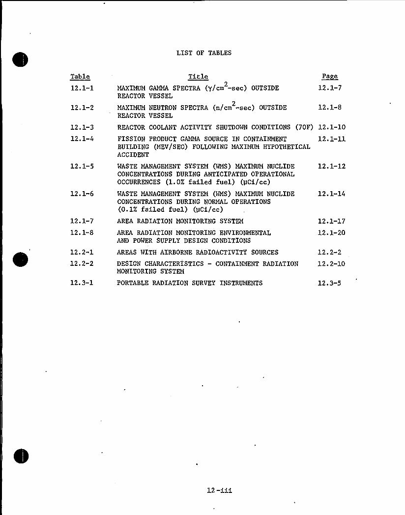
LIST OF TABLES
TitleMAXIMUMGAMA SPECTRA (g/cm -sec) OUTSIDE
2
REACTOR VESSEL
MAXIMUMNEUTRON SPECTRA (n/cm -sec) OUTSIDE2
REACTOR VESSEL
~Pa e
12.1-7
12.1-8
'REACTOR COOLANT ACTIVITY SHUTDOWN CONDITIONS (70F) 12.1-10
FISSION PRODUCT GAMMA SOURCE IN CONTAINMENT 12.1-11BUILDING (MEV/SEC) FOLLOWING MAXIMUMHYPOTHETICALACCIDENT
WASTE MANAGEMENT SYSTEM (WMS) MAXIMUMNUCLIDECONCENTRATIONS DURING ANTICIPATED OPERATIONALOCCURRENCES (1.0% failed fuel) (pCi/cc)WASTE MANAGEMENT SYSTEM (WMS) MAXIMUMNUCLIDECONCENTRATIONS DURING NORMAL OPERATIONS(0.1% failed fuel) (pCi/cc)
AREA RADIATION MONITORING SYSTEM
AREA RADIATION MONITORING ENVIRONMENTALAND POWER SUPPLY DESIGN CONDITIONS
AREAS WITH AIRBORNE RADIOACTIVITY SOURCES
DESIGN CHARACTERISTICS — CONTAINMENT RADIATIONMONITORING SYSTEM
PORTABLE RADIATION SURVEY INSTRUMENTS
12. 1-12
12. 1-14
12.1-17
12.1-20
12. 2-2
12. 2-10
12.3-5
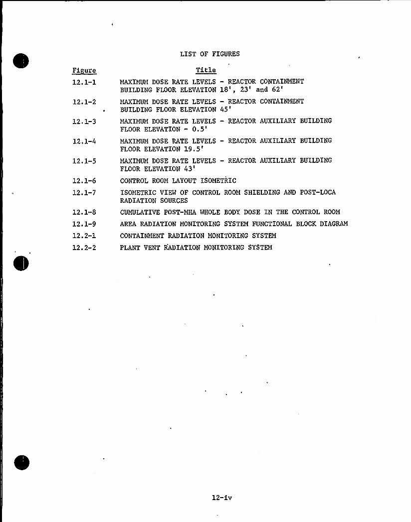
LIST OF FIGURES
~F1 use
12. 1-1
TitleMAXIMUM DOSE RATE LEVELS — REACTOR CONTAINMENTBUILDING FLOOR ELEVATION 18', 23'nd
62'2.1-2
MAXIMUMDOSE RATE LEVELS — REACTOR CONTAINMENTBUILDING FLOOR ELEVATION 45'
2 ~ 1 3
12.1-4
12.1-5
12.1-6
12el-j
12.1-8
12. 1-9
12.2-1
12. 2-2
MAXIMUMDOSE RATE LEVELS — REACTOR AUXILIARYBUILDINGFLOOR ELEVATION —
0.5'AXIMUM
DOSE RATE LEVELS — REACTOR AUXILIARY BUILDINGFLOOR ELEVATION
19.5'AXIMUM
DOSE RATE LEVELS — REACTOR AUXILIARYBUILDINGFLOOR ELEVATION
43'ONTROL
ROOM LAYOUT ISOMETRIC
ISOMETRIC VIEW OF CONTROL ROOM SHIELDING AND POST-LOCARADIATION SOURCES
CUMULATIVE POST-MHA WHOLE BODY DOSE IN THE CONTROL ROOM
AREA RADIATION MONITORING SYSTEM FUNCTIONAL BLOCK DIAGRAM
CONTAINMENT RADIATION MONITORING SYSTEM
PLANT VENT RADIATION MONITORING SYSTEM
12-iv
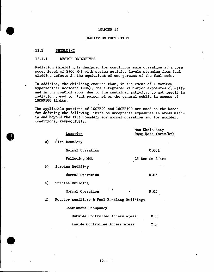
CHAPTER 12
RADIATION PROTECTION
12.1 SHIELDING
12.1.1 DESIGN OBJECTIVES
Radiation shielding is designed for continuous safe operation at a corepower level of 2700 Mwt with system activity levels stemming from fuelcladding defects in the equivalent of one percent of the fuel rods.
In addition, the shielding ensures that, in the event of a maximumhypothetical accident (MHA), the integrated radiation exposures off-siteand in the .control room, due to the contained activity, do not result inradiation doses to plant personnel or the general public in excess of10CFR100 limits.
The applicable portions of 10CFR20 and 10CFR100 are used as the basesfor defining the following limits on acceptable exposures in areas with-in and beyond the site boundary for normal operation and for accidentconditions, respectively.
LocationMax Whole BodyDose Rate mrem/hr)
a) Site Boundary
Normal Operation
Following MHA
0.001
25 Rem in 2 hrs
b) Service Building
Normal Operation 0.05
c) Turbine Building
Normal Operation 0.05
d) Reactor Auxiliary 6 Fuel Handling Buildings
Continuous Occupancy
Outside Controlled Access Areas
Inside Controlled Access Areas
0.5
2.5
12.1-1

LocationMax Whole BodyDose Rate (mrem/hr)
Controlled Occupancy
Occupancy for 6 hr/wk 15.0
Occupancy determined byHealth Physics Staff 100. 0
e) Limited Access Areas in Contain-ment Structure during Operationat Full Power 100. 0
f) Control Room
Normal Operation
Following MHA
0.5
3 rem integrated wholebody dose over 90 daysafter accident
Areas with dose rates greater than 100 mrem/hr are isolated and access tothese areas is controlled in accordance with 10CFR20 by means describedbelow.
The calculated maximum doserate levels (based on 1 percent failed fuel)in the plant are shown in Figures 12.1-1 through 12.1-5. For purposes ofdetermining length of occupancy, the plant has been divided into thefollowing zones:
Zone Assess Dose Rate (mr/hr)
No restriction < 0.5
Occupational Access 0.5 ~ 2.5
Periodic Access 25 ~ 150
IV Limited Access
Restricted Access
15.0 ~ 100'.0
> 100.0,
Zone II is a restricted radiation area'o which plant'ersonnel canhave continuous access during the regular 40 hr/wk work schedule, with-out exceeding the allowable whole body dose of l-l/4 rems per calendarquarter (10CFR20.101). This zone requires no posting.
12. 1-2


Zones III and IV are posted with "Caution-Radiation Area" signs. Thelength of occupancy varies with the actual radiation level in the room,the nature of the radiation present, and the past radiation history ofthe personnel entering.
Zone V is posted with "Caution-High Radiation Area" signs, and accessto it is strictly controlled. Zone V represents inaccessible restrictedareas, entry to which is permissible only with the approval of the shiftsupervisor. Each high radiation area therefore, is provided with abarrier or barriers which are kept locked. Access is by keys distributedfrom the control room.
Neutron and gamma radiation surveys are performed in all accessibleareas of the plant as required to determine shielding adequacy. Areassuch as the containment operating floor, reactor vessel head, reactorcoolant loop compartments and spent fuel handling areas are surveyedprior to access for refueling or after shutdown and a time-limited workschedule established.
12.1.2 DESIGN DESCRIPTION
Plant site plan and general arrangement drawings showing shielding andlocation of equipment are shown on Figures 1.2-1 through 1.2-19.
Design criteria for penetrations through shield walls and for acceptableradiation levels at valve stations for process equipment containingradioactive fluids are identical to the shielding criteria for the shieldwalls and process equipment involved.
12.1.2.1 Reactor Buildin Primar Shield
The primary shield function is to limit radiation emanating from thereactor vessel; this radiation during operation consists of neutrons(both fast and slow) emitted from the core, prompt fission gammas, fissionproduct gammas, and gamma radiation resulting from neutron capture inthe core internals and vessel. Following shutdown, only fission productgammas, and gamma radiation from neutron activation of the coolant andcorrosion products are present.
The primary shield consists of 7'-3" of reinforced concrete surroundingthe reactor vessel. The annular cavity between the primary shield andthe reactor vessel is air cooled to prevent overheating and dehydrationof the concrete shield (see Section 9.4.7.2.3).
The primary shield arrangement and thickness (shown in Figures 1.2-8,1.2-9 and 1.2-10 are designed to:
a) attentuate the neutron flux to prevent excessive activation ofunit components and structures
b) reduce the contribution of radiation from the reactor toobtain a reasonable division of the shielding function be-tween the primary and secondary shield
12. 1-3

c) reduce residual radiation from the core to a level whichpermits access to the region between the primary and secon-dary shields at a reasonable time after shutdown
d) permit access during shutdown for inspections
12.1.2.2 Reactor Buildin Secondar Shield
The secondary shield reduces the radiation activity from the reactorcoolant system to a level which allows limited access to the containmentduring operation and to supplement primary shielding. The controllingradiation source in the design of the secondary shield is N-16 resultingfrom the (n,p) reaction with the oxygen in the coolant.
The secondary shield is reinforced concrete 4'-0" thick surrounding thereactor coolant piping, pumps, steam generators, and pressurizer.
In addition, a partial 2'-0" thick reinforced concrete wall is locatedmidway between the primary and secondary shields in the main steam andfeedwater lines penetration region, to prevent streaming of gamma radia-tion from the reactor coolant system through the penetration openings.
The entire secondary shield system is shown in Figures 1.2-8, -9 and -10.
12.1.2.3 Shield Buildin
The steel containment structure is enclosed by a reinforced concreteshield building with 3'-0" thick cylindrical walls and a 2'-6" thickdome. In conjunction with the primary and secondary shields, the shieldbuilding limits the radiation level outside the structure from all sourceswithin the containment to less than 0.5 mrem/hr at 2700 Mwt with 1 per-cent failed fuel.
The combination of shield structures ensures that radiation doses at thesite boundary due to direct radiation from the activity within the con-tainment are below the recommended guideline values of 10CFR100 in theevent of the MHA.
12.1.2.4 Fuel Handlin Buildin Shieldin
Shielding is provided for radiation protection of plant personnel duringall phases of spent fuel removal, storage and preparation for off-siteshipment. Operations requiring shielding of personnel are: spent fuelremoval from the reactor, spent fuel transfer through the refueling canaland transfer tube, spent fuel storage, and spent fuel shipping caskloading prior to transporation.
All spent fuel removal, transfer and shipping cask loading operationsare done. under a minimum of 10'-4" of borated water.
The refueling cavity above the reactor vessel flange is flooded to eleva-tion 60 ft to provide 24 ft of water shielding above the reactor vesselflange. This height assures 132 inches of water above the active portion
12.1-4


of a withdrawn fuel assembly at its highest point of travel. Under theseconditions, the dose rate from the spent fuel assembly is less than2 mrem/hr at the water surface.
The fuel assembly removed from the reactor vessel is,moved to the upenderand horizontally transferred to the fuel pool by the fuel transfermechanism inside the fuel transfer tube. A 6'-0" concrete shield aroundthe refueling cavity protects the refueling personnel from radiationfrom the spent fuel assemblies and reactor internals.
The fuel pool is flooded to provide. shielding. as the fuel is beingwithdrawn from the fuel transfer tube and being raised by the spent fuelhandling machine for insertion in the spent fuel rack. The concretesides of the fuel pool are 6'-0" thick to ensure a dose rate of lessthan 0.5 mrem/hr at the outer surface of the structure.
12.1.2.5 Reactor Auxiliar Buildin Shieldin
The reactor auxiliary building shield walis are designed to protectpersonnel working near various system components, such as those in thechemical and volume control; waste management, shutdown cooling, andsampling systems.
In addition, major pieces of potentially radioactive equipment arehoused within shielded compartments so" that access to.any'omponent forrepair or inspection's permissible, without shutdown'nd decontaminationof the entire system.
The concrete thickness of each compartment shield wall is'ufficient toreduce. the dose rate outside the compartment at nearby normally accessibleareas to less than 2.5 mrem/hr. The individual enclosures also serve tocontain any major spill of radioactive liquid from any of the tanks orother components in the system.
A floor drainage system conveys any liquid spills to floor sumps fromwhich they are pumped to the waste management system for processing.
The floor drains are embedded in concrete so as to contain any spillsfrom leaking lines and/or to shield the line in access areas.
12.1.2.6 Control Room Shieldin
Direct radiation contribution to the dose rates in the" control roomfollowing a MHA stem from the following:
a) airborne activity in the containment (TID releases are assumedto be uniformly dispersed throughout the containment free volume)
b) shield building ventilation system filters
c) hydrogen purge system filtersThe control room layout and location relative to the sources of directradiation is shown in Figures 12.1-6 and 12.1-7 respectively. The
12.1-5

nearest filter is located at least 70 ft away with a minimum of 4 ftof concrete intervening. The shield thickness between the controlroom and the containment, located 31 ft away, is a minimum of 6 ftequivalent concrete (2 inch thick steel pressure vessel, 3 ft thickconcrete shield building and 2 ft thick control room wall).
The cumulative dose to the control room following a MHA is shown inFigure,12.1-8. The dominant contribution comes from the containment.
12.1.2.7 Emer enc Core Coolin S stem Area Shieldin
Shielding of the emergency core cooling system rooms has been designedfor normal operation and shutdown conditions. Under normal plantoperating conditions only the reactor drain pump and the low pressuresafety injection pumps are sources of radiation. Sufficient shieldingis achieved with 1 foot thick concrete walls. A 2 foot thick concretewall separates the two rooms. One room houses one low pressure safetyinjection pump, one high pressure safety injection pump, one contain-ment spray pump and two reactor drain tank pumps; the other room housesone low pressure safety injection pump, two high pressure safety injec-tion pumps and one containment spray pump. Refer to Figure 1.2-12.
This arrangement allows inspection and servicing of the safety featuresystems during plant operation and shutdown, and also some accessibilityduring the long term cooling following the postulated accident.
12.1.2.8 Materials and Structural Re uirements
The concrete for the primary and secondary shield, shield building,reactor auxiliary building and fuel handling building shield walls hasa density of 138 lb/ft . Since the primary and secondary shield wallsserve as support for the reactor coolant system components and providemissile protection and support for the refueling apparatus, reinforcedconcrete is used.
12.1.3 SOURCE TERMS
'lantshielding is designed to attenuate neutron and gamma radiationemanating from the following sources:
a) reactor vessel
b) reactor coolant loops
c) auxiliary systems equipment
d) spent fuel assemblies
e) radioactive material released during postulated accidents
The gamma and neutron-sources utilized in the design of the primaryshield are= shown in Tables 12.1-1 and 12.1-2. The gamma sources includecapture gammas from the reactor core, internals and vessel.
12. 1-6

TABLE 12. 1-1
MAXIMUMGAMMA SPECTRA (7/cm -sec)2
OUTSIDE REACTOR VESSEL
E (mev)
10.00
9.00
8.00
7.00
6.00
5.00
4.00
3. 00
2.00
1.38
1. 00
0. 75
0.50
0. 25
Side
1. 40 (+7) *
l. 22 (+8)
2. 29 (+8)
2. 28(+8)
2. 41(+8)
2.99(+8)
3.80(+8)
5.74(+8)
9.27(+8)
5. 46 (+8)
5.01(+8)
6.88(+8)
7. 45 (+8)
9. 65 (+8)
1.57(+3)
1.16 (+4)
1.23(+4)
2.07(+4)
2. 53 (+4)
3.21(+4)
4. 19 (+4)
5.47(+4)
8.02(+4)
4.82(+4)
4.33(+4)
5.97(+4)
9. 66 (+4)
1.18(+5)
Bottom
7. 34 (+3)
l. 08 (+7)
l.93(+7)
3. 42 (+7)
4. 91 (+7)
6. 71(+7)
8.88(+7)
1. 25 (+8)
1. 94 (+8)
l.14 (+8)
1.07 (+8)
1. 51(+8)
2. 51(+8)
3. 21(+8)
* Denotes power of ten.
12. 1-7

TABLE 12.1-2
MAXIMUMNEUTRON SPECTRA (n/cm -sec)2
OUTSIDE REACTOR VESSEL
E (mev)
18
10
0.33
Side
9.04(+3)*
5. 22 (+5)
l. 34(+7)
2. 88(+7)
5. 13 (+7)
4. 72 (+7)
3. 30 (+7)
3. 49 (+7)
3. 99 (+7)
4. 67 (+7)
4J
~pl
pl
Bottom
1. 09 (-2)
8. 08 (-1)
1. 35 (+1)
1. 00 (+1)
1. 06 (+1)
1. 16 (+1)
1. 33(+1)
1. 17 (+1)
1.53 (+1)
3.42(+1)
* Denotes power of ten.
12. 1-8

The activity of N-16 in the reactor coolant, 3.6 X 10 'Y/cc-sec at thevessel outlet nozzles, determines the amount of shielding requiredaround the reactor coolant loops during full power operation.
During shutdown the major sources of activity in the reactor coolantloops are the fission and corrosion products reported in Table 12.1-3,corrected to account for the change in coolant density from operatingof shutdown conditions.
The fission product gamma radiation source strength in the containmentat various times following the maximum hypothetical accident is shown inTable 12.1-4.
Fission product and corrosion activity also determine the shieldingrequirements for the auxiliary systems. The total quantity of the prin-cipal nuclides in process equipment that contains or transports radio-activity is identified for selected locations in Tables 12.1-5 and12.1-6. The selected locations are indicated by the numbers withinellipses on Figures 11.2-1, 11,2-3, 11.2-4, 11.3-1, 9.3-4 and 9.3-5.Expected maximum values, i.e., those used as a design basis for shieldingrequirements, correspond to the equivalent activity values calculatedto exist due to fuel cladding defects in 1.0 percent of the fuel rodsand are shown in Table 12.1-5. Expected average values correspond tofuel cladding defects in O.l percent of the fuel rods and are shown inTable 12.1-6.
The activity in the chemical and volume control system prefilter, ionexchangers'and afterfilter is determined by assuming a letdown flow of40 gpm and retention of at least 90 percent of the nonvolatile fissionproducts, except cesium, yttrium, molybdenum and tritium; for which noremoval is assumed. No credit is taken for radioactive decay.
In the boron recovery system, the activity in the preconcentrator ionexchangers is determined by assuming retention of at least 90 percentof all incoming radionuclides, except tritium, and a batch flow rate of20 gpm. The corresponding average annual flow rate is 1.5 gpm based on,processing 780,000 gallons, equivalent to 10 reactor volumes, fromsources listed in Table 11.2-1. Reactor coolant pump seal flow is notincluded in this average. A decontamination factor (DF) of 10 (ratioof bottoms to distillate activity) is assumed. for the boric acid con-centrator for all nuclides (except tritium). The influent activity istaken to be concentrated in the bottoms by a factor of 300. Nooperation of the boric acid condensate ion exchanger is assumed.
In the waste management system, the activity present in the gas decaytanks is that of the noble gases present in the coolant, with no credittaken for radioactive decay.
No radioactive waste or shipping casks are stored outside of buildings.See Section 11.5.7.
The routing of piping carrying potentially radioactive matter in quan-tities significant enough to affect the amount of exposure to plantpersonnel is done during the design stage to ensure that the piping is
12.1-9

TABLE 12.1-3
REACTOR COOLANT ACTIVITY
SEJTDOWN CONDITIONS (70 F
S acl(lc Actlvlt (a~CA/cc S act(le Actlvlt (I~CA/cc
NuclideHalfLife
AnticipatedOperationalOccurrence(1.0%FailedFuel)
NormalOperation(1.0%FailedFuel) Nuclide
HalfLife
AnticipatedOperationalOccurrence(1.0%FailedFuel)
NormalOperation(1.0%Failed~Fccl
H-3
Br-84
Kr-85m
Kr-85
Kr-87
Kr-88
Rb-88
Rb-89
Sr-89
Sr-90
Y-90
Sr-91
Y-91
Mo"99
Ru" 103
RU-106
Te-129
I-129
I-131
Ke-131m
Te-132
I"132
12.3y 0.182
32m
4.4h
6.43(-2)*
2.05
10.8y 1.22
76m
2. Sh
1.12
3. 58
18m
15m
51d
3.52
8. 83(-2)
7.0 (-3)
28.8y 3.6(-4)
64h 1.41(-3)
9.7h 4.9(-3)
59d 0.153
67h 2. 80
67m 3 '6(-2)1.7(7)y 9.95(-8)
8.0d
12d
78h
5.48
2.04
0.455
2,3h 1.41
39.6d F 7(-3)
367d 3.42(-4)
0. 148
6.43(-3)
0.205
1.22(-1)
1.12(-1)
0.358
0.352
8. 83 (-3)
7.0 (-4)
3. 6 (-5)
1.41(-4)
4.9 (-4)
1. 53 (-2)
0.280
5. 7 (-4)
3,42 (-5)
3. 46 (-3)
9.95 (-9)
0.548
0.204
4.55(-2)
0.141
I"I33
Xe-133
Te-134'-134
21h 7.81
5.3d 250.0
42m
52m
3.62(-2)
0.855
I-135
XQ-135
Cs-136
Cs-137
Xe-138
Cs-138
BQ-140
La-140
Pr-143
Ce-144
Co-60*~
Fe-59**
Co-58**
Mn-54**
Cr-51**
2r-95**
6.7h 3.72
9.2h 10.4
13d
30y
17m
32m
3. 52 (-2)
0.441
0 497
0.952
12.8d 8.42(-3)
40.2h 8.07(-3)
13.6d 8.05(-3)
285d 5 7(-3)
5.2y 7.16(-4)
45d
71d
2.94 (-5)
6.43(-3)
312d 3.8("5)
27d
65d
5.24(-3)
1. 29 (-6)
Cs-134 2.1y 0.138
0.781
25.0
3. 62 (-3)
8. 55 (-2)
1. 38 (-2)
0.372
1.04
3.52(-3)
4 '1(-2)4.97(-2)
9.52("2)
8. 42 (-4)
8. 07 (-4)
8. 05 (-4)
5. 7 (-4)
7. 16 (-4)
2. 94 (-5)
6. 43 (-3)
3. 8(-5)
5. 24 (-3)
1. 29 (-6)
* Denotes Power of ten
** Corrosion products

TABLE 12.1-4
FISSION PRODUCT GAMMA SOURCE IN CONTAINMENT BUILDING MEV/SECFOLLOWING MAXIMUMHYPOTHETICAL ACCIDENT
Ener Interval (Mev)
Time
0.5 hr1 hr2 hr8 hr
24 hr1 wk
1 mo
2 mo
4 mo
0.1 — 0.4
2.11 (18)*
2.01 (18)
1.94 (18)
1.84 (18)
1.43 (18)
7.93 (17)
2.10 (17)
2.81 (16)
4.10 (15)
5. 15 (14)
0.4 — 0.9
1.26 (19)
1.11 (19)
9.81 (18)
7.78 (18)
4.39 (18)
3.05 (18)
7.32 (17)
8.76 (16)
5.39 (16)
2.98 (16)
0.9 — 1. 35
5.00 (18)
4.56 (18)
3.98 (18)
3.22 (18)
1.48 (180
5.95 (17)
1.12 (17)
2.17 (15)
3.68 (14)
1.36 (14)
1.35 — 1. 8
9.39 (18)
3.44 (18)
3.05 (18)
2.44 (18)
1.08 (18)
4.27 (17)
1.20 (17)
1.66 (16)
2.95 (15)
3.34 (14)
1.8 — 2.2
6.10 (18)
3;17 (18)
2.14 (18)
1.47 (18)
4.76 (17)
1.59 (17)
4.03 (16)
1.00 (15)
5.29 (14)
4.42 (14)
2.2 — 2.6
4.39 (18)
3.56 (18)
2.95 (18)
2.09 (18)
3.95 (17)
7.08 (16)
2.13 (16)
1.27 (15)
1.95 (14)
2.34 (13)
2.6
1.99 (18)
2.54 (17)
9.32 (16)
3.00 (16)
1.07 (16)
1.76 (14)
1.19 (14)
3.78 (13)
1.22 (13)
5.29 (12)
* Denotes power of ten

TABLE 12.1-5WASTE MANAGEMENT SYSTEM (WMS) MAXIMUM NUCLIDE CONCENTRATIONS DURING
ANTICIPATED OPERATIONAL OCCURRENCES (1.0 failed fuel) (44Ci/cc)
Nuclide
H-3
Br-84
Kr-85m
Kr-85
Kr-87
Kr-88
Rb-88
Rb-89
Sr-89
Sr-90
Y-90
Sr-91
Y-91
Mo-99
Ru-103
Ru-106
Te-129
I-129
1-131
Xe-131m
Te-132
I-132
I-133
Xe-133
Te-134
I-134
Cs-134
CVCS 6WMS 1
1. 2 (-1) *
4.11(-3)1.57(0)
1.14(0)8.0(-1)2.68(0)5.96(-1)9.02(-3)3. 8
(-3)'.
8I4 (-1)6.71(-4)1. 69 (-3)2. 48 (-2)1.21(0)3.24(-3)1.67(-4)1 6(-2)4.0 (-8)l. 7 (0)
1. 18(0)
2. 31(-1)3. 46 (-1)1. 88 (0)
1.97(+2)
I4. 61 (-3)6. 95 (-2)
2.25(-1)
CVCS 7
1. 2 (-1)4.1l(-3)1. 57 (0)
1. 14 (0)
8.0 (-1)2. 68 (0)
5.96(-1)9.02(-3)3. 8 (-3)1.84(-1)6.71(-4)1.69(-3)2.48(-2)1.21(0)3.24(-3)1. 67 (-4)1. 6 (-2)4. 0 (-8)1.7 (0)1. 18 (0)
2. 31 (-1)3.46(-1)1.88(0)
1.97 (+2)
4.61(-3)6. 95 (-2)
2.25(-1)
CVCS 10WMS2345678
1. 2 (-1)4. 11 (-6)1.57 (0)
1. 1I4 (0)
8.0(-1)2.68(0)5.96(-1)9.02(-3)3.8(-5)1.84(-3)6. 71(-4)1. 69 (-5)2.48(-2)1.21(0)3.24(-4)1. 67 (-5)1.6 (-3)4.0(-11)>.7(-3)1. 18 (0)
2. 31 (-3)3. 46 (-I4)
1. 88 (-3)1. 97 (+2)
4.61(-4)6. 95 (-5)
2.25(-1)
1. 2 (-1)4.11(-6)7.85(-1)5. 7 (-1)4.0 (-1)1.34 (0)
5. 96 (-1)9. 02 (-3)3. 8 (-5)1.84(-3)6. 71(-4)1.69(-5)2.48(-2)1.21(0)3. 24 (-4)1.67(-5)1.6(-3)4.0 (-11)1. 7 (-3)5.9 (-1)2. 31 (-3)3.46(-4)1.88(-3)9. 85 (+1)
4.61(-4)6.95(-5)
2.25(-1)
1.2(-1)0
4.72(-1)
3.36(-5)1.84(-3)6. 58 (-5)3. 36 (-12)2.23(-2)1.25(-1)2. 77 (-4)1. 64 (-5)
4. 0 (-11)7.84(-4)2.89 (-1)3. 39 (-4)0
1. 51 (-6)2. 49 (+1)
2. 25 (-1)
SSS 9 10 11 SHS 12 13 14 WMS 15
1.2(-1)
4.72(-1)
3. 36 (-6)1.84(-4)6.58(-6)3.36(-13)2.23(-3)1.25(-2)2.77(-5)1.64(-6)
4.0(-14)7.84(-7)2. 89 (-1)3.39(-5)
1. 51(-9)2. 49 (+1)
2. 25 (-3)
18 19 20 21
1.2(-1)
2.36(-1)
1.18(-8)9. 2 (-7)3. 29 (-8)1. 18 (-15)1.12(-5)6.25(-5)1.39(-7)8.2(-9)
2. 0 (-16)3. 92 (-9)5. 78 (-2)1. 2 (-7)
7.55 (-12)4.98(0)0
1.13(-5)

TABLE 12.1-5 CONTINUED
NuclideCVCS 6WMS 1 CVCS 7
CVCS 10WMS 2 3 4 5 6 7 8 I0I3 9 10 11 I0I3 12 13 14 WMS 15 WMS 18 19 20 21
N-135
Xe-135
Cs-136
Cs-137
Xe-138
Cs-138
Ba-140
La-140
Pr-143
Ce-144
Co-60 **
Fe 59 4*
Co-58 **Mn-54 **Cr-51 *A
Zr-95
6.39 (-1)6.49 (0)
3. 47 (-2)9.58 (-1)3.4 (-1)3. 48(-1)
4. 64 (-3)4.58(-3)4.01(-3)2.57(-3)8.64(-4)3.54(-5)7.74(-3)4.57(-5)6.32(-3)1.56(-7)
6.39 (-1)6.49 (0)
3.47(-2)9.58(-1)3. 4 (-1)3.48(-1)4.64(-3)4.58(-3)4.01(-3)2.57(-3)8.64(-5)3. 54 (-6)7.74(-4)4.57(-6)6.32(-4)1.56(-8)
6. 39 (-4)6 ~ 49 (0)
3. 47 (-2)9.58(-1)3. 4 (-1)3. 48(-1)4.64(-5)4.58(-4)4.01(-4)2.57(-4)8. 64 (-5)3. 54 (-6)7.74(-4)4.57(-6)6.32(-4)1.56(-8)
6.39 (-4)3. 25 (0)
3.47(-2)9.58(-1)1. 7 (-1)3. 48 (-1)4.64(-5)4.58(-4)4.01(-4)2 ~ 57 (-4)8.64(-5)3. 54 (-6)7.74(-4)4.57(-6)6.32(-4)1.56 (-8)
2.15 (-2)9. 58 (-1)
2.85(-5)1. 1(-4)2.53 (-4),2. 46 (-4)8.64(-5)3.08(-6)7.14(-4)4.47(-6)5.02(-4)1. 42 (-8)
2.15(-4)9.58(-3)
2.85(-6)1.1(-5)2.53(-5)2 '6(-5)8.64(-5)3.08(-6)7.14(-4)4.47(-6)5.02 (-4)1.42(-8)
1.08(-6)4.79(-5)
1.93(-8)5.5 (-8)1. 27 (-7)1. 23 (-7)4.32(-7)1. 54 (-8)3. 57 (-6)2. 24 (-8)2.51(-6)7. 1(-11)
Denotes power of ten** Corrosion products

TABLE 12.1-6
WASTE MANAGEMENT SYSTEM (WMS) MAXIMUMNUCLIDE CONCENTRATIONS DURING NORMAL OPERATIONS 0.1% failed fuel) (PCi/cc)
Nuclide
H-3
Br-84
Kr-85m
Kr-85
Kr-87
Kr-88
Rb-88
Rb-89
Sr-89
Sr-90
Y-90
Sr-91
Y-91
Mo-99
Ru-103
RU-106
Te-129
I-129
I-131
Xe-131m
Te-132
I-132
I-133
Xe-133
Te-134
I-134
Cs-134
CQCS 6
WMS 1
8.4(-2)*4.11(-4)1.57(-l)1. 14 (-1)8. 0 (-2)2. 68 (-1)5.96(-2)9. 02 (-4)3.8(-4) "
1. 84 (-2)6. 71(-5)1.69(-4)2.48(-3)1.21(-1)3.24(-4)1. 67 (-5)1. 6 (-3)4. 0 (-9)1. 7 (-1)1. 18 (-1)2.31(-2)3.46(-2)1.88(-1)1. 97 (+1)
4. 61 (-4)6. 95 (-3)2.25(-2)
CVCS 7
8.4 (-2)4.11(-4)1.57(-1)1.14(-1)8.0(-2)2.68(-1)5.96(-2)9. 02 (-4)3. 8 (-4)1. 84 (-2)6. 71(-5)
1. 69 (-4)2.48(-3)1.21(-1)3. 24 (-4)l. 67 (-5)1. 6 (-3)4. 0 (-9)1. 7 (-1)1.18(-1)2.31(-2)3.46(-2)1. 88 (-1)l. 97 (+1)
4.61(-4)6.95(-3)
2.25(-2)
CVCS 10WMS 2 3 4 5 6 7 8
8. 4 (-2)4.11(-7)1.57(-1)1.14(-1)8.0(-2)2.68(-1)5.96(-2)9.02(-4)3 ~ 8 (-6)1. 84 (-4)6 '1(-5)1.69(-6)2.48(-3)1.21(-1)3.24(-5)1. 67 (-6)1. 6(-4)4. 0 (-12)
1. 7 (-4)5. 9 (-2)2.31(-4)3.46(-5)l. 88(-4)
1.97(+1)4.61(-5)6.95(-6)
2.25(-2)
8. 4 (-2)4. 11(-7)7.85(-2)5.7(-2)4.0(-2)1.34(-1)5.96(-2)9.04(-4)3. 8 (-6)1. 84 (-4)6.71(-5)1. 69 (-6)2.48(-3)1.21(-1)2.77(-5)1.67(-6)1.6(-4)4.0(-12)4.7(-4)2.89(-2)2.31(-4)3.46(-5)1.88(-4)9.85(0)4.61(-5)6.95(-6)
2.25(-2)
8. 4 (-2)
4. 72 (-2)
3.36(-6)1.84(-4)6. 58 (-6)3.36(-13)2.23(-3)1. 25 (-2)2.77(-5)1.64(-6)
4.0(-12)7.84(-5)2.89(-2)3.39(-5)
1.51(-7)2.49(0)
2.25(-2)
MHS 9 10 11 WMS 12 13 14 WMS 15
8.4(-2)
4.72(-2)
3. 36 (-7)1. 84 (-5)6.58(-7)3.36(-14)2. 23 (-4)1.25(-3)2.77(-6)1. 64 (-7)
4.0(-15)7. 84 (-8)2. 89 (-2)3. 39 (-6)
1.51(-10)2.49(0)
2.25(-4)
WMS 18 19 20 21
8.4(-2)0.
2.36(-2)
1. 18 (-9)9. 2 (-8)3.29(-9)1.18(-16)1. 12 (-6)6. 25 (-6)1. 39 (-8)8.2(-10)
2.0(-17)3.92(-10)5.78(-3)1.2(-8)
7.55(-13)4.98(-1)
1. 13 (-6)

TABLE 12. 1-6 CONTINUED
Nuclides
I-135
Xe-135
Cs-135
Cs-137
Xe-138
Cs-138
Ba-140
La-140
Pr-143
Ce-144
Co-60 **
Fe-59 ~~
Co-58 +*
Mn-54 **
51 AA
.Zr-95 ~~
CVCS 6WMS 1
6. 39 (-2)
6.49(-1)
3.47(-3)
9.58(-2)
CVCS 7
6. 39 (-2)
6. 49 (-1)
3.47(-3)
9.58(-2)
3. 48 (-2)
4.64(-4)
4.58(-4)
4. 01 (-4)
2.57(-4)
8,64(-4)
3.54(-5)
7.74(-3)
4. 57 (-5)
6.32(-3)
1.56(-7)
3.48(-2)
4.64(-4)'.58(-4)
4,01(-4)
2. 57 (-4)
8.64(-5)
3.54(-6)
7. 74 (-4)
4. 57 (-6)
6. 32(-4)
1. 56 (-8)
3.4(-2) . 3.4(-2)
CVCS 10WMS2345678
6. 39 (-5)
6.49(-1)
3.47(-3)
9.58(-2)
3.4(-2)
3.48(-2)
4.64(-6)
4.58(-5)
4.01(-5)
2.57(-5)
8.64(-5)
3.54(-6)
7.74(-4)
4.57(-6)
6.32(-4)
1.56(-8)
WHS91011 m1213146.39(-5) 0
3.25(-1) 0
3.47(-3) 2.15(-3)
9.58(-2) 9.58(-2)
1. 7 (-2)
3. 48 (-2) 0
4. 64 (-6) 2. 85 (-6)
4.58(-5) 1.1(-5)
4.01(-5) 2.53(-5)
2.57(-5) 2.46(-5)
8.64(-5) 8.64(-5)
3.54(-6) 3.08(-6)
7.74(-4) 7.14(-4)
4.57(-6) 4.47(-6)
6.32(-4) 5.02(-4)
1.56(-8) 1.42(-8)
WMS 15
2.15(-5)
9.58(-4)
2.85(-7)
1. 1 (-6)
2. 53 (-6)
2.46(-6)
8.64(-5)
3. 08 (-6)
7.14(-4)
4. 47 (-6)
5.02(-4)
1. 42 (-8)
WMS 18 19 20 21
1.08(-7)
4. 79 (-6)
1.93(-9).
5.5(-9)
1. 27 (-8)
1.23(-8)
4.32(-7)
1.54(-8)
3. 57 (-6)
2. 24 (-8)
2. 51 (-6)
7. 1(-11)
* Denotes power of ten
** Corrosion products

adequately shielded. Any such piping designed in the field is checkedfor shielding adequacy.
12.1.4 AREA MONITORING
The area radiation monitoring system is designed to:
a) warn of abnormal gamma radiation levels in areas where radioactivematerial may be stored, handled or inadvertently introduced
b) warn plant personnel whenever abnormal concentrations of airborneradioactive materials exist
c) supplement other systems, including the process radiation monitor-ing system (Section 11.4) and the leak detection system (Section5.2.4), in detecting abnormal migrations or accumulations ofradioactive material
d) initiate a containment isolation signal in the event of abnormalradiation inside the containment
The area radiation monitoring system is a complex of radiation monitorsand alarms which provide operating personnel with a continuous record ofradiation levels and integrated airborne gamma activity concentrationsat selected locations within the plant. The system assists in detectingunauthorized or inadvertent movement of radioactive material in theplant and in helping operating personnel decide on deployment of'erson-nel in the event of an accident resulting in the release of radioactivematerial.
12.1.4.2 S stem Descri tion
The area radiation monitoring system consists of 27 channels that arelocated at selected places in and around the plant to detect and recordthe radiation levels and, if necessary, annunciate abnormal conditions.The areas where the gamma monitors are located are shown in Table 12.1-7.Indication, annunciation and recording are all done in the control room.Indication and annunciation are also provided wherever there is a localindicator. The control room has readout modules for all 27 channels.
The gamma area radiation monitoring system is shown as a functional blockdiagram in Figure 12.1-9. A typical channel consists of a gamma sensi-tive halogen quenched Geiger Muller (GM) detector, an indicator and analarm/trip unit, a power supply and a shared multipoint recorder. Some
channels have, in addition, a local audio alarm auxiliary unit as in-dicated in Table 12.1-7.
Channels 2, 7, 8, 9, 12, 15, 19, 21 are provided with a remote alarmmeter. This remote alarm unit consists of a five decade readout meter(10 1 mr/hr to 104 m'/hr), a red high-high radiation light, and a highradiation horn which activates with the alarm light.
12.1-16

TABLE 12.1-7
AREA RADIATION MONITORING SYSTEM
ChannelNumber
Location and General ArrangementFi ure Number
Rangemr/hr
LocalMeter and
Alarm
Containment AnnulusFigure 1.2.8
0. 1-1,000 No
On Refueling MachineFigure 1.2-8
0.1-1,000 Yes
In Containment Cooling SystemRing Duct HeaderFigure 1.2-8
10-100,000 No
In Containment Cooling SystemRing Duct HeaderFigure 1.2-10
10-100,000 No
In Containment Cooling SystemRing Duct Header 10-10,000 No
In Containment Cooling System,Ring Duct HeaderFigure 1.2-8
10-100 $ 000 No
Control RoomFigure 1.2-17
0.1-19000 Yes
H&V Room el 43.0 ftFigure 1.2-14 Column RA2-RAE
0.1-1,000 Yes
10
Hot Chemistry LabFigure 1.2-13
Sample RoomFigure 1.2-13
0. 1-1,000
0.1-1,000
Yes
No
12
Figure 1.2-13, Column RAA-RA2el 19.5 ftDrumming StationFigure 1.2-13 Column RA2-16
0. 1-1,000 .
0.0-1%000
No
Yes
* The asterisk indicates the area monitors that are classified asseismic Class I electrical equipment and supply the containment iso-lation signal (CIS). For further discussion refer to Section 7.3.
12. 1-17

TABLE 12.1-7 (cont'd)
Channel Location and General ArrangementNumber Fi ure Number
Rangemr/hr
LocalMeter and
Alarm
13 Boric Acid Storage TankFigure 1.2-13 Column RAE-RA4el 19.5 ft
0. 1-1,000 No
14
15
16
17
18
19
20-
21
22
24
26
27
Machine ShopFigure 1.2-13
ECCS Rooms AGB
Figure 1.2-12
Containment Spray PumpsFigure 1.2-12
Charging PumpsFigure 1.2-12
Gas Decay TankFigure 1.2-12
Main Corridor el 0.5 ft at,Columns RAK-RA4Figure 1.2-12
Pipe Penetration Roomel 19.50 ftFigure 1.2-13
Spent Fuel Handling MachineFigure 1.2-18
New Fuel Storage AreaFuel handling bldg
Decontamination AreaFigure 1.2-18
NE Corner of SiteFigure 1.2-2
NW Corner of SiteFigure 1.2-2
SW Corner of SiteFigure 1.2-2
SE Corner of Site
01-1,000
0.1-1,000
0.1-1,000
0.1-1,000
0.1-1,000
0. 1-1,000
0. 1-1,000
0. 1-1,000
0.1-1,000
0.1-1,000
0.1-1,000
0. 1-1,000
0.1-1,000
0.1-1,000
No
Yes
No
No
No
Yes
No
Yes
No
No
'o
No
No
No
12. 1-18

The log readout module associated with these channels has a similar dy-namic range of five decades. It is provided with a 0-10 mv recorderoutput, a 0-50 mv computer output and a meter output required to operatefield mounted indicators.
Channels 3, 4, 5, 6 are provided with a 4-20 ma dc output for containmentisolation. Moreover, they are protected to continuously operate undera direct spray solution containing 0.97 percent boric acid.
12.1.4.3 Desi n Evaluation-1 4
The system provides five full decades (10 mr/hr to 10 mr/hr) of dy-namic range. This system provides the accuracy and reliability of apulse-counting circuit, without the necessity of compressing the fifthdecade, or operating in a combination pulse-counting and current-sensingmode, to achieve the five decade dynamic range. The energy responsehas been empirically determined by the manufacturer to be + 15 percentfrom 100 Kev to 1.5 Mev. The halogen quenched GM detector is mountedinside of an aluminum casting which provides safe operation of 'thedetector in external pressure in excess of 40 psig. This detector isprovided with a live zero to preclude spurious fail alarms when thebackground radiation level in which the detector is operating is lessthan 0.1 mr/hr. Natural background radiation and check source con-tribution hold the system in the non-failure condition. If for anyreason the system stops responding to radiation a failure condition willbe indicated on the readout module. A built-in anti-saturation circuitprevents the system readings from falling off full scale during over-range conditions.
To prevent a loss of monitoring of an entire area of the plant due toa loss of power, each of the 27 channels is connected to a separatepower supply in conformance with the AEC non-common mode failure criteria.Except for the containment area radiation monitors which initiate thecontainment isolation signal (CIS), all other monitors have power suppliesfed from an interruptible source and are inoperative during a loss ofoff-site power for a maximum period of 30 seconds until the dieselgenerator sets start. The four containment area radiation monitorswhich initiate the CIS are fed from four seismic Class I power sup-plies (125v dc system).
These four containment area radiation monitors identified by, channelnumbers 3, 4, 5 and 6 in Table 12.1-7 are designed as seismic Class Iand can withstand LOCA conditions including operation under direct con-tainment spray containing 0.97 percent boric acid for a period of atleast 15 minutes after an accident. See Section 3.11 for discussion ofthe environmental qualification of these components. All other arearadiation monitors are designed to withstand the environmental and powersupply conditions shown in Table 12.1-8
These four containment monitors are physically and electrically separat-ed from each other in accordance with the criteria at forth in IEEE 279,August 1968, and IEEE 308, November 1970. The output signals from themonitors (labeled MA, MB, MC and MD) feed the engineered safety featureslogic to make up the CIS. The four monitors are positioned in sets of
12.1-19
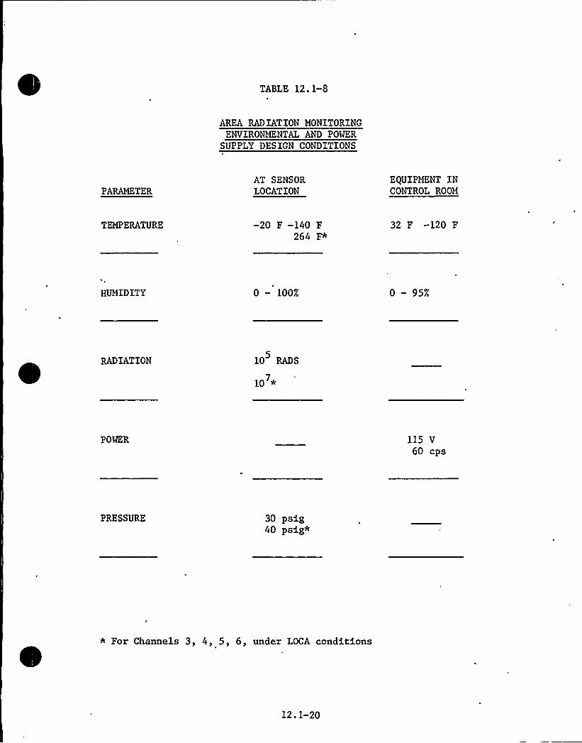
TABLE 12. 1-8
AREA RADIATION MONITORINGENVIRONMENTAL AND POWER
SUPPLY DESIGN CONDITIONS
PARAMETERAT SENSORLOCATION
EQUIPMENT INCONTROL ROOM
TEMPERATURE -20 F -140 F264 F*
32 F -120 F
HUMIDITY 0 — 100% 0 — 95%
RADIATION 10 RADS
10 *
POWER 115 V60 cps
PRESSURE 30 psig40 psig*
* For Channels 3, 4, 5, 6, under LOCA conditions
12.1-20

two 180 apart inside the containment cooling system ring header ductto assure homogeneity of the monitored atmosphere and to preclude thepossibility of spurious actuation due to direct radiation from equipment.The air flow through the ring header duct during normal operation is180,000 cfm. The radiation monitors level alarm is set at 10 R/hr. Asetpoint of 10 R/hr was selected based on response time for the highcontainment pressure setpoint of 5 psig since both signals feed the CIScircuitry.
The readout module incorporates three alarms as follows:
a) Alert Alarm: A white, push-button light goes "ON" and an alarmsounds when the radiation level exceeds a presetpoint. The level is adjustable over the entirerange. Depressing the push-button light causesthe meter to indicate where the alarm level hasbeen set;
b) High Alarm: A red, push-button light, which is identical tothe alert alarm described above, except the settingis higher;
c) Failure/ResetAlarm: An amber, push-button light, which remains "ON"
when the system is in normal operation, and goes"OFF" if high voltage, or line voltage fails.When this push-button light is depressed, itautomatically resets the alert and high alarms.
Two checking systems are provided to check the integrity of the arearadiation monitoring system; a continuous one which is described aboveas a failure/reset alarm, and an on-command system which activates acheck source into position. This causes an up-scale reading verifyingsystem integrity.
The integral check source provided with this detector assembly consistsof approximately 1 uCi of depleted uranium. This source is activatedfrom the readout module located on the control room radiation monitor-ing panel.
The environmental and power supply design conditions for the monitorsare given in Table 6.2-8.
12.1.4.4 Testin and Ins ection
An internal trip test circuit adjustable over the full range of the tripcircuit is a design feature. The test signal is fed into the indicatorand trip unit so that a meter reading is provided in addition to a realtrip. A, check source that is remotely controlled from the control roomis an integral part of each area radiation monitoring channel.
The function of the containment area monitors is discussed in Section7.3. Environmental qualifications of the containment area radiationmonitors is discussed in Section 3.11.
12.1-21

12.1.5 OPERATING PROCEDURES
Permanent shielding is installed wherever radioactive sources are ex-pected to occur and wherever operating and maintenance functions arenormally required. Both regular and special temporary radiation shieldsare available for use in all normal operational situations where radio-activity containing equipment must be transported or repaired. Time-radiation dose schedules will be developed and followed to formalizeoperations to be executed in unusually high gamma radiation fields insuch a manner that exposure to operating and maintenance personnel areminimized.
12.1.6 ESTIMATES OF EXPOSURE
The expected maximum dose rate .levels for .various in-plant locationsare listed below. The zones correspond to those shown in Figures12.1-1 through 12.1-5 but the dose rates .vary since the expected valuesare based on 0.1 percent failed fuel. During normal power operation,Zones IV and V areas within the containment are not represented by thevalues listed below since the dose rates for those areas are determinedby N-16 activity and not percentage of failed fuel.
Zone Dose Rate mr/hr)
.05 ~ .25
.25 ~ 1.5
IV 1.5 ~ 10.0
) 10.0
The physical models used to determine the shielding required areapproximations to the physical layout, i.e., cylindrical sources wereused to approximate tanks, line sources for pipes and so forth. Themethodology outlined in T. Rockwell III, "Reactor Shielding DesignManual," are employed to determine dose rates from the modelled equiva-lent sources. Conservative assumptions were made in the shieldinganalysis such as: waste tanks completely full; neglect wall thicknessof some pipes and neglect any air attenuation. Source data utilized inthe calculation of shielding thicknesses are given in Section 12.1.3.
12. 1-22

~vt\ o salasO OC
II-
Bg
S O Cl ~l Soot
SCC- ~
AAC
VCl C~ ~ l
PollAVAII.ACoaoc
CKC
CCO
'\ rr
Il
~Avvat c~CVAKCVC Oo
crvatctoCe I \)
'AA»'IA,CO\at
Kww\atKAC
COCO y+
.r~s 5';I'I"
o
Cl tat lo
v1SoottCOCO
ClI
'I Koaouvo
sI
oo
P
I
OAOOO rallCOOC'
bo K c,ooprr
ACACVA A Waar
«tv Aata,
Jg p
/f~4 \AV COV%CO
+(CA I Ala COA 8 II
C
IK I lie
It
I I I~OV
~ r
v Ar
ka,'loao
V cat'lvs': 1,
~ ll
Cl ~Acactatcr
e'er
'd. /~ ~
C~rO~
J \
~&K
CH l ~
C
jy .'
ak for J Rj ~C ~ l
to'lcaaao
l
\ ~ C
oo.
< a
P
'I
rs
I f
j/'~" ~ oal
OAKl\oooo tlc tce
cs
/PP I/-" 'K
~ aK
l O~aI
.Cts C
~avt Cia'lav/'O le ClatAaaaVh7 lc
/
~ 'a ~
~K
CLC l
Valor~Cacocl atter
4 OVC
0CC IcAVC4 ~Kco+sos
O l aov
C
OKo vvoao~ V
CCPtattSTCl4t'A T tOOR \t PAT.stCAACC CACVA'll CAAVC
CCKAKAo o AloeKVCCA
VO
SCQOR tc cbOsSC.ZSOO
cafocct'I
POA OO <ccsl acc octacasc tel slareoa
DIRECT RADIATIOHDOSE LEVELSHORMAL OPERATIOH
I 40.5 MR/HR'I 0.5 ~ 2.5HI 2.5 ~ 15.0,r *
IY. 15.0-100Y >100
'ecocoes Ii! 8 Hrs.ofter shotcfowlc.
tataRT ttttats tt 1S.SPS
8770-G. 065
FLORIDA POWER II LIGHT COMPANY
Hutchinson Island Plant
MAXIMUMDOSE RATE LEVELS—REACTOR CONTAINMENT BUILDINGFLOOR
ELEVATION 18', 23'ttttII2'IGURE12.1-1

&ws ~ tlo«voas1
(AAI
4 IL~ O LAC to «CAN.I«ttao«Ltkts
DIRECT RADIATIONDOSE LEVELSNORMAL OPERATION
I ~ Or5 MR/HRII 0.5 ~ 2.5
III 25 ~ 15 0
IV 15 0 ~ 100
V )100
~Iv
$ $ Larks
$(AL4 Bete«set III8 hrs.
ofter shutdown.
COla\4 haoo (4) OAL
OAuVALI.ALAKt
hseoLath
I'ir
4Aaa«ALLO
alai«
+>LAO&Osthhlterl'll\4 44
Il&«I
ta~«
10asat'n IAA4«r
&osLsutnt Lo
Itst IOOAg
shtttv vaa tcn&4lhaah O
5
A(V
—0
ottt«n~As«O
A
(IAt
ohstlv au«cnaa«
AK:
\lrhl ts
/I /') ~ leonOL WO«C
Seklo WAI L OAS
sa'ls
voe +
~Lslnsaat
/sr««a
O
IAV
evs"IIP
b&tltRCFLSAA&oat
«o5
%st
Noltrraheelt'll Al ~ A«4\OAA Ls$44 rw4erae 4 44&
IO S ao al tO ts
I(AIL&
rLoo«L cl A&40
~ H.'I~~.O.oo'44 AL
ttot
IS@PLASS EL 4590
t(AI 8770-G.066
FLORIDA POWER 8 LIGHT COMPANY
HutchInson IsIan(IPlant'AXIMUM
DOSE RATE LEVELS-REACTOR COmAINNENT BUILDING
FLOOR ELEVATION45'IGURE12.1-2

Ot \4 tecl
~L 4444l
l.
»
4%404 CL 0.%0 Trppcc IIII ~I ~
IL.tl,e1
Ti th, »%ifI III
TCAT»et
7
~TI» lie ltteI
444 44
IlTI I;Cl~ 4jlCI
\ 1 ~
~ tspcccac%4~ tci
~GATI
4144
OLI»'h'Wt
Ter c»a%i
~ loILS~~tor et%le,
ac 1%4% etc
~ e wc
cult
~4004 A40'
PPil4
I. OO
rc»~Ccctee
I
44cr
Sl
S ~
L S»p
~L
ILL»
%terCL
'4'-»eT"
»eltcrrl
Teer~SO
ceei\c
4%%4=4 IIIOetttl
rtl~ 1
Iletl »lccI ~
SIP 4t~ c
Leo'oe
Ct eALL~c ~ Sy
444TTA
tie ~rlOKctIr»Clt »
PN
A
Ottof»OSC
h.4tl'h CL.»OSISAloe»tc cccc ce
ttc LW»
Ipt.oftSP Ot 1 IOl LW
»eet recc~ Ate ~44\0
~clreetc cpt144
~Ve 0%0
~lLIT~ll 41
ccec»t I ~
'lLI holi
~~YAIS y o'lpc'le Ltsrcrs
.0WPP ~
I
I ccc Aeccl
I FOINT&&1'1
et 4%4'\4 9orp.
Oe
rac Itc
CW'
~4
CASNOtl»ry 4»rhr»IAcccp»
eeet
Itctheh 4%4 Qkl5ACTO
Lp»ra%140 4 lerr
~C
CS.
fycpsr gi.X, ye etc
~cpr
I~
41
4 Tra»Pe jr0
C~ 4 OTA E 40»»TS
1 ~ O
+~CTTO.OOTS
to C
~.—AAA
CAOLlTCAC WCLC»VAC~04 wt I» 1
4%4 J rtet r CAN AAC y NAA
PLAN ELJQ50
NAC
LEGEND~ CA COCITI rlAICAAOAIT4%%
AON AIC lAAIKLC NONITCe%
DIRECT RADIATIONDOSE LEVELSNORMAL OPERATION
I -0.$ MR/HRII 0.$ ~ 2.$In 2.$ 1$ .0IV IS.O - 100V > l00
t ~ » ~ te» 144%ryan
REFERENCE DRAWINGSLNTof orcrte»0 4llo 4440~CTOOLAN 4%%0.040%0INIACcco TLof%LAN STT4%40%4
I A%K:ACACTOCAC%Cue STTO OCT%A'OLAN.SN t
~ » Ctrtfot A%AC%ACT OTTO 4 oltOLNI %144
N AttlttACTOAA»IN»AT t TTO ~ C.oltteel 'sccllcels %4 I
Iio NL +CCTIOAS '%etAttrICCACIC%4 AetA»TTI, ~ 4% %0 OTOI$
4 Atlr44CTOA ATCILIAAT . 4'ro C ~ TC004»ec're'Tiles Istet
8270.C-069
FLORIDA POWER 8 LIGHT COMPANY
Hutchinson Island PiantMAXIMUMDOSE. RATE LEVELS-REACTOR AUXILIARYBUILDING
FLOOR ELEVATION-0.5'IGURE12.1-3

N
II4 4 «LLC
f«OLAO~ O«4
~(occ 1( «1cf
~t (I
DIRECT RADIATIOMD05E LEYEL5NORMAL OPERATIOII
I 5 0.$ MRhiRII 0.5 '.5111 2A . 1$ .0IY 15.0. 100
ff Y >100
««% ««I~ I
!I> ««Car«Cot«al\
<A \Ka\
C
Iaht~ ah'1 ~ ~
L«
ICOIO
ILLOOOhaacaIhhh'flat
fAh
Sit«Ca1( 41't+AICOI
f«LtCO<.tl(
Ictho
thta CahILLOO
Cll ~Ct fa1«C «««
~ I«I
I~ t< ~
C I«LI~
I«4 IOC ~ Lr
LO 4
LNN4
lt ~ 4
I ~L
«(f ll OLI „
Is
~ «4
II~LCLO
Cfaaa«crhacchatttlf
~h'«(ah<AcCL 41 ~
fa I«111
eh«ah oa hAlta«i oco
«11(ILK
«Qt
h Ot~ ~ I 41'f
«
~Lt
x
af Iah
laa
JI ~I rteart
Pf
CA ~1.
;;:U t,
I
'I~alt
~ C
~ «v ~
F
«O<C ICO (O
Xg~I
at«4~«
~I afICl
4
~ c< 4Laic«
la'IC444 actcS ~ otfctclrct tres~(Itwallal 4«at
~ ~ 1 ~ a
.Ihl«a «AO lf
~ A
~4
I II\ter
'IS I
t«4L\ tl~
faACcahw~ IC ~
giJI p OIIO4all
i=,tii- it~Ah +4
oa« t«f«oaowaf$Aat Oat -Jc
r.
C ~ ct«acts
Aa 4 0770.4070
FLORIDA POWER Ih LIGHT COMPANY
Hutchinson "Island Plant
MAXIMUMDOSE RATE LEVELS—REACTOR AUXILIARYBUILDING
FLOOR ELEVATION 19.5'FIGURE 12.1-4
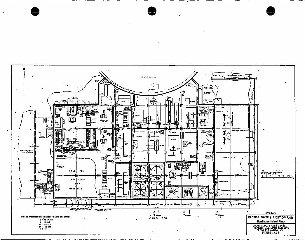
4thal atta
1 I ar\
~tla taWsra tallSau tattrt
weal
at
EE
I Qj~a
E
44a
I
l
etatrh alla(tauh a,lhr1
Pcv' t
~ I I~ I
WII
ra4 E
1 ~ ~trttII
I
-I tlat rat+W(Whe
~ WW ~4E ta
~r Il~ E
hat a~ I~
IJ
8+Irhllatttteeta
TRACT
(LTCi
E1NIT
TOR
TOOER'R
IE~ . t
Wttrtt
~ aha
ht
«/~ I» aaaa
awa ~
hva ~, IIIY
hath rtt
tati Itat attla ~ IEIlattllem\lt Ert SE444SS~ ~ ~ ~ . 4 4 wl4'44'=
Ete 'i '~II'lal a\ lal
Ea~4 t
OIRTCT RAOIATION 0055 LRYRL5 EEOREEAL OYRRATION
1 SERO EER/HR
11 On L5TO 55 ~ 15.0IY 1LO ~ 100Y >100
la a~at Eaat E4atstalra art 4 l
Jc~Irrtlt
IELA51 fL 43.00
Jc Qo 0770-COTI
FLORIDA POWER Ih LIGHT COMPANY
Hotchin5on blond Plant
MAXIMUMDOSE RATE LEVELS-REACTOR AUXILIARY8UILDING
FLOOR ELEVATION43'IGURE12.1.5

FLORIDA POWER & LIGHT COMPANY
Hutchinson Island Plant
CONTROL ROOM LAYOUT ISOMETRIC
FIGURE 12.1-6

FLORIDA POWER II LIGHT COMPANY
Hutchinson Island Plant
ISOMETRIC VIEW OF CONTROL ROOMSHIELDING AND POST-LOCA
RADIATIONSOURCES
FIGURE 12.1-7

'710'909
7
4
100,709
~A'
4
3 4O
2
I
2
'U
10 teo
7
10 29
1002 2 4 4 4 7 4 9oo 2 4 4 4 4 7 4990 2 210'02
TIME AFTER ACCIDENT (HR.)
4 4 4 7 491010s
FLORIDA POWER 8 LIGHT COMPANY
Hutchinsan Island Plant
CUMULATIVEPOST-MHA WHOLE BODYDOSE IN THE CONTROL ROOM
FIGURE 12.1.8

AREA RADIATIONMONITORCHANNELWITHOUTAUX. UNIT
AREA RADIATIONMONITORCHANNELWITH AUX. UNIT.
SENSOR &CONVERTER
SENSOR &CONVERTER
CONTROL POWERFROM 120V ACINSTRUMENT BUS
CONTROL PWR FROMLOCAL 120V ACDISTRIBUTIONPANEL
POWER SUPPLYFOR
INDICATORAND
TRIP UNIT
LOCALAUDIOALARM
AUXILIARYUNIT
INDICATORANDTRIP UNIT
INDICATORANDTRIP UNIT
MULTIPOINTRECORDER
TO LOCALALARMS
FLORIDA POWER & LIGHT COMPANY
HUTCHINSON ISLAND PLANTUNITS I 8 2
AREA RADIATIONMONITORING SYSTEMFUNCTIONAL BLOCK DIAGRAM
FIGURE 12.1-9

12. 2 VENTILATION
12. 2. 1 DESIGN OBJECTIVES
The design ob]ectives for the plant ventilation systems as they relateto radiation protection are to:
a) Limit the buildings of airborne radioactivity to levels that willpermit access required for operation, maintenance, inspection and
testing without exceeding the requirements of 10CFR20.
b) Assure migration of air toward areas having sources of airborneradioactivity.
Table 12.2-1 summarizes the areas subjected to contamination by airborneradioactivity and shows the effect of ventilation system operation on thesummation of the ratios of nuclide activity, (C), to their respectivemaximum permissible concentrations, (MPC), as set forth in 10CFR20,
Appendix B.
The information developed is based on Table 11.1-1 entitled "ReactorCoolant Activities." Table 11.1-1 is based on 0.1 percent failed fuel.
12.2.2 DESIGN DECRIPTION
12.2.2.1 General
Charcoal adsorbers, where referred to in the system descriptions, consistof banks composed of tray type units rated at 333 cfm capacity each. Traysare of stainless steel construction and consist of two carbon beds of twoinch thickness, separated by an interspace.
The charcoal is iodine impregnated with the capability of trapping a
minimum of 99.9 percent of the iodines at accident concentrations with5 percent as methyl iodide when operating at 70 percent relative humidityand 150 F. Test clips are provided for periodic testing to monitor char-coal for aging effects. Freon tests are periodically applied in accor-dance with USAEC Report DP-870 to assure minimum in-place leak testefficiencies of 99.9 percent.
High efficiency particulate (HEPA) air filters, where referred to, con-sist of banks assembled in 24" wide x 24" high x 11-1/2" deep extendedmedia dry type units. Each unit is rated at 1000 cfm. Filters arefabricated from a continuous sheet of asbestos or glass-asbestos media,closely pleated over aluminum separators, and have a minimum efficiencyof 99.97 percent when tested with thermally generated DOP droplets ofuni'form 0.3 micron size. Filters located within the containment areprovided with composition-asbestos separators in lieu of aluminum.Periodic in-place leak tests are applied, using DOP aerosol to assurefilter integrity.
Medium efficiency filters, where referred to, are of the dry-extendedmedia type, having an average National Bureau of Standards atmospheric
12.2-1

TABLE 12.2-1
AREAS WITH AIRBORNE RADIOACTIVITYSOUPCES
Area
AUXILIARYBUILDING ELEVATION -0.5
'irFlow(cfm)
LeakRate(gpd)
(3)SourceStrengthFactor gC/1a C
Haximum Whole BodyDose from Internal
Exposure (2)(rem/year)
Reactor Drain PumpsCharging PumpsSpent Resin TankBoric Acid Holding Tank and PumpsBoric Acid Condensate TanksBoric Acid Pre'concentrator FilterHoldup Drain PumpsChemical Drain TankRemaining Areas
AUXILIARYBUILDING ELEVATION +19. 5
'0,0006,000225
1,0251,500
3001,5001,2006,410
1.05.00.010.010.010.01O.l5.01.0
1.01.0
50.050.00.01O.l
50.00.10.1
4.17 (-2)3.48 (-1)9.26 (-1)2.03 (-1)2.70 (-5)1.39 (-2)1.391.74 (-1)6.50 (-3)
2.09 (-1)l. 744.631.021.35 (-4)6.95 (-2)6.958. 68 (-1)3.25 (-2)
Radio Chemistry Lab. and Counting RoomSample HX and H AnalyzerBoronometerPurificaton Filter, Flash Tankand Flash Tank PumpsFuel Pool Ion Exch., Boric AcidCondensate Ion Exch. Deborating Exch.Drumming StationBoric Acid and Waste ConcentratorBoric Acid Hakeup Tank and PumpsHoldup Tanks
1,0001,525
475
2,200
8002,2501,8002,1002,800
O.l1.00.1
0.1
O.l2.00.10.10.1
1.00.011.0
1.0
50.010.050.050.050.0
4. 17 (-2)2. 73 (-2)8. 77 (-2)
1.89 (-2)
2.6063.7061.1589.92 (-1)7. 44 (-1)
2.09 (-1)1. 36 (-1)4.38 (-1)
9.45 -(-2)
13.018.55.784.963. 72
(1) Refer to Figures 12.1-3, 12.1-4 and 12.1-5 for radiation zone classification f'r access.(2) Assumes continuous exposure for a 40 hr week, 50 weeks per year.(3) Ratio of nuclide radioactivity concentrations of leak source to those of the reactor coolant.

type test efficiency of 35 percent. Filter units are 2 in thick andeither 20" high x 20" wide or 24" high x 24" wide.
12.2.2.2 Containment Airborne Radioactivit Removal S stem
The containment airborne radioactivity removal system consists of twounits as shown on Figures 9.4-1 and 9.4-3. The system is designed toremove airborne radioactivity in particulate and iodine form by recircu-lating containment atmosphere through high efficiency filters and char-coal adsorbers. The system is used for radioactivity removal duringnormal operation only and serves no function for post-LOCA dose reduction.Each of the two units located at elevation 23'ncludes a suctionconnection from the containment cooling system ring duct header locatedat elevation 98'; a bank HEPA air filters, 2 units wide by 5 units high;a bank of unit tray type charcoal adsorbers, 2 units wide by 15 unitshigh; and a belt driven, single width single inlet, freely dischargingcentrifugal fan. Fan and filters for each of the two units are rated at10,000 cfm with a fan static pressure of 6 in. wg which permits ratedoperation with fully loaded filters.
The containment airborne radioactivity removal system is manuallyenergized from the control room. Charcoal adsorber temperature and HEPA
filter pressure drop are annunciated and monitored in the control room.Low flow annunciation is also provided.
All active components of the system are suitable for operation in 120 F
ambient temperature and 1 rad/hr of radiation. Ambient temperatures arelimited to a maximum of 120 F by normal operation of three containmentfan cooling units.
System design and calculational evaluation is based on normal plantoperation only, assuming a 1200 lb/day reactor coolant leakage into thecontainment. Specific equilibrium activities of the coolant are listedin Table 11.1-1. Other assumptions made .in the calculation model are:
a) Failed fuel is 0.1 percent.
b) Iodine partition coefficient is 0.10.
c) 100 percent of all noble gases become airborne at the leakageor generation rate.
d) Tritium, which is in water molecular form, concentrates in theatmosphere up to the level determined by the specific humidity(lb of water vapor per pound of dry air at 120 F dry bulb and50 percent relative humidity).
e) Mixing efficiency of all airborne constituents is 90 percent.
f) Because a quantity of leakage remains in liquid form, there islittle opportunity, barring liquid suiface disturbances, atomi-zation or residue following complete evaporation, for particu-lates to become airborne. Therefor'e, the assumption of allparticulates being airborne is conservative.
12.2-3
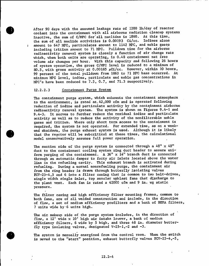
After 90 days with the assumed leakage rate of 1200 lb/day of reactorcoolant into the containment with all airborne radiation cleanup systemsinactive, the sum of C/HPC for'all nuclides is 1860. At this time,the sum of all nuclide activities is 0.00193 Ci/cc. Iodines aloneamount to 647 HPC, particulates amount to 1142 MPC, and noble gasesincluding tritium amount to 71 HPC. Pulldown time for the airborneradioactivity removal system is closely a function of air change ratewhich, when both units are operating, is 0.48 containment net freevolume air changes per hour. With this capacity and following 26 hoursof system operation, the gross C/MPC level is reduced to a minimum of80.5, with gross activity at 0.00185 pCi/cc. However, within 10 hours,99 percent of the total pulldown from 1860 to 71 MPC hass occurred. Atminimum MPC level, iodine, particulate and noble gas concentrations inHPC's have been reduced to 7.5, 0.7, and 71.3 respectively.
12.2.2.3 Containment Pur e S stem
The containment purge system, which exhausts the containment atmosphereto the environment, is rated at,42,000 cfm and is operated followingreduction of iodine and particulate activity by the containment airborneradioactivity removal system. The system is shown on Figures 9.4-1 and9.4-3. It serves to further reduce the residual iodine and particulateactivity as well as to reduce the activity of the nonfilterable noblegases and tritium. Where only short term access to the containment isrequired, the system is not operated. For extended time, as on a week-end shutdown, the purge exhaust system is used. Although it is likelythat the reactor will be subcritical at these times, the calculationalmodel conservatively assumes full power operation.
The suction side of the purge system is connected through a 48" x 48"duct to the containment cooling system ring duct header to assure uni-form purging of the containment. A 36" x 14" branch duct is connectedthrough an automatic damper to forty air inlets located above the waterline in the refueling cavity. This exhaust branch is activated duringrefueling. During a normal nonrefueling purge, the containment airfrom the ring header is drawn through butterfly isolating valvesFCV-25-4,5 and 6 into a filter casing that is common to two belt-driven,single width single inlet, top annular upblast fans that discharge tothe plant vent. Each fan is rated a 42000 cfm and 9 in. wg staticpressure.
The filter casing and high efficiency filter mounting frames, common toboth fans, are of all welded construction and include, in the directionof flow, a set of. medium efficiency prefilters and a bank of HEPA filters,7 units wide by*6 units high.
The air,. makeup side of the purge system includes, in the direction offlow, a 12'ide x 10'igh air intake louver, a bank of mediumefficiency filters, 6 wide by 5 high, and three 48 in. diameter butter-fly type isolating valves, designated V-25-1,-2 and -3.
The system is manually energized from the control room. When the switchis moved to the "start" position, exhaust butterfly valves FCV-25-4,-5,
12.2-4
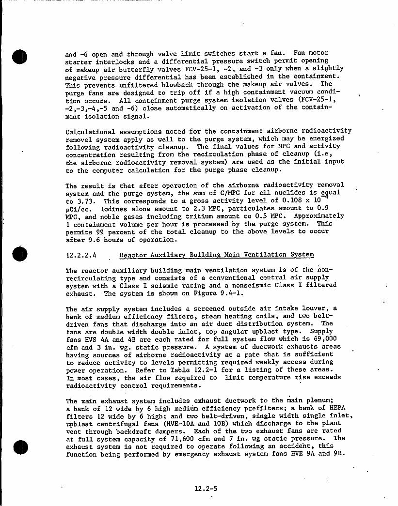
and -6 open and through valve limit switches start a fan. Fan motorstarter interlocks and a differential pressure switch permit openingof makeup air butterfly valves'FCV-25-1, -2, and -3 only when a slightlynegative pressure differential has been established in the containment.This prevents unfiltered blowback through the makeup air valves. The
purge fans are designed to trip off if a high containment vacuum condi-tion occurs. All containment purge system isolation valves (FCV-25-1,-2,-3,-4,-5 and -6) close automatically on activation of the contain-ment isolation signal.
Calculational assumptions noted for the containment airborne radioactivityremoval system apply as well to the purge system, which may be energizedfollowing radioactivity cleanup. The final values for MPC and activityconcentration resulting from the recirculation phase of cleanup (i.e,the airborne radioactivity removal system) are used as the initial inputto the computer calculation for the purge phase cleanup.
The result is that after operation of the airborne radioactivity removalsystem and the purge system, the sum of C/MPC for all nuclides is equalto 3.73. This corresponds to a gross activity level of 0.108 x 10
pCi/cc. Iodines alone amount to 2.3 MPC, particulates amount to 0.9MPC, and noble gases including tritium amount to 0.5 MPC. Approximately1 containment volume per hour is processed by the purge system. Thispermits 99 percent of the total cleanup to the above levels to occurafter 9.6 hours of operation.
12.2.2.4 Reactor Auxilia Buildin Main Ventilation S stem
The reactor auxiliary building main ventilation system is of the non-recirculating type and consists of a conventional central air supplysystem with a Class I seismic rating and a nonseismic Class I filteredexhaust. The system is shown on Figure 9.4-1.
The air supply system includes a screened outside air intake louver, abank of medium efficiency filters, steam heating coils, and two belt-driven fans that discharge into an air duct distribution system. Thefans are double width double inlet, top angular upblast type. Supplyfans HVS 4A and 4B are each rated for full system flow which is 69,000cfm and 3 in. wg. static pressure. A system of ductwork exhausts areashaving sources of airborne radioactivity at a gate that is sufficientto reduce activity to levels permitting required weekly access duringpower operation. Refer to Table 12.2-1 for a listing of these areas.In most cases, the air flow required to limit temperature rise exceedsradioactivity control requirements.
The main exhaust system includes exhaust ductwork to the main plenum;a bank of 12 wide by 6 high medium efficiency prefilters; a bank of HEPA
filters 12 wide by 6 high; and two belt-driven, single width single inlet,upblast centrifugal fans (HVE-10A and 10B) which discharge to the plantvent through backdraft dampers. Each of the two exhaust fans are ratedat full system capacity of 71,600 cfm and 7 in. wg static pressure. Theexhaust system is not required to operate following an accident, thisfunction being performed by emergency exhaust system fans HVE 9A and 9B.
12.2-5

Supply and exhaust fans, except for HVE 9A and 9B, are manually energizedfrom the control room.
Air flow stoppage is annunciated by means of flow switches located in thedischarge of each fan. HEPA filter pressure drop is indicated in thecontrol room and annunciated when in excess of 3 in. wg.
Other areas within the reactor auxiliary building that are free of air-borne radioactivity contaminating sources are exhausted directly to theenvironment. Such areas include laboratories, offices, electrical equip-ment areas, cold locker rooms, battery rooms, cold shower, cold areatoilet, clean clothes issue room and cable enclosure.
The total volume of the reactor auxiliary building is 978,770 cu ft ofwhich 638,370 cu ft are areas exhausted to the plant vent.
In most cases the minimum air change rate in any space within the reactorauxiliary building is 4 volumes per hour. The overall air change ratefor portions of the building exhausted to the plant vent is 6.73 volumesper hous. Air change rates for specific areas having sources of airbornecontamination are listed in Table 12.2-1.
12.2.2.5 Fuel Handlin Buildin Ventilation S stem
The fuel handling building ventilation system reduces plant personneldoses due to potential airborne activity resulting from diffusion offission products through the fuel pool water. The system consists of(a) a separate air supply and air exhaust network serving the fuel poolarea and (b) a separate air supply and air exhaust network serving thefuel pool equipment areas and the new fuel storage area. The system isshown on Figures 9.4-1 and 9.4-2.
Each air supply system includes a wall intake, disposable roughing fil-ters, 15 psi steam heating coils, and a cabinet type centrifugal fan.The first supply system is rated at 9800 cfm; the second supply systemis rated at 8300 cfm. These supply systems provide hourly air changesof 6.8 volumes and 4.7 volumes for the fuel pool and equipment areas,respectively.
The fuel pool is exhausted by 36, 8" x 4" air inlet ducts spaced 4'-0"on centers around the pool periphery and 1'-0" above the pool surface.Four such inlet ducts are located 8'-0" on centers in the south wall ofthe refueling canal. The fuel pool exhaust system includes the concrete-embedded welded steel pool exhaust ducts; the duct connection to thefilter casing; an all welded filter casing that includes a bank ofmedium efficiency filters, 9 wide x 3 high, and a bank of HEPA filters3 wide "x 3 high; and two belt-driven, single width single inlet, upblastfans. Each fan is rated to deliver full system airflow of 10,000 cfm at6 in. wg. static pressure which corresponds to an average velocity of1250 ft/min through the 36 fuel pool exhausts. Discharge is to a con-crete penthouse with a 7'-0" wide x 8'-0" high fixed louver located onits north face.
12.2-6

Air is supplied to the fuel pool at a rate of 9800 cfm from 10'-0" abovethe 62'-0" floor elevation forcing migration of all air downward to thefuel pool surface. The amount of air supplied, being less than thatexhausted, prevents out-leakage from the pool area to the equipmentspaces within the building and to the environment.
The fuel pool equipment areas are exhausted through a filter system ofthe same arrangement used in the fuel pool exhaust system. A singlewidth single inlet, upblast centrifugal fan exhausts the filter casingand discharges into the concrete penthouse. The fan is rated for 8100cfm flow and 4 in. wg. static pressure.
12.2.2.6 Control Room Ventilation S stem
The design of the control room reflects the limits of acceptable expo-sures to plant personnel as documented in 10CFR100 for normal and emer-gency operation. General Design Criterion 19 stipulates that radiationprotection shall be provided to permit access and occupancy of thecontrol room under accident conditions without personnel receivingradiation exposure in excess of 5 rem whole body, or its equivalent, toany part of the body for the duration of the accident. As stated inSection 12.1.1, the control room shielding is designed to limit themaximum whole body dose rate to 0.5 mrem/hr during normal operation andthe maximum integrated whole body dose to 3 rem for 90 days followingMHA. The actual expected cumulative whole body dose rate following a1KA is shown on Figure 12.1-8.
The control room ventilation system consists of three split-systemdirect expansion air conditioning units, a ducted air intake and airdistribution system, and an emergency filteration section with HEPAfilters and charcoal absorbers. The system is shown on Figures 9.4-1and 9.4-2.
Each of the three indoor units includes a fail-open electrically operatedinlet damper, medium efficiency filters, direct expansion refrigerantcooling coil, steam coil, cabinet type centrifugal fan rated at 7500 cfmand 1.25 in. wg. external static pressure, and a gravity damper to preventrecirculation through deenergized units. Each of the indoor sections isserved by a weather resistant, roof mounted condensing unit which con-sists of an air cooled condenser section assembled to a refrigerantcompressor section.
The emergency filtration system processes control room air throughcharcoal filters if the plant site is subject to airborne contamination.This system includes a manual shut-off damper, a 1 unit wide x 2 unithigh bank of HEPA filters, and a 1 unit wide x 6 unit high bank ofcharcoal adsorbers feeding into two full capacity centrifugal boosterfans arranged in parallel, each rated at 2000 cfm and 4 inches wg. staticpressure. Motorized inlet and gravity outlet dampers are provided ateach booster fan. Two electric motor operated 16 in. butterfly isolationvalves are located on each duct leading from the outside air intake hoodswhich are mounted on the north and south walls of the reactor auxiliarybuilding at elevation 78'-4". All ductwork is of welded construction.
12.2-7
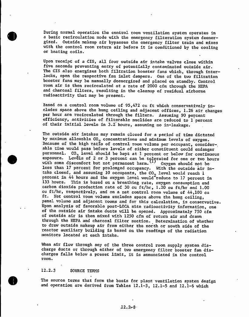
During normal operation the control room ventilation system operates ina basic recirculation mode with the emergency filteration system deener-gized. Outside makeup air bypasses the emergency filter train and mixeswith the control room return air before it is conditioned by the coolingor heating coils.
Upon receipt of a CIS, all four outside air intake valves close withinfive seconds preventing entry of potentially contaminated outside air.The CIS also energizes both filtration booster fans which, through inter-locks, open the respective fan inlet dampers. One of the two filtrationbooster fans may be manually deenergized and placed on standby. Controlroom air is then recirculated at a rate of 2000 cfm through the HEPAand charcoal filters, resulting in the cleanup of residual airborneradioactivity that may be present.
Based on a control room volume of 95,472 cu ft which conservatively in-cludes space above the hung ceiling and adjacent offices, 1.26 air changesper hour are recirculated through the filters. Assuming 90 percentefficiency, activities of filterable nuclides are reduced to 1 percentof their initial levels in 3.2 hours, assuming no in-leakage.
The outside air intakes may remain closed for a period of time dictatedby maximum allowable CO concentrations and minimum levels of oxygen.Because of the high ratio of control room volume per occupant, consider-.able time would pass before levels of either constituent could endangerpersonnel. C02 level should be kept at 1 percent or below for continuousexposure. Levels of 2 or 3 percent can be t~J~rated for one or two hourswith some discomfort but not permanent harm. Oxygen should not beless than 17 percent for prolonged occupancy. With the outside air in-take closed, and assuming 10 occupants, the C02 level would reach 1percent in 44 hours and the oxygen level would reduce to 17 percent in133 hours. This is based on a breathing rate, oxygen consumption andcarbon dioxide production rate of 30 cu ft/hr, 1.20 cu ft/hr and 1.00cu ft/hr, respectively, and on a net control room volume of 44,100 cuft. Net control room volume excludes space above the hung ceiling,panel volume and adjacent rooms and for this calculation, is conservative.Upon analysis of favorable post-LOCA site radioactivity information, oneof the outside air intake ducts will be opened. Approximately 750 cfmof outside air is then mixed with 1250 cfm of return air and drawnthrough the HEPA and charcoal filter section. Determination of whetherto draw outside makeup air from either the north or south side of thereactor auxiliary building is based on the readings of the radiationmonitors located at each intake.
When air flow through any of the three control room supply system dis-charge ducts or through either of two emergency filter booster fan dis-charges falls below a preset limit, it is annunciated in the controlroom.
12.2.3 SOURCE TERMS
The source terms that form the basis for plant ventilation system designand operation are derived from Tables 12.1-3, 12.1-5 and 12.1-6 which
J2,21-8-

12.2. 4
list the specific activities in process fluids and Table 12.2-1 whichlists estimates of leakage points and rates in the process systems. When
combined properly, the tables 'yield the source terms necessary for theinhalation dose calculations discussed in Section 12.2.6.
a
AIRBORNE RADIOACTIVITYMONITORING
12.2.4. 1 Containment Atmos here Radiation Monitorin S stem
The containment atmosphere radiation monitoring system is designed toprovide a continuous indication in the control room of the particulateand gaseous radioactivity levels inside the containment. Radioactivityin the containment atmosphere indicates either the presence of fissionproducts due to a reactor coolant leak or the presence of activationproducts due to neutron leakage from the reactor vessel. Refer toFigure.12.2-1 for the following discussion.
The sample flow is withdrawn from the plant vent through two isokineticnozzles. The nozzles are designed such that the sampling velocity is thesame as that in the containment cooling system ring duct so that preferen-tial selection does not occur, i.e., so that the weights of the radio-active particles do not become a factor in obtaining a representativesample.
One isokinetic stream passes through a moving paper filter which collectsparticulates greater than 1 micron in size; it then passes through a gassampler where it is monitored for radio-gas content before being pumpedback to the containment. The moving filter assembly consists of a fixedposition detector scanning the moving filter for any deposited activity.The other isokinetic sample stream passes through an iodine charcoalfilter holder before being pumped back to the containment. The filter isperiodically replaced and analyzed in the laboratory. Lead shieldingarranged in a 4n geometry around the detector prevents interferencefrom background radiation. Refer to Table 12.2-2 for design characteris-tics of the system.
The pumping system associated with the containment airborne radiationmonitoring system consists of 2 root pump assemblies. One 5 cfm pumpis connected to the iodine charcoal filter,to which the containmentair sample is drawn through an isokinetic nozzle. A second 10 cfmpump draws air sample after it has passed through the particulate andgaseous monitors described above.
Each detector system is processed at the factory through a primaryradionuclide calibration. In this process, two or more National Bureauof Standards calibrated isotopes are prepared in the proper form tosimulate the effluent for which the system will be used. The systemreadout is then compared with the actual activity being observed. Theactivity is then removed from the system, and with all other conditionsexactly the same, a point source (approximately 0.8 pCi) is attached tothe sensitive area of the detector and the detector is placed in itsnormal operating position. The response of the readout is now recorded.Since all other conditions and settings are identical to the primary
12.2-9 ~

TABLE 12.2-2
DESIGN CHARACTERISTICS — CONTAINMENT RADIATION MONITORING SYSTEM
1. Air Particulate Channel
a. Detector
Type 90Sensitivity to Sr in aO.l mR/hr background, pCi/cc
Dynamic range, pCi/ccDesign pressure, psigDesign temperature range, FAmperage, voltage, frequency,
phase
Check source*
beta plastic scintillator-1232x1012 -7
3.2 x 10 to 1.5 x 10
5032 to 122
10 amps, 110V ac, 60 Hz,single phase
Cs137 - 8 pCi
b. Ratemeter
TypeAccuracy, percentRange, cpmVoltage, frequency, power
log count+ 10 of scale10 to 106100-130V ac, 50-60 Hz, 10W
c. Moving Filter Paper**
Absorption efficiency, percent
Shield
2. Gaseous Radiation Monitorin Channel
99 for particulates 0.3microns in diameter
2 in. 4n geometry lead
a. Detector
Type 133Sensitivity to Xe in a0.1 mR/hr background, pCi/cc
Dynamic range, pCi/ccPressure, psigTemperature range, FCheck source*
beta plastic scintillator
2.8 x 1072.8 x 10 to 1.8 x 10
5032 to 122Cs137 - 8 pCi
b. Ratemeter (same as air particulate channel)
3. Iodine Charcoal Filter Holder Channel
Type.Efficiency, percent
Activated charcoal filter95
*Check source is activated from ratemeter located in control room.**Filterpaper movement may be selected for continuous or programmed step
advance.
12.2-10

~ 4

calibration, the point source is directly referenced to the primaryNational Bureau of Standards calibrated source. A calibration of thesystem at periodic intervals 'can now be easily achieved.
The push button operated check sources that come along with the monitoringsystem are used during the routine calibration process at the factory, atwhich time the response caused by the check source is recorded. This pro-vides a quick method of checking the system to ascertain that its stillin approximate calibration after installation and operation.
Power sources, indicating devices and recorders are all located on thesame main control room radiation panel. All radiation channels are in-dicated, recorded and annunciated on the control room radiation moni-toring panel. Abnormal radiation levels are indicated both visually andaudibly.
The sensitivity of the containment atmosphere monitoring system fordetecting reactor coolant leakage is discussed in Section 5.2.4.
12.2.4.2 Plant Vent Radiation Honitorin S stem
The plant vent radiation monitoring system is designed to representativelysample, monitor, indicate and record the radioactivity level in the planteffluent gases being discharged from the plant vent. It provides a con-tinuous indication in the control room of the activity levels of radio-active materials released to the environs so that determination of thetotal amount of activity release is possible.
A schematic diagram of the plant vent radiation monitoring system isshown in Figure 12.2-2.
The plant vent radiation monitoring system continuously monitors the plantvent exhaust for particulates, iodine and gases at the point of releaseto the atmosphere. Its function is to confirm that releases of radioac-tivity do not exceed the predetermined limits set by 100CFR20.
The sample flow is withdrawn from the plant vent through isokinetic nozzleslocated at a minimum of 8 vent diameters from the last point of radio-activity entry. The nozzles are designed such that the sampling velocityis the same as that in the plant vent so that preferential selection doesnot occur, i.e., so that the weights of the radioactive particles do notbecome a factor in obtaining a representative sample.
One stream passes through a moving filter tape which captures particulatesthat are greater than one micron in size. The stream then passes througha gas sampler where it is monitored for radiogas content. A 10 scfm rootpump draws the sample through the monitors before discharging to theatmosphere. The other stream passes through a fixed filter sampler andthen through a 5scfm root pump assembly before it is discharged to theatmosphere.
The particulate and gaseous detectors used for the vent plant monitoringsystem have the same technical descriptions as those for the containmentatmosphere radiation described in Table 12.2-2. The sampler and associ-
l2.2-11
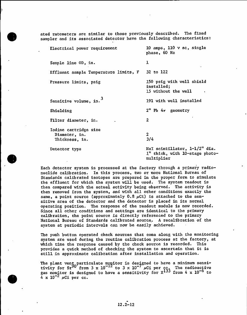
ated ratemeters are similar to those previously described. The fixedsampler and its associated detector have the following characteristics:
Electrical power requirement 10 amps, 110 v ac, singlephase, 60 Hz
Sample line OD, in.
Effluent sample Temperature limits, F 32 to 122
Pressure limits, psig
Sensitive volume, in. 3
Shielding
Filter diameter, in.
150 psig with well shieldinstalled;15 without the well
191 with well installed
2" Pb 4n. geometry
Iodine cartridge sizeDiameter, in.Thickness, in.
23/4
Detector type NaI scintillator, l-l/2" dia.1" thick, with 10-stage photo-multiplier
Each detector system is processed at the factory through a primary radio-nuclide calibration. In this process, two or more National Bureau ofStandards calibrated isotopes are prepared in the proper form to simulatethe effluent for which the system will be used. The system readout isthen compared with the actual activity being observed. The activity isthen removed from the system, and with all other conditions exactly thesame, a point source (approximately 0.8 pCi) is attached to the sen-sitive area of the detector and the detector is placed in its normaloperating position. The response of the readout module is now recorded.Since all other conditions and settings are identical to the primarycalibration, the point source is directly referenced to the primaryNational Bureau of Standards calibrated source. A recalibration of thesystem at periodic intervals can now be easily achieved.
The push button operated check sources that come along with the monitoringsystem are used during the routine calibration process at the factory, atwhich time the response caused by the check source is recorded. Thisprovides a quick method of checking the system to ascertain that it isstill in approximate calibration after installation and operation.
The plant ven) particulate m~gitor is designed to have a minimum sensi-tivity for Sr from 3 x 10 to 3 x 10 pCi per cc. The radioactivegas monitor is designed to have a sensitivity for X from 4 x 10 to4 x 10 pCi per cc.
12.2-12

12.2.5 OPERATING PROCEDURES
Stationary and portable detectors are provided for monitoring airborneactivity in operating and maintenance locations susceptible to radioactivecontamination. Where and when practicable, operational procedures willexplicitly specify the use of health physics respiratory equipment duringperformance of maintenance and repair involving potential activity releases.
12.2.6 ESTIMATES OF INHALATIONDOSES
Expected airborne activity concentrations for various auxiliary buildingareas are provided in Table 12.2-1 in terms of ratio of MPC's. Alsoprovided for reference are the maximum whole body doses from internalexposure which would be realized if an individual spent his entire 40hour work week, 50 weeks per year, in any of the designated areas. Inpractice this can not and will not occur because the total whole bodydose from both external and internal sources will be maintained wellbelow the occupational exposure limit of 5 rem per year by the planthealth physics programs. Areas with potentially high concentrations ofairborne activity is so marked and access controlled.
12. 2-13

12.3 HEALTH PHYSICS PROGRAM
12.3.1 PROGRAM OBJECTIVES
The program objectives are:
a) to implement a radiation monitoring program for protecting the healthand safety of plant personnel
b) to implement a medical examination program for plant personnel toconfirm the effectiveness of the radiation monitoring program.
12.3.2 FACILITIES AND EQUIPMENT
Health physics personnel have the responsibility for use and maintenanceof specially provided facilities and equipment for the protection of plantpersonnel, including the personnel radiation dosimetry program and theradiation worker medical examination program.
A comprehensive medical examination program for radiation workers isestablished for maintaining medical records of the physical status ofeach employee. Subsequent medical examinations will be held as determinednecessary. This program is design to preserve the health of employeesand to confirm the effectiveness of the radiation control methods employedat the plant.
The general arrangement of the locker room facilities in the reactor aux-iliary building is designed to provide adequate personnel decontaminationand change areas as shown in Figure 1.2-13. The cold locker room is usedto store personal items not required or allowed .in the radiation controlledareas. The hot locker room is employed as a change area and storage areafor potentially contaminated clothing. Personnel monitors are located atthe access point(s). All personnel will survey 'themselves on leavingradiation controlled areas. Showers, sinks and necessary monitoringequipment also are provided in the hot locker room to aid in the decon-tamination of personnel.
'll
personnel entering radiation controlled areas are required to wearprotective clothing. The nature of the work to be done is the governingfactor in the selection of protective clothing, to be worn by individuals.The protective apparel available includes shoe covers, head covers, gloves,and coveralls or lab coats. Additional items of specialized apparel suchas plastic or rubber suits, face shields, safety glasses and respiratorsare also available. In all cases, health physics-trained personnel willevaluate the radiological conditions and specify the required items ofprotective clothing to be worn.
Appropriate written procedures govern the proper use of protective clothing,where and how it is to be worn and removed, and how the change room anddecontamination facilities for personnel equipment, and plant areas are tobe used.
Provisions are made for decontamination of work areas throughout the plant.The spent fuel cask wash area has facilities to handle decontamination of
12.3-1

INSIDECOHTAINMEHT
OUTSIDE~ ~CONTAINMENT
ISOKIHETICSAMPLER
I" BALL VALVES(ALLOTHERS ~Z'ALVES) ~
}sswmmmaggm m~ arne(
84 ~ IW/2'b 4n SHIELDED
O
IOO
X
IODINE CHARCOALFILTER HOLDERW/SELF LOCKDISCONNECT
.I" BALL VALVE
843 20 11 DET. 0sl I-3
as
5 SCFMROOTS PUMP ASS'Y117 YAC lg 60Hz
IS
II
II
II
I
I
II
ROOTSPUMPASS'Y.
1117 YACld 60Hz10 SCFM
4I.IIII
Pl
I-I
I FISI II I
JI
I
,PURGEI844.3244 71 SHIELD
Pl
841.3/3 SAMPLERW/3" Pb
II
III
I
II
III
II
I
I
II
IIIIII
as844 20
843-20 DET.
I
MS TB- I844 550 ENCLOSUREI IFLORIDA POWER 8 LIGHT COMPANY
Hvtcbinson Island Plant
CONTAINMENTRADIATIONMONITORING SYSTEM
FIGURE 12.2-1
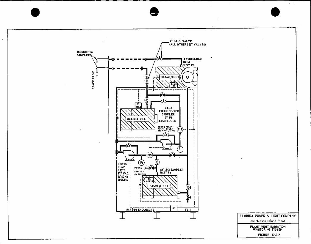
I" BALL VALVE(ALLOTHERS i/s" VALVES)
ISOKINETICSAMPLER
}e mmmm mm+ 4 xSHIELDED841.1W/2" Pb
O
SCuI
I
II
IIII
IIIII
CSSZZ 3
843 30 It DET.
84 1.2FIXED FILTER
SAMPLER2" Pb
4$ SHIELDED
ASS'T SNH FI 8ROOTS P
l1 1 YAC 14 SOHa
FIS
Pl
ROOTS I
PUMPASS'V I117 YAC I
Ill60Hz I
10SCFM I
Pl
PURGE
SZZ-33-3ZeSHl EO
CS044.30
841.3/3 SAMPLERW/3" Pb
843-20 P DET.
843.20 P DET Pzzz 3
CS
IIIIIIIIIIIIIIII
IIIII
IIIIIIIIIIIIIIII
L844.5-50 ENCLOSUREI I I
TB I
FLORIDA POWER 8 LIGHT COMPANY
Hutchinson Isiand Plant
PLANT VENT RADIATIONMONITORING SYSTEM
FIGURE 12.2-2

12.3 HEALTH PHYSICS PROGRAM
12.3.1 PROGRAM OBJECTIVES
The program objectives are:
a) to implement a radiation monitoring program for protecting the healthand safety of plant personnel
b) to implement a medical examination program for plant personnel toconfirm the effectiveness of the radiation monitoring program.
12.3.2 FACILITIES AND EQUIP>SNT
Health physics personnel have the responsibility for use and maintenanceof specially provided facilities and equipment for the protection of plantpersonnel, including the personnel radiation dosimetry program and theradiation worker medical examination program.
A comprehensive medical examination program for radiation workers isestablished for maintaining medical records of the physical status ofeach employee. Subsequent medical examinations will be held as determinednecessary. This program is design to preserve the health of employeesand to confirm the effectiveness of the radiation control methods employedat the plant.
The general arrangement of the locker room facilities in the reactor aux-iliary building is designed to provide adequate personnel decontaminationand change areas as shown in Figure 1.2-13. The cold locker room is usedto store personal items not required or allowed in the radiation controlledareas. The hot locker room is employed as a change area and storage areafor potentially contaminated clothing. Personnel monitors are located atthe access point(s). All personnel will survey themselves on leavingradiation controlled areas. Showers, sinks and necessary monitoringequipment also are provided in the hot locker room to aid in the decon-tamination of personnel.
'll
personnel entering radiation controlled areas are required to wearprotective clothing. The nature of the work to be done is the governingfactor in the selection of protective clothing to be worn by individuals.The protective apparel available includes shoe covers, head covers, gloves,and coveralls or lab coats. Additional items of specialized apparel suchas plastic or rubber suits, face shields, safety glasses and respiratorsare also available. In all cases, health physics-trained personnel willevaluate the radiological conditions and specify the required items ofprotective clothing to be worn.
Appropriate written procedures govern the proper use of protective clothing,where and how it is to be worn and removed, and how the change room anddecontamination facilities for personnel equipment, and.plant areas are tobe used.
Provisions are made for decontamination of work areas throughout the plant.The spent fuel cask wash area has facilities t'o handle decontamination of
12.3-1

large equipment. This area contains a decontamination enclosure and servicefacilities. A decontamination room external to the machine shop in thereactor auxiliary building is used for the decontamination of hand toolsand small equipment.
Respiratory protective devices are required in any situation arising fromoperations in which airborne radioactivity exists or is expected. Insuch cases, the airborne concentrations are evaluated by health physicstrained personnel and the necessary protective devices specified accord-ing to concentration and type of airborne contaminants present.
Respiratory devices available for use include:
a) half-face respirator (filter type)b) full-face respirator (filter, gas canister, or supplied air)c) self-contained breathing apparatus
Self-contained or supplied air breathing apparatus is used in any situ-ation involving exposure to gaseous activity or oxygen deficient atmospheres.
The following tabulation of airborne concentrations expected to be in ex-cess of 'maximum permissible concentration (MPC) limits specified in 10 CTR
20, Appendix B, Table I, is used to determine the appropriate type ofrespiratory protection equipment required.
Airborne Concentration ~Te
Particulate activity less than 10times MPC and gas activity of1 MPC or less
Half-face respirator(filter type)
Particulate activity less than 50times MPC and gas activity of1 MPC or less
Full-face respirator(filter type)
Particulate activity greater than50 times MPC or gas activitygreater than 1 MPC
Self-contained or suppliedair breathing apparatus
Respirators are maintained by checking for mechanical defects, contam-ination, and cleanliness by health physics trained personnel.
A health physics office and radiochemistry laboratory are located in thereactor auxiliary building (el. 19.5'). These facilities include bothlaboratory and shielded counting rooms. These are equipped to analyzeroutine air samples and contamination swipe surveys. Portable radiationsurvey instruments, respiratory protection equipment and contaminationcontrol supplies are stored in the reactor auxiliary building.
Portable personnel radiation monitors are located in the followingcontrolled access points:
12.3-2

a) Auxiliary Buildingb) Reactor Containment (during shutdown)c) Fuel Handling. Building
A portal monitor is located in the main guard station at the exit from theplant and provides a final radiation survey of all personnel levaing thegenerating station area.
The types and minimum quantities of portable radiation survey instrumentsavailable for routine monitoring functions are listed in Table 12.3-1.
Survey instruments are calibrated periodically and maintanance recordsare maintained for each instrument.
In order to protect personnel from access to high radiation areas thatmay exist temporarily as a result of plant operations and maintenance,warning signs, audible and visual indicators, barricades, and locked doorsare used as necessary.
Administrative and physical security measures are employed to preventunauthorized entry of personnel to any designated high radiation areaor contaminated area. These measures include the following:
a) Areas accessible to personnel as listed in Section 12.1.1 in whichradiation levels are such that a major portion of the body mightreceive in any one hour a dose in excess of 100 mrem are barricadedand conspicuously posted as "high radiation areas." Administrativecontrols require the issuance of a "radiation work permit" prior toentry to any high radiation area or contamination area. Locked wiremesh doors are provided to prevent unauthorized entry into theseareas in which the intensity of radiation is greater than 1000 mr/hr.
b) Any individual or group of individuals entering a high radiationarea is provided with a portable survey meter which continuouslyindicates the dose rate in the area.
c) All personnel are required to wear protective clothing for entryinto designated contaminated areas. The areas involved will bedecontaminated as soon as practicable to prevent the spread of con-tamination. Decontamination will be performed under the directionof health physics personnel.
12.3.3 PERSONNEL DOSIMETRY
The official and permanent record of accumulated external radiation ex-posure received by individuals is obtained principally from the interpre-tation of thermoluminescent dosimeters (TLD) and film badges. Directreading dosimeters provide day-by-day indication of external radiationexposure.
All persons subject to occupational radiation exposure are issued beta-gamma TLD's. and are required to wear them at all times. A badge withneutron sensitive film is issued to personnel whenever a significant neu-tron exposure is possible. Neutron film badges are issued at the controlled
1 2 ~ 3 3

access point or the main guard station. The TLD's and film badges areprocessed on a routine basis at monthly intervals. The TLD's and filmbadge of any individual is processed by special handling whenever it appearsthat an overexposure may have occurred.
Self reading dosimeters are issued, in addition to the TLD, to personnelwhere work conditions make desirable a day-to-,day indication of exposure.Dosimeters are read, recorded and rezeroed regularly. Dosimeter recordsfurnish the exposure data for the administrative control of radiationexposure.
Special or additional personnel monitors are issued as may be requiredunder unusual conditions. These devices are issued at the discretion ofhealth physics personnel.
Visitors to the controlled access areas are escorted by qualifiedpersonnel and are issued appropriate personnel monitoring devices in-cluding self reading dosimeters. An escort may not be required, forthose who have received the necessary radiation protection trainingwhen this arrangement is approved by the Health Physicist and authorizedby the Plant Superintendent.
Records of radiation exposure history and current occupational exposurewill be maintained for each individual for whom personnel monitors areissued.
12.3-4
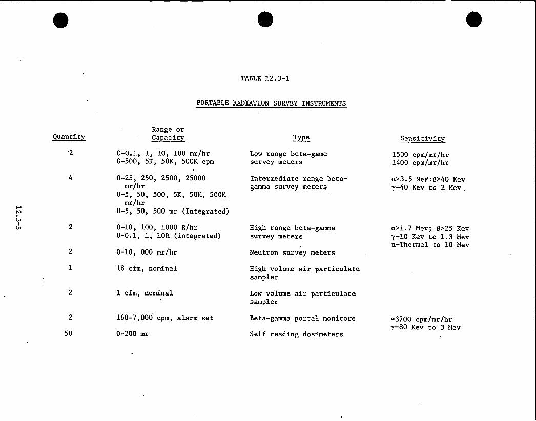
TABLE 12.3-1
PORTABLE RADIATION SURVEY INSTRUMENTS
uantitRange or~Ca acit
0-0.1, 1, 10, 100 mr/hr0-500, 5K, 50K, 500K cpm
l
0-25, 250, 2500, 25000mr/hr
0-5, 50, 500, 5K, 50K, 500Kmr/hr
0-5, 50, 500 mr (Integrated)
~Te
Low range beta-gamesurvey meters
Intermediate range beta-gamma survey meters
Sensitivit
1500 cpm/mr/hr1400 cpm/mr/hr
a>3.5 Mek':g>40 Kevy-40 Kev to 2 Mev .
0-10, 100, 1000 R/hr0-0.1, 1, 10R (integrated)
0-10, 000 mr/hr
18 cfm, nominal
High range beta-gammasurvey meters
Neutron survey meters
High volume air particulatesampler
a>1.7 Mev; S>25 Kevy-10 Kev to 1.3 Mevn-Thermal to 10 Mev
1 cfm, nominal Low volume air particulatesampler
50
160-7,000 cpm, alarm set
0-200 mr
Beta-gamma portal monitors
S'elf reading dosimeters
=3700 cpm/mr/hrY-80 Kev to 3 Mev

TABLE OF CONTENTS
CHAPTER 13CONDUCT OF OPERATIONS
Section Title ~Pa e
13. 1
13.1.1
13.1.1.1
13.1.1.2
13.1.1.3
13.1.1.4
13.1.2
13.1.2.1
13.1.2.2
13. 1. 3
13. 1.3. 1
13.1.3.2
13.1.3.3
13.1.3.4
13.1.3.5
13.1.3.6
13.1.3.7
13.1.3.8
13.1.3.9
13.1.3.10
13.1.3.11
ORGANIZATIONAL STRUCTURE OF APPLICANT
CORPORATE ORGANIZATION
Function and Res onsibilit
Mana ement and Technical Su ort Staff
Or anizational Relations Amon A licant NSSSand A-E
0 erations Staff
OPERATING ORGANIZATION
Plant Or anization
Administration
QUALIFICATION REQUIREMENTS FOR NUCLEAR FACILITYPERSONNEL
Plant Su erintendent
Assistant Plant Su erintendent — 0 erations
Assistant Plant Su erintendent — Maintenance
Assistant Plant Su erintendent — Technical
Plant En ineer — Instrument and Control
Reactor En ineer
Radiochemist
Health Ph sicist
Plant Su ervisor
Control Center 0 erator
13.1-1
13.1-1
13 ~ 1 1
1301-1
13.1-5
13.1-5
13.1-6
13.1-6
13 ~ 1 7
13.1-9
13.1-9
13.1-10
13.1-10
13.1-10
13.1-11
13.1-11
13.1-12
13.1-12
13.1-12
13.1-13
13.1-13

13.1.3.12
13. l. 3. 13
13. 1. 3. 14
13. 1. 3. 15
13. 1. 3. 16
13. 2
13,2.1
13.2.1.1
13.2.1.2
13.2.1.3
13.2.1.4
13.2.1.5
13. 2.1.6
13. 2.1. 7
13.2.1.8
13.2.1.9
13.2.2
13.2.3
13.2.4
13. 3
13. 3. 1
13.3.1.1
13. 3. l. 2
13. 3. 2
13. 3. 2. 1
13.3.2.2
Nuclear 0 erator
Turbine 0 erator
Technicians
Maintenance Personnel
Succession of Res onsibilit
TRAINING PROGRAM
PROGRAM DESCRIPTION
Formal Nuclear Trainin Pro ram Content
Schedule Chart
On-the-Job Reactor Plant 0 eration
Plant Simulator Trainin
Previous Nuclear Trainin
Formal On-Site Trainin
Non-licensed Personnel Trainin
General Em lo ee Trainin
Res onsible Trainin Coordinator
RETRAINING PROGRAM
REPLACEMENT TRAINING
TRAINING RECORDS
EMERGENCY PLANNING
EMERGENCY ORGANIZATION
Authorities Res onsibilities and Duties
Emer enc Notification Means
RADIOACTIVE MATERIALS RELEASE DETERMINATION
Ma nitude Criteria for Notification ofGovernmental A encies
Protective Measures and Levels of Action
13.1-14
13.1-14
13.1-14
13.1-15
13.1-15
13.2-1
13.2-1
130 2-1
13.2-1
1302-2
1 3 ~ 2 3
13. 2-3
13.2-3
13.2-4
13.2-4
13.2-4
13.2-4
13.2-5
13 ~ 2 5
13.3-1
13.3-1
13.3-1
13.3-4
13.3-7
13 ~ 3 7
13. 3-8

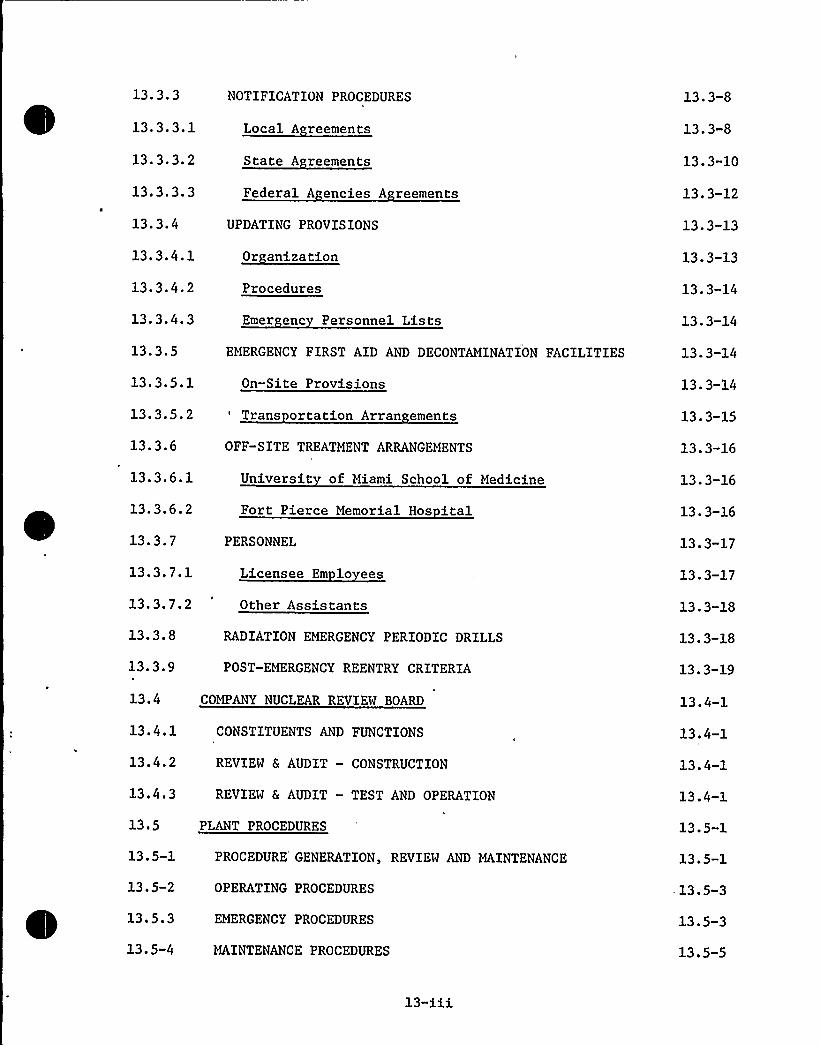
13. 3. 3
13.3.3.1
13. 3. 3. 2
13. 3.3. 3
13.3.4
13.3.4.1
13.3.4.2
13.3.4.3
13.3 '
13 '.5.113.3.5.2
13.3.6
13.3.6.1
13.3.6.2
13.3.7
13.3.7.1
NOTIFICATION PROCEDURES
Local A reements
State A reements
Federal A encies A reements
Trans ortation Arran ements
OFF-SITE TREATMENT ARRANGEMENTS
Universit of Miami School of Medicine
Fort Pierce Memorial Hos italPERSONNEL
Licensee Em lo ees
13.3.7.2 Other Assistants
13.3.8
13.3.9
RADIATION EMERGENCY PERIODIC DRILLS
POST-EMERGENCY REENTRY CRITERIA
13.4 COMPANY NUCLEAR REVIEW BOARD
13.4.1
13.4.2
13.4.3
CONSTITUENTS AND FUNCTIONS
REVIEW & AUDIT — CONSTRUCTION
REVIEW & AUDIT — TEST AND OPERATION
13.5 PLANT PROCEDURES
13.5-1
1305-2
13.5.3
13.5-4
PROCEDURE GENERATION, REVIEW AND MAINTENANCE
OPERATING PROCEDURES
EMERGENCY PROCEDURES
MAINTENANCE PROCEDURES
UPDATING PROVISIONS
Procedures
Emer enc Personnel Lists
EMERGENCY FIRST AID AND DECONTAMINATION FACILITIES
On-Site Provisions
13.3-8
13.3-8
13.3-10
13.3-12
13 ~ 3 13
13.3-13
13.3-14
13.3-14
13.3-14
13.3-14
13.3-15
13.3-16
13.3-16
13.3-16
13.3-17
13 ~ 3 17
13.3-18
13.3-18
13.3-19
13.4-1
13.4-1
13.4-1
13.4-1
13.5-1
13.5-1
-13.5-3
13.5-3
13.5-5

13. 5. 5
13.5.6
13.6
13.7
13;7.1
13.7.2
INSTRUMENT TEST AND CALIBRATION PROCEDURES
CHEMICAL — RADIOCHEMICAL CONTROL PROCEDURES
PLANT RECORDS
INDUSTRIAL SECURITY
PERSONNEL AND PLANT DESIGN
SECURITY PLAN
13.5-5
13.5-6
13.6-1
1 3 ~ 7 1
13.7-1
13.7-1
13-iv

LIST OF FIGURES
FIGURE TITLE
13.1-1
1301-2
13.2-1
1303-1
COMPANY ORGANIZATION CHART
PLANT ORGANIZATION DIAGRAM
EMPLOYEE TRAINING SCHEDULE
EMERGENCY ORGANIZATION
13-U

13. 1
13 ~ CONDUCT OF OPERATIONS
ORGANIZATIONAL STRUCTURE OF APPLICANT
13. l. 1 CORPORATE ORGANIZATION
13.1.1.1 Function and Res onsibilit
The FPL Company organization chart is shown in Figure 13.1-1. The en-gineering and operations functions are under the Operating Vice President.The design and engineering of power plants and coordination with construc-tion is the responsibility of the Vice President of Engineering.
Technical support capability for nuclear plant operation exists in theEngineering and Quality Assurance Departments and their consultants.
13.1.1.2 Mana ement and Technical Su ort Staff
The Quality Assurance Department is under the direction of a Vice Presi-dent, Dr. James Coughlin. Dr. Coughlin received a Ph.D. from PurdueUniversity Mechanical Engineering School where he was on the teachingstaff for seven years. In 1955 he joined the Babcock & Wilcox AtomicEnergy Division and, as Project Coordinator for the Consolidated EdisonIndian Point Unit 1, his activities involved reactor design, operationand control. In 1957 he was named Supervisor of Reactor Thermal Design,and a year later became Assistant Section Chief of Reactor Engineering,with collateral responsibility for preparation of research and develop-ment programs. In 1960 he became Nuclear Systems Specialist, servingas liaison with marketing sales and engineering in preparing both tech-nical and economic development of nuclear s'team system products. Hejoined FPL in 1967 and has the responsibility for nuclear power activities.Dr. Coughlin is a registered professional engineer and a member of numer-ous technical organizations including ASME, ANS and AIF.
Reporting to the Vice President, Nuclear Power Activities, is Joseph W.Williams, Jr., Manager of Quality Assurance, who was appointed to thisposition in May, 1972. He graduated from the University of Florida in1950 with a Bachelor of Chemical Engineering Degree.
Mr. Williams has twenty-one years of experience in the operation, main-tenance and supervision of modern oil and gas fueled high pressure steampower plants, including participation in the start up of three high pres-sure boiler and turbine generator units. This experience includes StudentEngineer, Training and Operations Departments, 1950 and 1951; BettermentEngineer, Plant Betterment Foreman, and Plant Results Foreman, PalatkaPlant, 1951 to 1955; Assistant Plant Superintendent — Operations, RivieraPlant, Palatka Plant and Cutler Plant, 1955 to 1960; and Plant Superin-tendent, Palatka Plant, Turkey Point Plant Units 1 and 2, 1960 to May,1972. As Plant Superintendent, he was responsible for operating andmaintaining the fossil fuel units in a safe, reliable, and efficientmanner.
13.1-1

He has completed the following nuclear industry related courses:
Nuclear Power Reactor — University of Florida, 1966Nuclear Fuel Management — NUS, 1966Radiological Health — Public Health Service, 1966Reactor Safety & Hazards Evaluation — Public Health Service, 1967Advanced Nuclear Technology — University of Florida, 1967
Mr. Williams is a registered professional engineer.
The Vice President — Engineering is Mr. James A. Lasseter. Mr. Lassetergraduated from the Georgia Institute of Technology in 1939 with a BS
degree in Electrical Engineering. He joined FPL in 1946'nd held variouspositions relating to distribution system design, equipment development,failure analysis and system studies. In 1953 he became System Distribu-tion Engineer with overall engineering responsibility for the Company'sdistribution system. In 1960 he became System Engineer with responsi-bilities relating to distribution systems and to installation and main-tenance of the Company's transmission system relaying, telemetering,load control and supervisory control equipment.
In 1964 he was named Assistant Chief Engineer. In 1965 he was appointedManager of Transmission and Distribution which included overall respon-sibility for construction, operation and maintenance of the Company'stransmission and distribution system.
In 1972 he was appointed Vice President — Engineering and is responsiblefor directing the Company's engineering activities relating to its gene-ration, transmission and distribution facilities.
13. 1-2

Reporting to the Vice President of Engineering is Mr. Walter H. Rogers, Jr.,Chief Engineer — Power Plants. A 1947 graduate of Rensselaer PolytechnicInstitute with a BME degree, Mr. Rogers was employed by Foster Wheelerfrom 1947 to 1952 in the Research and Development Department, participatingin steam generator design and development.
In 1952 he joined the Company and participated in the design of numerouspower plants now operating. In 1965 he was assigned to the Turkey PointProject participating in plant design. In 1968 he was appointed to thejob he now holds, with responsibility for procurement and engineering ofpower plants. He is a registered professional engineer.
Reporting to Mr. Rogers are two nuclear Project Managers, each with abouttwenty years experience in both nuclear and fossil power plant operation,testing and engineering, who coordinate engineering, design and qualityassurance on power plants assigned to them.
The Hutchinson Island Project Manager,. Mr. E. H. O'Neal graduated from theUniversity of Florida with a BME degree in 1949. Mr. O'Neal was employedby General Electric Company during 1949 and 1950 with various assignmentson G.E.'s training program including steam turbine development testing. Inlate 1950 he joined Florida Power & Light Company and has been involved inplant design and equipment procurement for over 20 units installed on FloridaPower & Light Company's system. He is a registered professional engineer.
The Turkey Point Project Manager, Mr. J. B. Olmstead, graduated from RensselaerPolytechnic Institute in 1950 and was employed by the Babcock and WilcoxCompany from 1950 to 1968 in various assignments including start-up of steamgeneration equipment, and participation in the start-up of SRE, Shippingportand S3G. From 1964 to early 1968 he was Manager of the Nuclear Power Gener-ation Department Proposal Section participating in the design and marketingof nuclear steam systems.
In early 1968 he joined FP&L as the Project Manager for Turkey Point.He is a registered professional engineer.
Reporting to the Project Managers are Project Engineers. Two of theseengineers have nuclear engineering degrees. Mr. Clifford S. Kent, Jr.,received an MSE in 1967 from the University of Florida, Department ofNuclear Engineering and joined the Company then. Mr. Sidney G. Braingraduated from the University of Florida with a Bachelor of Science inEngineering Sciences (Nuclear Option) in 1966. He joined the Company in1966 and has participated in the Turkey Point Project since then.
13.1-3

The Engineering Department, Power Plants staff engineers include special-ists in the fields of nuclear, mechanical and electrical engineering, andplant construction and quality assurance.
The staff engineer, nuclear specialty, is Mr. Francis P. Green who gradu-ated from the University of Illinois with a Master of Science Degree inElectrical Engineering in 1949, and in 1958 he received a Master's Certi-ficate in Nuclear Engineering from the Oak Ridge School of Reactor Tech-nology.
From 1949 through 1952 he was a development engineer in Van de Graaffaccelerator engineering and nuclear physics research with the NEPA Pro-ject and with the Union Carbide Corporation at Oak Ridge National Labora-tory. Continuing at the National Laboratory, from 1952 through 1960 hewas a development engineer in the Instrumentation and Controls Department,primarily associated with the use of analog computation in the design anddevelopment of reactor control systems. During the years 1961 through1965, he served Union Carbide Corporation, as Staff Assistant to theDirector of Research at the Parma Research Center and then as AdvancedPlanning and Criticality Officer in the development and manufacture ofgraphite-matrix nuclear reactor fuel. From 1966 through part of 1969 hewas a Senior Engineer with the Plant Safeguards and Licensing Departmentof the Nuclear Energy Systems Division, Westinghouse Electric Corporation,responsible for the preparation of Safety Analysis Reports for TurkeyPoint Units 3 and 4, the Carolina Power and Light, Robinson Unit 2 andthe Rochester Gas and Electric Corporation, Ginna Unit.
Mr. Green joined Florida Power and Light in 1969 and serves as nuclearconsultant and is involved in design'review and power plant licensing.
A staff engineer, mechanical specialty, is Mr. Ben F. Gilbert who attendedGeorgia Institute of Technology for three years in Mechanical Engineeringand who graduated from the University of Miami with a Bachelor .of ScienceDegree in Mechanical Engineering in 1965.
.He was a FPL summer employee, Engineer Trainee, at the Cutler Power Plantand a Student Engineer at the Lauderdale Power Plant while attending theUniversity of Miami. He joined FPL in February, 1965, as Engineer Traineeat the Cape Kennedy Power Plant, where he progressed to Plant Test En-gineer in 1965, Assistant Plant Engineer in 1966, and Plant Engineer in1967. He has participated in the start-up of two large high pressureboilers and turbine generators.
Mr. Gilbert participated in the procedures writing group at Turkey Pointin 1970 and following three months experience in the electrical engin-eering start-up group, joined the Engineering Department, Power Plantsin 1971.
A second staff engineer, mechanical specialty is Fred I. Brown who at-tained his Associate Degree in Applied Science and Bachelor of ScienceDegree in Mechanical Engineering at Purdue University.
His experience with summer employment while attending Purdue includedtwo summers as production machinist at Zolner Piston Corporation, onesummer as a copper tube bender at Wayne Fabricating Company, Fort Wayne,Indiana, and one summer in the Purdue University tin shop. He also hasone year experience in design and testing as a Junior Engineer at theResearch and Development Laboratory, Anaconda Wire & Cable Co.
13.1-4

He joined FPL in June, 1967, as Engineer Trainee and was assigned to theCutler Power Plant. He became Assistant Plant Engineer in January, 1968,and participated in the start-up of one large oil and gas fueled boilerand turbine generator. He transferred to the Turkey Point Plant April,1970, and worked in the writing group for Nuclear Units 3 and 4. InJune, 1972, he joined the Engineering Department, Power Plants.
Mr. Brown is a registered professional engineer.
Among the consultants available to Power Plant Engineering is Mr. RaymondL. Lyerly who spends over 50 per cent of his time on Company work. Mr.Lyerly has a 'MS in ME from Columbia University, is a registered profes«sional engineer and has had a private consulting practice since 1971.
Mr. Lyerly has had 22 years of experience in the fields of heat transfer andnuclear engineering, largely in the power generation field. His experienceincludes manufacturing, mechanical designs, experimental programs, analyses,plant start-up and operations, and consulting assignments. the last sixyears of his work has been heavily oriented toward nuclear safety.
Mr. Lyerly's early career was related to special heat transfer equipment forpower plants, stationary gas turbines, and early nuclear design programs.
In 1959 he joined General Nuclear Engineering Corporation as a Senior HeatTransfer Specialist. In this capacity he worked on several reactor designs,principally concentrating on fuel and core design, for both gas-cooled andwater-cooled reactor types. He was assigned to the BONUS Nuclear Power PlantProgram during the plant's final construction period (Rincon, Puerto Rico)and assisted in its power startup operations.
Mr. Lyerly joined Southern Nuclear Engineering, Inc., a design and consultingfirm as a founding member in 1964. His regular activities have included safetyevaluation, accident analyses, criteria development, design reviews, and otherassignments for various utility clients and Government agencies.
13.1.1.3 Or anizational Relations Amon A licant NSSS and A-E
The working interrelationships and organizational interfaces among the applicant,the nuclear steam supply system manufacturer, the architect-engineer and othercontractors is described in detail in Chapter 17.
13.1.1.4 0 erations Staff
The Power Resources Department, which is headed by the Director of Power Re-sources, Mr. A. D. Schmidt, reports to the Operating Vice President, Mr.Loftin Johnson. The Managers of Power Resources report to Mr. Schmidt.
Mr. Schmidt has approximately 30 years experience in the operation of electricgenerating plants. He received a BME from the University of Florida in 1942and is a registered professional engineer. He has taken courses in nuclearengineering given by the University of Florida for Company employees and hascompleted the course in Management of Radiation Accidents given by EPA.
13.1-5

Mr. Bensen received a BME degree from Tulane University in 1946 and joinedthe Company in 1947. He has approximately twenty five years experience inthe operation, maintenance and supervision of power plants.
He has taken nuclear engineering courses at the University of Florida,completed the Westinghouse Reactor Operator Training Program, the on-siteReactor Operator Training Program at Turkey Point Plant, and the EPA coursein the management of radiation accidents.
13.1.2 OPERATING ORGANIZATION
13.1.2.1 Plant Or anization
The organization chart for the Hutchinson Island Plant is shown on Figure13.1-2. The nuclear plant organization for Hutchinson Island Plant followsthe same basic plan as other power plants throughout the Florida Power &
Light Company system. This results in a staff of approximately 25 full timeoperating employees and 30 technical and maintenance employees. Theseemployees are grouped according to their duties in operation, maintenanceand technical staff. Other support personnel are available from the FloridaPower & Light Company system for specific work assignments.
The Plant Superintendent reports to the Manager of Power Resources — Nuclearon all matters concerning the operation and maintenance of the HutchinsonIsland Plant. Assistant Plant Superintendents report to the Plant Superin-tendent in their areas of responsibility. The n'ormal operating shift consistsof a Plant Supervisor, Watch Engineer, Control Center Operator, Nuclear Operatorand Turbine Operator. The Plant Supervisor is directly responsible to the As-sistant Plant Superintendent-Operations for all operations on his shift. Per-sonnel will hold AEC licenses as shown in Figure 13.1-3. During and followinginitial core loading a licensed Senior Operator will be on site at any timefuel is being handled in the refueling facilities and/or in the reactor, orwhen fuel is in the reactor.
The initial start-up, including system check outs, preoperational testing,fuel loading, initial criticality, and approach to full power operation willbe performed by the regular Hutchinson Island plant personnel with assistancefrom the Production Department staff, Combustion Engineering and Ebasco asneeded.
The maintenance force consists of approximately 15 men experienced in mechanicaland electrical maintenance of large steam electric generating plants headedby the Assistant Plant Superintendent-Maintenance. The nucleus of this groupwill have gained nuclear plant maintenance experience at the Turkey Point Plant.
The Technical staff supervised by the Assistant Plant Superintendent — Technical,consists of plant engineers, instrument and control personnel and technicianswho will function in the areas of reactor physics, radio chemistry, radiologicalprotection, water chemistry, instrument-control maintenance and plant performance.
13.1-6

All three groups are supported and augmented as necessary by the Power Re-
sources Department's staff of mechanical, electrical, chemical and nuclearengineers, the Power Plant Engineering Department, the Production Test Group,and the Central Chemical Laboratory.
Technical expertise will be augmented in the areas of reactor physics, fuelmanagement, radio chemistry, radiological protection and metallurgy by theuse of consultants in the particular field, or vendor advisory servicesduring the early years of operation.
13.1.2.2 Administration
Administrative policies will be established pertaining to personnel conduct,method of conducting operations, and preparing and retaining plant documents.The rules and instructions will provide a clear understanding of operatingphilosophy and management policies. In particular, written administrativepolicies will be provided to control the issurance of documents, includingchanges, which prescribe activities affecting safety-related structures,systems, or components, such as operating procedures, test procedures,equipment control and work permit procedures, maintenance or modificationprocedures, and refueling procedures. These policies will assure thatdocuments, including revisions or changes are reviewed for accuracy andapproved for release by authorized personnel and are distributed to andused by the personnel performing the prescribed activity.
The general responsibilities and authorities of the plant staff will bedelineated. ,These include:
a) The operator's authority and responsibility to shut down thereactor when he determines that the safety of the reactor is injeopardy or when operating parameters exceed the reactor protectivesystem setpoints and automatic shutdown does not occur.
b) The responsibility of the senior reactor operator to determinethe circumstances, analyze the cause, and determine or recommend to theappropriate level of management that operations can proceed safelybefore directing the return of the reactor to power after a trip or anunscheduled or unexplained power reduction.
c) The senior reactor operator's responsibility to be present at theplant and to provide direction for returning the reactor to power fol-lowing a trip or an unscheduled or unexplained power reduction.
d) The operator's responsibility to believe and respond to instrumentindications until they are proven to be incorrect.
13.1-7

e) The operator's responsibility to adhere to the plant TechnicalSpecifications.
In the event that a situation should arise which could affect the healthor safety of the public, the Plant Superintendent has the authority toshut down the unit. In his absence the Assistant Plant Superintendents—,Operation and Technical, the Plant Supervisor, the Watch Engineer and theControl Center Operator have authority to shut down the unit. The HealthPhysicist can effectively recommend a shutdown directly to any of theSupervisors. All plant supervisory personnel will have sufficient train-ing in radiation safety to appreciate recommendations from the HealthPhysicist and to recognize conditions requiring unit shutdown.
Administrative controls will be established to assure that all operations,maintenance procedures, tests and emergencies are handled in accordancewith written procedures which have been reviewed and approved throughestablished channels. The Plant Superintendent has the responsibilityand authority to operate the units within the limits of the facilitylicense. Within these limits, he has the authority to approve proceduresand their subsequent revisions.
Temporary changes which do not violate the intended purpose of theoriginal written procedures may be made provided such changes are reviewedfor safety considerations and are approved by two knowledgeable members ofthe plant supervisory staff, at least one of whom shall hold a SeniorOperator License. Such changes shall be documented and reviewed at thenext regular meeting of the Plant Nuclear Safety Committee and approved bythe Plant Superintendent.
Significant changes will be made only with authorization from the CompanyNuclear Review Board. Significant changes are those changes which conflictwith the intent of the Operating License and Technical Specification.
Written procedures for safety related systems will be reviewed by the PlantNuclear Safety Committee and recommendation for revision made to the PlantSuperintendent. Written revisions will then be approved and issued bythe Plant Superintendent. Current written procedures will be availableto the operator at all times.
Routine inspection of operating logs, charts and other data will be made byengineers on the plant staff. In addition all abnormal or nonroutineoperations will be reviewed by engineers of the Production Department staff.They will make periodic visits to the plant for general review of operationsand assistance with any problems that might arise.
Work of the plant Health Physicist will be reviewed by his direct super-visors.
13.1-8

Periodic meetings will be held by plant supervisory and technical personnelto keep all personnel appraised of current conditions and to review plantsafety procedures.
Review and audit of plant operations is performed by the Plant NuclearSafety Committee. Its description, responsibilities and authority arestated in detail in the Technical Specifications.
13.1.3 QUALIFICATION REQUIREMENTS FOR NUCLEAR FACILITY PERSONNEL
All key personnel assigned to the Hutchinson Island Plant will have hadextensive experience in nuclear and fossil fueled electric generatingplants in their respective areas of responsibility, or will have receivednuclear training to prepare them for their specific assignments. Allemployees at the plant will have training in health physics. Licensedpersonnel will receive training in the technical, license, and legalrequirements for protection of the health and safety of the public.Operating shift personnel will be trained concerning the effect ofradiation, the theory and use of radiation detection devices and pro-cedures for determining and establishing radiation work areas. Alicensed operator will be responsible for implementing radiation pro-tection procedures on each shift. All minimum qualification requirementsfor facility personnel satisfy ANSI 18.1, "Standard for Selection andTraining of Personnel for Nuclear Power Plants."
13.1.3.1 Plant Su erintendent
a) Function and Res onsibilit
The Plant Superintendent reports to the Director of Power Resources andhas direct responsibility for operating and maintaining the plant in asafe, reliable and efficient manner. He is responsible for protectionof the plant staff and the general public from avoidable radiation ex-posure and/or any other consequences of an accident at the plant. Hebears the responsibility for compliance with the facility operatinglicense. He has authority to take any action necessary, without con-sultation, to prevent or mitigate the consequences of an accident.
b) Minimum Re uirements
The Plant Superintendent shall have ten years of responsible power plantexperience of which a minimum of three years shall be nuclear power plantexperience. A maximum of four years of the remaining seven years may befulfilled by academic training on a one-for-one time basis. This academictraining shall be in an engineering or scientific field generally associatedwith power production. He shall have acquired the experience and trainingnormally required for examination by the AEC for a Senior Operator Licensewhether or not the examination is taken.
13.1-9

13.1.3.2 Assistant Plant Su erintendent — '0 erations
a) Function and Res onsibilit
The Assistant Plant Superintendent — Operations has the responsibility fordirecting the actual day-to-day operation of the plant and shall hold aSenior Operator License. He reports directly to the Plant Superintendentand directs the plant operating staff. He coordinates operation related tomaintenance activities with the Assistant Plant Superintendent — Maintenance.He assumes all of the Plant Superintendent's responsibilities and authorityin his absense. He is responsible for over all supervision of fuel handlingoperations.
He has the authority to shut down the unit if in his opinion conditionswarrant this action and he has the authority to initiate the Emergency Plans.
b) Minimum Re uirements
The Assistant Plant Superintendent — Operations shall have a minimum ofeight years of responsible power plant experience of which a minimum of threeyears shall be nuclear power plant experience. A maximum of two years of the,remaining five years of power plant experience may be fulfilled by satisfactorycompletion of academic or related technical training on a one-for-one timebasis. He will hold a Senior Operator License.
13.1'.3.3 Assistant Plant Su erintendent — Maintenance
-a) Function and Res onsibilit
Responsible for supervision of mechanical and electrical maintenance and forthe equipment maintenance records.
b) Minimum Re uirements
The Assistant Plant Superintendent — Maintenance shall have a minimum ofseven years of responsible power plant experience or applicable industrialexperience, a minimum of one year of which shall be nuclear power plantexperience. A maximum of two years of the remaining six years of powerplant or industrial experience may be fulfilled by satisfactory completionof academic or related technical training on a one-for-one time basis. Hefurther should have non-destructive testing familiarity, craft knowledge,and an understanding of electrical, pressure vessel, and piping codes.
13.1.3.4 Assistant Plant Su erintendent — Technical
a) Function and Res onsibilit
Supervises the instrument and control, chemistry and health physics, andreactor engineering groups.

He has the authority to shut down the unit if in his opinion conditionswarrant this action and he has the authority to initiate the EmergencyPlans.
He assists the Assistant Plant Superintendent — Operations in the super-vision of fuel handling operations.
b) Minimum Re uirements
The Assistant Plant Superintendent — Technical should have a minimum ofeight years in responsible positions, of which one year shall be nuclearpower plant experience. A maximum of four years of the remaining sevenyears of experience should be fulfilled by satisfactory completion ofacademic training.
13.1.3.5 Plant En ineer — Instrument and Control
a) Function and Res onsibilit
He is responsible for supervision of maintenance, calibrations andinstallation of all instrument and control equipment and for maintenanceof instrument and control records.
He has the authority to shut down the unit if in his opinion conditionswarrant this action and he has the authority to initiate the EmergencyPlans.
b) Minimum Re uirements
The Plant Engineer — Instrument and Control shall have a minimum of fiveyears experience in instrumentation and control, of which a minimum of sixmonths shall be in nuclear instrumentation and control, A minimum of twoyears of this five years experience should be related technical training,A maximum of four years of this five years experience may be fulfilled byrelated technical or academic training.
13.1.3.6 Reactor En ineer
a) Function and Res onsibilit
The Reactor Engineer conducts or supervises tests, accumulates and evaluatesdata and maintains records of the performance of all plant equipment includingcore performance and fuel records.
b) Minimum Re uirements
The Reactor Engineer shall have a minimum of a Bachelor's Degree inEngineering or the Physical Sciences and two years experience in suchareas as reactor physics, core measurements, core heat transfer and core
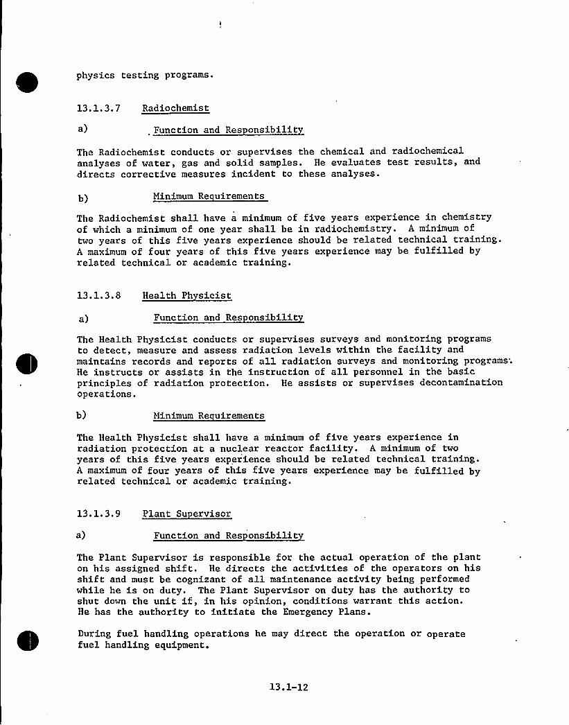
physics testing programs.
13.1.3.7 Radiochemist
a) Function and Res onsibilit
The Radiochemist conducts or supervises the chemical and radiochemicalanalyses of water, gas and solid samples. He evaluates test results, anddirects corrective measures incident to these analyses.
b) Minimum Re uirements
The Radiochemist shall have a minimum of five years experience in chemistryof which a minimum of one year shall be in radiochemistry. A minimum oftwo years of this five years experience should be related technical training.A maximum of four years of this five years experience may be fulfilled byrelated technical or academic training.
13.1.3.8 Health Ph sicist
a) Function and Res onsibilit
The Health Physicist conducts or supervises surveys and monitoring programsto detect, measure and assess radiation levels within the facility andmaintains records and reports of all radiation surveys and monitoring programs;He instructs or assists in the instruction of all personnel in the basicprinciples of radiation protection. He assists or supervises decontaminationoperations.
b) Minimum Re uirements
The Health Physicist shall have a minimum of five years experience inradiation protection at a nuclear reactor facility. A minimum of twoyears of this five years experience should be related technical training.A maximum of four years of this five years experience may be fulfilled byrelated technical or academic training.
13. l. 3.9 Plant Su ervisor
a) Function and Res onsibilit
The Plant Supervisor is responsible for the actual operation of the planton his assigned shift. He directs the activities of the operators on hisshift and must be cognizant of all maintenance activity being performedwhile he is on duty. The Plant Supervisor on duty has the authority toshut down the unit if, in his opinion, conditions warrant this action.He has the authority to initiate the Emergency Plans.
During fuel handling operations he may direct the operation or operatefuel handling equipment.
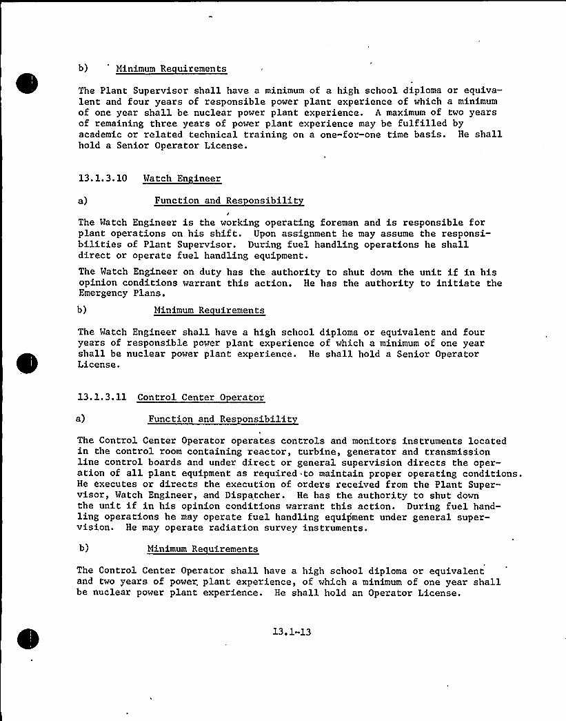
b) 'inimum Re uirements
The Plant Supervisor shall have a minimum of a high school diploma or equiva-lent and four years of responsible power plant experience of which a minimumof one year shall be nuclear power plant experience. A maximum of two yearsof remaining three years of power plant experience may be fulfilled byacademic or related technical training on a one-for-one time basis. He shallhold a Senior Operator License.
a) Function and Res onsibilit
The Watch Engineer is the working operating foreman and is responsible forplant operations on his shift. Upon assignment he may assume the responsi-bilities of Plant Supervisor. During fuel handling operations he shalldirect or operate fuel handling equipment.The Watch Engineer on duty has the authority to shut down the unit if in hisopinion conditions warrant this action. He has the authority to initiate theEmergency Plans.
b) Minimum Re uirements
The Watch Engineer shall have a high school diploma or equivalent and fouryears of responsible power plant experience of which a minimum of one yearshall be nuclear power plant experience. He shall hold a Senior OperatorLicense.
13.1.3.11 Control Center 0 erator
a) Function and Res onsibilitThe Control Center Operator operates controls and monitors instruments locatedin the control room containing reactor, turbine, generator and transmissionline control boards and under direct or general supervision directs the oper-ation of all plant equipment as required to maintain proper operating conditions.He executes or directs the execution of orders received from the Plant Super-visor, Watch Engineer, and Dispatcher. He has the authority to shut downthe unit if in his opinion conditions warrant this action. During fuel hand-ling operations he may operate fuel handling equipment under general super-vision. He may operate radiation survey instruments.
b) Minimum Re uirements
The Control Center Operator shall have a high school diploma or equivalentand two years of power, plant experience, of which a minimum of one year shallbe nuclear power plant experience. He shall hold an Operator License.

13. 1. 3. 12 Nuclear 0 erator
a) Function and Res onsibilit
Operates nuclear reactor auxiliary equipment and turbine-generator auxiliaryequipment under the direction of a licensed Operator or Senior Operator.Performs inspections of operating equipment and systems including but notlimited to the reactor coolant system, chemical and volume control system,component cooling, shutdown heat removal and spent fuel pool cooling systems,waste management system, engineered safety features systems and components,radiation detection equipment, containment and radioactive area ventilationand purge systems, primary water makeup system, refueling water tank, gassupply systems, liquid and gas sampling and analysis equipment and chemicalfeed addition equipment. He performs operating adjustments and services,records operating data, and operates radiation survey instruments. Duringfuel handling operations he may operate fuel handling equipment under directsupervision of a licensed operator.
He may operate other plant auxiliary equipment under the direction of aPlant Supervisor, Watch Engineer, or Control Center Operator.
b) Minimum Re uirements
The Nuclear Operator shall have a high school diploma or equivalent and shouldpossess a high degree of manual dexterity and mature judgments
13.1.3.13 Turbine 0 erator
a) Function and Res onsibilit
The Turbine Operator operates turbine controls and serves as turbine-gener-ator attendent. He may be assigned additional duties and assist the NuclearEquipment Operator. Performs operating adjustments and services. Recordsoperating data.
During fuel handling operations he may operate fuel handling equipment underthe direct supervision of a licensed operator.
b) Minimum Re uirements
The Turbine Operator shall have a high school diploma or equivalent and shouldpossess a high degree of manual dexterity and mature judgment.
13.1.3.14 Technicians
a) Minimum Re uirements
Technicians in responsible positions shall have a minimum of two years ofworking experience in their specialty and should have a minimum of one yearof related technical training in addition to their experience.
13.1-14

13.1.3.15 Maintenance Personnel
a) Minimum Re uirements
Maintenance personnel shall have a minimum of three years experience inone or more crafts. They shall possess a high degree of manual dexterityand ability and should be capable of learning and applying basic skills inmaintenance operations.
b) Maintenance Personnel Ex erience
Mechanics and electricians who will perform maintenance and repair of thenuclear plant and its components and auxiliaries have met the requirementsof the four year joint IBEW-FPL apprentice program or have equivalentmaintenance experience.
13.1.3.16 Succession of Res onsibilitThe following table lists the normal sequence of assignment of responsibilitiesin the event of absence or unavailability.
Plant Superintendent1. Assistant Plant Superintendent — Operations2 ~ Assistant Plant Superintendent - Technical
Assistant1.2,3.
Plant Superintendent — OperationsAssistant Plant Superintendent - TechnicalPlant SupervisorMatch Engineer
Assistantl.2.3 ~
Plant Superintendent — TechnicalAssistant Plant Superintendent — OperationsPlant Engineer — ReactorPlant Engineer — Instrumentation and Control
Assistant1.2.3 ~
4.
Plant Superintendent — MaintenanceAssistant Plant Superintendent — OperationsAssistant Plant Superintendent — TechnicalMaintenance SupervisorMaintenance Foreman


~ RESPONSIBILITY—COFJRUiICATIONP'iiESZDENT
VICE PRESIDENTENVIRONMENTAL
'LA?iNINGOPERATING
VICEPR"SIDENT
VICE PSMvIDEHT?R?CLEAR PO'iVR
ACTIVITIES
VZCE PRESIDENTOF
ENGINEERING
VICE PRESIDENTF TRANSMISSIONS DZSTRZBUTZO?I
MANAGER OP
FUELSUPILY
VICE PRESIDENTPOWER
SUPPLY
DIRECTORPOWER
RESOURCES
VICE .PRESIDENT
PURCHA SING
AUTOMOTIVE 'ONSTRUCTION
FANACER OFg:ALI~ Y
ASSURMsCE
CHIEF ENGINEERPOiZER PLA?ITS
PROJECT HA'?ACEPS
CHIEF ENGINEERGENERAL
ENGINEERING
STAFF'GINEERSMECH-ELECT
Cia LLNU?:LEAR
CONSULihNTS AND'RIDOR'DVIBORS
SUPERIN~KVDENT0
CYST RELAYOPERATIONS
I
I
I
I
I
I
I
a UQ?AGER
POWER RESOURCESNUCLEAR
SUPERVISINGCINEER
HEALTH PHYSZCS
PRODUCTIONTEST CROUP
PRODUCTION SUPERVISORSAND ENGINEERS
PROJECT ENCINEERS
FLORIDA POWER S LICHT COMPANY
HUTCHINSON ISLAND PLA?1TCONPhhY ORGANIZATION CHARTFIGURE 13,1-1

ASSISTANT PLANT SUPERINTENDENTMAINTENANCE
1
C SRO
PLANT SUPERINTENDENT
C SROASSISTANT PLANT SUPERINTENDENT
OPERATIONSASSISTANT PLANT SUPERINTENDENT
TECHNICAL STAFF
I
I"I
I
I
I
I
I
II
I
MECHANICAL
MAINTENANCEFOREMAN 1
CHIEF ELECTRICIAN PLANT SUPERVISOR1/S
SRO PLANT ENGINEERINSTRUMENT AND
'CONTROL
REACTOR
ENGINEERRADIOCHEMIST
MACHINISTMECHANICSAPPRENTICESHELPERGARDENERJANITOR
ELECTRICIANSAPPRENTICES WATCH ENGINEER
1/S
SRO
TECHNICIANS TECHNICIANS
I & C ENGINEERS ENGINEERS ENGINEERS
TECHNICIANS
ROCONTROL CENTER OPERATOR1/S 5
PLANT CLERKSGUARDS
HEALTH PHYSICIST
NUCLEAR OPERATOR1/S 5
TURBINE OPERATOR
1/S 5 TECHNICIAN
Legend
C
Position Title1/S
RO
C College GraduateRO AEC Reactor Operator LicenseSRO AEC Senior Reactor Operator License1/S Number Required Per Shift5 Total Number in Classification
HUTCHINSON ISLAND PLANTPLANT ORGANIZATION DIAGRAMFIGURE 13.1-2


13.2 TRAINING PROGRAM
13.2.1 PROGRAM DESCRIPTION
The overall objective of the training program is to provide technicaldevelopment, specialized training and operating experience to thoseFP&L personnel whose actions, orders or decisions can determine thedesign or affect or change the operating characteristics of the plant.The Plant Superintendent is responsible for -the conduct and administrationof the initial on-site training program and for the training of replace-ment plant personnel.
Beginning with the solicitation of proposals from nuclear equipmentsuppliers for Turkey Point Plant which will start up before the HutchinsonIsland Plant, Florida Power & Light Company senior engineering and operatingstaff members have undertaken a program of technical development designed toprovide them with a high level of proficiency in the evaluation of nuclearplant design. This program has included short courses, seminars, and visi-tation to operating nuclear power plants. Members of this group have beengiven responsibility for the evaluation of the designs submitted by theengineers and manufacturers. Guidance on the training program content wasobtained from ANSI N-18.1 and the AEC Licensing Guide, "Operating Licenses,Division of Reactor Licensing, November 1965."
13.2.1.1 Formal Nuclear Trainin Pro ram Content
A nuclear engineering course of 80 class hours was conducted for approximately40 employees of the Florida Power & Light Company by the University of Florida,Department of Nuclear Engineering. This group of employees included allsenior engineering and operating personnel plus a plant supervisory group fromwhom some of the Hutchinson Island plant supervisory personnel will be chosen.The course was followed by an 80 hour laboratory course at Gainesville, Florida,utilizing the University of Florida's test reactor. An advanced NuclearTechnology course was then given to approximately 20 employees by the Universityof Florida, Department of Nuclear Engineering. This group included seniorengineering and plant supervisory personnel.
The program for formal education and training of the Hutchinson Island Plantstaff is designed to meet the individual needs of the participants, dependingupon their background, previous training, and expected job assignment. Companypersonnel who compose the initial group to receive training include those fromwhom the plant staff will be selected. These people will then serve as in-structors for the training program to be given to the remainder of the plantpersonnel.
13.2.1.2 Schedule Chart
Figure 13.2-1 shows the training schedule for each employee in relationto the schedule for preoperational testing and fuel loading.
Most times indicated are tentative and constitute expected minimum requirements.
1 3 ~ 2 1

13.2.1.3 On-the-Job Reactor Plant 0 eration
The training program will be divided into several phases of activity.They are:
a) Initial Training at Turkey Point
It is planned that the cold license personnel for Hutchinson Islandwill be trained and be licensed at Turkey Point Plant Prior to the on-site phase at Hutchinson Island Plant. Technical training for candi-dates for AEC dold examinations at the reactor operator level willcover the following subjects:
1) principles of reactor operation2) design features of the nuclear power plant3) general operating characteristics of the nuclear power plant
involved4) instrumentation and control systems5) safety and emergency systems6) standard and emergency operating procedures7) radiation control and safety provisions
reactor theoryhandling and disposal of, and hazards associated with, radio-active materialsspecific operating characteristics of the nuclear power plantfuel handling and core parameters andadministrative procedures, conditions, and limitations.
10)11)12)
In addition to the above subjects, technical training for candidates forAEC cold examinations at the senior reactor operator level will cover'hefollowing subjects:
8)9)
This training will be conducted by the regular Turkey Point Plant staffinstructors. The course will follow the same outline that has beensuccessfully used for training Turkey Point licensed operat'ors.
Following the formal training program the operators will be examined andreceive hot licenses at Turkey Point. Selection of candidates for coldlicenses at Hutchinson Island will be made primarily from those who holdTurkey Point licenses.
13.2-2

b) Hutchinson Island Plant Design Lectures
Following the Turkey Point training phase, the Hutchinson Island Plantsupervisory staff will participate in a lecture series related to theNSSS design conducted by Combustion Engineering. The lectures will in-clude as a minimum the following subjects:
Core Mechanical DesignThermal and HydraulicsReactor PhysicsInstrument and Control Systems DesignMechanical Systems DesignElectrical Systems DesignNSSS ResponseSafety Analysis and Technical SpecificationsOperating and Emergency ProceduresStart-up Test Program
c) Plant Simulator Training
Each cold license candidate will participate in training on a plantsimulator which will be programmed to simulate Hutchinson IslandPlant parameters.
Approximately two months prior to initial core loading additional simulatortime will be given each license candidate using updated core parameters andset points.
d) Previous Nuclear Training
It is expected that in addition to training and experience received atTurkey Point, some license candidates will have received training in militaryservice or at other reactor locations.
Some of the Turkey Point formal training may be eliminated for these persons,based on the judgment of the Plant Superintendent. These license candidateswill however participate in the on-site and simulator training sessions.
e) Formal On-Site Training
Following the simulator training the cold license candidates will receiveon-the-job training and participate in plant checkout. This phase of thetraining program will be organized to train and familiarize the non-supervisorypersonnel in the theory, design, installation of equipment, testing, startup,and operation of the plant. During this phase, supervisory and non-supervisorypersonnel will assist in developing and writing instruction manuals and testprograms, testing of individual components and systems, developing and writingoperating, refueling and emergency procedures, preparation of maintenanceprocedures and participation in maintenance work.


Instrument and control, radiochemistry and health physics personnel willbe assigned several months prior to initial fuel loading and will be trainedas required in their respective responsibilities.
All personnel will receive training in radiation protection and emergencyprocedures prior to fuel loading.
f) Non-licensed Personnel Training
The nucleus of the non-licensed staff including supervisors, engineers,technicians, operators, and maintenance personnel, will be drawn from person-nel experienced at the Turkey Point Plant. In addition to on-the-job trainingat both Turkey Point and Hutchinson Island, all site personnel will be giventraining in radiation protection. In addition, some engineers and technicianswill receive training at locations other than Turkey Point and Hutchinson Islandwhen deemed necessary by the Plant Superintendent.
g) General Employee Training
Industrial Safety and First Aid training are conducted as a part of theregular company safety program at monthly meetings. This program will beimplemented to include topics applicable to the nuclear plant.
h) Training Coordinator
The Training Coordinator will be responsible for the employee training program.Initially, this will be an experienced Combustion Engineering training expert.He will be assisted by a FP&L supervisor who will assume the position afterthe completion of initial operator training.
13 ~ 2. 2 RETRAINING PROGRAM
Formal retraining will be given to all licensed operators in the form ofclassroom study, covering the initial on-site training material, and oraland written examinations. Personnel will be periodically enrolled inappropriate refresher courses or courses covering new concepts to ensurethe continued safe operation of the plant. Refresher courses will beconducted at approximately two year intervals.
The retraining program will include:
a) Plant start-up and shutdown preceduresb) Normal plant operating conditions and proceduresc) Operational limitations, precautions, and set pointsd) Emergency plans and security procedurese) Off normal condition operating proceduresf) Emergency shutdown systems
13.2-4
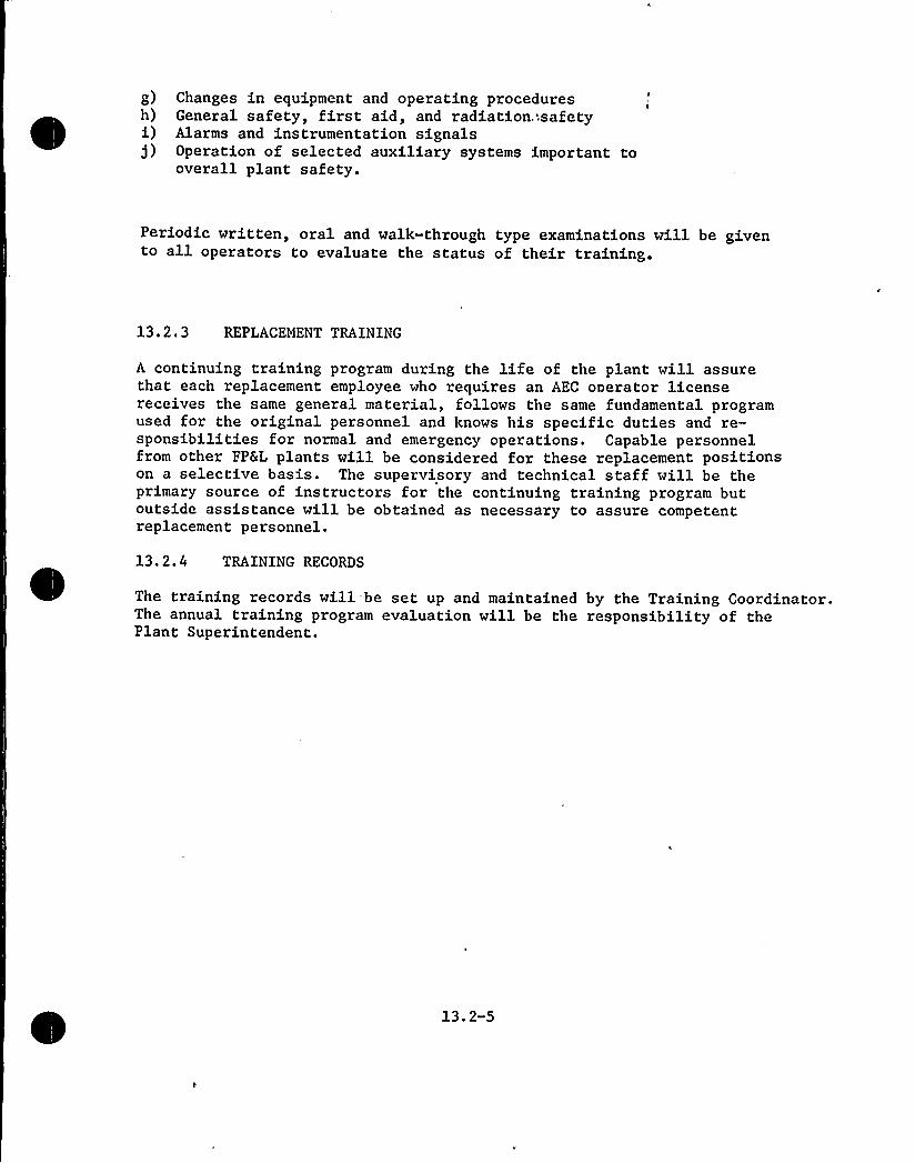
g) Changes in equipment and operating proceduresh) General safety, first aid, and radiation.'safetyi) Alarms and instrumentation signalsj) Operation of selected auxiliary systems important to
overall plant safety.
Periodic written, oral and walk-through type examinations will be givento all operators to evaluate the status of their training.
13.2.3 REPLACEMENT TRAINING
A continuing training program during the life of the plant will assurethat each replacement employee who requires an AEC onerator licensereceives the same general material, follows the same fundamental programused for the original personnel and knows his specific duties and re-sponsibilities for normal and emergency operations. Capable personnelfrom other Fp&L plants will be considered for these replacement positionson a selective basis. The supervisory and technical staff will be theprimary source of instructors for the continuing training program butoutside assistance will be obtained as necessary to assure competentreplacement personnel.
13.2.4 TRAINING RECORDS
The training records will-be set up and maintained by the Training Coordinator.The annual training program evaluation will be the responsibility of thePlant Superintendent.
13.2-5

EMPLOYEE TRAINING SCHEDULE
PLANTPREOPERATIONAL TESTING ~~
1 YEAR
HOT FUNCTIONAL FUELTESTING LOADING~~
3 MONTHS
REACTOR
OPERATORS
FORMAL TRAININGg6 MONTHS
LICENSINGTURKEY POINT SIMULATORS ON SITE q
3 MONTHS 6 WEEKS 3 MONTHS 2 WEEKS 6 WEEKS
SIMULATOR ~ ON SITE
SUPERUISORS(NON-LICENSED)
C. E.DESIGN
LECTURES ON SITE~9 MONTHS
ALL PERSONNELRADIATIONPROTECTION
1 WEEK PER PERSON
HUTCHINSON ISLAND PLANTEMPLOYEE TRAINING SCHEDULE
FIGURE 13.2-1

h
k
fl
hI
H
N
4
I
1
N'j

13.3 EMERGENCY PLANNING
A plan is being developed to cover all foreseeable emergencies such as fire,personnel injuries and illness, radiation exposure, contamination and otherconditions that could result from either nuclear or non-nuclear incidents.In order to assure continuing familiarity with the emergency plan, practice"drills will be held from time to time for training purposes. It is intendedthat the plant be self-sufficient insofar as possible in handling emergencyconditions, but when necessary, the Police, Fire Department, AEC, and otherlocal, state and federal agencies will be called upon. Agreements are beingmade with outside agencies concerning their expected role in any emergency.
13.3.1 EMERGENCY ORGANIZATION
13.3.1.1 Authorities Res onsibilities and Duties
The Company organization charts relating to the Hutchinson Island Plantoperation and to the review and approval of emergency plans and implementationare shown in Figures 13.3-1 through 13.3-3.
a) 0 eratin Vice President
1) Administer the overall planning and implementation of the EmergencyPlans
2) Make policy decisions and expend funds to implement the plan
3) Contract or arrange for the outside services and agreementsrequired to support the provisions of the plan
4) Conduct liaison with Federal, State, and Local Agencies, andcoordinate Company emergency planning with these agencies toensure a minimum of conflicting actions and authority in orderto avoid confusion and provide for efficient emergency protectiveactions
5) Ensure the physical securi.ty of the plant site
6) Act as Chairman of the Company Emergency Plan Review Committeeto ensure the adequacy of Company plans to cope with foreseeableemergencies.
b) Director of Power Resources
1) Provide plans, personnel, equipment and facilities to minimizethe consequences of all foreseeable incidents involving FPLnuclear power facilities
2) Periodically up-date the provisions of the Emergency Plans to reflectboth on-site and off-site emergency response capability
13.3-1

3) Act as the off-site Emergency Control Officer
4) In event of accidents or radiation incidents as describedin the Emergency Plans, Section VI, NOTIFICATION ANDREPORT REQUIREMENTS, notify and send required reports to theappropriate Federal and State agencies indicated in SectionVI
5) Obtain emergency support from off-site organizations
6) Provide for the continuation of the activities of theOff-Site Emergency Organization Headquarters, Ryan Building,Miami, through the plant re-entry and recovery operationsas required. If recovery is a long term operation, the Head-quarters may be relocated to the FPL General Office Building,Miami
c) Plant Su erintendent
1) Implement the provisions of the Plan and all Annexes andAppendices
2) Procure and store emergency equipment and supplies in appro-priate locations
3) Appoint emergency team leaders and alternates for each workshift and provide for back-up manning to assure adequateemergency coverage
4). Direct plant personnel in long-term post-accident planningand recovery operations
5) Limit the radiation exposures of personnel to reasonable valuesconsistent with the nature of the incident and the urgency to takeaction involving personnel exposure risk
6) Periodically up-date the provisions of the Emergency Plans to ensureon-site emergency response capability
7) Provide for appropriate training and refresher courses foremployees assigned to emergency reponse teams
8) Provide for semi-annual drills, on a non-interference basis,to exercise all elements comprising the emergency responsecapability of the Company, the Plant, the Medical Support person-nel and hospital treatment facilities, and those Federal, State,and Local agencies which may be involved
9) Submit a written evaluation of the drills to the OperatingVice President through established reporting channels withinseven working days
1O) Submit other verba1 and written reports as required

d) Plant Su ervisor
1) Act as Emergency Coordinator until relieved by a succeedingShift Supervisor or by command of higher authority
2) Declare the existence of an emergency and classify as to type
3) Evacuate on-site personnel as required
4) Act to control the emergency condition
5) Establish an Emergency Control Center
6) Obtain assistance from off-site groups as required
7) Follow, generally, the Emergency Action Sequence Guidelines
e) Emer enc Team Leaders
Emergency Team Leaders and Back-Up Emergency Team Leaders will beprepared to implement all aspects of their emergency assignments.They will:1) Be familiar with the detailed procedures and standing orders
necessary to implement the Emergency Plans.
2) Ensure the currency of their team roster to include the name,home address, telephone number, emergency assignment, training,drill experience, and physical limitations of team members.
3) Be prepared to assist the Emergency Coordinator in obtainingback-up emergency assistance during off-shift hours.
f) Off-Site Emer enc Or anization
The Off-Site Emergency Organization is composed of Company officialsand a staff of assistants and is responsible for all off-site emergencycontrol activities of FPL. It will provide assistance to the Plant inadministration, public relations, securi,ty, engineering, and technicalmatters.
1) Emer enc Control Officer Di ector of Power Resources
a. Direct the Off-Site Emergency Organizations
b. Activate the required members of the Organization upon receiptof notification of an emergency condition from the Plant DutyCall Supervisor or the Division Load Dispatcher
1 3 ~ 3 3

c. Obtain, as required, the assistance of off-site supportpersonnel of the Company, Local agencies, State and Federalagencies, and other support agreements or arrangements
d. Notify the V. S. Atomic Energy Commission in accord with theprovisions of 10 CFR 20.402 and 20.403, and the State Divisionof Health in accord with the FPL — Division of Health Agreementof November 1, 1971, as amended
2) Emer enc Administrative Officer 0 eratin Vice President)
a. Make any new policy decisions required
b. Authorize unusual expenditures of funds for emergency activities
c. Conduct liaison with regulatory agencies on administrativematters not covered by established emergency plans
3) Emer enc Information Officer Miami Area Vice President
Release information to the public and maintain liaison with localagencies and the news media for public relations purposes
4) Emer enc Securit Officer Executive Assistant — Securit
Provide and maintain liaison with local security and law enforcementagencies
5) Emer enc Technical Officer (Vice President En ineerin
Provide advice and technical information regarding engineeringdesign and as-built construction details for the HutchinsonIsland Plant
I
13.3.1.2 Emer enc Notification Means
Licensee Personnel
Any individual who discovers an emergency condition, or a condition whichcould become an emergency, shall take the following general
actions')
Notify the Plant Supervisor by telephone or in person and give him thedetails of the emergency condition found
b) Take any immediate action which he is qualified to perform that willaid'n
controlling and/or minimizing the effects of the emergency; keep otherpersonnel away from the affected area
c) Withdraw to a safe area, and if the possibility of radioactive contaminationexists, remain in the safe area until monitored
13.3-4

The Plant Supervisor, acting as Emergency Coordinator, shall use the plantP.A. system to announce that an emergency condition exists and to activatethe Emergency Teams. If the emergency condition is a fire, or one that re-quires evacuation of the containment, he will sound the fire alarm or con-tainment evacuation alarm and then make the P.A. announcement.
As soon as possible after determining that an emergency condition exists,the Emergency Coordinator, or his designee, shall notify the Duty CallSupervisor and request that he notify the Plant Superintendent, theEmergency Team Leaders and the Emergency Control Officer.
The Duty Call Supervisor will notify the other members of the PlantSupervisory staff.
The Emergency Team Leaders will notify the members of their teams. TheEmergency Control Officer will notify the required members of the Off-Site Emergency Organization and any required State or Federal agency. Iffor any reason the Emergency Coordinator cannot establish communicationswith the Duty Call Supervisor, the System Load Dispatchers in Miami willbe notified and will then make the notifications requested by the EmergencyCoordinator.
State and Federal Personnel
Notification and reporting requirements of State and Federal regulatory agencieswill be implemented by the Off-Site Emergency Organization.
a) State of Florida — Division of Health4
Notification of the Division of Health under the criteria„-shownbelow is in accord with the agreement between the Division ofHealth and the Company and does not constitute a request forassistance. However assistance ma be obtained if s ecificallre uested b the Com an
2) The State Division of Health, Radiological Emergency Staff DutyOfficer will be notified in event of incidents involving radio-nuclides which:
a. Cause or threaten to cause, within the Generating Station Area,serious injury to personnel, exposure to ionizing radiation inexcess of limits specified in 10 CFR 20, or excessive and/oruncontrolled spills or gaseous releases.
b. Result in any unplanned release of radioactive material toan area occupied by members of the general public, andwhich may require that protective measures be taken to pre-vent or minimize personnel exposure.
13.3-5
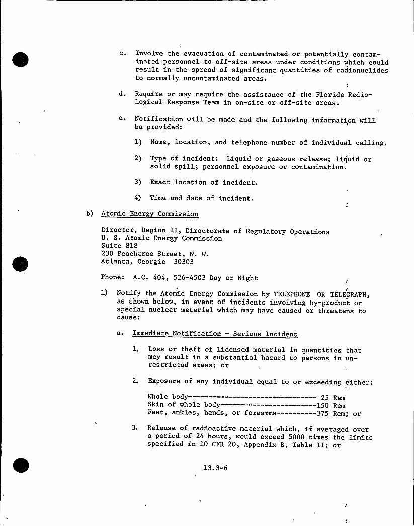
c. Involve the evacuation of contaminated or potentially contam-inated personnel to off-site areas under conditions which couldresult in the spread of significant quantities of radionuclidesto normally uncontaminated areas.
d. Require or may require the assistance of the Florida Radio-logical Response Team in on-site or off-site areas.
e Notification will be made and the following information willbe provided:
1) Name, location, and telephone number of individual calling.
2) Type of incident: Liquid or gaseous release; liq'uid orsolid spill; personnel exposure or contamination.
3) Exact location of incident.
4) Time and date of incident.
b) Atomic Ener Commission
Director, Region II, Directorate of Regulatory OperationsU. S. Atomic Energy CommissionSuite 818230 Peachtree Street, N. W.Atlanta, Georgia 30303
Phone: A.C. 404, 526-4503 Day or Night
1) Notify the Atomic Energy Commission by TELEPHONE OR TELEGRAPHas shown below, in event of incidents involving by-product orspecial nuclear material which may have caused or threatens tocause:
a. Immediate Notification — Serious Incident
1, Loss or theft of licensed material in quantities thatmay result in a substantial hazard to persons in un-restricted areas; or
2. Exposure of any individual equal to or exceeding either:
Whole body- 25 RemSkin of whole body 150 RemFeet, ankles, hands, or forearms —————375 Rem; or
3. Release of radioactive material which, if averaged overa period of 24 hours, would exceed 5000 times the limitsspecified in 10 CFR 20, Appendix B, Table II; or
13.3-6

4. A loss of one working week or more of the operation ofany facility affected; or
5. Damage to property in excess of $ 100,000.
b. Twent -Four Hour Notification - Re ortable Incident
1. Exposure of any individual equal to or exceeding either:
Whole body- 5 Rem
Skin of whole body 30 Rem
Feet, ankles, hands, or forearms ——————75 Rem; or
2 Release of radioactive material which, if averaged overa period of 24 hours would exceed 500 times the limitsspecified in 10 CFR 20, Appendix B; Table 2; or
3 A loss of one day or more of the operation of any'acilitiesaffected; .or
4 ~ Damage to property in excess of $ 1,000.
c. Notification — Other Incidents
Any incident not covered in 1) or 2) above, but which, inthe judgment of the Emergency Control Officer, would createserious public relations problems.
d. Any written report filed with the Commission pursuant „to1) and 2) above, shall be prepared so that names of individualswho have received exposure to radiation will be stated in aseparate part of the report.
13.3.2 RADIOACTIVE MATERIALS RELEASE DETERMINATION
13.3.2.1 Ma nitude Criteria for Notification of Governmental Agencies
The Off-Site Emergency Organization will act as the implementing clearinghouse on emergency conditions telephoned or communicated by radio by judgingfrom the received technical data which local areas if any could be affectedby a radioactive material release.
Nomograms and area maps will be used to successively generate an environmentalpicture of a developing off-site situation. Low population zone local evacuationprocedures would be followed in case that projected radiation levels were toexceed a predetermined value as delineated on a meteorological dispersion overlay.Cooperating local and State agencies would be notified to initiate Civil Defensetype activities appropriate to the projected conditions.

13.3.2.2 Protective Measures and Levels of Action
The Hutchinson Island Emergency Plans consider the classes of accidentsspecified in the proposed annex to 10 CFR 50, Appendix D "Discussion ofAccidents in Applicants Environmental Reports: Assumptions." Six addi-tional types of accidents or emergencies are also considered. Classesof accidents which would not require initiation of the Emergency Plans:are not discussed here.
In the analysis of hypothetical radiological accidents, some minor sub-stitution of analytical assumptions were made. For example, the maximumsite boundary exposure values are based on 1.0% failed fuel, where appli-cable, and atmospheric dispersion coefficients (X/Q) are 10 times thehighest annual average sector value at the site. The protective actionlevels established are designed to prevent any individual within the ex-clusion area from being exposed to a whole body radiation dose in excessof 2.5 Rems, or from being exposed to a concentration of airborne radio-active material which, if averaged over a period of 24 hours, would exceed500 times the limits specified for such materials in 10 CFR 20, Appendix8, Table II.Each of the classes of accidents considered includes the:
a) description of the accident
b) protective action level at which the Emergency Plans will be putinto effect
c) protective measures taken to minimize the effects of the accident
d) consequences of the accidentI
'Tables in the Emergency Plans show the location of the various fixed ra-ldiation monitors and their alarm set points.
13.3.3
13.3.3.1
NOTIFICATION PROCEDURES
Local A reements
a) Medical Su ort
A formal signed agreement between FPL and the University of Miamiprovides for medical support in event of actual, suspected, oralleged radiation injury and/or radionuclide contamination ofpersons resulting from an accident't the Hutchinson IslandPlant. The University of Miami, through its School of Medicine,Department of Radiology, Division of Nucl'ear Medicine, developedthe Radiation Emergency Evaluation Facility (REEF) to ca'rry outthe terms of, its agreement with FPL. REEF will:
13.3-8

1) Provide immediate availability of fully equipped local medicalfacilities in Fort Pierce and Miami, Florida, with an adequatestaff of physicians, nurses, and technical personnel skilledin the diagnosis and treatment of radiation injury and person-nel contamination. J
2) Provide fully equipped and staffed "regional" medical facili-ties to provide definitive medical care back-up for seriouscases of radiation exposure. "Regional" facilities are pro-vided through an agreement between REEF and the Oak RidgeAssociated Universities, Oak Ridge, Tennessee.
3) Provide training for FPL personnel in first aid related t'o
radiation injury and radionuclide contamination; assist FPL inradiation related injury investigation and exposure evaluation;participate in radiation accident drills; provide consultationin radiation related matters; conduct pre-placement medicalexaminations for certain job positions and maintain recor'ds ofsuch examinations.
4) An agreement between the Fort Pierce Memorial Hospital and theRadiation Emergency Evaluation Facility (REEF) of the Universityof Miami School of Medicine provides that the Fort Pierce MemorialHospital will:a ~ Provide immediate availability on a 24 hour basis, adequately
equipped medical facilities, staffed with physicians, nurses,and technical personnel trained in the treatment of radiationinjury and injury accompanied by radionuclide contamination.Such availability shall be for the benefit of FPL employees,and at the request of FPL, members of the public who are in-volved in actual or suspected radiation exposure or contami-nation resulting from an incident occurring at the HutchinsonIsland Plant.
b. Establish plans, procedures, and training programs forcasualty reception, diagnosis, and treatment; such plans,procedures, and programs shall be compatible with those ofthe Radiation Emergency Evaluation Facility (REEF) of theUniversity of Miami School of Medicine, and shall be subjectto the approval of FPL. Plans would be updated as requiredto reflect changes in personnel or other situations bearingon the effectiveness of the Plans.
c. Function, generally, as an auxiliary facility to REEF inradiation emergency casualty treatment, and be responsive tothe decisions of the REEF Director with respect to suchcasualty treatment.
13.3-9

d. Maintain permanently and for ready reference themedical records of all persons examined at the requestof FPL in relation to actual, suspected or allegedincidents involving possible 'exposure to radiation orradionuclide contamination. Copies of these recordswill be sent to FPL and will be made available to REEF.
b) Sheriff's De artments — St. Lucie and Martin Counties3
The County Sheriff's Departments will provide for trafficcontrol and security in off-site areas.
c) Fire De artments Ft. Pierce and Stuart
Will provide fire control support as back-up for theHutchinson Island Plant fire fighting capability.
13.3.3.2 State A reements
a) State of Florida Radiolo ical Res onse Plan
A formal signed agreement between FPL and the FloridaDivision of Health, Department of Health and RehabilitativeServices provides for off-site support in event of a radio-logical incident at the Hutchinson Island Plant. TheDepartment of Health and Rehabilitative Services RadiologicalResponse Plan, which is implemented by the Florida Divisionof Health, is the official State Plan for use by all agenciesof the State in responding to radiological emergencies inFlorida.
In addition to the specific assistance to be provided bythe Division of Health, the facilities and services ofother State agencies are available to the Division ofHealth. These include, but are not limited to those underthe jurisdiction of the Departments of Commerce, (Nuclearand Space Commission), Insurance (Fire Marshall's Office),Community Affairs (Civil Defense), Safety and Motor Vehicles(Florida Highway Patrol), Natural Resources (Marine Patrol),Transportation and Pollution Control.
The agreement with the Division of Health, and provisions oftheir Radiological Response Plan, provide that the Divisionof Health will:
1) Provide for a single point of contact between FPL and theState which will serve to activate all State and Countyemergency organizations supporting this plan.
2) Receive and record all reports of radiological incidentsat the Hutchinson Island Plant, furnish radiologicali
1
13.3-10
response teams, assess the impact or potential impactof such incidents and activate appropriate provisionsof the Radiological Response Plan to assess levels ofradioactivity in off-site areas.
3) Coordinate emergency actions such as the evacuation ofof off-site public areas and the establishment of off-site exclusion areas.
4) Formulate decontamination procedures and supervise thedecontamination of off-site areas to the extent requiredto protect public health.
5) Institute controls of dietary ingestion of radionuclidesby humans to limit intake levels and take action to re-duce the dietary intake to acceptable levels.
I
6) Coordinate its Radiological Response Plan with similarplans of Federal, State, and Local governmental agencieshaving legal jurisdiction in St. Lucie and Martin Counties.
7) Implement the provisions of the Plan for using the avail-able resources of other State agencies.
8) Train selected representatives of State and Localgovernmental agencies and private organizations tofamiliarize them with the health hazards and emergencyoperating procedures applicable to radiological incidents,and to insure adequate and coordinated emergency responsecapability.
l9) Assist State and Local governmental agencies in planning
for any required evacuation and/or exclusion of personsfrom public or private areas, and the housing and feedingof evacuees.
10) Provide radiological laboratory capability, includingmobile laboratory facilities, and field radiological,.instrumentation, equipment, and supplies to insure thatmeasures outlined above are properly and effectivelycarried out.
11) In the event of a radiological emergency caused by on-siteactivities of FPL, the Division of Health will aid and ad-vise FPL in its efforts to contain the spread of contamina-tion resulting therefrom and to decontaminate where necessaryany on-site or off-site areas. Supervision of decontaminationin off-site areas is the responsibility of t'e Division ofHealth.
Florida Hi hwa Patrol — De artment of Safet and MotorVehicles
The Florida Highway Patrol will:1) Use their radio network, as an alternate means, to cdn-
tact the Division of Health Radiological Emergency DutyOfficer at the request of FPL, and to contact local lawenforcement agencies and local health authorities
2) Render emergency assistance at the scene of off-siteradiation emergencies within their jurisdiction
3) Transport the State Radiological Response Team on re-quest
4) Within their capability, evacuate and exclude individualsfrom designated public and private areas
5) Aid in traffic and crowd control in off-site areas inaccordance with the Florida Radiological Response Plan
De artment of Communit Affairs Division of Emer encGovernment Civil Defense
Civil Defense organizations in both St. Lucie and MartinCounties will aid in personnel evacuation, feeding, andshelter in off-site areas. The decision to evacuate anarea will normally be made by the Florida Division of Health.
Florida Marine Patrol — De artment of Natural Resources
The Marine Patrol, at the request of the Florida Division ofHealth, will assist in the evacuation of water areas affectedby a radiological incident and will control access to theseareas.
~1
Federal A encies A reements
U. S. Coast Guard
The U. S. Coast Guard will employ helicopter, amphibiousaircraft and surface craft to implement their plan to"provide to any person or governmental authority any as-sitance that constitutes the rescue, aid, or evacuation ofpersons in danger, and the protection of property threatenedby any type of disaster.
1U. S. Atomic Ener Commission — Re ion II Directorate ofRe ulator 0 erations Atlanta Geor ia
Will receive notification of incidents and conduct investigativeactivities.
13.3-12
c) U. S. Atomic Ener Commission — Savannah River 0 erationsOffice Aiken South Carolina
Mill provide a Radiological Assistance Team to aid inevaluating radiological hazards, provide consultation andrender services for on-site and off-site radiation surveys
Iin accord with the provisions of their Radiological AssistancePlan. il
13. 3. 4 UPDATING PROVISIONS
An annual review of the Emergency Plan organization, procedures and person-nel lists will be conducted by the Administrative Assistant and the NuclearSupervising Engineer, who report to the Director of Power Resources.
13.3.4.1 Or anization
Emergency Information Kits will be prominently and consistently labeledand color coded. The contents of the kit will be posted on the exteriorof the kit, and will consist of:
a)
b)
Emergency Plans and Emergency Operating Procedures.
Emergency Health Physics Instructions.
c) Charts and overlays for estimating downwind radiation doseand dose rates, and delineating the areas affected.
d) Appropriate drawings of the plant si'te and generatingstation area.
e) List of items to be considered in emergency situations.
List showing the location and available supply of portableradiation survey instruments, personnel protective equipmentand clothing, and decontamination supplies.
Emergency Information Kits will be maintained in the following locations:
a) Control Room (Primary On-Site Emergency Control Center)
b) Plant Office (First Alternate On-Site Emergency ControlCenter)
c)
d)
e)
Plant Supervisor's Office
Health Physics Office
Reactor Auxiliary Building
13. 3-13


g)
h)
Main Guard Station
Site Boundary Station (Off-Site Emergency Control Center)
Alternate Off-Site Emergency Control Center (Fort Pierce)
Off-Site Emergency Organization Headquarters (Ryan Buildi'ng,Miami)
13.3.4.2 Procedures
Emergency Operating Procedures are provided to ensure the proper imple-mentation of the Emergency Plans. The procedures provide detailed informationand instructions on:
a) The specific authority, responsibility, duties and actionsof individuals, plant emergency teams and off-site emergencysupport elements.
b) The classification of radiation emergencies; radiationemergency evacuation criteria; and personnel evacuation,
'ssemblyand accountability procedures.
c)
d)
Re-entry following a radiation emergency evacuation.
Communication network operation.
e) Maintenance of the emergency personnel roster, and emergencyaccident records.
Emergency drills and emergency alarm tests.
13.3.4.3 Emer enc Personnel Lists
,The Emergency Plans contain the current emergency team lists and telephone.numbers for licensee and for outside organizations. These are dated andformally revised at least annually to reflect the inevitable personnel
:changes in any viable organization.
13.3.5 EMERGENCY FIRST AID AND DECONTAMINATION FACILITIES
13.3.5.1 On-Site Provisions
Personnel monitoring, decontamination and medical equipment and personnelemergency equipment and supplies will be maintained in "units" at two lo-cations within the plant area, at the Site Boundary Station and the Al-ternate Off-Site Emergency Control Center. The "units" will consist ofradiation survey instruments, air samplers, protective clothing, respira-tory protective equipment, decontamination supplies, ropes and signs, and'other miscellaneous equipment and supplies which may be required for re-entry into the Hutchinson Island site.
13.3-14

A full description of the contents of each unit will be posted on the unitcontainers; all units will be inspected on a quarterly schedule and pro-visions will be made to record the date on which the units were inspectedand the name of the inspector.
In all serious or potentially serious injury cases not requiring immediateaction to save life, competent medical advice will be sought before anyaction is taken which could have a seriously complicating effect.
To avoid the spread of radionuclide contamination to normally uncontami-nated on-site or off-site areas, and when such action is feasible, personswith minor injuries accompanied by radionuclide contamination will be de-contaminated and treated at the plant by trained first-aid personnel or bymedical personnel called to the site. Subsequent treatment and tests forradionuclide absorption will be conducted as recommended by the Chief, De-partment of Radiology, Fort Pierce Memorial Hospital and/or the REEF Direc-tor.
When the nature of the injury precludes first-aid treatment at the plaktfirst-aid station, contaminated clothing and equipment will be removed,if possible, and the injured person will be evacuated to Fort PierceMemorial Hospital.
Persons will be taken to or referred to the Fort Pierce Memorial Hospitaland/or REEF for tests, evaluation, and/or treatment when:
a)
b)
Actual, suspected, or alleged radiation exposure is inexcess of: 5 Rems — whole body; 30 Rems — skin of wholebody; 75 Rems — feet, ankles, hands, or forearms.
External contamination cannot be removed to acceptablelevels by normal plant first-aid decontamination procedures.
c) In the judgment of plant health physics personnel, theinhalation or ingestion of radionuclides is in excess of
Jestablished administrative control limits. Judgment, ininhalation cases, will generally be based on the respiratoryprotection used, the concentration of the specific radio-nuclide(s) involved as shown by monitoring equipment orcalculation, and the duration of exposure.
13.3.5.2 Trans ortation Arran ements
a) Trans ortation of In ured Persons
1) A company owned vehicle is maintained at the plant sitefor the transportation of injured persons to off-sitpmedical facilities.
2) When radionuclide contamination is not involved or canbe readily contained, ambulance service is availablefrom the Universal Ambulance Service in Ft. Pierce.
13. 3-15

3) Personal vehicles may be used when dictated by thecircumstances.
4) Under certain circumstances not involving emergency ac'tionspersonnel decontamination information should accompany per-sons sent to off-site medical treatment facilities. l.
13.3.6
13.3.6.1
OFF-SITE TREATMENT ARRANGEMENTS
Universit of Miami School of Medicine
The Radiation Emergency Evaluation Facility (REEF), Miami,Florida, will:
a) Provide, on 24-hour per day basis, for immediate avail-ability of adequately equipped and staffed local (FortPierce Memorial Hospital) medical facilities for thetreatment of radiation injury, or physical injury ac-companied by radionuclide contamination.
b) Provide for immediate availability of fully equippedmedical facilities (Miami) with an adequate staff ofnurses and technical personnel skilled in the diagnosisand treatment of radiation injury and personnel con-tamination, and fully equipped and staffed regionalfacilities (Oak Ridge, Tennessee) to provide definitivemedical care for serious cases of radiation exposure.
c)
d)
Designate t'e physical facilities and equipment to beused for initial emergency care and subsequent definitivecare and treatment of personnel with radiation injuries.
1
Coordinate the efforts of the multiple medical diciplineswithin the University of Miami School of Medicine whichare committed to support the radiation emergency medicaltreatment effort of REEF.
e) Designate physicians, basic science personnel and alternate,for special hospital and REEF emergency teams to handleradiation emergency patients.
Assist FPL in the investigation and evaluation of incidentsinvolving actual, suspected, or alleged radiation injuryor radionuclide inhalation or contamination, and provideconsultation on nuclear-medical matters.
13.3.6.2 Fort Pierce Memorial Hos italThe Fort Pierce Memorial Hospital, Fort Pierce, Florida, will:
a) Provide, on a 24-hour per day basis, adequately equipped and
13,3-16

staffed medical facilities for the treatment of physicalinjury accompanied by radionuclide contamination.
b) Function, generally, as an auxiliary facility to REEF inradiation emergency casualty treatment, be responsive tothe decisions of the REEF Director with respect to suchtreatment, and release to REEF any patients requiring long-term treatment or evaluation.
13. 3. 7 PERSONNEL
Licensee Em lo eesl
The Training Coordinator appointed by the Plant Superintendent will ensurethat each person assigned to work at Hutchinson Island on a permanent ortemporary basis receives a thorough orientation on all emergency plans-and procedures required to ensure his safety. All persons assigned to anemergency team or who will be expected to assist in event of an emergencywill receive additional training appropriate to his assignment.
The frequency of scheduled regular training courses or refresher courseswill be determined by the Training Coordinator and will be based on therequirement for maintaining fully trained emergency teams at all times;Personnel will be informed of changes in emergency plans and proceduresat scheduled monthly safety meetings, and refresher course for previouslytrained personnel will be given semi-annually.
Training courses will be conducted by or under the supervision of plantpersonnel as follows:
a)
b)
c)
Radiation: Plant Health Physicist
Fire: Assistant Plant Superintendent — Maintenance
First Aid and Personnel Decontamination: Plant Radiochemist
Security: Plant Security Supervisor
Special Medical First Aid Training
a) In addition to training given by the FPL Radiochemist (Seec. above), personnel of the University of Miami School ofMedicine, under the general direction of the Director of,REEF (Radiation Emergency Evaluation Facility), will trainselected FPL employees in:
1) The treatment of traumatic injury which may or may notbe accompanied by radiation exposure and/or radionuclidecontamination
2) Decontamination procedures for cases of gross personnel
13 ~ 3 17

contamination
3)'ersonnel evacuation procedures, for 1) and 2) above, tooff-site medical facilities
b) Details of the medical support available to FPL are given inthe Medical Plan, Personnel Evacuation and Treatment.
13.3. 7.2 Trainin of Non-FPL Personnel
a) County, Municipal, and Military groups or agencies which areincluded in the emergency plan or who may become involved inevent of an emergency affecting off-site areas will be o'-fered orientation and training in radiological emergencyresponse by State of Florida Division of Health personnel.
b) All non-FPL groups or agencies who may participate in on-siteemergency activities will be encouraged to become familiarwith the physical lay-out of the Hutchinson Island Plant, andwill be invited to attend appropriate training and emergencyplan orientation courses conducted by or for FPL.
13.3.8 RADIATION EMERGENCY PERIODIC DRILLS
Practice emergency drills will be held as required to assure emergencyteam proficiency, but at least semi-annually by each (shift) ~Emer encTeam and by each Back-U Emer enc Team. The drills will exercise allappropriate sections of the Emergency Plan including coordination withState, County, Local, and Military agencies which may be expected tofunction in support of Hutchinson Island emergency teams under actualemergency conditions. The extent of participation of non-FPL groupswill depend upon the nature and extent of the problems involved in the,simulated emergency.
Semi.-annually, a drill will be held to exercise all elements of the Plantemergency teams and the non-FPL emergency support teams and groups.
Planning, Execution, and Evaluation
a) The Assistant Plant Superintendent-Operations, assisted byother key personnel, will:1) Plan all emergency drills and will coordinate the
planning with all State, County, Local, Military, andFPL support groups involved
2) Schedule the execution of drills and insure that all,facets of the drills are observed by qualified super-visory and/or management personnel
13.3-18

3) Conduct a critique with the Plant Nuclear SafetyCommittee immediately following each drill to evaluateits effectiveness and to determine the adequacy ofpersonnel response and of the emergency proceduresinvolved. The Plant Nuclear Safety Committee will beresponsible for effecting any necessary changes in theEmergency Operating Procedures.
4) Submit to the Plant Superintendent a written evaluationof the drill.
13.3.9 POST-EMERGENCY REENTRY CRITERIA
The Emergency Coordinator will assess the radioactive contamination orother adverse environmenta1 condition levels obtained from monitoringinstruments for the area to be reentered. After specifying what protectiveequipment is required, appropriate personnel will enter the area and auditstatus of equipment and structures involved in the specified emergency. Whenfound or placed within normal or abnormal condition status, operations underestablished procedures may be reinitiated and the Emergency Coordinator willannounce termination of the emergency.
13. 3-19

LO.CA LOUTSIDE AGENCIES
I
..- LOClL
QERCENCT ASSISTAMCE
LE(NITI LUCIROCg4IT fIRK DEPARTNKNT
RA A OM MK
NOSPITALS
IACRSOX NENRIAL NOSPITAL
KT BIERCE HOSPITALPMYSIC IlXS
tlolltlCN ENERSBCTKTALQAYIOXBC IIITT STAFF
NEDICAL NOM.RADIATIOM BERCEXCT
. QRDLAMSK
-'AMSQUMCE SERYIC
RSSFITAL
j,'T/.PIEKCE HOS PIT'AL
BERCBCT TREATMENT,
troa Real@ION 10 NDSPITAL
Ot.-lOOITIOMALNEOIClL AID
NS'PctAXS"IQNIRIISgaF,
OFF-SITE EIIERGENCY ORGANIZATION0 N - S I T.E "'.,/E II E R G E H C Y 0 R G A N I Z A T I 0 H h
/
I
I
I
I
I
. I
I
I
. I
I
I
I
.I .
I
..I
I
I
.I
I('--
I
EHERGEHCY ADIIINISTRAT I YE OFFICER
OFElltllQ YICE flKSIOBT
(TICK FRESIDERI-NC«CF t01B SOFPLT)
(TICE PRBIOENT-PERSONIEL)
DUTY CALL SUPERVISOR EHERGEHCY CONtROL OFFICER~ PLANT SUPERT NTEHDENP
DIRECTOR OF POHER RESOURCES
/, (IHIR/ OF POFIEP RESOURCES-NUCL,LASS ICNED FROM PLhNi TECHLSIAFF)
STSTB OPELATIollEMERGENCY COORD INATOR
Lola DISPAYSNB oa ootttLAR1 SotERTI Sot oa Oott
I
I
I
I
~I
I
I
I
I
I
IJBERCBCT TECllICAL OfflCQ,
( VICE PRESIDiKVL'
HIEF BICINEER-POHER PLA',TIS
ttspEST gu. 'HIT INOON IsLAI(9;.ON Salft TBN
INIBIN LKADEll TUN LEADERSKNERCBCT TEARS
QElCBCT lECOYElT
C RESTORATION TEANfUNt ROPER IlTEIOERT
ADDITIONAL PLAXt TECRR ICAL STlff
ASSI. PUNT NPt.-OPERATICXS
l$$T. FLut Sott.-
tluT EXCINBRMBISTR
(NllLTM tNYSICIST)
NMCLEAl MATCN QC IMEERBERCBCT INFORMATION OFf ICER QBCERCT SECORITT OfflCERQERSEKjt RlOIATION TNI
(N'SCLEAR OtERATOl)'lICE PRO IOBT XIIXI AlEA
(DllECQR Of ASTEalllllC AMD PQSLICllT)
BECQTI'YE lSSI Slut-SECMlIITASST; PLAXT ROPY.
(A$$1. PLANT Sott.-NAIN't .
MATCN B(IXIIX,
(TORO INE OPElltot . )
(DIRECTOR or tECQRITT)BERCIXCT fllE TEAN(EIECDllTE uST.10 1ICE PRES.NIQI A!El)
TECNX ICAL
I
I
I
I
I
I
I
PUNT BCINKQINSTRDXBT l CONTROL
RADIOCNBISTSRO LICBSEO R.O.
(QRSINE OPBATOR )QERCBCY FIRST llo f
PERSONNEL OECOXTAllalt log TEAN (tLAMT BSINEB)
CAPT. Of TNE Coua
(CB.STAlloa ltu Calli)
PUNT SECSRI11 SOPBYISOR I. NOTIFICl1ION PillKNERCBCT SECStltt TEAN " (IIIUL
ALltullE ——~(CAPt.0F TNE Callo)
CONTRDLLB AREA CgupASSBSLT AREA SOPEltllll
FLAXY BSINEER-RKASTQX
(REACTOR Elllllu)(OQTSIOE PlltOL Ol auSB)1. lLTBll1Q- ( ).
l
I
I
RE-BTRT TKQS
(FOQB lS tERQIREO
OORINS ENEkCKNCT)
/ ~ /
I
I
,I
I
I
'I..I'
.
I STAB OF FLORIOl.allllloa Of
NElLTN'uIOLOSIClL
RESPONSE tLAN
fLCRIOA NICXMAY PATRDL
DIRECYORATE OFA.E.C. REGULATORY OPERATIONS
A.E.C. ~ SATAXMAN NITER OPBATIOXS OFFICE
RlollLOCICAL ASSIStlNCE PUl
TLUCIE'COUNTY POOLIC SAFKll SEPT.
CITIL DEFENSE - POLICE - FIRE
«s. Solst 'CMAu
STATE Of fLORI0A
OEFQTNBT OF NATDUL RKSODRCB
NARIlE FAT10L
DKtT. OF SlfETT S Xotot TBICLESfLolldl NI CMYll PltloL
OEF1. OF CNONXITT AfftlllCITIL OEfENSE
OEPARHIENT OF TRANSPOltATICN
0(tuBENT cf ccxxucE/
DBAltaBT OF IlloluCEF I RE NuSNALL
FLORIDA POlER A LIGHT CPHPAHY
Hm&iiSONmZSLAND. PLANT
EHERGEHCY ORGANIZATION
FIG.I 13,3-1
OUTS I DE AGEHC I ES

0
'h

13.4 COMPANY NUCLEAR REVIEW BOARD
Review and audit of design, construction and operation of nuclear unitsare performed by the Company Nuclear Review Board. Its purpose,authority, responsibility, and composition are described in detail in.the Technical Specifications.
13.4.1 CONSTITUENTS AND FUNCTIONS
The Company Nuclear Review Board consists of the Chairman, Vice President,Nuclear Power Activities; the Vice-Chairman, Chief Engineer — Power Plants;four members, Director of Power Resources, Manager of Power Resources'-Nuclear, Manager of Quality Assurance and Project Manager; the Secretary,Project Engineer; and one or more non-voting members including Plant Super-intendent and staff consultants. The Board operates under a written charterwith the authority to enforce safe operation and maintenance of the nuclearunits by critical examination and advisement of all aspects of operationincluding contemplated actions and after-the-fact anomalies.
13.4.2 REVIEW & AUDIT — CONSTRUCTION
Review and audit of the construction of the Hutchinson Island plant is theresponsibility of the Florida Power & Light Company Engineering Department—Power Plants and the Company Nuclear Review Board.
Specific guidelines for review and audit are detailed in the Florida Power& Light Company, Quality Assurance Department "Quality Assurance Program."
13.4.3 REVIEW & AUDIT — TEST AND OPERATION
Review and audit of plant test and operation is the responsibility of ~the Plant Superintendent and the Company Nuclear Review Board. The FloridaPower & Light Quality Assurance Department will provide an independentreview and audit of all tests and operations which might affect the safetyof the plant. The Company Nuclear Review Board has the power to confer withany consultants it believes necessary both from within FPL and from outsideagencies.
The Plant Nuclear Safety Committee will advise the Plant Superintendent onmatters of plant test and operation. Its description, responsibilities, andauthority is stated in detail in the Technical Specifications.
13.4-1

13. 5 PLANT PROCEDURES
13. 5. 1 PROCEDURE GENERATION, REVIEW AND MAINTENANCE
The plant operating and technical staff will have prepared written pro-cedures prior to fuel loading to be used for start-up, normal operationand anticipated off normal and emergency operating conditions. The ini-tial procedures will be reviewed by the Plant Nuclear Safety Committeefor safety considerations and reviewed by Combustion Engineering, Inc.for conformance to the intended purpose. The Plant Superintendent willthen give approval and issue the written procedures.
Initial procedures will be used in the operator training program ascourse material and will be included in the examinations. Subsequentto the initial training program, procedures will be distributed to acontrolled distribution list. Feedback will be required from each re-cipient that he has read and studied the procedure and has instructedpersonnel under his supervision in the use of the procedure. Periodicaudits will be made by plant supervision to determine the effectivenessof this instruction.
Temporary changes which do not, violate the intended purpose of the ori-ginal written procedure may be made provided such changes are reviewedfor safety considerations and are approved by two members of the plantsupervisory operating staff, at least one of whom shall hold SeniorOperator License. Such changes shall be documented and reviewed at thenext regular meeting of the Plant Nuclear Safety Committee and approvedby the Plant Superintendent.
I
Significant changes will be made only with authorization from the CompanyNuclear Review Board and from the AEC. Significant changes are thosechanges which conflict with the intent of the Operating License and Tech-nical Specifications.
I
13.5-1

Written procedures will be reviewed by the Plant Nuclear Safety Committeeand recommendation for revision made to the Plant Superintendent. Writ-ten revisions will then be approved and issued by the Plant Superintendent.Current written procedures will be available to the operator at all times.
Check off lists will be provided for procedures as required. Where prac-tical, the procedure itself will be in the form of a check off sheet whichwill be signed by 'the operator who completed it.Copies of all plant operating procedures and plans will be located in theplant office, control room, and the Match Engineer and Plant Supervisoroffices. In addition, copies of selected pertinent procedures will bemaintained in the reactor auxiliary building and turbine operating area.
Copies of maintenance procedures will be located in the maintenance office.During fuel handling or maintenance operations in containment pertinentinstructions and procedures will be maintained in the containment.
Written procedures shall include the following subjects:
a)
b)c)
d)
e)f)
g)h)i)
Normal start-up, operation and shutdown of the reactor and ofall systems and components involving nuclear safety of thefacility.Refueling operations.Actions to be taken to correct specific and foreseen potentialmalfunctions of systems or components, including responses toalarms, suspected primary system leaks and abnormal reactivitychanges.Emergency conditions involving potential or actual release ofradioactivity.Emergency and off-normal condition procedures.Preventive or corrective maintenance operations which could havean effect on the safety of the reactor.Surveillance and testing requirements.Plant Security Plan implementation.Emergency Plans implementation.
1305-2

13.5.2 OPERATING PROCEDURES
Operating procedures cover the normal and off-normal operation of allsystems and components.
Normal operating procedures cover the operation of a unit from a coldshutdown condition to power and return to cold shutdown. Additionalprocedures cover start-up, operation and shutdown of individual systemsand components. These include check lists. for establishing the necessarycondition of system components to perform the specific procedure, andprecautions to be followed during the procedure. Radiation controlprocedures specify the requirements and precautions necessary to maintaingood radiation protection for plant personnel and the public. Includedare responsibilities, exposure limits, use of radiation work permits,.protective clothing requirements and contamination control, requirementsfor training of personnel and standards for protection against radiation.
Off-normal condition operating procedures cover the range of equipmentand system troubles. These are procedures that describe actions to betaken to prevent equipment malfunction or to prevent a perturbationfrom resulting in a situation of more serious consequence. Typicalconditions included are excessive system leakage, pump failure, lossof off-site power, control air failure, and a stuck or faulty CEAassembly. An annunciator verification list relates the actions to beperformed should off-normal conditions occur in the operation of systemsor equipment. This list provides the guidelines for a preplanned courseof response to alarms under certain conditions; however, the particularsituation will govern the extent to which each suggested action iscarried out. These guidelines include (a) the possible cause of thealarm; (b) alarm set points and signal source; (c) immediate action tobe taken by the control operator; and (d) subsequent action based onoff-normal procedure.
13.5.3 EMERGENCY PROCEDURES
Emergency procedures are developed by the Administrative Assistant to theIDirector of Power Resources to ensure that proper action is taken in theevent of an emergency.
The emergency procedures provide each individual with sufficient detailedinformation so that he has a thorough understanding of his duties and,.responsibilities. Periodic drills will be conducted to maintain a highstate of proficiency in performing the emergency procedures.
Two general types of Emergency Procedures will be developed:
a) Emergency Operations Procedures provide the operator with instruc-tions required to stop the degradation of conditions and mitigatetheir consequences and to guide operations during potential emer-gencies. They will be written so that a trained operator willknow in advance the expected course of events that will identifyan emergency and the immediate action he should take. Since
13.5-3

emergencies may not follow anticipated patterns, the procedureswill provide sufficient flexibility to accommodate variations.
Emergency operation procedures that cover actions for manipula-tions of controls to prevent accidents or lessen their consequenceswill be based on a general sequence of observations and actions.Emphasis will be placed on operator responses to observations- andindications in the contxol room; that is, when immediate operatoractions are required to prevent or mitigate the consequences of aserious condition, procedures will require that those actions beimplemented promptly. Supplemental background information willbe appended to these procedures to further aid operators in takingproper emergency actions.
1)
2)
3)
4)
5)
6)
7)8)
9)
The following categories of events are examples of potential emer-gencies for which procedures will be written:1) Loss of coolant from identified and unidentified sources,
from small loss to maximum hypothetical accident loss2) Reactor transients and excursions3) Failure of vital equipment4) Loss or degradation of vital power sources5) Emergency shutdown6) Reactor trips7) Abnormally high radiation levelsEmergency Plans Implementing Procedures will provide the following:
I
Individual assignment of authorities and responsibilitiesfor performance of specific tasksProtective action levels specified for the emergency identifiedthat require implementation of the protective measures outlinedin the Emergency Plans and the actions required for such pro-tective measuresSpecific actions dealing with the measures to be taken by coor-dinating support groupsProcedures for medical treatment and handling of contaminatedindividualsSpecial equipment requirements for items such as medicaltreatment, emergency personnel removal, specific radiationdetection, personnel dosimetric and rescue operations. Pro-cedures for making this equipment available. Operatinginstructions for such equipment and provisions for periodicinspection and maintenanceIdentification of communications networks for the emergencyorganization, including communications required for effectivecoordination of all support groups and notification listsDescription of alarm signalsProcedures required to restore the plant to normal followingan emergencyRequirements for periodically testing implementing procedures,communications network, and alarm systems to assure that theyfunction properly
13. 5-4

13.5.4 MAINTENANCE PROCEDURES
Procedures will be written for maintenance of equipment expected torequire frequent attention. Examples of such equipment are controlrod drives, pump seals, important filters and strainers, dieselgenerator sets, major valves and steam generators. As experience is
'ainedin operation of the plant, routine maintenance will be alteredto improve equipment performance, and procedures written for repair ofequipment will be improved, if required. Since the probability of failureis usually unknown and the time and mode of failure are usually unpredict-able for most equipment, procedures will not be written for repair ofmost equipment before failure.
Radiation protection measures will be prescribed before the task begins.
Permission to release equipment or systems for maintenance will begranted by responsible operating personnel. Prior to granting permission,such operating personnel will verify that the equipment or system canbe released, and, if so, how long it may be out of service.
After permission has been granted, equipment will be made safe to workon. Measures will provide for protection of equipment and workers.Equipment and systems in a controlled status will be clearly identified.Strict control measures for such equipment will be enforced.
Conditions considered in preparing equipment for maintenance will include,for example, shutdown margin; method of emergency core cooling; establish-ment of a path for decay heat removal; temperature and pressure of thesystem; valves between work and hazardous material; venting, draining,and flushing; entry into closed vessels; hazardous atmospheres; handlinghazardous materials; electrical hazards; and physical barriers, asrequired.
The procedures will contain enough detail to permit the maintenance workto be performed safely and expeditiously.
Instructions will be included for returning the equipment to its normaloperating status. Operating personnel will place the equipment inoperation and verify its functional acceptability. Special attentionwill be given to restoration of normal conditions, such as removal ofsignals used in maintenance or testing, and to systems that can be defeatedby leaving valves or breakers mispositioned 'or by leaving switches in,"Test" or "Manual" positions. All jumpers will be controlled. Whenplaced into service, the equipment will receive special surveillanceuntil a run-in period has ended.
13.5.5 INSTRUMENT CALIBRATION AND TEST PROCEDURES
Procedures will be provided for periodic calibration and testing ofplant instrumentation such as interlocks, alarm devices, sensors,signal conditioners, and protective circuits. The procedures willhave provisions for meeting surveillance schedules and for assuringmeasurement accuracies adequate to keep safety parameters withinoperational and safety limits.
13.5-5

Procedures will be provide for proper control, periodic calibrationand adjustment of measuring and test equipment to maintain accuracywithin necessary limits.
13.5.6 CHEMICAL-RADIOCHEMICALCONTROL PROCEDURES
Procedures will be provided for chemical and radiochemical controlactivities. They will include, for example, the nature and frequencyof sampling and analyses; instructions for maintaining coolant qualitywithin prescribed limits; limitations on concentrations of agents thatcould cause corrosive attack, foul heat transfer surfaces, or becomesources of radiation hazards due to activation; and the control, treat-ment, and disposal of radioactive wastes.
13-5-6

13.6 PLANT RECORDS
The Plant Superintendent has direct responsibility for records management.Record books will be maintained on a shift basis to record principaloperating events, any unusual occurrences and the actions taken.Pertinent daily records will be used to monitor and evaluate routineand/or specific operating conditions and periodic tests will be conductedto audit plant performance.
Complete records for the first year of operation will be retainedpermanently. Unit operating log sheets, recorder charts and routinedaily reports will be retained for the current year and the preceding'six years. Manual recording methods are used for all records exceptthose recorded by plant instrumentation. Items to be retained includelogs of plant operation and records of:
a)b)c)d)
e)
f)g)h)i)j)k)1)m)
n)
Normal operation (e.g., power level, fuel exposure, shutdowns)Principal maintenance activitiesAbnormal occurrencesChecks, inspections, tests, and calibrations of components andsystemsReviews of changes made to procedures or equipment or reviewsof tests and experiments to comply with 10 CFR 50.59Radioactive shipmentsGaseous and liquid radioactive waste released to environsOffsite environmental monitoring surveysFuel inventories and transfersPlant radiation and contamination surveysRadiation exposures for all plant personnelReactor coolant system inservice inspectionsPlant changes reflected in updated, corrected, and as-built ,
drawings of the plantMinutes of meetings of the Plant Nuclear Safety Committee andthe Company Nuclear Review Board.
Retention periods of sufficient duration to assure the ability to recon-struct significant events and satisfy any statutory requirements'hichapply will be specified.
13.6-1

13.7 INDUSTRIAL SECURITY
A Security Plan and implementing procedures following the intent of AECSafety Guide 17 will be prepared and in effect prior to loading fuel,setting forth plans and procedures for the prevention or mitigation ofconsequences of industrial sabotage and other acts such, as vandalism,larson and civil disturbance which are inimical to the safe operation ofthe plant and the health and safety of the public. The Security Plan-willbe compatible with the Emergency Plan.
13.7.1 PERSONNEL AND PLANT DESIGN
A plant Security Supervisor reporting to the Plant Superintendentwill. be designated and the overall security program will be under;the supervision of the Company Director of Security. The Director ofSecurity will report to the Director of Power Resources and to the VicePresident, Personnel. The Plant Security Supervisor is responsible formonitoring security administrative procedures, supervises the SecurityGuard Force and verifies alarm system operation.
To the extent operationally feasible, the plant will be designed andarranged to enhance industrial security and reduce the vulnerability ofthe plant to industrial sabotage and other acts which may adverselyaffect the plant operation and the health and safety of the public.When this is not feasible, compensatory steps will be taken in theform of physical barriers, administrative controls, or electrical/electronic protection devices and alarms to assure the viability ofthe plan. Control and warning signs designating perimeter boundariesand conditions of entry will be posted.
A personnel screening program will provide an evaluation of allemployees with regard to stability, integrity, safety, reliability,ability to perform the job to which assigned, and aptitude and abilityto progress to higher classification. All employees will be provided„training in the Plant Industrial Security Program. The Security GuardForce provides the enforcement medium for the Security Plan, and willhave the ability to qualify with side-arm.
13.7.2 SECURITY PLAN
All personnel and material entry into the plant will be controlled throughthe use of access coded identification badges, material passes, the FacilityAccess Log, security guards and escorts. The plant will be enclosed with alighted barrier and entrance to internal vital areas such as the controlbuilding, containment, switchgear rooms, diesel generators and intake pumpareas shall be controlled by alarm and electrical/electronic devices and/orsecurity guards. Containers and vehicles are subject to inspection by theSecurity Force on entry to or exit from the site.
1307-1


All plant personnel will be issued permanent photo 'identification cardswhich will be issued, maintained and retrieved by the Security GuardForce at the Main Gate.
The occasional visitors categories are:
a)b)
c)
d)
Sightseers, delivery trucks and other occasional visitorsSalesmen and visitors requiring admittance to the plantoffice onlyManufacturer's Service Representatives, contractors andtheir employees, and AEC personnelCompany employees other than regular plant staff.
Category a visitors will be issued a badge that indicates that they mustbe escorted. They will be provided with an escort.
Category b visitors will be issued a badge identifying them as beingauthorized to visit the office only and will be directed to the officeafter receiving authorization from a member of the plant staff. Shouldit be necessary for them to visit other areas of the plant they will beprovided with an escort and the appropriate identification badge andmonitoring devices.
Category c visitors who are visiting the plant for the first time willbe issued a badge identifying them as authorized to visit the officeonly.
Category d visitors will identify themselves to the guard and, dependingon their reason for visiting the plant and the extent of their radiationtraining, will be treated in the same manner as Category a or c visitors.Badges will be worn visibly when practicable at all times when withinthe plant area. Unfamiliar or unidentified persons on-site are subjectto challenge by plant personnel.
The Security Guard Force is responsible for controlling access to theplant during emergency conditions. The Security Guard Force will receiveinstruction in specific situations from the Emergency Coordinator. Allpersonnel entering the plant during emergency conditions will be accountedfor, issued radiation monitoring devices and escorted, if required.
Frequent inspection trips will be made by operating personnel throughoperating, standby and emergency equipment areas to survey potential un-authorized status changes in equipment or structures.
13.7-2

Liaison will be established with Federal, state and local law enforce-ment agencies by the Plant Security Supervisor and/or the Director ofSecurity. A procedure will set forth instructions for action to be takenin emergency situations involving security. Incidents involving attemptedor actual breach of industrial security controls will be reported to 'theAEC within twenty-four hours.
Procedures will be issued relating to the Security Guard Force, PersonnelIdentification and Control of Movement, Employee Security OrientationProgram, The Lock and Key System, Inspections and Audits, Security Emer-gencies and Safeguard Equipment Status Control.
The inspections and audits will occur periodically to provide reports ofthe security program effectiveness, to develop employee awareness and toassure training program adequacy.
Security incidents, including unauthorized entry, introduction of dan-gerous materials and acts affecting national defense support capabilities,will be investigated by all involved agencies and reports made to accom-pany officials and the AEC.
13.7-3

Jjl'b' 4 I C
I
,'l
J
jI
H
ta
I
0!
I
L