Prairie Island Nuclear Generating Plant, Units 1 and 2; Refueli
92
UNITED STATES NUCLEAR REGULATORY COMMISSION REGION III 2443 WARRENVILLE ROAD, SUITE 210 LISLE, IL 60532-4352 August 1, 2011 Mr. Mark A. Schimmel Site Vice President Prairie Island Nuclear Generating Plant Northern States Power Company, Minnesota 1717 Wakonade Drive East Welch, MN 55089 SUBJECT: PRAIRIE ISLAND NUCLEAR GENERATING PLANT, UNITS 1 AND 2, INTEGRATED INSPECTION REPORT 05000282/2011003; 05000306/2011003 Dear Mr. Schimmel: On June 30, 2011, the U.S. Nuclear Regulatory Commission (NRC) completed an integrated inspection at your Prairie Island Nuclear Generating Plant, Units 1 and 2. The enclosed report documents the results of this inspection, which were discussed on July 14, 2011, with you and other members of your staff. The inspection examined activities conducted under your license as they relate to safety and compliance with the Commission’s rules and regulations and with the conditions of your license. The inspectors reviewed selected procedures and records, observed activities, and interviewed personnel. Based on the results of this inspection, eight NRC-identified findings of very low safety significance were identified. Each of the findings involved violations of NRC requirements. However, because of their very low safety significance, and because the issues were entered into your corrective action program, the NRC is treating the issues as non-cited violations (NCVs) in accordance with Section 2.3.2 of the NRC Enforcement Policy. Additionally, three licensee-identified violations are discussed in Section 4OA7 of this report. If you contest the subject or severity of any NCV, you should provide a response within 30 days of the date of this inspection report, with the basis for your denial, to the U.S. Nuclear Regulatory Commission, ATTN: Document Control Desk, Washington, DC 20555-0001, with a copy to the Regional Administrator, U.S. Nuclear Regulatory Commission - Region III, 2443 Warrenville Road, Suite 210, Lisle, IL 60532-4352; the Director, Office of Enforcement, U.S. Nuclear Regulatory Commission, Washington, DC 20555-0001; and the Resident Inspector Office at the Prairie Island Nuclear Generating Plant. In addition, if you disagree with the cross-cutting aspect assigned to any finding in this report, you should provide a response within 30 days of the date of this inspection report, with the basis for your disagreement, to the Regional Administrator, Region III, and the NRC Resident Inspector at the Prairie Island Nuclear Generating Plant.
-
Upload
khangminh22 -
Category
Documents
-
view
1 -
download
0
Transcript of Prairie Island Nuclear Generating Plant, Units 1 and 2; Refueli
UNITED STATES NUCLEAR REGULATORY COMMISSION
REGION III 2443 WARRENVILLE ROAD, SUITE 210
LISLE, IL 60532-4352
August 1, 2011
Mr. Mark A. Schimmel Site Vice President Prairie Island Nuclear Generating Plant Northern States Power Company, Minnesota 1717 Wakonade Drive East Welch, MN 55089 SUBJECT: PRAIRIE ISLAND NUCLEAR GENERATING PLANT, UNITS 1 AND 2,
INTEGRATED INSPECTION REPORT 05000282/2011003; 05000306/2011003
Dear Mr. Schimmel:
On June 30, 2011, the U.S. Nuclear Regulatory Commission (NRC) completed an integrated inspection at your Prairie Island Nuclear Generating Plant, Units 1 and 2. The enclosed report documents the results of this inspection, which were discussed on July 14, 2011, with you and other members of your staff.
The inspection examined activities conducted under your license as they relate to safety and compliance with the Commission’s rules and regulations and with the conditions of your license. The inspectors reviewed selected procedures and records, observed activities, and interviewed personnel.
Based on the results of this inspection, eight NRC-identified findings of very low safety significance were identified. Each of the findings involved violations of NRC requirements. However, because of their very low safety significance, and because the issues were entered into your corrective action program, the NRC is treating the issues as non-cited violations (NCVs) in accordance with Section 2.3.2 of the NRC Enforcement Policy. Additionally, three licensee-identified violations are discussed in Section 4OA7 of this report.
If you contest the subject or severity of any NCV, you should provide a response within 30 days of the date of this inspection report, with the basis for your denial, to the U.S. Nuclear Regulatory Commission, ATTN: Document Control Desk, Washington, DC 20555-0001, with a copy to the Regional Administrator, U.S. Nuclear Regulatory Commission - Region III, 2443 Warrenville Road, Suite 210, Lisle, IL 60532-4352; the Director, Office of Enforcement, U.S. Nuclear Regulatory Commission, Washington, DC 20555-0001; and the Resident Inspector Office at the Prairie Island Nuclear Generating Plant. In addition, if you disagree with the cross-cutting aspect assigned to any finding in this report, you should provide a response within 30 days of the date of this inspection report, with the basis for your disagreement, to the Regional Administrator, Region III, and the NRC Resident Inspector at the Prairie Island Nuclear Generating Plant.
M. Schimmel -2- In accordance with 10 CFR 2.390 of the NRC's "Rules of Practice," a copy of this letter, its enclosure, and your response (if any) will be available electronically for public inspection in the NRC Public Document Room or from the Publicly Available Records System (PARS) component of NRC's document system (ADAMS). ADAMS is accessible from the NRC Website at http://www.nrc.gov/reading-rm/adams.html (the Public Electronic Reading Room).
Sincerely, /RA/ John B. Giessner, Chief Branch 4 Division of Reactor Projects
Docket Nos. 50-282; 50-306; 72-010 License Nos. DPR-42; DPR-60; SNM-2506 Enclosure: Inspection Report 05000282/2011003; 05000306/2011003
w/Attachment: Supplemental Information
cc w/encl: Distribution via ListServ
Enclosure
U.S. NUCLEAR REGULATORY COMMISSION
REGION III
Docket Nos: 50-282; 50-306; 72-010 License Nos: DPR-42; DPR-60; SNM-2506
Report No: 05000282/2011003; 05000306/2011003
Licensee: Northern States Power Company, Minnesota
Facility: Prairie Island Nuclear Generating Plant, Units 1 and 2
Location: Welch, MN
Dates: April 1 through June 30, 2011
Inspectors: K. Stoedter, Senior Resident Inspector P. Zurawski, Resident Inspector D. Betancourt-Roldan, Acting Resident Inspector C. Brown, Reactor Engineer J. Corujo-Sandin, Reactor Engineer N. Feliz-Adorno, Reactor Engineer J. Jandovitz, Project Engineer M. Mitchell, Health Physicist M. Phalen, Senior Health Physicist E. Sanchez, Reactor Inspector S. Shah, Reactor Engineer Observers: S. Lynch, Nuclear Safety Professional Development
Program Participant Approved by: John B. Giessner, Chief
Branch 4 Division of Reactor Projects

Enclosure
TABLE OF CONTENTS
SUMMARY OF FINDINGS ......................................................................................................... 1
REPORT DETAILS .................................................................................................................... 6
Summary of Plant Status ........................................................................................................ 6
1. REACTOR SAFETY ..................................................................................................... 6 1R01 Adverse Weather Protection (71111.01) ........................................................... 6 1R04 Equipment Alignment (71111.04)...................................................................... 8 1R05 Fire Protection (71111.05) ................................................................................ 9 1R06 Flooding (71111.06) ........................................................................................10 1R07 Annual Heat Sink Performance (71111.07) ......................................................11 1R08 Inservice Inspection Activities (71111.08P) ......................................................12 1R11 Licensed Operator Requalification Program (71111.11) ..................................14 1R12 Maintenance Effectiveness (71111.12) ............................................................15 1R13 Maintenance Risk Assessments and Emergent Work Control (71111.13) .......16 1R15 Operability Evaluations (71111.15) ..................................................................17 1R18 Plant Modifications (71111.18) ........................................................................18 1R19 Post-Maintenance Testing (71111.19) .............................................................18 1R20 Outage Activities (71111.20) ............................................................................19 1R22 Surveillance Testing (71111.22) ......................................................................22
2. RADIATION SAFETY ..................................................................................................23 2RS1 Radiological Hazard Assessment and Exposure Controls (71124.01) .............23 2RS2 Occupational As-Low-As-Is-Reasonably-Achievable Planning and Controls
(71124.02) .......................................................................................................26 2RS3 In-Plant Airborne Radioactivity Control and Mitigation (71124.03) ...................27 2RS5 Radiation Monitoring Instrumentation (71124.05) ............................................28
4. OTHER ACTIVITIES ...................................................................................................34 4OA1 Performance Indicator Verification (71151) ......................................................34 4OA2 Identification and Resolution of Problems (71152) ...........................................36 4OA3 Follow-Up of Events and Notices of Enforcement Discretion (71153) ..............37 4OA5 Other Activities ................................................................................................40 4OA6 Management Meetings ....................................................................................63 4OA7 Licensee-Identified Violations ..........................................................................63
SUPPLEMENTAL INFORMATION ............................................................................................. 1
Key Points of Contact ............................................................................................................. 1
List of Items Opened, Closed and Discussed ......................................................................... 2
List of Documents Reviewed .................................................................................................. 4
List of Acronyms Used ...........................................................................................................20
1 Enclosure
SUMMARY OF FINDINGS
IR 05000282/2011003; 05000306/2011003; 04/01/2011 – 06/30/2011; Prairie Island Nuclear Generating Plant, Units 1 and 2; Refueling and Outage Activities; Radiation Monitoring Instrumentation; Event Followup; Other Activities.
This report covers a 3-month period of inspection by resident inspectors and announced baseline inspections by regional inspectors. Eight Green findings were identified by the inspectors. Each of the findings was considered to be a non-cited violation (NCV) of NRC regulations. The significance of most findings is indicated by their color (Green, White, Yellow, Red) using Inspection Manual Chapter (IMC) 0609, “Significance Determination Process” (SDP). Cross-cutting aspects were determined using IMC 0310, “Components within the Cross-Cutting Areas.” Findings for which the SDP does not apply may be Green or be assigned a severity level after NRC management review. The NRC’s program for overseeing the safe operation of commercial nuclear power reactors is described in NUREG-1649, “Reactor Oversight Process,” Revision 4, dated December 2006.
A. NRC-Identified and Self-Revealed Findings
Cornerstone: Initiating Events
• Green. A finding of very low safety significance and an associated NCV of 10 CFR Part 50, Appendix B, Criterion V, was identified by the inspectors on May 23, 2011, due to the licensee’s failure to follow Procedure D58.1.10 “Unit 1-Reactor Vessel Head Replacement.” Specifically, licensee personnel failed to ensure that the Unit 1 reactor vessel head was lifted no higher than the 756’ 3” elevation of the Unit 1 containment when the head was within 15 feet of the reactor vessel flange. Corrective actions for this issue included a human performance event investigation and the issuance of two procedure change requests to provide enhanced knowledge of the height and distance limitations during reactor vessel head movement. The issue was entered into the corrective action program (CAP) as CAP 1287268.
The inspectors determined that this issue was more than minor because, if left uncorrected, the failure to comply with Procedure D58.1.10 could lead to more significant safety concerns including exceeding the reactor vessel head drop/heavy loads analysis criteria. The finding is associated with the Initiating Events Cornerstone. The inspectors contacted a regional Senior Reactor Analyst (SRA) for assistance in determining the risk significance of this finding since the SDP for shutdown conditions did not address reactor vessel head drop concerns. The SRA concluded that the use of IMC 0609, Appendix M, “Significance Determination Process Using Qualitative Criteria,” was the appropriate method for determining the significance. In accordance with IMC 0609, Appendix M, management review of this issue determined that this finding was of very low safety significance since the movement of the reactor head did not exceed the reactor head drop analysis criteria. This finding was cross-cutting in the area of Human Performance, Work Practices, Supervisory and Management Oversight, because the licensee did not appropriately provide oversight of work activities, including contractors, such that nuclear safety was supported (H.4(c)). (Section 1R20)
2 Enclosure
Cornerstone: Mitigating Systems
• Green. A finding of very low safety significance and a NCV of 10 CFR Part 50, Appendix B, Criterion XVII, “Quality Assurance Records,” was identified by the inspectors on February 17, 2011, due to the licensee’s failure to maintain quality records in accordance with established requirements. Specifically, Procedure FP-G-RM-01, “Quality Assurance Records,” designated engineering evaluations as permanent quality records that were required to be retained for the life of the plant. However, licensee personnel were unable to produce several engineering evaluations which had been completed to evaluate the acceptability of scaffolding storage areas in safety-related areas within the auxiliary building. Corrective actions included performing an extent-of-condition review and reconstitution of the engineering evaluations. The issue was entered into the CAP as CAP 1272888. The inspectors determined that this finding was more than minor because it was similar to IMC 0612, Appendix E, “Examples of Minor Issues,” Example 1b, which stated that recordkeeping issues were more than minor if required records were irretrievably lost. In this case, the inspectors identified that several engineering evaluations associated with the storage of scaffolding near safety-related equipment were irretrievably lost and required reconstitution. Additionally, the inspectors determined the finding was more than minor because it was associated with the equipment performance attribute of the Mitigating Systems Cornerstone and affected the cornerstone objective, since the previously completed engineering evaluations were not available to show that the availability, reliability, and capability of equipment located in the scaffold storage areas was maintained. The inspectors evaluated the finding using the SDP and determined the finding was of very low safety significance because it did not result in a loss of system safety function; was not an actual loss of safety function for greater than the Technical Specification (TS) allowed outage time; and did not screen as a potentially significant seismic, flooding, or severe weather issue. No cross-cutting aspect was assigned to this finding as the missing engineering evaluations would have been completed more than 3 years ago and the failure to retain quality records was not reflective of current performance. (Section 4OA5.4)
• Green. The inspectors identified a finding of very low safety significance and an associated NCV of 10 CFR Part 50, Appendix B, Criterion III, “Design Control,” for the failure to adequately review the design of emergency core cooling, decay heat removal, and containment spray systems for gas susceptible locations. Specifically, the licensee’s original design reviews in response to Generic Letter 2008-01 did not identify all gas susceptible locations (i.e., pipe geometries that can accumulate gas). Corrective actions for this issue included the performance of ultrasonic examinations of most of the affected locations and did not find unacceptable void volumes. The licensee also evaluated the remaining locations for operability using alternative methods. There were no further operability concerns associated with these locations. The issue was entered into the CAP as CAP 1281658.
The performance deficiency was determined to be more than minor because, if left uncorrected, it would have the potential to lead to a more significant safety concern. The finding is associated with the Mitigating Systems Cornerstone. The finding screened as of very low safety significance because the finding involved a design or qualification deficiency that did not result in a loss of operability. This finding had a cross-cutting aspect in the area of problem identification and resolution because the
3 Enclosure
licensee did not implement operating experience through training. Specifically, although relevant operating experience associated with gas susceptible locations was implemented in the procedures used to review the piping system design, the training provided did not adequately address the concepts portrayed by the operating experience contained in these procedures (P.2(b)). (Section 4OA5.6.c(1))
• Green. The inspectors identified a finding of very low safety significance and an associated NCV of 10 CFR Part 50, Appendix B, Criterion V, “Instructions, Procedures and Drawings,” for the failure to follow Procedure H64, “Gas Accumulation Management Program.” Specifically, the licensee failed to develop alternate methods to monitor the potential for void formation at inaccessible susceptible locations that required periodic monitoring. The licensee performed an alternative assessment that reasonably demonstrated that each inaccessible location was not affected by the presence of an adverse void. The licensee also planned to perform an apparent cause evaluation. The issue was entered into the CAP as CAP 1281682.
The performance deficiency was determined to be more than minor because it was associated with the Mitigating Systems Cornerstone attribute of equipment performance and affected the cornerstone objective of ensuring the availability, reliability, and capability of systems that respond to initiating events to prevent undesirable consequences. The finding screened as of very low safety significance because it was a qualification deficiency confirmed not to result in loss of operability or functionality. The inspectors determined that this finding was cross-cutting in the area of human performance, work practices, because supervisory and management oversight did not ensure personnel adherence to the Procedure H64 requirement for the disposition of inaccessible locations (H.4(c)). (Section 4OA5.6.c(3)) Cornerstone: Barrier Integrity
• Green. A finding of very low safety significance and an associated NCV of 10 CFR Part 50, Appendix B, Criterion XI, “Test Control,” was identified by the inspectors for the failure to assure that all testing required to demonstrate the check valves installed as part of a temporary modification for low temperature over pressure (LTOP) protection would perform satisfactory in service was identified and performed. Specifically, the licensee failed to verify the check valves would pass the necessary air flow to support the required number of valve strokes assumed in the LTOP analysis. The licensee performed a subsequent test and determined that the check valves would allow adequate air flow rate. The issue was entered into the CAP as CAP 1242980.
The inspectors determined this finding was more than minor because, if left uncorrected, the failure to demonstrate that the check valves would perform satisfactorily in service could result in installing an inadequately designed LTOP system each refueling outage. This finding impacted the Barrier Integrity Cornerstone. The inspectors used IMC 0609, Appendix G, “Shutdown Operations Significance Determination Process,” and determined that the issue screened out in Phase 1 and did not require a quantitative assessment, because the failure to perform the test did not result in a non-compliance with the LTOP TSs as listed in the various Attachment 1 checklists. Therefore, the finding was of very low safety significance, Green. The inspectors did not identify a cross-cutting aspect associated with this finding because decisions regarding the check valve testing were made several years ago and were not reflective of current performance. (Section 4OA5.5)
4 Enclosure
• Green. The inspectors identified a finding of very low safety significance and an associated NCV of 10 CFR Part 50, Appendix B, Criterion III, “Design Control,” for the failure to evaluate the effects of dynamic loads at the containment spray discharge piping. Specifically, neither the structural design nor operation of the containment spray system addressed the dynamic loads that would result when the normally voided discharge piping rapidly fills up following system initiation. As a result of the inspectors concerns, the licensee performed an evaluation that showed that there was reasonable assurance that the system could tolerate the flow-induced dynamic loads following system initiation. The issue was entered into the CAP as CAP 1288035.
The performance deficiency was determined to be more than minor because it was associated with the structure, system, component and barrier performance attribute of the Barrier Integrity Cornerstone, and affected the cornerstone objective of providing reasonable assurance that physical design barriers protect the public from radionuclide releases caused by accidents or events. The finding screened as very low safety significance using IMC 0609 Appendix H, “Containment Integrity Significance Determination Process,” because it did not affect either core damage frequency or large early release frequency. The inspectors determined that this finding was cross-cutting in the area of problem identification and resolution because the licensee did not thoroughly evaluate external operating experience. Specifically, the licensee did not address the flow-induced dynamic loads at the containment spray discharge piping as it is rapidly filled up when evaluating the subject of gas accumulation/intrusion as requested by Generic Letter 2008-01 (P.2(a)). (Section 4OA5.6.c(2))
• Green. The inspectors identified a finding of very low safety significance and an associated NCV of 10 CFR Part 50, Appendix B, Criterion V, “Instructions, Procedures and Drawings,” for the failure to develop appropriate procedures when performing in-service testing of check valves 2SI-16-4 and 2SI-16-6. Specifically, the applicable procedures were not revised to account for a recent modification that altered the flow path used when testing these valves. As a result, the potential to mask unacceptable in-service testing results existed, which would cause an inoperable condition to go undetected. The licensee entered the applicable TS for the missed test. Since this in-service test could only be performed during outage conditions, the licensee performed the risk assessment required by the TSs. The assessment showed that the risk to the plant due to the missed test was small. The licensee planned to perform the missed in-service test during the next Unit 2 refueling outage. The issue was entered into the CAP as CAP 1286638.
The inspectors determined that this performance deficiency was more than minor because, if left uncorrected, it would have the potential to lead to a more significant safety concern. The finding is associated with the Barrier Integrity Cornerstone. This finding was of very low safety significance because it did not represent an actual open pathway in the physical integrity of reactor containment. The finding had a cross-cutting aspect in the area of human performance, work control, because the licensee did not appropriately coordinate work activities by incorporating actions to address the need for work groups to communicate and coordinate with each other during activities in which interdepartmental coordination is necessary to assure plant and human performance (H.3(b)). (Section 4OA5.6.c(4))
5 Enclosure
Cornerstone: Occupational and Public Radiation Safety
• Green. The inspectors identified a finding of very low safety significance and an associated NCV of 10 CFR 20.1501.b due to the licensee’s failure to evaluate the impact of changes in the isotopic profile (i.e., changes in the isotopic mix and percent abundance of specific radioisotopes) on the radiation monitoring instrumentation and the radiation assessment and measurement program. Corrective actions included performing an evaluation of the isotopic profile on the licensee’s radiation monitoring instrumentation. No substantive adjustments to the program were necessary. The licensee also planned to revise applicable procedures to ensure that changes to the isotopic profile continued to be evaluated. The issue was entered into the CAP as CAP 1280900.
The inspectors determined that this finding was more than minor because, if left uncorrected, the performance deficiency would have led to a more significant safety concern. This finding was associated with the Occupational Radiation Safety Cornerstone. Additionally, this issue did not involve As-Low-As-Is Reasonably-Achievable planning or work controls; there was no overexposure or substantial potential for an overexposure to a worker; nor was the licensee’s ability to assess dose compromised. Based on the information above, the inspectors concluded that the finding was of very low safety significance using IMC 0609, Appendix C, as guidance. The inspectors also reviewed the issue and no cross-cutting aspects were identified since decisions regarding the need to evaluate changes in the isotopic mix were made several years ago and were not reflective of current performance. (Section 2RS5.3)
B. Licensee-Identified Violations
Violations of very low safety significance that were identified by the licensee have been reviewed by inspectors. Corrective actions planned or taken by the licensee have been entered into the licensee’s CAP. These violations and corrective action tracking numbers are listed in Section 4OA7 of this report.
6 Enclosure
REPORT DETAILS
Summary of Plant Status
Unit 1 began the inspection period operating at 100 percent power. On April 25, 2011, operations personnel began lowering Unit 1 reactor power in preparation for Refueling Outage 1R27. The refueling outage began on April 29, 2011. Major activities completed during the outage included the installation of new safety-related battery chargers and Generic Letter (GL) 08-01 modifications, replacement of the 12 reactor coolant pump seal package, maintenance on both emergency diesel generators, and refueling the reactor. Unit 1 achieved criticality on June 10, 2011. Operations personnel synchronized the Unit 1 generator to the electrical grid on June 11, 2011. Unit 1 returned to full power on June 16, 2011. Unit 1 remained at full power operating levels at the conclusion of the inspection period.
Unit 2 began the inspection period operating at 100 percent power. On April 15, 2011, operations personnel lowered reactor power to 45 percent to conduct routine turbine valve testing. The operators returned Unit 2 to 100 percent power after completing the test. Unit 2 experienced an automatic reactor trip from 100 percent power on May 9, 2011. The licensee determined that the reactor trip occurred due to the failure to install a ground wire on switchyard breaker 8H15. The licensee corrected this condition and returned Unit 2 to power on May 10, 2011. On June 22, operations personnel lowered reactor power to 95 percent due to speed control problems with one of the operating heater drain tank pumps. After confirming that the speed of the heater drain tank pump could be manually controlled, operations personnel returned Unit 2 to full power. Unit 2 continued to operate at full power for the remainder of the inspection period.
1. REACTOR SAFETY
Cornerstones: Initiating Events, Mitigating Systems, and Barrier Integrity
1R01 Adverse Weather Protection (71111.01)
.1 Readiness of Offsite and Alternate AC Power Systems
a. Inspection Scope
The inspectors verified that plant features and procedures for operation and continued availability of offsite and onsite alternating current (AC) power systems during adverse weather were appropriate. The inspectors reviewed the licensee’s procedures affecting these areas and the communications protocols between the transmission system operator (TSO) and the licensee to verify that the appropriate information was being exchanged when issues arose that could impact the offsite power system. Examples of aspects considered in the inspectors’ review included:
• The coordination between the TSO and the licensee during off-normal or emergency events;
• The explanations for the events; • The estimates of when the offsite power system would be returned to a normal
state; and
7 Enclosure
• The notifications from the TSO to the plant when the offsite power system was returned to normal.
The inspectors also verified that plant procedures addressed measures to monitor and maintain availability and reliability of both the offsite AC power system and the onsite alternate AC power system prior to or during adverse weather conditions. Specifically, the inspectors verified that the procedures addressed the following:
• The actions to be taken when notified by the TSO that the post-trip voltage of the offsite power system at the plant would not be acceptable to assure the continued operation of the safety-related loads without transferring to the onsite power supply;
• The compensatory actions identified to be performed if it would not be possible to predict the post-trip voltage at the plant for the current grid conditions;
• A re-assessment of plant risk based on maintenance activities which could affect grid reliability, or the ability of the transmission system to provide offsite power; and
• The communications between the plant and the TSO when changes at the plant could impact the transmission system, or when the capability of the transmission system to provide adequate offsite power was challenged.
Documents reviewed are listed in the Attachment to this report. The inspectors reviewed open work orders (WOs) to ensure that any previously identified issue would not adversely impact the onsite or offsite AC power systems operability/functionality. The inspectors also reviewed corrective action program (CAP) items to verify that the licensee was identifying adverse weather issues at an appropriate threshold and entering them into their CAP in accordance with corrective action procedures.
This inspection constituted one readiness of offsite and alternate AC power systems sample as defined in Inspection Procedure (IP) 71111.01-05.
b. Findings
No findings were identified.
.2 External Flooding
a. Inspection Scope
On March 20, 2011, operations personnel entered Abnormal Operating Procedure AB-4, “Flood,” due to the 3-day forecasted river level being greater than 678 feet. The inspectors reviewed the abnormal operating procedure and the compensatory measures needed to mitigate the predicted flooding conditions to ensure they could be implemented as written. The inspectors evaluated the design and material condition of equipment used to mitigate flooding conditions and toured low lying areas to identify potential in-leakage. The inspectors also performed a walkdown of the protected area to identify any modification to the site which would inhibit site drainage during the predicted flood conditions or allow water ingress past a barrier. Operations personnel exited Procedure AB-4 on April 30, 2011.
Operations personnel re-entered Procedure AB-4 on May 26, 2011, due to the 3-day forecasted Mississippi River level being greater than 678 feet. The inspectors performed
8 Enclosure
an additional walkdown of the protected area to ensure that plant equipment was appropriately protected against potential water intrusion from the river. Operations personnel re-exited Procedure AB-4 on June 5, 2011. Documents reviewed are listed in the Attachment to this report.
This inspection constituted one external flooding sample as defined in IP 71111.01-05.
b. Findings
No findings were identified.
.3 Readiness For Impending Adverse Weather Condition – Extreme Heat Condition
a. Inspection Scope
The inspectors performed a detailed review of the licensee’s actions after having to declare the D1 and D2 emergency diesel generators (EDGs) inoperable due to outside air temperatures exceeding 100.5 degrees Fahrenheit on June 7, 2011. The inspectors monitored activities from the control room and reviewed temperature indications to ensure that temperature limitations for other safety-related components were not exceeded. The inspectors also reviewed the weather forecast and radar information to determine the likelihood of severe weather occurring during the time that the EDGs were inoperable. The inspectors discussed the condition of the EDGs with operations personnel and were told that the EDGs would be started and allowed to run if they were needed during an emergency condition. The inspectors also performed an inspection of the remaining operable EDGs to ensure that there were no obvious equipment deficiencies and to verify that there were no impediments to cooling the equipment. Once the outside air temperatures decreased to less than 100.5 degrees, operations personnel returned the D1 and D2 EDGs to an operable status. Documents reviewed during this inspection are listed in the Attachment to this report.
This inspection constituted one readiness for impending adverse weather condition sample as defined in IP 71111.01-05.
b. Findings
No findings were identified.
1R04 Equipment Alignment (71111.04)
.1 Quarterly Partial System Walkdowns
a. Inspection Scope
The inspectors performed partial system walkdowns of the following risk-significant systems:
• 12 Auxiliary Feedwater (FW) Pump and Piping; and • Bus 16.
The inspectors selected these systems based on their risk significance relative to the Reactor Safety Cornerstones at the time they were inspected. The inspectors attempted
9 Enclosure
to identify any discrepancies that could impact the function of the system and, therefore, potentially increase risk. The inspectors reviewed applicable operating procedures, system diagrams, Updated Safety Analysis Report (USAR), Technical Specification (TS) requirements, outstanding WOs, CAPs, and the impact of ongoing work activities on redundant trains of equipment in order to identify conditions that could have rendered the systems incapable of performing their intended functions. The inspectors also walked down accessible portions of the systems to verify system components and support equipment were aligned correctly and operable. The inspectors examined the material condition of the components and observed operating parameters of equipment to verify that there were no obvious deficiencies. The inspectors also verified that the licensee had properly identified and resolved equipment alignment problems that could cause initiating events or impact the capability of mitigating systems or barriers and entered them into the CAP with the appropriate significance characterization. Documents reviewed are listed in the Attachment to this report.
These activities constituted two partial system walkdown samples as defined in IP 71111.04-05.
b. Findings
No findings were identified.
1R05 Fire Protection (71111.05)
.1 Routine Resident Inspector Tours (71111.05Q)
a. Inspection Scope
The inspectors conducted fire protection walkdowns which were focused on availability, accessibility, and the condition of firefighting equipment in the following risk-significant plant areas:
• Unit 1 Turbine Building Ground Floor and Mezzanine (Fire Area 69); • Unit 2 Turbine Building Ground Floor and Mezzanine (Fire Area 70); • Unit 1 Auxiliary Building Ground Floor (Fire Area 58); • Unit 2 Auxiliary Building Ground Floor (Fire Area 73); and • Control Room (Fire Area 13).
The inspectors reviewed areas to assess if the licensee had implemented a fire protection program that adequately controlled combustibles and ignition sources within the plant, effectively maintained fire detection and suppression capability, maintained passive fire protection features in good material condition, and implemented adequate compensatory measures for out-of-service, degraded or inoperable fire protection equipment, systems, or features in accordance with the licensee’s fire plan. The inspectors selected fire areas based on their overall contribution to internal fire risk as documented in the Individual Plant Examination of External Events with later additional insights, their potential to impact equipment which could initiate or mitigate a plant transient, or their impact on the licensee’s ability to respond to a security event. Using the documents listed in the Attachment to this report, the inspectors verified that fire hoses and extinguishers were in their designated locations and available for immediate use; that fire detectors and sprinklers were unobstructed; that transient
10 Enclosure
material loading was within the analyzed limits; and fire doors, dampers, and penetration seals appeared to be in satisfactory condition. The inspectors also verified that minor issues identified during the inspection were entered into the licensee’s CAP. Documents reviewed are listed in the Attachment to this report.
These activities constituted five quarterly fire protection inspection samples as defined in IP 71111.05-05.
b. Findings
No findings were identified.
.2 Annual Fire Protection Drill Observation (71111.05A)
a. Inspection Scope
On June 22, 2011, the inspectors observed fire brigade activation for a simulated fire in the auxiliary building tool crib. Based on this observation, the inspectors evaluated the readiness of the fire brigade to fight fires. The inspectors verified that the licensee staff identified deficiencies; openly discussed the deficiencies in a self-critical manner at the drill debrief; and took appropriate corrective actions. Specific attributes evaluated were:
• proper wearing of turnout gear and self-contained breathing apparatus; • proper use and layout of fire hoses; • employment of appropriate firefighting techniques; • sufficient firefighting equipment brought to the scene; • effectiveness of fire brigade leader communications, command, and control; • search for victims and propagation of the fire into other plant areas; • smoke removal operations; • utilization of pre-planned strategies; • adherence to the pre-planned drill scenario; and • drill objectives.
Documents reviewed are listed in the Attachment to this report.
These activities constituted one annual fire protection inspection sample as defined in IP 71111.05-05.
b. Findings
No findings were identified.
1R06 Flooding (71111.06)
.1 Internal Flooding
a. Inspection Scope
The inspectors reviewed selected risk-important plant design features and licensee procedures intended to protect the plant and its safety-related equipment from internal flooding events. The inspectors reviewed flood analyses and design documents, including the USAR, engineering calculations, and abnormal operating procedures to
11 Enclosure
identify licensee commitments. The specific documents reviewed are listed in the Attachment to this report. In addition, the inspectors reviewed licensee drawings to identify areas and equipment that may be affected by internal flooding caused by the failure or misalignment of nearby sources of water, such as the fire suppression or the circulating water systems. The inspectors also reviewed the licensee’s corrective action documents with respect to past flood-related items identified in the CAP to verify the adequacy of the corrective actions. The inspectors performed a walkdown of the following plant area to assess the adequacy of watertight doors and verify drains and sumps were clear of debris, were operable, and that the licensee complied with its commitments:
• Turbine Building and Auxiliary Building as part of Temporary Instruction (TI) 2515/183 (see Section 4OA5 of this report).
This inspection constituted one internal flooding sample as defined in IP 71111.06-05.
b. Findings
No findings were identified.
1R07 Annual Heat Sink Performance (71111.07)
.1 Heat Sink Performance
a. Inspection Scope
The inspectors reviewed the licensee’s testing of the Unit 1 component cooling water heat exchangers to verify that the testing methodology was capable of detecting heat exchanger performance issues. The inspectors reviewed the licensee’s test data and compared the test results against the proceduralized acceptance criteria. The inspectors also reviewed the licensee’s heat exchanger testing methodology to ensure that instrument inaccuracies had been considered in the calculation of the test results. Lastly, the inspectors performed a visual inspection of one of the component cooling water heat exchangers to determine the overall cleanliness of the heat exchanger; to identify any potential tube blockage; to ensure that the licensee’s data regarding the number of plugged tubes was accurate; and to verify that frequency of the heat exchanger performance testing and cleaning were appropriate.
The inspectors also performed visual inspections of the three heat exchangers associated with the D2 EDG. During these inspections, the inspectors looked inside each of the heat exchangers to determine the overall material condition and to ensure that the heat exchanger tubes were not blocked with debris or shells from the Mississippi River. Documents reviewed for this inspection are listed in the Attachment to this report.
This annual heat sink performance inspection constituted two samples as defined in IP 71111.07-05.
b. Findings
No findings were identified.
12 Enclosure
1R08 Inservice Inspection Activities (71111.08P)
From May 2, 2011, through May 13, 2011, the inspectors conducted a review of the implementation of the licensee’s inservice inspection (ISI) program for monitoring degradation of the reactor coolant system (RCS), residual heat removal (RHR) system, and FW systems risk-significant piping and components, and containment systems.
The inspections described in Sections 1R08.1, 1R08.2, R08.3, IR08.4, and 1R08.5 below constituted one ISI sample as defined in IP 71111.08-05. Documents reviewed are listed in the Attachment to this report.
.1 Piping Systems Inservice Inspection
a. Inspection Scope
The inspectors observed and reviewed records of the following non-destructive examinations (NDE) required by the American Society of Mechanical Engineers (ASME) Section XI Code, and/or 10 CFR 50.55a, to evaluate compliance with the ASME Code Section XI and Section V requirements and, if any indications and defects were detected, to determine if these were dispositioned in accordance with the ASME Code or an NRC-approved alternative requirement.
• ultrasonic examination (UT) of a risk informed (R-A) 10-inch pressurizer surge line safe end-to-reducer weld, W-7;
• UT of a Class 2 steam generator (SG) FW nozzle inner radius, N1-IR; • dye penetrant examination (PT) of a risk-informed (R-A) 6-inch elbow-to-pipe
weld, SIS-06-SI-2003-06, on a containment spray (CS) line; • PT of a Class 1 integrated attachment weld, H-3/IA, on a seal injection line; • visual examination (VT) VT-3 of a Class 1 rod/clamp support, H-4; on the RCS; • VT-3 of Class 1 rod/clamp support, H-2; on the RCS; and • VT-1 of Class 1 valve bolting, B-1, on the RHR System.
There were no Unit 1 examinations from the previous outage with relevant/recordable indications for review.
The inspectors reviewed records of the following risk-significant pressure boundary ASME Code Section XI Class 1 and 2 welds fabricated since the beginning of the last refuelling outage (RFO) to determine if the licensee: followed the welding procedure; applied appropriate weld filler material; and implemented the applicable Section XI or Construction Code NDEs and acceptance criteria. Additionally, the inspectors reviewed the welding procedure specification and supporting weld procedure qualification records to determine if the weld procedure was qualified in accordance with the requirements of Construction Code and the ASME Code Section IX.
• Class 1 reactor vessel head vent system welds on line 1-RCS-82 fabricated to replace a damaged section of piping; and
• Class 2 SG blowdown system welds fabricated to replace valve MV-32058.
b. Findings
No findings were identified.
13 Enclosure
.2 Reactor Pressure Vessel Upper Head Penetration Inspection Activities
a. Inspection Scope
For the reactor vessel head, a bare metal visual (BMV) examination was required during this outage pursuant to 10 CFR 50.55a(g)(6)(ii)(D).
The inspectors observed the BMV examination conducted on the reactor vessel head at each of the penetration nozzles to determine if the activities were conducted in accordance with the requirements of ASME Code Case N-729-1 and 10 CFR 50.55a(g)(6)(ii)(D). Specifically, to determine:
• if the required VT scope/coverage was achieved and limitations (if applicable were recorded), in accordance with the licensee procedures;
• if the licensee criteria for VT quality and instructions for resolving interference and masking issues were adequate; and
• for indications of potential through-wall leakage, that the licensee entered the condition into the CAP and implemented appropriate corrective actions.
b. Findings
No findings were identified.
.3 Boric Acid Corrosion Control
a. Inspection Scope
On May 3 and 4, 2011, the inspectors conducted a walkdown of RCS piping within containment to identify components with boric acid (BA) present. The inspectors compared these results to records of the licensee’s VTs for BA leaks to determine if these examinations focused on locations where BA leaks can cause degradation of safety significant components.
The inspectors reviewed the following licensee evaluations of RCS components with BA deposits to determine if degraded components were documented in the corrective action system. The inspectors also evaluated corrective actions for any degraded RCS components to determine if they met the component Construction Code, ASME Section XI Code, and/or NRC-approved alternative.
• Boric Acid Corrosion Control (BACC) Condition Evaluation (CE) 1204657, MV-32071 Corrosion Evaluation; 11 Accumulator Loop ‘A’ Cold Leg Isolation Motor Valve;
• BACC CE 1197934, MV-32230 BA Evaluation;1 RCS LP ‘B’ Hot Leg RHR Supply;
• BACC CE 1198707, 157-051 Corrosion Evaluation, 11 Reactor Vessel; • BACC CE 1204822, 145-111 BA Evaluation, 11 RHR Pump; and • BACC CE 1197863, 135-011 Corrosion Evaluation, 11 Excess Letdown Heat
Exchanger.
The inspectors reviewed the following corrective actions related to evidence of BA leakage to determine if the corrective actions completed were consistent with
14 Enclosure
the requirements of the ASME Code Section XI and 10 CFR Part 50, Criterion XVI of Appendix B.
• CAP 1271338; BA on MV-32230; • CAP 1278228; BA Accumulation on SF-11-1; and • CAP 1271310; BA Accumulation on SI-15-9.
b. Findings
No findings were identified.
.4 Steam Generator Tube Inspection Activities
a. Inspection Scope
No examination was required pursuant to the TSs and none was conducted during the current RFO. Therefore, no NRC review was completed for this inspection procedure attribute.
b. Findings
No findings were identified.
.5 Identification and Resolution of Problems
a. Inspection Scope
The inspectors performed a review of ISI/SG related problems entered into the licensee’s CAP and conducted interviews with licensee staff to determine if:
• the licensee had established an appropriate threshold for identifying ISI-related problems;
• the licensee had performed a root cause (if applicable) and taken appropriate corrective actions; and
• the licensee had evaluated operating experience and industry generic issues related to ISI and pressure boundary integrity.
The inspectors performed these reviews to evaluate compliance with 10 CFR Part 50, Appendix B, Criterion XVI, “Corrective Action,” requirements.
b. Findings
No findings were identified.
1R11 Licensed Operator Requalification Program (71111.11)
.1 Resident Inspector Quarterly Review (71111.11Q)
a. Inspection Scope
On June 14, 2011, the inspectors observed a crew of licensed operators in the simulator during licensed operator requalification training to verify that operator performance was
15 Enclosure
adequate, evaluators were identifying and documenting crew performance problems, and training was being conducted in accordance with licensee procedures. The inspectors evaluated the following areas:
• licensed operator performance; • crew’s clarity and formality of communications; • ability to take timely actions in the conservative direction; • prioritization, interpretation, and verification of annunciator alarms; • correct use and implementation of abnormal and emergency procedures; • control board manipulations; • oversight and direction from supervisors; and • ability to identify and implement appropriate TS actions and Emergency Plan
actions and notifications.
The crew’s performance in these areas was compared to pre-established operator action expectations and successful critical task completion requirements. Documents reviewed are listed in the Attachment to this report.
This inspection constituted one quarterly licensed operator requalification program sample as defined in IP 71111.11.
b. Findings
No findings were identified.
1R12 Maintenance Effectiveness (71111.12)
.1 Routine Quarterly Evaluations (71111.12Q)
a. Inspection Scope
The inspectors evaluated degraded performance issues involving the following component:
• 11 Containment and Auxiliary Building Chiller.
The inspectors reviewed events such as where ineffective equipment maintenance had resulted in valid or invalid automatic actuations of engineered safeguards systems and independently verified the licensee's actions to address system performance or condition problems in terms of the following:
• implementing appropriate work practices; • identifying and addressing common cause failures; • scoping of systems in accordance with 10 CFR 50.65(b) of the maintenance rule; • characterizing system reliability issues for performance; • charging unavailability for performance; • trending key parameters for condition monitoring; • ensuring 10 CFR 50.65(a)(1) or (a)(2) classification or re-classification; and • verifying appropriate performance criteria for structures, systems, and
components (SSCs)/functions classified as (a)(2), or appropriate and adequate goals and corrective actions for systems classified as (a)(1).
16 Enclosure
The inspectors assessed performance issues with respect to the reliability, availability, and condition monitoring of the system. In addition, the inspectors verified maintenance effectiveness issues were entered into the CAP with the appropriate significance characterization. Documents reviewed are listed in the Attachment to this report.
This inspection constituted one quarterly maintenance effectiveness sample as defined in IP 71111.12-05.
b. Findings
No findings were identified.
1R13 Maintenance Risk Assessments and Emergent Work Control (71111.13)
.1 Maintenance Risk Assessments and Emergent Work Control
a. Inspection Scope
The inspectors reviewed the licensee's evaluation and management of plant risk for the maintenance and emergent work activities affecting risk-significant and safety-related equipment listed below to verify that the appropriate risk assessments were performed prior to removing equipment for work:
• Emergent Work on the D1 EDG and the Bus 15 Load Sequencer; • Missed TS Surveillance Test on Check Valve SI-9-3; • Planned Maintenance on the D2 EDG, the 22 Diesel Driven Cooling Water
Pump, and the D6 EDG; • Planned Maintenance on the D1 EDG with the Presence of Severe Weather; • An Unplanned Entry into an Orange Risk Condition due to Expanding a
Clearance Order Boundary for Cooling Water System Maintenance; and • Emergent Work on the 2RY Transformer After it Locked Out.
These activities were selected based on their potential risk significance relative to the Reactor Safety Cornerstones. As applicable for each activity, the inspectors verified that risk assessments were performed as required by 10 CFR 50.65(a)(4) and were accurate and complete. When emergent work was performed, the inspectors verified that the plant risk was promptly reassessed and managed. The inspectors reviewed the scope of maintenance work, discussed the results of the assessment with the licensee's probabilistic risk analyst or shift technical advisor, and verified plant conditions were consistent with the risk assessment. The inspectors also reviewed TS requirements and walked down portions of redundant safety systems, when applicable, to verify risk analysis assumptions were valid and applicable requirements were met. Documents reviewed are listed in the Attachment to this report.
These maintenance risk assessments and emergent work control activities constituted six samples as defined in IP 71111.13-05.
17 Enclosure
b. Findings
One licensee-identified finding of very low safety significance (Green) and an associated non-cited violation (NCV) is documented in Section 4OA7 of this report. No other findings were identified.
1R15 Operability Evaluations (71111.15)
.1 Operability Evaluations
a. Inspection Scope
The inspectors reviewed the following issues:
• Operability Recommendation (OPR) 1250561, Revision 2 – Safety-Related Battery Chargers may Lock Up Under Specific Conditions;
• OPR 1266815-02, Revision 2 – Auxiliary FW Pump Room Heat Up Analysis; • OPR 1270104, Revision 0 – Alternating Current Input Breakers to Inverters may
Trip during Load Sequencing; • OPR 1280933, Revision 1 – Oil Intrusion into the 121 and 122 Control Room
Special Ventilation System Particulate, Absolute and Charcoal Filter Systems; • Review of Ultrasonic Testing Results for Susceptible Void Locations inside
Containment; and • OPR 1290269, Revision 0 – Pressure Locking for RHR and Safety Injection
Valves.
The inspectors selected these potential operability issues based on the risk significance of the associated components and systems. The inspectors evaluated the technical adequacy of the evaluations to ensure that TS operability was properly justified and the subject component or system remained available such that no unrecognized increase in risk occurred. The inspectors compared the operability and design criteria in the appropriate sections of the TS and the USAR to the licensee’s evaluations to determine whether the components or systems were operable. Where compensatory measures were required to maintain operability, the inspectors determined whether the measures in place would function as intended and were properly controlled. The inspectors determined, where appropriate, compliance with bounding limitations associated with the evaluations. Additionally, the inspectors reviewed a sampling of corrective action documents to verify that the licensee was identifying and correcting any deficiencies associated with operability evaluations. Documents reviewed are listed in the Attachment to this report.
This operability inspection constituted six samples as defined in IP 71111.15-05.
b. Findings
No findings were identified.
18 Enclosure
1R18 Plant Modifications (71111.18)
.1 Permanent Plant Modifications
a. Inspection Scope
The inspectors reviewed the following modification:
• Engineering Change (EC) 17202 – Replacement of Unit 1 Safety-Related Battery Chargers.
The inspectors reviewed the configuration change and associated 10 CFR 50.59 safety evaluation/screening against the design basis, the USAR, and the TS, as applicable, to verify that the modification did not affect the operability or availability of the affected systems. The inspectors, as applicable, observed ongoing and completed work activities to ensure that the modification was installed as directed and consistent with the design control documents; the modification operated as expected; post-modification testing adequately demonstrated continued system operability, availability, and reliability; and that operation of the modification did not impact the operability of any interfacing systems. As applicable, the inspectors verified that relevant procedure, design, and licensing documents were properly updated. Lastly, the inspectors discussed the modification with operations, engineering, and training personnel to ensure that the individuals were aware of how the operation with the modification in place could impact overall plant performance. Documents reviewed are listed in the Attachment to this report.
This inspection constituted one permanent plant modification sample as defined in IP 71111.18-05.
b. Findings
No findings were identified.
1R19 Post-Maintenance Testing (71111.19)
.1 Post-Maintenance Testing
a. Inspection Scope
The inspectors reviewed post-maintenance testing for the following maintenance activities to verify that procedures and test activities were adequate to ensure system operability and functional capability:
• Replace Voltage Monitoring Relay on the Bus 15 Load Sequencer; • Planned Maintenance on the D1 EDG per WO 429722; • Perform RFO Maintenance on D1 EDG; • Perform RFO Maintenance on 12 Auxiliary FW Pump; • Perform Transient Load Testing on the D1 EDG Following RFO Maintenance
Activities; • RFO Maintenance on the 11 Turbine Driven Auxiliary FW Pump; and • Valve Installation under WO 409103.
19 Enclosure
These activities were selected based upon the SSCs ability to impact risk. The inspectors evaluated these activities for the following (as applicable): the effect of testing on the plant had been adequately addressed; testing was adequate for the maintenance performed; acceptance criteria were clear and demonstrated operational readiness; test instrumentation was appropriate; tests were performed as written in accordance with properly reviewed and approved procedures; equipment was returned to its operational status following testing (temporary modifications or jumpers required for test performance were properly removed after test completion); and test documentation was properly evaluated. The inspectors evaluated the activities against TSs, the USAR, 10 CFR Part 50 requirements, licensee procedures, and various NRC generic communications to ensure that the test results adequately ensured that the equipment met the licensing basis and design requirements. In addition, the inspectors reviewed corrective action documents associated with post-maintenance tests to determine whether the licensee was identifying problems and entering them in the CAP and that the problems were being corrected commensurate with their importance to safety. Documents reviewed are listed in the Attachment to this report.
This inspection constituted seven post-maintenance testing samples as defined in IP 71111.19-05.
b. Findings
No findings were identified.
1R20 Outage Activities (71111.20)
.1 Refueling Outage Activities
a. Inspection Scope
The inspectors reviewed the Outage Safety Plan (OSP) and contingency plans for the Unit 1 RFO, conducted April 30 through June 11, 2011, to confirm that the licensee had appropriately considered risk, industry experience, and previous site-specific problems in developing and implementing a plan that assured maintenance of defense-in-depth. During the RFO, the inspectors observed portions of the shutdown and cooldown processes and monitored licensee controls over the outage activities listed below. Documents reviewed during the inspection are listed in the Attachment to this report.
• Licensee configuration management, including maintenance of defense-in-depth commensurate with the OSP for key safety functions and compliance with the applicable TS when taking equipment out-of-service.
• Implementation of clearance activities and confirmation that tags were properly hung and equipment appropriately configured to safely support the work or testing.
• Installation and configuration of reactor coolant pressure, level, and temperature instruments to provide accurate indication, accounting for instrument error.
• Controls over the status and configuration of electrical systems to ensure that TS and OSP requirements were met, and controls over switchyard activities.
• Monitoring of decay heat removal processes, systems, and components. • Controls to ensure that outage work was not impacting the ability of the operators
to operate the spent fuel pool cooling system.
20 Enclosure
• Reactor water inventory controls including flow paths, configurations, and alternative means for inventory addition, and controls to prevent inventory loss.
• Controls over activities that could affect reactivity. • Maintenance of secondary containment as required by TS. • Refueling activities, including fuel handling and sipping to detect fuel assembly
leakage. • Startup and ascension to full power operation, tracking of startup prerequisites,
walkdown of the containment to verify that debris had not been left which could block emergency core cooling system suction strainers, and reactor physics testing.
• Licensee identification and resolution of problems related to RFO activities.
This inspection constituted one RFO sample as defined in IP 71111.20-05.
b. Findings
Failure to Maintain Reactor Vessel Head Height/Distance Limitation during Head Movement
Introduction: The inspectors identified a finding of very low safety significance (Green) and a NCV of 10 CFR Part 50, Appendix B, Criterion V, on May 23, 2011, due to the licensee’s failure to follow Procedure D58.1.10 “Unit 1 – Reactor Vessel Head Replacement.” Specifically, licensee personnel failed to ensure that the Unit 1 reactor vessel head was lifted no higher than the 756’ 3” elevation of the Unit 1 containment when the head was within 15 feet of the reactor vessel flange.
Description: On May 23, 2011, the licensee commenced activities to install the Unit 1 reactor vessel head. Prior to observing the head installation activities, the inspectors reviewed Procedure D58.1.10, “Unit 1 – Reactor Vessel Head Replacement.” The inspectors noted that Step 6.8 of the procedure established requirements to ensure that equipment that formed the RCS pressure boundary would not be damaged if the reactor vessel head was dropped. Specifically, Step 6.8 of Procedure D58.1.10 stated that the reactor vessel head was not allowed to be lifted any higher than the 765’ 3” elevation of the Unit 1 containment when the head was within 15 feet of the reactor vessel flange. The procedure also required that a spot be marked on the Unit 1 containment floor approximately 11 feet from the cavity pool edge as a visual reminder of the distance limitation.
Contrary to these requirements, the inspectors identified that Step 6.8 of Procedure D58.1.10 was not met during movement of the reactor head from the stand to the vessel on May 23. The inspectors identified that the reactor head was approximately 32 inches beyond the 11 foot mark on the floor and also 48 inches above the 756’ 3” elevation stated in the procedure. Immediately upon observing this condition, the inspectors informed the reactor vessel head installation supervisor. The supervisor directed the workers to lower the reactor head to less than 756’ 3”. Once the reactor head was in this location, further movement activities were stopped and the head replacement team discussed the procedure step which was missed. The licensee subsequently determined that although the procedural requirements were not met during the reactor vessel head movement, the containment load drop analysis was not exceeded by at least 12 inches.
21 Enclosure
Analysis: The inspectors determined that the failure to adhere to Step 6.8 of Procedure D58.1.10 was a performance deficiency that required evaluation using the Significance Determination Process (SDP). The inspectors concluded the finding was more than minor because it revealed weaknesses that, if left uncorrected, could lead to more significant safety concerns including exceeding the reactor vessel head drop analysis. This finding impacted the Initiating Event Cornerstone since load drops over the reactor vessel could result in a failure of the RCS pressure boundary. Since no actual load drop occurred and the criterion of the load drop analysis was not violated, IMC 0609 Appendices associated with typical SDP evaluations did not apply. The inspectors contacted a regional Senior Reactor Analyst (SRA) for additional assistance in determining the risk significance of this finding. The SRA concluded that the use of IMC 0609, Appendix M, “Significance Determination Process Using Qualitative Criteria,” was the appropriate method for determining the significance. In accordance with IMC 0609, Appendix M, management review of this issue determined that this finding was of very low safety significance since the movement of the reactor head did not exceed the reactor head drop analysis criteria. The Inspectors concluded the finding was cross-cutting in the area of Human Performance, Work Practices, Supervisory & Management Oversight, because the licensee did not appropriately provide oversight of work activities, including contractors, such that nuclear safety was supported (H.4.(c)).
Enforcement: Criterion V of 10 CFR Part 50, Appendix B, requires, in part, that activities affecting quality be prescribed and accomplished by procedures appropriate to the circumstance. Step 6.8 of Procedure D58.1.10, “Unit 1 – Reactor Vessel Head Replacement,” Revision 14, stated that for dropped load considerations the reactor head was not to be higher than the 756’ 3” elevation of the Unit 1 containment when the vessel head was within 15 feet of the reactor vessel flange.
Contrary to the above, on May 23, 2011, the licensee failed to accomplish installation of the Unit 1 reactor vessel head (an activity affecting quality) in accordance with Step 6.8 of Procedure D58.1.10. Specifically, the reactor vessel head was approximately 48 inches above the 756’ 3” elevation of the Unit 1 containment when the head was less than 15 feet from the reactor vessel flange. Because this violation was of very low safety significance and it was entered into the corrective action program as CAP 1287268, this violation is being treated as an NCV, consistent with Section 2.3.2 of the NRC Enforcement Policy (NCV 05000282/2011003-01; Failure to Maintain Reactor Head Height/Distance Limitation From Reactor Vessel). Corrective actions for this issue included a human performance event investigation and the issuance of two procedure change requests to provide an enhanced knowledge of the height and distance limitations during reactor vessel head movement.
.2 Other Outage Activities
a. Inspection Scope
The inspectors evaluated outage activities for an unplanned outage that began following a Unit 2 reactor trip on May 9, 2011, and continued through May 11, 2011. The inspectors reviewed activities to ensure that the licensee considered risk in developing, planning, and implementing outage-related activities.
22 Enclosure
The inspectors observed or reviewed the reactor equipment configuration and risk management, electrical lineups, startup and heatup activities, and identification and resolution of problems associated with the outage. Additional information regarding the Unit 2 reactor trip is contained in Section 4OA3 of this inspection report. Documents reviewed are listed in the Attachment to this report.
This inspection constituted one other outage sample as defined in IP 71111.20-05.
b. Findings
No findings were identified.
1R22 Surveillance Testing (71111.22)
.1 Surveillance Testing
a. Inspection Scope
The inspectors reviewed the test results for the following activities to determine whether risk-significant systems and equipment were capable of performing their intended safety function and to verify testing was conducted in accordance with applicable procedural and TS requirements:
• SP 1070 – RCS Integrity Test (Inservice Test (IST) and RCS); • SP 1083 – Integrated Safety Injection Test (Routine); • SP 1095 – Bus 16 Load Sequencer Test (Routine); • SP 1128 – Monthly Backflush of Emergency Bay Intake (Routine); • SP 1361 – Exercising FW Isolation and FW Check Valves (Iso Valve); • SP 1431 – Main Steam Safety Valve Test (Routine); • SP 2080.2 – 22 Shield Building Ventilation Filter Removal Efficiency Test
(Routine); and • SP 2307 – D6 18 Month 24-Hour Load Test (Routine).
The inspectors observed in-plant activities and reviewed procedures and associated records to determine the following:
• did preconditioning occur; • were the effects of the testing adequately addressed by control room personnel
or engineers prior to the commencement of the testing; • were acceptance criteria clearly stated, demonstrated operational readiness, and
consistent with the system design basis; • plant equipment calibration was correct, accurate, and properly documented; • as-left setpoints were within required ranges; and the calibration frequency was
in accordance with TSs, the USAR, procedures, and applicable commitments; • measuring and test equipment calibration was current; • test equipment was used within the required range and accuracy; applicable
prerequisites described in the test procedures were satisfied; • test frequencies met TS requirements to demonstrate operability and reliability;
tests were performed in accordance with the test procedures and other applicable procedures; jumpers and lifted leads were controlled and restored where used;

23 Enclosure
• test data and results were accurate, complete, within limits, and valid; • test equipment was removed after testing; • where applicable for IST activities, testing was performed in accordance with the
applicable version of Section XI, ASME code, and reference values were consistent with the system design basis;
• where applicable, test results not meeting acceptance criteria were addressed with an adequate operability evaluation or the system or component was declared inoperable;
• where applicable for safety-related instrument control surveillance tests, reference setting data were accurately incorporated in the test procedure;
• where applicable, actual conditions encountering high resistance electrical contacts were such that the intended safety function could still be accomplished;
• prior procedure changes had not provided an opportunity to identify problems encountered during the performance of the surveillance or calibration test;
• equipment was returned to a position or status required to support the performance of its safety functions; and
• all problems identified during the testing were appropriately documented and dispositioned in the CAP.
Documents reviewed are listed in the Attachment to this report.
This inspection constituted six routine surveillance testing samples, one IST sample, one RCS leak detection inspection sample, and one containment isolation valve sample as defined in IP 71111.22, Sections -02 and -05.
b. Findings
No findings were identified.
2. RADIATION SAFETY
2RS1 Radiological Hazard Assessment and Exposure Controls (71124.01)
This inspection constituted a partial sample as defined in IP 71124.01-05.
.1 Inspection Planning (02.01)
a. Inspection Scope
The inspectors reviewed all licensee performance indicators (PIs) for the Occupational Exposure Cornerstone for follow-up. The inspectors reviewed the results of radiation protection program audits (e.g., licensee’s quality assurance audits or other independent audits). The inspectors reviewed any reports of operational occurrences related to occupational radiation safety since the last inspection. The inspectors reviewed the results of the audit and operational report reviews to gain insights into overall licensee performance.
b. Findings
No findings were identified.
24 Enclosure
.2 Radiological Hazard Assessment (02.02)
a. Inspection Scope
The inspectors determined if there had been changes to plant operations since the last inspection that may result in a significant new radiological hazard for onsite workers or members of the public. The inspectors evaluated whether the licensee assessed the potential impact of these changes and had implemented periodic monitoring, as appropriate, to detect and quantify the radiological hazard.
The inspectors reviewed the last two radiological surveys from selected plant areas and evaluated whether the thoroughness and frequency of the surveys were appropriate for the given radiological hazard.
The inspectors conducted walkdowns of the facility, including radioactive waste processing, storage, and handling areas to evaluate material conditions and performed independent radiation measurements to verify conditions.
The inspectors selected the following radiologically risk-significant work activities that involved exposure to radiation.
• CV-31224 Pressurizer Spray Valve; • Reactor Head Disassembly/Reassembly; • Generic Letter 08-01 Safety Injection Pump Modification; and • Refueling Project.
For these work activities, the inspectors assessed whether the pre-work surveys performed were appropriate to identify and quantify the radiological hazard and to establish adequate protective measures. The inspectors evaluated the radiological survey program to determine if hazards were properly identified, including the following:
• identification of hot particles; • the presence of alpha emitters; • the potential for airborne radioactive materials, including the potential presence
of transuranics and/or other hard-to-detect radioactive materials (This evaluation may include licensee planned entry into non-routinely entered areas subject to previous contamination from failed fuel.);
• the hazards associated with work activities that could suddenly and severely increase radiological conditions and that the licensee has established a means to inform workers of changes that could significantly impact their occupational dose; and
• severe radiation field dose gradients that can result in non-uniform exposures of the body.
The inspectors observed work in potential airborne areas and evaluated whether the air samples were representative of the breathing air zone. The inspectors evaluated whether continuous air monitors were located in areas with low background to minimize false alarms and were representative of actual work areas. The inspectors evaluated the licensee’s program for monitoring levels of loose surface contamination in areas of the plant with the potential for the contamination to become airborne.
25 Enclosure
b. Findings
No findings were identified.
.3 Instructions to Workers (02.03)
a. Inspection Scope
The inspectors selected various containers holding non-exempt licensed radioactive materials that may cause unplanned or inadvertent exposure of workers, and assessed whether the containers were labeled and controlled in accordance with 10 CFR 20.1904, “Labeling Containers,” or met the requirements of 10 CFR 20.1905(g), “Exemptions To Labeling Requirements.”
The inspectors reviewed the following radiation work permits (RWPs) used to access high radiation areas and evaluated the specified work control instructions or control barriers.
• RWP 1377, On-line Remove Items from the Spent Fuel Pool, High Radiation Area;
• RWP 1224, Unit 1 Outage Containment Valve Work, High Radiation Area; and • RWP 1294, Auxiliary Valve and Pump Work, High Radiation Area.
For these RWPs, the inspectors assessed whether allowable stay times or permissible dose (including from the intake of radioactive material) for radiologically significant work under each RWP were clearly identified. The inspectors evaluated whether electronic personal dosimeter alarm setpoints were in conformance with survey indications and plant policy.
b. Findings
No findings were identified.
.4 Radiological Hazards Control and Work Coverage (02.05)
a. Inspection Scope
The inspectors evaluated ambient radiological conditions (e.g., radiation levels or potential radiation levels) during tours of the facility. The inspectors assessed whether the conditions were consistent with applicable posted surveys, RWPs, and worker briefings.
The inspectors evaluated the adequacy of radiological controls, such as required surveys, radiation protection job coverage (including audio and visual surveillance for remote job coverage), and contamination controls. The inspectors evaluated the licensee’s use of electronic personal dosimeters in high noise areas as high radiation area monitoring devices.
The inspectors assessed whether radiation monitoring devices were placed on the individual’s body consistent with licensee procedures. The inspectors assessed whether the dosimeter was placed in the location of highest expected dose or that the licensee properly employed an NRC-approved method of determining effective dose equivalent.
26 Enclosure
b. Findings
No findings were identified.
.5 Radiation Worker Performance (02.07)
a. Inspection Scope
The inspectors observed radiation worker performance with respect to stated radiation protection work requirements. The inspectors assessed whether workers were aware of the radiological conditions in their workplace and the RWP controls/limits in place, and whether their performance reflected the level of radiological hazards present.
b. Findings
No findings were identified.
.6 Radiation Protection Technician Proficiency (02.08)
a. Inspection Scope
The inspectors observed the performance of the radiation protection technicians with respect to all radiation protection work requirements. The inspectors evaluated whether technicians were aware of the radiological conditions in their workplace and the RWP controls/limits, and whether their performance was consistent with their training and qualifications with respect to the radiological hazards and work activities.
b. Findings
No findings were identified.
.7 Problem Identification and Resolution (02.09)
a. Inspection Scope
The inspectors evaluated whether problems associated with radiation monitoring and exposure control were being identified by the licensee at an appropriate threshold and were properly addressed for resolution in the licensee’s CAP. The inspectors assessed the appropriateness of the corrective actions for a selected sample of problems documented by the licensee that involve radiation monitoring and exposure controls. The inspectors assessed the licensee’s process for applying operating experience to their plant.
b. Findings
No findings were identified.
2RS2 Occupational As-Low-As-Is-Reasonably-Achievable Planning and Controls (71124.02)
The inspection activities supplement those documented in Inspection Report 05000282/2010004; 05000306/2010004, and constitute a partial sample as defined in IP 71124.02-05.
27 Enclosure
.1 Radiation Worker Performance (02.05)
a. Inspection Scope
The inspectors observed radiation worker and radiation protection technician performance during work activities being performed in radiation areas, airborne radioactivity areas, or high radiation areas. The inspectors evaluated whether workers demonstrated the as-low-as-is-reasonably-achievable (ALARA) philosophy in practice (e.g., workers are familiar with the work activity scope and tools to be used, workers used ALARA low-dose waiting areas) and whether there were any procedure compliance issues (e.g., workers are not complying with work activity controls). The inspectors observed radiation worker performance to assess whether the training and skill level was sufficient with respect to the radiological hazards and the work involved.
b. Findings
No findings were identified.
2RS3 In-Plant Airborne Radioactivity Control and Mitigation (71124.03)
This inspection constituted a partial sample as defined in IP 71124.03-05.
.1 Engineering Controls (02.02)
a. Inspection Scope
The inspectors reviewed the licensee’s use of permanent and temporary ventilation to determine whether the licensee used ventilation systems as part of its engineering controls (in lieu of respiratory protection devices) to control airborne radioactivity. The inspectors reviewed procedural guidance for use of installed plant systems, such as containment purge, spent fuel pool ventilation, and auxiliary building ventilation, and assessed whether the systems were used, to the extent practicable, during high-risk activities (e.g., using containment purge during cavity flood-up).
The inspectors selected installed ventilation systems used to mitigate the potential for airborne radioactivity, and evaluated whether the ventilation airflow capacity, flow path (including the alignment of the suction and discharges), and filter/charcoal unit efficiencies, as appropriate, were consistent with maintaining concentrations of airborne radioactivity in work areas below the concentrations of an airborne area to the extent practicable.
The inspectors selected temporary ventilation system setups (high-efficiency particulate air/charcoal negative pressure units, down draft tables, tents, metal “Kelly buildings,” and other enclosures) used to support work in contaminated areas. The inspectors assessed whether the use of these systems was consistent with licensee procedural guidance and the ALARA concept.
The inspectors reviewed airborne monitoring protocols by selecting installed systems used to monitor and warn of changing airborne concentrations in the plant and evaluating whether the alarms and setpoints were sufficient to prompt licensee/worker
28 Enclosure
action to ensure that doses were maintained within the limits of 10 CFR Part 20 and the ALARA concept.
The inspectors assessed whether the licensee had established trigger points (e.g., the Electric Power Research Institute’s “Alpha Monitoring Guidelines for Operating Nuclear Power Stations”) for evaluating levels of airborne beta-emitting (e.g., plutonium-241) and alpha-emitting radionuclides.
b. Findings
No findings were identified.
2RS5 Radiation Monitoring Instrumentation (71124.05)
This inspection constituted one complete sample as defined in IP 71124.05-05, and supplements the inspection activities documented in Inspection Report 05000282/2010002; 05000306/2010002.
.1 Inspection Planning (02.01)
a. Inspection Scope
The inspectors reviewed the USAR to identify radiation instruments associated with monitoring area radiological conditions including airborne radioactivity, process streams, effluents, materials/articles, and workers. Additionally, the inspectors reviewed the instrumentation and the associated TS requirements for post-accident monitoring instrumentation including instruments used for remote emergency assessment.
The inspectors reviewed a listing of in-service survey instrumentation including air samplers and small article monitors, along with instruments used to detect and analyze workers’ external contamination. Additionally, the inspectors reviewed personnel contamination monitors and portal monitors including whole-body counters to detect workers’ internal contamination. The inspectors reviewed this list to assess whether an adequate number and type of instruments are available to support operations.
The inspectors reviewed licensee and third-party evaluation reports of the radiation monitoring program since the last inspection. These reports were reviewed for insights into the licensee’s program and to aid in selecting areas for review (“smart sampling”).
The inspectors reviewed procedures that govern instrument source checks and calibrations, focusing on instruments used for monitoring transient high radiological conditions, including instruments used for underwater surveys. The inspectors reviewed the calibration and source check procedures for adequacy and as an aid to smart sampling.
The inspectors reviewed the area radiation monitor alarm setpoint values and setpoint bases as provided in the TS and the USAR.
The inspectors reviewed effluent monitor alarm setpoint bases and the calculation methods provided in the Offsite Dose Calculation Manual (ODCM).
29 Enclosure
b. Findings
No findings were identified.
.2 Walkdowns and Observations (02.02)
a. Inspection Scope
The inspectors walked down effluent radiation monitoring systems, including at least one liquid and one airborne system. Focus was placed on flow measurement devices and all accessible point-of-discharge liquid and gaseous effluent monitors of the selected systems. The inspectors assessed whether the effluent/process monitor configurations align with ODCM descriptions and observed monitors for degradation and out-of-service tags.
The inspectors selected portable survey instruments in use or available for issuance and assessed calibration and source check stickers for currency as well as instrument material condition and operability.
The inspectors observed licensee staff performance as the staff demonstrated source checks for various types of portable survey instruments. The inspectors assessed whether high-range instruments are source checked on all appropriate scales.
The inspectors walked down area radiation monitors and continuous air monitors to determine whether they are appropriately positioned relative to the radiation sources or areas they were intended to monitor. Selectively, the inspectors compared monitor response (via local or remote control room indications) with actual area conditions for consistency.
The inspectors selected personnel contamination monitors, portal monitors, and small article monitors and evaluated whether the periodic source checks were performed in accordance with the manufacturer’s recommendations and licensee procedures.
b. Findings
No findings were identified.
.3 Calibration and Testing Program (02.03)
Process and Effluent Monitors
a. Inspection Scope
The inspectors selected effluent monitor instruments (such as gaseous and liquid) and evaluated whether channel calibration and functional tests were performed consistent with radiological effluent TS/ODCM. The inspectors assessed whether: (a) the licensee calibrated its monitors with National Institute of Standards and Technology traceable sources; (b) the primary calibrations adequately represented the plant nuclide mix; (c) when secondary calibration sources were used, the sources were verified by the primary calibration; and (d) the licensee’s channel calibrations encompassed the instrument’s alarm setpoints.

30 Enclosure
The inspectors assessed whether the effluent monitor alarm setpoints are established as provided in the ODCM and station procedures.
For changes to effluent monitor setpoints, the inspectors evaluated the basis for changes to ensure that an adequate justification exists.
b. Findings
No findings were identified.
Laboratory Instrumentation
a. Inspection Scope
The inspectors assessed laboratory analytical instruments used for radiological analyses to determine whether daily performance checks and calibration data indicate that the frequency of the calibrations is adequate and there were no indications of degraded instrument performance.
The inspectors assessed whether appropriate corrective actions were implemented in response to indications of degraded instrument performance.
b. Findings
No findings were identified.
Whole Body Counter
a. Inspection Scope
The inspectors reviewed the methods and sources used to perform whole body count functional checks before daily use of the instrument and assessed whether check sources were appropriate and align with the plant’s isotopic mix.
The inspectors reviewed whole body count calibration records since the last inspection and evaluated whether calibration sources were representative of the plant’s source term and that appropriate calibration phantoms were used. The inspectors looked for anomalous results or other indications of instrument performance problems.
b. Findings
No findings were identified.
Post-Accident Monitoring Instrumentation
a. Inspection Scope
Inspectors selected containment high-range monitors and reviewed the calibration documentation since the last inspection.
The inspectors assessed whether an electronic calibration was completed for range decades above 10 rem/hour, and whether at least one decade at or below 10 rem/hour was calibrated using an appropriate radiation source.
31 Enclosure
The inspectors assessed whether calibration acceptance criteria were reasonable, accounting for the large measuring range and the intended purpose of the instruments.
The inspectors selected two effluent/process monitors that were relied on by the licensee in its emergency operating procedures as a basis for triggering emergency action levels and subsequent emergency classifications, or to make protective action recommendations during an accident. The inspectors evaluated the calibration and availability of these instruments.
The inspectors reviewed the licensee’s capability to collect high-range, post-accident iodine effluent samples.
As available, the inspectors observed electronic and radiation calibration of these instruments to verify conformity with the licensee’s calibration and test protocols.
b. Findings
No findings were identified.
Portal Monitors, Personnel Contamination Monitors, and Small Article Monitors
a. Inspection Scope
For each type of these instruments used onsite, the inspectors assessed whether the alarm setpoint values were reasonable under the circumstances to ensure that licensed material was not released from the site.
The inspectors reviewed the calibration documentation for each instrument selected and discussed the calibration methods with the licensee to determine consistency with the manufacturer’s recommendations.
b. Findings
No findings were identified.
Portable Survey Instruments, Area Radiation Monitors, Electronic Dosimetry, and Air Samplers/Continuous Air Monitors
a. Inspection Scope
The inspectors reviewed calibration documentation for at least one of each type of instrument. For portable survey instruments and area radiation monitors, the inspectors reviewed detector measurement geometry and calibration methods and had the licensee demonstrate use of its instrument calibrator as applicable. The inspectors conducted comparison of instrument readings versus an NRC survey instrument if problems were suspected.
As available, the inspectors selected portable survey instruments that did not meet acceptance criteria during calibration or source checks to assess whether the licensee had taken appropriate corrective action for instruments found significantly out of calibration (greater than 50 percent). The inspectors evaluated whether the licensee had evaluated the possible consequences of instrument use since the last successful calibration or source check.
32 Enclosure
b. Findings
No findings were identified.
Instrument Calibrator
a. Inspection Scope
As applicable, the inspectors reviewed the current output values for the licensee’s portable survey and area radiation monitor instrument calibrator unit(s). The inspectors assessed whether the licensee periodically measures calibrator output over the range of the instruments used through measurements by ion chamber/electrometer.
The inspectors assessed whether the measuring devices had been calibrated by a facility using National Institute of Standards and Technology traceable sources and whether corrective factors for these measuring devices were properly applied by the licensee in its output verification.
b. Findings
No findings were identified.
Calibration and Check Sources
a. Inspection Scope
The inspectors reviewed the licensee’s 10 CFR Part 61, “Licensing Requirements for Land Disposal of Radioactive Waste,” source term to assess whether calibration sources used were representative of the types and energies of radiation encountered in the plant.
b. Findings
Introduction: The inspectors identified a finding of very low safety significance (Green) and an associated NCV of 10 CFR 20.1501.b due to the licensee’s failure to evaluate the impact of changes in the plant’s isotopic profile (i.e., changes in the isotopic mix and percent abundance of specific radioisotopes) on the plant radiation monitoring instrumentation, and the radiation assessment and measurement program.
Description: Operational parameters such as, but not limited to, fuel leaks, power levels changes and crud bursts impact the plant’s isotopic profile. Changes in plant design features such as clean up systems filter media or system flows also have a significant impact on a plant’s isotopic profile. Consequently, even minor changes in the isotopic profile had a direct and immediate impact on the plant’s radiation monitoring instrumentation program. The isotopic profile of the plant is the cornerstone of establishing a radiation monitoring program and impacts the selection and use calibration sources and response check sources. Changes in an isotopic profile also impact instrument alarm set points and define the use of marker nuclides that are then scaled to hard-to-detect radioisotopes. The vulnerable elements of the radiation monitoring instrumentation program included, but were not limited to, whole body equipment, hand-held radiation monitoring instrumentation, installed plant radiation monitoring instrumentation, and personnel contamination monitoring equipment. During a review of the licensee’s instrumentation calibration program, the inspectors
33 Enclosure
identified that the licensee failed to evaluate the impact of changes in the plant’s isotopic profile (i.e., changes in the isotopic mix and percent abundance of specific radioisotopes) on the plant radiation monitoring instrumentation, and the radiation assessment and measurement program.
This issue was previously identified at the station in 2004. At that time, the corrective actions were to perform an isotopic profile evaluation for impact on the radiation monitoring instrument program and then to revise procedures to ensure that this evaluation was performed on a periodic basis. The isotopic evaluation was performed. However, the station failed to take actions to ensure that these evaluations were performed on an ongoing basis. Based upon the information above, the licensee performed a new isotopic assessment which resulted in no substantive adjustment to the radiation monitoring instrument program.
Analysis: The failure to assess the impact of changes in the plant’s isotopic profile on the station’s radiation monitoring instrumentation was determined to be a performance deficiency that was within the licensee’s ability to foresee and prevent. As a result, this issue was required to be evaluated using the SDP. The issue was determined to be more than minor because, if left uncorrected, the performance deficiency had the potential to lead to a more significant safety concern. Specifically, the inspectors determined that not assessing the impact of changes in the plant’s isotopic profile on the station’s radiation monitoring instrumentation compromised the radiation monitoring instrument, assessment and measurement program. The issue impacted the Occupational Radiation Safety Cornerstone.
Since the finding involved radiation monitoring instrumentation, the inspectors utilized IMC 0609, Appendix C, “Occupational Radiation Safety SDP,” to assess its significance. The inspectors concluded that the issue did not involve ALARA planning or work controls, there was no overexposure or substantial potential for an overexposure to workers, and the licensee’s ability to assess dose was not compromised. Consequently, the inspectors concluded that the SDP assessment for the finding was of very low safety significance (Green).
The inspectors also reviewed the issue and no cross-cutting aspects were identified. Specifically, when the issue was initially identified in 2004, the station failed to institute corrective actions that would ensure that the isotopic evaluations were performed on an ongoing basis. Consequently, the issue was determined to not be indicative of current plant performance.
Enforcement: Title 10 Part 20 Subpart 1501.b states, in part, that the licensee shall ensure that instruments and equipment used for quantitative radiation measurements (e.g., dose rate and effluent monitoring) are calibrated periodically for the radiation measured. Contrary to the above, prior to June 2011, the licensee did not ensure that instruments used for quantitative radiation measurements were calibrated for the radiation measured. As an immediate corrective action, the licensee performed an evaluation of their isotopic profile on the plant’s radiation monitoring instrumentation and no substantive adjustments to the program were necessary. The licensee also planned to institute a procedure to perform this evaluation on a specified frequency in accordance with industry practices. Since the licensee documented this issue in its corrective action program as CAP 1280900, and because this finding was of very low safety significance, it is being treated as an NCV, consistent with Section 2.3.2 of the
34 Enclosure
NRC Enforcement Policy (NCV 05000282/2011003-02; 05000306/2011003-02; Failure to Assess the Impact of Changes in the Plant’s Isotopic Profile).
.4 Problem Identification and Resolution (02.04)
a. Inspection Scope
The inspectors evaluated whether problems associated with radiation monitoring instrumentation were being identified by the licensee at an appropriate threshold and were properly addressed for resolution in the licensee CAP. The inspectors assessed the appropriateness of the corrective actions for a selected sample of problems documented by the licensee that involve radiation monitoring instrumentation.
b. Findings
No findings were identified.
4. OTHER ACTIVITIES
Cornerstones: Initiating Events, Mitigating Systems, Barrier Integrity, and Emergency Preparedness
4OA1 Performance Indicator Verification (71151)
.1 Safety System Functional Failures
a. Inspection Scope
The inspectors sampled licensee submittals for the Safety System Functional Failures Performance Indicator (PI) for Units 1 and 2 for the second quarter of 2010 through the first quarter of 2011. To determine the accuracy of the PI data reported during those periods, PI definitions and guidance contained in the Nuclear Energy Institute (NEI) Document 99-02, “Regulatory Assessment Performance Indicator Guideline,” Revision 6, dated October 2009, and NUREG-1022, “Event Reporting Guidelines 10 CFR 50.72 and 50.73," definitions and guidance, were used. The inspectors reviewed the licensee’s operator narrative logs, operability assessments, maintenance rule records, maintenance WOs, CAPs, event reports, and NRC Integrated Inspection Reports for the period discussed above to validate the accuracy of the submittals. The inspectors also reviewed the licensee’s CAP database to determine if any problems had been identified with the PI data collected or transmitted for this indicator and none were identified. Documents reviewed are listed in the Attachment to this report.
This inspection constituted two safety system functional failure samples as defined in IP 71151-05.
b. Findings
No findings were identified.

35 Enclosure
.2 Reactor Coolant System Leakage
The inspectors sampled licensee submittals for the RCS Leakage PI for both units made during 2009, 2010, and the first quarter of 2011. To determine the accuracy of the PI data reported during those periods, PI definitions and guidance contained in the NEI Document 9902, “Regulatory Assessment Performance Indicator Guideline,” Revision 6, dated October 2009, was used. The inspectors reviewed the licensee’s database that documents leak rates to validate the accuracy of the submittals. The inspectors also reviewed the licensee’s corrective action database to determine if any problems had been identified with the PI data collected or transmitted for this indicator and none were identified. Documents reviewed are listed in the Attachment to this report.
This inspection constituted two RCS leakage samples as defined in IP 71151-05.
.3 Mitigating Systems Performance Index - High Pressure Injection Systems
a. Inspection Scope
The inspectors sampled licensee submittals for the Mitigating Systems Performance Index (MSPI) - High Pressure Injection Systems PI for both units for the period from April 2010 through March 2011. To determine the accuracy of the PI data reported during those periods, PI definitions and guidance contained in NEI Document 99-02, “Regulatory Assessment Performance Indicator Guideline,” Revision 6, dated October 2009, were used. The inspectors reviewed the licensee’s operator narrative logs, CAPs, MSPI derivation reports, event reports, and NRC Integrated Inspection Reports for the period given above to validate the accuracy of the submittals. The inspectors reviewed the MSPI component risk coefficient to determine if it had changed by more than 25 percent in value since the previous inspection, and if so, that the change was in accordance with applicable NEI guidance. The inspectors also reviewed the licensee’s corrective action database to determine if any problems had been identified with the PI data collected or transmitted for this indicator and none were identified. Documents reviewed are listed in the Attachment to this report.
This inspection constituted two MSPI high pressure injection system samples as defined in IP 71151-05.
b. Findings
No findings were identified.
.4 Mitigating Systems Performance Index - Residual Heat Removal System
a. Inspection Scope
The inspectors sampled licensee submittals for the MSPI - RHR System PI for Unit 1 and 2 for the period from April 2010 through March 2011. To determine the accuracy of the PI data reported during those periods, PI definitions and guidance contained in NEI Document 99-02, “Regulatory Assessment Performance Indicator Guideline,” Revision 6, dated October 2009, were used. The inspectors reviewed the licensee’s operator narrative logs, CAPs, MSPI derivation reports, event reports, and NRC Integrated Inspection Reports for the period provided above to validate the
36 Enclosure
accuracy of the submittals. The inspectors reviewed the MSPI component risk coefficient to determine if it had changed by more than 25 percent in value since the previous inspection, and if so, that the change was in accordance with applicable NEI guidance. The inspectors also reviewed the licensee’s CAP database to determine if any problems had been identified with the PI data collected or transmitted for this indicator and none were identified. Documents reviewed are listed in the Attachment to this report.
This inspection constituted two MSPI RHR system samples as defined in IP 71151-05.
b. Findings
No findings were identified.
4OA2 Identification and Resolution of Problems (71152)
Cornerstones: Initiating Events, Mitigating Systems, Barrier Integrity, Emergency Preparedness, Public Radiation Safety, Occupational Radiation Safety, and Physical Protection
.1 Routine Review of Items Entered into the Corrective Action Program
a. Inspection Scope
As part of the various baseline inspection procedures discussed in previous sections of this report, the inspectors routinely reviewed issues during baseline inspection activities and plant status reviews to verify that they were being entered into the licensee’s CAP at an appropriate threshold, that adequate attention was being given to timely corrective actions, and that adverse trends were identified and addressed. Attributes reviewed included: identification of the problem was complete and accurate; timeliness was commensurate with the safety significance; evaluation and disposition of performance issues, generic implications, common causes, contributing factors, root causes, extent-of-condition reviews, and previous occurrences reviews were proper and adequate; and that the classification, prioritization, focus, and timeliness of corrective actions were commensurate with safety and sufficient to prevent recurrence of the issue. Minor issues entered into the licensee’s CAP as a result of the inspectors’ observations are included in the Attachment to this report.
These routine reviews for the identification and resolution of problems did not constitute any additional inspection samples. Instead, by procedure they were considered an integral part of the inspections performed during the quarter and documented in Section 1 of this report.
b. Findings
No findings were identified.
37 Enclosure
.2 Daily Corrective Action Program Reviews
a. Inspection Scope
In order to assist with the identification of repetitive equipment failures and specific human performance issues for follow-up, the inspectors performed a daily screening of items entered into the licensee’s CAP. This review was accomplished through inspection of the station’s daily condition report packages.
These daily reviews were performed by procedure as part of the inspectors’ daily plant status monitoring activities and, as such, did not constitute any separate inspection samples.
b. Findings
No findings were identified.
.3 Semi-Annual Trend Review
a. Inspection Scope
The inspectors performed a review of the licensee’s CAP and associated documents to identify trends that could indicate the existence of a more significant safety issue. The inspectors’ review was focused on repetitive equipment issues, but also considered the results of daily inspector CAP item screening discussed in Section 4OA2.2 above, licensee trending efforts, and licensee human performance results. The inspectors’ review nominally considered the 6 month period of December 2010 through May 2011, although some examples expanded beyond those dates where the scope of the trend warranted.
This review also included issues documented outside the normal CAP in major equipment problem lists; repetitive and/or rework maintenance lists; departmental problem/challenges lists; system health reports; quality assurance audit/surveillance reports; self-assessment reports; and Maintenance Rule assessments. The inspectors compared and contrasted their results with the results contained in the licensee’s CAP trending reports. Corrective actions associated with a sample of the issues identified in the licensee’s trending reports were reviewed for adequacy.
This review constituted a single semi-annual trend inspection sample as defined in IP 71152-05.
b. Findings
No findings were identified.
4OA3 Follow-Up of Events and Notices of Enforcement Discretion (71153)
.1 (Closed) Licensee Event Report 05000306-2011-001-00: Unit 2 Shield Building Inoperable due to Maintenance Activity
On February 19, 2011, the Unit 2 shield building was rendered inoperable during the performance of maintenance activities. Specifically, the maintenance activity required
38 Enclosure
the simultaneous opening of both shield building doors in an effort to determine the cause of a previously identified equipment issue. Although the need to open two specific doors was communicated to operations personnel, the crew failed to recognize that these doors were the shield building doors, that the doors would be opened simultaneously, and that the opening of both doors rendered the shield building inoperable.
Technical Specification 3.6.10 requires that the shield building be operable when the reactor is operating in Modes 1 through 4. If the shield building becomes inoperable, TS 3.6.10 requires that the shield building be returned to an operable status within 24 hours. The inspectors reviewed information associated with this issue and determined that although the doors were simultaneously opened multiple times, the amount of time both doors were opened was significantly less than 24 hours (approximately 10 seconds each time).
The licensee determined that this issue occurred because maintenance planning personnel did not clearly indicate the impact of the maintenance activity within the WO. As a result, the instructions provided in the WO were not appropriate for the maintenance activity. The licensee initiated CAP 1271750 to document this issue. Immediate corrective actions included closing the doors to restore shield building operability, revising procedures to clearly state that the opening of both doors can only be done in Mode 5 or 6, and the development of a plant impact statement checklist to aid in determining the impact of maintenance activities on plant operation. Enforcement aspects of this Licensee Event Report (LER) are discussed in Section 4OA7 of this inspection report. Documents reviewed as part of this inspection are listed in the Attachment to this report. This LER is closed.
This event follow-up review constituted one sample as defined in IP 71153-05.
.2 Unit 2 Automatic Reactor Trip during Severe Thunderstorm
a. Inspection Scope
The inspectors reviewed the licensee’s response to a Unit 2 automatic reactor trip from 100 percent power which occurred on May 9, 2011.
This event follow-up review constituted one sample as defined in IP 71153-05.
b. Findings
No findings were identified.
Unresolved Item
Introduction: An unresolved item (URI) was identified due to the licensee’s root cause investigation remaining in progress at the conclusion of the inspection period.
Description: On May 9, 2011, the area surrounding Prairie Island was experiencing an extended severe thunderstorm with significant lightning. Following a large lightning strike, Unit 2 automatically shut down from 100 percent power due to a trip of the main turbine. The inspectors were in the control room when the reactor trip occurred. The inspectors observed the response of the operating crew to ensure that the crew was
39 Enclosure
adhering to plant procedures. The inspectors also observed equipment parameters available in the control room to ensure that the reactor and the associated equipment responded as expected following the reactor trip. There were no findings in these areas. The inspectors reviewed documentation regarding the status of the electrical grid and substation maintenance work history to determine the direct cause of the trip. The licensee preliminarily determined that the reactor trip was caused by a deficiency in electrical substation maintenance activities performed by Xcel Energy employees not associated with Prairie Island. This deficiency was corrected prior to Unit 2 startup activities. However, the licensee’s root cause investigation was ongoing at the conclusion of the inspection. As a result, the inspectors determined that this issue should be considered an URI pending the review of the licensee’s root cause investigation report and the proposed corrective actions (URI 05000306/2011003-03: Unit 2 Reactor Trip during Severe Weather).
.3 Unsecured Emergency Diesel Generator Ventilation Fan Inspection Hatch
a. Inspection Scope
On April 16, 2011, operations personnel were notified that an inspection hatch on ventilation ductwork for one of the Unit 2 EDGs was open. The inspectors reviewed the operating crew’s response to this information, reviewed the corrective action document initiated in response to this issue, and reviewed the sequence of events to determine whether the open hatch had created a condition which impacted the operability of the EDG. Documents reviewed are listed in the Attachment to this report.
This event follow-up review constituted one sample as defined in IP 71153-05.
b. Findings
No findings were identified.
.4 Inadvertent Dilution of Unit 1 Reactor Coolant System due to Failure of Valve to Close
a. Inspection Scope
The inspectors reviewed the sequence of events surrounding the discovery of a reduction in RCS boron concentration on May 4, 2011. As part of the review, the inspectors discussed this event with operations personnel, reviewed procedures associated with the monitoring of reactor parameters, and reviewed the frequency and results of boron sampling activities performed by the chemistry staff. The licensee determined that the boron dilution had occurred due to a valve’s failure to completely close. The inspectors reviewed valve position indication information available to the control room operators and determined that there was no information directly available to the operators which showed that the valve was partially open. A review of chemistry boron sampling results determined that the Unit 1 boron concentration was reduced by 89 parts per million and was never below TS required limits. The licensing wrote a CAP and performed an apparent cause evaluation. The licensee plans to take corrective action to prevent the issue from recurring. Documents reviewed are listed in the Attachment to this report.
This event follow-up review constituted one sample as defined in IP 71153-05.
40 Enclosure
b. Findings
No findings were identified.
4OA5 Other Activities
.1 (Closed) NRC Temporary Instruction 2515/179: “Verification of Licensee Responses to NRC Requirement for Inventories of Materials Tracked in the National Source Tracking System Pursuant to Title 10 Code of Federal Regulations, Part 20.2207 (10 CFR 20.2207)”
a. Inspection Scope
The inspectors confirmed that the licensee had reported the initial inventories of sealed sources pursuant to 10 CFR 20.2207 and verified that the National Source Tracking System database correctly reflected the Category 1 and 2 sealed sources in custody of the licensee. Inspectors interviewed personnel and performed the following:
• Reviewed the licensee’s source inventory; • Verified the presence of any Category 1 or 2 sources; • Reviewed procedures for and evaluated the effectiveness of storage and
handling of sources; • Reviewed documents involving transactions of sources; and • Reviewed adequacy of licensee maintenance, posting, and labeling of nationally
tracked sources.
b. Findings
No findings were identified.
.2 (Closed) NRC Temporary Instruction 2515/183: “Followup to the Fukushima Daiichi Nuclear Station Fuel Damage Event”
a. Inspection Scope
The inspectors assessed the activities and actions taken by the licensee to assess its readiness to respond to an event similar to the Fukushima Daiichi Nuclear Plant fuel damage event. This included: (1) an assessment of the licensee’s capability to mitigate conditions that may result from beyond design basis events, with a particular emphasis on strategies related to the spent fuel pool, as required by NRC Security Order, Section B.5.b, issued February 25, 2002, as committed to in severe accident management guidelines (SAMGs), and as required by 10 CFR 50.54(hh); (2) an assessment of the licensee’s capability to mitigate station blackout conditions, as required by 10 CFR 50.63 and station design bases; (3) an assessment of the licensee’s capability to mitigate internal and external flooding events, as required by station design bases; and (4) an assessment of the thoroughness of the walkdowns and inspections of important equipment needed to mitigate fire and flood events, which were performed by the licensee to identify any potential loss of function of this equipment during seismic events possible for the site.
41 Enclosure
Inspection Report 05000282/2011009; 05000306/2011009 (ML111320389) documented detailed results of this inspection activity. Following issuance of the report, the inspectors conducted detailed follow-up on selected issues.
b. Findings
No findings were identified.
.3 (Closed) NRC Temporary Instruction 2515/184: “Availability and Readiness Inspection of Severe Accident Management Guidelines”
a. Inspection Scope
On May 27, 2011, the inspectors completed a review of the licensee’s Severe Accident Management Guidelines (SAMGs), implemented as a voluntary industry initiative in the 1990’s, to determine: (1) whether the SAMGs were available and updated; (2) whether the licensee had procedures and processes in place to control and update its SAMGs; (3) the nature and extent of the licensee’s training of personnel on the use of SAMGs; and (4) licensee personnel’s familiarity with SAMG implementation.
The results of this review were provided to the NRC task force chartered by the Executive Director for Operations to conduct a near-term evaluation of the need for agency actions following the Fukushima Daiichi fuel damage event in Japan. Plant-specific results for the Prairie Island Nuclear Generating Plant (PINGP) were provided as an Enclosure to a Memorandum to the Chief, Reactor Inspection Branch, Division of Inspection and Regional Support, dated June 1, 2011, (ML111520396).
b. Findings
No findings were identified.
Unresolved Item
Introduction: One URI was identified due to the discovery that some of the SAMG procedures had not been implemented to incorporate the most recent Westinghouse Owners Group guidance.
Description: As part of the TI inspection, the inspectors were asked to perform the following:
• Determine if the SAMGs were covered by the licensee’s procedure control and document management system, including the requirements for periodic review and revision; and
• Perform a high-level comparison of the SAMGs with available industry guidance to determine whether the SAMGs were consistent with the owners group guidance.
The inspectors found that the SAMGs were covered by the licensee’s procedure control and document management system. However, the licensee requested permission from the NRC to remove the requirement to biennially review and revise procedures from the Quality Assurance Manual in 2004. This request was approved by the NRC in April 2004.
42 Enclosure
The inspectors determined that the most recent industry SAMG guidance was provided by Westinghouse in October 2001. When the inspectors compared the licensee’s SAMG procedures to the October 2001 industry guidance, the inspectors found that multiple SAMGs had not been revised to be consistent with the industry guidance even though the licensee had a biennial requirement to review and revise procedures between 2001 and 2004. The licensee documented this issue as CAP 1294567.
As stated above, the results of this inspection were provided to the NRC’s Office of Nuclear Reactor Regulation for additional review. The NRC planned to provide additional guidance to the inspectors to ensure that issues identified during this inspection were handled consistently, and within the process, by each regional office. This guidance became available at the conclusion of the inspection period. As a result, this issue will remain unresolved pending further review by regional management (URI 05000282/2011003-04; 05000306/2011003-04; Multiple SAMG Procedures not Consistent with Industry Guidance).
.4 (Closed) Unresolved Item 05000282/2011002-04; 05000306/2011002-04: Evaluation of Equipment Stored near Safety-Related Equipment
a. Inspection Scope
The inspectors reviewed the licensee’s corrective action documentation for NRC URI 05000282/2011002-04; 05000306/2011002-04. This item was initially documented in Section 4OA5.1 of NRC Inspection Report 05000282/2011002; 05000306/2011002.
b. Findings
Introduction: A finding of very low safety significance (Green) and an NCV of 10 CFR Part 50, Appendix B, Criterion XVII, “Quality Assurance Records,” was identified by the inspectors on February 17, 2011, due to the licensee’s failure to maintain quality records in accordance with established requirements. Specifically, Procedure FP-G-RM-01, “Quality Assurance Records,” designated engineering evaluations as permanent quality records that were required to be retained for the life of the plant. However, licensee personnel were unable to produce several engineering evaluations which had been completed to evaluate the acceptability of scaffolding storage areas in safety-related areas within the auxiliary building. As a result, the licensee had to re-create the evaluations to ensure the storage of scaffolding in these areas was acceptable.
Description: On February 17, 2011, the inspectors performed a walkdown of the auxiliary building 715’ elevation. During the walkdown, the inspectors noted a large amount of scaffolding in a room designated as the “SVC EQUIP STG AREA.” The inspectors raised a concern that the scaffold equipment was in the vicinity of safety-related electrical equipment. Specifically, the inspectors questioned whether the scaffolding had been evaluated for movement during a seismic event such that the resulting scaffold movement did not have a detrimental effect on the adjacent safety-related equipment. The inspectors communicated this concern to the licensee and CAP 1272888 was generated to document the condition.
The licensee’s engineering staff initially believed that all of the auxiliary building scaffold storage areas had been previously evaluated. However, the licensee was unable to
43 Enclosure
find these evaluations. As a result, engineering personnel walked down the storage area in question and performed a calculation to determine whether the steel conduit, and cables inside, would be damaged as a result of scaffold movement due to a seismic event. The calculation concluded that, although the conduit would deform, there was reasonable assurance that the cables inside would not crush and cutting of the cables/insulation would be precluded, since the conduit deformation would not be a knife-edge type failure. In addition to this calculation, the licensee also constructed a metal barrier between the scaffold material and the adjacent safety-related equipment. This issue was originally identified as URI 05000282/2011002-04; 05000306/2011002-04, due to the licensee’s inability to locate an engineering evaluation for this scaffold storage area.
Subsequent to issuance of the URI, the licensee reviewed the scaffold storage areas in question and determined that previously performed engineering evaluations documenting the suitability for storage of scaffolding in the areas adjacent to safety-related equipment were not retrievable. The licensee’s evaluation of material stored in these areas concluded that reasonable assurance existed that a seismic event would not render any of the adjacent safety-related components inoperable. The licensee also determined that they were unable to locate engineering evaluations for several other scaffolding storage areas inside the plant. The licensee was in the process of re-performing these engineering evaluations at the conclusion of the inspection period.
The inspectors reviewed the licensee’s record retention requirements and determined that Procedure FP-G-RM-01, “Quality Assurance Records Control”, Revision 14, established requirements for the classification and retention of records. This procedure also described that RM-0044, “Records Retention Index,” defined specific document types and retention periods for quality records. Revision 4 of RM-0044 designated engineering evaluations as permanent quality records with lifetime retention.
Analysis: The inspectors determined that the failure to retain engineering evaluations for the life of the plant as required by RM-0044 was a performance deficiency that required an evaluation using the SDP. The inspectors determined that this finding was more than minor because it was similar to IMC 0612, Appendix E, “Examples of Minor Issues,” Example 1b, which states that recordkeeping issues would be more than minor if required records were irretrievably lost. In this case, the inspectors identified that several engineering evaluations associated with the storage of scaffolding near safety-related equipment were irretrievably lost and required reconstitution. Additionally, the inspectors determined the finding was more than minor because it was associated with the equipment performance attribute of the Mitigating Systems Cornerstone and affected the cornerstone objective in that records of activities affecting quality (e.g., engineering evaluations) must be maintained in order to provide auditable assurance of system operability. The inspectors evaluated the finding using IMC 0609, Attachment 4, and determined the finding was of very low safety significance because it did not result in a loss of system safety function, was not an actual loss of safety function for greater than the TS allowed outage time, and did not screen as a potentially significant seismic, flooding, or severe weather issue. No cross-cutting aspect was assigned to this finding as the failure to retain quality records was not reflective of current performance.
44 Enclosure
Enforcement: Title 10 CFR Part 50, Appendix B, Criterion XVII, “Quality Assurance Records,” requires, in part, that sufficient records be maintained to furnish evidence of activities affecting quality and that such records shall be identifiable and retrievable.
Procedure FP-G-RM-01, “Quality Assurance Records Control,” Revision 14, established requirements for the classification and retention of records. This procedure also described that RM-0044, “Records Retention Index,” defined specific document types and retention periods for quality records. Revision 4 of RM-0044 designated engineering evaluations as permanent quality records with lifetime retention.
Contrary to the above, prior to February 17, 2011, the licensee failed to maintain sufficient records to furnish evidence that engineering evaluations had been performed for scaffolding storage areas inside the auxiliary building. In addition, these records were not retrievable. As a result, the engineering evaluations were determined to be irretrievably lost and were required to be re-performed. Because this violation was of very low significance and was entered into the licensee’s corrective action program as CAP 1272888, this violation is being treated as an NCV, consistent with Section 2.3.2 of the NRC Enforcement Policy (NCV 05000282/2011003-05; 05000306/2011003-05; Evaluation of Equipment Stored near Safety-Related Equipment). Corrective actions included conducting an extent-of-condition review and re-constitution of the related engineering evaluations.
.5 (Closed) Unresolved Item 05000282/2010006-06; 05000306/2010006-06: No Full Flow Testing of PORV Air Supply Check Valves
a. Inspection Scope
During the 2010 Component Design Bases Inspection (CDBI) at Prairie Island, the inspectors opened URI 05000282/2010006-06; 05000306/2010006-06 to evaluate issues regarding the performance of post-modification testing on a low temperature over pressure (LTOP) check valve. This modification was installed as a temporary modification (Tmod) during each refueling outage. As part of this follow-up inspection, the inspectors reviewed related documents and observed a test performed by the licensee in order to establish the component’s operability. Specific documents reviewed are listed in the Attachment to this report.
b. Findings
Introduction: A finding of very low safety significance (Green) and an associated NCV of 10 CFR Part 50, Appendix B, Criterion XI, “Test Control,” was identified by the inspectors for the failure to assure that all testing required to demonstrate the check valves associated with the LTOP Tmod would perform satisfactory in service were completed. Specifically, the licensee failed to verify the check valves would pass the necessary air flow to support the number of valve strokes assumed in the LTOP analysis.
Description: Prairie Island Nuclear Generating Plant has two pressurizer power operated relief valves (PORVs) per unit. These valves may be used by operations personnel to depressurize the RCS when specific conditions occur. The PORVs are spring loaded closed and designed to fail closed upon a loss of power or air. The air to open the valves was normally supplied by a control air source. To assure the ability of

45 Enclosure
the valves to open on loss of control air, each PORV has a passive air accumulator as a permanent backup air supply.
In 2004, Westinghouse performed an analysis, “Westinghouse COMS Transient Analysis, Report. No. NSP-04-189,” which determined that the PORVs would need to stroke 143 times in ten minutes in order to provide sufficient LTOP protection during a mass addition transient. In order to supplement the permanent backup air supply, the licensee developed recurring Tmod 04T175 - Pressurizer PORV Air Accumulator Supplementation (LTOP Tmod), to be installed when the plant was in the LTOP mode of operation. The licensee has installed this recurring since 2004 (Unit 1) and 2005 (Unit 2).
During the 2010 CDBI, the inspectors reviewed Tmod 04T175 and noted that the licensee had not performed post-modification testing of the system to ensure the system would deliver the required amount of air flow rate assumed in the LTOP analysis. The CDBI inspectors questioned if the LTOP Tmod check valves were initially tested, or periodically tested, to ensure the valves would pass full design flow. The inspectors were informed that the valves were never tested to ensure the valves could pass full flow. On August 30, 2010, the licensee performed a flow test of the LTOP Tmod check valves to demonstrate that the check valves were able to open and pass flow under simulated LTOP design basis conditions. During testing, the test rig was unable to establish a differential pressure across the check valve that was high enough to demonstrate the required flow. The inspectors reviewed the test results and the licensee’s conclusion and determined that the licensee’s justification for operability was inadequate. The LTOP function is not required until the plant is shutdown at colder temperatures than at power temperatures. Therefore, with both units at power, no current operability existed. As a result the inspectors opened an URI 05000282/2010006-06; 05000306/2010006-06 to track the resolution of this issue.
On April 28, 2011, just prior to the Unit 1 outage, the inspectors observed the licensee perform a new test on both LTOP Tmod check valves using a new test rig which better simulated the actual field configuration. The test, documented under WO 421431, was able to demonstrate that the LTOP Tmod check valves were capable of passing the LTOP Tmod design flow rate and that the LTOP Tmod assemblies were able to provide sufficient air to stroke the pressurizer PORVs the required amount of times. As an additional corrective action, the licensee added steps to their Tmod installation procedures 1D108 and 2D108, “Pressurizer PORV Air Accumulator Supplementation,” to ensure the LTOP Tmod check valves were installed in the correct orientation and were clear of any obstruction.
Analysis: The inspectors determined that the failure to assure that all testing required to demonstrate the LTOP Tmod check valves would perform satisfactory in service was contrary to 10 CFR Part 50, Appendix B, Criterion XI, “Test Control,” and was a performance deficiency. The performance deficiency was determined to be more than minor because, if left uncorrected, the failure to demonstrate that the check valves would perform satisfactorily in service could result in installing an inadequately designed LTOP system each refueling outage. This finding impacted the Barrier Integrity Cornerstone.
The inspectors used IMC 0609, Appendix G, “Shutdown Operations Significance Determination Process,” and determined that the issue screened out in Phase 1 and did not require a quantitative assessment, because the failure to perform the test did not
46 Enclosure
result in a non-compliance with the LTOP TSs as listed in the various Attachment 1 checklists. Therefore, the finding was of very low safety significance, Green. The inspectors did not identify a cross-cutting aspect associated with this finding because decisions regarding the check valve testing were made several years ago and were not reflective of current performance.
Enforcement: Title 10 CFR Part 50, Appendix B, Criterion XI, “Test Control,” requires, in part, that a test program shall be established to assure that all testing required to demonstrate that SSCs will perform satisfactorily in service is identified and performed in accordance with written test procedures which incorporate the requirements and acceptable limits contained in applicable design documents.
Contrary to the above, during the time periods that the LTOP Tmods were installed, for Unit 1 starting on RFO 1R23 in 2004 and for Unit 2 starting on RFO 2R23 in 2005, and concluding when the LTOP Tmod check valves test was performed on April 28, 2011, the licensee failed to assure that all testing required to demonstrate that the LTOP Tmod check valves would perform satisfactorily in service were identified and performed. Specifically, the licensee failed to perform an appropriate test to ensure the LTOP Tmod check valves could allow a sufficient air flow rate to pass from the LTOP Tmod compressed air bottles to the pressurizer PORVs for the required number of strokes as determined by the LTOP analysis. Because this violation was of very low safety significance, was documented in your corrective action program as CAP 1242980, and a subsequent test performed by the licensee determined that the LTOP Tmod check valves could allow an adequate air flow rate, this violation is being treated as an NCV, consistent with Section 2.3.2 of the NRC Enforcement Policy (NCV 05000282/201103-06; 05000306/2011003-06, No Full Flow Testing of PORV Air Supply Check Valves).
Based on the above discussion, URI 05000282/2010006-06; 05000306/2010006-06 is closed.
.6 (Open) NRC Temporary Instruction 2515/177, “Managing Gas Accumulation in Emergency Core Cooling, Decay Heat Removal, and Containment Spray Systems (NRC Generic Letter
a. Inspection Scope
2008-01)”
The inspectors verified that the onsite documentation, system hardware, and licensee actions were consistent with the information provided in the licensee’s response to NRC GL 2008-01, “Managing Gas Accumulation in Emergency Core Cooling (ECCS), Decay Heat Removal (DHR), and Containment Spray (CS) Systems.” Specifically, the inspectors verified that the licensee had implemented or was in the process of implementing the commitments, modifications, and programmatically controlled actions described in the licensee’s response to GL 2008-01. The inspection was conducted in accordance with TI 2515/177, “Managing Gas Accumulation in ECCS, DHR, and CS Systems (NRC GL 2008-01),” and considered the site-specific supplemental information provided by the Office of Nuclear Reactor Regulation (NRR) to the inspectors.

47 Enclosure
b. Inspection Documentation
The selected TI areas of inspection were licensing basis, design, testing, and corrective actions. The documentation of the inspection effort and any resulting observations are below.
Licensing Basis: The inspectors reviewed selected portions of licensing basis documents to verify that they were consistent with the NRR assessment report and that they were processed by the licensee. The licensing basis verification included the verification of selected portions of the TS, the TS bases, the USAR, and the Technical Requirements Manual (TRM). The inspectors also verified that selected applicable documents that described the plant and plant operation, such as calculations, piping and instrumentation diagrams (P&IDs), procedures, and CAP documents, addressed the areas of concern and were changed if needed following plant changes.
The inspectors confirmed that TS did not require verification that GL 2008-01 subject systems were full of water as indicated in the licensee’s response to the GL. In addition, the inspectors noted that the licensee changed their commitment of including a similar requirement in the TRM to the creation of interim owner-controlled surveillance procedures with a quarterly periodicity. The licensee’s basis for this periodicity was, in part, the results of the surveillances performed up to the date of this inspection. In addition, the inspectors noted that Procedure H.64, “Gas Accumulation Management Program (GAMP),” required reassessing the periodicity based on the results of previous monitoring activities. The inspectors also confirmed that the licensee’s CAP captured the commitment to monitor the industry resolution of the gas accumulation TS issues and, if necessary, submit a license amendment request within one year following NRC approval of the Technical Specification Task Force (TSTF) Traveler or consolidated line item improvement process (CLIIP) notice of availability. This commitment was captured as CAP 1155174.
The inspectors also conducted a licensing basis verification in an earlier inspection period associated with EC 13483, “GL 2008-01 vent valve modification for ECCS piping in Unit 2.” This additional activity counted towards the completion of this TI and was documented in Inspection Report 05000282/2010003; 05000306/2010003.
Design: The inspectors reviewed selected design documents, performed system walkdowns, and interviewed plant personnel to verify that the design and operating characteristics were addressed by the licensee. Specifically:
• The inspectors assessed the licensee’s efforts for identifying the gas intrusion mechanisms that apply to the plant and noted the following examples where the licensee failed to recognize gas intrusion mechanisms associated with the residual heat removal (RHR), safety injection (SI), and CS systems:
1. The licensee had not identified that steam voids would occur at the RHR system during a loss-of-coolant-accident (LOCA) at Mode 4. This issue was determined to be a finding of low-safety significance (Green) and was treated as an NCV of 10 CFR Part 50, Appendix B, Criterion III, “Design Control.” The inspectors identified this issue in an earlier inspection period and documented it in detail in Inspection Report 05000282/2010004; 05000306/2010004.
48 Enclosure
2. The licensee did not evaluate gas susceptible locations using their quality assurance (QA) process when determining which susceptible locations had credible gas intrusion mechanisms. As a result, the licensee failed to identify that eight susceptible locations had a credible gas intrusion mechanism due to back leakage from the RCS cold leg and accumulators during their original GL 2008-01 reviews. This was identified by the licensee prior to the NRC inspection for this TI in February 2011. The details of this issue are discussed in Section 4OA7 of this report.
The inspectors also verified the licensee had identified the gas intrusion mechanisms associated with the following operability evaluations in an earlier inspection period: (1) OPR 1203628-01, “Revision 1 – Effects of gas void found in RHR piping at location 1SI-23"; (2) OPR 1203777-01, “Revision 1 – Effects of multiple gas voids found in caustic addition and containment spray systems"; and (3) OPR 1162055-01, “Revision 0 – Non-conservatism discovered in evaluation of previously identified void.” The review of the operability evaluations counted towards the completion of this TI and was documented in Inspection Report 05000282/2009005; 05000306/2009005. In addition, the inspectors verified the licensee had identified the gas intrusion mechanisms associated with operability evaluation OPR 1241732, “Unit 1 gas void in SI/RHR,” in an earlier inspection period. This additional activity also counted towards the completion of this TI and was documented in Inspection Report 05000282/2010004; 05000306/2010004.
• The inspectors assessed if the licensee’s void acceptance criteria was consistent with NRR’s void acceptance criteria. The inspectors also confirmed that: (1) the licensee addressed the effect of pressure changes during system startup and operation since such changes could significantly affect the void fraction from the initial value; and (2) the range of flow conditions evaluated by the licensee was consistent with the full range of design basis and expected flow rates for various break sizes and locations.
However, the inspectors noted concerns with respect to void assessment methodologies. Specifically, the inspectors noted that the licensee relied on the use of computer codes to evaluate the acceptability of some voids. Specifically, the licensee used a combination of PIPER Q2.05, SYSFLO Q3.08, and AIRDST. The code, PIPER Q2.05, was used to generate a mathematical model of the piping in the form of control volumes and connectors. The control volumes represented the mass and energy of the fluid while the connectors represented the inertia of the fluid and the hydraulic resistance of the flow path. SYSFLO Q3.08 used this model to solve the mass, energy, and momentum conservation equations to obtain the pressure, temperature, and flow rate information. The AIRDST program used these results to simulate transport of air in the flow. The inspectors noted instances where the basis of this void assessment analysis tool was questionable. Specifically, the licensee used WCAP-17271-P, “Air water transport in large diameter piping systems: analysis and evaluation of large diameter testing performed at Purdue,” to show that AIRDST can acceptably predict quantitative void transport behavior. WCAP-17271-P documented tests that were conducted by Westinghouse to study the transport of a gas void through a piping system. The inspectors noted that test configuration and conditions differed from actual plant configuration and conditions, and questioned if the application of some of the test results was acceptable. For example:
49 Enclosure
1. The difference between test and plant pressures was not considered in assessing void decrease in the vertical test section. The pressure range used during the test was significantly lower than the typical range in nuclear power plants. Therefore, the inspectors questioned if the void fraction change observed during testing would be analogous in a nuclear power plant.
2. Two phase fluid flow test data typically exhibited significant scatter. This was addressed by running many duplicate tests and carefully examining the test results. However, as documented in, “Forthcoming Meeting with the Nuclear Energy Institute to Discuss NRC GL 2008-01,” (ADAMS ML090150637), NRR stated this effort was not fully successful and some of the conclusions were not adequately supported by the test data due to data scatter. Specifically, this effort did not address allowance for uncertainty and the effect of actual plant pressures in contrast to test pressures.
3. The inspectors questioned whether the test report adequately considered a “water fall” effect (also known as “hydraulic jump”) when the upper part of the vertical pipe was voided. Specifically, the inspectors questioned whether the pipe length used for the test was representative of the limiting conditions of a plant. The inspectors were concerned if such an effect could propel air further down in the pipe than would be predicted using a single dimensional Froude number and would be of concern if the vertical pipe length was significantly less than the pipe used for the test.
The inspectors also noted that the evaluation that validated the use of AIRDST, Calculation 1067-1106-0038-00, “Comparison of Purdue Experimental Results to SYSFLO and AIRDST Program Predictions,” stated the repeatability of some of the test results was questionable. Specifically, the evaluation stated multiple readings did not always match with each other with the differences being significant. The evaluation also noted the AIRDST program over-predicted and under-predicted void fractions depending on the conditions in the piping.
The inspectors discussed these observations with NRR. It was determined that these observations required further evaluation by NRR to: (1) better understand the acceptability of the application of the test results contained in WCAP-17271-P to void assessment analysis and (2) assess potential generic implications. Therefore, this TI will remain open until this issue is resolved.
The inspectors also noted that several unventable voids currently existed in the suction piping for the RHR and CS systems (e.g., void locations 2CS-06, 1RH-04, 2RH-10, 1RH-06, and 2SI-30) and that the licensee had justified their acceptability using these computer codes. The inspectors also noted the pump acceptance criteria used in these calculations was inconsistent with the current NRR void acceptance criteria. Because of the inspectors’ questions associated with these computer codes, the licensee re-evaluated these voids using the conventional methods contained in ML103400347, “Guidance to NRC/NRR/DSS/SRXB reviewers for writing TI suggestions for the region inspections,” and confirmed the voids met the acceptance criteria with the exception of the void located between the containment sump isolation valves. The licensee initiated actions including performing an operability determination and evaluating potential modifications to address the void. Based on the
50 Enclosure
information currently available, the licensee assessed this void as operable, but non-conforming. The inspectors discussed this issue with NRR and confirmed the use of computer software in determining void acceptability will be addressed generically. Therefore, this TI will remain open until this issue is resolved.
Similarly, the inspectors noted that the licensee had relied on these computer codes to justify the acceptability of previously identified voids that no longer exist. The licensee also confirmed that these voids did not challenge system operability using the NRR’s conventional method with two exceptions. Specifically, voids found at locations 2CS-06 and 1RH-03 were determined to exceed NRR’s acceptance criteria when using NRR’s conventional method, which means these voids need to be further evaluated to determine if the operability of the systems was impacted. The licensee used the simplified method contained in WCAP-17276-P, “Investigation of simplified equation for gas transport,” and concluded that the voids were acceptable. However, the inspectors noted that only the void at location 1RH-03 was acceptable per the simplified equation method. The void at location 2CS-06 did not meet the limitations of the simplified equation method; therefore, this methodology could not be used to evaluate this void. The inspectors consulted with NRR on the acceptability of this methodology and found that NRR had not reviewed this methodology. In addition, this methodology was based on the same questionable test used to validate the computer codes. Because a void did not currently exist at location 2CS-06, the inspectors determined that past operability of the CS system will be addressed when NRR concluded their reviews on the use of computer software and the simplified equation methodology. Therefore, this TI will also remain open until this issue is resolved.
The inspectors reviewed the void acceptance criteria used by the licensee when evaluating the following operability evaluations in an earlier inspection period: (1) OPR 1203628-01, “Revision 1 – Effects of gas void found in RHR piping at location 1SI-23"; (2) OPR 1203777-01, “Revision 1 – Effects of multiple gas voids found in caustic addition and containment spray systems"; and (3) OPR 1162055-01, “Revision 0 – Non-conservatism discovered in evaluation of previously identified void.” This additional activity counted towards the completion of this TI and was documented in Inspection Report 05000282/2009005; 05000306/2009005. In addition, the inspectors also reviewed the void acceptance criteria used by the licensee when evaluating operability evaluation OPR 1241732, “Unit 1 gas void in SI/RHR,” in another earlier inspection period. This additional activity also counted towards the completion of this TI and was documented in Inspection Report 05000282/2010004; 05000306/2010004.
• The inspectors selectively reviewed applicable documents, including calculations and engineering evaluations, with respect to gas accumulation in the subject systems. Specifically, the inspectors verified that these documents addressed venting requirements, keep-full systems, aspects where pipes are normally voided such as some spray piping inside containment, void control during system realignments, and the effect of debris on strainers in containment emergency sumps causing accumulation of gas under the upper elevation of strainers and the impact on NPSH requirements. The inspectors identified that the licensee had not properly evaluated the effects of gas accumulation with respect to flow-induced dynamic loads.
51 Enclosure
Specifically, portions of the CS discharge piping were normally voided by design. However, neither the design nor operation of the system addressed the dynamic loads that would result when the voided piping was rapidly filled following system initiation. Details regarding this issue are discussed in Section 4OA5.6.c of this report.
• The inspectors conducted a walkdown of selected regions of SI and CS in sufficient detail to assess the licensee’s walkdowns. The inspectors also verified that the information obtained during the licensee’s walkdown was consistent with the items identified during the inspector’s independent walkdown.
The inspectors also conducted a similar walkdown of selected portions of normally inaccessible piping of SI and verified the accuracy of ECCS drawings in two earlier inspection periods. These additional activities counted toward the completion of this TI and were documented in Inspection Report 05000282/2009004; 05000306/2009004 and Inspection Report 05000282/2010003; 05000306/2010003.
• The inspectors verified that the licensee had P&IDs and isometric drawings that describe the RHR, SI, and CS system configurations and had confirmed the accuracy of the drawings resolution. The inspectors’ review of the selected portions of isometric drawings considered high point vents, high points that do not have vents, other areas where gas can accumulate and potentially impact subject system operability, etc.
• The inspectors verified that the licensee’s walkdowns have been completed. In addition, the inspectors selectively verified that information obtained during the licensee’s walkdowns and design reviews were addressed in procedures, the CAP, and training documents. The inspectors identified the licensee’s original design reviews did not identify all void susceptible locations (i.e., pipe geometries that can trap voids). Specifically, the licensee discovered approximately 60 new susceptible locations during their preparation for this inspection. While the licensee captured this issue in the CAP, the inspectors noted the licensee focused on documentation of the issues and had not evaluated the condition of these locations. Specifically the licensee had not confirmed that these locations were full of water, nor had they taken any other action to provide reasonable assurance that the systems were operable until prompted by the inspectors. The details and enforcement of this issue are discussed in Section 4OA5.6.c of this report.
Testing: The inspectors reviewed selected surveillance and post-maintenance test procedures and results to verify that the licensee had approved and was using procedures that were adequate to address the issue of gas accumulation and/or intrusion in the subject systems. This review included the verification of procedures used for conducting surveillances and determination of void volumes to ensure that the void criteria was satisfied and will be reasonably ensured to be satisfied until the next scheduled void surveillance. Also, the inspectors reviewed procedures used for filling and venting following conditions which may have introduced voids into the subject systems to verify that the procedures addressed testing for such voids and provided processes for their reduction or elimination.
52 Enclosure
The inspectors noted three examples where the GL 2008-01 testing program developed by the licensee as part of their commitment to create interim owner-controlled surveillance procedures was inadequate. Specifically
• Locations requiring periodic monitoring were incorrectly determined to not need monitoring. As discussed in the sub-section of Design, the licensee did not evaluate gas susceptible locations using their QA process when determining which susceptible locations required periodic monitoring. As a result, eight susceptible locations that had credible gas intrusion mechanisms were not identified as requiring periodic monitoring. This issue is discussed in Section 4OA7 of this report.
• Alternate methods were not developed for monitoring inaccessible susceptible locations. The details and enforcement of this issue are discussed in Section 4OA5.6.c of this report.
• The licensee was not trending void sizes obtained during periodic monitoring. Specifically, when a void was detected, the licensee documented qualitatively if the void size changed. However, trending in this manner (qualitative vs. quantitative) did not facilitate an understanding of the void accumulation history to preemptively identify degrading conditions and take reasonable actions to prevent an adverse condition, such as re-evaluating the monitoring periodicity.
The inspectors also noted that Procedure H.64 required “methods should be developed to trend the location and volume of gas voids found in the subject systems and identify the source of the gas.” Therefore, the inspectors determined that the licensee did not follow this procedure, which was contrary to 10 CFR Part 50, Appendix B, Criterion V, “Instruction, Procedures, and Drawings.” The performance deficiency was determined to be of minor significance because the inspectors confirmed that there was no adverse trends and that the qualitative assessments documented in the trending records demonstrated the GAMP program owner was informally tracking gas accumulation histories. The licensee captured this issue in the CAP as CAP 1271024.
The inspectors also review selected portions of procedures used during the surveillance testing of RHR in an earlier inspection period. This additional activity counted towards the completion of this TI and was documented in Inspection Report 05000282/2010004; 05000306/2010004.
Corrective Actions: The inspectors reviewed selected licensee assessment reports and CAP documents to assess the effectiveness of the licensee’s CAP when addressing the issues associated with GL 2008-01. In addition, the inspectors verified commitments were included in the CAP.
The inspectors noted the following examples were the licensee’s CAP documentation was unclear or did not adequately address issues associated with GL 2008-01:
• As discussed above, the licensee discovered the original design reviews did not identify all void susceptible locations (i.e., pipe geometries that can trap voids) as discussed briefly in the Design sub-section. While the licensee captured this issue in the CAP, the inspectors noted the licensee focused on documentation of the issues and did not evaluate the condition of these locations. That is, the licensee neither confirmed that these locations were full of water nor took any other action to provide
53 Enclosure
reasonable assurance that the systems were operable until prompted by the inspectors. The details and enforcement associated with this issue are discussed in Section 4OA5.6.c of this report.
• The inspectors noted an example where the licensee used an existing CAP document to track the corrective action of an unrelated issue. Specifically, the licensee used a CAP document previously generated during their self assessment to assign corrective actions necessary to address a new and unrelated concern originated during the inspection. The original issue, as documented in CAP 1271826, involved a concern that when voids were found, additional susceptible locations were not being monitored for the accumulated affect. The CAP description stated that either additional locations should be monitored or an evaluation be performed using the guidance in H.64 for documenting why additional monitoring was not required. However, the new issue focused on not developing alternate monitoring methods when locations requiring monitoring were inaccessible.
The inspectors noted that this was a vulnerability of the implementation of the CAP because it could affect the licensee’s ability to track, trend, and manage issues of concern. Specifically, tracking and managing issues would be difficult if the problem statement do not match the corrective actions. In addition, unrelated corrective actions may be justifiably canceled in the future because they are ineffective against the problem statement. Also, trending would be affected by giving the appearance of fewer issues than actuality. The inspectors notified the licensee of this vulnerability and the licensee initiated a CAP to address this aspect.
The inspectors concluded this TI will remain open for Prairie Island Nuclear Generating Plant and additional inspection will be necessary to address unresolved questions regarding the use of computer software and the simplified equation methodology to justify the acceptability of voids found in the subject systems.
c. Findings
(1) Generic Letter
Introduction: A finding of very low safety significance (Green) and an associated NCV of 10 CFR Part 50, Appendix B, Criterion III, “Design Control,” was identified by the inspectors for the failure to adequately review the design of ECCS, DHR, and CS systems for gas susceptible locations.
2008-01 Evaluations Did Not Adequately Verify the Design for Susceptible Locations of Gas Accumulation in Piping Systems
Description: On January 11, 2008, the NRC requested each GL 2008-01 addressee to evaluate the ECCS, DHR, and CS systems licensing basis, design, testing, and corrective actions to ensure that gas accumulation was maintained less than the amount that would challenge the operability of these systems. Addressees were instructed to take appropriate actions when conditions adverse to quality were identified. The licensee’s original actions to address these requests were, in part, to perform design reviews to identify gas susceptible locations, to inspect and/or evaluate these locations to confirm the existence of voids, and to evaluate the acceptability of any identified void.
On March 15, 2011, the licensee discovered two new susceptible locations during their review activities performed in preparation for the TI-177 inspection. This issue was captured as CAP 1275485. On March 24, 2011, the licensee discovered 18 additional
54 Enclosure
new susceptible locations and documented this issue as CAP 1277098. Lastly, on March 31, 2011, the licensee discovered 43 additional new susceptible locations and documented this issue as CAP 1276573. This issue affected the ECCS, DHR and the CS systems. In summary, during their preparation for this inspection, the licensee discovered approximately 60 new susceptible locations which had been previously viewed as acceptable.
Most of the new locations involved closed check valves in sloped lines, diameter reductions caused by valves, or closed valves in vertical runs of piping. These types of locations were addressed in the Enclosure of GL 2008-01, “Technical Considerations for Reasonably Assuring ECCS, DHR, and CS Systems Operability.” Specifically, the enclosure stated, in part, that some locations where gas can accumulate include under closed valves and in horizontal pipe diameter transitions. During interviews with plant personnel, the inspectors concluded in many cases the new locations were not identified during the original design reviews because the design reviewers did not understand the concepts presented in the available guidance. For example, some vertical runs of piping with closed valves were not originally scoped in as gas susceptible locations because the closed valves were actually located in short horizontal segments within the mostly vertical lines. That is, the design reviewers failed to recognize that the closed valves represented an obstruction for the voids as the void transported to the highest possible elevation.
On March 29, 2011, the inspectors noted that CAPs 1275485 and 1277098 documented the condition; however, the recommended action was “close to trend.” Corrective action document 1276573 was later dispositioned in the same manner. The inspectors interviewed plant personnel and confirmed the licensee had not planned activities to inspect or evaluate these locations to provide reasonable assurance that operability was maintained.
Procedure FP-OP-OL-01, “Operability/Functionality Determination,” defined a non-conforming condition as one that involved a failure to meet the current licensing basis or a situation in which quality has been reduced because of factors such as improper design or testing. Section 6.1.2.9, “Gas Accumulation Management,” of the USAR contained the licensee’s current licensing basis associated with the subject of gas accumulation management and stated, in part, that the potential for gas accumulating in safety significant systems is a concern to the operability of the systems and that acceptable gas voiding is determined via calculations. Procedure FP-OP-OL-01 also stated that an example of a non-conforming condition was operating experience that demonstrated a design inadequacy. The operating experience associated with gas accumulation management was the subject of GL 2008-01. This GL stated that gas accumulation could cause water hammer, gas binding in pumps, and inadvertent relief valve actuation that may damage pumps, valves, piping, and supports and may lead to loss of system operability. Therefore, new locations had the potential to be non-conforming conditions because unacceptable gas volumes could be trapped. In addition, Step 5.3.1 of Procedure FP-OP-OL-01 required, in part, an immediate determination of operability upon discovery of potential non-conforming conditions and/or unanalyzed conditions. Thus, these new locations required an immediate determination of operability.
The inspectors communicated their concerns to the licensee and on April 1, 2011, the licensee agreed that the new susceptible locations needed to be evaluated or

55 Enclosure
examined promptly. During the week of April 4, 2011, the licensee performed UTs on most of the new locations. Of the new locations tested, only two locations contained voids. The licensee evaluated the size of these voids and determined that neither challenged system operability. The voids were documented as CAPs 1279450 and 1279646. The remaining locations were either examined in the next couple of weeks due to accessibility concerns or evaluated using alternative methods. There were no further operability concerns associated with these locations. The licensee captured the inspectors’ concerns regarding the CAP weaknesses in addressing the new locations as CAP 1281658 and planned to perform an apparent cause evaluation.
Analysis: The inspectors determined that the failure to adequately review the design of ECCS, DHR, and CS systems for gas susceptible locations was contrary to 10 CFR Part 50, Appendix B, Criterion III, “Design Control,” and was a performance deficiency. The performance deficiency was determined to be more than minor because, if left uncorrected, it would have the potential to lead to a more significant safety concern. Specifically, an unrecognized gas susceptible location would not be monitored or evaluated to ensure system operability. In addition, some of the newly identified susceptible locations were determined to have credible gas intrusion mechanisms requiring periodic monitoring and voids were found in a sub-set of these. This finding affected the Mitigating Systems Cornerstone.
The inspectors determined the finding could be evaluated using the SDP in accordance with IMC 0609, “Significance Determination Process,” Attachment 0609.04, “Phase 1 - Initial Screening and Characterization of Findings,” Table 4a. This finding impacted the Mitigating Systems Cornerstone. The finding screened as of very low safety significance (Green) because the finding involved a design or qualification deficiency that did not result in a loss of operability. Specifically, the licensee performed UT examinations of most of the affected locations and did not find unacceptable void volumes. In addition, the licensee evaluated the remaining locations for operability using alternative methods. There were no further operability concerns associated with these locations.
This finding is being treated as an NRC-identified finding in accordance with IMC 0612 because, although the licensee discovered and captured the failure of the original design reviews to recognize approximately 60 gas susceptible locations in the CAP, the inspectors added significant value. Specifically, IMC 0612 stated that NRC-identified findings also include previously documented licensee findings to which the inspectors have significantly added value; that is, when the inspectors identify a previously unknown weakness in the licensee’s classification, evaluation, or corrective actions associated with the licensee’s correction of a finding. In this case the inspectors added significant value by identifying that the licensee had not recognized that the new locations were potential non-conforming conditions and that as a result, the operability of the affected systems was not promptly assessed.
The inspectors determined that this finding had a cross-cutting aspect in the area of problem identification and resolution because the licensee did not implement operating experience through training. Specifically, although relevant operating experience associated with gas susceptible locations was implemented in the procedures used to review the piping system design, the training provided did not adequately address the concepts portrayed by the operating experience contained in these procedures. Consequently, some of the criteria contained in these procedures were misapplied when identifying void susceptible locations (P.2(b)).
56 Enclosure
Enforcement: Title 10 CFR Part 50, Appendix B, Criterion III, “Design Control,” requires in part, design control measures shall provide for verifying or checking the adequacy of design, such as by the performance of design reviews.
Contrary to the above, as of March 24, 2011, the design control measures failed to verify the adequacy of the design of ECCS, DHR, and CS systems. Specifically, the design reviews did not correctly consider a number of pipe geometries or configurations that can accumulate gas. Because this violation was of very low safety significance and it was entered into the licensee’s corrective action program as CAP 1281658, this violation is being treated as an NCV, consistent with Section 2.3.2 of the NRC Enforcement Policy (NCV 05000282/2011003-07; 05000306/2011003-07, GL 2008-01 Evaluations Did Not Adequately Verify the Design for Susceptible Locations of Gas Accumulation in Piping Systems).
(2) Failure to Evaluate the Effects of Dynamic Loads at the Containment Spray Discharge Piping
Introduction: A finding of very low safety significance (Green) and an associated NCV of 10 CFR Part 50, Appendix B, Criterion III, “Design Control,” was identified by the inspectors for the licensee’s failure to evaluate the effects of dynamic loads at the CS discharge piping. Specifically, neither the structural design nor operation of the CS system addressed the dynamic loads that would result when the normally voided discharge piping rapidly filled following system initiation.
Description: On April 11, 2011, the inspectors identified that the licensee had not evaluated the potential effects of dynamic loads on the discharge piping of CS resulting from flow transients. The inspectors were concerned because portions of the CS discharge piping are normally voided by design and neither the structural design nor operation of the system addressed the dynamic loads that would result when the voided piping was rapidly filled following system initiation.
The primary purpose of the CS system was to spray cool water into the containment atmosphere in the event of a design-basis LOCA to ensure that containment pressure and temperature do not exceed their design value. In addition, the system is designed to scrub fission products from the containment atmosphere to minimize the offsite radiological consequences following a design-basis LOCA. The CS system also prevents the potential for stress corrosion cracking of stainless steel RHR components during the recirculation phase by providing a sufficient quantity of a caustic solution to the containment spray water.
Section 6.4 of the USAR, “Containment Vessel Internal Spray System,” stated that the piping of the CS system was designed to Class I criteria in accordance with the specifications discussed in USAR Section 6.2, “Safety Injection System,” for the piping of the SI system. Section 6.2 of the USAR also stated that the piping was designed to Power Piping Code USAS B31.1.0-1967.
Paragraph 101.5.1, “Impact,” of USAS B31.1.0-1967 stated, “Impact forces caused by all external and internal conditions shall be considered in the piping design.” Dynamic loads induced by flow transients are impact forces caused by an internal condition. In addition, Engineering Manual (EM) 3.2.1.1, “Specification for the Stress Analysis of Piping Systems,” Section 6.4.6, “Water/Steam Hammer Loading,”

57 Enclosure
stated that “dynamic loads resulting from water and/or steam hammer loading in the piping system are supplied to the support designer by the piping analyst.”
Section 6.3, “Loading Conditions,” of EM 3.2.1.1 stated the piping supports shall be evaluated for the load combinations and stress limits defined in EM 3.2.1.2, “Specifications for the Design of Pipe Supports.” Section 9.2.2, “Load Combinations and Stress Limits,” of EM 3.2.1.2 stated that the load combinations and stress limits applicable to Class I supports included upset conditions. Section 9.2.6, “Dynamic Load Combination,” of EM 3.2.1.2 stated the equation for the upset condition in Section 9.2.2 included combinations of dynamic loads, such as water and steam hammer, with the operational basis earthquake (OBE). Table 12.2-11 of the USAR, “Load Combinations for Components,” stated “GL 08-01 water hammer loads are combined with design basis earthquake (DBE) and OBE loads…” for Class I components. Lastly, USAR Section 6.2.3.1, “Protection Against Dynamic Effects,” stated pipes and piping supports were analyzed for water hammer loads per GL 2008-01.
During a review of the load combinations considered by calculation ENG-ME-590, “CS Piping/Pipe Support Analysis,” the inspectors found that the calculation did not include the water hammer or flow-induced dynamic loads that would result as the normally voided discharge piping upstream of the ring headers filled with water following system initiation. The water hammer loads considered by the CS pipe stress analysis were the loads associated with a postulated water hammer at the RHR system discharge piping for Unit 2 that is connected to the CS system. In addition, the licensee considered a water hammer at the CS ring headers as the non-condensable voids compress as the ring headers are filled up. The inspectors were also concerned because the ring headers have multiple nozzles that would allow the non-condensable voids to escape as the water fills up the system as oppose to compress; therefore, the voids would not dampen the resulting dynamic load as it would normally do in a closed system.
The resulting dynamic loads from a voided system were discussed in GL 2008-01. For instance, GL 2008-01 stated that additional work might be necessary to develop realistic criteria to determine the amount of gas that could impact operability including allowable limits for the pump discharge piping to alleviate water cannon effects on the piping. In addition, GL 2008-01 discussed operating experience related to dynamic loads resulting from gas accumulation/intrusion issues.
As a result of the inspectors concerns, the licensee performed an evaluation that showed that there was reasonable assurance that the system could tolerate the flow-induced dynamic loads following system initiation. The issue was documented as CAP 1288035 and the licensee planned to perform an apparent cause evaluation.
Analysis: The inspectors determined that the failure to evaluate the effects of dynamic loads at the CS discharge piping was contrary to Power Piping Code USAS B31.1.0-1967 and USAR Section 6.2.3.1, and was a performance deficiency. The performance deficiency was determined to be more than minor because it was associated with the Barrier Integrity cornerstone attribute of SSC and barrier performance and affected the cornerstone objective of providing reasonable assurance that physical design barriers protect the public from radionuclide releases caused by accidents or events. Specifically, the inspectors had reasonable doubt on the operability
58 Enclosure
of the CS system and the integrity of the reactor containment because the effects of flow transient induced dynamic loads in the CS discharge piping had not been analyzed.
The inspectors determined the finding could be evaluated using the SDP in Attachment 4 to IMC 0609. The possible degradation of containment heat removal equipment in the Barrier Cornerstone resulted in the question be answered ‘yes’. This required use of Appendix H. In accordance with IMC 0609, “Significance Determination Process,” Appendix H, “Containment Integrity Significance Determination Process,” Table 6.1, “Phase 1 Screening-Type B Findings at Full Power,” the finding screened as low safety significance (Green) because it did not affect either core damage frequency (CDF) or large early release frequency (LERF). Specifically, containment spray impacts late containment failure and source terms, but not CDF or LERF.
The inspectors determined that this finding had a cross-cutting aspect in the area of problem identification and resolution because the licensee had not thoroughly evaluated external operating experience. Specifically, the licensee had not addressed the flow-induced dynamic loads at the CS discharge piping as it is rapidly filled when evaluating the subject of gas accumulation/intrusion as requested by GL 2008-01 (P.2(a)).
Enforcement: Title 10 CFR Part 50, Appendix B, Criterion III, “Design Control,” requires, in part, that measures shall be established to assure that applicable regulatory requirements and the design basis are correctly translated into specifications, drawings, procedures, and instructions. Power Piping Code USAS B31.1.0-1967 was included in the design bases for the CS system piping.
Contrary to the above, as of April 11, 2011, the design control measures failed to translate applicable design basis into specifications. Specifically, the structural design of the CS system did not consider flow-induced dynamic loads consistent with USAS B31.1.0-1967 and USAR Section 6.2.3.1. Because this violation was of very low safety significance and it was entered into the licensee’s corrective action program as CAP 1288035, this violation is being treated as an NCV, consistent with Section 2.3.2 of the NRC Enforcement Policy (NCV 05000282/2011003-08; 05000306/2011003-08, Failure to Evaluate the Effects of Dynamic Loads at the CS Discharge Piping).
(3) Alternate Methods Were Not Developed for Monitoring Inaccessible Susceptible Locations
Introduction: A finding of very low safety significance (Green) and an associated NCV of 10 CFR Part 50, Appendix B, Criterion V, “Instructions, Procedures and Drawings,” was identified by the inspectors for the failure to follow Procedure H.64, “Gas Accumulation Management Program (GAMP).” Specifically, the licensee failed to develop alternative methods to monitor the potential for void formations at inaccessible susceptible locations that require periodic monitoring.
Description: The inspectors noted that the licensee was not properly managing the subject of gas accumulation in inaccessible gas susceptible locations that were determined to have credible gas intrusion mechanisms. The inspectors were concerned because this could allow an inoperable system to go undetected due to the potential formation of an adverse void. The affected systems were RHR and SI.
59 Enclosure
The licensee developed procedures TP 1468, “Unit 1 GL 08-01 Inspections,” and TP 2468, “Unit 2 GL 08-01 Inspections,” as part as one of their GL 08-01 commitments to periodically verify the piping of ECCS, DHR, and CS to be sufficiently full such that their functional requirements are maintained. These surveillance procedures provided instructions for performing UT examinations of susceptible void locations determined to have credible gas intrusion mechanisms. In addition, the licensee developed Procedure H.64 to programmatically control the overall requirements of the station’s GAMP. Section 4.5.4.B of procedure H.64 stated that monitoring may not be practical for locations that are inaccessible due to radiological and environmental conditions, plant configuration, or personnel safety. It further required the development of alternative methods to monitor these inaccessible locations.
The inspectors reviewed a sample of the results of TP 1468 and TP 2468, and noted that five gas susceptible locations that required periodic monitoring were not being monitored via UT examinations as required by these surveillance procedures due to environmental or radiological reasons. Specifically, locations 2RH-13, 2RH-15, 2SI-45, 1SI-41, and 1RH-21 were dispositioned as inaccessible during past surveillances. The inspectors interviewed plant personnel and learned that alternative methods for monitoring these inaccessible locations had not been developed. Therefore, these locations were not being properly managed for potential gas accumulation.
In order to address the inspectors’ concerns, the licensee created an assignment to an existing CAP document (i.e., CAP 1271826) to review these locations and determine additional actions. However, the inspectors noted that the problem statement or issue of concern being addressed by CAP 1271826 was unrelated to the inspectors’ concerns. Specifically, the problem statement was “when voids were found, additional susceptible locations were not being monitored for the accumulated affect.” The CAP description stated that either additional locations should be monitored or an evaluation be performed using the guidance in H.64 for documenting why additional monitoring was not required. However, the new concern was that some locations requiring monitoring were inaccessible and alternate monitoring methods were not developed to ensure system operability. The inspectors noted that this vulnerability could result in the cancelation of the assignment related to the new issue under the correct basis that it is not conducive to the resolution of the problem statement. The inspectors notified the licensee of this vulnerability and the licensee issued a different CAP document (i.e., CAP 1281682) to capture the newly identified issue.
In addition, the licensee performed the following alternative assessments to reasonably demonstrate that each inaccessible location was not affected by the presence of an adverse void:
• The gas intrusion mechanism of susceptible void locations 1SI-41, 2RH-13, 2RH-15, and 2SI-45 is back leakage from the RCS through their associated check valves. The licensee reviewed the leakage of these valves recorded during the last two IST examinations and confirmed that no significant leakage was detected. In addition, following the on-site portion of the inspection, the licensee started a refueling outage for Unit 1 (i.e., 1R27) which allowed the licensee to perform a UT examination at inaccessible location 1SI-45. No voids were found. Location 1SI-45 was downstream of 1SI-41 and was the actual gas intrusion location. The licensee decided to include location 1SI-41 in their gas surveillance procedures instead of location 1SI-45 because at normal operating conditions 1SI-45 was inaccessible.
60 Enclosure
However, this was an inappropriate alternative because location 1SI-41 was also inaccessible at normal operating conditions. Susceptible void locations 2RH-13, 2RH-15, and 2SI-45 will remain inaccessible until the next Unit 2 outage.
• Location 1RH-21 was determined to have been erroneously marked as inaccessible during periodic monitoring activities. Specifically, this location was a horizontal pipe section that was inaccessible only at one extreme due to high temperatures. That is, the opposite extreme of the pipe section was accessible for UT examinations and was part of the susceptible void location. On April 7, 2011, the licensee performed a UT examination of location 1RH-21, and found no voids. The licensee captured this issue as CAP 1286973.
Analysis: The inspectors determined that the failure to develop alternate methods for monitoring inaccessible susceptible locations was contrary to Procedure H.64 and was a performance deficiency. The performance deficiency was associated with the Mitigating Systems Cornerstone attribute of equipment performance and affected the cornerstone objective of ensuring the availability, reliability, and capability of systems that respond to initiating events to prevent undesirable consequences. Specifically, the failure to develop a method to monitor inaccessible susceptible locations does not ensure the availability and reliability of the GL 2008-01 subject systems because a potential adverse void would not be detected and managed.
The inspectors determined the finding could be evaluated using the SDP in accordance with IMC 0609, “Significance Determination Process,” Attachment 0609.04, “Phase 1 - Initial Screening and Characterization of Findings,” Table 4a for the Mitigating Systems Cornerstone. The finding screened as of very low safety significance (Green) because the finding was a design or qualification deficiency confirmed not to result in loss of operability. Specifically, the licensee performed alternative assessments that reasonably demonstrated that each inaccessible location was not affected by the presence of an adverse void. The inspectors had no further concerns.
The inspectors determined that this finding had a cross-cutting aspect in the area of human performance because the licensee did not ensure supervisory and management oversight of work activities. Specifically, the requirements of Procedure H.64 associated with the monitoring of inaccessible gas susceptible locations were not followed because of inadequate oversight of surveillance activities (H.4(c)).
Enforcement: Title 10 CFR Part 50, Appendix B, Criterion V, “Instructions, Procedures, and Drawings,” requires, in part, that activities affecting quality shall be prescribed and accomplished by procedures appropriate to the circumstances.
Contrary to the above, since October 22, 2010, the licensee did not follow Procedure H.64. Specifically, Section 4.5.4.B of Procedure H.64 required the licensee to develop alternate methods to monitor the potential for void formation at inaccessible susceptible locations. However, the licensee failed to develop an alternate method to monitor inaccessible locations. Because this violation was of very low safety significance and it was entered into the licensee’s corrective action program as CAP 1281682, this violation is being treated as an NCV, consistent with Section 2.3.2 of the NRC Enforcement Policy (NCV 05000282/2011003-09; 05000306/2011003-09, Alternate Methods Were Not Developed for Monitoring Inaccessible Susceptible Locations).
61 Enclosure
(4) Failure to Develop Appropriate Procedure for In-Service Testing of Check Valves
Introduction: A finding of very low safety significance (Green) and an associated NCV of 10 CFR Part 50, Appendix B, Criterion V, “Instructions, Procedures and Drawings,” was identified by the inspectors for the failure to develop appropriate procedures when performing in-service testing (IST) of check valves 2SI-16-4 and 2SI-16-6. Specifically, Procedure SP 2070, “Reactor Coolant System Integrity Test,” was not revised to account for a recent modification that altered the flow path used when testing these check valves.
Description: On May 5, 2011, the inspectors noted that the licensee installed a valve in response to GL 2008-01 that affected the flow path used during IST testing of check valves 2SI-16-4 and 2SI-16-6. However, the licensee did not revise the applicable IST procedure to account for this change. As a result, the instructions contained in the procedure were not appropriate and the IST results were not accurate.
While assessing the significance of the previous finding (i.e., “Alternate Methods Were Not Developed for Monitoring Inaccessible Susceptible Locations”), the inspectors questioned if the inaccessible locations that were not being properly monitored could be reasonably assured to be full of water. As a result, the licensee reviewed the leakage recorded during the two most recent IST tests for each of the check valves of the affected location with the intent of providing reasonable assurance that significant leakage was not occurring and, thus, an adverse void was not expected at these locations. Specifically, the licensee reviewed, in part, WO 367330, which was performed during refueling outage 2R26. This WO was used to complete activities associated with Procedure SP 2070.
Procedure SP 2070 tested the closed function of check valves 2SI-16-4 and 2SI-16-6 by recording any leakage detected by flow indicator 2FI-929, which was located downstream of valve 2SI-35-9. This IST test is associated with TS Surveillance Requirement 3.4.15.1 and verifies the safety function of check valves 2SI-16-4 and 2SI-16-6 to maintain the reactor coolant and containment isolation system process line pressure boundaries. The normally closed valve 2SI-35-9 was installed between the check valves and the flow indicator as part of EC 13483 in the SI accumulator test line during refueling outage 2R26 to prevent migration of potential voids between the process line and the test line. Therefore, valve 2SI-35-9 must be opened during the test; otherwise, it would prevent potential leak flow from reaching the flow indicator. However, it was discovered that valve 2SI-35-9 was closed while performing SP 2070 during refueling outage 2R26. Upon further review, it was noted that the licensee had not revised SP 2070 to account for the recent installation of valve 2SI-35-9 in the test flow path.
In addition, the inspectors reviewed the Design Input Checklist included within the modification package of EC 13483 and noted that it contained the following question: “Does the modification affect instrumentation used during IST testing?” The licensee marked “no” when answering this question for this modification package. As a result, SP 2070 was not revised to account for the installation of a closed valve within the test flow path. The licensee performed an apparent cause evaluation that determined that there was a lack of a clear owner for the IST test procedure when completing the Design Input Checklist.
The licensee captured the inspectors’ concerns as CAP 1286638, notified the Shift Manager, and performed a risk assessment. The licensee concluded that the risk
62 Enclosure
impact to Unit 2 was small, confirmed that the previous IST results were acceptable, and deferred completion of the missed TS surveillance until the next refueling outage (as allowed by the TS SR 3.0.3). In addition, the licensee determined that SP 1070, the equivalent procedure for Unit 1, was affected by a similar modification that was installed during refueling outage 1R27. The licensee confirmed that SP 1070 had not been implemented since the modification.
Analysis: The inspectors determined that the failure to develop appropriate procedures for performing IST tests was contrary to 10 CFR Part 50, Appendix B, Criterion V, and was a performance deficiency. The performance deficiency was determined to be more than minor because if left uncorrected it would have the potential to lead to a more significant safety concern. Specifically, the deficiency of SP 2070 and SP 1070 would have the potential to mask unacceptable IST results (i.e., unacceptable leakage through the check valves) causing an inoperable condition to go undetected. This finding affected the Barrier Integrity Cornerstone.
The inspectors determined the finding could be evaluated using the SDP in accordance with IMC 0609, “Significance Determination Process,” Attachment 0609.04, “Phase 1 - Initial Screening and Characterization of Findings,” Table 4a for the Containment Barrier Cornerstone. The finding screened as having very low safety significance (Green) because it did not represent: (1) a degradation of the barrier function of the control room against smoke or a toxic atmosphere; (2) an actual open pathway in the physical integrity of reactor containment; and (3) a reduction in function of hydrogen igniters in the reactor containment.
The inspectors determined that this finding had a cross-cutting aspect in the area of human performance because the licensee did not appropriately coordinate work activities by incorporating actions to address the need for work groups to communicate and coordinate with each other during activities in which interdepartmental coordination is necessary to assure plant and human performance. Specifically, there was no clear owner of the check valve testing involved in the development and review of the modification activities that installed closed valves in the tests flow paths (H.3(b)).
Enforcement: Title 10 CFR Part 50, Appendix B, Criterion V, “Instructions, Procedures, and Drawings,” requires, in part, that activities affecting quality shall be prescribed and accomplished by procedures appropriate to the circumstances.
Contrary to the above, since May 12, 2011, the licensee has failed to prescribe an appropriate procedure to meet TS Surveillance Requirement 3.4.15.1. Specifically, Procedures SP 2070 and SP 1070 did not require operators to open the valves recently installed in the tests flow paths when verifying the close function of the applicable check valves. This failure resulted in inadequate instrument readings. Because this violation was of very low safety significance, it was entered into the licensee’s CAP as CAP 1286638, this violation is being treated as an NCV, consistent with Section 2.3.2 of the NRC Enforcement Policy (NCV 05000282/2011003-10; 05000306/2011003-10, Failure To Prescribe Appropriate Procedure For In-Service Testing of Check Valves).
63 Enclosure
4OA6 Management Meetings
.1 Exit Meeting Summary
On July 14, 2011, the inspectors presented the inspection results to Mr. Mark Schimmel, and other members of the licensee staff. The licensee acknowledged the issues presented. The inspectors confirmed that none of the potential report input discussed was considered proprietary.
.2 Interim Exit Meetings
Interim exits were conducted for:
• The Radiological Hazard Assessment and Exposure Controls, Occupational ALARA Planning and Controls, and In-plant Airborne Radioactivity Control and Mitigation, on May 20, 2011, with Mssrs. K. Davison, Plant Manager, and M. Schimmel, Site Vice President;
• The Radiation Safety Inspection for Radiation Monitoring Instrumentation with Regulatory Affairs Manager, Mr. J. Anderson, and the Radiation Protection Manager, Mr. B. Boyer, on June 8, 2011;
• The Inservice Inspection with Mr. K. Davison on May 13, 2011; • Additionally, the Inservice Inspection was re-exited on June 21, 2011,
with Mr. T. Allen, Acting Site Engineering Director; • The LTOP URI on June 9, 2011, with Mr. M. Schimmel; and • The TI 2515/177 inspection on June 9, 2011, with Mr. M. Schimmel.
The inspectors confirmed that none of the potential report input discussed was considered proprietary. Proprietary material received during the inspection was returned to the licensee.
4OA7 Licensee-Identified Violations
The following violations of very low significance (Green) or Severity Level IV were identified by the licensee and are violations of NRC requirements which meet the criteria of the NRC Enforcement Policy for being dispositioned as NCVs.
• Section 50.65 (a)(iv) of Title 10 of the Code of Federal Regulations requires that licensees assess and manage the increase in risk that may result from proposed maintenance activities prior to performing maintenance. Contrary to the above, on May 10 and 11, 2011, the licensee failed to properly assess and manage the risk associated with the 12 diesel driven cooling water pump which was rendered unavailable when expanding a Unit 1 outage-related clearance order. This resulted in Unit 2 entering an unplanned orange risk condition. This issue was documented in CAPs 1282986 and 1285097. The licensee determined that this issue occurred because the risk model used by the work week managers and operations personnel had not been updated to reflect recent plant changes. Corrective actions included opening two valves, which restored cooling water supply to the pump, and ensuring personnel were aware of risk model changes that should be considered when performing risk assessments.
64 Enclosure
The inspectors determined that the failure to properly assess plant risk in accordance with 10 CFR Part 50.65(a)(iv) was a performance deficiency that required an SDP evaluation. The inspectors consulted IMC 0609 to assess the impact on both the outage (Unit 1) and online (Unit 2) units. Specifically, Checklist 4 of Appendix G, “Shutdown Operations,” was utilized by inspectors to assess the impact on Unit 1. The inspectors concluded that all checklist attributes were met and Phase 2 or 3 evaluations were not required. Additionally, the redundancy in cooling water pumps available at the time of occurrence did not cause a risk change to Unit 1. For Unit 2, the inspectors utilized IMC 0609, Appendix K, “Maintenance Rule Risk Assessment Significance Determination Process,” and determined the risk deficit was not greater than 1E-06. Consequently, the inspectors concluded that this finding was of low safety significance (Green).
• Technical Specification 5.4.1 states that written procedures shall be established, implemented, and maintained covering the applicable procedures recommended in Regulatory Guide 1.33, Revision 2, Appendix A, February 1978. Section 9 of Regulatory Guide 1.33, Revision 2, Appendix A, February 1978, requires that maintenance that affects the performance of safety-related equipment be properly preplanned and performed in accordance with written procedures, documented instructions, or drawings appropriate to the circumstances. Contrary to the above, on February 19, 2011, the licensee failed to properly pre-plan and perform maintenance on the Unit 2 shield building doors with written procedures, documented instructions, or drawings appropriate to the circumstances. Specifically, WO 408666 failed to include information that the performance of maintenance on the Unit 2 shield building doors would render the Unit 2 shield building inoperable. The licensee reported this event to the NRC on April 20, 2011, as required by 10 CFR Part 50.73(a)(2)(v). The licensee also initiated CAP 1271750 to document this issue. Immediate corrective actions included closing the doors to restore shield building operability, revising procedures to clearly state that the opening of both doors can only be done in Mode 5 or 6, and the development of a plant impact statement checklist to aid in determining the impact of maintenance activities on plant operation. The inspectors determined that this finding impacted the Barrier Integrity Cornerstone. The inspectors performed a Phase 1 SDP screening of this issue and determined that it was of very low safety significance (Green) because it did not represent a degradation of the radiological barrier function provided for the control room, the auxiliary building, or the spent fuel pool; did not represent a degradation of the barrier function of the control room against smoke or a toxic atmosphere; did not represent an actual open pathway in the physical integrity of the reactor containment; and did not involve an actual reduction in the function of the hydrogen ignitors.
• Title 10 CFR Part 50, Appendix B, Criterion XVII, “Quality Assurance Records,” requires, in part, that sufficient records be maintained to furnish evidence of activities affecting quality and that such records shall be identifiable and retrievable. Procedure FP-G-RM-01, “Quality Assurance Records Control,” Revision 14, established requirements for the classification and retention of records. This procedure also described that RM-0044, “Records Retention Index,” defined specific document types and retention periods for quality records.
65 Enclosure
Revision 4 of RM-0044 designated engineering evaluations as permanent quality records with lifetime retention. Prior to the TI 2515/177 inspection, the licensee identified that they had not documented the results of engineering evaluations performed to review susceptible locations of gas accumulation in piping. Specifically, the licensee did not have quality records documenting the evaluation of gas susceptible locations that determined which locations required periodic monitoring. The licensee identified this issue on February 24, 2011, and captured the issue as CAP 1272406. The licensee re-performed the evaluation and documented it as EC 17990, “Generic Letter 2008-01 Periodic Monitoring Engineering Evaluation.” As result, the licensee identified new locations that required periodic monitoring. This issue impacted the Mitigating Systems Cornerstone. The finding screened as of very low safety significance (Green) because the finding was a design or qualification deficiency confirmed not to result in loss of operability in accordance with Phase 1 screening IMC 0609.04. Specifically, the licensee performed UT examinations at the new locations requiring monitoring and did not find adverse voids.
ATTACHMENT: SUPPLEMENTAL INFORMATION
1 Attachment
SUPPLEMENTAL INFORMATION
KEY POINTS OF CONTACT
Licensee
M. Schimmel, Site Vice President K. Davison, Plant Manager S. Sharp, Assistant Plant Manager T. Allen, Site Engineering Deputy Director J. Anderson, Regulatory Affairs Manager C. Bough, Chemistry and Environmental Manager B. Boyer, Radiation Protection Manager K. DeFusco, Emergency Preparedness Manager T. Downing, ISI Program Engineer D. Goble, Safety and Human Performance Manager J. Hamilton, Security Manager P. Huffman, Site Engineering Director J. Lash, Nuclear Oversight Manager M. Milly, Maintenance Manager J. Muth, Operations Manager D. Potter, Fleet Section XI Supervisor R. Womack, Acting Production Planning Manager J. Wren, NDE Level III
Nuclear Regulatory Commission
J. Giessner, Chief, Reactor Projects Branch 4 T. Wengert, NRR Project Manager

2 Attachment
LIST OF ITEMS OPENED, CLOSED AND DISCUSSED
Opened
05000282/2011003-01 NCV Failure to Maintain Reactor Head Height/Distance Limitation From Reactor Vessel (Section 1R20)
05000282/2011003-02; 05000306/2011003-02
NCV Failure to Assess the Impact of Changes in the Plant’s Isotopic Profile (Section 2RS5.3)
05000306/2011003-03 URI Unit 2 Reactor Trip during Severe Weather (Section 4OA3.2) 05000282/2011003-04; 05000306/2011003-04
URI Multiple SAMG Procedures not Consistent with Industry Guidance (Section 4OA5.3)
05000282/2011003-05; 05000306/2011003-05
NCV Evaluation of Equipment Stored near Safety-Related Equipment (Section 4OA5.4)
05000282/2011003-06; 05000306/2011003-06
NCV No Full Flow Testing of PORV Air Supply Check Valves (Section 4OA5.5)
05000282/2011003-07; 05000306/2011003-07
NCV GL 2008-01 Evaluations Did Not Adequately Verify the Design for Susceptible Locations of Gas Accumulation in Piping Systems (Section 4OA5.6.c(1))
05000282/2011003-08 05000306/2011003-08
NCV Failure to Evaluate the Effects of Dynamic Loads at the CS Discharge Piping (Section 4OA5.6.c(2))
05000282/2011003-09; 05000306/2011003-09
NCV Alternate Methods Were Not Developed for Monitoring Inaccessible Susceptible Locations (Section 4OA5.6.c(3))
05000282/2011003-10; 05000306/2011003-10
NCV Failure To Prescribe Appropriate Procedure For In-Service Testing of Check Valves (Section 4OA5.6.c(4))
Closed
05000282/2011003-01 NCV Failure to Maintain Reactor Head Height/Distance Limitation From Reactor Vessel (Section 1R20)
05000282/2011003-02; 05000306/2011003-02
NCV Failure to Assess the Impact of Changes in the Plant’s Isotopic Profile (Section 2RS5.3)
05000306-2011-001-00 LER Unit 2 Shield Building Inoperable due to Maintenance Activity (Section 4OA3.1)
05000282/2011002-04; 05000306/2011002-04
URI Evaluation of Equipment Stored near Safety-Related Equipment (Section 4OA5.4)
05000282/2011003-05; 05000306/2011003-05
NCV Evaluation of Equipment Stored near Safety-Related Equipment (Section 4OA5.4)
05000282/2010006-06; 05000306/2010006-06
URI No Full Flow Testing of PORV Air Supply Check Valves (Section 4OA5.5)
05000282/2011003-06; 05000306/2011003-06
NCV No Full Flow Testing of PORV Air Supply Check Valves (Section 4OA5.5)
05000282/2011003-07; 05000306/2011003-07
NCV GL 2008-01 Evaluations Did Not Adequately Verify the Design for Susceptible Locations of Gas Accumulation in Piping Systems (Section 4OA5.6.c(1))
05000282/2011003-08 05000306/2011003-08
NCV Failure to Evaluate the Effects of Dynamic Loads at the CS Discharge Piping (Section 4OA5.6.c(2))
05000282/2011003-09; 05000306/2011003-09
NCV Alternate Methods Were Not Developed for Monitoring Inaccessible Susceptible Locations (Section 4OA5.6.c(3))
05000282/2011003-10; 05000306/2011003-10
NCV Failure To Prescribe Appropriate Procedure For In-Service Testing of Check Valves (Section 4OA5.6.c(4))
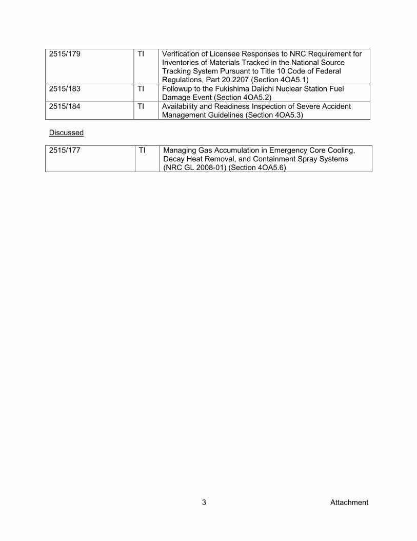
3 Attachment
2515/179 TI Verification of Licensee Responses to NRC Requirement for Inventories of Materials Tracked in the National Source Tracking System Pursuant to Title 10 Code of Federal Regulations, Part 20.2207 (Section 4OA5.1)
2515/183 TI Followup to the Fukishima Daiichi Nuclear Station Fuel Damage Event (Section 4OA5.2)
2515/184 TI Availability and Readiness Inspection of Severe Accident Management Guidelines (Section 4OA5.3)
Discussed 2515/177 TI Managing Gas Accumulation in Emergency Core Cooling,
Decay Heat Removal, and Containment Spray Systems (NRC GL 2008-01) (Section 4OA5.6)
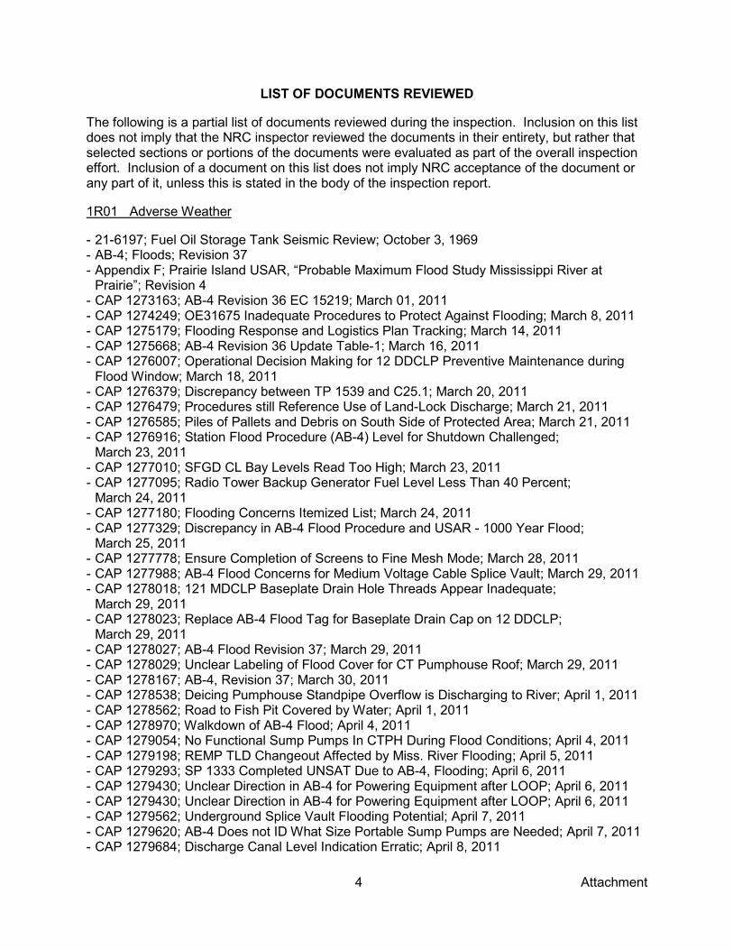
4 Attachment
LIST OF DOCUMENTS REVIEWED
The following is a partial list of documents reviewed during the inspection. Inclusion on this list does not imply that the NRC inspector reviewed the documents in their entirety, but rather that selected sections or portions of the documents were evaluated as part of the overall inspection effort. Inclusion of a document on this list does not imply NRC acceptance of the document or any part of it, unless this is stated in the body of the inspection report.
1R01 Adverse Weather
- 21-6197; Fuel Oil Storage Tank Seismic Review; October 3, 1969 - AB-4; Floods; Revision 37 - Appendix F; Prairie Island USAR, “Probable Maximum Flood Study Mississippi River at
Prairie”; Revision 4 - CAP 1273163; AB-4 Revision 36 EC 15219; March 01, 2011 - CAP 1274249; OE31675 Inadequate Procedures to Protect Against Flooding; March 8, 2011 - CAP 1275179; Flooding Response and Logistics Plan Tracking; March 14, 2011 - CAP 1275668; AB-4 Revision 36 Update Table-1; March 16, 2011 - CAP 1276007; Operational Decision Making for 12 DDCLP Preventive Maintenance during
Flood Window; March 18, 2011 - CAP 1276379; Discrepancy between TP 1539 and C25.1; March 20, 2011 - CAP 1276479; Procedures still Reference Use of Land-Lock Discharge; March 21, 2011 - CAP 1276585; Piles of Pallets and Debris on South Side of Protected Area; March 21, 2011 - CAP 1276916; Station Flood Procedure (AB-4) Level for Shutdown Challenged;
March 23, 2011 - CAP 1277010; SFGD CL Bay Levels Read Too High; March 23, 2011 - CAP 1277095; Radio Tower Backup Generator Fuel Level Less Than 40 Percent;
March 24, 2011 - CAP 1277180; Flooding Concerns Itemized List; March 24, 2011 - CAP 1277329; Discrepancy in AB-4 Flood Procedure and USAR - 1000 Year Flood;
March 25, 2011 - CAP 1277778; Ensure Completion of Screens to Fine Mesh Mode; March 28, 2011 - CAP 1277988; AB-4 Flood Concerns for Medium Voltage Cable Splice Vault; March 29, 2011 - CAP 1278018; 121 MDCLP Baseplate Drain Hole Threads Appear Inadequate;
March 29, 2011 - CAP 1278023; Replace AB-4 Flood Tag for Baseplate Drain Cap on 12 DDCLP;
March 29, 2011 - CAP 1278027; AB-4 Flood Revision 37; March 29, 2011 - CAP 1278029; Unclear Labeling of Flood Cover for CT Pumphouse Roof; March 29, 2011 - CAP 1278167; AB-4, Revision 37; March 30, 2011 - CAP 1278538; Deicing Pumphouse Standpipe Overflow is Discharging to River; April 1, 2011 - CAP 1278562; Road to Fish Pit Covered by Water; April 1, 2011 - CAP 1278970; Walkdown of AB-4 Flood; April 4, 2011 - CAP 1279054; No Functional Sump Pumps In CTPH During Flood Conditions; April 4, 2011 - CAP 1279198; REMP TLD Changeout Affected by Miss. River Flooding; April 5, 2011 - CAP 1279293; SP 1333 Completed UNSAT Due to AB-4, Flooding; April 6, 2011 - CAP 1279430; Unclear Direction in AB-4 for Powering Equipment after LOOP; April 6, 2011 - CAP 1279430; Unclear Direction in AB-4 for Powering Equipment after LOOP; April 6, 2011 - CAP 1279562; Underground Splice Vault Flooding Potential; April 7, 2011 - CAP 1279620; AB-4 Does not ID What Size Portable Sump Pumps are Needed; April 7, 2011 - CAP 1279684; Discharge Canal Level Indication Erratic; April 8, 2011
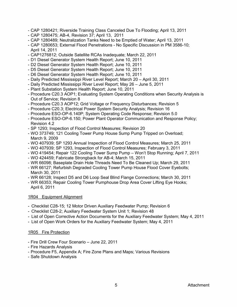
5 Attachment
- CAP 1280421; Riverside Training Class Canceled Due To Flooding; April 13, 2011 - CAP 1280475; AB-4, Revision 37; April 13, 2011 - CAP 1280489; Neutralization Tanks Need to be Emptied of Water; April 13, 2011 - CAP 1280653; External Flood Penetrations - No Specific Discussion in PM 3586-10;
April 14, 2011 - CAP1276812; Outside Satellite RCAs Inadequate; March 22, 2011 - D1 Diesel Generator System Health Report; June 10, 2011 - D2 Diesel Generator System Health Report; June 10, 2011 - D5 Diesel Generator System Health Report; June 10, 2011 - D6 Diesel Generator System Health Report; June 10, 2011 - Daily Predicted Mississippi River Level Report; March 20 – April 30, 2011 - Daily Predicted Mississippi River Level Report; May 26 – June 5, 2011 - Plant Substation System Health Report; June 10, 2011 - Procedure C20.3 AOP1; Evaluating System Operating Conditions when Security Analysis is
Out of Service; Revision 8 - Procedure C20.3 AOP12; Grid Voltage or Frequency Disturbances; Revision 5 - Procedure C20.3; Electrical Power System Security Analysis; Revision 16 - Procedure ESO-OP-6.140P; System Operating Code Response; Revision 5.0 - Procedure ESO-OP-6.150; Power Plant Operator Communication and Response Policy;
Revision 4.2 - SP 1293; Inspection of Flood Control Measures; Revision 20 - WO 373749; 121 Cooling Tower Pump House Sump Pump Tripped on Overload;
March 9, 2009 - WO 407939; SP 1293 Annual Inspection of Flood Control Measures; March 25, 2011 - WO 407939; SP 1293, Inspection of Flood Control Measures; February 3, 2011 - WO 419454; Repair 122 Cooling Tower Sump Pump – Won’t Stop Running; April 7, 2011 - WO 424459; Fabricate Strongback for AB-4; March 15, 2011 - WR 66098; Baseplate Drain Hole Threads Need To Be Cleaned Up; March 29, 2011 - WR 66127; Refurbish Degraded Cooling Tower Pump House Flood Cover Eyebolts;
March 30, 2011 - WR 66128; Inspect D5 and D6 Loop Seal Blind Flange Connections; March 30, 2011 - WR 66353; Repair Cooling Tower Pumphouse Drop Area Cover Lifting Eye Hooks;
April 6, 2011
1R04 Equipment Alignment
- Checklist C28-15; 12 Motor Driven Auxiliary Feedwater Pump; Revision 6 - Checklist C28-2; Auxiliary Feedwater System Unit 1; Revision 48 - List of Open Corrective Action Documents for the Auxiliary Feedwater System; May 4, 2011 - List of Open Work Orders for the Auxiliary Feedwater System; May 4, 2011 1R05 Fire Protection - Fire Drill Crew Four Scenario – June 22, 2011 - Fire Hazards Analysis - Procedure F5, Appendix A; Fire Zone Plans and Maps; Various Revisions - Safe Shutdown Analysis
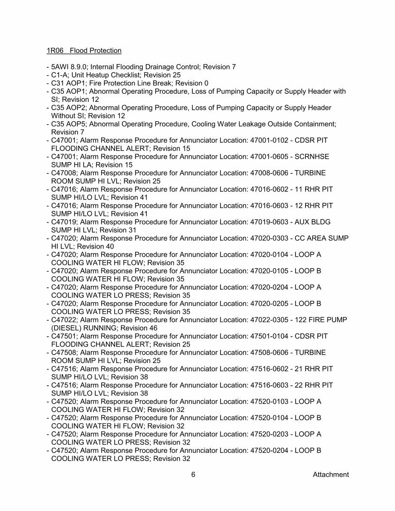
6 Attachment
1R06 Flood Protection - 5AWI 8.9.0; Internal Flooding Drainage Control; Revision 7 - C1-A; Unit Heatup Checklist; Revision 25 - C31 AOP1; Fire Protection Line Break; Revision 0 - C35 AOP1; Abnormal Operating Procedure, Loss of Pumping Capacity or Supply Header with
SI; Revision 12 - C35 AOP2; Abnormal Operating Procedure, Loss of Pumping Capacity or Supply Header
Without SI; Revision 12 - C35 AOP5; Abnormal Operating Procedure, Cooling Water Leakage Outside Containment;
Revision 7 - C47001; Alarm Response Procedure for Annunciator Location: 47001-0102 - CDSR PIT
FLOODING CHANNEL ALERT; Revision 15 - C47001; Alarm Response Procedure for Annunciator Location: 47001-0605 - SCRNHSE
SUMP HI LA; Revision 15 - C47008; Alarm Response Procedure for Annunciator Location: 47008-0606 - TURBINE
ROOM SUMP HI LVL; Revision 25 - C47016; Alarm Response Procedure for Annunciator Location: 47016-0602 - 11 RHR PIT
SUMP HI/LO LVL; Revision 41 - C47016; Alarm Response Procedure for Annunciator Location: 47016-0603 - 12 RHR PIT
SUMP HI/LO LVL; Revision 41 - C47019; Alarm Response Procedure for Annunciator Location: 47019-0603 - AUX BLDG
SUMP HI LVL; Revision 31 - C47020; Alarm Response Procedure for Annunciator Location: 47020-0303 - CC AREA SUMP
HI LVL; Revision 40 - C47020; Alarm Response Procedure for Annunciator Location: 47020-0104 - LOOP A
COOLING WATER HI FLOW; Revision 35 - C47020; Alarm Response Procedure for Annunciator Location: 47020-0105 - LOOP B
COOLING WATER HI FLOW; Revision 35 - C47020; Alarm Response Procedure for Annunciator Location: 47020-0204 - LOOP A
COOLING WATER LO PRESS; Revision 35 - C47020; Alarm Response Procedure for Annunciator Location: 47020-0205 - LOOP B
COOLING WATER LO PRESS; Revision 35 - C47022; Alarm Response Procedure for Annunciator Location: 47022-0305 - 122 FIRE PUMP
(DIESEL) RUNNING; Revision 46 - C47501; Alarm Response Procedure for Annunciator Location: 47501-0104 - CDSR PIT
FLOODING CHANNEL ALERT; Revision 25 - C47508; Alarm Response Procedure for Annunciator Location: 47508-0606 - TURBINE
ROOM SUMP HI LVL; Revision 25 - C47516; Alarm Response Procedure for Annunciator Location: 47516-0602 - 21 RHR PIT
SUMP HI/LO LVL; Revision 38 - C47516; Alarm Response Procedure for Annunciator Location: 47516-0603 - 22 RHR PIT
SUMP HI/LO LVL; Revision 38 - C47520; Alarm Response Procedure for Annunciator Location: 47520-0103 - LOOP A
COOLING WATER HI FLOW; Revision 32 - C47520; Alarm Response Procedure for Annunciator Location: 47520-0104 - LOOP B
COOLING WATER HI FLOW; Revision 32 - C47520; Alarm Response Procedure for Annunciator Location: 47520-0203 - LOOP A
COOLING WATER LO PRESS; Revision 32 - C47520; Alarm Response Procedure for Annunciator Location: 47520-0204 - LOOP B
COOLING WATER LO PRESS; Revision 32
7 Attachment
- CAP 1260473; Technical Review Pending Internal Flooding Evaluations; April 13, 2011 - CAP 1275453; Response To IER L1-11-1 Fukushima Daiichi Nuclear Station Fuel Damage
Caused by Earthquake and Tsunami; April 6, 2011 - CAP 1277773; Measured Door Gaps are Less Than Assumed in Calculation; March 28, 2011 - CAP 1277847; Hose Clamp on Flood Barrier on Sump B to 11 RHR Loose; March 28, 2011 - CAP 1278031; Respond to Violation Associated with Turbine Bldg Flooding; March 29, 2011 - CAP 1278082; Intake Screenhouse Discharge Trough is Plugged; March 29, 2011 - CAP 1278437; Unit-2 Condenser Cleaning; April 1, 2011 - CAP 1279556; Unit 1 Circulating Water High Level Trip Switch – No Apparent Testing;
April 7, 2011 - CAP 1280473; Technical Review Pending on Internal Flooding Evaluations; April 13, 2011 - CAP 1280574; No Clear Guidance to Power Plant Equipment During LOOP; April 13, 2011 - EC 16940; Condenser Pit Fill Time due to a Random Pipe Failure - EC 8070; Evaluate D5/D6 Compartments for Internal Flooding - EC 8754; Evaluate the Relay & Cable Spreading Room for Internal Flooding - EC 8975; Evaluate the U1 4.16kV & 480V Safeguards Switchgear Compartment for Internal
Flooding - EC 9069; Evaluate D1/D2 Compartments for Internal Flooding - EC 9076; Evaluate the 480V Safeguards Switchgear (Bus 112 & 122) & Event Monitoring
Rooms for Internal Flooding - EC 9377; Evaluate 121 & 122 CR Chiller Rooms for Internal Flooding - EC 9538; EC 9538, Evaluate the Control Room Compartment for Internal Flooding - ENG-ME-448; Auxiliary Building Flooding Analysis; Revision 1 - ENG-ME-732; Determination of HELB / Flooding Interactions in the Turbine Building;
Revision 1 - ENG-ME-758; Evaluation of HELB Target Flow Rates in the Turbine Building; Revision 0 - ENG-ME-759; GOTHIC Internal Flooding Calculation for the Turbine Building; Revision 0 - Generic Letter 87-11; Relaxation In Arbitrary Intermediate Pipe Rupture Requirements;
June 19, 1987 - H36; Plant Flooding; Revision 4 - Letter from DeYoung (AEC) to Dienhart (NSP), Subject: “Plant Flooding,” September 26, 1972 - Letter from Dienhart (NSP) to DeYoung (AEC), Subject: “30 day response to the 9/26/1972
letter,” October 23, 1972 - Letter from Skovholt (AEC) to Dienhart (NSP), Subject: “Flooding of Critical Equipment,”
August 3, 1972 - Letter, A Giambusso to AV Dienhart, “Clarification of Guidelines and Criteria Regarding a
Postulated Break in a Pipe Carrying a High-Energy Fluid”; January 11, 1973 - Letter, A Giambusso to AV Dienhart, “Request for Additional Information Concerning a
Postulated Steam Pipe Break Outside of Containment”; December 12, 1972 - Modification 86L907, “High Turbine Building Level Trip of the Circulating Water Pumps” - NRC Office of Nuclear Reactor Regulation Letter to NRC Region Ill, Task Interface Agreement
- Evaluation of Flooding Licensing Basis at PINGP; January 28, 2011 - OPR 1178236; Turbine Building HELB; November 1, 2009 - PINGP 195; Turbine Building Data - Unit 1; Revision 99 - PINGP 196; Turbine Building Data - Unit 2; Revision 113 - PINGP HELB Reconstitution Project Study; Revision 0 - Prairie Island Final Safety Analysis Report; Amendment 31 - Section 2; Prairie Island USAR “Site and Environs”; Revision 31 - Supplement 1 to Safety Evaluation by the Directorate of Licensing U. S. Atomic Energy
Commission in the Matter of Northern States Power Company Prairie Island Units 1 & 2 Docket Nos. 50-282 & 50-306; March 21, 1973

8 Attachment
- TP 1398; Verify Physical Inputs To Internal Flooding Evaluations; Revision 2 - TP 1398; Verify Physical Inputs To Internal Flooding Evaluations; Revision 2 - USAR; Prairie Island USAR, Appendix I, “High Energy Line Breaks Outside of Containment”;
Revision 32P - W O 391441; IC 1MD-3, Screen House Sump Level Alarm Calibration; December 7, 2010 - WO 290501; PE 0023-03T, Bus 23 Relay Test Trip; May 10, 2010. - WO 309081; PE 0013-10T, 4.16 kV Bus 23 Cubicle 3 21 Circulating Water Pump Electrical
Maintenance Test Tripping; Revision 5 - WO 323413; IC 0WL-16, 21 RHR Pit Sump Level Switch Calibration; January 25, 2008 - WO 326402; IC 0WL-14, 11 RHR Pit Sump Level Switch Calibration; May 2, 2008 - WO 326422; PMRQ 6956-01, IC 0WL-17, 22 RHR Pit Sump Level Switch Calibration;
December 6, 2007 - WO 326423; IC 0WL-15, 12 RHR Pit Sump Level Switch Calibration; June 12, 2008 - WO 352018; IC 0WL-7, Auxiliary Building and Radwaste Building Sump Level Alarm
Calibration; September 11, 2008 - WO 385792; ICPM 2-027, Loop B Cooling Water Header Instrument Calibration;
November 24, 2009 - WO 389490; IC 0CL-1, 122 Filtered Water Strainer Differential Pressure and Cooling Water
Strainer Pressure Alarm Calibration; October 1, 2010 - WO 389705; ICPM 1-027, Loop A Cooling Water Header Instrument Calibration;
January 7, 2010 - WO 391439; IC 2MD-1, Turbine Building Sump Level Switch Calibration; December 15, 2010 - WO 391442; IC 1MD-1, Turbine Building Sump Level Alarm Calibration; December 7, 2010 - WO 391977; 11 Condensate Pit Sump Pump Not Running; October 22, 2009 - WO 409082; Possible Blown Bearing on 22 Turbine Building Sump; December 13, 2010 - WO 412783; TP 1398, Verify Physical Inputs To Internal Flooding Evaluations;
March 28, 2011 - WR 66064; Hose Clamp on Flood Barrier on Sump B to 11 RHR Loose; March 26, 2011
1R07 Heat Sink
- SP 1304; Unit 1 Component Cooling Water Heat Exchanger Performance Test; May 7, 2011
1R08 Inservice Inspection Activities
- 2010V015; VT-3 Report, CWH-36, Sway/Strut Clamp; April 22, 2010 - 2011P001; Liquid Penetrant Examination Report, H-3/IA, Integrated Attachment
(Anchor Support); May 10, 2011 - 2011U001;UT Examination Report, W-7, Reducer-Safe End; May 6, 2011 - 2011U004; UT Inner Radius Examination Report, N1-IR, Nozzle Inner Radius; May 10, 2011 - 2011V017; Visual Examination of Pressure Retaining Bolting (VT-1) Report, B-1, Valve
Bolting; May 4, 2011 - 2011V018; VT-3 Report, H-2, Rod/Clamp; May 4, 2011 - 2011V019; VT-3 Report, H-4, Rod/Clamp; May 4, 2011 - 2011V035; Visual Examination System Leakage (VT-2) Report, RV Closure Head, Reactor
Vessel Closure Head Bare Metal Visual Examination; May 9, 2011 - 5AWI ASME Section XI Inservice Inspection and Pressure Testing - CAP 1191652; RHR Injection Flow Elements Not Included in SP 1392/2392; July 30, 2009 - CAP 1198656; FME Barrier for Open Manway Cover Inadequate; October 29, 2010 - CAP 1219016; Limited ISI Exam for 12 RHR Heat Exchanger; February 19, 2010 - CAP 1221282; SP 1168.7 CA Pressure Test not Complete as Scheduled; March 4, 2010

9 Attachment
- CAP 1228864; 2-CWH-36 Cooling Water Hanger ISI Indication; April 23, 2010 - CAP 1231202; VT-3 Signed Off With Unresolved Indications; May 28, 2010 - CAP 1241478; Potential Nonconformance Insulated Bolted Connections; July 15, 2010 - CAP 1283239; 11 RSG Secondary Side Leak; April 30, 2011 - CAP 1284199; Oil Dripping from MV-32067 Actuator; May 5, 2011 - CAP 1284208; RC-18-5 Body to Bonnet Bolt Thread Engagement; May 5, 2011 - CAP 1284249; Oil Leakage Noted on the 11 RCP Mounting Bolts; May 5, 2011 - CAP 1284610; Verification Review for Procedure Revision PINGP 1507; May 7, 2011 - CAP 1284978; Reactor Vessel Closure Head 157-051 Inspection Results 1R27; May 10, 2011 - CAP 1285000; SWI-NDE-DWG-2 Revision1 ISI Inspection Drawings; May 10, 2011 - CAP 1285205; SP1407 Requirements to Disposition Indications Not Followed; May 11, 2011 - CAP 1285208; Define “Leakage” or “Indication of Leakage” in BACC Program; May 11, 2011 - CAP 1285394; ISI Report 2010V015 need more information; May 12, 2011 - CAP 1285405; Potential Inadequacy for Equivalency Evaluation; May 12, 2011 - CAP 1285461; Question on Acceptability of 2-CWH-36 ISI Indication; May 12, 2011 - D63; Installation Guidelines for Threaded Fasteners (Studs or Bolts); Revision 20 - Drawing BE-5470-CW, Sheets 2H7-41/42; Pipe Support CWH-41; Revision 4 - EC 13953; Replace MV-32058; Revision 0 - EC 15064; Change Piping Materials For 1-RC-82 From SA-376 TP316 SA-312 TP304;
Revision 0 - FP-PE-NDE-402; Ultrasonic Examination or Austenitic Pipe Welds-Supplement 2; Revision 2 - FP-PE-NDE-510; Visual Examination, VT-1; Revision 3 - FP-PE-NDE-530; Visual Examination VT-3; Revision 4 - FP-PE-NDE-UT-03; Ultrasonic Detection and Sizing of Reactor Pressure Vessel Nozzle to
Shell Welds and Nozzle Inner Radius; Revision 2 - H2; Boric Acid Corrosion Control Program; Revision 15 - N-729-1; Alternative Examination Requirements for PWR Reactor Vessel Upper Heads With
Nozzles Having Pressure Retaining Partial Penetration Welds Section XI, Division 1; March 28, 2006
- NDE Procedure Qualification; SWI NDE PT-1; September 30, 2003 - NX-52230; 3”-150 Weld ends Stainless Steel Double Disc Gate Valve with Nickel Chrome
Facing and 12” Handwheel; Revision B - PQR KNPP-GMP-102-311-E70; Procedure Qualification Record (PQR); Revision 0 - PQR W-66; P8-TM-AG; Revision 0 - PrQR –W-12; P8-T-Ag; Revision 1 - SP 1392; Unit 1 Insulated Bolted Connection Inspection; Revision 9 - SP 1405; Unit 1 Mid-Cycle and Refueling Outage Boric Acid Corrosion Examinations Inside
Containment - SWI NDE PT-1; Solvent Removable, Visible Dye Penetrant Examination; Revision 1 - SWI NDE-VT-6.0; Visual Examination for Leakage on Reactor Vessel Penetrations (VT-2);
Revision 0 - WO 0039138-02; UNIT 1 Repair Reactor Vessel Head Vent Piping (Bent); October 15, 2009 - WO 355150-01; Cut Out and Replace MV-32058 with New Valve; September 12, 2009 - WPQR 1; SM-8-8; September 18, 1973 - WPQR 91-P8P8F6F5-2; Revision 5 - WPQR SM-1-1; Weld Procedure Qualification Record; Revision 5 - WPS FP-FE-831-P1P1-SM-003; Weld Procedure Specification (WPS) for Groove Welds with
E6010/E7018 Root Pass and Fillet Welds. P1-P1, SMAW, Groove without PWHT; Revision 0 - WPS FP-PE-III-P8P8-GTSM-062; Weld Procedure Specification (WPS) for Groove Welds and
Fillet Welds, P8-P8, GTAW/SMAW, Without PWHT; Revision 3
10 Attachment
1R11 Licensed Operator Requalification
- Simulator Exercise Guide P9110SD0801; LOR Cycle 10H DEP Evaluation No.1; Revision 0 1R12 Maintenance Effectiveness - CAP 1266075-02; Reportability Evaluation for Potential LER Issue on DEC 121 MDCLP
Autostart - Energy Supply Technical Training Lesson Plan R8301A-012; Gaskets; no date provided - LER 50-282/2011-001-00; Unplanned Actuation of 121 Motor Driven Cooling Water Pump;
April 26, 2011 - Lesson Plan P8345L-1004; Gaskets and O-ring Refresher; Revision 0 - MRE 1266075; Potential LER Issue on DEC 121 MDCLP Autostart - MSPI Failure Determination Data Entry Form; Rev. 0 for Potential LER Issue on DEC 121
MDCLP Autostart - Permatex Ultra Blue RTV Silicone Gasket Maker; Technical Data Sheet; Revision 06/09 - PM 3535-2-11; 11 Containment/Aux Bldg Chiller Annual Inspection; Rev. 7 - Procedure D63; Installation Guidelines for Threaded Fasteners; Revision 20 - Procedure FP-WM-PLA-01; Work Order Planning Process; Revision 10 - Root Cause Evaluation Report 1271750-01; Unplanned Entry into TS LCO 3.6.10 Condition A;
March 17, 2011 - Vendor Technical Manual NX-15639-1; Containment and Auxiliary Building Chillers - WO 382407-12; 11 Aux Building/Containment Chiller Gasket Repair; October 23, 2010
1R13 Maintenance Risk Assessment and Emergent Work
- 2C20.5 Unit 2- 4.16KV System; Revision 16 - AR 1292224; Troubleshooting Plan; June 28, 2011 - C20.3; Electrical Power System Security Analysis; Revision 16C - C20.3AOP5; Electric Power System Operating Restrictions and Limitations Loss of 2RY
Transformer; Revision 4 - NE-116786-03; Revision D - NE-119871; Substation & Plant Operating One-Line Diagram; Revision H - USAR Section 8.2; Transmission System; Revision 27 - V.SPA.11.021; Risk Evaluation for Check Valve SI-9-3 Closed Position Missed Surveillance
Test; April 21, 2011
1R15 Operability Evaluations
- 1E-1; Loss of Reactor or Secondary Coolant; Revision 23 - 2E-1; Loss of Reactor or Secondary Coolant; Revision 23 - BOP-VE-11-025; Ultrasonic Examination Report (2RH-2 & 2RH-18); April 6, 2011 - BOP-VE-11-026; Ultrasonic Examination Report (2RH-20); April 6, 2011 - BOP-VE-11-027; Ultrasonic Examination Report (2RH-13, 15, 17, 19, 21, & 22 and 2SI-52, 53,
55, 16, 39, 40, 41, 57, & 58); April 6, 2011 - C1.1.37-1[2]; Ventilation Systems; Revision 15 - CAP 1290269; RHR/SI Motor Valve Pressure Locking Concern; June 21, 2011 - F5; Control Room Evacuation; Revision 45 - FP-OP-OL-01; Operability Recommendation; Revision 7 - NF 39603-1; Admin Building Screenhouse & Control Room Flow Diagram; Revision 78
11 Attachment
- NF-40761-1; Interlock Logic Diagram Control Relay and Computer Room Ventilation System Units 1 and 2; Revision 75
- OPR 1290269; Pressure Locking for RHR and SI valves; Revision 0 - SP 1055.1; 121 Control Room Clean Up Ventilation System Filter Removal Efficiency Test;
Revision 17 - SP 1055.2; 122 Control Room Clean Up Ventilation System Filter Removal Efficiency Test;
Revision 18 - SP 1172; Ventilation System Monthly Operation; Revision 34 - SP 1185A; Control Room Clean Up Ventilation Train A Flow Verification; Revision 5 - SP 1185B; Control Room Clean Up Ventilation Train B Flow Verification; Revision 6 - SP1266; Fire Damper – 18 Month Inspection; Revision 16 - TS 5.5.9; Ventilation Filter Testing Program (VFTP); Unit 1 Amendment 186; Unit 2
Amendment 176 - TS and TS Bases 3.3.6; CRSVS Actuation Instrumentation; Unit 1 Amendment 158; Unit 2
Amendment 149 - TS and TS Bases 3.7.10; Control Room Special Ventilation System; Unit 1 Amendment 195;
Unit 2 Amendment 184 - UFSAR Section 10.3 3; Control Room Ventilation System; Revision 31 - Vendor Manual XH 236-23; CVI Ventilation Filters; Revision 6 - Vendor Manual XH-465-6; XH-465-6; Control Room Air Handlers; Revision 1 - WO 108114-01; P3147-1-121 121 Control Room Air Handler 6M Inspection; March 29, 2006 - WO 269790-01; P3147-1-121 121 Control Room Air Handler 6M Inspection; October 23, 2006 - WO 293625-01; P3147-1-122 122 Control Room Air Handler 6M Inspection; March 12, 2007 - WO 299911-01; P3147-1-121 121 Control Room Air Handler 6M Inspection; March 26, 2007 - WO 321092-01; P3147-1-121 121 Control Room Air Handler 6M Inspection;
September 26, 2007 - WO 330298-01; P3147-1-121 121 Control Room Air Handler 6M Inspection; April 29, 2008 - WO 358551-01; P3147-1-122 122 Control Room Air Handler 6M Inspection; February 3, 2009 - WO 376980-01; PMRQ 7240-01 -121 Cont Room Air Handler (076-21) 6M Inspection;
April 1, 2009 - WO 377501-01; PMRQ 7240-01 -121 Cont Room Air Handler (076-21) 6M Inspection;
December 8, 2009 - WO 382727-01; PMRQ 7240-01 -121 Cont Room Air Handler (076-21) 6M Inspection;
April 5, 2010 - WO 405215-01; PMRQ 7240-01 -121 Control Room Air Handler (076-21) 6M Inspection;
October 14, 2010 - WO 413742-01; PMRQ 7240-01 -121 Control Room Air Handler (076-21) 6M Inspection;
April 11, 2011 - WO 425503-01; UT Susceptible Void Locations in Unit 1 Containment; April 21, 2011
1R18 Modifications
- SP 1314; 12 Battery Discharge Test; May 26, 2011 - WO 424983-01; D1 Transient Analysis Test Run; June 1, 2011 - SP 1098; Unit 1 Integrated Safety Injection Test; June 3, 2011

12 Attachment
1R19 Post-Maintenance Testing
- WO 429722-07; D1 Room Ventilation Starts When Testing Alarms; May 1, 2011 - CAP 1285688; Erratic Speed Indication During D1 Post-Maintenance Testing; May 13, 2011 - WO 430611; Troubleshoot D1 Tachometer; May 14, 2011 - CAP 1287010; Adverse Trend: Motor Driven AFW Pumps Lube Oil Piping not Filled
Post-Maintenance; May 22, 2011 - Procedure PM 3133-1-12; 12 Motor-Driven Aux Feedwater Pump Inspection - WO 360013-01; 12 Motor Driven Auxiliary Feedwater Pump Refueling Inspection
1R20 Refueling and Outage - Unit One Refueling Outage April 2011 Shutdown Safety Assessment; Revision 1 - C47002; Alarm Response Procedure 47002-0103 (11/12/13 Feedwater Heater Hi Hi Level);
Revision 10 - 1C51.4; Instrument Failure Guide (Power Range Nuclear Instrument N-44 – High);
Revision 18 - FP-OP-COO-01; Conduct of Operations; Revision 10 - SWI-O-50; Reactivity Management; Revision 14 - WO 396172-01; SP-1177 Refuel Core Inventory Verification; May 12, 2011 - SP 1177; Refuel Core Inventory Verification; Revision 16 - 1R27 Refueling Outage Core and Baffle Inspection Prior to Upper Internals Replacement;
May 20, 2011 - U1R27 Core Inventory Verification; May 2011 - Unit 1 Cycle 27 Refueling Outage Fuel Assembly Foreign Material; May 18, 2011 - AR 1286127; Debris Found in Fuel Assembly Post 1R27; May 16, 2011 - PERA11-5; Product Risk Assessment – Risk Of Debris Related Issues At Prairie Island; No
Date - LTR-RC-11-28; Westinghouse Letter Regulatory Compliance to R.J. Sterdis Regarding Prairie
Island Risk Assessment For Loose Parts In Primary System; May 20, 2011 - OC-PI-2011-014; Xcel Energy Internal Correspondence Regarding CAP 1286127 (Debris
Found In Fuel Assembly Post 1R27 and FP-OP-ODM-01 Fact Based Decision Making; May 19, 2011
- D58.1.10; Unit 1 Reactor Vessel Head Replacement; Revisions 0 thru 14 - D58.1.9; Unit 1 Reactor Vessel Head Removal; Revision 18 - WO 399551-01; D58.1.10 Reactor Vessel Head Removal; April 25, 2011 - WO 359597-10; D58.1.9; Reactor Vessel Head Replacement; April 25, 2011 - Unit 2 Post Trip Report; May 9, 2011 - PINGP 662; Reactor Trip Report; May 9, 2011 - 2ES-0.1; Reactor Trip Recovery; Revision 23 - Unit 2 NSSS Annunciator Computer Report; May 9, 2011 - Unit 2 Delta T Recorder 42621 Plot; May 9, 2011 - Unit 2 Delta T Recorder 42622 Plot; May 9, 2011 - Unit 2 Delta T Recorder 42623 Plot; May 9, 2011 - Unit 2 Delta T Recorder 42619 Plot; May 9, 2011 - Unit 2 Steam Flow/Feed Flow Recorder 42510 Plot; May 9, 2011 - Unit 2 Steam Flow/Feed Flow Recorder 42504 Plot; May 9, 2011 - Unit 2 Pressurizer Level Recorder 42617 Plot; May 9, 2011 - Unit 2 Pressurizer Pressure Recorder 42618 Plot; May 9, 2011 - Unit 2 Tavg / Tref Recorder 42620 Plot; May 9, 2011 - Unit 2 Nuclear Power Recorder 42609; May 9, 2011
13 Attachment
- Unit 2 Turbine Control Alarm History; May 9, 2011 - Unit 2 post Trip Rod position Report; May 9, 2011 - SP 1750; Post Containment Close-Out Inspection; Revision 035A - CAP 1285571; Steam Generator Leakage Monitoring Challenged During Unit 2 Start Up;
May 13, 2011 - RPIP 4503; Steam Generator Primary to Secondary Leak Rate Determination; Revision 21
1R22 Surveillance Test
- WO 425887; SP-1094 Bus 15 Load Sequencer Test Failed; April 13, 2011 - SP 1095; Bus 16 Load Sequencer Test; Revision 31 - SP 2335; D6 Diesel Generator 18 Month 24 Hour Load Test; Revision 15 - WO 405610; SP-2307 D6 Diesel Generator 24 Hour Load test; April 29, 2011 - SP 2307; D6 Diesel Generator 6 Month Fast Start Test; Revision 33B - WO 413477; SP-2335 D6 Diesel Generator 6 Month Fast Start Test; April 29, 2011 - WO 396480-01; SP 1431 Main Steam Safety Valve Test (Power Operation); April 29, 2011 - SP 1431; Main Steam Safety Valve Test (Power Operation); Revision 3 - 102119; Furmanite Certificate of Calibration (Trevi Test Equipment); June 2, 2010 - 102242; Furmanite Certificate of Calibration (Trevi Test Equipment); February 23, 2011 - 101947; Furmanite Certificate of Calibration (Trevi Test Equipment); March 20, 2009 - 102157; Furmanite Certificate of Calibration (Trevi Test Equipment); August 27, 2010 - 101870; Furmanite Certificate of Calibration (Trevi Test Equipment); September 6, 2008 - 101869; Furmanite Certificate of Calibration (Trevi Test Equipment); September 6, 2008 - Calibration Check Report – Device Serial Number 52396; April 28, 2011 - Calibration Check Report – Device Serial Number 1032265; April 28, 2011 - 102TT103335/AW5961.001 through .005; Trevistest Valve Certificate for Valve RS-21-10;
April 28, 2011 - 102TT103335/AW5961.006 through .008; Trevistest Valve Certificate for Valve RS-21-6;
April 28, 2011 - 102TT103335/AW5961.009 through .013; Trevistest Valve Certificate for Valve RS-21-9;
April 28, 2011 - QA-4; Furmanite Trevitest Procedure; Revision 2 - FP-G-DOC-03; Procedure Use and Adherence; Revision 9 - 5AWI 15.5.1; Plant Equipment Control Process; Revision 31 - NSPM-1 QATR; Quality Assurance Topical Report; Revision 4 - SWI-O-39; Operations Training Plan; Revision 20 - SWI-O-43; Operator Qualification Program; Revision 12 - FP-MA-COF-01; Conduct of Fix It Now Team; Revision 3 - CAP 1283245; Loss of Position Indication for Motor Valve 32023; April 30, 2011 - WO 429982; Loss of Position Indication for Motor Valve 32023 - Outage Control Center Logs; various dates - WO 416457; SP 2080.2 22 Shield Building Ventilation Filter Removal Efficiency Test;
Revision 16 - WO 418082; SP 2073 B Monthly Train B Shield Building Ventilation System Test; Revision 8
14 Attachment
2RS1 Radiological Hazard Assessment and Exposure Controls
- CAP 1201838; RadWaste Building Ventilation Out of Service; October 10, 2009 - CAP 1232042; High Radiation Area Gate Not Checked Shut in Containment; May 10, 2010 - CAP 1260781; Radiation Worker Practice Moving Underwater Hose; November 30, 2010 - CAP 1263530; Unclear Posting Requirements in RPIP 1304 and RPIP 1120 - CAP 1264913; Obsolete NMC Radiation Monitors Need a Replacement Solution;
January 3, 2011 - CAP 1274179; RadWaste Ventilation Remains Out of Service; April 8, 2011 - CAP 1276812; Outside Satellite Radiologically Controlled Areas Inadequate; March 22, 2011 - CAP 1282925; Initial Containment Pre-Job Brief had Poor Attendance; April 29, 2011 - CAP 1283392; Worker Lost Thermoluminescence Detector in Unit One Containment;
May 2, 2011 - CAP 1283802; Shielding Package 11-19 Inadequate for Hot Spot; May 4, 2011 - CAP 1283842; Unnecessary Dose Received Working on Reactor Vessel Level Instrument
System; May 4, 2011 - CAP 1284182; 11 Residual Heat Removal High-Efficiency-Particulate-Air Air Circulation
Disconnected; May 5, 2011 - CAP 1284624; Dose of Reactor Head Lift Exceeded Dose Estimate; May 7, 2011 - CAP 1284701; Deviation Documentation per RPIP 1120, 14.3.2 High Radiation Area Posting;
May 8, 2011 - CAP 1284744; Poor Work Practices Result in Personnel Contamination Events; May 8, 2011 - CAP 1284754; Out of Service Radiation Monitors Challenge Fuel Handling; May 9, 2011 - CAP 1284907; Items Stored Against the East Side of the Barrel Yard Wall; May 9, 2011 - CAP 1285327; Potential Electronic Dosimeter Malfunction; May 11, 2011 - NOS 2010-01-011; Radiation Protection Quarterly Report Assessment Including Radioactive
Shipping; February 22, 2010 - NOS 2010-02-011; PINGP May Outage Review; May 27, 2010 - NOS 2010-02-033; PINGP Radiation Protection Review; July 21, 2010 - NOS 2011-01-031; PINGP Radiation Protection Review; April 12, 2011 - PINGP 1236; Reactor Coolant System Crudburst and Draindown Radiation Protection
Requirements; Revision 3 - PINGP 1560; Postings Changes for Fuel Handling; Revision 1 - PINGP 258; Radiation Protection Survey Record; Revision 14 - QF-1203; Radiological Work Assessment Form; Revision 6 - QF-1204; Radiological Work Assessment Form Contamination Control; Revision 5 - QF-1205; Radiological Work Assessment Form Exposure Control; Revision 4 - QF-1207; Radiological Work Assessment Form ALARA Review Checklist; Revision 2 - QF-1209; Pre-Job Briefing Items for 1R27 GL-08; Revision 4 - RPIP 1135; Radiological Work Permit Coverage; Revision 28 - RWP 1223; Unit One Outage Containment Valve Work; Revision 6 - RWP 1268; Unit One Support Activities for Reactor Head Assembly/Disassembly; Revision - RWP 1376; Online Remove Items from Spent Fuel Pool and Fuel Handling; Revision 6 - RWP 1565; Unit One Outage Containment Valve Work-High Radiation Area; Revision 0
2RS2 Occupational ALARA Planning and Controls
- FP-RP-JPP-01; Radiation Protection Job Planning; Revision 8 - FP-WM-IRM-01; Integrated Risk-Management; Revision 4
15 Attachment
2RS3 In-Plant Airborne Radioactivity Control and Mitigation
- Effluent Offsite Dose Calculation Information for Weeks 18 and 19, 2011 - WO 311317-05; Trouble Shoot Radwaste Building Exhaust Fan Operation; July 1, 2007 - WO 311317-09; Trouble Shoot Radwaste Building Exhaust Fan Operation; May 18, 2011 - WO 415795; Repair Contactor for CD-34184-121-Radwaste Building Exhaust Fan Discharge
2RS5 Radiation Monitoring Instrumentation
- 5AWI-10.1.0; Radiation Protection Program; Revision 10.1.0; Revision 10 - CAP 01212313; Improper Use of Calibration Stickers; February 2010 - CAP 01241325; Disposal of Radioactive Sources; dated July 2010 - CAP 01265443; 1R12 and 2R12 Installed Check Sources are Too Small; January 2011 - CAP 01266647; Smear Counter Efficiency Relies on Outdated Source Activity; January 2011 - CAP 01267001; Alpha Detection Level is Incorrect (non-conservative); January 2011 - CD 9.1; Radiation Protection Program; Revision 2 - FP-RP-EDC-01; DMC 2000 S/SOR Electronic Dosimeter and IRD-200 Calibration;
Revision 01 - Radiation Protection Equipment ‘Out Of Service’ Search; April 2011 - RPIP-1001; Radiation Protection Program; Revision 14 - RPIP 1123; Alpha Characterization Smears; Revision 00 - RPIP 1608; RO-2, RO-2A and RO-20 Operation `and Calibration; Revision 10 - RPIP 1611; RO-7 Ion Chamber Operation and Calibration; Revision 14 - RPIP 1632; RADECO AVS-28A Air Sampler Calibration; Revision 10 - RPIP 1637; Extender Model 2000W Operation and Calibration; Revision 10 - RPIP 1658; ASP-1 Neutron Meter Operation and Calibration; Revision 14 - RPIP 1660; Yearly Source Calibration; Revision 09 - RPIP 1674; PM-7 Portal Monitor Description, Operation, and Calibration; Revision 05 - RPIP 1675; Eberline PCM-1B Operation and Calibration; Revision 04 - RPIP 1677; SAM-11 Small Articles Monitor Operation and Calibration; Revision 04 - RPIP 1682; RADOS TSE Operation and Calibration; Revision 02 - RPIP 1684; AMP-100 Operation and Calibration; Revision 01
Source Leak Test Records; August, 2010
4OA1 Performance Indicator Verification
- LER 50-282/2011-001-00; Unplanned Actuation of 121 Motor Driven Cooling Water Pump; April 26, 2011
- LER 50-306/2011-001-00; Unit 2 Shield Building Inoperable due to Maintenance Activity; April 20, 2011
- LER 50/282/2010-004-00; Battery Charger Inoperability due to Potential Undervoltage Conditions; January 28, 2011
- LER 50-306/2010-003-00; Unit 2 Fuel Oil Transfer Pumps are Vulnerable to a Potential Common Mode Failure; July 16, 2010
- LER 50-306/2010-002-00; Unit 2 Turbine Shutdown due to the Loss of a Main Feed Water Pump that Resulted in a Reactor Scram; July 16, 2010
- LER 50-306/2010-001-00; Unit 2 Turbine Trip during Reactor Shutdown Resulting in a Reactor Scram; June 15, 2010
- LER 50-282/2010-005-00; Surveillance Required by TS for the Emergency Diesel Generator not Completed; November 8, 2010
16 Attachment
- LER 50-282/2010-004-00; Battery Charger Inoperability due to Potential Undervoltage Conditions; January 28, 2011
- LER 50-282/2010-003-00; Postulated Flooding of Battery Rooms due to Inadequate Battery Room Door Threshold Seals; August 9, 2010
- LER 50-282/2010-002-00; Postulated Flooding of Unit 1 Fuel Oil Transfer Pump Motor Starters could have Resulted in Reduced Fuel Oil Inventory; June 25, 2010
- LER 50-282/2010-001-01; Unanalyzed Condition Due to Postulated High Energy Line Break on Cooling Water System, Supplement 1; July 2, 2010
- LER 50-282/2010-001-00; Unanalyzed Condition due to Postulated High Energy Line Break on Cooling Water System; May 3, 2010
- LER 1-09-09; Radioactive Source Inventory Discrepancy; February 16, 2010 - LER 1-09-08; Unanalyzed Condition due to an Inadequate Fire Barrier; February 11, 2010 - LER 1-09-07, Supplement 1; Unanalyzed Condition due to a Breached Fire Barrier;
March 19, 2010 - LER 1-09-01; Unanalyzed Condition due to a Breached Fire Barrier; December 21, 2009 - LER 1-09-06; Unanalyzed Condition due to Potential Safety System Susceptibility to Turbine
Building Flooding due to a Postulated High Energy Line Break, Supplement 1; April 8, 2010 - LER 1-09-06; Unanalyzed Condition due to Potential Safety System Susceptibility to Turbine
Building Flooding due to a Postulated High Energy Line Break, December 7, 2009 - LER 1-09-05; Reactor Trip due to 12 Circulating Water Pump Trip Caused by Electrical
Ground Fault; July 17, 2009 - LER 1-09-04, Supplement 1; Residual Heat Removal System Inoperability while in Mode 4
due to Potential Steam Voiding; January 7, 2011 - LER 1-09-04; Residual Heat Removal System Inoperability while in Mode 4 due to Potential
Steam Voiding; June 5, 2009 - LER 1-09-03; Component Cooling System Vulnerability to Tornado Missile Hazard;
May 22, 2009 - LER 1-09-02; Unplanned Safety Related Actuation of 121 Cooling Water Pump; May 18, 2009 - LER 1-09-01; Unanalyzed Condition due to Manual Actions that do not Comply with
10 CFR 50, Appendix R; March 16, 2009 - LER 2-09-01; Clearance Order Render Opposite Train EDG Inoperable; April 20, 2009 - Licensee Computer, J:\RCS Leakage\RCS_Leakage\RCS leakage trends.xls; June 16, 2011 - Prairie Island Performance Indicators; June 16, 2011 - MSPI Derivation Report; Residual Heat Removal System; April 2010 through March 2011 - MSPI Derivation Report; High Pressure Safety Injection; April 2010 through March 2011 4OA2 Identification and Resolution of Problems - Maintenance Rule Monthly Reports; various dates - Department Roll Up Reports; various dates - NRC CAP Trending Database
4OA3 Followup of Events and Notices of Enforcement Discretion
- WO 408666-01; Repair Door 172 and 173 Unit 2 Auxiliary Building to Maintenance Airlock; February 13, 2011
- PM 3122-6; Quarterly Mechanical Door Repair Work; Revision 18 - SP 2773; Functional Check of Shield Building Doors; Revision 5 - Procedure FP-WM-PLA-01; Work Order Planning Process; Revision 10 - Root Cause Evaluation Report 1271750-01; Unplanned Entry into TS LCO 3.6.10 Condition A;
March 17, 2011
17 Attachment
- LER 50-282/2011-001-00; Unplanned Actuation of 121 MDCLP; April 26, 2011 - MRE 1266075; Potential LER Issue on DEC 121 MDCLP Autostart - CAP 1266075-02; Reportability Evaluation for Potential LER Issue on DEC 121 MDCLP
Autostart - PM 3535-2-11; 11 Containment/Aux Bldg Chiller Annual Inspection; Rev. 7 - MSPI Failure Determination Data Entry Form; Rev. 0 for Potential LER Issue on DEC
121 MDCLP Autostart - D63; Installation Guidelines for Threaded Fasteners (Studs or Bolts) - MSIP 1000; Gasket Material Selection - 5AWI 3.6.0; Reporting and NRC Notices of Violation - 5AWI 3.12.4; Post-Maintenance Testing - Work Order 419049-12, 00382407; Repair Leak at North Endbell - Work Order 419049;11 Cnmt and Aux Bldg Chiller - Xcel Energy Technical Training Manual R8301A-012; Gaskets - Xcel Energy Gaskets and O-Ring Refresher Training Manual P8345L-1004 - Permatex Technical Data Sheet for Permatex Ultra Blue RTV Silicone Gasket Maker - CAP 01266075, 01020503 - Jan 2011 MSPI Unavailability Review - Work Request 63221 - Licensee Operating Narrative Logs - WO 382407-12; 11 Aux Building/Containment Chiller Gasket Repair; October 23, 2010 - Procedure D63; Installation Guidelines for Threaded Fasteners; Revision 20 - Permatex Ultra Blue RTV Silicone Gasket Maker; Technical Data Sheet; Revision 06/09 - Vendor Technical Manual NX-15639-1; Containment and Auxiliary Building Chillers - Lesson Plan P8345L-1004; Gaskets and O-Ring Refresher; Revision 0 - Energy Supply Technical Training Lesson Plan R8301A-012; Gaskets; no date provided
4OA5 Other Activities
- WR 66619; Clean and Inspect Control Room Overhead; April 14, 2011 - SPCE ME-0223; Control Room Lighting Diffuser Tie-Down Equivalency Evaluation;
May 20, 1999 - NF 38552; Architectural Control Room Reflected Ceiling Plan; February 11, 1999 - PINGP 1198; Scaffold Construction Checklist (Auxiliary Feedwater Pump Room);
April 19, 2011 - 2C29.1 AOP4; Restarting Unit 2 AFWP After Low Suction/Discharge Pressure Trip; Revision 4 - AR 01245152; Snap Shot Self Assessment; NRC TI 2515/179; Revision 1; January 2011 - National Source Tracking Data Sheet; April 2011 - WO 421431; Perform Flow Testing of LTOP Tmod Check Valves; April 28, 2011 - Temporary Modification 04T175; Pressurizer PORV Air Accumulator Supplementation; 5A - 1D108; Pressurizer PORV Air Accumulator Supplementation; Revision 4 - GEN19990097; RHR waterhammer evaluation; January 20, 1999 - Design Change 00SI01; Boric Acid Reduction; August 16, 2001 - ENG-ME-545; RWST Volume Calculation; July 28, 2010 - ENG-ME-293; Safety Related Tank Usable Volume; October 29, 2009 - ENG-ME-005; Analysis of Available NPSH to the RHR Pumps from the Containment Sump;
March 17, 2008 - ENG-ME-657; Sump B Strainer Head Loss Determinations; Revision 3 - ENG-ME-560; Evaluation of Maximum RHR Pump Flow During Recirculation; February 12,
2010 - SPC-EP-102; U2 Miscellaneous EOP Parameters; September 10, 2007
18 Attachment
- ENG-ME-650; Caustic Addition Standpipe Volume Calculation; April 13, 2009 - ENG-ME-590; CS Piping/Pipe Support Analysis; September 30, 2004 - OPR1166457; ECCS Transfer to Recirculation; May 7, 2010 - OPR1154577; U2 RHR PIT Void; November 19, 2009 - EC13293; Evaluation of RHR System Air Void 22PIT-5; January 12, 2009 - EC17990; GL 2008-01 Periodic Monitoring Engineering Evaluation; April 9, 2011 - 2011-01-027; NOS Observation Report; February 25, 2011 - H10.1; Appendix D; P. I. In-Service Testing Basis Valve Datasheet – Unit 2; Revision 27 - H10.1; Appendix F; P. I. In-Service Testing Program Deferral – Unit 2; Revision 25 - WO 360743; U1 CS, RHR, and SI Piping Walkdown Outside Containment; January 23, 2009 - WO 360744; U1 CS, RHR, and SI Piping Walkdown In Containment; October 8, 2009 - WO 360748; U2 CS, RHR, and SI Piping Walkdown Outside Containment; September 20,
2008 - WO 360749; U2 CS, RHR, and SI Piping Walkdown Inside Containment; October 10, 2008 - WO 361250; Perform Piping Walkdown in 11 RHR PIT; October 8, 2009 - WO 361251; Perform Piping Walkdown in the 12 RHR PIT; October 7, 2009 - WO 361252; Perform Piping Walkdown in 21 RHR PIT; October 10, 2008 - WO 361253; Perform Piping Walkdown in 22 RHR PIT; October 10, 2008 - WO 414002-01; UT Examination of Susceptible locations on RHR & SI; March 16, 2011 - WO 405335-01; TP 2468 Unit 2 GL-08-01 Inspections; October 22, 2010 - WO 413997-01; TP 2468 Unit 2 GL-08-01 Inspections; February 1, 2011 - WO 400482-01; TP 2468 Unit 2 GL-08-01 Inspections; July 16, 2010 - WO 395346-01; TP 2468 Unit 2 GL-08-01 Inspections; April 14, 2010 - WO 409265-01; TP 1468 Unit 1 GL-08-01 Inspections; December 3, 2010 - WO 367330; Reactor Coolant System Integrity Test; May 12, 2010 - QF-0515A; Design Input Checklist; Revision 15 - 1ES-1.2; Transfer to Recirculation; May 29, 2009 - 1ES-1.3; Transfer to Recirculation with One Safeguard Train Out of Service; May 29, 2009 - C47019; Alarm Response for 47019-0403; Revision 31 - FP-PE-NDE-426; UT Examination for Determination of Fluid Levels; January 30, 2009 - SP 2083; U2 Integrated SI Test with a Simulated LOOP; February 1, 2010 - 2D2; RCS Reduced Inventory Operation; February 9, 2011 - 2C4.1; RCS Inventory Control – Pre-Refueling; February 9, 2011 - TP 2087A; Train A SI Pump Monthly Lubrication; April 29, 2010 - SP 2089A; Train A RHR Pump and Suction Valve from the RWST Quarterly Test; June 25,
2010 - SP 2092B; SI Check Valve Test; March 3, 2010 - SP 2371; Cold Shutdown Test of RHR Pumps and Check Valves; February 12, 2010 - SP 2090A; 21 CS Pump Quarterly Test; April 29, 2010 - SP 2088A; Train A SI Quarterly Test; February 17, 2011 - H64; Gas Accumulation Management Program; October 21, 2010 - TP 2468; Unit 2 GL-08-01 Inspections; Revision 3 - TP 2468; Unit 2 GL-08-01 Inspections; Revision 4 - TP 1468; Unit 1 GL-08-01 Inspections; Revision 1 - 2M-RH-TRN B; ECCS Train B: Isolate, Drain, Fill and Vent; Revision 5 - SWI IC-WP-1; I&C Section Maintenance Work Practice Standards & Procedures; Revision 18 - TP2448; Unit 2 GL-08-01 ECCS Venting Inside Containment; Revision 0 - SP1466; Dynamic Flush of RHR System (GL 2008-01); Revision 0 - FP-PA-ARP-01; CAP Action Request Process; Revision 29 - CAP 1276573; GL08-01 TI-177 – Previously Unidentified Susceptible Locations; March 21,
2011
19 Attachment
- CAP 1277098; GL08-01 TI-177 – Previously Unidentified Susceptible Locations; March 24, 2011
- CAP 1275485; GL08-01 TI-177 – Previously Unidentified Susceptible Locations; March 15, 2011
- CAP 1272406; Comprehensive GL08-01 engineering evaluation needed; February 24, 2011 - CAP 1279646; GL08-01 void found at 1RH-19; April 7, 2011 - CAP 1279450; GL08-01 void found at 2RH-02, 2RH-18, and 2RH-20; April 7, 2011 - CAP 1271826; GL-08-01 TI-177 NRC Inspection Prep – H64 Gap Analysis; February 21, 2011 - CAP 1271028; GL-08-01 TI-177 NRC Inspection Prep – H64 Gap Analysis; February 15, 2011 - CAP 1271024; GL-08-01 TI-177 NRC Inspection Prep – H64 Gap Analysis; February 15, 2011 - CAP 1272539; Training Caps Identified During GL 08-01 Assessment; February 25, 2011 - CAP 1271899; GL-08-01 TI-177 NRC Inspection Prep – H64 Gap Analysis; February 21, 2011 - CAP 1281682; TI 177 – Need Methods to Evaluate Inaccessible Locations; April 20, 2011 - CAP 1281652; TI 177 – Results of Susceptible Locations Reviews not Documented; April 20,
2011 - XH-1-44; Flow Diagram SI U1; April 11, 2007 - XH-1-31; Flow Diagram RHR U1; August 8, 2007 - XH-106-176; Isometric RHR U1; Revision 16 - XH-106-177; Isometric RHR U1; Revision 76 - XH-1001-6; Flow Diagram SI U2; April 12, 2007 - XH-1001-8; Flow Diagram RHR U2; August 3, 2007 - XH-1106-2708; Isometric SI U2; Revision 4 - XH-1106-2517; Isometric SI U2; Revision 12 - X-HIAW-1106-2553; Isometric RHR U2; Revision A
4OA7 Licensee-Identified Violations
- CAP 1282986; 1R27 EOSC Action Tracking; April 29, 2011 - CAP 1285097; Unit 2 was Placed in a Unplanned Orange PRA; May 11, 2011 - CAP 1285097; Rapid Operating Experience Report; May 15, 2011 - Risk Assessment for Proposed Work For Week Of 1119; May 11, 2011 - PINGP 1102; Unit 1 Shutdown Safety Assessment; May 10, 2011 (04:26) - PINGP 1102; Unit 1 Shutdown Safety Assessment; May 09, 2011 (16:07) - PINGP 1102; Unit 1 Shutdown Safety Assessment; May 11, 2011 (15:56) - PINGP 1102; Unit 1 Shutdown Safety Assessment; May 11, 2011 (03:53) - V.SPA.11.023; Evaluation Of Unplanned MR(a)(4) Orange Risk Rate Due To “A” CL Header
Isolation and 12 DDCLP Out Of Service; May 23, 2011 - WO 397206-10; PM 3110-1 Loop ‘A’ Cooling Water Header Internal Coating Inspection;
May 08, 2011 - C37.11; Chilled Water Safeguard System Operation; Revision 23 - C18.1; Engineered Safeguards Equipment Support Systems; Revision 30 - 397206-10, 11; Work Plan – Isolate And Restore Train “A” Cooling Water Header;
September 30, 2010 - NF-39217-2; Flow Diagram Cooling Water Auxiliary Building Unit 2; Revision 79 - WO 408666-01; Repair Door 172 and 173 Unit 2 Auxiliary Building to Maintenance Airlock;
February 13, 2011 - PM 3122-6; Quarterly Mechanical Door Repair Work; Revision 18 - SP 2773; Functional Check of Shield Building Doors; Revision 5 - Procedure FP-WM-PLA-01; Work Order Planning Process; Revision 10 - Root Cause Evaluation Report 1271750-01; Unplanned Entry into TS LCO 3.6.10 Condition A;
March 17, 2011
20 Attachment
LIST OF ACRONYMS USED
AC Alternating Current ADAMS Agencywide Document Access Management System ALARA As-Low-As-Is-Reasonably-Achievable ASME American Society of Mechanical Engineers BA Boric Acid BACC Boric Acid Corrosion Control BMV Bare Metal Visual CAP Corrective Action Program CDBI Component Design Bases Inspection CDF Core Damage Frequency CE Condition Evaluation CFR Code of Federal Regulations CLIIP Consolidate Line Item Improvement Process CS Containment Spray DBE Design Basis Earthquake DHR Decay Heat Removal DRP Division of Reactor Projects EC Engineering Change ECCS Emergency Core Cooling System EDG Emergency Diesel Generator EM Engineering Manual FW Feedwater GAMP Gas Accumulation Management Program GL Generic Letter IMC Inspection Manual Chapter IP Inspection Procedure ISI Inservice Inspection IST Inservice Test LER Licensee Event Report LERF Large Early Release Frequency LOCA Loss-of-Coolant-Accident LTOP Low Temperature Over Pressure MDCLP Motor Driven Cooling Water Pump MSPI Mitigating Systems Performance Index NCV Non-Cited Violation NDE Non-Destructive Examination NEI Nuclear Energy Institute NRC U.S. Nuclear Regulatory Commission OBE Operational Basis Earthquake ODCM Offsite Dose Calculation Manual OPR Operability Recommendation OSP Outage Safety Plan P&ID Piping and Instrumentation Diagram PARS Publicly Available Records System PI Performance Indicator PINGP Prairie Island Nuclear Generating Plant PORV Power Operated Relief Valve PT Penetrant Examination QA Quality Assurance
21 Attachment
RCS Reactor Coolant System RFO Refueling Outage RHR Residual Heat Removal RWP Radiation Work Permit SAMG Severe Accident Management Guideline SDP Significance Determination Process SG Steam Generator SI Safety Injection SRA Senior Reactor Analyst SSC Structure, System, and Component TI Temporary Instruction Tmod Temporary Modification TRM Technical Requirements Manual TS Technical Specification TSO Transmission System Operator TSTF Technical Specification Task Force URI Unresolved Item USAR Updated Safety Analysis Report UT Ultrasonic Examination VT Visual Examination WO Work Order

M. Schimmel -2- In accordance with 10 CFR 2.390 of the NRC's "Rules of Practice," a copy of this letter, its enclosure, and your response (if any) will be available electronically for public inspection in the NRC Public Document Room or from the Publicly Available Records System (PARS) component of NRC's document system (ADAMS). ADAMS is accessible from the NRC Website at http://www.nrc.gov/reading-rm/adams.html (the Public Electronic Reading Room).
Sincerely, /RA/ John B. Giessner, Chief Branch 4 Division of Reactor Projects
Docket Nos. 50-282; 50-306; 72-010 License Nos. DPR-42; DPR-60; SNM-2506 Enclosure: Inspection Report 05000282/2011003; 05000306/2011003
w/Attachment: Supplemental Information
cc w/encl: Distribution via ListServ DISTRIBUTION: See next page DOCUMENT NAME: G:\DRPIII\1-Secy\1-Work In Progress\PRA 2011 003.docx
Publicly Available Non-Publicly Available Sensitive Non-Sensitive To receive a copy of this document, indicate in the concurrence box "C" = Copy without attach/encl "E" = Copy with attach/encl "N" = No copy OFFICE
RIII
NAME JGiessner:cs/dtp
DATE 08/01/11
OFFICIAL RECORD COPY
Letter to M. Schimmel from J. Giessner dated August 1, 2011. SUBJECT: PRAIRIE ISLAND NUCLEAR GENERATING PLANT, UNITS 1 AND 2,
INTEGRATED INSPECTION REPORT 05000282/2011003; 05000306/2011003
DISTRIBUTION: Daniel Merzke RidsNrrPMPrairieIsland Resource RidsNrrDorlLpl3-1 Resource RidsNrrDirsIrib Resource Cynthia Pederson Steven Orth Jared Heck Allan Barker Carole Ariano Linda Linn DRPIII DRSIII Patricia Buckley Tammy Tomczak ROPreports Resource