Catalogue - CASA Modular Systems
276
english Catalogue 2013/2014 Catalogue 2013/2014 SYSTEMS FOR TIME, LIGHT, CLIMATE
-
Upload
khangminh22 -
Category
Documents
-
view
0 -
download
0
Transcript of Catalogue - CASA Modular Systems
english
Catalogue2013/2014
Cata
logu
e 20
13/2
014
SYSTEMS FORTIME, LIGHT, CLIMATE
Theben AGHohenbergstraße 32, 72401 Haigerloch, GERMANY Postfach 56, 72394 Haigerloch, GERMANY Fon +49 7474 692-0Fax +49 7474 [email protected], www.theben.de 99
0060
0 03
13
W
e re
serv
e th
e rig
ht to
mak
e te
chni
cal m
odifi
catio
ns a
nd im
prov
emen
ts.
00-10_CATen-2013_Umschlag_EAN-Code.indd 1 10.01.13 17:41
2
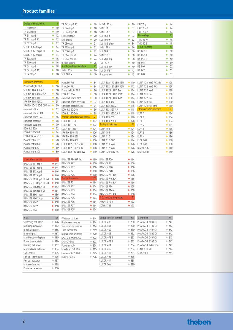
Product families
Digital time switches 9
TR 610 top2 ▶ 10TR 612 top2 ▶ 10TR 611 top2 ▶ 12TR 611 top2 RC ▶ 12TR 622 top2 ▶ 12SELEKTA 170 top2 ▶ 14SELEKTA 171 top2 RC ▶ 14SELEKTA 172 top2 ▶ 14TR 608 top2 ▶ 16TR 609 top2 ▶ 16TR 641 top2 ▶ 18TR 641 top2 RC ▶ 18TR 642 top2 ▶ 18
TR 642 top2 RC ▶ 18TR 644 top2 ▶ 18TR 644 top2 RC ▶ 18EM LAN top2 ▶ 20EM 4 top2 ▶ 20TR 030 top ▶ 21TR 635 top2 ▶ 22TR 636 top2 ▶ 22TR 684-1 top2 ▶ 24TR 684-2 top2 ▶ 24theben-eltimo ▶ 26Analogue time switches 29
SYN 160 a ▶ 30SUL 180 a ▶ 30
MEM 190 a ▶ 30SYN 151 h ▶ 32SYN 161 d ▶ 32SUL 181 d ▶ 32SUL 191 w ▶ 32SUL 188 g/hw ▶ 34SYN 169 s ▶ 36SUL 189 s ▶ 36SYN 269 h ▶ 38SUL 289 h/g ▶ 38TM 179 h ▶ 40SUL 189 hw ▶ 40SUL 285/2 T ▶ 42theben-timer ▶ 43
FRI 77 g ▶ 44FRI 77 h-2 ▶ 44FRI 77 g-2 ▶ 44Time relays 47
TM 345 M ▶ 48TM 345 B ▶ 48Hour counters 49
BZ 142-1 ▶ 50BZ 142-3 ▶ 50BZ 143-1 ▶ 50BZ 145 ▶ 50BZ 146 ▶ 52BZ 147 ▶ 52BZ 148 ▶ 52
Clock thermostats 143
RAMSES 811 top2 ▶ 144RAMSES 831 top2 ▶ 144RAMSES 812 top2 ▶ 146RAMSES 832 top2 ▶ 146RAMSES 813 top2 HF Set ▶ 148RAMSES 833 top2 HF Set ▶ 150RAMSES 816 top2 OT ▶ 152RAMSES 856 top2 OT ▶ 154RAMSES 366/1 top ▶ 156RAMSES 366/2 top ▶ 156RAMSES 784 S ▶ 158RAMSES 722 S ▶ 158RAMSES 784 ▶ 160
RAMSES 784 HF Set 1 ▶ 160RAMSES 722 ▶ 160RAMSES 782 ▶ 160RAMSES 721 ▶ 160RAMSES 725 ▶ 160Room thermostats 163
RAMSES 701 ▶ 164RAMSES 702 ▶ 164RAMSES 703 ▶ 164RAMSES 704 ▶ 164RAMSES 705 ▶ 164RAMSES 706 ▶ 164RAMSES 707 ▶ 164RAMSES 708 ▶ 164
RAMSES 709 ▶ 164RAMSES 741 ▶ 166RAMSES 746 ▶ 166RAMSES 748 ▶ 166RAMSES 741 RA ▶ 166RAMSES 746 RA ▶ 166RAMSES 748 RA ▶ 166RAMSES 714 ▶ 168RAMSES 714 A ▶ 168RAMSES 751 RA ▶ 168CO2 sensors, Hygrostat 171
AMUN 716 R ▶ 172SOTHIS 715 ▶ 173
KNX 175
Switching actuators ▶ 176Dimming actuators ▶ 182Blinds actuators ▶ 186Binary inputs ▶ 187Multifunction displays ▶ 189Room thermostats ▶ 190Heating actuators ▶ 192Motor-driven actuators ▶ 194CO2- sensor ▶ 195Fan coil thermostat ▶ 196Fan coil actuator ▶ 197Motion detectors ▶ 198Presence detectors ▶ 200
Weather stations ▶ 214Brightness sensors ▶ 214Temperature sensors ▶ 214Time tansmitter ▶ 219Digital time switches ▶ 220DALI Gateway KNX ▶ 222KNX-OT-Box ▶ 223Power supply ▶ 224Interface USB KNX ▶ 225Line coupler S KNX ▶ 225Indoor clocks ▶ 226
Living comfort control 229
LUXOR 400 ▶ 230LUXOR 404 ▶ 230LUXOR 402 ▶ 230LUXOR 405 ▶ 232LUXOR 408 S ▶ 233LUXOR 409 S ▶ 233LUXOR 411 ▶ 234LUXOR 412 ▶ 234LUXOR 413 ▶ 234LUXOR 426 ▶ 236LUXOR 414 ▶ 238LUXOR Sets ▶ 239
Controller 241
PHARAO-II 10 (AC) ▶ 242PHARAO-II 11 (DC) ▶ 242PHARAO-II 14 (AC) ▶ 242PHARAO-II 15 (DC) ▶ 242PHARAO-II 24 (AC) ▶ 242PHARAO-II 25 (DC) ▶ 242PHARAO-II extension ▶ 242LUNA 131 DDC ▶ 244SUD 228 II ▶ 244
Presence detectors 55
PresenceLight 360 ▶ 56SPHINX 104-360 AP ▶ 58SPHINX 104-360/2 AP ▶ 58SPHINX 104-360 ▶ 58SPHINX 104-360/2 ▶ 58SPHINX 104-360/2 DIM plus ▶ 60compact offi ce ▶ 62compact offi ce DIM ▶ 64compact offi ce DALI ▶ 66compact passage ▶ 68compact passimo ▶ 70ECO-IR 360A ▶ 72ECO-IR 360C NT ▶ 74ECO-IR DUAL-C NT ▶ 76PlanoCentro 101 ▶ 78PlanoCentro 000 ▶ 78PlanoCentro 201 ▶ 80PlanoCentro 300 ▶ 80
PlanoSet RQ ▶ 84PlanoSet RR ▶ 84PresenceLight 180 ▶ 86ECO-IR 180A ▶ 88compact offi ce 24V ▶ 90compact offi ce 24V Lux ▶ 92compact passage 24V ▶ 94ECO-IR 360-24V ▶ 96ECO-IR 180-24V ▶ 98Motion detectors/Spotlights 101
LUXA 101-150 ▶ 102LUXA 101-180 ▶ 102LUXA 101-360 ▶ 104SPHINX 105-110 ▶ 106SPHINX 105-220 ▶ 106SPHINX 105-300 ▶ 106LUXA 102-150/150W ▶ 108LUXA 102-150/500W ▶ 108LUXA 102-140 LED 8W ▶ 110
LUXA 102-140 LED 16W ▶ 110LUXA 102-180 LED 32W ▶ 112LUXA 102 FL LED 8W ▶ 114LUXA 102 FL LED 16W ▶ 114LUXA 102 FL LED 32W ▶ 114LUXA 103-360 ▶ 116LUXA 103-360/2 ▶ 116LUXA 103-360 AP ▶ 118LUXA 103-360/2 AP ▶ 118LUXA 103-200 ▶ 120LUXA 103-200 T ▶ 120Twilight switches 123
LUNA 108 ▶ 124LUNA 109 ▶ 124LUNA 110 ▶ 124LUNA 110 24V ▶ 124LUNA 111 top2 ▶ 126LUNA 112 top2 ▶ 126LUNA 121 top2 RC ▶ 128
LUNA 121 top2 RC 24V ▶ 128LUNA 122 top2 RC ▶ 128LUNA 120 top2 ▶ 128LUNA 126 star ▶ 130LUNA 127 star ▶ 130LUNA 128 star ▶ 130LUNA 129 star-time ▶ 130Staircase time switches 133
ELPA 1 ▶ 134ELPA 6 ▶ 134ELPA 3 ▶ 134ELPA 7 ▶ 134ELPA 8 ▶ 136ELPA 9 ▶ 136ELPA 4 ▶ 136ELPA 041 ▶ 138ELPA 047 ▶ 138DIMAX 532 ▶ 140DIMAX 534 ▶ 140
Catalogue_EN_2013.indb 2 16.01.13 17:17
3
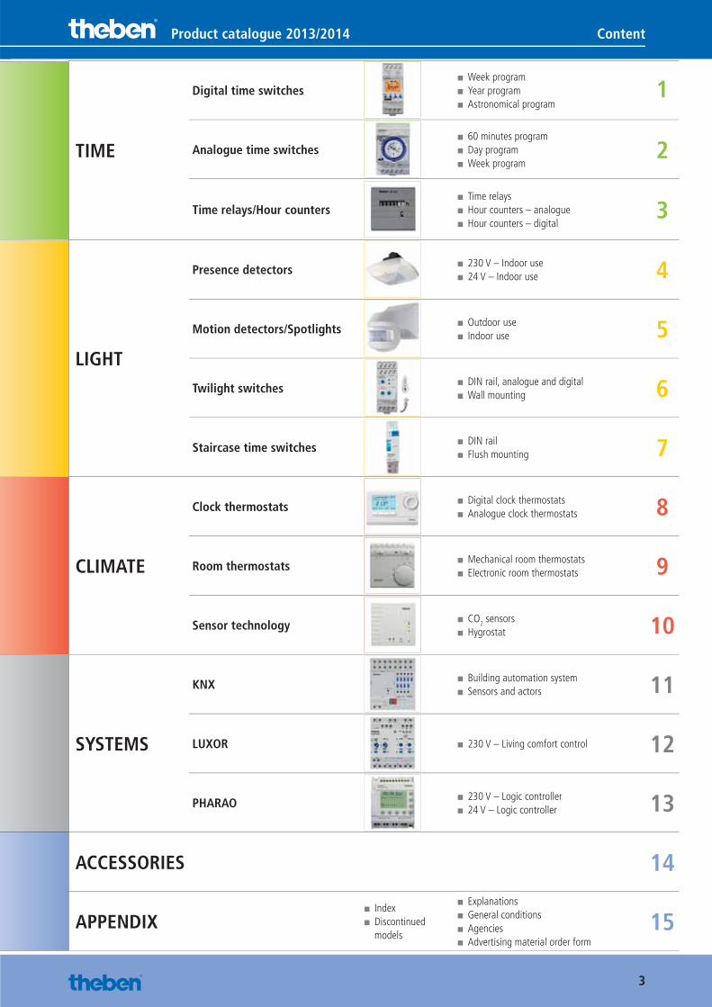
Product catalogue 2013/2014 Content
TIME
Digital time switches ■ Week program ■ Year program ■ Astronomical program
1
Analogue time switches ■ 60 minutes program ■ Day program ■ Week program
2
Time relays/Hour counters ■ Time relays ■ Hour counters – analogue ■ Hour counters – digital
3
LIGHT
Presence detectors ■ 230 V – Indoor use ■ 24 V – Indoor use 4
Motion detectors/Spotlights ■ Outdoor use ■ Indoor use 5
Twilight switches ■ DIN rail, analogue and digital ■ Wall mounting 6
Staircase time switches ■ DIN rail ■ Flush mounting 7
CLIMATE
Clock thermostats ■ Digital clock thermostats ■ Analogue clock thermostats 8
Room thermostats ■ Mechanical room thermostats ■ Electronic room thermostats 9
Sensor technology ■ CO2 sensors ■ Hygrostat 10
SYSTEMS
KNX ■ Building automation system ■ Sensors and actors 11
LUXOR ■ 230 V – Living comfort control 12
PHARAO ■ 230 V – Logic controller ■ 24 V – Logic controller 13
ACCESSORIES 14
APPENDIX ■ Index ■ Discontinued models
■ Explanations ■ General conditions ■ Agencies ■ Advertising material order form
15
Catalogue_EN_2013.indb 3 16.01.13 17:17

4
In the first decades after the company was founded in 1921, our core competence lay in solutions for time-switching devices. Very early on we got involved in the development of KNX technology and as a member of the "KNX Association" contributed significantly to the development of KNX into a global standard.
With four subsidiaries in Europe and more than 50 offices worldwide, today our focus is on intelligent, energy-saving solutions for building automation:
• Lighting control with dimming switches, presence and motion detectors.
• Climate control with analogue and digital timer thermostats for room temperature control.
• KNX components for building systems technology: from lighting and climate con-trol to fully automatic sun protection with weather station.
We are certified in accordance with DIN EN ISO 9001:2008 and have a testing labora-tory authorised by the VDE institute.
But our products don't just make a good im-pression technically: Our design also speaks for itself. For example, our multifunction display VARIA 826 KNX won the "red dot design award" and the presence detector PlanoCentro won the "iF product design award".
Thinking about the day after tomorrow, today.
Catalogue_EN_2013.indb 4 16.01.13 17:17

5
Introduction
Dear clients and partners,
In recent years the demands for energy-efficient and sustainable building control have increased enormously. Sophisticated customer requirements for safety, service and comfort also have to be fulfilled in every respect. By choosing Theben products you are opting not only for "Made in Germany" quality, but also a system provider with whom you can fulfil these demands now and in future. Simple installation, simple operation and the highest possible energy efficiency – Theben products represent all-round optimal solutions.
Energy efficiency and sustainability don't just play a central role in the Theben product range. Our company policy also follows these principles. More than 11 years ago, we installed photovoltaic systems in our buildings with a total output of now approx. 160 kWp. This alone saves us around 145 tonnes of CO2 annually. And our staff use electric cars for short journeys.
In 2013 we will again invest around 7 % of our revenue in product development. This allows us to go on offering you and your customers exactly the products and solutions you expect: management systems to control time, light and climate.
Here at Theben, we all look forward to continuing our excellent and co-operative working relationship.
Thomas Goes Chairman of the Board
Catalogue_EN_2013.indb 5 16.01.13 17:17

6
One call is all it takes: +49 7474 692-369
Or by E-mail: [email protected]
We are here to help you.
Catalogue_EN_2013.indb 6 16.01.13 17:17
DISTRIBUTIONTheben consistently pursues a three-stage approach to distribution via wholesale and retail outlets.
QUALITYTheben stands for the highest quality, gua-ranteed by rigorous fi nal testing.
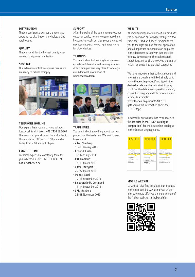
STORAGEOur extensive central warehouse means we are ready to deliver promptly.
TELEPHONE HOTLINEOur experts help you quickly and without fuss. A call is all it takes: +49 7474 692-369The team is at your disposal from Monday to Thursday from 7.00 am to 6.00 pm and on Friday from 7.00 am to 4.00 pm.
EMAIL HOTLINETechnical experts are constantly there for you. Ask for our CUSTOMER SERVICE [email protected]
SUPPORTAfter the expiry of the guarantee period, our customer service not only ensures rapid and inexpensive repair, but also sends the desired replacement parts to you right away – even for older devices.
TRAININGYou can fi nd central training from our own experts and decentralised training from our distribution partners very close to where you are. Additional information at www.theben.de/en
TRADE FAIRSYou can fi nd out everything about our new products at the trade fairs. We look forward to your visit:• eltec, Nürnberg
16–18 January 2013• E-world, Essen
7–9 February 2013• ISH, Frankfurt
12–16 March 2013• eltefa, Stuttgart
20–22 March 2013• ineltec, Basel
10–13 September 2013• Elektrotechnik, Dortmund
11–14 September 2013• SPS, Nürnberg
26–28 November 2013
WEBSITE
All important information about our products can be found on our website. With just a few clicks the "Product fi nder" function takes you to the right product for your application and all important documents can be placed in the document basket with just one click for easy downloading. The sophisticated search function quickly shows you the search results, arranged into practical categories.
We have made sure that both catalogue and internet are closely interlinked: simply go to www.theben.de/product/ and type in the desired article number and straightaway you'll get the data sheet, operating manual, connection diagram and lots more with just a click. An example: www.theben.de/product/6100103 gets you all the information about the TR 610 top2.
Incidentally, our website has twice received the 1st prize in the "INKA catalogue competition" for the best online catalogue in the German language area.
MOBILE WEBSITE
So you can also fi nd out about our products in the best possible way using your smart-phone, we now offer you a mobile version of the Theben website: m.theben.de/en
7
Service
Gesamtsiegerin der Kategorie Online:
Th eben AGwww.theben.de
Branchensieger „Maschinen/Geräte“in der Kategorie Online:
Th eben AGwww.theben.de
Ausgezeichneter Katalogin der Kategorie Print:
Th eben AGProduktkatalog 2011/2012
Catalogue_EN_2013.indb 7 16.01.13 17:17
8
TIME
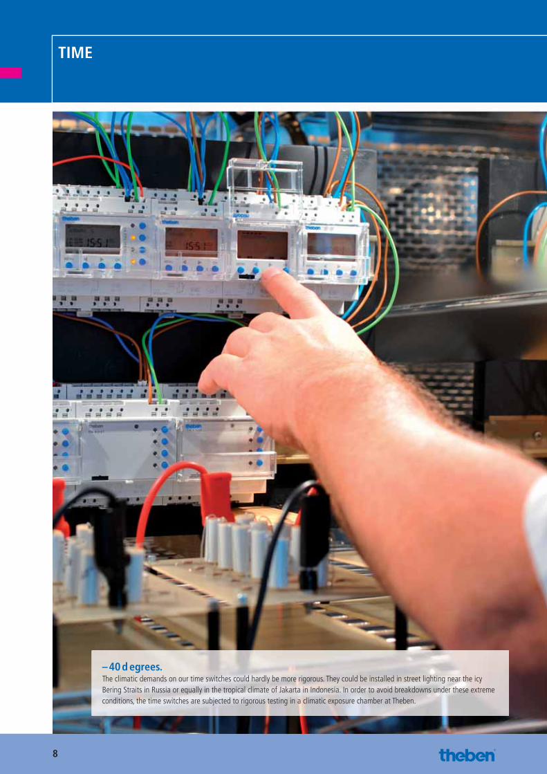
– 40 d egrees.The climatic demands on our time switches could hardly be more rigorous. They could be installed in street lighting near the icy Bering Straits in Russia or equally in the tropical climate of Jakarta in Indonesia. In order to avoid breakdowns under these extreme conditions, the time switches are subjected to rigorous testing in a climatic exposure chamber at Theben.
Catalogue_EN_2013.indb 8 16.01.13 17:18
9
Chapter summary
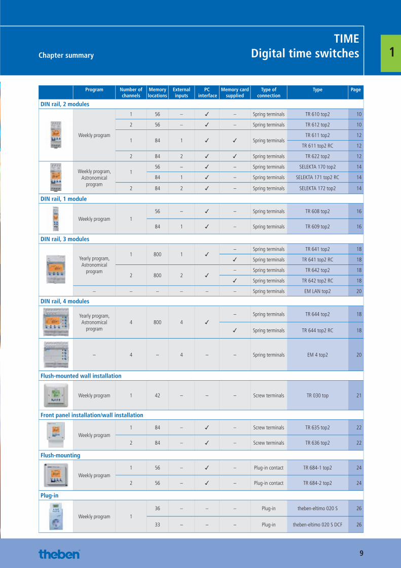
TIMEDigital time switches 1
Program Number of channels
Memory locations
External inputs
PC interface
Memory card supplied
Type of connection
Type Page
DIN rail, 2 modules
Weekly program
1 56 – ✓ – Spring terminals TR 610 top2 10
2 56 – ✓ – Spring terminals TR 612 top2 10
1 84 1 ✓ ✓ Spring terminalsTR 611 top2 12
TR 611 top2 RC 12
2 84 2 ✓ ✓ Spring terminals TR 622 top2 12
Weekly program, Astronomical
program
156 – ✓ – Spring terminals SELEKTA 170 top2 14
84 1 ✓ – Spring terminals SELEKTA 171 top2 RC 14
2 84 2 ✓ – Spring terminals SELEKTA 172 top2 14
DIN rail, 1 module
Weekly program 156 – ✓ – Spring terminals TR 608 top2 16
84 1 ✓ – Spring terminals TR 609 top2 16
DIN rail, 3 modules
Yearly program, Astronomical
program
1 800 1 ✓– Spring terminals TR 641 top2 18
✓ Spring terminals TR 641 top2 RC 18
2 800 2 ✓– Spring terminals TR 642 top2 18
✓ Spring terminals TR 642 top2 RC 18
– – – – – – Spring terminals EM LAN top2 20
DIN rail, 4 modules
Yearly program, Astronomical
program4 800 4 ✓
– Spring terminals TR 644 top2 18
✓ Spring terminals TR 644 top2 RC 18
– 4 – 4 – – Spring terminals EM 4 top2 20
Flush-mounted wall installation
Weekly program 1 42 – – – Screw terminals TR 030 top 21
Front panel installation/wall installation
Weekly program1 84 – ✓ – Screw terminals TR 635 top2 22
2 84 – ✓ – Screw terminals TR 636 top2 22
Flush-mounting
Weekly program1 56 – ✓ – Plug-in contact TR 684-1 top2 24
2 56 – ✓ – Plug-in contact TR 684-2 top2 24
Plug-in
Weekly program 1
36 – – – Plug-in theben-eltimo 020 S 26
33 – – – Plug-in theben-eltimo 020 S DCF 26
Catalogue_EN_2013.indb 9 16.01.13 17:18

10httpAdditional technical data at:
www.theben.de/product/ Article number
DIN rail, 2 modules TIMEDigital time switches
1Digital time switches with weekly program
TR 610 top2 TR 612 top2
Description
Common functions
■ Digital time switch with weekly program ■ Spring terminals ■ Text-oriented user guidance in display ■ 56 memory locations ■ Interface for OBELISK top2 memory card (PC programming)
■ 10 year power reserve (lithium battery)
■ Zero-cross switching for relay-saving switching and high lamp loads (not with 24 V devices)
■ ON-OFF switching times ■ Switching preselection ■ Permanent switching ON/OFF ■ Integrated operating hour counter ■ Holiday program ■ Display back light (can be turned off)
■ PIN coding ■ Automatic summer/winter time changeover
TR 610 top2
■ 1 channel
TR 612 top2
■ 2 channel
Product selection
Program Program-functions
Number of channels Switching load < 1 mA
Operating voltage Type Article number
Weekly program ON/OFF
1
– 230–240 V AC TR 610 top2 61001031)
✓ 230–240 V AC TR 610 top2 G 6100110
– 12–24 V UC TR 610 top2 24V 6104100
2 –230–240 V AC TR 612 top2 6120103 1)
12–24 V UC TR 612 top2 24V 6124100
1) Languages: GB, E, F, P, D (other article numbers with additional languages on request)
Catalogue_EN_2013.indb 10 16.01.13 17:18
11httpAdditional technical data at:
www.theben.de/product/ Article number
DIN rail, 2 modulesTIMEDigital time switches
1
Technical data
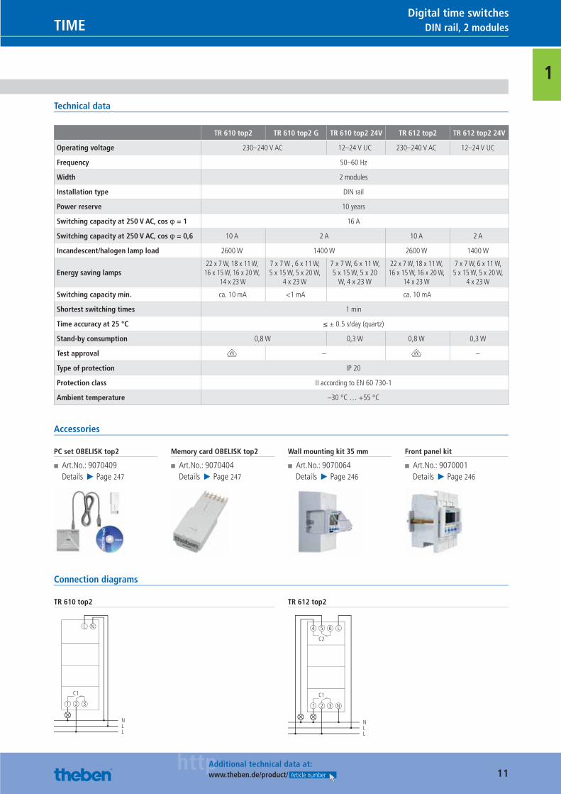
TR 610 top2 TR 610 top2 G TR 610 top2 24V TR 612 top2 TR 612 top2 24V
Operating voltage 230–240 V AC 12–24 V UC 230–240 V AC 12–24 V UC
Frequency 50–60 Hz
Width 2 modules
Installation type DIN rail
Power reserve 10 years
Switching capacity at 250 V AC, cos φ = 1 16 A
Switching capacity at 250 V AC, cos φ = 0,6 10 A 2 A 10 A 2 A
Incandescent/halogen lamp load 2600 W 1400 W 2600 W 1400 W
Energy saving lamps22 x 7 W, 18 x 11 W,
16 x 15 W, 16 x 20 W, 14 x 23 W
7 x 7 W , 6 x 11 W, 5 x 15 W, 5 x 20 W,
4 x 23 W
7 x 7 W, 6 x 11 W, 5 x 15 W, 5 x 20
W, 4 x 23 W
22 x 7 W, 18 x 11 W, 16 x 15 W, 16 x 20 W,
14 x 23 W
7 x 7 W, 6 x 11 W, 5 x 15 W, 5 x 20 W,
4 x 23 W
Switching capacity min. ca. 10 mA <1 mA ca. 10 mA
Shortest switching times 1 min
Time accuracy at 25 °C ≤ ± 0.5 s/day (quartz)
Stand-by consumption 0,8 W 0,3 W 0,8 W 0,3 W
Test approval V – V –
Type of protection IP 20
Protection class II according to EN 60 730-1
Ambient temperature –30 °C … +55 °C
Accessories
PC set OBELISK top2
■ Art.No.: 9070409Details ▶ Page 247
Memory card OBELISK top2
■ Art.No.: 9070404Details ▶ Page 247
Wall mounting kit 35 mm
■ Art.No.: 9070064Details ▶ Page 246
Front panel kit
■ Art.No.: 9070001Details ▶ Page 246
Connection diagrams
TR 610 top2
C1
1 2 3
L N
NLL
TR 612 top2
C2
C1
1 2 3
4 5 6 L
NLL
N
Catalogue_EN_2013.indb 11 16.01.13 17:18
12httpAdditional technical data at:
www.theben.de/product/ Article number
DIN rail, 2 modules TIMEDigital time switches
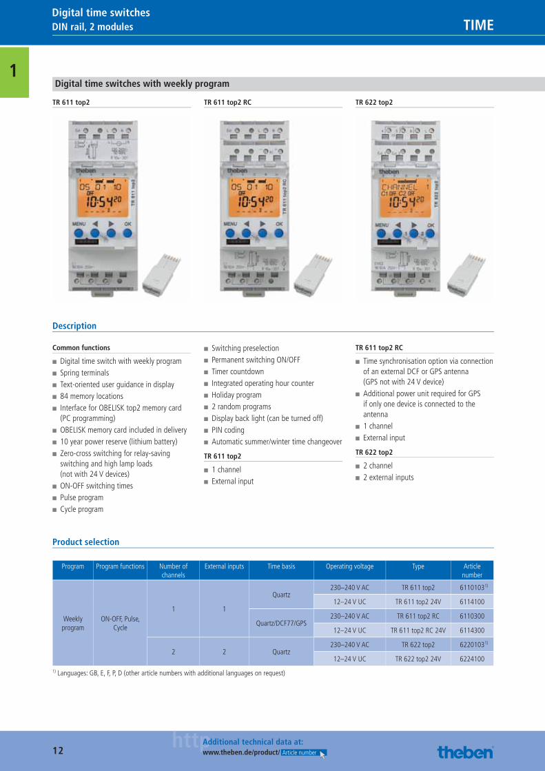
1Digital time switches with weekly program
TR 611 top2 TR 611 top2 RC TR 622 top2
Description
Common functions
■ Digital time switch with weekly program ■ Spring terminals ■ Text-oriented user guidance in display ■ 84 memory locations ■ Interface for OBELISK top2 memory card (PC programming)
■ OBELISK memory card included in delivery ■ 10 year power reserve (lithium battery) ■ Zero-cross switching for relay-saving switching and high lamp loads (not with 24 V devices)
■ ON-OFF switching times ■ Pulse program ■ Cycle program
■ Switching preselection ■ Permanent switching ON/OFF ■ Timer countdown ■ Integrated operating hour counter ■ Holiday program ■ 2 random programs ■ Display back light (can be turned off) ■ PIN coding ■ Automatic summer/winter time changeover
TR 611 top2
■ 1 channel ■ External input
TR 611 top2 RC
■ Time synchronisation option via connection of an external DCF or GPS antenna (GPS not with 24 V device)
■ Additional power unit required for GPS if only one device is connected to the antenna
■ 1 channel ■ External input
TR 622 top2
■ 2 channel ■ 2 external inputs
Product selection
Program Program functions Number of channels
External inputs Time basis Operating voltage Type Article number
Weekly program
ON-OFF, Pulse, Cycle
1 1
Quartz230–240 V AC TR 611 top2 6110103 1)
12–24 V UC TR 611 top2 24V 6114100
Quartz/DCF77/GPS230–240 V AC TR 611 top2 RC 6110300
12–24 V UC TR 611 top2 RC 24V 6114300
2 2 Quartz230–240 V AC TR 622 top2 62201031)
12–24 V UC TR 622 top2 24V 6224100
1) Languages: GB, E, F, P, D (other article numbers with additional languages on request)
Catalogue_EN_2013.indb 12 16.01.13 17:18
13httpAdditional technical data at:
www.theben.de/product/ Article number
DIN rail, 2 modulesTIMEDigital time switches
1
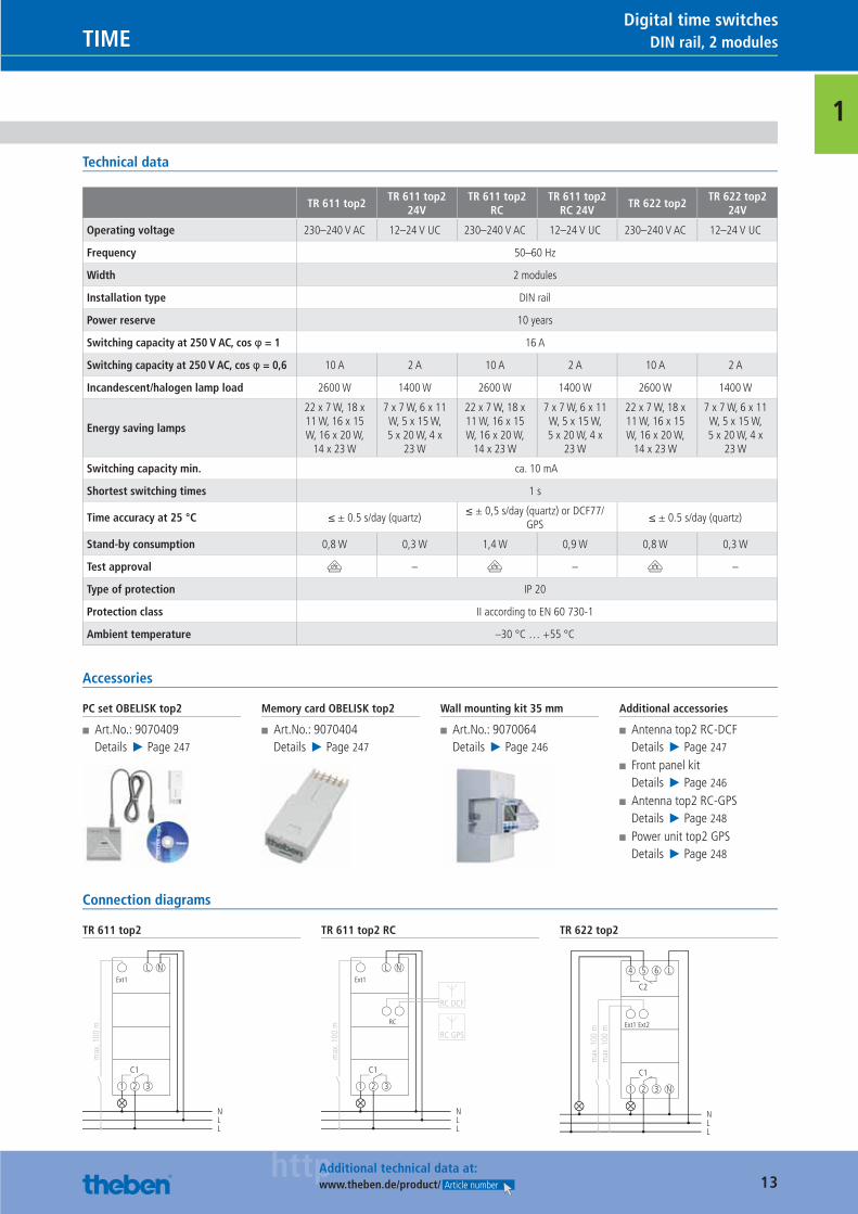
Technical data
TR 611 top2TR 611 top2
24VTR 611 top2
RCTR 611 top2
RC 24VTR 622 top2
TR 622 top2 24V
Operating voltage 230–240 V AC 12–24 V UC 230–240 V AC 12–24 V UC 230–240 V AC 12–24 V UC
Frequency 50–60 Hz
Width 2 modules
Installation type DIN rail
Power reserve 10 years
Switching capacity at 250 V AC, cos φ = 1 16 A
Switching capacity at 250 V AC, cos φ = 0,6 10 A 2 A 10 A 2 A 10 A 2 A
Incandescent/halogen lamp load 2600 W 1400 W 2600 W 1400 W 2600 W 1400 W
Energy saving lamps
22 x 7 W, 18 x 11 W, 16 x 15 W, 16 x 20 W,
14 x 23 W
7 x 7 W, 6 x 11 W, 5 x 15 W, 5 x 20 W, 4 x
23 W
22 x 7 W, 18 x 11 W, 16 x 15 W, 16 x 20 W,
14 x 23 W
7 x 7 W, 6 x 11 W, 5 x 15 W, 5 x 20 W, 4 x
23 W
22 x 7 W, 18 x 11 W, 16 x 15 W, 16 x 20 W,
14 x 23 W
7 x 7 W, 6 x 11 W, 5 x 15 W, 5 x 20 W, 4 x
23 W
Switching capacity min. ca. 10 mA
Shortest switching times 1 s
Time accuracy at 25 °C ≤ ± 0.5 s/day (quartz)≤ ± 0,5 s/day (quartz) or DCF77/
GPS≤ ± 0.5 s/day (quartz)
Stand-by consumption 0,8 W 0,3 W 1,4 W 0,9 W 0,8 W 0,3 W
Test approval V – V – V –
Type of protection IP 20
Protection class II according to EN 60 730-1
Ambient temperature –30 °C … +55 °C
Accessories
PC set OBELISK top2
■ Art.No.: 9070409Details ▶ Page 247
Memory card OBELISK top2
■ Art.No.: 9070404Details ▶ Page 247
Wall mounting kit 35 mm
■ Art.No.: 9070064Details ▶ Page 246
Additional accessories
■ Antenna top2 RC-DCFDetails ▶ Page 247
■ Front panel kitDetails ▶ Page 246
■ Antenna top2 RC-GPSDetails ▶ Page 248
■ Power unit top2 GPSDetails ▶ Page 248
Connection diagrams
TR 611 top2
C1
1 2 3
L N
NLL
Ext1
max
. 100
m
TR 611 top2 RC
C1
1 2 3
L N
NLL
Ext1
max
. 100
m
RC
RC DCF
RC GPS
TR 622 top2
C2
C1
1 2 3
4 5 6 L
NLL
Ext1
max
. 100
mm
ax. 1
00 m
Ext2
N
Catalogue_EN_2013.indb 13 16.01.13 17:18
14httpAdditional technical data at:
www.theben.de/product/ Article number
DIN rail, 2 modules TIMEDigital time switches
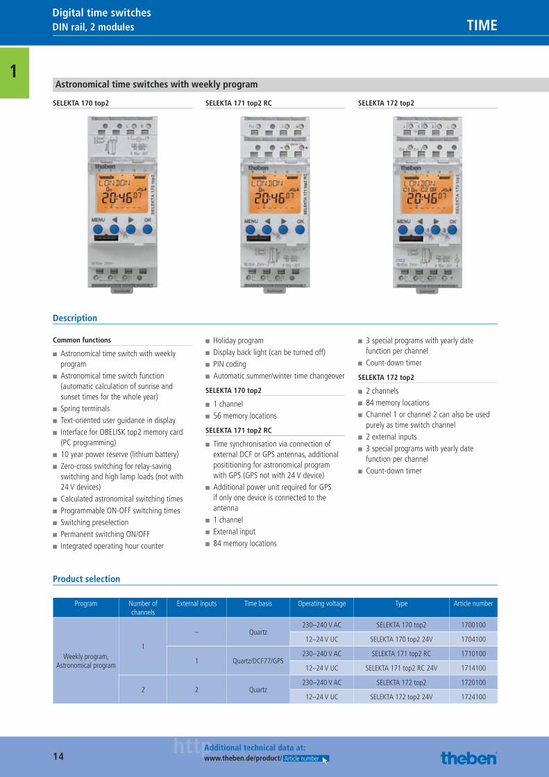
1Astronomical time switches with weekly program
SELEKTA 170 top2 SELEKTA 171 top2 RC SELEKTA 172 top2
Description
Common functions
■ Astronomical time switch with weekly program
■ Astronomical time switch function (automatic calculation of sunrise and sunset times for the whole year)
■ Spring terminals ■ Text-oriented user guidance in display ■ Interface for OBELISK top2 memory card (PC programming)
■ 10 year power reserve (lithium battery) ■ Zero-cross switching for relay-saving switching and high lamp loads (not with 24 V devices)
■ Calculated astronomical switching times ■ Programmable ON-OFF switching times ■ Switching preselection ■ Permanent switching ON/OFF ■ Integrated operating hour counter
■ Holiday program ■ Display back light (can be turned off) ■ PIN coding ■ Automatic summer/winter time changeover
SELEKTA 170 top2
■ 1 channel ■ 56 memory locations
SELEKTA 171 top2 RC
■ Time synchronisation via connection of external DCF or GPS antennas, additional posititioning for astronomical program with GPS (GPS not with 24 V device)
■ Additional power unit required for GPS if only one device is connected to the antenna
■ 1 channel ■ External input ■ 84 memory locations
■ 3 special programs with yearly date function per channel
■ Count-down timer
SELEKTA 172 top2
■ 2 channels ■ 84 memory locations ■ Channel 1 or channel 2 can also be used purely as time switch channel
■ 2 external inputs ■ 3 special programs with yearly date function per channel
■ Count-down timer
Product selection
Program Number of channels
External inputs Time basis Operating voltage Type Article number
Weekly program, Astronomical program
1
– Quartz230–240 V AC SELEKTA 170 top2 1700100
12–24 V UC SELEKTA 170 top2 24V 1704100
1 Quartz/DCF77/GPS230–240 V AC SELEKTA 171 top2 RC 1710100
12–24 V UC SELEKTA 171 top2 RC 24V 1714100
2 2 Quartz230–240 V AC SELEKTA 172 top2 1720100
12–24 V UC SELEKTA 172 top2 24V 1724100
Catalogue_EN_2013.indb 14 16.01.13 17:18

15httpAdditional technical data at:
www.theben.de/product/ Article number
DIN rail, 2 modulesTIMEDigital time switches
1
Technical data
SELEKTA 170 top2
SELEKTA 170 top2 24V
SELEKTA 171 top2 RC
SELEKTA 171 top2 RC 24V
SELEKTA 172 top2
SELEKTA 172 top2 24V
Operating voltage 230–240 V AC 12–24 V UC 230–240 V AC 12–24 V UC 230–240 V AC 12–24 V UC
Frequency 50–60 Hz
Width 2 modules
Installation type DIN rail
Power reserve 10 years
Switching capacity at 250 V AC, cos φ = 1 16 A
Switching capacity at 250 V AC, cos φ = 0,6 10 A 2 A 10 A 2 A 10 A 2 A
Incandescent/halogen lamp load 2600 W 1400 W 2600 W 1400 W 2600 W 1400 W
Energy saving lamps
22 x 7 W, 18 x 11 W, 16 x 15 W, 16 x 20 W, 14 x 23 W
7 x 7 W, 6 x 11 W, 5 x 15 W, 5 x 20 W,
4 x 23 W
22 x 7 W, 18 x 11 W, 16 x 15 W, 16 x 20 W, 14 x 23 W
7 x 7 W, 6 x 11 W, 5 x 15 W, 5 x 20 W,
4 x 23 W
22 x 7 W, 18 x 11 W, 16 x 15 W, 16 x 20 W, 14 x 23 W
7 x 7 W, 6 x 11 W, 5 x 15 W, 5 x 20 W,
4 x 23 W
Switching capacity min. ca. 10 mA
Shortest switching times 1 min
Time accuracy at 25 °C ≤ ± 0.5 s/day (quartz)≤ ± 0,5 s/day (quartz) or
DCF77/GPS≤ ± 0.5 s/day (quartz)
Stand-by consumption 0,8 W 0,2 W 1,4 W 0,8 W 0,2 W
Test approval V – V – V –
Type of protection IP 20
Protection class II according to EN 60 730-1
Ambient temperature –30 °C … +55 °C
Accessories
PC set OBELISK top2
■ Art.No.: 9070409Details ▶ Page 247
Memory card OBELISK top2
■ Art.No.: 9070404Details ▶ Page 247
Wall mounting kit 35 mm
■ Art.No.: 9070064Details ▶ Page 246
Additional accessories
■ Front panel kitDetails ▶ Page 246
■ Antenna top2 RC-DCFDetails ▶ Page 247
■ Antenna top2 RC-GPSDetails ▶ Page 248
■ Power unit top2 GPSDetails ▶ Page 248
Connection diagrams
SELEKTA 170 top2
C1
1 2 3
NLL
L N
SELEKTA 171 top2 RC
C1
1 2 3
NLL
L N
– +
Ext1
max
. 100
m
Data
RC DCF
RC GPS
SELEKTA 172 top2
C2
C1
1 2 3
4 5 6 L
NLL
Ext1
max
. 100
mm
ax. 1
00 m
Ext2
N
Catalogue_EN_2013.indb 15 16.01.13 17:18
16httpAdditional technical data at:
www.theben.de/product/ Article number
DIN rail, 1 module TIMEDigital time switches
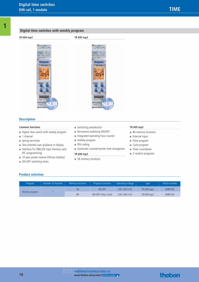
1Digital time switches with weekly program
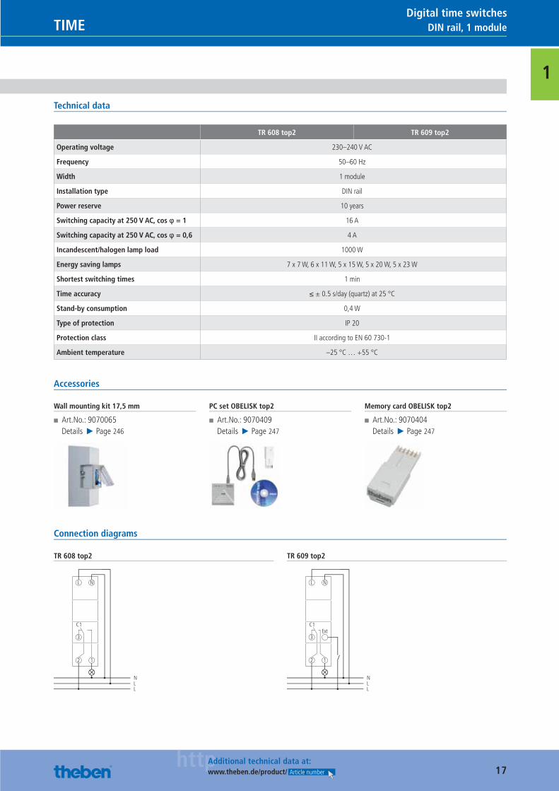
TR 608 top2 TR 609 top2
Description
Common functions
■ Digital time switch with weekly program ■ 1 channel ■ Spring terminals ■ Text-oriented user guidance in display ■ Interface for OBELISK top2 memory card (PC programming)
■ 10 year power reserve (lithium battery) ■ ON-OFF switching times
■ Switching preselection ■ Permanent switching ON/OFF ■ Integrated operating hour counter ■ Holiday program ■ PIN coding ■ Automatic summer/winter time changeover
TR 608 top2
■ 56 memory locations
TR 609 top2
■ 84 memory locations ■ External input ■ Pulse program ■ Cycle program ■ Timer countdown ■ 2 random programs
Product selection
Program Number of channels Memory locations Program functions Operating voltage Type Article number
Weekly program 156 ON-OFF 230–240 V AC TR 608 top2 6080100
84 ON-OFF, Pulse, Cycle 230–240 V AC TR 609 top2 6090100
NEW NEW
Catalogue_EN_2013.indb 16 16.01.13 17:18
17httpAdditional technical data at:
www.theben.de/product/ Article number
DIN rail, 1 moduleTIMEDigital time switches
1
Technical data
TR 608 top2 TR 609 top2
Operating voltage 230–240 V AC
Frequency 50–60 Hz
Width 1 module
Installation type DIN rail
Power reserve 10 years
Switching capacity at 250 V AC, cos φ = 1 16 A
Switching capacity at 250 V AC, cos φ = 0,6 4 A
Incandescent/halogen lamp load 1000 W
Energy saving lamps 7 x 7 W, 6 x 11 W, 5 x 15 W, 5 x 20 W, 5 x 23 W
Shortest switching times 1 min
Time accuracy ≤ ± 0.5 s/day (quartz) at 25 °C
Stand-by consumption 0,4 W
Type of protection IP 20
Protection class II according to EN 60 730-1
Ambient temperature –25 °C … +55 °C
Accessories
Wall mounting kit 17,5 mm
■ Art.No.: 9070065Details ▶ Page 246
PC set OBELISK top2
■ Art.No.: 9070409Details ▶ Page 247
Memory card OBELISK top2
■ Art.No.: 9070404Details ▶ Page 247
Connection diagrams
TR 608 top2
2
C1
3
1
L N
NLL
TR 609 top2
2
3
1
L N
NLL
C1Ext
Catalogue_EN_2013.indb 17 16.01.13 17:18
18httpAdditional technical data at:
www.theben.de/product/ Article number
DIN rail, 3 modules, 4 modules TIMEDigital time switches
1Digital time switches with yearly and astronomical program
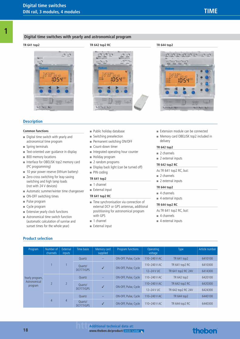
TR 641 top2 TR 642 top2 RC TR 644 top2
Description
Common functions
■ Digital time switch with yearly and astronomical time program
■ Spring terminals ■ Text-oriented user guidance in display ■ 800 memory locations ■ Interface for OBELISK top2 memory card (PC programming)
■ 10 year power reserve (lithium battery) ■ Zero-cross switching for leay-saving switching and high lamp loads (not with 24 V devices)
■ Automatic summer/winter time changeover ■ ON-OFF switching times ■ Pulse program ■ Cycle program ■ Extensive yearly clock functions ■ Astronomical time switch function (automatic calculation of sunrise and sunset times for the whole year)
■ Public holiday database ■ Switching preselection ■ Permanent switching ON/OFF ■ Count-down timer ■ Integrated operating hour counter ■ Holiday program ■ 2 random programs ■ Display back light (can be turned off) ■ PIN coding
TR 641 top2
■ 1 channel ■ External input
TR 641 top2 RC
■ Time synchronisation via connection of external DCF or GPS antennas, additional posititioning for astronomical program with GPS
■ 1 channel ■ External input
■ Extension module can be connected ■ Memory card OBELISK top2 included in delivery
TR 642 top2
■ 2 channels ■ 2 external inputs
TR 642 top2 RC
As TR 641 top2 RC, but: ■ 2 channels ■ 2 external inputs
TR 644 top2
■ 4 channels ■ 4 external inputs
TR 644 top2 RC
As TR 641 top2 RC, but: ■ 4 channels ■ 4 external inputs
Product selection
Program Number of channels
External inputs
Time basis Memory card supplied
Program functions Operating voltage
Type Article number
Yearly program, Astronomical
program
1 1
Quartz – ON-OFF, Pulse, Cycle 110–240 V AC TR 641 top2 6410100
Quartz/DCF77/GPS
✓ ON-OFF, Pulse, Cycle110–240 V AC TR 641 top2 RC 6410300
12–24 V UC TR 641 top2 RC 24V 6414300
2 2
Quartz – ON-OFF, Pulse, Cycle 110–240 V AC TR 642 top2 6420100
Quartz/DCF77/GPS
✓ ON-OFF, Pulse, Cycle110–240 V AC TR 642 top2 RC 6420300
12–24 V UC TR 642 top2 RC 24V 6424300
4 4Quartz – ON-OFF, Pulse, Cycle 110–240 V AC TR 644 top2 6440100
Quartz/DCF77/GPS
✓ ON-OFF, Pulse, Cycle 110–240 V AC TR 644 top2 RC 6440300
Catalogue_EN_2013.indb 18 16.01.13 17:18
19httpAdditional technical data at:
www.theben.de/product/ Article number
DIN rail, 3 modules, 4 modulesTIMEDigital time switches
1
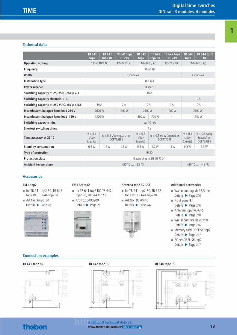
Technical data
TR 641 top2
TR 641 top2 RC
TR 641 top2 RC 24V
TR 642 top2
TR 642 top2 RC
TR 642 top2 RC 24V
TR 644 top2
TR 644 top2 RC
Operating voltage 110–240 V AC 12–24 V UC 110–240 V AC 12–24 V UC 110–240 V AC
Frequency 50–60 Hz
Width 3 modules 4 modules
Installation type DIN rail
Power reserve 8 years
Switching capacity at 250 V AC, cos φ = 1 16 A
Switching capacity channels 1+3 – 10 A
Switching capacity at 250 V AC, cos φ = 0,6 10 A 2 A 10 A 2 A 10 A
Incandescent/halogen lamp load 230 V 2600 W 1400 W 2600 W 1400 W 2300 W
Incandescent/halogen lamp load 120 V 1300 W – 1300 W 700 W – 1150 W
Switching capacity min. ca. 10 mA
Shortest switching times 1 s
Time accuracy at 25 °C≤ ± 0.5
s/day (quartz)
≤ ± 0,5 s/day (quartz) or DCF77/GPS
≤ ± 0.5 s/day
(quartz)
≤ ± 0,5 s/day (quartz) or DCF77/GPS
≤ ± 0.5 s/day
(quartz)
≤ ± 0,5 s/day (quartz) or DCF77/GPS
Stand-by consumption 0,6 W 1,2 W 1,5 W 0,6 W 1,2 W 1,5 W 0,5 W 1,3 W
Type of protection IP 20
Protection class II according to EN 60 730-1
Ambient temperature –30 °C … +55 °C –30 °C … +45 °C
Accessories
EM 4 top2
■ for TR 641 top2 RC, TR 642 top2 RC, TR 644 top2 RC
■ Art.No.: 6490104Details ▶ Page 20
EM LAN top2
■ for TR 641 top2 RC, TR 642 top2 RC, TR 644 top2 RC
■ Art.No.: 6490900Details ▶ Page 20
Antenna top2 RC-DCF
■ for TR 641 top2 RC, TR 642 top2 RC, TR 644 top2 RC
■ Art.No.: 9070410Details ▶ Page 247
Additional accessories
■ Wall mounting kit 52,5 mmDetails ▶ Page 246
■ Front panel kitDetails ▶ Page 246
■ Antenna top2 RC-GPSDetails ▶ Page 248
■ Wall mounting kit 70 mmDetails ▶ Page 246
■ Memory card OBELISK top2Details ▶ Page 247
■ PC set OBELISK top2Details ▶ Page 247
Connection examples
TR 641 top2 RC
C1
1 2 3
NLL
L N
Ext1
max
. 100
m
Data
RC DCF
EM 4top2
EM LANtop2
RC GPS
TR 642 top2 RC
C2
C1
1 2 3
4 5 6
NLL
L N
Ext1
max
. 100
mm
ax. 1
00 m
Ext2 Data
RC DCF
EM 4top2
EM LANtop2
RC GPS
TR 644 top2 RC
C2 C4
C1
1 2 3 7 8 9
4 5 6 10 11 12
NLL
C3
L N
Ext1
max
. 100
mm
ax. 1
00 m
max
. 100
mm
ax. 1
00 m
Ext2 Ext3 Ext4 Data
RC DCF
EM 4top2
EM LANtop2
RC GPS
Catalogue_EN_2013.indb 19 16.01.13 17:18
20httpAdditional technical data at:
www.theben.de/product/ Article number
DIN rail, 3 modules, 4 modules TIMEDigital time switches
1Extension modules
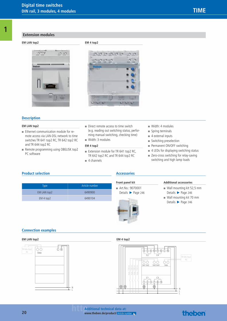
EM LAN top2 EM 4 top2
Description
EM LAN top2
■ Ethernet communication module for re-mote access via LAN-DSL network to time switches TR 641 top2 RC, TR 642 top2 RC and TR 644 top2 RC
■ Remote programming using OBELISK top2 PC software
■ Direct remote access to time switch (e.g. reading out switching status, perfor-ming manual switching, checking time)
■ Width: 3 modules
EM 4 top2
■ Extension module for TR 641 top2 RC, TR 642 top2 RC and TR 644 top2 RC
■ 4 channels
■ Width: 4 modules ■ Spring terminals ■ 4 external inputs ■ Switching preselection ■ Permanent ON/OFF switching ■ 4 LEDs for displaying switching status ■ Zero-cross switching for relay-saving switching and high lamp loads
Product selection
Type Article number
EM LAN top2 6490900
EM 4 top2 6490104
Accessories
Front panel kit
■ Art.No.: 9070001Details ▶ Page 246
Additional accessories
■ Wall mounting kit 52,5 mmDetails ▶ Page 246
■ Wall mounting kit 70 mmDetails ▶ Page 246
Connection examples
EM LAN top2
Data
NL
L NTR 64x top2 RC
EM 4 top2
C2 C4
C1
1 2 3 7 8 9
4 5 6 10 11 12
NLL
C3
L N
Ext1
max
. 100
mm
ax. 1
00 m
max
. 100
mm
ax. 1
00 m
Ext2 Ext3 Ext4 Data
TR 64x top2 RC
Catalogue_EN_2013.indb 20 16.01.13 17:18
21httpAdditional technical data at:
www.theben.de/product/ Article number
Flush-mounted wall installationTIMEDigital time switches
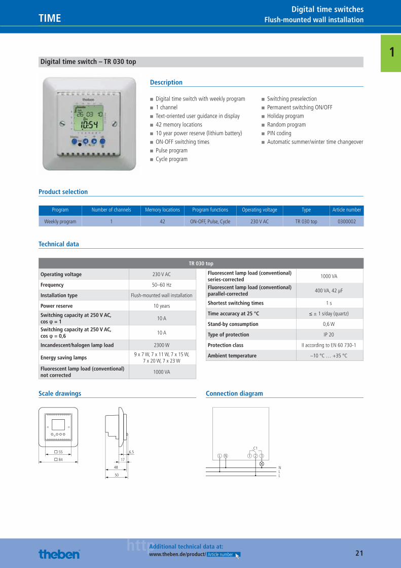
1Digital time switch – TR 030 top
Description
■ Digital time switch with weekly program ■ 1 channel ■ Text-oriented user guidance in display ■ 42 memory locations ■ 10 year power reserve (lithium battery) ■ ON-OFF switching times ■ Pulse program ■ Cycle program
■ Switching preselection ■ Permanent switching ON/OFF ■ Holiday program ■ Random program ■ PIN coding ■ Automatic summer/winter time changeover
Product selection
Program Number of channels Memory locations Program functions Operating voltage Type Article number
Weekly program 1 42 ON-OFF, Pulse, Cycle 230 V AC TR 030 top 0300002
Technical data
TR 030 top
Operating voltage 230 V AC
Frequency 50–60 Hz
Installation type Flush-mounted wall installation
Power reserve 10 years
Switching capacity at 250 V AC, cos φ = 1
10 A
Switching capacity at 250 V AC, cos φ = 0,6
10 A
Incandescent/halogen lamp load 2300 W
Energy saving lamps9 x 7 W, 7 x 11 W, 7 x 15 W,
7 x 20 W, 7 x 23 WFluorescent lamp load (conventional) not corrected
1000 VA
Fluorescent lamp load (conventional) series-corrected
1000 VA
Fluorescent lamp load (conventional) parallel-corrected
400 VA, 42 μF
Shortest switching times 1 s
Time accuracy at 25 °C ≤ ± 1 s/day (quartz)
Stand-by consumption 0,6 W
Type of protection IP 20
Protection class II according to EN 60 730-1
Ambient temperature –10 °C … +35 °C
Scale drawings
� 55
� 84
50
48
17
6,5
Connection diagram
NLL
L N
C1
1 2 3
Catalogue_EN_2013.indb 21 16.01.13 17:18
22httpAdditional technical data at:
www.theben.de/product/ Article number
Front panel installation/wall installation TIMEDigital time switches
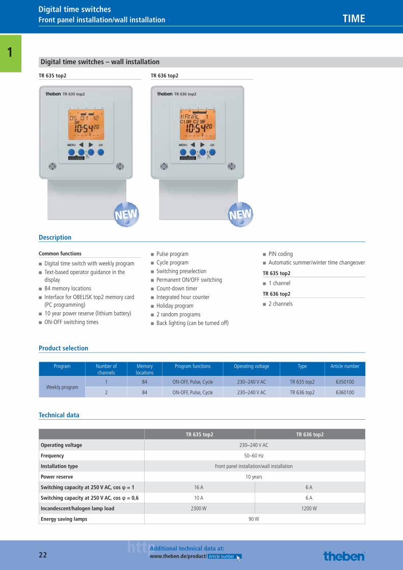
1Digital time switches – wall installation
TR 635 top2 TR 636 top2
Description
Common functions
■ Digital time switch with weekly program ■ Text-based operator guidance in the display
■ 84 memory locations ■ Interface for OBELISK top2 memory card (PC programming)
■ 10 year power reserve (lithium battery) ■ ON-OFF switching times
■ Pulse program ■ Cycle program ■ Switching preselection ■ Permanent ON/OFF switching ■ Count-down timer ■ Integrated hour counter ■ Holiday program ■ 2 random programs ■ Back lighting (can be turned off)
■ PIN coding ■ Automatic summer/winter time changeover
TR 635 top2
■ 1 channel
TR 636 top2
■ 2 channels
Product selection
Program Number of channels
Memory locations
Program functions Operating voltage Type Article number
Weekly program1 84 ON-OFF, Pulse, Cycle 230–240 V AC TR 635 top2 6350100
2 84 ON-OFF, Pulse, Cycle 230–240 V AC TR 636 top2 6360100
Technical data
TR 635 top2 TR 636 top2
Operating voltage 230–240 V AC
Frequency 50–60 Hz
Installation type Front panel installation/wall installation
Power reserve 10 years
Switching capacity at 250 V AC, cos φ = 1 16 A 6 A
Switching capacity at 250 V AC, cos φ = 0,6 10 A 6 A
Incandescent/halogen lamp load 2300 W 1200 W
Energy saving lamps 90 W
NEW NEW
Catalogue_EN_2013.indb 22 16.01.13 17:18
23httpAdditional technical data at:
www.theben.de/product/ Article number
Front panel installation/wall installationTIMEDigital time switches
1
TR 635 top2 TR 636 top2
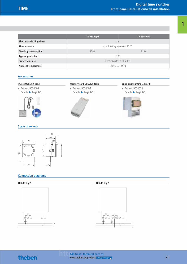
Shortest switching times 1 s
Time accuracy ≤ ± 0.5 s/day (quartz) at 25 °C
Stand-by consumption 0,9 W 1,1 W
Type of protection IP 20
Protection class II according to EN 60 730-1
Ambient temperature –30 °C … +55 °C
Accessories
PC set OBELISK top2
■ Art.No.: 9070409Details ▶ Page 247
Memory card OBELISK top2
■ Art.No.: 9070404Details ▶ Page 247
Snap-on mounting 72 x 72
■ Art.No.: 9070071Details ▶ Page 247
Scale drawings
104 �
66
72
72
65 25
16
54
69
Connection diagrams
TR 635 top2
C1
1 2 3
NLL
5 6
TR 636 top2
C1
1 2 3 4 5 6
NLL
C2
7 8
Catalogue_EN_2013.indb 23 16.01.13 17:18
24httpAdditional technical data at:
www.theben.de/product/ Article number
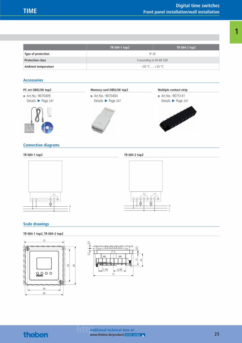
Front panel installation/wall installation TIMEDigital time switches
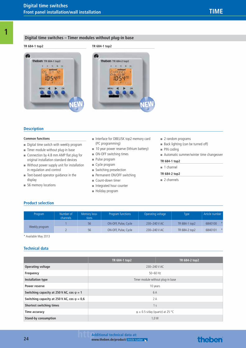
1Digital time switches – Timer modules without plug-in base
TR 684-1 top2 TR 684-1 top2
Description
Common functions
■ Digital time switch with weekly program ■ Timer module without plug-in base ■ Connection by 4.8 mm AMP fl at plug for original installation standard devices
■ Without power supply unit for installation in regulation and control
■ Text-based operator guidance in the display
■ 56 memory locations
■ Interface for OBELISK top2 memory card (PC programming)
■ 10 year power reserve (lithium battery) ■ ON-OFF switching times ■ Pulse program ■ Cycle program ■ Switching preselection ■ Permanent ON/OFF switching ■ Count-down timer ■ Integrated hour counter ■ Holiday program
■ 2 random programs ■ Back lighting (can be turned off) ■ PIN coding ■ Automatic summer/winter time changeover
TR 684-1 top2
■ 1 channel
TR 684-2 top2
■ 2 channels
Product selection
Program Number of channels
Memory loca-tions
Program functions Operating voltage Type Article number
Weekly program1 56 ON-OFF, Pulse, Cycle 230–240 V AC TR 684-1 top2 6840100 *
2 56 ON-OFF, Pulse, Cycle 230–240 V AC TR 684-2 top2 6840101 *
* Available May 2013
Technical data
TR 684-1 top2 TR 684-2 top2
Operating voltage 230–240 V AC
Frequency 50–60 Hz
Installation type Timer module without plug-in base
Power reserve 10 years
Switching capacity at 250 V AC, cos φ = 1 6 A
Switching capacity at 250 V AC, cos φ = 0,6 2 A
Shortest switching times 1 s
Time accuracy ≤ ± 0.5 s/day (quartz) at 25 °C
Stand-by consumption 1,0 W
NEW NEW
Catalogue_EN_2013.indb 24 16.01.13 17:19
25httpAdditional technical data at:
www.theben.de/product/ Article number
Front panel installation/wall installationTIMEDigital time switches
1
TR 684-1 top2 TR 684-2 top2
Type of protection IP 20
Protection class II according to EN 60 529
Ambient temperature –30 °C … +55 °C
Accessories
PC set OBELISK top2
■ Art.No.: 9070409Details ▶ Page 247
Memory card OBELISK top2
■ Art.No.: 9070404Details ▶ Page 247
Multiple contact strip
■ Art.No.: 9075141Details ▶ Page 247
Connection diagrams
TR 684-1 top2
C1
1 2 6
NLL
7 8
TR 684-2 top2
1 2 3
NLL
4 5 6 7 8
C2 C1
Scale drawings
TR 684-1 top2, TR 684-2 top2
59
69
59 69
72
7,105 22,85
72
6,5
3,3
3,2
21 24
Catalogue_EN_2013.indb 25 16.01.13 17:19
26httpAdditional technical data at:
www.theben.de/product/ Article number
Plug-in TIMEDigital time switches
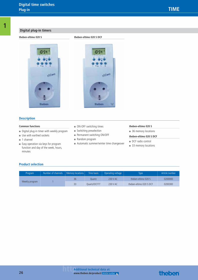
1Digital plug-in timers
theben-eltimo 020 S theben-eltimo 020 S DCF
Description
Common functions
■ Digital plug-in timer with weekly program ■ Use with earthed sockets ■ 1 channel ■ Easy operation via keys for program function and day of the week, hours, minutes
■ ON-OFF switching times ■ Switching preselection ■ Permanent switching ON/OFF ■ Random program ■ Automatic summer/winter time changeover
theben-eltimo 020 S
■ 36 memory locations
theben-eltimo 020 S DCF
■ DCF radio control ■ 33 memory locations
Product selection
Program Number of channels Memory locations Time basis Operating voltage Type Article number
Weekly program 136 Quartz 230 V AC theben-eltimo 020 S 0200000
33 Quartz/DCF77 230 V AC theben-eltimo 020 S DCF 0200300
Catalogue_EN_2013.indb 26 16.01.13 17:19
27httpAdditional technical data at:
www.theben.de/product/ Article number
Plug-inTIMEDigital time switches
1
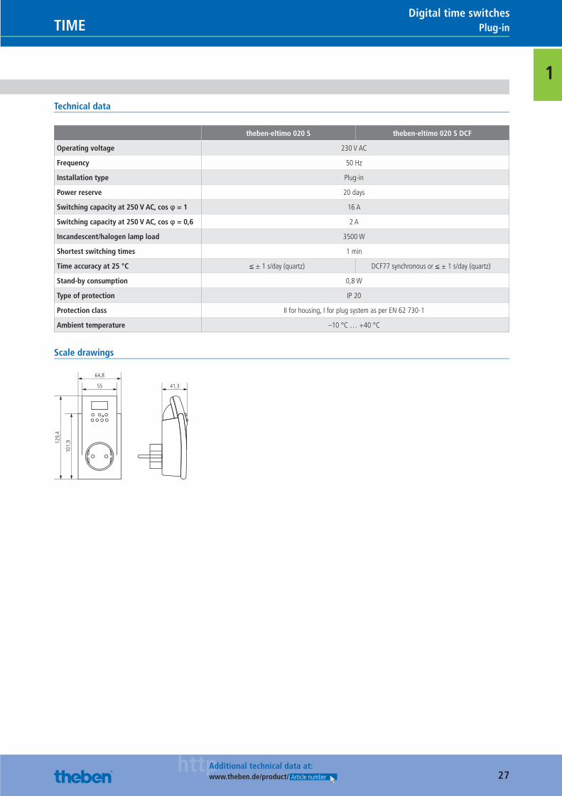
Technical data
theben-eltimo 020 S theben-eltimo 020 S DCF
Operating voltage 230 V AC
Frequency 50 Hz
Installation type Plug-in
Power reserve 20 days
Switching capacity at 250 V AC, cos φ = 1 16 A
Switching capacity at 250 V AC, cos φ = 0,6 2 A
Incandescent/halogen lamp load 3500 W
Shortest switching times 1 min
Time accuracy at 25 °C ≤ ± 1 s/day (quartz) DCF77 synchronous or ≤ ± 1 s/day (quartz)
Stand-by consumption 0,8 W
Type of protection IP 20
Protection class II for housing, I for plug system as per EN 62 730-1
Ambient temperature –10 °C … +40 °C
Scale drawings
55 41,3
64,8
101,
9129,
4
Catalogue_EN_2013.indb 27 16.01.13 17:19
28
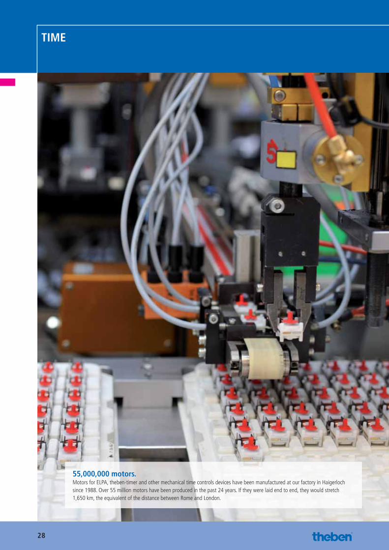
TIME
55,000,000 motors.Motors for ELPA, theben-timer and other mechanical time controls devices have been manufactured at our factory in Haigerloch since 1988. Over 55 million motors have been produced in the past 24 years. If they were laid end to end, they would stretch 1,650 km, the equivalent of the distance between Rome and London.
Catalogue_EN_2013.indb 28 16.01.13 17:19
29
Chapter summary
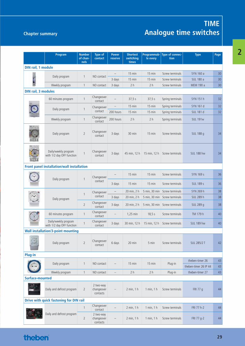
TIMEAnalogue time switches
2Program Number of chan-
nels
Type of contact
Power reserve
Shortest switching
times
Programmab-le every
Type of connec-tion
Type Page
DIN rail, 1 module
Daily program 1 NO contact– 15 min 15 min Screw terminals SYN 160 a 30
3 days 15 min 15 min Screw terminals SUL 180 a 30
Weekly program 1 NO contact 3 days 2 h 2 h Screw terminals MEM 190 a 30
DIN rail, 3 modules
60 minutes program 1Changeover
contact– 37,5 s 37,5 s Spring terminals SYN 151 h 32
Daily program 1Changeover
contact
– 15 min 15 min Spring terminals SYN 161 d 32
200 hours 15 min 15 min Spring terminals SUL 181 d 32
Weekly program 1Changeover
contact200 hours 2 h 2 h Spring terminals SUL 191w
Daily program 2Changeover
contact3 days 30 min 15 min Screw terminals SUL 188 g 34
Daily/weekly program with 1/2 day OFF function
1Changeover
contact3 days 45 min, 12 h 15 min, 12 h Screw terminals SUL 188 hw 34
Front panel installation/wall installation
Daily program 1Changeover
contact
– 15 min 15 min Screw terminals SYN 169 s 36
3 days 15 min 15 min Screw terminals SUL 189 s 36
Daily program1
Changeover contact
– 20 min, 2 h 5 min, 30 min Screw terminals SYN 269 h 38
3 days 20 min, 2 h 5 min, 30 min Screw terminals SUL 289 h 38
2Changeover
contact3 days 20 min, 2 h 5 min, 30 min Screw terminals SUL 289 g 38
60 minutes program 1Changeover
contact– 1,25 min 18,5 s Screw terminals TM 179 h 40
Daily/weekly program with 1/2 day OFF function
1Changeover
contact3 days 30 min, 12 h 15 min, 12 h Screw terminals SUL 189 hw 40
Wall installation/3-point mounting
Daily program 2Changeover
contact6 days 20 min 5 min Screw terminals SUL 285/2 T 42
Plug-in
Daily program 1 NO contact – 15 min 15 min Plug-intheben-timer 26 43
theben-timer 26 IP 44 43
Weekly program 1 NO contact – 2 h 2 h Plug-in theben-timer 27 43
Surface-mounted
Daily and defrost program 22 two-way changeover
contacts– 2 min, 1 h 1 min, 1 h Screw terminals FRI 77 g 44
Drive with quick fastening for DIN rail
Daily and defrost program
1Changeover
contact– 2 min, 1 h 1 min, 1 h Screw terminals FRI 77 h-2 44
22 two-way changeover
contacts– 2 min, 1 h 1 min, 1 h Screw terminals FRI 77 g-2 44
Catalogue_EN_2013.indb 29 16.01.13 17:19
30httpAdditional technical data at:
www.theben.de/product/ Article number
DIN rail, 1 module TIMEAnalogue time switches
2
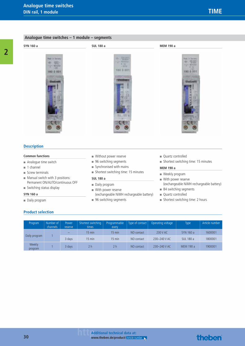
Analogue time switches – 1 module – segments
SYN 160 a SUL 180 a MEM 190 a
Description
Common functions
■ Analogue time switch ■ 1 channel ■ Screw terminals ■ Manual switch with 3 positions: Permanent ON/AUTO/continuous OFF
■ Switching status display
SYN 160 a
■ Daily program
■ Without power reserve ■ 96 switching segments ■ Synchronised with mains ■ Shortest switching time: 15 minutes
SUL 180 a
■ Daily program ■ With power reserve (exchangeable NiMH rechargeable battery)
■ 96 switching segments
■ Quartz controlled ■ Shortest switching time: 15 minutes
MEM 190 a
■ Weekly program ■ With power reserve (exchangeable NiMH rechargeable battery)
■ 84 switching segments ■ Quartz controlled ■ Shortest switching time: 2 hours
Product selection
Program Number of channels
Power reserve
Shortest switching times
Programmable every
Type of contact Operating voltage Type Article number
Daily program 1– 15 min 15 min NO contact 230 V AC SYN 160 a 1600001
3 days 15 min 15 min NO contact 230–240 V AC SUL 180 a 1800001
Weekly program
1 3 days 2 h 2 h NO contact 230–240 V AC MEM 190 a 1900001
Catalogue_EN_2013.indb 30 16.01.13 17:19
31httpAdditional technical data at:
www.theben.de/product/ Article number
DIN rail, 1 moduleTIMEAnalogue time switches
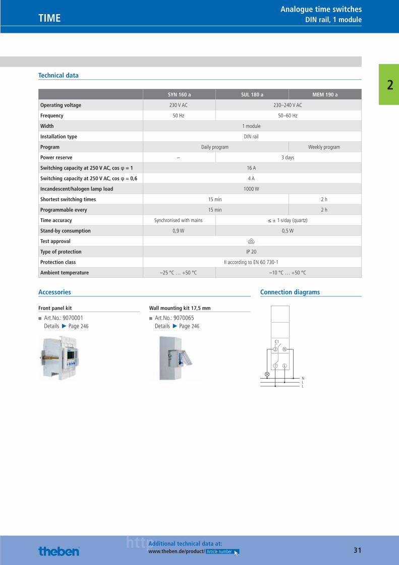
2Technical data
SYN 160 a SUL 180 a MEM 190 a
Operating voltage 230 V AC 230–240 V AC
Frequency 50 Hz 50–60 Hz
Width 1 module
Installation type DIN rail
Program Daily program Weekly program
Power reserve – 3 days
Switching capacity at 250 V AC, cos φ = 1 16 A
Switching capacity at 250 V AC, cos φ = 0,6 4 A
Incandescent/halogen lamp load 1000 W
Shortest switching times 15 min 2 h
Programmable every 15 min 2 h
Time accuracy Synchronised with mains ≤ ± 1 s/day (quartz)
Stand-by consumption 0,9 W 0,5 W
Test approval V
Type of protection IP 20
Protection class II according to EN 60 730-1
Ambient temperature –25 °C … +50 °C –10 °C … +50 °C
Accessories
Front panel kit
■ Art.No.: 9070001Details ▶ Page 246
Wall mounting kit 17,5 mm
■ Art.No.: 9070065Details ▶ Page 246
Connection diagrams
1
C1
2
L
N
NLL
Catalogue_EN_2013.indb 31 16.01.13 17:19
32httpAdditional technical data at:
www.theben.de/product/ Article number
DIN rail, 3 modules TIMEAnalogue time switches
2
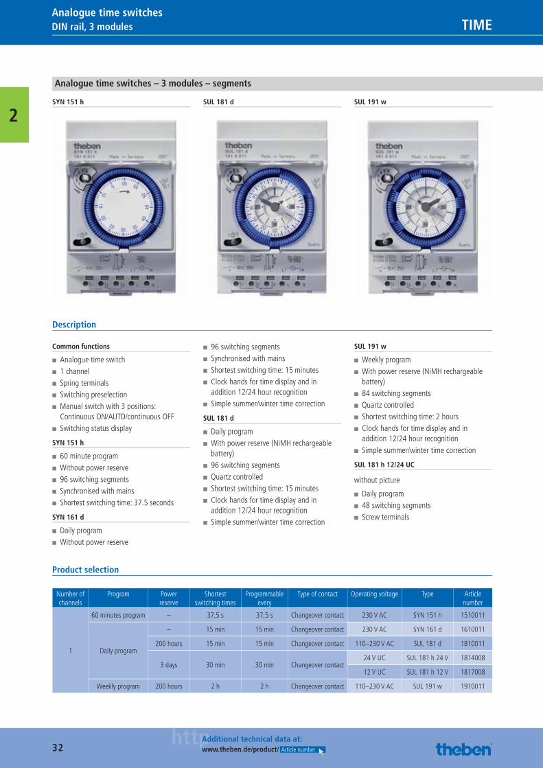
Analogue time switches – 3 modules – segments
SYN 151 h SUL 181 d SUL 191 w
Description
Common functions
■ Analogue time switch ■ 1 channel ■ Spring terminals ■ Switching preselection ■ Manual switch with 3 positions: Continuous ON/AUTO/continuous OFF
■ Switching status display
SYN 151 h
■ 60 minute program ■ Without power reserve ■ 96 switching segments ■ Synchronised with mains ■ Shortest switching time: 37.5 seconds
SYN 161 d
■ Daily program ■ Without power reserve
■ 96 switching segments ■ Synchronised with mains ■ Shortest switching time: 15 minutes ■ Clock hands for time display and in addition 12/24 hour recognition
■ Simple summer/winter time correction
SUL 181 d
■ Daily program ■ With power reserve (NiMH rechargeable battery)
■ 96 switching segments ■ Quartz controlled ■ Shortest switching time: 15 minutes ■ Clock hands for time display and in addition 12/24 hour recognition
■ Simple summer/winter time correction
SUL 191 w
■ Weekly program ■ With power reserve (NiMH rechargeable battery)
■ 84 switching segments ■ Quartz controlled ■ Shortest switching time: 2 hours ■ Clock hands for time display and in addition 12/24 hour recognition
■ Simple summer/winter time correction
SUL 181 h 12/24 UC
without picture
■ Daily program ■ 48 switching segments ■ Screw terminals
Product selection
Number of channels
Program Power reserve
Shortestswitching times
Programmable every
Type of contact Operating voltage Type Article number
1
60 minutes program – 37,5 s 37,5 s Changeover contact 230 V AC SYN 151 h 1510011
Daily program
– 15 min 15 min Changeover contact 230 V AC SYN 161 d 1610011
200 hours 15 min 15 min Changeover contact 110–230 V AC SUL 181 d 1810011
3 days 30 min 30 min Changeover contact24 V UC SUL 181 h 24 V 1814008
12 V UC SUL 181 h 12 V 1817008
Weekly program 200 hours 2 h 2 h Changeover contact 110–230 V AC SUL 191 w 1910011
Catalogue_EN_2013.indb 32 16.01.13 17:19
33httpAdditional technical data at:
www.theben.de/product/ Article number
DIN rail, 3 modulesTIMEAnalogue time switches
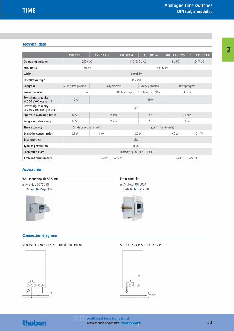
2Technical data
SYN 151 h SYN 161 d SUL 181 d SUL 191 w SUL 181 h 12 V SUL 181 h 24 V
Operating voltage 230 V AC 110–230 V AC 12 V UC 24 V UC
Frequency 50 Hz 50–60 Hz
Width 3 modules
Installation type DIN rail
Program 60 minutes program Daily program Weekly program Daily program
Power reserve – 200 hours, approx. 100 hours at 110 V 3 days
Switching capacity at 250 V AC, cos φ = 1
10 A 16 A
Switching capacity at 250 V AC, cos φ = 0,6
4 A
Shortest switching times 37,5 s 15 min 2 h 30 min
Programmable every 37,5 s 15 min 2 h 30 min
Time accuracy Synchronised with mains ≤ ± 1 s/day (quartz)
Stand-by consumption 0,9 W 1 VA 0,5 W 0,5 W 0,1 W
Test approval V
Type of protection IP 20
Protection class II according to EN 60 730-1
Ambient temperature –20 °C … +55 °C –20 °C … +50 °C
Accessories
Wall mounting kit 52,5 mm
■ Art.No.: 9070050Details ▶ Page 246
Front panel kit
■ Art.No.: 9070001Details ▶ Page 246
Connection diagrams
SYN 151 h, SYN 161 d, SUL 181 d, SUL 191 w
C1
1 2 3 L N
NLL
SUL 181 h 24 V, SUL 181 h 12 V
C1
1 2 3 8
7
N12V/24VL
Catalogue_EN_2013.indb 33 16.01.13 17:19
34httpAdditional technical data at:
www.theben.de/product/ Article number
DIN rail, 3 modules TIMEAnalogue time switches
2
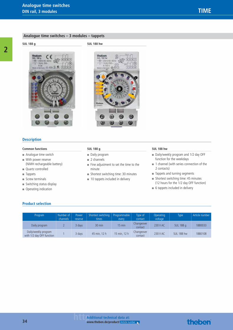
Analogue time switches – 3 modules – tappets
SUL 188 g SUL 188 hw
Description
Common functions
■ Analogue time switch ■ With power reserve (NiMH rechargeable battery)
■ Quartz controlled ■ Tappets ■ Screw terminals ■ Switching status display ■ Operating indication
SUL 188 g
■ Daily program ■ 2 channels ■ Fine adjustment to set the time to the minute
■ Shortest switching time: 30 minutes ■ 10 tappets included in delivery
SUL 188 hw
■ Daily/weekly program and 1/2 day OFF function for the weekdays
■ 1 channel (with series connection of the 2 contacts)
■ Tappets and turning segments ■ Shortest switching time: 45 minutes (12 hours for the 1/2 day OFF function)
■ 6 tappets included in delivery
Product selection
Program Number of channels
Power reserve
Shortest switching times
Programmable every
Type of contact
Operating voltage
Type Article number
Daily program 2 3 days 30 min 15 minChangeover
contact230 V AC SUL 188 g 1880033
Daily/weekly program with 1/2 day OFF function
1 3 days 45 min, 12 h 15 min, 12 hChangeover
contact230 V AC SUL 188 hw 1880108
Catalogue_EN_2013.indb 34 16.01.13 17:19
35httpAdditional technical data at:
www.theben.de/product/ Article number
DIN rail, 3 modulesTIMEAnalogue time switches
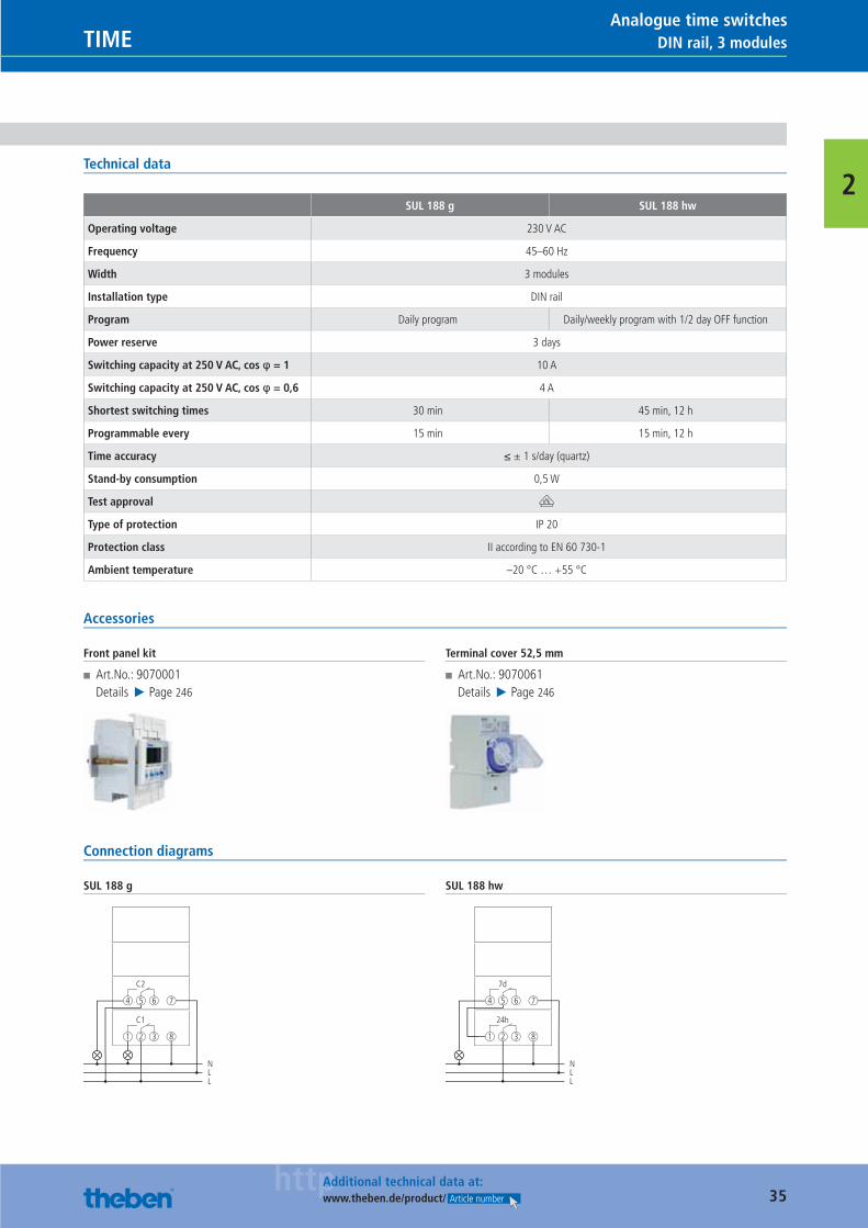
2Technical data
SUL 188 g SUL 188 hw
Operating voltage 230 V AC
Frequency 45–60 Hz
Width 3 modules
Installation type DIN rail
Program Daily program Daily/weekly program with 1/2 day OFF function
Power reserve 3 days
Switching capacity at 250 V AC, cos φ = 1 10 A
Switching capacity at 250 V AC, cos φ = 0,6 4 A
Shortest switching times 30 min 45 min, 12 h
Programmable every 15 min 15 min, 12 h
Time accuracy ≤ ± 1 s/day (quartz)
Stand-by consumption 0,5 W
Test approval V
Type of protection IP 20
Protection class II according to EN 60 730-1
Ambient temperature –20 °C … +55 °C
Accessories
Front panel kit
■ Art.No.: 9070001Details ▶ Page 246
Terminal cover 52,5 mm
■ Art.No.: 9070061Details ▶ Page 246
Connection diagrams
SUL 188 g
C1
1 2 3
C2
4 5 6
8
7
NLL
SUL 188 hw
24h
1 2 3
7d
4 5 6
8
7
NLL
Catalogue_EN_2013.indb 35 16.01.13 17:19
36httpAdditional technical data at:
www.theben.de/product/ Article number
Front panel installation/wall installation TIMEAnalogue time switches
2
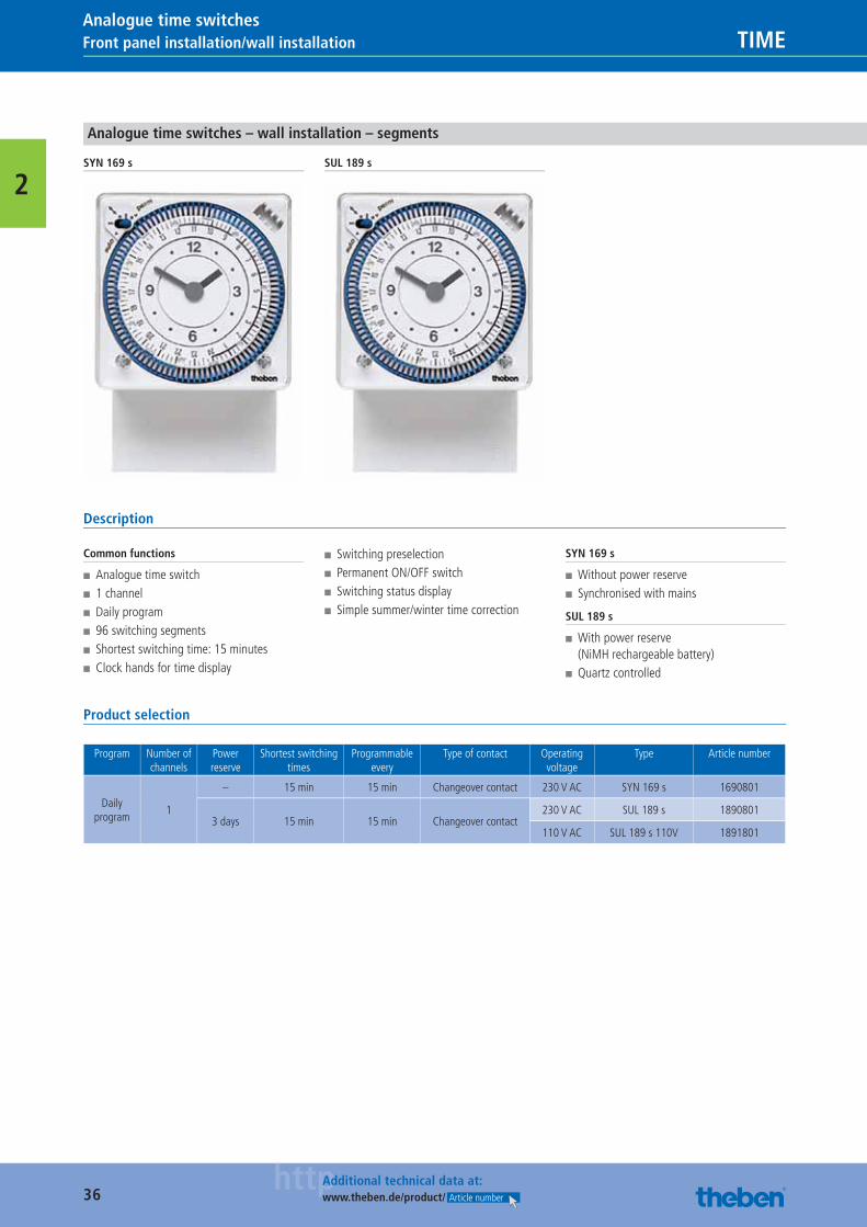
Analogue time switches – wall installation – segments
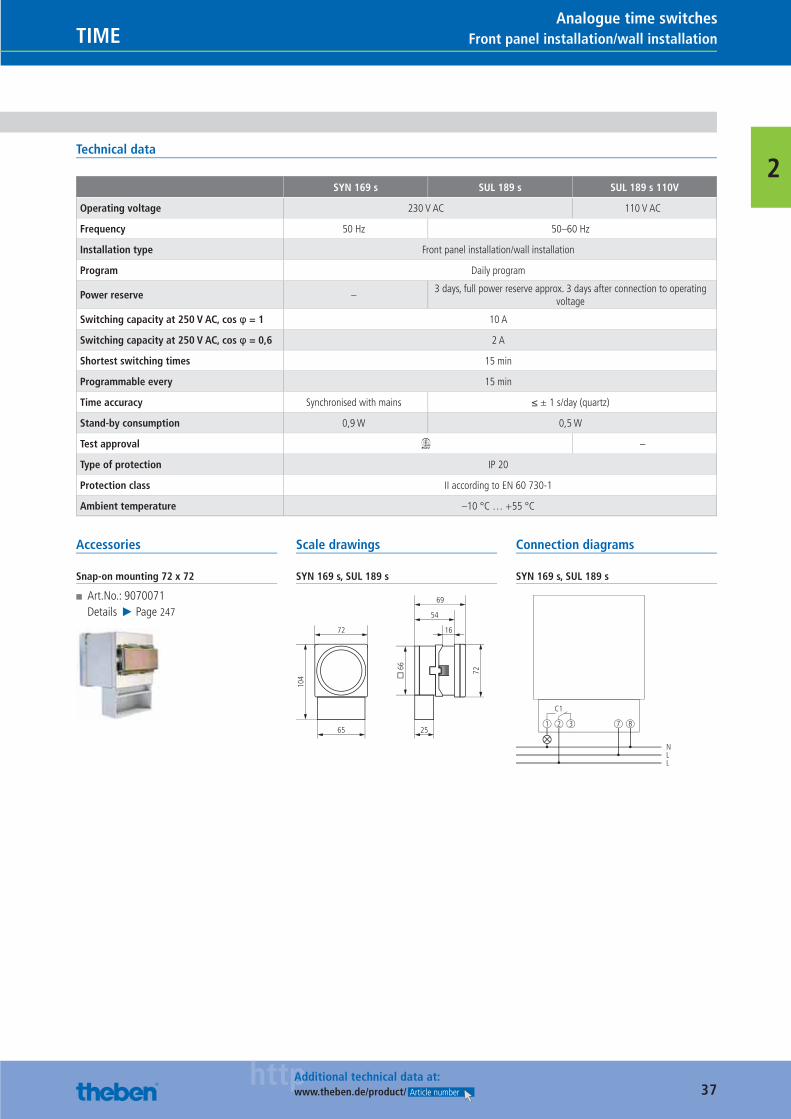
SYN 169 s SUL 189 s
Description
Common functions
■ Analogue time switch ■ 1 channel ■ Daily program ■ 96 switching segments ■ Shortest switching time: 15 minutes ■ Clock hands for time display
■ Switching preselection ■ Permanent ON/OFF switch ■ Switching status display ■ Simple summer/winter time correction
SYN 169 s
■ Without power reserve ■ Synchronised with mains
SUL 189 s
■ With power reserve (NiMH rechargeable battery)
■ Quartz controlled
Product selection
Program Number of channels
Power reserve
Shortest switching times
Programmable every
Type of contact Operating voltage
Type Article number
Daily program
1
– 15 min 15 min Changeover contact 230 V AC SYN 169 s 1690801
3 days 15 min 15 min Changeover contact230 V AC SUL 189 s 1890801
110 V AC SUL 189 s 110V 1891801
Catalogue_EN_2013.indb 36 16.01.13 17:19
37httpAdditional technical data at:
www.theben.de/product/ Article number
Front panel installation/wall installationTIMEAnalogue time switches
2Technical data
SYN 169 s SUL 189 s SUL 189 s 110V
Operating voltage 230 V AC 110 V AC
Frequency 50 Hz 50–60 Hz
Installation type Front panel installation/wall installation
Program Daily program
Power reserve –3 days, full power reserve approx. 3 days after connection to operating
voltage
Switching capacity at 250 V AC, cos φ = 1 10 A
Switching capacity at 250 V AC, cos φ = 0,6 2 A
Shortest switching times 15 min
Programmable every 15 min
Time accuracy Synchronised with mains ≤ ± 1 s/day (quartz)
Stand-by consumption 0,9 W 0,5 W
Test approval W –
Type of protection IP 20
Protection class II according to EN 60 730-1
Ambient temperature –10 °C … +55 °C
Accessories
Snap-on mounting 72 x 72
■ Art.No.: 9070071Details ▶ Page 247
Scale drawings
SYN 169 s, SUL 189 s
104 �
66
72
72
65 25
16
54
69
Connection diagrams
SYN 169 s, SUL 189 s
C1
1 2 3
NLL
7 8
Catalogue_EN_2013.indb 37 16.01.13 17:19
38httpAdditional technical data at:
www.theben.de/product/ Article number
Front panel installation/wall installation TIMEAnalogue time switches
2
Analogue time switches – wall installation – tappets
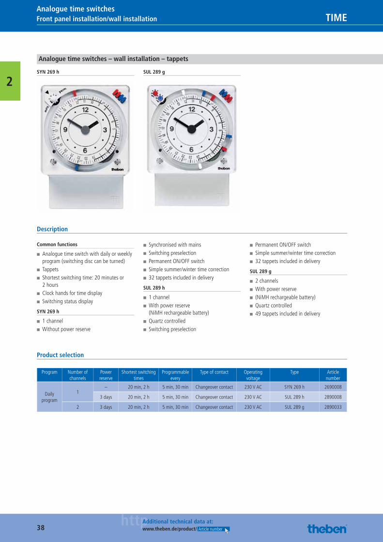
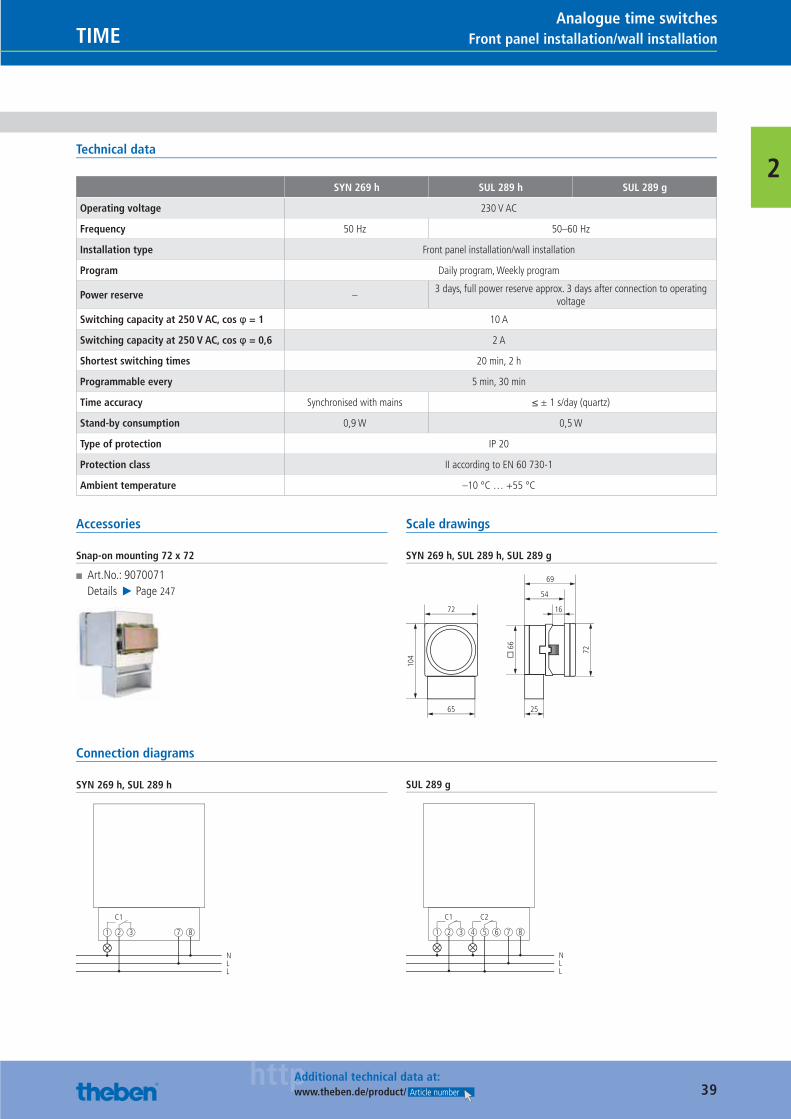
SYN 269 h SUL 289 g
Description
Common functions
■ Analogue time switch with daily or weekly program (switching disc can be turned)
■ Tappets ■ Shortest switching time: 20 minutes or 2 hours
■ Clock hands for time display ■ Switching status display
SYN 269 h
■ 1 channel ■ Without power reserve
■ Synchronised with mains ■ Switching preselection ■ Permanent ON/OFF switch ■ Simple summer/winter time correction ■ 32 tappets included in delivery
SUL 289 h
■ 1 channel ■ With power reserve (NiMH rechargeable battery)
■ Quartz controlled ■ Switching preselection
■ Permanent ON/OFF switch ■ Simple summer/winter time correction ■ 32 tappets included in delivery
SUL 289 g
■ 2 channels ■ With power reserve ■ (NiMH rechargeable battery) ■ Quartz controlled ■ 49 tappets included in delivery
Product selection
Program Number of channels
Power reserve
Shortest switching times
Programmable every
Type of contact Operating voltage
Type Article number
Daily program
1– 20 min, 2 h 5 min, 30 min Changeover contact 230 V AC SYN 269 h 2690008
3 days 20 min, 2 h 5 min, 30 min Changeover contact 230 V AC SUL 289 h 2890008
2 3 days 20 min, 2 h 5 min, 30 min Changeover contact 230 V AC SUL 289 g 2890033
Catalogue_EN_2013.indb 38 16.01.13 17:19
39httpAdditional technical data at:
www.theben.de/product/ Article number
Front panel installation/wall installationTIMEAnalogue time switches
2Technical data
SYN 269 h SUL 289 h SUL 289 g
Operating voltage 230 V AC
Frequency 50 Hz 50–60 Hz
Installation type Front panel installation/wall installation
Program Daily program, Weekly program
Power reserve –3 days, full power reserve approx. 3 days after connection to operating
voltage
Switching capacity at 250 V AC, cos φ = 1 10 A
Switching capacity at 250 V AC, cos φ = 0,6 2 A
Shortest switching times 20 min, 2 h
Programmable every 5 min, 30 min
Time accuracy Synchronised with mains ≤ ± 1 s/day (quartz)
Stand-by consumption 0,9 W 0,5 W
Type of protection IP 20
Protection class II according to EN 60 730-1
Ambient temperature –10 °C … +55 °C
Accessories
Snap-on mounting 72 x 72
■ Art.No.: 9070071Details ▶ Page 247
Scale drawings
SYN 269 h, SUL 289 h, SUL 289 g
104 �
66
72
72
65 25
16
54
69
Connection diagrams
SYN 269 h, SUL 289 h
C1
1 2 3
NLL
7 8
SUL 289 g
C1
1 2 3 4 5 6
NLL
C2
7 8
Catalogue_EN_2013.indb 39 16.01.13 17:19
40httpAdditional technical data at:
www.theben.de/product/ Article number
Front panel installation/wall installation TIMEAnalogue time switches
2
Analogue time switches – wall installation – tappets
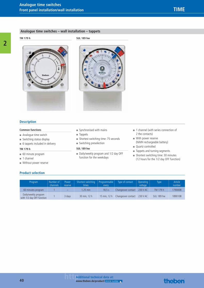
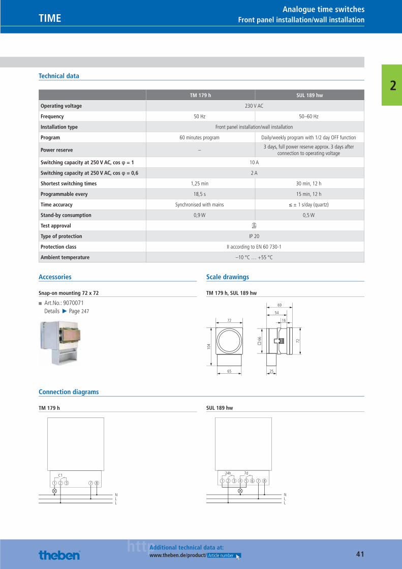
TM 179 h SUL 189 hw
Description
Common functions
■ Analogue time switch ■ Switching status display ■ 6 tappets included in delivery
TM 179 h
■ 60 minute program ■ 1 channel ■ Without power reserve
■ Synchronised with mains ■ Tappets ■ Shortest switching time: 75 seconds ■ Switching preselection
SUL 189 hw
■ Daily/weekly program and 1/2 day OFF function for the weekdays
■ 1 channel (with series connection of 2 the contacts)
■ With power reserve (NiMH rechargeable battery)
■ Quartz controlled ■ Tappets and turning segments ■ Shortest switching time: 30 minutes (12 hours for the 1/2 day OFF function)
Product selection
Program Number of channels
Power reserve
Shortest switching times
Programmable every
Type of contact Operating voltage
Type Article number
60 minutes program 1 – 1,25 min 18,5 s Changeover contact 230 V AC TM 179 h 1790008
Daily/weekly program with 1/2 day OFF function
1 3 days 30 min, 12 h 15 min, 12 h Changeover contact 230 V AC SUL 189 hw 1890108
Catalogue_EN_2013.indb 40 16.01.13 17:19
41httpAdditional technical data at:
www.theben.de/product/ Article number
Front panel installation/wall installationTIMEAnalogue time switches
2Technical data
TM 179 h SUL 189 hw
Operating voltage 230 V AC
Frequency 50 Hz 50–60 Hz
Installation type Front panel installation/wall installation
Program 60 minutes program Daily/weekly program with 1/2 day OFF function
Power reserve –3 days, full power reserve approx. 3 days after
connection to operating voltage
Switching capacity at 250 V AC, cos φ = 1 10 A
Switching capacity at 250 V AC, cos φ = 0,6 2 A
Shortest switching times 1,25 min 30 min, 12 h
Programmable every 18,5 s 15 min, 12 h
Time accuracy Synchronised with mains ≤ ± 1 s/day (quartz)
Stand-by consumption 0,9 W 0,5 W
Test approval W
Type of protection IP 20
Protection class II according to EN 60 730-1
Ambient temperature –10 °C … +55 °C
Accessories
Snap-on mounting 72 x 72
■ Art.No.: 9070071Details ▶ Page 247
Scale drawings
TM 179 h, SUL 189 hw
104 �
66
72
72
65 25
16
54
69
Connection diagrams
TM 179 h
C1
1 2 3
NLL
7 8
SUL 189 hw
24h
1 2 3 4 5 6
NLL
7d
7 8
Catalogue_EN_2013.indb 41 16.01.13 17:19
42httpAdditional technical data at:
www.theben.de/product/ Article number
Wall installation/3-point mounting TIMEAnalogue time switches
2
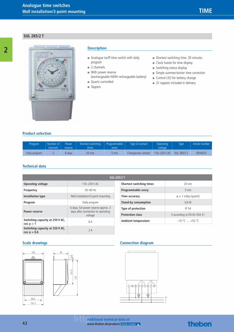
SUL 285/2 T
Description
■ Analogue tariff time switch with daily program
■ 2 channels ■ With power reserve (exchangeable NiMH rechargeable battery)
■ Quartz controlled ■ Tappets
■ Shortest switching time: 20 minutes ■ Clock hands for time display ■ Switching status display ■ Simple summer/winter time correction ■ Control LED for battery change ■ 32 tappets included in delivery
Product selection
Program Number of channels
Power reserve
Shortest switching times
Programmable every
Type of contact Operating voltage
Type Article number
Daily program 2 6 days 20 min 5 min Changeover contact 110–230 V AC SUL 285/2 T 2850033
Technical data
SUL 285/2 T
Operating voltage 110–230 V AC
Frequency 50–60 Hz
Installation type Wall installation/3-point mounting
Program Daily program
Power reserve6 days, full power reserve approx. 3 days after connection to operating
voltageSwitching capacity at 250 V AC, cos φ = 1
6 A
Switching capacity at 250 V AC, cos φ = 0,6
2 A
Shortest switching times 20 min
Programmable every 5 min
Time accuracy ≤ ± 1 s/day (quartz)
Stand-by consumption 0,6 W
Type of protection IP 54
Protection class II according to EN 62 054-21
Ambient temperature –10 °C … +55 °C
Scale drawings
74
121,
56,
5
105
175
84,5
101,5
Connection diagram
NLL
L 1a N
C1
3 4 5 6 7 8
C2
Catalogue_EN_2013.indb 42 16.01.13 17:19
43httpAdditional technical data at:
www.theben.de/product/ Article number
Plug-inTIMEAnalogue time switches
2
Analogue plug-in timers
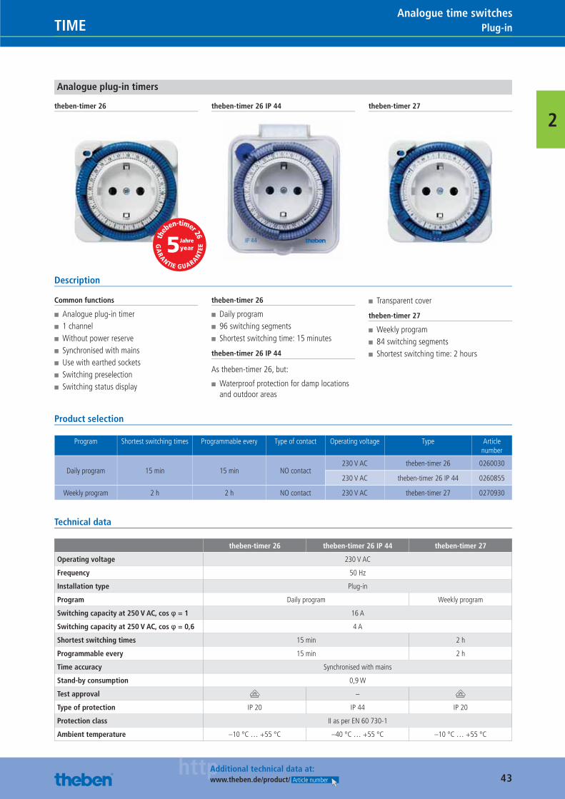
theben-timer 26 theben-timer 26 IP 44 theben-timer 27
Description
Common functions
■ Analogue plug-in timer ■ 1 channel ■ Without power reserve ■ Synchronised with mains ■ Use with earthed sockets ■ Switching preselection ■ Switching status display
theben-timer 26
■ Daily program ■ 96 switching segments ■ Shortest switching time: 15 minutes
theben-timer 26 IP 44
As theben-timer 26, but:
■ Waterproof protection for damp locations and outdoor areas
■ Transparent cover
theben-timer 27
■ Weekly program ■ 84 switching segments ■ Shortest switching time: 2 hours
Product selection
Program Shortest switching times Programmable every Type of contact Operating voltage Type Article number
Daily program 15 min 15 min NO contact230 V AC theben-timer 26 0260030
230 V AC theben-timer 26 IP 44 0260855
Weekly program 2 h 2 h NO contact 230 V AC theben-timer 27 0270930
Technical data
theben-timer 26 theben-timer 26 IP 44 theben-timer 27
Operating voltage 230 V AC
Frequency 50 Hz
Installation type Plug-in
Program Daily program Weekly program
Switching capacity at 250 V AC, cos φ = 1 16 A
Switching capacity at 250 V AC, cos φ = 0,6 4 A
Shortest switching times 15 min 2 h
Programmable every 15 min 2 h
Time accuracy Synchronised with mains
Stand-by consumption 0,9 W
Test approval V – V
Type of protection IP 20 IP 44 IP 20
Protection class II as per EN 60 730-1
Ambient temperature –10 °C … +55 °C –40 °C … +55 °C –10 °C … +55 °C
Jahreyear
theb
en-timer 26
GA
RANTIE GUARAN
TEE
Catalogue_EN_2013.indb 43 16.01.13 17:19
44httpAdditional technical data at:
www.theben.de/product/ Article number
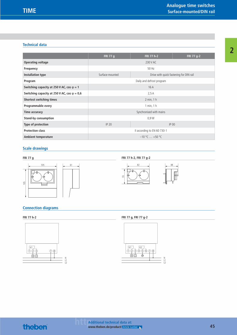
Surface-mounted/DIN rail TIMEAnalogue time switches
2
Analogue cooling timers
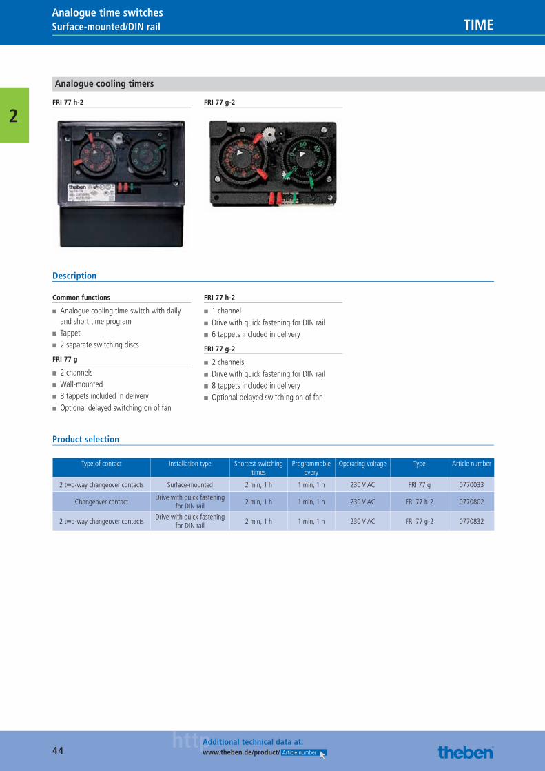
FRI 77 h-2 FRI 77 g-2
Description
Common functions
■ Analogue cooling time switch with daily and short time program
■ Tappet ■ 2 separate switching discs
FRI 77 g
■ 2 channels ■ Wall-mounted ■ 8 tappets included in delivery ■ Optional delayed switching on of fan
FRI 77 h-2
■ 1 channel ■ Drive with quick fastening for DIN rail ■ 6 tappets included in delivery
FRI 77 g-2
■ 2 channels ■ Drive with quick fastening for DIN rail ■ 8 tappets included in delivery ■ Optional delayed switching on of fan
Product selection
Type of contact Installation type Shortest switching times
Programmable every
Operating voltage Type Article number
2 two-way changeover contacts Surface-mounted 2 min, 1 h 1 min, 1 h 230 V AC FRI 77 g 0770033
Changeover contactDrive with quick fastening
for DIN rail2 min, 1 h 1 min, 1 h 230 V AC FRI 77 h-2 0770802
2 two-way changeover contactsDrive with quick fastening
for DIN rail2 min, 1 h 1 min, 1 h 230 V AC FRI 77 g-2 0770832
Catalogue_EN_2013.indb 44 16.01.13 17:19
45httpAdditional technical data at:
www.theben.de/product/ Article number
Surface-mounted/DIN railTIMEAnalogue time switches
2Technical data
FRI 77 g FRI 77 h-2 FRI 77 g-2
Operating voltage 230 V AC
Frequency 50 Hz
Installation type Surface-mounted Drive with quick fastening for DIN rail
Program Daily and defrost program
Switching capacity at 250 V AC, cos φ = 1 16 A
Switching capacity at 250 V AC, cos φ = 0,6 2,5 A
Shortest switching times 2 min, 1 h
Programmable every 1 min, 1 h
Time accuracy Synchronised with mains
Stand-by consumption 0,9 W
Type of protection IP 20 IP 00
Protection class II according to EN 60 730-1
Ambient temperature –10 °C … +50 °C
Scale drawings
FRI 77 g
105 61
105
FRI 77 h-2, FRI 77 g-2
82 48
55
Connection diagrams
FRI 77 h-2
K11 2 3
NL1L2
7 8
FRI 77 g, FRI 77 g-2
K1 K21 2 3 4 5 6
NL1L2
7 8
Catalogue_EN_2013.indb 45 16.01.13 17:19
46
TIME
92 years of expertise.Since the company was founded by Paul Schwenk in 1921, our core expertise has been in time management. No wonder that Theben timers count amongst the most durable and reliable devices in this sector. Strict controls ensure the constant high quality of all devices and provide you with maximum security.
Catalogue_EN_2013.indb 46 16.01.13 17:19
47
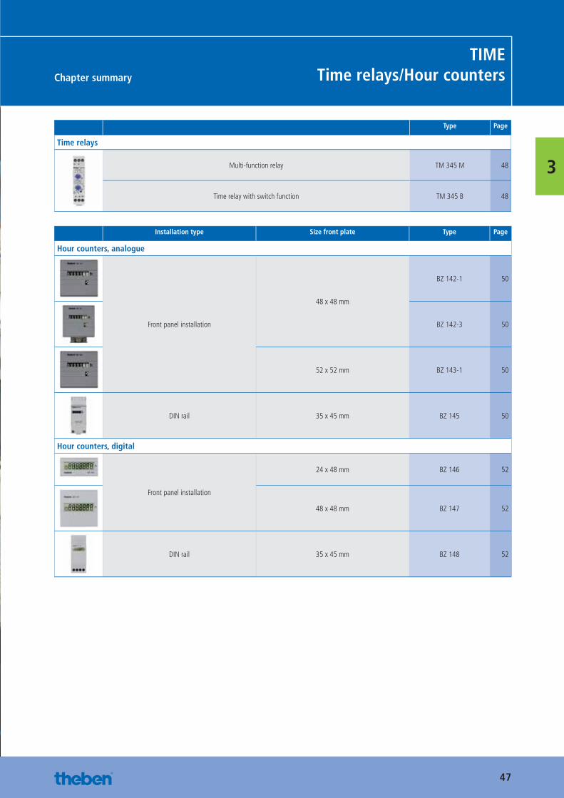
Chapter summary
TIMETime relays/Hour counters
3
Type Page
Time relays
Multi-function relay TM 345 M 48
Time relay with switch function TM 345 B 48
Installation type Size front plate Type Page
Hour counters, analogue
Front panel installation
48 x 48 mm
BZ 142-1 50
BZ 142-3 50
52 x 52 mm BZ 143-1 50
DIN rail 35 x 45 mm BZ 145 50
Hour counters, digital
Front panel installation
24 x 48 mm BZ 146 52
48 x 48 mm BZ 147 52
DIN rail 35 x 45 mm BZ 148 52
Catalogue_EN_2013.indb 47 16.01.13 17:19
48httpAdditional technical data at:
www.theben.de/product/ Article number
Analogue TIMETime relays
3
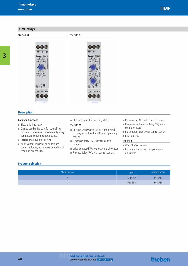
Time relays
TM 345 M TM 345 B
Description
Common functions
■ Electronic time relay ■ Can be used universally for controlling automatic processes in machines, lighting, ventilation, heating, cupboards etc.
■ Precise analogue time setting ■ Multi-voltage input for all supply and control voltages, no jumpers or additional terminals are required
■ LED to display the switching status
TM 345 M
■ Locking snap switch to select the period of time, as well as the following operating modes:
■ Response delay (AV), without control contact
■ Wipe contact (EW), without control contact ■ Release delay (RV), with control contact
■ Pulse former (IF), with control contact ■ Response and release delay (VZ), with control contact
■ Pulse output (WR), with control contact ■ Flip-fl op (TG)
TM 345 B
■ With fl ip-fl op function ■ Pulse and break time independently adjustable
Product selection
Multi-function Type Article number
✓ TM 345 M 3450731
– TM 345 B 3450730
Catalogue_EN_2013.indb 48 16.01.13 17:20
49httpAdditional technical data at:
www.theben.de/product/ Article number
AnalogueTIMETime relays
3
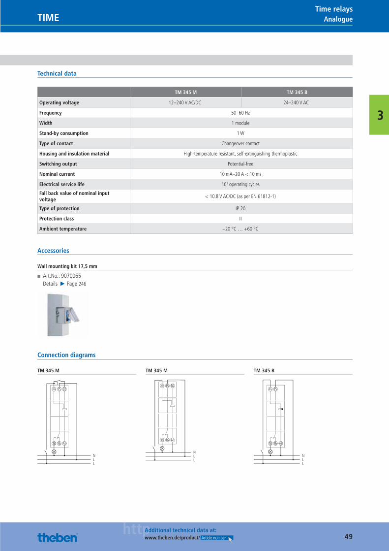
Technical data
TM 345 M TM 345 B
Operating voltage 12–240 V AC/DC 24–240 V AC
Frequency 50–60 Hz
Width 1 module
Stand-by consumption 1 W
Type of contact Changeover contact
Housing and insulation material High-temperature resistant, self-extinguishing thermoplastic
Switching output Potential-free
Nominal current 10 mA–20 A < 10 ms
Electrical service life 105 operating cycles
Fall back value of nominal input voltage
< 10.8 V AC/DC (as per EN 61812-1)
Type of protection IP 20
Protection class II
Ambient temperature –20 °C … +60 °C
Accessories
Wall mounting kit 17,5 mm
■ Art.No.: 9070065Details ▶ Page 246
Connection diagrams
TM 345 M
18 A2-16
A1+ B215S
NLL
TM 345 M
18 A2-16
A1+ B215
NLL
TM 345 B
18 A2-16
A1+ 15
NLL
Catalogue_EN_2013.indb 49 16.01.13 17:20
50httpAdditional technical data at:
www.theben.de/product/ Article number
Analogue TIMEHour counters
3
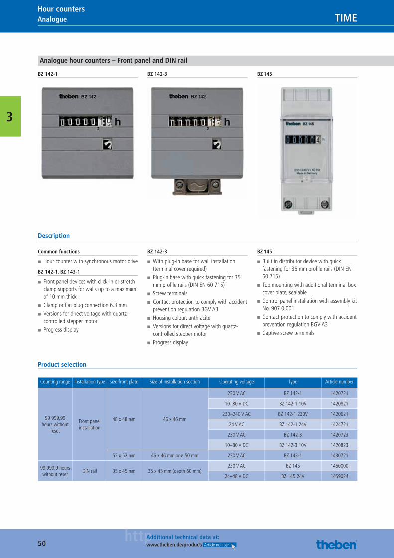
Analogue hour counters – Front panel and DIN rail
BZ 142-1 BZ 142-3 BZ 145
Description
Common functions
■ Hour counter with synchronous motor drive
BZ 142-1, BZ 143-1
■ Front panel devices with click-in or stretch clamp supports for walls up to a maximum of 10 mm thick
■ Clamp or fl at plug connection 6.3 mm ■ Versions for direct voltage with quartz-controlled stepper motor
■ Progress display
BZ 142-3
■ With plug-in base for wall installation (terminal cover required)
■ Plug-in base with quick fastening for 35 mm profi le rails (DIN EN 60 715)
■ Screw terminals ■ Contact protection to comply with accident prevention regulation BGV A3
■ Housing colour: anthracite ■ Versions for direct voltage with quartz-controlled stepper motor
■ Progress display
BZ 145
■ Built in distributor device with quick fastening for 35 mm profi le rails (DIN EN 60 715)
■ Top mounting with additional terminal box cover plate, sealable
■ Control panel installation with assembly kit No. 907 0 001
■ Contact protection to comply with accident prevention regulation BGV A3
■ Captive screw terminals
Product selection
Counting range Installation type Size front plate Size of Installation section Operating voltage Type Article number
99 999,99 hours without
reset
Front panel installation
48 x 48 mm 46 x 46 mm
230 V AC BZ 142-1 1420721
10–80 V DC BZ 142-1 10V 1420821
230–240 V AC BZ 142-1 230V 1420621
24 V AC BZ 142-1 24V 1424721
230 V AC BZ 142-3 1420723
10–80 V DC BZ 142-3 10V 1420823
52 x 52 mm 46 x 46 mm or ø 50 mm 230 V AC BZ 143-1 1430721
99 999,9 hours without reset
DIN rail 35 x 45 mm 35 x 45 mm (depth 60 mm)230 V AC BZ 145 1450000
24–48 V DC BZ 145 24V 1459024
Catalogue_EN_2013.indb 50 16.01.13 17:20
51httpAdditional technical data at:
www.theben.de/product/ Article number
AnalogueTIMEHour counters
3
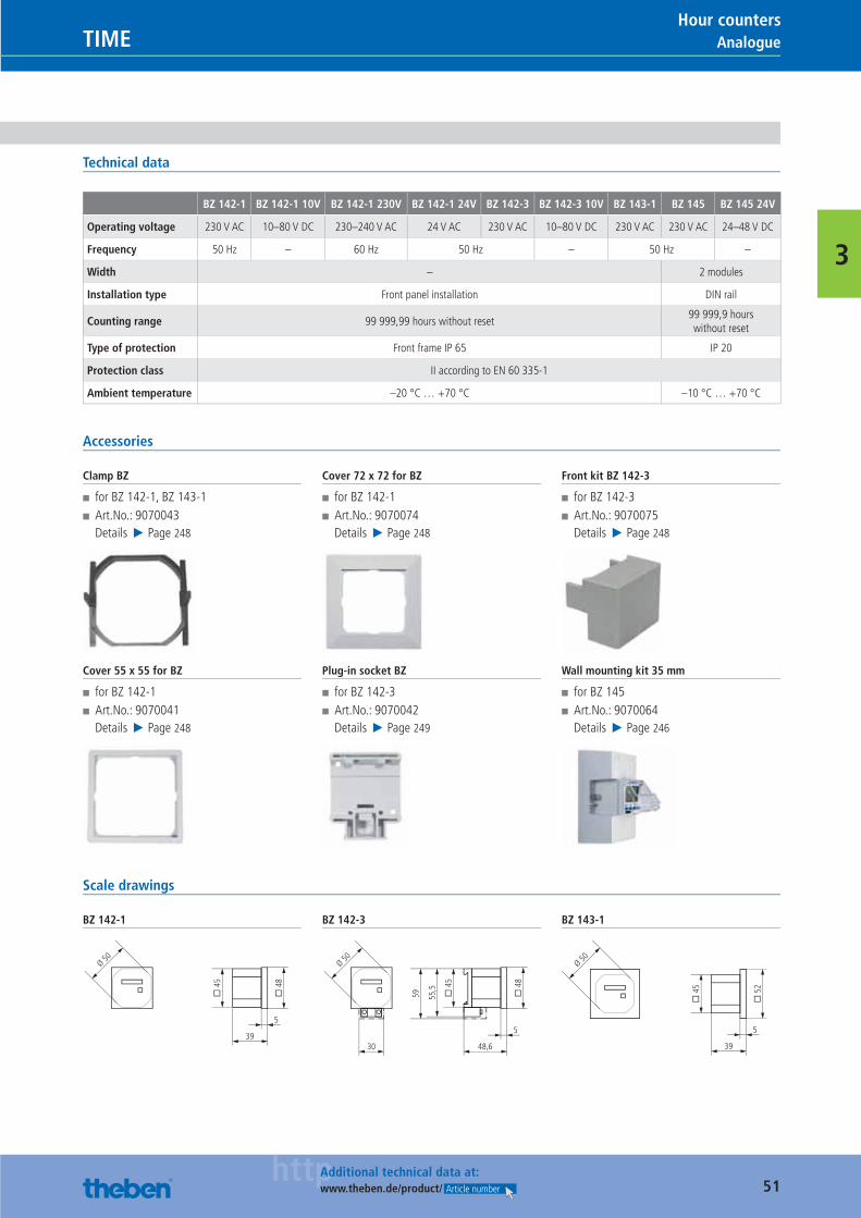
Technical data
BZ 142-1 BZ 142-1 10V BZ 142-1 230V BZ 142-1 24V BZ 142-3 BZ 142-3 10V BZ 143-1 BZ 145 BZ 145 24V
Operating voltage 230 V AC 10–80 V DC 230–240 V AC 24 V AC 230 V AC 10–80 V DC 230 V AC 230 V AC 24–48 V DC
Frequency 50 Hz – 60 Hz 50 Hz – 50 Hz –
Width – 2 modules
Installation type Front panel installation DIN rail
Counting range 99 999,99 hours without reset99 999,9 hours without reset
Type of protection Front frame IP 65 IP 20
Protection class II according to EN 60 335-1
Ambient temperature –20 °C … +70 °C –10 °C … +70 °C
Accessories
Clamp BZ
■ for BZ 142-1, BZ 143-1 ■ Art.No.: 9070043Details ▶ Page 248
Cover 55 x 55 for BZ
■ for BZ 142-1 ■ Art.No.: 9070041Details ▶ Page 248
Cover 72 x 72 for BZ
■ for BZ 142-1 ■ Art.No.: 9070074Details ▶ Page 248
Plug-in socket BZ
■ for BZ 142-3 ■ Art.No.: 9070042Details ▶ Page 249
Front kit BZ 142-3
■ for BZ 142-3 ■ Art.No.: 9070075Details ▶ Page 248
Wall mounting kit 35 mm
■ for BZ 145 ■ Art.No.: 9070064Details ▶ Page 246
Scale drawings
BZ 142-1
39
5
� 4
8
� 4
5
Ø 50
BZ 142-3
48,630
5
� 4
8
� 4
5
55,5
59
Ø 50
BZ 143-1
39
5
� 5
2
� 4
5
Ø 50
Catalogue_EN_2013.indb 51 16.01.13 17:20
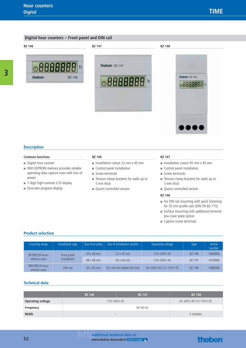
52httpAdditional technical data at:
www.theben.de/product/ Article number
Digital TIMEHour counters
3
Digital hour counters – Front panel and DIN rail
BZ 146 BZ 147 BZ 148
Description
Common functions
■ Digital hour counter ■ With EEPROM memory provides reliable operating data capture even with loss of power
■ 7-digit high-contrast LCD display ■ Onscreen progress display
BZ 146
■ Installation cutout 22 mm x 45 mm ■ Control panel installation ■ Screw terminals ■ Tension clamp brackets for walls up to 5 mm thick
■ Quartz controlled version
BZ 147
■ Installation cutout 45 mm x 45 mm ■ Control panel installation ■ Screw terminals ■ Tension clamp brackets for walls up to 5 mm thick
■ Quartz controlled version
BZ 148
■ For DIN rail mounting with quick fastening for 35 mm profi le rails (DIN EN 60 715)
■ Surface mounting with additional terminal box cover plate option
■ Captive screw terminals
Product selection
Counting range Installation type Size front plate Size of Installation section Operating voltage Type Article number
99 999,99 hours without reset
Front panel installation
24 x 48 mm 22 x 45 mm 110–240 V AC BZ 146 1460000
48 x 48 mm 45 x 45 mm 110–240 V AC BZ 147 1470000
999 999.9 hours without reset
DIN rail 35 x 45 mm 35 x 45 mm (depth 60 mm) 24–240 V AC/12–150 V DC BZ 148 1480000
Technical data
BZ 146 BZ 147 BZ 148
Operating voltage 110–240 V AC 24–240 V AC/12–150 V DC
Frequency 50–60 Hz
Width – 2 modules
Catalogue_EN_2013.indb 52 16.01.13 17:20
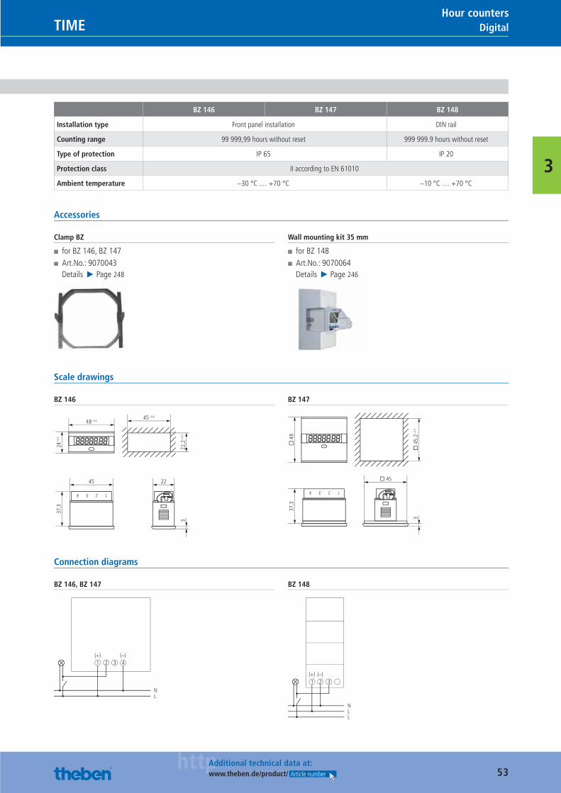
53httpAdditional technical data at:
www.theben.de/product/ Article number
DigitalTIMEHour counters
3
BZ 146 BZ 147 BZ 148
Installation type Front panel installation DIN rail
Counting range 99 999,99 hours without reset 999 999.9 hours without reset
Type of protection IP 65 IP 20
Protection class II according to EN 61010
Ambient temperature –30 °C … +70 °C –10 °C … +70 °C
Accessories
Clamp BZ
■ for BZ 146, BZ 147 ■ Art.No.: 9070043Details ▶ Page 248
Wall mounting kit 35 mm
■ for BZ 148 ■ Art.No.: 9070064Details ▶ Page 246
Scale drawings
BZ 146
48–0,245+0,6
22,2
+0,
3
24–0
,2
45 22
3
37,3
1234
BZ 147
� 45
3�
45,
2+0,
3
37,3
� 4
81234
Connection diagrams
BZ 146, BZ 147
NL
1 2 3 4(+) (–)
BZ 148
1 3
NLL
2(+) (–)
Catalogue_EN_2013.indb 53 16.01.13 17:20
54
LIGHT
More than 20 years of Presence Detectors.The Presence Detector was developed more than 20 years ago at the Laboratory for High Technology Systems in Switzerland (today ThebenHTS) which was a ground-breaking invention in the fi eld of presence dependant lighting control. Discover the „real deal“ and see for yourself the world leading detection quality with square detection area.
Catalogue_EN_2013.indb 54 16.01.13 17:20
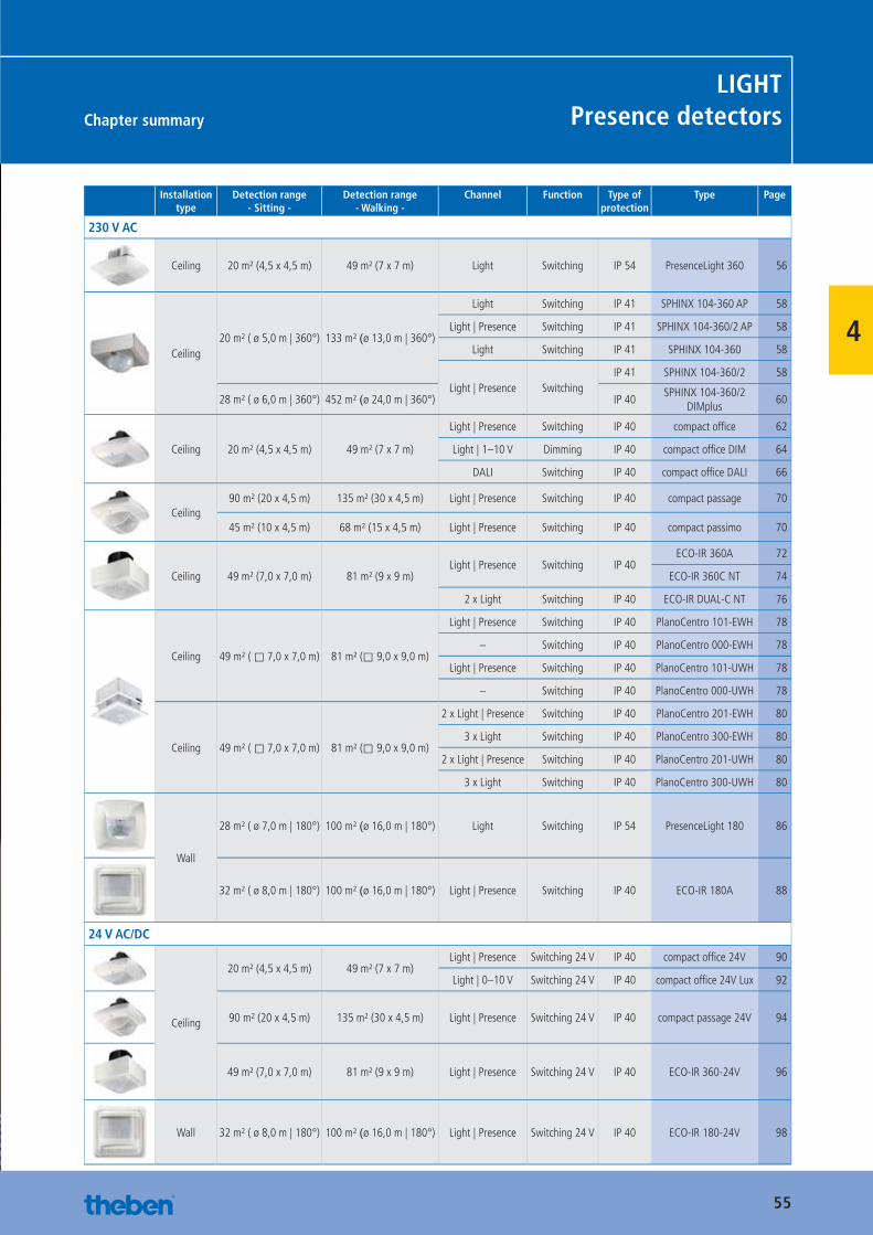
55
Chapter summary
LIGHTPresence detectors
4
Installation type
Detection range- Sitting -
Detection range- Walking -
Channel Function Type of protection
Type Page
230 V AC
Ceiling 20 m² (4,5 x 4,5 m) 49 m² (7 x 7 m) Light Switching IP 54 PresenceLight 360 56
Ceiling20 m² ( ø 5,0 m | 360°) 133 m² (ø 13,0 m | 360°)
Light Switching IP 41 SPHINX 104-360 AP 58
Light | Presence Switching IP 41 SPHINX 104-360/2 AP 58
Light Switching IP 41 SPHINX 104-360 58
Light | Presence SwitchingIP 41 SPHINX 104-360/2 58
28 m² ( ø 6,0 m | 360°) 452 m² (ø 24,0 m | 360°) IP 40SPHINX 104-360/2
DIMplus60
Ceiling 20 m² (4,5 x 4,5 m) 49 m² (7 x 7 m)
Light | Presence Switching IP 40 compact offi ce 62
Light | 1–10 V Dimming IP 40 compact offi ce DIM 64
DALI Switching IP 40 compact offi ce DALI 66
Ceiling90 m² (20 x 4,5 m) 135 m² (30 x 4,5 m) Light | Presence Switching IP 40 compact passage 70
45 m² (10 x 4,5 m) 68 m² (15 x 4,5 m) Light | Presence Switching IP 40 compact passimo 70
Ceiling 49 m² (7,0 x 7,0 m) 81 m² (9 x 9 m)Light | Presence Switching IP 40
ECO-IR 360A 72
ECO-IR 360C NT 74
2 x Light Switching IP 40 ECO-IR DUAL-C NT 76
Ceiling 49 m² ( ⃞ 7,0 x 7,0 m) 81 m² (⃞ 9,0 x 9,0 m)
Light | Presence Switching IP 40 PlanoCentro 101-EWH 78
– Switching IP 40 PlanoCentro 000-EWH 78
Light | Presence Switching IP 40 PlanoCentro 101-UWH 78
– Switching IP 40 PlanoCentro 000-UWH 78
Ceiling 49 m² ( ⃞ 7,0 x 7,0 m) 81 m² (⃞ 9,0 x 9,0 m)
2 x Light | Presence Switching IP 40 PlanoCentro 201-EWH 80
3 x Light Switching IP 40 PlanoCentro 300-EWH 80
2 x Light | Presence Switching IP 40 PlanoCentro 201-UWH 80
3 x Light Switching IP 40 PlanoCentro 300-UWH 80
Wall
28 m² ( ø 7,0 m | 180°) 100 m² (ø 16,0 m | 180°) Light Switching IP 54 PresenceLight 180 86
32 m² ( ø 8,0 m | 180°) 100 m² (ø 16,0 m | 180°) Light | Presence Switching IP 40 ECO-IR 180A 88
24 V AC/DC
Ceiling
20 m² (4,5 x 4,5 m) 49 m² (7 x 7 m)Light | Presence Switching 24 V IP 40 compact offi ce 24V 90
Light | 0–10 V Switching 24 V IP 40 compact offi ce 24V Lux 92
90 m² (20 x 4,5 m) 135 m² (30 x 4,5 m) Light | Presence Switching 24 V IP 40 compact passage 24V 94
49 m² (7,0 x 7,0 m) 81 m² (9 x 9 m) Light | Presence Switching 24 V IP 40 ECO-IR 360-24V 96
Wall 32 m² ( ø 8,0 m | 180°) 100 m² (ø 16,0 m | 180°) Light | Presence Switching 24 V IP 40 ECO-IR 180-24V 98
Catalogue_EN_2013.indb 55 16.01.13 17:20
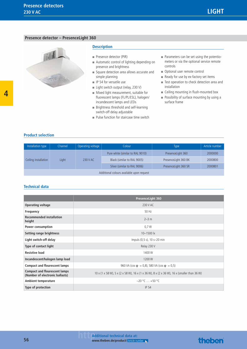
56httpAdditional technical data at:
www.theben.de/product/ Article number
230 V AC LIGHTPresence detectors
4
Presence detector – PresenceLight 360
Description
■ Presence detector (PIR) ■ Automatic control of lighting depending on presence and brightness
■ Square detection area allows accurate and simple planning
■ IP 54 for versatile use ■ Light switch output (relay, 230 V) ■ Mixed light measurement, suitable for fl uorescent lamps (FL/PL/ESL), halogen/incandescent lamps and LEDs
■ Brightness threshold and self-learning switch-off delay adjustable
■ Pulse function for staircase time switch
■ Parameters can be set using the potentio-meters or via the optional service remote controls
■ Optional user remote control ■ Ready for use by ex-factory set items ■ Test operation to check detection area and installation
■ Ceiling mounting in fl ush-mounted box ■ Possibility of surface mounting by using a surface frame
Product selection
Installation type Channel Operating voltage Colour Type Article number
Ceiling installation Light 230 V AC
Pure white (similar to RAL 9010) PresenceLight 360 2000000
Black (similar to RAL 9005) PresenceLight 360 BK 2000800
Silver (similar to RAL 9006) PresenceLight 360 SR 2000801
Additional colours available upon request
Technical data
PresenceLight 360
Operating voltage 230 V AC
Frequency 50 Hz
Recommended installation height
2–3 m
Power consumption 0,7 W
Setting range brightness 10–1500 lx
Light switch-off delay Impuls (0,5 s), 10 s–20 min
Type of contact light Relay 230 V
Resistive load 1400 W
Incandescent/halogen lamp load 1200 W
Compact and fl ourescent lamps 960 VA (cos φ = 0,8), 580 VA (cos φ = 0,5)
Compact and fl ourescent lamps (Number of electronic ballasts)
10 x (1 x 58 W), 5 x (2 x 58 W), 16 x (1 x 36 W), 8 x (2 x 36 W), 16 x (smaller than 36 W)
Ambient temperature –20 °C … +50 °C
Type of protection IP 54
Catalogue_EN_2013.indb 56 16.01.13 17:20
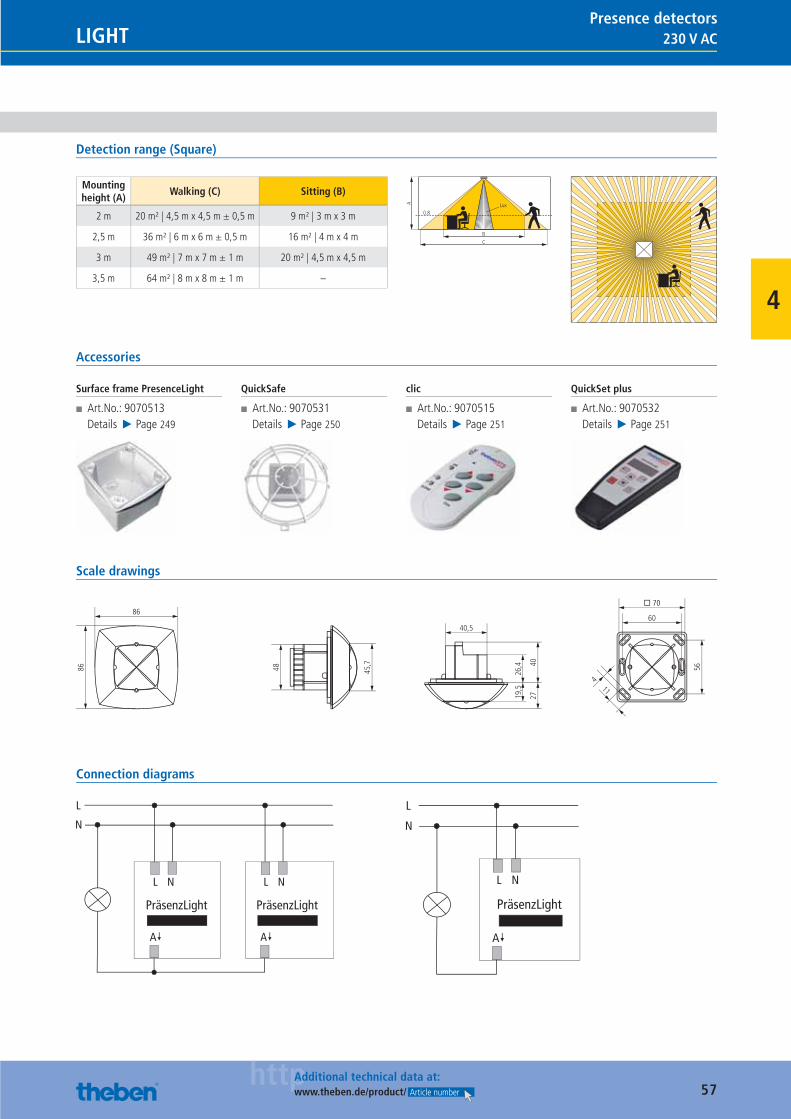
57httpAdditional technical data at:
www.theben.de/product/ Article number
230 V ACLIGHTPresence detectors
4
Detection range (Square)
Mounting height (A)
Walking (C) Sitting (B)
2 m 20 m² | 4,5 m x 4,5 m ± 0,5 m 9 m² | 3 m x 3 m
2,5 m 36 m² | 6 m x 6 m ± 0,5 m 16 m² | 4 m x 4 m
3 m 49 m² | 7 m x 7 m ± 1 m 20 m² | 4,5 m x 4,5 m
3,5 m 64 m² | 8 m x 8 m ± 1 m –
BC
0.8
A Lux
Accessories
Surface frame PresenceLight
■ Art.No.: 9070513Details ▶ Page 249
QuickSafe
■ Art.No.: 9070531Details ▶ Page 250
clic
■ Art.No.: 9070515Details ▶ Page 251
QuickSet plus
■ Art.No.: 9070532Details ▶ Page 251
Scale drawings
115645
,7
48
60
26,4
19,5
4027
40,5
� 70
4
86
86
Connection diagrams
Catalogue_EN_2013.indb 57 16.01.13 17:20
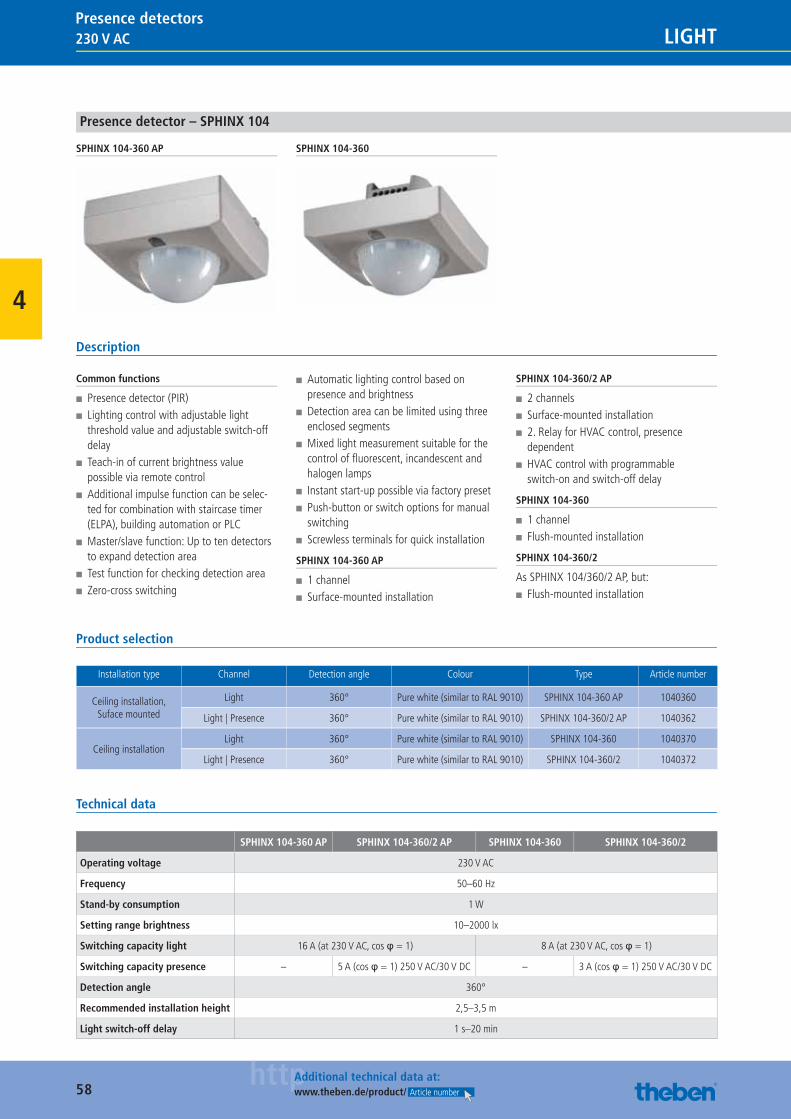
58httpAdditional technical data at:
www.theben.de/product/ Article number
230 V AC LIGHTPresence detectors
4
Presence detector – SPHINX 104
SPHINX 104-360 AP SPHINX 104-360
Description
Common functions
■ Presence detector (PIR) ■ Lighting control with adjustable light threshold value and adjustable switch-off delay
■ Teach-in of current brightness value possible via remote control
■ Additional impulse function can be selec-ted for combination with staircase timer (ELPA), building automation or PLC
■ Master/slave function: Up to ten detectors to expand detection area
■ Test function for checking detection area ■ Zero-cross switching
■ Automatic lighting control based on presence and brightness
■ Detection area can be limited using three enclosed segments
■ Mixed light measurement suitable for the control of fl uorescent, incandescent and halogen lamps
■ Instant start-up possible via factory preset ■ Push-button or switch options for manual switching
■ Screwless terminals for quick installation
SPHINX 104-360 AP
■ 1 channel ■ Surface-mounted installation
SPHINX 104-360/2 AP
■ 2 channels ■ Surface-mounted installation ■ 2. Relay for HVAC control, presence dependent
■ HVAC control with programmable switch-on and switch-off delay
SPHINX 104-360
■ 1 channel ■ Flush-mounted installation
SPHINX 104-360/2
As SPHINX 104/360/2 AP, but: ■ Flush-mounted installation
Product selection
Installation type Channel Detection angle Colour Type Article number
Ceiling installation, Suface mounted
Light 360° Pure white (similar to RAL 9010) SPHINX 104-360 AP 1040360
Light | Presence 360° Pure white (similar to RAL 9010) SPHINX 104-360/2 AP 1040362
Ceiling installationLight 360° Pure white (similar to RAL 9010) SPHINX 104-360 1040370
Light | Presence 360° Pure white (similar to RAL 9010) SPHINX 104-360/2 1040372
Technical data
SPHINX 104-360 AP SPHINX 104-360/2 AP SPHINX 104-360 SPHINX 104-360/2
Operating voltage 230 V AC
Frequency 50–60 Hz
Stand-by consumption 1 W
Setting range brightness 10–2000 lx
Switching capacity light 16 A (at 230 V AC, cos φ = 1) 8 A (at 230 V AC, cos φ = 1)
Switching capacity presence – 5 A (cos φ = 1) 250 V AC/30 V DC – 3 A (cos φ = 1) 250 V AC/30 V DC
Detection angle 360°
Recommended installation height 2,5–3,5 m
Light switch-off delay 1 s–20 min
Catalogue_EN_2013.indb 58 16.01.13 17:20
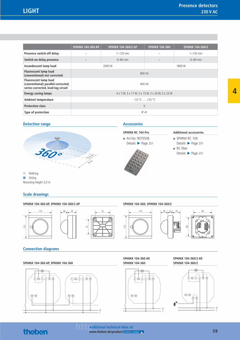
59httpAdditional technical data at:
www.theben.de/product/ Article number
230 V ACLIGHTPresence detectors
4
SPHINX 104-360 AP SPHINX 104-360/2 AP SPHINX 104-360 SPHINX 104-360/2
Presence switch-off delay – 1–120 min – 1–120 min
Switch-on delay presence – 0–60 min – 0–60 min
Incandescent lamp load 2000 W 1800 W
Fluorescent lamp load (conventional) not corrected
900 VA
Fluorescent lamp load (conventional) parallel-corrected, series-corrected, lead-lag circuit
400 VA
Energy saving lamps 4 x 7 W, 3 x 11 W, 3 x 15 W, 3 x 20 W, 3 x 23 W
Ambient temperature –10 °C … +55 °C
Protection class II
Type of protection IP 41
Detection range
2,5 m
6 m
360°■ Walking■ SittingMounting height 3,0 m
Accessories
SPHINX RC 104 Pro
■ Art.No: 9070536Details ▶ Page 251
Additional accessories
■ SPHINX RC 104Details ▶ Page 251
■ RC fi lterDetails ▶ Page 251
Scale drawings
SPHINX 104-360 AP, SPHINX 104-360/2 AP
72
72110
110
4328
SPHINX 104-360, SPHINX 104-360/2
90
90110
110
2528 35
Connection diagrams
SPHINX 104-360 AP, SPHINX 104-360
NL
Ext
M/S M/S
L‘ L L N N Ext
M/S M/S
L‘ L L N N
SPHINX 104-360 AP, SPHINX 104-360
NL
Ext
M/S M/S
L‘ L L N N
SPHINX 104-360/2 AP, SPHINX 104-360/2
NL
Ext
M/S M/S
P1 P2
L‘ L L N N
Catalogue_EN_2013.indb 59 16.01.13 17:20
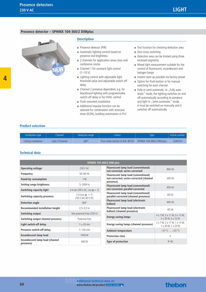
60httpAdditional technical data at:
www.theben.de/product/ Article number
230 V AC LIGHTPresence detectors
4
Presence detector – SPHINX 104-360/2 DIMplus
Description
■ Presence detector (PIR) ■ Automatic lighting control based on presence and brightness
■ 2 channels for application areas class and conference rooms
■ Channel 1 for constant light control (1–10 V)
■ Lighting control with adjustable light threshold value and adjustable switch-off delay
■ Channel 2 presence dependent, e.g. for blackboard lighting with programmable switch-off delay or for HVAC control
■ Flush-mounted installation ■ Additional impulse function can be selected for combination with staircase timer (ELPA), building automation or PLC
■ Test function for checking detection area ■ Zero-cross switching ■ Detection area can be limited using three enclosed segments
■ Mixed light measurement suitable for the control of fl uorescent, incandescent and halogen lamps
■ Instant start-up possible via factory preset ■ Option for Push-button or for manual switching for each channel
■ Fully or semi-automatic: In „Fully auto-matic“ mode, the lighting switches on and off automatically according to presence and light In „Semi-automatic“ mode, it must be switched on manually and it switches off automatically
Product selection
Installation type Channel Detection angle Colour Type Article number
Ceiling installation Light | Presence 360° Pure white (similar to RAL 9010) SPHINX 104-360/2 DIM plus 1040374
Technical data
SPHINX 104-360/2 DIM plus
Operating voltage 230 V AC
Frequency 50–60 Hz
Stand-by consumption 1 W
Setting range brightness 5–2000 lx
Switching capacity light 4 A (at 230 V AC, cos φ = 1)
Switching capacity presence2 A (cos φ = 1)
250 V AC/30 V DC
Detection angle 360°
Recommended installation height 2,5–3,5 m
Switching output Not potential-free (230 V)
Switching output channel presence Potential-free
Light switch-off delay 1 s–20 min
Presence switch-off delay 1–120 min
Incandescent lamp load 1000 W
Incandescent lamp load (channel presence)
400 W
Fluorescent lamp load (conventional) not corrected, series-corrected
900 VA
Fluorescent lamp load (conventional) not corrected, series-corrected (channel presence)
200 VA
Fluorescent lamp load (conventional) not corrected, parallel-corrected
400 VA
Fluorescent lamp load (conventional) parallel-corrected (channel presence)
60 VA
Fluorescent lamp load (electronic ballast)
400 VA
Fluorescent lamp load (electronic ballast) (channel presence)
40 VA
Energy saving lamps4 x 7 W, 3 x 11 W, 3 x 15 W,
3 x 20 W, 3 x 23 W
Energy saving lamps (channel presence)2 x 7 W, 2 x 11 W, 1 x 15 W,
1 x 20 W, 1 x 23 W
Ambient temperature –10 °C … +55 °C
Protection class II
Type of protection IP 40
NEW
Catalogue_EN_2013.indb 60 16.01.13 17:20
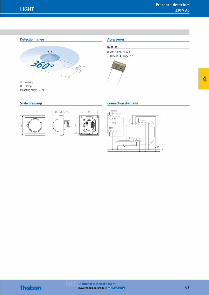
61httpAdditional technical data at:
www.theben.de/product/ Article number
230 V ACLIGHTPresence detectors
4
Detection range
3,0 m
12 m
360°■ Walking■ SittingMounting height 3,0 m
Accessories
RC fi lter
■ Art.No: 9070523Details ▶ Page 251
Scale drawings
90
90110
110
2528 35
Connection diagrams
NL
D+ D–
B1 B2
L L
OUTPUT
EVG
INPUT– +
Ext2 Ext1 L‘ N
Catalogue_EN_2013.indb 61 16.01.13 17:20
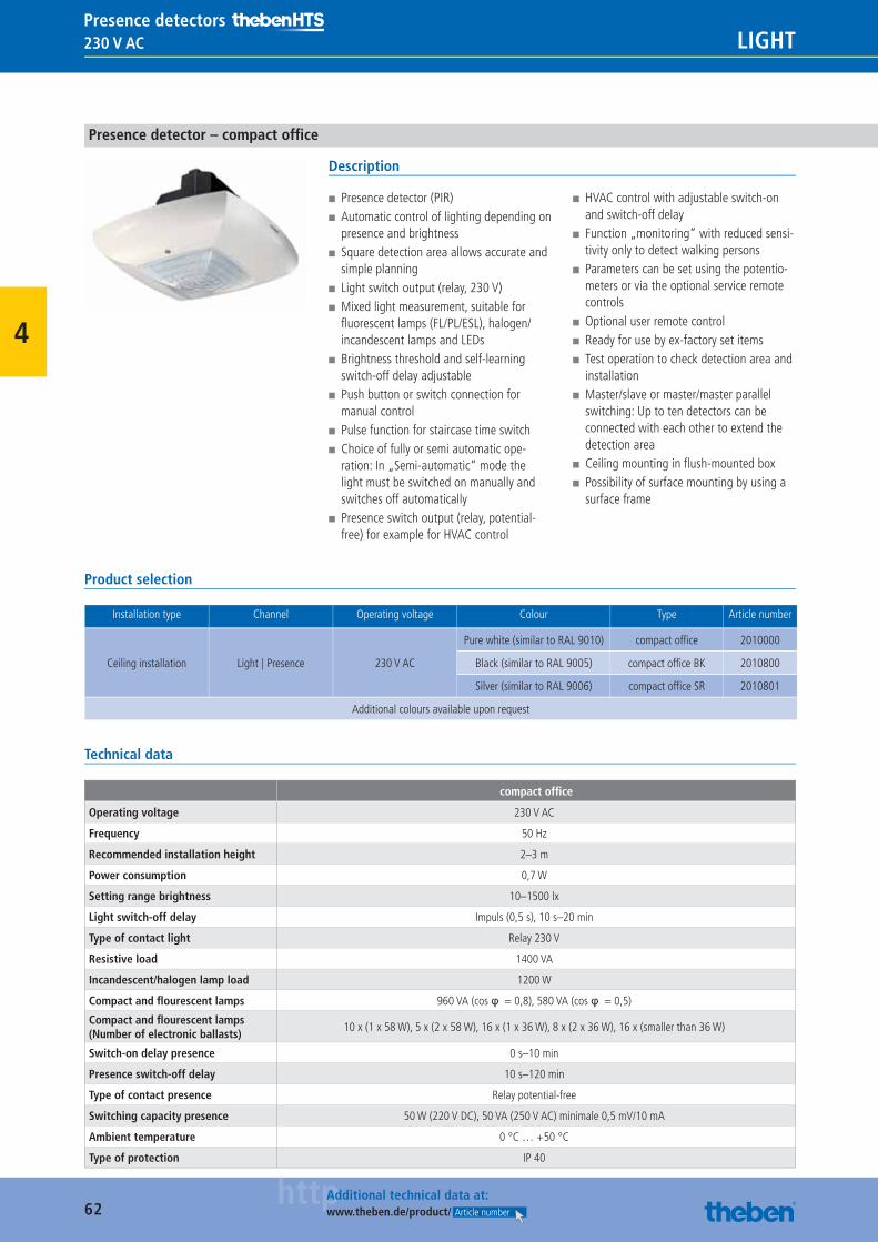
62httpAdditional technical data at:
www.theben.de/product/ Article number
230 V AC LIGHTPresence detectors
4
Presence detector – compact offi ce
Description
■ Presence detector (PIR) ■ Automatic control of lighting depending on presence and brightness
■ Square detection area allows accurate and simple planning
■ Light switch output (relay, 230 V) ■ Mixed light measurement, suitable for fl uorescent lamps (FL/PL/ESL), halogen/incandescent lamps and LEDs
■ Brightness threshold and self-learning switch-off delay adjustable
■ Push button or switch connection for manual control
■ Pulse function for staircase time switch ■ Choice of fully or semi automatic ope-ration: In „Semi-automatic“ mode the light must be switched on manually and switches off automatically
■ Presence switch output (relay, potential-free) for example for HVAC control
■ HVAC control with adjustable switch-on and switch-off delay
■ Function „monitoring“ with reduced sensi-tivity only to detect walking persons
■ Parameters can be set using the potentio-meters or via the optional service remote controls
■ Optional user remote control ■ Ready for use by ex-factory set items ■ Test operation to check detection area and installation
■ Master/slave or master/master parallel switching: Up to ten detectors can be connected with each other to extend the detection area
■ Ceiling mounting in fl ush-mounted box ■ Possibility of surface mounting by using a surface frame
Product selection
Installation type Channel Operating voltage Colour Type Article number
Ceiling installation Light | Presence 230 V AC
Pure white (similar to RAL 9010) compact offi ce 2010000
Black (similar to RAL 9005) compact offi ce BK 2010800
Silver (similar to RAL 9006) compact offi ce SR 2010801
Additional colours available upon request
Technical data
compact offi ce
Operating voltage 230 V AC
Frequency 50 Hz
Recommended installation height 2–3 m
Power consumption 0,7 W
Setting range brightness 10–1500 lx
Light switch-off delay Impuls (0,5 s), 10 s–20 min
Type of contact light Relay 230 V
Resistive load 1400 VA
Incandescent/halogen lamp load 1200 W
Compact and fl ourescent lamps 960 VA (cos φ = 0,8), 580 VA (cos φ = 0,5)
Compact and fl ourescent lamps (Number of electronic ballasts)
10 x (1 x 58 W), 5 x (2 x 58 W), 16 x (1 x 36 W), 8 x (2 x 36 W), 16 x (smaller than 36 W)
Switch-on delay presence 0 s–10 min
Presence switch-off delay 10 s–120 min
Type of contact presence Relay potential-free
Switching capacity presence 50 W (220 V DC), 50 VA (250 V AC) minimale 0,5 mV/10 mA
Ambient temperature 0 °C … +50 °C
Type of protection IP 40
Catalogue_EN_2013.indb 62 16.01.13 17:20
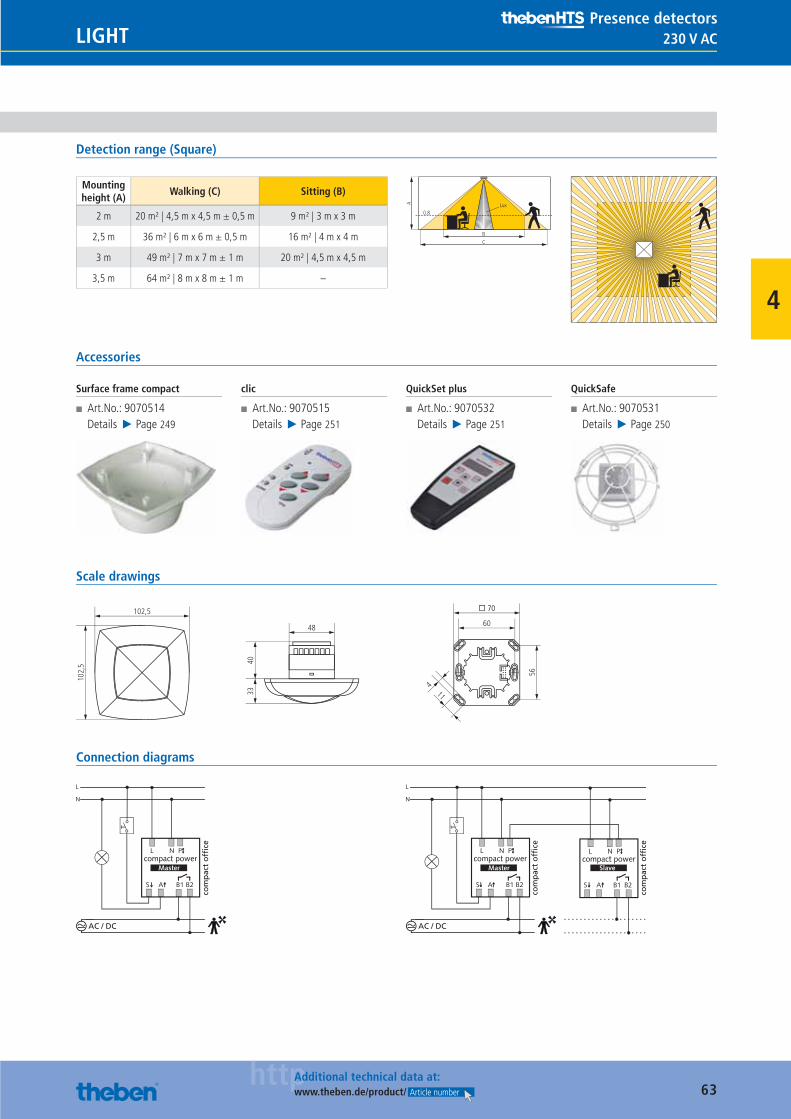
63httpAdditional technical data at:
www.theben.de/product/ Article number
230 V ACLIGHTPresence detectors
4
Detection range (Square)
Mounting height (A)
Walking (C) Sitting (B)
2 m 20 m² | 4,5 m x 4,5 m ± 0,5 m 9 m² | 3 m x 3 m
2,5 m 36 m² | 6 m x 6 m ± 0,5 m 16 m² | 4 m x 4 m
3 m 49 m² | 7 m x 7 m ± 1 m 20 m² | 4,5 m x 4,5 m
3,5 m 64 m² | 8 m x 8 m ± 1 m –
BC
0.8
A Lux
Accessories
Surface frame compact
■ Art.No.: 9070514Details ▶ Page 249
clic
■ Art.No.: 9070515Details ▶ Page 251
QuickSet plus
■ Art.No.: 9070532Details ▶ Page 251
QuickSafe
■ Art.No.: 9070531Details ▶ Page 250
Scale drawings
48
102,
5 4033
102,5
11
56
60
� 70
4
Connection diagrams
AC / DC
com
pac
t o
ffice
compact power
AC / DC
com
pac
t o
ffice
com
pac
t o
ffice
compact power compact power
Catalogue_EN_2013.indb 63 16.01.13 17:20

64httpAdditional technical data at:
www.theben.de/product/ Article number
230 V AC LIGHTPresence detectors
4
Presence detector – compact offi ce DIM
Description
■ Presence detector (PIR) ■ Automatic control of lighting depending on presence and brightness
■ Square detection area allows accurate and simple planning
■ Light switching output (relay, 230 V) and 1–10 V interface
■ Mixed light measurement, suitable for fl uorescent lamps (FL/PL/ESL), halogen/incandescent lamps and LEDs
■ Brightness threshold, self-learning switch-off delay and stand-by time adjustable
■ The stand-by time guarantees a minimum brightness and provides for a sense of security in hospital and care environments as the lighting does not switch off when areas are unoccupied but remains in stand-by mode for the set time
■ Choice of fully or semi automatic operation: In „Semi-automatic“ mode the light must be switched on manually and switches off automatically
■ Parameters can be set using the potentio-meters or via the optional service remote controls
■ Optional user remote control ■ Ready for use by ex-factory set items ■ Test operation to check detection area and installation
■ Master/slave or master/master parallel switching: Up to ten detectors can be connected with each other to extend the detection area
■ Ceiling mounting in fl ush-mounted box ■ Possibility of surface mounting by using a surface frame
Product selection
Installation type Channel Operating voltage Colour Type Article number
Ceiling installation Light | 1-10 V 230 V AC
Pure white (similar to RAL 9010) compact offi ce DIM 2010001
Black (similar to RAL 9005) compact offi ce DIM BK 2010803
Silver (similar to RAL 9006) compact offi ce DIM SR 2010804
Additional colours available upon request
Technical data
compact offi ce DIM
Operating voltage 230 V AC
Frequency 50 Hz
Recommended installation height 2–3 m
Power consumption 0,8 W
Setting range brightness 10–1500 lx
Light switch-off delay 10 s–20 min
Stand-by time light 0 s–60 min
Type of contact light Relay 230 V
Resistive load 1400 VA
Incandescent/halogen lamp load 1200 W
Compact and fl ourescent lamps 960 VA (cos φ = 0,8), 580 VA (cos φ = 0,5)
Compact and fl ourescent lamps (Number of electronic ballasts)
10 x (1 x 58 W), 5 x (2 x 58 W), 16 x (1 x 36 W), 8 x (2 x 36 W), 16 x (smaller than 36 W)
Control output 1–10 V DC/100 mA as per EN 60929/A1
Ambient temperature 0 °C … +50 °C
Type of protection IP 40
Catalogue_EN_2013.indb 64 16.01.13 17:20
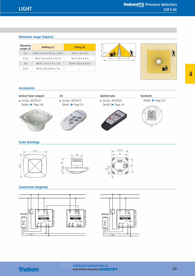
65httpAdditional technical data at:
www.theben.de/product/ Article number
230 V ACLIGHTPresence detectors
4
Detection range (Square)
Mounting height (A)
Walking (C) Sitting (B)
2 m 20 m² | 4,5 m x 4,5 m ± 0,5 m 9 m² | 3 m x 3 m
2,5 m 36 m² | 6 m x 6 m ± 0,5 m 16 m² | 4 m x 4 m
3 m 49 m² | 7 m x 7 m ± 1 m 20 m² | 4,5 m x 4,5 m
3,5 m 64 m² | 8 m x 8 m ± 1 m –
BC
0.8
A Lux
Accessories
Surface frame compact
■ Art.No.: 9070514Details ▶ Page 249
clic
■ Art.No.: 9070515Details ▶ Page 251
QuickSet plus
■ Art.No.: 9070532Details ▶ Page 251
QuickSafe
Details ▶ Page 250
Scale drawings
48
102,
5 4033
102,5
11
56
60
� 70
4
Connection diagrams
com
pac
t o
ffice
DIM
com
pac
t o
ffice
DIM
0 - 10V+ -
0 - 10V+ -
0 - 10V+ -
com
pac
t o
ffice
DIM
Catalogue_EN_2013.indb 65 16.01.13 17:20
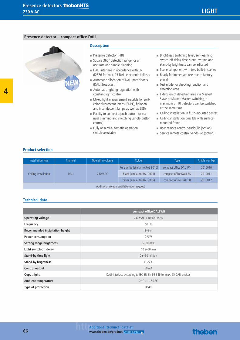
66httpAdditional technical data at:
www.theben.de/product/ Article number
230 V AC LIGHTPresence detectors
4
Presence detector – compact offi ce DALI
Description
■ Presence detector (PIR) ■ Square 360° detection range for an accurate and simple planning
■ DALI interface in accordance with EN 62386 for max. 25 DALI electronic ballasts
■ Automatic allocation of DALI participants (DALI Broadcast)
■ Automatic lighting regulation with constant light control
■ Mixed light measurement suitable for swit-ching fl uorescent lamps (FL/PL), halogen and incandescent lamps as well as LEDs
■ Facility to connect a push button for ma-nual dimming and switching (single-button control)
■ Fully or semi-automatic operation switch-selectable
■ Brightness switching level, self-learning switch-off delay time, stand-by time and stand-by brightness can be adjusted
■ Scene component with two built-in scenes ■ Ready for immediate use due to factory preset
■ Test mode for checking function and detection area
■ Extension of detection area via Master/Slave or Master/Master switching, a maximum of 10 detectors can be switched at the same time
■ Ceiling installation in fl ush-mounted socket ■ Ceiling installation possible with surface-mounted frame
■ User remote control SendoClic (option) ■ Service remote control SendoPro (option)
Product selection
Installation type Channel Operating voltage Colour Type Article number
Ceiling installation DALI 230 V AC
Pure white (similar to RAL 9010) compact offi ce DALI WH 2010010
Black (similar to RAL 9005) compact offi ce DALI BK 2010011
Silver (similar to RAL 9006) compact offi ce DALI SR 2010012
Additional colours available upon request
Technical data
compact offi ce DALI WH
Operating voltage 230 V AC +10 %/–15 %
Frequency 50 Hz
Recommended installation height 2–3 m
Power consumption 0,5 W
Setting range brightness 5–2000 lx
Light switch-off delay 10 s–60 min
Stand-by time light 0 s–60 min/on
Stand-by brightness 1–25 %
Control output 50 mA
Ouput light DALI-interface according to IEC SN EN 62 386 for max. 25 DALI devices
Ambient temperature 0 °C … +50 °C
Type of protection IP 40
NEW
Catalogue_EN_2013.indb 66 16.01.13 17:20
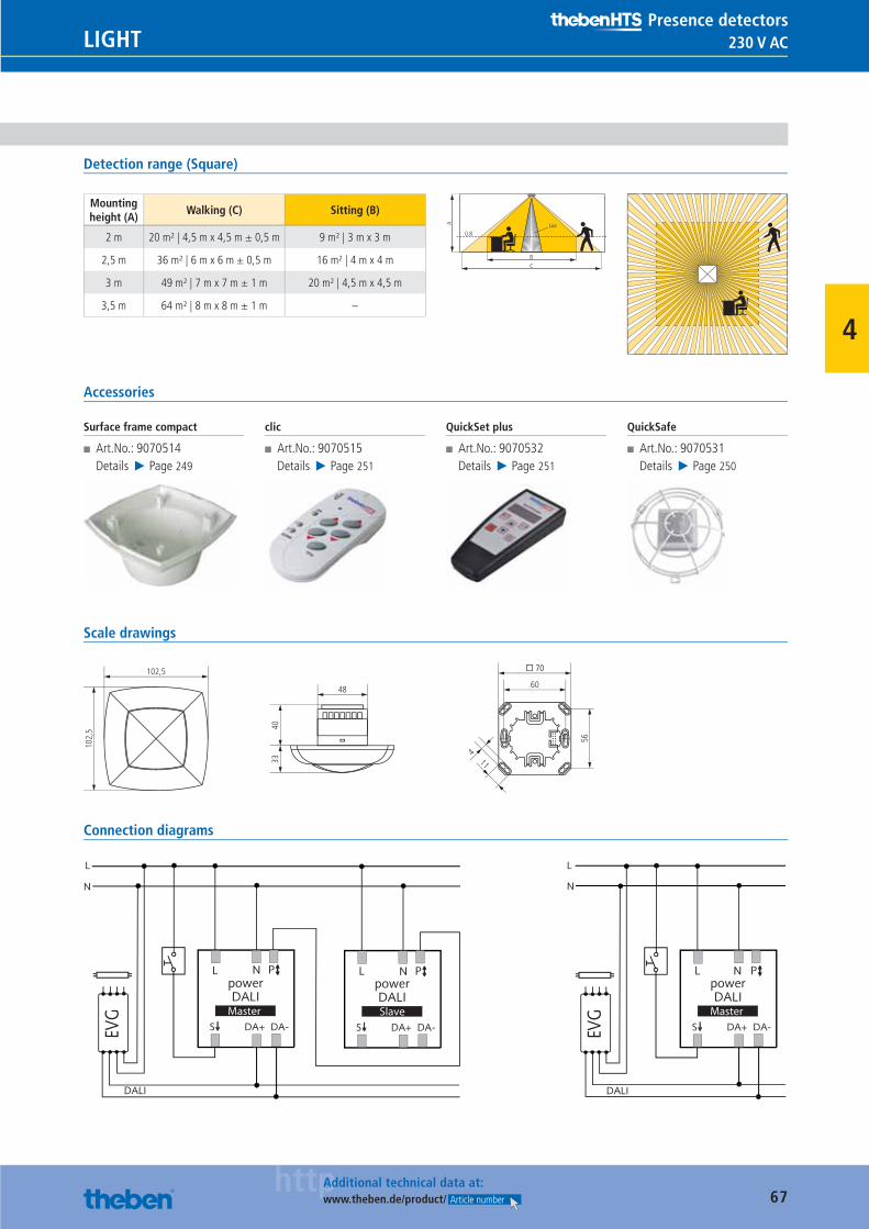
67httpAdditional technical data at:
www.theben.de/product/ Article number
230 V ACLIGHTPresence detectors
4
Detection range (Square)
Mounting height (A)
Walking (C) Sitting (B)
2 m 20 m² | 4,5 m x 4,5 m ± 0,5 m 9 m² | 3 m x 3 m
2,5 m 36 m² | 6 m x 6 m ± 0,5 m 16 m² | 4 m x 4 m
3 m 49 m² | 7 m x 7 m ± 1 m 20 m² | 4,5 m x 4,5 m
3,5 m 64 m² | 8 m x 8 m ± 1 m –
BC
0.8
A Lux
Accessories
Surface frame compact
■ Art.No.: 9070514Details ▶ Page 249
clic
■ Art.No.: 9070515Details ▶ Page 251
QuickSet plus
■ Art.No.: 9070532Details ▶ Page 251
QuickSafe
■ Art.No.: 9070531Details ▶ Page 250
Scale drawings
48
102,
5 4033
102,5
11
56
60
� 70
4
Connection diagrams
L
N
powerDALI
L
S
Master
EVG
DALI
DA+ DA-
powerDALI
L
S
SlaveDA+ DA-
PNPNpowerDALI
L
S
L
N
Master
EVG
DALI
DA+ DA-
PN
Catalogue_EN_2013.indb 67 16.01.13 17:20
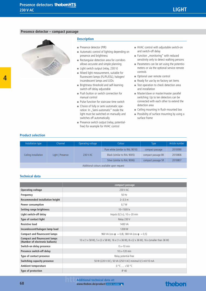
68httpAdditional technical data at:
www.theben.de/product/ Article number
230 V AC LIGHTPresence detectors
4
Presence detector – compact passage
Description
■ Presence detector (PIR) ■ Automatic control of lighting depending on presence and brightness
■ Rectangular detection area for corridors allows accurate and simple planning
■ Light switch output (relay, 230 V) ■ Mixed light measurement, suitable for fl uorescent lamps (FL/PL/ESL), halogen/incandescent lamps and LEDs
■ Brightness threshold and self-learning switch-off delay adjustable
■ Push button or switch connection for manual control
■ Pulse function for staircase time switch ■ Choice of fully or semi automatic ope-ration: In „Semi-automatic“ mode the light must be switched on manually and switches off automatically
■ Presence switch output (relay, potential-free) for example for HVAC control
■ HVAC control with adjustable switch-on and switch-off delay
■ Function „monitoring“ with reduced sensitivity only to detect walking persons
■ Parameters can be set using the potentio-meters or via the optional service remote controls
■ Optional user remote control ■ Ready for use by ex-factory set items ■ Test operation to check detection area and installation
■ Master/slave or master/master parallel switching: Up to ten detectors can be connected with each other to extend the detection area
■ Ceiling mounting in fl ush-mounted box ■ Possibility of surface mounting by using a surface frame
Product selection
Installation type Channel Operating voltage Colour Type Article number
Ceiling installation Light | Presence 230 V AC
Pure white (similar to RAL 9010) compact passage 2010090
Black (similar to RAL 9005) compact passage BK 2010806
Silver (similar to RAL 9006) compact passage SR 2010807
Additional colours available upon request
Technical data
compact passage
Operating voltage 230 V AC
Frequency 50 Hz
Recommended installation height 2–3,5 m
Power consumption 0,7 W
Setting range brightness 10–1500 lx
Light switch-off delay Impuls (0,5 s), 10 s–20 min
Type of contact light Relay 230 V
Resistive load 1400 VA
Incandescent/halogen lamp load 1200 W
Compact and fl ourescent lamps 960 VA (cos φ = 0,8), 580 VA (cos φ = 0,5)
Compact and fl ourescent lamps (Number of electronic ballasts)
10 x (1 x 58 W), 5 x (2 x 58 W), 16 x (1 x 36 W), 8 x (2 x 36 W), 16 x (smaller than 36 W)
Switch-on delay presence 0 s–10 min
Presence switch-off delay 10 s–120 min
Type of contact presence Relay potential-free
Switching capacity presence 50 W (220 V DC), 50 VA (250 V AC) minimal 0,5 mV/10 mA
Ambient temperature 0 °C … +50 °C
Type of protection IP 40
Catalogue_EN_2013.indb 68 16.01.13 17:20
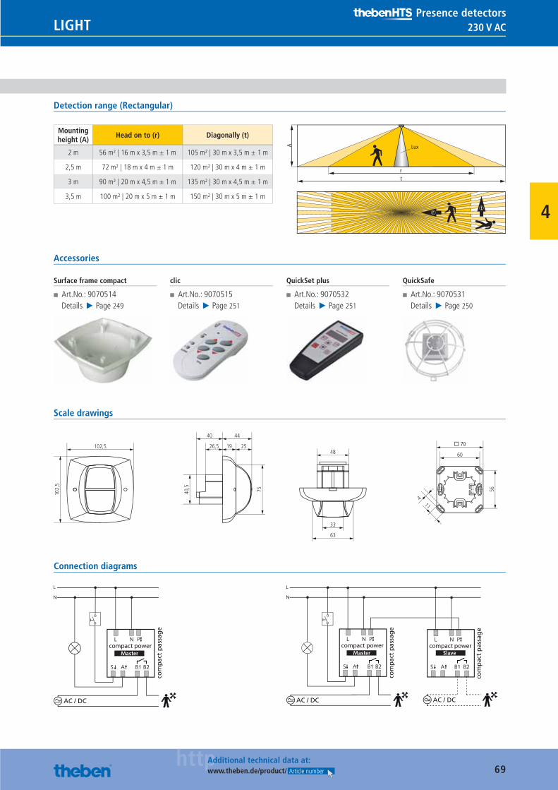
69httpAdditional technical data at:
www.theben.de/product/ Article number
230 V ACLIGHTPresence detectors
4
Detection range (Rectangular)
Mounting height (A)
Head on to (r) Diagonally (t)
2 m 56 m² | 16 m x 3,5 m ± 1 m 105 m² | 30 m x 3,5 m ± 1 m
2,5 m 72 m² | 18 m x 4 m ± 1 m 120 m² | 30 m x 4 m ± 1 m
3 m 90 m² | 20 m x 4,5 m ± 1 m 135 m² | 30 m x 4,5 m ± 1 m
3,5 m 100 m² | 20 m x 5 m ± 1 m 150 m² | 30 m x 5 m ± 1 m
rt
A Lux
tr
Accessories
Surface frame compact
■ Art.No.: 9070514Details ▶ Page 249
clic
■ Art.No.: 9070515Details ▶ Page 251
QuickSet plus
■ Art.No.: 9070532Details ▶ Page 251
QuickSafe
■ Art.No.: 9070531Details ▶ Page 250
Scale drawings
11
56
63
33
48 60
26,5
4440
19
40,5
75
� 70
4
102,
5
102,5 25
Connection diagrams
AC / DC
com
pac
t p
assa
ge
compact power
AC / DC
com
pac
t p
assa
ge
compact power compact power
com
pac
t p
assa
ge
AC / DC
Catalogue_EN_2013.indb 69 16.01.13 17:20

70httpAdditional technical data at:
www.theben.de/product/ Article number
230 V AC LIGHTPresence detectors
4
Presence detector – compact passimo
Description
■ Presence detector (PIR) ■ Automatic control of lighting depending on presence and brightness
■ Rectangular detection area for storage are-as with clear demarcation vertically below the presence detector allows accurate and simple planning
■ Light switch output (relay, 230 V) ■ Mixed light measurement, suitable for fl uorescent lamps (FL/PL/ESL), halogen/incandescent lamps and LEDs
■ Brightness threshold and self-learning switch-off delay adjustable
■ Push button or switch connection for manual control
■ Pulse function for staircase time switch ■ Choice of fully or semi automatic operation: In „Semi-automatic“ mode the light must be switched on manually and switches off automatically
■ Presence switch output (relay, potential-free) for example for HVAC control
■ HVAC control with adjustable switch-on and switch-off delay
■ Function „monitoring“ with reduced sensitivity only to detect walking persons
■ Parameters can be set using the potentio-meters or via the optional service remote controls
■ Optional user remote control ■ Ready for use by ex-factory set items ■ Test operation to check detection area and installation
■ Master/slave or master/master parallel switching: Up to ten detectors can be connected with each other to extend the detection area
■ Ceiling mounting in fl ush-mounted box ■ Possibility of surface mounting by using a surface frame
Product selection
Installation type Channel Operating voltage Colour Type Article number
Ceiling installation Light | Presence 230 V AC
Pure white (similar to RAL 9010) compact passimo WH 2010080
Black (similar to RAL 9005) compact passimo BK 2010809
Silver (similar to RAL 9006) compact passimo SR 2010810
Additional colours available upon request
Technical data
compact passimo WH
Operating voltage 230 V AC
Frequency 50 Hz
Recommended installation height 2–3,5 m
Power consumption 0,7 W
Setting range brightness 10–1500 lx
Light switch-off delay Impuls (0,5 s), 10 s–20 min
Type of contact light Relay 230 V
Resistive load 1400 VA
Incandescent/halogen lamp load 1200 W
Compact and fl ourescent lamps 960 VA (cos φ = 0,8), 580 VA (cos φ = 0,5)
Compact and fl ourescent lamps (Number of electronic ballasts)
10 x (1 x 58 W), 5 x (2 x 58 W), 16 x (1 x 36 W), 8 x (2 x 36 W), 16 x (smaller than 36 W)
Switch-on delay presence 0 s–10 min
Presence switch-off delay 10 s–120 min
Type of contact presence Relay potential-free
Switching capacity presence 50 W (220 V DC), 50 VA (250 V AC) minimal 0,5 mV/10 mA
Ambient temperature 0 °C … +50 °C
Type of protection IP 40
Catalogue_EN_2013.indb 70 16.01.13 17:20
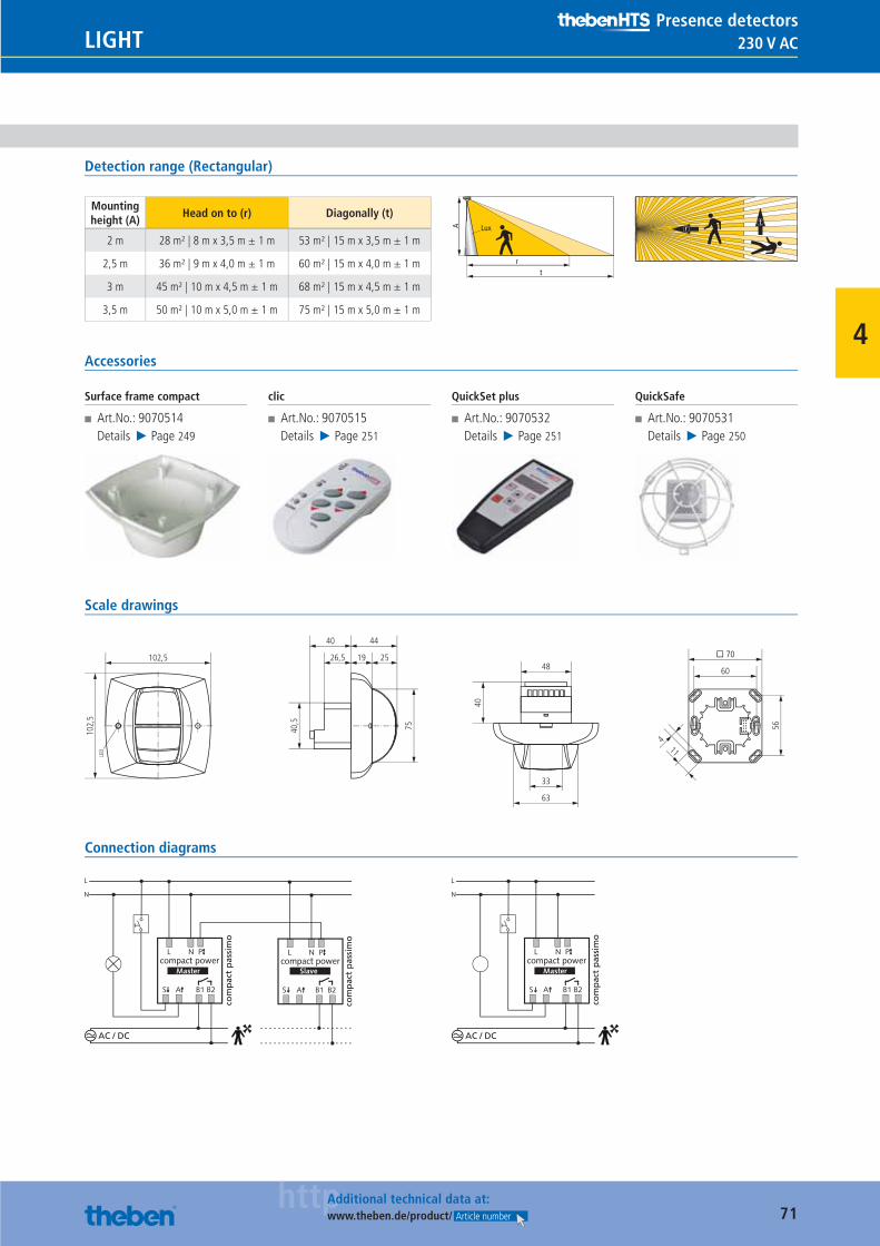
71httpAdditional technical data at:
www.theben.de/product/ Article number
230 V ACLIGHTPresence detectors
4
Detection range (Rectangular)
Mounting height (A)
Head on to (r) Diagonally (t)
2 m 28 m² | 8 m x 3,5 m ± 1 m 53 m² | 15 m x 3,5 m ± 1 m
2,5 m 36 m² | 9 m x 4,0 m ± 1 m 60 m² | 15 m x 4,0 m ± 1 m
3 m 45 m² | 10 m x 4,5 m ± 1 m 68 m² | 15 m x 4,5 m ± 1 m
3,5 m 50 m² | 10 m x 5,0 m ± 1 m 75 m² | 15 m x 5,0 m ± 1 m
rt
A Luxt
r
Accessories
Surface frame compact
■ Art.No.: 9070514Details ▶ Page 249
clic
■ Art.No.: 9070515Details ▶ Page 251
QuickSet plus
■ Art.No.: 9070532Details ▶ Page 251
QuickSafe
■ Art.No.: 9070531Details ▶ Page 250
Scale drawings
11
56
63
33
48 60
26,5
4440
19
40,5
75
� 70
4
102,
5
102,5 25
LED
40
Connection diagrams
AC / DC
com
pac
t p
assi
mo
compact power compact power
com
pac
t p
assi
mo
AC / DC
com
pac
t p
assi
mo
compact power
Catalogue_EN_2013.indb 71 16.01.13 17:20
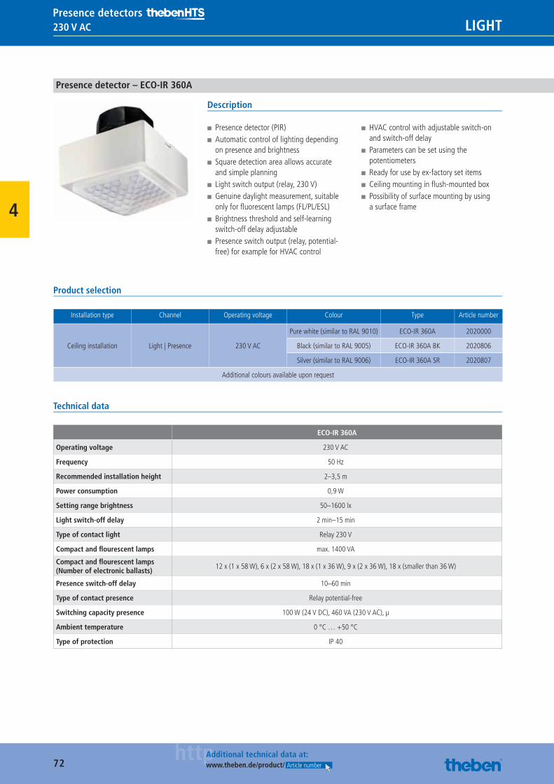
72httpAdditional technical data at:
www.theben.de/product/ Article number
230 V AC LIGHTPresence detectors
4
Presence detector – ECO-IR 360A
Description
■ Presence detector (PIR) ■ Automatic control of lighting depending on presence and brightness
■ Square detection area allows accurate and simple planning
■ Light switch output (relay, 230 V) ■ Genuine daylight measurement, suitable only for fl uorescent lamps (FL/PL/ESL)
■ Brightness threshold and self-learning switch-off delay adjustable
■ Presence switch output (relay, potential-free) for example for HVAC control
■ HVAC control with adjustable switch-on and switch-off delay
■ Parameters can be set using the potentiometers
■ Ready for use by ex-factory set items ■ Ceiling mounting in fl ush-mounted box ■ Possibility of surface mounting by using a surface frame
Product selection
Installation type Channel Operating voltage Colour Type Article number
Ceiling installation Light | Presence 230 V AC
Pure white (similar to RAL 9010) ECO-IR 360A 2020000
Black (similar to RAL 9005) ECO-IR 360A BK 2020806
Silver (similar to RAL 9006) ECO-IR 360A SR 2020807
Additional colours available upon request
Technical data
ECO-IR 360A
Operating voltage 230 V AC
Frequency 50 Hz
Recommended installation height 2–3,5 m
Power consumption 0,9 W
Setting range brightness 50–1600 lx
Light switch-off delay 2 min–15 min
Type of contact light Relay 230 V
Compact and fl ourescent lamps max. 1400 VA
Compact and fl ourescent lamps (Number of electronic ballasts)
12 x (1 x 58 W), 6 x (2 x 58 W), 18 x (1 x 36 W), 9 x (2 x 36 W), 18 x (smaller than 36 W)
Presence switch-off delay 10–60 min
Type of contact presence Relay potential-free
Switching capacity presence 100 W (24 V DC), 460 VA (230 V AC), μ
Ambient temperature 0 °C … +50 °C
Type of protection IP 40
Catalogue_EN_2013.indb 72 16.01.13 17:20
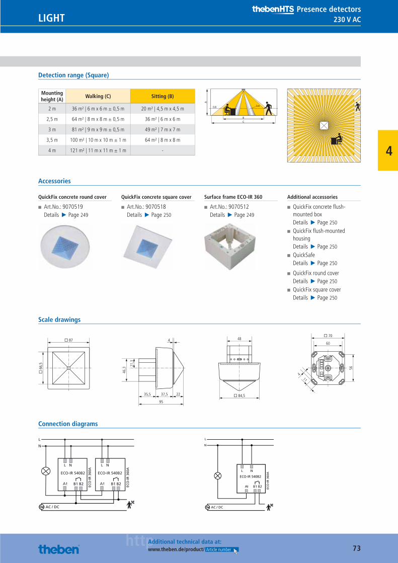
73httpAdditional technical data at:
www.theben.de/product/ Article number
230 V ACLIGHTPresence detectors
4
Detection range (Square)
Mounting height (A)
Walking (C) Sitting (B)
2 m 36 m² | 6 m x 6 m ± 0,5 m 20 m² | 4,5 m x 4,5 m
2,5 m 64 m² | 8 m x 8 m ± 0,5 m 36 m² | 6 m x 6 m
3 m 81 m² | 9 m x 9 m ± 0,5 m 49 m² | 7 m x 7 m
3,5 m 100 m² | 10 m x 10 m ± 1 m 64 m² | 8 m x 8 m
4 m 121 m² | 11 m x 11 m ± 1 m -
BC
0.8
A
Lux
Accessories
QuickFix concrete round cover
■ Art.No.: 9070519Details ▶ Page 249
QuickFix concrete square cover
■ Art.No.: 9070518Details ▶ Page 250
Surface frame ECO-IR 360
■ Art.No.: 9070512Details ▶ Page 249
Additional accessories
■ QuickFix concrete fl ush-mounted boxDetails ▶ Page 250
■ QuickFix fl ush-mounted housingDetails ▶ Page 250
■ QuickSafeDetails ▶ Page 250
■ QuickFix round coverDetails ▶ Page 250
■ QuickFix square coverDetails ▶ Page 250
Scale drawings
21,3
46,3
48
� 84,5
� 6
6,5
� 87
11
56
60
� 70
4
35,5 37,5
95
22
4
Connection diagrams
ECO-IR 540B2
L N
A
L
N
ECO-IR 540B2
L N
AB1 B2 B1 B2
ECO
-IR
360
A
ECO
-IR
360
A
AC / DC
L N
B1 B2
L
N
ECO-IR 540B2
AC / DC
ECO
-IR
360
A
A
Catalogue_EN_2013.indb 73 16.01.13 17:20
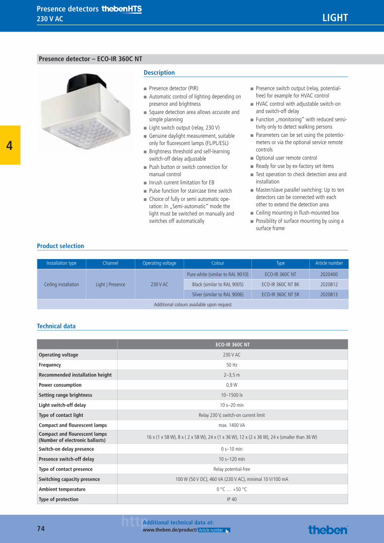
74httpAdditional technical data at:
www.theben.de/product/ Article number
230 V AC LIGHTPresence detectors
4
Presence detector – ECO-IR 360C NT
Description
■ Presence detector (PIR) ■ Automatic control of lighting depending on presence and brightness
■ Square detection area allows accurate and simple planning
■ Light switch output (relay, 230 V) ■ Genuine daylight measurement, suitable only for fl uorescent lamps (FL/PL/ESL)
■ Brightness threshold and self-learning switch-off delay adjustable
■ Push button or switch connection for manual control
■ Inrush current limitation for EB ■ Pulse function for staircase time switch ■ Choice of fully or semi automatic ope-ration: In „Semi-automatic“ mode the light must be switched on manually and switches off automatically
■ Presence switch output (relay, potential-free) for example for HVAC control
■ HVAC control with adjustable switch-on and switch-off delay
■ Function „monitoring“ with reduced sensi-tivity only to detect walking persons
■ Parameters can be set using the potentio-meters or via the optional service remote controls
■ Optional user remote control ■ Ready for use by ex-factory set items ■ Test operation to check detection area and installation
■ Master/slave parallel switching: Up to ten detectors can be connected with each other to extend the detection area
■ Ceiling mounting in fl ush-mounted box ■ Possibility of surface mounting by using a surface frame
Product selection
Installation type Channel Operating voltage Colour Type Article number
Ceiling installation Light | Presence 230 V AC
Pure white (similar to RAL 9010) ECO-IR 360C NT 2020400
Black (similar to RAL 9005) ECO-IR 360C NT BK 2020812
Silver (similar to RAL 9006) ECO-IR 360C NT SR 2020813
Additional colours available upon request
Technical data
ECO-IR 360C NT
Operating voltage 230 V AC
Frequency 50 Hz
Recommended installation height 2–3,5 m
Power consumption 0,9 W
Setting range brightness 10–1500 lx
Light switch-off delay 10 s–20 min
Type of contact light Relay 230 V, switch-on current limit
Compact and fl ourescent lamps max. 1400 VA
Compact and fl ourescent lamps (Number of electronic ballasts)
16 x (1 x 58 W), 8 x ( 2 x 58 W), 24 x (1 x 36 W), 12 x (2 x 36 W), 24 x (smaller than 36 W)
Switch-on delay presence 0 s–10 min
Presence switch-off delay 10 s–120 min
Type of contact presence Relay potential-free
Switching capacity presence 100 W (50 V DC), 460 VA (230 V AC), minimal 10 V/100 mA
Ambient temperature 0 °C … +50 °C
Type of protection IP 40
Catalogue_EN_2013.indb 74 16.01.13 17:20
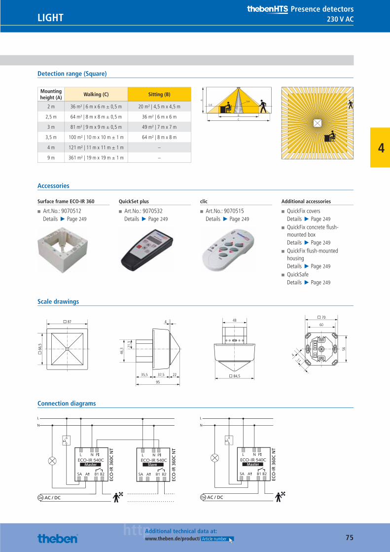
75httpAdditional technical data at:
www.theben.de/product/ Article number
230 V ACLIGHTPresence detectors
4
Detection range (Square)
Mounting height (A)
Walking (C) Sitting (B)
2 m 36 m² | 6 m x 6 m ± 0,5 m 20 m² | 4,5 m x 4,5 m
2,5 m 64 m² | 8 m x 8 m ± 0,5 m 36 m² | 6 m x 6 m
3 m 81 m² | 9 m x 9 m ± 0,5 m 49 m² | 7 m x 7 m
3,5 m 100 m² | 10 m x 10 m ± 1 m 64 m² | 8 m x 8 m
4 m 121 m² | 11 m x 11 m ± 1 m –
9 m 361 m² | 19 m x 19 m ± 1 m –
BC
0.8
A Lux
Accessories
Surface frame ECO-IR 360
■ Art.No.: 9070512Details ▶ Page 249
QuickSet plus
■ Art.No.: 9070532Details ▶ Page 249
clic
■ Art.No.: 9070515Details ▶ Page 249
Additional accessories
■ QuickFix coversDetails ▶ Page 249
■ QuickFix concrete fl ush-mounted boxDetails ▶ Page 249
■ QuickFix fl ush-mounted housingDetails ▶ Page 249
■ QuickSafeDetails ▶ Page 249
Scale drawings
21,3
46,3
48
� 84,5
� 6
6,5
� 87
11
56
60
� 70
4
35,5 37,5
95
22
4
Connection diagrams
AC / DC
ECO
-IR
360
C N
T
ECO
-IR
360
C N
T
AC / DC
ECO
-IR
360
C N
T
Catalogue_EN_2013.indb 75 16.01.13 17:20
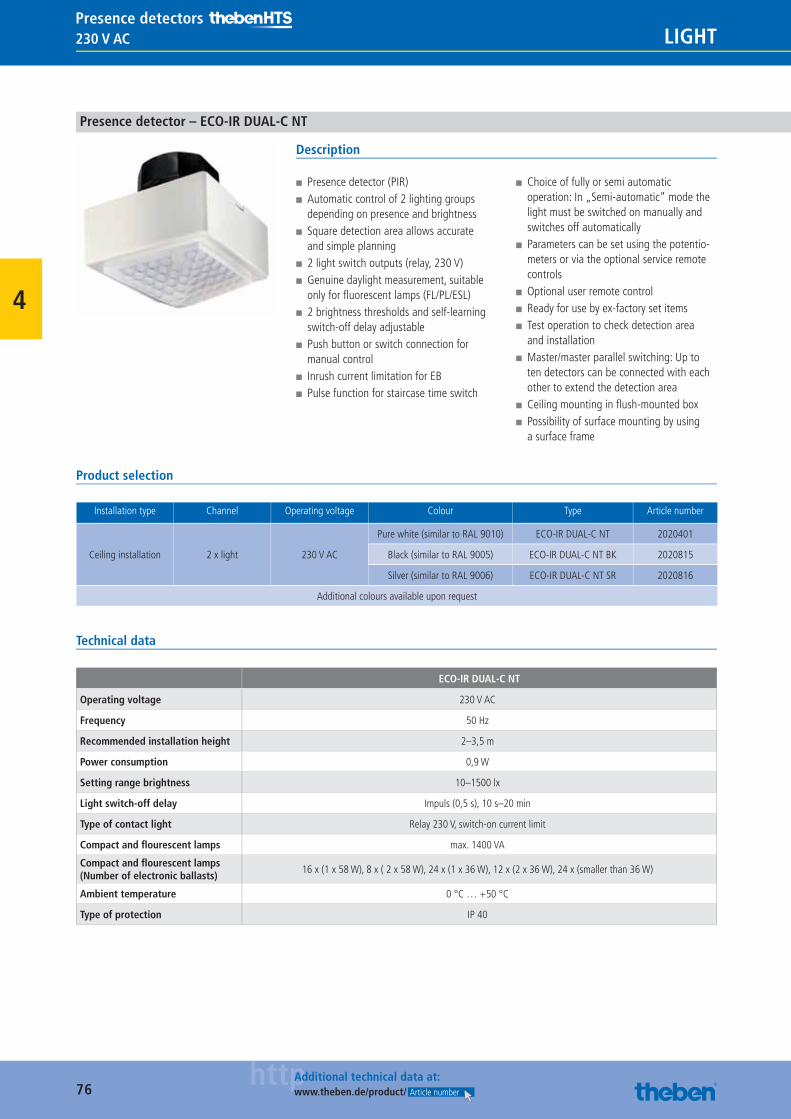
76httpAdditional technical data at:
www.theben.de/product/ Article number
230 V AC LIGHTPresence detectors
4
Presence detector – ECO-IR DUAL-C NT
Description
■ Presence detector (PIR) ■ Automatic control of 2 lighting groups depending on presence and brightness
■ Square detection area allows accurate and simple planning
■ 2 light switch outputs (relay, 230 V) ■ Genuine daylight measurement, suitable only for fl uorescent lamps (FL/PL/ESL)
■ 2 brightness thresholds and self-learning switch-off delay adjustable
■ Push button or switch connection for manual control
■ Inrush current limitation for EB ■ Pulse function for staircase time switch
■ Choice of fully or semi automatic operation: In „Semi-automatic“ mode the light must be switched on manually and switches off automatically
■ Parameters can be set using the potentio-meters or via the optional service remote controls
■ Optional user remote control ■ Ready for use by ex-factory set items ■ Test operation to check detection area and installation
■ Master/master parallel switching: Up to ten detectors can be connected with each other to extend the detection area
■ Ceiling mounting in fl ush-mounted box ■ Possibility of surface mounting by using a surface frame
Product selection
Installation type Channel Operating voltage Colour Type Article number
Ceiling installation 2 x light 230 V AC
Pure white (similar to RAL 9010) ECO-IR DUAL-C NT 2020401
Black (similar to RAL 9005) ECO-IR DUAL-C NT BK 2020815
Silver (similar to RAL 9006) ECO-IR DUAL-C NT SR 2020816
Additional colours available upon request
Technical data
ECO-IR DUAL-C NT
Operating voltage 230 V AC
Frequency 50 Hz
Recommended installation height 2–3,5 m
Power consumption 0,9 W
Setting range brightness 10–1500 lx
Light switch-off delay Impuls (0,5 s), 10 s–20 min
Type of contact light Relay 230 V, switch-on current limit
Compact and fl ourescent lamps max. 1400 VA
Compact and fl ourescent lamps (Number of electronic ballasts)
16 x (1 x 58 W), 8 x ( 2 x 58 W), 24 x (1 x 36 W), 12 x (2 x 36 W), 24 x (smaller than 36 W)
Ambient temperature 0 °C … +50 °C
Type of protection IP 40
Catalogue_EN_2013.indb 76 16.01.13 17:20
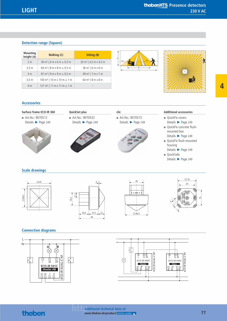
77httpAdditional technical data at:
www.theben.de/product/ Article number
230 V ACLIGHTPresence detectors
4
Detection range (Square)
Mounting height (A)
Walking (C) Sitting (B)
2 m 36 m² | 6 m x 6 m ± 0,5 m 20 m² | 4,5 m x 4,5 m
2,5 m 64 m² | 8 m x 8 m ± 0,5 m 36 m² | 6 m x 6 m
3 m 81 m² | 9 m x 9 m ± 0,5 m 49 m² | 7 m x 7 m
3,5 m 100 m² | 10 m x 10 m ± 1 m 64 m² | 8 m x 8 m
4 m 121 m² | 11 m x 11 m ± 1 m –
BC
0.8
A
Lux
Accessories
Surface frame ECO-IR 360
■ Art.No.: 9070512Details ▶ Page 249
QuickSet plus
■ Art.No.: 9070532Details ▶ Page 249
clic
■ Art.No.: 9070515Details ▶ Page 249
Additional accessories
■ QuickFix coversDetails ▶ Page 249
■ QuickFix concrete fl ush-mounted boxDetails ▶ Page 249
■ QuickFix fl ush-mounted housingDetails ▶ Page 249
■ QuickSafeDetails ▶ Page 249
Scale drawings
21,3
46,3
48
� 84,5
� 6
6,5
� 87
11
56
60
� 70
4
35,5 37,5
95
22
4
Connection diagrams
ECO
-IR
DU
AL-
C N
T
ECO
-IR
DU
AL-
C N
T
ECO
-IR
DU
AL-
C N
T
Catalogue_EN_2013.indb 77 16.01.13 17:20
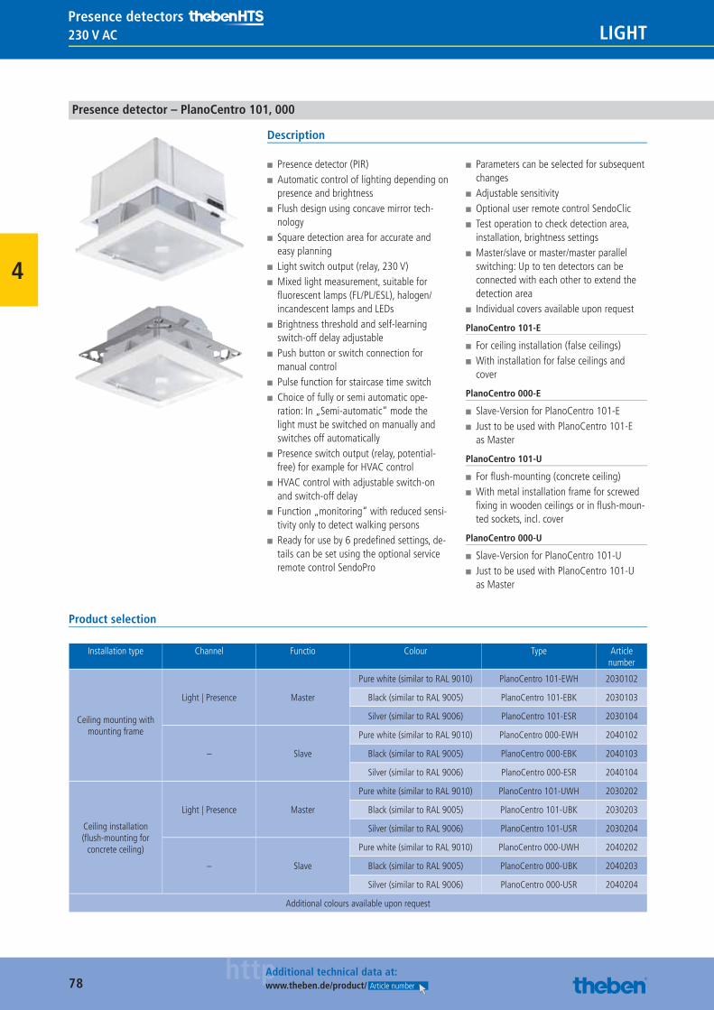
78httpAdditional technical data at:
www.theben.de/product/ Article number
230 V AC LIGHTPresence detectors
4
Presence detector – PlanoCentro 101, 000
Description
■ Presence detector (PIR) ■ Automatic control of lighting depending on presence and brightness
■ Flush design using concave mirror tech-nology
■ Square detection area for accurate and easy planning
■ Light switch output (relay, 230 V) ■ Mixed light measurement, suitable for fl uorescent lamps (FL/PL/ESL), halogen/incandescent lamps and LEDs
■ Brightness threshold and self-learning switch-off delay adjustable
■ Push button or switch connection for manual control
■ Pulse function for staircase time switch ■ Choice of fully or semi automatic ope-ration: In „Semi-automatic“ mode the light must be switched on manually and switches off automatically
■ Presence switch output (relay, potential-free) for example for HVAC control
■ HVAC control with adjustable switch-on and switch-off delay
■ Function „monitoring“ with reduced sensi-tivity only to detect walking persons
■ Ready for use by 6 predefi ned settings, de-tails can be set using the optional service remote control SendoPro
■ Parameters can be selected for subsequent changes
■ Adjustable sensitivity ■ Optional user remote control SendoClic ■ Test operation to check detection area, installation, brightness settings
■ Master/slave or master/master parallel switching: Up to ten detectors can be connected with each other to extend the detection area
■ Individual covers available upon request
PlanoCentro 101-E
■ For ceiling installation (false ceilings) ■ With installation for false ceilings and cover
PlanoCentro 000-E
■ Slave-Version for PlanoCentro 101-E ■ Just to be used with PlanoCentro 101-E as Master
PlanoCentro 101-U
■ For fl ush-mounting (concrete ceiling) ■ With metal installation frame for screwed fi xing in wooden ceilings or in fl ush-moun-ted sockets, incl. cover
PlanoCentro 000-U
■ Slave-Version for PlanoCentro 101-U ■ Just to be used with PlanoCentro 101-U as Master
Product selection
Installation type Channel Functio Colour Type Article number
Ceiling mounting with mounting frame
Light | Presence Master
Pure white (similar to RAL 9010) PlanoCentro 101-EWH 2030102
Black (similar to RAL 9005) PlanoCentro 101-EBK 2030103
Silver (similar to RAL 9006) PlanoCentro 101-ESR 2030104
– Slave
Pure white (similar to RAL 9010) PlanoCentro 000-EWH 2040102
Black (similar to RAL 9005) PlanoCentro 000-EBK 2040103
Silver (similar to RAL 9006) PlanoCentro 000-ESR 2040104
Ceiling installation (fl ush-mounting for
concrete ceiling)
Light | Presence Master
Pure white (similar to RAL 9010) PlanoCentro 101-UWH 2030202
Black (similar to RAL 9005) PlanoCentro 101-UBK 2030203
Silver (similar to RAL 9006) PlanoCentro 101-USR 2030204
– Slave
Pure white (similar to RAL 9010) PlanoCentro 000-UWH 2040202
Black (similar to RAL 9005) PlanoCentro 000-UBK 2040203
Silver (similar to RAL 9006) PlanoCentro 000-USR 2040204
Additional colours available upon request
Catalogue_EN_2013.indb 78 16.01.13 17:20
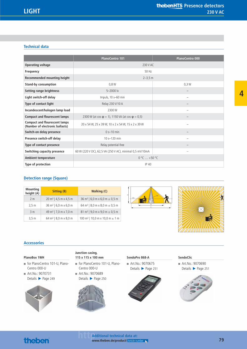
79httpAdditional technical data at:
www.theben.de/product/ Article number
230 V ACLIGHTPresence detectors
4
Technical data
PlanoCentro 101 PlanoCentro 000
Operating voltage 230 V AC
Frequency 50 Hz
Recommended mounting height 2–3,5 m
Stand-by consumption 0,8 W 0,3 W
Setting range brightness 5–2000 lx –
Light switch-off delay Impuls, 10 s–60 min –
Type of contact light Relay 230 V/10 A –
Incandescent/halogen lamp load 2300 W –
Compact and fl ourescent lamps 2300 W (at cos φ = 1), 1150 VA (at cos φ = 0,5) –
Compact and fl ourescent lamps (Number of electronic ballasts)
20 x 54 W, 25 x 39 W, 10 x 2 x 54 W, 15 x 2 x 39 W –
Switch-on delay presence 0 s–10 min –
Presence switch-off delay 10 s–120 min –
Type of contact presence Relay potential-free –
Switching capacity presence 60 W (220 V DC), 62,5 VA (250 V AC), minimal 0,5 mV/10mA –
Ambient temperature 0 °C … +50 °C
Type of protection IP 40
Detection range (Square)
Mounting height (A)
Sitting (B) Walking (C)
2 m 20 m² | 4,5 m x 4,5 m 36 m² | 6,0 m x 6,0 m ± 0,5 m
2,5 m 36 m² | 6,0 m x 6,0 m 64 m² | 8,0 m x 8,0 m ± 0,5 m
3 m 49 m² | 7,0 m x 7,0 m 81 m² | 9,0 m x 9,0 m ± 0,5 m
3,5 m 64 m² | 8,0 m x 8,0 m 100 m² | 10,0 m x 10,0 m ± 1 m
BC
0.8
A Lux
Accessories
PlanoBox 1WH
■ for PlanoCentro 101-U, Plano-Centro 000-U
■ Art.No.: 9070731Details ▶ Page 249
Junction casing, 115 x 115 x 100 mm
■ for PlanoCentro 101-U, Plano-Centro 000-U
■ Art.No.: 9070689Details ▶ Page 250
SendoPro 868-A
■ Art.No.: 9070675Details ▶ Page 251
SendoClic
■ Art.No.: 9070690Details ▶ Page 251
Catalogue_EN_2013.indb 79 16.01.13 17:20
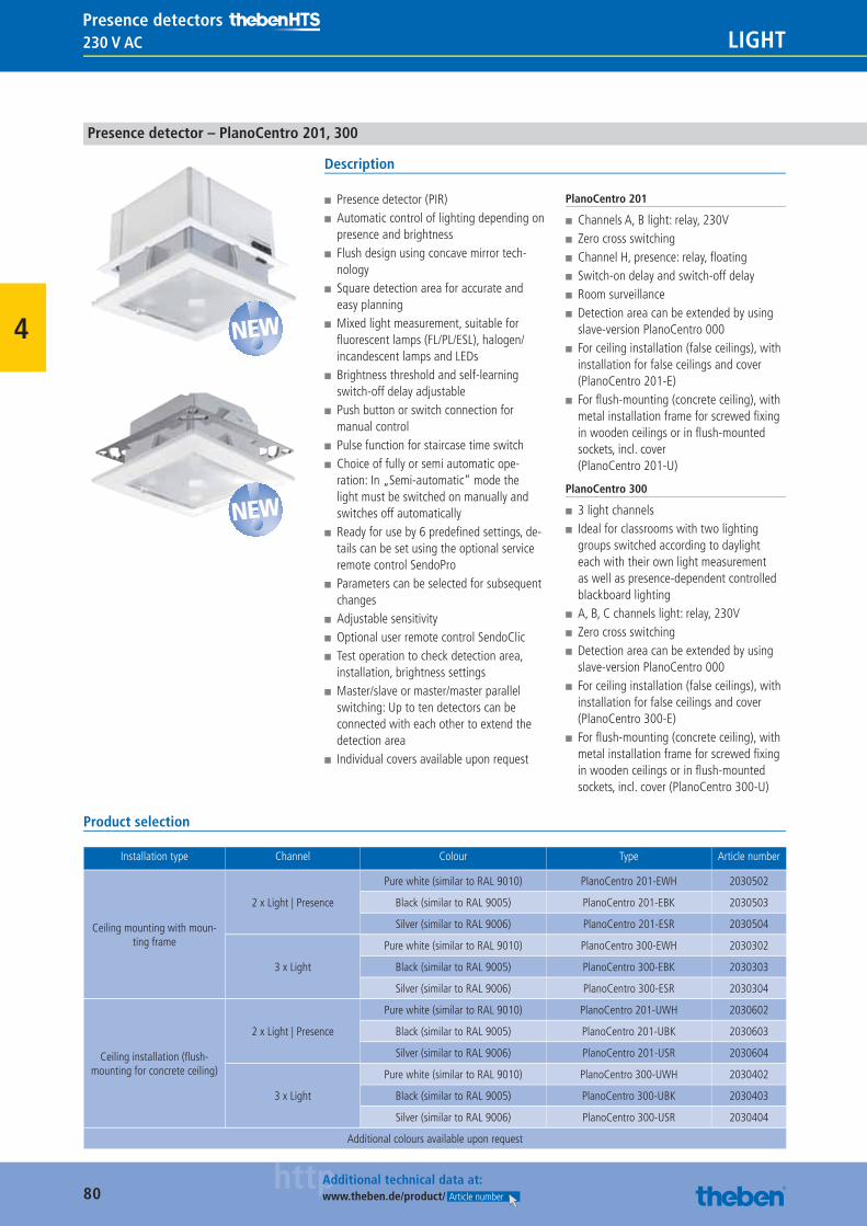
80httpAdditional technical data at:
www.theben.de/product/ Article number
230 V AC LIGHTPresence detectors
4
Presence detector – PlanoCentro 201, 300
Description
■ Presence detector (PIR) ■ Automatic control of lighting depending on presence and brightness
■ Flush design using concave mirror tech-nology
■ Square detection area for accurate and easy planning
■ Mixed light measurement, suitable for fl uorescent lamps (FL/PL/ESL), halogen/incandescent lamps and LEDs
■ Brightness threshold and self-learning switch-off delay adjustable
■ Push button or switch connection for manual control
■ Pulse function for staircase time switch ■ Choice of fully or semi automatic ope-ration: In „Semi-automatic“ mode the light must be switched on manually and switches off automatically
■ Ready for use by 6 predefi ned settings, de-tails can be set using the optional service remote control SendoPro
■ Parameters can be selected for subsequent changes
■ Adjustable sensitivity ■ Optional user remote control SendoClic ■ Test operation to check detection area, installation, brightness settings
■ Master/slave or master/master parallel switching: Up to ten detectors can be connected with each other to extend the detection area
■ Individual covers available upon request
PlanoCentro 201
■ Channels A, B light: relay, 230V ■ Zero cross switching ■ Channel H, presence: relay, fl oating ■ Switch-on delay and switch-off delay ■ Room surveillance ■ Detection area can be extended by using slave-version PlanoCentro 000
■ For ceiling installation (false ceilings), with installation for false ceilings and cover (PlanoCentro 201-E)
■ For fl ush-mounting (concrete ceiling), with metal installation frame for screwed fi xing in wooden ceilings or in fl ush-mounted sockets, incl. cover(PlanoCentro 201-U)
PlanoCentro 300
■ 3 light channels ■ Ideal for classrooms with two lighting groups switched according to daylight each with their own light measurement as well as presence-dependent controlled blackboard lighting
■ A, B, C channels light: relay, 230V ■ Zero cross switching ■ Detection area can be extended by using slave-version PlanoCentro 000
■ For ceiling installation (false ceilings), with installation for false ceilings and cover (PlanoCentro 300-E)
■ For fl ush-mounting (concrete ceiling), with metal installation frame for screwed fi xing in wooden ceilings or in fl ush-mounted sockets, incl. cover (PlanoCentro 300-U)
Product selection
Installation type Channel Colour Type Article number
Ceiling mounting with moun-ting frame
2 x Light | Presence
Pure white (similar to RAL 9010) PlanoCentro 201-EWH 2030502
Black (similar to RAL 9005) PlanoCentro 201-EBK 2030503
Silver (similar to RAL 9006) PlanoCentro 201-ESR 2030504
3 x Light
Pure white (similar to RAL 9010) PlanoCentro 300-EWH 2030302
Black (similar to RAL 9005) PlanoCentro 300-EBK 2030303
Silver (similar to RAL 9006) PlanoCentro 300-ESR 2030304
Ceiling installation (fl ush-mounting for concrete ceiling)
2 x Light | Presence
Pure white (similar to RAL 9010) PlanoCentro 201-UWH 2030602
Black (similar to RAL 9005) PlanoCentro 201-UBK 2030603
Silver (similar to RAL 9006) PlanoCentro 201-USR 2030604
3 x Light
Pure white (similar to RAL 9010) PlanoCentro 300-UWH 2030402
Black (similar to RAL 9005) PlanoCentro 300-UBK 2030403
Silver (similar to RAL 9006) PlanoCentro 300-USR 2030404
Additional colours available upon request
NEW
NEW
Catalogue_EN_2013.indb 80 16.01.13 17:20
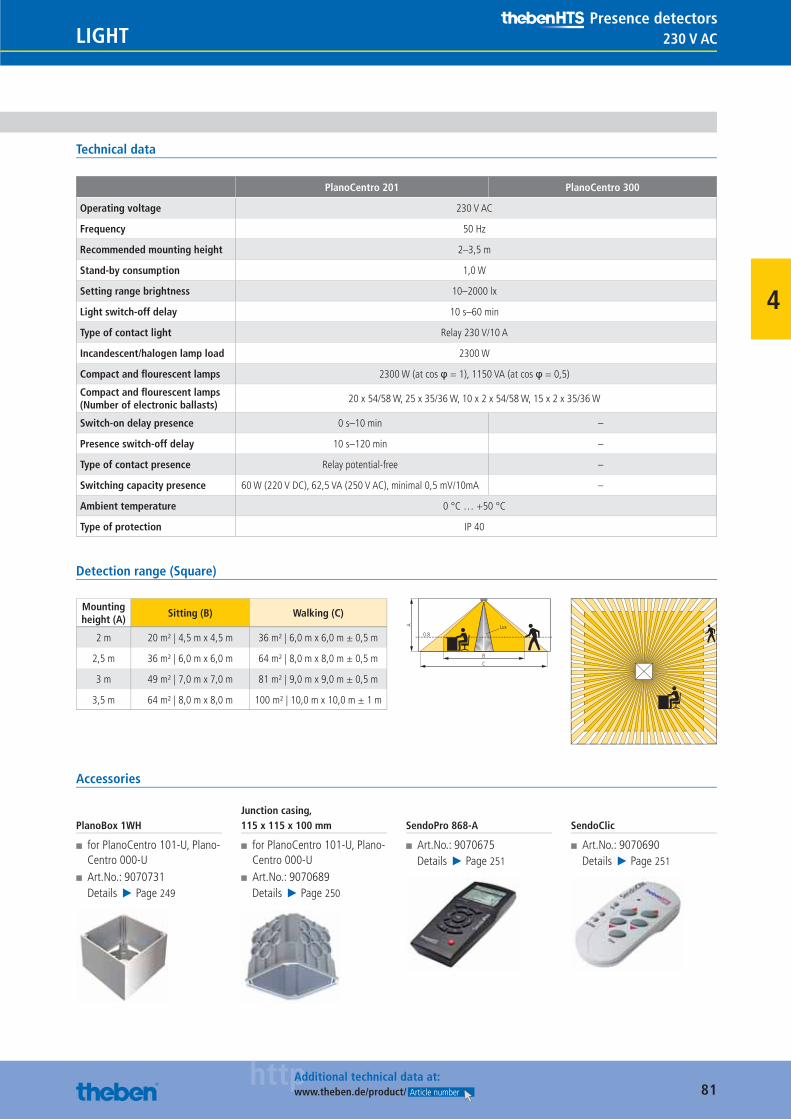
81httpAdditional technical data at:
www.theben.de/product/ Article number
230 V ACLIGHTPresence detectors
4
Technical data
PlanoCentro 201 PlanoCentro 300
Operating voltage 230 V AC
Frequency 50 Hz
Recommended mounting height 2–3,5 m
Stand-by consumption 1,0 W
Setting range brightness 10–2000 lx
Light switch-off delay 10 s–60 min
Type of contact light Relay 230 V/10 A
Incandescent/halogen lamp load 2300 W
Compact and fl ourescent lamps 2300 W (at cos φ = 1), 1150 VA (at cos φ = 0,5)
Compact and fl ourescent lamps (Number of electronic ballasts)
20 x 54/58 W, 25 x 35/36 W, 10 x 2 x 54/58 W, 15 x 2 x 35/36 W
Switch-on delay presence 0 s–10 min –
Presence switch-off delay 10 s–120 min –
Type of contact presence Relay potential-free –
Switching capacity presence 60 W (220 V DC), 62,5 VA (250 V AC), minimal 0,5 mV/10mA –
Ambient temperature 0 °C … +50 °C
Type of protection IP 40
Detection range (Square)
Mounting height (A)
Sitting (B) Walking (C)
2 m 20 m² | 4,5 m x 4,5 m 36 m² | 6,0 m x 6,0 m ± 0,5 m
2,5 m 36 m² | 6,0 m x 6,0 m 64 m² | 8,0 m x 8,0 m ± 0,5 m
3 m 49 m² | 7,0 m x 7,0 m 81 m² | 9,0 m x 9,0 m ± 0,5 m
3,5 m 64 m² | 8,0 m x 8,0 m 100 m² | 10,0 m x 10,0 m ± 1 m
BC
0.8
A Lux
Accessories
PlanoBox 1WH
■ for PlanoCentro 101-U, Plano-Centro 000-U
■ Art.No.: 9070731Details ▶ Page 249
Junction casing, 115 x 115 x 100 mm
■ for PlanoCentro 101-U, Plano-Centro 000-U
■ Art.No.: 9070689Details ▶ Page 250
SendoPro 868-A
■ Art.No.: 9070675Details ▶ Page 251
SendoClic
■ Art.No.: 9070690Details ▶ Page 251
Catalogue_EN_2013.indb 81 16.01.13 17:20
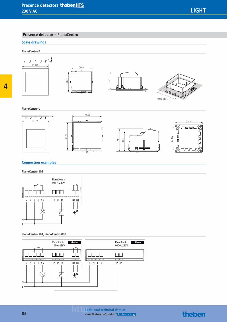
82httpAdditional technical data at:
www.theben.de/product/ Article number
230 V AC LIGHTPresence detectors
4
Presence detector – PlanoCentro
Scale drawings
PlanoCentro E
£ 112
100 x 100 ± 1
5
£ 89£
83
5
73PlanoCentro U
� 123
6
� 118
� 1
07
� 89
� 8
3
6270
Connection examples
PlanoCentro 101
N N L L P P S1 H2
PlanoCentro101-A-230V
H1
N
L
A
PlanoCentro 101, PlanoCentro 000
N N L L P P S1 H2
PlanoCentro101-A-230V
H1
N
L
N N L L P P
PlanoCentro000-A-230V
SlaveMaster
A
Catalogue_EN_2013.indb 82 16.01.13 17:20
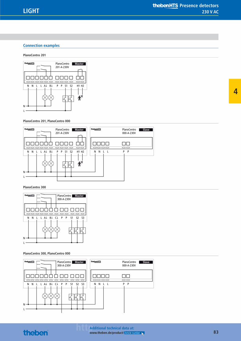
83httpAdditional technical data at:
www.theben.de/product/ Article number
230 V ACLIGHTPresence detectors
4
Connection examples
PlanoCentro 201
N N L L A� P P S1 H2
PlanoCentro201-A-230V
H1
N
L
Master
B� S2
PlanoCentro 201, PlanoCentro 000
N N L L A� P P S1 H2
PlanoCentro201-A-230V
H1
N
L
N N L L P P
PlanoCentro000-A-230V
SlaveMaster
B� S2
PlanoCentro 300
N
L
N N L L A� P P S1
PlanoCentro300-A-230V
Master
B� S2C� S3
PlanoCentro 300, PlanoCentro 000
N
L
N N L L P P
PlanoCentro000-A-230V
Slave
N N L L A� P P S1
PlanoCentro300-A-230V
Master
B� S2C� S3
Catalogue_EN_2013.indb 83 16.01.13 17:21
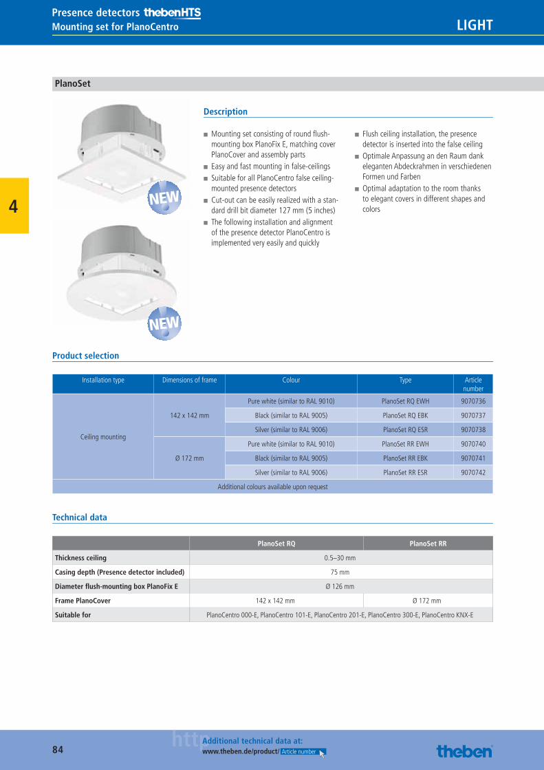
84httpAdditional technical data at:
www.theben.de/product/ Article number
LIGHTPresence detectorsMounting set for PlanoCentro
4
PlanoSet
Description
■ Mounting set consisting of round fl ush-mounting box PlanoFix E, matching cover PlanoCover and assembly parts
■ Easy and fast mounting in false-ceilings ■ Suitable for all PlanoCentro false ceiling-mounted presence detectors
■ Cut-out can be easily realized with a stan-dard drill bit diameter 127 mm (5 inches)
■ The following installation and alignment of the presence detector PlanoCentro is implemented very easily and quickly
■ Flush ceiling installation, the presence detector is inserted into the false ceiling
■ Optimale Anpassung an den Raum dank eleganten Abdeckrahmen in verschiedenen Formen und Farben
■ Optimal adaptation to the room thanks to elegant covers in different shapes and colors
Product selection
Installation type Dimensions of frame Colour Type Article number
Ceiling mounting
142 x 142 mm
Pure white (similar to RAL 9010) PlanoSet RQ EWH 9070736
Black (similar to RAL 9005) PlanoSet RQ EBK 9070737
Silver (similar to RAL 9006) PlanoSet RQ ESR 9070738
Ø 172 mm
Pure white (similar to RAL 9010) PlanoSet RR EWH 9070740
Black (similar to RAL 9005) PlanoSet RR EBK 9070741
Silver (similar to RAL 9006) PlanoSet RR ESR 9070742
Additional colours available upon request
Technical data
PlanoSet RQ PlanoSet RR
Thickness ceiling 0.5–30 mm
Casing depth (Presence detector included) 75 mm
Diameter fl ush-mounting box PlanoFix E Ø 126 mm
Frame PlanoCover 142 x 142 mm Ø 172 mm
Suitable for PlanoCentro 000-E, PlanoCentro 101-E, PlanoCentro 201-E, PlanoCentro 300-E, PlanoCentro KNX-E
NEW
NEW
Catalogue_EN_2013.indb 84 16.01.13 17:21
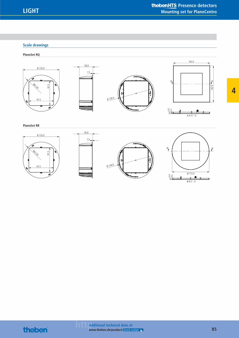
85httpAdditional technical data at:
www.theben.de/product/ Article number
LIGHTPresence detectors
Mounting set for PlanoCentro
4
Scale drawings
PlanoSet RQ
Ø 135.0
91.
5
91.5
R61.50
Ø 126.0
50.0
1.5
6.1
5
4.5
142.0
142.
0
AA
A-A (1 : 1)
PlanoSet RR
Ø 135.0
91.
5
91.5
R61.50
Ø 126.0
50.0
1.5
Ø 172.0
BB
B-B (1 : 1)
6.1
5
4.5
Catalogue_EN_2013.indb 85 16.01.13 17:21
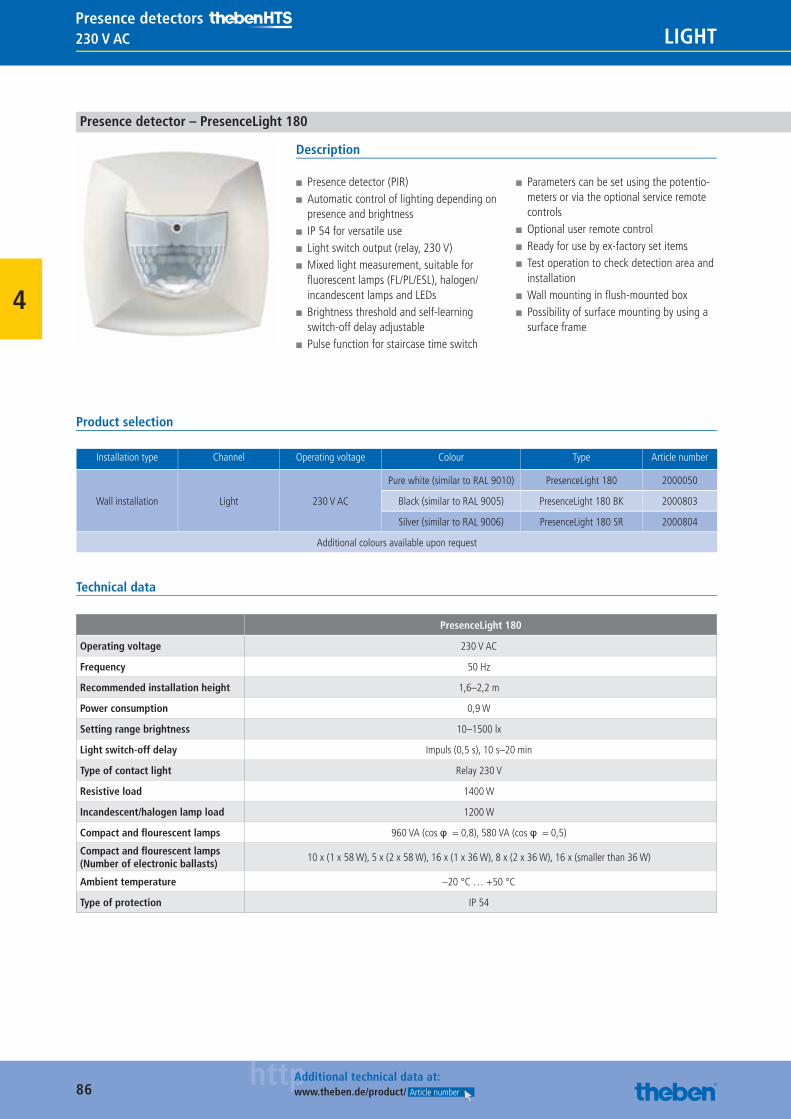
86httpAdditional technical data at:
www.theben.de/product/ Article number
230 V AC LIGHTPresence detectors
4
Presence detector – PresenceLight 180
Description
■ Presence detector (PIR) ■ Automatic control of lighting depending on presence and brightness
■ IP 54 for versatile use ■ Light switch output (relay, 230 V) ■ Mixed light measurement, suitable for fl uorescent lamps (FL/PL/ESL), halogen/incandescent lamps and LEDs
■ Brightness threshold and self-learning switch-off delay adjustable
■ Pulse function for staircase time switch
■ Parameters can be set using the potentio-meters or via the optional service remote controls
■ Optional user remote control ■ Ready for use by ex-factory set items ■ Test operation to check detection area and installation
■ Wall mounting in fl ush-mounted box ■ Possibility of surface mounting by using a surface frame
Product selection
Installation type Channel Operating voltage Colour Type Article number
Wall installation Light 230 V AC
Pure white (similar to RAL 9010) PresenceLight 180 2000050
Black (similar to RAL 9005) PresenceLight 180 BK 2000803
Silver (similar to RAL 9006) PresenceLight 180 SR 2000804
Additional colours available upon request
Technical data
PresenceLight 180
Operating voltage 230 V AC
Frequency 50 Hz
Recommended installation height 1,6–2,2 m
Power consumption 0,9 W
Setting range brightness 10–1500 lx
Light switch-off delay Impuls (0,5 s), 10 s–20 min
Type of contact light Relay 230 V
Resistive load 1400 W
Incandescent/halogen lamp load 1200 W
Compact and fl ourescent lamps 960 VA (cos φ = 0,8), 580 VA (cos φ = 0,5)
Compact and fl ourescent lamps (Number of electronic ballasts)
10 x (1 x 58 W), 5 x (2 x 58 W), 16 x (1 x 36 W), 8 x (2 x 36 W), 16 x (smaller than 36 W)
Ambient temperature –20 °C … +50 °C
Type of protection IP 54
Catalogue_EN_2013.indb 86 16.01.13 17:21
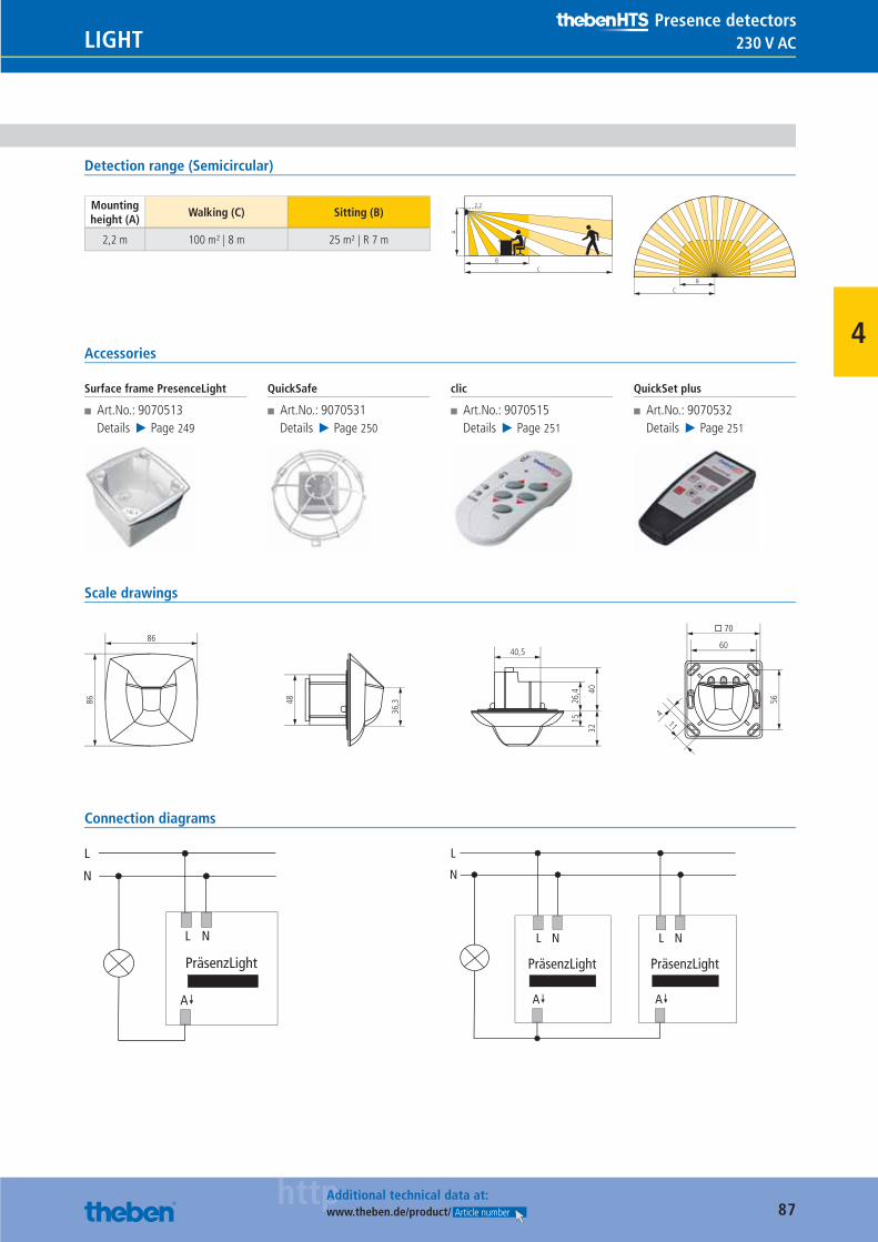
87httpAdditional technical data at:
www.theben.de/product/ Article number
230 V ACLIGHTPresence detectors
4
Detection range (Semicircular)
Mounting height (A)
Walking (C) Sitting (B)
2,2 m 100 m² | 8 m 25 m² | R 7 m
A
BC
2.2
B
C
Accessories
Surface frame PresenceLight
■ Art.No.: 9070513Details ▶ Page 249
QuickSafe
■ Art.No.: 9070531Details ▶ Page 250
clic
■ Art.No.: 9070515Details ▶ Page 251
QuickSet plus
■ Art.No.: 9070532Details ▶ Page 251
Scale drawings
11
56
36,348
60
26,4
15
4032
40,5
� 70
4
86
86
Connection diagrams
Catalogue_EN_2013.indb 87 16.01.13 17:21
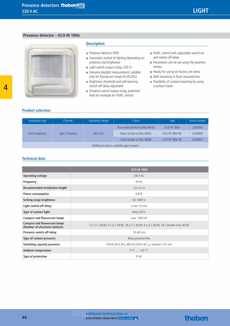
88httpAdditional technical data at:
www.theben.de/product/ Article number
230 V AC LIGHTPresence detectors
4
Presence detector – ECO-IR 180A
Description
■ Presence detector (PIR) ■ Automatic control of lighting depending on presence and brightness
■ Light switch output (relay, 230 V) ■ Genuine daylight measurement, suitable only for fl uorescent lamps (FL/PL/ESL)
■ Brightness threshold and self-learning switch-off delay adjustable
■ Presence switch output (relay, potential-free) for example for HVAC control
■ HVAC control with adjustable switch-on and switch-off delay
■ Parameters can be set using the potentio-meters
■ Ready for use by ex-factory set items ■ Wall mounting in fl ush-mounted box ■ Possibility of surface mounting by using a surface frame
Product selection
Installation type Channel Operating voltage Colour Type Article number
Wall installation Light | Presence 230 V AC
Pure white (similar to RAL 9010) ECO-IR 180A 2020050
Black (similar to RAL 9005) ECO-IR 180A BK 2020809
Silver (similar to RAL 9006) ECO-IR 180A SR 2020810
Additional colours available upon request
Technical data
ECO-IR 180A
Operating voltage 230 V AC
Frequency 50 Hz
Recommended installation height 1,6–2,2 m
Power consumption 0,9 W
Setting range brightness 50–1600 lx
Light switch-off delay 2 min–15 min
Type of contact light Relay 230 V
Compact and fl ourescent lamps max. 1400 VA
Compact and fl ourescent lamps (Number of electronic ballasts)
12 x (1 x 58 W), 6 x (2 x 58 W), 18 x (1 x 36 W), 9 x (2 x 36 W), 18 x (smaller than 36 W)
Presence switch-off delay 10–60 min
Type of contact presence Relay potential-free
Switching capacity presence 100 W (24 V DC), 460 VA (230 V AC), μ, minimal 1 V/1 mA
Ambient temperature 0 °C … +50 °C
Type of protection IP 40
Catalogue_EN_2013.indb 88 16.01.13 17:21
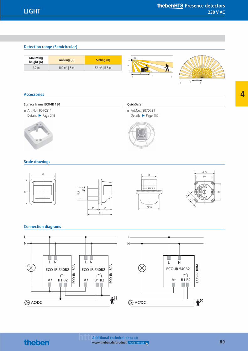
89httpAdditional technical data at:
www.theben.de/product/ Article number
230 V ACLIGHTPresence detectors
4
Detection range (Semicircular)
Mounting height (A)
Walking (C) Sitting (B)
2,2 m 100 m² | 8 m 32 m² | R 8 m
A
BC
2.2
B
C
Accessories
Surface frame ECO-IR 180
■ Art.No.: 9070511Details ▶ Page 249
QuickSafe
■ Art.No.: 9070531Details ▶ Page 250
Scale drawings
21,3
46,3
48
� 70
85
85
11
56
60
� 70
4
35 45
80
Connection diagrams
ECO-IR 540B2
L N
A
L
N
ECO-IR 540B2
L N
A B1 B2 B1 B2
ECO
-IR
180
A
ECO
-IR
180
A
AC/DC
L N
B1 B2
L
N
ECO-IR 540B2
AC/DC
ECO
-IR
180
A
A
Catalogue_EN_2013.indb 89 16.01.13 17:21

90httpAdditional technical data at:
www.theben.de/product/ Article number
24 V AC/DC LIGHTPresence detectors
4
Presence detector – compact offi ce 24V
Description
■ Presence detector (PIR) ■ Automatic control of lighting depending on presence and brightness
■ Square detection area allows accurate and simple planning
■ Light switch output (relay, potential-free) ■ Mixed light measurement, suitable for fl uorescent lamps (FL/PL/ESL), halogen/incandescent lamps and LEDs
■ Brightness threshold and self-learning switch-off delay adjustable
■ Pulse function for staircase time switch ■ Presence switch output (relay, potential-free) for example for HVAC control
■ HVAC control with adjustable switch-on and switch-off delay
■ Function „monitoring“ with reduced sensi-tivity only to detect walking persons
■ Parameters can be set using the potentio-meters or via the optional service remote controls
■ Optional user remote control ■ Ready for use by ex-factory set items ■ Test operation to check detection area and installation
■ Ceiling mounting in fl ush-mounted box ■ Possibility of surface mounting by using a surface frame
Product selection
Installation type Channel Operating voltage Colour Type Article number
Ceiling installation Light | Presence 24 V AC/DC
Pure white (similar to RAL 9010) compact offi ce 24V 2014000
Black (similar to RAL 9005) compact offi ce 24V BK 2014800
Silver (similar to RAL 9006) compact offi ce 24V SR 2014801
Additional colours available upon request
Technical data
compact offi ce 24V
Operating voltage 24 V AC/DC
Recommended installation height 2–3 m
Power consumption 0,4 W
Setting range brightness 10–1500 lx
Light switch-off delay Impuls (0,5 s), 10 s–20 min
Type of contact light Relay potential-free
Compact and fl ourescent lamps 50 W (24 V AC/DC), 460 VA (230 V AC), μ, minimal 1 V/1 mA
Switch-on delay presence 0 s–10 min
Presence switch-off delay 10 s–120 min
Type of contact presence Relay potential-free
Switching capacity presence 50 W (24 V AC/DC), 460 VA (230 V AC), μ, minimal 1 V/1 mA
Ambient temperature 0 °C … +50 °C
Type of protection IP 40
Catalogue_EN_2013.indb 90 16.01.13 17:21
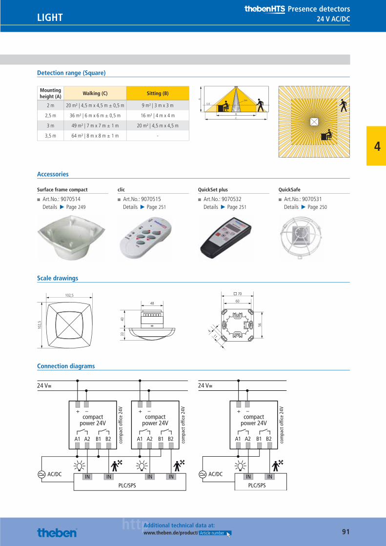
91httpAdditional technical data at:
www.theben.de/product/ Article number
24 V AC/DCLIGHTPresence detectors
4
Detection range (Square)
Mounting height (A)
Walking (C) Sitting (B)
2 m 20 m² | 4,5 m x 4,5 m ± 0,5 m 9 m² | 3 m x 3 m
2,5 m 36 m² | 6 m x 6 m ± 0,5 m 16 m² | 4 m x 4 m
3 m 49 m² | 7 m x 7 m ± 1 m 20 m² | 4,5 m x 4,5 m
3,5 m 64 m² | 8 m x 8 m ± 1 m -
BC
0.8
A Lux
Accessories
Surface frame compact
■ Art.No.: 9070514Details ▶ Page 249
clic
■ Art.No.: 9070515Details ▶ Page 251
QuickSet plus
■ Art.No.: 9070532Details ▶ Page 251
QuickSafe
■ Art.No.: 9070531Details ▶ Page 250
Scale drawings
48
102,
5 4033
102,5
11
56
60
� 70
4
Connection diagrams
24 V≅
compactpower 24V
com
pact
offi
ce 2
4V+ –
A1 A2 B1 B2
AC/DC
PLC/SPS
IN IN
compactpower 24V
com
pact
offi
ce 2
4V+ –
A1 A2 B1 B2
IN IN
24 V≅
compactpower 24V
com
pact
offi
ce 2
4V+ –
A1 A2 B1 B2
AC/DC
PLC/SPS
IN IN
Catalogue_EN_2013.indb 91 16.01.13 17:21
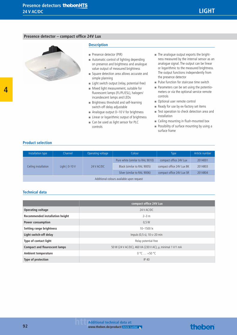
92httpAdditional technical data at:
www.theben.de/product/ Article number
24 V AC/DC LIGHTPresence detectors
4
Presence detector – compact offi ce 24V Lux
Description
■ Presence detector (PIR) ■ Automatic control of lighting depending on presence and brightness and analogue value output of measured brightness
■ Square detection area allows accurate and simple planning
■ Light switch output (relay, potential-free) ■ Mixed light measurement, suitable for fl uorescent lamps (FL/PL/ESL), halogen/incandescent lamps and LEDs
■ Brightness threshold and self-learning switch-off delay adjustable
■ Analogue output 0–10 V for brightness ■ Linear or logarithmic output of brightness ■ Can be used as light sensor for PLC controls
■ The analogue output exports the bright-ness measured by the internal sensor as an analogue signal. The output can be linear or logarithmic to the measured brightness. The output functions independently from the presence detector
■ Pulse function for staircase time switch ■ Parameters can be set using the potentio-meters or via the optional service remote controls
■ Optional user remote control ■ Ready for use by ex-factory set items ■ Test operation to check detection area and installation
■ Ceiling mounting in fl ush-mounted box ■ Possibility of surface mounting by using a surface frame
Product selection
Installation type Channel Operating voltage Colour Type Article number
Ceiling installation Light | 0-10 V 24 V AC/DC
Pure white (similar to RAL 9010) compact offi ce 24V Lux 2014001
Black (similar to RAL 9005) compact offi ce 24V Lux BK 2014803
Silver (similar to RAL 9006) compact offi ce 24V Lux SR 2014804
Additional colours available upon request
Technical data
compact offi ce 24V Lux
Operating voltage 24 V AC/DC
Recommended installation height 2–3 m
Power consumption 0,5 W
Setting range brightness 10–1500 lx
Light switch-off delay Impuls (0,5 s), 10 s–20 min
Type of contact light Relay potential-free
Compact and fl ourescent lamps 50 W (24 V AC/DC), 460 VA (230 V AC), μ, minimal 1 V/1 mA
Ambient temperature 0 °C … +50 °C
Type of protection IP 40
Catalogue_EN_2013.indb 92 16.01.13 17:21
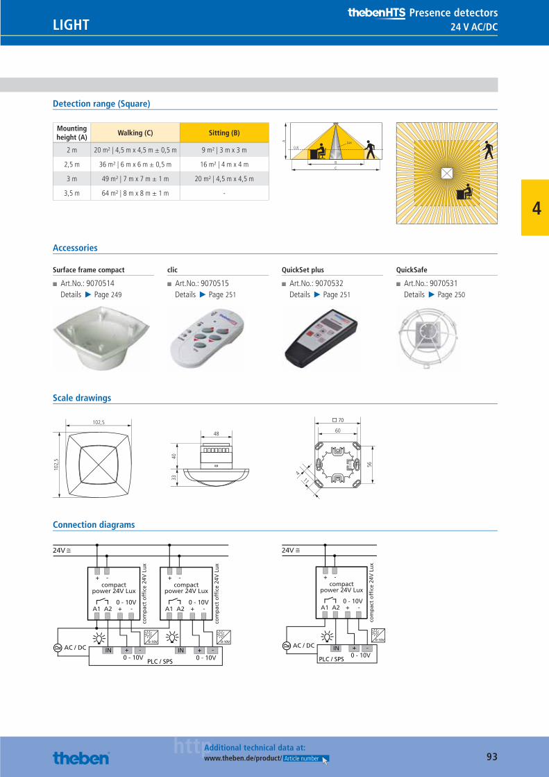
93httpAdditional technical data at:
www.theben.de/product/ Article number
24 V AC/DCLIGHTPresence detectors
4
Detection range (Square)
Mounting height (A)
Walking (C) Sitting (B)
2 m 20 m² | 4,5 m x 4,5 m ± 0,5 m 9 m² | 3 m x 3 m
2,5 m 36 m² | 6 m x 6 m ± 0,5 m 16 m² | 4 m x 4 m
3 m 49 m² | 7 m x 7 m ± 1 m 20 m² | 4,5 m x 4,5 m
3,5 m 64 m² | 8 m x 8 m ± 1 m -
BC
0.8
A Lux
Accessories
Surface frame compact
■ Art.No.: 9070514Details ▶ Page 249
clic
■ Art.No.: 9070515Details ▶ Page 251
QuickSet plus
■ Art.No.: 9070532Details ▶ Page 251
QuickSafe
■ Art.No.: 9070531Details ▶ Page 250
Scale drawings
48
102,
5 4033
102,5
11
56
60
� 70
4
Connection diagrams
24V
compactpower 24V Lux
com
pac
t o
ffice
24V
Lu
x
+ -
A1 A2 0 - 10V
+ -
0 - 10V
AC / DC
PLC / SPS
IN IN-+0 - 10V
-+0-10V
compactpower 24V Lux
com
pac
t o
ffice
24V
Lu
x
+ -
A1 A2 0 - 10V
+ -
0-10V
24V
compactpower 24V Lux
com
pac
t o
ffice
24V
Lu
x
+ -
A1 A20 - 10V+ -
0 - 10V
AC / DC
PLC / SPS
IN -+0-10V
Catalogue_EN_2013.indb 93 16.01.13 17:21
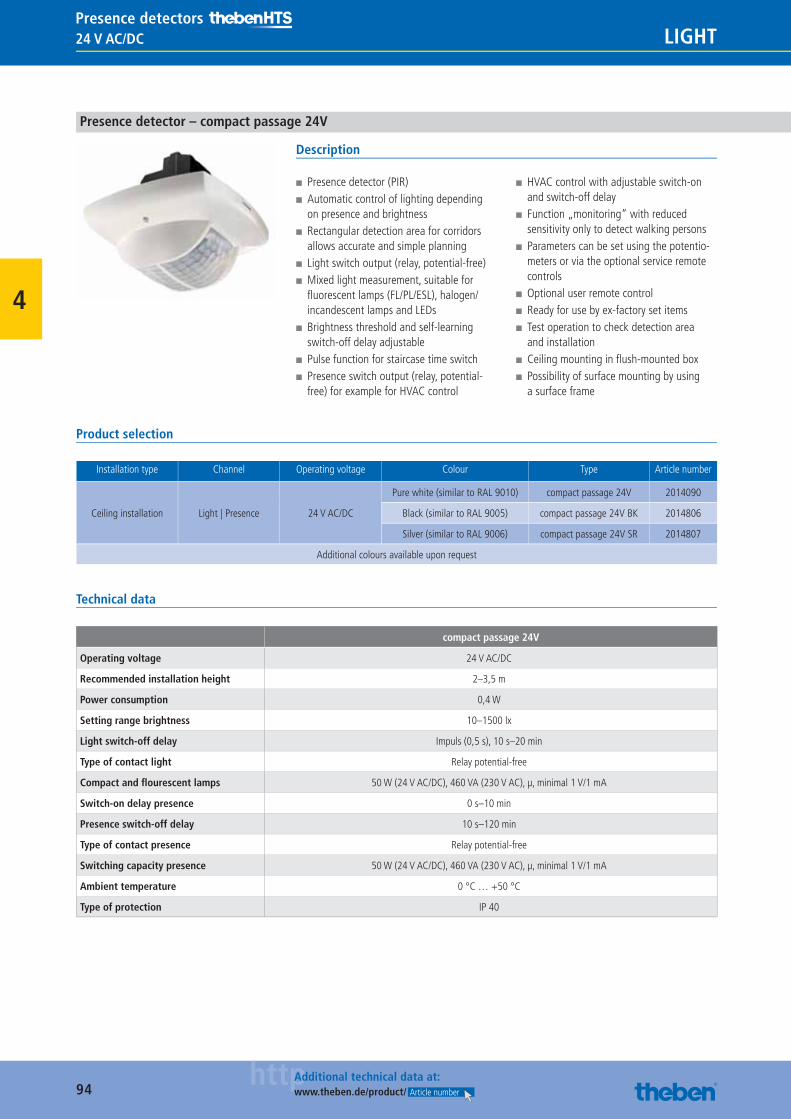
94httpAdditional technical data at:
www.theben.de/product/ Article number
24 V AC/DC LIGHTPresence detectors
4
Presence detector – compact passage 24V
Description
■ Presence detector (PIR) ■ Automatic control of lighting depending on presence and brightness
■ Rectangular detection area for corridors allows accurate and simple planning
■ Light switch output (relay, potential-free) ■ Mixed light measurement, suitable for fl uorescent lamps (FL/PL/ESL), halogen/incandescent lamps and LEDs
■ Brightness threshold and self-learning switch-off delay adjustable
■ Pulse function for staircase time switch ■ Presence switch output (relay, potential-free) for example for HVAC control
■ HVAC control with adjustable switch-on and switch-off delay
■ Function „monitoring“ with reduced sensitivity only to detect walking persons
■ Parameters can be set using the potentio-meters or via the optional service remote controls
■ Optional user remote control ■ Ready for use by ex-factory set items ■ Test operation to check detection area and installation
■ Ceiling mounting in fl ush-mounted box ■ Possibility of surface mounting by using a surface frame
Product selection
Installation type Channel Operating voltage Colour Type Article number
Ceiling installation Light | Presence 24 V AC/DC
Pure white (similar to RAL 9010) compact passage 24V 2014090
Black (similar to RAL 9005) compact passage 24V BK 2014806
Silver (similar to RAL 9006) compact passage 24V SR 2014807
Additional colours available upon request
Technical data
compact passage 24V
Operating voltage 24 V AC/DC
Recommended installation height 2–3,5 m
Power consumption 0,4 W
Setting range brightness 10–1500 lx
Light switch-off delay Impuls (0,5 s), 10 s–20 min
Type of contact light Relay potential-free
Compact and fl ourescent lamps 50 W (24 V AC/DC), 460 VA (230 V AC), μ, minimal 1 V/1 mA
Switch-on delay presence 0 s–10 min
Presence switch-off delay 10 s–120 min
Type of contact presence Relay potential-free
Switching capacity presence 50 W (24 V AC/DC), 460 VA (230 V AC), μ, minimal 1 V/1 mA
Ambient temperature 0 °C … +50 °C
Type of protection IP 40
Catalogue_EN_2013.indb 94 16.01.13 17:21
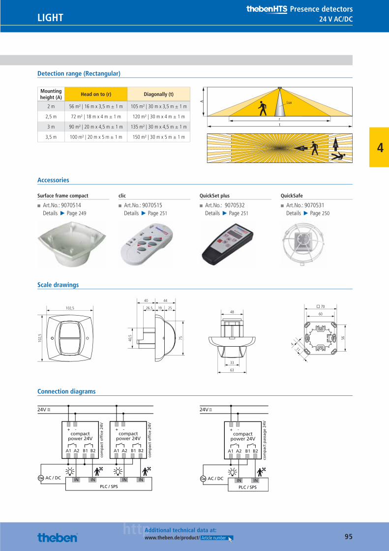
95httpAdditional technical data at:
www.theben.de/product/ Article number
24 V AC/DCLIGHTPresence detectors
4
Detection range (Rectangular)
Mounting height (A)
Head on to (r) Diagonally (t)
2 m 56 m² | 16 m x 3,5 m ± 1 m 105 m² | 30 m x 3,5 m ± 1 m
2,5 m 72 m² | 18 m x 4 m ± 1 m 120 m² | 30 m x 4 m ± 1 m
3 m 90 m² | 20 m x 4,5 m ± 1 m 135 m² | 30 m x 4,5 m ± 1 m
3,5 m 100 m² | 20 m x 5 m ± 1 m 150 m² | 30 m x 5 m ± 1 m
rt
A Lux
tr
Accessories
Surface frame compact
■ Art.No.: 9070514Details ▶ Page 249
clic
■ Art.No.: 9070515Details ▶ Page 251
QuickSet plus
■ Art.No.: 9070532Details ▶ Page 251
QuickSafe
■ Art.No.: 9070531Details ▶ Page 250
Scale drawings
11
56
63
33
48 60
26,5
4440
19
40,5
75
� 70
4
102,
5
102,5 25
Connection diagrams
24V
compactpower 24V
com
pac
t o
ffice
24V
+ -
A1 A2 B1 B2
AC / DC
PLC / SPS
IN IN
compactpower 24V
com
pac
t o
ffice
24V
+ -
A1 A2 B1 B2
IN IN
24V
compactpower 24V
com
pac
t p
assa
ge
24V
+ -
A1 A2 B1 B2
AC / DC
PLC / SPS
IN IN
Catalogue_EN_2013.indb 95 16.01.13 17:21
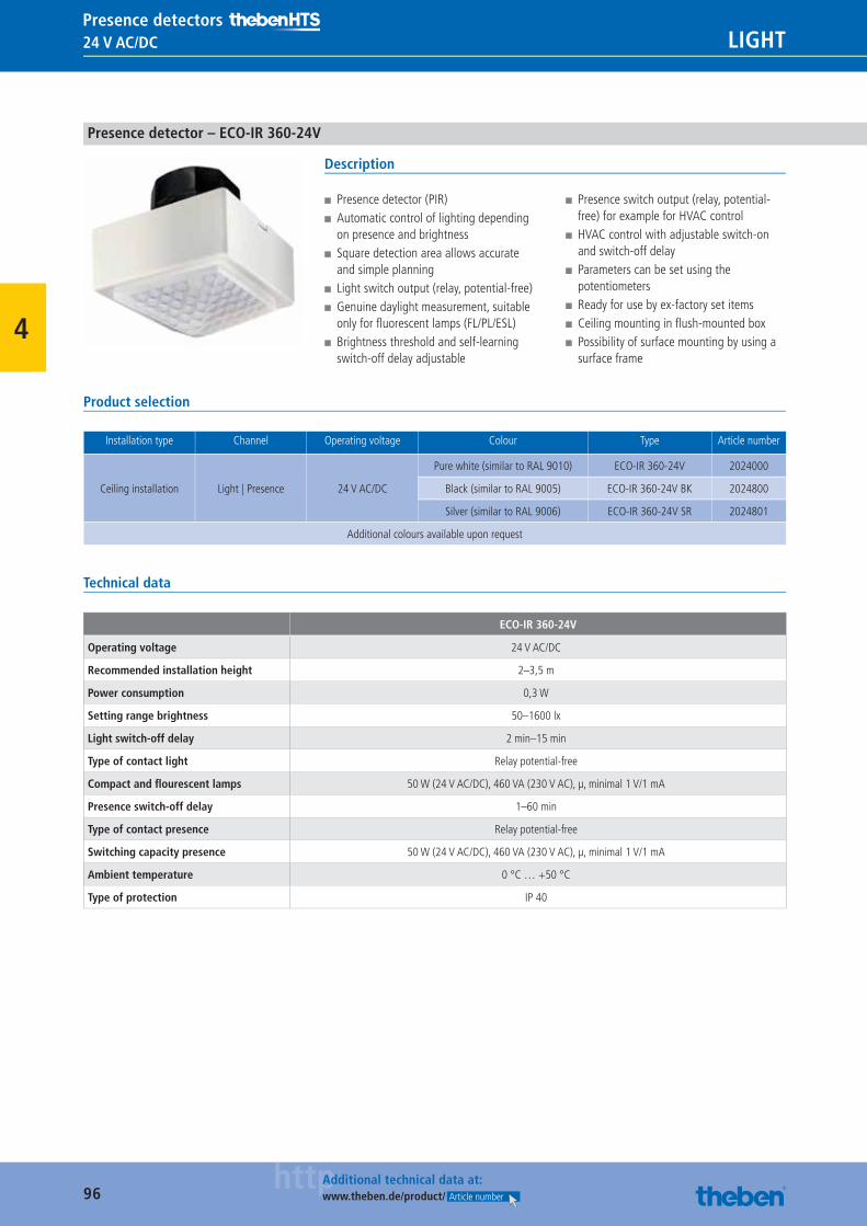
96httpAdditional technical data at:
www.theben.de/product/ Article number
24 V AC/DC LIGHTPresence detectors
4
Presence detector – ECO-IR 360-24V
Description
■ Presence detector (PIR) ■ Automatic control of lighting depending on presence and brightness
■ Square detection area allows accurate and simple planning
■ Light switch output (relay, potential-free) ■ Genuine daylight measurement, suitable only for fl uorescent lamps (FL/PL/ESL)
■ Brightness threshold and self-learning switch-off delay adjustable
■ Presence switch output (relay, potential-free) for example for HVAC control
■ HVAC control with adjustable switch-on and switch-off delay
■ Parameters can be set using the potentiometers
■ Ready for use by ex-factory set items ■ Ceiling mounting in fl ush-mounted box ■ Possibility of surface mounting by using a surface frame
Product selection
Installation type Channel Operating voltage Colour Type Article number
Ceiling installation Light | Presence 24 V AC/DC
Pure white (similar to RAL 9010) ECO-IR 360-24V 2024000
Black (similar to RAL 9005) ECO-IR 360-24V BK 2024800
Silver (similar to RAL 9006) ECO-IR 360-24V SR 2024801
Additional colours available upon request
Technical data
ECO-IR 360-24V
Operating voltage 24 V AC/DC
Recommended installation height 2–3,5 m
Power consumption 0,3 W
Setting range brightness 50–1600 lx
Light switch-off delay 2 min–15 min
Type of contact light Relay potential-free
Compact and fl ourescent lamps 50 W (24 V AC/DC), 460 VA (230 V AC), μ, minimal 1 V/1 mA
Presence switch-off delay 1–60 min
Type of contact presence Relay potential-free
Switching capacity presence 50 W (24 V AC/DC), 460 VA (230 V AC), μ, minimal 1 V/1 mA
Ambient temperature 0 °C … +50 °C
Type of protection IP 40
Catalogue_EN_2013.indb 96 16.01.13 17:21
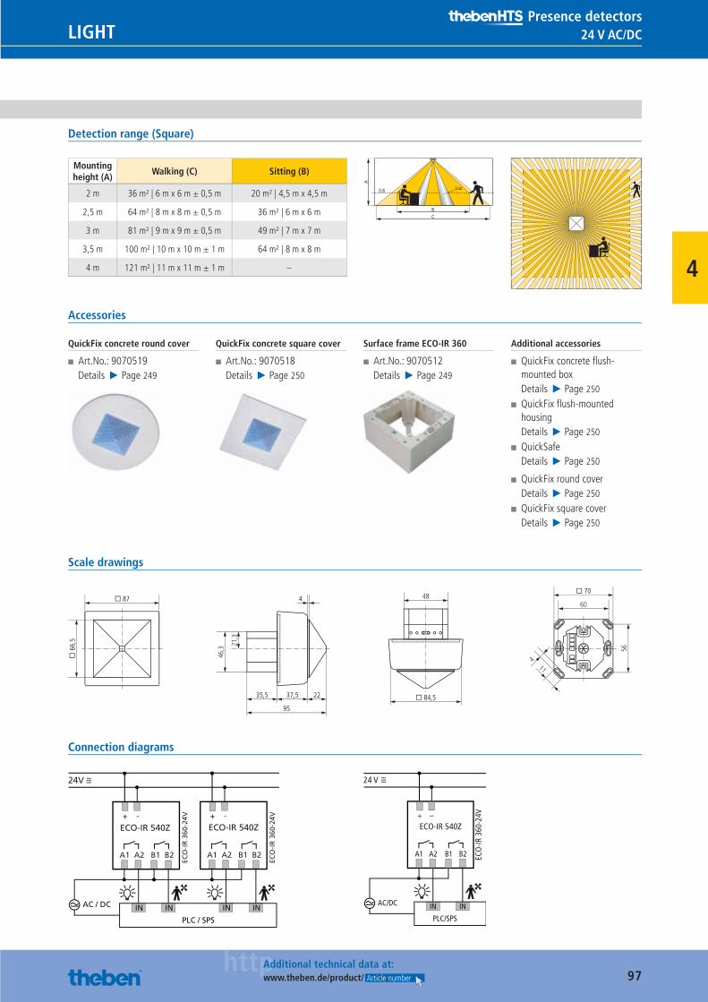
97httpAdditional technical data at:
www.theben.de/product/ Article number
24 V AC/DCLIGHTPresence detectors
4
Detection range (Square)
Mounting height (A)
Walking (C) Sitting (B)
2 m 36 m² | 6 m x 6 m ± 0,5 m 20 m² | 4,5 m x 4,5 m
2,5 m 64 m² | 8 m x 8 m ± 0,5 m 36 m² | 6 m x 6 m
3 m 81 m² | 9 m x 9 m ± 0,5 m 49 m² | 7 m x 7 m
3,5 m 100 m² | 10 m x 10 m ± 1 m 64 m² | 8 m x 8 m
4 m 121 m² | 11 m x 11 m ± 1 m –
BC
0.8
A
Lux
Accessories
QuickFix concrete round cover
■ Art.No.: 9070519Details ▶ Page 249
QuickFix concrete square cover
■ Art.No.: 9070518Details ▶ Page 250
Surface frame ECO-IR 360
■ Art.No.: 9070512Details ▶ Page 249
Additional accessories
■ QuickFix concrete fl ush-mounted boxDetails ▶ Page 250
■ QuickFix fl ush-mounted housingDetails ▶ Page 250
■ QuickSafeDetails ▶ Page 250
■ QuickFix round coverDetails ▶ Page 250
■ QuickFix square coverDetails ▶ Page 250
Scale drawings
21,3
46,3
48
� 84,5
� 6
6,5
� 87
11
56
60
� 70
4
35,5 37,5
95
22
4
Connection diagrams
24V
ECO-IR 540Z+ -
A1 A2 B1 B2
AC / DC
PLC / SPS
IN IN
+ -
A1 A2 B1 B2
IN IN
ECO-IR 540Z
ECO
-IR
360
-24V
ECO
-IR
360
-24V
24 V
ECO-IR 540Z
ECO
-IR 3
60-2
4V+ –
A1 A2 B1 B2
AC/DC
PLC/SPS
IN IN
Catalogue_EN_2013.indb 97 16.01.13 17:21
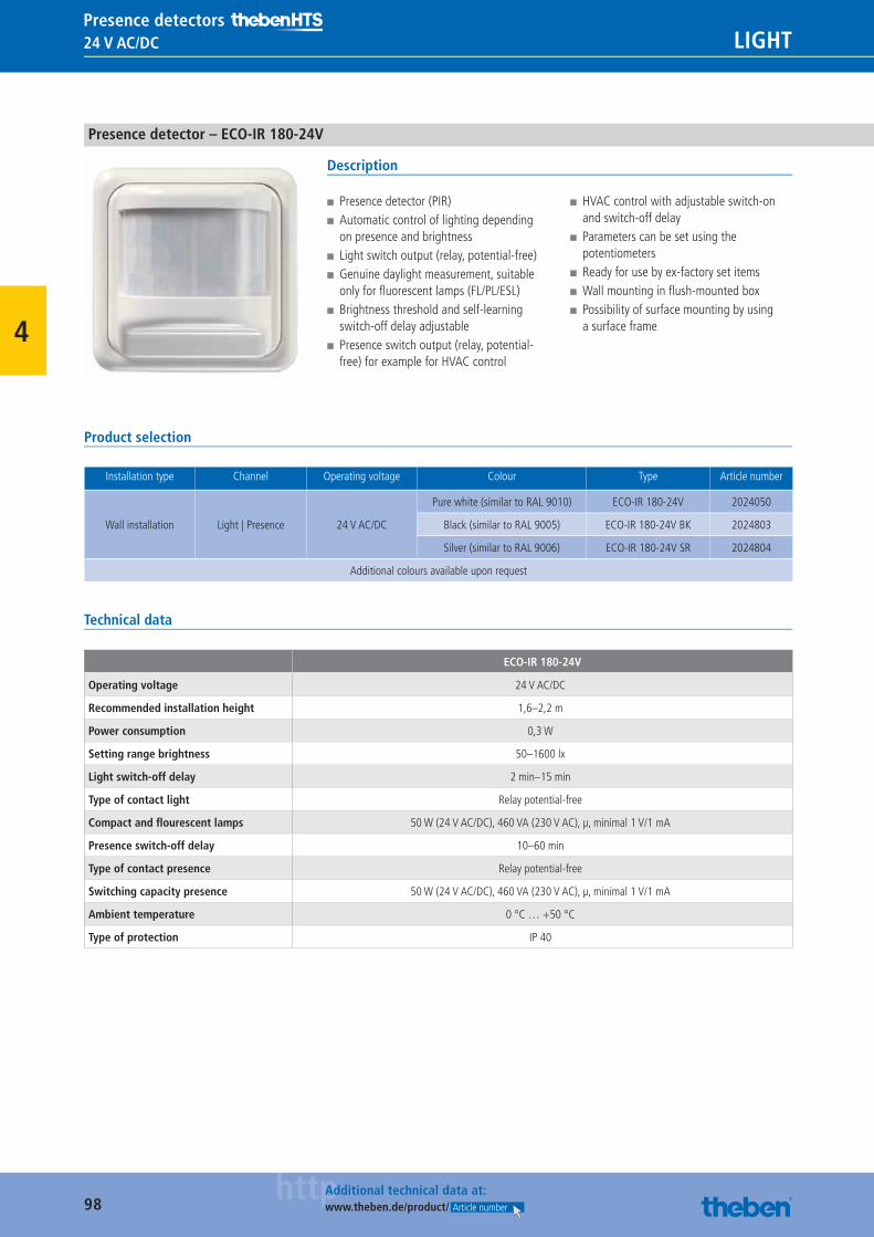
98httpAdditional technical data at:
www.theben.de/product/ Article number
24 V AC/DC LIGHTPresence detectors
4
Presence detector – ECO-IR 180-24V
Description
■ Presence detector (PIR) ■ Automatic control of lighting depending on presence and brightness
■ Light switch output (relay, potential-free) ■ Genuine daylight measurement, suitable only for fl uorescent lamps (FL/PL/ESL)
■ Brightness threshold and self-learning switch-off delay adjustable
■ Presence switch output (relay, potential-free) for example for HVAC control
■ HVAC control with adjustable switch-on and switch-off delay
■ Parameters can be set using the potentiometers
■ Ready for use by ex-factory set items ■ Wall mounting in fl ush-mounted box ■ Possibility of surface mounting by using a surface frame
Product selection
Installation type Channel Operating voltage Colour Type Article number
Wall installation Light | Presence 24 V AC/DC
Pure white (similar to RAL 9010) ECO-IR 180-24V 2024050
Black (similar to RAL 9005) ECO-IR 180-24V BK 2024803
Silver (similar to RAL 9006) ECO-IR 180-24V SR 2024804
Additional colours available upon request
Technical data
ECO-IR 180-24V
Operating voltage 24 V AC/DC
Recommended installation height 1,6–2,2 m
Power consumption 0,3 W
Setting range brightness 50–1600 lx
Light switch-off delay 2 min–15 min
Type of contact light Relay potential-free
Compact and fl ourescent lamps 50 W (24 V AC/DC), 460 VA (230 V AC), μ, minimal 1 V/1 mA
Presence switch-off delay 10–60 min
Type of contact presence Relay potential-free
Switching capacity presence 50 W (24 V AC/DC), 460 VA (230 V AC), μ, minimal 1 V/1 mA
Ambient temperature 0 °C … +50 °C
Type of protection IP 40
Catalogue_EN_2013.indb 98 16.01.13 17:21
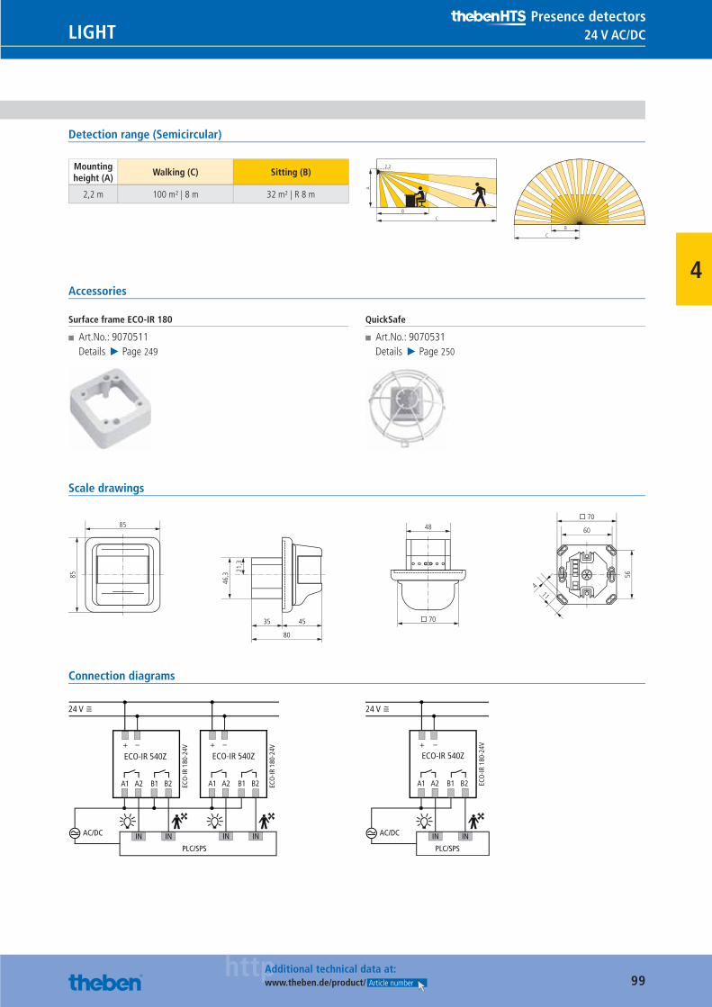
99httpAdditional technical data at:
www.theben.de/product/ Article number
24 V AC/DCLIGHTPresence detectors
4
Detection range (Semicircular)
Mounting height (A)
Walking (C) Sitting (B)
2,2 m 100 m² | 8 m 32 m² | R 8 m
A
BC
2.2
B
C
Accessories
Surface frame ECO-IR 180
■ Art.No.: 9070511Details ▶ Page 249
QuickSafe
■ Art.No.: 9070531Details ▶ Page 250
Scale drawings
21,3
46,3
48
� 70
85
85
11
56
60
� 70
4
35 45
80
Connection diagrams
24 V
ECO-IR 540Z+ –
A1 A2 B1 B2
AC/DC
PLC/SPS
IN IN
+ –
A1 A2 B1 B2
IN IN
ECO-IR 540Z
ECO
-IR 1
80-2
4V
ECO
-IR 1
80-2
4V
ECO-IR 540Z
ECO
-IR 1
80-2
4V+ –
A1 A2 B1 B2
AC/DC
PLC/SPS
IN IN
24 V
Catalogue_EN_2013.indb 99 16.01.13 17:21
100
LIGHT
7 % R&D.At Theben we invest 7 per cent of our turnover in research and development every year. That puts us well above the sector average. How does that benefi t you? The certainty that you will continue to receive innovative and reliable products, now and in the future.
Catalogue_EN_2013.indb 100 16.01.13 17:21
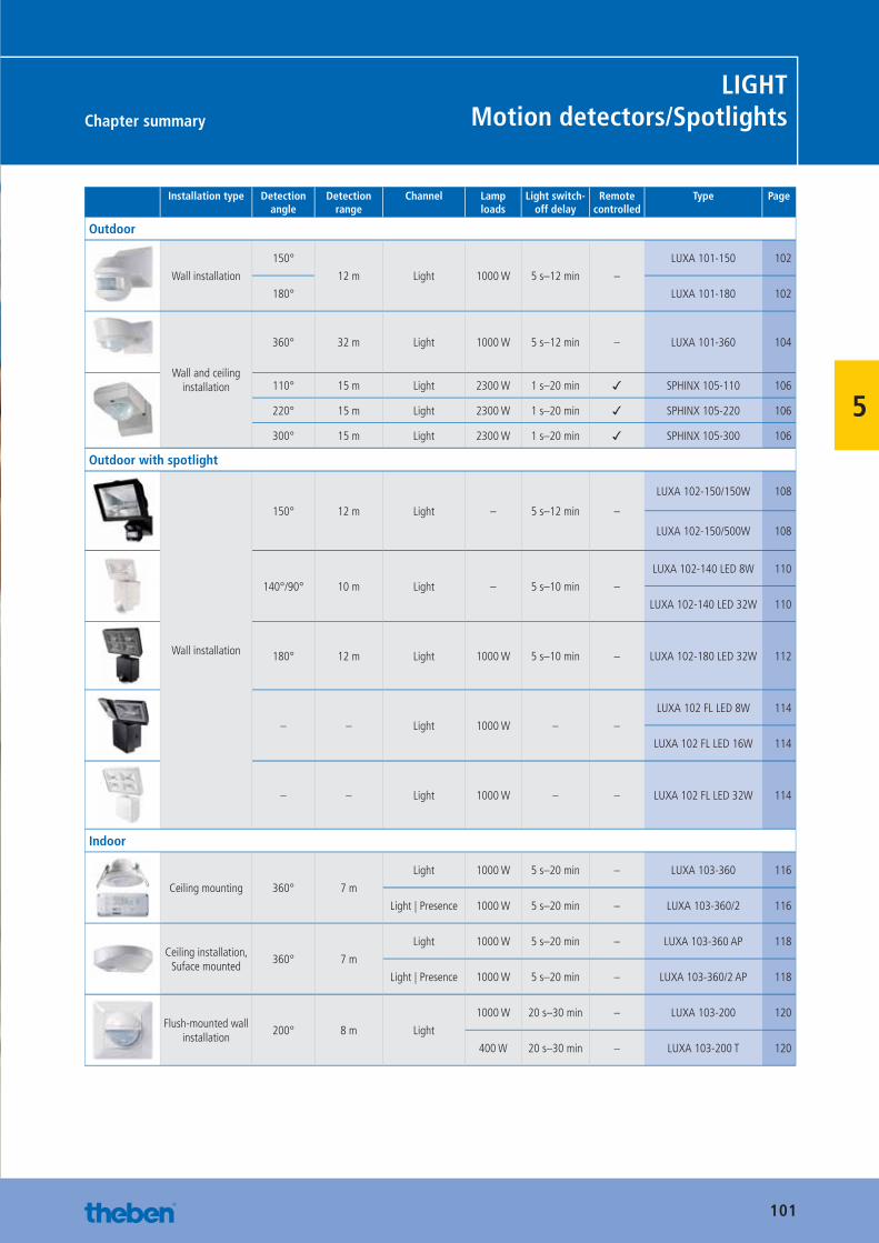
101
Chapter summary
LIGHTMotion detectors/Spotlights
5
Installation type Detection angle
Detection range
Channel Lamp loads
Light switch-off delay
Remote controlled
Type Page
Outdoor
Wall installation
150°
12 m Light 1000 W 5 s–12 min –
LUXA 101-150 102
180° LUXA 101-180 102
Wall and ceiling installation
360° 32 m Light 1000 W 5 s–12 min – LUXA 101-360 104
110° 15 m Light 2300 W 1 s–20 min ✓ SPHINX 105-110 106
220° 15 m Light 2300 W 1 s–20 min ✓ SPHINX 105-220 106
300° 15 m Light 2300 W 1 s–20 min ✓ SPHINX 105-300 106
Outdoor with spotlight
Wall installation
150° 12 m Light – 5 s–12 min –
LUXA 102-150/150W 108
LUXA 102-150/500W 108
140°/90° 10 m Light – 5 s–10 min –
LUXA 102-140 LED 8W 110
LUXA 102-140 LED 32W 110
180° 12 m Light 1000 W 5 s–10 min – LUXA 102-180 LED 32W 112
– – Light 1000 W – –
LUXA 102 FL LED 8W 114
LUXA 102 FL LED 16W 114
– – Light 1000 W – – LUXA 102 FL LED 32W 114
Indoor
Ceiling mounting 360° 7 m
Light 1000 W 5 s–20 min – LUXA 103-360 116
Light | Presence 1000 W 5 s–20 min – LUXA 103-360/2 116
Ceiling installation, Suface mounted
360° 7 m
Light 1000 W 5 s–20 min – LUXA 103-360 AP 118
Light | Presence 1000 W 5 s–20 min – LUXA 103-360/2 AP 118
Flush-mounted wall installation
200° 8 m Light
1000 W 20 s–30 min – LUXA 103-200 120
400 W 20 s–30 min – LUXA 103-200 T 120
Catalogue_EN_2013.indb 101 16.01.13 17:21
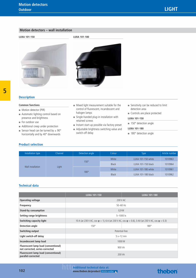
102httpAdditional technical data at:
www.theben.de/product/ Article number
Outdoor LIGHTMotion detectors
5
Motion detectors – wall installation
LUXA 101-150 LUXA 101-180
Description
Common functions
■ Motion detector (PIR) ■ Automatic lighting control based on presence and brightness
■ For outdoor use ■ Additional creep under protection ■ Sensor head can be turned by ± 90° horizontally and by 40° downwards
■ Mixed light measurement suitable for the control of fl uorescent, incandescent and halogen lamps
■ Single-handed plug-in installation with retained screws
■ Instant start-up possible via factory preset ■ Adjustable brightness switching value and switch-off delay
■ Sensitivity can be reduced to limit detection area
■ Controls are place protected
LUXA 101-150
■ 150° detection angle
LUXA 101-180
■ 180° detection angle
Product selection
Installation type Channel Detection angle Colour Type Article number
Wall installation Light
150°White LUXA 101-150 white 1010963
Black LUXA 101-150 black 1010964
180°White LUXA 101-180 white 1010961
Black LUXA 101-180 black 1010962
Technical data
LUXA 101-150 LUXA 101-180
Operating voltage 230 V AC
Frequency 50–60 Hz
Stand-by consumption 0,9 W
Setting range brightness 5–1000 lx
Switching capacity light 10 A (at 230 V AC, cos φ = 1), 6 A (at 230 V AC, cos φ = 0.6), 3 AX (at 230 V AC, cos φ = 0.3)
Detection angle 150° 180°
Switching output Potential-free
Light switch-off delay 5 s–12 min
Incandescent lamp load 1000 W
Fluorescent lamp load (conventional) not corrected, series-corrected
900 VA
Fluorescent lamp load (conventional) parallel-corrected
200 VA
Catalogue_EN_2013.indb 102 16.01.13 17:21
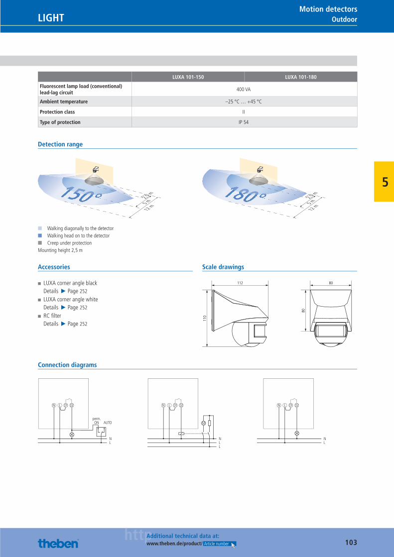
103httpAdditional technical data at:
www.theben.de/product/ Article number
OutdoorLIGHTMotion detectors
5
LUXA 101-150 LUXA 101-180
Fluorescent lamp load (conventional) lead-lag circuit
400 VA
Ambient temperature –25 °C … +45 °C
Protection class II
Type of protection IP 54
Detection range
2,5 m
5 m
12 m
150°■ Walking diagonally to the detector■ Walking head on to the detector■ Creep under protectionMounting height 2,5 m
2,5 m
5 m
12 m
180°
Accessories
■ LUXA corner angle blackDetails ▶ Page 252
■ LUXA corner angle whiteDetails ▶ Page 252
■ RC fi lterDetails ▶ Page 252
Scale drawings
110
112
80
80
Connection diagrams
N L D1
N
perm.ON AUTO
L
D2 N L D1
NL
D2
L
M
N L D1
NL
D2
Catalogue_EN_2013.indb 103 16.01.13 17:21
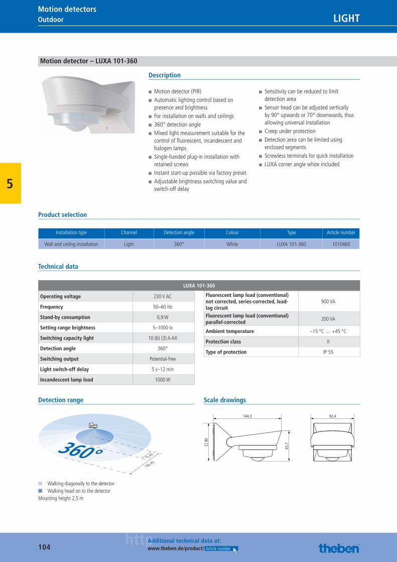
104httpAdditional technical data at:
www.theben.de/product/ Article number
Outdoor LIGHTMotion detectors
5
Motion detector – LUXA 101-360
Description
■ Motion detector (PIR) ■ Automatic lighting control based on presence and brightness
■ For installation on walls and ceilings ■ 360° detection angle ■ Mixed light measurement suitable for the control of fl uorescent, incandescent and halogen lamps
■ Single-handed plug-in installation with retained screws
■ Instant start-up possible via factory preset ■ Adjustable brightness switching value and switch-off delay
■ Sensitivity can be reduced to limit detection area
■ Sensor head can be adjusted vertically by 90° upwards or 70° downwards, thus allowing universal installation
■ Creep under protection ■ Detection area can be limited using enclosed segments
■ Screwless terminals for quick installation ■ LUXA corner angle white included
Product selection
Installation type Channel Detection angle Colour Type Article number
Wall and ceiling installation Light 360° White LUXA 101-360 1010460
Technical data
LUXA 101-360
Operating voltage 230 V AC
Frequency 50–60 Hz
Stand-by consumption 0,9 W
Setting range brightness 5–1000 lx
Switching capacity light 10 (6) (3) A AX
Detection angle 360°
Switching output Potential-free
Light switch-off delay 5 s–12 min
Incandescent lamp load 1000 W
Fluorescent lamp load (conventional) not corrected, series-corrected, lead-lag circuit
900 VA
Fluorescent lamp load (conventional) parallel-corrected
200 VA
Ambient temperature –15 °C … +45 °C
Protection class II
Type of protection IP 55
Detection range
5 m
16 m
360°■ Walking diagonally to the detector■ Walking head on to the detectorMounting height 2,5 m
Scale drawings
92,4
� 8
0
144,3
65,7
Catalogue_EN_2013.indb 104 16.01.13 17:21
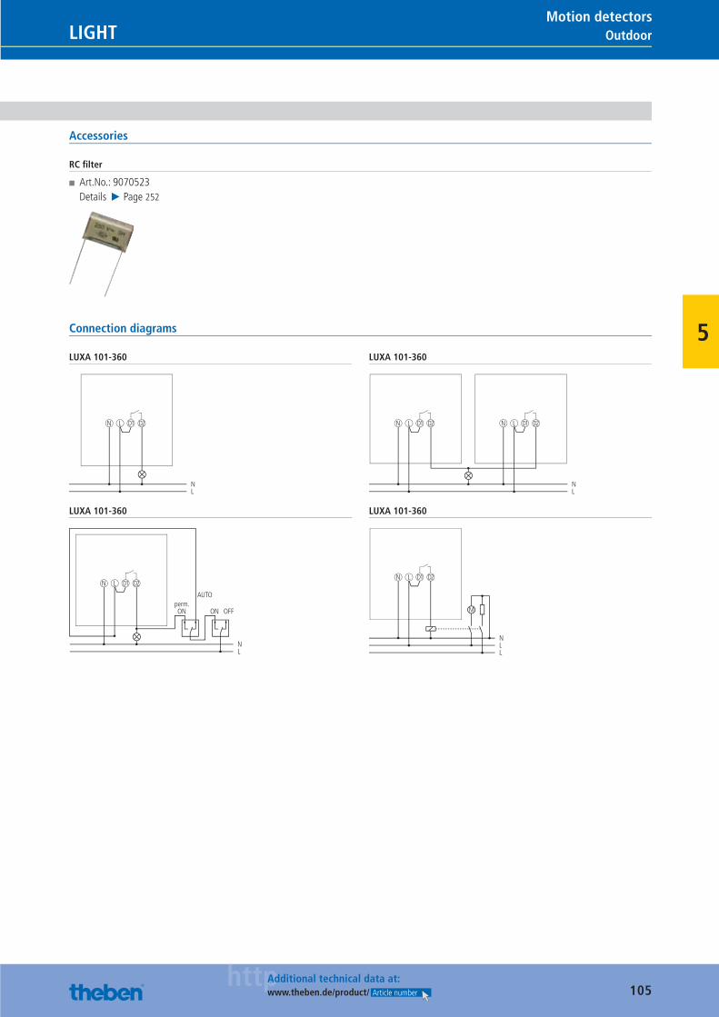
105httpAdditional technical data at:
www.theben.de/product/ Article number
OutdoorLIGHTMotion detectors
5
Accessories
RC fi lter
■ Art.No.: 9070523Details ▶ Page 252
Connection diagrams
LUXA 101-360
N L D1
NL
D2
LUXA 101-360
N L D1
NL
D2 N L D1 D2
LUXA 101-360
N L D1
N
perm.ON
AUTO
L
D2
ON OFF
LUXA 101-360
N L D1
NL
D2
L
M
Catalogue_EN_2013.indb 105 16.01.13 17:21
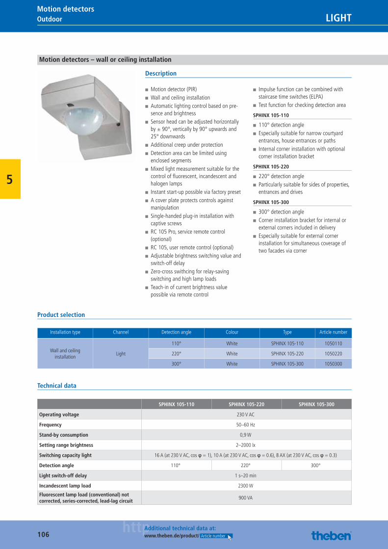
106httpAdditional technical data at:
www.theben.de/product/ Article number
Outdoor LIGHTMotion detectors
5
Motion detectors – wall or ceiling installation
Description
■ Motion detector (PIR) ■ Wall and ceiling installation ■ Automatic lighting control based on pre-sence and brightness
■ Sensor head can be adjusted horizontally by ± 90°, vertically by 90° upwards and 25° downwards
■ Additional creep under protection ■ Detection area can be limited using enclosed segments
■ Mixed light measurement suitable for the control of fl uorescent, incandescent and halogen lamps
■ Instant start-up possible via factory preset ■ A cover plate protects controls against manipulation
■ Single-handed plug-in installation with captive screws
■ RC 105 Pro, service remote control (optional)
■ RC 105, user remote control (optional) ■ Adjustable brightness switching value and switch-off delay
■ Zero-cross swithcing for relay-saving switching and high lamp loads
■ Teach-in of current brightness value possible via remote control
■ Impulse function can be combined with staircase time switches (ELPA)
■ Test function for checking detection area
SPHINX 105-110
■ 110° detection angle ■ Especially suitable for narrow courtyard entrances, house entrances or paths
■ Internal corner installation with optional corner installation bracket
SPHINX 105-220
■ 220° detection angle ■ Particularly suitable for sides of properties, entrances and drives
SPHINX 105-300
■ 300° detection angle ■ Corner installation bracket for internal or external corners included in delivery
■ Especially suitable for external corner installation for simultaneous coverage of two facades via corner
Product selection
Installation type Channel Detection angle Colour Type Article number
Wall and ceiling installation
Light
110° White SPHINX 105-110 1050110
220° White SPHINX 105-220 1050220
300° White SPHINX 105-300 1050300
Technical data
SPHINX 105-110 SPHINX 105-220 SPHINX 105-300
Operating voltage 230 V AC
Frequency 50–60 Hz
Stand-by consumption 0,9 W
Setting range brightness 2–2000 lx
Switching capacity light 16 A (at 230 V AC, cos φ = 1), 10 A (at 230 V AC, cos φ = 0.6), 8 AX (at 230 V AC, cos φ = 0.3)
Detection angle 110° 220° 300°
Light switch-off delay 1 s–20 min
Incandescent lamp load 2300 W
Fluorescent lamp load (conventional) not corrected, series-corrected, lead-lag circuit
900 VA
Catalogue_EN_2013.indb 106 16.01.13 17:21
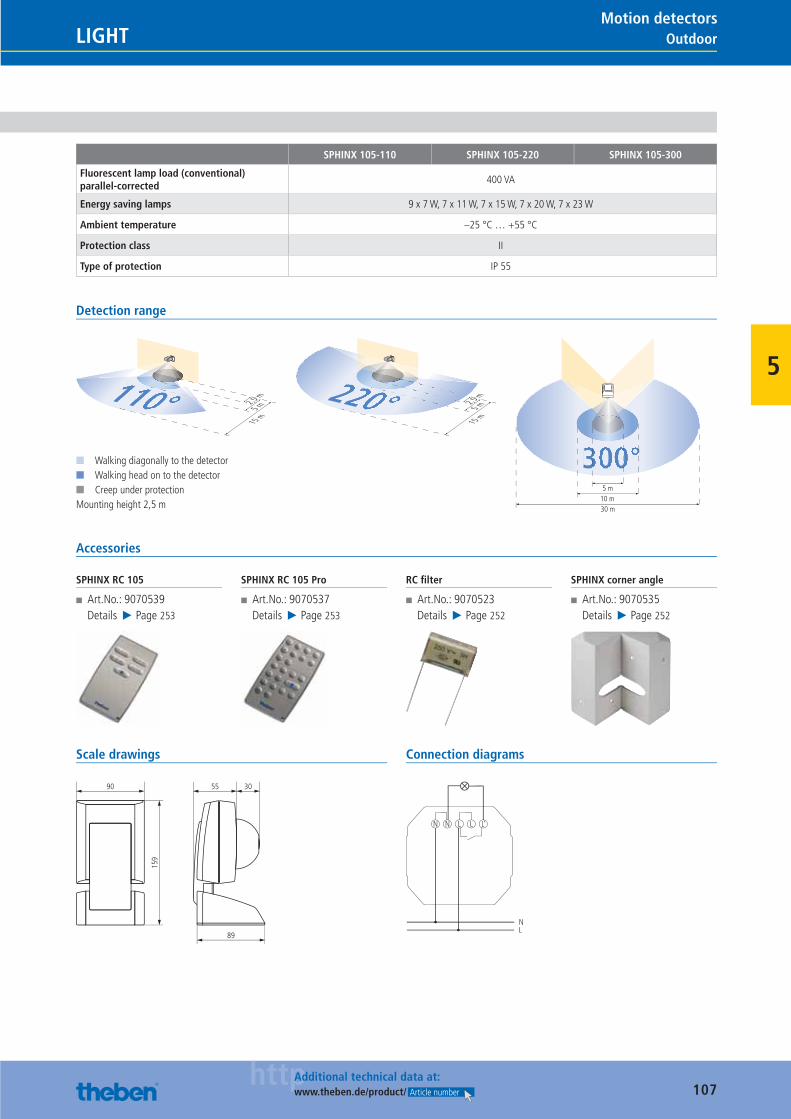
107httpAdditional technical data at:
www.theben.de/product/ Article number
OutdoorLIGHTMotion detectors
5
SPHINX 105-110 SPHINX 105-220 SPHINX 105-300
Fluorescent lamp load (conventional) parallel-corrected
400 VA
Energy saving lamps 9 x 7 W, 7 x 11 W, 7 x 15 W, 7 x 20 W, 7 x 23 W
Ambient temperature –25 °C … +55 °C
Protection class II
Type of protection IP 55
Detection range
2,5 m
5 m
15 m
110°
■ Walking diagonally to the detector■ Walking head on to the detector■ Creep under protectionMounting height 2,5 m
2,5 m5 m
15 m
220°
300°5 m
10 m30 m
Accessories
SPHINX RC 105
■ Art.No.: 9070539Details ▶ Page 253
SPHINX RC 105 Pro
■ Art.No.: 9070537Details ▶ Page 253
RC fi lter
■ Art.No.: 9070523Details ▶ Page 252
SPHINX corner angle
■ Art.No.: 9070535Details ▶ Page 252
Scale drawings
159
90
89
55 30
Connection diagrams
NL
L‘L LN N
Catalogue_EN_2013.indb 107 16.01.13 17:21
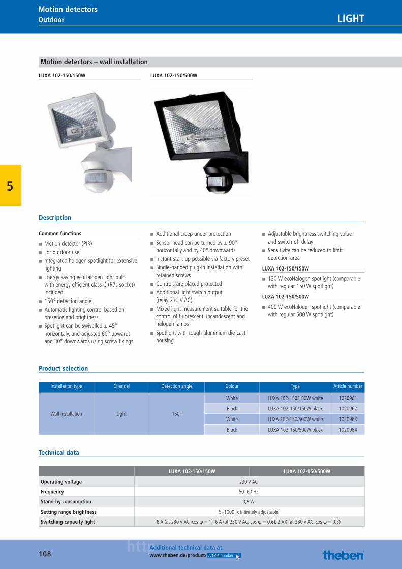
108httpAdditional technical data at:
www.theben.de/product/ Article number
Outdoor LIGHTMotion detectors
5
Motion detectors – wall installation
LUXA 102-150/150W LUXA 102-150/500W
Description
Common functions
■ Motion detector (PIR) ■ For outdoor use ■ Integrated halogen spotlight for extensive lighting
■ Energy saving ecoHalogen light bulb with energy effi cient class C (R7s socket) included
■ 150° detection angle ■ Automatic lighting control based on presence and brightness
■ Spotlight can be swivelled ± 45° horizontaly, and adjusted 60° upwards and 30° downwards using screw fi xings
■ Additional creep under protection ■ Sensor head can be turned by ± 90° horizontally and by 40° downwards
■ Instant start-up possible via factory preset ■ Single-handed plug-in installation with retained screws
■ Controls are placed protected ■ Additional light switch output (relay 230 V AC)
■ Mixed light measurement suitable for the control of fl uorescent, incandescent and halogen lamps
■ Spotlight with tough aluminium die-cast housing
■ Adjustable brightness switching value and switch-off delay
■ Sensitivity can be reduced to limit detection area
LUXA 102-150/150W
■ 120 W ecoHalogen spotlight (comparable with regular 150 W spotlight)
LUXA 102-150/500W
■ 400 W ecoHalogen spotlight (comparable with regular 500 W spotlight)
Product selection
Installation type Channel Detection angle Colour Type Article number
Wall installation Light 150°
White LUXA 102-150/150W white 1020961
Black LUXA 102-150/150W black 1020962
White LUXA 102-150/500W white 1020963
Black LUXA 102-150/500W black 1020964
Technical data
LUXA 102-150/150W LUXA 102-150/500W
Operating voltage 230 V AC
Frequency 50–60 Hz
Stand-by consumption 0,9 W
Setting range brightness 5–1000 lx Infi nitely adjustable
Switching capacity light 8 A (at 230 V AC, cos φ = 1), 6 A (at 230 V AC, cos φ = 0.6), 3 AX (at 230 V AC, cos φ = 0.3)
Catalogue_EN_2013.indb 108 16.01.13 17:21
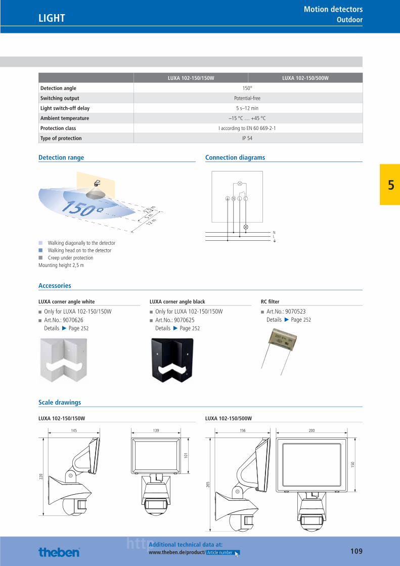
109httpAdditional technical data at:
www.theben.de/product/ Article number
OutdoorLIGHTMotion detectors
5
LUXA 102-150/150W LUXA 102-150/500W
Detection angle 150°
Switching output Potential-free
Light switch-off delay 5 s–12 min
Ambient temperature –15 °C … +45 °C
Protection class I according to EN 60 669-2-1
Type of protection IP 54
Detection range
2,5 m
5 m
12 m
150°■ Walking diagonally to the detector■ Walking head on to the detector■ Creep under protectionMounting height 2,5 m
Connection diagrams
N L
NL
L
Accessories
LUXA corner angle white
■ Only for LUXA 102-150/150W ■ Art.No.: 9070626Details ▶ Page 252
LUXA corner angle black
■ Only for LUXA 102-150/150W ■ Art.No.: 9070625Details ▶ Page 252
RC fi lter
■ Art.No.: 9070523Details ▶ Page 252
Scale drawings
LUXA 102-150/150W
220
145
101
139
LUXA 102-150/500W
265
156
150
200
Catalogue_EN_2013.indb 109 16.01.13 17:21
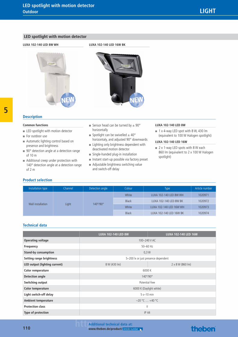
110httpAdditional technical data at:
www.theben.de/product/ Article number
Outdoor LIGHTLED spotlight with motion detector
5
LED spotlight with motion detector
LUXA 102-140 LED 8W WH LUXA 102-140 LED 16W BK
Description
Common functions
■ LED spotlight with motion detector ■ For outdoor use ■ Automatic lighting control based on presence and brightness
■ 90° detection angle at a detection range of 10 m
■ Additional creep under protection with 140° detection angle at a detection range of 2 m
■ Sensor head can be turned by ± 90° horizontally
■ Spotlight can be swivelled ± 40° horizontaly, and adjusted 90° downwards
■ Lighting only brightness dependent with deactivated motion detector
■ Single-handed plug-in installation ■ Instant start-up possible via factory preset ■ Adjustable brightness switching value and switch-off delay
LUXA 102-140 LED 8W
■ 1 x 4-way LED spot with 8 W, 430 lm (equivalent to 100 W Halogen spotlight)
LUXA 102-140 LED 16W
■ 2 x 1-way LED spots with 8 W each 860 lm (equivalent to 2 x 100 W Halogen spotlight)
Product selection
Installation type Channel Detection angle Colour Type Article number
Wall installation Light 140°/90°
White LUXA 102-140 LED 8W WH 1020971
Black LUXA 102-140 LED 8W BK 1020972
White LUXA 102-140 LED 16W WH 1020973
Black LUXA 102-140 LED 16W BK 1020974
Technical data
LUXA 102-140 LED 8W LUXA 102-140 LED 16W
Operating voltage 100–240 V AC
Frequency 50–60 Hz
Stand-by consumption 0,3 W
Setting range brightness 5–200 lx or just presence dependent
LED output (lighting current) 8 W (430 lm) 2 x 8 W (860 lm)
Color remperature 6000 K
Detection angle 140°/90°
Switching output Potential-free
Color temperature 6000 K (Daylight white)
Light switch-off delay 5 s–10 min
Ambient temperature –20 °C … +40 °C
Protection class II
Type of protection IP 44
NEW NEW
Catalogue_EN_2013.indb 110 16.01.13 17:21
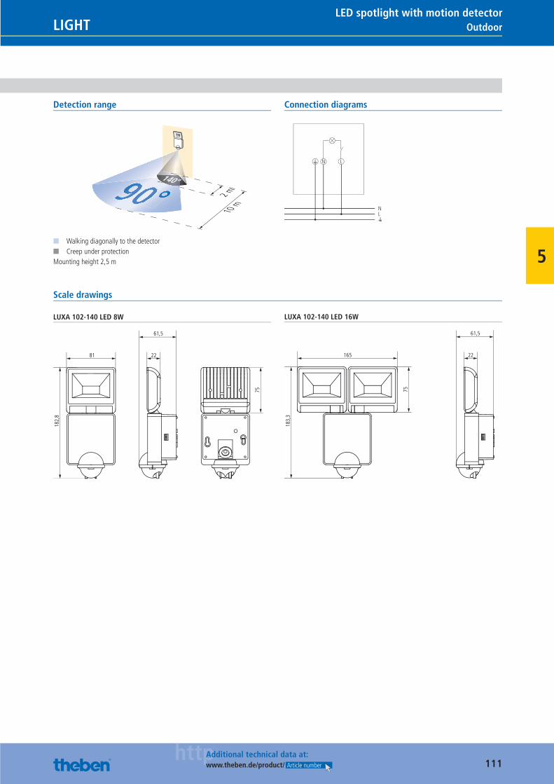
111httpAdditional technical data at:
www.theben.de/product/ Article number
OutdoorLIGHTLED spotlight with motion detector
5
Detection range
2 m
10 m90°
140°
■ Walking diagonally to the detector■ Creep under protectionMounting height 2,5 m
Connection diagrams
N L
NL
Scale drawings
LUXA 102-140 LED 8W
182,
8
81
75
22
61,5
LUXA 102-140 LED 16W
183,
3
165
75
22
61,5
Catalogue_EN_2013.indb 111 16.01.13 17:21
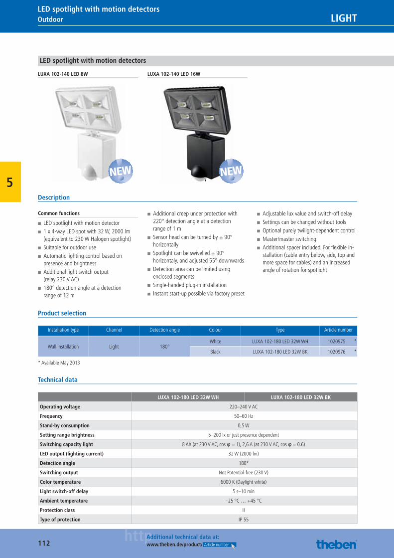
112httpAdditional technical data at:
www.theben.de/product/ Article number
Outdoor LIGHTLED spotlight with motion detectors
5
LED spotlight with motion detectors
LUXA 102-140 LED 8W LUXA 102-140 LED 16W
Description
Common functions
■ LED spotlight with motion detector ■ 1 x 4-way LED spot with 32 W, 2000 lm (equivalent to 230 W Halogen spotlight)
■ Suitable for outdoor use ■ Automatic lighting control based on presence and brightness
■ Additional light switch output (relay 230 V AC)
■ 180° detection angle at a detection range of 12 m
■ Additional creep under protection with 220° detection angle at a detection range of 1 m
■ Sensor head can be turned by ± 90° horizontally
■ Spotlight can be swivelled ± 90° horizontaly, and adjusted 55° downwards
■ Detection area can be limited using enclosed segments
■ Single-handed plug-in installation ■ Instant start-up possible via factory preset
■ Adjustable lux value and switch-off delay ■ Settings can be changed without tools ■ Optional purely twilight-dependent control ■ Master/master switching ■ Additional spacer included. For fl exible in-stallation (cable entry below, side, top and more space for cables) and an increased angle of rotation for spotlight
Product selection
Installation type Channel Detection angle Colour Type Article number
Wall installation Light 180°White LUXA 102-180 LED 32W WH 1020975 *
Black LUXA 102-180 LED 32W BK 1020976 *
* Available May 2013
Technical data
LUXA 102-180 LED 32W WH LUXA 102-180 LED 32W BK
Operating voltage 220–240 V AC
Frequency 50–60 Hz
Stand-by consumption 0,5 W
Setting range brightness 5–200 lx or just presence dependent
Switching capacity light 8 AX (at 230 V AC, cos φ = 1), 2,6 A (at 230 V AC, cos φ = 0.6)
LED output (lighting current) 32 W (2000 lm)
Detection angle 180°
Switching output Not Potential-free (230 V)
Color temperature 6000 K (Daylight white)
Light switch-off delay 5 s–10 min
Ambient temperature –25 °C … +45 °C
Protection class II
Type of protection IP 55
NEW NEW
Catalogue_EN_2013.indb 112 16.01.13 17:21
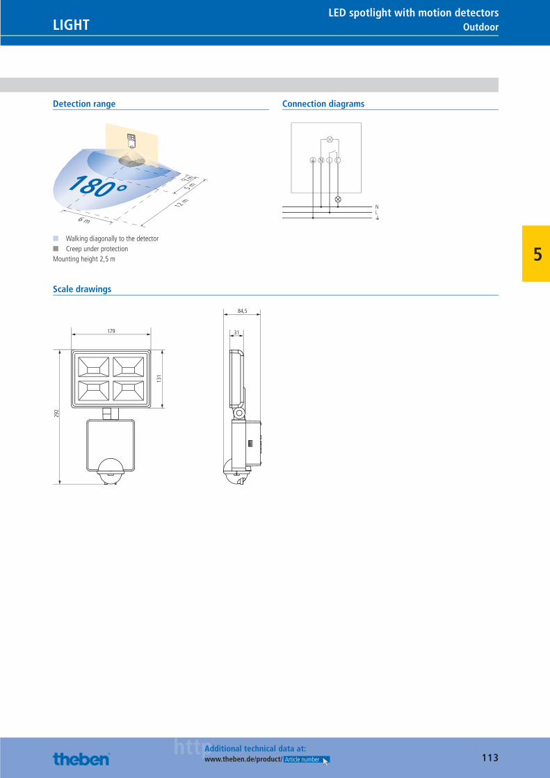
113httpAdditional technical data at:
www.theben.de/product/ Article number
OutdoorLIGHTLED spotlight with motion detectors
5
Detection range
1 m5 m
12 m
180°6 m
■ Walking diagonally to the detector■ Creep under protectionMounting height 2,5 m
Connection diagrams
N L
NL
L
Scale drawings
292
179
131
31
84,5
Catalogue_EN_2013.indb 113 16.01.13 17:21
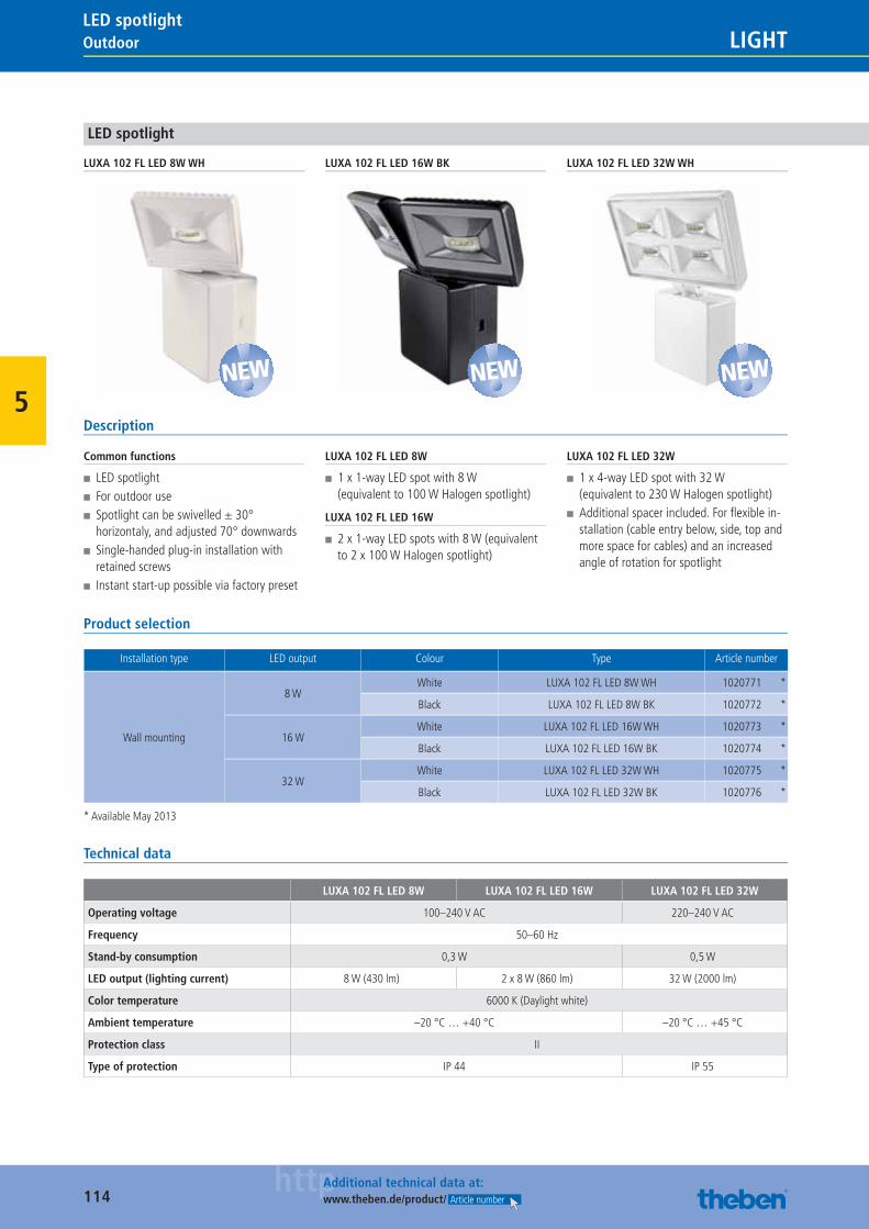
114httpAdditional technical data at:
www.theben.de/product/ Article number
Outdoor LIGHTLED spotlight
5
LED spotlight
LUXA 102 FL LED 8W WH LUXA 102 FL LED 16W BK LUXA 102 FL LED 32W WH
Description
Common functions
■ LED spotlight ■ For outdoor use ■ Spotlight can be swivelled ± 30° horizontaly, and adjusted 70° downwards
■ Single-handed plug-in installation with retained screws
■ Instant start-up possible via factory preset
LUXA 102 FL LED 8W
■ 1 x 1-way LED spot with 8 W (equivalent to 100 W Halogen spotlight)
LUXA 102 FL LED 16W
■ 2 x 1-way LED spots with 8 W (equivalent to 2 x 100 W Halogen spotlight)
LUXA 102 FL LED 32W
■ 1 x 4-way LED spot with 32 W (equivalent to 230 W Halogen spotlight)
■ Additional spacer included. For fl exible in-stallation (cable entry below, side, top and more space for cables) and an increased angle of rotation for spotlight
Product selection
Installation type LED output Colour Type Article number
Wall mounting
8 WWhite LUXA 102 FL LED 8W WH 1020771 *
Black LUXA 102 FL LED 8W BK 1020772 *
16 WWhite LUXA 102 FL LED 16W WH 1020773 *
Black LUXA 102 FL LED 16W BK 1020774 *
32 WWhite LUXA 102 FL LED 32W WH 1020775 *
Black LUXA 102 FL LED 32W BK 1020776 *
* Available May 2013
Technical data
LUXA 102 FL LED 8W LUXA 102 FL LED 16W LUXA 102 FL LED 32W
Operating voltage 100–240 V AC 220–240 V AC
Frequency 50–60 Hz
Stand-by consumption 0,3 W 0,5 W
LED output (lighting current) 8 W (430 lm) 2 x 8 W (860 lm) 32 W (2000 lm)
Color temperature 6000 K (Daylight white)
Ambient temperature –20 °C … +40 °C –20 °C … +45 °C
Protection class II
Type of protection IP 44 IP 55
NEW NEW NEW
Catalogue_EN_2013.indb 114 16.01.13 17:21
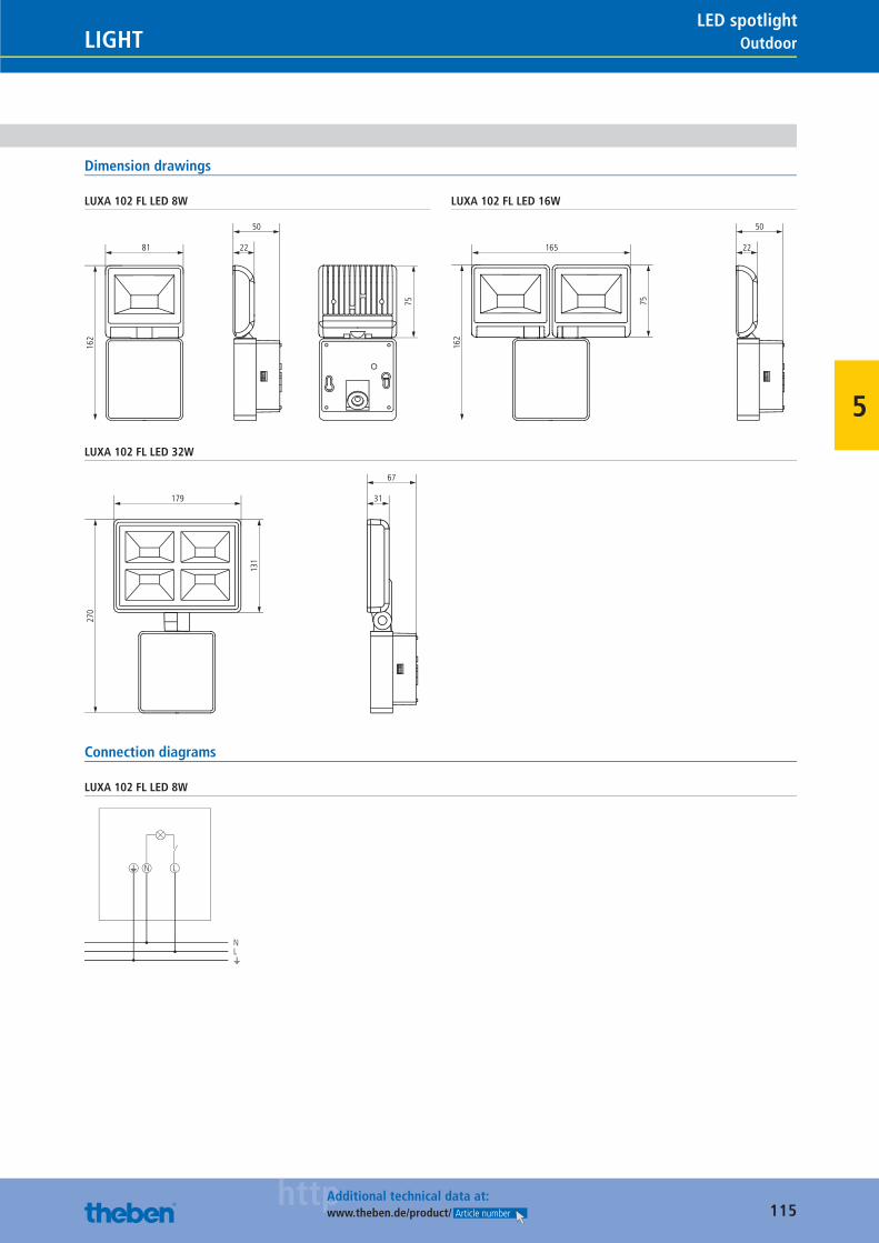
115httpAdditional technical data at:
www.theben.de/product/ Article number
OutdoorLIGHTLED spotlight
5
Dimension drawings
LUXA 102 FL LED 8W
162
81
75
22
50
LUXA 102 FL LED 16W
162
165
75
22
50
LUXA 102 FL LED 32W
270
179
131
31
67
Connection diagrams
LUXA 102 FL LED 8W
N L
NL
Catalogue_EN_2013.indb 115 16.01.13 17:21
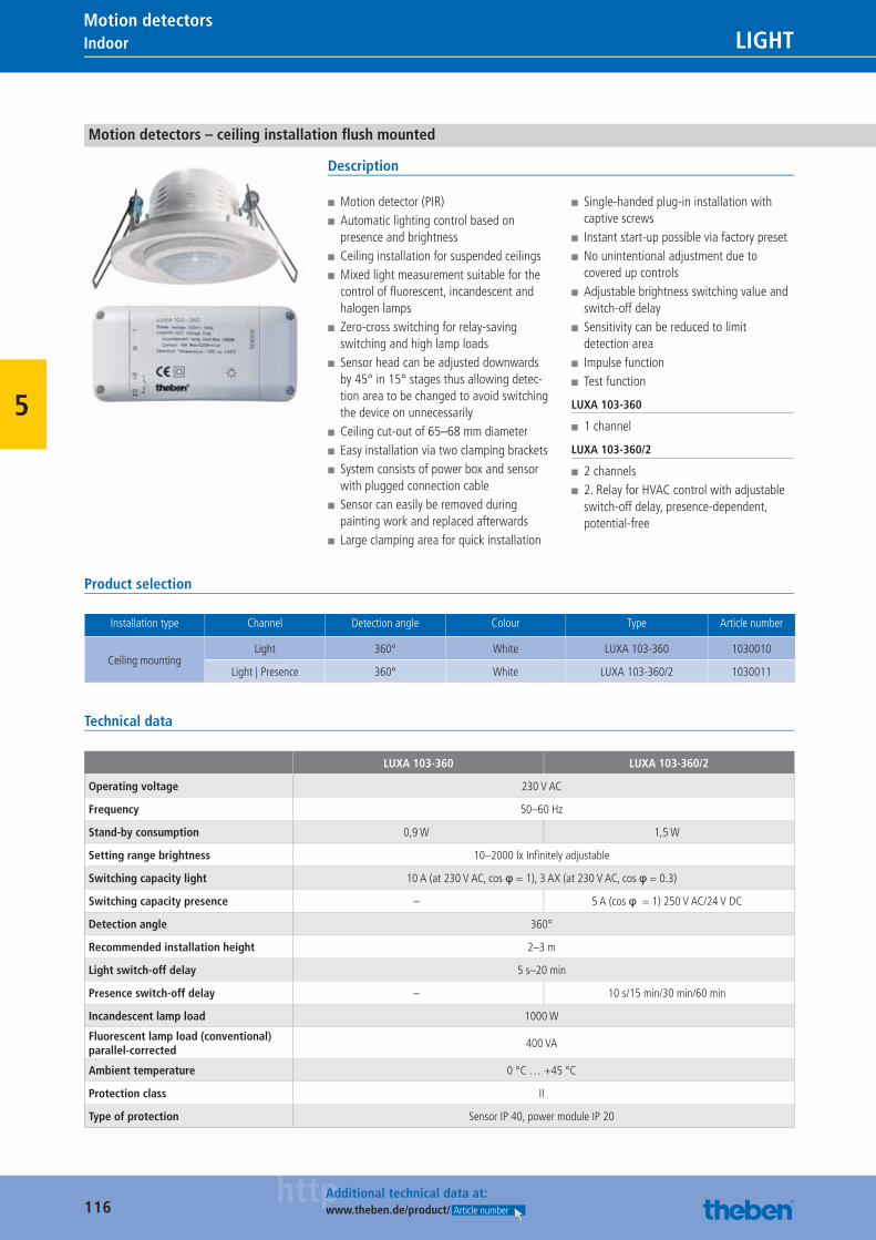
116httpAdditional technical data at:
www.theben.de/product/ Article number
Indoor LIGHTMotion detectors
5
Motion detectors – ceiling installation fl ush mounted
Description
■ Motion detector (PIR) ■ Automatic lighting control based on presence and brightness
■ Ceiling installation for suspended ceilings ■ Mixed light measurement suitable for the control of fl uorescent, incandescent and halogen lamps
■ Zero-cross switching for relay-saving switching and high lamp loads
■ Sensor head can be adjusted downwards by 45° in 15° stages thus allowing detec-tion area to be changed to avoid switching the device on unnecessarily
■ Ceiling cut-out of 65–68 mm diameter ■ Easy installation via two clamping brackets ■ System consists of power box and sensor with plugged connection cable
■ Sensor can easily be removed during painting work and replaced afterwards
■ Large clamping area for quick installation
■ Single-handed plug-in installation with captive screws
■ Instant start-up possible via factory preset ■ No unintentional adjustment due to covered up controls
■ Adjustable brightness switching value and switch-off delay
■ Sensitivity can be reduced to limit detection area
■ Impulse function ■ Test function
LUXA 103-360
■ 1 channel
LUXA 103-360/2
■ 2 channels ■ 2. Relay for HVAC control with adjustable switch-off delay, presence-dependent, potential-free
Product selection
Installation type Channel Detection angle Colour Type Article number
Ceiling mountingLight 360° White LUXA 103-360 1030010
Light | Presence 360° White LUXA 103-360/2 1030011
Technical data
LUXA 103-360 LUXA 103-360/2
Operating voltage 230 V AC
Frequency 50–60 Hz
Stand-by consumption 0,9 W 1,5 W
Setting range brightness 10–2000 lx Infi nitely adjustable
Switching capacity light 10 A (at 230 V AC, cos φ = 1), 3 AX (at 230 V AC, cos φ = 0.3)
Switching capacity presence – 5 A (cos φ = 1) 250 V AC/24 V DC
Detection angle 360°
Recommended installation height 2–3 m
Light switch-off delay 5 s–20 min
Presence switch-off delay – 10 s/15 min/30 min/60 min
Incandescent lamp load 1000 W
Fluorescent lamp load (conventional) parallel-corrected
400 VA
Ambient temperature 0 °C … +45 °C
Protection class II
Type of protection Sensor IP 40, power module IP 20
Catalogue_EN_2013.indb 116 16.01.13 17:21
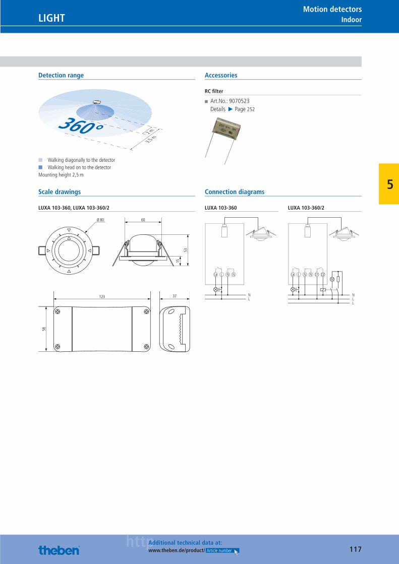
117httpAdditional technical data at:
www.theben.de/product/ Article number
IndoorLIGHTMotion detectors
5
Detection range
2 m
3,5 m
360°■ Walking diagonally to the detector■ Walking head on to the detectorMounting height 2,5 m
Accessories
RC fi lter
■ Art.No.: 9070523Details ▶ Page 252
Scale drawings
LUXA 103-360, LUXA 103-360/2
53
15
60Ø 80
58
37123
Connection diagrams
LUXA 103-360
L L N
NL
N
LUXA 103-360/2
L L N
NLL
NM
D1 D2
Catalogue_EN_2013.indb 117 16.01.13 17:21
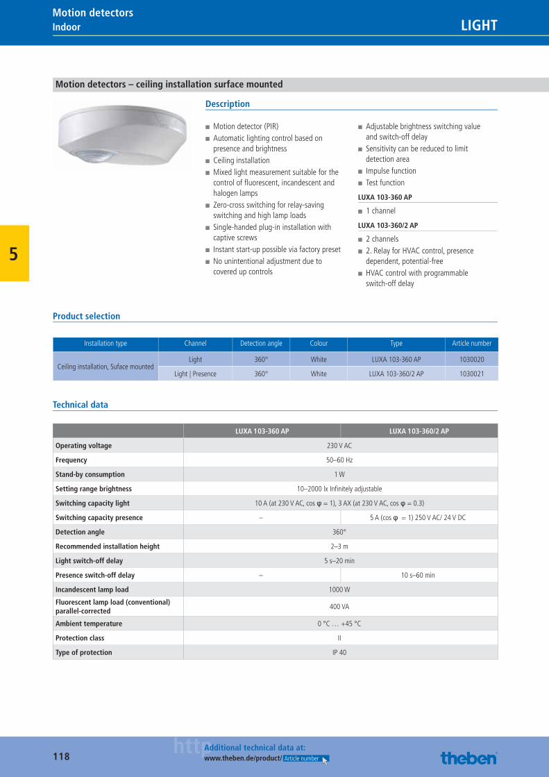
118httpAdditional technical data at:
www.theben.de/product/ Article number
Indoor LIGHTMotion detectors
5
Motion detectors – ceiling installation surface mounted
Description
■ Motion detector (PIR) ■ Automatic lighting control based on presence and brightness
■ Ceiling installation ■ Mixed light measurement suitable for the control of fl uorescent, incandescent and halogen lamps
■ Zero-cross switching for relay-saving switching and high lamp loads
■ Single-handed plug-in installation with captive screws
■ Instant start-up possible via factory preset ■ No unintentional adjustment due to covered up controls
■ Adjustable brightness switching value and switch-off delay
■ Sensitivity can be reduced to limit detection area
■ Impulse function ■ Test function
LUXA 103-360 AP
■ 1 channel
LUXA 103-360/2 AP
■ 2 channels ■ 2. Relay for HVAC control, presence dependent, potential-free
■ HVAC control with programmable switch-off delay
Product selection
Installation type Channel Detection angle Colour Type Article number
Ceiling installation, Suface mountedLight 360° White LUXA 103-360 AP 1030020
Light | Presence 360° White LUXA 103-360/2 AP 1030021
Technical data
LUXA 103-360 AP LUXA 103-360/2 AP
Operating voltage 230 V AC
Frequency 50–60 Hz
Stand-by consumption 1 W
Setting range brightness 10–2000 lx Infi nitely adjustable
Switching capacity light 10 A (at 230 V AC, cos φ = 1), 3 AX (at 230 V AC, cos φ = 0.3)
Switching capacity presence – 5 A (cos φ = 1) 250 V AC/ 24 V DC
Detection angle 360°
Recommended installation height 2–3 m
Light switch-off delay 5 s–20 min
Presence switch-off delay – 10 s–60 min
Incandescent lamp load 1000 W
Fluorescent lamp load (conventional) parallel-corrected
400 VA
Ambient temperature 0 °C … +45 °C
Protection class II
Type of protection IP 40
Catalogue_EN_2013.indb 118 16.01.13 17:21
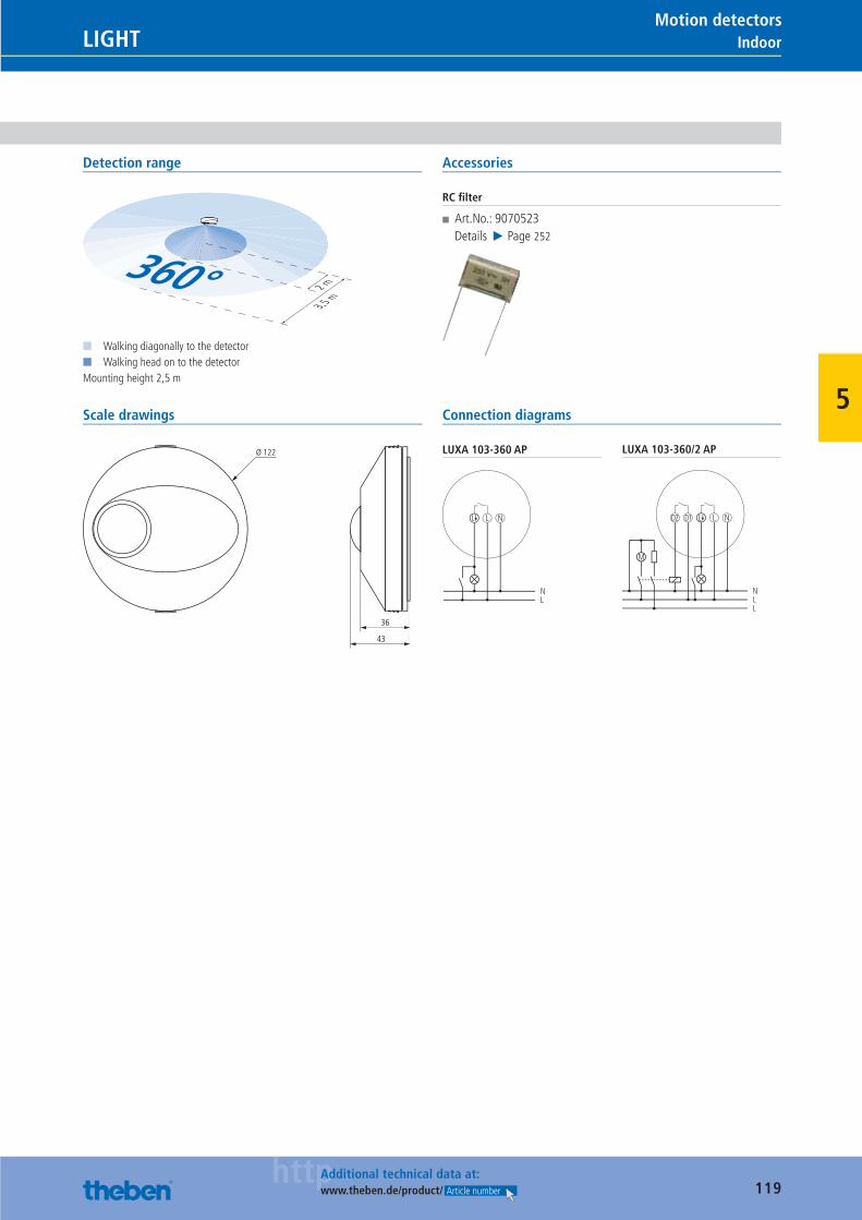
119httpAdditional technical data at:
www.theben.de/product/ Article number
IndoorLIGHTMotion detectors
5
Detection range
2 m
3,5 m
360°■ Walking diagonally to the detector■ Walking head on to the detectorMounting height 2,5 m
Accessories
RC fi lter
■ Art.No.: 9070523Details ▶ Page 252
Scale drawings
36
43
Ø 122
Connection diagrams
LUXA 103-360 AP
L NL
NL
LUXA 103-360/2 AP
L NLD1D2
NLL
M
Catalogue_EN_2013.indb 119 16.01.13 17:21
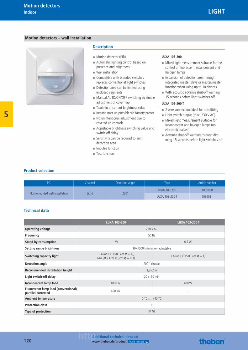
120httpAdditional technical data at:
www.theben.de/product/ Article number
Indoor LIGHTMotion detectors
5
Motion detectors – wall installation
Description
■ Motion detector (PIR) ■ Automatic lighting control based on presence and brightness
■ Wall installation ■ Compatible with branded switches, replaces conventional light switches
■ Detection area can be limited using enclosed segments
■ Manual AUTO/ON/OFF switching by simple adjustment of cover fl ap
■ Teach-in of current brightness value ■ Instant start-up possible via factory preset ■ No unintentional adjustment due to covered up controls
■ Adjustable brightness switching value and switch-off delay
■ Sensitivity can be reduced to limit detection area
■ Impulse function ■ Test function
LUXA 103-200
■ Mixed light measurement suitable for the control of fl uorescent, incandescent and halogen lamps
■ Expansion of detection area through integrated master/slave or master/master function when using up to 10 devices
■ With acoustic advance shut-off warning 15 seconds before light switches off
LUXA 103-200 T
■ 2 wire connection, ideal for retrofi tting ■ Light switch output (triac, 230 V AC) ■ Mixed light measurement suitable for incandescent and halogen lamps (no electronic ballast)
■ Advance shut-off warning through dim-ming 15 seconds before light switches off
Product selection
PG Channel Detection angle Type Article number
Flush-mounted wall installation Light 200°LUXA 103-200 1030030
LUXA 103-200 T 1030031
Technical data
LUXA 103-200 LUXA 103-200 T
Operating voltage 230 V AC
Frequency 50 Hz
Stand-by consumption 1 W 0,7 W
Setting range brightness 10–1000 lx Infi nitely adjustable
Switching capacity light10 A (at 230 V AC, cos φ = 1),
3 AX (at 230 V AC, cos φ = 0,3)2 A (at 230 V AC, cos φ = 1)
Detection angle 200°, circular
Recommended installation height 1,2–2 m
Light switch-off delay 20 s–30 min
Incandescent lamp load 1000 W 400 W
Fluorescent lamp load (conventional)parallel-corrected
400 VA –
Ambient temperature 0 °C … +45 °C
Protection class II
Type of protection IP 40
Catalogue_EN_2013.indb 120 16.01.13 17:21
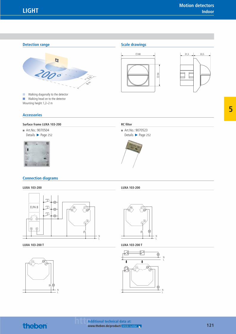
121httpAdditional technical data at:
www.theben.de/product/ Article number
IndoorLIGHTMotion detectors
5
Detection range
3 m
8 m
200°■ Walking diagonally to the detector■ Walking head on to the detectorMounting height 1,2–2 m
Scale drawings
� 80
� 5
0
31,5 33,5
Accessories
Surface frame LUXA 103-200
■ Art.No.: 9070504Details ▶ Page 252
RC fi lter
■ Art.No.: 9070523Details ▶ Page 252
Connection diagrams
LUXA 103-200
LNN
PT
L
NL
N
L
4
3
ELPA 8
LUXA 103-200
LNN
PT
L
NL
LUXA 103-200 T
TL
LL
NL
LUXA 103-200 T
TL
LL
NL
NL
Catalogue_EN_2013.indb 121 16.01.13 17:21
122
LIGHT
60 countries.We are fully committed to Germany as our base. Around 580 employees work at the company HQ in Haigerloch. Many of them have been with the company for over 40 years and they pass on their experience and expertise to their young colleagues. We export our products from Haigerloch to over 60 countries worldwide.
Catalogue_EN_2013.indb 122 16.01.13 17:21
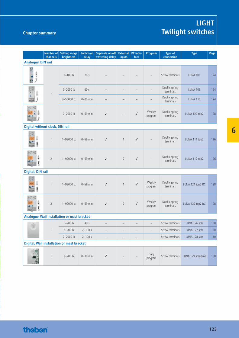
123
Chapter summary
LIGHTTwilight switches
6
Number of channels
Setting range brightness
Switch-on delay
Separate on/off switching delay
External inputs
PC inter-face
Program Type ofconnection
Type Page
Analogue, DIN rail
1
2–100 lx 20 s – – – – Screw terminals LUNA 108 124
2–2000 lx 60 s – – – –DuoFix spring
terminalsLUNA 109 124
2–50000 lx 0–20 min – – – –DuoFix spring
terminalsLUNA 110 124
2–2000 lx 0–59 min ✓ – ✓ Weekly program
DuoFix spring terminals
LUNA 120 top2 128
Digital without clock, DIN rail
1 1–99000 lx 0–59 min ✓ 1 ✓ –DuoFix spring
terminalsLUNA 111 top2 126
2 1–99000 lx 0–59 min ✓ 2 ✓ –DuoFix spring
terminalsLUNA 112 top2 126
Digital, DIN rail
1 1–99000 lx 0–59 min ✓ 1 ✓ Weekly program
DuoFix spring terminals
LUNA 121 top2 RC 128
2 1–99000 lx 0–59 min ✓ 2 ✓ Weekly program
DuoFix spring terminals
LUNA 122 top2 RC 128
Analogue, Wall installation or mast bracket
1
5–200 lx 40 s – – – – Screw terminals LUNA 126 star 130
2–200 lx 2–100 s – – – – Screw terminals LUNA 127 star 130
2–2000 lx 2–100 s – – – – Screw terminals LUNA 128 star 130
Digital, Wall installation or mast bracket
1 2–200 lx 0–10 min ✓ – –Daily
programScrew terminals LUNA 129 star-time 130
Catalogue_EN_2013.indb 123 16.01.13 17:21
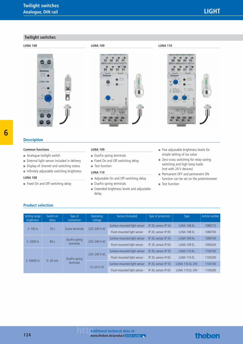
124httpAdditional technical data at:
www.theben.de/product/ Article number
Analogue, DIN rail LIGHTTwilight switches
6
Twilight switches
LUNA 108 LUNA 109 LUNA 110
Description
Common functions
■ Analogue twilight switch ■ External light sensor included in delivery ■ Display of channel and switching status ■ Infi nitely adjustable switching brightness
LUNA 108
■ Fixed On and Off switching delay
LUNA 109
■ DuoFix spring terminals ■ Fixed On and Off switching delay ■ Test function
LUNA 110
■ Adjustable On and Off switching delay ■ DuoFix spring terminals ■ Extended brightness levels and adjustable delay
■ Five adjustable brightness levels for simple setting of lux value
■ Zero-cross switching for relay-saving switching and high lamp loads (not with 24 V devices)
■ Permanent OFF and permanent ON function can be set on the potentiometer
■ Test function
Product selection
Setting range brightness
Switch-on delay
Type of connection
Operating voltage
Sensor (included) Type of protection Type Article number
2–100 lx 20 s Screw terminals 220–240 V ACSurface-mounted light sensor IP 20, sensor IP 54 LUNA 108 AL 1080710
Flush-mounted light sensor IP 20, sensor IP 65 LUNA 108 EL 1080700
2–2000 lx 60 sDuoFix spring
terminals220–240 V AC
Surface-mounted light sensor IP 20, sensor IP 55 LUNA 109 AL 1090100
Flush-mounted light sensor IP 20, sensor IP 65 LUNA 109 EL 1090200
2–50000 lx 0–20 minDuoFix spring
terminals
220–240 V ACSurface-mounted light sensor IP 20, sensor IP 55 LUNA 110 AL 1100100
Flush-mounted light sensor IP 20, sensor IP 65 LUNA 110 EL 1100200
12–24 V UCSurface-mounted light sensor IP 20, sensor IP 55 LUNA 110 AL 24V 1104100
Flush-mounted light sensor IP 20, sensor IP 65 LUNA 110 EL 24V 1104200
Catalogue_EN_2013.indb 124 16.01.13 17:21
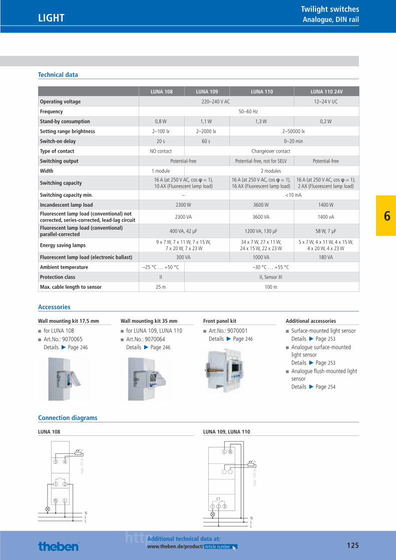
125httpAdditional technical data at:
www.theben.de/product/ Article number
Analogue, DIN railLIGHTTwilight switches
6
Technical data
LUNA 108 LUNA 109 LUNA 110 LUNA 110 24V
Operating voltage 220–240 V AC 12–24 V UC
Frequency 50–60 Hz
Stand-by consumption 0,8 W 1,1 W 1,3 W 0,2 W
Setting range brightness 2–100 lx 2–2000 lx 2–50000 lx
Switch-on delay 20 s 60 s 0–20 min
Type of contact NO contact Changeover contact
Switching output Potential-free Potential-free, not for SELV Potential-free
Width 1 module 2 modules
Switching capacity16 A (at 250 V AC, cos φ = 1), 10 AX (Fluorescent lamp load)
16 A (at 250 V AC, cos φ = 1), 16 AX (Fluorescent lamp load)
16 A (at 250 V AC, cos φ = 1), 2 AX (Fluorescent lamp load)
Switching capacity min. – <10 mA
Incandescent lamp load 2300 W 3600 W 1400 W
Fluorescent lamp load (conventional) not corrected, series-corrected, lead-lag circuit
2300 VA 3600 VA 1400 vA
Fluorescent lamp load (conventional) parallel-corrected
400 VA, 42 μF 1200 VA, 130 μF 58 W, 7 μF
Energy saving lamps9 x 7 W, 7 x 11 W, 7 x 15 W,
7 x 20 W, 7 x 23 W34 x 7 W, 27 x 11 W, 24 x 15 W, 22 x 23 W
5 x 7 W, 4 x 11 W, 4 x 15 W, 4 x 20 W, 4 x 23 W
Fluorescent lamp load (electronic ballast) 300 VA 1000 VA 180 VA
Ambient temperature –25 °C … +50 °C –30 °C … +55 °C
Protection class II II, Sensor III
Max. cable length to sensor 25 m 100 m
Accessories
Wall mounting kit 17,5 mm
■ for LUNA 108 ■ Art.No.: 9070065Details ▶ Page 246
Wall mounting kit 35 mm
■ for LUNA 109, LUNA 110 ■ Art.No.: 9070064Details ▶ Page 246
Front panel kit
■ Art.No.: 9070001Details ▶ Page 246
Additional accessories
■ Surface-mounted light sensorDetails ▶ Page 253
■ Analogue surface-mounted light sensorDetails ▶ Page 253
■ Analogue fl ush-mounted light sensorDetails ▶ Page 254
Connection diagrams
LUNA 108
N
1
L
2
NLL
43
max
. 25
m
LUNA 109, LUNA 110
C1
1 2 3
NLL
L N
max
. 100
m
Catalogue_EN_2013.indb 125 16.01.13 17:22
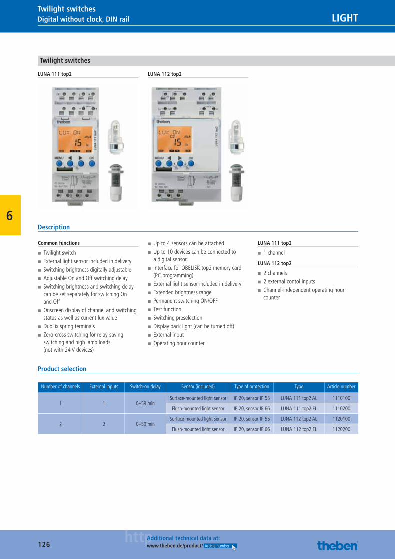
126httpAdditional technical data at:
www.theben.de/product/ Article number
Digital without clock, DIN rail LIGHTTwilight switches
6
Twilight switches
LUNA 111 top2 LUNA 112 top2
Description
Common functions
■ Twilight switch ■ External light sensor included in delivery ■ Switching brightness digitally adjustable ■ Adjustable On and Off switching delay ■ Switching brightness and switching delay can be set separately for switching On and Off
■ Onscreen display of channel and switching status as well as current lux value
■ DuoFix spring terminals ■ Zero-cross switching for relay-saving switching and high lamp loads (not with 24 V devices)
■ Up to 4 sensors can be attached ■ Up to 10 devices can be connected to a digital sensor
■ Interface for OBELISK top2 memory card (PC programming)
■ External light sensor included in delivery ■ Extended brightness range ■ Permanent switching ON/OFF ■ Test function ■ Switching preselection ■ Display back light (can be turned off) ■ External input ■ Operating hour counter
LUNA 111 top2
■ 1 channel
LUNA 112 top2
■ 2 channels ■ 2 external contol inputs ■ Channel-independent operating hour counter
Product selection
Number of channels External inputs Switch-on delay Sensor (included) Type of protection Type Article number
1 1 0–59 minSurface-mounted light sensor IP 20, sensor IP 55 LUNA 111 top2 AL 1110100
Flush-mounted light sensor IP 20, sensor IP 66 LUNA 111 top2 EL 1110200
2 2 0–59 minSurface-mounted light sensor IP 20, sensor IP 55 LUNA 112 top2 AL 1120100
Flush-mounted light sensor IP 20, sensor IP 66 LUNA 112 top2 EL 1120200
Catalogue_EN_2013.indb 126 16.01.13 17:22
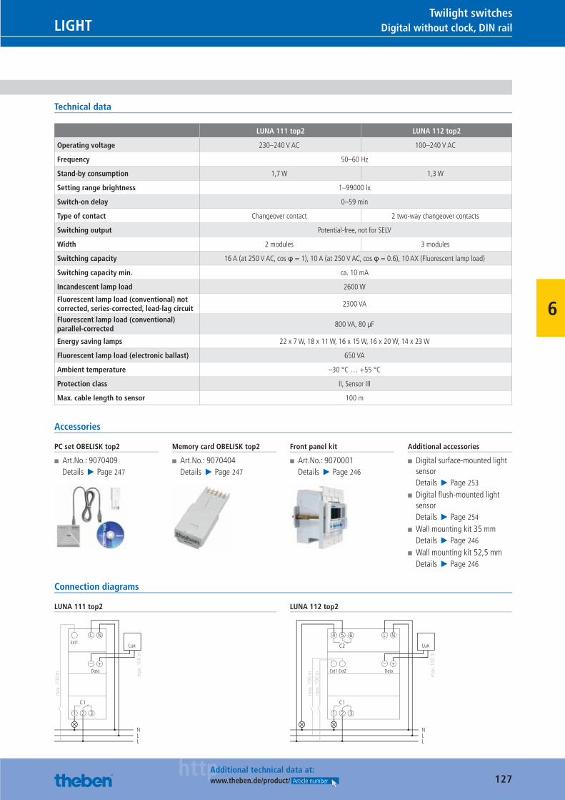
127httpAdditional technical data at:
www.theben.de/product/ Article number
Digital without clock, DIN railLIGHTTwilight switches
6
Technical data
LUNA 111 top2 LUNA 112 top2
Operating voltage 230–240 V AC 100–240 V AC
Frequency 50–60 Hz
Stand-by consumption 1,7 W 1,3 W
Setting range brightness 1–99000 lx
Switch-on delay 0–59 min
Type of contact Changeover contact 2 two-way changeover contacts
Switching output Potential-free, not for SELV
Width 2 modules 3 modules
Switching capacity 16 A (at 250 V AC, cos φ = 1), 10 A (at 250 V AC, cos φ = 0.6), 10 AX (Fluorescent lamp load)
Switching capacity min. ca. 10 mA
Incandescent lamp load 2600 W
Fluorescent lamp load (conventional) not corrected, series-corrected, lead-lag circuit
2300 VA
Fluorescent lamp load (conventional) parallel-corrected
800 VA, 80 μF
Energy saving lamps 22 x 7 W, 18 x 11 W, 16 x 15 W, 16 x 20 W, 14 x 23 W
Fluorescent lamp load (electronic ballast) 650 VA
Ambient temperature –30 °C … +55 °C
Protection class II, Sensor III
Max. cable length to sensor 100 m
Accessories
PC set OBELISK top2
■ Art.No.: 9070409Details ▶ Page 247
Memory card OBELISK top2
■ Art.No.: 9070404Details ▶ Page 247
Front panel kit
■ Art.No.: 9070001Details ▶ Page 246
Additional accessories
■ Digital surface-mounted light sensorDetails ▶ Page 253
■ Digital fl ush-mounted light sensorDetails ▶ Page 254
■ Wall mounting kit 35 mmDetails ▶ Page 246
■ Wall mounting kit 52,5 mmDetails ▶ Page 246
Connection diagrams
LUNA 111 top2
C1
1 2 3
NLL
L N
– +
Ext1
max
. 100
m
Data
Lux
max
. 100
m
LUNA 112 top2
C2
C1
1 2 3
4 5 6
NLL
L N
Ext1
max
. 100
mm
ax. 1
00 m
Ext2 Data
– +
Lux
max
. 100
m
Catalogue_EN_2013.indb 127 16.01.13 17:22
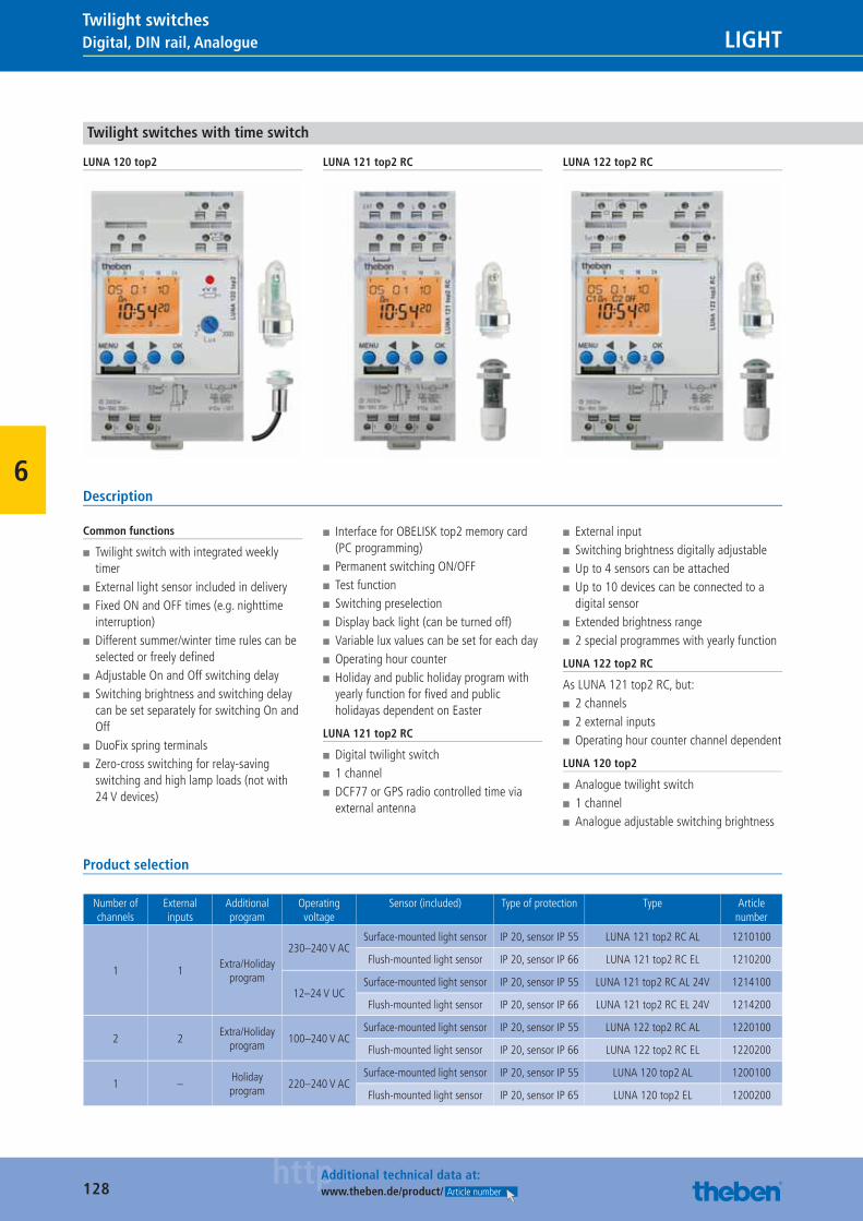
128httpAdditional technical data at:
www.theben.de/product/ Article number
Digital, DIN rail, Analogue LIGHTTwilight switches
6
Twilight switches with time switch
LUNA 120 top2 LUNA 121 top2 RC LUNA 122 top2 RC
Description
Common functions
■ Twilight switch with integrated weekly timer
■ External light sensor included in delivery ■ Fixed ON and OFF times (e.g. nighttime interruption)
■ Different summer/winter time rules can be selected or freely defi ned
■ Adjustable On and Off switching delay ■ Switching brightness and switching delay can be set separately for switching On and Off
■ DuoFix spring terminals ■ Zero-cross switching for relay-saving switching and high lamp loads (not with 24 V devices)
■ Interface for OBELISK top2 memory card (PC programming)
■ Permanent switching ON/OFF ■ Test function ■ Switching preselection ■ Display back light (can be turned off) ■ Variable lux values can be set for each day ■ Operating hour counter ■ Holiday and public holiday program with yearly function for fi ved and public holidayas dependent on Easter
LUNA 121 top2 RC
■ Digital twilight switch ■ 1 channel ■ DCF77 or GPS radio controlled time via external antenna
■ External input ■ Switching brightness digitally adjustable ■ Up to 4 sensors can be attached ■ Up to 10 devices can be connected to a digital sensor
■ Extended brightness range ■ 2 special programmes with yearly function
LUNA 122 top2 RC
As LUNA 121 top2 RC, but: ■ 2 channels ■ 2 external inputs ■ Operating hour counter channel dependent
LUNA 120 top2
■ Analogue twilight switch ■ 1 channel ■ Analogue adjustable switching brightness
Product selection
Number of channels
External inputs
Additional program
Operating voltage
Sensor (included) Type of protection Type Article number
1 1Extra/Holiday
program
230–240 V AC Surface-mounted light sensor IP 20, sensor IP 55 LUNA 121 top2 RC AL 1210100
Flush-mounted light sensor IP 20, sensor IP 66 LUNA 121 top2 RC EL 1210200
12–24 V UC Surface-mounted light sensor IP 20, sensor IP 55 LUNA 121 top2 RC AL 24V 1214100
Flush-mounted light sensor IP 20, sensor IP 66 LUNA 121 top2 RC EL 24V 1214200
2 2Extra/Holiday
program100–240 V AC
Surface-mounted light sensor IP 20, sensor IP 55 LUNA 122 top2 RC AL 1220100
Flush-mounted light sensor IP 20, sensor IP 66 LUNA 122 top2 RC EL 1220200
1 –Holiday program
220–240 V AC Surface-mounted light sensor IP 20, sensor IP 55 LUNA 120 top2 AL 1200100
Flush-mounted light sensor IP 20, sensor IP 65 LUNA 120 top2 EL 1200200
Catalogue_EN_2013.indb 128 16.01.13 17:22
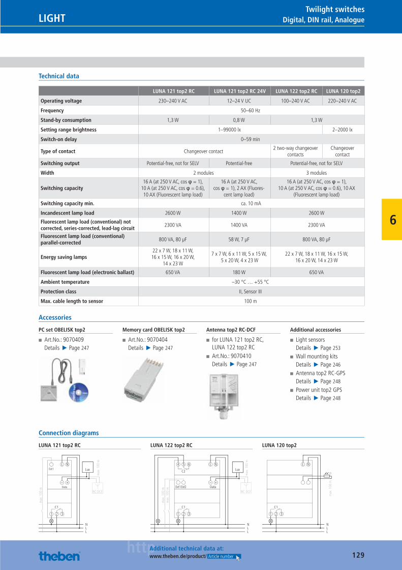
129httpAdditional technical data at:
www.theben.de/product/ Article number
Digital, DIN rail, AnalogueLIGHTTwilight switches
6
Technical data
LUNA 121 top2 RC LUNA 121 top2 RC 24V LUNA 122 top2 RC LUNA 120 top2
Operating voltage 230–240 V AC 12–24 V UC 100–240 V AC 220–240 V AC
Frequency 50–60 Hz
Stand-by consumption 1,3 W 0,8 W 1,3 W
Setting range brightness 1–99000 lx 2–2000 lx
Switch-on delay 0–59 min
Type of contact Changeover contact2 two-way changeover
contactsChangeover
contact
Switching output Potential-free, not for SELV Potential-free Potential-free, not for SELV
Width 2 modules 3 modules
Switching capacity16 A (at 250 V AC, cos φ = 1),
10 A (at 250 V AC, cos φ = 0.6), 10 AX (Fluorescent lamp load)
16 A (at 250 V AC, cos φ = 1), 2 AX (Fluores-
cent lamp load)
16 A (at 250 V AC, cos φ = 1), 10 A (at 250 V AC, cos φ = 0.6), 10 AX
(Fluorescent lamp load)
Switching capacity min. ca. 10 mA
Incandescent lamp load 2600 W 1400 W 2600 W
Fluorescent lamp load (conventional) not corrected, series-corrected, lead-lag circuit
2300 VA 1400 VA 2300 VA
Fluorescent lamp load (conventional) parallel-corrected
800 VA, 80 μF 58 W, 7 μF 800 VA, 80 μF
Energy saving lamps22 x 7 W, 18 x 11 W, 16 x 15 W, 16 x 20 W,
14 x 23 W
7 x 7 W, 6 x 11 W, 5 x 15 W, 5 x 20 W, 4 x 23 W
22 x 7 W, 18 x 11 W, 16 x 15 W, 16 x 20 W, 14 x 23 W
Fluorescent lamp load (electronic ballast) 650 VA 180 W 650 VA
Ambient temperature –30 °C … +55 °C
Protection class II, Sensor III
Max. cable length to sensor 100 m
Accessories
PC set OBELISK top2
■ Art.No.: 9070409Details ▶ Page 247
Memory card OBELISK top2
■ Art.No.: 9070404Details ▶ Page 247
Antenna top2 RC-DCF
■ for LUNA 121 top2 RC, LUNA 122 top2 RC
■ Art.No.: 9070410Details ▶ Page 247
Additional accessories
■ Light sensorsDetails ▶ Page 253
■ Wall mounting kitsDetails ▶ Page 246
■ Antenna top2 RC-GPSDetails ▶ Page 248
■ Power unit top2 GPSDetails ▶ Page 248
Connection diagrams
LUNA 121 top2 RC
C1
1 2 3
NLL
L NExt1
max
. 100
m
Data
RC DCF
– +
Lux
max
. 100
m
LUNA 122 top2 RC
C2
C1
1 2 3
4 5 6
NLL
L N
Ext1
max
. 100
mm
ax. 1
00 m
Ext2 DataRC DCF
– +
Lux
max
. 100
m
LUNA 120 top2
C1
1 2 3
NLL
L N
max
. 100
m
Catalogue_EN_2013.indb 129 16.01.13 17:22
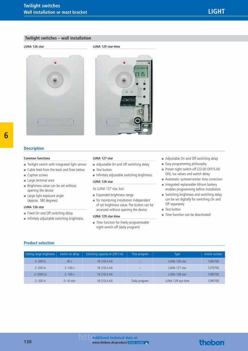
130httpAdditional technical data at:
www.theben.de/product/ Article number
Wall installation or mast bracket LIGHTTwilight switches
6
Twilight switches – wall installation
LUNA 126 star LUNA 129 star-time
Description
Common functions
■ Twilight switch with integrated light sensor ■ Cable feed from the back and from below ■ Captive screws ■ Large terminal area ■ Brightness value can be set without opening the device
■ Large light exposure angle (approx. 180 degrees)
LUNA 126 star
■ Fixed On and Off switching delay ■ Infi nitely adjustable switching brightness
LUNA 127 star
■ Adjustable On and Off switching delay ■ Test button ■ Infi nitely adjustable switching brightness
LUNA 128 star
As LUNA 127 star, but:
■ Expanded brightness range ■ for monitoring installation independent of set brightness value. The button can be accessed without opening the device
LUNA 129 star-time
■ Time function for freely-programmable night switch-off (daily program)
■ Adjustable On and Off switching delay ■ Easy programming philosophy ■ Preset night switch-off (23.00 OFF/5.00 ON), lux values and switch delay
■ Automatic summer/winter time correction ■ Integrated replaceable lithium battery enables programming before installation
■ Switching brightness and switching delay can be set digitally for switching On and Off separately
■ Test button ■ Time function can be deactivated
Product selection
Setting range brightness Switch-on delay Switching capacity at 230 V AC Time program Type Article number
5–200 lx 40 s 16 (10) A AX – LUNA 126 star 1260700
2–200 lx 2–100 s 16 (10) A AX – LUNA 127 star 1270700
2–2000 lx 2–100 s 16 (10) A AX – LUNA 128 star 1280700
2–200 lx 0–10 min 16 (10) A AX Daily program LUNA 129 star-time 1290700
Catalogue_EN_2013.indb 130 16.01.13 17:22
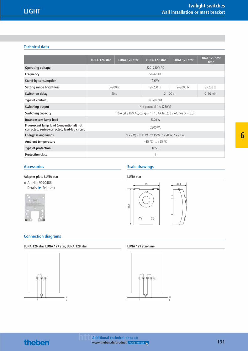
131httpAdditional technical data at:
www.theben.de/product/ Article number
Wall installation or mast bracketLIGHTTwilight switches
6
Technical data
LUNA 126 star LUNA 126 star LUNA 127 star LUNA 128 starLUNA 129 star-
time
Operating voltage 220–230 V AC
Frequency 50–60 Hz
Stand-by consumption 0,6 W
Setting range brightness 5–200 lx 2–200 lx 2–2000 lx 2–200 lx
Switch-on delay 40 s 2–100 s 0–10 min
Type of contact NO contact
Switching output Not potential-free (230 V)
Switching capacity 16 A (at 230 V AC, cos φ = 1), 10 AX (at 230 V AC, cos φ = 0.3)
Incandescent lamp load 2300 W
Fluorescent lamp load (conventional) not corrected, series-corrected, lead-lag circuit
2300 VA
Energy saving lamps 9 x 7 W, 7 x 11 W, 7 x 15 W, 7 x 20 W, 7 x 23 W
Ambient temperature –35 °C … +55 °C
Type of protection IP 55
Protection class II
Accessories
Adapter plate LUNA star
■ Art.No.: 9070486Details ▶ Seite 253
Scale drawings
LUNA star
49,485
118,
4
Connection diagrams
LUNA 126 star, LUNA 127 star, LUNA 128 star
L N
NL
LUNA 129 star-time
L N‘
NL
N
Catalogue_EN_2013.indb 131 16.01.13 17:22

132
LIGHT
20,000 switching cycles.Every one of our ELPA test devices from the current production run are put through 20,000 two-minute switching cycles. After these 40,000 minutes we know exactly about the quality of our ELPAs. And you know that you and your customers can always rely on reliable and durable products.
Catalogue_EN_2013.indb 132 16.01.13 17:22
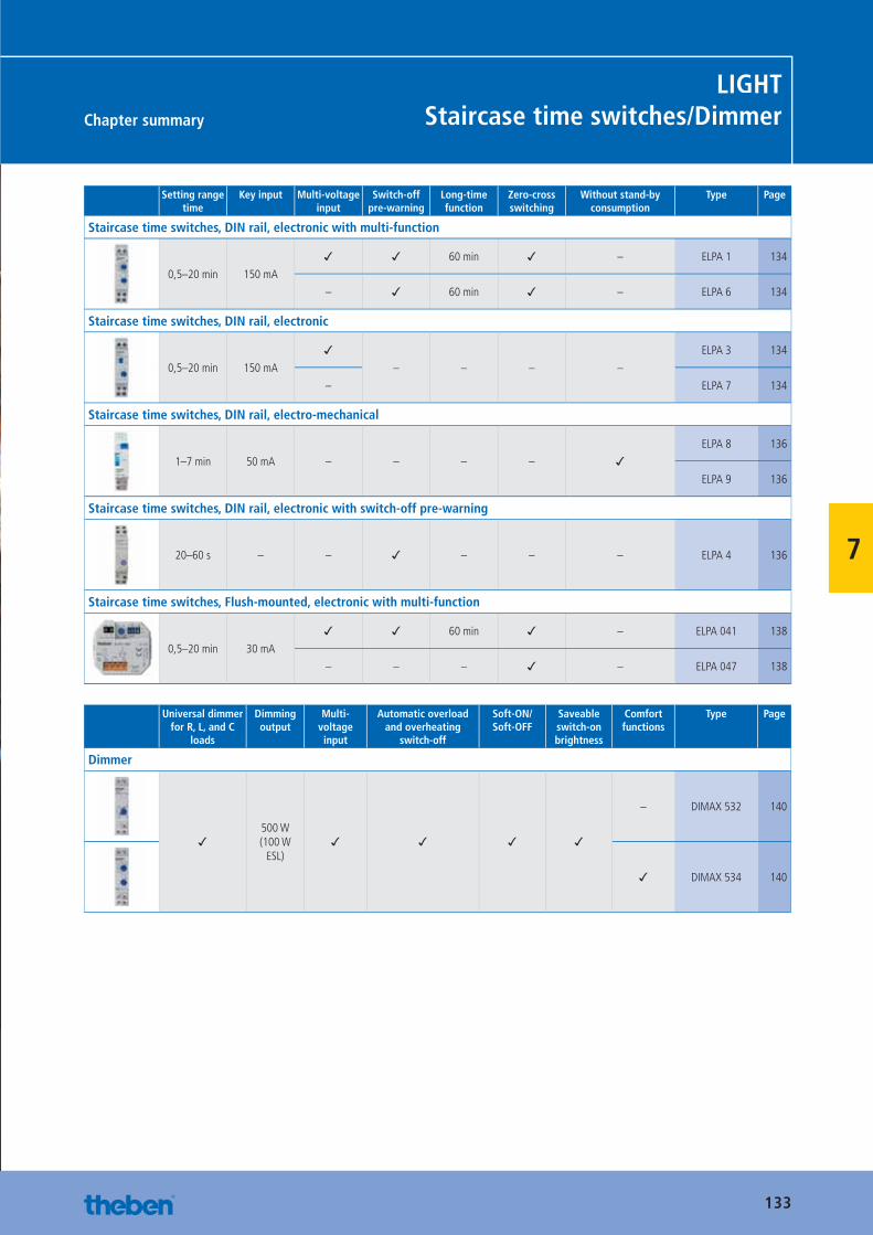
133
Chapter summary
LIGHTStaircase time switches/Dimmer
7
Setting range time
Key input Multi-voltage input
Switch-off pre-warning
Long-time function
Zero-cross switching
Without stand-by consumption
Type Page
Staircase time switches, DIN rail, electronic with multi-function
0,5–20 min 150 mA
✓ ✓ 60 min ✓ – ELPA 1 134
– ✓ 60 min ✓ – ELPA 6 134
Staircase time switches, DIN rail, electronic
0,5–20 min 150 mA
✓– – – –
ELPA 3 134
– ELPA 7 134
Staircase time switches, DIN rail, electro-mechanical
1–7 min 50 mA – – – – ✓ELPA 8 136
ELPA 9 136
Staircase time switches, DIN rail, electronic with switch-off pre-warning
20–60 s – – ✓ – – – ELPA 4 136
Staircase time switches, Flush-mounted, electronic with multi-function
0,5–20 min 30 mA
✓ ✓ 60 min ✓ – ELPA 041 138
– – – ✓ – ELPA 047 138
Universal dimmer for R, L, and C
loads
Dimming output
Multi-voltage input
Automatic overload and overheating
switch-off
Soft-ON/ Soft-OFF
Saveable switch-on brightness
Comfort functions
Type Page
Dimmer
✓500 W(100 W
ESL)✓ ✓ ✓ ✓
– DIMAX 532 140
✓ DIMAX 534 140
Catalogue_EN_2013.indb 133 16.01.13 17:22
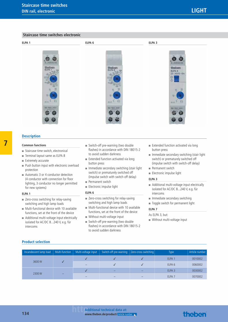
134httpAdditional technical data at:
www.theben.de/product/ Article number
DIN rail, electronic LIGHTStaircase time switches
7
Staircase time switches electronic
ELPA 1 ELPA 6 ELPA 3
Description
Common functions
■ Staircase time switch, electronical ■ Terminal layout same as ELPA 8 ■ Extremely accurate ■ Push button input with electronic overload protection
■ Automatic 3 or 4 conductor detection (4 conductor with connection for fl oor lighting, 3 conductor no longer permitted for new systems)
ELPA 1
■ Zero-cross switching for relay-saving switching and high lamp loads
■ Multi-functional device with 10 available functions, set at the front of the device
■ Additional multi-voltage input electrically isolated for AC/DC 8...240 V, e.g. für intercoms
■ Switch-off pre-warning (two double fl ashes) in accordance with DIN 18015-2 to avoid sudden darkness
■ Extended function activated via long button press
■ Immediate secondary switching (stair light switch) or prematurely switched off (impulse switch with switch-off delay)
■ Permanent switch ■ Electronic impulse light
ELPA 6
■ Zero-cross switching for relay-saving switching and high lamp loads
■ Multi-functional device with 10 available functions, set at the front of the device
■ Without multi-voltage input ■ Switch-off pre-warning (two double fl ashes) in accordance with DIN 18015-2 to avoid sudden darkness
■ Extended function activated via long button press
■ Immediate secondary switching (stair light switch) or prematurely switched off (impulse switch with switch-off delay)
■ Permanent switch ■ Electronic impulse light
ELPA 3
■ Additional multi-voltage input electrically isolated for AC/DC 8...240 V, e.g. für intercoms
■ Immediate secondary switching ■ Toggle switch for permanent light
ELPA 7
As ELPA 3, but: ■ Without multi-voltage input
Product selection
Incandescent lamp load Multi-function Multi-voltage input Switch-off pre-warning Zero-cross switching Type Article number
3600 W ✓✓ ✓ ✓ ELPA 1 0010002
– ✓ ✓ ELPA 6 0060002
2300 W –✓ – – ELPA 3 0030002
– – – ELPA 7 0070002
Catalogue_EN_2013.indb 134 16.01.13 17:22
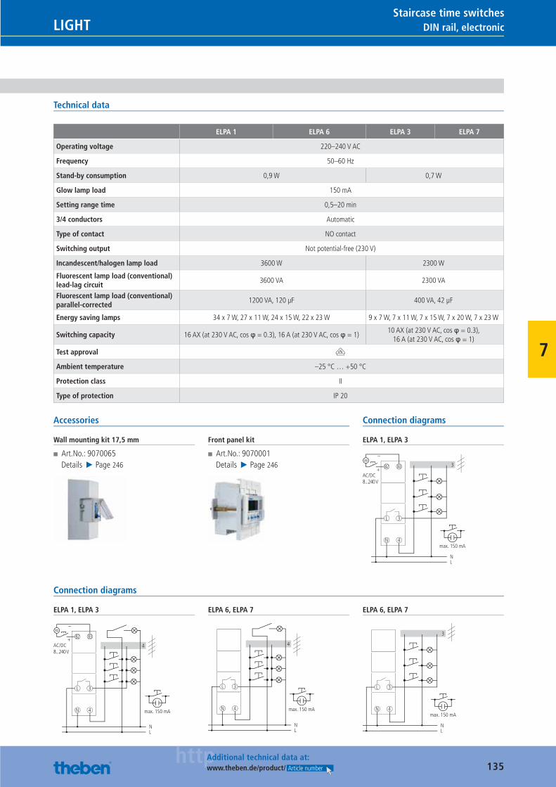
135httpAdditional technical data at:
www.theben.de/product/ Article number
DIN rail, electronicLIGHTStaircase time switches
7
Technical data
ELPA 1 ELPA 6 ELPA 3 ELPA 7
Operating voltage 220–240 V AC
Frequency 50–60 Hz
Stand-by consumption 0,9 W 0,7 W
Glow lamp load 150 mA
Setting range time 0,5–20 min
3/4 conductors Automatic
Type of contact NO contact
Switching output Not potential-free (230 V)
Incandescent/halogen lamp load 3600 W 2300 W
Fluorescent lamp load (conventional) lead-lag circuit
3600 VA 2300 VA
Fluorescent lamp load (conventional) parallel-corrected
1200 VA, 120 μF 400 VA, 42 μF
Energy saving lamps 34 x 7 W, 27 x 11 W, 24 x 15 W, 22 x 23 W 9 x 7 W, 7 x 11 W, 7 x 15 W, 7 x 20 W, 7 x 23 W
Switching capacity 16 AX (at 230 V AC, cos φ = 0.3), 16 A (at 230 V AC, cos φ = 1)10 AX (at 230 V AC, cos φ = 0.3),
16 A (at 230 V AC, cos φ = 1)
Test approval V
Ambient temperature –25 °C … +50 °C
Protection class II
Type of protection IP 20
Accessories
Wall mounting kit 17,5 mm
■ Art.No.: 9070065Details ▶ Page 246
Front panel kit
■ Art.No.: 9070001Details ▶ Page 246
Connection diagrams
ELPA 1, ELPA 3
3
N
L
4
3
N
max. 150 mA
L
B3B2
–
+AC/DC8...240 V
Connection diagrams
ELPA 1, ELPA 3
N
L
4
3
NL
4
B3B2
–
+AC/DC8...240 V
max. 150 mA
ELPA 6, ELPA 7
N
L
4
3
NL
4
max. 150 mA
ELPA 6, ELPA 7
3
N
L
4
3
N
max. 150 mA
L
Catalogue_EN_2013.indb 135 16.01.13 17:22
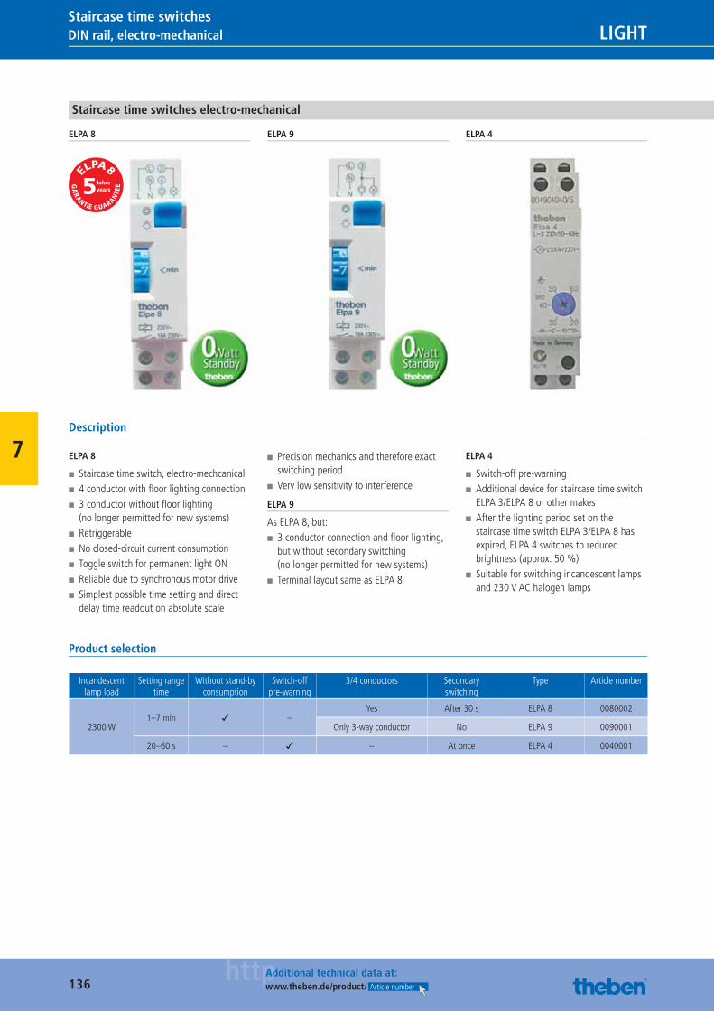
136httpAdditional technical data at:
www.theben.de/product/ Article number
DIN rail, electro-mechanical LIGHTStaircase time switches
7
Staircase time switches electro-mechanical
ELPA 8 ELPA 9 ELPA 4
Description
ELPA 8
■ Staircase time switch, electro-mechcanical ■ 4 conductor with fl oor lighting connection ■ 3 conductor without fl oor lighting (no longer permitted for new systems)
■ Retriggerable ■ No closed-circuit current consumption ■ Toggle switch for permanent light ON ■ Reliable due to synchronous motor drive ■ Simplest possible time setting and direct delay time readout on absolute scale
■ Precision mechanics and therefore exact switching period
■ Very low sensitivity to interference
ELPA 9
As ELPA 8, but: ■ 3 conductor connection and fl oor lighting, but without secondary switching (no longer permitted for new systems)
■ Terminal layout same as ELPA 8
ELPA 4
■ Switch-off pre-warning ■ Additional device for staircase time switch ELPA 3/ELPA 8 or other makes
■ After the lighting period set on the staircase time switch ELPA 3/ELPA 8 has expired, ELPA 4 switches to reduced brightness (approx. 50 %)
■ Suitable for switching incandescent lamps and 230 V AC halogen lamps
Product selection
Incandescent lamp load
Setting range time
Without stand-by consumption
Switch-off pre-warning
3/4 conductors Secondary switching
Type Article number
2300 W1–7 min ✓ –
Yes After 30 s ELPA 8 0080002
Only 3-way conductor No ELPA 9 0090001
20–60 s – ✓ – At once ELPA 4 0040001
Catalogue_EN_2013.indb 136 16.01.13 17:22
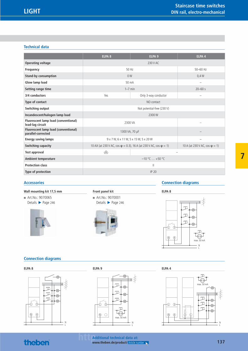
137httpAdditional technical data at:
www.theben.de/product/ Article number
DIN rail, electro-mechanicalLIGHTStaircase time switches
7
Technical data
ELPA 8 ELPA 9 ELPA 4
Operating voltage 230 V AC
Frequency 50 Hz 50–60 Hz
Stand-by consumption 0 W 0,4 W
Glow lamp load 50 mA –
Setting range time 1–7 min 20–60 s
3/4 conductors Yes Only 3-way conductor –
Type of contact NO contact
Switching output Not potential-free (230 V)
Incandescent/halogen lamp load 2300 W
Fluorescent lamp load (conventional) lead-lag circuit
2300 VA –
Fluorescent lamp load (conventional) parallel-corrected
1300 VA, 70 μF –
Energy saving lamps 9 x 7 W, 6 x 11 W, 5 x 15 W, 5 x 20 W –
Switching capacity 10 AX (at 230 V AC, cos φ = 0.3), 16 A (at 230 V AC, cos φ = 1) 10 A (at 230 V AC, cos φ = 1)
Test approval V –
Ambient temperature –10 °C … +50 °C
Protection class II
Type of protection IP 20
Accessories
Wall mounting kit 17,5 mm
■ Art.No.: 9070065Details ▶ Page 246
Front panel kit
■ Art.No.: 9070001Details ▶ Page 246
Connection diagrams
ELPA 8
3
N
L
4
3
N
max. 50 mA
L
Connection diagrams
ELPA 8
N
L
4
3
NL
4
ELPA 9
3
N
L 3
LN
max. 50 mA
ELPA 4
N
L
4
3
3 L
NL
4
max. 50 mA
Catalogue_EN_2013.indb 137 16.01.13 17:22
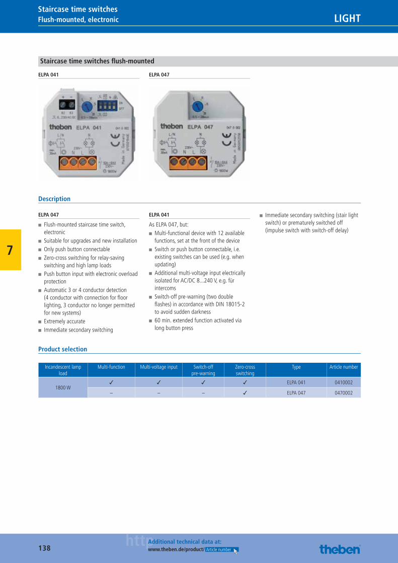
138httpAdditional technical data at:
www.theben.de/product/ Article number
Flush-mounted, electronic LIGHTStaircase time switches
7
Staircase time switches fl ush-mounted
ELPA 041 ELPA 047
Description
ELPA 047
■ Flush-mounted staircase time switch, electronic
■ Suitable for upgrades and new installation ■ Only push button connectable ■ Zero-cross switching for relay-saving switching and high lamp loads
■ Push button input with electronic overload protection
■ Automatic 3 or 4 conductor detection (4 conductor with connection for fl oor lighting, 3 conductor no longer permitted for new systems)
■ Extremely accurate ■ Immediate secondary switching
ELPA 041
As ELPA 047, but: ■ Multi-functional device with 12 available functions, set at the front of the device
■ Switch or push button connectable, i.e. existing switches can be used (e.g. when updating)
■ Additional multi-voltage input electrically isolated for AC/DC 8...240 V, e.g. für intercoms
■ Switch-off pre-warning (two double fl ashes) in accordance with DIN 18015-2 to avoid sudden darkness
■ 60 min. extended function activated via long button press
■ Immediate secondary switching (stair light switch) or prematurely switched off (impulse switch with switch-off delay)
Product selection
Incandescent lamp load
Multi-function Multi-voltage input Switch-off pre-warning
Zero-cross switching
Type Article number
1800 W✓ ✓ ✓ ✓ ELPA 041 0410002
– – – ✓ ELPA 047 0470002
Catalogue_EN_2013.indb 138 16.01.13 17:22
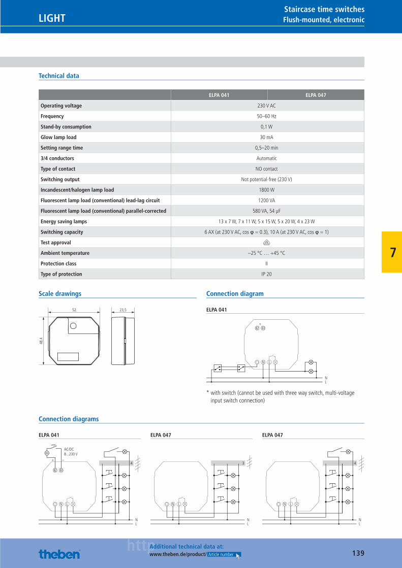
139httpAdditional technical data at:
www.theben.de/product/ Article number
Flush-mounted, electronicLIGHTStaircase time switches
7
Technical data
ELPA 041 ELPA 047
Operating voltage 230 V AC
Frequency 50–60 Hz
Stand-by consumption 0,1 W
Glow lamp load 30 mA
Setting range time 0,5–20 min
3/4 conductors Automatic
Type of contact NO contact
Switching output Not potential-free (230 V)
Incandescent/halogen lamp load 1800 W
Fluorescent lamp load (conventional) lead-lag circuit 1200 VA
Fluorescent lamp load (conventional) parallel-corrected 580 VA, 54 μF
Energy saving lamps 13 x 7 W, 7 x 11 W, 5 x 15 W, 5 x 20 W, 4 x 23 W
Switching capacity 6 AX (at 230 V AC, cos φ = 0.3), 10 A (at 230 V AC, cos φ = 1)
Test approval V
Ambient temperature –25 °C … +45 °C
Protection class II
Type of protection IP 20
Scale drawings
52 23,5
48,4
Connection diagram
ELPA 041
NL
N
*B3B2
L
* with switch (cannot be used with three way switch, multi-voltage input switch connection)
Connection diagrams
ELPA 041
NL
N
B3B2
L
–+4
AC/DC8...230 V
ELPA 047
NL
N L
3
ELPA 047
NL
N L
4
Catalogue_EN_2013.indb 139 16.01.13 17:22
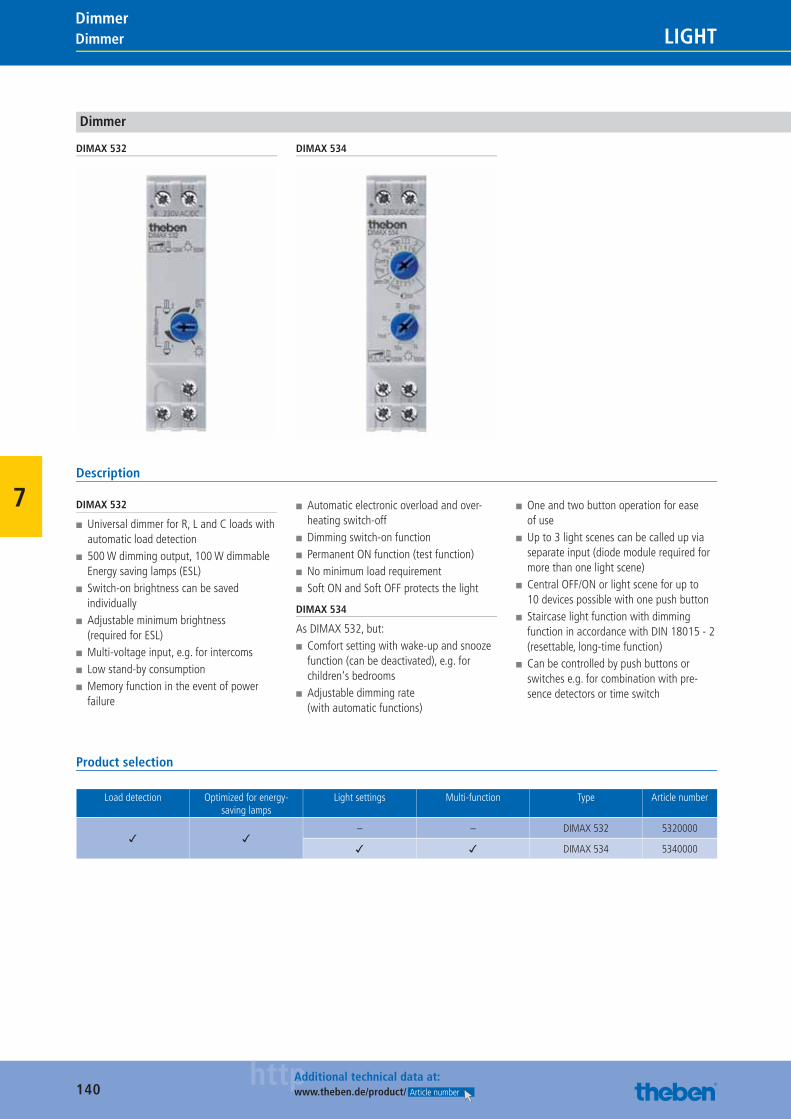
140httpAdditional technical data at:
www.theben.de/product/ Article number
LIGHTDimmer Dimmer
7
Dimmer
DIMAX 532 DIMAX 534
Description
DIMAX 532
■ Universal dimmer for R, L and C loads with automatic load detection
■ 500 W dimming output, 100 W dimmable Energy saving lamps (ESL)
■ Switch-on brightness can be saved individually
■ Adjustable minimum brightness (required for ESL)
■ Multi-voltage input, e.g. for intercoms ■ Low stand-by consumption ■ Memory function in the event of power failure
■ Automatic electronic overload and over-heating switch-off
■ Dimming switch-on function ■ Permanent ON function (test function) ■ No minimum load requirement ■ Soft ON and Soft OFF protects the light
DIMAX 534
As DIMAX 532, but: ■ Comfort setting with wake-up and snooze function (can be deactivated), e.g. for children‘s bedrooms
■ Adjustable dimming rate (with automatic functions)
■ One and two button operation for ease of use
■ Up to 3 light scenes can be called up via separate input (diode module required for more than one light scene)
■ Central OFF/ON or light scene for up to 10 devices possible with one push button
■ Staircase light function with dimming function in accordance with DIN 18015 - 2 (resettable, long-time function)
■ Can be controlled by push buttons or switches e.g. for combination with pre-sence detectors or time switch
Product selection
Load detection Optimized for energy-saving lamps
Light settings Multi-function Type Article number
✓ ✓– – DIMAX 532 5320000
✓ ✓ DIMAX 534 5340000
Catalogue_EN_2013.indb 140 16.01.13 17:22
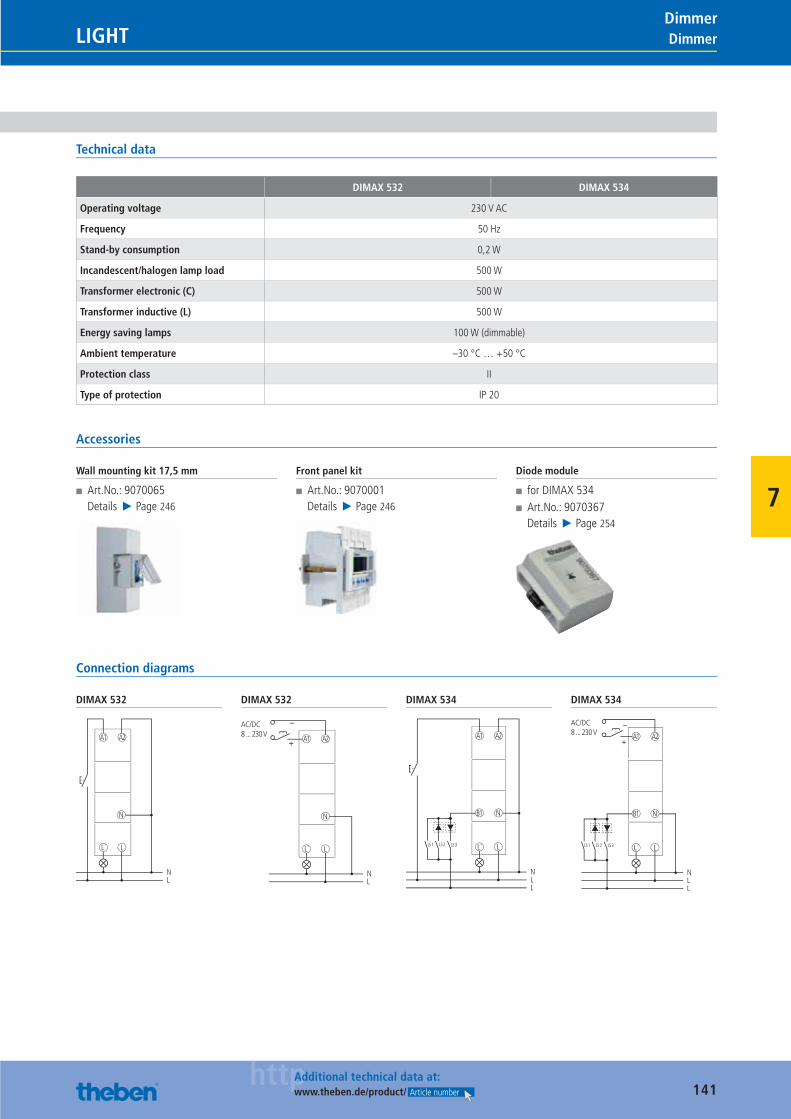
141httpAdditional technical data at:
www.theben.de/product/ Article number
LIGHTDimmerDimmer
7
Technical data
DIMAX 532 DIMAX 534
Operating voltage 230 V AC
Frequency 50 Hz
Stand-by consumption 0,2 W
Incandescent/halogen lamp load 500 W
Transformer electronic (C) 500 W
Transformer inductive (L) 500 W
Energy saving lamps 100 W (dimmable)
Ambient temperature –30 °C … +50 °C
Protection class II
Type of protection IP 20
Accessories
Wall mounting kit 17,5 mm
■ Art.No.: 9070065Details ▶ Page 246
Front panel kit
■ Art.No.: 9070001Details ▶ Page 246
Diode module
■ for DIMAX 534 ■ Art.No.: 9070367Details ▶ Page 254
Connection diagrams
DIMAX 532
N
LL´
NL
A2A1
DIMAX 532
N
LL´
NL
A2A1
–
+
AC/DC8 ... 230 V
DIMAX 534
N
LL´
NLL
A2A1
B1
LS 1 LS 2 LS 3
DIMAX 534
N
LL´
NLL
A2A1
B1
LS 1 LS 2 LS 3
–
+
AC/DC8 ... 230 V
Catalogue_EN_2013.indb 141 16.01.13 17:22
142
CLIMATE
100 % quality.Test, test and test again: All of our products undergo the strictest controls, so that they fully conform to all our quality requirements and your expectations of quality. For example, all RAMSES clock thermostats are tested from top to bottom at our testing station in Haigerloch and then calibrated. That can‘t be beaten.
Catalogue_EN_2013.indb 142 16.01.13 17:22
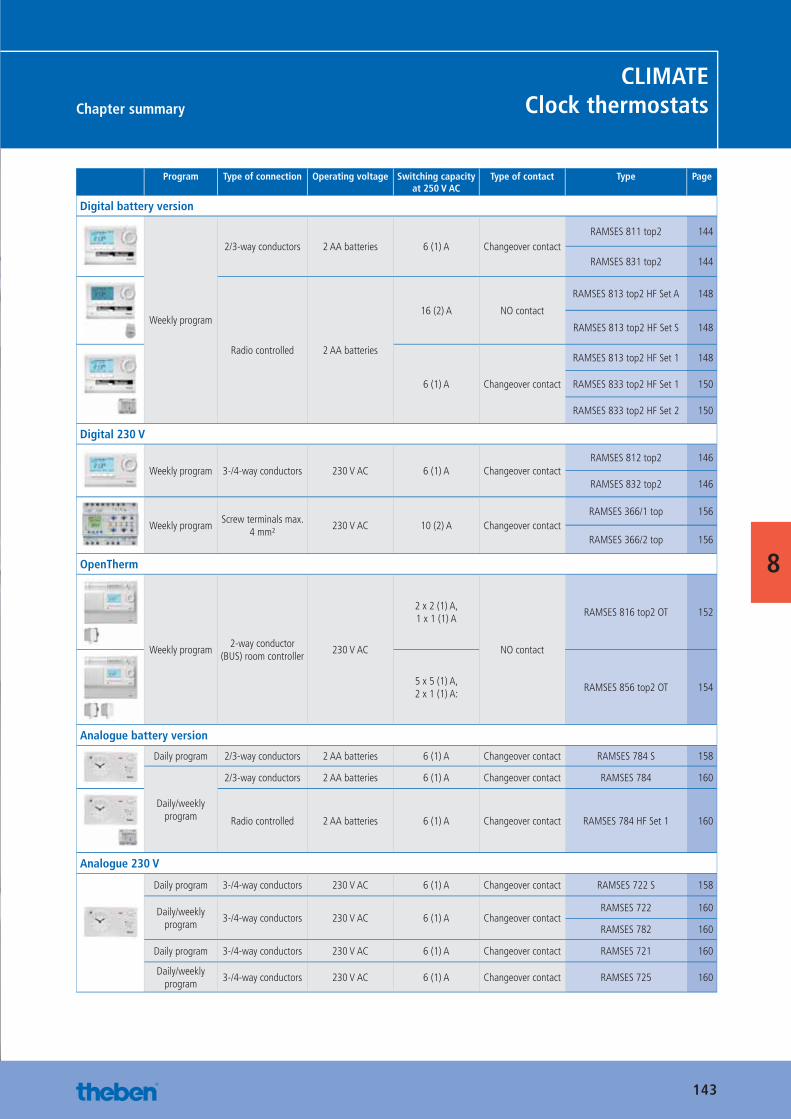
143
Chapter summary
CLIMATEClock thermostats
8
Program Type of connection Operating voltage Switching capacity at 250 V AC
Type of contact Type Page
Digital battery version
Weekly program
2/3-way conductors 2 AA batteries 6 (1) A Changeover contactRAMSES 811 top2 144
RAMSES 831 top2 144
Radio controlled 2 AA batteries
16 (2) A NO contact
RAMSES 813 top2 HF Set A 148
RAMSES 813 top2 HF Set S 148
6 (1) A Changeover contact
RAMSES 813 top2 HF Set 1 148
RAMSES 833 top2 HF Set 1 150
RAMSES 833 top2 HF Set 2 150
Digital 230 V
Weekly program 3-/4-way conductors 230 V AC 6 (1) A Changeover contactRAMSES 812 top2 146
RAMSES 832 top2 146
Weekly programScrew terminals max.
4 mm²230 V AC 10 (2) A Changeover contact
RAMSES 366/1 top 156
RAMSES 366/2 top 156
OpenTherm
Weekly program2-way conductor
(BUS) room controller230 V AC
2 x 2 (1) A,1 x 1 (1) A
NO contact
RAMSES 816 top2 OT 152
5 x 5 (1) A,2 x 1 (1) A:
RAMSES 856 top2 OT 154
Analogue battery version
Daily program 2/3-way conductors 2 AA batteries 6 (1) A Changeover contact RAMSES 784 S 158
Daily/weekly program
2/3-way conductors 2 AA batteries 6 (1) A Changeover contact RAMSES 784 160
Radio controlled 2 AA batteries 6 (1) A Changeover contact RAMSES 784 HF Set 1 160
Analogue 230 V
Daily program 3-/4-way conductors 230 V AC 6 (1) A Changeover contact RAMSES 722 S 158
Daily/weekly program
3-/4-way conductors 230 V AC 6 (1) A Changeover contactRAMSES 722 160
RAMSES 782 160
Daily program 3-/4-way conductors 230 V AC 6 (1) A Changeover contact RAMSES 721 160
Daily/weekly program
3-/4-way conductors 230 V AC 6 (1) A Changeover contact RAMSES 725 160
Catalogue_EN_2013.indb 143 16.01.13 17:22
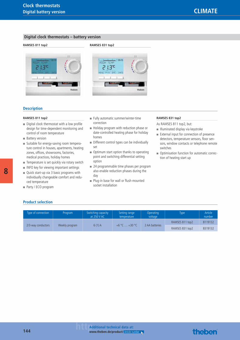
144httpAdditional technical data at:
www.theben.de/product/ Article number
Digital battery version CLIMATEClock thermostats
8
Digital clock thermostats – battery version
RAMSES 811 top2 RAMSES 831 top2
Description
RAMSES 811 top2
■ Digital clock thermostat with a low profi le design for time-dependent monitoring and control of room temperature
■ Battery version ■ Suitable for energy-saving room tempera-ture control in houses, apartments, heating zones, offi ces, showrooms, factories, medical practices, holiday homes
■ Temperature is set quickly via rotary switch ■ INFO key for viewing important settings ■ Quick start-up via 3 basic programs with individually changeable comfort and redu-ced temperature
■ Party / ECO program
■ Fully automatic summer/winter-time correction
■ Holiday program with reduction phase or date-controlled heating phase for holiday homes
■ Different control types can be individually set
■ Optimum start option thanks to operating point and switching differential setting option
■ 24 programmable time phases per program also enable reduction phases during the day
■ Plug-in base for wall or fl ush-mounted socket installation
RAMSES 831 top2
As RAMSES 811 top2, but: ■ Illuminated display via keystroke ■ External input for connection of presence detectors, temperature sensors, fl oor sen-sors, window contacts or telephone remote switches
■ Optimisation function for automatic correc-tion of heating start up
Product selection
Type of connection Program Switching capacity at 250 V AC
Setting range temperature
Operating voltage
Type Article number
2/3-way conductors Weekly program 6 (1) A +6 °C … +30 °C 2 AA batteriesRAMSES 811 top2 8119132
RAMSES 831 top2 8319132
Catalogue_EN_2013.indb 144 16.01.13 17:22
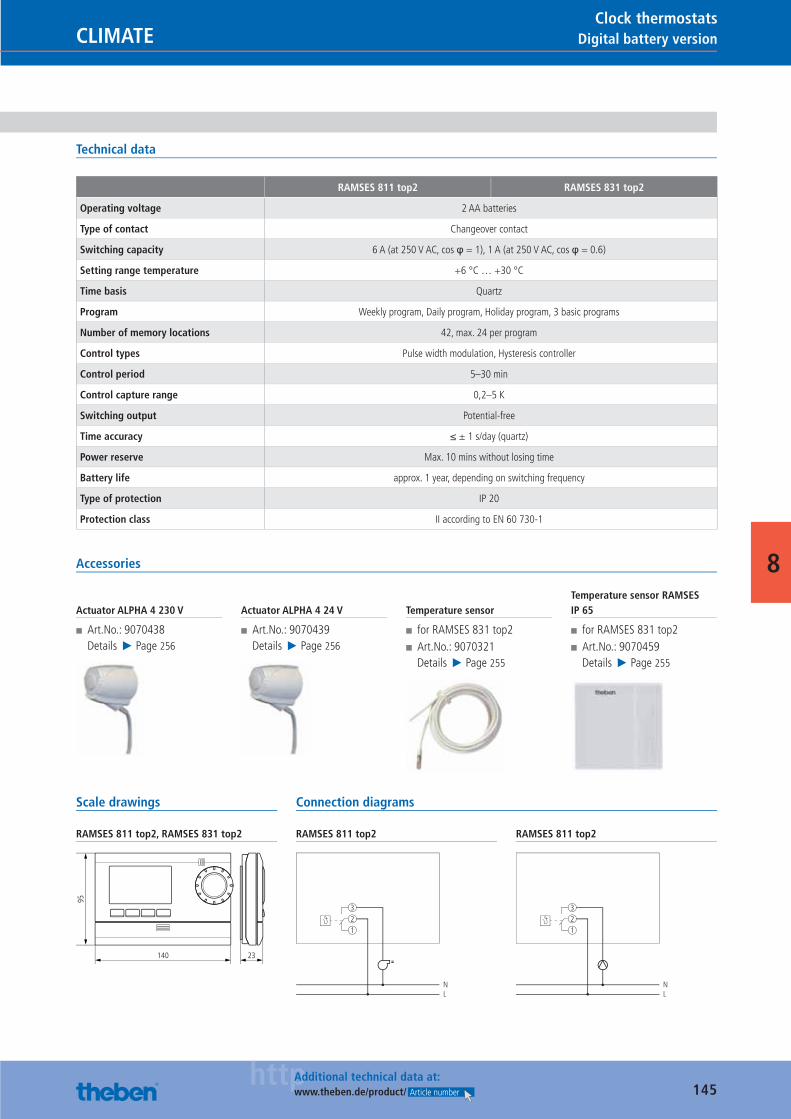
145httpAdditional technical data at:
www.theben.de/product/ Article number
Digital battery versionCLIMATEClock thermostats
8
Technical data
RAMSES 811 top2 RAMSES 831 top2
Operating voltage 2 AA batteries
Type of contact Changeover contact
Switching capacity 6 A (at 250 V AC, cos φ = 1), 1 A (at 250 V AC, cos φ = 0.6)
Setting range temperature +6 °C … +30 °C
Time basis Quartz
Program Weekly program, Daily program, Holiday program, 3 basic programs
Number of memory locations 42, max. 24 per program
Control types Pulse width modulation, Hysteresis controller
Control period 5–30 min
Control capture range 0,2–5 K
Switching output Potential-free
Time accuracy ≤ ± 1 s/day (quartz)
Power reserve Max. 10 mins without losing time
Battery life approx. 1 year, depending on switching frequency
Type of protection IP 20
Protection class II according to EN 60 730-1
Accessories
Actuator ALPHA 4 230 V
■ Art.No.: 9070438Details ▶ Page 256
Actuator ALPHA 4 24 V
■ Art.No.: 9070439Details ▶ Page 256
Temperature sensor
■ for RAMSES 831 top2 ■ Art.No.: 9070321Details ▶ Page 255
Temperature sensor RAMSES IP 65
■ for RAMSES 831 top2 ■ Art.No.: 9070459Details ▶ Page 255
Scale drawings
RAMSES 811 top2, RAMSES 831 top2
140
95
23
Connection diagrams
RAMSES 811 top2
NL
321
RAMSES 811 top2
NL
321
Catalogue_EN_2013.indb 145 16.01.13 17:22
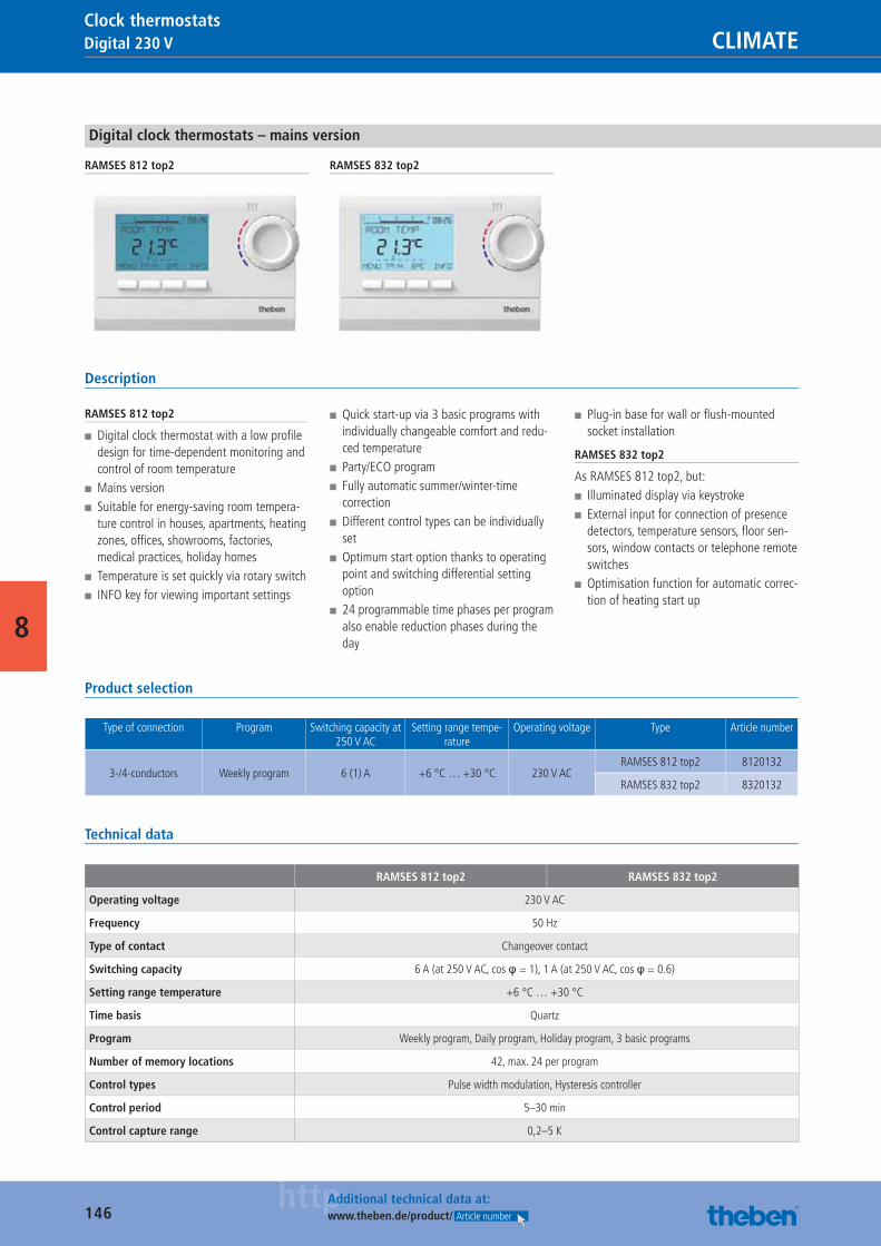
146httpAdditional technical data at:
www.theben.de/product/ Article number
Digital 230 V CLIMATEClock thermostats
8
Digital clock thermostats – mains version
RAMSES 812 top2 RAMSES 832 top2
Description
RAMSES 812 top2
■ Digital clock thermostat with a low profi le design for time-dependent monitoring and control of room temperature
■ Mains version ■ Suitable for energy-saving room tempera-ture control in houses, apartments, heating zones, offi ces, showrooms, factories, medical practices, holiday homes
■ Temperature is set quickly via rotary switch ■ INFO key for viewing important settings
■ Quick start-up via 3 basic programs with individually changeable comfort and redu-ced temperature
■ Party/ECO program ■ Fully automatic summer/winter-time correction
■ Different control types can be individually set
■ Optimum start option thanks to operating point and switching differential setting option
■ 24 programmable time phases per program also enable reduction phases during the day
■ Plug-in base for wall or fl ush-mounted socket installation
RAMSES 832 top2
As RAMSES 812 top2, but: ■ Illuminated display via keystroke ■ External input for connection of presence detectors, temperature sensors, fl oor sen-sors, window contacts or telephone remote switches
■ Optimisation function for automatic correc-tion of heating start up
Product selection
Type of connection Program Switching capacity at 250 V AC
Setting range tempe-rature
Operating voltage Type Article number
3-/4-conductors Weekly program 6 (1) A +6 °C … +30 °C 230 V AC RAMSES 812 top2 8120132
RAMSES 832 top2 8320132
Technical data
RAMSES 812 top2 RAMSES 832 top2
Operating voltage 230 V AC
Frequency 50 Hz
Type of contact Changeover contact
Switching capacity 6 A (at 250 V AC, cos φ = 1), 1 A (at 250 V AC, cos φ = 0.6)
Setting range temperature +6 °C … +30 °C
Time basis Quartz
Program Weekly program, Daily program, Holiday program, 3 basic programs
Number of memory locations 42, max. 24 per program
Control types Pulse width modulation, Hysteresis controller
Control period 5–30 min
Control capture range 0,2–5 K
Catalogue_EN_2013.indb 146 16.01.13 17:22
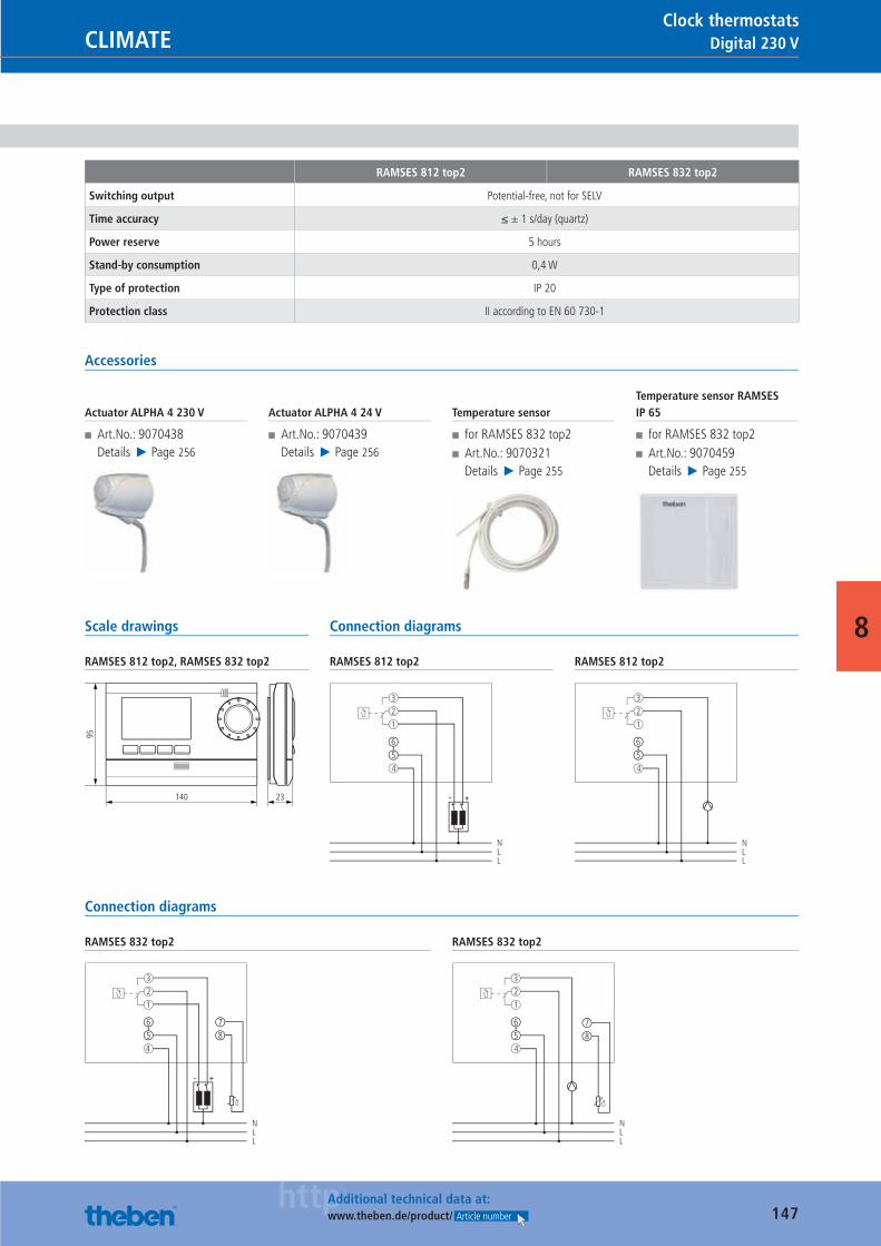
147httpAdditional technical data at:
www.theben.de/product/ Article number
Digital 230 VCLIMATEClock thermostats
8
RAMSES 812 top2 RAMSES 832 top2
Switching output Potential-free, not for SELV
Time accuracy ≤ ± 1 s/day (quartz)
Power reserve 5 hours
Stand-by consumption 0,4 W
Type of protection IP 20
Protection class II according to EN 60 730-1
Accessories
Actuator ALPHA 4 230 V
■ Art.No.: 9070438Details ▶ Page 256
Actuator ALPHA 4 24 V
■ Art.No.: 9070439Details ▶ Page 256
Temperature sensor
■ for RAMSES 832 top2 ■ Art.No.: 9070321Details ▶ Page 255
Temperature sensor RAMSES IP 65
■ for RAMSES 832 top2 ■ Art.No.: 9070459Details ▶ Page 255
Scale drawings
RAMSES 812 top2, RAMSES 832 top2
140
95
23
Connection diagrams
RAMSES 812 top2
NLL
3
2
1
5
6
4
+-
RAMSES 812 top2
NLL
3
2
1
5
6
4
Connection diagrams
RAMSES 832 top2
NLL
3
2
1
5
6
8
7
4
+-
RAMSES 832 top2
NLL
3
2
1
5
6
48
7
Catalogue_EN_2013.indb 147 16.01.13 17:22
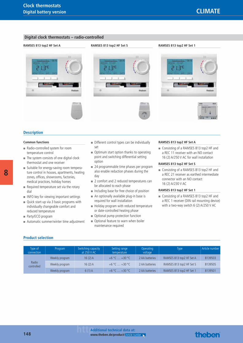
148httpAdditional technical data at:
www.theben.de/product/ Article number
Digital battery version CLIMATEClock thermostats
8
Digital clock thermostats – radio-controlled
RAMSES 813 top2 HF Set A RAMSES 813 top2 HF Set S RAMSES 813 top2 HF Set 1
Description
Common functions
■ Radio-controlled system for room temperature control
■ The system consists of one digital clock thermostat and one receiver
■ Suitable for energy-saving room tempera-ture control in houses, apartments, heating zones, offi ces, showrooms, factories, medical practices, holiday homes
■ Required temperature set via the rotary dial
■ INFO key for viewing important settings ■ Quick start-up via 3 basic programs with individually changeable comfort and reduced temperature
■ Party/ECO program ■ Automatic summer/winter time adjustment
■ Different control types can be individually set
■ Optimum start option thanks to operating point and switching differential setting option
■ 24 programmable time phases per program also enable reduction phases during the day
■ 2 comfort and 2 reduced temperatures can be allocated to each phase
■ Including base for free choice of position ■ An optionally available plug-in base is required for wall installation
■ Holiday program with reduced temperature or date-controlled heating phase
■ Optional pump protection function ■ Optional feature to warn when boiler maintenance required
RAMSES 813 top2 HF Set A
■ Consisting of a RAMSES 813 top2 HF and a REC 11 receiver with an NO contact 16 (2) A/250 V AC for wall installation
RAMSES 813 top2 HF Set S
■ Consisting of a RAMSES 813 top2 HF and a REC 21 receiver as earthed intermediate connector with an NO contact 16 (2) A/230 V AC
RAMSES 813 top2 HF Set 1
■ Consisting of a RAMSES 813 top2 HF and a REC 1 receiver (DIN rail mounting device) with a two-way switch 6 (2) A/250 V AC
Product selection
Type of connection
Program Switching capacity at 250 V AC
Setting range temperature
Operating voltage
Type Article number
Radio controlled
Weekly program 16 (2) A +6 °C … +30 °C 2 AA batteries RAMSES 813 top2 HF Set A 8139503
Weekly program 16 (2) A +6 °C … +30 °C 2 AA batteries RAMSES 813 top2 HF Set S 8139505
Weekly program 6 (1) A +6 °C … +30 °C 2 AA batteries RAMSES 813 top2 HF Set 1 8139501
Catalogue_EN_2013.indb 148 16.01.13 17:22
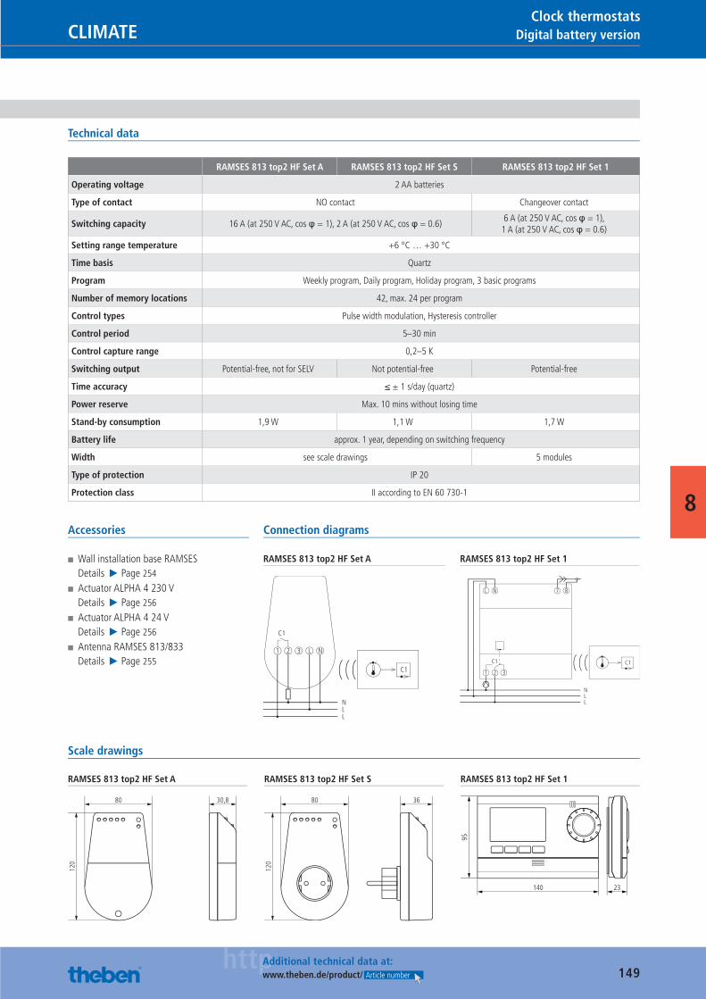
149httpAdditional technical data at:
www.theben.de/product/ Article number
Digital battery versionCLIMATEClock thermostats
8
Technical data
RAMSES 813 top2 HF Set A RAMSES 813 top2 HF Set S RAMSES 813 top2 HF Set 1
Operating voltage 2 AA batteries
Type of contact NO contact Changeover contact
Switching capacity 16 A (at 250 V AC, cos φ = 1), 2 A (at 250 V AC, cos φ = 0.6)6 A (at 250 V AC, cos φ = 1),
1 A (at 250 V AC, cos φ = 0.6)
Setting range temperature +6 °C … +30 °C
Time basis Quartz
Program Weekly program, Daily program, Holiday program, 3 basic programs
Number of memory locations 42, max. 24 per program
Control types Pulse width modulation, Hysteresis controller
Control period 5–30 min
Control capture range 0,2–5 K
Switching output Potential-free, not for SELV Not potential-free Potential-free
Time accuracy ≤ ± 1 s/day (quartz)
Power reserve Max. 10 mins without losing time
Stand-by consumption 1,9 W 1,1 W 1,7 W
Battery life approx. 1 year, depending on switching frequency
Width see scale drawings 5 modules
Type of protection IP 20
Protection class II according to EN 60 730-1
Accessories
■ Wall installation base RAMSESDetails ▶ Page 254
■ Actuator ALPHA 4 230 VDetails ▶ Page 256
■ Actuator ALPHA 4 24 VDetails ▶ Page 256
■ Antenna RAMSES 813/833Details ▶ Page 255
Connection diagrams
RAMSES 813 top2 HF Set A
C1
1 2 3
NLL
L N
C1
RAMSES 813 top2 HF Set 1
C1
1 2 3
L N
NLL
7 8
C1
Scale drawings
RAMSES 813 top2 HF Set A
80 30,8
120
RAMSES 813 top2 HF Set S
80 36
120
RAMSES 813 top2 HF Set 1
140
95
23
Catalogue_EN_2013.indb 149 16.01.13 17:22
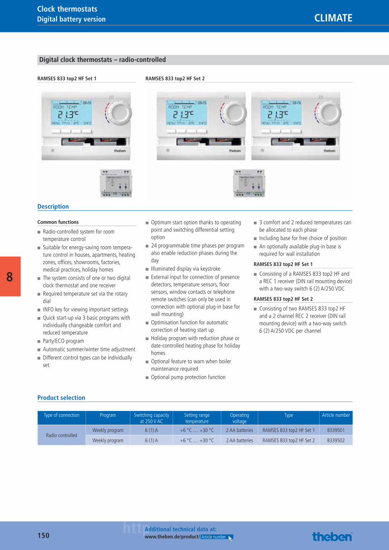
150httpAdditional technical data at:
www.theben.de/product/ Article number
Digital battery version CLIMATEClock thermostats
8
Digital clock thermostats – radio-controlled
RAMSES 833 top2 HF Set 1 RAMSES 833 top2 HF Set 2
Description
Common functions
■ Radio-controlled system for room temperature control
■ Suitable for energy-saving room tempera-ture control in houses, apartments, heating zones, offi ces, showrooms, factories, medical practices, holiday homes
■ The system consists of one or two digital clock thermostat and one receiver
■ Required temperature set via the rotary dial
■ INFO key for viewing important settings ■ Quick start-up via 3 basic programs with individually changeable comfort and reduced temperature
■ Party/ECO program ■ Automatic summer/winter time adjustment ■ Different control types can be individually set
■ Optimum start option thanks to operating point and switching differential setting option
■ 24 programmable time phases per program also enable reduction phases during the day
■ Illuminated display via keystroke ■ External input for connection of presence detectors, temperature sensors, fl oor sensors, window contacts or telephone remote switches (can only be used in connection with optional plug-in base for wall mounting)
■ Optimisation function for automatic correction of heating start up
■ Holiday program with reduction phase or date-controlled heating phase for holiday homes
■ Optional feature to warn when boiler maintenance required
■ Optional pump protection function
■ 3 comfort and 2 reduced temperatures can be allocated to each phase
■ Including base for free choice of position ■ An optionally available plug-in base is required for wall installation
RAMSES 833 top2 HF Set 1
■ Consisting of a RAMSES 833 top2 HF and a REC 1 receiver (DIN rail mounting device) with a two-way switch 6 (2) A/250 VDC
RAMSES 833 top2 HF Set 2
■ Consisting of two RAMSES 833 top2 HF and a 2 channel REC 2 receiver (DIN rail mounting device) with a two-way switch 6 (2) A/250 VDC per channel
Product selection
Type of connection Program Switching capacity at 250 V AC
Setting rangetemperature
Operating voltage
Type Article number
Radio controlledWeekly program 6 (1) A +6 °C … +30 °C 2 AA batteries RAMSES 833 top2 HF Set 1 8339501
Weekly program 6 (1) A +6 °C … +30 °C 2 AA batteries RAMSES 833 top2 HF Set 2 8339502
Catalogue_EN_2013.indb 150 16.01.13 17:22
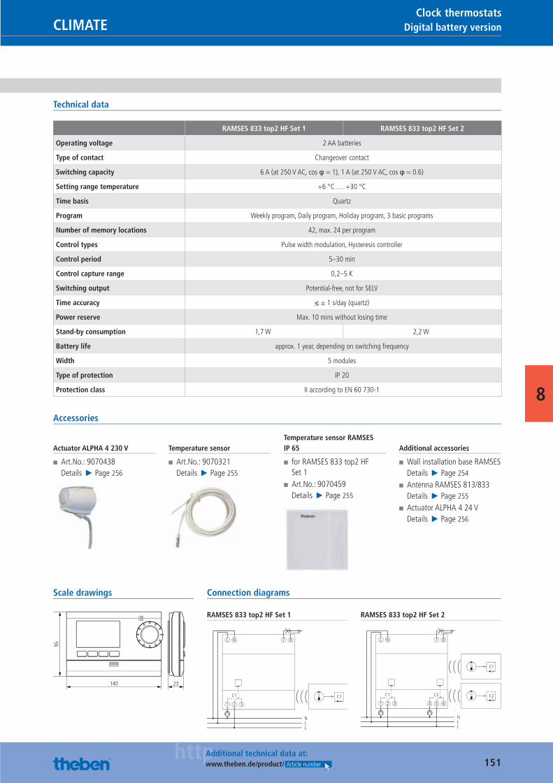
151httpAdditional technical data at:
www.theben.de/product/ Article number
Digital battery versionCLIMATEClock thermostats
8
Technical data
RAMSES 833 top2 HF Set 1 RAMSES 833 top2 HF Set 2
Operating voltage 2 AA batteries
Type of contact Changeover contact
Switching capacity 6 A (at 250 V AC, cos φ = 1), 1 A (at 250 V AC, cos φ = 0.6)
Setting range temperature +6 °C … +30 °C
Time basis Quartz
Program Weekly program, Daily program, Holiday program, 3 basic programs
Number of memory locations 42, max. 24 per program
Control types Pulse width modulation, Hysteresis controller
Control period 5–30 min
Control capture range 0,2–5 K
Switching output Potential-free, not for SELV
Time accuracy ≤ ± 1 s/day (quartz)
Power reserve Max. 10 mins without losing time
Stand-by consumption 1,7 W 2,2 W
Battery life approx. 1 year, depending on switching frequency
Width 5 modules
Type of protection IP 20
Protection class II according to EN 60 730-1
Accessories
Actuator ALPHA 4 230 V
■ Art.No.: 9070438Details ▶ Page 256
Temperature sensor
■ Art.No.: 9070321Details ▶ Page 255
Temperature sensor RAMSES IP 65
■ for RAMSES 833 top2 HF Set 1
■ Art.No.: 9070459Details ▶ Page 255
Additional accessories
■ Wall installation base RAMSESDetails ▶ Page 254
■ Antenna RAMSES 813/833Details ▶ Page 255
■ Actuator ALPHA 4 24 VDetails ▶ Page 256
Scale drawings
140
95
23
Connection diagrams
RAMSES 833 top2 HF Set 1
C1
1 2 3
L N
NLL
7 8
C1
RAMSES 833 top2 HF Set 2
C1
1 2 3 4 5 6
L N
NLL
C2
7 8
C1
C2
Catalogue_EN_2013.indb 151 16.01.13 17:22
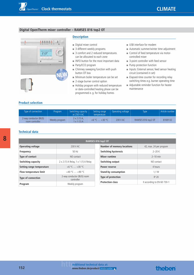
152httpAdditional technical data at:
www.theben.de/product/ Article number
CLIMATEClock thermostats
8
Digital OpenTherm mixer controller – RAMSES 816 top2 OT
Description
■ Digital mixer control ■ 3 different weekly programs ■ 3 comfort and 2 reduced temperatures can be allocated to each zone
■ INFO button for the most important data ■ Party/ECO program ■ Chimney sweeping function with push button OT box
■ Minimum boiler temperature can be set ■ 2-stage burner control option ■ Holiday program with reduced temperature or date-controlled heating phase can be programmed e. g. for holiday homes
■ USB interface for modem ■ Automatic summer/winter time adjustment ■ Control of feed temperature via motor-controlled mixer
■ 3-point controller with feed sensor ■ Pump protection function ■ Inputs: External sensor, feed sensor heating circuit (contained in set)
■ Elapsed-time counter for recording relay switching times e.g. burner operating time
■ Adjustable reminder function for heater maintenance
Product selection
Type of connection Program Switching capacity at 250 V AC
Setting range temperature
Operating voltage Type Article number
2-way conductor (BUS) room controller
Weekly program2 x 2 (1) A,1 x 1 (1) A
+6 °C … +30 °C 230 V AC RAMSES 816 top2 OT 8169132
Technical data
RAMSES 816 top2 OT
Operating voltage 230 V AC
Frequency 50 Hz
Type of contact NO contact
Switching capacity 2 x 2 (1) A Relay, 1 x 1 (1) A Relay
Setting range temperature +6 °C … +30 °C
Flow temperature limit +40 °C … +90 °C
Type of connection2-way conductor (BUS) room
controller
Program Weekly program
Number of memory locations 42, max. 24 per program
Switching hysteresis 2–20 K
Mixer runtime 2–10 min
Switching output NO contact
Power reserve 4 hours
Stand-by consumption 1,1 W
Type of protection IP 20
Protection class II according to EN 60 730-1
NEW
Catalogue_EN_2013.indb 152 16.01.13 17:22
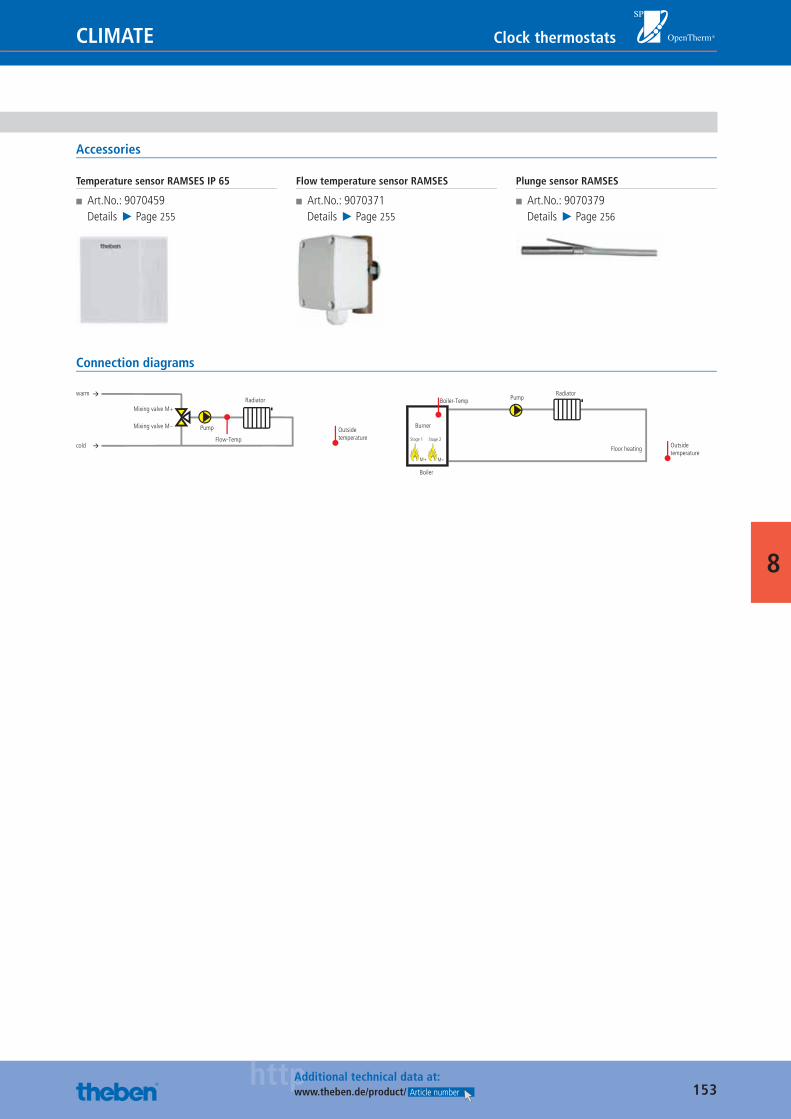
153httpAdditional technical data at:
www.theben.de/product/ Article number
Clock thermostatsCLIMATE
8
Accessories
Temperature sensor RAMSES IP 65
■ Art.No.: 9070459Details ▶ Page 255
Flow temperature sensor RAMSES
■ Art.No.: 9070371Details ▶ Page 255
Plunge sensor RAMSES
■ Art.No.: 9070379Details ▶ Page 256
Connection diagrams
Pump
Flow-Temp
warm
cold
Mixing valve M+
Outsidetemperature
Mixing valve M–
Radiator
à
à Radiator
Floor heating
M+ M–
Pump
Boiler
Burner
Boiler-Temp
Outsidetemperature
Stage 1 Stage 2
Catalogue_EN_2013.indb 153 16.01.13 17:22
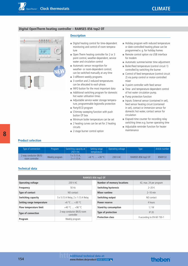
154httpAdditional technical data at:
www.theben.de/product/ Article number
CLIMATEClock thermostats
8
Digital OpenTherm heating controller – RAMSES 856 top2 OT
Description
■ Digital heating control for time-dependent monitoring and control of room tempera-ture
■ Open Therm heating controller for 2 or 3 point control, weather-dependent, service water and circulation control
■ Automatic sensor recognition for weather- or room-dependent control; can be switched manually at any time
■ 3 different weekly programs ■ 3 comfort and 2 reduced temperatures can be allocated to each phase.
■ INFO button for the most important data ■ Additional switching program for domestic hot water utilisation times
■ Adjustable service water storage tempera-ture, programmable legionella protection
■ Party/ECO program ■ Chimney sweeping function with push button OT box
■ Minimum boiler temperature can be set ■ 2 heating curves can be set for 2 heating circuits
■ 2-stage burner control option
■ Holiday program with reduced temperature or date-controlled heating phase can be programmed e. g. for holiday homes
■ Remote control option via USB interface for modem
■ Automatic summer/winter time adjustment ■ Boiler/feed temperature (control circuit 1) controlled by switching the burner
■ Control of feed temperature (control circuit 2) via pump control or motor-controlled mixer
■ 3-point controller with feed sensor ■ Time- and temperature-dependent control of hot water circulation pump.
■ Pump protection function ■ Inputs: External sensor (contained in set), feed sensor heating circuit (contained in set), contact or immersion sensor for domestic hot water, contact sensor for circulation
■ Elapsed-time counter for recording relay switching times e.g. burner operating time
■ Adjustable reminder function for heater maintenance
Product selection
Type of connection Program Switching capacity at 250 V AC
Setting range temperature
Operating voltage Type Article number
2-way conductor (BUS) room controller
Weekly program5 x 5 (1) A,2 x 1 (1) A
+6 °C … +30 °C 230 V AC RAMSES 856 top2 OT 8569132
Technical data
RAMSES 856 top2 OT
Operating voltage 230 V AC
Frequency 50 Hz
Type of contact NO contact
Switching capacity 5 x 5 (1) A Relay, 2 x 1 (1) A Relay
Setting range temperature +6 °C … +30 °C
Flow temperature limit +40 °C … +90 °C
Type of connection2-way conductor (BUS) room
controller
Program Weekly program
Number of memory locations 42, max. 24 per program
Switching hysteresis 2–20 K
Mixer runtime 2–10 min
Switching output NO contact
Power reserve 4 hours
Stand-by consumption 1,1 W
Type of protection IP 20
Protection class II according to EN 60 730-1
NEW
Catalogue_EN_2013.indb 154 16.01.13 17:22
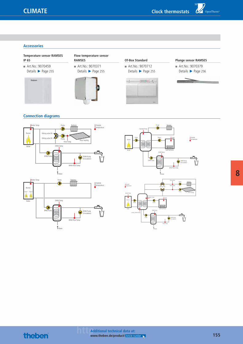
155httpAdditional technical data at:
www.theben.de/product/ Article number
CLIMATE Clock thermostats
8
Accessories
Temperature sensor RAMSES IP 65
■ Art.No.: 9070459Details ▶ Page 255
Flow temperature sensor RAMSES
■ Art.No.: 9070371Details ▶ Page 255
OT-Box Standard
■ Art.No.: 9070712Details ▶ Page 255
Plunge sensor RAMSES
■ Art.No.: 9070379Details ▶ Page 256
Connection diagrams
Radiator
Floor heating
Pump
Pump
Flow-Temp
DHW-Temp
DHW-Pump
DHW-Flow Temp
Water
DHW-Cylinder
Boiler
Burner
Boiler-Temp
Mixing valve M+
Outside temperature
Mixing valve M–
DHW-Pump(Circulation)
Radiator
Temp
DHW-Temp
DHW-Pump
DHW-Flow Temp
Water
DHW-Cylinder
Boiler
Burner
Cylinder-Temp
Pump Outside temperature
Pump
DHW-Pump(Circulation)
Solid fuel boiler
Pump
RadiatorPump
DHW-Temp
DHW-Pump
DHW-Flow Temp
Water
DHW-Cylinder
Boiler
Burner
Boiler-Temp
Outsidetemperature
DHW-Pump(Circulation)
Stage 1 Stage 2
Temp
DHW-Temp
Pump
Flow-Temp
Water
DHW-Cylinder
Boiler
Burner
Pump
Outsidetemperature
Pump
DHW-Pump(Circulation)
Solid fuel boiler
Boiler-Temp
Lower cylinder temp
Radiator
Floor heating
Flow sensor
Flow sensor
Pump
Pump
Mixing valve
Cylinder-Temp
Catalogue_EN_2013.indb 155 16.01.13 17:22
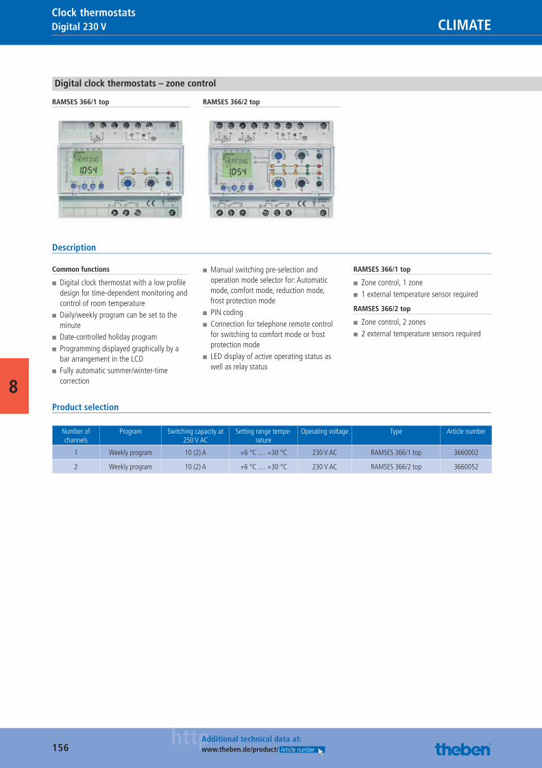
156httpAdditional technical data at:
www.theben.de/product/ Article number
Digital 230 V CLIMATEClock thermostats
8
Digital clock thermostats – zone control
RAMSES 366/1 top RAMSES 366/2 top
Description
Common functions
■ Digital clock thermostat with a low profi le design for time-dependent monitoring and control of room temperature
■ Daily/weekly program can be set to the minute
■ Date-controlled holiday program ■ Programming displayed graphically by a bar arrangement in the LCD
■ Fully automatic summer/winter-time correction
■ Manual switching pre-selection and operation mode selector for: Automatic mode, comfort mode, reduction mode, frost protection mode
■ PIN coding ■ Connection for telephone remote control for switching to comfort mode or frost protection mode
■ LED display of active operating status as well as relay status
RAMSES 366/1 top
■ Zone control, 1 zone ■ 1 external temperature sensor required
RAMSES 366/2 top
■ Zone control, 2 zones ■ 2 external temperature sensors required
Product selection
Number of channels
Program Switching capacity at 250 V AC
Setting range tempe-rature
Operating voltage Type Article number
1 Weekly program 10 (2) A +6 °C … +30 °C 230 V AC RAMSES 366/1 top 3660002
2 Weekly program 10 (2) A +6 °C … +30 °C 230 V AC RAMSES 366/2 top 3660052
Catalogue_EN_2013.indb 156 16.01.13 17:22
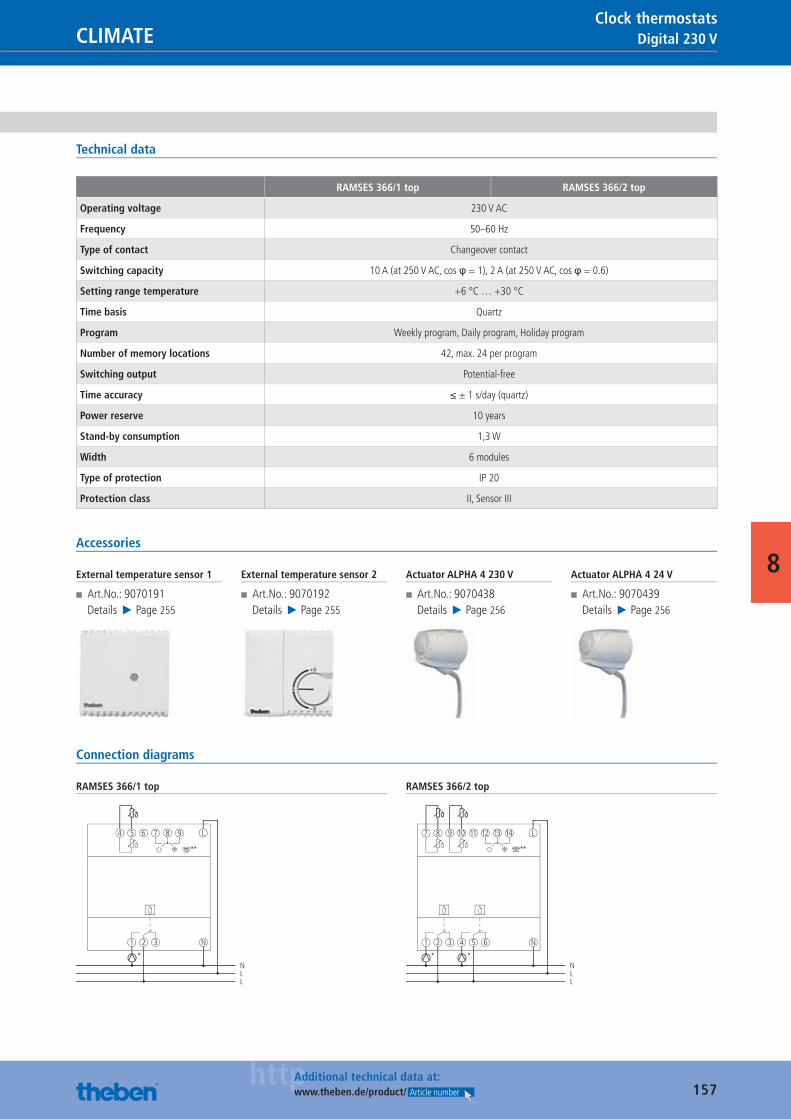
157httpAdditional technical data at:
www.theben.de/product/ Article number
Digital 230 VCLIMATEClock thermostats
8
Technical data
RAMSES 366/1 top RAMSES 366/2 top
Operating voltage 230 V AC
Frequency 50–60 Hz
Type of contact Changeover contact
Switching capacity 10 A (at 250 V AC, cos φ = 1), 2 A (at 250 V AC, cos φ = 0.6)
Setting range temperature +6 °C … +30 °C
Time basis Quartz
Program Weekly program, Daily program, Holiday program
Number of memory locations 42, max. 24 per program
Switching output Potential-free
Time accuracy ≤ ± 1 s/day (quartz)
Power reserve 10 years
Stand-by consumption 1,3 W
Width 6 modules
Type of protection IP 20
Protection class II, Sensor III
Accessories
External temperature sensor 1
■ Art.No.: 9070191Details ▶ Page 255
External temperature sensor 2
■ Art.No.: 9070192Details ▶ Page 255
Actuator ALPHA 4 230 V
■ Art.No.: 9070438Details ▶ Page 256
Actuator ALPHA 4 24 V
■ Art.No.: 9070439Details ▶ Page 256
Connection diagrams
RAMSES 366/1 top
*
1 2 3
4 5 6 7
NLL
8 9
**
N
L
RAMSES 366/2 top
1
* *
2 3 4 5 6
7 8 9 10 11 12
NLL
13 14
**
N
L
Catalogue_EN_2013.indb 157 16.01.13 17:22
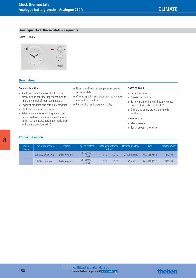
158httpAdditional technical data at:
www.theben.de/product/ Article number
Analogue battery version, Analogue 230 V CLIMATEClock thermostats
8
Analogue clock thermostats – segments
RAMSES 784 S
Description
Common functions
■ Analogue clock thermostat with a low profi le design for time-dependent monito-ring and control of room temperature
■ Segment program disc with daily program ■ Electronic temperature control ■ Selector switch for operating mode: con-tinuous reduced temperature, continuous normal temperature, automatic mode, frost and plant protection +6 °C
■ Normal and reduced temperature can be set separately
■ Operating point and electronic recirculation are set from the front
■ Party switch and program display
RAMSES 784 S
■ Battery version ■ Quartz mechanism ■ Battery monitoring with battery replace-ment indicator via fl ashing LED
■ Silting and pump protection function (option)
RAMSES 722 S
■ Mains version ■ Synchronous motor drive
Product selection
Power reserve
Type of connection Program Type of contact Setting range tempe-rature
Operating voltage Type Article number
–2/3-way conductors Daily program
Changeover contact
+10 °C … +30 °C 2 AA batteries RAMSES 784 S 7840801
3-/4-conductors Daily programChangeover
contact+10 °C … +30 °C 230 V AC RAMSES 722 S 7220801
Catalogue_EN_2013.indb 158 16.01.13 17:22
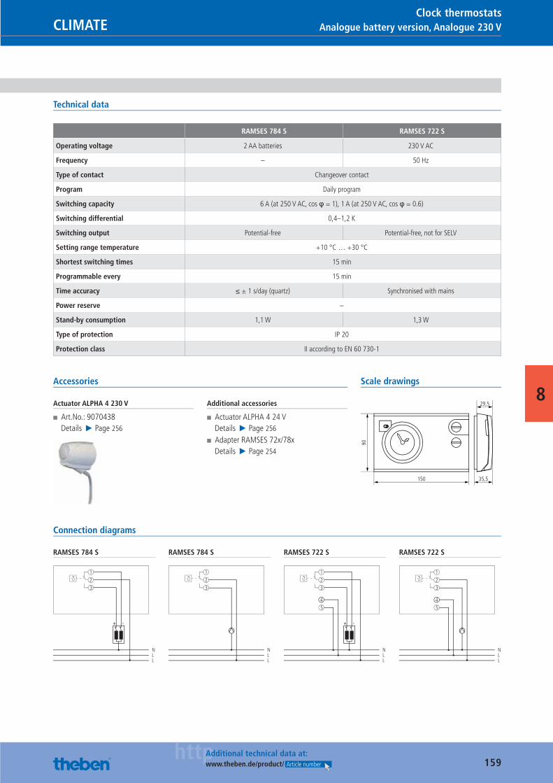
159httpAdditional technical data at:
www.theben.de/product/ Article number
Analogue battery version, Analogue 230 VCLIMATEClock thermostats
8
Technical data
RAMSES 784 S RAMSES 722 S
Operating voltage 2 AA batteries 230 V AC
Frequency – 50 Hz
Type of contact Changeover contact
Program Daily program
Switching capacity 6 A (at 250 V AC, cos φ = 1), 1 A (at 250 V AC, cos φ = 0.6)
Switching differential 0,4–1,2 K
Switching output Potential-free Potential-free, not for SELV
Setting range temperature +10 °C … +30 °C
Shortest switching times 15 min
Programmable every 15 min
Time accuracy ≤ ± 1 s/day (quartz) Synchronised with mains
Power reserve –
Stand-by consumption 1,1 W 1,3 W
Type of protection IP 20
Protection class II according to EN 60 730-1
Accessories
Actuator ALPHA 4 230 V
■ Art.No.: 9070438Details ▶ Page 256
Additional accessories
■ Actuator ALPHA 4 24 VDetails ▶ Page 256
■ Adapter RAMSES 72x/78xDetails ▶ Page 254
Scale drawings
150
90
35,5
29,5
Connection diagrams
RAMSES 784 S
NLL
1
2
3
-+
RAMSES 784 S
NLL
1
2
3
RAMSES 722 S
NLL
1
2
3
4
5
-+
RAMSES 722 S
NLL
1
2
3
4
5
Catalogue_EN_2013.indb 159 16.01.13 17:22
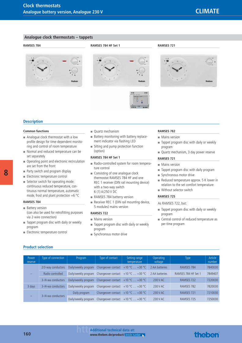
160httpAdditional technical data at:
www.theben.de/product/ Article number
Analogue battery version, Analogue 230 V CLIMATEClock thermostats
8
Analogue clock thermostats – tappets
RAMSES 784 RAMSES 784 HF Set 1 RAMSES 721
Description
Common functions
■ Analogue clock thermostat with a low profi le design for time-dependent monito-ring and control of room temperature
■ Normal and reduced temperature can be set separately
■ Operating point and electronic recirculation are set from the front
■ Party switch and program display ■ Electronic temperature control ■ Selector switch for operating mode: continuous reduced temperature, con-tinuous normal temperature, automatic mode, frost and plant protection +6 °C
RAMSES 784
■ Battery version(can also be used for retrofi tting purposes via 2-wire connection)
■ Tappet program disc with daily or weekly program
■ Electronic temperature control
■ Quartz mechanism ■ Battery monitoring with battery replace-ment indicator via fl ashing LED
■ Silting and pump protection function (option)
RAMSES 784 HF Set 1
■ Radio-controlled system for room tempera-ture control
■ Consisting of one analogue clock thermostat RAMSES 784 HF and one REC 1 receiver (DIN rail mounting device)with a two-way switch 6 (1) A/250 V DC
■ RAMSES 784 batterry version ■ Receiver REC 1 (DIN rail mounting device, 5 modules) mains version
RAMSES 722
■ Mains version ■ Tappet program disc with daily or weekly program
■ Synchronous motor drive
RAMSES 782
■ Mains version ■ Tappet program disc with daily or weekly program
■ Quartz mechanism, 3 day power reserve
RAMSES 721
■ Mains version ■ Tappet program disc with daily program ■ Synchronous motor drive ■ Reduced temperature approx. 5 K lower in relation to the set comfort temperature
■ Without selector switch
RAMSES 725
As RAMSES 722, but:
■ Tappet program disc with daily or weekly program
■ Central control of reduced temperature as per time program
Product selection
Power reserve
Type of connection Program Type of contact Setting range temperature
Operating voltage
Type Article number
–
2/3-way conductors Daily/weekly program Changeover contact +10 °C … +30 °C 2 AA batteries RAMSES 784 7840030
Radio controlled Daily/weekly program Changeover contact +10 °C … +30 °C 2 AA batteries RAMSES 784 HF Set 1 7849407
3-/4-wa conductors Daily/weekly program Changeover contact +10 °C … +30 °C 230 V AC RAMSES 722 7220030
3 days 3-/4-wa conductors Daily/weekly program Changeover contact +10 °C … +30 °C 230 V AC RAMSES 782 7820030
– 3-/4-wa conductorsDaily program Changeover contact +10 °C … +30 °C 230 V AC RAMSES 721 7210030
Daily/weekly program Changeover contact +10 °C … +30 °C 230 V AC RAMSES 725 7250030
Catalogue_EN_2013.indb 160 16.01.13 17:22
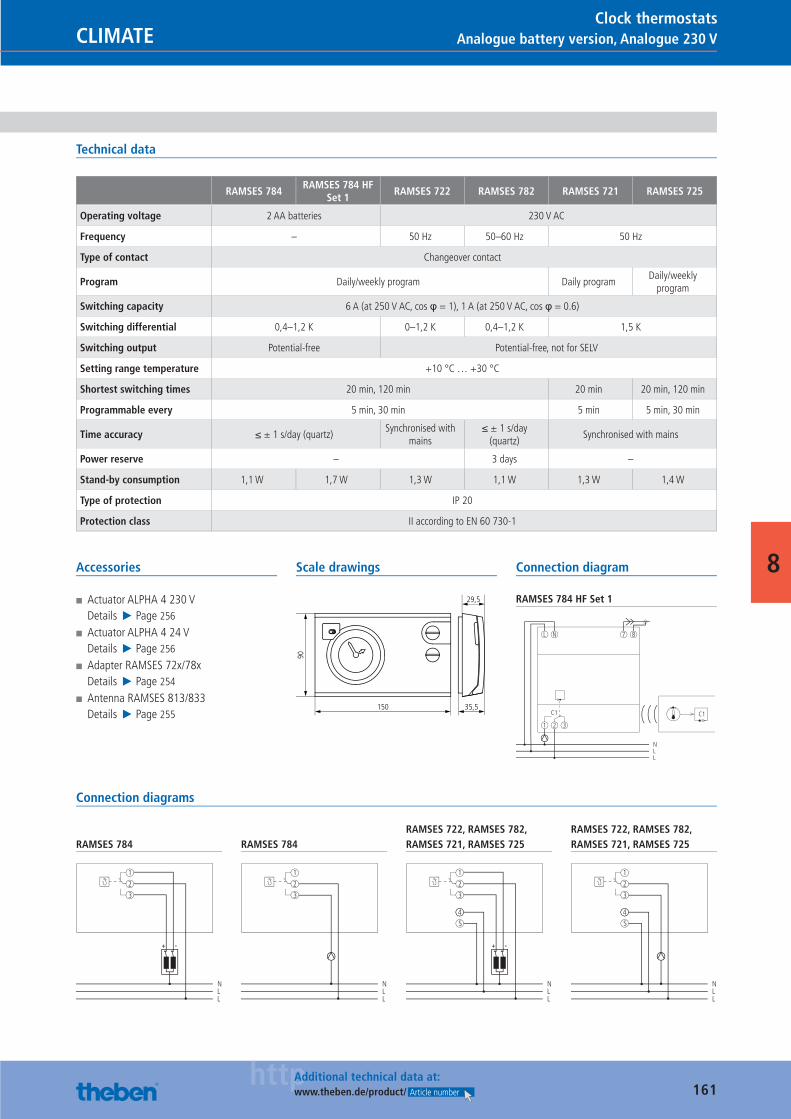
161httpAdditional technical data at:
www.theben.de/product/ Article number
Analogue battery version, Analogue 230 VCLIMATEClock thermostats
8
Technical data
RAMSES 784RAMSES 784 HF
Set 1RAMSES 722 RAMSES 782 RAMSES 721 RAMSES 725
Operating voltage 2 AA batteries 230 V AC
Frequency – 50 Hz 50–60 Hz 50 Hz
Type of contact Changeover contact
Program Daily/weekly program Daily programDaily/weekly
program
Switching capacity 6 A (at 250 V AC, cos φ = 1), 1 A (at 250 V AC, cos φ = 0.6)
Switching differential 0,4–1,2 K 0–1,2 K 0,4–1,2 K 1,5 K
Switching output Potential-free Potential-free, not for SELV
Setting range temperature +10 °C … +30 °C
Shortest switching times 20 min, 120 min 20 min 20 min, 120 min
Programmable every 5 min, 30 min 5 min 5 min, 30 min
Time accuracy ≤ ± 1 s/day (quartz)Synchronised with
mains≤ ± 1 s/day
(quartz)Synchronised with mains
Power reserve – 3 days –
Stand-by consumption 1,1 W 1,7 W 1,3 W 1,1 W 1,3 W 1,4 W
Type of protection IP 20
Protection class II according to EN 60 730-1
Accessories
■ Actuator ALPHA 4 230 VDetails ▶ Page 256
■ Actuator ALPHA 4 24 VDetails ▶ Page 256
■ Adapter RAMSES 72x/78xDetails ▶ Page 254
■ Antenna RAMSES 813/833Details ▶ Page 255
Scale drawings
150
90
35,5
29,5
Connection diagram
RAMSES 784 HF Set 1
C1
1 2 3
L N
NLL
7 8
C1
Connection diagrams
RAMSES 784
NLL
1
2
3
-+
RAMSES 784
NLL
1
2
3
RAMSES 722, RAMSES 782, RAMSES 721, RAMSES 725
NLL
1
2
3
4
5
-+
RAMSES 722, RAMSES 782, RAMSES 721, RAMSES 725
NLL
1
2
3
4
5
Catalogue_EN_2013.indb 161 16.01.13 17:22

162
CLIMATE
100 % growth.Here at Theben, we take the training of every young person very seriously and we see it as an investment in the future rather than a tiresome duty. Therefore, we have doubled the number of apprenticechips in the past year. This new generation of qualifi ed and motiva-ted employees will ensure we maintain our long-term position as: An innovative company that thinks and acts sustainably.
Catalogue_EN_2013.indb 162 16.01.13 17:22
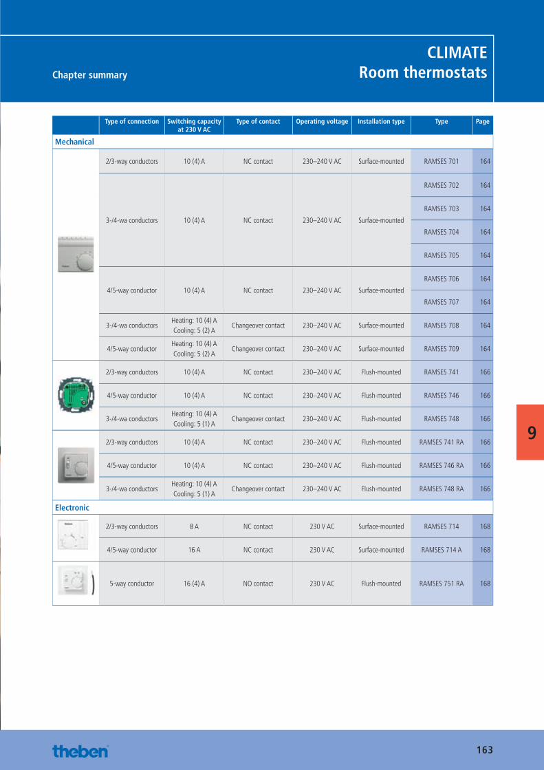
163
Chapter summary
CLIMATERoom thermostats
9
Type of connection Switching capacity at 230 V AC
Type of contact Operating voltage Installation type Type Page
Mechanical
2/3-way conductors 10 (4) A NC contact 230–240 V AC Surface-mounted RAMSES 701 164
3-/4-wa conductors 10 (4) A NC contact 230–240 V AC Surface-mounted
RAMSES 702 164
RAMSES 703 164
RAMSES 704 164
RAMSES 705 164
4/5-way conductor 10 (4) A NC contact 230–240 V AC Surface-mounted
RAMSES 706 164
RAMSES 707 164
3-/4-wa conductorsHeating: 10 (4) ACooling: 5 (2) A
Changeover contact 230–240 V AC Surface-mounted RAMSES 708 164
4/5-way conductorHeating: 10 (4) ACooling: 5 (2) A
Changeover contact 230–240 V AC Surface-mounted RAMSES 709 164
2/3-way conductors 10 (4) A NC contact 230–240 V AC Flush-mounted RAMSES 741 166
4/5-way conductor 10 (4) A NC contact 230–240 V AC Flush-mounted RAMSES 746 166
3-/4-wa conductorsHeating: 10 (4) ACooling: 5 (1) A
Changeover contact 230–240 V AC Flush-mounted RAMSES 748 166
2/3-way conductors 10 (4) A NC contact 230–240 V AC Flush-mounted RAMSES 741 RA 166
4/5-way conductor 10 (4) A NC contact 230–240 V AC Flush-mounted RAMSES 746 RA 166
3-/4-wa conductorsHeating: 10 (4) ACooling: 5 (1) A
Changeover contact 230–240 V AC Flush-mounted RAMSES 748 RA 166
Electronic
2/3-way conductors 8 A NC contact 230 V AC Surface-mounted RAMSES 714 168
4/5-way conductor 16 A NC contact 230 V AC Surface-mounted RAMSES 714 A 168
5-way conductor 16 (4) A NO contact 230 V AC Flush-mounted RAMSES 751 RA 168
Catalogue_EN_2013.indb 163 16.01.13 17:23
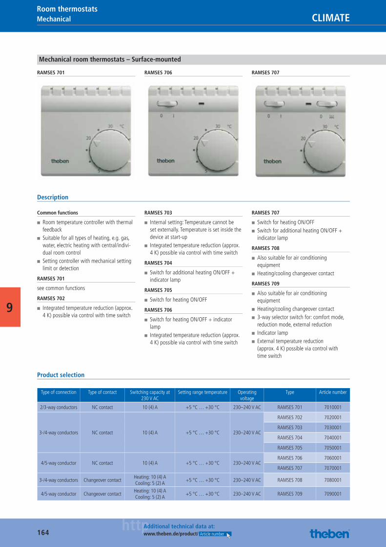
164httpAdditional technical data at:
www.theben.de/product/ Article number
Mechanical CLIMATERoom thermostats
9
Mechanical room thermostats – Surface-mounted
RAMSES 701 RAMSES 706 RAMSES 707
Description
Common functions
■ Room temperature controller with thermal feedback
■ Suitable for all types of heating, e.g. gas, water, electric heating with central/indivi-dual room control
■ Setting controller with mechanical setting limit or detection
RAMSES 701
see common functions
RAMSES 702
■ Integrated temperature reduction (approx. 4 K) possible via control with time switch
RAMSES 703
■ Internal setting: Temperature cannot be set externally. Temperature is set inside the device at start-up
■ Integrated temperature reduction (approx. 4 K) possible via control with time switch
RAMSES 704
■ Switch for additional heating ON/OFF + indicator lamp
RAMSES 705
■ Switch for heating ON/OFF
RAMSES 706
■ Switch for heating ON/OFF + indicator lamp
■ Integrated temperature reduction (approx. 4 K) possible via control with time switch
RAMSES 707
■ Switch for heating ON/OFF ■ Switch for additional heating ON/OFF + indicator lamp
RAMSES 708
■ Also suitable for air conditioning equipment
■ Heating/cooling changeover contact
RAMSES 709
■ Also suitable for air conditioning equipment
■ Heating/cooling changeover contact ■ 3-way selector switch for: comfort mode, reduction mode, external reduction
■ Indicator lamp ■ External temperature reduction (approx. 4 K) possible via control with time switch
Product selection
Type of connection Type of contact Switching capacity at 230 V AC
Setting range temperature Operating voltage
Type Article number
2/3-way conductors NC contact 10 (4) A +5 °C … +30 °C 230–240 V AC RAMSES 701 7010001
3-/4-way conductors NC contact 10 (4) A +5 °C … +30 °C 230–240 V AC
RAMSES 702 7020001
RAMSES 703 7030001
RAMSES 704 7040001
RAMSES 705 7050001
4/5-way conductor NC contact 10 (4) A +5 °C … +30 °C 230–240 V AC RAMSES 706 7060001
RAMSES 707 7070001
3-/4-way conductors Changeover contactHeating: 10 (4) ACooling: 5 (2) A
+5 °C … +30 °C 230–240 V AC RAMSES 708 7080001
4/5-way conductor Changeover contactHeating: 10 (4) ACooling: 5 (2) A
+5 °C … +30 °C 230–240 V AC RAMSES 709 7090001
Catalogue_EN_2013.indb 164 16.01.13 17:23
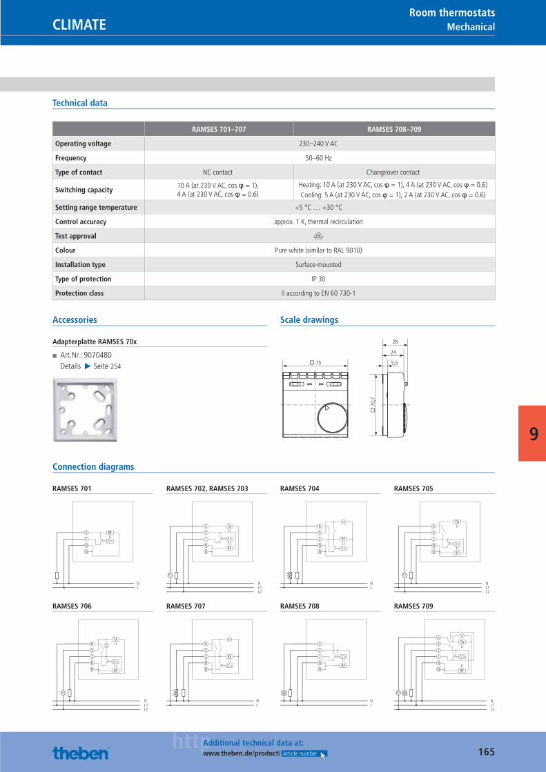
165httpAdditional technical data at:
www.theben.de/product/ Article number
MechanicalCLIMATERoom thermostats
9
Technical data
RAMSES 701–707 RAMSES 708–709
Operating voltage 230–240 V AC
Frequency 50–60 Hz
Type of contact NC contact Changeover contact
Switching capacity10 A (at 230 V AC, cos φ = 1),4 A (at 230 V AC, cos φ = 0.6)
Heating: 10 A (at 230 V AC, cos φ = 1), 4 A (at 230 V AC, cos φ = 0.6)Cooling: 5 A (at 230 V AC, cos φ = 1), 2 A (at 230 V AC, cos φ = 0.6)
Setting range temperature +5 °C … +30 °C
Control accuracy approx. 1 K, thermal recirculation
Test approval V
Colour Pure white (similar to RAL 9010)
Installation type Surface-mounted
Type of protection IP 30
Protection class II according to EN 60 730-1
Accessories
Adapterplatte RAMSES 70x
■ Art.Nr.: 9070480Details ▶ Seite 254
Scale drawings
� 75�
70,
75,5
24
28
Connection diagrams
RAMSES 701
2
1
N
N
NL
>
RF
RAMSES 702, RAMSES 703
5
2
1
RFN
N
NL1L2
>
TA
RAMSES 704
6
5
2 RF
>N
N
NL
RAMSES 705
6
5
2
RF
N
N
NL1L2
>
TA
RAMSES 706
6
5
2
RF
N
N
NL1L2
>
TA
RAMSES 707
6
5
2 RF
>N
N
NL
RAMSES 708
3
2
1
RFN
N
NL
>
RAMSES 709
>
3
5
2
1
RF
N
N
NL1L2
TA
Catalogue_EN_2013.indb 165 16.01.13 17:23
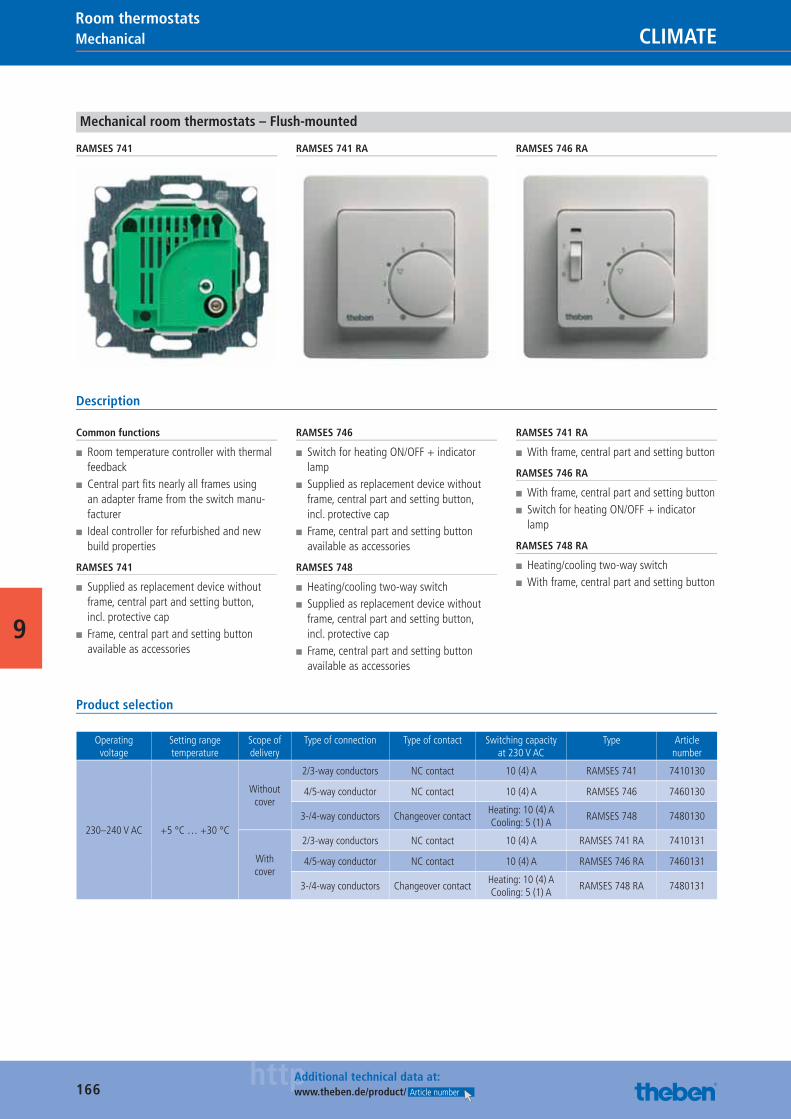
166httpAdditional technical data at:
www.theben.de/product/ Article number
Mechanical CLIMATERoom thermostats
9
Mechanical room thermostats – Flush-mounted
RAMSES 741 RAMSES 741 RA RAMSES 746 RA
Description
Common functions
■ Room temperature controller with thermal feedback
■ Central part fi ts nearly all frames using an adapter frame from the switch manu-facturer
■ Ideal controller for refurbished and new build properties
RAMSES 741
■ Supplied as replacement device without frame, central part and setting button, incl. protective cap
■ Frame, central part and setting button available as accessories
RAMSES 746
■ Switch for heating ON/OFF + indicator lamp
■ Supplied as replacement device without frame, central part and setting button, incl. protective cap
■ Frame, central part and setting button available as accessories
RAMSES 748
■ Heating/cooling two-way switch ■ Supplied as replacement device without frame, central part and setting button, incl. protective cap
■ Frame, central part and setting button available as accessories
RAMSES 741 RA
■ With frame, central part and setting button
RAMSES 746 RA
■ With frame, central part and setting button ■ Switch for heating ON/OFF + indicator lamp
RAMSES 748 RA
■ Heating/cooling two-way switch ■ With frame, central part and setting button
Product selection
Operating voltage
Setting range temperature
Scope of delivery
Type of connection Type of contact Switching capacity at 230 V AC
Type Article number
230–240 V AC +5 °C … +30 °C
Without cover
2/3-way conductors NC contact 10 (4) A RAMSES 741 7410130
4/5-way conductor NC contact 10 (4) A RAMSES 746 7460130
3-/4-way conductors Changeover contactHeating: 10 (4) ACooling: 5 (1) A
RAMSES 748 7480130
With cover
2/3-way conductors NC contact 10 (4) A RAMSES 741 RA 7410131
4/5-way conductor NC contact 10 (4) A RAMSES 746 RA 7460131
3-/4-way conductors Changeover contactHeating: 10 (4) ACooling: 5 (1) A
RAMSES 748 RA 7480131
Catalogue_EN_2013.indb 166 16.01.13 17:23
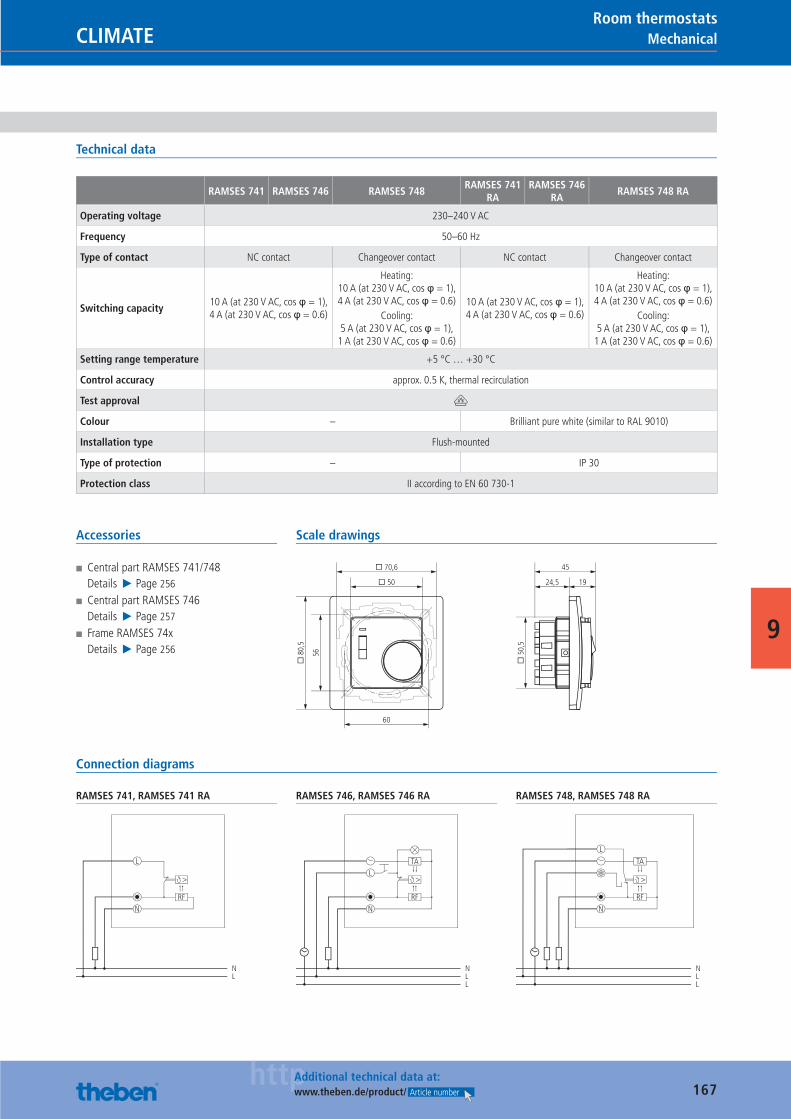
167httpAdditional technical data at:
www.theben.de/product/ Article number
MechanicalCLIMATERoom thermostats
9
Technical data
RAMSES 741 RAMSES 746 RAMSES 748RAMSES 741
RARAMSES 746
RARAMSES 748 RA
Operating voltage 230–240 V AC
Frequency 50–60 Hz
Type of contact NC contact Changeover contact NC contact Changeover contact
Switching capacity10 A (at 230 V AC, cos φ = 1), 4 A (at 230 V AC, cos φ = 0.6)
Heating: 10 A (at 230 V AC, cos φ = 1), 4 A (at 230 V AC, cos φ = 0.6)
Cooling: 5 A (at 230 V AC, cos φ = 1),
1 A (at 230 V AC, cos φ = 0.6)
10 A (at 230 V AC, cos φ = 1), 4 A (at 230 V AC, cos φ = 0.6)
Heating: 10 A (at 230 V AC, cos φ = 1), 4 A (at 230 V AC, cos φ = 0.6)
Cooling: 5 A (at 230 V AC, cos φ = 1),
1 A (at 230 V AC, cos φ = 0.6)
Setting range temperature +5 °C … +30 °C
Control accuracy approx. 0.5 K, thermal recirculation
Test approval V
Colour – Brilliant pure white (similar to RAL 9010)
Installation type Flush-mounted
Type of protection – IP 30
Protection class II according to EN 60 730-1
Accessories
■ Central part RAMSES 741/748Details ▶ Page 256
■ Central part RAMSES 746Details ▶ Page 257
■ Frame RAMSES 74xDetails ▶ Page 256
Scale drawings
1924,5
45
� 8
0,5
56
60
� 50
� 70,6
� 5
0,5
Connection diagrams
RAMSES 741, RAMSES 741 RA
L
RF
N
NL
>
RAMSES 746, RAMSES 746 RA
L
RF
N
NLL
>
TA
RAMSES 748, RAMSES 748 RA
L
RF
N
NLL
>
TA
Catalogue_EN_2013.indb 167 16.01.13 17:23
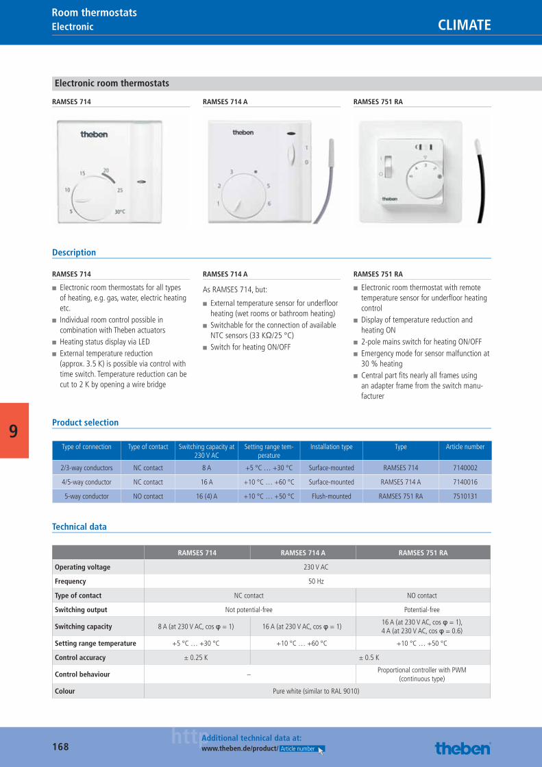
168httpAdditional technical data at:
www.theben.de/product/ Article number
Electronic CLIMATERoom thermostats
9
Electronic room thermostats
RAMSES 714 RAMSES 714 A RAMSES 751 RA
Description
RAMSES 714
■ Electronic room thermostats for all types of heating, e.g. gas, water, electric heating etc.
■ Individual room control possible in combination with Theben actuators
■ Heating status display via LED ■ External temperature reduction (approx. 3.5 K) is possible via control with time switch. Temperature reduction can be cut to 2 K by opening a wire bridge
RAMSES 714 A
As RAMSES 714, but:
■ External temperature sensor for underfl oor heating (wet rooms or bathroom heating)
■ Switchable for the connection of available NTC sensors (33 KΩ/25 °C)
■ Switch for heating ON/OFF
RAMSES 751 RA
■ Electronic room thermostat with remote temperature sensor for underfl oor heating control
■ Display of temperature reduction and heating ON
■ 2-pole mains switch for heating ON/OFF ■ Emergency mode for sensor malfunction at 30 % heating
■ Central part fi ts nearly all frames using an adapter frame from the switch manu-facturer
Product selection
Type of connection Type of contact Switching capacity at 230 V AC
Setting range tem-perature
Installation type Type Article number
2/3-way conductors NC contact 8 A +5 °C … +30 °C Surface-mounted RAMSES 714 7140002
4/5-way conductor NC contact 16 A +10 °C … +60 °C Surface-mounted RAMSES 714 A 7140016
5-way conductor NO contact 16 (4) A +10 °C … +50 °C Flush-mounted RAMSES 751 RA 7510131
Technical data
RAMSES 714 RAMSES 714 A RAMSES 751 RA
Operating voltage 230 V AC
Frequency 50 Hz
Type of contact NC contact NO contact
Switching output Not potential-free Potential-free
Switching capacity 8 A (at 230 V AC, cos φ = 1) 16 A (at 230 V AC, cos φ = 1)16 A (at 230 V AC, cos φ = 1),4 A (at 230 V AC, cos φ = 0.6)
Setting range temperature +5 °C … +30 °C +10 °C … +60 °C +10 °C … +50 °C
Control accuracy ± 0.25 K ± 0.5 K
Control behaviour –Proportional controller with PWM
(continuous type)
Colour Pure white (similar to RAL 9010)
Catalogue_EN_2013.indb 168 16.01.13 17:23
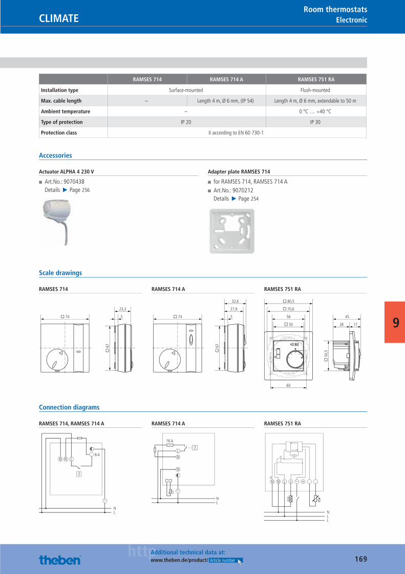
169httpAdditional technical data at:
www.theben.de/product/ Article number
ElectronicCLIMATERoom thermostats
9
RAMSES 714 RAMSES 714 A RAMSES 751 RA
Installation type Surface-mounted Flush-mounted
Max. cable length – Length 4 m, Ø 6 mm, (IP 54) Length 4 m, Ø 6 mm, extendable to 50 m
Ambient temperature – 0 °C … +40 °C
Type of protection IP 20 IP 30
Protection class II according to EN 60 730-1
Accessories
Actuator ALPHA 4 230 V
■ Art.No.: 9070438Details ▶ Page 256
Adapter plate RAMSES 714
■ for RAMSES 714, RAMSES 714 A ■ Art.No.: 9070212Details ▶ Page 254
Scale drawings
RAMSES 714
� 74
� 6
7
5
23,3
RAMSES 714 A
� 74
� 6
7
5
27,9
32,6
RAMSES 751 RA
1728
4556
60
� 50
� 70,6
� 80,5
� 5
0,5
f
3 24
5
Connection diagrams
RAMSES 714, RAMSES 714 A
NL
N N L8 A
RAMSES 714 A
NL
N
L
16 A
N
RAMSES 751 RA
NN L
NLL
Catalogue_EN_2013.indb 169 16.01.13 17:23
170
CLIMATE
Zero emissions.Energy effi ciency, environmental responsibility and sustainability are not just important in our range of products. These tenets are fi rmly anchored in our company policy: In addition to a solar power system and heat pumps for climatizing the production section, we have recently introduced our fi rst zero emission electric company car.
Catalogue_EN_2013.indb 170 16.01.13 17:23
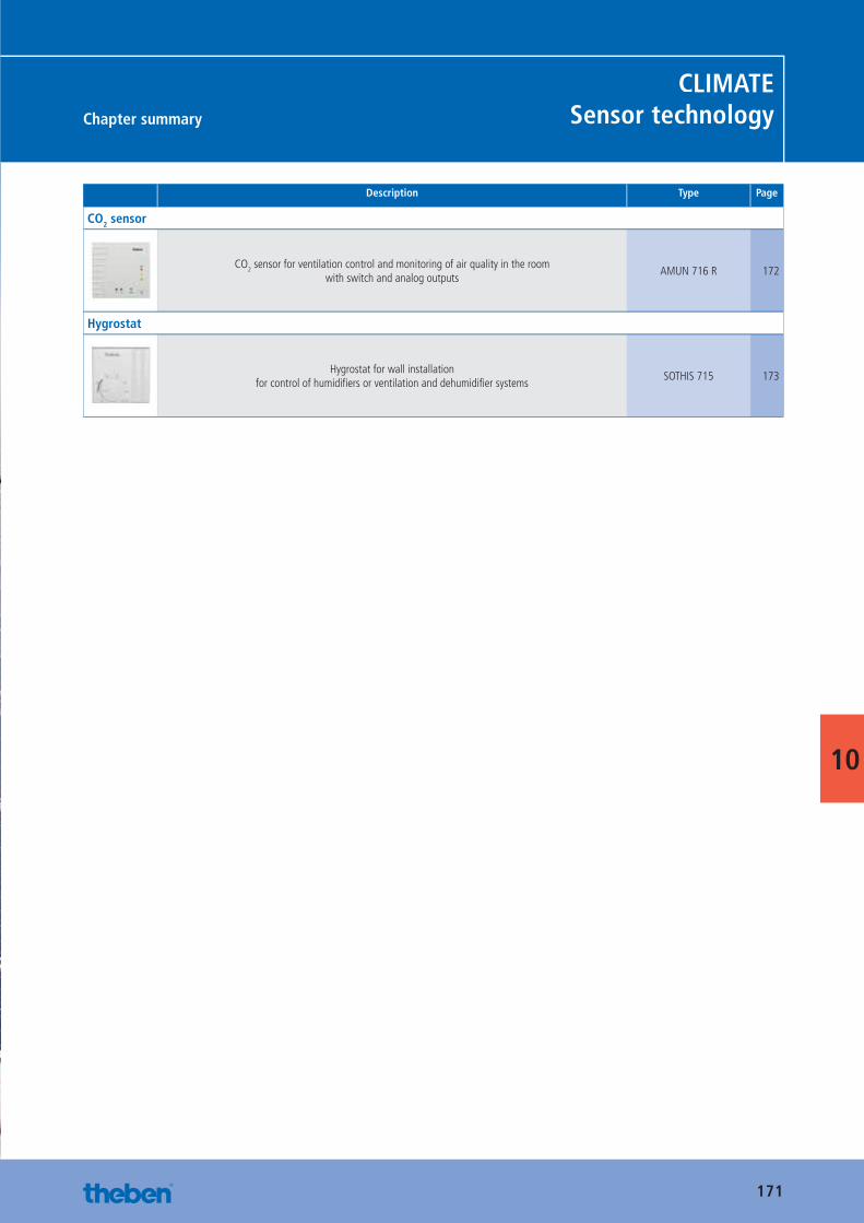
171
Chapter summary
CLIMATESensor technology
10
Description Type Page
CO2 sensor
CO2 sensor for ventilation control and monitoring of air quality in the roomwith switch and analog outputs
AMUN 716 R 172
Hygrostat
Hygrostat for wall installationfor control of humidifi ers or ventilation and dehumidifi er systems
SOTHIS 715 173
Catalogue_EN_2013.indb 171 16.01.13 17:23
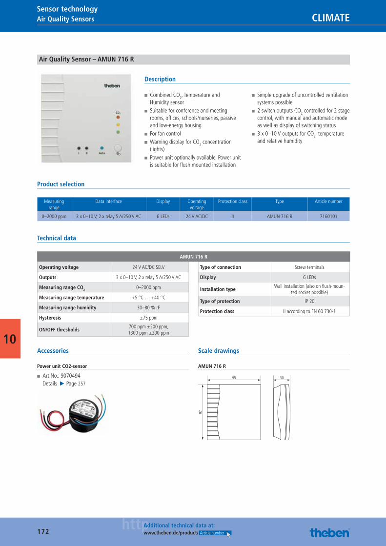
172httpAdditional technical data at:
www.theben.de/product/ Article number
Air Quality Sensors CLIMATESensor technology
10
Air Quality Sensor – AMUN 716 R
Description
■ Combined CO2, Temperature and Humidity sensor
■ Suitable for conference and meeting rooms, offi ces, schools/nurseries, passive and low-energy housing
■ For fan control ■ Warning display for CO2 concentration (lights)
■ Power unit optionally available. Power unit is suitable for fl ush mounted installation
■ Simple upgrade of uncontrolled ventilation systems possible
■ 2 switch outputs CO2 controlled for 2 stage control, with manual and automatic mode as well as display of switching status
■ 3 x 0–10 V outputs for CO2, temperature and relative humidity
Product selection
Measuring range
Data interface Display Operating voltage
Protection class Type Article number
0–2000 ppm 3 x 0–10 V, 2 x relay 5 A/250 V AC 6 LEDs 24 V AC/DC II AMUN 716 R 7160101
Technical data
AMUN 716 R
Operating voltage 24 V AC/DC SELV
Outputs 3 x 0–10 V, 2 x relay 5 A/250 V AC
Measuring range CO2 0–2000 ppm
Measuring range temperature +5 °C … +40 °C
Measuring range humidity 30–80 % rF
Hysteresis ±75 ppm
ON/OFF thresholds700 ppm ±200 ppm,1300 ppm ±200 ppm
Type of connection Screw terminals
Display 6 LEDs
Installation typeWall installation (also on fl ush-moun-
ted socket possible)
Type of protection IP 20
Protection class II according to EN 60 730-1
Accessories
Power unit CO2-sensor
■ Art.No.: 9070494Details ▶ Page 257
Scale drawings
AMUN 716 R
95 30
97
Catalogue_EN_2013.indb 172 16.01.13 17:23
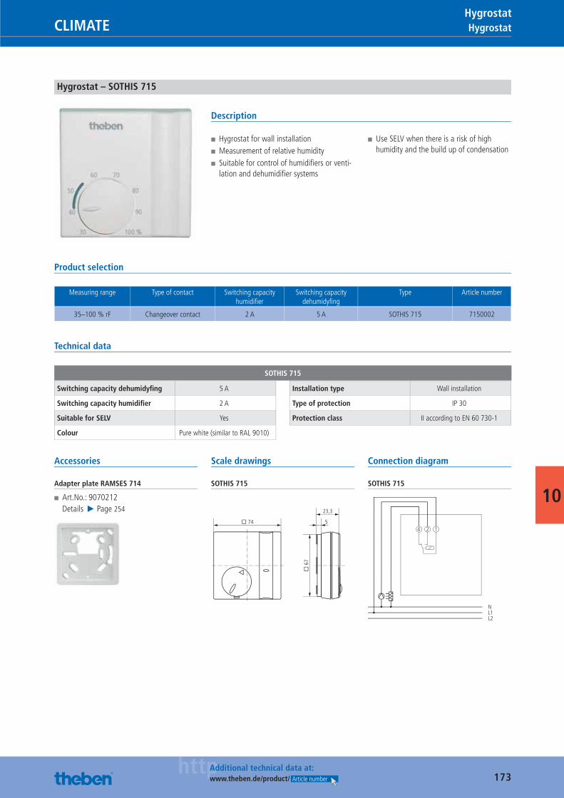
173httpAdditional technical data at:
www.theben.de/product/ Article number
HygrostatCLIMATEHygrostat
10
Hygrostat – SOTHIS 715
Description
■ Hygrostat for wall installation ■ Measurement of relative humidity ■ Suitable for control of humidifi ers or venti-lation and dehumidifi er systems
■ Use SELV when there is a risk of high humidity and the build up of condensation
Product selection
Measuring range Type of contact Switching capacity humidifi er
Switching capacity dehumidyfi ng
Type Article number
35–100 % rF Changeover contact 2 A 5 A SOTHIS 715 7150002
Technical data
SOTHIS 715
Switching capacity dehumidyfi ng 5 A
Switching capacity humidifi er 2 A
Suitable for SELV Yes
Colour Pure white (similar to RAL 9010)
Installation type Wall installation
Type of protection IP 30
Protection class II according to EN 60 730-1
Accessories
Adapter plate RAMSES 714
■ Art.No.: 9070212Details ▶ Page 254
Scale drawings
SOTHIS 715
� 74
� 6
7
5
23,3
Connection diagram
SOTHIS 715
4
NL1L2
2 1
Catalogue_EN_2013.indb 173 16.01.13 17:23
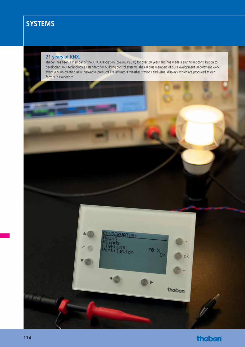
174
SYSTEMS
21 years of KNX.Theben has been a member of the KNX Association (previously EIB) for over 20 years and has made a signifi cant contribution to developing KNX technology as standard for building control systems. The 60 plus members of our Development Department work every year on creating new innovative products like actuators, weather stations and visual displays, which are produced at our factory in Haigerloch.
Catalogue_EN_2013.indb 174 16.01.13 17:23
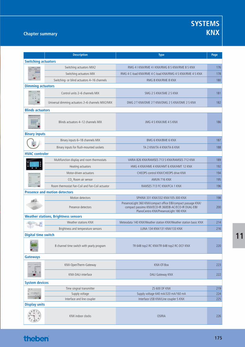
175
Chapter summary
SYSTEMSKNX
11
Description Type Page
Switching actuators
Switching actuators MIX2 RMG 4 I KNX/RME 4 I KNX/RMG 8 S KNX/RME 8 S KNX 176
Switching actuators MIX RMG 4 C-load KNX/RME 4 C-load KNX/RMG 4 S KNX/RME 4 S KNX 178
Switching- or blind actuators 4–16 channels RMG 8 KNX/RME 8 KNX 180
Dimming actuators
Control units 2–6 channels MIX SMG 2 S KNX/SME 2 S KNX 181
Universal dimming actuators 2–6 channels MIX2/MIX DMG 2 T KNX/DME 2 T KNX/DMG 2 S KNX/DME 2 S KNX 182
Blinds actuators
Blinds actuators 4–12 channels MIX JMG 4 S KNX/JME 4 S KNX 186
Binary inputs
Binary inputs 6–18 channels MIX BMG 6 KNX/BME 6 KNX 187
Binary inputs for fl ush-mounted sockets TA 2 KNX/TA 4 KNX/TA 6 KNX 188
HVAC controler
Multifunction display and room thermostats VARIA 826 KNX/RAMSES 713 S KNX/RAMSES 712 KNX 189
Heating actuators HMG 4 KNX/HME 4 KNX/HMT 6 KNX/HMT 12 KNX 192
Motor-driven actuators CHEOPS control KNX/CHEOPS drive KNX 194
CO2 Room air sensor AMUN 716 KNX 195
Room thermostat Fan-Coil and Fan-Coil actuator RAMSES 713 FC KNX/FCA 1 KNX 196
Presence and motion detectors
Motion detectors SPHINX 331 KNX/332 KNX/105-300 KNX 198
Presence detectorsPresenceLight 360 KNX/compact offi ce EIB/compact passage KNX/
compact passimo KNX/ECO-IR 360EIB-AC/ECO-IR DUAL-EIB/PlanoCentro KNX/PresenceLight 180 KNX
200
Weather stations, Brightness sensors
Weather stations KNX Meteodata 140 KNX/Weather station KNX/Weather station basic KNX 214
Brightness and temperature sensors LUNA 134 KNX/131 KNX/133 KNX 216
Digital time switch
8 channel time switch with yearly program TR 648 top2 RC KNX/TR 648 top2 RC-DCF KNX 220
Gateways
KNX-OpenTherm-Gateway KNX-OT-Box 223
KNX-DALI-interface DALI Gateway KNX 222
System devices
Time singnal transmitter ZS 600 DF KNX 219
Supply voltage Supply voltage 640 mA/320 mA/160 mA 224
Interface and line coupler Interface USB KNX/Line coupler S KNX 225
Display units
KNX indoor clocks OSIRIA 226
Catalogue_EN_2013.indb 175 16.01.13 17:23
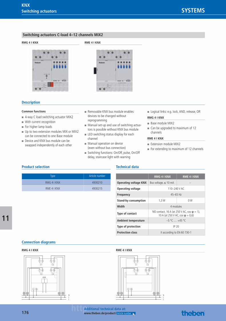
176httpAdditional technical data at:
www.theben.de/product/ Article number
Switching actuators SYSTEMSKNX
11
Switching actuators C-load 4–12 channels MIX2
RMG 4 I KNX RME 4 I KNX
Description
Common functions
■ 4-way C load switching actuator MIX2 ■ With current recognition ■ For higher lamp loads ■ Up to two extension modules MIX or MIX2 can be connected to one Base module
■ Device and KNX bus module can be swapped independently of each other
■ Removable KNX bus module enables devices to be changed without reprogramming
■ Manual set-up and use of switching actua-tors is possible without KNX bus module
■ LED switching status display for each channel
■ Manual operation on device (even without bus connection)
■ Switching functions: On/Off, pulse, On/Off delay, staircase light with warning
■ Logical links: e.g. lock, AND, release, OR
RMG 4 I KNX
■ Base module MIX2 ■ Can be upgraded to maximum of 12 channels
RME 4 I KNX
■ Extension module MIX2 ■ For extending to maximum of 12 channels
Product selection
Type Article number
RMG 4 I KNX 4930210
RME 4 I KNX 4930215
Technical data
RMG 4 I KNX RME 4 I KNX
Operating voltage KNX Bus voltage, ≤ 10 mA –
Operating voltage 110–240 V AC
Frequency 45–65 Hz
Stand-by consumption 1,3 W 0 W
Width 4 modules
Type of contactNO contact, 16 A (at 250 V AC, cos φ = 1),
10 A (at 250 V AC, cos φ = 0,6)
Ambient temperature –5 °C … +45 °C
Type of protection IP 20
Protection class II according to EN 60 730-1
Connection diagrams
RMG 4 I KNX
C1 C2
L N
3 4
NLL
5 6
C3 C4
7 8 9 10
KNX
RME 4 I KNX
C1 C2
L N
3 4
NLL
5 6
C3 C4
7 8 9 10
Catalogue_EN_2013.indb 176 16.01.13 17:23
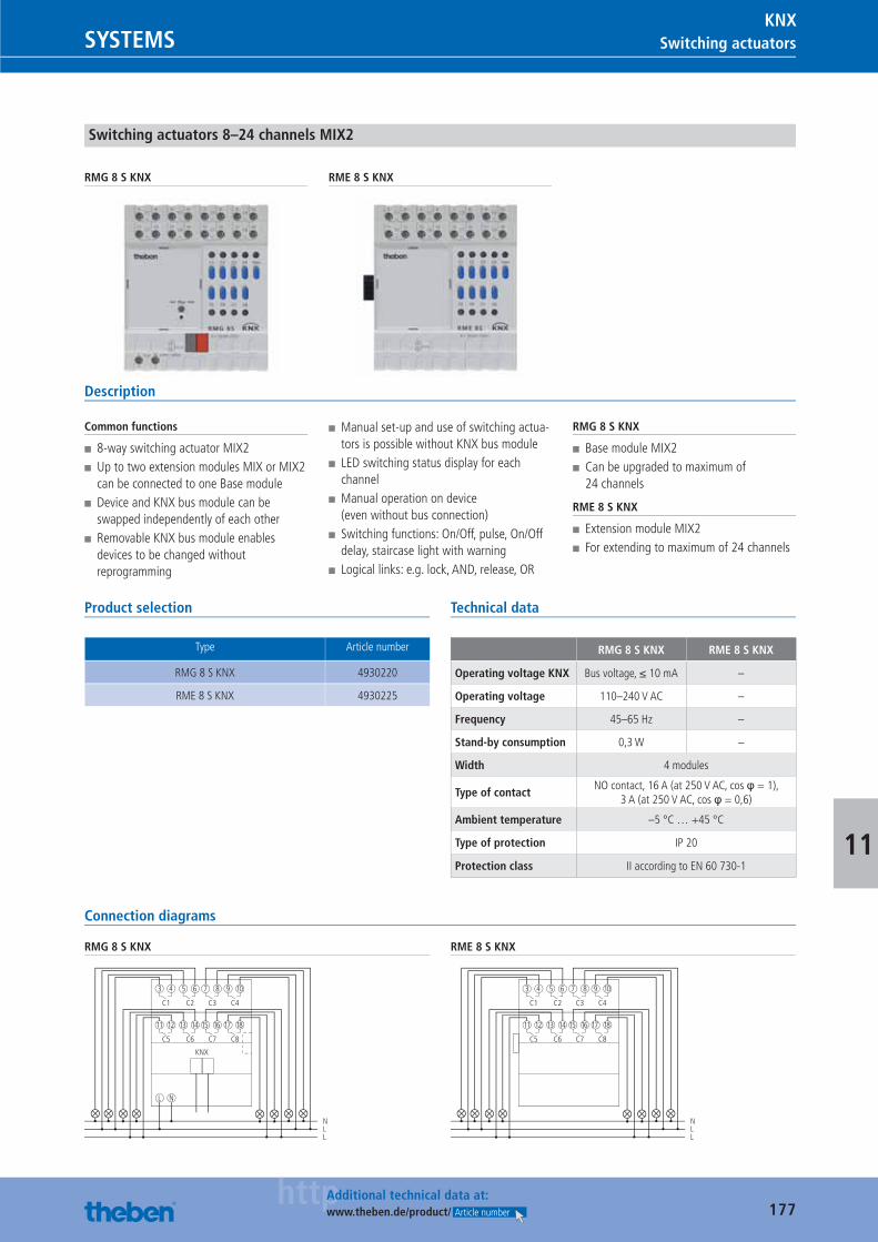
177httpAdditional technical data at:
www.theben.de/product/ Article number
Switching actuatorsSYSTEMSKNX
11
Switching actuators 8–24 channels MIX2
RMG 8 S KNX RME 8 S KNX
Description
Common functions
■ 8-way switching actuator MIX2 ■ Up to two extension modules MIX or MIX2 can be connected to one Base module
■ Device and KNX bus module can be swapped independently of each other
■ Removable KNX bus module enables devices to be changed without reprogramming
■ Manual set-up and use of switching actua-tors is possible without KNX bus module
■ LED switching status display for each channel
■ Manual operation on device (even without bus connection)
■ Switching functions: On/Off, pulse, On/Off delay, staircase light with warning
■ Logical links: e.g. lock, AND, release, OR
RMG 8 S KNX
■ Base module MIX2 ■ Can be upgraded to maximum of 24 channels
RME 8 S KNX
■ Extension module MIX2 ■ For extending to maximum of 24 channels
Product selection
Type Article number
RMG 8 S KNX 4930220
RME 8 S KNX 4930225
Technical data
RMG 8 S KNX RME 8 S KNX
Operating voltage KNX Bus voltage, ≤ 10 mA –
Operating voltage 110–240 V AC –
Frequency 45–65 Hz –
Stand-by consumption 0,3 W –
Width 4 modules
Type of contactNO contact, 16 A (at 250 V AC, cos φ = 1),
3 A (at 250 V AC, cos φ = 0,6)
Ambient temperature –5 °C … +45 °C
Type of protection IP 20
Protection class II according to EN 60 730-1
Connection diagrams
RMG 8 S KNX
C1 C4
L N
3 4
NLL
C2
5 6 9 10
C3
7 8
C6 C8
13 14
C5
11 12 17 18
C7
15 16
KNX
RME 8 S KNX
C1 C4
3 4
NLL
C2
5 6 9 10
C3
7 8
C6 C8
13 14
C5
11 12 17 18
C7
15 16
Catalogue_EN_2013.indb 177 16.01.13 17:23
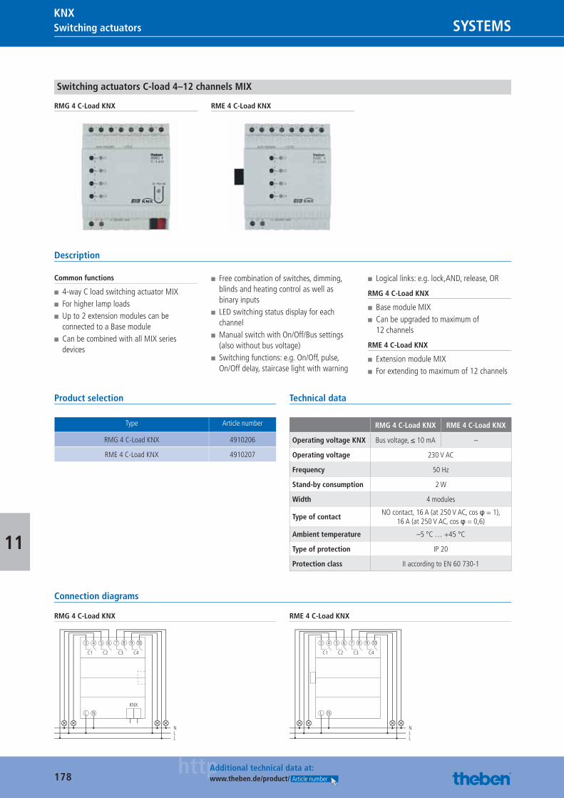
178httpAdditional technical data at:
www.theben.de/product/ Article number
Switching actuators SYSTEMSKNX
11
Switching actuators C-load 4–12 channels MIX
RMG 4 C-Load KNX RME 4 C-Load KNX
Description
Common functions
■ 4-way C load switching actuator MIX ■ For higher lamp loads ■ Up to 2 extension modules can be connected to a Base module
■ Can be combined with all MIX series devices
■ Free combination of switches, dimming, blinds and heating control as well as binary inputs
■ LED switching status display for each channel
■ Manual switch with On/Off/Bus settings (also without bus voltage)
■ Switching functions: e.g. On/Off, pulse, On/Off delay, staircase light with warning
■ Logical links: e.g. lock,AND, release, OR
RMG 4 C-Load KNX
■ Base module MIX ■ Can be upgraded to maximum of 12 channels
RME 4 C-Load KNX
■ Extension module MIX ■ For extending to maximum of 12 channels
Product selection
Type Article number
RMG 4 C-Load KNX 4910206
RME 4 C-Load KNX 4910207
Technical data
RMG 4 C-Load KNX RME 4 C-Load KNX
Operating voltage KNX Bus voltage, ≤ 10 mA –
Operating voltage 230 V AC
Frequency 50 Hz
Stand-by consumption 2 W
Width 4 modules
Type of contactNO contact, 16 A (at 250 V AC, cos φ = 1),
16 A (at 250 V AC, cos φ = 0,6)
Ambient temperature –5 °C … +45 °C
Type of protection IP 20
Protection class II according to EN 60 730-1
Connection diagrams
RMG 4 C-Load KNX
C1
L N
3 4 5 6 7 8
N
KNX
LL
C2 C3 C4
9 10
RME 4 C-Load KNX
C1
L N
3 4 5 6 7 8
NLL
C2 C3 C4
9 10
Catalogue_EN_2013.indb 178 16.01.13 17:24
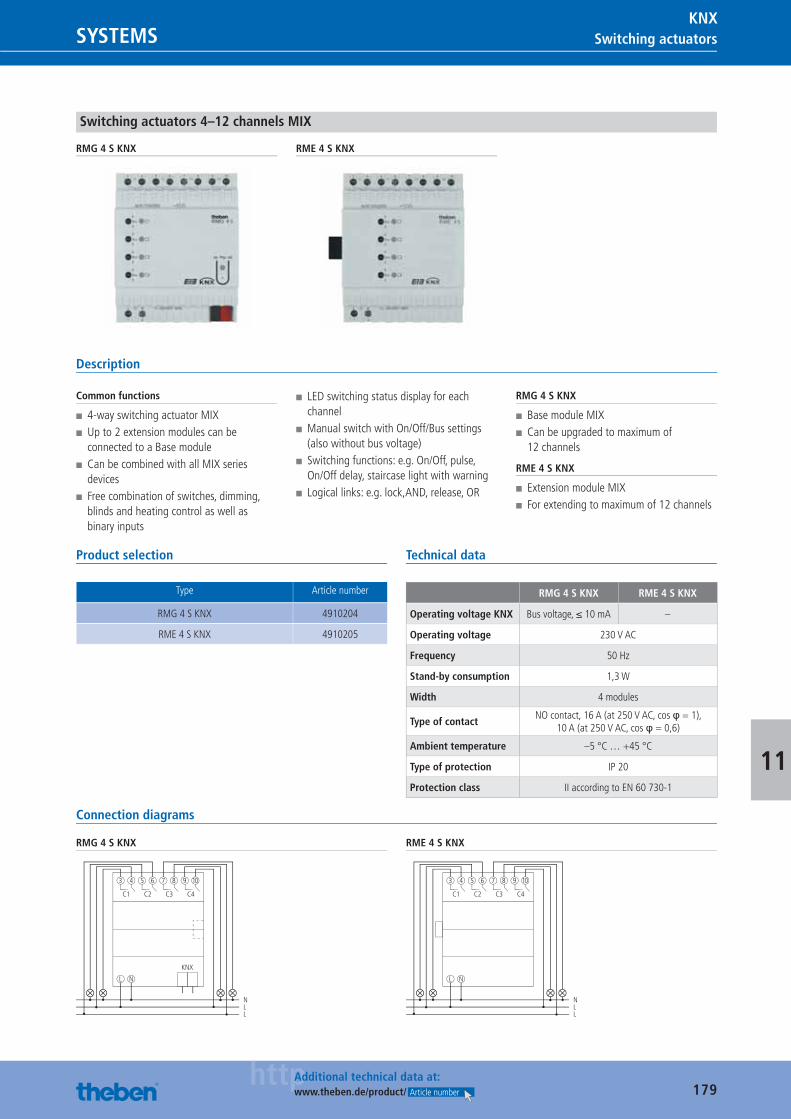
179httpAdditional technical data at:
www.theben.de/product/ Article number
Switching actuatorsSYSTEMSKNX
11
Switching actuators 4–12 channels MIX
RMG 4 S KNX RME 4 S KNX
Description
Common functions
■ 4-way switching actuator MIX ■ Up to 2 extension modules can be connected to a Base module
■ Can be combined with all MIX series devices
■ Free combination of switches, dimming, blinds and heating control as well as binary inputs
■ LED switching status display for each channel
■ Manual switch with On/Off/Bus settings (also without bus voltage)
■ Switching functions: e.g. On/Off, pulse, On/Off delay, staircase light with warning
■ Logical links: e.g. lock,AND, release, OR
RMG 4 S KNX
■ Base module MIX ■ Can be upgraded to maximum of 12 channels
RME 4 S KNX
■ Extension module MIX ■ For extending to maximum of 12 channels
Product selection
Type Article number
RMG 4 S KNX 4910204
RME 4 S KNX 4910205
Technical data
RMG 4 S KNX RME 4 S KNX
Operating voltage KNX Bus voltage, ≤ 10 mA –
Operating voltage 230 V AC
Frequency 50 Hz
Stand-by consumption 1,3 W
Width 4 modules
Type of contactNO contact, 16 A (at 250 V AC, cos φ = 1),
10 A (at 250 V AC, cos φ = 0,6)
Ambient temperature –5 °C … +45 °C
Type of protection IP 20
Protection class II according to EN 60 730-1
Connection diagrams
RMG 4 S KNX
C1
L N
3 4 5 6 7 8
N
KNX
LL
C2 C3 C4
9 10
RME 4 S KNX
C1
L N
3 4 5 6 7 8
NLL
C2 C3 C4
9 10
Catalogue_EN_2013.indb 179 16.01.13 17:24
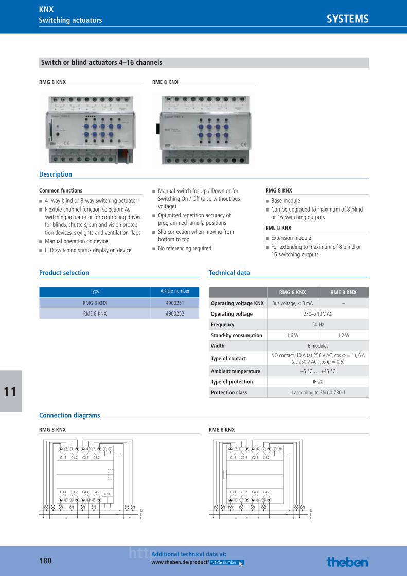
180httpAdditional technical data at:
www.theben.de/product/ Article number
Switching actuators SYSTEMSKNX
11
Switch or blind actuators 4–16 channels
RMG 8 KNX RME 8 KNX
Description
Common functions
■ 4- way blind or 8-way switching actuator ■ Flexible channel function selection: As switching actuator or for controlling drives for blinds, shutters, sun and vision protec-tion devices, skylights and ventilation fl aps
■ Manual operation on device ■ LED switching status display on device
■ Manual switch for Up / Down or for Switching On / Off (also without bus voltage)
■ Optimised repetition accuracy of programmed lamella positions
■ Slip correction when moving from bottom to top
■ No referencing required
RMG 8 KNX
■ Base module ■ Can be upgraded to maximum of 8 blind or 16 switching outputs
RME 8 KNX
■ Extension module ■ For extending to maximum of 8 blind or 16 switching outputs
Product selection
Type Article number
RMG 8 KNX 4900251
RME 8 KNX 4900252
Technical data
RMG 8 KNX RME 8 KNX
Operating voltage KNX Bus voltage, ≤ 8 mA –
Operating voltage 230–240 V AC
Frequency 50 Hz
Stand-by consumption 1,6 W 1,2 W
Width 6 modules
Type of contactNO contact, 10 A (at 250 V AC, cos φ = 1), 6 A
(at 250 V AC, cos φ = 0,6)
Ambient temperature –5 °C … +45 °C
Type of protection IP 20
Protection class II according to EN 60 730-1
Connection diagrams
RMG 8 KNX
C1.1
2
NLL
C1.2
3
C2.1
6
C2.2
7 L N
C3.1
10
C3.2
11
C4.1
14
C4.2
15
KNX
RME 8 KNX
C1.1
2
NLL
C1.2
3
C2.1
6
C2.2
7 L N
C3.1
10
C3.2
11
C4.1
14
C4.2
15
Catalogue_EN_2013.indb 180 16.01.13 17:24
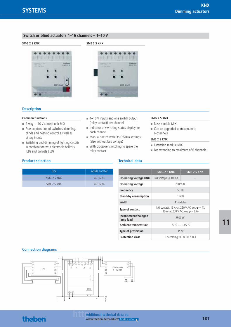
181httpAdditional technical data at:
www.theben.de/product/ Article number
Dimming actuatorsSYSTEMSKNX
11
Switch or blind actuators 4–16 channels – 1–10 V
SMG 2 S KNX SME 2 S KNX
Description
Common functions
■ 2-way 1–10 V control unit MIX ■ Free combination of switches, dimming, blinds and heating control as well as binary inputs
■ Switching and dimming of lighting circuits in combination with electronic ballasts (EBs and ballasts LED)
■ 1–10 V inputs and one switch output (relay contact) per channel
■ Indicator of switching status display for each channel
■ Manual switch with On/Off/Bus settings (also without bus voltage)
■ With crossover switching to spare the relay contact
SMG 2 S KNX
■ Base module MIX ■ Can be upgraded to maximum of 6 channels
SME 2 S KNX
■ Extension module MIX ■ For extending to maximum of 6 channels
Product selection
Type Article number
SMG 2 S KNX 4910273
SME 2 S KNX 4910274
Technical data
SMG 2 S KNX SME 2 S KNX
Operating voltage KNX Bus voltage, ≤ 10 mA –
Operating voltage 230 V AC
Frequency 50 Hz
Stand-by consumption 1,6 W
Width 4 modules
Type of contactNO contact, 16 A (at 250 V AC, cos φ = 1),
10 A (at 250 V AC, cos φ = 0,6)Incandescent/halogen lamp load
2500 W
Ambient temperature –5 °C … +45 °C
Type of protection IP 20
Protection class II according to EN 60 730-1
Connection diagrams
C1
L N
31
EVG2
3
4
–
+
L1
N
4 + – + –7 8
N
KNX
LL
C1 C2 C2
–
LED Controller1-10 V DIM
+–
+
L1
N
Catalogue_EN_2013.indb 181 16.01.13 17:24
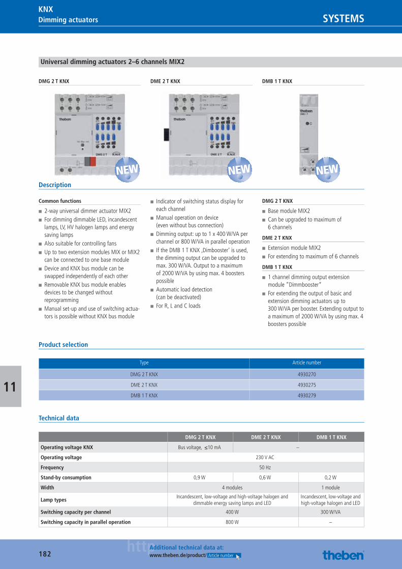
182httpAdditional technical data at:
www.theben.de/product/ Article number
Dimming actuators SYSTEMSKNX
11
Universal dimming actuators 2–6 channels MIX2
DMG 2 T KNX DME 2 T KNX DMB 1 T KNX
Description
Common functions
■ 2-way universal dimmer actuator MIX2 ■ For dimming dimmable LED, incandescent lamps, LV, HV halogen lamps and energy saving lamps
■ Also suitable for controlling fans ■ Up to two extension modules MIX or MIX2 can be connected to one base module
■ Device and KNX bus module can be swapped independently of each other
■ Removable KNX bus module enables devices to be changed without reprogramming
■ Manual set-up and use of switching actua-tors is possible without KNX bus module
■ Indicator of switching status display for each channel
■ Manual operation on device (even without bus connection)
■ Dimming output: up to 1 x 400 W/VA per channel or 800 W/VA in parallel operation
■ If the DMB 1 T KNX ‚Dimbooster‘ is used, the dimming output can be upgraded to max. 300 W/VA. Output to a maximum of 2000 W/VA by using max. 4 boosters possible
■ Automatic load detection (can be deactivated)
■ For R, L and C loads
DMG 2 T KNX
■ Base module MIX2 ■ Can be upgraded to maximum of 6 channels
DME 2 T KNX
■ Extension module MIX2 ■ For extending to maximum of 6 channels
DMB 1 T KNX
■ 1 channel dimming output extension module ”Dimmbooster“
■ For extending the output of basic and extension dimming actuators up to 300 W/VA per booster. Extending output to a maximum of 2000 W/VA by using max. 4 boosters possible
Product selection
Type Article number
DMG 2 T KNX 4930270
DME 2 T KNX 4930275
DMB 1 T KNX 4930279
Technical data
DMG 2 T KNX DME 2 T KNX DMB 1 T KNX
Operating voltage KNX Bus voltage, ≤10 mA –
Operating voltage 230 V AC
Frequency 50 Hz
Stand-by consumption 0,9 W 0,6 W 0,2 W
Width 4 modules 1 module
Lamp typesIncandescent, low-voltage and high-voltage halogen and
dimmable energy saving lamps and LEDIncandescent, low-voltage and high-voltage halogen and LED
Switching capacity per channel 400 W 300 W/VA
Switching capacity in parallel operation 800 W –
NEW NEW NEW
Catalogue_EN_2013.indb 182 16.01.13 17:24
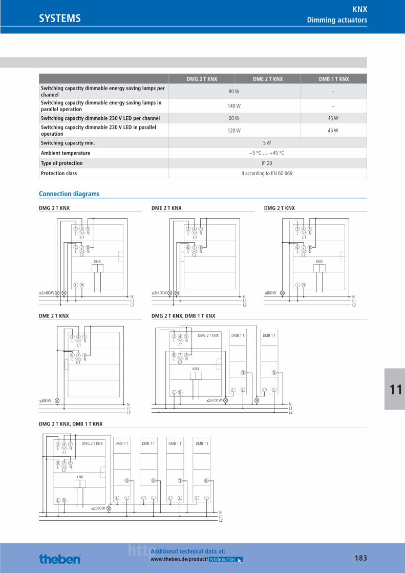
183httpAdditional technical data at:
www.theben.de/product/ Article number
Dimming actuatorsSYSTEMSKNX
11
DMG 2 T KNX DME 2 T KNX DMB 1 T KNX
Switching capacity dimmable energy saving lamps per channel
80 W –
Switching capacity dimmable energy saving lamps in parallel operation
140 W –
Switching capacity dimmable 230 V LED per channel 60 W 45 W
Switching capacity dimmable 230 V LED in parallel operation
120 W 45 W
Switching capacity min. 5 W
Ambient temperature –5 °C … +45 °C
Type of protection IP 20
Protection class II according to EN 60 669
Connection diagrams
DMG 2 T KNX
L N
KNX
C1
3 4 5L N
8
C2
6 7L N
≤2x400 WNL1L2
DME 2 T KNX
NL1L2
C1
3 4 5L N
8
C2
6 7L N
≤2x400 W
DMG 2 T KNX
L N
C1
3 4 5L N
8
C2
6 7L N
≤800 W
KNX
NL1L2
DME 2 T KNX
C1
3 4 5L N
8
C2
6 7L N
≤800 WNL1L2
DMG 2 T KNX, DMB 1 T KNX
L N
KNX
DMG 2 T KNX DMB 1 T DMB 1 T
C1
3 4 5L N
8
C2
6 7L N
≤2x700 W
N
LL´
N
LL´
NL1L2
DMG 2 T KNX, DMB 1 T KNX
L N
KNX
C1
3 4 5L N
8
C2
6 7L N
≤2000 W
N
LL´
N
LL´
N
LL´
N
LL´
DMG 2 T KNX DMB 1 T DMB 1 T DMB 1 T DMB 1 T
NL1L2
Catalogue_EN_2013.indb 183 16.01.13 17:24
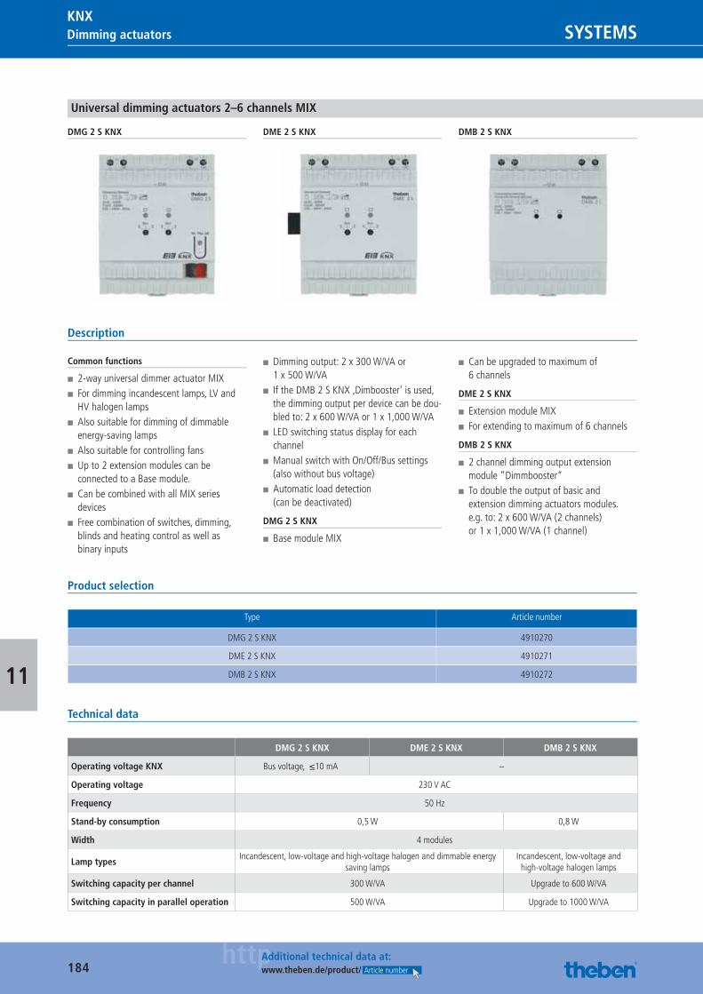
184httpAdditional technical data at:
www.theben.de/product/ Article number
Dimming actuators SYSTEMSKNX
11
Universal dimming actuators 2–6 channels MIX
DMG 2 S KNX DME 2 S KNX DMB 2 S KNX
Description
Common functions
■ 2-way universal dimmer actuator MIX ■ For dimming incandescent lamps, LV and HV halogen lamps
■ Also suitable for dimming of dimmable energy-saving lamps
■ Also suitable for controlling fans ■ Up to 2 extension modules can be connected to a Base module.
■ Can be combined with all MIX series devices
■ Free combination of switches, dimming, blinds and heating control as well as binary inputs
■ Dimming output: 2 x 300 W/VA or 1 x 500 W/VA
■ If the DMB 2 S KNX ‚Dimbooster‘ is used, the dimming output per device can be dou-bled to: 2 x 600 W/VA or 1 x 1,000 W/VA
■ LED switching status display for each channel
■ Manual switch with On/Off/Bus settings (also without bus voltage)
■ Automatic load detection (can be deactivated)
DMG 2 S KNX
■ Base module MIX
■ Can be upgraded to maximum of 6 channels
DME 2 S KNX
■ Extension module MIX ■ For extending to maximum of 6 channels
DMB 2 S KNX
■ 2 channel dimming output extension module ”Dimmbooster“
■ To double the output of basic and extension dimming actuators modules. e.g. to: 2 x 600 W/VA (2 channels) or 1 x 1,000 W/VA (1 channel)
Product selection
Type Article number
DMG 2 S KNX 4910270
DME 2 S KNX 4910271
DMB 2 S KNX 4910272
Technical data
DMG 2 S KNX DME 2 S KNX DMB 2 S KNX
Operating voltage KNX Bus voltage, ≤10 mA –
Operating voltage 230 V AC
Frequency 50 Hz
Stand-by consumption 0,5 W 0,8 W
Width 4 modules
Lamp typesIncandescent, low-voltage and high-voltage halogen and dimmable energy
saving lampsIncandescent, low-voltage and high-voltage halogen lamps
Switching capacity per channel 300 W/VA Upgrade to 600 W/VA
Switching capacity in parallel operation 500 W/VA Upgrade to 1000 W/VA
Catalogue_EN_2013.indb 184 16.01.13 17:24
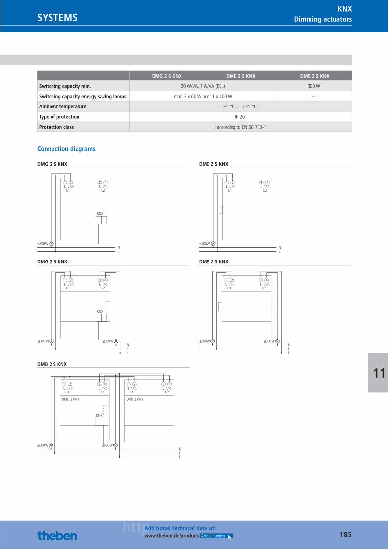
185httpAdditional technical data at:
www.theben.de/product/ Article number
Dimming actuatorsSYSTEMSKNX
11
DMG 2 S KNX DME 2 S KNX DMB 2 S KNX
Switching capacity min. 20 W/VA, 7 W/VA (ESL) 300 W
Switching capacity energy saving lamps max. 2 x 60 W oder 1 x 100 W –
Ambient temperature –5 °C … +45 °C
Type of protection IP 20
Protection class II according to EN 60 730-1
Connection diagrams
DMG 2 S KNX
C1
≤500 W
1 2
N
KNX
L
C2
3L L
4
DME 2 S KNX
C1
≤500 W
1 2
NL
C2
3L L
4
DMG 2 S KNX
C1
≤300 W ≤300 W
1L
2
N
KNX
LL
C2
3L
4
DME 2 S KNX
C1
≤300 W ≤300 W
1 2
NLL
C2
3L L
4
DMB 2 S KNX
C1
≤600 W ≤600 W
1 2
N
KNX
DMG 2 KNX DMB 2 KNX
LL
C2
3 4
C1
1 2
C2
3L L L L
4
Catalogue_EN_2013.indb 185 16.01.13 17:24
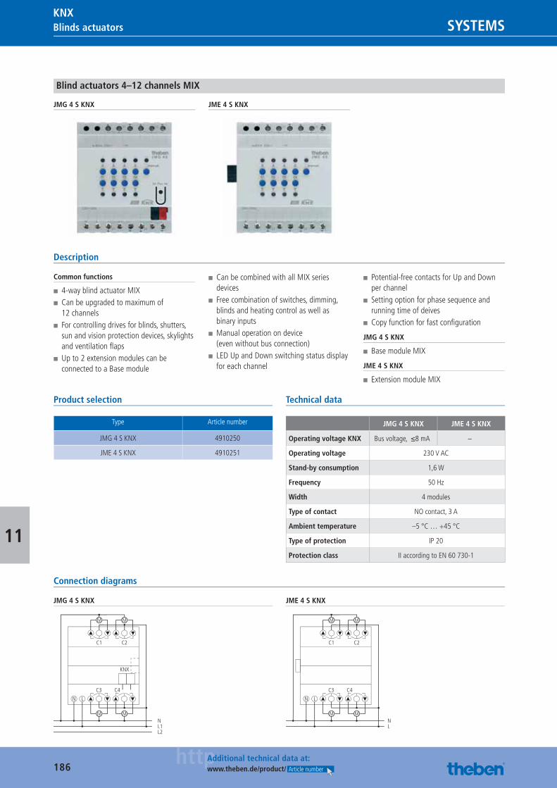
186httpAdditional technical data at:
www.theben.de/product/ Article number
Blinds actuators SYSTEMSKNX
11
Blind actuators 4–12 channels MIX
JMG 4 S KNX JME 4 S KNX
Description
Common functions
■ 4-way blind actuator MIX ■ Can be upgraded to maximum of 12 channels
■ For controlling drives for blinds, shutters, sun and vision protection devices, skylights and ventilation fl aps
■ Up to 2 extension modules can be connected to a Base module
■ Can be combined with all MIX series devices
■ Free combination of switches, dimming, blinds and heating control as well as binary inputs
■ Manual operation on device (even without bus connection)
■ LED Up and Down switching status display for each channel
■ Potential-free contacts for Up and Down per channel
■ Setting option for phase sequence and running time of deives
■ Copy function for fast confi guration
JMG 4 S KNX
■ Base module MIX
JME 4 S KNX
■ Extension module MIX
Product selection
Type Article number
JMG 4 S KNX 4910250
JME 4 S KNX 4910251
Technical data
JMG 4 S KNX JME 4 S KNX
Operating voltage KNX Bus voltage, ≤8 mA –
Operating voltage 230 V AC
Stand-by consumption 1,6 W
Frequency 50 Hz
Width 4 modules
Type of contact NO contact, 3 A
Ambient temperature –5 °C … +45 °C
Type of protection IP 20
Protection class II according to EN 60 730-1
Connection diagrams
JMG 4 S KNX
NL1L2
C3
M
M M
C1 C2
LN
C4
M
KNX
JME 4 S KNX
NL
C3
M
M M
C1 C2
LN
C4
M
Catalogue_EN_2013.indb 186 16.01.13 17:24
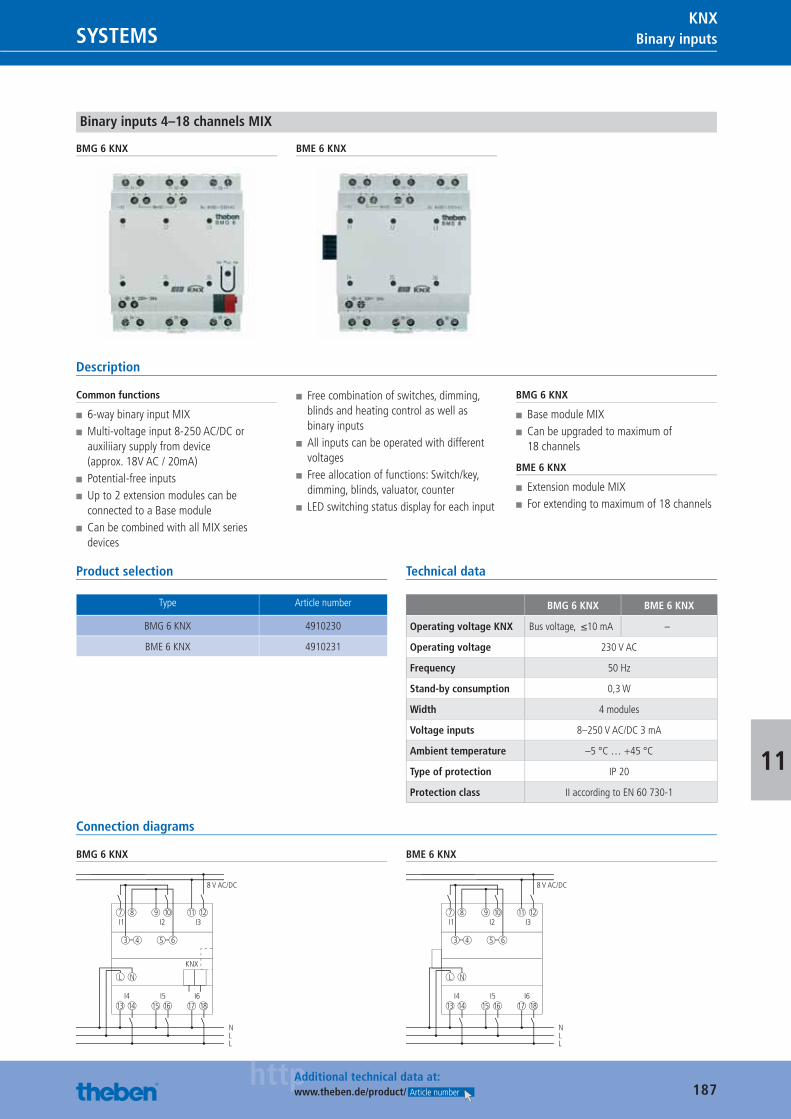
187httpAdditional technical data at:
www.theben.de/product/ Article number
Binary inputsSYSTEMSKNX
11
Binary inputs 4–18 channels MIX
BMG 6 KNX BME 6 KNX
Description
Common functions
■ 6-way binary input MIX ■ Multi-voltage input 8-250 AC/DC or auxiliiary supply from device (approx. 18V AC / 20mA)
■ Potential-free inputs ■ Up to 2 extension modules can be connected to a Base module
■ Can be combined with all MIX series devices
■ Free combination of switches, dimming, blinds and heating control as well as binary inputs
■ All inputs can be operated with different voltages
■ Free allocation of functions: Switch/key, dimming, blinds, valuator, counter
■ LED switching status display for each input
BMG 6 KNX
■ Base module MIX ■ Can be upgraded to maximum of 18 channels
BME 6 KNX
■ Extension module MIX ■ For extending to maximum of 18 channels
Product selection
Type Article number
BMG 6 KNX 4910230
BME 6 KNX 4910231
Technical data
BMG 6 KNX BME 6 KNX
Operating voltage KNX Bus voltage, ≤10 mA –
Operating voltage 230 V AC
Frequency 50 Hz
Stand-by consumption 0,3 W
Width 4 modules
Voltage inputs 8–250 V AC/DC 3 mA
Ambient temperature –5 °C … +45 °C
Type of protection IP 20
Protection class II according to EN 60 730-1
Connection diagrams
BMG 6 KNX
I1 I2 I3
L N
7 8
I4 I5 I6
9
1413 1615 1817
10
N
8 V AC/DC
LL
11 12
5 643
KNX
BME 6 KNX
I1 I2 I3
L N
7 8
I4 I5 I6
9
1413 1615 1817
10
N
8 V AC/DC
LL
11 12
5 643
Catalogue_EN_2013.indb 187 16.01.13 17:24
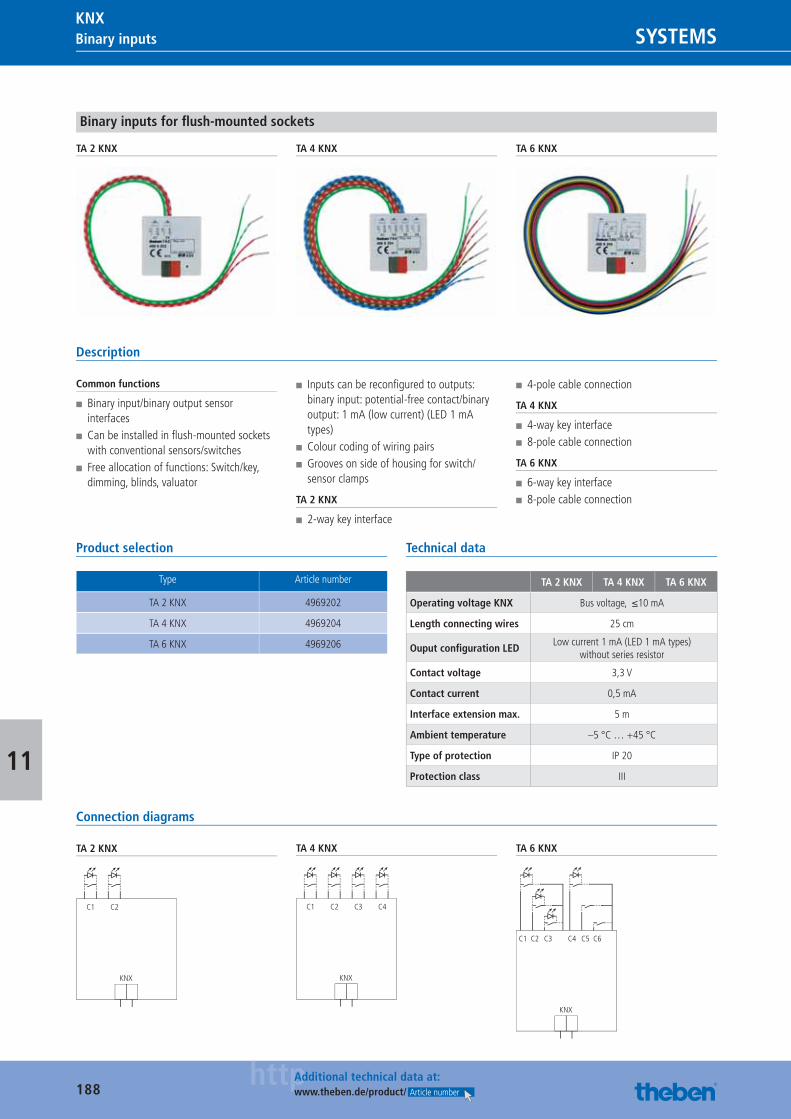
188httpAdditional technical data at:
www.theben.de/product/ Article number
Binary inputs SYSTEMSKNX
11
Binary inputs for fl ush-mounted sockets
TA 2 KNX TA 4 KNX TA 6 KNX
Description
Common functions
■ Binary input/binary output sensor interfaces
■ Can be installed in fl ush-mounted sockets with conventional sensors/switches
■ Free allocation of functions: Switch/key, dimming, blinds, valuator
■ Inputs can be reconfi gured to outputs: binary input: potential-free contact/binary output: 1 mA (low current) (LED 1 mA types)
■ Colour coding of wiring pairs ■ Grooves on side of housing for switch/sensor clamps
TA 2 KNX
■ 2-way key interface
■ 4-pole cable connection
TA 4 KNX
■ 4-way key interface ■ 8-pole cable connection
TA 6 KNX
■ 6-way key interface ■ 8-pole cable connection
Product selection
Type Article number
TA 2 KNX 4969202
TA 4 KNX 4969204
TA 6 KNX 4969206
Technical data
TA 2 KNX TA 4 KNX TA 6 KNX
Operating voltage KNX Bus voltage, ≤10 mA
Length connecting wires 25 cm
Ouput confi guration LEDLow current 1 mA (LED 1 mA types)
without series resistor
Contact voltage 3,3 V
Contact current 0,5 mA
Interface extension max. 5 m
Ambient temperature –5 °C … +45 °C
Type of protection IP 20
Protection class III
Connection diagrams
TA 2 KNX
C1 C2
KNX
TA 4 KNX
C1 C2 C3 C4
KNX
TA 6 KNX
C1 C2 C3 C4 C5 C6
KNX
Catalogue_EN_2013.indb 188 16.01.13 17:24
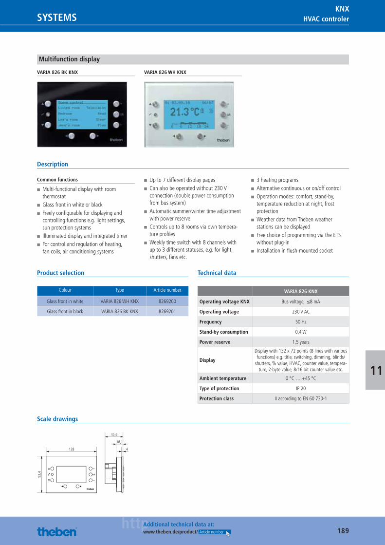
189httpAdditional technical data at:
www.theben.de/product/ Article number
HVAC controlerSYSTEMSKNX
11
Multifunction display
VARIA 826 BK KNX VARIA 826 WH KNX
Description
Common functions
■ Multi-functional display with room thermostat
■ Glass front in white or black ■ Freely confi gurable for displaying and controlling functions e.g. light settings, sun protection systems
■ Illuminated display and integrated timer ■ For control and regulation of heating, fan coils, air conditioning systems
■ Up to 7 different display pages ■ Can also be operated without 230 V connection (double power consumption from bus system)
■ Automatic summer/winter time adjustment with power reserve
■ Controls up to 8 rooms via own tempera-ture profi les
■ Weekly time switch with 8 channels with up to 3 different statuses, e.g. for light, shutters, fans etc.
■ 3 heating programs ■ Alternative continuous or on/off control ■ Operation modes: comfort, stand-by, temperature reduction at night, frost protection
■ Weather data from Theben weather stations can be displayed
■ Free choice of programming via the ETS without plug-in
■ Installation in fl ush-mounted socket
Product selection
Colour Type Article number
Glass front in white VARIA 826 WH KNX 8269200
Glass front in black VARIA 826 BK KNX 8269201
Technical data
VARIA 826 KNX
Operating voltage KNX Bus voltage, ≤8 mA
Operating voltage 230 V AC
Frequency 50 Hz
Stand-by consumption 0,4 W
Power reserve 1,5 years
Display
Display with 132 x 72 points (8 lines with various functions) e.g. title, switching, dimming, blinds/
shutters, % value, HVAC, counter value, tempera-ture, 2-byte value, 8/16 bit counter value etc.
Ambient temperature 0 °C … +45 °C
Type of protection IP 20
Protection class II according to EN 60 730-1
Scale drawings
128 4
18,1
45,6
93,4
Catalogue_EN_2013.indb 189 16.01.13 17:24
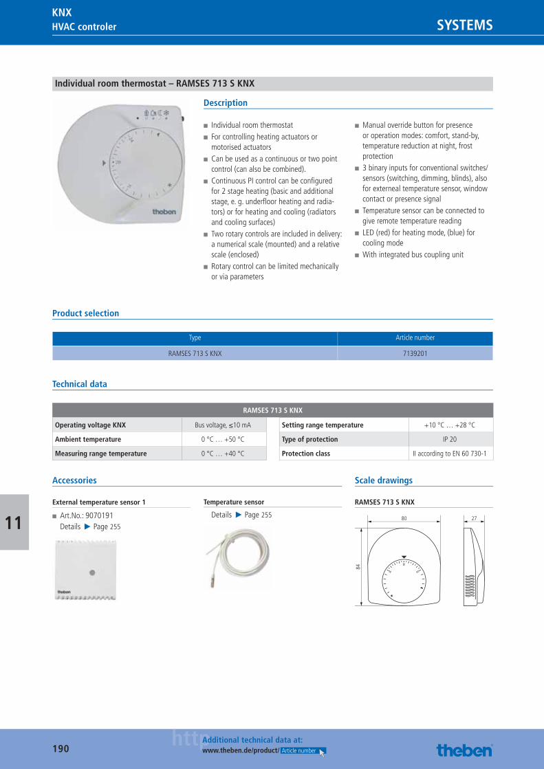
190httpAdditional technical data at:
www.theben.de/product/ Article number
HVAC controler SYSTEMSKNX
11
Individual room thermostat – RAMSES 713 S KNX
Description
■ Individual room thermostat ■ For controlling heating actuators or motorised actuators
■ Can be used as a continuous or two point control (can also be combined).
■ Continuous PI control can be confi gured for 2 stage heating (basic and additional stage, e. g. underfl oor heating and radia-tors) or for heating and cooling (radiators and cooling surfaces)
■ Two rotary controls are included in delivery: a numerical scale (mounted) and a relative scale (enclosed)
■ Rotary control can be limited mechanically or via parameters
■ Manual override button for presence or operation modes: comfort, stand-by, temperature reduction at night, frost protection
■ 3 binary inputs for conventional switches/sensors (switching, dimming, blinds), also for externeal temperature sensor, window contact or presence signal
■ Temperature sensor can be connected to give remote temperature reading
■ LED (red) for heating mode, (blue) for cooling mode
■ With integrated bus coupling unit
Product selection
Type Article number
RAMSES 713 S KNX 7139201
Technical data
RAMSES 713 S KNX
Operating voltage KNX Bus voltage, ≤10 mA
Ambient temperature 0 °C … +50 °C
Measuring range temperature 0 °C … +40 °C
Setting range temperature +10 °C … +28 °C
Type of protection IP 20
Protection class II according to EN 60 730-1
Accessories
External temperature sensor 1
■ Art.No.: 9070191Details ▶ Page 255
Temperature sensor
Details ▶ Page 255
Scale drawings
RAMSES 713 S KNX
80 27
84
Catalogue_EN_2013.indb 190 16.01.13 17:24
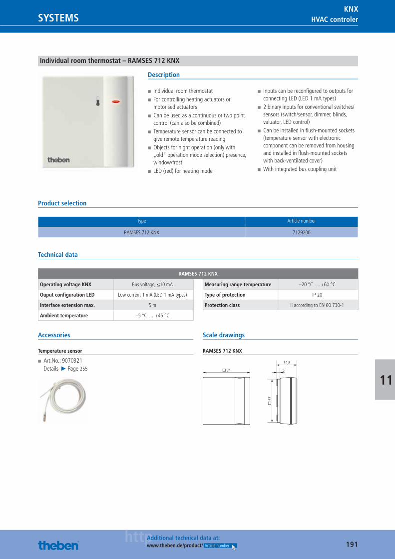
191httpAdditional technical data at:
www.theben.de/product/ Article number
HVAC controlerSYSTEMSKNX
11
Individual room thermostat – RAMSES 712 KNX
Description
■ Individual room thermostat ■ For controlling heating actuators or motorised actuators
■ Can be used as a continuous or two point control (can also be combined)
■ Temperature sensor can be connected to give remote temperature reading
■ Objects for night operation (only with „old“ operation mode selection) presence, window/frost.
■ LED (red) for heating mode
■ Inputs can be reconfi gured to outputs for connecting LED (LED 1 mA types)
■ 2 binary inputs for conventional switches/sensors (switch/sensor, dimmer, blinds, valuator, LED control)
■ Can be installed in fl ush-mounted sockets (temperature sensor with electronic component can be removed from housing and installed in fl ush-mounted sockets with back-ventilated cover)
■ With integrated bus coupling unit
Product selection
Type Article number
RAMSES 712 KNX 7129200
Technical data
RAMSES 712 KNX
Operating voltage KNX Bus voltage, ≤10 mA
Ouput confi guration LED Low current 1 mA (LED 1 mA types)
Interface extension max. 5 m
Ambient temperature –5 °C … +45 °C
Measuring range temperature –20 °C … +60 °C
Type of protection IP 20
Protection class II according to EN 60 730-1
Accessories
Temperature sensor
■ Art.No.: 9070321Details ▶ Page 255
Scale drawings
RAMSES 712 KNX
� 74
� 6
7
5
30,8
Catalogue_EN_2013.indb 191 16.01.13 17:24
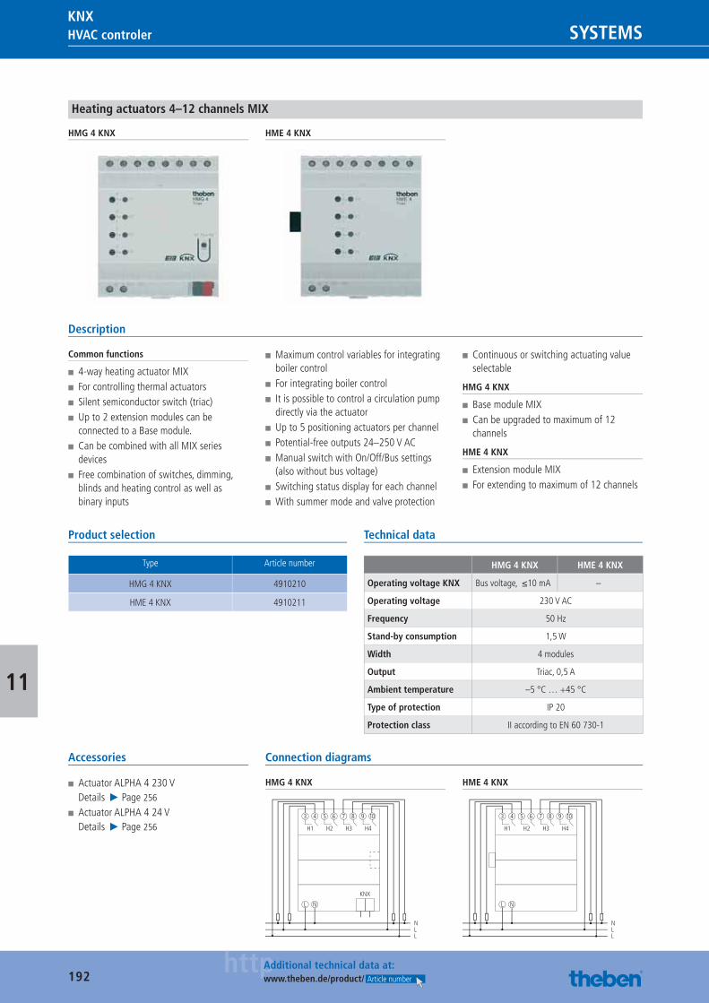
192httpAdditional technical data at:
www.theben.de/product/ Article number
HVAC controler SYSTEMSKNX
11
Heating actuators 4–12 channels MIX
HMG 4 KNX HME 4 KNX
Description
Common functions
■ 4-way heating actuator MIX ■ For controlling thermal actuators ■ Silent semiconductor switch (triac) ■ Up to 2 extension modules can be connected to a Base module.
■ Can be combined with all MIX series devices
■ Free combination of switches, dimming, blinds and heating control as well as binary inputs
■ Maximum control variables for integrating boiler control
■ For integrating boiler control ■ It is possible to control a circulation pump directly via the actuator
■ Up to 5 positioning actuators per channel ■ Potential-free outputs 24–250 V AC ■ Manual switch with On/Off/Bus settings (also without bus voltage)
■ Switching status display for each channel ■ With summer mode and valve protection
■ Continuous or switching actuating value selectable
HMG 4 KNX
■ Base module MIX ■ Can be upgraded to maximum of 12 channels
HME 4 KNX
■ Extension module MIX ■ For extending to maximum of 12 channels
Product selection
Type Article number
HMG 4 KNX 4910210
HME 4 KNX 4910211
Technical data
HMG 4 KNX HME 4 KNX
Operating voltage KNX Bus voltage, ≤10 mA –
Operating voltage 230 V AC
Frequency 50 Hz
Stand-by consumption 1,5 W
Width 4 modules
Output Triac, 0,5 A
Ambient temperature –5 °C … +45 °C
Type of protection IP 20
Protection class II according to EN 60 730-1
Accessories
■ Actuator ALPHA 4 230 VDetails ▶ Page 256
■ Actuator ALPHA 4 24 VDetails ▶ Page 256
Connection diagrams
HMG 4 KNX
H1
L N
3 4 5 6 7 8
NLL
H2 H3 H4
9 10
KNX
HME 4 KNX
H1
L N
3 4 5 6 7 8
NLL
H2 H3 H4
9 10
Catalogue_EN_2013.indb 192 16.01.13 17:24
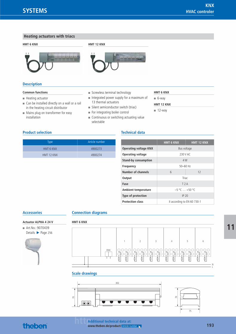
193httpAdditional technical data at:
www.theben.de/product/ Article number
HVAC controlerSYSTEMSKNX
11
Heating actuators with triacs
HMT 6 KNX HMT 12 KNX
Description
Common functions
■ Heating actuator ■ Can be installed directly on a wall or a rail in the heating circuit distributor
■ Mains plug on transformer for easy installation
■ Screwless terminal technology ■ Integrated power supply for a maximum of 13 thermal actuators
■ Silent semiconductor switch (triac) ■ For integrating boiler control ■ Continuous or switching actuating value selectable
HMT 6 KNX
■ 6-way
HMT 12 KNX
■ 12-way
Product selection
Type Article number
HMT 6 KNX 4900273
HMT 12 KNX 4900274
Technical data
HMT 6 KNX HMT 12 KNX
Operating voltage KNX Bus voltage
Operating voltage 230 V AC
Stand-by consumption 4 W
Frequency 50–60 Hz
Number of channels 6 12
Output Triac
Fuse T 2 A
Ambient temperature –5 °C … +50 °C
Type of protection IP 20
Protection class II according to EN 60 730-1
Accessories
Actuator ALPHA 4 24 V
■ Art.No.: 9070439Details ▶ Page 256
Connection diagrams
HMT 6 KNX
1
NL
2 3 4 5 6
KNX
Scale drawings
302
70
75
70
Catalogue_EN_2013.indb 193 16.01.13 17:24
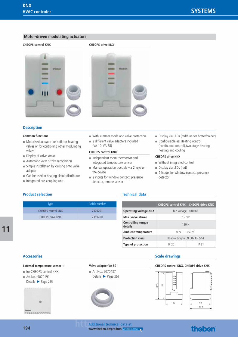
194httpAdditional technical data at:
www.theben.de/product/ Article number
HVAC controler SYSTEMSKNX
11
Motor-driven modulating actuators
CHEOPS control KNX CHEOPS drive KNX
Description
Common functions
■ Motorised actuator for radiator heating valves or for controlling other modulating valves
■ Display of valve stroke ■ Automatic valve stroke recognition ■ Simple installation by clicking onto valve adapter
■ Can be used in heating circuit distributor ■ Integrated bus coupling unit
■ With summer mode and valve protection ■ 2 different valve adapters included (VA 10, VA 78)
CHEOPS control KNX
■ Independent room thermostat and integrated temperature sensor
■ Manual operation possible via 2 keys on the device
■ 2 inputs for window contact, presence detector, remote sensor
■ Display via LEDs (red/blue for hotter/colder) ■ Confi gurable as: Heating control (continuous control),two stage heating, heating and cooling
CHEOPS drive KNX
■ Without integrated control ■ Display via LEDs (red) ■ 2 inputs for window contact, presence detector
Product selection
Type Article number
CHEOPS control KNX 7329201
CHEOPS drive KNX 7319200
Technical data
CHEOPS control KNX CHEOPS drive KNX
Operating voltage KNX Bus voltage, ≤10 mA
Max. valve stroke 7,5 mm
Controlling torque details
120 N
Ambient temperature 0 °C … +50 °C
Protection class III according to EN 60730-2-14
Type of protection IP 20 IP 21
Accessories
External temperature sensor 1
■ for CHEOPS control KNX ■ Art.No.: 9070191Details ▶ Page 255
Valve adapter VA 80
■ Art.No.: 9070437Details ▶ Page 256
Scale drawings
CHEOPS control KNX, CHEOPS drive KNX
82,5 80
62
64,7
50
Catalogue_EN_2013.indb 194 16.01.13 17:24
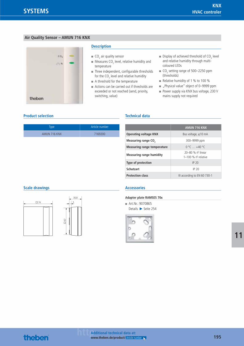
195httpAdditional technical data at:
www.theben.de/product/ Article number
HVAC controlerSYSTEMSKNX
11
Air Quality Sensor – AMUN 716 KNX
Description
■ CO2 air quality sensor ■ Measures CO2 level, relative humidity and temperature
■ Three independent, confi gurable thresholds for the CO2 level and relative humidity
■ A threshold for the temperature ■ Actions can be carried out if thresholds are exceeded or not reached (send, priority, switching, value)
■ Display of achieved threshold of CO2 level and relative humidity through multi-coloured LEDs
■ CO2 setting range of 500–2250 ppm (thresholds)
■ Relative humidity of 1 % to 100 % ■ „Physical value“ object of 0–9999 ppm ■ Power supply via KNX bus voltage, 230 V mains supply not required
Product selection
Type Article number
AMUN 716 KNX 7169200
Technical data
AMUN 716 KNX
Operating voltage KNX Bus voltage, ≤10 mA
Measuring range CO2 300–9999 ppm
Measuring range temperature 0 °C … +40 °C
Measuring range humidity20–80 % rF linear
1–100 % rF relative
Type of protection IP 20
Schutzart IP 20
Protection class III according to EN 60 730-1
Scale drawings
� 74
� 6
7
5
30,8
Accessories
Adapter plate RAMSES 70x
■ Art.Nr.: 9070865Details ▶ Seite 254
Catalogue_EN_2013.indb 195 16.01.13 17:24
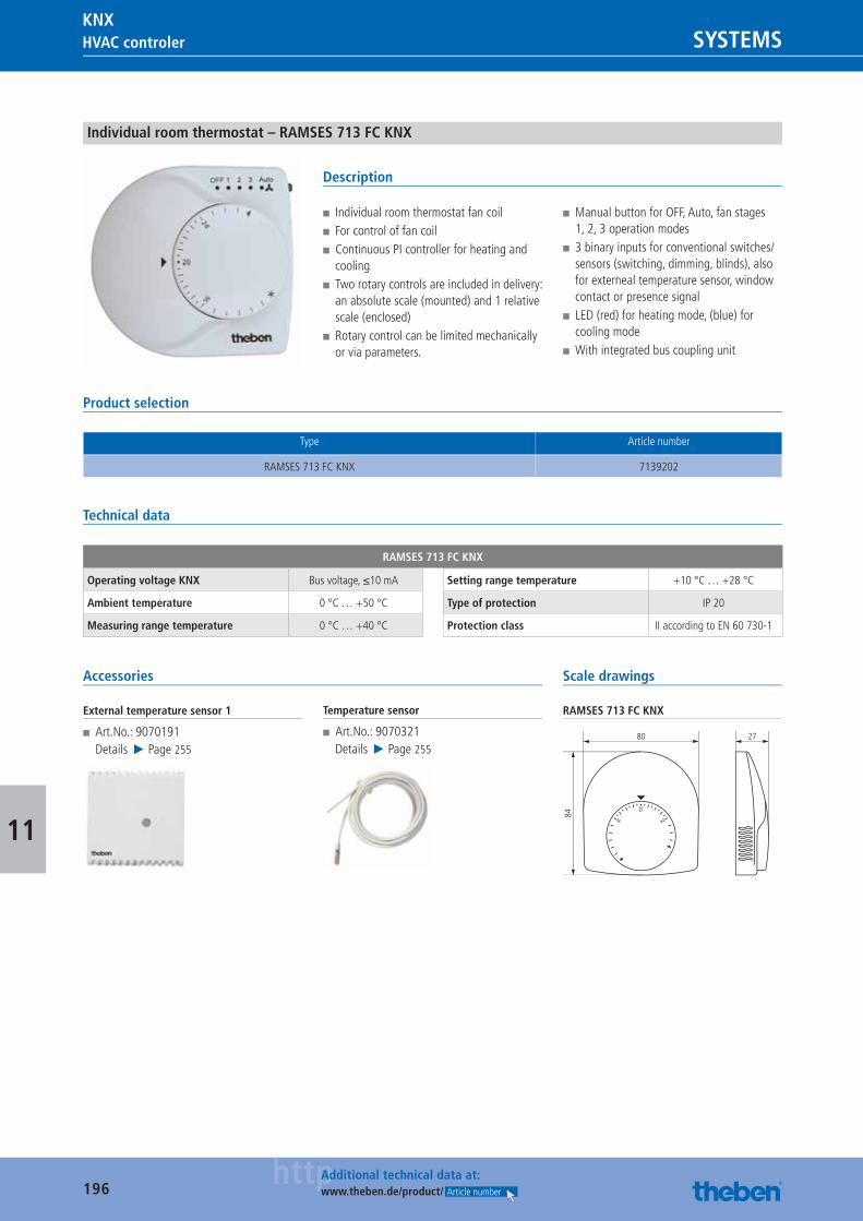
196httpAdditional technical data at:
www.theben.de/product/ Article number
HVAC controler SYSTEMSKNX
11
Individual room thermostat – RAMSES 713 FC KNX
Description
■ Individual room thermostat fan coil ■ For control of fan coil ■ Continuous PI controller for heating and cooling
■ Two rotary controls are included in delivery: an absolute scale (mounted) and 1 relative scale (enclosed)
■ Rotary control can be limited mechanically or via parameters.
■ Manual button for OFF, Auto, fan stages 1, 2, 3 operation modes
■ 3 binary inputs for conventional switches/sensors (switching, dimming, blinds), also for externeal temperature sensor, window contact or presence signal
■ LED (red) for heating mode, (blue) for cooling mode
■ With integrated bus coupling unit
Product selection
Type Article number
RAMSES 713 FC KNX 7139202
Technical data
RAMSES 713 FC KNX
Operating voltage KNX Bus voltage, ≤10 mA
Ambient temperature 0 °C … +50 °C
Measuring range temperature 0 °C … +40 °C
Setting range temperature +10 °C … +28 °C
Type of protection IP 20
Protection class II according to EN 60 730-1
Accessories
External temperature sensor 1
■ Art.No.: 9070191Details ▶ Page 255
Temperature sensor
■ Art.No.: 9070321Details ▶ Page 255
Scale drawings
RAMSES 713 FC KNX
80 27
84
Catalogue_EN_2013.indb 196 16.01.13 17:24
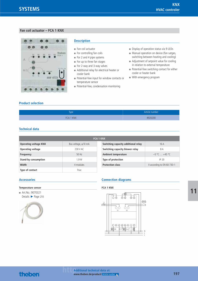
197httpAdditional technical data at:
www.theben.de/product/ Article number
HVAC controlerSYSTEMSKNX
11
Fan coil actuator – FCA 1 KNX
Description
■ Fan coil actuator ■ For controlling fan coils ■ For 2 and 4 pipe systems ■ For up to three fan stages ■ For 2-way and 3-way valves ■ Additional relay for electrical heater or cooler bank
■ Potential-free input for window contacts or temperature sensor
■ Potential-free, condensation monitoring
■ Display of operation status via 9 LEDs ■ Manual operation on device (fan satges, switching between heating and cooling)
■ Adjustment of setpoint value for cooling in relation to external temperature
■ Potential-free switching contact for either cooler or heater bank
■ With emergency program
Product selection
Type Article number
FCA 1 KNX 4920200
Technical data
FCA 1 KNX
Operating voltage KNX Bus voltage, ≤10 mA
Operating voltage 230 V AC
Frequency 50 Hz
Stand-by consumption 1,9 W
Width 4 modules
Type of contact Triac
Switching capacity additional relay 16 A
Switching capacity blower relay 8 A
Ambient temperature –5 °C … +45 °C
Type of protection IP 20
Protection class II according to EN 60 730-1
Accessories
Temperature sensor
■ Art.No.: 9070321Details ▶ Page 255
Connection diagrams
FCA 1 KNX
C-
+C°
C+ LC LH H+ H-
L
M
N S1 S2
NLL
L C1
S3 LS
E1 E2
M
Catalogue_EN_2013.indb 197 16.01.13 17:24
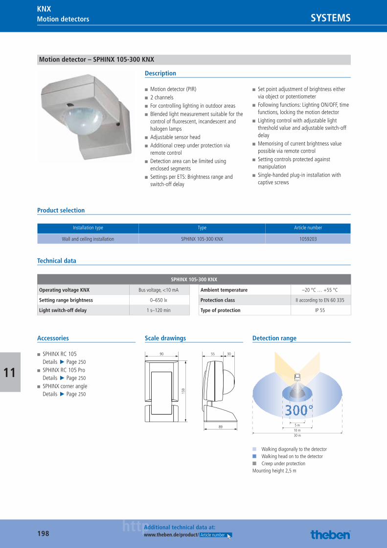
198httpAdditional technical data at:
www.theben.de/product/ Article number
Motion detectors SYSTEMSKNX
11
Motion detector – SPHINX 105-300 KNX
Description
■ Motion detector (PIR) ■ 2 channels ■ For controlling lighting in outdoor areas ■ Blended light measurement suitable for the control of fl uorescent, incandescent and halogen lamps
■ Adjustable sensor head ■ Additional creep under protection via remote control
■ Detection area can be limited using enclosed segments
■ Settings per ETS: Brightness range and switch-off delay
■ Set point adjustment of brightness either via object or potentiometer
■ Following functions: Lighting ON/OFF, time functions, locking the motion detector
■ Lighting control with adjustable light threshold value and adjustable switch-off delay
■ Memorising of current brightness value possible via remote control
■ Setting controls protected against manipulation
■ Single-handed plug-in installation with captive screws
Product selection
Installation type Type Article number
Wall and ceiling installation SPHINX 105-300 KNX 1059203
Technical data
SPHINX 105-300 KNX
Operating voltage KNX Bus voltage, <10 mA
Setting range brightness 0–650 lx
Light switch-off delay 1 s–120 min
Ambient temperature –20 °C … +55 °C
Protection class II according to EN 60 335
Type of protection IP 55
Accessories
■ SPHINX RC 105Details ▶ Page 250
■ SPHINX RC 105 ProDetails ▶ Page 250
■ SPHINX corner angleDetails ▶ Page 250
Scale drawings
159
90
89
55 30
Detection range
300°5 m
10 m30 m
■ Walking diagonally to the detector■ Walking head on to the detector■ Creep under protectionMounting height 2,5 m
Catalogue_EN_2013.indb 198 16.01.13 17:24
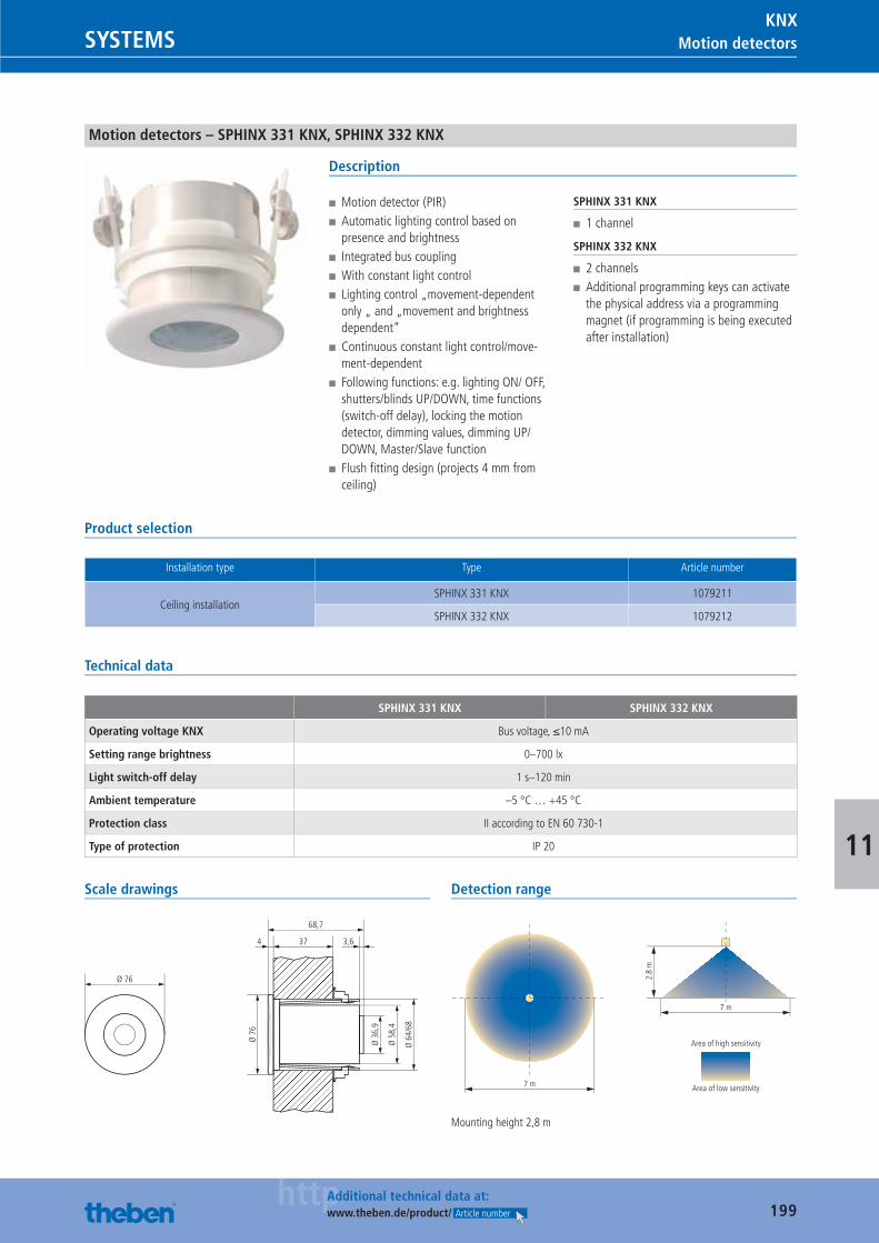
199httpAdditional technical data at:
www.theben.de/product/ Article number
Motion detectorsSYSTEMSKNX
11
Motion detectors – SPHINX 331 KNX, SPHINX 332 KNX
Description
■ Motion detector (PIR) ■ Automatic lighting control based on presence and brightness
■ Integrated bus coupling ■ With constant light control ■ Lighting control „movement-dependent only „ and „movement and brightness dependent“
■ Continuous constant light control/move-ment-dependent
■ Following functions: e.g. lighting ON/ OFF, shutters/blinds UP/DOWN, time functions (switch-off delay), locking the motion detector, dimming values, dimming UP/DOWN, Master/Slave function
■ Flush fi tting design (projects 4 mm from ceiling)
SPHINX 331 KNX
■ 1 channel
SPHINX 332 KNX
■ 2 channels ■ Additional programming keys can activate the physical address via a programming magnet (if programming is being executed after installation)
Product selection
Installation type Type Article number
Ceiling installationSPHINX 331 KNX 1079211
SPHINX 332 KNX 1079212
Technical data
SPHINX 331 KNX SPHINX 332 KNX
Operating voltage KNX Bus voltage, ≤10 mA
Setting range brightness 0–700 lx
Light switch-off delay 1 s–120 min
Ambient temperature –5 °C … +45 °C
Protection class II according to EN 60 730-1
Type of protection IP 20
Scale drawings
Ø 76
37
68,7
4 3,6
Ø 3
6,9
Ø 5
8,4
Ø 6
4/68
Ø 7
6
Detection range
Mounting height 2,8 m
Catalogue_EN_2013.indb 199 16.01.13 17:24
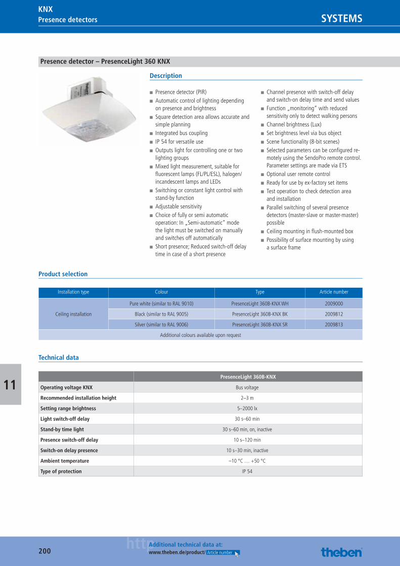
200httpAdditional technical data at:
www.theben.de/product/ Article number
Presence detectors SYSTEMSKNX
11
Presence detector – PresenceLight 360 KNX
Description
■ Presence detector (PIR) ■ Automatic control of lighting depending on presence and brightness
■ Square detection area allows accurate and simple planning
■ Integrated bus coupling ■ IP 54 for versatile use ■ Outputs light for controlling one or two lighting groups
■ Mixed light measurement, suitable for fl uorescent lamps (FL/PL/ESL), halogen/incandescent lamps and LEDs
■ Switching or constant light control with stand-by function
■ Adjustable sensitivity ■ Choice of fully or semi automatic operation: In „Semi-automatic“ mode the light must be switched on manually and switches off automatically
■ Short presence; Reduced switch-off delay time in case of a short presence
■ Channel presence with switch-off delay and switch-on delay time and send values
■ Function „monitoring“ with reduced sensitivity only to detect walking persons
■ Channel brightness (Lux) ■ Set brightness level via bus object ■ Scene functionality (8-bit scenes) ■ Selected parameters can be confi gured re-motely using the SendoPro remote control. Parameter settings are made via ETS
■ Optional user remote control ■ Ready for use by ex-factory set items ■ Test operation to check detection area and installation
■ Parallel switching of several presence detectors (master-slave or master-master) possible
■ Ceiling mounting in fl ush-mounted box ■ Possibility of surface mounting by using a surface frame
Product selection
Installation type Colour Type Article number
Ceiling installation
Pure white (similar to RAL 9010) PresenceLight 360B-KNX WH 2009000
Black (similar to RAL 9005) PresenceLight 360B-KNX BK 2009812
Silver (similar to RAL 9006) PresenceLight 360B-KNX SR 2009813
Additional colours available upon request
Technical data
PresenceLight 360B-KNX
Operating voltage KNX Bus voltage
Recommended installation height 2–3 m
Setting range brightness 5–2000 lx
Light switch-off delay 30 s–60 min
Stand-by time light 30 s–60 min, on, inactive
Presence switch-off delay 10 s–120 min
Switch-on delay presence 10 s–30 min, inactive
Ambient temperature –10 °C … +50 °C
Type of protection IP 54
Catalogue_EN_2013.indb 200 16.01.13 17:24
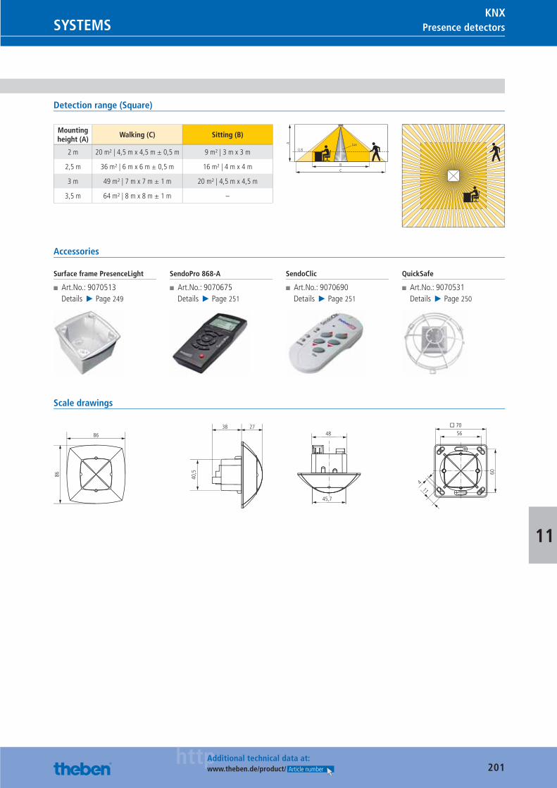
201httpAdditional technical data at:
www.theben.de/product/ Article number
Presence detectorsSYSTEMSKNX
11
Detection range (Square)
Mounting height (A)
Walking (C) Sitting (B)
2 m 20 m² | 4,5 m x 4,5 m ± 0,5 m 9 m² | 3 m x 3 m
2,5 m 36 m² | 6 m x 6 m ± 0,5 m 16 m² | 4 m x 4 m
3 m 49 m² | 7 m x 7 m ± 1 m 20 m² | 4,5 m x 4,5 m
3,5 m 64 m² | 8 m x 8 m ± 1 m –
BC
0.8
A Lux
Accessories
Surface frame PresenceLight
■ Art.No.: 9070513Details ▶ Page 249
SendoPro 868-A
■ Art.No.: 9070675Details ▶ Page 251
SendoClic
■ Art.No.: 9070690Details ▶ Page 251
QuickSafe
■ Art.No.: 9070531Details ▶ Page 250
Scale drawings
86
86
114
40,5
38 27
60
� 70
5648
45,7
Catalogue_EN_2013.indb 201 16.01.13 17:24
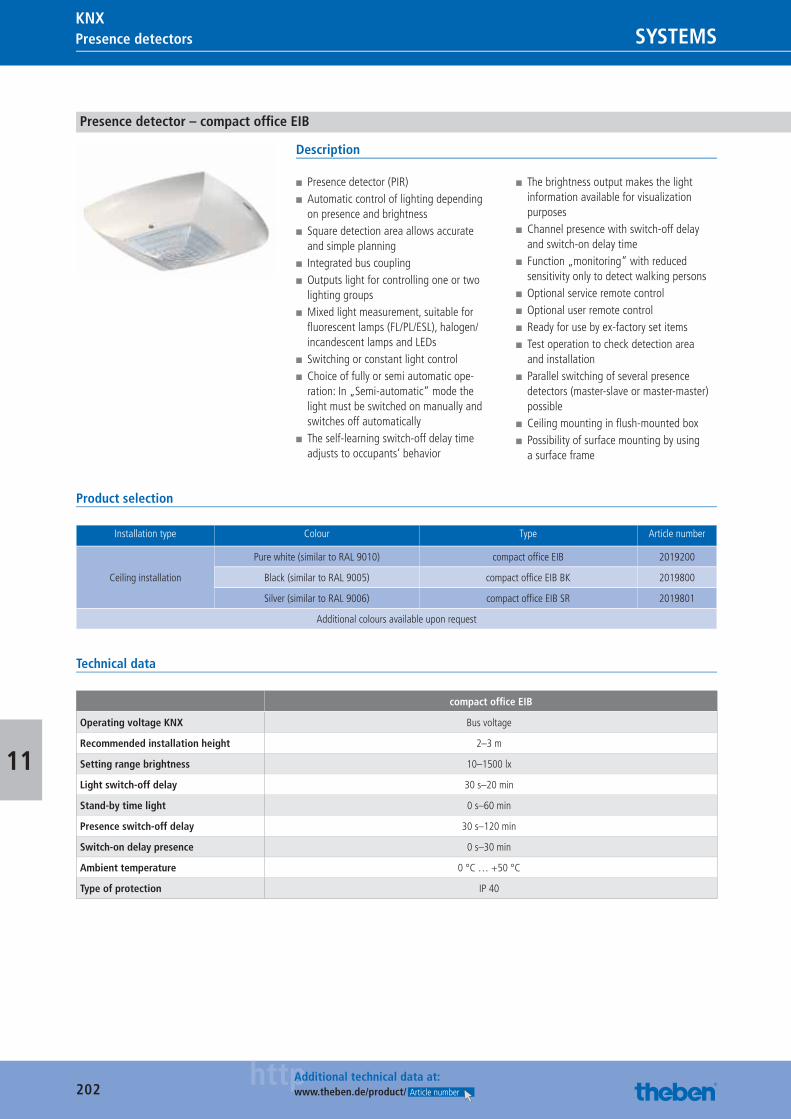
202httpAdditional technical data at:
www.theben.de/product/ Article number
Presence detectors SYSTEMSKNX
11
Presence detector – compact offi ce EIB
Description
■ Presence detector (PIR) ■ Automatic control of lighting depending on presence and brightness
■ Square detection area allows accurate and simple planning
■ Integrated bus coupling ■ Outputs light for controlling one or two lighting groups
■ Mixed light measurement, suitable for fl uorescent lamps (FL/PL/ESL), halogen/incandescent lamps and LEDs
■ Switching or constant light control ■ Choice of fully or semi automatic ope-ration: In „Semi-automatic“ mode the light must be switched on manually and switches off automatically
■ The self-learning switch-off delay time adjusts to occupants‘ behavior
■ The brightness output makes the light information available for visualization purposes
■ Channel presence with switch-off delay and switch-on delay time
■ Function „monitoring“ with reduced sensitivity only to detect walking persons
■ Optional service remote control ■ Optional user remote control ■ Ready for use by ex-factory set items ■ Test operation to check detection area and installation
■ Parallel switching of several presence detectors (master-slave or master-master) possible
■ Ceiling mounting in fl ush-mounted box ■ Possibility of surface mounting by using a surface frame
Product selection
Installation type Colour Type Article number
Ceiling installation
Pure white (similar to RAL 9010) compact offi ce EIB 2019200
Black (similar to RAL 9005) compact offi ce EIB BK 2019800
Silver (similar to RAL 9006) compact offi ce EIB SR 2019801
Additional colours available upon request
Technical data
compact offi ce EIB
Operating voltage KNX Bus voltage
Recommended installation height 2–3 m
Setting range brightness 10–1500 lx
Light switch-off delay 30 s–20 min
Stand-by time light 0 s–60 min
Presence switch-off delay 30 s–120 min
Switch-on delay presence 0 s–30 min
Ambient temperature 0 °C … +50 °C
Type of protection IP 40
Catalogue_EN_2013.indb 202 16.01.13 17:24
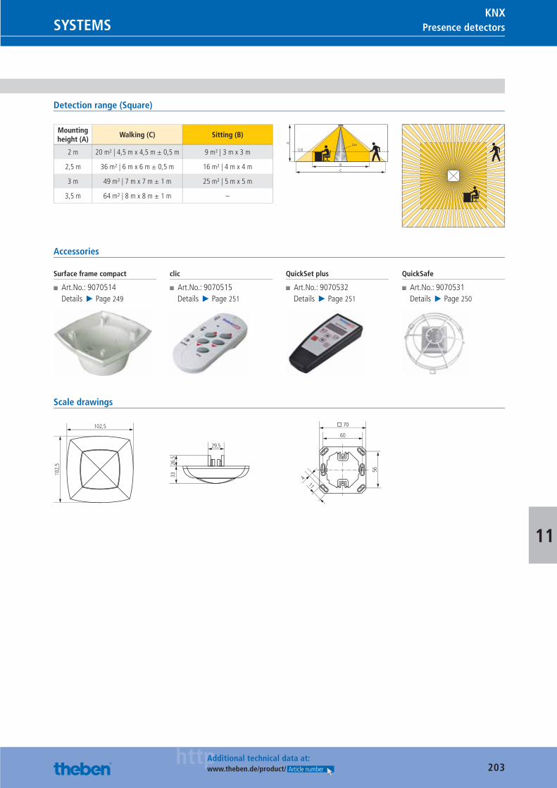
203httpAdditional technical data at:
www.theben.de/product/ Article number
Presence detectorsSYSTEMSKNX
11
Detection range (Square)
Mounting height (A)
Walking (C) Sitting (B)
2 m 20 m² | 4,5 m x 4,5 m ± 0,5 m 9 m² | 3 m x 3 m
2,5 m 36 m² | 6 m x 6 m ± 0,5 m 16 m² | 4 m x 4 m
3 m 49 m² | 7 m x 7 m ± 1 m 25 m² | 5 m x 5 m
3,5 m 64 m² | 8 m x 8 m ± 1 m –
BC
0.8
A Lux
Accessories
Surface frame compact
■ Art.No.: 9070514Details ▶ Page 249
clic
■ Art.No.: 9070515Details ▶ Page 251
QuickSet plus
■ Art.No.: 9070532Details ▶ Page 251
QuickSafe
■ Art.No.: 9070531Details ▶ Page 250
Scale drawings
29,5
102,
5 26,5
33
102,5
60
� 70
56
114
Catalogue_EN_2013.indb 203 16.01.13 17:24
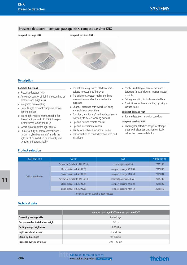
204httpAdditional technical data at:
www.theben.de/product/ Article number
Presence detectors SYSTEMSKNX
11
Presence detectors – compact passage KNX, compact passimo KNX
compact passage KNX compact passimo KNX
Description
Common functions
■ Presence detector (PIR) ■ Automatic control of lighting depending on presence and brightness
■ Integrated bus coupling ■ Outputs light for controlling one or two lighting groups
■ Mixed light measurement, suitable for fl uorescent lamps (FL/PL/ESL), halogen/incandescent lamps and LEDs
■ Switching or constant light control ■ Choice of fully or semi automatic ope-ration: In „Semi-automatic“ mode the light must be switched on manually and switches off automatically
■ The self-learning switch-off delay time adjusts to occupants‘ behavior
■ The brightness output makes the light information available for visualization purposes
■ Channel presence with switch-off delay and switch-on delay time
■ Function „monitoring“ with reduced sensi-tivity only to detect walking persons
■ Optional service remote control ■ Optional user remote control ■ Ready for use by ex-factory set items ■ Test operation to check detection area and installation
■ Parallel switching of several presence detectors (master-slave or master-master) possible
■ Ceiling mounting in fl ush-mounted box ■ Possibility of surface mounting by using a surface frame
compact passage KNX
■ Square detection range for corridors
compact passimo KNX
■ Rectangular detection range for storage areas with clear demarcation vertically below the presence detector
Product selection
Installation type Colour Type Article number
Ceiling installation
Pure white (similar to RAL 9010) compact passage KNX 2019290
Black (similar to RAL 9005) compact passage KNX BK 2019803
Silver (similar to RAL 9006) compact passage KNX SR 2019804
Pure white (similar to RAL 9010) compact passimo KNX WH 2019280
Black (similar to RAL 9005) compact passimo KNX BK 2019809
Silver (similar to RAL 9006) compact passimo KNX SR 2019810
Additional colours available upon request
Technical data
compact passage KNX/compact passimo KNX
Operating voltage KNX Bus voltage
Recommended installation height 2–3 m
Setting range brightness 10–1500 lx
Light switch-off delay 30 s–20 min
Stand-by time light 0 s–60 min
Presence switch-off delay 30 s–120 min
Catalogue_EN_2013.indb 204 16.01.13 17:24
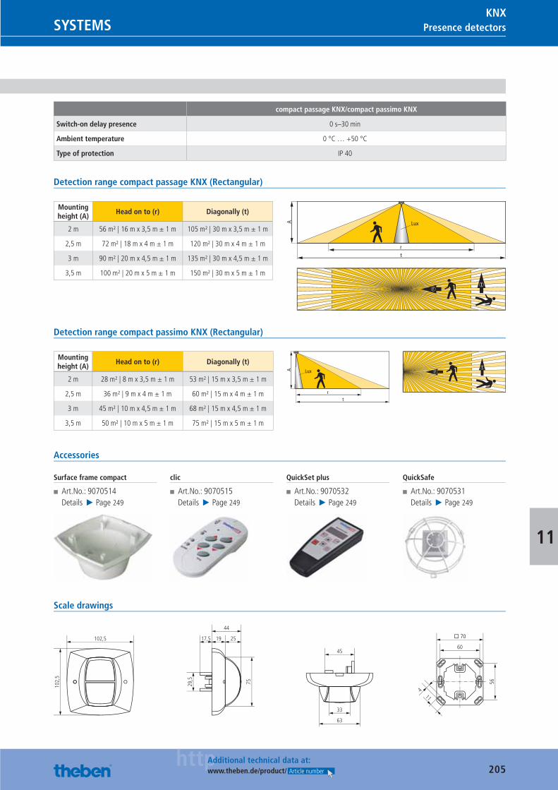
205httpAdditional technical data at:
www.theben.de/product/ Article number
Presence detectorsSYSTEMSKNX
11
compact passage KNX/compact passimo KNX
Switch-on delay presence 0 s–30 min
Ambient temperature 0 °C … +50 °C
Type of protection IP 40
Detection range compact passage KNX (Rectangular)
Mounting height (A)
Head on to (r) Diagonally (t)
2 m 56 m² | 16 m x 3,5 m ± 1 m 105 m² | 30 m x 3,5 m ± 1 m
2,5 m 72 m² | 18 m x 4 m ± 1 m 120 m² | 30 m x 4 m ± 1 m
3 m 90 m² | 20 m x 4,5 m ± 1 m 135 m² | 30 m x 4,5 m ± 1 m
3,5 m 100 m² | 20 m x 5 m ± 1 m 150 m² | 30 m x 5 m ± 1 m
rt
A Lux
tr
Detection range compact passimo KNX (Rectangular)
Mounting height (A)
Head on to (r) Diagonally (t)
2 m 28 m² | 8 m x 3,5 m ± 1 m 53 m² | 15 m x 3,5 m ± 1 m
2,5 m 36 m² | 9 m x 4 m ± 1 m 60 m² | 15 m x 4 m ± 1 m
3 m 45 m² | 10 m x 4,5 m ± 1 m 68 m² | 15 m x 4,5 m ± 1 m
3,5 m 50 m² | 10 m x 5 m ± 1 m 75 m² | 15 m x 5 m ± 1 m
rt
A Luxt
r
Accessories
Surface frame compact
■ Art.No.: 9070514Details ▶ Page 249
clic
■ Art.No.: 9070515Details ▶ Page 249
QuickSet plus
■ Art.No.: 9070532Details ▶ Page 249
QuickSafe
■ Art.No.: 9070531Details ▶ Page 249
Scale drawings
63
33
45
17,5
44
19
29,5
75
102,
5
102,5 25
60
� 70
56
114
Catalogue_EN_2013.indb 205 16.01.13 17:24
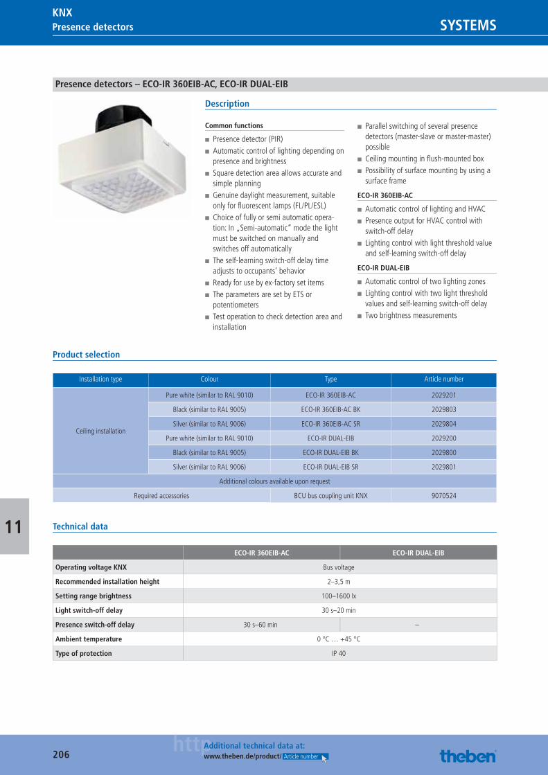
206httpAdditional technical data at:
www.theben.de/product/ Article number
Presence detectors SYSTEMSKNX
11
Presence detectors – ECO-IR 360EIB-AC, ECO-IR DUAL-EIB
Description
Common functions
■ Presence detector (PIR) ■ Automatic control of lighting depending on presence and brightness
■ Square detection area allows accurate and simple planning
■ Genuine daylight measurement, suitable only for fl uorescent lamps (FL/PL/ESL)
■ Choice of fully or semi automatic opera-tion: In „Semi-automatic“ mode the light must be switched on manually and switches off automatically
■ The self-learning switch-off delay time adjusts to occupants’ behavior
■ Ready for use by ex-factory set items ■ The parameters are set by ETS or potentiometers
■ Test operation to check detection area and installation
■ Parallel switching of several presence detectors (master-slave or master-master) possible
■ Ceiling mounting in fl ush-mounted box ■ Possibility of surface mounting by using a surface frame
ECO-IR 360EIB-AC
■ Automatic control of lighting and HVAC ■ Presence output for HVAC control with switch-off delay
■ Lighting control with light threshold value and self-learning switch-off delay
ECO-IR DUAL-EIB
■ Automatic control of two lighting zones ■ Lighting control with two light threshold values and self-learning switch-off delay
■ Two brightness measurements
Product selection
Installation type Colour Type Article number
Ceiling installation
Pure white (similar to RAL 9010) ECO-IR 360EIB-AC 2029201
Black (similar to RAL 9005) ECO-IR 360EIB-AC BK 2029803
Silver (similar to RAL 9006) ECO-IR 360EIB-AC SR 2029804
Pure white (similar to RAL 9010) ECO-IR DUAL-EIB 2029200
Black (similar to RAL 9005) ECO-IR DUAL-EIB BK 2029800
Silver (similar to RAL 9006) ECO-IR DUAL-EIB SR 2029801
Additional colours available upon request
Required accessories BCU bus coupling unit KNX 9070524
Technical data
ECO-IR 360EIB-AC ECO-IR DUAL-EIB
Operating voltage KNX Bus voltage
Recommended installation height 2–3,5 m
Setting range brightness 100–1600 lx
Light switch-off delay 30 s–20 min
Presence switch-off delay 30 s–60 min –
Ambient temperature 0 °C … +45 °C
Type of protection IP 40
Catalogue_EN_2013.indb 206 16.01.13 17:24
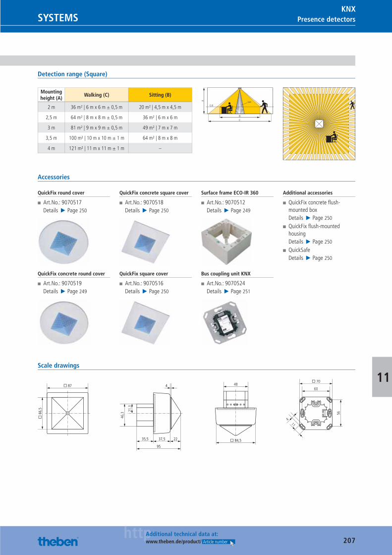
207httpAdditional technical data at:
www.theben.de/product/ Article number
Presence detectorsSYSTEMSKNX
11
Detection range (Square)
Mounting height (A)
Walking (C) Sitting (B)
2 m 36 m² | 6 m x 6 m ± 0,5 m 20 m² | 4,5 m x 4,5 m
2,5 m 64 m² | 8 m x 8 m ± 0,5 m 36 m² | 6 m x 6 m
3 m 81 m² | 9 m x 9 m ± 0,5 m 49 m² | 7 m x 7 m
3,5 m 100 m² | 10 m x 10 m ± 1 m 64 m² | 8 m x 8 m
4 m 121 m² | 11 m x 11 m ± 1 m –
BC
0.8
A Lux
Accessories
QuickFix round cover
■ Art.No.: 9070517Details ▶ Page 250
QuickFix concrete round cover
■ Art.No.: 9070519Details ▶ Page 249
QuickFix concrete square cover
■ Art.No.: 9070518Details ▶ Page 250
QuickFix square cover
■ Art.No.: 9070516Details ▶ Page 250
Surface frame ECO-IR 360
■ Art.No.: 9070512Details ▶ Page 249
Bus coupling unit KNX
■ Art.No.: 9070524Details ▶ Page 251
Additional accessories
■ QuickFix concrete fl ush-mounted boxDetails ▶ Page 250
■ QuickFix fl ush-mounted housingDetails ▶ Page 250
■ QuickSafeDetails ▶ Page 250
Scale drawings
21,3
46,3
48
� 84,5
� 6
6,5
� 87
35,5 37,5
95
22
4
11
56
60
� 70
4
Catalogue_EN_2013.indb 207 16.01.13 17:24
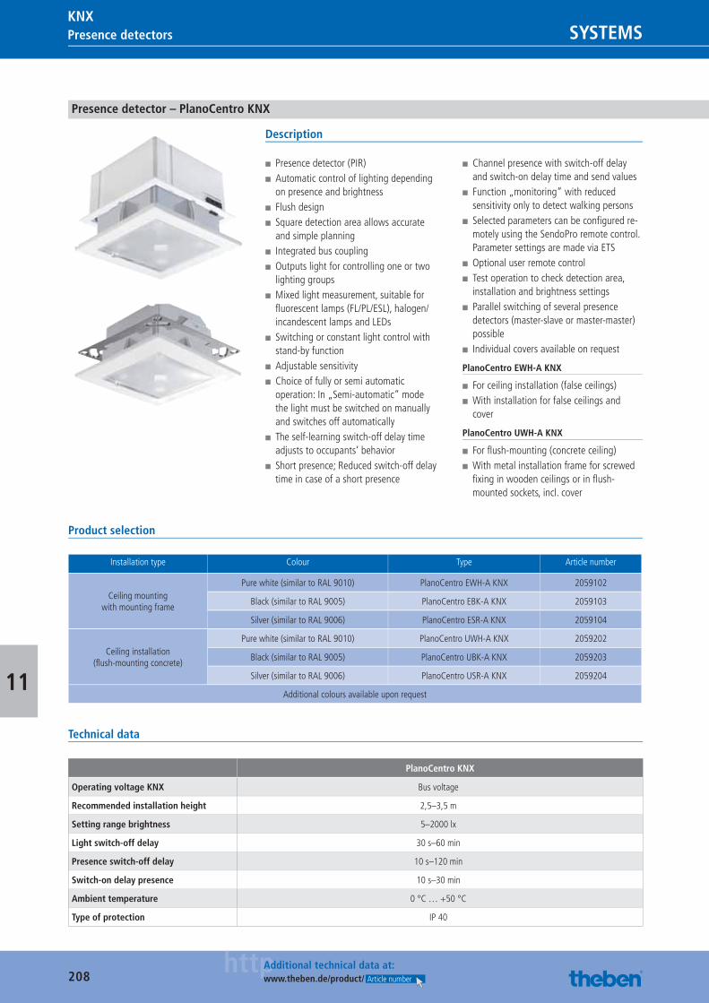
208httpAdditional technical data at:
www.theben.de/product/ Article number
Presence detectors SYSTEMSKNX
11
Presence detector – PlanoCentro KNX
Description
■ Presence detector (PIR) ■ Automatic control of lighting depending on presence and brightness
■ Flush design ■ Square detection area allows accurate and simple planning
■ Integrated bus coupling ■ Outputs light for controlling one or two lighting groups
■ Mixed light measurement, suitable for fl uorescent lamps (FL/PL/ESL), halogen/incandescent lamps and LEDs
■ Switching or constant light control with stand-by function
■ Adjustable sensitivity ■ Choice of fully or semi automatic operation: In „Semi-automatic“ mode the light must be switched on manually and switches off automatically
■ The self-learning switch-off delay time adjusts to occupants‘ behavior
■ Short presence; Reduced switch-off delay time in case of a short presence
■ Channel presence with switch-off delay and switch-on delay time and send values
■ Function „monitoring“ with reduced sensitivity only to detect walking persons
■ Selected parameters can be confi gured re-motely using the SendoPro remote control. Parameter settings are made via ETS
■ Optional user remote control ■ Test operation to check detection area, installation and brightness settings
■ Parallel switching of several presence detectors (master-slave or master-master) possible
■ Individual covers available on request
PlanoCentro EWH-A KNX
■ For ceiling installation (false ceilings) ■ With installation for false ceilings and cover
PlanoCentro UWH-A KNX
■ For fl ush-mounting (concrete ceiling) ■ With metal installation frame for screwed fi xing in wooden ceilings or in fl ush-mounted sockets, incl. cover
Product selection
Installation type Colour Type Article number
Ceiling mounting with mounting frame
Pure white (similar to RAL 9010) PlanoCentro EWH-A KNX 2059102
Black (similar to RAL 9005) PlanoCentro EBK-A KNX 2059103
Silver (similar to RAL 9006) PlanoCentro ESR-A KNX 2059104
Ceiling installation (fl ush-mounting concrete)
Pure white (similar to RAL 9010) PlanoCentro UWH-A KNX 2059202
Black (similar to RAL 9005) PlanoCentro UBK-A KNX 2059203
Silver (similar to RAL 9006) PlanoCentro USR-A KNX 2059204
Additional colours available upon request
Technical data
PlanoCentro KNX
Operating voltage KNX Bus voltage
Recommended installation height 2,5–3,5 m
Setting range brightness 5–2000 lx
Light switch-off delay 30 s–60 min
Presence switch-off delay 10 s–120 min
Switch-on delay presence 10 s–30 min
Ambient temperature 0 °C … +50 °C
Type of protection IP 40
Catalogue_EN_2013.indb 208 16.01.13 17:24
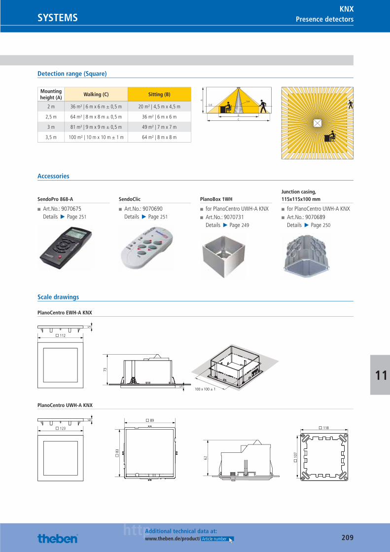
209httpAdditional technical data at:
www.theben.de/product/ Article number
Presence detectorsSYSTEMSKNX
11
Detection range (Square)
Mounting height (A)
Walking (C) Sitting (B)
2 m 36 m² | 6 m x 6 m ± 0,5 m 20 m² | 4,5 m x 4,5 m
2,5 m 64 m² | 8 m x 8 m ± 0,5 m 36 m² | 6 m x 6 m
3 m 81 m² | 9 m x 9 m ± 0,5 m 49 m² | 7 m x 7 m
3,5 m 100 m² | 10 m x 10 m ± 1 m 64 m² | 8 m x 8 m
BC
0.8
A Lux
Accessories
SendoPro 868-A
■ Art.No.: 9070675Details ▶ Page 251
SendoClic
■ Art.No.: 9070690Details ▶ Page 251
PlanoBox 1WH
■ for PlanoCentro UWH-A KNX ■ Art.No.: 9070731Details ▶ Page 249
Junction casing, 115x115x100 mm
■ for PlanoCentro UWH-A KNX ■ Art.No.: 9070689Details ▶ Page 250
Scale drawings
PlanoCentro EWH-A KNX
100 x 100 ± 1
¨ 112
73
5
5
PlanoCentro UWH-A KNX
� 118
� 1
07
� 89
� 8
3
62
� 123
6
Catalogue_EN_2013.indb 209 16.01.13 17:24
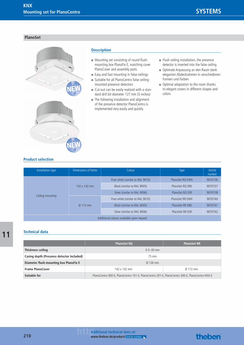
210httpAdditional technical data at:
www.theben.de/product/ Article number 210httpAdditional technical data at:
www.theben.de/product/ Article number
Presence detectors SYSTEMSKNX
SYSTEMSKNXMounting set for PlanoCentro
11
PlanoSet
Description
■ Mounting set consisting of round fl ush-mounting box PlanoFix E, matching cover PlanoCover and assembly parts
■ Easy and fast mounting in false-ceilings ■ Suitable for all PlanoCentro false ceiling-mounted presence detectors
■ Cut-out can be easily realized with a stan-dard drill bit diameter 127 mm (5 inches)
■ The following installation and alignment of the presence detector PlanoCentro is implemented very easily and quickly
■ Flush ceiling installation, the presence detector is inserted into the false ceiling
■ Optimale Anpassung an den Raum dank eleganten Abdeckrahmen in verschiedenen Formen und Farben
■ Optimal adaptation to the room thanks to elegant covers in different shapes and colors
Product selection
Installation type Dimensions of frame Colour Type Article number
Ceiling mounting
142 x 142 mm
Pure white (similar to RAL 9010) PlanoSet RQ EWH 9070736
Black (similar to RAL 9005) PlanoSet RQ EBK 9070737
Silver (similar to RAL 9006) PlanoSet RQ ESR 9070738
Ø 172 mm
Pure white (similar to RAL 9010) PlanoSet RR EWH 9070740
Black (similar to RAL 9005) PlanoSet RR EBK 9070741
Silver (similar to RAL 9006) PlanoSet RR ESR 9070742
Additional colours available upon request
Technical data
PlanoSet RQ PlanoSet RR
Thickness ceiling 0.5–30 mm
Casing depth (Presence detector included) 75 mm
Diameter fl ush-mounting box PlanoFix E Ø 126 mm
Frame PlanoCover 142 x 142 mm Ø 172 mm
Suitable for PlanoCentro 000-E, PlanoCentro 101-E, PlanoCentro 201-E, PlanoCentro 300-E, PlanoCentro KNX-E
NEW
NEW
Catalogue_EN_2013.indb 210 16.01.13 17:24
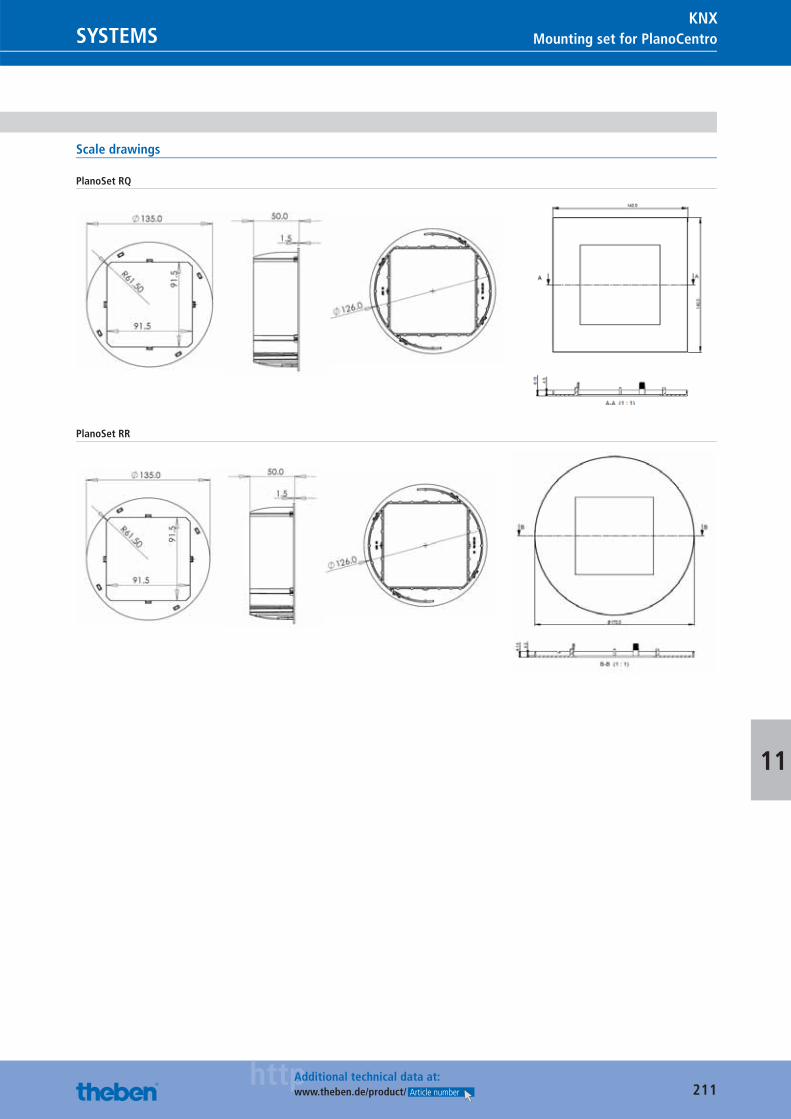
211httpAdditional technical data at:
www.theben.de/product/ Article number 211httpAdditional technical data at:
www.theben.de/product/ Article number
Presence detectorsSYSTEMSKNX
SYSTEMSKNX
Mounting set for PlanoCentro
11
Scale drawings
PlanoSet RQ
PlanoSet RR
Catalogue_EN_2013.indb 211 16.01.13 17:24
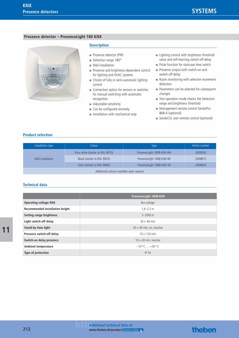
212httpAdditional technical data at:
www.theben.de/product/ Article number
Presence detectors SYSTEMSKNX
11
Presence detector – PresenceLight 180 KNX
Description
■ Presence detector (PIR) ■ Detection range 180° ■ Wall installation ■ Presence and brightness-dependent control for lighting and HVAC systems
■ Choice of fully or semi-automatic lighting control
■ Connection option for sensors or switches for manual switching with automatic recognition
■ Adjustable sensitivity ■ Can be confi gured remotely ■ Installation with mechanical stop
■ Lighting control with brightness threshold value and self-learning switch-off delay
■ Pulse function for staircase time switch ■ Presence output with switch-on and switch-off delay
■ Room monitoring with selective movement detection
■ Parameters can be selected for subsequent changes
■ Test operation mode checks the Detection range and brightness threshold
■ Management remote control SendoPro 868-A (optional)
■ SendoClic user remote control (optional)
Product selection
Installation type Colour Type Article number
Wall installation
Pure white (similar to RAL 9010) PresenceLight 180B-KNX WH 2009050
Black (similar to RAL 9005) PresenceLight 180B-KNX BK 2009815
Silver (similar to RAL 9006) PresenceLight 180B-KNX SR 2009816
Additional colours available upon request
Technical data
PresenceLight 180B-KNX
Operating voltage KNX Bus voltage
Recommended installation height 1,6–2,2 m
Setting range brightness 5–2000 lx
Light switch-off delay 30 s–60 min
Stand-by time light 30 s–60 min, on, inactive
Presence switch-off delay 10 s–120 min
Switch-on delay presence 10 s–30 min, inactive
Ambient temperature –10 °C … +50 °C
Type of protection IP 54
Catalogue_EN_2013.indb 212 16.01.13 17:24
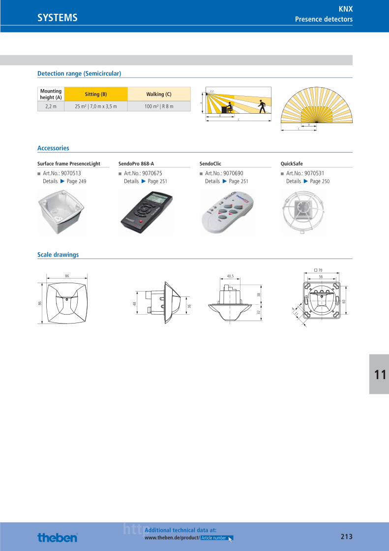
213httpAdditional technical data at:
www.theben.de/product/ Article number
Presence detectorsSYSTEMSKNX
11
Detection range (Semicircular)
Mounting height (A)
Sitting (B) Walking (C)
2,2 m 25 m² | 7,0 m x 3,5 m 100 m² | R 8 m
A
BC
2.2
B
C
Accessories
Surface frame PresenceLight
■ Art.No.: 9070513Details ▶ Page 249
SendoPro 868-A
■ Art.No.: 9070675Details ▶ Page 251
SendoClic
■ Art.No.: 9070690Details ▶ Page 251
QuickSafe
■ Art.No.: 9070531Details ▶ Page 250
Scale drawings
86
86
114
48
36
3832
40,5
60
� 70
56
Catalogue_EN_2013.indb 213 16.01.13 17:25
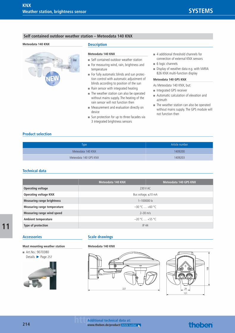
214httpAdditional technical data at:
www.theben.de/product/ Article number
Weather station, brightness sensor SYSTEMSKNX
11
Self contained outdoor weather station – Meteodata 140 KNX
Meteodata 140 KNX Description
Meteodata 140 KNX
■ Self contained outdoor weather station ■ For measuring wind, rain, brightness and temperature
■ For fully automatic blinds and sun protec-tion control with automatic adjustment of blinds according to position of the sun
■ Rain sensor with integrated heating ■ The weather station can also be operated without mains supply. The heating of the rain sensor will not function then
■ Measurement and evaluation directly on device
■ Sun protection for up to three facades via 3 integrated brightness sensors
■ 4 additional threshold channels for connection of external KNX sensors
■ 6 logic channels ■ Display of weather data e.g. with VARIA 826 KNX multi-function display
Meteodata 140 GPS KNX
As Meteodata 140 KNX, but: ■ Integrated GPS receiver ■ Automatic calculation of elevation and azimuth
■ The weather station can also be operated without mains supply. The GPS module will not function then
Product selection
Type Article number
Meteodata 140 KNX 1409200
Meteodata 140 GPS KNX 1409203
Technical data
Meteodata 140 KNX Meteodata 140 GPS KNX
Operating voltage 230 V AC
Operating voltage KNX Bus voltage, ≤10 mA
Measuring range brightness 1–100000 lx
Measuring range temperature –30 °C … +60 °C
Measuring range wind speed 2–30 m/s
Ambient temperature –20 °C … +55 °C
Type of protection IP 44
Accessories
Mast mounting weather station
■ Art.No.: 9070380Details ▶ Page 257
Scale drawings
Meteodata 140 KNX
227 29
121
108
NEW
Catalogue_EN_2013.indb 214 16.01.13 17:25
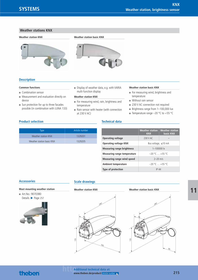
215httpAdditional technical data at:
www.theben.de/product/ Article number
Weather station, brightness sensorSYSTEMSKNX
11
Weather stations KNX
Weather station KNX Weather station basic KNX
Description
Common functions
■ Combination sensor ■ Measurement and evaluation directly on device
■ Sun protection for up to three facades possible (in combination with LUNA 133)
■ Display of weather data, e.g. with VARIA multi-function display
Weather station KNX
■ For measuring wind, rain, brightness and temperature
■ Rain sensor with heater (with connection at 230 V AC)
Weather station basic KNX
■ For measuring wind, brightness and temperature
■ Without rain sensor ■ 230 V AC connection not required ■ Brightness range from 1–100,000 lux ■ Temperature range –20 °C to +55 °C
Product selection
Type Article number
Weather station KNX 1329201
Weather station basic KNX 1329205
Technical data
Weather station KNX
Weather station basic KNX
Operating voltage 230 V AC –
Operating voltage KNX Bus voltage, ≤10 mA
Measuring range brightness 1–100000 lx
Measuring range temperature –20 °C … +55 °C
Measuring range wind speed 2–20 m/s
Ambient temperature –20 °C … +55 °C
Type of protection IP 44
Accessories
Mast mounting weather station
■ Art.No.: 9070380Details ▶ Page 257
Scale drawings
Weather station KNX
135
66
280
160
Weather station basic KNX
135
66
280
80
Catalogue_EN_2013.indb 215 16.01.13 17:25
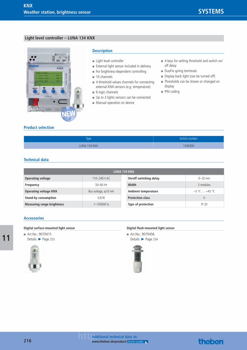
216httpAdditional technical data at:
www.theben.de/product/ Article number
Weather station, brightness sensor SYSTEMSKNX
11
Light level controller – LUNA 134 KNX
Description
■ Light level controller ■ External light sensor included in delivery ■ For brightness-dependent controlling ■ 10 channels ■ 4 threshold values channels for connecting external KNX-sensors (e.g. temperature)
■ 6 logic channels ■ Up to 3 lights sensors can be connected ■ Manual operation on device
■ 4 keys for setting threshold and switch on/off delay
■ DuoFix spring terminals ■ Display back light (can be turned off) ■ Thresholds can be shown or changed on display
■ PIN coding
Product selection
Type Article number
LUNA 134 KNX 1349200
Technical data
LUNA 134 KNX
Operating voltage 110–240 V AC
Frequency 50–60 Hz
Operating voltage KNX Bus voltage, ≤10 mA
Stand-by consumption 0,8 W
Measuring range brightness 1–100000 lx
On/off switching delay 0–20 min
Width 3 modules
Ambient temperature –5 °C … +45 °C
Protection class II
Type of protection IP 20
Accessories
Digital surface-mounted light sensor
■ Art.No.: 9070415Details ▶ Page 253
Digital fl ush-mounted light sensor
■ Art.No.: 9070456Details ▶ Page 254
NEW
Catalogue_EN_2013.indb 216 16.01.13 17:25
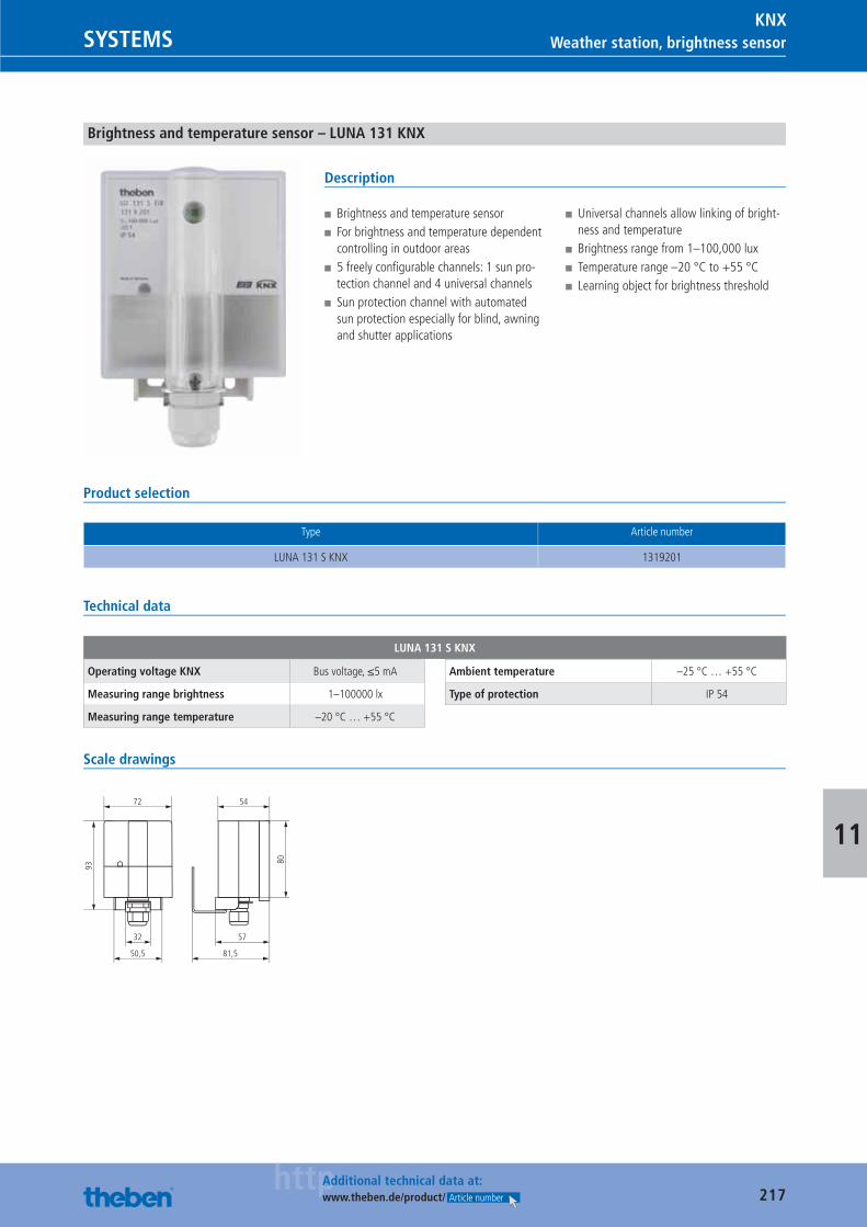
217httpAdditional technical data at:
www.theben.de/product/ Article number
Weather station, brightness sensorSYSTEMSKNX
11
Brightness and temperature sensor – LUNA 131 KNX
Description
■ Brightness and temperature sensor ■ For brightness and temperature dependent controlling in outdoor areas
■ 5 freely confi gurable channels: 1 sun pro-tection channel and 4 universal channels
■ Sun protection channel with automated sun protection especially for blind, awning and shutter applications
■ Universal channels allow linking of bright-ness and temperature
■ Brightness range from 1–100,000 lux ■ Temperature range –20 °C to +55 °C ■ Learning object for brightness threshold
Product selection
Type Article number
LUNA 131 S KNX 1319201
Technical data
LUNA 131 S KNX
Operating voltage KNX Bus voltage, ≤5 mA
Measuring range brightness 1–100000 lx
Measuring range temperature –20 °C … +55 °C
Ambient temperature –25 °C … +55 °C
Type of protection IP 54
Scale drawings
93
80
72 54
50,5 81,5
32 57
Catalogue_EN_2013.indb 217 16.01.13 17:25
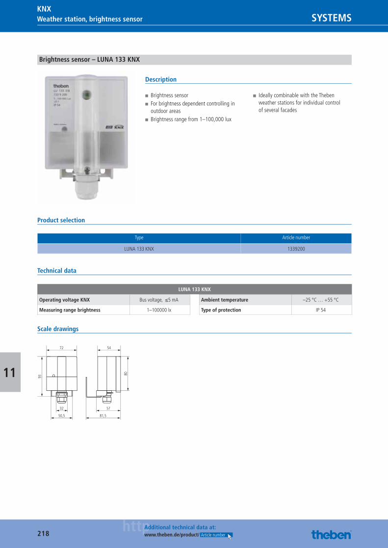
218httpAdditional technical data at:
www.theben.de/product/ Article number
Weather station, brightness sensor SYSTEMSKNX
11
Brightness sensor – LUNA 133 KNX
Description
■ Brightness sensor ■ For brightness dependent controlling in outdoor areas
■ Brightness range from 1–100,000 lux
■ Ideally combinable with the Theben weather stations for individual control of several facades
Product selection
Type Article number
LUNA 133 KNX 1339200
Technical data
LUNA 133 KNX
Operating voltage KNX Bus voltage, ≤5 mA
Measuring range brightness 1–100000 lx
Ambient temperature –25 °C … +55 °C
Type of protection IP 54
Scale drawings
93
80
72 54
50,5 81,5
32 57
Catalogue_EN_2013.indb 218 16.01.13 17:25
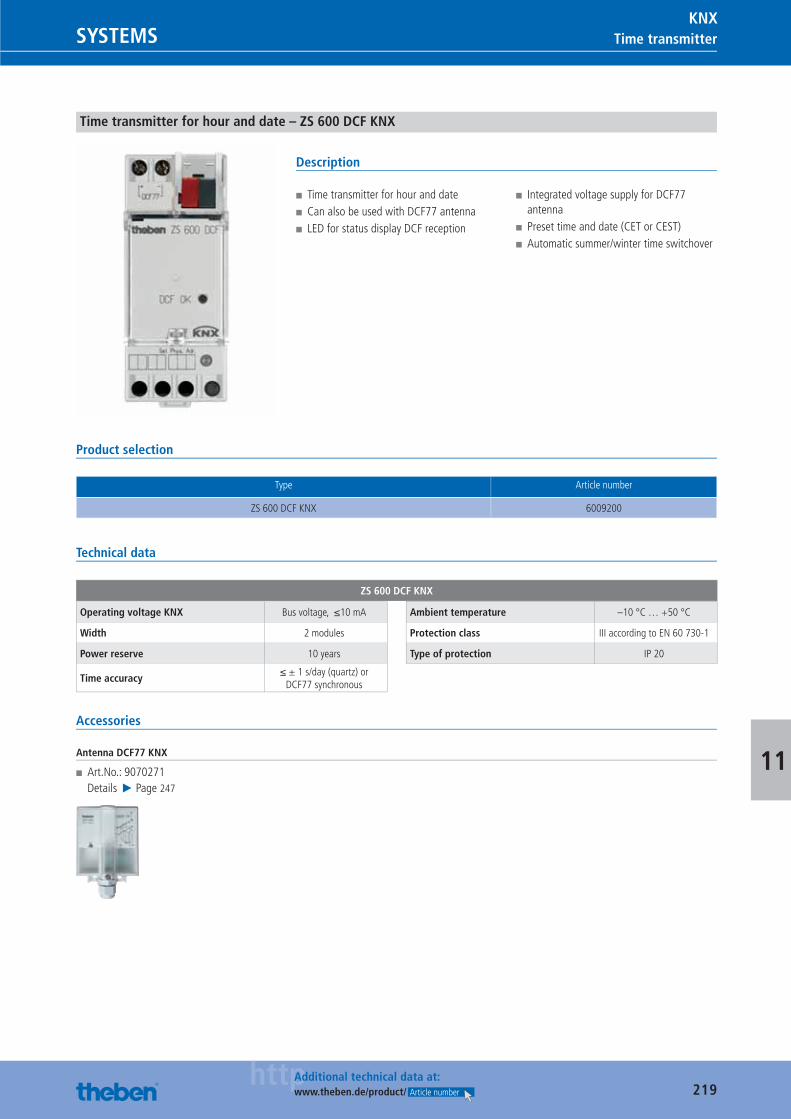
219httpAdditional technical data at:
www.theben.de/product/ Article number
Time transmitterSYSTEMSKNX
11
Time transmitter for hour and date – ZS 600 DCF KNX
Description
■ Time transmitter for hour and date ■ Can also be used with DCF77 antenna ■ LED for status display DCF reception
■ Integrated voltage supply for DCF77 antenna
■ Preset time and date (CET or CEST) ■ Automatic summer/winter time switchover
Product selection
Type Article number
ZS 600 DCF KNX 6009200
Technical data
ZS 600 DCF KNX
Operating voltage KNX Bus voltage, ≤10 mA
Width 2 modules
Power reserve 10 years
Time accuracy≤ ± 1 s/day (quartz) or
DCF77 synchronous
Ambient temperature –10 °C … +50 °C
Protection class III according to EN 60 730-1
Type of protection IP 20
Accessories
Antenna DCF77 KNX
■ Art.No.: 9070271Details ▶ Page 247
Catalogue_EN_2013.indb 219 16.01.13 17:25
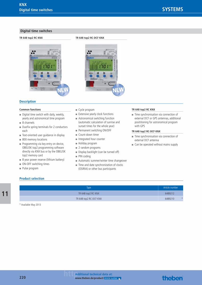
220httpAdditional technical data at:
www.theben.de/product/ Article number
Digital time switches SYSTEMSKNX
11
Digital time switches
TR 648 top2 RC KNX TR 648 top2 RC-DCF KNX
Description
Common functions
■ Digital time switch with daily, weekly, yearly and astronomical time program
■ 8 channels ■ DuoFix spring terminals for 2 conductors each
■ Text-oriented user guidance in display ■ 800 memory locations ■ Programming via key entry on device, OBELISK top2 programming software directly via KNX bus or by the OBELISK top2 memory card
■ 8 year power reserve (lithium battery) ■ ON-OFF switching times ■ Pulse program
■ Cycle program ■ Extensive yearly clock functions ■ Astronomical switching function (automatic calculation of sunrise and sunset times for the whole year)
■ Permanent switching ON/OFF ■ Count-down timer ■ Integrated hour counter ■ Holiday program ■ 2 random programs ■ Display backlight (can be turned off) ■ PIN coding ■ Automatic summer/winter time changeover ■ Time and date synchronization of clocks (OSIRIA) or other bus participants
TR 648 top2 RC KNX
■ Time synchronisation via connection of external DCF or GPS antennas, additional posititioning for astronomical program with GPS
TR 648 top2 RC-DCF KNX
■ Time synchronisation via connection of external DCF antenna
■ Can be operated without mains supply
Product selection
Type Article number
TR 648 top2 RC KNX 6489212
TR 648 top2 RC-DCF KNX 6489210 *
* Available May 2013
NEW NEW
Catalogue_EN_2013.indb 220 16.01.13 17:25
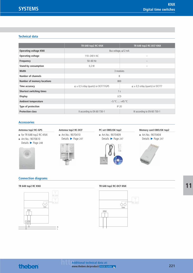
221httpAdditional technical data at:
www.theben.de/product/ Article number
Digital time switchesSYSTEMSKNX
11
Technical data
TR 648 top2 RC KNX TR 648 top2 RC-DCF KNX
Operating voltage KNX Bus voltage, ≤12 mA
Operating voltage 110–240 V AC –
Frequency 50–60 Hz –
Stand-by consumption 0,2 W –
Width 3 modules
Number of channels 8
Number of memory locations 800
Time accuracy ≤ ± 0,5 s/day (quartz) or DCF77/GPS ≤ ± 0,5 s/day (quartz) or DCF77
Shortest switching times 1 s
Display LCD
Ambient temperature –5 °C … +45 °C
Type of protection IP 20
Protection class II according to EN 60 730-1 III according to EN 60 730-1
Accessories
Antenna top2 RC-GPS
■ for TR 648 top2 RC-KNX ■ Art.No.: 9070610Details ▶ Page 248
Antenna top2 RC-DCF
■ Art.No.: 9070410Details ▶ Page 247
PC set OBELISK top2
■ Art.No.: 9070409Details ▶ Page 247
Memory card OBELISK top2
■ Art.No.: 9070404Details ▶ Page 247
Connection diagrams
TR 648 top2 RC KNX
L N
NL
Data
RC DCF
RC GPS
KNX
TR 648 top2 RC-DCF KNX
Data
RC DCF
KNX
Catalogue_EN_2013.indb 221 16.01.13 17:25
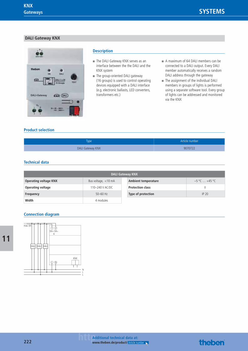
222httpAdditional technical data at:
www.theben.de/product/ Article number
Gateways SYSTEMSKNX
11
DALI Gateway KNX
Description
■ The DALI Gateway KNX serves as an interface between the the DALI and the KNX system
■ The group-oriented DALI gateway (16 groups) is used to control operating devices equipped with a DALI interface (e.g. electronic ballasts, LED converters, transformers etc.)
■ A maximum of 64 DALI members can be connected to a DALI output. Every DALI member automatically receives a random DALI address through the gateway
■ The assignment of the individual DALI members in groups of lights is performed using a separate software tool. Every group of lights can be addressed and monitored via the KNX
Product selection
Type Article number
DALI Gateway KNX 9070722
Technical data
DALI Gateway KNX
Operating voltage KNX Bus voltage, <10 mA
Operating voltage 110–240 V AC/DC
Frequency 50–60 Hz
Width 4 modules
Ambient temperature –5 °C … +45 °C
Protection class II
Type of protection IP 20
Connection diagram
DA+ DA–A
L N
1 2
N
KNX
DALI
LL
DALIDALI
max. 64
Catalogue_EN_2013.indb 222 16.01.13 17:25
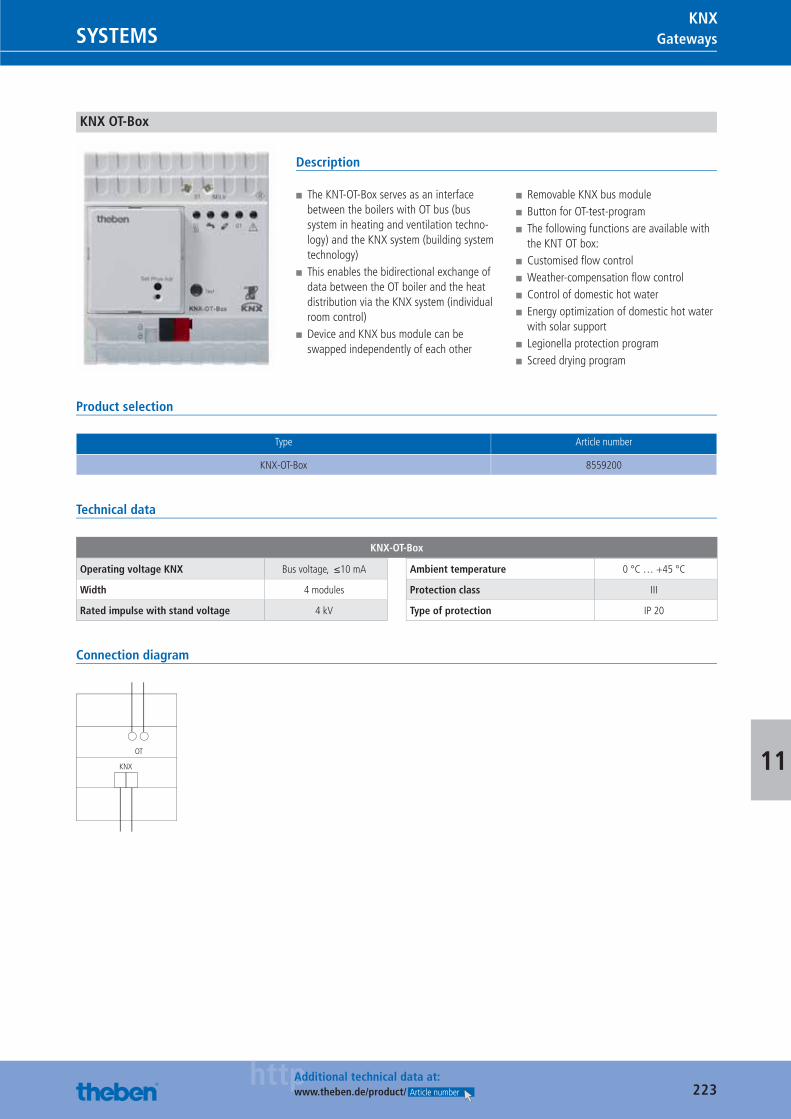
223httpAdditional technical data at:
www.theben.de/product/ Article number
GatewaysSYSTEMSKNX
11
KNX OT-Box
Description
■ The KNT-OT-Box serves as an interface between the boilers with OT bus (bus system in heating and ventilation techno-logy) and the KNX system (building system technology)
■ This enables the bidirectional exchange of data between the OT boiler and the heat distribution via the KNX system (individual room control)
■ Device and KNX bus module can be swapped independently of each other
■ Removable KNX bus module ■ Button for OT-test-program ■ The following functions are available with the KNT OT box:
■ Customised fl ow control ■ Weather-compensation fl ow control ■ Control of domestic hot water ■ Energy optimization of domestic hot water with solar support
■ Legionella protection program ■ Screed drying program
Product selection
Type Article number
KNX-OT-Box 8559200
Technical data
KNX-OT-Box
Operating voltage KNX Bus voltage, ≤10 mA
Width 4 modules
Rated impulse with stand voltage 4 kV
Ambient temperature 0 °C … +45 °C
Protection class III
Type of protection IP 20
Connection diagram
OT
KNX
Catalogue_EN_2013.indb 223 16.01.13 17:25
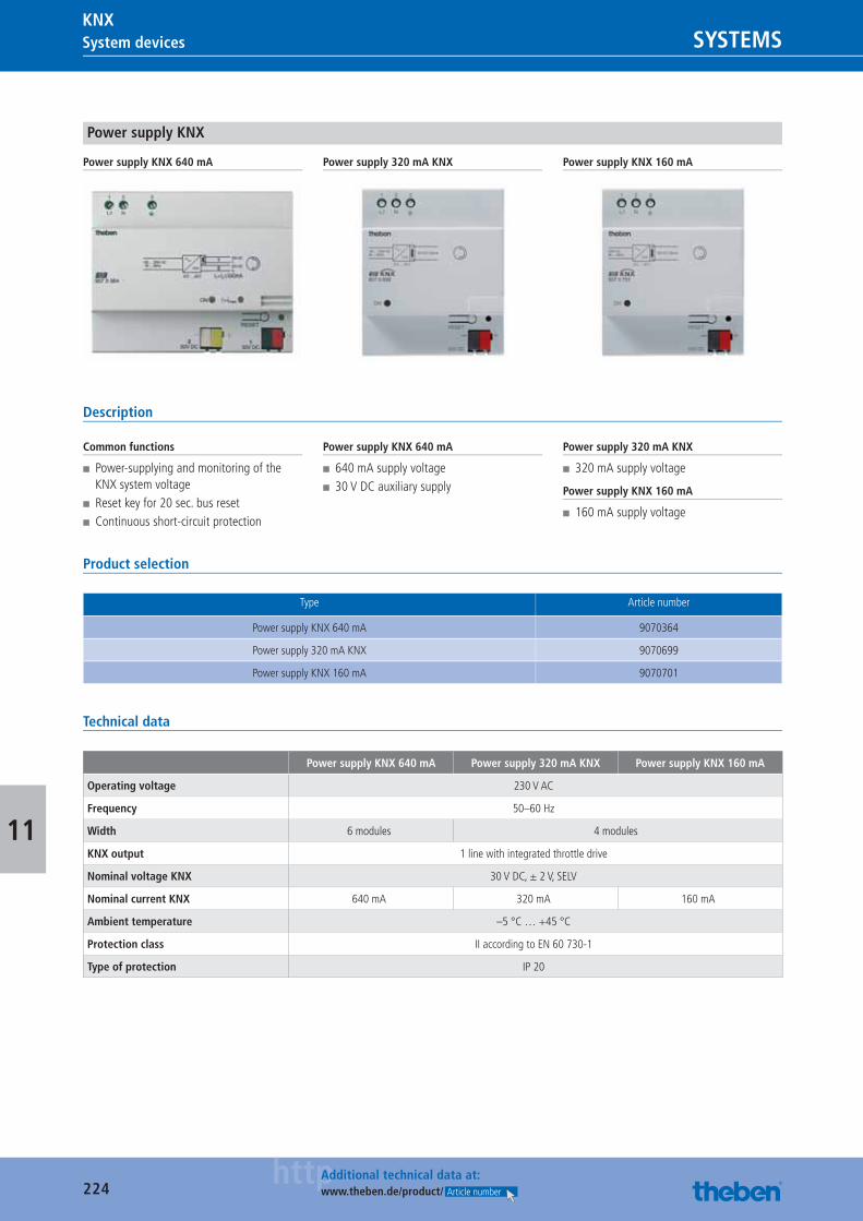
224httpAdditional technical data at:
www.theben.de/product/ Article number
System devices SYSTEMSKNX
11
Power supply KNX
Power supply KNX 640 mA Power supply 320 mA KNX Power supply KNX 160 mA
Description
Common functions
■ Power-supplying and monitoring of the KNX system voltage
■ Reset key for 20 sec. bus reset ■ Continuous short-circuit protection
Power supply KNX 640 mA
■ 640 mA supply voltage ■ 30 V DC auxiliary supply
Power supply 320 mA KNX
■ 320 mA supply voltage
Power supply KNX 160 mA
■ 160 mA supply voltage
Product selection
Type Article number
Power supply KNX 640 mA 9070364
Power supply 320 mA KNX 9070699
Power supply KNX 160 mA 9070701
Technical data
Power supply KNX 640 mA Power supply 320 mA KNX Power supply KNX 160 mA
Operating voltage 230 V AC
Frequency 50–60 Hz
Width 6 modules 4 modules
KNX output 1 line with integrated throttle drive
Nominal voltage KNX 30 V DC, ± 2 V, SELV
Nominal current KNX 640 mA 320 mA 160 mA
Ambient temperature –5 °C … +45 °C
Protection class II according to EN 60 730-1
Type of protection IP 20
Catalogue_EN_2013.indb 224 16.01.13 17:25
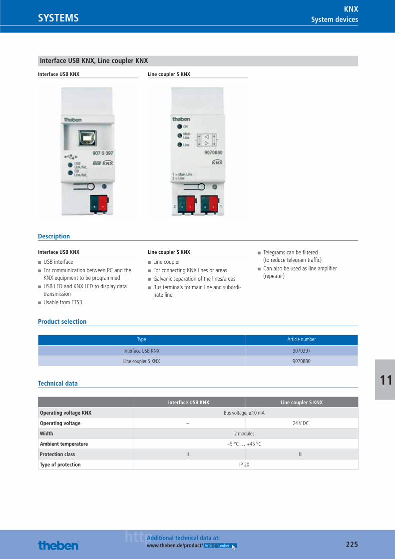
225httpAdditional technical data at:
www.theben.de/product/ Article number
System devicesSYSTEMSKNX
11
Interface USB KNX, Line coupler KNX
Interface USB KNX Line coupler S KNX
Description
Interface USB KNX
■ USB interface ■ For communication between PC and the KNX equipment to be programmed
■ USB LED and KNX LED to display data transmission
■ Usable from ETS3
Line coupler S KNX
■ Line coupler ■ For connecting KNX lines or areas ■ Galvanic separation of the lines/areas ■ Bus terminals for main line and subordi-nate line
■ Telegrams can be fi ltered (to reduce telegram traffi c)
■ Can also be used as line amplifi er (repeater)
Product selection
Type Article number
Interface USB KNX 9070397
Line coupler S KNX 9070880
Technical data
Interface USB KNX Line coupler S KNX
Operating voltage KNX Bus voltage, ≤10 mA
Operating voltage – 24 V DC
Width 2 modules
Ambient temperature –5 °C … +45 °C
Protection class II III
Type of protection IP 20
Catalogue_EN_2013.indb 225 16.01.13 17:25
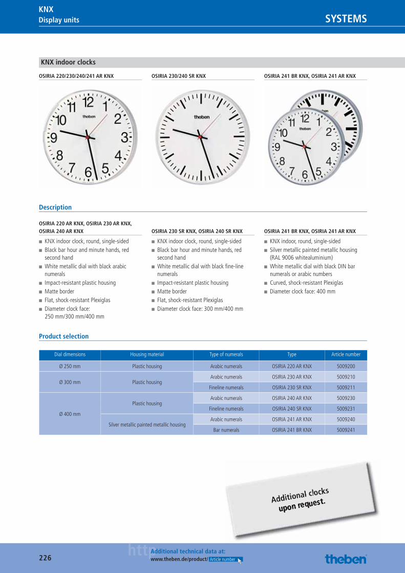
226httpAdditional technical data at:
www.theben.de/product/ Article number
Display units SYSTEMSKNX
KNX indoor clocks
OSIRIA 220/230/240/241 AR KNX OSIRIA 230/240 SR KNX OSIRIA 241 BR KNX, OSIRIA 241 AR KNX
Description
OSIRIA 220 AR KNX, OSIRIA 230 AR KNX, OSIRIA 240 AR KNX
■ KNX indoor clock, round, single-sided ■ Black bar hour and minute hands, red second hand
■ White metallic dial with black arabic numerals
■ Impact-resistant plastic housing ■ Matte border ■ Flat, shock-resistant Plexiglas ■ Diameter clock face: 250 mm/300 mm/400 mm
OSIRIA 230 SR KNX, OSIRIA 240 SR KNX
■ KNX indoor clock, round, single-sided ■ Black bar hour and minute hands, red second hand
■ White metallic dial with black fi ne-line numerals
■ Impact-resistant plastic housing ■ Matte border ■ Flat, shock-resistant Plexiglas ■ Diameter clock face: 300 mm/400 mm
OSIRIA 241 BR KNX, OSIRIA 241 AR KNX
■ KNX indoor, round, single-sided ■ Silver metallic painted metallic housing(RAL 9006 whitealuminium)
■ White metallic dial with black DIN bar numerals or arabic numbers
■ Curved, shock-resistant Plexiglas ■ Diameter clock face: 400 mm
Product selection
Dial dimensions Housing material Type of numerals Type Article number
Ø 250 mm Plastic housing Arabic numerals OSIRIA 220 AR KNX 5009200
Ø 300 mm Plastic housingArabic numerals OSIRIA 230 AR KNX 5009210
Fineline numerals OSIRIA 230 SR KNX 5009211
Ø 400 mm
Plastic housingArabic numerals OSIRIA 240 AR KNX 5009230
Fineline numerals OSIRIA 240 SR KNX 5009231
Silver metallic painted metallic housingArabic numerals OSIRIA 241 AR KNX 5009240
Bar numerals OSIRIA 241 BR KNX 5009241
Catalogue_EN_2013.indb 226 16.01.13 17:25
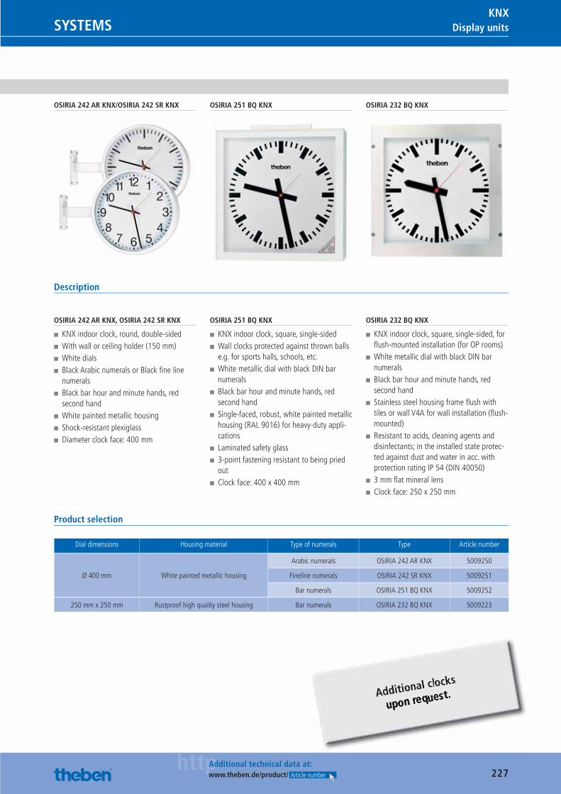
227httpAdditional technical data at:
www.theben.de/product/ Article number
Display unitsSYSTEMSKNX
OSIRIA 242 AR KNX/OSIRIA 242 SR KNX OSIRIA 251 BQ KNX OSIRIA 232 BQ KNX
Description
OSIRIA 242 AR KNX, OSIRIA 242 SR KNX
■ KNX indoor clock, round, double-sided ■ With wall or ceiling holder (150 mm) ■ White dials ■ Black Arabic numerals or Black fi ne line numerals
■ Black bar hour and minute hands, red second hand
■ White painted metallic housing ■ Shock-resistant plexiglass ■ Diameter clock face: 400 mm
OSIRIA 251 BQ KNX
■ KNX indoor clock, square, single-sided ■ Wall clocks protected against thrown balls e.g. for sports halls, schools, etc.
■ White metallic dial with black DIN bar numerals
■ Black bar hour and minute hands, red second hand
■ Single-faced, robust, white painted metallic housing (RAL 9016) for heavy-duty appli-cations
■ Laminated safety glass ■ 3-point fastening resistant to being pried out
■ Clock face: 400 x 400 mm
OSIRIA 232 BQ KNX
■ KNX indoor clock, square, single-sided, for fl ush-mounted installation (for OP rooms)
■ White metallic dial with black DIN bar numerals
■ Black bar hour and minute hands, red second hand
■ Stainless steel housing frame fl ush with tiles or wall V4A for wall installation (fl ush-mounted)
■ Resistant to acids, cleaning agents and disinfectants; in the installed state protec-ted against dust and water in acc. with protection rating IP 54 (DIN 40050)
■ 3 mm fl at mineral lens ■ Clock face: 250 x 250 mm
Product selection
Dial dimensions Housing material Type of numerals Type Article number
Ø 400 mm White painted metallic housing
Arabic numerals OSIRIA 242 AR KNX 5009250
Fineline numerals OSIRIA 242 SR KNX 5009251
Bar numerals OSIRIA 251 BQ KNX 5009252
250 mm x 250 mm Rustproof high quality steel housing Bar numerals OSIRIA 232 BQ KNX 5009223
Catalogue_EN_2013.indb 227 16.01.13 17:25
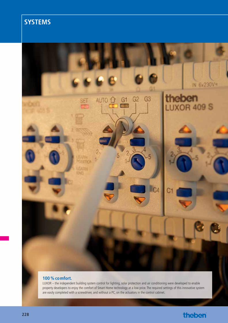
228
SYSTEMS
100 % comfort.LUXOR – the independent building system control for lighting, solar protection and air conditioning were developed to enable property developers to enjoy the comfort of Smart Home technology at a low price. The required settings of this innovative system are easily completed with a screwdriver, and without a PC, on the actuators in the control cabinet.
Catalogue_EN_2013.indb 228 16.01.13 17:25
229
Chapter summary
SYSTEMSLiving comfort control
12
Beschreibung Type Page
Switching
LUXOR switching
LUXOR 400 230
LUXOR 404 230
LUXOR 402 230
Dimming
LUXOR dimming LUXOR 405 232
Shutter control
LUXOR shutter control
LUXOR 408 S 233
LUXOR 409 S 233
Weather sensors
LUXOR weather sensors
LUXOR 412 234
LUXOR 411 234
LUXOR 413 234
Multifunction display
LUXOR multifunction display LUXOR 426 236
Clock module
LUXOR cloxk LUXOR 414 238
LUXOR Sets
LUXOR sets
LUXOR Set 3 239
LUXOR Set 4 239
LUXOR Set 5 239
Catalogue_EN_2013.indb 229 16.01.13 17:25
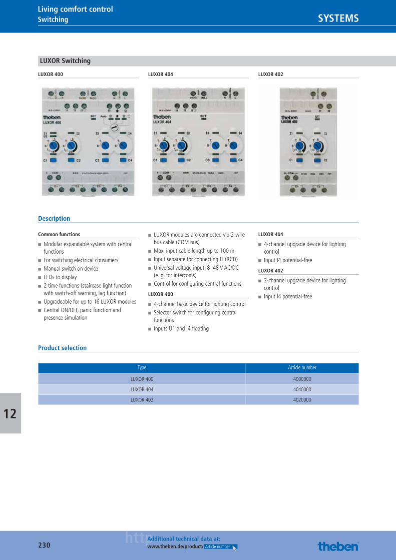
230httpAdditional technical data at:
www.theben.de/product/ Article number
Switching SYSTEMSLiving comfort control
12
LUXOR Switching
LUXOR 400 LUXOR 404 LUXOR 402
Description
Common functions
■ Modular expandable system with central functions
■ For switching electrical consumers ■ Manual switch on device ■ LEDs to display ■ 2 time functions (staircase light function with switch-off warning, lag function)
■ Upgradeable for up to 16 LUXOR modules ■ Central ON/OFF, panic function and presence simulation
■ LUXOR modules are connected via 2-wire bus cable (COM bus)
■ Max. input cable length up to 100 m ■ Input separate for connecting FI (RCD) ■ Universal voltage input: 8–48 V AC/DC (e. g. for intercoms)
■ Control for confi guring central functions
LUXOR 400
■ 4-channel basic device for lighting control ■ Selector switch for confi guring central functions
■ Inputs U1 and I4 fl oating
LUXOR 404
■ 4-channel upgrade device for lighting control
■ Input I4 potential-free
LUXOR 402
■ 2-channel upgrade device for lighting control
■ Input I4 potential-free
Product selection
Type Article number
LUXOR 400 4000000
LUXOR 404 4040000
LUXOR 402 4020000
Catalogue_EN_2013.indb 230 16.01.13 17:25
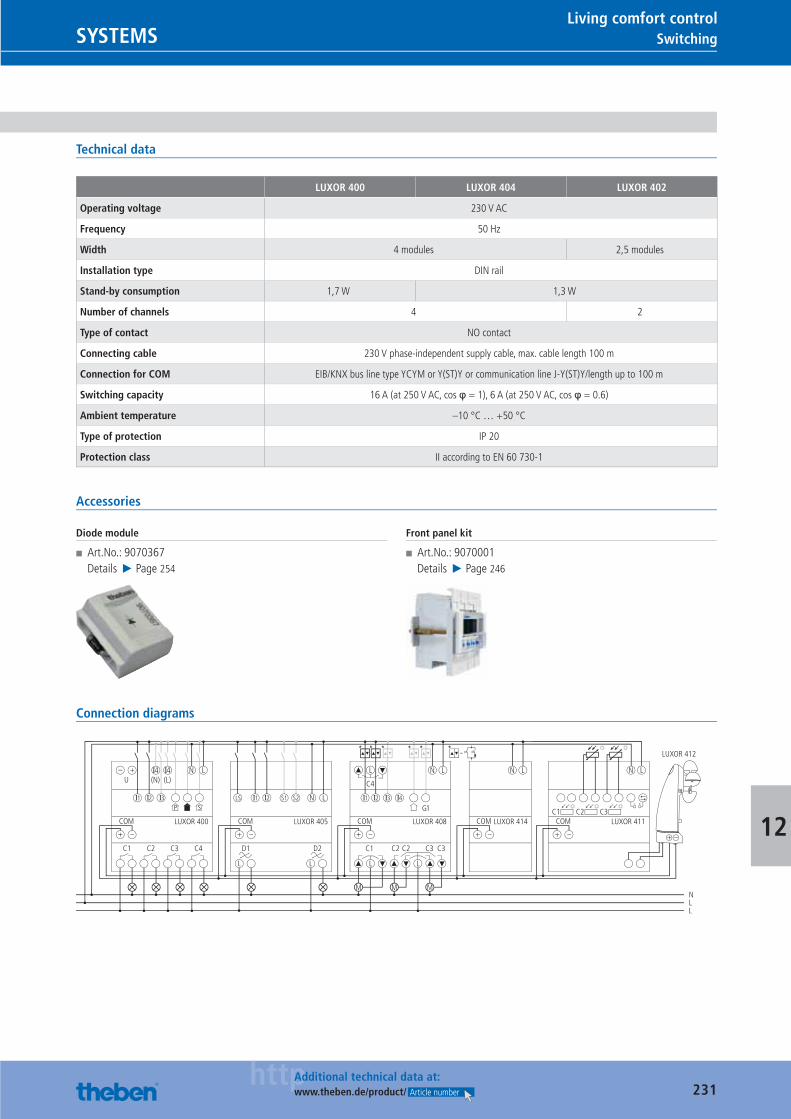
231httpAdditional technical data at:
www.theben.de/product/ Article number
SwitchingSYSTEMSLiving comfort control
12
Technical data
LUXOR 400 LUXOR 404 LUXOR 402
Operating voltage 230 V AC
Frequency 50 Hz
Width 4 modules 2,5 modules
Installation type DIN rail
Stand-by consumption 1,7 W 1,3 W
Number of channels 4 2
Type of contact NO contact
Connecting cable 230 V phase-independent supply cable, max. cable length 100 m
Connection for COM EIB/KNX bus line type YCYM or Y(ST)Y or communication line J-Y(ST)Y/length up to 100 m
Switching capacity 16 A (at 250 V AC, cos φ = 1), 6 A (at 250 V AC, cos φ = 0.6)
Ambient temperature –10 °C … +50 °C
Type of protection IP 20
Protection class II according to EN 60 730-1
Accessories
Diode module
■ Art.No.: 9070367Details ▶ Page 254
Front panel kit
■ Art.No.: 9070001Details ▶ Page 246
Connection diagrams
U
COM
+ –
– +(L)(N)
C1 C2 C3
I4 I4
NLL
C4
N L
I2 I3I1
LUXOR 400 LUXOR 405
P S
C4
**** *
G1
COM
M
+ –
L
C1 C2 C2 C3 C3
N L N L
I3 I4
M M
I2
LUXOR 408
I1
COM
+ –
D1 D2
N L
L L
I2 S1 S2I1LS
LUXOR 414COM
+ –
*
L L
C1COM
+ –
LUXOR 412
+ –
N L
LUXOR 411C2 C3
=
Catalogue_EN_2013.indb 231 16.01.13 17:25
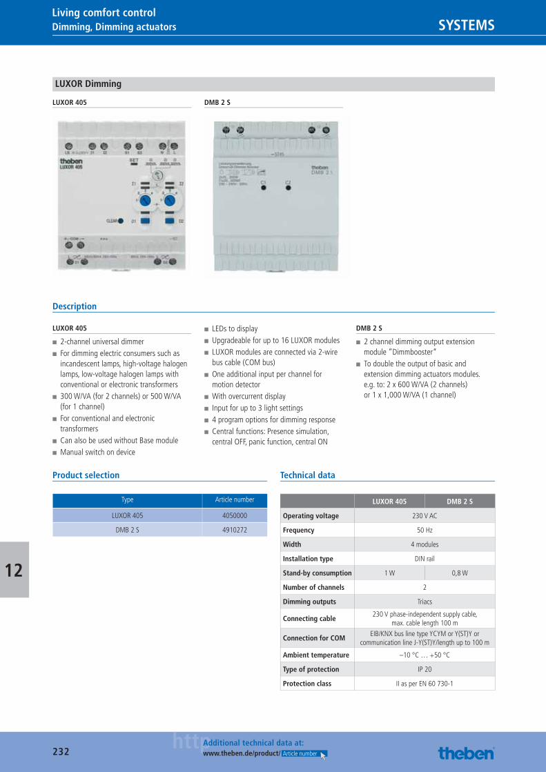
232httpAdditional technical data at:
www.theben.de/product/ Article number
Dimming, Dimming actuators SYSTEMSLiving comfort control
12
LUXOR Dimming
LUXOR 405 DMB 2 S
Description
LUXOR 405
■ 2-channel universal dimmer ■ For dimming electric consumers such as incandescent lamps, high-voltage halogen lamps, low-voltage halogen lamps with conventional or electronic transformers
■ 300 W/VA (for 2 channels) or 500 W/VA (for 1 channel)
■ For conventional and electronic transformers
■ Can also be used without Base module ■ Manual switch on device
■ LEDs to display ■ Upgradeable for up to 16 LUXOR modules ■ LUXOR modules are connected via 2-wire bus cable (COM bus)
■ One additional input per channel for motion detector
■ With overcurrent display ■ Input for up to 3 light settings ■ 4 program options for dimming response ■ Central functions: Presence simulation, central OFF, panic function, central ON
DMB 2 S
■ 2 channel dimming output extension module ”Dimmbooster“
■ To double the output of basic and extension dimming actuators modules. e.g. to: 2 x 600 W/VA (2 channels) or 1 x 1,000 W/VA (1 channel)
Product selection
Type Article number
LUXOR 405 4050000
DMB 2 S 4910272
Technical data
LUXOR 405 DMB 2 S
Operating voltage 230 V AC
Frequency 50 Hz
Width 4 modules
Installation type DIN rail
Stand-by consumption 1 W 0,8 W
Number of channels 2
Dimming outputs Triacs
Connecting cable230 V phase-independent supply cable,
max. cable length 100 m
Connection for COMEIB/KNX bus line type YCYM or Y(ST)Y or
communication line J-Y(ST)Y/length up to 100 m
Ambient temperature –10 °C … +50 °C
Type of protection IP 20
Protection class II as per EN 60 730-1
Catalogue_EN_2013.indb 232 16.01.13 17:25
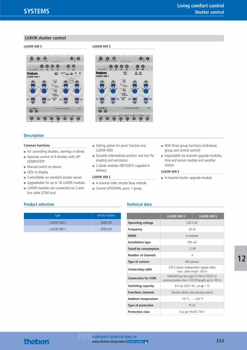
233httpAdditional technical data at:
www.theben.de/product/ Article number
Shutter controlSYSTEMSLiving comfort control
12
LUXOR shutter control
LUXOR 408 S LUXOR 409 S
Description
Common functions
■ For controlling shutters, awnings or blinds ■ Separate control of 4 shutters with UP/DOWN/STOP
■ Manual switch on device ■ LEDs to display ■ Controllable via standard shutter sensor ■ Upgradeable for up to 16 LUXOR modules ■ LUXOR modules are connected via 2-wire bus cable (COM bus)
■ Setting option for panic function (via LUXOR 400)
■ Storable intermediate position and turn for shading and ventilation
■ 2 diode modules (9070367) supplied in delivery
LUXOR 408 S
■ 4-channel roller shutter Base module ■ Central UP/DOWN, panic 1 group
■ With three group functions (individual, group and central control)
■ Expandable via channel upgrade modules, time and sensor module and weather station
LUXOR 409 S
■ 4-channel shutter upgrade module
Product selection
Type Article number
LUXOR 408 S 4080100
LUXOR 409 S 4090100
Technical data
LUXOR 408 S LUXOR 409 S
Operating voltage 230 V AC
Frequency 50 Hz
Width 4 modules
Installation type DIN rail
Stand-by consumption 1,3 W
Number of channels 4
Type of contact NO contact
Connecting cable230 V phase-independent supply cable,
max. cable length 100 m
Connection for COMEIB/KNX bus line type YCYM or Y(ST)Y or
communication line J-Y(ST)Y/length up to 100 m
Switching capacity 6 A (at 250 V AC, cos φ = 1)
Functions channels Shutter, blinds and awning control
Ambient temperature –10 °C … +50 °C
Type of protection IP 20
Protection class II as per EN 60 730-1
Catalogue_EN_2013.indb 233 16.01.13 17:25
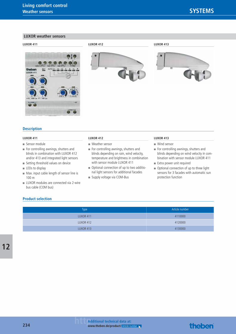
234httpAdditional technical data at:
www.theben.de/product/ Article number
Weather sensors SYSTEMSLiving comfort control
12
LUXOR weather sensors
LUXOR 411 LUXOR 412 LUXOR 413
Description
LUXOR 411
■ Sensor module ■ For controlling awnings, shutters and blinds in combination with LUXOR 412 and/or 413 and integrated light sensors
■ Setting threshold values on device ■ LEDs to display ■ Max. input cable length of sensor line is 100 m
■ LUXOR modules are connected via 2-wire bus cable (COM bus)
LUXOR 412
■ Weather sensor ■ For controlling awnings, shutters and blinds depending on rain, wind velocity, temperature and brightness in combination with sensor module LUXOR 411
■ Optional connection of up to two additio-nal light sensors for additional facades
■ Supply voltage via COM-Bus
LUXOR 413
■ Wind sensor ■ For controlling awnings, shutters and blinds depending on wind velocity in com-bination with sensor module LUXOR 411
■ Extra power unit required ■ Optional connection of up to three light sensors for 3 facades with automatic sun protection function
Product selection
Type Article number
LUXOR 411 4110000
LUXOR 412 4120000
LUXOR 413 4130000
Catalogue_EN_2013.indb 234 16.01.13 17:25
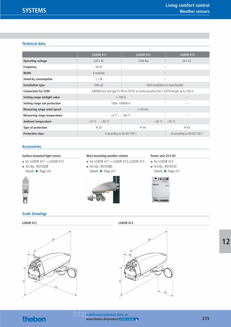
235httpAdditional technical data at:
www.theben.de/product/ Article number
Weather sensorsSYSTEMSLiving comfort control
12
Technical data
LUXOR 411 LUXOR 412 LUXOR 413
Operating voltage 230 V AC COM-Bus 24 V DC
Frequency 50 Hz –
Width 4 modules –
Stand-by consumption 1,1 W –
Installation type DIN rail Wall installation or mast bracket
Connection for COM EIB/KNX bus line type YCYM or Y(ST)Y or communication line J-Y(ST)Y/length up to 100 m
Setting range twilight value 1–100 lx –
Setting range sun protection 1000–100000 lx –
Measuring range wind speed 2–20 m/s
Measuring range temperature +0 °C … +60 °C –
Ambient temperature –10 °C … +50 °C –20 °C … +55 °C
Type of protection IP 20 IP 44 IP 43
Protection class II according to EN 60 730-1 III according to EN 60 730-1
Accessories
Surface-mounted light sensor
■ for LUXOR 411 + LUXOR 412 ■ Art.No.: 9070008Details ▶ Page 253
Mast mounting weather station
■ for LUXOR 411 + LUXOR 413, LUXOR 413 ■ Art.No.: 9070380Details ▶ Page 257
Power unit 24 V DC
■ for LUXOR 413 ■ Art.No.: 9079330Details ▶ Page 257
Scale drawings
LUXOR 412
135
66
280
160
LUXOR 413
135
66
280
80
Catalogue_EN_2013.indb 235 16.01.13 17:25
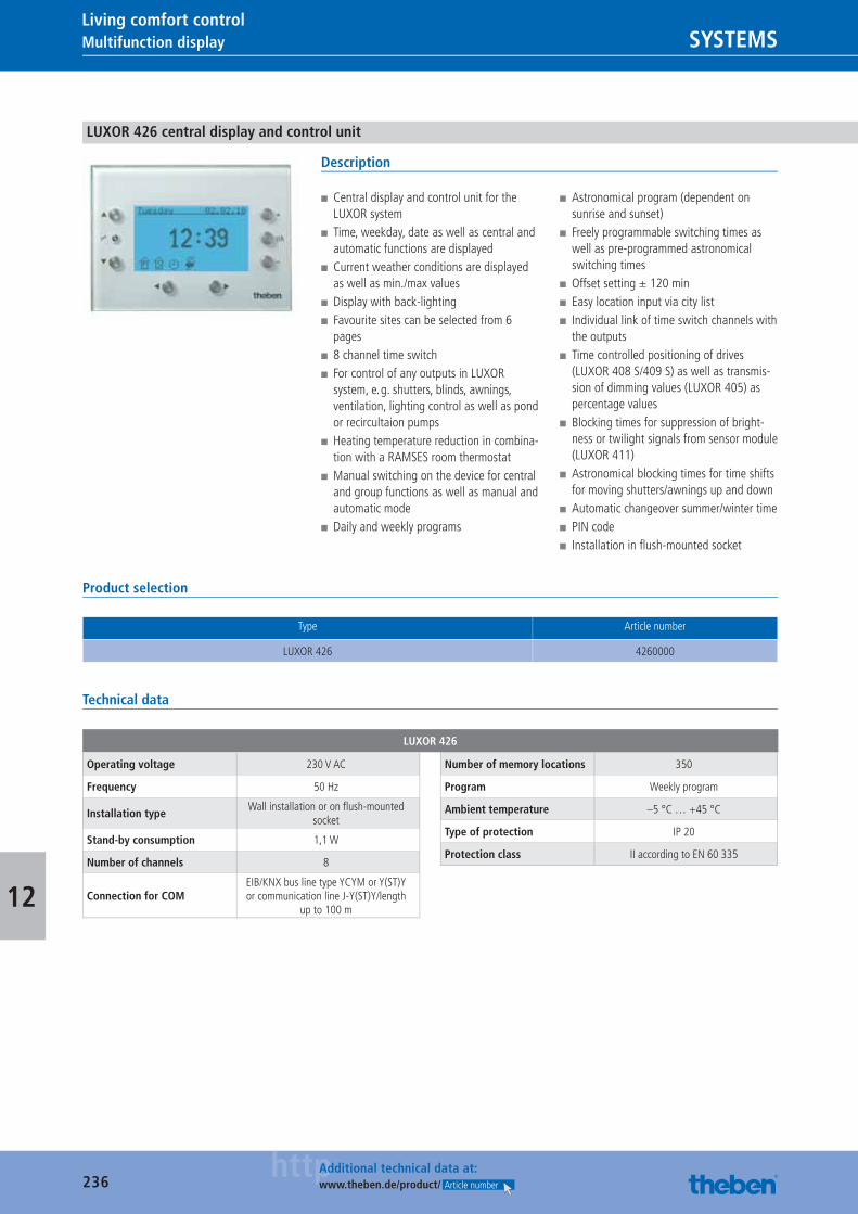
236httpAdditional technical data at:
www.theben.de/product/ Article number
Multifunction display SYSTEMSLiving comfort control
12
LUXOR 426 central display and control unit
Description
■ Central display and control unit for the LUXOR system
■ Time, weekday, date as well as central and automatic functions are displayed
■ Current weather conditions are displayed as well as min./max values
■ Display with back-lighting ■ Favourite sites can be selected from 6 pages
■ 8 channel time switch ■ For control of any outputs in LUXOR system, e. g. shutters, blinds, awnings, ventilation, lighting control as well as pond or recircultaion pumps
■ Heating temperature reduction in combina-tion with a RAMSES room thermostat
■ Manual switching on the device for central and group functions as well as manual and automatic mode
■ Daily and weekly programs
■ Astronomical program (dependent on sunrise and sunset)
■ Freely programmable switching times as well as pre-programmed astronomical switching times
■ Offset setting ± 120 min ■ Easy location input via city list ■ Individual link of time switch channels with the outputs
■ Time controlled positioning of drives (LUXOR 408 S/409 S) as well as transmis-sion of dimming values (LUXOR 405) as percentage values
■ Blocking times for suppression of bright-ness or twilight signals from sensor module (LUXOR 411)
■ Astronomical blocking times for time shifts for moving shutters/awnings up and down
■ Automatic changeover summer/winter time ■ PIN code ■ Installation in fl ush-mounted socket
Product selection
Type Article number
LUXOR 426 4260000
Technical data
LUXOR 426
Operating voltage 230 V AC
Frequency 50 Hz
Installation typeWall installation or on fl ush-mounted
socket
Stand-by consumption 1,1 W
Number of channels 8
Connection for COMEIB/KNX bus line type YCYM or Y(ST)Y or communication line J-Y(ST)Y/length
up to 100 m
Number of memory locations 350
Program Weekly program
Ambient temperature –5 °C … +45 °C
Type of protection IP 20
Protection class II according to EN 60 335
Catalogue_EN_2013.indb 236 16.01.13 17:25
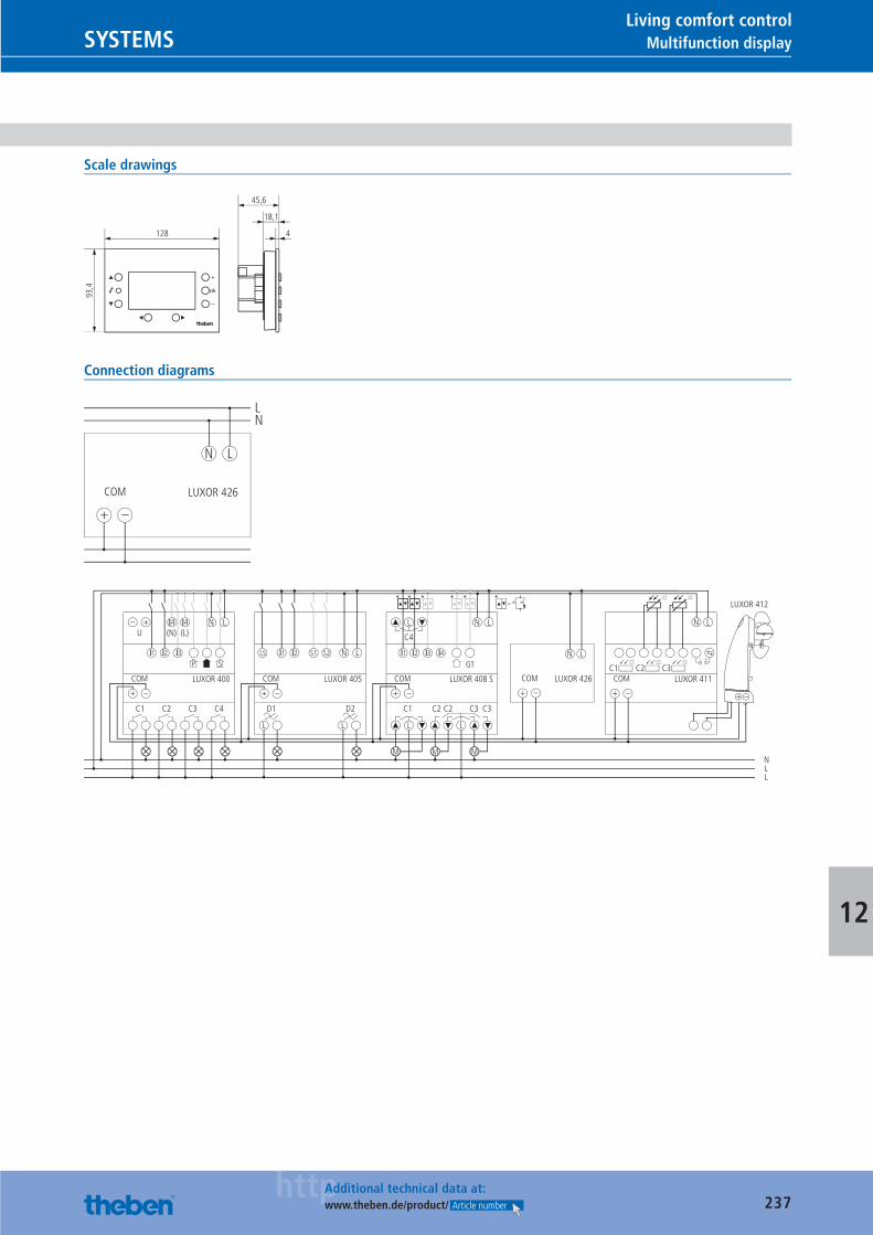
237httpAdditional technical data at:
www.theben.de/product/ Article number
Multifunction displaySYSTEMSLiving comfort control
12
Scale drawings
128 4
18,1
45,6
93,4
Connection diagrams
LN
N L
LUXOR 426COM
+ –
U
COM
+ –
– +(L)(N)
C1 C2 C3
I4 I4
NLL
C4
N L
I2 I3I1
LUXOR 400 LUXOR 405
P S
C4
**** *
G1
COM
M
+ –
L
C1 C2 C2 C3 C3
N L
N LI3 I4
M M
I2
LUXOR 408 S
I1
COM
+ –
D1 D2
N L
L L
I2 S1 S2I1LS
LUXOR 426COM
+ –
*
L L
C1COM
+ –
LUXOR 412
+ –
N L
LUXOR 411C2 C3
=
Catalogue_EN_2013.indb 237 16.01.13 17:25
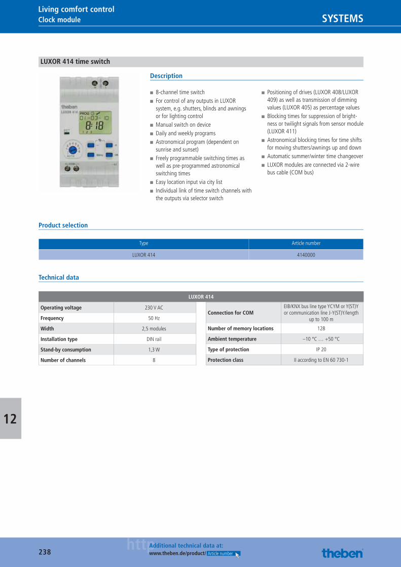
238httpAdditional technical data at:
www.theben.de/product/ Article number
Clock module SYSTEMSLiving comfort control
12
LUXOR 414 time switch
Description
■ 8-channel time switch ■ For control of any outputs in LUXOR system, e.g. shutters, blinds and awnings or for lighting control
■ Manual switch on device ■ Daily and weekly programs ■ Astronomical program (dependent on sunrise and sunset)
■ Freely programmable switching times as well as pre-programmed astronomical switching times
■ Easy location input via city list ■ Individual link of time switch channels with the outputs via selector switch
■ Positioning of drives (LUXOR 408/LUXOR 409) as well as transmission of dimming values (LUXOR 405) as percentage values
■ Blocking times for suppression of bright-ness or twilight signals from sensor module (LUXOR 411)
■ Astronomical blocking times for time shifts for moving shutters/awnings up and down
■ Automatic summer/winter time changeover ■ LUXOR modules are connected via 2-wire bus cable (COM bus)
Product selection
Type Article number
LUXOR 414 4140000
Technical data
LUXOR 414
Operating voltage 230 V AC
Frequency 50 Hz
Width 2,5 modules
Installation type DIN rail
Stand-by consumption 1,3 W
Number of channels 8
Connection for COMEIB/KNX bus line type YCYM or Y(ST)Y or communication line J-Y(ST)Y/length
up to 100 m
Number of memory locations 128
Ambient temperature –10 °C … +50 °C
Type of protection IP 20
Protection class II according to EN 60 730-1
Catalogue_EN_2013.indb 238 16.01.13 17:25
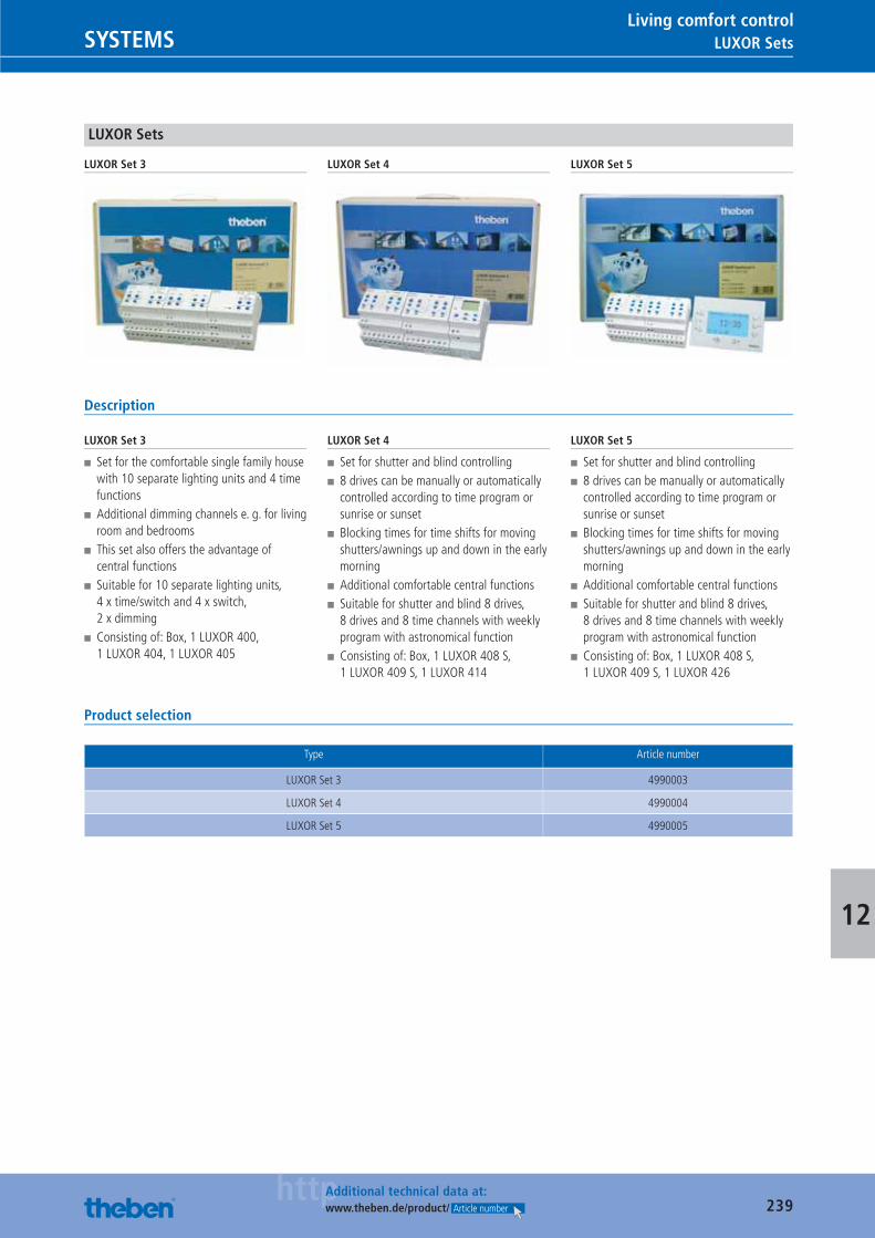
239httpAdditional technical data at:
www.theben.de/product/ Article number
LUXOR SetsSYSTEMSLiving comfort control
12
LUXOR Sets
LUXOR Set 3 LUXOR Set 4 LUXOR Set 5
Description
LUXOR Set 3
■ Set for the comfortable single family house with 10 separate lighting units and 4 time functions
■ Additional dimming channels e. g. for living room and bedrooms
■ This set also offers the advantage of central functions
■ Suitable for 10 separate lighting units, 4 x time/switch and 4 x switch, 2 x dimming
■ Consisting of: Box, 1 LUXOR 400, 1 LUXOR 404, 1 LUXOR 405
LUXOR Set 4
■ Set for shutter and blind controlling ■ 8 drives can be manually or automatically controlled according to time program or sunrise or sunset
■ Blocking times for time shifts for moving shutters/awnings up and down in the early morning
■ Additional comfortable central functions ■ Suitable for shutter and blind 8 drives, 8 drives and 8 time channels with weekly program with astronomical function
■ Consisting of: Box, 1 LUXOR 408 S, 1 LUXOR 409 S, 1 LUXOR 414
LUXOR Set 5
■ Set for shutter and blind controlling ■ 8 drives can be manually or automatically controlled according to time program or sunrise or sunset
■ Blocking times for time shifts for moving shutters/awnings up and down in the early morning
■ Additional comfortable central functions ■ Suitable for shutter and blind 8 drives, 8 drives and 8 time channels with weekly program with astronomical function
■ Consisting of: Box, 1 LUXOR 408 S, 1 LUXOR 409 S, 1 LUXOR 426
Product selection
Type Article number
LUXOR Set 3 4990003
LUXOR Set 4 4990004
LUXOR Set 5 4990005
Catalogue_EN_2013.indb 239 16.01.13 17:25

240
SYSTEMS
0049 7474 692-369: Just call us.What needs to be taken in to account when installing clock thermostats? Why do 5 LEDs display the reception quality on radio receivers? Ease of installation, use and reliability play a big role in the development of our products. But if you have any questions: Our friendly expert Hotline staff will be happy to help you via e-mail or telephone.
Catalogue_EN_2013.indb 240 16.01.13 17:25
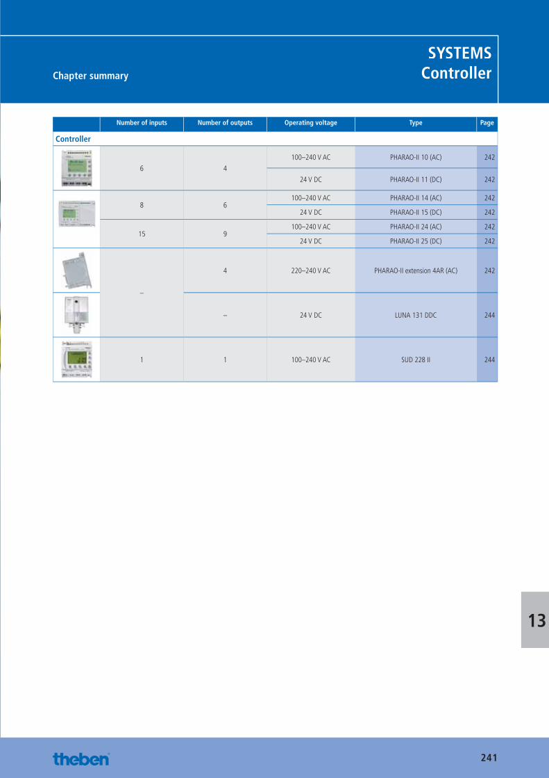
241
Chapter summary
SYSTEMSController
13
Number of inputs Number of outputs Operating voltage Type Page
Controller
6 4
100–240 V AC PHARAO-II 10 (AC) 242
24 V DC PHARAO-II 11 (DC) 242
8 6100–240 V AC PHARAO-II 14 (AC) 242
24 V DC PHARAO-II 15 (DC) 242
15 9100–240 V AC PHARAO-II 24 (AC) 242
24 V DC PHARAO-II 25 (DC) 242
–
4 220–240 V AC PHARAO-II extension 4AR (AC) 242
– 24 V DC LUNA 131 DDC 244
1 1 100–240 V AC SUD 228 II 244
Catalogue_EN_2013.indb 241 16.01.13 17:25
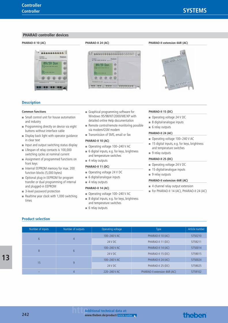
242httpAdditional technical data at:
www.theben.de/product/ Article number
Controller SYSTEMSController
13
PHARAO controller devices
PHARAO-II 10 (AC) PHARAO-II 24 (AC) PHARAO-II extension 4AR (AC)
Description
Common functions
■ Small control unit for house automation and industry
■ Programming directly on device via eight buttons without interface cable
■ Display back light with operator guidance in clear text
■ Input and output switching status display ■ Lifespan of relay contacts is 100,000 switching cycles at nominal current
■ Assignment of programmed functions on front keys
■ Internal EEPROM memory for max. 200 function blocks (5,000 bytes)
■ Optional plug-in EEPROM for program transfer or dual programming of internal and plugged-in EEPROM
■ 3-level password protection ■ Realtime year clock with 1,000 switching times
■ Graphical programming software for Windows 95/98/NT/2000/ME/XP with detailed online Help documentation
■ Remote control/remote monitoring possible via modem/GSM modem
■ Transmission of SMS, email or fax
PHARAO-II 10 (AC)
■ Operating voltage 100–240 V AC ■ 6 digital inputs, e.g. for keys, brightness and temperature switches
■ 4 relay outputs
PHARAO-II 11 (DC)
■ Operating voltage 24 V DC ■ 6 digital/analogue inputs ■ 4 relay outputs
PHARAO-II 14 (AC)
■ Operating voltage 100–240 V AC ■ 8 digital inputs, e.g. for keys, brightness and temperature switches
■ 6 relay outputs
PHARAO-II 15 (DC)
■ Operating voltage 24 V DC ■ 8 digital/analogue inputs ■ 6 relay outputs
PHARAO-II 24 (AC)
■ Operating voltage 100–240 V AC ■ 15 digital inputs, e.g. for keys, brightness and temperature switches
■ 9 relay outputs
PHARAO-II 25 (DC)
■ Operating voltage 24 V DC ■ 15 digital/analogue inputs ■ 9 relay outputs
PHARAO-II extension 4AR (AC)
■ 4 channel relay output extension ■ For PHARAO-II 14 (AC), PHARAO-II 24 (AC)
Product selection
Number of inputs Number of outputs Operating voltage Type Article number
6 4100–240 V AC PHARAO-II 10 (AC) 5750210
24 V DC PHARAO-II 11 (DC) 5759211
8 6100–240 V AC PHARAO-II 14 (AC) 5750014
24 V DC PHARAO-II 15 (DC) 5759015
15 9100–240 V AC PHARAO-II 24 (AC) 5750024
24 V DC PHARAO-II 25 (DC) 5759025
– 4 220–240 V AC PHARAO-II extension 4AR (AC) 5759102
Catalogue_EN_2013.indb 242 16.01.13 17:26
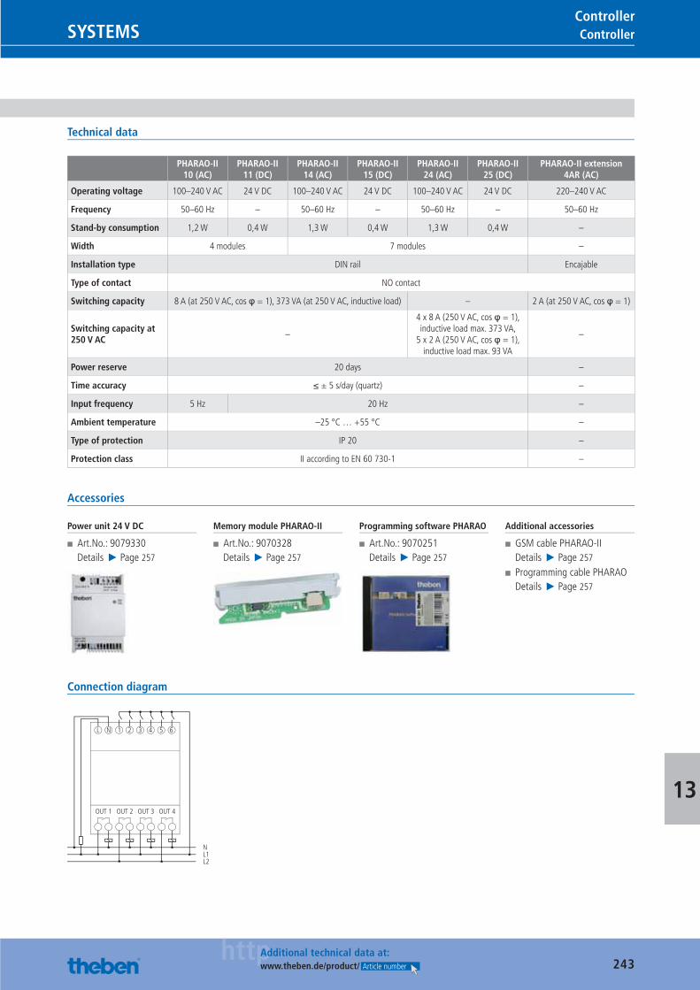
243httpAdditional technical data at:
www.theben.de/product/ Article number
ControllerSYSTEMSController
13
Technical data
PHARAO-II 10 (AC)
PHARAO-II 11 (DC)
PHARAO-II 14 (AC)
PHARAO-II 15 (DC)
PHARAO-II 24 (AC)
PHARAO-II 25 (DC)
PHARAO-II extension 4AR (AC)
Operating voltage 100–240 V AC 24 V DC 100–240 V AC 24 V DC 100–240 V AC 24 V DC 220–240 V AC
Frequency 50–60 Hz – 50–60 Hz – 50–60 Hz – 50–60 Hz
Stand-by consumption 1,2 W 0,4 W 1,3 W 0,4 W 1,3 W 0,4 W –
Width 4 modules 7 modules –
Installation type DIN rail Encajable
Type of contact NO contact
Switching capacity 8 A (at 250 V AC, cos φ = 1), 373 VA (at 250 V AC, inductive load) – 2 A (at 250 V AC, cos φ = 1)
Switching capacity at 250 V AC
–
4 x 8 A (250 V AC, cos φ = 1), inductive load max. 373 VA,
5 x 2 A (250 V AC, cos φ = 1), inductive load max. 93 VA
–
Power reserve 20 days –
Time accuracy ≤ ± 5 s/day (quartz) –
Input frequency 5 Hz 20 Hz –
Ambient temperature –25 °C … +55 °C –
Type of protection IP 20 –
Protection class II according to EN 60 730-1 –
Accessories
Power unit 24 V DC
■ Art.No.: 9079330Details ▶ Page 257
Memory module PHARAO-II
■ Art.No.: 9070328Details ▶ Page 257
Programming software PHARAO
■ Art.No.: 9070251Details ▶ Page 257
Additional accessories
■ GSM cable PHARAO-IIDetails ▶ Page 257
■ Programming cable PHARAODetails ▶ Page 257
Connection diagram
OUT 1
L N 1 2 3 4
NL1L2
5 6
OUT 2 OUT 3 OUT 4
Catalogue_EN_2013.indb 243 16.01.13 17:26
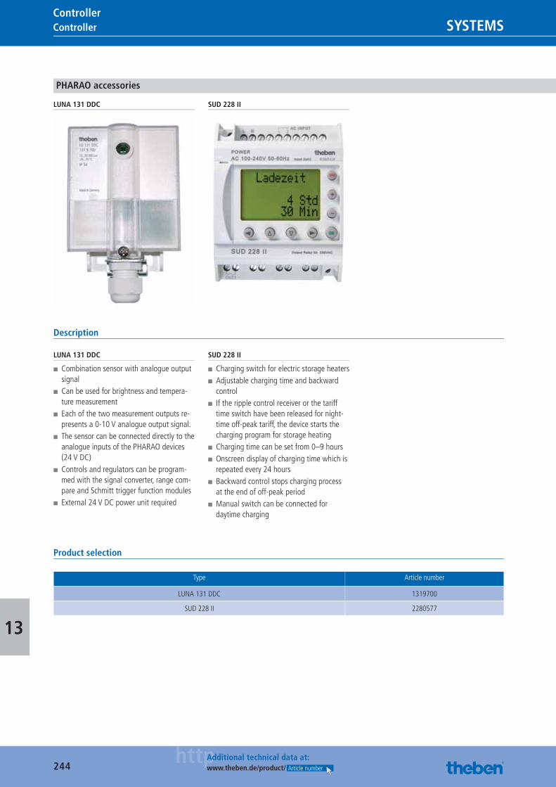
244httpAdditional technical data at:
www.theben.de/product/ Article number
Controller SYSTEMSController
13
PHARAO accessories
LUNA 131 DDC SUD 228 II
Description
LUNA 131 DDC
■ Combination sensor with analogue output signal
■ Can be used for brightness and tempera-ture measurement
■ Each of the two measurement outputs re-presents a 0-10 V analogue output signal.
■ The sensor can be connected directly to the analogue inputs of the PHARAO devices (24 V DC)
■ Controls and regulators can be program-med with the signal converter, range com-pare and Schmitt trigger function modules
■ External 24 V DC power unit required
SUD 228 II
■ Charging switch for electric storage heaters ■ Adjustable charging time and backward control
■ If the ripple control receiver or the tariff time switch have been released for night-time off-peak tariff, the device starts the charging program for storage heating
■ Charging time can be set from 0–9 hours ■ Onscreen display of charging time which is repeated every 24 hours
■ Backward control stops charging process at the end of off-peak period
■ Manual switch can be connected for daytime charging
Product selection
Type Article number
LUNA 131 DDC 1319700
SUD 228 II 2280577
Catalogue_EN_2013.indb 244 16.01.13 17:26
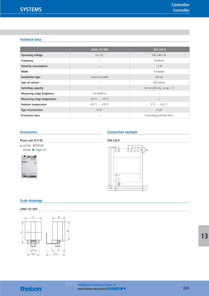
245httpAdditional technical data at:
www.theben.de/product/ Article number
ControllerSYSTEMSController
13
Technical data
LUNA 131 DDC SUD 228 II
Operating voltage 24 V DC 100–240 V AC
Frequency – 50–60 Hz
Stand-by consumption – 1,2 W
Width – 4 modules
Installation type Surface-mounted DIN rail
Type of contact – NO contact
Switching capacity – 8 A (at 250 V AC, cos φ = 1)
Measuring range brightness 10–50000 lx –
Measuring range temperature –30 °C … +70 °C –
Ambient temperature –30 °C … +70 °C 0 °C … +55 °C
Type of protection IP 54 IP 20
Protection class – II according to EN 60 730-1
Accessories
Power unit 24 V DC
■ Art.No.: 9079330Details ▶ Page 257
Connection example
SUD 228 II
OUT 1
L N 1 2
NLL
3 4
Scale drawings
LUNA 131 DDC
93
80
72 54
50,5 81,5
32 57
Catalogue_EN_2013.indb 245 16.01.13 17:26
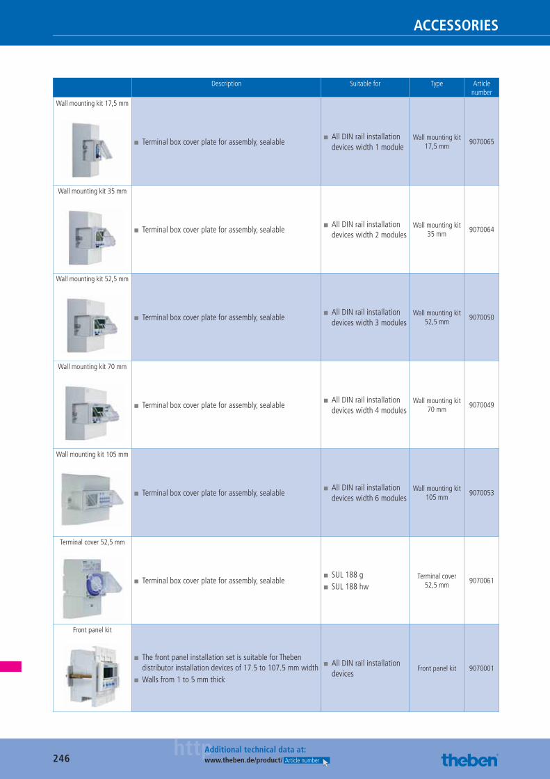
246httpAdditional technical data at:
www.theben.de/product/ Article number
ACCESSORIES
Description Suitable for Type Article number
Wall mounting kit 17,5 mm
■ Terminal box cover plate for assembly, sealable ■ All DIN rail installation devices width 1 module
Wall mounting kit 17,5 mm
9070065
Wall mounting kit 35 mm
■ Terminal box cover plate for assembly, sealable ■ All DIN rail installation devices width 2 modules
Wall mounting kit 35 mm
9070064
Wall mounting kit 52,5 mm
■ Terminal box cover plate for assembly, sealable ■ All DIN rail installation devices width 3 modules
Wall mounting kit 52,5 mm
9070050
Wall mounting kit 70 mm
■ Terminal box cover plate for assembly, sealable ■ All DIN rail installation devices width 4 modules
Wall mounting kit 70 mm
9070049
Wall mounting kit 105 mm
■ Terminal box cover plate for assembly, sealable ■ All DIN rail installation devices width 6 modules
Wall mounting kit 105 mm
9070053
Terminal cover 52,5 mm
■ Terminal box cover plate for assembly, sealable ■ SUL 188 g ■ SUL 188 hw
Terminal cover 52,5 mm
9070061
Front panel kit
■ The front panel installation set is suitable for Theben distributor installation devices of 17.5 to 107.5 mm width
■ Walls from 1 to 5 mm thick
■ All DIN rail installation devices
Front panel kit 9070001
Catalogue_EN_2013.indb 246 16.01.13 17:26
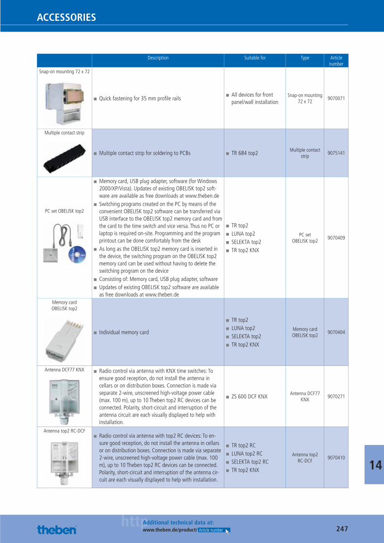
247httpAdditional technical data at:
www.theben.de/product/ Article number
ACCESSORIES
14
Description Suitable for Type Article number
Snap-on mounting 72 x 72
■ Quick fastening for 35 mm profi le rails ■ All devices for front panel/wall installation
Snap-on mounting 72 x 72
9070071
Multiple contact strip
■ Multiple contact strip for soldering to PCBs ■ TR 684 top2 Multiple contact strip
9075141
PC set OBELISK top2
■ Memory card, USB plug adapter, software (for Windows 2000/XP/Vista). Updates of existing OBELISK top2 soft-ware are available as free downloads at www.theben.de
■ Switching programs created on the PC by means of the convenient OBELISK top2 software can be transferred via USB interface to the OBELISK top2 memory card and from the card to the time switch and vice versa. Thus no PC or laptop is required on-site. Programming and the program printout can be done comfortably from the desk
■ As long as the OBELISK top2 memory card is inserted in the device, the switching program on the OBELISK top2 memory card can be used without having to delete the switching program on the device
■ Consisting of: Memory card, USB plug adapter, software ■ Updates of existing OBELISK top2 software are available as free downloads at www.theben.de
■ TR top2 ■ LUNA top2 ■ SELEKTA top2 ■ TR top2 KNX
PC set OBELISK top2
9070409
Memory card OBELISK top2
■ Individual memory card
■ TR top2 ■ LUNA top2 ■ SELEKTA top2 ■ TR top2 KNX
Memory card OBELISK top2
9070404
Antenna DCF77 KNX ■ Radio control via antenna with KNX time switches: To ensure good reception, do not install the antenna in cellars or on distribution boxes. Connection is made via separate 2-wire, unscreened high-voltage power cable (max. 100 m), up to 10 Theben top2 RC devices can be connected. Polarity, short-circuit and interruption of the antenna circuit are each visually displayed to help with installation.
■ ZS 600 DCF KNX Antenna DCF77 KNX
9070271
Antenna top2 RC-DCF ■ Radio control via antenna with top2 RC devices: To en-sure good reception, do not install the antenna in cellars or on distribution boxes. Connection is made via separate 2-wire, unscreened high-voltage power cable (max. 100 m), up to 10 Theben top2 RC devices can be connected. Polarity, short-circuit and interruption of the antenna cir-cuit are each visually displayed to help with installation.
■ TR top2 RC ■ LUNA top2 RC ■ SELEKTA top2 RC ■ TR top2 KNX
Antenna top2 RC-DCF
9070410
Catalogue_EN_2013.indb 247 16.01.13 17:26
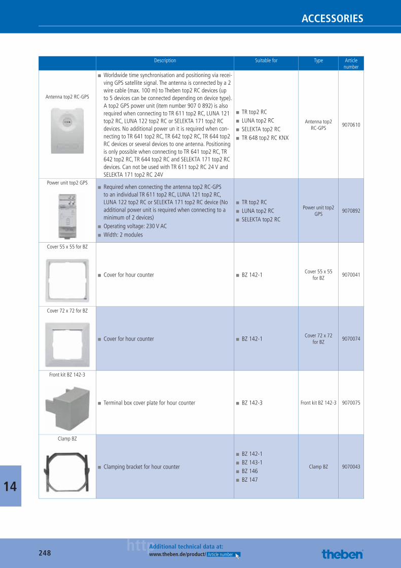
248httpAdditional technical data at:
www.theben.de/product/ Article number
ACCESSORIES
14
Description Suitable for Type Article number
Antenna top2 RC-GPS
■ Worldwide time synchronisation and positioning via recei-ving GPS satellite signal. The antenna is connected by a 2 wire cable (max. 100 m) to Theben top2 RC devices (up to 5 devices can be connected depending on device type). A top2 GPS power unit (item number 907 0 892) is also required when connecting to TR 611 top2 RC, LUNA 121 top2 RC, LUNA 122 top2 RC or SELEKTA 171 top2 RC devices. No additional power un it is required when con-necting to TR 641 top2 RC, TR 642 top2 RC, TR 644 top2 RC devices or several devices to one antenna. Positioning is only possible when connecting to TR 641 top2 RC, TR 642 top2 RC, TR 644 top2 RC and SELEKTA 171 top2 RC devices. Can not be used with TR 611 top2 RC 24 V and SELEKTA 171 top2 RC 24V
■ TR top2 RC ■ LUNA top2 RC ■ SELEKTA top2 RC ■ TR 648 top2 RC KNX
Antenna top2 RC-GPS
9070610
Power unit top2 GPS ■ Required when connecting the antenna top2 RC-GPS to an individual TR 611 top2 RC, LUNA 121 top2 RC, LUNA 122 top2 RC or SELEKTA 171 top2 RC device (No additional power unit is required when connecting to a minimum of 2 devices)
■ Operating voltage: 230 V AC ■ Width: 2 modules
■ TR top2 RC ■ LUNA top2 RC ■ SELEKTA top2 RC
Power unit top2 GPS
9070892
Cover 55 x 55 for BZ
■ Cover for hour counter ■ BZ 142-1 Cover 55 x 55 for BZ
9070041
Cover 72 x 72 for BZ
■ Cover for hour counter ■ BZ 142-1 Cover 72 x 72 for BZ
9070074
Front kit BZ 142-3
■ Terminal box cover plate for hour counter ■ BZ 142-3 Front kit BZ 142-3 9070075
Clamp BZ
■ Clamping bracket for hour counter
■ BZ 142-1 ■ BZ 143-1 ■ BZ 146 ■ BZ 147
Clamp BZ 9070043
Catalogue_EN_2013.indb 248 16.01.13 17:26
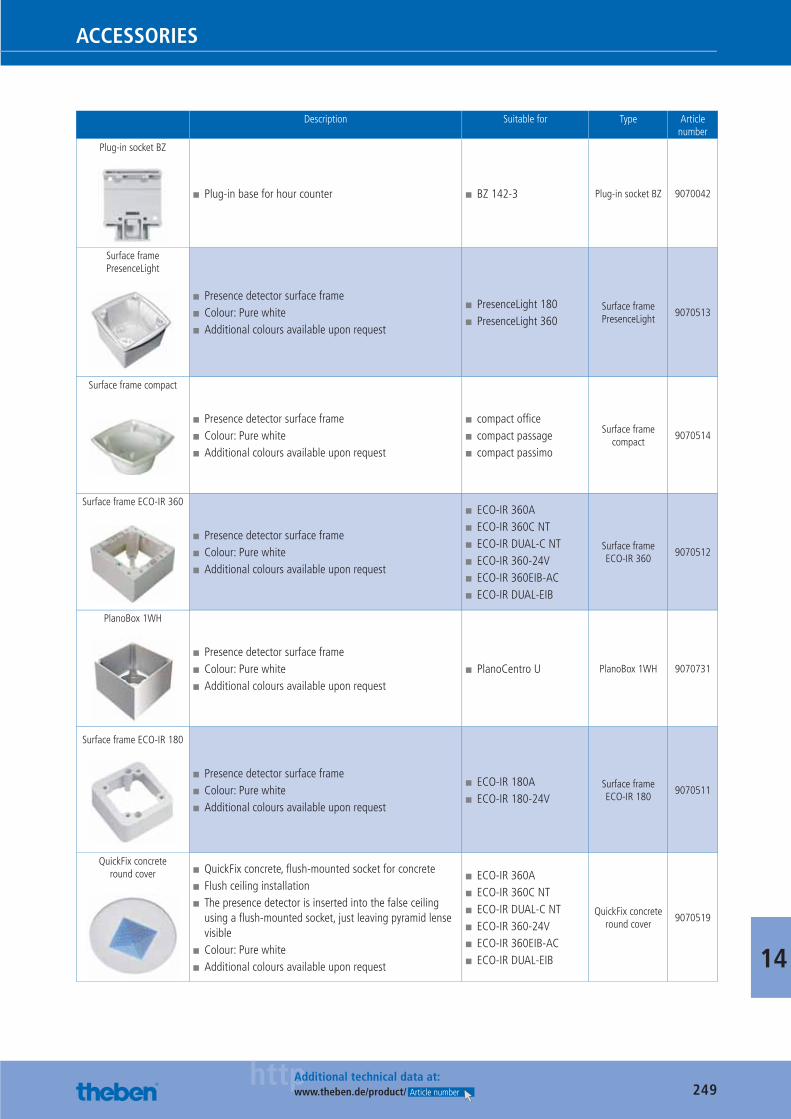
249httpAdditional technical data at:
www.theben.de/product/ Article number
ACCESSORIES
14
Description Suitable for Type Article number
Plug-in socket BZ
■ Plug-in base for hour counter ■ BZ 142-3 Plug-in socket BZ 9070042
Surface frame PresenceLight
■ Presence detector surface frame ■ Colour: Pure white ■ Additional colours available upon request
■ PresenceLight 180 ■ PresenceLight 360
Surface frame PresenceLight
9070513
Surface frame compact
■ Presence detector surface frame ■ Colour: Pure white ■ Additional colours available upon request
■ compact offi ce ■ compact passage ■ compact passimo
Surface frame compact
9070514
Surface frame ECO-IR 360
■ Presence detector surface frame ■ Colour: Pure white ■ Additional colours available upon request
■ ECO-IR 360A ■ ECO-IR 360C NT ■ ECO-IR DUAL-C NT ■ ECO-IR 360-24V ■ ECO-IR 360EIB-AC ■ ECO-IR DUAL-EIB
Surface frame ECO-IR 360
9070512
PlanoBox 1WH
■ Presence detector surface frame ■ Colour: Pure white ■ Additional colours available upon request
■ PlanoCentro U PlanoBox 1WH 9070731
Surface frame ECO-IR 180
■ Presence detector surface frame ■ Colour: Pure white ■ Additional colours available upon request
■ ECO-IR 180A ■ ECO-IR 180-24V
Surface frame ECO-IR 180
9070511
QuickFix concrete round cover ■ QuickFix concrete, fl ush-mounted socket for concrete
■ Flush ceiling installation ■ The presence detector is inserted into the false ceiling using a fl ush-mounted socket, just leaving pyramid lense visible
■ Colour: Pure white ■ Additional colours available upon request
■ ECO-IR 360A ■ ECO-IR 360C NT ■ ECO-IR DUAL-C NT ■ ECO-IR 360-24V ■ ECO-IR 360EIB-AC ■ ECO-IR DUAL-EIB
QuickFix concrete round cover
9070519
Catalogue_EN_2013.indb 249 16.01.13 17:26
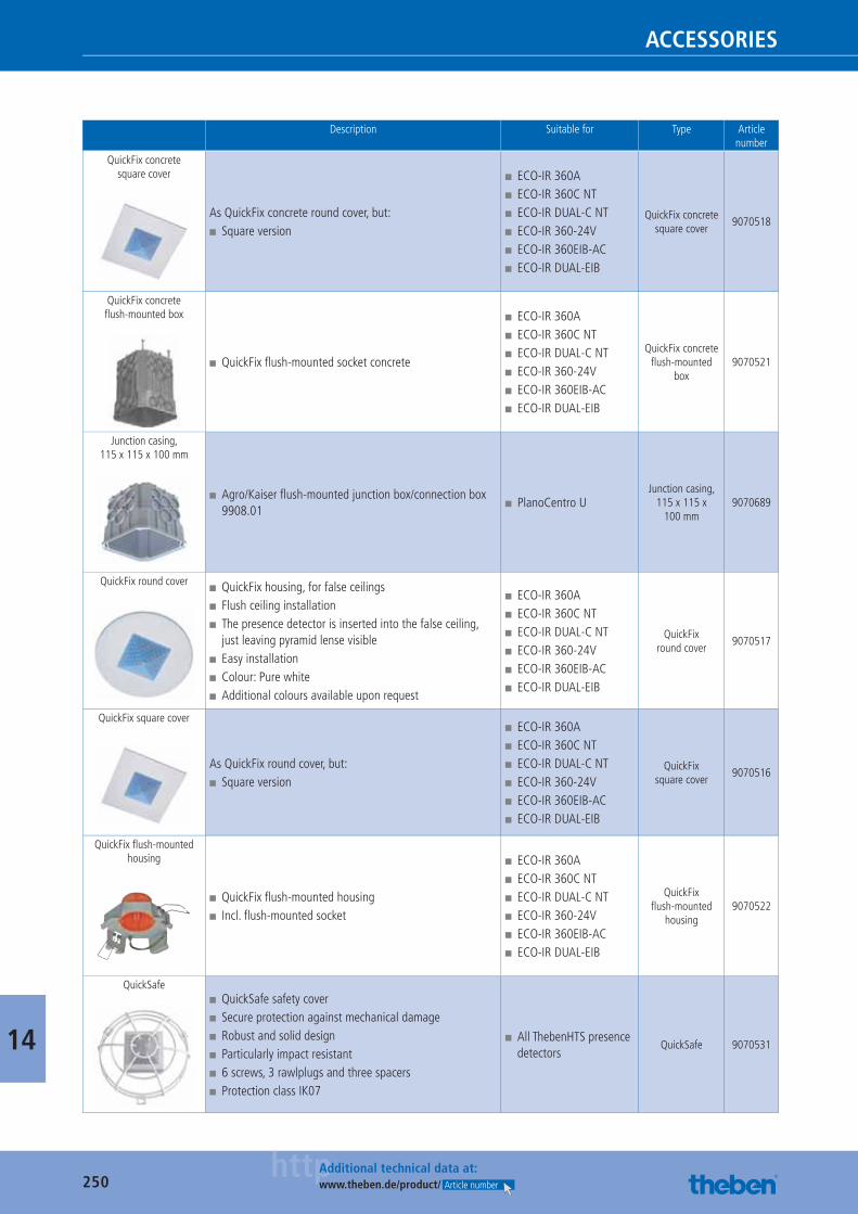
250httpAdditional technical data at:
www.theben.de/product/ Article number
ACCESSORIES
14
Description Suitable for Type Article number
QuickFix concrete square cover
As QuickFix concrete round cover, but: ■ Square version
■ ECO-IR 360A ■ ECO-IR 360C NT ■ ECO-IR DUAL-C NT ■ ECO-IR 360-24V ■ ECO-IR 360EIB-AC ■ ECO-IR DUAL-EIB
QuickFix concrete square cover
9070518
QuickFix concrete fl ush-mounted box
■ QuickFix fl ush-mounted socket concrete
■ ECO-IR 360A ■ ECO-IR 360C NT ■ ECO-IR DUAL-C NT ■ ECO-IR 360-24V ■ ECO-IR 360EIB-AC ■ ECO-IR DUAL-EIB
QuickFix concrete fl ush-mounted
box9070521
Junction casing, 115 x 115 x 100 mm
■ Agro/Kaiser fl ush-mounted junction box/connection box 9908.01
■ PlanoCentro UJunction casing,
115 x 115 x 100 mm
9070689
QuickFix round cover ■ QuickFix housing, for false ceilings ■ Flush ceiling installation ■ The presence detector is inserted into the false ceiling, just leaving pyramid lense visible
■ Easy installation ■ Colour: Pure white ■ Additional colours available upon request
■ ECO-IR 360A ■ ECO-IR 360C NT ■ ECO-IR DUAL-C NT ■ ECO-IR 360-24V ■ ECO-IR 360EIB-AC ■ ECO-IR DUAL-EIB
QuickFix round cover
9070517
QuickFix square cover
As QuickFix round cover, but: ■ Square version
■ ECO-IR 360A ■ ECO-IR 360C NT ■ ECO-IR DUAL-C NT ■ ECO-IR 360-24V ■ ECO-IR 360EIB-AC ■ ECO-IR DUAL-EIB
QuickFix square cover
9070516
QuickFix fl ush-mounted housing
■ QuickFix fl ush-mounted housing ■ Incl. fl ush-mounted socket
■ ECO-IR 360A ■ ECO-IR 360C NT ■ ECO-IR DUAL-C NT ■ ECO-IR 360-24V ■ ECO-IR 360EIB-AC ■ ECO-IR DUAL-EIB
QuickFix fl ush-mounted
housing9070522
QuickSafe ■ QuickSafe safety cover ■ Secure protection against mechanical damage ■ Robust and solid design ■ Particularly impact resistant ■ 6 screws, 3 rawlplugs and three spacers ■ Protection class IK07
■ All ThebenHTS presence detectors
QuickSafe 9070531
Catalogue_EN_2013.indb 250 16.01.13 17:26
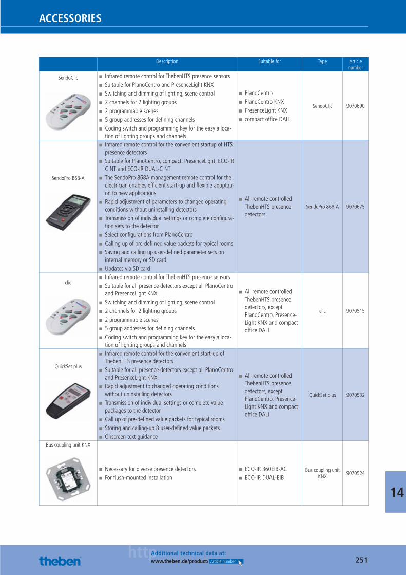
251httpAdditional technical data at:
www.theben.de/product/ Article number
ACCESSORIES
14
Description Suitable for Type Article number
SendoClic ■ Infrared remote control for ThebenHTS presence sensors ■ Suitable for PlanoCentro and PresenceLight KNX ■ Switching and dimming of lighting, scene control ■ 2 channels for 2 lighting groups ■ 2 programmable scenes ■ 5 group addresses for defi ning channels ■ Coding switch and programming key for the easy alloca-tion of lighting groups and channels
■ PlanoCentro ■ PlanoCentro KNX ■ PresenceLight KNX ■ compact offi ce DALI
SendoClic 9070690
SendoPro 868-A
■ Infrared remote control for the convenient startup of HTS presence detectors
■ Suitable for PlanoCentro, compact, PresenceLight, ECO-IR C NT and ECO-IR DUAL-C NT
■ The SendoPro 868A management remote control for the electrician enables effi cient start-up and fl exible adaptati-on to new applications
■ Rapid adjustment of parameters to changed operating conditions without uninstalling detectors
■ Transmission of individual settings or complete confi gura-tion sets to the detector
■ Select confi gurations from PlanoCentro ■ Calling up of pre-defi ned value packets for typical rooms ■ Saving and calling up user-defi ned parameter sets on internal memory or SD card
■ Updates via SD card
■ All remote controlled ThebenHTS presence detectors
SendoPro 868-A 9070675
clic ■ Infrared remote control for ThebenHTS presence sensors ■ Suitable for all presence detectors except all PlanoCentro and PresenceLight KNX
■ Switching and dimming of lighting, scene control ■ 2 channels for 2 lighting groups ■ 2 programmable scenes ■ 5 group addresses for defi ning channels ■ Coding switch and programming key for the easy alloca-tion of lighting groups and channels
■ All remote controlled ThebenHTS presence detectors, exceptPlanoCentro, Presence-Light KNX and compact offi ce DALI
clic 9070515
QuickSet plus
■ Infrared remote control for the convenient start-up of ThebenHTS presence detectors
■ Suitable for all presence detectors except all PlanoCentro and PresenceLight KNX
■ Rapid adjustment to changed operating conditions without uninstalling detectors
■ Transmission of individual settings or complete value packages to the detector
■ Call up of pre-defi ned value packets for typical rooms ■ Storing and calling-up 8 user-defi ned value packets ■ Onscreen text guidance
■ All remote controlled ThebenHTS presence detectors, exceptPlanoCentro, Presence-Light KNX and compact offi ce DALI
QuickSet plus 9070532
Bus coupling unit KNX
■ Necessary for diverse presence detectors ■ For fl ush-mounted installation
■ ECO-IR 360EIB-AC ■ ECO-IR DUAL-EIB
Bus coupling unit KNX
9070524
Catalogue_EN_2013.indb 251 16.01.13 17:26
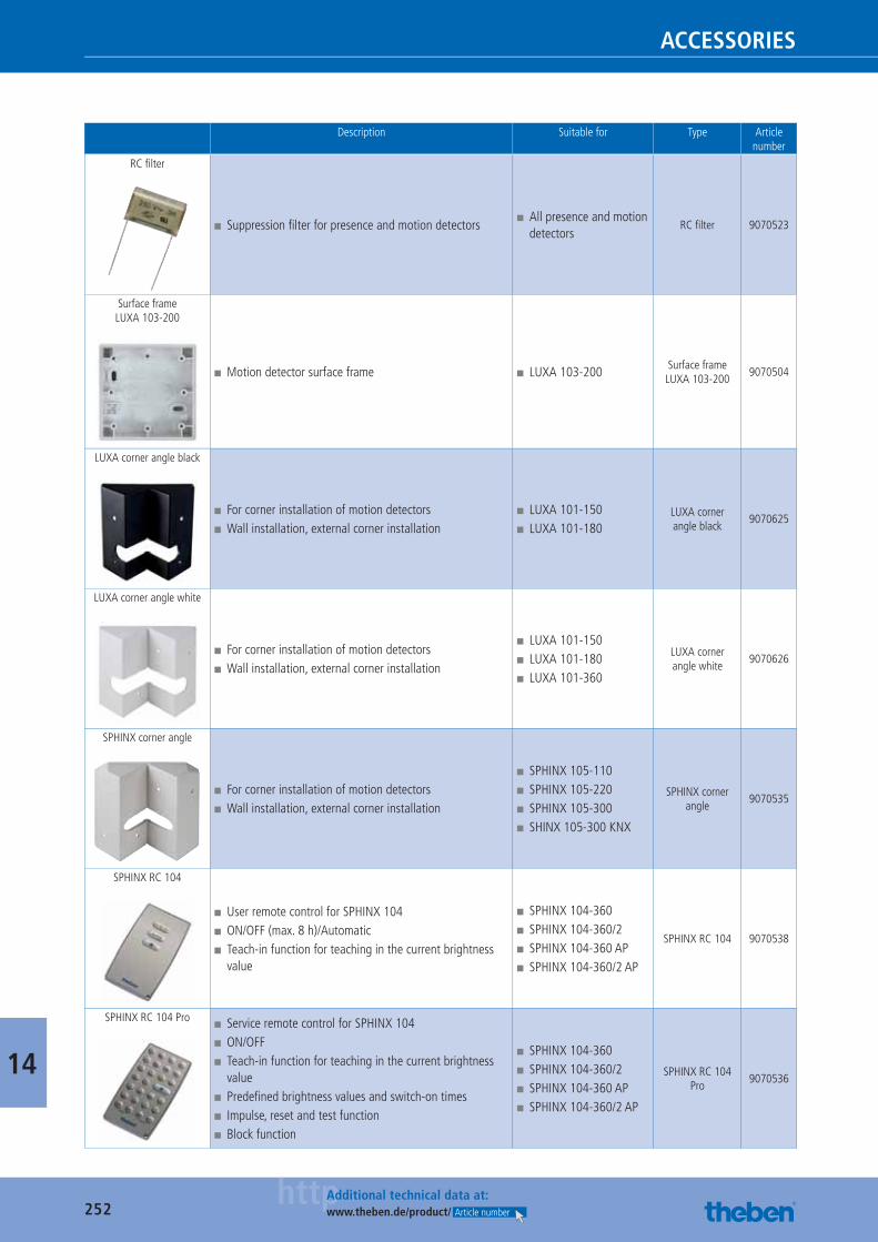
252httpAdditional technical data at:
www.theben.de/product/ Article number
ACCESSORIES
14
Description Suitable for Type Article number
RC fi lter
■ Suppression fi lter for presence and motion detectors ■ All presence and motion detectors
RC fi lter 9070523
Surface frame LUXA 103-200
■ Motion detector surface frame ■ LUXA 103-200 Surface frame LUXA 103-200
9070504
LUXA corner angle black
■ For corner installation of motion detectors ■ Wall installation, external corner installation
■ LUXA 101-150 ■ LUXA 101-180
LUXA corner angle black
9070625
LUXA corner angle white
■ For corner installation of motion detectors ■ Wall installation, external corner installation
■ LUXA 101-150 ■ LUXA 101-180 ■ LUXA 101-360
LUXA corner angle white
9070626
SPHINX corner angle
■ For corner installation of motion detectors ■ Wall installation, external corner installation
■ SPHINX 105-110 ■ SPHINX 105-220 ■ SPHINX 105-300 ■ SHINX 105-300 KNX
SPHINX corner angle
9070535
SPHINX RC 104
■ User remote control for SPHINX 104 ■ ON/OFF (max. 8 h)/Automatic ■ Teach-in function for teaching in the current brightness value
■ SPHINX 104-360 ■ SPHINX 104-360/2 ■ SPHINX 104-360 AP ■ SPHINX 104-360/2 AP
SPHINX RC 104 9070538
SPHINX RC 104 Pro ■ Service remote control for SPHINX 104 ■ ON/OFF ■ Teach-in function for teaching in the current brightness value
■ Predefi ned brightness values and switch-on times ■ Impulse, reset and test function ■ Block function
■ SPHINX 104-360 ■ SPHINX 104-360/2 ■ SPHINX 104-360 AP ■ SPHINX 104-360/2 AP
SPHINX RC 104 Pro
9070536
Catalogue_EN_2013.indb 252 16.01.13 17:26
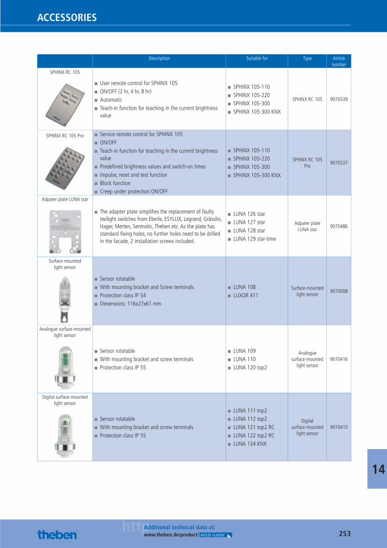
253httpAdditional technical data at:
www.theben.de/product/ Article number
ACCESSORIES
14
Description Suitable for Type Article number
SPHINX RC 105
■ User remote control for SPHINX 105 ■ ON/OFF (2 hr, 4 hr, 8 hr) ■ Automatic ■ Teach-in function for teaching in the current brightness value
■ SPHINX 105-110 ■ SPHINX 105-220 ■ SPHINX 105-300 ■ SPHINX 105-300 KNX
SPHINX RC 105 9070539
SPHINX RC 105 Pro ■ Service remote control for SPHINX 105 ■ ON/OFF ■ Teach-in function for teaching in the current brightness value
■ Predefi ned brightness values and switch-on times ■ Impulse, reset and test function ■ Block function ■ Creep under protection ON/OFF
■ SPHINX 105-110 ■ SPHINX 105-220 ■ SPHINX 105-300 ■ SPHINX 105-300 KNX
SPHINX RC 105 Pro
9070537
Adpater plate LUNA star
■ The adapter plate simplifi es the replacement of faulty twilight switches from Eberle, ESYLUX, Legrand, Grässlin, Hager, Merten, Senmatic, Theben etc. As the plate has standard fi xing holes, no further holes need to be drilled in the facade, 2 installation screws included.
■ LUNA 126 star ■ LUNA 127 star ■ LUNA 128 star ■ LUNA 129 star-time
Adpater plate LUNA star
9070486
Surface-mounted light sensor
■ Sensor rotatable ■ With mounting bracket and Screw terminals ■ Protection class IP 54 ■ Dimensions: 116x27x61 mm
■ LUNA 108 ■ LUXOR 411
Surface-mounted light sensor
9070008
Analogue surface-mounted light sensor
■ Sensor rotatable ■ With mounting bracket and screw terminals ■ Protection class IP 55
■ LUNA 109 ■ LUNA 110 ■ LUNA 120 top2
Analogue surface-mounted
light sensor9070416
Digital surface-mounted light sensor
■ Sensor rotatable ■ With mounting bracket and screw terminals ■ Protection class IP 55
■ LUNA 111 top2 ■ LUNA 112 top2 ■ LUNA 121 top2 RC ■ LUNA 122 top2 RC ■ LUNA 134 KNX
Digital surface-mounted
light sensor9070415
Catalogue_EN_2013.indb 253 16.01.13 17:26
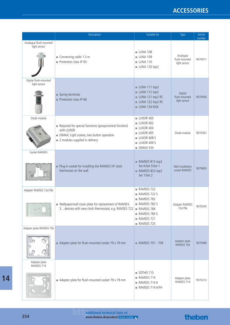
254httpAdditional technical data at:
www.theben.de/product/ Article number
ACCESSORIES
14
Description Suitable for Type Article number
Analogue fl ush-mounted light sensor
■ Connecting cable 1.5 m ■ Protection class IP 65
■ LUNA 108 ■ LUNA 109 ■ LUNA 110 ■ LUNA 120 top2
Analogue fl ush-mounted
light sensor9070011
Digital fl ush-mounted light sensor
■ Spring terminals ■ Protection class IP 66
■ LUNA 111 top2 ■ LUNA 112 top2 ■ LUNA 121 top2 RC ■ LUNA 122 top2 RC ■ LUNA 134 KNX
Digital fl ush-mounted
light sensor9070456
Diode module
■ Required for special functions (group/central function) with LUXOR
■ DIMAX: Light scenes, two button operation ■ 2 modules supplied in delivery
■ LUXOR 400 ■ LUXOR 402 ■ LUXOR 404 ■ LUXOR 405 ■ LUXOR 408 S ■ LUXOR 409 S ■ DIMAX 534
Diode module 9070367
Socket RAMSES
■ Plug-in socket for installing the RAMSES HF clock thermostat on the wall
■ RAMSES 813 top2 Set A/Set S/Set 1
■ RAMSES 833 top2 Set 1/Set 2
Wall installation socket RAMSES
9070605
Adapter RAMSES 72x/78x
■ Wallpaper/wall cover plate for replacement of RAMSES 3…devices with new clock thermostats, e.g. RAMSES 722
■ RAMSES 722 ■ RAMSES 722 S ■ RAMSES 782 ■ RAMSES 782 S ■ RAMSES 784 ■ RAMSES 784 S ■ RAMSES 721 ■ RAMSES 725
Adapter RAMSES 72x/78x
9070245
Adapter plate RAMSES 70x
■ Adapter plate for fl ush-mounted socket 79 x 79 mm ■ RAMSES 701 - 709 Adapter plate RAMSES 70x
9070480
Adapter plate RAMSES 714
■ Adapter plate for fl ush-mounted socket 79 x 79 mm
■ SOTHIS 715 ■ RAMSES 714 ■ RAMSES 714 A ■ RAMSES 714 A/FH
Adapter plate RAMSES 714
9070212
Catalogue_EN_2013.indb 254 16.01.13 17:26
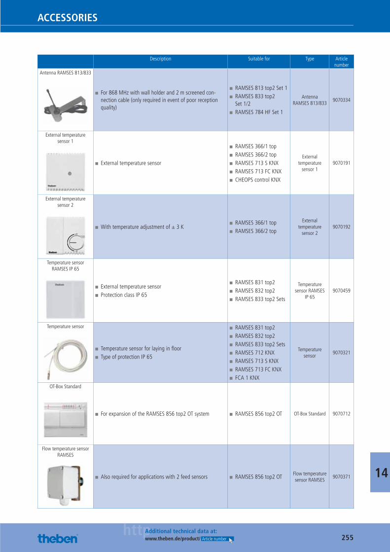
255httpAdditional technical data at:
www.theben.de/product/ Article number
ACCESSORIES
14
Description Suitable for Type Article number
Antenna RAMSES 813/833
■ For 868 MHz with wall holder and 2 m screened con-nection cable (only required in event of poor reception quality)
■ RAMSES 813 top2 Set 1 ■ RAMSES 833 top2 Set 1/2
■ RAMSES 784 HF Set 1
Antenna RAMSES 813/833
9070334
External temperature sensor 1
■ External temperature sensor
■ RAMSES 366/1 top ■ RAMSES 366/2 top ■ RAMSES 713 S KNX ■ RAMSES 713 FC KNX ■ CHEOPS control KNX
External temperature
sensor 19070191
External temperature sensor 2
■ With temperature adjustment of ± 3 K ■ RAMSES 366/1 top ■ RAMSES 366/2 top
External temperature
sensor 29070192
Temperature sensor RAMSES IP 65
■ External temperature sensor ■ Protection class IP 65
■ RAMSES 831 top2 ■ RAMSES 832 top2 ■ RAMSES 833 top2 Sets
Temperature sensor RAMSES
IP 659070459
Temperature sensor
■ Temperature sensor for laying in fl oor ■ Type of protection IP 65
■ RAMSES 831 top2 ■ RAMSES 832 top2 ■ RAMSES 833 top2 Sets ■ RAMSES 712 KNX ■ RAMSES 713 S KNX ■ RAMSES 713 FC KNX ■ FCA 1 KNX
Temperature sensor
9070321
OT-Box Standard
■ For expansion of the RAMSES 856 top2 OT system ■ RAMSES 856 top2 OT OT-Box Standard 9070712
Flow temperature sensor RAMSES
■ Also required for applications with 2 feed sensors ■ RAMSES 856 top2 OT Flow temperature sensor RAMSES
9070371
Catalogue_EN_2013.indb 255 16.01.13 17:26
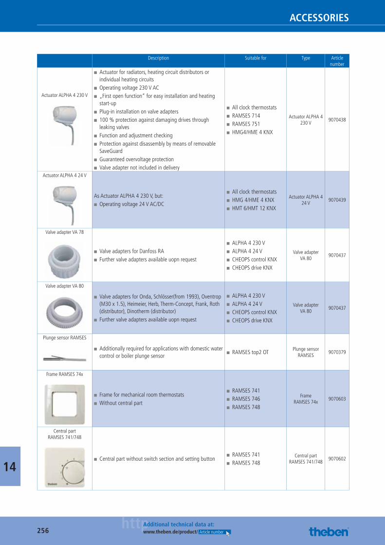
256httpAdditional technical data at:
www.theben.de/product/ Article number
ACCESSORIES
14
Description Suitable for Type Article number
Actuator ALPHA 4 230 V
■ Actuator for radiators, heating circuit distributors or individual heating circuits
■ Operating voltage 230 V AC ■ „First open function“ for easy installation and heating start-up
■ Plug-in installation on valve adapters ■ 100 % protection against damaging drives through leaking valves
■ Function and adjustment checking ■ Protection against disassembly by means of removable SaveGuard
■ Guaranteed overvoltage protection ■ Valve adapter not included in delivery
■ All clock thermostats ■ RAMSES 714 ■ RAMSES 751 ■ HMG4/HME 4 KNX
Actuator ALPHA 4 230 V
9070438
Actuator ALPHA 4 24 V
As Actuator ALPHA 4 230 V, but: ■ Operating voltage 24 V AC/DC
■ All clock thermostats ■ HMG 4/HME 4 KNX ■ HMT 6/HMT 12 KNX
Actuator ALPHA 4 24 V
9070439
Valve adapter VA 78
■ Valve adapters for Danfoss RA ■ Further valve adapters available uopn request
■ ALPHA 4 230 V ■ ALPHA 4 24 V ■ CHEOPS control KNX ■ CHEOPS drive KNX
Valve adapter VA 80
9070437
Valve adapter VA 80
■ Valve adapters for Onda, Schlösser(from 1993), Oventrop (M30 x 1.5), Heimeier, Herb, Therm-Concept, Frank, Roth (distributor), Dinotherm (distributor)
■ Further valve adapters available uopn request
■ ALPHA 4 230 V ■ ALPHA 4 24 V ■ CHEOPS control KNX ■ CHEOPS drive KNX
Valve adapter VA 80
9070437
Plunge sensor RAMSES
■ Additionally required for applications with domestic water control or boiler plunge sensor
■ RAMSES top2 OT Plunge sensor RAMSES
9070379
Frame RAMSES 74x
■ Frame for mechanical room thermostats ■ Without central part
■ RAMSES 741 ■ RAMSES 746 ■ RAMSES 748
Frame RAMSES 74x
9070603
Central part RAMSES 741/748
■ Central part without switch section and setting button ■ RAMSES 741 ■ RAMSES 748
Central part RAMSES 741/748
9070602
Catalogue_EN_2013.indb 256 16.01.13 17:26
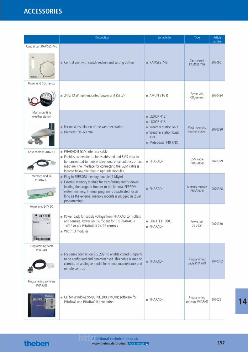
257httpAdditional technical data at:
www.theben.de/product/ Article number
ACCESSORIES
14
Description Suitable for Type Article number
Central part RAMSES 746
■ Central part with switch section and setting button ■ RAMSES 746 Central part RAMSES 746
9070601
Power unit CO2-sensor
■ 24 V/12 W fl ush-mounted power unit (SELV) ■ AMUN 716 R Power unit CO2-sensor
9070494
Mast mounting weather station
■ For mast installation of the weather station ■ Diameter 50–60 mm
■ LUXOR 412 ■ LUXOR 413 ■ Weather station KNX ■ Weather station basic KNX
■ Meteodata 140 KNX
Mast mounting weather station
9070380
GSM cable PHARAO-II ■ PHARAO-II GSM interface cable ■ Enables connection to be established and SMS data to be transmitted to mobile telephone, email address or fax machine. The interface for connecting the GSM cable is located below the plug-in upgrade modules.
■ PHARAO-II GSM cable PHARAO-II
9070329
Memory module PHARAO-II
■ Plug-in EEPROM memory module (5 kByte) ■ External memory module for transferring and/or down-loading the program from or to the internal EEPROM system memory. Internal program is deactivated for as long as the external memory module is plugged in (dual programming).
■ PHARAO-II Memory module PHARAO-II
9070328
Power unit 24 V DC
■ Power pack for supply voltage from PHARAO controllers and sensors. Power unit suffi cient for 5 x PhARAO-II 14/15 or 4 x PHARAO-II 24/25 controls
■ Width: 3 modules
■ LUNA 131 DDC ■ PHARAO-II
Power unit 24 V DC
9079330
Programming cable PHARAO
■ For series connection (RS 232) to enable conrol programs to be confi gured and parameterised. This cable is used to connect an analogue model for remote maintenance and remote control.
■ PHARAO-II Programming cable PHARAO
9070252
Programming software PHARAO
■ CD for Windows 95/98/NT/2000/ME/XP, software for PHARAO and PHARAO II generation
■ PHARAO-II Programming software PHARAO
9070251
Catalogue_EN_2013.indb 257 16.01.13 17:26
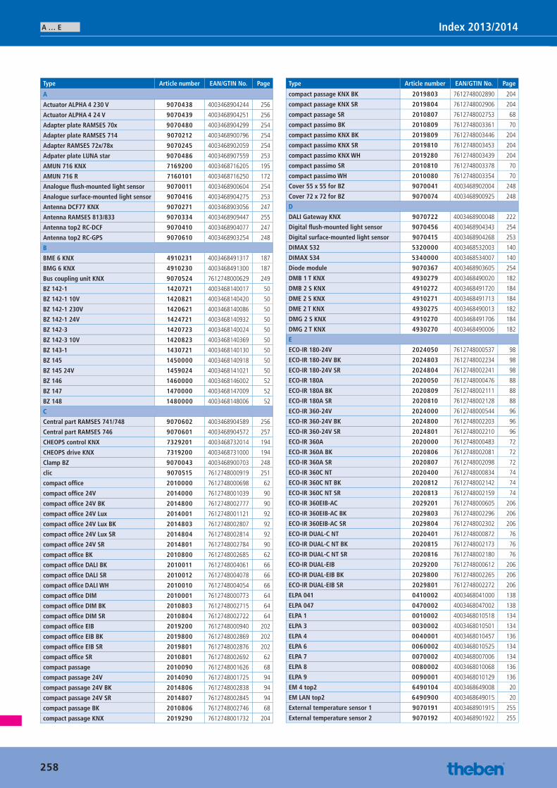
A … E Index 2013/2014
Type Article number EAN/GTIN No. Page
A
Actuator ALPHA 4 230 V 9070438 4003468904244 256
Actuator ALPHA 4 24 V 9070439 4003468904251 256
Adapter plate RAMSES 70x 9070480 4003468904299 254
Adapter plate RAMSES 714 9070212 4003468900796 254
Adapter RAMSES 72x/78x 9070245 4003468902059 254
Adpater plate LUNA star 9070486 4003468907559 253
AMUN 716 KNX 7169200 4003468716205 195
AMUN 716 R 7160101 4003468716250 172
Analogue fl ush-mounted light sensor 9070011 4003468900604 254
Analogue surface-mounted light sensor 9070416 4003468904275 253
Antenna DCF77 KNX 9070271 4003468903056 247
Antenna RAMSES 813/833 9070334 4003468909447 255
Antenna top2 RC-DCF 9070410 4003468904077 247
Antenna top2 RC-GPS 9070610 4003468903254 248
B
BME 6 KNX 4910231 4003468491317 187
BMG 6 KNX 4910230 4003468491300 187
Bus coupling unit KNX 9070524 7612748000629 249
BZ 142-1 1420721 4003468140017 50
BZ 142-1 10V 1420821 4003468140420 50
BZ 142-1 230V 1420621 4003468140086 50
BZ 142-1 24V 1424721 4003468140932 50
BZ 142-3 1420723 4003468140024 50
BZ 142-3 10V 1420823 4003468140369 50
BZ 143-1 1430721 4003468140130 50
BZ 145 1450000 4003468140918 50
BZ 145 24V 1459024 4003468141021 50
BZ 146 1460000 4003468146002 52
BZ 147 1470000 4003468147009 52
BZ 148 1480000 4003468148006 52
C
Central part RAMSES 741/748 9070602 4003468904589 256
Central part RAMSES 746 9070601 4003468904572 257
CHEOPS control KNX 7329201 4003468732014 194
CHEOPS drive KNX 7319200 4003468731000 194
Clamp BZ 9070043 4003468900703 248
clic 9070515 7612748000919 251
compact offi ce 2010000 7612748000698 62
compact offi ce 24V 2014000 7612748001039 90
compact offi ce 24V BK 2014800 7612748002777 90
compact offi ce 24V Lux 2014001 7612748001121 92
compact offi ce 24V Lux BK 2014803 7612748002807 92
compact offi ce 24V Lux SR 2014804 7612748002814 92
compact offi ce 24V SR 2014801 7612748002784 90
compact offi ce BK 2010800 7612748002685 62
compact offi ce DALI BK 2010011 7612748004061 66
compact offi ce DALI SR 2010012 7612748004078 66
compact offi ce DALI WH 2010010 7612748004054 66
compact offi ce DIM 2010001 7612748000773 64
compact offi ce DIM BK 2010803 7612748002715 64
compact offi ce DIM SR 2010804 7612748002722 64
compact offi ce EIB 2019200 7612748000940 202
compact offi ce EIB BK 2019800 7612748002869 202
compact offi ce EIB SR 2019801 7612748002876 202
compact offi ce SR 2010801 7612748002692 62
compact passage 2010090 7612748001626 68
compact passage 24V 2014090 7612748001725 94
compact passage 24V BK 2014806 7612748002838 94
compact passage 24V SR 2014807 7612748002845 94
compact passage BK 2010806 7612748002746 68
compact passage KNX 2019290 7612748001732 204
Type Article number EAN/GTIN No. Page
compact passage KNX BK 2019803 7612748002890 204
compact passage KNX SR 2019804 7612748002906 204
compact passage SR 2010807 7612748002753 68
compact passimo BK 2010809 7612748003361 70
compact passimo KNX BK 2019809 7612748003446 204
compact passimo KNX SR 2019810 7612748003453 204
compact passimo KNX WH 2019280 7612748003439 204
compact passimo SR 2010810 7612748003378 70
compact passimo WH 2010080 7612748003354 70
Cover 55 x 55 for BZ 9070041 4003468902004 248
Cover 72 x 72 for BZ 9070074 4003468900925 248
D
DALI Gateway KNX 9070722 4003468900048 222
Digital fl ush-mounted light sensor 9070456 4003468904343 254
Digital surface-mounted light sensor 9070415 4003468904268 253
DIMAX 532 5320000 4003468532003 140
DIMAX 534 5340000 4003468534007 140
Diode module 9070367 4003468903605 254
DMB 1 T KNX 4930279 4003468490020 182
DMB 2 S KNX 4910272 4003468491720 184
DME 2 S KNX 4910271 4003468491713 184
DME 2 T KNX 4930275 4003468490013 182
DMG 2 S KNX 4910270 4003468491706 184
DMG 2 T KNX 4930270 4003468490006 182
E
ECO-IR 180-24V 2024050 7612748000537 98
ECO-IR 180-24V BK 2024803 7612748002234 98
ECO-IR 180-24V SR 2024804 7612748002241 98
ECO-IR 180A 2020050 7612748000476 88
ECO-IR 180A BK 2020809 7612748002111 88
ECO-IR 180A SR 2020810 7612748002128 88
ECO-IR 360-24V 2024000 7612748000544 96
ECO-IR 360-24V BK 2024800 7612748002203 96
ECO-IR 360-24V SR 2024801 7612748002210 96
ECO-IR 360A 2020000 7612748000483 72
ECO-IR 360A BK 2020806 7612748002081 72
ECO-IR 360A SR 2020807 7612748002098 72
ECO-IR 360C NT 2020400 7612748000834 74
ECO-IR 360C NT BK 2020812 7612748002142 74
ECO-IR 360C NT SR 2020813 7612748002159 74
ECO-IR 360EIB-AC 2029201 7612748000605 206
ECO-IR 360EIB-AC BK 2029803 7612748002296 206
ECO-IR 360EIB-AC SR 2029804 7612748002302 206
ECO-IR DUAL-C NT 2020401 7612748000872 76
ECO-IR DUAL-C NT BK 2020815 7612748002173 76
ECO-IR DUAL-C NT SR 2020816 7612748002180 76
ECO-IR DUAL-EIB 2029200 7612748000612 206
ECO-IR DUAL-EIB BK 2029800 7612748002265 206
ECO-IR DUAL-EIB SR 2029801 7612748002272 206
ELPA 041 0410002 4003468041000 138
ELPA 047 0470002 4003468047002 138
ELPA 1 0010002 4003468010518 134
ELPA 3 0030002 4003468010501 134
ELPA 4 0040001 4003468010457 136
ELPA 6 0060002 4003468010525 134
ELPA 7 0070002 4003468007006 134
ELPA 8 0080002 4003468010068 136
ELPA 9 0090001 4003468010129 136
EM 4 top2 6490104 4003468649008 20
EM LAN top2 6490900 4003468649015 20
External temperature sensor 1 9070191 4003468901915 255
External temperature sensor 2 9070192 4003468901922 255
258
Catalogue_EN_2013.indb 258 16.01.13 17:26
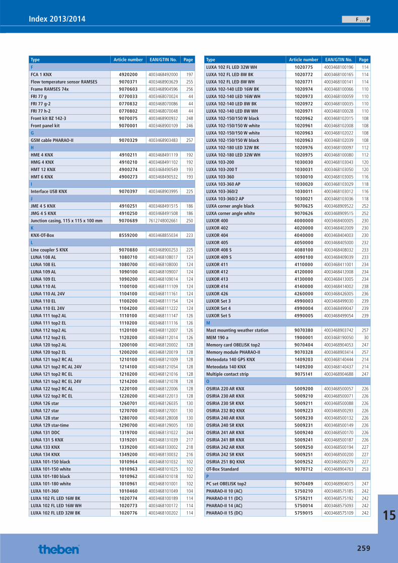
F … PIndex 2013/2014
15
Type Article number EAN/GTIN No. Page
F
FCA 1 KNX 4920200 4003468492000 197
Flow temperature sensor RAMSES 9070371 4003468903629 255
Frame RAMSES 74x 9070603 4003468904596 256
FRI 77 g 0770033 4003468070024 44
FRI 77 g-2 0770832 4003468070086 44
FRI 77 h-2 0770802 4003468070048 44
Front kit BZ 142-3 9070075 4003468900932 248
Front panel kit 9070001 4003468900109 246
G
GSM cable PHARAO-II 9070329 4003468903483 257
H
HME 4 KNX 4910211 4003468491119 192
HMG 4 KNX 4910210 4003468491102 192
HMT 12 KNX 4900274 4003468490549 193
HMT 6 KNX 4900273 4003468490532 193
I
Interface USB KNX 9070397 4003468903995 225
J
JME 4 S KNX 4910251 4003468491515 186
JMG 4 S KNX 4910250 4003468491508 186
Junction casing, 115 x 115 x 100 mm 9070689 7612748002661 250
K
KNX-OT-Box 8559200 4003468855034 223
L
Line coupler S KNX 9070880 4003468900253 225
LUNA 108 AL 1080710 4003468108017 124
LUNA 108 EL 1080700 4003468108000 124
LUNA 109 AL 1090100 4003468109007 124
LUNA 109 EL 1090200 4003468109014 124
LUNA 110 AL 1100100 4003468111109 124
LUNA 110 AL 24V 1104100 4003468111161 124
LUNA 110 EL 1100200 4003468111154 124
LUNA 110 EL 24V 1104200 4003468111222 124
LUNA 111 top2 AL 1110100 4003468111147 126
LUNA 111 top2 EL 1110200 4003468111116 126
LUNA 112 top2 AL 1120100 4003468112007 126
LUNA 112 top2 EL 1120200 4003468112014 126
LUNA 120 top2 AL 1200100 4003468120002 128
LUNA 120 top2 EL 1200200 4003468120019 128
LUNA 121 top2 RC AL 1210100 4003468121009 128
LUNA 121 top2 RC AL 24V 1214100 4003468121054 128
LUNA 121 top2 RC EL 1210200 4003468121016 128
LUNA 121 top2 RC EL 24V 1214200 4003468121078 128
LUNA 122 top2 RC AL 1220100 4003468122006 128
LUNA 122 top2 RC EL 1220200 4003468122013 128
LUNA 126 star 1260701 4003468126035 130
LUNA 127 star 1270700 4003468127001 130
LUNA 128 star 1280700 4003468128008 130
LUNA 129 star-time 1290700 4003468129005 130
LUNA 131 DDC 1319700 4003468131022 244
LUNA 131 S KNX 1319201 4003468131039 217
LUNA 133 KNX 1339200 4003468133002 218
LUNA 134 KNX 1349200 4003468130032 216
LUXA 101-150 black 1010964 4003468101032 102
LUXA 101-150 white 1010963 4003468101025 102
LUXA 101-180 black 1010962 4003468101018 102
LUXA 101-180 white 1010961 4003468101001 102
LUXA 101-360 1010460 4003468101049 104
LUXA 102 FL LED 16W BK 1020774 4003468100189 114
LUXA 102 FL LED 16W WH 1020773 4003468100172 114
LUXA 102 FL LED 32W BK 1020776 4003468100202 114
Type Article number EAN/GTIN No. Page
LUXA 102 FL LED 32W WH 1020775 4003468100196 114
LUXA 102 FL LED 8W BK 1020772 4003468100165 114
LUXA 102 FL LED 8W WH 1020771 4003468100141 114
LUXA 102-140 LED 16W BK 1020974 4003468100066 110
LUXA 102-140 LED 16W WH 1020973 4003468100059 110
LUXA 102-140 LED 8W BK 1020972 4003468100035 110
LUXA 102-140 LED 8W WH 1020971 4003468100028 110
LUXA 102-150/150 W black 1020962 4003468102015 108
LUXA 102-150/150 W white 1020961 4003468102008 108
LUXA 102-150/150 W white 1020963 4003468102022 108
LUXA 102-150/150 W black 1020963 4003468102039 108
LUXA 102-180 LED 32W BK 1020976 4003468100097 112
LUXA 102-180 LED 32W WH 1020975 4003468100080 112
LUXA 103-200 1030030 4003468103043 120
LUXA 103-200 T 1030031 4003468103050 120
LUXA 103-360 1030010 4003468103005 116
LUXA 103-360 AP 1030020 4003468103029 118
LUXA 103-360/2 1030011 4003468103012 116
LUXA 103-360/2 AP 1030021 4003468103036 118
LUXA corner angle black 9070625 4003468909522 252
LUXA corner angle white 9070626 4003468909515 252
LUXOR 400 4000000 4003468400005 230
LUXOR 402 4020000 4003468402009 230
LUXOR 404 4040000 4003468404003 230
LUXOR 405 4050000 4003468405000 232
LUXOR 408 S 4080100 4003468408032 233
LUXOR 409 S 4090100 4003468409039 233
LUXOR 411 4110000 4003468411001 234
LUXOR 412 4120000 4003468412008 234
LUXOR 413 4130000 4003468413005 234
LUXOR 414 4140000 4003468414002 238
LUXOR 426 4260000 4003468426005 236
LUXOR Set 3 4990003 4003468499030 239
LUXOR Set 4 4990004 4003468499047 239
LUXOR Set 5 4990005 4003468499054 239
M
Mast mounting weather station 9070380 4003468903742 257
MEM 190 a 1900001 4003468190050 30
Memory card OBELISK top2 9070404 4003468904053 247
Memory module PHARAO-II 9070328 4003468903414 257
Meteodata 140 GPS KNX 1409203 4003468140444 214
Meteodata 140 KNX 1409200 4003468140437 214
Multiple contact strip 9075141 4003468904688 247
O
OSIRIA 220 AR KNX 5009200 4003468500057 226
OSIRIA 230 AR KNX 5009210 4003468500071 226
OSIRIA 230 SR KNX 5009211 4003468500088 226
OSIRIA 232 BQ KNX 5009223 4003468500293 226
OSIRIA 240 AR KNX 5009230 4003468500132 226
OSIRIA 240 SR KNX 5009231 4003468500149 226
OSIRIA 241 AR KNX 5009240 4003468500170 226
OSIRIA 241 BR KNX 5009241 4003468500187 226
OSIRIA 242 AR KNX 5009250 4003468500194 227
OSIRIA 242 SR KNX 5009251 4003468500200 227
OSIRIA 251 BQ KNX 5009252 4003468500279 227
OT-Box Standard 9070712 4003468904763 253
P
PC set OBELISK top2 9070409 4003468904015 247
PHARAO-II 10 (AC) 5750210 4003468575185 242
PHARAO-II 11 (DC) 5759211 4003468575192 242
PHARAO-II 14 (AC) 5750014 4003468575093 242
PHARAO-II 15 (DC) 5759015 4003468575109 242
259
Catalogue_EN_2013.indb 259 16.01.13 17:26
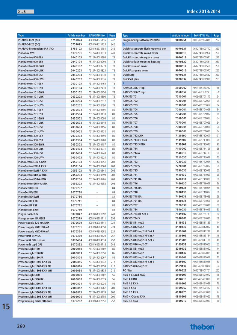
Q ... R Index 2013/2014
15
Type Article number EAN/GTIN No. Page
PHARAO-II 24 (AC) 5750024 4003468575116 242
PHARAO-II 25 (DC) 5759025 4003468575123 242
PHARAO-II extension 4AR (AC) 5759102 4003468575154 242
PlanoBox 1WH 9070731 7612748003873 249
PlanoCentro 000-EBK 2040103 7612748003286 78
PlanoCentro 000-ESR 2040104 7612748003293 78
PlanoCentro 000-EWH 2040102 7612748003279 78
PlanoCentro 000-UBK 2040203 7612748003323 78
PlanoCentro 000-USR 2040204 7612748003330 78
PlanoCentro 000-UWH 2040202 7612748003316 78
PlanoCentro 101-EBK 2030103 7612748002463 78
PlanoCentro 101-ESR 2030104 7612748002470 78
PlanoCentro 101-EWH 2030102 7612748002456 78
PlanoCentro 101-UBK 2030203 7612748002500 78
PlanoCentro 101-USR 2030204 7612748002517 78
PlanoCentro 101-UWH 2030202 7612748002494 78
PlanoCentro 201-EBK 2030503 7612748003101 80
PlanoCentro 201-ESR 2030504 7612748003118 80
PlanoCentro 201-EWH 2030502 7612748003095 80
PlanoCentro 201-UBK 2030603 7612748003149 80
PlanoCentro 201-USR 2030604 7612748003156 80
PlanoCentro 201-UWH 2030602 7612748003132 80
PlanoCentro 300-EBK 2030303 7612748003194 80
PlanoCentro 300-ESR 2030304 7612748003200 80
PlanoCentro 300-EWH 2030302 7612748003187 80
PlanoCentro 300-UBK 2030403 7612748003231 80
PlanoCentro 300-USR 2030404 7612748003248 80
PlanoCentro 300-UWH 2030402 7612748003224 80
PlanoCentro EBK-A KNX 2059103 7612748003651 208
PlanoCentro ESR-A KNX 2059104 7612748003668 208
PlanoCentro EWH-A KNX 2059102 7612748003644 208
PlanoCentro UBK-A KNX 2059203 7612748003699 208
PlanoCentro USR-A KNX 2059204 7612748003705 208
PlanoCentro UWH-A KNX 2059202 7612748003682 208
PlanoSet RQ EBK 9070737 – 84
PlanoSet RQ ESR 9070738 – 84
PlanoSet RQ EWH 9070736 – 84
PlanoSet RR EBK 9070741 – 84
PlanoSet RR ESR 9070742 – 84
PlanoSet RR EWH 9070740 – 84
Plug-in socket BZ 9070042 4003468900697 249
Plunge sensor RAMSES 9070379 4003468903711 256
Power supply 320 mA KNX 9070699 4003468904541 224
Power supply KNX 160 mA 9070701 4003468904558 224
Power supply KNX 640 mA 9070364 4003468903582 224
Power unit 24 V DC 9079330 4003468903520 257
Power unit CO2-sensor 9070494 4003468904534 257
Power unit top2 GPS 9070892 4003468904718 248
PresenceLight 180 2000050 7612748001602 86
PresenceLight 180 BK 2000803 7612748002050 86
PresenceLight 180 SR 2000804 7612748002067 86
PresenceLight 180B-KNX BK 2009815 7612748003842 212
PresenceLight 180B-KNX SR 2009816 7612748003859 212
PresenceLight 180B-KNX WH 2009050 7612748003835 212
PresenceLight 360 2000000 7612748001107 56
PresenceLight 360 BK 2000800 7612748002029 56
PresenceLight 360 SR 2000801 7612748002036 56
PresenceLight 360B-KNX BK 2009812 7612748003767 200
PresenceLight 360B-KNX SR 2009813 7612748003774 200
PresenceLight 360B-KNX WH 2009000 7612748003750 200
Programming cable PHARAO 9070252 4003468902851 257
Type Article number EAN/GTIN No. Page
Programming software PHARAO 9070251 4003468902844 257
Q
QuickFix concrete fl ush-mounted box 9070521 7612748000742 250
QuickFix concrete round cover 9070519 7612748000964 250
QuickFix concrete square cover 9070518 7612748000971 249
QuickFix fl ush-mounted housing 9070522 7612748000551 250
QuickFix round cover 9070517 7612748000568 250
QuickFix square cover 9070516 7612748000575 250
QuickSafe 9070531 7612748000582 250
QuickSet plus 9070532 7612748000926 251
R
RAMSES 366/1 top 3660002 4003468360217 156
RAMSES 366/2 top 3660052 4003468360293 156
RAMSES 701 7010001 4003468701140 164
RAMSES 702 7020001 4003468702055 164
RAMSES 703 7030001 4003468703052 164
RAMSES 704 7040001 4003468704028 164
RAMSES 705 7050001 4003468705032 164
RAMSES 706 7060001 4003468706022 164
RAMSES 707 7070001 4003468707029 164
RAMSES 708 7080001 4003468708026 164
RAMSES 709 7090001 4003468709030 164
RAMSES 712 KNX 7129200 4003468712009 191
RAMSES 713 FC KNX 7139202 4003468713020 196
RAMSES 713 S KNX 7139201 4003468713013 190
RAMSES 714 7140002 4003468714126 168
RAMSES 714 A 7140016 4003468714133 168
RAMSES 721 7210030 4003468721018 160
RAMSES 722 7220030 4003468722015 160
RAMSES 722 S 7220801 4003468722022 158
RAMSES 725 7250030 4003468725016 160
RAMSES 741 7410130 4003468741023 166
RAMSES 741 RA 7410131 4003468741030 166
RAMSES 746 7460130 4003468746028 166
RAMSES 746 RA 7460131 4003468746035 166
RAMSES 748 7480130 4003468748022 166
RAMSES 748 RA 7480131 4003468748039 166
RAMSES 751 RA 7510131 4003468751008 168
RAMSES 782 7820030 4003468782019 160
RAMSES 784 7840030 4003468784013 160
RAMSES 784 HF Set 1 7849407 4003468784143 160
RAMSES 784 S 7840801 4003468784020 158
RAMSES 811 top2 8119132 4003468811139 144
RAMSES 812 top2 8120132 4003468812037 146
RAMSES 813 top2 HF Set 1 8139501 4003468813218 148
RAMSES 813 top2 HF Set A 8139503 4003468813164 148
RAMSES 813 top2 HF Set S 8139505 4003468813188 148
RAMSES 816 top2 OT 8169132 4003468810002 152
RAMSES 831 top2 8319132 4003468831052 144
RAMSES 832 top2 8320132 4003468832035 146
RAMSES 833 top2 HF Set 1 8339501 4003468833049 150
RAMSES 833 top2 HF Set 2 8339502 4003468833056 150
RAMSES 856 top2 OT 8569132 4003468850084 154
RC fi lter 9070523 7612748001701 252
RME 4 C-Load KNX 4910207 4003468491072 178
RME 4 I KNX 4930215 4003468493090 176
RME 4 S KNX 4910205 4003468491058 179
RME 8 KNX 4900252 4003468490457 180
RME 8 S KNX 4930225 4003468493076 177
RMG 4 C-Load KNX 4910206 4003468491065 178
RMG 4 I KNX 4930210 4003468493083 176
260
Catalogue_EN_2013.indb 260 16.01.13 17:26
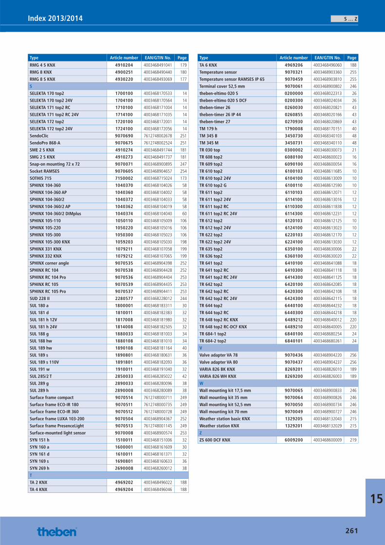
S … ZIndex 2013/2014
15
Type Article number EAN/GTIN No. Page
RMG 4 S KNX 4910204 4003468491041 179
RMG 8 KNX 4900251 4003468490440 180
RMG 8 S KNX 4930220 4003468493069 177
S
SELEKTA 170 top2 1700100 4003468170533 14
SELEKTA 170 top2 24V 1704100 4003468170564 14
SELEKTA 171 top2 RC 1710100 4003468171004 14
SELEKTA 171 top2 RC 24V 1714100 4003468171035 14
SELEKTA 172 top2 1720100 4003468172001 14
SELEKTA 172 top2 24V 1724100 4003468172056 14
SendoClic 9070690 7612748002678 251
SendoPro 868-A 9070675 7612748002524 251
SME 2 S KNX 4910274 4003468491744 181
SMG 2 S KNX 4910273 4003468491737 181
Snap-on mounting 72 x 72 9070071 4003468900895 247
Socket RAMSES 9070605 4003468904657 254
SOTHIS 715 7150002 4003468715024 173
SPHINX 104-360 1040370 4003468104026 58
SPHINX 104-360 AP 1040360 4003468104002 58
SPHINX 104-360/2 1040372 4003468104033 58
SPHINX 104-360/2 AP 1040362 4003468104019 58
SPHINX 104-360/2 DIMplus 1040374 4003468104040 60
SPHINX 105-110 1050110 4003468105009 106
SPHINX 105-220 1050220 4003468105016 106
SPHINX 105-300 1050300 4003468105023 106
SPHINX 105-300 KNX 1059203 4003468105030 198
SPHINX 331 KNX 1079211 4003468107058 199
SPHINX 332 KNX 1079212 4003468107065 199
SPHINX corner angle 9070535 4003468904398 252
SPHINX RC 104 9070538 4003468904428 252
SPHINX RC 104 Pro 9070536 4003468904404 253
SPHINX RC 105 9070539 4003468904435 253
SPHINX RC 105 Pro 9070537 4003468904411 253
SUD 228 II 2280577 4003468228012 244
SUL 180 a 1800001 4003468183311 30
SUL 181 d 1810011 4003468182383 32
SUL 181 h 12V 1817008 4003468181980 32
SUL 181 h 24V 1814008 4003468182505 32
SUL 188 g 1880033 4003468181003 34
SUL 188 hw 1880108 4003468181010 34
SUL 189 hw 1890108 4003468181164 40
SUL 189 s 1890801 4003468180631 36
SUL 189 s 110V 1891801 4003468182093 36
SUL 191 w 1910011 4003468191040 32
SUL 285/2 T 2850033 4003468285022 42
SUL 289 g 2890033 4003468280096 38
SUL 289 h 2890008 4003468280089 38
Surface frame compact 9070514 7612748000711 249
Surface frame ECO-IR 180 9070511 7612748000735 249
Surface frame ECO-IR 360 9070512 7612748000728 249
Surface frame LUXA 103-200 9070504 4003468904367 252
Surface frame PresenceLight 9070513 7612748001145 249
Surface-mounted light sensor 9070008 4003468900574 253
SYN 151 h 1510011 4003468151006 32
SYN 160 a 1600001 4003468161609 30
SYN 161 d 1610011 4003468161371 32
SYN 169 s 1690801 4003468160633 36
SYN 269 h 2690008 4003468260012 38
T
TA 2 KNX 4969202 4003468496022 188
TA 4 KNX 4969204 4003468496046 188
Type Article number EAN/GTIN No. Page
TA 6 KNX 4969206 4003468496060 188
Temperature sensor 9070321 4003468903360 255
Temperature sensor RAMSES IP 65 9070459 4003468903810 255
Terminal cover 52,5 mm 9070061 4003468900802 246
theben-eltimo 020 S 0200000 4003468022313 26
theben-eltimo 020 S DCF 0200300 4003468024034 26
theben-timer 26 0260030 4003468020821 43
theben-timer 26 IP 44 0260855 4003468020166 43
theben-timer 27 0270930 4003468020869 43
TM 179 h 1790008 4003468170151 40
TM 345 B 3450730 4003468340103 48
TM 345 M 3450731 4003468340110 48
TR 030 top 0300002 4003468030073 21
TR 608 top2 6080100 4003468600023 16
TR 609 top2 6090100 4003468600054 16
TR 610 top2 6100103 4003468611685 10
TR 610 top2 24V 6104100 4003468613009 10
TR 610 top2 G 6100110 4003468612590 10
TR 611 top2 6110103 4003468612071 12
TR 611 top2 24V 6114100 4003468613016 12
TR 611 top2 RC 6110300 4003468611838 12
TR 611 top2 RC 24V 6114300 4003468612231 12
TR 612 top2 6120103 4003468612125 10
TR 612 top2 24V 6124100 4003468613023 10
TR 622 top2 6220103 4003468612170 12
TR 622 top2 24V 6224100 4003468613030 12
TR 635 top2 6350100 4003468630006 22
TR 636 top2 6360100 4003468630020 22
TR 641 top2 6410100 4003468641088 18
TR 641 top2 RC 6410300 4003468641118 18
TR 641 top2 RC 24V 6414300 4003468641125 18
TR 642 top2 6420100 4003468642085 18
TR 642 top2 RC 6420300 4003468642108 18
TR 642 top2 RC 24V 6424300 4003468642115 18
TR 644 top2 6440100 4003468644232 18
TR 644 top2 RC 6440300 4003468644218 18
TR 648 top2 RC KNX 6489212 4003468640012 220
TR 648 top2 RC-DCF KNX 6489210 4003468640005 220
TR 684-1 top2 6840100 4003468680254 24
TR 684-2 top2 6840101 4003468680261 24
V
Valve adapter VA 78 9070436 4003468904220 256
Valve adapter VA 80 9070437 4003468904237 256
VARIA 826 BK KNX 8269201 4003468826010 189
VARIA 826 WH KNX 8269200 4003468826003 189
W
Wall mounting kit 17,5 mm 9070065 4003468900833 246
Wall mounting kit 35 mm 9070064 4003468900826 246
Wall mounting kit 52,5 mm 9070050 4003468900734 246
Wall mounting kit 70 mm 9070049 4003468900727 246
Weather station basic KNX 1329205 4003468132043 215
Weather station KNX 1329201 4003468132029 215
Z
ZS 600 DCF KNX 6009200 4003468600009 219
261
Catalogue_EN_2013.indb 261 16.01.13 17:26
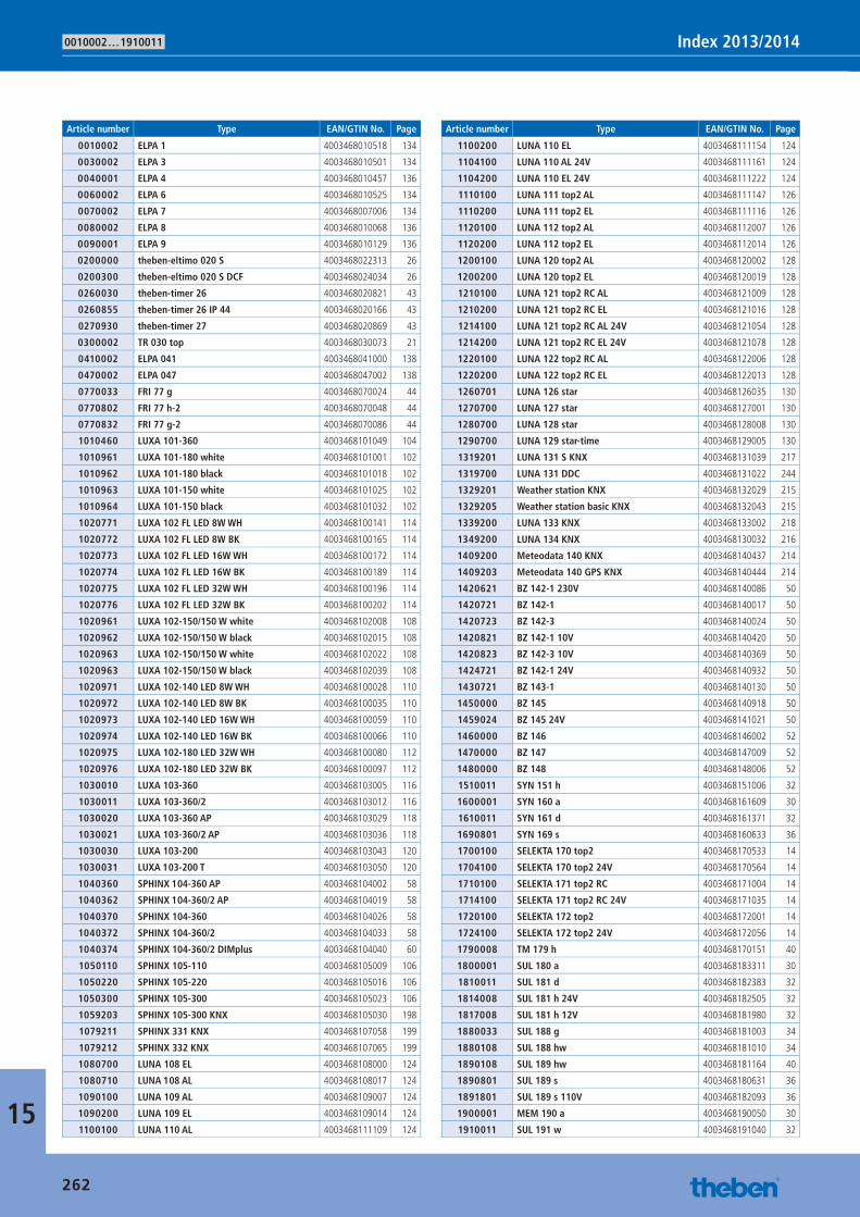
0010002 … 1910011 Index 2013/2014
15
Article number Type EAN/GTIN No. Page
0010002 ELPA 1 4003468010518 134
0030002 ELPA 3 4003468010501 134
0040001 ELPA 4 4003468010457 136
0060002 ELPA 6 4003468010525 134
0070002 ELPA 7 4003468007006 134
0080002 ELPA 8 4003468010068 136
0090001 ELPA 9 4003468010129 136
0200000 theben-eltimo 020 S 4003468022313 26
0200300 theben-eltimo 020 S DCF 4003468024034 26
0260030 theben-timer 26 4003468020821 43
0260855 theben-timer 26 IP 44 4003468020166 43
0270930 theben-timer 27 4003468020869 43
0300002 TR 030 top 4003468030073 21
0410002 ELPA 041 4003468041000 138
0470002 ELPA 047 4003468047002 138
0770033 FRI 77 g 4003468070024 44
0770802 FRI 77 h-2 4003468070048 44
0770832 FRI 77 g-2 4003468070086 44
1010460 LUXA 101-360 4003468101049 104
1010961 LUXA 101-180 white 4003468101001 102
1010962 LUXA 101-180 black 4003468101018 102
1010963 LUXA 101-150 white 4003468101025 102
1010964 LUXA 101-150 black 4003468101032 102
1020771 LUXA 102 FL LED 8W WH 4003468100141 114
1020772 LUXA 102 FL LED 8W BK 4003468100165 114
1020773 LUXA 102 FL LED 16W WH 4003468100172 114
1020774 LUXA 102 FL LED 16W BK 4003468100189 114
1020775 LUXA 102 FL LED 32W WH 4003468100196 114
1020776 LUXA 102 FL LED 32W BK 4003468100202 114
1020961 LUXA 102-150/150 W white 4003468102008 108
1020962 LUXA 102-150/150 W black 4003468102015 108
1020963 LUXA 102-150/150 W white 4003468102022 108
1020963 LUXA 102-150/150 W black 4003468102039 108
1020971 LUXA 102-140 LED 8W WH 4003468100028 110
1020972 LUXA 102-140 LED 8W BK 4003468100035 110
1020973 LUXA 102-140 LED 16W WH 4003468100059 110
1020974 LUXA 102-140 LED 16W BK 4003468100066 110
1020975 LUXA 102-180 LED 32W WH 4003468100080 112
1020976 LUXA 102-180 LED 32W BK 4003468100097 112
1030010 LUXA 103-360 4003468103005 116
1030011 LUXA 103-360/2 4003468103012 116
1030020 LUXA 103-360 AP 4003468103029 118
1030021 LUXA 103-360/2 AP 4003468103036 118
1030030 LUXA 103-200 4003468103043 120
1030031 LUXA 103-200 T 4003468103050 120
1040360 SPHINX 104-360 AP 4003468104002 58
1040362 SPHINX 104-360/2 AP 4003468104019 58
1040370 SPHINX 104-360 4003468104026 58
1040372 SPHINX 104-360/2 4003468104033 58
1040374 SPHINX 104-360/2 DIMplus 4003468104040 60
1050110 SPHINX 105-110 4003468105009 106
1050220 SPHINX 105-220 4003468105016 106
1050300 SPHINX 105-300 4003468105023 106
1059203 SPHINX 105-300 KNX 4003468105030 198
1079211 SPHINX 331 KNX 4003468107058 199
1079212 SPHINX 332 KNX 4003468107065 199
1080700 LUNA 108 EL 4003468108000 124
1080710 LUNA 108 AL 4003468108017 124
1090100 LUNA 109 AL 4003468109007 124
1090200 LUNA 109 EL 4003468109014 124
1100100 LUNA 110 AL 4003468111109 124
Article number Type EAN/GTIN No. Page
1100200 LUNA 110 EL 4003468111154 124
1104100 LUNA 110 AL 24V 4003468111161 124
1104200 LUNA 110 EL 24V 4003468111222 124
1110100 LUNA 111 top2 AL 4003468111147 126
1110200 LUNA 111 top2 EL 4003468111116 126
1120100 LUNA 112 top2 AL 4003468112007 126
1120200 LUNA 112 top2 EL 4003468112014 126
1200100 LUNA 120 top2 AL 4003468120002 128
1200200 LUNA 120 top2 EL 4003468120019 128
1210100 LUNA 121 top2 RC AL 4003468121009 128
1210200 LUNA 121 top2 RC EL 4003468121016 128
1214100 LUNA 121 top2 RC AL 24V 4003468121054 128
1214200 LUNA 121 top2 RC EL 24V 4003468121078 128
1220100 LUNA 122 top2 RC AL 4003468122006 128
1220200 LUNA 122 top2 RC EL 4003468122013 128
1260701 LUNA 126 star 4003468126035 130
1270700 LUNA 127 star 4003468127001 130
1280700 LUNA 128 star 4003468128008 130
1290700 LUNA 129 star-time 4003468129005 130
1319201 LUNA 131 S KNX 4003468131039 217
1319700 LUNA 131 DDC 4003468131022 244
1329201 Weather station KNX 4003468132029 215
1329205 Weather station basic KNX 4003468132043 215
1339200 LUNA 133 KNX 4003468133002 218
1349200 LUNA 134 KNX 4003468130032 216
1409200 Meteodata 140 KNX 4003468140437 214
1409203 Meteodata 140 GPS KNX 4003468140444 214
1420621 BZ 142-1 230V 4003468140086 50
1420721 BZ 142-1 4003468140017 50
1420723 BZ 142-3 4003468140024 50
1420821 BZ 142-1 10V 4003468140420 50
1420823 BZ 142-3 10V 4003468140369 50
1424721 BZ 142-1 24V 4003468140932 50
1430721 BZ 143-1 4003468140130 50
1450000 BZ 145 4003468140918 50
1459024 BZ 145 24V 4003468141021 50
1460000 BZ 146 4003468146002 52
1470000 BZ 147 4003468147009 52
1480000 BZ 148 4003468148006 52
1510011 SYN 151 h 4003468151006 32
1600001 SYN 160 a 4003468161609 30
1610011 SYN 161 d 4003468161371 32
1690801 SYN 169 s 4003468160633 36
1700100 SELEKTA 170 top2 4003468170533 14
1704100 SELEKTA 170 top2 24V 4003468170564 14
1710100 SELEKTA 171 top2 RC 4003468171004 14
1714100 SELEKTA 171 top2 RC 24V 4003468171035 14
1720100 SELEKTA 172 top2 4003468172001 14
1724100 SELEKTA 172 top2 24V 4003468172056 14
1790008 TM 179 h 4003468170151 40
1800001 SUL 180 a 4003468183311 30
1810011 SUL 181 d 4003468182383 32
1814008 SUL 181 h 24V 4003468182505 32
1817008 SUL 181 h 12V 4003468181980 32
1880033 SUL 188 g 4003468181003 34
1880108 SUL 188 hw 4003468181010 34
1890108 SUL 189 hw 4003468181164 40
1890801 SUL 189 s 4003468180631 36
1891801 SUL 189 s 110V 4003468182093 36
1900001 MEM 190 a 4003468190050 30
1910011 SUL 191 w 4003468191040 32
262
Catalogue_EN_2013.indb 262 16.01.13 17:26
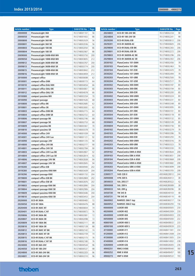
2000000 … 4900273Index 2013/2014
15
Article number Type EAN/GTIN No. Page
2000000 PresenceLight 360 7612748001107 56
2000050 PresenceLight 180 7612748001602 86
2000800 PresenceLight 360 BK 7612748002029 56
2000801 PresenceLight 360 SR 7612748002036 56
2000803 PresenceLight 180 BK 7612748002050 86
2000804 PresenceLight 180 SR 7612748002067 86
2009000 PresenceLight 360B-KNX WH 7612748003750 200
2009050 PresenceLight 180B-KNX WH 7612748003835 212
2009812 PresenceLight 360B-KNX BK 7612748003767 200
2009813 PresenceLight 360B-KNX SR 7612748003774 200
2009815 PresenceLight 180B-KNX BK 7612748003842 212
2009816 PresenceLight 180B-KNX SR 7612748003859 212
2010000 compact offi ce 7612748000698 62
2010001 compact offi ce DIM 7612748000773 64
2010010 compact offi ce DALI WH 7612748004054 66
2010011 compact offi ce DALI BK 7612748004061 66
2010012 compact offi ce DALI SR 7612748004078 66
2010080 compact passimo WH 7612748003354 70
2010090 compact passage 7612748001626 68
2010800 compact offi ce BK 7612748002685 62
2010801 compact offi ce SR 7612748002692 62
2010803 compact offi ce DIM BK 7612748002715 64
2010804 compact offi ce DIM SR 7612748002722 64
2010806 compact passage BK 7612748002746 68
2010807 compact passage SR 7612748002753 68
2010809 compact passimo BK 7612748003361 70
2010810 compact passimo SR 7612748003378 70
2014000 compact offi ce 24V 7612748001039 90
2014001 compact offi ce 24V Lux 7612748001121 92
2014090 compact passage 24V 7612748001725 94
2014800 compact offi ce 24V BK 7612748002777 90
2014801 compact offi ce 24V SR 7612748002784 90
2014803 compact offi ce 24V Lux BK 7612748002807 92
2014804 compact offi ce 24V Lux SR 7612748002814 92
2014806 compact passage 24V BK 7612748002838 94
2014807 compact passage 24V SR 7612748002845 94
2019200 compact offi ce EIB 7612748000940 202
2019280 compact passimo KNX WH 7612748003439 204
2019290 compact passage KNX 7612748001732 204
2019800 compact offi ce EIB BK 7612748002869 202
2019801 compact offi ce EIB SR 7612748002876 202
2019803 compact passage KNX BK 7612748002890 204
2019804 compact passage KNX SR 7612748002906 204
2019809 compact passimo KNX BK 7612748003446 204
2019810 compact passimo KNX SR 7612748003453 204
2020000 ECO-IR 360A 7612748000483 72
2020050 ECO-IR 180A 7612748000476 88
2020400 ECO-IR 360C NT 7612748000834 74
2020401 ECO-IR DUAL-C NT 7612748000872 76
2020806 ECO-IR 360A BK 7612748002081 72
2020807 ECO-IR 360A SR 7612748002098 72
2020809 ECO-IR 180A BK 7612748002111 88
2020810 ECO-IR 180A SR 7612748002128 88
2020812 ECO-IR 360C NT BK 7612748002142 74
2020813 ECO-IR 360C NT SR 7612748002159 74
2020815 ECO-IR DUAL-C NT BK 7612748002173 76
2020816 ECO-IR DUAL-C NT SR 7612748002180 76
2024000 ECO-IR 360-24V 7612748000544 96
2024050 ECO-IR 180-24V 7612748000537 98
2024800 ECO-IR 360-24V BK 7612748002203 96
2024801 ECO-IR 360-24V SR 7612748002210 96
Article number Type EAN/GTIN No. Page
2024803 ECO-IR 180-24V BK 7612748002234 98
2024804 ECO-IR 180-24V SR 7612748002241 98
2029200 ECO-IR DUAL-EIB 7612748000612 206
2029201 ECO-IR 360EIB-AC 7612748000605 206
2029800 ECO-IR DUAL-EIB BK 7612748002265 206
2029801 ECO-IR DUAL-EIB SR 7612748002272 206
2029803 ECO-IR 360EIB-AC BK 7612748002296 206
2029804 ECO-IR 360EIB-AC SR 7612748002302 206
2030102 PlanoCentro 101-EWH 7612748002456 78
2030103 PlanoCentro 101-EBK 7612748002463 78
2030104 PlanoCentro 101-ESR 7612748002470 78
2030202 PlanoCentro 101-UWH 7612748002494 78
2030203 PlanoCentro 101-UBK 7612748002500 78
2030204 PlanoCentro 101-USR 7612748002517 78
2030302 PlanoCentro 300-EWH 7612748003187 80
2030303 PlanoCentro 300-EBK 7612748003194 80
2030304 PlanoCentro 300-ESR 7612748003200 80
2030402 PlanoCentro 300-UWH 7612748003224 80
2030403 PlanoCentro 300-UBK 7612748003231 80
2030404 PlanoCentro 300-USR 7612748003248 80
2030502 PlanoCentro 201-EWH 7612748003095 80
2030503 PlanoCentro 201-EBK 7612748003101 80
2030504 PlanoCentro 201-ESR 7612748003118 80
2030602 PlanoCentro 201-UWH 7612748003132 80
2030603 PlanoCentro 201-UBK 7612748003149 80
2030604 PlanoCentro 201-USR 7612748003156 80
2040102 PlanoCentro 000-EWH 7612748003279 78
2040103 PlanoCentro 000-EBK 7612748003286 78
2040104 PlanoCentro 000-ESR 7612748003293 78
2040202 PlanoCentro 000-UWH 7612748003316 78
2040203 PlanoCentro 000-UBK 7612748003323 78
2040204 PlanoCentro 000-USR 7612748003330 78
2059102 PlanoCentro EWH-A KNX 7612748003644 208
2059103 PlanoCentro EBK-A KNX 7612748003651 208
2059104 PlanoCentro ESR-A KNX 7612748003668 208
2059202 PlanoCentro UWH-A KNX 7612748003682 208
2059203 PlanoCentro UBK-A KNX 7612748003699 208
2059204 PlanoCentro USR-A KNX 7612748003705 208
2280577 SUD 228 II 4003468228012 244
2690008 SYN 269 h 4003468260012 38
2850033 SUL 285/2 T 4003468285022 42
2890008 SUL 289 h 4003468280089 38
2890033 SUL 289 g 4003468280096 38
3450730 TM 345 B 4003468340103 48
3450731 TM 345 M 4003468340110 48
3660002 RAMSES 366/1 top 4003468360217 156
3660052 RAMSES 366/2 top 4003468360293 156
4000000 LUXOR 400 4003468400005 230
4020000 LUXOR 402 4003468402009 230
4040000 LUXOR 404 4003468404003 230
4050000 LUXOR 405 4003468405000 232
4080100 LUXOR 408 S 4003468408032 233
4090100 LUXOR 409 S 4003468409039 233
4110000 LUXOR 411 4003468411001 234
4120000 LUXOR 412 4003468412008 234
4130000 LUXOR 413 4003468413005 234
4140000 LUXOR 414 4003468414002 238
4260000 LUXOR 426 4003468426005 236
4900251 RMG 8 KNX 4003468490440 180
4900252 RME 8 KNX 4003468490457 180
4900273 HMT 6 KNX 4003468490532 193
263
Catalogue_EN_2013.indb 263 16.01.13 17:26
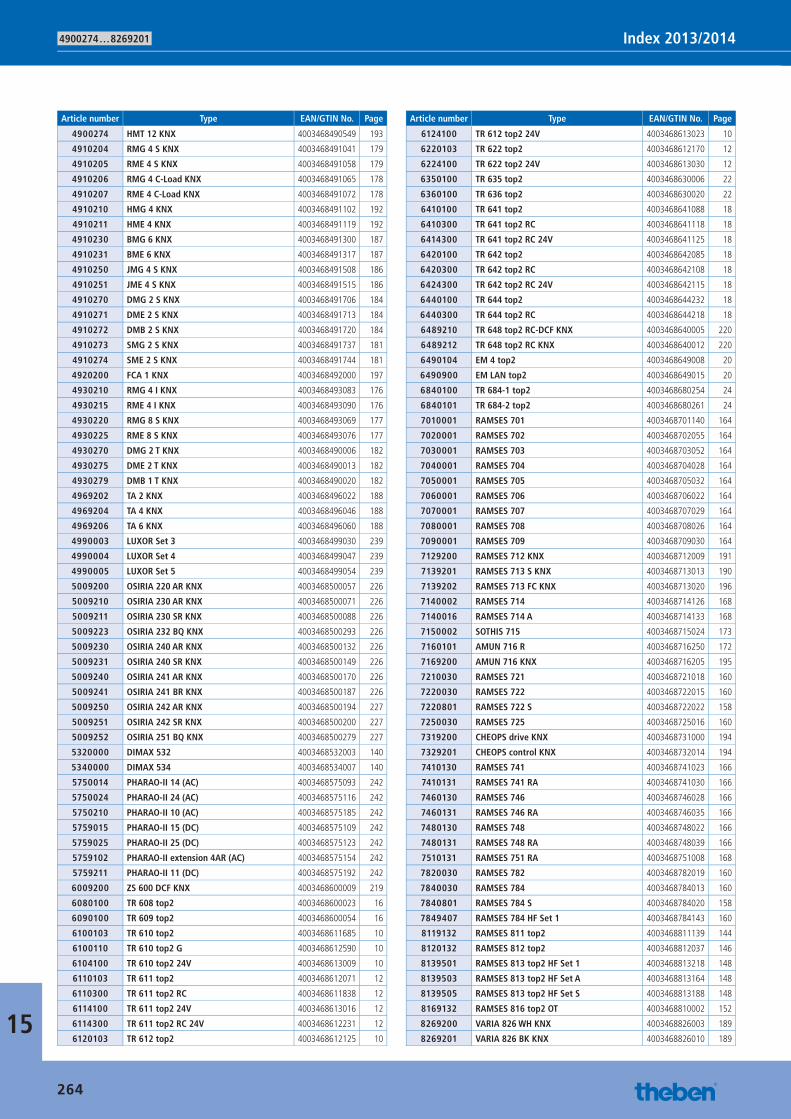
4900274 … 8269201 Index 2013/2014
15
Article number Type EAN/GTIN No. Page
4900274 HMT 12 KNX 4003468490549 193
4910204 RMG 4 S KNX 4003468491041 179
4910205 RME 4 S KNX 4003468491058 179
4910206 RMG 4 C-Load KNX 4003468491065 178
4910207 RME 4 C-Load KNX 4003468491072 178
4910210 HMG 4 KNX 4003468491102 192
4910211 HME 4 KNX 4003468491119 192
4910230 BMG 6 KNX 4003468491300 187
4910231 BME 6 KNX 4003468491317 187
4910250 JMG 4 S KNX 4003468491508 186
4910251 JME 4 S KNX 4003468491515 186
4910270 DMG 2 S KNX 4003468491706 184
4910271 DME 2 S KNX 4003468491713 184
4910272 DMB 2 S KNX 4003468491720 184
4910273 SMG 2 S KNX 4003468491737 181
4910274 SME 2 S KNX 4003468491744 181
4920200 FCA 1 KNX 4003468492000 197
4930210 RMG 4 I KNX 4003468493083 176
4930215 RME 4 I KNX 4003468493090 176
4930220 RMG 8 S KNX 4003468493069 177
4930225 RME 8 S KNX 4003468493076 177
4930270 DMG 2 T KNX 4003468490006 182
4930275 DME 2 T KNX 4003468490013 182
4930279 DMB 1 T KNX 4003468490020 182
4969202 TA 2 KNX 4003468496022 188
4969204 TA 4 KNX 4003468496046 188
4969206 TA 6 KNX 4003468496060 188
4990003 LUXOR Set 3 4003468499030 239
4990004 LUXOR Set 4 4003468499047 239
4990005 LUXOR Set 5 4003468499054 239
5009200 OSIRIA 220 AR KNX 4003468500057 226
5009210 OSIRIA 230 AR KNX 4003468500071 226
5009211 OSIRIA 230 SR KNX 4003468500088 226
5009223 OSIRIA 232 BQ KNX 4003468500293 226
5009230 OSIRIA 240 AR KNX 4003468500132 226
5009231 OSIRIA 240 SR KNX 4003468500149 226
5009240 OSIRIA 241 AR KNX 4003468500170 226
5009241 OSIRIA 241 BR KNX 4003468500187 226
5009250 OSIRIA 242 AR KNX 4003468500194 227
5009251 OSIRIA 242 SR KNX 4003468500200 227
5009252 OSIRIA 251 BQ KNX 4003468500279 227
5320000 DIMAX 532 4003468532003 140
5340000 DIMAX 534 4003468534007 140
5750014 PHARAO-II 14 (AC) 4003468575093 242
5750024 PHARAO-II 24 (AC) 4003468575116 242
5750210 PHARAO-II 10 (AC) 4003468575185 242
5759015 PHARAO-II 15 (DC) 4003468575109 242
5759025 PHARAO-II 25 (DC) 4003468575123 242
5759102 PHARAO-II extension 4AR (AC) 4003468575154 242
5759211 PHARAO-II 11 (DC) 4003468575192 242
6009200 ZS 600 DCF KNX 4003468600009 219
6080100 TR 608 top2 4003468600023 16
6090100 TR 609 top2 4003468600054 16
6100103 TR 610 top2 4003468611685 10
6100110 TR 610 top2 G 4003468612590 10
6104100 TR 610 top2 24V 4003468613009 10
6110103 TR 611 top2 4003468612071 12
6110300 TR 611 top2 RC 4003468611838 12
6114100 TR 611 top2 24V 4003468613016 12
6114300 TR 611 top2 RC 24V 4003468612231 12
6120103 TR 612 top2 4003468612125 10
Article number Type EAN/GTIN No. Page
6124100 TR 612 top2 24V 4003468613023 10
6220103 TR 622 top2 4003468612170 12
6224100 TR 622 top2 24V 4003468613030 12
6350100 TR 635 top2 4003468630006 22
6360100 TR 636 top2 4003468630020 22
6410100 TR 641 top2 4003468641088 18
6410300 TR 641 top2 RC 4003468641118 18
6414300 TR 641 top2 RC 24V 4003468641125 18
6420100 TR 642 top2 4003468642085 18
6420300 TR 642 top2 RC 4003468642108 18
6424300 TR 642 top2 RC 24V 4003468642115 18
6440100 TR 644 top2 4003468644232 18
6440300 TR 644 top2 RC 4003468644218 18
6489210 TR 648 top2 RC-DCF KNX 4003468640005 220
6489212 TR 648 top2 RC KNX 4003468640012 220
6490104 EM 4 top2 4003468649008 20
6490900 EM LAN top2 4003468649015 20
6840100 TR 684-1 top2 4003468680254 24
6840101 TR 684-2 top2 4003468680261 24
7010001 RAMSES 701 4003468701140 164
7020001 RAMSES 702 4003468702055 164
7030001 RAMSES 703 4003468703052 164
7040001 RAMSES 704 4003468704028 164
7050001 RAMSES 705 4003468705032 164
7060001 RAMSES 706 4003468706022 164
7070001 RAMSES 707 4003468707029 164
7080001 RAMSES 708 4003468708026 164
7090001 RAMSES 709 4003468709030 164
7129200 RAMSES 712 KNX 4003468712009 191
7139201 RAMSES 713 S KNX 4003468713013 190
7139202 RAMSES 713 FC KNX 4003468713020 196
7140002 RAMSES 714 4003468714126 168
7140016 RAMSES 714 A 4003468714133 168
7150002 SOTHIS 715 4003468715024 173
7160101 AMUN 716 R 4003468716250 172
7169200 AMUN 716 KNX 4003468716205 195
7210030 RAMSES 721 4003468721018 160
7220030 RAMSES 722 4003468722015 160
7220801 RAMSES 722 S 4003468722022 158
7250030 RAMSES 725 4003468725016 160
7319200 CHEOPS drive KNX 4003468731000 194
7329201 CHEOPS control KNX 4003468732014 194
7410130 RAMSES 741 4003468741023 166
7410131 RAMSES 741 RA 4003468741030 166
7460130 RAMSES 746 4003468746028 166
7460131 RAMSES 746 RA 4003468746035 166
7480130 RAMSES 748 4003468748022 166
7480131 RAMSES 748 RA 4003468748039 166
7510131 RAMSES 751 RA 4003468751008 168
7820030 RAMSES 782 4003468782019 160
7840030 RAMSES 784 4003468784013 160
7840801 RAMSES 784 S 4003468784020 158
7849407 RAMSES 784 HF Set 1 4003468784143 160
8119132 RAMSES 811 top2 4003468811139 144
8120132 RAMSES 812 top2 4003468812037 146
8139501 RAMSES 813 top2 HF Set 1 4003468813218 148
8139503 RAMSES 813 top2 HF Set A 4003468813164 148
8139505 RAMSES 813 top2 HF Set S 4003468813188 148
8169132 RAMSES 816 top2 OT 4003468810002 152
8269200 VARIA 826 WH KNX 4003468826003 189
8269201 VARIA 826 BK KNX 4003468826010 189
264
Catalogue_EN_2013.indb 264 16.01.13 17:26
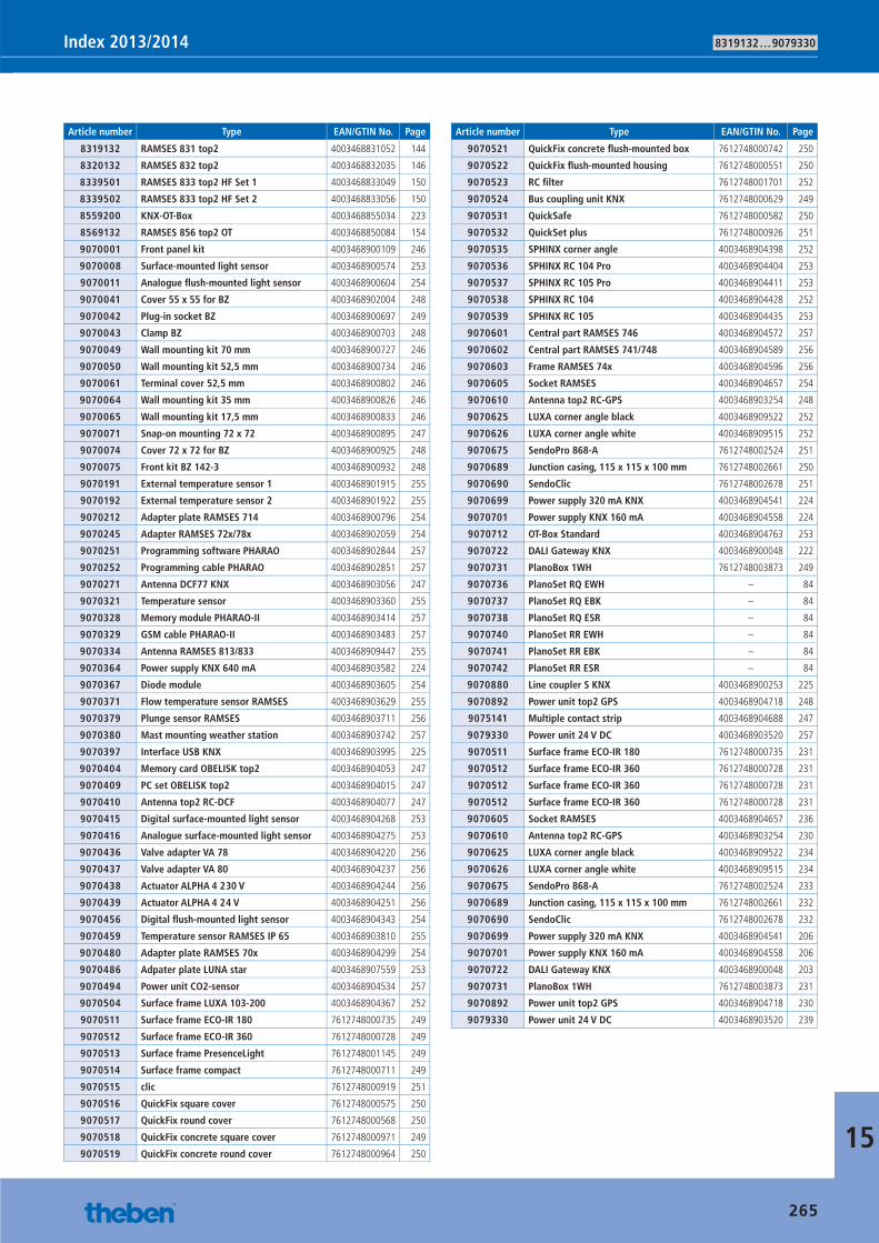
8319132 … 9079330Index 2013/2014
15
Article number Type EAN/GTIN No. Page
8319132 RAMSES 831 top2 4003468831052 144
8320132 RAMSES 832 top2 4003468832035 146
8339501 RAMSES 833 top2 HF Set 1 4003468833049 150
8339502 RAMSES 833 top2 HF Set 2 4003468833056 150
8559200 KNX-OT-Box 4003468855034 223
8569132 RAMSES 856 top2 OT 4003468850084 154
9070001 Front panel kit 4003468900109 246
9070008 Surface-mounted light sensor 4003468900574 253
9070011 Analogue fl ush-mounted light sensor 4003468900604 254
9070041 Cover 55 x 55 for BZ 4003468902004 248
9070042 Plug-in socket BZ 4003468900697 249
9070043 Clamp BZ 4003468900703 248
9070049 Wall mounting kit 70 mm 4003468900727 246
9070050 Wall mounting kit 52,5 mm 4003468900734 246
9070061 Terminal cover 52,5 mm 4003468900802 246
9070064 Wall mounting kit 35 mm 4003468900826 246
9070065 Wall mounting kit 17,5 mm 4003468900833 246
9070071 Snap-on mounting 72 x 72 4003468900895 247
9070074 Cover 72 x 72 for BZ 4003468900925 248
9070075 Front kit BZ 142-3 4003468900932 248
9070191 External temperature sensor 1 4003468901915 255
9070192 External temperature sensor 2 4003468901922 255
9070212 Adapter plate RAMSES 714 4003468900796 254
9070245 Adapter RAMSES 72x/78x 4003468902059 254
9070251 Programming software PHARAO 4003468902844 257
9070252 Programming cable PHARAO 4003468902851 257
9070271 Antenna DCF77 KNX 4003468903056 247
9070321 Temperature sensor 4003468903360 255
9070328 Memory module PHARAO-II 4003468903414 257
9070329 GSM cable PHARAO-II 4003468903483 257
9070334 Antenna RAMSES 813/833 4003468909447 255
9070364 Power supply KNX 640 mA 4003468903582 224
9070367 Diode module 4003468903605 254
9070371 Flow temperature sensor RAMSES 4003468903629 255
9070379 Plunge sensor RAMSES 4003468903711 256
9070380 Mast mounting weather station 4003468903742 257
9070397 Interface USB KNX 4003468903995 225
9070404 Memory card OBELISK top2 4003468904053 247
9070409 PC set OBELISK top2 4003468904015 247
9070410 Antenna top2 RC-DCF 4003468904077 247
9070415 Digital surface-mounted light sensor 4003468904268 253
9070416 Analogue surface-mounted light sensor 4003468904275 253
9070436 Valve adapter VA 78 4003468904220 256
9070437 Valve adapter VA 80 4003468904237 256
9070438 Actuator ALPHA 4 230 V 4003468904244 256
9070439 Actuator ALPHA 4 24 V 4003468904251 256
9070456 Digital fl ush-mounted light sensor 4003468904343 254
9070459 Temperature sensor RAMSES IP 65 4003468903810 255
9070480 Adapter plate RAMSES 70x 4003468904299 254
9070486 Adpater plate LUNA star 4003468907559 253
9070494 Power unit CO2-sensor 4003468904534 257
9070504 Surface frame LUXA 103-200 4003468904367 252
9070511 Surface frame ECO-IR 180 7612748000735 249
9070512 Surface frame ECO-IR 360 7612748000728 249
9070513 Surface frame PresenceLight 7612748001145 249
9070514 Surface frame compact 7612748000711 249
9070515 clic 7612748000919 251
9070516 QuickFix square cover 7612748000575 250
9070517 QuickFix round cover 7612748000568 250
9070518 QuickFix concrete square cover 7612748000971 249
9070519 QuickFix concrete round cover 7612748000964 250
Article number Type EAN/GTIN No. Page
9070521 QuickFix concrete fl ush-mounted box 7612748000742 250
9070522 QuickFix fl ush-mounted housing 7612748000551 250
9070523 RC fi lter 7612748001701 252
9070524 Bus coupling unit KNX 7612748000629 249
9070531 QuickSafe 7612748000582 250
9070532 QuickSet plus 7612748000926 251
9070535 SPHINX corner angle 4003468904398 252
9070536 SPHINX RC 104 Pro 4003468904404 253
9070537 SPHINX RC 105 Pro 4003468904411 253
9070538 SPHINX RC 104 4003468904428 252
9070539 SPHINX RC 105 4003468904435 253
9070601 Central part RAMSES 746 4003468904572 257
9070602 Central part RAMSES 741/748 4003468904589 256
9070603 Frame RAMSES 74x 4003468904596 256
9070605 Socket RAMSES 4003468904657 254
9070610 Antenna top2 RC-GPS 4003468903254 248
9070625 LUXA corner angle black 4003468909522 252
9070626 LUXA corner angle white 4003468909515 252
9070675 SendoPro 868-A 7612748002524 251
9070689 Junction casing, 115 x 115 x 100 mm 7612748002661 250
9070690 SendoClic 7612748002678 251
9070699 Power supply 320 mA KNX 4003468904541 224
9070701 Power supply KNX 160 mA 4003468904558 224
9070712 OT-Box Standard 4003468904763 253
9070722 DALI Gateway KNX 4003468900048 222
9070731 PlanoBox 1WH 7612748003873 249
9070736 PlanoSet RQ EWH – 84
9070737 PlanoSet RQ EBK – 84
9070738 PlanoSet RQ ESR – 84
9070740 PlanoSet RR EWH – 84
9070741 PlanoSet RR EBK – 84
9070742 PlanoSet RR ESR – 84
9070880 Line coupler S KNX 4003468900253 225
9070892 Power unit top2 GPS 4003468904718 248
9075141 Multiple contact strip 4003468904688 247
9079330 Power unit 24 V DC 4003468903520 257
9070511 Surface frame ECO-IR 180 7612748000735 231
9070512 Surface frame ECO-IR 360 7612748000728 231
9070512 Surface frame ECO-IR 360 7612748000728 231
9070512 Surface frame ECO-IR 360 7612748000728 231
9070605 Socket RAMSES 4003468904657 236
9070610 Antenna top2 RC-GPS 4003468903254 230
9070625 LUXA corner angle black 4003468909522 234
9070626 LUXA corner angle white 4003468909515 234
9070675 SendoPro 868-A 7612748002524 233
9070689 Junction casing, 115 x 115 x 100 mm 7612748002661 232
9070690 SendoClic 7612748002678 232
9070699 Power supply 320 mA KNX 4003468904541 206
9070701 Power supply KNX 160 mA 4003468904558 206
9070722 DALI Gateway KNX 4003468900048 203
9070731 PlanoBox 1WH 7612748003873 231
9070892 Power unit top2 GPS 4003468904718 230
9079330 Power unit 24 V DC 4003468903520 239
265
Catalogue_EN_2013.indb 265 16.01.13 17:26
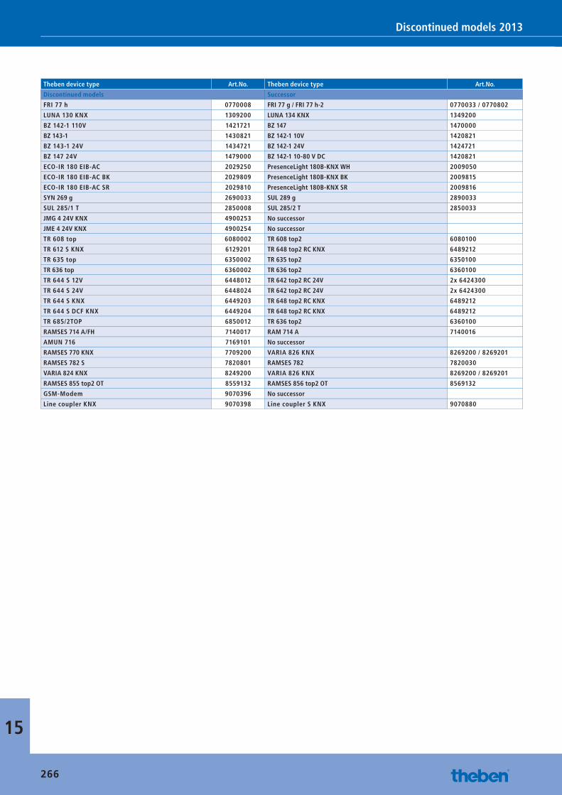
Discontinued models 2013
Theben device type Art.No. Theben device type Art.No.
Discontinued models Successor
FRI 77 h 0770008 FRI 77 g / FRI 77 h-2 0770033 / 0770802
LUNA 130 KNX 1309200 LUNA 134 KNX 1349200
BZ 142-1 110V 1421721 BZ 147 1470000
BZ 143-1 1430821 BZ 142-1 10V 1420821
BZ 143-1 24V 1434721 BZ 142-1 24V 1424721
BZ 147 24V 1479000 BZ 142-1 10-80 V DC 1420821
ECO-IR 180 EIB-AC 2029250 PresenceLight 180B-KNX WH 2009050
ECO-IR 180 EIB-AC BK 2029809 PresenceLight 180B-KNX BK 2009815
ECO-IR 180 EIB-AC SR 2029810 PresenceLight 180B-KNX SR 2009816
SYN 269 g 2690033 SUL 289 g 2890033
SUL 285/1 T 2850008 SUL 285/2 T 2850033
JMG 4 24V KNX 4900253 No successor
JME 4 24V KNX 4900254 No successor
TR 608 top 6080002 TR 608 top2 6080100
TR 612 S KNX 6129201 TR 648 top2 RC KNX 6489212
TR 635 top 6350002 TR 635 top2 6350100
TR 636 top 6360002 TR 636 top2 6360100
TR 644 S 12V 6448012 TR 642 top2 RC 24V 2x 6424300
TR 644 S 24V 6448024 TR 642 top2 RC 24V 2x 6424300
TR 644 S KNX 6449203 TR 648 top2 RC KNX 6489212
TR 644 S DCF KNX 6449204 TR 648 top2 RC KNX 6489212
TR 685/2TOP 6850012 TR 636 top2 6360100
RAMSES 714 A/FH 7140017 RAM 714 A 7140016
AMUN 716 7169101 No successor
RAMSES 770 KNX 7709200 VARIA 826 KNX 8269200 / 8269201
RAMSES 782 S 7820801 RAMSES 782 7820030
VARIA 824 KNX 8249200 VARIA 826 KNX 8269200 / 8269201
RAMSES 855 top2 OT 8559132 RAMSES 856 top2 OT 8569132
GSM-Modem 9070396 No successor
Line coupler KNX 9070398 Line coupler S KNX 9070880
15
266
Catalogue_EN_2013.indb 266 16.01.13 17:26
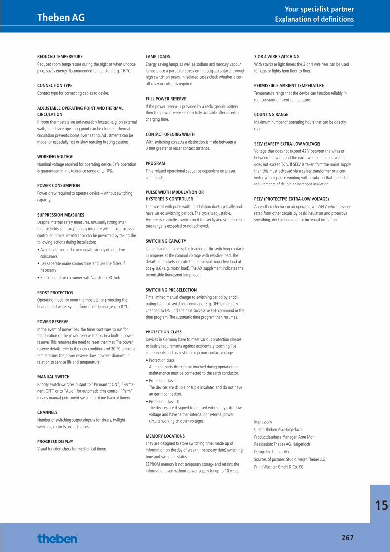
15
REDUCED TEMPERATURE
Reduced room temperature during the night or when unoccu-pied, saves energy. Recommended temperature e. g. 16 °C.
CONNECTION TYPE
Contact type for connecting cables to device.
ADJUSTABLE OPERATING POINT AND THERMAL CIRCULATION
If room thermostats are unfavourably located, e. g. on external walls, the device operating point can be changed. Thermal circulation prevents rooms overheating. Adjustments can be made for especially fast or slow reacting heating systems.
WORKING VOLTAGE
Nominal voltage required for operating device. Safe operation is guaranteed in in a tolerance range of ± 10%.
POWER CONSUMPTION
Power draw required to operate device – without switching capacity.
SUPPRESSION MEASURES
Despite internal safety measures, unusually strong inter-ference fi elds can exceptionally interfere with microprocessor-controlled timers. Interference can be prevented by taking the following actions during installation:
• Avoid installing in the immediate vicinity of inductive consumers.
• Lay separate mains connections and use line fi lters if necessary
• Shield inductive consumer with Varistor or RC link.
FROST PROTECTION
Operating mode for room thermostats for protecting the heating and water system from frost damage, e. g. +8 °C.
POWER RESERVE
In the event of power loss, the timer continues to run for the duration of the power reserve thanks to a built-in power reserve. This removes the need to reset the timer. The power reserve details refer to the new condition and 20 °C ambient temperature. The power reserve does however diminish in relation to service life and temperature.
MANUAL SWITCH
Priority switch switches output to "Permanent ON", "Perma-nent OFF" or to "Auto" for automatic time control. "Perm" means manual permanent switching of mechanical timers.
CHANNELS
Number of switching outputs/inputs for timers, twilight switches, controls and actuators.
PROGRESS DISPLAY
Visual function check for mechanical timers.
LAMP LOADS
Energy saving lamps as well as sodium and mercury vapour lamps place a particular stress on the output contacts through high switch-on peaks. In isolated cases check whether a cut-off relay or cutout is required.
FULL POWER RESERVE
If the power reserve is provided by a rechargeable battery then the power reserve is only fully available after a certain charging time.
CONTACT OPENING WIDTH
With switching contacts a distinction is made between a 3 mm greater or lesser contact distance.
PROGRAM
Time-related operational sequence dependent on preset commands.
PULSE WIDTH MODULATION OR HYSTERESIS CONTROLLER
Thermostat with pulse width modulation clock cyclically and have varied switching periods. The cycle is adjustable. Hysteresis controllers switch on if the set hysteresis tempera-ture range is exceeded or not achieved.
SWITCHING CAPACITY
is the maximum permissible loading of the switching contacts in amperes at the nominal voltage with resistive load. The details in brackets indicate the permissible inductive load at cos ϕ 0.6 (e. g. motor load). The AX supplement indicates the permissible fl uorescent lamp load.
SWITCHING PRE-SELECTION
Time limited manual change to switching period by antici-pating the next switching command. E. g. OFF is manually changed to ON until the next successive OFF command in the time program. The automatic time program then resumes.
PROTECTION CLASS
Devices in Germany have to meet various protection classes to satisfy requirements against accidentally touching live components and against too high non-contact voltage.
• Protection class I:All metal parts that can be touched during operation or maintenance must be connected to the earth conductor.
• Protection class II:The devices are double or triple insulated and do not have an earth connection.
• Protection class III:The devices are designed to be used with safety extra-low voltage and have neither internal nor external power circuits working on other voltages.
MEMORY LOCATIONS
They are designed to store switching times made up of information on the day of week (if necessary date) switching time and switching status.
EEPROM memory is not temporary storage and retains the information even without power supply for up to 10 years.
3 OR 4 WIRE SWITCHING
With staircase light timers the 3 or 4 wire riser can be used for keys or lights from fl oor to fl oor.
PERMISSIBLE AMBIENT TEMPERATURE
Temperature range that the device can function reliably in, e. g. constant ambient temperature.
COUNTING RANGE
Maximum number of operating hours that can be directly read.
SELV (SAFETY EXTRA-LOW VOLTAGE)
Voltage that does not exceed 42 V between the wires or between the wires and the earth where the idling voltage does not exceed 50 V. If SELV is taken from the mains supply then this must achieved via a safety transformer or a con-verter with separate winding with insulation that meets the requirements of double or increased insulation.
PELV (PROTECTIVE EXTRA-LOW VOLTAGE)
An earthed electric circuit operated with SELV which is sepa-rated from other circuits by basic insulation and protective sheathing, double insulation or increased insulation.
Impressum
Client: Theben AG, Haigerloch
Productdatabase Manager: Arne Mohl
Realisation: Theben AG, Haigerloch
Design by: Theben AG
Sources of pictures: Studio Majer, Theben AG
Print: Wachter GmbH & Co. KG
267
Explanation of defi nitions Theben AGYour specialist partner
Catalogue_EN_2013.indb 267 16.01.13 17:26
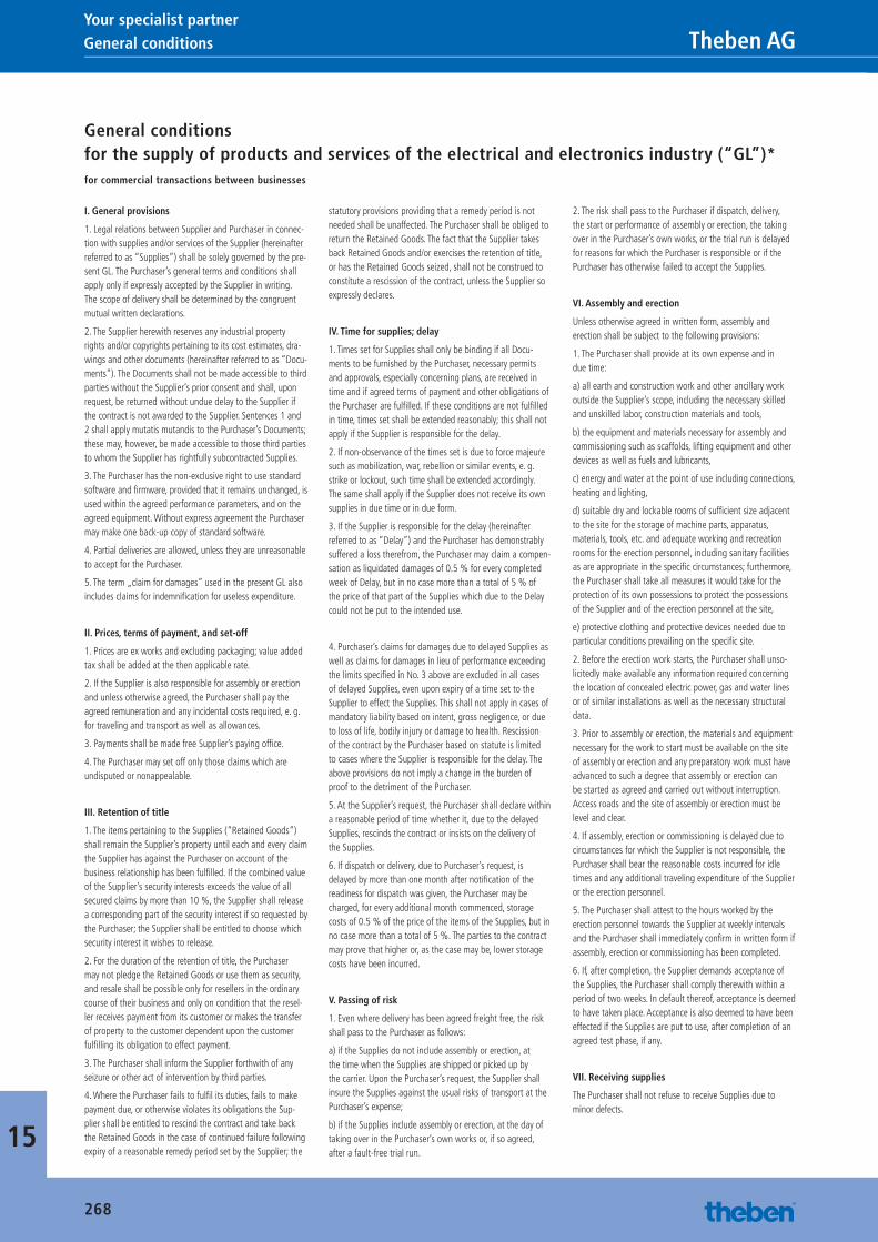
15
268
I. General provisions
1. Legal relations between Supplier and Purchaser in connec-tion with supplies and/or services of the Supplier (hereinafter referred to as “Supplies”) shall be solely governed by the pre-sent GL. The Purchaser’s general terms and conditions shall apply only if expressly accepted by the Supplier in writing. The scope of delivery shall be determined by the congruent mutual written declarations.
2. The Supplier herewith reserves any industrial property rights and/or copyrights pertaining to its cost estimates, dra-wings and other documents (hereinafter referred to as “Docu-ments”). The Documents shall not be made accessible to third parties without the Supplier’s prior consent and shall, upon request, be returned without undue delay to the Supplier if the contract is not awarded to the Supplier. Sentences 1 and 2 shall apply mutatis mutandis to the Purchaser’s Documents; these may, however, be made accessible to those third parties to whom the Supplier has rightfully subcontracted Supplies.
3. The Purchaser has the non-exclusive right to use standard software and fi rmware, provided that it remains unchanged, is used within the agreed performance parameters, and on the agreed equipment. Without express agreement the Purchaser may make one back-up copy of standard software.
4. Partial deliveries are allowed, unless they are unreasonable to accept for the Purchaser.
5. The term „claim for damages” used in the present GL also includes claims for indemnifi cation for useless expenditure.
II. Prices, terms of payment, and set-off
1. Prices are ex works and excluding packaging; value added tax shall be added at the then applicable rate.
2. If the Supplier is also responsible for assembly or erection and unless otherwise agreed, the Purchaser shall pay the agreed remuneration and any incidental costs required, e. g. for traveling and transport as well as allowances.
3. Payments shall be made free Supplier’s paying offi ce.
4. The Purchaser may set off only those claims which are undisputed or nonappealable.
III. Retention of title
1. The items pertaining to the Supplies (“Retained Goods”) shall remain the Supplier’s property until each and every claim the Supplier has against the Purchaser on account of the business relationship has been fulfi lled. If the combined value of the Supplier’s security interests exceeds the value of all secured claims by more than 10 %, the Supplier shall release a corresponding part of the security interest if so requested by the Purchaser; the Supplier shall be entitled to choose which security interest it wishes to release.
2. For the duration of the retention of title, the Purchaser may not pledge the Retained Goods or use them as security, and resale shall be possible only for resellers in the ordinary course of their business and only on condition that the resel-ler receives payment from its customer or makes the transfer of property to the customer dependent upon the customer fulfi lling its obligation to effect payment.
3. The Purchaser shall inform the Supplier forthwith of any seizure or other act of intervention by third parties.
4. Where the Purchaser fails to fulfi l its duties, fails to make payment due, or otherwise violates its obligations the Sup-plier shall be entitled to rescind the contract and take back the Retained Goods in the case of continued failure following expiry of a reasonable remedy period set by the Supplier; the
statutory provisions providing that a remedy period is not needed shall be unaffected. The Purchaser shall be obliged to return the Retained Goods. The fact that the Supplier takes back Retained Goods and/or exercises the retention of title, or has the Retained Goods seized, shall not be construed to constitute a rescission of the contract, unless the Supplier so expressly declares.
IV. Time for supplies; delay
1. Times set for Supplies shall only be binding if all Docu-ments to be furnished by the Purchaser, necessary permits and approvals, especially concerning plans, are received in time and if agreed terms of payment and other obligations of the Purchaser are fulfi lled. If these conditions are not fulfi lled in time, times set shall be extended reasonably; this shall not apply if the Supplier is responsible for the delay.
2. If non-observance of the times set is due to force majeure such as mobilization, war, rebellion or similar events, e. g. strike or lockout, such time shall be extended accordingly. The same shall apply if the Supplier does not receive its own supplies in due time or in due form.
3. If the Supplier is responsible for the delay (hereinafter referred to as “Delay”) and the Purchaser has demonstrably suffered a loss therefrom, the Purchaser may claim a compen-sation as liquidated damages of 0.5 % for every completed week of Delay, but in no case more than a total of 5 % of the price of that part of the Supplies which due to the Delay could not be put to the intended use.
4. Purchaser’s claims for damages due to delayed Supplies as well as claims for damages in lieu of performance exceeding the limits specifi ed in No. 3 above are excluded in all cases of delayed Supplies, even upon expiry of a time set to the Supplier to effect the Supplies. This shall not apply in cases of mandatory liability based on intent, gross negligence, or due to loss of life, bodily injury or damage to health. Rescission of the contract by the Purchaser based on statute is limited to cases where the Supplier is responsible for the delay. The above provisions do not imply a change in the burden of proof to the detriment of the Purchaser.
5. At the Supplier’s request, the Purchaser shall declare within a reasonable period of time whether it, due to the delayed Supplies, rescinds the contract or insists on the delivery of the Supplies.
6. If dispatch or delivery, due to Purchaser’s request, is delayed by more than one month after notifi cation of the readiness for dispatch was given, the Purchaser may be charged, for every additional month commenced, storage costs of 0.5 % of the price of the items of the Supplies, but in no case more than a total of 5 %. The parties to the contract may prove that higher or, as the case may be, lower storage costs have been incurred.
V. Passing of risk
1. Even where delivery has been agreed freight free, the risk shall pass to the Purchaser as follows:
a) if the Supplies do not include assembly or erection, at the time when the Supplies are shipped or picked up by the carrier. Upon the Purchaser’s request, the Supplier shall insure the Supplies against the usual risks of transport at the Purchaser’s expense;
b) if the Supplies include assembly or erection, at the day of taking over in the Purchaser’s own works or, if so agreed, after a fault-free trial run.
2. The risk shall pass to the Purchaser if dispatch, delivery, the start or performance of assembly or erection, the taking over in the Purchaser’s own works, or the trial run is delayed for reasons for which the Purchaser is responsible or if the Purchaser has otherwise failed to accept the Supplies.
VI. Assembly and erection
Unless otherwise agreed in written form, assembly and erection shall be subject to the following provisions:
1. The Purchaser shall provide at its own expense and in due time:
a) all earth and construction work and other ancillary work outside the Supplier’s scope, including the necessary skilled and unskilled labor, construction materials and tools,
b) the equipment and materials necessary for assembly and commissioning such as scaffolds, lifting equipment and other devices as well as fuels and lubricants,
c) energy and water at the point of use including connections, heating and lighting,
d) suitable dry and lockable rooms of suffi cient size adjacent to the site for the storage of machine parts, apparatus, materials, tools, etc. and adequate working and recreation rooms for the erection personnel, including sanitary facilities as are appropriate in the specifi c circumstances; furthermore, the Purchaser shall take all measures it would take for the protection of its own possessions to protect the possessions of the Supplier and of the erection personnel at the site,
e) protective clothing and protective devices needed due to particular conditions prevailing on the specifi c site.
2. Before the erection work starts, the Purchaser shall unso-licitedly make available any information required concerning the location of concealed electric power, gas and water lines or of similar installations as well as the necessary structural data.
3. Prior to assembly or erection, the materials and equipment necessary for the work to start must be available on the site of assembly or erection and any preparatory work must have advanced to such a degree that assembly or erection can be started as agreed and carried out without interruption. Access roads and the site of assembly or erection must be level and clear.
4. If assembly, erection or commissioning is delayed due to circumstances for which the Supplier is not responsible, the Purchaser shall bear the reasonable costs incurred for idle times and any additional traveling expenditure of the Supplier or the erection personnel.
5. The Purchaser shall attest to the hours worked by the erection personnel towards the Supplier at weekly intervals and the Purchaser shall immediately confi rm in written form if assembly, erection or commissioning has been completed.
6. If, after completion, the Supplier demands acceptance of the Supplies, the Purchaser shall comply therewith within a period of two weeks. In default thereof, acceptance is deemed to have taken place. Acceptance is also deemed to have been effected if the Supplies are put to use, after completion of an agreed test phase, if any.
VII. Receiving supplies
The Purchaser shall not refuse to receive Supplies due to minor defects.
General conditions Theben AG Your specialist partner
General conditionsfor the supply of products and services of the electrical and electronics industry (“GL”)* for commercial transactions between businesses
Catalogue_EN_2013.indb 268 16.01.13 17:26
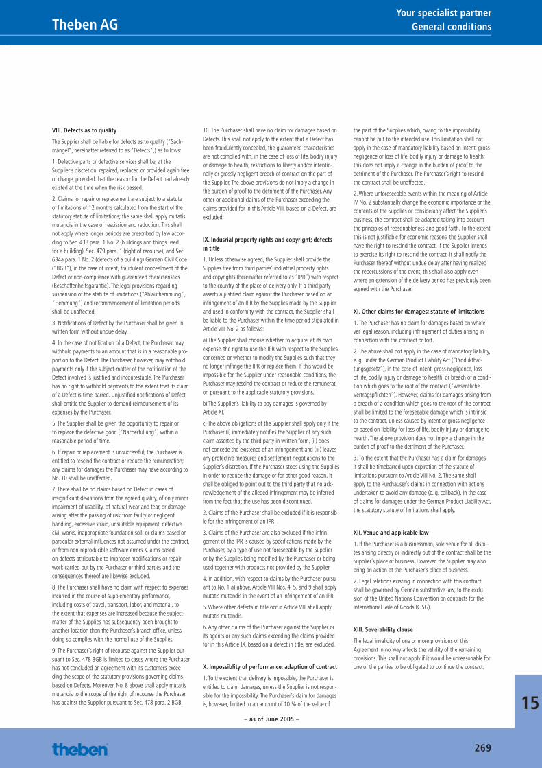
15
269
VIII. Defects as to quality
The Supplier shall be liable for defects as to quality (“Sach-mängel”, hereinafter referred to as “Defects”,) as follows:
1. Defective parts or defective services shall be, at the Supplier’s discretion, repaired, replaced or provided again free of charge, provided that the reason for the Defect had already existed at the time when the risk passed.
2. Claims for repair or replacement are subject to a statute of limitations of 12 months calculated from the start of the statutory statute of limitations; the same shall apply mutatis mutandis in the case of rescission and reduction. This shall not apply where longer periods are prescribed by law accor-ding to Sec. 438 para. 1 No. 2 (buildings and things used for a building), Sec. 479 para. 1 (right of recourse), and Sec. 634a para. 1 No. 2 (defects of a building) German Civil Code (“BGB”), in the case of intent, fraudulent concealment of the Defect or non-compliance with guaranteed characteristics (Beschaffenheitsgarantie). The legal provisions regarding suspension of the statute of limitations (“Ablaufhemmung”, “Hemmung”) and recommencement of limitation periods shall be unaffected.
3. Notifi cations of Defect by the Purchaser shall be given in written form without undue delay.
4. In the case of notifi cation of a Defect, the Purchaser may withhold payments to an amount that is in a reasonable pro-portion to the Defect. The Purchaser, however, may withhold payments only if the subject-matter of the notifi cation of the Defect involved is justifi ed and incontestable. The Purchaser has no right to withhold payments to the extent that its claim of a Defect is time-barred. Unjustifi ed notifi cations of Defect shall entitle the Supplier to demand reimbursement of its expenses by the Purchaser.
5. The Supplier shall be given the opportunity to repair or to replace the defective good (“Nacherfüllung”) within a reasonable period of time.
6. If repair or replacement is unsuccessful, the Purchaser is entitled to rescind the contract or reduce the remuneration; any claims for damages the Purchaser may have according to No. 10 shall be unaffected.
7. There shall be no claims based on Defect in cases of insignifi cant deviations from the agreed quality, of only minor impairment of usability, of natural wear and tear, or damage arising after the passing of risk from faulty or negligent handling, excessive strain, unsuitable equipment, defective civil works, inappropriate foundation soil, or claims based on particular external infl uences not assumed under the contract, or from non-reproducible software errors. Claims based on defects attributable to improper modifi cations or repair work carried out by the Purchaser or third parties and the consequences thereof are likewise excluded.
8. The Purchaser shall have no claim with respect to expenses incurred in the course of supplementary performance, including costs of travel, transport, labor, and material, to the extent that expenses are increased because the subject-matter of the Supplies has subsequently been brought to another location than the Purchaser’s branch offi ce, unless doing so complies with the normal use of the Supplies.
9. The Purchaser’s right of recourse against the Supplier pur-suant to Sec. 478 BGB is limited to cases where the Purchaser has not concluded an agreement with its customers excee-ding the scope of the statutory provisions governing claims based on Defects. Moreover, No. 8 above shall apply mutatis mutandis to the scope of the right of recourse the Purchaser has against the Supplier pursuant to Sec. 478 para. 2 BGB.
10. The Purchaser shall have no claim for damages based on Defects. This shall not apply to the extent that a Defect has been fraudulently concealed, the guaranteed characteristics are not complied with, in the case of loss of life, bodily injury or damage to health, restrictions to liberty and/or intentio-nally or grossly negligent breach of contract on the part of the Supplier. The above provisions do not imply a change in the burden of proof to the detriment of the Purchaser. Any other or additional claims of the Purchaser exceeding the claims provided for in this Article VIII, based on a Defect, are excluded.
IX. Indusrial property rights and copyright; defects in title
1. Unless otherwise agreed, the Supplier shall provide the Supplies free from third parties’ industrial property rights and copyrights (hereinafter referred to as “IPR”) with respect to the country of the place of delivery only. If a third party asserts a justifi ed claim against the Purchaser based on an infringement of an IPR by the Supplies made by the Supplier and used in conformity with the contract, the Supplier shall be liable to the Purchaser within the time period stipulated in Article VIII No. 2 as follows:
a) The Supplier shall choose whether to acquire, at its own expense, the right to use the IPR with respect to the Supplies concerned or whether to modify the Supplies such that they no longer infringe the IPR or replace them. If this would be impossible for the Supplier under reasonable conditions, the Purchaser may rescind the contract or reduce the remunerati-on pursuant to the applicable statutory provisions.
b) The Supplier’s liability to pay damages is governed by Article XI.
c) The above obligations of the Supplier shall apply only if the Purchaser (i) immediately notifi es the Supplier of any such claim asserted by the third party in written form, (ii) does not concede the existence of an infringement and (iii) leaves any protective measures and settlement negotiations to the Supplier’s discretion. If the Purchaser stops using the Supplies in order to reduce the damage or for other good reason, it shall be obliged to point out to the third party that no ack-nowledgement of the alleged infringement may be inferred from the fact that the use has been discontinued.
2. Claims of the Purchaser shall be excluded if it is responsib-le for the infringement of an IPR.
3. Claims of the Purchaser are also excluded if the infrin-gement of the IPR is caused by specifi cations made by the Purchaser, by a type of use not foreseeable by the Supplier or by the Supplies being modifi ed by the Purchaser or being used together with products not provided by the Supplier.
4. In addition, with respect to claims by the Purchaser pursu-ant to No. 1 a) above, Article VIII Nos. 4, 5, and 9 shall apply mutatis mutandis in the event of an infringement of an IPR.
5. Where other defects in title occur, Article VIII shall apply mutatis mutandis.
6. Any other claims of the Purchaser against the Supplier or its agents or any such claims exceeding the claims provided for in this Article IX, based on a defect in title, are excluded.
X. Impossiblity of performance; adaption of contract
1. To the extent that delivery is impossible, the Purchaser is entitled to claim damages, unless the Supplier is not respon-sible for the impossibility. The Purchaser’s claim for damages is, however, limited to an amount of 10 % of the value of
the part of the Supplies which, owing to the impossibility, cannot be put to the intended use. This limitation shall not apply in the case of mandatory liability based on intent, gross negligence or loss of life, bodily injury or damage to health; this does not imply a change in the burden of proof to the detriment of the Purchaser. The Purchaser’s right to rescind the contract shall be unaffected.
2. Where unforeseeable events within the meaning of Article IV No. 2 substantially change the economic importance or the contents of the Supplies or considerably affect the Supplier’s business, the contract shall be adapted taking into account the principles of reasonableness and good faith. To the extent this is not justifi able for economic reasons, the Supplier shall have the right to rescind the contract. If the Supplier intends to exercise its right to rescind the contract, it shall notify the Purchaser thereof without undue delay after having realized the repercussions of the event; this shall also apply even where an extension of the delivery period has previously been agreed with the Purchaser.
XI. Other claims for damages; statute of limitations
1. The Purchaser has no claim for damages based on whate-ver legal reason, including infringement of duties arising in connection with the contract or tort.
2. The above shall not apply in the case of mandatory liability, e. g. under the German Product Liability Act (“Produkthaf-tungsgesetz”), in the case of intent, gross negligence, loss of life, bodily injury or damage to health, or breach of a condi-tion which goes to the root of the contract (“wesentliche Vertragspfl ichten”). However, claims for damages arising from a breach of a condition which goes to the root of the contract shall be limited to the foreseeable damage which is intrinsic to the contract, unless caused by intent or gross negligence or based on liability for loss of life, bodily injury or damage to health. The above provision does not imply a change in the burden of proof to the detriment of the Purchaser.
3. To the extent that the Purchaser has a claim for damages, it shall be timebarred upon expiration of the statute of limitations pursuant to Article VIII No. 2. The same shall apply to the Purchauser’s claims in connection with actions undertaken to avoid any damage (e. g. callback). In the case of claims for damages under the German Product Liability Act, the statutory statute of limitations shall apply.
XII. Venue and applicable law
1. If the Purchaser is a businessman, sole venue for all dispu-tes arising directly or indirectly out of the contract shall be the Supplier’s place of business. However, the Supplier may also bring an action at the Purchaser’s place of business.
2. Legal relations existing in connection with this contract shall be governed by German substantive law, to the exclu-sion of the United Nations Convention on contracts for the International Sale of Goods (CISG).
XIII. Severability clause
The legal invalidity of one or more provisions of this Agreement in no way affects the validity of the remaining provisions. This shall not apply if it would be unreasonable for one of the parties to be obligated to continue the contract.
General conditions Theben AGYour specialist partner
– as of June 2005 –
Catalogue_EN_2013.indb 269 16.01.13 17:26
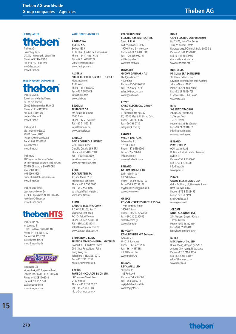
15
270
Group companies – Agencies Theben AG Theben AG worldwide
HEADQUARTER
Theben AGHohenbergstr. 32D-72401 Haigerloch, GERMANYPhone +49 7474 692-0Fax +49 7474 [email protected]
THEBEN GROUP COMPANIES
Theben S.A.R.L. Zone Industrielle des Vignes32–38 rue Bernard93012 Bobigny cédex, FRANCEPhone +33 1 49159700Fax +33 1 [email protected]
Theben S.R.L.Via Simone de Gatti, 320091 Bresso, ITALYPhone +39 02 66505083Fax +39 02 [email protected]
Theben AGRO Singapore, German Center25 International Business Park #05-00609916 Singapore, SINGAPORE+65 6560 3464+65 6560 [email protected]
Theben NederlandLaan van de Leeuw 347324 BD Apeldoorn, [email protected]/nl
Theben HTS AGIm Langhag 118307 Effretikon, SWITZERLANDPhone +41 52 355 1700Fax +41 52 355 [email protected]
Timeguard LtdVictory Park, 400 Edgeware RoadLondon NW2 6ND, GREAT BRITAINPhone +44 208 4508944Fax +44 208 [email protected]
WORLDWIDE AGENCIES
ARGENTINAHERTIG SA.Bolivar 1335C1141AAD Ciudad de Buenos AiresPhone +54 11 43617136Fax +54 11 [email protected]
AUSTRIASIBLIK ELEKTRIK Ges.M.B.H. & Co.KGMurbangasse 61108 WienPhone +43 1 680060Fax +43 1 [email protected]
BELGIUMTEMPOLEC SA.49, Route de Biesme6530 ThuinPhone +32 71 590039Fax +32 71 [email protected]
CANADADAVIS CONTROLS LIMITED2200 Bristol CircleOakville Ontario L6H 5R3Phone +1 905 8292000Fax +1 905 [email protected]
CHILESCHARFSTEIN SAAv. Sta. Maria 0510Providencia, SantiagoPhone +56 2 550 0000Fax +56 2 550 [email protected]
CHINACANAAN ELECTRIC CORP.P.O. 6F-5, No.63, Sec. 2Chang An East RoadRC 104 Taipei/TaiwanPhone +886 2 25082331Fax +886 2 [email protected]
CHINA/HONG KONGFRIENDS ENVIRONMENTAL MATERIALRoom 806, 8F, Fortress Tower250 Kings Road, North PointHong Kong SarTelephone +852 29519710Fax +852 [email protected]
CYPRUSPAMBOS NICOLAOU & SON LTD.38 Strovolos Street Tseri2480 NicosiaPhone +35 22 38 03 77Fax +35 22 38 33 [email protected]
CZECH REPUBLICELEKTRO-SYSTEM-TECHNIKSpol. S. R. O.Pod Pekarnami 338/1219000 Praha 9 – VysocanyPhone +420 266 090711Fax +420 266 [email protected]
DENMARKGYCOM DANMARK A/STheilgaards Torv 14600 KøgePhone +45 56 26 66 35Fax +45 56 26 77 [email protected]
EGYPTCAIRO ELECTRICAL GROUPGarden City9, Rostroum Str. Apt. 37ET, 11516 Maglis El Shaab CairoPhone +20 796 1337Fax +20 796 [email protected]
ESTONIAVALLIN BALTIC ASMäepealse 212618 TallinnPhone +372 6593200Fax +372 [email protected]
FINLANDGYCOM FINLAND OYLarin Kyöstin tie 400650 HelsinkiPhone +358 9 25252100Fax +358 9 [email protected]
GREECECONSTANTACATOS BROTHERS S.A.17Km Ethnikis Thinon14564 Kifi ssiaPhone +30 210 6252001Fax +30 210 [email protected]
HUNGARYKAMLEITHNER KFT BudapestAttila út 71.H-1012 BudapestPhone +36 1 4253288Fax +36 1 [email protected]
ICELANDREYKJAFELL LTD.Skipholti 35 105 ReykjavikPhone +354 5886000Fax +354 [email protected]
INDIACAPE ELECTRIC CORPORATIONNo. TS-76, Sidco Tiny SectorThiru-Vi-Ka Ind. EstateEkkattuthangal Chennai, India-6000-32Phone +91 44 45540041Fax +91 44 [email protected]
INDONESIAPT GUNA ERA DISTRIBUSIJln. Rawa Gelam Ii No. 8Kawasan Perindustrian Pulo GadungJakarta Timur 13930Phone +62 21 46825050Fax +62 21 [email protected]
IRANS.G. RIAZI TRADING#4. No. 29 Parasto. StrSt. Valiasr Ave.15929 TehranPhone +98 21 88890340Fax +98 21 [email protected]
IRELANDPEWL GROUP90/4 Lagan RoadDublin Industrial Estate GlasnevinDublin 11Phone +353 1 8304666Fax +353 1 [email protected]
ISRAELGALOZ ELECTRONICS LTD.Galoz Building; 15, Hameretz StreetRosh Ha'Ayin 40850Phone +972 3 9023456Fax +972 3 [email protected]
JORDANNOOR ALA NOOR EST.214 Gardens Street - Khilda11192 AmmanPhone +962 65332410Fax +962 [email protected]
KOREAMEC Systech Co., LTDBisan-2dong, dongan-gu 576-8Anyang City, Kyunggki-do, KoreaPhone +82 2 2194 3336Fax +82 2 2194 [email protected]
Catalogue_EN_2013.indb 270 16.01.13 17:26
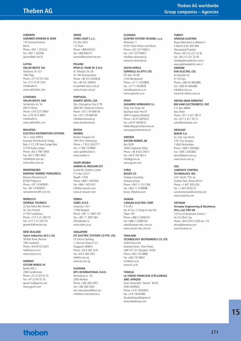
15
271
Group companies – Agencies Theben AGTheben AG worldwide
LEBANONGARABED AYANIAN & SONS176 Gouraud AvenueBeirutPhone +961 1 255222Fax +961 1 [email protected]
LATVIAVALLIN BALTIC SIA Maskavas Str 3221063 RigaPhone +371 6718 7204Fax +371 6718 [email protected]
LITHUANIAVALLIN BALTIC UABSeimyniskiu str. 5A09312 VilniusPhone +370 5272 8893Fax +370 5272 [email protected]
MALAYSIAELECTECH DISTRIBUTION SYSTEMS16–1, Jalan 6/89 B, Kawasan Perindustrian Trisegi,Batu 3 1/2, Off Jalan Sungei Besi57100 Kuala LumpurPhone +60 3 7981 8950Fax +60 3 7981 [email protected]
MONTENEGRORAROVAC KOMERC PODGORICABracana Bracanovica 681000 PodgoricaPhone +38 1 81609091Fax +38 1 [email protected]
MOROCCOGENERAL TECHNICS22 Rue Rahal Ben Ahmed(Ex. Rue Dinant)21700 CasablancaPhone +212 5 22 246170Fax +212 5 22 [email protected]
NEW ZEALANDVynco Industries (N.Z.) Ltd.58 Wall Road, Penrose1061 AucklandPhone +64 09 525 [email protected]
NORWAYGYCOM NORGE ASBalder Allé 22060 GardermoenPhone +47 22 64 55 25Fax +47 22 64 55 [email protected]
OMANSTARS LIGHT L.L.C.P.O. Box 2822112 RuwiPhone +968 697025Fax +968 [email protected]
POLANDPPUH EL-TEAM SP. Z.O.O.Al. Mlodych 26–2841-106 SiemianowicePhone +48 322 0430628Fax +48 322 [email protected]
PORTUGALDUARTE NEVES, LDAQta. Estrangeiros, Rua D 782665-601 Venda do PinheiroPhone +351 219 668100Fax +351 219 [email protected]
RUSSIAMARBELBolshoi Prospect V.O.199178 St. PetersburgPhone + 7 812 3242777Fax +7 495 [email protected]
SAUDI ARABIAANWAR AL-WESSAM EST.Gurabi Bin Shaihon CenterP. O. Box 23521Riyadh 11436Phone +966 1 4055942Fax +966 1 [email protected]
SERBIASOBEL D.O.OUstanicka 125-I11000 BelgradPhone +381 11 3087 507Fax +381 11 3087 064offi [email protected]
SINGAPOREITE ELECTRIC SYSTEMS CO PTE. LTD.ITE Electric Building1, Harrison Road 01-01, Singapore 369652Phone +65 6 285 2233Fax +65 6 284 [email protected]
SLOVENIAMTS INTERNATIONAL D.O.O.Perhavčeva ul. 15c2000 MariborPhone +386 26612001Fax +386 [email protected]@mts-international.si
SLOVAKIAELEKTRO-SYSTEM-TECHNIK, s.r.o.Mnesická 1191501 Nové Mesto nad VáhomPhone +421 327740814Fax +421 [email protected]
SOUTH AFRICASUPARULE SA (PTY) LTD.P.O. Box 761282144 WendywoodPhone +27 11 4529800Fax +27 11 [email protected]
SPAINGUIJARRO HERMANOS S.L.Polig. Ind. Virgen DeButarque Isaac Peral 628914 Leganes (Madrid)Phone +34 91 6870022Fax +34 91 [email protected]
SWEDENGYCOM NORDIC ABBox 502819405 Upplands VäsbyPhone +46 8 632 300 0Fax +46 8 792 065 [email protected]
SYRIABOUZO COTrading-ConsultingDamascus/SyriaPhone +963 11 3311306Fax +963 11 [email protected]
TAIWANCANAAN ELECTRIC CORP.P. O. 6F5No. 63 Sec 2 Chang An East Rd.Taipei 104Phone +886 2 25082331Fax +886 2 [email protected]
THAILANDTECHNOLOGY INSTRUMENTS CO. LTD549/9 Onnut Rd.Kwaeng Pravet, Khet Pravet, 208/132-137, Bangkok 10250Phone +662 743 8888Fax +662 743 [email protected]
TUNESIALA TUNISO FRANCAISE D'ÉCLAIRAGEABEL AFRIQUEZone Industrielle "Morize" BP 652090 MORNEGPhone +216 79350955Fax +216 [email protected]
TURKEYGÖKHAN ELEKTRIKPerpa Elektrokent Is Merkezi AA Blok K.8 No. 692-694Okmeydaný/ÝstanbulPhone +90 212 221 32 36Fax +90 212 221 32 40ufuk@gokhanelektrik.com.trwww.gokhanelektrik.com.trUKRAINEKVK-ELECTRO, LTD.43 Kikvidze Str.01103 KyivPhone +380 44 4962886Fax +380 44 [email protected]
UNITED ARAB EMIRATESBIN HAM ELECTROMECH. ENT.P. O. Box 46844Abu DhabiPhone +971 4 227 393 9Fax +971 4 221 761 [email protected]
URUGUAYBERON S.A.Av. Gral. San Martin 2761 Esq. Burgues11800 MontevideoPhone +598 2 2002862Fax +598 2 2002862 [email protected]
USALUMENITE CONTROL TECHNOLOGY, INC.2331 North 17th. Av.Franklin Park, Illinois 60131Phone +1 847 4551450Fax +1 847 [email protected]
VIETNAMTerramar Engineering & Machinery (Pte.) Ltd. PRO VN 123 Le Loi Boulevard, District 1Ho Chi Minh CityPhone +84 8 3915 3209 ext. [email protected]
Catalogue_EN_2013.indb 271 16.01.13 17:26
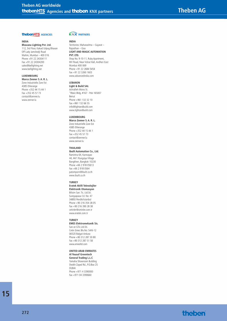
15
272
Agencies and KNX partners Theben AG Theben AG worldwide
AGENCIES
INDIABhavana Lighting Pvt. Ltd.112, 3rd Floor, Kakad Udyog BhavanOff Lady Jamshedji RoadMahim, Mumbai – 400 016Phone +91 22 24304111Fax +91 22 [email protected]
LUXEMBOURGMarco Zenner S. A. R. L.Zone Industrielle Zare Est4385 EhlerangePhone +352 44 15 44 1Fax +352 45 57 [email protected]
PARTNERS
INDIATerritories: Maharashtra – Gujarat – Rajasthan – GoaLIGHT AND MAGIC AUTOMATION PVT. LTD.Shop No. 9-10-11, Ruby Apartment, MV Road, Near Vishal Hall, Andheri EastMumbai 400 069Phone +91 22 2684 5454Fax +91 22 3260 1603www.advancedindia.com
LEBANONLight & Build SALAchrafi eh Mono St."Rbeiz Bldg. #167 - Pob 165007BeirutPhone +961 132 32 10Fax +961 132 66 [email protected]
LUXEMBOURGMarco Zenner S. A. R. L.Zone Industrielle Zare Est4385 EhlerangePhone +352 44 15 44 1Fax +352 45 57 [email protected]
THAILANDIbuilt Automation Co., Ltd.Ramintra 64, Kannayao44, 44/1 Rungsiya VillageBangkhen, Bangkok 10230Phone +66 2 918 05613Fax +66 2 918 [email protected]
TURKEYEratek Akilli Teknolojiler Elektronik OtomasyonBilisim San. Tic. Ltd.Sti.Sureyyapasa Cd. No: 4734893 Pendik/IstanbulPhone +90 216 354 28 05Fax +90 216 390 28 [email protected]
TURKEYEMES Elektromekanik Sis. San.ve GTic.Ltd.Sti.Cetin Emec Blv.No: 54/6-1206520 Balgat-AnkaraPhone +90 312 287 30 80Fax +90 312 287 51 58www.emesltd.com
UNITED ARAB EMIRATESAl Yousuf GreentechGeneral Trading L.L.CYamaha Showroom BuildingSheikh Zayed Rd., P.O.Box 25DUBAIPhone +971 4 3390000Fax +971 04 3390660
Catalogue_EN_2013.indb 272 16.01.13 17:26
273
Notes Theben AG
15
Catalogue_EN_2013.indb 273 16.01.13 17:26
15
274
Free of charge Theben AG Advertising material order
Under www.theben.de you can find the leaflets above as pdf-files.
In addition, you can find downloads on the Internet at:
• Texts for tenders
• Operating instructions
• Databases
• KNX-manuals
• KNX-databases
• OBELISK-software
• Supplementary lists for units not in the current
range
• Certificates
Sender
Company
Street
Phone
Fax
Contacts
Post code/Location
Mobile
Trade Industry Wholesale
Please put me in contact with one of your technical advisors.
Theben AG, Hohenbergstraße 32, 72401 Haigerloch, www.theben.de, Phone +49 7474 692-0, Fax +49 7474 692-150
Theben General Catalogue
Product catalogue “TIME”
Product catalogue “LIGHT”
Leaflet “Living comfort control units LUXOR”
Leaflet “12 useful energy saving tips”
Leaflet “ENERGY SAVING IDEAS”
Leaflet “MIX examples KNX”
Further detailed information is available on request free of charge!
FAX +49 7474 692-199or local office see pages 270–272
Catalogue_EN_2013.indb 274 16.01.13 17:26

Catalogue_EN_2013.indb 275 16.01.13 17:26
english
Catalogue2013/2014
Cata
logu
e 20
13/2
014
SYSTEMS FORTIME, LIGHT, CLIMATE
Theben AGHohenbergstraße 32, 72401 Haigerloch, GERMANY Postfach 56, 72394 Haigerloch, GERMANY Fon +49 7474 692-0Fax +49 7474 [email protected], www.theben.de 99
0060
0 03
13
W
e re
serv
e th
e rig
ht to
mak
e te
chni
cal m
odifi
catio
ns a
nd im
prov
emen
ts.
00-10_CATen-2013_Umschlag_EAN-Code.indd 1 10.01.13 17:41


![[Salis M.] Casa aragonese](https://static.fdokumen.com/doc/165x107/632402435f71497ea9049a67/salis-m-casa-aragonese.jpg)