Modular platform vision and strategy
22
◆ Modular Platform Vision and Strategy Patricia A. Battaglia, Charles C. Byers, Leslie A. Guth, Albert Holliday, Claudio Spinelli, and Jason J. Tong A platform is a set of hardware, software, and process building blocks that can form the basis of many different products. The goals of platforms are to reuse and/or share assets wherever possible, to save on development costs, to spread fixed development and production costs across the largest volumes, and to offer highly integrated solutions, all while maintaining critical differentiation of products. Using platforms correctly can produce substantial life-cycle cost benefits and can lead to enhanced supplier management and customer satisfaction. This paper will begin by describing the general concept of platforms. It will then consider their economic benefits to development teams, suppliers, and customers. Next, it will discuss the role of industry standards in forming the basis of a platform offer. It will consider the changing architectures of telecommunications networks, along with the contribution of platforms to these changes. Finally, the paper will outline an example set of platform building blocks and their requirements, along with some case studies of how to combine these building blocks into products. © 2004 Lucent Technologies Inc. Introduction to Standards-Based Modular Platforms The global telecommunications industry is in the midst of tremendous challenges and opportunities. The network service providers are experiencing huge financial and technical pressures as they seek to reduce costs while still providing increased network capacity, reliability, and feature content. At the same time, many telecommunications equipment manu- facturers (TEMs) are facing unprecedented pressures of their own. They are experiencing decreasing sales and shrinking development budgets, yet they need to continue to field innovative products. With these ex- traordinary challenges, however, come extraordinary opportunities for innovative network architectures and network element designs. This paper introduces the concept of a standards- based modular platform, which is a set of hardware and software assets that can form the basis for many types of telecommunications network elements. Commonality and standardization are important attributes in telecommunications network design, as they can greatly improve efficiency, reduce churn, and greatly reduce the life-cycle cost of ownership of telecommunications networks for network operators. Equipment manufacturer benefits include reduced de- velopment time resulting in faster time-to-market and reduced production variations, hardware/software in- ventory, and maintenance costs. Design reuse and cost reductions are realized by sharing assets over more Bell Labs Technical Journal 9(1), 121–142 (2004) © 2004 Lucent Technologies Inc. Published by Wiley Periodicals, Inc. Published online in Wiley InterScience (www.interscience.wiley.com). • DOI: 10.1002/bltj.20009
-
Upload
independent -
Category
Documents
-
view
0 -
download
0
Transcript of Modular platform vision and strategy

� Modular Platform Vision and StrategyPatricia A. Battaglia, Charles C. Byers, Leslie A. Guth,Albert Holliday, Claudio Spinelli, and Jason J. Tong
A platform is a set of hardware, software, and process building blocks thatcan form the basis of many different products. The goals of platforms areto reuse and/or share assets wherever possible, to save on developmentcosts, to spread fixed development and production costs across the largestvolumes, and to offer highly integrated solutions, all while maintainingcritical differentiation of products. Using platforms correctly can producesubstantial life-cycle cost benefits and can lead to enhanced suppliermanagement and customer satisfaction. This paper will begin by describingthe general concept of platforms. It will then consider their economicbenefits to development teams, suppliers, and customers. Next, it will discussthe role of industry standards in forming the basis of a platform offer. It willconsider the changing architectures of telecommunications networks, alongwith the contribution of platforms to these changes. Finally, the paper willoutline an example set of platform building blocks and their requirements,along with some case studies of how to combine these building blocks intoproducts. © 2004 Lucent Technologies Inc.
Introduction to Standards-BasedModular Platforms
The global telecommunications industry is in the
midst of tremendous challenges and opportunities.
The network service providers are experiencing huge
financial and technical pressures as they seek to
reduce costs while still providing increased network
capacity, reliability, and feature content. At the same
time, many telecommunications equipment manu-
facturers (TEMs) are facing unprecedented pressures
of their own. They are experiencing decreasing sales
and shrinking development budgets, yet they need to
continue to field innovative products. With these ex-
traordinary challenges, however, come extraordinary
opportunities for innovative network architectures
and network element designs.
This paper introduces the concept of a standards-
based modular platform, which is a set of hardware
and software assets that can form the basis for
many types of telecommunications network elements.
Commonality and standardization are important
attributes in telecommunications network design, as
they can greatly improve efficiency, reduce churn,
and greatly reduce the life-cycle cost of ownership of
telecommunications networks for network operators.
Equipment manufacturer benefits include reduced de-
velopment time resulting in faster time-to-market and
reduced production variations, hardware/software in-
ventory, and maintenance costs. Design reuse and cost
reductions are realized by sharing assets over more
Bell Labs Technical Journal 9(1), 121–142 (2004) © 2004 Lucent Technologies Inc. Published by Wiley Periodicals, Inc.Published online in Wiley InterScience (www.interscience.wiley.com). • DOI: 10.1002/bltj.20009

122 Bell Labs Technical Journal
products, by larger manufacturing volumes, and
through vendor consolidation. In addition, software
platforms deliver increased reliability and easier mi-
gration from old to new releases of products, while
reducing operation support systems to network ele-
ment interface maintenance and field support/services
organization training costs.
A standards-based modular platform can be
thought of as a set of building blocks based on a
common architecture, which includes elements like
enclosures, chassis, backplanes, cooling infrastructure,
circuit board assemblies, and basic software that form
the basis for the development of many different
classes of network elements. By adding a small set
of application-specific assets to the broad base of
standards-based modular platform assets, many dif-
ferent network element designs can be realized.
Further, by basing the platform assets on industry
standards, several extra degrees of freedom for the
development process result. Particular elements of a
design could be purchased off the shelf from various
original equipment manufacturers (OEMs). Good
examples of this sort of element would be enclosures,
chassis, backplanes, general-purpose processor cards,
and software operating systems. Other elements of
standards-based modular platforms could be built in-
house by the TEM using traditional design and build
processes. Examples of elements one may choose
to build in-house include special interfaces, signal
processors, and management software. Figure 1shows the decision process used to determine the mix
of commercial off-the-shelf (COTS) and custom com-
ponents. The real benefits of standards-based modu-
lar platforms are realized when an appropriate mix
of COTS components and custom-built components
come together to produce a platform-based system
with exactly the performance, reliability, cost, and
time-to-market properties needed.
Panel 1. Abbreviations, Acronyms, and Terms
ADSL—asymmetric DSLAdvancedTCA*—advanced telecom computing
architecture standards (PICMG 3.X)ATM—asynchronous transfer modeCGLWG—Carrier Grade Linux Working GroupCMTS—cable modem termination systemCOGS—cost of goods sold COTS—commercial off the shelfCP—circuit pack CompactPCI*—compact PCI standards
(PICMG 2.X)CompactPSB—compact PCI packet switching
backplane standard (PICMG 2.16)CPU—central processing unitDS1—digital signal level 1, transmission rate of
1.544 Mb/sDS3—digital signal level 3, transmission rate of
44.736 Mb/sDSL—digital subscriber lineDSLAM—DSL access multiplexerDSP—digital signal processor FTTH—fiber to the homeFPGA—field programmable gate array I/O—input/outputIP—Internet protocol
LMPI—Lucent Modular Platform Initiative mRT—micro remote terminal MSC—mobile switching centerNE—network elementOC-12—optical carrier digital signal rate of
622 Mb/sOEM—original equipment manufacturer OSDL—Open Source Development Lab PBB—platform building blockPCI—peripheral component interconnectPICMG—PCI Industrial Computer
Manufacturers Group PSTN—public switched telephone networkRAM—random access memory SAForum*—Service Availability ForumSAN—storage area networkSONET—synchronous optical network T1—24-channel digital carrier system for DS1
signals (1.544 Mb/s) TDM—time division multiplexed TEM—telecommunications equipment
manufacturer VDSL—very high bit rate DSLWDM—wavelength division multiplexingxDSL—any of various DSL technologies

Bell Labs Technical Journal 123
Cost and time savings can be realized with greater
reuse across a product portfolio. Reuse and all of its
benefits are enabled by common platform architec-
ture and a set of complementary hardware and
software platform building blocks.
DefinitionsPlatform building blocks (PBBs) are what we call
the common elements that can be used in multiple
products and can be specific to a particular TEM (called
proprietary) or bought on the COTS market. A propri-
etary PBB is common to multiple products within a
company’s portfolio. A proprietary PBB can be based on
an industry standard or on a vendor-specific design.
The development costs are shared by multiple products
within the portfolio, and supply chain costs are reduced
by aggregating larger volumes bought from a few com-
peting suppliers. A COTS PBB is developed by an out-
side supplier and is common to many companies’
products. Development costs are spread over many
outside users and prices are reduced through higher
manufacturing volumes and competition among func-
tionally equivalent (and interchangeable) versions from
many different suppliers.
COTS PBBs already exist in the form of compo-
nents like integrated circuits and connectors. Software
components already exist in the form of operating
systems, communications protocol packages, and
common library functions. The natural extension of
the platform concept is to develop platform enclo-
sures, chassis, backplanes, and circuit packs for com-
mon functions within different products.
Lucent Technologies is in the process of selecting a
set of hardware and software PBBs to serve as the basis
for the evolution of many products in its existing port-
folio, as well as to support new product opportunities.
We call the specific set of PBBs chosen by Lucent, and
the processes that surround their application to our
Universal platform?
TEM developed or COTS?
N
N
Y
Y
MixCOTS
COTS—Commercial off-the-shelf
TEM
Functionality to be delivered
All platformelements
from third-party
suppliers
Standards-based
platform witha mix of
COTS andTEM builtelements
Standards-based
platformbuilt by
TEM
Small numberof proprietary
multi-useplatforms
Many proprietaryhardware
developmentsin parallel
Standards based?
Figure 1.Platform decision tree.

124 Bell Labs Technical Journal
products the Lucent Modular Platform Initiative
(LMPI).
Design for PlatformingIn order to implement a platform strategy, we
must first identify the minimum set of functions
needed to build the products of interest, decompose
the functions into a minimum set of building blocks,
and finally classify these building blocks as:
• Unique to the given product,
• Differentiators that provide a competitive advan-
tage to the TEM but could be common to many
products in the portfolio, and
• Not differentiators but are in common with many
products including our competitors’ products.
COTS PBBs should then be used to implement
functions that are not product differentiators, and pro-
prietary PBBs should be used to implement functions
that are differentiators with respect to competitors’
products or that have a large enough volume that
there is a cost advantage. Functions unique to a given
product are not implemented as PBBs.
Product architectures must then be made com-
patible with the platform strategy by partitioning
functions so that the interfaces between platform
building blocks and product-specific functions are as
simple and stable as possible to facilitate interaction
between platform and product development teams.
The partitioning of the product functions must also
align with the functions of the PBB offerings, from
both the internal platform development teams and
those offered by external suppliers.
COTS PBBs should be available as stock products
for which minimal internal development resources
are needed for implementation. A common develop-
ment team for all products should implement propri-
etary PBBs, reusing as many assets as practical.
Many factors must be considered when deciding
if a particular PBB is proprietary or COTS. These in-
clude the development cost and the volume and mar-
gin considerations listed above, as well as full-stream
cost and life-cycle cost of ownership factors.
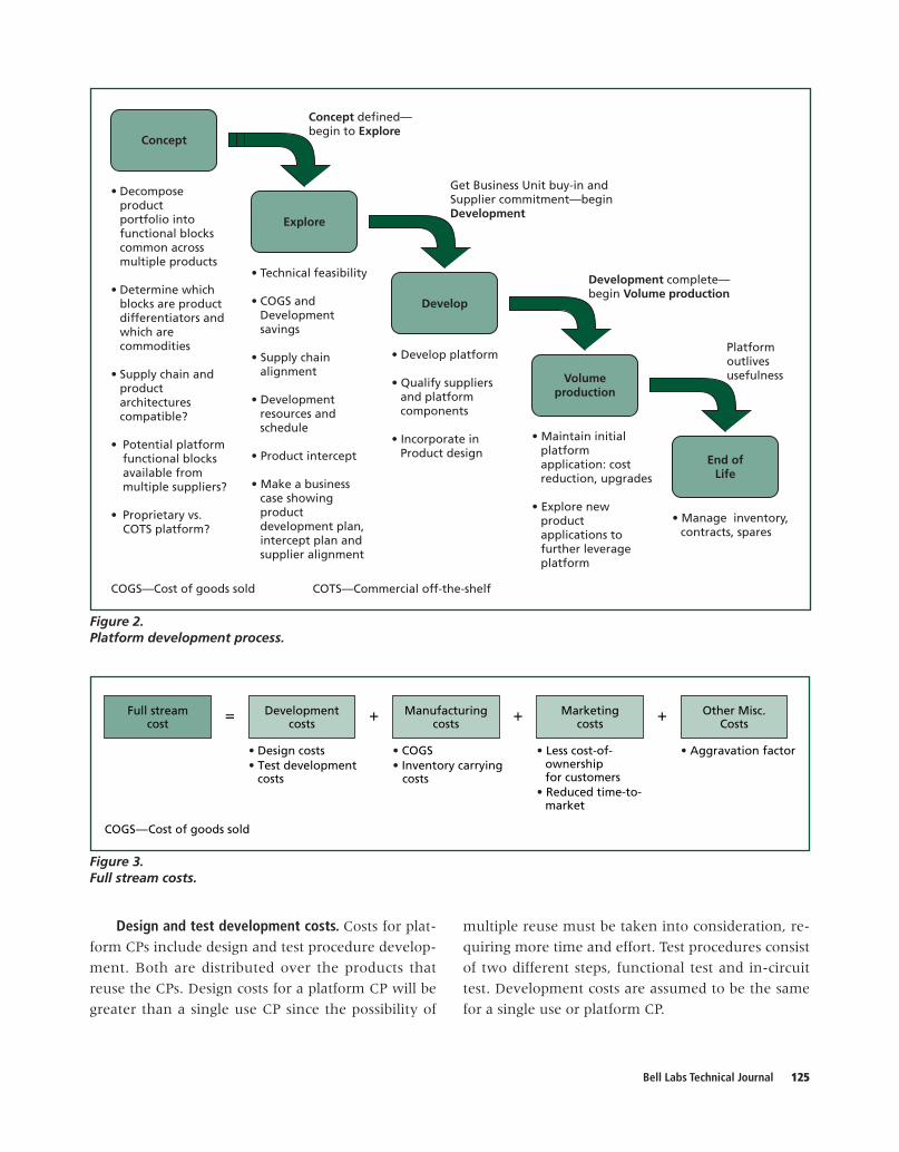
Platform Strategy ImplementationFigure 2 shows a five-step process that has been
defined for identifying and creating new platform
building blocks. Implementation of this platform strat-
egy requires coordination of internal portfolio and
PBB suppliers’ product developments. Where COTS
PBBs exist, product development needs to be made
aware of them and encouraged to use them where
strategically advantageous. Where COTS PBBs do not
exist or need modification to meet Lucent’s needs,
supplier management needs to drive suppliers to make
the desired changes. The product portfolio knowledge
needed by supplier management to coordinate COTS
platform development also can be used to identify
candidates for proprietary PBB development.
Effectively taking advantage of software compo-
nent reuse not only depends on component iden-
tification, but also on how those components are
combined as building blocks. Software building blocks
need to be maintained by a centralized development
organization and may consist of homegrown compo-
nents as well as third-party commercial software.
Platform Business Case and Cost ModelsThe primary advantage of platform use by TEMs
is reduced development cost, time-to-market, and risk
through the reuse or existing designs and reduced
manufacturing cost through higher manufacturing
volumes. Service providers also benefit from platforms
through these cost savings being passed on to them
and by improved operational expense. Any imple-
mentation of a platform must be supported by a full-
stream cost business case showing the expected return
on investment.
Full-stream CostsIn order to fully evaluate numerous benefits
of PBBs, we utilize a concept of full-stream cost by
which not only direct material cost but also other in-
direct overhead costs can be accounted for. As shown
in Figure 3, the full-stream cost includes develop-
ment costs, manufacturing costs, cost of ownership,
and other miscellaneous costs that are not captured
in the previous three cost categories. For each cost
category, benefits of PBBs are examined in terms of
cost savings. A circuit pack (CP) is chosen as an ex-
ample PBB for this analysis. While actual costs vary
from product to product, we will illustrate the method
of analysis with hypothetical but typical costs.
Bell Labs Technical Journal 125
End ofLife
Develop
Concept
Explore
Volumeproduction
Concept defined—begin to Explore
Get Business Unit buy-in andSupplier commitment—beginDevelopment
Platformoutlivesusefulness
Development complete—begin Volume production
COGS—Cost of goods sold COTS—Commercial off-the-shelf
• Decompose productportfolio into functional blocks common acrossmultiple products
• Determine which blocks are productdifferentiators andwhich are commodities
• Supply chain andproduct architecturescompatible?
• Potential platformfunctional blocksavailable from multiple suppliers?
• Proprietary vs. COTS platform?
• Technical feasibility
• COGS and Development savings
• Supply chainalignment
• Development resources and schedule
• Product intercept
• Make a business case showing product development plan,intercept plan andsupplier alignment
• Develop platform
• Qualify suppliersand platformcomponents
• Incorporate inProduct design
• Maintain initial platform application: costreduction, upgrades
• Explore new product applications to further leverage platform
• Manage inventory,contracts, spares
Figure 2.Platform development process.
Full streamcost
Developmentcosts
Manufacturingcosts
Marketingcosts
• Design costs• Test development
costs
• COGS• Inventory carrying
costs
• Less cost-of-ownershipfor customers
• Reduced time-to-market
• Aggravation factor
COGS—Cost of goods sold
Other Misc.Costs
� � � �
Figure 3.Full stream costs.
Design and test development costs. Costs for plat-
form CPs include design and test procedure develop-
ment. Both are distributed over the products that
reuse the CPs. Design costs for a platform CP will be
greater than a single use CP since the possibility of
multiple reuse must be taken into consideration, re-
quiring more time and effort. Test procedures consist
of two different steps, functional test and in-circuit
test. Development costs are assumed to be the same
for a single use or platform CP.

126 Bell Labs Technical Journal
Manufacturing costs. Manufacturing costs have
two components—one is cost of goods sold (COGS),
most of which is direct material cost, and the other is
inventory-carrying cost. Non-trivial savings in mate-
rial costs of platform CPs are expected as they
are reused multiple times across various products.
However, the amount of savings depends on contract
terms that result from negotiation with contract man-
ufacturers or COTS suppliers. Direct material costs
also drop quickly as volumes increase but flatten out
after a certain quantity. For some high-running prod-
ucts, the volumes for a single product alone may max-
imize these savings.
Inventory carrying cost is the cost of maintaining
average inventory in a warehouse or manufacturing
line where raw material, finished goods, or work in
progress is kept. Cost of capital for inventory, ware-
house cost, handling cost, and obsolescence cost are
major factors to be included in the inventory cost.
These costs, of course, vary from business to business.
For this example, we will use a typical industry value
of 25% of average inventory value on hand [11].
Appropriate inventory level is usually determined
in such a way that a certain level of on-time delivery
rate can be achieved for a given variability in demand.
The more variability in demand is expected, the big-
ger inventory needs to be kept. Demands for PBBs
are to be obtained from aggregation of individual de-
mands of products where PBBs are reused. Since ag-
gregated demands yield less variability than individual
demands, overall inventory level can be reduced with
more reuse. In fact, variability reduces with demand
aggregation at a rate of the square root of N [2],
where N is the number of demands aggregated. It
should be noted that the square root of N explains
typical cost savings when the demands aggregated
have similar average values and they are not corre-
lated with each other.
Marketing costs. From a marketing point of view,
PBBs provide various advantages including less cost-
of-ownership for customers and reduced time-to-
market. Network infrastructures using PBBs enable
service providers to reduce employee training costs
and the labor required for deploying and operating
the infrastructures. In addition, service providers can
reduce inventory-carrying cost by reducing the quan-
tity of spare parts for replacements. In fact, a cost-of-
ownership study carried out by a strategy consulting
firm shows that service providers can save 20 to 25%
of operating expenses and 35% of capital expendi-
tures with advanced telecommunications computing
architecture-based network infrastructures for wide-
band code division multiple access [5]. In addition to
the compelling cost benefit to the customers, fast
time-to-market due to reusing PBBs should allow
TEMs to take over a superior position in marketing
their products. Impact of the superior market posi-
tion to the full-stream cost is assigned to the market-
ing cost category. However, valuation of the impact
involves too much unavoidable uncertainty in quan-
tification due to its intangible nature, so we decided
not to include it in our numerical example.
Aggravation costs. In order to account for cost
associated with drawbacks of PBBs, we define an
“aggravation factor” as the price that has to be paid for
multiple reuses of PBBs, and classify the factor as the
last miscellaneous cost category for the full-stream
cost analysis. The aggravation factor accounts for the
added cost associated with coordinating and designing
(non-optimal design for specific applications) a widely
reusable CP asset to meet the requirements for mul-
tiple product units. Obviously, the aggravation factor
will grow as the platform CP gets reused more. With
an assumption of quadratic growth with the CP reuse,
the aggravation factor is expressed in terms of nega-
tive cost savings.
ExampleTake as a specific example (based on Lucent man-
ufacturing experience) a CP that costs $75,000 for
design and $110,000 for test development. Assume
design of a platform CP is double the single use cost,
or $150,000, but the test development cost remains
the same. In addition, assume annual COGS of each
individual CP to be $5M and inventory turn-over
ratio to be 10 so that average inventory level would be
one-tenth of annual COGS and inventory carrying
cost is 25% of inventory level. Because of their un-
certainty, volume discounts were not included in the
model but could be added after, once the specifics are
known. Figure 4 shows the savings in each area.

Bell Labs Technical Journal 127
With the aggravation factor taken into account,
the optimum number of reuses is graphically shown
in Figure 5. Since design cost and test develop-
ment cost reduce with 1/N rate and inventory cost
savings increase with the square root of N, summation
of the three cost savings shows decreasing mar-
ginal cost savings with increasing common CP reuse
(dotted curve). In other words, significant savings
occur with the first few reuses and the effects of reuses
in cost savings diminish with more reuses. It also
should be noted that there is very little difference in
total savings (solid curve) after a certain number of
reuses (N � 5) whether or not the common CP is
reused optimally (N � 9).
As the last step of the analysis, sensitivity tests
were carried out by changing input parameters such
as platform CP design cost, test development cost, and
inventory carrying cost. Figure 6 shows the variation
in total savings when the test development cost for
the platform CP is increased by 200%. This is a typi-
cal result, where total savings varies significantly
when the number of reuse (N) is small but stays more
or less at 3% for N � 5.
Based on this analysis, a strategy to develop one
versatile PBB that can be reused across a large num-
ber of products may not be as effective as having sev-
eral PBBs reusable in a limited number of products.
Different input conditions for the business case analy-
sis may result in different outcomes, but the general
trends of saturating the cost-savings curve, the exis-
tence of optimum number of reuse, and little sensi-
tivity around the optimum point would not change.
Savi
ng
s ($
)/C
P
�$100,000
�$50,000
$0
$50,000
$100,000
$150,000
$200,000
$250,000
Number of CPs reused
1 2 3 4 5 6 7 8 9 10 11 12 13 14 15 16
Inventory cost savings Test development cost savings
Design cost savings Aggravation factor
CP—Circuit pack
Figure 4.Total cost savings per circuit pack.

128 Bell Labs Technical Journal
Industry StandardsIndustry standards are essential to our modular
platform vision. Through the appropriate application
of open industry standards, platforms can provide all
of the benefits required to serve as the basis of a suc-
cessful product portfolio. The following section dis-
cusses some of the hardware and software standards
that are particularly applicable to platform work.
Hardware StandardsThe PCI Industrial Computer Manufacturers
Group (PICMG*) controls the hardware industry
standards most applicable to serve as the basis for
standards-based modular platforms. This open indus-
try standards organization has over 600 member com-
panies and several hundred companies actively
making products that conform to their standards [7].
COGS—Cost of goods sold CP—Circuit pack
Total savings/COGS
�2.00%
�1.00%
0.00%
1.00%
2.00%
3.00%
4.00%
Number of CPs reused
Savi
ng
s as
% o
f C
OG
S
w/o aggravation factor
w/ aggravation factor
1 2 3 4 5 6 7 8 9 10 11 12 13 14 15 16
Figure 5.Total savings as percent of COGS.
COGS—Cost of goods sold CP—Circuit pack
Total savings/COGSSensitivity to test development cost
�6.00%
�4.00%
�2.00%
0.00%
2.00%
4.00%
1 2 3 4 5 6 7 8 9 10 11 12 13 14 15 16
Number of CPs reused
Savi
ng
s as
% o
f C
OG
S
Figure 6.Total savings as percent of COGS with varying test development cost.

Bell Labs Technical Journal 129
CompactPCI* is a very popular PICMG standard.
CompactPCI (also called PICMG 2.X) covers the use of
standard PCI buses (as found in desktop personal com-
puters) into a hardened industrial/telecommunications
environment [8]. Extensions to PICMG 2.X have
added capabilities like hot swap, advanced manage-
ment, and an Ethernet packet-switched fabric. The
later capability, in particular, is called Compact Packet
Switching Backplane (CompactPSB) or PICMG 2.16
and is very valuable for telecommunications platforms.
CompactPCI systems are currently undergoing field
deployment worldwide.
PICMG has recently completed a new standard
called Advanced Telecom Computing Architecture
(AdvancedTCA* or PICMG 3.X) [9]. The AdvancedTCA
standard is an optimal choice for an industry standard
to serve as a basis for a standards-based modular plat-
form for many large-scale applications. Many properties
of AdvancedTCA, such as large board areas, huge back-
plane bandwidths, high thermal load capacities, ad-
vanced packaging, cable management, and advanced
shelf management infrastructure make it an ideal
choice for these applications. AdvancedTCA is equally
applicable to both simple, small, cost-sensitive elements
and very high capacity core elements. AdvancedTCA
was in the testing and laboratory demonstration stage
in 2003, with field deployments expected in 2004.
Table I is a comparison matrix between
CompactPCI (PICMG 2.X), CompactPSB (PICMG 2.16),
and AdvancedTCA (PICMG 3.X).
Software StandardsIn general, standards are important to the plat-
form initiative. They require suppliers/vendors to
build to a specification, producing commodity building
blocks for the platform builder to use. The Service
Availability Forum (SAForum*) specification [10]
should be followed to manage the platform so that
PICMG 2 PICMG 2.16 PICMG 3Attribute Compact PCI† Compact PSB Advanced TCA†
Board size 6 U � 160 mm � .8” 6 U � 160 mm � .8” 8 U � 280 mm � .1.2”57 sq. in. � 2 Mez 57 sq. in. � 2 Mez 140 sq. in. � 4 Mez
Board power 35–50 Watts 35–50 Watts 150–200 Watts
Backplane bandwidth �4 Gb/s �38 Gb/s �2.4 TB/s
Number of active boards 21 19 16
Power system Centralized converter Centralized converter Distributed converters5, 12, 3.3V backplane 5, 12, 3.3V backplane Dual 48V backplane
Management OK OK Advanced
I/O Limited OK Extensive
Clock, update, test bus No No Yes
Regulatory conformance Vendor specific Vendor specific In standard
Multi-vendor support Extensive Building Anticipated in 2003
Base cost of shelf Low Low—Moderate Moderate—High
Functional density of shelf Low Moderate High
Life-cycle cost per function High Moderate Low
Standard GA schedule 1995 2001 2H 2003
Table I. Comparison between PICMG 2, PICMG 2.16, and PICMG 3.
GA—General availabilityI/O—Input/output†Registered trademarks of the PCI Industrial Computer Manufacturers Group
130 Bell Labs Technical Journal
services can be provided to the application software
that allows it to be independent of any particular
hardware. The SAForum standard specifies a set of
fault-tolerant middleware that greatly simplifies and
standardizes the creation of software infrastructures
for high availability systems. Another important stan-
dard is the Open Source Development Lab (OSDL*)
[6], Carrier Grade Linux Working Group (CGLWG)
[1], which is driving the requirements and roadmap
for carrier grade Linux* distributions.
Platform Evolution and VisionPlatforms contribute to the improved capital and
operational expense of telecommunications networks
through improved integration. Functions that were
once performed by dozens of different network
elements can be integrated into only a few
standards-based modular platform-based elements.
The following telecommunications network archi-
tectural progression study illustrates the benefits of
integration.
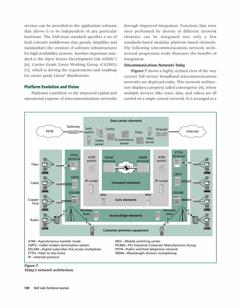
Telecommunications Networks TodayFigure 7 shows a highly stylized view of the way
current full service broadband telecommunications
networks are deployed today. This network architec-
ture displays a property called convergence [4], where
multiple services (like voice, data, and video) are all
carried on a single central network. It is arranged as a
Customer premises equipment
Transport elements
WDMterminal
WDMterminal
Fiber
Cable
Copperloop
Radio
ATMswitch
IP router
CMTS
DSLAM
FTTHterminal
CMTS
DSLAM
FTTHterminal
Webserver
Firewall
Videoserver
Cache
E-commerceserver
FilterSoft-
switch
Gateway
Wirelessbase
ATM—Asynchronous transfer modeCMTS—Cable modem termination systemDSLAM—Digital subscriber line access multiplexerFTTH—Fiber to the homeIP—Internet protocol
MSC—Mobile switching centerPICMG—PCI Industrial Computer Manufacturers GroupPSTN—Public switched telephone networkWDM—Wavelength division multiplexing
Data center elements
MSC
Access/Edge elements
Wirelessbase
MSC
ATMswitch
IP router
InternetPSTN
Core elements
Figure 7.Today’s network architecture.
Bell Labs Technical Journal 131
series of concentric zones, each having its own set of
properties and each requiring its own types of net-
work elements. Customer premises equipment is lo-
cated around the outside perimeter of the network.
Here, there are typical telecommunications endpoints,
like telephones, computers, video equipment, and
wireless devices. The various remote network
elements, like cable modems, digital subscriber line
(DSL) modems, and fixed wireless line units are here,
also. This is the set of equipment most visible to the
subscriber and also the equipment with the most cost
pressure. Various types of physical media, like twisted
pair, cable television, fiber, and wireless air interfaces
complete the interconnection from the customer
premises equipment to the network.
The next layer includes the access and edge
elements of a telecommunication network. Elements
like wireless base stations, DSL access multiplex-
ers (DSLAMs), cable modem termination systems
(CMTSs), and fiber-to-the-home (FTTH) terminals
reside here. These elements represent some of the
most critical cost and density requirements of a
telecommunications network. Network providers are
always trying to reduce their footprint and power dis-
sipation, increase their capacity, and improve their cost
of ownership. In addition, there has been much ongo-
ing controversy over the regulatory implications of
these elements [3]. This is where unbundling occurs
when an incumbent network operator wholesales
network access capability to a competitive provider.
Moving toward the core of the network, the next
layer encountered is the core elements. Switching and
related functions are performed here. Asynchronous
transfer mode (ATM) switches, Internet protocol (IP)
routers, and mobile switching center (MSC) elements
perform the switching, routing, bandwidth manage-
ment, and call control functions needed for a complex
network. These elements are not usually as cost or
density constrained as those found in the access and
edge layer. Instead, they are dominated by capacity,
performance, and reliability requirements.
At the core of the network lie the transport
elements. Data streams are collected from the core
elements and processed by optical terminals to be
sent over the long-haul fiber optical facilities. Often,
wavelength division multiplexing (WDM) is em-
ployed to greatly increase the capacity of the inter-
city fiber network.
A layer of data center elements sits above the
entire network. Many different elements, including
servers for Web traffic, e-commerce, and video, are
located here. There are also network security devices
like firewalls and filters, caching elements, and
softswitches for control. Finally, this layer includes a
voice gateway that provides connections to the pub-
lic switched telephone network (PSTN) and to the
Internet’s backbone.
One important thing to observe about this current
network design is the large number of boxes required.
These boxes are typically all fully custom designs and
very TEM and product-specific. This poses problems to
network operators, since their wire centers must have
enough floor space to accommodate this large collec-
tion of elements. Further, the fact that they are all dif-
ferent leads to many life-cycle cost of ownership issues
for network providers, including evolution problems,
churn, increased craft training, larger spare parts
pools, and premature obsolescence. Having to create
this large collection of box types also poses problems
for the TEMs, since they have to invest many re-
sources in the design, production, deployment, and
ongoing support of many different element types.
Fortunately, standards-based modular platforms
offer relief from these problems. Using a standards-
based modular platform strategy, it is possible to pro-
duce a small set of very versatile standards-based
modular platform assets and incrementally add only
the few elements needed to customize the platform
into the many boxes shown in Figure 7. For example,
the same platform that provides CMTS service
through a cable interface board can also be equipped
as a DSLAM by providing an additional DSL modem
board. This modular platform approach is highly de-
sirable for the network operators, as it greatly reduces
their life-cycle cost of ownership. It also allows them
to react much faster to changing technology since
they may be able to simply switch out a board or two
in an existing platform to install a new technology
and not have to change out the whole box. The plat-
form approach is also highly desirable to TEMs, as

132 Bell Labs Technical Journal
Customer premises equipment
Transport elements
WDMterminal
WDMterminal
Fiber
Cable
Copperloop
Radio
ATMswitch
IP router
CMTS
DSLAM
FTTHterminal
CMTS
DSLAM
FTTHterminal
Webserver
Firewall
Videoserver
Cache
E-commerceserver
FilterSoft-
switch
Gateway
Wirelessbase
ATM—Asynchronous transfer modeCMTS—Cable modem termination systemDSLAM—Digital subscriber line access multiplexerFTTH—Fiber to the homeIP—Internet protocol
†Registered trademark of PCI Industrial Computer Manufacturers Group
MSC—Mobile switching centerPICMG—PCI Industrial Computer Manufacturers GroupPICMG 3—AdvancedTCA† standardsPSTN—Public switched telephone networkWDM—Wavelength division multiplexing
Data center elements
MSC
Access/Edge elementsWireless
base
MSC
InternetPSTN
Core elements
ATMswitch
IP router
PICMG 3PICMG 3
PICMG 3
PICMG 3
PICMG 3
PICMG 3
PICMG 3
PICMG 3
PICMG 3
PICMG 3
PICMG 3
PICMG 3PICMG 3
PICMG 3
PICMG 3
PICMG 3PICMG 3
PICMG 3PICMG 3PICMG 3PICMG 3
PICMG 3
PICMG 3
PICMG 3
Figure 8.Platform-based network architecture.
they are able to leverage the platform development
effort across the production of many of the boxes
shown in Figure 7. Development effort is greatly
reduced and quality, feature richness, and time-to-
market can be greatly enhanced.
Telecommunications Networks TomorrowFigure 8 shows a network similar to the
one shown in Figure 7. However, in this case, the
multitude of different box designs serving the cen-
tral network is replaced by boxes with equivalent
functionalities, but all built from a standards-based
modular platform.
The modular platform standard chosen for this
example is the AdvancedTCA. The AdvancedTCA
provides an excellent base upon which to build all of
these network elements. The AdvancedTCA standard
has been carefully designed to optimize its applicabil-
ity as a standards-based modular telecommunications
platform. Of course, other standards, like CompactPCI
Packet Switching Backplane, could also serve as the
basis for many of these elements.
Using AdvancedTCA as the base technology for a
platform can greatly reduce the total number of
shelves, backplanes, boards, and mezzanines needed
to equip a full service broadband network. This can

Bell Labs Technical Journal 133
Customer premises equipment
Fiber
Cable
Copperloop
Radio
Universalaccess
element
Universalaccess
element
Universal server element
Gateway
Wirelessbase
PICMG—PCI Industrial Computer Manufacturers GroupPICMG 3—AdvancedTCA† standards
†Registered trademark of PCI Industrial Computer Manufacturers Group
PSTN—Public switched telephone networkWDM—Wavelength division multiplexing
Data center elements
Access/Edge elementsWireless
base
InternetPSTN
Core elements
Universalcore
element
Universalcore
element
PICMG 3
PICMG 3 PICMG 3
PICMG 3
PICMG 3
PICMG 3PICMG 3
Figure 9.Ideal network architecture.
have great development cost, materials cost, time-to-
market, and support benefits for the TEM and a
greatly decreased life-cycle cost of ownership for the
network provider. This refinement is also viewed as
highly desirable to the network service providers, who
are the TEM’s customers.
Telecommunications Networks the Day After TomorrowThe network architecture shown in Figure 8 does
not go quite far enough in evolving a telecommuni-
cations network, however. The problem is that there
are still a very large number of box types needed to
provide a full service network (even though the ma-
jority of them are based on common platforms). The
next logical step in the evolution of networks is the
integration of the functions of several of these boxes
into single elements with much higher feature con-
tent. Figure 9 shows a rather extreme example of
this integration trend.
Notice that the functions that were performed on
as many as sixteen element types in the architecture
of Figure 7 have been integrated into only four major
network elements. There is a universal access element
serving all the edge needs of the wireline subscribers
(fiber, cable, and DSL interfaces on the same chassis).
A highly integrated wireless base station serves all the
edge needs of the wireless subscribers. The universal
core element performs all the core packet switching
previously found on the IP routers and ATM switches
and also integrates the optical transport and WDM
functions into the same device. Finally, the universal

134 Bell Labs Technical Journal
server element performs all control processing, server,
packet filtering, video, and gateway functions.
Integration of this magnitude is incredibly valuable
to network providers, as they can reduce the num-
ber of box types in their networks to just a handful.
They also have new freedom in moving functions
between elements of similar designs. This is very
valuable to regulated network providers as they com-
partmentalize their network’s capabilities between
regulated and non-regulated business units. It is also
incredibly valuable to the TEMs, as the number of dif-
ferent boxes they must design and support is reduced
from dozens to just a handful and it is easy to inte-
grate new, or non-traditional, functionality onto each
box. The universal nature of the AdvancedTCA stan-
dard is instrumental in allowing all four of these ele-
ment types to share a common infrastructure, further
reducing costs and improving feature richness.
Requirements of Standards-BasedModular Platforms
Some basic architectural requirements must be
met by a platform if it is to be successful as the basis
for the LMPI. These relate to the capacity, perform-
ance, reliability, and cost of the systems that will be
built from these platforms. The following list repre-
sents a sampling of the high-level platform require-
ments for the LMPI:
• Scalable capacity to 2.5 Tb/s;
• Scalable availability to 99.999%;
• Multiprotocol support for interfaces up to
40 Gb/s;
• High levels of modularity and configurability;
• The ability to host large pools of digital signal
processors (DSPs), network processors, proces-
sors, and storage;
• Convergence of telecommunications access, core,
optical, and data center functions;
• Advanced software infrastructure providing ap-
plication programmer interfaces and operations,
administration, maintenance, and provisioning;
• World-class element cost and operational expense;
• A healthy, dynamic, multi-vendor, interoperable
“ecosystem”;
• Global regulatory conformance; and
• Availability in 2003, with a design-in life through
2009.
Platform Building BlocksMany different hardware and software elements
are required to complete a full platform building block
offer.
Description of Hardware Building BlocksHardware at the frame, shelf, board, and mezza-
nine level will all be required platform building blocks.
Frame-level building blocks. An industry standard
frame is required to hold nearly all types of equip-
ment we propose to build with the platform. This uni-
versal frame will include mechanical mounting and
anchoring facilities for up to three shelves, as well as
cable management, cooling, power distribution, and
craft interface facilities.
Shelf-level building blocks. Several different classes
of shelves will be required to span the entire platform
offer. These shelves typically have facilities to mount
them to the frames and have slots into which a num-
ber of boards will be inserted.
Two different families of shelves are envisioned
for use in Lucent, CompactPSB, and AdvancedTCA.
The AdvancedTCA offers will further be subdivided
into those with dual star backplanes and those sup-
porting full mesh backplanes.
Board-level building blocks. Many different types
of boards will be required as platform building blocks.
Processor boards containing central processing units
(CPUs) are essential. Fabric boards serving as the hubs
of dual star backplane topologies will be useful on
many configurations. Several different input/output
(I/O) boards will be valuable, especially those con-
taining network processors. Finally, carrier boards will
be widely used in our designs. Carrier boards contain
a backplane interface, processor, power subsystem,
and sockets onto which two to four mezzanine boards
can be mounted.
Mezzanine-level building blocks. Mezzanines (also
called child boards or daughter boards) are a very im-
portant part of our strategy. Through the extensive
use of mezzanines, platform-based architecture can
attain unprecedented levels of configurability, inte-
gration, and versatility.
Bell Labs Technical Journal 135
Operationssupportsystems
Common user interface framework
Endusers
Application
Craft/Technicians
Routerapplication
5ESS®CommonOA&M UserInterfaces
OthersApplication-
specificpeers
App componentsLMPI componentsCOTS components
LMPIcommon
frameworks
Domain specificframeworks
Operating system(s)
LMPI hardware platform
Operationssupportinterface
frameworks Application-provided
frameworks
App device driversLMPI device driversCOTS device drivers
5ESS®—Electrical switching system 5COTS—Commercial off the shelf
LMPI—Lucent Modular Platform InitiativeOA&M—Operations, administration, and maintenance
Figure 10.Software platform building blocks.
One important mezzanine design will include one
or more CPU cores to perform call processing and
system control functions and also act as servers.
Another mezzanine card is the network processor, re-
sponsible for packet processing and I/O. Third is the
digital signal processor mezzanine, which includes a
pool of general-purpose DSP chips for functions like
filtering, voice coding, conference bridges, and tone
detection. Several other types of mezzanines will be
added as the platform offer matures, including field
programmable gate array (FPGA) pools, bulk RAM,
storage interfaces, and a number of subscriber line
interface types.
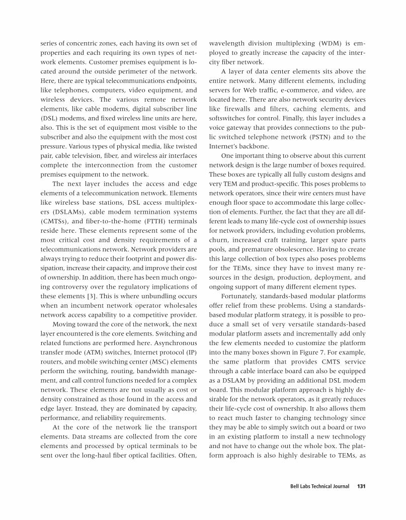
Description of Software Building BlocksFigure 10 illustrates an example of building
blocks for a software platform built on top of the LMPI
hardware. This could be a standard hardware plat-
form such as AdvancedTCA. The software building
blocks are structured in layers.
Device drivers. The device drivers are the first soft-
ware building block layer. The COTS device drivers are
those that can be purchased from third-party vendors.
The common device drivers (LMPI device drivers) are
provided by the LMPI software platform. The applica-
tion device drivers are those that are customized and
provided by the product unit using the LMPI software
platform for their own specific needs.
Operating system. A real-time operating system
will reside above the device drivers. An operating
system must satisfy a minimum set of requirements. It
must:
• Interact with the hardware components, servicing
all low-level programmable elements included in
the hardware platform, and
• Provide an execution environment to the appli-
cations that run on the system.
In a platform design-based system, an operating
system must allow software function to be modular so
136 Bell Labs Technical Journal
that functions can be added as needed using a build-
ing block method. Some examples of possible operat-
ing system choices could be VxWorks,* Linux,* QNX.*
Some may find Linux to be an attractive choice due to
its open source nature.
Software components. The next layer will consist of
COTS components, LMPI components, and applica-
tion components (provided by the product unit), such
as databases and protocol stacks.
Common frameworks. Following the component
layer of software building blocks are the LMPI
common frameworks such as configuration manage-
ment, fault management, accounting management,
performance management, security management, and
diagnostic framework. The domain-specific frame-
works would consist of frameworks that may only be
applicable to a product family such as wireless prod-
ucts. The application-provided frameworks would be
those provided by the product unit itself in order to
customize its product. The operations support inter-
face frameworks would interface with the operations
support system and LMPI common frameworks.
The next layer consists of the common user in-
terface framework as well as the applications specific
to a product.
Applications and ConfigurationsIt is helpful to study a few concrete examples of
the sort of systems that could eventually be imple-
mented with standards-based modular platforms. Two
are shown below. The first example is a DSLAM. This
is an edge element that terminates the xDSL lines
from hundreds of wireline subscribers. The second
example is a core network element called a voice gate-
way. This device converts voice connections between
the converged voice-over-packet world and the tradi-
tional telephone network. These examples are not
meant to be complete designs; they are illustrative
examples of how PBBs can be reused in two widely
different applications.
Application Example: DSLAMThe following hardware example describes a pos-
sible portfolio of xDSL/Access products built on the
AdvancedTCA industry standard modular platform.
It uses a combination of reusable common platform
building blocks (chassis, backplane and universal car-
rier board) and product-specific xDSL/Access build-
ing blocks. Access building blocks could consist of
FTTH, “plain old telephone service,” broadband radio,
and CMTS, while xDSL building blocks could be
asymmetric DSL (ADSL) (full-rate), ADSL (G.lite),
symmetric DSL, and very high bit rate DSL (VDSL).
These building block capabilities are then designed
onto mezzanine boards that conform to the
AdvancedTCA specifications and are needed for mod-
ularity and reuse purposes.
Now that the needed capabilities have been de-
fined and organized onto mezzanine building blocks,
we can populate the universal carrier board as shown
in Figure 11. These mezzanine boards give any com-
bination of capabilities the customer requires. This
modular and reused design allows Lucent to mix and
match PBBs within the same chassis, increasing op-
erational efficiencies for product design and the sup-
ply chain. Benefits to the supply chain include
reducing unique component types and inventory.
With design for reuse, there is a reduced possibility
of stranded inventory upon product pruning or inac-
curate forecasting. A value to Lucent is that using a
single platform minimizes capital expenditures and
allows us to quickly launch new high-value offerings
as the technology becomes available.
Figure 12 demonstrates the full flexibility of the
standards-based modular platform. The first chassis
configuration (Figure 12a) has been populated with
all ADSL (full rate) mezzanine boards creating a ca-
pacity of 1152 ADSL (full rate) lines. The second chas-
sis configuration (Figure 12b) has been modified by
replacing ADSL (full rate) mezzanine building blocks
with other x-DSL/Access building blocks to demon-
strate the possibility of integrating voice, data, and
video on one common platform. The line count for
this chassis is still 1,152 lines, but the chassis can be
configured for the combination of functions that meet
the customers needs. The value of the standards-based
modular platform to the customer is the mixing and
matching of functionality in a reusable chassis asset.
This provides investment protection, revenue, and
service flexibility along with upgradeability options
by positioning themselves for future technologies

Bell Labs Technical Journal 137
ADSL (full rate)
ADSL(G.lite)
VDSL
CMTSFTTH
Universal carrier card
ADSL—Asymmetric digital subscriber lineCMTS—Cable modem termination system
FTTH—Fiber to the homeVDSL—Very high bit rate digital subscriber line
Figure 11.Universal carrier cards with mezzanine assets.
incrementally. The platform building blocks defined
here allow for multi-service flexibility, giving service
providers the opportunity to quickly capitalize on op-
portunities to bring in additional income. The third
chassis configuration (Figure 12c) represents a micro
remote terminal (mRT) and would use the same PBBs
used in the larger systems.
By defining the right PBB, it is possible to expand
this futuristic portfolio example to include broadband,
wireless, transport, and core applications.
Application Example: Universal GatewayFigure 13 shows a universal voice gateway,
which is an element similar in function to the gateway
shown in the upper left corner of Figure 7. The func-
tion of this element is to accept packet voice traffic
arriving from the broadband network on either
IP/Ethernet facilities or ATM/SONET facilities, per-
form signal processing, and forward the voice traffic to
the PSTN through time division multiplexed (TDM)
trunks.
This architecture consists of a 16-slot
AdvancedTCA chassis equipped with sixteen carrier
boards. Each carrier board is further equipped with
up to four mezzanine boards, which hold various
complements of CPUs, DSPs, and I/O. By using mez-
zanine boards, it is possible to optimally configure a
shelf in small increments to perform exactly the
required tasks.
These carrier boards conform to the
AdvancedTCA standard. They consist of a circuit
board (about 322 mm high � 280 mm deep � 30 mm
thick), power supply (accepting dual DC buses from
the AdvancedTCA backplane, �48 V nominal, up to
200 W), board control processor (with RAM, periph-
erals, and board control interfaces), and a backplane
interface (driving the AdvancedTCA backplane in
either dual star or full mesh topology). Each carrier
also has the capability to direct appropriate bandwidth
between the backplane interface (which has a band-
width range from 2 Gb/s up to 150 Gb/s) and the four
mezzanine slots.

138 Bell Labs Technical Journal
Figure 12.Standards-based modular platform.
AdvancedTCA* backplane
1,152 ADSL (full rate)lines per shelf
Uplink tobackbones
HUB HUB UCC
ADSL
ADSL
ADSL
ADSL
UCC
ADSL
ADSL
ADSL
ADSL
UCC
ADSL
ADSL
ADSL
ADSL
UCC
ADSL
ADSL
ADSL
ADSL
UCC
ADSL
ADSL
ADSL
ADSL
UCC
ADSL
ADSL
ADSL
ADSL
UCC
ADSL
ADSL
ADSL
ADSL
UCC
ADSL
ADSL
ADSL
ADSL
UCC
ADSL
ADSL
ADSL
ADSL
UCC
ADSL
ADSL
ADSL
ADSL
UCC
ADSL
ADSL
ADSL
ADSL
UCC
ADSL
ADSL
ADSL
ADSL
GE
CPU
CPU
ETN
ETN
100BT
100BT
GE
(a) ADSL DSLAM
1,152 (xDSL and Access)lines per shelf
Uplink tobackbones
DSL
DSL
DSL
DSL
DSL
DSL
DSL
DSL
DSL
DSL
DSL
DSL
DSL
DSL
DSL
DSL
DSL
DSL
DSL
DSL
DSL
DSL
DSL
DSL
DSL
DSL
DSL
DSL
DSL
DSL
DSL
DSL
FTTH
ADSL
CMTS
VDSL
FTTH
ADSL
CMTS
VDSL
FTTH
ADSL
CMTS
VDSL
FTTH
ADSL
CMTS
VDSL
AdvancedTCA backplane
HUB HUB UCC UCC UCC UCC UCC UCC UCC UCC UCC UCC UCC UCC
GE
CPU
CPU
ETN
ETN
100BT
100BT
GE
(b) DSLAM with integrated functions

Bell Labs Technical Journal 139
mRT—1,152 (xDSL and Access)lines per shelf
UC
CU
CCFTTHADSLCMTSVDSL
FTTHADSLCMTSVDSL
Ad
vTCA
†
mR
T
ADSL—Asymmetric DSLCMTS—Cable modem termination systemCPU—Central processing unitDSL—Digital subscriber lineDSLAM—DSL access multiplexer FTTH—Fiber to the home
GE—Gigabit Ethernet mRT—Micro remote terminalVDSL—Very high bit rate DSL xDSL—Any of various DSL technologies 100 BT—100 BaseT (twisted-pair Ethernet cabling)
†Registered trademark of PCI Industrial Computer Manufacturers Group
(c) Micro remote terminal
Figure 12. (Continued).Standards-based modular platform.
Two carrier boards perform the IP network con-
nection functions. These are equipped with a mix of
gigabit Ethernet and 100 MB Ethernet interfaces.
A pair of ATM interface boards performs a similar
function for the ATM network, but uses ATM over
SONET interface mezzanine boards at the 622 Mb/s
OC-12 rate.
Up to eight signal processing resource boards are
equipped with up to four DSP mezzanines each. This
board performs essential voice processing functions
like echo cancellation, voice compression, voicemail,
tone detection, and speech recognition.
A pair of TDM boards provides connections to the
PSTN. The connections shown here are high density
OC-12/SONET interconnects, with 8064 standard
voice channels each, but other physical layers includ-
ing T1 or DS3 could also be used.
There is a pair of central control, cache, and storage
boards that host the control computers, some RAM-
based storage (for announcements and voicemail), and
a storage area network (SAN) interface to an external
disk array to store voice announcements, voice mail
messages, and speech recognition templates.
An interesting property of this sort of architecture
is how easy it is to modify its functionality. It is a very
simple matter to change the mix of interfaces (e.g.,
replacing some of the IP, ATM, TDM or SAN interfaces
with other types). It is also easy to add completely
new functions. For example, a softswitch to perform
call control could be easily added by replacing a cou-
ple of the DSP mezzanine boards with additional
CPUs. Line interfaces, such as fiber, DSL, cable, or
wireless can even be integrated into the same box.
This is an example of the integration trend toward
penultimate network architecture, called “central
office in a box,” where the entire function of a full
service telecommunication network’s infrastructure
is in a single, highly functional, network element.
Basing an entire network’s worth of boxes on a stan-
dards-based modular platform makes arbitrary com-
binations of functions like this simple.
ConclusionsConverged broadband telecommunications net-
works are evolving in stages. The current evolution
trend is to move from a number of proprietary
element designs to a standards-based modular plat-
form (based on an industry standard like CompactPSB
or AdvancedTCA). The next stage involves collapsing
the various types of platform-based boxes into a very
small set of universal network elements. By using the
design techniques illustrated in the above examples,
very powerful network elements can be created out of
only a handful of basic building blocks. This results

140 Bell Labs Technical Journal
in reduced life-cycle costs and improved functionality
for the network operators and reduced development
expenses, improved margins, and simplified support
for the TEMs.
AcknowledgmentsThe authors wish to thank Dave Ayers, Lucent’s
SCN Vice President of Product Design Chain Solutions
for his unwavering support of the platform initiative.
Thanks to Joe Carson, Scott Searls, Tom Park, Brendan
Lynch, Thelma Cole, Jerry Sidone, Lee L’Esperance,
Jim Mosher, and Steve Miller of Lucent’s Supply Chain
Networks team for their invaluable advice on the LMPI
project. A special thanks to Steve Kim for his endless
work on the platform business case and cost models.
Thanks also to the experts from Bell Labs who assisted
us on sticky technical problems, especially Bill Mielke
and Bob Hanmer for their insightful software platform
analysis. We appreciate the feedback from Lucent’s
product teams, especially Todd Keaffaber and Drew
Scott from the Mobility organization. We would like to
thank the PICMG standards community and the ven-
dor ecosystem that surrounds it for working with us to
define the standards and building blocks. A special
word of thanks for Mike Nielsen and Paul Mankiewich,
Signalprocessingresources
ATM—Asynchronous transfer modeCPU—Central processing unit DSP—Digital signal processorENET—Ethernet GE—Gigabit Ethernet IP—Internet protocol
OC12—Optical carrier digital signal rate of 622 Mb/sRAM—Random access memorySAN—Storage area networkTDM—Time division multiplexed100 BT—100 BaseT (twisted-pair Ethernet cabling)
†Registered trademark of PCI Industrial Computer Manufacturers Group
AdvancedTCA† Backplane
Control,cache, and
storage
SAN
CPU
CPU
TDM
TDM
OC12
OC12
OC12
OC12
OC12
OC12
OC12
OC12
DSP
DSP
DSP
DSP
DSP
DSP
DSP
DSP
DSP
DSP
DSP
DSP
DSP
DSP
DSP
DSP
DSP
DSP
DSP
DSP
DSP
DSP
DSP
DSP
DSP
DSP
DSP
DSP
DSP
DSP
DSP
DSP
DSP
DSP
DSP
DSP
DSP
DSP
DSP
DSP
ATM
OC12
OC12
OC12
OC12
ATM
OC12
OC12
OC12
OC12
SAN
GE
GE
100BT
100BT
100BT
100BT
ENET
GE
GE
ENET
CPU
CPU
CPU
CPU
RAM
RAM
SAN
TDMnetwork
connections
ATMnetwork
connections
IPnetwork
connections
Figure 13.Voice gateway implementation example.
Bell Labs Technical Journal 141
Lucent’s CTOs, and Jose Mejia, President, Lucent
Supply Chain Networks, for their leadership and
vision.
*TrademarksAdvancedTCA, CompactPCI, and PICMG are registered
trademarks of the PCI Industrial Computer Manu-facturers Group.
Linux is a registered trademark of Linus Torvalds.
OSDL is a trademark of Open Source Development Labs.
QNX is a registered trademark of QNX Software Systems.
SAForum is a trademark of the Service AvailabilityForum.
VxWorks is a registered trademark of Wind River, Inc.
References[1] Carrier Grade Linux Technical Working Group,
<http://www.osdl.org/projects/cgl/technical.html>.
[2] S. Chopra and P. Meindl, Supply ChainManagement: Strategy, Planning andOperations, Prentice Hall, Upper Saddle River,NJ, 2000.
[3] Federal Communications Commission, “FCCPromotes Local TelecommunicationsCompetition,” Sept. 1999,<http://ftp.fcc.gov/Bureaus/Common_Carrier/News_Releases/1999/nrcc9066.html>.
[4] Lucent Technologies, “Voice Over IP—AnOverview for Enterprise Organizations andCarriers,” 2000, <http://www.lucent.com/ livelink/0900940380004a45_White_paper.pdf>.
[5] P. Marshall and X. Wang, WirelessInfrastructure Opportunities for ModularTechnology Solutions, The Yankee GroupReport, Boston, MA, 2002.
[6] Open Source Development Lab,<http://www.osdl.org/>.
[7] PCI Industrial Computer Manufacturers Group,<http://www.picmg.org>.
[8] PCI Industrial Computer Manufacturers Group,Compact PCI, PICMG 2.X, Sept. 1997,<http://www.picmg.org/compactpci.stm>.
[9] PCI Industrial Computer Manufacturers Group,Advanced Telecom Computing Architecture,PICMG 3.X, Jan. 2003, <http://www.picmg.org/newinitiative.stm>.
[10] Service Availability Forum,<http://www.saforum.org/home>.
[11] J. R. Stock and D. W. Lambert, StrategicLogistics Management, 2nd ed., Irwin,Homewood, IL, 1987.
(Manuscript approved January 2004)
PATRICIA A. BATTAGLIA is a technical manager inSupply Chain Networks Product DesignChain at Lucent Technologies in Holmdel,New Jersey, where she has been involved insoftware requirements, architecture, design,and development in several data networking
and optical networking products. She is currentlyworking on the software architecture and realization ofthe Lucent Modular Platform Initiative. Ms. Battagliaholds a B.S. in mathematics from the University ofDelaware in Newark and an M.S. in computer sciencefrom the University of Michigan in Ann Arbor.
CHARLES C. BYERS is a consulting member of technicalstaff in Supply Chain Networks at LucentTechnologies in Naperville, Illinois, wherehe has been involved in electronic design atthe chip, circuit board, and system level, aswell as network architecture and marketing.
He is currently working on the architecture andimplementation of advanced broadband networks andplatforms. He is also a leader in the Advanced TelecomComputing Architecture (AdvancedTCA/PICMG 3.X)standards body. Mr. Byers, who is a Bell Labs Fellow, hasbeen awarded 22 U.S. patents. He holds a B.S. inelectrical and computer engineering and an M.S. inelectrical engineering from the University of Wisconsin,Madison.
LESLIE A. GUTH is the director of advanced technologyand platforms in Supply Chain NetworksProduct Design Chain at LucentTechnologies in Holmdel, New Jersey, whereshe has been involved in many cross-product design, packaging, and
manufacturing improvements. She is currently leadingthe Lucent Modular Platform Initiative efforts. Sheholds a B.A. in physics from the University of NorthCarolina in Chapel Hill, and a Ph.D. in engineering fromthe University of Pennsylvania in Philadelphia. Dr. Guthhas been awarded five U.S. patents.
ALBERT HOLLIDAY is a distinguished member oftechnical staff in Supply Chain NetworksProduct Design Chain at Lucent Technologiesin Holmdel, New Jersey, where he has beeninvolved in research and development ofcircuit pack design standards, assembly
processes, and attachment reliability studies for BGAs

142 Bell Labs Technical Journal
and CSPs. Recently, he has worked in the areas ofvirtual prototyping, design cost reductions, andsupplier management. Mr. Holliday, who holds fourU.S. patents, is currently working on the architectureand implementation on the Lucent Modular PlatformInitiative. He holds a B.S. in electrical engineering fromDrexel University in Philadelphia, Pennsylvania, andan M.S. in manufacturing systems engineeringfrom Rensselaer Polytechnic Institute in Troy,New York.
CLAUDIO SPINELLI is a distinguished member oftechnical staff in Supply Chain NetworksAdvanced Technologies at LucentTechnologies in Holmdel, New Jersey, wherehe has been involved in research anddevelopment of real-time embedded
software, as well architecture and design of cordlesstelephones, converged voice and data networkelement (PathStar Access Server), and the Lambdaproject. He is currently working on the softwarearchitecture, design, and implementation of a Lucentcommon software platform. Mr. Spinelli has beenawarded one U.S. patent. He holds a B.S. degree inelectrical engineering from Pratt Institute in Brooklyn,New York.
JASON J. TONG is a member of technical staff inLucent’s Supply Chain Networks ProductDesign Chain, where he has developedand implemented new electronicsmanufacturing equipment and processesfor circuit packs, flat panel displays, and
cellular phone handsets. He holds a B.S. in mechanicalengineering from the Massachusetts Institute ofTechnology in Cambridge, an M.S. in mechanicalengineering from the University of Michigan in AnnArbor, and a Ph.D. in mechanical engineering fromSyracuse University in New York. Dr. Tong is currentlycoordinating development of new technologies andplatforms by Lucent’s suppliers. �