MEASURING INSTRUMENTS - CASA Modular Systems
28
Chapter 1 Chapter 2 Chapter 3 RESTRICTED SECTION 6 A.P. 3302, PART I MEASURING INSTRUMENTS . . . . . . . . . . Ammeters and . . . . . . . . . . Test Instruments . . . . . . . . . . Measurement of Power RESTRICTED
-
Upload
khangminh22 -
Category
Documents
-
view
0 -
download
0
Transcript of MEASURING INSTRUMENTS - CASA Modular Systems
Chapter 1
Chapter 2
Chapter 3
RESTRICTED
SECTION 6
A.P. 3302, PART I
MEASURING INSTRUMENTS
. . . . . . . . . . Ammeters and
. . . . . . . . . . Test Instruments
. . . . . . . . . . Measurement of Power
RESTRICTED

RESTRICTED
SECTION 6
CHAPTER 1
AMMETERS AND VOLTMETERS
Introduction . . . . . . . . . .
Essentials of a Measuring Instrument . . . . Differences Between Ammeters and Voltmeters . .
Moving Coil Instruments . . . . . .
Extension of Meter Range . . . . . .
Rectifier Instruments . . . . . . . .
Moving Iron Instruments . . . . . .
Hot-wire Instruments . . . . ... . .
Thermo-junction Instruments . . . . . .
Electrostatic Voltmeters . . . . . . . .
Summary . . . . . . . . . . . .
A.P. 3382. PART 1
Paragraph . . 1
RESTRICTED


RESTRICTED
PART 1, SECTION 6, CHAPTER 1
AMMETERS AND VOLTMETERS
Introduction 1. Reference has been made in previous chapters to the values of various electrical quantities without any explanation of how such quantities are measured in practice. The quantities which commonly require measurement are the currents established in, and the p.d.s developed across, various parts of a circuit. The measuring instru- ments used for these purposes are termed ammeters and voltmeters respectively. In this Chapter the operation of certain types of these "meters" is discussed.
Essentials of a Measuring Instrument 2. Measuring instruments have a moving system (usually mounted in jewelled bearings and free to rotate about a fixed axis) which carries a pointer over a graduated scale. When discussing the principle of operation of such instruments three forces have to be considered:-
(a) Deflecting force. This is the force which moves the pointer over the scale and it exists only when the meter is connected to a "live" circuit. The rotat- ing system is deflected from its zero position by a torque that is some function of the quantity to be measured. (b) Controlling force. This force acts in opposition to the deflecting force and brings the pointer to rest at a position on the scale where the deflecting and con- trolling forces are equal. In addition, the controlling force returns the pointer to zero when the deflecting force is removed, and for this reason it is sometimes termed the restoring force. The majority of meters have a "zero adjustment" on the controlling system so that the instrument can be set to zero when there is no de- flecting force. Most instruments use a hairspring system to supply the con- trolling force, but control by a system of weights is sometimes used. (c) Damping force. It is important that the movement should take up its final position quickly and without oscillation. Mechanical damping by a small plunger moving in a cylinder, or electromagnetic damping by induced eddy currents, are the means employed to secure this.
Differences Between Ammeters and Volt- meters
3. Most meters are current-operated; that is, the deflecting force results from a current passing through the instrument, althcugh the meter may be scaled to read either amperes or volts. Thus in general, ammeters and voltmeters both work on the same principles. (An important exception is the electrostatic voltmeter described in Para. 26). The differences that occur in design are due only to their different functions:-
(a) Ammeter. This instrument is inserted in series with the circuit so that the current to be measured passes through it. The ammeter must be of low resistance, other- wise the circuit current will be consider- ably reduced when the meter is inserted and test conditions upset. (b) Voltmeter. This instrument measures p.d. and so must be connected across the two points in a circuit between which the voltage is to be found. It must therefore have a high resistance, otherwise it will by-pass considerable current from the circuit being examined and test conditions will be upset.
4. The same instrument can be used either as an ammeter or as a voltmeter by suitably adjusting its resistance value (see Para. 9). The various types of ammeters and volt- meters in general use are classified as follows :-
(a) Moving coil. (b) Rectifier. (c) Moving Iron. (d) Hot-wire. (e) Thermo-junction. (f) Electrostatic (voltmeter only).
Moving Coil Instruments 5. The operation of the moving coil meter is based on "the motor principle"; that is a current-carrying coil in a magnetic field experiences a torque (see Sect. 3, Chap. 2). The construction of a moving coil meter is illustrated in Fig. 1. The magnetic field is provided by a horse-shoe permanent magnet. Between the poles is fixed a cylindrical soft-iron core (concentrator) which serves to concentrate the flux in the air gap and give
"This leaf issued with A.L. 4"
TED

RESTRICTED A.P. 3302, P.4~1. 1, SECT. 6 , CHAPTER 1
TOP PIVOT SCALE JEWEL BRIDGE
\ PIECE
CONTROL MO~ING PERM~NENT SPRING COIL \ MAGNET
CONCENTRATOR
(a ) GENERAL VIEW
H A I R - \ CONCENTRATOR
b INPUT
Cb) PLAN OF MOVING PARTS Cwith lop bridge piece removed)
CONCENTRATOR 'JEWEL
(c)SECTlON THROUGH MOVING PARTS
Fig. I. MOVING COlL METER, CONSTRUCTION
a uniform radial field. A moving coil of fine copper wire is mounted on a light, rect- angular, aluminium former placed over the iron core. The coil is pivoted to move freely in the air gap between the pole faces and the cylindrical core. The electrical connections to the coil are made by two hair- springs, one at either end of the coil former. The hairsprings are of phosphor-bronze or beryllium-copper, both of which have very stable elastic properties. The springs also provide the controlling force and are coiled in opposite directions to reduce the effect of temperature variation. The tension of the springs can be varied slightly to give zero adjustment. The pointer is attached to the same spindle as the coil former.
6. When the instrument is inserted in a circuit, current flows through the hair- springs to the coil. The resultant force tends to turn the coil on its pivots in a direction dependent upon that of the current (Fleming's left hand rule). Since the mag- netic field is of the same intensity at all coil positions, the coil is subjected to a constant torque directly proportional to the current in it. As the coil rotates, the hairsprings become twisted and set up an opposing torque proportional to the angle through which the coil has turned. The coil there- fore takes up a position in which the con-
trolling force due to the springs just balances the deflecting force due to the current. Since these forces are proportional to the angle of rotation of the coil and to the current in the coil respectively, it follows that the deflection of the pointer attached to the coil is directly proportional to the current in the coil; the scale is therefore evenly divided. When the aluminium former is in motion, circulating eddy currents are estab- . lished in it. From Lenz's law, the eddy currents produce a force tending to oppose the motion producing them, thereby acting as a damping device to bring the pointer to rest without oscillation.
7. The main attributes of moving coil meters are:-
(a) High sensitivity. (b) Low power consumption. (c) Suitability for adaptation as voltmeters or ammeters. (d) Freedom from the effects of external magnetic fields. (e) Linear scale. ( f ) Excellent damping.
8. A disadvantage of moving coil meters is that, unless suitably modified, they are useful only for d.c. measurements. Since the direction in which the coil rotates is depend-
RESTRICTED
ent on the direction of the current, the meter must be connected in the correct polarity. For this reason the two test terminals are marked with + and - signs. Some moving coil meters have a centre-zero scale and can be read in either direction, in which case polarity is not important. If an alternating current of very low frequency is applied to such a moving coil meter, the meter will be able to follow the alternations and the pointer will move from side to side about the zero mark. At frequencies in excess of a few cycles per second however the pointer will be unable to follow and will read the average value of the current - i.e., zero. Hence, alternating current will not register on a moving coil meter. On the other hand, if the current consists of d.c. plus an a.c. component, a moving coil meter in the circuit will read the d.c. and be unaffected by the ax.
Extension of Meter Range 9. I t was stated in Para. 4 that a meter can be adapted as either an ammeter or voltmeter by suitably adjusting its resistance value. Consider a moving coil meter, having a coil resistance of 100a and a full scale deflection (f.s.d.) current of 1 mA, as shown in Fig. 2.
F.r.d. = Irn A ----t
COlL RESISTANCE = 100n
Fig. 2. BASIC MOVING COlL METER
RESTRICTED
RESTRICTED
CIRCUIT
The voltage necessary for f.s.d. is:- V = IR (volts)
1 v = --- 1,000 loo
:. V = 0.1V or 100 mV. Thus, the meter scale could be calibrated to read either current or voltage, but only to a maximum of IrnA or lOOmV respectively. To extend these to more practical ranges, suitable meter "shunts" or "multipliers" must be incorporated to change the meter resistance.
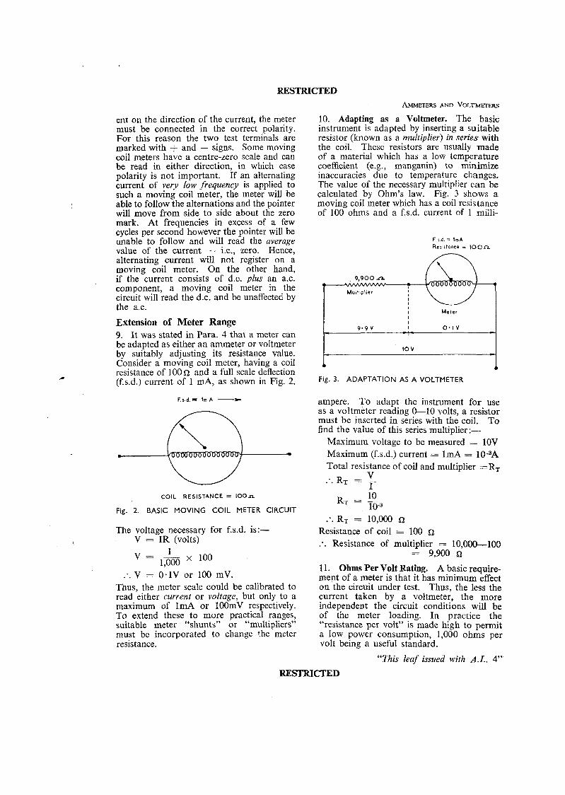
10. Adapting as a Voltmeter. The basic instrument is adapted by inserting a suitable resistor (known as a multiplier) in series with the coil. These resistors are usually made of a material which has a low temperature coefficient (e.g., manganin) to minimize inaccuracies due to temperature changes. The value of the necessary multiplier can be calculated by Ohm's law. Fig. 3 shows a moving coil meter which has a coil resistance of 100 ohms and a f.s.d. current of 1 milli-
F r d. = IrnA Resirtancc - 100n
n
9,900 n
Mulf~pl ier I I I I Meter I
F.ig. 3. ADAPTATION AS A VOLTMETER
ampere. To adapt the instrument for use as a voltmeter reading 0-10 volts, a resistor must be inserted in series with the coil. To find the value of this series multiplier :-
Maximum voltage to be measured = 10V Maximum (f.s.d.) current = 1mA = 10-3A Total resistance of coil and multiplier =R,
V ... RT = - I
... RT = 10,000 Resistance of coil = 100 a :. Resistance of multiplier = 10,000-100
= 9,900 a 1 1. Ohms Per Volt Rating. A basic require- ment of a meter is that it has minimum effect on the circuit under test. Thus, the less the current taken by a voltmeter, the more independent the circuit conditions will be of the meter loading. In practice the "resistance per volt" is made high to permit a low power consumption, 1,000 ohms per volt being a useful standard.
"This leaf issued with A.L. 4"'
RESTRICTED A.P. 3302, PART 1, SED. 6 , CHAP. 1
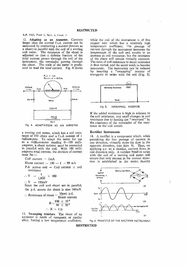
12. Adapting as an Ammeter. Currents larger than the normal f.s.d. current can be measured by connecting a resistor (known as a shunt) in parallel with the coil of a moving coil meter. The resistance of the shunt is adjusted so that a definite fraction of the total current passes through the coil of the instrument, the remainder passing through the shunt. The scale of the meter is gradu- ated to read the total current. Fig. 4 shows
F.1.d. = I m A Resistance = 100n
while the coil of the instrument is of fine copper wire which has a relatively high temperature coefficient. The passage of current through the instrument increases the temperature of the coil and results in an increase in coil resistance; but the resistance of the shunt will remain virtually constant. The ratio of coil resistance to shunt resistance is thus varied, and the meter tends to become inaccurate. The inaccuracy can be reduced by inserting a "swamping" resistor of manganin in series with the coil (Fig. 5).
Meter
S h u n t
Fig. 4. ADAPTATION AS AN AMMETER
a moving coil meter, which has a coil resis- tance of 100 ohms and a f.s.d. current of 1 milliampere. To adapt the meter for use as a milliammeter reading 0-100 milli- amperes, a shunt resistor must be connected in parallel with the coil. With 100 milli- amperes total current, the division of current must be:-
Coil current = IrnA Shunt current = 100 - 1 = 99 mA P.d. across coil = Coil current x coil
resistance 1 :. v = -- x loo
1,000 :. V = 100mV Since the coil and shunt are in parallel, the p.d. across the shunt is also 100rnV.
:. Resistance of shunt = Shunt p.d.
Shunt current
13. Swamping resistors. The shunt of an ammeter is made of manganin or similar alloy, having a low temperature coefficient,
1 Shunt 0 * 0
Fig. 5. SWAMPING RESISTOR
If the added resistance is high in relation to the coil resistance, any small changes in coil resistance due to heating are "swamped" by the constancy of the remainder of the resis- tance in the coil circuit.
Rectifier Instruments 14. A rectifier is a component which, while permitting the free passage of current in one direction, virtually stops the flow in the opposite direction, (see Sect. 9). Thus, on applying a.c. to a rectifier, current flows in one direction only. A rectifier fitted in series with the coil of a moving coil meter will ensure that only current in the correct direc- tion is established in the meter, thereby
1 Applied k i n g "11 t-+eter,&D
Altcmalinq u Voltaqe C
Input 0
lo -
Fig. 6. PRINCIPLE OF THE RECTIFIER INSTRUMENT
RESTRICTED

RESTRICTED A~.IMETERs AND VOLTMETERS
preventing reversal of the deflecting force on the coil. By this means, a moving coil meter with a rectifier can be used to measure alter- nating currents and voltages. A typical arrangement is shown in Fig. 6(a). When the alternating voltage of Fig. 6(b) is applied between terminals A and B, the current through the moving coil meter connected between C and D is a "rectified" current as shown in Fig. 6(c). The meter reads the average value of the rectified current, but the scale is normally calibrated to indicate r.m.s. values. When a moving coil meter has been modified in the manner described it can be used for a.c. measurements up to frequencies of the order of 100 kc/s.
Moving Iron Instruments 15. There are two types of moving iron instrument which differ according to whether deflection is produced by magnetic attraction or repulsion. The former makes use of the attraction of iron in the electromagnetic field of a current-carrying solenoid; the latter depends upon the mutual repulsion of two similar, magnetised pieces of iron within an energised solenoid, one being fixed and the other movable.
16. Attraction type. This instrument is illustrated in Fig. 7. The current to be measured passes through a coil wound on a non-magnetic former, thereby establishing a magnetic field whose strength is pro- portional to the current. An eccentrically pivoted soft iron vane, which carries a light
pointer, is magnetised by induction from the field and assumes opposite polarity, irres- pective of the direction of the current. I t is consequently attracted into the open end of the coil, thus moving the pointer over the graduated scale. The controlling force is provided by a hairspring (as shown) or by the pull of gravity on the soft iron vane. Damping is provided by a piston moving in a dashpot.
17. The force of attraction between the soft iron vane and the coil (i.e. the deflecting force) is proportional to the strength of the field due to the current in the coil, and t o the strength of the induced magnetism in the soft iron vane. Both are proportional t o the coil current. The deflecting force is, therefore, proportional to the square of the current. As a result, the graduations of the scale are not uniform, but are crowded at the lower end. A scale of this type is generally known as a "square-law" scale. The meter scale is fundamentally a square-law one, but by suit- able shaping of the vane, the scale may be made to approach a linear law.
18. Repulsion type. This is illustrated in Fig. 8. Two pieces of soft iron are arranged
Square Law
Fig. 8. REPULSION TYPE MOVING IRON INSTRUMENT
Dorhpot
Fig. 7. ATTRACTION TYPE MOVING IRON INSTRUMENT
inside and parallel to the axis of a circular magnetising coil, which is carrying the current to be measured. One of the pieces (A) is of uniform breadth and is attached to a pivoted spindle which also carries the
"This leaf issued with A.L. 4"
RESTRICTED
A.P. 3302, PART 1, SECT. 6 , CHAP. 1
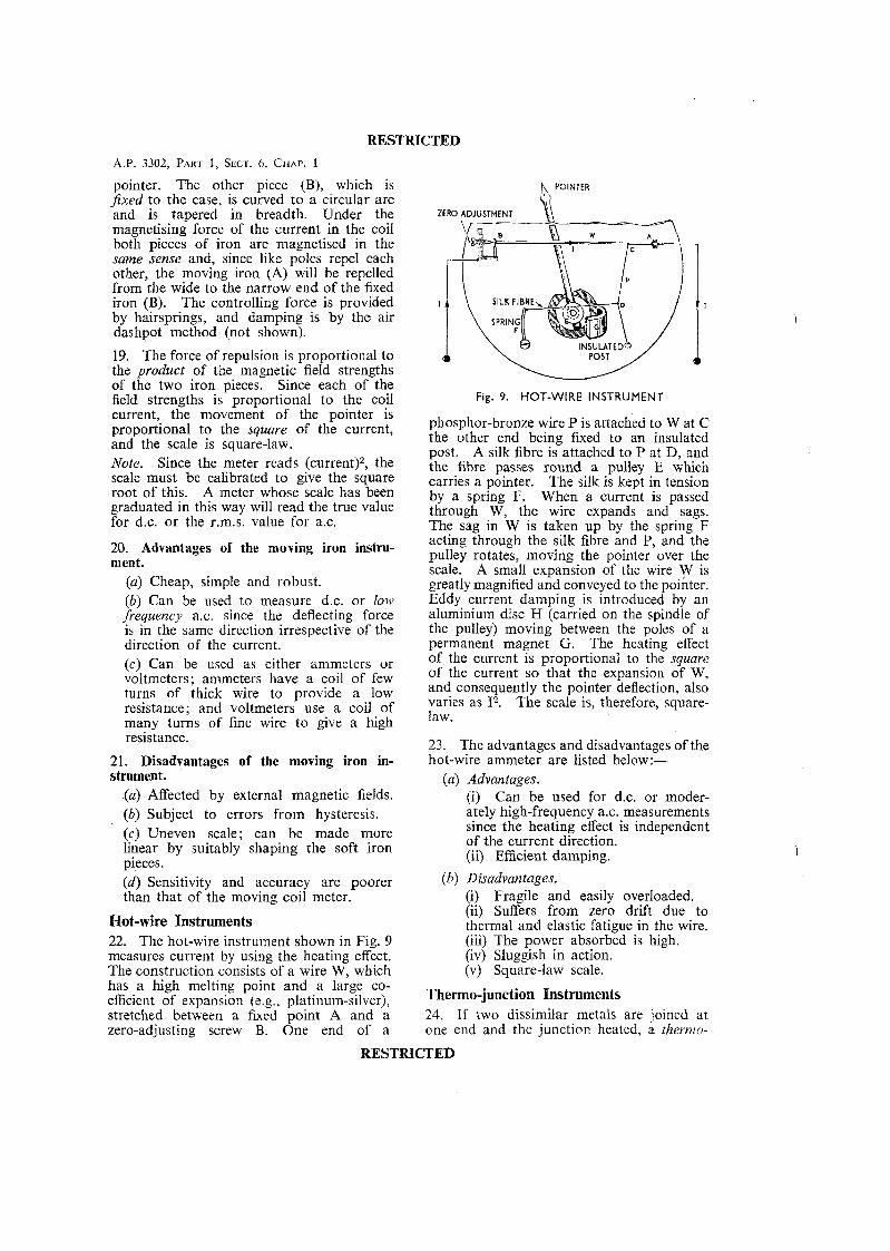
pointer. The other piece (B), which is $xed to the case, is curved to a circular arc and is tapered in breadth. Under the magnetising force of the current in the coil both pieces of iron are magnetised in the same sense and, since like poles repel each other, the moving iron (A) will be repelled from the wide to the narrow end of the fixed iron (B). The controlling force is provided by hairsprings, and damping is by the air dashpot method (not shown).
19. The force of repulsion is proportional to the product of the magnetic field strengths of the two iron pieces. Since each of the field strengths is proportional to the coil current, the movement of the pointer is proportional to the square of the current, and the scale is square-law. Note. Since the meter reads (current)*, the scale must be calibrated to give the square root of this. A meter whose scale has been graduated in this way will read the true value for d.c. or the r.m.s. value for ax .
20. Advantages of the moving iron instru- ment.
(a) Cheap, simple and robust. (b) Can be used to measure d.c. or low frequency a.c. since the deflecting force is in the same direction irrespective of the direction of the current. (c) Can be used as either ammeters or voltmeters; ammeters have a coil of few turns of thick wire to provide a low resistance; and voltmeters use a coil of many turns of fine wire to give a high resistance.
21. Disadvantages of the moving iron in- strument.
(a) Affected by external magnetic fields. (b) Subject to errors from hysteresis. (c) Uneven scale; can be made more linear by suitably shaping the soft iron pieces. ( d ) Sensitivity and accuracy are poorer than that of the moving coil meter.
Hot-wire Instruments 22. The hot-wire instrument shown in Fig. 9 measures current by using the heating effect. The construction consists of a wire W, which has a high melting point and a large co- efficient of expansion (e.g., platinum-silver), stretched between a fixed point A and a zero-adjusting screw B. One end of a
ZERO ADJUSTMENT rTER RESTRICTED
,
RESTRICTED
SPRING v Fig. 9. HOT-WIRE INSTRUMENT
phosphor-bronze wire P is attached to W at C the other end being fixed to an insulated post. A silk fibre is attached to P at D, and the fibre passes round a pulley E which carries a pointer. The silk is kept in tension by a spring F. When a current is passed through W, the wire expands and sags. The sag in W is taken up by the spring F acting through the silk fibre and P, and the pulley rotates, moving the pointer over the scale. A small expansion of the wire W is greatly magnified and conveyed to the pointer. Eddy current damping is introduced by an aluminium disc H (carried on the spindle of the pulley) moving between the poles of a permanent magnet G. The heating effect of the current is proportional to the square of the current so that the expansion of W, and consequently the pointer deflection, also varies as 12. The scale is, therefore, square- law.
23. The advantages and disadvantages of the hot-wire ammeter are listed below:-
(a) Advantages. (i) Can be used for d.c. or moder- ately high-frequency ax . measurements since the heating effect is independent of the current direction. (ii) Efficient damping.
(b) Disadvantages. (i) Fragile and easily overloaded. (ii) Suffers from zero drift due to thermal and elastic fatigue in the wire. (iii) The power absorbed is high. (iv) Sluggish in action. (v) Square-law scale.
Thermo-junction Instruments 24. If two dissimilar metals are joined at one end and the junction heated, a therrnn-
RESTRICTED A L ~ ~ ~ ~ ~ AVD VOLTMETER^
electric e.m.f. is set up and current will flow it can be used for the measurement of radio in any circuit connected to the other ends frequency current. of the two metals. The usual "thermo- junction" used in meters consists of bismuth Voltmeters and antimony, but other combinations may 26. The action of this instrument depends be used. on the force of attraction which exists
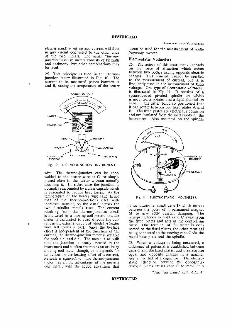
between two bodies having opposite electric 25. This principle is used in the thermo- charges. This principle cannot be applied junction meter illustrated in Fig. 10. The to the measurement of current, but it is to be measured passes between A frequently used in the measurement of high and B y raising the temperature of the heater voltage. One type of electrostatic voltmeter is illustrated in Fig. 11. I t consists of a
SOUARE LAW SCALE spring-loaded pivoted spindle on which is mounted a pointer and a light aluminium vane C, the latter being so positioned tha t it can rotate between two fixed plates A and B. The k e d plates are electrically common and are insulated from the metal body of the instrument. Also mounted on the spindle
MOVING COIL
GLASS CAPSULE
INSULATED MEASURED MOUNTING
Fig. 10. THERMO-JUNCTION INSTRUMENT
wire. The thermo-junction can be spot- BASE PLATE
welded to the heater wire at C, or simply placed close to the heater without actually touching it. In either case the junction is normally surrounded by a glass capsule which is evacuated to reduce heat losses. As the temperature of the heater wire (and hence Fig. l I . ELECTROSTATIC VOLTMETER that of the thermo-iunction) rises with increased current, so the e.m:f. across the two dissimilar metals rises. The current resulting from the thermo-junction e.m.f. is indicated by a moving coil meter, and the meter is calibrated to read directly the cur-
I rent in the external circuit of which the heater wire AB forms a part. Since the heating effect is independent of the direction of the current, the thermo-junction meter is suitable for both a.c. and d.c. The meter is so built that the junction is neatly encased in the instrument and it often resembles an ordinary moving coil meter though, as it depends for its action on the heating effect of a current, its scale is square-law. The thermo-junction meter has all the advantages of the moving coil meter, with the added advantage that
is an additional small vane D which moves between the poles of a permanent magnet M to give eddy current damping. The hairspring tends to hold vane C away from the fixed plates and acts as the controlling force. One terminal of the meter is con- nected to the fixed plates, the other terminal being connected to the moving vane C via the metal base plate and the spindle.
27. When a voltage is being measured, a difference of potential is established between vane C and the fixed plates, and they acquire equal and opposite charges in a manner similar to that of a capacitor. The electro- static attraction between the oppositely- charged plates causes vane C to move into
"This leaf issued with A.L. 4"
RESTRICTED
RESTRICTED A.P. 3302. PART 1, SECT. 6 , CHAP. I
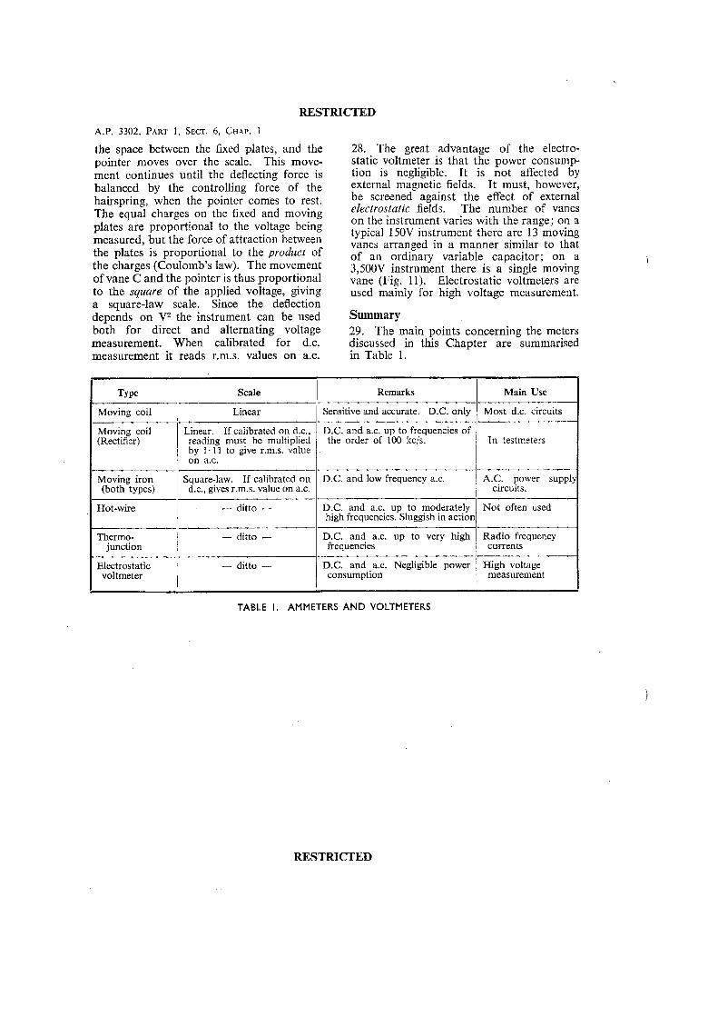
the space between the fixed plates, and the pointer moves over the scale. This move- ment continues until the deflecting force is balanced by the controlling force of the hairspring, when the pointer comes to rest. The equal charges on the fixed and moving plates are proportional to the voltage being measured, but the force of attraction between the plates is proportional to the product of the charges (Coulomb's law). The movement of vane C and the pointer is thus proportional to the square of the applied voltage, giving a square-law scale. Since the deflection depends on V2 the instrument can be used both for direct and alternating voltage measurement. When calibrated for d.c. measurement it reads r.m.s. values on a.c.
28. The great advantage of the electro- static voltmeter is that the power consump- tion is negligible. I t is not affected by external magnetic fields. I t must, however, be screened against the effect of external electrostatic fields. The number of vanes on the instrument varies with the range; on a typical 150V instrument there are 13 moving vanes arranged in a manner similar to that of an ordinary variable capacitor; on a 3,500V instrument there is a single moving vane (Fig. 11). Electrostatic voltmeters are used mainly for high voltage measurement.
Summary 29. The main points concerning the meters discussed in this Chapter are summarised in Table 1.
-
Type I Scale
Moving coil 1 Linear
Moving coil Linear. If calibrated on d.c., (Rectifier) reading must be multiplied
by 1. 11 to give r.m.s. value / on a.c.
Thermo- I - ditto - junction
Moving iron (both types)
Hot-wire
Square-law. If calibrated on d.c., gives r.m.s. value on ax.
- ditto -
Remarks
Electrostatic voltmeter
Sensitive and accurate. D.C. only
- ditto -
D.C. and a.c. up to frequencies of the order of 100 kcis.
D.C. and low frequency ax.
D.C. and a.c. up to moderately high frequencies. Sluggish in actior
D.C. and a.c. up to very high frequencies
D.C. and a s . Neghgible power consumption
--
TABLE I. AMMETERS AND VOLTMETERS
Main Use
Most d.c. circuits
In testmeters
.--
A.C. power suppl circuits.
Not often used
--- Radio frequency currents
High voltage measurement
RESTRICTED
RESTRICTED
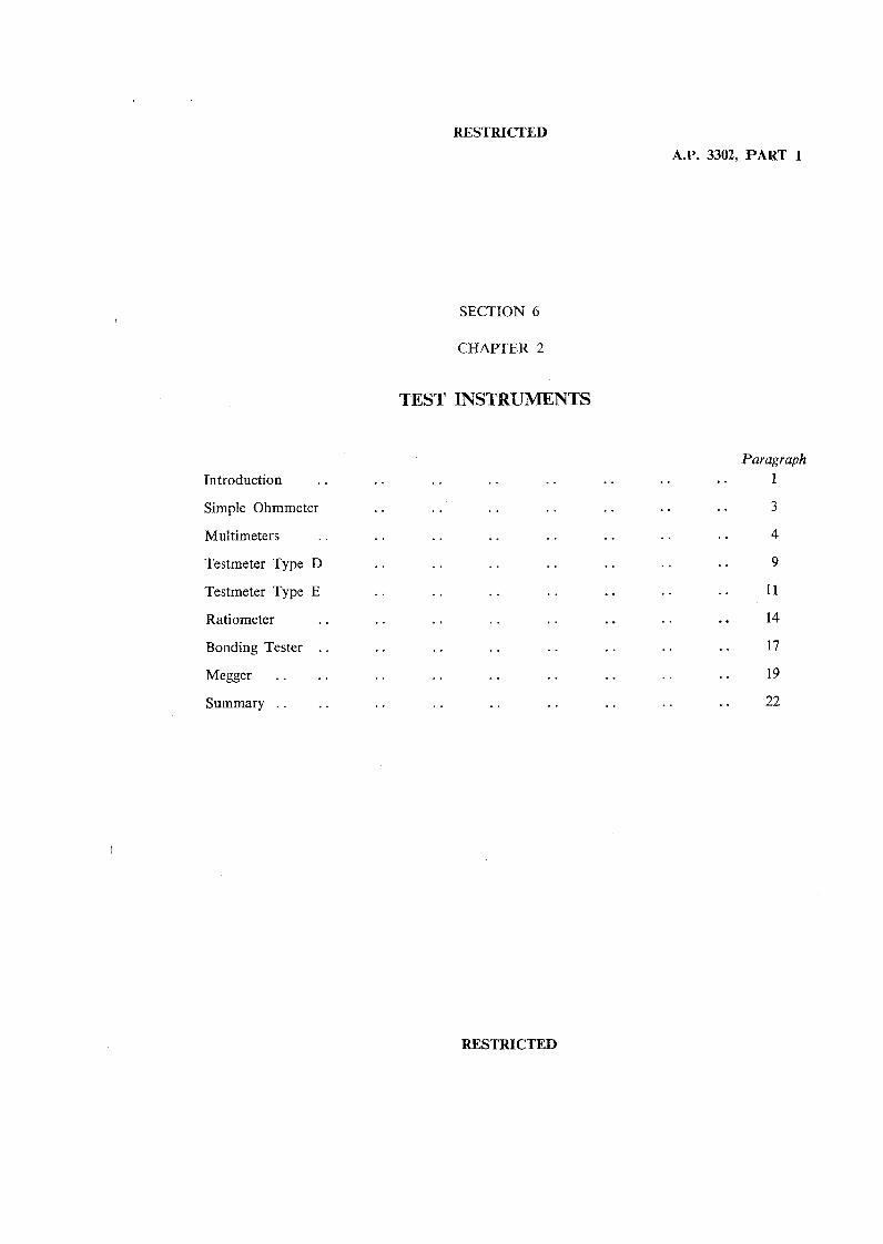
Introduction . .
Simple Ohmmeter
Multimeters . .
Testmeter Type D
Testmeter Type E
Ratiometer . .
Bonding Tester . .
Megger . . . . . . . . Summary
A.P. 3302. PART 1
SECTION 6
CHAPTER 2
TEST INSTRUMENTS
Paragraph . . 1
RESTRICTED

RESTRICTED
PART 1, SECTION 6, CHAPTER 2
TEST INSTRUMENTS
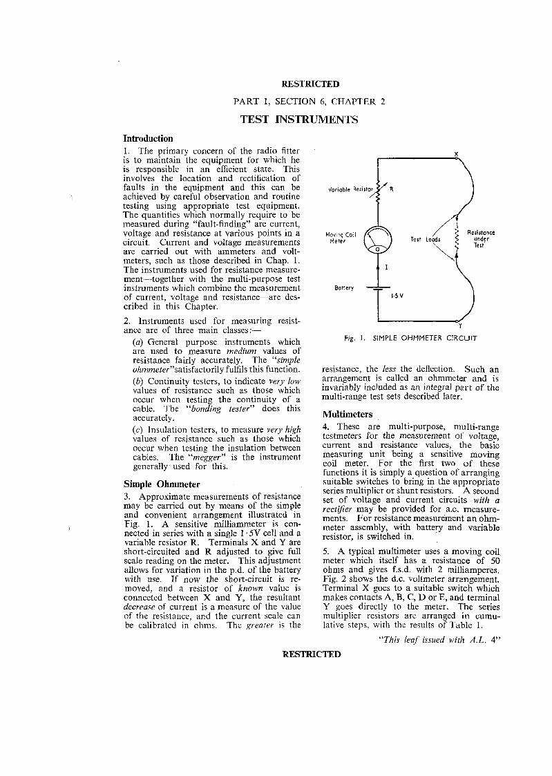
Introduction 1. The primary concern of the radio fitter is to maintain the equipment for which he is responsible in an efficient state. This involves the location and rectification of faults in the equipment and this can be achieved by careful observation and routine testing using appropriate test equipment. The quantities which normally require to be measured during "fault-finding" are current, voltage and resistance at various points in a circuit. Current and voltage measurements are carried out with ammeters and volt- meters, such as those described in Chap. 1. The instruments used for resistance measure- ment-together with the multi-purpose test instruments which combine the measurement of current, voltage and resistance-are des- cribed in this Chapter.
2. Instruments used for measuring resist- ance are of three main classes:-
(a) General purpose instruments which are used to measure medium values of resistance fairly accurately. The "simple ohmmeter"satisfactori1y fulfils this function. (b) Continuity testers, to indicate very low values of resistance such as those which occur when testing the continuity of a cable. The "bonding tester" does this accurately. (c) Insulation testers, to measure very high values of resistance such as those which occur when testing the insulation between cables. The "megger" is the instrument generally used for this.
Simple Ohmmeter 3. Approximate measurements of resistance may be carried out by means of the simple and convenient arrangement illustrated in Fig. 1. A sensitive milliammeter is con- nected in series with a single 1 .5V cell and a variable resistor R. Terminals X and Y are short-circuited and R adjusted to give full scale reading on the meter. This adjustment allows for variation in the p.d. of the battery with use. If now the short-circuit is re- moved, and a resistor of known value is connected between X and Y, the resultant decrease of current is a measure of the value of the resistance, and the current scale can be calibrated in ohms. The greater is the
Fig. I . SIMPLE O H M M E T E R CIRCUIT
resistance, the less the deflection. Such an arrangement is called an ohmmeter and is invariably included as an integral part of the multi-range test sets described later.
Multimeters 4. These are multi-purpose, multi-range testmeters for the measurement of voltage, current and resistance values, the basic measuring unit being a sensitive moving coil meter. For the first two of these functions it is simply a question of arranging suitable switches to bring in the appropriate series multiplier or shunt resistors. A second set of voltage and current circuits with a rectiJier may be provided for a.c. measure- ments. For resistance measurement an ohm- meter assembly, with battery and variable resistor, is switched in.
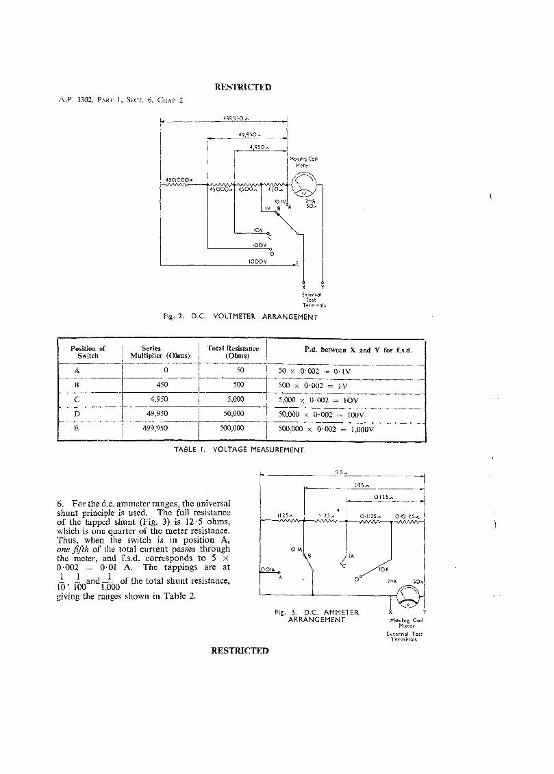
5. A typical multimeter uses a moving coil meter which itself has a resistance of 50 ohms and gives f.s.d. with 2 milliamperes. Fig. 2 shows the d.c. voltmeter arrangement. Terminal X goes to a suitable switch which makes contacts A, B, C, D or E, and terminal Y goes directly to the meter. The series multiplier resistors are arranged in cumu- lative steps, with the results of Table 1.
"This leaf issued with A.L. 4"
RESTRICTED
RESTRICTED A.P. 3302, PART 1, S E C ~ . 6 , CHAP 2
Mov~nq Coil Meter
External Tell
Term~na l r
Fig. 2. D.C. VOLTMETER ARRANGEMENT
I Position of Series / Total Resistance P.d. between X and Y for f.s.d. Switch 1 Multiplier (Ohms) 1 (Ohms) I
TABLE I. VOLTAGE MEASUREMENT
6. For the d.c. ammeter ranges, the universal shunt principle is used. The full resistance of the tapped shunt (Fig. 3) is 12.5 ohms, which is one quarter of the meter resistance. Thus, when the switch is in position A, onejifth of the total current passes through the meter, and f.s.d. corresponds t o 5 x 0.002 = 0.01 A. The tappings are at 1 1 1 - a n d o f the total shunt resistance, Z ~ A SO
I 0 ' 100 1,000 giving the ranges shown in Table 2.
Fig. 3. D.C. AMMETER 1
Y
ARRANGEMENT Moving Coil Meter
External Tesr Terminals
RESTRICTED
RESTRICTED
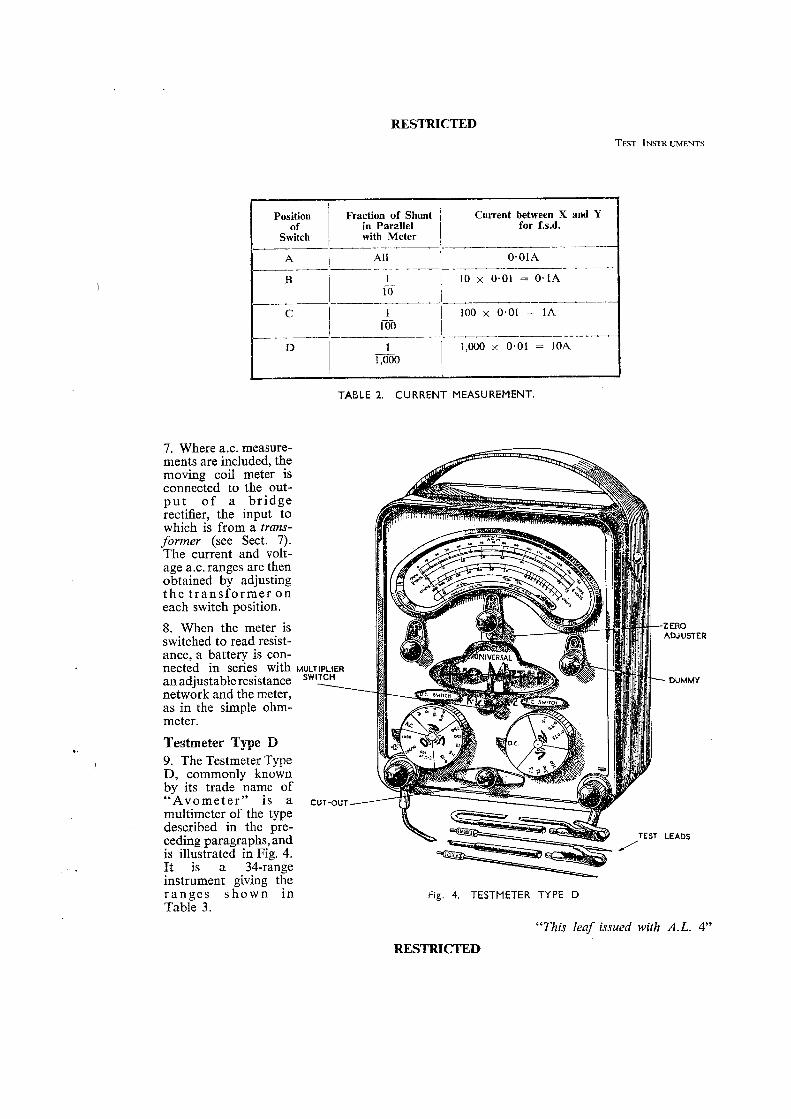
Position Fraction of Shunt j Current between X and Y in Parallel for f.s.d.
Switch -- A i All 1 0.01A
- -- --- -
7. Where a.c. measure- ments are included, the moving coil meter is connected to the out- p u t o f a b r idge rectifier, the input to which is from a trans- former (see Sect. 7). The current and volt- age a.c. ranges are then obtained by adjusting t h e t r ans fo rmer o n each switch position.
8. When the meter is switched to read resist- ance, a battery is con- nected in series with an adjustable resistance network and the meter, as in the simple ohm- meter.
Testmeter Type D 9. The Testmeter Type D, commonly known by its trade name of "Avometer" is a multimeter of the type described in the pre- ceding paragraphs, and is illustrated in Fig. 4. It is a 34-range instrument giving the r a n g e s s h o w n in Table 3.
TABLE 2. CURRENT MEASUREMENT.
MULTIPLIER SWITCH \
CUT-OUT
Fig. 4. TESTMETER TYPE D
-ZERO ADJUSTER
- DUMMY
LEADS
"This leaf issued with A.L. 4"
RESTRICTED
RESTRICTED A.P. 3302, PART 1 , SECT. 6, CHAP. 2
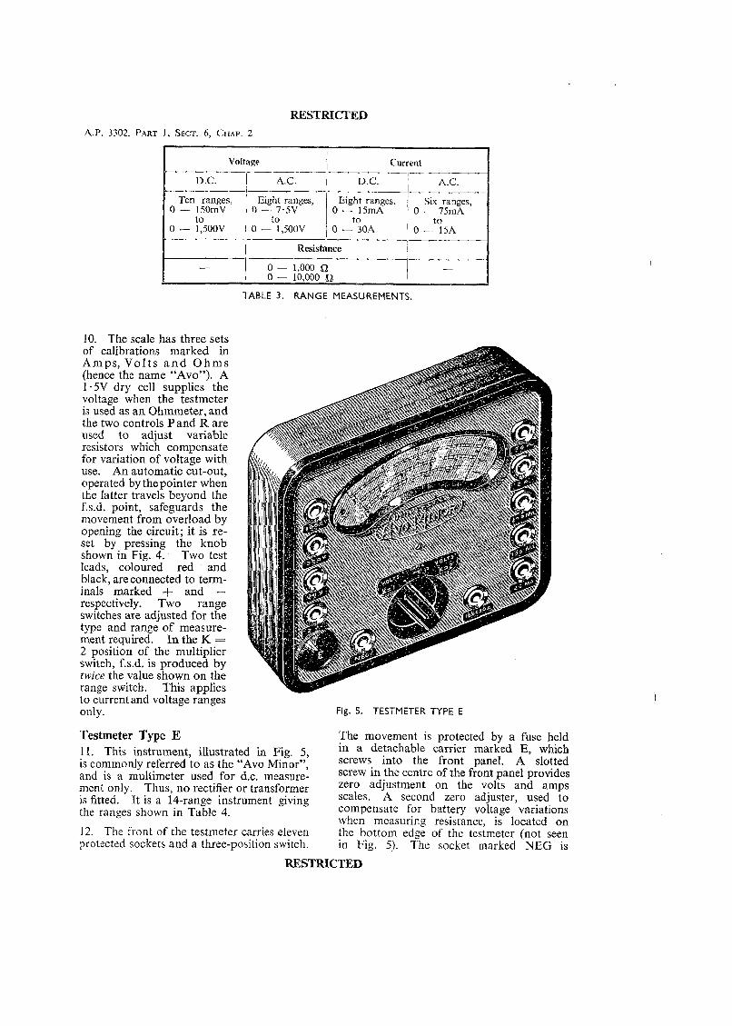
Voltage 1 Current
A.C. D.C.
Eight ranges, Eight ranges, j Six ranges, 0 - 15mA ; 0 - 75mA
Resistance ,-
TABLE 3. RANGE MEASUREMENTS.
10. The scale has three sets of calibrations marked in Amps, V o l t s a n d O h m s (hence the name "Avo"). A 1.5V dry cell supplies the voltage when the testmeter is used as an Ohmmeter, and the two controls P and R are used to adjust variable resistors which compensate for variation of voltage with use. An automatic cut-out, operated by the pointer when the latter travels beyond the f.s.d. point, safeguards the movement from overload by opening the circuit; it is re- set by pressing the knob shown in Fig. 4. Two test leads, coloured red and black, are connected to term- inals marked + and - respectively. Two range switches are adjusted for the type and range of measure- ment required. In the K = 2 position of the multiplier switch, f.s.d. is produced by twice the value shown on the range switch. This applies to currentand voltage ranges only.
Testmeter Type E 11. This instrument, illustrated in Fig. 5, is commonly referred to as the "Avo Minor7', and is a multimeter used for d.c. measure- ment only. Thus, no rectifier or transformer is fitted. It is a 14-range instrument giving the ranges shown in Table 4.
12. The front of the test~neter carries eleven protected sockets and a three-position switch.
Fig. 5. TESTMETER TYPE E
The movement is protected by a fuse held in a detachable carrier marked E, which screws into the front panel. A slotted screw in the centre of the front panel provides zero adjustment on the volts and amps scales. A second zero adjuster, used to compensate for battery voltage variations when measuring resistance, is located on the bottom edge of the testmeter (not seen in Fig. 5). The socket marked NEG is
RESTRICTED

RESTRICTED
I Voltage k e n t I Five ranges,
0 - 20mA
0 - 2,OOOV 0 - 20A
I Multiplier switch on the panel doubles voltage indications in position K = 2
Tesr INSTRUMENTS
hairspring control so that with both coils disconnected from the supply the pointer will "wander", having no fixed position.
TABLE 4. RANGE MEASUREMENTS.
common to all ranges and carries one of the test leads, the other test lead being plugged into the socket covering the desired range. The three-position switch must be correctly set.
13. The simple ohmmeter, as used in Test- meters Types D and E, requires continual adjustment if the error due to variation in supply voltage is to be eliminated. This error occurs since the deflecting force varies with the applied voltage, but the controlling force exerted by the springs of the instrument remains unaffected. This unsatisfactory fea- ture is overcome in the ratiometer type of ohmmeter.
The Ratiometer Principle 14. In the ratiometer the controlling force is an electrical force which is derived from the same supply voltage as the deflecting force. Any variation in supply voltage affects both forces equally, and error due to variation in the supply voltage is eliminated. The ratiometer is illustrated in Fig. 6. I t is essentially a moving coil instrument in which the usual solid cylindrical iron core is replaced by a hollow concentrator which is mounted eccentrically to give a varying air gap. The flux density between the pole faces and the concentrator therefore varies from a maximum at the lower pole faces to a minimum at the upper portion. In addition to the normal deflecting coil A, a second coil B is wound on the same former- unit, but at an angle to coil A. Only one side of coil B is exposed to the magnetic flux, the other side being screened from the flux by the concentrator. The coils are wound in such a way that when they are connected to a single source they will produce opposing torques. The instrument has no
P;RMANENT/ \ PIVOT MAGNET
Fig. 6. RATIOMETER TYPE O F OHMMETER
15. The coils are wound with very fine wire and can carry only a small current. Each coil is therefore connected in series with a resistor in order to limit the current. Coil B, with its associated resistor X, is connected across the supply voltage. Coil A, with its
Fig. 7. CIRCUIT O F RATIOMETER
"This leaf issued with A.L. 4"
RESTRICTED
RESTRICTED
A.P. 3302, PART 1, SECT. 6 , CHAP. 2
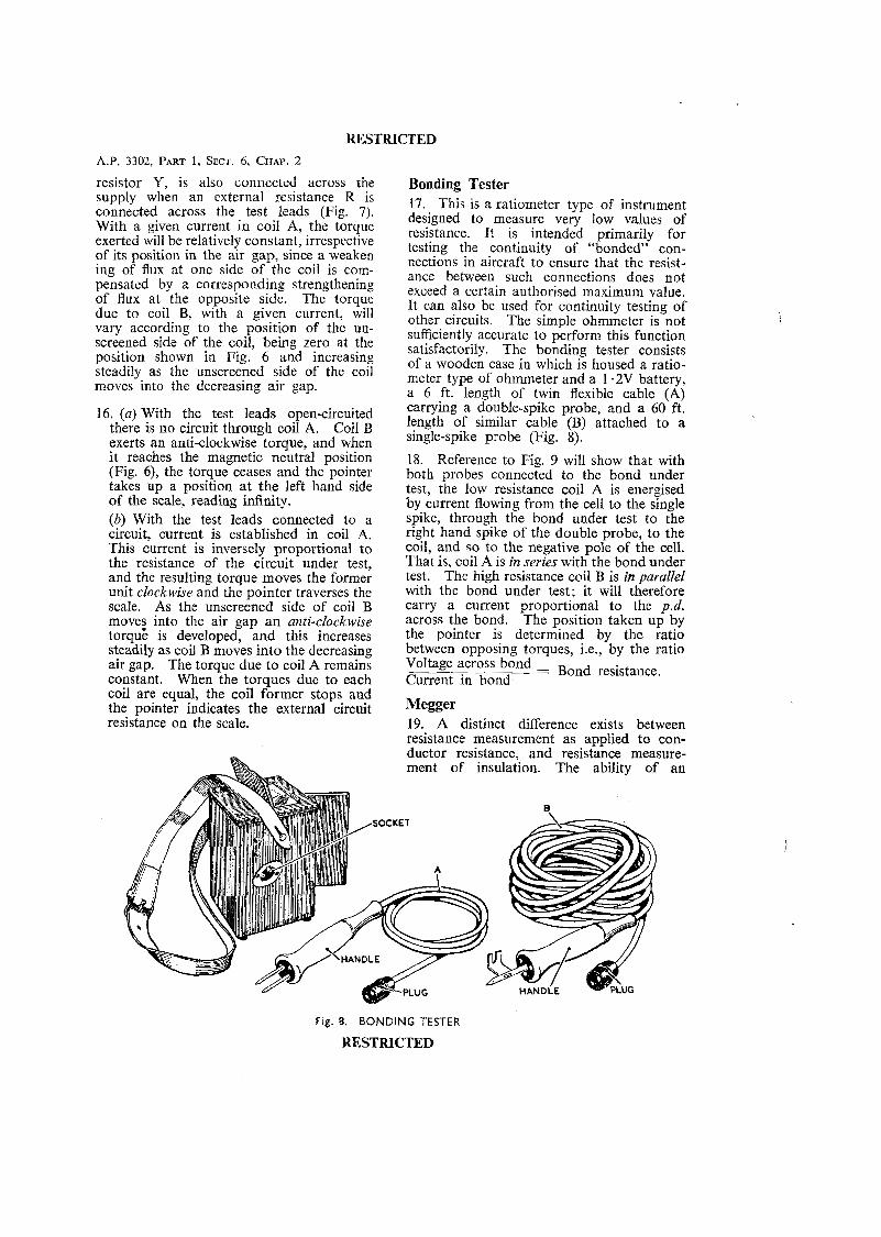
resistor Y, is also connected across the supply when an external resistance R is connected across the test leads (Fig. 7). With a given current in coil A, the torque exerted will be relatively constant, irrespective of its position in the air gap, since a weaken ing of flux at one side of the coil is com- pensated by a corresponding strengthening of flux at the opposite side. The torque due to coil B, with a given current, will vary according to the position of the un- screened side of the coil, being zero at the position shown in Fig. 6 and increasing steadily as the unscreened side of the coil moves into the decreasing air gap.
16. (a) With the test leads open-circuited there is no circuit through coil A. Coil B exerts an anti-clockwise torque, and when it reaches the magnetic neutral position (Fig. 6), the torque ceases and the pointer takes up a position a t the left hand side of the scale, reading infinity. (b) With the test leads connected to a circuit, current is established in coil A. This current is inversely proportional to the resistance of the circuit under test, and the resulting torque moves the former unit clockwise and the pointer traverses the scale. As the unscreened side of coil B moves into the air gap an anti-clockwise torque is developed, and this increases steadily as coil B moves into the decreasing air gap. The torque due to coil A remains constant. When the torques due to each coil are equal, the coil former stops and the pointer indicates the external circuit resistance on the scale.
Bonding Tester 17. This is a ratiometer type of instrument designed to measure very low values of resistance. Tt is intended primarily for testing the continuity of "bonded" con- nections in aircraft to ensure that the resist- ance between such connections does not exceed a certain authorised maximum value. It can also be used for continuity testing of other circuits. The simple ohmmeter is not sufficiently accurate to perform this function satisfactorily. The bonding tester consists of a wooden case in which is housed a ratio- meter type of ohmmeter and a 1 -2V battery, a 6 ft. length of twin flexible cable (A) carrying a double-spike probe, and a 60 ft. length of similar cable (B) attached to a single-spike probe (Fig. 8).
18. Reference to Fig. 9 will show that with both probes connected to the bond under test, the low resistance coil A is energised by current flowing from the cell to the single spike, through the bond under test to the right hand spike of the double probe, to the coil, and so to the negative pole of the cell. That is, coil A is in series with the bond under test. The high resistance coil B is in parallel with the bond under test; it will therefore carry a current proportional to the p.d. across the bond. The position taken up by the pointer is determined by the ratio between opposing torques, i.e., by the ratio
Megger 19. A distinct difference exists between resistance measurement as applied to con- ductor resistance, and resistance measure- ment of insulation. The ability of an
Fig. 8. BONDING TESTER
RESTRICTED
RESTRICTED
Fig. 9. CIRCUIT OF BONDING TESTER
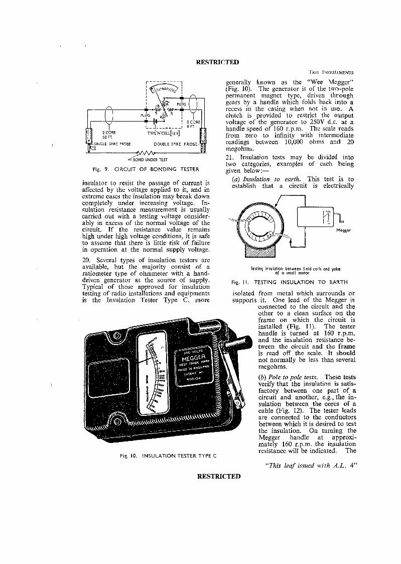
insulator to resist the passage of current is affected by the voltage applied to it, and in extreme cases the insulation may break down completely under increasing voltage. In- sulation resistance measurement is usually carried out with a testing voltage consider- ably in excess of the normal voltage of the circuit. If the resistance value remains high under high voltage conditions, it is safe to assume that there is little risk of failure in operation at the normal supply voltage.
20. SeveraI types of insulation testers are available, b.ut the majority consist of a ratiometer type of ohmmeter with a hand- driven generator as the source of supply. Typical of those approved for insulation testing of radio installations and equipments is the Insulation Tester Type C, more
generally known as the "Wee Megger" (Fig. 10). The generator is of the two-pole permanent magnet type, driven through gears by a handle which folds back into a recess in the casing when not in use. A clutch is provided to restrict the output voltage of the generator to 250V d.c. a t a handle speed of 160 r.p.m. The scale reads from zero to infinity with intermediate readings between 10,000 ohms and 20 megohms. 21. Insulation tests may be divided into two categories, examples of each being given below:-
(a) Insulation to earth. This test is to establish that a circuit is electrically
Testing insulation between field coils and yoke of a small motor
Fig. 1 1 . TESTING INSULATION TO EARTH
isolated from metal which surrounds or supports it. One lead of the Megger is
connected to the circuit and the
Fig. 10. INSULATION TESTER TYPE C
RESTRICTED
other to a clean surface on the frame on which the circuit is installed (Fig. 11). The tester handle is turned at 160 r.p.m. and the insulation resistance be- tween the circuit and the frame is read off the scale. It should not normally be less than several megohms.
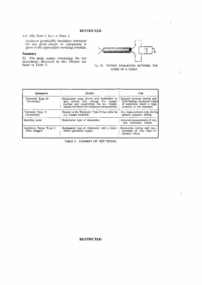
(b) Pole to pole tests. These tests verify that the insulation is satis- factory between one part of a circuit and another, e.g., the in- sulation between the cores of a cable (Fig. 12). The tester leads are connected to the conductors between which it is desired to test the insulation. On turning the Megger handle at approxi- mately 160 r.p.m. the insulation resistance will be indicated. The
"This leaf issued with A.L. 4"
RESTRICTED
A.P. 3302, PART 1, SECT. 6, CHAP. 2
niinimum permissiblt: insulation resistance for any given circuit or component is given in the appropriate servicing schedule.
Summary 22. The main points concerning the test instruments discussed in this Chapter are listed in Table 5.
U Fig. 12. TESTING INSULATION BETWEEN THE
CORES OF A CABLE
TABLE 5. SUMMARY OF TEST METERS.
RESTRICTED
Use
General purpose testing and fault-finding: moderate value of resistance where a high accuracy is not essential.
D.c, measurements only durinl general purpose testing.
Accurate measurement of very low resistance values.
Insultation testing and mea- surement of very high re- sistance values.
Instrument
Testmeter Type D (Avometer)
Testmeter Type E (Avorninor)
Bonding tester
Insulation Tester Type C (Wee Megger)
Details
Multimeter using shunts and multipliers to give current and voltage d.c. ranges: rectifier and transformer for a.c. ranges: simple ohmmeter for resistance measurement.
Similar to the Testmeter Type D but with the a.c, ranges excluded.
Ratiometer type of ohmmeter.
Ratiometer type of ohmmeter with a hand- driven generator supply.
RESTRICTED
A.P. 3302, PART 1
SECTION 6
CHAPTER 3
MEASUREMENT OF POWER
Introduction . . . . . .
Dynamometer Wattmeter . . . . Power Ratios . . . . . .
The Decibel . . . . . . Absolute Powers Expressed in Dbm
Current and Voltage Ratios . .
Decibel Meters . . . . . .
The Neper . . . . . .
Paragraph . . . . 1
RESTRIC TED

RESTRICTED
PART 1, SECTION 6, CHAPTER 3
MEASUREMENT OF POWER
Introduction 1. In a d.c. circuit, the product VI, where V is the steady p.d. across a load and 1 the steady current through it, measures the power consumption of the load. In an a.c. circuit, the product of the instantaneous values of voltage and current gives the instantaneous rate of working. The product of the r.m.s. values of V and I gives the apparent power in the circuit. Except in the case of a purely resistive load, there will
P W T JEWELS /
\ DAMPHG VANES
PODJTER
JEWELS
WG
DAMPHG VANES
Fig. I. THE DYNAMOMETER WATTMETER
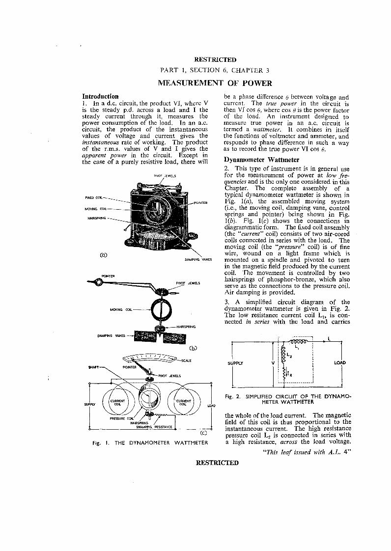
be a phase difference 0 between voltage and current. The true power in the circuit is then VI cos Q, where cos 6 is the power factor of the load. An instrument designed to measure true power in an a.c. circuit is termed a wattmeter. It combines in itself the functions of voltmeter and ammeter, and responds to phase difference in such a way as to record the true power VI cos 0.
Dynamometer Wattmeter 2. This type of instrument is in general use for the measurement of power at low fre- quencies and is the only one considered in this Chapter. The complete assembly of a typical dynamometer wattmeter is shown in Fig. l(a), the assembled moving system (i.e., the moving coil, damping vane, control springs and pointer) being shown in Fig. I(b). Fig. l(c) shows the connections in diagrammatic form. The fixed coil assembly (the "current" coil) consists of two air-cored coils connected in series with the load. The moving coil (the "pressure" coil) is of fine wire, wound on a light frame which is mounted on a spindle and pivoted t o turn in the magnetic field produced by the current coil. The movement is controlled by two hairsprings of phosphor-bronze, which also serve as the connections to the pressure coil. Air damping is provided.
3. A simplified circuit diagram of the dynamometer wattmeter is given in Fig. 2. The low resistance current coil L,, is con- nected in series with the load and carries
Fig. 2. SIMPLIFIED CIRCUIT OF THE DYNAMO- METER WATTMETER
the whole of the load current. The magnetic field of this coil is thus proportional to the instantaneous current. The high resistance pressure coil Lp is connected in series with a high resistance, across the load voltage.
"This leaf issued with A.L. 4"
RESTRICTED
The leactanct: of this circuit can therefore be neglected at low frequencies, and the current in the pressurc coil is in phase with, and proportional to, the load voltage. The connections of the fixed coil L, resemble those of an ammeter and the connections of the moving coil L, those of a voltmeter.
4. The torque exerted upon the moving coil is proportional to the product of the currents in each of the coil assemblies; that is, to the product of the instantaneous current and the instantaneous voltage in the load, namely the instantaneous power. The aver- age value of this torque over any number of complete cycles gives an indication of the true power (VI cos 0 ) and the scale is gradu- ated accordingly.
5. At high frequencies, the increased react- ance of the instrument introduces additional phase shift and the meter becomes increas- ingly inaccurate. The usual practice at high frequencies is to measure the current in a known resistance in the circuit. Alter- natively, the voltage across a standard resistance inserted in the circuit can be measured. The power is then calculated from the relationship:-
v2 P = - (watts). R
The ammeter or voltmeter used will normally be a rectifier type of instrument, and the scale may be calibrated directly in watts (when used with a standard resistance).
Power Ratios
6. No device can deliver more power than is supplied to it. Amplifiers are designed to increase the power of an a.c. by drawing additional power from an independent supply. If the power supplied to operate the amplifier (the input) is 2 watts, and the power delivered from the amplifier to a load (the output) is 40 watts, the power ratio or "gain" is
%= 20. The power drawn from the supply 2
is 40 - 2 = 38 watts.
7. Power losses occur under certain con- ditions, and circuits called attenuators are designed to reduce the power of an a.c. If the input power to the attenuator is 5 watts and the output power is 3 watts, then
'7
the power ratio, or "loss" is 3 = 0.6. 5
RESTRICTED
RESTRICTED
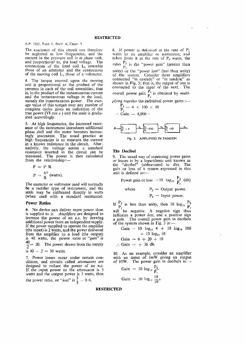
8. If power 1s delivered at the rate of P, watts to an amplifier or attenuator, and taken from it at the rate of P, watts, the
ratio P2 is the "power gain" (greater than P. - I
unity) or the "power loss" (less than unity) of the system. Consider three amplifiers connected "in cascade" or "in tandem" as shown in Fig. 3; that is, the output of one is connected to the input of the next. The
P overall power gain - is obtained by multi- p1
plying together the individual power gains :-
5 = 4 X 1 0 0 X 1 0 PI :. Gain = 4,000 .
Fig. 3. AMPLIFIERS IN TANDEM
The Decibel 9. The usual way of expressing power gains or losses is by a logarithmic unit known as the "decibel" (abbreviated to db). The gain or loss of a system expressed in this unit is defined as:-
Power gain or loss = 10 log,, 5 (db) Pl
where P, = Output power.
P, = Input power.
P P2 If 5 s less than unity, then 10 log,, -- p, Pl
will be negative. A negative sign thus indicates a power loss, and a positive sign a gain. The overall power gain in decibels of the system shown in Fig. 3 is:-
Gain = 10 log,, 4 + 10 log,, 100 + 10 loglo 10
Gain = 6 + 20 f 10 Gain = + 36 db. * .
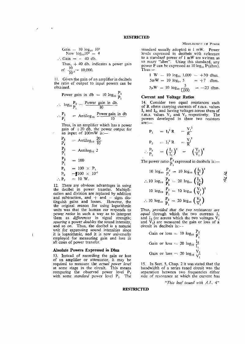
10. As an example, consider an amplifier with an input of 1mW giving an output of 10W. The power gain in decibels is:-
Gain = 10 log,, p2 P1 10 Gain = 10 log,, m 3
RESTRICTED
Gain = 10 logl0 10: NOW 1og,,104 = 4
:. Gain = 4- 40 db. Thus, + 40 db. indicates a power gain
I 1. Given the gain of an amplifier in decibels the ratio of output to input powers can be obtained.
pz Power gain in db = 10 log,, -- Pl
P, - Power gain in db. .'. log,, -- - p 1 10
Power gain in db :. 5 = Antilog,, -- PI 10
standard usually adopted is 1 mW. Power levels expressed in decibels with reference to a standard power of 1 mW are written as so many "dbrn". Using this standard, any power P can be expressed as 10 log,, P(dbm). Thus:--
1 W = 10 log,, 1,000 = +30 dbrn. 5mW = 10 log,, 5 = 1-7 dbm.
5 - 5pW = 10 log,, ---- - -23 dbm. 1,000
Current and Voltage Ratios 14. Consider two equal resistances each of R ohms carrying currents of r.m.s. values I, and I,, and having voltages across them of r.m.s. values V, and V, respectively. The powers developed in these two resistors are :- Thus, in an amplifier which has a power
gain of 1-20 db, the power output for P, = I,, R -
v12 an input of lOOmW is:- - R-
20 '2 = Antilog,, - P7 10
5 = Antilog,, 2 Pl
12. There are obvious advantages in using the decibel in power transfer. Multipli- cation and division are replaced by addition and subtraction, and + and - signs dis- tinguish gains and losses. However, the the original reason for using logarithmic units was that the human ear responds to power ratios in such a way as to interpret them as differences in signal strength; squaring a power doubles the sound intensity, and so on. Thus, the decibel is a natural unit for expressing sound intensities since it is logarithmic, and it is now universally employed for measuring gain and loss in all cases of power transfer.
Absolute Powers Expressed in Dbm 13. Instead of recording the gain or loss of an amplifier or attenuator, it may be required to measure the actual power level at some stage in the circuit. This means comparing the observed power level P, with some standard power level P,. The
P, = 1z2 R vz2 = K
2 . " = ( ) = * - P,
The power ratio 11-2 expressed in decibels is :- p I
P 10 log,, -, = 10 log,, p 1 (*I2 5! P :. 10 log,, -2 = 20 log,, p1 (S) ?
10 log,, 5 = 10 log,, (%), p1
:. 10 log,, 3 = 20 log,, (? ) p 1
Thus, provided that the two resistances are equal through which the two currents I, and I, (or across which the two voltages V, and V,) are measured the gain or loss of a circuit in decibels is:-
Gain or loss = 10 log,, p, K
Gain or loss = 20 log I2 I0 q
Gain or loss = 20 log,, 2 Vl
15. In Sect. 5, Chap. 2 it was stated that the bandwidth of a series tuned circuit was the separation between two frequencies either side of resonance at which the current has
"This leaf issued with A.L. 4"
RESTRICTED
RESTRICTED A.P. 3302, PART 1, SECT. 6 , CHAP. 3
fallen to 70 % of its peak value. In terms of decibels, the current ratio is:-
0.707 - - 3 &, 20 log,, ---- - 1
The bandwidth is then expressed as so many kc/s at "3 db down". Another figure at which the bandwidth is commonly measured is 6 db down. At this latter figure the current has fallen to half its peak value.
Decibel Meters 16. By comparing the voltages they cause when connected in turn across a standard impedance, the powers of two sources can be compared. A high impedance voltmeter (Fig. 4) is connected across the impedance
SOURCE
Fig. 4. POWER COMPARISON
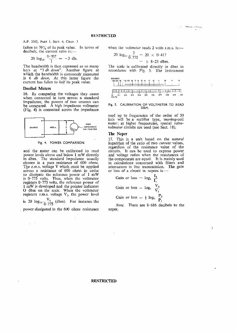
and the meter can be calibrated to read power levels above and below 1 mW directly in dbm. The standard impedance usually chosen is a pure resistance of 600 ohms. The r.m.s. voltage V which must be applied across a resistance of 600 ohms in order to dissipate the reference power of 1 mW is 0.775 volts. Thus, when the voltmeter registers 0.775 volts, the reference power of 1 mW is developed and the pointer indicates 0 dbm on the scale. When the voltmeter registers r.m.s. voltage V,, the power level
is 20 loglo---- (dbm). For instance the 0.775
power dissipated in the 600 ohms resistance
when the voltmeter reads 2 volts r.m.s. is:-- L 20 log,, - - - 20 x 0.417
0.775 = 4- 8.23 dbm.
The scale is calibrated directly in dbm in accordance with Fig. 5. The instrument
DECIBELS -3010 -16 -12 .I0 d - 6 -5 -4 -3 - 2 .Z
.lo VOLTS
Fig. 5. CALIBRATION OF VOLTMETER TO READ DBM.
used up to frequencies of the order of 50 kc/s will b e a rectifier type, moving-coil meter; at higher frequencies, special valve- voltmeter circuits are used (see Sect. 18).
The Neper 17. This is a unit based on the natural logarithm of the ratio of two current values, regardless of the resistance value of the circuits. It can be used to express power and voltage ratios when the resistances of the components are equal. I t is mainly used in calculations concerned with filters and attenuators in line transmission. The gain or loss of a circuit in nepers is:-
Gain or loss = log, I2 F Gain or loss = log, v2
F Gain or loss = + log, p2
6 Note. There are 8.686 decibels to the
neper.
RESTRICTED