DM4500F | Status Instruments
67
Page 1 of 67 COUNTER - TOTALIZER TACHOMETER - TOTALIZER FREQUENCY METER CHRONOMETER INSTRUCTION MANUAL DM4500F
-
Upload
khangminh22 -
Category
Documents
-
view
0 -
download
0
Transcript of DM4500F | Status Instruments

Page 1 of 67
COUNTER - TOTALIZER TACHOMETER - TOTALIZER
FREQUENCY METER CHRONOMETER
INSTRUCTION MANUAL
DM4500F

Page 2 of 67

Page 3 of 67
INDEX 1. OVERVIEW ...................................................................................................... 5
1.1 Introduction to the DM4500F................................................................... 5
2. GETTING STARTED? ....................................................................................... 9 2.1 Power Supply. Connectors ...................................................................... 13 2.2 Description functions keys and LEDs in programming mode and
mode RUN................................................................................................... 15 2.3 Input signal (CN2) Connection ................................................................ 17
3. INPUT PROGRAMMING / COUNTER CONFIGURATION ............................... 18
3.1 Selection of sensor type.......................................................................... 18 3.2 Diagram of programming mode: COUNTER.............................................. 19 3.3 Counter configuration ............................................................................. 20
3.4 Mode count programming....................................................................... 21 3.5 Programming of display .......................................................................... 25
3.5.1 Options of the Process Variable .................................................. 25 3.5.2 Brightness level configuration ..................................................... 27 3.5.3 Totalizer Option ......................................................................... 27
3.5.4 Totalizer visualization ................................................................ 28 4. Programming Mode CHRONOMETER ............................................................ 29
4.1 Chronometer Configuration ..................................................................... 30
4.1.1 Inputs ....................................................................................... 30 4.1.2 Measure .................................................................................... 30 4.1.3 Display...................................................................................... 31
4.1.4 Offset........................................................................................ 31 4.1.5 Reset ........................................................................................ 31
4.2 Input Setup ........................................................................................... 32
4.2.1 Start Stop - Mode In-A ............................................................... 32 4.2.2 Start Stop - Mode In-AB ............................................................. 32 4.2.3 Up Down Direction uP ................................................................ 32
4.2.4 Up Down Direction do ................................................................ 33 4.2.5 Time Range............................................................................... 33
5. FREQUENCY METER / TACHOMETER............................................................. 34 5.1 Frequency meter / Tachometer ............................................................... 37
5.1.1 Frequency meter ....................................................................... 37
5.1.2 Tachometer RPM ....................................................................... 37 5.1.3 Tachometer RATE...................................................................... 38
5.2 Display Setup ........................................................................................ 40
5.2.1 Options of the Process Variable................................................... 41 5.2.2 TOTAL, MAX and MIN visualization.............................................. 43
6. LOGIC FUNCTIONS ......................................................................................... 43
6.1 Programmable functions table ................................................................... 45 6.1.1 Logic functions diagram .............................................................. 45
6.2 Programming the functions ....................................................................... 46
7. PROGRAM PARAMETERS AND KEYBOARD FUNCTIONS LOCK-OUT ............ 47 7.1 Security menu diagram ........................................................................... 48
8. RESTORATION TO FACTORY CONFIGURATION ........................................... 51

Page 4 of 67
9. OUTPUT OPTIONS .......................................................................................... 52
9.1 SETPOINTS OUTPUT............................................................................... 53
9.1.1 Introduction .............................................................................. 53 9.1.2 Wiring ....................................................................................... 54 9.1.3 Technical specifications .............................................................. 55
9.1.4 Set points menu diagram in mode Frequency meter / Tachometer........................................................................................ 56 9.1.5 Direct access to set points value programming ............................ 57
9.1.6 Description of operation in mode Frequency meter, Tachometer ....................................................................................... 58 9.1.7 Set points menu Diagram in mode Counter / Chronometer ........... 59
9.1.8 Description of mode relays operating as Counter / Chronometer...................................................................................... 60
9.2 ANALOG OUTPUT ................................................................................... 63 9.2.1 Introduction .............................................................................. 63 9.2.2 Technical specifications .............................................................. 64
9.2.3 Analogue output menu diagram.................................................. 64 10. TECHNICAL CHARACTERISTICS .................................................................. 65
Page 5 of 67
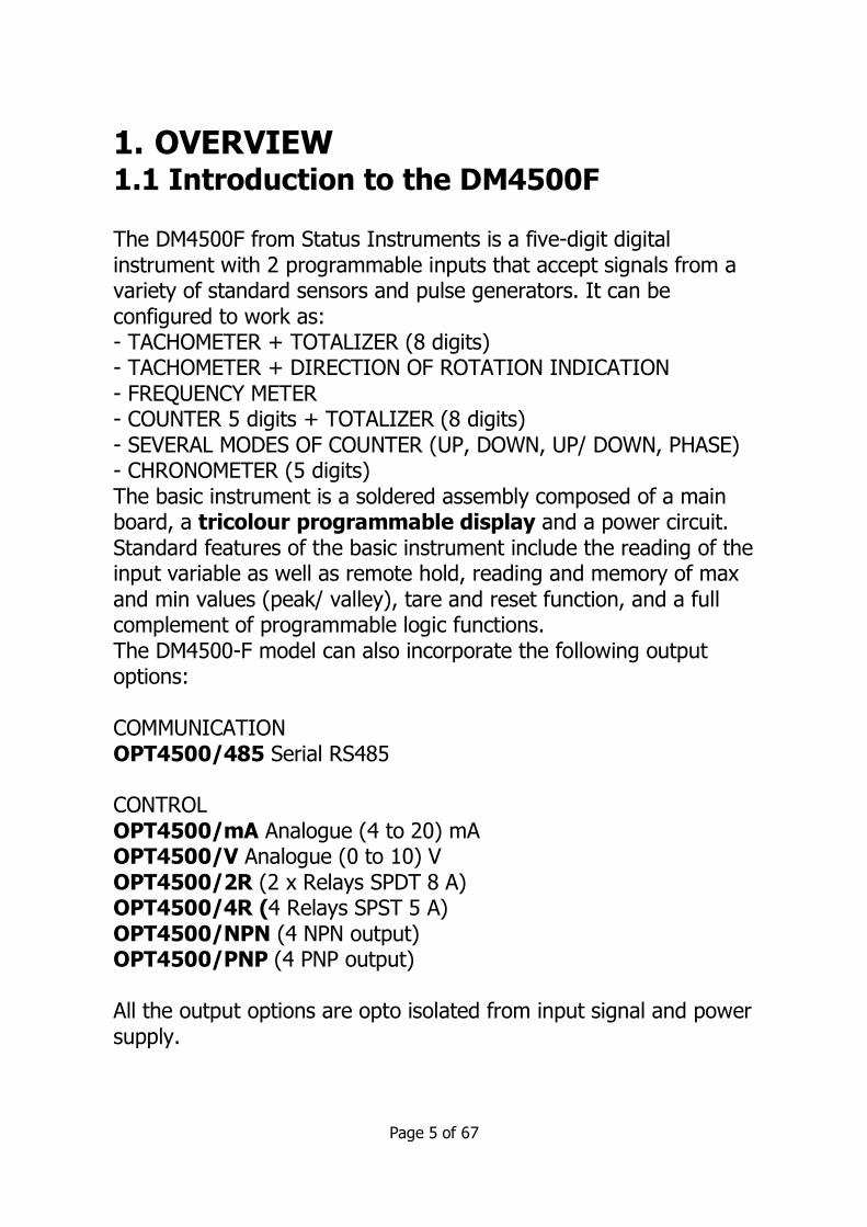
1. OVERVIEW 1.1 Introduction to the DM4500F The DM4500F from Status Instruments is a five-digit digital instrument with 2 programmable inputs that accept signals from a variety of standard sensors and pulse generators. It can be configured to work as: - TACHOMETER + TOTALIZER (8 digits) - TACHOMETER + DIRECTION OF ROTATION INDICATION - FREQUENCY METER - COUNTER 5 digits + TOTALIZER (8 digits) - SEVERAL MODES OF COUNTER (UP, DOWN, UP/ DOWN, PHASE) - CHRONOMETER (5 digits) The basic instrument is a soldered assembly composed of a main board, a tricolour programmable display and a power circuit. Standard features of the basic instrument include the reading of the input variable as well as remote hold, reading and memory of max and min values (peak/ valley), tare and reset function, and a full complement of programmable logic functions. The DM4500-F model can also incorporate the following output options: COMMUNICATION OPT4500/485 Serial RS485 CONTROL OPT4500/mA Analogue (4 to 20) mA OPT4500/V Analogue (0 to 10) V OPT4500/2R (2 x Relays SPDT 8 A) OPT4500/4R (4 Relays SPST 5 A) OPT4500/NPN (4 NPN output) OPT4500/PNP (4 PNP output) All the output options are opto isolated from input signal and power supply.

Page 6 of 67
PROCESS COUNTER
UP counter, DOWN counter and bidirectional UP/DOWN counter • In UP/ DOWN mode it can be programmed to work:
Independent, Directional or Phase. • Remote and front-panel reset • Decimal point indication • Reset may load a count value (OFFSET), programmable or entered from the display
• Multiplier/Divider factor from 0.0001 to 99999 • Programmable low frequency debounce filter (20 Hz) activates automatically when a contact closure input type is selected.
• Key-lock for RESET
TOTALIZER COUNTER
• Selectable totalizer with separate decimal point and scale factor independent from process counter.
• Count display from 99999999 to -9999999. Decimal point position programmable.
• Selectable 4 positions decimal point • Input configuration and count mode is the same as selected for the process counter
• Alternating display of 4 digits high order part and 4 digits low order part of the value with corresponding indication H and L.
• No offset possibility • Key-lock for the RESET function • Remote and front-panel reset • Scale factor from 0.0001 to 99999

Page 7 of 67
CHRONOMETER • Four ranges 999.99 s, 999 m 59 s, 999 h 59 m, 9999.9 h
• Remote and front-panel reset
• Reset may load a count value (OFFSET), programmable or entered from the display
• Counts UP or DOWN
• Key-lock for RESET FREQUENCY METER / TACHOMETER • Measures frequency, rpm, rate, flow and time. • Decimal point indication • Scale factor programmable from 0.0001 to 9999 • Display update time programmable from (0.1 to 9.9) s • Pulse arrival time limit programmable from (1 to 99.9) s • MAX and MIN values memorisation (TACHOMETER) TACHOMETER WITH DIRECTION INDICATION
• The DM4500F senses direction of rotation and indicates polarity of the signal by means of LEDs represented by up and down arrows. This function requires programming the totalizer for up/down PHASE or DIREC mode.
TACHOMETER WITH TOTALIZER COUNTER
• The totalizer has the same scaling facilities as for the counter configuration thus allowing it to have two simultaneous values for the same signal, for example, speed and flow.
Programmable logic functions operated at the rear connector enhance the functionality of the meter and allow basic operations remotely. In addition, commands through the serial port are available to allow reading and changing the setpoint values, request the display and reset to zero, etc...

Page 8 of 67
Special software capabilities are programmable, lock-out for individual menus or the entire program parameters, as well as the return to factory configuration. Programmable display colour (red, green or amber) assignable to: programming, partial count value, total, setpoints, relay activation etc.
This instrument conforms to the following community standards: 89/336/CEE and 73/23/CEE Warning: Refer to the instruction manual to preserve safety protection.

Page 9 of 67
2. GETTING STARTED Packing contents Instruction manual Digital panel meter DM4500F. Accessories for panel mounting (sealing gasket and fixing
clips). Accessories for wiring connections (plug-in terminal block
connectors with a fingertip key). Wiring label (fixed to the product housing). Legend label with engineering units. Check the packing contents.
Programming instructions
The Instrument is programmable via the front panel keyboard and allows access to several independent programming menus for configuration of the input, the display and the logic functions. If additional options are installed (serial outputs, analogue output and relays output) once recognised by the instrument, they activate their own programming software.
Programming lock-out (See section 7).
The software can be configured to allow total programming lockout but also selective lockout of the programming parameters. The instrument is delivered from the factory with unlocked
programming, e.g., with all the programming levels accessible to the operator
TIP! - Write down the security code and keep it in a secure place.

Page 10 of 67
Front: 96 x 48 mm Depth: 60 mm
Panel cut-out: 92 x 45 mm
CLEANING: Front cover should be cleaned only with a soft cloth soaked in neutral
soap product.
DO NOT USE SOLVENTS
Dimensions and mounting

Page 11 of 67
Programming the instrument. First, connect the instrument to the corresponding supply; automatically a display test will be performed and the software version will be shown, then the instrument will go to run mode.
Next, press the key to enter into the programming mode, the indication "-Pro-" will appear on the display. How to store programmed parameters? To save the changes that have been programmed, the operator must complete the programming of all the parameters contained in the current routine. In the last step of the routine, by pressing the
key, “StorE” will be displayed and all changes are stored in memory. The instrument will then return to the run mode. How is the programming routine organised? Programming software is composed by a number of menus and submenus. In the diagram below, beginning with indication "-Pro-",
press repeatedly on to get access to programming menus. Blocks 3, 4 and 5 relate to output options and will only be shown if the option is fitted. Selecting one menu, access to the different programming
submenus is done by pressing . Module selection level
Page 12 of 67
Accessing to programmed parameters
Because of the menu structure, the programming routines allow access to change one parameter without passing through the whole list of parameters.
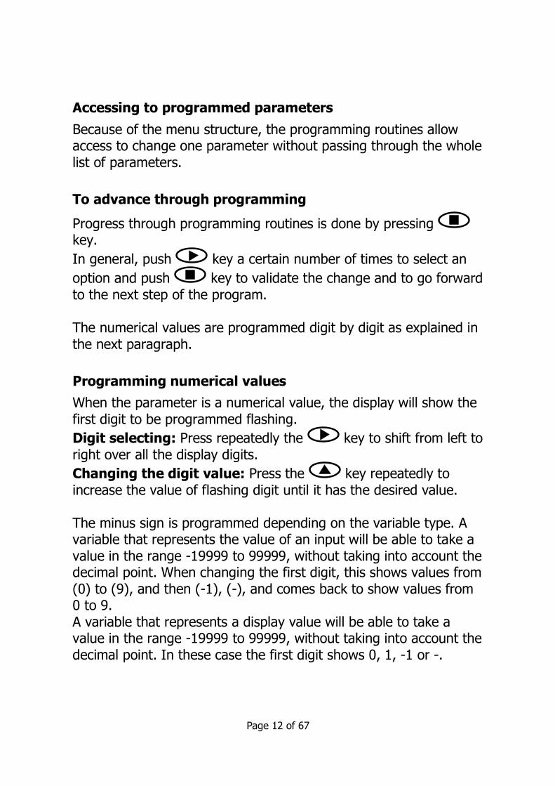
To advance through programming
Progress through programming routines is done by pressing key.
In general, push key a certain number of times to select an
option and push key to validate the change and to go forward to the next step of the program. The numerical values are programmed digit by digit as explained in the next paragraph.
Programming numerical values
When the parameter is a numerical value, the display will show the first digit to be programmed flashing.
Digit selecting: Press repeatedly the key to shift from left to right over all the display digits.
Changing the digit value: Press the key repeatedly to increase the value of flashing digit until it has the desired value. The minus sign is programmed depending on the variable type. A variable that represents the value of an input will be able to take a value in the range -19999 to 99999, without taking into account the decimal point. When changing the first digit, this shows values from (0) to (9), and then (-1), (-), and comes back to show values from 0 to 9. A variable that represents a display value will be able to take a value in the range -19999 to 99999, without taking into account the decimal point. In these case the first digit shows 0, 1, -1 or -.

Page 13 of 67
Selecting an option from the list When the parameter is an option to be chosen among different
possibilities, the key allows you to browse through the list of options until you find the desired parameter. 2.1 – Power Supply and connectors WARNING: If not installed and used in accordance with these instructions, protection against hazards may be impaired. In order to guarantee the electromagnetic compatibility, the following guidelines should be kept in mind: - Power supply wires should be
routed separately from signal wires.
- Never run power and signal wires in the same conduit.
- Use shielded cable for signal wiring and connect the shield to the ground of the indicator.
- The cable section should be >0.25 mm2
INSTALLATION To meet the requirements of the directive EN61010-1, where the unit is permanently connected to the mains supply, it is obligatory to install a circuit breaking device within easy reach of the operator and clearly marked as the disconnect device.
1 2

Page 14 of 67
WIRING and POWER SUPPLY RANGE DM4500/S1 (85 to 265) VAC (50 to 60) Hz, or (100 to 300) VDC DM4500/S2 (22 to 53) VAC (50 to 60) Hz, or (10.5 to 70) VDC Pin 1: Live Pin 2: Neutral CONNECTORS CN1 To perform wiring connections, strip the wire leaving between (7 and 10) mm exposed and insert it in the required terminal while pushing the clamp tool down to open the clamp inside the connector as indicated in the figures. CN1 terminal accepts cables of section between 0.33 mm² and 2 mm² (22 to 14 AWG) Recommended cables size 2.0 mm² CN2 & CN3 To perform wiring connections, strip the wire leaving between (5 and 6) mm exposed and insert it in the required terminal while pushing the fingertip tool in to open the clamp inside the connector as indicated in the figures. Each terminal accepts cables of section between 0.08 mm² and 0.5 mm² (28 to 20 AWG) Recommended cables size 0.5 mm²

Page 15 of 67
2.2 Functions keys and LED's description in programming mode and RUN mode
KEY Function in programming mode
DATA ENTER
- to step forward in programming menu - to validate programmed values - to exit programming menu
MAX/ MIN
TOTAL
- to move blinking digit
RESET OFFSET
- to increase blinking digit value - Direct access to Setpoints value
LED’s Function in programming mode TARE MAX Indicates rotation sense (polarity) MIN Indicates rotation sense (polarity) PROG Indicates you are in programming mode
1 - 2 - 3 - 4 Indicates the Setpoint that is being programmed

Page 16 of 67
KEY Function in RUN mode
DATA ENTER
- to enter programming menu or to visualize parameters if programming is locked
MAX/ MIN TOTAL
1st press allows TOTALIZER visualization (if activated) 2nd press allows Max visualization ( only Tachometer) 3rd press allows Min visualization ( only Tachometer) Following press: back to current value.
RESET OFFSET
In Tachometer mode reset of MAX/ MIN/ TOTAL (if present on display) In Counter mode Reset / OFFSET (starts measuring)
LED’s Function in RUN mode TARE Indicates that there is an offset value programmed
MAX Fixed indicates rotation sense or count polarity Blinking indicates visualization of a Max value
MIN Fixed indicates rotation sense or count polarity Blinking indicates visualization of a Min value
PROG Not active in run mode 1 - 2 - 3 - 4 Indicates the activated Setpoint

Page 17 of 67
2.3 – Input signal (CN2) Connection Refer to connection recommendations on page 14
CN2 PIN 1 = No Connection PIN 2 = (+) 18 V Excitation PIN 3 = (+) 8.2 V Excitation
Namur sensors PIN 4 = ( - ) Common
excitation / input PIN 5 = Signal B input PIN 6 = Signal A input PIN 7 = No Connection PIN 8 = High voltage input (300 Vac max.)
MAGNETIC PICKUPCN2
1 8
Secondary Principal
CONTACT CLOSURECN2
1 8
Secondary Principal
NAMUR SENSORCN2
1 8
Secondary Principal

Page 18 of 67
3. INPUT PROGRAMMING / COUNTER CONFIGURATION
3.1 Selection of sensor type
The diagram below shows first the configuration menu of the different sensors types, the next step is then going back into the run mode selection. When selecting the Contact closure sensor type, anti rebound filtering will activate automatically Both input channels are programmed automatically for the same type of sensor input.
INPUT TYPE
1 (10 to 300) V ac2 Magnetic Pickup3 NAMUR Sensor4 PNP Sensor5 NPN Sensor6 TTL/ 24 V Encoder7 Contact Closure
CnlnP
-1-
MODE
-2- -3- -4- -5- -6- -7-

Page 19 of 67
3.2 COUNTER mode programming diagram MODE Mode selection the options are Count, CHron, FrEC and tACH Count SEE 3.3 Counter mode For programming the counter mode options SEE 3.4 CHron SEE 4.0 FrEC/tACH SEE 5.0

Page 20 of 67
3.3 Counter configuration
INPUTS The counter has two inputs, the A input receives the pulses to count, and the B input serves to inhibit the count or to change the count direction, except in case of bidirectional counter IndEP where the second input is also used to count pulses.
PULSE MEASUREMENT The pulses applied to the input are detected in the rising edge and immediately update the value of the counter and the setpoints status if the card is installed. The display updates every 100 ms. In a power failure or disconnection from the supply source, the instrument keeps the count values.
VARIABLES The main variable of the counter is the PROCESS variable that is the number of pulses registered from the last RESET operation. If the totalizer option is enabled, we have PROC and TOTAL variables.
The TOTAL variable counts the total number of pulses received, independently of the reset operations that may take place in the process display.
DISPLAY Process: The limits of the display are 99999 and -99999. When the instrument exceeds 99999, it shows OVER, and when it falls below -99999, it shows UNDER. The positive sign is indicated by the red LED Up arrow located on the left side of the display and the negative sign is indicated by the red LED Down arrow located on the left side of the display. The decimal point can be located in any one of the digits of the display, and it has no value, that is, the display always shows the whole part of the measurement.
Total: The limits of the display are 99999999 and -9999999. When the instrument exceeds these limits the display shows the indications OVER or UNDER.

Page 21 of 67
The negative sign, when the value has less than five digits, appears in the most significant digit of the display. The negative sign is indicated by the MIN LED. When the total value has more than five digits, the display alternates the 4 digits high order part and the 4 digits low order part (the letters 'H' and 'L' in the auxiliary digit indicate which part is on display). The decimal point can be located in anyone of the digits of the low part, and it does not have a value, the display shows the whole part of the measurement.
3.4 Mode count programming
The input setup is available on the 'CnInp' menu which allows configuration of the count mode and batch operation.
Count Modes The software provides setup for five different count modes:
uP Up count do Down count. In-A Allows count on A input regardless of input B InA-B (*1) Pulses applied at the A input are added or subtracted to the count display if the B input is at low level and being used as inhibited input. uP-do IndEP (*2) Pulses applied at the A input are added to the count display while pulses at the B input are subtracted. uP-do dIrEC (*3) When B input is at low level, the pulses applied at the A input increment the count. When B input is at high level, the pulses at the A input decrement the count. uP-do PHASE (*4)

Page 22 of 67
The rising edges at the A input increment the count if the B input is at a low level. The falling edges at the A input decrement the count if the B input is at a low level.
Unidirectional counters:
MODE uP InA-B (*1) A counts up if B = '0'. B = ‘1’ inhibits count.
MODE do InA-B (*1)
A counts down if B = '0'. B = ‘1’ inhibits count.
Bidirectional counters:
MODE uP-do IndEP (*2) A counts up. B counts down.
MODE uP-do dIrEC (*3) A counts up if B = ‘0’ and counts down if B = ‘1’
1 process
input A
input B
2 3 4 5
8 process
input A
input B
7 6 5 4
1 process
input A
input B
0 -1 2 3 0 1 0 1
1 process
input A
input B
2 3 4 3 -1 2 0

Page 23 of 67
MODE uP-do PHASE (*4) Rising edge of A counts up if B = ‘0’. Falling edge of A counts down if B = ‘0’.
Programming diagram of the DISPLAY in MODE: COUNTER
1 process
input A
input B
2 3 1 2 1 0 2

Page 24 of 67
CndSP Channel display, for setting the display parameters
Proc SEE 3.5.1 Processes variable configuration in COUNT mode
Note: the following options do not have a heading on the DM4500F display menu and are programmed in sequence.
DP SEE 3.5.1 Decimal point
Offset SEE 3.5.1 Offset (reset value)
SF SEE 3.5.1 Scaling Factor
SF DP SEE 3.5.1 Scaling Factor decimal point (divisor)
tot SEE 3.5.3 Totalizer configuration in COUNT mode
no/YES SEE 3.5.4 Totalizer on or off
Note: the following options do not have a heading on the DM3500F display menu and are programmed in sequence
DP tot SEE 3.5.4 Decimal point
SF tot SEE 3.5.4 Scaling Factor for the totalizer
SF DP tot SEE 3.5.4 Scaling Factor decimal point (divisor) for the totalizer.

Page 25 of 67
3.5. Scaling setup
3.5.1. Options of the Process Variable In the menu ProC of the CndSP module can be found the parameters related to PROCESS variable measurement, -Decimal Point, Offset, and Multiplier Factor-
DECIMAL POINT
The decimal point indication helps to read the display in the desired engineering units. The decimal point has no real value, i.e. the digits to the right of the decimal point are not actually decimals. To read values with resolution to the desired decimal places a combination of decimal point and scaling factor is required.
For example, a system that provides 100 pulses per 2 meters length of a material. To display length in meters and centimetres, you should program a factor of 2 (1 pulse = 2 cms) and place the decimal point to the left of the third digit.
OFFSET
OFFSET is the value that applies to the counter in a reset event. By default it is zero whatever is the configuration. Configurable in the menu ProC The OFFSET is applied to the PROCESS variable exclusively. When the OFFSET is different from zero, the LED TARE will remain active while in the run mode.
SCALE FACTOR
The scale factor is programmable from 0.0001 to 99999. Individual decimal point location makes it possible to program any value within this range independently from the main decimal point of the display. Any number below 1 acts like a divisor while a number above 1 acts like a multiplier. (It is not possible to program a factor=0).

Page 26 of 67
IMPORTANT: Direction sensing indication is achieved by selecting one of the bidirectional count modes PHASE or dIrEC. "Positive sign" indication occurs when the pulses applied to the instrument increase the counter while "negative sign" indication occurs when the input pulses decrement the counter. A change in the polarity of rate is recognized when the meter receives at least two consecutive pulses in the opposite direction of the previous pulses. RESET KEY Pressing the RESET key will clear to zero the variable present on the display and reinitiate the count in counter mode or chronometer, from zero or offset. The RESET key will not operate if, in the program lock-out routine, its corresponding step is activated.

Page 27 of 67
3.5.2 Configuration of display brightness level Programming diagram of the DISPLAY in MODE: All CndSP Channel display; for setting the display parameters. briGH Brightness setting for the display; the options are High and Low. 3.5.3. Totalizer Option
The totalizer facility can be enabled and disabled by software. The totalizer counter shares the same input setup, count mode and count direction as the process counter but provides separate decimal point and scaling factor. Each pulse received at the input increments or decrements the process and total counters in exactly the same way, although the displayed value may vary from one to another according to individual scaling factor and reset operations.
The limits of the display are -9999999 and 99999999 (7 digits with minus sign or 8 digits).
CndSP
briGH
Pro
-HI- -Lo-
Enter > 3s.

Page 28 of 67
The decimal point can be set to five decimal places. The scaling factor is programmable between 0.0001 and 99999, as for the process counter. The totalizer has no possibility to load a user selected display value in a reset event.
3.5.4. Totalizer visualisation
The total value accumulated since the last reset will be displayed in the format indicated hereafter, when pressing on key TOTAL (if activated).
DISPLAY FORMAT
When the total value is between -9999 and 99999, it is shown on the display with the letter ‘L’ in the auxiliary digit and with the red led up and down arrows for positive and negative.
When the accumulated value exceeds 4 digits, the display alternates a 4 digit high order part (with the letter 'H' in the auxiliary digit) and a 4 digit low order part (indicated by the letter 'L' in the auxiliary digit).
(The switching between high and low order parts takes place at a rate of approximately 2 s each part).
6.8L 2

Page 29 of 67
4.0. Programming diagram in MODE: CHRONOMETER MODE Mode selection the options are Count, CHron, FrEC, ,and tACH
CHRON SEE 4.1 Chrono/timer mode
In A SEE 4.2.1 Start mode In A-B SEE 4.2.2 Start mode
H.H/H.MM/M.SS/0.01 S SEE 4.2.5 Selectable time range.
uP SEE 4.2.3 The DM4500F counts UP like a stopwatch.
do SEE 4.2.4 The DM4500F counts Down like a timer.
MODE
Count
H.H
CHron FrEC tACH
In A In A-B
H.MM M.SS 0.01 S
UP do
PrO

Page 30 of 67
4.1 CHRONOMETER CONFIGURATION
4.1.1 INPUTS
The meter has two inputs for the START and STOP signals that provide different types of time measurement according to the input setup (see 4.2.1) "Start and Stop Modes"). There are two selectable operating modes: mode In-A, this allows to measurement of the width of a pulse, and mode In-AB, that is used to measure the difference between two signals
4.1.2 MEASURE
Time measurement is initiated on a rising edge of the START input. This starts up an internal counter which is controlled by a high precision crystal quartz clock. The STOP signal suspends the internal count keeping the value of the counter for the START of the following time measurement cycle. The counter is set to zero in a RESET operation. In the event of a disconnection from the power source, the instrument saves the count value reached internally.
t
t

Page 31 of 67
4.1.3 DISPLAY
CndSP Channel display for setting the display parameters in CHRONOMETER mode Note: the following option does not have a heading on the DM4500F display menu and is programmed in sequence Offset See Below Pre set value time count down from the display can not be scaled, it only reads time in the units selected according to the programmed time range. The decimal point appears at a fixed position according to the time range. 4.1.4 OFFSET An offset value can be programmed for example to count down to zero from the preset time value. The measured value, and the alarms if they exist, are updated in each minimum unit of the selected magnitude. Display refreshment: each 100 ms. 4.1.5 RESET KEY Pressing the RESET key will clear to zero the variable present on the display and reinitiate the count in counter mode or chronometer, from zero or offset. The RESET key will not operate if in the program lock-out routine if its corresponding step is activated.
Programming diagram of the Display in MODE: CHRONOMETER

Page 32 of 67
4.2 Input Setup
START AND STOP MODES
4.2.1
MODE In-A START on rising edge of input A. STOP on falling edge of input A.
4.2.2
MODE In-AB START on rising edge if input A.
STOP on rising edge of input B.
UP or DOWN DIRECTION
4.2.3 uP: The meter acts as a stopwatch. It counts up the time elapsed between the START and STOP signals. When accumulated value exceeds from 99999, the display reads OVER.
st
art
d isplay
input A
sto
p
sta
rt
stop
sta
rt
t1 t2 t3
sta
rt display
input A
sta
rt
stop
sta
rt
t1 t2
t3
input B

Page 33 of 67
4.2.4 do: The meter acts as a timer. It counts down from a user programmed offset to zero (a setpoint may be used to perform any function at this point). A reset operation sets the timer to the offset value; the START signal initiates the timing count. When the accumulated value reaches 0, the next decrement makes the display read UNDER. 4.2.5 TIME RANGE
There are four selectable time ranges:
H.H 9999.9 h (resolution 0.1 hours) H.MM 999 h 59 m (resolution 1 minute) M.SS 999 m 59 s (resolution 1 second) 0.01-S 999.99 s (resolution 0.01 second)
The decimal point appears in the position according to the programmed time range. (In a power failure, the meter saves the time value and the internal count value).
Page 34 of 67
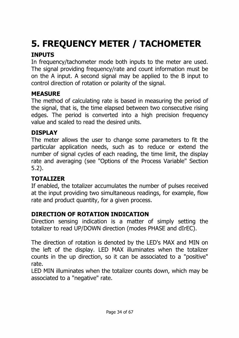
5. FREQUENCY METER / TACHOMETER INPUTS In frequency/tachometer mode both inputs to the meter are used. The signal providing frequency/rate and count information must be on the A input. A second signal may be applied to the B input to control direction of rotation or polarity of the signal.
MEASURE The method of calculating rate is based in measuring the period of the signal, that is, the time elapsed between two consecutive rising edges. The period is converted into a high precision frequency value and scaled to read the desired units.
DISPLAY The meter allows the user to change some parameters to fit the particular application needs, such as to reduce or extend the number of signal cycles of each reading, the time limit, the display rate and averaging (see "Options of the Process Variable" Section 5.2).
TOTALIZER If enabled, the totalizer accumulates the number of pulses received at the input providing two simultaneous readings, for example, flow rate and product quantity, for a given process. DIRECTION OF ROTATION INDICATION Direction sensing indication is a matter of simply setting the totalizer to read UP/DOWN direction (modes PHASE and dIrEC). The direction of rotation is denoted by the LED's MAX and MIN on the left of the display. LED MAX illuminates when the totalizer counts in the up direction, so it can be associated to a "positive" rate. LED MIN illuminates when the totalizer counts down, which may be associated to a "negative" rate.

Page 35 of 67
A change in the polarity of rate is recognized when the meter receives at least two consecutive pulses in the opposite direction to one of the previous pulses. Programming diagram for MODE: FREQUENCY METER/ TACHOMETER MODE Mode selection the options are Count, CHron, FREC, and tACH
FREC SEE 5.1 Frequency meter mode
Note: the following options do not have a heading on the DM4500F display menu and are programmed in sequence
MODE
COUNT CHRON FREC TAC
DP
PrO
rPM
PPR
DP
PrO
rAtE
dirEC inVEr
InFreq
DP
Freq
DSP
DP DSP
PrO

Page 36 of 67
DP SEE 5.1.1 Decimal Point
MODE Mode selection the options are Count, CHron, FrEC, ,and tACH
TAC SEE 5.1.2 Tachometer mode
rPM SEE 5.1.2 Revolutions per minutes, select rpm or rate
Note: the following options do not have a heading on the DM4500F display menu and are programmed in sequence PPR SEE 5.1.2 Pulses per revolution, enter a value
DP SEE 5.1.2 Decimal Point for the displayed value
rAtE SEE 5.1.3 Rate, select rate or rpm
dirEC/inVEr SEE 5.1.3 Direct or inverted/reversed scaling
Note: the following options do not have a heading on the DM4500F display menu and are programmed in sequence InFreq SEE 5.1.3 Input Frequency, enter a value
DP Freq SEE 5.1.3 Decimal point for the input frequency
DSP (Value) SEE 5.1.3 Displayed value for given DPFreq enter a value
DP DSP SEE 5.1.3 Decimal point for the displayed value

Page 37 of 67
5.1. Frequency meter / Tachometer
CONFIGURATION
The different configurations allow measurement of almost any process quantity based in frequency calculation.
5.1.1. Frequency meter
To use this instrument as a frequency indicator, select directly the frequency meter input.
DECIMAL POINT
The only parameter to select in this input menu is the position of the decimal point, which can be 0, 1 or 2. The decimal point position determines the max. and min. frequencies visible on display: with two decimals, max. frequency will be 999.99 Hz and min. frequency 0.01 Hz; with one decimal, max. frequency will be 9999.9 Hz and min. frequency 0.1 Hz; and with no decimal, max. frequency is limited according to the selected options (see technical features in Section 10) and min. frequency will be 1 Hz.
5.1.2. Tachometer for RPM
In this configuration the meter reads rotational rate in revolutions per minute (RPM). The tachometer is configured by entering the number of pulses per revolution and the decimal point location. PPR (PULSES PER REVOLUTION) The PPR parameter is the actual number of pulses that a sensor connected to a wheel gives to the input of the meter in a rotation of the wheel. The method of measurement is based in calculating the time necessary for the system to produce a complete rotation of the

Page 38 of 67
wheel, therefore, by default, each reading extends over the programmed number of pulses.
DECIMAL POINT
The decimal point location, in combination with a suitable scale factor, allows the display reading be expressed into other units different from RPM if desired. 5.1.3. Tachometer Rate In this configuration the meter can be easily scaled to read direction, speed, flow or time directly in the desired units by entering only two parameters: Input Frequency and Desired Display.
DIRECT OR REVERSED INPUT SCALING
Direct scaling. The relationship between frequency and display is directly proportional, that is, the higher the frequency, the greater the display. This will be the mode to choose in most applications. I/P * Y = O/P * Y Reversed scaling. The relationship between frequency and display is reversed, that is, the higher the frequency, the lower the display. DISPLAY SETTINGS The scaling procedure consists of entering a display value corresponding to an input value. A straight line plotted from this point to zero (input=0, display=0) establishes a linear relationship between frequency and display. In Freq INPUT FREQUENCY For scaling purposes, the input frequency value can be programmed within all range of the display (the frequency limits are given in Section 10).

Page 39 of 67
DP Freq The input frequency can be programmed with 0, 1 or 2 decimal places. The decimal point position has value, for example, a frequency value of 200 Hz can be programmed as 200, 200.0 or 200.00 DSP DESIRED DISPLAY IN THIS PHASE ENTER THE DISPLAY VALUE CORRESPONDING TO THE PROGRAMMED INPUT FREQUENCY. DP DSP The decimal point can be located in any of the digits of the display to help reading the display in the desired units.
Page 40 of 67
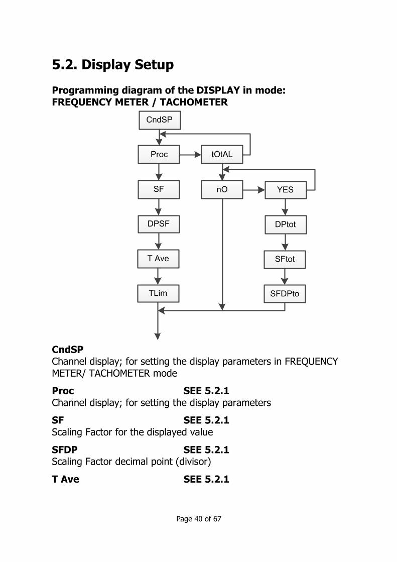
5.2. Display Setup Programming diagram of the DISPLAY in mode: FREQUENCY METER / TACHOMETER CndSP Channel display; for setting the display parameters in FREQUENCY METER/ TACHOMETER mode
Proc SEE 5.2.1 Channel display; for setting the display parameters
SF SEE 5.2.1 Scaling Factor for the displayed value
SFDP SEE 5.2.1 Scaling Factor decimal point (divisor)
T Ave SEE 5.2.1
CndSP
Proc tOtAL
SF
DPSF
T Ave
TLim
nO YES
DPtot
SFtot
SFDPto

Page 41 of 67
Time average
T Lim SEE 5.2.1 Time Limit tot SEE 3.5.3 Totalizer configuration in COUNT mode
no/YES SEE 3.5.4 Totalizer on or off
Note: the following options do not have a heading on the DM4500F display menu and are programmed in sequence
DPtot SEE 3.5.4 Decimal point
SFtot SEE 3.5.4 Scaling Factor for the totalizer
SF DPtot SEE 3.5.4 Scaling Factor decimal point (divisor) for the totalizer. 5.2.1. Options of the Process Variable
The menu ProC in the module CndSP contains various parameters for scaling and filtering the display -Scale Factor, Max and Min Times, Averaging-.
SCALE FACTOR
The scale factor is programmable between 0.0001 and 9999 and multiplicities or divides depending if it is higher or lower than 1. For example, it can be used to change display units, rpm instead of rps. TIME LIMIT The time limit, programmable from (1 to 99) seconds, is the amount of time that the meter waits for at least one pulse to be produced at the input before it is considered to be zero.

Page 42 of 67
The time limit is initialized at the reception of each input pulse. If no more pulses are detected before the time limit runs out, the display is forced to zero.
0.............. 0.............. 0.................... t limit 0............. ......
Display = 0
Decreasing the limit time makes the instrument respond more quickly to the zero condition when the system stops. Nevertheless, this reduction will also cut the lowest frequencies (for example: with a time limit of 10 s, it would be impossible to see frequencies under 0.1 Hz and with a time of 1 s, frequencies under 1 Hz).
AVERAGE TIME The average time is a time interval in seconds during which all readings calculated from the input are averaged.
The average time is programmable from (0 to 9.9) seconds. To disable this feature program 0.
When the display presents unwanted variations, due to an irregular input signal, programming the average time for a larger value may help stabilize the display.
The average time can be calculated for a desired number of readings knowing the signal frequency.
Example: With a setup of 0.1 s, if the input signal frequency is of approx. 10 Hz or less, the meter will only take one reading every 0.1 s making no average. With an input signal of approx. 100 Hz, the meter will be able to collect and average about 10 readings in 0.1 s. If the input signal is of approx. 1000 Hz, the display will read out the average of about 100 readings.

Page 43 of 67
RESET KEY The RESET key in Tachometer mode allows setting of the Max and Min memories to the current value.
To re set the MAX or MIN value to the current value, set the display to Max or Min as required and press the reset key.
To reset the totalizer it is necessary to recall the TOTAL variable on to the display by pressing the TOTAL key and then pressing RESET.
The RESET key will not operate if, in the program lock-out routine, its corresponding step is activated. 5.2.2 TOTAL, MAX and MIN Display In tachometer mode one push on the MAX/MIN key shows, when activated, the total value in the programmed colour; next push shows the peak value with the flashing led MAX indicator; next push shows the valley value with the flashing led MIN indicator; another push brings us back to current value indication.
6 – LOGIC FUNCTIONS
The rear connector CN3 provides 3 user programmable opto-coupled inputs that can be operated from external contacts or logic levels supplied by an electronic system. Three different functions may be added to the functions available from the front-panel keys. Each function is associated to one pin (PIN 2, PIN 3, PIN 4) and is activated by applying a falling edge or a low level pulse to the corresponding pin with respect to common (PIN 1). Each pin can be assigned one of the 8 functions listed on the following pages. • Factory configuration Functions associated to Connector CN3 in factory configuration are: OFFSET, RESET and RESET TOTALIZER.
Page 44 of 67
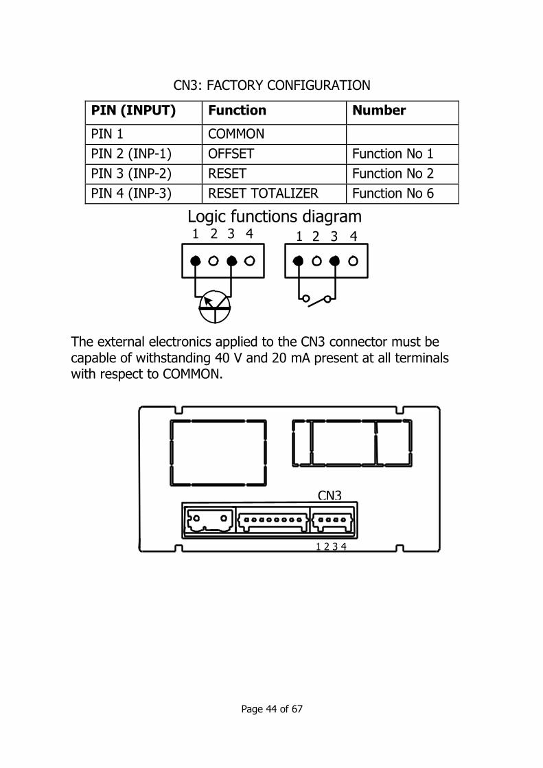
CN3: FACTORY CONFIGURATION
PIN (INPUT) Function Number
PIN 1 COMMON
PIN 2 (INP-1) OFFSET Function No 1
PIN 3 (INP-2) RESET Function No 2
PIN 4 (INP-3) RESET TOTALIZER Function No 6
The external electronics applied to the CN3 connector must be capable of withstanding 40 V and 20 mA present at all terminals with respect to COMMON.
CN3
1 2 3 4
Logic functions diagram11 2 3 4 2 3 4

Page 45 of 67
6.1 – Programmable functions table
• No: Number to select the function via software.
• Function: function name.
• Description: Function operation and characteristics. • Activation by :
Falling edge: the function is activated applying a falling edge to the corresponding pin with respect to common.
Low level: The function will remain activated as long as the corresponding pin is held at a low level.
6.1.1 – Logic functions diagram
Nº Function Description Activation by
0 Deactivated None None
1 OFFSET Adds the current display value to the offset memory
and sets the display to zero.
Falling edge
2 RESET Sets to zero the partial counter value (Proc)
Falling edge
3 MAX Displays the peak value. (MAX.) In Tachometer
mode.
Low level
4 MIN Displays the valley value.
(MIN) In Tachometer mode.
Low level
LoGIn
Inp -1
88
-Pro-
Inp -2
88
-Pro-
Inp -3
88
-Pro-

Page 46 of 67
6.2 – Program of functions 0 to 13 If the selected function is number 13 and any of the 2R, 4R, 4NPN,
4PNP options are installed, the user will have to choose one of the two or four setpoints available depending on the option, which will
be the value displayed by the instrument when this function is activated.
5 RESET
MAX/ MIN
Clears the peak or valley
readings (the one shown in the display).
Falling edge
6 RESET TOTALIZER
Sets the TOTALIZER to zero.
Low level
11 BRIGHTNESS Change the display brightness from Hi to Low
Low level
12 SETPOINT
VALUE
Displays the selected
setpoint value (see diagram next page)
Low level
13 False Setpoints
Simulates that the instrument has a four
setpoints option installed
Low level
12
SEt 1 SEt 2 SEt 3 SEt 4
-Pro- -Pro- -Pro- -Pro-
Page 47 of 67
7. PROGRAM PARAMETERS AND KEYBOARD FUNCTIONS LOCK-OUT
The instrument is supplied with all software programming parameters accessible to the operator's modifications. After
completing the software configuration, it is recommended to protect configuration settings by the following steps:
1. Lockout programming parameters to protect from accidental or unauthorized modifications.
2. Lockout keyboard functions to prevent accidental or
unauthorized modifications.
3. There are two modes to lock-out the program parameters;
total or selective. If some parts of the program have to be adjusted at a later time, make a selective lock. If you don’t
need to make changes, make a total lock.
4. Access to the lockout routine is allowed by entering a safety
code. At factory this code is set to 0000. We recommend changing this code, and writing it down and keeping it in a
safe place.
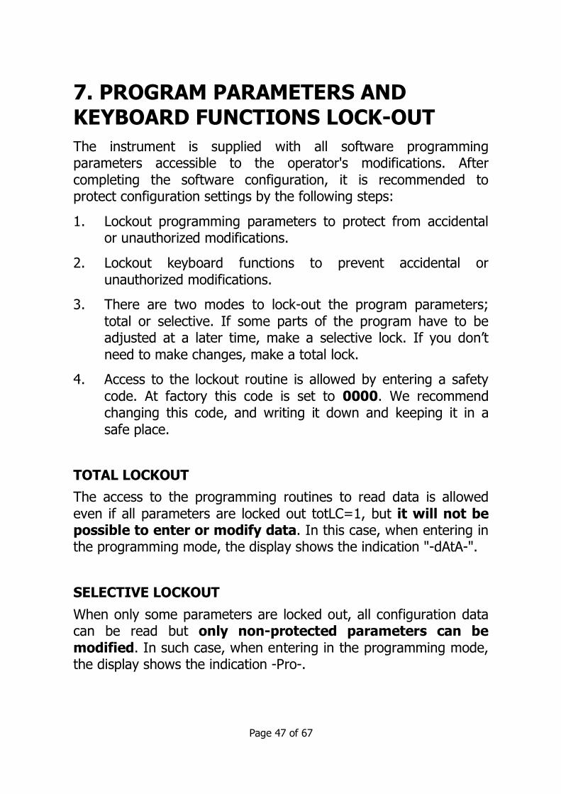
TOTAL LOCKOUT
The access to the programming routines to read data is allowed
even if all parameters are locked out totLC=1, but it will not be possible to enter or modify data. In this case, when entering in the programming mode, the display shows the indication "-dAtA-".
SELECTIVE LOCKOUT
When only some parameters are locked out, all configuration data can be read but only non-protected parameters can be modified. In such case, when entering in the programming mode, the display shows the indication -Pro-.

Page 48 of 67
Menus or submenus that can be locked out are: • Setpoint 1 configuration (SEt 1).
• Setpoint 2 configuration (SEt 2). • Setpoint 3 configuration (SEt 3).
• Setpoint 4 configuration (SEt 4). • Input configuration (InPut).
• Display (dsp) • Analog output configuration (Anout).
• Serial output configuration (rSout). • Logic inputs configuration (LoGIn).
• Lock-out of the reset key, not of the logic function.
• Offset value configuration • Direct access to the Setpoints value configuration (SEtVAL).
The first four and “SEtVAL” only appear if the corresponding option OPT4500/2R, OPT4500/4R, OPT4500/NPN or OPT4500/PNP have
been installed, “Anout” will appear when any of the OPT4500/mA or OPT4500/V options are installed, and “rSout” when any of the
OPT4500/2R or OPT4500/4R options are installed.
7.1 – Security menu diagram The following flow chart shows the security menu for the
programming lockout. Access to this menu is from the run mode by
pressing the key for 3 seconds, until the "CodE" indication appears. The instrument is shipped from the factory with the following
default code: "0000". When this code is entered, the “LISt” indication will appear, from which the parameters lockout can be
entered. Access to the "CHAnG" menu will allow the user to change the default code to one of their own choice. Changing the personal
code overwrites the original code. If an incorrect code is entered, the instrument will return
automatically to the run mode. Total lockout programming is achieved by changing “totLC" to 1,
changing it to 0, will lead to the selective lockout of the programming variables. Programming each one of the parameters

Page 49 of 67
to 1 will enable the lockout; if they are set to 0 programming will be accessible. Though the programming is locked out, it remains possible to view the current programming.
The "StorE" indication informs that the modifications have been stored correctly.
CodE Enter 4 digit pass code (default 0000) and press ENTER key the options are;
Note: the colour selection of the alarms is made in the setpoints menu
3s
ENTER
RUN
Code
8888
=Code RUN
CHANGLISt
(param. list)
totLC
(Total lock)
Page 50
CoLor
_ _ _ _Run
(Red)
Run
(Green)
Run
(Yellow)
8888
Pro
(Red)
Pro
(Green)
Pro
(Yellow)
StorE StorE

Page 50 of 67
LISt CHANG CoLor
totLC - - - - run
1 = total lockout
0 = selectable lockout
Select new 4 digit
passcode
Select display colour for run
mode
Pro
Select display colour
for programme mode
Page 49
=Code StorE
Set 1
Set 2
Set 3
Set 4
InPut
dSP
*
*
*
*
Anout
rSout
LoGIn
rESEt
oFFSEt
StVAL
*
*
*
Store
0 allows programming
1 locks access to programming * Only appear if the corresponding options have been installed
Page 51 of 67
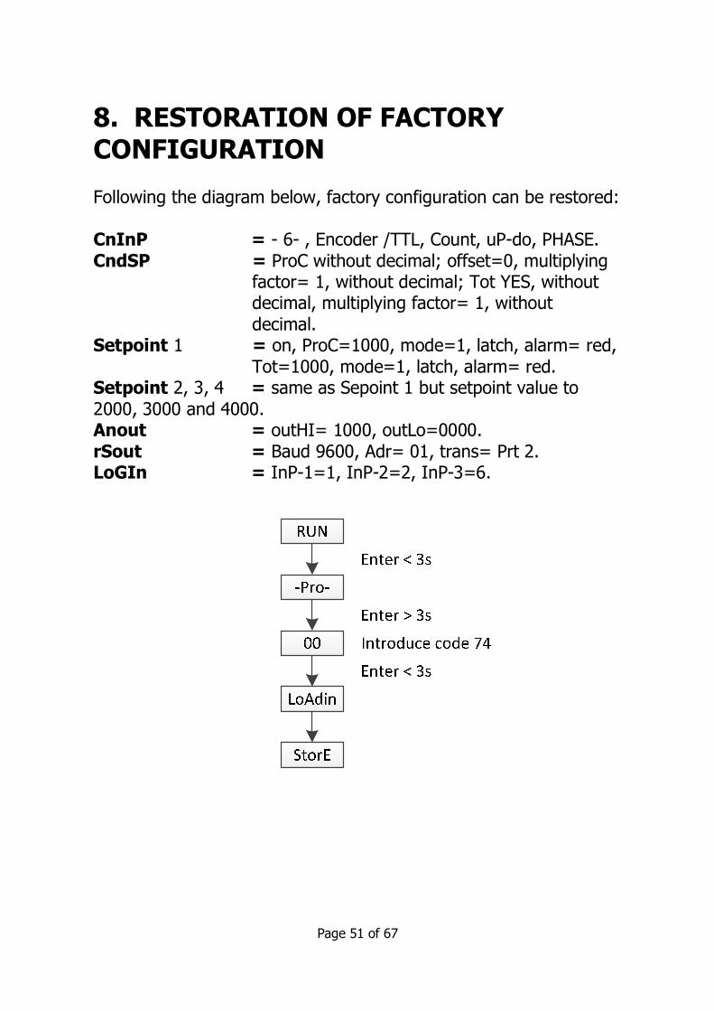
8. RESTORATION OF FACTORY CONFIGURATION Following the diagram below, factory configuration can be restored:
CnInP = - 6- , Encoder /TTL, Count, uP-do, PHASE. CndSP = ProC without decimal; offset=0, multiplying
factor= 1, without decimal; Tot YES, without decimal, multiplying factor= 1, without
decimal. Setpoint 1 = on, ProC=1000, mode=1, latch, alarm= red,
Tot=1000, mode=1, latch, alarm= red. Setpoint 2, 3, 4 = same as Sepoint 1 but setpoint value to
2000, 3000 and 4000. Anout = outHI= 1000, outLo=0000. rSout = Baud 9600, Adr= 01, trans= Prt 2. LoGIn = InP-1=1, InP-2=2, InP-3=6.

Page 52 of 67
9. OUTPUT OPTIONS
The following output options are available for control or
communication:
Communication options
OPT4500/485 Serial RS485
Refer to the Communications Manual
Control options
OPT4500/mA Analog (4 to 20) mA OPT4500/V Analog (0 to 10) V
OPT4500/2RLY 2 Relays SPDT 8 A OPT4500/4RLY 4 Relays SPST 5 A
OPT4500/NPN 4 NPN outputs OPT4500/PNP 4 PNP outputs
All mentioned options are isolated with respect to input signal and power supply, each one activates its own programming modules
that provides complete software configuration. Additional capabilities of the unit with output options:
• Control and processing of limit values via ON/OFF logic outputs (2 relays, 4 relays, 4 NPN outputs or 4 PNP outputs) or proportional output (4 to 20) mA, (0 to 10) V.
• Communication, data transmission and remote programming via serial interface.
The OPT4500/RLY, NPN, PNP options are alternatives and only one
of them can be used.
The OPT4500/mA and OPT4500/V options are alternatives and only one can be used.
Up to three output options can be present at the same time and
operate simultaneously:
• One analogue mA or V • One RS485
• One 2RLY or 4RLY or 4 NPN or 4 PNP

Page 53 of 67
9.1 –SETPOINTS OUTPUT 9.1.1 – Introduction An option of 2 or 4 SETPOINTS, programmable within the full
display range, can be incorporated to the unit thus providing alarm and control capabilities by means of individual LED indicators and
relay or transistor outputs. Programming of the set points can configure; setpoint value, time delay (in seconds), asymmetrical or
symmetrical hysteresis (in counts of display value) and selectable HI/LO trip action.
The setpoint option consists of an optional card that activates its own programming module, they are totally configurable by the user
and their access can be locked out via software.
These are the control output options available: OPT4500/2RLY: 2 Relays SPDT 8 A
OPT4500/4RLY: 4 Relays SPST 5 A OPT4500/NPN : 4 NPN outputs OPT4500/PNP : 4 PNP outputs

Page 54 of 67
9.1.2 – Wiring
OPT4500/2RLY 2 RELAY OPTION PIN 4 = NO2 PIN 1 = NO1
PIN 5 = COMM2 PIN 2 = COMM1 PIN 6 = NC2 PIN 3 = NC1
OPT4500/4RLY 4 RELAY OPTION PIN 4 = RL4 PIN 1 = RL1 PIN 5 = N/C PIN 2 = RL2
PIN 6 = COMM PIN 3 = RL3
OPT4500/NPN NPN OPTION
PIN 4 = OP4 PIN 1 = OP1 PIN 5 = N/C PIN 2 = OP2
PIN 6 = COMM PIN 3 = OP3
OTP4500PNP PNP OPTION PIN 4 = OP4 PIN 1 = OP1
PIN 5 = N/C PIN 2 = OP2 PIN 6 = COMM PIN 3 = OP3
NOTE: In case that the outputs are used to drive inductive loads, it is recommended to add an RC network between the coil terminals (preferably) or between the relay contacts to limit electromagnetic
effects.
1
2
3
4
5
6
CN6CN7
OPTO3
OPTO2
OPTO1OPTO4
COMMON

Page 55 of 67
9.1.3 – technical specifications
CHARACTERISTICS OPT4500 / 2RLY
OPT4500 / 4RLY
MAX.CURRENT
(RESISTIVE LOAD) 8 A 5 A
MAX.POWER 2000 VA /
192 W 1250 VA /
150 W
MAX.VOLTAGE 250 VAC / 150 VDC
277 VAC / 125 VDC
CONTACT RESISTANCE
Max. 3 mΩ Max. 30 mΩ
SWITCHING TIME Max. 10 ms Max. 10 ms
OPT4500/NPN and PNP
MAX VOLTAGE 50 VDC
MAX CURRENT 50 mA
LEAKAGE CURRENT 100 µA
(max.)
SWITCHING TIME 1 ms (max.)

Page 56 of 67
9.1.4 Setpoints menu diagram in mode frequency meter / Tachometer
The complete programming of one of the setpoints is showed here, it is valid for the rest of the setpoints.
SEtP
SEt 1
-on-
ProC
-Hi-
L 8888
-Lo-
88
ALArM
Red
-Hys-
888.88
No CH
-Pro-
-dLy-
ALArM
Green
ALArM
Amber
-off-
-Pro-
Set 2 Set 3 Set 4
They can only be programed if the
corresponding option has been installed
or if if the logic function No 13 has been
programmed.
* -Hys- cannot be programmed for
totalizer*
Total
H 8888

Page 57 of 67
9.1.5 – Direct access to the setpoints value programming If any of the options corresponding to the setpoints have been installed, it is possible to directly access the setpoints value without
the need to go through the programming menu just by pressing the
key in PROG mode, as showed in diagram below.
-Pro-
888.88
SEt 1
SEt 2
888.88
SEt 3
888.88
SEt 4
888.88
StorE
NOTE: The decimal point position will be determined by what has been programmed in the SCAL menu.
Page 58 of 67
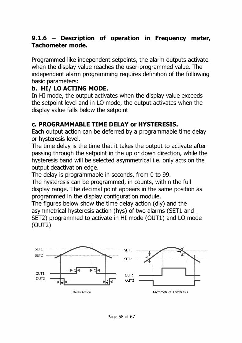
9.1.6 – Description of operation in Frequency meter, Tachometer mode. Programmed like independent setpoints, the alarm outputs activate when the display value reaches the user-programmed value. The
independent alarm programming requires definition of the following basic parameters:
b. HI/ LO ACTING MODE. In HI mode, the output activates when the display value exceeds the setpoint level and in LO mode, the output activates when the
display value falls below the setpoint c. PROGRAMMABLE TIME DELAY or HYSTERESIS. Each output action can be deferred by a programmable time delay
or hysteresis level. The time delay is the time that it takes the output to activate after
passing through the setpoint in the up or down direction, while the hysteresis band will be selected asymmetrical i.e. only acts on the
output deactivation edge. The delay is programmable in seconds, from 0 to 99.
The hysteresis can be programmed, in counts, within the full display range. The decimal point appears in the same position as
programmed in the display configuration module. The figures below show the time delay action (dly) and the
asymmetrical hysteresis action (hys) of two alarms (SET1 and SET2) programmed to activate in HI mode (OUT1) and LO mode (OUT2)
SET1
SET2
OUT1
OUT2
Delay Action
Page 59 of 67
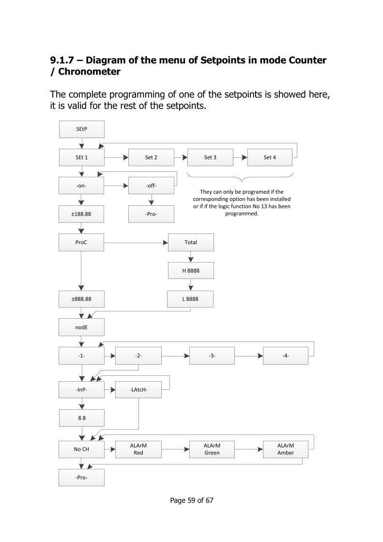
9.1.7 – Diagram of the menu of Setpoints in mode Counter / Chronometer
The complete programming of one of the setpoints is showed here, it is valid for the rest of the setpoints.
SEtP
SEt 1
-on-
±188.88
ProC Total
H 8888
L 8888
ALArM
Red
±888.88
nodE
No CH
-Pro-
ALArM
Green
ALArM
Amber
-off-
-Pro-
Set 2 Set 3 Set 4
They can only be programed if the
corresponding option has been installed
or if if the logic function No 13 has been
programmed.
-2--1- -3- -4-
-LAtcH--InP-
8.8

Page 60 of 67
9.1.8 - Description of Mode relays operating as Counter/ Chronometer Mode 1 No function. When configured as Process or total counter, enables the output (pulse or latch), whether it comes from a lower
or higher value than the programmed value.
Mode 2 Reset The value of the variable to which the setpoint is related is reset to
zero (or to the offset value) when enabling output. In this mode the output cannot be programmed as Latch.
Counter
Proc or
Total
0 or offset
Set 2
Set 1
OUT 1
Pulse 1 s
Mode 1
OUT 2
Pulse 2 s
Mode 2

Page 61 of 67
Mode 3 Stop All process, batch and total counters, where applicable, will stop during the output enabling time. Where the output is pulse, the
counters will restart once the enabling time is complete. If the output is latch, the counters will restart when the counter to which
the setpoint is related is reset.
Counter
Proc or
Total
0 or offset
Set 2
Set 1
OUT 1
Pulse 1 s
Mode 1
OUT 2
Pulse 4 s
Mode 3

Page 62 of 67
Mode 4 Clear On enabling the output, the previous setpoint output is disabled, if it had been enabled.
(The setpoint prior to 1 is 4)

Page 63 of 67
9.2 ANALOG OUTPUT OPT4500/mA AND V 9.2.1 – Introduction Two ranges of analogue output (0 to 10) V and (4 to 20) mA can be incorporated into the DM4500F, either the OPT4500/V option for
voltage output or the OPT4500/mA option for current output. Note: Both cards cannot be used simultaneously.
The outputs are isolated with respect to the signal input and the power supply. The optional board provides a two terminal
connector [(+) and (-)] that drives out a signal variation from (0 to 10) V or from (4 to 20) mA proportional to a user-defined display
range.
The instrument will detect the type of option that has been installed and will operate accordingly. The display values producing the full
scale output (OUT-HI and OUT-LO) are also introduced via front-panel buttons in the same programming module. The analogue
output then follows the display variation between the HI and LO programmed points.
The output signal can be set up for reverse action by programming the low display for the high output (OUT-HI) and the high display
for the low output (OUT-LO).

Page 64 of 67
9.2.2 – Technical specifications
CHARACTERISTICS OPT4500 / mA OUTPUT
OPT4500 / V OUTPUT
RESOLUTION 13 BITS 13 BITS
ACCURACY 0.1% F.S. ±1BIT 0.1% F.S. ±1BIT
RESPONSE TIME 50 ms 50 ms
THERMAL DRIFT 0.5 µA/ºC 0.2 mV/ºC
MAXIMUM LOAD <= 500 Ω >=10 KΩ
9.2.3 – Analog output menu diagram

Page 65 of 67
10. Technical Characteristics
INPUT SIGNAL
Frequency meter and Tachometer
Frequency Limits
MIN frequency .......................................................0.01 Hz MAX frequency without totalizer .............................. 19 KHz
MAX frequency with totalizer.................................. 9.9 KHz
Counter MAX count rate (*) Up or down without relays ...................................... 20 KHz Up or down with relays........................................... 15 KHz
Bidirectionnal Phase or Direc without relays ............. 20 KHz Bidirectionnal phase or Direc with relays.................. 15 KHz
Bidirectionnal Indep without relays.......................... 20 KHz Bidirectionnal Indep with relays............................... 15 KHz
EXCITATION ................................. 8 V/24 V DC @ 30 mA 18 Vdc (not stabilized) @ 100 mA
Contact closure FILTER Fc with duty cycle 50% ............................................ 20 Hz
Fc with duty cycle 30% ............................................ 10 Hz
INPUTS (2 CHANNELS)
MAGNETIC PICKUP
Sensitivity ........................ Vin (AC) > 60 mVpp @ F < 1kHz >120 mVpp @ F >1 kHz

Page 66 of 67
NAMUR Rc ........................................................ 3k3 (incorporated) Ion.................................................................. < 1 mA DC
Ioff.................................................................. > 3 mA DC
TTL/24V DC (encoder) Logic levels ........................."0" < 2.4 V DC, "1" > 2.6 V DC
NPN or PNP
Rc ........................................................ 3K3 (incorporated) Logic levels ........................."0" < 2.4 V DC, "1" > 2.6 V DC
CONTACT CLOSURE
Vc ............................................................................... 5 V Rc ............................................................................ 3.9 K Fc (activated automatically) ...................................... 20 Hz
HIGH VOLTAGE INPUT (1 CHANNEL)
Voltage limits ........................................... (10 to 300) V AC
COUNTER IN CHRONOMETER MEMORY Non-volatile E2PROM retains all programming data and count value
when power is removed or interrupted.
DISPLAY Type......................... 5 programmable tricolor 14 mm digits
LED's...................................8, control and status indication Decimal Point...............................................programmable Sign ........................................... automatic s/configuration
Positive overflow indication .........................................OvEr Negative overflow indication ......................................-OvEr
Counter display limits ................... Process -99999 to 99999 Totalizer ...................................... -99999999 to 99999999
Chronometer ranges............... 4, from 999.99 s to 9999.9 h Frequency ranges......... 0.01 Hz to 20 KHz/10 KHz(totalizer)

Page 67 of 67
Tachometer range ..0 to 99999(rpm), programmable (rate)
Scale factor Counter .................. programmable from 0.0001 to 99999
Freq/Tach............... programmable from 0.0001 to 99999
Display update rate Counter ................................................................. 100 ms
Chronometer.......................................................... 100 ms Frequency/Tachometer...............programmable 0.1 to 9.9 s
POWER DM4500/S1....................(85 to 265) VAC, (100 to 300) VDC
DM4500/S2...................... (22 to 53) VAC, (10.5 to 70) VDC
Consumption....................5 W (without options), 10 W max
ACCURACY Frequency/Tachometer......................................... 0.005 %
Chronometer.......................................................... 0.01 % Temperature coefficient................................... 0.005 %/°C
Warm up time.................................................... 5 minutes
AMBIENT Indoor use Operating temp............................................ (-10 to 60) °C Storage temperature .................................... (-25 to 85) °C Relative humidity (non condensing)........... < 95 % at 40 °C
Max altitude...........................................................2000 m
MECHANICAL Dimensions ............................ (96x48x60) mm (DIN 43700)
Panel cut out ..................................................(92x45) mm Weight 200 g
Case material ............................. Polycarbonate (UL 94 V-0) Sealed front panel ...................................................... IP65