Action Instruments - Product Handbook
404
-
Upload
khangminh22 -
Category
Documents
-
view
0 -
download
0
Transcript of Action Instruments - Product Handbook

Technical Support: 703-669-1318 Order Entry: 703-669-1305
For over 35 years Eurotherm has built an international reputationfor developing premium quality “fit for purpose” products andsolutions. The Eurotherm brands (Action Instruments, Barber-Colman, Chessell, Continental and Eurotherm) have long beenrecognized as the leaders in the industrial automation market.
Action Instruments provides the signal conditioning industry thehighest quality, most innovative solutions to remote signal condi-tioning and isolation applications. Action defined the standard foraccuracy and reliability and our focus on technological innovationcontinues to raise that standard. The people behind the ActionInstruments brand are devoted to understanding your needs andovercoming obstacles to the collection and transmission of indus-trial automation process signals.
Easy Solutions to Tough ProblemsEvery Action product is designed for easy installation, operationand maintenance. Whether you are amplifying or splitting signals,conditioning sensor outputs, isolating grounding problems, oradding more drive to current loops, Action’s complete productselection provides simple, convenient solutions to any analogsignal conditioning need.
High Performance and Proven ReliabilityReliable signal processing under harsh conditions. That’s whatAction’s products deliver. Nearly three decades of proven successcan assure you of our adherence to the highest quality standardsand the best in manufacturing techniques.
Real World RuggednessAction products are in tune with the industrial environment - thereal world of hard-hats, forklifts, and EMI/RFI - they are ruggedizedto survive the extremes of vibration, shock, temperature andhumidity that are common to the manufacturing arena.
Action’s Personal Commitment to Your SuccessWe know how tough it is on the plant floor and we realize thatevery application has different requirements. That’s why Action’ssolutions are tailored to your problems.
Best Engineering Support in the IndustryExperienced, knowledgeable and friendly engineers are availablethroughout the world to answer your questions.
Think Reliable, Think Smart, Think ActionOur goal is to be your exclusive supplier for industrial measure-ment and control products. What can we offer you? Plenty.
Eurotherm: a company that understandssignal conditioning and isolating.
IsolationA ground loop can occur if more than one groundconnection is made to a single control signal. Becausegrounds are seldom at the same potential, an un-wanted current will be generated and interfere withthe control signal. Signal isolators break the ground
loop current path and maintain the integrity of the measurement.
Signal ConversionIndustrial applications use a wide array of sensors tomeasure temperature, flow, length, speed, frequency,etc. These signals may then need to be converted intoa form usable by the instrumentation to which they areconnected. Any sensor signal (thermocouple, RTD, DC
voltage, DC current, AC voltage, frequency, resistance, etc.) can beconverted to any standard process signal.
Noise FilteringIsolators incorporate low pass filters that eliminatehigh frequency EMI/RFI and unwanted signals frompower lines, generators and motors.
LinearizationMany sensors output a signal that is not linearlyrelated to the engineering value being measured. Forexample, a thermocouple used to measure tempera-ture has a nonlinear millivolt output. A thermo-couple input signal isolator translates this to a stan-
dard, robust linear signal such as 4 to 20 mA.
Limit AlarmsLimit alarm units take in a process signal and compareit to one or more setpoints. They then provide anoutput signal, usually a relay contact, when the signalcrosses the setpoint.
MathIsolators that can perform addition, subtraction, mul-tiplication, division, square root, and averaging.
w w w . e u r o t h e r m . c o m / a c t i o n i o
What do Action Products Do?

Technical Support: 703-669-1318 Order Entry: 703-669-1305
Signal conditioners are electronic instruments used in factory ormachine automation. They can amplify, convert, boost, trans-form, buffer, filter, alarm and isolate process control signals.There seems to be no limit to the variety of things controlengineers want to do with control signals. Signal conditioners areknown by many names: converters, transducers, isolators, trans-mitters, and black boxes. Conventionally, most signal conditionersand isolators fall into two categories based on the number of wiresrequired for power and signal.
Four-wire TransmittersA four-wire transmitter has two wires for power and two wires forthe signal output. A four-wire transmitter can be either AC or DCpowered. Four-wire transmitters provide a powered output,either a voltage signal (e.g., 0-10V, 1-5V); a current signal (e.g., 4-20mA, 10-50mA); or in some cases a relay (e.g., solid state orcontact closure). Four-wire transmitters require a power supply- they do not use power from the input or output signal lines. Thepower supply allows four-wire transmitters to power their outputsignal. Because of this, they are often used to boost signal strengthfor retransmission.
w w w . e u r o t h e r m . c o m / a c t i o n i o
What is Signal Conditioning?
of a four-wire transmitter. It isimportant to note that two-wiretransmitters can be isolated or non-isolated. Many low cost two-wiretransmitters are not isolated, whichmakes it important to ensure thatthe input sensor is not grounded.All of Action’s two-wire transmittersare fully isolated. Members of thisgroup include the TransPak seriesand most of the Q5xx products.
Limit AlarmsLimit alarms are considered a four-wire transmitter since theyhave two wires for power and at least two wires for the relay signaloutput. Limit alarms are similar to a thermostat. On yourthermostat at home you may have the temperature set to a cozy72°F or 23°C. If the room temperature falls below that “setpoint”the heater will turn on. This is an example of on/off control. A limitalarm performs the same function. It has a setpoint which iscompared to a process signal. If the temperature gets too high,the limit alarm is used to alert an operator or shut down theprocess. Other applications include limit alarms that can also actas backup for a control system to perform a controlled shutdownprocess in order to prevent damage or other hazards.
Digital IndicatorsDigital indicators (or panel meters) will also accept direct sensorinputs. For the most part, AC powered indicators can be consid-ered a four-wire transmitter if they are configured with an analogor relay output. Indicators are most commonly used to displayprocess variables, however some have secondary functions, suchas a 4-20mA transmitter output, limit alarm, or relay contactclosure output.
Loop powered indicators such as Action’s V560 are an importanttype of digital indicator. These indicators are designed for fielduse and have operating characteristics similar to a two-wiretransmitter. They use a 4-20mA signal for power and therefore,as low power devices, are ideal for use in hazardous environments.
Two-wire TransmittersA two-wire transmitter is powered by the same two wires that carrythe output signal. A two-wire transmitter is always DC poweredand the output can only be a current signal, typically 4-20mA, orsometimes 10-50mA. The two-wire transmitter is considered afield device and requires very little power (milliwatts). It istherefore appropriate for hazardous (explosive) environments,such as chemical refineries and pharmaceutical plants. The low DCpower requirement, which ranges from 10-48VDC at currents aslow as 4mA, reduces the chances of an electrical spark causingignition of flammable vapors or dust. Additionally, two-wire
transmitters save on wire costs since both the signal and power areon the same wires. Locating a two-wire transmitter as far as 2000feet from the control room is possible and at half the wiring cost
Four-wire Transmitter
Two-wire Transmitter
WV408 Ultra SlimPak II
VisiPak, 1/8 DIN Rail Mount Indicator
Page I

Technical Support: 703-669-1318 Order Entry: 703-669-1305
Ultra SlimPak™ II Ultra SlimPak™ ActionPak™
InputType
DC VoltsDC Current
RTD
Thermocouple
Potentiometer
Strain Gauge
AC VoltsAC Current
Frequency
Accessories
LimitAlarms
SignalConditioners
LimitAlarms
SignalConditioners
LimitAlarms
SignalConditioners
AP1080AP1090
AP1280AP1290
AP1690
AP4380, AP4382AP4390, 4391, 4392
AP750x
AP4151
AP4351
AP4003
AP4081
AP6380
AP7380AP7510
WV108
WV118
WV128
WV168
WV408
WV418
WV428
WV438
WV448
WV468
WV478
G108
G118
G128
G168
G408
G418
G428
G438
G448
G468
G478
ConfigurationTools available
ConfigurationTools available
24VDCPower Supplies AP9046 AP9046H910
H915H910H915
WV905 WV905
OtherEthernet ConnectivityPC and Button Setup
Removable ConnectorsFixed Connectors
Most Complete Rangeof Legacy Models
Product Selection Guide
w w w . e u r o t h e r m . c o m / a c t i o n i o
Page II
Pages 1 - 50 Pages 139 - 186 Pages 225 - 280
Technical Support: 703-669-1318 Order Entry: 703-669-1305
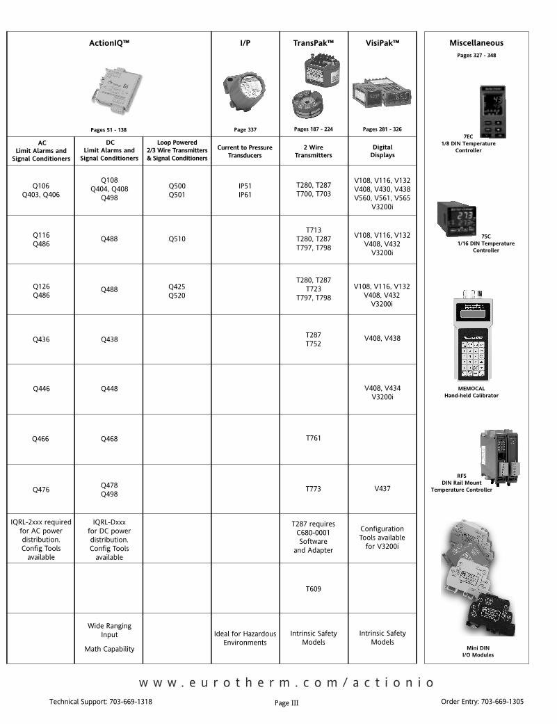
ActionIQ™ TransPak™ VisiPak™I/P
ACLimit Alarms and
Signal Conditioners
Loop Powered2/3 Wire Transmitters& Signal Conditioners
2 WireTransmitters
DigitalDisplays
DCLimit Alarms and
Signal Conditioners
Q106Q403, Q406
Q116Q486
Q126Q486
Q436
Q446
Q466
Q476
Q488
Q488
Q438
Q448
Q468
Q478Q498
Q510
Q425Q520
Q108Q404, Q408
Q498
Q500Q501
T280, T287T700, T703
T713T280, T287T797, T798
T280, T287T723
T797, T798
T287T752
T761
T773
IP51IP61
V108, V116, V132V408, V430, V438V560, V561, V565
V3200i
V108, V116, V132V408, V432
V3200i
V108, V116, V132V408, V432
V3200i
V408, V438
V408, V434V3200i
V437
IQRL-2xxx requiredfor AC powerdistribution.Config Tools
available
IQRL-Dxxxfor DC powerdistribution.Config Tools
available
T287 requiresC680-0001Software
and Adapter
T609
Current to PressureTransducers
Wide RangingInput
Math Capability
Ideal for HazardousEnvironments
Intrinsic SafetyModels
Intrinsic SafetyModels
Miscellaneous
ConfigurationTools available
for V3200i
w w w . e u r o t h e r m . c o m / a c t i o n i o
7EC1/8 DIN Temperature
Controller
7SC1/16 DIN Temperature
Controller
MEMOCALHand-held Calibrator
RFSDIN Rail Mount
Temperature Controller
Mini DINI/O Modules
Page III
Pages 51 - 138 Page 337 Pages 187 - 224 Pages 281 - 326
Pages 327 - 348
Technical Support: 703-669-1318 Order Entry: 703-669-1305
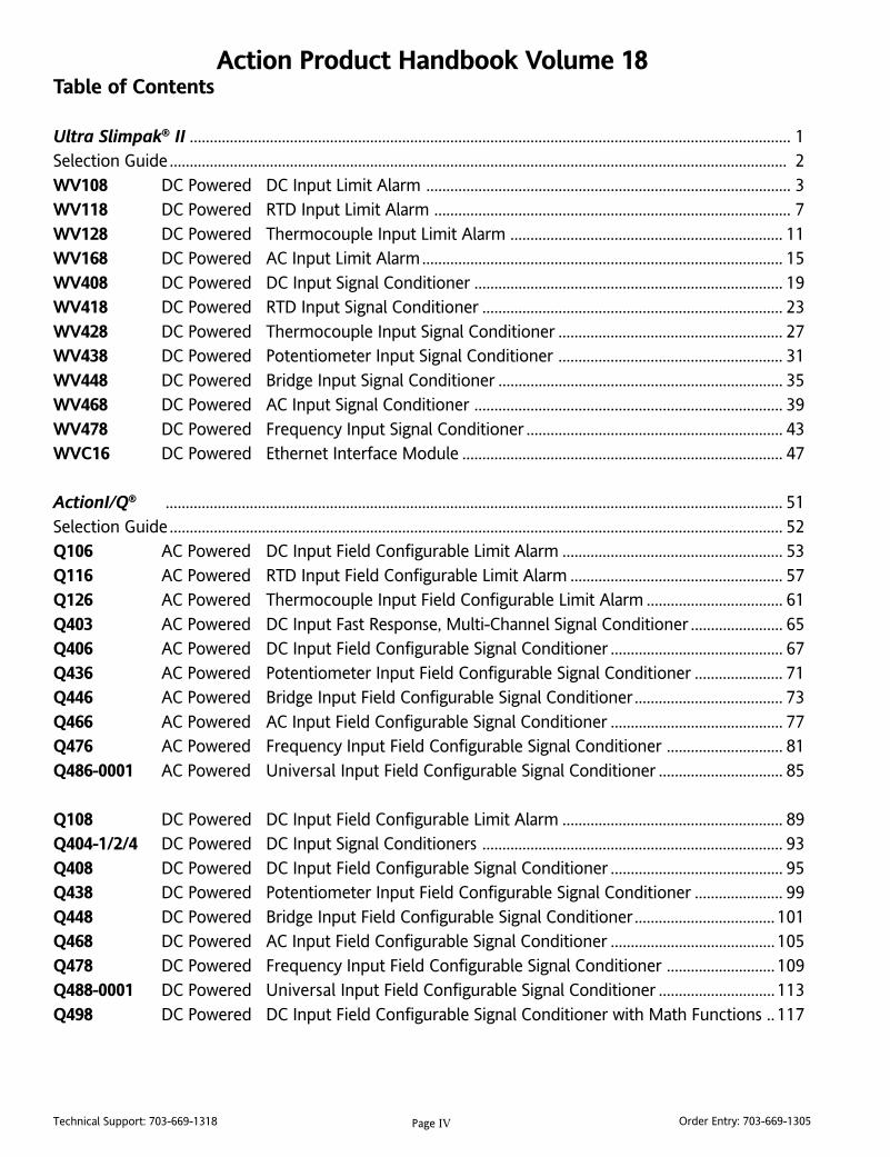
Action Product Handbook Volume 18Table of Contents
Ultra Slimpak® II ...................................................................................................................................................... 1Selection Guide.......................................................................................................................................................... 2WV108 DC Powered DC Input Limit Alarm ........................................................................................... 3WV118 DC Powered RTD Input Limit Alarm ......................................................................................... 7WV128 DC Powered Thermocouple Input Limit Alarm .................................................................... 11WV168 DC Powered AC Input Limit Alarm.......................................................................................... 15WV408 DC Powered DC Input Signal Conditioner ............................................................................. 19WV418 DC Powered RTD Input Signal Conditioner ........................................................................... 23WV428 DC Powered Thermocouple Input Signal Conditioner ........................................................ 27WV438 DC Powered Potentiometer Input Signal Conditioner ........................................................ 31WV448 DC Powered Bridge Input Signal Conditioner ....................................................................... 35WV468 DC Powered AC Input Signal Conditioner ............................................................................. 39WV478 DC Powered Frequency Input Signal Conditioner ................................................................ 43WVC16 DC Powered Ethernet Interface Module ................................................................................ 47
ActionI/Q® .......................................................................................................................................................... 51Selection Guide......................................................................................................................................................... 52Q106 AC Powered DC Input Field Configurable Limit Alarm ....................................................... 53Q116 AC Powered RTD Input Field Configurable Limit Alarm ..................................................... 57Q126 AC Powered Thermocouple Input Field Configurable Limit Alarm .................................. 61Q403 AC Powered DC Input Fast Response, Multi-Channel Signal Conditioner ....................... 65Q406 AC Powered DC Input Field Configurable Signal Conditioner ........................................... 67Q436 AC Powered Potentiometer Input Field Configurable Signal Conditioner ...................... 71Q446 AC Powered Bridge Input Field Configurable Signal Conditioner..................................... 73Q466 AC Powered AC Input Field Configurable Signal Conditioner ........................................... 77Q476 AC Powered Frequency Input Field Configurable Signal Conditioner ............................. 81Q486-0001 AC Powered Universal Input Field Configurable Signal Conditioner ............................... 85
Q108 DC Powered DC Input Field Configurable Limit Alarm ....................................................... 89Q404-1/2/4 DC Powered DC Input Signal Conditioners ........................................................................... 93Q408 DC Powered DC Input Field Configurable Signal Conditioner ........................................... 95Q438 DC Powered Potentiometer Input Field Configurable Signal Conditioner ...................... 99Q448 DC Powered Bridge Input Field Configurable Signal Conditioner................................... 101Q468 DC Powered AC Input Field Configurable Signal Conditioner ......................................... 105Q478 DC Powered Frequency Input Field Configurable Signal Conditioner ........................... 109Q488-0001 DC Powered Universal Input Field Configurable Signal Conditioner ............................. 113Q498 DC Powered DC Input Field Configurable Signal Conditioner with Math Functions .. 117
Page IV
Technical Support: 703-669-1318 Order Entry: 703-669-1305
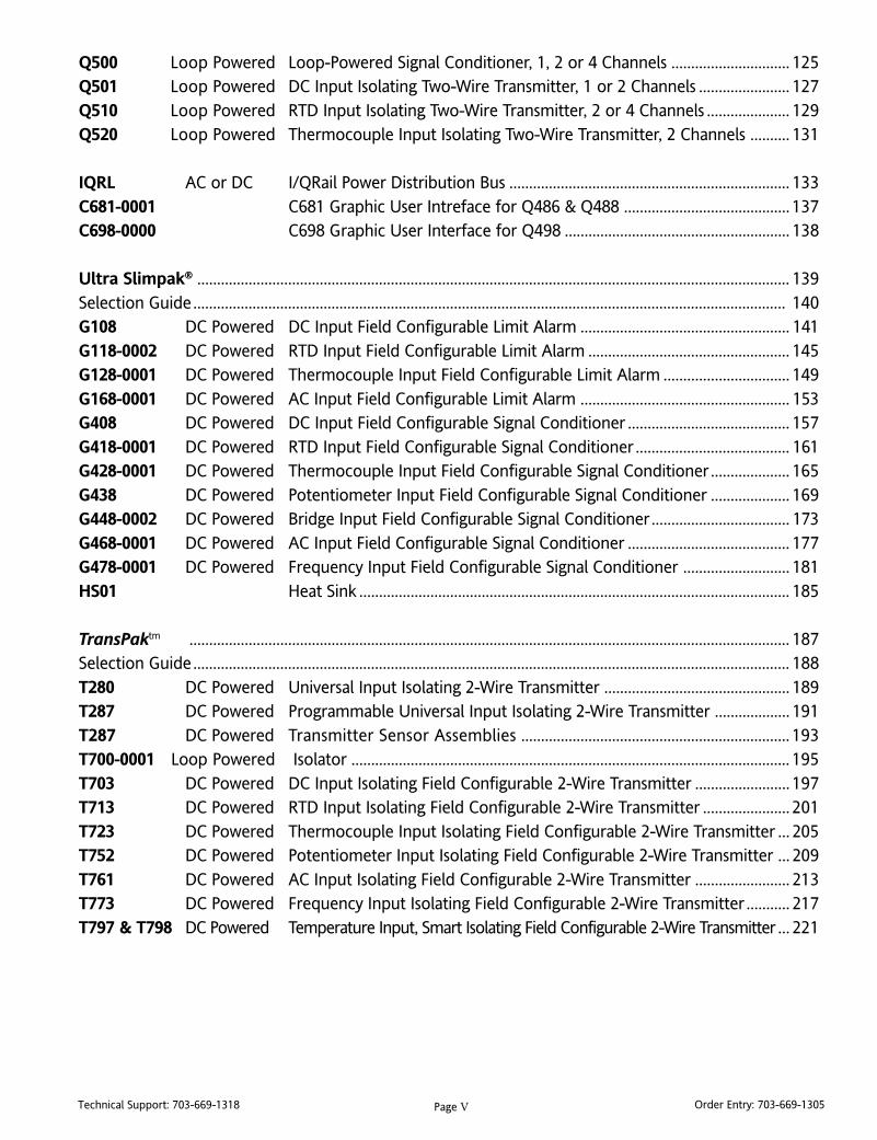
Q500 Loop Powered Loop-Powered Signal Conditioner, 1, 2 or 4 Channels .............................. 125Q501 Loop Powered DC Input Isolating Two-Wire Transmitter, 1 or 2 Channels ....................... 127Q510 Loop Powered RTD Input Isolating Two-Wire Transmitter, 2 or 4 Channels ..................... 129Q520 Loop Powered Thermocouple Input Isolating Two-Wire Transmitter, 2 Channels .......... 131
IQRL AC or DC I/QRail Power Distribution Bus ....................................................................... 133C681-0001 C681 Graphic User Intreface for Q486 & Q488 .......................................... 137C698-0000 C698 Graphic User Interface for Q498 ......................................................... 138
Ultra Slimpak® ...................................................................................................................................................... 139Selection Guide...................................................................................................................................................... 140G108 DC Powered DC Input Field Configurable Limit Alarm ..................................................... 141G118-0002 DC Powered RTD Input Field Configurable Limit Alarm ................................................... 145G128-0001 DC Powered Thermocouple Input Field Configurable Limit Alarm ................................ 149G168-0001 DC Powered AC Input Field Configurable Limit Alarm ..................................................... 153G408 DC Powered DC Input Field Configurable Signal Conditioner ......................................... 157G418-0001 DC Powered RTD Input Field Configurable Signal Conditioner ....................................... 161G428-0001 DC Powered Thermocouple Input Field Configurable Signal Conditioner.................... 165G438 DC Powered Potentiometer Input Field Configurable Signal Conditioner .................... 169G448-0002 DC Powered Bridge Input Field Configurable Signal Conditioner................................... 173G468-0001 DC Powered AC Input Field Configurable Signal Conditioner ......................................... 177G478-0001 DC Powered Frequency Input Field Configurable Signal Conditioner ........................... 181HS01 Heat Sink ............................................................................................................. 185
TransPaktm ........................................................................................................................................................ 187Selection Guide....................................................................................................................................................... 188T280 DC Powered Universal Input Isolating 2-Wire Transmitter ............................................... 189T287 DC Powered Programmable Universal Input Isolating 2-Wire Transmitter ................... 191T287 DC Powered Transmitter Sensor Assemblies .................................................................... 193T700-0001 Loop Powered Isolator ............................................................................................................... 195T703 DC Powered DC Input Isolating Field Configurable 2-Wire Transmitter ........................ 197T713 DC Powered RTD Input Isolating Field Configurable 2-Wire Transmitter ...................... 201T723 DC Powered Thermocouple Input Isolating Field Configurable 2-Wire Transmitter ... 205T752 DC Powered Potentiometer Input Isolating Field Configurable 2-Wire Transmitter ... 209T761 DC Powered AC Input Isolating Field Configurable 2-Wire Transmitter ........................ 213T773 DC Powered Frequency Input Isolating Field Configurable 2-Wire Transmitter ........... 217T797 & T798 DC Powered Temperature Input, Smart Isolating Field Configurable 2-Wire Transmitter ... 221
Page V

Technical Support: 703-669-1318 Order Entry: 703-669-1305
Action Pak® ........................................................................................................................................................ 225Selection Guide....................................................................................................................................................... 226AP1080/1090 AC Powered DC Input Field Configurable Limit Alarm ..................................................... 227AP1280/1290 AC Powered Thermocouple Input Field Configurable Limit Alarm ................................ 231AP1690 AC Powered AC Input Field Configurable Limit Alarm ..................................................... 235AP4003-0001 AC Powered Potentiometer Input Signal Conditioner ...................................................... 239AP4081 AC Powered Bridge Input Field Configurable Isolator ...................................................... 243AP4151 AC Powered RTD Input Signal Conditioner ......................................................................... 247AP4351 AC Powered Thermocouple Input Field Configurable Signal Conditioner.................... 251AP4380-200X AC Powered DC Input Isolator ............................................................................................... 255AP4382 AC Powered DC Input Bipolar Output Field Configurable Isolator ................................ 259AP439X AC Powered DC Input Dual Channel Isolators .................................................................... 263AP6380 AC Powered AC Input Field Configurable Isolator ............................................................. 267AP7380 AC Powered Frequency Input Field Configurable Signal Conditioner ........................... 271AP750X AC Powered DC to Frequency Converter ............................................................................ 275AP7510 AC Powered Frequency Divider/Scaler ................................................................................. 279
VisiPaktm ....................................................................................................................................................... 281Selection Guide....................................................................................................................................................... 282V3200i AC Powered Temperature/Process Indicator ...................................................................... 283V108 AC Powered Temperature/Process Indicator ...................................................................... 289V116/132 AC Powered Miniature Temperature/Process Indicator ................................................... 291V408 AC Powered Universal Temperature/Pressure/Process Indicator .................................... 293V430 AC Powered Analog Input, Rate Indicator/Totalizer/Batch Controller ........................... 297V432 AC Powered Temperature Input Digital Indicator .............................................................. 301V434 AC Powered Bridge/Strain Gauge Input Digital Indicator ................................................. 305V437 AC Powered Frequency/Pulse Input, Rate Indicator/Totalizer/Batch Controller ......... 309V438 AC Powered DC Input Digital Indicator ................................................................................ 313V560 Loop-Powered LCD Indicator .................................................................................................... 317V561 Loop-Powered Explosion Proof LCD Indicator ...................................................................... 321V565 Loop-Powered High Performance LCD Indicator .................................................................. 323
Miscellaneous Products7SC 1/16 DIN Temperature Controller ......................................................................................... 3277EC 1/8 DIN Temperature Controller ........................................................................................... 329RFS Compact DIN Rail Mount Controller .................................................................................... 331Mini DIN I/O DIN Rail Mount I/O Modules .................................................................................................. 335IP51/IP61 Current to Pressure Transducers ........................................................................................... 337MEMOCAL Hand-held Calibrator ................................................................................................................ 339WV905 24 Vdc DIN Rail Mount Power Supply ................................................................................. 343H910/H915 24 Vdc DIN Rail Mount Power Supplies .............................................................................. 345AP9046 24 Vdc Power Supply ................................................................................................................ 347
Page VI

Technical Support: 703-669-1318 Order Entry: 703-669-1305
Application NotesPump Control .......................................................................................................................................................... 349Pipeline Leak Detection ........................................................................................................................................ 349Sensitive Flow Measurement ............................................................................................................................... 350Tank Level (Unpressurized) .................................................................................................................................. 350Tank Level (Pressurized) ........................................................................................................................................ 351Motor Load.............................................................................................................................................................. 351Overheating Control .............................................................................................................................................. 352Power Usage Measurement ................................................................................................................................. 352Low Air Pressure Detection .................................................................................................................................. 353Multiple Temperature Zones................................................................................................................................ 353Safe Water Temperature ....................................................................................................................................... 354Combining Load Cells ............................................................................................................................................ 354Loop Isolation ........................................................................................................................................................ 355Tank Level Differential ........................................................................................................................................... 355Controlling Thermocouple Calibration Errors Caused by Thermal Shock .................................................. 356Displaying Flow ....................................................................................................................................................... 357Mass Flow ................................................................................................................................................................ 357Hazardous Environments ...................................................................................................................................... 358Water Level .............................................................................................................................................................. 358“Long Distance” 4-20mA....................................................................................................................................... 359Powering Multiple Transmitters ........................................................................................................................... 359Ramping a 4-20mA Output .................................................................................................................................. 360Remote Signal Conditioning for Industrial Sensors ......................................................................................... 360Summing Two Flows ........................................................................................................................................... 363PLC/DCS Loop Isolation ........................................................................................................................................ 363Loop Drive Capability ............................................................................................................................................ 364Differential Temperature - Measurement & Display ....................................................................................... 364Differential Temperature Control ....................................................................................................................... 365Debounce Circuit ................................................................................................................................................... 365Breaking a Current-Loop, without breaking it... ............................................................................................... 366High Current Sensing ............................................................................................................................................. 366
Articles by Arthur HollandWho is Arthur Holland? ....................................................................................................................................... 367A Look at 4-20mA Signals .................................................................................................................................... 367Signal Conditioners - the little hidden boxes that manipulate your process signals ............................................ 368Smart Field-Mounted Control Components - they obey your commands and tell you how they are doing...... 369Traps and Color Confusion in Thermocouple Wiring ..................................................................................... 371Thermocouples Part 1: Eight Established Types to Choose From. What Type do I Need? ................................. 373Thermocouples Part 2: Traps and Hazards and Why We Don’t Need Types J, K, T, E and S ............................... 374
Page VII

Technical Support: 703-669-1318 Order Entry: 703-669-1305
Dimensional DrawingsAction Pak (8-pin) Dimensions ............................................................................................................................ 375Action Pak (11-pin) Dimensions .......................................................................................................................... 376ActionI/Q Dimensions ........................................................................................................................................... 377TransPak Dimensions ............................................................................................................................................. 378Ultra Slimpak Dimensions .................................................................................................................................... 379Ultra Slimpak II Dimensions ................................................................................................................................. 379VisiPak V108, V116, V132 & V408 Dimensions ................................................................................................ 380VisiPak V43X & V561 Dimensions ....................................................................................................................... 381VisiPak V560 & V565 Dimensions ....................................................................................................................... 382
Agency ListingsAction Agency Approvals ..................................................................................................................................... 383
Page VIII
Page 1Technical Support: 703-669-1318 Order Entry: 703-669-1305
Ultra Slim
pak
® II
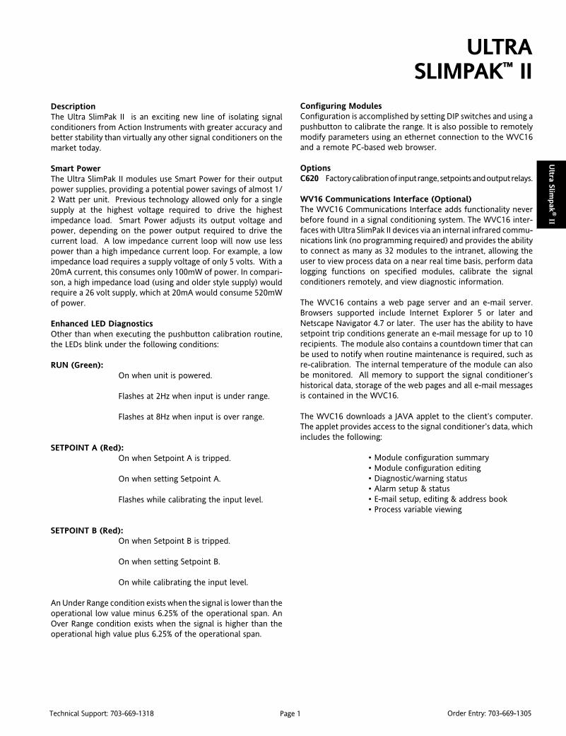
DescriptionThe Ultra SlimPak II is an exciting new line of isolating signalconditioners from Action Instruments with greater accuracy andbetter stability than virtually any other signal conditioners on themarket today.
Smart PowerThe Ultra SlimPak II modules use Smart Power for their outputpower supplies, providing a potential power savings of almost 1/2 Watt per unit. Previous technology allowed only for a singlesupply at the highest voltage required to drive the highestimpedance load. Smart Power adjusts its output voltage andpower, depending on the power output required to drive thecurrent load. A low impedance current loop will now use lesspower than a high impedance current loop. For example, a lowimpedance load requires a supply voltage of only 5 volts. With a20mA current, this consumes only 100mW of power. In compari-son, a high impedance load (using and older style supply) wouldrequire a 26 volt supply, which at 20mA would consume 520mWof power.
Enhanced LED DiagnosticsOther than when executing the pushbutton calibration routine,the LEDs blink under the following conditions:
RUN (Green):On when unit is powered.
Flashes at 2Hz when input is under range.
Flashes at 8Hz when input is over range.
SETPOINT A (Red):On when Setpoint A is tripped.
On when setting Setpoint A.
Flashes while calibrating the input level.
SETPOINT B (Red):On when Setpoint B is tripped.
On when setting Setpoint B.
On while calibrating the input level.
An Under Range condition exists when the signal is lower than theoperational low value minus 6.25% of the operational span. AnOver Range condition exists when the signal is higher than theoperational high value plus 6.25% of the operational span.
ULTRASLIMPAK™ II
Configuring ModulesConfiguration is accomplished by setting DIP switches and using apushbutton to calibrate the range. It is also possible to remotelymodify parameters using an ethernet connection to the WVC16and a remote PC-based web browser.
OptionsC620 Factory calibration of input range, setpoints and output relays.
WV16 Communications Interface (Optional)The WVC16 Communications Interface adds functionality neverbefore found in a signal conditioning system. The WVC16 inter-faces with Ultra SlimPak II devices via an internal infrared commu-nications link (no programming required) and provides the abilityto connect as many as 32 modules to the intranet, allowing theuser to view process data on a near real time basis, perform datalogging functions on specified modules, calibrate the signalconditioners remotely, and view diagnostic information.
The WVC16 contains a web page server and an e-mail server.Browsers supported include Internet Explorer 5 or later andNetscape Navigator 4.7 or later. The user has the ability to havesetpoint trip conditions generate an e-mail message for up to 10recipients. The module also contains a countdown timer that canbe used to notify when routine maintenance is required, such asre-calibration. The internal temperature of the module can alsobe monitored. All memory to support the signal conditioner’shistorical data, storage of the web pages and all e-mail messagesis contained in the WVC16.
The WVC16 downloads a JAVA applet to the client’s computer.The applet provides access to the signal conditioner’s data, whichincludes the following:
• Module configuration summary• Module configuration editing• Diagnostic/warning status• Alarm setup & status• E-mail setup, editing & address book• Process variable viewing

Page 2Technical Support: 703-669-1318 Order Entry: 703-669-1305
Ult
ra S
lim
pak
® II
Ultra SlimPak™ II Selection Guide
tupnI noitacilppAlacipyT noitpircseD ledoM
tnerruCroegatloVCD)Am,A,Vm,V( )Am,A,Vm,V( )Am,A,Vm,V( )Am,A,Vm,V( )Am,A,Vm,V(
,noitalosi,gnilacstnerruC/egatloVevirdlangisdnanoitcuderesion
tupniCDelbarugifnocdleiFrotalosi
804VW
,timiltnerruc/rotomCDerusserpOL/IH,lortnocnoitisop/level
,gninrawdnamedrewop,mralalennahc-2,mralanoitazilatot
rotarapmoc
timiltupniCDelbarugifnocdleiFmrala
801VW
retemoitnetoP)smhOk001-0otpu,smhO001-0( )smhOk001-0otpu,smhO001-0( )smhOk001-0otpu,smhO001-0( )smhOk001-0otpu,smhO001-0( )smhOk001-0otpu,smhO001-0(
atad,gnirotinom,lortnoclevelknaTrosnesnoitisopecnatsiser,noitisiuqca
gninoitidnoc
retemoitnetopelbarugifnocdleiFrenoitidnoclangistupni
834VW
DTR)uC,iN,tPsepyT( )uC,iN,tPsepyT( )uC,iN,tPsepyT( )uC,iN,tPsepyT( )uC,iN,tPsepyT(
,gnirotinom,lortnocerutarepmeTnoitisiuqcaatad
tupniDTRelbarugifnocdleiFrotalosi
814VW
OL/IH,lortnocrelooc/retaeHrotom,mralaerutarepmet
rotinomerutarepmet
timiltupniDTRelbarugifnocdleiFmrala
811VW
elpuocomrehT)T,S,R,K,J,E,BsepyT( )T,S,R,K,J,E,BsepyT( )T,S,R,K,J,E,BsepyT( )T,S,R,K,J,E,BsepyT( )T,S,R,K,J,E,BsepyT(
,gnirotinom,lortnocerutarepmeTnoitisiuqcaatad
elpuocomrehtelbarugifnocdleiFrotalositupni
824VW
OL/IH,lortnocrelooc/retaeHrotom,mralaerutarepmet
rotinomerutarepmet
elpuocomrehtelbarugifnocdleiFmralatimiltupni
821VW
ycneuqerF)zHk01-0otzH2-0( )zHk01-0otzH2-0( )zHk01-0otzH2-0( )zHk01-0otzH2-0( )zHk01-0otzH2-0(
,gnirotinomrolortnocyticolev/wolFeslup,gnilacs,lortnocdeepsrotomgnizilatot,noitargetni,noitalumucca
elbarugifnocdleiFrotalositupniycneuqerf
874VW
eguaGniartS)V/Vm05,02,01,5,3,1,5.0( )V/Vm05,02,01,5,3,1,5.0( )V/Vm05,02,01,5,3,1,5.0( )V/Vm05,02,01,5,3,1,5.0( )V/Vm05,02,01,5,3,1,5.0(noitaticxEelbatsujdAV01ot1 noitaticxEelbatsujdAV01ot1 noitaticxEelbatsujdAV01ot1 noitaticxEelbatsujdAV01ot1 noitaticxEelbatsujdAV01ot1
sutatserusserp,lortnocerusserPllecdaol,thgiew,gnirotinom
noitisiuqcaataddnagninoitidnoc
elbarugifnocdleiFrotalositupniegdirb
844VW
tnerruCroegatloVCA)Am,A,Vm,V( )Am,A,Vm,V( )Am,A,Vm,V( )Am,A,Vm,V( )Am,A,Vm,V(
rewop,gnilacstnerruC/egatloVgnireffub,noitalosi,gnirotinom
elbarugifnocdleiFrotalositupniCA
864VW
rewopCA,timiltnerruc/rotomCArotinomsutats
elbarugifnocdleiFmralatimiltupniCA
861VW
CDtloV42seilppuSrewoP seilppuSrewoP seilppuSrewoP seilppuSrewoP seilppuSrewoP
otrewopCDV42ylppuSsrettimsnarteriw4dna3,2
Am005,CDV42 509VW
A0.1,CDV42 019H
A3.2,CDV42 519H

Page 3Technical Support: 703-669-1318 Order Entry: 703-669-1305
Ultra Slim
pak
® II
ULTRA SLIMPAK® IIWV108
DC Powered DC Input Limit Alarm
Provides Relay Contact Closuresat a Preset DC Input Level
Programmable HI or LO, Failsafe or Non-failsafe Improved Accuracy 24VDC Transducer Excitation Bussed Power with Plug-in Power Clips Removable Terminals for Easy Service
DescriptionThe Ultra SlimPak II is an exciting new line of isolating signalconditioners from Action Instruments with greater accuracy andbetter stability than virtually any other signal conditioners on themarket today.
The WV108 is a DC Voltage or Current Input Limit Alarm with dualsetpoints and two contact closure outputs. The input type andalarm functions are field configurable, offering maximum flexibil-ity. There are five input voltage ranges between ±20mV and±200V, and two current input ranges, ±10mA and ±100mA. Alarmsetpoints are fully adjustable throughout the entire range.
The WV108-2000 contains two standard non-latching SPDT relays.When power is removed, the relays revert to their non-poweredstate. The WV108-2001 contains two latching relays. Whateverposition the relays are in when power is removed is where they willremain when power is re-applied (a reset switch is provided toreset the relays after the alarm is no longer true). Both models areconfigurable as a single or dual setpoint alarm, with HI or LO trips.The WV108-2000 supports failsafe or non-failsafe operation. Infailsafe operation the relay coil is energized when the process isbelow the HI setpoint or above the LO setpoint (opposite for non-failsafe). In the failsafe mode, a power failure results in an alarmstate output.
OperationEach of the alarm setpoints has a respective HI or LO deadband.Red LEDs will illuminate indicating an alarm condition. The trip willreset only when the process falls below the HI deadband or risesabove the LO deadband. (The WV108-2001 requires pressing thereset switch in order to reset the relays after being tripped.) Thedeadband can be left at the minimum level (the factory default)or can be set to whatever level is desired.
OptionsC620 Factory calibration of input range, setpoints and output relays.
Enhanced LED DiagnosticsOther than when executing the pushbutton calibration routine,the LEDs blink under the following conditions:
RUN (Green):On when unit is powered.Flashes at 2Hz when input is under range.Flashes at 8Hz when input is over range.
SETPOINT A (Red):On when Setpoint A is tripped.On when setting Setpoint A.Flashes while calibrating the input level.
SETPOINT B (Red):On when Setpoint B is tripped.On when setting Setpoint B.On while calibrating the input level.
An Under Range condition exists when the signal is lower than theoperational low value minus 6.25% of the operational span. AnOver Range condition exists when the signal is higher than theoperational high value plus 6.25% of the operational span.
WV108-2000 (non-latching)
WV108-2001 (latching)
Touch Cal for Best Stability and Accuracy RoHS Compliant Adjustable Deadband LED Trip and Input Indicators Optional E-mail Notification of Alarms
Figure 1: Limit alarm operation and effect of deadband.

Page 4Technical Support: 703-669-1318 Order Entry: 703-669-1305
Ult
ra S
lim
pak
® II
Configuring ModulesUnless otherwise specified, the factory presets the Model WV108as follows:
Input: CurrentRange: ±100mA
Output: Dual, SPDTTrip: A: HI, B: LO
Failsafe: NoDeadband: A, B: minimum
Remote Cal: No
1. For other ranges, refer to the SWITCH SETTINGS table (seeFigure 4). Reconfigure switches S1 and S2 for the desired inputtype and range.
2. Set position 1 of S1 to ON if a WVC16 will be utilized and remotecalibration capability is desired.
3. Set position 2 and 3 of S1 to ON for a Hi trip setpoint or to OFFfor a Low trip setpoint.
4. Set position 4 of S1 to ON for failsafe operation (e.g. alarm tripsupon power failure) or OFF for non-failsafe operation (-2000 only).
It is also possible to remotely select the setpoints using an Ethernetconnection and the optional WVC16 WebView CommunicationsInterface module.
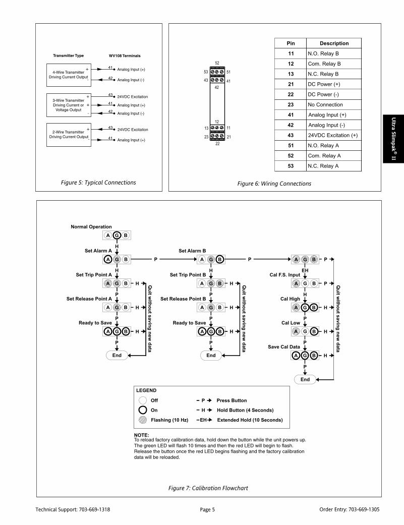
24VDC Transducer ExcitationThe 24VDC source, which is isolated from line power, is used fortransducer excitation. Typical connections for voltage and currentare shown in Figure 5.
Relay Protection and EMI SuppressionWhen switching inductive loads, maximum relay life and transientEMI suppression is achieved using external protection (see Figures2 & 3). Place all protection devices directly across the load andminimize all lead lengths. For AC inductive loads, place a properly-rated MOV across the load in parallel with a series RC snubber. Usea 0.01 to 0.1mF pulse film capacitor (foil polypropylene recom-mended) of sufficient voltage, and a 47ohm, 1/2W carbon resistor.For DC inductive loads, place a diode across the load (PRV > DCsupply, 1N4006 recommended) with (+) to cathode and (-) toanode (the RC snubber is an optional enhancement).
CalibrationSee the calibration flowchart in Figure 7. The complete calibrationprocedure is contained in the Installation & Calibration Instruc-tions document, which is available on our website(www.actionio.com). You can also obtain it by telephoning Actiontechnical support (703-669-1318).
Note that Custom Calibration (option C620) is available from thefactory (settings MUST be within the units specifications). For aC620, specify the following:
a) Input Type (mA, mV, V).
b) Setpoint A trip point and reset point.
c) Setpoint B trip point and reset point.
d) Failsafe (ON/OFF).
Note that if a deadband entry is not specified, the default settingof 0.25% will be used.
Figure 4: Switch Settings
noitcnuF 1S 2S
1 2 3 4 5 6 7 1 2
tupnIegatloV
Vm02-/+ - - - -
Vm002-/+ - - - -
V2-/+ - - - -
V02-/+ - - - -
V002-/+ - - - -
tupnItnerruC
Am01-/+ - - - -
Am001-/+ - - - -
elbanElaCetomeR - - - - - - - -
)iH(woL/iHA - - - - - - -
)iH(woL/iHB - - - - - - -
efasliaF - - - - - - - -
:yeK a/n=-;desolCroNO=1=
ON = Closed
1 2 3 4 5 6 7
ON = Closed
1 2
Remote Cal EnableRemote Cal Disable
OnOff
"A" Hi Trip"A" Low Trip
OnOff
"B" Hi Trip"B" Low Trip
OnOff
FailsafeNon-Failsafe
OnOff
Range: +/-100 ma(see Table)
Default Switch Settings
Figure 2: DC Inductive Loads Figure 3: AC Inductive Loads
Page 5Technical Support: 703-669-1318 Order Entry: 703-669-1305
Ultra Slim
pak
® II
Figure 6: Wiring ConnectionsFigure 5: Typical Connections
niP noitpircseD
11 ByaleR.O.N
21 ByaleR.moC
31 ByaleR.C.N
12 )+(rewoPCD
22 )-(rewoPCD
32 noitcennoCoN
14 )+(tupnIgolanA
24 )-(tupnIgolanA
34 )+(noitaticxECDV42
15 AyaleR.O.N
25 AyaleR.moC
35 AyaleR.C.N
Figure 7: Calibration Flowchart
Page 6Technical Support: 703-669-1318 Order Entry: 703-669-1305
Ult
ra S
lim
pak
® II
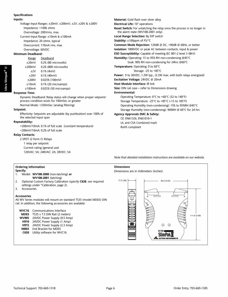
Ordering InformationSpecify:1. Model: WV108-2000 (non-latching) or
WV108-2001 (latching)2. Optional Custom Factory Calibration (specify C620, see required
settings under "Calibration, page 2).3. Accessories.
AccessoriesAll WV Series modules will mount on standard TS35 (model MD03) DINrail. In addition, the following accessories are available:
WVC16 Communications InterfaceMD03 TS35 x 7.5 DIN Rail (2 meters)
WV905 24VDC Power Supply (0.5 Amp)H910 24VDC Power Supply (1 Amp)H915 24VDC Power Supply (2.3 Amp)MB03 End Bracket for MD03C650 Utility software for WVC16
Specifications
Inputs:
Voltage Input Ranges: ±20mV, ±200mV, ±2V, ±20V & ±200V
Impedance: >100k ohms
Overvoltage: 200Vrms, max.
Current Input Range: ±10mA & ±100mA
Impedance: 20 ohms, typical
Overcurrent: 170mA rms, max
Overvoltage: 60VDC
Minimum Deadband:
Range Deadband
±20mV 0.2% (80 microvolts)
±200mV 0.2% (800 microvolts)
±2V 0.1% (4mV)
±20V 0.1% (40mV)
±200V 0.025% (100mV)
±10mA 0.1% (20 microamps)
±100mA 0.025% (50 microamps)
Response Time:
Dynamic Deadband: Relay status will change when proper setpoint/process condition exists for 100mSec or greater
Normal Mode: <250mSec (analog filtering)
Setpoint:
Effectivity: Setpoints are adjustable (by pushbutton) over 100% ofthe selected input span
Repeatability:
>200mV/10mA: 0.1% of full scale (constant temperature)
<200mV/10mA: 0.2% of full scale
Relay Contacts:
2 SPDT (2 form C) Relays
1 relay per setpoint
Current rating (general use)
120VAC: 5A; 240VAC: 2A; 28VDC: 5A
Material: Gold flash over silver alloy
Electrical Life: 105 operations
Reset Switch: For unlatching the relay once the process is no longer inthe alarm state (WV108-2001 only).
Local Range Selection: By DIP switch
Stability: ±100ppm of FS/°CCommon Mode Rejection: 120dB @ DC, >90dB @ 60Hz, or better
Isolation: 1800VDC or peak AC between contacts, input & power
ESD Susceptibility: Capable of meeting IEC 801-2 level 3 (8kV)
Humidity: Operating: 15 to 95% RH non-condensing @45°CSoak: 90% RH non-condensing for 24hrs @60°C
Temperature: Operating: 0 to 60°C Storage: -25 to +85°C
Power: 9 to 30VDC; 1.2W typ., (2.2W max. with both relays energized)
Excitation Voltage: 24VDC @ 20mA
Host Module Interface: IR link
Size: DIN rail case – refer to Dimensions drawing
Environmental:
Operating Temperature: 0°C to +60°C (32 to 140°F)
Storage Temperature: -25°C to +85°C (-13 to 185°F)
Operating Humidity (non-condensing): 15% to 95%RH @45°CStorage Humidity (non-condensing): 90%RH @ 60°C for 24 hrs
Agency Approvals EMC & Safety:
CE: EN61326, EN61010-1
UL and CSA Combined mark
RoHS compliant
Note that detailed installation instructions are available on our website.
Dimensions
Dimensions are in millimeters (inches)

Page 7Technical Support: 703-669-1318 Order Entry: 703-669-1305
Ultra Slim
pak
® II
DC Powered RTD Input Limit Alarm
Provides Relay Contact Closuresat a Preset Temperature Level
DescriptionThe Ultra SlimPak II is an exciting new line of isolating signalconditioners from Action Instruments with greater accuracy andbetter stability than virtually any other signal conditioners on themarket today.
The WV118 is an RTD Limit Alarm with dual setpoints and twocontact closure outputs. The input type and alarm functions arefield configurable, offering maximum flexibility. The WV118 sup-ports Pt100, in both 0.00385 and 0.00392 alphas, and Cu10 RTDs.All ranges allow the setpoints to be fully adjustable throughout theentire range.
The WV118-2000 contains two standard non-latching SPDT relays.When power is removed, the relays revert to their non-poweredstate. The WV118-2001 contains two latching relays. Whateverposition the relays are in when power is removed is where they willremain when power is re-applied (a reset switch is provided toreset the relays after the alarm is no longer true). Both models areconfigurable as a single or dual setpoint alarm, with HI or LO trips.The WV118-2000 supports failsafe or non-failsafe operation. Infailsafe operation the relay coil is energized when the process isbelow the HI setpoint or above the LO setpoint (opposite for non-failsafe). In the failsafe mode, a power failure results in an alarmstate output.
OperationEach of the alarm setpoints has a respective HI or LO deadband.Red LEDs will illuminate indicating an alarm condition. The trip willreset only when the process falls below the HI deadband or risesabove the LO deadband. (The WV118-2001 requires pressing thereset switch in order to reset the relay after being tripped.) Thedeadband can be left at the minimum level (the factory default)or can be set to whatever level is desired.
OptionsC620 Factory calibration of input range, setpoints, and output relays.
ULTRA SLIMPAK® IIWV118
Programmable HI or LO, Failsafe or Non-failsafe Improved Accuracy Adjustable Deadband Bussed Power with Plug-in Power Clips Removable Terminals for Easy Service
WV118-2000 (non-latching)
WV118-2001 (latching)
Touch Cal for Best Stability and Accuracy RoHS Compliant LED Trip and Input Indicators Optional E-mail Notification of Alarms Supports 2-Wire and 3-Wire RTDs
Enhanced DiagnosticsOther than when executing the pushbutton calibration routine,the LEDs blink under the following conditions:
RUN (Green):On when unit is powered.Flashes at 2Hz when input is under range.Flashes at 8Hz when input is over range.
SETPOINT A (Red):On when Setpoint A is tripped.On when setting Setpoint A.Flashes while calibrating the input level.
SETPOINT B (Red):On when Setpoint B is tripped.On when setting Setpoint B.On while calibrating the input level.
Figure 1: Limit alarm operation and effect of deadband.
An Under range condition exists when the signal is lower than theoperational low value by 5°C. An Over Range condition exists whenthe signal is higher than the operational high value by 5°C.
Page 8Technical Support: 703-669-1318 Order Entry: 703-669-1305
Ult
ra S
lim
pak
® II
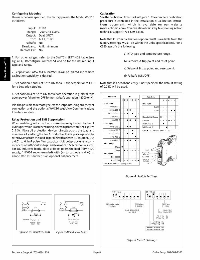
Configuring ModulesUnless otherwise specified, the factory presets the Model WV118as follows:
Input: Pt100Range: -200°C to 600°C
Output: Dual, SPDTTrip: A: HI, B: LO
Failsafe: NoDeadband: A, B: minimum
Remote Cal: No
1. For other ranges, refer to the SWITCH SETTINGS table (seeFigure 4). Reconfigure switches S1 and S2 for the desired inputtype and range.
2. Set position 1 of S2 to ON if a WVC16 will be utilized and remotecalibration capability is desired.
3. Set position 2 and 3 of S2 to ON for a Hi trip setpoint or to OFFfor a Low trip setpoint.
4. Set position 4 of S2 to ON for failsafe operation (e.g. alarm tripsupon power failure) or OFF for non-failsafe operation (-2000 only).
It is also possible to remotely select the setpoints using an Ethernetconnection and the optional WVC16 WebView CommunicationsInterface module.
Relay Protection and EMI SuppressionWhen switching inductive loads, maximum relay life and transientEMI suppression is achieved using external protection (see Figures2 & 3). Place all protection devices directly across the load andminimize all lead lengths. For AC inductive loads, place a properly-rated MOV across the load in parallel with a series RC snubber. Usea 0.01 to 0.1mF pulse film capacitor (foil polypropylene recom-mended) of sufficient voltage, and a 47ohm, 1/2W carbon resistor.For DC inductive loads, place a diode across the load (PRV > DCsupply, 1N4006 recommended) with (+) to cathode and (-) toanode (the RC snubber is an optional enhancement).
Figure 4: Switch Settings
CalibrationSee the calibration flowchart in Figure 6. The complete calibrationprocedure is contained in the Installation & Calibration Instruc-tions document, which is available on our website(www.actionio.com). You can also obtain it by telephoning Actiontechnical support (703-669-1318).
Note that Custom Calibration (option C620) is available from thefactory (settings MUST be within the units specifications). For aC620, specify the following:
a) RTD type and temperature range.
b) Setpoint A trip point and reset point.
c) Setpoint B trip point and reset point.
d) Failsafe (ON/OFF)
Note that if a deadband entry is not specified, the default settingof 0.25% will be used.
Figure 2: DC Inductive Loads Figure 3: AC Inductive Loads
noitcnuF 1S
1 2 3 4 5 6 7
tupnI001tP
C006ot002- - - -
C062ot002- - - -
C001-ot002- - - -
C001ot05- - - -
C003ot81- - - -
tupnI01uC
C062ot002- - - -
C001ot002- - - -
C001-ot002- - - -
C001ot05- - - -
C062ot81- - - -
gifnoCDTR
eriW3 - - - - -
eriW2 - - - - -
ahplADTR
58300.0tP - - - - - -
29300.0tP - - - - - -
:yeK a/n=-;desolCroNO=1=
noitcnuF 2S
1 2 3 4 5 6 7
epyTDTR
001tP - - - -
01uC - - - -
elbanElaCetomeR - - - - -
efasliaF - - - - -
)iH(woL/iHA - - - -
)iH(woL/iHB - - - -
:yeK a/n=-;desolCroNO=1=
Default Switch Settings
ON = Closed
1 2 3 4 5 6 7
RTD Config: 3-wire(see Table)
"A" Hi Trip"A" Low Trip
OnOff
"B" Hi Trip"B" Low Trip
OnOff
FailsafeNon-Failsafe
OnOff
Input: -200 to 600°C(see Table)
ON = Closed
1 2 3 4 5 6
RTD Alpha:0.00385
Remote Cal EnableRemote Cal Disable
OnOff
RTD Type:Pt100
Page 9Technical Support: 703-669-1318 Order Entry: 703-669-1305
Ultra Slim
pak
® II
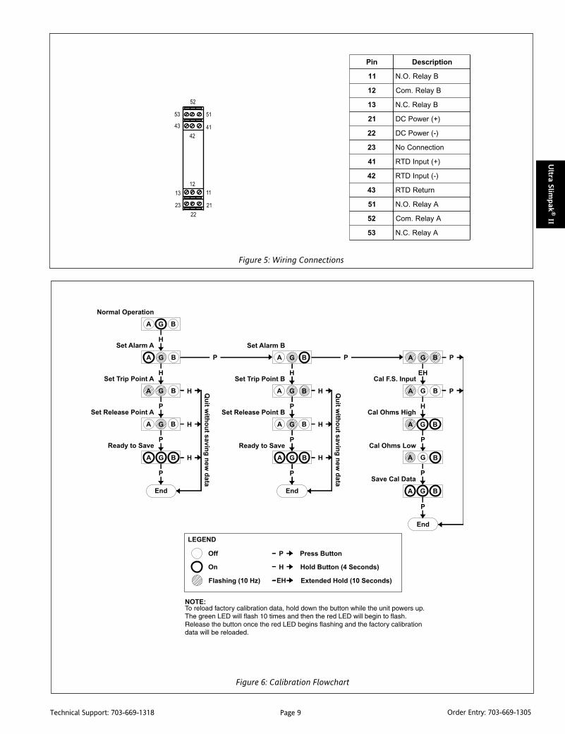
niP noitpircseD
11 ByaleR.O.N
21 ByaleR.moC
31 ByaleR.C.N
12 )+(rewoPCD
22 )-(rewoPCD
32 noitcennoCoN
14 )+(tupnIDTR
24 )-(tupnIDTR
34 nruteRDTR
15 AyaleR.O.N
25 AyaleR.moC
35 AyaleR.C.N
Figure 5: Wiring Connections
Figure 6: Calibration Flowchart

Page 10Technical Support: 703-669-1318 Order Entry: 703-669-1305
Ult
ra S
lim
pak
® II
SpecificationsInputs:
Sensor Types: Pt100 0.00385, Pt100 0.00392, Cu10Sensor Connection: 2-wire or 3-wireRanges:Pt100 RTDs:
°C °F alpha range no.-200 to 600 -32 to 1112 0.00385 1-200 to 260 -328 to 500 0.00385 2-200 to -100 -328 to -148 0.00385 3-50 to 100 -58 to 212 0.00385 4-18 to 300 0 to 572 0.00385 5
-200 to 600 -328 to 1112 0.00392 6-200 to 260 -328 to 500 0.00392 7-200 to -100 -328 to -148 0.00392 8-50 to 100 -58 to 122 0.00392 9-18 to 300 0 to 572 0.00392 10
Cu10 RTDs:°C °F range no.
-200 to 260 -328 to 500 11-200 to 100 -328 to 212 12-200 to -100 -328 to -148 13-50 to 100 -58 to 212 14-18 to 260 0 to 500 15
RTD Excitation:Pt100: 0.45mA, max.; Cu10: 5.0mA, max.
Lead Wire Resistance:40% of the base sensor resistance maximum or 100 ohms(whichever is less)
Lead Wire Effect:Changing from 0 ohm lead resistance (each lead) to maximumallowed lead resistance: Error <1% of largest span PT and Cu ranges;-200 to 600°C for Pt and –200 to 260°C for Cu.
Pushbutton Adjustment: Effective zero offset: >95%(Inputs >10mV): Effective span turn down: >95%
Local Range Selection: By DIP switch
Response Time:Dynamic Deadband: Relay status will change when proper setpoint/process condition exists for 100mSec.Normal Mode: <250mSec (analog filtering)
Setpoint Effectivity:Setpoints are adjustable (by pushbutton) over 100% of the selectedinput span
Repeatability: ±0.05% of FS, ±1°C (constant temp)Relay Contacts: 2 SPDT (2 form C) Relays, 1 relay per setpointCurrent rating (general use): 120VAC: 5A; 240VAC: 2A; 28VDC: 5AMaterial: Gold flash over silver alloyElectrical Life: 105 operations at rated loadReset Switch:
For unlatching the relay once the process is no longer in the alarmstate (WV118-2001 only).
Stability: ±100ppm of full scale/°C (±0.01%/°C)Common Mode Rejection: 120dB @ DC, >90dB @ 60Hz, or betterIsolation: >1800VDC or peak AC between input, output and power.ESD Susceptibility: Capable of meeting IEC 801-2 level 3 (8kV)Humidity (non-condensing):
Operating: 15 to 95% RH (@45°C)Soak: 90% RH for 24hrs (@60°C)
Temperature:Operating: 0 to 60°CStorage: -25 to +85°C
Power: 9 to 30VDC, 1.0W typical, 2.0W maxHost Module Interface: IR link, same specs as Phase 1 modulesSize: DIN rail case – refer to Dimensions drawingEnvironmental:
Operating Temperature: 0°C to +60°C (32 to 140°F)Storage Temperature: -25°C to +85°C (-13 to 185°F)Operating Humidity (non-condensing): 15% to 95%RH at 45°CStorage Humidity: 90%RH at 60°C for 24 hours
Agency Approvals (EMC & Safety):CE: EN61326, EN61010-1UL and CSA Combined mark
RoHS compliant
Note that detailed installation instructions are available on our website.
Ordering InformationSpecify:1. Model:
WV118-2000 (non-latching) orWV118-2001 (latching)
2. Optional Custom Factory Calibration (specify C620, see requiredsettings under "Calibration, page 2).
3. Accessories.
AccessoriesAll WV Series modules will mount on standard TS35 (model MD03)DIN rail. In addition, the following accessories are available:
WVC16 Communications InterfaceMD03 TS35 x 7.5 DIN Rail (2 meters)
WV905 24VDC Power Supply (0.5 Amp)H910 24VDC Power Supply (1 Amp)H915 24VDC Power Supply (2.3 Amp)MB03 End Bracket for MD03C650 Utility software for WVC16
DimensionsDimensions are in millimeters (inches)

Page 11Technical Support: 703-669-1318 Order Entry: 703-669-1305
Ultra Slim
pak
® II
DescriptionThe Ultra SlimPak II is an exciting new line of isolating signalconditioners from Action Instruments with greater accuracy andbetter stability than virtually any other signal conditioners on themarket today.
The WV128 is a Thermocouple Input Limit Alarm with dualsetpoints and two contact closure outputs. The input type andalarm functions are field configurable, offering maximum flexibil-ity. There are seven thermocouple types (B, E, J, K, R, S and T) fromwhich to choose. Alarm setpoints are fully adjustable throughoutthe entire range.
The WV128-2000 contains two standard non-latching SPDT relays.When power is removed, the relays revert to their non-poweredstate. The WV128-2001 contains two latching relays. Whateverposition the relays are in when power is removed is where they willremain when power is re-applied (a reset switch is provided toreset the relays after the alarm is no longer true). Both models areconfigurable as a single or dual setpoint alarm, with HI or LO trips.The WV128-2000 supports failsafe or non-failsafe operation. Infailsafe operation the relay coil is energized when the process isbelow the HI setpoint or above the LO setpoint (opposite for non-failsafe). In the failsafe mode, a power failure results in an alarmstate output.
OperationEach of the alarm setpoints has a respective HI or LO deadband.Red LEDs will illuminate indicating an alarm condition. The trip willreset only when the process falls below the HI deadband or risesabove the LO deadband. (The WV128-2001 requires pressing thereset switch in order to reset the relays after being tripped.) Thedeadband can be left at the minimum level (the factory default)or can be set to whatever level is desired.
OptionsC620 Factory cal of input range, setpoints and output relays.
ULTRA SLIMPAK® IIWV128
DC Powered T/C Input Limit Alarm
Provides Relay Contact Closures at aPreset Temperature Input Level
Programmable HI or LO, Failsafe or Non-failsafe Improved Accuracy Adjustable Deadband Bussed Power with Plug-in Power Clips Removable Terminals for Easy Service
WV128-2000 (non-latching)
WV128-2001 (latching)
Touch Cal for Best Stability and Accuracy RoHS Compliant LED Trip and Input Indicators Optional E-mail Notification of Alarms
Enhanced LED DiagnosticsOther than when executing the pushbutton calibration routine,the LEDs blink under the following conditions:
RUN (Green):On when unit is powered.Flashes at 2Hz when input is under range.Flashes at 8Hz when input is over range.
SETPOINT A (Red):On when Setpoint A is tripped.On when setting Setpoint A.Flashes while calibrating the input level.
SETPOINT B (Red):On when Setpoint B is tripped.On when setting Setpoint B.On while calibrating the input level.
An Under Range condition exists when the signal is lower than theoperational low value minus 6.25% of the operational span. AnOver Range condition exists when the signal is higher than theoperational high value plus 6.25% of the operational span.
Figure 1: Limit alarm operation and effect of deadband.
Page 12Technical Support: 703-669-1318 Order Entry: 703-669-1305
Ult
ra S
lim
pak
® II
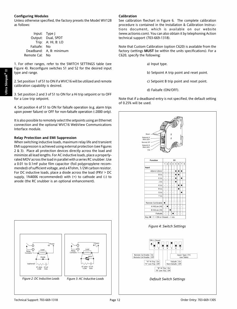
Configuring ModulesUnless otherwise specified, the factory presets the Model WV128as follows:
Input: Type JOutput: Dual, SPDT
Trip: A: HI, B: LOFailsafe: No
Deadband: A, B: minimumRemote Cal: No
1. For other ranges, refer to the SWITCH SETTINGS table (seeFigure 4). Reconfigure switches S1 and S2 for the desired inputtype and range.
2. Set position 1 of S1 to ON if a WVC16 will be utilized and remotecalibration capability is desired.
3. Set position 2 and 3 of S1 to ON for a Hi trip setpoint or to OFFfor a Low trip setpoint.
4. Set position 4 of S1 to ON for failsafe operation (e.g. alarm tripsupon power failure) or OFF for non-failsafe operation (-2000 only).
It is also possible to remotely select the setpoints using an Ethernetconnection and the optional WVC16 WebView CommunicationsInterface module.
Relay Protection and EMI SuppressionWhen switching inductive loads, maximum relay life and transientEMI suppression is achieved using external protection (see Figures2 & 3). Place all protection devices directly across the load andminimize all lead lengths. For AC inductive loads, place a properly-rated MOV across the load in parallel with a series RC snubber. Usea 0.01 to 0.1mF pulse film capacitor (foil polypropylene recom-mended) of sufficient voltage, and a 47ohm, 1/2W carbon resistor.For DC inductive loads, place a diode across the load (PRV > DCsupply, 1N4006 recommended) with (+) to cathode and (-) toanode (the RC snubber is an optional enhancement).
CalibrationSee calibration flwchart in Figure 6. The complete calibrationprocedure is contained in the Installation & Calibration Instruc-tions document, which is available on our website(www.actionio.com). You can also obtain it by telephoning Actiontechnical support (703-669-1318).
Note that Custom Calibration (option C620) is available from thefactory (settings MUST be within the units specifications). For aC620, specify the following:
a) Input type.
b) Setpoint A trip point and reset point.
c) Setpoint B trip point and reset point.
d) Failsafe (ON/OFF).
Note that if a deadband entry is not specified, the default settingof 0.25% will be used.
Figure 4: Switch Settings
noitcnuF 1S
1 2 3 4 5 6 7 8
tupnI
Vm02-/Vm08+ - - - -
c/tB - - - -
c/tE - - - -
c/tJ - - - -
c/tK - - - -
c/tR - - - -
c/tS - - - -
c/tT - - - -
elbanElaCetomeR - - - - - -
)iH(woL/iHA - - - - -
)iH(woL/iHB - - - - -
efasliaF - - - - - -
:yeK a/n=-;desolCroNO=1=
Figure 2: DC Inductive Loads Figure 3: AC Inductive Loads
ON = Closed
1 2 3 4 5 6 7
Remote Cal EnableRemote Cal Disable
OnOff
"A" Hi Trip"A" Low Trip
OnOff
"B" Hi Trip"B" Low Trip
OnOff
FailsafeNon-Failsafe
OnOff
Input: Type J T/C(see Table)
Default Switch Settings

Page 13Technical Support: 703-669-1318 Order Entry: 703-669-1305
Ultra Slim
pak
® II
niP noitpircseD
11 ByaleR.O.N
21 ByaleR.moC
31 ByaleR.C.N
12 )+(rewoPCD
22 )-(rewoPCD
32 noitcennoCoN
14 )+(tupnIC/T
24 )-(tupnIC/T
34 noitcennoCoN
15 AyaleR.O.N
25 AyaleR.moC
35 AyaleR.C.N
Figure 5: Wiring Connections
Figure 6: Calibration Flowchart

Page 14Technical Support: 703-669-1318 Order Entry: 703-669-1305
Ult
ra S
lim
pak
® II
Specifications
Inputs:
Thermocouples Supported: B, E, J, K, R, S, T
Ranges:
T/C °C °FB +75 to 1820 +167 to 3308
E -265 to 1000 -445 to 1832
J -210 to 760 -346 to 1400
K -265 to 1372 -445 to 2502
R -25 to 1760 -13 to 3200
S -25 to 1760 -13 to 3200
T -265 to 390 -445 to 734
Overvoltage: ±10V differential
Common Mode: 1800VDC (Input to Ground)
Limit Differential (deadband): 0.2% to 100% of span. Set byPushbutton Adjustment.
Response Time:
Dynamic Deadband: Relay status will change when proper setpoint/process condition exists for 100mSec.
Normal Mode: <250mSec (analog filtering)
Setpoint:
Effectivity: Setpoints are adjustable (by pushbutton) over 100% ofthe selected input span.
Repeatability: ±0.05% of FS, ±1°C (constant temp)
Relay Contacts:
2 SPDT (2 form C) Relays
1 relay per setpoint
Current rating (general use):
120VAC: 5A; 240VAC: 2A; 28VDC: 5A
Material: Gold flash over silver alloy
Electrical Life: 105 operations
Reset Switch:
For unlatching the relay once the process is no longer in the alarmstate. (WV128-2001 only)
Local Range Selection: By DIP switch
Stability: ±100ppm of FS/°CCommon Mode Rejection: 120dB @ DC, >90dB @ 60Hz, or better
Isolation: 1800VDC or peak AC between contacts, input & power.
ESD Susceptibility: Capable of meeting IEC 801-2 level 3 (8kV)
Power: 9 to 30VDC; 1.2W typ., (3.25W max both relays energized)
Host Module Interface: IR link
Wire Terminations: Screw terminations for 12-22 AWG
Size: DIN rail case – refer to Dimensions drawing
Environmental:
Operating Temperature: 0°C to +60°C (32 to 140°F)
Storage Temperature: -25°C to +85°C (-13 to 185°F)
Operating Humidity (non-condensing): 15% to 95% at 45°CStorge Humidity (non-condensing): 90% at 60°C for 24 hours
Agency Approvals (EMC & Safety):
CE: EN61326, EN61010-1
UL and CSA Combined mark
RoHS compliant
Note that detailed installation instructions are available on our website.
Ordering InformationSpecify:1. Model:
WV128-2000 (non-latching) orWV128-2001 (latching)
2. Optional Custom Factory Calibration (specify C620, see requiredsettings under "Calibration, page 2).
3. Accessories.
AccessoriesAll WV Series modules will mount on standard TS35 (model MD03)DIN rail. In addition, the following accessories are available:
WVC16 Communications InterfaceMD03 TS35 x 7.5 DIN Rail (2 meters)
WV905 24VDC Power Supply (0.5 Amp)H910 24VDC Power Supply (1 Amp)H915 24VDC Power Supply (2.3 Amp)MB03 End Bracket for MD03C650 Utility software for WVC16
DimensionsDimensions are in millimeters (inches)
Page 15Technical Support: 703-669-1318 Order Entry: 703-669-1305
Ultra Slim
pak
® II
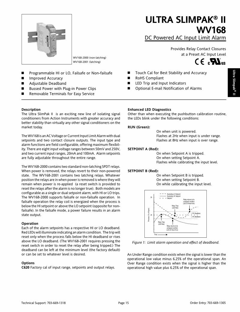
DescriptionThe Ultra SlimPak II is an exciting new line of isolating signalconditioners from Action Instruments with greater accuracy andbetter stability than virtually any other signal conditioners on themarket today.
The WV168 is an AC Voltage or Current Input Limit Alarm with dualsetpoints and two contact closure outputs. The input type andalarm functions are field configurable, offering maximum flexibil-ity. There are eight input voltage ranges between 50mV and 250V,and two current input ranges, 20mA and 100mA. Alarm setpointsare fully adjustable throughout the entire range.
The WV168-2000 contains two standard non-latching SPDT relays.When power is removed, the relays revert to their non-poweredstate. The WV168-2001 contains two latching relays. Whateverposition the relays are in when power is removed is where they willremain when power is re-applied (a reset switch is provided toreset the relays after the alarm is no longer true). Both models areconfigurable as a single or dual setpoint alarm, with HI or LO trips.The WV168-2000 supports failsafe or non-failsafe operation. Infailsafe operation the relay coil is energized when the process isbelow the HI setpoint or above the LO setpoint (opposite for non-failsafe). In the failsafe mode, a power failure results in an alarmstate output.
OperationEach of the alarm setpoints has a respective HI or LO deadband.Red LEDs will illuminate indicating an alarm condition. The trip willreset only when the process falls below the HI deadband or risesabove the LO deadband. (The WV168-2001 requires pressing thereset switch in order to reset the relay after being tripped.) Thedeadband can be left at the minimum level (the factory default)or can be set to whatever level is desired.
OptionsC620 Factory cal of input range, setpoints and output relays.
ULTRA SLIMPAK® IIWV168
DC Powered AC Input Limit Alarm
Provides Relay Contact Closuresat a Preset AC Input Level
Programmable HI or LO, Failsafe or Non-failsafe Improved Accuracy Adjustable Deadband Bussed Power with Plug-in Power Clips Removable Terminals for Easy Service
WV168-2000 (non-latching)
WV168-2001 (latching)
Touch Cal for Best Stability and Accuracy RoHS Compliant LED Trip and Input Indicators Optional E-mail Notification of Alarms
Figure 1: Limit alarm operation and effect of deadband.
Enhanced LED DiagnosticsOther than when executing the pushbutton calibration routine,the LEDs blink under the following conditions:
RUN (Green):On when unit is powered.Flashes at 2Hz when input is under range.Flashes at 8Hz when input is over range.
SETPOINT A (Red):On when Setpoint A is tripped.On when setting Setpoint A.Flashes while calibrating the input level.
SETPOINT B (Red):On when Setpoint B is tripped.On when setting Setpoint B.On while calibrating the input level.
An Under Range condition exists when the signal is lower than theoperational low value minus 6.25% of the operational span. AnOver Range condition exists when the signal is higher than theoperational high value plus 6.25% of the operational span.

Page 16Technical Support: 703-669-1318 Order Entry: 703-669-1305
Ult
ra S
lim
pak
® II
Configuring ModulesUnless otherwise specified, the factory presets the Model WV168as follows:
Input: mVACRange: 0-500mV
Output: Dual, SPDTTrip: A: HI, B: LO
Failsafe: NoDeadband: A, B: minimum
Failsafe: Off
1. For other ranges, refer to the SWITCH SETTINGS table.Reconfigure switches S1 and S2 for the desired input type and range.
2. Set position 1 of S1 to ON if a WVC16 will be utilized and remotecalibration capability is desired.
3. Set position 2 and 3 of S1 to ON for a Hi trip setpoint or to OFFfor a Low trip setpoint.
4. Set position 4 of S1 to ON for failsafe operation (e.g. alarm tripsupon power failure) or OFF for non-failsafe operation (-2000 only).
It is also possible to remotely select the setpoints using an Ethernetconnection and the optional WVC16 WebView CommunicationsInterface module.
Relay Protection and EMI SuppressionWhen switching inductive loads, maximum relay life and transientEMI suppression is achieved using external protection (see Figures2 & 3). Place all protection devices directly across the load andminimize all lead lengths. For AC inductive loads, place a properly-rated MOV across the load in parallel with a series RC snubber. Usea 0.01 to 0.1mF pulse film capacitor (foil polypropylene recom-mended) of sufficient voltage, and a 47ohm 1/2W carbon resistor.For DC inductive loads, place a diode across the load (PRV > DCsupply, 1N4006 recommended) with (+) to cathode and (-) toanode (the RC snubber is an optional enhancement).
CalibrationSee the calibration flowchart in Figure 6. The complete calibrationprocedure is contained in the Installation & Calibration Instruc-tions document, which is available on our website(www.actionio.com). You can also obtain it by telephoning Actiontechnical support (703-669-1318).
Note that Custom Calibration (option C620) is available from thefactory (settings MUST be within the units specifications). For aC620, specify the following:
a) Input type.
b) Setpoint A trip point and reset point.
c) Setpoint B trip point and reset point.
d) Failsafe (ON/OFF).
Note that if a deadband entry is not specified, the default settingof 0.25% will be used.
noitcnuF 1S 2S
1 2 3 4 5 6 7 8 1 4
tupnIegatloV
V052 - - - -
V051 - - - -
V05 - - - -
V02 - - - -
V5 - - - -
Vm005 - - - -
Vm051 - - - -
Vm05 - - - -
tupnItnerruC
Am02 - - - -
Am001 - - - -
elbanElaCetomeR - - - - - - - - -
)iH(woL/iHA - - - - - - - -
)iH(woL/iHB - - - - - - - -
efasliaF - - - - - - - - -
:yeK a/n=-;desolCroNO=1=
Figure 4: Switch Settings
Default Switch Settings
Figure 2: DC Inductive Loads Figure 3: AC Inductive Loads
ON = Closed
1 2 3 4 5 6 7
ON = Closed
1 4
Remote Cal EnableRemote Cal Disable
OnOff
"A" Hi Trip"A" Low Trip
OnOff
"B" Hi Trip"B" Low Trip
OnOff
FailsafeNon-Failsafe
OnOff
Range: 0 to 500 mV(see Table)
8

Page 383Technical Support: 703-669-1318 Order Entry: 703-669-1305
Agen
cy Appro
vals
Approval AgenciesCE Conformite Europeenne, European UnionCSA Canadian Standards Association, CanadaCUL Canadian Safety Approval from ULFM Factory Mutual Research Corporation, USANEC National Electronics Council, USANEMA National Electrical Manufacturer's Association, USAUL Underwriters Laboratories, USA
CE Mark (CE)CE mark approval for the Ultra SlimPak, the Ultra SlimPak II,VisiPak and ActionI/Q are defined by European Norms(EN#50081-1 and EN# 50082-2). Consult Action TechnicalSupport for more details.
CSA CertificationThe CSA certification of the Action Pak series, Ultra SlimPak,Ultra SlimPak II and ActionI/Q complies with CSA standardC22.2 No. 0-M1982: General Requirements/Canadian ElectricalCode, Part II, and No. 0-M1983: Process Control Equipment/Industrial Products, Certificate No. LR 42272. The only ActionPaks to qualify are those with an 8 or 11-pin base.
Action Pak®
AP1000 Series: All models except those with 20 pin base.AP4000 Series: All models.AP4400 Series: AP4440 only.AP4500 Series: AP4570 and AP4580 only.AP6000 Series: AP6380 only.AP7000 Series: AP7380 only.AP7500 Series: AP7500 and AP7501 only.AP9000 Series: AP9046 only.
Ultra SlimPak®
G100 Series: All models.G400 Series: All models.
Ultra SlimPak® IIWV100 Series: All models.WV400 Series: All models.
ActionI/Q™Q400 Series: All models.Q500 Series: All models.
TransPak™The CSA certification of the T700 series allows intrinsically safeinstallations in Class I, Division 1, Groups A-D hazardous locations.All installations require approved intrinsic barriers permanufacturer's drawing 790-0025-00. Certificate No. LR 42272.
The CSA certification of the T797-1 and T798-1 allows intrinsicallysafe installations in Class I, Division 1, Groups A-D; Class II, Division1, Groups E, F and G; and Class III, Division 1, when installed inaccordance with drawing 732-0220-00 or 732-0221-00.
T700 Series: T703-2000, T761, and T773.T797 & T798: All models.
VisiPak™The CSA certification of the V508/V509 complies with CSAStandard C22.2 No. 0-M1982: General Requirements/CanadianElectrical Code, Part II, and No. 0-M1983: Process ControlEquipment/Industrial Products. Certificate No. LR 42272. V508and V509 only.
The CSA certification of the V560 series allows intrinsically safeinstallations in Class I, Division 1, Groups A-D hazardous locations.All installations require approved intrinsic barriers per manufacturer'sdrawing 790-0027-00. Certificate No. LR 42272-10. V560, V560Cand V565. See enclosure ratings for V560EP and V561.
Factory Mutual (FM)TransPak™The FM approval of the T600/T700 series allows intrinsically safeinstallations in Class I, Division 1, Groups A-D hazardous loca-tions. All installations require approved intrinsic barriers permanufacturer's drawing 790-0024-00.
The T700 series (except the T700-0001 and T703-2000) is alsopermitted in non-incendive Class I, Division 2, Groups A-D; andClass II and III, Division 2, Group G areas. Division 2 locations donot require barriers. Certificate No. J.I.2M2A5.AX(3611).
The T703-2000 is approved Intrinsically Safe, Entity, Class I, II, III,Division 1, Groups A-G hazardous locations per drawing 790-0028-00; and non-incendive Class 1, Division 2, Groups A-Dhazardous indoor locations per manufacturer's drawing 790-0028-00. Certificate No. J.I.1V4A5.AX.
T700 Series: All models except T700, T761, and T773.T797 & T798: All models.
VisiPak™The FM approval of the V560/V565 series permits intrinsicallysafe installations in Class I, Division 1, Groups A-D hazardouslocations and non-incendive Class I, II, III, Division 2, Groups A-D and G areas. All Division 1 installations require approvedintrinsic barriers per manufacturer's drawing 790-0024-00. Divi-sion 2 installations do not require a barrier. Certificate No.J.I.2M2A5.AX (3611). V565 is Entity Approved, drawing 790-0029-00, Certificate No. J.I.3V1A5.AX. V560, V560C, V565 andV565C only.
Action Product Agency Approvals
Page 384Technical Support: 703-669-1318 Order Entry: 703-669-1305
Age
ncy
Appro
vals
Underwriters Laboratories (UL and CUL)UL recognition for Action Pak, Ultra SlimPak, Ultra SlimPak II,ActionI/Q and VisiPak complies with UL standard 508 for Indus-trial Equipment. Canadian safety requirements C22.2 are metwith CUL (as indicated).
Action Pak®
AP1080/1090-2000AP1280/1290-2000AP1680/1690-2000AP4351AP4380-2000AP4382, AP4390, AP4391, AP4392, AP6380, AP7380
Ultra SlimPak®
G100 Series: All models.G400 Series: All models.
Ultra SlimPak® IIWV100 Series: All models.WV400 Series: All models.
ActionI/Q™Q400 Series: All models.Q500 Series: All models.
VisiPak™V108, V116, V132, V408: UL and CUL listed.V430 Series: All UL and CUL listed except V436.V508-5000 Series only.V509-5000 Series only.
M Series Sockets: All except M020.
Explosion Proof Ratings for Enclosures
Action Pak®
C008: NEC, NEMA 4, CSA.C011: NEC, NEMA 4, CSA.
TransPak®
T690/691EP: NEC, NEMA 4.T79E (except T79E-1): NEMA 4X and 7, CSA, FMT800: NEC, NEMA 4, CSAT805: NEC, NEMA 4, CSA, FM
VisiPak™V560EP: NEC, NEMA 4, CSA, FMV561: NEC, NEMA 4, CSA, FMV960: NEC, NEMA 4, CSA, FM
FieldPak™Housing and transmitter are approved separately. Refer to theT805 housing and the T700 TransPak series.
NOTES:
The NEC and CSA approvals for the C008, C011, T690EP, T691EPand T800 enclosures permit installations in Class I, Group D (alsoGroup C with approved 3/4" or smaller reducer); Class I, GroupsE and G; Class III hazardous locations per Articles 500 through 517(1987 edition). The above enclosures are equipped with 3/4"NEC approved reducers for Group C rating and a gasket for NEMA4 protection against liquids. The use of the supplied gasket doesnot void the hazardous rating.
The NEC, CSA and FM approvals for the T805 and F700 enclosurespermit installations in Class I, Groups B, C, D; and Class II, GroupsE, F, G hazardous locations. All enclosures are equipped with agasket for NEMA 4 protection aganst washdowns. The use of thesupplied gasket does not void the hazardous rating.
The CSA and FM approvals for the T79E explosion proof housings,available with and without windows, permit installations in ClassI, Divisions 1 and 2, Groups B, C and D; Class II, Divisions 1 and 2,Groups E, F and G; and Class III, and are rated for NEMA 4X andNEMA 7 environments.
The NEC, CSA and FM approvals for the V560EP and V960enclosures permit installations in Class I, Groups C and D; andClass II, Groups E, F and G hazardous locations. Both enclosuresare NEMA 4 rated.
The NEC, CSA and FM approvals for the V561 enclosure permitsinstallations in Class I, Groups B, C and D; and Class II, Groups E, Fand G hazardous locations. The V561 enclosure is NEMA 4 rated.

Page 19Technical Support: 703-669-1318 Order Entry: 703-669-1305
Ultra Slim
pak
® II
DescriptionThe Ultra SlimPak II is an exciting new line of isolating signalconditioners from Action Instruments with greater accuracy andbetter stability than virtually any other signal conditioners on themarket today. The Ultra SlimPak II features Smart Power, whicheliminates wasted power for low loop resistance loads in thecurrent output mode.
The WV408 has both voltage and current input ranges. Fourvoltage input ranges (±150mV, ±1.5V, ±15V and ±150V) are DIPswitch selectable. Each of these ranges has at least 95% zero andspan adjustment, which, for example, would allow you to set a 0-20mV user range on the ±150mV full scale range. Two currentinput ranges (±2.5mA and ±25mA) are also DIP switch selectable."Sigma-Delta" conversion produces an effective resolution of 15bits. Both voltage and current have input accuracies of 0.015% offull scale. Outputs include 0-10V, 0-20mA and 4-20mA. TheWV408 also supports reverse output. The WV408 is recognized foruse in Class 1, Division 2, Groups A, B, C, D hazardous locations.
Smart PowerThe Ultra SlimPak II uses Smart Power to control its output supply.Smart Power automatically adjusts the the voltage to drive theoutput loop to the required current. A low impedance currentloop will subsequently require less voltage than a loop with higherimpedance. Previous designs provided only a single supply at thehighest voltage required to drive the highest impedance load.Using Smart Power results in power savings and reduces theoperating temperature of the signal conditioner.
Approved for use in Class I Div 2 Group A, B, C, D areasUsers can now enjoy significant labor savings over traditionalprotection methods since there is no need for explosion proofenclosures and conduits.
A Class I hazardous location is one in which flammable gases orvapors may be present in the air to be ignitable or explosive(typical applications include petroleum refineries, spray finishingareas, utility gas plants and fuel servicing areas).
ULTRA SLIMPAK® IIWV408
DC Powered DC Voltage/Current InputIsolating Signal Conditioner
High Accuracy Signal Conditioner with anIsolated DC Voltage or Current Output
Lower Power Requirements with SmartPower Improved Accuracy Bussed Power with Plug-in Power Clips Removable Terminals for Easy Service Approved for use in Class I Div 2 Group A, B, C, D areas
WV408-2000
RoHS Compliant Touch Cal for Best Stability and Accuracy DIP Switch Configuration Optional E-mail Notification of Alarms
A Division 2 area is one in which the flammable gases or vapors arenormally not present in an explosive concentration, but couldaccidentally exist.
Group A is acetylene; Group B includes hydrogen; Group C includesether; and Group D includes hydrocarbons, fuels and solvents.
Enhanced LED DiagnosticsOther than when executing the pushbutton calibration routine,the LEDs blink under the following conditions:
GREEN:Flashes at 2Hz when the input is under range.Flashes at 8Hz when the input is over range.
RED: Flashes at 2Hz when the output is under range.Flashes at 8Hz when the output is over range.
An Under Range condition exists when the signal is lower than theoperational low value minus 6.25% of the operational span. AnOver Range condition exists when the signal is higher than theoperational high value plus 6.25% of the operational span.
A voltage output short circuit may cause an under range condition(RED blinking at 2Hz rate). A current output open circuit may causean over range condition (RED blinking at an 8Hz rate).
There could be two or more LEDs blinking at the same time, whichmeans the module has more than one error condition. Only whenall error conditions have been removed, will the LEDs be back tonormal (Green ON, Red and Yellow Off).
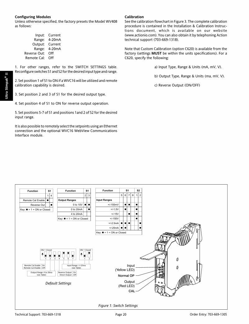
Page 20Technical Support: 703-669-1318 Order Entry: 703-669-1305
Ult
ra S
lim
pak
® II
Figure 1: Switch Settings
noitcnuF 1S
2 3
segnaRtuptuO
V01ot0
Am02ot0
Am02ot4
:yeK desolCroNO=1=
noitcnuF 1S
1 4
elbanElaCetomeR
tuOesreveR
:yeK desolCroNO=1=
noitcnuF 1S 2S
5 6 7 8 1 2
segnaRtupnI
Vm051-/+
V5.1-/+
V51-/+
V051-/+
Am5.2-/+
Am52-/+
:yeK desolCroNO=1=
Configuring ModulesUnless otherwise specified, the factory presets the Model WV408as follows:
Input: CurrentRange: 4-20mA
Output: CurrentRange: 4-20mA
Reverse Out: OffRemote Cal: Off
1. For other ranges, refer to the SWITCH SETTINGS table.Reconfigure switches S1 and S2 for the desired input type and range.
2. Set position 1 of S1 to ON if a WVC16 will be utilized and remotecalibration capability is desired.
3. Set position 2 and 3 of S1 for the desired output type.
4. Set position 4 of S1 to ON for reverse output operation.
5. Set positions 5-7 of S1 and positions 1and 2 of S2 for the desiredinput range.
It is also possible to remotely select the setpoints using an Ethernetconnection and the optional WVC16 WebView CommunicationsInterface module.
CalibrationSee the calibration flowchart in Figure 3. The complete calibrationprocedure is contained in the Installation & Calibration Instruc-tions document, which is available on our website(www.actionio.com). You can also obtain it by telephoning Actiontechnical support (703-669-1318).
Note that Custom Calibration (option C620) is available from thefactory (settings MUST be within the units specifications). For aC620, specify the following:
a) Input Type, Range & Units (mA, mV, V).
b) Output Type, Range & Units (ma, mV, V).
c) Reverse Output (ON/OFF)
Default Settings
ON = Closed
1 2 3 4 5 6 7
ON = Closed
1 2
Remote Cal EnableRemote Cal Disable
OnOff
Reverse OutputDirect Output
OnOff
Output Range: 4 to 20ma(see Table)
Input Range: +/-25ma(see Table)

Page 21Technical Support: 703-669-1318 Order Entry: 703-669-1305
Ultra Slim
pak
® II
Figure 2: Wiring Connections
niP noitpircseD
11 )+(rewoPCD
21 )-(rewoPCD
12 )+(rewoPCD
22 )-(rewoPCD
14 )+(tupnI
24 nommoCtupnI
15 )+(tuptuO
25 nommoCtuptuO
Figure 3: Calibration Flowchart

Page 22Technical Support: 703-669-1318 Order Entry: 703-669-1305
Ult
ra S
lim
pak
® II
Specifications
Inputs:
Voltage:
±150mV, ±1.5V, ±15V or ±150VDC
Impedance: >100k Ohms
Over voltage: 180Vrms
Current:
±2.5mA or ±25mA
Impedance: <75 Ohms
Over current: 170mA, protected by resetting fuse
Over voltage: 60V
Zero & Span Adjustment: ±95% of Full Scale
Input Accuracy: ±0.015% of Full Scale
Outputs:
Voltage: 0 to 10VDC
Source Impedance: <10 Ohms
Drive: 10mA
Current: 0 to 20mA
Source Impedance: >100k Ohms
Compliance: 20V@20mA (1k Ohms max)
Output Accuracy: ±0.05% of Full Scale Local Range
Selection: By DIP switch
Response Time: 100mSec (10 to 90%)
Stability: ±100ppm of full scale/°C (±0.01%/°C)
Common Mode Rejection: 120dB @ DC,
>90dB @ 60Hz, or better
Isolation: 1800VDC or peak AC between input, output & power
ESD Susceptibility: Capable of IEC 801-2 level 3 (8kV)
Power: 9-30VDC; 1.0W typ., 2.0W max.
Host Module Interface: IR Link
Size: DIN rail case – refer to Dimensions drawing
Operating Temperature: 0 to +60°C (32 to 140°F)
Storage Temperature: -25 to +85°C (-13 to 185°F)
Operating Humidity: 15% to 95% RH,non-condensing @ 45°CStorage Humidity: 90% RH, non-condensing @ 60°C for 24 hours
Agency Approvals (EMC & Safety):
CE: EN50081-1, EN50082-2, EN61010
CSA C22.2, No. 0-M91, 142-M1987
UL508
RoHS compliant
Note that detailed installation instructions are available on our website.
Ordering InformationSpecify:1. Model:
WV408-20002. Optional Custom Factory Calibration (specify C620, see required
settings under "Calibration, page 2).3. Accessories.
AccessoriesAll WV Series modules will mount on standard TS35 (model MD03)DIN rail. In addition, the following accessories are available:
WVC16 Communications InterfaceMD03 TS35 x 7.5 DIN Rail (2 meters)
WV905 24VDC Power Supply (0.5 Amp)H910 24VDC Power Supply (1 Amp)H915 24VDC Power Supply (2.3 Amp)MB03 End Bracket for MD03C650 Utility software for WVC16
DimensionsDimensions are in millimeters (inches)

Page 23Technical Support: 703-669-1318 Order Entry: 703-669-1305
Ultra Slim
pak
® II
DescriptionThe Ultra SlimPak II is an exciting new line of isolating signalconditioners from Action Instruments with greater accuracy andbetter stability than virtually any other signal conditioners on themarket today. The Ultra SlimPak II features Smart Power, whicheliminates wasted power for low loop resistance loads in thecurrent output mode.
The WV418 supports 2-wire, 3-wire or 4-wire Pt100 RTDs withalphas of either 0.00385 or 0.00392, as well as Cu10. Ranges areDIP switch selectable or (optionally) PC programmable. Outputsinclude 0-10V, 0-20mA and 4-20mA.
Smart PowerThe Ultra SlimPak II uses Smart Power to control its output supply.Smart Power automatically adjusts the the voltage to drive theoutput loop to the required current. A low impedance currentloop will subsequently require less voltage than a loop with higherimpedance. Previous designs provided only a single supply at thehighest voltage required to drive the highest impedance load.Using Smart Power results in power savings and reduces theoperating temperature of the signal conditioner.
ULTRA SLIMPAK® IIWV418
DC Powered RTD InputIsolating Signal Conditioner
High Accuracy Signal Conditioner with anIsolated DC Voltage or Current Output
Lower Power Requirements with SmartPower Improved Accuracy Bussed Power with Plug-in Power Clips Removable Terminals for Easy Service
WV418-2000
RoHS Compliant Touch Cal for Best Stability and Accuracy DIP Switch Configuration Supports 2, 3 or 4 Wire RTD's
Enhanced LED DiagnosticsOther than when executing the pushbutton calibration routine,the LEDs blink under the following conditions:
GREEN:Flashes at 2Hz when the input is under range.Flashes at 8Hz when the input is over range.
RED:Flashes at 2Hz when the output is under range.Flashes at8Hz when the output is over range.
An Under Range condition exists when the signal is lower than theoperational low value minus 6.25% of the operational span. AnOver Range condition exists when the signal is higher than theoperational high value plus 6.25% of the operational span.
A voltage output short circuit may cause an under range condition(RED blinking at 2Hz rate). A current output open circuit may causean over range condition (RED blinking at an 8Hz rate).
There could be two or more LEDs blinking at the same time, whichmeans the module has more than one error condition. Only whenall error conditions have been removed will the LEDs be back tonormal (Green ON, Red and Yellow Off).
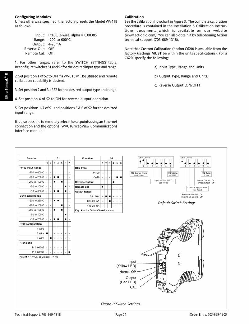
Page 24Technical Support: 703-669-1318 Order Entry: 703-669-1305
Ult
ra S
lim
pak
® II
Figure 1: Switch Settings
noitcnuF 1S
1 2 3 4 5 6 7
egnaRtupnI001tP
C006ot002- - - -
C062ot002- - - -
C001-ot002- - - -
C001ot05- - - -
C003ot81- - - -
egnaRtupnI01uC
C062ot002- - - -
C001ot002- - - -
C001-ot002- - - -
C001ot05- - - -
C062ot81- - - -
noitarugifnoCDTR
eriW4 - - - - -
eriW3 - - - - -
eriW2 - - - - -
ahplaDTR
58300.0tP - - - - - -
29300.0tP - - - - - -
:yeK a/n=-;desolCroNO=1=
noitcnuF 2S
1 2 3 4 5 6
epyTDTR
001tP - - -
01uC - - -
tuptuOesreveR
laCetomeR - - - - -
egnaRtuptuO
V01ot0 - - - -
Am02ot0 - - - -
Am02ot4 - - - -
:yeK a/n=-;desolCroNO=1=
Configuring ModulesUnless otherwise specified, the factory presets the Model WV418as follows:
Input: Pt100, 3-wire, alpha = 0.00385Range: -200 to 600°C
Output: 4-20mAReverse Out: OffRemote Cal: Off
1. For other ranges, refer to the SWITCH SETTINGS table.Reconfigure switches S1 and S2 for the desired input type and range.
2. Set position 1 of S2 to ON if a WVC16 will be utilized and remotecalibration capability is desired.
3. Set position 2 and 3 of S2 for the desired output type and range.
4. Set position 4 of S2 to ON for reverse output operation.
5. Set positions 1-7 of S1 and positions 5 & 6 of S2 for the desirredinput range.
It is also possible to remotely select the setpoints using an Ethernetconnection and the optional WVC16 WebView CommunicationsInterface module.
CalibrationSee the calibration flowchart in Figure 3. The complete calibrationprocedure is contained in the Installation & Calibration Instruc-tions document, which is available on our website(www.actionio.com). You can also obtain it by telephoning Actiontechnical support (703-669-1318).
Note that Custom Calibration (option C620) is available from thefactory (settings MUST be within the units specifications). For aC620, specify the following:
a) Input Type, Range and Units.
b) Output Type, Range and Units.
c) Reverse Output (ON/OFF)
Default Switch Settings
ON = Closed
1 2 3 4 5 6 7
RTD Config: 3-wire(see Table)
Output Range: 4-20mA(see Table)
Reverse OutputDirect output
OnOff
Input: -200 to 600°C(see Table)
ON = Closed
1 2 3 4 5 6
RTD Alpha:0.00385
Remote Cal EnableRemote Cal Disable
OnOff
RTD Type:Pt100
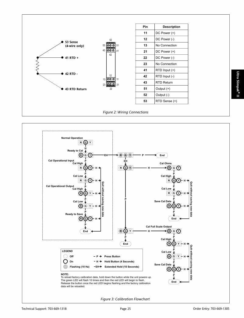
Page 25Technical Support: 703-669-1318 Order Entry: 703-669-1305
Ultra Slim
pak
® II
Figure 2: Wiring Connections
niP noitpircseD
11 )+(rewoPCD
21 )-(rewoPCD
31 noitcennoCoN
12 )+(rewoPCD
22 )-(rewoPCD
32 noitcennoCoN
14 )+(tupnIDTR
24 )-(tupnIDTR
34 nruteRDTR
15 )+(tuptuO
25 )-(tuptuO
35 )+(esneSDTR
Figure 3: Calibration Flowchart
53 Sense(4-wire only)
41 RTD +
42 RTD -
43 RTD Return

Page 26Technical Support: 703-669-1318 Order Entry: 703-669-1305
Ult
ra S
lim
pak
® II
Specifications
Inputs:
Sensor Types:
Pt100, 0.00385 alpha & 0.00392 alpha
Cu10
Sensor Connection: 2-wire, 3-wire or 4-wire RTD
Ranges:
Pt100 RTDs:Range
Number
°C °F alpha
-200 to 600 -328 to 1112 0.00385 1
-200 to 260 -328 to 500 0.00385 2
-200 to -100 -328 to -148 0.00385 3
-50 to 100 -58 to 212 0.00385 4
-18 to 300 0 to 572 0.00385 5
-200 to 600 -328 to 1112 0.00392 6
-200 to 260 -328 to 500 0.00392 7
-200 to -100 -328 to -148 0.00392 8
-50 to 100 -58 to 122 0.00392 9
-18 to 300 0 to 572 0.00392 10
Cu10 RTDs:Range
°C °F Number
-200 to 260 -328 to 500 11
-200 to 100 -328 to 212 12
-200 to -100 -328 to -148 13
-50 to 100 -58 to 212 14
-18 to 260 0 to 500 15
RTD Excitation:
Pt100: 0.45mA, max
Cu10: 5.0mA, max
Lead Wire Resistance: 40% of the base sensor resistance maximumor 100 ohms (whichever is less)
Lead Wire Effect: Changing from 0 ohm lead resistance (each lead) tomaximum allowed lead resistance: Error <1% of largest span PT and Curanges; -200 to 600°C for Pt and –200 to 260°C for Cu.
Pushbutton Adjustment (Inputs >10mV):
Effective zero offset: >95%
Effective span turn down: >95%
Local Range Selection: By DIP switch
Output:
Voltage: 0 to 10V
Source Impedance: <10 ohms
Drive: 10mA
Current: 0 to 20mA
Source Impedance: >100k ohms
Compliance: 20V
Output Accuracy: 0.05% of Full Scale
Response Time: 100mSec (10 to 90%)
Stability: ±100ppm of full scale/°C (±0.01%/°C)
Common Mode Rejection: 120dB @ DC, >90dB @ 60Hz, or better
Isolation: >1800VDC or peak AC between input, output & power.
ESD Susceptibility: Capable of meeting IEC 801-2 level 3 (8kV)
Humidity (non-condensing):
Operating:15 to 95% RH @45°CSoak: 90% RH for 24hrs @60°C
Temperature:
Operating: 0 to 60°CStorage:-25 to +85°C
Power: 9 to 30VDC; 1.0W typical, 2.0W max
Host Module Interface: IR link
Size: DIN rail case – refer to Dimensions drawing
Agency Approvals (EMC & Safety):
CE: EN61326, EN61010-1
UL & CSA combined mark
RoHS compliant
Note that detailed installation instructions are available on our website.
Ordering InformationSpecify:1. Model:
WV418-20002. Optional Custom Factory Calibration (specify C620, see required
settings under "Calibration, page 2).3. Accessories.
AccessoriesAll WV Series modules will mount on standard TS35 (model MD03)DIN rail. In addition, the following accessories are available:
WVC16 Communications InterfaceMD03 TS35 x 7.5 DIN Rail (2 meters)
WV905 24VDC Power Supply (0.5 Amp)H910 24VDC Power Supply (1 Amp)H915 24VDC Power Supply (2.3 Amp)MB03 End Bracket for MD03C650 Utility software for WVC16
DimensionsDimensions are in millimeters (inches)

Page 27Technical Support: 703-669-1318 Order Entry: 703-669-1305
Ultra Slim
pak
® II
DescriptionThe Ultra SlimPak II is an exciting new line of isolating signalconditioners from Action Instruments with greater accuracy andbetter stability than virtually any other signal conditioners on themarket today. The Ultra SlimPak II features Smart Power, whicheliminates wasted power for low loop resistance loads in thecurrent output mode.
The WV428 supports B, C, E, J, K, N, R, S & T thermocouples thatare DIP switch selectable. The WV428 also supports a millivoltrange of –20 to +80mVDC. The input accuracy of the WV428 is±0.05% with a CJC error of £ ±1°C. Both voltage and current havean input accuracy of 0.015% of full scale. Outputs include 0-10V,0-20mA and 4-20mA. The WV428 is recognized for use in Class 1,Division 2, Groups A, B, C, D hazardous locations.
Smart PowerThe Ultra SlimPak II uses Smart Power to control its output supply.Smart Power automatically adjusts the the voltage to drive theoutput loop to the required current. A low impedance currentloop will subsequently require less voltage than a loop with higherimpedance. Previous designs provided only a single supply at thehighest voltage required to drive the highest impedance load.Using Smart Power results in power savings and reduces theoperating temperature of the signal conditioner.
Approved for use in Class I Div 2 Group A, B, C, D areasUsers can now enjoy significant labor savings over traditionalprotection methods since there is no need for explosion proofenclosures and conduits.
A Class I hazardous location is one in which flammable gases orvapors may be present in the air to be ignitable or explosive(typical applications include petroleum refineries, spray finishingareas, utility gas plants and fuel servicing areas).
A Division 2 area is one in which the flammable gases or vapors arenormally not present in an explosive concentration, but couldaccidentally exist.
Group A is acetylene; Group B includes hydrogen; Group C includesether; and Group D includes hydrocarbons, fuels and solvents.
ULTRA SLIMPAK® IIWV428
DC Powered Thermocouple InputIsolating Signal Conditioner
High Accuracy Signal Conditioner with an Isolated,Linearized DC Voltage or Current Output
Lower Power Requirements with SmartPower Improved Accuracy Bussed Power with Plug-in Power Clips Removable Terminals for Easy Service Approved for use in Class I Div 2 Group A, B, C, D areas
WV428-2000
RoHS Compliant Touch Cal for Best Stability and Accuracy DIP Switch Configuration Optional E-mail Notification of Alarms
Instant AccuracyTM
Instant Accuracy maximizes accuracy and performance duringwarmup and during changes in ambient temperature. Thispatented cold-junction compensation technique utilizes two tem-perature sensors to measure the differential temperature near theterminal block. Using heat transfer calculations with the mea-sured differential temperature and the known thermal conductiv-ity of the PCB, the terminal junction temperature is determinedwith extreme accuracy. Even during unstable thermal states suchas start-up, ambient temperature changes, or changing load orpower, the WV408 performs extremely accurate thermocoupletemperature measurement. Instant Accuracy improves systemperformance and productivity due to reduced warm-up time,fewer temperature measurement errors, and tighter processcontrol for higher quality. Most significantly, it allows calibrationto be checked quickly and accurately without the effects of rapidambient temperature changes due to opening a control paneldoor, which often causes erroneous readings and miscalibrations- a common cause of measurement errors.
Enhanced LED DiagnosticsOther than when executing the pushbutton calibration routine,the LEDs blink under the following conditions:
GREEN:Flashes at 2Hz when the input is under range.Flashes at 8Hz when the input is over range.
RED:Flashes at 2Hz when the output is under range.Flashes at 8Hz when the output is over range.
YELLOW: Flashes at 2Hz for a TC burnout.
An Under Range condition exists when the signal is lower than theoperational low value minus 6.25% of the operational span. AnOver Range condition exists when the signal is higher than theoperational high value plus 6.25% of the operational span.
A voltage output short circuit may cause an under range condition(RED blinking at 2Hz rate). A current output open circuit may causean over range condition (RED blinking at an 8Hz rate).
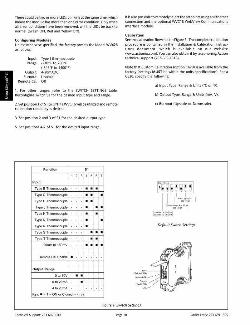
Page 28Technical Support: 703-669-1318 Order Entry: 703-669-1305
Ult
ra S
lim
pak
® II
Figure 1: Switch Settings
noitcnuF 1S
1 2 3 4 5 6 7
tupnI
elpuocomrehTBepyT - - -
elpuocomrehTCepyT - - -
elpuocomrehTEepyT - - -
elpuocomrehTJepyT - - -
elpuocomrehTKepyT - - -
elpuocomrehTNepyT - - -
elpuocomrehTRepyT - - -
elpuocomrehTSepyT - - -
elpuocomrehTTepyT - - -
Vm08+otVm02- - - -
elbanElaCetomeR - - - - - -
egnaRtuptuO
V01ot0 - - - - -
Am02ot0 - - - - -
Am02ot4 - - - - -
:yeK a/n=-;desolCroNO=1=
There could be two or more LEDs blinking at the same time, whichmeans the module has more than one error condition. Only whenall error conditions have been removed, will the LEDs be back tonormal (Green ON, Red and Yellow Off).
Configuring ModulesUnless otherwise specified, the factory presets the Model WV428as follows:
Input: Type J thermocoupleRange: -210°C to 760°C
(-346°F to 1400°F)Output: 4-20mADC
Burnout: UpscaleRemote Cal: Off
1. For other ranges, refer to the SWITCH SETTINGS table.Reconfigure switch S1 for the desired input type and range.
2. Set position 1 of S1 to ON if a WVC16 will be utilized and remotecalibration capability is desired.
3. Set position 2 and 3 of S1 for the desired output type.
5. Set positions 4-7 of S1 for the desired input range.
It is also possible to remotely select the setpoints using an Ethernetconnection and the optional WVC16 WebView CommunicationsInterface module.
CalibrationSee the calibration flowchart in Figure 3. The complete calibrationprocedure is contained in the Installation & Calibration Instruc-tions document, which is available on our website(www.actionio.com). You can also obtain it by telephoning Actiontechnical support (703-669-1318).
Note that Custom Calibration (option C620) is available from thefactory (settings MUST be within the units specifications). For aC620, specify the following:
a) Input Type, Range & Units (°C or °F).
b) Output Type, Range & Units (mA, V).
c) Burnout (Upscale or Downscale).
Default Switch Settings
ON = Closed
1 2 3 4 5 6 7
Remote Cal OnRemote Cal Off
Output Range: 4 to 20 mA(see Table)
Input: Type J T/C(see Table)
OnOff

Page 29Technical Support: 703-669-1318 Order Entry: 703-669-1305
Ultra Slim
pak
® II
Figure 2: Wiring Connections
niP noitpircseD
11 )+(rewoPCD
21 )-(rewoPCD
12 )+(rewoPCD
22 )-(rewoPCD
14 )+(tupnI
24 )-(tupnI
15 )+(tuptuO
25 )-(tuptuO
Figure 3: Calibration Flowchart
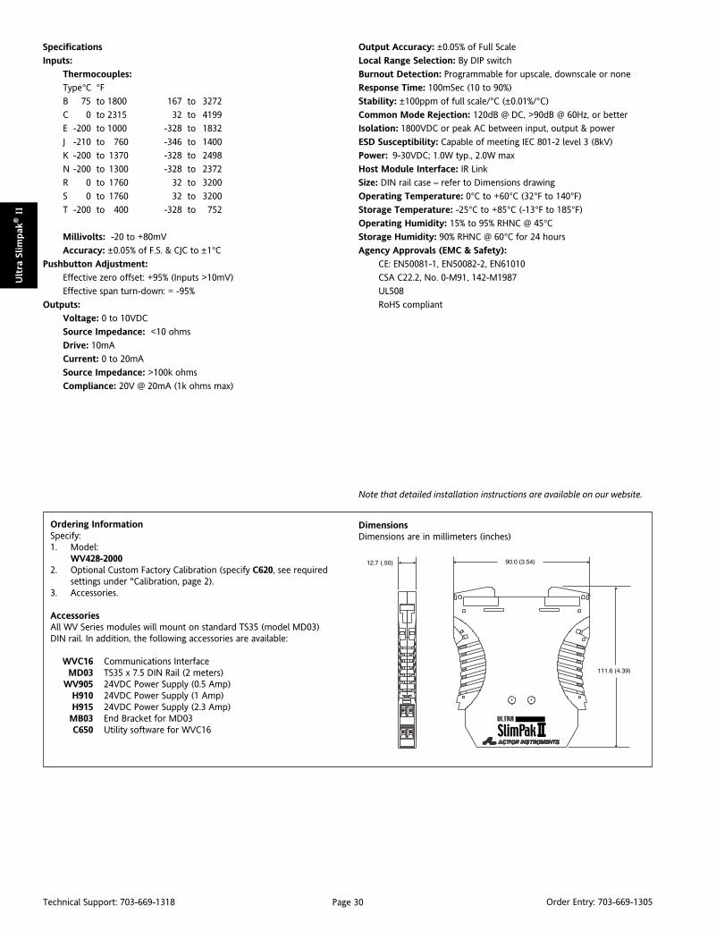
Page 30Technical Support: 703-669-1318 Order Entry: 703-669-1305
Ult
ra S
lim
pak
® II
Specifications
Inputs:
Thermocouples:
Type°C °FB 75 to 1800 167 to 3272
C 0 to 2315 32 to 4199
E -200 to 1000 -328 to 1832
J -210 to 760 -346 to 1400
K -200 to 1370 -328 to 2498
N -200 to 1300 -328 to 2372
R 0 to 1760 32 to 3200
S 0 to 1760 32 to 3200
T -200 to 400 -328 to 752
Millivolts: -20 to +80mV
Accuracy: ±0.05% of F.S. & CJC to ±1°CPushbutton Adjustment:
Effective zero offset: +95% (Inputs >10mV)
Effective span turn-down: = -95%
Outputs:
Voltage: 0 to 10VDC
Source Impedance: <10 ohms
Drive: 10mA
Current: 0 to 20mA
Source Impedance: >100k ohms
Compliance: 20V @ 20mA (1k ohms max)
Output Accuracy: ±0.05% of Full Scale
Local Range Selection: By DIP switch
Burnout Detection: Programmable for upscale, downscale or none
Response Time: 100mSec (10 to 90%)
Stability: ±100ppm of full scale/°C (±0.01%/°C)
Common Mode Rejection: 120dB @ DC, >90dB @ 60Hz, or better
Isolation: 1800VDC or peak AC between input, output & power
ESD Susceptibility: Capable of meeting IEC 801-2 level 3 (8kV)
Power: 9-30VDC; 1.0W typ., 2.0W max
Host Module Interface: IR Link
Size: DIN rail case – refer to Dimensions drawing
Operating Temperature: 0°C to +60°C (32°F to 140°F)
Storage Temperature: -25°C to +85°C (-13°F to 185°F)
Operating Humidity: 15% to 95% RHNC @ 45°CStorage Humidity: 90% RHNC @ 60°C for 24 hours
Agency Approvals (EMC & Safety):
CE: EN50081-1, EN50082-2, EN61010
CSA C22.2, No. 0-M91, 142-M1987
UL508
RoHS compliant
Note that detailed installation instructions are available on our website.
DimensionsDimensions are in millimeters (inches)
Ordering InformationSpecify:1. Model:
WV428-20002. Optional Custom Factory Calibration (specify C620, see required
settings under "Calibration, page 2).3. Accessories.
AccessoriesAll WV Series modules will mount on standard TS35 (model MD03)DIN rail. In addition, the following accessories are available:
WVC16 Communications InterfaceMD03 TS35 x 7.5 DIN Rail (2 meters)
WV905 24VDC Power Supply (0.5 Amp)H910 24VDC Power Supply (1 Amp)H915 24VDC Power Supply (2.3 Amp)MB03 End Bracket for MD03C650 Utility software for WVC16
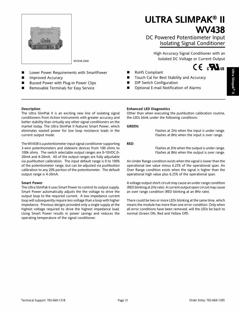
Page 31Technical Support: 703-669-1318 Order Entry: 703-669-1305
Ultra Slim
pak
® II
DescriptionThe Ultra SlimPak II is an exciting new line of isolating signalconditioners from Action Instruments with greater accuracy andbetter stability than virtually any other signal conditioners on themarket today. The Ultra SlimPak II features Smart Power, whicheliminates wasted power for low loop resistance loads in thecurrent output mode.
The WV438 is a potentiometer input signal conditioner supporting3-wire potentiometers and slidewire devices from 100 ohms to100k ohms. The switch selectable output ranges are 0-10VDC,0-20mA and 4-20mA. All of the output ranges are fully adjustablevia pushbutton calibration. The input default range is 0 to 100%of the potentiometer range, but can be adjusted via pushbuttoncalibration to any 20% portion of the potentiometer. The defaultoutput range is 4-20mA.
Smart PowerThe Ultra SlimPak II uses Smart Power to control its output supply.Smart Power automatically adjusts the the voltage to drive theoutput loop to the required current. A low impedance currentloop will subsequently require less voltage than a loop with higherimpedance. Previous designs provided only a single supply at thehighest voltage required to drive the highest impedance load.Using Smart Power results in power savings and reduces theoperating temperature of the signal conditioner.
ULTRA SLIMPAK® IIWV438
DC Powered Potentiometer InputIsolating Signal Conditioner
High Accuracy Signal Conditioner with anIsolated DC Voltage or Current Output
Lower Power Requirements with SmartPower Improved Accuracy Bussed Power with Plug-in Power Clips Removable Terminals for Easy Service
WV438-2000
RoHS Compliant Touch Cal for Best Stability and Accuracy DIP Switch Configuration Optional E-mail Notification of Alarms
Enhanced LED DiagnosticsOther than when executing the pushbutton calibration routine,the LEDs blink under the following conditions:
GREEN:Flashes at 2Hz when the input is under range.Flashes at 8Hz when the input is over range.
RED:Flashes at 2Hz when the output is under range.Flashes at 8Hz when the output is over range.
An Under Range condition exists when the signal is lower than theoperational low value minus 6.25% of the operational span. AnOver Range condition exists when the signal is higher than theoperational high value plus 6.25% of the operational span.
A voltage output short circuit may cause an under range condition(RED blinking at 2Hz rate). A current output open circuit may causean over range condition (RED blinking at an 8Hz rate).
There could be two or more LEDs blinking at the same time, whichmeans the module has more than one error condition. Only whenall error conditions have been removed, will the LEDs be back tonormal (Green ON, Red and Yellow Off).
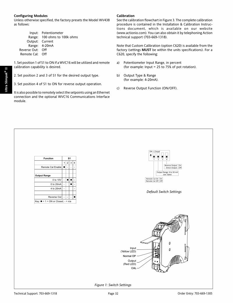
Page 32Technical Support: 703-669-1318 Order Entry: 703-669-1305
Ult
ra S
lim
pak
® II
Figure 1: Switch Settings
noitcnuF 1S
1 2 3 4
elbanElaCetomeR - - -
egnaRtuptuO
V01ot0 - -
Am02ot0 - -
Am02ot4 - -
tuOesreveR - - -
:yeK a/n=-;desolCroNO=1=
Configuring ModulesUnless otherwise specified, the factory presets the Model WV438as follows:
Input: PotentiometerRange: 100 ohms to 100k ohms
Output: CurrentRange: 4-20mA
Reverse Out: OffRemote Cal: Off
1. Set position 1 of S1 to ON if a WVC16 will be utilized and remotecalibration capability is desired.
2. Set position 2 and 3 of S1 for the desired output type.
3. Set position 4 of S1 to ON for reverse output operation.
It is also possible to remotely select the setpoints using an Ethernetconnection and the optional WVC16 Communications Interfacemodule.
CalibrationSee the calibration flowchart in Figure 3. The complete calibrationprocedure is contained in the Installation & Calibration Instruc-tions document, which is available on our website(www.actionio.com). You can also obtain it by telephoning Actiontechnical support (703-669-1318).
Note that Custom Calibration (option C620) is available from thefactory (settings MUST be within the units specifications). For aC620, specify the following:
a) Potentiometer Input Range, in percent(for example: Input = 25 to 75% of pot rotation).
b) Output Type & Range(for example: 4-20mA).
c) Reverse Output Function (ON/OFF).
Default Switch Settings
ON = Closed
1 2 3 4
Remote Cal OnRemote Cal Off
Output Range: 4 to 20 mA(see Table)
OnOff
Reverse OutputDirect Output
OnOff
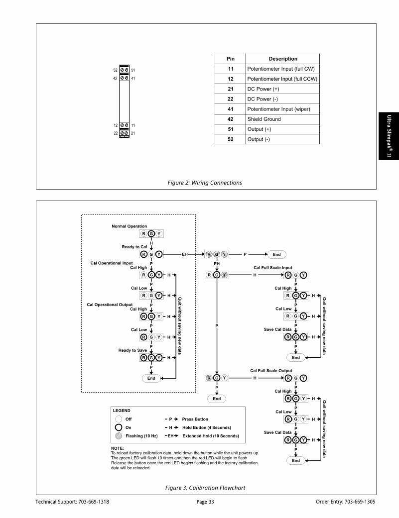
Page 33Technical Support: 703-669-1318 Order Entry: 703-669-1305
Ultra Slim
pak
® II
Figure 2: Wiring Connections
niP noitpircseD
11 )WClluf(tupnIretemoitnetoP
21 )WCClluf(tupnIretemoitnetoP
12 )+(rewoPCD
22 )-(rewoPCD
14 )repiw(tupnIretemoitnetoP
24 dnuorGdleihS
15 )+(tuptuO
25 )-(tuptuO
Figure 3: Calibration Flowchart

Page 34Technical Support: 703-669-1318 Order Entry: 703-669-1305
Ult
ra S
lim
pak
® II
Specifications
Potentiometer Resistance (end to end):
100 ohms (min.) to 100k ohms (max.)
Input Ranges: Pushbutton adjustable
Linearity: ±0.1% of span, typical
Excitation: 300mV, nominal
Turn-Up/Turn-Down: 80% (90% to ±0.2% linearity)
Common Mode Rejection:
60Hz: >100dB
DC: >120dB
Output Ranges:
0 to 10VDC
0 to 20mA
4 to 20 mA
Response Time: 100mSec typical
Stability: ±100ppm of full scale/°COutput Ripple: 0.2% of span, or 5mVrms, whichever is greater
Output Impedance:
Voltage Output: <10 ohms
Currnet Output: >100k ohms
Output Drive:
Voltage Output: 10 mA, max
Current Output: 20V compliance @ 20mA
Power: 9-30VDC; 1.0W typ., 2.0W max.
Isolation: 1800VDC input to output to power
Host Module Interface: IR Link
Size: DIN rail case – refer to Dimensions drawing
Operating Temperature: 0 to +60°C (32 to 140°F)
Storage Temperature: -25 to +85°C (-13 to 185°F)
Operating Humidity: 15% to 95% RH,non-condensing @ 45°CStorage Humidity: 90% RH, non-condensing @ 60°C for 24 hours
Agency Approvals (EMC & Safety):
CE: EN50081-1, EN50082-2, EN61010
CSA C22.2, No. 0-M91, 142-M1987
UL508
RoHS compliant
Note that detailed installation instructions are available on our website.
Ordering InformationSpecify:1. Model:
WV438-20002. Optional Custom Factory Calibration (specify C620, see required
settings under "Calibration, page 2).3. Accessories.
AccessoriesAll WV Series modules will mount on standard TS35 (model MD03)DIN rail. In addition, the following accessories are available:
WVC16 Communications InterfaceMD03 TS35 x 7.5 DIN Rail (2 meters)
WV905 24VDC Power Supply (0.5 Amp)H910 24VDC Power Supply (1 Amp)H915 24VDC Power Supply (2.3 Amp)MB03 End Bracket for MD03C650 Utility software for WVC16
DimensionsDimensions are in millimeters (inches)

Page 35Technical Support: 703-669-1318 Order Entry: 703-669-1305
Ultra Slim
pak
® II
DescriptionThe Ultra SlimPak II is an exciting new line of isolating signalconditioners from Action Instruments with greater accuracy andbetter stability than virtually any other signal conditioners on themarket today. The Ultra SlimPak II features Smart Power, whicheliminates wasted power for low loop resistance loads in thecurrent output mode.
The WV448 is a bridge input signal conditioner supporting bridgeinput full scale ranges of ±5mV to ±200mV, (default is ±50mV). Theswitch selectable output ranges are 0-10VDC, 0-20mA and 4-20mA.All the input and output ranges are fully adjustable via pushbuttoncalibration. The default output range is 4-20mA.
Smart PowerThe Ultra SlimPak II uses Smart Power to control its output supply.Smart Power automatically adjusts the the voltage to drive theoutput loop to the required current. A low impedance currentloop will subsequently require less voltage than a loop with higherimpedance. Previous designs provided only a single supply at thehighest voltage required to drive the highest impedance load.Using Smart Power results in power savings and reduces theoperating temperature of the signal conditioner.
ULTRA SLIMPAK® IIWV448
DC Powered Bridge InputIsolating Signal Conditioner
High Accuracy Signal Conditioner with anIsolated DC Voltage or Current Output
Lower Power Requirements with SmartPower Improved Accuracy Bussed Power with Plug-in Power Clips Removable Terminals for Easy Service Optional E-mail Notification of Alarms
WV448-2000
RoHS Compliant Touch Cal for Best Stability and Accuracy DIP Switch Configuration 120mA Excitation to Drive up to Four 350
Ohm Load Cells
Enhanced LED DiagnosticsOther than when executing the pushbutton calibration routine,the LEDs blink under the following conditions:
GREEN:Flashes at 2Hz when the input is under range.Flashes at 8Hz when the input is over range.
RED:Flashes at 2Hz when the output is under range.Flashes at 8Hz when the output is over range.
An Under Range condition exists when the signal is lower than theoperational low value minus 6.25% of the operational span. AnOver Range condition exists when the signal is higher than theoperational high value plus 6.25% of the operational span.
A voltage output short circuit may cause an under range condition(RED blinking at 2Hz rate). A current output open circuit may causean over range condition (RED blinking at an 8Hz rate).
There could be two or more LEDs blinking at the same time, whichmeans the module has more than one error condition. Only whenall error conditions have been removed, will the LEDs be back tonormal (Green ON, Red and Yellow Off).

Page 36Technical Support: 703-669-1318 Order Entry: 703-669-1305
Ult
ra S
lim
pak
® II
Figure 1: Switch Settings
noitcnuF 1S
1 2 3 4 5 6
tupnI
Vm5-/+ - - -
Vm01-/+ - - -
Vm02-/+ - - -
Vm05-/+ - - -
Vm001-/+ - - -
Vm002-/+ - - -
elbanElaCetomeR - - - - -
egnaRtuptuO
V01ot0 - - - -
Am02ot0 - - - -
Am02ot4 - - - -
:yeK a/n=-;desolCroNO=1=
Configuring ModulesUnless otherwise specified, the factory presets the Model WV448as follows:
Input: 0-30mV(using ±50mV range)
Excitation: 10VOutput: CurrentRange: 4-20mA
Remote Cal: Off
1. For other ranges, refer to the SWITCH SETTINGS table.Reconfigure switch S1 for the desired input type and range.
2. Set position 1 of S1 to ON if a WVC16 will be utilized and remotecalibration capability is desired.
3. Set position 2 and 3 of S1 for the desired output type.
5. Set positions 4-6 of S1 for the desired input range.
It is also possible to remotely select the setpoints using an Ethernetconnection and the optional WVC16 WebView CommunicationsInterface module.
CalibrationSee the calibration flowchart in Figure 3. The complete calibrationprocedure is contained in the Installation & Calibration Instruc-tions document, which is available on our website(www.actionio.com). You can also obtain it by telephoning Actiontechnical support (703-669-1318).
Note that Custom Calibration (option C620) is available from thefactory (settings MUST be within the units specifications). For aC620, specify the following:
a) Input Range.
b) Output Type, Range & Units (mA, V).
c) Excitation Voltage.
Default Switch Settings
ON = Closed
1 2 3 4
Remote Cal OnRemote Cal Off
Output Range: 4 to 20 mA(see Table)
OnOff
5 6
Input Range: +/-50mV(see Table)

Page 37Technical Support: 703-669-1318 Order Entry: 703-669-1305
Ultra Slim
pak
® II
Figure 2: Wiring Connections
niP noitpircseD
11 )+(rewoPCD
21 )-(rewoPCD
31 noitcennoCoN
12 )+(rewoPCD
22 )-(rewoPCD
32 noitcennoCoN
14 )+(tupnIegdirB
24 )-(tupnIegdirB
34 )+(noitaticxE
15 )+(tuptuO
25 )-(tuptuO
35 )-(noitaticxE
Figure 3: Switch Settings
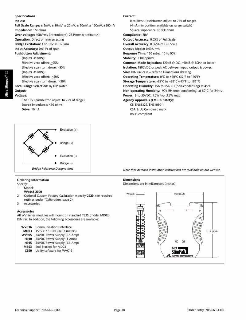
Page 38Technical Support: 703-669-1318 Order Entry: 703-669-1305
Ult
ra S
lim
pak
® II
DimensionsDimensions are in millimeters (inches)
Ordering InformationSpecify:1. Model:
WV448-20002. Optional Custom Factory Calibration (specify C620, see required
settings under "Calibration, page 2).3. Accessories.
AccessoriesAll WV Series modules will mount on standard TS35 (model MD03)DIN rail. In addition, the following accessories are available:
WVC16 Communications InterfaceMD03 TS35 x 7.5 DIN Rail (2 meters)
WV905 24VDC Power Supply (0.5 Amp)H910 24VDC Power Supply (1 Amp)H915 24VDC Power Supply (2.3 Amp)MB03 End Bracket for MD03C650 Utility software for WVC16
Specifications
Inputs:
Full Scale Range: ± 5mV, ± 10mV, ± 20mV, ± 50mV, ± 100mV, ±200mV
Impedance: 1M ohms
Over-voltage: 400Vrms (intermittent); 264Vrms (continuous)
Operation: Direct or reverse acting
Bridge Excitation: 1 to 10VDC, 120mA
Input Accuracy: 0.015% of span
Pushbutton Adjustment:
(Inputs <10mV):
Effective zero offset: >95%
Effective span turn down: >95%
(Inputs <10mV):
Effective zero offset: >50%
Effective span turn down: >50%
Local Range Selection: By DIP switch
Output:
Voltage:
0 to 10V (pushbutton adjust. to 75% of range)
Source Impedance: <10 ohms
Drive: 10mA
Current:
0 to 20mA (pushbutton adjust. to 75% of range)
(4mA min position available on range switch)
Source Impedance: >100k ohms
Compliance: 20V
Output Accuracy: 0.05% of Full Scale
Overall Accuracy: 0.065% of Full Scale
Output Ripple: 0.03% rms
Response Time: 150 mSec, 10 to 90%
Stability: ±100ppm/°CCommon Mode Rejection: 120dB @ DC, >90dB @ 60Hz, or better
Isolation: 1800VDC or peak AC between input, output & power.
Size: DIN rail case – refer to Dimensions drawing
Operating Temperature: 0°C to +60°C (32°F to 140°F)
Storage Temperature: -25°C to +85°C (-13°F to 185°F)
Operating Humidity: 15% to 95% RH (non-condensing) at 45°CNon-operating Humidity: 90% RH (non-condensing) at 60°C for 24hrs
Power: 9 to 30VDC, 1.5W typ, 3.5W max.
Agency Approvals (EMC & Safety):
CE: EN61326, EN61010-1
CSA & UL Combined mark
RoHS compliant
Note that detailed installation instructions are available on our website.Bridge Reference Designations

Page 39Technical Support: 703-669-1318 Order Entry: 703-669-1305
Ultra Slim
pak
® II
DescriptionThe Ultra SlimPak II is an exciting new line of isolating signalconditioners from Action Instruments with greater accuracy andbetter stability than virtually any other signal conditioners on themarket today. The Ultra SlimPak II features Smart Power, whicheliminates wasted power for low loop resistance loads in thecurrent output mode.
The WV468 has both voltage and current input ranges. Eight ACvoltage input ranges (50mV, 150mV, 500mV, 5V, 20V, 50V, 150V &250V) are DIP switch selectable. Each of these ranges has at least 95%zero and span adjustment. Two AC current input ranges (20mA and100mA) are also available. Outputs include 0-10V, 0-20mA and 4-20mA. The WV468 also supports reverse output mode.
Smart PowerThe Ultra SlimPak II uses Smart Power to control its output supply.Smart Power automatically adjusts the the voltage to drive theoutput loop to the required current. A low impedance currentloop will subsequently require less voltage than a loop with higherimpedance. Previous designs provided only a single supply at thehighest voltage required to drive the highest impedance load.Using Smart Power results in power savings and reduces theoperating temperature of the signal conditioner.
ULTRA SLIMPAK® IIWV468
DC Powered AC Voltage/Current InputIsolating Signal Conditioner
High Accuracy Signal Conditioner with anIsolated DC Voltage or Current Output
True RMS Output Lower Power Requirements with SmartPower Improved Accuracy Bussed Power with Plug-in Power Clips Removable Terminals for Easy Service
WV468-2000
RoHS Compliant Touch Cal for Best Stability and Accuracy DIP Switch Configuration Optional E-mail Notification of Alarms
Enhanced LED DiagnosticsOther than when executing the pushbutton calibration routine,the LEDs blink under the following conditions:
GREEN:Flashes at 2Hz when the input is under range.Flashes at 8Hz when the input is over range.
RED:Flashes at 2Hz when the output is under range.Flashes at 8Hz when the output is over range.
An Under Range condition exists when the signal is lower than theoperational low value minus 6.25% of the operational span. AnOver Range condition exists when the signal is higher than theoperational high value plus 6.25% of the operational span.
A voltage output short circuit may cause an under range condition(RED blinking at 2Hz rate). A current output open circuit may causean over range condition (RED blinking at an 8Hz rate).
There could be two or more LEDs blinking at the same time, whichmeans the module has more than one error condition. Only whenall error conditions have been removed, will the LEDs be back tonormal (Green ON, Red and Yellow Off).

Page 40Technical Support: 703-669-1318 Order Entry: 703-669-1305
Ult
ra S
lim
pak
® II
Figure 1: Switch Settings
noitcnuF 1S
2 3
segnaRtuptuO
V01ot0
Am02ot0
Am02ot4
:yeK desolCroNO=1=
noitcnuF 1S
1 4
elbanElaCetomeR
tuOesreveR
:yeK desolCroNO=1=
noitcnuF 1S 2S
5 6 7 8 1 4
segnaRtupnI
V052
V051
V05
V02
V5
Vm005
Vm051
Vm05
Am001
Am02
:yeK desolCroNO=1=
Configuring ModulesUnless otherwise specified, the factory presets the Model WV468as follows:
Input: mVACRange: 0-500mV
Output: DC CurrentRange: 4-20mA
Reverse Out: OffRemote Cal: Off
1. For other ranges, refer to the SWITCH SETTINGS table.Reconfigure switches S1 and S2 for the desired input type and range.
2. Set position 1 of S1 to ON if a WVC16 will be utilized and remotecalibration capability is desired.
3. Set position 2 and 3 of S1 for the desired output type.
4. Set position 4 of S1 to ON for reverse output operation.
5. Set positions 5-8 of S1 and positions 1 & 4 of S2 for the desiredinput range.
It is also possible to remotely select the setpoints using an Ethernetconnection and the optional WVC16 WebView CommunicationsInterface module.
CalibrationSee the calibration flowchart in Figure 3. The complete calibrationprocedure is contained in the Installation & Calibration Instruc-tions document, which is available on our website(www.actionio.com). You can also obtain it by telephoning Actiontechnical support (703-669-1318).
Note that Custom Calibration (option C620) is available from thefactory (settings MUST be within the units specifications). For aC620, specify the following:
a) Input Type, Range and Units.
b) Output Type, Range and Units.
c) Reverse Output (ON/OFF).
Default Switch Settings
ON = Closed
1 4
Remote Cal OnRemote Cal Off
ON = Closed
1 2 3 4 5 6
Output Range: 4-20ma(see Table)
Input: 0 to 500mvDC(see Table)
Reverse OutputDirect Output
OnOff
OnOff
7 8
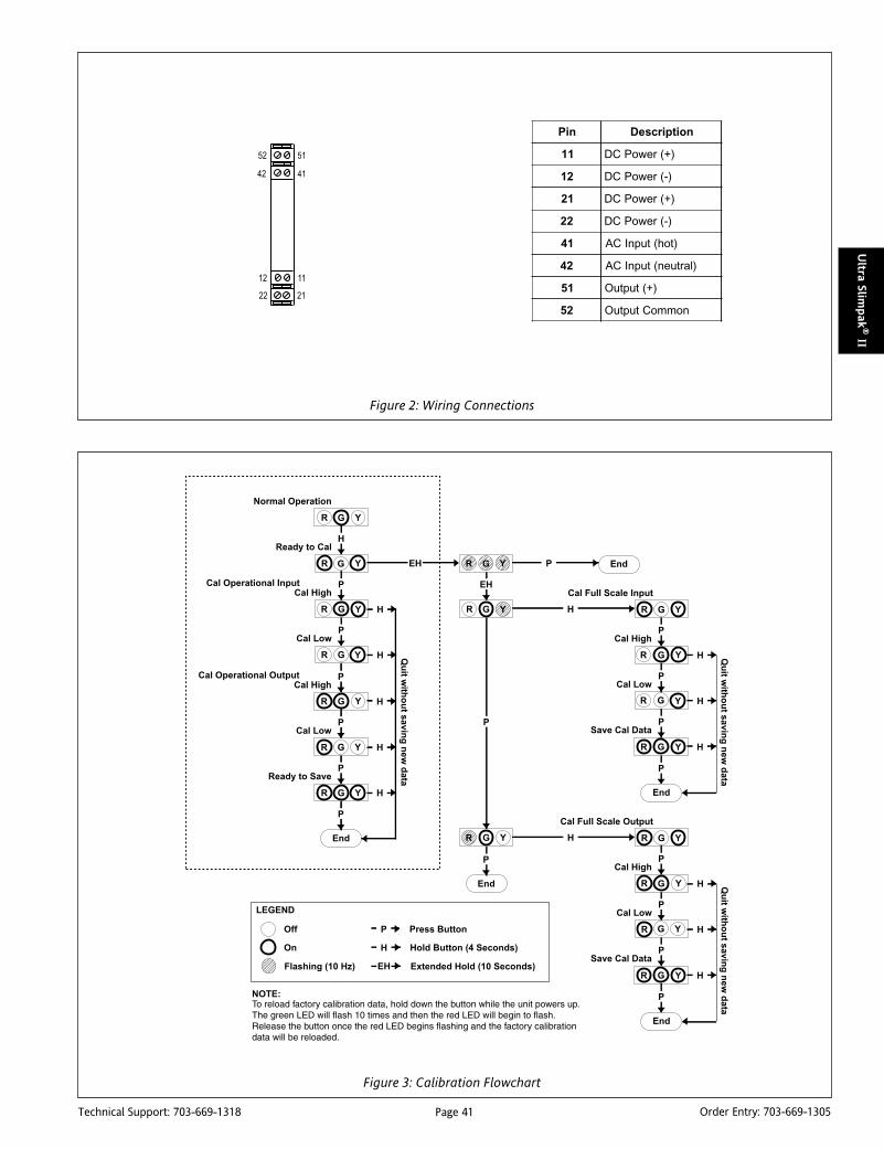
Page 41Technical Support: 703-669-1318 Order Entry: 703-669-1305
Ultra Slim
pak
® II
Figure 2: Wiring Connections
niP noitpircseD
11 )+(rewoPCD
21 )-(rewoPCD
12 )+(rewoPCD
22 )-(rewoPCD
14 )toh(tupnICA
24 )lartuen(tupnICA
15 )+(tuptuO
25 nommoCtuptuO
Figure 3: Calibration Flowchart
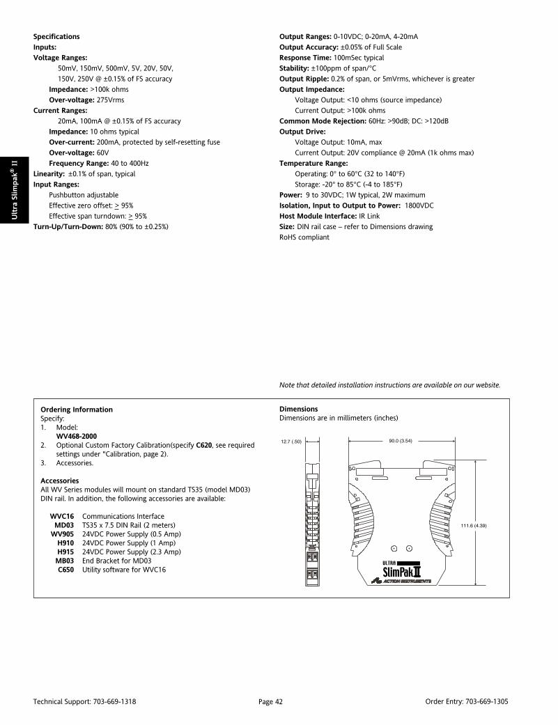
Page 42Technical Support: 703-669-1318 Order Entry: 703-669-1305
Ult
ra S
lim
pak
® II
Specifications
Inputs:
Voltage Ranges:
50mV, 150mV, 500mV, 5V, 20V, 50V,
150V, 250V @ ±0.15% of FS accuracy
Impedance: >100k ohms
Over-voltage: 275Vrms
Current Ranges:
20mA, 100mA @ ±0.15% of FS accuracy
Impedance: 10 ohms typical
Over-current: 200mA, protected by self-resetting fuse
Over-voltage: 60V
Frequency Range: 40 to 400Hz
Linearity: ±0.1% of span, typical
Input Ranges:
Pushbutton adjustable
Effective zero offset: > 95%
Effective span turndown: > 95%
Turn-Up/Turn-Down: 80% (90% to ±0.25%)
Output Ranges: 0-10VDC; 0-20mA, 4-20mA
Output Accuracy: ±0.05% of Full Scale
Response Time: 100mSec typical
Stability: ±100ppm of span/°COutput Ripple: 0.2% of span, or 5mVrms, whichever is greater
Output Impedance:
Voltage Output: <10 ohms (source impedance)
Current Output: >100k ohms
Common Mode Rejection: 60Hz: >90dB; DC: >120dB
Output Drive:
Voltage Output: 10mA, max
Current Output: 20V compliance @ 20mA (1k ohms max)
Temperature Range:
Operating: 0° to 60°C (32 to 140°F)
Storage: -20° to 85°C (-4 to 185°F)
Power: 9 to 30VDC; 1W typical, 2W maximum
Isolation, Input to Output to Power: 1800VDC
Host Module Interface: IR Link
Size: DIN rail case – refer to Dimensions drawing
RoHS compliant
Note that detailed installation instructions are available on our website.
Ordering InformationSpecify:1. Model:
WV468-20002. Optional Custom Factory Calibration(specify C620, see required
settings under "Calibration, page 2).3. Accessories.
AccessoriesAll WV Series modules will mount on standard TS35 (model MD03)DIN rail. In addition, the following accessories are available:
WVC16 Communications InterfaceMD03 TS35 x 7.5 DIN Rail (2 meters)
WV905 24VDC Power Supply (0.5 Amp)H910 24VDC Power Supply (1 Amp)H915 24VDC Power Supply (2.3 Amp)MB03 End Bracket for MD03C650 Utility software for WVC16
DimensionsDimensions are in millimeters (inches)

Page 43Technical Support: 703-669-1318 Order Entry: 703-669-1305
Ultra Slim
pak
® II
DescriptionThe Ultra SlimPak II is an exciting new line of isolating signalconditioners from Action Instruments with greater accuracy andbetter stability than virtually any other signal conditioners on themarket today. The Ultra SlimPak II features Smart Power, whicheliminates wasted power for low loop resistance loads in thecurrent output mode.
The WV478 accepts a frequency of up to 10kHz, with a minimuminput span of 2Hz. The input amplitude can range from 150mVpto 150Vrms.
Smart PowerThe Ultra SlimPak II uses Smart Power to control its output supply.Smart Power automatically adjusts the the voltage to drive theoutput loop to the required current. A low impedance currentloop will subsequently require less voltage than a loop with higherimpedance. Previous designs provided only a single supply at thehighest voltage required to drive the highest impedance load.Using Smart Power results in power savings and reduces theoperating temperature of the signal conditioner.
ULTRA SLIMPAK® IIWV478
DC Powered Frequency InputIsolating Signal Conditioner
High Accuracy Signal Conditioner with anIsolated DC Voltage or Current Output
Lower Power Requirements with SmartPower Improved Accuracy Bussed Power with Plug-in Power Clips Removable Terminals for Easy Service
WV478-2000
RoHS Compliant Touch Cal for Best Stability and Accuracy DIP Switch Configuration
Enhanced LED DiagnosticsOther than when executing the pushbutton calibration routine,the LEDs blink under the following conditions:
GREEN:Flashes at 2Hz when the input is under range.Flashes at 8Hz when the input is over range.
RED:Flashes at 2Hz when the output is under range.Flashes at8Hz when the output is over range.
An Under Range condition exists when the signal is lower than theoperational low value minus 6.25% of the operational span. AnOver Range condition exists when the signal is higher than theoperational high value plus 6.25% of the operational span.
A voltage output short circuit may cause an under range condition(RED blinking at 2Hz rate). A current output open circuit may causean over range condition (RED blinking at an 8Hz rate).
There could be two or more LEDs blinking at the same time, whichmeans the module has more than one error condition. Only whenall error conditions have been removed, will the LEDs be back tonormal (Green ON, Red and Yellow Off).

Page 44Technical Support: 703-669-1318 Order Entry: 703-669-1305
Ult
ra S
lim
pak
® II
Figure 1: Switch Settings
noitcnuF 2S
1
ytivitisneStupnI
)smrV051otpVm005(egnaRhgiH
)smrV05otpVm051(egnaRwoL
:yeK a/n=-;desolCroNO=1=
noitcnuF 1S
1 2 3
laCetomeR - -
tuptuO
V01ot0 -
Am02ot0 -
Am02ot4 -
:yeK a/n=-;desolCroNO=1=
Configuring ModulesUnless otherwise specified, the factory presets the Model WV478as follows:
Input: FrequencyRange: 0-1000Hz
Sensitivity: Low (set at 1Vrms)Output: DC CurrentRange: 4-20mA
Remote Cal: Off
1. For other ranges, refer to the SWITCH SETTINGS table.Reconfigure switches S1 and S2 for the desired input type and range.
2. Set position 1 of S1 to ON if a WVC16 will be utilized and remotecalibration capability is desired.
3. Set position 2 and 3 of S1 for the desired output type.
4. Set position 4 of S1 to ON for reverse output operation.
5. Set position 1 of S2 for the desired input sensitivity.
It is also possible to remotely select the setpoints using an Ethernetconnection and the optional WVC16 WebView CommunicationsInterface module.
CalibrationSee the calibration flowchart in Figure 3. The complete calibrationprocedure is contained in the Installation & Calibration Instruc-tions document, which is available on our website(www.actionio.com). You can also obtain it by telephoning Actiontechnical support (703-669-1318).
Note that Custom Calibration (option C620) is available from thefactory (settings MUST be within the units specifications). For aC620, specify the following:
a) Input Frequency Range (for example: 0 to 5000Hz).
b) Input Amplitude (for example: 2.5 Volts, Peak).
c) Output Type and Range (for example: 4 to 20mA).
Default Switch Settings
ON = Closed
1 2 3
Remote Cal OnRemote Cal Off
Output Range: 4 to 20 mA(see Table)
OnOff
Input Sensitivity: 150mVp to 50Vrms(see Table)
ON = Closed
1
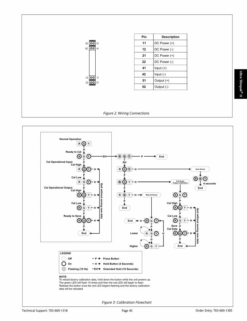
Page 45Technical Support: 703-669-1318 Order Entry: 703-669-1305
Ultra Slim
pak
® II
Figure 2: Wiring Connections
niP noitpircseD
11 )+(rewoPCD
21 )-(rewoPCD
12 )+(rewoPCD
22 )-(rewoPCD
14 )+(tupnI
24 )-(tupnI
15 )+(tuptuO
25 )-(tuptuO
Figure 3: Calibration Flowchart

Page 46Technical Support: 703-669-1318 Order Entry: 703-669-1305
Ult
ra S
lim
pak
® II
Specifications
Input:
Frequency Input Range: 0 to 10kHz
Minimum Input Span: 2Hz
Amplitude (switch selectable):
Low Range: 150mVp to 50Vrms
High Range: 500mVp to 150Vrms
Output:
Voltage: 0 to 10VDC;
Source Impedance: 10 ohms
Drive: 10mA
Current: 0 to 20mA
Source Impedance: >100k ohms
Compliance: 20V@20mA (1k ohms max)
Output Accuracy:
±0.05% of full scale local range
Response Time:
100mSec + 3 input cycles (10-90%) typical
Stability:
±100ppm of full scale/°C (±0.01%/°C)
Common Mode Rejection:
60Hz: >90dB
DC: >120dB
Isolation:
Input to Output to Power: 1800VDC
ESD Susceptibility:
Capable of meeting IEC801-2 level 3 (8kV)
Power:
9 to 30VDC
1W typical, 2W maximum
Host Module Interface:
IR Link
Size:
DIN rail case – refer to Dimensions drawing
Temperature Range:
Operating: 0°C to 60°C (32°F to 140°F)
Storage: -25°C to 85°C (-13°F to 185°F)
Humidity Range:
Operating: 15% to 95% RHNC @ 45°CStorage: 90% RHNC @60°C for 24 hrs
Agency Approvals (EMC & Safety):
CE: EN50081-1, EN50082-2, EN61010
CSA C22.2, No. 0-M91, 142-M1987
UL508
RoHS compliant
Note that detailed installation instructions are available on our website.
Ordering InformationSpecify:1. Model:
WV478-20002. Optional Custom Factory Calibration (specify C620, see required
settings under "Calibration, page 2).3. Accessories.
AccessoriesAll WV Series modules will mount on standard TS35 (model MD03)DIN rail. In addition, the following accessories are available:
WVC16 Communications InterfaceMD03 TS35 x 7.5 DIN Rail (2 meters)
WV905 24VDC Power Supply (0.5 Amp)H910 24VDC Power Supply (1 Amp)H915 24VDC Power Supply (2.3 Amp)MB03 End Bracket for MD03C650 Utility software for WVC16
DimensionsDimensions are in millimeters (inches)

Page 47Technical Support: 703-669-1318 Order Entry: 703-669-1305
Ultra Slim
pak
® II
DescriptionThe Ultra SlimPak II Communications Interface adds functionalitynever before found in a signal conditioning system. A singleWVC16 interfaces with as many as 32 Ultra SlimPak II devices bymeans of an internal infrared communications link. Through anEthernet link in the WVC16, the information can then madeavailable over the user's intranet. This powerful combinationallows the user to view process data on a near real time basis,perform data logging functions on specified modules, view diag-nostic information, and (under certain conditions) calibrate themodules remotely.
The WVC16 can send email messages to people who might needto be notified when an alarm condition exists. It can also send anemail message letting maintenance personnel know when it's timeto perform calibration checks. All of this functionality is madepossible by a signed Java applet which is (transparently) down-loaded to run on the client's computer. Using an applet ratherthan a traditional web page allows data to be updated in near realtime. The applet provides access to the signal conditioner's data,which includes:
• Module configuration summary• Module configuration editing• Diagnostic/warning status• Alarm setup & status• E-mail setup, editing & address book• Process variable viewing• Data logging capabilities
All memory to support the signal conditioner's historical data isbattery backed. The web pages and all e-mail messages are storedin non-volatile memory.
The SoftwareThere are two software programs built into the WVC16. The firstis a web server that provides the connection between the WVC16and the client's computer. The second is the Ultra SlimPak II DataViewer applet.
ULTRA SLIMPAK® IIWVC16
Communications Interface
Provides Ethernet Connection forUltra SlimPak II Modules
Interface with up to 32 Signal Conditioning Modules Bussed Power with Plug-in Power Clips Removable Terminals for Easy Service
RoHS Compliant Battery Backed Data No Programming Required
The web server (see Figure 1) is the "Home" page. Other functionscan be selected from there. The Statistics frame contains informa-tion on the Ethernet connection, the frames sent and received, aswell as information about the infrared bus between the modules.An Error Log will list any errors that have occurred. The Help filecontains the entire user instruction manual for the WVC16.
The Data Viewer applet is launched from the Home page. Note thatin order to install the Data Viewer, you must first have the JavaRuntime Environment (JRE) 1.3.1 (or greater) plug-in installed on theclient machine. If the plug-in has not been installed, the web browserwill detect the fact and automatically connect to Sun MicrosystemsJava site in order to download and install the plug-in. Once the plug-in is installed, the Data Viewer will download and open.
The Data Viewer is used to view process data, define data loggingparameters, and set up e-mail and address book information. Theapplet runs in a window of its own. The window shows all of themodules connected to the WVC16 (see Figure 2). The data loggingfunction is defined in this window. Note that data logging is notsimultaneous data from channel to channel - there is a time delayfrom sample to sample, as well as network delays that may need tobe considered. The time-stamped data gathered here would thenbe downloaded to a program like MS Excel for further analysis.
Clicking on a module name brings up a window showing the signalconnected to the selected module. From this window, the inputand output ranges can be viewed, high and low alarm limits canbe set, and module calibration can be performed. The About tabwill list the firmware revision, the current temperature of themodule, the high and low temperature to which the module hasbeen subjected, and the number of hours it has been in operation.

Page 48Technical Support: 703-669-1318 Order Entry: 703-669-1305
Ult
ra S
lim
pak
® II
Figure 1: The Webserver Home Page
LED IndicatorsThere are six LED indicators, in two groups of three, that can beviewed through the translucent front cover. They are located downthe left side of the unit. There is also a power LED located on theright side of the unit. There functions are described as follows:
POWER (Green):On when 9 to 30VDC is applied to the unit.
(Upper Group)ERROR (Red):
Flashes if a module error has been logged intothe non-volatile SRAM or if the battery wasdisabled prior to applying power.
CONNECT (Green):On to indicate Ethernet Client connection.
Flashes if no connection.
Off if network parameters need to be set.
MODULE (Yellow):On when modules are detected on IR bus.
Flashes if no modules are detected on IR bus.
(Lower Group)OFFLINE (Red):
On to indicate a network socket connectionfault.
TRAFFIC (Yellow):On to indicate 10Base-T transmit/receive andcollision activity.
LINK (Yellow):On to indicate 10Base-T link activity.
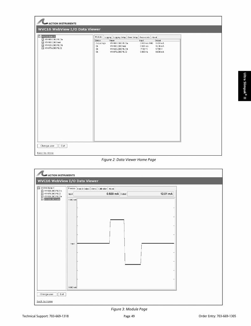
Page 49Technical Support: 703-669-1318 Order Entry: 703-669-1305
Ultra Slim
pak
® II
Figure 2: Data Viewer Home Page
Figure 3: Module Page

Page 50Technical Support: 703-669-1318 Order Entry: 703-669-1305
Ult
ra S
lim
pak
® II
Specifications
Processor:
AM186ESLV, 25MHz
Data Logging Capacity:
>24k samples
Host Interface:
Type: Ethernet, 10Base-T
Connector: RJ45
Cable: Cat 5 recommended
Utility Interface:
Type: RS-232
Baud Rate: 9600
Data Bits: 8
Stop Bits: 1
Parity: None
Flow Control: None
Module Interface:
Type: Infrared
32 Modules max
User Interface:
Type: Web Browser, requires Java 2 Plug-in; Internet Explorer 5.01(or later) or Netscape Navigator 4.7 (or later)
Isolation:
1500Vrms between 10Base-T port and all other external connections.
Battery:
Type: 3V Lithium, non-rechargeable cr2032 or BR2032. Lifeexpectancy is 16 months typical in use (battery enable switch ON).Shelf life 10 yrs.
Power:
9-30VDC; 1.2W max
Size:
DIN rail case – refer to Dimensions drawing
Operating Temperature:
0°C to +60°C (32°F to 140°F)
Storage Temperature:
-25°C to +85°C (-13°F to 185°F)
Operating Humidity:
15% to 95% RHNC @ 45°CStorage Humidity:
90% RHNC @ 60°C for 24 hours
Agency Approvals (EMC & Safety):
CE: EN50081-1, EN50082-2, EN61010
CSA C22.2, No. 0-M91, 142-M1987
UL508
RoHS compliant
Note that detailed installation instructions are available on our website.
DimensionsDimensions are in millimeters (inches)
Ordering InformationSpecify:1. Model:
WVC162. Accessories:
C650-0000 - Utility CD and Serial Interface Cable (one C650-0000accessory kit is necessary per installation, in order to set the IPaddress on the WVC16's).

Page 51Technical Support: 703-669-1318 Order Entry: 703-669-1305
Actio
nIQ
®
DescriptionThe ActionI/Q DIN rail mount package was developed to reducethe cost of signal conditioning. The two primary design consid-erations were to house as many channels of isolated I/O aspossible and to reduce the number of power connections and I/O disconnects. Providing more I/O channels per module reducesper channel material cost and wiring savings reduces the longterm cost of ownership.
The result is a 3/4" wide plug-in DIN rail mount package containgtwo full size printed circuit boards and fitted with up to 26 terminalsfor plug-in I/O. The ActionI/Q provides some of the most costeffective signal conditioning and isolation solutions in the world,including the the four channel RTD transmitter (model Q510) andthe four channel, 4-20mA loop powered isolator (model Q500)from the original ActionI/Q series of multi-channel transmitters.
Original ActionI/Q SeriesThe original ActionI/Q series consists of loop powered, two-wireand three-wire transmitters for sensor signal inputs including DCvoltage, DC current, Platinum 100 Ohm RTDs and thermocouples.These DC powered, fixed range, multi-channel signal conditionersand isolators offer stable 0.1% accuracy over an operating ambienttemperature range of 20° to 80°C. Their multi-channel designensures high density and low material cost. Plug-in terminalsockets make wiring quick and easy.
To isolate a powered 4-20mA loop, the Q500 loop poweredisolator is available for one, two or four channel applications.Voltage or current DC inputs can be specified by range for theQ501 two-wire transmitter, which is available with one or two 4-20mA output channels. The Q510 two-wire transmitter providestwo or four RTD input channels and the Q520 two-wire transmit-ter provides two channels for the most popular thermocoupleinput types and ranges.
ACTIONI/Q®
AC ActionI/Q SeriesThe AC powered ActionI/Q series of four-wire transmitters offermany of the most advanced microprocessor and ASIC based signalcondioning solutions available. Field configurable and wideranging, these modules are an off-the-shelf solution for mostisolation, signal condioning, and limit alarm applications. Thebenefits enjoyed by users include lower spares inventories andquick availability for DC, RTD, thermocouple, potentiometer,strain gauge, AC and frequency input signal applications.
Action's unique TouchCal™ pushbutton calibration providesincreased stability, as well as higher repeatability and accuracysince it replaces adjustment potentiometers which can be ther-mally sensitive and mechanically less reliable. Additional cost ofownership benefits are realized in terms of reduced calibrationtime and the wiring savings provided by the use of an I/QRail. TheI/QRail is used to power all AC ActionI/Q modules and provides anadded level of safety.
For temperature measurement, the model Q486 with patentedInstant Accuracy cold junction compensation technology, is twiceas accurate and four times more stable than older temperaturemeasurement instruments. The Q486 can be field configuredusing DIP switches, or it can be configured using a PC, whichreduces setup time to seconds.
DC ActionI/Q SeriesThe DC ActionI/Q series is similar to the AC series except that it mustbe powered by a 9-30Vdc supply. The DC series can be wired usingthe power terminals or an optionally available DC powered I/QRail.
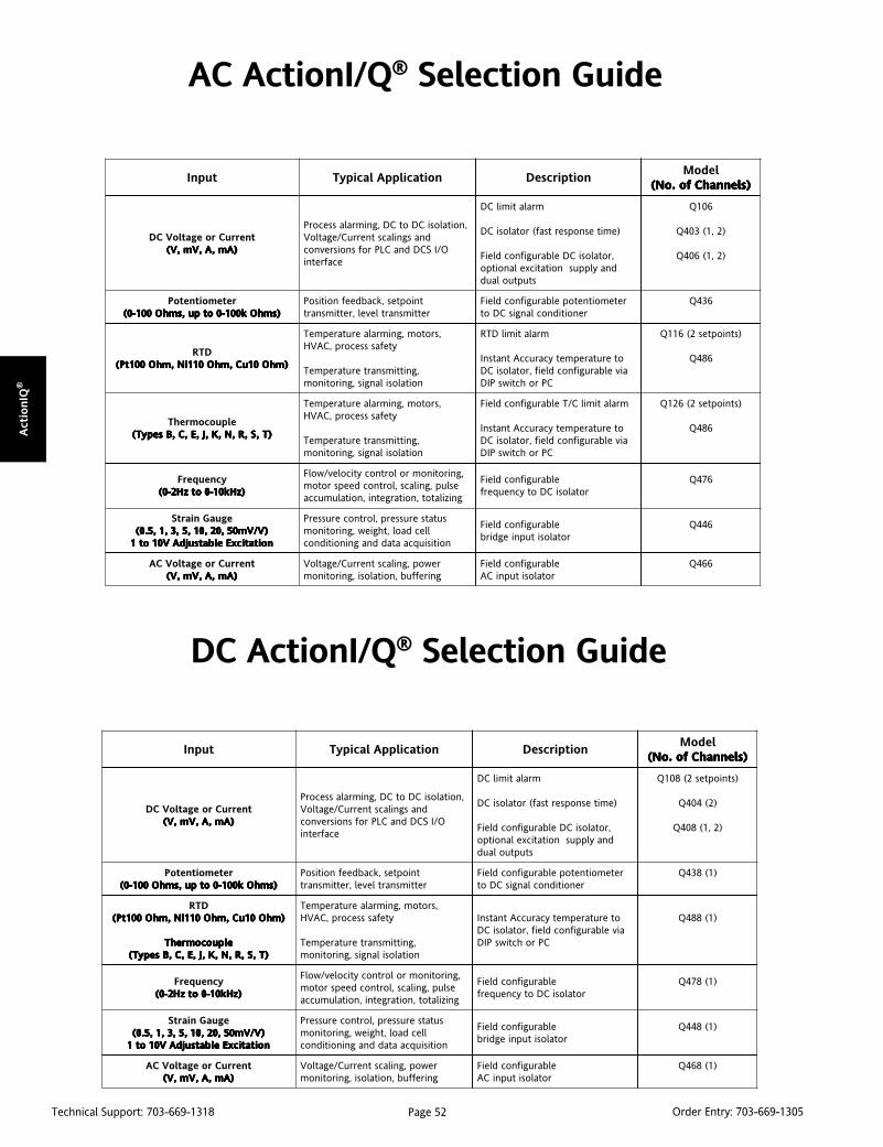
Page 52Technical Support: 703-669-1318 Order Entry: 703-669-1305
Act
ionIQ
®
AC ActionI/Q® Selection Guide
DC ActionI/Q® Selection Guide
tupnI noitacilppAlacipyT noitpircseDledoM
)slennahCfo.oN( )slennahCfo.oN( )slennahCfo.oN( )slennahCfo.oN( )slennahCfo.oN(
tnerruCroegatloVCD)Am,A,Vm,V( )Am,A,Vm,V( )Am,A,Vm,V( )Am,A,Vm,V( )Am,A,Vm,V(
,noitalosiCDotCD,gnimralassecorPdnasgnilacstnerruC/egatloV
O/ISCDdnaCLProfsnoisrevnocecafretni
mralatimilCD
)emitesnopsertsaf(rotalosiCD
,rotalosiCDelbarugifnocdleiFdnaylppusnoitaticxelanoitpo
stuptuolaud
601Q
)2,1(304Q
)2,1(604Q
retemoitnetoP)smhOk001-0otpu,smhO001-0( )smhOk001-0otpu,smhO001-0( )smhOk001-0otpu,smhO001-0( )smhOk001-0otpu,smhO001-0( )smhOk001-0otpu,smhO001-0(
tnioptes,kcabdeefnoitisoPrettimsnartlevel,rettimsnart
retemoitnetopelbarugifnocdleiFrenoitidnoclangisCDot
634Q
DTR)mhO01uC,mhO011iN,mhO001tP( )mhO01uC,mhO011iN,mhO001tP( )mhO01uC,mhO011iN,mhO001tP( )mhO01uC,mhO011iN,mhO001tP( )mhO01uC,mhO011iN,mhO001tP(
,srotom,gnimralaerutarepmeTytefasssecorp,CAVH
,gnittimsnarterutarepmeTnoitalosilangis,gnirotinom
mralatimilDTR
oterutarepmetycaruccAtnatsnIaivelbarugifnocdleif,rotalosiCD
CProhctiwsPID
)stnioptes2(611Q
684Q
elpuocomrehT)T,S,R,N,K,J,E,C,BsepyT( )T,S,R,N,K,J,E,C,BsepyT( )T,S,R,N,K,J,E,C,BsepyT( )T,S,R,N,K,J,E,C,BsepyT( )T,S,R,N,K,J,E,C,BsepyT(
,srotom,gnimralaerutarepmeTytefasssecorp,CAVH
,gnittimsnarterutarepmeTnoitalosilangis,gnirotinom
mralatimilC/TelbarugifnocdleiF
oterutarepmetycaruccAtnatsnIaivelbarugifnocdleif,rotalosiCD
CProhctiwsPID
)stnioptes2(621Q
684Q
ycneuqerF)zHk01-0otzH2-0( )zHk01-0otzH2-0( )zHk01-0otzH2-0( )zHk01-0otzH2-0( )zHk01-0otzH2-0(
,gnirotinomrolortnocyticolev/wolFeslup,gnilacs,lortnocdeepsrotomgnizilatot,noitargetni,noitalumucca
elbarugifnocdleiFrotalosiCDotycneuqerf
674Q
eguaGniartS)V/Vm05,02,01,5,3,1,5.0( )V/Vm05,02,01,5,3,1,5.0( )V/Vm05,02,01,5,3,1,5.0( )V/Vm05,02,01,5,3,1,5.0( )V/Vm05,02,01,5,3,1,5.0(noitaticxEelbatsujdAV01ot1 noitaticxEelbatsujdAV01ot1 noitaticxEelbatsujdAV01ot1 noitaticxEelbatsujdAV01ot1 noitaticxEelbatsujdAV01ot1
sutatserusserp,lortnocerusserPllecdaol,thgiew,gnirotinom
noitisiuqcaataddnagninoitidnoc
elbarugifnocdleiFrotalositupniegdirb
644Q
tnerruCroegatloVCA)Am,A,Vm,V( )Am,A,Vm,V( )Am,A,Vm,V( )Am,A,Vm,V( )Am,A,Vm,V(
rewop,gnilacstnerruC/egatloVgnireffub,noitalosi,gnirotinom
elbarugifnocdleiFrotalositupniCA
664Q
tupnI noitacilppAlacipyT noitpircseDledoM
)slennahCfo.oN( )slennahCfo.oN( )slennahCfo.oN( )slennahCfo.oN( )slennahCfo.oN(
tnerruCroegatloVCD)Am,A,Vm,V( )Am,A,Vm,V( )Am,A,Vm,V( )Am,A,Vm,V( )Am,A,Vm,V(
,noitalosiCDotCD,gnimralassecorPdnasgnilacstnerruC/egatloV
O/ISCDdnaCLProfsnoisrevnocecafretni
mralatimilCD
)emitesnopsertsaf(rotalosiCD
,rotalosiCDelbarugifnocdleiFdnaylppusnoitaticxelanoitpo
stuptuolaud
)stnioptes2(801Q
)2(404Q
)2,1(804Q
retemoitnetoP)smhOk001-0otpu,smhO001-0( )smhOk001-0otpu,smhO001-0( )smhOk001-0otpu,smhO001-0( )smhOk001-0otpu,smhO001-0( )smhOk001-0otpu,smhO001-0(
tnioptes,kcabdeefnoitisoPrettimsnartlevel,rettimsnart
retemoitnetopelbarugifnocdleiFrenoitidnoclangisCDot
)1(834Q
DTR)mhO01uC,mhO011iN,mhO001tP( )mhO01uC,mhO011iN,mhO001tP( )mhO01uC,mhO011iN,mhO001tP( )mhO01uC,mhO011iN,mhO001tP( )mhO01uC,mhO011iN,mhO001tP(
elpuocomrehT elpuocomrehT elpuocomrehT elpuocomrehT elpuocomrehT)T,S,R,N,K,J,E,C,BsepyT( )T,S,R,N,K,J,E,C,BsepyT( )T,S,R,N,K,J,E,C,BsepyT( )T,S,R,N,K,J,E,C,BsepyT( )T,S,R,N,K,J,E,C,BsepyT(
,srotom,gnimralaerutarepmeTytefasssecorp,CAVH
,gnittimsnarterutarepmeTnoitalosilangis,gnirotinom
oterutarepmetycaruccAtnatsnIaivelbarugifnocdleif,rotalosiCD
CProhctiwsPID
)1(884Q
ycneuqerF)zHk01-0otzH2-0( )zHk01-0otzH2-0( )zHk01-0otzH2-0( )zHk01-0otzH2-0( )zHk01-0otzH2-0(
,gnirotinomrolortnocyticolev/wolFeslup,gnilacs,lortnocdeepsrotomgnizilatot,noitargetni,noitalumucca
elbarugifnocdleiFrotalosiCDotycneuqerf
)1(874Q
eguaGniartS)V/Vm05,02,01,5,3,1,5.0( )V/Vm05,02,01,5,3,1,5.0( )V/Vm05,02,01,5,3,1,5.0( )V/Vm05,02,01,5,3,1,5.0( )V/Vm05,02,01,5,3,1,5.0(noitaticxEelbatsujdAV01ot1 noitaticxEelbatsujdAV01ot1 noitaticxEelbatsujdAV01ot1 noitaticxEelbatsujdAV01ot1 noitaticxEelbatsujdAV01ot1
sutatserusserp,lortnocerusserPllecdaol,thgiew,gnirotinom
noitisiuqcaataddnagninoitidnoc
elbarugifnocdleiFrotalositupniegdirb
)1(844Q
tnerruCroegatloVCA)Am,A,Vm,V( )Am,A,Vm,V( )Am,A,Vm,V( )Am,A,Vm,V( )Am,A,Vm,V(
rewop,gnilacstnerruC/egatloVgnireffub,noitalosi,gnirotinom
elbarugifnocdleiFrotalositupniCA
)1(864Q

Page 53Technical Support: 703-669-1318 Order Entry: 703-669-1305
Actio
nIQ
®A
C P
ow
ered
DescriptionThe ActionI/Q model Q106 is a DIN rail mount, DC voltage orcurrent input limit alarm with dual setpoints and two contactclosure outputs. The field configurable input and alarm functionsoffer flexible setpoint capability. Input voltage spans from 10mVto 200V and input current spans from 1mA to 100mA can be fieldconfigured. Bipolar inputs are also accepted.
The Q106 is configurable as a single or dual setpoint alarm, withHI or LO trips and failsafe or non-failsafe operation. Also includedare adjustable deadbands (up to 100% of full scale input) for eachsetpoint, a 24VDC voltage source (isolated from line power) fortransducer excitation, and a universal AC power supply whichaccepts any voltage between 85 and 265VAC.
TouchCAL TechnologyAction has simplified setpoint calibration. Using a pushbuttoninstead of potentiometers, improvements in calibration resolu-tion and reliability are realized due to the elimination of thepotentiometers’ mechanical variability.
For calibration, simply input the signal level of the desired trip andpress the pushbutton to store it in non-volatile memory.Deadband is entered the same way with another pushbutton pressto store.
Diagnostic LEDSThe Q106 is equipped with three front panel LEDs. The green LEDis a dual function LED labeled IN, which indicates line power andinput signal status. Active AC power is indicated by the illuminatedLED. If this LED is off, check AC power and wiring connections. Ifthe input signal is 7% above or below the configured input rangethe green LED will flash at 8Hz or 4Hz, respectively.
The two red LEDs indicate the relay state of each setpoint. Anilluminated red LED indicates the tripped condition for therespective setpoint.
OutputThe Q106 is equipped with two SPDT (form C) relays, rated at120VAC or 28VDC at 5 amperes. Each of these relays is indepen-dently controlled by the field configurable setpoint anddeadband.
ACTIONI/Q®
Q106AC Powered DC Input Limit Alarm
Provides Relay Contact Closuresat a Preset DC Input Level
Field Configurable Input Ranges TouchCALTM Technology Setpoints Programmable HI or LO and Failsafe or
Non-Failsafe DIN Rail Mounting with IQRL
Q106-0000
Universal AC Power 85 to 265 VAC 24VDC Transducer Excitation SnapLocTM Plug-in Terminals ASIC Technology for Enhanced Reliability
OperationThe Q106 limit alarm setpoints can be configured for HI or LO,failsafe or non-failsafe operation. Each of the setpoints has arespective HI or LO deadband. In a tripped condition, the setpointis exceeded and the appropriate red LED will illuminate. The tripwill reset only after the process falls below the HI deadband orrises above the low deadband (see Figure 1). For proper deadbandoperation, the HI setpoint must be set above the LO setpoint. Infailsafe operation, the relay is energized when the process is belowthe HI setpoint or above the LO setpoint (opposite for non-failsafe). In the failsafe mode, a power failure results in an alarmstate output.
Dynamic DeadbandCircuitry in the Q106 prevents false trips by repeatedly samplingthe input. The input must be beyond the setpoint for 100milliseconds, uninterrupted, to qualify as a valid trip condition.Likewise, the input must fall outside the deadband and remainthere for 100 milliseconds to return the alarm to an untrippedcondition. This results in a “dynamic deadband” —based ontime— in addition to the normal deadband.
ConfigurationUnless otherwise specified, the factory presets the Model Q106 asfollows:
Input: CurrentRange: 0-20mA
Output: Dual, SPDTTrip: A: HI, B: LO
Failsafe: NoDeadband: A, B: 0.25%
The AC power input accepts any AC source between 85 and 265VAC.
Note: An I/QRail is required to power the modules. See orderinginformation.
For other I/O ranges, refer to Table 1 and Figure 5. Reconfigureswitch SW1 for the desired input type, range and function.

Page 54Technical Support: 703-669-1318 Order Entry: 703-669-1305
Act
ionIQ
®A
C P
ow
ered
WARNING: Do not change switch settings with power applied.Severe damage will result!
1. With the module removed from the rail and not powered, snapoff the face plate by lifting the right edge away from the heat sink.Note the input switch (SW1) is located under the face plate. Setpositions 9 & 10 for voltage or current input (see Table 1).
2. Set positions 1 through 4 of input range switch “SW1” for thedesired input range (see Table 1).
3. Set position 5 of input range switch “SW1” to ON (closed) forunipolar (e.g., zero based, 0-20mA) range or OFF (open) forbipolar (e.g. -100% offset, -20 to 20mA) range.
4. Set positions 6 and 7 of input range switch “SW1” to ON for aHI trip setpoint or OFF for a LO trip setpoint.
5. Set position 8 of input range switch “SW1” to ON for non-failsafeoperation or OFF for failsafe operation (e.g., alarm trips on powerfailure).
Calibration1. After configuring the DIP switches, connect the input to acalibrated DC source and apply power. Refer to the terminalwiring in the specifications section.
Note: For best results, calibration should be performed in theoperating environment, mounted on a DIN rail, allowing at leastone hour for thermal equilibrium of the system.
2. After applying power to the unit all three LEDs will flash forapproximately 10 seconds. Adjust the input signal level for theRelay “A” setpoint. The green LED should be on. Press and holdthe CAL button for four seconds (until the red LED starts flashing)to enter the calibration mode. The green LED will be on and thered Relay “A” LED will be be flashing.
NOTE: If the green LED is flashing , the input is out of range (i.e. 7%above or below the configured range). Check to make sure theinput signal is within the DIP switch configuration range. Doublecheck the DIP switch settings.
3. Setpoint "A": Input the desired trip level for Relay "A" and pressthe CAL button. The green LED and the red Relay "A" LED will beflashing. Note that the green LED will stop flashing when the inputdrops below a high setpoint or rises above a low setpoint.
4. Deadband "A": For minimum deadband (approximately 0.25%),press and hold the CAL button for 4 seconds. For high setpoints,lower the input level to the desired deadband point and push theCAL button. For low setpoints increase the input level (green LEDturns off) to the desired deadband level and push the CAL button.The green LED will be on and the red Relay "B" LED will be flashing.
5. Setpoint “B”: Input the desired trip level for Relay “B” and pushthe CAL button. The green and the red Relay “B” LED will beflashing. Note that the green LED will stop flashing when the inputdrops below a high setpoint or rises above a low setpoint.
6. Deadband “B”: For minimum deadband (approximately 0.25%),press and hold the CAL button for 4 seconds. For high setpointslower the input level (green LED turns off) to the desireddeadband point and push the CAL button. For low setpointsincrease the input level to the desired deadband level and pushthe CAL button. The green LED will be on and both the red LEDswill be flashing.
7. Press the CAL button once again to exit the calibration mode.Check the setpoint and deadband to validate calibration.
Relay Protection and EMI SuppressionWhen switching inductive loads, maximum relay life and transientEMI suppression is achieved by using external protection (seeFigures 2 and 3). Place all protection devices directly across the loadand minimize lead lengths. For AC inductive loads, place a properlyrated MOV across the load in parallel with a series RC snubber. Usea 0.01 to 0.1mF pulse film capacitor (foil polypropylene recom-mended) of sufficient voltage, and a 47 ohm, 1/2W carbon resistor.For DC inductive loads, place a diode across the load (PRV > DCsupply, 1N4006 recommended) with (+) to cathode and (-) to anode(the RC snubber is an optional enhancement).
egatloV tnerruC
egnaRtupnI1WSrotceleS 1WSrotceleS 1WSrotceleS 1WSrotceleS 1WSrotceleS
1 2 3 4
Vm01 Am1
Vm02 Am2
Vm05 Am5
Vm001 Am01
Vm002 Am02
Vm005 Am05
V1 Am001
V2
V5
V01
V02
V05
V001
V002
:yeK desolCroNO=1=
Table 1: Q106 Input Range Switch
Figure 1: Limit alarm operation and effect of deadband.

Page 55Technical Support: 703-669-1318 Order Entry: 703-669-1305
Actio
nIQ
®A
C P
ow
ered
Figure 5: Q106 Input Range/Function Selection (SW1) Factory Default SettingsNote: For voltage inputs Current Enable must be off. For current inputs Voltage Enable must be off.
Figure 6: Q106 Calibration Flow Chart
Flashing
Input Trip ASignal Level
Input Trip BSignal Level
On
Off
Green LED
Red LED
Figure 4: Typical Connections for Voltage or Current for Q106
Figure 2: DC Inductive Loads Figure 3: AC Inductive Loads

Page 56Technical Support: 703-669-1318 Order Entry: 703-669-1305
Act
ionIQ
®A
C P
ow
ered
Ordering InformationModels & AccessoriesSpecify (model number)1) Q106-00002) Specify I/QRail type and quantity (required)3) Accessories: (see Accessories)4) Optional Custom Factory Calibration: Specify C620 with desired
input, setpoint and deadband.
AccessoriesActionI/Q series modules mount on standard TS32 (model MD02) or TS35(model MD03) DIN rail. In addition, the following accessories are available:
MD02 TS32 DIN railMD03 TS35 x 7.5 DIN rail
IQRL-2002 2 Position I/QRail & DIN railIQRL-2004 4 Position I/QRail & DIN railIQRL-2008 8 Position I/QRail & DIN rail
Dimensions
Specifications
Voltage Input:
Range: 10mV to +200V; Impedance: >100K ohms
Overvoltage: 200V rms, max.
Current Input:
Range: 1mA to +100mA; Impedance: 20 ohms, typical
Overcurrent: 170mA rms, max.
Overvoltage: 60VDC (self-resetting fuse)
Common Mode (Input to Gnd): 1800VDC, max.
LED Indicators:
Input (Green):
>110% input: 8Hz flash
<10% input: 4Hz flash
Setpoint (Red):
Tripped: Solid red
Safe: Off
Limit Differential (Deadband):
>50mV/5mA: 0.25% to 100% of span
<50mV/5mA: 1% to 100% of span
Response Time:
Dynamic Deadband:
Relay status will change when proper setpoint/process conditionexists for 100msec.
Normal Mode (analog filtering): <250mSec, (10-90%)
Setpoints:
Effectivity: Setpoints are adjustable over 100% of the selected input span.
Repeatability (constant temp.):
>50mV/5mA: 0.1% of full scale
<50mV/5mA: 0.2% of full scale
Stability:
Temperature: +0.05% of full scale/°C, max.
Excitation Voltage:
24VDC, 20mA, maximum
Common Mode Rejection:
DC to 60Hz: 120dB
Isolation:
1800VDC between contacts, input and power
ESD & Transient Susceptibility: Meets IEC 801-2, Level 3 (8KV)
Humidity (Non-Condensing):
Operating: 15 to 95% @ 45°CSoak: 90% for 24hours @ 65°C
Temperature Range:
Operating: 0 to 55°C (32 to 131°F)
Storage: -25 to 70°C (-13 to 158°F)
Power: 2.5W max.,100 to 240VAC +10%, 50Hz -400Hz
Relay Contacts: 2 SPDT (2 form C) Relays; 1 Relay per setpoint
Current Rating (resistive) 120VAC:5A; 240VAC: 2A; 28VDC: 5AMaterial: Gold flash over silver alloy
Electrical Life:105 operations at rated load
Note: External relay contact protection is required for use withinductive loads.
Mechanical Life: 107 operations
Wire Terminations: Screw terminations for 12-22 AWG
Weight: 0.56 lbs.
Agency Approvals:
CSA certified per standard C22.2 (File No LR42272)
UL recognized per standard UL508 (File No E99775)
CE EN61326, EN61010-1
lanimreT noitcennoC lanimreT noitcennoC
1A .O.N,AyaleR 4C noitaticxECDV42
2A nommoC,AyaleR 5C )-(tupnI
3A .C.N,AyaleR 6C )+(tupnI
4A .O.N,ByaleR 1P )toH(rewoPCA
5A nommoC,ByaleR 2P desUtoN
6A .C.N,ByaleR 3P desUtoN
3C,2C,1C detcennoCyllanretnItoN 4P )lartueN(rewoPCA

Page 57Technical Support: 703-669-1318 Order Entry: 703-669-1305
Actio
nIQ
®A
C P
ow
ered
DescriptionThe ActionI/Q model Q116 is a DIN rail mount, RTD input limit alarmwith dual setpoints and two contact closure outputs. The fieldconfigurable input and alarm functions offer flexible setpointcapability. There are up to eight temperature ranges available foreach RTD type to ensure accuracy and maximize setpoint resolution.
The Q116 is configurable as a single or dual setpoint alarm, withHI or LO trips and failsafe or non-failsafe operation. Also includedare adjustable deadbands (up to 100% of full scale input) for eachsetpoint and a universal AC power supply which accepts anyvoltage between 85 and 265VAC.
TouchCAL Technology Action has simplified setpoint calibration. Using a pushbuttoninstead of potentiometers, improvements in calibration resolu-tion are realized due to the elimination of the potentiometer'smechanical variability.
For calibration, simply input the signal level of the desired trip andpress the pushbutton to store it in non-volatile memory.Deadband is entered the same way with another pushbutton pressto store.
Diagnostic LEDSThe Q116 is equipped with three front panel LEDs. The green LEDis a dual function LED labeled IN, which indicates line power andinput signal status. Active AC power is indicated by the illuminatedLED. If this LED is off, check AC power and wiring connections. Ifthe input signal is 7% above or below the configured input rangethe green LED will flash at 8Hz or 4Hz, respectively.
The two red LEDs indicate the relay state of each setpoint. Anilluminated red LED indicates the tripped condition for therespective setpoint.
OutputThe Q116 is equipped with two SPDT (form C) relays, rated at120VAC or 28VDC at 5 amperes. Each of these relays is indepen-dently controlled by the field configurable setpoint anddeadband.
ACTIONI/Q®
Q116AC Powered RTD Input Limit Alarm
Provides Relay Contact Closuresat a Preset RTD Input Level
Field Configurable Input Ranges TouchCALTM Technology Setpoints Programmable HI or LO and Failsafe or
Non-Failsafe DIN Rail Mounting with IQRL
Q116-0000
Universal AC Power 85 to 265 VAC SnapLocTM Plug-in Terminals ASIC Technology
OperationThe Q116 limit alarm setpoints can be configured for HI or LO,failsafe or non-failsafe operation. Each of the setpoints has arespective HI or LO deadband. In a tripped condition, the setpointis exceeded and the appropriate red LED will illuminate. The tripwill reset only after the process falls below the HI deadband orrises above the low deadband (see Figure 1). For proper deadbandoperation, the HI setpoint must be set above the LO setpoint. Infailsafe operation, the relay is energized when the process is belowthe HI setpoint or above the LO setpoint (opposite for non-failsafe). In the failsafe mode, a power failure results in an alarmstate output.
Dynamic DeadbandCircuitry in the Q116 prevents false trips by repeatedly samplingthe input. The input must be beyond the setpoint for 100milliseconds, uninterrupted, to qualify as a valid trip condition.Likewise, the input must fall outside the deadband and remainthere for 100 milliseconds to return the alarm to an untrippedcondition. This results in a “dynamic deadband” —based ontime— in addition to the normal deadband.
ConfigurationUnless otherwise specified, the factory presets the Model Q116 asfollows:
Input: Platinum (100 ohm)Range: 0 to 250°C
Output: Dual, SPDTTrip: A: HI; B: LO
Failsafe: NoDeadband: A, B: 0.25%
The AC power input accepts any AC source between 85 and265VAC.
Note: An I/Q Rail is required to power the modules. See orderinginformation.
For other I/O ranges, refer to Tables 1 through 4 and reconfigureswitches SW1 and SW2 for the desired input type, range andfunction.
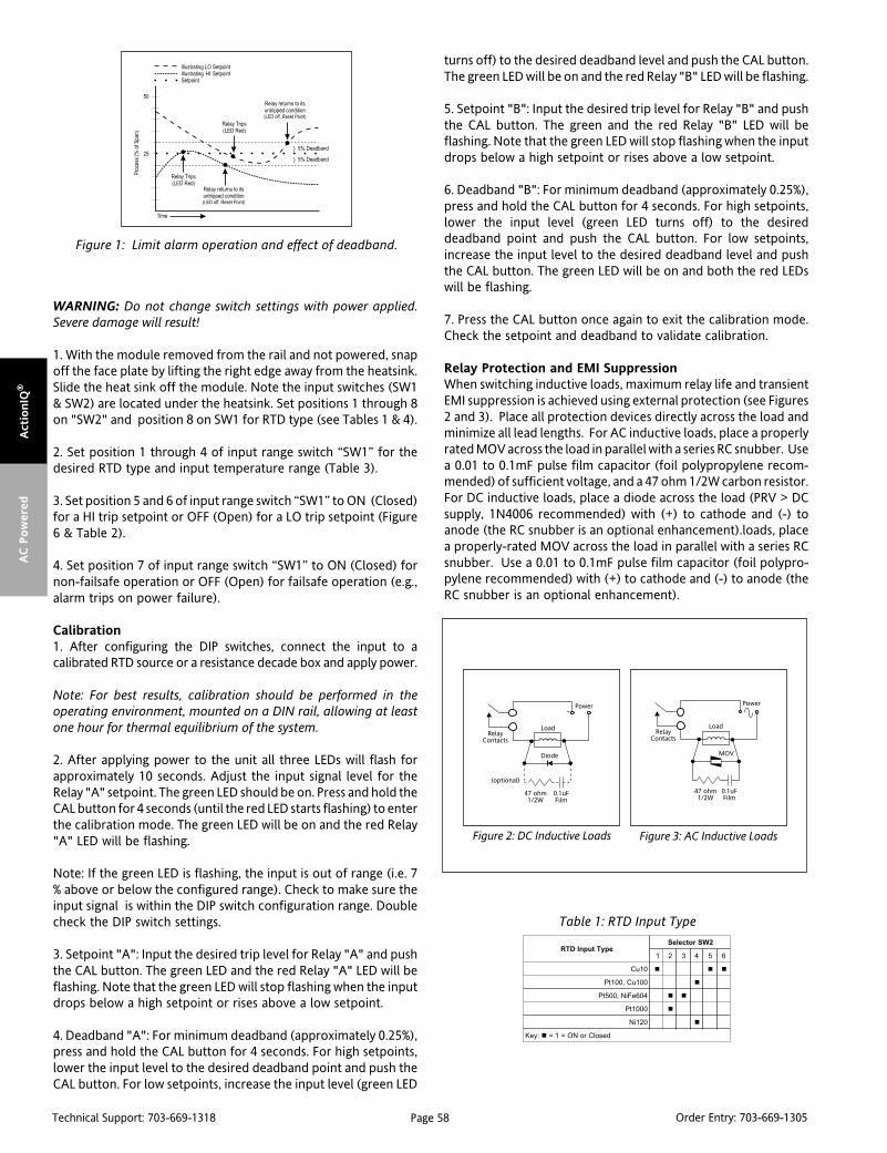
Page 58Technical Support: 703-669-1318 Order Entry: 703-669-1305
Act
ionIQ
®A
C P
ow
ered
WARNING: Do not change switch settings with power applied.Severe damage will result!
1. With the module removed from the rail and not powered, snapoff the face plate by lifting the right edge away from the heatsink.Slide the heat sink off the module. Note the input switches (SW1& SW2) are located under the heatsink. Set positions 1 through 8on "SW2" and position 8 on SW1 for RTD type (see Tables 1 & 4).
2. Set position 1 through 4 of input range switch “SW1” for thedesired RTD type and input temperature range (Table 3).
3. Set position 5 and 6 of input range switch “SW1” to ON (Closed)for a HI trip setpoint or OFF (Open) for a LO trip setpoint (Figure6 & Table 2).
4. Set position 7 of input range switch “SW1” to ON (Closed) fornon-failsafe operation or OFF (Open) for failsafe operation (e.g.,alarm trips on power failure).
Calibration1. After configuring the DIP switches, connect the input to acalibrated RTD source or a resistance decade box and apply power.
Note: For best results, calibration should be performed in theoperating environment, mounted on a DIN rail, allowing at leastone hour for thermal equilibrium of the system.
2. After applying power to the unit all three LEDs will flash forapproximately 10 seconds. Adjust the input signal level for theRelay "A" setpoint. The green LED should be on. Press and hold theCAL button for 4 seconds (until the red LED starts flashing) to enterthe calibration mode. The green LED will be on and the red Relay"A" LED will be flashing.
Note: If the green LED is flashing, the input is out of range (i.e. 7% above or below the configured range). Check to make sure theinput signal is within the DIP switch configuration range. Doublecheck the DIP switch settings.
3. Setpoint "A": Input the desired trip level for Relay "A" and pushthe CAL button. The green LED and the red Relay "A" LED will beflashing. Note that the green LED will stop flashing when the inputdrops below a high setpoint or rises above a low setpoint.
4. Deadband "A": For minimum deadband (approximately 0.25%),press and hold the CAL button for 4 seconds. For high setpoints,lower the input level to the desired deadband point and push theCAL button. For low setpoints, increase the input level (green LED
turns off) to the desired deadband level and push the CAL button.The green LED will be on and the red Relay "B" LED will be flashing.
5. Setpoint "B": Input the desired trip level for Relay "B" and pushthe CAL button. The green and the red Relay "B" LED will beflashing. Note that the green LED will stop flashing when the inputdrops below a high setpoint or rises above a low setpoint.
6. Deadband "B": For minimum deadband (approximately 0.25%),press and hold the CAL button for 4 seconds. For high setpoints,lower the input level (green LED turns off) to the desireddeadband point and push the CAL button. For low setpoints,increase the input level to the desired deadband level and pushthe CAL button. The green LED will be on and both the red LEDswill be flashing.
7. Press the CAL button once again to exit the calibration mode.Check the setpoint and deadband to validate calibration.
Relay Protection and EMI SuppressionWhen switching inductive loads, maximum relay life and transientEMI suppression is achieved using external protection (see Figures2 and 3). Place all protection devices directly across the load andminimize all lead lengths. For AC inductive loads, place a properlyrated MOV across the load in parallel with a series RC snubber. Usea 0.01 to 0.1mF pulse film capacitor (foil polypropylene recom-mended) of sufficient voltage, and a 47 ohm 1/2W carbon resistor.For DC inductive loads, place a diode across the load (PRV > DCsupply, 1N4006 recommended) with (+) to cathode and (-) toanode (the RC snubber is an optional enhancement).loads, placea properly-rated MOV across the load in parallel with a series RCsnubber. Use a 0.01 to 0.1mF pulse film capacitor (foil polypro-pylene recommended) with (+) to cathode and (-) to anode (theRC snubber is an optional enhancement).
Table 1: RTD Input Type
epyTtupnIDTR2WSrotceleS
1 2 3 4 5 6
01uC
001uC,001tP
406eFiN,005tP
0001tP
021iN
:yeK desolCroNO=1=
Figure 1: Limit alarm operation and effect of deadband.
Figure 2: DC Inductive Loads Figure 3: AC Inductive Loads

Page 59Technical Support: 703-669-1318 Order Entry: 703-669-1305
Actio
nIQ
®A
C P
ow
ered
noitaticxEDTR1WS 2WS
8 7 8
DTReriw-3
DTReriw-4
:yeK desolCroNO=1=
egnaRtupnIDTR 1WSrotceleS )smhO(ecnatsiseR
)58300.0=ahpla(0001,005,001tP 1 2 3 4 001tP*
)F°221ot23(C°05ot0 4.911ot001
)F°221ot85-(C°05ot05-
)F°212ot23(C°001ot0 5.831ot001
)F°212ot841-(C°001ot001- 5.831ot2.06
)F°284ot23(C°052ot0 1.491ot001
)F°284ot823-(C°052ot002- 1.491ot5.81
)F°2201ot23(C°055ot0 4.792ot001
)F°2651ot23(C°058ot0 3.093ot001
01uC 1 2 3 4 01uC
)F°851ot77(C°07ot52
)F°851ot22-(C°07ot03- 47.11ot678.7
)F°842ot77(C°021ot52 76.31ot0.01
)F°842ot49-(C°021ot07- 76.31ot813.6
)F°005ot77(C°062ot52 611.91ot0.01
)F°005ot823-(C°062ot002- 611.91ot850.1
001uC 1 2 3 4 001uC
)F°761ot77(C°57ot52 5.511ot001
)F°761ot31-(C°57ot52- 5.511ot7.08
)F°203ot77(C°051ot52 3.841ot001
)F°203ot841-(C°051ot001- 3.841ot3.15
)F°005ot77(C°062ot52 2.191ot001
)F°005ot823-(C°062ot002- 2.191ot6.01
021iN 1 2 3 4 021iN
)F°68ot22-(C°03ot03- 1.241ot4.99
)F°68ot211-(C°03ot08- 1.241ot6.66
)F°212ot22-(C°001ot03-
)F°293ot22-(C°002ot03- 5.303ot4.99
)F°806ot22-(C°023ot03- 2.174ot4.99
406eFiN 1 2 3 4 406eFiN
)F°23ot04-(C°0ot04- 0.406ot1.994
)F°221ot04-(C°05ot04- 8.157ot1.994
)F°221ot823-(C°05ot002- 8.157ot3.542
)F°212ot823-(C°001ot002- 3.719ot3.542
)F°464ot823-(C°042ot002- 6.5741ot3.542
:yeK n desolCroNO=1=
ecnatsiserehtsemit01dna5era0001tPdna005tProfseulavecnatsiseR*.ylevitcepser,001tPfo
Figure 6: Q116 Input Range/Function Selection (SW1) Factory Default Settings
Figure 4: Q116 Calibration Flow Chart
Flashing
On
Off
Green LED
Red LED
Input Trip ASignal Level
Input Trip BSignal Level
noitcnuFtniopteS1WSrotceleS
5 6 7
IH"B"pirT
IH"A"pirT
efasliaF-noN
:yeK desolCroNO=1=
Table 2: Setpoint Function
Table 3: Input Range
Table 4: Excitation Type
Off
On
"B" LO Trip
"B" HI Trip
Off
On
"A" LO Trip
"A" HI Trip
Off
On
Failsafe
Non-failsafe
Off
On
Not Used
Not Used
Input RangeSee Table 3
Figure 5: Q116 RTD Connections

Page 60Technical Support: 703-669-1318 Order Entry: 703-669-1305
Act
ionIQ
®A
C P
ow
ered
Dimensions
Specifications
Sensor Types:
Pt100, Pt500, Pt1000 (0.00385Ω/Ω/°C); Cu10, Cu100; Ni120, NiFe604
Sensor Connection: 3-wire.
Input Ranges: see Table 1.
Excitation Current (Maximum):
<2mA for Pt100, Pt500, Pt1000, Ni120, Cu100 or NiFe604
<10mA for Cu10
Leadwire Resistance:
40% of base sensor resistance or 100 ohms (whichever is less),maximum per lead.
Leadwire Effect:
Less than 1% of full scale over entire leadwire resistance range.
Input Protection:
Normal Mode: Withstands ±5VDC.
Common Mode (Input to Ground): 1800VDC, max.
LED Indicators:
Input Range (Green)
>110% input: 8Hz flash
<-10% input: 4Hz flash
Setpoint (Red)
Tripped: Solid red
Safe: Off
Limit Differential (Deadband): 0.25% to 100% of span
Response Time:
Dynamic Deadband: Relay status will change when propersetpoint/process condition exists for 100msec.
Normal Mode (analog filtering): <250mSec, (10-90%)
Setpoints:
Effectivity: Setpoints adjustable over 100% of the selected input span
Repeatability (constant temp.): ±0.2% of full scale
Stability:
Line Voltage: ±0.01%/%, max.
Temperature: ±0.05% of full scale/°C, max.
Common Mode Rejection:
DC to 60Hz: 120dB
>60Hz: 100dB
Isolation: 1800VDC between contacts, input and power
ESD Susceptibility: Capable of meeting IEC 801-2 level 3(8KV)
Humidity (Non-Condensing):
Operating: 15 to 95% @45°CSoak: 90% for 24 hours @65°C
Temperature Range:
Operating: -15 to 55°C (5 to 131°F)
Storage: -25 to 75°C (-13 to 158°F)
Power: 2.5W max.; 100 to 240VAC +10%; 50-400Hz
Relay Contacts:
2 SPDT (2 form C) Relays, 1 Relay per setpoint
Current Rating (resistive):
120VAC: 5A; 240VAC: 2A; 28VDC: 5A
Material: Gold flash over silver alloy
Electrical Life: 105 operations at rated load
Note: External relay contact protection is required for use withinductive loads.
Mechanical Life: 107 operations
Weight: 0.56lbs.
Agency Approvals:
CSA certified per standard C22.2 (File No LR 42272).
UL recognized per standard UL 508 (File No E99775).
CE EN61326, EN61010-1
Ordering InformationModels & AccessoriesSpecify (model number)1) Q116-00002) Specify I/QRail type and quantity (required)3) Accessories: (see Accessories)4) Optional Custom Factory Calibration: Specify C620 with desired
input, setpoint and deadband.
AccessoriesActionI/Q series modules mount on standard TS32 (model MD02) or TS35(model MD03) DIN rail. In addition, the following accessories are available:
MD02 TS32 DIN railMD03 TS35 x 7.5 DIN rail
IQRL-2002 2 Position I/QRail & DIN railIQRL-2004 4 Position I/QRail & DIN railIQRL-2008 8 Position I/QRail & DIN rail
lanimreT noitcennoC lanimreT noitcennoC
1A .O.N,AyaleR 3C )-(tupnIDTR
2A nommoC,AyaleR 4C nruteRtupnIDTR
3A .C.N,AyaleR 5C desUtoN
4A .O.N,ByaleR 6C desUtoN
5A nommoC,ByaleR 1P )toH(rewoPCA
6A .C.N,ByaleR 2P desUtoN
1C esneStupnIDTR 3P desUtoN
2C )+(tupnIDTR 4P )lartueN(rewoPCA
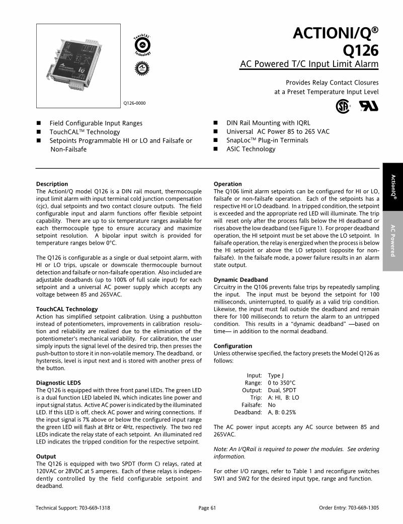
Page 61Technical Support: 703-669-1318 Order Entry: 703-669-1305
Actio
nIQ
®A
C P
ow
ered
DescriptionThe ActionI/Q model Q126 is a DIN rail mount, thermocoupleinput limit alarm with input terminal cold junction compensation(cjc), dual setpoints and two contact closure outputs. The fieldconfigurable input and alarm functions offer flexible setpointcapability. There are up to six temperature ranges available foreach thermocouple type to ensure accuracy and maximizesetpoint resolution. A bipolar input switch is provided fortemperature ranges below 0°C.
The Q126 is configurable as a single or dual setpoint alarm, withHI or LO trips, upscale or downscale thermocouple burnoutdetection and failsafe or non-failsafe operation. Also included areadjustable deadbands (up to 100% of full scale input) for eachsetpoint and a universal AC power supply which accepts anyvoltage between 85 and 265VAC.
TouchCAL TechnologyAction has simplified setpoint calibration. Using a pushbuttoninstead of potentiometers, improvements in calibration resolu-tion and reliability are realized due to the elimination of thepotentiometer's mechanical variability. For calibration, the usersimply inputs the signal level of the desired trip, then presses thepush-button to store it in non-volatile memory. The deadband, orhysteresis, level is input next and is stored with another press ofthe button.
Diagnostic LEDSThe Q126 is equipped with three front panel LEDs. The green LEDis a dual function LED labeled IN, which indicates line power andinput signal status. Active AC power is indicated by the illuminatedLED. If this LED is off, check AC power and wiring connections. Ifthe input signal is 7% above or below the configured input rangethe green LED will flash at 8Hz or 4Hz, respectively. The two redLEDs indicate the relay state of each setpoint. An illuminated redLED indicates the tripped condition for the respective setpoint.
OutputThe Q126 is equipped with two SPDT (form C) relays, rated at120VAC or 28VDC at 5 amperes. Each of these relays is indepen-dently controlled by the field configurable setpoint anddeadband.
ACTIONI/Q®
Q126AC Powered T/C Input Limit Alarm
Provides Relay Contact Closuresat a Preset Temperature Input Level
Field Configurable Input Ranges TouchCALTM Technology Setpoints Programmable HI or LO and Failsafe or
Non-Failsafe
Q126-0000
DIN Rail Mounting with IQRL Universal AC Power 85 to 265 VAC SnapLocTM Plug-in Terminals ASIC Technology
OperationThe Q106 limit alarm setpoints can be configured for HI or LO,failsafe or non-failsafe operation. Each of the setpoints has arespective HI or LO deadband. In a tripped condition, the setpointis exceeded and the appropriate red LED will illuminate. The tripwill reset only after the process falls below the HI deadband orrises above the low deadband (see Figure 1). For proper deadbandoperation, the HI setpoint must be set above the LO setpoint. Infailsafe operation, the relay is energized when the process is belowthe HI setpoint or above the LO setpoint (opposite for non-failsafe). In the failsafe mode, a power failure results in an alarmstate output.
Dynamic DeadbandCircuitry in the Q106 prevents false trips by repeatedly samplingthe input. The input must be beyond the setpoint for 100milliseconds, uninterrupted, to qualify as a valid trip condition.Likewise, the input must fall outside the deadband and remainthere for 100 milliseconds to return the alarm to an untrippedcondition. This results in a “dynamic deadband” —based ontime— in addition to the normal deadband.
ConfigurationUnless otherwise specified, the factory presets the Model Q126 asfollows:
Input: Type JRange: 0 to 350°C
Output: Dual, SPDTTrip: A: HI, B: LO
Failsafe: NoDeadband: A, B: 0.25%
The AC power input accepts any AC source between 85 and265VAC.
Note: An I/QRail is required to power the modules. See orderinginformation.
For other I/O ranges, refer to Table 1 and reconfigure switchesSW1 and SW2 for the desired input type, range and function.
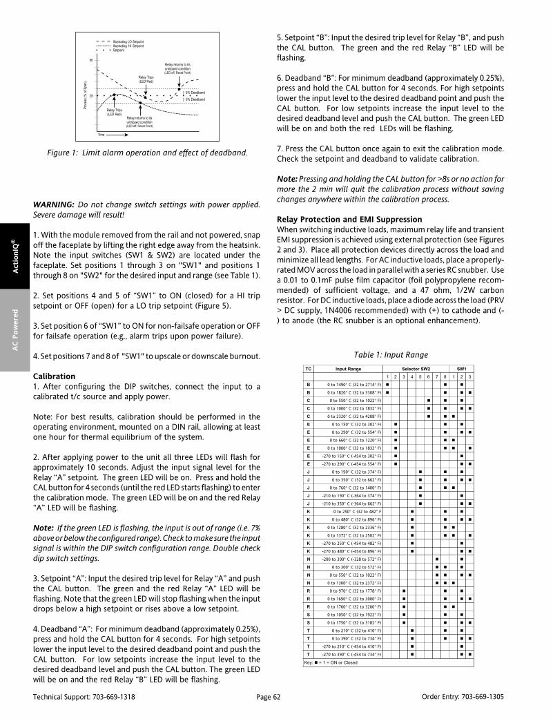
Page 62Technical Support: 703-669-1318 Order Entry: 703-669-1305
Act
ionIQ
®A
C P
ow
ered
WARNING: Do not change switch settings with power applied.Severe damage will result!
1. With the module removed from the rail and not powered, snapoff the faceplate by lifting the right edge away from the heatsink.Note the input switches (SW1 & SW2) are located under thefaceplate. Set positions 1 through 3 on "SW1" and positions 1through 8 on "SW2" for the desired input and range (see Table 1).
2. Set positions 4 and 5 of “SW1” to ON (closed) for a HI tripsetpoint or OFF (open) for a LO trip setpoint (Figure 5).
3. Set position 6 of “SW1” to ON for non-failsafe operation or OFFfor failsafe operation (e.g., alarm trips upon power failure).
4. Set positions 7 and 8 of "SW1" to upscale or downscale burnout.
Calibration1. After configuring the DIP switches, connect the input to acalibrated t/c source and apply power.
Note: For best results, calibration should be performed in theoperating environment, mounted on a DIN rail, allowing at leastone hour for thermal equilibrium of the system.
2. After applying power to the unit all three LEDs will flash forapproximately 10 seconds. Adjust the input signal level for theRelay “A” setpoint. The green LED will be on. Press and hold theCAL button for 4 seconds (until the red LED starts flashing) to enterthe calibration mode. The green LED will be on and the red Relay“A” LED will be flashing.
Note: If the green LED is flashing, the input is out of range (i.e. 7%above or below the configured range). Check to make sure the inputsignal is within the DIP switch configuration range. Double checkdip switch settings.
3. Setpoint “A”: Input the desired trip level for Relay “A” and pushthe CAL button. The green and the red Relay “A” LED will beflashing. Note that the green LED will stop flashing when the inputdrops below a high setpoint or rises above a low setpoint.
4. Deadband “A”: For minimum deadband (approximately 0.25%),press and hold the CAL button for 4 seconds. For high setpointslower the input level to the desired deadband point and push theCAL button. For low setpoints increase the input level to thedesired deadband level and push the CAL button. The green LEDwill be on and the red Relay “B” LED will be flashing.
5. Setpoint “B”: Input the desired trip level for Relay “B”, and pushthe CAL button. The green and the red Relay “B” LED will beflashing.
6. Deadband “B”: For minimum deadband (approximately 0.25%),press and hold the CAL button for 4 seconds. For high setpointslower the input level to the desired deadband point and push theCAL button. For low setpoints increase the input level to thedesired deadband level and push the CAL button. The green LEDwill be on and both the red LEDs will be flashing.
7. Press the CAL button once again to exit the calibration mode.Check the setpoint and deadband to validate calibration.
Note: Pressing and holding the CAL button for >8s or no action formore the 2 min will quit the calibration process without savingchanges anywhere within the calibration process.
Relay Protection and EMI SuppressionWhen switching inductive loads, maximum relay life and transientEMI suppression is achieved using external protection (see Figures2 and 3). Place all protection devices directly across the load andminimize all lead lengths. For AC inductive loads, place a properly-rated MOV across the load in parallel with a series RC snubber. Usea 0.01 to 0.1mF pulse film capacitor (foil polypropylene recom-mended) of sufficient voltage, and a 47 ohm, 1/2W carbonresistor. For DC inductive loads, place a diode across the load (PRV> DC supply, 1N4006 recommended) with (+) to cathode and (-) to anode (the RC snubber is an optional enhancement).
CT egnaRtupnI 2WSrotceleS 1WS
1 2 3 4 5 6 7 8 1 2 3
B )F°4172ot23(C°0941ot0
B )F°8033ot23(C°0281ot0
C )F°2201ot23(C°055ot0
C )F°2381ot23(C°0001ot0
C )F°8024ot23(C°0232ot0
E )F°203ot23(C°051ot0
E )F°455ot23(C°092ot0
E )F°0221ot23(C°066ot0
E )F°2381ot23(C°0001ot0
E )F°203ot454-(C°051ot072-
E )F°455ot454-(C°092ot072-
J )F°473ot23(C°091ot0
J )F°266ot23(C°053ot0
J )F°0041ot23(C°067ot0
J )F°473ot463-(C°091ot012-
J )F°266ot463-(C°053ot012-
K F°284ot23(C°052ot0
K )F°698ot23(C°084ot0
K )F°6332ot23(C°0821ot0
K )F°2052ot23(C°2731ot0
K )F°284ot454-(C°052ot072-
K )F°698ot454-(C°084ot072-
N )F°275ot823-(C°003ot002-
N )F°275ot23(C°003ot0
N )F°2201ot23(C°055ot0
N )F°2732ot23(C°0031ot0
R )F°8771ot23(C°079ot0
R )F°0003ot23(C°0961ot0
R )F°0023ot23(C°0671ot0
S )F°2291ot23(C°0501ot0
S )F°2813ot23(C°0571ot0
T )F°014ot23(C°012ot0
T )F°437ot23(C°093ot0
T )F°014ot454-(C°012ot072-
T )F°437ot454-(C°093ot072-
:yeK desolCroNO=1=
Table 1: Input Range
Figure 1: Limit alarm operation and effect of deadband.
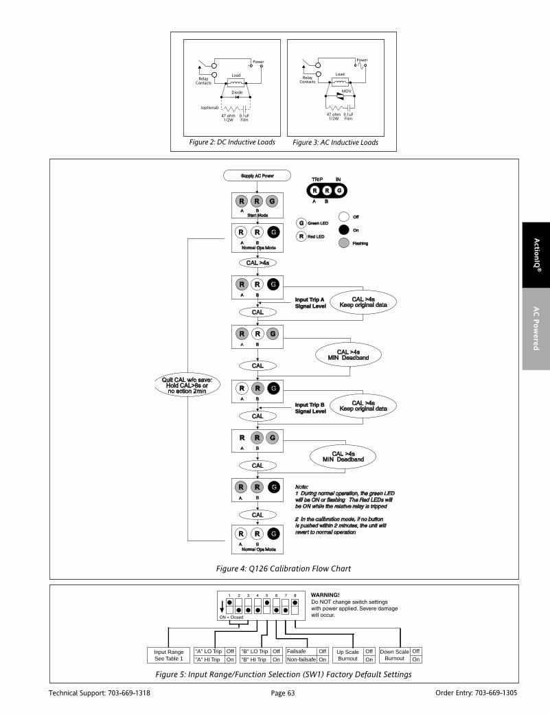
Page 63Technical Support: 703-669-1318 Order Entry: 703-669-1305
Actio
nIQ
®A
C P
ow
ered
Figure 4: Q126 Calibration Flow Chart
FlashingFlashing
OnOn
OfOff
Green LEDGreen LED
Red LEDRed LED
Input TInput Trip rip ASignal LevelSignal Level
Input TInput Trip Brip BSignal LevelSignal Level
Off
On
"A" LO Trip
"A" HI Trip
Off
On
"B" LO Trip
"B" HI Trip
Off
On
Off
OnUp ScaleBurnout
Input RangeSee Table 1
Off
OnDown Scale
BurnoutFailsafe
Non-failsafe
Figure 5: Input Range/Function Selection (SW1) Factory Default Settings
Figure 2: DC Inductive Loads Figure 3: AC Inductive Loads

Page 64Technical Support: 703-669-1318 Order Entry: 703-669-1305
Act
ionIQ
®A
C P
ow
ered
Ordering InformationModels & AccessoriesSpecify (model number)1) Q126-00002) Specify I/QRail type and quantity (required)3) Accessories: (see Accessories)4) Optional Custom Factory Calibration: Specify C620 with desired
input, setpoint and deadband.
AccessoriesActionI/Q series modules mount on standard TS32 (model MD02) or TS35(model MD03) DIN rail. In addition, the following accessories are available:
MD02 TS32 DIN railMD03 TS35 x 7.5 DIN rail
IQRL-2002 2 Position I/QRail &DIN railIQRL-2004 4 Position I/QRail &DIN railIQRL-2008 8 Position I/QRail &DIN rail
Dimensions
Specifications
Inputs:
Range: See Table 1
Impedance: >1 Megohm
Input Bias Current (burnout detect): <1.5 microamp
Overvoltage: ±10V differential
Common Mode (Input to Ground): 1800VDC, max.
LED Indicators:
Input Range (Green)
>110% input: 8Hz flash
<-10% input: 4Hz flash
Setpoint (Red):
Tripped: Solid red
Safe: off
Limit Differential (Deadband):
0.25% to 100% of span
Response Time:
Dynamic Deadband:
Relay status will change when proper setpoint/process conditionexists for 100msec
Normal Mode (analog filtering):
<250msec, (10-90%)
Setpoint:
Effectivity: Setpoints adjustable over 100% of the selected input span.
Repeatability (constant temp.):
0.2% for temp > 0°C0.3% for temp < 0°C
Stability:
Temperature: ±0.05% of full scale/°C, max.
Common Mode Rejection:
DC to 60Hz: 120dB
Isolation:
1800VDC between contacts, input and power
ESD Susceptibility:
Capable of meeting IEC 801-2 level 3 (8kV)
Humidity (Non-Condensing):
Operating: 15 to 95% @45°CSoak: 90% for 24 hours @65°C
Temperature Range:
Operating: 0 to 55°C (32 to 131°F)
Storage: -15 to 70°C (5 to 158°F)
Power:
2.5W max. 100 to 240VAC ±10%, 50 to 400Hz
Relay Contacts:
2 SPDT (2 Form C) Relays, 1 Relay per setpoint
Current Rating (resistive):
120VAC: 5A; 240VAC: 2A; 28VDC: 5A
Material: Gold flash over Silver alloy
Electrical Life: 105 operations at rated load
Note: External relay contact protection is required for use withinductive loads.
Mechanical Life: 107 operations
Wire Termination:
Screw terminations for 12-22 AWG
Weight:
0.56lbs.
Agency Approvals:
CSA certified per standard C22.2 (File No LR 42272).
UL recognized per standard UL 508 (File No E99775).
CE EN61326, EN61010-1
lanimreT noitcennoC lanimreT noitcennoC
1A .O.N,AyaleR 3C desUtoN
2A nommoC,AyaleR 4C desUtoN
3A .C.N,AyaleR 5C )-(tupnIelpuocomrehT
4A .O.N,ByaleR 6C )+(tupnIelpuocomrehT
5A nommoC,ByaleR 1P )toH(rewoPCA
6A .C.N,ByaleR 2P desUtoN
1C desUtoN 3P desUtoN
2C desUtoN 4P )lartueN(rewoPCA

Page 65Technical Support: 703-669-1318 Order Entry: 703-669-1305
Actio
nIQ
®A
C P
ow
ered
DescriptionThe model Q403 is a fast response, DIN rail mount, DC input signalconditioner with 2000VAC isolation between input, output andpower. It is available as a single channel signal conditioner (1input/1 output) or multi-channel signal conditioner (2 inputs/2outputs).
Factory configured input and output ranges support bipolarvoltage signals (+5 Volts and +10 Volts) or unipolar ranges of 4-20mA, 0-5 Volts, 0-10 Volts and 1-5 Volts. Front accessed zero andspan potentiometers allow adjustment of offset and gain tocompensate for sensor errors or signal losses.
All ActionI/Q modules feature SnapLoc plug-in, screw terminalsfor easy installation. Two or more modules can slide together andinterlock for solid, high density mounting (remove either the DINrail foot or the adjacent unit’s face plate, for right side or left sidemounting, respectively). The module to be attached will easilyslide on to the side of the mounted unit.
ApplicationDC input four-wire transmitters are used to isolate and convert DCvoltage or current signals into proportional, standard industrialcontrol signals such as -5/5V or -10/10V. Typically an industrialcontrol system such as a DCS or PLC requires standard industrialcontrol signals and isolation to ensure reliable strong signals.
In most industrial process control or data acquisition applicationsseveral different input sources, including voltages and currentsfrom various field instruments (e.g. level, flow, pressure andposition sensors), are common. Four-wire transmitters acceptthese field inputs and provide the controller (DCS & PLC) with thestandard industrial signals it requires. The four-wire transmitterwill increase the signal drive to high impedance loads and mayimprove resolution of the process variable.
The 2000VAC isolation capability of the Q403 prevents groundloops from causing errors in DC signals. Filtering and commonmode rejection are included to reduce susceptibility to EMI andRFI. Isolation also provides protection from high voltages andcurrent spikes which can damage expensive Supervisory Controland Data Acquisition (SCADA) equipment.
ACTIONI/Q®
Q403AC Powered DC InputMulti-Channel Isolator
Provides 1 or 2 Fully Isolated DC Output Signalsin Proportion to 1 or 2 DC Inputs
Multi-Channel Design 2000VAC Isolation High Density DIN Rail Mounting
Q403-1 (1 input; 1 output)
Q403-2 (2 inputs; 2 outputs)
Universal AC Power 85 to 265 VAC SnapLocTM Plug-in Terminals Fast Response
OperationThe Q403 operates as a four-wire transmitter; each channelderives its power from an independent, transformer isolated, ACto DC power source (85 to 265VAC).
The Q403 has fixed input/output ranges. The standard I/O rangesin Tables 1 are calibrated to rated accuracy. One range permodule; two channels per module, maximum.
CalibrationNote: For best results, calibration should be performed with theintended output load, in the operating environment, mounted ona DIN rail, allowing at least one hour for thermal equilibrium of thesystem.
1. To check calibration connect the input to a calibrated DCsource. Connect the output to a DC voltage or current meter andthe input power to an AC source (between 85 and 256 VAC)capable of providing up to 0.5 Amps.
2. Set the calibrator to the specified minimum DC input value andadjust the zero potentiometer for minimum (e.g. -10V) output.
3. Set the calibrator to the specified maximum DC input value andadjust the span potentiometer for maximum (e.g. +10V) output.
4. Repeat steps 2 and 3 to validate calibration to the output load.
Table 1: Standard Ranges
sledoMelbaliavA
ledoM tupnI tuptuO
80L1-304Q stloV01ot0 Am02ot4
90L1-304Q stloV01ot0stloV01ot0stloV01ot0
stloV5ot0stloV5ot1stloV01ot0
82L1-304QstloV01/01-stloV01/01-
stloV5/5-stloV01/01-
00L2-304QAm02ot4
)slennahChtob(Am02ot4
)slennahChtob(
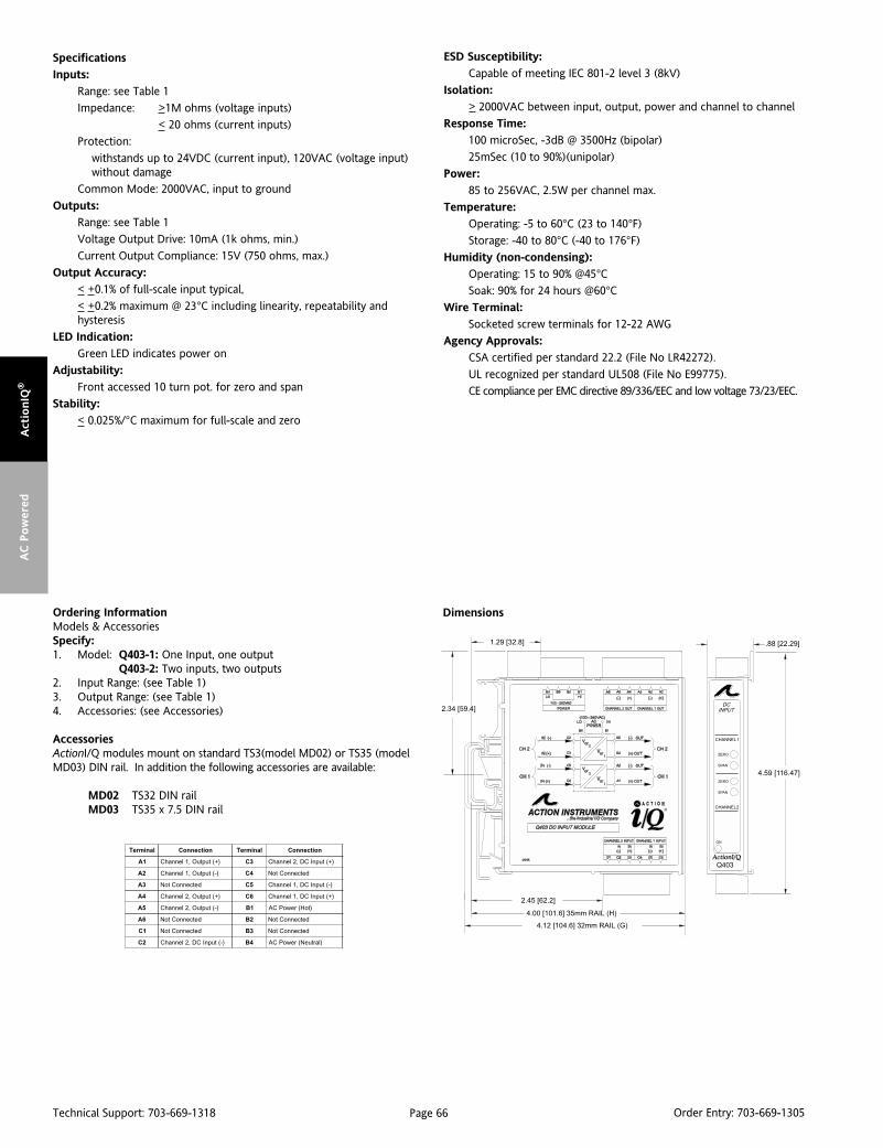
Page 66Technical Support: 703-669-1318 Order Entry: 703-669-1305
Act
ionIQ
®A
C P
ow
ered
Dimensions
Specifications
Inputs:
Range: see Table 1
Impedance: >1M ohms (voltage inputs)
< 20 ohms (current inputs)
Protection:
withstands up to 24VDC (current input), 120VAC (voltage input)without damage
Common Mode: 2000VAC, input to ground
Outputs:
Range: see Table 1
Voltage Output Drive: 10mA (1k ohms, min.)
Current Output Compliance: 15V (750 ohms, max.)
Output Accuracy:
< +0.1% of full-scale input typical,
< +0.2% maximum @ 23°C including linearity, repeatability andhysteresis
LED Indication:
Green LED indicates power on
Adjustability:
Front accessed 10 turn pot. for zero and span
Stability:
< 0.025%/°C maximum for full-scale and zero
ESD Susceptibility:
Capable of meeting IEC 801-2 level 3 (8kV)
Isolation:
> 2000VAC between input, output, power and channel to channel
Response Time:
100 microSec, -3dB @ 3500Hz (bipolar)
25mSec (10 to 90%)(unipolar)
Power:
85 to 256VAC, 2.5W per channel max.
Temperature:
Operating: -5 to 60°C (23 to 140°F)
Storage: -40 to 80°C (-40 to 176°F)
Humidity (non-condensing):
Operating: 15 to 90% @45°CSoak: 90% for 24 hours @60°C
Wire Terminal:
Socketed screw terminals for 12-22 AWG
Agency Approvals:
CSA certified per standard 22.2 (File No LR42272).
UL recognized per standard UL508 (File No E99775).
CE compliance per EMC directive 89/336/EEC and low voltage 73/23/EEC.
Ordering InformationModels & AccessoriesSpecify:1. Model: Q403-1: One Input, one output
Q403-2: Two inputs, two outputs2. Input Range: (see Table 1)3. Output Range: (see Table 1)4. Accessories: (see Accessories)
AccessoriesActionI/Q modules mount on standard TS3(model MD02) or TS35 (modelMD03) DIN rail. In addition the following accessories are available:
MD02 TS32 DIN railMD03 TS35 x 7.5 DIN rail
lanimreT noitcennoC lanimreT noitcennoC
1A )+(tuptuO,1lennahC 3C )+(tupnICD,2lennahC
2A )-(tuptuO,1lennahC 4C detcennoCtoN
3A detcennoCtoN 5C )-(tupnICD,1lennahC
4A )+(tuptuO,2lennahC 6C )+(tupnICD,1lennahC
5A )-(tuptuO,2lennahC 1B )toH(rewoPCA
6A detcennoCtoN 2B detcennoCtoN
1C detcennoCtoN 3B detcennoCtoN
2C )-(tupnICD,2lennahC 4B )lartueN(rewoPCA

Page 67Technical Support: 703-669-1318 Order Entry: 703-669-1305
Actio
nIQ
®A
C P
ow
ered
DescriptionThe model Q406 is an AC powered, DIN rail mount, DC input signalconditioner, with 1800V isolation between input, output andpower. The field configurable input and output feature offersflexible, wide ranging capability for DC current and voltage signals.
The Q406 is available as a single channel signal conditioner (1input/1 output) or as a multi-channel signal conditioner (1 input/2 outputs, or 2 inputs/2 outputs). All models maintain the high1800V isolation level from channel to channel, as well as input tooutput to power.
TouchCAL TechnologyAction has simplified setpoint calibration. Using a pushbuttoninstead of potentiometers, improvements in calibration resolu-tion and reliability are realized due to the elimination of thepotentiometers’ mechanical variability. The thermal drift andmechanical variability of the potentiometers has been removedand replaced with a digitally stable circuit. Additionally, theinherent zero and span interactivity of analog amplifier circuitry isremoved, providing 100% non-interactive adjustment.
The Q406 can be field configured for virtually any DC input to DCoutput within the limits specified. Calibration utilizes “TouchCAL”technology where the user simply configures the input for thecurrent or voltage range via switches, then follows the CalibrationFlow Chart. The output is set by adjusting the input until thedesired output is present and then pressing the CAL button tostore the output level.
Optionally available is a 24VDC excitation source (20mA max.)common to the input and isolated from AC power, which can beused to power a two- or three-wire transducer.
Diagnostic LEDSThe Q406 has three diagnostic LEDs. The green (RUN) LED is usedfor diagnostics to indicate that power is on. It will flash quickly ifthe input signal is above the calibrated range or slowly if the inputsignal is below range. It is on continuously when the unit isfunctioning within the calibrated range.
The yellow (IN) LED is on while calibrating the input and the red(OUT) LED is on while calibrating the output.
ACTIONI/Q®
Q406AC Powered DC InputMulti-Channel Isolator
Provides 1 or 2 Fully Isolated DC Output Signalsin Proportion to 1 or 2 DC Inputs
Field Configurable Input Ranges Field Configurable Output Ranges 1800VAC Isolation TouchCAL™ Technology
Q406-A000 (1 input; 1 output)
Q406-A001 (1 input; 1 output with Excitation Source)
Q406-A002 (signal splitter: 1 input; 2 output)
Q406-A003 (1 input; 2 output with Excitation Source)
Q406-A004 (2 input; 2 output)
High Density DIN Rail Mounting Universal AC Power 85 to 265 VAC SnapLocTM Plug-in Terminals
Configuration The Q406 can be configured for input ranges from 10mV to 100Vor 1mA to 100mA, with >90% input offset or will adjust down to<10% of full scale input span (except on 20mV/2mA range wheremaximum offset or gain adjustment is 50%). Unless a specificcustom calibration is specified, the factory presets the ModelQ406 as follows:
Input Range: 20mA (Current on)Input Configuration: Unipolar
Calibrated Input: 4-20mAOperation: Direct (Reverse off)
Calibrated Output: 4-20mA
For other I/O ranges, refer to the tables below.
WARNING: Do not change switch settings with power applied.Severe damage will result!
1. With power off, snap off the faceplate by lifting the right edgeaway from the heatsink. Slide the heatsink forward and off themodule.
2. The single channel module has two eight position switch blocks,one for input and one for output. The dual output modules havea second board behind the heatsink. Gently lift this board awayfrom the main board, rocking it back while lifting. The one input,two output module has one ten position switch block for input andchannel 1 output, along with a two position switch for the secondoutput. The two input, two output module has two ten positionswitch blocks, one for each channel.
3. For single channel modules, choose the desired input, functionand output range from Table 1, 2, and 3. For multi-channelmodules, use Table 4. Set the dip switches for the desired I/O.
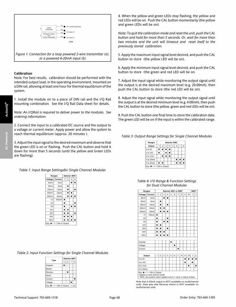
Page 68Technical Support: 703-669-1318 Order Entry: 703-669-1305
Act
ionIQ
®A
C P
ow
ered
CalibrationNote: For best results, calibration should be performed with theintended output load, in the operating environment, mounted ona DIN rail, allowing at least one hour for thermal equilibrium of thesystem.
1. Install the module on to a piece of DIN rail and the I/Q Railmounting combination. See the I/Q Rail Data sheet for details.
Note: An I/QRail is required to deliver power to the modules. Seeordering information.
2. Connect the input to a calibrated DC source and the output toa voltage or current meter. Apply power and allow the system toreach thermal equilibrium (approx. 20 minutes ).
3. Adjust the input signal to the desired maximum and observe thatthe green LED is on or flashing. Push the CAL button and hold itdown for more than 5 seconds (until the yellow and Green LEDsare flashing).
Figure 1: Connection for a loop powered 2-wire transmitter (a), or a powered 4-20mA input (b).
epyT1WSrotceleS
5 6 7 8
ralopinU - - -
ralopiB - - -
esreveR - - -
tceriD - - -
tnerruC - -
egatloV - -
:yeK a/n=-;desolCroNO=1=
segnaR *2WSro1WSrotceleS **2WS
egatloV tnerruC 1 2 3 4 5 6 7 8 9 01 1 2
Vm02 Am2
Vm05 Am5
Vm001 Am01
Vm002 Am02
Vm005 Am05
V1 Am001
V2
V5
V01
V52
V05
V001
ralopinU
egatloV
tnerruC
tuptuO 1 2 3 4 5 6 7 8 9 01 1 2
V5ot0
V01ot0
Am1ot0
Am02ot4
:yeK desolCroNO=1=ledomlennahclaudotseilppA*
eludomtuptuo2,tupni1otylnoseilppahctiwsnoitisopowt,2WS**
segnaR 1WSrotceleS
egatloV tnerruC 1 2 3 4
Vm02 Am2
Vm05 Am5
Vm001 Am01
Vm002 Am02
Vm005 Am05
V1 Am001
V2
V5
V01
V52
V05
V001
:yeK desolCroNO=1=
segnaR 2WSrotceleS
tuptuO 1 2 3 4 5 6 7 8
V5ot0
V01ot0
Am1ot0
Am02ot4
Am02ot0
:yeK desolCroNO=1=
Table 1: Input Range Settingsfor Single Channel Modules
Table 3: Output Range Settings for Single Channel Modules
Table 2: Input Function Settings for Single Channel Modules
Table 4: I/O Range & Function Settingsfor Dual Channel Modules
Note that 0-20mA output is NOT available on multichannel
units. Note also that Reverse Action is NOT available on
multichannel units.
4. When the yellow and green LEDs stop flashing, the yellow andred LEDs will be on. Push the CAL button momentarily (the yellowand green LEDs will be on).
Note: To quit the calibration mode and reset the unit, push the CALbutton and hold for more than 5 seconds. Or, wait for more thantwo minutes and the unit will timeout and reset itself to thepreviously stored calibration.
5. Apply the maximum input signal level desired, and push the CALbutton to store (the yellow LED will be on).
6. Apply the minimum input signal level desired, and push the CALbutton to store (the green and red LED will be on.
7. Adjust the input signal while monitoring the output signal untilthe output is at the desired maximum level (e.g. 20.00mA), thenpush the CAL button to store (the red LED will be on).
8. Adjust the input signal while monitoring the output signal untilthe output is at the desired minimum level (e.g. 4.00mA), then pushthe CAL button to store (the yellow, green and red LEDs will be on).
9. Push the CAL button one final time to store the calibration data.The green LED will be on if the input is within the calibrated range.
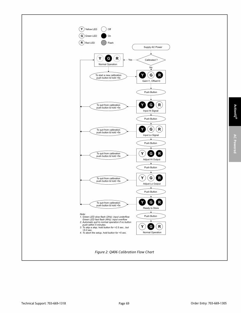
Page 69Technical Support: 703-669-1318 Order Entry: 703-669-1305
Actio
nIQ
®A
C P
ow
ered
Figure 2: Q406 Calibration Flow Chart

Page 70Technical Support: 703-669-1318 Order Entry: 703-669-1305
Act
ionIQ
®A
C P
ow
ered
Specifications
Inputs:
Voltage:
Range Limits: 10mV to 100V (see Table 1)
Impedance: >100k ohms
Overvoltage: 200V continuous
Current Input:
Range Limits: 1mA to 100mA
Impedance: 20 ohms typical
Overcurrent: 170mA, protected by self resetting fuse
Overvoltage: 60V
Pushbutton Adjustment (inputs>10mV)
Effective zero offset: > 90%
Effective span turn down: > 90% except 20mV/2mA range inwhich 50% is max. zero offset and span turndown
Outputs:
Voltage:
Output: 0-5V, 0-10V
Source Impedance: <10 ohms
Drive: 10mA max.
Current:
Output: 4-20mA, 0-1mA (0-20mA on single channel versions only)
Source Impedance: >100k ohms
Compliance:
0-1mA: 7.5V max. (7.5k ohms)
4-20mA: 12V max. (600 ohms)*
0-20mA: 12V max. (600 ohms)
*10V max. (500 ohms) on dual out versions
Output Ripple:
<50% offset or span adjust:<0.1% off full scale span or 25mV RMS,whichever is greater
>50% offset or span adjust:<0.2% of full scale span or 50mV RMS,whichever is greater.
Output Accuracy:
>2mA / >20mV input spans:+0.1% of full-scale input typical, +0.2% maximum
<2mA / <20mV input spans:
+ 0.35% of fullscale input typical, + 0.5% maxmum; includinglinearity, repeatability and hysteresis @23C.
Response Time: 200mSec, typical
Stability: +0.025% of full scale /C, maximum for fullscale and zero
Excitation Voltage (optional): 24VDC, 20mA maximum
Common Mode Rejection: 120dB at DC, >90dB at 60Hz
Isolation: > 1800VDC or peak AC between input, output, power andchannel to channel
ESD Susceptibility: Capable of meeting IEC 801-2 level 3(8kV)
Humidity (non-condensing):
Operating: 15 to 95% RH @45°CSoak: 90% RH for 24 hours @60°C
Temperature:
Operating: 0 to 55°C (32 to 131°F)
Storage: -25 to 70°C (-13 to 158°F)
Power: 2.5W max; 100 to 240VAC, +10%, 50 to 400Hz
Wire Terminals: Socketed screw terminals for 12-22 AWG
Agency Approvals:
CSA certified per standard C22,2 (File No LR 42272).
UL recognized per standard UL508 (File No. E99775).
CE compliance per EMC directive 89/336/EECand low voltage 73/23/EEC.
DimensionsOrdering InformationModels & AccessoriesSpecify:1. Model:
Q406-A000: one input, one output DC IsolatorQ406-A001: one input, one output DC Isolator
with 24VDC excitation sourceQ406-A002: one input, two output DC IsolatorQ406-A003: one input, two output DC Isolator
with 24VDC excitation sourceQ406-A004: two input, two output DC Isolator
2. Specify I/QRail type and quantity (required)3. Custom Calibration: C620 - calibrates units to a customer specified range.4. Accessories: (see Accessories)
AccessoriesActionI/Q modules mount on standard TS32 (model MD02) or TS35 (modelMD03) DIN rail. In addition the following accessories are available:
MD02 TS32 DIN railMD03 TS35 x 7.5 DIN rail
IQRL-2002 2 Position I/QRail & DIN railIQRL-2004 4 Position I/QRail & DIN railIQRL-2008 8 Position I/QRail & DIN rail
lanimreT noitcennoC lanimreT noitcennoC
1B )+(tuO1lennahC 4C )CDV42+(ylppuSegatloV
2B )-(tuO1lennahC 5C )-(nI1lennahC
3B )+(tuO2lennahC 6C )+(nI1lennahC
4B )-(tuO2lennahC 1P )toH(rewoPCA
1C )-(nI2lennahC 2P desUtoN
2C )+(nI2lennahC 3P desUtoN
3C detcennoCtoN 4P )lartueN(rewoPCA
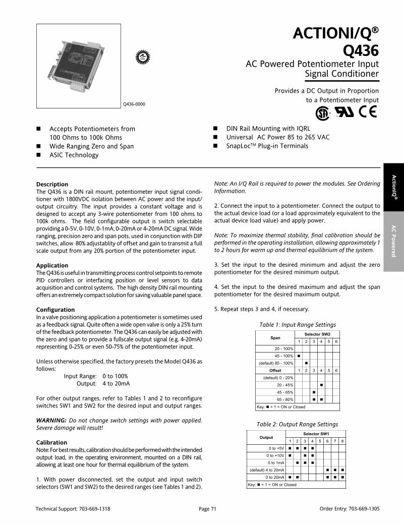
Page 71Technical Support: 703-669-1318 Order Entry: 703-669-1305
Actio
nIQ
®A
C P
ow
ered
DescriptionThe Q436 is a DIN rail mount, potentiometer input signal condi-tioner with 1800VDC isolation between AC power and the input/output circuitry. The input provides a constant voltage and isdesigned to accept any 3-wire potentiometer from 100 ohms to100k ohms. The field configurable output is switch selectableproviding a 0-5V, 0-10V, 0-1mA, 0-20mA or 4-20mA DC signal. Wideranging, precision zero and span pots, used in conjunction with DIPswitches, allow 80% adjustablity of offset and gain to transmit a fullscale output from any 20% portion of the potentiometer input.
ApplicationThe Q436 is useful in transmitting process control setpoints to remotePID controllers or interfacing position or level sensors to dataacquisition and control systems. The high density DIN rail mountingoffers an extremely compact solution for saving valuable panel space.
ConfigurationIn a valve positioning application a potentiometer is sometimes usedas a feedback signal. Quite often a wide open valve is only a 25% turnof the feedback potentiometer. The Q436 can easily be adjusted withthe zero and span to provide a fullscale output signal (e.g. 4-20mA)representing 0-25% or even 50-75% of the potentiometer input.
Unless otherwise specified, the factory presets the Model Q436 asfollows:
Input Range: 0 to 100%Output: 4 to 20mA
For other output ranges, refer to Tables 1 and 2 to reconfigureswitches SW1 and SW2 for the desired input and output ranges.
WARNING: Do not change switch settings with power applied.Severe damage will result!
CalibrationNote: For best results, calibration should be performed with the intendedoutput load, in the operating environment, mounted on a DIN rail,allowing at least one hour for thermal equilibrium of the system.
1. With power disconnected, set the output and input switchselectors (SW1 and SW2) to the desired ranges (see Tables 1 and 2).
ACTIONI/Q®
Q436AC Powered Potentiometer Input
Signal Conditioner
Provides a DC Output in Proportionto a Potentiometer Input
Accepts Potentiometers from100 Ohms to 100k Ohms
Wide Ranging Zero and Span ASIC Technology
Q436-0000
DIN Rail Mounting with IQRL Universal AC Power 85 to 265 VAC SnapLocTM Plug-in Terminals
Note: An I/Q Rail is required to power the modules. See OrderingInformation.
2. Connect the input to a potentiometer. Connect the output tothe actual device load (or a load approximately equivalent to theactual device load value) and apply power.
Note: To maximize thermal stability, final calibration should beperformed in the operating installation, allowing approximately 1to 2 hours for warm up and thermal equilibrium of the system.
3. Set the input to the desired minimum and adjust the zeropotentiometer for the desired minimum output.
4. Set the input to the desired maximum and adjust the spanpotentiometer for the desired maximum output.
5. Repeat steps 3 and 4, if necessary.
napS2WSrotceleS
1 2 3 4 5 6
%001-02
%001-54
%001-58)tluafed(
tesffO 1 2 3 4 5 6
%02-0)tluafed(
%54-02
%56-54
%08-56
:yeK desolCroNO=1=
Table 1: Input Range Settings
tuptuO1WSrotceleS
1 2 3 4 5 6 7 8
V5+ot0
V01+ot0
Am1ot0
Am02ot4)tluafed(
Am02ot0
:yeK desolCroNO=1=
Table 2: Output Range Settings

Page 72Technical Support: 703-669-1318 Order Entry: 703-669-1305
Act
ionIQ
®A
C P
ow
ered
Specifications
Potentiometer Input:
End-to-end Resistance: 100 ohms up to 100k ohms
Input Impedance: >1M ohms
Input Excitation: 500mV, 5mA maximum drive.
Zero Turn-Up: 80% of full scale input
Span Turn-Down: 80% of full scale input
Common Mode Rejection: 1800VDC (input to power)
Output:
Voltage
Output: 0-5V, 0-10V
Source Impedance: <10 ohms
Drive: 10mA, max. (1k ohms min. @10V)
Current Output
Output: 0-1mA, 0-20mA, 4-20mA
Source Impedance: >100k ohms
Compliance:
0-1mA: 7.5V, max. (7.5k ohms, max.)0-20mA: 12V, max. (600 ohms, max.)4-20mA: 12V, max. (600 ohms, max.)
Accuracy (Including Linearity, Hysteresis):
±0.1% maximum at 25°C.
Stability:
Temperature: <±0.05%/°C maximum of full scale range.
Response Time (10 to 90%):
<200mSec., typical.
Common Mode Rejection:
120dB @ DC, >100dB @ 60Hz
Isolation:
800VDC between line power and input, output
EMC Compliance (CE Mark):
Emissions: EN50081-1
Immunity: EN50082-2
Safety: EN50178
Ordering InformationModels and AccessoriesSpecify:1. Model: Q436-00002. Specify I/QRail type and quantity (required)3. Optional Custom Factory Calibration; specify C620 with desired
input and output range4. Accessories: (see Accessories)
AccessoriesActionI/Q modules will mount on standard TS32 (model MD02) or TS35(model MD03) DIN Rail. In addition, the following accessories are available:
MD02 TS32 DIN railMD03 TS35 x 7.5 DIN rail
IQRL-2002 2 Position I/QRail & DIN railIQRL-2004 4 Position I/QRail & DIN railIQRL-2008 8 Position I/QRail & DIN rail
C620 Factory Calibration
Dimensions
LED Indication (green):
Active DC power
Humidity (Non-Condensing):
Operating: 15 to 95% @ 45°CSoak: 90% for 24 hours @ 65°C
Temperature Range:
Operating: 0 to 55°C (32 to 131°F)
Storage: -25 to 70°C (-13 to 158°F)
Power:
Consumption: 1.5W typical, 2.5W max
Range: 100 to 240VAC, ±10%, 50 to 400Hz
Weight:
0.48 lbs
Agency Approvals:
UL recognized per standard UL508 (File No. E99775).
CSA certified per standard C22.2, No. 0-M91
and 142-M1987 (Cert. # 2500003630).
CE Compliance per EMC directive 89/336/EECand Low Voltage 73/23/EEC.
lanimreT noitcennoC lanimreT noitcennoC
1A )+(tuptuOCD 3C dnuorGdleihS
2A )-(tuptuOCD 4C )WCCylluf(tupnI.toP
3A desUtoN 5C repiWtupnI.toP
4A desUtoN 6C )WCylluf(tupnI.toP
5A desUtoN 1P )toH(rewoPCA
6A desUtoN 2P desUtoN
1C desUtoN 3P desUtoN
2C desUtoN 4P )lartueN(rewoPCA
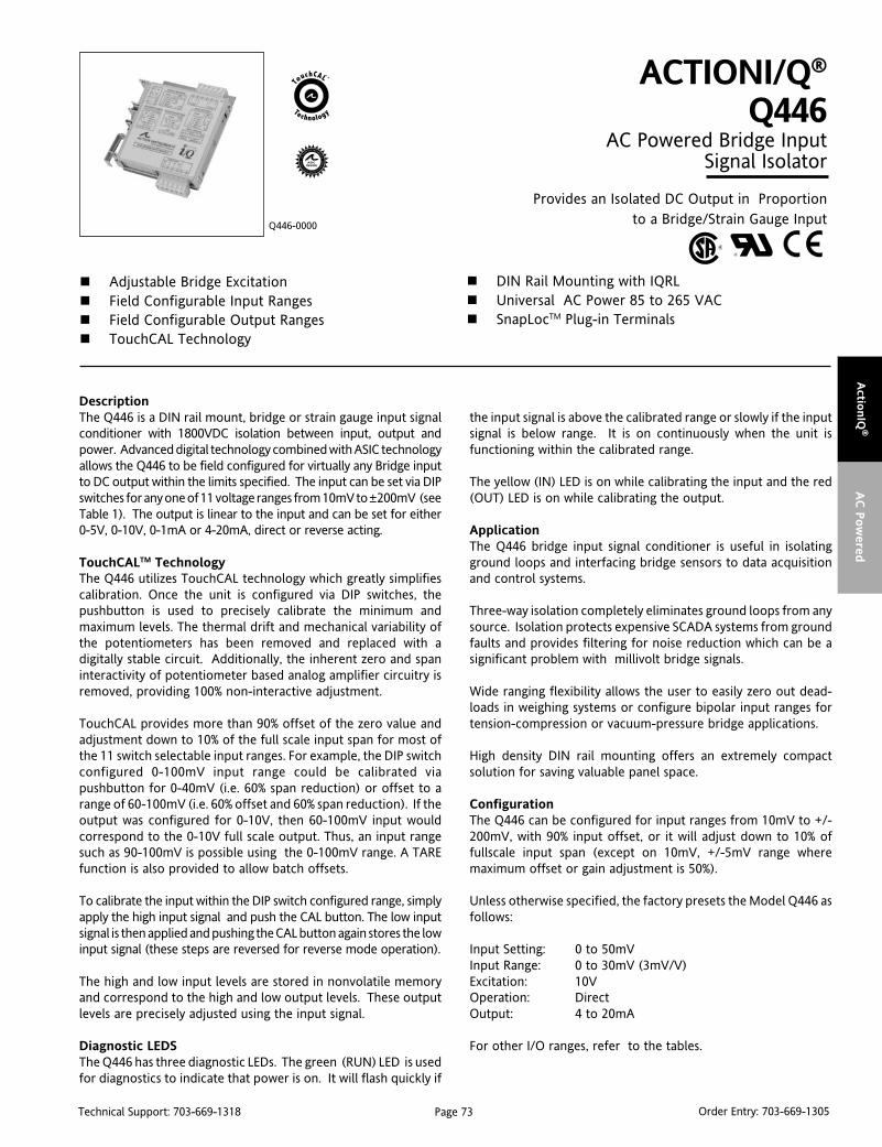
Page 73Technical Support: 703-669-1318 Order Entry: 703-669-1305
Actio
nIQ
®A
C P
ow
ered
DescriptionThe Q446 is a DIN rail mount, bridge or strain gauge input signalconditioner with 1800VDC isolation between input, output andpower. Advanced digital technology combined with ASIC technologyallows the Q446 to be field configured for virtually any Bridge inputto DC output within the limits specified. The input can be set via DIPswitches for any one of 11 voltage ranges from 10mV to ±200mV (seeTable 1). The output is linear to the input and can be set for either0-5V, 0-10V, 0-1mA or 4-20mA, direct or reverse acting.
TouchCALTM TechnologyThe Q446 utilizes TouchCAL technology which greatly simplifiescalibration. Once the unit is configured via DIP switches, thepushbutton is used to precisely calibrate the minimum andmaximum levels. The thermal drift and mechanical variability ofthe potentiometers has been removed and replaced with adigitally stable circuit. Additionally, the inherent zero and spaninteractivity of potentiometer based analog amplifier circuitry isremoved, providing 100% non-interactive adjustment.
TouchCAL provides more than 90% offset of the zero value andadjustment down to 10% of the full scale input span for most ofthe 11 switch selectable input ranges. For example, the DIP switchconfigured 0-100mV input range could be calibrated viapushbutton for 0-40mV (i.e. 60% span reduction) or offset to arange of 60-100mV (i.e. 60% offset and 60% span reduction). If theoutput was configured for 0-10V, then 60-100mV input wouldcorrespond to the 0-10V full scale output. Thus, an input rangesuch as 90-100mV is possible using the 0-100mV range. A TAREfunction is also provided to allow batch offsets.
To calibrate the input within the DIP switch configured range, simplyapply the high input signal and push the CAL button. The low inputsignal is then applied and pushing the CAL button again stores the lowinput signal (these steps are reversed for reverse mode operation).
The high and low input levels are stored in nonvolatile memoryand correspond to the high and low output levels. These outputlevels are precisely adjusted using the input signal.
Diagnostic LEDSThe Q446 has three diagnostic LEDs. The green (RUN) LED is usedfor diagnostics to indicate that power is on. It will flash quickly if
ACTIONI/Q®
Q446AC Powered Bridge Input
Signal Isolator
Provides an Isolated DC Output in Proportionto a Bridge/Strain Gauge Input
Adjustable Bridge Excitation Field Configurable Input Ranges Field Configurable Output Ranges TouchCAL Technology
Q446-0000
DIN Rail Mounting with IQRL Universal AC Power 85 to 265 VAC SnapLocTM Plug-in Terminals
the input signal is above the calibrated range or slowly if the inputsignal is below range. It is on continuously when the unit isfunctioning within the calibrated range.
The yellow (IN) LED is on while calibrating the input and the red(OUT) LED is on while calibrating the output.
ApplicationThe Q446 bridge input signal conditioner is useful in isolatingground loops and interfacing bridge sensors to data acquisitionand control systems.
Three-way isolation completely eliminates ground loops from anysource. Isolation protects expensive SCADA systems from groundfaults and provides filtering for noise reduction which can be asignificant problem with millivolt bridge signals.
Wide ranging flexibility allows the user to easily zero out dead-loads in weighing systems or configure bipolar input ranges fortension-compression or vacuum-pressure bridge applications.
High density DIN rail mounting offers an extremely compactsolution for saving valuable panel space.
ConfigurationThe Q446 can be configured for input ranges from 10mV to +/-200mV, with 90% input offset, or it will adjust down to 10% offullscale input span (except on 10mV, +/-5mV range wheremaximum offset or gain adjustment is 50%).
Unless otherwise specified, the factory presets the Model Q446 asfollows:
Input Setting: 0 to 50mVInput Range: 0 to 30mV (3mV/V)Excitation: 10VOperation: DirectOutput: 4 to 20mA
For other I/O ranges, refer to the tables.
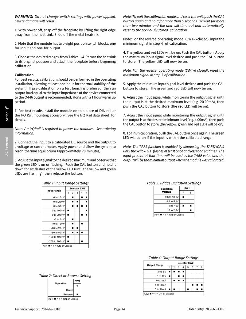
Page 74Technical Support: 703-669-1318 Order Entry: 703-669-1305
Act
ionIQ
®A
C P
ow
ered
WARNING: Do not change switch settings with power applied.Severe damage will result!
1. With power off, snap off the faceplate by lifting the right edgeaway from the heat sink. Slide off the metal heatsink.
2. Note that the module has two eight position switch blocks, onefor input and one for output.
3. Choose the desired ranges from Tables 1-4. Return the heatsinkto its original position and attach the faceplate before beginningcalibration.
CalibrationFor best results, calibration should be performed in the operatinginstallation, allowing at least one hour for thermal stability of thesystem. If pre-calibration on a test bench is preferred, then anoutput load equal to the input impedance of the device connectedto the Q446 output is recommended, along with a 1 hour warm upperiod.
1. For best results install the module on to a piece of DIN rail orthe I/Q Rail mounting accessory. See the I/Q Rail data sheet fordetails.
Note: An I/QRail is required to power the modules. See orderinginformation.
2. Connect the input to a calibrated DC source and the output toa voltage or current meter. Apply power and allow the system toreach thermal equilibrium (approximately 20 minutes).
3. Adjust the input signal to the desired maximum and observe thatthe green LED is on or flashing. Push the CAL button and hold itdown for six flashes of the yellow LED (until the yellow and greenLEDs are flashing), then release the button.
Note: To quit the calibration mode and reset the unit, push the CALbutton again and hold for more than 5 seconds. Or wait for morethan two minutes and the unit will time-out and automaticallyreset to the previously stored calibration.
Note: For the reverse operating mode (SW1-6 closed), input theminimum signal in step 4 of calibration.
4. The yellow and red LEDs will be on. Push the CAL button. Applythe maximum input signal level desired and push the CAL buttonto store. The yellow LED will now be on.
Note: For the reverse operating mode (SW1-6 closed), input themaximum signal in step 5 of calibration.
5. Apply the minimum input signal level desired and push the CALbutton to store. The green and red LED will now be on.
6. Adjust the input signal while monitoring the output signal untilthe output is at the desired maximum level (e.g. 20.00mA), thenpush the CAL button to store (the red LED will be on).
7. Adjust the input signal while monitoring the output signal untilthe output is at the desired minimum level (e.g. 4.00mA), then pushthe CAL button to store (the yellow, green and red LEDs will be on).
8. To finish calibration, push the CAL button once again. The greenLED will be on if the input is within the calibrated range.
Note: The TARE function is enabled by depressing the TARE/(CAL)until the yellow LED flashes at least once and less than six times. Theinput present at that time will be used as the TARE value and theoutput will be the minimum output when the module was calibrated.
noitarepO1WS
6
tceriD
esreveR
:yeK desolCroNO=1=
egnaRtupnI1WSrotceleS
1 2 3 4 5
Vm01ot0
Vm02ot0
Vm05ot0
Vm001ot0
Vm002ot0
Vm5ot5-
Vm01ot01-
Vm02ot02-
Vm05ot05-
Vm001ot001-
Vm002ot002-
:yeK desolCroNO=1=
egnaRtuptuO2WSrotceleS
1 2 3 4 5 6 7 8
V5ot0
V01ot0
Am1ot0
Am02ot4
Am02ot0
:yeK desolCroNO=1=
noitaticxEegatloV egatloV egatloV egatloV egatloV
1WS
7 8
V1.01ot8.9
V2.5ot8.4
V01ot0
V5.2ot0
:yeK desolCroNO=1=
Table 1: Input Range Settings
Table 2: Direct or Reverse Setting
Table 3: Bridge Excitation Settings
Table 4: Output Range Settings
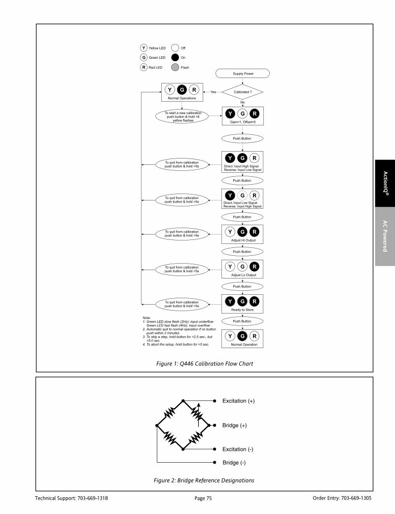
Page 75Technical Support: 703-669-1318 Order Entry: 703-669-1305
Actio
nIQ
®A
C P
ow
ered
Figure 1: Q446 Calibration Flow Chart
Figure 2: Bridge Reference Designations

Page 76Technical Support: 703-669-1318 Order Entry: 703-669-1305
Act
ionIQ
®A
C P
ow
ered
SpecificationsInput:
Voltage:Full Scale Range: 10mV to ±200mV (Table 1).Impedance: >1M ohmOvervoltage:
Intermittent 400V, max.Continuous 264V, max.
Common Mode (Input to Ground):1800VDC, max.
Pushbutton Adjustment:Effective zero offset: >90%Effective span turn down: >90% except for 10mV & +/-5mV
range in which 50% is max. zero offset and span turndownOperation: direct or reverse acting
Output:Voltage:
Output: 0-5V, 0-10VImpedance: <10 ohmsDrive: 10mA, max. (1K ohms, min. @ 10V)
Current:Output: 0-1mA, 0-20mA, 4-20mAImpedance: >100K ohmsCompliance:
0-1mA; 7.5V, max. (7.5K ohms, max.)0-20mA; 12V, max. (600 ohms, max.)4-20mA; 12V, max. (600 ohms, max.)
Bridge Excitation:1 to 10VDC, 120mA max. Current drive decreases at 10mA/V below
5V (e.g. 4V, 110mA max.)Accuracy (Including Linearity, Hysteresis):
±0.1% typical, ±0.2% maximum of selected input range at 25°C.Stability:
±0.025%/°C typical, 0.05%/°C maximum, of selected full scale input range.
Output Noise (maximum):0.1% rms of span, or 10mV whichever is greater.
Response Time (10 to 90%):<200mSec., typical.
Common Mode Rejection:DC to 60Hz: 120dB, 100dB (0 -1mA, range)
Isolation:1800VDC between input, output and power.
EMC Compliance (CE Mark)Emissions: EN50081-1; Immunity: EN50082-2; Safety: EN50178
LED Indication (Green):Input Range (approx.)
>110% input: 8Hz flash<0% input: 4Hz flash
Humidity (Non-Condensing):Operating: 15 to 95% @ 45°CSoak: 90% for 24 hours @ 65°C
Temperature Range:Operating: 0 to 55°C (32 to 131°F)Storage: -25 to 70°C (-13 to 158°F)
Power:Consumption:
2.7W typical (one 350 ohm bridge),5W max. (four 350 ohm bridges).
Range: 100-240VACShipping Weight:
0.54 lbs.Wire Terminations:
Screw terminals for 12-22 AWGAgency Approvals:
UL recognized per standard UL508.CSA certified per standard 22.2 No. 0-M91 and 142-M1987.CE Compliance per EMC directive 89/3/36 EEC and Low Voltage 73/23/EEC.
Ordering InformationModels & AccessoriesSpecify:1. Model: Q446-0000;2. Specify optional I/QRail, type and quantity (required)3. Accessories: (see Accessories)4. Optional Factory Custom Calibration, specify C620 - with desired
input and output ranges.
AccessoriesActionI/Q modules mount on standard TS32 (model MD02) or TS35 (modelMD03) DIN rail. In addition the following accessories are available:
MD02 TS32 DIN railMD03 TS35 x 7.5 DIN rail
IQRL-2002 2 Position I/QRail & DIN railIQRL-2004 4 Position I/QRail & DIN railIQRL-2008 8 Position I/QRail & DIN rail
Dimensions
lanimreT noitcennoC lanimreT noitcennoC
1A )+(tuptuOCD 3C )-(tupnIegdirB
2A )-(tuptuOCD 4C )-(noitaticxEegdirB
3A desUtoN 5C detcennoCtoN
4A desUtoN 6C detcennoCtoN
5A desUtoN 1P )toH(rewoPCA
6A desUtoN 2P desUtoN
1C )+(noitaticxEegdirB 3P desUtoN
2C )+(tupnIegdirB 4P )lartueN(rewoPCA

Page 77Technical Support: 703-669-1318 Order Entry: 703-669-1305
Actio
nIQ
®A
C P
ow
ered
DescriptionThe Q466 is a DIN rail mount, AC input signal conditioner with1800VDC isolation between input, output and power. The fieldconfigurable input and output offers flexible, wide ranging capa-bility for scaling, converting or buffering AC inputs ranging from5mA to 100mAAC or 50mV to 300VAC.
For current inputs above 100mA, it is recommended that an inputshunt resistor be used and the Q466 be configured for the properinput range. For example, a 5A current transformer output can usethe C006 shunt resistor (0.1 ohm, 5W) with the input of the Q466set for 0-500mVAC.
The DC output of the Q466 is proportional to the average of thefully-rectified AC input signal, and is calibrated for sine wavesbetween 40-400Hz.
TouchCALTM TechnologyThe Q466 utilizes TouchCAL technology which greatly simplifiescalibration. The thermal drift and mechanical variability of thepotentiometers has been removed and replaced with a digitallystable circuit. Once the unit is configured via DIP switches forvoltage or current, the pushbutton is used to precisely calibratethe minimum and maximum levels.
To set the input level within the dip switch configured range,simply apply the high input signal (voltage or current) and push theCAL button. The low input signal is then applied and pushing theCAL button again stores the low input signal. The high and lowinput levels are stored in nonvolatile memory and correspond tothe high and low output levels. These output levels are preciselyadjusted using the input signal.
TouchCAL technology enables precise calibration and provides morethan 90% offset of the zero value and adjustment down to 10% of thefull scale input span for most of the 16 switch selectable input ranges.For example, the dipswitch configured 0-200V input range could becalibrated via pushbutton for 0-80V (i.e. 60% span reduction) or offsetto a range of 120-200V (i.e. 60% offset and 60% span reduction). If theoutput was configured for 0-10V, then 120-200V input wouldcorrespond to the 0-10V full scale output. Input ranges such as 180-200V or 0-20V are possible using the 0-200V range.
ACTIONI/Q®
Q466AC Powered AC Input Field
Configurable Isolator
Provides an Isolated DC Outputin Proportion to an AC Input
Eliminates Ground Loops Field Configurable Input Ranges Field Configurable Output Ranges TouchCAL Technology
Q446-0000
DIN Rail Mounting with IQRL Universal AC Power 85 to 265 VAC SnapLocTM Plug-in Terminals
Advanced digital technology combined with Action’s exclusiveASIC technology allows the Q466 to be field configured forvirtually any AC input to DC output within the limits specified.
ApplicationThe Q466 is useful in applications requiring an isolated, condi-tioned DC output from an AC signal. Typical applications includeenergy management, load shedding, motor current/load monitor-ing, locked rotor detection, isolation and data acquisition. Theoutput of the Q466 can drive a digital meter for direct display orcan interface with alarm or control devices including PLCs andcomputers.
Diagnostic LEDSThe Q466 has three diagnostic LEDs. The green (RUN) LED is usedfor diagnostics to indicate that power is on. It will flash quickly ifthe input signal is above the calibrated range or slowly if the inputsignal is below range. It is on continuously when the unit isfunctioning within the calibrated range.
The yellow (INPUT) LED is on while calibrating the input level. Thered (OUTPUT) LED is on while calibrating the output level.
ConfigurationThe Q466 can be configured for input ranges from 50mV to 300Vor 5mA to 100mA, with >90% input offset or it will adjust downto <10% of full scale input span (except on the 100mV/10mA rangein which maximum offset or gain adjustment is 50%).
Unless a specific custom calibration is specified, the factorypresets the Q466 as follows:
Input Range: 0 -500mVCalibrated Output: 4-20mA
For other I/O ranges, refer to the tables.

Page 78Technical Support: 703-669-1318 Order Entry: 703-669-1305
Act
ionIQ
®A
C P
ow
ered
WARNING: Do not change switch settings with power applied.Severe damage will result!
1. With power off, snap off the faceplate by lifting the right edge awayfrom the heatsink. Slide the heatsink forward and off the module.
2. Choose the desired range from Tables 1-3. Return the heatsink to itsoriginal position and attach the faceplate before beginning calibration.
CalibrationFor best results, calibration should be performed in the operatinginstallation, allowing at least one hour for thermal stability of thesystem. If pre-calibration on a test bench is preferred, then an outputload equal to the input impedance of the device connected to theQ466 output is recommended, along with a 1 hour warm up period.
1. For best results install the module on to a piece of DIN rail orthe I/Q Rail mounting accessories if desired. See the I/Q Rail Datasheet for details.
Note: An I/QRail is required to power the modules. See orderinginformation.
2. Connect the input to a calibrated AC source and the output toa voltage or current meter. Apply power and allow the system toreach thermal equilibrium (approx. 20 minutes ).
3. Adjust the input signal to the desired maximum and observe thatthe green LED is on or flashing. Push the CAL button and hold itdown for more than 5 seconds (until the yellow and Green LEDsare flashing), then release the button.
Figure 1: Load monitoring using a currenttransformer and the Q466
segnaR 1WSrotceleS
egatloVCA tnerruCCA 1 2 3 4 5 6 7
Vm001 Am01
Vm002 Am02
Vm005 Am05
V1 Am001
V2
V5
V01
V02
V05
V001
V002
V003
:yeK desolCroNO=1=
segnaR 2WSrotceleS
tuptuO 1 2 3 4 5 6 7 8
V5ot0
V01ot0
Am1ot0
Am02ot4
Am02ot0
:yeK desolCroNO=1=
epyTtupnI1WS
8
tnerruC
egatloV
:yeK desolCronO=1=
Table 1: Input Range Settings
Table 2: Output Range Settings
Table 3: Input Type Settings
Note: To quit the calibration mode and reset the unit, push andhold the CAL button for more than 5 seconds. Or, wait for more thantwo minutes and the unit will timeout and automatically reset tothe previously stored calibration.
4. When the yellow and green LEDs stop flashing, the yellow andred LEDs will be on. Push the CAL button momentarily (the yellowand green LEDs will now be on).
5. Apply the maximum input signal level desired and push the CALbutton to store. The yellow LED will now be on.
6. Apply the minimum input signal level desired and push the CALbutton to store. The green and red LED will now be on.
7. Adjust the input signal while monitoring the output signal untilthe output is at the desired maximum level (e.g. 20.00mA), thenpush the CAL button to store (the red LED will be on).
8. Adjust the input signal while monitoring the output signal untilthe output is at the desired minimum level (e.g. 4.00mA), then pushthe CAL button to store (the yellow, green and red LEDs will be on).
9. To finish calibration, push the CAL button once again. The greenLED will be on if the input is within the calibrated range.
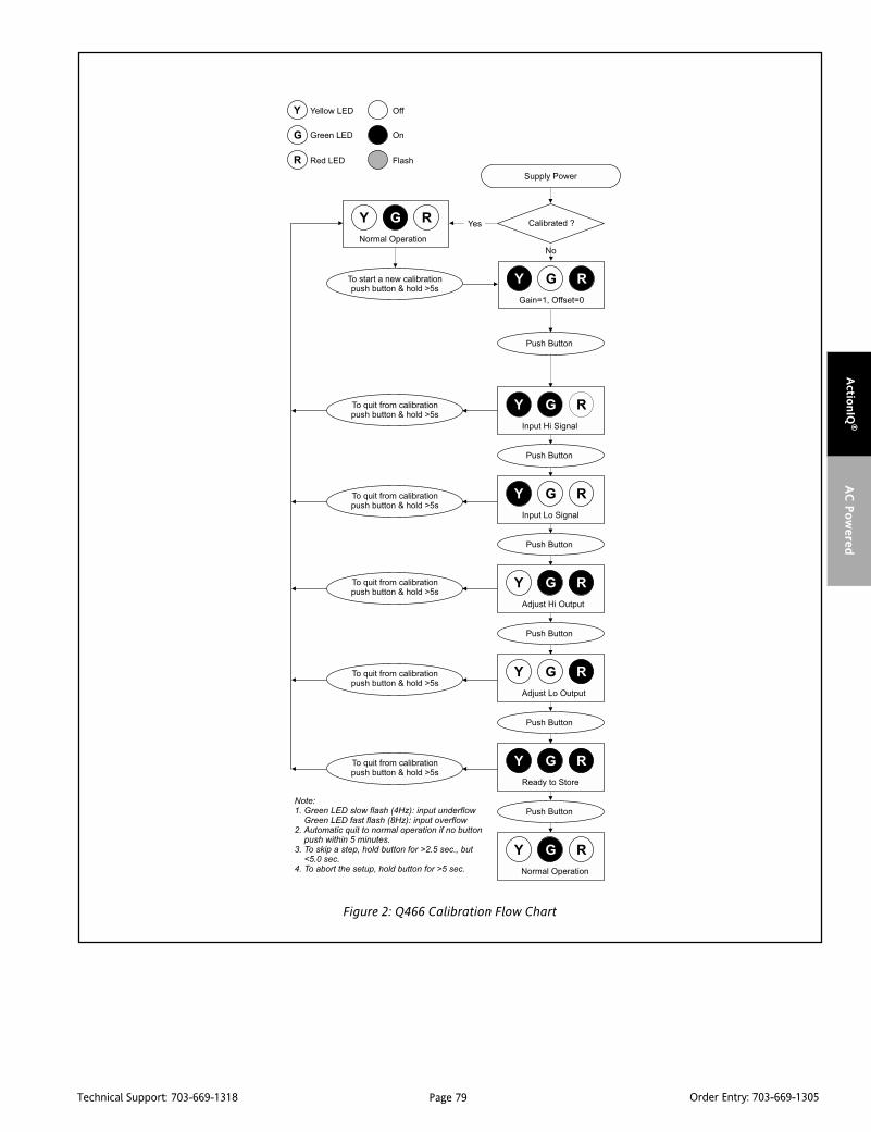
Page 79Technical Support: 703-669-1318 Order Entry: 703-669-1305
Actio
nIQ
®A
C P
ow
ered
Figure 2: Q466 Calibration Flow Chart

Page 80Technical Support: 703-669-1318 Order Entry: 703-669-1305
Act
ionIQ
®A
C P
ow
ered
SpecificationsInputs:
Voltage:Ranges: 100mVAC to 300VACImpedance: >100K ohmsOvervoltage: 330VAC
Current:Ranges:10mAAC to 100mAACImpedance: 20 ohms, typicalOvercurrent: 170mAACOvervoltage: 60V peak
Frequency Range:40Hz to 400Hz, factory calibrated at 60Hz
Common Mode (Input to Ground):1800VDC, max.
Pushbutton Adjustment:Max. zero offset and span turn down is 50%
Output:Voltage:
Output: 0-5V, 0-10VSource Impedance: <10 ohmsDrive: 10mA, max. (1K ohms, min. @ 10V)
Current:Output: 0-1mA, 0-20mA, 4-20mASource Impedance: >100K ohmsCompliance:
0-1mA; 7.5V, max. (7.5K ohms, max.)0-20mA; 12V, max. (600 ohms, max.)4-20mA; 12V, max. (600 ohms, max.)
LED IndicationRUN (green):
On when unit is poweredflashes at 8Hz when input is 7% above max.
INPUT (yellow):On while calibrating the input level
OUTPUT (red):On while calibrating the output level
Accuracy (Including Linearity & Hysteresis):+0.1% of span, typical, +0.2% max.+0.5% of span, maximum (100mV range)
Stability:+0.025%/°C of selected input span, typical.
Response Time (10 to 90%):250mSec., typical.
Common Mode Rejection:DC to 60Hz: 90dB
Isolation:1800VDC between input, output and power.
EMC Compliance (CE Mark):Emmissions: EN50081-1; Immunity: EN50082-2; Safety: EN50178
Humidity (Non-Condensing):Operating: 15 to 95% @ 45°CSoak: 90% for 24 hours @ 65°C
Temperature Range:Operating: 0 to 55°C (32 to 131°F)Storage: -25 to 70°C (-13 to 158°F)
Power:Consumption: 1.5W typical, 2.5W max.Range: 100 to 240 VAC ±10%, 50 to 400 Hz
Wire Terminations:Screw terminals for 12-22 AWG
Shipping Weight:0.48 lbs.
Agency Approvals:UL recognized per standard UL508 (File No. E99775)CSA certified per standard C22.2 No. 0-M91 and 142-M1987
(File No. LR42272-84).CE Compliance per EMC directive 89/3/36 EEC and Low Voltage 73/23/EEC.
Ordering InformationModels And AccessoriesSpecify:1. Model: Q466-0000; one input, one output AC Isolator2. Specify I/QRail type and quantity (required)3. Accessories: (see Accessories)4. Optional Custom Factory Calibration: specify C620 with desired
input and output range.
AccessoriesActionI/Q modules mount on standard TS32 (model MD02) or TS35 (modelMD03) DIN rail. In addition the following accessories are available:
MD02 TS32 DIN railMD03 TS35 x 7.5 DIN rail
IQRL-2002 2 Position I/QRail & DIN railIQRL-2004 4 Position I/QRail & DIN railIQRL-2008 8 Position I/QRail & DIN rail
Dimensions
lanimreT noitcennoC lanimreT noitcennoC
1A )+(tuptuO 3C )eniL(egatloVtupnI
2A )-(tuptuO 4C desUtoN
3A desUtoN 5C )lartueN(tupnI
4A desUtoN 6C )eniL(tnerruCtupnI
5A desUtoN 1P )toH(rewoPCA
6A desUtoN 2P desUtoN
1C desUtoN 3P desUtoN
2C desUtoN 4P )lartueN(rewoPCA

Page 81Technical Support: 703-669-1318 Order Entry: 703-669-1305
Actio
nIQ
®A
C P
ow
ered
DescriptionThe Q476 is a DIN rail mount, frequency input signal conditionerwith 1800VDC isolation between input, output and power. Thefield configurable input and output offers flexible, wide rangingcapability for variable frequency drives, magnetic pickups, turbineflowmeters, and other pulse or frequency output transducers.
The input of the Q476 can be configured for any frequency spanfrom 2Hz to 10,000Hz. The input amplitude threshold sensitivitycan be adjusted from 150mVp to 10Vp to ensure accuratefrequency measurement and minimize transient noise relatederrors. The maximum input amplitude is 150 Vrms. The output canbe set for either 0-5V, 0-10V, 0-1mA, 0-20mA or 4-20mA.
The Q476 can be field configured for virtually any frequency inputto DC signal output within the ranges specified. There is also an8VDC excitation source common to the input. This can be used asa signal source for relay contacts or as an excitation source foropen collector type proximity sensors. The Q476 is AC poweredand will accept any power between 85 and 265VAC.
TouchCAL TechnologyThe Q476 utilizes TouchCAL Technology to greatly simplify con-figuration. The high and low input ranges are stored in non-volatile memory and correspond to the high and low output rangewhich is selected via DIP switches.
Diagnostic LEDSThe Q476 utilizes three diagnostic LEDs. The green (RUN) LEDindicates DC power and input signal status. Active line power isindicated by an illuminated LED. If the input signal is 7% or morehigh, the LED will flash at 8Hz. If the input signal is 7% or more low,the LED will flash at 4Hz.
The yellow (IN) LED is lit when calibrating the input. The red (OUT)LED is lit when calibrating the output.
ApplicationThe Q476 field configurable, frequency input signal conditioner isuseful in eliminating ground loops and interfacing pulse outputtransducers, such as turbine flow meters and magnetic pickups, todata acquisition and control systems.
ACTIONI/Q®
Q476AC Powered Frequency Input
Field Configurable Isolator
Provides an Isolated DC Outputin Proportion to Input Frequency
Eliminates Ground Loops Field Configurable Input Ranges 2Hz to 10,000Hz Field Configurable Output Ranges 150mV to 150V Input Amplitude
Q476-0000
TouchCAL Technology DIN Rail Mounting with IQRL Universal AC Power 85 to 265 VAC SnapLocTM Plug-in Terminals
Advanced digital technology, combined with ASIC technology,provides a stable output at low frequencies for higher accuracy,and 3-way isolation which completely eliminates ground loopsfrom any source.
ConfigurationAny 2Hz range from 0 to 10,000Hz can be converted to a full scaleoutput signal (e.g. 0-2Hz/4-20mA or 9998-10,000Hz/4-20mA).
Unless otherwise specified, the factory presets the Model Q476 asfollows:
Input Range: 0 to 1000HzSensitivity: 1V RMS
Output Range: 4 to 20mA
Note that "Sensitivity" refers to the noise rejection level (the triggerthreshold of the input).
For other I/O ranges, refer to the tables below.
WARNING: Do not change switch settings with power applied.Severe damage will result!
1. With power off, snap off the faceplate by lifting the right edgeaway from the heatsink. Then slide the heatsink forward and offthe module. The output switch block (SW2) is located under theheatsink. Choose the desired output voltage/current range fromTable 1 and set positions 1-8 of SW2.
2. Set the input sensitivity switch (SW2, 9 & 10) to LO for inputamplitudes between 150mVp and 50Vrms, with noise rejection to1Vp; or to HI for input amplitudes between 500mVp and 150Vrms,with noise rejection up to 10Vp.
3. Return the heatsink to its original position and attach thefaceplate before beginning calibration.
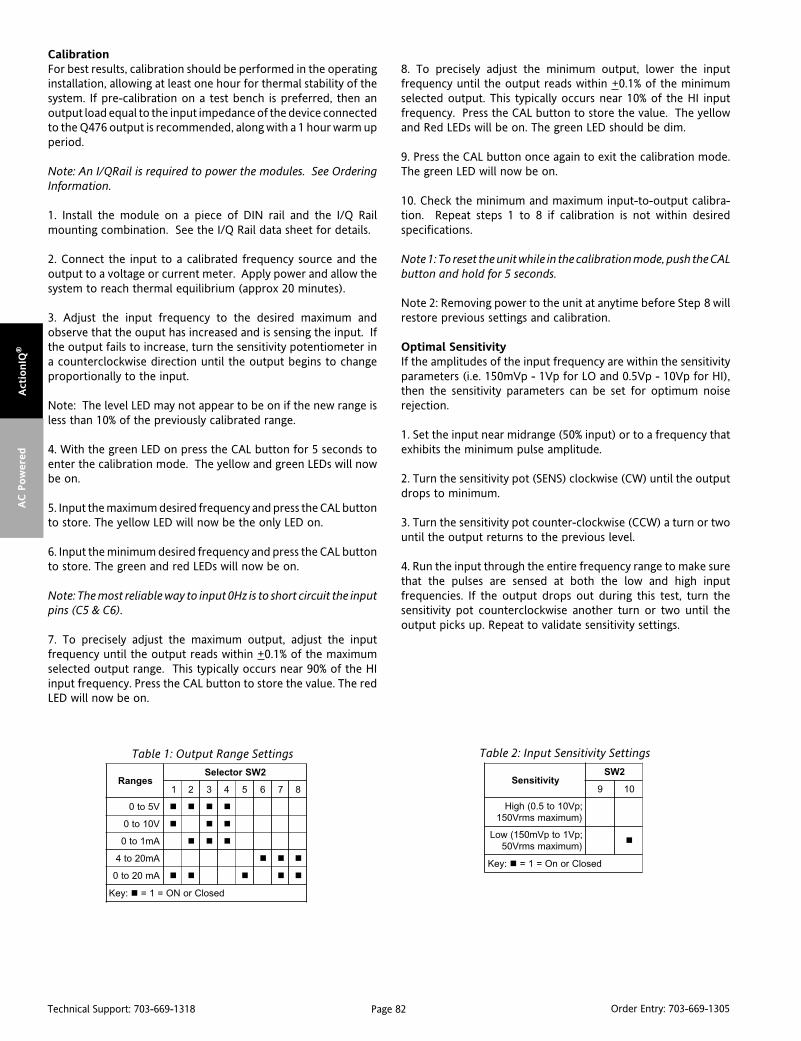
Page 82Technical Support: 703-669-1318 Order Entry: 703-669-1305
Act
ionIQ
®A
C P
ow
ered
CalibrationFor best results, calibration should be performed in the operatinginstallation, allowing at least one hour for thermal stability of thesystem. If pre-calibration on a test bench is preferred, then anoutput load equal to the input impedance of the device connectedto the Q476 output is recommended, along with a 1 hour warm upperiod.
Note: An I/QRail is required to power the modules. See OrderingInformation.
1. Install the module on a piece of DIN rail and the I/Q Railmounting combination. See the I/Q Rail data sheet for details.
2. Connect the input to a calibrated frequency source and theoutput to a voltage or current meter. Apply power and allow thesystem to reach thermal equilibrium (approx 20 minutes).
3. Adjust the input frequency to the desired maximum andobserve that the ouput has increased and is sensing the input. Ifthe output fails to increase, turn the sensitivity potentiometer ina counterclockwise direction until the output begins to changeproportionally to the input.
Note: The level LED may not appear to be on if the new range isless than 10% of the previously calibrated range.
4. With the green LED on press the CAL button for 5 seconds toenter the calibration mode. The yellow and green LEDs will nowbe on.
5. Input the maximum desired frequency and press the CAL buttonto store. The yellow LED will now be the only LED on.
6. Input the minimum desired frequency and press the CAL buttonto store. The green and red LEDs will now be on.
Note: The most reliable way to input 0Hz is to short circuit the inputpins (C5 & C6).
7. To precisely adjust the maximum output, adjust the inputfrequency until the output reads within +0.1% of the maximumselected output range. This typically occurs near 90% of the HIinput frequency. Press the CAL button to store the value. The redLED will now be on.
8. To precisely adjust the minimum output, lower the inputfrequency until the output reads within +0.1% of the minimumselected output. This typically occurs near 10% of the HI inputfrequency. Press the CAL button to store the value. The yellowand Red LEDs will be on. The green LED should be dim.
9. Press the CAL button once again to exit the calibration mode.The green LED will now be on.
10. Check the minimum and maximum input-to-output calibra-tion. Repeat steps 1 to 8 if calibration is not within desiredspecifications.
Note 1: To reset the unit while in the calibration mode, push the CALbutton and hold for 5 seconds.
Note 2: Removing power to the unit at anytime before Step 8 willrestore previous settings and calibration.
Optimal SensitivityIf the amplitudes of the input frequency are within the sensitivityparameters (i.e. 150mVp - 1Vp for LO and 0.5Vp - 10Vp for HI),then the sensitivity parameters can be set for optimum noiserejection.
1. Set the input near midrange (50% input) or to a frequency thatexhibits the minimum pulse amplitude.
2. Turn the sensitivity pot (SENS) clockwise (CW) until the outputdrops to minimum.
3. Turn the sensitivity pot counter-clockwise (CCW) a turn or twountil the output returns to the previous level.
4. Run the input through the entire frequency range to make surethat the pulses are sensed at both the low and high inputfrequencies. If the output drops out during this test, turn thesensitivity pot counterclockwise another turn or two until theoutput picks up. Repeat to validate sensitivity settings.
segnaR2WSrotceleS
1 2 3 4 5 6 7 8
V5ot0
V01ot0
Am1ot0
Am02ot4
Am02ot0
:yeK desolCroNO=1=
ytivitisneS2WS
9 01
;pV01ot5.0(hgiH)mumixamsmrV051
;pV1otpVm051(woL)mumixamsmrV05
:yeK desolCronO=1=
Table 1: Output Range Settings Table 2: Input Sensitivity Settings

Page 83Technical Support: 703-669-1318 Order Entry: 703-669-1305
Actio
nIQ
®A
C P
ow
ered
Figure 1: Q476 Calibration Flow Chart

Page 84Technical Support: 703-669-1318 Order Entry: 703-669-1305
Act
ionIQ
®A
C P
ow
ered
Ordering InformationModels & AccessoriesSpecify:1. Model: Q476-00002. Specify I/QRail type and quantity (required)3. Accessories: (see Accessories)4. Optional Custom Factory Calibration; specify C620 with desired
input and output range
AccessoriesActionI/Q modules will mount on standard TS32 (model MD02) or TS35(model MD03) DIN Rail. In addition, the following accessories are available:
MD02 TS32 DIN RailMD03 TS35 x 7.5 DIN Rail
IQRL-2002 2 Position I/QRail &DIN railIQRL-2004 4 Position I/QRail &DIN railIQRL-2008 8 Position I/QRail &DIN rail
SpecificationsInput:
FrequencyFull Scale Range: 2Hz to 10,000Hz.Amplitude Range: 150mVp to 150VrmsImpedance: >10K ohmsOvervoltage: 180Vrms, max.Over-range: 20KHz, max.Common Mode (Input to Gnd): 1800V, max.Zero Turn-Up: 99% of full scale range (9998Hz)Span Turn-Down: 99% of full scale range (2Hz)
Output:Voltage
Output: 0-5V, 0-10VSource Impedance: <100 ohmsDrive: 10mA, max. (1K ohms, min. @ 10V)
CurrentOutput: 0-1mA, 0-20mA, 4-20mASource Impedance: >100K ohmsCompliance:
0-1mA; 7.5V, max. (7.5K ohms, max.)0-20mA; 12V, max. (600 ohms, max.)4-20mA; 12V, max. (600 ohms, max.)
Accuracy (Including Linearity & Hysteresis):+0.1% of selected range at 25°C
Stability:+0.025%/°C maximum of selected range.
Excitation Voltage:8VDC, for open collector and contact closureinputs. 5mA short circuit current max.
Response Time (10 to 90%):500mSec., or 100 times the period of the full scale frequency.
Common Mode Rejection:DC: 100dB>60Hz: 80dB
Isolation:1800VDC between input, output and power.
ESD Susceptibility:Capable of meeting IEC 801-2 level 3(8KV)
LED Indication (green):LVL (green):
Lit when power is onInput < 107% then 8Hz flashInput > -7% then 4Hz flash
IN (yellow):Input range programming status
OUT (red):Output range programming status
Humidity (Non-Condensing):Operating: 15 to 95% @ 45°CSoak: 90% for 24 hours @ 65°C
Temperature Range:Operating: 0 to 55°C (5 to 131°F)Storage: -25 to 70°C (-13 to 158°F)
Power:2.5W max., 100 to 240VAC +10%, 50 to 400Hz
Weight:0.50 lbs
Wire Terminations:Screw terminals for 12-22 AWG
Agency Approvals:CSA certified per standard C22.2 (File No LR 42272).UL recognized per standard UL508 (File No E99775).
Dimensions
lanimreT noitcennoC lanimreT noitcennoC
1B )+(tuptuOCD 4C )CDV8(ecruoSnoitaticxE
2B )-(tuptuOCD 5C )-(tupnIycneuqerF
3B desUtoN 6C )+(tupnIycneuqerF
4B desUtoN 1P )toH(rewoPCA
1C desUtoN 2P desUtoN
2C desUtoN 3P desUtoN
3C desUtoN 4P )lartueN(rewoPCA
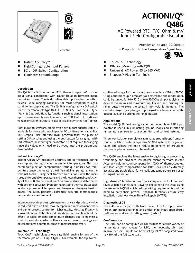
Page 85Technical Support: 703-669-1318 Order Entry: 703-669-1305
Actio
nIQ
®A
C P
ow
ered
DescriptionThe Q486 is a DIN rail mount, RTD, thermocouple, mV or Ohminput signal conditioner with 1800V isolation between input,output and power. The field configurable input and output offersflexible, wide ranging capability for most temperature signalconditioning applications. The Q486 is configured via DIP switchfor the thermocouple type (B, C, E, J, K, N, R, S, T) or the RTD type(Pt, Ni & Cu). Additionally, functions such as signal linearization,up or down scale burnout, number of RTD leads (2, 3, 4) andvoltage or current output are also set via dip switches (see Tables).
Configuration software, along with a serial port adapter cable isavailable for those who would prefer PC configuration capability.This Graphic User Interface (GUI) program takes the place ofsetting DIP switches and using the pushbutton for ranging. Withthis software, an input signal calibrator is not required for rangingsince the values only need to be typed into the program anddownloaded.
Instant AccuracyTM
Instant AccuracyTM maximizes accuracy and performance duringwarmup and during changes in ambient temperature. This pat-ented cold-junction compensation technique utilizes two tem-perature sensors to measure the differential temperature near theterminal block. Using heat transfer calculations with the mea-sured differential temperature and the known thermal conductiv-ity of the PCB, the terminal junction temperature is determinedwith extreme accuracy. Even during unstable thermal states suchas start-up, ambient temperature changes or changing load orpower, the Q486 performs extremely accurate thermocoupletemperature measurement.
Instant Accuracy improves system performance and productivity dueto reduced warm up time, fewer temperature measurement errorsand tighter process control for higher quality. Most significantly, itallows calibration to be checked quickly and accurately without theeffects of rapid ambient temperature changes due to opening acontrol panel door, which often causes erroneous readings andmiscalibrations; a common cause of measurement errors.
TouchCALTM TechnologyTouchCALTM technology allows easy field ranging for any of thethermocouple or RTD input types. For example, the dip switch
ACTIONI/Q®
Q486AC Powered RTD, T/C, Ohm & mV
Input Field Configurable Isolator
Provides an Isolated DC Outputin Proportion to the Temperature Signal Input
Instant AccuracyTM
Field Configurable Input Ranges PC or DIP Switch Configuration Eliminates Ground Loops
Q486-0001
TouchCAL Technology DIN Rail Mounting with IQRL Universal AC Power 85 to 265 VAC SnapLocTM Plug-in Terminals
configured range for the J type thermocouple is -210 to 760°C.Using a thermocouple simulator as a reference, the model Q486could be ranged for 0 to 50°C or 0 to 500°C by simply applying thedesired minimum and maximum input levels and pushing therange button to store the levels in non-volatile memory. Theoutput is ranged by applying an input signal to achieve an accurateoutput level and pushing the range button.
ApplicationsThe model Q486 field configurable thermocouple or RTD inputisolator is useful in eliminating ground loops and interfacingtemperature sensors to data acquisition and control systems.
Three-way isolation completely eliminates ground loops from anysource. Isolation protects expensive SCADA systems from groundfaults and allows the noise reduction benefits of groundedthermocouples or sensors to be realized.
The Q486 employs the latest analog to digital signal processingtechnology and advanced low-power microprocessors. InstantAccuracy cold-junction-compensation (CJC) of thermocouples,and lead length compensation for RTDs ensures an extremelyaccurate and stable signal for virtually any temperature sensor toDC signal conversion.
High density DIN rail mounting offers a very compact solution andsaves valuable panel space. Power is delivered to the Q486 usingthe exclusive I/QRail which reduces wiring requirements and theneed to daisy-chain power. SnapLoc terminals ensure easyinstallation and low Mean-Time-To-Repair (MTTR).
Diagnostic LEDSThe Q486 is equipped with front panel LEDs for input power(green-on), input overrange and underrange; input open circuit(yellow-on); and switch setting error (red-on).
Configuration The Q486 can be configured via DIP switchs for a wide variety oftemperature input ranges for RTD, thermocouple, ohm andmillivolt sensors. Inputs can be offset by >90% or adjusted downto <10% of the full scale span.
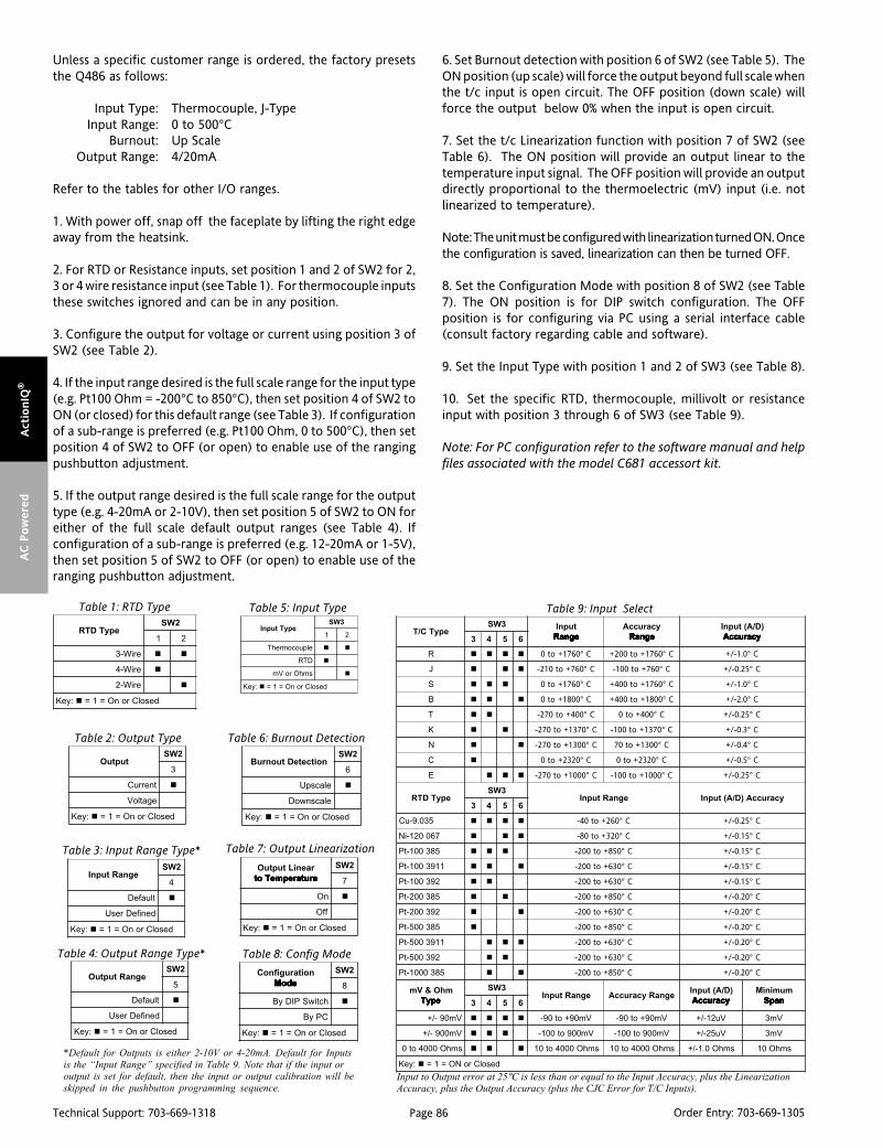
Page 86Technical Support: 703-669-1318 Order Entry: 703-669-1305
Act
ionIQ
®A
C P
ow
ered
Unless a specific customer range is ordered, the factory presetsthe Q486 as follows:
Input Type: Thermocouple, J-TypeInput Range: 0 to 500°C
Burnout: Up ScaleOutput Range: 4/20mA
Refer to the tables for other I/O ranges.
1. With power off, snap off the faceplate by lifting the right edgeaway from the heatsink.
2. For RTD or Resistance inputs, set position 1 and 2 of SW2 for 2,3 or 4 wire resistance input (see Table 1). For thermocouple inputsthese switches ignored and can be in any position.
3. Configure the output for voltage or current using position 3 ofSW2 (see Table 2).
4. If the input range desired is the full scale range for the input type(e.g. Pt100 Ohm = -200°C to 850°C), then set position 4 of SW2 toON (or closed) for this default range (see Table 3). If configurationof a sub-range is preferred (e.g. Pt100 Ohm, 0 to 500°C), then setposition 4 of SW2 to OFF (or open) to enable use of the rangingpushbutton adjustment.
5. If the output range desired is the full scale range for the outputtype (e.g. 4-20mA or 2-10V), then set position 5 of SW2 to ON foreither of the full scale default output ranges (see Table 4). Ifconfiguration of a sub-range is preferred (e.g. 12-20mA or 1-5V),then set position 5 of SW2 to OFF (or open) to enable use of theranging pushbutton adjustment.
6. Set Burnout detection with position 6 of SW2 (see Table 5). TheON position (up scale) will force the output beyond full scale whenthe t/c input is open circuit. The OFF position (down scale) willforce the output below 0% when the input is open circuit.
7. Set the t/c Linearization function with position 7 of SW2 (seeTable 6). The ON position will provide an output linear to thetemperature input signal. The OFF position will provide an outputdirectly proportional to the thermoelectric (mV) input (i.e. notlinearized to temperature).
Note: The unit must be configured with linearization turned ON. Oncethe configuration is saved, linearization can then be turned OFF.
8. Set the Configuration Mode with position 8 of SW2 (see Table7). The ON position is for DIP switch configuration. The OFFposition is for configuring via PC using a serial interface cable(consult factory regarding cable and software).
9. Set the Input Type with position 1 and 2 of SW3 (see Table 8).
10. Set the specific RTD, thermocouple, millivolt or resistanceinput with position 3 through 6 of SW3 (see Table 9).
Note: For PC configuration refer to the software manual and helpfiles associated with the model C681 accessort kit.
*Default for Outputs is either 2-10V or 4-20mA. Default for Inputs
is the “Input Range” specified in Table 9. Note that if the input oroutput is set for default, then the input or output calibration will be
skipped in the pushbutton programming sequence.
Table 1: RTD Type
epyTDTR2WS
1 2
eriW-3
eriW-4
eriW-2
:yeK desolCronO=1=
tuptuO2WS
3
tnerruC
egatloV
:yeK desolCronO=1=
epyTC/T3WS tupnI
egnaR egnaR egnaR egnaR egnaRycaruccA
egnaR egnaR egnaR egnaR egnaR)D/A(tupnI
ycaruccA ycaruccA ycaruccA ycaruccA ycaruccA3 4 5 6
R C°0671+ot0 C°0671+ot002+ C°0.1-/+
J C°067+ot012- C°067+ot001- C°52.0-/+
S C°0671+ot0 C°0671+ot004+ C°0.1-/+
B C°0081+ot0 C°0081+ot004+ C°0.2-/+
T C°004+ot072- C°004+ot0 C°52.0-/+
K C°0731+ot072- C°0731+ot001- C°3.0-/+
N C°0031+ot072- C°0031+ot07 C°4.0-/+
C C°0232+ot0 C°0232+ot0 C°5.0-/+
E C°0001+ot072- C°0001+ot001- C°52.0-/+
epyTDTR3WS
egnaRtupnI ycaruccA)D/A(tupnI3 4 5 6
530.9-uC C°062+ot04- C°52.0-/+
760021-iN C°023+ot08- C°51.0-/+
583001-tP C°058+ot002- C°51.0-/+
1193001-tP C°036+ot002- C°51.0-/+
293001-tP C°036+ot002- C°51.0-/+
583002-tP C°058+ot002- C°02.0-/+
293002-tP C°036+ot002- C°02.0-/+
583005-tP C°058+ot002- C°02.0-/+
1193005-tP C°036+ot002- C°02.0-/+
293005-tP C°036+ot002- C°02.0-/+
5830001-tP C°058+ot002- C°02.0-/+
mhO&VmepyT epyT epyT epyT epyT
3WSegnaRtupnI egnaRycaruccA
)D/A(tupnIycaruccA ycaruccA ycaruccA ycaruccA ycaruccA
muminiMnapS napS napS napS napS3 4 5 6
Vm09-/+ Vm09+ot09- Vm09+ot09- Vu21-/+ Vm3
Vm009-/+ Vm009ot001- Vm009ot001- Vu52-/+ Vm3
smhO0004ot0 smhO0004ot01 smhO0004ot01 smhO0.1-/+ smhO01
:yeK desolCroNO=1=
epyTtupnI3WS
1 2
elpuocomrehT
DTR
smhOroVm
:yeK desolCronO=1=
egnaRtuptuO2WS
5
tluafeD
denifeDresU
:yeK desolCronO=1=
noitceteDtuonruB2WS
6
elacspU
elacsnwoD
:yeK desolCronO=1=
raeniLtuptuOerutarepmeTot erutarepmeTot erutarepmeTot erutarepmeTot erutarepmeTot
2WS
7
nO
ffO
:yeK desolCronO=1=
noitarugifnoCedoM edoM edoM edoM edoM
2WS
8
hctiwSPIDyB
CPyB
:yeK desolCronO=1=
Table 2: Output Type
Table 3: Input Range Type*
Table 4: Output Range Type*
Table 5: Input Type
Table 6: Burnout Detection
Table 7: Output Linearization
Table 8: Config Mode
Table 9: Input Select
Input to Output error at 25°C is less than or equal to the Input Accuracy, plus the LinearizationAccuracy, plus the Output Accuracy (plus the CJC Error for T/C Inputs).
egnaRtupnI2WS
4
tluafeD
denifeDresU
:yeK desolCronO=1=
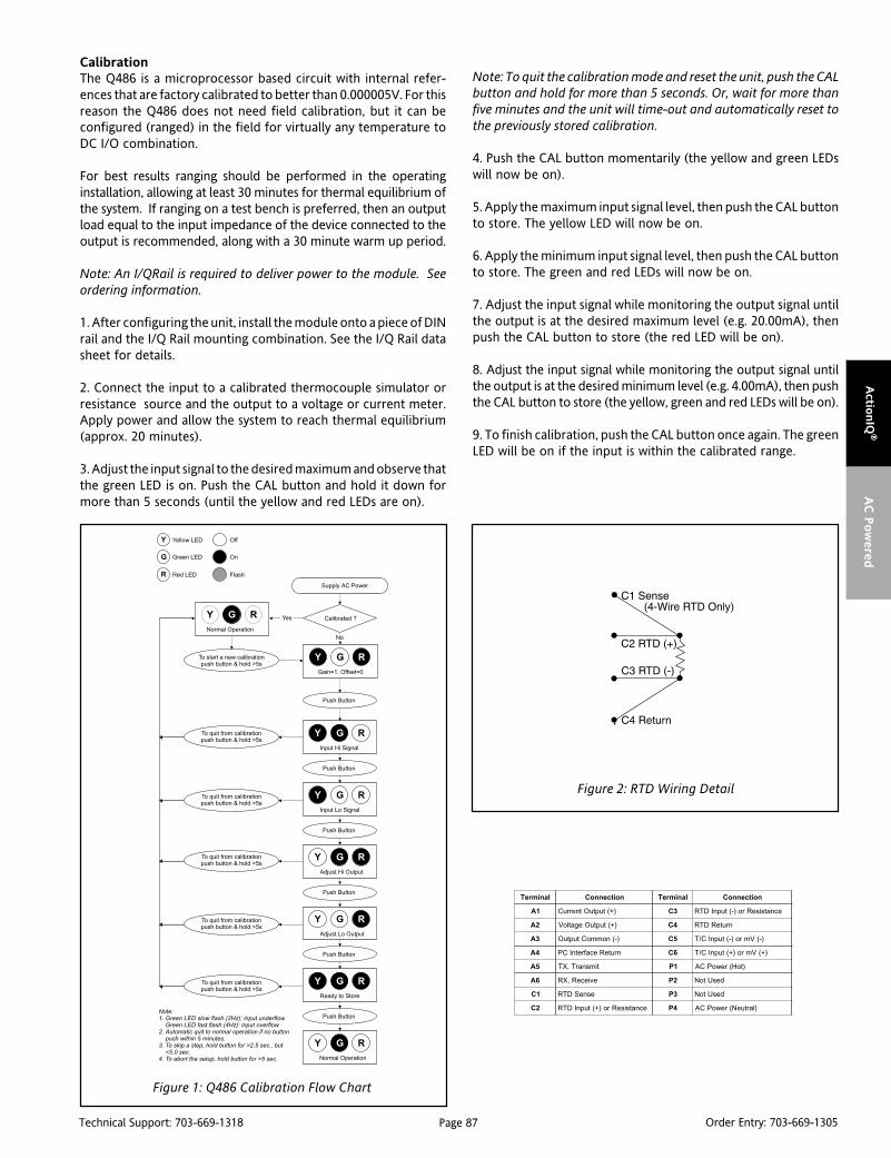
Page 87Technical Support: 703-669-1318 Order Entry: 703-669-1305
Actio
nIQ
®A
C P
ow
ered
Figure 1: Q486 Calibration Flow Chart
CalibrationThe Q486 is a microprocessor based circuit with internal refer-ences that are factory calibrated to better than 0.000005V. For thisreason the Q486 does not need field calibration, but it can beconfigured (ranged) in the field for virtually any temperature toDC I/O combination.
For best results ranging should be performed in the operatinginstallation, allowing at least 30 minutes for thermal equilibrium ofthe system. If ranging on a test bench is preferred, then an outputload equal to the input impedance of the device connected to theoutput is recommended, along with a 30 minute warm up period.
Note: An I/QRail is required to deliver power to the module. Seeordering information.
1. After configuring the unit, install the module onto a piece of DINrail and the I/Q Rail mounting combination. See the I/Q Rail datasheet for details.
2. Connect the input to a calibrated thermocouple simulator orresistance source and the output to a voltage or current meter.Apply power and allow the system to reach thermal equilibrium(approx. 20 minutes).
3. Adjust the input signal to the desired maximum and observe thatthe green LED is on. Push the CAL button and hold it down formore than 5 seconds (until the yellow and red LEDs are on).
Note: To quit the calibration mode and reset the unit, push the CALbutton and hold for more than 5 seconds. Or, wait for more thanfive minutes and the unit will time-out and automatically reset tothe previously stored calibration.
4. Push the CAL button momentarily (the yellow and green LEDswill now be on).
5. Apply the maximum input signal level, then push the CAL buttonto store. The yellow LED will now be on.
6. Apply the minimum input signal level, then push the CAL buttonto store. The green and red LEDs will now be on.
7. Adjust the input signal while monitoring the output signal untilthe output is at the desired maximum level (e.g. 20.00mA), thenpush the CAL button to store (the red LED will be on).
8. Adjust the input signal while monitoring the output signal untilthe output is at the desired minimum level (e.g. 4.00mA), then pushthe CAL button to store (the yellow, green and red LEDs will be on).
9. To finish calibration, push the CAL button once again. The greenLED will be on if the input is within the calibrated range.
lanimreT noitcennoC lanimreT noitcennoC
1A )+(tuptuOtnerruC 3C ecnatsiseRro)-(tupnIDTR
2A )+(tuptuOegatloV 4C nruteRDTR
3A )-(nommoCtuptuO 5C )-(Vmro)-(tupnIC/T
4A nruteRecafretnICP 6C )+(Vmro)+(tupnIC/T
5A timsnarT,XT 1P )toH(rewoPCA
6A evieceR,XR 2P desUtoN
1C esneSDTR 3P desUtoN
2C ecnatsiseRro)+(tupnIDTR 4P )lartueN(rewoPCA
Figure 2: RTD Wiring Detail
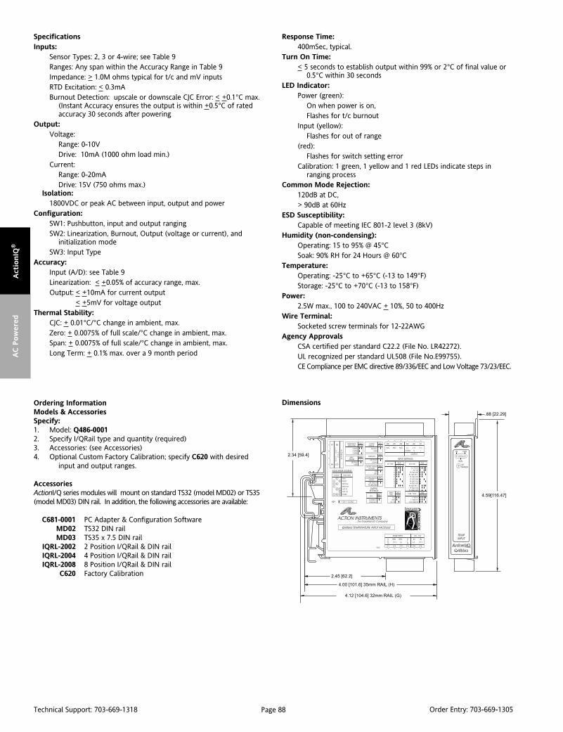
Page 88Technical Support: 703-669-1318 Order Entry: 703-669-1305
Act
ionIQ
®A
C P
ow
ered
Dimensions
SpecificationsInputs:
Sensor Types: 2, 3 or 4-wire; see Table 9Ranges: Any span within the Accuracy Range in Table 9Impedance: > 1.0M ohms typical for t/c and mV inputsRTD Excitation: < 0.3mABurnout Detection: upscale or downscale CJC Error: < +0.1°C max.
(Instant Accuracy ensures the output is within +0.5°C of ratedaccuracy 30 seconds after powering
Output:Voltage:
Range: 0-10VDrive: 10mA (1000 ohm load min.)
Current:Range: 0-20mADrive: 15V (750 ohms max.)
Isolation:1800VDC or peak AC between input, output and power
Configuration:SW1: Pushbutton, input and output rangingSW2: Linearization, Burnout, Output (voltage or current), and
initialization modeSW3: Input Type
Accuracy:Input (A/D): see Table 9Linearization: < +0.05% of accuracy range, max.Output: < +10mA for current output
< +5mV for voltage outputThermal Stability:
CJC: + 0.01°C/°C change in ambient, max.Zero: + 0.0075% of full scale/°C change in ambient, max.Span: + 0.0075% of full scale/°C change in ambient, max.Long Term: + 0.1% max. over a 9 month period
Response Time:400mSec, typical.
Turn On Time:< 5 seconds to establish output within 99% or 2°C of final value or
0.5°C within 30 secondsLED Indicator:
Power (green):On when power is on,Flashes for t/c burnout
Input (yellow):Flashes for out of range
(red):Flashes for switch setting error
Calibration: 1 green, 1 yellow and 1 red LEDs indicate steps inranging process
Common Mode Rejection:120dB at DC,> 90dB at 60Hz
ESD Susceptibility:Capable of meeting IEC 801-2 level 3 (8kV)
Humidity (non-condensing):Operating: 15 to 95% @ 45°CSoak: 90% RH for 24 Hours @ 60°C
Temperature:Operating: -25°C to +65°C (-13 to 149°F)Storage: -25°C to +70°C (-13 to 158°F)
Power:2.5W max., 100 to 240VAC + 10%, 50 to 400Hz
Wire Terminal:Socketed screw terminals for 12-22AWG
Agency ApprovalsCSA certified per standard C22.2 (File No. LR42272).UL recognized per standard UL508 (File No.E99755).CE Compliance per EMC directive 89/336/EEC and Low Voltage 73/23/EEC.
Ordering InformationModels & AccessoriesSpecify:1. Model: Q486-00012. Specify I/QRail type and quantity (required)3. Accessories: (see Accessories)4. Optional Custom Factory Calibration; specify C620 with desired
input and output ranges.
AccessoriesActionI/Q series modules will mount on standard TS32 (model MD02) or TS35(model MD03) DIN rail. In addition, the following accessories are available:
C681-0001 PC Adapter & Configuration SoftwareMD02 TS32 DIN railMD03 TS35 x 7.5 DIN rail
IQRL-2002 2 Position I/QRail & DIN railIQRL-2004 4 Position I/QRail & DIN railIQRL-2008 8 Position I/QRail & DIN rail
C620 Factory Calibration

Page 89Technical Support: 703-669-1318 Order Entry: 703-669-1305
Actio
nIQ
®D
C P
ow
ered
DescriptionThe ActionI/Q model Q108 is a DIN rail mount, DC voltage orcurrent input limit alarm with dual setpoints and two contactclosure outputs. The field configurable input and alarm functionsoffer flexible setpoint capability. Input voltage spans from 10mVto 200V and input current spans from 1mA to 100mA can be fieldconfigured. Bipolar inputs are also accepted.
The Q108 is configurable as a single or dual setpoint alarm, withHI or LO trips and failsafe or non-failsafe operation. Also includedare adjustable deadbands (up to 100% of full scale input) for eachsetpoint, a 24VDC voltage source (isolated from line power) fortransducer excitation, and a universal DC power supply whichaccepts any voltage between 9 and 30VDC.
TouchCAL TechnologyAction has simplified setpoint calibration. Using a pushbuttoninstead of potentiometers, improvements in calibration resolu-tion and reliability are realized due to the elimination of thepotentiometers’ mechanical variability.
For calibration, simply input the signal level of the desired trip andpress the pushbutton to store it in non-volatile memory.Deadband is entered the same way with another pushbutton pressto store.
Diagnostic LEDSThe he Q108 is equipped with three front panel LEDs. The greenLED is a dual function LED labeled IN, which indicates line powerand input signal status. Active DC power is indicated by theilluminated LED. If this LED is off, check DC power and wiringconnections. If the input signal is 10% above or below theconfigured input range the green LED will flash at 8Hz or 4Hz,respectively.
The two red LEDs indicate the relay state of each setpoint. Anilluminated red LED indicates the tripped condition for therespective setpoint.
OutputThe Q108 is equipped with two SPDT (form C) relays, rated at120VAC or 28VDC at 5 amperes. Each of these relays is indepen-dently controlled by the field configurable setpoint and deadband.
ACTIONI/Q®
Q108DC Powered DC Input Limit Alarm
Provides Relay Contact Closuresat a Preset DC Input Level
Field Configurable Input Ranges TouchCALTM Technology Setpoints Programmable HI or LO and Failsafe or
Non-Failsafe High Density DIN Rail Mounting
Q108-0000
Flexible 9 to 30VDC Power Supply 24VDC Transducer Excitation SnapLocTM Plug-in Terminals ASIC Technology
OperationThe Q108 limit alarm setpoints can be configured for HI or LO,failsafe or non-failsafe operation. Each of the setpoints has arespective HI or LO deadband. In a tripped condition, the setpointis exceeded and the appropriate red LED will illuminate. The tripwill reset only after the process falls below the HI deadband orrises above the low deadband (see Figure 1). For proper deadbandoperation, the HI setpoint must be set above the LO setpoint. Infailsafe operation, the relay is energized when the process is belowthe HI setpoint or above the LO setpoint (opposite for non-failsafe). In the failsafe mode, a power failure results in an alarmstate output.
Dynamic DeadbandCircuitry in the Q108 prevents false trips by repeatedly samplingthe input. The input must be beyond the setpoint for 100milliseconds, uninterrupted, to qualify as a valid trip condition.Likewise, the input must fall outside the deadband and remainthere for 100 milliseconds to return the alarm to an untrippedcondition. This results in a “dynamic deadband” —based ontime— in addition to the normal deadband.
ConfigurationUnless otherwise specified, the factory presets the Model Q108 asfollows:
Input: CurrentRange: 0-20mA
Output: Dual, SPDTTrip: A: HI; B: LO
Failsafe: NoDeadband: A, B: 0.25%
The DC power input accepts any DC source between 9 and 30VDC.
Note: An I/QRail is an optional accessory to power the modules. A2, 4, or 8 position rail is available. See ordering information.
For other I/O ranges, refer to Table 1 and Figure 5. Reconfigureswitch SW1 for the desired input type, range and function.
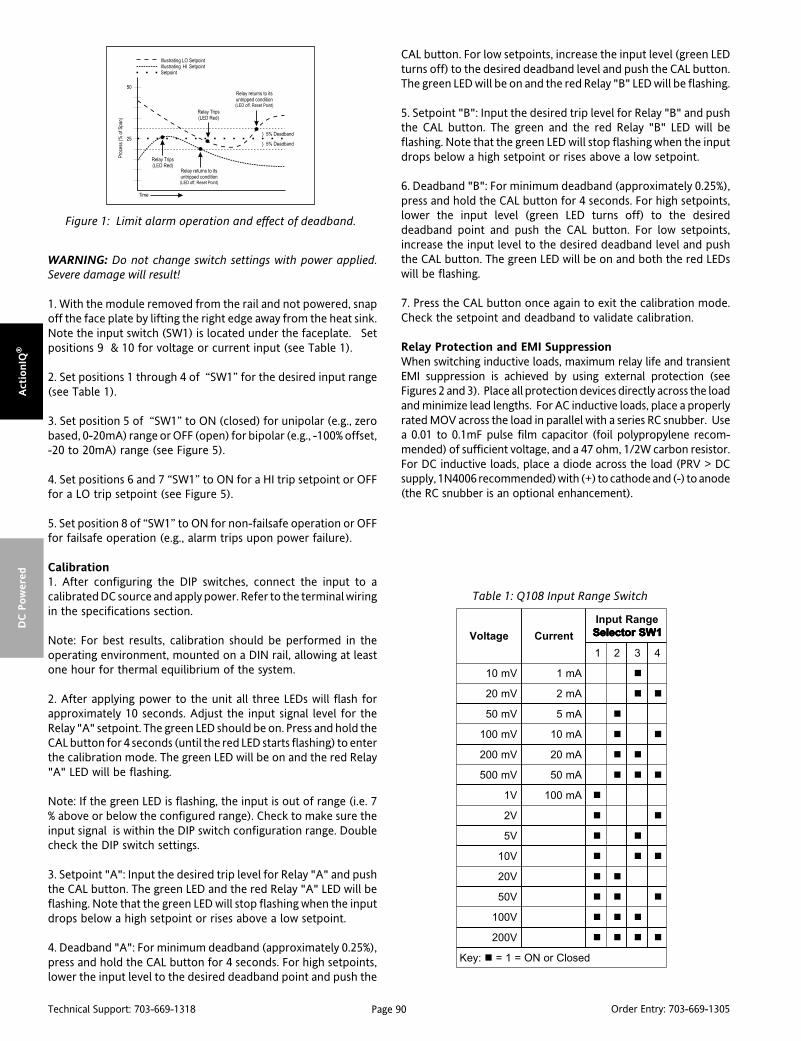
Page 90Technical Support: 703-669-1318 Order Entry: 703-669-1305
Act
ionIQ
®D
C P
ow
ered
WARNING: Do not change switch settings with power applied.Severe damage will result!
1. With the module removed from the rail and not powered, snapoff the face plate by lifting the right edge away from the heat sink.Note the input switch (SW1) is located under the faceplate. Setpositions 9 & 10 for voltage or current input (see Table 1).
2. Set positions 1 through 4 of “SW1” for the desired input range(see Table 1).
3. Set position 5 of “SW1” to ON (closed) for unipolar (e.g., zerobased, 0-20mA) range or OFF (open) for bipolar (e.g., -100% offset,-20 to 20mA) range (see Figure 5).
4. Set positions 6 and 7 “SW1” to ON for a HI trip setpoint or OFFfor a LO trip setpoint (see Figure 5).
5. Set position 8 of “SW1” to ON for non-failsafe operation or OFFfor failsafe operation (e.g., alarm trips upon power failure).
Calibration1. After configuring the DIP switches, connect the input to acalibrated DC source and apply power. Refer to the terminal wiringin the specifications section.
Note: For best results, calibration should be performed in theoperating environment, mounted on a DIN rail, allowing at leastone hour for thermal equilibrium of the system.
2. After applying power to the unit all three LEDs will flash forapproximately 10 seconds. Adjust the input signal level for theRelay "A" setpoint. The green LED should be on. Press and hold theCAL button for 4 seconds (until the red LED starts flashing) to enterthe calibration mode. The green LED will be on and the red Relay"A" LED will be flashing.
Note: If the green LED is flashing, the input is out of range (i.e. 7% above or below the configured range). Check to make sure theinput signal is within the DIP switch configuration range. Doublecheck the DIP switch settings.
3. Setpoint "A": Input the desired trip level for Relay "A" and pushthe CAL button. The green LED and the red Relay "A" LED will beflashing. Note that the green LED will stop flashing when the inputdrops below a high setpoint or rises above a low setpoint.
4. Deadband "A": For minimum deadband (approximately 0.25%),press and hold the CAL button for 4 seconds. For high setpoints,lower the input level to the desired deadband point and push the
CAL button. For low setpoints, increase the input level (green LEDturns off) to the desired deadband level and push the CAL button.The green LED will be on and the red Relay "B" LED will be flashing.
5. Setpoint "B": Input the desired trip level for Relay "B" and pushthe CAL button. The green and the red Relay "B" LED will beflashing. Note that the green LED will stop flashing when the inputdrops below a high setpoint or rises above a low setpoint.
6. Deadband "B": For minimum deadband (approximately 0.25%),press and hold the CAL button for 4 seconds. For high setpoints,lower the input level (green LED turns off) to the desireddeadband point and push the CAL button. For low setpoints,increase the input level to the desired deadband level and pushthe CAL button. The green LED will be on and both the red LEDswill be flashing.
7. Press the CAL button once again to exit the calibration mode.Check the setpoint and deadband to validate calibration.
Relay Protection and EMI SuppressionWhen switching inductive loads, maximum relay life and transientEMI suppression is achieved by using external protection (seeFigures 2 and 3). Place all protection devices directly across the loadand minimize lead lengths. For AC inductive loads, place a properlyrated MOV across the load in parallel with a series RC snubber. Usea 0.01 to 0.1mF pulse film capacitor (foil polypropylene recom-mended) of sufficient voltage, and a 47 ohm, 1/2W carbon resistor.For DC inductive loads, place a diode across the load (PRV > DCsupply, 1N4006 recommended) with (+) to cathode and (-) to anode(the RC snubber is an optional enhancement).
egatloV tnerruC
egnaRtupnI1WSrotceleS 1WSrotceleS 1WSrotceleS 1WSrotceleS 1WSrotceleS
1 2 3 4
Vm01 Am1
Vm02 Am2
Vm05 Am5
Vm001 Am01
Vm002 Am02
Vm005 Am05
V1 Am001
V2
V5
V01
V02
V05
V001
V002
:yeK desolCroNO=1=
Figure 1: Limit alarm operation and effect of deadband.
Table 1: Q108 Input Range Switch

Page 91Technical Support: 703-669-1318 Order Entry: 703-669-1305
Actio
nIQ
®D
C P
ow
ered
Figure 6: Q108 Calibration Flow Chart
Flashing
Input Trip ASignal Level
Input Trip BSignal Level
On
Off
Green LED
Red LED
Figure 5: Q108 Input Range/Function Selection (SW1) Factory Default SettingsNote: For voltage inputs Current Enable must be off. For current inputs Voltage Enable must be off.
Figure 4: Typical Connections for Voltage or Current for Q108
Figure 2: DC Inductive Loads Figure 3: AC Inductive Loads

Page 92Technical Support: 703-669-1318 Order Entry: 703-669-1305
Act
ionIQ
®D
C P
ow
ered
Specifications
Inputs:
Voltage Input:
Range: 10mV to +200V; Impedance: >100k ohms
Overvoltage: 200V rms, max.
Current Input:
Range: 1mA to +100mA; Impedance: 20 ohms, typical
Overcurrent: 170mA rms, max.
Overvoltage: 60VDC (protected by self resetting fuse)
Common Mode (Input to Ground): 1800VDC, max.
LED Indicators:
Input Range (Green)
>110% input: 8Hz flash
<10% input: 4Hz flash
Setpoint (Red)
Tripped: Solid red
Safe: Off
Limit Differential (Deadband):
>50mV/5mA: 0.25% to 100% of span
<50mV/5mA: 1% to 100% of span
Response Time:
Dynamic Deadband:
Relay status will change when proper setpoint/process conditionexists for 100msec.
Normal Mode (analog filtering): <250mSec (10-90%)
Setpoints:
Effectivity: Setpoints are adjustable over 100% of selected input span.
Repeatability (constant temp.):
>50mV/5mA: 0.1% of full scale
<50mV/5mA: 0.2% of full scale
Temperature Stability: +0.05% of full scale/°C, max.
Excitation Voltage: 24VDC, 20mA, maximum
Ordering InformationModels & AccessoriesSpecify (model number)1) Q108-00002) Specify I/QRail type and quantity (optional)3) Accessories: (see Accessories)4) Optional Custom Factory Calibration: Specify C620 with desired
input, setpoint and deadband.
AccessoriesActionI/Q series modules mount on standard TS32 (model MD02) or TS35(model MD03) DIN rail. In addition, the following accessories are available:
MD02 TS32 DIN railMD03 TS35 x 7.5 DIN rail
WV905 24VDC Power Supply (500mA)H910 24VDC Power Supply (1 Amp)H915 24VDC Power Supply (2.3 Amp)
IQRL-2002 2 Position I/QRail &DIN railIQRL-2004 4 Position I/QRail &DIN railIQRL-2008 8 Position I/QRail &DIN rail
Dimensions
Common Mode Rejection: DC to 60Hz: 120dB
Isolation: 1800VDC between contacts, input and power
ESD & Transient Susceptibility: Meets IEC 801-2, Level 3 (8KV)
Humidity (Non-Condensing):
Operating: 15 to 95% @45°CSoak: 90% for 24 hours @65°C
Temperature Range:
Operating: 0 to 55°C (32 to 131°F)
Storage: -25 to 70°C (-13 to 158°F)
Power: 2.5W max., 9 to 30VDC
Relay Contacts
2 SPDT (2 form C) Relays; 1 Relay per setpoint
Current Rating (resistive)
120VAC: 5A; 240VAC: 2A; 28VDC: 5A
Material: Gold flash over silver alloy
Electrical Life:105 operations at rated load
Note: External relay contact protection is required for use withinductive loads.
Mechanical Life: 107 operations
Wire Terminations: Screw terminations for 12-22 AWG
Weight: 0.56lbs.
Agency Approvals
UL recognized per standard UL508 (File No. E99775).
CSA certified per C22.2 No. 0-M91 & 142-M1987 (File No. LR42272-84).
CE Compliance per EMC directive 89/3/36 EEC and Low Voltage73/23/EEC.
lanimreT noitcennoC lanimreT noitcennoC
1A .O.N,AyaleR 3C .C.N,ByaleR
2A nommoC,AyaleR 4C )CDV42+(ylppuSegatloV
3A .C.N,AyaleR 5C )-(tupnI
4A detcennoCtoN 6C )+(tupnI
5A )+(rewoPCD 1P desUtoN
6A )-(rewoPCD 2P desUtoN
1C .O.N,ByaleR 3P )+(rewoPCD
2C nommoC,ByaleR 4P )-(rewoPCD

Page 93Technical Support: 703-669-1318 Order Entry: 703-669-1305
Actio
nIQ
®D
C P
ow
ered
DescriptionThe model Q404 is a DIN rail mount, DC input signal conditioner,with 2000VAC isolation between input output and power. It isavailable as a single channel signal conditioner (1 input/1 output)or as a multi-channel signal conditioner (1 input/2 outputs or 2inputs/2 outputs).
Factory configured input and output ranges support standardindustrial control signals such as 4-20mA and 0-10V. Frontaccessed zero and span potentiometers allow 50% adjustment ofoffset and gain to compensate for sensor errors or signal losses.
All ActionI/Q modules feature SnapLoc plug-in screw terminals foreasy installation . Two or more modules can slide together andinterlock for solid, high density mounting (remove either the DINrail foot or the adjacent unit’s faceplate, for right side or left sidemounting, respectively). The module to be attached will easilyslide onto the side of the mounted unit.
ApplicationDC input four-wire transmitters are used to isolate and convert DCvoltage or current signals into proportional, standard industrialcontrol signals such as 4-20mA or 0-10V. Typically an industrialcontrol system such as a DCS or PLC requires standard industrialcontrol signals with full isolation to ensure reliable, strong signals.
In most industrial process control or data acquisition applications,several different input sources, including voltages and currentsfrom various field instruments (e.g. level, flow, pressure andposition sensors), are common. Four-wire transmitters acceptthese field inputs and provide the controller (DCS & PLC) with thestandard industrial signal it requires. The four-wire transmitterwill increase the signal drive to high impedance loads and mayimprove resolution of the process variable.
ACTIONI/Q®
Q404-2/3/4DC Powered DC InputMulti-Channel Isolator
Provides 1 or 2 Fully Isolated DC Output Signalsin Proportion to 1 or 2 DC Inputs
Multi-Channel Design 2000VAC Isolation High Density DIN Rail Mounting
Q404-2 (2 inputs; 2 outputs)
Q404-3 (1 input; 1 output; 24V Exc)
Q404-4 (signal splitter: 1 input; 2 outputs)
Universal DC Power 10.8 to 26.4VDC SnapLocTM Plug-in Terminals Fast Response Time
OperationThe ActionI/Q model Q404 operates as a four-wire transmitter;each channel derives its power from an independent, transformerisolated DC power source (10.8 to 26.4VDC).
The Q404 has fixed input and output ranges. The standard inputand output ranges shown in Table 1 are calibrated to ratedaccuracy. One range per module; two channels per module,maximum.
CalibrationNote: For best results, calibration should be performed with theintended output load, in the operating environment, mounted ona DIN rail, allowing at least one hour for thermal equilibrium of thesystem.
1) To check calibration, connect the input to a calibrated DCsource. Connect the output to a DC voltage or current meter andthe input power to a DC source (10.8 to 26.4VDC) capable ofproviding up to 0.5 Amps.
2) Set the calibrator to the specified minimum DC input value andadjust the zero potentiometer for minimum (e.g. 4mA) output.
3) Set the calibrator to the specified maximum DC input value andadjust the span potentiometer for maximum (e.g. 20mA) output.
4) Repeat steps 2 and 3 to validate calibration to the output load.
segnaRdradnatS
ledoM tupnI tuptuO
80L2-404Q stloV01ot0 Am02ot4
80L2-404Q stloV01ot0stloV01ot0stloV01ot0
stloV5ot0stloV5ot1stloV01ot0
82L2-404Q stloV01/01- stloV5/5-stloV01/01-
00L3-404Q stloV01/01- Am02ot4
10L3-404Q Am02ot4 stloV5ot0stloV5ot1stloV01ot0
00L4-404Q Am02ot4 Am02ot4
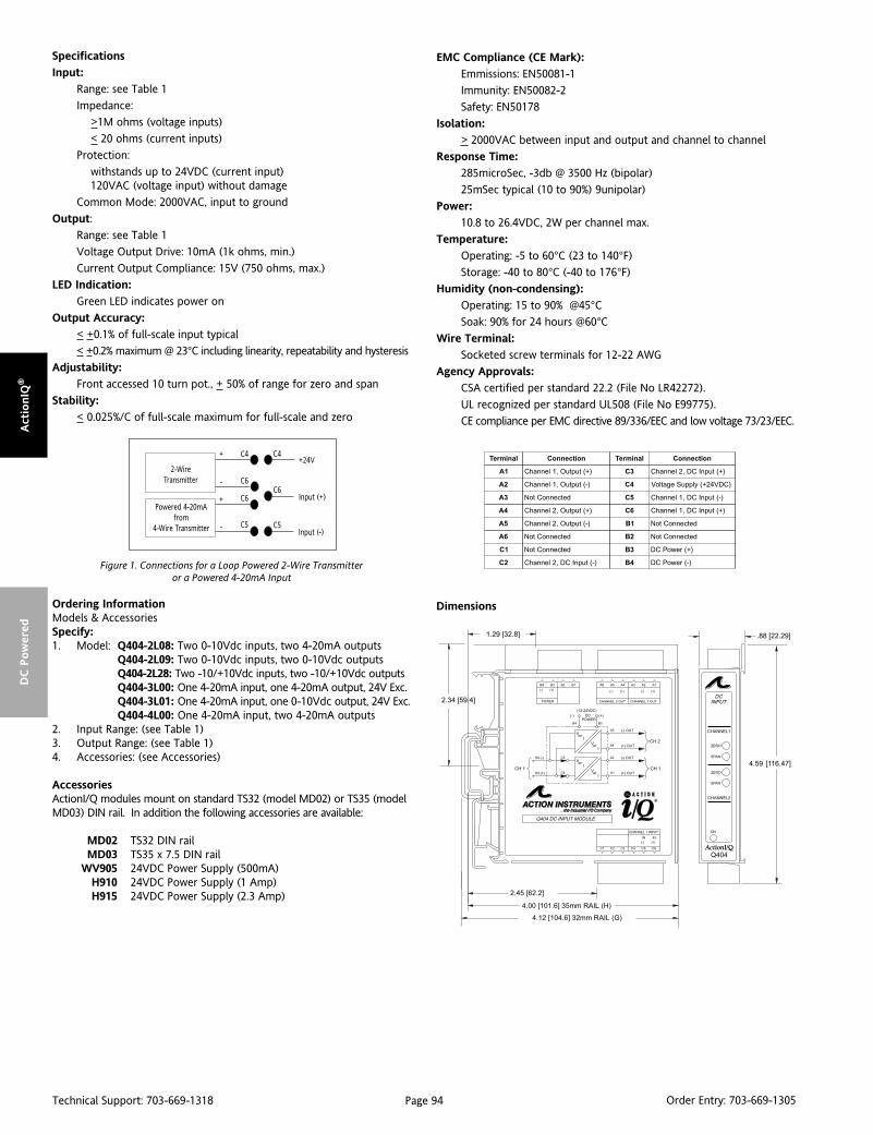
Page 94Technical Support: 703-669-1318 Order Entry: 703-669-1305
Act
ionIQ
®D
C P
ow
ered
lanimreT noitcennoC lanimreT noitcennoC
1A )+(tuptuO,1lennahC 3C )+(tupnICD,2lennahC
2A )-(tuptuO,1lennahC 4C )CDV42+(ylppuSegatloV
3A detcennoCtoN 5C )-(tupnICD,1lennahC
4A )+(tuptuO,2lennahC 6C )+(tupnICD,1lennahC
5A )-(tuptuO,2lennahC 1B detcennoCtoN
6A detcennoCtoN 2B detcennoCtoN
1C detcennoCtoN 3B )+(rewoPCD
2C )-(tupnICD,2lennahC 4B )-(rewoPCD
DimensionsOrdering InformationModels & AccessoriesSpecify:1. Model: Q404-2L08: Two 0-10Vdc inputs, two 4-20mA outputs
Q404-2L09: Two 0-10Vdc inputs, two 0-10Vdc outputsQ404-2L28: Two -10/+10Vdc inputs, two -10/+10Vdc outputsQ404-3L00: One 4-20mA input, one 4-20mA output, 24V Exc.Q404-3L01: One 4-20mA input, one 0-10Vdc output, 24V Exc.Q404-4L00: One 4-20mA input, two 4-20mA outputs
2. Input Range: (see Table 1)3. Output Range: (see Table 1)4. Accessories: (see Accessories)
AccessoriesActionI/Q modules mount on standard TS32 (model MD02) or TS35 (modelMD03) DIN rail. In addition the following accessories are available:
MD02 TS32 DIN railMD03 TS35 x 7.5 DIN rail
WV905 24VDC Power Supply (500mA)H910 24VDC Power Supply (1 Amp)H915 24VDC Power Supply (2.3 Amp)
Specifications
Input:
Range: see Table 1
Impedance:
>1M ohms (voltage inputs)
< 20 ohms (current inputs)
Protection:
withstands up to 24VDC (current input)120VAC (voltage input) without damage
Common Mode: 2000VAC, input to ground
Output:
Range: see Table 1
Voltage Output Drive: 10mA (1k ohms, min.)
Current Output Compliance: 15V (750 ohms, max.)
LED Indication:
Green LED indicates power on
Output Accuracy:
< +0.1% of full-scale input typical
< +0.2% maximum @ 23°C including linearity, repeatability and hysteresis
Adjustability:
Front accessed 10 turn pot., + 50% of range for zero and span
Stability:
< 0.025%/C of full-scale maximum for full-scale and zero
EMC Compliance (CE Mark):
Emmissions: EN50081-1
Immunity: EN50082-2
Safety: EN50178
Isolation:
> 2000VAC between input and output and channel to channel
Response Time:
285microSec, -3db @ 3500 Hz (bipolar)
25mSec typical (10 to 90%) 9unipolar)
Power:
10.8 to 26.4VDC, 2W per channel max.
Temperature:
Operating: -5 to 60°C (23 to 140°F)
Storage: -40 to 80°C (-40 to 176°F)
Humidity (non-condensing):
Operating: 15 to 90% @45°CSoak: 90% for 24 hours @60°C
Wire Terminal:
Socketed screw terminals for 12-22 AWG
Agency Approvals:
CSA certified per standard 22.2 (File No LR42272).
UL recognized per standard UL508 (File No E99775).
CE compliance per EMC directive 89/336/EEC and low voltage 73/23/EEC.
2-WireTransmitter
Powered 4-20mAfrom
4-Wire Transmitter
+
+
-
-
C4 C4
C6
C6
C5
C6
C5
+24V
Input (+)
Input (-)
Figure 1. Connections for a Loop Powered 2-Wire Transmitteror a Powered 4-20mA Input

Page 95Technical Support: 703-669-1318 Order Entry: 703-669-1305
Actio
nIQ
®D
C P
ow
ered
DescriptionThe model Q408 is a DC powered, DIN rail mount, DC input signalconditioner, with 1800V isolation between input, output andpower. The field configurable inputs and outputs provide flexible,wide ranging capability for DC current and voltage signals.
The Q408 is available as a single channel signal conditioner (1input/1 output) or a multi-channel signal conditioner (2 inputs/2outputs). All models maintain the high 1800V isolation level fromchannel to channel, as well as input to output to power.
TouchCAL TechnologyAction has simplified setpoint calibration. Using a pushbuttoninstead of potentiometers, improvements in calibration resolu-tion and reliability are realized due to the elimination of thepotentiometers’ mechanical variability. The thermal drift andmechanical variability of the potentiometers has been removedand replaced with a digitally stable circuit. Additionally, theinherent zero and span interactivity of analog amplifier circuitry isremoved, providing 100% non-interactive adjustme
The field configurable input of the Q408 can be set via DIP switchesfor any one of 12 voltage ranges from 10mV to 100V or 6 currentranges from 1mA to 100mA (see Table 1). The field configurableout put is linear to the input and can be set for either 0-5V, 0-10V,0-1mA or 4-20mA.
ApplicationThe ActionI/Q Q408 field configurable isolator is useful in elimi-nating ground loops, converting signal levels, and providing signaldrive. The field configurable, wide ranging capabilities ensuremaximum flexibility for most DC to DC applications, minimizingspare parts requirements.
Diagnostic LEDSThe Q408 has three diagnostic LEDs. The green (RUN) LED is usedfor diagnostics to indicate that power is on. It will flash quickly ifthe input signal is above the calibrated range or slowly if the inputsignal is below range. It is on continuously when the unit isfunctioning within the calibrated range. The yellow (IN) LED is onwhile calibrating the input and the red (OUT) LED is on whilecalibrating the output.
ACTIONI/Q®
Q408DC Powered DC InputMulti-Channel Isolator
Provides 1 or 2 Fully Isolated DC Output Signalsin Proportion to 1 or 2 DC Inputs
Field Configurable Input Ranges Field Configurable Output Ranges 1800VAC Isolation TouchCAL™ Technology
Q408-A000 (1 input; 1 output)
Q408-A004 (2 inputs; 2 outputs)
High Density DIN Rail Mounting Universal DC Power 10.8 to 26.4VDC SnapLocTM Plug-in Terminals
Configuration The Q408 can be configured for input ranges from 10mV to 100Vor 1mA to 100mA, with >90% input offset or it will adjust downto <10% of fullscale input span (except on 20mV/2mA range wheremaximum offset or gain adjustment is 50%).
Unless a specific custom calibration is specified, the factorypresets the Q408 as follows:
Input Range: 20mA (Current on)Input Configuration: Unipolar
Calibrated Input: 4-20mAOperation: Direct (Reverse off)
Calibrated Output: 4-20mA
For other I/O ranges, refer to the tables below.
WARNING: Do not change switch settings with power applied.Severe damage will result!
1. With power off, snap off the faceplate by lifting the right edgeaway from the heatsink. Slide the heatsink forward and off themodule.
2. The single channel module has two eight position switch blocks,one for input and one for output. The dual output modules havea second board behind the heatsink. Gently lift this board awayfrom the main board, rocking it back while lifting. The one input,two output module has one ten position switch block for input andchannel 1 output, along with a two position switch for the secondoutput. The two input, two output module has two ten positionswitch blocks, one for each channel.
3. For single channel modules, choose the desired input, functionand output range from Table 1, 2, and 3. For multi-channelmodules, use Table 4. Set the dip switches for the desired I/O.

Page 96Technical Support: 703-669-1318 Order Entry: 703-669-1305
Act
ionIQ
®D
C P
ow
ered
CalibrationNote: For best results, calibration should be performed with theintended output load, in the operating environment, mounted ona DIN rail, allowing at least one hour for thermal equilibrium of thesystem.
1. Install the module on to a piece of DIN rail and the I/Q Railmounting combination. See the I/Q Rail Data sheet for details.
Note: An I/QRail is required to deliver power to the modules. Seeordering information.
2. Connect the input to a calibrated DC source and the output toa voltage or current meter. Apply power and allow the system toreach thermal equilibrium (approx. 20 minutes ).
3. Adjust the input signal to the desired maximum and observe thatthe green LED is on or flashing. Push the CAL button and hold itdown for more than 5 seconds (until the yellow and Green LEDsare flashing).
4. When the yellow and green LEDs stop flashing, the yellow andred LEDs will be on. Push the CAL button momentarily (the yellowand green LEDs will be on).
segnaR 1WSrotceleS
egatloV tnerruC 1 2 3 4
Vm02 Am2
Vm05 Am5
Vm001 Am01
Vm002 Am02
Vm005 Am05
V1 Am001
V2
V5
V01
V52
V05
V001
:yeK desolCroNO=1=
segnaR 2WSrotceleS
tuptuO 1 2 3 4 5 6 7 8
V5ot0
V01ot0
Am1ot0
Am02ot4
Am02ot0
:yeK desolCroNO=1=
segnaR *2WSro1WSrotceleS
egatloV tnerruC 1 2 3 4 5 6 7 8 9 01
Vm02 Am2
Vm05 Am5
Vm001 Am01
Vm002 Am02
Vm005 Am05
V1 Am001
V2
V5
V01
V52
V05
V001
ralopinU
egatloV
tnerruC
tuptuO 1 2 3 4 5 6 7 8 9 01
V5ot0
V01ot0
Am1ot0
Am02ot4
:yeK desolCroNO=1=ledomlennahclaudotseilppA*
epyT1WSrotceleS
5 6 7 8
ralopinU - - -
ralopiB - - -
esreveR - - -
tceriD - - -
tnerruC - -
egatloV - -
:yeK a/n=-;desolCroNO=1=
Table 1: Input Range Settings for Single Channel Modules
Table 3: Output Range Settings for Single Channel Modules
Table 2: Input Function Settings for Single Channel Modules
Table 4: I/O Range & Function Settings for Dual Channel Modules
Note that 0-20mA output is NOT available on multichannel
units. Note also that Reverse Action is NOT available on
multichannel units.
Note: To quit the calibration mode and reset the unit, push the CALbutton and hold for more than 5 seconds. Or, wait for more thantwo minutes and the unit will timeout and reset itself to thepreviously stored calibration.
5. Apply the maximum input signal level desired, and push the CALbutton to store (the yellow LED will be on).
6. Apply the minimum input signal level desired, and push the CALbutton to store (the green and red LED will be on.
7. Adjust the input signal while monitoring the output signal untilthe output is at the desired maximum level (e.g. 20.00mA), thenpush the CAL button to store (the red LED will be on).
8. Adjust the input signal while monitoring the output signal untilthe output is at the desired minimum level (e.g. 4.00mA), then pushthe CAL button to store (the yellow, green and red LEDs will be on).
9. Push the CAL button one final time to store the calibration data.The green LED will be on if the input is within the calibrated range.

Page 97Technical Support: 703-669-1318 Order Entry: 703-669-1305
Actio
nIQ
®D
C P
ow
ered
Figure 1: Q408 Calibration Flow Chart

Page 98Technical Support: 703-669-1318 Order Entry: 703-669-1305
Act
ionIQ
®D
C P
ow
ered Ordering Information
Models & AccessoriesSpecify:1. Model:
Q408-A000: one input, one output DC IsolatorQ408-A004: two input, two output DC Isolator
2. Specify optional I/QRail, type and quantity.3. Optional Factory Custom Calibration, specify C620 - with desired
input and output ranges.4. Accessories: (see Accessories)
AccessoriesActionI/Q modules mount on standard TS32 (model MD02) or TS35 (modelMD03) DIN rail. In addition the following accessories are available:
MD02 TS32 DIN railMD03 TS35 x 7.5 DIN rail
IQRL-D002 2 Position I/QRail & DIN railIQRL-D004 4 Position I/QRail & DIN railIQRL-D008 8 Position I/QRail & DIN rail
WV905 24VDC Power Supply (0.5Amp)H910 24VDC Power Supply (1Amp)H915 24VDC Power Supply (2.3Amp)
Specifications
Input:
Voltage:Range Limits: 10mV to 100V (see Table 1)Impedance: >100k ohmsOvervoltage: 200V continuous
Current:Range Limits: 1mA to 100mAImpedance: 20 ohms typicalOvercurrent: 170mA, protectedby self resetting fuseOvervoltage: 60V
Pushbutton Adjustment (inputs>10mV)Effective zero offset: > 90%Effective span turn down: > 90% except for 20mV/2mA range
where 50% is max. zero offset and span turndown
Output:
Voltage:Output: 0-5V, 0-10VSource Impedance: <10 ohmsDrive: 10mA max.
Current:Output: 4-20mA, 0-1mA
(and 0-20mA on single output channel versions only)Source Impedance: >100k ohmsCompliance:
0-1mA: 7.5V max. (7.5k ohms)4-20mA: 12V max. (600 ohms)*0-20mA: 12V max. (600 ohms)*10V max. (500ohms) on dual output versions
Output Accuracy:
>2mA / >20mV input spans:+0.1% of full-scale input typical,
+0.2% maximum<2mA / <20mV input spans:
+ 0.35% of fullscale input typical,
+ 0.5% maxmum; including linearity, repeatability and hysteresis @23°C
Output Ripple:
<50% offset or span adjust:
<0.1% off full scale span or 25mV RMS, whichever is greater
>50% offset or span adjust:
<0.2% of full scale span or 50mV RMS, whichever is greater.
Response Time: 200mSec, typical
Stability: +0.025% of fullscale/°C, max. (fullscale & zero)
Common Mode Rejection: 120dB at DC, >90dB at 60Hz
Isolation:
> 1800VDC or peak AC between input, output, power and channelto channel
ESD Susceptibility: Capable of meeting IEC 801-2 level 3 (8kV)
Humidity (non-condensing):
Operating: 15 to 95% RH @45°CSoak: 90% RH for 24 hours @60°C
Temperature:
Operating: 0 to 55°C (32 to 131°F)Storage: -25 to 70°C (-13 to 158°F)
Power: 2.5W max; 9-30VDC
Wire Terminals: Socketed screw terminals for 12-22 AWG
Agency Approvals
CSA certified per standard C22,2 (File No LR 42272).UL recognized per standard UL508 (File No. E99775).
Dimensions
lanimreT noitcennoC lanimreT noitcennoC
1A )+(tuO1lennahC 3C detcennoCtoN
2A )-(tuO1lennahC 4C detcennoCtoN
3A )+(tuO2lennahC 5C )-(nI1lennahC
4A )-(tuO2lennahC 6C )+(nI1lennahC
5A )+(rewoPCD 1P desUtoN
6A )-(rewoPCD 2P desUtoN
1C )-(nI2lennahC 3P )+(rewoPCD
2C )+(nI2lennahC 4P )-(rewoPCD

Page 99Technical Support: 703-669-1318 Order Entry: 703-669-1305
Actio
nIQ
®D
C P
ow
ered
DescriptionThe Q438 is a DIN rail mount, potentiometer input signal condi-tioner with 1800VDC isolation between DC power and the input/output circuitry. The input provides a constant voltage and isdesigned to accept any three-wire potentiometer from 100 ohms to100k ohms. The field configurable output is switch selectableproviding a 0-5V, 0-10V, 0-1mA, 0-20mA or 4-20mA DC signal. Wideranging, precision zero and span pots, used in conjunction with DIPswitches, allow 80% adjustablity of offset and gain to transmit a fullscale output from any 20% portion of the potentiometer input.
ApplicationThe Q438 is useful in transmitting process control setpoints to remotePID controllers or interfacing position or level sensors to dataacquisition and control systems. The high density DIN rail mountingoffers an extremely compact solution for saving valuable panel space.
ConfigurationIn a valve positioning application a potentiometer is sometimes usedas a feedback signal. Quite often a wide open valve is only a 25% turnof the feedback potentiometer. The Q438 can easily be adjusted withthe zero and span to provide a fullscale output signal (e.g. 4-20mA)representing 0-25% or even 50-75% of the potentiometer input.
Unless otherwise specified, the factory presets the Model Q438 asfollows:
Input Range: 0 to 100%Output: 4 to 20mA
For other output ranges, refer to Tables 1 and 2 to reconfigureswitches SW1 and SW2 for the desired input and output ranges.
WARNING: Do not change switch settings with power applied.Severe damage will result!
CalibrationNote: For best results, calibration should be performed with theintended output load, in the operating environment, mounted ona DIN rail, allowing at least one hour for thermal equilibrium of thesystem.
1. With power disconnected, set the output and input switchselectors (SW1 and SW2) to the desired ranges (see Tables 1 and 2).
ACTIONI/Q®
Q438DC Powered Potentiometer Input
Signal Conditioner
Provides a DC Output in Proportionto a Potentiometer Input
Accepts Potentiometers from 100 Ohms to 100k Ohms Wide Ranging Zero and Span ASIC Technology
Q438-0000
High Density DIN Rail Mounting Flexible DC Power Supply 9 to 30VDC SnapLocTM Plug-in Terminals
2. Connect the input to a potentiometer. Connect the output tothe actual device load (or a load approximately equivalent to theactual device load value) and apply power.
Note: To maximize thermal stability, final calibration should beperformed in the operating installation, allowing approximately 1to 2 hours for warm up and thermal equilibrium of the system.
3. Set the input to the desired minimum and adjust the zeropotentiometer for the desired minimum output.
4. Set the input to the desired maximum and adjust the spanpotentiometer for the desired maximum output.
5. Repeat steps 3 and 4, if necessary.
napS2WSrotceleS
1 2 3 4 5 6
%001-02
%001-54
%001-58)tluafed(
tesffO 1 2 3 4 5 6
%02-0)tluafed(
%54-02
%56-54
%08-56
:yeK desolCroNO=1=
Table 1: Input Range Settings
tuptuO1WSrotceleS
1 2 3 4 5 6 7 8
V5+ot0
V01+ot0
Am1ot0
Am02ot4)tluafed(
Am02ot0
:yeK desolCroNO=1=
Table 2: Output Range Settings

Page 100Technical Support: 703-669-1318 Order Entry: 703-669-1305
Act
ionIQ
®D
C P
ow
ered
Specifications
Potentiometer Input:
End-to-end Resistance: 100 ohms up to 100k ohms
Input Impedance: >1M ohms
Input Excitation: 500mV, 5mA maximum drive.
Zero Turn-Up: 80% of full scale input
Span Turn-Down: 80% of full scale input
Output:
Voltage:
Output: 0-5V, 0-10V
Source Impedance: <10 ohms
Drive: 10mA, max. (1k ohms min. @10V)
Current Output:
Output: 0-1mA, 0-20mA, 4-20mA
Source Impedance: >100k ohms
Compliance:
0-1mA; 7.5V, max. (7.5k ohms, max.)
0-20mA; 12V, max. (600 ohms, max.)4-20mA; 12V, max. (600 ohms, max.)
Accuracy (Including Linearity, Hysteresis):
±0.1% maximum at 25°CStability:
<±0.05%/°C maximum of full scale range
Response Time (10 to 90%):
<200mSec., typical.
Common Mode Rejection:
120dB @ DC, >100dB @ 60Hz
Ordering InformationModels And AccessoriesSpecify:1. Model: Q438-00002. Specify optional I/QRail, type and quantity.3. Optional Custom Factory Calibration; specify C620 with desired
input and output range4. Accessories: (see Accessories)
AccessoriesActionI/Q modules will mount on standard TS32 (model MD02) or TS35(model MD03) DIN Rail. In addition, the following accessories are available:
MD02 TS32 DIN railMD03 TS35 x 7.5 DIN rail
IQRL-D002 2 Position I/QRail & DIN railIQRL-D004 4 Position I/QRail & DIN railIQRL-D008 8 Position I/QRail & DIN rail
WV905 24VDC Power Supply (0.5Amp)H910 24VDC Power Supply (1Amp)H915 24VDC Power Supply (2.3Amp)
Isolation:
1800VDC between line power and input, and power and output
EMC Compliance (CE Mark):
Emissions: EN50081-1
Immunity: EN50082-2
Safety: EN50178
LED Indication (green):
Active DC power
Humidity (Non-Condensing):
Operating: 15 to 95% @ 45°CSoak: 90% for 24 hours @ 65°C
Temperature Range:
Operating: 0 to 55°C (32 to 131°F)
Storage: -25 to 70°C (-13 to 158°F)
Power:
Consumption: 1.5W typical, 2.5W max
Range: 9 to 30VDC
Weight:
0.48 lbs
Agency Approvals:
UL recognized per standard UL508 (File No. E99775)
CSA certified per standard C22.2 No. 0-M91and 142-M1987 (File No. LR42272-84).
CE Compliance per EMCdirective 89/3/36 EEC and Low Voltage 73/23/EEC.
Dimensions
lanimreT noitcennoC lanimreT noitcennoC
1A )+(tuptuOCD 1C desUtoN
2A )-(tuptuOCD 2C desUtoN
3A desUtoN 3C dnuorGesaC.toP
4A desUtoN 4C )WCCylluf(tupnI.toP
5A )+(rewoPCD 5C repiWtupnI.toP
6A )-(rewoPCD 6C )WCylluf(tupnI.toP

Page 101Technical Support: 703-669-1318 Order Entry: 703-669-1305
Actio
nIQ
®D
C P
ow
ered
DescriptionThe Q448 is a DIN rail mount, DC powered bridge or strain gaugeinput signal conditioner with 1800VDC isolation between input,output and power. Advanced digital technology combined withASIC technology allows the Q448 to be field configured forvirtually any Bridge input to DC output within the limits specified.The input can be set via DIP switches for any one of 11 voltageranges from 10mV to ±200mV (see Table 1). The output is linearto the input and can be set for either 0-5V, 0-10V, 0-1mA or 4-20mA, direct or reverse acting.
TouchCALTM TechnologyThe Q448 utilizes TouchCAL technology which greatly simplifiescalibration. Once the unit is configured via DIP switches, thepushbutton is used to precisely calibrate the minimum andmaximum levels. The thermal drift and mechanical variability ofthe potentiometers has been removed and replaced with adigitally stable circuit. Additionally, the inherent zero and spaninteractivity of potentiometer based analog amplifier circuitry isremoved, providing 100% non-interactive adjustment.
TouchCAL provides more than 90% offset of the zero value andadjustment down to 10% of the full scale input span for most of the11 switch selectable input ranges. For example, the DIP switchconfigured 0-100mV input range could be calibrated viapushbutton for 0-40mV (i.e. 60% span reduction) or offset to a rangeof 60-100mV (i.e. 60% offset and 60% span reduction). If the outputwas configured for 0-10V, then 60-100mV input would correspondto the 0-10V full scale output. Thus, an input range such as 90-100mV is possible using the 0-100mV range. A TARE function is alsoprovided to allow batch offsets (0285 and later firmware).
To calibrate the input within the DIP switch configured range,simply apply the high input signal and push the CAL button. Thelow input signal is then applied and pushing the CAL button againstores the low input signal (these steps are reversed for reversemode operation).
The high and low input levels are stored in nonvolatile memoryand correspond to the high and low output levels. These outputlevels are precisely adjusted using the input signal.
ACTIONI/Q®
Q448DC Powered Bridge Input
Signal Isolator
Provides an Isolated DC Output in Proportionto a Bridge/Strain Gauge Input
Adjustable Bridge Excitation Field Configurable Input Ranges Field Configurable Output Ranges TouchCAL Technology
Q448-0000
High Density DIN Rail Mounting Flexible DC Power Supply Accepts 18 to 30VDC SnapLocTM Plug-in Terminals
Diagnostic LEDSThe Q448 has three diagnostic LEDs. The green (RUN) LED is usedfor diagnostics to indicate that power is on. It will flash quickly ifthe input signal is above the calibrated range or slowly if the inputsignal is below range. It is on continuously when the unit isfunctioning within the calibrated range.
The yellow (IN) LED is on while calibrating the input and the red(OUT) LED is on while calibrating the output.
ApplicationThe Q448 bridge input signal conditioner is useful in isolatingground loops and interfacing bridge sensors to data acquisition andcontrol systems. Three-way isolation completely eliminates groundloops from any source. Isolation protects expensive SCADA systemsfrom ground faults and provides filtering for noise reduction whichcan be a significant problem with millivolt bridge signals.
Wide ranging flexibility allows the user to easily zero out dead-loads in weighing systems or configure bipolar input ranges fortension-compression or vacuum-pressure bridge applications.
High density DIN rail mounting offers an extremely compactsolution for saving valuable panel space.
ConfigurationThe Q448 can be configured for input ranges from 10mV to +/-200mV, with 90% input offset, or it will adjust down to 10% offullscale input span (except on 10mV, +/-5mV range wheremaximum offset or gain adjustment is 50%).
Unless otherwise specified, the factory presets the Model Q448 asfollows:
Input Setting: 0 to 50mVInput Range: 0 to 30mV (3mV/V)
Excitation: 10VOperation: Direct
Output: 4 to 20mA
For other I/O ranges, refer to the tables below.
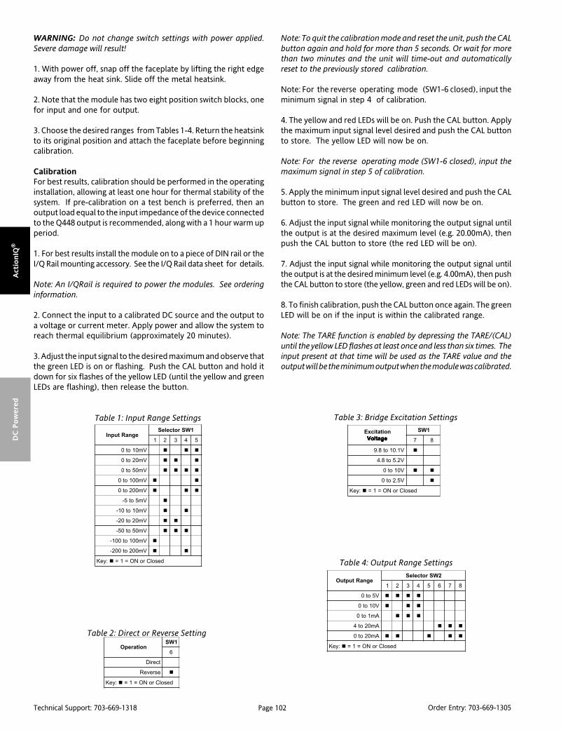
Page 102Technical Support: 703-669-1318 Order Entry: 703-669-1305
Act
ionIQ
®D
C P
ow
ered
WARNING: Do not change switch settings with power applied.Severe damage will result!
1. With power off, snap off the faceplate by lifting the right edgeaway from the heat sink. Slide off the metal heatsink.
2. Note that the module has two eight position switch blocks, onefor input and one for output.
3. Choose the desired ranges from Tables 1-4. Return the heatsinkto its original position and attach the faceplate before beginningcalibration.
CalibrationFor best results, calibration should be performed in the operatinginstallation, allowing at least one hour for thermal stability of thesystem. If pre-calibration on a test bench is preferred, then anoutput load equal to the input impedance of the device connectedto the Q448 output is recommended, along with a 1 hour warm upperiod.
1. For best results install the module on to a piece of DIN rail or theI/Q Rail mounting accessory. See the I/Q Rail data sheet for details.
Note: An I/QRail is required to power the modules. See orderinginformation.
2. Connect the input to a calibrated DC source and the output toa voltage or current meter. Apply power and allow the system toreach thermal equilibrium (approximately 20 minutes).
3. Adjust the input signal to the desired maximum and observe thatthe green LED is on or flashing. Push the CAL button and hold itdown for six flashes of the yellow LED (until the yellow and greenLEDs are flashing), then release the button.
Note: To quit the calibration mode and reset the unit, push the CALbutton again and hold for more than 5 seconds. Or wait for morethan two minutes and the unit will time-out and automaticallyreset to the previously stored calibration.
Note: For the reverse operating mode (SW1-6 closed), input theminimum signal in step 4 of calibration.
4. The yellow and red LEDs will be on. Push the CAL button. Applythe maximum input signal level desired and push the CAL buttonto store. The yellow LED will now be on.
Note: For the reverse operating mode (SW1-6 closed), input themaximum signal in step 5 of calibration.
5. Apply the minimum input signal level desired and push the CALbutton to store. The green and red LED will now be on.
6. Adjust the input signal while monitoring the output signal untilthe output is at the desired maximum level (e.g. 20.00mA), thenpush the CAL button to store (the red LED will be on).
7. Adjust the input signal while monitoring the output signal untilthe output is at the desired minimum level (e.g. 4.00mA), then pushthe CAL button to store (the yellow, green and red LEDs will be on).
8. To finish calibration, push the CAL button once again. The greenLED will be on if the input is within the calibrated range.
Note: The TARE function is enabled by depressing the TARE/(CAL)until the yellow LED flashes at least once and less than six times. Theinput present at that time will be used as the TARE value and theoutput will be the minimum output when the module was calibrated.
noitarepO1WS
6
tceriD
esreveR
:yeK desolCroNO=1=
noitaticxEegatloV egatloV egatloV egatloV egatloV
1WS
7 8
V1.01ot8.9
V2.5ot8.4
V01ot0
V5.2ot0
:yeK desolCroNO=1=
egnaRtuptuO2WSrotceleS
1 2 3 4 5 6 7 8
V5ot0
V01ot0
Am1ot0
Am02ot4
Am02ot0
:yeK desolCroNO=1=
egnaRtupnI1WSrotceleS
1 2 3 4 5
Vm01ot0
Vm02ot0
Vm05ot0
Vm001ot0
Vm002ot0
Vm5ot5-
Vm01ot01-
Vm02ot02-
Vm05ot05-
Vm001ot001-
Vm002ot002-
:yeK desolCroNO=1=
Table 1: Input Range Settings
Table 2: Direct or Reverse Setting
Table 3: Bridge Excitation Settings
Table 4: Output Range Settings
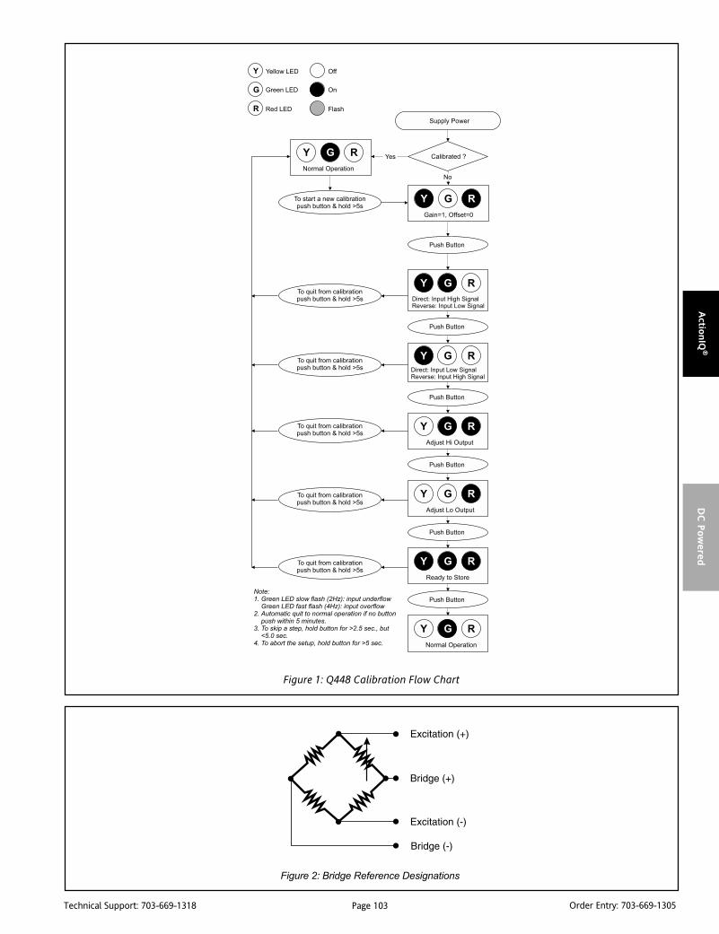
Page 103Technical Support: 703-669-1318 Order Entry: 703-669-1305
Actio
nIQ
®D
C P
ow
ered
Figure 2: Bridge Reference Designations
Figure 1: Q448 Calibration Flow Chart

Page 104Technical Support: 703-669-1318 Order Entry: 703-669-1305
Act
ionIQ
®D
C P
ow
ered
SpecificationsInput:
Voltage:Full Scale Range: 10mV to ±200mV (Table 1).Impedance: >1M ohmOvervoltage:
Intermittent 400V, max.; Continuous 264V, max.Common Mode (Input to Ground):
1800VDC, max.Pushbutton Adjustment:
Effective zero offset: >90%Effective span turn down: >90% except for 10mV & +/-5mV range
in which 50% is max. zero offset and span turndownOperation: direct or reverse acting
Output:Voltage:
Output: 0-5V, 0-10VImpedance: <10 ohmsDrive: 10mA, max. (1K ohms, min. @ 10V)
Current:Output: 0-1mA, 0-20mA, 4-20mAImpedance: >100K ohmsCompliance:
0-1mA; 7.5V, max.(7.5K ohms, max.)0-20mA; 12V, max. (600 ohms, max.)4-20mA; 12V, max. (600 ohms, max.)
Bridge Excitation1 to 10VDC, 120mA max. Current drive decreases at 10mA/V below5V (e.g. 4V, 110mA max.)
Accuracy (Including Linearity, Hysteresis):±0.1% typical, ±0.2% maximum of selected input range at 25°C.
Stability:±0.025%/°C typical, 0.05%/°C maximum, of selected full scale input range.
Output Noise (maximum):0.1% of span, rms, or 10mV, whichever is greater.
Response Time (10 to 90%):<200mSec., typical.
Common Mode Rejection:DC to 60Hz: 120dB, 100dB (0 -1mA, range)
Isolation:800VDC between input, output and power.
EMC Compliance (CE Mark):Emissions: EN50081-1; Immunity: EN50082-2; Safety: EN50178
LED Indication (green):Input Range (approx.)
>110% input: 8Hz flash<0% input: 4Hz flash
Humidity (Non-Condensing):Operating: 15 to 95% @ 45°CSoak: 90% for 24 hours @ 65°C
Temperature Range:Operating: 0 to 55°C (32 to 131°F)Storage: -25 to 70°C (-13 to 158°F)
Power:Consumption:
2.7W typical (one 350 ohm bridge)4W max. (four 350 ohm bridges).Range: 18 to 30VDC
Shipping Weight:0.54 lbs.
Wire Terminations:Screw terminals for 12-22 AWG
Agency Approvals:UL recognized per standard UL508 (File No. E99775).CSA certified per standard C22.2 No. 0-M91 and 142-M1987
(File No. LR42272-84).CE Compliance per EMC directive 89/3/36 EEC and Low Voltage 73/23/EEC.
lanimreT noitcennoC lanimreT noitcennoC
1A )+(tuptuOCD 3C )-(tupnIegdirB
2A )-(tuptuOCD 4C )-(noitaticxEegdirB
3A desUtoN 5C detcennoCtoN
4A desUtoN 6C detcennoCtoN
5A )+(rewoPCD 1P desUtoN
6A )-(rewoPCD 2P desUtoN
1C )+(noitaticxEegdirB 3P )+(rewoPCD
2C )+(tupnIegdirB 4P )-(rewoPCD
Ordering InformationModels & AccessoriesSpecify:1. Model: Q448-0000;2. Specify optional I/QRail, type and quantity.3. Optional Factory Custom Calibration, specify C620 - with desired
input and output ranges.4. Accessories: (see Accessories)
AccessoriesActionI/Q modules mount on standard TS32 (model MD02) or TS35 (modelMD03) DIN rail. In addition the following accessories are available:
MD02 TS32 DIN railMD03 TS35 x 7.5 DIN rail
IQRL-D002 2 Position I/QRail & DIN railIQRL-D004 4 Position I/QRail & DIN railIQRL-D008 8 Position I/QRail & DIN rail
WV905 24VDC Power Supply (0.5Amp)H910 24VDC Power Supply (1Amp)H915 24VDC Power Supply (2.3Amp)
Dimensions

Page 105Technical Support: 703-669-1318 Order Entry: 703-669-1305
Actio
nIQ
®D
C P
ow
ered
DescriptionThe Q468 is a DIN rail mount, AC input signal conditioner with1800VDC isolation between input, output and power. The fieldconfigurable input and output offers flexible, wide ranging capa-bility for scaling, converting or buffering AC inputs ranging from5mA to 100mAAC or 50mV to 300VAC.
For current inputs above 100mA, it is recommended that an inputshunt resistor be used and the Q468 be configured for the properinput range. For example, a 5A current transformer output can usethe C006 shunt resistor (0.1 ohm, 5W) with the input of the Q468set for 0-500mVAC.
The DC output of the Q468 is proportional to the average of thefully-rectified AC input signal, and is calibrated for sine wavesbetween 40-400Hz.
TouchCALTM TechnologyThe Q468 utilizes TouchCAL technology which greatly simplifiescalibration. The thermal drift and mechanical variability of thepotentiometers has been removed and replaced with a digitallystable circuit. Once the unit is configured via DIP switches forvoltage or current, the pushbutton is used to precisely calibratethe minimum and maximum levels.
To set the input level within the dip switch configured range,simply apply the high input signal (voltage or current) and push theCAL button. The low input signal is then applied and pushing theCAL button again stores the low input signal. The high and lowinput levels are stored in nonvolatile memory and correspond tothe high and low output levels. These output levels are preciselyadjusted using the input signal.
TouchCAL technology enables precise calibration and provides morethan 90% offset of the zero value and adjustment down to 10% of thefull scale input span for most of the 16 switch selectable input ranges.For example, the dipswitch configured 0-200V input range could becalibrated via pushbutton for 0-80V (i.e. 60% span reduction) or offsetto a range of 120-200V (i.e. 60% offset and 60% span reduction). If theoutput was configured for 0-10V, then 120-200V input wouldcorrespond to the 0-10V full scale output. Input ranges such as 180-200V or 0-20V are possible using the 0-200V range.
ACTIONI/Q®
Q468DC Powered AC Input
Signal Isolator
Provides an Isolated DC Outputin Proportion to an AC Input
Eliminates Ground Loops Field Configurable Input Ranges Field Configurable Output Ranges TouchCAL Technology
Q468-0000
High Density DIN Rail Mounting Flexible DC Power Supply Accepts 9 to 30VDC SnapLocTM Plug-in Terminals
Advanced digital technology combined with Action’s exclusiveASIC technology allows the Q468 to be field configured forvirtually any AC input to DC output within the limits specified.
ApplicationThe Q468 is useful in applications requiring an isolated, conditionedDC output from an AC signal. Typical applications include energymanagement, load shedding, motor current/load monitoring, lockedrotor detection, isolation and data acquisition. The output of theQ466 can drive a digital meter for direct display or can interface withalarm or control devices including PLCs and computers.
Diagnostic LEDSThe Q468 has three diagnostic LEDs. The green (RUN) LED is usedfor diagnostics to indicate that power is on. It will flash quickly ifthe input signal is above the calibrated range or slowly if the inputsignal is below range. It is on continuously when the unit isfunctioning within the calibrated range.
The yellow (INPUT) LED is on while calibrating the input level. Thered (OUTPUT) LED is on while calibrating the output level.
ConfigurationThe Q468 can be configured for input ranges from 50mV to 300Vor 5mA to 100mA, with >90% input offset or it will adjust downto <10% of full scale input span (except on the 100mV/10mA rangein which maximum offset or gain adjustment is 50%).
Unless a specific custom calibration is specified, the factorypresets the Q468 as follows:
Input Range: 0 -500mVCalibrated Output: 4-20mA
For other I/O ranges, refer to the tables.
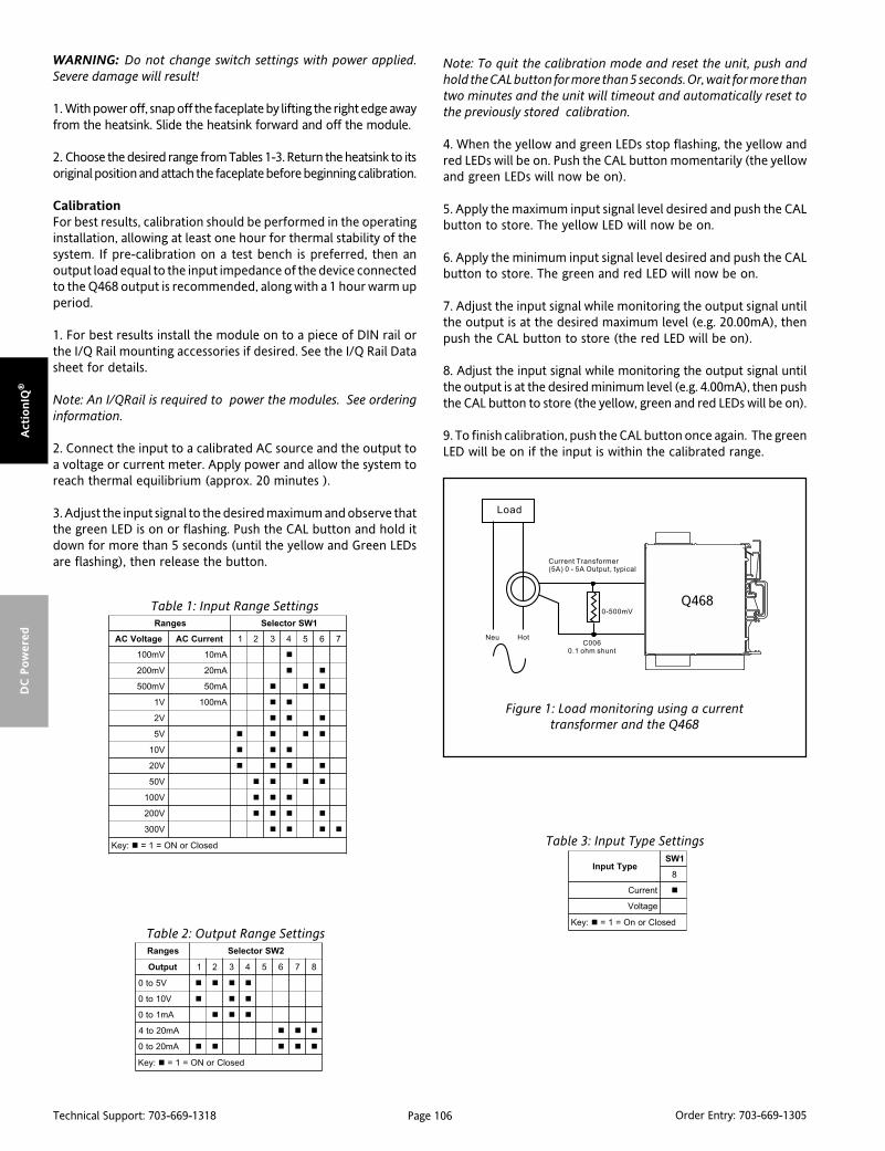
Page 106Technical Support: 703-669-1318 Order Entry: 703-669-1305
Act
ionIQ
®D
C P
ow
ered
WARNING: Do not change switch settings with power applied.Severe damage will result!
1. With power off, snap off the faceplate by lifting the right edge awayfrom the heatsink. Slide the heatsink forward and off the module.
2. Choose the desired range from Tables 1-3. Return the heatsink to itsoriginal position and attach the faceplate before beginning calibration.
CalibrationFor best results, calibration should be performed in the operatinginstallation, allowing at least one hour for thermal stability of thesystem. If pre-calibration on a test bench is preferred, then anoutput load equal to the input impedance of the device connectedto the Q468 output is recommended, along with a 1 hour warm upperiod.
1. For best results install the module on to a piece of DIN rail orthe I/Q Rail mounting accessories if desired. See the I/Q Rail Datasheet for details.
Note: An I/QRail is required to power the modules. See orderinginformation.
2. Connect the input to a calibrated AC source and the output toa voltage or current meter. Apply power and allow the system toreach thermal equilibrium (approx. 20 minutes ).
3. Adjust the input signal to the desired maximum and observe thatthe green LED is on or flashing. Push the CAL button and hold itdown for more than 5 seconds (until the yellow and Green LEDsare flashing), then release the button.
segnaR 1WSrotceleS
egatloVCA tnerruCCA 1 2 3 4 5 6 7
Vm001 Am01
Vm002 Am02
Vm005 Am05
V1 Am001
V2
V5
V01
V02
V05
V001
V002
V003
:yeK desolCroNO=1=
segnaR 2WSrotceleS
tuptuO 1 2 3 4 5 6 7 8
V5ot0
V01ot0
Am1ot0
Am02ot4
Am02ot0
:yeK desolCroNO=1=
epyTtupnI1WS
8
tnerruC
egatloV
:yeK desolCronO=1=
Figure 1: Load monitoring using a currenttransformer and the Q468
Table 1: Input Range Settings
Table 2: Output Range Settings
Table 3: Input Type Settings
Note: To quit the calibration mode and reset the unit, push andhold the CAL button for more than 5 seconds. Or, wait for more thantwo minutes and the unit will timeout and automatically reset tothe previously stored calibration.
4. When the yellow and green LEDs stop flashing, the yellow andred LEDs will be on. Push the CAL button momentarily (the yellowand green LEDs will now be on).
5. Apply the maximum input signal level desired and push the CALbutton to store. The yellow LED will now be on.
6. Apply the minimum input signal level desired and push the CALbutton to store. The green and red LED will now be on.
7. Adjust the input signal while monitoring the output signal untilthe output is at the desired maximum level (e.g. 20.00mA), thenpush the CAL button to store (the red LED will be on).
8. Adjust the input signal while monitoring the output signal untilthe output is at the desired minimum level (e.g. 4.00mA), then pushthe CAL button to store (the yellow, green and red LEDs will be on).
9. To finish calibration, push the CAL button once again. The greenLED will be on if the input is within the calibrated range.

Page 107Technical Support: 703-669-1318 Order Entry: 703-669-1305
Actio
nIQ
®D
C P
ow
ered
Figure 2: Q468 Calibration Flow Chart

Page 108Technical Support: 703-669-1318 Order Entry: 703-669-1305
Act
ionIQ
®D
C P
ow
ered
SpecificationsInputs:
Voltage:Ranges: 100mVAC to 300VACImpedance: >100K ohmsOvervoltage: 330VAC
Current:Ranges: 10mA to 100mAACImpedance: 20 ohms, typicalOvercurrent: 170mAACOvervoltage: 60V peak
Frequency Range:DC to 400Hz, factory calibrated at 60Hz
Common Mode (Input to Ground):1800VDC, max.
Pushbutton Adjustment:Effective zero offset: >90%Effective span turn down: >90% except for 100mV/10mA
range in which 50% is max. zero offset and span turn downOutput:
Voltage:Output: 0-5V, 0-10VSource Impedance: <10 ohmsDrive: 10mA, max. (1K ohms, min. @ 10V)
Current:Output: 0-1mA, 0-20mA, 4-20mASource Impedance: >100K ohmsCompliance:
0-1mA; 7.5V, max. (7.5K ohms, max.)0-20mA; 12V, max. (600 ohms, max.)4-20mA; 12V, max. (600 ohms, max.)
LED Indication:RUN (green):
On when unit is poweredflashes at 8Hz when input is 7% above max.
INPUT (yellow):On while calibrating the input level
OUTPUT (red):On while calibrating the output level
Accuracy (Including Linearity & Hysteresis):+0.1% of span, typical+0.5% of span, maximum (100mV range)
Stability:+0.025%/°C of selected input span, typical.
Response Time (10 to 90%):250mSec., typical.
Common Mode Rejection:DC to 60Hz: 120dB
Isolation:1800VDC between input, output and power.
EMC Compliance (CE Mark):Emmissions: EN50081-1; Immunity: EN50082-2; Safety: EN50178
Humidity (Non-Condensing):Operating: 15 to 95% @ 45°CSoak: 90% for 24 hours @ 65°C
Temperature Range:Operating: 0 to 55°C (32 to 131°F)Storage: -25 to 70°C (-13 to 158°F)
Power:Consumption: 1.5W typical, 2.5W max.Range: 9 to 30VDC
Wire Terminations:Screw terminals for 12-22 AWG
Shipping Weight:0.48 lbs.
Agency Approvals:UL recognized per standard UL508 (File No. E99775).CSA certified per standard C22.2 No. 0-M91 and 142-M1987
(File No. LR42272-84).CE Compliance per EMC directive 89/336/EEC and Low Voltage 73/23/EEC.
Ordering InformationModels and AccessoriesSpecify:1. Model: Q468-00002. Specify optional I/QRail, type and quantity.3. Optional Factory Custom Calibration, specify C620 - with desired
input and output ranges.4. Accessories: (see Accessories)
AccessoriesActionI/Q modules mount on standard TS32 (model MD02) or TS35 (modelMD03) DIN rail. In addition the following accessories are available:
MD02 TS32 DIN railMD03 TS35 x 7.5 DIN rail
IQRL-D002 2 Position I/QRail & DIN railIQRL-D004 4 Position I/QRail & DIN railIQRL-D008 8 Position I/QRail & DIN rail
WV905 24VDC Power Supply (0.5Amp)H910 24VDC Power Supply (1Amp)H915 24VDC Power Supply (2.3Amp)
Dimensions
lanimreT noitcennoC lanimreT noitcennoC
1A )+(tuptuO 3C )eniL(egatloVtupnI
2A )-(tuptuO 4C desUtoN
3A desUtoN 5C )lartueN(tupnI
4A desUtoN 6C )eniL(tnerruCtupnI
5A )+(rewoPCD 1P desUtoN
6A )-(rewoPCD 2P desUtoN
1C desUtoN 3P )+(rewoPCD
2C desUtoN 4P )-(rewoPCD

Page 109Technical Support: 703-669-1318 Order Entry: 703-669-1305
Actio
nIQ
®D
C P
ow
ered
DescriptionThe Q478 is a DC powered DIN rail mount, frequency input signalconditioner with 1800VDC isolation between input, output andpower. The field configurable input and output offers flexible,wide ranging capability for variable frequency drives, magneticpickups, turbine flowmeters, and other pulse or frequency outputtransducers.
The input of the Q478 can be configured for any frequency spanfrom 2Hz to 10,000Hz. The input amplitude threshold sensitivitycan be adjusted from 150mVp to 10Vp to ensure accuratefrequency measurement and minimize transient noise relatederrors. The maximum input amplitude is 150 Vrms. The output canbe set for either 0-5V, 0-10V, 0-1mA, 0-20mA or 4-20mA.
The Q478 can be field configured for virtually any frequency inputto DC signal output within the ranges specified. There is also an8VDC excitation source common to the input. This can be used asa signal source for relay contacts or as an excitation source foropen collector type proximity sensors. The Q478 is DC poweredand will accept any power between 9 and 30VDC.
TouchCAL TechnologyThe Q478 utilizes TouchCAL Technology to greatly simplify con-figuration. The high and low input ranges are stored in non-volatile memory and correspond to the high and low output rangewhich is selected via DIP switches.
Diagnostic LEDSThe Q478 utilizes three diagnostic LEDs. The green (RUN) LEDindicates DC power and input signal status. Active line power isindicated by an illuminated LED. If the input signal is 7% or morehigh, the LED will flash at 8Hz. If the input signal is 7% or more low,the LED will flash at 4Hz.
The yellow (IN) LED is lit when calibrating the input. The red (OUT)LED is lit when calibrating the output.
ApplicationThe Q478 field configurable, frequency input signal conditioner isuseful in eliminating ground loops and interfacing pulse outputtransducers, such as turbine flow meters and magnetic pickups, todata acquisition and control systems.
ACTIONI/Q®
Q478DC Powered Frequency Input
Field Configurable Isolator
Provides an Isolated DC Outputin Proportion to an Input Frequency
Eliminates Ground Loops Field Configurable Input Ranges 2Hz to 10,000Hz Field Configurable Output Ranges 150mV to 150V Input Amplitude
Q478-0000
TouchCAL Technology High Density DIN Rail Mounting Flexible DC Power Supply Accepts 9 to 30VDC SnapLocTM Plug-in Terminals
Advanced digital technology, combined with ASIC technology,provides a stable output at low frequencies for higher accuracy,and 3-way isolation which completely eliminates ground loopsfrom any source.
ConfigurationAny 2Hz range from 0 to 10,000Hz can be converted to a full scaleoutput signal (e.g. 0-2Hz/4-20mA or 9998-10,000Hz/4-20mA).
Unless otherwise specified, the factory presets the Model Q478 asfollows:
Input Range: 0 to 1000HzSensitivity: 1V RMS
Output Range: 4 to 20mA
Note that "Sensitivity" refers to the noise rejection level (the triggerthreshold of the input).
For other I/O ranges, refer to the tables.
WARNING: Do not change switch settings with power applied.Severe damage will result!
1. With power off, snap off the faceplate by lifting the right edgeaway from the heatsink. Then slide the heatsink forward and offthe module. The output switch block (SW2) is located under theheatsink. Choose the desired output voltage/current range fromTable 1 and set positions 1-8 of SW2.
2. Set the input sensitivity switch (SW2, 9 & 10) to LO for inputamplitudes between 150mVp and 50Vrms, with noise rejection to1Vp; or to HI for input amplitudes between 500mVp and 150Vrms,with noise rejection up to 10Vp.
3. Return the heatsink to its original position and attach thefaceplate before beginning calibration.
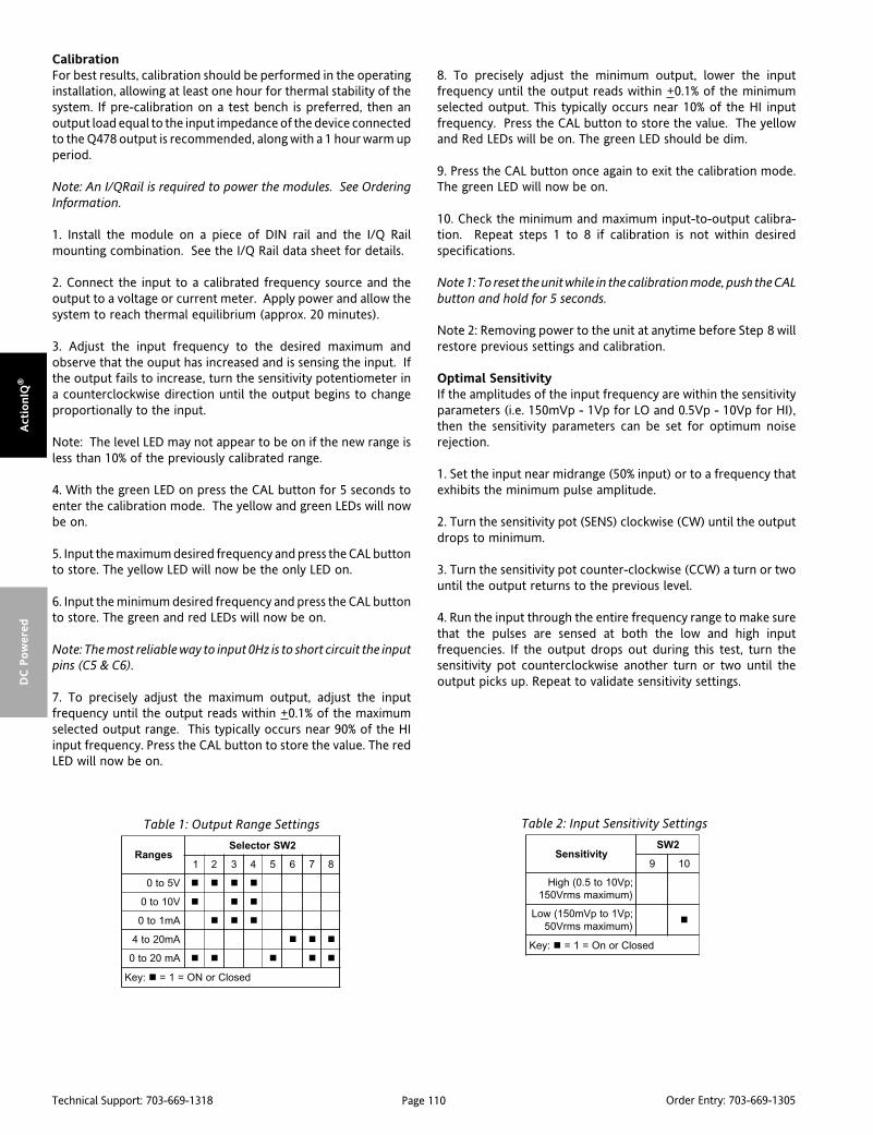
Page 110Technical Support: 703-669-1318 Order Entry: 703-669-1305
Act
ionIQ
®D
C P
ow
ered
CalibrationFor best results, calibration should be performed in the operatinginstallation, allowing at least one hour for thermal stability of thesystem. If pre-calibration on a test bench is preferred, then anoutput load equal to the input impedance of the device connectedto the Q478 output is recommended, along with a 1 hour warm upperiod.
Note: An I/QRail is required to power the modules. See OrderingInformation.
1. Install the module on a piece of DIN rail and the I/Q Railmounting combination. See the I/Q Rail data sheet for details.
2. Connect the input to a calibrated frequency source and theoutput to a voltage or current meter. Apply power and allow thesystem to reach thermal equilibrium (approx. 20 minutes).
3. Adjust the input frequency to the desired maximum andobserve that the ouput has increased and is sensing the input. Ifthe output fails to increase, turn the sensitivity potentiometer ina counterclockwise direction until the output begins to changeproportionally to the input.
Note: The level LED may not appear to be on if the new range isless than 10% of the previously calibrated range.
4. With the green LED on press the CAL button for 5 seconds toenter the calibration mode. The yellow and green LEDs will nowbe on.
5. Input the maximum desired frequency and press the CAL buttonto store. The yellow LED will now be the only LED on.
6. Input the minimum desired frequency and press the CAL buttonto store. The green and red LEDs will now be on.
Note: The most reliable way to input 0Hz is to short circuit the inputpins (C5 & C6).
7. To precisely adjust the maximum output, adjust the inputfrequency until the output reads within +0.1% of the maximumselected output range. This typically occurs near 90% of the HIinput frequency. Press the CAL button to store the value. The redLED will now be on.
8. To precisely adjust the minimum output, lower the inputfrequency until the output reads within +0.1% of the minimumselected output. This typically occurs near 10% of the HI inputfrequency. Press the CAL button to store the value. The yellowand Red LEDs will be on. The green LED should be dim.
9. Press the CAL button once again to exit the calibration mode.The green LED will now be on.
10. Check the minimum and maximum input-to-output calibra-tion. Repeat steps 1 to 8 if calibration is not within desiredspecifications.
Note 1: To reset the unit while in the calibration mode, push the CALbutton and hold for 5 seconds.
Note 2: Removing power to the unit at anytime before Step 8 willrestore previous settings and calibration.
Optimal SensitivityIf the amplitudes of the input frequency are within the sensitivityparameters (i.e. 150mVp - 1Vp for LO and 0.5Vp - 10Vp for HI),then the sensitivity parameters can be set for optimum noiserejection.
1. Set the input near midrange (50% input) or to a frequency thatexhibits the minimum pulse amplitude.
2. Turn the sensitivity pot (SENS) clockwise (CW) until the outputdrops to minimum.
3. Turn the sensitivity pot counter-clockwise (CCW) a turn or twountil the output returns to the previous level.
4. Run the input through the entire frequency range to make surethat the pulses are sensed at both the low and high inputfrequencies. If the output drops out during this test, turn thesensitivity pot counterclockwise another turn or two until theoutput picks up. Repeat to validate sensitivity settings.
segnaR2WSrotceleS
1 2 3 4 5 6 7 8
V5ot0
V01ot0
Am1ot0
Am02ot4
Am02ot0
:yeK desolCroNO=1=
ytivitisneS2WS
9 01
;pV01ot5.0(hgiH)mumixamsmrV051
;pV1otpVm051(woL)mumixamsmrV05
:yeK desolCronO=1=
Table 1: Output Range Settings Table 2: Input Sensitivity Settings
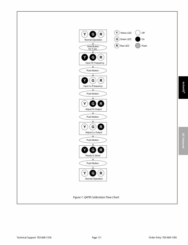
Page 111Technical Support: 703-669-1318 Order Entry: 703-669-1305
Actio
nIQ
®D
C P
ow
ered
Figure 1: Q478 Calibration Flow Chart

Page 112Technical Support: 703-669-1318 Order Entry: 703-669-1305
Act
ionIQ
®D
C P
ow
ered
SpecificationsInput:
FrequencyFull Scale Range: 2 Hz to 10,000Hz.Amplitude Range: 150mVp to 150VrmsImpedance: >10K ohmsOvervoltage: 180Vrms, max.Over-range: 20KHz, max.Common Mode (Input to Gnd): 1800V, max.Zero Turn-Up: 99% of full scale range (9998Hz)Span Turn-Down: 99% of full scale range (2Hz)
Output:Voltage:
Output: 0-5V, 0-10VSource Impedance: <100 ohmsDrive: 10mA, max. (1K ohms, min. @ 10V)
Current:Output: 0-1mA, 0-20mA, 4-20mASource Impedance: >100K ohmsCompliance:
0-1mA; 7.5V, max. (7.5K ohms, max.)0-20mA; 12V, max. (600 ohms, max.)4-20mA; 12V, max. (600 ohms, max.)
Accuracy (Including Hysteresis & Linearity):+0.1% of selected range at 25°C
Stability:+0.025%/°C maximum of selected range.
Excitation Voltage:8VDC, for open collector and contact closure inputs, 5mA short
circuit current max.Response Time (10 to 90%)
500mSec., or 100 times the period of the full scale frequency.Common Mode Rejection:
DC: 100dB>60Hz: 80dB
Isolation:1800VDC between input, output and power.
ESD SusceptibilityCapable of meeting IEC 801-2 level 3(8KV)
LED Indication:LVL (green):
Lit when power is onInput < 107% then 8Hz flashInput > -7% then 4Hz flash
IN (yellow):Input range programming status
OUT (red):Output range programming status
Humidity (Non-Condensing):Operating: 15 to 95% @ 45°CSoak: 90% for 24 hours @ 65°C
Temperature Range:Operating: 0 to 55°C (5 to 131°F)Storage: -25 to 70°C (-13 to 158°F)
Power:2.5W max., 9 to 30VDC
Weight:0.50 lbs
Wire Terminations:Screw terminals for 12-22 AWG
Agency Approvals:UL recognized per standard UL508 (File No. E99775).CSA Certified per standard C222 No.0-M91 and 142-M1987
(File No. LR42272-84.)
lanimreT noitcennoC lanimreT noitcennoC
1A )+(tuptuOCD 3C desUtoN
2A )-(tuptuOCD 4C )CDV8(ecruoSnoitaticxE
3A desUtoN 5C )-(tupnIycneuqerF
4A desUtoN 6C )+(tupnIycneuqerF
5A )+(rewoPCD 1P desUtoN
6A )-(rewoPCD 2P desUtoN
1C desUtoN 3P )+(rewoPCD
2C desUtoN 4P )-(rewoPCD
Dimensions
Ordering InformationModels & AccessoriesSpecify:1. Model: Q478-00002. Specify optional I/QRail, type and quantity.3. Optional Custom Factory Calibration; specify C620 with desired
input and output range4. Accessories: (see Accessories)
AccessoriesActionI/Q modules will mount on standard TS32 (model MD02) or TS35(model MD03) DIN Rail. In addition, the following accessories are available:
MD02 TS32 DIN railMD03 TS35 x 7.5 DIN railIQRL-D002 2 Position I/QRail & DIN railIQRL-D004 4 Position I/QRail & DIN railIQRL-D008 8 Position I/QRail & DIN railWV905 24VDC Power Supply (0.5Amp)H910 24VDC Power Supply (1Amp)H915 24VDC Power Supply (2.3Amp)
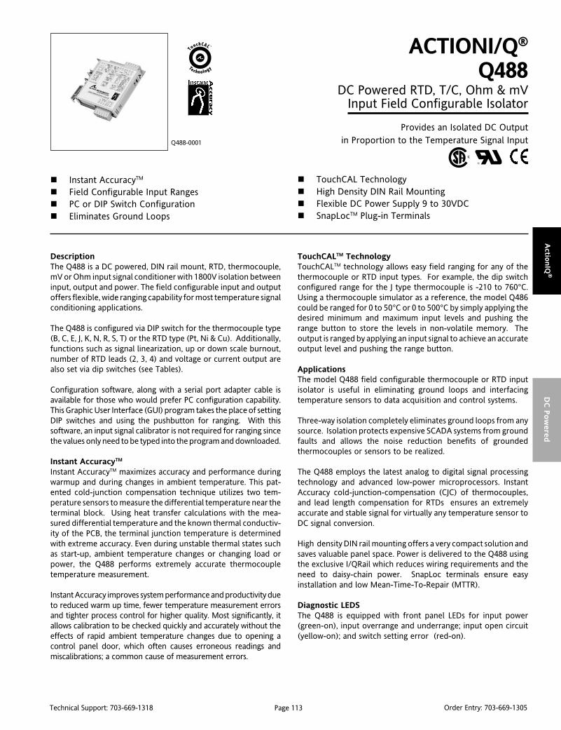
Page 113Technical Support: 703-669-1318 Order Entry: 703-669-1305
Actio
nIQ
®D
C P
ow
ered
DescriptionThe Q488 is a DC powered, DIN rail mount, RTD, thermocouple,mV or Ohm input signal conditioner with 1800V isolation betweeninput, output and power. The field configurable input and outputoffers flexible, wide ranging capability for most temperature signalconditioning applications.
The Q488 is configured via DIP switch for the thermocouple type(B, C, E, J, K, N, R, S, T) or the RTD type (Pt, Ni & Cu). Additionally,functions such as signal linearization, up or down scale burnout,number of RTD leads (2, 3, 4) and voltage or current output arealso set via dip switches (see Tables).
Configuration software, along with a serial port adapter cable isavailable for those who would prefer PC configuration capability.This Graphic User Interface (GUI) program takes the place of settingDIP switches and using the pushbutton for ranging. With thissoftware, an input signal calibrator is not required for ranging sincethe values only need to be typed into the program and downloaded.
Instant AccuracyTM
Instant AccuracyTM maximizes accuracy and performance duringwarmup and during changes in ambient temperature. This pat-ented cold-junction compensation technique utilizes two tem-perature sensors to measure the differential temperature near theterminal block. Using heat transfer calculations with the mea-sured differential temperature and the known thermal conductiv-ity of the PCB, the terminal junction temperature is determinedwith extreme accuracy. Even during unstable thermal states suchas start-up, ambient temperature changes or changing load orpower, the Q488 performs extremely accurate thermocoupletemperature measurement.
Instant Accuracy improves system performance and productivity dueto reduced warm up time, fewer temperature measurement errorsand tighter process control for higher quality. Most significantly, itallows calibration to be checked quickly and accurately without theeffects of rapid ambient temperature changes due to opening acontrol panel door, which often causes erroneous readings andmiscalibrations; a common cause of measurement errors.
ACTIONI/Q®
Q488DC Powered RTD, T/C, Ohm & mV
Input Field Configurable Isolator
Provides an Isolated DC Outputin Proportion to the Temperature Signal Input
Instant AccuracyTM
Field Configurable Input Ranges PC or DIP Switch Configuration Eliminates Ground Loops
Q488-0001
TouchCAL Technology High Density DIN Rail Mounting Flexible DC Power Supply 9 to 30VDC SnapLocTM Plug-in Terminals
TouchCALTM TechnologyTouchCALTM technology allows easy field ranging for any of thethermocouple or RTD input types. For example, the dip switchconfigured range for the J type thermocouple is -210 to 760°C.Using a thermocouple simulator as a reference, the model Q486could be ranged for 0 to 50°C or 0 to 500°C by simply applying thedesired minimum and maximum input levels and pushing therange button to store the levels in non-volatile memory. Theoutput is ranged by applying an input signal to achieve an accurateoutput level and pushing the range button.
ApplicationsThe model Q488 field configurable thermocouple or RTD inputisolator is useful in eliminating ground loops and interfacingtemperature sensors to data acquisition and control systems.
Three-way isolation completely eliminates ground loops from anysource. Isolation protects expensive SCADA systems from groundfaults and allows the noise reduction benefits of groundedthermocouples or sensors to be realized.
The Q488 employs the latest analog to digital signal processingtechnology and advanced low-power microprocessors. InstantAccuracy cold-junction-compensation (CJC) of thermocouples,and lead length compensation for RTDs ensures an extremelyaccurate and stable signal for virtually any temperature sensor toDC signal conversion.
High density DIN rail mounting offers a very compact solution andsaves valuable panel space. Power is delivered to the Q488 usingthe exclusive I/QRail which reduces wiring requirements and theneed to daisy-chain power. SnapLoc terminals ensure easyinstallation and low Mean-Time-To-Repair (MTTR).
Diagnostic LEDSThe Q488 is equipped with front panel LEDs for input power(green-on), input overrange and underrange; input open circuit(yellow-on); and switch setting error (red-on).

Page 114Technical Support: 703-669-1318 Order Entry: 703-669-1305
Act
ionIQ
®D
C P
ow
ered
Configuration The Q488 can be configured via DIP switchs for a wide variety oftemperature input ranges for RTD, thermocouple, ohm andmillivolt sensors. Inputs can be offset by >90% or adjusted downto <10% of the full scale span.
Unless a specific customer range is ordered, the factory presetsthe Q488 as follows:
Input Type: Thermocouple, J-TypeInput Range: 0 to 500°C
Burnout: Up ScaleOutput Range: 4/20mA
Refer to the tables for other I/O ranges.
1. With power off, snap off the faceplate by lifting the right edgeaway from the heatsink.
2. For RTD or Resistance inputs, set position 1 and 2 of SW2 for 2,3 or 4 wire resistance input (see Table 1). For thermocouple inputsthese switches ignored and can be in any position.
3. Configure the output for voltage or current using position 3 ofSW2 (see Table 2).
4. If the input range desired is the full scale range for the input type(e.g. Pt100 Ohm = -200°C to 850°C), then set position 4 of SW2 toON (or closed) for this default range (see Table 3). If configurationof a sub-range is preferred (e.g. Pt100 Ohm, 0 to 500°C), then setposition 4 of SW2 to OFF (or open) to enable use of the rangingpushbutton adjustment.
5. If the output range desired is the full scale range for the outputtype (e.g. 4-20mA or 2-10V), then set position 5 of SW2 to ON foreither of the full scale default output ranges (see Table 4). Ifconfiguration of a sub-range is preferred (e.g. 12-20mA or 1-5V),then set position 5 of SW2 to OFF (or open) to enable use of theranging pushbutton adjustment.
6. Set Burnout detection with position 6 of SW2 (see Table 5). TheON position (up scale) will force the output beyond full scale whenthe t/c input is open circuit. The OFF position (down scale) willforce the output below 0% when the input is open circuit.
7. Set the t/c Linearization function with position 7 of SW2 (seeTable 6). The ON position will provide an output linear to thetemperature input signal. The OFF position will provide an outputdirectly proportional to the thermoelectric (mV) input (i.e. notlinearized to temperature).
Note: The unit must be configured with linearization turned ON. Oncethe configuration is saved, linearization can then be turned OFF.
8. Set the Configuration Mode with position 8 of SW2 (see Table7). The ON position is for DIP switch configuration. The OFFposition is for configuring via PC using a serial interface cable(consult factory regarding cable and software).
9. Set the Input Type with position 1 and 2 of SW3 (see Table 8).
10. Set the specific RTD, thermocouple, millivolt or resistanceinput with position 3 through 6 of SW3 (see Table 9).
Note: For PC configuration refer to the software manual and helpfiles associated with the model C681 accessort kit.
epyTDTR2WS
1 2
eriW-3
eriW-4
eriW-2
:yeK desolCronO=1=
tuptuO2WS
3
tnerruC
egatloV
:yeK desolCronO=1=
egnaRtupnI2WS
4
tluafeD
denifeDresU
:yeK desolCronO=1=
egnaRtuptuO2WS
5
tluafeD
denifeDresU
:yeK desolCronO=1=
epyTC/T3WS tupnI
egnaR egnaR egnaR egnaR egnaRycaruccA
egnaR egnaR egnaR egnaR egnaR)D/A(tupnI
ycaruccA ycaruccA ycaruccA ycaruccA ycaruccA3 4 5 6
R C°0671+ot0 C°0671+ot002+ C°0.1-/+
J C°067+ot012- C°067+ot001- C°52.0-/+
S C°0671+ot0 C°0671+ot004+ C°0.1-/+
B C°0081+ot0 C°0081+ot004+ C°0.2-/+
T C°004+ot072- C°004+ot0 C°52.0-/+
K C°0731+ot072- C°0731+ot001- C°3.0-/+
N C°0031+ot072- C°0031+ot07 C°4.0-/+
C C°0232+ot0 C°0232+ot0 C°5.0-/+
E C°0001+ot072- C°0001+ot001- C°52.0-/+
epyTDTR3WS
egnaRtupnI ycaruccA)D/A(tupnI3 4 5 6
530.9-uC C°062+ot04- C°52.0-/+
760021-iN C°023+ot08- C°51.0-/+
583001-tP C°058+ot002- C°51.0-/+
1193001-tP C°036+ot002- C°51.0-/+
293001-tP C°036+ot002- C°51.0-/+
583002-tP C°058+ot002- C°02.0-/+
293002-tP C°036+ot002- C°02.0-/+
583005-tP C°058+ot002- C°02.0-/+
1193005-tP C°036+ot002- C°02.0-/+
293005-tP C°036+ot002- C°02.0-/+
5830001-tP C°058+ot002- C°02.0-/+
mhO&VmepyT epyT epyT epyT epyT
3WSegnaRtupnI egnaRycaruccA
)D/A(tupnIycaruccA ycaruccA ycaruccA ycaruccA ycaruccA
muminiMnapS napS napS napS napS3 4 5 6
Vm09-/+ Vm09+ot09- Vm09+ot09- Vu21-/+ Vm3
Vm009-/+ Vm009ot001- Vm009ot001- Vu52-/+ Vm3
smhO0004ot0 smhO0004ot01 smhO0004ot01 smhO0.1-/+ smhO01
:yeK desolCroNO=1=
noitceteDtuonruB2WS
6
elacspU
elacsnwoD
:yeK desolCronO=1=
raeniLtuptuOerutarepmeTot erutarepmeTot erutarepmeTot erutarepmeTot erutarepmeTot
2WS
7
nO
ffO
:yeK desolCronO=1=
noitarugifnoCedoM edoM edoM edoM edoM
2WS
8
hctiwSPIDyB
CPyB
:yeK desolCronO=1=
*Default for Outputs is either 2-10V or 4-20mA. Default for Inputsis the “Input Range” specified in Table 9. Note that if the input or
output is set for default, then the input or output calibration will be
skipped in the pushbutton programming sequence.
Table 1: RTD Type
Table 2: Output Type
Table 3: Input Range Type*
Table 4: Output Range Type*
Table 5: Input Type
Table 6: Burnout Detection
Table 7: Output Linearization
Table 8: Config Mode
Table 9: Input Select
Input to Output error at 25°C is less than or equal to the Input Accuracy, plus the LinearizationAccuracy, plus the Output Accuracy (plus the CJC Error for T/C Inputs).
epyTtupnI3WS
1 2
elpuocomrehT
DTR
smhOroVm
:yeK desolCronO=1=
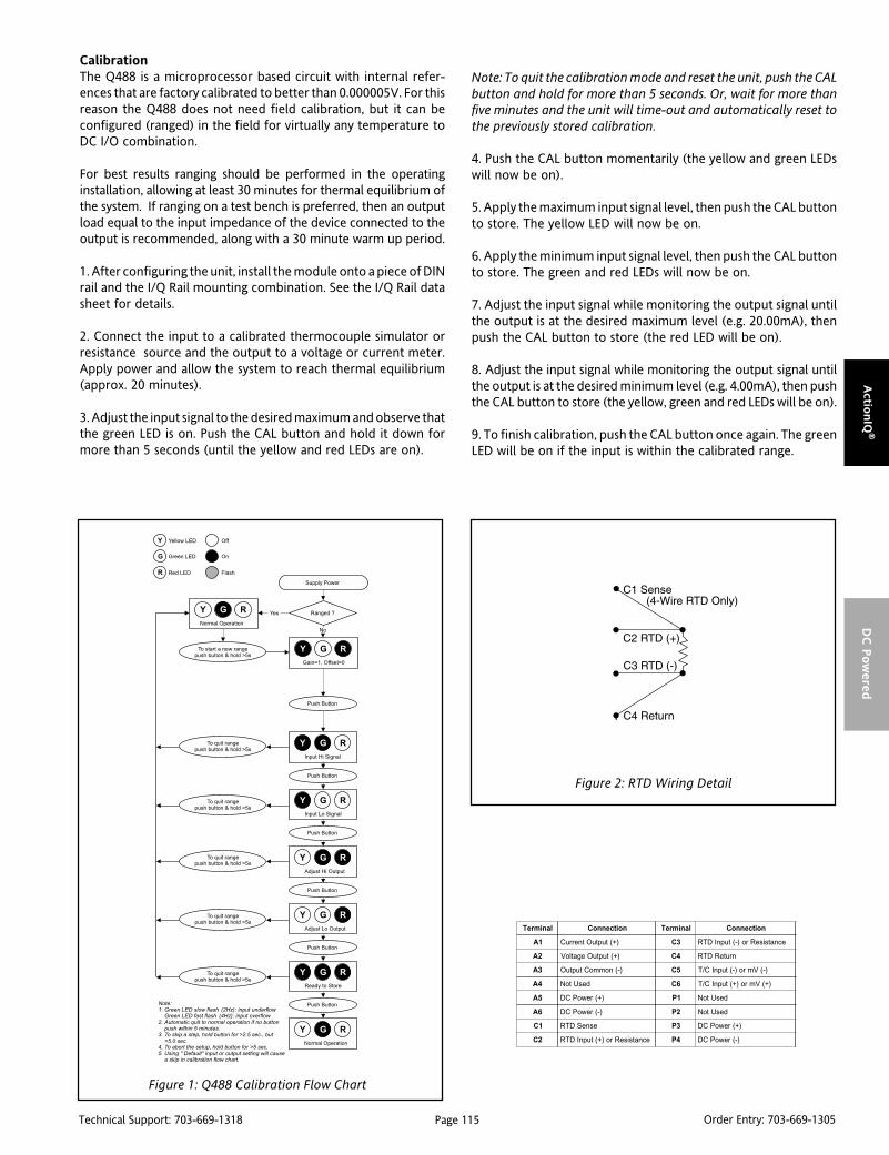
Page 115Technical Support: 703-669-1318 Order Entry: 703-669-1305
Actio
nIQ
®D
C P
ow
ered
CalibrationThe Q488 is a microprocessor based circuit with internal refer-ences that are factory calibrated to better than 0.000005V. For thisreason the Q488 does not need field calibration, but it can beconfigured (ranged) in the field for virtually any temperature toDC I/O combination.
For best results ranging should be performed in the operatinginstallation, allowing at least 30 minutes for thermal equilibrium ofthe system. If ranging on a test bench is preferred, then an outputload equal to the input impedance of the device connected to theoutput is recommended, along with a 30 minute warm up period.
1. After configuring the unit, install the module onto a piece of DINrail and the I/Q Rail mounting combination. See the I/Q Rail datasheet for details.
2. Connect the input to a calibrated thermocouple simulator orresistance source and the output to a voltage or current meter.Apply power and allow the system to reach thermal equilibrium(approx. 20 minutes).
3. Adjust the input signal to the desired maximum and observe thatthe green LED is on. Push the CAL button and hold it down formore than 5 seconds (until the yellow and red LEDs are on).
Figure 1: Q488 Calibration Flow Chart
Note: To quit the calibration mode and reset the unit, push the CALbutton and hold for more than 5 seconds. Or, wait for more thanfive minutes and the unit will time-out and automatically reset tothe previously stored calibration.
4. Push the CAL button momentarily (the yellow and green LEDswill now be on).
5. Apply the maximum input signal level, then push the CAL buttonto store. The yellow LED will now be on.
6. Apply the minimum input signal level, then push the CAL buttonto store. The green and red LEDs will now be on.
7. Adjust the input signal while monitoring the output signal untilthe output is at the desired maximum level (e.g. 20.00mA), thenpush the CAL button to store (the red LED will be on).
8. Adjust the input signal while monitoring the output signal untilthe output is at the desired minimum level (e.g. 4.00mA), then pushthe CAL button to store (the yellow, green and red LEDs will be on).
9. To finish calibration, push the CAL button once again. The greenLED will be on if the input is within the calibrated range.
lanimreT noitcennoC lanimreT noitcennoC
1A )+(tuptuOtnerruC 3C ecnatsiseRro)-(tupnIDTR
2A )+(tuptuOegatloV 4C nruteRDTR
3A )-(nommoCtuptuO 5C )-(Vmro)-(tupnIC/T
4A desUtoN 6C )+(Vmro)+(tupnIC/T
5A )+(rewoPCD 1P desUtoN
6A )-(rewoPCD 2P desUtoN
1C esneSDTR 3P )+(rewoPCD
2C ecnatsiseRro)+(tupnIDTR 4P )-(rewoPCD
Figure 2: RTD Wiring Detail
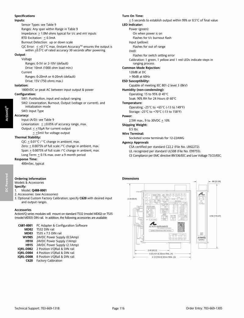
Page 116Technical Support: 703-669-1318 Order Entry: 703-669-1305
Act
ionIQ
®D
C P
ow
ered
DimensionsOrdering InformationModels & AccessoriesSpecify:1. Model: Q488-00012. Accessories: (see Accessories)3. Optional Custom Factory Calibration; specify C620 with desired input
and output ranges.
AccessoriesActionI/Q series modules will mount on standard TS32 (model MD02) or TS35(model MD03) DIN rail. In addition, the following accessories are available:
C681-0001 PC Adapter & Configuration SoftwareMD02 TS32 DIN railMD03 TS35 x 7.5 DIN rail
WV905 24VDC Power Supply (0.5Amp)H910 24VDC Power Supply (1Amp)H915 24VDC Power Supply (2.1Amp)
IQRL-D002 2 Position I/QRail & DIN railIQRL-D004 4 Position I/QRail & DIN railIQRL-D008 8 Position I/QRail & DIN rail
C620 Factory Calibration
SpecificationsInputs:
Sensor Types: see Table 9Ranges: Any span within Range in Table 9Impedance: > 1.0M ohms typical for t/c and mV inputsRTD Excitation: < 0.3mABurnout Detection: up or down scaleCJC Error: < +0.1°C max. (Instant AccuracyTM ensures the output is
within +0.5°C of rated accuracy 30 seconds after poweringOutput:
VoltageRanges: 0-5V or 2-10V (default)Drive: 10mA (1000 ohm load min.)
CurrentRanges: 0-20mA or 4-20mA (default)Drive: 15V (750 ohms max.)
Isolation:1800VDC or peak AC between input output & power
Configuration:SW1: Pushbutton, input and output rangingSW2: Linearization, Burnout, Output (voltage or current), and
initialization modeSW3: Input Type
Accuracy:Input (A/D): see Table 9Linearization: < +0.05% of accuracy range, max.Output: < +10µA for current output
< +5mV for voltage outputThermal Stability:
CJC: + 0.01°C / °C change in ambient, max.Zero: + 0.0075% of full scale /°C change in ambient, max.Span: + 0.0075% of full scale /°C change in ambient, max.Long Term: + 0.1% max. over a 9 month period
Response Time:400mSec, typical
Turn On Time:< 5 seconds to establish output within 99% or 0.5°C of final value
LED Indicator:Power (green):
On when power is onFlashes for t/c burnout flash
Input (yellow):Flashes for out of range
(red):Flashes for switch setting error
Calibration: 1 green, 1 yellow and 1 red LEDs indicate steps inranging process
Common Mode Rejection:120dB at DC> 90dB at 60Hz
ESD Susceptibility:Capable of meeting IEC 801-2 level 3 (8kV)
Humidity (non-condensiing):Operating: 15 to 95% @ 45°CSoak: 90% RH for 24 Hours @ 60°C
Temperature:Operating: -25°C to +65°C (-13 to 149°F)Storage: -25°C to +70°C (-13 to 158°F)
Power:2.5W max., 9 to 30VDC + 10%
Shipping Weight:0.5 lbs.
Wire Terminal:Socketed screw terminals for 12-22AWG
Agency ApprovalsCSA certified per standard C22.2 (File No. LR42272).UL recognized per standard UL508 (File No. E99755).CE Compliance per EMC directive 89/336/EEC and Low Voltage 73/23/EEC.

Page 117Technical Support: 703-669-1318 Order Entry: 703-669-1305
Actio
nIQ
®D
C P
ow
ered
DescriptionThe Q498 is a DC powered, DIN rail mount, DC input signalconditioner. The unit is fully isolated to 1800V between input,output and power. It has two isolated analog inputs that eachaccept either a DC voltage or current input signal. The one analogoutput delivers either DC bi-polar voltage or uni-polar current.The Q498 also has a separate frequency input channel and afrequency output, as well as a discrete input and output channel.The field configurable input and output feature provides flexible,wide ranging capability for DC current and voltage signals. TheQ498 can also be configured via a PC with the optional C698Windows based GUI software. The Q498 is also capable ofperforming math calculations on the input values. This providesthe ability to perform single or double input math functions. Thefrequency input can also have the math functions applied (withthe exception of Sq and Sqroot). The available operators are: +,-, *, /, Sq, Sqroot & Average. Process control functions include Hi/Lo Select (utilizing the Digital Output for channel identification),Rate of Change Limiter and Track & Hold (utilizing the Digital Inputfor the hold control). A 25-point linearization function is availablefor the Channel 1 Analog input only. Note that all output math andprocess control functions require the C698 software.
The field configurable input of the Q498 can be set via DIPswitches. Voltage input ranges are: ±150mV, ±1.5V, ±15V and±150V. The current input ranges are: ±2.5mA and ±25mA. Allranges are fully adjustable over a ≈90% range from zero or span.Simply choose the range closest to your needs and perform thecalibration based on zero and span values.
There are three analog output ranges, 0 to 20mA, 0 to 10VDC and–10 to +10VDC, which are also fully adjustable. If the applicationrequires a 4-20mA output, simply choose the 0-20mA range andcalibrate with the zero point at 4mA (the Math Functions can beused to scale the output).
ACTIONI/Q®
Q498DC Powered DC Input Field Configurable
Isolator with Math Functions
Provides 2 Isolated Analog Inputs, 1 Analog Output & 1Frequency Output, as well as a Discrete Input & Output
Multi-Function, Multi-Channel Input TouchCALTM Technology DC-Frequency or Frequency-DC Converter Optional PC Based Programming Software
Q498-0000
High Density DIN Rail Mounting Math Function Capability SnapLocTM Plug-in Terminals
The frequency section has two separate inputs, depending onvoltage levels, only one of which can be active at a time. The LoVinput supports signals with amplitudes from 150mVp to 5Vp(50Vrms max) and the HiV input supports signals between500mVp and 20Vp (150Vrms max). The frequency range is from2Hz to 10kHz in software selectable ranges.
ApplicationsThe Q498 can be used in many types of operations. This sectiondescribes a few process control applications and how to configurethe unit in order to perform the various operations.
Track & HoldThe Digital Input is used as the control element for Track & Hold.Short the Digital Input (Pin A6) to Digital Common (Pin A3) usingan external relay or switch. The Analog Output will be held at thecurrent output level until the connection is opened. Because thesystem is under microprocessor control, when the digital input isgrounded, the current output level that is being processed cannotbe stopped. As an extreme example, if the output has been toldto make a step change from 0V to 10V, the output could still bein the process of slewing to that value (which could take as longas 700mSec). When the Hold input is applied during that 700mSecwindow, the output will continue to rise to the 10V level and thenhold at that point. The Hold function only stops any future inputchanges from having an effect on the output.
If a step response is not desired when the Hold line is released, ensurethat the Output Changing Limit is set to the desired amount (in theConfiguration Window section of the C698 Configuration Software).

Page 118Technical Support: 703-669-1318 Order Entry: 703-669-1305
Act
ionIQ
®D
C P
ow
ered
Hi/Lo SelectThis function is accomplished by selecting either the Max or Minfunction for F1(x). (Refer to the Output Math section of theSpecifications.) After F1(x) has been assigned the Max or Minfunction, the higher input (or lower if Min is selected) will drive theoutput. If a step response is not desired when the input channelsswitch control, then ensure the Output Changing Limit (accessedin the Configuration window of the configuration software) is setto the desired amount. Take note that the coefficients A and B andthe exponents of each channel also effect the comparison.
The digital output can be programmed to go high when CH1>CH2, orwhen CH1<CH2. The Yellow LED indicates the status of the digital output.
25-Point LinearizationThe Q498 provides the ability to input unique linearization tables.This feature is only available through the C698 software package,and can only be used on analog input 1 (Ch 1).
Digital & Frequency Output LoadsThe digital and frequency outputs are designed to be poweredwith a 24VDC external supply. These outputs will each safely sinka maximum of 20mA. If an external supply is not used, the digitaland frequency outputs are limited to 1mA.
Math FunctionsAll of the basic math functions perform percentage math, not truemath. The formulas are as follows:
Addition: %Output = (%Ch1 + %Ch2)/2
Subtraction: %Output = (%Ch1 - %Ch2),Ch1 must be ≥Ch2
Multiplication: %Output= (%Ch1)(%Ch2)
Division: %Output = %Ch1/%Ch2
Sq. Root: %Output = %Chx 0.5
PC ProgrammableThe Model Q498 is calibrated either by using a serial port from aPC or by using the onboard DIP switch and pushbutton. Math andProcess Control Functions are only configurable using the optionalPC Configuration Software Model C698.
The software comes with a serial cable to connect the Q498 to aserial port of a PC. The software is also available on our Website.The software is compatible with Windows 95, 98, 2000 and NToperating systems. Instructions are included in the program asHelp screens.
TouchCALTM TechnologyTouch-CALTM technology allows for the replacement of zero andspan adjustment potentiometers with a pushbutton. The thermaldrift and mechanical variability of the potentiometers is removedand replaced with a digitally stable circuit. Additionally, theinherent zero and span interactivity of potentiometer basedanalog amplifier circuitry is removed, providing 100% non-interac-tive adjustment.
TouchCAL enables precise calibration and provides more than90% offset of the zero value and adjustment down to 10% of thefull scale input span for most of the six switch selectable inputranges. For example, the DIP switch set for ±25mA input rangecould be configured via the pushbutton for an offset range of 4to 20mA (58% offset and 68% span reduction) or –25 to 0mA (a 50%span reduction). If the output was configured for 0-10V, then –25to 0mA input would correspond to the 0-10V full scale output.Thus, input ranges such as 4-20mA or 0-5mA are possible using the±25mA range.
Diagnostic LEDSThe Q498 has three diagnostic LED’s. The green (RUN) LED is usedto indicate that power is on, and for diagnostics. It flashes quicklyif the input signal is above the configured range or slowly if theinput signal is below range. It is continuously on when the unit isfunctioning within the configured range. The red LED flashes whenthe output is over/under range. The yellow LED indicates the statusof the Discrete Output. The LED’s also provide indication of whichsteps are being performed during pushbutton calibration.
Wiring Connections
PowerPower can be applied either by means of an IQ Rail adapter (seethe Accessories section), in which case pins P3 and P4 will apply thepower through the adapter; or if the IQ Rail adapter is not utilized,power is applied via connector “B” on the top rear of the unit (theconnector nearest the DIN rail mounting foot). Pin B1 is for thepositive (+) 9-30VDC and pin B2 is for the common (-).
Analog InputsThe DC voltage or current inputs are applied using connector “C” onthe bottom front of the unit. Each channel has its own separate voltageor current input. Channel 1 (CH1) positive voltage input is pin C6.Channel 1 positive current input is pin C4. The common connection forCH1 is pin C5. The Channel 2 inputs are pin C3 for positive voltage, pinC1 for positive current and pin C2 for the common. [Note: In order toutilize CH2, the C698 software is required.] Either channel can be setindependently for voltage or current.
Frequency InputsThe Frequency Input is applied using connector “D” on the bottomrear of the unit (the connector next to the DIN rail mounting foot).There are two inputs shown: IN LOV for voltages of 150mV to50Vrms max.; IN HIV for voltages of 0.5V to 150Vrms max. Note thatthere are NOT two separate frequency inputs - only one set ofterminals can be used at a time. The Frequency Input Common ispin D4. The positive terminal for the low voltage range is pin D5, andthe positive terminal for the high voltage range is pin D6. [Note: Inorder to utilize the frequency input, the C698 software is required.]
OutputsThe outputs and the discrete function are applied to connector“A” on the top front of the Q498. Pin A1 is the positive terminal(+) of the Voltage or Current output. Pin A3 is the Voltage Returnand Pin A2 is the Current Return. Pin A3 is also the CommonReturn (-) for the Discrete (digital) Input and Output, as well as theFrequency Output Common. Several wires can be twisted togetherfor the various commons as long as the combined wire size doesnot exceed the 12 AWG limit of the terminal. The Discrete Output(+) is pin A4 while the Discrete Input (+) is pin A6. The FrequencyOutput (+) is pin A5.
Page 119Technical Support: 703-669-1318 Order Entry: 703-669-1305
Actio
nIQ
®D
C P
ow
ered
Default SettingsThe default settings are 4-20mA input on Analog Channel 1 (pinsC4/C5) and 4-20mA output from the Analog Output (pins A1/A2).The frequency and digital inputs and outputs are not active, andrequire the C698 Configuration Software to utilize. The OutputMath equation for the Analog Output is set as follows: A=1,F1(x)=”+”, B=0, F2(x)=”+”, C=0, D=1. Any change to the outputmath requires the C698 software.
IsolationThe Analog Inputs (CH1 & CH2) are isolated from each other, as wellas from the Analog Output and Power. The Frequency Inputcircuitry is in the same isolation section as Analog Input CH2, so itis isolated from CH1, but not CH2. The Frequency Output isreferenced to the same common as the Analog Output, therefore,the Frequency Output is not isolated from the Analog Output, butis isolated from the Frequency Input, Analog Inputs CH1 & CH2 andPower. The Digital Input and Digital Output are not isolated fromeach other and are referenced to the same common as the AnalogOutput and Frequency Output. The Serial Port is also referenced tothe output section, so it is not isolated from the Output circuitry, butis isolated from the Analog and Frequency Input Sections. TheIsolation level between all isolated sections is 1800VDC.
Serial PortThe serial port connection for using the C698 software is locatedbelow the DIP switch. The cable is provided with the C698 softwareoption. Please refer to the software Help File for further explanation.
CalibrationFor best results, calibration should be performed in the operatingenvironment, allowing at least one hour for thermal stability of thesystem. If pre-calibration on a test bench is preferred then anoutput load equal to the input impedance of the devices con-nected to the Q498 output is recommended.
1. For the optimum results, install the module on to a piece of DINrail or an I/Q Rail.
Note: An I/Q Rail is an optional accessory to deliver power to themodules. A two, four or eight position rail is available. See theordering information.
2. Connect the analog input to be calibrated (usually starting withCh. 1) to a calibrated DC source and the analog output to a voltageor current meter. A frequency source should be connected to thefrequency input and a frequency counter to the frequency output.Apply power and allow the system to reach thermal equilibrium(approx. 20 minutes).
The Q498 can be calibrated by either of two methods, manually, asdescribed in this procedure, or by means of the C698 configurationsoftware utility. For software calibration, first set DIP switch positionSW1-10 to ON to enable PC Calibration. Refer to the information inthe Help files of the software for the correct procedure.
While performing a manual calibration, refer to the flow charts inFigures 1a & 1b.
3. While it is not mandatory, less button-pushing is involved if allinputs are calibrated before calibrating the output. To start theprocess, the Green LED should be on.
4. Press and hold the calibration button for 4 seconds. The GreenLED will be lit and the Yellow LED will be flashing. From this point,to calibrate channel 1, press and hold the button down again for4 seconds. The Red and Yellow LED’s will be lit indicating the inputis ready to calibrate.
5. Press the button once. The Yellow and Green LED’s will be lit.
6. Apply the maximum input signal and press the button once. TheYellow LED will be lit.
Note: After any calibration step, you can abort by pressing thebutton and holding for 4 seconds. This will take you back to normaloperation without saving the new data. You then step backthrough the flowchart to return to where you were in yourcalibration.
7. Apply the minimum input signal and press the button once. Allthree LED’s will be lit.
8. Press the button once again. The Channel 1 input data is savedand you are back at the beginning with the Green LED lit.
9. Press and hold the button for 4 seconds. The Green LED will belit and the Yellow LED will be flashing. Press the button one moretime and the Red LED will be lit and the Yellow LED will be flashing.From this point, to calibrate channel 2, press and hold the buttondown for 4 seconds. The Red and Yellow LED’s will be lit.
10. Repeat steps 5 through 8.
11. After completing the analog input calibration, the Green LEDis lit. Press and hold the button for 4 seconds. The Green LED willbe lit and the Yellow LED will be flashing. Press the button twice.The Green LED will be lit and the Red LED will be flashing,indicating that the frequency input is ready for calibration.
12. Press and hold the button for 4 seconds. The Red LED andYellow LED’s will be flashing.
13. Repeat steps 5 through 8.
14. After completing the frequency input calibration, the GreenLED is lit. Press and hold the button for 4 seconds. The Green LEDwill be lit and the Yellow led will be flashing. Press the button threetimes. The Yellow LED will be lit and the Red LED will be flashing.The analog output is now ready for calibration.
15. Press and hold the button for 4 seconds. The Red and YellowLED’s will be lit.
16. Press the button once. The Red and Green LED’s will be lit.
17. While monitoring the output, increase the input (from eitherCh1 or Ch2) until the desired maximum output signal level isreached. Press the button once. The Red LED will be lit.
18. Monitor the output and decrease the input until the desiredminimum output signal level is reached. Press the button once. Allthree LED’s will be lit. Press the button once again to save the dataand you will be back to the Green LED lit.

Page 120Technical Support: 703-669-1318 Order Entry: 703-669-1305
Act
ionIQ
®D
C P
ow
ered
1WS-sgnitteStupnI
egnaR1lennahC 2lennahC
1 2 3 4 5 6
Vm051-/+
V5.1-/+
V51-/+
V051-/+
Am5.2-/+
Am52-/+
:yeK desolCroNO=1=
1WS-sgnitteStuptuO
egnaR 7 8
V01-0
V01-/+
Am02-0
:yeK desolCroNO=1=
egnaRtuptuOycneuqerF1WS-ylnOnoitarbilaClaunaM 1WS-ylnOnoitarbilaClaunaM 1WS-ylnOnoitarbilaClaunaM 1WS-ylnOnoitarbilaClaunaM 1WS-ylnOnoitarbilaClaunaM
egnaR 9 01
zH5-0
zH05-0
zH000,1-0
zH000,01-0
:yeK desolCroNO=1=
1WS-laCtnioP-52elbanE
9
noitarbilaCtnioP-52elbanE
:yeK desolCroNO=1=
1WS-laCCPelbanE
01
noitarbilaCCPelbanE
:yeK desolCroNO=1=
Table 1: Input Settings Table 5: Output Settings
Table 5: Manual Calibration Frequency Settings
Table 2: Enable 25-Point Calibration Setting
Table 2: Enable PC Calibration Setting
19. Press and hold the button for 4 seconds. The Green LED will belit and the Yellow LED will be flashing. Press the button 4 times(until the Green LED is flashing). The frequency output is nowready for calibration.
20. Press and hold the button down for 4 seconds. The Red andYellow LED’s will be lit. Manually calibrating the output frequencyrequires first selecting the desired frequency output range withDIP Switch SW1, positions 9 & 10, as described in Figure 1B. Theseswitch settings are not required if calibrating via the softwareutility. After the output frequency is calibrated, the switches canbe reset to their previous settings for calibration method. Press thebutton one more time and the Red and Green LED’s will be lit.
21. Set the input frequency to maximum. While monitoring theoutput of the frequency output channel with a frequency counter,decrease the input until the desired maximum output is reached.Press the button once and the Red LED will be lit.
22. Set the input to minimum. While monitoring the output,increase the input until the desired minimum output value isreached. Press the button once and all three LED’s will be lit.
23. Press the button once again and you are back to the Green LEDlit (normal operating condition).

Page 121Technical Support: 703-669-1318 Order Entry: 703-669-1305
Actio
nIQ
®D
C P
ow
ered
Figure 1a: Q498 Input Calibration Flow Chart
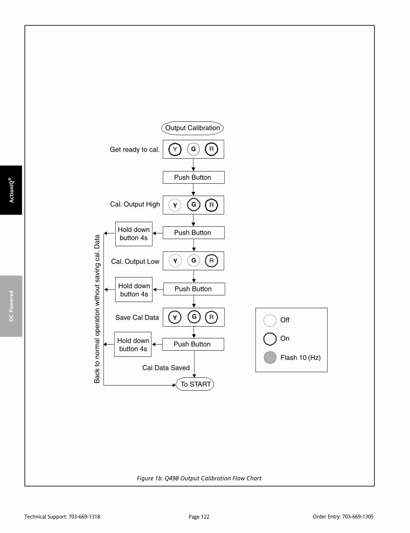
Page 122Technical Support: 703-669-1318 Order Entry: 703-669-1305
Act
ionIQ
®D
C P
ow
ered
Figure 1b: Q498 Output Calibration Flow Chart

Page 123Technical Support: 703-669-1318 Order Entry: 703-669-1305
Actio
nIQ
®D
C P
ow
ered
Specifications
Analog Input Ranges (2 Isolated Channels):
+/-150mV, +/-1.5V, +/-15V, +/-150V
+/-2.5mA, +/-25mA
Pushbutton Adjustment:
Effective zero offset: >90%
Effective span turn-down: >90%
Analog Maximum Overload (continuous):200V DC for voltage inputs;
170mA DC or 60V DC maximum for currentinputs (protected by self-resetting fuse)
Analog Output Ranges:
0-20mA, 0-10V, -10 to +10V
Analog Output Drive:
0-20mA: 12VDC compliance. (600 ohms max.)
Voltage ranges: 10mA drive (1000 ohm load min.)
Analog Output Accuracy:
+0.005% of the FS Input Range (±0.05% on 150volts range), plus +0.05% of the FS OutputRange (±0.1% for output loads <200 ohms)
Analog Stability:
+0.005% of Full Scale/°C typical (±0.01%maximum) for zero and span
Analog Response Time:
750mSec max. (10-90%)
Analog Input Impedance:
>100k ohms on voltage ranges > 1.5V
>10M ohms on voltage ranges < 1.5V
70 ohm typ. (non-overload) on all current ranges
Analog Output Impedance:
Less than 3 ohms on voltage output ranges
> 500k ohms on current output ranges
Frequency Input:
One frequency channel with two different voltage range inputs,LOV for 150mV to 50Vrms with 5Vp noise suppression, or HIVfor 0.5V to150Vrms with 20Vp noise suppression, 2Hz to 10kHzin software selectable ranges.
Frequency Output:
2Hz to 10kHz in software selectable ranges.
Open collector pulled up through 20k to 18V, with 1mA drive.Sinks up to 20mA through a load from a 24V external supply.
Frequency Output Accuracy:
±0.1%
Discrete Output:
Open collector pulled up through 20k to 18V, with 1mA drive.Sinks up to 20mA through a load from a 24V external supply.Operation under software control.
Discrete Input:
Input active to Common, with soft pull-up (1mA) to +18V.Operation under software control.
Output Math:
Vout = (A*CH1y F1(x) B*CH2z F2(x) C*CH3)/D
Fout = (A*CH1y F1(x) B*CH2z F2(x) C*CH3)/D
CH1: Output value contributed by channel 1 input only
CH2: Output value contributed by channel 2 input only
CH3: Output value contributed by frequency input only
Where:
Fx(x) can be: +, -, *, /, Min, Max, Average, and y & z can be: 0, 1,2, or 1/2
The constants A-D can be any number from 0 to 255 (except Dcannot be equal to 0).
When using the square or square root functions, the relative inputchannel should be calibrated in the positive direction only.
Process Control Functions:
Hi/Lo Select (Max/Min), Rate of Change Limiter, Track & Hold and25-Point Linearization (25-point linearization only on AnalogInput Ch 1 and only effects the Analog Output channel. Also, inthis mode the square and square root functions are not available.)
Default Settings:
Analog Input 1 (Ch1):
±25mA range, calibrated for 4-20mA
Analog Output:
0-20mA range, calibrated for 4-20mA
Math:
(1*CH1 + 0*CH2 + 0*CH3)/1
Analog Input 2 (Ch2):
Not active (nulled by the math)
Frequency:
Not active (nulled by the math)
(The unit can be reconfigured manually for different ranges oninput and output, using only Analog Input 1 (CH1) and theAnalog Output. In order to utilize scaling factors, math functions,other inputs/outputs and process control functions, the C698software is required.)
Common Mode Rejection:
> 90dB for 60 Hz
120 dB @ DC
Diagnostics:
Green LED Indicator flashes for over or under range
Red LED flashes for output malfunction
(Voltage short circuit or current open)
Yellow LED indicates status of Discrete Output
Power Requirements:
9-30VDC, 2.5 watts max
Power Supply Current:
280mA max. @ 9VDC; limited to prevent in-rush currents fromexceeding steady-state value. (At turn on, the unit appears as acapacitive load up to 100mF.)
Wire Terminals:
Socketed screw terminals for 12-22 AWG
Isolation:
Input to Input to Output to Power, 1800VDC (Analog Input 2 andthe Frequency input are both considered Channel 2. TheFrequency Input is isolated from Analog Input 1 but not fromAnalog Input 2. The Discrete Input is not isolated from theDiscrete Output, but is isolated from the Analog and FrequencyInputs. All of the outputs are isolated from the Analog andFrequency Inputs.)
Size:
DIN rail case (0.88” x 4.0” x 4.59”)
Operating Temperature:
0°C to +55°C (32 to 131°F)
Storage Temperature:
-25°C to +70°C (-13 to 158°F)
Operating Humidity:
15% to 95%RHNC at 45°CNon-operating Humidity:
90%RH at 65°C for 24 hours
Agency Approvals (EMC & Safety):
UL recognized per standard UL508 (File No. E99775).
CSA certified per standard C22.2, No. 0-M91 and 142-M1987
(Cert. # 2500003630).
CE Compliance per EMC directive 89/336/EEC and Low Voltage 73/23/EEC.
Minimum PC for the C698 Calibration Software:
100MHz CPU, 16MB RAM, 20MB hard disk space
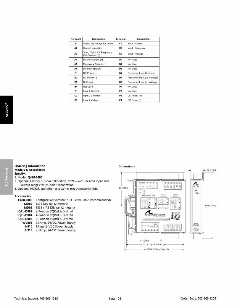
Page 124Technical Support: 703-669-1318 Order Entry: 703-669-1305
Act
ionIQ
®D
C P
ow
ered
Ordering InformationModels & AccessoriesSpecify:1. Model: Q498-00002. Optional Factory Custom Calibration, C620 – with desired input and
output ranges for 25-point linearization.3. Optional I/QRail, and other accessories (see Accessories list).
AccessoriesC698-0000 Configuration Software & PC Serial Cable (recommended)
MD02 TS32 DIN rail (2 meters)MD03 TS35 x 7.5 DIN rail (2 meters)
IQRL-D002 2-Position I/QRail & DIN railIQRL-D004 4-Position I/QRail & DIN railIQRL-D008 8-Position I/QRail & DIN rail
WV905 0.5Amp, 24VDC Power SupplyH910 1Amp, 24VDC Power SupplyH915 2.3Amp, 24VDC Power Supply
Dimensions
lanimreT noitcennoC lanimreT noitcennoC
1A tnerruC&egatloV)+(tuptuO 4C tnerruC1tupnI
2A )-(tuptuOtnerruC 5C nommoC1tupnI
3AycneuqerF,O/IlatigiD,tuoV
)-(nommoCtuO6C egatloV1tupnI
4A )+(tuptuOetercsiD 1D desUtoN
5A )+(tuptuOycneuqerF 2D desUtoN
6A )+(tupnIetercsiD 3D desUtoN
1B )+(rewoPCD 4D nommoCtupnIycneuqerF
2B )-(rewoPCD 5D )egatloVoL(tupnIycneuqerF
3B desUtoN 6D )egatloViH(tupnIycneuqerF
4B desUtoN 1P desUtoN
1C tnerruC2tupnI 2P desUtoN
2C nommoC2tupnI 3P )+(rewoPCD
3C egatloV2tupnI 4P )-(rewoPCD

Page 125Technical Support: 703-669-1318 Order Entry: 703-669-1305
Actio
nIQ
®Lo
op P
ow
ered
DescriptionThe Q500 is a DIN rail mount, loop-powered isolator with single,dual or quad (4) channel capability. Each channel accepts a 0-20mA or 4-20mA input and outputs a proportional 0-20mA or 4-20mA signal. The Q500 provides 1800VDC signal isolation frominput to output and channel to channel.
All ActionI/Q modules feature SnapLoc plug-in screw terminals foreasy installation and low Mean-Time-To-Repair (MTTR). Two ormore modules can slide together and interlock for solid, highdensity mounting. This is accomplished by removing either thefoot or the adjacent unit's faceplate (for right-hand side or left-hand side mounting, respectively). The module to be attached willeasily slide on to the side of the mounted unit.
ApplicationLoop-powered isolators are used to isolate process signals trans-mitted between field instrumentation, Programmable Logic Con-trollers (PLC), Distributed Control Systems (DCS) and Data Acqui-sition Systems (DAS). Outputs from these systems can also driveone or more isolator channels of the Q500. Field devices such asflow, level or temperature transmitters can also drive a Q500isolator channel. The 1800VDC isolation capability preventsground loops from causing errors in 4-20mA current signals andcan reduce susceptibility to Radio Frequency Interference (RFI).Isolation also provides protection from high voltages and currentspikes which can damage expensive Supervisory Control And DataAcquisition (SCADA) equipment, such as a PLC or DCS.
ACTIONI/Q®
Q500Loop Powered Multi-Channel Isolator
Provides up to 4 Isolated DC Current Outputs inProportion to the Input Currents
Up to 4 Loop Isolators in a Single Package Prevents Ground Loops High Density DIN Rail Mounting
Q500-1B00 (1 channel)
Q500-2B00 (2 channel)
Q500-4B00 (4 channel)
SnapLocTM Plug-in Terminals ASIC Technology
OperationThe Q500 operates as a loop-powered isolator, with each channelderiving its power from the input loop current, 0(4)-20mA. Theeffective load of a Q500 isolator channel on a loop is 300 ohmsplus the output load resistance. For example, if the load on anoutput of the Q500 is 500 ohms, then the current loop connectedto the input would need to drive 300 ohms plus 500 ohms (i.e. 800ohms) at a maximum current of 20mA, or 800 ohms x 20mA whichequals 16.0V.
The Q500 is protected from reverse input polarity and outputshort circuit. A span pot is provided for each channel in order tocalibrate the output to the load.
Calibration1. Connect the input to a calibrated milliamp source. Connect theoutput to the actual device or to a load (between 100 and 500ohms) equivalent to the actual device. Monitor the output currentwith a milliamp meter in series with the load or monitor thevoltage across the load.
2. Set the calibrator to 20mA and adjust the span potentiometerfor 20mA output.
3. Set the calibrator to 4mA and confirm that the output is 4mA.

Page 126Technical Support: 703-669-1318 Order Entry: 703-669-1305
Act
ionIQ
®Lo
op P
ow
ered
Specifications
Input Range:
0(4) to 20mA, 30VDC max, each channel
Voltage Drop: 6V (300 ohms), plus output load
Output Range:
0(4) to 20mA,
Drive: 10V or 500 ohms maximum @ 20mA, 100 ohms minimum
Output Accuracy:
Better than +0.2% of full-scale, including linearity, hysteresis andrepeatability, maximum
Linearity:
0.1% of span typical, from 4 to 20mA at 250ohm load
Stability:
±0.02%/oC of span max. for full-scale and zero
Load Regulation:
±0.1% of span, typical per 10 ohm change
Common Mode Rejection Ratio:
> 100dB (DC to 60Hz)
Isolation:
1800VDC, input to output and channel to channel.
ESD Susceptibility:
Capable of meeting IEC 801-2 level 3 (8kV)
Response Time:
50mSec typical, 100mSec max 10 to 90% (each channel)
Temperature:
Operating: -40 to 80oC (-40 to 176oF)
Storage: -40 to 80oC (-40 to 176oF)
Humidity (non-condensing):
25 to 95% (@40oC)
Wire Terminals:
Socketed screw terminals for 12-22 AWG
Weight:
0.34lbs
Agency Approvals:
CSA certified per standard C22.2 (File No. LR42272).
UL recognized per standard UL508 (File No.E99775).
CE conformance per EMC directive 89/336/EEC and Low voltage 73/23/EEC.
Dimensions
Ordering InformationModels & AccessoriesSpecify:1. Model:
Q500-1B00, Single (1) Channel,Q500-2B00, Dual (2) Channel, orQ500-4B00, Quad (4) ChannelLoop-Powered Isolator
2. Accessories: (see Accessories)
AccessoriesActionI/Q modules mount on standard TS32 (model MD02) or TS35 (modelMD03) DIN rail. In addition the following accessories are available:
MD02 TS32 DIN railMD03 TS35 x 7.5 DIN rail
lanimreT noitcennoC lanimreT noitcennoC
1A )+(tuptuO1lennahC 1C detcennoCtoN
2A )-(tuptuO1lennahC 2C detcennoCtoN
3A detcennoCtoN 3C detcennoCtoN
4A detcennoCtoN 4C detcennoCtoN
5A detcennoCtoN 5C )-(tupnI1lennahC
6A detcennoCtoN 6C )+(tupnI1lennahC
Q500-1B Terminals
lanimreT noitcennoC lanimreT noitcennoC
1A )+(tuptuO1lennahC 1C detcennoCtoN
2A )-(tuptuO1lennahC 2C )-(tupnI2lennahC
3A detcennoCtoN 3C )+(tupnI2lennahC
4A )+(tuptuO2lennahC 4C detcennoCtoN
5A )-(tuptuO2lennahC 5C )-(tupnI1lennahC
6A detcennoCtoN 6C )+(tupnI1lennahC
Q500-2B Terminals
lanimreT noitcennoC lanimreT noitcennoC
1A )+(tuptuO1lennahC 1C detcennoCtoN
2A )-(tuptuO1lennahC 2C )-(tupnI2lennahC
3A detcennoCtoN 3C )+(tupnI2lennahC
4A )+(tuptuO2lennahC 4C detcennoCtoN
5A )-(tuptuO2lennahC 5C )-(tupnI1lennahC
6A detcennoCtoN 6C )+(tupnI1lennahC
1B )+(tuptuO3lennahC 1D detcennoCtoN
2B )-(tuptuO3lennahC 2D )-(tupnI4lennahC
3B )+(tuptuO4lennahC 3D )+(tupnI4lennahC
4B )-(tuptuO4lennahC 4D detcennoCtoN
5D )-(tupnI3lennahC
6D )+(tupnI3lennahC
Q500-4B Terminals

Page 127Technical Support: 703-669-1318 Order Entry: 703-669-1305
Actio
nIQ
®Lo
op P
ow
ered
DescriptionThe Q501 is a DIN rail mount, DC input, single or dual channel, two-wire transmitter. Each channel accepts a DC voltage or currentinput and provides an isolated 4-20mA output. Each channel is fullyisolated (1800VDC) from input to output and channel to channel.
All I/Q modules feature SnapLoc plug-in screw terminals for easyinstallation and low Mean-Time-To-Repair (MTTR). Two or moremodules can slide together and interlock for solid, high densitymounting. This is accomplished by removing either the foot, or theadjacent unit's faceplate (for right-hand side or left-hand handside mounting, respectively). The module to be attached will easilyslide on to the side of the mounted unit.
ApplicationDC input, two-wire transmitters are used to isolate and convert aDC voltage or current into a proportional 4-20mA signal. Two-wire transmitters are primarily used in remote locations near thesensor since they reduce the probability of signal errors and savewiring costs by utilizing the two power wires to send the 4-20mAsignal. The current signal is usually monitored by a control systemor displayed for an operator.
Typically, DC voltages or currents from various field instruments(e.g. level, flow, pressure and position sensors) are used tomonitor and control a manufacturing process. Voltage signals canonly run a short distance to a panel without errors caused by noiseor lead resistance in the wires. These sensor (voltage) signal wiresare usually terminated at the two-wire transmitter and convertedinto a 4-20mA signal which is highly immune to noise and notaffected by lead resistance, both of which can cause significanterrors in voltage signals transmitted over long distances.
The 1800VDC isolation capability of the Q501 prevents groundloops from causing errors in DC voltage or current signals and canreduce susceptibility to Radio Frequency Interference (RFI).Isolation also provides protection from high voltages and currentspikes which can damage expensive Supervisory Control And DataAcquisition (SCADA) equipment, such as a PLC or DCS.
ACTIONI/Q®
Q501Loop Powered Multi-Channel DC Input
Isolating, 2-Wire Transmitter
Provides One or Two Isolated 4-20mA Output CurrentLoops in Proportion to One or Two DC Inputs
Multi-Channel Design Prevents Ground Loops Standard Input Ranges
Q501-1xxx (1 channel out)
Q501-2xxx (2 channel out)
High Density DIN Rail Mounting SnapLocTM Plug-in Terminals Output Loop Powered from 12 to 35VDC
OperationThe Q501 operates as a two-wire transmitter; each channelderives its power from a 12-35VDC source connected in serieswith the 4-20mA output loop. Typically a 24VDC source is used forpower, allowing 12VDC (600 ohms @ 20mA) for other devicesconnected in series in the current loop. The outputs of the Q501are isolated from the inputs and protected from reverse polarity.Zero and span pots are provided for each channel to calibrate theoutput to the input source (+/-5%).
Standard input ranges (see Table) are calibrated to rated accuracy.One range per module; one or two channels per module.
Calibration1. Connect the input to a calibrated DC source. Connect theoutput in series to a voltage source capable of supplying at least20mA and a milliamp current meter.
Note: The voltage source (Vs) must be sufficient to accommodateall other device loads (R
L) in the current loop:
Vs > 12 + (0.02RL)
2. Set the calibrator to the specified minimum DC input value andadjust the zero potentiometer for 4mA output.
3. Set the calibrator to the specified maximum DC input value andadjust the span potentiometer for 20mA output.
4. Repeat steps 2 and 3, as necessary.
*Consult factory for non-standard ranges
segnaRtupnI105Q
Am1ot0 Vm05ot0 V1ot0 V01-/+
Am02ot0 Vm001ot0 V5ot0
Am02ot4 Vm005ot0 V5ot1
V01ot0
V001ot0

Page 128Technical Support: 703-669-1318 Order Entry: 703-669-1305
Act
ionIQ
®Lo
op P
ow
ered
Ordering InformationModels & AccessoriesSpecify:1. Model: Q501 (see above)2. Channels: 1 or 23. Input Range: (see Table)4. Accessories: (see Accessories)
AccessoriesActionI/Q modules mount on standard TS32 (model MD02) or TS35 (modelMD03) DIN rail. In addition the following accessories are available:
MD02 TS32 DIN railMD03 TS35 x 7.5 DIN rail
WV905 24VDC Power Supply (500mA)H910 24VDC Power Supply (1 Amp)H915 24VDC Power Supply (2.3 A)
Dimensions
lanimreT noitcennoC lanimreT noitcennoC
1A1lennahC
)+(tuptuO&rewoP1C detcennoCtoN
2A1lennahC
)-(tuptuO&rewoP2C
2lennahC)-(tupnICD
3A detcennoCtoN 3C2lennahC
)+(tupnICD
4A2lennahC
)+(tuptuO&rewoP4C detcennoCtoN
5A2lennahC
)-(tuptuO&rewoP5C
1lennahC)-(tupnICD
6A detcennoCtoN 6C1lennahC
)+(tupnICD
Specifications
Input:
Ranges: see Table
Impedance:
>100K ohms (voltage inputs)
< 20 ohms (20mA Inputs),
< 400 ohms (1mA Inputs)
Protection: withstands up to 24VDC (current input), 120VAC(voltage input) without damage
Output Range:
4-20mA
Supply Voltage Range:
12 to 35VDC, each channel
Output Accuracy:
< 0.1% of full-scale input typical, < 0.2% max. @23oC includinglinearity, repeatability and hysteresis
Adjustability:
Front accessed 10 turn, + 5% of span for zero and span, typical
Stability:
< 0.025%/oC of full-scale maximum
Meets IEC 801-2 level 2 (4kV)
ESD Susceptibility:
Meets IEC 801-2 level 2 (4kV)
Isolation:
1800VDC or peak AC between input and output and channel tochannel
Response Time:
100mSec typical (10 to 90%)
Temperature:
Operating: -40 to 80oC (-40 to 176oF)
Storage: -40 to 80oC (-40 to 176oF)
Humidity (non-condensing):
Operating: 15 to 90% (@45oC)
Wire Terminals:
Socketed screw terminals for 12-22 AWG
Weight:
0.34lbs
Agency Approvals:
CSA certified per standard C22.2 (File No. LR42272).
UL recognized per standard UL508 (File No. E99775).
CE conformance per EMC directive 89/336/EEC and low voltage
73/23/ EEC (Input <75VDC)
Q501-1B00: 1 Channel; 4-20mA input; 4-20mA outputsQ501-1B01: 1 Channel; 0-20mA input; 4-20mA outputQ501-1B02: 1 Channel; 0-1mA input; 4-20mA outputQ501-1B03: 1 Channel; 0-10Vdc input; 4-20mA outputQ501-1B04: 1 Channel; 0-5Vdc input; 4-20mA outputQ501-1B05: 1 Channel; 1-5Vdc input; 4-20mA outputQ501-1B07: 1 Channel; 0-500mVdc input; 4-20mA outputQ501-1B08: 1 Channel; 0-1Vdc input; 4-20mA outputQ501-1B09: 1 Channel; 0-100mVdc input; 4-20mA outputQ501-1B11: 1 Channel; -10/10Vdc input; 4-20mA outputQ501-1B13: 1 Channel; 0-100Vdc input; 4-20mA output
Q501-2B00: 2 Channel; 4-20mA inputs; 4-20mA outputsQ501-2B01: 2 Channel; 0-20mA inputs; 4-20mA outputsQ501-2B02: 2 Channel; 0-1mA inputs; 4-20mA outputsQ501-2B03: 2 Channel; 0-10Vdc inputs; 4-20mA outputsQ501-2B04: 2 Channel; 0-5Vdc inputs; 4-20mA outputsQ501-2B05: 2 Channel; 1-5Vdc inputs; 4-20mA outputsQ501-2B07: 2 Channel; 0-500mVdc inputs; 4-20mA outputsQ501-2B08: 2 Channel; 0-1Vdc inputs; 4-20mA outputsQ501-2B09: 2 Channel; 0-100mVdc inputs; 4-20mA outputsQ501-2B11: 2 Channel; -10/10Vdc inputs; 4-20mA outputsQ501-2B13: 2 Channel; 0-100Vdc inputs; 4-20mA outputs
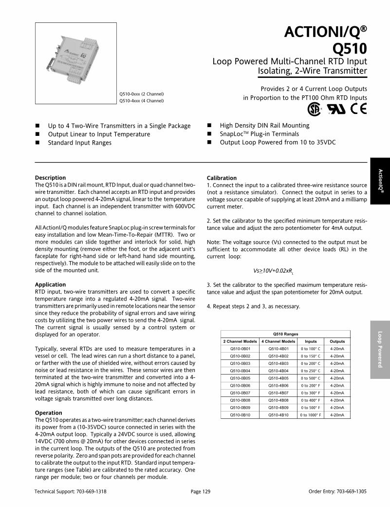
Page 129Technical Support: 703-669-1318 Order Entry: 703-669-1305
Actio
nIQ
®Lo
op P
ow
ered
DescriptionThe Q510 is a DIN rail mount, RTD Input, dual or quad channel two-wire transmitter. Each channel accepts an RTD input and providesan output loop powered 4-20mA signal, linear to the temperatureinput. Each channel is an independent transmitter with 600VDCchannel to channel isolation.
All ActionI/Q modules feature SnapLoc plug-in screw terminals foreasy installation and low Mean-Time-To-Repair (MTTR). Two ormore modules can slide together and interlock for solid, highdensity mounting (remove either the foot, or the adjacent unit'sfaceplate for right-hand side or left-hand hand side mounting,respectively). The module to be attached will easily slide on to theside of the mounted unit.
ApplicationRTD input, two-wire transmitters are used to convert a specifictemperature range into a regulated 4-20mA signal. Two-wiretransmitters are primarily used in remote locations near the sensorsince they reduce the probability of signal errors and save wiringcosts by utilizing the two power wires to send the 4-20mA signal.The current signal is usually sensed by a control system ordisplayed for an operator.
Typically, several RTDs are used to measure temperatures in avessel or cell. The lead wires can run a short distance to a panel,or farther with the use of shielded wire, without errors caused bynoise or lead resistance in the wires. These sensor wires are thenterminated at the two-wire transmitter and converted into a 4-20mA signal which is highly immune to noise and not affected bylead resistance, both of which can cause significant errors involtage signals transmitted over long distances.
OperationThe Q510 operates as a two-wire transmitter; each channel derivesits power from a (10-35VDC) source connected in series with the4-20mA output loop. Typically a 24VDC source is used, allowing14VDC (700 ohms @ 20mA) for other devices connected in seriesin the current loop. The outputs of the Q510 are protected fromreverse polarity. Zero and span pots are provided for each channelto calibrate the output to the input RTD. Standard input tempera-ture ranges (see Table) are calibrated to the rated accuracy. Onerange per module; two or four channels per module.
ACTIONI/Q®
Q510Loop Powered Multi-Channel RTD Input
Isolating, 2-Wire Transmitter
Provides 2 or 4 Current Loop Outputsin Proportion to the PT100 Ohm RTD Inputs
Up to 4 Two-Wire Transmitters in a Single Package Output Linear to Input Temperature Standard Input Ranges
Q510-0xxx (2 Channel)
Q510-4xxx (4 Channel)
High Density DIN Rail Mounting SnapLocTM Plug-in Terminals Output Loop Powered from 10 to 35VDC
Calibration1. Connect the input to a calibrated three-wire resistance source(not a resistance simulator). Connect the output in series to avoltage source capable of supplying at least 20mA and a milliampcurrent meter.
2. Set the calibrator to the specified minimum temperature resis-tance value and adjust the zero potentiometer for 4mA output.
Note: The voltage source (Vs) connected to the output must besufficient to accommodate all other device loads (RL) in thecurrent loop:
Vs>10V+0.02xRL
3. Set the calibrator to the specified maximum temperature resis-tance value and adjust the span potentiometer for 20mA output.
4. Repeat steps 2 and 3, as necessary.
segnaR015Q
sledoMlennahC2 sledoMlennahC4 stupnI stuptuO
10B0-015Q 10B4-015Q 001ot0 C° Am02-4
20B0-015Q 20B4-015Q 051ot0 C° Am02-4
30B0-015Q 30B4-015Q 002ot0 C° Am02-4
40B0-015Q 40B4-015Q 052ot0 C° Am02-4
50B0-015Q 50B4-015Q 005ot0 C° Am02-4
60B0-015Q 60B4-015Q 002ot0 F° Am02-4
70B0-015Q 70B4-015Q 003ot0 F° Am02-4
80B0-015Q 80B4-015Q 004ot0 F° Am02-4
90B0-015Q 90B4-015Q 005ot0 F° Am02-4
01B0-015Q 01B4-015Q 0001ot0 F° Am02-4
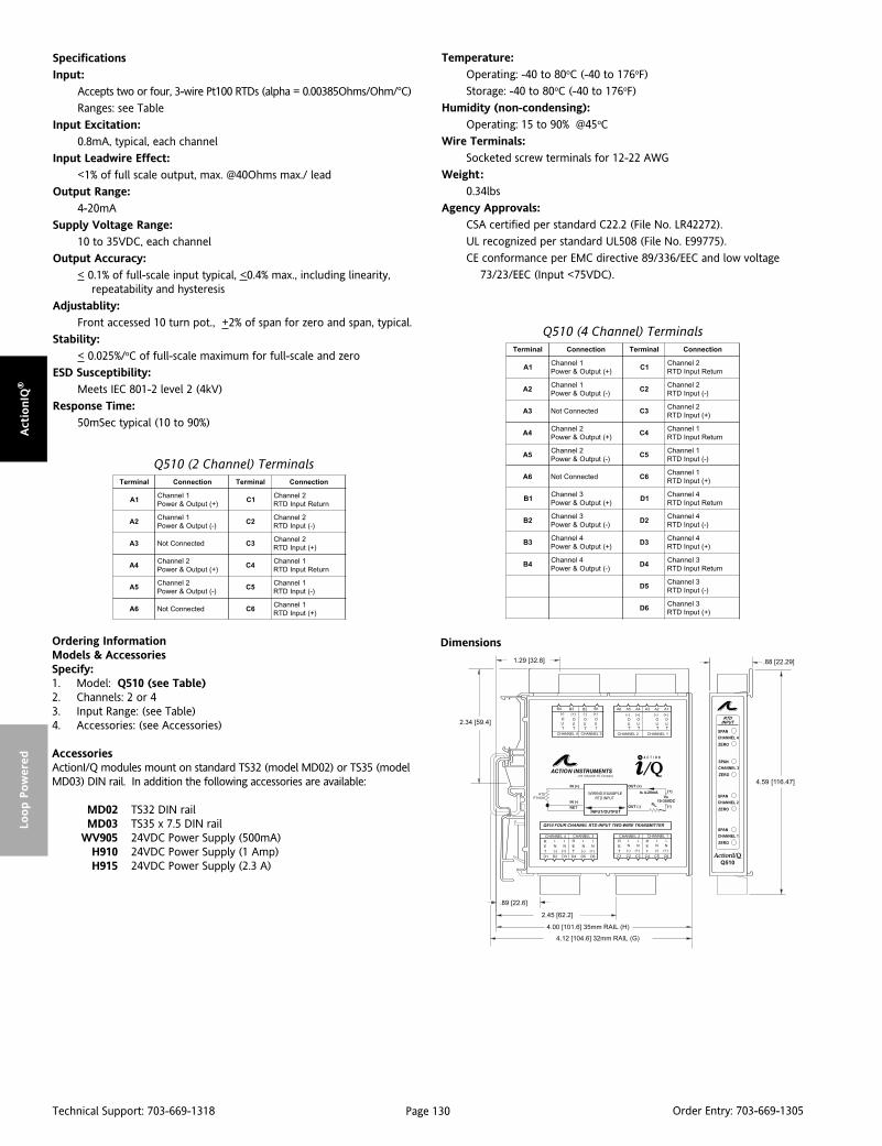
Page 130Technical Support: 703-669-1318 Order Entry: 703-669-1305
Act
ionIQ
®Lo
op P
ow
ered
Ordering InformationModels & AccessoriesSpecify:1. Model: Q510 (see Table)2. Channels: 2 or 43. Input Range: (see Table)4. Accessories: (see Accessories)
AccessoriesActionI/Q modules mount on standard TS32 (model MD02) or TS35 (modelMD03) DIN rail. In addition the following accessories are available:
MD02 TS32 DIN railMD03 TS35 x 7.5 DIN rail
WV905 24VDC Power Supply (500mA)H910 24VDC Power Supply (1 Amp)H915 24VDC Power Supply (2.3 A)
Dimensions
lanimreT noitcennoC lanimreT noitcennoC
1A1lennahC
)+(tuptuO&rewoP1C
2lennahCnruteRtupnIDTR
2A1lennahC
)-(tuptuO&rewoP2C
2lennahC)-(tupnIDTR
3A detcennoCtoN 3C2lennahC
)+(tupnIDTR
4A2lennahC
)+(tuptuO&rewoP4C
1lennahCnruteRtupnIDTR
5A2lennahC
)-(tuptuO&rewoP5C
1lennahC)-(tupnIDTR
6A detcennoCtoN 6C1lennahC
)+(tupnIDTR
1B3lennahC
)+(tuptuO&rewoP1D
4lennahCnruteRtupnIDTR
2B3lennahC
)-(tuptuO&rewoP2D
4lennahC)-(tupnIDTR
3B4lennahC
)+(tuptuO&rewoP3D
4lennahC)+(tupnIDTR
4B4lennahC
)-(tuptuO&rewoP4D
3lennahCnruteRtupnIDTR
5D3lennahC
)-(tupnIDTR
6D3lennahC
)+(tupnIDTR
Q510 (4 Channel) Terminals
Q510 (2 Channel) Terminals
Specifications
Input:
Accepts two or four, 3-wire Pt100 RTDs (alpha = 0.00385Ohms/Ohm/°C)
Ranges: see Table
Input Excitation:
0.8mA, typical, each channel
Input Leadwire Effect:
<1% of full scale output, max. @40Ohms max./ lead
Output Range:
4-20mA
Supply Voltage Range:
10 to 35VDC, each channel
Output Accuracy:
< 0.1% of full-scale input typical, <0.4% max., including linearity,repeatability and hysteresis
Adjustablity:
Front accessed 10 turn pot., +2% of span for zero and span, typical.
Stability:
< 0.025%/oC of full-scale maximum for full-scale and zero
ESD Susceptibility:
Meets IEC 801-2 level 2 (4kV)
Response Time:
50mSec typical (10 to 90%)
Temperature:
Operating: -40 to 80oC (-40 to 176oF)
Storage: -40 to 80oC (-40 to 176oF)
Humidity (non-condensing):
Operating: 15 to 90% @45oC
Wire Terminals:
Socketed screw terminals for 12-22 AWG
Weight:
0.34lbs
Agency Approvals:
CSA certified per standard C22.2 (File No. LR42272).
UL recognized per standard UL508 (File No. E99775).
CE conformance per EMC directive 89/336/EEC and low voltage
73/23/EEC (Input <75VDC).
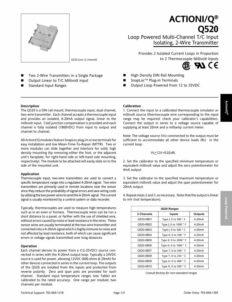
Page 131Technical Support: 703-669-1318 Order Entry: 703-669-1305
Actio
nIQ
®Lo
op P
ow
ered
DescriptionThe Q520 is a DIN rail mount, thermocouple input, dual channel,two-wire transmitter. Each channel accepts a thermocouple inputand provides an isolated, 4-20mA output signal, linear to themillivolt input. Cold junction compensation is provided and eachchannel is fully isolated (1800VDC) from input to output andchannel to channel.
All ActionI/Q modules feature SnapLoc plug-in screw terminals foreasy installation and low Mean-Time-To-Repair (MTTR). Two ormore modules can slide together and interlock for solid, highdensity mounting (by removing either the foot, or the adjacentunit's faceplate, for right-hand side or left-hand side mounting,respectively). The module to be attached will easily slide on to theside of the mounted unit.
ApplicationThermocouple input, two-wire transmitters are used to convert aspecific temperature range into a regulated 4-20mA signal. Two-wiretransmitters are primarily used in remote locations near the sensorsince they reduce the probability of signal errors and save wiring costsby utilizing the two power wires to send the 4-20mA signal. The currentsignal is usually monitored by a control system or data recorder.
Typically, thermocouples are used to measure high temperaturessuch as in an oven or furnace. Thermocouple wires can be run ashort distance to a panel, or farther with the use of shielded wire,without errors caused by noise or lead resistance in the wires. Thesesensor wires are usually terminated at the two-wire transmitter andconverted into a 4-20mA signal which is highly immune to noise andnot affected by lead resistance, both of which can cause significanterrors in voltage signals transmitted over long distances.
OperationEach channel derives its power from a (12-35VDC) source con-nected in series with the 4-20mA output loop. Typically a 24VDCsource is used for power, allowing 12VDC (600 ohms @ 20mA) forother devices connected in series in the current loop. The outputsof the Q520 are isolated from the inputs and protected fromreverse polarity. Zero and span pots are provided for eachchannel. Standard input temperature ranges (see Table) arecalibrated to the rated accuracy. One range per module; twochannels per module.
ACTIONI/Q®
Q520Loop Powered Multi-Channel T/C Input
Isolating, 2-Wire Transmitter
Provides 2 Isolated Current Loops in Proportionto 2 Thermocouple Millivolt Inputs
Two 2-Wire Transmitters in a Single Package Output Linear to T/C Millivolt Input Standard Input Ranges
Q520-2xxx (2 channel)
High Density DIN Rail Mounting SnapLocTM Plug-in Terminals Output Loop Powered from 12 to 35VDC
Calibration1. Connect the input to a calibrated thermocouple simulator ormillivolt source (thermocouple wire corresponding to the inputrange may be required; check your calibrator's capabilities).Connect the output in series to a voltage source capable ofsupplying at least 20mA and a milliamp current meter.
Note: The voltage source (Vs) connnected to the output must besufficient to accommodate all other device loads (RL) in thecurrent loop:
Vs>12V+0.02xRL
2. Set the calibrator to the specified minimum temperature orequivalent millivolt value and adjust the zero potentiometer for4mA output.
3. Set the calibrator to the specified maximum temperature orequivalent millivolt value and adjust the span potentiometer for20mA output.
4. Repeat steps 2 and 3, as necessary. Note that the output is linearto mV (not temperature).
Consult factory for non-standard ranges
segnaR025Q
slennahC2 stupnI stuptuO
10B0-025Q 005ot0;JepyT F° Am02-4
20B0-025Q 0001ot0;JepyT F° Am02-4
30B0-025Q 005ot0;JepyT C° Am02-4
40B0-025Q 005ot0;KepyT F° Am02-4
50B0-025Q 0002ot0;KepyT F° Am02-4
60B0-025Q 0001ot0;KepyT C° Am02-4
70B0-025Q 005ot0;TepyT F° Am02-4
80B0-025Q 052ot0;TepyT C° Am02-4
90B0-025Q 004ot0;KepyT C° Am02-4
01B0-025Q 005ot0;KepyT C° Am02-4

Page 132Technical Support: 703-669-1318 Order Entry: 703-669-1305
Act
ionIQ
®Lo
op P
ow
ered
Specifications
Input:
Accepts two J, K or T Type thermocouples
Ranges: see Table
Burnout Detection:
Upscale standard; Downscale, option B
Cold-Junction Compensation Error
1oC typical, 0 to 80oC ambient;
3oC typical, -40 to 0oC ambient
Output Range:
4-20mA
Supply Voltage Range:
12 to 35VDC, each channel
Output Accuracy:
< 0.1% of full-scale input (mV) typical, < 0.2% max. @23oC includinglinearity, repeatability and hysteresis (not including CJC error)
Adjustability:
Front accessed 10 turn pot., + 5% of span for zero and span
Stability:
<0.025%/oC of full-scale max. for full-scale and zero
ESD Susceptibility:
Meets IEC 801-2 level 2 (4kV)
Ordering InformationModels & AccessoriesSpecify:1. Model: Q520 (see Table)2. Option: B (downscale burnout detection), upscale standard3. Input Range: (see Table)4. Accessories: (see Accessories)
AccessoriesActionI/Q modules mount on standard TS32 (model MD02) or TS35 (modelMD03) DIN rail. In addition the following accessories are available:
MD02 TS32 DIN railMD03 TS35 x 7.5 DIN rail
WV905 24VDC Power Supply (500mA)H910 24VDC Power Supply (1A)H915 24VDC Power Supply (2.3A)
Isolation:
1800VDC or peak AC between input and outputand channel tochannel
Response Time:
100mSec typical (10 to 90%)
Temperature:
Operating: -40 to 80oC (-40 to 176oF)
Storage: -40 to 80oC (-40 to 176oF)
Humidity (non-condensing):
Operating: 15 to 90% (@45oC)
Wire Terminals:
Socketed screw terminals for 12-22 AWG
Weight:
0.34 lbs
Agency Approvals:
CSA certified per standard C22.2 (File No. LR42272).
UL recognized per standard UL508 (File No. E99775).
CE conformance per EMC directive 89/336/EEC and low voltage
73/23/EEC (Input <75VDC).
Dimensions
lanimreT noitcennoC lanimreT noitcennoC
1A1lennahC
)+(tuptuO&rewoP1C detcennoCtoN
2A1lennahC
)-(tuptuO&rewoP2C
2lennahC)-(tupnIC/T
3A detcennoCtoN 3C2lennahC
)+(tupnIC/T
4A2lennahC
)+(tuptuO&rewoP4C detcennoCtoN
5A2lennahC
)-(tuptuO&rewoP5C
1lennahC)-(tupnIC/T
6A detcennoCtoN 6C1lennahC
)+(tupnIC/T
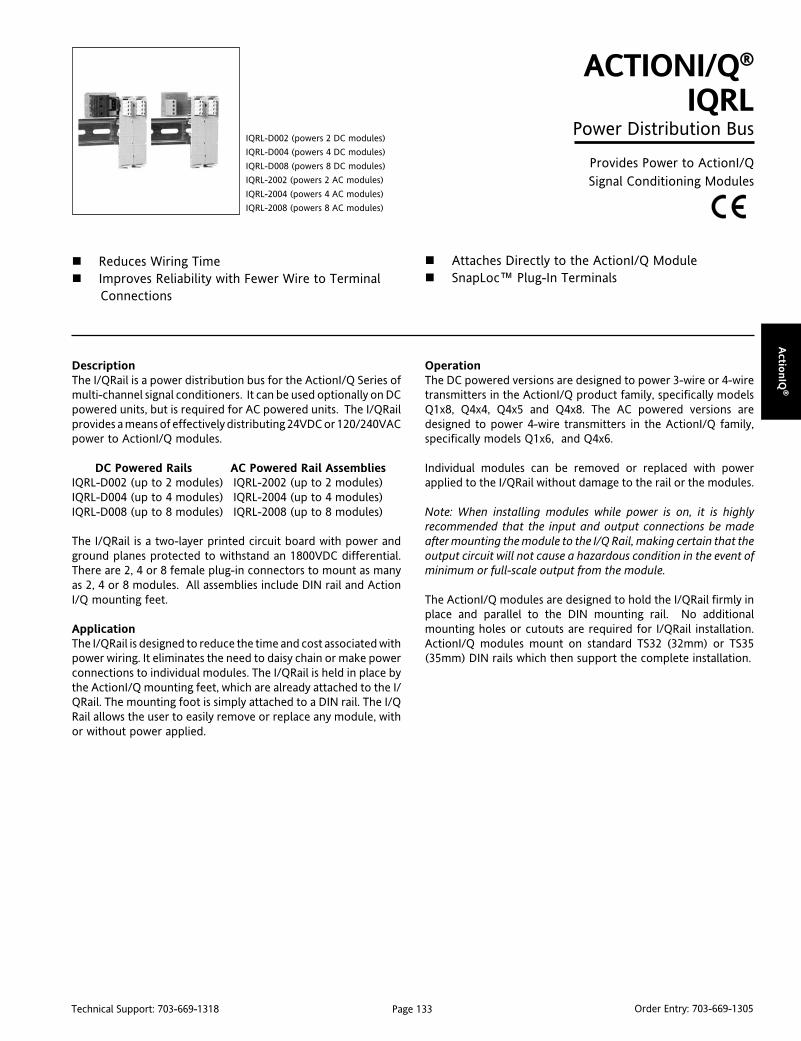
Page 133Technical Support: 703-669-1318 Order Entry: 703-669-1305
Actio
nIQ
®
DescriptionThe I/QRail is a power distribution bus for the ActionI/Q Series ofmulti-channel signal conditioners. It can be used optionally on DCpowered units, but is required for AC powered units. The I/QRailprovides a means of effectively distributing 24VDC or 120/240VACpower to ActionI/Q modules.
DC Powered Rails AC Powered Rail AssembliesIQRL-D002 (up to 2 modules) IQRL-2002 (up to 2 modules)IQRL-D004 (up to 4 modules) IQRL-2004 (up to 4 modules)IQRL-D008 (up to 8 modules) IQRL-2008 (up to 8 modules)
The I/QRail is a two-layer printed circuit board with power andground planes protected to withstand an 1800VDC differential.There are 2, 4 or 8 female plug-in connectors to mount as manyas 2, 4 or 8 modules. All assemblies include DIN rail and ActionI/Q mounting feet.
ApplicationThe I/QRail is designed to reduce the time and cost associated withpower wiring. It eliminates the need to daisy chain or make powerconnections to individual modules. The I/QRail is held in place bythe ActionI/Q mounting feet, which are already attached to the I/QRail. The mounting foot is simply attached to a DIN rail. The I/QRail allows the user to easily remove or replace any module, withor without power applied.
ACTIONI/Q®
IQRLPower Distribution Bus
Provides Power to ActionI/QSignal Conditioning Modules
Reduces Wiring Time Improves Reliability with Fewer Wire to Terminal
Connections
IQRL-D002 (powers 2 DC modules)
IQRL-D004 (powers 4 DC modules)
IQRL-D008 (powers 8 DC modules)
IQRL-2002 (powers 2 AC modules)
IQRL-2004 (powers 4 AC modules)
IQRL-2008 (powers 8 AC modules)
Attaches Directly to the ActionI/Q Module SnapLoc™ Plug-In Terminals
OperationThe DC powered versions are designed to power 3-wire or 4-wiretransmitters in the ActionI/Q product family, specifically modelsQ1x8, Q4x4, Q4x5 and Q4x8. The AC powered versions aredesigned to power 4-wire transmitters in the ActionI/Q family,specifically models Q1x6, and Q4x6.
Individual modules can be removed or replaced with powerapplied to the I/QRail without damage to the rail or the modules.
Note: When installing modules while power is on, it is highlyrecommended that the input and output connections be madeafter mounting the module to the I/Q Rail, making certain that theoutput circuit will not cause a hazardous condition in the event ofminimum or full-scale output from the module.
The ActionI/Q modules are designed to hold the I/QRail firmly inplace and parallel to the DIN mounting rail. No additionalmounting holes or cutouts are required for I/QRail installation.ActionI/Q modules mount on standard TS32 (32mm) or TS35(35mm) DIN rails which then support the complete installation.

Page 134Technical Support: 703-669-1318 Order Entry: 703-669-1305
Act
ionIQ
®
Installation1. Separate the DIN rail from the I/Q Rail assembly by either slidingit off or releasing each mounting foot tab. Mount the DIN rail inthe panel or rack at the desired location.
Note: The module which is to mount on the I/QRail and DIN rail hasa base (foot) which is removable from the body. This foot has onebracket to mount on a DIN rail (32mm or 35mm) and anotherbracket to hold the I/QRail (see Figure 1).
2. Once the DIN rail is firmly in place, snap the foot and I/QRailassembly to the DIN mounting rail, starting from the center uniton the rail and working outward. When all the feet are mountedto the DIN rail the I/QRail should be held firmly in place parallelwith the DIN mounting rail (see Figure 2).
3. To mount the first module on its foot, start with the farthest lefthand foot (P1 or P2 on I/QRail). Snap the module to this footmaking sure that the rail connector matches the opening recep-tacle on the base of the module. Check that both tabs on the foothave snapped in place.
Figure 1: ActionI/Q Module and Mounting Foot Figure 2: ActionI/Q Mounting Foot Attachedto IQRail and DIN Rail
4. The second module can now slide on to the first module's metalheatsink. Align the plastic ridges, which start at the base of thesecond unit, into the grooves on the metal heatsink. Slide thesecond unit down until the foot tabs snap in place. Repeat thisprocedure for the remaining modules to be attached.
5. To remove a module from a row, first detach the faceplate ofthe unit to the right of the unit to be removed (see figure 3). Thenremove the terminal connectors by gently pulling them away fromthe module. Once the terminals are clear, use a blade screw driverto release the foot tabs from the base of the module while pullingthe unit gently free (see Figure 4). Replace the faceplate of theadjacent unit.
6. Installation can be accomplished by reversing step 5, makingsure the right hand unit's faceplate is removed before installation.
7. Individual modules can be removed or replaced with powerapplied to the I/QRail, without damage to the rail or the modules.
8. Calibration should be performed as specified on the specificmodule’s data sheet.

Page 135Technical Support: 703-669-1318 Order Entry: 703-669-1305
Actio
nIQ
®
Figure 4: ActionI/Q Modules and Interlocking Slides
Figure 3: ActionI/Q Module and Removable Faceplate
Specifications
Isolation:
1800V DC, between power conductors
Power Rating:
DC Versions: 30VDC max., powering up to 8 two channel modules
AC Versions: 265VAC max., powering up to 8 two channel modules
ESD Susceptibility:
Meets IEC 801-2 Level 2 (4kV)
Temperature:
Operating: 0 to 65°C (32 to 131°F)
Storage: -40 to 80°C (-40 to 176°F)
Humidity (non-condensing):
Operating: 25 to 95% @40°CSoak: 90% for 24 hours @60°C
Wire Terminals:
Socketed screw terminals for 14-22 AWG
Agency Approvals
The IQRL is designed to operate with and support the UL, CE andCSA approvals for the specific signal conditioners listed. Refer tothe signal conditioner data sheets for specific approvals.
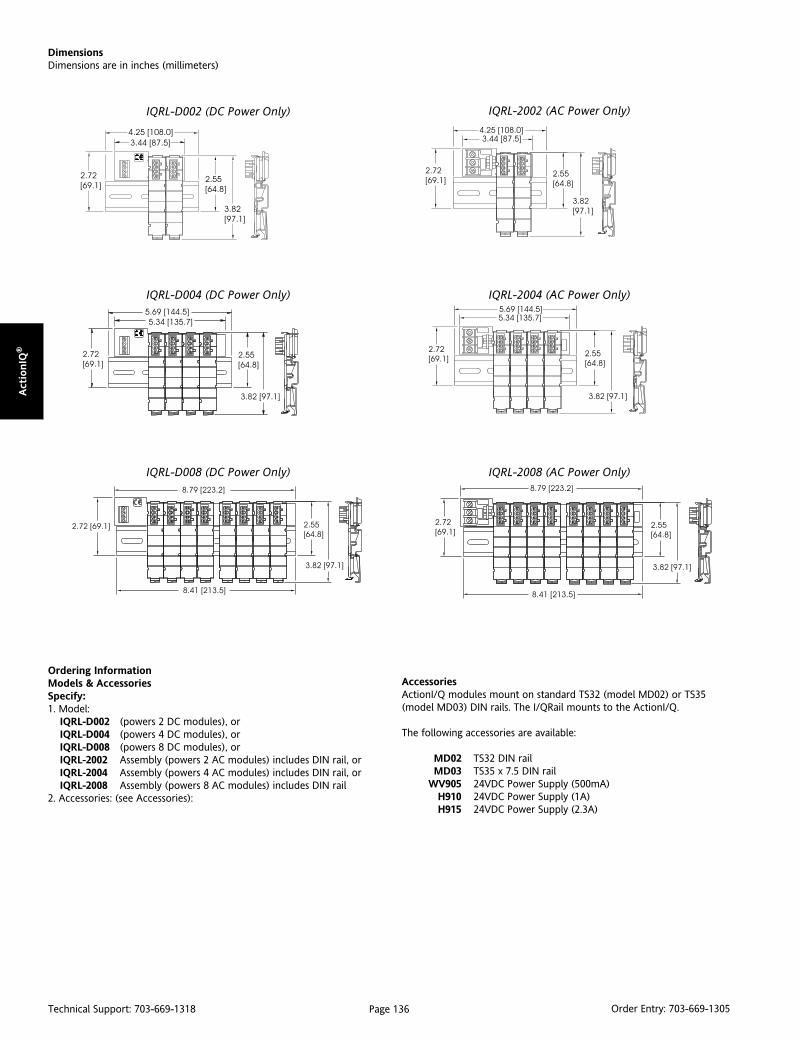
Page 136Technical Support: 703-669-1318 Order Entry: 703-669-1305
Act
ionIQ
®
DimensionsDimensions are in inches (millimeters)
IQRL-D002 (DC Power Only)
IQRL-D004 (DC Power Only)
IQRL-D008 (DC Power Only)
IQRL-2002 (AC Power Only)
IQRL-2004 (AC Power Only)
IQRL-2008 (AC Power Only)
Ordering InformationModels & AccessoriesSpecify:1. Model:
IQRL-D002 (powers 2 DC modules), orIQRL-D004 (powers 4 DC modules), orIQRL-D008 (powers 8 DC modules), orIQRL-2002 Assembly (powers 2 AC modules) includes DIN rail, orIQRL-2004 Assembly (powers 4 AC modules) includes DIN rail, orIQRL-2008 Assembly (powers 8 AC modules) includes DIN rail
2. Accessories: (see Accessories):
AccessoriesActionI/Q modules mount on standard TS32 (model MD02) or TS35(model MD03) DIN rails. The I/QRail mounts to the ActionI/Q.
The following accessories are available:
MD02 TS32 DIN railMD03 TS35 x 7.5 DIN rail
WV905 24VDC Power Supply (500mA)H910 24VDC Power Supply (1A)H915 24VDC Power Supply (2.3A)

Page 137Technical Support: 703-669-1318 Order Entry: 703-669-1305
Actio
nIQ
®
DescriptionThe C681 is a Graphic User Interface (GUI) program and interfacecable used to configure Q486 and Q488 Temperature Transmit-ters. The C681 speeds configuration and can also be used as adiagnostic tool to confirm switch positions or read the measuredtemperature to check accuracy.
Note that this software is designed to be used as a configurationtool for normal setup and operation. In some cases under abnormalcircumstances it may not always report sensor data values cor-rectly. For example, during burnout or open circuit sensor condi-tions, the software may report high or low default values and notnecessarily the actual sensor input and output data.
Instruction ManualA complete instruction manual is contained on the CD ROM. Thefile ("Q486HELP.doc.") can be read directly using Microsoft Wordor WordPad or it can be read using the online help command whilerunning the application. For detailed information relating tosystem requirements, program installation and operation, readSection 3 of the instruction manual.
Program Installation1. Insert the CD into the CD ROM drive.
2. If the program does not start automatically, click on the"Setup.exe" file.
3. Follow the instructions on the screen to install the program ontoyour hard drive.
4. To run the application, click the AIQ486GUI.exe icon.
ACTIONI/Q®
C681Q486 & Q488 Graphic User Interface
Provides a Graphic User Interface and CommunicationCable to Speed Transmitter Configuration
Quickly Configures Q486 & Q488 Transmitters CD ROM Contains Program & User Guide Configure Multiple Modules Quickly & Easily
C681-0001
Displays Measured Temperature to Check Accuracy Displays Diagnostics Information to Check Switch
Settings
Connecting the Q488 or Q486-0001 to a Personal Computer1. Connect the communication cable to an unused RS-232 serialport of the PC (e.g., com1, com2).
2. Remove the front panel of the Q488 (or Q486-0001) to accessthe communication jack connector and plug the cable into thejack connector.
Connecting the Q486-0000 to a Personal Computer1. Connect the communication cable to an unused RS-232 serialport of the PC.
2. Install the cable adaptor provided to the output connector, A4to A6, and plug the cable into the jack connector.

Page 138Technical Support: 703-669-1318 Order Entry: 703-669-1305
Act
ionIQ
®
DescriptionThe C698 is a Graphic User Interface (GUI) program and interfacecable used to configure the Model Q498 Math Function Module.The C698 speeds configuration and can be used as a diagnostictool to confirm switch positions. This software is required in orderto take advantage of the math functions.
Instruction ManualA complete instruction manual is contained on the CD ROM. Thefile ("Q498HELP.doc.") can be read directly using Microsoft Wordor WordPad or it can be read using the online help command whilerunning the application.
ACTIONI/Q®
C698Q498 Graphic User Interface
Provides a Graphic User Interface and CommunicationCable to Speed Transmitter Configuration
Quickly Configures Q498 Math Modules CD ROM Contains Program & User Guide
C698-0000
Configure Multiple Modules Quickly & Easily Displays Diagnostics Information to Check Switch
Settings
Program Installation1. Insert the CD into the CD ROM drive.
2. If the program does not start automatically, click on the"Setup.exe" file.
3. Follow the instructions on the screen to install the program ontoyour hard drive.
4. To run the application, click the AIQ498GUI.exe icon.
Connecting the Q498 to a Personal Computer1. Connect the communication cable to an unused RS-232 serialport of the PC (e.g., com1, com2).
2. Remove the front panel of the Q498 to access the communi-cation jack connector and plug the cable into the jack connector.

Page 139Technical Support: 703-669-1318 Order Entry: 703-669-1305
Ultra Slim
pak
®
DescriptionThe Ultra SlimPak is the result of over 10 years of experience inwide-ranging, field configurable instrument design. The UltraSlimPak utilizes ASIC and microprocessor technology to provide1800VDC isolation and wide ranging adjustments for easy, accu-rate, discrete signal conditioning. The power supply of the UltraSlimPak will accept any AC or DC source between 9 and 30 volts,typically a 12 or 24VDC supply is used.
The value of a field configurable instrument is that it allows the userto easily set the instrument for their specific (or custom) I/O range.This flexibility reduces spare parts inventory and increases theefficiency of the process by maximizing resolution in critical processmeasurements.
Ultra High DensityThe Ultra SlimPak was developed for high density applications inwhich panel space cannot be wasted. From 17 to 24 Ultra SlimPakscan mount on one linear foot of DIN rail. DIN rail mounting alsoprovides easy "snap in place" installation.
Limit AlarmsLimit alarms are setpoint controllers that regulate industrial pro-cesses – discrete, batch or continuous. Two-position (On/Off)controllers simplify processes through automation, and by remov-ing personnel from tedious and possibly harmful environments.
Alarms are indicators of problems – whether it is a production linefault, a process upset, an equipment failure or a control systemabnormality. Limit alarms safeguard industrial facilities and workersby alerting and informing process personnel of abnormal conditions.
Ultra SlimPak G1X8 Series of Limit AlarmsThe Ultra SlimPak G1X8 series of limit alarms accept the mostpopular process signals: DC voltage and current (G108); RTD(G118); thermocouples (G128); and AC voltage and current(G168). Their output is a dual contact closure (2 SPDT relays) thatcan be used to light hazard beacons, sound audible alarms or alertcontrol systems of abnormalities.
ULTRA SLIMPAK®
Setpoint FlexibilityWide ranging, field configurable Ultra SlimPaks allow the user toconfigure the input type, input range, setpoint, deadband, HI/LOoperation and failsafe or non-failsafe relay state.
These features provide the flexibility required to solve manydiverse process control applications, with the additional benefitsof reduced spare parts inventory and the convenience of an off-the-shelf solution.
Signal ConditionersSignal conditioners amplify and condition weak signals generatedby process sensors. They send signals long distances withoutdegradation by electrical noise. They are also used to drive devicessuch as indicators, alarms, controllers, computer interfaces andother process instrumentation.
Ultra SlimPAk G4X8 Series of ConditionersThe Ultra SlimPak G4X8 series of signal conditioners accepts avariety of process signals: DC voltage and current (G428); RTD(G418); thermocouple (G428); potentiometer (G438); strain gauge(G448); AC voltage and current (G468); and frequency/pulse(G478). Three port isolation – input to output to power – ensuresthat common ground faults are eliminated from any source.
ASIC ReliabilityAction's exclusive analog ASIC increases reliability by reducingcomponents and interconnections by up to 70%.
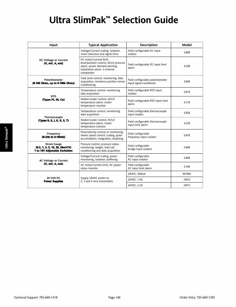
Page 140Technical Support: 703-669-1318 Order Entry: 703-669-1305
Ult
ra S
lim
pak
®
Ultra SlimPak™ Selection Guide
tupnI noitacilppAlacipyT noitpircseD ledoM
tnerruCroegatloVCD)Am,A,Vm,V( )Am,A,Vm,V( )Am,A,Vm,V( )Am,A,Vm,V( )Am,A,Vm,V(
,noitalosi,gnilacstnerruC/egatloVevirdlangisdnanoitcuderesion
tupniCDelbarugifnocdleiFrotalosi
804G
,timiltnerruc/rotomCDerusserpOL/IH,lortnocnoitisop/level
,gninrawdnamedrewop,mralalennahc-2,mralanoitazilatot
rotarapmoc
timiltupniCDelbarugifnocdleiFmrala
801G
retemoitnetoP)smhOk001-0otpu,smhO001-0( )smhOk001-0otpu,smhO001-0( )smhOk001-0otpu,smhO001-0( )smhOk001-0otpu,smhO001-0( )smhOk001-0otpu,smhO001-0(
atad,gnirotinom,lortnoclevelknaTrosnesnoitisopecnatsiser,noitisiuqca
gninoitidnoc
retemoitnetopelbarugifnocdleiFrenoitidnoclangistupni
834G
DTR)uC,iN,tPsepyT( )uC,iN,tPsepyT( )uC,iN,tPsepyT( )uC,iN,tPsepyT( )uC,iN,tPsepyT(
,gnirotinom,lortnocerutarepmeTnoitisiuqcaatad
tupniDTRelbarugifnocdleiFrotalosi
814G
OL/IH,lortnocrelooc/retaeHrotom,mralaerutarepmet
rotinomerutarepmet
timiltupniDTRelbarugifnocdleiFmrala
811G
elpuocomrehT)T,S,R,K,J,E,BsepyT( )T,S,R,K,J,E,BsepyT( )T,S,R,K,J,E,BsepyT( )T,S,R,K,J,E,BsepyT( )T,S,R,K,J,E,BsepyT(
,gnirotinom,lortnocerutarepmeTnoitisiuqcaatad
elpuocomrehtelbarugifnocdleiFrotalositupni
824G
OL/IH,lortnocrelooc/retaeHrotom,mralaerutarepmet
rotinomerutarepmet
elpuocomrehtelbarugifnocdleiFmralatimiltupni
821G
ycneuqerF)zHk01-0otzH2-0( )zHk01-0otzH2-0( )zHk01-0otzH2-0( )zHk01-0otzH2-0( )zHk01-0otzH2-0(
,gnirotinomrolortnocyticolev/wolFeslup,gnilacs,lortnocdeepsrotomgnizilatot,noitargetni,noitalumucca
elbarugifnocdleiFrotalositupniycneuqerf
874G
eguaGniartS)V/Vm05,02,01,5,3,1,5.0( )V/Vm05,02,01,5,3,1,5.0( )V/Vm05,02,01,5,3,1,5.0( )V/Vm05,02,01,5,3,1,5.0( )V/Vm05,02,01,5,3,1,5.0(noitaticxEelbatsujdAV01ot1 noitaticxEelbatsujdAV01ot1 noitaticxEelbatsujdAV01ot1 noitaticxEelbatsujdAV01ot1 noitaticxEelbatsujdAV01ot1
sutatserusserp,lortnocerusserPllecdaol,thgiew,gnirotinom
noitisiuqcaataddnagninoitidnoc
elbarugifnocdleiFrotalositupniegdirb
844G
tnerruCroegatloVCA)Am,A,Vm,V( )Am,A,Vm,V( )Am,A,Vm,V( )Am,A,Vm,V( )Am,A,Vm,V(
rewop,gnilacstnerruC/egatloVgnireffub,noitalosi,gnirotinom
elbarugifnocdleiFrotalositupniCA
864G
rewopCA,timiltnerruc/rotomCArotinomsutats
elbarugifnocdleiFmralatimiltupniCA
861G
CDtloV42seilppuSrewoP seilppuSrewoP seilppuSrewoP seilppuSrewoP seilppuSrewoP
otrewopCDV42ylppuSsrettimsnarteriw4dna3,2
Am005,CDV42 509VW
A0.1,CDV42 019H
A3.2,CDV42 519H
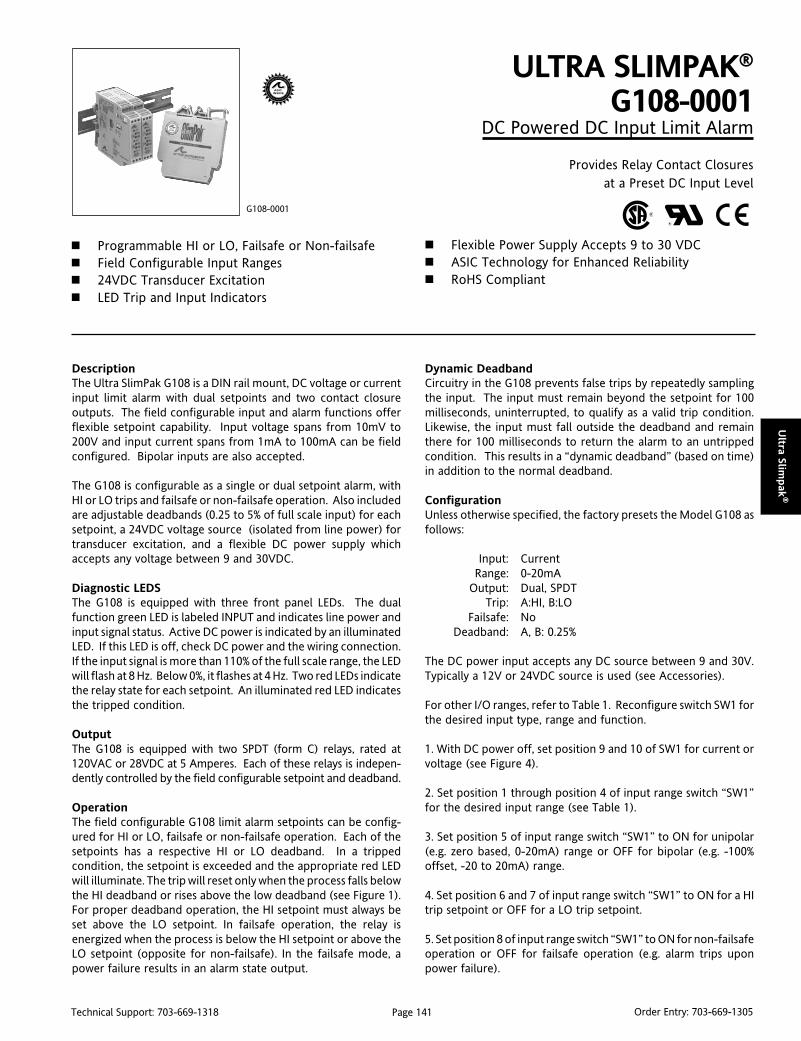
Page 141Technical Support: 703-669-1318 Order Entry: 703-669-1305
Ultra Slim
pak
®
DescriptionThe Ultra SlimPak G108 is a DIN rail mount, DC voltage or currentinput limit alarm with dual setpoints and two contact closureoutputs. The field configurable input and alarm functions offerflexible setpoint capability. Input voltage spans from 10mV to200V and input current spans from 1mA to 100mA can be fieldconfigured. Bipolar inputs are also accepted.
The G108 is configurable as a single or dual setpoint alarm, withHI or LO trips and failsafe or non-failsafe operation. Also includedare adjustable deadbands (0.25 to 5% of full scale input) for eachsetpoint, a 24VDC voltage source (isolated from line power) fortransducer excitation, and a flexible DC power supply whichaccepts any voltage between 9 and 30VDC.
Diagnostic LEDSThe G108 is equipped with three front panel LEDs. The dualfunction green LED is labeled INPUT and indicates line power andinput signal status. Active DC power is indicated by an illuminatedLED. If this LED is off, check DC power and the wiring connection.If the input signal is more than 110% of the full scale range, the LEDwill flash at 8 Hz. Below 0%, it flashes at 4 Hz. Two red LEDs indicatethe relay state for each setpoint. An illuminated red LED indicatesthe tripped condition.
OutputThe G108 is equipped with two SPDT (form C) relays, rated at120VAC or 28VDC at 5 Amperes. Each of these relays is indepen-dently controlled by the field configurable setpoint and deadband.
OperationThe field configurable G108 limit alarm setpoints can be config-ured for HI or LO, failsafe or non-failsafe operation. Each of thesetpoints has a respective HI or LO deadband. In a trippedcondition, the setpoint is exceeded and the appropriate red LEDwill illuminate. The trip will reset only when the process falls belowthe HI deadband or rises above the low deadband (see Figure 1).For proper deadband operation, the HI setpoint must always beset above the LO setpoint. In failsafe operation, the relay isenergized when the process is below the HI setpoint or above theLO setpoint (opposite for non-failsafe). In the failsafe mode, apower failure results in an alarm state output.
ULTRA SLIMPAK®
G108-0001DC Powered DC Input Limit Alarm
Provides Relay Contact Closuresat a Preset DC Input Level
Programmable HI or LO, Failsafe or Non-failsafe Field Configurable Input Ranges 24VDC Transducer Excitation LED Trip and Input Indicators
G108-0001
Flexible Power Supply Accepts 9 to 30 VDC ASIC Technology for Enhanced Reliability RoHS Compliant
Dynamic DeadbandCircuitry in the G108 prevents false trips by repeatedly samplingthe input. The input must remain beyond the setpoint for 100milliseconds, uninterrupted, to qualify as a valid trip condition.Likewise, the input must fall outside the deadband and remainthere for 100 milliseconds to return the alarm to an untrippedcondition. This results in a “dynamic deadband” (based on time)in addition to the normal deadband.
ConfigurationUnless otherwise specified, the factory presets the Model G108 asfollows:
Input: CurrentRange: 0-20mA
Output: Dual, SPDTTrip: A:HI, B:LO
Failsafe: NoDeadband: A, B: 0.25%
The DC power input accepts any DC source between 9 and 30V.Typically a 12V or 24VDC source is used (see Accessories).
For other I/O ranges, refer to Table 1. Reconfigure switch SW1 forthe desired input type, range and function.
1. With DC power off, set position 9 and 10 of SW1 for current orvoltage (see Figure 4).
2. Set position 1 through position 4 of input range switch “SW1”for the desired input range (see Table 1).
3. Set position 5 of input range switch “SW1” to ON for unipolar(e.g. zero based, 0-20mA) range or OFF for bipolar (e.g. -100%offset, -20 to 20mA) range.
4. Set position 6 and 7 of input range switch “SW1” to ON for a HItrip setpoint or OFF for a LO trip setpoint.
5. Set position 8 of input range switch “SW1” to ON for non-failsafeoperation or OFF for failsafe operation (e.g. alarm trips uponpower failure).
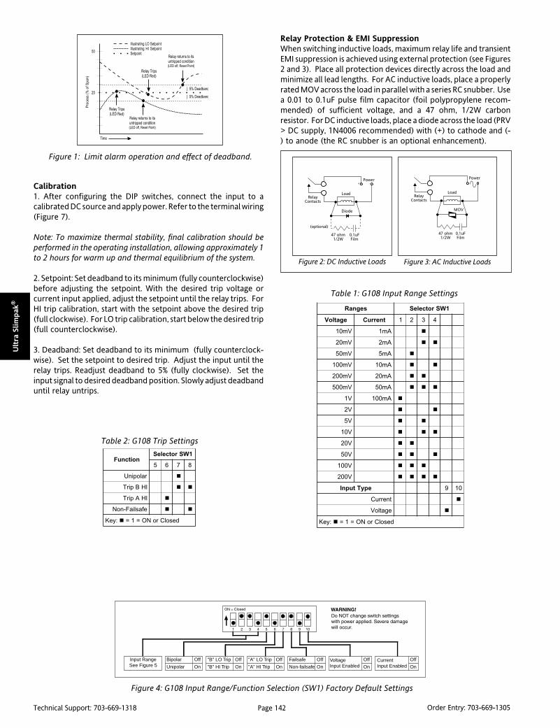
Page 142Technical Support: 703-669-1318 Order Entry: 703-669-1305
Ult
ra S
lim
pak
®
Calibration1. After configuring the DIP switches, connect the input to acalibrated DC source and apply power. Refer to the terminal wiring(Figure 7).
Note: To maximize thermal stability, final calibration should beperformed in the operating installation, allowing approximately 1to 2 hours for warm up and thermal equilibrium of the system.
2. Setpoint: Set deadband to its minimum (fully counterclockwise)before adjusting the setpoint. With the desired trip voltage orcurrent input applied, adjust the setpoint until the relay trips. ForHI trip calibration, start with the setpoint above the desired trip(full clockwise). For LO trip calibration, start below the desired trip(full counterclockwise).
3. Deadband: Set deadband to its minimum (fully counterclock-wise). Set the setpoint to desired trip. Adjust the input until therelay trips. Readjust deadband to 5% (fully clockwise). Set theinput signal to desired deadband position. Slowly adjust deadbanduntil relay untrips.
Figure 4: G108 Input Range/Function Selection (SW1) Factory Default Settings
Off
On
Bipolar
Unipolar
Off
On
"B" LO Trip
"B" HI Trip
Off
On
"A" LO Trip
"A" HI Trip
Off
On
Failsafe
Non-failsafe
Off
OnVoltageInput Enabled
Off
OnCurrentInput Enabled
Input RangeSee Figure 5
segnaR 1WSrotceleS
egatloV tnerruC 1 2 3 4
Vm01 Am1
Vm02 Am2
Vm05 Am5
Vm001 Am01
Vm002 Am02
Vm005 Am05
V1 Am001
V2
V5
V01
V02
V05
V001
V002
epyTtupnI 9 01
tnerruC
egatloV
:yeK desolCroNO=1=
Table 1: G108 Input Range Settings
Figure 1: Limit alarm operation and effect of deadband.
Figure 2: DC Inductive Loads Figure 3: AC Inductive Loads
Relay Protection & EMI SuppressionWhen switching inductive loads, maximum relay life and transientEMI suppression is achieved using external protection (see Figures2 and 3). Place all protection devices directly across the load andminimize all lead lengths. For AC inductive loads, place a properlyrated MOV across the load in parallel with a series RC snubber. Usea 0.01 to 0.1uF pulse film capacitor (foil polypropylene recom-mended) of sufficient voltage, and a 47 ohm, 1/2W carbonresistor. For DC inductive loads, place a diode across the load (PRV> DC supply, 1N4006 recommended) with (+) to cathode and (-) to anode (the RC snubber is an optional enhancement).
noitcnuF1WSrotceleS
5 6 7 8
ralopinU
IHBpirT
IHApirT
efasliaF-noN
:yeK desolCroNO=1=
Table 2: G108 Trip Settings
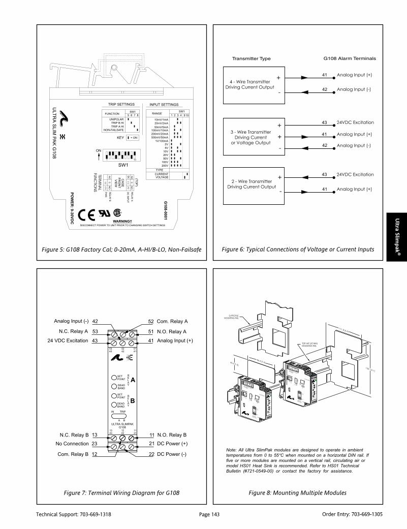
Page 143Technical Support: 703-669-1318 Order Entry: 703-669-1305
Ultra Slim
pak
®Figure 5: G108 Factory Cal; 0-20mA, A-HI/B-LO, Non-Failsafe
Note: All Ultra SlimPak modules are designed to operate in ambient
temperatures from 0 to 55°C when mounted on a horizontal DIN rail. If
five or more modules are mounted on a vertical rail, circulating air or
model HS01 Heat Sink is recommended. Refer to HS01 Technical
Bulletin (#721-0549-00) or contact the factory for assistance.
Figure 6: Typical Connections of Voltage or Current Inputs
Figure 8: Mounting Multiple ModulesFigure 7: Terminal Wiring Diagram for G108

Page 144Technical Support: 703-669-1318 Order Entry: 703-669-1305
Ult
ra S
lim
pak
®
DimensionsOrdering InformationModels & AccessoriesSpecify:1. Model: G108-00012. Accessories: (see Accessories)3. Optional Custom Factory Calibration; specify C620 with desired
input and output range.
AccessoriesSlimPak “G” series modules will mount on standard TS32 (model MD02) or TS35(model MD03) DIN rail. In addition, the following accessories are available:
HS01 Heatsink (vertical rail applications)MD03 TS35 x 7.5 DIN rail
WV905 24VDC Power Supply (0.5A)H910 24VDC Power Supply (1A)H915 24VDC Power Supply (2.3A)MB03 End Bracket for MD03C664 I/O Descriptive TagsC006 Shunt Resistor (0.1 ohm, 5A max.)
Setpoints
Effectivity:
Setpoints are adjustable over 100% ofthe selected input span.
Repeatability (constant temp.):
>50mV/5mA: 0.1% of full scale
<50mV/5mA: 0.2% of full scale
Stability
Temperature: +0.05% of full scale/°C, max.
Excitation Voltage
24VDC, 20mA, maximum
Common Mode Rejection
DC to 60Hz: 120dB
Isolation
1800VDC between contacts, input & power
EMC Compliance (CE Mark)
Emmissions: EN50081-1
Immunity: EN50082-2
Safety: EN50178
Humidity (Non-Condensing)
Operating: 15 to 95% @45°CSoak: 90% for 24hours @65°C
Temperature Range
Operating: 0 to 55°C (32 to 131°F)
Storage: -25 to 70°C (-13 to 158°F)
Power
Consumption: 1.5W typical, 2.5W max.
Supply Range: 9 to 30VDC, inverter isolated
Specifications
Inputs
Voltage
Range: 10mV to +200V
Impedance: >100K ohms
Overvoltage: 200V rms, max.
Current
Range: 1mA to +100mA
Impedance: 20 ohms, typical
Overcurrent: 170mA rms, max.
Overvoltage: 60VDC (protected by selfresetting fuse)
Common Mode (Input to Ground):
1800VDC, max.
LED Indicators
Input Range (Green)
>110% input: 8Hz flash
<0% input: 4Hz flash
Setpoint (Red)
Tripped: Solid red
Safe: Off
Limit Differentials (Deadbands)
>50mV/5mA: 0.25% to 5% of span
<50mV/5mA: 1% to 5% of span
Response Time
Dynamic Deadband:
Relay status will change when propersetpoint/process condition exists for100msec.
Normal Mode (analog filtering):
<250mSec, (10-90%)
Relay Contacts
2 SPDT (2 form C) Relays
1 Relay per setpoint
Current Rating (resistive):
120VAC: 5A; 240VAC: 2A; 28VDC: 5A
Material: Gold flash over silver alloy
Electrical Life:105 operations at rated load
Note: External relay contact protection isrequired for use with inductive loads(see Figures 2 & 3).
Mechanical Life: 107 operations
Wire Terminations
Screw terminations for 12-22 AWG
Weight
0.56lbs.
Agency Approvals
CSA certified per standard C22.2, No. 0-M91and 142-M1987 (File No. LR42272)
UL recognized per standard UL508
(File No.E99775)
CE Conformance per EMC directive 89/336/EEC and Low Voltage 73/23/EEC
(Input < 75VDC, only).
RoHS Compliant
Note that detailed installation instructions are
available on our web site.

Page 145Technical Support: 703-669-1318 Order Entry: 703-669-1305
Ultra Slim
pak
®
DescriptionThe Ultra SlimPak G118 is a DIN rail mount, RTD input limit alarmwith dual setpoints and two contact closure outputs. The fieldconfigurable input and alarm functions offer flexible setpointcapability. There are up to eight temperature ranges available foreach RTD type to ensure accuracy and maximize setpoint resolution.
The G118 is configurable as a single or dual setpoint alarm, withHI or LO trips and failsafe or non-failsafe operation. Also includedare adjustable deadbands (0.25 to 5% of full scale input) for eachsetpoint and a flexible DC power supply which accepts any voltagebetween 9 and 30VDC.
Diagnostic LEDSThe G118 is equipped with three front panel LEDs. The dualfunction green LED is labeled INPUT and indicates line power andinput signal status. Active DC power is indicated by an illuminatedLED. If this LED is off, check DC power and the wiring connection.If the input signal is more than 110% of the full scale range, the LEDwill flash at 8 Hz. Below 0%, it flashes at 4 Hz. Two red LEDs indicatethe relay state for each setpoint. An illuminated red LED indicatesthe tripped condition.
OutputThe G118 is equipped with two SPDT (form C) relays, rated at120VAC or 28VDC at 5 Amperes. Each of these relays is indepen-dently controlled by the field configurable setpoint anddeadband.
OperationThe field configurable G118 limit alarm setpoints can be config-ured for HI or LO, failsafe or non-failsafe operation. Each of thesetpoints has a respective HI or LO deadband. In a trippedcondition, the setpoint is exceeded and the appropriate red LEDwill illuminate. The trip will reset only when the process falls belowthe HI deadband or rises above the LO deadband (see Figure 1).For proper deadband operation the HI setpoint must always be setabove the LO setpoint. In failsafe operation, the relay is energizedwhen the process is below the HI setpoint or above the LO setpoint(opposite for non-failsafe). In the failsafe mode, a power failureresults in an alarm state output.
ULTRA SLIMPAK®
G118-0002DC Powered RTD Input Limit Alarm
Provides Relay Contact Closuresat a Preset RTD/Resistance Input Level
Programmable HI or LO, Failsafe or Non-failsafe Field Configurable Ranges for Platinum, Nickel
and Copper RTDs Ultra Slim Housing for High Density Installations
G118-0002
LED Trip and Input Indicators Flexible Power Supply Accepts 9 to 30 VDC ASIC Technology for Enhanced Reliability RoHS Compliant
Dynamic DeadbandCircuitry in the G118 prevents false trips by repeatedly samplingthe input. The input must remain beyond the setpoint for 100milliseconds, uninterrupted, to qualify as a valid trip condition.Likewise, the input must fall outside the deadband and remainthere for 100 milliseconds to return the alarm to an untrippedcondition. This results in a “dynamic deadband” (based on time)in addition to the normal deadband.
ConfigurationUnless otherwise specified, the factory presets the Model G118 asfollows:
Input: Platinum (100 Ohm)Range: 0 to 250°C
Output: Dual, SPDTTrip: A:HI, B:LO
Failsafe: NoDeadband: A, B: 1.0%
The DC power input accepts any DC source between 9 and 30V;typically a 12V or 24VDC source is used (see Accessories).
For other I/O ranges, refer to Tables 1 through 3 and reconfigureswitches SW1 and SW2 for the desired input type, range and function.
WARNING: Do not change switch settings with power applied.Severe damage will result!
1. With DC power off, position input switches 1 through 6 on“SW2” for RTD type (Table 1).
2. Set position 1 through 4 of input range switch “SW1” for thedesired RTD type and input temperature range (Table 3).
3. Set position 5 and 6 of input range switch “SW1” to ON for a HItrip setpoint or OFF for a LO trip setpoint (Figure 4).
4. Set position 7 of input range switch “SW1” to ON for non-failsafeoperation or OFF for failsafe operation (e.g. alarm trips uponpower failure).
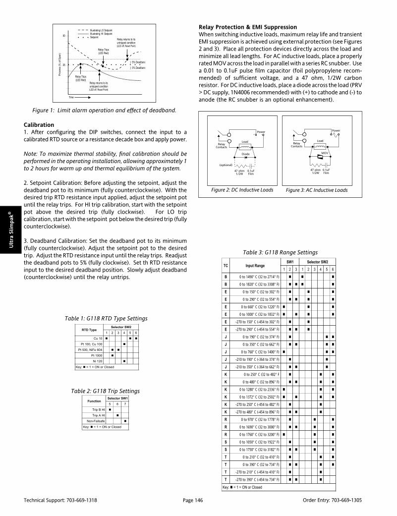
Page 146Technical Support: 703-669-1318 Order Entry: 703-669-1305
Ult
ra S
lim
pak
®
Calibration1. After configuring the DIP switches, connect the input to acalibrated RTD source or a resistance decade box and apply power.
Note: To maximize thermal stability, final calibration should beperformed in the operating installation, allowing approximately 1to 2 hours for warm up and thermal equilibrium of the system.
2. Setpoint Calibration: Before adjusting the setpoint, adjust thedeadband pot to its minimum (fully counterclockwise). With thedesired trip RTD resistance input applied, adjust the setpoint potuntil the relay trips. For HI trip calibration, start with the setpointpot above the desired trip (fully clockwise). For LO tripcalibration, start with the setpoint pot below the desired trip (fullycounterclockwise).
3. Deadband Calibration: Set the deadband pot to its minimum(fully counterclockwise). Adjust the setpoint pot to the desiredtrip. Adjust the RTD resistance input until the relay trips. Readjustthe deadband pots to 5% (fully clockwise). Set th RTD resistanceinput to the desired deadband position. Slowly adjust deadband(counterclockwise) until the relay untrips.
CT egnaRtupnI1WS 2WSrotceleS
1 2 3 1 2 3 4 5 6
B )F°4172ot23(C°0941ot0
B )F°8033ot23(C°0281ot0
E )F°203ot23(C°051ot0
E )F°455ot23(C°092ot0
E )F°0221ot23(C°066ot0
E )F°2381ot23(C°0001ot0
E )F°203ot454-(C°051ot072-
E )F°455ot454-(C°092ot072-
J )F°473ot23(C°091ot0
J )F°266ot23(C°053ot0
J )F°0041ot23(C°067ot0
J )F°473ot463-(C°091ot012-
J )F°266ot463-(C°053ot012-
K F°284ot23(C°052ot0
K )F°698ot23(C°084ot0
K )F°6332ot23(C°0821ot0
K )F°2052ot23(C°2731ot0
K )F°284ot454-(C°052ot072-
K )F°698ot454-(C°084ot072-
R )F°8771ot23(C°079ot0
R )F°0003ot23(C°0961ot0
R )F°0023ot23(C°0671ot0
S )F°2291ot23(C°0501ot0
S )F°2813ot23(C°0571ot0
T )F°014ot23(C°012ot0
T )F°437ot23(C°093ot0
T )F°014ot454-(C°012ot072-
T )F°437ot454-(C°093ot072-
:yeK desolCroNO=1=
noitcnuF1WSrotceleS
5 6 7
IHBpirT
IHApirT
efasliaF-noN
:yeK desolCroNO=1=
Table 1: G118 RTD Type Settings
Table 2: G118 Trip Settings
Table 3: G118 Range Settings
epyTDTR2WSrotceleS
1 2 3 4 5 6
01uC
001uC,001tP
406eFiN,005tP
0001tP
021iN
:yeK desolCroNO=1=
Figure 1: Limit alarm operation and effect of deadband.
Figure 2: DC Inductive Loads Figure 3: AC Inductive Loads
Relay Protection & EMI SuppressionWhen switching inductive loads, maximum relay life and transientEMI suppression is achieved using external protection (see Figures2 and 3). Place all protection devices directly across the load andminimize all lead lengths. For AC inductive loads, place a properlyrated MOV across the load in parallel with a series RC snubber. Usea 0.01 to 0.1uF pulse film capacitor (foil polypropylene recom-mended) of sufficient voltage, and a 47 ohm, 1/2W carbonresistor. For DC inductive loads, place a diode across the load (PRV> DC supply, 1N4006 recommended) with (+) to cathode and (-) toanode (the RC snubber is an optional enhancement).

Page 147Technical Support: 703-669-1318 Order Entry: 703-669-1305
Ultra Slim
pak
®
Figure 4: G118 Input Range/Function Selection (SW1) Factory Default Settings
Figure 5: G118 Factory Cal; 0-250°C (Pt 100),A-HI/B-LO, Non-Failsafe
Off
On
"B" LO Trip
"B" HI Trip
Off
On
"A" LO Trip
"A" HI Trip
Off
On
Failsafe
Non-failsafeInput RangeSee Table 3 Not Used
Figure 6: Terminal Wiring Diagram for G118
Figure 7: Mounting Multiple Modules
Note: All Ultra SlimPak modules are designed to operate in ambient
temperatures from 0 to 55°C when mounted on a horizontal DIN rail. If
five or more modules are mounted on a vertical rail, circulating air or
model HS01 Heat Sink is recommended. Refer to HS01 Technical
Bulletin (#721-0549-00) or contact the factory for assistance.

Page 148Technical Support: 703-669-1318 Order Entry: 703-669-1305
Ult
ra S
lim
pak
®
Ordering InformationModels & AccessoriesSpecify:1. Model: G118-00022. Accessories: (see Accessories)3. Optional Custom Factory Calibration; specify C620 with desired
input and output range.
AccessoriesSlimPak “G” series modules will mount on standard TS32 (model MD02) or TS35(model MD03) DIN rail . In addition, the following accessories are available:
HS01 Heat SinkMD03 TS35 x 7.5 DIN Rail
WV905 24VDC Power Supply (0.5 Amp)H910 24VDC Power Supply (1Amp)H915 24VDC Power Supply (2.3 Amp)MB03 End Bracket for MD03C664 I/O Descriptive Tags
Specifications
Inputs
Sensors:
Pt100, Pt500, Pt1000 (0.00385Ohms/Ohm/°C);
Cu10, Cu100; Ni120, NiFe604
Sensor Connection: 3-wire.
Input Ranges: See table 1.
Excitation Current (Max)
<2mA for Pt100, Pt500, Pt1000, Ni120,Cu100 or NiFe604
<10mA for Cu10
Leadwire Resistance
40% of base sensor resistance or 100 Ohms(whichever is less), maximum per lead.
Leadwire Effect
Less than 1% of selected span over entireleadwire resistance range.
Input Protection
Normal Mode: Withstands ±5VDC.
Common Mode (Input to Gnd): 1800VDC, max.
LED Indicators
Input Range (Green):
>110% input: 8Hz flash;
>-10% input: 4Hz flash
Setpoint (Red):
Tripped: Solid red;
Safe: Off
Limit Differentials (Deadbands)
0.25% to 5% of span
Dimensions
Response Time
Dynamic Deadband:
Relay status will change when propersetpoint/ process condition exists for100msec.
Normal Mode (analog filtering):
<250mSec, (10-90%)
Setpoints
Effectivity:
Setpoints are adjustable over 100% ofthe selected input span
Repeatability (constant temp.):
±0.2% of full scale
Stability
Line Voltage: ±0.01%/%, max.
Temperature: ±0.05% of full scale/°C, max.
Common Mode Rejection
DC to 60Hz: 120dB
>60Hz: 100dB
Isolation
1800VDC between contacts, input & power
EMC Compliance (CE Mark)
Emissions: EN50081-1
Immunity: EN50082-2
Safety: EN50178
Humidity (Non-Condensing)
Operating: 15 to 95% @45°CSoak: 90% for 24 hours @65°C
Temperature Range
Operating: -15 to 55°C (5 to 131°F)
Storage: -25 to 75°C (-13 to 158°F)
Power
Consumption: 1.5W typical, 2.5W max.
Supply Range: 9 to 30VDC, inverter isolated
Relay Contacts
2 SPDT (2 form C) Relays, 1 Relay persetpoint
Current Rating (resistive)
120VAC: 5A; 240VAC: 2A; 28VDC: 5A
Material: Gold flash over silver alloy
Electrical Life:105 operations at rated load
Note: External relay protection is requiredfor use with inductive loads (see Figures 2 & 3).
Mechanical Life: 107 operations
Weight
0.56lbs.
Agency Approvals
CSA certified per standard C22.2, No. 0-M91and 142-M1987 (File No. LR42272)
UL recognized per standard UL508
(File No.E99775)
CE Compliance per EMC directive 89/336/EEC
Note that detailed installation instructions are
available on our web site.

Page 149Technical Support: 703-669-1318 Order Entry: 703-669-1305
Ultra Slim
pak
®
DescriptionThe Ultra Slim Pak G128 is a DIN rail mount, thermocouple inputlimit alarm with input terminal cold junction compensation (cjc),dual setpoints and two contact closure outputs. The fieldconfigurable input and alarm functions offer flexible setpointcapability. There are up to six temperature ranges available foreach thermocouple type to ensure accuracy and maximizesetpoint resolution.
The G128 is configurable as a single or dual setpoint alarm, withHI or LO trips, upscale or downscale thermocouple burnoutdetection and failsafe or non-failsafe operation. Also included areadjustable deadbands (0.25 to 5% of full scale input) for eachsetpoint and a flexible DC power supply which accepts any voltagebetween 9 and 30VDC.
Diagnostic LEDSThe G128 is equipped with three front panel LEDs. The dualfunction green LED is labeled INPUT and indicates line power andinput signal status. Active DC power is indicated by an illuminatedLED. If this LED is off, check DC power and the wiring connection.If the input signal is more than 110% of the full scale range, the LEDwill flash at 8 Hz. Below -10%, it flashes at 4 Hz. Two red LEDsindicate the relay state for each setpoint. An illuminated red LEDindicates the tripped condition.
OutputThe G128 is equipped with two SPDT (form C) relays, rated at120VAC or 28VDC at 5 Amperes. Each of these relays is indepen-dently controlled by the field configurable setpoint and deadband.
OperationThe field configurable G128 limit alarm setpoints can be config-ured for HI or LO, failsafe or non-failsafe operation. Each of thesetpoints has a respective HI or LO deadband. In a trippedcondition, the setpoint is exceeded and the appropriate red LEDwill illuminate. The trip will reset only when the process fallsbelow the HI deadband or rises above the LO deadband (see Figure1). For proper deadband operation, the HI setpoint must alwaysbe set above the LO setpoint. In failsafe operation, the relay isenergized when the process is below the HI setpoint or above theLO setpoint (opposite for non-failsafe). In the failsafe mode, apower failure results in an alarm state output.
ULTRA SLIMPAK®
G128-0001DC Powered T/C Input Limit Alarm
Provides Relay Contact Closuresat a Preset Temperature Input Level
Programmable HI or LO, Failsafe or Non-failsafe Field Configurable Input Ranges LED Trip and Input Indicators
G128-0001
Flexible Power Supply Accepts 9 to 30 VDC ASIC Technology for Enhanced Reliability RoHS Compliant
Dynamic DeadbandCircuitry in the G128 prevents false trips by repeatedly samplingthe input. The input must remain beyond the setpoint for 100milliseconds, uninterrupted, to qualify as a valid trip condition.Likewise, the input must fall outside the deadband and remainthere for 100 milliseconds to return the alarm to an untrippedcondition. This results in a “dynamic deadband” (based on time)in addition to the normal deadband.
ConfigurationUnless otherwise specified, the factory presets the Model G128 asfollows:
Input: J TypeRange: 0 to 350°C
Output: Dual, SPDTTrip: A: HI, B: LO
Failsafe: NoDeadband: A, B: 0.25%
The DC power input accepts any DC source between 9 and 30V;typically a 12V or 24VDC source is used (see Accessories).
For other I/O ranges, refer to Table 1 and reconfigure switchesSW1 and SW2 for the desired input type, range and function.
WARNING: Do not change switch settings with power applied.Severe damage will result!
1. With DC power off, set SW1-1, 2, 3 and SW2-1 through 6 for thedesired input range (Table 1).
2. Set positions 4 and 5 of “SW1” to ON for a HI trip setpoint orOFF for a LO trip setpoint (Figure 4).
3. Set position 6 of “SW1” to ON for non-failsafe operation or OFFfor failsafe operation (e.g., alarm trips upon power failure).
4. Set positions 7 and 8 of "SW1" to upscale or downscale burnout.

Page 150Technical Support: 703-669-1318 Order Entry: 703-669-1305
Ult
ra S
lim
pak
®
Calibration1. After configuring the DIP switches, connect the input to acalibrated TC source and apply power. Refer to the terminal wiring(Figure 5).
Note: To maximize thermal stability, final calibration should beperformed in the operating installation, allowing approximately 1to 2 hours for warm up and thermal equilibrium of the system.
2. Setpoint: set deadband at its minimum (fully counterclockwise)before adjusting the setpoint. With the desired trip thermocouplemillivolt input applied, adjust the setpoint until the relay trips. ForHI trip calibration, start with the setpoint above the desired trip(fully clockwise). For LO trip calibration, start below the desiredtrip (fully counterclockwise).
3. Deadband: Set deadband to its minimum (fully counterclock-wise). Set the setpoint to the desired trip. Adjust the thermo-couple millivolt input until the relay trips. Readjust deadband to5% (fully clockwise). Set the input to the desired deadbandposition. Slowly adjust deadband until the relay untrips
CT egnaRtupnI1WS 2WSrotceleS
1 2 3 1 2 3 4 5 6
B )F°4172ot23(C°0941ot0
B )F°8033ot23(C°0281ot0
E )F°203ot23(C°051ot0
E )F°455ot23(C°092ot0
E )F°0221ot23(C°066ot0
E )F°2381ot23(C°0001ot0
E )F°203ot454-(C°051ot072-
E )F°455ot454-(C°092ot072-
J )F°473ot23(C°091ot0
J )F°266ot23(C°053ot0
J )F°0041ot23(C°067ot0
J )F°473ot463-(C°091ot012-
J )F°266ot463-(C°053ot012-
K F°284ot23(C°052ot0
K )F°698ot23(C°084ot0
K )F°6332ot23(C°0821ot0
K )F°2052ot23(C°2731ot0
K )F°284ot454-(C°052ot072-
K )F°698ot454-(C°084ot072-
R )F°8771ot23(C°079ot0
R )F°0003ot23(C°0961ot0
R )F°0023ot23(C°0671ot0
S )F°2291ot23(C°0501ot0
S )F°2813ot23(C°0571ot0
T )F°014ot23(C°012ot0
T )F°437ot23(C°093ot0
T )F°014ot454-(C°012ot072-
T )F°437ot454-(C°093ot072-
:yeK desolCroNO=1=
Table 1: G128 Input Range Settings
noitcnuF1WSrotceleS
4 5 6 7 8
IHBpirT
IHApirT
efasliaF-noN
pUtuonruB
nwoDtuonruB
:yeK desolCroNO=1=
Table 2: G128 Trip Settings
Figure 1: Limit alarm operation and effect of deadband.
Figure 2: DC Inductive Loads Figure 3: AC Inductive Loads
Relay Protection & EMI SuppressionWhen switching inductive loads, maximum relay life and transientEMI suppression is achieved using external protection (see Figures2 and 3). Place all protection devices directly across the load andminimize all lead lengths. For AC inductive loads, place a properlyrated MOV across the load in parallel with a series RC snubber. Usea 0.01 to 0.1uF pulse film capacitor (foil polypropylene recom-mended) of sufficient voltage, and a 47 ohm, 1/2W carbonresistor. For DC inductive loads, place a diode across the load (PRV> DC supply, 1N4006 recommended) with (+) to cathode and (-) to anode (the RC snubber is an optional enhancement).

Page 151Technical Support: 703-669-1318 Order Entry: 703-669-1305
Ultra Slim
pak
®
Figure 4: Input Range/Function Selection (SW1) Factory Default Settings
Off
On
"B" LO Trip
"B" HI Trip
Off
On
"A" LO Trip
"A" HI Trip
Off
On
Failsafe
Non-failsafeInput RangeSee Table 1
Off
OnUpscaleBurnout
Off
OnDownscaleBurnout
Figure 5: G128 Factory Cal: J-Type, 0 to 350°C,A-HI/B-LO, Non-failsafe
Figure 6: Wiring Diagram for G128
Figure 7: Mounting Multiple Modules
Note: All Ultra SlimPak modules are designed to operate in ambient
temperatures from 0 to 55°C when mounted on a horizontal DIN rail. If
five or more modules are mounted on a vertical rail, circulating air or
model HS01 Heat Sink is recommended. Refer to HS01 Technical
Bulletin (#721-0549-00) or contact the factory for assistance.

Page 152Technical Support: 703-669-1318 Order Entry: 703-669-1305
Ult
ra S
lim
pak
®
Ordering InformationModels & AccessoriesSpecify:1. Model: G128-00012. Accessories: (see Accessories)3. Optional Custom Factory Calibration; specify C620 with desired
input and output range.
AccessoriesSlimPak “G” series modules will mount on standard TS32 (model MD02) or TS35(model MD03) DIN rail. In addition, the following accessories are available:
HS01 Heat SinkMD03 TS35 x 7.5 DIN Rail
WV905 24VDC Power Supply (0.5A)H910 24VDC Power Supply (1A)H915 24VDC Power Supply (2.3A)MB03 End Bracket for MD03C664 I/O Descriptive Tags
Specifications
Inputs
Range: See Table 1
Impedance: >1M Ohm
Input Bias Current (burnout detect): <1.5 uAmp
Overvoltage: ±10V differential
Common Mode (Input to Gnd): 1800VDC, max.
LED Indicators
Input Range (Green)
>110% input: 8Hz flash
<-10% input: 4Hz flash
Setpoint (Red):
Tripped: Solid red
Safe: off
Limit Differentials (Deadbands)
0.25% to 5% of span
Response Time
Dynamic Deadband:
Relay status will change when propersetpoint/process condition exists for 100msec
Normal Mode (analog filtering):
<250msec, (10-90%)
Setpoint
Effectivity:
Setpoints are adjustable over 100% ofthe selected input span
Repeatability (constant temp.):
0.2% for temp > 0°C0.3% for temp < 0°C
Dimensions
Stability
Temperature: ±0.05% of full scale/°C, max.
Common Mode Rejection
DC to 60Hz: 120dB
Isolation
1800VDC between contacts, input & power
EMC Compliance (CE Mark)
Emissions: EN50081-1
Immunity: EN50082-2
Safety: EN50178
Humidity (Non-Condensing)
Operating: 15 to 95% @45°CSoak: 90% for 24 hours @65°C
Temperature Range
Operating: 0 to 55°C (32 to 131°F)
Storage: -15 to 70°C (5 to 158°F)
Power
Consumption: 1.5W typical, 2.5W max.
Supply Range: 9 to 30 VDC, inverter isolated
Relay Contacts
2 SPDT (2 Form C) Relays, 1 Relay persetpoint
Current Rating (resistive)
120VAC: 5A; 240VAC: 2A; 28VDC: 5A
Material: Gold flash over silver alloy
Electrical Life: 105 operations at rated load
Note: External relay contact protectionis required for use with inductive loads(see relay protection Figures 2 & 3).
Mechanical Life: 107 operations
Wire Terminations
Screw terminations for 12-22 AWG
Weight
0.56lbs.
Agency Approvals
CSA certified per standard C22.2, No. 0-M91and 142-M1987 (File No. LR42272)
UL recognized per standard UL508
(File No.E99775)
CE Compliance per EMC directive 89/336/EECand low voltage 73/23/EEC.
RoHS Compliant
Note that detailed installation instructions are
available on our web site.

Page 153Technical Support: 703-669-1318 Order Entry: 703-669-1305
Ultra Slim
pak
®
DescriptionThe Ultra Slim Pak G168 is a DIN rail mount, DC powered, ACvoltage or current input limit alarm with dual setpoints and twocontact closure outputs. The field configurable input and alarmfunctions offer flexible setpoint capability. Input voltage spansfrom 100mV to 250VAC and input current spans from 10mA to100mA AC can be field configured. For current input spans of 1 to5 Amps a 0.1 Ohm (5W) shunt resistor (Model# C006) is available.
The G168 is configurable as a single or dual setpoint alarm, with HI orLO trips and failsafe or non-failsafe operation. Also included areadjustable deadbands (0.25 to 5% of full scale input) for each setpoint.The G168 will accept any DC voltage between 9 and 30VDC.
Diagnostic LEDSThe G168 is equipped with three front panel LEDs. The dualfunction green LED is labeled INPUT and indicates line power andinput signal status. Active DC power is indicated by an illuminatedLED. If this LED is off, check DC power and the wiring connection.If the input signal is more than 110% of the full scale range, the LEDwill flash at 8 Hz. Below 0%, it flashes at 4 Hz. Two red LEDs indicatethe relay state for each setpoint. An illuminated red LED indicatesthe tripped condition.
OutputThe G168 is equipped with two SPDT (form C) relays, rated at120VAC or 28VDC at 5 Amperes. Each of these relays is indepen-dently controlled by the field configurable setpoint and deadband.
OperationThe field configurable G168 limit alarm setpoints can be config-ured for HI or LO, failsafe or non-failsafe operation. Each of thesetpoints have a respective HI or LO deadband. In a trippedcondition, the setpoint is exceeded and the appropriate red LEDwill illuminate. The trip will reset only when the process falls belowthe HI deadband or rises above the LO deadband (see Figure 1).For proper deadband operation, the HI setpoint must always beset above the LO setpoint. In failsafe operation, the relay isenergized when the process is below the HI setpoint or above theLO setpoint (opposite for non-failsafe). In the failsafe mode, apower failure results in an alarm state output.
ULTRA SLIMPAK®
G168-0001DC Powered AC Input Limit Alarm
Provides Relay Contact Closuresat a Preset AC Input Level
Programmable HI or LO, Failsafe or Non-failsafe Field Configurable Input Ranges LED Trip and Input Indicators
G168-0001
Flexible Power Supply Accepts 9 to 30 VDC ASIC Technology for Enhanced Reliability RoHS Compliant
Dynamic DeadbandCircuitry in the G168 prevents false trips by repeatedly samplingthe input. The input must remain beyond the setpoint for 100milliseconds, uninterrupted, to qualify as a valid trip condition.Likewise, the input must fall outside the deadband and remainthere for 100 milliseconds to return the alarm to an untrippedcondition. This results in a “dynamic deadband” (based on time)in addition to the normal deadband.
ConfigurationUnless otherwise specified, the factory presets the Model G168 asfollows:
Input: VoltageRange: 0-500mVAC
Output: Dual, SPDTTrip: A:HI, B:LO
Failsafe: NoDeadband: A, B: 0.25%
The DC power input accepts any DC source between 9 and 30V;typically a 12V or 24VDC source is used (see Accessories).
For other I/O ranges, refer to Table 1 and Figure 4 to reconfigureswitches SW1 and SW2 for the desired input type, range andfunction.
1. With DC power off, position input switch "SW1-9, 10" for voltageor current.
2. Set position 1 through 8 of “SW1” for the desired input range(see Table 1).
3. Set position 1 and 2 of "SW2" to ON for a HI trip setpoint orOFF for a LO trip (see Figure 4).
4. Set position 4 of "SW2" to ON for non-failsafe operation or OFFfor failsafe operation (e.g., alarm trips when power fails).
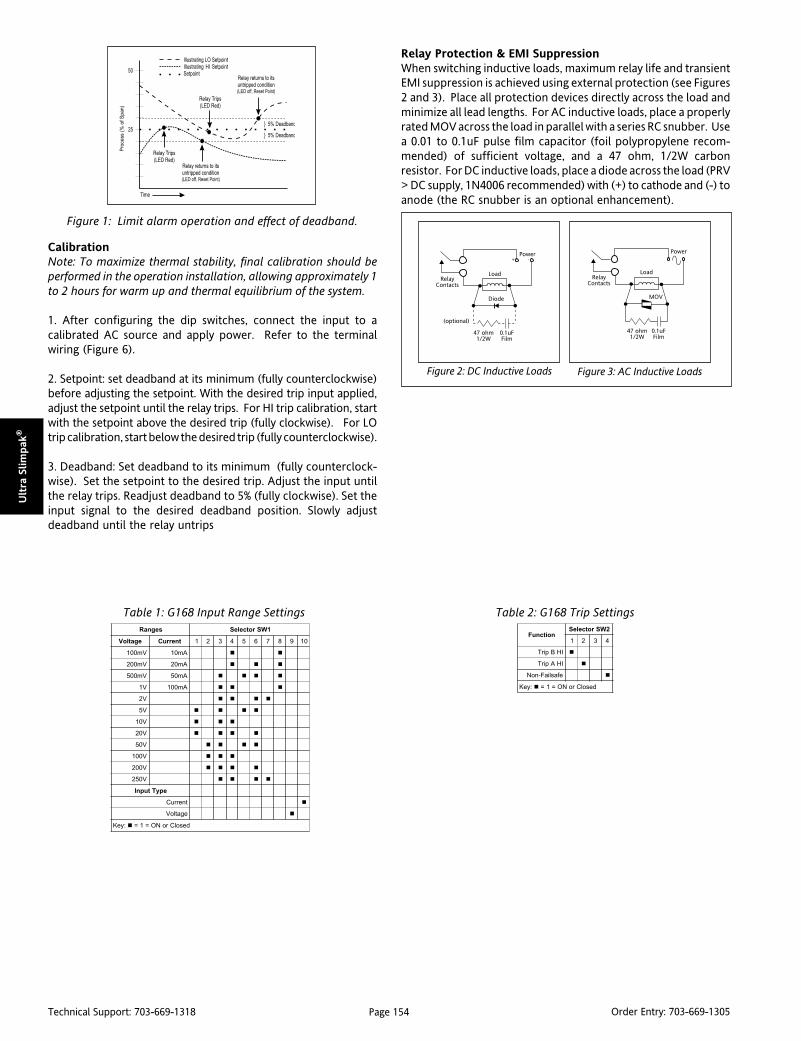
Page 154Technical Support: 703-669-1318 Order Entry: 703-669-1305
Ult
ra S
lim
pak
®
CalibrationNote: To maximize thermal stability, final calibration should beperformed in the operation installation, allowing approximately 1to 2 hours for warm up and thermal equilibrium of the system.
1. After configuring the dip switches, connect the input to acalibrated AC source and apply power. Refer to the terminalwiring (Figure 6).
2. Setpoint: set deadband at its minimum (fully counterclockwise)before adjusting the setpoint. With the desired trip input applied,adjust the setpoint until the relay trips. For HI trip calibration, startwith the setpoint above the desired trip (fully clockwise). For LOtrip calibration, start below the desired trip (fully counterclockwise).
3. Deadband: Set deadband to its minimum (fully counterclock-wise). Set the setpoint to the desired trip. Adjust the input untilthe relay trips. Readjust deadband to 5% (fully clockwise). Set theinput signal to the desired deadband position. Slowly adjustdeadband until the relay untrips
segnaR 1WSrotceleS
egatloV tnerruC 1 2 3 4 5 6 7 8 9 01
Vm001 Am01
Vm002 Am02
Vm005 Am05
V1 Am001
V2
V5
V01
V02
V05
V001
V002
V052
epyTtupnI
tnerruC
egatloV
:yeK desolCroNO=1=
noitcnuF2WSrotceleS
1 2 3 4
IHBpirT
IHApirT
efasliaF-noN
:yeK desolCroNO=1=
Table 1: G168 Input Range Settings Table 2: G168 Trip Settings
Figure 1: Limit alarm operation and effect of deadband.
Figure 2: DC Inductive Loads Figure 3: AC Inductive Loads
Relay Protection & EMI SuppressionWhen switching inductive loads, maximum relay life and transientEMI suppression is achieved using external protection (see Figures2 and 3). Place all protection devices directly across the load andminimize all lead lengths. For AC inductive loads, place a properlyrated MOV across the load in parallel with a series RC snubber. Usea 0.01 to 0.1uF pulse film capacitor (foil polypropylene recom-mended) of sufficient voltage, and a 47 ohm, 1/2W carbonresistor. For DC inductive loads, place a diode across the load (PRV> DC supply, 1N4006 recommended) with (+) to cathode and (-) toanode (the RC snubber is an optional enhancement).

Page 155Technical Support: 703-669-1318 Order Entry: 703-669-1305
Ultra Slim
pak
®
Figure 4: G168 Function Selection Switch-Settings (SW4) Factory Default Settings
Off
On
"B" LO Trip
"B" HI Trip
Off
On
"A" LO Trip
"A" HI Trip
Off
On
Failsafe
Non-failsafeNot Used Not Used Not Used
Figure 7: Mounting Multiple Modules
Note: All Ultra SlimPak modules are designed to operate in ambient
temperatures from 0 to 55°C when mounted on a horizontal DIN rail. If
five or more modules are mounted on a vertical rail, circulating air or
model HS01 Heat Sink is recommended. Refer to HS01 Technical
Bulletin (#721-0549-00) or contact the factory for assistance.
Figure 5: G168 Factory Calibration; 0-500mV,A-HI/B-LO, Non-Failsafe
Figure 6: G168 Wiring Diagram

Page 156Technical Support: 703-669-1318 Order Entry: 703-669-1305
Ult
ra S
lim
pak
®
Ordering InformationModels & AccessoriesSpecify:1. Model: G168-00012. Accessories: (see Accessories)3. Optional Custom Factory Calibration; specify C620 with desired
input and output range.
AccessoriesSlimPak “G” series modules will mount on standard TS32 (model MD02) orTS35 (model MD03) DIN. In addition, the following accessories are available:
HS01 Heat SinkMD03 TS35 x 7.5 DIN Rail
WV905 24VDC Power Supply (0.5Amp)H910 24VDC Power Supply (1Amp)H915 24VDC Power Supply (2.3 Amp)MB03 End Bracket for MD03C664 I/O Descriptive TagsC006 Shunt Resistor (0.1W, 5A max.)
Specifications
Inputs
Voltage Input
Range: 100mV to 250VAC
Impedance: >100K Ohms
Overvoltage: 300VAC, max.
Current Input
Range: 10mA to 100mA AC
Impedance: 20 Ohms, typical
Overcurrent: 200mA AC, max.
Overvoltage: 60V peak (protected byself resetting fuse)
Frequency Range: 40 to 400HzCommon Mode (Input to Gnd):1800VDC, max.
LED Indicators
Input Range (Green)
>110% input: 8Hz flash
Setpoint (Red)
Tripped: Solid red
Safe: Off
Limit Differentials (Deadbands)
>50mV/5mA: 0.25% to 5% of span
<50mV/5mA: 1% to 5% of span
Response Time
Dynamic Deadband:
Relay status will change when propersetpoint/process condition exists for 100msec.
Normal Mode (analog filtering):
<250mSec, (10-90%)
Dimensions
Setpoints
Effectivity:
Setpoints are adjustable over 100% ofthe selected input span
Repeatability (constant temp.):
0.2% of full scale
Stability
Temperature: +0.025% of full scale/°C, max.
Common Mode Rejection
DC to 60Hz: 120dB
Isolation
1800VDC between contacts, input & power
EMC Compliance (CE Mark)
Emmissions: EN50081-1
Immunity: EN50082-1
Safety: EN50178
Humidity (Non-Condensing)
Operating: 15 to 95% @45°CSoak: 90% for 24hours @65°C
Temperature Range
Operating: 0 to 55°C (32 to 131°F)
Storage: -25 to 70°C (-13 to 158°F)
Power
Consumption: 1.5W typical, 2.5W max.
Supply Range: 9 to 30VDC, inverter isolated
Relay Contacts
2 SPDT (2 form C) Relays, 1 Relay persetpoint
Current Rating (resistive):
120VAC: 5A; 240VAC: 2A; 28VDC: 5A
Material: Gold flash over silver alloy
Electrical Life:105 operations at rated load
Note: External relay contact protection isrequired for use with inductive loads
(see Figures 2 & 3).
Mechanical Life: 107 operations
Wire Terminations
Screw terminals for 12-22 AWG
Agency Approvals
CSA certified per standard C22.2, No. 0-M91and 142-M1987 (File No. LR42272)
UL recognized per standard UL508
(File No.E99775)
CE Conformance per EMC directive 89/336/EEC& Low Voltage 73/23/EEC (Input <50VAC, only).
RoHS Compliant
Note that detailed installation instructions are
available on our web site.

Page 157Technical Support: 703-669-1318 Order Entry: 703-669-1305
Ultra Slim
pak
®
DC Powered DC Input FieldConfigurable Isolator
Provides a Fully Isolated DC Outputin Proportion to a DC Input
DescriptionThe Ultra SlimPak G408 is a DIN rail mount, DC input signalconditioner with 1800VDC isolation between input, output andpower. The field configurable input and output offers flexible,wide ranging capability for DC current and voltage signals.
The input can be configured for any one of 12 voltage ranges from10mV to 100V or 6 current ranges from 1mA to 100mA (see Table1). The output is linear to the input and can be set for either 0-5V, 0-10V, 0-1mA, 0-20mA or 4-20mA (for models G408-0001)and -5 to +5V or -10 to +10V (for model G408-1001).
Wide ranging, precision zero and span pots allow 50% adjustabilityof offset and span turn-down within each of the 18 switchselectable ranges. For example, the 0-2mA input range could beturned down to 0-1mA and provide a full scale output signal (e.g.4-20mA), or turned down and offset to achieve a 1-2mA/4-20mAI/O combination.
The G408 also accepts bipolar inputs (e.g. 10V range set to bipolar =-10 to +10V) and offers selectable normal or reverse operation (e.g.4-20mA/20-4mA). The ASIC based I/O channel is optically isolatedto 1800VDC and is transformer isolated from the power supply.
ApplicationThe G408 is useful in eliminating ground loops, converting signallevels, and providing signal drive. The field configurable, wideranging capability ensures maximum flexibility for most DC to DCapplications, minimizing spare part requirements.
Diagnostic LEDThe G408 is equipped with a dual function LED signal monitor. Thegreen, front mounted LED indicates both DC power and inputsignal status. Active DC power is indicated by an illuminated LED.If the input signal is more than 110% of the full scale range, the LEDwill flash at 8Hz. Below -10%, the flash rate is 4Hz.
ULTRA SLIMPAK®
G408-0001 & G408-1001
Eliminates Ground Loops Field Configurable Input Ranges: 10mV to 100V,
1mA to 100mA Field Configurable Output Ranges: 0-5V, 0-10V,
0-1mA, 0-20mA, 4-20mA, ±5v, ±10V
G408-0001 (standard outputs)
G408-1001 (bipolar outputs)
Ultra Slim Housing for High Density Installations Flexible Power Supply Accepts 9 to 30 VDC ASIC Technology RoHS Compliant
ConfigurationThe G408 has 18 input range settings. Trim potentiometers allow50% input zero and span adjustability within each of the 18 fullscale input ranges.
Unless otherwise specified, the factory presets the Model G408-0001 and G408-1001 as follows:
G408-0001Input Range: 4-20mA
Output Range: 4-20mA
G408-1001Input Range: 4-20mA
Output Range: -10 to +10V
The DC power input accepts any source between 9 and 30V;typically a 12V or 24VDC source is used (see Accessories).
To minumize interference from electrical and magnetic fields, theuse of shielded, twisted pair wires on the input and output isrecommended.
WARNING! Do not change switch settings with power applied.Severe damage will result!
Refer to Tables 1 through 4 for the proper switch settings. Use theswitches on SW1 to select the input type (voltage or current) andalso to select the desired input range and function setting. UseSW2 to select the desired output type.

Page 158Technical Support: 703-669-1318 Order Entry: 703-669-1305
Ult
ra S
lim
pak
®
Calibration1. After configuring the DIP switches, connect the input to a calibratedDC source. Connect the output to the actual device load (or a loadapproximately equivalent to the device load) and apply power.
Note: To maximize thermal stability, final calibration should beperformed in the operating installation, allowing approximately 1to 2 hours for warm up and thermal equilibrium of the system.
2. Set the calibrator to the desired minimum input and adjust thezero potentiometer for the desired minimum output.
3. Set the calibrator to the desired maximum input and adjust thespan potentiometer for the desired maximum output.
4. Repeat steps 2 and 3, as necessary, for best accuracy.
Figure 1: G408 Block Diagram
1000-804GsegnaR segnaR segnaR segnaR segnaR
2WSrotceleS
1 2 3 4 5 6 7 8
V5ot0
V01ot0
Am1ot0
m02ot4
Am02ot0
:yeK desolCroNO=1=
1001-804GsegnaR segnaR segnaR segnaR segnaR
1WSrotceleS
9 01
V5+otV5-
V01+otV01-
:yeK desolCroNO=1=
segnaR 1WSrotceleS
egatloV tnerruC 1 2 3 4
Vm02 Am2
Vm05 Am5
Vm001 Am01
Vm002 Am02
Vm005 Am05
V1 Am001
V2
V5
V01
V52
V05
V001
:yeK desolCroNO=1=
noitcnuF1WSrotceleS
5 6 7 8
tupnIralopinU
tuptuOesreveR
tupnItnerruC
tupnIegatloV
:yeK desolCroNO=1=
Table 1: G408 Input Range Settings
Table 2: G408 Function Settings
Table 3: G408-0001 Output Settings
Table 4: G408-1001 Output Settings
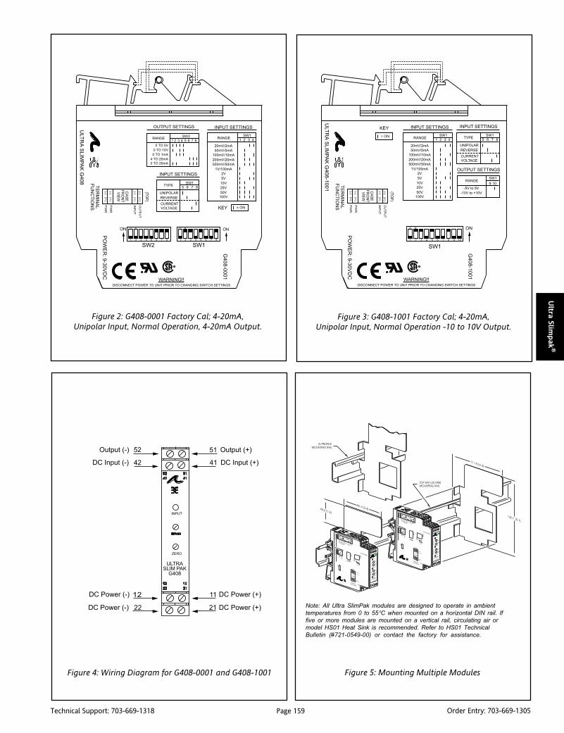
Page 159Technical Support: 703-669-1318 Order Entry: 703-669-1305
Ultra Slim
pak
®
Figure 2: G408-0001 Factory Cal; 4-20mA,Unipolar Input, Normal Operation, 4-20mA Output.
Figure 3: G408-1001 Factory Cal; 4-20mA,Unipolar Input, Normal Operation -10 to 10V Output.
Note: All Ultra SlimPak modules are designed to operate in ambient
temperatures from 0 to 55°C when mounted on a horizontal DIN rail. If
five or more modules are mounted on a vertical rail, circulating air or
model HS01 Heat Sink is recommended. Refer to HS01 Technical
Bulletin (#721-0549-00) or contact the factory for assistance.
Figure 5: Mounting Multiple ModulesFigure 4: Wiring Diagram for G408-0001 and G408-1001

Page 160Technical Support: 703-669-1318 Order Entry: 703-669-1305
Ult
ra S
lim
pak
®
Ordering InformationModels & AccessoriesSpecify:1. Model: G408-0001 (standard outputs) or
G408-1001 (bipolar outputs)2. Accessories: (see Accessories)3. Optional Custom Factory Calibration; specify C620 with desired
input and output range.
AccessoriesSlimPak "G" series modules will mount on standard TS32 (model MD02)or TS35 (model MD03) DIN rail and include model HS01 heat sink. Inaddition, the following accessories are available:
MD03 TS35x7.5 DIN railWV905 24VDCPower Supply (0.5 Amp)
H910 24VDC Power Supply (1 Amp)H915 24VDC Power Supply (2.3 Amp)MB03 End Bracket for MD03C664 I/O Descriptive TagsC006 0.1 Ohm, 5W, 1% shunt resistor
Specifications
Input:
Voltage:
Range Limits: 10mV to 100V
Impedance: >100K Ohms
Overvoltage:
400 Vrms, max.(Intermittent);
264 Vrms,max. (Continous)
Current:
Range Limits: 1mA to 100mA
Impedance: 20 Ohms, typical
Overcurrent: 170mA RMS, max.
Overvoltage: 60VDC
Zero Turn-Up: 50% of full scale input
Span Turn-Down: 50% of full scale input
Common Mode (Input to Gnd): 1800 VDC, max.
Output (G408-0001):
Voltage:
Output: 0-5V, 0-10V
Source Impedance: <10 Ohms
Drive: 10mA, max.
Current:
Output: 0-1mA,4-20mA,0-20mA
Source Impedance: >100K Ohms
Compliance:
0-1mA: 7.5V, max (7.5K Ohms)
4-20mA: 12V, max (600 Ohms)
0-20mA: 12V, max (600 Ohms)
Output (G408-1001):
Voltage:
Output: -5V to +5V, -10 to +10V
Source Impedance: <10 Ohms
Drive: 10mA, max.
LED Indication (green):
Input Range
>110%(approx) input:8Hz flash
< -10%(approx) input: 4Hz flash
Accuracy (Including Linearity, Hysteresis):<2mA/<20mV:± 0.35% of full scale,
typical; 0.5%,max.
>2mA/>20mV:± 0.1% of full scale,typical; 0.2%, max.
Response Time (10-90%):
200mSec., typical
Stability (Temperature):
±0.025% of full scale/°C,typical; ±0.05%/°C, max.
Common Mode Rejection:
DC to 60Hz: 100dB
Isolation (Input to Output):
1800VDC between input, output & power
EMC Compliance (CE Mark):
Emissions: EN50081-1
Immunity: EN50082-2
Safety: EN50178
Mean Time Between Failures:
60K Hours
Dimensions
Humidity (Non-Condensing):
Operating: 15 to 95% @ 45°CSoak: 90% for 24 hours @ 65°C
Temperature Range:
Operating: 0 to 55°C (32 to 131°F)
Storage: -25 to 70°C (-13 to 158°F)
Wire Terminals:
Screw terminals for 12-22AWG
Power:
Consumption: 1.5W typical, 2.5W max.
Range: 9 to 30VDC
Weight:
0.5 lbs.
Agency Approvals:
CSA certified per standard C22.2, No. 0-M91and 142-M1987 (File No. LR42272).
UL recognized per standard UL508
(File No.E99775).
CE Conformance per EMC directive 89/336/EECand Low Voltage 73/23/EEC
(Input < 75VDC, only).
RoHS Compliant
Note that detailed installation instructions are
available on our web site.

Page 161Technical Support: 703-669-1318 Order Entry: 703-669-1305
Ultra Slim
pak
®
DescriptionThe Ultra SlimPak G418 is a DIN rail mount, RTD input signalconditioner with 1800VDC isolation between input, output andpower. The field configurable input and output offers flexible,wide ranging capability for Platinum and Copper RTDs.
The G418 can be configured for any one of up to 16 temperatureranges (see Tables 1 & 2). The output is linear to the RTDtemperature input and can be set for either 0-5V, 0-10V, 0-1mA,0-20mA or 4-20mA.
Wide ranging, precision zero and span pots allow 50% adjustablity ofoffset and span turn-down within each of the switch selectable ranges.For example, the 0-500°F range could be offset and turned down toprovide a 4-20mA signal representing 0-250°F (or 250-500°F).
ApplicationThree way isolation in the G418 completely eliminates groundloops from any source. Isolation protects expensive SCADAsystems from ground faults and significantly reduces the effect ofhigh common mode voltages which are prevalent in many RTDapplications.
The constant current RTD excitation circuitry uses the third leadof the RTD to sense and compensate for the RTD lead resistance,resulting in an accurate RTD temperature measurement.
High density DIN rail mounting offers an extremely compactsolution for saving valuable panel space.
Diagnostic LEDThe G418 is equipped with a dual function LED signal monitor. Thegreen, front mounted LED indicates both DC power and inputsignal status. Active DC power is indicated by an illuminated LED.If the input signal is more than 110% of the full scale range, the LEDwill flash at 1Hz. Below -10%, the flash rate is 0.5Hz. If the LEDflashes very fast, then the RTD input wires are open circuit. An 8Hzflash indicates that RTD (+) input (terminal 41) is open circuit, ora 4Hz flash indicates that either RTD (-) or RTD Return (terminal42 or 43) are open. The CAL LED is on under normal operatingconditions. If the CAL LED is off when the unit is powered, consultthe factory for assistance.
ULTRA SLIMPAK®
G418-0001RTD Input Field Configurable Isolator
Provides an Isolated, Linearized DC Outputin Proportion to an RTD Input
Field Configurable Input Ranges for Platinum andCopper RTDs
Eliminates Ground Loops Field Configurable Output Ranges: 0-5V, 0-10V, 0-
1mA, 0-20mA and 4-20mA
G418-0001
Ultra Slim Housing for High Density Installations Flexible Power Supply Accepts 9 to 30 VDC ASIC Technology for Enhanced Reliability RoHS Compliant
ConfigurationThe G418 has 16 input temperature range settings, six RTD typesettings and five output range settings. Trim potentiometers allow50% input zero and span adjustability within each of the 16 fullscale input ranges.
Unless otherwise specified, the factory presets the Model G418 asfollows:
Input: Pt100 OhmRange: -200 to 600°C
Output: 4-20mA
The DC power input accepts any DC source between 9 and 30V;typically a 12V or 24VDC source is used (see Accessories).
Calibration1. After configuring the dip switches, connect the input to acalibrated RTD source or decade resistance box. Connect theoutput to the device load (or a load approximately equivalent tothe device load) and apply power.
Note: To maximize thermal stability, final calibration should beperformed in the operating installation, allowing approximately 1to 2 hours for warm-up and thermal equalibrium of the system.
2. Set the calibrator to the desired minimum temperature andadjust the zero potentiometer for the desired minimum output.
3. Set the calibrator to the desired maximum temperature andadjust the span potentiometer for the desired maximum output.
4. Repeat steps 2 and 3, as necessary for best accuracy.

Page 162Technical Support: 703-669-1318 Order Entry: 703-669-1305
Ult
ra S
lim
pak
®
egnaR2WS
1 2 3 4 5
1
2
3
4
5
6
7
8
9
01
11
21
31
41
51
61
:yeK desolCroNO=1=
001uC&52uC,01uCegnaR
suisleC tiehnerhaF
C°062ot002- F°005ot823- 4
C°0ot002- F°23ot823- 5
C°001-ot002- F°841-ot823- 6
C°062ot001- F°005ot841- 7
C°001ot001- F°212ot841- 8
C°05ot05- F°221ot85- 9
C°05ot81- F°221ot0 01
C°001ot81- F°212ot0 11
C°062ot81- F°005ot0 21
noitaticxEepyT epyT epyT epyT epyT
3WS
1 2 3 4 5 6 7 8
001uC,001tP
005tP
0001tP
01uC
52uC
:yeK desolCroNO=1=
tuptuO1WS
1 2 3 4 5 6 7 8
V5ot0
V01ot0
Am1ot0
Am02ot4
Am02ot0
:yeK desolCroNO=1=
0001tP&005tP,001tPegnaR
suisleC tiehnerhaF
C°006ot002- F°2111ot823- 1
C°004ot002- F°257ot823- 2
C°004ot001- F°257ot841- 3
C°062ot002- F°005ot823- 4
C°0ot002- F°23ot823- 5
C°001-ot002- F°841-ot823- 6
C°062ot001- F°005ot841- 7
C°001ot001- F°212ot841- 8
C°05ot05- F°221ot85- 9
C°05ot81- F°221ot0 01
C°001ot81- F°212ot0 11
C°062ot81- F°005ot0 21
C°003ot81- F°275ot0 31
C°004ot81- F°257ot0 41
C°005ot81- F°239ot0 51
C°006ot81- F°2111ot0 61
DTRepyT epyT epyT epyT epyT
2WS
6 7 8
001tP
005tP
0001tP
01uC
52uC
001uC
:yeK desolCroNO=1=
Table 1: G418 Platinum RTD Ranges
Table 2: G418 Copper RTD Ranges
Table 3: RTD Range Settings
Table 4: G418 RTD Input Type
Table 5: G418 Excitation Type
Table 6: G418 Output Settings
(SW2-1 is undefined)
(SW3-8 is undefined)

Page 163Technical Support: 703-669-1318 Order Entry: 703-669-1305
Ultra Slim
pak
®
Figure 1: G418 Factory Cal: -200 to 600°C(Pt 100) Input; 4-20mA Output
Note: All Ultra SlimPak modules are designed to operate in ambient
temperatures from 0 to 55°C when mounted on a horizontal DIN rail. If
five or more modules are mounted on a vertical rail, circulating air or
model HS01 Heat Sink is recommended. Refer to HS01 Technical
Bulletin (#721-0549-00) or contact the factory for assistance.
Figure 4: Mounting Multiple Modules
Figure 2: Wiring Diagram for G418-0001
Figure 3: RTD Reference Designations
RTD Input (-)
RTD Input (+)
RTD Return

Page 164Technical Support: 703-669-1318 Order Entry: 703-669-1305
Ult
ra S
lim
pak
®
Ordering InformationModels & AccessoriesSpecify:1. Model: G418-00012. Accessories: (see Accessories)3. Optional Custom Factory Calibration; specify C620 with desired
input and output range.
AccessoriesSlimPak "G" series modules will mount on standard TS32 (model MD02) or TS35(model MD03) DIN rail. In addition, the following accessories are available:
HS01 Heat SinkMD03 TS35 x 7.5 DIN rail
WV905 24VDC Power Supply (0.5A)H910 24VDC Power Supply (1A)H915 24VDC Power Supply (2.3A)MB03 End Bracket for MD03C664 I/O Descriptive Tags
Specifications
Input:
Sensor Types:
Pt100, Pt500, Pt1000
(alpha: 0.00385Ohms/Ohm/°C or
0.00392Ohms/Ohm/°C); Cu10, Cu25, Cu100.
Sensor Connection:
3-wire
Input Ranges: see table 1.
Common Mode (Input to Gnd): 1800VDC, max.
Zero Turn-Up:
50% of full scale range
Span Turn-Down:
50% of full scale range
Excitation Current:
<2mA for Pt100, Pt500, Pt1000;<5mA for Cu100;<10mA for Cu10, Cu25.
Leadwire Resistance:
40% of base sensor resistance or 100 Ohms(whichever is less), max per lead.
Leadwire Effect:
Less than 1% of the max. inputtemperature span
Output:
Voltage:
Output: 0-5V, 0-10V
Source Impedance: <10 Ohms
Drive: 10mA, max. (1K Ohms, min @10V)
Current:
Output: 0-1mA, 0-20mA, 4-20mA
Source Impedance: >100K Ohms
Compliance:
0-1mA; 7.5V, max.(7.5K Ohms)
0-20mA; 12V, max.(600 Ohms)
4-20mA; 12V, max.(600 Ohms)
LED Diagnostics:
Solid Green:
power on
Flashing Green:
0.5Hz input under range (<-10%)
1.0Hz input over range (110%)
4Hz input open circuit (terminal 41)
8Hz input open circuit (terminal 42 or 43)
Yellow ON = CAL OK
Accuracy (Including Linearity, Hysteresis):±0.1% typical, ±0.2% max. of the
maximum input temperature rangeconfigurable for the RTD type; @ 25°Cambient and 0 Ohms lead resistance.
Stability:
±0.015% of the max. input temperaturerange for the RTD type per °C changein ambient temperature, max.
Response Time (10 to 90%):
200mSec., typical.
Common Mode Rejection:
DC to 60Hz: 120dB
Isolation:
1800VDC between input, output & power.
Dimensions
ESD Susceptibility:
Meets IEC801-2, Level 2 (4kV)
Humidity (Non-Condensing):
Operating: 15 to 95% @ 45°CSoak: 90% for 24 hours @ 65°C
Temperature Range:
Operating: 0 to 55°C (32 to 131°F)Storage: -25 to 70°C (-13 to 158°F)
Wire Terminations:
Screw terminals for 12-22 AWG
Power:
Consumption: 1.5W typical, 2.5 W Max.
Range: 9-30VDC
Weight:
0.54 lbs
Agency Approvals:
CSA certified per standard C22.2, No. 0-M91and 142-M1987 (File No. LR42272)
UL recognized per standard UL508
(File No.E99775)
CE Conformance per EMC directive 89/336/EECand low voltage 73/23/EEC.
RoHS Compliant
Note that detailed installation instructions are
available on our web site.

Page 165Technical Support: 703-669-1318 Order Entry: 703-669-1305
Ultra Slim
pak
®
DescriptionThe G428 is a DIN rail mount, thermocouple input signal condi-tioner with 1800VDC isolation between input, output and power.The field configurable input and output offer flexible, wideranging capability for J, K, T, R, S, E and B type thermocouples.
The G428 input can be configured for over 60 thermocoupletemperature ranges (see Table 6). The output is linear to temperatureand can be set for either 0-5V, 0-10V, 0-1mA, 0-20mA or 4-20mA.
Wide ranging, precision zero and span pots allow 50% adjustablityof offset and span turn-down within each of the ranges. Forexample, the 0-1000°C range could be offset and turned down toprovide a 4-20mA signal representing 500-1000°C. Similarly,adjustment can be referenced to the output range. The exampleabove could be used to provide a 12-20mA signal from a 750 to1000°C temperature input.
ApplicationThree way isolation in the G428 completely eliminates groundloops from any source. Isolation protects expensive SCADAsystems from ground faults and allows the noise reductionbenefits of grounded thermocouples to be realized.
The G428 is equipped with cold junction compensation (CJC)circuitry to provide ice-point reference. Upscale or downscalethermocouple burnout detection is switch selectable.
High density DIN rail mounting offers an extremely compactsolution to save valuable panel space.
Diagnostic LEDsThe G428 is equipped with front panel LEDs for INPUT (green),TROUBLE (yellow) and CAL OK (yellow). At start-up, both theINPUT and the CAL OK LEDs flash alternately for 10 seconds.
INPUTThis green LED is lit continuously when the input is within thespecified range. In the full temperature range setting, for theoverrange condition the LED flashes at 8Hz; for the under rangecondition it flashes at 4Hz. In a sub-range temperature setting, forthe overrange condition the LED flashes at 1Hz; for the underrange condition it flashes at 0.5Hz.
ULTRA SLIMPAK®
G428-0001T/C Input Field Configurable Isolator
Provides an Isolated, Linearized DC Outputin Proportion to a Thermocouple Input
Field Configurable Input Rangesfor J, K, T, R, S, E, and B Type Thermocouples
Eliminates Ground Loops Field Configurable Output Ranges: 0-5V, 0-10V, 0-
1mA, 0-20mA and 4-20mA
G428-0001
Ultra Slim Housing for High Density Installations Flexible Power Supply Accepts 9 to 30 VDC ASIC Technology for Enhanced Reliability RoHS Compliant
CAL OKThis yellow LED is continuously on when the device is calibrated.
TROUBLEThis yellow LED is off during the normal operation. Consult factoryif this LED is on, indicating a microprocessor malfunction.
ConfigurationThe G428 offers 50% input zero and span adjustablity within eachof the fullscale input ranges. Unless otherwise specified, thefactory presets the Model G428 as follows:
Input: J-typeRange: 0 to 500°C
Output: 4 to 20mABurn Out: Upscale
The DC power input accepts any DC source between 9 and 30V;typically a 12V or 24VDC source is used (see Accessories).
For other I/O ranges, refer to Tables 1 through 6 and reconfigureswitches SW1 and SW2 for the desired input type range andoutput.
WARNING: Do not change switch settings with power applied.Severe damage will result!
1. Choose the desired temperature range from Table 6, then useTable 1 and 2 to configure the switches (as described in thefollowing steps) for thermocouple type and range.
2. With DC power off, position input switches 1 and 2 of SW2 forthe desired burnout detection mode.
3. Set positions 4 through 10 of SW2 for the desired thermocouplerange and type.
4. Set positions 1 through 8 of SW1 for the desired output signal.(Table 4)

Page 166Technical Support: 703-669-1318 Order Entry: 703-669-1305
Ult
ra S
lim
pak
®
Calibration1. After configuring the dip switches, connect the input to acalibrated thermocouple source. Connect the output to thedevice (or a load approximately equivalent to the device) andapply power.
Note: To maximize thermal stability, final calibration should beperformed in the operation installation, allowing approximately 1to 2 hours for warm up and thermal equilibrium of the system.
2. Set the calibrator to the desired minimum input and adjust thezero potentiometer for the desired minimum output.
3. Set the calibrator to the desired maximum input and adjust thespan potentiometer for the desired maximum output.
4. Repeat steps 2 and 3, if necessary for best accuracy.
epyT2WS
8 9 01
B
E
J
K
R
S
T
:yeK desolCroNO=1=
tuonruB2WS
1 2
dewollAtoN
elacspU
elacsnwoD
enoN
:yeK desolCroNO=1=
egnaR2WS
4 5 6 7
1
2
3
4
5
6
7
8
9
01
11
21
31
41
51
61
:yeK desolCroNO=1=
tuptuO1WS
1 2 3 4 5 6 7 8
V5ot0
V01ot0
Am1ot0
Am02ot4
Am02ot0
:yeK desolCroNO=1=
epyTCT egnaR egnaRerutarepmeT
B
6 )F°8033ot239(C°0281ot005
7 )F°8033ot2381(C°0281ot0001
8 )F°2381ot239(C°0001ot005
11 )F°8033ot239(C°0281ot005
21 )F°2381ot2831(C°0001ot057
E
2 )F°2381ot0(C°0001ot81-
3 )F°239ot0(C°005ot81-
4 )F°284ot0(C°052ot81-
5 )F°752ot0(C°521ot81-
8 )F°2381ot239(C°0001ot005
9 )F°239ot284(C°005ot052
01 )F°284ot752(C°052ot521
21 )F°2381ot2831(C°0001ot057
31 )F°239ot707(C°005ot573
41 )F°2831ot832-(C°057ot051-
51 )F°284ot832-(C°052ot051-
61 )F°23ot832-(C°0ot051-
J
2 )F°2831ot0(C°057ot81-
3 )F°239ot0(C°005ot81-
4 )F°284ot0(C°052ot81-
5 )F°752ot0(C°521ot81-
8 )F°2831ot239(C°057ot005
9 )F°239ot284(C°005ot052
01 )F°284ot752(C°052ot521
31 )F°239ot707(C°005ot573
41 )F°2831ot823-(C°057ot002-
51 )F°284ot823-(C°052ot002-
61 )F°23ot823-(C°0ot002-
epyTCT egnaR egnaRerutarepmeT
K
1 )F°8942ot0(C°0731ot81-
2 )F°2381ot0(C°0001ot81-
3 )F°239ot0(C°005ot81-
4 )F°284ot0(C°052ot81-
5 )F°752ot0(C°521ot81-
7 )F°8942ot2381(C°0731ot0001
8 )F°2381ot239(C°0001ot005
9 )F°239ot284(C°005ot052
01 )F°284ot752(C°052ot521
21 )F°2381ot2831(C°0001ot057
31 )F°239ot707(C°005ot573
41 )F°2831ot823-(C°057ot002-
51 )F°284ot823-(C°052ot002-
61 )F°23ot823-(C°0ot002-
S,R
1 )F°0023ot221(C°0671ot05
2 )F°2381ot221(C°0001ot05
3 )F°239ot221(C°005ot05
4 )F°284ot221(C°052ot05
7 )F°0023ot2381(C°0671ot0001
8 )F°2381ot239(C°0001ot005
9 )F°239ot284(C°005ot052
01 )F°284ot752(C°052ot521
21 )F°2381ot2831(C°0001ot057
31 )F°239ot707(C°005ot573
T
3 )F°257ot0(C°004ot81-
4 )F°284ot0(C°052ot81-
5 )F°752ot0(C°521ot81-
9 )F°257ot284(C°04ot052
01 )F°284ot752(C°052ot521
31 )F°257ot707(C°004ot573
41 )F°257ot832-(C°004ot051-
51 )F°284ot832-(C°052ot051-
61 )F°23ot832-(C°0ot051-
Table 1:G428 T/C Types
Table 2:G428 Range Settings
Table 3:G428 Burnout Settings
Table 4:G428 Output Settings
Table 6: G428 Thermocouple Range Settings
epyTCT egnaRerutarepmeT ycaruccA
JC°057ot002-
)F°2831ot823-(C°0.2-/+)F°6.3-/+(
KC°041ot002-
)F°022-ot823-(C°0.5-/+)F°0.9-/+(
KC°0521ot041-)F°2822ot022-(
C°0.2-/+)F°6.3-/+(
KC°0731ot0521)F°8942ot2822(
C°0.4-/+)F°2.7-/+(
EC°0001ot051-)F°2381ot832-(
C°5.2-/+)F°5.4-/+(
TC°004ot051-)F°257ot832-(
C°0.3-/+)F°4.5-/+(
RC°0671ot05
)F°0023ot221(C°0.6-/+
)F°8.01-/+(
SC°0671ot05
)F°0023ot221(C°0.6-/+
)F°8.01-/+(
BC°0281ot005)F°8033ot239(
C°0.5-/+)F°0.9-/+(
Table 5:G428 Thermocouple Accuracy
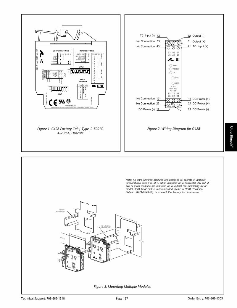
Page 167Technical Support: 703-669-1318 Order Entry: 703-669-1305
Ultra Slim
pak
®
Figure 1: G428 Factory Cal: J-Type, 0-500°C,4-20mA, Upscale
Figure 2: Wiring Diagram for G428
Note: All Ultra SlimPak modules are designed to operate in ambient
temperatures from 0 to 55°C when mounted on a horizontal DIN rail. If
five or more modules are mounted on a vertical rail, circulating air or
model HS01 Heat Sink is recommended. Refer to HS01 Technical
Bulletin (#721-0549-00) or contact the factory for assistance.
Figure 3: Mounting Multiple Modules
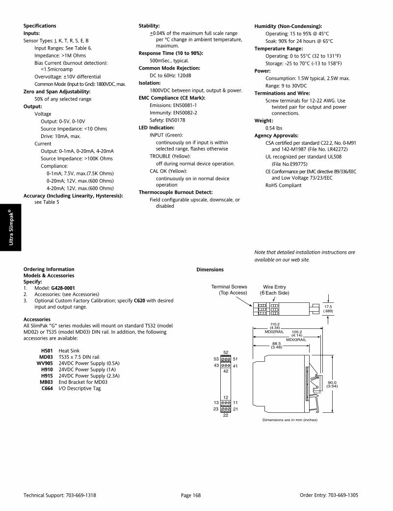
Page 168Technical Support: 703-669-1318 Order Entry: 703-669-1305
Ult
ra S
lim
pak
®
Ordering InformationModels & AccessoriesSpecify:1. Model: G428-00012. Accessories: (see Accessories)3. Optional Custom Factory Calibration; specify C620 with desired
input and output range.
AccessoriesAll SlimPak "G" series modules will mount on standard TS32 (modelMD02) or TS35 (model MD03) DIN rail. In addition, the followingaccessories are available:
HS01 Heat SinkMD03 TS35 x 7.5 DIN rail
WV905 24VDC Power Supply (0.5A)H910 24VDC Power Supply (1A)H915 24VDC Power Supply (2.3A)MB03 End Bracket for MD03C664 I/O Descriptive Tag
Specifications
Inputs:
Sensor Types: J, K, T, R, S, E, B
Input Ranges: See Table 6.
Impedance: >1M Ohms
Bias Current (burnout detection):<1.5microamp
Overvoltage: ±10V differential
Common Mode (Input to Gnd): 1800VDC, max.
Zero and Span Adjustability:
50% of any selected range
Output:
Voltage
Output: 0-5V, 0-10V
Source Impedance: <10 Ohms
Drive: 10mA, max.
Current
Output: 0-1mA, 0-20mA, 4-20mA
Source Impedance: >100K Ohms
Compliance:
0-1mA; 7.5V, max.(7.5K Ohms)
0-20mA; 12V, max.(600 Ohms)
4-20mA; 12V, max.(600 Ohms)
Accuracy (Including Linearity, Hysteresis):see Table 5
Dimensions
Stability:
+0.04% of the maximum full scale rangeper ºC change in ambient temperature,maximum.
Response Time (10 to 90%):
500mSec., typical.
Common Mode Rejection:
DC to 60Hz: 120dB
Isolation:
1800VDC between input, output & power.
EMC Compliance (CE Mark):
Emissions: EN50081-1
Immunity: EN50082-2
Safety: EN50178
LED Indication:
INPUT (Green):
continuously on if input is withinselected range, flashes otherwise
TROUBLE (Yellow):
off during normal device operation.
CAL OK (Yellow):
continuously on in normal deviceoperation
Thermocouple Burnout Detect:
Field configurable upscale, downscale, ordisabled
Humidity (Non-Condensing):
Operating: 15 to 95% @ 45°CSoak: 90% for 24 hours @ 65°C
Temperature Range:
Operating: 0 to 55°C (32 to 131°F)
Storage: -25 to 70°C (-13 to 158°F)
Power:
Consumption: 1.5W typical, 2.5W max.
Range: 9 to 30VDC
Terminations and Wire:
Screw terminals for 12-22 AWG. Usetwisted pair for output and powerconnections.
Weight:
0.54 lbs
Agency Approvals:
CSA certified per standard C22.2, No. 0-M91and 142-M1987 (File No. LR42272)
UL recognized per standard UL508
(File No.E99775)
CE Conformance per EMC directive 89/336/EECand Low Voltage 73/23/EEC
RoHS Compliant
Note that detailed installation instructions are
available on our web site.

Page 169Technical Support: 703-669-1318 Order Entry: 703-669-1305
Ultra Slim
pak
®
DescriptionThe G438 is a DIN rail mount, potentiometer input signal condi-tioner with 1800VDC isolation between input, output and power.The input provides a constant voltage and is designed to acceptany three-wire potentiometer from 100 Ohms to 100K Ohms. Thefield configurable output is switch selectable providing either a 0-5V, 0-10V, 0-1mA, 0-20mA or 4-20mA DC signal.
Wide ranging precision zero and span pots used in conjunctionwith DIP switches allow 80% adjustablity of offset and gain totransmit a fullscale output from any 20% portion of the potenti-ometer input.
ApplicationThe G438 is useful in transmitting process control setpoints toremote PID controllers or interfacing position sensors to dataacquisition and control systems. The high density DIN railmounting offers an extremely compact solution for saving valu-able panel space.
In a valve positioning application a potentiometer is sometimesused as a feedback signal. Quite often a wide open valve is only a25% turn of the feedback potentiometer. In a case such as this, theG438 can easily be adjusted with the zero and span to provide afullscale output signal (e.g. 4-20mA) representing 0-25% or even50-75% of the potentiometer input.
ULTRA SLIMPAK®
G438-0001Potentiometer Input Field
Configurable Isolator
Provides an Isolated, Linearized DC Outputin Proportion to a Potentiometer Input
Potentiometers from 100 Ohms to 100K Ohms Wide Ranging Zero & Span Adjustability Field Configurable Output Ranges: 0-5V, 0-10V,
0-1mA, 0-20mA and 4-20mA
G438-0001
Ultra Slim Housing for High Density Installations Flexible Power Supply Accepts 9 to 30 VDC ASIC Technology for Enhanced Reliability RoHS Compliant
ConfigurationUnless otherwise specified, the factory presets the Model G438 asfollows:
Input Range: 0 to 100%Output: 4 to 20mA.
The DC power input accepts any DC source between 9 and 30V;typically a 12V or 24VDC source is used (see Accessories). Forother output ranges, refer to Tables 1 and 2 to reconfigureswitches SW1 and SW2 for the desired input and output ranges.
WARNING: Do not change switch settings with power applied.Severe damage will result!
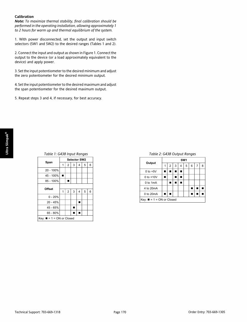
Page 170Technical Support: 703-669-1318 Order Entry: 703-669-1305
Ult
ra S
lim
pak
®
napS2WSrotceleS
1 2 3 4 5 6
%001-02
%001-54
%001-58
tesffO1 2 3 4 5 6
%02-0
%54-02
%56-54
%08-56
:yeK desolCroNO=1=
tuptuO1WS
1 2 3 4 5 6 7 8
V5+ot0
V01+ot0
Am1ot0
Am02ot4
Am02ot0
:yeK desolCroNO=1=
Table 1: G438 Input Ranges Table 2: G438 Output Ranges
CalibrationNote: To maximize thermal stability, final calibration should beperformed in the operating installation, allowing approximately 1to 2 hours for warm up and thermal equilibrium of the system.
1. With power disconnected, set the output and input switchselectors (SW1 and SW2) to the desired ranges (Tables 1 and 2).
2. Connect the input and output as shown in Figure 1. Connect theoutput to the device (or a load approximately equivalent to thedevice) and apply power.
3. Set the input potentiometer to the desired minimum and adjustthe zero potentiometer for the desired minimum output.
4. Set the input potentiometer to the desired maximum and adjustthe span potentiometer for the desired maximum output.
5. Repeat steps 3 and 4, if necessary, for best accuracy.

Page 171Technical Support: 703-669-1318 Order Entry: 703-669-1305
Ultra Slim
pak
®
Note: All Ultra SlimPak modules are designed to operate in ambient
temperatures from 0 to 55°C when mounted on a horizontal DIN rail. If
five or more modules are mounted on a vertical rail, circulating air or
model HS01 Heat Sink is recommended. Refer to HS01 Technical
Bulletin (#721-0549-00) or contact the factory for assistance.
Figure 3: Mounting Multiple Modules
Figure 1: Wiring Diagram for G438 Figure 2: Potentiometer Wiring for G438

Page 172Technical Support: 703-669-1318 Order Entry: 703-669-1305
Ult
ra S
lim
pak
®
Specifications
Potentiometer Input:
Resistance (End to End):
100 Ohms up to 100K Ohms
Input Impedance: >1M Ohms
Input Excitation: 500mV, 5mA max. drive.
Zero Turn-Up: 80% of full scale input
Span Turn-Down: 80% of full scale input(Table 1)
Common Mode Rejection:
1800VDC (input to ground)
Output:
Voltage:
Output: 0-5V, 0-10V
Source Impedance: <10 Ohms
Drive: 10mA, max. (1K Ohms min. @ 10V)
Current:
Output: 0-1mA, 0-20mA, 4-20mA
Source Impedance: >100K Ohms
Compliance:
0-1mA; 7.5V, max. (7.5K Ohms, max.)
0-20mA; 12V, max. (600 Ohms, max.)4-20mA; 12V, max. (600 Ohms, max.)
Accuracy (Including Linearity, Hysteresis):±0.1% maximum at 25°C.
Stability:
Temperature: <±0.05%/°C max. of fullscale range.
Response Time (10 to 90%):
<200mSec., typical.
Common Mode Rejection:
DC to 60Hz: 120dB
Isolation:
1800VDC between line pwr & input, output
EMC Compliance (CE Mark):
Emissions: EN50081-1
Immunity: EN50082-2
Safety: EN50178
LED Indication (green):
Active DC power
Humidity (Non-Condensing):
Operating: 15 to 95% @ 45°CSoak: 90% for 24 hours @ 65°C
Temperature Range:
Operating: 0 to 55°C (32 to 131°F)
Storage: -25 to 70°C (-13 to 158°F)
Ordering InformationModels & AccessoriesSpecify:1. Model: G438-00012. Accessories: (see Accessories)3. Optional Custom Factory Calibration: specify C620 with desired
input and output range.
AccessoriesSlimPak “G” series modules will mount on standard TS32 (model MD02) or TS35(model MD03) DIN rail. In addition, the following accessories are available:
HS01 Heat SinkMD03 TS35 x 7.5 DIN rail
WV905 24VDC Power Supply (0.5 Amp)H910 24VDC Power Supply (1 Amp)H915 24VDC Power Supply (2.3 Amp)MB03 End Bracket for MD03C664 I/O Descriptive Tag
Dimensions
Mounting:
Horizontal DIN rail mounting isrecommended.
Vertical DIN rail mounting requiresheatsink (model HS01, included) andcirculating air is recommended.
Power:
Consumption: 1.5W typical, 2.5W max
Range: 9 to 30VDC
Weight:
0.48 lbs
Agency Approvals:
CSA certified per standard C22.2, No. 0-M91and 142-M1987 (File No. LR42272)
UL recognized per standard UL508
(File No.E99775)
CE Conformance per EMC directive 89/336/EECand low voltage 73/23/EEC
RoHS Compliant
Note that detailed installation instructions are
available on our web site.

Page 173Technical Support: 703-669-1318 Order Entry: 703-669-1305
Ultra Slim
pak
®
DescriptionThe G448 is a DIN rail mount, bridge or strain gauge input signalconditioner with 1800VDC isolation between input, output andpower. The field configurable input and output offer flexible, wideranging capability for bridge or strain gauge input applicationsfrom 0.5mV/V to over 50mV/V.
Wide ranging, precision zero and span pots allow 50% adjustablityof offset and gain within each of the 11 switch selectable inputranges. The output can be set for either 0-5V, 0-10V, 0-1mA, 0-20mA or 4-20mA.
ApplicationThree way isolation in the G448 completely eliminates groundloops from any source. Isolation protects expensive SCADAsystems from ground faults and provides filtering for noisereduction which can be a significant problem with small, millivolt,bridge signals. Wide ranging flexibility allows the user to easilyzero out dead-loads in weighing systems or configure bipolarinput ranges for expansion-compression or vacuum-pressurebridge applications.
Diagnostic LEDThe G448 is equipped with a dual function LED signal monitor. Thegreen, front mounted LED indicates both DC power and inputsignal status. Active DC power is indicated by an illuminated LED.If the input signal is more than 110% of the full scale range, the LEDwill flash at 8Hz. Below -10%, the flash rate is 4Hz.
ULTRA SLIMPAK®
G448-0002Bridge Input Field Configurable Isolator
Provides an Isolated DC Outputin Proportion to a Bridge/Strain Gauge Input
Adjustable Excitation 1 to 10V with up to 120mA drive Field Configurable Inputs from 10mV to ±200mV
(0.5mV/V to >50mV/V) Field Configurable Outputs:
0-5V, 0-10V, 0-1mA, 0-20mA and 4-20mA
G448-0002
Ultra Slim Housing for High Density Installations Flexible Power Supply Accepts 9 to 30 VDC ASIC Technology for Enhanced Reliability RoHS Compliant
ConfigurationThe G448 has 11 input range switch settings. Trim potentiometersallow 50% input zero and span adjustablity within each of the 11full-scale, input ranges.
For example, the 200mV switch setting in Table 1 configures theinput for a 0 to 200mV range. Since the span can be contractedby 50%, this enables an input span as narrow as 100mV of therange, or 50%. This span can be positioned anywhere within the0-200mV range with a zero off-set as large as 50% of the full scalerange (e.g. 100 to 200mV input).
Unless otherwise specified, the factory presets the Model G448 asfollows:
Input Setting: 0 to 50mVInput Range: 0 to 30mV (3mV/V)
Excitation: 10VOperation: Direct
Output: 4 to 20mA
The DC power input accepts any DC source between 18 and 30V,typically a 24VDC source is used (see Accessories).
For other I/O ranges refer to Tables 1 through 4 and reconfigureswitches SW1 and SW2 for the desired input range, function,excitation and output range.
WARNING: Do not change switch settings with power applied.Severe damage will result!

Page 174Technical Support: 703-669-1318 Order Entry: 703-669-1305
Ult
ra S
lim
pak
®
tupnIegnaR egnaR egnaR egnaR egnaR
1WSrotceleS
1 2 3 4 5
Vm01ot0
Vm02ot0
Vm05ot0
Vm001ot0
Vm002ot0
Vm5ot5-
Vm01ot01-
Vm02ot02-
Vm05ot05-
Vm001ot001-
Vm002ot002-
:yeK desolCroNO=1=
egdirBnoitaticxE noitaticxE noitaticxE noitaticxE noitaticxE
1WS
7 8
V1.01ot8.9
V2.5ot8.4
V01ot0
V5.2ot0
:yeK desolCroNO=1=
noitarepO1WS
6
tceriD
esreveR
:yeK desolCroNO=1=
Table 1: G448 Input Ranges
Table 2: G448 Director Reverse Operation
Table 3: G448 BridgeExcitation Settings Table 4: G448 Output Settings
Excitation (+)
Bridge (+)
Excitation (-)
Bridge (-)
tuptuO2WS
1 2 3 4 5 6 7 8
V5+ot0
V01+ot0
Am1ot0
Am02ot4
Am02ot0
:yeK desolCroNO=1=
Calibration1. After configuring the DIP switches, connect the input to acalibrated millivolt source. Connect the output to the device (ora load equivalent to the device) and apply power. (see WiringDiagram, Figure 2 or 3).
Note: To maximize thermal stability, final calibration should beperformed in the operating installation, allowing approximately 1to 2 hours for warm up and thermal equilibrium of the system.
2. Set the calibrator to the desired minimum and adjust the zeropotentiometer for the desired minimum output.
3. Set the calibrator to the desired maximum and adjust the spanpotentiometer for the desired maximum output.
4. Repeat steps 2 and 3, if necessary for best accuracy.
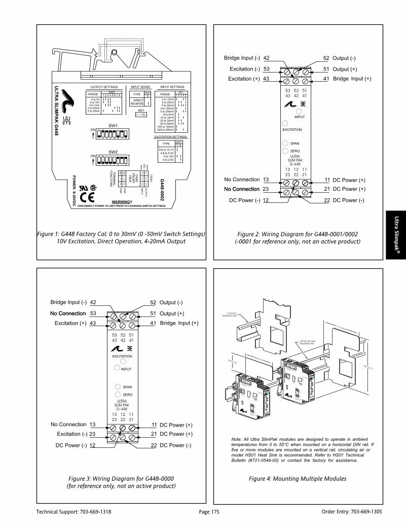
Page 175Technical Support: 703-669-1318 Order Entry: 703-669-1305
Ultra Slim
pak
®
Figure 1: G448 Factory Cal: 0 to 30mV (0 -50mV Switch Settings)10V Excitation, Direct Operation, 4-20mA Output
Figure 2: Wiring Diagram for G448-0001/0002(-0001 for reference only, not an active product)
Figure 3: Wiring Diagram for G448-0000(for reference only, not an active product)
Note: All Ultra SlimPak modules are designed to operate in ambient
temperatures from 0 to 55°C when mounted on a horizontal DIN rail. If
five or more modules are mounted on a vertical rail, circulating air or
model HS01 Heat Sink is recommended. Refer to HS01 Technical
Bulletin (#721-0549-00) or contact the factory for assistance.
Figure 4: Mounting Multiple Modules

Page 176Technical Support: 703-669-1318 Order Entry: 703-669-1305
Ult
ra S
lim
pak
®
Ordering InformationModels & AccessoriesSpecify:1. Model: G448-00022. Accessories: (see Accessories)3. Optional Custom Factory Calibration; specify C620 with desired
input and output ranges.
AccessoriesSlim Pak “G” series modules will mount on standard TS32 (model MD02) orTS35 (model MD03) DIN rail. In addition, the following accessories are available:
HS01 Heat SinkMD03 TS35 x 7.5 DIN rail
WV905 24VDC Power Supply (0.5 Amp)H910 24VDC Power Supply (1 Amp)H915 24VDC Power Supply (2.3 Amp)MB03 End Bracket for MD03C664 I/O Descriptive Tags
Specifications
Input:
Voltage:
Full Scale Range: 10mV to ±200mV (Table 1).
Impedance: >1M Ohms
Overvoltage:
intermittent 400V, max.;
continuous 264V, max.
Common Mode (Input to Ground):
1800VDC, max.
Zero Turn-Up:
50% of full scale range
Span Turn-Down:
50% of full scale range
Operation:
direct or reverse acting
Output:
Voltage:
Output: 0-5V, 0-10V
Impedance: <10 Ohms
Drive: 10mA, max. (1K Ohms, min. @ 10V)
Current:
Output: 0-1mA, 0-20mA, 4-20mA
Impedance: >100K Ohms
Compliance:
0-1mA; 7.5V, max.(7.5K Ohms, max.)
0-20mA; 12V, max. (600 Ohms, max.)
4-20mA; 12V, max. (600 Ohms, max.)
Bridge Excitation:
1 to 10VDC, 120mA max.
Accuracy (Including Linearity, Hysteresis):±0.1% typical, ±0.2% maximum of selected
input range at 25°C.
Stability:
±0.025%/°C typical, 0.05%/°C maximum, ofselected full scale input range.
Output Noise (maximum):
0.1% of span, rms, or 10mV whichever isgreater.
Response Time (10 to 90%):
<200mSec., typical.
Common ModeRejection:
DC to 60Hz: ≈120dB, ≈100dB for 0 -1mA range
Isolation:
1800VDC between input, output & power.
EMC Compliance (CE Mark):
Emissions: EN50081-1
Immunity: EN50082-2
Safety: EN50178
LED Indication (green):
Input Range (approx.)
>110% input: 8Hz flash
<0% input: 4Hz flash
Humidity (Non-Condensing):
Operating: 15 to 95% @ 45°CSoak: 90% for 24 hours @ 65°C
Dimensions
Temperature Range:
Operating: 0 to 55°C (32 to 131°F)
Storage: -25 to 70°C (-13 to 158°F)
Power:
Consumption:
2.5W typical (one 350 Ohm bridge),
4W max. (four 350 Ohm bridges).
Range: 18 to 30VDC
Weight:
0.54 lbs.
Wire Terminations:
Screw terminals for 12-22 AWG
Agency Approvals:
CSA certified per standard C22.2, No. 0-M91and 142-M1987 (File No. LR42272).
UL recognized per standard UL508
(File No.E99775).
CE Conformance per EMC directive 89/336/EECand low voltage 73/23/EEC.
RoHS Compliant
Note that detailed installation instructions are
available on our web site.

Page 177Technical Support: 703-669-1318 Order Entry: 703-669-1305
Ultra Slim
pak
®
DescriptionThe G468 is a DIN rail mount, AC input signal conditioner with1800VDC isolation between input, output and power. The fieldconfigurable input and output offers flexible, wide ranging capa-bility for scaling, converting or buffering AC inputs ranging from5mA to 100mA or 50mV to 250V.
For AC current measurements above 100mA, use the model C006shunt resistor (0.1 Ohm, 5Watt). This resistor must be wired inseries with the current source, with the G468 configured tomeasure the voltage generated across the resistor (see Figure 3 foran example).
The DC output of the G468 is proportional to the average of thefully-rectified AC input signal, and is calibrated for sine wavesbetween 40-400Hz.
ApplicationThe G468 is useful in applications requiring an isolated, condi-tioned DC output from an AC signal. Typical applications includeenergy management, load shedding, motor current/load monitor-ing, locked rotor detection, isolation and data acquisition. Theoutput of the G468 can drive a digital meter for direct display orit can interface with alarm or control devices, including PLCs andcomputers.
Diagnostic LEDThe G468 is equipped with a dual function LED signal monitor. Thegreen, front mounted LED indicates both DC power and inputsignal status. Active DC power is indicated by an illuminated LED.If the input signal is more than 110% of the full scale range, the LEDwill flash at 8Hz. Below -10%, the flash rate is 4Hz.
ULTRA SLIMPAK®
G468-0001AC Input Field Configurable Isolator
Provides an Isolated DC Outputin Proportion to an AC Input
Field Configurable Input Ranges: 50mV to 250VAC,5mA to 5A AC
Eliminates Ground Loops Field Configurable Outputs: 0-5V, 0-10V, 0-1mA,
0-20-mA and 4-20mA
G468-0001
Ultra Slim Housing for High Density Installations Flexible Power Supply Accepts 9 to 30 VDC ASIC Technology for Enhanced Reliability RoHS Compliant
ConfigurationThe G468 has 15 input range switch settings. Trim potentiometersallow 50% input zero and span adjustablity within each of the 15fullscale, input ranges.
Since the unit has 50% adjustability, it can be ranged so that any100 volt input span can create the full output (e.g., 25 to 125Vac= full output).
Unless otherwise specified, the factory presets the Model G468 asfollows:
Input Range: 0-500mVACOutput: 4-20mA
The DC power input accepts any DC source between 9 and 30V;typically a 12V or 24VDC source is used (see Accessories).
Refer to Tables 1 through 3 for the proper switch settings. Withpower disconnected, use the switches (9 & 10) on SW1 to selectthe input type (voltage or current), on SW2 to select the desiredoutput ranges, and (1-8) on SW1 to select the desired input range.
WARNING: Do not change switch settings with power applied.Severe damage will result!

Page 178Technical Support: 703-669-1318 Order Entry: 703-669-1305
Ult
ra S
lim
pak
®
segnaR 1WSrotceleS
egatloV tnerruC 1 2 3 4 5 6 7 8 9 01
Vm001 Am01
Vm002 Am02
Vm005 Am05
V1 Am001
V2
V5
V01
V02
V05
V001
V002
V052
epyTtupnI
tnerruC
egatloV
:yeK desolCroNO=1=
tuptuO2WS
1 2 3 4 5 6 7 8
V5+ot0
V01+ot0
Am1ot0
Am02ot4
Am02ot0
:yeK desolCroNO=1=
Table 1: G468 Input Ranges Table 2: G468 Output Ranges
Calibration1. After configuring the DIP switches, connect the input to acalibrated AC source. Connect the output to the device (or a loadapproximately equivalent to the device) and apply power. Referto the Terminal Wiring Diagram (Figure 2).
Note: To maximize thermal stability, final calibration should beperformed in the operating installation, allowing approximately 1to 2 hours for warm up and thermal equilibrium of the system.
2. Set the calibrator to the desired minimum and adjust the zeropotentiometer for the desired minimum output.
3. Set the calibrator to the desired maximum and adjust the spanpotentiometer for the desired maximum output.
4. Repeat steps 2 and 3, if necessary for best accuracy.

Page 179Technical Support: 703-669-1318 Order Entry: 703-669-1305
Ultra Slim
pak
®
Figure 1: G468 Factory Cal: 0-500mVAC, 4-20mA
Figure 3: A Typical Application - Load MonitoringUsing a Current Transformer and the G468
Note: All Ultra SlimPak modules are designed to operate in ambient
temperatures from 0 to 55°C when mounted on a horizontal DIN rail. If
five or more modules are mounted on a vertical rail, circulating air or
model HS01 Heat Sink is recommended. Refer to HS01 Technical
Bulletin (#721-0549-00) or contact the factory for assistance.
Figure 4: Mounting Multiple Modules
Figure 2: Wiring Diagram for G468

Page 180Technical Support: 703-669-1318 Order Entry: 703-669-1305
Ult
ra S
lim
pak
®
Ordering InformationModels & AccessoriesSpecify:1. Model: G468-00012. Accessories: (see Accessories)3. Optional Custom Factory Calibration; specify C620 with desired
inputand output ranges.
AccessoriesSlimPak "G" series modules mount on standard TS32 (model MD02) or TS35(model MD03) DIN rail. In addition, the following accessories are available:
HS01 Heat SinkMD03 TS35 x 7.5 DIN rail
WV905 24VDC Power Supply (0.5 Amp)H910 24VDC Power Supply (1 Amp)H915 24VDC Power Supply (2.3 Amp)MB03 End Bracket for MD03C664 I/O Descriptive Tags
Specifications
Inputs:
Voltage:
Ranges: 100mV to 250VAC
Impedance: >100K Ohms
Overvoltage: 300VAC
Current:
Ranges:10mA to 100mA AC
Impedance: 20 Ohms, typical
Overcurrent: 200mAAC
Overvoltage: 60V peak
Frequency Range:
DC or 40 to 400Hz AC, factorycalibrated at 60Hz
Common Mode(Input to Ground):
1800VDC, max.
Zero and Span Range:
Zero Turn-Up: 50% of full scale range
Span Turn-Down: 50% of full scale range
Output:
Voltage:
Output: 0-5V, 0-10V
Source Impedance: <10 Ohms
Drive: 10mA, max. (1K Ohms, min. @ 10V)
Current:
Output: 0-1mA, 0-20mA, 4-20mA
Source Impedance: >100K Ohms
Compliance:
0-1mA; 7.5V, max. (7.5K Ohms, max.)
0-20mA; 12V, max. (600 Ohms, max.)
4-20mA; 12V, max. (600 Ohms, max.)
LED Indicator (green):
8Hz flash when input is 110% of full scalerange
4Hz flash when input is 10% below fullscale range
Accuracy (Including Linearity, Hysteresis):+0.1% of span, typical
+0.5% of span, maximum
Stability:
+0.025%/°C of selected input span, typical.
Response Time (10 to 90%):
250mSec., typical.
Common Mode Rejection:
DC to 60Hz: 120dB
Isolation:
1800VDC between input, output & power.
EMC Compliance (CE Mark):
Emmissions: EN50081-1
Immunity: EN50082-2
Safety: EN50178
Humidity (Non-Condensing):
Operating: 15 to 95% @ 45°CSoak: 90% for 24 hours @ 65°C
Temperature Range:
Operating: 0 to 55°C (32 to 131°F)
Storage: -25 to 70°C (-13 to 158°F)
Dimensions
Power:
Consumption: 1.5W typical, 2.5W max.
Range: 9 to 30VDC
Wire Terminations:
Screw terminals for 12-22 AWG
Weight:
0.48 lbs.
Agency Approvals:
CSA certified per standard C22.2, No. 0-M91and 142-M1987 (File No. LR42272).
UL recognized per standard UL508
(File No.E99775).
CE Compliance per EMC directive 89/336/EECand Low Voltage 73/23/EEC.
RoHS Compliant
Note that detailed installation instructions are
available on our web site.

Page 181Technical Support: 703-669-1318 Order Entry: 703-669-1305
Ultra Slim
pak
®
DescriptionThe G478 is a DIN rail mount, frequency input signal conditionerwith 1800VDC isolation between input, output and power. The fieldconfigurable input and output offer flexible, wide ranging capabilityfor variable frequency drives, magnetic pick-ups, turbine flowmeters, and other pulse or frequency output transducers.
The input of the G478 can be configured for any frequency spanfrom 2Hz to 10,000Hz. The input amplitude threshold sensitivitycan be adjusted from 150mVp to 10Vp to ensure accuratefrequency measurement and minimize transient noise relatederrors. The maximum input amplitude is 150 Vrms. The output canbe set for 0-5V, 0-10V, 0-1mA, 0-20mA or 4-20mA.
The G478 to be field configured for virtually any frequency inputto DC signal output within the ranges specified. Calibration utilizes‘Touch-Cal’ technology in which the user simply applies theminimum and maximum input frequencies, and touches a re-cessed button to configure the corresponding minimum andmaximum output range.
The Ultra SlimPak housing allows installation of up to 24 units perlinear foot. The wide ranging power supply is inverter isolated andaccepts any voltage between 9 and 30VDC.
ApplicationThe G478 is useful in eliminating ground loops and interfacingpulse output transducers, such as turbine flow meters and mag-netic pick-ups, to data acquisition and control systems.
Advanced digital technology, combined with Action’s ASIC technol-ogy, provide a stable output at low frequencies for higher accuracy.
‘Touch-CALTM TechnologyThe G478 utilizes ‘Touch-Cal’ technology to greatly simplifyconfiguration. To set the input frequency range, simply apply thehigh input frequency and push the CAL button while the INPUTLED is lit. The low input frequency is then applied and pushing theCAL button once again stores the low frequency input. The highand low ranges are stored in non-volatile memory and correspondto the high and low output range which is selected via DIP switches.
Frequency Input,Field Configurable Isolator
Provides an Isolated DC Outputin Proportion to a Frequency Input
ULTRA SLIMPAK®
G478-0001
Field Configurable Input Ranges from 2Hz to 10,000Hz Eliminates Ground Loops Field Configurable Output Ranges: 0-5V, 0-10V,
0-1mA, 0-20mA, 4-20mA Ultra Slim Housing for High Density Installations
G478-0001
150mV to 150V Input Amplitude Level Touch-CalTM for Simplified Ranging Flexible Power Supply Accepts 9 to 30 VDC ASIC Technology for Enhanced Reliability RoHS Compliant
To precisely adjust the output, the user adjusts the input fre-quency while the OUTPUT LED is lit until the desired output levelis achieved. The output levels are locked-in by pushing the CALbutton. Status LEDs show the operation mode of the device.
Status LEDsThe G478 utilizes three status LEDs.
The green LED varies intensity as the frequency changes from 0 to100% of full scale range (e.g., for a configuration of 0-1000Hz, the LEDwill be off with an input of 0Hz and fully illuminated at 1000Hz. Withan input of 500Hz, the LED will be dim). If the input signal is 10% morethan full scale range (over-ranged), the LED will flash at 8Hz.
The yellow INPUT LED denotes input programming modes.
The red OUTPUT LED denotes output programming modes (seeConfiguration, Calibration and Figure 2 for details).
ConfigurationAny 2Hz range from 0 to 10,000Hz can be converted to a full scaleoutput signal (e.g. 0-2Hz/4-20mA or 9998-10,000Hz/4-20mA).Unless otherwise specified, the factory presets the Model G478 as follows:
Input Range: 0 to 1000HzSensitivity: 1V RMS
Output Range: 4 to 20mA
Note: "Sensitivity" refers to the noise rejection level (the triggerthreshold) of the input.
For other I/O ranges, refer to Table 1 and 2. For calibration modereference, see the step-by-step flow chart in Figure 4.
1. With DC power off, choose the desired output voltage/currentrange from Table 1 and set position 1 through 8 of SW1.
2. Set the Input sensitivity switch (SW1, 9 & 10) to LO for inputamplitudes between 150mVp and 50Vrms, with noise rejection to1Vp. Set the switch to HI for input amplitudes between 500mVpand 150Vrms, with noise rejection up to 10Vp (see Table 2).
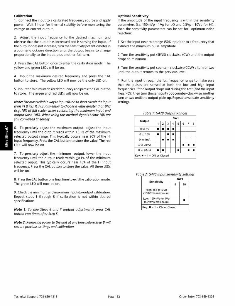
Page 182Technical Support: 703-669-1318 Order Entry: 703-669-1305
Ult
ra S
lim
pak
®
Calibration1. Connect the input to a calibrated frequency source and applypower. Wait 1 hour for thermal stability before monitoring thevoltage or current output.
2. Adjust the input frequency to the desired maximum andobserve that the ouput has increased and is sensing the input. Ifthe output does not increase, turn the sensitivity potentiometer ina counter-clockwise direction until the output begins to changeproportionally to the input, plus another full turn.
3. Press the CAL button once to enter the calibration mode. Theyellow and green LEDs will be on.
4. Input the maximum desired frequency and press the CALbutton to store. The yellow LED will now be the only LED on.
5. Input the minimum desired frequency and press the CAL buttonto store. The green and red LEDs will now be on.
Note: The most reliable way to input 0Hz is to short circuit the input(Pins 41 & 42). It is usually easier to choose a value greater than 0Hz(e.g.,10% of full scale) when calibrating the minimum input andoutput (also 10%). When using this method signals below 10% arestill converted linearally.
6. To precisely adjust the maximum output, adjust the inputfrequency until the output reads within +0.1% of the maximumselected output range. This typically occurs near 90% of the HIinput frequency. Press the CAL button to store the value. The redLED will now be on.
7. To precisely adjust the minimum output, lower the inputfrequency until the output reads within +0.1% of the minimumselected ouput. This typically occurs near 10% of the HI inputfrequency. Press the CAL button to store the value. All three LEDswill be on.
8. Press the CAL button one final time to exit the calibration mode.The green LED will now be on.
9. Check the minimum and maximum input-to-output calibration.Repeat steps 1 through 8 if calibration is not within desiredspecifications.
Note 1: To skip Steps 6 and 7 (output adjustment), press CALbutton two times after Step 5.
Note 2: Removing power to the unit at any time before Step 8 willrestore previous settings and calibration.
Optimal SensitivityIf the amplitude of the input frequency is within the sensitivityparameters (i.e. 150mVp - 1Vp for LO and 0.5Vp - 10Vp for HI),then the sensitivity parameters can be set for optimum noiserejection:
1. Set the input near midrange (50% input) or to a frequency thatexhibits the minimum pulse amplitude.
2. Turn the sensitivity pot (SENS) clockwise (CW) until the outputdrops to minimum.
3. Turn the sensitivity pot counter- clockwise(CCW) a turn or twountil the output returns to the previous level.
4. Run the input through the full frequency range to make surethat the pulses are sensed at both the low and high inputfrequencies. If the output drops out during this test (and the inputfreq. >0%) then turn the sensitivity pot counter-clockwise anotherturn or two until the output picks up. Repeat to validate sensitivitysettings.
ytivitisneS1WS
9 01
pV01ot5.0:hgiH)mumixamsmrV051(
pV1otpVm051:woL)mumixamsmrV05(
:yeK desolCroNO=1=
tuptuO1WS
1 2 3 4 5 6 7 8
V5ot0
V01ot0
Am1ot0
Am02ot4
Am02ot0
:yeK desolCroNO=1=
Table 1: G478 Output Ranges
Table 2: G478 Input Sensitivity Settings

Page 183Technical Support: 703-669-1318 Order Entry: 703-669-1305
Ultra Slim
pak
®
Figure 2: Wiring Diagram for G478Figure 1: Factory Cal: 0 to 1000Hz, 1Vrms, 4-20mA
Note: All Ultra SlimPak modules are designed to operate in ambient
temperatures from 0 to 55°C when mounted on a horizontal DIN rail. If
five or more modules are mounted on a vertical rail, circulating air or
model HS01 Heat Sink is recommended. Refer to HS01 Technical
Bulletin (#721-0549-00) or contact the factory for assistance.
Figure 3: Mounting Multiple Modules Figure 4: G478 Calibration Flowchart

Page 184Technical Support: 703-669-1318 Order Entry: 703-669-1305
Ult
ra S
lim
pak
®
Specifications
Input:
Frequency Input
Full Scale Range: 2 Hz minimum
from 2Hz to 10,000Hz.
Amplitude Range: 150mVp to 150Vrms
Impedance: >10K Ohms
Over-voltage: 180Vrms, max.
Over-range: 20KHz, max.
Common Mode (Input to Gnd):
1800VDC, max.
Zero Turn-Up:
99% of full scale range (9998Hz)
Span Turn-Down:
99% of full scale range (2Hz)
Output:
Voltage:
Output: 0-5V, 0-10V
Source Impedance: <100 Ohms
Drive: 10mA, max. (1K Ohms, min. @ 10V)
Current:
Output: 0-1mA, 0-20mA, 4-20mA
Source Impedance: >100K Ohms
Compliance:
0-1mA; 7.5V, max. (7.5K Ohms, max.)
0-20mA; 12V, max. (600 Ohms, max.)
4-20mA; 12V, max. (600 Ohms, max.)
Ordering InformationModels & AccessoriesSpecify:1. Model: G478-00012. Accessories: (see accessories)3. Optional Custom Factory Calibration: specify C620 with desired
input and output range
AccessoriesSlimPak "G" Series modules will mount on standard TS32 (model MD02) orTS35 (model MD03) DIN Rail. In addition, the following accessories are available:
HS01 Heat SinkMD03 TS35 x 7.5 DIN rail
WV905 24VDC Power Supply (0.5 Amp)H910 24VDC Power Supply (1 Amp)H915 24VDC Power Supply (2.3 Amp)MB03 End Bracket for MD03C664 I/O Descriptive Tags
Accuracy (Including Linearity, Hysteresis):+0.1% of selected range at 25°C.
Stability:
+0.025%/°C maximum of selected range.
Response Time (10 to 90%):
3 input cycles + 250ms
Common Mode Rejection:
DC: 100dB
>60Hz: 80dB
Isolation:
1800VDC between input, output & power.
EMC Compliance (CE Mark):
Emissions: EN50081-1
Immunity: EN50082-2
Safety: EN50178
LED Indication:
LEVEL (green):
lit when power is on
Input > 110% then 8Hz. flash
Input < -10% then 4Hz flash
INPUT (yellow):
input range programming status
OUTPUT (red):
output range programming status
Dimensions
Humidity (Non-Condensing):
Operating: 15 to 95% @ 45°CSoak: 90% for 24 hours @ 65°C
Temperature Range:
Operating: 0 to 55°C (5 to 131°F)
Storage: -25 to 70°C (-13 to 158°F)
Power:
Consumption: 1.5W typical, 2.5W max.
Range: 9 to 30VDC
Weight:
0.50 lbs
Wire Terminations:
Screw terminals for 12-22 AWG
Agency Approvals:
CSA certified per standard C22.2, No. 0-M91and 142-M1987 (File No. LR42272).
UL recognized per standard UL508
(File No.E99775).
CE Conformance per EMC directive 89/336/EECand Low Voltage 73/23/EEC
(Input < 75Vp or < 50Vrms, only).
RoHS Compliant
Note that detailed installation instructions are
available on our web site.

Page 185Technical Support: 703-669-1318 Order Entry: 703-669-1305
Ultra Slim
pak
®
All Ultra SlimPak (USP) modules are designed and tested to operate in ambient temperatures from 0 to 55°C whenmounted on a horizontal rail (see figure A) or with approximately 1/2" between modules on a vertical or horizontal rail(see figure B) to allow adequate air circulation.
When more than five modules are mounted in close proximity, our model HS01 Heat Sink is recommended (see figuresC & D).
Figure A
Figure D
Figure B
Figure C
Ultra SlimPak SeriesModel HS01 Heat Sink
TECHNICAL BULLETIN
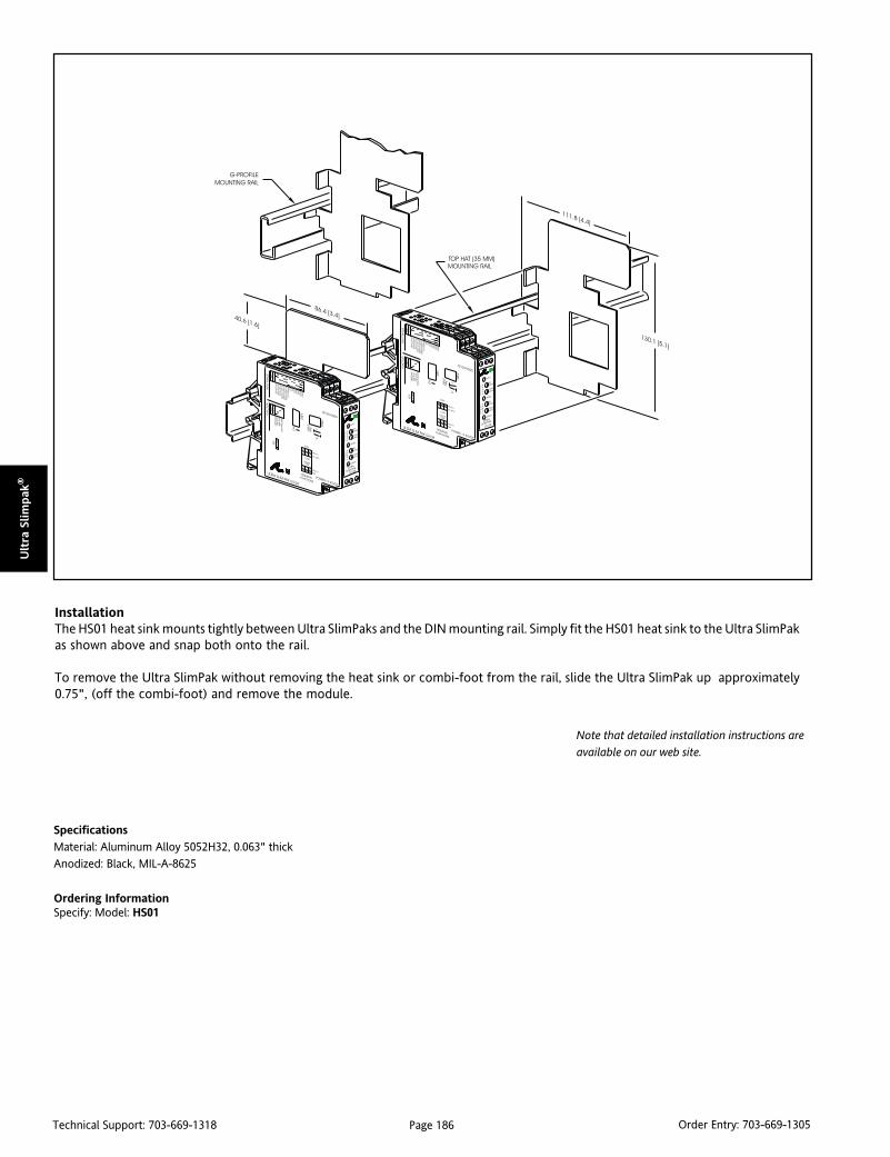
Page 186Technical Support: 703-669-1318 Order Entry: 703-669-1305
Ult
ra S
lim
pak
®
Specifications
Material: Aluminum Alloy 5052H32, 0.063" thick
Anodized: Black, MIL-A-8625
Ordering InformationSpecify: Model: HS01
InstallationThe HS01 heat sink mounts tightly between Ultra SlimPaks and the DIN mounting rail. Simply fit the HS01 heat sink to the Ultra SlimPakas shown above and snap both onto the rail.
To remove the Ultra SlimPak without removing the heat sink or combi-foot from the rail, slide the Ultra SlimPak up approximately0.75", (off the combi-foot) and remove the module.
Note that detailed installation instructions are
available on our web site.

Page 187Technical Support: 703-669-1318 Order Entry: 703-669-1305
Tran
sPak
™
DescriptionTransmitters are used to amplify and condition the very smallelectrical signals which are generated by sensors as they measurethe physical variables of a process. Once conditioned to usablelevels, these signals are used to drive other instrumentation suchas industrial computers, dataloggers, chart recorders, alarms,panel meters and controllers.
The TransPak SeriesTransPak series two-wire transmitters are compact, rugged unitsthat receive signals and direct sensor inputs, and operate frompower derived from the output signal loop. The TransPak seriesprovides a complete line of direct interface and conditioningmodules for use with temperature, pressure, flow, strain, andother parameters. TransPak transmitters also accept a wide rangeof other electrical DC and AC voltage and current inputs.
Two-wire TransmittersTwo-wire transmitters (also called "field transmitters" becausethey can be placed anywhere along the signal in a process) offerseveral major advantages over conventional four-wire types,which require two wires for the output signal and two more forthe power supply, typically 120VAC. In applications where theprocess sensor might be located up to several thousand feet fromthe instrument, two-wire transmitters are more advantageousbecause their current output signals do not attenuate or degradeover distance as do the voltage signals of typical four-wireconditioners. There can also be significant savings in wiring costssince only two wires are needed for the power and signal whencompared to the four-wire type.
TRANSPAK™
Intrinsic SafetyBecause two-wire transmitters are powered by low-level 4-20mAor 10-50mA output current signals, no additional power has to besupplied to the remote transmitting location. This eliminates theassociated problem of having to provide and maintain long runsof expensive wiring, and adds the benefit of being able to complywith safety requirements restricting the use of high voltage(120VAC) in hazardous locations.
Due to their low energy consumption and storage, two-wiretransmitters are the only types of transmitters considered forintrinsically safe applications. Many of Action's TransPaks areFactory Mutual (FM), Canadian Standards Association (CSA) andCENELEC approved for intrinsically safe operation in hazardous -even explosive - environments when installed in accordance withthe manufacturer's drawings.
Input SelectionSix types of inputs are available to suit your process needs:
DC Voltage or CurrentPotentiometerThermocoupleAC Voltage or CurrentRTDFrequency

Page 188Technical Support: 703-669-1318 Order Entry: 703-669-1305
Tra
nsp
ak™
TransPak™ Selection Guide
tupnI noitacilppAlacipyT noitpircseD ledoM
tnerruCroegatloVCD)Am,A,Vm,V( )Am,A,Vm,V( )Am,A,Vm,V( )Am,A,Vm,V( )Am,A,Vm,V(
cisnirtni,noitisiuqcaatadetomeRdna,erusserpottnerruc,ytefas
tnempiuqesedivorptahtnoitalosi.noitcetorplanosrepdna
gninoitidnocdnagniretlifsedulcnIotytilibitpecsusecuderot
.esionlangisdnastneisnart
)rotalosIpooL(007T)gnignaRediW(307T)ylnoVm(782T,082T
retemoitnetoP)smhOk002otpu,smhO05( )smhOk002otpu,smhO05( )smhOk002otpu,smhO05( )smhOk002otpu,smhO05( )smhOk002otpu,smhO05(
,noitisiuqcaatadlevelknatetomeRecnatsiser,noissimsnarttnioptesdnagninoitidnocrosnesnoitisoptahtnoitalosidnaytefascisnirtnilanosrepdnatnempiuqesedivorp
.noitcetorp
-3rofylppusnoitaticxesedulcnI,seriwedilsroretemoitnetoperiw
.rosnesehttayrtiucriceziminimot
)gnignaRediW(257T)smhok02-0(782T
DTR)01uC,011iN,tPepyT( )01uC,011iN,tPepyT( )01uC,011iN,tPepyT( )01uC,011iN,tPepyT( )01uC,011iN,tPepyT(
,noitisiuqcaataderutarepmetetomeRdnaytefascisnirtni,etarrefsnartUTB
tnempiuqesedivorptahtnoitalosi.noitcetorplanosrepdna
rofylppusnoitaticxeCDsedulcnIdnasrosnesecnatsiserDTReriw-3
.noitcetedtuonrubrosnes
)gnignaRediW(317T)traH/elbammargorP(8/797T
)ylno001tP(782T,082T
elpuocomrehT)T,S,R,N,K,J,E,C,BsepyT( )T,S,R,N,K,J,E,C,BsepyT( )T,S,R,N,K,J,E,C,BsepyT( )T,S,R,N,K,J,E,C,BsepyT( )T,S,R,N,K,J,E,C,BsepyT(
,noitisiuqcaataderutarepmetetomeRtahtnoitalosidnaytefascisnirtnilanosrepdnatnempiuqesedivorp
.noitcetorp
dlocdetaluspacnesedulcnIdna)CJC(noitasnepmocnoitcnuj
.noitcetedtuonrubrosnes
)gnignaRediW(327T)traH/elbammargorP(8/797T
782T,082T
ycneuqerF)zHk01-0otzH05-0( )zHk01-0otzH05-0( )zHk01-0otzH05-0( )zHk01-0otzH05-0( )zHk01-0otzH05-0(
wolfetomer,deepspmup/rotoMdnaytefascisnirtni,noitisiuqcaatad
tnempiuqesedivorptahtnoitalosi.noitcetorplanosrepdna
napsretaergro%05sedulcnIstpeccA.ytilibatsujda"nwodnrut"otppvM001morfsedutilpmatupni
.smrV02
)gnignaRediW(377T
tnerruCroegatloVCA)Am,A,Vm,V( )Am,A,Vm,V( )Am,A,Vm,V( )Am,A,Vm,V( )Am,A,Vm,V(
CA,noitisiuqcaatadCAetomeRnoitalosidnalortnocsutatsrotom
dnatnempiuqesedivorptaht.noitcetorplanosrep
gninoitidnocdnagniretlifsedulcnIotytilibitpecsusecuderot
.esionlangisdnastneisnart)gnignaRediW(167T

Page 189Technical Support: 703-669-1318 Order Entry: 703-669-1305
Tran
sPak
™
DescriptionThe T280 is an isolated, 2-wire temperature and mV inputtransmitter designed to fit in a standard industrial thermal-head.The T280 supports Pt-100 RTD and thermocouple inputs as well asvoltages up to 100mV. Thermocouples supported include B, E, J,K, L, N, R, S and T. If thermal-head mounting is not required, theT280 can either be mounted directly on a bulkhead or to a DIN railusing the included DIN rail clip.
Three different series make up the T280 family. The –1xxx units arefor Pt-100 RTD inputs. The default configuration from the factoryis 3-wire, but the units can be easily reconfigured for 2-wire, asexplained in the installation instructions. The –2xxx units are forthermocouple inputs and the –3xxx units are for millivolt inputs.
The list of model numbers shows our most popular ranges. Contactthe Technical Services Group for information about other ranges.
TRANSPAK™
T280Isolated Universal 2-Wire Transmitter for
Pt-100 RTD, Thermocouple, & mV
Miniature Thermal-Head Mounted,1000VDC Input to Output Isolation
Universal Input Reduces Inventory Levels Eliminates Ground Loops Low Profile Design
see next page
Hinged Cover Protects Potentiometers fromthe Environment
Embedded Terminals
Head Mount Enclosure
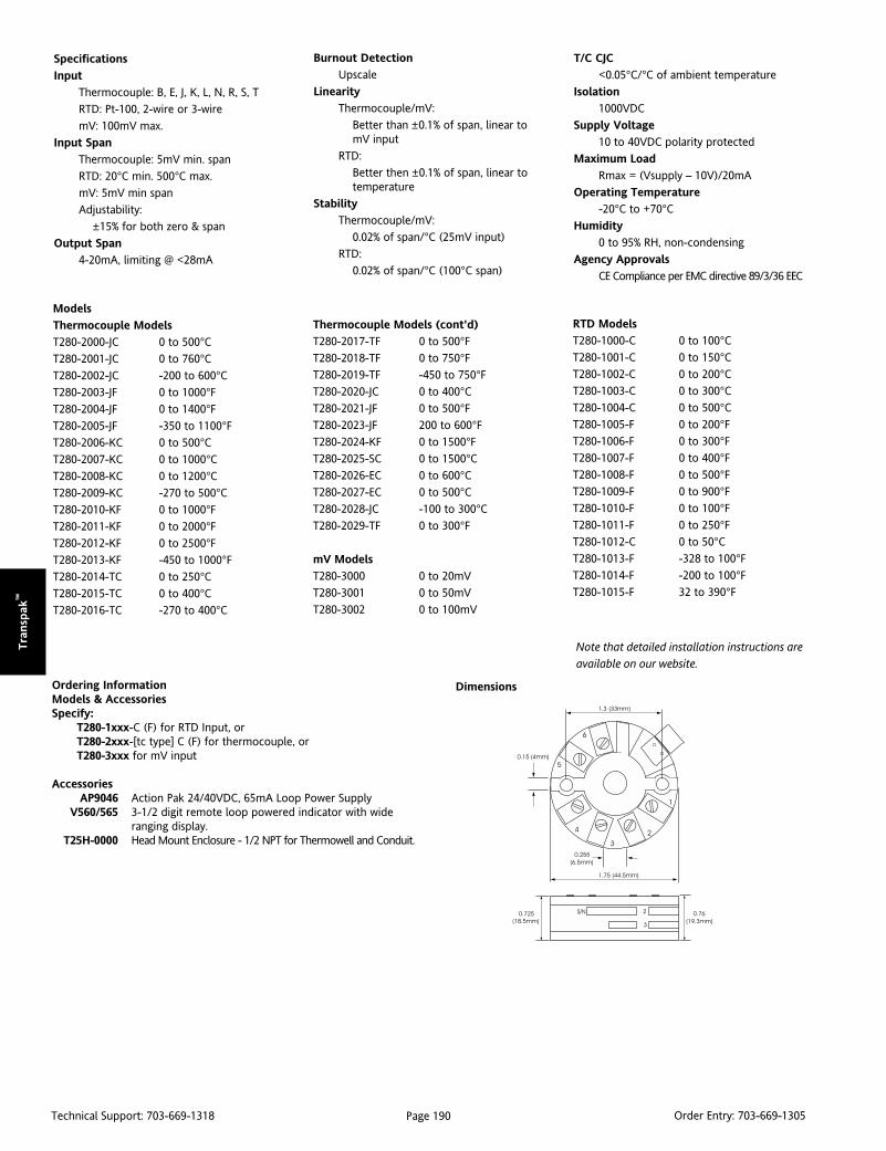
Page 190Technical Support: 703-669-1318 Order Entry: 703-669-1305
Tra
nsp
ak™
Models
Thermocouple Models
T280-2000-JC 0 to 500°CT280-2001-JC 0 to 760°CT280-2002-JC -200 to 600°CT280-2003-JF 0 to 1000°FT280-2004-JF 0 to 1400°FT280-2005-JF -350 to 1100°FT280-2006-KC 0 to 500°CT280-2007-KC 0 to 1000°CT280-2008-KC 0 to 1200°CT280-2009-KC -270 to 500°CT280-2010-KF 0 to 1000°FT280-2011-KF 0 to 2000°FT280-2012-KF 0 to 2500°FT280-2013-KF -450 to 1000°FT280-2014-TC 0 to 250°CT280-2015-TC 0 to 400°CT280-2016-TC -270 to 400°C
Specifications
Input
Thermocouple: B, E, J, K, L, N, R, S, T
RTD: Pt-100, 2-wire or 3-wire
mV: 100mV max.
Input Span
Thermocouple: 5mV min. span
RTD: 20°C min. 500°C max.
mV: 5mV min span
Adjustability:
±15% for both zero & span
Output Span
4-20mA, limiting @ <28mA
Burnout Detection
Upscale
Linearity
Thermocouple/mV:
Better than ±0.1% of span, linear tomV input
RTD:
Better then ±0.1% of span, linear totemperature
Stability
Thermocouple/mV:
0.02% of span/°C (25mV input)
RTD:
0.02% of span/°C (100°C span)
Dimensions
T/C CJC
<0.05°C/°C of ambient temperature
Isolation
1000VDC
Supply Voltage
10 to 40VDC polarity protected
Maximum Load
Rmax = (Vsupply – 10V)/20mA
Operating Temperature
-20°C to +70°CHumidity
0 to 95% RH, non-condensing
Agency Approvals
CE Compliance per EMC directive 89/3/36 EEC
Thermocouple Models (cont'd)
T280-2017-TF 0 to 500°FT280-2018-TF 0 to 750°FT280-2019-TF -450 to 750°FT280-2020-JC 0 to 400°CT280-2021-JF 0 to 500°FT280-2023-JF 200 to 600°FT280-2024-KF 0 to 1500°FT280-2025-SC 0 to 1500°CT280-2026-EC 0 to 600°CT280-2027-EC 0 to 500°CT280-2028-JC -100 to 300°CT280-2029-TF 0 to 300°F
mV Models
T280-3000 0 to 20mV
T280-3001 0 to 50mV
T280-3002 0 to 100mV
Ordering InformationModels & AccessoriesSpecify:
T280-1xxx-C (F) for RTD Input, orT280-2xxx-[tc type] C (F) for thermocouple, orT280-3xxx for mV input
AccessoriesAP9046 Action Pak 24/40VDC, 65mA Loop Power Supply
V560/565 3-1/2 digit remote loop powered indicator with wideranging display.
T25H-0000 Head Mount Enclosure - 1/2 NPT for Thermowell and Conduit.
RTD Models
T280-1000-C 0 to 100°CT280-1001-C 0 to 150°CT280-1002-C 0 to 200°CT280-1003-C 0 to 300°CT280-1004-C 0 to 500°CT280-1005-F 0 to 200°FT280-1006-F 0 to 300°FT280-1007-F 0 to 400°FT280-1008-F 0 to 500°FT280-1009-F 0 to 900°FT280-1010-F 0 to 100°FT280-1011-F 0 to 250°FT280-1012-C 0 to 50°CT280-1013-F -328 to 100°FT280-1014-F -200 to 100°FT280-1015-F 32 to 390°F
Note that detailed installation instructions are
available on our website.
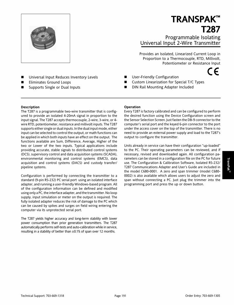
Page 191Technical Support: 703-669-1318 Order Entry: 703-669-1305
Tran
sPak
™
DescriptionThe T287 is a programmable two-wire transmitter that is config-ured to provide an isolated 4-20mA signal in proportion to theinput signal. The T287 accepts thermocouple, 2-wire, 3-wire, or 4-wire RTD, potentiometer, resistance and millivolt inputs. The T287supports either single or dual inputs. In the dual input mode, eitherinput can be selected to control the output, or math functions canbe applied in which both inputs have an effect on the output. Thefunctions available are Sum, Difference, Average, Higher of thetwo or Lower of the two inputs. Typical applications includeproviding accurate, stable signals to distributed control systems(DCS), supervisory control and data acquisition systems (SCADA),environmental monitoring and control systems (EMCS), dataacquisition and control systems (DACS) and custody transfer/pipeline systems.
Configuration is performed by connecting the transmitter to astandard (9-pin RS-232) PC serial port using an isolated interfaceadapter, and running a user-friendly Windows-based program. Allof the configuration information can be defined and modifiedusing only a PC, the interface adapter, and the transmitter. No loopsupply, input simulation or meter on the output is required. Thefully isolated adapter reduces the risk of damage to the PC whichcan be caused by spikes and surges on field wiring entering thecomputer via its unprotected serial port.
The T287 yields higher accuracy and long-term stability with lowerpower consumption than prior generation transmitters. The T287automatically performs self-tests and auto-calibration while in service,resulting in a stability of better than ±0.1% of span over 12 months.
TRANSPAK™
T287Programmable Isolating
Universal Input 2-Wire Transmitter
Provides an Isolated, Linearized Current Loop inProportion to a Thermocouple, RTD, Millivolt,
Potentiometer or Resistance Input
Universal Input Reduces Inventory Levels Eliminates Ground Loops Supports Single or Dual Inputs
User-Friendly Configuration Custom Linearization for Special T/C Types DIN Rail Mounting Adapter Included
OperationEvery T287 is factory calibrated and can be configured to performthe desired function using the Device Configuration screen andthe Sensor Selection Screen. Just fasten the DB-9 connector to thecomputer’s serial port and the keyed 6-pin connector to the portunder the access cover on the top of the transmitter. There is noneed to provide an external power supply and load to the T287’soutput to configure the transmitter.
Units already in service can have their configuration “up-loaded”to the PC. Their operating parameters can be reviewed, and ifnecessary, revised and downloaded again. All configuration pa-rameters can be stored in a configuration file on the PC for futureuse. The Configuration & Calibration Software, Isolated RS-232/T287 Communications Adapter and User’s Guide are included inthe model C680-0001. A zero and span trimmer (model C680-0002) is also available which allows users to adjust the zero andspan without connecting a PC. Just plug the trimmer into theprogramming port and press the up or down button.
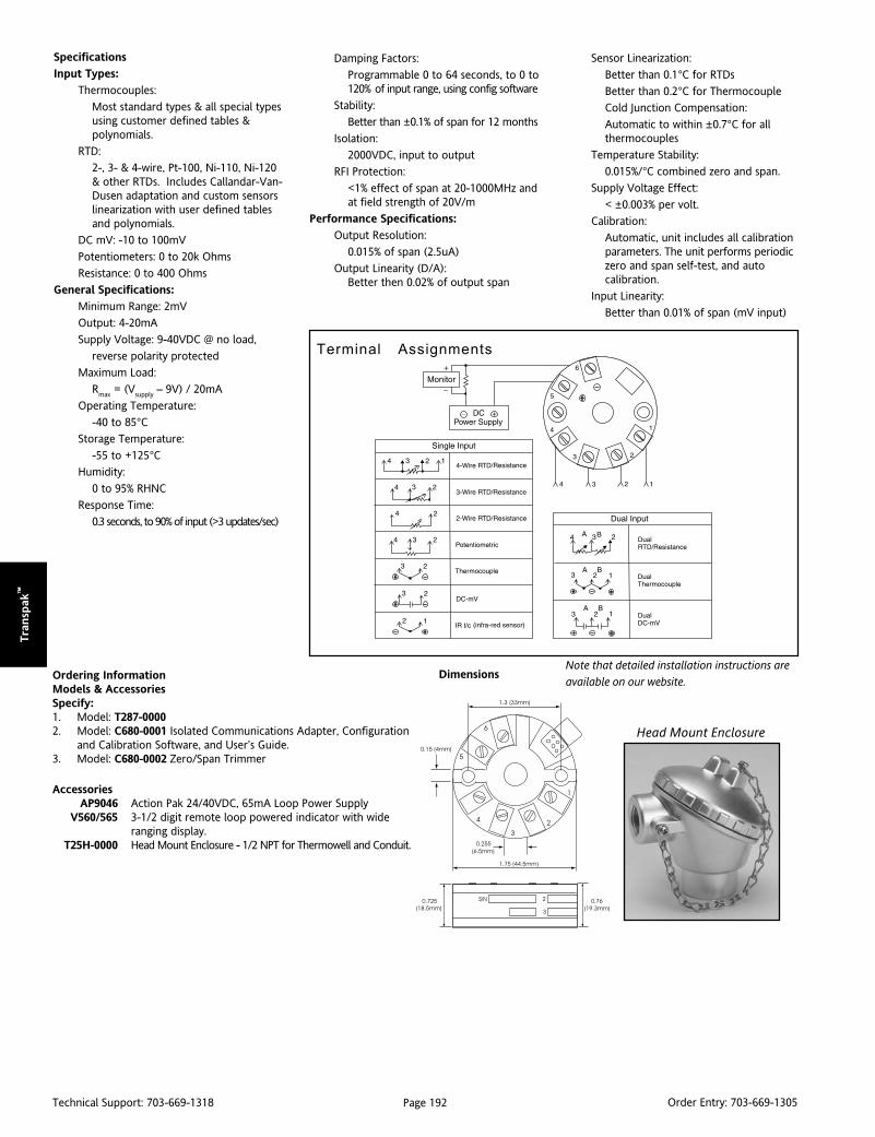
Page 192Technical Support: 703-669-1318 Order Entry: 703-669-1305
Tra
nsp
ak™
Dimensions
Head Mount Enclosure
Specifications
Input Types:
Thermocouples:
Most standard types & all special typesusing customer defined tables &polynomials.
RTD:
2-, 3- & 4-wire, Pt-100, Ni-110, Ni-120& other RTDs. Includes Callandar-Van-Dusen adaptation and custom sensorslinearization with user defined tablesand polynomials.
DC mV: -10 to 100mV
Potentiometers: 0 to 20k Ohms
Resistance: 0 to 400 Ohms
General Specifications:
Minimum Range: 2mV
Output: 4-20mA
Supply Voltage: 9-40VDC @ no load,
reverse polarity protected
Maximum Load:
Rmax = (Vsupply – 9V) / 20mA
Operating Temperature:
-40 to 85°CStorage Temperature:
-55 to +125°CHumidity:
0 to 95% RHNC
Response Time:
0.3 seconds, to 90% of input (>3 updates/sec)
Damping Factors:
Programmable 0 to 64 seconds, to 0 to120% of input range, using config software
Stability:
Better than ±0.1% of span for 12 months
Isolation:
2000VDC, input to output
RFI Protection:
<1% effect of span at 20-1000MHz andat field strength of 20V/m
Performance Specifications:
Output Resolution:
0.015% of span (2.5uA)
Output Linearity (D/A):Better then 0.02% of output span
Ordering InformationModels & AccessoriesSpecify:1. Model: T287-00002. Model: C680-0001 Isolated Communications Adapter, Configuration
and Calibration Software, and User’s Guide.3. Model: C680-0002 Zero/Span Trimmer
AccessoriesAP9046 Action Pak 24/40VDC, 65mA Loop Power Supply
V560/565 3-1/2 digit remote loop powered indicator with wideranging display.
T25H-0000 Head Mount Enclosure - 1/2 NPT for Thermowell and Conduit.
Terminal Assignments
Sensor Linearization:
Better than 0.1°C for RTDs
Better than 0.2°C for Thermocouple
Cold Junction Compensation:
Automatic to within ±0.7°C for allthermocouples
Temperature Stability:
0.015%/°C combined zero and span.
Supply Voltage Effect:
< ±0.003% per volt.
Calibration:
Automatic, unit includes all calibrationparameters. The unit performs periodiczero and span self-test, and autocalibration.
Input Linearity:
Better than 0.01% of span (mV input)
Note that detailed installation instructions are
available on our website.

Page 193Technical Support: 703-669-1318 Order Entry: 703-669-1305
Tran
sPak
™
TRANSPAK™
T287 Transmitter Sensor AssembliesThermocouple and RTD Assemblies with
the T287 2-Wire Transmitter Installed
Preassembled, PreconfiguredTemperature Sensor Solutions
T287 Configured to Desired Range Type J, K, T or Pt-100 Sensors Four Head Styles
Spring Loaded Available Three Types of Thermowells Mounting Bushings Included
DescriptionEurotherm/Barber-Colman manufactures thermocouples andRTDs with the Action T287 transmitter already installed. Thesensor assembly ships with the transmitter already configured tothe customer specified temperature range. Some of the morecommon styles are listed here.
Class II, Div. II, Groups E, F & G. The white polypropylene head issuitable for wash down environments or applications in whichcorrosion resistance is an issue.
The SKS-6416 series and SKS-6415 series are identical except thatthe SK-6416 is equipped with a spring loaded bushing, making itsuitable for applications in thermowells. The stainless steel springloaded bushing provides greater than 1/2” travel.
Contact us ats e n s o r s @ e u r o t h e r m . c o m
The SKS-6415 series are general purpose probes with 1/2” NPTmounting bushing. Thermocouples have ungrounded MgO insu-lated elements. Type J and T elements have a 304 stainless steelsheath. Type K elements have an Inconel sheath.
PT-100 RTDs are available with either Teflon® or fiberglass insulatedleads. The Teflon insulated units are rated for operation to 260°C. Thefiberglass insulated RTDs are rated for operation to 500°C.
Four styles of NEMA 4 connecting heads are offered. Thealuminum or cast iron screw cover heads provide excellentprotection in most conditions. The aluminum explosion proofhead is FM/CSA approved for Class I, Div. I, Groups B, C & D, and
The SKS-6417 series are complete assemblies that include athermowell and a spring loaded bushing. Three styles ofthermowells are available; straight shank, heavy duty tapered andreduced tip. All have 3/4” NPT threads and are manufactured from304 stainless steel.
Eurotherm/Barber-Colman manufactures a complete line of ther-mocouples and RTDs. Contact us with your requirements.
SKS-6415
SKS-6416
SKS-6417
Heads
Cast Aluminum
Cast Iron
Explosion Proof
Polypropylene
ShanksStraight
Tapered
Reduced Tip
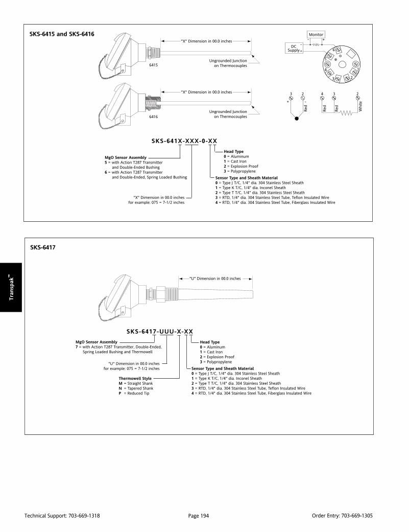
Page 194Technical Support: 703-669-1318 Order Entry: 703-669-1305
Tra
nsp
ak™
"X" Dimension in 00.0 inches
Ungrounded Junctionon Thermocouples
"X" Dimension in 00.0 inches
Ungrounded Junctionon Thermocouples
6415
6416
1
2
6
5
4
3
DCSupply+
-
Monitor- +
SKS-641X-XXX-0-XX
"X" Dimension in 00.0 inchesfor example: 075 = 7-1/2 inches
Head Type0 = Aluminum1 = Cast Iron2 = Explosion Proof3 = Polypropylene
Sensor Type and Sheath Material0 = Type J T/C, 1/4" dia. 304 Stainless Steel Sheath1 = Type K T/C, 1/4" dia. Inconel Sheath2 = Type T T/C, 1/4" dia. 304 Stainless Steel Sheath3 = RTD, 1/4" dia. 304 Stainless Steel Tube, Teflon Insulated Wire4 = RTD, 1/4" dia. 304 Stainless Steel Tube, Fiberglass Insulated Wire
MgO Sensor Assembly5 = with Action T287 Transmitter and Double-Ended Bushing6 = with Action T287 Transmitter and Double-Ended, Spring Loaded Bushing
SKS-6415 and SKS-6416
3 2 4 3 2
+ -
Red
Red
Red
Whi
te
SKS-6417
SKS-6417-UUU-X-XX
"U" Dimension in 00.0 inchesfor example: 075 = 7-1/2 inches
Head Type0 = Aluminum1 = Cast Iron2 = Explosion Proof3 = Polypropylene
Sensor Type and Sheath Material0 = Type J T/C, 1/4" dia. 304 Stainless Steel Sheath1 = Type K T/C, 1/4" dia. Inconel Sheath2 = Type T T/C, 1/4" dia. 304 Stainless Steel Sheath3 = RTD, 1/4" dia. 304 Stainless Steel Tube, Teflon Insulated Wire4 = RTD, 1/4" dia. 304 Stainless Steel Tube, Fiberglass Insulated Wire
Thermowell StyleMNP
= Straight Shank= Tapered Shank= Reduced Tip
"U" Dimension in 00.0 inches
MgO Sensor Assembly7 = with Action T287 Transmitter, Double-Ended, Spring Loaded Bushing and Thermowell
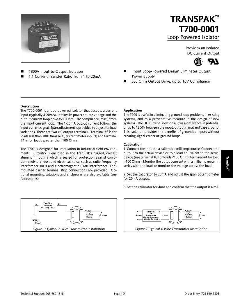
Page 195Technical Support: 703-669-1318 Order Entry: 703-669-1305
Tran
sPak
™
DescriptionThe T700-0001 is a loop-powered isolator that accepts a currentinput (typically 4-20mA). It takes its power source voltage and theoutput current loop drive (500 Ohm, 10V compliance, max.) fromthe input current loop. The 1-20mA output current follows theinput current signal. Span adjustment is provided to adjust for loadvariations. There are two (+) output terminals. Terminal #3 is forloads less than 100 Ohms (e.g., current meter inputs) and terminal#4 is for loads greater than 100 Ohms.
The T700 is designed for installation in industrial field environ-ments. Circuitry is enclosed in the TransPak’s rugged, diecastaluminum housing which is sealed for protection against corro-sion, moisture, dust and electrical noise, such as radio frequencyinterference (RFI) and electromagnetic (EMI) interference. Top-mounted barrier terminal strip connections are provided. Op-tional mounting solutions and enclosures are also available (seeAccessories).
TRANSPAK™
T700-0001Loop Powered Isolator
Provides an IsolatedDC Current Output
1800V Input-to-Output Isolation 1:1 Current Transfer Ratio from 1 to 20mA
Input Loop-Powered Design Eliminates OutputPower Supply
500 Ohm Output Drive, up to 10V Compliance
ApplicationThe T700 is useful in eliminating ground loop problems in existingsystems, and as a preventative measure in the design of newsystems. The DC current isolation allows a difference in potentialof up to 1800V between the input, output signal and case ground.This isolation provides the benefits of grounded inputs withoutcreating signal errors or ground loops.
Calibration1. Connect the input to a calibrated milliamp source. Connect theoutput to the actual device or to a load equivalent to the actualdevice (use terminal #3 for loads <100 Ohms, terminal #4 for load>100 Ohms). Monitor the output current with a milliamp meter inseries with the load or monitor the voltage across the load.
2. Set the calibrator to 20mA and adjust the span potentiometerfor 20mA output.
3. Set the calibrator for 4mA and confirm that the output is 4 mA.
Two-Wire
Transmitter
(P/I, Temp., etc.)
DC
Supply
Isolated
OutputLoad Power
Controlleror
Transmitter(Temp., Pressure,etc., to Current)
Isolated
OutputLoad
Figure 1: Typical 2-Wire Transmitter Installation Figure 2: Typical 4-Wire Transmitter Installation

Page 196Technical Support: 703-669-1318 Order Entry: 703-669-1305
Tra
nsp
ak™
Specifications
Input:
Ranges: 1-20mA and 4-20mA, 30Vdc max.
Voltage Drop: <3V, plus output load
Common Mode Rejection:
>100dB (DC to 60Hz)
Output:
Range: 1-20mA and 4-20mA
Terminal #4 Drive: 100 to 500 Ohm loads,
10V Max. at 20mA
Terminal #3 Drive: 0 to 100 Ohm loads,
2V Max. at 20mA
Note that only one (+) output terminal(either #3 or #4) can be used at a time.
Output Accuracy:
+0.1% of full-scale typical (250 Ohm load),
+0.2% maximum including linearity,hysterisis and repeatability.
Stability:
< 0.02%/°C of span max. for full-scale and zero
Load Regulation:
< 0.1% of span, typical per 10 Ohmchange, from 100 to 500 Ohms
Isolation:
1800Vdc, input to output to case ground
ESD Susceptibility:
Meets IEC 801-2 level 3 (8kV)
Terminal Wiring
Dimensions
Dimensions are in millimeters (inches)
Response Time:
50mSec maximum, 10 to 90%
Temperature:
Operating/Storage: -20 to 80°C (-4 to 176°F)Humidity:
25 to 95% @ 40°C, non-condensing
Weight:
0.56 lb.
Agency Approvals:
UL recognized per standard UL508,
(File No. E99775).
CSA certified per standard C22.2, No. 0-M91,and 142-M1987, (Certificate No. 2500001267).
Current
Loop
Input
Case Ground
Isolated
Output (Loads >100 Ohms)
Output (Loads <100 Ohms)
Optional Mounting Hardware
Ordering InformationModels & AccessoriesSpecify:1. Model T700-0001
AccessoriesM004 Snap-in Channel Track, 4 feet.T805 Explosion-Proof Housing.T902 Mounting Plate for M004, includes 4" track.T903 Extra Retaining Ring for T805 (included in T805).T906 Extra Mounting Plate w/slotted thumbscrews for Visipak
V565C (included in V565C).T910 Bulkhead Mounting Plate.
AP9046 Action Pak 24/40VDC, 65mA Power Supply.V565C 3-1/2 Digit LCD Indicator, wide-ranging display, NEMA 4X
Housing, Option C to house Transpak.
T805 Field Mountable Housing(EP, NEMA 4 rated) 3/4" Hub
(Includes T903 Retainer Ring & NEMA 4 Gasket)
Note that detailed installation instructions are
available on our website.

Page 197Technical Support: 703-669-1318 Order Entry: 703-669-1305
Tran
sPak
™
DescriptionThe T703 has 16 overlapping input ranges which are field select-able via top-accessed DIP switches (see Table 1). The T703canaccept input voltage spans from 20mV to 200 volts and inputcurrent spans from 1mA to 50mA. Bipolar selection modifies theunipolar range to include a negative offset (e.g. 200V becomes±100V). The T703 provides 1000Vrms of transformer-coupledisolation and 120VAC continuous input overload protection. Thetop-mounted super bright LED illuminates when the loop currentis above 3.3mA. Standard surface mount RFI filters reject walkie-talkie interference and noise. Current output is in proportion tothe selected voltage or current input.
The T703 has 80% zero “turn-up” and 80% span “turn-down”adjustments within any user-selected input range. For example,Range 11 of Table 1 specifies 0 to 100V with a minimum span of20V (100V - 20V = 80V, or 80%). This 80% adjustability allows theuser to field-calibrate the unit from the maximum (0 to 100V)down to any minimum (20V) span (e.g. 25V to 45V) within theselected 0 to 100V range. The same is true in any user-selectablerange: all spans are field adjustable from 20% (minimum span) to100% of the specified range.
ApplicationThe T703 is useful in any application requiring an isolated two-wireloop current from a DC source. Typical applications include longdistance signal transmission and the elimination of ground loops.The output of the T703 can be used to drive a digital meter fordirect display, or to interface with a computer for monitoring andcontrol applications.
The model T703 is FM approved for intrinsically safe operation,entity, Classes I, II, III, Division 1, Groups A-G and Nonincendive,Class I, Division 2, Groups A-D hazardous when installed permanufacturer’s drawing 790-0028-00.
The model T703 is CSA approved for intrinsically safe operationfor Class 1, Division 1, temperature code T3C, Groups A, B, C andD hazardous locations when installed per manufacturer’s drawing790-0025-00. Refer to model F703 for NEMA 4, FM/CSA/CENELECapproved explosion-proof housing.
TRANSPAK™
T703DC Input Isolating, Field Configurable
Two-Wire Transmitter
Provides an Isolated Current Loop in Proportion to aDC Current or Voltage Input
Field Configurable Input Ranges: 20mV to 200V,1mA to 50mA
Eliminates Ground Loops
Wide Ranging Zero and Span Super Bright LED Provides Go/No-Go Loop Status FM and CSA Safety Approval for Hazardous Installations
OptionsU Urethane coating of circuitry for protection from corrosiveatmospheres.
CalibrationNote: Factory settings are:
Input Range: 0 - 10VOutput: 4-20mA
1. Open the access lid on the top of the unit (see Top ViewDiagrams).
2. Select the input range from Table 1 and configure switches S1through S6. Bipolar span selection will divide the unipolar span inhalf (e.g., 20mA span = ±10mA bipolar span).
3. Determine the Span turn-down % (see Table 2).
% =
Example, Input: 0-10V
% =
4. Set the coarse Span rotary switch to the nearest span turn-down% setting (e.g., 10.7% = 20% position 1).
5. Determine the Zero turn-up % (see Table 3).
% =
*Note: On range 14, subtract 4mA from Desired Min. Input.
Example, Input: 0-10V
% =
6. Set the coarse step Zero turn-up switch to the nearest % setting(e.g., 0% = position 0).
(Limit Span) - (Desired Span)
Limit Spanx 100%
11.2V - 10V
11.2Vx 100% = 10.7%
x 100%Desired Min. Input*
Limit Span
0V
11.2Vx 100% = 0%
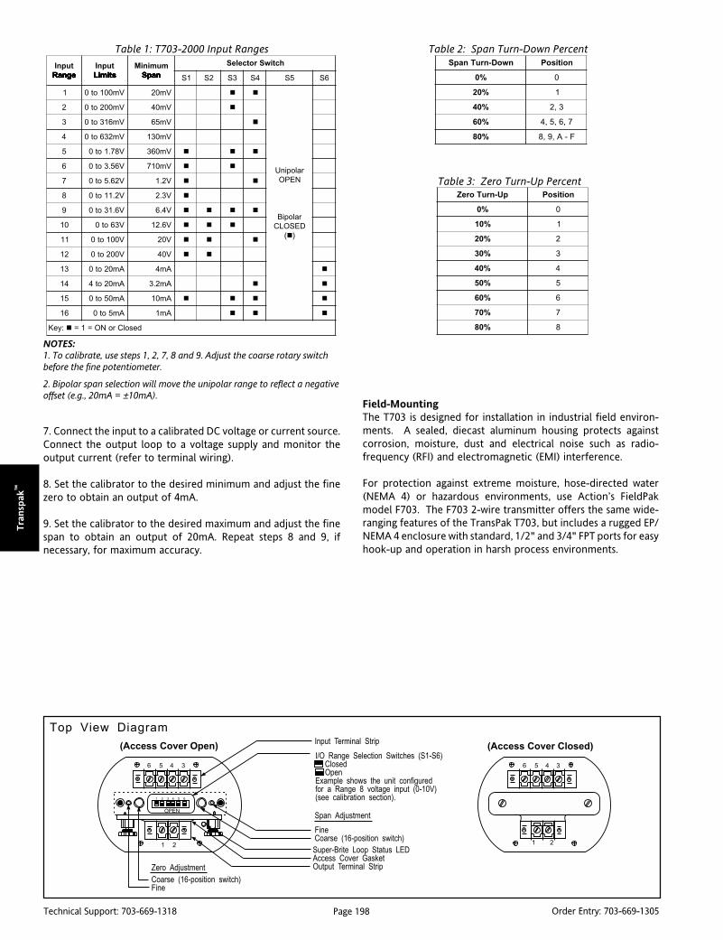
Page 198Technical Support: 703-669-1318 Order Entry: 703-669-1305
Tra
nsp
ak™
7. Connect the input to a calibrated DC voltage or current source.Connect the output loop to a voltage supply and monitor theoutput current (refer to terminal wiring).
8. Set the calibrator to the desired minimum and adjust the finezero to obtain an output of 4mA.
9. Set the calibrator to the desired maximum and adjust the finespan to obtain an output of 20mA. Repeat steps 8 and 9, ifnecessary, for maximum accuracy.
NOTES:1. To calibrate, use steps 1, 2, 7, 8 and 9. Adjust the coarse rotary switchbefore the fine potentiometer.
2. Bipolar span selection will move the unipolar range to reflect a negativeoffset (e.g., 20mA = ±10mA).
tupnIegnaR egnaR egnaR egnaR egnaR
tupnIstimiL stimiL stimiL stimiL stimiL
muminiMnapS napS napS napS napS
hctiwSrotceleS
1S 2S 3S 4S 5S 6S
1 Vm001ot0 Vm02
ralopinU
NEPO
ralopiB
DESOLC
()
2 Vm002ot0 Vm04
3 Vm613ot0 Vm56
4 Vm236ot0 Vm031
5 V87.1ot0 Vm063
6 V65.3ot0 Vm017
7 V26.5ot0 V2.1
8 V2.11ot0 V3.2
9 V6.13ot0 V4.6
01 V36ot0 V6.21
11 V001ot0 V02
21 V002ot0 V04
31 Am02ot0 Am4
41 Am02ot4 Am2.3
51 Am05ot0 Am01
61 Am5ot0 Am1
:yeK desolCroNO=1=
nwoD-nruTnapS noitisoP
%0 0
%02 1
%04 3,2
%06 7,6,5,4
%08 F-A,9,8
pU-nruToreZ noitisoP
%0 0
%01 1
%02 2
%03 3
%04 4
%05 5
%06 6
%07 7
%08 8
Table 1: T703-2000 Input Ranges Table 2: Span Turn-Down Percent
Table 3: Zero Turn-Up Percent
Top View Diagram
Field-MountingThe T703 is designed for installation in industrial field environ-ments. A sealed, diecast aluminum housing protects againstcorrosion, moisture, dust and electrical noise such as radio-frequency (RFI) and electromagnetic (EMI) interference.
For protection against extreme moisture, hose-directed water(NEMA 4) or hazardous environments, use Action’s FieldPakmodel F703. The F703 2-wire transmitter offers the same wide-ranging features of the TransPak T703, but includes a rugged EP/NEMA 4 enclosure with standard, 1/2" and 3/4" FPT ports for easyhook-up and operation in harsh process environments.

Page 199Technical Support: 703-669-1318 Order Entry: 703-669-1305
Tran
sPak
™
Note 2: For best RF & common mode rejection, ground the case (pin 6).Note 3: R
L represents any other device loads in the current loop.
1. The T703 loop supply Entity parameters: Vmax - 33V, Imax - 178.5mA, Ci - 12, nF, Li - 0uH.
2. FMRC Entity Approved associated apparatus used in an Approved configuration with Voc or Vt less thanVmax (33V) and lsc or lt less than Imax (178.5mA).
3. Ci of T703 (12 nF) plus total cable capacitance may not exceed Ca of associated apparatus.
4. Li of T703 (0uH) plus total cable inductance may not exceed La of associated apparatus.
5. Observe all requirements specified by the manufacturer's installation drawing for the Entity Approvedx-mitter as well as the following requirements:
a. Voc or Vt of associated apparatus supplying FMRC Entity Approved x-mitter may not exceed 30V orthe Vmax of the x-mitter, whichever is lower.
b. Isc or It of associated apparatus supplying FMRC Entity Approved x-mitter may not exceed 60mA ofthe Imax of the x-mitter, whichever is lower.
c. Ci of FMRC Entity Approved x-mitter plus total cable capacitance may not exceed Ca of associatedapparatus. T703 input terminals contribute 0uF.
d. Li of FMRC Entity Approved x-mitter plus total cable inductance may not exceed La of associatedapparatus. T703 terminals contribute 0uH.
6. Control room equipment may not use or generate over 250 VRMS.
7. Install in accordance with the NEC and local codes.
8. Run all wiring within separate cables or separate shields.
Installation (Drawing No. 790-0028-00)
Mounting HardwareDimensions in millimeters (inches)
T805 Field Mountable Housing (EP, NEMA 4 rated) 3/4" Hub(Includes T903 Retainer Ring & NEMA 4 Gasket)
T703 Terminal Wiring1. Loop Output (-)2. Loop Output (+)3. No Connection4. Input (+)5. Input (-)6. Shield (Gnd)
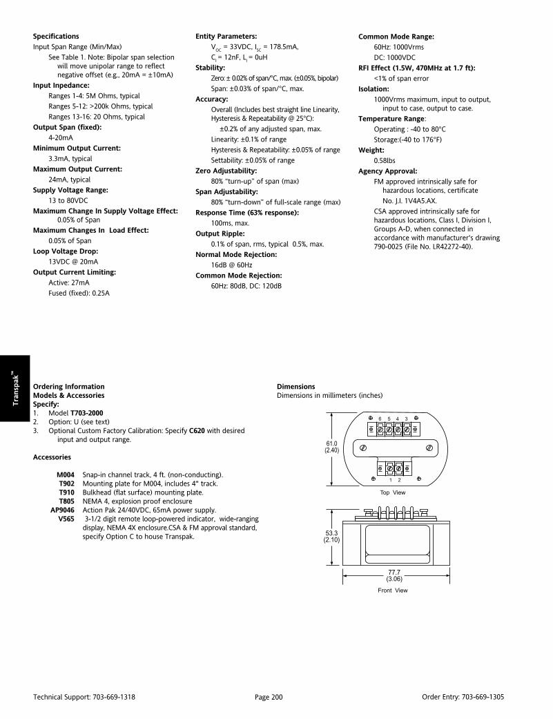
Page 200Technical Support: 703-669-1318 Order Entry: 703-669-1305
Tra
nsp
ak™
Ordering InformationModels & AccessoriesSpecify:1. Model T703-20002. Option: U (see text)3. Optional Custom Factory Calibration: Specify C620 with desired
input and output range.
Accessories
M004 Snap-in channel track, 4 ft. (non-conducting).T902 Mounting plate for M004, includes 4" track.T910 Bulkhead (flat surface) mounting plate.T805 NEMA 4, explosion proof enclosure
AP9046 Action Pak 24/40VDC, 65mA power supply.V565 3-1/2 digit remote loop-powered indicator, wide-ranging
display, NEMA 4X enclosure.CSA & FM approval standard,specify Option C to house Transpak.
Specifications
Input Span Range (Min/Max)
See Table 1. Note: Bipolar span selectionwill move unipolar range to reflectnegative offset (e.g., 20mA = ±10mA)
Input Inpedance:
Ranges 1-4: 5M Ohms, typical
Ranges 5-12: >200k Ohms, typical
Ranges 13-16: 20 Ohms, typical
Output Span (fixed):
4-20mA
Minimum Output Current:
3.3mA, typical
Maximum Output Current:
24mA, typical
Supply Voltage Range:
13 to 80VDC
Maximum Change In Supply Voltage Effect:0.05% of Span
Maximum Changes In Load Effect:
0.05% of Span
Loop Voltage Drop:
13VDC @ 20mA
Output Current Limiting:
Active: 27mA
Fused (fixed): 0.25A
Entity Parameters:
VOC = 33VDC, ISC = 178.5mA,
CI = 12nF, LI = 0uH
Stability:
Zero: ± 0.02% of span/°C, max. (±0.05%, bipolar)
Span: ±0.03% of span/°C, max.
Accuracy:
Overall (Includes best straight line Linearity,Hysteresis & Repeatability @ 25°C):
±0.2% of any adjusted span, max.
Linearity: ±0.1% of range
Hysteresis & Repeatability: ±0.05% of range
Settability: ±0.05% of range
Zero Adjustability:
80% “turn-up” of span (max)
Span Adjustability:
80% “turn-down” of full-scale range (max)
Response Time (63% response):
100ms, max.
Output Ripple:
0.1% of span, rms, typical 0.5%, max.
Normal Mode Rejection:
16dB @ 60Hz
Common Mode Rejection:
60Hz: 80dB, DC: 120dB
Common Mode Range:
60Hz: 1000Vrms
DC: 1000VDC
RFI Effect (1.5W, 470MHz at 1.7 ft):
<1% of span error
Isolation:
1000Vrms maximum, input to output,input to case, output to case.
Temperature Range:
Operating : -40 to 80°CStorage:(-40 to 176°F)
Weight:
0.58lbs
Agency Approval:
FM approved intrinsically safe forhazardous locations, certificate
No. J.I. 1V4A5.AX.
CSA approved intrinsically safe forhazardous locations, Class I, Division I,Groups A-D, when connected inaccordance with manufacturer's drawing790-0025 (File No. LR42272-40).
DimensionsDimensions in millimeters (inches)

Page 201Technical Support: 703-669-1318 Order Entry: 703-669-1305
Tran
sPak
™
DescriptionThe T713 series has 6 widely adjustable input ranges and 2 outputranges, all of which are field selectable via top accessed DIPswitches. The T713 provides 600VDC of isolation with outputs ofeither 4-20mA or 10-50mA. Current outputs are linear to tempera-ture. Urethane coating of internal circuitry for protection fromcorrosive atmospheres is included as standard.
The T713 has an 80% zero and span adjustability within any userselected input range. For example, Range 1 of Table 1 specifies 0to 1000° F with a minimum span of 200° F (1000° - 200° = 800°,or 80%). This 80% adjustability allows the user to field calibrate theunit for the maximum (0 to 1000°) down to any minimum (200°)span (e.g. 740° to 940°) - as long as that adjusted span remainswithin the selected 0 to 1000°F range. The same is true for any userselectable range: all spans are field adjustable from 20% (minimumspan) to 100% of the specified range.
TRANSPAK™
T713RTD Input Isolating, Field Configurable
Two-Wire Transmitter
Provides an Isolated, Linearized Current Loop inProportion to a 3-Wire Pt100 RTD Input
Field Configurable, Switch Selectable Input Ranges Eliminates Ground Loops Wide Ranging Zero & Span
T713-0000
T713-0013 (-200°C offset)
Integral RTD Linearization/Output Linear toTemperature
FM Safety Approval for Hazardous Installations
ApplicationThe T713 is useful in any application requiring isolation of a 2-wireloop current from a 3-wire RTD. Typical applications includeSCADA and remote data acquisition such as monitoring boiler orcustody transfer/pipeline temperatures. The output of the T713can be used to drive a digital meter for direct display or interfacewith a computer for monitoring and control applications.
The T713 is FM approved for intrinsically safe operation in ClassI, Division 1, Groups A, B, C, and D; Nonincendive Class I Division2, Groups A, B, C and D, and Classes II & III, Division 2, Group Ghazardous locations when installed per manufacturer’s drawing790-0024-00. Refer to model T805 for NEMA 4, FM/CSA/CENELECapproved explosion proof housing.
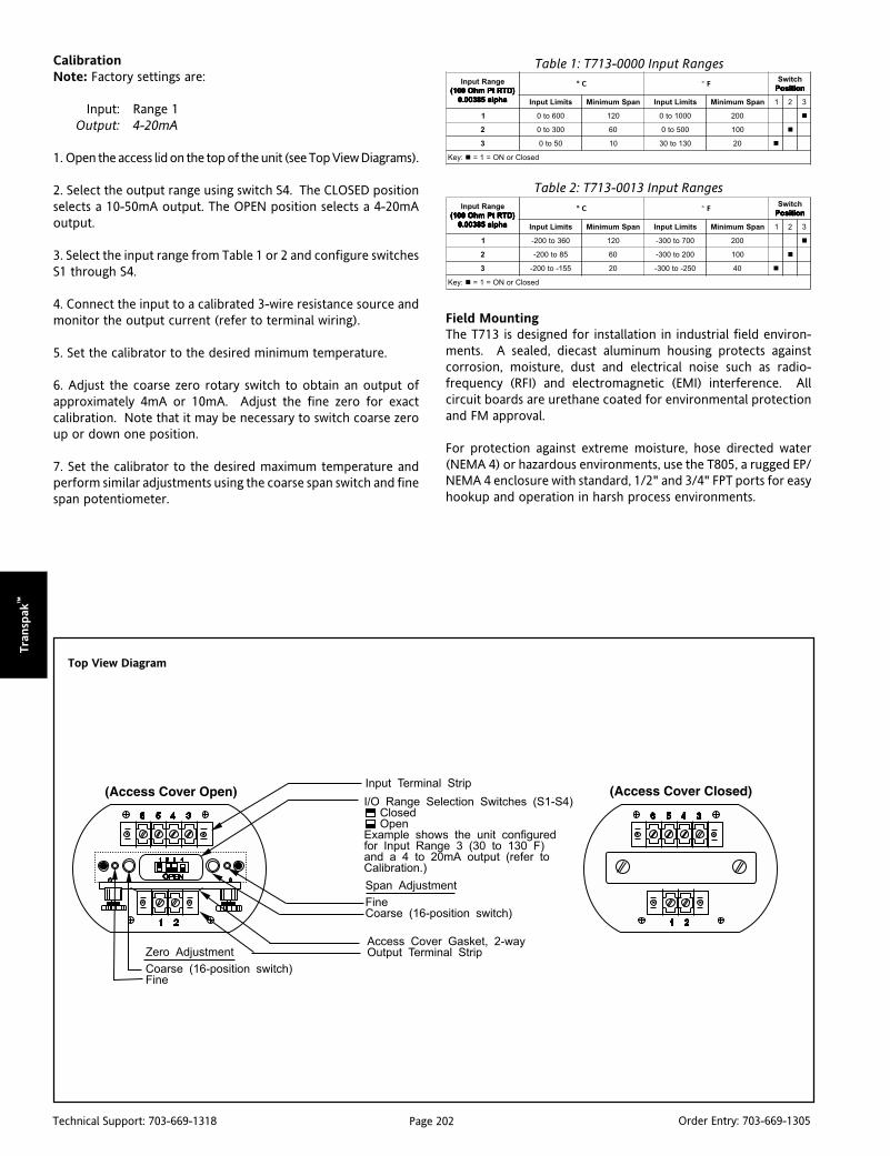
Page 202Technical Support: 703-669-1318 Order Entry: 703-669-1305
Tra
nsp
ak™
Top View Diagram
CalibrationNote: Factory settings are:
Input: Range 1Output: 4-20mA
1. Open the access lid on the top of the unit (see Top View Diagrams).
2. Select the output range using switch S4. The CLOSED positionselects a 10-50mA output. The OPEN position selects a 4-20mAoutput.
3. Select the input range from Table 1 or 2 and configure switchesS1 through S4.
4. Connect the input to a calibrated 3-wire resistance source andmonitor the output current (refer to terminal wiring).
5. Set the calibrator to the desired minimum temperature.
6. Adjust the coarse zero rotary switch to obtain an output ofapproximately 4mA or 10mA. Adjust the fine zero for exactcalibration. Note that it may be necessary to switch coarse zeroup or down one position.
7. Set the calibrator to the desired maximum temperature andperform similar adjustments using the coarse span switch and finespan potentiometer.
Table 1: T713-0000 Input Ranges
Table 2: T713-0013 Input Ranges
egnaRtupnI)DTRtPmhO001( )DTRtPmhO001( )DTRtPmhO001( )DTRtPmhO001( )DTRtPmhO001(
ahpla58300.0 ahpla58300.0 ahpla58300.0 ahpla58300.0 ahpla58300.0
C° ° FhctiwSnoitisoP noitisoP noitisoP noitisoP noitisoP
stimiLtupnI napSmuminiM stimiLtupnI napSmuminiM 1 2 3
1 006ot0 021 0001ot0 002
2 003ot0 06 005ot0 001
3 05ot0 01 031ot03 02
:yeK desolCroNO=1=
egnaRtupnI)DTRtPmhO001( )DTRtPmhO001( )DTRtPmhO001( )DTRtPmhO001( )DTRtPmhO001(
ahpla58300.0 ahpla58300.0 ahpla58300.0 ahpla58300.0 ahpla58300.0
C° ° FhctiwSnoitisoP noitisoP noitisoP noitisoP noitisoP
stimiLtupnI napSmuminiM stimiLtupnI napSmuminiM 1 2 3
1 063ot002- 021 007ot003- 002
2 58ot002- 06 002ot003- 001
3 551-ot002- 02 052-ot003- 04
:yeK desolCroNO=1=
Field MountingThe T713 is designed for installation in industrial field environ-ments. A sealed, diecast aluminum housing protects againstcorrosion, moisture, dust and electrical noise such as radio-frequency (RFI) and electromagnetic (EMI) interference. Allcircuit boards are urethane coated for environmental protectionand FM approval.
For protection against extreme moisture, hose directed water(NEMA 4) or hazardous environments, use the T805, a rugged EP/NEMA 4 enclosure with standard, 1/2" and 3/4" FPT ports for easyhookup and operation in harsh process environments.

Page 203Technical Support: 703-669-1318 Order Entry: 703-669-1305
Tran
sPak
™
T713 Terminal Connections
1. Loop Output (-)2. Loop Output (+)3. RTD Exc (+)4. RTD (+)5. RTD (-)6. Shield (Gnd)
Mounting Hardware
Dimensions in millimeters (inches)
NOTE 1: RL represents any other device loads in the current loop.
NOTE 2: For best RF and common mode rejection, ground the case (pin #6).
T805 Field Mountable Housing (EP, NEMA 4 rated) 3/4" Hub(Includes T903 Retainer Ring & NEMA 4 Gasket)

Page 204Technical Support: 703-669-1318 Order Entry: 703-669-1305
Tra
nsp
ak™ Ordering Information
Models & AccessoriesSpecify:1. Model:
T713-0000T713-0013 (-200°C offset)
2. Optional Custom Factory Calibration: Specify C620 with desiredinput and output range.
Accessories
M004 Snap-in Channel Track, 4 ft. (nonconducting).T902 Mounting plate for M004, includes 4" track.T910 Bulkhead (flat surface) mounting plate.
AP9046 Action Pak 24/40VDC, 65mA Power Supply.T805 NEMA 4, explosion proof enclosure.V565 3-1/2 digit remote loop-powered indicator, wide ranging
display, NEMA 4X enclosure, CSA & FM approvalstandard. Specify Option C to house Transpak.
C620 Factory calibration (user specified).
DimensionsDimensions in millimeters (inches)
Specifications
Input Span Range (Min/Max):
See Tables 1, 2
Excitation Current:
1mA, typical
Leadwire Resistance Effect:
1% of span error with up to 40 Ohms/lead
Output Span:
4-20mA/10-50mA, switch selectable
Minimum Output Current:
3.3mA, typical
Maximum Output Current:
4-20mA: 24mA, typical
10-50mA: 58mA, typical
Supply Voltage Range:
4-20mA: 12 to 80VDC
10-50mA: 12 to 60VDC
Maximum Change in Supply - Voltage Effect:0.05% of span
Maximum Change in Load Effect:0.05% of span
Loop Voltage Drop:
12VDC @ 20mA
Linearizing Accuracy:
T713-0000: ± 0.1% of standard R/T tables,typical; 0.2% max.
T713-0013: ± 0.21% of standard R/T tables,typical; 0.3% max.
Stability:
Zero: ± 0.02% of span/°C, typical, or 2mV,whichever is greater
Span: ± 0.01% of span/°C, typical
Overall Accuracy (Includes Linearity,Hysteresis, Stability):
± 0.5% of any adjusted span, max.
Zero and Span Adjustability:
80% of any selected range
Repeatability:
± 0.05% of span, typical
Response Time:
150ms, typical, 400ms max.
Output Ripple:
0.1% of span, rms, typical
RFI Effect (5W, 470MHz at 3 Ft.):
<1% of span error
Isolation:
600V DC maximum, input to output to case
Temperature Range:
Operating: -40 to 80°C (-40 to 176°F)
Weight:
0.64lbs
Agency Approval:
FM approved intrinsically safe for hazardouslocations, certificate No. J.I. 2M2A5.AX (3611).

Page 205Technical Support: 703-669-1318 Order Entry: 703-669-1305
Tran
sPak
™
DescriptionThe T723 offers a choice of J/K/T or E/R/S input ranges and 2output ranges, which are field selectable via top-accessed DIPswitches (see Tables 1-2). The T723 provides 600 VDC input tooutput isolation with outputs of either 4-20mA or 10-50mA. Thecurrent output is linear to the equivalent mV thermocouple signaland non-linear to temperature, which is useful in data acquisitionsystems that utilize linearizing software. Upscale burnout (maxi-mum output with an open thermocouple) is standard.
The T723 has 80% zero and span adjustability within any userselected input ranges shown in Table 1 and 2. For example, RangeK1 of Table 1 specifies 0° to 500°C with a minimum span of 100°C(500°-100° = 400°, or 80%). This 80% adjustability allows the user tofield calibrate the unit from the maximum (0 to 500°) down to anyminimum (100°C) span (e.g. 14°C to 114°C) as long as that adjustedspan remains within the selected 0 to 500°C range. The same is truefor any user selectable range: all spans are field adjustable from 20%(minimum span) to 100% of the specified range.
TRANSPAK™
T723Thermocouple Input Isolating, FieldConfigurable Two-Wire Transmitter
Provides an Isolated Current Loopin Proportion to a Thermocouple Input
Field Configurable Switch Selectable Input Ranges Eliminates Ground Loops Integral Cold-Junction Compensation
T723-0000 (Type J/K/T input)
T723-0001 (Type E/R/S input)
600V Input to Output Isolation Wide Ranging Zero and Span Adjustability (80%) FM Safety Approval for Hazardous Installations
ApplicationThe T723 is useful in any application requiring isolation of a 2-wireloop current from a thermocouple input. Typical applicationsinclude energy management and data acquisition such as moni-toring remote boiler temperatures. The output of the T723 caninterface with a digital meter for direct display or interface with acomputer for monitoring and control applications.
The T723 is FM approved for intrinsically safe operation in ClassI, Division 1, Groups A, B, C, and D; Nonincendive Class I Division2, Groups A, B, C and D, and Classes II & III, Division 2, Group Ghazardous locations when installed per manufacturer’s drawing790-0024-00. Refer to model T805 for NEMA 4, FM/CSA/CENELECapproved explosion proof, field mount housing.
OptionsB Downscale Burnout (minimum output with an open TC)
Urethane coating of internal circuitry for protection from corro-sive atmospheres is included as standard.
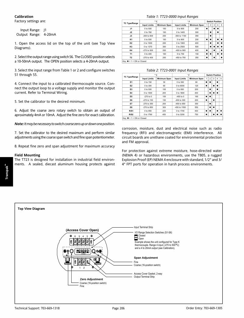
Page 206Technical Support: 703-669-1318 Order Entry: 703-669-1305
Tra
nsp
ak™
Top View Diagram
CalibrationFactory settings are:
Input Range: J1Output Range: 4-20mA
1. Open the access lid on the top of the unit (see Top ViewDiagrams).
2. Select the output range using switch S6. The CLOSED position selectsa 10-50mA output. The OPEN position selects a 4-20mA output.
3. Select the input range from Table 1 or 2 and configure switchesS1 through S5.
4. Connect the input to a calibrated thermocouple source. Con-nect the output loop to a voltage supply and monitor the outputcurrent. Refer to Terminal Wiring.
5. Set the calibrator to the desired minimum.
6. Adjust the coarse zero rotary switch to obtain an output ofaproximately 4mA or 10mA. Adjust the fine zero for exact calibration.
Note: It may be necessary to switch coarse zero up or down one position.
7. Set the calibrator to the desired maximum and perform similaradjustments using the coarse span switch and fine span potentiometer.
8. Repeat fine zero and span adjustment for maximum accuracy
Field MountingThe T723 is designed for installation in industrial field environ-ments. A sealed, diecast aluminum housing protects against
egnaR/epyTCTC° ° F noitisoPhctiwS
stimiLtupnI napSmuminiM stimiLtupnI napSmuminiM 1 2 3 4 5
1E 051ot0 03 003ot0 06
2E 003ot0 06 0006ot0 021
3E 005ot0 001 059ot0 002
4E 0001ot0 002 0081ot0 004
5E 0ot072- 001 0ot054- 061
6E 051ot072- 051 003ot054- 002
7E 053ot072- 002 056ot054- 053
8E 058ot072- 003 0551ot054- 055
1S/R 059ot0 022 0071ot0 004
2S/R 0671ot0 054 0023ot0 057
:yeK desolCroNO=1=
Table 1: T723-0000 Input Ranges
Table 2: T723-0001 Input Ranges
Zero Adjustment
Span Adjustment
corrosion, moisture, dust and electrical noise such as radiofrequency (RFI) and electromagnetic (EMI) interference. Allcircuit boards are urethane coated for environmental protectionand FM approval.
For protection against extreme moisture, hose-directed water(NEMA 4) or hazardous environments, use the T805, a ruggedExplosion Proof (EP) NEMA 4 enclosure with standard, 1/2" and 3/4" FPT ports for operation in harsh process environments.
egnaR/epyTCTC° ° F noitisoPhctiwS
stimiLtupnI napSmuminiM stimiLtupnI napSmuminiM 1 2 3 4 5
1J 005ot0 001 009ot0 002
2J 067ot0 051 0041ot0 003
3J 006ot002- 002 0011ot053- 053
1K 005ot0 001 009ot0 002
2K 0001ot0 002 0091ot0 004
3K 0731ot0 003 0052ot0 005
4K 005ot072- 002 009ot054- 004
1T 004ot0 001 057ot0 051
2T 004ot072- 002 057ot054- 053
:yeK desolCroNO=1=

Page 207Technical Support: 703-669-1318 Order Entry: 703-669-1305
Tran
sPak
™
Note 1: For best RF & common mode rejection, ground the case (pin 6).Note 2: R
L represents any other device loads in the current loop.
T723 Terminal Connections
1. Loop Output (-)2. Loop Output (+)3. No Connection4. Input (+)5. Input (-)6. Shield (Gnd)
Mounting Hardware
Dimensions in millimeters (inches)
T805 Field Mountable Housing (EP, NEMA 4 rated) 3/4" Hub(Includes T903 Retainer Ring & NEMA 4 Gasket)

Page 208Technical Support: 703-669-1318 Order Entry: 703-669-1305
Tra
nsp
ak™
Ordering InformationModels & AccessoriesSpecify:1. Model: T723-0000: J/K/T Inputs
Model: T723-0001: E/R/S Inputs2. Option: B (Downscale Burnout)3. Optional Custom Factoy Calibration: Specify C620 with desired
input and output range.
Accessories
M004 Snap-in Channel Track, 4 feet.T902 Mounting plate for M004, includes 4" track.T910 Bulkhead (flat surface) Mounting plate.T805 Explosion Proof/NEMA4 enclosure
AP9046 Action Pak 24/40VDC, 65mA Power Supply.V565 3-1/2 digit remote loop powered indicator. Wide
ranging display, NEMA 4X enclosure. CSA & FM approvalstandard. Specify Option C to house Transpak.
Specifications
Input Span Range (Max/Min):
See Tables 1 and 2
Leadwire Resistance Effect:
<0.25 uV/Ohm
Burnout Detection Current:
250nA, max.
Output Span:
4-20mA/10-50mA, switch selectable
Minimum Output Current:
3.3mA, typical
Maximum Output Current:
4-20mA: 24mA, typical
10-50mA: 58mA, typical
Supply Voltage Range:
4-20mA: 12 to 80VDC
10-50mA: 12 to 60VDC
Maximum Change in Supply:
0.05% of span
Maximum Change in Load Effect:0.05% of span
Loop Voltage Drop:
12VDC @ 20mA
Stability:
Zero: ±0.02% of span/°C, max.
Span: ±0.01% of span/°C, max.
Overall Accuracy (Includes Linearity,Hysteresis, Stability):±0.5% of any adjusted span, max.
Zero and Span Adjustability:
80% of any selected range
Repeatability:
±0.05% of span, typical
Cold-Junction Error (Ambient):
J/K/T/E Inputs
0 to 80°C: 1°C, typical
-40 to 0°C: 3°C, typical
R/S Inputs
0 to 80°C: 2°C, typical
-40 to 0°C: 5°C, typical
DimensionsDimensions in millimeters (inches)
Response Time:
100ms, typical; 200ms, max.
Output Ripple:
0.1% of span, rms, typical
RFI Effect (5W, 470MHz at 3 Ft.):
<1% of span error, typical
Isolation:
600V DC or peak AC max., input tooutput to case
Temperature Range:
Operating: -40 to 80°C (-40 to 176°F)
Weight:
0.56lbs
Agency Approvals:
FM approved intrinsically safe for hazardouslocations, certificate No. 2M2A5.AX.
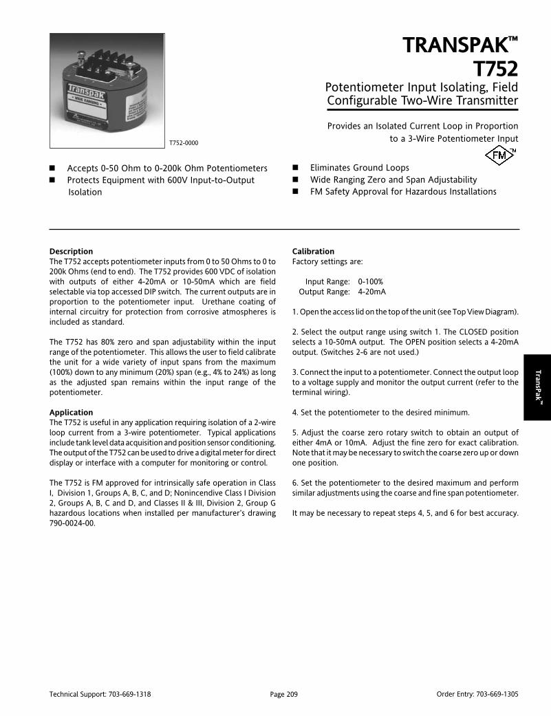
Page 209Technical Support: 703-669-1318 Order Entry: 703-669-1305
Tran
sPak
™
DescriptionThe T752 accepts potentiometer inputs from 0 to 50 Ohms to 0 to200k Ohms (end to end). The T752 provides 600 VDC of isolationwith outputs of either 4-20mA or 10-50mA which are fieldselectable via top accessed DIP switch. The current outputs are inproportion to the potentiometer input. Urethane coating ofinternal circuitry for protection from corrosive atmospheres isincluded as standard.
The T752 has 80% zero and span adjustability within the inputrange of the potentiometer. This allows the user to field calibratethe unit for a wide variety of input spans from the maximum(100%) down to any minimum (20%) span (e.g., 4% to 24%) as longas the adjusted span remains within the input range of thepotentiometer.
ApplicationThe T752 is useful in any application requiring isolation of a 2-wireloop current from a 3-wire potentiometer. Typical applicationsinclude tank level data acquisition and position sensor conditioning.The output of the T752 can be used to drive a digital meter for directdisplay or interface with a computer for monitoring or control.
The T752 is FM approved for intrinsically safe operation in ClassI, Division 1, Groups A, B, C, and D; Nonincendive Class I Division2, Groups A, B, C and D, and Classes II & III, Division 2, Group Ghazardous locations when installed per manufacturer’s drawing790-0024-00.
TRANSPAK™
T752Potentiometer Input Isolating, FieldConfigurable Two-Wire Transmitter
Provides an Isolated Current Loop in Proportionto a 3-Wire Potentiometer Input
Accepts 0-50 Ohm to 0-200k Ohm Potentiometers Protects Equipment with 600V Input-to-Output
Isolation
T752-0000
Eliminates Ground Loops Wide Ranging Zero and Span Adjustability FM Safety Approval for Hazardous Installations
CalibrationFactory settings are:
Input Range: 0-100%Output Range: 4-20mA
1. Open the access lid on the top of the unit (see Top View Diagram).
2. Select the output range using switch 1. The CLOSED positionselects a 10-50mA output. The OPEN position selects a 4-20mAoutput. (Switches 2-6 are not used.)
3. Connect the input to a potentiometer. Connect the output loopto a voltage supply and monitor the output current (refer to theterminal wiring).
4. Set the potentiometer to the desired minimum.
5. Adjust the coarse zero rotary switch to obtain an output ofeither 4mA or 10mA. Adjust the fine zero for exact calibration.Note that it may be necessary to switch the coarse zero up or downone position.
6. Set the potentiometer to the desired maximum and performsimilar adjustments using the coarse and fine span potentiometer.
It may be necessary to repeat steps 4, 5, and 6 for best accuracy.
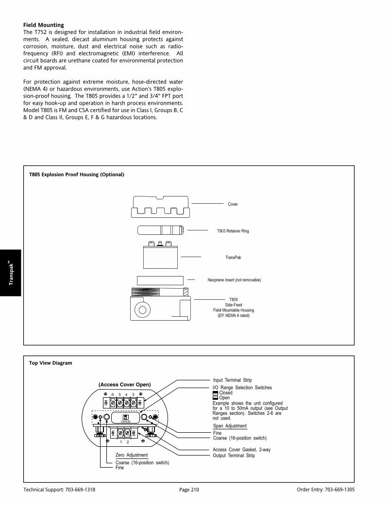
Page 210Technical Support: 703-669-1318 Order Entry: 703-669-1305
Tra
nsp
ak™
Top View Diagram
T805 Explosion Proof Housing (Optional)
Field MountingThe T752 is designed for installation in industrial field environ-ments. A sealed, diecast aluminum housing protects againstcorrosion, moisture, dust and electrical noise such as radio-frequency (RFI) and electromagnetic (EMI) interference. Allcircuit boards are urethane coated for environmental protectionand FM approval.
For protection against extreme moisture, hose-directed water(NEMA 4) or hazardous environments, use Action’s T805 explo-sion-proof housing. The T805 provides a 1/2" and 3/4" FPT portfor easy hook-up and operation in harsh process environments.Model T805 is FM and CSA certified for use in Class I, Groups B, C& D and Class II, Groups E, F & G hazardous locations.

Page 211Technical Support: 703-669-1318 Order Entry: 703-669-1305
Tran
sPak
™
T752 Terminal Connections
1. Loop Output (-)2. Loop Output (+)3. Pot (CW)4. Pot wiper5. Pot (CCW)6. Shield (Gnd)
Note 1: For best RF & common mode rejection, ground the case (pin 6).Note 2: R
L represents any other device loads in the current loop.
Mounting Hardware
T805 Field Mountable Housing (EP, NEMA 4 rated) 3/4" Hub(Includes T903 Retainer Ring & NEMA 4 Gasket)
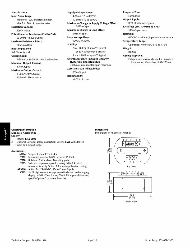
Page 212Technical Support: 703-669-1318 Order Entry: 703-669-1305
Tra
nsp
ak™ Ordering Information
Models & AccessoriesSpecify:1. Model: T752-00002. Optional Custom Factory Calibration: Specify C620 with desired
input and output range.
AccessoriesM004 Snap-in Channel Track, 4 feet.T902 Mounting plate for M004, includes 4" track.T910 Bulkhead (flat surface) Mounting plate.T805 Side feed explosion-proof housing (NEMA 4 rated),
uncoated (specify Option P for white polyester coating).AP9046 Action Pak 24/40VDC, 65mA Power Supply.
V565 3-1/2 digit remote loop-powered indicator, wide-rangingdisplay, NEMA 4X enclosure, CSA & FM approval standard,specify Option C to house TransPak.
Specifications
Input Span Range:
Max: 0 to 100% of potentiometer
Min: 0 to 20% of potentiometer
Excitation Voltage:
50mV typical
Potentiometer Resistance (End to End):
50 Ohms to 200k Ohms
Leadwire Resistance Effect:
<0.25 uV/Ohm
Input Impedance:
5M Ohms, typical
Output Span:
4-20mA or 10-50mA, switch selectable
Minimum Output Current:
3.3mA typical
Maximum Output Current:
4-20mA: 24mA typical
10-50mA: 58mA typical
DimensionsDimensions in millimeters (inches)
Supply-Voltage Range:
4-20mA: 12 to 80VDC
10-50mA: 12 to 60VDC
Maximum Change in Supply Voltage Effect:0.05% of span
Maximum Change in Load Effect:
0.05% of span
Loop Voltage Drop:
12VDC @ 20mA
Stability:
Zero: ±0.02% of span/°C typical,
or 2uV, whichever is greater
Span: ±0.01% of span/°C typical
Overall Accuracy (Includes Linearity,Hysteresis, Repeatability):±0.05% of any adjusted span maximum
Zero and Span Adjustability:
80% of input
Repeatability:
±0.05% of span
Response Time:
50ms, max.
Output Ripple:
0.1% of span rms, typical
RFI Effect (5W, 470MHz at 3 Ft.):
<1% of span error
Isolation:
600V DC maximum, input to output to case
Temperature Range:
Operating: -40 to 80°C (-40 to 176F)
Weight:
0.62lbs
Agency Approval:
FM approved intrinsically safe for hazardouslocation, certificate No. J.I. 2M2A5.AX.
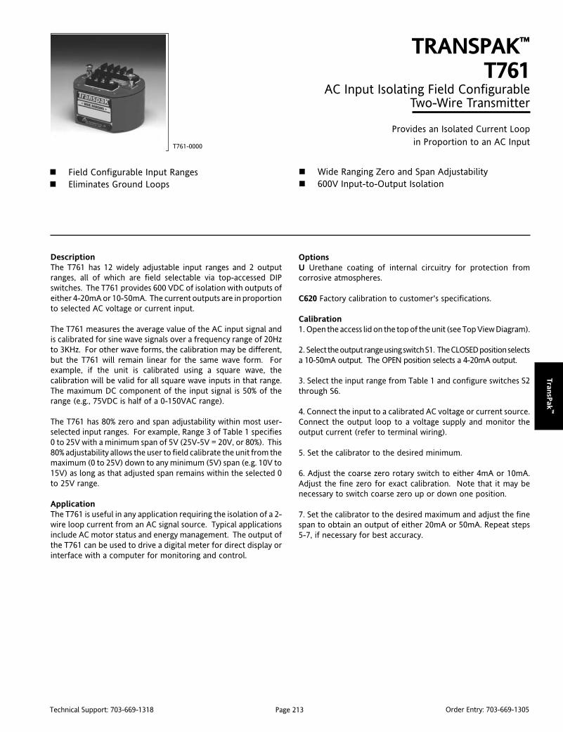
Page 213Technical Support: 703-669-1318 Order Entry: 703-669-1305
Tran
sPak
™
DescriptionThe T761 has 12 widely adjustable input ranges and 2 outputranges, all of which are field selectable via top-accessed DIPswitches. The T761 provides 600 VDC of isolation with outputs ofeither 4-20mA or 10-50mA. The current outputs are in proportionto selected AC voltage or current input.
The T761 measures the average value of the AC input signal andis calibrated for sine wave signals over a frequency range of 20Hzto 3KHz. For other wave forms, the calibration may be different,but the T761 will remain linear for the same wave form. Forexample, if the unit is calibrated using a square wave, thecalibration will be valid for all square wave inputs in that range.The maximum DC component of the input signal is 50% of therange (e.g., 75VDC is half of a 0-150VAC range).
The T761 has 80% zero and span adjustability within most user-selected input ranges. For example, Range 3 of Table 1 specifies0 to 25V with a minimum span of 5V (25V-5V = 20V, or 80%). This80% adjustability allows the user to field calibrate the unit from themaximum (0 to 25V) down to any minimum (5V) span (e.g. 10V to15V) as long as that adjusted span remains within the selected 0to 25V range.
ApplicationThe T761 is useful in any application requiring the isolation of a 2-wire loop current from an AC signal source. Typical applicationsinclude AC motor status and energy management. The output ofthe T761 can be used to drive a digital meter for direct display orinterface with a computer for monitoring and control.
TRANSPAK™
T761AC Input Isolating Field Configurable
Two-Wire Transmitter
Provides an Isolated Current Loopin Proportion to an AC Input
Field Configurable Input Ranges Eliminates Ground Loops
T761-0000
Wide Ranging Zero and Span Adjustability 600V Input-to-Output Isolation
OptionsU Urethane coating of internal circuitry for protection fromcorrosive atmospheres.
C620 Factory calibration to customer's specifications.
Calibration1. Open the access lid on the top of the unit (see Top View Diagram).
2. Select the output range using switch S1. The CLOSED position selectsa 10-50mA output. The OPEN position selects a 4-20mA output.
3. Select the input range from Table 1 and configure switches S2through S6.
4. Connect the input to a calibrated AC voltage or current source.Connect the output loop to a voltage supply and monitor theoutput current (refer to terminal wiring).
5. Set the calibrator to the desired minimum.
6. Adjust the coarse zero rotary switch to either 4mA or 10mA.Adjust the fine zero for exact calibration. Note that it may benecessary to switch coarse zero up or down one position.
7. Set the calibrator to the desired maximum and adjust the finespan to obtain an output of either 20mA or 50mA. Repeat steps5-7, if necessary for best accuracy.
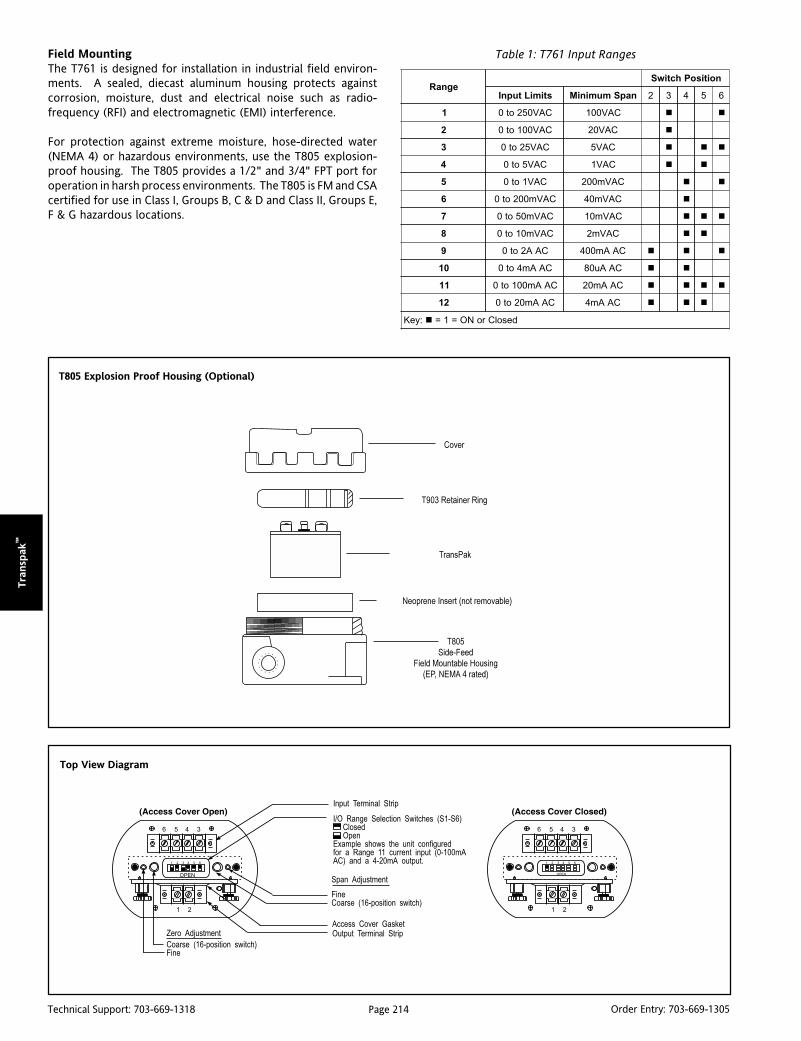
Page 214Technical Support: 703-669-1318 Order Entry: 703-669-1305
Tra
nsp
ak™
egnaRnoitisoPhctiwS
stimiLtupnI napSmuminiM 2 3 4 5 6
1 CAV052ot0 CAV001
2 CAV001ot0 CAV02
3 CAV52ot0 CAV5
4 CAV5ot0 CAV1
5 CAV1ot0 CAVm002
6 CAVm002ot0 CAVm04
7 CAVm05ot0 CAVm01
8 CAVm01ot0 CAVm2
9 CAA2ot0 CAAm004
01 CAAm4ot0 CAAu08
11 CAAm001ot0 CAAm02
21 CAAm02ot0 CAAm4
:yeK desolCroNO=1=
Table 1: T761 Input Ranges
Top View Diagram
T805 Explosion Proof Housing (Optional)
Field MountingThe T761 is designed for installation in industrial field environ-ments. A sealed, diecast aluminum housing protects againstcorrosion, moisture, dust and electrical noise such as radio-frequency (RFI) and electromagnetic (EMI) interference.
For protection against extreme moisture, hose-directed water(NEMA 4) or hazardous environments, use the T805 explosion-proof housing. The T805 provides a 1/2" and 3/4" FPT port foroperation in harsh process environments. The T805 is FM and CSAcertified for use in Class I, Groups B, C & D and Class II, Groups E,F & G hazardous locations.

Page 215Technical Support: 703-669-1318 Order Entry: 703-669-1305
Tran
sPak
™
Note 1: For best RF & common mode rejection, ground the case (pin 6).Note 2: R
L represents any other device loads in the current loop.
T761 Terminal Connections
1. Loop Output (-)2. Loop Output (+)3. No Connection4. Input5. Input6. Shield (Gnd)
Mounting Hardware
T805 Field Mountable Housing (EP, NEMA 4 rated) 3/4" Hub(Includes T903 Retainer Ring & NEMA 4 Gasket)
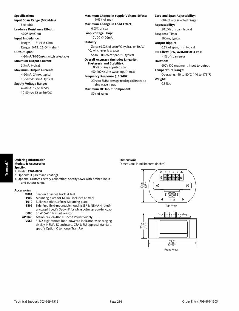
Page 216Technical Support: 703-669-1318 Order Entry: 703-669-1305
Tra
nsp
ak™
Ordering InformationModels & AccessoriesSpecify:1. Model: T761-00002. Options: U (Urethane coating)3. Optional Custom Factory Calibration: Specify C620 with desired input
and output range.
AccessoriesM004 Snap-in Channel Track, 4 feet.T902 Mounting plate for M004, includes 4" track.T910 Bulkhead (flat surface) Mounting plate.T805 Side feed field-mountable housing (EP & NEMA 4 rated),
uncoated (specify Option P for white polyester powder coat).C006 0.1W, 5W, 1% shunt resistor
AP9046 Action Pak 24/40VDC 65mA Power Supply.V565 3-1/2 digit remote loop-powered indicator, wide-ranging
display, NEMA 4X enclosure, CSA & FM approval standard,specify Option C to house TransPak
Specifications
Input Span Range (Max/Min):
See table 1
Leadwire Resistance Effect:
<0.25 uV/Ohm
Input Impedance:
Ranges 1-8: >1M Ohm
Ranges 9-12: 0.5 Ohm shunt
Output Span:
4-20mA/10-50mA, switch selectable
Minimum Output Current:
3.3mA, typical
Maximum Output Current:
4-20mA: 24mA, typical
10-50mA: 58mA, typical
Supply-Voltage Range:
4-20mA: 12 to 80VDC
10-50mA: 12 to 60VDC
DimensionsDimensions in millimeters (inches)
Maximum Change in supply Voltage Effect:0.05% of span
Maximum Change in Load Effect:
0.05% of span
Loop Voltage Drop:
12VDC @ 20mA
Stability:
Zero: ±0.02% of span/°C, typical, or 10uV/°C, whichever is greater
Span: ±0.02% of span/°C, typical
Overall Accuracy (Includes Linearity,Hysteresis and Stability):
±0.5% of any adjusted span
(50-400Hz sine wave input), max.
Frequency Response (±0.5dB):
20Hz to 3KHz; average reading calibrated tosine wave input
Maximum DC Input Component:
50% of range
Zero and Span Adjustability:
80% of any selected range
Repeatability:
±0.05% of span, typical
Response Time:
500ms, typical
Output Ripple:
0.5% of span, rms, typical
RFI Effect (5W, 470MHz at 3 Ft.):
<1% of span error
Isolation:
600V DC maximum, input to output
Temperature Range:
Operating: -40 to 80°C (-40 to 176°F)
Weight:
0.64lbs

Page 217Technical Support: 703-669-1318 Order Entry: 703-669-1305
Tran
sPak
™
DescriptionThe T773 isolating two-wire transmitter has 5 input ranges and 2output ranges, all of which are field selectable via top-accessedDIP switches. The T773 can accept square, triangle or pulsewaveforms up to 18KHz with amplitudes from 10mVrms to 35Vpeak-to-peak. The T773 provides 1000Vrms of transformer-coupled isolation with outputs of either 4-20mA or 10-50mA.Current outputs are in proportion to a selected frequency input.
The T773 has 30% zero “turn-up” and 80% span “turn-down”adjustments within any user-selected input range. For example,Range 3 of Table 1 specifies 0 to 2100Hz with a minimum span of420Hz (2100Hz - 420Hz = 1680Hz, or 80%). This 80% adjustabilityallows the user to field calibrate the unit for the maximum rangeof 0 to 2100Hz down to the minimum range of 0 to 420Hz. Themaximum obtainable offset is 30% of the calibrated span: acalibrated range of 0 of 1000 Hz can be offset by 300Hz (e.g., 300Hzto 1000Hz).
ApplicationThe T773 is useful in any application requiring isolation of a 2-wireloop current from a pulse output transducer, such as a magneticpickup or a turbine flowmeter. The output of the T773 can be usedto drive a digital meter for direct display of flow or velocity, or tointerface with a computer or PLC for monitoring and controlapplications.
The T773 is CSA approved for intrinsically safe operation in ClassI, Division 1, Groups A, B, C and D hazardous locations wheninstalled per manufacturing drawing number.
OptionsU Urethane Coating of internal circuitry for protection fromcorrosive atmospheres.
TRANSPAK™
T773Frequency Input, Isolating Field
Configurable Two-Wire Transmitter
Provides an Isolated Current Loopin Proportion to a Frequency Input
Digitally-Synthesized, Field Configurable Ranges(105Hz to 18kHz)
Eliminates Ground Loops
T773-0000
Wide Ranging Zero and Span Adjustability Direct Magnetic Pickup Input Protects Equipment with 1000VRMS Isolation
CalibrationFactory settings are:
Input Range: 1Output Range: 4-20mA
1. Open the access lid on the top of the unit (see Top View Diagram).
2. Select the output range using switch S6. The CLOSED position selectsa 10-50mA output. The OPEN position selects a 4-20mA output.
3. Select the input range from Table 1 and configure switches S1through S5.
4. Determine the percent of span by the ratio of the desired maximuminput to the input limit in Table 1 (e.g., 1000Hz/2100Hz = 48%).
5. Set the step Span rotary switch to the desired percent of span(e.g., 48% = position 4).
Percent of Span Position100% A≥90% 9≥80% 8≥70% 7≥60% 6≥50% 5≥40% 4≥30% 3≥20% 2
6. Determine Zero turn-up % by the ratio of desired minimuminput to the desired maximum input (e.g., 0/1000Hz = 0%).

Page 218Technical Support: 703-669-1318 Order Entry: 703-669-1305
Tra
nsp
ak™
7. Set step Zero turn-up switch to offset %. (e.g., 0% = position 0).
Zero Turn-Up % Position0% 0≤10% 1≤20% 2≤30% 3
8. Connect the input to a calibrated frequency source. Connect theoutput loop to a voltage supply and monitor the output current(refer to the terminal wiring).
9. Set the calibrator to the desired minimum and adjust the finezero to obtain an output of either 4mA or 10mA.
10. Set the calibrator to the desired maximum and adjust the finespan to obtain an output of either 20mA or 50mA. Repeat steps9 and 10, if necessary, for maximum accuracy.
Note: If loop current "swings" on input ranges 1-2, close S-5 forextra filtering.
Table 1: T773 Input Ranges
Top View Diagram
T805 Explosion Proof Housing (Optional)
egnaRnoitisoPhctiwS
stimiLtupnI napSmuminiM 1 2 3 4 5
1 zHK81ot0 zH0063
2 zHK9ot0 zH0081
3 zH0012ot0 zH024
4 zH525ot0 zH501
:yeK desolCroNO=1=
Field MountingThe T773 is designed for installation in industrial field environ-ments. A sealed, diecast aluminum housing protects againstcorrosion, moisture, dust and electrical noise such as radio-frequency (RFI) and electromagnetic (EMI) interference.
For protection against extreme moisture, hose-directed water(NEMA 4) or hazardous environments, use the T805 explosion-proof housing. The T805 provides a 1/2" and 3/4" FPT port foroperation in harsh process environments. The T805 is FM and CSAcertified for use in Class I, Groups B, C & D and Class II, Groups E,F & G hazardous locations.
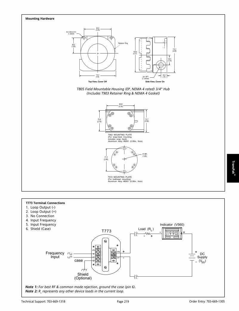
Page 219Technical Support: 703-669-1318 Order Entry: 703-669-1305
Tran
sPak
™
Note 1: For best RF & common mode rejection, ground the case (pin 6).Note 2: R
L represents any other device loads in the current loop.
Mounting Hardware
T805 Field Mountable Housing (EP, NEMA 4 rated) 3/4" Hub(Includes T903 Retainer Ring & NEMA 4 Gasket)
T773 Terminal Connections
1. Loop Output (-)2. Loop Output (+)3. No Connection4. Input Frequency5. Input Frequency6. Shield (Case)

Page 220Technical Support: 703-669-1318 Order Entry: 703-669-1305
Tra
nsp
ak™
Ordering InformationModels & AccessoriesSpecify:1. Model: T773-00002. Options: U (Urethane coating)3. Optional Custom Factory Calibration: Specify C620 with desired input
and output range.
AccessoriesM004 Snap-in Channel Track, 4 feet.T902 Mounting plate for M004, includes 4" track.T910 Bulkhead (flat surface) Mounting plate.T805 Side feed field-mountable housing (EP & NEMA 4 rated),
uncoated (specify Option P for white polyester powder coat).AP9046 Action Pak 24/40VDC 65mA Power Supply.
V565 3-1/2 digit remote loop-powered indicator, wide-rangingdisplay, NEMA 4X enclosure, CSA & FM approval standard,specify Option C to house TransPak
Specifications
Input:
Span Range (Max/Min): See Table 1Type: Capacitive coupledMinimum Amplitude:
105-2150Hz: 10mVrms>2150Hz: 15mVrms
Maximum Amplitude:
35Vp-p
Impedance:
100-1KHz: >6k Ohms>1KHz: >40k Ohms
Output Span:
4-20mA/10-50mA, switch selectable
Minimum Output Current:
3.3mA, typical
Maximum Output Current:
4-20mA: 24mA, typical10-50mA: 58mA, typical
Supply Voltage Range:
4-20mA: 13 to 75VDC10-50mA: 13 to 50VDC
Line Regulation:
0.07% of span (13-75V)
Load Regulation:
0.05% of span (0-3k Ohms)
DimensionsDimensions in millimeters (inches)
Voltage Drop:
13VDC @ 20mA
Stability:
Zero: ±0.015% of span/°C, typical,
±0.028%/°C, max.
Span:±0.022% of span/°C, typical,
±0.043%/°C, max.
Overall Accuracy (Includes Linearity,Hysteresis, Stability):±0.2% of adjusted span, max.
Zero Adjustability:
30% “turn-up” of span
Span Adjustability:
80% “turn-down" of full-scale limit (Table 1)
Repeatability:
±0.05% of span
Response Time (63% response):
<9KHz: 500mSec.>9KHz: 40mSec.
Output Ripple, P-P (% at max. input rangefrequency; 0% turn-down):
Range 1: 0.5% (18KHz)Range 2: 0.5% (9KHz)Range 3: 0.7% (2100Hz)Range 4: 1.2% (525Hz)
Common Mode Rejection:
60Hz: 97dB, DC: 120dB
Common Mode Range:
60Hz: 75Vrms, max.
DC: 1KV, max.
RFI Effect (1.5W, 470MHz at 1.5 ft.):
<1% of span error
Isolation:
1000Vrms maximum input to output,input to case, output to case
Operating Temperature Range:
4-20mA: -40 to 80°C (-40 to 176°F)10-50mA: -40 to 60°C (-40 to 140°F)
Weight:
0.58lbs
Agency Approval:
CSA approved intrinsically safe for hazardouslocations (File No. LR42272-70).
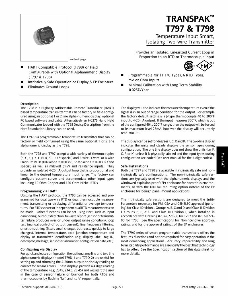
Page 221Technical Support: 703-669-1318 Order Entry: 703-669-1305
Tran
sPak
™
DescriptionThe T798 is a Highway Addressable Remote Transducer (HART)based temperature transmitter that can be factory or field config-ured using an optional 1 or 2 line alpha-numeric display, optionalPC based software and cable. Alternatively an HC275 Hand HeldCommunicator loaded with the T798 Device Description from theHart Foundation Library can be used.
The T797 is a programmable temperature transmitter that can befactory or field configured using the same optional 1 or 2 linealphanumeric display as the T798.
Both the T798 and T797 accept a wide variety of thermocouples(B, C, E, J, K, L, N, R, S, T, U & special) and 2-wire, 3-wire, or 4-wirePlatinum RTDs (DIN alpha = 0.00385, SAMA alpha = 0.003923 andspecial) as well as millivolt (mV) and resistance inputs. Theyprovide an isolated 4-20mA output loop that is proportional andlinear to the desired temperature input range. The factory canconfigure custom curves and accommodate other input typesincluding 10 Ohm Copper and 120 Ohm Nickel RTDs.
Programming via HARTUtilizing the HART protocol, the T798 can be accessed and pro-grammed for dual two-wire RTD or dual thermocouple measure-ment; transmitting or displaying differential or average tempera-tures. For RTDs secure or independent dual RTD measurements canbe made. Other functions can be set using Hart, such as inputdampening, burnout detection, fail-safe report (sensor or transmit-ter failure produces over or under output range condition), looptest (manual control of output current), line frequency filtering,smart smoothing (filters small changes but reacts quickly to largechanges), internal temperature, cold junction temperature anddisplay or transmitter identification (e.g. display label, tag ID,descriptor, message, sensor serial number, configuration date, etc.).
Configuring via DisplayFor quick and easy configuration the optional one line and two linealphanumeric displays (model T79D-1 and T79D-2) are useful forsetting up and trimming the 4-20mA output or display reading tocorrect for sensor errors. These displays provide a 4 digit readingof the temperature (e.g. 2345, 234.5, 23.45) and will alert the userin the case of sensor failure or burnout for both RTDs andthermocouples by flashing ‘fail’ and ‘safe’ sequentially.
TRANSPAK™
T797 & T798Temperature Input Smart,
Isolating Two-wire Transmitter
Provides an Isolated, Linearized Current Loop inProportion to an RTD or Thermocouple Input
HART Compatible Protocol (T798) or FieldConfigurable with Optional Alphanumeric Display(T797 & T798)
Intrinsically Safe Operation or Display & EP Enclosure Eliminates Ground Loops
see back page
Programmable for 11 T/C Types, 6 RTD Types,mV or Ohm Inputs
Minimal Calibration with Long Term Stability0.025%/Year
The display will also indicate the measured temperature even if thesignal is in an out of range condition for the output. For examplethe factory default setting is a J-type thermocouple 40 to 200°Finput to 4-20mA output. If the input measures 300°F, which is outof the configured 40 to 200°F range, then the output will be forcedto its maximum level 23mA, however the display will accuratelyread 300.0°F.
The displays can be set for degrees F, C, R and K. The two-line displayindicates the units and clearly displays the sensor types duringconfiguration. The one line display does not show the units (i.e. F,C, R or K) unless it is physically labeled and the input types duringconfiguration are coded (see user manual for the 4 digit codes).
Safe InstallationsBoth the T797 and T798 are available in intrinsically safe and non-intrinsically safe configurations. The non-intrinsically safe ver-sions are typically used with the alphanumeric displays and thewindowed explosion proof (EP) enclosure for hazardous environ-ments, or with the DIN rail mounting option instead of the EPenclosure for benign panel mount applications.
The intrinsically safe versions are designed to meet the EntityParameters necessary for FM, CSA and CENELEC approval (pend-ing) for Class I Division I, Groups A, B, C and D; and Class II, DivisionI, Groups E, F, & G and Class III Division I, when installed inaccordance with Drawing #732-0220-00 for T797 and #732-0221-00 for T798. See the specifications for Nonincendive approvalratings and for the approval ratings of the EP enclosures.
The T79X series of smart programmable transmitters offers thefeatures, functions and options required for easy operation in themost demanding applications. Accuracy, repeatability and longterm stability performance are essentially the best that technologyhas to offer. See the Specification section of this data sheet formore details.
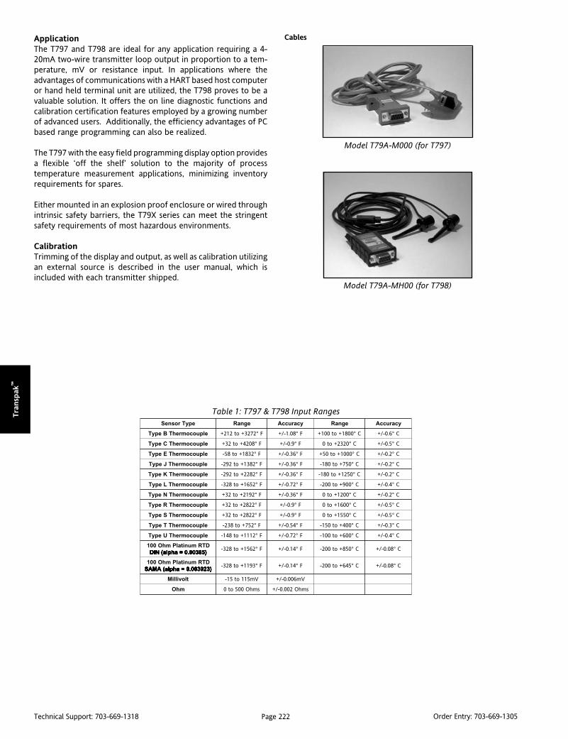
Page 222Technical Support: 703-669-1318 Order Entry: 703-669-1305
Tra
nsp
ak™
ApplicationThe T797 and T798 are ideal for any application requiring a 4-20mA two-wire transmitter loop output in proportion to a tem-perature, mV or resistance input. In applications where theadvantages of communications with a HART based host computeror hand held terminal unit are utilized, the T798 proves to be avaluable solution. It offers the on line diagnostic functions andcalibration certification features employed by a growing numberof advanced users. Additionally, the efficiency advantages of PCbased range programming can also be realized.
The T797 with the easy field programming display option providesa flexible ‘off the shelf’ solution to the majority of processtemperature measurement applications, minimizing inventoryrequirements for spares.
Either mounted in an explosion proof enclosure or wired throughintrinsic safety barriers, the T79X series can meet the stringentsafety requirements of most hazardous environments.
CalibrationTrimming of the display and output, as well as calibration utilizingan external source is described in the user manual, which isincluded with each transmitter shipped.
Cables
Model T79A-MH00 (for T798)
Model T79A-M000 (for T797)
epyTrosneS egnaR ycaruccA egnaR ycaruccA
elpuocomrehTBepyT F°2723+ot212+ F°80.1-/+ C°0081+ot001+ C°6.0-/+
elpuocomrehTCepyT F°8024+ot23+ F°9.0-/+ C°0232+ot0 C°5.0-/+
elpuocomrehTEepyT F°2381+ot85- F°63.0-/+ C°0001+ot05+ C°2.0-/+
elpuocomrehTJepyT F°2831+ot292- F°63.0-/+ C°057+ot081- C°2.0-/+
elpuocomrehTKepyT F°2822+ot292- F°63.0-/+ C°0521+ot081- C°2.0-/+
elpuocomrehTLepyT F°2561+ot823- F°27.0-/+ C°009+ot002- C°4.0-/+
elpuocomrehTNepyT F°2912+ot23+ F°63.0-/+ C°0021+ot0 C°2.0-/+
elpuocomrehTRepyT F°2282+ot23+ F°9.0-/+ C°0061+ot0 C°5.0-/+
elpuocomrehTSepyT F°2282+ot23+ F°9.0-/+ C°0551+ot0 C°5.0-/+
elpuocomrehTTepyT F°257+ot832- F°45.0-/+ C°004+ot051- C°3.0-/+
elpuocomrehTUepyT F°2111+ot841- F°27.0-/+ C°006+ot001- C°4.0-/+
DTRmunitalPmhO001)58300.0=ahpla(NID )58300.0=ahpla(NID )58300.0=ahpla(NID )58300.0=ahpla(NID )58300.0=ahpla(NID
F°2651+ot823- F°41.0-/+ C°058+ot002- C°80.0-/+
DTRmunitalPmhO001)329300.0=ahpla(AMAS )329300.0=ahpla(AMAS )329300.0=ahpla(AMAS )329300.0=ahpla(AMAS )329300.0=ahpla(AMAS
F°3911+ot823- F°41.0-/+ C°546+ot002- C°80.0-/+
tlovilliM Vm511ot51- Vm600.0-/+
mhO smhO005ot0 smhO200.0-/+
Table 1: T797 & T798 Input Ranges

Page 223Technical Support: 703-669-1318 Order Entry: 703-669-1305
Tran
sPak
™
Installations
No Barrier
T79E Explosion Proof Housing
Hazardous/Barrier
Figure 1: Normal Installation
Figure 2: Intrinsically Safe Installation
T79A-D DIN Mounting Kit T79A-P Pipe Mount Bracket
Dimensions Input Wiring

Page 224Technical Support: 703-669-1318 Order Entry: 703-669-1305
Tra
nsp
ak™
Specifications
Linearization:
Thermocouple and RTD linearization to±0.05°C. Custom linearization with 22 ptcurve (consult factory).
Input Impedance:
Greater than 1M Ohm
Output:
Analog, Two-wire 4 to 20mA
Transmitter Accuracy:
±0.05% of the millivolt or ohm equivalentinputreading, or the value from theAccuracy Table, whichever is greater; plus±0.05% of the span. For thermocouples,add ±0.5°C (0.9°F) for cold junctioneffect. Accuracy includes transmitterrepeatability, hysteresis and linearity aswell as ambient temperature effect. A/Dconversion error, analog output error,line voltage effets, humidity effect undernon-condensing conditions and vibrationeffect to 2g's & 500 Hz.
Transmitter Repeatability:
One-half the transmitter accuracy
Cold-Junction Compensation:
Digital self-correcting over the ambienttemperature range to within ±0.5°C
Output Ranging Adjustments:
Analog Zero: 100% of Sensor range (Non-interacting)
Analog Full-scale: Normal or Reverse Acting
Ambient Temperature Stability:
Self-correcting over operatingtemperature range
Long Term Stability:
Deviation per year is less than: 0.025% ofthe output span ±0.05% of the reading)
Damping:
Factory selectable constant (63%) from 0to 32 sec.
Failsafe:
User settable to 3.6 or 23mA
Operating Temperature Range:
Electronics:
-40°C to +85°C, -40°F to +185°FDisplay (full visibility):
-20°C to +70°C, -4°F to +158°FDisplay (with reduced visibility):
-40°C to +85°C, -40°F to +185°FStorage Temperature Range:
-50°C to +85°C, -58°F to +185°FMounting Position:
No effect on measurement value
Weight:
T787: 6 oz.
T79E-O/D: 21/2 lbs.
T79E-1: 12 oz.
Isolation:
500VAC Input to Output
Power Supply:
The transmitter operates on 12 to 42VDC(30VDC for I/S installations) with no load.Transmitter is protected against reversepolarity connection.
Load Limitation:
Loop resistance including optional indicator:R(k Ohms) =
(Supply Voltage - 12 VDC)/(23mA)
Electromagnetic Compatability
(CE Compliance):Transmitter operates within specificationin fields from 20 to 1,000MHz with fieldstrengths to 30V/m. Meets EN 50082-1Generic Immunity Standard and EN 55011Compatibility Emissions Standard.
Dynamic Response:
Update Rate:
150 milliseconds (7 times per second), typical
Response to Step Change:
250 milliseconds minimum; 1 second, typical
Start-up Time:
7 sec. Operation to spec in less than 30 sec.
Ordering InformationSpecify: (model number)1) Transmitter Model: T79X-XXXX2) Optional Display, Configuration Cable, Software:3) Optional Enclosure:4) Optional Enclosure Mounting:5) Optional Factory Configuration: Specify model C620 and desired configuration
TransmittersT797-0000 Temperature Transmitter, Non IST797-1000 Temperature Transmitter, IS-FM/CSAT797-2000 TemperatureTransmitter, IS CENELECT798-0000 Temperature Transmitter, Hart, Non IST798-1000 Temperature Transmitter, Hart, IS-FM/CSAT798-2000 Temperature Transmitter, Hart, IS-CENELEC
Displays & OptionsT79D-2000 Two Line Alphanumeric DisplayT79D-1000 One line alpha-numeric DisplayT79E-D000 Explosion Proof Housing w/ WindowT79E-0000 Explosion Proof Housing w/out WindowT79E-1000 Weather Proof Head-Mount EnclosureT79E-H000 Explosion Proof Head-Mount EnclosureT79A-P000 Pipe Mount Bracket for T79E-0/D onlyT79A-B000 Bulkhead (flat surface) Mounting PlateT79A-D000 DIN Rail Mounting KitT79A-M000 T797 PC Serial Configuration Cable (6')T79A-MH00 T798 Hart Configuration Cable (6')T79A-C000 Configuration Software for T797 & T798T79A-E000 Mounting Kit for EP Enclosure
Ambient Temperature Change:
Selfcorrecting for ambient temperaturechanges up to 20°C/hr.
Interchangeability:
Fully interchangeable without fieldcalibration
Hazardous Location Certifications:Explosion Proof:
Explosion Proof Housings availablewith and without windows; CSA andFM approved for Class I, Div I & II,Groups B, C & D; Class II, Div I & II,Groups E, F,& G, Class III and are ratedfor NEMA 4X & NEMA 7 environments.
Nonincendive:
Transmitter is CSA & FM ratednonincendive in Class I, Div II, GroupsA, B, C & D and Class II, Div I, Groups F& G, and Class III, Div II, CENELEC Ex NIIC T4-T6 certification pending.
Intrinsic Safety:
The Intrinsically Safe Rated ModelsT797-1 & T798-1 Transmitters are CSAand FM rated Intrinsically Safe forClass I, Div I, Groups A, B, C & D andClass II, Div I, Groups E, F & G, andClass III, Div I, Installed in accordancewith Drawing #732-0220-00 for T797and #732-0221-00 for T798. CENELECEEx ia IIC T4-T6 Intrinsically Safecertification pending.
Standard Configuration:
Sensor Input: J Type Thermocouple
LRV (4mA): 40°F Lower Range Value
URV (20mA): 200°F Upper Range Value
Damping: 0 seconds
Output Linear with Temperature
Failsafe: Upscale (23mA)

Page 225Technical Support: 703-669-1318 Order Entry: 703-669-1305
Actio
n P
ak®
Action Pak AlarmsLimit alarms are setpoint controllers that regulate industrialprocesses - discrete, batch or continuous. Two-position control-lers simplify processes through automation, and by removingpersonnel from tedious and possibly harmful environments.
Alarms are used to indicate problems - production line faults,process upsets, equipment failures or control system abnormali-ties. Limit alarms safeguard industrial facilities and workers byalerting and informing process personnel of abnormal conditions.
The AP1000 SeriesThe AP1000 series limit alarms are compact, electronic plug-inmodules that receive direct sensor inputs and operate from120VAC power (or optionally on 24VDC on some models). Theyprovide the broad range of limit alarm and control capabilitiesrequired in today's industrial processes. The AP1000 seriesaccepts a variety of direct sensor or transducer inputs, andprovides either single trip, latching or dual trip relay outputs.
Hard Control/Analog BackFactory automation systems run the risk of central failures. Afailure in a central system can prevent proper actions for criticalconditions, resulting in costly downtimes and possible injury topersonnel. Redundancy and reliability are important concernsthat are best met with Hard Control/Analog Back (HC/AB) alarmsystems.
The AP1000 series dedicated single-channel limit alarm providesexcellent single-point control with a proven record of reliability.
Setpoint ControlSetpoint adjustment is available to suit many needs:
Single-turn or 10-turn screwdriver adjust.10-turn clockface dial (for precise settings).
Setpoints are adjustable over the entire span to assure full-rangealarm capabilities.
Field Configurable AlarmsThe DC input AP1080/90, the thermocouple input AP1280/90 andthe AC input AP1690 can all be configured in the field by settingDIP switches for input range or type, alarm function (HI/LO) andalarm state (failsafe/non-failsafe). This minimizes spare partsinventory and provides an off-the-shelf solution for virtually anyalarm function.
ACTION PAK™
Action Pak Signal ConditionersSignal conditioners amplify and condition weak signals generatedby process sensors. They send signals long distances without beingdegraded by electrical noise. They are also used to drive devicessuch as indicators, alarms, controllers, computer interfaces andother process instrumentation.
The AP4000 - AP9000 SeriesThe AP4000 to AP9000 series signal conditioners are compact,electronic, plug-in modules that take direct sensor inputs andsignals and convert them into useful high level signals. They operatefrom 120VAC power (or optionally on 24VDC on some models).
Four-wire TransmittersThe AP4000 series four-wire transmitters typically operate fromexternal AC line power and require two wires for that operatingpower and two wires for the output signal. Outputs are conven-tional DC process signals, such as 4-20mA or 0-10V, and are fullycompatible with all important process instrumentation equipment,including other Action Pak modules. When AC power is impracticalor not available, most 4000 series modules are available with a DCoption so that they can be operated from a 24VDC source.
IsolationGrounding remote sensors is generally advised in order to reducenoise pickup and protect equipment from being damaged bylightning or other high voltages. However, if both the sensor and thesignal conditioner are grounded, it is possible to get an unwantedcurrent (a "ground loop") due to ground-to-ground potential differ-ences. Ground loops degrade signal quality to the point of useless-ness and can harm personnel and receiving equipment.
Isolation eliminates ground loops and common mode voltage, andchecks power surges. Isolation also simplifies the connection of loopelements by eliminating the need for special grounding systems.
Input SelectionSeven standard type of inputs are available to suit your processneeds. Other input types are available on request.
DC Voltage or CurrentThermocoupleRTDStrain GaugePotentiometerAC Voltage or CurrentFrequency
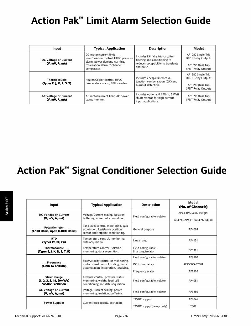
Page 226Technical Support: 703-669-1318 Order Entry: 703-669-1305
Act
ion P
ak®
Action Pak™ Limit Alarm Selection Guide
Action Pak™ Signal Conditioner Selection Guide
tupnI noitacilppAlacipyT noitpircseDledoM
)slennahCfo.oN( )slennahCfo.oN( )slennahCfo.oN( )slennahCfo.oN( )slennahCfo.oN(
tnerruCroegatloVCD)Am,A,Vm,V( )Am,A,Vm,V( )Am,A,Vm,V( )Am,A,Vm,V( )Am,A,Vm,V(
,noitalosi,gnilacstnerruC/egatloV.evird,noitcuderesion,gnireffub
rotalosielbarugifnocdleiF)elgnis(2834PA/0834PA
)laud(2934PA/1934PA/0934PA
retemoitnetoP)smhOk001-0otpu,smhO001-0( )smhOk001-0otpu,smhO001-0( )smhOk001-0otpu,smhO001-0( )smhOk001-0otpu,smhO001-0( )smhOk001-0otpu,smhO001-0(
atad,gnirotinom,lortnoclevelknaTnoitisopecnatsiseR,noitisiuqca
.gninoitidnoctnioptesdnarosnesesopruplareneG 3004PA
DTR)uC,iN,tPsepyT( )uC,iN,tPsepyT( )uC,iN,tPsepyT( )uC,iN,tPsepyT( )uC,iN,tPsepyT(
,gnirotinom,lortnocerutarepmeT.noitisiuqcaatad
gniziraeniL 1514PA
elpuocomrehT)B,T,S,R,K,J,EsepyT( )B,T,S,R,K,J,EsepyT( )B,T,S,R,K,J,EsepyT( )B,T,S,R,K,J,EsepyT( )B,T,S,R,K,J,EsepyT(
,noitalosi,lortnocerutarepmeT.noitisiuqcaatad,gnirotinom
,elbarugifnocdleiFrotalosigniziranil
1534PA
ycneuqerF)zHk01-0otzH2-0( )zHk01-0otzH2-0( )zHk01-0otzH2-0( )zHk01-0otzH2-0( )zHk01-0otzH2-0(
,gnirotinomrolortnocyticolev/wolFeslup,gnilacs,lortnocdeepsrotom
.gnizilatot,noitargetni,noitalumucca
rotalosielbarugifnocdleiF
ycneuqerfotCD
relacsycneuqerF
0837PA
1057PA/0057PA
0157PA
eguaGniartS)V/Vm02,01,5,3,2,1( )V/Vm02,01,5,3,2,1( )V/Vm02,01,5,3,2,1( )V/Vm02,01,5,3,2,1( )V/Vm02,01,5,3,2,1(
noitaticxEV01-V5 noitaticxEV01-V5 noitaticxEV01-V5 noitaticxEV01-V5 noitaticxEV01-V5
sutatserusserp,lortnocerusserPllecdaol,thgiew,gnirotinom
.noitisiuqcaataddnagninoitidnocrotalosielbarugifnocdleiF 1804PA
tnerruCroegatloVCA)Am,A,Vm,V( )Am,A,Vm,V( )Am,A,Vm,V( )Am,A,Vm,V( )Am,A,Vm,V(
rewop,gnilacstnerruC/egatloV.gnireffub,noitalosi,gnirotinom
rotalosielbarugifnocdleiF 0836PA
seilppuSrewoP .noitaticxe,ylppuspooltnerruCylppusCDV42
)ytudyvaeh(ylppusCDV42
6409PA
906T
tupnI noitacilppAlacipyT noitpircseD ledoM
tnerruCroegatloVCD)Am,A,Vm,V( )Am,A,Vm,V( )Am,A,Vm,V( )Am,A,Vm,V( )Am,A,Vm,V(
,timiltnerruc/rotomCDerusserpOL/IH,lortnocnoitisop/level
,gninrawdnamedrewop,mralalennahc-2,mralanoitazilatot
.rotarapmoc
,yrtiucricpirteslafISLsedulcnIotgninoitidnocdnagniretlif
stneisnartotytilibitpecsusecuder.esiondna
pirTelgniS0801PAstuptuOyaleRTDPD
pirTlauD0901PAstuptuOyaleRTDPS
elpuocomrehT)T,S,R,K,J,EsepyT( )T,S,R,K,J,EsepyT( )T,S,R,K,J,EsepyT( )T,S,R,K,J,EsepyT( )T,S,R,K,J,EsepyT(
OL/IH,lortnocrelooC/retaeH.rotinomUTB,mralaerutarepmet
-dlocdetaluspacnesedulcnIdna)CJC(noitasnepmocnoitcnuj
.noitcetedtuonrub
pirTelgniS0821PAstuptuOyaleRTDPD
pirTlauD0921PAstuptuOyaleRTDPS
tnerruCroegatloVCA)Am,A,Vm,V( )Am,A,Vm,V( )Am,A,Vm,V( )Am,A,Vm,V( )Am,A,Vm,V(
rewopCA,timiltnerruc/rotomCA.rotinomsutats
ttaW5,mhO1.0lanoitposedulcnItnerruchgihrofrotsisertnuhs
.snoitacilppatupni
pirTlauD0961PAstuptuOyaleRTDPS

Page 227Technical Support: 703-669-1318 Order Entry: 703-669-1305
Actio
n P
ak®
Action PAK®
AP1080 & AP1090
DescriptionAction Pak models AP1080 single setpoint and AP1090 dualsetpoint limit alarms offer flexible, wide-ranging DC input capabil-ity. Voltage spans from 10mV to 200 volts and current spans from1mA to 100mA can be field configured. Bipolar inputs are alsoaccepted. Both models offer configurable latching, failsafe and HI/LO operation. The AP1080 and AP1090 also include 0.25%-50%adjustable deadbands and selectable 120/240VAC input power.
Diagnostic LEDModels AP1080-2000 and AP1090-2000 are equipped with a dualfunction diagnostic LED. The green center LED indicates linepower and input signal status. Active line power is indicated byan illuminated LED. If the center LED is off, check line power andthe wiring connection. If the input signal is above 100% full scale,the LED will flash at approximately 8Hz. Below 0%, the flash rateis approximately 4Hz.
Output SelectionThe single setpoint AP1080 and the dual setpoint AP1090 providethe following relay outputs:
AP1080 Single Trip (DPDT, 5A)AP1090 Single/Dual Trip (2 SPDT, 5A)
Setpoints are top accessed multi-turn potentiometers or option"P" provides top mounted ten-turn dials.
OperationThe field configurable AP1080 and AP1090 limit alarm setpointscan be configured for HI, LO, latching or failsafe trip operation.Non-latching HI and LO setpoints have respective HI and LOdeadbands. In a tripped condition, the setpoint is exceeded andthe appropriate red LED will illuminate. The trip will reset onlywhen the process falls below the HI deadband or rises above theLO deadband (see figure 1). To reset a latched setpoint the signalmust be in the safe region and the line power turned off for at least5 seconds. For proper deadband operation, a HI setpoint mustalways be set above a LO setpoint.
DC Input, Field Configurable Limit Alarms
Provides Relay Contact Closuresat a Preset DC Input Level
Field Configurable Input Ranges for DC Voltageand Current
Exclusive “Dynamic Deadband” PreventsFalse Trips
AP1080 (Single Trip, DPDT, 5A)
AP1090 (Single/Dual Trip, 2 SPDT, 5A)
Setpoints Programmable HI or LO Selectable Failsafe/Latching Operation Selectable 120/240VAC Input Power
(9 to 30 VDC Available)
In failsafe operation, the relay is energized when the process isbelow the HI setpoint or above the LO setpoint (opposite for non-failsafe). In the failsafe mode, the relays go to the trippedcondition when the power fails.
Dynamic DeadbandThe input must remain beyond the setpoint for 100 milliseconds,uninterrupted, to qualify as a valid trip condition. Likewise, theinput must fall outside the deadband and remain there for 100milliseconds to return the alarm to an untripped condition. Thiseffectively results in a “dynamic deadband” - based on time - inaddition to the normal deadband.
OptionsU Urethane coating of internal circuitry for protection from
corrosive atmospheres.
P Top Mounted, Ten-Turn Dial(s) for setpoint adjustment.
C620 Factory calibration to input range, setpoints and outputrelays. Not available with option P.
ConfigurationThe factory presets models AP1080 and AP1090 as follows:
AP1080 AP1090Input 0-20mA 0-20mAOutput Single, DPDT Dual, SPDTTrip HI A: HI, B: LOLatching No NoFailsafe Yes NoDeadband 0.25% A/B: 0.25%Power 120VAC 120VAC
For other I/O ranges, remove the four base screws and case toaccess the configuration switches.
Replace the cover before applying power.
Refer to Figure 5 for switch locations.
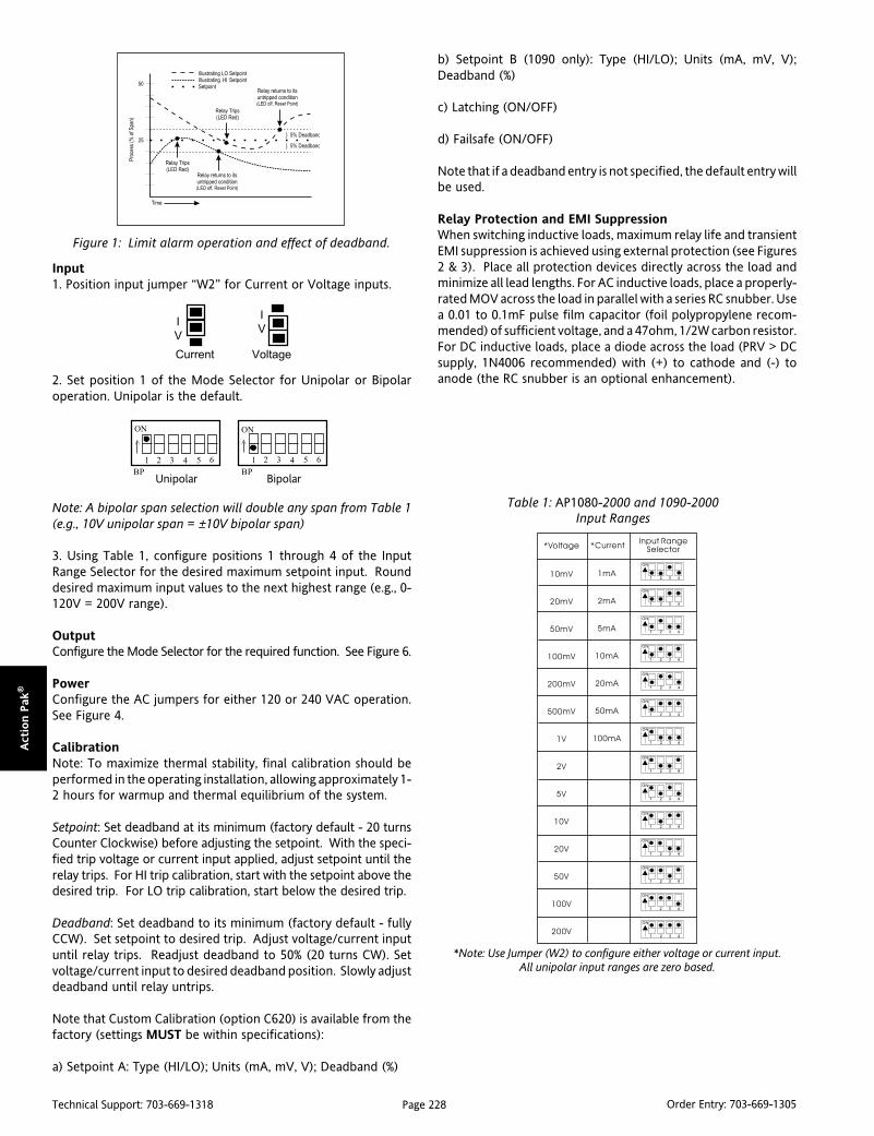
Page 228Technical Support: 703-669-1318 Order Entry: 703-669-1305
Act
ion P
ak®
Input1. Position input jumper “W2” for Current or Voltage inputs.
2. Set position 1 of the Mode Selector for Unipolar or Bipolaroperation. Unipolar is the default.
Note: A bipolar span selection will double any span from Table 1(e.g., 10V unipolar span = ±10V bipolar span)
3. Using Table 1, configure positions 1 through 4 of the InputRange Selector for the desired maximum setpoint input. Rounddesired maximum input values to the next highest range (e.g., 0-120V = 200V range).
OutputConfigure the Mode Selector for the required function. See Figure 6.
PowerConfigure the AC jumpers for either 120 or 240 VAC operation.See Figure 4.
CalibrationNote: To maximize thermal stability, final calibration should beperformed in the operating installation, allowing approximately 1-2 hours for warmup and thermal equilibrium of the system.
Setpoint: Set deadband at its minimum (factory default - 20 turnsCounter Clockwise) before adjusting the setpoint. With the speci-fied trip voltage or current input applied, adjust setpoint until therelay trips. For HI trip calibration, start with the setpoint above thedesired trip. For LO trip calibration, start below the desired trip.
Deadband: Set deadband to its minimum (factory default - fullyCCW). Set setpoint to desired trip. Adjust voltage/current inputuntil relay trips. Readjust deadband to 50% (20 turns CW). Setvoltage/current input to desired deadband position. Slowly adjustdeadband until relay untrips.
Note that Custom Calibration (option C620) is available from thefactory (settings MUST be within specifications):
a) Setpoint A: Type (HI/LO); Units (mA, mV, V); Deadband (%)
b) Setpoint B (1090 only): Type (HI/LO); Units (mA, mV, V);Deadband (%)
c) Latching (ON/OFF)
d) Failsafe (ON/OFF)
Note that if a deadband entry is not specified, the default entry willbe used.
Relay Protection and EMI SuppressionWhen switching inductive loads, maximum relay life and transientEMI suppression is achieved using external protection (see Figures2 & 3). Place all protection devices directly across the load andminimize all lead lengths. For AC inductive loads, place a properly-rated MOV across the load in parallel with a series RC snubber. Usea 0.01 to 0.1mF pulse film capacitor (foil polypropylene recom-mended) of sufficient voltage, and a 47ohm, 1/2W carbon resistor.For DC inductive loads, place a diode across the load (PRV > DCsupply, 1N4006 recommended) with (+) to cathode and (-) toanode (the RC snubber is an optional enhancement).
6
Table 1: AP1080-2000 and 1090-2000Input Ranges
*Note: Use Jumper (W2) to configure either voltage or current input.All unipolar input ranges are zero based.
Voltage
I
V
Current
I
V
Figure 1: Limit alarm operation and effect of deadband.
Bipolar
ON
BP
1 2 3 4 5
>
Unipolar
ON
BP
1 2 3 4 65
>

Page 229Technical Support: 703-669-1318 Order Entry: 703-669-1305
Actio
n P
ak®
Figure 5: AP1090-2000 Factory Calibration 0-20mA, Dual HI/LO, Non-Latching, Non-Failsafe.
Figure 4: 120/240 VAC Selection
Figure 6: Mode Selection Dual Trip/A: HI, B: LO, Non-Latching, Non-Failsafe *AP1090-2000 only.
ON = Closed
1 2 3 4 5 6
UnipolarBipolar
OnOff
"A" Hi Trip"A" Low Trip
OnOff
"B" Hi Trip"B" Low Trip
OnOff
LatchingNon-Latching
OnOff
Non-FailsafeFailsafe
OnOff
Single Trip (A)Dual Trip Trip
OnOff
*
*
Figure 2: DC Inductive Loads Figure 3: AC Inductive Loads
M011 (Track/Surface)
MD11 (DIN Rail)
MountingAll Action Paks feature plug-in installation. Mod els AP1080 and AP1090 use an 11-pin base, either molded socket (M011) or DIN rail socket (MD11).
DimensionsDimensions are in millimeters (inches)
Mark III

Page 230Technical Support: 703-669-1318 Order Entry: 703-669-1305
Act
ion P
ak®
Ordering InformationSpecify:1. Model: AP1080-2000, AP1090-20002. Options: U, P (see text)3. Line Power (see specs.)(All power supplies are transformer-isolated
from the internal circuitry.)4. C620 Custom Calibration? (see Options)
Accessories:
M801-0000 Retaining Spring
M011-A 11 pin Track Mount Socket
M004-0000 4 ft Long Channel Track
MD11-0000 11 pin DIN Mount Socket
Specifications
Inputs:
Voltage Input:
Range: 10mV to 200V
Impedance: >100Kohms
Overvoltage: 400V, max
Current Input:
Range: 1mA to 100mA
Impedance: 20ohms, typical
Overcurrent: 200mA, max
Overvoltage: 60VDC
Common Mode (Input to Ground):
1000VDC, max
LED Indications:
Input Range (Green)
>100% input: 8Hz flash
<0% input: 4Hz flash
Setpoint (Red)
Tripped: Solid red
Safe: Off
Limit Differential (Deadband):
>50mV/5mA: 0.25% to 50% of span
<50mV/5mA: 1% to 50% of span
Response Time:
Dynamic Deadband:
Relay status will change when propersetpoint/process condition existsuninterrupted for 100msec.
Normal Mode (analog filtering):
<250msec, (10-90%)
Setpoint:
Effectivity:
Setpoints are adjustable over 100% ofthe selected input span.
Repeatability (constant temp):
>50mV/5mA: 0.1% of full scale
<50mV/5mA: 0.2% of full scale
Stability:
Line Voltage: ±0.01%/%, max.
Temperature: ±0.05% of full scale/°C, max.
Common Mode Rejection:
DC to 60Hz: 120dB
Isolation:
1000VDC between contacts, input & power
ESD Susceptibility:
Meets IEC 801-2, Level 2 (4KV)
Humidity:
Operating: 15 to 95% (@45°C)
Soak: 90% for 24 hours (@65°C)
Temperature Range:
Operating: 0 to 60°C (32 to 140°F)
Storage: -15 to 70°C (5 to 158°F)
Power:
Consumption: 2W typical, 5W max.
Standard:
Selectable 120/ 240VAC (±10%, 50-60Hz)Optional:
9 to 30VDC, Inverter-Isolated
Relay Contacts:
AP1080: DPDT (2 Form C)
AP1090: 1 SPDT (1 Form C) per setpoint
Current Rating (resistive)
120VAC: 5A; 240VAC: 2A; 28VDC: 5A
Material: Silver-Cadmium Oxide
Electrical Life: 105 operations at rated load
Note: External relay contact protection isrequired for use with inductive loads. Seerelay protection section (Fig 2 & 3).
Mechanical Life: 107 operations
Latch Reset Time:
5 seconds
Weight:
AP1080: 0.46lbs; AP1090: 0.62lbs
Agency Approvals:
CSA certified per standard C22.2,No. M1982, File No. LR42272-8, 9)
UL recognized per standard UL508,(File No. E99775)
Pin Connections1 AC Power (Hot)2 No Connection3 AC Power (Neu)4 Input (+)5 Input (-)6 (A) N.O.7 (A) C8 (A) N.C.9 (B) N.O.
10 (B) C11 (B) N.C.
Key:N.O. = Normally OpenC = CommonN.C. = Normally ClosedDC Power: Pin 1 = (+)
Pin 3 = (-)
*Contacts are in the “normal” statewhen the relay is de-energized.

Page 231Technical Support: 703-669-1318 Order Entry: 703-669-1305
Actio
n P
ak®
DescriptionAction Pak models AP1280 and AP1290 limit alarms offer wideranging inputs and flexible setpoint capability. They accept sixpopular thermocouple types with inputs ranging from -270°C (-454°F) to 1760°C (3200°F). The AP1280 provides a single-setpointalarm while the AP1290 provides two independent setpointalarms. The AP1280 and AP1290 also include 0.25%-50% adjust-able deadbands and selectable 120/240VAC power.
Diagnostic LEDModels AP1280 and AP1290 are equipped with a dual functiondiagnostic LED. The green center LED indicates line power and inputsignal status. Active line power is indicated by an illuminated LED.If the center LED is off, check line power and the wiring connection.If the input signal is above 100% full scale, the LED will flash atapproximately 8Hz. Below 0%, the flash rate is approximately 4Hz.
Output SelectionThe two models of thermocouple limit alarms reflect two styles ofoutput and setpoint selection:
AP1280 Single Trip (DPDT, 5A)AP1290 Single/Dual Trip (2 SPDT, 5A)
Setpoints are top accessed multi-turn potentiometers (or option"P" provides top mounted ten-turn dials).
OperationThe field configurable AP1280 and AP1290 limit alarm setpointscan be configured for HI, LO, latching or fail-safe trip operation.Non-latching HI and LO setpoints have respective HI and LOdeadbands. In a tripped condition, the setpoint is exceeded andthe appropriate red LED is lit. The trip will reset only when theprocess falls below the HI deadband or rises above the LOdeadband (see figure 1). To reset a latched setpoint the signalmust be in the safe region and the line power must be turned offfor at least 5 seconds. For proper deadband operation, the HIsetpoint must always be set above the LO setpoint.
In failsafe operation, the relay is energized when the process isbelow a HI setpoint or above a LO setpoint (opposite for non-failsafe). In the failsafe mode, a power failure results in an alarmcondition.
Action PAK®
AP1280 & AP1290Thermocouple Input,
Field Configurable Limit Alarms
Provides Relay Contact Closuresat a Preset Temperature Input Level
Field Configurable Input Ranges for E, J, K, R, S andT Type Thermocouples
Exclusive “Dynamic Deadband” Prevents False Trips Burnout Detection
AP1280 (Single Trip, DPDT, 5A)
AP1290 (Single/Dual Trip, 2 SPDT, 5A)
Setpoints Programmable HI or LO Selectable Failsafe/Latching Operation Selectable 120/240VAC Input Power
(9 to 30 VDC Available)
Dynamic DeadbandThe input must remain beyond the setpoint for 100 milliseconds,uninterrupted, to qualify as a valid trip condition. Likewise, theinput must fall outside the deadband and remain there for 100milliseconds to return the alarm to an untripped condition. Thiseffectively results in a “dynamic deadband” - based on time -inaddition to the normal deadband.
OptionsU Urethane coating of internal circuitry for protection
from corrosive atmospheres.
P Top mounted, ten-turn dial(s) for setpoint adjustment.
C620 Factory calibration of input range, set points and outputrelays. Not available with option P.
ConfigurationThe factory presets for AP1280 and AP1290 are as follows:
AP1280 AP1290Input J-type J-type
0-360°C 0-360°CBurn Out Positive PositiveOutput Single, DPDT Dual, SPDTTrip HI A: HI, B: LOLatching No NoFailsafe Yes NoDeadband 0.25% A/B: 0.25%Power 120VAC 120VAC
Refer to Figure 5 for switch locations.
For other I/O ranges, remove the four base screws and case toaccess the configuration switches.
Replace the cover before applying power.
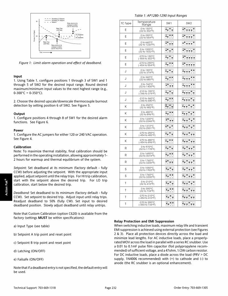
Page 232Technical Support: 703-669-1318 Order Entry: 703-669-1305
Act
ion P
ak®
Input1. Using Table 1, configure positions 1 through 3 of SW1 and 1through 5 of SW2 for the desired input range. Round desiredmaximum/minimum input values to the next highest range (e.g.,0-300°C = 0-350°C).
2. Choose the desired upscale/downscale thermocouple burnoutdetection by setting position 6 of SW2. See Figure 5.
Output1. Configure positions 4 through 8 of SW1 for the desired alarmfunctions. See Figure 6.
Power1. Configure the AC jumpers for either 120 or 240 VAC operation.See Figure 4.
CalibrationNote: To maximize thermal stability, final calibration should beperformed in the operating installation, allowing approximately 1-2 hours for warmup and thermal equilibrium of the system.
Setpoint: Set deadband at its minimum (factory default - fullyCCW) before adjusting the setpoint. With the appropriate inputapplied, adjust setpoint until the relay trips. For HI trip calibration,start with the setpoint above the desired trip. For LO tripcalibration, start below the desired trip.
Deadband: Set deadband to its minimum (factory default - fullyCCW). Set setpoint to desired trip. Adjust input until relay trips.Readjust deadband to 50% (fully CW). Set input to desireddeadband position. Slowly adjust deadband until relay untrips.
Note that Custom Calibration (option C620) is available from thefactory (settings MUST be within specifications):
a) Input Type (see table)
b) Setpoint A trip point and reset point
c) Setpoint B trip point and reset point
d) Latching (ON/OFF)
e) Failsafe (ON/OFF)
Note that if a deadband entry is not specified, the default entry willbe used.
Table 1: AP1280-1290 Input Ranges
Relay Protection and EMI SuppressionWhen switching inductive loads, maximum relay life and transientEMI suppression is achieved using external protection (see Figures2 & 3). Place all protection devices directly across the load andminimize lead lengths. For AC inductive loads, place a properly-rated MOV across the load in parallel with a series RC snubber. Usea 0.01 to 0.1mF pulse film capacitor (foil polypropylene recom-mended) of sufficient voltage, and a 47ohm, 1/2W carbon resistor.For DC inductive loads, place a diode across the load (PRV > DCsupply, 1N4006 recommended) with (+) to cathode and (-) toanode (the RC snubber is an optional enhancement).
Figure 1: Limit alarm operation and effect of deadband.
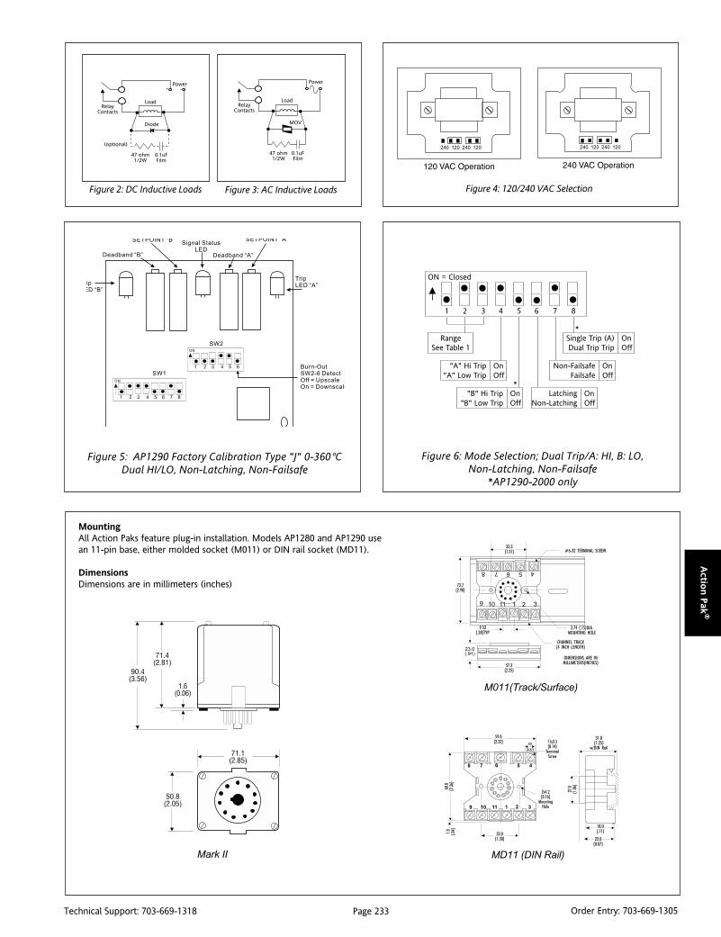
Page 233Technical Support: 703-669-1318 Order Entry: 703-669-1305
Actio
n P
ak®
Figure 5: AP1290 Factory Calibration Type "J" 0-360°CDual HI/LO, Non-Latching, Non-Failsafe
Figure 6: Mode Selection; Dual Trip/A: HI, B: LO,Non-Latching, Non-Failsafe
*AP1290-2000 only
Figure 4: 120/240 VAC SelectionFigure 2: DC Inductive Loads Figure 3: AC Inductive Loads
ON = Closed
1 2 3 4 5 6
RangeSee Table 1
"A" Hi Trip"A" Low Trip
OnOff
"B" Hi Trip"B" Low Trip
OnOff
LatchingNon-Latching
OnOff
Non-FailsafeFailsafe
OnOff
Single Trip (A)Dual Trip Trip
OnOff
*
*
7 8
MountingAll Action Paks feature plug-in installation. Models AP1280 and AP1290 usean 11-pin base, either molded socket (M011) or DIN rail socket (MD11).
DimensionsDimensions are in millimeters (inches)
M011(Track/Surface)
MD11 (DIN Rail)Mark II
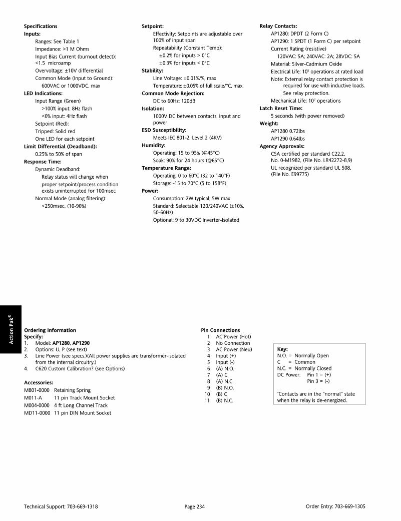
Page 234Technical Support: 703-669-1318 Order Entry: 703-669-1305
Act
ion P
ak®
Pin Connections1 AC Power (Hot)2 No Connection3 AC Power (Neu)4 Input (+)5 Input (-)6 (A) N.O.7 (A) C8 (A) N.C.9 (B) N.O.
10 (B) C11 (B) N.C.
Key:N.O. = Normally OpenC = CommonN.C. = Normally ClosedDC Power: Pin 1 = (+)
Pin 3 = (-)
*Contacts are in the “normal” statewhen the relay is de-energized.
Specifications
Inputs:
Ranges: See Table 1
Impedance: >1 M Ohms
Input Bias Current (burnout detect):<1.5 microamp
Overvoltage: ±10V differential
Common Mode (Input to Ground):
600VAC or 1000VDC, max
LED Indications:
Input Range (Green)
>100% input: 8Hz flash
<0% input: 4Hz flash
Setpoint (Red):
Tripped: Solid red
One LED for each setpoint
Limit Differential (Deadband):
0.25% to 50% of span
Response Time:
Dynamic Deadband:
Relay status will change when
proper setpoint/process conditionexists uninterrupted for 100msec
Normal Mode (analog filtering):
<250msec, (10-90%)
Setpoint:
Effectivity: Setpoints are adjustable over100% of input span
Repeatability (Constant Temp):
±0.2% for inputs > 0°C±0.3% for inputs < 0°C
Stability:
Line Voltage: ±0.01%/%, max
Temperature: ±0.05% of full scale/°C, max.
Common Mode Rejection:
DC to 60Hz: 120dB
Isolation:
1000V DC between contacts, input andpower
ESD Susceptibility:
Meets IEC 801-2, Level 2 (4KV)
Humidity:
Operating: 15 to 95% (@45°C)
Soak: 90% for 24 hours (@65°C)
Temperature Range:
Operating: 0 to 60°C (32 to 140°F)
Storage: -15 to 70°C (5 to 158°F)
Power:
Consumption: 2W typical, 5W max
Standard: Selectable 120/240VAC (±10%,50-60Hz)
Optional: 9 to 30VDC Inverter-Isolated
Relay Contacts:
AP1280: DPDT (2 Form C)
AP1290: 1 SPDT (1 Form C) per setpoint
Current Rating (resistive)
120VAC: 5A; 240VAC: 2A; 28VDC: 5A
Material: Silver-Cadmium Oxide
Electrical Life: 105 operations at rated load
Note: External relay contact protection isrequired for use with inductive loads.
See relay protection.
Mechanical Life: 107 operations
Latch Reset Time:
5 seconds (with power removed)
Weight:
AP1280 0.72lbs
AP1290 0.64lbs
Agency Approvals:
CSA certified per standard C22.2,No. 0-M1982, (File No. LR42272-8,9)
UL recognized per standard UL 508,(File No. E99775)
Ordering InformationSpecify:1. Model: AP1280, AP12902. Options: U, P (see text)3. Line Power (see specs.)(All power supplies are transformer-isolated
from the internal circuitry.)4. C620 Custom Calibration? (see Options)
Accessories:
M801-0000 Retaining Spring
M011-A 11 pin Track Mount Socket
M004-0000 4 ft Long Channel Track
MD11-0000 11 pin DIN Mount Socket

Page 235Technical Support: 703-669-1318 Order Entry: 703-669-1305
Actio
n P
ak®
DescriptionThe Action Pak model AP1690 dual setpoint limit alarm offersflexible, wide ranging AC input and relay output capability.Voltage spans from 100mV to 200VAC and current spans from10mA to 100mA AC can be field configured. For current inputspans of 1 to 5 Amps a 0.1W (0.1%) shunt resistor (Model #C006)is available. The AP1690 offers configurable latching, failsafe, andHI/LO operation. The unit also includes 0.25% to 50% adjustabledeadband and selectable 120/240VAC power.
Diagnostic LEDThe Model AP1690 is equipped with a dual function diagnosticLED. The green center LED indicates line power and input signalstatus. Active line power is indicated by an illuminated LED. If thecenter LED is off, check line power and the wiring connection. Ifthe input signal is above 100% full scale, the LED will flash atapproximately 8Hz.
Output SelectionThe dual setpoint AP1690 provides the following relay outputs:
AP1690 Single/Dual Trip (2 SPDT, 5A)
Setpoints are top accessed multi-turn potentiometers or option"P" provides top mounted ten-turn clock face dials.
OperationThe field configurable AP1690 limit alarm setpoints can beconfigured for HI, LO, latching or failsafe trip operation. Non-latching HI and LO setpoints have respective HI and LOdeadbands. In a tripped condition, the setpoint is exceeded andthe appropriate red LED will illuminate. The non-latching trip willreset only when the process falls below the HI deadband or risesabove the low deadband (see figure 1). To reset a latched setpointthe signal must be in the safe region and the line power turned offfor at least 5 seconds. For proper deadband operation, the HIsetpoint must always be set above the LO setpoint.
In failsafe operation, the relay is energized when the process isbelow the HI setpoint or above the LO setpoint (opposite for non-failsafe). In the failsafe mode, the relays go to the trip conditionwhen power fails.
Action PAK®
AP1690AC Input, Field Configurable Limit Alarms
Provides Relay Contact Closuresat a Preset AC Input Level
Field Configurable Input Ranges for AC Voltage orCurrent
Exclusive “Dynamic Deadband” PreventsFalse Trips
AP1690 (Single/Dual Trip, 2 SPDT, 5A)
Setpoints Programmable HI or LO Selectable Failsafe/Latching Operation Selectable 120/240VAC Input Power
Dynamic DeadbandThe input must remain beyond the setpoint for 100 milliseconds,uninterrupted, to qualify as a valid trip condition. Likewise, theinput must fall outside the deadband and remain there for 100milliseconds to return the alarm to an untripped condition. Thiseffectively results in a “dynamic deadband” – based on time – inaddition to the normal deadband.
OptionsU Urethane coating of internal circuitry for protection from
corrosive atmospheres.
P Top Mounted, 10-Turn Clockface Dials for setpoint adjustment.
C620 Factory calibration of input range, setpoints and outputrelays. Not available with option P.
ConfigurationThe factory presets are as follows:
Input 0-500mVOutput Dual, SPDTTrip A: HI, B: LOLatching NoFailsafe NoDeadband A/B: 0.25%Power 120VAC
For other input ranges, remove the 4 base screws and case toaccess the configuration switches.
Replace the cover before applying power.
Refer to Figure 4 for switch locations.
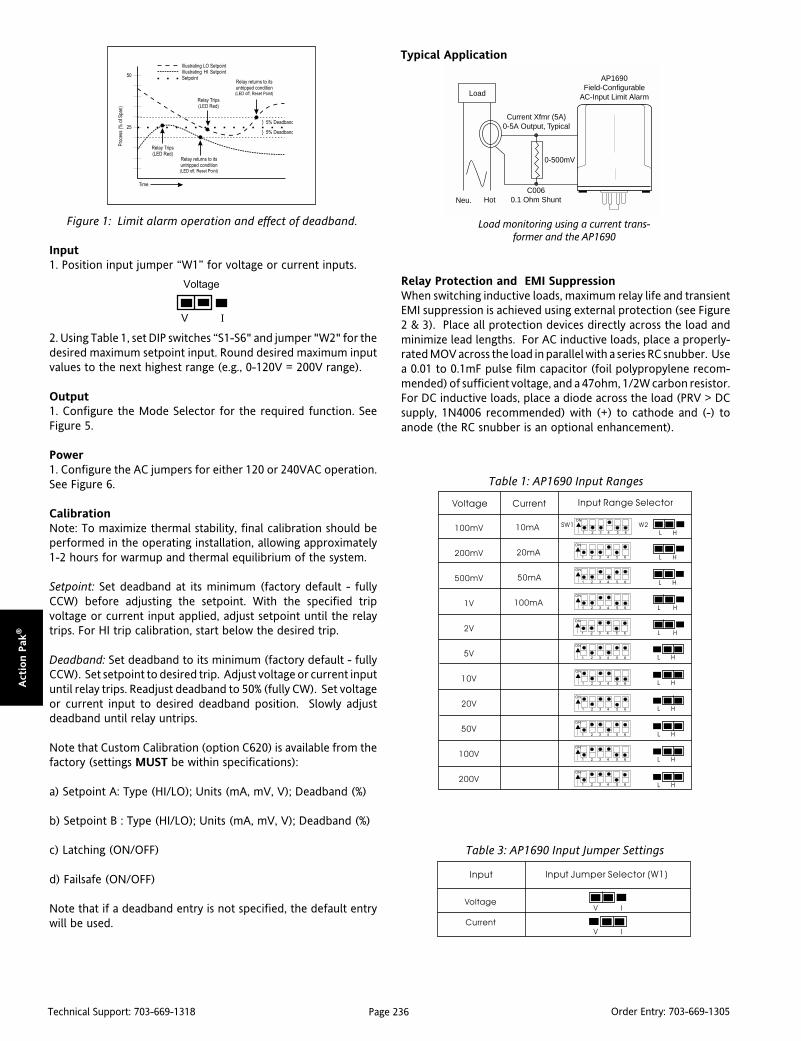
Page 236Technical Support: 703-669-1318 Order Entry: 703-669-1305
Act
ion P
ak®
Input1. Position input jumper “W1” for voltage or current inputs.
2. Using Table 1, set DIP switches “S1-S6" and jumper "W2" for thedesired maximum setpoint input. Round desired maximum inputvalues to the next highest range (e.g., 0-120V = 200V range).
Output1. Configure the Mode Selector for the required function. SeeFigure 5.
Power1. Configure the AC jumpers for either 120 or 240VAC operation.See Figure 6.
CalibrationNote: To maximize thermal stability, final calibration should beperformed in the operating installation, allowing approximately1-2 hours for warmup and thermal equilibrium of the system.
Setpoint: Set deadband at its minimum (factory default - fullyCCW) before adjusting the setpoint. With the specified tripvoltage or current input applied, adjust setpoint until the relaytrips. For HI trip calibration, start below the desired trip.
Deadband: Set deadband to its minimum (factory default - fullyCCW). Set setpoint to desired trip. Adjust voltage or current inputuntil relay trips. Readjust deadband to 50% (fully CW). Set voltageor current input to desired deadband position. Slowly adjustdeadband until relay untrips.
Note that Custom Calibration (option C620) is available from thefactory (settings MUST be within specifications):
a) Setpoint A: Type (HI/LO); Units (mA, mV, V); Deadband (%)
b) Setpoint B : Type (HI/LO); Units (mA, mV, V); Deadband (%)
c) Latching (ON/OFF)
d) Failsafe (ON/OFF)
Note that if a deadband entry is not specified, the default entrywill be used.
Table 1: AP1690 Input Ranges
Table 3: AP1690 Input Jumper Settings
Relay Protection and EMI SuppressionWhen switching inductive loads, maximum relay life and transientEMI suppression is achieved using external protection (see Figure2 & 3). Place all protection devices directly across the load andminimize lead lengths. For AC inductive loads, place a properly-rated MOV across the load in parallel with a series RC snubber. Usea 0.01 to 0.1mF pulse film capacitor (foil polypropylene recom-mended) of sufficient voltage, and a 47ohm, 1/2W carbon resistor.For DC inductive loads, place a diode across the load (PRV > DCsupply, 1N4006 recommended) with (+) to cathode and (-) toanode (the RC snubber is an optional enhancement).
Typical Application
Load monitoring using a current trans-former and the AP1690
Neu. HotC006
0.1 Ohm Shunt
0-500mV
Current Xfmr (5A)0-5A Output, Typical
Load
AP1690Field-Configurable
AC-Input Limit Alarm
Figure 1: Limit alarm operation and effect of deadband.
Voltage
V I
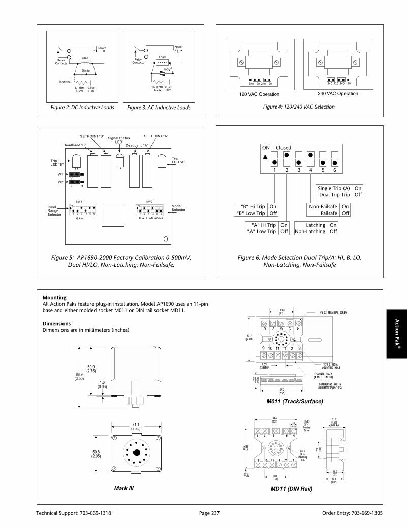
Page 237Technical Support: 703-669-1318 Order Entry: 703-669-1305
Actio
n P
ak®
Figure 5: AP1690-2000 Factory Calibration 0-500mV,Dual HI/LO, Non-Latching, Non-Failsafe.
Figure 6: Mode Selection Dual Trip/A: HI, B: LO,Non-Latching, Non-Failsafe
Figure 4: 120/240 VAC SelectionFigure 2: DC Inductive Loads Figure 3: AC Inductive Loads
ON = Closed
1 2 3 4 5 6
"B" Hi Trip"B" Low Trip
OnOff
"A" Hi Trip"A" Low Trip
OnOff
LatchingNon-Latching
OnOff
Non-FailsafeFailsafe
OnOff
Single Trip (A)Dual Trip Trip
OnOff
MountingAll Action Paks feature plug-in installation. Model AP1690 uses an 11-pinbase and either molded socket M011 or DIN rail socket MD11.
DimensionsDimensions are in millimeters (inches)
M011 (Track/Surface)
MD11 (DIN Rail)Mark III

Page 238Technical Support: 703-669-1318 Order Entry: 703-669-1305
Act
ion P
ak®
Ordering InformationSpecify:1. Model: AP1690-20002. Options: U, P (see text)3. Line Power (see specs.) (All power supplies are transformer isolated
from the internal circuitry)4. C006 (0.1ohm shunt for 1 to 5Amp current inputs).5. C620 Custom Calibration? (see Options)
Accessories:
M801-0000 Retaining Spring
M011-A 11 pin Track Mount Socket
M004-0000 4 ft Long Channel Track
MD11-0000 11 pin DIN Mount Socket
Pin Connections1 AC Power (Hot)2 No Connection3 AC Power (Neu)4 Input (+)5 Input (-)6 (A) N.O.7 (A) C8 (A) N.C.9 (B) N.O.
10 (B) C11 (B) N.C.
Key:N.O. = Normally OpenC = CommonN.C. = Normally ClosedDC Power: Pin 1 = (+)
Pin 3 = (-)
Contacts are in the “normal” state when therelay is de-energized.
Specifications
Inputs:
Voltage Input
Range: 100mV to 200VAC
Impedance: >100K Ohms
Overvoltage: 300VAC, max.
Current Input
Range: 10mA to 100mAAC
Impedance: 20 Ohms, typical
Overcurrent: 200mA AC, 60V peak, max
Frequency Range: DC 40-400Hz,
factory calibrated at 60Hz
Common Mode (Input to Ground):1000V, max
LED Indications:
Input Range (Green)
>100% input: 8Hz flash (approx)
Setpoint (Red):
Tripped: Solid red
Safe: Off
Limit Differentials (Deadbands):
0.25% to 50% of selected span
Response Time:
Dynamic Deadband:
Relay status will change when propersetpoint/process conditionexistsuninterrupted for 100msec.
Normal Mode (analog filtering):
<250msec, (10-90%)
Setpoint:
Effectivity:
Setpoints are adjustable over 100% of theselected input span.
Repeatability (constant temp):
0.1% of selected input span
Stability:
Line Voltage: ±0.01%/%, max.
Temperature: ±0.025% of full scale/°C, max.
Common Mode Rejection:
DC to 60Hz: 120dB
Isolation:
1000VDC between contacts, input & power
ESD Susceptibility:
Meets IEC 801-2, Level 2 (4KV)
Humidity:
Operating: 15 to 95% (@45°C)
Soak: 90% for 24 hours (@65°C)
Temperature Range:
Operating: 0 to 60°C (32 to 140°F)
Storage: -15 to 70°C (5 to 158°F)
Power:
Consumption: 2W typical, 5W max
Standard:
Selectable 120/240VAC (+10%, 50-60Hz)
Relay Contacts:
1 SPDT (1 Form C) per setpoint
Current Rating (resistive):
120VAC: 5A; 240VAC: 2A; 28VDC: 5A
Material: Gold flash over silver alloy
Electrical Life: 105 operations at rated load
Note: External relay contact protection isrequired for use with inductive loads.See Relay Protection section.
Mechanical Life: 107 operations
Latch Reset Time:
5 seconds
Weight:
0.64lbs
Agency Approvals:
CSA certified per standard C22.2
(File No.LR42272-54).
UL recognized per standard UL 805
(File No. E99775)

Page 239Technical Support: 703-669-1318 Order Entry: 703-669-1305
Actio
n P
ak®
DescriptionModel AP4003-0001 is the new version of the previous AP4003-xxxx series. Wide-ranging technology from the Ultra Slimpak IIseries has been utilized in this new version. This single modelcontains all of the input capability of previous dash numberswithout the need for custom ranging from the factory. Theresistance range is still 100 to 100k ohms. The default range is 0to 100% but any portion of the span from 10% to 100% can beselected by pushbutton ranging. Four output ranges (0-5VDC, 0-10VDC, 0-20mA and 4-20mA) are available. A 15VDC output canalso be used, but at a reduced drive level of 3mA. The defaultoutput is 4-20mA.
Action PAK®
AP4003Potentiometer Input Signal Conditioner
Provides a DC Output in Proportionto a Potentiometer Position Input
Constant Voltage Excitation 100 to 100k Ohm Potentiometers Tank Level and Position Applications Selectable Failsafe/Latching Operation
AP4003-0001
Plug-in Installation Selectable Failsafe/Latching Operation AC Line Powered
ApplicationsThe AP4003-0001 is useful for converting potentiometer settingsto voltage or current. It can be used anywhere a potentiometeror slidewire is used to determine position, displacement orrotation. The constant-voltage excitation allows use with poten-tiometers/slidewires with total resistances from 100 ohms to 100kohms without affecting accuracy. For additional information oncalibration, operation and installation, contact our TechnicalSupport Group.
MountingAll Action Paks feature plug-in installation. Model AP4003 uses an 8-pinbase, either molded socket (M008) or DIN rail socket (MD08).
DimensionsDimensions are in millimeters (inches)
MD08 (DIN Rail)
M008 (Track/Surface)
Mark lll

Page 240Technical Support: 703-669-1318 Order Entry: 703-669-1305
Act
ion P
ak®
MountingAll Action Paks feature plug-in installation. The AP4003-0001 usesan 8-pin base, either the molded socket (M008) or the DIN railsocket (MD08). An optional retaining spring (M801) is available ifrequired for the application.
Power ConnectionsSee the pin connections at the back of this document. The unitsupports either 115VAC input (the default) or 230VAC input. For230VAC input, the jumpers next to the input transformer (on thebase board) need to be changed according to the diagram below.
Diagnostic LEDSOther than when executing the pushbutton calibration routine,the LEDs blink under the following conditions:
GREEN: 2Hz when the input is under range 8Hz when theinput is over range
RED: 2Hz when the output is under range 8 Hz when theoutput is over range
An Under Range condition exists when the signal is lower than theoperational low value minus 6.25% of the operational span. AnOver Range condition exists when the signal is higher than theoperational high value plus 6.25% of the operational span.
A voltage output short circuit may cause an under range condition(RED blinking at a 2Hz rate). A current output open circuit maycause an over range condition (RED blinking at an 8Hz rate). Therecould be two or more LEDs blinking at the same time. That meansthe module has more then one error condition present. Only whenall error conditions have been cleared will the LEDs be back totheir normal condition (Green ON, Red and Yellow OFF).
CalibrationFor best results, calibration should be performed in the operatingenvironment, allowing at least one hour warm-up for thermalstability of the system. If pre-calibration on a test bench is desired,then an output load equal to the input impedance of the devicesconnected to the AP4003-0001 output is recommended, alongwith the warm-up period.
Note: Many applications do not require calibrating the outputlevels and simply utilize the default operational ranges of the unit(0-5VDC, 0-10VDC, 0-20mA or 4-20mA). If the factory defaultcalibration has been changed, the last saved operational outputvalues are utilized. In those applications, the only calibrationrequired is the operational input values. Once the maximum andminimum input values have been set, the Green and Red LEDs willbe on. At this point, simply press the CAL button rapidly 3 timesand you will exit the calibration routine without effecting the lastsaved calibration for the operational output values.
1. Connect a precision, multi-turn potentiometer of the requiredvalue to the input, with the CW lead connected to Pin 6, the Wiperlead to Pin 5 and the CCW lead to Pin 4. Connect the output to avoltage or current meter, depending on your application. Applypower and allow the system to reach thermal equilibrium.
2. Rotate the pot fully CW or to the desired maximum point andobserve that the Green LED is on or flashing. Push the CAL buttonand hold for more than 4 seconds. The Yellow and Red LEDsshould be on. Push the CAL button momentarily and the Yellowand Green LEDs will be on. (From this point on, you can exit thecalibration procedure at any step without saving new data byholding the CAL button for at least 4 seconds.)
3. With the pot at the maximum input signal level desired, push theCAL button. The Yellow LED should now be on.
4. Rotate the pot to the full CCW position, or the exact minimuminput signal level desired, then push the CAL button. The Greenand Red LEDs should now be on. If you do not wish to change theoutput calibration, press the CAL button rapidly three times to exitthe calibration routine.
5. If you do wish to do a custom operational range for the output,rotate the pot CW until the output is precisely at the desiredmaximum level (e.g. 20.00mA), then push the CAL button. The RedLED should be on.
6. Rotate the pot CCW until the output is precisely at the desiredminimum level (e.g. 4.00mA), then push the CAL button. All threeLEDs should now be on.
7. To finish calibration, push the button one final time. Thecalibration data is now saved. The Green LED should be on if theinput is within the calibrated range.
Default SettingsInput Range: 0 to 100%Output Range: 4 to 20mA
noitcnuF 1S
1 2 3
egnaRtuptuO
Am02ot4
Am02ot0
cdV5ot0
cdV01ot0
:yeK desolCroNO=1=
noitcnuF 1S
4
mroFtuptuO
tuOtceriD
tuOesreveR
:yeK desolCroNO=1=
115 Vac
230 Vac
JMPR 1 JMPR 2
JMPR 1 JMPR 2
Table 1. Output Range
Table 2. Output Form

Page 241Technical Support: 703-669-1318 Order Entry: 703-669-1305
Actio
n P
ak®
Figure 1. Calibration Flow Chart

Page 242Technical Support: 703-669-1318 Order Entry: 703-669-1305
Act
ion P
ak®
Specifications
Input:
Impedance: >100M ohms
Linearity: ±0.1% of span, typical
Excitation: 300mV, nominal
Potentiometer Resistance:
100 ohms (min) to 100k ohms (max)
(end to end)
Input Range:
Any portion of the potentiometer from
10% to 100% using pushbuttoncalibration
Turn-Up/Turn-Down: 75%
(90% of span @ 0.5% linearity; 80% of
span @ 0.15% linearity)
Common Mode Rejection:
60Hz: >100dB
DC: >120dB
Output Ranges:
0-5VDC, 0-10VDC
(higher voltage to 15V @ 3mA drive)
0-20mA
4-20mA
Response Time:
100mSec, typical
Stability:
±100ppm (±0.01%) of span/°C, typical
Output Ripple:
0.2% of span, or 5mVrms, whichever is greater
Output Impedance:
Voltage Output: <10 ohms
Current Output: >100k ohms
Output Drive:
Voltage Output: 10mA, max
Current Output: 20V compliance @20mA
LED Indication:
RUN (Green): On when unit is powered.Flashes at 2Hz when input is belowoperational low minus 6.25% ofoperational span.
Flashes at 8Hz when input is aboveoperational span plus 6.25% ofoperational span. INPUT (Yellow): Onwhile calibrating the input level.
OUTPUT (Red): On while calibrating theoutput level. Flashes at 2Hz when outputis below opertional low minus 6.25% ofoperational span.Flashes at 8Hz whenoutput is above operational span plus6.25% of operational span.
Temperature Range:
Operating: 0 to 60°C (32 to 140°F)
Storage: -20 to 85°C (-4 to 185°F)
Humidity:
Operating: 15 to 95% RH non-condensing
Non-operating: 90% RH @ 65°C for 24 hrs
Power Consumption:
3W typical, 5W max
Standard: 115/230VAC ±10%
Isolation:
Input to Output Power: 1500VDC
Agency Approvals:
CSA C22.2, No. 0-M91, 142-M1987
UL508
Ordering InformationSpecify:1. Model: AP4003-0001
Accessories:
M801-0000 Retaining Spring
M008-A 8 pin Track Mount Socket
M004-0000 4 ft Long Channel Track
MD08-0000 8 pin DIN Mount Socket
Pin Connections1 AC Power (Hot)2 Shield (GND)3 AC Power (Neu)4 Pot CCW/Shield5 Pot W6 Pot CW7 Output (+)8 Output (-)
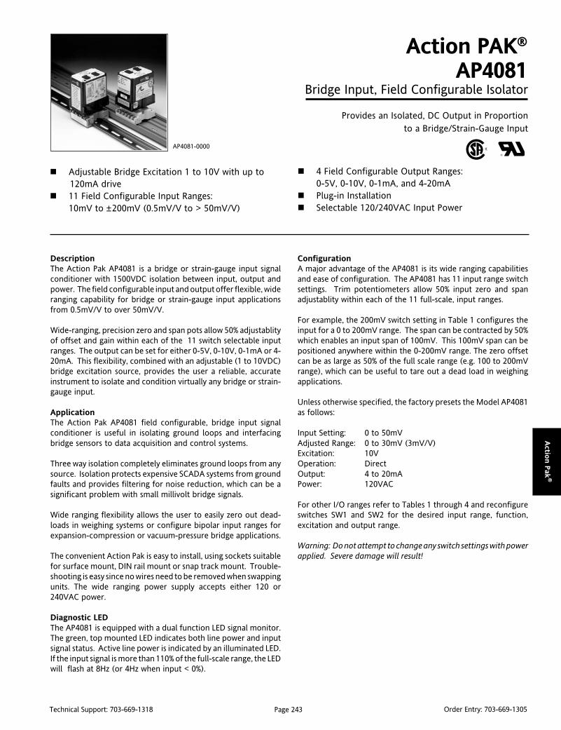
Page 243Technical Support: 703-669-1318 Order Entry: 703-669-1305
Actio
n P
ak®
DescriptionThe Action Pak AP4081 is a bridge or strain-gauge input signalconditioner with 1500VDC isolation between input, output andpower. The field configurable input and output offer flexible, wideranging capability for bridge or strain-gauge input applicationsfrom 0.5mV/V to over 50mV/V.
Wide-ranging, precision zero and span pots allow 50% adjustablityof offset and gain within each of the 11 switch selectable inputranges. The output can be set for either 0-5V, 0-10V, 0-1mA or 4-20mA. This flexibility, combined with an adjustable (1 to 10VDC)bridge excitation source, provides the user a reliable, accurateinstrument to isolate and condition virtually any bridge or strain-gauge input.
ApplicationThe Action Pak AP4081 field configurable, bridge input signalconditioner is useful in isolating ground loops and interfacingbridge sensors to data acquisition and control systems.
Three way isolation completely eliminates ground loops from anysource. Isolation protects expensive SCADA systems from groundfaults and provides filtering for noise reduction, which can be asignificant problem with small millivolt bridge signals.
Wide ranging flexibility allows the user to easily zero out dead-loads in weighing systems or configure bipolar input ranges forexpansion-compression or vacuum-pressure bridge applications.
The convenient Action Pak is easy to install, using sockets suitablefor surface mount, DIN rail mount or snap track mount. Trouble-shooting is easy since no wires need to be removed when swappingunits. The wide ranging power supply accepts either 120 or240VAC power.
Diagnostic LEDThe AP4081 is equipped with a dual function LED signal monitor.The green, top mounted LED indicates both line power and inputsignal status. Active line power is indicated by an illuminated LED.If the input signal is more than 110% of the full-scale range, the LEDwill flash at 8Hz (or 4Hz when input < 0%).
Action PAK®
AP4081Bridge Input, Field Configurable Isolator
Provides an Isolated, DC Output in Proportionto a Bridge/Strain-Gauge Input
Adjustable Bridge Excitation 1 to 10V with up to120mA drive
11 Field Configurable Input Ranges:10mV to ±200mV (0.5mV/V to > 50mV/V)
AP4081-0000
4 Field Configurable Output Ranges:0-5V, 0-10V, 0-1mA, and 4-20mA
Plug-in Installation Selectable 120/240VAC Input Power
ConfigurationA major advantage of the AP4081 is its wide ranging capabilitiesand ease of configuration. The AP4081 has 11 input range switchsettings. Trim potentiometers allow 50% input zero and spanadjustablity within each of the 11 full-scale, input ranges.
For example, the 200mV switch setting in Table 1 configures theinput for a 0 to 200mV range. The span can be contracted by 50%which enables an input span of 100mV. This 100mV span can bepositioned anywhere within the 0-200mV range. The zero offsetcan be as large as 50% of the full scale range (e.g. 100 to 200mVrange), which can be useful to tare out a dead load in weighingapplications.
Unless otherwise specified, the factory presets the Model AP4081as follows:
Input Setting: 0 to 50mVAdjusted Range: 0 to 30mV (3mV/V)Excitation: 10VOperation: DirectOutput: 4 to 20mAPower: 120VAC
For other I/O ranges refer to Tables 1 through 4 and reconfigureswitches SW1 and SW2 for the desired input range, function,excitation and output range.
Warning: Do not attempt to change any switch settings with powerapplied. Severe damage will result!

Page 244Technical Support: 703-669-1318 Order Entry: 703-669-1305
Act
ion P
ak®
Calibration1. Connect the input to a calibrated millivolt source, load theexcitation supply with the bridge or an equivalent load and applypower. Wait at least 15 minutes for thermal stability beforemonitoring the voltage/current.
2. Adjust excitation to the desired level.
3. Set the calibrator to the desired minimum input and adjust thezero potentiometer for minimum output.
4. Set the calibrator to the desired maximum input and adjust thespan potentiometer for maximum output.
5. Repeat steps 3 and 4, as necessary for best accuracy.
Table 2: Direct or Reverse Operation Setting
Table 1: Input Range Selector-Switch settings
Table 3: Bridge Excitation Selector-Switch Settings
Table 4: Output Range Selector-Switch Settings

Page 245Technical Support: 703-669-1318 Order Entry: 703-669-1305
Actio
n P
ak®
Figure 1: Factory Calibration; 0 to 50mV (calibrated to 0-30mV), 10V excitation, Direct, 4-20mA.
Figure 2: 120/240 VAC Selection
WARNING: Do not attemptto change any switch
settings with power applied.Severe damage will result!
M011 (Track/Surface)
MountingAll Action Paks feature plug-in installation. Model AP4081 uses an 11-pinbase, either molded socket (M011) or DIN rail socket (MD11).
DimensionsDimensions are in millimeters (inches)
MD11 (DIN Rail)Mark II
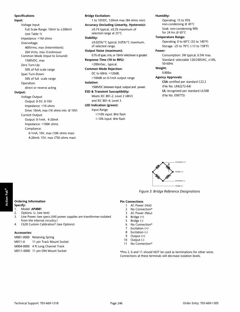
Page 246Technical Support: 703-669-1318 Order Entry: 703-669-1305
Act
ion P
ak®
Ordering InformationSpecify:1. Model: AP40812. Options: U, (see text)3. Line Power (see specs.)(All power supplies are transformer-isolated
from the internal circuitry.)4. C620 Custom Calibration? (see Options)
Accessories:
M801-0000 Retaining Spring
M011-A 11 pin Track Mount Socket
M004-0000 4 ft Long Channel Track
MD11-0000 11 pin DIN Mount Socket
Pin Connections1 AC Power (Hot)2 No Connection*3 AC Power (Neu)4 Bridge (+)5 Bridge (-)6 No Connection*7 Excitation (+)8 Excitation (-)9 Output (+)
10 Output (-)11 No Connection*
*Pins 2, 6 and 11 should NOT be used as terminations for other wires.Connections at these terminals will decrease isolation levels.
Specifications
Input:
Voltage Input:
Full Scale Range: 10mV to ±200mV
(see Table 1)
Impedance: >1M ohms
Overvoltage:
400Vrms, max (Intermittent);
264 Vrms, max (Continous)Common Mode (Input to Ground):
1500VDC, max
Zero Turn-Up:
50% of full scale range
Span Turn-Down:
50% of full scale range
Operation:
direct or reverse acting
Output:
Voltage Output:
Output: 0-5V, 0-10V
Impedance: <10 ohms
Drive: 10mA, max (1K ohms min. @ 10V)
Current Output:
Output: 0-1mA, 4-20mA
Impedance: >100K ohms
Compliance:
0-1mA; 10V, max (10K ohms max)
4-20mA; 15V, max (750 ohms max)
Bridge Excitation:
1 to 10VDC, 120mA max (84 ohms min)
Accuracy (Including Linearity, Hysteresis):
±0.1% typical, ±0.2% maximum ofselected range at 25°C.
Stability:
±0.025%/°C typical, 0.05%/°C maximum,of selected range.
Output Noise (maximum):
0.1% of span, rms, or 10mV whichever is greater.
Response Time (10 to 90%):
<200mSec., typical.
Common Mode Rejection:
DC to 60Hz: >120dB,
>100dB on 0-1mA output range
Isolation:
1500VDC between input, output and power.
ESD & Transient Susceptibility:
Meets IEC 801-2, Level 2 (4KV)
and IEC 801-4, Level 3
LED Indication (green):
Input Range
>110% input: 8Hz flash
<-10% input: 4Hz flash
Figure 3: Bridge Reference Designations
Excitation (+)
Bridge (+)
Excitation (-)
Bridge (-)
Humidity:
Operating: 15 to 95%non-condensing @ 45°CSoak: non-condensing 90%for 24 hrs @ 65°C
Temperature Range:
Operating: 0 to 60°C (32 to 140°F)
Storage: -25 to 70°C (-13 to 158°F)
Power:
Consumption: 3W typical, 6.5W max.
Standard: selectable 120/240VAC, ±10%,50-60Hz
Weight:
0.80lbs
Agency Approvals:
CSA certified per standard C22.2
(File No. LR42272-64)
UL recognized per standard UL508
(File No. E99775)
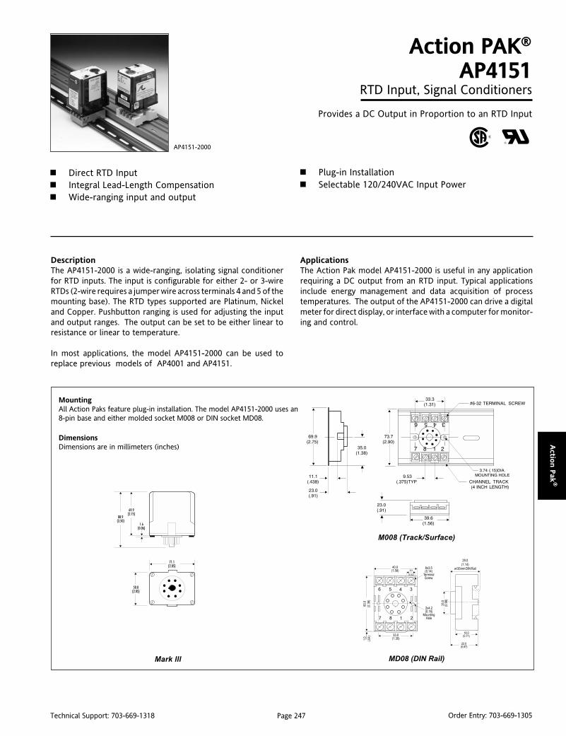
Page 247Technical Support: 703-669-1318 Order Entry: 703-669-1305
Actio
n P
ak®
DescriptionThe AP4151-2000 is a wide-ranging, isolating signal conditionerfor RTD inputs. The input is configurable for either 2- or 3-wireRTDs (2-wire requires a jumper wire across terminals 4 and 5 of themounting base). The RTD types supported are Platinum, Nickeland Copper. Pushbutton ranging is used for adjusting the inputand output ranges. The output can be set to be either linear toresistance or linear to temperature.
In most applications, the model AP4151-2000 can be used toreplace previous models of AP4001 and AP4151.
Action PAK®
AP4151RTD Input, Signal Conditioners
Provides a DC Output in Proportion to an RTD Input
Direct RTD Input Integral Lead-Length Compensation Wide-ranging input and output
AP4151-2000
Plug-in Installation Selectable 120/240VAC Input Power
ApplicationsThe Action Pak model AP4151-2000 is useful in any applicationrequiring a DC output from an RTD input. Typical applicationsinclude energy management and data acquisition of processtemperatures. The output of the AP4151-2000 can drive a digitalmeter for direct display, or interface with a computer for monitor-ing and control.
MountingAll Action Paks feature plug-in installation. The model AP4151-2000 uses an8-pin base and either molded socket M008 or DIN socket MD08.
DimensionsDimensions are in millimeters (inches)
MD08 (DIN Rail)
M008 (Track/Surface)
Mark lll
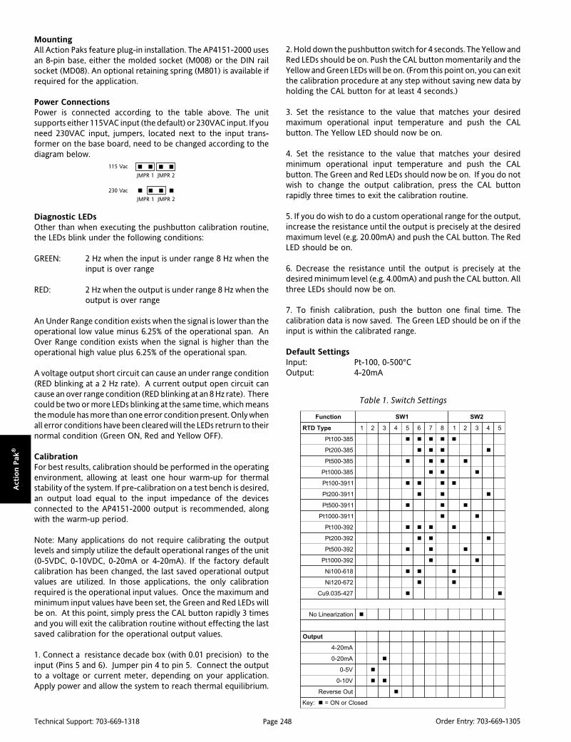
Page 248Technical Support: 703-669-1318 Order Entry: 703-669-1305
Act
ion P
ak®
MountingAll Action Paks feature plug-in installation. The AP4151-2000 usesan 8-pin base, either the molded socket (M008) or the DIN railsocket (MD08). An optional retaining spring (M801) is available ifrequired for the application.
Power ConnectionsPower is connected according to the table above. The unitsupports either 115VAC input (the default) or 230VAC input. If youneed 230VAC input, jumpers, located next to the input trans-former on the base board, need to be changed according to thediagram below.
Diagnostic LEDsOther than when executing the pushbutton calibration routine,the LEDs blink under the following conditions:
GREEN: 2 Hz when the input is under range 8 Hz when theinput is over range
RED: 2 Hz when the output is under range 8 Hz when theoutput is over range
An Under Range condition exists when the signal is lower than theoperational low value minus 6.25% of the operational span. AnOver Range condition exists when the signal is higher than theoperational high value plus 6.25% of the operational span.
A voltage output short circuit can cause an under range condition(RED blinking at a 2 Hz rate). A current output open circuit cancause an over range condition (RED blinking at an 8 Hz rate). Therecould be two or more LEDs blinking at the same time, which meansthe module has more than one error condition present. Only whenall error conditions have been cleared will the LEDs retrurn to theirnormal condition (Green ON, Red and Yellow OFF).
CalibrationFor best results, calibration should be performed in the operatingenvironment, allowing at least one hour warm-up for thermalstability of the system. If pre-calibration on a test bench is desired,an output load equal to the input impedance of the devicesconnected to the AP4151-2000 output is recommended, alongwith the warm-up period.
Note: Many applications do not require calibrating the outputlevels and simply utilize the default operational ranges of the unit(0-5VDC, 0-10VDC, 0-20mA or 4-20mA). If the factory defaultcalibration has been changed, the last saved operational outputvalues are utilized. In those applications, the only calibrationrequired is the operational input values. Once the maximum andminimum input values have been set, the Green and Red LEDs willbe on. At this point, simply press the CAL button rapidly 3 timesand you will exit the calibration routine without effecting the lastsaved calibration for the operational output values.
1. Connect a resistance decade box (with 0.01 precision) to theinput (Pins 5 and 6). Jumper pin 4 to pin 5. Connect the outputto a voltage or current meter, depending on your application.Apply power and allow the system to reach thermal equilibrium.
2. Hold down the pushbutton switch for 4 seconds. The Yellow andRed LEDs should be on. Push the CAL button momentarily and theYellow and Green LEDs will be on. (From this point on, you can exitthe calibration procedure at any step without saving new data byholding the CAL button for at least 4 seconds.)
3. Set the resistance to the value that matches your desiredmaximum operational input temperature and push the CALbutton. The Yellow LED should now be on.
4. Set the resistance to the value that matches your desiredminimum operational input temperature and push the CALbutton. The Green and Red LEDs should now be on. If you do notwish to change the output calibration, press the CAL buttonrapidly three times to exit the calibration routine.
5. If you do wish to do a custom operational range for the output,increase the resistance until the output is precisely at the desiredmaximum level (e.g. 20.00mA) and push the CAL button. The RedLED should be on.
6. Decrease the resistance until the output is precisely at thedesired minimum level (e.g. 4.00mA) and push the CAL button. Allthree LEDs should now be on.
7. To finish calibration, push the button one final time. Thecalibration data is now saved. The Green LED should be on if theinput is within the calibrated range.
Default SettingsInput: Pt-100, 0-500°COutput: 4-20mA
115 Vac
230 Vac
JMPR 1 JMPR 2
JMPR 1 JMPR 2
noitcnuF 1WS 2WS
epyTDTR 1 2 3 4 5 6 7 8 1 2 3 4 5
583-001tP
583-002tP
583-005tP
583-0001tP
1193-001tP
1193-002tP
1193-005tP
1193-0001tP
293-001tP
293-002tP
293-005tP
293-0001tP
816-001iN
276-021iN
724-530.9uC
noitaziraeniLoN
tuptuO
Am02-4
Am02-0
V5-0
V01-0
tuOesreveR
:yeK desolCroNO=
Table 1. Switch Settings

Page 249Technical Support: 703-669-1318 Order Entry: 703-669-1305
Actio
n P
ak®
Figure 1. Calibration Flow Chart
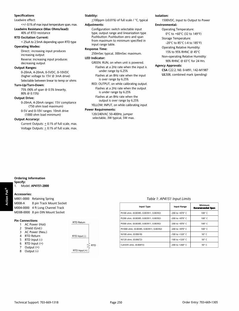
Page 250Technical Support: 703-669-1318 Order Entry: 703-669-1305
Act
ion P
ak®
Specifications
Leadwire effect:
<+/- 0.1% of max input temperature span, max.
Leadwire Resistance (Max Ohms/lead):40% of RTD resistance
RTD Excitation Current:
< 25uA to 2.5mA depending upon RTD type
Operating Modes:
Direct:: increasing input producesincreasing output
Reverse: increasing input producesdecreasing output
Output Ranges:
0-20mA, 4-20mA, 0-5VDC, 0-10VDC(higher voltage to 15V @ 3mA drive)
Selectable between linear to temp or ohms
Turn-Up/Turn-Down:
75% (90% of span @ 0.5% linearity,80% @ 0.15%)
Output Drive:
0-20mA, 4-20mA ranges: 15V compliance(750 ohm load maximum)
0-5V and 0-10V ranges: 10mA drive(1000 ohm load minimum)
Output Accuracy:
Current Outputs: + 0.1% of full scale, max.
Voltage Outputs: + 0.1% of full scale, max.
Ordering InformationSpecify:1. Model: AP4151-2000
Accessories:
M801-0000 Retaining Spring
M008-A 8 pin Track Mount Socket
M004-0000 4 ft Long Channel Track
MD08-0000 8 pin DIN Mount Socket
Pin Connections1 AC Power (Hot)2 Shield (Gnd.)3 AC Power (Neu.)4 RTD Return5 RTD Input (-)6 RTD Input (+)7 Output (+)8 Output (-)
Stability:
+100ppm (±0.01%) of full scale / °C, typical
Adjustments:
Configuration: switch selectable inputtype, output range and linearization typePushbutton: Pushbutton zero and spanfrom maximum to minimum specified ininput range table.
Response Time:
250mSec typical, 300mSec maximum.
LED Indicator:
GREEN: RUN, on when unit is powered.
Flashes at a 2Hz rate when the input isunder range by 6.25%
Flashes at an 8Hz rate when the inputis over range by 6.25%
RED: OUTPUT, on while calibrating output.
Flashes at a 2Hz rate when the outputis under range by 6.25%
Flashes at an 8Hz rate when theoutput is over range by 6.25%
YELLOW: INPUT, on while calibrating input
Power Requirements:
120/240VAC 50-400Hz, jumper selectable, 3W typical, 5W max.
Isolation:
1500VDC, Input to Output to Power
Environmental:
Operating Temperature:
0°C to +60°C (32 to 149°F)
Storage Temperature:
-20°C to 85°C (-4 to 185°F)
Operating Relative Humidity:
15% to 95% RHNC @ 45°CNon-operating Relative Humidity:
90% RHNC @ 65°C for 24 Hrs.
Agency Approvals:
CSA C22.2, N0. 0-M91, 142-M1987
UL508, combined mark (pending)
Table 1: AP4151 Input Limits
epyTtupnI egnaRtupnImuminiM
napSdednemmoceR napSdednemmoceR napSdednemmoceR napSdednemmoceR napSdednemmoceR
)29300.0,119300.0,58300.0(,mho001tP C°078+ot002- C°001
)29300.0,119300.0,58300.0(,mho002tP C°078+ot002- C°001
)29300.0,119300.0,58300.0(,mho005tP C°078+ot002- C°001
)29300.0,119300.0,58300.0(,mho0001tP C°078+ot002- C°001
)81600.0(,mho001iN C°023+ot001- C°05
)27600.0(,mho021iN C°023+ot001- C°05
)27400.0(,mho530.9uC C°062+ot002- C°05

Page 251Technical Support: 703-669-1318 Order Entry: 703-669-1305
Actio
n P
ak®
DescriptionThe AP4351 isolating thermocouple conditioner offers wide rang-ing input and output capability. The AP4351 can be field config-ured by the user to accept input from thermocouple types J, K, T,R, S, E, and B and to provide current or voltage output. The outputis linearized to temperature according to the particular thermo-couple type.
The AP4351 is a three-port industrial isolator — the output isoptically isolated from the input up to 1500V, and both input andoutput are transformer isolated from the line power. Isolationallows the noise reduction benefits of grounded thermocouples tobe realized without creating ground loop problems and it providesfaster response. The AP4351 utilizes the latest in advanced analog/digital signal processing technology. In addition to its multiplemicroprocessors, it employs special ASIC circuitry for high accu-racy and reliability.
The AP4351 is equipped with cold-junction compensation (CJC)circuitry to provide ice-point reference. Upscale, downscale ordisabled thermocouple burnout detection is switch selectable.
ApplicationThe Action Pak Model AP4351 is useful in any application requiringan isolated DC output from a thermocouple input. Typical appli-cations include energy management and data acquisition ofprocess temperatures. The output of the AP4351 can drive a digitalmeter for direct display or interface with a computer for monitor-ing and control applications.
Status LEDsModel AP4351 is equipped with top-mounted LEDs for INPUT(green), TROUBLE (yellow) and CAL OK (yellow). At start-up, boththe INPUT and the CAL OK LEDs light up momentarily for 1 second.Afterwards, these LEDs flash alternately for 10 seconds while start-up takes place.
Input LEDThis input LED is a diagnostic tool. It remains continuously lit if themeasured temperature is within the selected range of the thermo-couple. However, if the measured temperature is outside the fullrange of the thermocouple (for example, for a type J - belowminus 200°C or above 750°C), the LED will flash at a rate of 4 or
Action PAK®
AP4351Thermocouple-Input,
Field Configurable Isolator
Provides Isolated, Linearized DC Outputin Proportion to Thermocouple Input
Field Configurable Thermocouple Types Linearized Outputs Wide-Ranging Zero and Span Adjustability (50%
AP4351-2000
Eliminates Ground Loops Thermocouple Burnout Detection ASIC Technology for Enhanced Reliability
8Hz for under/over range, repectively. If the thermocouple iswithin the full temperature range, but outside the selected sub-range (for example, if a type J thermocouple is set for range 13 andthe temperature is either below 375°C or above 500°C) the LEDwill flash at 0.5 or 1Hz respectively.
Cal OK LEDThis LED is continuously on when the device is properly storing thefactory calibration reference voltage.
Trouble LEDThis LED is off during normal operation of the device. If this LEDis on contact Action's Technical Services Group.
OptionsU Urethane coating of internal circuitry for protection from
corrosive atmospheres.
C620 Factory calibration (specifyinput thermocouple type, temperature range and output).
ConfigurationA major advantage of the AP4351 is its wide ranging capabilitiesand ease of configuration. The AP4351 enables 50% input zero andspan adjustability within the selected sub-range.
For example, range #5 for an E-Type thermocouple in Table 6specifies -18°C to 125°C. Since the span can be contracted by 50%,this enables an input span as narrow as 50% of 143°C, or 72°C. Thisspan can then be positioned anywhere within the temperaturerange and can have a zero step-up as large as 50% of the full scalerange (e.g. span can start as high as 53°C).
Unless otherwise specified, the factory pre-sets the Model AP4351as follows:
Input: J-typeRange: 0-500°COutput: 4-20mABurn Out: Upscale
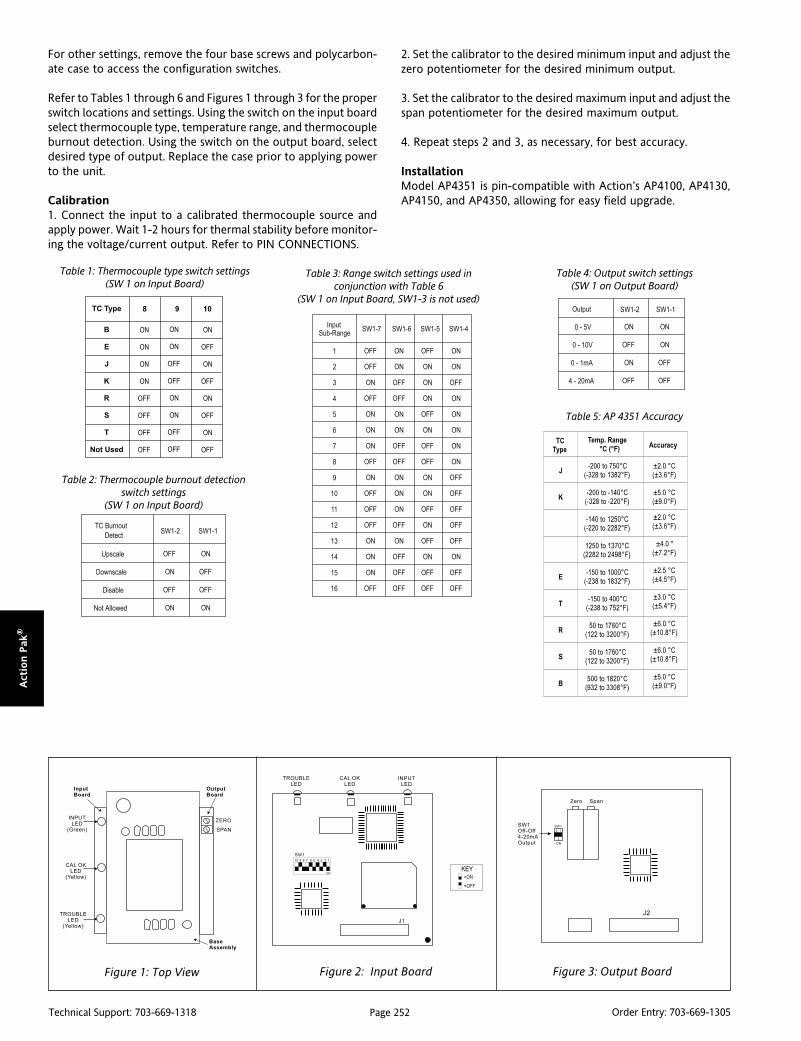
Page 252Technical Support: 703-669-1318 Order Entry: 703-669-1305
Act
ion P
ak®
For other settings, remove the four base screws and polycarbon-ate case to access the configuration switches.
Refer to Tables 1 through 6 and Figures 1 through 3 for the properswitch locations and settings. Using the switch on the input boardselect thermocouple type, temperature range, and thermocoupleburnout detection. Using the switch on the output board, selectdesired type of output. Replace the case prior to applying powerto the unit.
Calibration1. Connect the input to a calibrated thermocouple source andapply power. Wait 1-2 hours for thermal stability before monitor-ing the voltage/current output. Refer to PIN CONNECTIONS.
Table 1: Thermocouple type switch settings(SW 1 on Input Board)
Table 3: Range switch settings used inconjunction with Table 6
(SW 1 on Input Board, SW1-3 is not used)
Table 5: AP 4351 Accuracy
Table 4: Output switch settings(SW 1 on Output Board)
Table 2: Thermocouple burnout detectionswitch settings
(SW 1 on Input Board)
Figure 1: Top View Figure 2: Input Board Figure 3: Output Board
2. Set the calibrator to the desired minimum input and adjust thezero potentiometer for the desired minimum output.
3. Set the calibrator to the desired maximum input and adjust thespan potentiometer for the desired maximum output.
4. Repeat steps 2 and 3, as necessary, for best accuracy.
InstallationModel AP4351 is pin-compatible with Action’s AP4100, AP4130,AP4150, and AP4350, allowing for easy field upgrade.

Page 253Technical Support: 703-669-1318 Order Entry: 703-669-1305
Actio
n P
ak®
Table 6: Thermocouple Range Settings
epyTCTegnaRrebmuN rebmuN rebmuN rebmuN rebmuN
egnaRerutarepmeT
B
6 C°0281ot005 )F°8033ot239(
7 C°0281ot0001 )F°8033ot2381(
8 C°0001ot005 )F°2381ot239(
11 C°0281ot0051 )F°8033ot2372(
21 C°0001ot057 )F°2381ot2831(
E
2 C°0001ot81- )F°2381ot0(
3 C°005ot81- )F°239ot0(
4 C°052ot81- )F°284ot0(
5 C°521ot81- )F°752ot0(
8 C°0001ot005 )F°2381ot239(
9 C°005ot052 )F°239ot284(
01 C°052ot521 )F°284ot752(
21 C°0001ot057 )F°2381ot2831(
31 C°005ot573 )F°239ot707(
41 C°057ot051- )F°2831ot832-(
51 C°052ot051- )F°284ot832-(
61 C°0ot051- )F°23ot832-(
J
2 C°057ot81- )F°2831ot0(
3 C°005ot81- )F°239ot0(
4 C°052ot81- )F°284ot0(
5 C°521ot81- )F°752ot0(
8 C°057ot005 )F°2831ot239(
9 C°005ot052 )F°239ot284(
01 C°052ot521 )F°284ot752(
31 C°005ot573 )F°239ot707(
41 C°057ot002- )F°2831ot823-(
51 C°052ot002- )F°284ot823-(
61 C°0ot002- )F°23ot823-(
epyTCTegnaRrebmuN rebmuN rebmuN rebmuN rebmuN
egnaRerutarepmeT
K
1 C°0731ot81- )F°8942ot0(
2 C°0001ot81- )F°2381ot0(
3 C°005ot81- )F°239ot0(
4 C°052ot81- )F°284ot0(
5 C°521ot81- )F°752ot0(
7 C°0731ot0001 )F°8942ot2381(
8 C°0001ot005 )F°2381ot239(
9 C°005ot052 )F°239ot284(
01 C°052ot521 )F°284ot752(
21 C°0001ot057 )F°2381ot2831(
31 C°005ot573 )F°239ot707(
41 C°057ot002- )F°2831ot823-(
51 C°052ot002- )F°284ot823-(
61 C°0ot002- )F°23ot823-(
S,R
1 C°0671ot05 )F°0023ot221(
2 C°0001ot05 )F°2381ot221(
3 C°005ot05 )F°239ot221(
4 C°052ot05 )F°284ot221(
7 C°0671ot0001 )F°0023ot2381(
8 C°0001ot005 )F°2381ot239(
9 C°005ot052 )F°239ot284(
01 C°052ot521 )F°284ot752(
11 C°0671ot0051 )F°0023ot2372(
21 C°0001ot057 )F°2381ot2831(
31 C°005ot573 )F°239ot707(
T
3 C°004ot81- )F°257ot0(
4 C°052ot81- )F°284ot0(
5 C°521ot81- )F°752ot0(
9 C°004ot052 )F°257ot284(
01 C°052ot521 )F°284ot752(
31 C°004ot573 )F°257ot707(
41 C°004ot051- )F°257ot832-(
51 C°052ot051- )F°284ot832-(
61 C°0ot051- )F°23ot832-(
epyTCTegnaRrebmuN rebmuN rebmuN rebmuN rebmuN
egnaRerutarepmeT
MountingAll Action Paks feature plug-in installation. Model AP4351-2000 uses an8-pin base and molded-sockets M008, or DIN-socket MD08.
DimensionsDimensions are in millimeters (inches)
M008 (Track/Surface)
MD08 (DIN Rail)Mark III
Page 254Technical Support: 703-669-1318 Order Entry: 703-669-1305
Act
ion P
ak®
Ordering InformationSpecify:1. Model: AP4351-20002. Option: C620 factory calibration (specify input thermocouple type,
temperature range and output).3. Option: U, see text4. Line Power, see specifications (All power supplies are transformer-
isolated from the internal circuitry)
Accessories:
M801-0000 Retaining Spring
M008-A 8 pin Track Mount Socket
M004-0000 4 ft Long Channel Track
MD08-0000 8 pin DIN Mount Socket
Specifications
Inputs:
Ranges: field configurable, see Table 6
Impedance: >1M Ohms
Input Bias Current (burnout detection):<1.5 microamp
Overvoltage: ±10V differential
Common Mode (Input to Ground):1500VDC or peak AC, max
Zero and Span Range:
Zero Turn-Up:
0 to 50% of full scale range
Span Turn-Down:
100 to 50% of full scale range
Outputs:
Voltage Output: field-configurable
Ranges: 0-5V, 0-10V
Impedance: <10 Ohms
Drive: 10mA, max. (1K Ohms, min.)
Current Output: field-configurable
Ranges: 0-1mA, 4-20mA
Impedance: >100K Ohms
Compliance: 10V, max. (500 Ohms, max. @ 20mA)
Accuracy (Including Linearity, Hysteresis):
see Table 5
Response Time(10-90%):
500 mSec, typical
Stability:
±0.04%/°C of full scale range
Isolation:
1500VDC or peak AC between input,output and power
ESD Susceptibility:
Meets IEC 801- 2, Level 2 (4KV)
Common Mode Rejection:
DC - 60Hz: 120dB
LED Indicators:
TROUBLE LED: Yellow - off during normaldevice operation
INPUT LED: Green - continuously on ifinput is within selected range, flashesotherwise
CAL OK LED: Yellow - continuously on innormal device operation
Thermocouple Burnout Detect:
Field-configurable Up or Downscale, ordisabled
Humidity (Non-Condensing):
Operating: 25 to 95% (@ 45°C)
Soak: 90% for 24 Hrs. (@65°C)
Temperature Range:
Operating: 0 to 60°C (32 to 140°F)
Storage: -15 to 75°C (5 to 167°F)
Power:
Consumption: 3W typical, 5W max
Standard: 120VAC ±10%, 50 - 60Hz
Optional: 240VAC
Weight:
0.62lbs
Approvals:
UL recognized per standard UL508.
(FileNo. E99775).
CSA certified per standards C22.2 No.M1982 (File No. LR42272-41).
Pin Connections1 Power (Hot)2 No Connection3 Power (Neu)4 Do not use5 Input (+)6 Input (-)7 Output (+)8 Output (-)
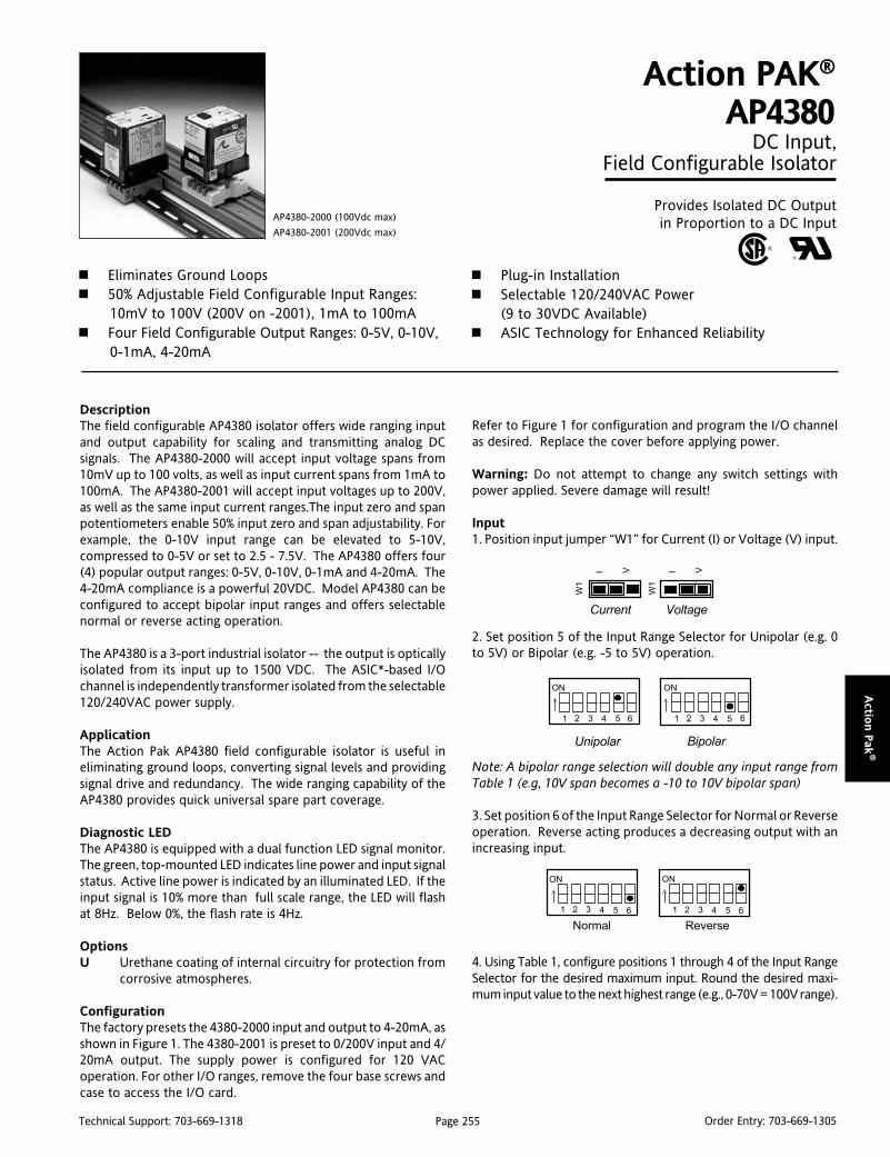
Page 255Technical Support: 703-669-1318 Order Entry: 703-669-1305
Actio
n P
ak®
DescriptionThe field configurable AP4380 isolator offers wide ranging inputand output capability for scaling and transmitting analog DCsignals. The AP4380-2000 will accept input voltage spans from10mV up to 100 volts, as well as input current spans from 1mA to100mA. The AP4380-2001 will accept input voltages up to 200V,as well as the same input current ranges.The input zero and spanpotentiometers enable 50% input zero and span adjustability. Forexample, the 0-10V input range can be elevated to 5-10V,compressed to 0-5V or set to 2.5 - 7.5V. The AP4380 offers four(4) popular output ranges: 0-5V, 0-10V, 0-1mA and 4-20mA. The4-20mA compliance is a powerful 20VDC. Model AP4380 can beconfigured to accept bipolar input ranges and offers selectablenormal or reverse acting operation.
The AP4380 is a 3-port industrial isolator -- the output is opticallyisolated from its input up to 1500 VDC. The ASIC*-based I/Ochannel is independently transformer isolated from the selectable120/240VAC power supply.
ApplicationThe Action Pak AP4380 field configurable isolator is useful ineliminating ground loops, converting signal levels and providingsignal drive and redundancy. The wide ranging capability of theAP4380 provides quick universal spare part coverage.
Diagnostic LEDThe AP4380 is equipped with a dual function LED signal monitor.The green, top-mounted LED indicates line power and input signalstatus. Active line power is indicated by an illuminated LED. If theinput signal is 10% more than full scale range, the LED will flashat 8Hz. Below 0%, the flash rate is 4Hz.
OptionsU Urethane coating of internal circuitry for protection from
corrosive atmospheres.
ConfigurationThe factory presets the 4380-2000 input and output to 4-20mA, asshown in Figure 1. The 4380-2001 is preset to 0/200V input and 4/20mA output. The supply power is configured for 120 VACoperation. For other I/O ranges, remove the four base screws andcase to access the I/O card.
Action PAK®
AP4380 DC Input,
Field Configurable Isolator
Provides Isolated DC Outputin Proportion to a DC Input
Eliminates Ground Loops 50% Adjustable Field Configurable Input Ranges:
10mV to 100V (200V on -2001), 1mA to 100mA Four Field Configurable Output Ranges: 0-5V, 0-10V,
0-1mA, 4-20mA
AP4380-2000 (100Vdc max)
AP4380-2001 (200Vdc max)
Plug-in Installation Selectable 120/240VAC Power
(9 to 30VDC Available) ASIC Technology for Enhanced Reliability
Refer to Figure 1 for configuration and program the I/O channelas desired. Replace the cover before applying power.
Warning: Do not attempt to change any switch settings withpower applied. Severe damage will result!
Input1. Position input jumper “W1” for Current (I) or Voltage (V) input.
2. Set position 5 of the Input Range Selector for Unipolar (e.g. 0to 5V) or Bipolar (e.g. -5 to 5V) operation.
Note: A bipolar range selection will double any input range fromTable 1 (e.g, 10V span becomes a -10 to 10V bipolar span)
3. Set position 6 of the Input Range Selector for Normal or Reverseoperation. Reverse acting produces a decreasing output with anincreasing input.
4. Using Table 1, configure positions 1 through 4 of the Input RangeSelector for the desired maximum input. Round the desired maxi-mum input value to the next highest range (e.g., 0-70V = 100V range).
I V I V
Current Voltage
W1
W1
ON
Unipolar Bipolar
1 2 3 4 65
> >
ON
1 2 3 4 5 6
ON
1 2 3 4
> >
65
Normal Reverse
1 2 3 4 65
ON

Page 256Technical Support: 703-669-1318 Order Entry: 703-669-1305
Act
ion P
ak®
OutputWarning: Do not configure the output ranges with the power on.Damage to unit may result.
1. Using Table 2, configure Output Selector for one of the four (4)standard outputs.
Power1. Configure the AC jumpers for either 120 or 240 VAC operation.See Figure 2.
Table 1: AP4380-2000/2001 Input Ranges
* Use jumper (W1) to configure voltage or current input. All unipolar ranges are zero based.
Input Range Selector(SW1)
>
6
>
6
6
* For bipolar voltage outputs (e.g. -10 to +10V) see model AP4382.
Table 2: AP4380-2000 Output Ranges
Output Range Selector(SW2)Range*
0 to 10V
0 to 5V
0 to 1mA
4 to 20mA
641 2 3
ON
>
5
>
41 2 3
ON
5 6
>
41 2 3
ON
5 6
>
41 2 3
ON
5 6
Calibration1. Connect the input to a calibrated DC voltage or current sourceand apply power. Wait 1 hour for thermal stability before monitor-ing the voltage/current output. Refer to PIN CONNECTIONS.
2. Set the calibrator to the desired minimum input and adjust theZero, 20-turn, potentiometer for desired minimum output.
3. Set the calibrator to the desired maximum input and adjust theSpan, 20-turn, potentiometer for desired maximum output.
4. Repeat steps 2 and 3 for best accuracy.
Voltage* Current*
20mV 2mA
50mV 5mA
100mV 10mA
200mV 20mA
500mV 50mA
1V 100mA
2V
41 2 3
ON
5 6
41 2 3
ON
5
>
41 2 3
ON
5
>
41 2 3
ON
5 6
641 2 3
ON
5
6
>
41 2 3
ON
5
>
41 2 3
ON
5
>
41 2 3
ON
5
641 2 3
ON
5
>
41 2 3
ON
5 6
>
41 2 3
ON
5 6
>
41 2 3
ON
5 6
5V (-2000)10V (-2001)
10V (-2000)20V (-2001)
25V (-2000)50V (-2001)
50V (-2000)100V (-2001)
100V (-2000)200V (-2001)
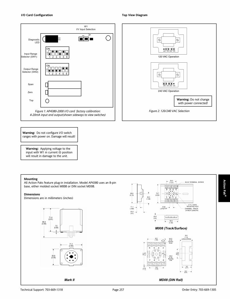
Page 257Technical Support: 703-669-1318 Order Entry: 703-669-1305
Actio
n P
ak®
I/O Card Configuration
W1
I/V Input Selection
Warning: Do not configure I/O switchranges with power on. Damage will result!
Warning: Applying voltage to theinput with W1 in current (I) positionwill result in damage to the unit.
Top View Diagram
Figure 2: 120/240 VAC Selection
Input Range
Selector (SW1)
Diagnostic
LED
Output Range
Selector (SW2)
Figure 1: AP4380-2000 I/O card factory calibration:4-20mA input and output(shown sideways to view switches)
>ON
1 2 3 4 65
>
I V
Top
Span
Zero
ON
1 2 3 4 65
Warning: Do not changewith power connected!
MountingAll Action Paks feature plug-in installation. Model AP4380 uses an 8-pinbase, either molded socket M008 or DIN socket MD08.
DimensionsDimensions are in millimeters (inches)
M008 (Track/Surface)
MD08 (DIN Rail)Mark II
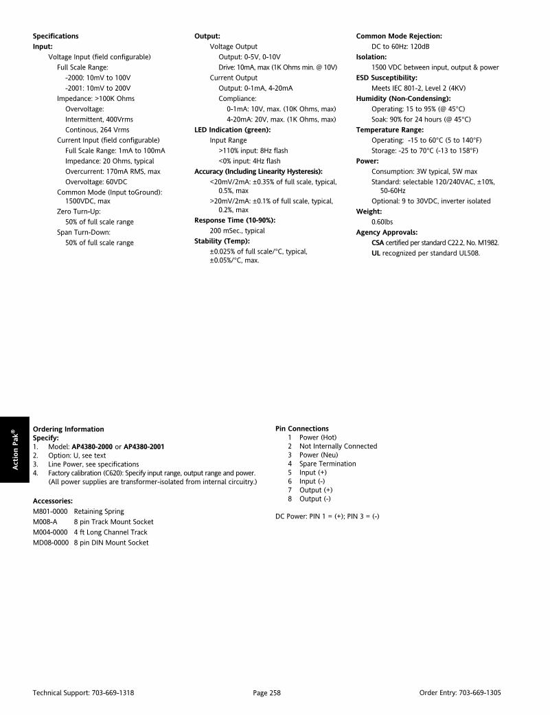
Page 258Technical Support: 703-669-1318 Order Entry: 703-669-1305
Act
ion P
ak® Ordering Information
Specify:1. Model: AP4380-2000 or AP4380-20012. Option: U, see text3. Line Power, see specifications4. Factory calibration (C620): Specify input range, output range and power.
(All power supplies are transformer-isolated from internal circuitry.)
Accessories:
M801-0000 Retaining Spring
M008-A 8 pin Track Mount Socket
M004-0000 4 ft Long Channel Track
MD08-0000 8 pin DIN Mount Socket
Specifications
Input:
Voltage Input (field configurable)
Full Scale Range:
-2000: 10mV to 100V
-2001: 10mV to 200V
Impedance: >100K Ohms
Overvoltage:
Intermittent, 400Vrms
Continous, 264 Vrms
Current Input (field configurable)
Full Scale Range: 1mA to 100mA
Impedance: 20 Ohms, typical
Overcurrent: 170mA RMS, max
Overvoltage: 60VDC
Common Mode (Input toGround):1500VDC, max
Zero Turn-Up:
50% of full scale range
Span Turn-Down:
50% of full scale range
Output:
Voltage Output
Output: 0-5V, 0-10V
Drive: 10mA, max (1K Ohms min. @ 10V)
Current Output
Output: 0-1mA, 4-20mA
Compliance:
0-1mA: 10V, max. (10K Ohms, max)
4-20mA: 20V, max. (1K Ohms, max)
LED Indication (green):
Input Range
>110% input: 8Hz flash
<0% input: 4Hz flash
Accuracy (Including Linearity Hysteresis):
<20mV/2mA: ±0.35% of full scale, typical,0.5%, max
>20mV/2mA: ±0.1% of full scale, typical,0.2%, max
Response Time (10-90%):
200 mSec., typical
Stability (Temp):
±0.025% of full scale/°C, typical,±0.05%/°C, max.
Common Mode Rejection:
DC to 60Hz: 120dB
Isolation:
1500 VDC between input, output & power
ESD Susceptibility:
Meets IEC 801-2, Level 2 (4KV)
Humidity (Non-Condensing):
Operating: 15 to 95% (@ 45°C)
Soak: 90% for 24 hours (@ 45°C)
Temperature Range:
Operating: -15 to 60°C (5 to 140°F)
Storage: -25 to 70°C (-13 to 158°F)
Power:
Consumption: 3W typical, 5W max
Standard: selectable 120/240VAC, ±10%,50-60Hz
Optional: 9 to 30VDC, inverter isolated
Weight:
0.60lbs
Agency Approvals:
CSA certified per standard C22.2, No. M1982.
UL recognized per standard UL508.
Pin Connections1 Power (Hot)2 Not Internally Connected3 Power (Neu)4 Spare Termination5 Input (+)6 Input (-)7 Output (+)8 Output (-)
DC Power: PIN 1 = (+); PIN 3 = (-)

Page 259Technical Support: 703-669-1318 Order Entry: 703-669-1305
Actio
n P
ak®
DescriptionThe field configurable AP4382 isolator offers wide ranging inputand output capability for scaling and transmitting analog DCsignals. The AP4382 will accept input voltage spans from 10mV upto 100 volts, as well as input current spans from 1mA to 100mA.The input zero and span potentiometers enable 50% input zeroand span adjustability. For example, the 0-10V input range can beelevated to 5-10V, or compressed to 0-5V. The AP4382 offers two(2) bipolar output ranges: -5 to 5V and -10 to 10V.
Model AP4382 also accepts bipolar inputs and offers selectablenormal or reverse acting operation
The AP4382 is an industrial isolator - the output is optically isolatedfrom its input up to 1500 VDC. The ASIC-based I/O channel isindependently transformer isloated from the selectable 120/240VAC power supply.
ApplicationThe Action Pak AP4382 field configurable isolator is useful ineliminating ground loops, converting signal levels and providingsignal drive. The wide ranging capability of the AP4382 providesquick universal spare part coverage.
Diagnostic LEDThe AP4382 is equipped with a dual function LED signal monitor.The green, top-mounted LED indicates line power and input signalstatus. Active line power is indicated by an illuminated LED. If theinput signal is 10% above the full scale range, the LED will flash at8Hz. Below 0%, the flash rate is 4Hz.
OptionsU Urethane coating of internal circuitry for protection from
corrosive atmospheres.
ConfigurationThe factory preset input is 4-20mA and the output is -10 to 10V,as shown in Figure 1. The supply power is configured for 120 VACoperation. For other I/O ranges, remove the four base screws andcase to access the I/O card.
Refer to Figure 1 for configuration and program the I/O channelas desired. Replace the cover before applying power.
Action PAK®
AP4382DC Input, Bipolar Output,
Field Configurable Isolator
Provides a Fully Isolated DC Outputin Proportion to DC Input
Eliminates Ground Loops Field Configurable Input Ranges: 10mV to 100V,
1mA to 100mA Two Field Configurable Output Ranges: -5 to 5V
and -10 to 10V
AP4382-2000
Plug-in Installation Selectable 120/240VAC Input Power
(9 to 30 VDC Available) ASIC Technology for Enhanced Reliability
Warning: Do not change switch settings with power applied.Severe damage will result!
Input1. Position input jumper “W1” for Current (I) or Voltage (V) input.
2. Set position 5 of the Input Range Selector for Unipolar (e.g. 0to 5V) or Bipolar (e.g. -5 to 5V) operation.
Note: A bipolar range selection will double any input range fromTable 1 (e.g, 10V span = -10 to 10V bipolar span)
3. Set position 6 of the Input Range Selector for Normal or Reverseoperation. Reverse acting produces a decreasing output with anincreasing input.
4. Using Table 1, configure positions 1 through 4 of the Input RangeSelector for the desired maximum input. Round the desired maxi-mum input value to the next highest range (e.g., 0-70V = 100V range).
Current Voltage
W1
I V
W1
I VUnipolar Bipolar
> >
ON
1 2 3 4 65
ON
1 2 3 4 65
ON
1 2 3 4
> >
65
Normal Reverse
ON
1 2 3 4 65

Page 260Technical Support: 703-669-1318 Order Entry: 703-669-1305
Act
ion P
ak®
Warning: Do not configure the output ranges with the power on.Damage to unit will result.
Output1. Position output jumper "W2" for -5 to 5V or -10 to 10 V
Power1. Configure the AC jumpers for either 120 or 240 VAC operation.See Figure 2.
Calibration1. Connect the input to a calibrated DC voltage or current sourceand apply power. Wait 1 hour for thermal stability beforemonitoring the voltage/current output. Refer to PIN CONNEC-TIONS.
2. Set the calibrator to the desired minimum input and adjust theZero, 20-turn, potentiometer for desired minimum output.
3. Set the calibrator to the desired maximum input and adjust theSpan, 20-turn, potentiometer for desired maximum output.
4. Repeat steps 2 and 3 for best accuracy.
W2W2
-10 to 10V -5 to 5V
*Note: Use jumper (W1) to configure either voltage or current input. For high voltage inputs >100V consult factory.
Table 1: AP4382 Input Ranges
Input RangeSelector (SW1)Voltage* Current*
20mV 2mA
50mV 5mA
100mV 10mA
200mV 20mA
500mV 50mA
1V 100mA
2V
5V
10V
25V
50V
100V
>>
>
1 2 3 4 5 6
1 2 3 4
ON
5 6
1 2 3 4
ON
>
5 6
>
1 2 3 4
ON
5 6
>
1 2 3 4
ON
5 6
1 2 3 4
ON
5 6
>
1 2 3 4
ON
5 6
>
1 2 3 4
ON
5 6
1 2 3 4
ON
5 6
>
1 2 3 4
ON
5 6
>
1 2 3 4
ON
5 6
>
ON
>
1 2 3 4
ON
5 6
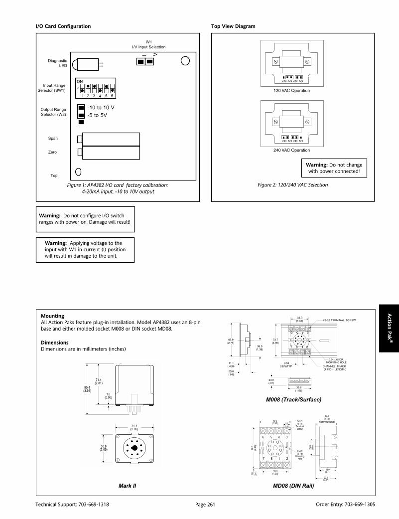
Page 261Technical Support: 703-669-1318 Order Entry: 703-669-1305
Actio
n P
ak®
I/O Card Configuration Top View Diagram
Figure 1: AP4382 I/O card factory calibration: 4-20mA input, -10 to 10V output
Figure 2: 120/240 VAC Selection
Warning: Do not changewith power connected!
W1
I/V Input Selection
Input Range
Selector (SW1)
Diagnostic
LED
Output Range
Selector (W2)
Top
Span
Zero
ON
1 2 3 4 65
>
-10 to 10 V
-5 to 5V
I V
Warning: Do not configure I/O switchranges with power on. Damage will result!
Warning: Applying voltage to theinput with W1 in current (I) positionwill result in damage to the unit.
MountingAll Action Paks feature plug-in installation. Model AP4382 uses an 8-pinbase and either molded socket M008 or DIN socket MD08.
DimensionsDimensions are in millimeters (inches)
M008 (Track/Surface)
MD08 (DIN Rail)Mark II
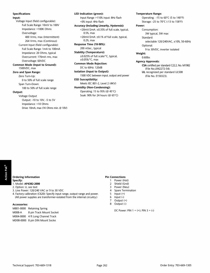
Page 262Technical Support: 703-669-1318 Order Entry: 703-669-1305
Act
ion P
ak®
Ordering InformationSpecify:1. Model: AP4382-20002. Option: U, see text3. Line Power: 120/240 VAC or 9 to 30 VDC4. Factory calibration (C620): Specify input range, output range and power. (All power supplies are transformer-isolated from the internal circuitry.)
Accessories:
M801-0000 Retaining Spring
M008-A 8 pin Track Mount Socket
M004-0000 4 ft Long Channel Track
MD08-0000 8 pin DIN Mount Socke
Specifications
Input:Voltage Input (field configurable):
Full Scale Range: 10mV to 100V
Impedance: >100K Ohms
Overvoltage:
400 Vrms, max (Intermittent)
264 Vrms, max (Continous)
Current Input (field configurable):
Full Scale Range: 1mA to 100mA
Impedance: 20 Ohms, typical
Overcurrent: 170mA rms, max
Overvoltage: 60VDC
Common Mode (Input to Ground):1500VDC, max
Zero and Span Range:
Zero Turn-Up:
0 to 50% of full scale range
Span Turn-Down:
100 to 50% of full scale range
Output:
Voltage Output
Output: -10 to 10V, -5 to 5V
Impedance: <10 Ohms
Drive: 10mA, max (1K Ohms min. @ 10V)
LED Indication (green):
Input Range >110% input: 8Hz flash
<0% input: 4Hz flash
Accuracy (Including Linearity, Hysteresis):
<20mV/2mA: ±0.35% of full scale, typical,0.5%, max
>20mV/2mA: ±0.1% of full scale, typical,0.2%, max
Response Time (10-90%):
200 mSec., typical
Stability (Temperature):
±0.025% of full scale/°C, typical,±0.05%/°C, max
Common Mode Rejection:
DC to 60Hz: 120dB
Isolation (Input to Output):
1500 VDC between input, output and power
ESD Susceptibility:
Meets IEC 801-2, Level 2 (4KV)
Humidity (Non-Condensing):
Operating: 15 to 95% (@ 45°C)
Soak: 90% for 24 hours (@ 65°C)
Temperature Range:
Operating: -15 to 60°C (5 to 140°F)
Storage: -25 to 70°C (-13 to 158°F)
Power:
Consumption:
3W typical, 5W max
Standard:
selectable 120/240VAC, ±10%, 50-60Hz
Optional:
9 to 30VDC, inverter isolated
Weight:
0.60lbs
Agency Approvals:
CSA certified per standard C22.2, No. M1982(File No.LR42272-54).
UL recognized per standard UL508
(File No. E150323).
Pin Connections1 Power (Hot)2 Shield (Gnd)3 Power (Neu)4 Spare Termination5 Input (+)6 Input (-)7 Output (+)8 Output (-)
DC Power: PIN 1 = (+); PIN 3 = (-)
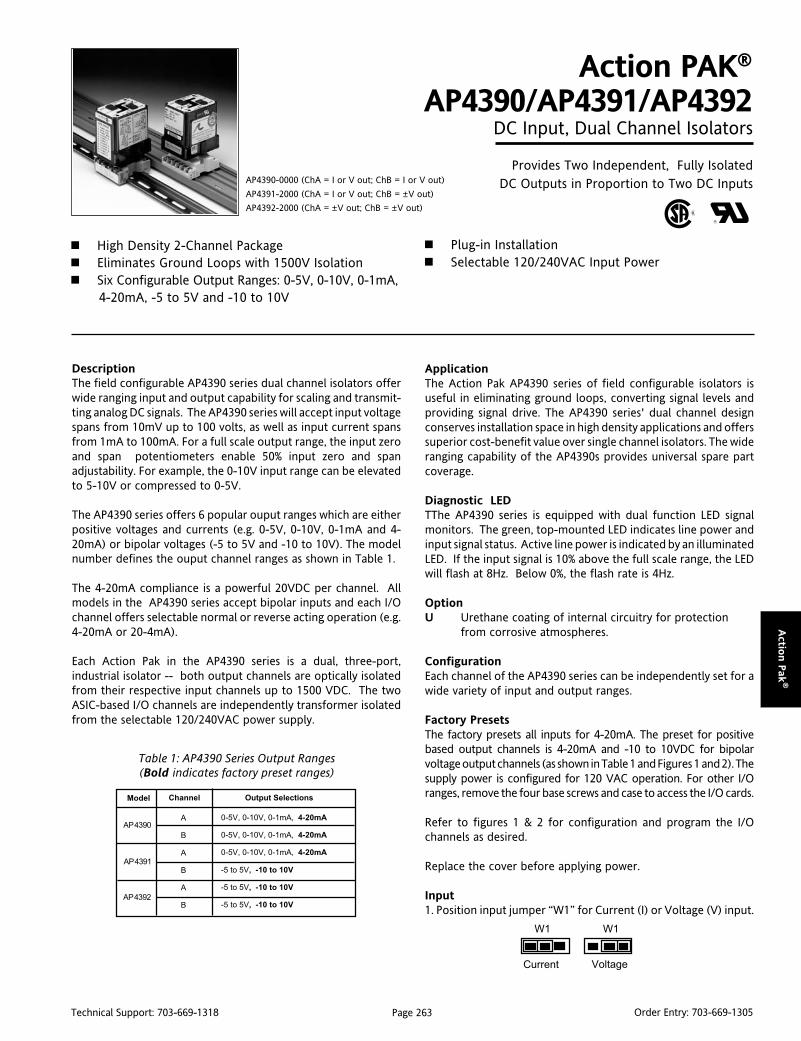
Page 263Technical Support: 703-669-1318 Order Entry: 703-669-1305
Actio
n P
ak®
DescriptionThe field configurable AP4390 series dual channel isolators offerwide ranging input and output capability for scaling and transmit-ting analog DC signals. The AP4390 series will accept input voltagespans from 10mV up to 100 volts, as well as input current spansfrom 1mA to 100mA. For a full scale output range, the input zeroand span potentiometers enable 50% input zero and spanadjustability. For example, the 0-10V input range can be elevatedto 5-10V or compressed to 0-5V.
The AP4390 series offers 6 popular ouput ranges which are eitherpositive voltages and currents (e.g. 0-5V, 0-10V, 0-1mA and 4-20mA) or bipolar voltages (-5 to 5V and -10 to 10V). The modelnumber defines the ouput channel ranges as shown in Table 1.
The 4-20mA compliance is a powerful 20VDC per channel. Allmodels in the AP4390 series accept bipolar inputs and each I/Ochannel offers selectable normal or reverse acting operation (e.g.4-20mA or 20-4mA).
Each Action Pak in the AP4390 series is a dual, three-port,industrial isolator -- both output channels are optically isolatedfrom their respective input channels up to 1500 VDC. The twoASIC-based I/O channels are independently transformer isolatedfrom the selectable 120/240VAC power supply.
Action PAK®
AP4390/AP4391/AP4392DC Input, Dual Channel Isolators
Provides Two Independent, Fully IsolatedDC Outputs in Proportion to Two DC Inputs
High Density 2-Channel Package Eliminates Ground Loops with 1500V Isolation Six Configurable Output Ranges: 0-5V, 0-10V, 0-1mA,
4-20mA, -5 to 5V and -10 to 10V
AP4390-0000 (ChA = I or V out; ChB = I or V out)
AP4391-2000 (ChA = I or V out; ChB = ±V out)
AP4392-2000 (ChA = ±V out; ChB = ±V out)
Plug-in Installation Selectable 120/240VAC Input Power
Table 1: AP4390 Series Output Ranges(Bold indicates factory preset ranges)
ApplicationThe Action Pak AP4390 series of field configurable isolators isuseful in eliminating ground loops, converting signal levels andproviding signal drive. The AP4390 series' dual channel designconserves installation space in high density applications and offerssuperior cost-benefit value over single channel isolators. The wideranging capability of the AP4390s provides universal spare partcoverage.
Diagnostic LEDTThe AP4390 series is equipped with dual function LED signalmonitors. The green, top-mounted LED indicates line power andinput signal status. Active line power is indicated by an illuminatedLED. If the input signal is 10% above the full scale range, the LEDwill flash at 8Hz. Below 0%, the flash rate is 4Hz.
OptionU Urethane coating of internal circuitry for protection
from corrosive atmospheres.
ConfigurationEach channel of the AP4390 series can be independently set for awide variety of input and output ranges.
Factory PresetsThe factory presets all inputs for 4-20mA. The preset for positivebased output channels is 4-20mA and -10 to 10VDC for bipolarvoltage output channels (as shown in Table 1 and Figures 1 and 2). Thesupply power is configured for 120 VAC operation. For other I/Oranges, remove the four base screws and case to access the I/O cards.
Refer to figures 1 & 2 for configuration and program the I/Ochannels as desired.
Replace the cover before applying power.
Input1. Position input jumper “W1” for Current (I) or Voltage (V) input.
AP 4391
AP 4392
AP 4390A
B
A
B
A
B
0-5V, 0-10V, 0-1mA, 4-20mA
0-5V, 0-10V, 0-1mA, 4-20mA
0-5V, 0-10V, 0-1mA, 4-20mA
-5 to 5V, -10 to 10V
-5 to 5V, -10 to 10V
-5 to 5V, -10 to 10V
Model Channel Output Selections
Current Voltage
W1W1
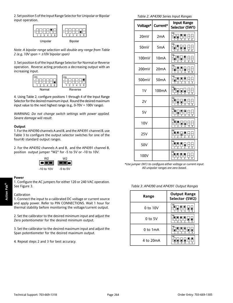
Page 264Technical Support: 703-669-1318 Order Entry: 703-669-1305
Act
ion P
ak®
2. Set position 5 of the Input Range Selector for Unipolar or Bipolarinput operation.
Note: A bipolar range selection will double any range from Table2 (e.g, 10V span = ±10V bipolar span)
3. Set position 6 of the Input Range Selector for Normal or Reverseoperation. Reverse acting produces a decreasing output with anincreasing input.
4. Using Table 2, configure positions 1 through 4 of the Input RangeSelector for the desired maximum input. Round the desired maximuminput value to the next highest range (e.g., 0-70V = 100V range).
WARNING: Do not change switch settings with power applied.Severe damage will result.
Output1. For the AP4390 channels A and B, and the AP4391 channel B, useTable 3 to configure the output selector switches for one of thefour(4) standard output ranges.
2. For the AP4392 channels A and B, and the AP4391 channel B,position output jumper "W2" for -5 to 5V or -10 to 10V.
Power1. Configure the AC jumpers for either 120 or 240 VAC operation.See Figure 3.
Calibration1. Connect the input to a calibrated DC voltage or current sourceand apply power. Refer to PIN CONNECTIONS. Wait 1 hour forthermal stability before monitoring the voltage/current output.
2. Set the calibrator to the desired minimum input and adjust theZero potentiometer for the desired minimum output.
3. Set the calibrator to the desired maximum input and adjust theSpan potentiometer for the desired maximum output.
4. Repeat steps 2 and 3 for best accuracy.
Unipolar Bipolar
1 2 3 4 65> >
1 2 3 4 65
ONON
> >
Normal Reverse
1 2 3 4 65 1 2 3 4 65
Table 2: AP4390 Series Input Ranges
Table 3: AP4390 and AP4391 Output Ranges
*Use jumper (W1) to configure either voltage or current input.All unipolar ranges are zero based.
W2W2
-10 to 10V -5 to 5V
Input RangeSelector (SW1)Voltage* Current*
20mV 2mA
50mV 5mA
100mV 10mA
200mV 20mA
500mV 50mA
1V 100mA
2V
5V
10V
25V
50V
100V >>
>
1 2 3 4
>
ON
>>
>>
>>
5 6
>>
1 2 3 4
ON
5 6
1 2 3 4
ON
5 6
1 2 3 4
ON
5 6
1 2 3 4
ON
5 6
1 2 3 4
ON
5 6
1 2 3 4
ON
5 6
1 2 3 4
ON
5 6
1 2 3 4
ON
5 6
1 2 3 4
ON
5 6
1 2 3 4
ON
5 6
1 2 3 4
ON
5 6
0 to 10V
0 to 5V
0 to 1mA
4 to 20mA
Output RangeSelector (SW2)
Range
>>
>>
1 2 3 4
ON
5 6
1 2 3 4
ON
5 6
1 2 3 4
ON
5 6
1 2 3 4
ON
5 6

Page 265Technical Support: 703-669-1318 Order Entry: 703-669-1305
Actio
n P
ak®
I/O Card Configuration
Figure 1: AP4390 and AP4391(A) I/O card factory calibration:4-20mA input and 4-20mA output
Figure 2: AP4391(B) and AP4392 I/O card factory calibration:4-20mA input, -10 to10V output
W1
I/V Input Selection
Input Range
Selector (SW1)
Diagnostic
LED
Output Range
Selector (W2)
Top
Span
Zero
ON
1 2 3 4 65
>
-10 to 10 V
-5 to 5V
I V
W1
I/V Input Selection
Input Range
Selector (SW1)
Diagnostic
LED
Output Range
Selector (SW2)
>
ON
1 2 3 4 65>
I V
Top
Span
Zero
ON
1 2 3 4 65
MountingAll Action Paks feature plug-in installation. Models AP4390, AP4391 andAP4392 use an 11-pin base and either molded socket M011 or DIN socketMD11 for mounting.
DimensionsDimensions are in millimeters (inches)
M011 (Track/Surface)
MD11 (DIN Rail)
Channel BI/O Card
Channel AI/O Card
Warning:Do not change with power connected!
Top View Diagrams
Warning: Do not change switch settings with power applied. Severedamage will result!Warning: Applying voltage to the input with W2 in current (I)position will result in damage to the unit.
Mark II
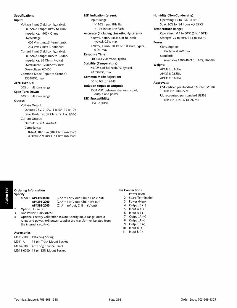
Page 266Technical Support: 703-669-1318 Order Entry: 703-669-1305
Act
ion P
ak®
Specifications
Input:
Voltage Input (field configurable):
Full Scale Range: 10mV to 100V
Impedance: >100K Ohms
Overvoltage:
400 Vrms, max(Intermittent);
264 Vrms, max (Continous)
Current Input (field configurable):
Full Scale Range: 1mA to 100mA
Impedance: 20 Ohms, typical
Overcurrent: 170mArms, max
Overvoltage: 60VDC
Common Mode (Input to Ground):
1500VDC, max
Zero Turn-Up:
50% of full scale range
Span Turn-Down:
50% of full scale range
Output:
Voltage Output:
Output:: 0-5V, 0-10V, -5 to 5V, -10 to 10V
Drive: 10mA, max. (1K Ohms min. load @10V)
Current Output:
Output: 0-1mA, 4-20mA
Compliance:
0-1mA: 10V, max (10K Ohms max load)4-20mA: 20V, max (1K Ohms max load)
LED Indication (green):
Input Range:
>110% input: 8Hz flash
<-10% input: 4Hz flash
Accuracy (Including Linearity, Hysteresis):
<20mV, <2mA: ±0.35% of full scale,typical, 0.5%, max
>20mV, >2mA: ±0.1% of full scale, typical,0.2%, max
Response Time:
(10-90%) 200 mSec., typical
Stability (Temperature):
±0.025% of full scale/°C, typical,
±0.05%/°C, max.
Common Mode Rejection:
DC to 60Hz: 120dB
Isolation (Input to Output):
1500 VDC between channels, input,output and power
ESD Susceptibility:
Level 2 (4KV)
Ordering InformationSpecify:1. Model: AP4390-0000 (ChA = I or V out; ChB = I or V out)
AP4391-2000 (ChA = I or V out; ChB = ±V out)AP4392-2000 (ChA = ±V out; ChB = ±V out)
2. Option: U, see text3. Line Power: 120/240VAC4. Optional Factory Calibration (C620): specify input range, output
range and power. (All power supplies are transformer-isolated fromthe internal circuitry.)
Accessories:
M801-0000 Retaining Spring
M011-A 11 pin Track Mount Socket
M004-0000 4 ft Long Channel Track
MD11-0000 11 pin DIN Mount Socket
Pin Connections1 Power (Hot)2 Spare Termination3 Power (Neu)4 Output B (+)5 Input A (+)6 Input A (-)7 Output A (+)8 Output A (-)9 Output B (-)
10 Input B (+)11 Input B (-)
Humidity (Non-Condensing):
Operating: 15 to 95% (@ 45°C)
Soak: 90% for 24 hours (@ 65°C)
Temperature Range:
Operating: -15 to 60°C (5 to 140°F)
Storage: -25 to 70°C (-13 to 158°F)
Power:
Consumption:
4W typical, 6W max
Standard:
selectable 120/240VAC, ±10%, 50-60Hz
Weight:
AP4390: 0.66lbs
AP4391: 0.68lbs
AP4392: 0.68lbs
Approvals:
CSA certified per standard C22.2 No. M1982(File No. LR42272).
UL recognized per standard UL508
(File No. E150323/E99775).
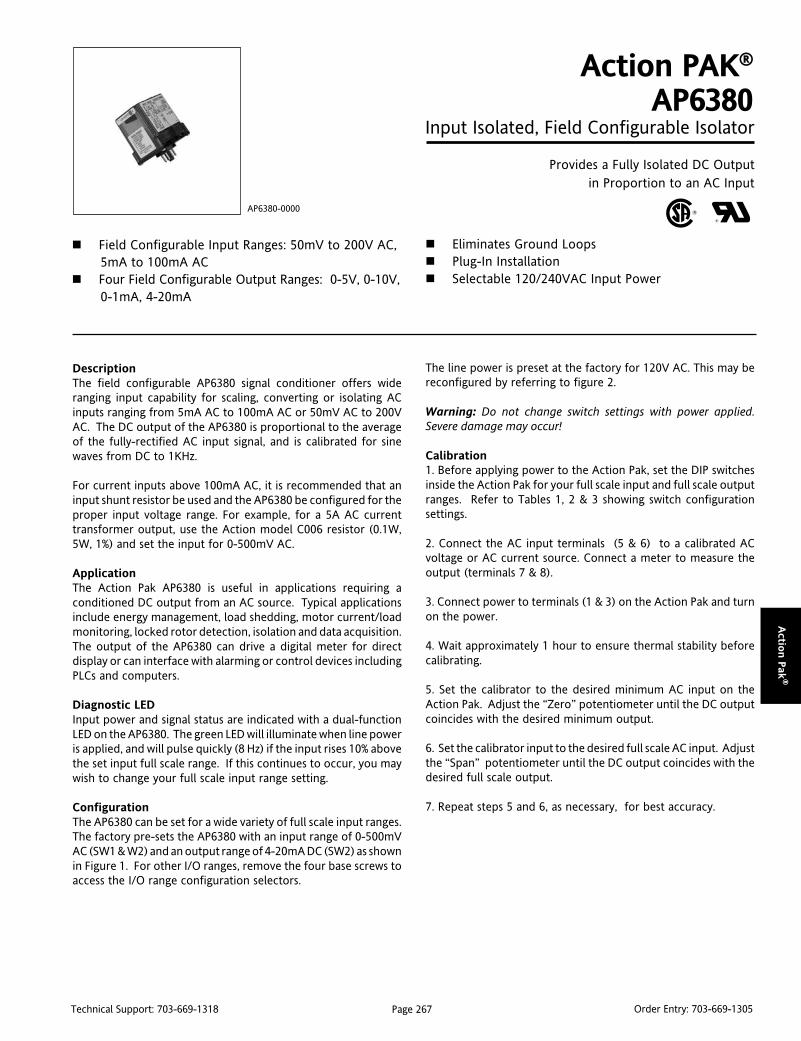
Page 267Technical Support: 703-669-1318 Order Entry: 703-669-1305
Actio
n P
ak®
DescriptionThe field configurable AP6380 signal conditioner offers wideranging input capability for scaling, converting or isolating ACinputs ranging from 5mA AC to 100mA AC or 50mV AC to 200VAC. The DC output of the AP6380 is proportional to the averageof the fully-rectified AC input signal, and is calibrated for sinewaves from DC to 1KHz.
For current inputs above 100mA AC, it is recommended that aninput shunt resistor be used and the AP6380 be configured for theproper input voltage range. For example, for a 5A AC currenttransformer output, use the Action model C006 resistor (0.1W,5W, 1%) and set the input for 0-500mV AC.
ApplicationThe Action Pak AP6380 is useful in applications requiring aconditioned DC output from an AC source. Typical applicationsinclude energy management, load shedding, motor current/loadmonitoring, locked rotor detection, isolation and data acquisition.The output of the AP6380 can drive a digital meter for directdisplay or can interface with alarming or control devices includingPLCs and computers.
Diagnostic LEDInput power and signal status are indicated with a dual-functionLED on the AP6380. The green LED will illuminate when line poweris applied, and will pulse quickly (8 Hz) if the input rises 10% abovethe set input full scale range. If this continues to occur, you maywish to change your full scale input range setting.
ConfigurationThe AP6380 can be set for a wide variety of full scale input ranges.The factory pre-sets the AP6380 with an input range of 0-500mVAC (SW1 & W2) and an output range of 4-20mA DC (SW2) as shownin Figure 1. For other I/O ranges, remove the four base screws toaccess the I/O range configuration selectors.
Action PAK®
AP6380Input Isolated, Field Configurable Isolator
Provides a Fully Isolated DC Outputin Proportion to an AC Input
Field Configurable Input Ranges: 50mV to 200V AC,5mA to 100mA AC
Four Field Configurable Output Ranges: 0-5V, 0-10V,0-1mA, 4-20mA
AP6380-0000
Eliminates Ground Loops Plug-In Installation Selectable 120/240VAC Input Power
The line power is preset at the factory for 120V AC. This may bereconfigured by referring to figure 2.
Warning: Do not change switch settings with power applied.Severe damage may occur!
Calibration1. Before applying power to the Action Pak, set the DIP switchesinside the Action Pak for your full scale input and full scale outputranges. Refer to Tables 1, 2 & 3 showing switch configurationsettings.
2. Connect the AC input terminals (5 & 6) to a calibrated ACvoltage or AC current source. Connect a meter to measure theoutput (terminals 7 & 8).
3. Connect power to terminals (1 & 3) on the Action Pak and turnon the power.
4. Wait approximately 1 hour to ensure thermal stability beforecalibrating.
5. Set the calibrator to the desired minimum AC input on theAction Pak. Adjust the “Zero” potentiometer until the DC outputcoincides with the desired minimum output.
6. Set the calibrator input to the desired full scale AC input. Adjustthe “Span” potentiometer until the DC output coincides with thedesired full scale output.
7. Repeat steps 5 and 6, as necessary, for best accuracy.
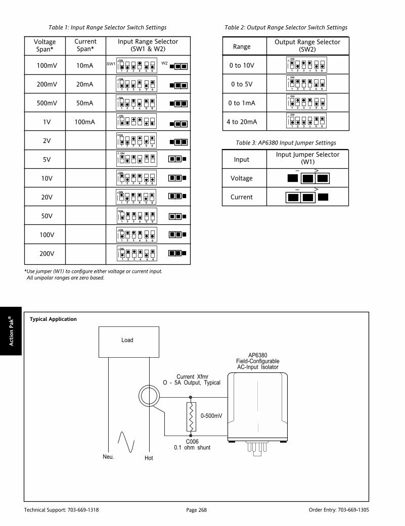
Page 268Technical Support: 703-669-1318 Order Entry: 703-669-1305
Act
ion P
ak® Typical Application
Table 1: Input Range Selector Switch Settings
Input Range Selector(SW1 & W2)
100mV 10mA
200mV 20mA
500mV 50mA
1V 100mA
2V
5V
10V
20V
50V
100V
200V
Table 2: Output Range Selector Switch Settings
Table 3: AP6380 Input Jumper Settings
*Use jumper (W1) to configure either voltage or current input. All unipolar ranges are zero based.
VoltageSpan*
CurrentSpan*
>>
>>
>>
>
ON
>>
SW1
>
61 2 3 4 5
ON
61 2 3 4 5
ON
61 2 3 4 5
ON
61 2 3 4 5
ON
61 2 3 4 5
ON
61 2 3 4 5
ON
61 2 3 4 5
ON
61 2 3 4 5
ON
61 2 3 4 5
ON
>ON
W2
Range
0 to 10V
0 to 5V
0 to 1mA
4 to 20mA
41 2 3
ON>
5 6
ON>
41 2 3 5 6
41 2 3
ON>
5 6
ON>
41 2 3 5 6
Output Range Selector(SW2)
I V
I V
Input Jumper Selector(W1)Input
Voltage
Current
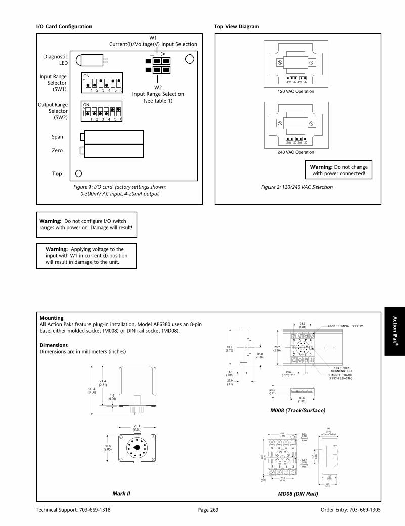
Page 269Technical Support: 703-669-1318 Order Entry: 703-669-1305
Actio
n P
ak®
MountingAll Action Paks feature plug-in installation. Model AP6380 uses an 8-pinbase, either molded socket (M008) or DIN rail socket (MD08).
DimensionsDimensions are in millimeters (inches)
MD08 (DIN Rail)
M008 (Track/Surface)
Warning: Do not configure I/O switchranges with power on. Damage will result!
Warning: Applying voltage to theinput with W1 in current (I) positionwill result in damage to the unit.
Top View Diagram
Figure 2: 120/240 VAC Selection
Warning: Do not changewith power connected!
Figure 1: I/O card factory settings shown:0-500mV AC input, 4-20mA output
I/O Card Configuration
DiagnosticLED
Input RangeSelector
(SW1)
Output RangeSelector
(SW2)
I V
Span
Zero
W1Current(I)/Voltage(V) Input Selection
W2Input Range Selection
(see table 1)
Top
>
ON
1 2 3 4 65
ON
1 2 3 4 65
>
Mark II

Page 270Technical Support: 703-669-1318 Order Entry: 703-669-1305
Act
ion P
ak®
Specifications
Input Ranges (selectable):
Voltage: 50mV AC to 200V AC
Current: 5mA AC to 100mA AC
Input Frequency:
DC-1KHz, factory calibrated at 60Hz
Input Impedance:
Voltage: >100K Ohms
Current: 20 Ohms typical
Input Overload (without damage):
Voltage: 300V AC
Current: 200mA AC, 60V peak
Common Mode Voltage:
1500V DC, input to ground
Output Ranges (selectable):
Voltage: 0-5V DC, 0-10V DC
Current: 4-20mA DC, 0-1mA DC
Output Source Impedance:
Voltage: <10 Ohms
Current: >100K Ohms
Output Drive:
Voltage: 10mA, max (1K Ohms min. @ 10V)
Current: 20VDC compliance
(1K Ohms max @ 20mA)
Span Turn Down:
50% of full scale range
Zero Turn Up:
50% of full scale range
LED Indication:
8Hz flash when input is 10% above fullscale configuration
Accuracy (including hysteresis and linearity):
±0.1% of span, typical
±0.5% of span, maximum
Response Time:
250mSec, typical
Stability:
±0.025% of full scale per °C, typical
Common Mode Rejection:
120dB, DC to 60Hz
Isolation (input to output to power):
1500V DC or peak AC
Temperature Range:
Operating: 0 to 60°C (32 to 140°F)
Storage: -15 to 70°C (5 to 158°F)
Humidity (Non-Condensing):
10 to 95% RH, at 45°CPower:
Consumption: 3W typical, 5W max
Standard: Selectable 120/240V AC(±10%, 50-60Hz)
Weight:
0.60lbs
Agency Approvals:
CSA certified per standard C22.2, No. M1982(File No. LR42272-38).
UL recognized per standard UL508
(File No. E150323).
Ordering InformationSpecify:1. Model: AP6380-0000.2. Option U (see text).3. Line Power (see specs).4. Optional Factory Calibration (C620):
Specify input range, output range and power.5. C006 (0.1 Ohm shunt for 1 to 5 Amp current inputs).
Accessories:
M801-0000 Retaining Spring
M008-A 8 pin Track Mount Socket
M004-0000 4 ft Long Channel Track
MD08-0000 8 pin DIN Mount Socket
Pin Connections1 AC Power (Hot)2 Shield (GND)3 AC Power (Neu)4 Spare Termination5 Input6 Input7 Output (+)8 Output (-)

Page 271Technical Support: 703-669-1318 Order Entry: 703-669-1305
Actio
n P
ak®
DescriptionThe Action Pak Model AP7380 is a frequency input signal condi-tioner with 1500VDC isolation between input, output and power.The field configurability of the input and output offers flexible,wide ranging capability for magnetic pick-ups, turbine flowmeters, and other pulse or frequency output transducers.
The input of the AP7380 can be configured for any frequency spanfrom 2Hz (e.g., 59-61Hz) to 10,000Hz. The input amplitudethreshold (SENS POT) can be adjusted from 150mVp to 10Vp toensure accurate frequency measurement and minimize transientnoise related errors. The maximum input amplitude is 150 Vrms.The output can be set for either 0-5V, 0-10V,0-1mA or 4-20mA.
Advanced digital technology allows the AP7380 to be field config-ured to convert virtually any frequency input to a DC signal outputwithin the ranges specified. Calibration utilizes ‘Touch-Sample’technology by which the user simply applies the desired inputfrequency, and touches a recessed button to configure thecorresponding input range.
The convenient Action Pak is very easy to install using surfacemount, DIN rail mount or snap track mounting sockets. Troubleshooting is very easy since no wires need to be removed whenswapping units. The wide ranging power supply can be configuredfor either 120 or 240VAC power.
ApplicationThe AP7380 field configurable, frequency input signal conditioneris useful in eliminating ground loops and interfacing pulse outputtransducers, such as turbine flow meters and magnetic pick-ups,to data acquisition and control systems.
Advanced digital technology, combined with Action’s ASIC tech-nology, provides a stable output at low frequencies for higheraccuracy, and three-way isolation completely eliminates groundloops from any source.
OptionU Urethane coating of internal circuitry for protection from
corrosive atmospheres
Action PAK®
AP7380Frequency Input, Field Configurable
Signal Conditioner
Provides an Isolated DC Outputin Proportion to Frequency Input
Field Configurable Input Rangesfrom 2Hz to 10,000Hz Four Field Configurable Output Ranges 0-5V, 0-10V,
0-1mA, 4-20mA Eliminates Ground Loops
AP7380-0000
Plug-in Installation Selectable 120/240VAC Input Power ASIC Technology for Enhanced Reliability
'Touch Sample' TechnologyThe AP7380 utilizes Action Instruments’ ‘Touch-Sample’ technol-ogy which greatly simplifies configuration. To set the inputfrequency range, the user simply applies the high input frequencyand pushes the CAL button while the INPUT LED is on. The lowinput frequency is then applied and pushing the CAL button againstores the low frequency input.
The high and low ranges are stored in non-volatile memory andcorrespond to the high and low output ranges which have beenselected via DIP switches.
To precisely adjust the output, the user adjusts the input fre-quency while the OUTPUT LED is on until the desired output levelis achieved. The output levels are locked in by pushing the CALbutton. Status LEDs show the operational mode of the device.
Status LEDsThe AP7380 utilizes three status LEDs. The green LEVEL LEDchanges in intensity with input level. Its intensity varies with thefrequency of the input signal during normal operation. If the inputsignal is 10% more than full scale range, the LED will flash at 8Hz.Below 0%, the flash rate is 4Hz.
The yellow INPUT LED, when on, denotes input programmingmodes.
The red OUTPUT LED, when on, denotes output programmingmodes (see Configuration, Calibration and Figure 1 for details).
ConfigurationA major advantage of the AP7380 is its wide ranging capabilitiesand ease of configuration. The AP7380 enables virtually 99% zeroand span adjustability. Any 2Hz range from 0 to 10,000Hz can beconverted to a full scale output signal (e.g. 0-2Hz/4-20mA or 9998-10,000Hz/4-20mA).

Page 272Technical Support: 703-669-1318 Order Entry: 703-669-1305
Act
ion P
ak®
Unless otherwise specified, the factory presets are as follows:
Input Range: 0 to 1000HzSensitivity: 1V peak (LO)Output Range: 4 to 20mAPower: 120VAC
Note: "Sensitivity" refers to the noise rejection level or the triggerthreshold of the input.
For other I/O ranges, refer to Table 1 for output range (SW1)switch settings and to Figure 4 for sensitivity jumper setting (P3).For quick and easy calibration mode reference, see the step-by-step flow chart in Figure 1.
1. With DC power off, choose the desired output voltage/currentrange from Table 1 and set position 1 through 6 of the outputswitch selector (SW1).
2. Set the Input sensitivity jumper (P3) to LO for input amplitudesbetween 150mVp and 50Vrms, with noise rejection to 1Vp. Set P3to HI for input amplitudes between 500mVp and 150Vrms, withnoise rejection up to 10Vp.
Calibration1. Connect the input to a calibrated frequency source and applypower. Wait 1 hour for thermal stability before monitoring thevoltage or current output.
2. Adjust the input frequency to the desired maximum andobserve that the output has increased and is sensing the input. Ifthis is not observed, turn the sensitivity potentiometer in acounter-clockwise direction until the output changes proportion-ally to the input.
3. With the green LED on press the CAL button once to enter thecalibration mode. The yellow and green LEDs should now be on.
4. Input the maximum desired frequency (if not done already) andpress the CAL button to store. The yellow LED should now be theonly LED on.
5. Input the minimum desired frequency and press the CAL buttonto store. The green and red LEDs should now be on.
Note: The most reliable way to input 0Hz is to short circuit the inputpins (5&6).
6. To precisely adjust the maximum output, adjust the inputfrequency until the output reads within +0.1% of the maximumselected output range. This typically occurs near 90% of the HIinput frequency. Press the CAL button to store the value. The redLED should now be on.
7. To precisely adjust the minimum output, lower the inputfrequency until the output reads within +0.1% of the minimumselected ouput. This typically occurs less than 10% of the HI inputfrequency. Press the CAL button to store the value. The Yellow,Red and Green LEDs should be on (see Figure 1).
8. Press the CAL button one final time to exit the calibration mode.The green LED should now be on. (With only 5-10% of input, thegreen LED is off.)
9. Check the minimum and maximum input-to-output calibration.Repeat steps 1 through 8 if calibration is not within desiredspecifications.
Note 1: To skip Steps 6 and 7 (output adjustment), press CALbutton two times after Step 5.
Note 2: Removing power to the unit at any time before Step 8 willrestore previous settings
Optimal SensitivityIf the amplitudes of the input frequency is within the sensitivityparameters (i.e. 150mVp - 1Vp for LO and 0.5Vp - 10Vp for HI),then the sensitivity parameters can be set for optimum noiserejection.
1. Set the input near midrange (50% input) or to a frequency thatexhibits the minimum pulse amplitude.
2. Turn the sensitivity pot (SENS) clockwise (CW) until the outputdrops to minimum.
3. Turn the sensitivity pot counter- clockwise(CCW) until theoutput returns to the previous level. A couple more CCW turns willprovide optimal noise rejection.
4. Run the input through the full frequency range to make surethat the pulses are sensed at both the low and high inputfrequencies. If the output drops out during this test, when theinput freq. >0% then turn the sensitivity pot counter -clockwiseanother turn or two until the output picks up. Repeat to validatesensitivity settings.
Figure 1: Calibration Flow Chart
* Green LED may be very dim and appear off.

Page 273Technical Support: 703-669-1318 Order Entry: 703-669-1305
Actio
n P
ak®
Figure 2: I/O Card Factory Calibration: 0 to 1000Hz,1V peak, 4-20mA (Shown sideways to view switches)
I/O Card Configuration
Figure 4: Input Sensitivity Settings (P3)(can reject voltage up to those shown)
Top View Diagram
Figure 3: 120/240 VAC Selection
*
Warning: Do not changewith power connected!
Warning: Do not configure I/O switchranges with power on. Damage will result!
Warning: Applying voltage to theinput with W1 in current (I) positionwill result in damage to the unit.
HI
LO
P3
150mVp -1Vp,
0.5Vp-10Vp,
Warning: Do not changewith power connected!
Table 1: Output Switch Settings(SW1, 1 through 6)
AccessoriesAll Action Paks feature plug-in installation. Model AP7380 uses an8-pin base and either molded socket M008 or DIN socket MD08.
DimensionsDimensions are in millimeters (inches)
M008 (Track/Surface)
MD08 (DIN Rail)Mark II
Page 274Technical Support: 703-669-1318 Order Entry: 703-669-1305
Act
ion P
ak®
Ordering InformationSpecify:1. Model: AP7380-00002. Option: U, see text3. Line Power: 120/240VAC4. C620: Factory Calibration of input range, setpoints and output relays.
(All power supplies are transformer-isolated from the internal circuitry.)Note: For UL applications above 100V (unrestricted), the signal must betransient limited (e.g. 150V MOV). For CSA applications above 100V(unrestricted), the signal must be isolated from the primary by a 150VAtransformer and no fire result from a short circuit at the input.
Accessories:
M801-0000 Retaining Spring
M008-A 8 pin Track Mount Socket
M004-0000 4 ft Long Channel Track
MD08-0000 8 pin DIN Mount Socket
Specifications
Input Ranges (selectable):
Frequency Input:
Full Scale Range: 2 Hz to 10,000Hz
Amplitude Range:
150mVp to 10Vp,150Vrms max
Impedance: >10K Ohms
Over-voltage: 180Vrms, max
Over-range: 20KHz, max.
Common Mode (Input to Ground):1500VDC, max
Zero Turn-Up:
99% of full scale range (9998Hz)
Span Turn-Down:
99% of full scale range (2Hz)
Output:
Voltage Output:
Output: 0-5V, 0-10V
Impedance: <10 Ohms
Drive: 10mA, max. (1K Ohms, min @10V)
Current Output:
Output: 0-1mA, 4-20mA
Impedance: >100K Ohms
Compliance:
0-1mA; 10V, max.(10K Ohms, max)
4-20mA; 20V, max.(1K Ohms, max)
Accuracy (including Linearity & Hysterisis):
+0.1% of selected range at 25°C.
Stability:
+0.025%/°C maximum of selected range.
Response Time (10-90%):
3 input cycles plus 250mSec
Common Mode Rejection:
DC: 100dB
>60Hz: 80dB
Isolation:
1500VDC between input, output and power.
ESD & Transient Susceptibility:
Meets IEC 801-2, Level 2 (4KV)
LED Indication:
LEVEL (green): lit when power is on(Intensity varies with input signal);
input > 107% then 8Hz flash
input < -7% then 4Hz flash
INPUT (yellow): input range programmingstatus
OUTPUT (red): output range programmingstatus
Pin Connections1 Power (Hot)2 Shield (Gnd)3 Power (Neu)4 Spare Termination5 Frequency Input (+)6 Frequency Input (-)7 Output (+)8 Output (-)
Humidity (Non-Condensing):
Operating: 15 to 95% (@ 45°C)
Soak: 90% for 24 hours (@ 65°C)
Temperature Range:
Operating: -15 to 60°C (5 to140°F)
Storage: -25 to 70°C (-13 to158°F)
Power:
Consumption:
2W typical, 3W max
Standard:
selectable 120/240VAC, ±10%, 50-60Hz
Weight:
.60lbs
Agency Approvals:
CSA certified per standard C22.2 No. 0-M91and 142-M1987 (File No. LR42272 - 64).
UL recognized per standard UL508
(File No. E99775)

Page 275Technical Support: 703-669-1318 Order Entry: 703-669-1305
Actio
n P
ak®
ApplicationThe AP7500 and AP7501 are useful in totalizing applications, wherethe total number of pulses counted in a given time periodrepresents the time integral of the DC input. If, for example, theinput represents a flow in gallons per hour, then the time integralof this flow signal (total count) will represent total gallons. TheAP7500’s 6V square wave output can be used to drive electroniccounters (DTL, TTL, CMOS). The AP7501 can be used to driveelectromechanical counters when connected to an external AC orDC power source. In the AP7501, the DPDT relay contacts arepulsed (closed) for only a short duration (100 milliseconds) forcompatibility with standard electromechanical counters. TheAP7500 can also be used in telemetry systems, where the dc signalis converted to a frequency, transmitted over long lines, and thendecoded at the receiving end by means of a frequency to DCconverter, such as the AP7380.
OptionsCS Canadian Standards Association Certification.U Urethane coating of internal circuitry for protection from
corrosive atmospheres.C Open collector output instead of the standard 6V output,
sinks up to 50mA, up to 30V (AP7500 only).
Output RangesThe output frequency range is selectable via the 16-position rotaryswitch accessible through the top cover. See tables 1 and 2 foroutput selection. Since ranging is accomplished through digitalcircuitry, the accuracy of the unit is unaffected by the switchposition; each successive position exactly halves (clockwise) ordoubles (counterclockwise) the previous output frequency (see“Calibration”).
Action PAK®
AP7500 & AP7501DC to Frequency Converters
Provides a Field Selectable Frequency Outputin Proportion to a DC Input
Switch Selectable Output Range Adjustable Low End Cutout (0-10%) Totalization/Integration Applications
AP7500-5012 (0-20mA in; square wave output)AP7500-5016 (4-20mA in; square wave output)AP7500-5065 (0-1Vdc in; square wave output)AP7500-5068 (0-5Vdc in; square wave output)AP7500-5070 (0-10Vdc in; square wave output)AP7500-5085 (1-5Vdc in; square wave output)AP7501-6007 (0-1mA in; relay contact output)AP7501-6012 (0-20mA in; relay contact output)AP7501-6016 (4-20mA in; relay contact output)AP7501-6065 (0-1Vdc in; relay contact output)AP7501-6068 (0-5Vdc in; relay contact output)AP7501-6070 (0-10Vdc in; relay contact output)AP7501-6085 (1-5Vdc in; relay contact output)
Plug-In Installation Square Wave (AP7500) or Relay Contact (AP7501) Output Selectable 120/240VAC Input Power
Input RangesStandard input ranges and limits are included in Tables 3 and 4.
CutoutThe top accessed Cutout adjustment determines the input (level)at which the AP7500 or AP7501 no longer responds (i.e., the unitis effectively “off”) and is adjustable from 0-10% of the input span.This feature is especially useful with low frequency spans, wherethe time between output pulses is excessively long at low inputlevels. A light-emitting diode (LED) visible through the top-coveraids in adjusting cutout. This LED lights when the unit is no longerresponding to the input. With the input at the desired cutout level,adjust Cutout slowly clockwise until the LED lights. Then turn theadjustment counterclockwise until the LED just goes out. Cutoutis now set for the input level present.
CalibrationZero, Span and Low-End Cutout adjustments are screwdriveradjustable, accessible through the top cover.
Zero and Span: Monitor the unit’s output using an accuratefrequency counter. Apply an input equal to 5% of the specifiedinput span. If the cutout LED (visible through the top cover) is lit,adjust Cutout counterclockwise until it turns off. Adjust Zero for5% of the desired full scale output frequency. Apply full scale inputand adjust Span for the desired maximum output frequency.Repeat these adjustments for best accuracy.
Note: For faster calibration of low frequency spans, use the rangeselector switch to multiply the output frequency. Each positioncounterclockwise exactly doubles the output frequency. Aftercalibration, return the selector switch to the proper range position.

Page 276Technical Support: 703-669-1318 Order Entry: 703-669-1305
Act
ion P
ak®
AP7500 Functional Diagram/Pin Connections
Table 3: AP7500/AP7501 Standard Inputs Table 4: AP7500/AP7501 Input Limits
hctiwSnoitisoP noitisoP noitisoP noitisoP noitisoP
muminiMegnaR egnaR egnaR egnaR egnaR
mumixaMegnaR egnaR egnaR egnaR egnaR
0 zHk5-0 zHk01-0
1 zHk5.2-0 zHk5-0
2 zHk52.1-0 zHk5.2-0
3 zH526-0 zHk52.1-0
4 zH213-0 zH526-0
5 zH651-0 zH213-0
6 zH87-0 zH651-0
7 zH93-0 zH87-0
8 zH02-0 zH93-0
9 zH01-0 zH02-0
A zH5-0 zH01-0
B zH5.2-0 zH5-0
C zH52.1-0 zH5.2-0
D mpp63-0 zH52.1-0
E mpp81-0 mpp63-0
F mpp9-0 mpp81-0
hctiwSnoitisoP noitisoP noitisoP noitisoP noitisoP
muminiMegnaR egnaR egnaR egnaR egnaR
mumixaMegnaR egnaR egnaR egnaR egnaR
0 mpp56-0 mpp031-0
1 mpp23-0 mpp56-0
2 mpp61-0 mpp23-0
3 mpp8-0 mpp61-0
4 mpp4-0 mpp8-0
5 mpp2-0 mpp4-0
6 mpp1-0 mpp2-0
7 mpp5.0-0 mpp1-0
8 mpp52.0-0 mpp5.0-0
9 hpp8-0 hpp61-0
A hpp4-0 hpp8-0
B hpp2-0 hpp4-0
C hpp1-0 hpp2-0
D hpp5.0-0 hpp1-0
E hpp42.0-0 hpp5.0-0
F hpp21.0-0 hpp42.0-0
Table 1: AP7500 Output Ranges Table 2: AP7501 Output Ranges
V1ot0 V5ot1 Am02ot4
V5ot0 V01ot0 Am05ot01
napSmuminiM)egatloV( )egatloV( )egatloV( )egatloV( )egatloV(
napSmuminiM)tnerruC( )tnerruC( )tnerruC( )tnerruC( )tnerruC(
tupnImumixaM)egatloV( )egatloV( )egatloV( )egatloV( )egatloV(
tupnImumixaM)tnerruC( )tnerruC( )tnerruC( )tnerruC( )tnerruC(
Vm002 Am1 V002 Am001
Zero Span
AveragingCircuit
Voltage-ControlledOscillator
RangeSelector
2n
Input
Output
Inhibit
ProgrammableDivider
Push-PullOutput Stage
FrequencyOutput
DCInput
InputAmplifier
Cutout
DifferentialAmplifier
Comparator
CutoutCalibration
LED
NOTE: Input and Output arereferenced to different levels.DO NOT Ground both.
TransformerIsolated
Power Supply
AC AC
Shield
DC Input
FrequencyOutput
AC (Neu)
AC (Hot)
(Shield)GND
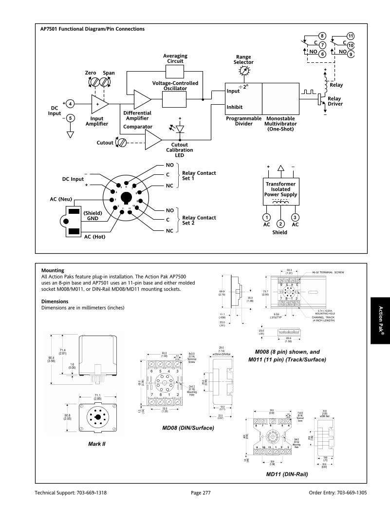
Page 277Technical Support: 703-669-1318 Order Entry: 703-669-1305
Actio
n P
ak®
Zero Span
AveragingCircuit
Voltage-ControlledOscillator
DCInput
InputAmplifier
Cutout
DifferentialAmplifier
Comparator
CutoutCalibration
LED
AC (Neu)
AC (Hot)
(Shield)GND
RangeSelector
2n
Input
Inhibit
ProgrammableDivider
Output
MonostableMultivibrator(One-Shot)
RelayDriver
Relay
C C
NO NO
TransformerIsolated
Power Supply
AC AC
Shield
DC InputC
NO
NC
C
NO
NC
Relay ContactSet 1
Relay ContactSet 2
AP7501 Functional Diagram/Pin Connections
MountingAll Action Paks feature plug-in installation. The Action Pak AP7500uses an 8-pin base and AP7501 uses an 11-pin base and either moldedsocket M008/M011, or DIN-Rail MD08/MD11 mounting sockets.
DimensionsDimensions are in millimeters (inches)
MD08 (DIN/Surface)
M008 (8 pin) shown, and
M011 (11 pin) (Track/Surface)
MD11 (DIN-Rail)
Mark II
Page 278Technical Support: 703-669-1318 Order Entry: 703-669-1305
Act
ion P
ak®
Specifications
Input Impedance:
Voltage Input: Greater than 100KW
Current Input: Less than 500mV shunt @full scale (e.g. 20W for 20mA)
Input Protection: Withstands 200% of span
Linearity (Best Straight Line & Linear Input):
0.25% of span, typical
Low Input Cutout:
Adjustable, 0-10% of span (factory set at 1%),LED cutout indication
Output:
AP7500: Square-wave, 0/6V, 1:1 mark/space ratio, source 10mA, sink 50mA.Option C 50mA sink, 30V.
AP7501: Isolated DPDT relay contacts,rated 120VAC @5A or 28VDC @ 5A(100mSec min. on time).
Contact Material: Silver Cadmium Oxide
Life: 105 operations at rated load
Response Time:
100 milliseconds typical, 200 milliseconds max
Overrange Capability:
Output is linear to 120% of input
Stability:
Better than 0.05% of span per degree C
Common Mode Rejection:
DC: > 100dB
60 Hz: > 80dB
Maximum Common Mode Voltage:
50V
Temperature Range:
Operating: 0 to 60°C (32 to 140°F)
Storage: -20 to 85°C (-4 to 185°F)
Power:
Consumption: 3W typical, 5W max
Standard: 120 VAC (±10%, 50-400Hz)
Available: 240VAC (±10%, 50-400Hz)
Weight:
0.62lbs
Agency Approvals:
CSA certified per standard C22.2, No. 0-M1982(File No. LR42272-8, 9)
Ordering InformationSpecify:1. Model: AP7500 or AP7501 (see above)2. Options: CS, U, C (see text)3. Input Range (see Tables 3, 4)4. Line Power (see specs)5. C620 Factory Calibration of input, setpoints and output relays.
Accessories:
M801-0000 Retaining Spring
M008-A 8 pin Track Mount Socket
M011-A 11 pin Track Mount Socket
M004-0000 4 ft Long Channel Track
MD08-0000 8 pin DIN Mount Socket
MD11-0000 11 pin DIN Mount Socket
Pin ConnectionsAP7500
1 AC Power (Hot)2 Shield (Gnd)3 AC Power (Neu)4 No Connection5 Input (+)6 Input (-)7 Output (+)8 Output (-)
AP75011 AC Power (Hot)2 Shield (Gnd)3 AC Power (Neu)4 Input (+)5 Input (-)6 N.O.7 C Set 18 N.C.9 N.O.
10 C Set 211 N.C.
AP7500-5012 (0-20mA in; square wave output)AP7500-5016 (4-20mA in; square wave output)AP7500-5065 (0-1Vdc in; square wave output)AP7500-5068 (0-5Vdc in; square wave output)AP7500-5070 (0-10Vdc in; square wave output)AP7500-5085 (1-5Vdc in; square wave output)AP7501-6007 (0-1mA in; relay contact output)AP7501-6012 (0-20mA in; relay contact output)AP7501-6016 (4-20mA in; relay contact output)AP7501-6065 (0-1Vdc in; relay contact output)AP7501-6068 (0-5Vdc in; relay contact output)AP7501-6070 (0-10Vdc in; relay contact output)AP7501-6085 (1-5Vdc in; relay contact output)
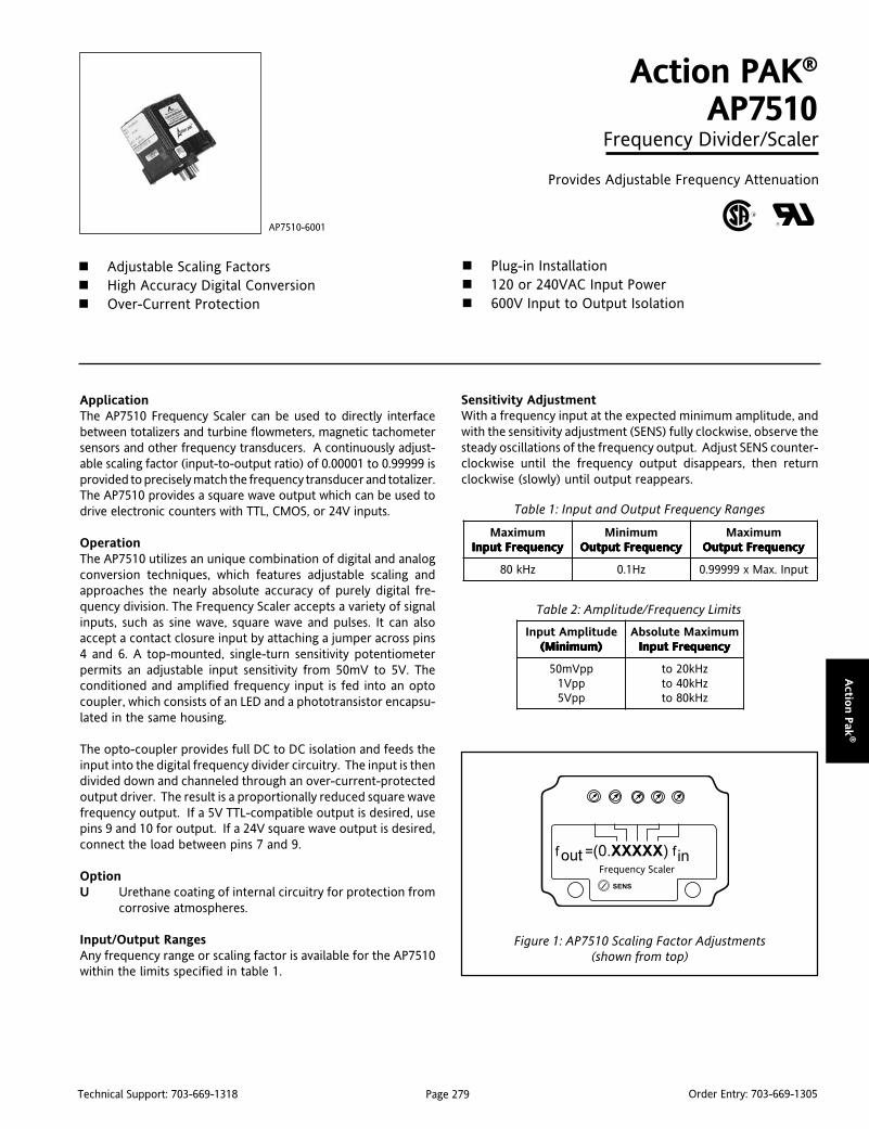
Page 279Technical Support: 703-669-1318 Order Entry: 703-669-1305
Actio
n P
ak®
ApplicationThe AP7510 Frequency Scaler can be used to directly interfacebetween totalizers and turbine flowmeters, magnetic tachometersensors and other frequency transducers. A continuously adjust-able scaling factor (input-to-output ratio) of 0.00001 to 0.99999 isprovided to precisely match the frequency transducer and totalizer.The AP7510 provides a square wave output which can be used todrive electronic counters with TTL, CMOS, or 24V inputs.
OperationThe AP7510 utilizes an unique combination of digital and analogconversion techniques, which features adjustable scaling andapproaches the nearly absolute accuracy of purely digital fre-quency division. The Frequency Scaler accepts a variety of signalinputs, such as sine wave, square wave and pulses. It can alsoaccept a contact closure input by attaching a jumper across pins4 and 6. A top-mounted, single-turn sensitivity potentiometerpermits an adjustable input sensitivity from 50mV to 5V. Theconditioned and amplified frequency input is fed into an optocoupler, which consists of an LED and a phototransistor encapsu-lated in the same housing.
The opto-coupler provides full DC to DC isolation and feeds theinput into the digital frequency divider circuitry. The input is thendivided down and channeled through an over-current-protectedoutput driver. The result is a proportionally reduced square wavefrequency output. If a 5V TTL-compatible output is desired, usepins 9 and 10 for output. If a 24V square wave output is desired,connect the load between pins 7 and 9.
OptionU Urethane coating of internal circuitry for protection from
corrosive atmospheres.
Input/Output RangesAny frequency range or scaling factor is available for the AP7510within the limits specified in table 1.
Action PAK®
AP7510Frequency Divider/Scaler
Provides Adjustable Frequency Attenuation
Adjustable Scaling Factors High Accuracy Digital Conversion Over-Current Protection
AP7510-6001
Plug-in Installation 120 or 240VAC Input Power 600V Input to Output Isolation
Sensitivity AdjustmentWith a frequency input at the expected minimum amplitude, andwith the sensitivity adjustment (SENS) fully clockwise, observe thesteady oscillations of the frequency output. Adjust SENS counter-clockwise until the frequency output disappears, then returnclockwise (slowly) until output reappears.
Table 1: Input and Output Frequency Ranges
Table 2: Amplitude/Frequency Limits
mumixaMycneuqerFtupnI ycneuqerFtupnI ycneuqerFtupnI ycneuqerFtupnI ycneuqerFtupnI
muminiMycneuqerFtuptuO ycneuqerFtuptuO ycneuqerFtuptuO ycneuqerFtuptuO ycneuqerFtuptuO
mumixaMycneuqerFtuptuO ycneuqerFtuptuO ycneuqerFtuptuO ycneuqerFtuptuO ycneuqerFtuptuO
zHk08 zH1.0 tupnI.xaMx99999.0
edutilpmAtupnI)muminiM( )muminiM( )muminiM( )muminiM( )muminiM(
mumixaMetulosbAycneuqerFtupnI ycneuqerFtupnI ycneuqerFtupnI ycneuqerFtupnI ycneuqerFtupnI
ppVm05ppV1ppV5
zHk02otzHk04otzHk08ot
Figure 1: AP7510 Scaling Factor Adjustments(shown from top)
Frequency Scaler

Page 280Technical Support: 703-669-1318 Order Entry: 703-669-1305
Act
ion P
ak®
Specifications
Calibration Capability (includes Accuracy):
± 1 Input pulse
Input (see table 2):
Sine wave, square wave, or pulse;50mVpp to 5Vpp to a max of 80kHz, or
contact closures (15V pullup @ 1mA)
Sensitivity:
Adjustable input of 50mVpp to 5Vpp,user accessible
Input Impedance:
10k Ohms, nominal
Isolation:
Input to output, or either input/outputto line power: 600VDC
MountingAll Action Paks feature plug-in installation. The Action Pak AP7510uses an 11-pin base and either molded socket M011 or DIN-Rail MD11mounting sockets.
DimensionsDimensions are in millimeters (inches)
M011 (Track/Surface)
Output:
5VDC pulse @10mA max, TTL compatible,or 24VDC pulse, 1KW load min.; frequencyto 0.99999 of maximum input.
Scaling Range:
Multiplies input frequency by an adjustablefactor of 0.00001 through 0.99999
Temperature Range:
Operating: 0° C to 60° C (32 to140° F)
Storage: -20 to 85°C (-4 to 185°F)
Power:
Consumption: 3W typical, 5W max.
Standard: 120VAC (± 10%, 50 - 400 Hz)
Available: 240VAC (±10%, 50-400Hz)
Weight:
0.60lbs
MD11 (DIN Rail)
24V Pulse Output
Ordering InformationSpecify:1. Model: AP7510-60012. Option U (see text)3. Line Power (see specs)4. C620 Factory Calibration. Specify input range, output range and power.
Accessories:
M801-0000 Retaining Spring
M011-A 11 pin Track Mount Socket
M004-0000 4 ft Long Channel Track
MD11-0000 11 pin DIN Mount Socket
Pin Connections1 AC Power (Hot)2 Shield (Gnd)3 AC Power (Neu)4 Input (+)5 Input (-)6 For Contact Closure Input, connect to Pin 4.7 For 24V Pulse Output, connect load with Pins 7 and 9 (see figure above).8 No Connection9 Output (+)
10 Output (-)11 No Connection
Mark II

Page 281Technical Support: 703-669-1318 Order Entry: 703-669-1305
VisiP
ak™
VisiPak Digital IndicatorsAction's VisiPak indicators are a reliable, cost effective solution fordisplaying virtually any sensor or process variable. All VisiPakindicators have NEMA 4 or higher front panel ratings and a varietyof agency approvals.
V408 Modular, Universal Process IndicatorThe V408 is Action's most advanced indicator. It accepts tempera-ture (RTD and thermocouple), pressure or weight (strain gauge),and DC process signals. With better than 2 micro-volt inputresolution and a bright red or green 5 digit display, the V408accurately measures and displays the majority of signal typesfound in industrial process control or factory automation applica-tions. The V408's modular design provides three I/O expansionslots and one communications slot to hold any of the 14 optionmodules. This allows the user to configure the best solution foran application by using modules to add functions, such as a secondinput, for signal comparison. Or add a retransmission module totransmit process variables or setpoint levels. Add digital inputs oroutputs for remote pushbutton acknowledgment, function pro-gramming, alarm status signaling or annunciation. Add a voltageexcitation module module to power a strain gauge or currentloop. Finally, the Modbus serial communication module can makethe V408 an excellent window to the process, providing measure-ment data to a local PLC or back to an office PC.
Miniature (1/32 DIN) to Standard (1/8 DIN) Indicatorsfor Temperature and DC SignalsThe V108, V116 and V132 are 1/8, 1/16 and 1/32 DIN indicatorsthat are field configurable for temperature (RTD and thermo-couple) or DC process signals. They are an economical solutionthat fits most panels and budgets. The V108 has three alarms, tworelay outputs and a 5 digit display. The smaller V116 and V132have three alarms, one relay output and a 4 digit display.Programmable as failsafe or non-failsafe, latching or non-latching,the relays and alarms can be acknowledged remotely with apushbutton signal or locally using the configuration buttons onthe front panel.
VISIPAKtm
Flow, Temperature, Weight, Pressure, AC Power, Frequency/Rate,Totalization and DC ProcessThe V43x series has an indicator for every application. The V430accepts 4-20mA DC flow signals and can display the flow rate,calculate the accumulated flow, and control the On/Off filling ofcontainers with programmable alarm setpoint offsets. The V432measures temperature (RTD or thermocouple) and, like all V43xindicators, has options for dual relay contact outputs and 4-20mAsignal outputs. The V434 accepts bridge or strain gauge inputs andis designed for pressure or weight applications with tare, peak-holdand alarm setpoint offset options for easy application solutions. TheV436 True RMS AC input indicator measures AC voltage or ACcurrent to monitor motor loads and help with preventive mainte-nance. The V437 accepts frequency or pulse inputs for rate andtotalization applications, similar to the V430 for flow. The V438 isa DC process indicator with curve linearization capability, as well asfull field programmability like the other V43x indicators.
Loop Powered Field Mount IndicatorsThe V56x series provides a reliable solution regardless of environ-mental conditions. The V560 and V565 are intrinsically safe, and areapproved by CSA and FM for use in hazardous locations, either withsafety barriers and the standard NEMA 4X housing, or with theoptional explosion proof housing. The small V561 explosion proof,loop powered indicator is handy for easy viewing in pipe mountapplications. The optional backlighting feature sheds light onmeasurements in those dark, hazardous locations. The V56x seriesis a rugged, reliable solution with 15 years of field proven quality.

Page 282Technical Support: 703-669-1318 Order Entry: 703-669-1305
Vis
iPak
™
VisiPak™ Selection Guide
tupnI noitacilppAlacipyT noitpircseD ledoM
tnerruCroegatloVCD)Am,A,Vm,V( )Am,A,Vm,V( )Am,A,Vm,V( )Am,A,Vm,V( )Am,A,Vm,V(
dnagnirotinomlangisssecorpCD,lortnocFFO/NOgnidulcni,gnimralassecorpfonoissimsnarterdnagnilacs
rettimsnarteriw-owt,langisderewoppoolAm02-4,noitaticxehctabdnalortnocwolf,noitacidni
.gnissecorp
tupnielbarugifnocdleifsedulcnInoitaziraenilgnittifevruc,segnarediw,noitcartxetoorerauqsdnadnagniretlifhtiwyalpsidgnignar
ecuderotgninoitidnocdnastneisnartotytilibitpecsus
.esion
mralAgnitacidnI801VmralAgnitacidnI611VmralAgnitacidnI231V
subdoM/lasrevinU804VrezilatoT,etaR,wolF034V
narteR,smralA834VSIdrwppooL065V
gnisuoHPEdrwppooL165VSIfrePhgiHdrwppooL,565V
retemoitnetoP)smhOk01-0otpu,smhO003-0( )smhOk01-0otpu,smhO003-0( )smhOk01-0otpu,smhO003-0( )smhOk01-0otpu,smhO003-0( )smhOk01-0otpu,smhO003-0(
tnioptesdnanoitisop,levelknaTdnagnimrala,gnirotinom,noitacidni
.lortnocFFO/NO
ylppusnoitaticxeV01ro5sedulcnIrosretemoitnetoperiw-3rof
tayrtiucriceziminimot,seriwedils,etaruccaedivorpdnarosneseht
.tnemerusaemelbats
subdoM/lasrevinU804VnarteR,smralA834V
DTR)uC,iN,tPepyT( )uC,iN,tPepyT( )uC,iN,tPepyT( )uC,iN,tPepyT( )uC,iN,tPepyT(
,gnirotinom,noitacidnierutarepmeTfonoissimsnarterdnagnimrala
.erutarepmet
ylppusnoitaticxeAmCDsedulcnItnemerusaemelbats,etaruccarofecnatsiserDTReriw-3roeriw-2fo
.srosnes
mralAgnitacidnI801VmralAgnitacidnI611VmralAgnitacidnI231V
subdoM/lasrevinU804VnarteR,smralA234V
elpuocomrehT)T,S,R,K,J,EsepyT( )T,S,R,K,J,EsepyT( )T,S,R,K,J,EsepyT( )T,S,R,K,J,EsepyT( )T,S,R,K,J,EsepyT(
,gnirotinom,noitacidnierutarepmeTfonoissimsnarterdnagnimrala
.erutarepmet
dlocdetaluspacnesedulcnIdna)CJC(noitasnepmocnoitcnuj.noitcetedtuonrubelbarugifnoc
mralAgnitacidnI801VmralAgnitacidnI611VmralAgnitacidnI231V
subdoM/lasrevinU804VnarteR,smralA234V
rezilatoT/ycneuqerF)zHk03-0otzH1-0( )zHk03-0otzH1-0( )zHk03-0otzH1-0( )zHk03-0otzH1-0( )zHk03-0otzH1-0(
,noitacidnideeps,etar,wolFdnatcetedkaep,noitazilatot
gnikcartteserpgnidulcni,gnimrala.snoitacilppallifreniatnocrof
nepo,LTT,evawerauqsroesluP,erusolctcatnocrorotcelloc
.sedutilpmaV021otppVm521
narteR,smralA734V
eguaGniartS)Vm002otVm51-/+( )Vm002otVm51-/+( )Vm002otVm51-/+( )Vm002otVm51-/+( )Vm002otVm51-/+(
,noitacidnillecdaoldnaerusserPFFO/NO,gnimrala,gnirotinom.ERATsulp,dlohkaep,lortnoc
rof,noitaticxeV01ro5sedulcnIk01otsmhO003morfsegdirb
.smhO
subdoM/lasrevinU804VnarteR,smralA434V
tnerruCroegatloVCA)V052otpu,Vm05-0,A5-0( )V052otpu,Vm05-0,A5-0( )V052otpu,Vm05-0,A5-0( )V052otpu,Vm05-0,A5-0( )V052otpu,Vm05-0,A5-0(
,gnirotinomdaoldnarewopCAnoissimsnarterdetalosidnagnimrala
.langisdenoitidnocfo
rotupniegatlovhgih,SMReurTlanoitpohtiwtupnitnerruchgih
.rotsisertnuhsnarteR,smralA634V

VisiP
ak™
Page 283Technical Support: 703-669-1318 Order Entry: 703-669-1305
DescriptionAction’s range of V3200i indicators offer accurate indication oftemperature and process measurements. Process interlocks,including overtemperature furnace limits, are implemented usingrelay output channels.
The emphasis is on ease of use. A simple ‘Quick Start’ code is usedto configure all the functions essential for indication and protec-tion of your process, including input sensor type, measurementrange and alarms, making ‘Out the Box’ operation truly achievable.In operation every parameter has a scrolling text message describ-ing its function and is available in English, German, French, Spanishor Italian. More advanced features, including scrolling text mes-sages, are configured using iTools, a PC based configurationwizard, which is an easy to use and instructive guide to all thefunctions available.
Universal InputA wide range of temperature and process inputs can be selectedusing the front panel pushbuttons without the need for anyhardware change. This provides easy on-site set up.
Strain Gauge InputMelt pressure and weigh scale inputs can be energised from aninternal 10Vdc transducer supply. An automatic shunt calibrationroutine is provided to remove zero and span offsets. The displayon the V32h8i can show a full 5 digit value.
Process AlarmsFour internal alarm setpoints are provided. They can be used toenergise up to three relay outputs, which can be latched ifrequired. A special ‘Alarm Blocking’ mode is available whichensures that when the unit is powered up an alarm must first entera good state before the alarm becomes active. This is particularlyuseful for low alarms which can be blocked while the process iswarming up.
Custom Text MessagingCustom messages can be created with iTools and downloaded tothe V3200i to display when an event, alarm or process conditionoccurs. This provides the operator with good visibility of what ishappening in the process and provides messages that they canunderstand and act upon.
V3200i
Indicator and Alarm Units
Easy to Use, Versatile Units Provide"Out of the Box" Performance
Universal Input PV Retransmission Scrolling Text Messages
Recipes Modbus Communications Optional PC Based Configuration
RecipesiTools recipes can be created that can be used to change theoperating parameters of the V3200i simply by selecting a recipeusing the V3200i pushbuttons. This is very useful where multipleproducts are processed but require different parameters to be set.It can also be used to change the set-up of a indicator thereforeallowing one unit to be used as a spare for multiple applications.
Analogue RetransmissionThe measured process value can be retransmitted as either a mAor voltage signal with a selection of outputs including 4-20mA and0-10Vdc. In the V32h8i this signal is isolated from all otherelectronics within the unit.
Digital CommunicationsAll units support both EIA232 and EIA485 communication usingthe Modbus protocol as a slave device. It is also possible to digitallyretransmit one parameter using a Modbus broadcast to all otherModbus devices on the network.
iTools WizardUsed to simplify the set up of V3200i series indicators, the wizardguides the user through the configuration process with interactivehelp and graphical demonstrations of features.
V3204 (1/4 DIN)
V32h8 (1/8 DIN Horizontal)
V3216 (1/16 DIN)
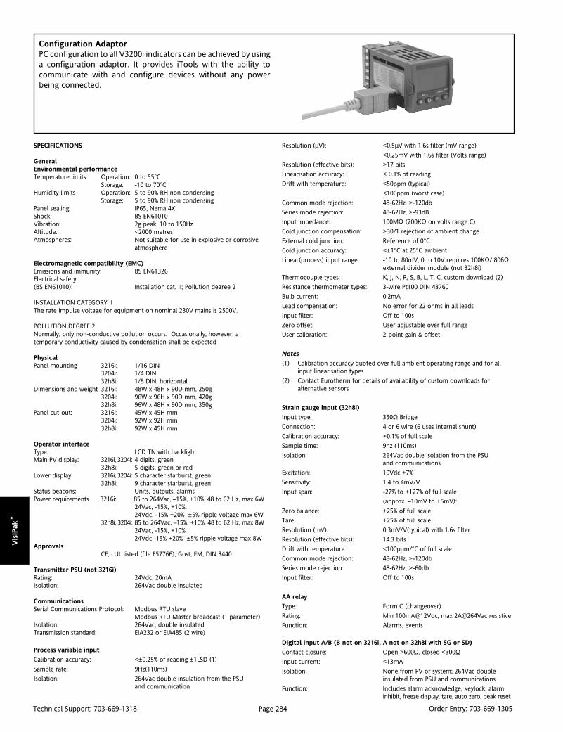
Vis
iPak
™
Page 284Technical Support: 703-669-1318 Order Entry: 703-669-1305
SPECIFICATIONS
GeneralEnvironmental performanceTemperature limits Operation: 0 to 55°C
Storage: -10 to 70°CHumidity limits Operation: 5 to 90% RH non condensing
Storage: 5 to 90% RH non condensingPanel sealing: IP65, Nema 4XShock: BS EN61010Vibration: 2g peak, 10 to 150HzAltitude: <2000 metresAtmospheres: Not suitable for use in explosive or corrosive
atmosphere
Electromagnetic compatibility (EMC)Emissions and immunity: BS EN61326Electrical safety(BS EN61010): Installation cat. II; Pollution degree 2
INSTALLATION CATEGORY IIThe rate impulse voltage for equipment on nominal 230V mains is 2500V.
POLLUTION DEGREE 2Normally, only non-conductive pollution occurs. Occasionally, however, atemporary conductivity caused by condensation shall be expected
PhysicalPanel mounting 3216i: 1/16 DIN
3204i: 1/4 DIN32h8i: 1/8 DIN, horizontal
Dimensions and weight 3216i: 48W x 48H x 90D mm, 250g3204i: 96W x 96H x 90D mm, 420g32h8i: 96W x 48H x 90D mm, 350g
Panel cut-out: 3216i: 45W x 45H mm3204i: 92W x 92H mm32h8i: 92W x 45H mm
Operator interfaceType: LCD TN with backlightMain PV display: 3216i, 3204i: 4 digits, green
32h8i: 5 digits, green or redLower display: 3216i, 3204i: 5 character starburst, green
32h8i: 9 character starburst, greenStatus beacons: Units, outputs, alarmsPower requirements 3216i: 85 to 264Vac, –15%, +10%, 48 to 62 Hz, max 6W
24Vac, -15%, +10%.24Vdc, -15% +20% ±5% ripple voltage max 6W
32h8i, 3204i: 85 to 264Vac, –15%, +10%, 48 to 62 Hz, max 8W24Vac, -15%, +10%.24Vdc -15% +20% ±5% ripple voltage max 8W
ApprovalsCE, cUL listed (file E57766), Gost, FM, DIN 3440
Transmitter PSU (not 3216i)Rating: 24Vdc, 20mAIsolation: 264Vac double insulated
CommunicationsSerial Communications Protocol: Modbus RTU slave
Modbus RTU Master broadcast (1 parameter)Isolation: 264Vac, double insulatedTransmission standard: EIA232 or EIA485 (2 wire)
Process variable input
Calibration accuracy: <±0.25% of reading ±1LSD (1)
Sample rate: 9Hz(110ms)
Isolation: 264Vac double insulation from the PSUand communication
Resolution (µV): <0.5µV with 1.6s filter (mV range)
<0.25mV with 1.6s filter (Volts range)
Resolution (effective bits): >17 bits
Linearisation accuracy: < 0.1% of reading
Drift with temperature: <50ppm (typical)
<100ppm (worst case)
Common mode rejection: 48-62Hz, >-120db
Series mode rejection: 48-62Hz, >-93dB
Input impedance: 100MΩ (200KΩ on volts range C)
Cold junction compensation: >30/1 rejection of ambient change
External cold junction: Reference of 0°CCold junction accuracy: <±1°C at 25°C ambient
Linear(process) input range: -10 to 80mV, 0 to 10V requires 100KΩ/ 806Ωexternal divider module (not 32h8i)
Thermocouple types: K, J, N, R, S, B, L, T, C, custom download (2)
Resistance thermometer types: 3-wire Pt100 DIN 43760
Bulb current: 0.2mA
Lead compensation: No error for 22 ohms in all leads
Input filter: Off to 100s
Zero offset: User adjustable over full range
User calibration: 2-point gain & offset
Notes
(1) Calibration accuracy quoted over full ambient operating range and for allinput linearisation types
(2) Contact Eurotherm for details of availability of custom downloads foralternative sensors
Strain gauge input (32h8i)
Input type: 350Ω Bridge
Connection: 4 or 6 wire (6 uses internal shunt)
Calibration accuracy: +0.1% of full scale
Sample time: 9hz (110ms)
Isolation: 264Vac double isolation from the PSUand communications
Excitation: 10Vdc +7%
Sensitivity: 1.4 to 4mV/V
Input span: -27% to +127% of full scale
(approx. –10mV to +5mV):
Zero balance: +25% of full scale
Tare: +25% of full scale
Resolution (mV): 0.3mV/V(typical) with 1.6s filter
Resolution (effective bits): 14.3 bits
Drift with temperature: <100ppm/°C of full scale
Common mode rejection: 48-62Hz, >-120db
Series mode rejection: 48-62Hz, >-60db
Input filter: Off to 100s
AA relay
Type: Form C (changeover)
Rating: Min 100mA@12Vdc, max 2A@264Vac resistive
Function: Alarms, events
Digital input A/B (B not on 3216i, A not on 32h8i with SG or SD)
Contact closure: Open >600Ω, closed <300ΩInput current: <13mA
Isolation: None from PV or system; 264Vac doubleinsulated from PSU and communications
Function: Includes alarm acknowledge, keylock, alarminhibit, freeze display, tare, auto zero, peak reset
Configuration AdaptorPC configuration to all V3200i indicators can be achieved by usinga configuration adaptor. It provides iTools with the ability tocommunicate with and configure devices without any powerbeing connected.

VisiP
ak™
Page 285Technical Support: 703-669-1318 Order Entry: 703-669-1305
Isolation Diagrams
Logic I/O module (3216i only)
Output
Rating: ON: 12Vdc@<44mA,
OFF: <300mV@100µA
Isolation: None from PV or system.264Vac double insulated from PSU and comms
Function: Alarms, events
Input
Contact closure: Open >500Ω, closed <150ΩIsolation: None from PV or system
264Vac double insulated from PSU and comms
Function: Includes alarm acknowledge, keylock, alarminhibit, freeze display, tare, auto zero, peak reset
Relay output channels
Type 3216i: Form A (normally open)
32h8i, 3204i: Form C (changeover)
Rating: Min 100mA@12vdc, max 2A@264Vac resistive
Function: Alarms, events
Analogue output
OP1, OP2 (3216i only)
Rating: 0-20mA into <500ΩAccuracy: ± (<0.5% of Reading + <100µA)
Resolution: 11.5 bits
Isolation: None from PV or system264Vac double insulated from PSU and comms
Function: Retransmission
OP3 (not on 3216i)
Isolation: 264Vac double insulated
Function: Retransmission
Current Output Rating: 0-20mA into <500ΩAccuracy: ±(<0.25% of Reading + <50µA)
Resolution: 13.6 bits
Voltage Output Rating (not on 3204i): 0-10V into >500ΩAccuracy: ±(<0.25% of Reading +<25mV)
Resolution: 13.6 bits
Software features
Alarms
Number: 4
Type: Absolute high & low, Rate of change
(rising or falling)
Latching: Auto or manual latching, non-latching, event only
Output assignment: Up to 4 conditions can be assigned to one output
Other status outputs
Function: Sensor break, power fail, new alarm, pre-alarm
Output assignment: Up to 4 conditions can be assigned to one output
Custom messages
Number: 15 scrolling text messages
No of characters: 127 characters per message max
Languages: English, German, French, Spanish, Italian
Selection: Active on any parameter status usingconditional command
Recipes
Number: 5 recipes with 19 parameters
Selection: HMI interface, communications or digital IO
Transducer calibration
Calibration types: Shunt, load cell, comparison
Other features: Auto-zero, tare
Other features
Display colour (32h8i): Upper display selectable green or red orchange on alarm
Scrolling text: Parameter help, custom messages
Display filter: Off to zero last 2 digits
Peak monitor: Stores high and low values
FM/DIN 3440
Alarm 1 configuration: Absolute hi or lo, de-energised in alarm
Latching output on Form C (AA) Relay
All alarms active on sensor break and power fail
Alarm setpoint: Adjustment protection via password
Configuration security: FM/DIN 3440 option prevents reconfigurationof alarm config
264Vac Double
264Vac Double
Rectification264Vac Double
PowerSupplyCircuits
Power
Relays & Triacs
µP &systemcircuits
Serialcomms
All logic inputs andoutputs & DC modules
Micro mountedPV Input
Serialcomms
264Vac Double
264Vac Double
264Vac Double
264Vac Double
264Vac Double
PowerPowerSupplyCircuits
µP &systemcircuits
Rectification
Relays & Triacs
Analogue (OP3) output
All logic inputs andoutputs & DC modules
Transmitter PSU
Micro mountedPV Input
3216i 32h8i/3204i

Vis
iPak
™
Page 286Technical Support: 703-669-1318 Order Entry: 703-669-1305
isolation Diagrams
3216i 32h8i/3204i
AA
AB
AC
VI
V+
V-
1A
1B
2A
2B
L
N
Line
Neutral
100 to 240Vac or 24 Vac/dc
HD
HE
HF
COM
A(+)
B(-)
+
-
+
-
+
-
+
-OP1
OP2
mA
RTD
AARelay(OP4)
CT
C
LA
AAABACHDHEHF
1A1B2A2BLBLC
CTCLAVIV+V-
3A3B3C3DLN
mA
AARelay(OP4)
Dig in A
COMA (+) B (-)
100 to 240Vac or 24 Vac/dc Dig in B
+-+-
DC Retran(OP3)
24Vdc Tx PSU
Signal Txder Supply
mA
Ext+Ext-Cal2Cal1+-
Model Function PowerSupply Outputs AA Relay Options Fascia
Color
Model
V3216i
V32h8i
V3204i
1/16 DIN Unit
1/8 DIN Horizontal Unit
1/4 DIN Unit
ProductLanguage
ManualLanguage
InputAdaptor
WarrantyCalibrationCertificate
CustomLabel
Specials& Access
Function
AL
FM
DN
SG
Standard Unit
FM Alarm Unit
DIN 3440 Alarm Unit
Strain Gauge Input
(32h8i only)
Power Supply
VH
VL
85-264 Vac
20-29 Vac/Vdc
Outputs
LRXX
RRXX
LDXX
DRXX
RXXX
RXDX
OP1
Logic
Relay
Logic
Analog
OP1
Relay
Relay
OP2
Relay
Relay
Analog
Relay
OP3
None
Analog
3216i
32h8i/3204i
AA Relay
X
R
Disabled
Form C (changeover)
Options
XXX
XXL
2XL
4XL
Not Fitted
Digital Input A
RS232 + Digital Input A
RS485 + Digital Input A
Fascia Color
G
S
Green
Silver
Product Language
ENG
FRA
GER
SPA
ITA
English
French
German
Spanish
Italian
Manual Language
ENG
FRA
GER
SPA
ITA
English
French
German
Spanish
Italian
Input Adaptor
XX
V1
A1
None
0-10 Vdc*
mA Burden Resistor
(2.49Ω, 0.1%)
*Not required for 32h8i
Warranty
XXXXX
WL005
Standard
Extended
Calibration Certificate
XXXXX
CERT1
CERT2
None
Certificate of Conformity
5 Point Factory Calibration
Specials and Accessories
XXXXX
RES250
RES500
None
250Ω Resistor for 0-5Vdc OP
500Ω Resistor for 0-10Vdc OP
Custom Label
F0734 Action Instruments
Ordering Code
AccessoriesUser Guide . . . . . . . . . . . . . . . HA029005
Engineering Manual . . . . . . . . HA029006
2.49Ω Precision Resistor . . . . . SUB35/ACCESS/2.49R.1
Configuration Clip . . . . . . . . . . iTools/None/3000CK
0-10V Input Adaptor . . . . . . . . SUB21/1V10

VisiP
ak™
Page 287Technical Support: 703-669-1318 Order Entry: 703-669-1305
Optional Quick Start Code
InputType
DisplayLimits
DecimalPoint PV Color
32h8iOnly
HomeDisplay
RangeLow
RangeHigh
Input Type
B
J
K
L
N
R
S
T
C
P
M
2
4
0
1
3
6
G
Thermocouple
Type B
Type J
Type K
Type L
Type N
Type R
Type S
Type T
Type C
RTD
Pt100
Linear
0-80mV
0-20mA
4-20mA
32h8i Only
0-10Vdc
1-5Vdc
2-10Vdc
0-5Vdc
Strain Gauge
OP1 OP2 OP3 OP4 AARelay
DigitalInput A
Not32h8i/SG
DigitalInput B
Display Limits
X
C
F
K
P
None
Deg C Full Range
Deg F Full Range
Kelvin
Percentage
Pressure
Pa
mPa
Kpa
Bar
mBar
PSI
Kgcm2
mmWG
inWG
mmHG
Torr
PV Color (32h8i Only)
X
G
R
C
Not Applicable
Green
Red
Change on any alarm
(Green to Red)
Range Low
Enter Value
Home Display
N
A
1
2
PV Only
First Alarm SP Only
PV + Alarm SP
PV + Alarm SP (read only)
32h8i Only
0
1
2
3
4
5
6
7
8
9
A
Flow Rate
L-H
L-m
General
%RH
%O2
%CO2
%CP
V
Amps
mA
mV
Ohms
ppm
RPM
m-s
B
D
E
G
H
J
L
M
R
T
U
W
Y
Z
Decimal Point
0
1
2
3
4
nnnnn
nnnn.n
nnn.nn
nn.nnn (32h8i only)
n.nnnn (32h8i only)
Range High
Enter Value
OP1
Unconfigured
High Alarm
Low Alarm
Rising Rate of Change
New Alarm
Sensor Break
Power Fail
High Alarm
Low Alarm
Rising Rate of Change
High Alarm
Low Alarm
Rising Rate of Change
High Alarm
Low Alarm
Rising Rate of Change
X
H
L
R
N
O
P
7
8
9
A
B
C
E
F
G
Combined with Sensor Break
Combined with Power Fail
Combined with Sensor Break
and Power Fail
4-20mA
0-20mA
Alarm Acknowledge
Keylock
Remote UP Button
Remote DOWN Button
Alarm Inhibit
Peak Reset
Freeze Displayed PV
Recipe 1/2 Select
1
2
W
K
U
D
J
M
Y
V
3216i Only
Analog Output PV Retran
Digital Input Logic Input
OP2 (3216i), OP3 (32h8i & 3204)
Unconfigured
4-20mA
0-20mA
0-5Vdc
1-5Vdc
0-10Vdc
2-10Vdc
X
1
2
3
4
5
6
Analog Out PV Retran
32h8i/3204i Only
High Alarm
Low Alarm
Rising Rate of Change
New Alarm
Sensor Break
Power Fail
High Alarm
Low Alarm
Rising Rate of Change
H
L
R
N
O
P
7
8
9
3216i OnlyRelay or Logic Out (Alarm 2)
Alarm 2
Combined with Sensor Break
High Alarm
Low Alarm
Rising Rate of Change
High Alarm
Low Alarm
Rising Rate of Change
A
B
C
E
F
G
Combined with Sensor Breakand Power Fail
Combined with Power Fail
OP4 (AA Relay)
Unconfigured
High Alarm
Low Alarm
Rising Rate of Change
New Alarm
Sensor Break
Power Fail
High Alarm
Low Alarm
Rising Rate of Change
High Alarm
Low Alarm
Rising Rate of Change
High Alarm
Low Alarm
Rising Rate of Change
X
H
L
R
N
O
P
7
8
9
A
B
C
E
F
G
Combined with Sensor Break
Combined with Power Fail
Combined with Sensor Break
and Power Fail
Digital Input A (n/a 32h81/SG)
Unconfigured
Alarm Acknowledge
Keylock
Remote UP Button
Remote DOWN Button
Alarm Inhibit
Peak Reset
Freeze Displayed PV
Recipe 1/2 Select
X
W
K
U
D
J
M
Y
V
Digital Input B
Unconfigured
Alarm Acknowledge
Keylock
Remote UP Button
Remote DOWN Button
Alarm Inhibit
Peak Reset
Freeze Displayed PV
Recipe 1/2 Select
Tare Correction
Auto Shunt (Melt Pressure)
Calibration
X
W
K
U
D
J
M
Y
V
T
Z
32h8i Strain Gauge
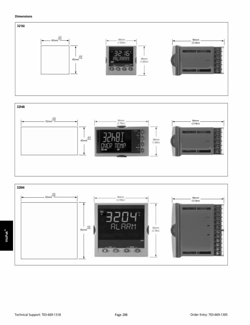
Vis
iPak
™
Page 288Technical Support: 703-669-1318 Order Entry: 703-669-1305
Dimensions
3216i
45mm-0.0+0.6
45mm-0.0+0.6
90mm(3.54in)
32h8i
90mm(3.54in)
92mm-0.0+0.8
45mm-0.0+0.6
3204i
92mm-0.0+0.8
92mm-0.0+0.8
90mm(3.54in)
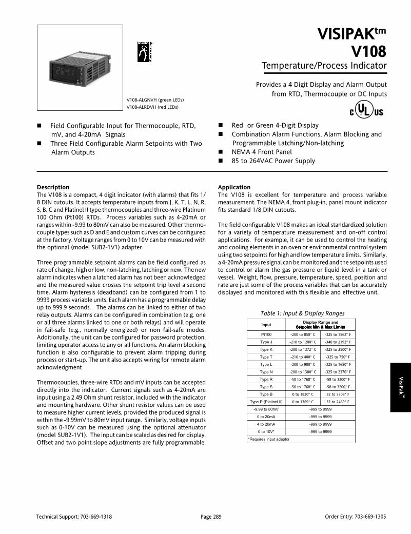
VisiP
ak™
Page 289Technical Support: 703-669-1318 Order Entry: 703-669-1305
DescriptionThe V108 is a compact, 4 digit indicator (with alarms) that fits 1/8 DIN cutouts. It accepts temperature inputs from J, K, T, L, N, R,S, B, C and Platinel II type thermocouples and three-wire Platinum100 Ohm (Pt100) RTDs. Process variables such as 4-20mA orranges within -9.99 to 80mV can also be measured. Other thermo-couple types such as D and E and custom curves can be configuredat the factory. Voltage ranges from 0 to 10V can be measured withthe optional (model SUB2-1V1) adapter.
Three programmable setpoint alarms can be field configured asrate of change, high or low; non-latching, latching or new. The newalarm indicates when a latched alarm has not been acknowledgedand the measured value crosses the setpoint trip level a secondtime. Alarm hysteresis (deadband) can be configured from 1 to9999 process variable units. Each alarm has a programmable delayup to 999.9 seconds. The alarms can be linked to either of tworelay outputs. Alarms can be configured in combination (e.g. oneor all three alarms linked to one or both relays) and will operatein fail-safe (e.g., normally energized) or non fail-safe modes.Additionally, the unit can be configured for password protection,limiting operator access to any or all functions. An alarm blockingfunction is also configurable to prevent alarm tripping duringprocess or start-up. The unit also accepts wiring for remote alarmacknowledgment
Thermocouples, three-wire RTDs and mV inputs can be accepteddirectly into the indicator. Current signals such as 4-20mA areinput using a 2.49 Ohm shunt resistor, included with the indicatorand mounting hardware. Other shunt resistor values can be usedto measure higher current levels, provided the produced signal iswithin the -9.99mV to 80mV input range. Similarly, voltage inputssuch as 0-10V can be measured using the optional attenuator(model SUB2-1V1). The input can be scaled as desired for display.Offset and two point slope adjustments are fully programmable.
VISIPAKtm
V108Temperature/Process Indicator
Provides a 4 Digit Display and Alarm Outputfrom RTD, Thermocouple or DC Inputs
Field Configurable Input for Thermocouple, RTD,mV, and 4-20mA Signals
Three Field Configurable Alarm Setpoints with TwoAlarm Outputs
V108-ALGNVH (green LEDs)
V108-ALRDVH (red LEDs)
Red or Green 4-Digit Display Combination Alarm Functions, Alarm Blocking and
Programmable Latching/Non-latching NEMA 4 Front Panel 85 to 264VAC Power Supply
ApplicationThe V108 is excellent for temperature and process variablemeasurement. The NEMA 4, front plug-in, panel mount indicatorfits standard 1/8 DIN cutouts.
The field configurable V108 makes an ideal standardized solutionfor a variety of temperature measurement and on-off controlapplications. For example, it can be used to control the heatingand cooling elements in an oven or environmental control systemusing two setpoints for high and low temperature limits. Similarly,a 4-20mA pressure signal can be monitored and the setpoints usedto control or alarm the gas pressure or liquid level in a tank orvessel. Weight, flow, pressure, temperature, speed, position andrate are just some of the process variables that can be accuratelydisplayed and monitored with this flexible and effective unit.
tupnIdnaegnaRyalpsiD
stimiLxaM&niMtniopteS stimiLxaM&niMtniopteS stimiLxaM&niMtniopteS stimiLxaM&niMtniopteS stimiLxaM&niMtniopteS
001tP 058ot002- C° 2651ot523- F°
JepyT 0021ot012- C° 2912ot043- F°
KepyT 2731ot002- C° 0052ot523- F°
TepyT 004ot012- C° 057ot523- F°
LepyT 009ot002- C° 0561ot523- F°
NepyT 0031ot002- C° 0732ot523- F°
RepyT 8671ot05- C° 0023ot85- F°
SepyT 8671ot05- C° 0023ot85- F°
BepyT 0281ot0 C° 8033ot23 F°
)IIlenitalP(PepyT 9631ot0 C° 9642ot23 F°
Vm08ot99.9- 9999ot999-
Am02ot0 9999ot999-
Am02ot4 9999ot999-
*V01ot0 9999ot999-
rotpadatupniseriuqeR*
Table 1: Input & Display Ranges
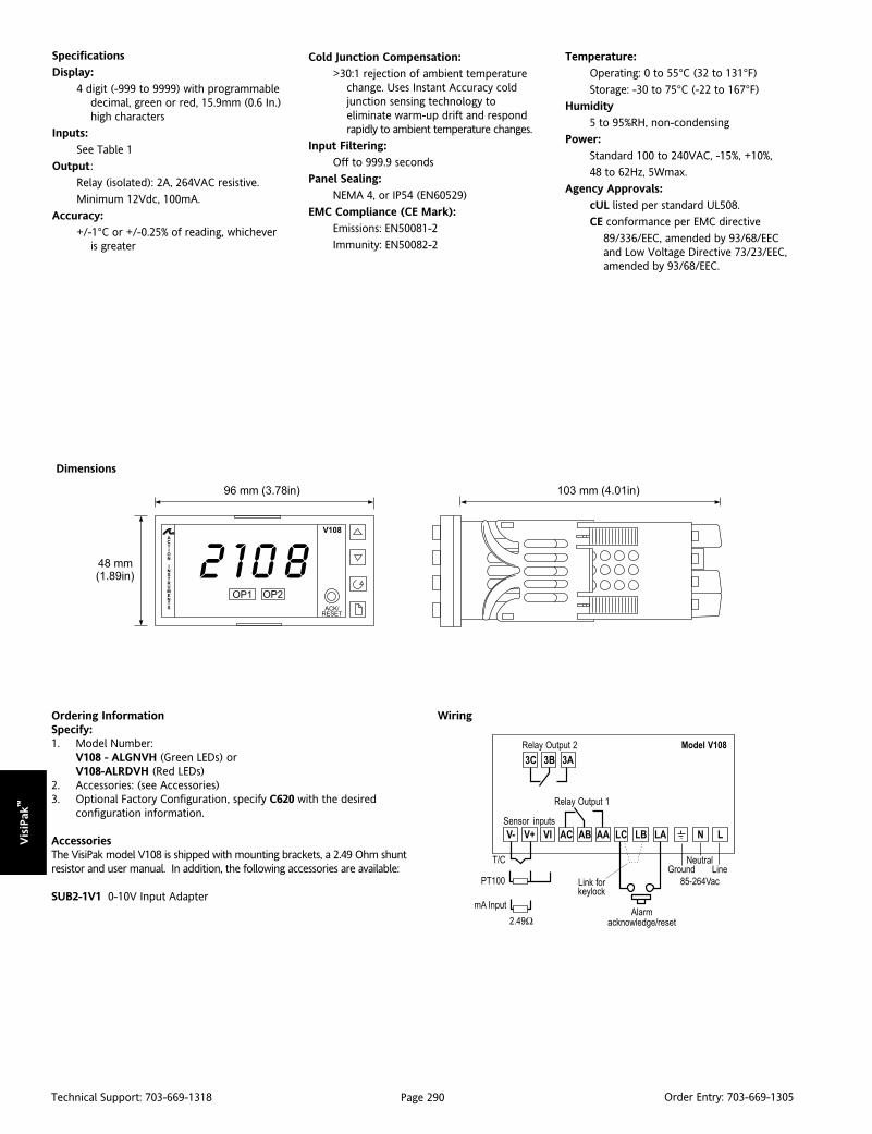
Vis
iPak
™
Page 290Technical Support: 703-669-1318 Order Entry: 703-669-1305
Dimensions
WiringOrdering InformationSpecify:1. Model Number:
V108 - ALGNVH (Green LEDs) orV108-ALRDVH (Red LEDs)
2. Accessories: (see Accessories)3. Optional Factory Configuration, specify C620 with the desired
configuration information.
AccessoriesThe VisiPak model V108 is shipped with mounting brackets, a 2.49 Ohm shuntresistor and user manual. In addition, the following accessories are available:
SUB2-1V1 0-10V Input Adapter
Specifications
Display:
4 digit (-999 to 9999) with programmabledecimal, green or red, 15.9mm (0.6 In.)high characters
Inputs:
See Table 1
Output:
Relay (isolated): 2A, 264VAC resistive.
Minimum 12Vdc, 100mA.
Accuracy:
+/-1°C or +/-0.25% of reading, whicheveris greater
Cold Junction Compensation:
>30:1 rejection of ambient temperaturechange. Uses Instant Accuracy coldjunction sensing technology toeliminate warm-up drift and respondrapidly to ambient temperature changes.
Input Filtering:
Off to 999.9 seconds
Panel Sealing:
NEMA 4, or IP54 (EN60529)
EMC Compliance (CE Mark):
Emissions: EN50081-2
Immunity: EN50082-2
Temperature:
Operating: 0 to 55°C (32 to 131°F)
Storage: -30 to 75°C (-22 to 167°F)
Humidity
5 to 95%RH, non-condensing
Power:
Standard 100 to 240VAC, -15%, +10%,
48 to 62Hz, 5Wmax.
Agency Approvals:
cUL listed per standard UL508.
CE conformance per EMC directive
89/336/EEC, amended by 93/68/EECand Low Voltage Directive 73/23/EEC,amended by 93/68/EEC.
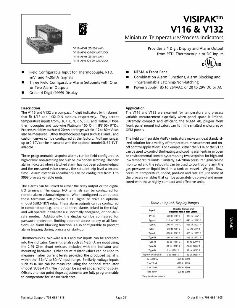
VisiP
ak™
Page 291Technical Support: 703-669-1318 Order Entry: 703-669-1305
DescriptionThe V116 and V132 are compact, 4 digit indicators (with alarms)that fit 1/16 and 1/32 DIN cutouts, respectively. They accepttemperature inputs from J, K, T, L, N, R, S, C, B, and Platinel II typethermocouples and two-wire Platinum 100 Ohm (Pt100) RTDs.Process variables such as 4-20mA or ranges within -12 to 80mV canalso be measured. Other thermocouple types such as D and E andcustom curves can be configured at the factory. Voltage rangesup to 0-10V can be measured with the optional (model SUB2-1V1)adaptor.
Three programmable setpoint alarms can be field configured ashigh or low, non-latching and high or low or new, latching. The newalarm indicates when a latched alarm has not been acknowledgedand the measured value crosses the setpoint trip level a secondtime. Alarm hysterisis (deadband) can be configured from 1 to9999 process variable units.
The alarms can be linked to either the relay output or the digitalI/O terminals. The digital I/O terminals can be configured forremote alarm acknowledgment. When configured as an output,those terminals will provide a TTL signal or drive an optional(model SUB2-1R7) relay. These alarm outputs can be configuredin combination (e.g., one or all three alarms linked to the relay)and will operate in fail-safe (i.e., normally energized) or non-fail-safe modes. Additionally, the display can be configured forpassword protection, limiting operator access to any or all func-tions. An alarm blocking function is also configurable to preventalarm tripping during process or start-up.
Thermocouples, two-wire RTDs and mV inputs can be acceptedinto the indicator. Current signals such as 4-20mA are input usingthe 2.49 Ohm shunt resistor, included with the indicator andmounting hardware. Other shunt resistor values can be used tomeasure higher current levels provided the produced signal iswithin the -12mV to 80mV input range. Similarly, voltage inputssuch as 0-10V can be measured using the optional attenuator(model SUB2-1V1). The input can be scaled as desired for display.Offsets and two point slope adjustments are fully programmableto compensate for sensor variances.
VISIPAKtm
V116 & V132Miniature Temperature/Process Indicators
Provides a 4 Digit Display and Alarm Outputfrom RTD, Thermocouple or DC Inputs
Field Configurable Input for Thermocouple, RTD,mV and 4-20mA Signals
Three Field Configurable Alarm Setpoints with Oneor Two Alarm Outputs
Green 4 Digit (9999) Display
V116-ALVH (65-264 VAC)
V116-ALVL (20-29 VAC/VDC)
V116-ALVH (65-264 VAC)
V116-ALVL (20-29 VAC/VDC)
NEMA 4 Front Panel Combination Alarm Functions, Alarm Blocking and
Programmable Latching/Non-latching Power Supply: 85 to 264VAC or 20 to 29V DC or AC
ApplicationThe V116 and V132 are excellent for temperature and processvariable measurement especially when panel space is limited.Extremely compact and efficient, the NEMA 4X, plug-in fromfront, panel mount indicators can fit in the smallest enclosures orOEM panels.
The field configurable VisiPak indicators make an ideal standard-ized solution for a variety of temperature measurement and on-off control applications. For example, either the V116 or the V132can be used to control the heating and cooling elements in an ovenor environmental control system using two setpoints for high andlow temperature limits. Similarly, a 4-20mA pressure signal can bemonitored and the setpoints can be used to control or alarm thegas pressure or liquid level in a tank or vessel. Weight, flow,pressure, temperature, speed, position and rate are just some ofthe process variables that can be accurately displayed and moni-tored with these highly compact and effective units.
Table 1: Input & Display Ranges
tupnIdnaegnaRyalpsiD
stimiLxaM&niMtniopteS stimiLxaM&niMtniopteS stimiLxaM&niMtniopteS stimiLxaM&niMtniopteS stimiLxaM&niMtniopteS
001tP 058ot002- C° 2651ot523- F°
JepyT 0021ot012- C° 2912ot043- F°
KepyT 2731ot002- C° 0052ot523- F°
TepyT 004ot012- C° 057ot523- F°
LepyT 009ot002- C° 0561ot523- F°
NepyT 0031ot002- C° 0732ot523- F°
RepyT 8671ot05- C° 0023ot85- F°
SepyT 8671ot05- C° 0023ot85- F°
BepyT 0281ot0 C° 8033ot23 F°
)IIlenitalP(PepyT 9631ot0 C° 9642ot23 F°
Vm08ot21- 9999ot999-
Am02ot0 9999ot999-
Am02ot4 9999ot999-
*V01ot0 9999ot999-
rotpadatupniseriuqeR*

Vis
iPak
™
Page 292Technical Support: 703-669-1318 Order Entry: 703-669-1305
Specifications
Display:
4 digit (-999 to 9999) with programmabledecimal, green, 10mm (0.4 In.) highcharacters
Inputs:
See Table 1
Output:
Relay (isolated): 2A, 264VAC resistive.
Minimum 12V DC, 100mA.
Logic (non-isolated): 9VDC, 12mA. Can beused as alarm output or alarmacknowledge input.
Accuracy:
+/-1°C or +/-0.25% of reading, whicheveris greater
Cold Junction Compensation:
>30 to 1 rejection of ambient temperaturechange. Uses Instant Accuracy coldjunction sensing technology to eliminatewarm-up drift and respond rapidly toambient temperature changes.
Input Filtering:
Off to 999.9 seconds
Panel Sealing:
NEMA 4X, or IP65 (EN60529)
EMC Compliance (CE Mark):
Emissions: EN50081-2
Immunity: EN50082-2
Dimensions Wiring
Ordering InformationSpecify:1. Model Number:
V116-ALVH (65-264VAC powered) orV116-ALVL (20-29VDC/AC powered) orV132-ALVH (65-264VAC powered) orV132-ALVL (20-29VDC/AC powered)
2. Accessories: (see Accessories)3. Optional Factory Configuration, specify C620 with the desired
configuration information.
AccessoriesThe VisiPak model V116 and V132 are shipped with mounting brackets,2.49 Ohm shunt resistor and user manual. In addition, the followingaccessories are available:
SUB2-1R7 External RelaySUB2-1V10-10V Input Adapter
Temperature:
Operating: 0 to 55°C (32 to 131°F)
Storage: -30 to 75°C (-22 to 167°F)
Humidity:
5 to 95%RH, non-condensing
Power:
Standard 85 to 264VAC, 48 to 62Hz,
optional 20 to 29V DC or AC, 5 W max.
Agency Approvals:
cUL listed per standard UL508.
CE conformance per EMC directive 89/336/EEC,amended by 93/68/EEC and Low VoltageDirective 73/23/EEC, amended by 93/68/EEC.
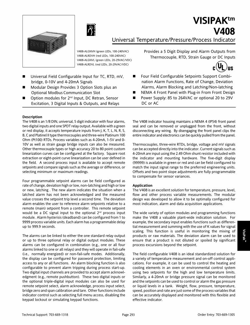
VisiP
ak™
Page 293Technical Support: 703-669-1318 Order Entry: 703-669-1305
DescriptionThe V408 is an 1/8 DIN, universal, 5 digit indicator with four alarms,two digital inputs and one SPDT relay output. Available with a greenor red display, it accepts temperature inputs from J, K, T, L, N, R, S,B, C and Platinel II type thermocouples and three-wire Platinum 100Ohm (Pt100) RTDs. Process variables such as 4-20mA, 1-5V and 0-10V as well as strain gauge bridge inputs can also be measured.Other thermocouple types or high accuracy 20 to 80 point customlinearization curves can be configured at the factory. Square rootextraction or eight-point curve linearization can be user defined inthe field. A second process input is available to accept remotesetpoints and compare signals such as the average or difference, orselecting minimum or maximum readings.
Four programmable setpoint alarms can be field configured asrate of change, deviation high or low, non-latching and high or lowor new, latching . The new alarm indicates the situation when alatched alarm has not been acknowledged and the measuredvalue crosses the setpoint trip level a second time. The deviationalarm enables the user to reference alarm setpoints relative to aremote (main) setpoint from a controller. This remote setpointwould be a DC signal input to the optional 2nd process inputmodule. Alarm hysterisis (deadband) can be configured from 1 to9999 process variable units. Each alarm has a programmable delayup to 999.9 seconds.
The alarms can be linked to either the one standard relay outputor up to three optional relay or digital output modules. Thesealarms can be configured in combination (e.g., one or all fouralarms linked to one or all relays) and they will operate in fail-safe(i.e., normally energized) or non-fail-safe modes. Additionally,the display can be configured for password protection, limitingaccess to any or all functions. An alarm blocking function is alsoconfigurable to prevent alarm tripping during process start-up.Two digital input channels are provided to accept alarm acknowl-edgment (e.g., remote pushbutton). These two digital inputs orthe optional triple-digital input modules can also be used forremote setpoint select, alarm acknowledge, process input select,bridge zero and span calibration and tare. Other functions includeindicator control such as selecting full menu access, disabling thekeypad lockout or simulating keypad functions.
VISIPAKtm
V408Universal Temperature/Pressure/Process Indicator
Provides a 5 Digit Display and Alarm Outputs fromThermocouple, RTD, Strain Gauge or DC Inputs
Universal Field Configurable Input for TC, RTD, mV,bridge, 0-10V and 4-20mA Signals
Modular Design Provides 3 Option Slots plus anOptional Modbus Communication Slot
Option modules for 2nd Input, DC Retran, SensorExcitation, 3 Digital Inputs & Outputs, and Relays
V408-ALGNVH (green LEDs, 100-240VAC)
V408-ALRDVH (red LEDs, 100-240VAC)
V408-ALGNVL (green LEDs, 20-29VAC/VDC)
V408-ALRDVL (red LEDs, 20-29VAC/VDC)
Four Field Configurable Setpoints Support Combi-nation Alarm Functions, Rate of Change, DeviationAlarms, Alarm Blocking and Latching/Non-latching
NEMA 4 Front Panel with Plug-in From Front Design Power Supply: 85 to 264VAC or optional 20 to 29V
DC or AC
The V408 indicator housing maintains a NEMA 4 (IP54) front panelseal and can be removed or unplugged from the front, withoutdisconnecting any wiring. By disengaging the front panel clips theentire indicator and electronics can be quickly pulled from the panel.
Thermocouples, three-wire RTDs, bridge, voltage and mV signalscan be accepted directly into the indicator. Current signals such as4-20mA are input using the 2.49 Ohm shunt resistor included withthe indicator and mounting hardware. The five-digit display(99999) is available in green or red and can be field configured tomatch the input signal range to the preferred engineering units.Offsets and two point slope adjustments are fully programmableto compensate for sensor variances.
ApplicationThe V408 is an excellent solution for temperature, pressure, level,flow and other process variable measurements. The modulardesign was developed to allow it to be optimally configured formost indication, alarm and data acquisition applications.
The wide variety of option modules and programming functionsmake the V408 a valuable plant-wide indication solution. Forexample, the secondary input enables functions such as differen-tial measurement and summing with the use of K values for signalscaling. This function is useful in monitoring the mixing ofproducts or raw materials. The deviation alarm can be used toensure that a product is not diluted or spoiled by significantprocess excursions beyond the setpoint.
The field configurable V408 is an ideal standardized solution fora variety of temperature measurement and on-off control appli-cations. For example, it can be used to control the heating andcooling elements in an oven or environmental control systemusing two setpoints for the high and low temperature limits.Similarly, a 4-20mA or bridge pressure signal can be monitoredand the setpoints can be used to control or alarm the gas pressureor liquid levels in a tank. Weight, flow, pressure, temperature,speed, position and rate are just some of the process variables thatcan be accurately displayed and monitored with this flexible andeffective indicator.
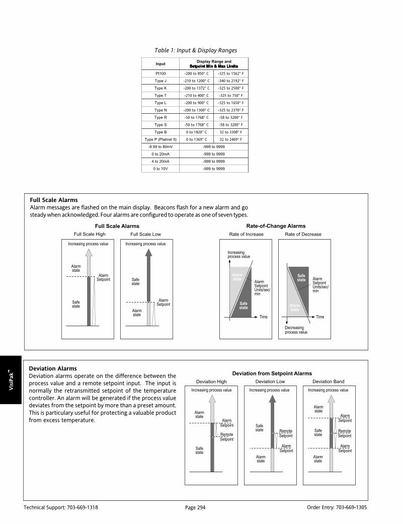
Vis
iPak
™
Page 294Technical Support: 703-669-1318 Order Entry: 703-669-1305
Deviation AlarmsDeviation alarms operate on the difference between theprocess value and a remote setpoint input. The input isnormally the retransmitted setpoint of the temperaturecontroller. An alarm will be generated if the process valuedeviates from the setpoint by more than a preset amount.This is particulary useful for protecting a valuable productfrom excess temperature.
Table 1: Input & Display Ranges
Full Scale AlarmsAlarm messages are flashed on the main display. Beacons flash for a new alarm and gosteady when acknowledged. Four alarms are configured to operate as one of seven types.
tupnIdnaegnaRyalpsiD
stimiLxaM&niMtniopteS stimiLxaM&niMtniopteS stimiLxaM&niMtniopteS stimiLxaM&niMtniopteS stimiLxaM&niMtniopteS
001tP 058ot002- C° 2651ot523- F°
JepyT 0021ot012- C° 2912ot043- F°
KepyT 2731ot002- C° 0052ot523- F°
TepyT 004ot012- C° 057ot523- F°
LepyT 009ot002- C° 0561ot523- F°
NepyT 0031ot002- C° 0732ot523- F°
RepyT 8671ot05- C° 0023ot85- F°
SepyT 8671ot05- C° 0023ot85- F°
BepyT 0281ot0 C° 8033ot23 F°
)IIlenitalP(PepyT 9631ot0 C° 9642ot23 F°
Vm08ot99.9- 9999ot999-
Am02ot0 9999ot999-
Am02ot4 9999ot999-
V01ot0 9999ot999-
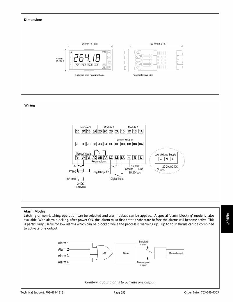
VisiP
ak™
Page 295Technical Support: 703-669-1318 Order Entry: 703-669-1305
Alarm ModesLatching or non-latching operation can be selected and alarm delays can be applied. A special ‘alarm blocking’ mode is alsoavailable. With alarm blocking, after power ON, the alarm must first enter a safe state before the alarms will become active. Thisis particularly useful for low alarms which can be blocked while the process is warming up. Up to four alarms can be combinedto activate one output.
Combining four alarms to activate one output
Dimensions
Wiring
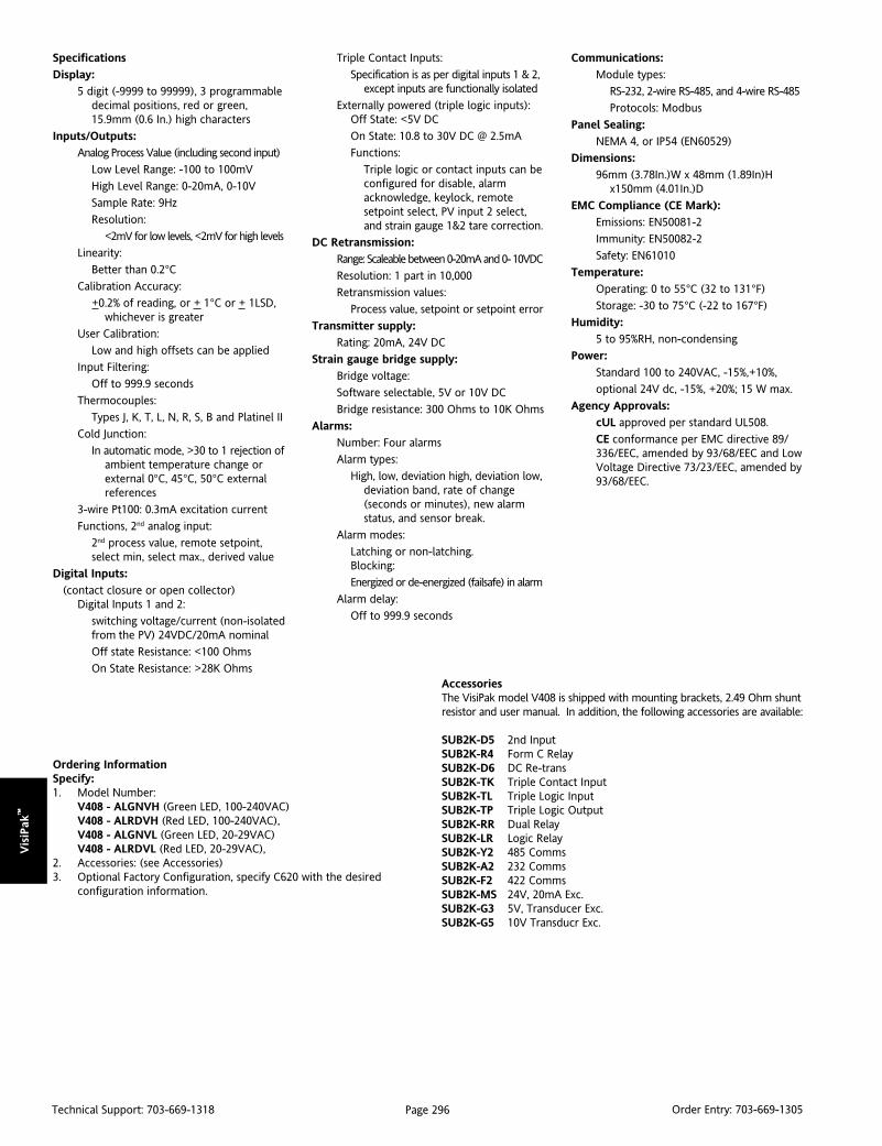
Vis
iPak
™
Page 296Technical Support: 703-669-1318 Order Entry: 703-669-1305
Ordering InformationSpecify:1. Model Number:
V408 - ALGNVH (Green LED, 100-240VAC)V408 - ALRDVH (Red LED, 100-240VAC),V408 - ALGNVL (Green LED, 20-29VAC)V408 - ALRDVL (Red LED, 20-29VAC),
2. Accessories: (see Accessories)3. Optional Factory Configuration, specify C620 with the desired
configuration information.
AccessoriesThe VisiPak model V408 is shipped with mounting brackets, 2.49 Ohm shuntresistor and user manual. In addition, the following accessories are available:
SUB2K-D5 2nd InputSUB2K-R4 Form C RelaySUB2K-D6 DC Re-transSUB2K-TK Triple Contact InputSUB2K-TL Triple Logic InputSUB2K-TP Triple Logic OutputSUB2K-RR Dual RelaySUB2K-LR Logic RelaySUB2K-Y2 485 CommsSUB2K-A2 232 CommsSUB2K-F2 422 CommsSUB2K-MS 24V, 20mA Exc.SUB2K-G3 5V, Transducer Exc.SUB2K-G5 10V Transducr Exc.
Specifications
Display:
5 digit (-9999 to 99999), 3 programmabledecimal positions, red or green,15.9mm (0.6 In.) high characters
Inputs/Outputs:
Analog Process Value (including second input)
Low Level Range: -100 to 100mV
High Level Range: 0-20mA, 0-10V
Sample Rate: 9Hz
Resolution:
<2mV for low levels, <2mV for high levels
Linearity:
Better than 0.2°CCalibration Accuracy:
+0.2% of reading, or + 1°C or + 1LSD,whichever is greater
User Calibration:
Low and high offsets can be applied
Input Filtering:
Off to 999.9 seconds
Thermocouples:
Types J, K, T, L, N, R, S, B and Platinel II
Cold Junction:
In automatic mode, >30 to 1 rejection ofambient temperature change orexternal 0°C, 45°C, 50°C externalreferences
3-wire Pt100: 0.3mA excitation current
Functions, 2nd analog input:
2nd process value, remote setpoint,select min, select max., derived value
Digital Inputs:
(contact closure or open collector)Digital Inputs 1 and 2:
switching voltage/current (non-isolatedfrom the PV) 24VDC/20mA nominal
Off state Resistance: <100 Ohms
On State Resistance: >28K Ohms
Triple Contact Inputs:
Specification is as per digital inputs 1 & 2,except inputs are functionally isolated
Externally powered (triple logic inputs):Off State: <5V DC
On State: 10.8 to 30V DC @ 2.5mA
Functions:
Triple logic or contact inputs can beconfigured for disable, alarmacknowledge, keylock, remotesetpoint select, PV input 2 select,and strain gauge 1&2 tare correction.
DC Retransmission:
Range: Scaleable between 0-20mA and 0- 10VDC
Resolution: 1 part in 10,000
Retransmission values:
Process value, setpoint or setpoint error
Transmitter supply:
Rating: 20mA, 24V DC
Strain gauge bridge supply:
Bridge voltage:
Software selectable, 5V or 10V DC
Bridge resistance: 300 Ohms to 10K Ohms
Alarms:
Number: Four alarms
Alarm types:
High, low, deviation high, deviation low,deviation band, rate of change(seconds or minutes), new alarmstatus, and sensor break.
Alarm modes:
Latching or non-latching.Blocking:
Energized or de-energized (failsafe) in alarm
Alarm delay:
Off to 999.9 seconds
Communications:
Module types:
RS-232, 2-wire RS-485, and 4-wire RS-485
Protocols: Modbus
Panel Sealing:
NEMA 4, or IP54 (EN60529)
Dimensions:
96mm (3.78In.)W x 48mm (1.89In)Hx150mm (4.01In.)D
EMC Compliance (CE Mark):
Emissions: EN50081-2
Immunity: EN50082-2
Safety: EN61010
Temperature:
Operating: 0 to 55°C (32 to 131°F)
Storage: -30 to 75°C (-22 to 167°F)
Humidity:
5 to 95%RH, non-condensing
Power:
Standard 100 to 240VAC, -15%,+10%,
optional 24V dc, -15%, +20%; 15 W max.
Agency Approvals:
cUL approved per standard UL508.
CE conformance per EMC directive 89/336/EEC, amended by 93/68/EEC and LowVoltage Directive 73/23/EEC, amended by93/68/EEC.

VisiP
ak™
Page 297Technical Support: 703-669-1318 Order Entry: 703-669-1305
DescriptionThe V430 is a programmable, analog input LED indicator whichdisplays either rate or the totalized count of the rate. The VisiPakhousing provides a NEMA 4X water tight front panel that fits 1/8DIN cutouts. The time base of the rate can be set for seconds,minutes, or hours (e.g., pulses per second, gallons per minute, orbarrels per day) and the totalization factor can be set forconversion of rate units to totalization units (e.g., gallons perminute rate converted to totalized barrels). Additionally, squareroot, peak hold, low flow cut-off, square root and 11 pointlinearization functions are also included.
The four visual setpoint alarms are annunciated via individual frontpanel LEDs and come as standard on the unit. Two can be pro-grammed to alarm on rate limits and two can be programmed toalarm on a specific count or total, complete with delays and offsets.
Two form C relays are available as optional outputs for the first twosetpoints; either two for rate or two for totalized count. The ratealarms can be configured as high or low, failsafe or non-failsafe.Each rate setpoint has a 100% adjustable deadband (or reset point)which can be effectively used in on/off control applications or asa latching alarm. An isolated 4-20mA transmitter output thatfollows the rate input is also available.
The totalized count alarms can be configured to trip at an absoluteor offset count (e.g., setpoint #1 trips 10 counts before setpoint#2), for applications where batch size varies. Additionally thePriority Batch Programming feature allows quick access to thesetpoints by holding the ENTER button down for three seconds.
The V430 accepts 4-20mA, 0-20mA, 0-5V, 1-5V, 0-10V analoginputs and displays the rate or the totalized count, and canalternate between the rate and count display on a ten secondcycle. The unit has an isolated 24V excitation source to power atwo-wire transmitter or the optional 4-20mA output.
VISIPAKtm
V430Analog Input, Rate Indicator/
Totalizer/Batch Controller
Provides a Digital Display of Rate or TotalizedCount from a DC Current or Voltage Input
Field Configurable Input: 4-20mA, 1-5V, 0-5V, or 0-10V 6 Digit Display for Counts to + 999999 Independent Scaling for Rate & Total Programmable Square Root, 11 Pt Linearization &
Peak Hold Functions
V430-0000 (no options)
V430-1000 (2 relays, rate or count)
V430-2000 (4-20mA output)
V430-3000 (4-20mA and 2 relays, rate or count)
NEMA 4 Front Panel Optional 2 Relay Output & 4-20mA Transmitter
Output Isolated 24V Excitation Source
Field configuration of the input range, alarm function, and analogtransmitter output scaling is quick and easy. The indicator is factorycalibrated to rated accuracy and can be field adjusted as necessary.
Terminals are provided for both remote alarm acknowledgmentand remote count reset.
A lockout jumper is used to limit access to the configurationbuttons. The lockout function can be used to display only thosevariables needed for operator use.
ApplicationThe V430 is ideal for indication, control and alarming of any analograte signal. The input range can be scaled for display as required.
The peak hold and setpoint alarms can be used for flow andcontainer filling applications. Alarms are useful as annunciatorsfor critical process variables such as excessive motor speed or lowcoolant flow.
The unit accepts 11 user entered point-pairs for sensors with non-linear inputs. The square root function resolves flow from adifferential pressure transducer across an orifice plate.
In all applications the highly visible 0.56 inch, eight-segment LEDsprovide a clear reading of the measured variable. The NEMA 4Xrating allows the V430 to be used in most industrial control panelsunder harsh environmental conditions.
The wide selection of scaling and control functions make the V430an excellent choice as a standard totalizer, batch controller, rateindicator and alarm. Its versatility makes it a cost effective solution.
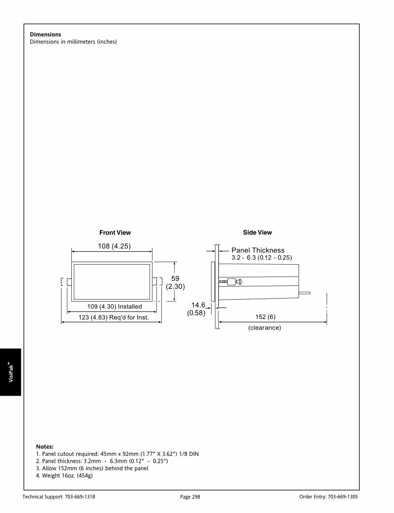
Vis
iPak
™
Page 298Technical Support: 703-669-1318 Order Entry: 703-669-1305
DimensionsDimensions in millimeters (inches)
Notes:1. Panel cutout required: 45mm x 92mm (1.77" X 3.62") 1/8 DIN2. Panel thickness: 3.2mm - 6.3mm (0.12" - 0.25")3. Allow 152mm (6 inches) behind the panel4. Weight 16oz. (454g)

VisiP
ak™
Page 299Technical Support: 703-669-1318 Order Entry: 703-669-1305
The jumper array is located at the rear of the instrument, next to the screwternminal block. Remove jumper J3 (if installed) to disable the Lockoutfeature.
4-20mA output signal powered by an external 24V power supply.4-20mA output signal powered by the V430’s internal 24V power supply.
Use a diode with a reverse breakdown voltage two to three times thecircuit voltage and forward current at least as large as the loadcurrent.
Choose R and C as followsR: 0.5 to 1 Ohm for each volt across the contactsC: 0.5 to 1 microfarad for each 1A through closed contacts
Notes:1. Use connectors rated for 240 VAC.
2. Snubbers may affect load release time of solenoid loads, check toconfirm proper operational mode.
3. Install the RC network at the V430’s relay screw terminals. An RC networkcan also be installed across the load. Experiment for best results.
Switching Inductive LoadsTo minimize the effect of electrical noise and also prolong the life ofthe relay contacts, the use of a suppression network is recommended.RC networks can be purchased as an assembly. Refer to the followingcircuits for RC network assembly and installation:
Notes:1. Alarm acknowledgment terminals (ACK and COM) are located on the meter main board.
2. In the alarm condition, the NC contact is connected to common in the failsafe mode.
3. J2 Terminals are for Total relays and J3 Terminals are for Rate relays.
PIN Function Screw Terminal Block1 Transmitter J12 Transmitter J1
1 Relay #1 Common J22 Relay #1 NC J23 Relay #1 NO J24 Relay #2 Common J25 Relay #2 NC J26 Relay #2 NO J2
Input Signal Jumper 1: Jumper 2:1-5, 0-5 V OFF OFF0-10V OFF ON0-20, 4-20mA ON OFF
Wiring Instructions1. All field connections to be made with insulated copper wire, either solid orstranded. Tighten all screw terminals to 7 in/lb. (0.8Nm). Strip length = 1/4 in(7mm). DO NOT pre-treat wire with solder.
2. Terminals L & L: Use AWG #12-18 wire, 600 volt, 60°C. Only one wire to eachterminal.
3. Terminals P+, P-, S-, S+, COM, RST & ACK: Use AWG #12-22 wire, 150 volt,60°C. If using AWG #20 or smaller wire, up to 2 wires can be connected toeach terminal. If using AWG #18 or larger wire, only 1 wire can be connected toeach terminal.
Terminal Assignments
V430 Wiring DiagramsAnalog Input, Rate Indicator/Totalizer/Batch Controller
AC & DC Loads
Low Voltage DC Loads

Vis
iPak
™
Page 300Technical Support: 703-669-1318 Order Entry: 703-669-1305
Specifications
BASIC METER
Inputs:
Field selectable 4-20mA, 0-20mA, 0-5V, 1-5V, 0-10V
Calibration Range:
4mA (1V) input can be set anywhere inrange of the meter; 20mA (5V) can beset anywhere above or below 4mA (1V) input.
Loop Power:
Isolated, up to 20 mA at 24VDC regulated ±5%,noise less than 10mVpp. Max. loopresistance of 1200 Ohms. Use to powereither external transmitter or 4-20mAoutput signal.
Linear Input Accuracy:
0.05% of calibrated span, ±1 count
Square Root Extraction Accuracy:±0.1% F.S. ±1 count from 10-100% of flow,
±1% F.S. (0-10% flow)
Minimum Input Span:
1.6 mA between points
Input Impedance:
Voltage ranges; greater than 300k OhmsCurrent ranges; 100 Ohms
Display:
6 digit, 0.56" (14.2mm) high efficiency red LED.Rate: 0 to 29,999(0) with selectable extra zero.Total: 0 to 999,999. Automatic lead zero
blanking.
Alternating Display:
Display can be programmed to alternatebetween rate and total every 10 sec.
Power:
115VAC ±10%, 50/60 Hz,10VA
Totalize:r
Calculates total based on rate and fieldprog. multiplier to display total inengineering units.
Total Reset:
Via front panel ENTER button, externalcontact closure at terminals RST andCOM, or automatic via user selectablepreset value #2.
Peak Hold:
Captures the peak rate and displays it viathe front panel ENTER button.
Peak Hold Indication:
Front panel flashing “R” LED
Low Flow Cutoff:
1 count to 100% F.S., user selectable. Todisable low flow cutoff, program cutoffvalue to zero.
Rollover:
Totalizer “rolls over” when display exceeds999,999. Relay status reflects display.
Lockout:
Jumper at rear of instrument restrictsmodification of calibration values.
Temperature/Humidity:
Operating range: 0 to +65°CStorage range: -40 to +85°CRH: 0 to 90%, non-condensing
Front Panel/Enclosure:
NEMA 4X, panel gasket provided/1/8 DIN,
high impact plastic, UL 94V-0
Connections:
Removable screw terminal block
RELAYS (OPTIONAL)
Rating:
2 SPDT (form C); rated 2Amp @ 30VDCor 2Amp @ 250VAC resistive load;
1/14 HP @ 125/250VAC for inductive loads
Ordering InformationSpecify:1. Model Number:
V430-0000 (no options),V430-1000 (2 relays, rate or count)V430-2000 (4-20mA output)V430-3000 (4-20mA and 2 relays, rate or count)
2. Power: 115VAC (standard)
3. Optional Factory Configuration. Specify C620 with the desiredconfiguration information.
Totalizer Presets:
Relays #1 and #2 are assigned to totaland can be programmed anywhere inthe range of the meter; relays tripwhen total exceeds preset value andreset when total is reset to zero. #2preset is user programmable to resettotal to zero when preset value isreached. A delay between 1 and 999seconds can be programmed beforerelays #1 and #2 reset.
Preset Value Tracking:
Relay #1 can be programmed to trip atany point below relay #2 preset value.If relay offset mode is selected, relay#1 will always trip at programmedoffset value before relay #2 trips, eg., ifthe relay offset is set at 10 then relay#1 will trip at 10 counts before relay #2.
Rate Relays:
#3 & #4 assigned to rate, any combinationof high or low alarms.
Rate Alarm Deadband:
0-100% of full scale, user selectable
TRANSMITTER (OPTIONAL)
Calibration Range:
The transmitter output (4-20mA) can becalibrated so that a 4mA output isproduced for any rate displayed on themeter. The 20mA output must correspondto any rate that is at least 501 countsgreater than or 501 counts less thanthe rate corresponding to 4mA (forexample, 4mA = 0, 20mA = 501). Ifthe span from 4 to 20mA is less than501 counts, an error message will appear.
Output Loop Resistance:
24VDC: 10 Ohms min; 600 Ohms max
35VDC max (ext.): 600 Ohms min; 1k Ohms max
Accuracy:
±0.1% F.S., ±.004mA
Isolation:
500VDC or peak AC, input-to-output or
input/output-to-power line
External Loop Power Supply:
35Vmax

VisiP
ak™
Page 301Technical Support: 703-669-1318 Order Entry: 703-669-1305
DescriptionThe V432 is a versatile, field configurable, 1/8 DIN, RTD andthermocouple input LED indicator. Four visual setpoint alarms areannunciated via individual front panel LEDs and are a standardfeature of the V432. The unit has a front panel NEMA 4X rating.
Two form C relays are available as optional outputs for the first twosetpoints. They can be configured as high or low, failsafe or non-failsafe. Each setpoint has a 100% adjustable deadband (or resetpoint) which can be effectively used in on/off control applicationsor as a latching alarm. An isolated 4-20mA transmitter output isalso available as an option.
The V432 accepts types J, K, T, E, R, and S thermocouples and 100Ohm Pt RTD (0.00385 and 0.00392 alpha curves) and displaystemperature with 1 degree resolution (°F or °C). In addition, typeT thermocouple and the 100 Ohm Pt RTD can be diplayed at 0.1degree resolution.
Field configuration of the input type, alarm function, and analogtransmitter output scaling is simple. The indicator is factory cali-brated to rated accuracy and can be field adjusted as necessary.
A front panel button is used for acknowledgment of alarms. Wiringterminals are also provided for remote alarm acknowledgment.
A lockout jumper is used to limit access to configuration functions.When in the lockout mode, only alarm setpoints and outputscaling functions are displayed and cannot be altered.
ApplicationThe V432 is ideal for indication, control and alarming of processtemperature variables. The unit can be used on heating andcooling systems to maintain the required temperature range,providing on/off control for refrigeration, oven or kiln applica-tions. It can be used as a high or low temperature alarm and thecurrent transmitter output can feed a multi-loop controller forzone furnace applications.
VISIPAKtm
V432Temperature Input, Digital Indicator
Provides a Digital Display of Temperaturefrom RTD and Thermocouple Inputs
Field Configurable Input Accepts Pt100 Ohm RTDsand J, K, T, E, R & S Type Thermocouples
RTD Display to 1° or 0.1° 4 Visual Alarm Points with Front Panel LED Status
V432-0000 (no options)
V432-1000 (2 relay outputs)
V432-2000 (4-20mA outputs)
V432-3000 (4-20mA and 2 relay outputs)
NEMA 4 Front Panel Optional 2 Relay Output & 4-20mA Transmitter Output 115VAC Power Supply std; 24VDC optional
In all applications, the highly visible 0.56 inch, eight-segment LEDsprovide a clear reading of the measured temperature. Con-structed to withstand corrosion and moisture, the NEMA 4X ratedV432 can be used in most industrial control panels under harshenvironmental conditions.
The field configurable design and wide selection of input andoutput types makes the V432 an excellent choice as a standardtemperature display and alarm.
epyTrosneS egnaR ycaruccA
elpuocomrehTJepyTF°2831ot823-
C°057ot002-F°4.1-/+C°8.0-/+
elpuocomrehTKepyTF°8942ot823-C°0331ot002-
F°7.1-/+C°9.0-/+
elpuocomrehTTepyTF°067ot033-C°404ot002-
*F°5.1-/+**C°8.0-/+
elpuocomrehTEepyTF°2381ot823-C°0001ot002-
F°4.1-/+C°8.0-/+
elpuocomrehTRepyTF°3123ot23
C°7671ot0F°8.4-/+C°7.2-/+
elpuocomrehTSepyTF°4123ot04
C°8671ot4F°7.5-/+C°9.2-/+
DTRmhO001F°2831ot823-
C°057ot002-F°6.0-/+C°3.0-/+
F°6.4-/+siF°133-otF°054-morfycaruccaehT*C°6.2-/+siC°102-otC°362-morfycaruccaehT**
Table 1: V432 Input Ranges

Vis
iPak
™
Page 302Technical Support: 703-669-1318 Order Entry: 703-669-1305
DimensionsDimensions in millimeters (inches)
Notes:1. Panel cutout required: 45mm x 92mm (1.77" X 3.62") 1/8 DIN2. Panel thickness: 3.2mm - 6.3mm (0.12" - 0.25")3. Allow 152mm (6 inches) behind the panel4. Weight 16oz. (454g)
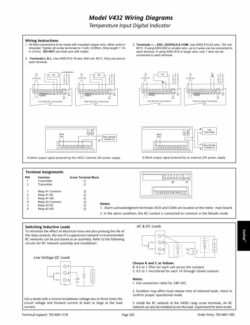
VisiP
ak™
Page 303Technical Support: 703-669-1318 Order Entry: 703-669-1305
Model V432 Wiring DiagramsTemperature Input Digital Indicator
Use a diode with a reverse breakdown voltage two to three times thecircuit voltage and forward current at least as large as the loadcurrent.
Choose R and C as followsR: 0.5 to 1 Ohm for each volt across the contactsC: 0.5 to 1 microfarad for each 1A through closed contacts
Notes:1. Use connectors rated for 240 VAC.
2. Snubbers may affect load release time of solenoid loads, check toconfirm proper operational mode.
3. Install the RC network at the V430’s relay screw terminals. An RCnetwork can also be installed across the load. Experiment for best results.
Switching Inductive LoadsTo minimize the effect of electrical noise and also prolong the life ofthe relay contacts, the use of a suppression network is recommended.RC networks can be purchased as an assembly. Refer to the followingcircuits for RC network assembly and installation:
AC & DC Loads
Low Voltage DC Loads
Notes:1. Alarm acknowledgment terminals (ACK and COM) are located on the meter main board.
2. In the alarm condition, the NC contact is connected to common in the failsafe mode.
PIN Function Screw Terminal Block1 Transmitter J12 Transmitter J1
1 Relay #1 Common J22 Relay #1 NC J23 Relay #1 NO J24 Relay #2 Common J25 Relay #2 NC J26 Relay #2 NO J2
Terminal Assignments
4-20mA output signal powered by an external 24V power supply.4-20mA output signal powered by the V432’s internal 24V power supply.
Wiring Instructions1. All field connections to be made with insulated copper wire, either solid or
stranded. Tighten all screw terminals to 7 in/lb. (0.8Nm). Strip length = 1/4
in (7mm). DO NOT pre-treat wire with solder.
2. Terminals L & L: Use AWG #12-18 wire, 600 volt, 60°C. Only one wire to
each terminal.
3. Terminals +, -, EXC, ACK/HLD & COM: Use AWG #12-22 wire, 150 volt,
60°C. If using AWG #20 or smaller wire, up to 2 wires can be connected to
each terminal. If using AWG #18 or larger wire, only 1 wire can be
connected to each terminal.

Vis
iPak
™
Page 304Technical Support: 703-669-1318 Order Entry: 703-669-1305
Specifications
BASIC METER
Inputs:
Field selectable, type J, K, T, E, R, or Sthermocouples with 1° resolution; type Tto 0.1°; 100 Ohm platinum RTD (0.00385or 0.00392 curve) to 1° or 0.1° resolution.
Display:
14.2mm (0.56") high efficiency red LEDs,4-1/2digits. "F" or "C" can be switched onto indicate Fahrenheit or Celsius.
Cold Junction Reference:
Automatic, fixed, no user calibration needed.
T/C Open Indication:
Open thermocouple circuit indicated bydisplay flashing ‘OPEN’. Relays will remainin same state prior to open T/C condition.
Hold Reading:
Connect switch to ACK/HLD and COMterminals, also connect JP1 HLD pins.
Accuracy:
See Input Ranges table.
Lockout:
Jumper JP2 at rear of instrument restrictsmodification of calibration values.
Input Impedance:
>100k Ohms
Ordering InformationSpecify:1. Model number:
V432-0000 (no options)V432-1000 (2 relays)V432-2000 (4-20mA output)V432-3000 (4-20mA and 2 relays)
2. Power: 115VAC (standard),18-36VDC (optional)
3. Optional Factory Configuration, specify C620 with the desiredconfiguration information.
Power:
115 VAC ±10%, 50/60Hz, 10VA (std)
18-36VDC (optional)
Common/Normal Mode Rejection:
110dB/64dB at 50-60Hz
Temperature/Humidity:
Operating range: 0 to 65°CStorage range: -40 to 85°CRH: 0 to 90%, non-condensing
Front Panel/Enclosure:
NEMA 4X, panel gasket provided/1/8 DIN,high impact plastic, UL 94V-0
Connections:
Removable screw terminal block (provided),accepts 24 to 12 AWG.
Alarm Points:
4, any combination of high or low alarms,front panel LED indicated.
Alarm Deadband:
0-100% of full scale, user selectable.
RELAYS (OPTIONAL)
Rating:
2 SPDT (form C); rated 2Amp @ 30VDC or2Amp @ 250 VAC resistive load; 1/14 Hp@ 125/250 VAC for inductive loads.
TRANSMITTER (OPTIONAL)
Calibration Range:
The transmitter output (4-20mA) can becalibrated so that a 4mA output isproduced for any number displayed onthe meter. The 20mA output cancorrespond to any other (larger orsmaller) number displayed on the meter.However, best results are obtained with a501 (minimum) count difference betweenthe 4 & 20mA output displays.
Loop Power:
Isolated, up to 20mA at 24VDC regulated± 5%, noise less than 10mV p-p max. Topower the 4-20mA output signal.
Output Loop Resistance:
Between 10 and 600 Ohms when usingthe built in 24 Volt power supply.Between 600 and 1000 Ohms when usingan external 35 Volt power supply.
External Loop Power Supply:
35V max.
Accuracy:
± 0.1% F.S., ± .004mA
Isolation:
500VDC or peak AC, input-to-output
or input/output-to-power line.

VisiP
ak™
Page 305Technical Support: 703-669-1318 Order Entry: 703-669-1305
DescriptionThe V434 is a 1/8 DIN, field configurable, bridge and strain gaugeinput LED indicator. Four visual setpoint alarms are annunciatedvia individual front panel LEDs and are a standard feature of theV434. Programmable tare and peak hold functions are incorpo-rated for weight and pressure measurement applications. The unithas a front panel NEMA 4X rating.
Two form C relays are available as optional outputs for the first twosetpoints. They can be configured as high or low, failsafe or non-failsafe. Each setpoint has a 100% adjustable deadband (or resetpoint) which can be effectively used in on/off control applicationsor as a latching alarm. An isolated 4-20mA transmitter output isalso available as an option.
The V434 accepts 0-30mV, 0-200mV, +15mV, and + 100mV inputs,which can be scaled as desired between +199990 with a program-mable decimal point (minimum span is 501 counts). The unitincludes an isolated, field configurable 5V, 10V or 24V excitationsource to power a bridge or strain gauge, or the optional two-wiretransmitter output.
Field configuration of the input range, alarm function, and analogtransmitter output scaling is simple. The indicator is factory cali-brated to rated accuracy and can be field adjusted as necessary.
The programmable tare function can accept a measured value byusing the TARE button or a tare value can be input via the display,using the ENTER button. Terminals are provided for remote alarmacknowledgment.
A lockout jumper is used to limit access to configuration functions.When the lockout mode is enabled, only tare, peak, alarmsetpoints and output scaling functions are displayed and, exceptfor the tare, cannot be altered without moving the jumper.
VISIPAKtm
V434Bridge/Strain Gauge Input, Digital Indicator
Provides a Digital Display fromBridge & Strain Gauge mV Inputs
Field Configurable Input Accepts 0-30mV, 0-200mV,+ 15mV and +100mV
Field Configurable Excitation Source 5V, 10V & 24VDC 4-1/2 Digit Display for up to +199990 Count Spans
V434-0000 (no options)
V434-1000 (2 relay outputs)
V434-2000 (4-20mA output)
V434-3000 (4-20mA and 2 relay outputs)
4 Visual Alarm Points with Front Panel LED Status NEMA 4 Front Panel Optional 2 Relay Output & 4-20mA Transmitter Output Programmable Tare and Peak Hold Functions
ApplicationThe V434 is ideal for indication, control and alarming of any bridgeor strain gauge signals. It can be used to display whatever processmeasurement is required for weight, pressure, tension and com-pression applications.
The tare function and setpoint alarms can be used for weightcontrol on a scale; tare function can zero the container weight andthe setpoints can be used for fast and slow fill rates. Alarms areuseful as annunciators for a critical process variable such asexcessive pressure in a vessel or weight on a conveyor.
An 11 point-pair custom curve can be user entered for non-linearsensors.
In all applications, the highly visible 0.56 inch, eight-segment LEDsprovide a clear reading of the measured variable. Constructed towithstand corrosion and moisture, the NEMA 4X rated V434 canbe used in most industrial control panels under harsh environ-mental conditions.
The field configurable design and wide selection of input andoutput types makes the V434 an excellent choice as a standardpressure display, weight display and alarm. The versatility of theV434 makes it a cost effective solution.
tupnI napSmuminiM
Vm03ot0 Vm0.1
Vm002ot0 Vm0.5
Vm51ot51- Vm0.1
Vm001ot001- Vm0.5
Table 1: V434 Input Ranges

Vis
iPak
™
Page 306Technical Support: 703-669-1318 Order Entry: 703-669-1305
DimensionsDimensions in millimeters (inches)
Notes:1. Panel cutout required: 45mm x 92mm (1.77" X 3.62") 1/8 DIN2. Panel thickness: 3.2mm - 6.3mm (0.12" - 0.25")3. Allow 152mm (6 inches) behind the panel4. Weight 16oz. (454g)
Set the configuration Switch (SW1) for the desired Input and Excitation perthe chart below. The Configuration Switch is located at the rear of theinstrument next to the screw terminal block. Set switch 8 to the OFFposition to disable the Lockout feature.
noitcnuF1WShctiwSnoitarugifnoC
8 7 6 5 4 3 2 1
noitaticxElanretnIhtiwcirtemoitaR NO NO
noitaticxElanretxEhtiwcirtemoitaR FFO FFO
tupnIVm03ot0 NO FFO
tupnIVm001ot0 FFO FFO
tupnIVm51-/+ NO NO
tupnIVm001-/+ FFO NO
noitaticxECDV42 FFO FFO NO
noitaticxECDV01 NO FFO FFO
noitaticxECDV5 FFO NO FFO
serutaeFtuokcoL NO
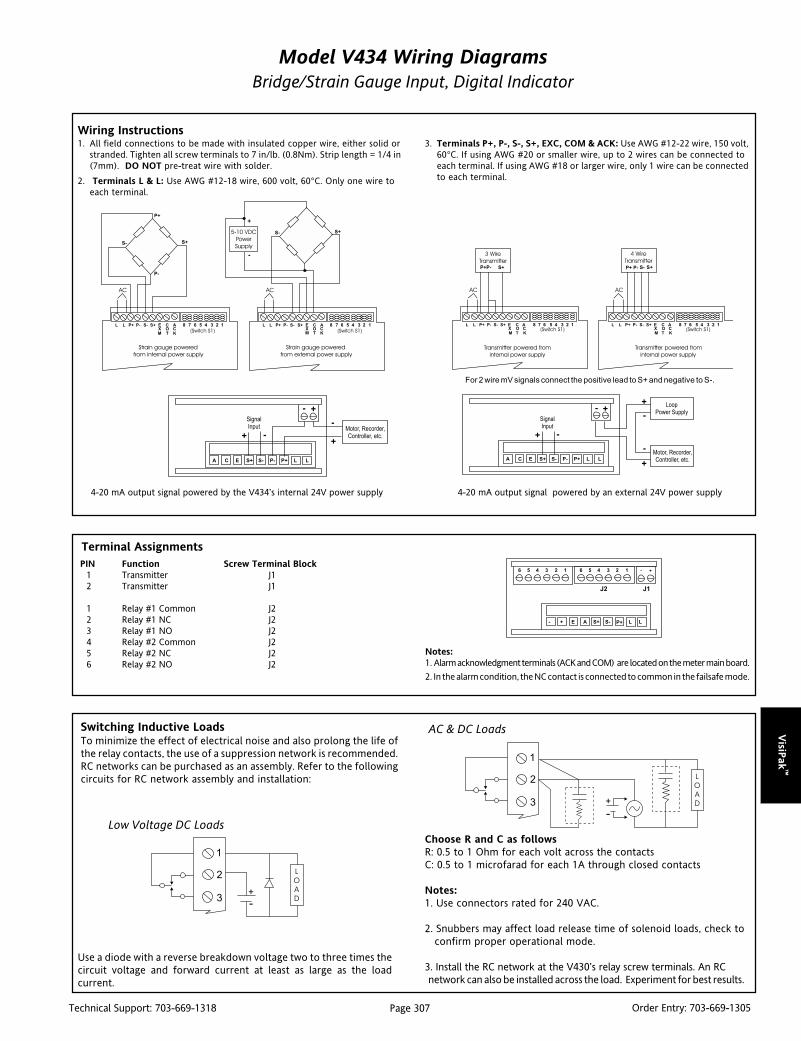
VisiP
ak™
Page 307Technical Support: 703-669-1318 Order Entry: 703-669-1305
Model V434 Wiring DiagramsBridge/Strain Gauge Input, Digital Indicator
4-20 mA output signal powered by the V434’s internal 24V power supply 4-20 mA output signal powered by an external 24V power supply
For 2 wire mV signals connect the positive lead to S+ and negative to S-.
Use a diode with a reverse breakdown voltage two to three times thecircuit voltage and forward current at least as large as the loadcurrent.
Choose R and C as followsR: 0.5 to 1 Ohm for each volt across the contactsC: 0.5 to 1 microfarad for each 1A through closed contacts
Notes:1. Use connectors rated for 240 VAC.
2. Snubbers may affect load release time of solenoid loads, check to confirm proper operational mode.
3. Install the RC network at the V430’s relay screw terminals. An RC network can also be installed across the load. Experiment for best results.
Switching Inductive LoadsTo minimize the effect of electrical noise and also prolong the life ofthe relay contacts, the use of a suppression network is recommended.RC networks can be purchased as an assembly. Refer to the followingcircuits for RC network assembly and installation:
AC & DC Loads
Low Voltage DC Loads
Notes:1. Alarm acknowledgment terminals (ACK and COM) are located on the meter main board.
2. In the alarm condition, the NC contact is connected to common in the failsafe mode.
PIN Function Screw Terminal Block1 Transmitter J12 Transmitter J1
1 Relay #1 Common J22 Relay #1 NC J23 Relay #1 NO J24 Relay #2 Common J25 Relay #2 NC J26 Relay #2 NO J2
Terminal Assignments
Wiring Instructions1. All field connections to be made with insulated copper wire, either solid or
stranded. Tighten all screw terminals to 7 in/lb. (0.8Nm). Strip length = 1/4 in(7mm). DO NOT pre-treat wire with solder.
2. Terminals L & L: Use AWG #12-18 wire, 600 volt, 60°C. Only one wire toeach terminal.
3. Terminals P+, P-, S-, S+, EXC, COM & ACK: Use AWG #12-22 wire, 150 volt,60°C. If using AWG #20 or smaller wire, up to 2 wires can be connected toeach terminal. If using AWG #18 or larger wire, only 1 wire can be connectedto each terminal.

Vis
iPak
™
Page 308Technical Support: 703-669-1318 Order Entry: 703-669-1305
Specifications
BASIC METER
Inputs:
Field selectable: 0-30mV, 0-200mV,
+ 15mV, and +100mV
Ratiometric Compensation:
Deviation less than 0.1% of full scale, +1count, with +10% variation in excitationvoltage.
Display:
0.56" (14.2mm) high efficiency red LEDs,
4 1/2 digits + extra zero can be switchedon to display +19999(0). Leading zerosblanked.
Calibration Range:
Minimum (0mV) input can be setanywhere in range of the meter.Maximum (200mV) can be set anywhereabove or below the minimum (0mV) input.
Isolated Power Supply:
Selectable 5VDC or 10VDC, + 5% @50mA, 24VDC, + 5% @ 20mA. Noise lessthan 10mVpp. Available for either signalinput or 4-20mA output option (notboth). Max. loop resistance of 1200 Ohms.
Peak Hold:
Captures the peak reading and displays itvia front panel ENTER button.
Tare:
Capture - Sets current display to zero viafront panel TARE button. Programmable- Automatically sets TARE to a preset value.
Accuracy:
0.05% of calibrated span, +1 count.
Zero Stability:
0.5mV/°C
Span Stability:
0.005% of full scale /°CSensitivity:
Max 0.6mV
Lockout:
Switch 8 at rear of instrument restrictsmodification of calibrated values.
Input Impedance:
20k Ohms
Power:
115 VAC ±10%, 50/60Hz, 10VA
Isolation:
500VDC or peak AC, input to output
or input/output to power line.
Common/Normal Mode Rejection:120dB/60dB at 60Hz
Overload Protection:
30VDC or VAC across inputs or input to gnd
Temperature/Humidity:
Operating range: 0 to 65°CStorage range: -40 to 85°CRH: 0 to 90%, non-condensing
Front Panel/Enclosure:
NEMA 4X, panel gasket provided/1/8 DIN,high impact plastic, UL 94V-0.
Connections:
Removable screw terminal block (provided),accepts 24 to 12 AWG.
Alarm Points:
4, any combination of high or low alarms,front panel LED, Indication
Alarm Deadband:
0-100% of full scale, user selectable.
Ordering InformationSpecify:1. Model Number:
V434-0000 (no options)V434-1000 (2 relays)V434-2000 (4-20mA output)V434-3000 (4-20mA and 2 relays)
2. Power:115VAC (standard),
3. Optional Factory Configuration, specify C620 with the desiredconfiguration information.
11 Point Linearization:
See Input Spans table. Example, min. spanfor a 11 point 30mV calibration is 1mVbetween inputs.
RELAYS (OPTIONAL)
Rating:
2 SPDT (form C); rated 2Amp @ 30VDC or
2 Amp @ 250VAC resistive load; 1/14 HP@ 125/250VAC for inductive loads.
TRANSMITTER (OPTIONAL)
Calibration Range:
The transmitter output (4-20mA) can becalibrated so that a 4mA output isproduced for any number displayed onthe meter. The 20mA output mustcorrespond to any rate that is at least 501counts greater than or 501 counts lessthan the rate corresponding to 4mA (forexample, 4mA = 0, 20mA = 501). If thespan from 4 to 20mA is less than 501counts, an error message will appear.
Loop Power:
Isolated, up to 20mA at 24VDC regulated± 5%, noise less than 10 mV p-p. Use topower the 4-20mA output signal.
Output Loop Resistance:
1500 Ohms max. using external looppower supply. 500 Ohms max. using built-inloop-power supply.
External Loop Power Supply:
35V max.
Accuracy:
± 0.1% F.S., ± .004mA

VisiP
ak™
Page 309Technical Support: 703-669-1318 Order Entry: 703-669-1305
DescriptionThe V437 is a 1/8 DIN programmable, frequency or pulse input LEDindicator which displays either a totalized count or the pulse rate,complete with scaling k-factor function.
The programmable k-factor for pulse scaling ensures that thedisplay can be configured to show the preferred engineering units(e.g Gallons, GPM, Barrels, BPD, ppm, Hz, etc.) as they relate to thenumber of pulses. Additionally, peak-hold, low flow cut-off, and11 point linearization functions are also included.
Four visual setpoint alarms are annunciated via individual front panelLEDs and are included as standard on the unit. Two can be pro-grammed to alarm on rate limits and two can be programmed toalarm on a specific count or total, complete with delays and offsets.
Two form C relays are available as optional outputs for thesetpoints; either two for rate or two for totalized count. The ratealarms can be configured as high or low, failsafe or non-failsafe.Each rate setpoint has a 100% adjustable deadband (or reset point)which can be effectively used in on/off control applications or asa latching alarm.
The totalized count alarms can be configured to trip at an absolutecount or one can be programmed to trip at an offset count (e.g.,setpoint #1 trips 10 counts before setpoint #2) for applicationswherebatch size varies. Additionally, the Priority Batch Programmingfeature allows quick access to the setpoints by holding the ENTERbutton down for three seconds.
An isolated 4-20mA transmitter output that follows the rate inputis also available as an option, with or without the two relays.
The V437 accepts pulse, open collector, switch closure, TTL orsquare wave frequency inputs and displays the rate or the totalizedcount. The display can alternate between rate and count every tenseconds. There is an isolated, field configurable 12V or 24Vexcitation source to power open collector and contact closuretransducer inputs.
VISIPAKtm
V437Frequency/Pulse Input, Rate Indicator/
Totalizer/Batch Controller
Provides a Digital Display of Rate or Totalized Countfrom a Frequency or Pulse Input
Field Configurable Input Accepts Pulse, OpenColletor, Switch Closure, TTL or Square Wave
6 Digit Display for Counts up to +999999 4 Visual Alarm Points with Front Panel LED Status Programmable 11 Point Linearization and Peak
Hold Functions
V437-0000 (no options)
V437-1000 (2 relays, rate or count)
V437-2000 (4-20mA output)
V437-3000 (4-20mA and 2 relays, rate or count)
NEMA 4 Front Panel Isolated 12V and 24V Excitation Source Optional 2 Relay Output & 4-20mA Transmitter
Output
Field configuration of the input range, alarm function, and analogtransmitter output scaling is simple. The indicator is factory cali-brated to rated accuracy and can be field adjusted as necessary.
Terminals are provided for remote alarm acknowledgment andremote count reset.
A lockout jumper is used to limit access to the configurationfunctions. The unit can be programmed to display only thosevariables needed for operator use.
ApplicationThe V437 is ideal for indication, control and alarming of any pulseor frequency signals. It can be scaled to display whatever processflow, rate, speed or counted quantity is desired.
The peak hold and setpoint alarms can be used for flow andcontainer filling applications. Alarms are useful as annunciatorsfor critical process variables such as excessive motor speed or lowcoolant flow.
The highly visible 0.56 inch, eight-segment LEDs provide a clearreading of the measured variable. Constructed to withstand corro-sion and moisture, the NEMA 4X rated V437 can be used in mostindustrial control panels under harsh environmental conditions.
The field configurable design and wide selection of scaling andcontrol functions makes the V437 an excellent choice as a standardtotalizer, batch controller, rate indicator and alarm. The versatilityof the V437 makes it a cost effective solution since it incorporatesmany indicator and controller functions in a single display.

Vis
iPak
™
Page 310Technical Support: 703-669-1318 Order Entry: 703-669-1305
Program the jumper selection array and switch S1 for desired input andexcitation per Table 1 below. The jumper array is located at the rear of theinstrument, next to the screw terminal block. Remove jumper JP2 todisable lockout feature.
DimensionsDimensions in millimeters (inches)
Notes:1. Panel cutout required: 45mm x 92mm (1.77" X 3.62") 1/8 DIN2. Panel thickness: 3.2mm - 6.3mm (0.12" - 0.25")3. Allow 152mm (6 inches) behind the panel4. Weight 16oz. (454g)
noitcnuF
repmuJ
1PJ 2PJ5PJ)2-1(
5PJ)3-2(
1S
tupnIesluPVm FFO NO Vm
tupnIesluPV5 NO FFO V
tupnIesluPV21 FFO NO V
noitaticxECDV21 NO
noitaticxECDV42 FFO
serutaeFtuokcoL NO
Table 1: Jumper Settings

VisiP
ak™
Page 311Technical Support: 703-669-1318 Order Entry: 703-669-1305
Notes:1. External alarm acknowledgment terminals (ACK and COM) are located on the meter main board.2. In the alarm condition, the NC contact is connected to common in the failsafe mode
4-20mA output signal powered from an external 24V power supply.4-20mA output signal powered by internal 24V power supply.
Use a diode with a reverse breakdown voltage two to three times thecircuit voltage and forward current at least as large as the loadcurrent.
Choose R and C as followsR: 0.5 to 1 Ohm for each volt across the contactsC: 0.5 to 1 microfarad for each 1A through closed contacts
Notes:1. Use connectors rated for 240 VAC.
2. Snubbers may affect load release time of solenoid loads, check toconfirm proper operational mode.
3. Install the RC network at the V437’s relay screw terminals. An RCnetwork can also be installed across the load. Experiment for best results.
Switching Inductive LoadsTo minimize the effect of electrical noise and also prolong the life ofthe relay contacts, the use of a suppression network is recommended.RC networks can be purchased as an assembly. Refer to the followingcircuits for RC network assembly and installation:
AC & DC Loads
Low Voltage DC Loads
Model V437 Wiring DiagramsFrequency/Pulse Input, Rate Indicator/Totalizer/Batch Controller
PIN Function Screw Terminal Block1 Transmitter J12 Transmitter J1
1 Relay #1 Common J22 Relay #1 NC J23 Relay #1 NO J24 Relay #2 Common J25 Relay #2 NC J26 Relay #2 NO J2
Terminal Assignments
Wiring Instructions1. All field connections to be made with insulated copper wire, either solid or
stranded. Tighten all screw terminals to 7 in/lb. (0.8Nm). Strip length = 1/4in (7mm). DO NOT pre-treat wire with solder.
2. Terminals L & L: Use AWG #12-18 wire, 600 volt, 60°C. Only one wire toeach terminal.
3. Terminals P+, P-, S-, S+, COM, RST & ACK: Use AWG #12-22 wire, 150 volt,60°C. If using AWG #20 or smaller wire, up to 2 wires can be connected toeach terminal. If using AWG #18 or larger wire, only 1 wire can be connectedto each terminal.

Vis
iPak
™
Page 312Technical Support: 703-669-1318 Order Entry: 703-669-1305
Specifications
BASIC METER
Frequency Inputs:
Field selectable: Pulse or Square Wave 0-5Vor 0-12V @ 30kHz;TTL; Open Collector4.7k Ohms pull up to 12V 30kHz; SwitchContact 4.7k Ohms pull up to 12V @40 Hz.1Hz minimum input
Low Voltage/Mag Pickup (Isolated):Sensitivity: 125mV p-p
Hysteresis: 30mV
Calibration:
Can be calibrated using K-factor scaling,internal calibration or by externalcalibration signal
Output Power:
Field selectable, isolated, 12VDC @ 50mAfor sensor supply, or 24VDC @ 20mAregulated ±5%, noise less than 10mVpp.Max. loop resistance of 1200 Ohms
Accuracy:
±0.1% of full scale
Minimum input Span:
2.0Hz between points
Display:
6 digit, 0.56" (14.2mm) high efficiency red LED.Rate: 0 to 29,999(0) with selectable extrazero. Total: 0 to 999,999.
Automatic lead zero blanking
Alternating Display:
Display can be programmed to alternatebetween rate and total every 10 seconds.
Power:
115VAC ±10%, 50/60Hz,10VA
Totalizer:
Calculates total based on rate and fieldprog.multiplier to display total in any
engineering units
Total Reset:
Via front panel ENTER button, externalcontact closure at terminals RST andCOM, automatically via user selectablepreset value #2.
Peak Hold:
Captures the peak rate and displays it viathe front panel ENTER button
Peak Hold Indication:
Front panel flashing “R” LED.
Low Flow Cutoff:
1 count to 100% F.S., user selectable. Todisable low flow cutoff, program cutoffvalue to zero
Roll Over :
Totalizer “rolls over” when display exceeds999,999 or preset value. Relay statusreflects display.
Lockout:
Jumper at rear of instrument restrictsmodification of calibration values
Temperature/Humidity:
Operating range: 0 to +65°CStorage range: -40 to +85°CRH: 0 to 90%, non-condensing
Front Panel/Enclosure:
NEMA 4X, panel gasket provided1/8 DIN,high impact plastic, UL 94V-0
Connections:
Removable screw terminal block (provided)
Input Impedance:
Pulse Input: Greater than 300k ohms @1kHz Open Collector/ Switch Input: 4.7kOhms pull-up resistor to 12V
RELAYS (OPTIONAL)
Rating:
2 SPDT (form C); rated 2Amp @ 30VDC or
2 Amp @ 250VAC resistive load; 1/14 HP@ 125/250VAC for inductive loads
Totalizer Presets:
Relays #1 and #2 are assigned to total orrate and can be programmed anywhere inthe range of the meter; relays trip whentotal exceeds preset value and reset whentotal is reset to zero. #2 preset is userprogrammable to reset total to zero whenpreset value is reached. A delay of between1 and 999 seconds can be programmedbefore relays #1 and #2 reset.
Ordering InformationSpecify:1. Model number:
V437-0000 (no options)V437-1000 (2 relays, rate or count)V437-2000 (4-20mA output)V437-3000 (4-20mA and 2 relays, rate or count)
2. Power: 115VAC (standard)3. Optional Factory Configuration, specify C620 with the desired
configuration information.
Preset Value Tracking:
Relay #1 can be programmed to trip atany point below relay #2 preset value. Ifrelay offset mode is selected relay #1 willalways trip at a programmed offset valuebefore relay #2 trips, e.g., if the relayoffset is set at 10 then relay #1 will trip at10 counts before relay #2.
TRANSMITTER (OPTIONAL)
Calibration Range:
The transmitter output (4-20mA) can becalibrated so that a 4mA output isproduced for any rate displayed on themeter. The 20mA output can correspondto any other (larger or smaller) numberdisplayed on the meter. However, bestresults are obtained with a 501 minimumcount difference between the 4 & 20mAoutput displays.
Output Loop Resistance:
24VDC, 10 Ohms min. 500 Ohms max.;
35VDC max (ext.), 600 Ohms min. 1k Ohms max.
Accuracy:
±0.1% F.S., ±.004mA
Isolation:
500VDC or peak AC, input-to-output or
input/output-to-powerline
External Loop Power Supply:
35V max

VisiP
ak™
Page 313Technical Support: 703-669-1318 Order Entry: 703-669-1305
DescriptionThe V438 is a versatile, field configurable, DC current and voltageinput LED indicator. The unit provides a NEMA 4X water tight frontpanel that fits 1/8 DIN cutouts. Four visual setpoint alarms areannunciated via individual front panel LEDs and are a standardfeature of the indicator.
Two form C relays are available as optional outputs for the first twosetpoints. They can be configured as high or low, failsafe or non-failsafe. Each setpoint has a 100% adjustable deadband (or resetpoint) which can be effectively used in on/off control applications,or as latching alarms. An isolated 4-20mA transmitter output isalso available as an option.
The V438 accepts 4-20mA, 1-5V, 0-5V and 0-10V inputs which canbe scaled as required between + 199990 (with a minimum span of501 counts). An isolated 24V excitation source is included topower a two-wire transmitter or transducer.
Field configuration of the input range, alarm function, and analogtransmitter output scaling is simple. The indicator is factorycalibrated to rated accuracy but can be field adjusted as necessary.
Latched alarms can be acknowledged via a front panel button or bywiring to the terminals provided for remote alarm acknowledgment.
A lockout jumper is used to limit access to configuration functions.With the lockout mode enabled, only alarm setpoints and outputscaling functions are displayed and cannot be altered without movingthe jumper. When in the lockout mode, the unit can be programmedto display only those variables required for operator use.
VISIPAKtm
V438DC Input Digital Indicator
Provides a Digital Display of Process Variablesfrom DC Voltage and Current Inputs
Field Configurable Input 4-20mA, 1-5V, 0-5V& 0-10V 4-1/2 Digit Display for +199990 Count Spans 4 Visual Alarm Points with Front Panel LED Status Optional 2 Relay Output & 4-20mA Transmitter
Output
V438-0000-1 (Indicator)
V438-1000-1 (2 relay outs)
V438-2000-1 (4-20mA out)
V438-3000-1 (4-20mA & 2 relay outs)
NEMA 4 Front Panel Isolated 24VDC Excitation for 2-Wire Transmitter
Inputs or Optional 4-20mA Output 11 Point Linearization & Square Root - Curve Fitting
ApplicationThe V438 is ideal for indication, control and alarming of processvariables. It can be used to display whatever process variable isrepresented by the dc input signal: level, flow, temperature,pressure, speed, weight, etc.
Built-in linearization functions allow users to program the unit tosolve non-linear equations, such as the volume of material in ahorizontal cylindrical tank from the level signal, or linear flow fromthe square root of the differential pressure across an orifice plate.
The setpoint alarms can be used for level control on a tank in whichthe low setpoint starts the filling process and the high setpointstops it. Alarms are also useful as annunciators, warning of a criticalprocess variable.
In all applications, the highly visible 0.56 inch, eight-segment LEDsprovide a clear reading of the measured variable. Constructed towithstand corrosion and moisture, the NEMA 4X rated V438 canbe used in most industrial control panels, under harsh environ-mental conditions.
The field configurable design and wide selection of input andoutput types makes the V438 an excellent choice as a standardprocess meter and alarm.

Vis
iPak
™
Page 314Technical Support: 703-669-1318 Order Entry: 703-669-1305
Notes:1. Panel cutout required: 45mm x 92mm (1.77" X 3.62") 1/8 DIN2. Panel thickness: 3.2mm - 6.3mm (0.12" - 0.25")3. Allow 152mm (6 inches) behind the panel4. Weight 16oz. (454g)
Table 1: V438 Input Spans
tupnI napSmuminiM
V5ot0 V61.0
V01ot0 V23.0
Am02ot4 Am6.1
tnioP11noitaziraeniL noitaziraeniL noitaziraeniL noitaziraeniL noitaziraeniL
napSmuminiM
V5ot0 )V1-stpfo.oN(/61.0
V01ot0 )V1-stpfo.oN(/23.0
Am02ot4 )Am1-stpfo.oN(/6.1
DimensionsDimensions in millimeters (inches)

VisiP
ak™
Page 315Technical Support: 703-669-1318 Order Entry: 703-669-1305
Model V438 Wiring DiagramsDC Input Digital Indicator
4-20mA output signal being powered by external 24V power supply.4-20mA output signal powered by internal 24V power supply(AC powered units only).
Program the Signal Input Selection Array according to chart below. This jumperarray is located at the rear of the instrument, next to the screw terminal block.Remove J3 to disable lockout feature.
Input Signal Jumper 1: Jumper 2:1-5, 0-5 V OFF OFF
0-10V OFF ON0-20, 4-20mA ON OFF
Use a diode with a reverse breakdown voltage two to three times thecircuit voltage and forward current at least as large as the loadcurrent.
Choose R and C as followsR: 0.5 to 1 Ohm for each volt across the contactsC: 0.5 to 1 microfarad for each 1A through closed contacts
Notes:1. Use connectors rated for 240 VAC.
2. Snubbers may affect load release time of solenoid loads, check toconfirm proper operational mode.
3. Install the RC network at the V438’s relay screw terminals. An RCnetwork can also be installed across the load. Experiment for best results.
Switching Inductive LoadsTo minimize the effect of electrical noise and also prolong the life ofthe relay contacts, the use of a suppression network is recommended.RC networks can be purchased as an assembly. Refer to the followingcircuits for RC network assembly and installation:
AC & DC Loads
Low Voltage DC Loads
Notes:1. External alarm acknowledgment terminals (ACK and COM) are located on the meter main board.2. In the alarm condition, the NC contact is connected to common in the failsafe mode.
PIN Function Screw Terminal Block1 Transmitter J12 Transmitter J1
1 Relay #1 Common J22 Relay #1 NC J23 Relay #1 NO J24 Relay #2 Common J25 Relay #2 NC J26 Relay #2 NO J2
Terminal Assignments
Wiring Instructions1. All field connections to be made with insulated copper wire, either solid or
stranded. Tighten all screw terminals to 7 in/lb. (0.8Nm). Strip length = 1/4in (7mm). DO NOT pre-treat wire with solder.
2. Terminals L & L: Use AWG #12-18 wire, 600 volt, 60°C. Only one wire toeach terminal.
3. Terminals P+, P-, S-, S+, COM, HLD & ACK: Use AWG #12-22 wire, 150 volt,60°C. If using AWG #20 or smaller wire, up to 2 wires can be connected toeach terminal. If using AWG #18 or larger wire, only 1 wire can be connectedto each terminal.

Vis
iPak
™
Page 316Technical Support: 703-669-1318 Order Entry: 703-669-1305
Specifications
BASIC METER
Inputs:
Field selectable:
4 to 20mA, 1 to 5V, 0 to 5V and 0 to 10V
Display:
0.56" (14.2mm) high efficiency red LED,4-1/2 digits + extra zero can be switchedon to display + 19999(0). Programmabledecimal 501 count min.
Calibration:
Can be calibrated using internal calibration(I-CAL) or by external calibration signal(E-CAL).
Calibration Range:
4mA (1V) input can be set anywhere inrange of the meter. 20mA (5V) can beset above or below the 4mA (1V) input.An error message will appear if input 1signal and input 2 signal are too closetogether (see Input Spans table).Corresponds to any range (larger or smaller)
Loop Power (AC powered units only):
Isolated 24VDC @ 20mA regulated + 5%.Noise less than 10mV p-p. Max. loopresistance of 1200 Ohms. Available foreither signal input or 4-20mA outputoption, but not both.
Hold Reading:
Connect terminals HLD and COM.
Accuracy:
0.05% of calibrated span, + 1 count.
Lockout:
Jumper JP3 restricts modification of cal values.
Input Impedance:
Voltage ranges: greater than 300k Ohms.Current ranges: 100 Ohms.
Power:
115 VAC ±10%, 50/60Hz, 10VA.
Isolation:
500VDC or peak AC, input-to-output orinput/output-to-power line.
Common/Normal ModeRejection:110dB/64dB at 50-60Hz
Temperature/Humidity:
Operating range: 0 to 65°CStorage range: -40 to 85°CRH: 0 to 90% RH non-condensing
Front Panel/Enclosure:
NEMA 4X, panel gasket provided/1/8 DIN,high impact plastic, UL 94V-0.
Connections:
Removable screw terminal block (provided),accepts 22 to 12 AWG.
Alarm Points:
4, any combination of high or low alarms,front panel LED indicated
Alarm Deadband:
0-100% of full scale, user selectable.
11 Point Linearizaton:
See minimum Input Spans table. Example,min. span for a 11 point 4-20mAcalibration is 0.16mA between inputs.
SQUARE ROOT EXTRACTION
Accuracy:
+ 0.1% F.S. +1 count from 10 to 100% offlow. Low flow cut-off, 0 to 100% of fullscale, user selectable.
Ordering InformationSpecify:1. Model number:
V438-0000-1 (indicator only)V438-1000-1 (2 relays)V438-2000-1 (4-20mA output)V438-3000-1 (4-20mA and 2 relays)
2. Power: 115VAC (standard)3. Optional Factory Configuration, specify C620 with the desired
configuration information.
RELAYS (OPTIONAL)
Rating:
2 SPDT (form C); rated 2Amp @ 30VDC
or 2 Amp @ 250VAC resistive load; 1/14 HP
@ 125/250VAC for inductive loads.
Deadband:
0-100%, User selectable.
TRANSMITTER (OPTIONAL)
Calibration Range:
The transmitter output (4-20mA) can becalibrated so that a 4mA output isproduced for any rate displayed on themeter. The 20mA output must correspond toany rate that is at least 501 counts greaterthan or 501 counts less than the ratecorresponding to 4mA (for example, 4mA= 0, 20mA = 501). If the span from 4 to20mA is less than 501 counts, an errormessage will appear.
Output Loop Resistance:
Power Supply
24VDC: min 10 Ohms, max 600 Ohms
35VDC (external): min 600 Ohms, max1k Ohms
External Loop Power Supply:
35V max.
Accuracy:
± 0.1% F.S., ± .004mA

Page 317Technical Support: 703-669-1318 Order Entry: 703-669-1305
VisiP
ak™
DescriptionThe V560 is a loop powered digital process indicator which derivesits power entirely from the 4-20mA or 10-50mA signal beingmeasured. No local power is required at the point of measure-ment. A large, 3˚ digit, 0.8" high LCD provides clear visibility andcan be quickly and easily calibrated to the required range. Zerocan be adjusted to ±1999 counts with a span of 100 counts orgreater. The trailing “dummy” zero allows display readings to±19990. The decimal point position is switch selectable and can beindependently set to any of 4 positions (1. 9. 9. 9. 0).
ApplicationThe V560 is useful in any application requiring a wide ranging 3˚digit display from a 4-20mA or 10-50mA current source. Thestandard NEMA 4X housing enables indoor or outdoor installationwith protection from sleet, corrosion, moisture, chemicals, andeven hose directed water or severe condensation. The V560 isideal for displaying process variables such as temperature, pres-sure or flow, in local and remote areas where line power is eitherimpractical or not available. Refer to the V565 High-PerformanceLCD indicator for 1.00 Volt loop-drop and square root selection.
The V560 is FM/CSA approved for intrinsically safe operation inClass I, Division 1, Groups A, B, C, & D hazardous locations whenconnected in accordance with manufacturer’s drawing 790-0024(FM) or 790-0025(CSA).
VISIPAKtm
V560Loop Powered LCD Indicator
Provides a 3-1/2 Digit Liquid Crystal Display (LCD)in Proportion to a 4-20mA Current Input
Eliminates Extra Power Supply LCD Readable from 30ft. Switch Selectable mA Inputs and Decimal Points Field Configurable Wide Ranging Display
V560
NEMA 4 Front Panel Readings to ±19990 FM & CSA Safety Approval for Hazardous Installations
Options/AccessoriesC Conduit housing for internal mounting of T600/T700 series
transmitters; includes external mounting bracket, conformalcoating, T906 mounting plate, screws (pictured above).
EP Explosion-proof housing (Class I, Gr. C&D, Class II, Gr.E,F,G;NEMA 4), LCD board conformal coated, includesT901 and screws.
U Urethane coating of internal circuitry for additionalprotection from corrosive atmospheres.
C620 Factory Calibration, specify desired range.
T901 TransPak mounting plate for option EP.
T906 TransPak mounting plate for option C enclosure.
V860 Conduit mounting kit (option C without LCD main board),includes T906 mounting plate & screws.
V960 Explosion-proof mounting kit, (option EP without LCDmain board), includes T901 & screws.
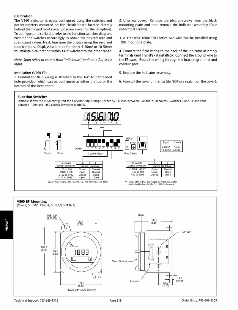
Page 318Technical Support: 703-669-1318 Order Entry: 703-669-1305
Vis
iPak
™
Function SwitchesExample shows the V560 configured for a 4/20mA input range (Switch S2), a span between 950 and 2100 counts (Switches 6 and 7), and zerobetween -1999 and -450 counts (Switches 8 and 9).
1 2 3 4 5 6 7 8 9
V560 EP Mounting(Class I, Gr. C&D, Class II, Gr. E,F,G, NEMA 4)
CalibrationThe V560 indicator is easily configured using the switches andpotentiometers mounted on the circuit board located directlybehind the hinged front cover (or screw cover for the EP option).To configure and calibrate, refer to the function switches diagram.Position the switches accordingly to obtain the desired zero andspan count values. Next, fine tune the display using the zero andspan trimpots. Displays calibrated for either 4-20mA or 10-50mAwill maintain calibration within 1% if switched to the other range.
Note: Span refers to counts from "minimum" and not a full-scaleinput.
Installation (V560 EP)1. Conduit for field wiring is attached to the 3/4" NPT threadedhole provided, which can be configured as either the top or thebottom of the instrument.
2. Unscrew cover. Remove the phillips screws from the blackmounting plate and then remove the indicator assembly (fouroutermost screws).
3. A TransPak T600/T700 series two-wire can be installed usingT901 mounting plate.
4. Connect the field wiring to the back of the indicator assemblyterminals (and TransPak if installed). Connect the ground wire tothe EP case. Route the wiring through the bracket grommet andconduit port.
5. Replace the indicator assembly.
6. Reinstall the cover until snug (do NOT use sealant on the cover).
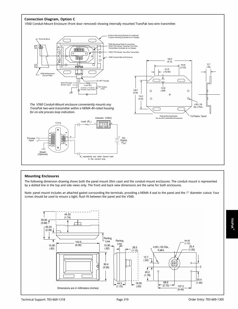
Page 319Technical Support: 703-669-1318 Order Entry: 703-669-1305
VisiP
ak™
V560 Conduit-Mount Enclosure (front door removed) showing internally mounted TransPak two-wire transmitter.
Connection Diagram, Option C
The V560 Conduit-Mount enclosure conveniently mounts anyTransPak two-wire transmitter within a NEMA 4X-rated housingfor on-site process loop indication.
Mounting Enclosures
The following dimension drawing shows both the panel mount (thin case) and the conduit-mount enclosures. The conduit mount is representedby a dotted line in the top and side views only. The front and back view dimensions are the same for both enclosures.
Note: panel mount includes an attached gasket surrounding the terminals, providing a NEMA 4 seal to the panel and the 1" diameter cutout. Fourscrews should be used to ensure a tight, flush fit between the panel and the V560.

Page 320Technical Support: 703-669-1318 Order Entry: 703-669-1305
Vis
iPak
™
Ordering InformationSpecify:1. Model V560, V860, V9602. Options C, EP, U (see text)
Specifications
Input Current Ranges:
4-20mA and 10-50mA, switch selectable
Input Current Limits:
Minimum: 3mA
Maximum: 100mA
Input Voltage Drop:
3.9V maximum at fullscale input
(20mA or 50mA)
Power Consumption:
12mW maximum @ 3mA input
Display Reading Update:
2.5 conversions per second
Readout Display:
Type: 0.8" High Liquid Crystal, 3˚ digit (1999)
Decimal Point Indication: Switch-selectable, four positions: 1.9.9.9.
Dummy Zero: Switch-selectable trailingzero, e.g., 19990
Underrange (belowm - 1999): displays -1
Overrange (above +1999): displays 1
Wide Range Display Calibration:
Zero (4mA/10mA):
Adjustable from -1999 to 1999
Span (20mA/50mA):
Adjustable from 100 to 3998 counts
Accuracy:
±0.1% of span counts, ±1 count
Screws (V560/V560C):
Front Panel: 10-32 brass with corrosionresistant stainless steel plating:
MIL-W-52263C (MR)
Rear Electrical: 6-32 nickel plated brass
Temperature Coefficient:
(Standard Calibration: -10 to 70°C)Zero: ±50ppm/°C, typical, ±100ppm/°C, max.
Span: ±50ppm/°C, typical, ±150ppm/°C, max.
Temperature Range:
Standard: -10 to 70°C (14 to 158°F)
Storage: -55 to 85°C (-67 to 185°F)
Weight:
V560: 14 oz
V560C: 2.2 lbs
V560 EP: 11 lbs
Agency Approval:
FM and CSA approved intrinsically safefor hazardous locations, certificate No.2M2A5.AX. Contact factory forinstallation drawings.

Page 321Technical Support: 703-669-1318 Order Entry: 703-669-1305
VisiP
ak™
DescriptionThe V561 3˚ digit loop-powered meter is perfect for applications inwhich a simple inexpensive display is required but no ac power isavailable. The V561 is supplied in an explosion-proof enclosure. Theloop-powered backlight eliminates the need for additional wiring orbatteries and provides a good view under any lighting conditions.
SetupAll that is required for calibration of the unit is a calibrated currentsource and a screwdriver.
DisassemblyThe removable screw terminal connector is located on the lowercircuit board. To access these input terminals it is necessary toremove the display board from the input signal board. Firstremove the enclosure cover. Next, loosen the 2 screws that holdthe display board to the standoffs. Rotate the display board so thatthe right side comes off the standoff first, and then proceed toremove the display board from both standoffs. Avoid contact ofthe display with rough surfaces. The display board can be discon-nected from the ribbon cable simply by pulling up on the ribboncable connector located above the display.
Connect a 4-20 mA input signal to terminal J5 located on the inputsignal board.
When re-assembling be careful NOT to over-tighten the screws.
InstallationInstallation is accomplished using the two ˚” NPT conduit holesprovided with ˚” NPT fittings. There are no provisions for wallmounting.
VISIPAKtm
V561Loop Powered LCD Indicator
Provides a 3-1/2 Digit Liquid Crystal Display (LCD)in Proportion to a 4-20mA Current Input
4-20mA Input 3-1/2 Digit Display Easy Calibration and Installation
V561-0000 Loop Powered, Explosion Proof LCD Indicator
V561-1000 Loop Powered, Explosion Proof LCD Indicator with Backlight
Loop-Powered Backlight Option -40 to 85°C Operation FM and CSA Approved Explosion Proof Enclosure
Decimal Point SelectionThe decimal point jumper array (JP1) is located at the upper rightcorner of the display board. Place a jumper across the bottom pinsfor a display of XXX.X; across the middle pins for a display of XX.XX;and across the top pins for a display of X.XXX.
CalibrationThe LO calibration control (R11) is located below the display andthe HI calibration control (R9) is located to the right of the display.
Apply a 4 mA input signal and adjust the LO control to display thedesired reading. Apply a signal between 16 and 20 mA and adjust theHI control to display the desired reading. Complete the procedure bymaking any minor adjustments to the LO and HI controls.
Dimensions

Page 322Technical Support: 703-669-1318 Order Entry: 703-669-1305
Vis
iPak
™
Ordering InformationSpecify:1. Model number:
V561-0000 Loop Powered, Explosion Proof LCD IndicatorV561-1000 Loop Powered, Explosion Proof LCD Indicator with Backlight
Specifications
Input:
4-20 mA
Display:
0.5" high LCD, 3˚ digits; 1999, Userselectable decimal point.
Calibration:
2 Step; Non-interacting zero and span.
Calibration Range:
4 mA input: -500 to +500;
20 mA input: between 20 to 2000 above4 mA display.
Connections Decimal Point Selection and Calibration Controls
Maximum Current:
30 mA
Maximum Voltage Drop:
1.5 VDC @ 20 mA; 3.5 VDC @ 20 mA withbacklighting option.
Accuracy:
±0.1% of span, ±1 count.
Connections:
Removable screw terminal block (provided).
Operating Temperature Range:
-40 to 85°CWeight:
4 lbs.
V561 Enclosure:
Cast aluminum, approved by FM and CSA;NEMA 4, 7 & 9; Class I, Groups B, C & Dand Class II, Groups E, F, & G. Two 1/2"NPT holes provided.
Loop-Powered Backlighting Option:Factory installed only. Powered directlyoff the 4-20 mA loop, no batteriesrequired. The display brightness willincrease as the input signal currentincreases.

Page 323Technical Support: 703-669-1318 Order Entry: 703-669-1305
VisiP
ak™
DescriptionThe V565 is a loop-powered digital process indicator which derivesits power entirely from the 4-20mA or 10-50mA signal beingmeasured. No local power is required at the point of measurement.
The 3-1/2 digit, 0.8" high Liquid Crystal Display (LCD) providesclear visibility up to a distance of 30 feet, and can be easilycalibrated to the required range. Zero and fullscale can be setanywhere between -1999 and 1999. Span can be from 0 to 3998counts (100 count minimum span).
The V565 provides linear and square root operation, permittingdirect flow readings from differential pressure origins (e.g., orificeplates). The V565 is also equipped with selectable direct/reversedisplay gain. Reverse operation provides a decreasing count withan increasing input. A trailing, dummy, zero allows display readingsto ±19990. The decimal point position is switch selectable and canbe independently set to any of four positions (1.9.9.9.).
ApplicationThe V565 is useful in any application requiring a wide-ranging 3˚digit display from a 4-20mA or 10-50mA current source. TheV565’s standard NEMA 4X housing enables indoor or outdoorinstallation with protection from sleet, corrosion, moisture,chemicals, and even hose directed water or severe condensation.The V565 is ideal for displaying process variables in local andremote areas where line power is not available or impractical.
The V565 is entity approved by FM for intrinsically safe operationin Class I, II, and III, Division 1 & 2 hazardous locations wheninstalled per manufacturer's drawing 790-0029-00.
The V565 is also intrinsically safe per CSA for operation with thefollowing housings when installed per manufacturers drawing790-0025-00: panel housing: Class I, Groups A, B, C and D; conduithousing: (Opt C) Class I, Groups A, B, C and D. Class II, Groups E,F and G. Class III; EP housing: Class I, Groups C and D. Class II,Groups E, F and G.t.
Loop Drop of 1 VoltThe supply requirement of model V565 is only 1.0 volt on a 4-20mA current loop. This is beneficial in applications whereintrinsic safety barriers are used and voltage compliance is at a
VISIPAKtm
V565High Performance Loop-Powered LCD Indicator
Provides a 3-1/2 Digit LCD Indication with a 1 Volt Loop Drop
Loop Drop of Only 1 Volt Provides Extra Compliance Selectable Square Root Mode for Flow Applications LCD Readable from 30ft. Switch Selectable 4-20mA, 10-50mA, Decimal Point
and Direct/Reverse "Display Gain"
V565-0000
NEMA 4 Front Panel FM and CSA Safety Approval for Hazardous Installations Wide-Ranging 3-1/2 Digit Display
premium. The V565 can provide an extra 3-5 volts of loop driveabove standard loop-powered indicators.
OptionsC NEMA 4X conduit housing, allows internal mounting of
Transpak T700 series 2-wire transmitter, includes externalmounting bracket.
C620 Factory calibration; specify range
EP Explosion-Proof housing (Class I, Gr. C&D, Class II, Gr. E, F,G; NEMA 4), LCD board conformal coated, includesT901 and screws.
U Urethane coating of internal circuitry for additionalprotection from corrosive atmospheres
Display ConfigurationThe V565 is easily configured using the switches and potentiom-eters on the display board. To configure the unit, refer to thefunction switches diagram below.
1. Set jumpers W1 & W2 to "Normal" or "Reverse" for direct orreverse count, respectively.
2. Set switch S2 for the correct current input: "Linear" for linearoperation and "Square Root" for square root operation.
3. Set switch S1 accordingly to obtain the desired zero and spancount values.
4. Fine tune the display using the "Display Zero" and "DisplaySpan" trimpots. Use table 1 for square root display configuration.Display readings calibrated for either 4-20mA or 10-50mA linearscaling will maintain calibration within 1% if switched to the otherrange. If readings are inaccurate, the input amplifiers may requireadjustment. See Factory Calibration.
Note: Span refers to counts from minimum to full-scale input.
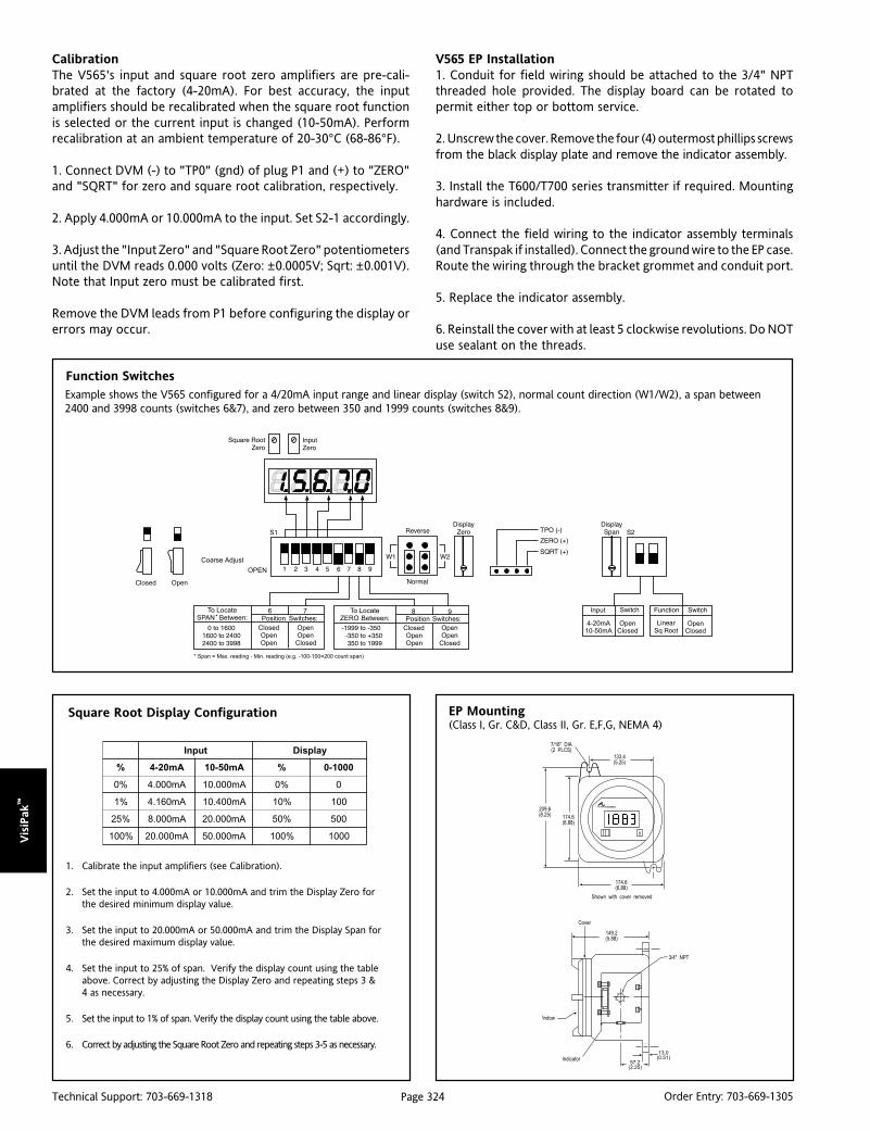
Page 324Technical Support: 703-669-1318 Order Entry: 703-669-1305
Vis
iPak
™
CalibrationThe V565's input and square root zero amplifiers are pre-cali-brated at the factory (4-20mA). For best accuracy, the inputamplifiers should be recalibrated when the square root functionis selected or the current input is changed (10-50mA). Performrecalibration at an ambient temperature of 20-30°C (68-86°F).
1. Connect DVM (-) to "TP0" (gnd) of plug P1 and (+) to "ZERO"and "SQRT" for zero and square root calibration, respectively.
2. Apply 4.000mA or 10.000mA to the input. Set S2-1 accordingly.
3. Adjust the "Input Zero" and "Square Root Zero" potentiometersuntil the DVM reads 0.000 volts (Zero: ±0.0005V; Sqrt: ±0.001V).Note that Input zero must be calibrated first.
Remove the DVM leads from P1 before configuring the display orerrors may occur.
V565 EP Installation1. Conduit for field wiring should be attached to the 3/4" NPTthreaded hole provided. The display board can be rotated topermit either top or bottom service.
2. Unscrew the cover. Remove the four (4) outermost phillips screwsfrom the black display plate and remove the indicator assembly.
3. Install the T600/T700 series transmitter if required. Mountinghardware is included.
4. Connect the field wiring to the indicator assembly terminals(and Transpak if installed). Connect the ground wire to the EP case.Route the wiring through the bracket grommet and conduit port.
5. Replace the indicator assembly.
6. Reinstall the cover with at least 5 clockwise revolutions. Do NOTuse sealant on the threads.
Function Switches
Square Root Display Configuration EP Mounting(Class I, Gr. C&D, Class II, Gr. E,F,G, NEMA 4)
tupnI yalpsiD
% Am02-4 Am05-01 % 0001-0
%0 Am000.4 Am000.01 %0 0
%1 Am061.4 Am004.01 %01 001
%52 Am000.8 Am000.02 %05 005
%001 Am000.02 Am000.05 %001 0001
1. Calibrate the input amplifiers (see Calibration).
2. Set the input to 4.000mA or 10.000mA and trim the Display Zero forthe desired minimum display value.
3. Set the input to 20.000mA or 50.000mA and trim the Display Span forthe desired maximum display value.
4. Set the input to 25% of span. Verify the display count using the tableabove. Correct by adjusting the Display Zero and repeating steps 3 &4 as necessary.
5. Set the input to 1% of span. Verify the display count using the table above.
6. Correct by adjusting the Square Root Zero and repeating steps 3-5 as necessary.
Example shows the V565 configured for a 4/20mA input range and linear display (switch S2), normal count direction (W1/W2), a span between2400 and 3998 counts (switches 6&7), and zero between 350 and 1999 counts (switches 8&9).

Page 325Technical Support: 703-669-1318 Order Entry: 703-669-1305
VisiP
ak™
Conduit-Mount Enclosure (front door removed) showing internally mounted TransPak two-wire transmitter.
Connection Diagram, Option C
The Conduit-Mount enclosure convenientlymounts any TransPak two-wire transmitterwithin a NEMA 4X-rated housing for on-site process loop indication.
Mounting EnclosuresThe following dimension drawing shows both the panel mount (thin case) and the conduit-mount enclosures. The conduit mount is representedby a dotted line in the top and side views only. The front and back view dimensions are the same for both enclosures.
Note: panel mount includes an attached gasket surrounding the terminals, providing a NEMA 4 seal to the panel and the 1" diameter cutout. Fourscrews should be used to ensure a tight, flush fit between the panel and the V565.

Page 326Technical Support: 703-669-1318 Order Entry: 703-669-1305
Vis
iPak
™
Ordering InformationSpecify:1. Model: V565-00002. Options C, EP, U (EP includes conformal coat)
Specifications
Input Current Ranges:
4-20mA and 10-50mA, switch selectable
Input Current Limits:
Minimum: 3mA
Maximum: 220mA (Fuse)
Input Voltage Drop:
4-20mA: 1 volt max. @ 20mA
10-50mA: 1.4 volt max @ 50mA
Power Consumption:
2.5mW maximum @ 3.5mA input
Display Reading Update
2 readings per second
Readout Display:
Type: 0.8" High Liquid Crystal, 3-1/2 digit (1999)
Decimal Point Indication: Switch-selectable,four positions 1.9.9.9.
Dummy Zero: Switch-selectable trailingzero, e.g., 19990
Direction: Jumper-selectable,
Underrange (below -1999): displays -1
Overrange (above +1999): displays 1
Display Calibration:
Zero (4mA/10mA):
Adjustable from -1999 to 1999
Span (20mA/50mA):
Adjustable from 0 to 3998
Accuracy (@ 25 ±5°C):
Linear:<±0.1% of span counts, ±1 count.
Square-Root: <±0.1% of span counts, ±1count (from 1% to 100% of span)
Ripple Rejection:
1 count error with 1mA p-p ripple @ 50Hz
Screws (V565/V565C):
Front Panel: 10-32, brass with corrosionresistant stainless steel plating:
MIL-W-52263C (MR)
Rear Electrical: 6-32, nickel plated brass
Terminals:
Standard: 6-32 screw (accepts 0.2" ring lug)
Conduit mount (Opt C): Screw clamp,
12 AWG wire gauge, max.
Temperature Coefficient:
(Std Calibration: -10 to 70°C; Linear mode):Zero: ±0.1 counts/°C, ±1 count, typical.
±0.2 counts/°C, ±1 count, max.
Span (1000 to 3998): ±150ppm/°C,
±1 count, max.
Span (100 to 999):
150ppm/°C + .95(1000 - Span), ±1 count, max.
Temperature Coefficient (Square-root):Equivalent to 1uA/°C max. input drift
Temperature Range:
Standard: -10 to 70°C (14 to 158°F)
Storage: -55 to 80°C (-67 to 176°F)
Humidity (with conformal coat @25°C):
5 to 95% RH, non-condensing
Weight:
V565: 15 oz.
V565C: 2.2 lbs.
V565 EP: 11 lbs.
Agency Approval:
FM approved intrinsically safe for hazardouslocations, certificate No.3V1A5.AX.Contact factory for installation drawings.CSA approved intrinsically safe forhazardous locations, (File No.LR422272-45).
FM Entity Parameters:
Vmax=33V
Imax=178.5mA
Ci=0mF
Li=0mH
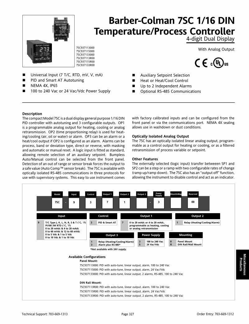
Page 327Technical Support: 703-669-1313 Order Entry: 703-669-1312
Miscellan
eous
Pro
ducts
DescriptionThe compact Model 7SC is a dual display general purpose 1/16 DINPID controller with autotuning and 3 configurable outputs. OP1is a programmable analog output for heating, cooling or analogretransmission. OP2 (time proportioning relay) is used for heat-ing/cooling (air, oil or water) or alarm. OP3 can be an alarm or aheat/cool output if OP2 is configured as an alarm. Alarms can beprocess, band or deviation type, direct or reverse, with maskingand automatic or manual reset. A logic input is fitted as standard,allowing remote selection of an auxiliary setpoint. BumplessAuto/Manual control can be selected from the front panel.Detection of an out of range or sensor break forces the output toa safe value (Auto Comp™ sensor break). The 7SC is available withoptically isolated RS-485 communications in three protocols foruse with supervisory systems. This easy to use instrument comes
Barber-Colman 7SC 1/16 DINTemperature/Process Controller
4-digit Dual Display
With Analog Output
Universal Input (7 T/C, RTD, mV, V, mA) PID and Smart AT Autotuning NEMA 4X, IP65 100 to 240 Vac or 24 Vac/Vdc Power Supply
Auxiliary Setpoint Selection Heat or Heat/Cool Control Up to 2 Independent Alarms Optional RS-485 Communications
with factory calibrated inputs and can be configured from thefront panel or via the communications port. NEMA 4X sealingallows use in washdown or dust conditions.
Optically Isolated Analog OutputThe 7SC has an optically isolated linear analog output, program-mable as a control output for heating or cooling, or as a filteredretransmission of process variable or setpoint.
Other FeaturesThe externally selected (logic input) transfer betweeen SP1 andSP2 can be a step or a ramp with two configurable rates of change(ramp up/ramp down). The 7SC also has an “output off” function,allowing the instrument to disable control and act as an indicator.
7SC9371130007SC9371150007SC9371330007SC937113R007SC937115R007SC937133R00
Model Input Control
9 3
Output 1 Output 2
7SC
Output 3 PowerSupply
1 3
MountinBag Reserved
00- -7
Output 1
7 0 to 20 mAdc or 4 to 20 mAdc,programmable as heating, coolingor analog retransmission
Output 2
1 Relay (Heating/Cooling/Alarm)
Control
3 PID & Smart AT
Power Supply
3 100 to 240 Vac5 24 Vac/Vdc
Output 3
1 Relay (Heating/Cooling/Alarm)3 Alarm plus RS-485*
*Not available with 24V supply.
Mounting
0 Panel MountR DIN Rail/Wall Mount
Input
9 T/C Type J, K, L, N, R, S & T (°C, °F)Pt100 3W RTD (°C, °F)0 to 20 mAdc & 4 to 20 mAdc0 to 60 mVdc & 12 to 60 mVdc0 to 5 Vdc & 1 to 5 Vdc0 to 10 Vdc & 1 to 10 Vdc
Available ConfigurationsPanel Mount:
7SC937113000: PID with auto-tune, linear output, alarm, 100 to 240 Vac
7SC937115000: PID with auto-tune, linear output, alarm, 24 Vac/Vdc
7SC937133000: PID with auto-tune, linear output, 2 alarms, RS-485, 100 to 240 Vac
DIN Rail Mount:
7SC937113R00: PID with auto-tune, linear output, alarm, 100 to 240 Vac
7SC937115R00: PID with auto-tune, linear output, alarm, 24 Vac/Vdc
7SC937133R00: PID with auto-tune, linear output, 2 alarms, RS-485, 100 to 240 Vac
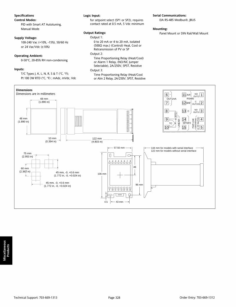
Page 328Technical Support: 703-669-1313 Order Entry: 703-669-1312
Mis
cellan
eous
Pro
duct
s
Specifications
Control Modes:
PID with Smart AT Autotuning,
Manual Mode
Supply Voltage:
100-240 Vac (+10%, -15%), 50/60 Hz
or 24 Vac/Vdc (±10%)
Operating Ambient:
0-50°C, 20-85% RH non-condensing
Inputs:
T/C Types J, K, L, N, R, S & T (°C, °F);
Pt 100 3W RTD (°C, °F) ; mAdc, mVdc, Vdc
DimensionsDimensions are in millimeters
Logic Input:
for setpoint select (SP1 or SP2), requirescontact rated at 0.5 mA, 5 Vdc minimum
Output Ratings:
Output 1:
0 to 20 mA or 4 to 20 mA, isolated(500Ω max.) (Control) Heat, Cool orRetransmission of PV or SP
Output 2:
Time Proportioning Relay (Heat/Cool)or Alarm 1 Relay, (NO/NC JumperSelectable), 2A/250V, SPST, Resistive
Output 3:
Time Proportioning Relay (Heat/Coolor Alm 2 Relay, 2A/250V, SPST, Resistive
Serial Communications:
EIA RS-485 Modbus®, JBUS
Mounting:
Panel Mount or DIN Rail/Wall Mount
1
3
4
5
6
7
8
9
10
2
11
13
14
15
12RS485
NOOUT3
OUT1mAC
OUT2/3
LIN
EA
R
PW
R L
INE
100/
240V
acor
24
Vac
/Vdc
A/A'
B/B'
NOOUT2
SP/SP2
C
+
_
TC
RT
D
+
_
1 2 3 4 5 6 7 8
9 10 11 12 13 14 15 16
57.50 mm
43 mm
46
96 mm
106 mm
4.5
144 mm for models with serial interface122 mm for models without serial interface
45 mm, -0, +0.6 mm(1.772 in, -0, +0.024 in)
45 mm, -0, +0.6 mm(1.772 in, -0, +0.024 in)
75 mm(2.953 in)
10 mm(0.394 in)
60 mm(2.362 in)
122 mm(4.803 in)
48 mm(1.890 in)
48 mm(1.890 in)
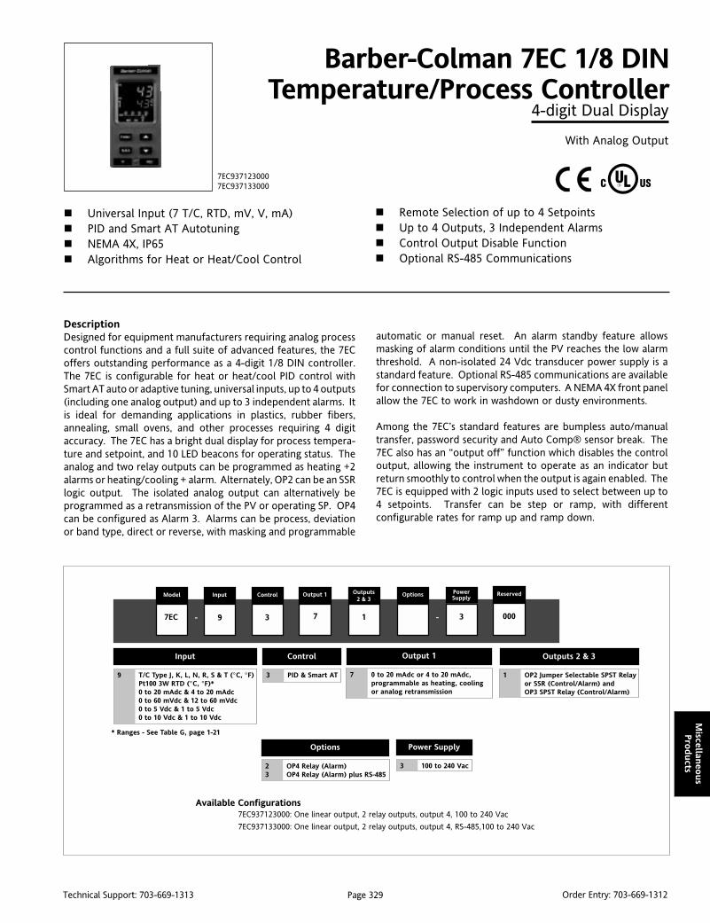
Page 329Technical Support: 703-669-1313 Order Entry: 703-669-1312
Miscellan
eous
Pro
ducts
DescriptionDesigned for equipment manufacturers requiring analog processcontrol functions and a full suite of advanced features, the 7ECoffers outstanding performance as a 4-digit 1/8 DIN controller.The 7EC is configurable for heat or heat/cool PID control withSmart AT auto or adaptive tuning, universal inputs, up to 4 outputs(including one analog output) and up to 3 independent alarms. Itis ideal for demanding applications in plastics, rubber fibers,annealing, small ovens, and other processes requiring 4 digitaccuracy. The 7EC has a bright dual display for process tempera-ture and setpoint, and 10 LED beacons for operating status. Theanalog and two relay outputs can be programmed as heating +2alarms or heating/cooling + alarm. Alternately, OP2 can be an SSRlogic output. The isolated analog output can alternatively beprogrammed as a retransmission of the PV or operating SP. OP4can be configured as Alarm 3. Alarms can be process, deviationor band type, direct or reverse, with masking and programmable
Barber-Colman 7EC 1/8 DINTemperature/Process Controller
4-digit Dual Display
With Analog Output
Universal Input (7 T/C, RTD, mV, V, mA) PID and Smart AT Autotuning NEMA 4X, IP65 Algorithms for Heat or Heat/Cool Control
Remote Selection of up to 4 Setpoints Up to 4 Outputs, 3 Independent Alarms Control Output Disable Function Optional RS-485 Communications
7EC9371230007EC937133000
Available Configurations7EC937123000: One linear output, 2 relay outputs, output 4, 100 to 240 Vac
7EC937133000: One linear output, 2 relay outputs, output 4, RS-485,100 to 240 Vac
automatic or manual reset. An alarm standby feature allowsmasking of alarm conditions until the PV reaches the low alarmthreshold. A non-isolated 24 Vdc transducer power supply is astandard feature. Optional RS-485 communications are availablefor connection to supervisory computers. A NEMA 4X front panelallow the 7EC to work in washdown or dusty environments.
Among the 7EC’s standard features are bumpless auto/manualtransfer, password security and Auto Comp® sensor break. The7EC also has an “output off” function which disables the controloutput, allowing the instrument to operate as an indicator butreturn smoothly to control when the output is again enabled. The7EC is equipped with 2 logic inputs used to select between up to4 setpoints. Transfer can be step or ramp, with differentconfigurable rates for ramp up and ramp down.
Model Input Control
9 3
Output 1 Options PowerSupply
3- -
Control
3 PID & Smart AT
7
Outputs2 & 3
1
Power Supply
3 100 to 240 Vac
Reserved
0007EC
Output 1
7 0 to 20 mAdc or 4 to 20 mAdc,programmable as heating, coolingor analog retransmission
Outputs 2 & 3
1 OP2 Jumper Selectable SPST Relayor SSR (Control/Alarm) andOP3 SPST Relay (Control/Alarm)
Input
9 T/C Type J, K, L, N, R, S & T (°C, °F)Pt100 3W RTD (°C, °F)*0 to 20 mAdc & 4 to 20 mAdc0 to 60 mVdc & 12 to 60 mVdc0 to 5 Vdc & 1 to 5 Vdc0 to 10 Vdc & 1 to 10 Vdc
Options
2 OP4 Relay (Alarm)3 OP4 Relay (Alarm) plus RS-485
* Ranges - See Table G, page 1-21

Page 330Technical Support: 703-669-1313 Order Entry: 703-669-1312
Mis
cellan
eous
Pro
duct
s
Specifications
Control Modes:
PID with Smart AT Autotuning
Supply Voltage:
100-240 Vac (+10%, -15%), 50/60 Hz
Operating Ambient:
0-50°C, 20-85% RH non-condensing
Inputs:
T/C Types J, K, L, N, R, S & T (°C, °F);
Pt 100 3W RTD (°C, °F); mAdc, mVdc, Vdc
Logic Inputs (2):
for setpoint select (SP, SP2, SP3, SP4),requires contacts rated at 0.5 mA, 5 Vdc min.
Aux Transducer Power Supply:
Non-isolated 24 Vdc (±10%) rated at
25 mAdc, short circuit protected
Mounting:
Panel Mount or DIN Rail
Output Ratings:
Output 1:
0 to 20 mA or 4 to 20 mA, isolated(500Ω max.) Control Out (Heat orCool) or Retran of PV or SP
Output 2:
Relay, 3A/250V, SPST, NO/NC Selectable,Resistive Time Proportioning Heat orCool, Alarm 1.
Jumper Selectable Logic SSR (unisolated)
Logic Level 1: 14 Vdc ±20% @ 20 mA max.
(700 Ω min.) 24 Vdc max. ±20% @ 1mA
Logic Level 0: Less than 0.5 Vdc
Time Proportioning Heat or CoolOutput 3:
Relay, 2A/250V, SPST, Resistive
Time Prop. Heat or Cool, Alarm 2
Output 4:
Relay, 2A/250V, SPST, Resistive
Optional Alarm 3
Serial Communications:
EIA RS-485 Modbus®, JBUS
MountingDimensions:
48W x 96H x 116D mm
Cutout:
45W (-0, +0.6) x 92H (-0, +0.8) mm
125 mm min. center-to-center verticalspacing; 60 mm min. center-to-centerhorizontal spacing
Weight:
400 gm max.
100/240VacPWR LINE
12
13
15
14OUT 1
mA
AUX 24V
DIG1
DIG2
C
OUT 2SSR
16
17
18
19
21
22
8
7
6
5
4
3
TC
1
20
NO
NO
NO
LINEARINPUTS
RT
D
OUT 3
OUT 4
OUT 2
C
C
11
10
9RS 485
A/A'
B/B'
C
DimensionsDimensions are in millimeters
116 mm 4.567 in
60 mm 2.362 in
125 mm 4.921 in
45 mm, -0, +0.6 mm 1.772 in, -0, +0.024 in
92 mm, -0, +0.8 mm 3.622 in, -0, +0.031 in
48 mm 1.890 in
96 mm 3.780 in
10 mm (0.394 in)

Page 331Technical Support: 703-669-1313 Order Entry: 703-669-1312
Miscellan
eous
Pro
ducts
DescriptionThe RFS provides outstanding control performance and a compre-hensive solution for a wide variety of applications; such as foodprocessing, plastic manufacturing, and process applications re-quiring heat/cool control and process protection alarms in acompact DIN rail mounted package.
Universal thermocouple or RTD input coupled with a responsiveSMART auto-tuning PID control algorithm that is equipped withspecial functions, including soft start and non-linear cooling. Acomplete set of process protection alarm functions; high and lowlimit, band and deviation are included.
Modular interconnection allows simultaneous connection of allcommon instrument elements: power supply, serial interface,logic input and open collector output for common alarms. TheRFS-AL alarm-logic input expansion unit makes use of the modularinterconnection function to provide additional I/O capacity.
Dual Setpoint SelectionTwo user configurable operation setpoints are selectable throughlogic input or the communication interface. For ON/OFF controlaction, this provides a method for fast and convenient run-holdswitching, either by an external switch or by a host supervisory system.
The setpoint ramp rates of all heating zones within a group aresynchronized by “holding back” the ramping setpoint. In order toachieve this, the individual loop band alarms are controlled by thecommon alarm output and isolated logic input functions.
PC Interface Port + OPC Based Configuration SoftwareThe integrated configuration port uses special software and anadaptor allowing:
1. Easy configuration of the instrument, with descriptions of theparameters and the relative limits.
2. Computer storage of the complete configuration allowing it tobe copied to other RFS units.
3. Copying and cloning of the configuration to a new instrument.4. The configuration interface port can be used for configuration
and for monitoring the process during setup.
Barber-Colman RFSTemperature/Process Controller
Compact DIN Rail Mount Controller
Equipped with RS-485 ModbusCommunications as Standard
Universal T/C, 3-Wire RTD, and Linear mA,mV and V Input
Smart Tune PID Control
Soft Start power Limiter 3 Relay/SSR Outputs OPC Based Configuration Software
Synchronized Pre-heatingEliminates differential heating during startup due to different heatrates of individual heaters in applications such as extruders andinjection hot runner control.
Process Protection AlarmsProcess (high or low limit), Band and Deviation alarm outputs areavailable with the additional flexibility of latching and maskingfunctions until the process variable reaches the alarm threshold.Band and Deviation alarms are also masked after a setpoint changeuntil the process variable reaches the alarm threshold. The alarmlatching function holds the alarm on until it is acknowledged.
Smart TuningAutomatically adjusts the PID parameters according to the processdynamics. An important characteristic of the Eurotherm Controlscontinuous self tuning algorithm is its ability to optimize controlparameters without injecting any artificial disturbances into the system.
I/O CommunicationsAll RFS I/O can be read directly over the Modbus communicationinterface by the host supervisory system. Additionally, thecommunication host can write to RFS outputs that are notassigned as alarm or status functions. This expands available PLCand host supervisory system I/O, simplifies machine troubleshoot-ing and provides the ability to perform remote diagnostics.
Sequential Modbus AddressesTo maximize the data transfer rates between the RFS and the hostsupervisory system, important operating parameters are grouped.Digital status information is transferred as data words to increaseefficiency. The RFS is able to communicate relevant parameterinformation with a single data request, instead of a series ofseparate address operations.
Startup Energy ManagementAt machine startup, the sequence of the RFS control outputs isscheduled according to the selected instrument Modbus address.This significantly reduces maximum startup current requirementsand offers potential savings in electrical installation capacity andcabling specification requirements.
Page 332Technical Support: 703-669-1313 Order Entry: 703-669-1312
Mis
cellan
eous
Pro
duct
s
OFD - Output Failure Detection (optional)Using the CT input, the output failure detection function monitorsthe current in the load driven by output 1. Load and actuatorprotection is provided in the following manner:
During the ON period of the output, the instrument measures thecurrent through the load and generates an alarm condition if the
INPUTS
All inputs are configurable and calibrated at the factory.
RTD Input:
Type: 3-wire Pt100
Calibration: according to DIN 43760
Measuring current: 130µA
Line resistance: auto-compensation up to 20 ohms per wire with nomeasurable error
Engineering units: programmable ºC or ºF
Sensor break: indicates break of sensor or one or more wires;indicates short circuit when sensor resistance <12 ohms
Thermocouple Input:
Sensor break: open circuit sensor break detection
Cold junction compensation: automatic compensation oftemperature beween 0 and 50ºC
Cold junction compensation error: 0.1ºC/ºC
Input impedance: 1M ohms
Calibration: according to IEC 584-1: 1995; DIN 43710-1977 for TC type L
Linear Inputs:
Scaling: programmable from keyboard -2000 to 4000
Decimal point: programmable to any position
Logic Input:
Selection of the operating setpoint (SP or SP2) or of the temporaryblock of setpoint ramp
Type: dry contact excitation 8V, 8mA
Insulation: functional insulation
Insulation voltage: 50Vrms
Current Transformer Input:
Input current: 50mA, 50/60Hz
Full scale range: 0-10A, 0-100A (configurable)
Resolution: 0-20A: 0.1A; 21-100A: 1A
Programmable output: NO or NC relay control output; Logic level 1 or 0;SSR control output
Minimum period: On and Off: 400mSec
OUTPUTS
Output 1 and 2 - SSR:
Function: control output
Type: non-isolated
Logic level 1: 27VDC max. @ 1mA; 14VDC min. @ 20mA
Logic level 0: < 0.5V
Output 1 and 2 - Relay:
Output 1:
Function: control output
Type: SPST
Contact load: 3A @ 250VAC max. on resistive load
Output 2:
Function: control output or alarm
Type: relay with SPST contact
Contact load: 3A @ 250VAC max. on resistive load
Output 3 and 4 - Relay:
Output 3:
Function: alarm output
Type: relay with SPDT contact
Contact load: 3A @ 250VAC max. on resistive load
Output 4:
Function: group alarm (common output)
Type: open collector
Contact load: 20mA max. @ 48V
Control:
Type: one (heating) or two (heating/cooling) control outputs
Output action: time proportioning
Control Action: ON/OFF; PI or PID + SMART
Proportional band: 1.0% to 100.0% of the input range for onecontrol element; 1.5% to 100.0% of the input range for twocontrol elements; Setting PB = 0 causes ON/OFF control
Hysteresis: programmable from 0.1% to 10.0% of the input span
Integral time: programmable from 1 second to 20 minutes (or none)
Derivative time: programmable from 1 second to 10 minutes (or none)
Integral offset: for one control element (heating), the offset isprogrammable from 0 to 100% of the output range; for twocontrol elements (heating/cooling) the offset is programmablefrom -100% to +100% of the output range.
Output 1 cycle time: 1 second to 200 seconds
Manual to Auto: bumpless
Output 2 relative gain: Programmable from 0.20 to 1.00 of theproportional band
Output 2 cycle time: 1 second to 200 seconds
Overlap/deadband: programmable from -20% (deadband) to +50%(overlap) of the proportional band
Alarms:
Alarm action: direct or inverse
Alarm functions: configurable as process, band or deviation alarms
Alarm reset: programmable as automatic or manual
Alarm masking: configurable as masked or unmasked alarms
Hysteresis: 0.1 to 10.0% of input
Serial Interface:
Type: isolated RS-485
Protocol: Modbus (2-wire)
Baud rate: 600 to 19200 BAUD
Byte format: 8 bit
Parity: even, odd or none
Stop bit: one
Address: 1 to 254
Voltage levels: according to EIA comm standard
Line loading: 1/4 unit load
current is lower than a pre-programmed threshold. A low currentindicates a partial or total breakdown of the load or actuator SSR.During the OFF period of the output, the instrument measures theleakage current through the load and generates an alarm conditionif the current is higher than a pre-programmed threshold value. Ahigh leakage current indicates a short circuit of the actuator.

Page 333Technical Support: 703-669-1313 Order Entry: 703-669-1312
Miscellan
eous
Pro
ducts
RFS Controller
117 (4.606)
101 (3.976)22.5
(0.886)
8.5 (0.335)
131
(5.1
57)
120
(4.7
24)
24V power supply/comms
CPI connector
status indicators
OUT 3 relay
CT input
Dig input
1 2 3 4 5
678910111213
141516
171819
20212223
OUT 2 SSR or relay
OUT 1 SSR or relay
PV
sen
sor
input
modula
r buss
ed
inte
rconnec
tion
RFS Alarm Unit
117 (4.606)
101 (3.976)22.5
(0.886)
8.5 (0.335)
131
(5.1
57)
120
(4.7
24)
24V power supply/comms
status indicator
OUT 4 relay
Dig input
1 2 3 4 5
modula
r buss
ed
inte
rconnec
tion
RFS Text Display Unit
132 (5.196)
74 (
2.91
3)
104
(4.0
9)
118 (4.645)
7 (0.275) 7 (0.275)
31 (1.22) 43 (1.693) 9. Modbus10. 24 Vdc11. Not used

Page 334Technical Support: 703-669-1313 Order Entry: 703-669-1312
Mis
cellan
eous
Pro
duct
s
Text Display
Specifications
Case: PC/ABS grey
Self-extinguishing degree: V0 according to UL 746C
Front protection: IP20
Weight: 250g max.
Power supply: switching 24VAC/VDC (±10% of nominal value)
Power consumption: 6VA
Insulation: reinforced insulation is guaranteed between supply input,instrument inputs and outputs
Common mode rejection: 120dB @ 50/60Hz
Normal mode rejection: 60dB @ 50/60Hz
Installation: DIN rail mounting
Installation category: II
EMC/Safety: CE certified; compliant with regs 89/336/EEC (harmonizedreference standard EN-50081-2 and EN-50082-2) and 73/23/EEC e 93/68/EEC (harmonized reference standard EN61010-1)
Sampling time: 250mSec for linear inputs
500mSec for TC or RTD inputs
Accuracy: ±0.2% f.s.v. @ 25°C with nominal supply voltage
Operating temperature: 0 to +50°CStorage temperature: -20 to +70°CHumidity: 20% to 85% RH, non-condensing
High Visibility Display Up to 4 Lines of 20 Characters Three Color Backlighting Extended Graphics Multiple Languages including Cyrillic and Katakana 128 Customizable Characters
Specifications
Operating Temperature: 0 to 55°CHumidity: 20 to 85% RH, non-condensing
Comm Port: DB25 Female; RS-232, RS-485 Modbus Master, RTU up to19.2k baud
Supply Voltage: 24 Vdc (18-30 Vdc, 5W max.)
Protection: IP65 (front)
Certification: CE,uL, CSA
Model
RFS
Input
5
ControlAction
3
Output 1 Output 2 Options PowerSupply
5
Model
RFS DIN Rail Temperature Controller(order connectors separately)
Input
5 TC Type L, J, K, N, R, S, T and
3-Wire PT100 RTD
Output 1
1
6
Relay
SSR
Output 2
0
1
6
None
Relay
SSR
Options
0
4
5
None
OFD + Logic IN
ALM2 + OFD + Logic IN
Power Supply
5 24 Vac/Vdc
Customer Configuration
0ER Standard Labels
CustomerConfig
0ER
Order Information AccessoriesConnector Kit . . . . . . . . . . . . . . . . . . . . . . . . . . . . . . ARFSKITCON000
Interconnecting Bus Cable . . . . . . . . . . . . . . . . . . . . ARFSFLAT13000
Current Transformers
10A . . . . . . . . . . . . . . . . . . . . . . . . . . . . . . 7ERR10000000
25A . . . . . . . . . . . . . . . . . . . . . . . . . . . . . . 7ERR20000000
50A . . . . . . . . . . . . . . . . . . . . . . . . . . . . . . 7ERR40000000
100A . . . . . . . . . . . . . . . . . . . . . . . . . . . . . . 7ERR50000000
RFS Configuration Port Interface Cable
(without power supply) . . . . . . . . . . . . . . . . . . . . . . CPI1202000ER
RFS Configuration Port Interface Cable
(with power supply) . . . . . . . . . . . . . . . . . . . . . . . . . CPI1222000ER
RFS Alarm Unit . . . . . . . . . . . . . . . . . . . . . . . . . . . . . ARFSAL00000ER
RFS User Manual CD . . . . . . . . . . . . . . . . . . . . . . . . . HA136732
RFS Text Display . . . . . . . . . . . . . . . . . . . . . . . . . . . . 71-1165
Text Display Configuration Software & Cable . . . . . 71-1166
RFS to Text Display Cable . . . . . . . . . . . . . . . . . . . . . A-60222
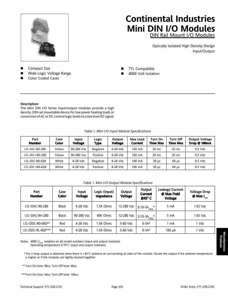
Page 335Technical Support: 571-258-2101 Order Entry: 571-258-2105
Miscellan
eous
Pro
ducts
DescriptionThe Mini DIN I/O Series input/output modules provide a highdensity, DIN rail mountable device for low power heating loads orconversion of AC or DC control logic levels to a low level DC signal.
Continental IndustriesMini DIN I/O Modules
DIN Rail Mount I/O Modules
Optically Isolated High Density DesignInput/Output
Compact Size Wide Logic Voltage Range Color Coded Cases
TTL Compatible 4000 Volt Isolation
Table 1. Mini I/O Input Module Specifications
traPrebmuN rebmuN rebmuN rebmuN rebmuN
esaCroloC roloC roloC roloC roloC
tupnIegatloV egatloV egatloV egatloV egatloV
cigoLepyT epyT epyT epyT epyT
tuptuOegatloV egatloV egatloV egatloV egatloV
daoLxaMtnerruC tnerruC tnerruC tnerruC tnerruC
nOnruTxaMemiT xaMemiT xaMemiT xaMemiT xaMemiT
ffOnruTxaMemiT xaMemiT xaMemiT xaMemiT xaMemiT
egatloVtuptuOAm001@porD Am001@porD Am001@porD Am001@porD Am001@porD
082-0R-CAI-.O.I wolleY caV082-09 evitageN cdV82-4 Am001 sm02 sm02 cdV5.0
082-0R+CAI-.O.I wolleY caV082-09 evitisoP cdV82-4 Am001 sm02 sm02 cdV5.0
820-0R-CDI-.O.I etihW cdV82-4 evitageN cdV82-4 Am001 sµ03 sµ06 cdV5.0
820-0R+CDI-.O.I etihW cdV82-4 evitisoP cdV82-4 Am001 sµ03 sµ06 cdV5.0
traPrebmuN rebmuN rebmuN rebmuN rebmuN
esaCroloC roloC roloC roloC roloC
tupnIegatloV egatloV egatloV egatloV egatloV
)tupnI(cigoLecnadepmI ecnadepmI ecnadepmI ecnadepmI ecnadepmI
tuptuOegatloV egatloV egatloV egatloV egatloV
tuptuOtnerruC tnerruC tnerruC tnerruC tnerruC
C°54@ C°54@ C°54@ C°54@ C°54@
tnerruCegakaeLdleiFxaM@ dleiFxaM@ dleiFxaM@ dleiFxaM@ dleiFxaM@
egatloV egatloV egatloV egatloV egatloV
porDegatloVIxaM@ IxaM@ IxaM@ IxaM@ IxaM@
tuo
082-0R-CAO-.O.I kcalB cdV82-4 smhOK5.1 caV082-21 A3-01.0smr* Am5 caV56.1
082-AR-CAO-.O.I kcalB caV082-09 smhOK04 caV082-21 A3-01.0smr* Am5 caV56.1
**060-0R-CDO-.O.I deR cdV82-4 smhOK5.1 cdV06-5 *A3-0 Am1 cdV1
***060-LR-CDO-.O.I deR cdV82-4 smhOK5.1 cdV06-5 *A3-0 Aµ001 cdV1
Table 1. Mini I/O Output Module Specifications
Notes: 4000 VRMS isolation on all model numbers (input and output modules)Operating temperature 0-70°C (input and output modules)
*The 3 Amp output is obtained when there is <45°C ambient air surrounding all sides of the module. Derate the output if the ambient temperatureis higher or if the modules are tightly stacked together.
** Turn On time: 40us; Turn Off time: 40us
***Turn On time: 50us; Turn Off time: 100us

Page 336Technical Support: 571-258-2101 Order Entry: 571-258-2105
Mis
cellan
eous
Pro
duct
s
DimensionsDimensions are in millimeters (inches)
7.5(0.30)
63(2.48)
80(3.15)
Input Modules Output Modules
A voltage on the field sidewill cause the voltage onterminal 4 to changefrom Vcc to ground.
A voltage on the field sidewill cause the voltage onterminal 4 to changefrom ground to Vcc.
A voltage on the field sidewill cause the voltage onterminal 4 to changefrom Vcc to ground.
A voltage on the field sidewill cause the the voltageon terminal 4 to changefrom ground to Vcc.
Application of a voltagehere will cause the loadto turn on.
IAC-
IAC+
IDC-
IDC+
OAC-R0
OAC-RA
ODC
Application of a voltagehere will cause the loadto turn on.
Application of a voltagehere will cause the loadto turn on.
eludoMcigoL cigoL cigoL cigoL cigoL
dleiF?egatloV ?egatloV ?egatloV ?egatloV ?egatloV
egatloVcigoL)4lanimreT(langiS )4lanimreT(langiS )4lanimreT(langiS )4lanimreT(langiS )4lanimreT(langiS
evitageN seY oN
evitageN oN seY
evitisoP seY seY
evitisoP oN oN
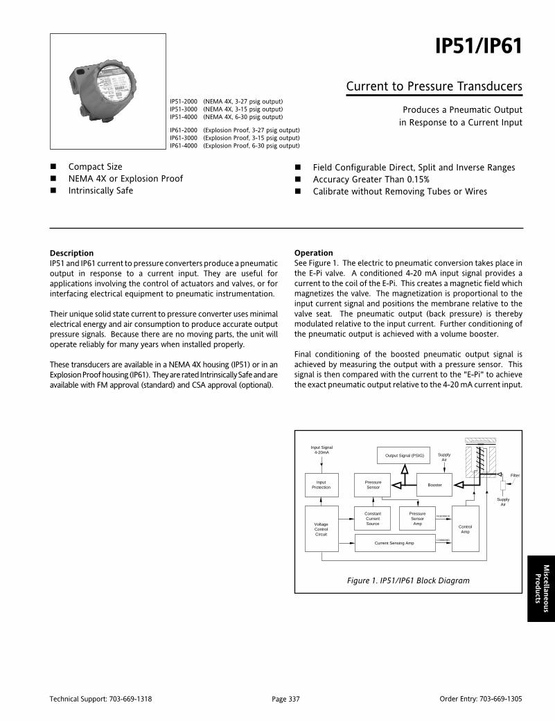
Page 337Technical Support: 703-669-1318 Order Entry: 703-669-1305
Miscellan
eous
Pro
ducts
DescriptionIP51 and IP61 current to pressure converters produce a pneumaticoutput in response to a current input. They are useful forapplications involving the control of actuators and valves, or forinterfacing electrical equipment to pneumatic instrumentation.
Their unique solid state current to pressure converter uses minimalelectrical energy and air consumption to produce accurate outputpressure signals. Because there are no moving parts, the unit willoperate reliably for many years when installed properly.
These transducers are available in a NEMA 4X housing (IP51) or in anExplosion Proof housing (IP61). They are rated Intrinsically Safe and areavailable with FM approval (standard) and CSA approval (optional).
IP51/IP61
Current to Pressure Transducers
Produces a Pneumatic Outputin Response to a Current Input
Compact Size NEMA 4X or Explosion Proof Intrinsically Safe
Field Configurable Direct, Split and Inverse Ranges Accuracy Greater Than 0.15% Calibrate without Removing Tubes or Wires
OperationSee Figure 1. The electric to pneumatic conversion takes place inthe E-Pi valve. A conditioned 4-20 mA input signal provides acurrent to the coil of the E-Pi. This creates a magnetic field whichmagnetizes the valve. The magnetization is proportional to theinput current signal and positions the membrane relative to thevalve seat. The pneumatic output (back pressure) is therebymodulated relative to the input current. Further conditioning ofthe pneumatic output is achieved with a volume booster.
Final conditioning of the boosted pneumatic output signal isachieved by measuring the output with a pressure sensor. Thissignal is then compared with the current to the "E-Pi" to achievethe exact pneumatic output relative to the 4-20 mA current input.
IP51-2000 (NEMA 4X, 3-27 psig output)IP51-3000 (NEMA 4X, 3-15 psig output)IP51-4000 (NEMA 4X, 6-30 psig output)
IP61-2000 (Explosion Proof, 3-27 psig output)IP61-3000 (Explosion Proof, 3-15 psig output)IP61-4000 (Explosion Proof, 6-30 psig output)
Input Signal4-20mA
InputProtection
VoltageControlCircuit
Output Signal (PSIG)
PressureSensor Booster
SupplyAir
SupplyAir
Filter
ConstantCurrentSource
PressureSensor
Amp
Current Sensing Amp
ControlAmp
FEEDBACK
COMMAND
Figure 1. IP51/IP61 Block Diagram
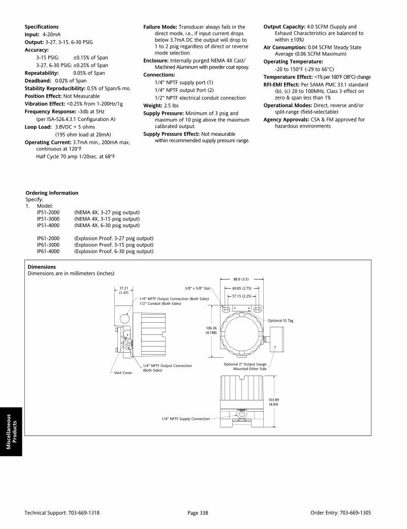
Page 338Technical Support: 703-669-1318 Order Entry: 703-669-1305
Mis
cellan
eous
Pro
duct
s
Specifications
Input: 4-20mA
Output: 3-27, 3-15, 6-30 PSIG
Accuracy:
3-15 PSIG: ±0.15% of Span
3-27, 6-30 PSIG: ±0.25% of Span
Repeatability: 0.05% of Span
Deadband: 0.02% of Span
Stability Reproducibility: 0.5% of Span/6 mo.
Position Effect: Not Measurable
Vibration Effect: <0.25% from 1-200Hz/1g
Frequency Response: -3db at 5Hz
(per ISA-S26.4.3.1 Configuration A)
Loop Load: 3.8VDC + 5 ohms
(195 ohm load at 20mA)
Operating Current: 3.7mA min., 200mA max,continuous at 120°FHalf Cycle 70 amp 1/20sec. at 68°F
DimensionsDimensions are in millimeters (inches)
Ordering InformationSpecify:1. Model:
IP51-2000 (NEMA 4X, 3-27 psig output)IP51-3000 (NEMA 4X, 3-15 psig output)IP51-4000 (NEMA 4X, 6-30 psig output)
IP61-2000 (Explosion Proof, 3-27 psig output)IP61-3000 (Explosion Proof, 3-15 psig output)IP61-4000 (Explosion Proof, 6-30 psig output)
Failure Mode: Transducer always fails in thedirect mode, i.e., if input current dropsbelow 3.7mA DC the output will drop to1 to 2 psig regardless of direct or reversemode selection.
Enclosure: Internally purged NEMA 4X Cast/Machined Aluminum with powder coat epoxy.
Connections:
1/4" NPTF supply port (1)
1/4" NPTF output Port (2)
1/2" NPTF electrical conduit connection
Weight: 2.5 Ibs
Supply Pressure: Minimum of 3 psig andmaximum of 10 psig above the maximumcalibrated output.
Supply Pressure Effect: Not measurablewithin recommended supply pressure range.
Output Capacity: 4.0 SCFM (Supply andExhaust Characteristics are balanced towithin ±10%)
Air Consumption: 0.04 SCFM Steady StateAverage (0.06 SCFM Maximum)
Operating Temperature:
-20 to 150°F (-29 to 66°C)
Temperature Effect: <1% per 100°F (38°C) change
RFI-EMI Effect: Per SAMA PMC 33.1 standard(b), (c) 20 to 100MHz, Class 3 effect onzero & span less than 1%
Operational Modes: Direct, reverse and/orsplit-range (field-selectable)
Agency Approvals: CSA & FM approved forhazardous environments
37.21(1.47)
3/8" x 5/8" Slot
57.15 (2.25)
69.85 (2.75)
88.9 (3.5)
Optional 2" Output GaugeMounted Either Side
106.36(4.188)
Optional SS Tag
1/4" NPTF Output Connection (Both Sides)1/2" Conduit (Both Sides)
1/4" NPTF Output Connection(Both Sides)
Vent Cover
103.89(4.09)
1/4" NPTF Supply Connection
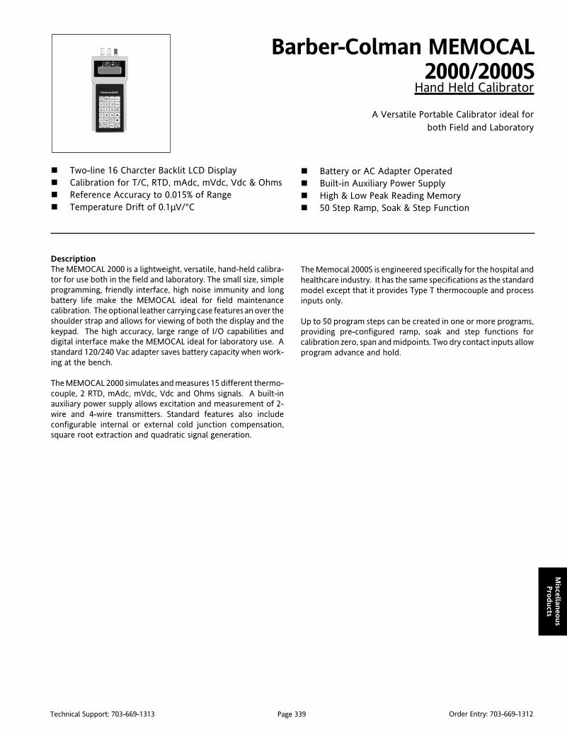
Page 339Technical Support: 703-669-1313 Order Entry: 703-669-1312
Miscellan
eous
Pro
ducts
DescriptionThe MEMOCAL 2000 is a lightweight, versatile, hand-held calibra-tor for use both in the field and laboratory. The small size, simpleprogramming, friendly interface, high noise immunity and longbattery life make the MEMOCAL ideal for field maintenancecalibration. The optional leather carrying case features an over theshoulder strap and allows for viewing of both the display and thekeypad. The high accuracy, large range of I/O capabilities anddigital interface make the MEMOCAL ideal for laboratory use. Astandard 120/240 Vac adapter saves battery capacity when work-ing at the bench.
The MEMOCAL 2000 simulates and measures 15 different thermo-couple, 2 RTD, mAdc, mVdc, Vdc and Ohms signals. A built-inauxiliary power supply allows excitation and measurement of 2-wire and 4-wire transmitters. Standard features also includeconfigurable internal or external cold junction compensation,square root extraction and quadratic signal generation.
Barber-Colman MEMOCAL2000/2000S
Hand Held Calibrator
A Versatile Portable Calibrator ideal forboth Field and Laboratory
Two-line 16 Charcter Backlit LCD Display Calibration for T/C, RTD, mAdc, mVdc, Vdc & Ohms Reference Accuracy to 0.015% of Range Temperature Drift of 0.1µV/°C
Battery or AC Adapter Operated Built-in Auxiliary Power Supply High & Low Peak Reading Memory 50 Step Ramp, Soak & Step Function
The Memocal 2000S is engineered specifically for the hospital andhealthcare industry. It has the same specifications as the standardmodel except that it provides Type T thermocouple and processinputs only.
Up to 50 program steps can be created in one or more programs,providing pre-configured ramp, soak and step functions forcalibration zero, span and midpoints. Two dry contact inputs allowprogram advance and hold.

Page 340Technical Support: 703-669-1313 Order Entry: 703-669-1312
Mis
cellan
eous
Pro
duct
s
CTepyT epyT epyT epyT epyT
F°niegnaR noituloseRecnerefeR
)±(ycaruccA )±(ycaruccA )±(ycaruccA )±(ycaruccA )±(ycaruccA
J F°2912otF°823- F°1.0 %120.0
K
F°3otF°823- F°2.0< %810.0
F°2771otF°33 F°1.0 %410.0
F°4622otF°3771 F°1.0 %320.0
F°8942otF°5622 F°3.0< %230.0
*TF°23otF°823- F°2.0< %540.0
F°257otF°33 F°1.0 %320.0
E F°2381otF°823- F°1.0 %910.0
R
F°23otF°85- F°5.0< %80.0
F°053otF°33 F°4.0< %840.0
F°005otF°153 F°3.0< %630.0
F°2603otF°105 F°2.0< %520.0
F°4123otF°3603 F°3.0< %730.0
S
F°23otF°85- F°5.0< %60.0
F°041otF°33 F°4.0< %840.0
F°074otF°141 F°3.0< %630.0
F°4123otF°174 F°2.0< %420.0
B
F°212otF°221 F°4< %57.0
F°023otF°312 F°2< %52.0
F°006otF°123 F°1< %21.0
F°0521otF°106 F°5.0< %360.0
F°0771otF°1521 F°3.0< %140.0
F°6723otF°1771 F°2.0< %520.0
U F°2111otF°823- F°1.0 %720.0
LF°9921otF°823- F°1.0 %610.0
F°2561otF°0031 F°2.0< %620.0
N
F°3801otF°23 F°2.0< %410.0
F°6002otF°4801 F°1.0 %820.0
F°0752otF°7002 F°2.0< %130.0
iN/iNF°9251otF°23 F°1.0 %610.0
F°2732otF°0351 F°2.0< %420.0
IILP
F°429otF°841- F°1.0 %310.0
F°1671otF°529 F°2.0< %510.0
F°2552otF°2671 F°3.0< %930.0
)G(W
F°293otF°23 F°2.1< %61.0
F°2921otF°393 F°2.0< %540.0
F°9032otF°3921 F°1.0 %320.0
F°6872otF°0132 F°2.0 %520.0
F°6723otF°7872 F°3.0< %830.0
)D(3W
F°275otF°23 F°2.0< %420.0
F°2381otF°375 F°1.0 %710.0
F°4991otF°3381 F°2.0< %910.0
F°6723otF°5991 F°3.0< %350.0
5W
F°275otF°23 F°2.0< %810.0
F°8591otF°375 F°3.0< %840.0
F°6723otF°9591 F°4.0< %450.0
CTepyT epyT epyT epyT epyT
C°niegnaR noituloseRecnerefeR
)±(ycaruccA )±(ycaruccA )±(ycaruccA )±(ycaruccA )±(ycaruccA
J C°0021otC°002- C°1.0 %120.0
KC°769otC°002- C°1.0 %810.0
C°0731otC°869 C°2.0< %230.0
*TC°0otC°002- C°1.0 %540.0
C°004otC°1 C°1.0 %320.0
E C°0001otC°002- C°1.0 %910.0
R
C°0otC°05- C°3.0< %80.0
C°053otC°1 C°2.0< %840.0
C°4861otC°153 C°1.0 %420.0
C°0671otC°5861 C°2.0< %730.0
S
C°0otC°05- C°3.0< %60.0
C°006otC°1 C°2.0 %840.0
C°0671otC°106 C°1.0 %420.0
B
C°001otC°05 C°3< %7.0
C°002otC°101 C°1< %32.0
C°006otC°102 C°5.0< %11.0
C°0511otC°106 C°2.0 %930.0
C°0281otC°1511 C°1.0 %320.0
U C°006otC°002- C°1.0 %720.0
L C°009otC°002- C°1.0 %620.0
N C°0141otC°0 C°2.0< %430.0
iN/iN C°0031otC°0 C°1.0 %420.0
IILPC°169otC°001- C°1.0 %410.0
C°0041otC°269 C°2.0< %930.0
)G(W
C°05otC°0 C°1< %621.0
C°001otC°15 C°3.0< %840.0
C°052otC°101 C°2.0< %530.0
C°0351otC°152 C°1.0 %910.0
C°0032otC°1351 C°2.0< %30.0
)D(3W
C°001otC°0 C°1.0 %910.0
C°0901otC°101 C°1.0 %410.0
C°0132otC°1901 C°3.0< %240.0
5W
C°6901otC°0 C°1.0 %410.0
C°0522otC°7901 C°2.0 %730.0
C°5132otC°1522 C°3.0< %240.0
egnaR noituloseRecnerefeR
)±(ycaruccA )±(ycaruccA )±(ycaruccA )±(ycaruccA )±(ycaruccA
Vm02otVm02- Vµ1 %510.0
Vm002otVm002- Vµ01 %510.0
V2otV2- Vµ001 %510.0
V02otV02- Vm1 %020.0
Am02otAm02- Aµ1 %510.0
Am031otAm031- Aµ01 %020.0
egnaR noituloseRecnerefeR
)±(ycaruccA )±(ycaruccA )±(ycaruccA )±(ycaruccA )±(ycaruccA
C°053otC°06- C°1.0 %920.0
F°266otF°67- F°1.0 %920.0
egnaR noituloseRecnerefeR
)±(ycaruccA )±(ycaruccA )±(ycaruccA )±(ycaruccA )±(ycaruccA
C°058otC°002- C°1.0 %820.0
F°215otF°823- F°1.0 %210.0
F°2651otF°315 F°2.0< %920.0
egnaR noituloseRecnerefeR
)±(ycaruccA )±(ycaruccA )±(ycaruccA )±(ycaruccA )±(ycaruccA
008ot0 1.0 %520.0
Thermocouple Input Ranges (°F) Thermocouple Input Ranges (°C)
mV, Volt and mA Input Ranges*
Pt100 RTD Input Ranges*
Ni100 RTD Input Ranges
Ohms Input Range
* Only ranges marked with an asterisk are available with the Healthcare version (2000S).
Shaded ranges available only when the IPTS standard is selected.

Page 341Technical Support: 703-669-1313 Order Entry: 703-669-1312
Miscellan
eous
Pro
ducts
egnaR noituloseRecnerefeR
)±(ycaruccA )±(ycaruccA )±(ycaruccA )±(ycaruccA )±(ycaruccA
Vm02otVm4- Vµ1 %510.0
Vm002otVm04- Vµ01 %510.0
Vm0002otVm004- Vµ001 %510.0
V02otV4- Vm1 %020.0
Am12otAm0 Aµ1 %510.0
egnaR noituloseRecnerefeR
)±(ycaruccA )±(ycaruccA )±(ycaruccA )±(ycaruccA )±(ycaruccA
C°053otC°06- C°1.0 %630.0
F°086otF°67- F°1.0 %630.0
egnaR noituloseRecnerefeR
)±(ycaruccA )±(ycaruccA )±(ycaruccA )±(ycaruccA )±(ycaruccA
005ot51 1.0 %130.0
egnaR noituloseRecnerefeR
)±(ycaruccA )±(ycaruccA )±(ycaruccA )±(ycaruccA )±(ycaruccA
C°058otC°002- C°1.0 %920.0
F°215otF°823- F°1.0 %220.0
F°2651otF°315 F°2.0< %520.0
mV, Volt and mA Output Ranges Pt100 RTD Output Ranges
Ni100 RTD Output RangesOhms Output Range
Specifications
Case: ABS, color similar to RAL 6038.
Self-extinguishing
degree: V-0 according to UL.
Input Protection: All ranges are protected against a fault connectionup to 30 Vac/Vdc.
Terminals: 3 external screw female plugs, 4 mm diameter.
Weight: 600 grams (1.4lb) maximum.
Power Supply: - 4 AA batteries (Alkaline 1.5V; Ni-Cd 1.2V;
or Ni-MH 1.2V).
- Switching Type AC adapter (100 to 240 Vac).
Battery Life: 24 hours average (with Ni-MH batteries).
Recharging Time: 12 Hours
Insulation Res: Greater than 100MΩ.
Isolation Voltage: 1500 Vac rms
Common Mode
Rejection Ratio: 120 dB @ 50/60 Hz.
Normal Mode
Rejection Ratio: 60 dB @ 50/60 Hz.
Safety Standard: Meets EN60950/A2
EMC Standard: Meets generic emissions standard EN50081-2 andimmunity standard EN50082-2 for industrial environments.
A/D Conversion: Dual slope integration.
Sampling Time: 500 ms.
Display Update: 500 ms.
Temperature Drift: 0.0028%/°C or 28ppm/°COperating Temp: 0 to 40 °C.
Storage Temp: -10 to 60 °C.
Humidity: 20% to 85% RH, non-condensing.
Measuring Inputs
Thermocouple Inputs:
Type: (J, K, T, E, R, S, B, U, L, N, W, W3, W5, Ni/Ni-Mo andPlatinel II), keyboard configurable (and programmablechoice of IPTS-68 or ITS 90).
Engineering Units: °C and °F keyboard configurable.
Burn Out: Detection of the open input circuit (wires orsensor) with "OPEN" indication
Cold Junction: Automatic compensation
Cold Junction
Compensation Error: ±0.3 °C, ±0.05 °C/°C.
External Cold Junction
Compensation: Programmable from -20 to 80 °C.
Input Impedance: Greater than 10MΩ.
RTD Inputs:
Type: Pt100 Ω and Ni100 Ω, 3-wire connection.
Calibration: Programmable according to IPTS-68 or ITS-90
Line Resistance: Up to 20 Ω/wire with no measurable error.
Engineering Units: °C and °F keyboard configurable.
Measuring Current: 100 µAmps.
Burn Out: Detection of sensor open circuit and one or morewire open circuit
mA, mV & Volts Inputs:
Type: Linear Inputs (mAdc, mVdc, Vdc), keyboardprogrammable.
Input Impedance: 10 Ω for mAdc inputs.
Greater than 500KΩ for 20 Volt input.
Range Selection: Automatic or manual.
Square Root
Extraction: Programmable.
Readout: -20,000 to 20,000 keyboard programmable.
Decimal Point: Programmable to any position.
Ohms Input:
Range: 0 to 800.
Resolution: 0.1 Ω.
Outputs:
Thermocouple Outputs:
Type: (J, K, T, E, R, S, B, U, L, N, W, W3, W5, Ni/Ni-Mo andPlatinel II), keyboard configurable (and programmablechoice of IPTS-68 or ITS 90).
Engineering Units: °C and °F keyboard configurable.
Output Impedance: 50 Ω.
RTD Outputs:
Type: Pt100 Ω and Ni100 Ω, 3-wire connection.
Engineering Units: °C and °F keyboard configurable.
Calibration: According to DIN 43760.
mA, mV & Volts Outputs:
Type: Linear (mAdc, mVdc, Vdc), keyboard programmable.
Output Impedance: 50 Ω for mVdc outputs.
0.5 Ω for Vdc outputs.
Current Output
Maximum Load: 500 Ω.
Range Selection: Automatic or manual.
Quadratic Signal
Generation: Programmable.
Readout: -20,000 to 20,000 keyboard programmable.
Decimal Point: Programmable to any position.

Page 342Technical Support: 703-669-1313 Order Entry: 703-669-1312
Mis
cellan
eous
Pro
duct
s
DimensionsDimensions are in millimeters (inches)
Ohms Output:
Type: Ohms.
Range: 15 to 80; 80 to 500.
Resolution: 0.1 Ω.
Special Functions
Peak High/Peak LowDetection:
The instrument memorizes (and displays) the highand lowest detected reading.
Backlight: The backlight on the LED display automaticallyturns off after 30 seconds.
Program Routine: Up to 50 steps which can be programmed to oneor more separate routines.
Battery Check: The instrument operates at 3 different battery levels:
Level 1 The instrument is fully operational.
Level 2 The instrument is still fully operational,but “BATTERY LOW” appears on theupper display.
Level 3 The instrument turns OFF automaticallyand utilizes the remaining power formemory back-up only.
Logic Inputs: (Not available with digital communications)
Logic Input 1 sequences to the next program step.
Logic Input 2 starts/stops program operation.
Digital Communications (optional):
Type: Built-in RS-232C. External RS-232 to RS-485converter available in desk-top stand.
Protocol: MODBUS, JBUS.
Baud Rate: 600, 1200, 2400, 4800, 9600 and 19,200 baud.
Byte Format: 8 bits.
Parity: Even, odd, or none.
Stop Bit: One.
Address: From 1 to 255.
Memocal 2000
101(3.97)
26(1.02)
212(8.35)
36(1.42)
19(0.75)
168(6.62)
111(4.37)
25°
Ordering InformationSpecify:1. Model: MEM2090 (standard product)
MEM2095 (healthcare version)
2. Options: RS-232 Communications (n/a with MEM2095)
Desk top Adaptor (n/a with MEM2095)
Case
3. Accessories.
AccessoriesMEM2000BATTO Rechargeable battery packMEM2000CALER Factory calibration and certificate

Page 345Technical Support: 703-669-1318 Order Entry: 703-669-1305
Miscellan
eous
Pro
ducts
DescriptionThe WV905 power supply can be used to operate most 24VDCinstruments, including Action's Ultra SlimPak II, Ultra SlimPak, andActionI/Q models. The WV905 will operate on input voltagesranging from 85 to 265VAC or 120 to 300VDC. The 24VDC, 0.5Aoutput has overcurrent shutdown with automatic restart andthermal shutdown. The input is proteccted by fuse, a thermistorfor inrush current protection, and a varistor for over voltage.
ULTRA SLIMPAK® IIWV905
DIN Rail Mount Power Supply24VDC @ 0.5A
The perfect power source for Ultra SlimPak IISignal Conditioners and Alarms
Compact Size Auto-ranging Input Thermal Shutdown Bussed Power with Plug-in Power Clips
RoHS Compliant Removable Terminals for Easy Service Overcurrent Shutdown with Automatic Restart UL, CSA & CE
niP noitpircseD
11 )+(rewoPCD
21 )+(rewoPCD
31 )+(rewoPCD
12 )-(rewoPCD
22 )-(rewoPCD
32 )-(rewoPCD
14 )CAV032-511(nIeniL
24 dnuorGhtraE
34 lartueN
15 noitcennoCoN
25 noitcennoCoN
35 noitcennoCoN
The WV905 is the perfect power source for Ultra SlimPak II signalconditioners and alarm units. The integrated power jumpingsystem makes short work of connecting power, eliminating theneed to "daisy-chain" power wires.

Page 346Technical Support: 703-669-1318 Order Entry: 703-669-1305
Mis
cellan
eous
Pro
duct
s
Specifications
Input Voltage:
Typical: 115 to 239VAC, ±10%, 50/60Hz
Minimum: 85VAC, 120VDC
Maximum: 265VAC, 300VDC
Input Current:
(average values for reference only)
@115VAC: 250mArms, ±20%
@230VAC: 150mArms, ±20%
@125VDC: 125mA, ±20%
@250VDC: 65mA, ±20%
Output Voltage:
24VDC
Maximum Output Current:
0.5A
Input Protection:
Fuse: 2A slowblow (internal)
Inrush Current: Thermistor
Over Voltage: Varistor
Switching Frequency:
100kHz
Efficiency @ Maximum Load:
79%
Maximum Ripple:
0.1%
Load Regulation:
0.2% (10% to 100% Load)
Line Regulation:
0.2% (85VAC to 265VAC In)
DimensionsDimensions are in millimeters (inches)
Ordering InformationSpecify:1. Model:
WV905-0000
Overload Protection:
Over current shutdown with automatic restart
plus thermal shutdown
Maximum Load Capacitance on Output:
5.000uF
Hold Time:
(full output current after loss of input)
@115VAC: 14ms
@230VAC: 70ms
Isolation:
Input to Output: 3kV
Input/Output to Rail: 4kV
Input to Ground: 1.5kV
Output to Ground: 500V
Wire Size:
26-12AWG (0.1 to 4.0mm2)
Operating Temperature:
-20°C to +50°C (-4°F to 122°F)
Storage Temperature:
-40°C to +85°C (-40°F to 185°F)
Operating Humidity:
20% to 85% RHNC @ 45°CStorage Humidity:
20% to 90% RHNC @ 60°C for 24 hours
Size:
DIN rail case – refer to Dimensions drawing
Agency Approvals:
UL, CSA, CE mark
RoHS compliant
Note that detailed installation instructions are available on our website.

Page 345Technical Support: 703-669-1318 Order Entry: 703-669-1305
Miscellan
eous
Pro
ducts
DescriptionModel H910 and H915 power supplies can be used to operate most24VDC instruments, including Action's Ultra SlimPak® and theActionI/QTM. All models convert 110VAC to 24VDC.
Model H910 supplies up to 1000mA at 24VDC and the H915supplies up to 2300mA at 24VDC. Both models feature an LEDpower indicator. The H915 has multiple wire terminal connec-tions. They both have input fuse protection and their outputs haveDC short circuit protection.
Ordering InformationModels & AccessoriesSpecify:1. Model: H910 or H915
AccessoriesDIN-rail mount power supplies will mount on standard TS32 (model MD02) orTS35 (model MD03) DIN rail. In addition, the following accessories are available:
MD03 TS35 X 7.5 DIN rail, 2 meters, slottedC664 I/O Descriptive Tags
Terminal ConnectionsH910 and H915
L Line Power Hot (Black)N Line Power Neutral (White)+ DC Power Output (+)- DC Power Output (-)
H910/H915
DIN-Rail Mount Power Supplies
Provides 24VDC Power for DC-Powered Equipment
For use with Ultra SlimPakTM, ActionI/QTM andother 24VDC Powered Products
DIN-Rail Mount Housing for High-Density Installations Overload and Short Circuit Protection
Two Different Models and Power Ratings 110VAC or 85 to 265VAC RoHS Compliant
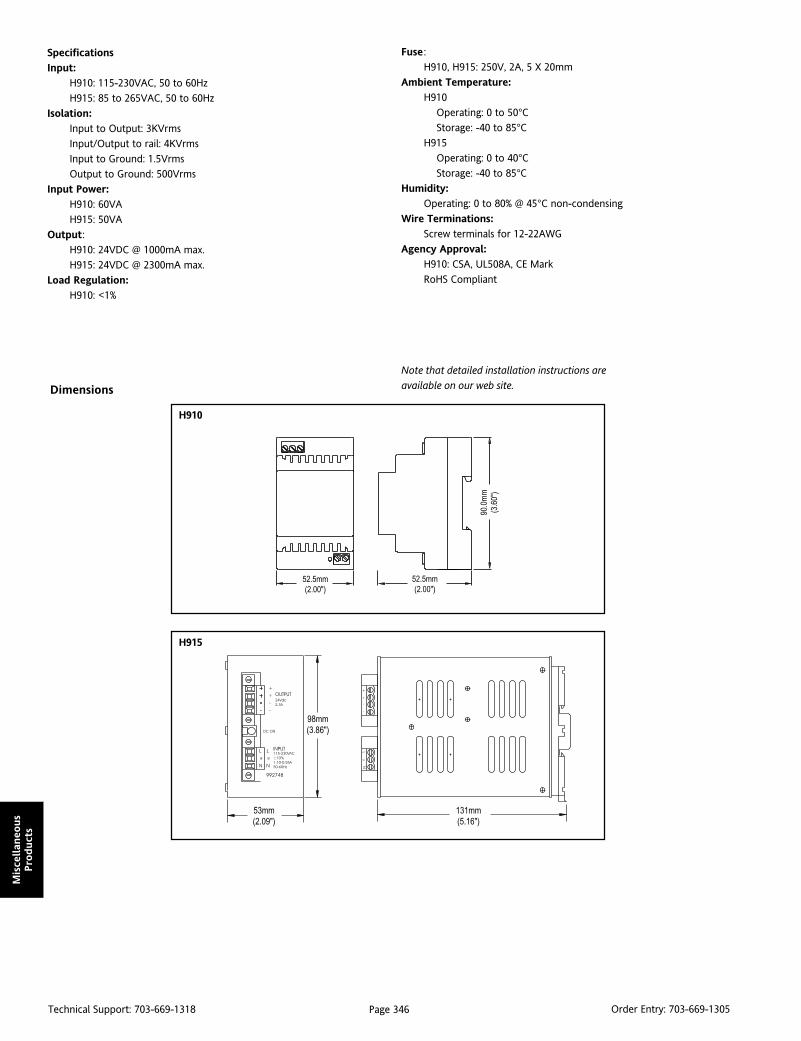
Page 346Technical Support: 703-669-1318 Order Entry: 703-669-1305
Mis
cellan
eous
Pro
duct
s
Specifications
Input:
H910: 115-230VAC, 50 to 60Hz
H915: 85 to 265VAC, 50 to 60Hz
Isolation:
Input to Output: 3KVrms
Input/Output to rail: 4KVrms
Input to Ground: 1.5Vrms
Output to Ground: 500Vrms
Input Power:
H910: 60VA
H915: 50VA
Output:
H910: 24VDC @ 1000mA max.
H915: 24VDC @ 2300mA max.
Load Regulation:
H910: <1%
Fuse :
H910, H915: 250V, 2A, 5 X 20mm
Ambient Temperature:
H910
Operating: 0 to 50°CStorage: -40 to 85°C
H915
Operating: 0 to 40°CStorage: -40 to 85°C
Humidity:
Operating: 0 to 80% @ 45°C non-condensing
Wire Terminations:
Screw terminals for 12-22AWG
Agency Approval:
H910: CSA, UL508A, CE Mark
RoHS Compliant
Note that detailed installation instructions are
available on our web site.Dimensions
H910
H915
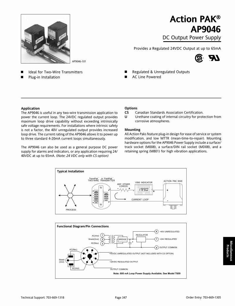
Page 347Technical Support: 703-669-1318 Order Entry: 703-669-1305
Miscellan
eous
Pro
ducts
ApplicationThe AP9046 is useful in any two-wire transmission application topower the current loop. The 24VDC regulated output providesmaximum loop drive capability without exceeding intrinsicallysafe voltage requirements. For installations where intrinsic safetyis not a factor, the 40V unregulated output provides increasedloop drive. The current rating of the AP9046 allows it to power upto three standard 4-20mA current loops simultaneously.
The AP9046 can also be used as a general purpose DC powersupply for alarms and indicators, or any application requiring 24/40VDC at up to 65mA. (Note: 24 VDC only with CS option)
Action PAK®
AP9046DC Output Power Supply
Provides a Regulated 24VDC Output at up to 65mA
Ideal for Two-Wire Transmitters Plug-in Installation
AP9046-101
Regulated & Unregulated Outputs AC Line Powered
OptionsCS Canadian Standards Association Certification.U Urethane coating of internal circuitry for protection from
corrosive atmospheres.
MountingAll Action Paks feature plug-in design for ease of service or systemmodification, and low MTTR (mean-time-to-repair). Mountinghardware options for the AP9046 Power Supply include a surface/track socket (M008), a surface/DIN rail socket (MD08), and aretaining spring (M801) for high vibration applications.
Typical Installation
Functional Diagram/Pin Connections
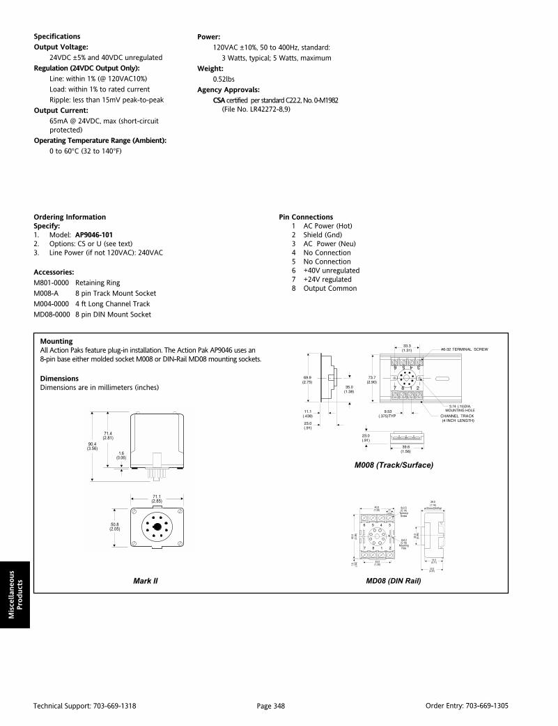
Page 348Technical Support: 703-669-1318 Order Entry: 703-669-1305
Mis
cellan
eous
Pro
duct
s
Specifications
Output Voltage:
24VDC ±5% and 40VDC unregulated
Regulation (24VDC Output Only):
Line: within 1% (@ 120VAC10%)
Load: within 1% to rated current
Ripple: less than 15mV peak-to-peak
Output Current:
65mA @ 24VDC, max (short-circuitprotected)
Operating Temperature Range (Ambient):
0 to 60°C (32 to 140°F)
M008 (Track/Surface)
MD08 (DIN Rail)
MountingAll Action Paks feature plug-in installation. The Action Pak AP9046 uses an8-pin base either molded socket M008 or DIN-Rail MD08 mounting sockets.
DimensionsDimensions are in millimeters (inches)
Ordering InformationSpecify:1. Model: AP9046-1012. Options: CS or U (see text)3. Line Power (if not 120VAC): 240VAC
Accessories:
M801-0000 Retaining Ring
M008-A 8 pin Track Mount Socket
M004-0000 4 ft Long Channel Track
MD08-0000 8 pin DIN Mount Socket
Pin Connections1 AC Power (Hot)2 Shield (Gnd)3 AC Power (Neu)4 No Connection5 No Connection6 +40V unregulated7 +24V regulated8 Output Common
Power:
120VAC ±10%, 50 to 400Hz, standard:
3 Watts, typical; 5 Watts, maximum
Weight:
0.52lbs
Agency Approvals:
CSA certified per standard C22.2, No. 0-M1982(File No. LR42272-8,9)
Mark II

Page 349Technical Support: 703-669-1318 Order Entry: 703-669-1305
Applicatio
n N
otes
Pump ControlProblemPart of a beer brewing process involves gravity flow pipes carrying liquid to downstream pumps that need to be controlledin relation to the level of liquid in the pipe. If the level is not controlled properly, the quality of the process is affected.Unfortunately, the pipes used are often too shallow for conventional pressure-based measurement. In one case, operatorsinstalled four level switches that are set to trip at 25%, 50%, 75% and 100% of the capacity of the pipes. Since the pumps arecontrolled by a 4-20mA signal, the problem becomes how to convert the discrete inputs into 4, 8, 12, 16 and 20mA.
SolutionWe solved this problem using a single off-the-shelf Potentiometer Input Transmitter. Three pots were chained to thePotentiometer Transmitter and the level switches were used to select the wiper of the appropriate pot, with the pots setat 25%, 50%, and 75% of their rotation. (For enhanced reliability, each pot could have been replaced by a pair of fixedresistors selected for the desired ratio.) A Potentiometer Transmitter provides constant voltage excitation for loads as lowas 100 ohms. Because of this, we selected 10k pots so that the equivalent parallel resistance would stay above 100 ohms.The 4mA and 20mA outputs were obtained by merely tying the wiper connection to the CCW and CW terminals respec-tively - no pots are needed for 0% or 100%. The Potentiometer Transmitter is useful for converting manual potentiometersettings to a voltage or current for input to instrumentation, and in any application where a potentiometer or slidewireis used to determine position, displacement or rotation.
Pipeline Leak DetectionProblemAn oil pipeline company transfers crude oil from a well to a refinery through a large pipeline. A portion of the pipelinecrosses under a bay, and hence is difficult to inspect and maintain. Always present is the chance of pipeline breakagedue to a colliding ship, moving earth, or simple corrosion. Leakage of crude oil into the bay must be detected to avoidloss of product, and especially to minimize environmental impact and resulting fines. On each side of the bay areflowmeters that provide 4-20mA signals.
SolutionTwo Ultra SlimPak II WV408 DC Input, FieldConfigurable Isolators scale the 4-20mA sig-nals from the flowmeters into 0-10VDC sig-nals. Isolation avoids possible ground loopsbetween the flowmeters. The outputs of theisolators are wired to "buck" each other, orsubtract, and are sent to an Ultra SlimPak IIWV108 DC Input, Field Configurable LimitAlarm. A no-leak condition yields a null sig-nal (zero volts are sent to the limit alarm).If a leak occurs, the flow rates will be differ-ent and the voltage at the WV108's inputwill rise. The limit alarm detects the voltagedifference and trips the alarm. Both theWV408 and the WV108 are field configurablefor most standard input and output signals.
Application Notes
WV438
Potentiometer Input
Signal Conditioner
24VDC
PWR
V/mA/mV
Output
WV408
DC/DC Signal Conditioner
V/mA/mV
Output
DC Input24VDC
PWR
Two "Form C"
Relay Outputs
DC Input Limit Alarm
WV108
DC Signal24VDC
PWR
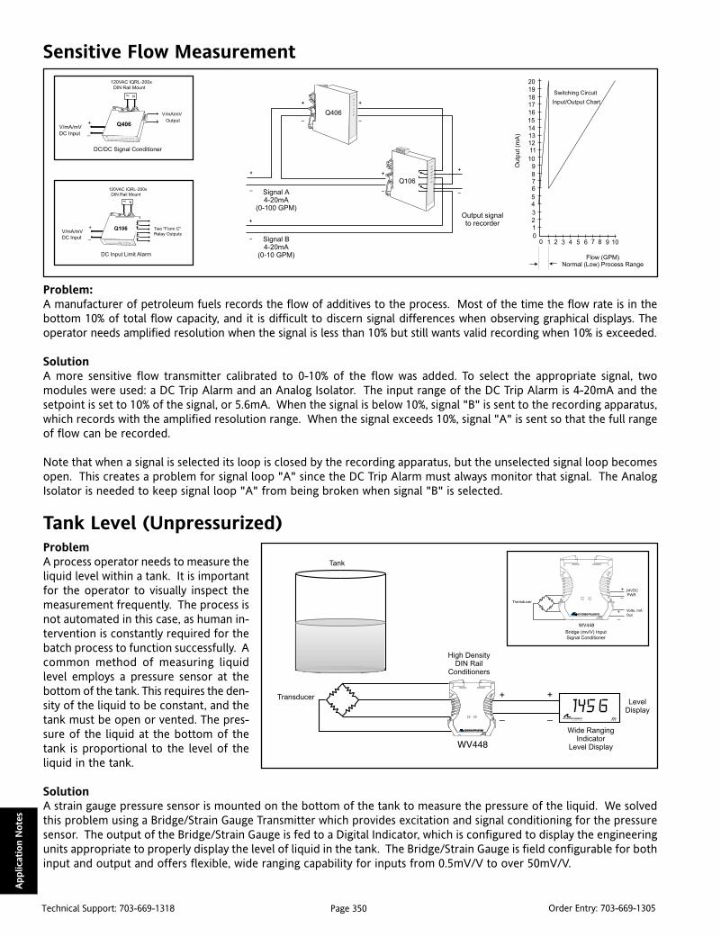
Page 350Technical Support: 703-669-1318 Order Entry: 703-669-1305
Applic
atio
n N
ote
s
Sensitive Flow Measurement
Problem:A manufacturer of petroleum fuels records the flow of additives to the process. Most of the time the flow rate is in thebottom 10% of total flow capacity, and it is difficult to discern signal differences when observing graphical displays. Theoperator needs amplified resolution when the signal is less than 10% but still wants valid recording when 10% is exceeded.
SolutionA more sensitive flow transmitter calibrated to 0-10% of the flow was added. To select the appropriate signal, twomodules were used: a DC Trip Alarm and an Analog Isolator. The input range of the DC Trip Alarm is 4-20mA and thesetpoint is set to 10% of the signal, or 5.6mA. When the signal is below 10%, signal "B" is sent to the recording apparatus,which records with the amplified resolution range. When the signal exceeds 10%, signal "A" is sent so that the full rangeof flow can be recorded.
Note that when a signal is selected its loop is closed by the recording apparatus, but the unselected signal loop becomesopen. This creates a problem for signal loop "A" since the DC Trip Alarm must always monitor that signal. The AnalogIsolator is needed to keep signal loop "A" from being broken when signal "B" is selected.
Tank Level (Unpressurized)ProblemA process operator needs to measure theliquid level within a tank. It is importantfor the operator to visually inspect themeasurement frequently. The process isnot automated in this case, as human in-tervention is constantly required for thebatch process to function successfully. Acommon method of measuring liquidlevel employs a pressure sensor at thebottom of the tank. This requires the den-sity of the liquid to be constant, and thetank must be open or vented. The pres-sure of the liquid at the bottom of thetank is proportional to the level of theliquid in the tank.
SolutionA strain gauge pressure sensor is mounted on the bottom of the tank to measure the pressure of the liquid. We solvedthis problem using a Bridge/Strain Gauge Transmitter which provides excitation and signal conditioning for the pressuresensor. The output of the Bridge/Strain Gauge is fed to a Digital Indicator, which is configured to display the engineeringunits appropriate to properly display the level of liquid in the tank. The Bridge/Strain Gauge is field configurable for bothinput and output and offers flexible, wide ranging capability for inputs from 0.5mV/V to over 50mV/V.
Q406
DC/DC Signal Conditioner
V/mA/mV
DC Input
120VAC IQRL-200x
DIN Rail Mount
Output
V/mA/mV
~ N
Q106
DC Input Limit Alarm
V/mA/mV
DC Input
120VAC IQRL-200x
DIN Rail Mount
~ N
Two "Form C"
Relay Outputs
24VDC
PWR
Bridge (mv/V) Input
Signal Conditioner
Volts, mA
Out

Page 351Technical Support: 703-669-1318 Order Entry: 703-669-1305
Applicatio
n N
otes
Tank Level (Pressurized)
ProblemThe liquid level of a pressurized tank needs to be measured. Since the tank is sealed, the pressure above the liquid will notbe constant and the simple method of measuring the pressure at the bottom of the tank is not accurate.
SolutionUnder these conditions, pressure in the tank that is not caused by the weight of the liquid must be subtracted from thebottom pressure. The pressure measured at X is equal to the pressure caused by the weight of the liquid plus the pressureat U, known as the ullage pressure. The two Bridge/Strain Gauge Transmitters provide excitation to the pressure sensorsat X and U, and scale the signals from them into 0-10VDC. The outputs of the two Bridge Strain Gauge Isolators areconnected to the Q498, which performs the subtraction, the result of which is displayed on a Digital Indicator. An emptytank yields a null condition (Zero volts are sent to the indicator). As the tank fills, there is a pressure differential, and thevoltage sent to the Digital Indicator increases proportionally to the level in the tank.
Motor Load
ProblemA mining operation has several pieces of machinery, such as conveyor belts and crushers, that are driven by electricmotors. Because of the nature of ore, it is quite possible for the motors to become overloaded, resulting in damage tobearings, brushes, and rotor bars. The operator wants to measure the load on a motor and shut it off when the loadbecomes too great.
SolutionThe current drawn by a motor is proportionalto the load applied to the motor. A currenttransformer is placed in the power line to themotor. Installing a 0.1 ohm shunt resistor con-verts the secondary current into a low level volt-age for the AC Input Trip Alarm. As the load onthe motor increases, the current increases. Thetrip alarm is set to trip at the current level cor-responding to the maximum safe load. The dy-namic deadband circuitry of the repeatedlysamples the current, which must remain beyondthe setpoint for 100 milliseconds uninterruptedbefore the limit alarm relay activates, shuttingdown the power to the motor. This eliminatestripping on nuisance spikes. The unit can alsobe configured as a latching alarm, so that themotor is not automatically restarted once theoverload is removed.
RTD
T/C
Ohm
mV
24VDC
PWR
Q488
RTD, T/C, Ohm, & mV DC
Signal Conditioner
To Display,
PLC, etc.V/mA/mV
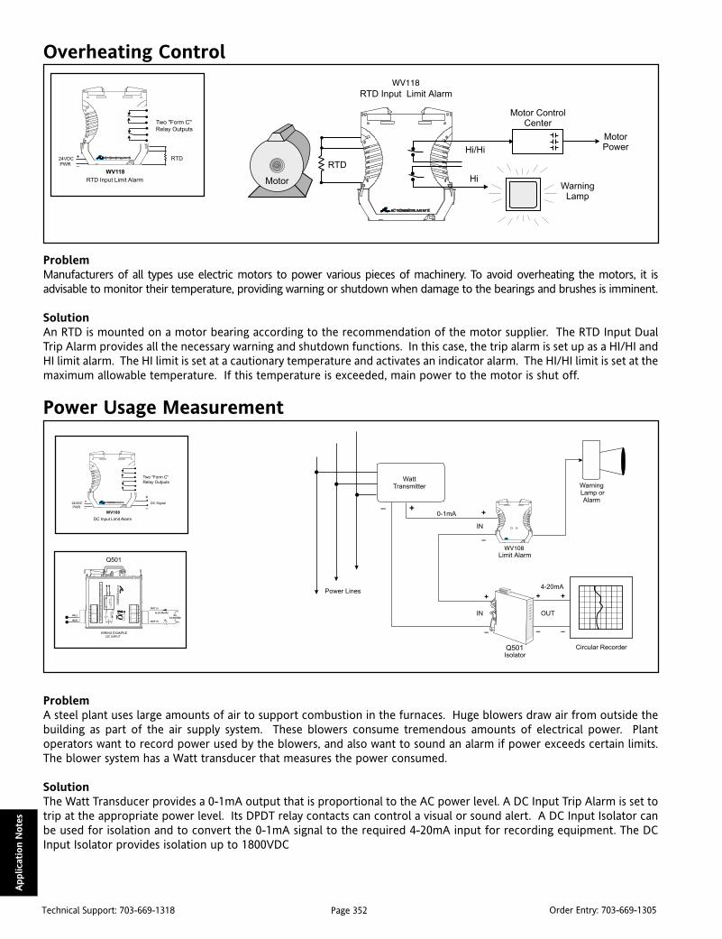
Page 352Technical Support: 703-669-1318 Order Entry: 703-669-1305
Applic
atio
n N
ote
s
Overheating Control
ProblemManufacturers of all types use electric motors to power various pieces of machinery. To avoid overheating the motors, it isadvisable to monitor their temperature, providing warning or shutdown when damage to the bearings and brushes is imminent.
SolutionAn RTD is mounted on a motor bearing according to the recommendation of the motor supplier. The RTD Input DualTrip Alarm provides all the necessary warning and shutdown functions. In this case, the trip alarm is set up as a HI/HI andHI limit alarm. The HI limit is set at a cautionary temperature and activates an indicator alarm. The HI/HI limit is set at themaximum allowable temperature. If this temperature is exceeded, main power to the motor is shut off.
Power Usage Measurement
ProblemA steel plant uses large amounts of air to support combustion in the furnaces. Huge blowers draw air from outside thebuilding as part of the air supply system. These blowers consume tremendous amounts of electrical power. Plantoperators want to record power used by the blowers, and also want to sound an alarm if power exceeds certain limits.The blower system has a Watt transducer that measures the power consumed.
SolutionThe Watt Transducer provides a 0-1mA output that is proportional to the AC power level. A DC Input Trip Alarm is set totrip at the appropriate power level. Its DPDT relay contacts can control a visual or sound alert. A DC Input Isolator canbe used for isolation and to convert the 0-1mA signal to the required 4-20mA input for recording equipment. The DCInput Isolator provides isolation up to 1800VDC
Two "Form C"
Relay Outputs
WV118
RTD
RTD Input Limit Alarm
24VDC
PWR
Two "Form C"
Relay Outputs
DC Input Limit Alarm
WV108
DC Signal24VDC
PWR
Q501

Page 353Technical Support: 703-669-1318 Order Entry: 703-669-1305
Applicatio
n N
otes
Low Air Pressure Detection
ProblemSome automated assembly lines use pneumatic nailers in various stages of the operation, as in this case with furnituremanufacturing. If the supply of air pressure to a nailer should drop below a certain level, incorrect nailing can occurwhich would result in waste material. The operator needs to detect inadequate pressure so that they can shut down theappropriate phase of assembly.
SolutionThe Bridge/Strain Gauge Transmitter is used to provide excitation to the pressure sensor and transmit a signal to a DCInput Trip Alarm. The alarm is set to trip when the pressure level drops too low, and with the adjustable deadband, resetwhen the pressure returns to normal.
Optionally, if the pressure sensor is a two-wire device, one DC Input Trip Alarm is all that is required. The internal loopsupply allows the DC Trip Alarm to power the loop and monitor the current, all in one module. The DC Trip Alarmprovides a relay contact closure at a preset DC input level.
Multiple Temperature ZonesProblemA maker of ceramic insulators is expanding operations and installing a new 3-zone furnace. The curing process of theceramic parts involves passing them through the zones of the furnace slowly on a conveyor belt. Each zone is maintained ata different temperature. The operator needs to condition the signals from three thermocouples, display the temperature,and provide a 4-20mA signal for the temperature controllers.
SolutionThe Thermocouple Transmitterisolates and linearizes thermo-couple signals, and provides a 4-20mA signal proportional totemperature for indication andcontrol. The Loop-Powered Indi-cator displays individual zonetemperatures. Note that eachzone has a separate thermo-couple, conditioner, indicatorand controller. The Thermo-couple Transmitter features wideranging zero and spanadjustability and offers thermo-couple burnout detection for allthe popular thermocouple types.
Two "Form C"
Relay Outputs
DC Input Limit Alarm
WV108
DC Signal24VDC
PWR
24VDC
PWR
Bridge (mv/V) Input
Signal Conditioner
Volts, mA
Out
RTD
T/C
Ohm
mV
Q486
RTD, T/C, Ohm, & mV DC
Signal Conditioner
To Display,
PLC, etc.V/mA/mV
~ N
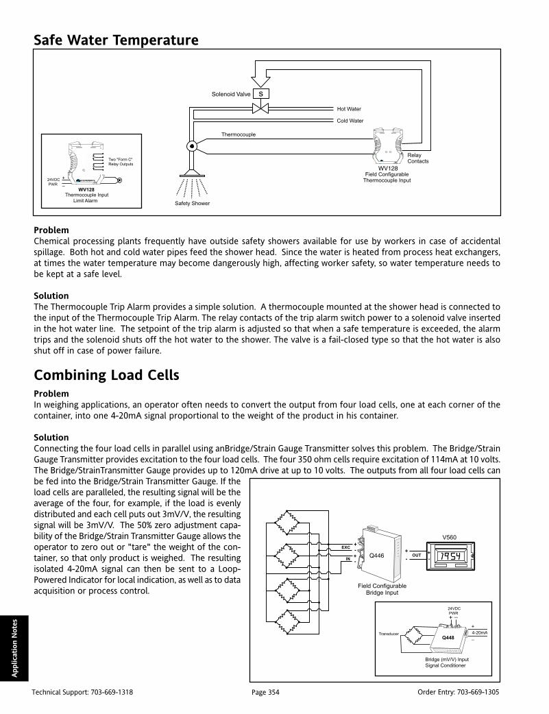
Page 354Technical Support: 703-669-1318 Order Entry: 703-669-1305
Applic
atio
n N
ote
s
Safe Water Temperature
ProblemChemical processing plants frequently have outside safety showers available for use by workers in case of accidentalspillage. Both hot and cold water pipes feed the shower head. Since the water is heated from process heat exchangers,at times the water temperature may become dangerously high, affecting worker safety, so water temperature needs tobe kept at a safe level.
SolutionThe Thermocouple Trip Alarm provides a simple solution. A thermocouple mounted at the shower head is connected tothe input of the Thermocouple Trip Alarm. The relay contacts of the trip alarm switch power to a solenoid valve insertedin the hot water line. The setpoint of the trip alarm is adjusted so that when a safe temperature is exceeded, the alarmtrips and the solenoid shuts off the hot water to the shower. The valve is a fail-closed type so that the hot water is alsoshut off in case of power failure.
Combining Load CellsProblemIn weighing applications, an operator often needs to convert the output from four load cells, one at each corner of thecontainer, into one 4-20mA signal proportional to the weight of the product in his container.
SolutionConnecting the four load cells in parallel using anBridge/Strain Gauge Transmitter solves this problem. The Bridge/StrainGauge Transmitter provides excitation to the four load cells. The four 350 ohm cells require excitation of 114mA at 10 volts.The Bridge/StrainTransmitter Gauge provides up to 120mA drive at up to 10 volts. The outputs from all four load cells canbe fed into the Bridge/Strain Transmitter Gauge. If theload cells are paralleled, the resulting signal will be theaverage of the four, for example, if the load is evenlydistributed and each cell puts out 3mV/V, the resultingsignal will be 3mV/V. The 50% zero adjustment capa-bility of the Bridge/Strain Transmitter Gauge allows theoperator to zero out or "tare" the weight of the con-tainer, so that only product is weighed. The resultingisolated 4-20mA signal can then be sent to a Loop-Powered Indicator for local indication, as well as to dataacquisition or process control.
Thermocouple Input
Limit Alarm
WV128
24VDC
PWR
Two "Form C"
Relay Outputs
Q448
Bridge (mV/V) Input
Signal Conditioner
4-20mA
24VDC
PWR
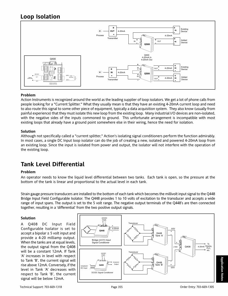
Page 355Technical Support: 703-669-1318 Order Entry: 703-669-1305
Applicatio
n N
otes
Loop Isolation
ProblemAction Instruments is recognized around the world as the leading supplier of loop isolators. We get a lot of phone calls frompeople looking for a "Current Splitter." What they usually mean is that they have an existing 4-20mA current loop and needto also route this signal to some other piece of equipment, typically a data acquisition system. They also know (usually frompainful experience) that they must isolate this new loop from the existing loop. Many industrial I/O devices are non-isolated,with the negative sides of the inputs commoned to ground. This unfortunate arrangement is incompatible with mostexisting loops that already have a ground point somewhere else in their wiring, hence the need for isolation.
SolutionAlthough not specifically called a "current splitter," Action's isolating signal conditioners perform the function admirably.In most cases, a single DC Input loop isolator can do the job of creating a new, isolated and powered 4-20mA loop froman existing loop. Since the input is isolated from power and output, the isolator will not interfere with the operation ofthe existing loop.
Tank Level DifferentialProblemAn operator needs to know the liquid level differential between two tanks. Each tank is open, so the pressure at thebottom of the tank is linear and proportional to the actual level in each tank.
Strain gauge pressure transducers are installed to the bottom of each tank which becomes the millivolt input signal to the Q448Bridge Input Field Configurable Isolator. The Q448 provides 1 to 10 volts of excitation to the transducer and accepts a widerange of input spans. The output is set to the 5 volt range. The negative output terminals of the Q448’s are then connectedtogether, resulting in a ‘differential’ from the two positive output signals.
Solution
A Q408 DC Input FieldConfigurable Isolator is set toaccept a bipolar ± 5 volt input andprovide a 4-20 milliamp output.When the tanks are at equal levels,the output signal from the Q408will be a constant 12mA. If Tank‘A’ increases in level with respectto Tank ‘B’, the current signal willrise above 12mA. Conversely, if thelevel in Tank ‘A’ decreases withrespect to Tank ‘B’, the currentsignal will be below 12mA.
Q500
Q448
Bridge (mV/V) Input
Signal Conditioner
4-20mA
24VDC
PWR
Q408
DC/DC Signal Conditioner
V/mA/mV
DC Input
24VDC
PWR
Output
V/mA/mV

Page 356Technical Support: 703-669-1318 Order Entry: 703-669-1305
Applic
atio
n N
ote
s
Controlling Thermocouple Calibration Errors Caused by Thermal Shock“Cold Junction Temperature sensing is the Achilles Heel of temperature measurement.”
When thermocouples are wired directly to control instrumentation, it is often the instruments’ thermal behavior whichlimits performance. Excessive warm-up times and poor repeatability are common problems. When the effective coldjunction is at the input terminals of an instrument, measuring its temperature accurately requires the CJT sensor belocated very close (in a thermal sense) to those terminals. The successful measurement of temperature by an instrumentusing a thermocouple is dependent upon three things:
· the location of the thermocouple ‘Hot Junction’ relative to the load or work being processed
· the accuracy, drift and calibration of the measurement electronics
· the ability of the cold junction sensor to properly measure the CJT, Cold Junction Temperature
Locating the hot junction of the thermocouple at the work is a simple or easily understood task. Accuracy, drift andcalibration of the measuring electronics is clearly specified in instrument data sheets and can be maintained. SuccessfulCJT measurement is another story. CJT measurement is based on many factors, some of which are based on the mechanicsof the rear of the instrument. The location of the CJT sensor, the thermal mass of the entire instrument and changes inthe local ambient temperature all affect the cold junction temperature measurement. These uncontrollable characteristicsof the CJT circuit account for why ‘CJT sensing is the Achilles Heel of temperature measurement’.
ProblemDuring routine maintenance of control cabinets, it is an accepted practice to open a cabinet to check the state of a relaycoil or replace a blown fuse or even retrieve a misplaced tool or blueprint. It is also common to air-condition a controlcabinet to prolong the life of the electronics. Air-conditioning is even more common in hot climates, which includesmost of the United States.
Consider what happens when an air-conditioned control cabinet is opened on a hotsummer day. When closed, the cabinet ambient is controlled to around 65 degrees F.The outside room ambient on a hot August afternoon can easily exceed 110 degrees F.Conventional temperature transmitters are mounted in the control cabinet. When thedoor is opened, the temperature transmitters are exposed to the 110 degree room air;they are subjected to a 45 degree F thermal shock. This thermal shock alters the ColdJunction Temperature and, more importantly, the ability of the CJT sensor to accuratelymeasure the CJT. In short, the transmitter is out of calibration until it returns to equilibrium.The amount of calibration error and the settling time varies with the instrument. Sometransmitters are quick to respond while others with high thermal mass are quite sluggish.Some transmitters deviate by only a small amount while others with loosely coupled CJTsensors may have 5 or even 10 degree excursions before returning to an accurate reading.
What makes this situation worse is that the calibration error is not apparent to the operator. Quite often, the instrument’ssignal will be used to control the process to this new offset value which is in fact in error. Simply put, the instrument isout of cal and nobody knows.
Anyone in charge of a process which must be controlled to within 2 degrees F must be keenly aware ofthis phenomenon.
SolutionThe Q486, Q488 and WV428 temperature transmitters use a patenteddual sensor method of measuring CJT. We call this technique ‘InstantAccuracy.’ One sensor is used to measure the CJT near the rear terminalsof the instrument, and the second is used to extrapolate out to the rearterminals. In this way, the CJC network can compensate for any heatflow temperature error and respond quickly to internal warming affectsas well as external influences. This extrapolation makes these transmittershighly responsive to ambient temperature changes and also providesrapid recovery to stability.
Note that there is some calibration shift as a result of a change in ambientconditions - this is caused by the imperfect nature of the Cold JunctionCompensation and is specified in the data bulletins for the products. Recovery time from thermal shock is often notspecified, however. The graph details the recovery of a Q488 to a 25°C thermal plunge. The peak excursion was 1.15°Cbut settled within 15 minutes at the final offset value of 0.6°C. Even the best competitive instrument tested was found tobe still settling in after one hour and the maximum excursion was almost 2°C. The worst instrument tested exhibited anexcursion of over 5°C as a result of a 25 degree thermal plunge.
The thermal plunge associated with opening a control cabinet door can have a major effect on product quality for criticalprocesses. The most devastating aspect of this is that the transmitter appears to be functioning properly with no ill effectswhereas, in fact, it is out of calibration and producing substandard product.

Page 357Technical Support: 703-669-1318 Order Entry: 703-669-1305
Applicatio
n N
otes
Displaying Flow
Problem:In many processes, the flow of a liquid or gas may need to be indicated or visually monitored, often for safety or qualityreasons. Examples are chemicals that are mixed into a product, steam used to provide heat, or fuel used by engines topower equipment. Differential pressure transmitters are often used to provide the flow signal. A differential pressuretransmitter yields a flow signal that is proportional to the square root of the pressure difference between the two pointsseparated by a restriction in the flow line. To linearize the display, a squre root function must be applied.
Solution:Action’s high performance VisiPak V565 Loop-Powered Digital Indicator is perfect for thistype of application. The indicator is poweredfrom the same current loop as the pressuretranmitter and performs the square root func-tion to correctly display the flow. The wideadjustability of the V565 assures that it canbe set to display in the desired engineeringunits. No additional wiring is required.
Mass Flow
Problem:To determine the mass flow and density of a polymer, a chemical company has chosen to use an in-line mass flowtransmitter. The flow transmitter outputs a 0-10kHz signal proportional to mass flow, but the operator uses a hostcomputer that requires a 4-20mA input signal.
Solution:Since line power is not easily available in the area of the plant where the flow sensor is located, Action’s TransPak T773 Two-Wire Frequency Transmitter can be used to eliminate the cost and danger of routing power lines in a processing plant. TheT773 is located near the flow sensor and receives loop power from the Action Pak AP9046 Power Supply, which is locatedwhere 120Vac is easily available. The resulting 4-20mA proportional signal is sent to the host computer for monitoring. Insome cases, the host computer can supply loop voltage, further simplifying the solution.
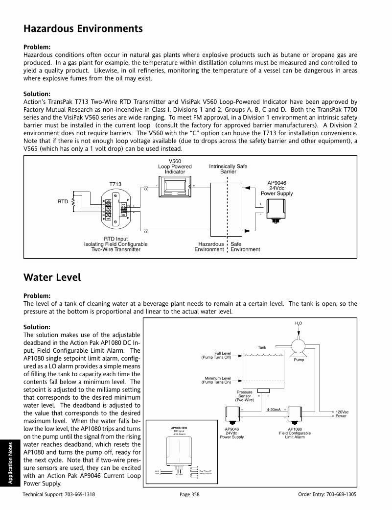
Page 358Technical Support: 703-669-1318 Order Entry: 703-669-1305
Applic
atio
n N
ote
s
Hazardous Environments
Problem:Hazardous conditions often occur in natural gas plants where explosive products such as butane or propane gas areproduced. In a gas plant for example, the temperature within distillation columns must be measured and controlled toyield a quality product. Likewise, in oil refineries, monitoring the temperature of a vessel can be dangerous in areaswhere explosive fumes from the oil may exist.
Solution:Action’s TransPak T713 Two-Wire RTD Transmitter and VisiPak V560 Loop-Powered Indicator have been approved byFactory Mutual Research as non-incendive in Class I, Divisions 1 and 2, Groups A, B, C and D. Both the TransPak T700series and the VisiPak V560 series are wide ranging. To meet FM approval, in a Division 1 environment an intrinsic safetybarrier must be installed in the current loop (consult the factory for approved barrier manufacturers). A Division 2environment does not require barriers. The V560 with the “C” option can house the T713 for installation convenience.Note that if there is not enough loop voltage available (due to drops across the safety barrier and other equipment), aV565 (which has only a 1 volt drop) can be used instead.
Water Level
Problem:The level of a tank of cleaning water at a beverage plant needs to remain at a certain level. The tank is open, so thepressure at the bottom is proportional and linear to the actual water level.
Solution:The solution makes use of the adjustabledeadband in the Action Pak AP1080 DC In-put, Field Configurable Limit Alarm. TheAP1080 single setpoint limit alarm, config-ured as a LO alarm provides a simple meansof filling the tank to capacity each time thecontents fall below a minimum level. Thesetpoint is adjusted to the milliamp settingthat corresponds to the desired minimumwater level. The deadband is adjusted tothe value that corresponds to the desiredmaximum level. When the water falls be-low the low level, the AP1080 trips and turnson the pump until the signal from the risingwater reaches deadband, which resets theAP1080 and turns the pump off, ready forthe next cycle. Note that if two-wire pres-sure sensors are used, they can be excitedwith an Action Pak AP9046 Current LoopPower Supply.
AP1080-1090
DC Input Limit Alarm
A/mV
nput
Two "Form C"
Relay OutputsAC PWR

Page 359Technical Support: 703-669-1318 Order Entry: 703-669-1305
Applicatio
n N
otes
“Long Distance” 4-20mA
Problem:The city of Hillsborough, North Carolina needed to monitor the level of a remote tank in their wastewater treatmentsystem. The tank is over 4 miles away from the monitoring station. The telephone company could provide a permanent,dedicated “dry pair” of wires for only $15 a month. The catch is that they use relatively small gauge wire, and the amountof resistance in an 8 mile circuit (4 miles out and 4 miles back) was too high for a conventional 4-20mA current loop.
Solution:Action solved the problem with a unique low-cost combination of units. At the tank, a two-wire pressure sensor pro-duces a 4-20mA signal that represents the level in the tank. Power is supplied by an AP9046 24Vdc supply. The 4-20mAsignal is fed to an action AP7500 DC to Frequency Converter which converts the 4-20mA signal into a 0-500Hz signal. Thissignal is then connected to the dry pair of wires. At the receiving end, a WV478 Frequency Input, Field ConfigurableIsolator accepts the 0-500Hz signal and converts it back to 4-20mA for their monitoring purposes. There is someamplitude loss along the lines (about 5% in this case) but that still leaves adequate signal to trigger the WV478, which isable to correctly read the frequency and provide an accurate output.
This solution represents a major cost savings for the city of Hillsborough, compared to the least expensive single-pointtelemetry units, which start at around $1200.
Powering Multiple Transmitters
Problem:We are frequently asked how to wire a circuit that uses a single powersupply to power multiple two-wire transmitters. These loops typicallyfeed computer analog input cards, I/O Pak Plus input modules, or anynumber of other receiving devices.
Solution:The correct wiring is shown here. The power supply can be anAP9046 (65mA) for up to 3 loops, or a T609 (600mA) for up to 30loops. Although all of the loops shown here share the one commonpower supply, each receiving device is in a section of the loop uniqueto each transmitter. As always, we highly recommend using iso-lated, two-wire transmitters (i.e., the T700 Series) to avoid groundloops from sensors that are grounded. In most cases, the negativeinput terminals on analog input cards are tied together to thecomputer’s ground as a common. This makes the use of isolatingtransmitters mandatory.
WV478
Frequency Input
Signal Conditioner
Frequency
Input
V/mA/mV
Output
24VDC
PWR

Page 360Technical Support: 703-669-1318 Order Entry: 703-669-1305
Applic
atio
n N
ote
s
Ramping a 4-20mA Output
Problem:Most industrial facilities use motorized valves somewhere in their system. Operators often manually adjust the positionof these valves by generating a 4-20mA control signal to drive the valve’s positioner. To minimize wear and tear on thesevalves, it is desirable to limit the rate at which the valves open and close. We are often asked to provide a device that willcreate a 4-20mA signal that can be ramped up or down using a pushbutton.
Solution:The Action Pak AP4830 Up/Down Ramp Generator can be configured to do exactly this with a minimum of external parts.The AP4830 is quite flexible and can support complex ramping requirements. In this application, all that is required is theup and down pushbuttons and one 10k Ohm potentiometer to set the ramp rate. Typically, the operators would haveaccess to the pushbuttons, but not the potentiometer. As long as they hold one of the pushbuttons closed, the valve willmove at the preset rate. If neither button is closed, the valve will maintain its poistion. It is common practice to includean indicator such as the V560 loop powered indicator in the output loop to display valve position. This arrangement hasalso been used to control the speed of large fans, and the position of overhead cranes or other equipment that reequiresgentle adjustment.
Remote Signal Conditioning for Industrial Sensors
Two-wire transmitters amplify and condition low voltage signals generated by industrial process sensors such as thoseused for temperature (thermocouples and RTDs), frequency (magnetic and photocell pickups), force and strain (loadcells and strain gauges), and position (potentiometers and LVDTs).
Once conditioned, the signals can be transmitted over long distances (often up to several thousand feet) to panel meters,controllers, data loggers, chart recorders, industrial computers, and other process instrumentation. The most commonrequirement of today’s receivers is a 4 to 20 mA current proportional to the sensor output.
Two-wire transmitters are so named because they require only two wires to carry both the output signal and the powersupply. The transmitter draws a small current from a DC power supply, in direct proportion to the level of the inputsignal. In a 4-20mA loop, for example, a transmitter for thermocouples draws 4mA at the lowest reported temperature.As temperature increases, the transmitter draws more current until reaching 20mA at the highest reported temperature.
Internal conditioning circuitry, powered by a portion of the loop current, determines the temperature range representedby the output signal. The power supply’s voltage level determines the line drive capability of the transmitter.
Advantages of Two-Wire TransmittersTwo-wire transmitters offer major advantages over other types of transmitters. To assuremore accurate measurements,their current output does not attenuate over distance as do DC voltage signals from four-wire transmitters or sensorswhich connect directly to a receiver. Furthermore, their current output is highly immune to noise pickup, especially whencompared to the signal from the sensor itself. Any residual noise voltage is usually eliminated by the common moderejection of the receiver.
The natural noise immunity of two-wire transmitters also eliminates costs associated with installing expensive extensioncables, and providing and maintaining adequate shielding against large electric motors and other electromagnetic orinductive fields commonly found in industrial environments.

Page 361Technical Support: 703-669-1318 Order Entry: 703-669-1305
Applicatio
n N
otes
Two-wire transmitters also save the cost of running a separate set of power cables, which are often 120Vac in four-wiresystems. This enables two-wire transmitters to comply with safety requirements that restrict the use of AC power inhazardous locations such as chemical environments and dusty atmospheres.
Since they employ only low level current, TransPak transmitters are intrinsically safe. And many are Factory Mutual andCanadian Standards Association approved for intrinsically safe operation, even in explosive environments.
Electrical IsolationRemote sensors and their receivers are usually electrically grounded to suppress noise pickup and to protect them fromlightning. Since there is typically a difference in voltage potential between two grounding points on the earth’s surface,current can flow between the grounding points and induce an error signal on the transmission line.
To prevent these “ground loops” from occurring, users can select an isolating two-wire transmitter. This type of transmit-ter electronically isolates the sensor signal from the output current loop, enabling the system to be safely grounded atboth the sensor and the receiver. Besides reducing measurement errors, isolation provides protection for personnel andequipment.
Loop DriveThe capability of two-wire transmitters to provide accurate transmission over long distances can be calculated using thefollowing formula:
where:
= Supply voltage of power source (volts)
= Transmitter’s minimum operating voltage (volts)
= Transmitter’s maximum output current (amps)
= Loop’s maximum resistance (ohms)
If, for example, the selected output current is 4 to 20mA, the supply voltage is 90 volts, and the drop required by thetransmitter is 12 volts, the equation is expressed as:
The transmitter can therefore deliver accurate signals over any connecting line in which the resistance does not exceed3900 Ohms.

Page 362Technical Support: 703-669-1318 Order Entry: 703-669-1305
Applic
atio
n N
ote
s
Alternaive 1:The most elementary way to transmit thermocouplesignals is to run special extension wire from the coldjunction to the control room. This practice is notacceptable because thermocouple wire is expensiveand, unless well shielded, will lead to noise pickupfrom electric motors, generators, radio transmitters,power lines, etc. Since thermocouple signals are onlya few millivolts, any noise is a problem, and it doesn’ttake much to completely mask the temperature data.
Alternative 2:The risks of noise pickup can be reduced by using afour-wire transmitter with voltage output to amplifythe signal at the cold junction. Whereas 20 mV ofinduced noise can completely mask a 0 to 10mVsignal in Alternative 1, its effect is greatly reduced ifthe signal is amplified to 0 to 10 volts. In actualpractice, however, several volts of noise can be en-countered, resulting in degradation of even a 0 to10 volt signal.
Another weakness in four-wire transmitters is voltageloss due to the resistance of the extension wires, result-ing in system calibration being dependent on line lengthand temperature. Line losses can be overcome by ahigh input impedance receiving device, but this makesthe system even more susceptible to noise pickup.
Alternative 3:Significant advantages are realized if the transmitterhas a current output instead of a voltage output.The threat of resistance losses is eliminated becausethe current remains constant. Also, noise pickup isvirtually eliminated by the inherent noise immunityof the current line. This allows use of low cost,twisted-pair connection wire, representing consid-erable savings over the shielded cable required inAlternative 2. The wires are twisted so that any noisewill appear on both lines and will therefore be fil-tered out by the common mode rejection of thereceiving device. The only remaining challenge is toeliminate the two extra wires used to power thetransmitters in Alternative 2 and 3.
Alternative 4:The best alternative is a two-wire transmitter whichemploys a single pair of wires to carry both the cur-rent signal and the power supply. This system hasall of the advantages of current output systems (highnoise immunity, no line losses, and inexpensive con-necting wires). It has the added advantage of notrequiring a separate set of power wires. Moreover,since the supply is DC, the transmission can be in-trinsically safe all the way back to the sensor.
Evolution of the Two-Wire Transmitter

Page 363Technical Support: 703-669-1318 Order Entry: 703-669-1305
Applicatio
n N
otes
Summing Two Flows
ProblemA customer needs to find the sum of two flow transmitters, provide a visual warning of an overflow condition and recordtotal flow from the transmitters.
Solution
We suggested a system utilizing the Q498 Math Module, the Q108 Field Configurable Limit Alarm, two flow transmittersand a chart recorder.Each flow transmitter (FT) draws 4 to 20mA (based on product flow) from the 24VDC power supply.The two 4-20mA signals are fed into the Q498 Math Module. The Q498 is a highly configurable multi-input modulecapable of providing various math functions such as addition, subtraction, multiplication, etc. In this application, thesignals are summed.
The Q108’s input terminals are connected in series with the chart recorder. Both the Q108 and the chart recorder areconfigured for a current input. When flow exceeds a predetermined setpoint, the Q108 limit alarm trips.
PLC/DCS Loop Isolation
ProblemOne of the more common requests we receive is based on the need to “isolate” a 4-wire field transmitter from a PLC orDCS that supplies loop power. This is not “isolation” in the traditional sense of eliminating ground loops. In this case, theproblem is that there are too many devices powering the 4-20mA loop.
SolutionBy definition, a 4-wire transmitter supplies the required loop voltage ( “sources” the current - sometimes referred to asan “active output”). This is handy when the field device is a 2-wire transmitter (“current sinking” or “passive”). Theproblem arises when the receiving device also tries to put voltage on the loop.
The benefits of 2-wire transmitters are well documented, and frequently analog input cards have loop power built in asa “feature”. But when the field device is a 4-wire transmitter, sending a current signal out towards the PLC, and the PLCis trying to push current into that output, there is literally a collision of currents. In many instances, the customer has acombination of 2- and 4-wire transmitters, and frequently experiences a mismatched loop or two.
Action is better prepared than ever to “isolate” (buffer?) these two competing power supplies. The Q501, in single anddual channel formats, is ideally suited to the task. This unit is a 2-wire transmitter, satisfying the demands of the inputdevice supplying loop power. Traditionally, 2-wire transmitters were packaged for rugged field locations (like Action’sT700 series), but more and more 2-wires are finding their way into cabinets, and the DIN rail mount format and dualchannel design of the Q501 is perfect for such installations.
Q108
DC Input Limit Alarm
V/mA/mV
DC Input
Two "Form C"
Relay Outputs
24VDC
PWR

Page 364Technical Support: 703-669-1318 Order Entry: 703-669-1305
Applic
atio
n N
ote
s
Loop Drive CapabilityProblemWhen designing a two-wire loop-powered system, the voltage supply selected is an important consideration. The supplymust be of sufficient voltage to drive all components in the current loop. Two-wire transmitters typically require from 10to 13 volts to operate and each device in the system will produce a voltage across its shunt resistance.
SolutionTo determine the minimum supply voltage needed, you must know the total resistance in the current loop. Multiply thetotal resistance by 0.02 and add the two-wire transmitter’s requirement. The 0.02 represents the maximum current of 20mA, hence the maximum voltage requirement. The general formula is:
VSmin = (R
L x 0.02) + V
t
where:VS min is the minimum voltage supply requiredRL is the total resistance in the current loopVt is the transmitter voltage requirement
For example, a system using a Transpak T797-0000 is con-nected in series to the input of a PLC and a chart re-corder. Since the T797 requires 12 volts to operate andthe input impedance of the PLC and recorder are 250Ohms each, we have a minimum voltage requirement of22 volts: (500 x .02) + 12 = 22. A 24 volt supply is suffi-cient to drive the 4-20 mA current signal through all de-vices in the system. When existing loop-powered systemsare being expanded, determining voltage supply require-ment is equally important. If the above system was beingexpanded to accommodate a remote loop-powered display, would you choose the Visipak V560 or the V565? Only theV565 would work without changing the power supply. The V565 requires only 1 volt from the supply to operate,resulting in a total voltage requirement of 23 volts. Selecting the V560 (which requires 4 volts to operate) would meanthat you would need a minimum supply voltage of 26 volts to ensure proper operation.
Differential Temperature - Measurement & DisplayProblemHow to measure and display differential temperature.
SoutionThis is an example of an easy and accurate way of displaying differential temperature measurements using thermo-couples. The Action Pak 4351-2001 or, if a DIN rail mounting is preferred, the ActionI/Q Q486-0000’s are used to linearizethe thermocouple signal. By tying thenegative output of the devices togetherand running the positive outputs intothe Action Pak 4380-2000, the 4380becomes a differential amplifier and theoutput will represent the temperaturedifference between the two thermo-couples.
To alarm on the difference, an ActionPak 1080-2000 (single trip) or an ActionPak 1090-2000 (dual trip) can be usedin place of the 4380. A Visipak display isused to show the actual difference ofthe thermocouple signals.
4351-2000or
Q486-0001
4351-2000or
Q486-0001
4380-2000
0 - 5V
0 - 5V
+
+
+
-
-
-
123.4
C
VisipakDisplay
+/- 5V

Page 365Technical Support: 703-669-1318 Order Entry: 703-669-1305
Applicatio
n N
otes
Differential Temperature ControlProblemAn engineer called and told us she was heating both sides of her product and it was critical to keep the temperatureswithin a couple of degrees of each other. She wanted a system to monitor both sides and modulate the burners to keepthe temperatures tracking each other. She had a burner controller that accepted a single input. She also needed anindication if the temperatures exceeded a specified differential.
SolutionFor this application, we chose a T287-0000 temperature transmitter. The T287-0000 is a head mount, PC configurable,temperature transmitter that can be con-figured for a differential thermocoupleinput. The 4/20 mA dc output representsthe differential temperature. When bothtemperatures are equal the output willbe at 12 mA. The controller will respondto heat the A side of the product if the4/20 mA signal is less than 12 mA, andthe B side if the 4/20 mA signal is greaterthan 12 mA.
The indication of excessive variance is accomplished using a Q108-0000 (or G108). The Q108-0000’s configurable input isset for the 20 mA input range. One setpoint is configured as a ‘Hi’ trip, the other as a ‘Lo’ trip. The setpoints are adjustedfor the specified temperature differential. When A exceeds B by the specified temperature differential the ‘Hi’ relay willtrip. Similarly, when B exceeds A by the specified differential the ‘Lo’ relay will trip.
The Q108-0000 has an isolated 24 Vdc, 20 mA source to power the T287-0000. The T287-0000 causes a mere 9 V drop, allowingfor 15 V drive remaining in the current loop, more than enough to accommodate the input of the controller. If the T287-0000is not mounted in a thermocouple head junction assembly it can be DIN rail mounted next to the Q108-0000.
Debounce Circuit
ProblemOne of our customers is using the Q476, AC powered, frequency to DC isolator. The (standard) 10V excitation source is usedto drive a relay. The relay provides an input frequency from 0-2.32Hz and the Q476 is set to provide a 0-1mA output to achart recorder. The graph of their chart recorder, scaled for 0-1mA, is shown below. The horizontal axis shows a time frameof about eight hours. As can be seen, whenever the output rises to about 500uA, it begins to intermittently slam high.
SolutionThe module was returned to us to determinewhy there was a spike on the output. A relaywas connected to the input terminals and sureenough, the spike was observed when input fre-quencies were above 1Hz. The cause was tracedto the relay which was occasionally sending afalse trip (an additional closure) to the Q476.Adding a debounce circuit to the input of theQ476 was an effective solution. A 47 Ohm resis-tor in series with a 0.1mF film capacitor acrossthe Q476’s input terminals completely sup-pressed the unwanted signal. Action not onlyprovides unparalleled assistance in helping cus-tomers select and use our products, we also pro-vide excellent after sales support.

Page 366Technical Support: 703-669-1318 Order Entry: 703-669-1305
Applic
atio
n N
ote
s
Breaking a Current-Loop, without breaking it...
ProblemA customer has a 4-20mA current loop and wants to install a loop powered indicator. The Visipak V560 is a perfect fit toprovide an LCD display in proportion to a 4-20mA signal. However, they also need the capability of removing theindicator without breaking or affecting the current signal.
SolutionBy placing a zener diode in parallel with the V560, the indica-tor can be removed without disrupting the current signal. TheV560 has an input voltage drop of 3.9 volts maximum at 20mA,so the zener diode selected must have a threshold greater than3.9 volts. Since Zener diodes operate in reverse breakdownand the zener threshold is greater that 3.9 volts, the V560 tracksthe 4-20mA signal when installed in the loop. When the V560is removed from the loop, the zener threshold is exceededand allows current to flow uninterrupted. For the typical ap-plication below using a Two-Wire Transmitter, the power sup-ply must be of sufficient voltage to drive all components in thecurrent loop. The general formula is expressed as:
Vsmin=(RL x 0.02) + Vt + Vz
where:
Vsmin is the minimum power supply required
RL is the total resistance (load) in the current loop
Vt is the transmitter voltage requirement
Vz is the zener threshold
Recommended Zener Diodes:
1. 1N750A: VZmin = 4.23V; VZmax = 5.12V2. 1n751A: VZmin = 4.59V; VZmax = 5.61V
High Current SensingProblem An engineering company is constructing a system totest solenoids. Their circuit typically generates a cur-rent flow of 1 Amp. They need to trip an alarm with ahigh current input signal.
SolutionThis application has a wide range of similar uses. A0.5 Ohm, 1 Watt precision resistor connected in se-ries with the current loop produces a 500 millivoltsignal. This 500mV signal becomes the input to anUltra Slimpak II WV108 Limit Alarm. A Hi alarm isindicated if the solenoid is drawing too much currentand a Lo alarm if the solenoid is drawing insufficientcurrent. If an AC powered module is preferred, ei-ther the Action Pak 1090-2000 or an ActionI/Q Q106-0000 can be used.

Page 367Technical Support: 703-669-1318 Order Entry: 703-669-1305
Applicatio
n N
otes
Who is Arthur Holland?Arthur Holland operates Holland Technical Skills in Oakville Ontario, a consulting engineering firm specializing inprocess instrumentation, temperature and power control technology and technical writing. He also writes a monthlycolumn on control technology in Process Heating magazine out of Bensenville, Illinois. Mr. Holland has worked as aninstrument and control engineer with Honeywell, the UK Atomic Energy Authority, Eurotherm, and Holland InstrumentCompany. He has for several years practiced his profession serving Canada’s manufacturing and research sectors.
A Look at 4-20mA SignalsArthur Holland, Holland Technical Skills
Wherever a process is monitored or controlled you find 4 – 20mA dc as the standard analog signal of choice. Ofcourse, there are others such as 0 – 5V dc and tthe many digital signal standards.
As Process VariablesEmerging from transmitters (signal converters and transducers), 4-20mA signals represent variables such as temperature,pressure and power. They are routed to controllers, indicators, PLCs, DCS systems etc., to be used in display, control andalarm monitoring of the process.
Transducers handling non-linear inputs, for example, thermocouples and differential pressure flowmeters, often handthe job of linearizing the signal over to the receiving device. Some so-called “smart” modules have digital processingcircuitry that can linearize the process signal. Even smarter models are configurable, meaning that you can select andrange any one of several types of process signals as the input. It is a short step from here to incorporate a digitallycoded output, typically for entry into a DCS system.
Compared with the low millivolt signals from thermocouples or RTDs, the 4-20mA signal is robust enough to ignoreelectrical interference in plant-wide wiring. The signal wire can be copper, not the more expensive, dedicated thermo-couple extension wire.
Why is this Signal Known as a Current Source?It means that the receiving circuit and wiring can have any resistance (typically between 0 and 600 ohms) withoutaffecting the accuracy of the mA signal. Similarly, a voltage source remains stable for the entire range of load resis-tances within its specification.
Loop-Powered TransmittersA loop-powered transmitter is one in which the transmitter output, an external dc power supply and the receivingdevices are strung in a series loop. Some 12 volt’s of the dc supply is dropped across the transmitter as power for theinternal electronic circuit. If the receiving device resistance is too high for the power supply, a higher voltage dcsupply (up to about 90V) can be used..Self Powered TransmittersThese have a second pair of terminals that take the normal 115V ac supply from which the now internal dc supply isderived. You can now achieve electrical isolation between all transmitters on the same ac power supply as well asbetween inputs, outputs and ground. This avoids the gross, unpredictable measurement errors that connection togrounded receiving devices can cause. Input/output isolation is also important. For example, when a thermocouple tipis exposed and vulnerable to touching high heater or process voltages (in furnaces or duct heaters). Isolation keepshazardous voltages off the plant signal wiring and avoids common-mode measurement errors.
As a control signal, the 4-20mA would come from (for example) the output of a temperature controller and feed intoa final control device such as an electro-pneumatic control valve or silicon controlled rectifier. Usually a high controlsignal calls for high output of the final control device (direct acting mode). Reverse acting is the other option, forexample, high milliamps to close a valve. So decide which action you want - if your controller or wiring should breakwith loss of milliamps, choose the mode that is fail-safe.
Force-balance principleThe 4 -20mA signal is about the right size for use in the force balance system found in pressure transmitters. Here themagnetic force of the milliamps in a coil performs a null-balance against the diaphragm pressure, resulting in anaccurate transduction of pressure to milliamps.
The same principle is used in I/P (current to pressure) converters, often incorporated into electro-pneumatic controlvalves or valve positioners where, by servo action, the valve is forced to a position proportional to the mA signal.
Signal ConvertersA simple example is the signal isolator with 4-20mA in and 4-20mA out. It is used to isolate an incoming signal that isgrounded from a receiving device that cannot tolerate a second ground reference. The input/output/ground isolationwill usually withstand about 1500V. There are many combinations of available signal ranges for both inputs andoutputs, including multiple channels, mathematical functions, and user defined linearizations. Packaging can be a DINrail mounted box or a plant mounted pillbox shaped enclosure with two pairs of terminals (for input and output - athird pair is added on models having external ac power).

Page 368Technical Support: 703-669-1318 Order Entry: 703-669-1305
Applic
atio
n N
ote
s
Signal ConditionersThe Little Hidden Boxes that Manipulate your Process SignalsArthur Holland, Holland Technical Skills
When you are planning or modifying your process control and monitoring system, the odds are you will be reaching foryour inventor’s hat. This is because there are always some functions that cannot be performed by the normal controlsystem; or there may be unforeseen requirements that need an extra device of some kind.
Look around your process and you might see small hockey-puck shaped components on the heads or inside the coversof temperature sensors. You might find others in a different package around the plant and inside control enclosures,mounted on a bulkhead or on a DIN rail. There is a good chance that these are signal conditioners, doing jobs thatcomplement that of your main control system. These are essential items in the inventor’s tool kit.
They are stand-alone components whose internal circuitry is usually powered by the 115V ac line or by a 24V dc supply.They can alternatively be loop-powered, which means that the power for the device comes from an incoming or anoutgoing 4-20mA circuit driven by its own dc power supply.
Signal conditioners have at least one pair of input terminals and one pair of output terminals. The power supply pair canbe omitted if you take loop power from a 4-20 mA input or output signal.
Input/Output Options and How they Apply to Signal isolatorsThe signal isolator may come as a millivolt in/voltage out model, with isolation, adjustable gain and offset, high inputimpedance and a robust low-impedance output signal.
A current in/current out isolator would also offer adjustable gain and offset. It would have near zero input impedance(current sink) and very high output impedance (current source). Voltage/current and current/voltage isolators are alsoavailable. De facto standard process signals are 0-10V dc and 4-20mA dc. Five-way isolation applies between input,output, power supply, relay contacts and ground. The isolation is commonly designed to withstand 700V rms ac and1000V peak. Some models can withstand up to 4000V peak.
Signal isolators are also available with an inversion option in which the output increases from 0 to 100% as the inputdecreases from 100 to 0% of working range. This could, for example, be used to convert a reverse acting control loopinto a direct acting control loop. Gain and offset adjustments are usually provided. This would allow you, for example,to adjust the working range of a control valve. Major benefits of isolation are reliable operation in electrically noisyplants and the elimination of common-mode and ground-loop problems.
Signal Conversion - Thermocouple to DC mA with IsolationThis provides a robust interference-free signal and enables use of copper extension cable in place of the more expensiveand higher resistance thermocouple extension cable. There are two things to bear in mind. Most low-cost models comewith only one choice out of a selection of the most popular thermocouples and would be factory configured (not fieldconfigurable). The output signal would conform to the same non-linear law as the thermocouple, which means that youwould have to take into account the inaccuracy if you use a linear receiving indicator or recorder.
Volt, mV and mA Signal ScalingThe gain function can be selected to be linear, or to follow a mathematical function or to follow a custom curve. Asquare root function requirement is common when handling flow signals. A custom curve can be used either tolinearize a grossly non-linear final control element which otherwise would harm control stability, or to linearize anuncommon non-linear sensor.
Math FunctionsSome models have multiple inputs that can be manipulated mathematically to form the output.
Voltage-to-Frequency (V/f) and Frequency-to-Voltage Converters.The output of V/f converters can be monitored over great distances using a telephone line and then easilyreconverted to represent a process measurement at the receiving end using an f/V converter. Models are availablewith multiple and mixed inputs and outputs.
In one case a BTU/h measurement was required, calculated from mass flow rate x (T2 – T1). Inlet and outlettemperatures T1and T2 were taken from two RTDs into a three-input conditioner. The third input was a frequencysignal representing flow from a mass flowmeter. The temperature difference (T2 – T1) was obtained and thenmultiplied by the frequency signal. The resulting dc output was scaled to show BTU/h. A second conditioner took inthe dc BTU/h signal and converted it to a frequency in which each cycle represented a fixed number of BTUs. Thefrequency was suitably scaled and totalized as BTUs on an electric counter. Later versions of conditioners can derivethe same two results using only one conditioner with multiple inputs and outputs.

Page 369Technical Support: 703-669-1318 Order Entry: 703-669-1305
Applicatio
n N
otes
3-Terminal Potentiometer to High-Level DCTwo applications here: retransmission to the control room of gate position on a hydro-electric station, and manualadjustment of a remote electro-pneumatic damper positioner.
Potentiometer to Pulse-Width ModulationOne application example is manual adjustment of percentage input of a heat process. The heat source could be gas,electricity or a heat transfer medium.
Strain Gauge Output to High Level DCWeight measurement and batch loading applications.
Alternating Voltage and Current InputsAC inputs can be converted to signals representing voltage, current, power, reactive power, kVA, power factor and,with a frequency output, pulses representing watt hours per count. Monitoring and alarm annunciation functions canminimize the demand component of energy costs.Signal Input/Output ConfigurationAn increasing number of models now are field configurable in respect to magnitude and type of input and output signal.This can be done by manual adjustments and DIP switches, or alternatively by a PC. The upmarket models linearizethermocouple and RTD signals. An LCD display is available on some models to show the process signal or as an aid tofield configuration.
Rate of Change of Signal LimiterLet’s say your process cannot tolerate more than a certain rate of change of power input, pressure, flow, etc. Someconverters offer an adjustable output ramp rate limit in the face of a wildly varying signal input.
Alarm ChoicesMultiple alarm relays or open collector outputs can be specified and configured as high, low, deviation or rate ofchange of signal.
CommunicationsModels are available with RS-232 or RS-485 communication capability, providing internet access to process signals andalarm conditions. Remote ranging and some configuration items are also possible.
Intrinsic SafetyIn this context, intrinsic safety refers to instruments and low voltage circuits designed to prevent release of sufficientenergy to ignite volatile gases. Signal conditioners are available that comply with the rules of intrinsic safety inspecified hazardous atmospheres.
Smart Field-Mounted Control ComponentsThey Obey Your Commands and Tell You How They’re DoingArthur Holland, Holland Technical Skills
You are already accustomed to the smart and versatile nature of communicating process controllers. The dumb andobedient field devices have for some time been evolving in the same way.
Access to process information and the ability to act on it is becoming faster and easier year after year. Watch-keepingand actions that once involved a walk and poke around the plant are now being done from the control room.Archived records become readily available for environmental conformity and process fault and incident analysis.
There are impressive case histories of time and cost savings on commissioning, maintenance, asset management,process up-time and record keeping. Control components that make this possible have digital electronics andsensing devices built in and are often called smart or intelligent. These are also marketing words so judge eachcase carefully.
A communications cable leaving the control room calls at each component enabling you to watch and manipulate itsparameters. This has bestowed great benefits onto process diagnostics, preventive maintenance and plant up time; anddon’t forget wiring complexity. These components include control valves, power control devices, temperature sensors,signal converters, transducers and motor drives. Controllers, indicators and PLCs have long had smart features. Theytoo are often remote but can still keep in touch with a control center.

Page 370Technical Support: 703-669-1318 Order Entry: 703-669-1305
Applic
atio
n N
ote
s
Control ValvesA control valve is not often located where you can see it working. You may see its 4-20mA command signal and ananalog position signal in the control room. What more could you want to do without leaving your seat?
Control the valve position with a digital signal (modbus,profibus, etc.)
Set the stroke (the span and zero positions of the valve)
Make its travel linear
Measure the applied thrust or torque
Observe the deadband
Measure the speed
Count the number operations
Measure and control the flow; usually a more relevant and linear manipulated variable than position
Measure upstream and downstream pressures
All these functions can be built into a microprocessor incorporated into a control valve and exploited from the controlroom while the process is running.
Power Control.Many heat processes are controlled using low-cost solid-state contactors (SSRs) operating in the time-proportioningmode. At this basic level, more features may not give you a payback and you may not even justify a load ammeter. Asmall but handy step up market is a bit of circuitry that compares the coincidence of a control pulse with the resultingload current and gives an alarm upon finding an inconsistency. For example; pulse present but no load current (=load open circuit); also no pulse but load current present (= short circuit SSR). These say “you’ll soon be makingscrap, get out here.”
There are many rich control features that let you grow the SSR into a sophisticated SCR unit. Though they usetraditional logic and analog techniques I rate them smart even before we turn to microprocessor use.
Some Smart Features of SCRs
Soft start
Control by voltage˝, current˝ and true power
Transfer between these modes
Voltage, current and power limiting and monitoring
Line-voltage monitoring
Receive measurements over the analog control line
Heatsink temperature alarm
Partial load failure alarm
Phase unbalance monitoring and control
With communicating SSRs and SCRs, access to these features over your Ethernet link enables remote adjustment, fastfault diagnosis, automatic or operator intervention and recording of load and process behavior.

Page 371Technical Support: 703-669-1318 Order Entry: 703-669-1305
Applicatio
n N
otes
Signal ConditionersA typical conditioner may come with millivolt input and voltage output, with 3-way (in/out/ground) isolation, adjustablegain and offset, high input impedance and a robust low-impedance at the output. A current in/current out isolatorwould also offer adjustable gain and offset. It would have near zero input impedance (current sink) and very high outputimpedance (current source). You find appropriately ranged models buried in flow transmitters or thermocouple heads.
Other functions include: Inversion, thermocouple/mA with isolation, mV, Volt and mA signal scaling, customlinearizing, voltage-to-frequency (V/f) and f/V conversion, math functions, relay or logic alarm outputs. Manymodels now are field configurable in respect to magnitude and type of input and output signal. This can typically bedone by manual adjustments and DIP switches; or alternatively by a PC. LCD displays are available showing theprocess signal and other parameters to aid field configuration.
Using an extra module you can, with a standard web browser, calibrate and configure some models and view all thesensor’s data directly. You can automatically trigger e-mail messages when process variables or maintenance-basedperformance parameters exceed preset limits.
Traps and Color Confusion in Thermocouple WiringArthur Holland, Holland Technical Skills
This article addresses inaccuracies and instabilities caused by misuse of thermocouple extension cable ontemperature control systems. The jungle of different cable color codes is a major source of such problems.
A newly wired furnace suffered burnout of all six of its silicon carbide elements at a cost of some $9000. The controllerswere in good order and showed normal working temperature though the furnace was clearly much hotter. The Type Rthermocouples were good and located properly but somehow the controllers were being deceived.
CauseThe extension cables were Type J and should have been Type R. Red was connected as + and white as – (i.e., the wires werecrossed at both ends).
Red as positive sounds logical being a common worldwide convention but not on North American thermocouple wires.This is an understandable but costly error. Treacherous too, because for a while after the furnace came up to temperaturethere was no problem. But as the thermocouple head heated up in relation to the controller terminals, the Type Jextension cable injected a large negative signal into the controller. This made it read low by as much as 5 times thethermocouple head-to-controller temperature difference, causing it to severely overheat the furnace. Knowledge ofextension cables and their color codes could have prevented this damage.
Typical SymptomYou suspect that your processing temperature is high even though the correct temperature shows on the controller. Theprocess appears to overheat gradually over the first few hours after start up. This usually occurs on an imported or newlyinstalled process or one where the thermocouple has been rewired or worked on.
You have verified that you are using the right thermocouple for the temperature and atmosphere; it is located where itsees the work temperature and it is calibrated correctly. Your controller is accurate, calibrated for the thermocouple inuse and is tuned for good control stability.
How the Controller receives Signals from the ProcessThe circuit below shows the signal route from the hot tip of the thermocouple to the temperature controller. Degrees Care used in this example.
Figure 1. Thermocouple Wiring

Page 372Technical Support: 703-669-1318 Order Entry: 703-669-1305
Applic
atio
n N
ote
s
There are three contributions to the millivolt signal that the controller receives and acts upon, totalling 200 degreesworth in this case:
Those generated between the hot junction and head of the thermocouple(180 degrees worth in this case, being proportional to the temperature difference).
Those generated by the extension cable between the thermocouple head and the controller(0 degrees worth at this point, because there is no temperature difference).
Those generated by the controller, representing its own (ambient) temperature (20 degrees in this example).It needs to contribute this so as not to be short by an amount equal to its own ambient temperature.This is called cold junction compensation.
After start up, the outside of the process begins to warm up and let’s say the temperature of the thermocouple head risesto 40 degrees. The thermocouple now delivers 160 degrees of signal and the correct extension cable will generate the 20degrees representing the 20 degree end to end difference. The controller will still see 200 degrees.
Trap 1. Use copper instead of extension cableThe copper fails to generate the 20 degrees of signal in the above example and the controller faces the prospect of seeing180 degrees instead of the true 200 degrees. However it will get to work as soon as any shortfall appears and will alreadybe turning the process up towards 220 degrees in order to be satisfied. This will raise no suspicion because the controllerwill be indicating the desired 200 degree temperature all the time the temperature is slowly climbing. Ignoring thermocouplenon-linearities the temperature will settle out too high by an amount about equal to the head-to-controller temperaturedifference.
Trap 2. Use the correct extension cable but cross the pair of wires at both endsThis is even worse than using copper. The temperature will settle out higher than indicated by about twice the head-to-controller temperature difference. This error can vary during the day from not noticeable to some 100 degrees too hot,depending on how near the thermocouple head is to the hot process and how long the process has been running.
This double reversal wiring error is common and understandable since the negative wire is color coded red on all NorthAmerican extension cables and can be mistaken for positive. Red positive is indeed used by Japan and Germany (see thetable on the inside back cover).
Trap 3. Use the wrong extension cableRemember that extension cable makes its contribution to the millivolt signal, which is interpreted as temperature by thecontroller. The proper cable will match the thermocouple in respect to its microvolts per degree. Wrong cable can makethe controller indicate too high or too low, depending on how much its microvolts per degree differs from that of thethermocouple. In the burnout case noted above, the Type J extension cable delivered some 5 times the output of thecorrect Type R cable, and injected errors of some hundreds of degrees. There are even worse combinations than this.
Extension Cable Color CodesThe table on the inside back cover includes the six most commonly used thermocouple types. It shows five varieties ofcable color codes used in various countries, plus the IEC codes. The IEC codes represent a single world standard and arebeginning to show up on European equipment. They will eventually replace the currently used codes.
Tips for cable identification
Look at the colors of the cable all the way from the thermocouple head to the controller.
Check for wires crossed at both ends.
If you don’t trust or cannot see the colors, perform a heat test for polarity:Disconnect the extension cable from the thermocouple head and twist or clamp the extension cablebare wire ends together. The controller should now show room temperature at that location and theindication should increase when you heat this junction.
A magnet test is useful with Types J and K wire:On Type J, the positive conductor is iron and therefore magnetic.On Type K, the negative conductor is Ni/Al and slightly magnetic.
Note too that thermocouple connectors are color coded to agree with the corresponding cable jacket.

Page 373Technical Support: 703-669-1318 Order Entry: 703-669-1305
Applicatio
n N
otes
Thermocouples Part 1:Eight Established Types to Choose From. What Type do I Need?Arthur Holland, Holland Technical Skills
Of all the temperature sensors used in industry and research, the thermocouple is the sensor of choice on grounds oftemperature range, speed of response, ruggedness and cost. Though there are other important sensors, this article islimited to the eight most commonly used thermocouples, Types J, K, T, E, N, S, R and B. These letter designations,now used world wide, follow the recommendations of the IEC (International Electrotechnical Commission), the ISA(Instrumentation, Systems and Automation Society), the ASTM (American Society for Testing and Materials) and theANSI (American National Standards Institute).
Type J is useable up to 720°C. It is not very susceptible to aging up to about 540°C. It is cost effective and is thethermocouple of choice in the plastics processing industry where temperatures rarely exceed 400 °C. The iron con-ductor is subject to oxidation at higher temperatures and when unprotected.
Type K is useable up to 1150°C in an oxidizing atmosphere. Metallurgical changes can cause a calibration drift of 1 to2°C in a few hours, increasing to 5°C over time. A special grade of Type K is available that can maintain special limitaccuracy up to ten times longer than the regular grade.
Type E – Chromel/Constantan is useable up to 820°C. It has the highest mV output of all the thermocouples and hassimilar calibration drift to that of Type.
Type N – Nicrosil/Nisil is useable up to1260°C. It was developed to overcome several problems inherent in Type Kthermocouples. Aging in the 300 to 600°C range is considerably less. Also Type N has been found to be more stablethan Type K in nuclear environments, where Type K has been the sensor of choice.
Type T – Copper/Constantan Oxidization of the copper limits the useable temperature to about 370°C. It has beenthe thermocouple of choice for applications down to – 200°C.
Type R – (Platinum-13% Rhodium/Platinum) and Type S (Platinum-10% Rhodium/Platinum) are usable up to1480°C. They are extremely stable but reducing atmospheres are particularly damaging. These types should beprotected by a gas-tight ceramic tube and a secondary tube of porcelain, silicon carbide or metal, as conditionsrequire. Type R delivers some 15% more mV than Type S.
Type B – (Platinum-13% Rhodium/Platinum-6% Rhodium) is usable up to 1700°C. Also easily contaminated anddamaged by reducing atmospheres. The same protective measures for R and S apply to Type B thermocouples.
Wire Size and AtmosphereThe upper temperature limits and life expectancy of all thermocouples are dependent on atmosphere and wire size.Don’t count on reaching those limits in most applications. For longer life and higher temperature use, choose larger sizewires. For speed of response, choose the smaller sizes; but note that a protection tube will dominate response time.With the platinum alloys the high cost and the long life of the materials usually dictate small wire sizes, typically 0.35mm.
ConstructionBasic: Take two wires, join them at the hot end, measure the mV at the other end; who needs more? Often nothingwrong with that. Poke it in a duct or a non-aggressive liquid, or clamp it to the process under a screw and washer or ahose clip. For protection from damage, abrasion and corrosion, I’ll give a few choices here, but for the hundreds ofreal workable answers look in the many excellent supplier catalogs and web sites. Here are just a few designexamples:
1. Twin or quad bore alumina with the wires inside. The junction can be exposed, given a non-aggressiveenvironment. Otherwise it can be fitted in a metal or ceramic outer tube to protect from atmosphere or damage.
2. Fiberglass or ceramic-fiber insulated wire inside a stainless steel tube; hot junction welded to the closed end.This is common on plastics machinery and good for fast heat transfer.
3. The metal clad MgO (magnesium oxide) compacted design is rugged, easily bent and good for protectionfrom aggressive media. There is a wide choice of sizes and metal sheath grades for different media.
4. The thermowell is a tough, handy fitting for giving access to the contents of a vessel or pipe. You can slip yourthermocouple inside it and still get to it for service or replacement without draining the contents. The hotjunction stops short of the closed end of the well. To aid heat transfer you might use a blob of electricallyinsulating, thermally conducting material at the tip. Thermowell assemblies can be big, strong and slow, andso can mess up your control system response. Keep them small as possible.
Response Times of thermocouplesA “time constant” is the time taken to reach 63% of the final value. Time constants go from 0.1S (e.g., exposed tip in afast stream) to some 15S (e.g., a thermowell in a tank). Watch that you don’t hurt the control response by putting aslow thermocouple on a lively process.

Page 374Technical Support: 703-669-1318 Order Entry: 703-669-1305
Applic
atio
n N
ote
s
Thermocouples Part 2:Traps and Hazards and Why We Don’t Need Types J, K, T, E and SArthur Holland, Holland Technical Skills
How do you pick up all of the temperature?Keep in mind that you are processing material, so try to get to it rather than a pipe or vessel surface. If it’s a liquid or agas stream, you need an immersion depth at least four times the probe diameter. Heavy metal-sheathed probes canconduct heat outwards, cooling the tip and giving a lower than true reading. Thin wall or non-metallic probes mitigatethis effect. Plastic processing machinery calls for deep holes drilled in barrels, molds and dies, ending just short of thepolymer. You then insert a spring-loaded bayonet-mounted thermocouple that has a grounded hot junction in contactwith the blind end of the hole. On a work-piece in an oven or furnace, an attached thermocouple is advisable in additionto one in the space. In a vacuum furnace you have to wonder what a thermocouple in the space is representing.
Surface MeasurementsThese may be acceptable but you need a low mass thermocouple in intimate contact with the surface and under athermally insulating pad. Otherwise the reading will be a compromise between the true surface temperature and thesurrounding air temperature.
For a clean or reasonably conducting metal surface you can use a foundry probe. This is a spring-loaded pair ofsharp spikes of different thermocouple materials (e.g., one of chromel, the other of alumel). These are connected bythe appropriate thermocouple extension cable out to your instrument. The metal that you are prodding completesthe hot junction but makes no thermoelectric interference with the measurement. This probe is usually used for spotmeasurements of billets and castings rather than for control.
Don’t Ground Thermocouple WiringMany thermocouples are grounded already at the hot end during manufacture for reasons of fast response. Any moregrounds, at the protection tube or anywhere at all along the wiring route will more often than not reduce the tem-perature signal, tell lies to the controller and overheat the process.
Millivolts Vs Degrees CurvesThese curves are different for every type of thermocouple. The top end of the useable range is around 12mV for TypeB and some 60mV for Type E. Modern dc amplifiers are so stable that the magnitude of the signal is not a big issuewhen choosing a thermocouple. The curves and tables are widely available from suppliers and on the internet so arenot shown here.
The Hazards of Variety - The Wider the Choice, The Greater The RiskMismatching controllers and thermocouples during installation and maintenance has long been a threat, not just toproduct yield and quality but also to people and plant. You cannot depend on round the clock vigilance of operators,installers and maintenance technicians. Do all you can to reduce the variety of thermocouples in your plant. Decidewhether you want a °F or a °C shop and stick to it. Label your indicators, controllers, thermocouples and zones withthe thermocouple type.
The continued use of six different territorial extension cable color codes multiplied by eight different thermocoupletypes in an importing and exporting industrial market cannot be justified. The color codes have since 1989 been harmo-nized and standards agreed world wide by representatives of the major industrial countries through the IEC committees.Their adoption in North America has not yet begun at year 2002.
Standards Committee work is needed, aimed at minimizing the variety of thermocouple types in process plants. Fourof the eight most common (J, K, T and E) can be replaced by Type N, which has been around and proven for 30 ormore years. This would eliminate the short and long-term instability problems associated with these four. Type T iswell established for low temperatures in the food industry and has the advantage of about 40% bigger signal than TypeN. The useable range of Type N (-250 to 1230 °C) brackets all four. Also, there is no need to keep both Type R andType S. Either one could go and not be missed. For many years controllers, indicators and recording systems, beingmicroprocessor based, have been field configurable to match any of the eight standard thermocouples, so changing athermocouple type does not present a problem. A bigger challenge would be replacement of the thermocoupleextension cables in the plant.
Name ConfusionSome common thermocouple alloys are given registered trade names that differ from the commonly used names ordefined alloy composition names. Some have caught on and are almost generic and are even used here to avoidbeing pedantic. Other trade names may not be recognizable and could add to identification problems.

Page 375Technical Support: 703-669-1318 Order Entry: 703-669-1305
Dim
emsio
ns
Action Pak® Dimensions
M008 (Track/Surface) Mounting
MD08 (DIN Rail) Mounting
Mark III
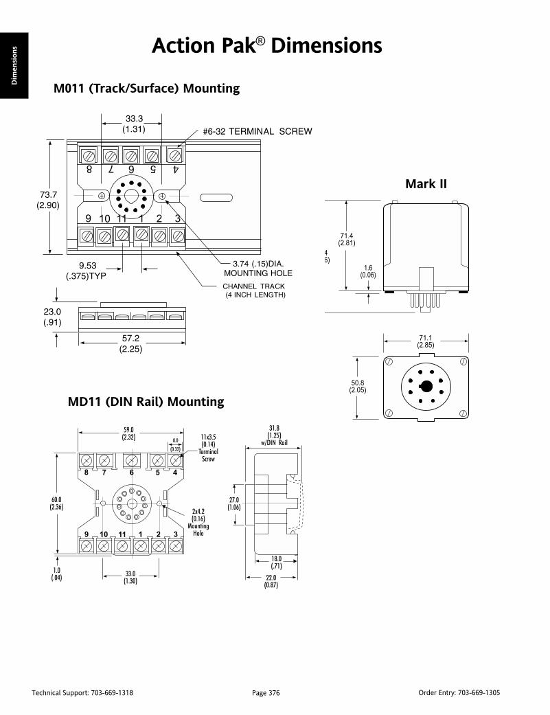
Page 376Technical Support: 703-669-1318 Order Entry: 703-669-1305
Dim
ensi
ons Action Pak® Dimensions
M011 (Track/Surface) Mounting
MD11 (DIN Rail) Mounting
Mark II

Page 377Technical Support: 703-669-1318 Order Entry: 703-669-1305
Dim
emsio
ns
IQRL-D008 (DC Power Only) IQRL-2008 (AC Power Only)
IQRL-D004 (DC Power Only) IQRL-2004 (AC Power Only)
IQRL-D002 (DC Power Only) IQRL-2002 (AC Power Only)
ActionI/Q® Dimensions

Page 378Technical Support: 703-669-1318 Order Entry: 703-669-1305
Dim
ensi
ons TransPak® Dimensions
T700 Series T700 Series Mounting Hardware
T805 Explosion Proof Enclosure T804 Conduit Device Housing
T280 & T287

Page 379Technical Support: 703-669-1318 Order Entry: 703-669-1305
Dim
emsio
ns
Ultra Slimpak® Dimensions
Ultra Slimpak® II Dimensions

Page 380Technical Support: 703-669-1318 Order Entry: 703-669-1305
Dim
ensi
ons VisiPak® Dimensions
V108
V116
V132
V408
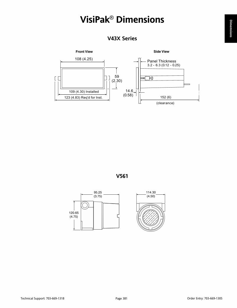
Page 381Technical Support: 703-669-1318 Order Entry: 703-669-1305
Dim
emsio
ns
VisiPak® Dimensions
V43X Series
V561

Page 382Technical Support: 703-669-1318 Order Entry: 703-669-1305
Dim
ensi
ons VisiPak® Dimensions
V560 & V565
V560 & V565 Explosion Proof Housing

Page 383Technical Support: 703-669-1318 Order Entry: 703-669-1305
Agen
cy Appro
vals
Approval AgenciesCE Conformite Europeenne, European UnionCSA Canadian Standards Association, CanadaCUL Canadian Safety Approval from ULFM Factory Mutual Research Corporation, USANEC National Electronics Council, USANEMA National Electrical Manufacturer's Association, USAUL Underwriters Laboratories, USA
CE Mark (CE)CE mark approval for the Ultra SlimPak, the Ultra SlimPak II,VisiPak and ActionI/Q are defined by European Norms(EN#50081-1 and EN# 50082-2). Consult Action TechnicalSupport for more details.
CSA CertificationThe CSA certification of the Action Pak series, Ultra SlimPak,Ultra SlimPak II and ActionI/Q complies with CSA standardC22.2 No. 0-M1982: General Requirements/Canadian ElectricalCode, Part II, and No. 0-M1983: Process Control Equipment/Industrial Products, Certificate No. LR 42272. The only ActionPaks to qualify are those with an 8 or 11-pin base.
Action Pak®
AP1000 Series: All models except those with 20 pin base.AP4000 Series: All models.AP4400 Series: AP4440 only.AP4500 Series: AP4570 and AP4580 only.AP6000 Series: AP6380 only.AP7000 Series: AP7380 only.AP7500 Series: AP7500 and AP7501 only.AP9000 Series: AP9046 only.
Ultra SlimPak®
G100 Series: All models.G400 Series: All models.
Ultra SlimPak® IIWV100 Series: All models.WV400 Series: All models.
ActionI/Q™Q400 Series: All models.Q500 Series: All models.
TransPak™The CSA certification of the T700 series allows intrinsically safeinstallations in Class I, Division 1, Groups A-D hazardous locations.All installations require approved intrinsic barriers permanufacturer's drawing 790-0025-00. Certificate No. LR 42272.
The CSA certification of the T797-1 and T798-1 allows intrinsicallysafe installations in Class I, Division 1, Groups A-D; Class II, Division1, Groups E, F and G; and Class III, Division 1, when installed inaccordance with drawing 732-0220-00 or 732-0221-00.
T700 Series: T703-2000, T761, and T773.T797 & T798: All models.
VisiPak™The CSA certification of the V508/V509 complies with CSAStandard C22.2 No. 0-M1982: General Requirements/CanadianElectrical Code, Part II, and No. 0-M1983: Process ControlEquipment/Industrial Products. Certificate No. LR 42272. V508and V509 only.
The CSA certification of the V560 series allows intrinsically safeinstallations in Class I, Division 1, Groups A-D hazardous locations.All installations require approved intrinsic barriers per manufacturer'sdrawing 790-0027-00. Certificate No. LR 42272-10. V560, V560Cand V565. See enclosure ratings for V560EP and V561.
Factory Mutual (FM)TransPak™The FM approval of the T600/T700 series allows intrinsically safeinstallations in Class I, Division 1, Groups A-D hazardous loca-tions. All installations require approved intrinsic barriers permanufacturer's drawing 790-0024-00.
The T700 series (except the T700-0001 and T703-2000) is alsopermitted in non-incendive Class I, Division 2, Groups A-D; andClass II and III, Division 2, Group G areas. Division 2 locations donot require barriers. Certificate No. J.I.2M2A5.AX(3611).
The T703-2000 is approved Intrinsically Safe, Entity, Class I, II, III,Division 1, Groups A-G hazardous locations per drawing 790-0028-00; and non-incendive Class 1, Division 2, Groups A-Dhazardous indoor locations per manufacturer's drawing 790-0028-00. Certificate No. J.I.1V4A5.AX.
T700 Series: All models except T700, T761, and T773.T797 & T798: All models.
VisiPak™The FM approval of the V560/V565 series permits intrinsicallysafe installations in Class I, Division 1, Groups A-D hazardouslocations and non-incendive Class I, II, III, Division 2, Groups A-D and G areas. All Division 1 installations require approvedintrinsic barriers per manufacturer's drawing 790-0024-00. Divi-sion 2 installations do not require a barrier. Certificate No.J.I.2M2A5.AX (3611). V565 is Entity Approved, drawing 790-0029-00, Certificate No. J.I.3V1A5.AX. V560, V560C, V565 andV565C only.
Action Product Agency Approvals

Page 384Technical Support: 703-669-1318 Order Entry: 703-669-1305
Age
ncy
Appro
vals
Underwriters Laboratories (UL and CUL)UL recognition for Action Pak, Ultra SlimPak, Ultra SlimPak II,ActionI/Q and VisiPak complies with UL standard 508 for Indus-trial Equipment. Canadian safety requirements C22.2 are metwith CUL (as indicated).
Action Pak®
AP1080/1090-2000AP1280/1290-2000AP1680/1690-2000AP4351AP4380-2000AP4382, AP4390, AP4391, AP4392, AP6380, AP7380
Ultra SlimPak®
G100 Series: All models.G400 Series: All models.
Ultra SlimPak® IIWV100 Series: All models.WV400 Series: All models.
ActionI/Q™Q400 Series: All models.Q500 Series: All models.
VisiPak™V108, V116, V132, V408: UL and CUL listed.V430 Series: All UL and CUL listed except V436.V508-5000 Series only.V509-5000 Series only.
M Series Sockets: All except M020.
Explosion Proof Ratings for Enclosures
Action Pak®
C008: NEC, NEMA 4, CSA.C011: NEC, NEMA 4, CSA.
TransPak®
T690/691EP: NEC, NEMA 4.T79E (except T79E-1): NEMA 4X and 7, CSA, FMT800: NEC, NEMA 4, CSAT805: NEC, NEMA 4, CSA, FM
VisiPak™V560EP: NEC, NEMA 4, CSA, FMV561: NEC, NEMA 4, CSA, FMV960: NEC, NEMA 4, CSA, FM
FieldPak™Housing and transmitter are approved separately. Refer to theT805 housing and the T700 TransPak series.
NOTES:
The NEC and CSA approvals for the C008, C011, T690EP, T691EPand T800 enclosures permit installations in Class I, Group D (alsoGroup C with approved 3/4" or smaller reducer); Class I, GroupsE and G; Class III hazardous locations per Articles 500 through 517(1987 edition). The above enclosures are equipped with 3/4"NEC approved reducers for Group C rating and a gasket for NEMA4 protection against liquids. The use of the supplied gasket doesnot void the hazardous rating.
The NEC, CSA and FM approvals for the T805 and F700 enclosurespermit installations in Class I, Groups B, C, D; and Class II, GroupsE, F, G hazardous locations. All enclosures are equipped with agasket for NEMA 4 protection aganst washdowns. The use of thesupplied gasket does not void the hazardous rating.
The CSA and FM approvals for the T79E explosion proof housings,available with and without windows, permit installations in ClassI, Divisions 1 and 2, Groups B, C and D; Class II, Divisions 1 and 2,Groups E, F and G; and Class III, and are rated for NEMA 4X andNEMA 7 environments.
The NEC, CSA and FM approvals for the V560EP and V960enclosures permit installations in Class I, Groups C and D; andClass II, Groups E, F and G hazardous locations. Both enclosuresare NEMA 4 rated.
The NEC, CSA and FM approvals for the V561 enclosure permitsinstallations in Class I, Groups B, C and D; and Class II, Groups E, Fand G hazardous locations. The V561 enclosure is NEMA 4 rated.

Page 385Technical Support: 703-669-1318 Order Entry: 703-669-1305
Success ServicesSM
from Eurotherm
Training
Help Desk
Repair Depot
Field Service
Commissioning
Project Engineering
Application Engineering
Service and Support Agreements
www.eurotherm.com
Product Services...System Services...
Annuity Services...Let us support, maintain and enhance your process
Page 385Technical Support: 703-669-1318 Order Entry: 703-669-1305

Page 386Technical Support: 703-669-1318 Order Entry: 703-669-1305
Eurotherm - what we make:
Recorders and Data Management Equipment
Graphic Recorders (100, 180, 250mm)
Circular Chart Recorders
Strip Chart Recorders (100, 180, 250mm)
Data Acquisition/Management
Configuration Software
Ethernet Connection
Modbus® and Profibus® EIA Communications
Validation Support (GAMP)
Temperature and Process Controllers, Indicators and Alarm Units
1/32, 1/16, 1/8 and 1/4 DIN
Single and Multi-loop with Remote I/O
Temperature, Flow, Level, Pressure, Atmosphere, Ratio and Cascade
Setpoint Controllers, Ramp/Dwell Programmers
Common Operation and Hardware
PC Configuration and Software
Modbus®, Profibus®, DeviceNet®, Ethernet
FM Alarm Units
Power Controllers and Solid State Relays
Single Phase (120-690V/16-1650A)
Two Phase (120-690V/16-1650A)
Three Phase (240-690V/16-1800A)
Modbus®, Profibus®, EI Bisync and Jbus Communications
Field Configurable
Custom Units
Filters and Fuses
CE Mark
MACO®/EM-3 Control Systems
Extrusion Control Systems
Injection Control Systems
Blow Molding Control Systems
Operator Stations and Touchscreen Monitors
Industrial PCs
Application Specific Blocks and Rack Systems
Terminal I/O Blocks
Pushbutton Stations
Page 386Technical Support: 703-669-1318 Order Entry: 703-669-1305

Page 387Technical Support: 703-669-1318 Order Entry: 703-669-1305
Process Control Systems
T Series Controllers/Processors
PC300/PC3000 Programmable Controllers
Network Support and I/O Drivers
Visualization Packages
Data Reporting and Manipulation
Configuration Tools
Control and Application Modules
Actuators
EA Series Rotary Actuators with Integrated Electronics
Spring Return and Non-spring Return Actuators
Current to Position Converters
Resistance to Position Converters
Accessories
Signal Conditioners, Thermocouples and RTDs
Thermocouples and RTDs
Atmosphere Probes
Special Builds
Handheld Calibration Devices
DIN Rail Conditioning Modules/Transmitters
Valve Bodies, Components and Assemblies
Two-way and Three-way Globe Valve Bodies
Linkage Kits
Valve Assembly Tables
Annuity Service
Valve Usage Guidelines
Replacement Parts and Accessories
Page 387Technical Support: 703-669-1318 Order Entry: 703-669-1305

Page 388Technical Support: 703-669-1318 Order Entry: 703-669-1305
Eurotherm - where you find us:
Food and BeveragesDistillation Columns
Fermentation Vessels
Pasteurization
CIP
Baking & Conveyor Ovens
Gas Burners
Freezer & Cold Stores
Mixers & Blenders
WaterDosing Control
Penstock Control
Weir Level Control
Effluent, pH and Turbidity Monitoring
Level, Temperature and Pressure Monitoring
Hospitals & HealthcareBoiler Control
Sterilizer Control
Sterilizer Monitoring
Washer/Disinfector Monitoring
Periodic Scheduled Testing
Blood Storage Monitoring
Heat TreatmentVacuum Control
Casting
Hardening
Brazing
Creep Testing
Atmosphere Control
Annealing Furnaces
Quench Furnaces
GlassMelting & Electrode Heating
Forehearth Control
Glass Lehrs
Batch Monitoring & Reporting
Float Line Controls
Glass Level Ratio Controls
Power/Energy Control
PlasticsExtrusion
Injection Molding
Blow Molding
Thermoforming
Blown Film
Cast Film
Page 388Technical Support: 703-669-1318 Order Entry: 703-669-1305

Page 389Technical Support: 703-669-1318 Order Entry: 703-669-1305
Power GenerationBoiler Leak Detection
Remote Data Recording
Turbine Monitoring
Drum Level
Steam Monitoring
Wind Speed & Direction
Waste Water Plants
PharmaceuticalsPressure/pH/Temperature/Flow Control
Fermentation
Reaction Vessels
Freeze Drying
Environment Monitoring Systems
Autoclave Control
Spray Drier Control
Clean Steam
Purified Water
Equipment Sterilization
Mixers and Blenders
Environmental Testing& Monitoring
Control of Temperature, Humidity,
Altitude, Pressure and Light
Plant and Biological Growth
Compressor Control
Altitude Monitoring
Gene Developments
MetalsFurnaces & Soaking Pits
Galvanizing & Aluminizing
Sinter Strands
Blast Furnaces & Stoves
Coking Plants
Continuous Casting Lines
Coating Lines
Boiler ControlTDS Control
Integrated Boiler Control
Gas Burner Management
Level & Pressure Control
Flow Computer
Continuous Blowdown
Timed Bottom Blowdown
Pressure Control
Steam Main Warm-up
Pump Sequence Control
Semiconductor FabricationDiffusion Furnaces
MBE Machines
Crystal Growth
CVD
Environment Monitoring
Page 389Technical Support: 703-669-1318 Order Entry: 703-669-1305

Page 390Technical Support: 703-669-1318 Order Entry: 703-669-1305
21 CFR Part 11
Eurotherm has a range of product solutions that are usedin pharmaceutical applications. Additional functionality hasrecently been added in order to meet the requirements of21 CFR Part 11. This capability for electronic signaturesand electronic records is provided in our 5000 Series dataacquisition and management products, Visual Supervisor,multifunction controllers and EurothermSuite OperationsServer and Viewer plant management systems.
To match 21 CFR Part 11 requirements, the following keyfeatures are now available:
Electronic Records
Tamperproof data viewable in human readable form
Audit trails including process values, alarms, events andelectronic signatures
Date and time stamps
Time synchronization
Data export conversion to standard packages (e.g., Excel)
Electronic Signatures
User actions with signing and authorization
Unique signatures
Automatic log-off
Minimum length password
Access control according to authority level
Automatic password expiration
Page 390Technical Support: 703-669-1318 Order Entry: 703-669-1305

Page 391Technical Support: 703-669-1318 Order Entry: 703-669-1305
Notes

Page 392Technical Support: 703-669-1318 Order Entry: 703-669-1305
Notes


Eurotherm: International sales and service
AUSTRALIA SydneyEurotherm Pty. Ltd.T (+61 2) 9838 0099F (+61 2) 9838 9288E [email protected]
AUSTRIA ViennaEurotherm GmbHT (+43 1) 7987601F (+43 1) 7987605E [email protected]
BELGIUM & LUXEMBOURG MohaEurotherm S.A/N.V.T (+32) 85 274080F (+32) 85 274081E [email protected]
BRAZIL Campinas-SPEurotherm Ltda.T (+5519) 3707 5333F (+5519) 3707 5345E [email protected]
DENMARK CopenhagenEurotherm Danmark AST (+45 70) 234670F (+45 70) 234660E [email protected]
FINLAND AboEurotherm FinlandT (+358) 22506030F (+358) 22503201E [email protected]
FRANCE LyonEurotherm Automation SAT (+33 478) 664500F (+33 478) 352490E [email protected]
GERMANY LimburgEurotherm Deutschland GmbHT (+49 6431) 2980F (+49 6431) 298119E [email protected]
HONG KONG & CHINAEurotherm Limited North PointT (+85 2) 28733826F (+85 2) 28700148E [email protected]
Guangzhou OfficeT (+86 20) 8755 5099F (+86 20) 8755 5831E [email protected]
Beijing OfficeT (+86 10) 6567 8506F (+86 10) 6567 8509E [email protected]
Shanghai OfficeT (+86 21) 6145 1188F (+86 21) 6145 1187E [email protected]
INDIA ChennaiEurotherm India LimitedT (+91 44) 24961129F (+91 44) 24961831E [email protected]
IRELAND DublinEurotherm Ireland LimitedT (+353 1) 4691800F (+353 1) 4691300E [email protected]
ITALY ComoEurotherm S.r.lT (+39 31) 975111F (+39 31) 977512E [email protected]
KOREA SeoulEurotherm Korea LimitedT (+82 31) 2738507F (+82 31) 2738508E [email protected]
NETHERLANDS Alphen a/d RijnEurotherm B.V.T (+31 172) 411752F (+31 172) 417260E [email protected]
NORWAY OsloEurotherm A/ST (+47 67) 592170F (+47 67) 118301E [email protected]
POLAND KatowiceInvensys Eurotherm Sp z o.o.T (+48 32) 2185100F (+48 32) 2177171E [email protected]
SPAIN MadridEurotherm España SAT (+34 91) 6616001F (+34 91) 6619093E [email protected]
SWEDEN MalmoEurotherm ABT (+46 40) 384500F (+46 40) 384545E [email protected]
SWITZERLAND WollerauEurotherm Produkte (Schweiz) AGT (+41 44) 7871040F (+41 44) 7871044E [email protected]
UNITED KINGDOM WorthingEurotherm LimitedT (+44 1903) 268500F (+44 1903) 265982E [email protected]
USA Leesburg VAEurotherm Inc.T (+1 703) 443 0000F (+1 703) 669 1300E [email protected]
Providing local support is a key part of Eurotherm’s business. Complementing worldwide Eurotherm offices are an entire range ofpartners and a comprehensive technical support team - ensuring that you get service to which you will return.
AlgeriaAzerbaijanBahrainBangladeshBeninBosnia and HerzegovinaBulgariaBurkina FasoCameroonCanadaCzech RepublicEgyptGeorgiaGreeceGuinea-ConakryHungaryIndonesiaIranIraqIsraelIvory CoastJapanJordanKazakhstanKenyaKuwaitLatviaLithuania
© Copyright Eurotherm Limited 2007Invensys, Eurotherm, the Eurotherm logo, Chessell, EurothermSuite, Mini8, Eycon, Eyris and Wonderware are trademarks of Invensys plc, its subsidiaries and affiliates. All other brands may be trademarks of their respectiveowners. All rights are strictly reserved. No part of this document may be reproduced, modified, or transmitted in any form by any means, nor may it be stored in a retrieval system other than for the purpose to act as anaid in operating the equipment to which the document relates, without the prior written permission of Eurotherm Inc. Eurotherm Limited pursues a policy of continuous development and product improvement. Thespecifications in this document may therefore be changed without notice. The information in this document is given in good faith, but is intended for guidance only. Eurotherm Limited will accept no responsibility for anylosses arising from errors in this document.
Part No. HA136731 Issue 2
Eurotherm is also represented in the following countries:
MalaysiaMaliMexicoNew ZealandNigerNigeriaOmanPakistanPhilippinesPuerto RicoQatarRomaniaRussiaSaudi ArabiaSerbia and MontenegroSingaporeSlovak RepublicSloveniaSouth AfricaSri LankaThailandTogoTunisiaTurkeyTurkmenistanUAEUkraineUzbekistan
Represented by:
Actio
n In
strum
ents P
roduct H
andbook
Volu
me 18