Measuring instruments for - INTECH2000
48
Measuring instruments for: Flue gas analysis Pressure Temperature Leakage Visual inspections: Video inspection Endoscopes Inspection mirrors Cleaning tools for: Boilers Chimneys Ventilation ducts
-
Upload
khangminh22 -
Category
Documents
-
view
0 -
download
0
Transcript of Measuring instruments for - INTECH2000

Measuringinstruments for:Flue gas analysisPressureTemperatureLeakage
Visualinspections:Video inspectionEndoscopesInspection mirrors
Cleaningtools for:BoilersChimneysVentilation ducts

USA & Canada
Wöhler USA Inc.Mr. Andy CoppCary NC 27513Tel. (1) 919 678-9809, Fax: -9897
ChimCraft SystemsBrockville, Ontario - K6V 1C3Tel. or Fax: (1) 613 498 0884
Czech. Republik
Wöhler Bohemia s.r.o.393 01 PelhrimovTel.: (420) 3663230 -67, Fax: -78
Denmark
SkorstensfejervaerktojJens Arne Frandsen6840 OksbolTel.: (45) 7527 -1396, Fax: -1362
Finland
Avatermos OY20700 TurkuTel.: (358) 22325 -229, Fax: -279
France
Self - Climat77200 TorcyTel.: (33) 1 60 -051853, Fax: -175839
Ent. de Ramonage Straub Fils67140 BarrTel.: (33) 38808 -4788, Fax: -1874
Luxembourg
Ramirez-Electro S.A.4384 EhlerangeTel.: (352) 2655 451, Fax -2655 1245
Australia
INLINE Systems Pty. Ltd.Warriewood NSW 2102Tel.: (61) 29999 2696, Fax -29979 8703
worldwide
Great BritainWöhler UKDerbyshire DE56 1NPTel. or Fax: (44) 1773 821144
HungaryLipták Fivérek5600 BékéscsabaTel. or Fax: (36) 66 441 611
ItalyVolta S.p.A.39100 BolzanoTel.: (390) 471 561 -000, Fax -100
NetherlandsPh. van Vugt JR. B.V.1221 JV HilversumTel.: (31) 3568 -38444, Fax -53764
J. Feije2071 VH Santpoort - N.Tel.: (31) 23 -5381803, Fax -5374298
NorwayVarmeokonomiG. Mikkelsen3133 DukenTel.: (47) 3338 -7557, Fax -7482
PolandJeremias Spólka z o.o.Mr. Janusz Borzych62-200 GnieznoTel.: (48) 61424 -1709, Fax -1710
SpainEscal Calefaccion, S.L.28033 MadridTel.: (34) 91 -7633660, Fax -3812518
SwedenSvenska Mätapparater F.A.B.SWEMA123 56 FarstaTel.: (46) 8 -940090 Fax -934493
TurkeyROTEK Ltd. Sti.81090 Kozyatagi - IstanbulTel.: (90) 216 362 2670, Fax -216 362 0649
CroatiaSTURM d.o.o.51215 KastavTel.: (385) 51-225 073 Fax -51 224 631
ChinaHefei Duwei Instruments Scienceand Technology Co., Ltd.Hefei City, Anhui 230031Tel.: (86) 551 514 2920 Fax -551 511 1633
The No. 1 distributor for measuring andcleaning tools around the heat appliance.
That means for you: experience, which alsofacilitates the work for heating systems fitters.
Since the 1940th Wöhler has been developinghigh-quality measuring and cleaninginstruments for heating systems together withthe German Enviromental Protection Agency,the Chimney Sweep Association and theInstaller organisations.
MESSGERÄTE KEHRGERÄTE GmbH
Responsable for you:
HRB 2781 Amtsgericht PaderbornUST-Id. Nr. (Vat) DE 812 015 128
Your customer number:
Austria
Christian Feichtinger4642 WelsTel.: (43) 7244 /200-25, Fax -254
Belgium
molimex - therm n.v.s.a.1930 Zaventem - Zuid 7Tel.: (32) 2715 -2400, Fax: -2466
Switzerland
Bösch Spezialbürsten9443 WidnauTel.: (41) 71722 -1852, Fax: -1859
Rocco Ditaranto8264 EschenzTel. or Fax: (41) 52741-4450

Internet: http://www.woehler.com/mgkg3
Heati
ng S
yste
ms
handy...
...universal
...easy memory access
...innovative technique.
A 97
Measurement: Heating Systems

Internet: http://www.woehler.com/mgkg4
Heati
ng S
yste
ms
Order No. n
Application:
The A 97 Analysis Computer is ideally suited for :
• Measurements on oil, gas and wood furnaces
• Measurements confirming to national directives for CO measurement
• Measurements confirming to regulations for NO measurement
Measurements:
Oxygen (O2): 0...20.9 Vol.-%
Carbon monoxide (CO): 0...2000 ppm
Carbon monoxide (CO): 0...16000 ppm
Nitric oxide (NO): 0...2.000 ppm
Flue-gas temp. (TF): 0.0...800°C
Air temperature (TA): -20.0...99.9°C
Chimney draught (PD): 0...+/-4000 Pa
Computed values:
Flue-gas loss (qF)
Efficiency (η): from 0...120 %
condensation is
automatically detected
Excess Air (l):
Carbon dioxide content (CO2)
Carbon monoxide content in undiluted flue-gas
(COnorm): Reference oxygene freely
adjustale (standard 0 %)
Carbon monoxide content in flue-gas solid fuel
heating systems: Reference oxygene freely
adjustable (standard 13 %)
Nitric ocide in undiluted flue-gas (NOnorm
):
Reference oxygene freely
adjustable (standard 13 %)
Condensate amount in kg/m3 or kg/l
Flue-gas dew point
Date / time
Storage temperature: -20...50 °C
Work temperature: 10...40 °C
Weight: ca. 1600 g
Size: 190x145x50 mm
Advantages:
• Responsive - for the adjustment of
multilevel burners
• Simple operation via touch
screen
• Excellent overview
on the large display
• Expandable e.g. for continuous
measurements: see following pages
The A 97 analysis computer offers
outstanding performance for
administration of your measuring data
by the combination of large display and
touch screen. To the input of customer
data a complete alphanumeric keyboard
can be used, so that the character by
character input, e.g. over arrow keys, is
avoided. The standard memory of 100
measuring data sets can be extended to
1,000 measuring data sets.
Data exchange with PC or thermal
printer HP is made by an IrDA interface.
If your PC should not have an inserted
infrared interface, please use the IR
interface over a serial port of your PC
(see accessories). For data exchange we
put on our web page free of charge an
appropriate PC program to your disposal.
The data can be processed then
problem-free with usual spread-sheet
programs.
TÜV By RgG 180
• Simply entry of customer data for
measurement data management
with alphanummeric keyboard -
wireless data transmission to the
printer and PC via the bi-directional
IrDA interface
• Simple to maintain with a
modular structure (see diagram
above), simple cell change
Measuring Data Management A 97
A 97 Analysis Computer
O2
DP
40 hPACO
2
CO
2,000
CO
16,000
NO
2,000TFlueGas
TAir
TTaup
Draft2000 Pa
lhqA CIrDA

Internet: http://www.woehler.com/mgkg5
Heati
ng S
yste
ms
Order No. n
Advantages:
• durable, upright standing Craftsman leather suit-case
• large space for the measuring instruments necessary with adjusting and inspection
work at oil and gas firings: Analysis Computer A 97 incl. accessoiries, Printer and
Soot test pump as well as additional tool
• the A 97 is placed diagonally on a metal plate - ideally for the operation of the
equipment in the suit-case
• A 97 with Memory for 1,000 data records
Comes with:
A 97 Analysis Computer basic equipment, Memory for 1,000 data records, Multi-hole
Plug-in probe - 60/160, Combustion air temperature probe 280 mm with magnetic
holder, RP 72 Soot test pump (set), PTFE-Cone, Swivel probe holder, Clamping cone
Ø 8 mm, Fastening clips (100 pieces), 5 Coarse filters, 3 Water-stop filters, Spare
parts kit A 97, Leather case
Comes with:
A 97 Analysis Computer basic equipment, but with 3 m Hose-Cable, Multi-Hole Plug-
in Probe - 60/160, Combustion Air Temperature Probe with magnetic holder,
Thermoprinter HP with 10 rolls of paper and batteries, RP 72 Soot test pump (set),
PTFE-Cone, Swivel probe holder, Clamping cone, Coarse filter (5 pieces), Water-stop
filter (3 pieces), Aluminium case
9650 J
9664 I
9660 J
Advantages:
• large space for A 97 - basic equipment incl. accessoiries and printer
• impact protection by foam material Inlet
• operation of A 97 in suit-case by special arrangement of the devices possible
Comes with:
A 97 Analysis Computer basic equipment with 3 m Hose-Cable, Combustion air
temperature probe 280 mm, Thermo printer HP, Clamping cone, PTFE cone, Wadding
rolls short, Plastic case
A 97 Leather Equipment Case
A 97 Complete Plastic Case
A 97 Aluminium Equipment CaseAdvantages:
• large space for the measuring instruments necessary with adjusting and inspection
work at oil and gas firings: Analysis Computer A 97 incl. accessoiries, printer and
soot test pump
• 2-Level-Inlet, practical for carrying of lots of useful equipment
• operation of A 97 in suit-case by special arrangement of the devices possible
• operation of A 97 and printing of measuring data can be done in the suit-case
• A 97 - Hose-Cable length 3 m
A 97 Analysis Computer Complete Equipment
9600 JA97 basic equipment with 1.7 m Hose-Cable, for:
O2, CO
2, CO, COnorm, T
Flue-gas, T
Air, T
Taup, Draft, DP, qA, η, l
Comes with:
A 97 Analysis Computer with IrDA-interface, Data administration up to 100 data
records, 4 Mignon-rechargeable batteries (NiCd), Leather protection case,
Interchangeable Probe with Plug-in Probe - 295 mm long and Cable-Hose,
Combustion air temperature probe, Wadding rolls short for condensate separator,
Condensate wiper, charger, 1 Coarse filter, 1 Water-Stop Filter
A 97 Analysis Computer - Basic equipment
A 97 basic equipment with 3 m Hose-Cable, like above 9659 J

Internet: http://www.woehler.com/mgkg6
Heati
ng S
yste
ms
Order No. nContinuous Flue Gas Measurement - A 97
A 97 Peltier-Cooler
A 97 Air Flow-rate Measuring
Funnel (see page 27)
A 97 Special Wall
Temperature Sensor Type W(see page 31)
Auxiliary Probes A 97
Function:
The Peltier-Cooler A 97 is attached directly at the Interchangeable probe A 97 in place
of the Coarse filter. Thus as soon as possible the condensate is extracted from the flue
gas by an active cooling over a regulated, high-performance Peltier element - heated
probe hoses are not necessary. In connection with the separate Condensate pump the
continuous operation of the measuring instrument becomes possible with long-term
measurements.
Applications:
• For adjustments at large firings
• Measurements over several hours
• Measurements with much condensate
• Measuremants with high dust and
soot content
Comes with:
A 97 Peltier-Cooler for attaching to the
Interchangeable probe A 97 incl. power
pack
A 97 Condensate pump for Peltier-
Cooler, with Condensate reservoir
4635 J
Function:
For the continuous data communication the A 97 is connected by the IrDA-interface with the notebook/PC and the IrDA-mode at
A 97 is switched on. The powerful DasyLab-PC-Software receives the data continuously transmitted from the A 97 and enables
convenient evaluation and processing using tables and graphics.
Comes with:
DasyLab-PC-Software on CD-ROM incl.
user license
Applications:
• for easy measuring data collection and
management with long-term
measurements
• measurements in laboratories - ideally by
compatibility to professionel DasyLab-
Software and over ASCII-tables to all other
programs
• large display for training courses
• remote display for measurements on
larger burner heating systems
5125 L
Advantages:
• direct connection of the cooling to the Interchangeable probe A 97 - heated probe hoses
are not necessary
• active cooling over high-performance Peltier element - Protection of the measuring
instrument from condensate
Dew point depression: 15°
Work temperature: 10 ...40 °C
Storage temperature: 0 ...50 °C
Condenser service period:10 h
Power supply: 7 Volt
Current consumption: max 3 A
Weight: 240 g
Size (mm): 43 x 62 x 100
4636 J
The auxiliary probes for the connection
to the A 97 enable the measurement of
important physical dimensions in related
spheres of activity.
Your A 97 is a
universal measuring instrument.
DasyLab-PC-Software A 97

Internet: http://www.woehler.com/mgkg7
Heati
ng S
yste
ms
Order No. nA 97 - units and accessories
A 97 Analysis Computer, Basic Equipment see page 5 9600 J
A 97 Analysis Computer, Basic Equipment 9610 J
+ CO: 0 - 16,000 ppm
A 97 Analysis Computer, Basic Equipment 9649 J
+ Memory for 1,000 data sets
A 97 Analysis Computer, Basic Equipment 9574 J
+ CO: 0 - 16,000 ppm
+ Memory for 1,000 data sets
A 97 Analysis Computer, Basic Equipment 9620 J
+ NO: 0 - 2,000 ppm
A 97 Analysis Computer, Basic Equipment 9630 J
+ CO: 0 - 16,000 ppm
+ NO: 0 - 2,000 ppm
A 97 Analysis Computer, Basic Equipment 9570 J
+ CO: 0 - 16,000 ppm
+ NO: 0 - 2,000 ppm
+ Memory for 1,000 data sets
A 97 Probesfor simultanious gas extraction,
pressure- and temperature measuring:
7 Multi-hole Plug-in Probe A 97 - 60/160, for CO measurement, with long PTFE-Cone 9615 L
8 Multi-hole Plug-in Probe A 97 - 160/260, for CO measurement, with long PTFE-Cone 9616 L
9 Combustion Air Temperature Probe A 97, Plug form 9605 J
10 Combustion Air Temperature Probe A 97, 100 mm with 2 m cable 9651 J
11 Combustion Air Temperature Probe A 97, 280 mm, with 2 m cable 9611 J
Magnetic holder to fix the Combustion Air Temperature Probes 6142 J
PTFE-Cone, to fix the Combustion Air Temperature Probes 2463 B
PTFE-Cone, extra long, for Multi-hole Plug-in Probe 6170 B
1 Interchangeable probe A 97 9603 L
1 Interchangeable probe A 97, in exchange 9534 Q
2 Cable-Hose Fitting A 97, 1.7 m 9604 J
2 Cable-Hose Fitting A 97, 3.0 m 9626 J
2 Cable-Hose Fitting A 97, 1.7 m, in exchange 9672 O
2 Cable-Hose Fitting A 97, 3.0 m, in exchange 9673 O
Connector for 2 cable-hose fittings, up to max. 9 m possible 9446 O
A 97 Interchangeable Probe
A 97 Cable-Hose Fitting
1
2
3 Plug-in probe A 97 - 500 mm with protection cap 9614 J
4 Plug-in probe A 97 - 295 mm with protection cap 9622 J
5 Plug-in probe A 97 - 180 mm with protection cap 9613 J
6 Plug-in probe A 97 - 130 mm with protection cap 9652 J
A 97 Analysis Computer, Basic Equipment
3 4 5 6
9
7 8
11
10

Internet: http://www.woehler.com/mgkg8
Heati
ng S
yste
ms
Order No. nA 97 - units and accessories
Data management
4 Water-stop filter A 97, 3 pieces 9621 J
5 Coarse filter A 97, 5 pieces 9632 D
6 Condensate wiper 619 D
7 Bulb pump, for checking probe sealing 2340 L
Spare parts bag A 97 9623 J
Active carbon filter A 97, supplementary filter for measurement of solid-fuel appliances 5876 J
Protection Case A 97 9617 J
Shoulder belt for protection case A 97 9624 J
Aluminium case A 97 9618 Q
Leather case A 97 9619 L
Shoulder belt for Leather case A 97 7617 J
Plastic case A 97 50794 L
1 Rucksack (only), made of light, stain and water resistant Cordura 5540 J
Advantages:
• adjustable, broad-padded belts in shoulder- and hip range
• large, easily accessable side pockets
• removable plastic compartment
HP Thermoprinter 9130 J
Memory upgrade A 97, Data management for 1,000 measurement data records
IR-Interface for yor PC, bidirectional after IrDA-Standard 9631 L
Interface-program „MESSEN.EXE“, on 3.5“ Disk, 7504 O
(free Download from our Webseite)
2 Set of rechargeable batteries NiMH Mignon for A 97 / E 98 9407 M
3 Set of rechargeable batteries NiCd Mignon for E 98 / A 97 / A 91 / A 86 3114 J
Charger A 97, charging period 15 hours 9633 J
Rapid charger A 97, charging period 3 hours, prevents memory effect 9612 J
Maintenance A 97The sensors built in the analysis
computers are subject to wear. The
measuring instruments should be
examined once annually or sooner if
needed.
Analysing computer pre and final inspection, Calibration and adjustment 18 Z
O2-Sensor A 97 with installation and pre and final inspection 9779 O
CO-Sensor A97 with installation and pre and final inspection 9780 O
With the change of both sensors the price reduces by a pre and final inspection.
Fitting A 97 with Co Measuring Cell 9609 O
measurement range 0 up to 16,000 Vol.-ppm
Fitting A 97 with NO Measuring Cell 9608 O
measurement range 0 up to 2,000 Vol.-ppm
Upgrade Service
4 5
6
7
2 3
Batteries, Charger
1

Internet: http://www.woehler.com/mgkg9
Heati
ng S
yste
ms
Order No. nE 98 Economical flue-gas analyzer
Application:
• Adjustments on oil and gas-fired heating systems.
• Replaces old-fashioned analyzers and does much more.
Advantages:
• Optional data memory for ten sets of measurement
data and IR interface for printing out data and permanent data
transmission
• Optional 1.7 m hose (E 98 Maxi)
• Additional pressure connection for gas pressure adjustments or differential
pressure measurements
• Fast response time
• Uses regular or rechargeable batteries
• Long operating period: e.g. 38 hours
of operation with Mignon dry cells
(2.3 Ah) or 10 hours with standard
NiCd rechargeables (600 mAh)
• Gas conditions can be easily
removed for cleaning
• Rugged due to well-designed gas
treatment section with integral, easily
replaceable water stop filter
The Econometer E 98 -
high performance in a small size ...
TÜV By RgG 195
O2 measurement
Sensor: electrochemical
Range: 0...20.9 Vol.-%
Accuracy: 0.3 Vol.-% absolute
CO indicator (not H2compensated)
Sensor: Semiconductor
Range: 0...350 ppm
Accuracy: 50 ppm
CO sensor
Sensor: electrochemical
Range: 0...1,500 ppm
Accuracy: ± 5 % o.r.
> 5ppm
Inlet air temperature measurement- TA
Range: 0...99.9 °C with TF probe
Accuracy: 2 °C: 0...50 °C
opt. (for measurements accord. to
pollution control regulations)
Range: -20.0...99.9 °C with TA
probe
Accuracy: 1 °C: 0...50 °C
Flue-gas temperature measurement - TF
Range: 0...800 °C
Accuracy: 2 °C: 0...125 °C
3 °C: 125...250 °C
4 °C: 250...400 °C
Chimney draft, DP
Range: -100...+4,000 Pa
Accuracy: 3 Pa: -20...100 Pa
3 % FSD: -1.0...4.0 hPa
CO2 determination
Display range: 0...CO2max
Resolution: 0.1 %
Flue-gas loss determination - qA
Depending on fuel, resolution 0.1 %
Efficiency - ηηηηηDisplay range: 0...120.0 %
Resolution: 0.1 %
Dewpoint temperature measurement
Depending on fuel, resolution 0.1 °C
Condensate quantity
Display in kg/m (gas) or kg/l (oil)
That is all that you need:
Econometer E 98
IR
... now also with 1.7 m
hose fitting, probe
and IR:
Econometer E 98 Maxi
You measure:
You let the unit compute:
You set the type of fuel:
You switch on:
Take advantage of the E 98’s performance vs. costs and equip each of your
technicians with an E 98 Econometer. For the heating business this new
compact device for flue-gas analysis is the ideal way to save time and
eliminate double work. With a press of a key the E 98 shows you the flue-
gas conditions on the large display.
You print the results!
ηηηηηqAqAqAqAqA
lDP
40 hPA
Draft
100 PaT
TaupT
AirT
FlueGas
COInd
350ppmCO
2O
2
Internet: http://www.woehler.com/mgkg10
Heati
ng S
yste
ms
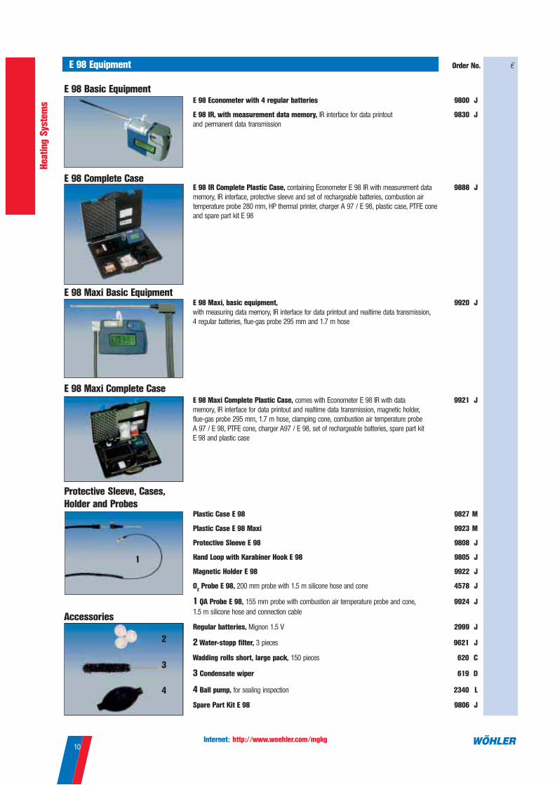
Order No. nE 98 Equipment
E 98 Basic EquipmentE 98 Econometer with 4 regular batteries 9800 J
E 98 IR, with measurement data memory, IR interface for data printout 9830 J
and permanent data transmission
E 98 IR Complete Plastic Case, containing Econometer E 98 IR with measurement data 9888 J
memory, IR interface, protective sleeve and set of rechargeable batteries, combustion air
temperature probe 280 mm, HP thermal printer, charger A 97 / E 98, plastic case, PTFE cone
and spare part kit E 98
E 98 Complete Case
AccessoriesRegular batteries, Mignon 1.5 V 2999 J
2 Water-stopp filter, 3 pieces 9621 J
Wadding rolls short, large pack, 150 pieces 620 C
3 Condensate wiper 619 D
4 Ball pump, for sealing inspection 2340 L
Spare Part Kit E 98 9806 J
4
3
2
E 98 Maxi Complete Plastic Case, comes with Econometer E 98 IR with data 9921 J
memory, IR interface for data printout and realtime data transmission, magnetic holder,
flue-gas probe 295 mm, 1.7 m hose, clamping cone, combustion air temperature probe
A 97 / E 98, PTFE cone, charger A97 / E 98, set of rechargeable batteries, spare part kit
E 98 and plastic case
E 98 Maxi Complete Case
E 98 Maxi, basic equipment, 9920 J
with measuring data memory, IR interface for data printout and realtime data transmission,
4 regular batteries, flue-gas probe 295 mm and 1.7 m hose
E 98 Maxi Basic Equipment
Plastic Case E 98 9827 M
Plastic Case E 98 Maxi 9923 M
Protective Sleeve E 98 9808 J
Hand Loop with Karabiner Hook E 98 9805 J
Magnetic Holder E 98 9922 J
O2 Probe E 98, 200 mm probe with 1.5 m silicone hose and cone 4578 J
1 QA Probe E 98, 155 mm probe with combustion air temperature probe and cone, 9924 J
1.5 m silicone hose and connection cable
Protective Sleeve, Cases,
Holder and Probes
1

Internet: http://www.woehler.com/mgkg11
Heati
ng S
yste
ms
Order No. nDC 2000 Pressure Computer
Digital Manometer for all pressure measurements
Specification:
Differential pressure:
Range: ± 2 bar
Accuracy: < 3% from measuring,
in range <± 200 Pa
better than ± 6 Pa
Resolution: 1 Pa in range -125 Pa
up to + 125 Pa,
otherwise 10 Pa
Temperature (internal NTC):
Range: -5°C up to 55°C
Accuracy: < ±4°C
Resolution: 1°C
Relative humidity (optional):
Range: 0% up to 100% rH,
non condensing
Accuracy: ±5% rH (0-60% rH),
otherwise <10% rH
Resolution: 1%rH
Storage temp.: -20°C up to +60°C
Work temp.: -5°C up to +60°C
Weight: 450 g (with case)
Size: 54 x 165 x 52 mm
Applications:
• Fine tuning of burners with 1 Pa
resolution
• Stress and Main test according to
TRGI G 600
• Draft Measurement
• Velocity measurement with Prandtl
tube (0.0 - 150.00 m/s)
• Leakage test of water pipes
• Air control: Long term recording of
temperature/humidity/pressure
Advantages:
• Switchable units for temperature
(°C,°F) and pressure (hPa, Pa,
mmH2O, PSI, mbar)
• Quick response time
• Extra wide pressure range
• Leakage rate
• Internal temperature sensor, external
probe option
• IR interface for PC and printer,
personalized printout
DC 2000, basic equipment with hose 1.5 m 7200 I
DC 2000, with humidity measurement, brass connectors and hose 1.5 m 7201 I
DC 2000 protection sleeve with 2 magnets 7202 I
DC 2000 set, including order no. 7201, protection bag, 2 x hoses 1.5 m with plug in connectors and plastic carrying case MINI 7206 I
DC 2000 Prandtl-set, including order no. 7206, Prandtl tube 35 cm, temperature probe with 2 m cable, carrying case MIDI 7207 I
• Humidity measurement (optional)
• Data logger (approx. 3 years)
• 2 x type AA batteries
Complete set for pressure testing and leakage detection
Recommended Applications:
• Pressure test on gas lines according to
TRGI main- and stresstest
• Locating of leaks
• Gas pressure measurement for burner
adjustment
• Measurement of velocity in ductwork
• Leakage testing on water lines (TRWI)
DC 2000 Test set I, DC 2000 with humidity sensor, protection sleeve with magnets, 7220 J
gas detector GS 20, thermal printer, leakage spray, 2 high pressure locks, plastic carrying
case MAXI and gas line sealing set consisting of: 2 adjustable cones, 1 lock, 1 gasmeter lock,
1 pump, 1 X-connector, various hoses with plug in connectors
DC 2000 Test set II, DC 2000 with humidity sensor, protection sleeve with magnets, 7221 F
thermal printer, leakagespray, 2 high pressure locks, plastic carrying case MAXI and
gas line sealling set consisting of: 2 adjustable cones, 1 lock, 1 gasmeter lock, 1 pump,
1 X-connector, various hoses with plug in connectors
DC 2000 Test set MIDI , DC 2000 with humidity sensor, protection sleeve, 7277 J
gas line sealing set consisting of: 2 adjustable cones, 1 pump, 1 X-connector, various hoses
with plug in connectors, carrying case MIDI

Internet: http://www.woehler.com/mgkg12
Heati
ng S
yste
ms
Order No. n
1 Telescopic Multi-Hole Probe, suitable for all measuring instruments with probe 8 mm Ø, 9639 J
extendable up to 130 cm, with telescopic handle and multi-hole probe
2 Telescopic Multi-Hole Probe with Flex Holder extra long 9694 J
suitable for all measuring instruments with probe 8 mm Ø, with telescopic handle, flex holder
and multi-hole probe, extendable up to 148 cm
CO measurement
O2 measurement in annular gaps
Annular-Gap Multi-Hole Probe 4505 J
suitable for all measuring insruments with probes 8 mm Ø
Application: For checking the sealing of LAS-flue-gas pipes by measuring the O2
content in the annular gap.
HD 2000 Heating Diagnosis
HD 2000 Heating Diagnosticfor long-term monitoring of oil-fired heating systems
Advantage:
• Acoustic and visual service indication
for clogging of oil burners
• Determination of customer-specific
consumption data
• Determination of level of annual usage
• Data transfer in the IrDA mode
• Easiest mounting using magnetic
holder
• Maintenance-free
Comes with:
HD 2000 Heating Diagnostic
incl. probe, cone and batteries
Regular battery, monocell
Function:
The HD 2000 heating diagnostic adapts itself in the first week after startup by a learning
phase to the dynamic behavior of the exhaust gas temperature of the heating system. It
determines heating cycles, which serve exclusively for the covering of the stop losses.
By these consumer-independent characteristic values a change shows itself through
e.g. contamination more clearly than with the usual exhaust thermometers. Request for
maintenance takes place via acoustic and visual indication.
7500 A
51922O
1
2
Special Probes for O2 and CO measurement
Function:
The software executable under Excel picks the data out from the HD 2000 via
IR interface. Pre-programmed diagrams supply the following data:
• Annual consumption index
• Firing operation period
HD 2000 Software
HD 2000 Software, 3.5“ disk 7503 O
• Burner operation period
• T continous measurement
Flue-gas temperature:
Range: 0...500 °C
Accuracy: ± 3 °C
Display:
Flue-gas temperature, operating and burner
operating time according to VDI 3808, total
hours
Data logger:
Memory for more than 3.5 years
Power supply:
2 x 1.5 V monocells for max. 3.5 years

Internet: http://www.woehler.com/mgkg13
Heati
ng S
yste
ms
Order No. nSmoke Test Pump
Complete Set
Individual
RP 72 / RG 68 Soot Testing Pump
The well-proven soot test pump with
numerous advantages:
• Long measuring hose, ideal even for
inaccessible meaurement openings
• Decentralised suction channel enables a
number of smoke spot images on one filter
paper to be obtained - ideal for comparisons
• Ryton plastic measurement head against
condensation as standard
• Various probe lengths
TÜV By 112 RgG 015 / 014
1
2
4
6
7
5
3
Ringelmann-Glass
Application:
To the fast recognition of too dark smoke trails (§ 2, 1. BlmSchV)
complete with leather bag, with the shading:
Grey tone 1 and Grey tone 2 1007 N
Grey tone 3 and Grey tone 4 2738 N
Ringelmann-Glass
8 12 13
109
11
RP 72 Soot Testing Pump in following set with: extraction probe 200 mm, 9152 J
with Ryton measuring head, smoke spot comparison scale, threated cone, oil test bottle,
servicing oil, filter papers, short wadding, long wadding, probe brush
1 RP 72 Soot Testing Pump TÜV 112 RgG 015, with extraction probe 220 mm 2412 J
RG 68 Soot Testing Pump TÜV 112 RgG 014, Pump with stroke counter, 2411 O
with extracting probe 220 mm
Ryton measuring head, with 220 mm probe and turbulence spiral 7547 L
2 Alu measuring head for temperatures over 230° C and for use with stainless steel probes 2728 O
of special length
3 Stainless steel probe 220 mm 2727 L
RP 72 / RG 68 Turbulence Spiral 20401O
4 Smoke spot comparison scale TÜV 12 RgG 818 2416 G
5 Special servicing oil 2418 C
6 Oil test bottle, solvent Aceton for testing for oil derivates, with dropper rod 2481 C
7 Special brush 6 mm Ø 2419 D
8 Filter paper large pack TÜV 12 RgG 001, 34 mm Ø, 1800 pieces 590 C
9 Filter paper transparent can TÜV 12 RgG 001, 34 mm Ø, 300 pieces 2414 D
Bag of Filter paper TÜV 12 RgG 001, 34 mm Ø, 300 pieces 2415 H
10 Filter paper dispenser, TÜV 12 RgG 001, with 300 pieces of filter paper 3700 G
Spare Parts Kit RP 72 1077 O
11 Spare Parts Kit RG 68 1076 L
12 Wadding rolls short, large pack, 150 pieces 620 C
Wadding rolls, 25 pieces 1006 D
13 Wadding rolls long, large pack, 150 pieces 621 C
Wadding rolls long, 50 pieces 2450 D
Makrolon measuring head 3879 L

Internet: http://www.woehler.com/mgkg14
Heati
ng S
yste
ms
Order No. nRZ 95 Smoke Test Computer
Reflectance values:
Measuring principle: Optical Reflection
measurement
Measurement range: 0.000 - 0.999
reflectance
Mass flow of flue-gases:
Measuring principle: Hot-film
anemometer
Measurement range: 0 - 5 NL/min.
Linearity error: 3 % of actual
value
Computed and displayed values:
Flue-gas normalised volume:
1.63 ± 0.070 NL,
Ref. values 990 hPa, 20°C
Smoke spot no: from 0.0 to 9.9
Weight: 1,650 g with probe
Function:
In maximally 60 sec. (typically 40 sec..) the miniature engine pump with flow sensor draws an exhaust volume of 1.63 NL (standard
litres) independently of air pressure and temperature. The caused soot mark leads to a change of the optical reflecting power on the
filter paper. This is determined directly by the microprocessor in the hand-held instrument as smoke spot number with a resolution of
0.1. The equipment uses for it the commercial filter paper disks (TUEV 12 RgG 001, see page 13). By turning of the filter paper holder
three individual measurings can be done with one filter paper. Apart from the single results the middle smoke test number is indicated.
TÜV By RgG 167
Advantages:
• Precise - first hand-held instrument that
samples the flue-gas volume in a regulated
manner and evaluates the smoke spot
number with a resolution of 0.1
• Simplifies and objectivises the well-proven
method of determining the smoke spot
number
• With commercially available filter paper
Application:
The RZ 95 Smoke Test Computer is
ideally suitable for precise determination
of smoke spot number with a resolution
of 0.1.
Accessories RZ 95 Test Paper 9456 G
Porosilicate, gas drying agent, 200 g 9457 D
Charger for RZ 95 51878J
Filter paper, Wadding rolls long and short, see page 13
RZ 95 hand-held instrument with optoelectronic measuring head, sampling probe 200 mm, 9200 O
threaded cone, condensate trap, charger, Leather bag with carrying strap, Test Paper,
probe brush 6 mm Ø, bag of short wadding, bag of long wadding, bag of porosilicate,
bag of filter papers 1,800 pieces
Basic Equipment

Internet: http://www.woehler.com/mgkg15
Heati
ng S
yste
ms
Order No. nCO Meter
CM 99 CO Meter
CO measurement
Range: 0...500 ppm
0...1,500 ppm (briefly)
Accuracy: ±5 ppm, 0...99 ppm
±5%, 100...499 ppm
±10%, 500...1,500 ppm
Setting time t90
: < 30 s
Display: 3 1/2 figure LCD, CO dep.
puls-width modulated signal tone
Storage temp.: -20...50 °C
Work temp.: 10...40 °C
Supply: 9 V block battery
Size: 12 x 6 x 2.5 cm
Weight: 230 g
Application:
• Measurement of CO concentration in the
ambient air
• Control of gas leakages on firings
Advantages:
• Easy operation - one button
• Flex holder (400 mm) for measurement at
inaccessible points
• Precise electrochemical sensor
• Visual and acoustic indications
7240 J
6818 J
Dew platesAll Dew Plates are supplied with leather covering.
4 Small Dew Plate 80 mm long 1115 J
5 Small Dew Plate with flex holder 15 cm 1116 J
6 Small Dew Plate with flex holder 40 cm 1017 J
7 Large Dew Plate 170 mm long 1114 F
Scope of supply: Instrument with flexholder, leather bag and battery
3 Probe Mirror for reflecting segment blocks and gas nozzles of geysers. 1018 L
With adjustable krypton lamp 2.5 V, ground plane mirror 20 mm Ø.
1 TI 91 Dew-Point Indicator
Application:
For the inspection of burner appliances for
flue-gas spillage in the scope of flue-gas
path inspections.
Advantages:
• Small sensor plate for inaccessible
locations
• Reliable result through 3 indicators: visual,
acoustic and temperature rise
2 R 98 Spillage Tester
Application:
Like Dew Point Indicator s.a., but only
acoustic signal
Comes with:
Instrument with 9V block battery and
protection bag for sensor
Accessories:
Protection bag with magnetic foil 8105 F
Size
Housing: 5.2 x 1.8 x 2 cm
Flex holder: 30 cm
Supply: 3.6 V Lithium batt.ery
6800 J
Mirrorsfor checking the flue-gas paths s. page 36
Techno Endoscopesfor checking the flue-gas paths
see page 35
Dew-Point Indicator
1
2
3
Temperature
Range: -30...+150 °C
Resolution: 0.1 °C
Size
Housing: 12 x 6 x 2.5 cm
Flexarm: 30 cm
Sensor plate: 1 x 3 cm
Weight: 200 g
Supply: 9 V block battery
4
5
6
7
Comes with: Instrument with flex
holder, leather cover and battery
Accessories:
Protection Bag with magnetic foil 8105 F

Internet: http://www.woehler.com/mgkg16
Heati
ng S
yste
ms
Order No. nDP 94-200 Leak Test Unit For flue-gas pipes
DP 94-200 Leak Test Unit
DP 94-200 Leakage Test Unit, carrying bag in Cordura, sealing bladders 50-150 mm Ø 8110 J
with and without double gas lead-through, HP Thermoprinter
Carrying bag for DP 94 and for accessories, Material: Cordura 8106 L
Application:
For the leak test of flue-gas systems
with flue-gas with low temperatures.
Test pressure: 200 Pa.
Complete Set
Function:
The flue-gas pipe to be tested for leakage is enclosed in sealing bladders and expanded to a constant overpressure (200 Pa) with
the Leak Test Unit DP 94. The air flow rate is needed to maintain the overpressure that is measured. This flow rate corresponds to
the leakage of the flue-gas pipe. If the flue-gas pipe tested in this way is not adequately sealed, then using another procedure, the
pressure to which the pipe is adequately sealed can be found. To do this the flue-gas pipe is subjected to a quantity of air
corresponding to the determined permissable leakage rate and the established stationary pressure is measured. Comparison with
the operating pressure of the corresponding burning appliance enables a comprehensive assessment to be made.
Advantages:
• menu guided measurement sequence
• menu control via back-lit LCD display
• tested by TüV
• IR interface for data transfer to HP printer
Accessories
1 Centering Set for Sealing Bladders 7980 O
Flowing back of condensate from the exit gas line into the Leakage Test Unit can be avoided
by the assembly of the centering set. Der PEK-star serves as spacer and lifts the double gas
lead-through of the sealing bladders over the condensate possibly in the exit gas line.
Sealing Bladders
2 Sealing bladders with double gas lead-through 50 - 150 mm 7973 Q
150 - 350 mm 7974 Q
350 - 600 mm 7966 Q
3 Sealing bladders without double gas lead-through 50 - 150 mm 7970 Q
150 - 350 mm 7971 Q
350 - 600 mm 7981 Q
Replacement sealing bladders 50 - 150 mm 8034 G
150 - 350 mm 6217 G
350 - 600 mm 6215 G
4 Sealing adapter, square for Isomit ASS flue-gas pipes 80 mm 8117 O
100 mm 8118 O
120 mm 8119 O
140 mm 8120 O
Pressure
Range: 40...250 Pa
Accuracy: ± 5Pa, ± 5 %
Flow rate
Range: 0.10...10.00 l/min related
to 1013 hPa, 20 °C
Accuracy: ± 0.05 l/min, ± 5 %
Calculated values: permissible total leakage
rate of up to 3 tubing sections
Supply: 230 V, 50 Hz, max. 300 W
Size: 33x32x15 cm
Weight: 7 kg
• computation of permissible leakage rate
• integrated running-time acquisition
• expanded measurement method with
possibility of finding leakage rate
corresponding to operating pressure
DP 94-200 Leakage Test Unit pre and final inspection, Calibration and adjustment 9717 Z
1
2
3
4

Internet: http://www.woehler.com/mgkg17
Heati
ng S
yste
ms
Order No. n
Sealing elements without hole, dimensions in mm
120/120 x 190/190 50671 O
180/180 x 250/250 50672 O
220/200 x 290/290 50673 O
330/330 x 390/390 50675 O
110 x 150 round 8041 K
170 x 210 round 8042 K
100/200 x 150/260 50665 O
110/230 x 190/310 50666 O
220/330 x 350/400 50668 O
270/410 x 340/480 50670 O
220/250 x 290/310 50667 O
DP 97 Leak Test Unit For chimneys
Application:
For leakage testing of negative-pressure
flue-gas systems / chimneys (see
EN1443).
Function:
The flue-gas system to be tested for leakage is sealed with sealing elements or sealing bladders (with round chimneys) and
subjected to the relevant required test pressure (accord. to Chimney Class N1, N2 or continuously adjustable). The air flow rate
needed to maintain this test pressure corresponds to the leakage of the flue-gas system. The user is guided through the
measurement sequence via a 4-figure LCD display. Entries, e.g. the dimensions of the flue-gas system, are made using five
membrane keys. From the dimensions, the DP 97 computes the permissible leakage rate. The measurement log can be printed out
on the HP Thermoprinter using cordless IR interface.
Advantages:
• the leakage verification on chimneys can
be supported with measurements - ideal
for specialist reporting activities
• automatic microprocessor controlled
measurement sequence
Accessories
• precise measurement
• menu-guided operation
• IR interface for data transfer to the HP
Thermoprinter
• test pressure adjustable up to 200 Pa
• computation of the permissable leakage
rate
Smoke Powder, Smoke Stick
1 Smoke Powder, 1 kg, smoke colour white 1742 L
2 Smoke Stick, pack with 10 off. 1746 L
1
2
Pressure
Range: 0...250 Pa
Accuracy: ± 1 Pa: at 20 Pa
± 2 Pa: at 40 Pa
Resolution: 0.3 Pa
Flow rate
Range: 10...250 m3/h
Accuracy: ± 2.5 m3/h, ± 5 %
Computed values: permissible leakage rate
according to entered tube size
Work temperatur: 10...40 °C
Storage temperatur: -20...40 °C
Supply: 230 V, 50 Hz, max. 9 A
Size: 35x40x16 cm
Weight: 9.5 kg
DP 97 Basic Equipment, Probe DP 97, pressure measuring line and air connection line 8200 JScope of supply
DP 97 Set of Sealing Elements, 6 sealing elements with probe lead-throughs for all current 8220 O
chimney doors and 5 sealing elements for square chimneys from 100 x 100 mm to 380 x 380 mm.
Extension Tube PVC, for probe DP 97, 50 mm Ø, 500 mm long 8205 O
DP 97 Leak Test Unit
Sealing elements for chimney doors and chimney openings
Sealing elements with hole 40 mm Ø, dimensions in mm
Labove
/Ldown
x Babove
/Bdown
x T (150 mm)

Internet: http://www.woehler.com/mgkg18
Heati
ng S
yste
ms
Order No. n
GS 20 Gas sniffer
Applications:
• Leakage detection at gas lines
• Examination of heating systems and
exhaust ways on combustible gases
Advantages:
• Calibrated for methane and
liquid gas (2 indicator scales)
• Highly sensitive and fast-response
GS 20 Gas sniffer, with batteries and goose neck 200 mm 6681 J
Sensor for GS 20 6682 O
Advantages:
• One instrument - many applications
• Multi-use technology:
natural gas (CH4) and Propane (C
3H
8)
or hydrogen (H2),
• Kind of gas selectable over menu
• Precisely calibratable before each
employment by means of test gas
• Indication of the lower explosion limit
• Indication of the gas concentration over
LC display in ppm or vol.%
Gas sniffer GS 1 with rechargeable batteries, charger in plastic case, for CH4 and C
3H
84361 J
Gas sniffer GS 1 with rechargeable batteries, charger in plastic case, for H2 selectively 4380 J
Gas sniffer GS 1, complete set for CH4 and C
3H
8 in metal case, additionally with test gas bottle, 4362 J
gas sniffer, test gas filling CH4, pressure control, calibration piece and hose connector
Gas sniffer GS 1, complete set in plastic case with Akkus, charger and flex holder, 4375 J
300 mm long
GS 1 Gas Sniffer according to DVGW G 465-4 - also for leakage detection at water pipes
Leakage detection: Gas and Water
Applications:
• Leakage detection at natural gas and
liquid gas systems
• Leakage detection hydrogen (H2), e.g.
at fuel cells
• Leakage detection at waterpipelines
by forming gas
• Threshold values : LEDs and tone
sequence
• Simple one-hand operation
Accessories GS 1
Sensitivity: 1 ppm
Sensor: Semiconductor
with Ex permission
Range: 0 - 999 ppm
0.1 Vol.% to lower explosion
limit, automatic change-over
Flex holder: 300 mm long
Preheating time: approx. 40 sec.
Work temperature: -5...40 °C
Storage temperature: -25...40 °C
Storage and transport moisture:
20....80 % rel.
Supply: 4 Mignon rechargeables
NiMH, 1.2V, 1,600 mAh
Operation time: approx. 10 hours
Size: 190 x 40 x 28 mm
Weight: approx. 320 g
Protection bag for GS 1 4374 J
Replacement-Sensor for GS 1, standard 4363 L
Replacement-Sensor for GS 1, hydrogen selectively 4364 L
Flexarm for GS 1, 300 mm long 4365 J
Spiral cable for GS 1, 300 mm to 1,000 mm long 4377 J
Test gas 50 litres 1 % CH4, rest synthetic air, filling 4366 L
Test gas 50 litres 5 % H2, rest nitrogen, filling 4367 L
Deposit, for test gas can 4368 Z
Sensitivity: 40 ppm
Sensor: Semiconductor
Indicators: Indication by acoustic signal and
optically by stage-LED
Flexarm: 200 mm long
Preheating time: max. 50 sec.
Period of reply: 2 sec.
Work temperature: -5...45 °C
Supply: 4 Mignon batteries, 1.5 V
Size: 130 x 70 x 35 mm
Weight: 300 g

Internet: http://www.woehler.com/mgkg19
Heati
ng S
yste
ms
Technical Details
Useful information for the Specialist
An important part of the first federal directive on pollution control (1. BImSchV) is the determination of the loss of flue-gas on
small furnace facilities which are not subject to approval. This determination of the loss of flue-gas takes place within the
scope of a flue-gas analysis using measurement equipment that has been qualification tested. Table 1 gives an overview of
legal quantities in relationship to the fuel within the framework of pollution control.
Fig. 1 shows the working principle of a flue-gas analysis computer that has been
type tested for the measurements. A micropump draws a sample over a probe
with a thermocouple for the determination of the flue-gas temperature. This gas
sample is then analysed by a sensor system in the cell block. There is a
condensate seperator that protects the sensors from condensate damage.
The flue-gas loss according to Tab. 1 is computed automatically by the analysis
computer from the measured quantities following Equ. 1 and shown on a display.
The flue-gas loss QF describes the heat which is lost unused with the flue gases. It is calculated using Equ. 1 from the
difference between the flue-gas temperature TF and the combustion air temperature T
A, the measured residual oxygen
content O2meas
and the fuel-dependent constants A2 and B:
The flue-gas loss QF is computed with reference to the lower calorific value of a fuel. The Analysis Computers A 86, A 91, A
97 and Econometer E 98 from Wöhler compute the flue-gas loss automatically. The instruments determine the constants A2
and B from the selected fuel. All the fuel-specific constants used are listed in the individual operating instructions. The
adjacent table shows the currently
applicable limits for the maximum
permissible flue-gas loss according to
[ZI97]. The following tolerances are
added to the limit in Table 2 in relation
to the measured oxygen content O2meas
.
These tolerance points take into
account any measurement
uncertainties in favour of the operator.
Flue-gas analysis/
flue-gas leakage
Fig. 1
Principle of a
qualification-tested
flue-gas analysis
computer.
Equ. 1
Calculation of the
flue-gas loss QF
Tab. 1
Pollution control
measurements
Tab. 2
Limits for
flue-gas loss
Tab. 3
Points of tolerance
Nominal heating Day of installation or of major modifications
power up to 31.12.82 from 1.1.83 from 1.10.88 from 1.1.98
in KW to 30.9.88
over 4 bis 25 15 14 12 11
over 25 bis 50 14 13 11 10
over 50 13 12 10 9
Tolerance points O2meas
P 11% O2meas
> 11%
Burner with blower 1 1
Burner without blower 2 3
condensate separator
cell block
QF = ( T
F - T
A ) • (
A2
+ B )21,0 % - O
2meas
wad
draft
measurement
semiconductor2. 5C/6C
O2
COnozzle
pump
PTFE filter
tube connection
probe tube
hermo couple
Fuel Measurement quantity
Oil/gas Flue-gas loss
Smoke spot number
(for oil)
Chimney draft
Solid fuel additionally Dust measurement
for wood CO measurement

Internet: http://www.woehler.com/mgkg20
Heati
ng S
yste
ms
Example of the
determination of the
maximum permissable
flue-gas loss
Fig. 2
Smoke spot number comparison
scale.
Tab. 4
Limits for the smoke spot number
according to [ZI97]
Automatic
smoke spot number
measurement with 0.1 Rz
resolution
Classical smoke
spot measurement
Another obligatory measurement quantity according to pollution control regulations for heating oil as in Table 1 is the smoke
spot number Rz. Soot consists of almost pure carbon. The better the combustion in a furnace system, the lower the smoke
spot number Rz and therefore the less darkening of a 6 mm measurement spot on the filter paper.
When measuring the smoke spot number,
the probe with an inserted filter is
introduced into the flue duct and 1.63
litres of flue gas are extracted in ten
uniform strokes of the pump. After each
suction stroke there must be a waiting
period for the pressure equalisation of the
filter paper to take place. The complete
pump process must be finished within 60
seconds maximum. Three measurements
are carried out in this way. Then a
comparison of the smoke spots is made with the ten grey grades of a smoke number comparison scale. When doing this, the
smoke spot is assessed according to DIN 51 402 using the nearest integer smoke spot number on the scale. Then the rounded
mean is formed and compared with the maximum permissable smoke spot number, see Tab. 4.
With classical smoke spot measurement using the comparison scale described above, each individual measurement can only
be assessed with an integer smoke spot number. Modern firings however typically have smoke spot numbers between 0 to 1
smoke spot numbers. From it the demand results to increase the resolution of the smoke spot number measurement
drastically . The suitability-examined Smoke Test Computer RZ 95 outlined in Fig. 3 ensures a resolution of 0.1 smoke spot
numbers. It contains apart from a Remissionsmessung with optoelectronic components directly on the filterpaper in the
measuring head of the probea regulated and of the microprocessor supervised extraction procedure of 1.63 standard litres
[ES95]. Both with the classical and during the automatic soot number measurement the flow material test (admission with
acetone) may not prove unburned oil derivates by yellow colouring.
Fig. 3
W orking principle of the Smoke Spot
Measurement Instrument RZ 95.
Example: The flue-gas loss QF on a furnace with 11 kW nominal power and blower-type burner installed on 10th December
1989 is to be checked. The oxygen content indicated by a Wöhler analysis computer is O2meas
= 6.3 Vol. % and the flue-gas
loss indicated is QF = 7.4 %.
Test:
1st step: „10th December 1989” and a nominal heating power of „11 KW” in Tab. 2 give a limit of 12 %.
2nd step: O2meas
= 6.3 Vol. % with a “burner with blower” from Table 3 gives a tolerance point of 1 %.
3rd step: The reference value is given by 12 % + 1 % = 13 %
4thstep: Rounding of the flue-gas loss QF indicated on the measurement instrument.
Decimal values up to 0.50 are rounded down, higher values rounded up.
The measured flue-gas loss QF = 7.4 % is rounded here to Q
F = 7 %.
5th step: Assessment:
Actual value 7% < reference value 13 % Y System is OK
Nominal heating power Smoke spot number
in KW System installed or modified
Type of burner up to 30.9.88 from 1.10.88 from 1.1.98
4 - 11 Atomising burner 2 1 1
Vaporising burner 3 3 3
over 11 Atomising burner 2 1 1
Vaporising burner 2 2 2
measuring head or flue-gas probe
receiver
smoke spotfilter paper
extraction probe
flue-gas
probe
integrator
flow sensor suction pump
calibration factor
actuator
Standard volume
transmitter
1.63 NL
m.
S v

Internet: http://www.woehler.com/mgkg21
Heati
ng S
yste
ms
„Flue-gas path
inspection“,
„CO measurement“ on
fired furnace systems
The previously described quantities are defined in the pollution control regulation, 1.BImSchV. With the exception of the “CO
measurement” on wood-fired furnaces, no CO limits are defined here. These are only monitored within the scope of the safety
inspection on gas-fired furnaces, the “flue-gas path inspection”, [ZI90]. Here, a supplementary safety inspection is involved
which is carried out as well as the flue-gas loss measurement of 1.BImSchV (Table 1) and primarily gives protection to the
system users. This safety inspection is regulated in the sweeping and inspection directive of the individual federal states [ZI90].
Table 5 gives the sixteen working steps in the “flue-gas path inspection” and allocates the appropriate test and cleaning
equipment.
Dust Measurement
CO Measurement Wood
„Ringelmann Glas“
The third quantity which is obligatory for pollution control according to Table 1 is the chimney draught. As with all Wöhler
A 86, A 91, A 97 and E 98 Analysis Computers, the Dust Measurement Instrument SM 96-CO can also measure draught.
Typical draught measurement values are below 20 Pa. Draught values that are too high impair combustion and increase the
standstill losses. In this case so-called draught controllers or draught limiters can be used. Draught values that are too low or
vary significantly due to the influence of the wind can be improved by Wöhler chimney cowls. When measuring draught,
correct “zeroing” of the display is particularly important. To do this, the probe must be taken out of the measurement aperture.
Draught Measurement
Fig. 4
Assessing a flue-gas plume with a
Ringelmann scale
“In continuous operation, furnace systems for solid fuels must be operated such that their flue-gas plume is lighter than the
grey value 1 in the specified Ringelmann scale”, from pollution control reg. 1. BImSchV, §4 (1). The visual comparison of a
flue-gas plume with the Ringelmann scale, which contains six uniformly graded grey values from 0-5, occurs at the point in
the flue gas with the highest grey colouration shortly above the outlet of the chimney [ZI97]. Fig. 4 shows a Wöhler
Ringelmann Glass in use. It must be held with an outstretched arm such that the edge of the smoke plume is located as
accurately as possible on the grey edge of the tinted glasses shortly above the chimney outlet.
With combustions of wood over 15 KW nominal heating output there must be determined the average carbon monoxid
concentration during the measuring time of 15 minutes. Therefore a part of the extracted flue-gas is led into a gas collecting
bag and then analysed. This has the advantage that also high however brief CO peak values can be determined correctly. In
the dust measuring instrument SM 96-CO this happens automatically after each measurement. The content of an exhaust
collecting bag can also be analysed with an Analysing Computer A 97 with high CO sensor (CO sensor up to 16,000 ppm).
With heating systems over 15 KW nominal heat output is fixed according to the 1.BImSchV to a maximum dust ejection fuel-
independently of 0.15 g/m3 [ZI97].The measurement of the dust content takes place gravimetrically. Therefore the Wöhler dust
measurement instruments SM 96 and SM 96-CO extract 135 standard liters gas automatically regulated in a time period of 15
minutes through a heated filter. By weighing the filter out before and after such a measurement the dust loading in g/m3 is
determined from the increase of weight. With exhaust gas temperatures over 225°C appropriate flue gas condenser tubes
must be switched before the filter holder.

Internet: http://www.woehler.com/mgkg22
Heati
ng S
yste
ms
Tab. 5
W orking steps and test equipment
for the flue-gas path inspection
according to [ZI 90]
In the following, Working step 13 in Table 5 is explained:
To eliminate start-up effects of the furnace system fro the measurement results, the CO measurement must only start at the
earliest 2 minutes after putting the system into operation and at a distance of twice the diameter of the flue-gas pipe after
the flow safeguarding. The special
feature of CO measurement within the
scope of a flue-gas path inspection is
the application of a multi-hole probe.
This probe exhibits a row of equidistant
holes. Consequently, the CO
concentration over the whole diameter
of the flue-gas pipe is determined
when extracting the sample and the
influence of CO strands is eliminated.
Fig. 5 shows the variation in the
distribution of concentration in the flue-
gas pipe in the form of lines of equal
CO concentration.
Fig. 5
Concentration distribution in the
fjlue-gas pipe.
No Working step Test and cleaning equipment
1 Check operational readiness of the heating appliance, its conditon Possibly gas leakage detection
and that of the connection piece. instrument
2 Close the windows and doors in the vicinity. -
3 Switch off any ventilators. -
4 Check existing air apertures for free cross-section. Torch, mirror.
5 Inspect the flue-gas pipe for free cross-section. Torch, endoscope, mirror, Camera
VIS2000, run through with brush equipment.
6 Inspection of combustion chamber *) Torch, endoscope.
7 Heating-gas path inspection*) endoscope.
8 Putting into operation. -
9 Inspection of the flue-gas flap In addition, CO room air with e.g. CM 99.
10 Observation and assessment of the flame appearance. -
11 Inspection of the flue-gas pipe from the burner. Blockage Detector TI 91/R 98, dew-point plates,
smoke tubes, also CO room air with CM 99.
12 Inspection of the flue-gas pipe from the flow safeguarding. Blockage Detector TI 91/R 98, dew-point plates,
smoke tubes, also CO room air with CM 99.
13 CO measurement in the flue-gas with mulit-hole probe. Analysis comp., e.g. A 97 with multi-hole probe.
14 Watch for further defects. Torch, endoscope
15 Complete working documentation. /
16 Complete inspection log. /
*) not required for room heaters, but checking housing for corrosion and thermal damage.
Since the CO concentration occurs
after the flow safeguarding, the original CO concentration is already diluted by fresh air at that point. For this reason this
diluted COmeas
measurement is converted to the undiluted COnorm
value with the aid of the measured oxygen concentration
CO2meas
according to Equ. 2.
The reference oxygen O2ref
in Equ. 2 is equal to 0 vol. % for oil and gas-fired heating appliances. When assessing te
measurement result, only the normalised measurement COnorm
found from Equ. 2 should be compared with the limits in Table 6
below.
Tab. 6:
Limits for the undiluted CO
concentration CO norm
Recently, CO measurements are increasingly being carried out in the room or ambient air, because backflow of the flue-gas
can lead to dangerous CO poisoning. The ambient CO measurement in the room air can be carried out with our Carbon
Monoxide Measurement Instrument CM 99 or also using a normal flue-gas analyser, eg. with the A 97. When using a normal
flue-gas analyser, it must however be ensured that during calibration, the fresh air is absolutely free of traces of CO. For
example, also after longer smoking break the breath of a smoker contains up to 10 ppm of CO. If the „zeroing“ in the
Equ. 2:
Determination of the normalised CO
concentration
COnorm
= COmeas
• 21,0 % - O
2ref
21,0 % - O2 meas
Limits Assessment
COnorm P 500 ppm CO measurement OK
500 ppm < COnorm
P 1000ppm System maintenance required
1000 ppm < COnorm
Rejection of system

Internet: http://www.woehler.com/mgkg23
Heati
ng S
yste
ms
During the burn process unburned components, e.g. soot, can remain in the fire place. With increasing actual working time the soot
deposits increase in the flue gas-lateral walls, which leads to a clear degradation of the heat transfer in the fire place. This means
that with increasing contamination the efficiency of the heating sinks.
The heating diagnosis unit HD 2000 analyses independently the degree of pollution of single-step oil and gas firings and requests
the operator by optical and acoustic signals in time for maintenance. Therefore modern procedures of the digital signal analyisis
are applied to the course of the flue-gas temperature.The equipment can later be installed to all existing single-step small firings.
An intervention into existing electrical installation is not necessary as the replaceable battery guarantees a network independent
operation of more than three years.
The heating diagnosis unit HD 2000 solves the following three tasks:
The first task insists in the automatic long-term monitoring of domestic oil blower firings on contermination with the purpose
of punctual request for maintenance. First the equipment in a one-week learning phase adapts itself to the dynamic behavior
of the exhaust gas temperature of the firing. After conclusion of the learning phase the actual monitoring takes place
automatically. Only temperature gradients in heating cycles are analyzed, which serve exclusively for the covering of the stop
losses and thus are consumer independent. Boiler contermination can be much more clearly recognized than this was possible
with the usual exhaust thermometers. Over floating relay contacts also external signal generators can be headed for.
Determination of the annual consumption index: The equipment supplies the annual ready status time apart from the actual
firing operation hours and readiness hours as genuine measured variables the annual ready status time in h/a and the annual
firing period of operationin h/a after VDI3808.
In addition the HD 2000 has a logging function for documentation of customized consumption data in form of 4 data
memories:
Memory 1 contains the exhaust gas temperature of the last 23 h of the learning phase (1 measured value each 10 seconds).
Memory 2 contains the exhaust gas temperauter of the last 23 h of the monitoring phase (1 measured value each 10
seconds).
Memory 3 contains the accumulated firing operation time in h after restart of the system (1 measured value each week over
maximum 3.5 years).
Memory 4 contains service system information about learned and current characteristic values, error events etc.
All memory contents can be transferred to each PC with IrDA interface (9600 Bit/s). For the receipt of the data one uses the
Excel software HD 2000 (free download from our website), which represents the data in pre-programmed diagrams.
. .
Previously, measurements within the framework of flue-gas analysis were carried out exclusively for pollution control and
safety inspection on furnaces. In the following simplified set-up and maintenance work on burners is dealt with.
One of the most important quantities when adjusting furnace systems is the residual oxygen in the flue gas O2meas
. The air-fuel
ratio l is calculated from this oxygen content according to Equ. 3.
The air-fuel ratio l (lambda) gives the ratio of the actual existing quantity of air to the theoretically required quantity of air.
During theoretical combustion all oxygen in the flue-gas is „consumed“, so that according to Equ. 3 the air-fuel ratio l is 1.
However, in practice an excess of air (l > 1) is needed for clean, trouble-free combustion. Generally, it can be assumed that
a furnace which is adjusted with an air-fuel ratio l according to Table 7 burns cleanly.
l = 21.0 % / (21.0% - O2 meas
)
CO2 = CO
2max •
21.0% - O2meas
21.0%
Set-up and maintenance
work on furnace systems
- simplified set-up rules
The third column in Table 7 indicates the range of characteristic CO2 concentrations. In modern flue-gas measurement these
CO2 figures are also automatically computed from the measured oxygen content O
2meas and fuel-specific CO
2max figure according
to Equ. 4 (heating oil: CO2max
= 15.4 %; natural gas: CO2max
= 11.8 %).
In the past this CO2 concentration was relatively complicated and less accurately determined using the so-called „vibrating
bottle“ analyser. Wöhler now offers a low-cost analysis computer, the Econometer E 98 which has been developed as a direct
replacement of this type of analyser, but which offers numerous additional functions.
Equ. 3:
Determination of the air-fuel ratio l
Equ. 4:
Determination of the CO2
concentration.
Tab. 7:
Characteristic l and CO2 values of
real system
Furnaces Air-fuel ratio l CO2 Concentration / vol.%
Atmospheric gas-fired l = 1.3..1.5 CO2= 7.9.. 9.1
Gas-blower fired l = 1.1..1.4 CO2= 8.4..10.7
Oil-blower fired l = 1.1..1.4 CO2=11.0..14.0
Heating diagnosis and
automatic long-term
monitoring of single-step
blower firings
calibration phase is carried out with concentration, the analysis computer would be 10 ppm less sensitive to CO. The
maximum concentration of CO at the work place (MAK value) is currently 30 ppm. In doubtful cases the analysis computer
should be calibrated outside in the fresh air in an area free of traffic.
Internet: http://www.woehler.com/mgkg24
Heati
ng S
yste
ms
[EN 1443] prEN 1443: “Chimneys – General Requirements”, 1996
[HA 94] Hausladen: Handbuch der Schornsteintechnik, (manual of chimney technology)
3rd edition, R. Oldenburg Verlag Munich, Vienna, 1994
[DIN 18160] DIN 18160 part 1: “Hausschornsteine; Anforderungen, Planung und Ausführung”
(house chimneys; requirements; planning and implementation)
[BU94] Buderus: Handbuch für Heizungstechnik, (Manual of heating engineering), 33rd edition 1994, Publ.:
Buderus Heiztechnik GmbH, Beuth Verlag GmbH, Berlin, Vienna, Zurich, 1994
[ES95] Ester S., Lötfering J., Wöhler F.: Meßtechnik an Kleinfeuerungsanlagen, Spezialmeßgerät über
BImSchV hinaus: Rußzahlmeßgerät, (Measurement on small furnaces, special instrument goes beyond
pollution control directive: Smoke spot measurement instrument) IKZ-Haustechnik, Issue 22, Strobel Verlag,
November 1995, ISSN 0177-3054, pg.20
[ZI90] ZIV: Abgaswegüberprüfung ab Brenner und Bestimmung des CO-Gehaltes im Abgas, (Flue-gas
path inspection from burner and determination of the CO content in flue gas), Worksheet No. 102, Publ.:
Zentralinnungsverband des Schornsteinfegerhandwerks (Chimney sweep Association), Düsseldorf 1, 1990
[ZI97] ZIV: Erste Verordnung zur Durchführung des Bundes-Immissionsschutzgesetzes, (First directive
for implementing the federal pollution control law), directive about small furnace systems, 1.BImSchV,
Worksheet No. 601, Publ.: Verein zur Förderung von Maßnahmen für Feuersicherheit und Umweltschutz des
Schornsteinfegerhandwerks e.V. (Chimney sweeps society for the promotion of measures on heating safety
and environmental protection), Sankt Augustin, March 1997
Vperm
= Ai • L where: V
perm permissible leakage rate of system
Ai inner area in m2
L permissible leakage rate per m2 (Table 1)
. .
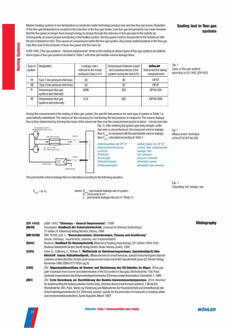
During the measurement of the sealing of aflue-gas system, the specific test pressure for each type of system in Table 1 is
automatically established. The volume air flow necessay for maintaining the test pressure is measured. The volume leakage
flow is then determined by forming the mean of the volume air flow over the measurement period of about minute (see also
Fig. 1). After entering the system geometry (length, width,
diameter or circumferance), the measured volume leakage
flow Vmeas
is compared with the permissible volume leakage
flow Vperm
calculated according to Table 1.
The permissible volume leakage flow is calculated according to the following equation:
Fig. 1
Measurement technique
of the DP 97/DP 94-200.
Equ. 1
Calculating the leakage rate.
Bibliography
Sealing test in flue-gas
systems
Modern heating systems in low temperature or condensin-boiler technology produce less and less flue-gas losses. Reduction
of the flue-gas temperature is coupled to the reduction in the flue-gas losses. Low flue-gas temperatures can mean however
that the flue gases no longer have enough energy to escape through the chimney or flue-gas pipe to the outside air.
Consequently, to ensure proper functioning of the heating system, the flue gases must be transported to the outside air with
the aid of blowerd or fans. This causes an overpressure within the flue-gas system. Any poorly sealed locations in the flue-gas
may then lead to the emission of toxic flue gases into the room air.
In EN 1443 „Flue-gas systems – General requirements“ limits on the sealing of various types of flue-gas systems are defined.
Some types of flue-gas systems are listed in Table 1 with their permissible volume leakage flows.
Type of Designation Leakage rate L Overpressure between inside
system referred to the inside and outsidesurfaces of the Instrument for taking
surface in l/(sec x m2) system during the test in Pa measurements
N1 Type 1 low pressure chimneys 2.0 40 DP 97
N2 Type 2 low pressure chimneys 3.0 20 DP 97
PI Overpressure flue-gas 0.006 200 DP 94-200
systems laid internally
PE Overpressure flue-gas 0.12 200 (DP 94-200)
systems laid externally
Tab. 1
Types of flue-gas systems
according to EN 1443, [EN1443]
Turbinengebläse bei DP 97 turbine blower for DP 97
Volumenstrommessung volume flow measurementLeckrate leakage rate
Prüfdruck test pressure
Druckregler pressure controllerDrehzahlvorgabe demanded speed
Prüfdruckvorgabe demanded test pressure

Internet: http://www.woehler.com/mgkg25
Venti
lati
on a
nd I
ndoor
Air
Quality
Order no. nAir Speed / Temperature
TA 22 Thermo Anemometer
LCA 6000 VA Impellar Anemometer
Advantages:
The LCA 6000 VA’s wide impellar and
special microprocessor technology allows
averaging even with turbulences.
• direct display of the air speed in m/s
• direct display of the volume flow in m3/s
• continiously adjustable average time
• adjustable cross-section area in m2
• measurement of the volume flow with
special hoods (see picture below)
Range: 0.25...30 m/s
0.002...2700 m3/s
Surface input: 0.008...90.00 m2
Average time: variable, min. 3 sec., max.
depending on the speed,
e.g.:
2 min. at 7.5 m/s
1 min. at 15 m/s
30 s at approx. 30 m/s
Accuracy: 1...12 m/s: < ± 5%
12...30 m/s: < ± 2%
Supply: 9 V battery, for approx. 50 h
Size: 110 x 40 x 265 mm
Weight: approx. 290 g
Volume Flow Measurement
Comes with:
LCA 6000 VA Impellar Anemometer with 9V battery
Accessories:
Carrying Bag for LCA 6000 VA
Flow Rate Hoods Set A consisting of: 1 round hood Ø 180 mm,
1 square hood 285 x 235 mm, carrying bag, Flow Rate Curve
Flow Rate Hoods Set B, 335 x 335 mm (opening inside), 440 x 440 mm (outer
dimension) with carrying bag
Application:
• Adjustment of air openings
at ventilation systems
• Examination of fans and air flows in
halls and corridors
4450 O
4639 O
4452 O
4451 O
Application:
• For Measurement of the air speed and
temperature in the vents
• Detection of leaks in the building wall e.g.
at plug sockets, windows, doors, etc
• High sensitive sensor for lower flow rates
Advantages:
• Simultaneous reading of air speed and
temperature
• Average value
• Min / Max - function
• automatic calculation of flow rates
• Hold-function
• various units available
• Probe with 1.7 m cable
4643 J
53798 P
Comes with:
TA 22 Thermo Anemometer with 300
mm probe, 1.7 m cable
Accessories:
Protection Sleeve with magnetic holder
and stand
Probe extension 300 mm 53797 P
Air Speed:
Range: 0.00...30.00 m/s
Resolution: 0.0...3.00 m/s:0.01 m/s
3.1...30.0 m/s: 0.1 m/s
Accuracy: 0.0...3.0 m/s:
±3 % f. m., ±0.06 m/s
3.1...30.0 m/s:
±3 % f. m., ±0.2 m/s
Air Temperature:
Range: -20...80 °C
Resolution: 0.1°C
Accuracy: 2 % f. m., ±0.3 °C
Volume Flow:
Range: 0...2,000 m3/h
Resolution: 1 m3/h
Accuracy: 3 % f. m., ±1m3/h
Units:
Air Speed: m/s, fpm
Temperature: °C, °F, K
Volume Flow: m3/h, cfm, l/s, m3/s
Probe Ø: 8 mm
Size: 175 x 45 x 34 mm
Weight: 190 g
Supply: 9 V block battery
Volume Flow
Application:
• For precise adjustment and control of the
flow rate at air inlets or outlets
Advantages:
• automatic flow rate reading in
combination with TA 22
• various funnels in different sizes
• very light weight
Funnel K 35 with bag
size 200x200x330 mmm
Funnel K 75 with bag
size 300x300x370 mm
Funnel K 120 with bag
size 450x450x370 mm
Funnel K 150 with bag
size 550x100x600
53794 P
53793 P
53789 P
53788P

Internet: http://www.woehler.com/mgkg26
Venti
lati
on a
nd I
ndoor
Air
Quality
Volume Flow Measurement
SWA 233 Flow Rate Measuring InstrumentRange: 2...65 l/s and
7...233 m3/h
Display: digital
Resolution: 0.1
Accurancy: < 0.5 l/s < 5% v.M.
Pressure loss: 2.5 Pa bei 100 m3/h
Supply: NiMH-rechargeable batteries
(installed)
Weight: 2.0 kg (Funnel)
Size: 190 x 190 mm
(Funnel opening)
Auxiliary funnel:340 x 340 mm (2) oder
370 x 370 mm folding (s.b.)
for supply air measurements
1 SWA 233 Flow Rate Measuring instrument comes with funnel 190 x 190 mm, 9385 L
Telescope handle and rugged carrying case
Function:
The funnel of the SWA 233 is covered by a thermal hot wire sensor. The measured
airflow influences the sensors resistance. The current needed to stabilize the hot wire
temperature is proportional to the air flow. This principle allows quick response time,
precise measurement and indicates variations in the air flow. Due to the very low
aerodynamic resistance of the SWA 233 (typ. 0.01“ water column @ 2700 ft3/h) the
airflow will not be affected by the measurement itself.
Application:
• extremely reaction-poor examination
of the exhaust air and supply air
openings at ventilation systems
Advantages:
• very low aerodynamic resistance
• quick response time
Auxiliary funnel
• indication of air flow variations
• measurement of the entire flow rate
profile with averaging function
Volumetric Air Flow Funnel A 97
Range: 1.0...65.0 l/s
Resolution: 0.1 l/s
Accuracy: < 0.5 l/s or 5 % f.m.
Display at A 97: value and y-t-Graphic for
recognition of fluctuation
Supply, weight, auxiliary funnel see
above
Air Flow Funnel A 97, comes with connection cable and protection case 4650 L
Quick Charger A 97, necessary to recharge the batteries 9612 J
Applications:
as SWA 233 (see above)
Advantages:
as SWA 233 (see above), additionally:
• graph mode display for better
representation and indication of flow rate
fluctuations
2 Funnel 340 x 340 mm, attachable to funnel 190x190 mm, 9486 J
necessary e.g. for larger inlets or outlets
Auxiliary Funnel 370x370 mm, 280 mm high, collapsable 4448 L
for larger inlets or outlets
The SWA 233 funnel and sensor element is also available for use with A 97. This probe is connected via the standard probe
connection of the A 97.
Comes with
1
2

Internet: http://www.woehler.com/mgkg27
Venti
lati
on a
nd I
ndoor
Air
Quality
Order No. n
DC 100 Pressure Computer
Application:
The DC 100 allows measurements of
extremely low differential pressure. By using
cappilary probes pressure differences of
adjoining rooms can be measured. Air speed
measurements are possible in combination
with Pitot tubes. Pressure differences of less
than 0.1 Pa are indicated.
Advantages:
• multi-function operation
• precise and stable measurement of
lowest pressure
Capillary, flexibly 4593 J
DC 100 Pressure Computer
Telaire 7001 CO2 Measuring instrument - Examination of the change of air rate
CO2 - measurement
Range: 0...10,000 ppm
Sensitivity: ± 1 ppm
Accuracy: ± 50 ppm or ± 5 %
Temperature drift: ± 0.1 % or ± 2ppm
per °C
Period of reply t90
: < 60 sec.
Temperature-measuring
Range: 0...50 °C
Resolution: 0.1°C
Accuracy: ± 1 °C
Analogue output: 0...4 V DC, / ppm,
1 mV/pm 4.000
ppm max.
Supply: 6 V DC
Work temp.: 0...50 °C
Storage temp.: -40...60 °C
Size: 170 x 80 x 40 mm
Weight: 280 g
Application:
• Evaluation of the air quality in rooms
• Examination of the change of air rate:
Energy conservation by appropriate
change of air
• Localisation of exhaust gases e.g. of
fire places
Advantages:
• patented two-jet infrared sensor
with high accuracy and good long-term
stability
• well readable display
• analogue data output
• PC interface
• 48 hours of service life
Accessoiries
CO2 measurement
Function:
The equipment which can be served simply determines the CO2 content by means of
a patented 2-jet infrared absorption sensors in less than 30 seconds and shows it and
the temperature at the same time on one large display.
Software Telaire 7001
Advantages:
• low auxiliary costs because of Windows
standard
• quick evaluation of the change of air rate
• all possibilities of the data subsequent
treatment
Telaire 7001 with 4 Mignon batteries
Data communication cable, for Telaire 7001
with software (free of charge)
7840 L
7841 L
Pressure:
Range: ± 100 hPa
Accuracy: < 5% from measuring
Resolution: 0.1 Pa in range ±11 hPa
otherwise 1 Pa
Temperature (internal NTC):
Range: -5°C up to 55°C
Accuracy: < ±4°C
Resolution: 0.1°C
Relative humidity (optional):
Range: 0% up to 100% rH,
non condensing
Accuracy: ±5% rH (0-60% rH),
otherwise <10% rH
Resolution: 1%rH
Storage temp.: -20°C up to +60°C
Work temp.: -5°C up to +60°C
Weight: 450 g (with case)
Size: 54 x 165 x 52 mm
Function:
With the data communication cable and the
Excel software the data can be transmitted
to Microsoft Excel and evaluated.
Measurement with Pitot Tubes
Application:
For measurement of the air speed with the Pressure Computer DC 100
or DC 2000.
Pitot Tube, length 35 cm, 7mm diameter 9487 M
Pitot Tube, length 50 cm, 7mm diameter 9488 M
Pitot Tube, length 100 cm, 7mm diameter 9489 M
7274 I

Internet: http://www.woehler.com/mgkg28
Venti
lati
on a
nd I
ndoor
Air
Quality
Order No. nMeasurement of distance, surface and volume
Application:
• fast calculation of area and volume
• trouble-free measuring without
additional devices
Advantages:
• with light beam for better orientation
• storage of measured values
• display in m/cm or ft/inch
8888 N
Range: min. 0.6 m, max. 20 m
Resolution: 1 cm, 1 inch
Accuracy: ±1 %: -5...50 °C
±0.5 %: 10...40 °C
Units: m, cm ,ft , inch
Supply: 9 V block battery
Size: 157 x 66 x 42 mm
Weight: 200 g
Comes with:
Digital Ultrasonic Distance Meter Bosch DUS 20 plus, with 9 V battery
Leica DISTO-classic Laser Distance MeterApplication:
• computation of surface and volume
• easy measuring without additional
aids
Advantages:
• precise distance measurement by
laser technology
• even chimney lengths measurable
• point of laser for orientation
• measured value memory
8899 O
Range: min. 0.3 m.....100 m
Resolution: 0.001 m
Accuracy: ± 0.5 mm
Units: m ,ft , in
Supply: 4 Micro batteries 1.5 V
for light pen
Size: 172 x 67 x 40 mm
Weight: 360 g
LE 94 - Air Yield Measuring
Function:
From the measurement of the differential air pressure in the setting up area between the
conditions „running“ and „switched off“ gas firings (simulation by exhaust over fan) the
air productivity can be concluded. The equipment accomplishes both in the reference G
625 planned duty cycles and determines the differential pressure with a resolution of
0.1 Pa. A data output to the thermal printer HP over the inserted infrared interface is
possible.
LE 94 Air Yield Measuring Instrument 8800 J
Comes with:
LE 94, with chimney adapters for
furnace pipe connections 110, 120 und
130 mm and Cordura carrying bag.
Application:
The LE 94 measures the availability of
supply air for heat appliances.
Flow rate:
Range: 10.0... 80.0 m3/h
Accuracy: ± 2 m3/h, 5 % f.m.:
10...40 m3/h
± 4 m3/h, 5 % f.m.:
40...80 m3/h
Pressure
Range: -100.0...100.0 Pa
Accuracy: ± 0.5 Pa, 5 % over one
measuring period
Computed values accord. to TRGI G 625
Differential pressure of the last measuring
interval
Average value of the computed differential
pressures
Largest deviation from the average value
Storage temperature: -20...50°C
Work temperature: 10...30°C
Size: 130x250x210 mm
(housing)
Ø 130x95 mm
(blower unit)
Weight: 5.2 kg
Supply: 230 V AC
Power consumption: approx. 100 W
Advantages:
• assistance for problems with the
supply of combustion air - causes can
be determined
• automatic measurement sequence
• menu control
• infrared interface for data output
Comes with:
Instrument with 4 Micro batteries 1.5 V
and protection bag made of Cordura
Bosch DUS 20 plus Ultrasonic Distance Meter

Internet: http://www.woehler.com/mgkg29
Venti
lati
on a
nd I
ndoor
Air
Quality
Order No. nSound Level Meter SP 22
Applications:
- building services
- building physics
- heat appliances
Advantages:
• accuracy class 3 L
• different measuring range and
scanning rates
• Hold function
• RS 232 interface
Range: 31.5 Hz ... 8 kHz
Accuracy: ± 1.5 dB
Measurement Level A filter:
30 dB ... 130 dB
Measurement Level C filter:
35 dB ... 130 dB
Measurement Level Range:
6 levels in 10 dB steps:
30 ... 80 dB, 40 ... 90 dB,
50 ... 100dB, 60 ... 110 dB,
70 ... 120 dB, 80 ... 130 dB
Automatic Range: 30 ... 130 dB
Display: 3 1/2 digit LCD, resolution
0.1 dB, update every 0.5 sec.
Quasi Analog Bar Indicator:
1 dB display steps, 50 dB
display range, updated
every 50 ms
Range: 50 dB
Time Weighting:
Fast (F): 125 ms
Slow (S): 1 s
Size: 80x256x38 mm
Weight: 240g
Supply: 9 V block battery
Sound Level Meter SP 22 6670 J
Application:
Leak detection at e.g.:
- gas lines
- water lines
- LNG-tankers
- refrigerating air conditioning
installations
Function:
The digital sound level meter SP 22 provides automatic or manual ranging in six measurement ranges from 30 to 130 dB. The unit meets ANSI S 1.4
and IEC 651 Type 2 standards, and features 0.1 dB resolution.
A background noise absorber permits you to measure sound levels accurately even in the presence of high background noise.
The meter allows you to select between fast and slow response times and A and C weighting. A maximum hold function is provided.
Jacks on the meter provide both AC and DC analog output, while a digital RS-232 interface allows you to use an optional cable to capture sound level
data on a PC.
UL 22 Ultrasonic Leak Detector
UL 22 Ultrasonic Leak Detector 3620 J
A leak is a not wanted flow of a substance out of a system, or in a vacuum into the system. Friction
in flow generates sound, water in pipes creates sound as well as air out of a tire. The sound we can
hear is less than a third of the total sprectrum of frequencies generated. The sound from small leaks
is mostly ultrasonic. Humans cannot hear this because it is above the human spectral range. In
order for a leak to generate ultrasonic frequencies, the flow through the leak has to be turbulent. The
velocity of the moving gas must be high in relation to the orifice. The UL 22 receives the ultrasonic
sound that is emitted by a leak, processes it, and displays its level. As larger the leak, as higher the
indication. In addition to the display, it produces an audio reproduction of the leak sound. The
intensity of the audio will change proportionally to the ultrasonic sound level.
US 22 Ultrasonic Sound Generator
Application:
The Ultrasonic sound generator US 22 is used to detect leaks in enclosures which are not under
pressure. It is ideal for the leak detection at
- buildings: doors, windows and other leakages (support of the leak detection with the BlowerCheck
BC 21)
- automotives: panes, doors etc
- containers
- freezers
3621 J
As the device is able to detect leaks in different types of medium (gas, liquid), there is a great
number of different applications, especially in the sectors heating, air-conditioning, buildings. So
the UL 22 is an effective and cost saving device that helps the craftsman and the engineer to
resolve many leakage-problems.
- pneumatic systems
- hydraulic systems
- vacuum systems
- electrical systems: switches, relays and other
contacts

Internet: http://www.woehler.com/mgkg30
Venti
lati
on a
nd I
ndoor
Air
Quality
Order No. n
IK 21 Infrared Camera
The IK 21 infrared camera is a powerful combination of an uncooled IR detector and
an easy to use photo camera. The camera is operated by a keypad and a large colour
TFT display on the backside. Snapshots are initiated by a trigger on the frontside, just
like a camera. The IK 21 could easily be used by hand, but for best performance a
tripod is recommended.
5800 Z
IK 21 IR Camera
Advantages:
• Costs: uncooled detector - lowest running
costs
• Readability: integrated large colour
display
• Operation: intuitively over integrated menu
guidance and arrow keys - thermography
at the press of a button
• Operating modes: continuous search and
single-frame modes
• Display: various colour displays can be
selected
IR spectral region: 8-12 mm
Sensor: patented, uncooled thermo-
electrical IR detector
Range: -20 up to 350 °C,
Resolution 0..1 °C
Resolution: 120 x 120,
50 mm Pixel
Accuracy: 2 °C, -20 up to 0 °C
2 % f.m., 0 to 350 °C
Objective: 20 mm (17.5°)
Display: high intensity 4.0“ colour LCD
Ambient air temp.: 0 up to 40 °C
Memory: 8.0 MByte ATA Flash
card for up to 280 images
Software: Win95/NT/... software for
evaluation and documentation (standard),
optional RS 232-Software for external control
of the IK 21
Interface: standard video output
Supply: standard 3 Ah camcorder
rechargeable battery NP 98
for approx. 60 minutes
operating time
Size (mm): 240 x 100 x 130
Weight: < 2 kg
• Evaluation: automatic tracing of the
hottest locations, adjustable single
temperatures and emission factors
• Image memory: 8 MByte memory card for
280 thermographs with all detail
information
• PC evaluation: incl. extensive software for
documentation and image analysis
(isothermals, parameters, ...)
Comes with:
Infrared Camera IK 21 with rechargeable
battery, spare battery, charger, glare
protection, shoulder strap, 8 MB memory
card, Win-PC software and video lead in
strong carrying case.
Accessories:
Various objectives on request
Application:
• Detection of cold bridges at buildings
- examination of the insulation
• Identification of leakages of the building
cover in connection with the blower door
• Representation of the heating distribution
at heating elements
• Measurement of the radiation losses at
hot water tanks, boilers/pipes
• Leakage detection at under-floor heatings
and water pipes
Operation and PC software
• Arrow keys: for menu operation and
cursor guidance during temperature
analysis on the display.
• Enter key: for menu selection and entry
of, for example, emission factors.
• Escape key: Changes between menu and
cursor, return function.
• Power key: For switching the camera on
and off
• Video socket, RS 232 socket

Internet: http://www.woehler.com/mgkg31
Venti
lati
on a
nd I
ndoor
Air
Quality
Order No. nTemperature measurement
IRTemp 100 L Infrared Thermometer
Range: -32...520 °C
Accuracy: 23...520 °C ± 1% f.m.
-32...23 °C ± 1.5°C
Resolution: 0.1°C to 199.9 °C
1 °C from 200 °C
Ratio: 12 : 1
Reaction time: 500 ms
Display: LCD, 3 figure
Current supply: 4 Mignon batteris 1.5 V
Size: 140 x 51 x 216 mm
Weight: 318 g
Application:
• Localisation of cold bridges in and
around buildings
• Non-contact temperature
measurement at surfaces
Advantages:
• with display of measuring point
• adjustable emissivity
• display of maximum, minimum and
mean temperature valuesComes with:
IRTemp 100 L with batteries
5692 J
IRTemp 10 Infrared Thermometer
Range: -20...420 °C ± 2% f.m.
Resolution: 1°C
Ratio: 8 : 1
Reaction time: 1 sec.
Display: LCD, 3 figure
Supply: 9V battery
Size: 170 x 44 x 40 mm
Weight: 200 g
6671 JApplication:
• non-contact temperature
measurement at surfaces
Advantages:
• for the localisation of cold bridges
• Laser Pointer
• fixed emissivity factor of 0.95
DT 22 Digital Thermometer
Range: -50.0 °C...1,300 °C
Accuracy: -50.0...1,000 °C:
± 0.3 % rdg + 1 °C
1,000...1,300 °C:
± 0.5 % rdg + 1 °C
(at 18 to 28 °C ambient temperature)
Display: 3 1/2 figure LCD 37x42 mm
Sampling rates: 2.5 per second
Size: 181 x 71 x 30 mm
Temperature Coefficient:
0.1 times the applicable accuracy specification
per °C from 0 °C to 18 °C and 28 °C to 50 °C
Application:
• temperature measuring in and around
building physics, house and fuel
engineering
Advantages:
• connection of various NiCr-Ni-sensors
possible
• 2 temperature measuring connections:
difference can be announced
• hold function
• determination of the k-value with
special wall temperature sensor
6665 J
• Control of the k-values at walls
• Determination of cold bridges
• Measurement of the pre and return
temperature of heating circles
Application:
The k-value of walls informs about the amount of heat, which is transported through
a wall due to a temperature gradient. Over the measurement of the wall surface
temperature and the knowledge of the interior and outside temperature the k-value
with sufficient accuracy can be determined with the help of a table. The difficult
measurement of the wall surface temperature is accomplished with the special type
W in connection with the A 97 or the DMT-K7 with high accuracy.
Wall Temperature Sensor Type W on A 97 Analysis Computer (k-value determination)
Comes with: see above
Wall Temperature Sensor Typ W
Measuring probe length: 65 mm
Measuring head Ør: 53 mm
Max. measuring temp.: 70 °C
Comes with:
IRTemp 10 with 9V block and protection bag
Surface Sensor IRTemp 100 L, balancing of emissivity 6694 J
Protection bag IRTemp 100 L 6695 J
Temperature Sensors
Speciall Wall Temperature Sensor Type W, for precise measurement of surface 4651 J
temperatures at walls (k-value s. below), ceilings, window frameworks. Also to control
radiation losses at Isolations.
Air Temperature Sensor Type L, for fast and exact determination of the air temperature 5684 J
in rooms, outside and in air ducts. Very quick reaction.
Max. measuring temperature: 150° C, with stainless steel protection tube
Flue-Gas Temperature Sensor Type TA, only 1.5 mm Ø , 250 mm probe, 5685 J
max. temperature up to 1,000 °C
Comes with:
Digital Thermometer with 9V battery
without temperature sensor

Internet: http://www.woehler.com/mgkg32
Venti
lati
on a
nd I
ndoor
Air
Quality
Order No. nBuilding Tightness
Blower Check BC 21 4800 J
Modern measuring instrument - quick setup and easy operation
• automatic measuring operation according to EN 13829
• results are shown and can be printed directly
• simple installation, as measuring instrument and blower unit seperately
Application:
• determination of the tightness of the
building cover
• all measurements according to EN13829
• leakage detection in the building cover
• proof of the building quality
• over and negative pressure measurement
by key pressing
• promting over WindowsTM similar screen
layout
• short setup by new clip system
• compact measuring instrument, can be
transported completely in 2 suit-cases
• comfortable data input over complete
alphanumeric touch screen keyboard
• integrated measuring data memory
• leakage detection with continuous
measured value display
Advantages:
• integrated measurement of the interior
and outside temperature
• continuous display of the flow rate in m3/h
• excellent price achievement relationship
• large diagramable LC display - all
measured values on a view
• over and negative pressure measurement
by key pressing
• date, time
• IrDA interface for printers and PC
Air flow: more than 3,000 m3/h at a
pressure difference of 50 Pa
Pressure difference: -100...+100 Pa
Air temp.: -20.00...50.00 °C
Accuracy: according to EN 13829
Blower: automatically regulated
Touch Screen: LCD 248 x 128 pix
Supply: 230 V
Size:
Operation unit: 130 x 240 x 280 mm
Blower: 440 x 440 x 120 mm
Installation dimensions:
max. 1,300 x 2,300 mm
min. 370 x 650 mm
Weight: 22 kg in 2 cases
Comes with:
Blower check basic equipment, blower,
hose set, thermal printer, carrying bag
and aluminium suit-case
Touchscreen: variable
Data administration
Tightness measurement
Result
Parameter input

Internet: http://www.woehler.com/mgkg33
Vis
ual
Inspecti
on
Order No. n
Pan & Tilt Video Inspection
Pan & Tilt Video Inspection System
1 VIS 2000 Video Inspection System, basic equipment 7800 J
with colour monitor, colour camera head, rubber collar as impact protection, 20 m of
camera cable with metric marking, leather protective bag with glare protection and
shoulder belt, power pack VIS 2000
2 VIS 2000 Video Inspection System, complete case 7825 J
like Order No. 7800 and additionally with cable winder and transport case
Application:
• inspection and documentation of
damage in ventilation and
exhaust systems
• menu insertion date,
time, mobile cursor,
and title with 10 figures
• compatible to all
camera heads of the following
pages
Advantages:
• splash-proof head enclosed in
illuminating housing
• simple and exact inspection
by the 180° tilt and 360° pan of
the camera head
• high beam LEDs for extra light
VIS 2000 Colour Monitor, with menu insertion 7804 J
Installation of the menu announcement, for colour monitor VIS 2000 7810 L
VIS 2000 Camera head colour 7806 J
VIS 98 Camera head b/w 7801 P
Replacement Glass Dome, for camera heads VIS 98 and VIS 2000 7802 P
VIS 2000 Power supply 51878 J
VIS 2000 Leather Protective Bag, with glare protection and shoulder belt 7815 L
VIS 2000 Transport case 7824 L
VIS 2000 Transport case XXL
Adapter cable, 12 V for car connection 8637 O
4 Additional Glare Protection 7833 J
5 Camera roller guide with protection cage, for camera head VIS 98 and VIS 2000 7826 J
Sets
Visual Inspection
Camera head colour
Type: colour camera CCD
Light sensitivity: colour: 5.0 Lux
b/w: 0.5 Lux
Objective lense: f = 2.0 mm, F = 2.0
Image angle: 98° x 75°
Rotates: 360°
Swivels: 180°
Light sources: 4 filament lamps under
diffuser and 6 switchable
white LEDs
Size: Ø 51 mm x 99 mm
Weight: 240 g
Monitor
Size housing: 21 x 13 x 65 cm
TFT Display: 117 x 87 mm
Video Out: FBAS-Signal
Weight: 1950 g
Supply: NiMH rechargeable
batteries or over rapid charger
Operation time: approx. 2 hours
Individual
1
2
3
3 VIS 2000 Video inspection System with camera viper, complete case 7830 J
with colour monitor, colour camera head, camera viper, viper stand, 20 m GRP rod 7 mm Ø,
leather protective bag with shoulder belt, camera roller guide with VA protective cage (see p. 36),
power pack VIS 2000, centering star 20 cm Ø (see p. 34) and carrying case XXL
• wide angle objective (f=2.0 mm) for
large point of view and large depth
sharpness (starting from approx.1 cm)
• compact, light monitor in a leather
bag with glare protection and carrying
belt - can be carried in front of the
body
4
5

Internet: http://www.woehler.com/mgkg34
Vis
ual
Inspecti
on
Order No. nMini Camera Video Inspection
VIS 2000 Mini Camera
Application:
outstanding suitably for the optical
inspection and control of
• channels
• pipes
• exit gas lines
• ventilation ducts and annular gaps
The Mini Camera VIS 2000 can be
pushed problem-free through pipes from
a Ø of 40 mm.
Advantages:
• miniature camera head only 26mm Ø
• up to 3 bar water resistant
• durable stainless steel housing
• wide angle objective (f 2.5 mm)
also for large pipes
Sets
Individual
Monitor see page 32, compatible
with the systems
Camera head colour
Type: 1/3“ COLOUR CMOS
Light sensitivity: colour: 3.0 Lux
b/w: 0.2 Lux
Objektive lense: f = 2.5 mm, F = 2.0
Image angle: 120°
Light sources: 12 white LEDs
Size: Ø 26.5 mm x 84 mm
Weight: 240 g
Camera Viper
Rotary transfer: up to 30 m rod length
Weight: 2,000 g (without rod)
Connection cable: 2.5 m long
• simple handling by viper,
alternatively by hand, from belt or
on the floor
1
5
23
1 VIS 2000 Mini Camera, baic equipment 7865 J
with miniature camera head, colour monitor VIS 2000, leather protection bag with glare
protection and shoulder straps, power pack VIS 2000, GRP camera rod black, 20 m long, 6 mm Ø
and camera viper with stand
2 Miniature camera head colour, with flexible connection for GRP camera rod 7817 J
Miniature camera head b/w, with flexible connection for GRP camera rod 7871 J
3 Protection Sleeve, for miniature camera head 7863 J
Side view mirror, for miniature camera head 7923 J
6 Centering star, 15 cm Ø, for miniature camera head 8771 H
6 Centering star, 20 cm Ø, for miniature camera head 9771 H
6 Centering star, 25 cm Ø, for miniature camera head 8772 H
4 Camera viper, with GRP camera rod black, 20 m long, 6 mm Ø and connection cable 7308 J
Camera viper, with GRP camera rod red, 20 m long, 7 mm Ø and connection cable 7309 J
to monitor - particularly suitable for camera heads VIS 98 and VIS 2000
Camera viper, for GRP camera rods up to 30 m, with 2.5 m connection cable to monitor 7822 J
5 Viper stand 7823 J
Transport case XXL, for camera viper and accessories 5824 L
Camera rod black, 6 mm Ø, 5 m long, for the inspection of pipes with the miniature 7821 J
camera head
Camera rod black, 6 mm Ø, 20 m long 7818 J
Camera rod black, 6 mm Ø, 30 m long 7819 J
Camera rod red, 7 mm Ø, 5 m long for the inspection of pipes from 100 mm Ø 7305 J
and chimneys up to 20 x 20 cm with the camera heads VIS 2000 and VIS 98
Camera rod red, 7 mm Ø, 20 m long 7829 J
Camera rod red, 7 mm Ø, 30 m long 7306 J
Special cable 0.8 m long, for comfortable connection of the single camera rods with 9181 L
the monitor
4
6

Internet: http://www.woehler.com/mgkg35
Vis
ual
Inspecti
on
Order No. nVideo Inspection System Accessories
2
3
1 Cable reel for VIS 2000 7816 J
with shoulder strap and connecting cable to monitor, without camera cable. Designed for cable
lengths up to 30 m, collapsable stand legs, adjustable camera holder
30 m Camera Cable with metric marking 7812 L
20 m Camera Cable with metric marking 9172 L
10 m Extension cable with metric marking 8636 L
2 Camera Spring Guide, for centering of the camera head in vertical vents. A stainless 8633 J
steel spring prevents a rotating and oscillating of the camera head. The spring is adjustable
on the tubing size up to 35 cm.
3 Viper camera holder, with connection cable to camera cable and M 10 thread 8680 J
for attaching to rods. The camera is in a protective cage and faces down , so that incidental
daylight does not cause problems. Attached to rods both, horizontal and vertical pipes can be
examined.
4 Stabilization sleeve with star holder, for camera head VIS 2000 and VIS 98 when used 3590 L
with 6 or 7 mm camera viper
- can be screwed to VIS 98 and VIS 2000 camera heads and even to the roller guide with VA
protection cage (see p. 32)
5
6
5 Telescope Dolly, stainless steel, for letting down the camera head at the cable, 5706 L
from 22 - 40 cm extendable Also with extended roll support the role remains about centrically
6 LED supplementary light with red-yellow LEDs, for camera head b/w, 9177 P
incl. battery pack with four Mignon batteriees 1.5 V in Cordura bag
The supplementary light is simply pushed onto the camera.
LED supplementary light with white LEDs, for camera head colour 9377 P
7
7 Transport Case VIS 2000 with shoulder strap 7824 L
Transport Case XXL, for camera viper VIS 2000, with shoulder strap 5824 L
9
10
8
11
12
8 Camera Trolley, ideally suitable for the Inspection of horizontally running pipes from about 9548 F
150 mm diameter, e.g. in ventilation ducts. The spray tube for controled spraying out the air
ducts with desinfectant can be mounted on the trolley. Adapters for the connection to the mini
viper (M 5) as well as to the large viper (M 10) are included.
Size: 160 x 125 x 120 mm
9 Maxi Adapter for Camera Trolley for the inspection of larger ventilation ducts 9549 F
(from about 300 mm), size: 350 x 175 x 125 mm
10 Spray tube with nozzle for Camera Trolley, size: 400 mm long, Ø 12 mm 9709 F
11 Digital Image Converter 6233 J
for the storage of images on a Notebook/PC, with USB interface, cable and software
12 USB Port Mobile Adapter, provides 2 USB ports via the PCMCIA slot. 6234 J
1
4

Internet: http://www.woehler.com/mgkg36
Vis
ual
Inspecti
on
Order No. nTechno Edoscopes
5
3
1
2
4
6
HEINE Techno Endoscope 56/420
Application:
• Inspection of air ducts and other pipes
with small cross section
• Examination of isolations
• Exhaust way examination with boilers
and wall devices
• Inspection of cavities
Advantages:
• view angle of 56° provides excellent
picture
• super-bright halogen illumination, 12
V Heine XHL
• high-quality image transmission via
achromatic lenses
• focusing eyepiece, excellent for
people who wear glasses
• extra long operation period: over one
hour
• ideal length 420 mm, 8 mm Ø
• short lamp forepart, only 21 mmfrom
tip of endoscope to objective lens
Combination 5 Techno Endoscope 56/42, straight, 12 V XHL, with angular adapter 120/250 mm, 8655 Q
connecting lead, battery box with charging transformer and endoscope leather box.
as combination 5, without endoscope leather box, with protective tube. 8653 Q
Techno Endoscope 35/330, 12V, straight, angular adaptor 120/120 mm, connecting lead, 5118 Q
battery box with charging transformer, protective tube
1 Techno Endoscope 56/420, straight, 12 V XHL, super-bright, 8654 Q
probe length 420 mm, without power supply
2 Techno Endoscope 35/330, straight, 12 V, probe length 330 mm, without power supply 6267 Q
3 Angular Adapter 120/250, plug onto straight endoscope, good optical transition 8616 Q
4 Angular Adapter120/120, plug onto straight endoscope, good optical transition 5265 Q
Halogen bulb 12 V XHL Nr. 092 for Techno Endoscope 56/420 and 45/420 8618 Q
Halogen bulb 12 V Nr. 079 for Techno Endoscope 35/330, 35/485 and Angular 6274 Q
Techno Endoscope.
Screw cap for Techno Endoscope 56/420 809 Q
Screw cap for Techno Endoscope 35/330 6275 Q
5 Connecting lead 12 V, 2 m long, for battery box 6272 Q
5 Connecting lead 12 V, 50 cm long, for Endoskope Camera Head 6277 Q
Protective tube for Techno Endoscope 56/420 and 45/420 6205 Q
Protective tube for Techno Endoscope 35/330 1035 Q
6 Battery box 12 V with charging transformer 8617 Q
Eyepiece Eye-Guard plugs on, rubber 6907 Q
Combination 6
Combination 2The well-proven and economical Techno
Endoscope 35/330
Individual
Accessoiries
Endoscope Leather Box and Endoscope Bag (without contents)
7
7 Endoscope LeatherBox
for combinations 2, 5 and 6,
435x100x55 mm. From leather with
foam material insert. Fits into the
intermediate bottom of the standing
leather suit-case A97 and into the
aluminium suit-case A 97, as well as
into the rucksack A 97.
8 Endoscope Bag from Cordura, for
combinations 2, 5, 6 and the Angular
Techno Endoscope
8614 L
630 J
8

Internet: http://www.woehler.com/mgkg37
Vis
ual
Inspecti
on
Order No. nCold-Light Endoscope
Cold-Light Endoscope 900, flexible
Application:
is suitable outstanding for optical
control of smallest openings
Overall length: 1000 mm or 2000 mm
Illumination: Halogen bulb 3.5 V
approx. 20,000 Lux
Running time: 3.5 hours
Viewing direction: 0° straight on,
90° (optional)
Viewing angle: 55°
Image transfer: Single fibre 35 mm Ø
Operating temp.: - 20 to 60 °C
Probe + optics: waterproof up to 1 bar
Focus: > 10 mm
Weight: 580 g
Advantages:
• only 8 mm Ø
• very flexible
• bright illumination of 2,000 lux
• focusable eyepiece: always sharp
picture, with or without glasses
• probe length 900 mm
• independent of mains
1 Cold-Light Endoscope 900, flexible, viewing direction straighton, 4507 L
with 3 batteries 1.5 V and durable carrying case
Cold-Light Endoscope 2000, flexible, viewing direction straighton, 4517 L
with 3 batteries 1.5 V and durable carrying case
2 Side-View Adapter for Cold-Light Endoscope 4504 L
Protective Bag for Cold-Light Endoscope 4508 L
made of Codura, with shelfes for side-view adapter and 3 batteries
Halogen bulb 3.5 V 078 4509 Q
Battery 1.5 V 1029 O
Accessoiries
Inspection with mirrors
1 2 3 4 5 6 1 Glass Mirror large, 8x15 cm with telescopic handle, 1m and artificial leather cover 1107 J
The large polished crystal mirror permits excellent optical control of exhaust systems.
The glass mirror is provided with a metal plate for protection backside.
2 Glass Miirror central, 5x8 cm with telescopic handle, 54 cm and artificial leather 8060 J
cover, with stainless steel back
3 Glass Mirror small, 2.6x7 cm with telescopic handle, 54 cm and artificial leather cover 8670 J
4 Chimney Mirror small, 7x10 cm with telescopic handle, 54 cm and artificial 1748 K
leather cover. High-quality high polish-chromed metal mirror
5 Glass Hand-Mirror, 7x10x95 mm with artificial leather cover 5064 K
6 Chimney Mirror small, 7x10 cm with artificial leather cover 1015 O
Halogen Pocket Light
7 8Ideal for the inspection work with mirrors:
7 Halogen Pocket Light, very bright illuminating, small and flat 400 J
with 3 Mignon batteries a 1.5 V
8 Halogen Long Range Head Light, 350 m lightwhite Halogen light 6510 G
operating time with rechargeable batteries 30 minutes
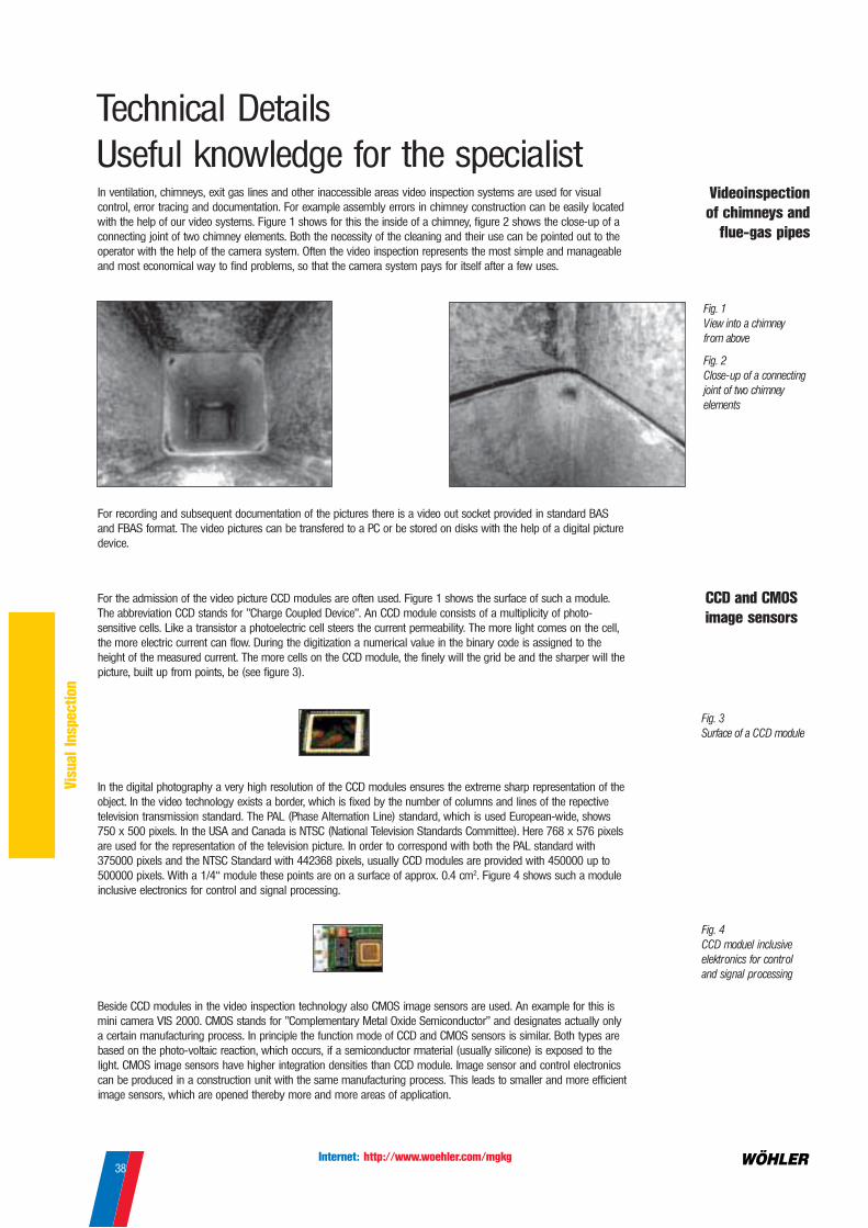
Internet: http://www.woehler.com/mgkg38
Vis
ual
Inspecti
on
Technical Details
Useful knowledge for the specialistIn ventilation, chimneys, exit gas lines and other inaccessible areas video inspection systems are used for visual
control, error tracing and documentation. For example assembly errors in chimney construction can be easily located
with the help of our video systems. Figure 1 shows for this the inside of a chimney, figure 2 shows the close-up of a
connecting joint of two chimney elements. Both the necessity of the cleaning and their use can be pointed out to the
operator with the help of the camera system. Often the video inspection represents the most simple and manageable
and most economical way to find problems, so that the camera system pays for itself after a few uses.
For recording and subsequent documentation of the pictures there is a video out socket provided in standard BAS
and FBAS format. The video pictures can be transfered to a PC or be stored on disks with the help of a digital picture
device.
For the admission of the video picture CCD modules are often used. Figure 1 shows the surface of such a module.
The abbreviation CCD stands for "Charge Coupled Device". An CCD module consists of a multiplicity of photo-
sensitive cells. Like a transistor a photoelectric cell steers the current permeability. The more light comes on the cell,
the more electric current can flow. During the digitization a numerical value in the binary code is assigned to the
height of the measured current. The more cells on the CCD module, the finely will the grid be and the sharper will the
picture, built up from points, be (see figure 3).
In the digital photography a very high resolution of the CCD modules ensures the extreme sharp representation of the
object. In the video technology exists a border, which is fixed by the number of columns and lines of the repective
television transmission standard. The PAL (Phase Alternation Line) standard, which is used European-wide, shows
750 x 500 pixels. In the USA and Canada is NTSC (National Television Standards Committee). Here 768 x 576 pixels
are used for the representation of the television picture. In order to correspond with both the PAL standard with
375000 pixels and the NTSC Standard with 442368 pixels, usually CCD modules are provided with 450000 up to
500000 pixels. With a 1/4“ module these points are on a surface of approx. 0.4 cm2. Figure 4 shows such a module
inclusive electronics for control and signal processing.
Beside CCD modules in the video inspection technology also CMOS image sensors are used. An example for this is
mini camera VIS 2000. CMOS stands for "Complementary Metal Oxide Semiconductor" and designates actually only
a certain manufacturing process. In principle the function mode of CCD and CMOS sensors is similar. Both types are
based on the photo-voltaic reaction, which occurs, if a semiconductor rmaterial (usually silicone) is exposed to the
light. CMOS image sensors have higher integration densities than CCD module. Image sensor and control electronics
can be produced in a construction unit with the same manufacturing process. This leads to smaller and more efficient
image sensors, which are opened thereby more and more areas of application.
Videoinspection
of chimneys and
flue-gas pipes
Fig. 1
V iew into a chimney
from above
Fig. 2
Close-up of a connecting
joint of two chimney
elements
CCD and CMOS
image sensors
Fig. 3
Surface of a CCD module
Fig. 4
CCD moduel inclusive
elektronics for control
and signal processing

Internet: http://www.woehler.com/mgkg39
Cle
anin
g a
nd a
ccessoir
ies
Stars / Extra Large Stars / Threaded Brushes / Specialty Brushes
Stainless-Steel Flat Wire1.4310
Marking: A black outer cardboard disc indicates the
stainless steel wire, the second cardboard disc indicates
the wire thickness.
• VA 00 (1.25 x 0.25 mm), very soft,only for push-head brushes, no marking
• VA 0 (2 x 0.25 mm), soft,white cardboard disc
• VA I (2 x 0.35 mm), medium hard,green cardboard disc
• VA II (2.75 x 0.35 mm), hard,red cardboard disc
PEK
The high-tech fibre for light-duty sweeping, strongplastic bristles retain their shape up to about 140 °C.
Perlon
Plastic bristle for stainless steel pipes retain theirshape up to about 50 °C.
Stainless Steel wire, crimped
Special manufacture:We would be pleased to make the listed stars andpush-head brushes also in other sizes and with morelayers.Please state the diameter you require and the bristlematerial.
Spring-Steel Flat Wire
A cardboard disc indicates the wire thickness.• 00 (1.25 x 0.25 mm), very soft,
no marking, only for push-head brushesand small-hole stars
• 0 (2.00 x 0.25 mm), soft,white cardboard disc
• I (2 x 0.35 mm), medium hard,green cardboard disc
• II (2.75 x 0.35 mm), hard,red cardboard disc
• III (3.3 x 0.6 mm), very hard,in bright metal and galvanised version.(Heavy-duty and pumper stars),blue cardboard disc
Perlon 1 - - - - 1466 B -
Legend: MT = Material WE = Wire Ends KN = Marking PU = Packing Unit
Threaded
Brushes
with M 5 thread
Dome Brush
with M 10 thread
MT PU Ø 7 cm Ø 10 cm Ø 13 cm Ø 15 cm Ø 18 cm Ø 20 cm
Order No. Order No. Order No. Order No. Order No. Order No.
PEK 1 3803 L 8076 L 7091 L 3839 L - 7990 L
Specialty
Brushes
with hole 6 mm Ø
PEK 1 8644 C 8645 C 8646 C 8647 C - 8648 C
Extra Large
Stars
with hole 28 mm Ø
Spring-Steel Flat Wire
galvanised, very hard, 120 wire ends
Extra Large Stars, 50 cm Ø 1426 A
Extra Large Stars, 60 cm Ø 1427 A
Extra Large Stars, 65 cm Ø 1428 A
Extra Large Stars, 70 cm Ø 1429 A
Extra Large Stars, 80 cm Ø 1430 A
Support Ring
for Extra
Large Stars
strong metal frame
for insertion into the
screwed joint 1432 F
Heavy-Duty
Stars
with hole 28 mm Ø
Spring-Steel Flat Wire
with bent wire ends,
very hard, 80 wire ends
Heavy-Duty Stars, 14 x 14 cm 3586 F
Heavy-Duty Stars, 14 x 20 cm 218 F
Heavy-Duty Stars, 16 x 26 cm 3198 F
Heavy-Duty Stars, 20 x 20 cm 99 F
Order No.Order No.

Internet: http://www.woehler.com/mgkg40
Cle
anin
g a
nd a
ccessoir
ies
Stars / Threaded Brushes
Strength WE KN PU Ø 15 cm Ø 18 cm Ø 20 cm Ø 25 cm Ø 30 cm Ø 35 cm Ø 40 cm
Order No. Order No. Order No. Order No. Order No. Order No. Order No.
Spring-Steel Flat Wire
soft 80 1 2832 C - - 1266 C 1267 C - -
medium hard 80 1 - - 1268 C 1269 C 1270 C 1271 C 1272 C
medium hard 80 5 - - - 5358 G 5375 G 5384 G -
medium hard120 1 - - - 1290 C 1291 C 1292 C -
hard 80 1 - - 1273 C 1274 C 1275 C 1276 C 1277 C
hard 80 5 - - - 5358 G 5350 G 5353 G -
hard 120 1 - - - 1295 C 1296 C 1297 C 1298 C
VA Flat Wire
soft 80 1 6291 C - 5453 C 5455 C 5454 C - -
soft 80 3 2851 G - 2852 G 2853 G 2854 G - -
medium hard 80 1 - - 1283 C 1284 C 1285 C 742 C 761 C
medium hard 80 3 - - - 2945 G 3008 G 3219 C -
hard 80 1 - - - 5362 C 5363 C 5364 C 5479 C
hard 80 3 - - - 3638 G 4683 G 5220 G -
VA crimped 480 C 513 C 1315 C 1316 C - - -
PEK 1 6904 G 6903 G 6900 G 6901 G 6902 G - -
2 5296 G 5299 G 5311 G 5342 G 5346 G - -
Perlon 1 2743 G - 1306 G 1307 G 1308 G - -
Spring-Steel Flat Wire
mediumhard 80 1 - - 1320 C 1321 C 1322 C 1323 C -
hard 80 1 - - - 1325 C 1326 C 1327 C -
VA Flat Wire
soft 80 1 - - 5461 C 5394 C - - -
mediumhard 80 1 - - 1328 C 1329 C 5397 C - -
PEK 1 283 G 330 G 333 G 327 G - - -
Perlon 1 - 640 C 2211 C 1335 C - - -
Spring-Steel Flat Wire
very soft 120 1 - - 1344 G - - - -
soft 80 1 1352 G - 1346 G - - - -
soft 80 3 - - 5456 G - - - -
soft 120 1 - - 1347 G
med. hard 80 1 - - 1349 G - - - -
med. hard 120 1 - - 1350 G - - - -
VA Flat Wire
soft, double 3 - - 5312 G - - - -
PEK 1 5468 G - 885 G - - - -
Spring-Steel Flat Wire, with M 10 thread
soft, 2 layers 1 1357 C - 1365 C 1373 C - - -
med. hard, 2 layers 1 1359 C - 1367 C 1375 C 1383 C 1391 C -
med. hard, 3 layers 1 1360 C - 1368 C 1376 C 1384 C 1392 C -
hard, 2 layers 1 - - - 1377 C 1385 C 1393 C -
hard, 3 layers 1 - - - 1378 C 1386 C 1394 C -
VA Flat Wire
very soft, 2 layers 1 9423 C 9424 C 9425 C - - - -
soft, 2 layers 1 - - 5447 C 5448 C 4162 C - -
hard 1 - - - 4676 C 5575 C 5588 C -
PEK 1 518 K 324 K 315 K 316 K - - -
Perlon 1 545 C 790 C 1413 C 1415 C 531 C - -
Small-Hole
Stars
with hole 10 mm Ø
Stars
with hole 28 mm Ø
Threaded
Brushes
Stars
with hole 16 mm Ø

Internet: http://www.woehler.com/mgkg41
Cle
anin
g a
nd a
ccessoir
ies
Order No. nVipers and GRP-Rod Types
Advantages:
• run-out brake
• can be secured for transport
• can be used standing upright or in lying
position
• light weight
• frame can store up to 3 stars
• protective tubeto prevent scraping of the
GRP rod
Viper with GRP Rod 9 mm Ø, 15 m long 9412 J
9 mm Ø, 20 m long 9413 J
Viper with GRP-Rod 9 mm Ø
Comes with:
GRP rod with two M 10 stainless steel
end-pieces for push-head brushes, GRP
push-head adapter for accepting line
stars, protection tube 75 cm long
Advantages:
• freewheel brake, precisely adjustable
• belt clip for sweeping and carrying
• transport possibility for 2 stars
• light weight
• viper stand available
• protective tube to prevent scraping of the
GRP rod
1 Handy viper with GRP-rod 7 mm Ø, 15 m long 7649 J
7 mm Ø, 20 m long 7648 J
Protection tube for handy viper 51984 L
2 Viper stand 7823 J
Cage Ø: 42 cm
Maximum height: 42 cm
Width: 10 cm
Weight: 1,800 g
Freewheel brake: precisely
adjustable
Handy Viper with GRP-Rod 7 mm Ø
Comes with:
GRP-rod with M10 stainless steel end-
piece for push-head brushes, GRP push-
head adapter for accepting stars
Application:
The VIPER is an uniquely designed line of various sized rods for the professional to use when sweeping chimneys, ventilation
systems, duct work or stoves. The VIPER rods are made of a central fiberglass core with a plastic, protective cover. The rods come
in varying lengths and thicknesses as shown in the table below to provide you with the right combination of flexibility and length
to suit you cleaning needs.
From our thickest 9 mm Chimney VIPER to our most flexible 4.5 mm Mini VIPER, there is a wide selection of threaded or STAR
brushes that you can use to customize your cleaning action. The continuous rod design housed in either a free standing or hand
held rotating rod basket provides for easy operation that saves you time, effort and money.
Sheath Ext.-Ø Core-Ø Main application
mm mm
Black 4.5 3.0 • in the Mini Viper 32 for flue-gas pipes up to 200 mm Øand for room ventilation systems
• as single rod for ventilation ducts
Yellow 6.0 4.5 • in the Mini Viper 42 for large flue-gas pipes from 130 mm diam.,small chimneys up to about 16 x 16 cm and 10 m length andventilation ducts• as single rod for connecting pieces and ventilation ducts
Red 7.0 4.8 • in the manual sweeping reel for small and medium chimneys up to15 m, length also for roof-space work• as single rod for connecting pieces and chimneys
Black 9.0 6.2 • in the sweeping rod reel for medium and large chimneys from about14 x 14 cm.• as single rod for chimneys
Cage Ø: 59 cm
Maximum height: 61 cm
Weight: 4.3 - 5.3 kg
Brake: adjustable, additonal transport
lock over lever
2
1

Internet: http://www.woehler.com/mgkg42
Cle
anin
g a
nd a
ccessoir
ies
Order No. n
Mini Viper 42 with GRP-Rod 6 mm Ø
Advantages:
• handy viper with precisely adjustable
freewheel brake - makes running in
and out of the GRP rod possible
without holding the cage
• folding handle - space-saving
for transport
• light weight
Advantages:
• construction like Min VIper 42
• well suited for tight bends
• for mini hole stars and tube brushes
PEK and spongues
Mini Viper 32 with GRP-Rod 4.5 mm Ø
Comes with:
Mini Viper 42 with GRP-rod 6 mm Ø, 15
m long, with stainless steel end-piece
M10 and push-head adapter 28 mm Ø
Comes with:
Mini Viper 32 with GRP-rod 4.5 mm, 15
m long, stainless steel end-piece M5,
deviation spiral M5 and guide ball
GRP-Rods, singleWe supply GRP-rods also individually cut
to length with end-pieces and rubber
end-ball (9/11mm Ø) and/or with guide
ball M5 (4.5mm Ø) and/or with stainless
steel end-piece M10 (6mm Ø) for better
handling. For the use of stars
additionally a push-head adapter (6/9/11
mm Ø) is to be used, for the GRP-rod 4.5
mm a deviation spiral M5 is
recommended.
GRP-Rod 4.5 mm Ø, 2 m long with 2 stainless steel end-pieces and guide ball M5 7415 J
GRP-Rod 6 mm Ø, 3 m long with 2 stainless steel end-pieces M10 7420 J
GRP-Rod 9 mm Ø, 5 m long with 2 end-pieces M10 and rubber end-ball 1464 J
GRP-Rod 11 mm Ø, 10 m long with 2 end-pieces M10 and rubber end-ball 102 J
GRP Push-head adapter 28 mm Ø for GRP-rods 9/11mm Ø, for line stars 7979 A
Push-head adapter 28 mm Ø for GRP-rods 6 mm Ø, for line stars / spongues 9421 G
Deviation spiral M5, stainless steel for GRP-rods 4.5 mm Ø 8639 L
GRP Push head adapter 15 mm Ø for GRP-rods 4.5 mm, for spongues 9422 G
Mini Vipers Replacement GRP-Rods
GRP-Rod 4,5 mm Ø, 15 m long with stainless steel end-piece M 5 9703 A
GRP-Rod 6 mm Ø, 15 m long with stainless steel end-piece M 10 8015 A
GRP-Rod 6 mm Ø, 20 m long with stainless steel end-piece M 10 8020 A
GRP-Rod 7 mm Ø, 15 m long with stainless steel end-piece M 10 7015 A
GRP-Rod 7 mm Ø, 20 m long with stainless steel end-piece M 10 7020 A
GRP-Rod 9 mm Ø, 15 m long with 2 stainless steel end-pieces M 10 9015 A
GRP-Rod 9 mm Ø, 20 m long with 2 stainless steel end-pieces M 10 9020 A
Replacement rods
Mini Viper 42 with folding handle 8649 J
Mini Viper 42 with belt clip 8869 J
Mini Viper 42 with folding handle and belt clip 8873 J
Cage Ø: 32 cm
Weight: 1.1 kg incl. 15 m GRP-rod
Brake: precisely adjustable freewheel
brake
Cage Ø: 42 cm
Weight: 1.6 kg incl. 15 m GRP-rod
Brake: precisely adjustable
freewheel brake
Mini Viper 32 with folging handle 8650 J
Mini Viper 32 with belt clip 8870 J
Mini Viper 32 with folding handle and belt clip 8872 J
Belt Clip Retrofit Kit for Mini Vipers 32 and 42, for self-assembly 8480 L

Internet: http://www.woehler.com/mgkg43
Cle
anin
g a
nd a
ccessoir
ies
Order No. nSweeping Rods for Chimneys Steel Rods
GRP-Rods with stainless steel end-piece on both sides, with internal thread M 10
GRP-rod 7 mm Ø, 3 m long 3211 J
GRP-rod 7 mm Ø, 5 m long 3210 J
GRP-rods 9 mm Ø, 3 m long 1196 J
GFK-rods 9 mm Ø, 4 m long 7363 J
GFK-rods 9 mm Ø, 5 m long 1464 J
GFK-rods 9 mm Ø, 6 m long 1124 J
GFK-rods 9 mm Ø, 8 m long 1718 J
GRP-rod 11 mm Ø, 12 m long 103 J
GRP-rod 11 mm Ø, 10 m long 102 J
Complete Rod GRP 9 mm Ø, 5 m long
with GRP push-head adapter for accepting line stars 5583 E
GRP-rods are available in all lengths. Please state which type you require and its
length.
Accessoiries
1 GRP Push-head 28 mm for GRP-rods 9 mm Ø and steel rods 7979 A
for accepting line stars
2 Large Push-head adapter, stainless steel 5280 E
with aluminium taper, stainless steel cap and stainless steel screw M 10 x 40 for line stars
3 Small Push-head Adapter, for push-head stars 1440 E
4 Rubber End-Ball, M 10 thread, 5656 E
for GRP and steel rods, shock deadening and easy to hold
5 End-Ball Aluminium 1448 A
6 Rod connector in stainless steel with union nut, twist lock using square pin, M 10 threaded 1409 E
on each end and 17 mm wrench
7 Brass Threaded Connector 1454 A
8 Steel Chisel M 10 1457 E
9 Roller Opener, stainless steel 1455 E
10 Harpon with Barbs 1459 L
Steel Rods with brass end-piece on both sides and internal thread M 10
B-Steel rod 3 x 3.6 mm Ø, 3 m long 2731 J
B-Steel rod 3 x 3.6 mm Ø, 5 m long 2732 J
B-Steel rod 3 x 3.6 mm Ø, 6 m long 2740 J
B-Steel rod 3 x 3.6 mm Ø, 8 m long 2741 J
C-Steel rod 2 x 4.5 mm Ø, 5 m long 2795 J
C-Steel rod 2 x 4.5 mm Ø, 6 m long 2805 J
C-Steel rod 2 x 4.5 mm Ø, 8 m long 2812 J
C-Steel rod 2 x 4.5 mm Ø, 10 m long 2847 J
D-Steel rod 3 x 4.5 mm Ø, 5 m lang 2848 J
D-Steel rod 3 x 4.5 mm Ø, 6 m lang 2866 J
D-Steel rod 3 x 4.5 mm Ø, 8 m lang 2849 J
D-Steel rod 3 x 4.5 mm Ø, 10 m lang 2850 J
Steel rods are available in all lengths up to 12 meter. Please state which type you
require and its length.
Complete rod B, 5 m long, 3 x 3.6 mm Ø, twisted, brass end piece with internal thread M 10, 5582 E
large stainless steel push-head for accepting stars and aluminium end-balls.

Internet: http://www.woehler.com/mgkg44
Cle
anin
g a
nd a
ccessoir
ies
Order No. nThe Apparate
1 The Apparate / chain, fast and simple changing of the stars,
stainless steel chain with T-fitting 50 cm long, GRP screw connection 28 mm Ø, cast iron ball
with cast iron ball 0.8 kg 5149 E
with cast iron ball 1.1 kg 5152 E
with cast iron ball 1.6 kg 5160 E
with cast iron ball 2.0 kg 3652 E
2 The Apparate / rope, especially suitable for all modern chimneys because all parts
are made of plastic, rope 50 cm long, cast iron ball, GRP screw connection 28 mm Ø
with cast iron ball 0.8 kg 5970 E
with cast iron ball 1.1 kg 5770 E
with cast iron ball 1.6 kg 5971 E
3 The Gas Apparate, with rubber ball 6 cm Ø, rope 40 cm, GRP screw connection
16 mm Ø, PEK star 20 cm Ø, M6 eyelet stainless steel
with rubber ball 590 g 5469 L
with rubber ball 430 g 5489 L
1 2
3
Furnace Cleaning
Furnace brushes
Furnace brushes, with 2 m handle, Perlon 0.8 m
180 mm Ø 1695 G
200 mm Ø 1697 G
Stove brushes
Stove brush, with 1 m handle, horsehair-perlon mixture
80 mm Ø 1665 G
100 mm Ø 1666 G
120 mm Ø 1667 G
Stove brush, with 0.3 m handle, horsehair-perlon mixture
80 mm Ø 1669 G
100 mm Ø 1670 G
120 mm Ø 1671 G

Internet: http://www.woehler.com/mgkg45
Cle
anin
g a
nd a
ccessoir
ies
Order No. nRotary Viper
Rotary Viper for chimneys
Application:
Advantages:
• the stable Rotary Viper PE can be used
without guide rod in chimneys
• clutch increases security
• comfortable and fast cleaning
Rotary Viper model PERotary Viper model PERotary Viper model PERotary Viper model PERotary Viper model PE
Lengths: 15, 23 or 33 ft
Coat: non-buckling, 20mm Ø
Threaded connection: M 10 Internal thread
Tap for drill chuck: 10 mm Ø
End piece: running in ball bearings
Core: 13 mm Ø
The Rotary Viper PE is designed to give you that extra power in your tool kit when youre fighting glazed creosote. Driven by a
standard drill, the Rotary Viper PEs stainless steel chain-link teeth pack a tremendous bite.
Rotary Viper for vents
Rotary Viper PX, 8 m/26 ft long, flexible, for boiler cleaning and bigger vents 4833 L
Rotary Viper PX, 10 m/33 ft long, flexible, for boiler cleaning and bigger vents 7834 L
Rotary Viper, PA, 3 m/9 ft, very flexible, for smaller vents, with short connecting piece 4831 L
at brush end
Rotary Viper, PA, 5 m/15 ft, very flexible, for smaller vents, with short connecting piece 4832 L
at brush end
Double end M 10 screw brass, to connect 2 PA or PX rods together 1454 A
Endpiece for ChainEndpiece for holding chains, stainless steel, for use with Rotary Viper PE, 7540 ID
with M 12 screw and 4 screws for attachment of the chains
Chain SS, 5 mm Ø, 3 m long 3108 O
Rotary Viper PRotary Viper PRotary Viper PRotary Viper PRotary Viper PA, PXA, PXA, PXA, PXA, PX
Seele: 10 mm Ø
Threaded connection: M 10 internal thread
Zapfen für Bohrfutter: 10 mm Ø
Sealing ElementsSealing elements with hole, size: conical 110/230 x 190/310 mm 50666 O
Rotary Viper PE, 5 m/15 ft long, durable, with SS endpiece and SS chain 5 mm Ø, 7537 D
Rotary Viper PE, 7 m/23 ft long, durable, with SS endpiece and SS chain 5 mm Ø, 52723D
Rotary Viper PE, 10 m/33 ft long, durable, with SS endpiece and SS chain 5 mm Ø, 7538 D
Safety Clutch for Rotary Viper 7539 D

Internet: http://www.woehler.com/mgkg46
Cle
anin
g a
nd a
ccessoir
ies
Order No. nBoiler Cleaning with Boiler Brushes
Boiler Brush with thread M 10, round and rectangular
Application:
The boiler brushes are used for manual
boiler cleaning. The extra heavy duty
model with a flat wire core of 3.5 x 7
mm guarantees an outstanding cleaning
efficiency.
Boiler Brush VA wire, crimped 20 mm Ø 1573 C 25 mm Ø 1576 C 30 mm Ø 1579 C 40 mm Ø 1583 C 50 mm Ø 1587 C 60 mm Ø 1591 C 80 mm Ø 1595 C100 mm Ø 1599 C120 mm Ø 1603 C
1 Boiler Brush Polyamid 20 mm Ø 1574 C
25 mm Ø 1577 C30 mm Ø 1580 C40 mm Ø 1584 C50 mm Ø 1588 C60 mm Ø 1592 C80 mm Ø 1596 C
Boiler Brush Springs, 3 mm ø 40 mm Ø 1726 G60 mm Ø 1727 G
80 mm Ø 2827 G
Boiler Brush flat wire, 0.28 mm ø 30 mm Ø 1578 C40 mm Ø 1581 C50 mm Ø 1585 C60 mm Ø 1589 C
2 Boiler Brush VA wire, crimped 25 x 50 mm 1607 C
40 x 80 mm 1611 C50 x 100 mm 1615 C70 x 120 mm 5121 C
Boiler Brush Polyamid 25 x 50 mm 1608 C40 x 80 mm 1612 C50 x 100 mm 1616 C70 x 120 mm 5124 C
Boiler Brush flat wire 1.25 x 0.25 mm 40 x 80 mm 1610 C50 x 100 mm 1614 C70 x 120 mm 5148 C
Boiler Brush steel wire 0.28 mm ø 25 x 50 mm 1605 C40 x 80 mm 1609 C50 x 100 mm 1613 C
The handle is turned from the galvanized
wire of the brush, trimming length 100
mm.
Boiler Brushes with handle
1m, round or rectangular
Boiler Brush SS wire, crimped 20 mm Ø 1 m handle 1637 G30 mm Ø 1 m handle 1638 G40 mm Ø 1 m handle 1639 G50 mm Ø 1 m handle 1640 G60 mm Ø 1 m handle 1641 G80 mm Ø 1 m handle 1642 G
Boiler Brush SS wire, crimped 10 x 25 mm 1 m handle 1653 G25 x 50 mm 1 m handle 1654 G40 x 80 mm 1 m handle 1656 G15 x 80 mm 1 m handle 1658 G
Boiler Brush Polyamid 20 mm Ø 1 m handle 1645 G30 mm Ø 1 m handle 1646 G40 mm Ø 1 m handle 1647 G50 mm Ø 1 m handle 1648 G60 mm Ø 1 m handle 1649 G80 mm Ø 1 m handle 1650 G
Boiler Brush Polyamid 10 x 25 mm 1 m handle 1659 G25 x 50 mm 1 m handle 1660 G40 x 80 mm 1 m handle 1662 G
1
2
Brush Rods
Rod 1 m long, Aluminium pipe, 20 x 1.2 mm, with external and internal M10 thread 5433 G
Rod, spring steel, Type B (3 x 3.8 mm Ø), with internal M10 thread
Length: 1 m 1624 G
1.2 m 1625 G

WORLDWIDE BEST ... A 97’s

Measuring instruments
Flue gas analyser• Econometer E 98• Analysing Computer A 97• Pressure Computer DC 2000
Accessories• IR Receiver Interface for PC• Data Managment Software• Active gas sampling• Special probes• NO, NO2 measurement• Thermal IR printer
Soot testing• Soot testing pump RP 72• Soot Count Computer RZ 95
Differential pressure• DM 1 0 - 100 Pa• DC 2000 ± 2 bar• DC 100 ± 100 Pa
Temperature• Digital thermometer• Surface temperature probe• Infrared thermometer/camera
Leakage• DP 94-200• DP 97• Gas detection
Air flow and volume• Thermal Anemometer• Hydrometric vane• Ventilation flow meter• Air flow probe
Humidity / moisture• Wood• Building material
Ambient air control• CO meter• CO detector card• CO2 meter• Spillage tester• Dew-Point indicator• Condensate pH meter• Air yield meter• Air Flow Probe
Distance meter• Ultrasonic distance meter• Laser distance meter
Visual inspection equipment
Video Inspection• Visual Inspection System b/w• Visual Inspection System colour• Mini Spring Camera 26mm• Mini Spring Camera colour• Digital VCR• Endoscope Camera Adapter
Endoscope• Techno endoscope d. 8mm• Flexible endoscope• Bend fitting
Mirrors• Glass mirror• Metal mirror
Smoke generator• Smoke powder• Smoke candle• Smoke matches
Cleaning tools
Ventilation duct and chimneycleaning• Viper 15/20 m rod for brushes• Mini viper 32• Handy viper
Boiler cleaning• Motordriven boiler brush• Threaded brush• Danish brush• Buderus brush• Viesmann brush• Back plate brush• Vacuum cleaner• Boiler spray
Stars and brushes• Push head brush• Perlon brush head• Hearth brushes• Mini-Hole Star• Star• Sponge
Schützenstr. 38D-33181 Bad Wünnenberg
Tel. +49( 0) 29 53 / 73 211Fax:+49( 0) 29 53 / 73 250
e-mail: mgkg @ woehler.dehttp://www.woehler.com
MESSGERÄTE KEHRGERÄTE GmbH