Instruments for Testing Refractories
24
Analyzing & Testing Instruments for Testing Refractories Hot Modulus of Rupture – HMOR 422 Refractories under Load and Creep in Compression – RUL/CIC 421
-
Upload
khangminh22 -
Category
Documents
-
view
4 -
download
0
Transcript of Instruments for Testing Refractories

Analyzing & Testing
Instruments for Testing RefractoriesHot Modulus of Rupture – HMOR 422 Refractories under Load and Creep in Compression – RUL/CIC 421

2
REFRACTORIES
Today, selection of the proper refractory material is more crucial than ever when it comes to improving the cost-effectiveness of a process and prolonging the life cycle. Appropriate selection of the refractory furnace lining can only be made with accurate knowledge of the properties of the refractory materials and the stresses on the materials during service.
Thermomechanical properties are determined using high-temperature test methods with external forces causing stresses on the tested material. The stress-strain behavior of refractories at high temperatures includes reversible elastic strain as well as non-reversible time-dependent defor-mations. Therefore, the thermomechanical behavior of refractories must be considered as an interaction of stress, strain, temperature and time.
The testing of refractories – clearlyan essential process – includes thefollowing applications: ∙ Selection of material ∙ Characterization of new
materials ∙ Prediction of service conditions ∙ Quality control of the process and the product ∙ Failure analysis ∙ Mathematical modeling for product improvements
The efficiency of any technical furnace plant depends – for the most part – on the quality of the refractory material and the correct installation of the furnace lining.
3
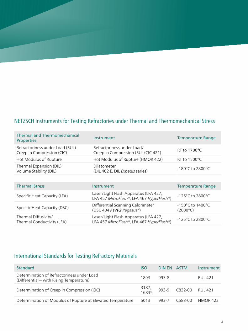
NETZSCH Instruments for Testing Refractories under Thermal and Thermomechanical Stress
International Standards for Testing Refractory Materials
Thermal and Thermomechanical Properties
Instrument Temperature Range
Refractoriness under Load (RUL)Creep in Compression (CIC)
Refractoriness under Load/ Creep in Compression (RUL/CIC 421)
RT to 1700°C
Hot Modulus of Rupture Hot Modulus of Rupture (HMOR 422) RT to 1500°C
Thermal Expansion (DIL)Volume Stability (DIL)
Dilatometer (DIL 402 E, DIL Expedis series)
-180°C to 2800°C
Standard ISO DIN EN ASTM Instrument
Determination of Refractoriness under Load (Differential—with Rising Temperature)
1893 993-8 RUL 421
Determination of Creep in Compression (CIC)3187,16835
993-9 C832-00 RUL 421
Determination of Modulus of Rupture at Elevated Temperature 5013 993-7 C583-00 HMOR 422
Thermal Stress Instrument Temperature Range
Specific Heat Capacity (LFA)Laser/Light Flash Apparatus (LFA 427, LFA 457 MicroFlash®, LFA 467 HyperFlash®)
-125°C to 2800°C
Specific Heat Capacity (DSC)Differential Scanning Calorimeter(DSC 404 F1/F3 Pegasus®)
-150°C to 1400°C (2000°C)
Thermal Diffusivity/ Thermal Conductivity (LFA)
Laser/Light Flash Apparatus (LFA 427, LFA 457 MicroFlash®, LFA 467 HyperFlash®)
-125°C to 2800°C

4
RUL/CIC 421 Refractoriness Under Load and Creep in Compression
Method
Refractoriness under load (RUL) is a measure of the resistance of a refractory product to subsidence when subjected to the combined effects of load, rising temperature at a pre- defined heating rate. The range in which softening occurs is not identical with the melting range of pure raw materials, but it is influenced by the content and the degree of distribution of low melting point fluxing agents.
RUL
The RUL test method is described in ISO 1893, Refractoriness under load (RUL, differential – with rising temper-ature). A cylindrical test piece (50 mm in Ø and height with coaxial bore of 12.5 mm) is subjected to a specified constant compressive load and heated at a specified rate until a prescribed deformation or subsidence occurs. The deformation of the test piece is recorded as the temperature increases, and the temperatures corresponding to specified proportional degrees of deformation are determined.
CIC
The instrument can also be used for the determination of creep in compression (CIC) as described in ISO 3187. A cylindrical test piece is heated under specified conditions (see RUL) to a given temperature. While being held at that constant temperature, the deformation of the test piece is recorded and the percentage change is evaluated as a function of time.
Refractoriness under load evaluates the behavior of fired refractory bricks under rising temperature and constant load conditions.
RUL/CIC 421

5
RUL/CIC 421 Refractoriness Under Load and Creep in Compression
Measuring Unit – Specimen
The measuring unit consists of a console, furnace guide frame, furnace (max. 1700°C), balance weight of the loading device (max. 1000 N) and a differential measuring system. To prevent chimney effects and to guarantee a sufficient zone of constant temperature, the furnace is closed at the top. The test piece is placed on the supporting column; the furnace is lowered and load is applied by counterbalancing (minimum of 100 cN increments) the weight of the furnace. Thermocouples serve to control the furnace and to determine the test piece temperature.
Schematic of the gas-tight RUL/CIC 421 G/6 for measurements in protective gas atmosphere
Gas outlet
Heating elementSample
Controlthermocouple
Outer tube
Inner tube
Bellows
Vacuum-tight seal
Variable contact force
Evacuating system
Gas inlet
Inductivetransducer
Gastightcasing
Supportingcolumn
Hood type furnace
Outer thermocouple
Protective tube
Loading column
Variable load
Inner thermocouple
Sample with coaxial bore and inner tube
Signal Generation – Expansion
The length change is transmitted by a measuring system consisting of an inner and outer tube which act differentially. These tubes made of alumina are connected to an inductive transducer. Its signal is amplified and stored after A/D conversion.The thermal expansion of the tubes is self-compensating. Therefore, only the expansion of that part of the inner tube which corresponds to the test pieces must be considered. The differ-ential measuring system can be used to measure the length change of the test piece through its center bore (ISO/DIN) or along the outside.

6
Test Atmosphere
Measurements can be carried out in static air (basic version) or using an optional device for inert gas purge within the test piece area.
Testing Carbon-Containing Materials For testing carbon-containing materials (e.g., magnesia-carbon graphite bricks), a non-oxidizing test atmosphere can be realized with a gas-tight test chamber (optional; see figure on previous page). This chamber can be evacuated and then purged with protective gas. Measurements can be carried out up to 1600°C.
Variable Loading Device
Optionally, the loading device can be equipped for load variation. The preload can be up to 300 N and the verifying load can be applied in the range from 0 N to 700 N at a rate between 0.3 N/s and 3 N/s.
Test Piece Dimension
Generally, identical test piece dimensions of 50 mm in diameter and 50 mm in height are used for both the RUL and the CIC test. For the high-precision differential measuring system used in deter-mining expansion and defor-mation, the cylindrical test piece has a coaxial bore of 12.5 mm. The ground faces should be plane, parallel and perpendicular to the axis of the cylinder (ISO/DIN). Other test piece dimensions are also possible (e.g., 36 mm, GOST 4070-20000). .
Sample Preparation Machines
NETZSCH offers the following machines for the appropriate preparation of optimum test pieces:
∙ Drilling machine 421/11 ∙ Grinding machine 421/12 ∙ Sawing machine 421/13
Gas-tight version for
testing oxygen-
sensitive specimens
RUL/CIC 421

7
Temperature / °C
dL
/ L0
/%
2000 400 800600 1000 1200 1400 1600
-0.6
-0.4
-0.2
0.0
0.2
0.4
0.6
0.8
Temperature / °C
dL
/ L0
/%
dL
/ L0
/%
200 400 800600 1000 1200
Time / h0 5 1510 20 25
0.0
0.45
0.50
0.55
0.65
0.70
0.60
0.2
0.4
0.6
0.8
1.0
Peak: 1387.0 °C
dLmax = 0.724 %T(dLmax) = 1387.0 °CT 0.5 = 1564.7 °CT 1.0 = 1599.8 °C
Peak: 1283.0 °C
cr (0.00, 1.00) = 0.063 %/hcr (0.00, 10.00) = 0.019 %/hcr (0.00, 15.00) = 0.015 %/hcr (0.00, 20.00) = 0.013 %/hcr (0.00, 25.00) = 0.011 %/hcr (0.25) = 0.011 %/h
dLmax = 0.729 %T(dL max) = 1283.0 °CT(2.5 h) = 1280.4 °CISOZ 0.00 = 0.000 %Z 5.00 = 0.136 %Z 10.00 = 0.191 %Z 15.00 = 0.228 %Z 20.00 = 0.258 %Z 25.00 = 0.282 %Z(5.25) = 0.146
Temperature / °C
dL
/ L0
/%
2000 400 800600 1000 1200 1400 1600
-0.6
-0.4
-0.2
0.0
0.2
0.4
0.6
0.8
Temperature / °C
dL
/ L0
/%
dL
/ L0
/%
200 400 800600 1000 1200
Time / h0 5 1510 20 25
0.0
0.45
0.50
0.55
0.65
0.70
0.60
0.2
0.4
0.6
0.8
1.0
Peak: 1387.0 °C
dLmax = 0.724 %T(dLmax) = 1387.0 °CT 0.5 = 1564.7 °CT 1.0 = 1599.8 °C
Peak: 1283.0 °C
cr (0.00, 1.00) = 0.063 %/hcr (0.00, 10.00) = 0.019 %/hcr (0.00, 15.00) = 0.015 %/hcr (0.00, 20.00) = 0.013 %/hcr (0.00, 25.00) = 0.011 %/hcr (0.25) = 0.011 %/h
dLmax = 0.729 %T(dL max) = 1283.0 °CT(2.5 h) = 1280.4 °CISOZ 0.00 = 0.000 %Z 5.00 = 0.136 %Z 10.00 = 0.191 %Z 15.00 = 0.228 %Z 20.00 = 0.258 %Z 25.00 = 0.282 %Z(5.25) = 0.146
Evaluation Routines for RUL and CIC The upper plot shows a RUL measurement (differential) on a test piece of a fireclay brick with increasing temperature. At 1387°C, the test piece reaches its maximum expansion. Defor-mations of 0.5% and 1.0% occurred at 1565°C (T0.5) and 1600°C (T1), respectively.
The lower two plots depict a CIC measurement on a test piece of a silica brick. In the upper plot, the dynamic heating segment is presented.
The lower one shows the time-scaled creep over 25 hours at a constant temperature of 1280°C.
Refractoriness under Load; test conditions: 0.2 N/mm², 5 K/min, static air
Creep in Compression; isothermal creep at 1280°C, 25 h in static air
Creep in Compression; heating segment at a heating rate of 5 K/min

8
Temperature / °C
Exp
ansi
on /
%
2000 400 800600 1000 1200 1400 1600 1800-0.8
-0.6
-0.4
-0.2
0
0.2
0.4
0.6
0.8
Temperature / °C
Exp
ansi
on /
%
2000 400 800600 1000 1200 1400 1600 1800-2.0
-1.5
-1.0
-0.5
0.0
0.5
1.0
1.5
Time at 1425°C / h
Exp
ansi
on /
%
50 1510 20 250
0.1
0.2
0.3
0.4
0.5
0.6
0.7
Firing at (°C)
T0.5 (°C)
T1 (°C)
T2 (°C)
1430
1470
1510
1625
1650
1670
1675
1695
>1700
>1700
>1700
>1700
Firing at (°C)
1430
1470
1510
Lab Test
Product 1; poor result
Product 1; good result
Applications
Refractoriness under Load (RUL) of Andalusite Bricks
This plot shows three measure-ments on andalusite bricks fired at three different temperatures: 1430°C, 1470°C and 1510°C. At approx. 1425°C, all three test pieces reach their maximum expansion. After applying sample or calibration curve correction, the software calculates the character-istic T0.5, T1 and T2 temperatures from the RUL tests where 0.5%, 1% or 2% shrinkage is reached after the maximum expansion. The influence of the firing temperature can be clearly seen.
RUL/CIC 421
RUL behavior of andalusite bricks (approx. 65% Al2O3) fired at three different temperatures; test conditions: 0.2 N/mm2, 5 K/min, static air

9
Temperature / °C
Exp
ansi
on /
%
2000 400 800600 1000 1200 1400 1600 1800-0.8
-0.6
-0.4
-0.2
0
0.2
0.4
0.6
0.8
Temperature / °C
Exp
ansi
on /
%
2000 400 800600 1000 1200 1400 1600 1800-2.0
-1.5
-1.0
-0.5
0.0
0.5
1.0
1.5
Time at 1425°C / h
Exp
ansi
on /
%
50 1510 20 250
0.1
0.2
0.3
0.4
0.5
0.6
0.7
Firing at (°C)
T0.5 (°C)
T1 (°C)
T2 (°C)
1430
1470
1510
1625
1650
1670
1675
1695
>1700
>1700
>1700
>1700
Firing at (°C)
1430
1470
1510
Lab Test
Product 1; poor result
Product 1; good result
Temperature / °C
Exp
ansi
on /
%
2000 400 800600 1000 1200 1400 1600 1800-0.8
-0.6
-0.4
-0.2
0
0.2
0.4
0.6
0.8
Temperature / °C
Exp
ansi
on /
%
2000 400 800600 1000 1200 1400 1600 1800-2.0
-1.5
-1.0
-0.5
0.0
0.5
1.0
1.5
Time at 1425°C / h
Exp
ansi
on /
%
50 1510 20 250
0.1
0.2
0.3
0.4
0.5
0.6
0.7
Firing at (°C)
T0.5 (°C)
T1 (°C)
T2 (°C)
1430
1470
1510
1625
1650
1670
1675
1695
>1700
>1700
>1700
>1700
Firing at (°C)
1430
1470
1510
Lab Test
Product 1; poor result
Product 1; good result
Creep in Compression (CIC) of Andalusite Bricks
Test pieces of the andalusite bricksfired at different temperatures are used for CIC tests. In these tests, the load is applied once the temperature is reached (here, at 1425°C). This is contrary to RUL tests, where the load is applied from the very beginning of the measurement. This plot only shows the time-scaled creep at constant temperature (the heating segment is not depicted).
Quality Control of CastableRefractories by RUL Tests Castables are mixed with water and then installed by either pouring or pumping. These measurements were carried out on finished construction parts. Castables have to be prepared exactly as instructed by the product manufacturer. Field tests show that the product depicted here by the red sample curve was improperly handled. The divergent shrinkage behavior (as compared to the blue and green curves) causes failures in the finished product.
CIC behavior of andalusite bricks (approx. 65% Al2O3) fired at three different temperatures; test conditions: 0.2 N/mm2, 5 K/min, static air, 25 h at 1425°C
RUL test as quality control for a finished construction part

10
State-of-the-Art Software Including Various Evaluation Routines
∙ Graphic and tabulated results, calculated according to ISO/DIN
∙ Correction of the measured data by calibration curves
∙ Determination of characteristic data according to user’s require-ments
∙ Automatic softening point detection
∙ Derivation of curves for deter-mination of the temperature- or time-dependent linear expansion rates
∙ Possibilities for temperature control (max. 96 isothermal or dynamic temperature program steps)
∙ Presentation of the measuring values temperature- or time-scaled for RUL and time-scaled for CIC
∙ Determination of the absolute maximum in the length dilatation spectrum (RUL)
∙ Determination of the sample temperature 2.5 h after start of isothermal phase (CIC)
∙ Determination of relative length changes at preset times
∙ Calculation of creep rates in preset time intervals
∙ Simultaneous analysis of up to 8 curves/temperature segments (curve comparison)
∙ Calculation of single values of physical or technical expansion coefficients
∙ Calculation and graphic display of the 1st and/or 2nd derivative, peak determination
RUL/CIC 421Software

11
State-of-the-Art Software Including Various Evaluation Routines
Technical Specifications
Model RUL/CIC 421 E/6
Temperature range RT to 1700°C
Heating elements 4 Super-Kanthal 1800
Test atmosphere Static air; optional inert purge gas
Safety switch Failure of test piece
RUL/CIC 421
The RUL/CIC runs under Proteus® software on Windows® for the fully automatic test run, data acquisition, storage and off-line evaluation.
∙ Semi-automatic routines for the determination of reaction steps as extrapolated onset, point of inflection, peak, peak end
∙ Output or ASCII file export of the corrected measuring data
∙ Graphic export
∙ Data transfer of the sample length from an external gauge (optional)
Model RUL/CIC 421 G/6
Temperature range RT to 1600°C
Heating elements 4 Super-Kanthal 1800
Protective tube Al2O3
Ability to evacuate Up to 10-2 mbar
Test atmosphere Static/dynamic air and inert gas
Safety switches Failure of test piece, cooling water
General Data
Test piece Ø 50 mm, height 50 mm
Load range1 N to 1000 N; steps of 1 N to 100 N
Max. stress 0.5 N/mm2
Measuring range20 mm; resolution 4,000,000 steps
Measuring system Differential
Digital resolution 5 nm
Thermocouples Type B
Power Supply Electronics ∙Electronics : 230 V/10 A 50 Hz ∙Furnace: 230 V/70 A/50 Hz;
max. 15 kW
Dimensions ∙Measuring unit: ≈ 1200 mm x
610 mm x 2400 mm ∙Control unit: 562 mm x 555 mm x 1183 mm
Weights ∙Measuring unit: ≈ 480 kg ∙Control unit: ≈ 220 kg

12
Thermal Diffusivity and Specific Heat CapacityLaser/Light Flash Analysis – An Alternative Method for Refractories
For decades, thermophysical properties (thermal diffu-sivity [a], specific heat capacity [cp], and thermal conduc-tivity [λ]) have been determined using sta- tionary methods (e.g., guarded hot plate technique) or standardized transient techniques such as the hotwire method according to ISO 8894. However, these methods are time-consuming and limited to large samples and materials of low thermal conductivity.
Light/Laser Flash methods (LFA) are absolute, non-contact measurement techniques and can handle high thermal conductivity materials without any difficulties. Modern LFA systems often also allow for
LFA 427
LFA 457 MicroFlash®
simultaneous measurement of the specific heat capacity so that thermal conductivity can be determined, without additional measurements, per the following formula:
λ(T) = a(T) · ρ(T) · cp(T)
In addition, the rapidity of the flash methods allows for testing on a larger number of samples (up to 25.4 mm in Ø).
Precise determination of the thermal diffusivity is offered by the NETZSCH LFA 427, LFA 457 MicroFlash® and LFA 467 HyperFlash® systems.

13
0 200 400 600 800 1000 1200 1400
Temperature / °C
Temperature / °C
0.0
0.5
1.0
1.5
2.0
Ther
mal
Di�
usiv
ity
/ m
m2/
s
0
1
2
3
4
5
6
7
8
Ther
mal
Con
duc
tivi
ty /
W/(
m·K
)
Ther
mal
Con
duc
tivi
ty /
W/(
m·K
)
0
1
2
3
4
5
Spec
ific
Hea
t Cap
acit
y /
J/(g
·K)
#1
#2
#3
#1
#2#3
#1
#2 #3
0
1
2
3
4
5
6
7
8
9
0 200 400 600 800 1000 1200 1400 1600
Ther
mal
C
ond
ucti
vity
/W/(
m
K)
TCT 426LFA 427 #1LFA 427 #2LFA 427 #3Average(LFA/TCT) ±10%
Thermal Diffusivity and Specific Heat CapacityLaser/Light Flash Analysis – An Alternative Method for Refractories
LFA 467 HyperFlash®
Magnesia bricks – high refractoriness and great corrosion-resistance
Magnesia Spinel Brick
Magnesia alumina spinel brick is widely used in the transition zones of cement rotary kilns, glass tank regenerators and lime kilns. Elevated kiln capacity and the increasing use of alternative fuels present a challenge to basic refractories for the burning zone of cement rotary kilns. When using alternative fuels, thermal stress can be caused by local overheating in the first lining zones. This has a weakening effect on the microstructure of the brick. This plot compares TCT and LFA thermal conductivity results for a magnesia spinel brick. Over the entire measu-rement up to 1450°C, all results are within the range of ± 10%.
Magnesia spinel brick made of 85% MgO and 12% Al2O3.
14
0 200 400 600 800 1000 1200 1400
Temperature / °C
Temperature / °C
0.0
0.5
1.0
1.5
2.0
Ther
mal
Di�
usiv
ity
/ m
m2/
s
0
1
2
3
4
5
6
7
8
Ther
mal
Con
duc
tivi
ty /
W/(
m·K
)
Ther
mal
Con
duc
tivi
ty /
W/(
m·K
)
0
1
2
3
4
5
Spec
ific
Hea
t Cap
acit
y /
J/(g
·K)
#1
#2
#3
#1
#2#3
#1
#2 #3
0
1
2
3
4
5
6
7
8
9
0 200 400 600 800 1000 1200 1400 1600
Ther
mal
C
ond
ucti
vity
/W/(
m
K)
TCT 426LFA 427 #1LFA 427 #2LFA 427 #3Average(LFA/TCT) ±10%
Ther
mal
Con
duc
tivi
ty /
W/(
m·K
)
Spec
ific
Hea
t Cap
acit
y /
J/(g
·K)
150010005000Temperature / °C
0
0.1
0.2
0.3
0.4
0.5
0.6
Ther
mal
Di�
usiv
ity
/ m
m²/
s
Sample: JM 30Thickness: 2.570 mmDensity: 1.014 g/cm³
0.0
0.1
0.2
0.3
0.4
0.5
0.6
0.7
0.8
0.9
1.0
0.0
0.2
0.4
0.6
0.8
1.0
1.2
1.4
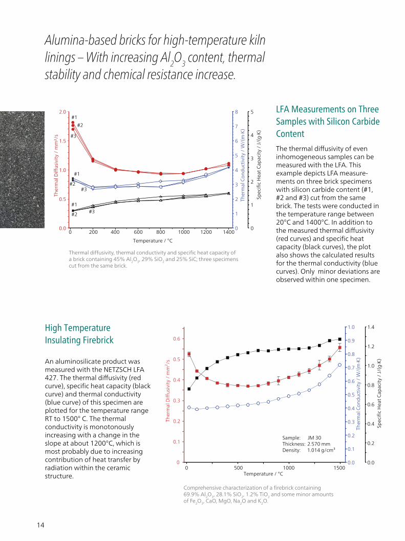
Alumina-based bricks for high-temperature kiln linings – With increasing Al2O3 content, thermal stability and chemical resistance increase.
The thermal diffusivity of even inhomogeneous samples can be measured with the LFA. This example depicts LFA measure-ments on three brick specimens with silicon carbide content (#1, #2 and #3) cut from the same brick. The tests were conducted in the temperature range between 20°C and 1400°C. In addition to the measured thermal diffusivity (red curves) and specific heat capacity (black curves), the plot also shows the calculated results for the thermal conductivity (blue curves). Only minor deviations are observed within one specimen.
Thermal diffusivity, thermal conductivity and specific heat capacity of a brick containing 45% Al2O3, 29% SiO2 and 25% SiC; three specimens cut from the same brick.
Comprehensive characterization of a firebrick containing 69.9% Al2O3, 28.1% SiO2, 1.2% TiO2 and some minor amounts of Fe2O3, CaO, MgO, Na2O and K2O.
LFA Measurements on Three Samples with Silicon Carbide Content
An aluminosilicate product was measured with the NETZSCH LFA 427. The thermal diffusivity (red curve), specific heat capacity (black curve) and thermal conductivity (blue curve) of this specimen are plotted for the temperature range RT to 1500° C. The thermal conductivity is monotonously increasing with a change in the slope at about 1200°C, which is most probably due to increasing contribution of heat transfer by radiation within the ceramic structure.
High Temperature Insulating Firebrick

15
Expertise in
SERVICE
All over the world, the name NETZSCH stands for comprehensive support and expert, reliable service, both before and after sale. Our qualified personnel from the technical service and application depart-ments are always available for consultation. In special training programs tailored for you and your employees, you will learn to tap the full potential of your instrument.
To maintain and protect your investment, you will be accompanied by our experienced service team over the entire life span of your instrument.
LABORATORY
Application Serviceand Contract Testing
Training
ComprehensiveInstrument and
Method Training
TRAININGTECHNICAL SERVICE
Maintenanceand Repair
Exchange Service
Software Updates
IQ/OQDocuments
Moving Service
Spare PartAssistance
CalibrationService

16
HMOR 422 High-Temperature Bending Strength Tester
Determination of the Hot Modulus of Rupture The hot modulus of rupture (HMOR) is an important parameter in the characterization of refractories. Along with other thermophysical properties, the maximum load until breakage at high temperatures plays a significant role in the quality control and development of furnace linings.
HMOR 422 Models
NETZSCH offers two HMOR models:
∙ HMOR 422 D/3 for continuous operation up to 1500°C and a maximum load of 5000 N with optional devices for:
∙ Load and deformation tests
∙ Constant deformation rate
∙ HMOR 422 E/4 for 4-point bending measurements up to 1450°C
Method
The Modulus of Rupture is definedas the maximum stress a rectan-gular test piece of specific dimen-sions can withstand in a 3-point bending test until it breaks, expressed in N/mm² or MPa.
Standard and Test Piece Dimensions
The international standard testmethod is described in ISO 5013.The test piece dimensions are150 mm x 25 mm x 25 mm. Up to 30 samples can be loaded onto the sliding rail and measured in succession.
HMOR 422
17
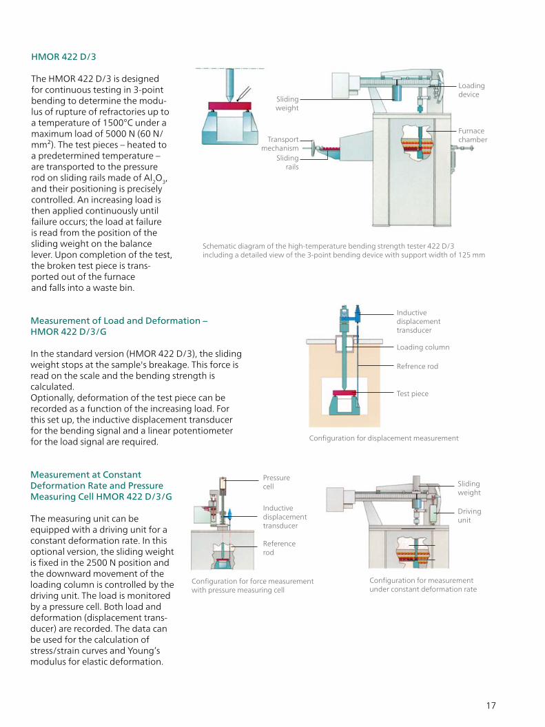
Measurement of Load and Deformation –HMOR 422 D/3/G
In the standard version (HMOR 422 D/3), the sliding weight stops at the sample's breakage. This force is read on the scale and the bending strength is calculated. Optionally, deformation of the test piece can be recorded as a function of the increasing load. For this set up, the inductive displacement transducer for the bending signal and a linear potentiometer for the load signal are required.
Measurement at Constant Deformation Rate and Pressure Measuring Cell HMOR 422 D/3/G
The measuring unit can be equipped with a driving unit for a constant deformation rate. In this optional version, the sliding weight is fixed in the 2500 N position and the downward movement of the loading column is controlled by the driving unit. The load is monitored by a pressure cell. Both load and deformation (displacement trans-ducer) are recorded. The data can be used for the calculation of stress/strain curves and Young’s modulus for elastic deformation.
HMOR 422 D/3
The HMOR 422 D/3 is designed for continuous testing in 3-point bending to determine the modu- lus of rupture of refractories up to a temperature of 1500°C under a maximum load of 5000 N (60 N/mm²). The test pieces – heated to a predetermined temperature – are transported to the pressure rod on sliding rails made of Al2O3, and their positioning is precisely controlled. An increasing load is then applied continuously until failure occurs; the load at failure is read from the position of the sliding weight on the balance lever. Upon completion of the test, the broken test piece is trans-ported out of the furnace and falls into a waste bin.
Schematic diagram of the high-temperature bending strength tester 422 D/3 including a detailed view of the 3-point bending device with support width of 125 mm
Loading device
Slidingrails
Transportmechanism
Slidingweight
Furnace chamber
Configuration for measurement under constant deformation rate
Sliding weight
Driving unit
Configuration for force measurement with pressure measuring cell
Pressurecell
Reference rod
Inductivedisplacementtransducer
Configuration for displacement measurement
Inductivedisplacementtransducer
Loading column
Refrence rod
Test piece

18
HMOR 422 E/4 – Recording of Load and Deformation
The HMOR 422 E/4 performs bending strength measurements on test pieces with dimensions of 45 mm x 4.5 mm x 3.4 mm. In contrast with the 422 D/3 model, deformation of the test piece is here measured at the bottom via a differential measuring device. The internal tube comes into contact with the bottom of the test piece and the external tube is attached to the bottomflange of the 4-point bending device as a reference point. The split shell furnace (max. 1450°C) is hinged and opens for easy insertion of the test piece. The loading device is the same as that used for the 422 D/3.
HMOR 422 E/4 with detailed view of the 4-point bending device
Comprehensive HMOR Software
HMOR 422
∙ Graphic interface (MS Windows)
∙ Integrated HELP system
∙ Transfer of specimen dimensions via the external gauge (optional)
∙ Predefinition of a measurement run for up to 32 specimens, with the option of adapting the parameters and extending to a maximum of 64 specimens while the experiment is in progress
∙ Control of the temperature program
∙ Determination of modulus of rupture
∙ Start of load increase until specimen failure is detected
∙ Display and storage of results, temperature, maximum load (at the moment of specimen failure) and test parameters
∙ Following measurement, option to select specimen files, calculate the load at failure or modulus of rupture and transfer to MS EXCEL
∙ Determination of modulus of rupture at elevated temperatures with measurement of specimen deformation
∙ Presentation of the results in a single graph
∙ Continuous recording of test data until specimen failure is detected; saved with the test parameters
∙ Determination and storage of calibration curve (optional)
∙ Transfer of measured data to MS EXCEL and option to calculate Young's modulus
Loading device
Sliding weight
Split shell furnace
Test piece
Differential measuring system

19
Technical SpecificationsHMOR 422 D/3 HMOR 422 E/4
Bending mode 3-point 4-point
Temperature range RT to 1500°C RT to 1450°C
FurnaceChamber furnace with
pre-heating zoneSwing-open furnace
Thermocouples Type S Type S
Mode of operation Continuous Single measurement
Test piece dimensions 150 mm x 25 mm x 25 mm 45 mm x 4.5 mm x 3.5 mm
Distance between support edges 125 mm 40 mm
Distance between 4-point bending edges
N/A 20 mm
Loading device with movable weight
∙Weighing lever ∙Load range: 0 ... 500 ... 1250 ... 2500 ... 5000 N; ∙Load rate: 4 speeds (2, 4.2, 8, 12 N/s)
∙Weighing lever ∙Load range: 0 ... 500 ... 1250 ... 2500 ... 5000 N; ∙Load rate: 4 speeds (2, 4.2, 8, 12 N/s)
Measurement deformationInductive system with
reference rod (optional)Differential measuring
system (standard)
Measuring range Max. 10 mm Max. 5 mm
Digital resolution 2.5 nm 1.25 nm
Constant deformation rate Optional N/A
Load rate 10 ... 2000 μm/min N/A
Electrical supply furnace 3 x 400 V/N/PE, 50/60 Hz 230 V, 50/60 Hz
Electrical supply electronics 230 V/10 A, 50/60 Hz 230 V/10 A, 50/60 Hz
Measuring unit dimensions 2200 x 1800 x 870 mm; 540 kg 2100 x 1600 x 750 mm; 430 kg
Control unit dimensions 1120 x 565 x 452 mm; 250 kg 1120 x 565 x 452 mm; 250 kg

20
ApplicationsQuality Control – Modulus of Rupture of a Kiln Furnace Product
The HMOR yields information on the maximum stress a rectan-gular test piece can withstand prior to breakage when it is tested in a three-point bending device. The deformation under increasing load (stress-strain curve) can additionally be measured using the optional load and deformation device.
The test results on three kiln furnace products below clearly show that the average modulus of rupture decreases by a factor of nearly two between 1100°C and 1300°C. Scattering in the data of the samples at the same temperature is most likely due to inhomogeneities in the material.
HMOR 422
kiln furniture product A
05
10152025303540
1 6 11 16 21 26 31
sample no.
HM
OR
/ N
/mm
2
1300°C 1200°C 1100°C
kiln furniture product B
05
10152025303540
1 2 3 4 5 6 7 8 9 10 11 12 13 14 15 16 17 18
sample no.
HM
OR
/ N
/mm
2
1300°C 1200°C 1100°C
mean values
05
10152025303540
1100°C 1200°C 1300°Ctemperature
HM
OR
/ N
/mm
2
Product A Product B Product C
kiln furniture product C
05
1015202530354045
1 2 3 4 5 6 7 8 9 10 11
sample no.
HM
OR
/ N
/mm
2
1300°C 1200°C 1100°C

21
TEST PIECE PREPARATIONDepending upon user needs, a variety of accessory
machines is available for the preparation of test pieces for each instrument, as follows:
Machine Required for
Pillar drilling machine 421/11 RUL/CIC 421
Grinding machine 421/12 (Ø 125 mm cup) RUL/CIC 421 HMOR 422
Grinding machine 421/12 (Ø 200 mm cup) RUL/CIC 421 HMOR 422
Stone sawing machine 421/13 RUL/CIC 421 HMOR 422

22
Grinding Machine The surface grinding machine with swingable grinding head and precision grinding spindle for mounting cup grinding wheels (Ø 125 mm) is available for the preparation of test pieces used for RUL/CIC and HMOR measurements. The vertical fine adjustment has a reading accuracy of 0.01 mm. The permanent magnet plate (Ø 125 mm) is designed for clamping steel support devices. The wet grinding device consists of a cooling agent vessel with a clearing tank, an electric immersion pump, and a water-collection plate with plate slide, cock and hose line. A ceramic cup grinding wheel (Ø 125 x 60 x Ø 20 mm) is included.
∙ Clamping device for holding test bodies, Ø 50 mm, height 50 mm, with reducing clamp rings for Ø 35.7 mm and Ø 30 mm ∙ Cup grinding wheel made of a ceramic compound for soft to medium-hard test pieces, Ø 125 mm, height 60 mm, hole 20 mm ∙ Diamond cup grind wheel for special hard ceramic materials, Ø 125 mm, hole 32 mm, coating width 5 mm, coating height 2 mm, grain size Ø 100 µm for rough grinding ∙ Diamond cup grinding wheel for special hard ceramic materials, Ø 125 mm, hole 32 mm, coating width 5 mm, coating height 2 mm, grain size Ø 30 µm for finish grinding
Pillar Drilling Machine
The NETZSCH drilling machine is used for drilling cylindrical test pieces from refrac-tories, stone, ceramics or products similar to ceramics.
The drilling machine is a sturdy boxtype construction with a complete casing for all rotating parts. The drilling table can be swung 360° to include the water-protective case. In addition, it has a working table light incorporated and infinitely variable speed control for the drilling spindle via a V-belt control system. The water-protective case, two clamping angles to hold the workpiece and a water-flushing box with plug MK2/B16 (without drills) are included.
Various drills are available for the outer diameter of the test piece:
∙ Diamond hollow drill, outer Ø 30 mm, inner Ø 25 mm, drilling depth 100 mm ∙ Diamond hollow drill, outer Ø 42 mm, inner Ø 36 mm, drilling depth 100 mm ∙ Diamond hollow drill, outer Ø 56 mm, inner Ø 50 mm, drilling depth 100 mm ∙ Diamond hollow drill, outer Ø 108.4 mm, inner Ø100 mm, drilling depth 120 mm
To fulfill DIN/ISO standards, these drills for the inner coaxial bore are also available:
∙ Diamond hollow drill, outer Ø 12 mm, inner Ø 7 mm, drilling depth 100 mm ∙ Diamond hollow drill, outer Ø 12.5 mm, inner Ø 7.5 mm, drilling depth 100 mm

23
Sawing Machine for RUL/CIC and HMOR Systems
The NETZSCH sawing machine is used for cutting test pieces from refractories, stone, ore, ceramics, glass and hard metals. The circular blade cuts from bottom to top, plunging into the cooling agent tank below the table and drawing the cooling agent into the cut over the shortest path. The sawing machine consists of a plate (700 x 600 mm) with spindle for cutting wheels of Ø 200 mm to 350 mm, a pole-reversible three-phase motor with motor protection and foot switch revolutions of 3500 min-1 and 1750 min-1, and a feed table. In addition, it comes with a clamping device, yoke support, prism support with column, stop angle and guide pulley for automatic feed. Included are also a swing and spindle along with hand bar and counter weight (with angle support). There is a two-jawed vise that can be both turned and swung, and a three-jawed vise that can be turned. We offer two cutting wheels for the sawing machine:
∙ Diamond cutoff wheel (Ø 200) mm with bronze bonding, cutting width 1.5 mm, max. cutting depth 45 mm, hole Ø 30 mm ∙ Diamond cutoff wheel Ø 350) mm, with bronze-alloy bonding, cutting width 1.8 mm, max. cutting depth 120 mm, hole Ø 30 mm
All from one source!

NETZSCH-Gerätebau GmbHWittelsbacherstraße 42 95100 SelbGermanyTel.: +49 9287 881-0 Fax: +49 9287 881 [email protected] N
GB
· Ref
ract
ory
Mat
eria
ls ·
EN ·
0420
· N
WS
· Tec
hnic
al s
pec
ifica
tion
s ar
e su
bje
ct to
cha
nge.
The NETZSCH Group is an owner-managed, international technology company with headquarters in Germany. The Business Units Analyzing & Testing, Grinding & Dispersing and Pumps & Systems represent customized solutions at the highest level. More than 3,700 employees in 36 countries and a worldwide sales and service network ensure customer proximity and competent service. Our performance standards are high. We promise our customers Proven Excellence – exceptional performance in everything we do, proven time and again since 1873.
When it comes to Thermal Analysis, Calorimetry (adiabatic & reaction), the determination of Thermophysical Properties, Rheology and Fire Testing, NETZSCH has it covered. Our 50 years of applications experience, broad state-of-the-art product line and comprehensive service offerings ensure that our solutions will not only meet your every requirement but also exceed your every expectation.