
Sol−Gel Monolithic Columns with Reversed Electroosmotic Flow for Capillary Electrochromatography
Upload
khangminh22Category
view
3download
0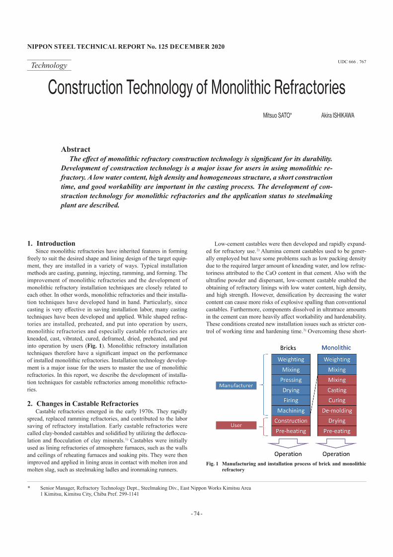
- 74 -
NIPPON STEEL TECHNICAL REPORT No. 125 DECEmbER 2020
UDC 666 . 767Technology
Construction Technology of Monolithic RefractoriesMitsuo SATO* Akira ISHIKAWA
AbstractThe effect of monolithic refractory construction technology is significant for its durability.
Development of construction technology is a major issue for users in using monolithic re-fractory. A low water content, high density and homogeneous structure, a short construction time, and good workability are important in the casting process. The development of con-struction technology for monolithic refractories and the application status to steelmaking plant are described.
1. IntroductionSince monolithic refractories have inherited features in forming
freely to suit the desired shape and lining design of the target equip-ment, they are installed in a variety of ways. Typical installation methods are casting, gunning, injecting, ramming, and forming. The improvement of monolithic refractories and the development of monolithic refractory installation techniques are closely related to each other. In other words, monolithic refractories and their installa-tion techniques have developed hand in hand. Particularly, since casting is very effective in saving installation labor, many casting techniques have been developed and applied. While shaped refrac-tories are installed, preheated, and put into operation by users, monolithic refractories and especially castable refractories are kneaded, cast, vibrated, cured, deframed, dried, preheated, and put into operation by users (Fig. 1). Monolithic refractory installation techniques therefore have a significant impact on the performance of installed monolithic refractories. Installation technology develop-ment is a major issue for the users to master the use of monolithic refractories. In this report, we describe the development of installa-tion techniques for castable refractories among monolithic refracto-ries.
2. Changes in Castable RefractoriesCastable refractories emerged in the early 1970s. They rapidly
spread, replaced ramming refractories, and contributed to the labor saving of refractory installation. Early castable refractories were called clay-bonded castables and solidified by utilizing the defloccu-lation and flocculation of clay minerals. 1) Castables were initially used as lining refractories of atmosphere furnaces, such as the walls and ceilings of reheating furnaces and soaking pits. They were then improved and applied in lining areas in contact with molten iron and molten slag, such as steelmaking ladles and ironmaking runners.
Low-cement castables were then developed and rapidly expand-ed for refractory use. 2) Alumina cement castables used to be gener-ally employed but have some problems such as low packing density due to the required larger amount of kneading water, and low refrac-toriness attributed to the CaO content in that cement. Also with the ultrafine powder and dispersant, low-cement castable enabled the obtaining of refractory linings with low water content, high density, and high strength. However, densification by decreasing the water content can cause more risks of explosive spalling than conventional castables. Furthermore, components dissolved in ultratrace amounts in the cement can more heavily affect workability and hardenability. These conditions created new installation issues such as stricter con-trol of working time and hardening time. 3) Overcoming these short-
Fig. 1 manufacturing and installation process of brick and monolithic refractory
* Senior Manager, Refractory Technology Dept., Steelmaking Div., East Nippon Works Kimitsu Area 1 Kimitsu, Kimitsu City, Chiba Pref. 299-1141
NIPPON STEEL TECHNICAL REPORT No. 125 DECEmbER 2020
- 75 -
comings, we have taken the advantage of low-cement castables and developed many installation techniques for highly densified linings.
3. Installation of Castable RefractoriesInstallation of castable refractories mainly consists of kneading,
casting, curing, deframing, and drying. Important points in those processes are to make refractory linings with low water content, high density, and high strength, and to achieve a shorter installation time and better workability. The problems to be solved and the tech-niques to be developed in the respective steps are described below.3.1 Kneading3.1.1 Overview
Castable refractories are composite materials consisting of dif-ferent types and sizes of raw materials. Generally speaking, they are mixed with water to induce fluidity and cast into forms. The added water is divided into bonded water used in the hydration reaction and non-bonded water. Non-bonded water can be divided into re-straint water that is strongly confined in the vicinity of interparticle voids and does not contribute to fluidity, and into free water that can freely move and contributes to the fluidity of the kneaded mixture. 4) The purposes of the kneading step are to uniformly mix the refrac-tory material powder and water for strong bonding and to ensure the fluidity of the mixture.
Sufficient water must be added to ensure the fluidity of the kneaded mixture. If excess water is added, on the other hand, evapo-ration of free water increases pores and decreases the strength and corrosion resistance of the refractory installation. The kneading time also affects the fluidity of the kneaded mixture. Generally, when the kneading time is short, the kneaded mixture is not fully deflocculat-ed and lacks in fluidity. If excessively kneaded, the mixture may rise in temperature and lose fluidity. In the kneading step, the kneading time is generally controlled by monitoring the fluidity (free flow, tap flow, et al.) of the kneaded mixture as an index.
The water content and kneading time required to obtain a homo-geneous and fully fluid kneaded mixture generally vary with the type of refractory or mixer. A low-moisture and uniform refractory installation is considered to have high durability. In this respect, se-lection of the kneader model and optimization of the kneading con-ditions to meet specific refractories are essential for making full use of castable refractories. Typical mixers used to knead monolithic re-fractories are described below.3.1.2 Kneaders 5)
(1) Medium-speed vertical axis kneadersThe kneading action is principally shearing with blade rotation.
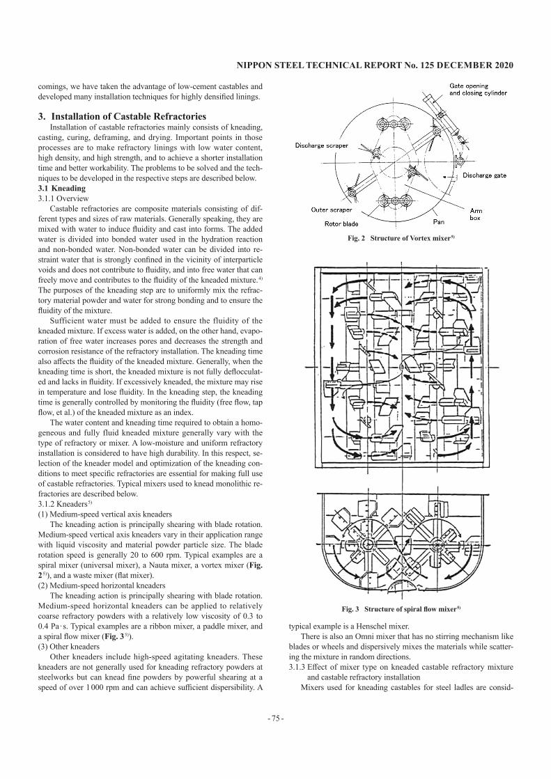
Medium-speed vertical axis kneaders vary in their application range with liquid viscosity and material powder particle size. The blade rotation speed is generally 20 to 600 rpm. Typical examples are a spiral mixer (universal mixer), a Nauta mixer, a vortex mixer (Fig. 2 5)), and a waste mixer (flat mixer).(2) Medium-speed horizontal kneaders
The kneading action is principally shearing with blade rotation. Medium-speed horizontal kneaders can be applied to relatively coarse refractory powders with a relatively low viscosity of 0.3 to 0.4 Pa · s. Typical examples are a ribbon mixer, a paddle mixer, and a spiral flow mixer (Fig. 3 5)).(3) Other kneaders
Other kneaders include high-speed agitating kneaders. These kneaders are not generally used for kneading refractory powders at steelworks but can knead fine powders by powerful shearing at a speed of over 1 000 rpm and can achieve sufficient dispersibility. A
typical example is a Henschel mixer.There is also an Omni mixer that has no stirring mechanism like
blades or wheels and dispersively mixes the materials while scatter-ing the mixture in random directions.3.1.3 Effect of mixer type on kneaded castable refractory mixture
and castable refractory installationMixers used for kneading castables for steel ladles are consid-
Fig. 2 Structure of Vortex mixer 5)
Fig. 3 Structure of spiral flow mixer 5)
- 76 -
NIPPON STEEL TECHNICAL REPORT No. 125 DECEmbER 2020
ered to affect the characteristics of the kneaded mixture and formed shape. Nippon Steel Corporation investigated the influence of types of mixers on the characteristics of resultant monolithic castables. The employed mixers were Cake, Nauta, Henschel, ribbon, Omni, and Pan mixers. 6) According to this research, the mixtures kneaded with the Henschel mixer had the highest fluidity and the lowest air content. The shapes formed from these mixtures had low porosity, high modulus of elasticity, high strength, and high corrosion resis-tance (Table 1).
The results with the Nauta mixer were contrary to those with the Henschel mixture. When the pore size distribution of the formed shapes was measured, pores of a diameter equivalent to that of or-ganic fibers were not detected. Kneading with the Henschel mixer produced high-fluidity mixtures and high-strength shapes. One pos-sible reason is the destruction of organic fibers by powerful knead-ing with the high-speed rotation of the mixer. A kneading method with high kneading intensity is expected to produce refractory shapes with low porosity, high strength, and high corrosion resis-tance, and to increase the durability of formed shapes.3.2 Casting and vibration3.2.1 Overview
The kneaded mixture is poured into a lining mold to obtain the desired shape. While pouring the mixture, the kneaded mixture needs to spread throughout the mold including the narrow corners, and to remove the entrapped air. For this purpose, the mixture is usually vibrated mechanically by the core or other vibrating ma-chines.. Excessive vibration causes the separation of the aggregate and fine powder and produces an inhomogeneous shape. Therefore, the poured mixture must be vibrated by an appropriate method for ideal duration. It is necessary to select the vibrator type and adjust the vibration conditions to meet the particle size composition of the refractory to be used and the shape of the mold. Specific examples of vibrators are described below.3.2.2 Vibration methods(1) Internal vibration method (internal vibrator)
The internal vibrator is inserted into the kneaded mixture to di-rectly vibrate the kneaded mixture. The vibration time is determined to suit the type of the refractory and the performance of the vibrator. Specifically, the vibration time is set so that the refractory surface is not depressed but is virtually level and that material separation does not occur.(2) External vibration method (mold vibrator)
A vibrator is installed in the mold (or core) or is applied to the mold from outside. The vibration energy is generally absorbed by the mold. This limits the effective range of vibration within the sur-face of the kneaded mixture and reduces the effect of vibration on the bulk of the kneaded mixture. For this reason, the mold vibrator is often used auxiliary to the internal vibrator.
3.2.3 Relationship between vibration conditions and properties of castables
When castable refractories are placed, their fluidity greatly var-ies with the vibration method. The relationships of the vibration method and especially the vibration acceleration, frequency, and amplitude with the viscosity of castables were investigated. 7) Three factors of vibration (frequency, acceleration, and amplitude) are cor-related as given by
a = d
where d is the amplitude (mm), a is the acceleration, and f is the fre-quency (Hz).
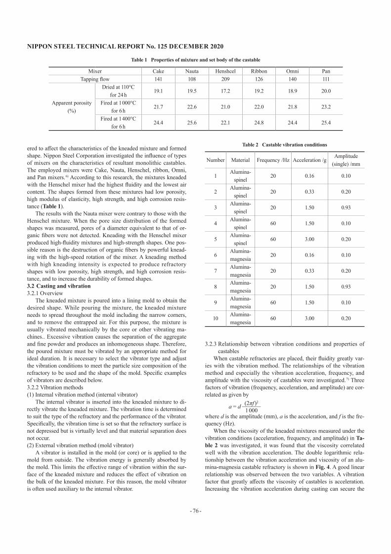
When the viscosity of the kneaded mixtures measured under the vibration conditions (acceleration, frequency, and amplitude) in Ta-ble 2 was investigated, it was found that the viscosity correlated well with the vibration acceleration. The double logarithmic rela-tionship between the vibration acceleration and viscosity of an alu-mina-magnesia castable refractory is shown in Fig. 4. A good linear relationship was observed between the two variables. A vibration factor that greatly affects the viscosity of castables is acceleration. Increasing the vibration acceleration during casting can secure the
(2πf )2
1 000
Table 1 Properties of mixture and set body of the castable
Mixer Cake Nauta Henshcel Ribbon Omni PanTapping flow 141 108 209 126 140 111
Apparent porosity(%)
Dried at 110°Cfor 24 h
19.1 19.5 17.2 19.2 18.9 20.0
Fired at 1 000°Cfor 6 h
21.7 22.6 21.0 22.0 21.8 23.2
Fired at 1 400°Cfor 6 h
24.4 25.6 22.1 24.8 24.4 25.4
Table 2 Castable vibration conditions
Number Material Frequency /Hz Acceleration /gAmplitude
(single) /mm
1Alumina-
spinel20 0.16 0.10
2Alumina-
spinel20 0.33 0.20
3Alumina-
spinel20 1.50 0.93
4Alumina-
spinel60 1.50 0.10
5Alumina-
spinel60 3.00 0.20
6Alumina-magnesia
20 0.16 0.10
7Alumina-magnesia
20 0.33 0.20
8Alumina-magnesia
20 1.50 0.93
9Alumina-magnesia
60 1.50 0.10
10Alumina-magnesia
60 3.00 0.20
NIPPON STEEL TECHNICAL REPORT No. 125 DECEmbER 2020
- 77 -
fluidity of the castable. Installing the castable refractory with high vibration acceleration helps to further reduce the water content and to increase the durability of the castable refractory lining.3.3 Curing and drying3.3.1 Overview
After installation, the castable refractory is cured still for protec-tion from external impact until it is sufficiently hardened. The hard-ening time varies with the material type and air temperature. The frame must be removed after checking that the castable is properly hardened. The cured refractory contains moisture. It is dried with a gas burner. The productivity of furnaces and ovens (or to shorten their down time) requires the drying time to be shortened. Thus ex-plosive spalling in the drying step must be managed during such rapid heating.
In the drying step, the moisture remaining in the installed refrac-tory is vaporized by being heated. The resultant water vapors are discharged outside through the pores in the refractory lining. When the formation rate of water vapor exceeds their discharge rate, the water vapor pressure rises in the refractory lining. When the water vapor pressure exceeds the strength of the refractory lining, a refrac-tory breakage phenomenon, called explosive spalling, is considered to occur. Explosive spalling is a dangerous problem in which broken refractory pieces fly off. At the same time, it necessitates the rein-stallation of the refractory and does damage to the productivity of the equipment concerned. Since it is necessary to carefully dry the refractory in the temperature region of 300°C and below during heating with the explosive spalling risk, the drying rate of the refrac-tory is adjusted to achieve a slow temperature rise. 8) When the re-fractory is dried in the temperature range over 300°C, it is held at the temperature long enough to remove its residual moisture. The drying pattern is set to meet the strength, air permeability, and in-stalled thickness of the refractory to be used. Dense refractory lin-ings installed with low moisture require technology for shortening the drying time without explosive spalling.3.3.2 Drying methods(1) Gas burner drying
Today’s gas burners mix coke-oven gas (COG) or similar gas with air and burn the mixture to produce heat. A process is devel-oped that arranges “permeable solid” wire meshes or ceramic fibers in the gas passage, converts the sensible heat of the gas into the ra-diant heat of the solid, promotes the heat transfer, and reduces the fuel consumption. 9) The heating uniformity and combustion effi-ciency of gas burners change with the flame shape and air-fuel ratio.
It is necessary to select optimum gas burners for the shape of the re-fractory to be installed.(2) Microwave drying
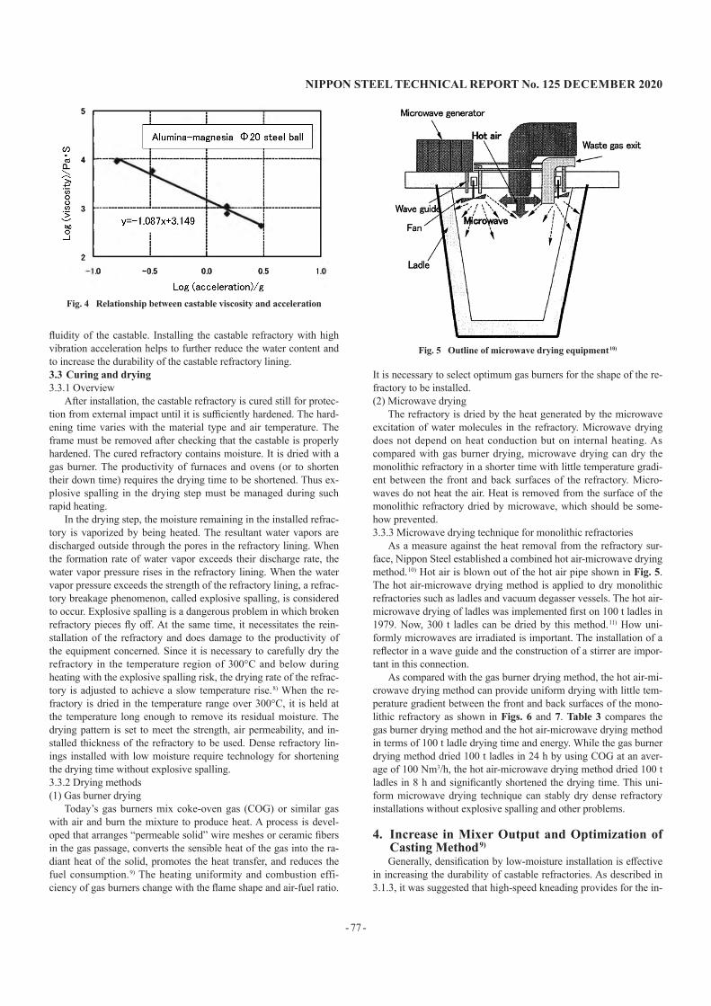
The refractory is dried by the heat generated by the microwave excitation of water molecules in the refractory. Microwave drying does not depend on heat conduction but on internal heating. As compared with gas burner drying, microwave drying can dry the monolithic refractory in a shorter time with little temperature gradi-ent between the front and back surfaces of the refractory. Micro-waves do not heat the air. Heat is removed from the surface of the monolithic refractory dried by microwave, which should be some-how prevented.3.3.3 Microwave drying technique for monolithic refractories
As a measure against the heat removal from the refractory sur-face, Nippon Steel established a combined hot air-microwave drying method. 10) Hot air is blown out of the hot air pipe shown in Fig. 5. The hot air-microwave drying method is applied to dry monolithic refractories such as ladles and vacuum degasser vessels. The hot air-microwave drying of ladles was implemented first on 100 t ladles in 1979. Now, 300 t ladles can be dried by this method. 11) How uni-formly microwaves are irradiated is important. The installation of a reflector in a wave guide and the construction of a stirrer are impor-tant in this connection.
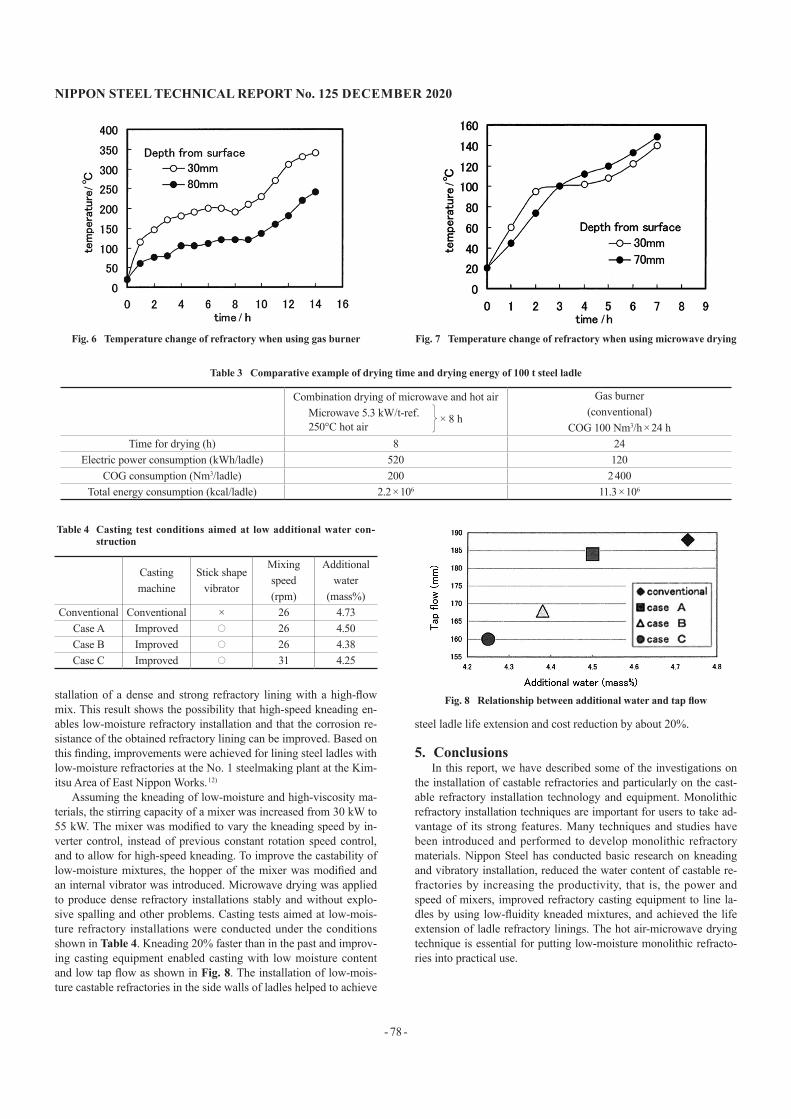
As compared with the gas burner drying method, the hot air-mi-crowave drying method can provide uniform drying with little tem-perature gradient between the front and back surfaces of the mono-lithic refractory as shown in Figs. 6 and 7. Table 3 compares the gas burner drying method and the hot air-microwave drying method in terms of 100 t ladle drying time and energy. While the gas burner drying method dried 100 t ladles in 24 h by using COG at an aver-age of 100 Nm3/h, the hot air-microwave drying method dried 100 t ladles in 8 h and significantly shortened the drying time. This uni-form microwave drying technique can stably dry dense refractory installations without explosive spalling and other problems.
4. Increase in mixer Output and Optimization of Casting method 9)
Generally, densification by low-moisture installation is effective in increasing the durability of castable refractories. As described in 3.1.3, it was suggested that high-speed kneading provides for the in-
Fig. 4 Relationship between castable viscosity and acceleration
Fig. 5 Outline of microwave drying equipment 10)
- 78 -
NIPPON STEEL TECHNICAL REPORT No. 125 DECEmbER 2020
stallation of a dense and strong refractory lining with a high-flow mix. This result shows the possibility that high-speed kneading en-ables low-moisture refractory installation and that the corrosion re-sistance of the obtained refractory lining can be improved. Based on this finding, improvements were achieved for lining steel ladles with low-moisture refractories at the No. 1 steelmaking plant at the Kim-itsu Area of East Nippon Works. 12)
Assuming the kneading of low-moisture and high-viscosity ma-terials, the stirring capacity of a mixer was increased from 30 kW to 55 kW. The mixer was modified to vary the kneading speed by in-verter control, instead of previous constant rotation speed control, and to allow for high-speed kneading. To improve the castability of low-moisture mixtures, the hopper of the mixer was modified and an internal vibrator was introduced. Microwave drying was applied to produce dense refractory installations stably and without explo-sive spalling and other problems. Casting tests aimed at low-mois-ture refractory installations were conducted under the conditions shown in Table 4. Kneading 20% faster than in the past and improv-ing casting equipment enabled casting with low moisture content and low tap flow as shown in Fig. 8. The installation of low-mois-ture castable refractories in the side walls of ladles helped to achieve
steel ladle life extension and cost reduction by about 20%.
5. ConclusionsIn this report, we have described some of the investigations on
the installation of castable refractories and particularly on the cast-able refractory installation technology and equipment. Monolithic refractory installation techniques are important for users to take ad-vantage of its strong features. Many techniques and studies have been introduced and performed to develop monolithic refractory materials. Nippon Steel has conducted basic research on kneading and vibratory installation, reduced the water content of castable re-fractories by increasing the productivity, that is, the power and speed of mixers, improved refractory casting equipment to line la-dles by using low-fluidity kneaded mixtures, and achieved the life extension of ladle refractory linings. The hot air-microwave drying technique is essential for putting low-moisture monolithic refracto-ries into practical use.
Fig. 6 Temperature change of refractory when using gas burner Fig. 7 Temperature change of refractory when using microwave drying
Table 3 Comparative example of drying time and drying energy of 100 t steel ladle
Combination drying of microwave and hot air Microwave 5.3 kW/t-ref. 250°C hot air
× 8 h
Gas burner(conventional)
COG 100 Nm3/h × 24 hTime for drying (h) 8 24
Electric power consumption (kWh/ladle) 520 120COG consumption (Nm3/ladle) 200 2 400
Total energy consumption (kcal/ladle) 2.2 × 10⁶ 11.3 × 10⁶
Table 4 Casting test conditions aimed at low additional water con-struction
Casting machine
Stick shape vibrator
Mixing speed(rpm)
Additional water
(mass%)Conventional Conventional × 26 4.73
Case A Improved 〇 26 4.50Case B Improved 〇 26 4.38Case C Improved 〇 31 4.25
Fig. 8 Relationship between additional water and tap flow

NIPPON STEEL TECHNICAL REPORT No. 125 DECEmbER 2020
- 79 -
References1) Fujimoto, S. et al.: Taikabutsu. 28 (219), 153 (1976)2) Yoshitomi, J.: Ceramics Japan. 35 (8), 622 (2000)3) Eguchi, T. et al.: Taikabutsu. 40 (363), 200 (1988)4) Ishikawa, M.: Ceramics Japan. 42 (8), 554 (2007)5) Hashimoto, K.: Kneaders (in Japanese). Second Edition, Fujisho Print-
ing Inc., 1987, p. 2256) Goto, K. et al.: Taikabutsu. 60 (3), 146 (2008)7) Goto, K.: Proceedings of 23 Annual Meeting, Technical Association of
Refractories, Fukuoka, 2010-48) Shimada, K. et al.: Seitetsu Kenkyu. (331), 27 (1988)9) Kato, G. et al.: Taikabutsu. 38 (336), 23 (1986)
10) Taira, H. et al.: Taikabutsu. 55 (540), 19 (2003)11) Ochiai, T. et al.: Taikabutsu. 33 (282), 365 (1981)12) Takeuchi, T. et al.: The 84th Refractories Committee of ISIJ, The 90th
Technical Committee on Refractories for Steel Casting, Fukuoka, 2008-11
Mitsuo SATOSenior ManagerRefractory Technology Dept.Steelmaking Div.East Nippon Works Kimitsu Area 1 Kimitsu, Kimitsu City, Chiba Pref. 299-1141
Akira ISHIKAWAManagerRefractory Technology Dep.Steelmaking Div.East Nippon Works Kimitsu Area
Copyright © 2022 FDOKUMEN