
Nama -Nama dan Fungsi Menu Data pada Minitab 1. Copy a. Columns to Columns
Sol-Gel Monolithic Columns with ReversedElectroosmotic Flow for CapillaryElectrochromatography
James D. Hayes and Abdul Malik*
Department of Chemistry, University of South Florida, Tampa, Florida 33620-5250
Sol-gel chemistry was used to prepare porous monolithiccolumns for capillary electrochromatography. The devel-oped sol-gel approach proved invaluable and generatesmonolithic columns in a simple and rapid manner.Practically any desired column length ranging from a fewtens of centimeters to a few meters may be readilyobtained. The incorporation of the sol-gel precursor,N-octadecyldimethyl[3-(trimethoxysilyl)propyl]ammoni-um chloride, into the sol solution proved to be critical asthis reagent possesses an octadecyl moiety that allows forchromatographic interactions of analytes with the mono-lithic stationary phase. Additionally, this reagent servedto yield a positively charged surface, thereby providingthe relatively strong reversed electroosmotic flow (EOF)in capillary electrochromatography. The enhanced perme-ability of the monolithic capillaries allowed for the use ofsuch columns without the need for modifications to thecommercial CE instrument. There was no need to pres-surize both capillary ends during operation or to use highpressures for column rinsing. With the developed proce-dure, no bubble formation was detected during analysiswith the monolithic capillaries when using electric fieldstrengths of up to 300 V cm-1. The EOF in the monolithcolumns was found to be dependent on the percentage oforganic modifier present in the mobile phase. Separationefficiencies of up to 1.75 × 10⁵ plates/m (87 300 plates/column) were achieved on a 50 cm × 50 µm i.d. columnusing polycyclic aromatic hydrocarbons and aromaticaldehydes and ketones as test solutes.
Capillary electrochromatography (CEC) is a fairly novel elec-trokinetic separation technique representing a hybrid of high-performance liquid chromatography (HPLC) and capillary elec-trophoresis (CE). In CEC, the electroosmotic flow (EOF) is usedto drive the mobile phase through the capillary, using typicalHPLC mobile and stationary phases that provide the essentialchromatographic interactions. Because of the flat pluglike profileof the electroosmotic flow, CEC offers greatly enhanced separationefficiencies relative to HPLC. Unlike CE, CEC is not restricted tocharged solutes as both neutral and charged species may interactwith the stationary phase. Thus, the potential for CEC, as a
separation technique is much wider. Pretorius1 was one of thefirst influential pioneers of CEC who, in 1974, demonstrated theadvantages of electroosmosis as a pumping mechanism forchromatographic separations. Jorgenson and Lucas publishedCEC analyses of 9-methylanthracene and perylene on an ODS-packed capillary column.2 Meanwhile, a 1987 report by Tsudademonstrated the possibility of achieving CEC separations by thesimultaneous use of both electroosmotic- and pressure-drivenflows in the separation column.3 Yet another significant contribu-tion to the development of this technique was made by Knox andGrant.4 Following this publication, the term “electrochromatog-raphy” became generally accepted and numerous researchersrefocused their attention to CEC.
Capillary electrochromatography is a rapidly growing area inanalytical separations. A great deal of research effort is currentlybeing devoted to materialize the great analytical potential that thisnew hybrid technique has to offer. In order for CEC to achievesuccess as an independent chromatographic separation technique,significant advancements are needed in the area of columntechnology. This is explained by the fact that, in CEC, the columnserves not only as the separation chamber but also as the pumpingdevice to drive the mobile phase through the system. This makesthe column the “heart” of the CEC system both in the functionaland in literal sense of the word.
Two major types of columns are used in current CEC practices
packed and open tubular types. Packed columns comprise thepredominant class of CEC columns. Most often the packedcapillaries contain l.5-5 µm, nonpolar, octadecylated (ODS)particles. The ODS particles possess both the chemically bondedoctadecyl stationary phase, providing the essential chromato-graphic interactions, and the silanol moieties, responsible for thegeneration of electroosmotic flow to drive the mobile phase andthe solutes through the packed capillary. The commercial avail-ability of the ODS-bonded particles and the previously establishedLC separation protocols are two advantages attracting manyresearchers to use these packed capillaries in CEC. However, themost significant advantage of packed columns in CEC is thepossibility of using small micrometer and nanometer size particles.High separation efficiency during fast analysis is achieved inpacked-CEC without requiring ultrahigh pressures, as in HPLC,
* Corresponding author: (phone) (813) 974-9688; (fax) (813) 974-3203;(e-mail) [email protected].
(1) Pretorius, V.; Hopkins, B. J.; Schieke, J. D. J. Chromatogr. 1974, 99, 23.(2) Jorgenson, J. W.; Lukacs, K. D. J. Chromatogr. 1981, 218, 209.(3) Tsuda, T. Anal. Chem. 1987, 59, 521.(4) Knox, J. H.; Grant, I. H. Chromatographia 1987, 24, 135.
Anal. Chem. 2000, 72, 4090-4099
4090 Analytical Chemistry, Vol. 72, No. 17, September 1, 2000 10.1021/ac000120p CCC: $19.00 © 2000 American Chemical SocietyPublished on Web 07/29/2000
to drive the mobile phase through the columns packed with suchsmall particles.
The greatest challenge here is the preparation of a uniformpacking bed out of such small particles. Researchers currentlyuse a variety of packing procedures ranging from slurry,5-17
electrokinetic,18-20 centripetal,21 and supercritical fluid22,23 packingmethods. Although a great degree of difficulty still remainsassociated with the ability to pack long, narrow-bore capillaries.Moreover, packed capillaries require end frits to retain the packingparticles within the packed capillary bed. Creation of the retainingfrits remains the bottleneck in column preparation as these fritsmust be rigid enough to retain the particles under a wide rangeof column packing, rinsing, and operating conditions. Yet the fritsmust possess a highly porous structure to permit a uniformmobile-phase flow through the entire cross section of the column.
Monolithic column technology can effectively overcome bothof the difficulties associated with conventional packed capillarycolumn technology. In the monolithic approach, a continuousseparation bed representing a single piece of porous material iscreated inside the capillary using a solution that undergoeschemical and physical changes in the confined environment insidethe capillary to produce the separation bed. The choice ofappropriate chemistry allows the porous bed to get chemicallybonded to the inner walls of the capillary. The use of monolithiccolumns as an alternative to packed capillaries was originallyreported in gas24 and liquid chromatography.25-29,32-34,42-47 This
approach is currently being used in CEC to alleviate the extensivelabor involved with packed column fabrication. Moreover, thegreatest inherent advantage of the monolithic capillary columnsis the elimination of the need for end frits to retain the stationaryphase. The elimination of retaining frits allows the entire columnto remain homogeneous, rather than exhibiting different proper-ties by the packing particles and retaining frits. It is reported thatthe end frits are believed to reduce the column’s separationefficiency and be responsible for bubble formation during theanalysis.30
Depending on the nature of the monolithic material, two majordirections can be identified: (i) organic polymer-based and (ii)bonded silica-based monolithic column technology. In the firstapproach, fabrication of monolithic capillaries is accomplishedthrough a single-step polymerization reaction of an organicmonomeric precursor. Hileman et al.24 used Carbowax-coatedopen-pore polyurethane monolithic capillaries for the separationsof several classes of analytes including aromatic hydrocarbons,aliphatic alcohols, and metal chelates through gas chromatogra-phy. Hjerten et al. prepared monolithic capillaries with compressedpolyacrylamide gels for separation of proteins using HPLC27-29
and of low molecular mass compounds30 and basic proteins usingCEC.31 Frechet and co-workers reported a series of publicationson the use of methacrylate monomers for the preparation ofHPLC32-34 and CEC35-37 monolithic capillaries through copoly-merization. Palm and Novotny prepared CEC monoliths usingmixtures of polyacrylamide/poly(ethylene glycol), derivatized witheither C4 or C12 ligands, which were used to separate alkylphenones and peptides.38 Additionally, Fujimoto et al.39,40 reportedthe usage of cross-linked polyacrylamides for the separation ofsmall dansylated amino acids and neutral steroids and PAHs onmonolithic CEC capillaries. Polymer-based monolithic columnspossess excellent pH stability, and they are much simpler thanpacked capillaries. However, monolithic columns prepared throughpolymerization continue to possess certain limitations. One criticaldrawback associated with this type of monolithic capillary is itstendency to swell/shrink during exposure to various solventscontained in the running mobile phases.40,41 This swelling/shrinking may result in reductions in the permeability of the
(5) Frame, L. A.; Robinson, M. L.; Lough, W. J. J. Chromatogr., A 1998, 798,243.
(6) Van den Bosch, S. E.; Heemstra, S.; Kraak, J. C.; Poppe, H. J. Chromatogr.,A 1996, 755, 165.
(7) Smith, N. W.; Evans, M. C. Chromatographia 1994, 38, 649.(8) Moffatt, F.; Cooper, P. A.; Jessop, K. M. Anal. Chem. 1999, 71, 1119.(9) Behnke, B.; Bayer, E. J. Chromatogr., A 1994, 680, 93.
(10) Dittmann, M. M.; Rozing, G. P. J. Chromatogr., A 1996, 744, 63.(11) Behnke, B.; Grom, E.; Bayer, E. J. Chromatogr., A 1995, 716, 207.(12) Seifer, R. M.; Kraak, J. C.; Th. Kok, W.; Poppe, H. J. Chromatogr., A 1998,
808, 71.(13) Ludtke, S.; Adam, T.; Unger, K. K. J. Chromatogr., A 1997, 786, 229.(14) Zhang, M.; El Rassi, Z. Electrophoresis 1998, 19, 2068.(15) Zhang, M.; El Rassi, Z. Electrophoresis 1999, 20, 31.(16) Zhang, M.; Yang, C.; El Rassi, Z. Anal. Chem. 1999, 71, 3277.(17) Zimina, T. M.; Smith, R. M.; Meyers, P. J. Chromatogr., A 1997, 758, 191.(18) Yan, C.; Dadoo, R.; Zhao, H.; Zare, R. N.; Rakestraw, D. J. Anal. Chem. 1995,
67, 2026.(19) Dulay, M. T.; Yan, C.; Rakestraw, D. J.; Zare, R. N. J. Chromatogr., A 1996,
725, 361.(20) Wei, W.; Luo, G. A.; Hua, G. Y.; Yan, C. J. Chromatogr., A 1998, 817, 65.(21) Colon, L. A.; Fermier, A. M.; Guo, Y.; Reynolds, K. J. Ninth International
Symposium on High Performance Capillary Electrophoresis (HPCE ‘97),Anaheim, CA, 1997; p 80.
(22) Xin, B.; Lee, M. L. Electrophoresis 1999, 20, 67.(23) Tang, Q.; Wu, N.; Lee, M. L. J. Microcolumn Sep. 1999, 11, 550.(24) Hileman, F. D.; Sievers, R. E.; Hess, G. G.; Ross, W. D. Anal. Chem. 1973,
45, 1126.(25) Cortes, H. J.; Pfeiffer, C. D.; Richter, B. E.; Stevens, T. S. J. High Resolut.
Chromatogr. Chromatogr. Commun. 1987, 10, 446.(26) Fields, S. M. Anal. Chem. 1996, 68, 2709.(27) Hjerten, S.; Liao, J. L.; Zhang, R. J. Chromatogr. 1989, 473, 273.(28) Hjerten, S.; Li, Y. M.; Liao, J. L.; Mohammad, J.; Nakazato, K.; Pettersson,
G. Nature 1992, 356, 810.(29) Li, Y. M.; Liao, J. L.; Nakazato, K.; Mohammad, J.; Terenius, L.; Hjerten, S.
Anal. Biochem. 1994, 223, 153.(30) Ericson, C.; Liao, J.-L.; Nakazato, K.; Hjerten, S. J. Chromatogr., A 1997,
767, 33.(31) Ericson, C.; Hjerten, S. Anal. Chem. 1999, 71, 1621.(32) Svec, F.; Frechet, J. M. J. Anal. Chem. 1992, 64, 820.(33) Wang, Q. C.; Svec, F.; Frechet, J. M. J. Anal. Chem. 1993, 65, 2243.(34) Svec, F.; Frechet, J. M. J. J. Chromatogr., A 1995, 702, 89.
(35) Peters, E. C.; Petro, M.; Svec, F.; Frechet, J. M. J. Anal. Chem. 1997, 69,3646.
(36) Peters, E. C.; Petro, M.; Svec, F.; Frechet, J. M. J. Anal. Chem. 1998, 70,2288.
(37) Svec, F.; Peters, E. C.; Sykora, D.; Yu, C.; Frechet, J. M. J. J. H. Resolut.Chromatogr. 2000, 23, 3.
(38) Palm, A.; Novotny, M. V. Anal. Chem. 1997, 69, 4499.(39) Fujimoto, C. Anal. Chem. 1995, 67, 2050.(40) Fujimoto, C.; Fujise, Y.; Matsuzawa, E. Anal. Chem. 1996, 68, 2753.(41) Pietrzyk, D. J. In Packings and Stationary Phases in Chromatographic
Techniques; Unger, K. K., Ed.; Marcel Dekker: New York, 1990; Vol. 47,Chapter 10.
(42) Minakuchi, H.; Nakanishi, K.; Soga, N.; Ishizuka, N.; Tanaka, N. Anal. Chem.1996, 68, 3498.
(43) Minakuchi, H.; Nakanishi, K.; Soga, N.; Ishizuka, N.; Tanaka, N. J.Chromatogr., A 1997, 762, 135.
(44) Nakanishi, K.; Minakuchi, H.; Soga, N.; Tanaka, N. J. Sol-gel Sci. Technol.1997, 8, 547.
(45) Minakuchi, H.; Nakanishi, K.; Soga, N.; Ishizuka, N.; Tanaka, N. J.Chromatogr., A 1998, 797, 121.
(46) Ishizuka, N.; Minakuchi, H.; Nakanishi, K.; Soga, N.; Tanaka, N. J.Chromatogr., A 1998, 797, 133.
(47) Tanaka, N.; Nagayama, H.; Kobayashi, H.; Ikegami, T.; Hosoya, K.; Ishizuka,N.; Minakuchi, H.; Nakanishi, K.; Cabrera, K.; Lubda, D. J. High Resolut.Chromatogr. 2000, 23, 111.
Analytical Chemistry, Vol. 72, No. 17, September 1, 2000 4091
monolith as a result of alterations in the porosity of the monolith.Such structural change may ultimately lead to changes in thecolumn during the course of its use.
An alternative procedure for the construction of monolithiccolumns is often with bonded silica stationary phase through theuse of sol-gel chemistry. Cortes and co-workers25 preparedporous beds by polymerizing potassium silicate (Kasil) solutionsin situ. The columns containing the porous beds were then packedwith 5-µm Spherisorb ODS particles for use in LC. Fields usedsolutions of potassium silicate (Kasil) and formamide to create aporous bed, which was further reacted with dimethyloctadecyl-chlorosilane, and achieved plate heights of 65 µm in LC.26 Tanakaand co-workers used the sol-gel technique for the developmentof octadecylsilylated, porous monolithic columns for use in liquidchromatography and CEC.42-47 In these studies, poly(ethyleneoxide) (PEO) was incorporated into a mixture of tetramethoxysi-lane (TMOS) and acetic acid to develop the porous silica rods,followed by an on-column octadecylsilylation reaction. Followingwashings, and drying at 50 °C for 3 days, the silica rods werethen treated for 2 h at 600 °C. Dulay et al.48 used sol-geltechnology for the preparation of monolithic columns loaded with3-µm ODS particles. Here the sol-gel solution served as aretaining matrix, immobilizing and shielding the ODS stationaryphase particles. Sol-gel capillary columns containing the ODSembedded particles yielded CEC separation efficiencies on theorder of 80 000 plates/m (16 000 plates/column) for a test mixtureof six uncharged polyaromatic hyrdrocarbons (PAHs). Xin andLee22 also used sol-gel chemistry to glue 7-µm ODS particles,thereby creating a continuous large-pore CEC capillary column.The sol-gel technology in this approach was used to create abridge between adjacent particles, as well as the capillary walland particles in its vicinity, thereby eliminating the need forretaining frits, and resulted in efficient separations of small organicand aromatic amine compounds on such “sol-gel-glued” mono-lithic columns. Unlike the monolithic separation beds from organicpolymers, columns containing a porous silica-based monolithicmatrix prepared through sol-gel chemistry do not suffer fromthe swelling phenomenon, thus offering a versatile and promisingalternative to packed capillaries.
In this paper, we introduce a novel sol-gel chemistry-basedgeneral approach to the preparation of monolithic columns usinga solution only, without requiring the use of particles. Thepresented sol-gel approach, a single-step process, is used to insitu create a chromatographically favorable porous monolithic bedof stationary phase that is chemically bonded to the inner wallsof the fused-silica capillary. In this approach, a commerciallyavailable sol-gel precursor, N-octadecyldimethyl[3-(trimethoxysil-yl)propyl]ammonium chloride (C18-TMS) is used to create a C18-containing monolithic bed. The C18-TMS also contains a positivelycharged ammonium moiety and is responsible for the generationof EOF in the reversed (anodic) direction.
EXPERIMENTAL SECTIONChemicals and Materials. Fused-silica tubing of 50-µm i.d.
was purchased from Polymicro Technologies (Phoenix, AZ).Deionized water, ∼18 MΩ, used for the preparation of electrolytesolutions and for column rinsing, was acquired from a Barnstead
model 04741 Nanopure deionized water system (Barnstead/Thermodyne, Dubuque, IO). Eppendorf, 1.5 mL, microcentrifugetubes were purchased from Brinkmann Instruments (Westbury,NY). Naphthalene, HPLC grade acetonitrile, methanol, and 0.5-mL microcentrifuge tubes, used in all monolithic CEC experi-ments, were purchased from Fisher Scientific (Pittsburgh, PA).Tetramethyl orthosilicate (99+%), trifluoroacetic acid (99%), methylsulfoxide (99.9%), anthracene (99%), valerophenone (99%), buty-rophenone (99+%), benzaldehyde (99+%), o-tolualdehyde (97%),heptanophenone (98%), thiourea (99%), benzene (99.9+%), toluene(99%), ethylbenzene (99+%), propylbenzene (98%), butylbenzene(99+%), and amylbenzene (99%) were used as test solutespurchased from Aldrich (Milwaukee, WI). Reagent grade Tris-(hydroxymethyl)aminomethane hydrochloride (Tris-HCl), usedin the preparation of background electrolyte solutions, waspurchased from Sigma (St. Louis, MO). Adjustments of pH of theelectrolyte solutions were achieved through the addition ofconcentrated (37 wt %) hydrochloric acid (99.999 +%) or 0.1 Msodium hydroxide (99.99%) prepared from NaOH pellets pur-chased from Aldrich. Phenyldimethylsilane (PheDMS) and C18-TMS were purchased from United Chemical Technologies, Inc.(Bristol, PA).
Equipment. A Bio-Rad BioFocus 3000 capillary electrophore-sis system (Bio-Rad Laboratories, Hercules, CA) equipped with aprogrammable, multiwavelength UV/visible detector, was usedfor all monolithic CEC separations. CEC data were collected andprocessed using the BioFocus 3000 operating software system,version 6.00. A Microcentaur model APO 5760 centrifuge (Ac-curate Chemical and Scientific Corp., Westbury, NY) was utilizedfor any necessary centrifugation. A Fisher model G-560 VortexGenie 2 system (Fisher Scientific) was used for thorough mixingof sol solutions prior to further usage. A Chemcadet model 5984-50 pH meter (Cole-Palmer Instrument Co., Chicago, IL) equippedwith a TRIS-specific pH electrode (Sigma-Aldrich, St. Louis, MO)was used to measure the pH of the running background electrolytesolutions.
Preparation of the Sol-Gel Solution. In this study, the sol-gel solutions were prepared by mixing 100 µL of TMOS with 100µL of C18-TMS, 10 µL of PheDMS, 100 µL of 99% trifluoroaceticacid (TFA), and 100 µL of 90% TFA in a microvial. This mixturewas thoroughly vortexed for 5 min, and the precipitate was thenseparated from the sol-gel solution through centrifugation at13 000 rpm (15682g) for 5 min. The supernatant was decantedinto another microvial and used for the creation of the monolithicseparation bed.
Preparation of Monolithic CEC Columns. The preparationof CEC columns containing a porous monolithic matrix requiredsome additional efforts as the column must possess one sectionof continuous monolithic matrix and an undisturbed end sectionneeded for the creation of an optical window to allow for on-columnUV detection. To accomplish this, preparation of the monolithicCEC columns involved the following sequential steps: (1) pre-treatment of the inner fused-silica surface, (2) sealing of the distalcapillary end, (3) preparation of the sol-gel solution, (4) filling acertain length of the capillary with the sol solution, (5) sealingthe proximal capillary end, (6) thermal conditioning, and (7)rinsing with a series of solvents prior to rinsing with the desiredrunning mobile phase. A detailed schematic representing each(48) Dulay, M. T.; Kulkarni, R. P.; Zare, R. N. Anal. Chem. 1998, 70, 5103.
4092 Analytical Chemistry, Vol. 72, No. 17, September 1, 2000
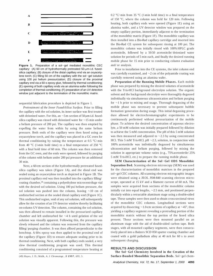
sequential fabrication procedure is depicted in Figure 1.Pretreatment of the Inner Fused-Silica Surface. Prior to filling
the capillary with the sol solution, its inner surface was first treatedwith deionized water. For this, an ∼5-m section of 50-µm-i.d. fused-silica capillary was rinsed with deionized water for ∼15 min undera helium pressure of 200 psi. The capillary was then emptied byexpelling the water from within by using the same heliumpressure. Both ends of the capillary were then fused using anoxyacetylene torch, and the capillary was placed in a GC oven forthermal conditioning by raising the temperature at 0.5 °C/minfrom 40 °C (1-min hold time) to a final temperature of 250 °Cwith a final hold time of 60 min. The column was then removedfrom the GC oven, and the ends were opened, followed by purgingof the column with helium under 200 psi pressure for an additional30 min.
Next, a 60-cm section of the hydrothermally pretreated fused-silica capillary was taken (Figure 1A), and the distal end wassealed using an oxyacetylene torch as depicted in Figure 1B. Theproximal capillary end was then installed into the capillary filling/coating chamber,49 containing a polyethylene microcentrifuge vialwith the desired sol solution. Using 100 psi helium pressure, thesol solution was pushed into the column, leaving ∼10 cm ofundisturbed section at the sealed distal capillary end (Figure 1C).This undisturbed region, void of any sol solution, will subsequentlyallow for the creation of an UV detector window thereby facilitatingon-column UV detection. The column, containing the sol solution,was then allowed to remain installed in the pressurized capillarychamber and left undisturbed for ∼4 h until gelation of the solsolution was visually apparent. Following this, the pressure wasslowly released and the column was removed from the capillaryfilling/purging chamber. It was then affixed perpendicular to thebenchtop. A 60-s epoxy was then applied to the proximal end ofthe capillary (Figure 1D) to ensure adequate sealing prior to itsthermal conditioning. Next, with both capillary ends sealed, a veryslow thermal conditioning program was used. This thermalconditioning consisted of a programmed temperature heating at
0.2 °C/min from 35 °C (1-min hold time) to a final temperatureof 150 °C, where the column was held for 120 min. Followingheating, both capillary ends were opened (Figure 1E) using analumina wafer, and a UV detector window was prepared on theempty capillary portion, immediately adjacent to the terminationof the monolithic matrix (Figure 1F). The monolithic capillary wasthen installed into a Bio-Rad capillary cartridge and inserted intothe Bio-Rad CE system for subsequent rinsing at 100 psi. Themonolithic column was initially rinsed with 100% HPLC gradeacetonitrile, followed by a 50:50 acetonitrile/deionized watersolution for periods of 5 min each, and finally the desired runningmobile phase for 15 min prior to conducting column evaluationand/or analysis.
Prior to installation into the CE systems, the inlet column endwas carefully examined, and ∼2 cm of the polyamide coating wascarefully removed using an alumina wafer.
Preparation of the Running Mobile Phases. Each mobilephase was prepared by mixing the desired volumes of acetonitrilewith the Tris-HCl background electrolyte solution. The organicsolvent and the background electrolyte were thoroughly degassedindividually via simultaneous ultrasonication and helium purgingfor ∼1 h prior to mixing and usage. Thorough degassing of themobile phase was necessary to prevent subsequent bubbleformation/generation during usage. This initial degassing proce-dure allowed for electrochromatographic experiments to becontinuously performed without pressurization of the mobilephase. To achieve the desired concentration of aqueous electro-lyte, a 50 mM solution was initially prepared followed by dilutionto achieve the 5 mM concentration. The pH of this 5 mM solutionwas then measured and adjusted to ∼2.3 by using concentratedHCl. This 5 mM Tris-HCl, pH ∼2.3, solution, in conjunction with100% acetonitrile was individually degassed by simultaneousultrasonication and helium purging, followed by mixing thesolution in appropriate volume ratios (e.g., 75% acetonitrile/25%5 mM Tris-HCl, etc.) to prepare the running mobile phase.
SEM Characterization of the Sol-Gel ODS MonolithicSeparation Bed. Scanning electron microscopy (SEM) was usedfor the characterization of monolithic matrixes in the preparedsol-gel CEC columns. All scanning electron micrographic imageswere obtained using a JEOL JSM-840 scanning electron micro-scope, operated at 15 kV and a filament current of 60 mA. Thesamples were acquired from sections of the monolithic columninitially cut into equal lengths, ∼2.5 mm, and positioned perpen-dicularly within a retractable aluminum stage using a double-sidedtape. These samples were then used to obtain cross-sectional viewsof the monolithic CEC columns. Longitudinal sections wereacquired by dissecting ∼1.0-cm sections of capillary at ∼45°, thusyielding a capillary segment revealing a protruding portion of themonolithic matrix without the top portion of the fused silicapresent. These sections were then mounted parallel on analuminum stage with the aid of double-sided carbon tape. Bothstages, with all mounted capillary segments, were then consecu-tively placed into a Balzers SCD 050 sputter coating chamber andcoated with a gold/palladium alloy at 40 mA for 60 s to avertsubsequent charging.
RESULTS AND DISCUSSIONThe Sol-Gel Chemistry Involved in the Creation of the
Surface-Bonded Monolithic Separation Beds. Sol-gel chem-(49) Hayes, J. D.; Malik, A. J. Chromatogr., B 1997, 695, 3.
Figure 1. Preparation of a sol-gel mediated monolithic CECcapillary: (A) 60 cm of hydrothermally pretreated 50-µm-i.d. fused-silica capillary; (B) closure of the distal capillary end via an oxyacety-lene torch; (C) filling 50 cm of the capillary with the sol-gel solutionusing 100 psi helium pressurization; (D) closure of the proximalcapillary end via a 60-s epoxy glue, followed by thermal conditioning;(E) opening of both capillary ends via an alumina wafer following thecompletion of thermal conditioning; (F) preparation of an UV detectionwindow just adjacent to the termination of the monolithic matrix.
Analytical Chemistry, Vol. 72, No. 17, September 1, 2000 4093
istry provides a versatile pathway for the in situ creation ofchromatographic stationary phases with surface-bonded ligands,in both open tubular and monolithic formats. In this approach,unlike conventional techniques, various column preparationprocesses (e.g., deactivation, coating/packing, stationary-phaseimmobilization, end-frit making, etc.) are advantageously carriedout in one single step, thus reducing the time and labor associatedwith column fabrication. Previously, we have reported the ap-plication of sol-gel chemistry for the preparation of Ucon-coatedcapillaries for CE.49 However, this is a quite general approach tocolumn preparation, which is not limited to liquid-phase separa-tions as evidenced by our recent reports of sol-gel technologyfor the preparation of high-performance GC columns and SPMEfibers.50-52
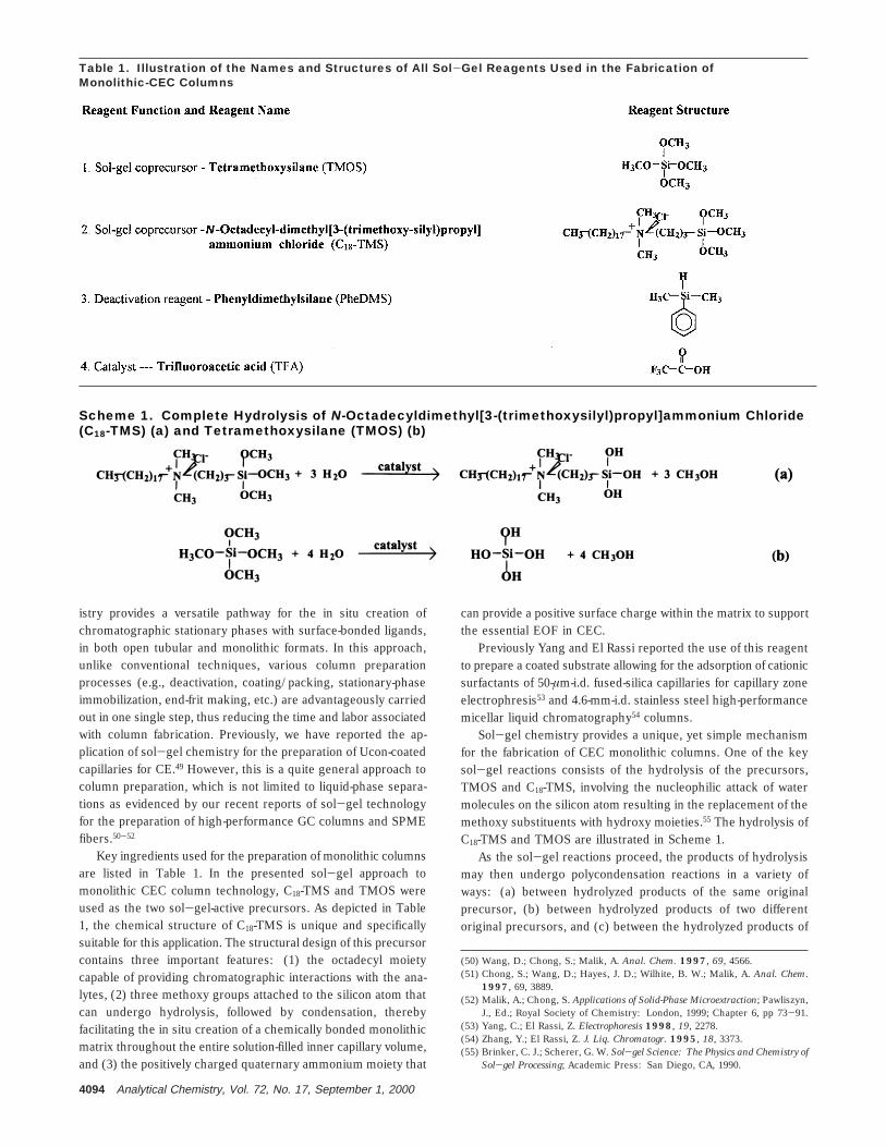
Key ingredients used for the preparation of monolithic columnsare listed in Table 1. In the presented sol-gel approach tomonolithic CEC column technology, C18-TMS and TMOS wereused as the two sol-gel-active precursors. As depicted in Table1, the chemical structure of C18-TMS is unique and specificallysuitable for this application. The structural design of this precursorcontains three important features: (1) the octadecyl moietycapable of providing chromatographic interactions with the ana-lytes, (2) three methoxy groups attached to the silicon atom thatcan undergo hydrolysis, followed by condensation, therebyfacilitating the in situ creation of a chemically bonded monolithicmatrix throughout the entire solution-filled inner capillary volume,and (3) the positively charged quaternary ammonium moiety that
can provide a positive surface charge within the matrix to supportthe essential EOF in CEC.
Previously Yang and El Rassi reported the use of this reagentto prepare a coated substrate allowing for the adsorption of cationicsurfactants of 50-µm-i.d. fused-silica capillaries for capillary zoneelectrophresis53 and 4.6-mm-i.d. stainless steel high-performancemicellar liquid chromatography54 columns.
Sol-gel chemistry provides a unique, yet simple mechanismfor the fabrication of CEC monolithic columns. One of the keysol-gel reactions consists of the hydrolysis of the precursors,TMOS and C18-TMS, involving the nucleophilic attack of watermolecules on the silicon atom resulting in the replacement of themethoxy substituents with hydroxy moieties.55 The hydrolysis ofC18-TMS and TMOS are illustrated in Scheme 1.
As the sol-gel reactions proceed, the products of hydrolysismay then undergo polycondensation reactions in a variety ofways: (a) between hydrolyzed products of the same originalprecursor, (b) between hydrolyzed products of two differentoriginal precursors, and (c) between the hydrolyzed products of
(50) Wang, D.; Chong, S.; Malik, A. Anal. Chem. 1997, 69, 4566.(51) Chong, S.; Wang, D.; Hayes, J. D.; Wilhite, B. W.; Malik, A. Anal. Chem.
1997, 69, 3889.(52) Malik, A.; Chong, S. Applications of Solid-Phase Microextraction; Pawliszyn,
J., Ed.; Royal Society of Chemistry: London, 1999; Chapter 6, pp 73-91.(53) Yang, C.; El Rassi, Z. Electrophoresis 1998, 19, 2278.(54) Zhang, Y.; El Rassi, Z. J. Liq. Chromatogr. 1995, 18, 3373.(55) Brinker, C. J.; Scherer, G. W. Sol-gel Science: The Physics and Chemistry of
Sol-gel Processing; Academic Press: San Diego, CA, 1990.
Table 1. Illustration of the Names and Structures of All Sol-Gel Reagents Used in the Fabrication ofMonolithic-CEC Columns
Scheme 1. Complete Hydrolysis of N-Octadecyldimethyl[3-(trimethoxysilyl)propyl]ammonium Chloride(C18-TMS) (a) and Tetramethoxysilane (TMOS) (b)
4094 Analytical Chemistry, Vol. 72, No. 17, September 1, 2000
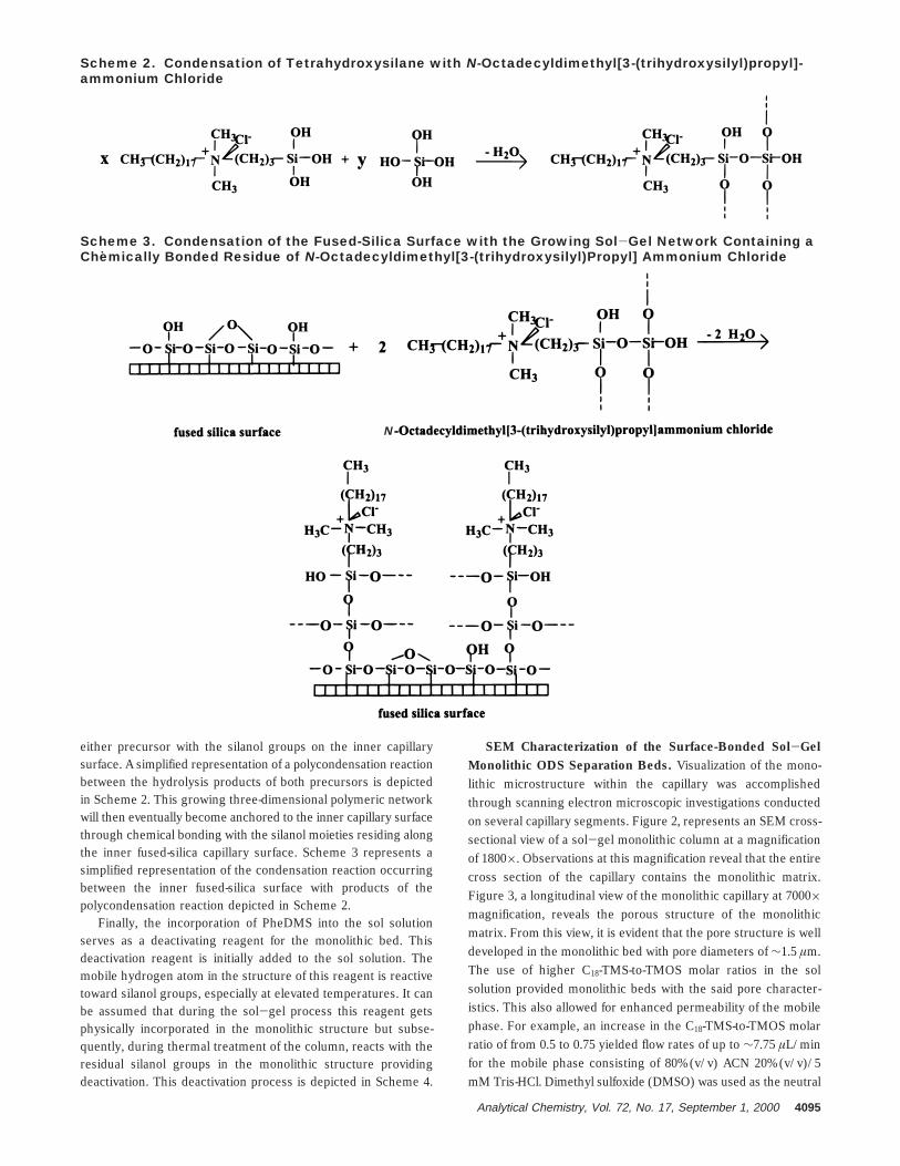
either precursor with the silanol groups on the inner capillarysurface. A simplified representation of a polycondensation reactionbetween the hydrolysis products of both precursors is depictedin Scheme 2. This growing three-dimensional polymeric networkwill then eventually become anchored to the inner capillary surfacethrough chemical bonding with the silanol moieties residing alongthe inner fused-silica capillary surface. Scheme 3 represents asimplified representation of the condensation reaction occurringbetween the inner fused-silica surface with products of thepolycondensation reaction depicted in Scheme 2.
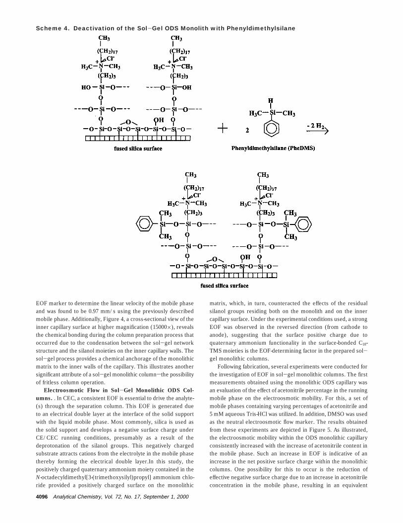
Finally, the incorporation of PheDMS into the sol solutionserves as a deactivating reagent for the monolithic bed. Thisdeactivation reagent is initially added to the sol solution. Themobile hydrogen atom in the structure of this reagent is reactivetoward silanol groups, especially at elevated temperatures. It canbe assumed that during the sol-gel process this reagent getsphysically incorporated in the monolithic structure but subse-quently, during thermal treatment of the column, reacts with theresidual silanol groups in the monolithic structure providingdeactivation. This deactivation process is depicted in Scheme 4.
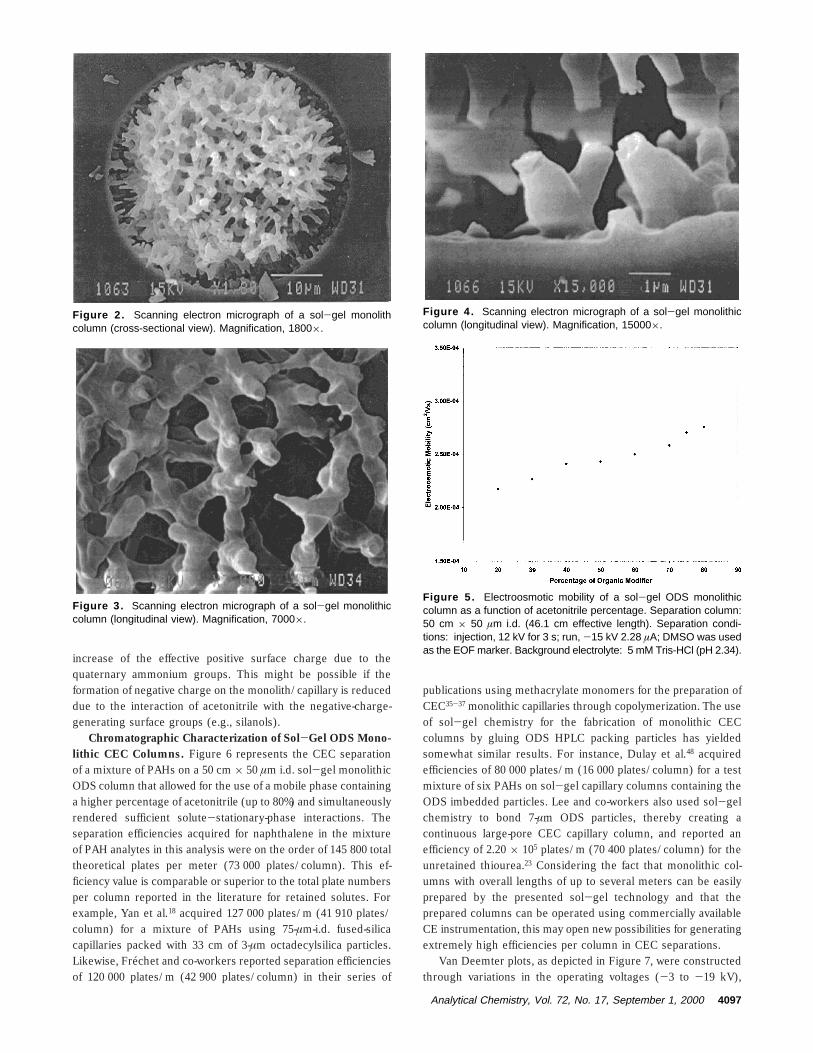
SEM Characterization of the Surface-Bonded Sol-GelMonolithic ODS Separation Beds. Visualization of the mono-lithic microstructure within the capillary was accomplishedthrough scanning electron microscopic investigations conductedon several capillary segments. Figure 2, represents an SEM cross-sectional view of a sol-gel monolithic column at a magnificationof 1800×. Observations at this magnification reveal that the entirecross section of the capillary contains the monolithic matrix.Figure 3, a longitudinal view of the monolithic capillary at 7000×magnification, reveals the porous structure of the monolithicmatrix. From this view, it is evident that the pore structure is welldeveloped in the monolithic bed with pore diameters of ∼1.5 µm.The use of higher C18-TMS-to-TMOS molar ratios in the solsolution provided monolithic beds with the said pore character-istics. This also allowed for enhanced permeability of the mobilephase. For example, an increase in the C18-TMS-to-TMOS molarratio of from 0.5 to 0.75 yielded flow rates of up to ∼7.75 µL/minfor the mobile phase consisting of 80% (v/v) ACN 20% (v/v)/5mM Tris-HCl. Dimethyl sulfoxide (DMSO) was used as the neutral
Scheme 2. Condensation of Tetrahydroxysilane with N-Octadecyldimethyl[3-(trihydroxysilyl)propyl]-ammonium Chloride
Scheme 3. Condensation of the Fused-Silica Surface with the Growing Sol-Gel Network Containing aChemically Bonded Residue of N-Octadecyldimethyl[3-(trihydroxysilyl)Propyl] Ammonium Chloride
N
Analytical Chemistry, Vol. 72, No. 17, September 1, 2000 4095
EOF marker to determine the linear velocity of the mobile phaseand was found to be 0.97 mm/s using the previously describedmobile phase. Additionally, Figure 4, a cross-sectional view of theinner capillary surface at higher magnification (15000×), revealsthe chemical bonding during the column preparation process thatoccurred due to the condensation between the sol-gel networkstructure and the silanol moieties on the inner capillary walls. Thesol-gel process provides a chemical anchorage of the monolithicmatrix to the inner walls of the capillary. This illustrates anothersignificant attribute of a sol-gel monolithic columnsthe possibilityof fritless column operation.
Electroosmotic Flow in Sol-Gel Monolithic ODS Col-umns. . In CEC, a consistent EOF is essential to drive the analyte-(s) through the separation column. This EOF is generated dueto an electrical double layer at the interface of the solid supportwith the liquid mobile phase. Most commonly, silica is used asthe solid support and develops a negative surface charge underCE/CEC running conditions, presumably as a result of thedeprotonation of the silanol groups. This negatively chargedsubstrate attracts cations from the electrolyte in the mobile phasethereby forming the electrical double layer.In this study, thepositively charged quaternary ammonium moiety contained in theN-octadecyldimethyl[3-(trimethoxysilyl)propyl] ammonium chlo-ride provided a positively charged surface on the monolithic
matrix, which, in turn, counteracted the effects of the residualsilanol groups residing both on the monolith and on the innercapillary surface. Under the experimental conditions used, a strongEOF was observed in the reversed direction (from cathode toanode), suggesting that the surface positive charge due toquaternary ammonium functionality in the surface-bonded C18-TMS moieties is the EOF-determining factor in the prepared sol-gel monolithic columns.
Following fabrication, several experiments were conducted forthe investigation of EOF in sol-gel monolithic columns. The firstmeasurements obtained using the monolithic ODS capillary wasan evaluation of the effect of acetonitrile percentage in the runningmobile phase on the electroosmotic mobility. For this, a set ofmobile phases containing varying percentages of acetonitrile and5 mM aqueous Tris-HCl was utilized. In addition, DMSO was usedas the neutral electroosmotic flow marker. The results obtainedfrom these experiments are depicted in Figure 5. As illustrated,the electroosmotic mobility within the ODS monolithic capillaryconsistently increased with the increase of acetonitrile content inthe mobile phase. Such an increase in EOF is indicative of anincrease in the net positive surface charge within the monolithiccolumns. One possibility for this to occur is the reduction ofeffective negative surface charge due to an increase in acetonitrileconcentration in the mobile phase, resulting in an equivalent
Scheme 4. Deactivation of the Sol-Gel ODS Monolith with Phenyldimethylsilane
4096 Analytical Chemistry, Vol. 72, No. 17, September 1, 2000
increase of the effective positive surface charge due to thequaternary ammonium groups. This might be possible if theformation of negative charge on the monolith/capillary is reduceddue to the interaction of acetonitrile with the negative-charge-generating surface groups (e.g., silanols).
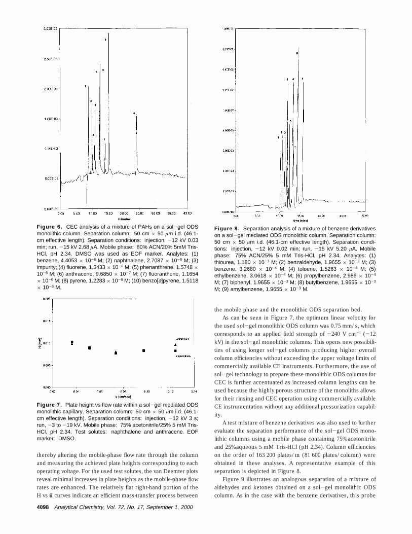
Chromatographic Characterization of Sol-Gel ODS Mono-lithic CEC Columns. Figure 6 represents the CEC separationof a mixture of PAHs on a 50 cm × 50 µm i.d. sol-gel monolithicODS column that allowed for the use of a mobile phase containinga higher percentage of acetonitrile (up to 80%) and simultaneouslyrendered sufficient solute-stationary-phase interactions. Theseparation efficiencies acquired for naphthalene in the mixtureof PAH analytes in this analysis were on the order of 145 800 totaltheoretical plates per meter (73 000 plates/column). This ef-ficiency value is comparable or superior to the total plate numbersper column reported in the literature for retained solutes. Forexample, Yan et al.18 acquired 127 000 plates/m (41 910 plates/column) for a mixture of PAHs using 75-µm-i.d. fused-silicacapillaries packed with 33 cm of 3-µm octadecylsilica particles.Likewise, Frechet and co-workers reported separation efficienciesof 120 000 plates/m (42 900 plates/column) in their series of
publications using methacrylate monomers for the preparation ofCEC35-37 monolithic capillaries through copolymerization. The useof sol-gel chemistry for the fabrication of monolithic CECcolumns by gluing ODS HPLC packing particles has yieldedsomewhat similar results. For instance, Dulay et al.48 acquiredefficiencies of 80 000 plates/m (16 000 plates/column) for a testmixture of six PAHs on sol-gel capillary columns containing theODS imbedded particles. Lee and co-workers also used sol-gelchemistry to bond 7-µm ODS particles, thereby creating acontinuous large-pore CEC capillary column, and reported anefficiency of 2.20 × 10⁵ plates/m (70 400 plates/column) for theunretained thiourea.23 Considering the fact that monolithic col-umns with overall lengths of up to several meters can be easilyprepared by the presented sol-gel technology and that theprepared columns can be operated using commercially availableCE instrumentation, this may open new possibilities for generatingextremely high efficiencies per column in CEC separations.
Van Deemter plots, as depicted in Figure 7, were constructedthrough variations in the operating voltages (-3 to -19 kV),
Figure 2. Scanning electron micrograph of a sol-gel monolithcolumn (cross-sectional view). Magnification, 1800×.
Figure 3. Scanning electron micrograph of a sol-gel monolithiccolumn (longitudinal view). Magnification, 7000×.
Figure 4. Scanning electron micrograph of a sol-gel monolithiccolumn (longitudinal view). Magnification, 15000×.
Figure 5. Electroosmotic mobility of a sol-gel ODS monolithiccolumn as a function of acetonitrile percentage. Separation column:50 cm × 50 µm i.d. (46.1 cm effective length). Separation condi-tions: injection, 12 kV for 3 s; run, -15 kV 2.28 µA; DMSO was usedas the EOF marker. Background electrolyte: 5 mM Tris-HCl (pH 2.34).
Analytical Chemistry, Vol. 72, No. 17, September 1, 2000 4097
thereby altering the mobile-phase flow rate through the columnand measuring the achieved plate heights corresponding to eachoperating voltage. For the used test solutes, the van Deemter plotsreveal minimal increases in plate heights as the mobile-phase flowrates are enhanced. The relatively flat right-hand portion of theH vs uj curves indicate an efficient mass-transfer process between
the mobile phase and the monolithic ODS separation bed.As can be seen in Figure 7, the optimum linear velocity for
the used sol-gel monolithic ODS column was 0.75 mm/s, whichcorresponds to an applied field strength of -240 V cm-1 (-12kV) in the sol-gel monolithic columns. This opens new possibili-ties of using longer sol-gel columns producing higher overallcolumn efficiencies without exceeding the upper voltage limits ofcommercially available CE instruments. Furthermore, the use ofsol-gel technology to prepare these monolithic ODS columns forCEC is further accentuated as increased column lengths can beused because the highly porous structure of the monoliths allowsfor their rinsing and CEC operation using commercially availableCE instrumentation without any additional pressurization capabil-ity.
A test mixture of benzene derivatives was also used to furtherevaluate the separation performance of the sol-gel ODS mono-lithic columns using a mobile phase containing 75% acetonitrileand 25% aqueous 5 mM Tris-HCl (pH 2.34). Column efficiencieson the order of 163 200 plates/m (81 600 plates/column) wereobtained in these analyses. A representative example of thisseparation is depicted in Figure 8.
Figure 9 illustrates an analogous separation of a mixture ofaldehydes and ketones obtained on a sol-gel monolithic ODScolumn. As in the case with the benzene derivatives, this probe
Figure 6. CEC analysis of a mixture of PAHs on a sol-gel ODSmonolithic column. Separation column: 50 cm × 50 µm i.d. (46.1-cm effective length). Separation conditions: injection, -12 kV 0.03min; run, -15 kV 2.68 µA. Mobile phase: 80% ACN/20% 5mM Tris-HCl, pH 2.34. DMSO was used as EOF marker. Analytes: (1)benzene, 4.4053 × 10⁻⁶ M; (2) naphthalene, 2.7087 × 10⁻⁶ M; (3)impurity; (4) fluorene, 1.5433 × 10⁻⁶ M; (5) phenanthrene, 1.5748 ×10⁻⁶ M; (6) anthracene, 9.6850 × 10⁻⁷ M; (7) fluoranthene, 1.1654× 10⁻⁶ M; (8) pyrene, 1.2283 × 10⁻⁶ M; (10) benzo[a]pyrene, 1.5118× 10⁻⁶ M.
Figure 7. Plate height vs flow rate within a sol-gel mediated ODSmonolithic capillary. Separation column: 50 cm × 50 µm i.d. (46.1-cm effective length). Separation conditions: injection, -12 kV 3 s;run, -3 to -19 kV. Mobile phase: 75% acetonitrile/25% 5 mM Tris-HCl, pH 2.34. Test solutes: naphthalene and anthracene. EOFmarker: DMSO.
Figure 8. Separation analysis of a mixture of benzene derivativeson a sol-gel mediated ODS monolithic column. Separation column:50 cm × 50 µm i.d. (46.1-cm effective length). Separation condi-tions: injection, -12 kV 0.02 min; run, -15 kV 5.20 µA. Mobilephase: 75% ACN/25% 5 mM Tris-HCl, pH 2.34. Analytes: (1)thiourea, 1.180 × 10⁻³ M; (2) benzaldehyde, 1.9655 × 10⁻³ M; (3)benzene, 3.2680 × 10⁻⁴ M; (4) toluene, 1.5263 × 10⁻⁴ M; (5)ethylbenzene, 3.0618 × 10⁻⁴ M; (6) propylbenzene, 2.986 × 10⁻⁴
M; (7) biphenyl, 1.9655 × 10⁻³ M; (8) butylbenzene, 1.9655 × 10⁻³
M; (9) amylbenzene, 1.9655 × 10⁻³ M.
4098 Analytical Chemistry, Vol. 72, No. 17, September 1, 2000
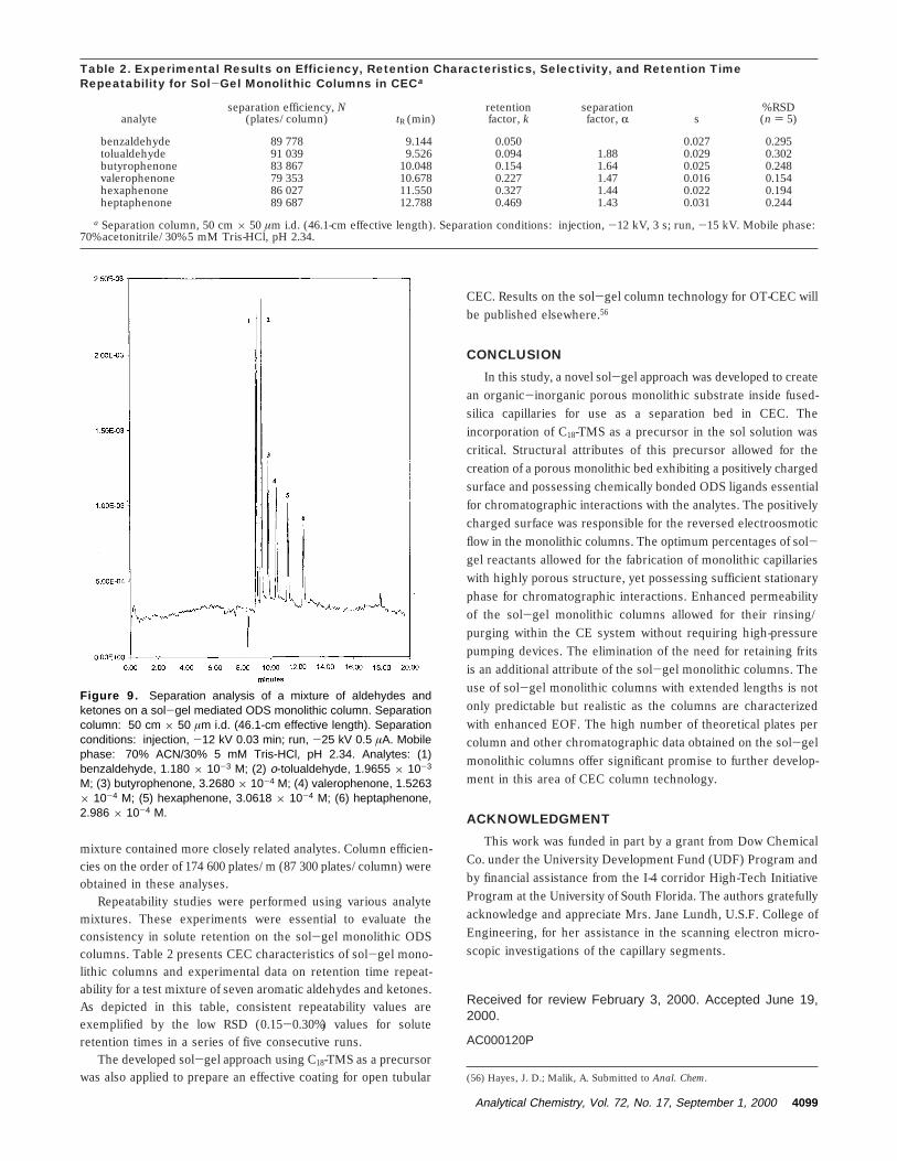
mixture contained more closely related analytes. Column efficien-cies on the order of 174 600 plates/m (87 300 plates/column) wereobtained in these analyses.
Repeatability studies were performed using various analytemixtures. These experiments were essential to evaluate theconsistency in solute retention on the sol-gel monolithic ODScolumns. Table 2 presents CEC characteristics of sol-gel mono-lithic columns and experimental data on retention time repeat-ability for a test mixture of seven aromatic aldehydes and ketones.As depicted in this table, consistent repeatability values areexemplified by the low RSD (0.15-0.30%) values for soluteretention times in a series of five consecutive runs.
The developed sol-gel approach using C18-TMS as a precursorwas also applied to prepare an effective coating for open tubular
CEC. Results on the sol-gel column technology for OT-CEC willbe published elsewhere.56
CONCLUSION
In this study, a novel sol-gel approach was developed to createan organic-inorganic porous monolithic substrate inside fused-silica capillaries for use as a separation bed in CEC. Theincorporation of C18-TMS as a precursor in the sol solution wascritical. Structural attributes of this precursor allowed for thecreation of a porous monolithic bed exhibiting a positively chargedsurface and possessing chemically bonded ODS ligands essentialfor chromatographic interactions with the analytes. The positivelycharged surface was responsible for the reversed electroosmoticflow in the monolithic columns. The optimum percentages of sol-gel reactants allowed for the fabrication of monolithic capillarieswith highly porous structure, yet possessing sufficient stationaryphase for chromatographic interactions. Enhanced permeabilityof the sol-gel monolithic columns allowed for their rinsing/purging within the CE system without requiring high-pressurepumping devices. The elimination of the need for retaining fritsis an additional attribute of the sol-gel monolithic columns. Theuse of sol-gel monolithic columns with extended lengths is notonly predictable but realistic as the columns are characterizedwith enhanced EOF. The high number of theoretical plates percolumn and other chromatographic data obtained on the sol-gelmonolithic columns offer significant promise to further develop-ment in this area of CEC column technology.
ACKNOWLEDGMENT
This work was funded in part by a grant from Dow ChemicalCo. under the University Development Fund (UDF) Program andby financial assistance from the I-4 corridor High-Tech InitiativeProgram at the University of South Florida. The authors gratefullyacknowledge and appreciate Mrs. Jane Lundh, U.S.F. College ofEngineering, for her assistance in the scanning electron micro-scopic investigations of the capillary segments.
Received for review February 3, 2000. Accepted June 19,2000.
AC000120P
(56) Hayes, J. D.; Malik, A. Submitted to Anal. Chem.
Table 2. Experimental Results on Efficiency, Retention Characteristics, Selectivity, and Retention TimeRepeatability for Sol-Gel Monolithic Columns in CECa
analyteseparation efficiency, N
(plates/column) tR (min)retentionfactor, k
separationfactor, R s
% RSD(n ) 5)
benzaldehyde 89 778 9.144 0.050 0.027 0.295tolualdehyde 91 039 9.526 0.094 1.88 0.029 0.302butyrophenone 83 867 10.048 0.154 1.64 0.025 0.248valerophenone 79 353 10.678 0.227 1.47 0.016 0.154hexaphenone 86 027 11.550 0.327 1.44 0.022 0.194heptaphenone 89 687 12.788 0.469 1.43 0.031 0.244
a Separation column, 50 cm × 50 µm i.d. (46.1-cm effective length). Separation conditions: injection, -12 kV, 3 s; run, -15 kV. Mobile phase:70% acetonitrile/30% 5 mM Tris-HCl, pH 2.34.
Figure 9. Separation analysis of a mixture of aldehydes andketones on a sol-gel mediated ODS monolithic column. Separationcolumn: 50 cm × 50 µm i.d. (46.1-cm effective length). Separationconditions: injection, -12 kV 0.03 min; run, -25 kV 0.5 µA. Mobilephase: 70% ACN/30% 5 mM Tris-HCl, pH 2.34. Analytes: (1)benzaldehyde, 1.180 × 10⁻³ M; (2) o-tolualdehyde, 1.9655 × 10⁻³
M; (3) butyrophenone, 3.2680 × 10⁻⁴ M; (4) valerophenone, 1.5263× 10⁻⁴ M; (5) hexaphenone, 3.0618 × 10⁻⁴ M; (6) heptaphenone,2.986 × 10-4 M.
Analytical Chemistry, Vol. 72, No. 17, September 1, 2000 4099
Copyright © 2022 FDOKUMEN