Construction Technology of Monolithic Refractories - Nippon ...

This article was downloaded by: [Vilnius Gedimino Tech University]On: 14 April 2015, At: 00:24Publisher: Taylor & FrancisInforma Ltd Registered in England and Wales Registered Number: 1072954 Registered office: MortimerHouse, 37-41 Mortimer Street, London W1T 3JH, UK
Click for updates
Journal of Civil Engineering and ManagementPublication details, including instructions for authors and subscription information:http://www.tandfonline.com/loi/tcem20
Flexural capacity and stiffness of monolithic biaxialhollow slabsJuozas Valivonisa, Bronius Jonaitisa, Robertas Zavalisa, Tomas Skuturnaa & ArnoldasŠneiderisa
a Department of Reinforced Concrete and Masonry Structures, Vilnius GediminasTechnical University, Saulėtekio al. 11, 10223 Vilnius, LithuaniaPublished online: 20 Oct 2014.
To cite this article: Juozas Valivonis, Bronius Jonaitis, Robertas Zavalis, Tomas Skuturna & Arnoldas Šneideris (2014)Flexural capacity and stiffness of monolithic biaxial hollow slabs, Journal of Civil Engineering and Management, 20:5,693-701, DOI: 10.3846/13923730.2014.917122
To link to this article: http://dx.doi.org/10.3846/13923730.2014.917122
PLEASE SCROLL DOWN FOR ARTICLE
Taylor & Francis makes every effort to ensure the accuracy of all the information (the “Content”) containedin the publications on our platform. However, Taylor & Francis, our agents, and our licensors make norepresentations or warranties whatsoever as to the accuracy, completeness, or suitability for any purpose ofthe Content. Any opinions and views expressed in this publication are the opinions and views of the authors,and are not the views of or endorsed by Taylor & Francis. The accuracy of the Content should not be reliedupon and should be independently verified with primary sources of information. Taylor and Francis shallnot be liable for any losses, actions, claims, proceedings, demands, costs, expenses, damages, and otherliabilities whatsoever or howsoever caused arising directly or indirectly in connection with, in relation to orarising out of the use of the Content.
This article may be used for research, teaching, and private study purposes. Any substantial or systematicreproduction, redistribution, reselling, loan, sub-licensing, systematic supply, or distribution in anyform to anyone is expressly forbidden. Terms & Conditions of access and use can be found at http://www.tandfonline.com/page/terms-and-conditions

Corresponding author: Juozas Valivonis E-mail: [email protected] Copyright © 2014 Vilnius Gediminas Technical University (VGTU) Press www.tandfonline.com/tcem 693
JOURNAL OF CIVIL ENGINEERING AND MANAGEMENT
ISSN 1392-3730 / eISSN 1822-3605 2014 Volume 20(5): 693–701
doi:10.3846/13923730.2014.917122
FLEXURAL CAPACITY AND STIFFNESS OF MONOLITHIC BIAXIAL HOLLOW SLABS
Juozas VALIVONIS, Bronius JONAITIS, Robertas ZAVALIS, Tomas SKUTURNA, Arnoldas ŠNEIDERIS Department of Reinforced Concrete and Masonry Structures, Vilnius Gediminas Technical University,
Saulėtekio al. 11, 10223 Vilnius, Lithuania Received 22 Nov 2012; accepted 04 Apr 2014
Abstract. The article presents a research on flexural behaviour of hollow monolithic reinforced concrete slabs. It focuses on the results of experimental investigation into full-size hollow reinforced concrete slabs and analyses their flexural ca-pacity and stiffness. The self-weight of the slabs directly depends on the shape and number of hollows. An increase in the hollowness of a slab significantly reduces the load caused by self-weight. This allows increasing the estimated length of the slab under the same payload. An increase in the amount of hollows of the slab changes the stiffness of the slab cross-section that has a direct impact on slab deflection. Considering the shape of the slab cross-section, theoretical calculations of the flexural capacity and deflection of experimental slabs were made. The design of a new type of slabs and variations in different parameters of the slab experience difficulties in conducting a large amount of experimental tests. Therefore, the initial analysis may apply to numerical simulation. The paper describes the principles of designing a numerical model. The calculations were made using DIANA software. The stiffness and flexural capacity of the hollow slabs were estab-lished employing numerical simulation compared to the results of experimental investigations. The findings indicate that numerical simulation can be applied for analysing the stress state of the examined structures. Keywords: monolithic reinforced concrete, slab, hollows, stiffness, flexural capacity, numerical simulation.
Introduction A slab is a very important structural member for making a space in a building. Multi-storey buildings are frequent-ly erected using monolithic reinforced concrete. Usually, slabs that are used in buildings are made of reinforced concrete and have a single-piece cross-section structure.
The design of public and industrial buildings frequently requires a large continuous space. In this case, increasing the distance between columns is essential, which expands the space between slab supports. The performance characteristics of reinforced concrete slabs are often determined by the serviceability limit state and satisfied requirements, which increases the slab stiffness. Besides, the stiffness of reinforced concrete slabs can be improved by either using pre-stressed reinforcement or increasing the height of the cross-section of the slab or changing mechanical properties of concrete (Abramski et al. 2010; Santa Cruz Astorqui et al. 2009; Sprince et al. 2011, 2013). Prestressing of reinforcement of mo-nolithic reinforced concrete slabs is a rather complex process and requires expensive equipment and high la-bour costs. Thus, in construction practice, stiffness is most frequently increased raising the height of the cross-section of reinforced concrete slabs. However, a greater height of the single-piece cross-section results in the loss of useful space and, therefore, increased weight, i.e. the load of the slab. An omission in the reinforced concrete
girder slab shows that adding to thickness slightly redu-ces the deflection of the slab, and in some cases, in large dimensions, even increases it. Hence, to reduce the def-lection of monolithic reinforced concrete and girder slabs, other solutions have to be put forward. One of them is a reduction in the weight of the slab leaving the same space between supports and the applied load. Another solution, which is used worldwide involves monolithic reinforced concrete slabs with plastic inserts, which form hollows in slabs. This way, the cross-section of the monolithic rein-forced concrete slab becomes analogous to the cross-section of the hollow slab of prefabricated reinforced concrete. The use of such slabs allows overlaying larger openings and increasing the height of the cross-section practically avoiding changes or slightly increasing the loads induced by self-weight. Literature points to the elements forming circular and oval-shaped hollows, the application of which enables to save 20% and 30% of concrete, respectively (Fiala, Hajek 2007; Ordon-Beska 2012; Yang et al. 2013; Abramski et al. 2010; Marais et al. 2010; Hai et al. 2013; Chung et al. 2011).
Manufacturing of reinforced concrete structures emits a massive amount of pollutants to the environment. A decrease in the amount of concrete used for producing reinforced concrete slabs of buildings reduces the volume of cement. Production of 1 ton of cement results in 500 kg CO2 emitted to the environment. The manufacture of hollow reinforced concrete slabs results in reduction of
Dow
nloa
ded
by [
Viln
ius
Ged
imin
o T
ech
Uni
vers
ity]
at 0
0:24
14
Apr
il 20
15
J. Valivonis et al. Flexural capacity and stiffness of monolithic biaxial hollow slabs 694
the required amount of concrete, which at the same time lowers the cement consumption. This only indicates that rational decisions on reinforced concrete structures can significantly cut down energy and raw material input, thus reducing environmental pollution (Fiala, Hajek 2007; Abramski et al. 2010). Plastic inserts made for shaping hollows in slabs can be produced from household plastic waste, which is an environmentally-friendly waste management solution.
Plastic inserts used for shaping hollows change the behaviour of reinforced concrete slabs affected by an external load. Upper and lower shelves as well as two-way reinforced concrete edges are designed in such slabs during their production. The two-way edges in a slab change the stiffness of the cross-section at the transverse reinforced concrete edge and between the edges (beside plastic inserts). Thus, the stiffness and deflection of the above-mentioned slabs partially depend on variations in stiffness along the slab.
The article explores the stiffness and flexural strength of reinforced concrete slabs with hollows close to the square cross-section.
Research on experimental and numerical simula-tions was carried out to find out the behaviour of a rein-forced concrete slab with plastic inserts in operation, to monitor crack formation and development, and to display the character of a fracture.
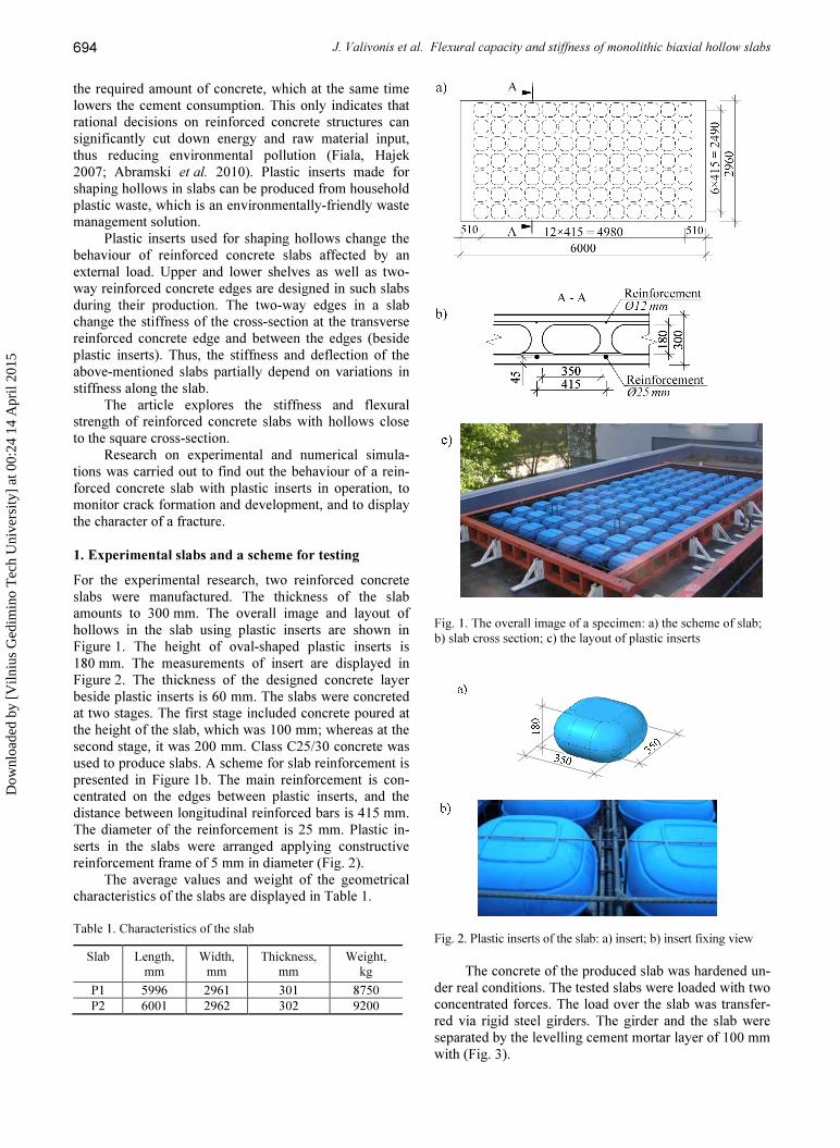
1. Experimental slabs and a scheme for testing For the experimental research, two reinforced concrete slabs were manufactured. The thickness of the slab amounts to 300 mm. The overall image and layout of hollows in the slab using plastic inserts are shown in Figure 1. The height of oval-shaped plastic inserts is 180 mm. The measurements of insert are displayed in Figure 2. The thickness of the designed concrete layer beside plastic inserts is 60 mm. The slabs were concreted at two stages. The first stage included concrete poured at the height of the slab, which was 100 mm; whereas at the second stage, it was 200 mm. Class C25/30 concrete was used to produce slabs. A scheme for slab reinforcement is presented in Figure 1b. The main reinforcement is con-centrated on the edges between plastic inserts, and the distance between longitudinal reinforced bars is 415 mm. The diameter of the reinforcement is 25 mm. Plastic in-serts in the slabs were arranged applying constructive reinforcement frame of 5 mm in diameter (Fig. 2).
The average values and weight of the geometrical characteristics of the slabs are displayed in Table 1.
Table 1. Characteristics of the slab Slab Length,
mm Width, mm
Thickness, mm
Weight, kg
P1 5996 2961 301 8750 P2 6001 2962 302 9200
Fig. 1. The overall image of a specimen: a) the scheme of slab; b) slab cross section; c) the layout of plastic inserts
Fig. 2. Plastic inserts of the slab: a) insert; b) insert fixing view
The concrete of the produced slab was hardened un-
der real conditions. The tested slabs were loaded with two concentrated forces. The load over the slab was transfer-red via rigid steel girders. The girder and the slab were separated by the levelling cement mortar layer of 100 mm with (Fig. 3).
Dow
nloa
ded
by [
Viln
ius
Ged
imin
o T
ech
Uni
vers
ity]
at 0
0:24
14
Apr
il 20
15

Journal of Civil Engineering and Management, 2014, 20(5): 693–701
695
b)
Fig. 3. Slab testing: a) testing scheme; b) testing view
The tested slabs were loaded periodically. The load
during the first stage made 70% of the designed destruc-tive load and was equal to 371 kN. The slabs were unloa-ded before the second stage. The load during the second stage was increased from 0 to the fracture of the slab. The load was increased gradually. The value of the load of the step amounted to 0.1 of the designed destructive load (ΔP = 53 kN). At every step, the load was maintained for 5 min.
Slab deflections, strains of compressed concrete and the tensile zone as well as the width of the crack were measured during each tested stage. Deflections were measured at the middle of the slab and 1500 mm away from the middle in both directions. The arrangement of measuring equipment is shown in Figure 3a.
Slab experiments were conducted applying the uni-versal test stand (Fig. 3b). The samples affected by the acting force during the performed test, strains and slab deflections were recorded with the help of universal electronic testing equipment PCS 800 Walter-bai. Deflec-tion and strains were measured employing LVDT 50R and LVDT 10R inductive tensometers, respectively.
2. Results of experimental research on slabs Mechanical properties of concrete were established test-ing cubes, cylinders and prisms. Concrete samples, simi-larly to reinforced concrete slabs, were stored under the same conditions. Testing was carried out with reference to standard requirements EN12390-3 established in 2009. Testing of cylinders involves measuring longitudinal concrete strains. The test results have assisted in estab-lishing compressive concrete strength fcm and elasticity modulus Ecm. The flexural strength of concrete was found while testing rectangular prisms. With reference to flex-ural strength and according to Model Code 90 (MC90
1993) recommendations, the average tensile strength fctm was set. The samples and slabs of the same span were tested. The tests of the reinforced bars used for slab rein-forcement disclosed that the average reinforcement yield stresses fym of the bars of 25 mm in diameter makes 534 MPa, whereas the bars of 12 mm in diameter reach 550.3 MPa. Results of the research on the mechanical properties of concrete and reinforcement are presented in Table 2. Table 2. Mechanical properties of concrete slabs
Parameter Value, MPa Average strength of concrete cubes fc,cube 37,5 Average strength of concrete cylinders fcm 34,1 Average tensile strength of concrete fctm 2,8 Concrete elasticity module Ecm 31×103 Reinforcement Ø25 mm fym 534 Reinforcement Ø12 mm fym 550
According to the scheme offered in Figure 3a, the
fracture of both slabs has taken place in the perpendicular cross-section close to the place of one of the added for-ces, i.e. in the cross-section where the maximum bending moment is acting. Both slabs fractured under the effect of a bending moment (Fig. 4). The fracture occurred after reinforcement in the tensile zone reached yield stresses and concrete stresses of the compressive zone achieved compressive yield strength. Close to the support affected by greater share force, oblique cracks occurred; however, they were insufficiently wide and, therefore, could have not caused any danger. Experimental forces destructing the slabs are shown in Table 3.
b)
Fig. 4. A fracture of the slab: a) general view; b) view of a frac-ture in the tensile zone
Dow
nloa
ded
by [
Viln
ius
Ged
imin
o T
ech
Uni
vers
ity]
at 0
0:24
14
Apr
il 20
15

J. Valivonis et al. Flexural capacity and stiffness of monolithic biaxial hollow slabs 696
Table 3. Results of slab testing Slab Slab deflection ωobs mm,
when P = 0.6 Pd,** Destructive
load Pu,obs, kN
Destructive bending moment Mu,obs, kNm
First stage of loading
Second stage of loading
P1 17.6 18.2 794* 588.4 P2 18.2 20.9 789* 583.1 * – loads are provided following evaluation of the self-
weight of the slab; ** – designed destructive load.
Apart from preliminary reinforcement stress, the
withstood load of reinforced concrete slabs is frequently determined by a deflection rather than flexural capacity. Thus, the tests measured slab deflection at 6 points. A scheme for deflection measurements is shown in Figu-re 3a. The results of measured slab deflections are presen-ted in Figure 5.
The slab loaded with up to 70% of the destructive load and then unloaded (1st stage of loading) shows that the remaining strains (deflection) of slabs P1 and P2 ma-ke 3.5 mm and 1.8 mm, respectively. The data of slab testing disclosed that the maximum deflections of slabs P1 and P2, when reinforcement stress reaches the yield point, are equal to 37.7 mm and 42.2 mm, respectively.
Fig. 5. The deflection-bending moment dependence of slab P1 and P2 in the middle of the slab
Deflection is usually evaluated when the structure is
affected by a characteristic load, which is approximately equal to 60% of the designed destructive load (Pd), consi-dering which the load should agree with P = 370 kN. Therefore, the deflection was established under the effect of such load. The samples loaded up to the fracture (2nd stage of loading) indicate that the deflection of slabs P1 and P2 beside the mid-span were equal to 18.2 mm and 20.9, respectively, and made L/302 and L/263, with L as the calculated span length of the experimental slab.
Testing included the measurements of the strains of compressive and tensile concrete. The strains of compres-sive and tensile concrete used for the slabs were measu-red at the mid-span and the added power point. The ave-rage strains of the compressive concrete of the slab and the average strains of the reinforcement of the tensile
zone in the same cross-section are presented in Figure 6. Tensile strains were measured at the bottom of the slab.
Fig. 6. The average longitudinal bending moment-strain depen-dence of the slab PL-1: 1 – in the tensile zone of the slab; 2 – in the compressive zone of the slab
3. Results and main assumptions for slab calculations The calculation of the flexural capacity and stiffness of hollow monolithic reinforced concrete slabs takes place through changing the actual cross-section of the slab into the effective one. The actual cross-section of the slab is most frequently replaced by the I-section (Fig. 7). The use of inserts for formation of spherical-shape hollows makes the creation of an effective cross-section more complicated (Gumilang Jati 2013; Hai et al. 2013). In that case, when square inserts have slightly rounded corners, i.e. the rounding radius is small, for investigating flexural capacity or calculating longitudinal reinforcement, the calculated I-section can be accepted, where the edge width bw and flange height hf are equal to the actual width of the slab edge and flange thickness in the thinnest plac-es (Fig. 7b).
For examining the stiffness of the slab, the edge width of the effective T-cross-section and the thickness of the flange can be accepted as bw = bw1, hf1 = hf1.1 and hf2 = hf1.2.1 (Fig. 7c).
Fig. 7. The cross-section of the hollow monolithic reinforced concrete slab: a) actual; b) effective, calculating flexural capaci-ty; c) effective, calculating stiffness
Dow
nloa
ded
by [
Viln
ius
Ged
imin
o T
ech
Uni
vers
ity]
at 0
0:24
14
Apr
il 20
15

Journal of Civil Engineering and Management, 2014, 20(5): 693–701
697
When applying effective cross-sections, the flexural capacity and stiffness of the slab are determined accor-ding to general principles used for calculating reinforced concrete structures. The principles are laid down in de-sign standards EN 1992-1-1 of reinforced concrete struc-tures.
Having accepted the effective cross-section (Fig. 7b) according to EN 1992-1-1 calculating methodo-logy and having evaluated the actual strength of concrete and reinforcement (Table 2), flexural capacity equal to MR,cal = 632 kNm was determined. Slab deflection was found (Fig. 7c) having accepted the effective cross-section and having evaluated the actual module of conc-rete elasticity (Table 2) and cracks. The worked out slab deflection, under the load-making 60% of the designed destructive load, is ωcal = 19 mm.
For verifying calculation pre-conditions, experi-mental research on the flexural capacity and stiffness of the hollow monolithic reinforced concrete slab working in one direction was carried out.
4. Numerical simulation of the state of stress in slabs The conducted research disclosed (Schnellenbach-Held, Pfeffer 2002; Balevičius, Marčiukaitis 2013; Gribniak et al. 2010; Sergiu, C., Sergiu, B. 2011) that the numeri-cal simulation of the structure allows analysing the stress state of formations and forecasting the behaviour under loading.
To properly identify the flexural capacity of the slab, it is necessary to accurately assess the distribution of cross-sectional stresses at the investigated stage. For ana-lysing the stress state of the slab, numerical simulation was applied and completed using Diana software. The numerical model of the examined hollow slab was deve-loped accurately designing the elements forming hollows as well as describing the reinforcement of tensile and compressive zones. For investigating stress distribution in the cross-section of the slab, a dense mesh of finite ele-ments is required. To reduce computation time, the slab section symmetrical in two planes was studied. The mesh of finite elements is made from isoparametric six-node solid wedge and eight-node solid brick elements. The mesh of finite elements of the examined slab (numerical simulation) is shown in Figure 8. Boundary conditions and a loading scheme were accepted according to the slab testing plan (Fig. 3).
1 9 5 0
2 8 0 0
7 5 0
zxy
Load
Load
Constraint
Constraint
PlateLoad
Fig. 8. Scheme for a numerical model
Reinforcement bars are designed as elements lac-king embedded reinforcement. They relate to the basic elements of the concrete part of the cross-section. Diana software automatically reduces the stiffness of these ele-ments that depend on the parameters of the elements of the reinforcement bars crossing the basic concrete ele-ment (TNO DIANA 2011).
The behaviour of the slab is described using the model of the total strain based on the principles of the smeared crack method. The introduced model evaluates variations in the stress and strain state and can be referred to as to the fixed stress strain concept. Tensile and comp-ressive stresses are characterized as strain-dependant functions.
The behaviour of concrete under compression was defined employing parabolic dependence (TNO DIANA 2011) (Fig. 9a). The compressive energy of a fracture
fcG was calculated with reference to the dependence suggested in works by Lourenço (1996) and Sandoval, Roca (2012): 215 0.43 0.0036fc c cG f f= + − , (1)
where: cf – accepted average cylindrical compressive strength of concrete.
a)
τc)
ε
ftGFc/h
fc
1/3fcβ G
γ
τ
ε
σb)
GF/h
σ
Fig. 9. Material models applied for concrete: a) compression; b) tension; c) model for share
The behaviour of the tensioned concrete was descri-
bed employing an exponential dependence assessing the strength of the tensioned concrete and fracture energy (TNO DIANA 2011) (Fig. 9b). Tensile fracture energy was established according to Model Code 90 (MC90 1993) – the dependence of compressive strength and fracture energy under tension: ( )0.70.03 10F cmG f= , (2) where: cmf – the average compressive strength of con-crete set according to (EN 1992-1-1 (EC2)). This depend-ence is applied when concrete filling makes less than 16 mm.
The behaviour of concrete between cracks under shearing stress was defined using the constant reduction factor (Fig. 9c).
Crack band width h presented in Figure 9 depends on the size of finite elements. Software Diana provides its automatic evaluation.
The mechanical characteristics of reinforcement steel were described employing the von Mises condition of elasticity. The parameters of the mechanical properties
Dow
nloa
ded
by [
Viln
ius
Ged
imin
o T
ech
Uni
vers
ity]
at 0
0:24
14
Apr
il 20
15
J. Valivonis et al. Flexural capacity and stiffness of monolithic biaxial hollow slabs 698
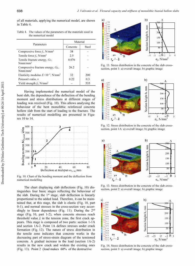
of all materials, applying the numerical model, are shown
in Table 4.
Table 4. The values of the parameters of the materials used in
the numerical model
Parameters Material
Concrete Steel
Compressive force fc, N/mm2 38 –
Tensile force ft, N/mm2 2.5 –
Tensile fracture energy, GF,
Nmm/mm2 0.076 –
Compressive fracture energy, Gfc,
Nmm/mm2
26.2 –
Elasticity modulus E×10–3, N/mm2 32 200
Poisson's ratio, ν 0.22 0.3
Yield strength fy, N/mm2 – 535
Having implemented the numerical model of the
bent slab, the dependence of the deflection of the bending
moment and stress distributions at different stages of
loading was received (Fig. 10). This allows analysing the
behaviour of the bent monolithic reinforced concrete
hollow slab from the start of loading to the fracture. The
results of numerical modelling are presented in Figu-
res 10 to 14.
0
100
200
300
400
500
600
0 20 40 60 80
Fig. 10. Chart of the bending moment and the deflection from
numerical modelling
The chart displaying slab deflections (Fig. 10) dis-
tinguishes four basic stages reflecting the behaviour of
the slab. During the 1st stage, slab deflection is linearly
proportional to the added load. Therefore, it can be main-
tained that, at this stage, the slab is elastic (Fig. 10, part
0-1), and normal stresses in the cross-section vary accor-
dingly to linear dependence (Fig. 11). During the 2nd
stage (Fig. 10, part 1-2), when concrete stresses reach
threshold value ft in the tension zone, the first crack ap-
pears. This stage is composed of two parts: section 1-1A
and section 1A-2. Point 1A defines stresses under crack
formation (Fig. 12). The nature of stress distribution in
the tensile zone indicates that concrete works in the
decreasing part of stress-strain diagram of the tensioned
concrete. A gradual increase in the load (section 1A-2)
results in the new crack and widens the existing ones
(Fig. 13). Point 2 (load makes 60% of the destructive
Fig. 11. Stress distribution in the concrete of the slab cross-
section, point 1: a) overall image; b) graphic image
Fig. 12. Stress distribution in the concrete of the slab cross-
section, point 1A: a) overall image; b) graphic image
Fig. 13. Stress distribution in the concrete of the slab cross-
section, point 2: a) overall image; b) graphic image
Fig. 14. Stress distribution in the concrete of the slab cross-
section, point 3: a) overall image; b) graphic image
Dow
nloa
ded
by [
Viln
ius
Ged
imin
o T
ech
Uni
vers
ity]
at 0
0:24
14
Apr
il 20
15

Journal of Civil Engineering and Management, 2014, 20(5): 693–701
699
load) describes the action of the slab close to the service-
ability limit state. A further rise in the load (Fig. 10, sec-
tion 2-3) does not result in forming new cracks, as those
that appeared at earlier stages develop (opening and
height increase) and, therefore, the height of the compres-
sive zone decreases. This stage lasts until reinforcement
stresses arrive to the yield point. Yield stress formation in
reinforcement is shown by the 3rd deflection point pre-
sented in the diagram (Fig. 10). Further, the load slightly
increases (Fig. 10, section 3-4) until the concrete of the
compressive zone is fractured. The 4th point in the dia-
gram appears as the fracture of the bent monolithic hol-
low slab. The diagram of stresses (Fig. 14) clearly shows
that the real height of the compressive zone is within the
boundaries of the upper flange of the slab.
The obtained results of numerical simulation disclo-
sed that compressive stresses are unevenly distributed in
the upper flange of the slab. The highest compressive
stresses on the flange of the slab can be observed beside
the middle of the inserts, and this zone experiences cracks
in the tension zone and maximum stresses in reinforce-
ment.
5. Comparison of experimental and theoretical results
The obtained results of experimental research on the
stiffness and flexural capacity of hollow reinforced con-
crete slabs were compared with numerical simulation and
theoretical calculations. The received deflection curves of
experimental research and numerical simulation are pre-
sented in Figure 15.
0
100
200
300
400
500
600
0 20 40 60 80 100
Deflection at midspan ω, mm
1 – Numerical modeling
2 – PL1 (experiment)
2
1
a)
0
100
200
300
400
500
600
0 20 40 60 80 100
Ben
din
g m
om
ent
MR, kN
m
Fig. 15. Charts of the bending moment and deflection:
a) slab P1; b) slab P2. 1 – curve of numerical modelling,
2 – experimental curve
A comparison of deflection curves draws a fairly
good agreement of both slab deflection and destructive
force (flexural capacity). A slight difference at the initial
stage of slab loading can be observed (up to 152 kNm).
This is due to the fact that initial micro-cracks weren’t
evaluated while making the numerical model. They
weren’t assessed, because the performed research was
aimed at estimating the behaviour of the reinforced con-
crete slab under operational and fracture loads. Experi-
mental deflections of the slabs ωobs were compared with
the deflections of numerical simulation ωnum and theoreti-
cal calculations ωEN according to EN 1992-1-1 methodo-
logy. The received results are shown in Table 4. On ave-
rage, the difference between the results of numerical
simulation and theoretical calculations and experimental
values makes 10% and 7%, respectively.
Table 4. Comparison of research on slab deflections
Slab Deflections, mm obs
num
ω
ω
obs
EN
ω
ω
Experimental
ωobs*
Calculated
ωnum* ωEN*
P1 18.2 17.7 19
1.03 0.96
P2 20.9 1.18 1.1
* deflections were determined under the load making 60% of
the designed destructive load.
Experimental flexural capacity MR,obs was compared
with flexural capacity established applying numerical si-
mulation MR,num and calculated employing EN 1992-1-1
methodology MR,EN. The obtained results are displayed in
Table 5. Flexural capacity found employing numerical
simulation agrees with the values determined through the
conducted experiments. The difference between flexural
capacities determined with reference to EN 1992-1-1
methodology and that estimated by experiments makes up
to 8%.
Table 5. Comparison of the results of research on the flexural
capacity of the slab
Slab
Flexural capacity, kNm
,
R,obs
R num
M
M
,
,
R obs
R EN
M
M
Experi-
mental
MR,obs*
Calculated
MR,num* MR,EN*
P1 588.4 586 632
1.0 0.93
P2 583.1 0.99 0.92
* bending moments were calculated with reference to the
evaluated self-weight of the slab.
Theoretical and experimental research disclosed that
for investigation into the behaviour of the hollow mono-
lithic reinforced concrete slab, the numerical simulation
method can be successfully applied.
Conclusions
The use of plastic inserts for shaping hollows in the man-
ufacture of monolithic reinforced concrete slabs allows
reducing concrete input by 20–40% compared to similar
slabs having a continuous cross-section and the same
dimensions. A decrease in cement input results in a re-
Dow
nloa
ded
by [
Viln
ius
Ged
imin
o T
ech
Uni
vers
ity]
at 0
0:24
14
Apr
il 20
15

J. Valivonis et al. Flexural capacity and stiffness of monolithic biaxial hollow slabs 700
duction in carbon dioxide released to the atmosphere. Plastic inserts use for shaping hollows are produced from plastic waste, which together with decreased input con-tribute to environmental protection.
The inserts used for shaping hollows cut down the self-weight of the slab, thus insignificantly changing the stiffness of the structure. The experiments on hollow monolithic slabs disclosed that under an operational load, the average deflection of the slab made on average L/280, which is less than the allowed relative deflection of L/250.
The deflection established using numerical simula-tion and calculated according to EN 1992-1-1 methodo-logy changing the real cross-section into the equivalent one has a fairly good agreement with the results of experimental research. The results of numerical model-ling and theoretical calculations differ from experimental values by 10% and 7%, respectively.
The flexural capacity of hollow monolithic slabs found applying numerical simulation completely agrees with the values set by the conducted experiments, whereas the difference between flexural capacities calcu-lated according to EN 1992-1-1 methodology and deter-mined with the help of the performed experiments makes up to 8%.
Experimental and theoretical investigation into the behaviour of hollow monolithic slabs demonstrated that the flexural capacity and deflections of such slabs can be worked out with reference to EN 1992-1-1 methodology changing the actual cross-section with the effective one.
A good agreement of the results of numerical simu-lation and experimental research indicates that numerical simulation can be successfully applied for predicting the flexural capacity and stiffness of hollow monolithic slabs. This allows, while designing similar structures, to analyse their behaviour and reduce the volume of experimental research.
Acknowledgements This work was funded by the European Social Fund Agency, Project No. VP1-3.1-MES-10-V-02-006. References Abramski, M.; Albert, A.; Pfeffer, K.; Schnell, J. 2010.
Experimentelle und numerische Untersuchungen zum Tragverhalten von Stahlbetondecken mit kugelförmigen Hohlkörpern, Beton- und Stahlbetonbau 105(6): 349–361. http://dx.doi.org/10.1002/best.201000031
Balevičius, R.; Marčiukaitis, G. 2013. Linear and non-linear creep models for a multi-layered concrete composite, Ar-chives of Civil and Mechanical Engineering 13(4): 472–490.
Chung, J. H.; Choi, H. K.; Lee, S. C.; Choi, C. S. 2011. Shear capacity of biaxial hollow slab with donut type hollow sphere, Procedia Engineering 14: 2219–2222. http://dx.doi.org/10.1016/j.proeng.2011.07.279
EN 1992-1-1: 2005. Design of concrete structures – Part 1-1: General rules and rules for buildings.
EN 12390-3: 2009. Testing hardened concrete – Part 3: Comp-ressive strength of test specimens.
Fiala, C.; Hajek, P. 2007. Environmentally based optimization of RC slab floor structures, CESB 07 Conference Procee-dings, 24–26 September 2007, Prague, Czech Republic, 416–423.
Gribniak, V.; Kaklauskas, G.; Idnurm, S.; Bačinskas, D. 2010. Finite element mesh size effect on deformation predic-tions of reinforced concrete bridge girder, The Baltic Journal of Road and Bridge Engineering 5(1): 19–27.
Gumilang Jati, D. 2013. Analisis lentur pelat satu arah beton bertulang berongga bola menggunakan metode elemen hingga non linier, in Proc. of Konferensi Nasional Teknik Sipil 7 (KoNTekS 7), 24–26 October 2013, Malaysia.
Hai, L. V.; Hung, V. D.; Thi, T. M.; Nguyen-Thoi, T.; Phuoc, N. T. 2013. The experimental analysis of bubble-deck slab using modified elliptical balls, in Proc. of the Thirteenth East Asia-Pacific Conference on Structural Engineering and Construction (EASEC-13), 11–13 Sep-tember 2013, Sapporo, Japan. 9 p.
Lourenço, P. B. 1996. A user/programmer’s guide for the mic-ro-modeling of masonry structures. TU Delft, report no. 03.21.1.31.35. Delft University of Technology, Delft, the Netherlands.
Marais, C. C.; Robberts, J. M.; van Rensburg, B. W. J. 2010. Spherical void formers in concrete slabs, Journal of the South African Institution of Civil Engineering 52(2): 2–11.
MC90. 1993. CEB-FIB Model Code 1990 for concrete structu-res, CEB Bulletin d’Information, No. 213/214, Comité Euro-International du Béton. Lausanne.
Ordon-Beska, B. 2012. Porównanie materiałochłonności stropu żelbetowego pełnego i stropu bubbledeck, Budownictwo o Zoptymalizowanym Potencjale Energetycznym 1(9): 77–83.
Sandoval, C.; Roca, P. 2012. Study of the influence of different parameters on the buckling behaviour of masonry walls, Construction and Building Materials 35: 888–899. http://dx.doi.org/10.1016/j.conbuildmat.2012.04.053
Santa Cruz Astorqui, J.; del Río Merino, M.; Cache-ro Alonso, G.; Monje García, I.; Rubio Madueño, D. 2009. Fissure analysis in one-directional slabs with on-site concrete rib by continuous formwork, Construction and Building Materials 23(7): 2567–2579. http://dx.doi.org/10.1016/j.conbuildmat.2009.02.020
Schnellenbach-Held, M.; Pfeffer, K. 2002. Punching behavior of biaxial hollow slabs, Cement and Concrete Composites 24(6): 551–556. http://dx.doi.org/10.1016/S0958-9465(01)00071-3
Sergiu, C.; Sergiu, B. 2011. Nonlinear finite elements modeling of spherical voided bi-axial concrete floor slabs, in Proc. of International Symposium of Computational Civil Engi-neering, 81–92.
Sprince, A.; Fischer, G.; Pakrastinsh, L.; Korjakins, A. 2013. Crack propagation in concrete with silica particles, Advanced Materials Research 842: 470–476. http://dx.doi.org/10.4028/www.scientific.net/AMR.842.470
Sprince, A.; Pakrastins, L.; Korjakins, A. 2011. Experimental study on creep of new concrete mixtures, in Proc. of the 3rd International Conference Civil Engineering 2011, 20–26.
TNO Diana. 2011. DIANA finite element analysis, User’s Ma-nual. The Netherlands.
Yang, W.; Yang, Y.; Han, B.; Jiang, P. 2013. Experimental study on mechanical property of corner columns suppor-ted reinforced concrete honeycombed-core girderless floor, The Open Civil Engineering Journal 7: 179–188. http://dx.doi.org/10.2174/1874149501307010170
Dow
nloa
ded
by [
Viln
ius
Ged
imin
o T
ech
Uni
vers
ity]
at 0
0:24
14
Apr
il 20
15

Journal of Civil Engineering and Management, 2014, 20(5): 693–701
701
Juozas VALIVONIS. Prof., Dr at the Department of Reinforced Concrete and Masonry Structures, Vilnius Gediminas Technical University (VGTU). Publications: the author and co-author of more than 92 scientific publications, 4 textbooks, 12 course books. Research interests: theory of reinforced concrete behaviour, composite structures, reinforced concrete bridges. Bronius JONAITIS. Doctor, Associate Professor at the Department of Reinforced Concrete and Masonry Structures, Vilnius Gediminas Technical University. Research interests: theory of reinforced concrete behaviour, masonry and ma-sonry constructions, composite structures, strengthening of structures. Robertas ZAVALIS. Doctor, Assistant at the Department of Reinforced Concrete and Masonry Structures, Vilnius Gediminas Technical University. Research interests: reinforced concrete, masonry and masonry constructions. Tomas SKUTURNA. Doctor, Associate Professor at the Department of Reinforced Concrete and Masonry Structures, Vilnius Gediminas Technical University. Research interests: theory of reinforced concrete behaviour, composite struc-tures, strengthening of reinforced concrete structures. Arnoldas ŠNEIDERIS. Doctor, Associate Professor at the Department of Reinforced Concrete and Masonry structures at Vilnius Gediminas Technical University. Research interests: strengthening of reinforced concrete and masonry structures; behaviour of concrete and reinforced concrete in the fire temperatures; an experimental test of materials and structures.
Dow
nloa
ded
by [
Viln
ius
Ged
imin
o T
ech
Uni
vers
ity]
at 0
0:24
14
Apr
il 20
15
Copyright © 2022 FDOKUMEN