Analysis of Flexural NSRC-HSRC Composite Members ...
9
83 Journal of Sustainable Architecture and Civil Engineering 2014/3/8 JSACE 3/8 Journal of Sustainable Architecture and Civil Engineering Vol. 3 / No. 8 / 2014 pp. 83-91 DOI 10.5755/j01.sace.8.3.7144 © Kaunas University of Technology Received 2014/05/22 Accepted aſter revision 2014/07/05 Analysis of Flexural NSRC-HSRC Composite Members Cracking Behaviour and Concrete Properties Tadas Zingaila*, Mindaugas Augonis Kaunas University of Technology, Faculty of Civil Engineering and Architecture Studentu st. 48, LT-51367 Kaunas, Lithuania *Corresponding author: [email protected] The application of high strength concrete to reinforced concrete structures is very popular nowadays. This paper presents two main topics. In the first part of this paper, it is presented elasto-plastic properties of normal and high strength compressive concrete. It is known that actual behaviour of concrete is nonlinear. Design standard EN 1992-1-1 provides nonlinear stress-strain relation of compressive concrete for structural analysis. Expression to calculate this relation is given in standard. In this article, there are suggested coefficients which evaluate elasto-plastic behaviour of normal and high strength compressive concrete. Good correlation can be observed between stress-strain relation of compressive concrete given in standard EC2 and calculated relation using suggested elasto-plastic coefficients. In the second part of the paper, it is presented an overview of cracking moment calculations of reinforced concrete composite flexural members made from normal and high strength concrete and normal cross-section beams. These calculations were performed using existing design standard, technical construction regulation, structural building code (EN 1992-1-1, STR 2.05.05:2005, ACI 318) and layer method. New approximate values of elasto-plastic coefficients were suggested for tension concrete. KEYWORDS: cracking moment, high strength concrete, stress-strain curve, elasto-plastic behaviour, composite beams. Analysis of Flexural NSRC-HSRC Composite Members Cracking Behaviour and Concrete Properties http://dx.doi.org/10.5755/j01.sace.8.3.7144 The applicability of concrete in structures is very popular due to various reasons: strength, dura- bility, versatility, fire-resistance, etc. Concrete is also known as ecological building material. Me- chanical properties of concrete are continuously studied. It is well known that the real behaviour of the concrete is nonlinear. However, the bigger part of the design standards provide cracking moment calculation methods, where the assumptions are made that the behaviour of the con- crete is elastic (ACI 318; EC2; Mosley, Bungey and Hulse 2007; Wight and MacGregor 2008). When the calculations of cracking moment are performed, it is normal that the compression zone of the flexural member behaves elastically, but the real behaviour of the tension zone is nonlinear. The influence of tension zone nonlinearity should be taken into account when the calculations are performed. However, it can be observed that there are too little publications, books, or other sources about the stress-strain relation of tensile concrete. It is difficult to obtain direct tensile stress-strain curve, therefore limited and conflicting data of tensile concrete stress-strain relation are available (Kumar et al.; Shi et al., 2008). Influence of tensile concrete elasto-plastic behaviour is especially important in serviceability calculations (cracking moment, deflection, curvature, etc.). Introduction
-
Upload
khangminh22 -
Category
Documents
-
view
1 -
download
0
Transcript of Analysis of Flexural NSRC-HSRC Composite Members ...

83Journal of Sustainable Architecture and Civil Engineering 2014/3/8
JSACE 3/8
Journal of Sustainable Architecture and Civil EngineeringVol. 3 / No. 8 / 2014pp. 83-91DOI 10.5755/j01.sace.8.3.7144 © Kaunas University of Technology
Received 2014/05/22
Accepted after revision 2014/07/05
Analysis of Flexural NSRC-HSRC Composite Members Cracking Behaviour and Concrete Properties
Tadas Zingaila*, Mindaugas AugonisKaunas University of Technology, Faculty of Civil Engineering and ArchitectureStudentu st. 48, LT-51367 Kaunas, Lithuania
*Corresponding author: [email protected]
The application of high strength concrete to reinforced concrete structures is very popular nowadays. This paper presents two main topics. In the first part of this paper, it is presented elasto-plastic properties of normal and high strength compressive concrete. It is known that actual behaviour of concrete is nonlinear. Design standard EN 1992-1-1 provides nonlinear stress-strain relation of compressive concrete for structural analysis. Expression to calculate this relation is given in standard. In this article, there are suggested coefficients which evaluate elasto-plastic behaviour of normal and high strength compressive concrete. Good correlation can be observed between stress-strain relation of compressive concrete given in standard EC2 and calculated relation using suggested elasto-plastic coefficients. In the second part of the paper, it is presented an overview of cracking moment calculations of reinforced concrete composite flexural members made from normal and high strength concrete and normal cross-section beams. These calculations were performed using existing design standard, technical construction regulation, structural building code (EN 1992-1-1, STR 2.05.05:2005, ACI 318) and layer method. New approximate values of elasto-plastic coefficients were suggested for tension concrete.
KEYWORDS: cracking moment, high strength concrete, stress-strain curve, elasto-plastic behaviour, composite beams.
Analysis of Flexural NSRC-HSRC Composite Members Cracking Behaviour and Concrete Properties
http://dx.doi.org/10.5755/j01.sace.8.3.7144
The applicability of concrete in structures is very popular due to various reasons: strength, dura-bility, versatility, fire-resistance, etc. Concrete is also known as ecological building material. Me-chanical properties of concrete are continuously studied. It is well known that the real behaviour of the concrete is nonlinear. However, the bigger part of the design standards provide cracking moment calculation methods, where the assumptions are made that the behaviour of the con-crete is elastic (ACI 318; EC2; Mosley, Bungey and Hulse 2007; Wight and MacGregor 2008). When the calculations of cracking moment are performed, it is normal that the compression zone of the flexural member behaves elastically, but the real behaviour of the tension zone is nonlinear. The influence of tension zone nonlinearity should be taken into account when the calculations are performed. However, it can be observed that there are too little publications, books, or other sources about the stress-strain relation of tensile concrete. It is difficult to obtain direct tensile stress-strain curve, therefore limited and conflicting data of tensile concrete stress-strain relation are available (Kumar et al.; Shi et al., 2008). Influence of tensile concrete elasto-plastic behaviour is especially important in serviceability calculations (cracking moment, deflection, curvature, etc.).
Introduction
Journal of Sustainable Architecture and Civil Engineering 2014/3/884
According to STR and EC2, it is assumed that elastic zone of compressive concrete is approxi-mately equal to 0.4ƒcm. However, it is observed that for high strength concrete the zone of elastic stress-strain relation is higher than for normal strength concrete. It was determined by Iravani et al. (1994) that depending on the class of high strength concrete, the value of this coefficient can reach 0.85 or even higher.
Great attention is given to the applicability of high strength concrete to reinforced concrete struc-tures. In order to optimize or improve behaviour of reinforced concrete flexural members, series of analysis are performed. Partial use of high strength concrete can increase stiffness of the rein-forced concrete composite beams, ultimate capacity, initial cracking load and other parameters, when comparing with the beams which are made from normal strength concrete. It is observed that partial use of HSC (high strength concrete) can reduce crack width. Composite beams can be also named as hybrid beams. Various configurations of composite beams layers are possible. Strengthening by high strength concrete can be provided in compression zone, tension zone or in compression and tension zones together. Casting operation of composite NSRC-HSRC (two layers of normal and high strength concrete) beams can be performed in two cases. In the first case, both layers can be cast while the concrete is in fresh condition. This should insure full bond between dif-ferent layers of the concrete. Also, it is observed that transverse reinforcement can increase bond between the layers. In the other case, the second layer of new concrete can be cast when the first layer of concrete reaches its design strength (after 28 days or even later). This case can be applied for the analysis of the structural members which have to be rehabilitated or repaired. Howev-er, long time between casting phases could require additional tools to insure full bond between two layers of the concrete. Application of steel fibre reinforced concrete is common in composite cross-section beams, but in this study only by steel bars reinforced concrete flexural members are analysed (Kheder et al., 2010; Lapko et al., 2005; Sadowska-Buraczewska et al., 2007).
There is no united design standard which provides the calculation method for such type of the flex-ural members. It should be noted that it is necessary to take into account nonlinear behaviour of tension and compression concrete. Therefore, this paper is intended for the analysis of the flexural NSRC-HSRC composite members cracking behaviour and concrete properties.
Estimation of
coefficient λc,lim
according to EC2
stress-strain relation
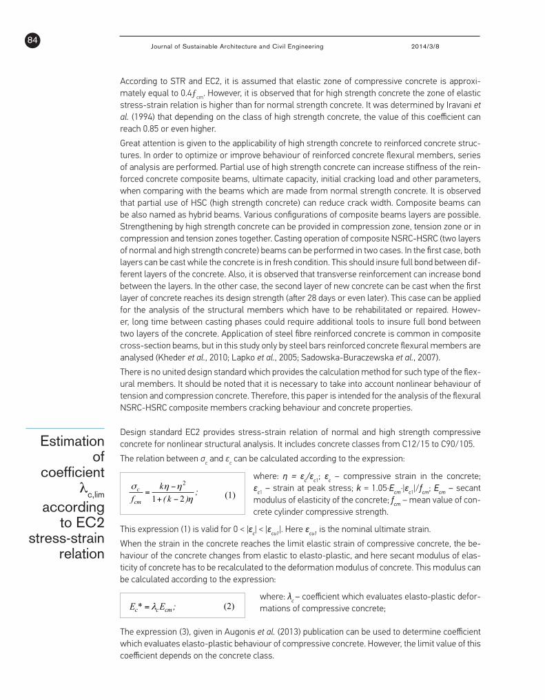
Design standard EC2 provides stress-strain relation of normal and high strength compressive concrete for nonlinear structural analysis. It includes concrete classes from C12/15 to C90/105.
The relation between σc and εc can be calculated according to the expression:
where: η = εc/εc1; εc – compressive strain in the concrete; εc1 – strain at peak stress; k = 1.05·Ecm·|εc1|/fcm; Ecm – secant modulus of elasticity of the concrete; fcm – mean value of con-crete cylinder compressive strength.
flexural NSRC-HSRC composite members cracking behaviour and concrete properties.
2. Estimation of coefficient λc,lim according to EC2 stress-strain relation
Design standard EC2 provides stress-strain relation of normal and high strength compressive concrete for nonlinear structural analysis. It includes concrete classes from C12/15 to C90/105.
The relation between σc and εc can be calculated according to the expression:
;)k(
kfcmc
ηηησ21
2
−+
−= (1)
where: η = εc/εc1; εc – compressive strain in the concrete; εc1 – strain at peak stress; k = 1.05·Ecm·|εc1|/fcm; Ecm – secant modulus of elasticity of the concrete; fcm – mean value of concrete cylinder compressive strength.
This expression (1) is valid for 0 < |εc1| < |εcu1|. Here εcu1 is the nominal ultimate strain.
When the strain in the concrete reaches the limit elastic strain of compressive concrete, the behaviour of the concrete changes from elastic to elasto-plastic, and here secant modulus of elasticity of concrete has to be recalculated to the deformation modulus of concrete. This modulus can be calculated according to the expression:
;E*E cmcc λ=
(2) where: λc – coefficient which evaluates elasto-plastic
deformations of compressive concrete; The expression (3), given in Augonis et al. (2013)
publication can be used to determine coefficient which evaluates elasto-plastic behaviour of compressive concrete. However, the limit value of this coefficient depends on the concrete class.
;kel,clim,c
el,ci,ccc εε
εελ
−
−−=1 (3)
where: kc = 1-λc,lim; λc,lim – the limit value of coefficient which evaluates elasto-plastic deformations of compressive concrete; εc,i – compressive strain in the concrete; εc,el – limit elastic strain of compressive concrete; εc,lim – the limit strain of compressive concrete at the peak stress.
The limit elastic strain of the compressive concrete can be calculated according to the expression:
;Efk
cm
cmc,elel,c
⋅=ε (4)
where: kel,c – coefficient which evaluates the limit of elastic strain of compressive concrete;
The limit strain of compressive concrete at the peak stress can be calculated according to the expression:
;Ef
cmlim,c
cmlim,c λ
ε = (5)
EC2 provides stress-strain relation until the nominal ultimate strain εcu1. In this research cracking moment calculations are performed. The assumption is made that λc,lim values are applied to obtain the limit strain of tensile concrete, due to this reason only the first part of stress-strain relation is analysed (until the limit strain of compressive concrete at the peak stress – εc1). From Fig. 1. can be observed that stress-strain relation calculated according to expression (1), which is given in EC2, has a good correlation with suggested stress-strain relation which is calculated using kel,c and λc,lim coefficients. It also can be seen that with the increase of the concrete class, the linear part of stress-strain relation also increases.
Fig. 1. Comparison of stress-strain relation of compressive concrete calculated according to EN 1992-1-1 and stress-strain relation (*) calculated using coefficients kel,c and λc.
In order to calculate the limit elastic strain of the compressive concrete εc,el, which approximately corresponds the shape of EC2 stress-strain curve, coefficient kel,c is suggested for different concrete classes. The values of this coeficient using mentioned method vary from 0.01 to 0.4 for concrete classes from C20/25 to C45/55, and respectively from 0.5 to 0.65 for the concrete classes from C50/60 to C90/105. It is a tendency that for ultra-high strength concrete the value of this coefficient could be even higher. However, in the cracking moment calculations not less than 0.4 is assumed to evaluate the elastic zone of concrete.
To obtain accurate values of kel,c coefficients, more experimental analysis is necessary. Summary of the specific
This expression (1) is valid for 0 < |εc| < |εcu1|. Here εcu1 is the nominal ultimate strain.
When the strain in the concrete reaches the limit elastic strain of compressive concrete, the be-haviour of the concrete changes from elastic to elasto-plastic, and here secant modulus of elas-ticity of concrete has to be recalculated to the deformation modulus of concrete. This modulus can be calculated according to the expression:
where: λc – coefficient which evaluates elasto-plastic defor-mations of compressive concrete;
The expression (3), given in Augonis et al. (2013) publication can be used to determine coefficient which evaluates elasto-plastic behaviour of compressive concrete. However, the limit value of this coefficient depends on the concrete class.

85Journal of Sustainable Architecture and Civil Engineering 2014/3/8
flexural NSRC-HSRC composite members cracking behaviour and concrete properties.
2. Estimation of coefficient λc,lim according to EC2 stress-strain relation
Design standard EC2 provides stress-strain relation of normal and high strength compressive concrete for nonlinear structural analysis. It includes concrete classes from C12/15 to C90/105.
The relation between σc and εc can be calculated according to the expression:
;)k(
kfcmc
ηηησ21
2
−+
−= (1)
where: η = εc/εc1; εc – compressive strain in the concrete; εc1 – strain at peak stress; k = 1.05·Ecm·|εc1|/fcm; Ecm – secant modulus of elasticity of the concrete; fcm – mean value of concrete cylinder compressive strength.
This expression (1) is valid for 0 < |εc1| < |εcu1|. Here εcu1 is the nominal ultimate strain.
When the strain in the concrete reaches the limit elastic strain of compressive concrete, the behaviour of the concrete changes from elastic to elasto-plastic, and here secant modulus of elasticity of concrete has to be recalculated to the deformation modulus of concrete. This modulus can be calculated according to the expression:
;E*E cmcc λ=
(2) where: λc – coefficient which evaluates elasto-plastic
deformations of compressive concrete; The expression (3), given in Augonis et al. (2013)
publication can be used to determine coefficient which evaluates elasto-plastic behaviour of compressive concrete. However, the limit value of this coefficient depends on the concrete class.
;kel,clim,c
el,ci,ccc εε
εελ
−
−−=1 (3)
where: kc = 1-λc,lim; λc,lim – the limit value of coefficient which evaluates elasto-plastic deformations of compressive concrete; εc,i – compressive strain in the concrete; εc,el – limit elastic strain of compressive concrete; εc,lim – the limit strain of compressive concrete at the peak stress.
The limit elastic strain of the compressive concrete can be calculated according to the expression:
;Efk
cm
cmc,elel,c
⋅=ε (4)
where: kel,c – coefficient which evaluates the limit of elastic strain of compressive concrete;
The limit strain of compressive concrete at the peak stress can be calculated according to the expression:
;Ef
cmlim,c
cmlim,c λ
ε = (5)
EC2 provides stress-strain relation until the nominal ultimate strain εcu1. In this research cracking moment calculations are performed. The assumption is made that λc,lim values are applied to obtain the limit strain of tensile concrete, due to this reason only the first part of stress-strain relation is analysed (until the limit strain of compressive concrete at the peak stress – εc1). From Fig. 1. can be observed that stress-strain relation calculated according to expression (1), which is given in EC2, has a good correlation with suggested stress-strain relation which is calculated using kel,c and λc,lim coefficients. It also can be seen that with the increase of the concrete class, the linear part of stress-strain relation also increases.
Fig. 1. Comparison of stress-strain relation of compressive concrete calculated according to EN 1992-1-1 and stress-strain relation (*) calculated using coefficients kel,c and λc.
In order to calculate the limit elastic strain of the compressive concrete εc,el, which approximately corresponds the shape of EC2 stress-strain curve, coefficient kel,c is suggested for different concrete classes. The values of this coeficient using mentioned method vary from 0.01 to 0.4 for concrete classes from C20/25 to C45/55, and respectively from 0.5 to 0.65 for the concrete classes from C50/60 to C90/105. It is a tendency that for ultra-high strength concrete the value of this coefficient could be even higher. However, in the cracking moment calculations not less than 0.4 is assumed to evaluate the elastic zone of concrete.
To obtain accurate values of kel,c coefficients, more experimental analysis is necessary. Summary of the specific
where: kc = 1-λc,lim; λc,lim – the limit value of coeffi-cient which evaluates elasto-plastic deformations of compressive concrete; εc,i – compressive strain in the concrete; εc,el – limit elastic strain of compressive
The limit elastic strain of the compressive concrete can be calculated according to the expression:
The limit strain of compressive concrete at the peak stress can be calculated according to the expression:
where: kel,c – coefficient which evaluates the limit of elastic strain of compressive concrete;
EC2 provides stress-strain relation until the nominal ultimate strain εcu1. In this research cracking moment calculations are performed. The assumption is made that λc,lim values are applied to obtain the limit strain of tensile concrete, due to this reason only the first part of stress-strain relation is analysed (until the limit strain of compressive concrete at the peak stress – εc1). From Fig. 1. can be observed that stress-strain relation calculated according to expression (1), which is given in EC2, has a good corre-lation with suggested stress-strain re-lation which is calculated using kel,c and λc,lim coefficients. It also can be seen that with the increase of the concrete class, the linear part of stress-strain relation also increases.
In order to calculate the limit elastic strain of the compressive concrete εc,el, which approximately corresponds the shape of EC2 stress-strain curve, coeffi-
Fig. 1Comparison of stress-strain relation of compressive concrete calculated according to EN 1992-1-1 and stress-strain relation (*) calculated using coefficients kel,c and λc.
cient kel,c is suggested for different concrete classes. The values of this coeficient using mentioned method vary from 0.01 to 0.4 for concrete classes from C20/25 to C45/55, and respectively from 0.5 to 0.65 for the concrete classes from C50/60 to C90/105. It is a tendency that for ultra-high strength concrete the value of this coefficient could be even higher. However, in the cracking mo-ment calculations not less than 0.4 is assumed to evaluate the elastic zone of concrete.
To obtain accurate values of kel,c coefficients, more experimental analysis is necessary. Summary of the specific values of approximate coefficients are given in Table 1 and Table 2.
To determine the limit strain of the compressive concrete at the peak stress, λc,lim coefficient is
concrete; εc,lim – the limit strain of compressive concrete at the peak stress.

Journal of Sustainable Architecture and Civil Engineering 2014/3/886
used. The approximate values of this coefficient vary from 0.467 to 0.613 for concrete classes from C20/25 to C45/55, and respectively from 0.640 to 0.795 for the concrete classes from C50/60 to C90/105. The same tencen-cy as for coeffient kel,c remains that for ultra-high strength concrete the value of this coefficient could be even higher. Summary of the specific values of ap-proximate coefficients are given in Table 1 and Table 2.
In Fig. 2. it is presented the variation of λc coefficient, depending on the class of the concrete. The similar values of these coefficients are calculated by Židonis
values of approximate coefficients are given in Table 1 and Table 2.
To determine the limit strain of the compressive concrete at the peak stress, λc,lim coefficient is used. The approximate values of this coeficient vary from 0.467 to 0.613 for concrete classes from C20/25 to C45/55, and respectively from 0.640 to 0.795 for the concrete classes from C50/60 to C90/105. The same tencency as for coeffient kel,c remains that for ultra-high strength concrete the value of this coefficient could be even higher. Summary of the specific values of approximate coefficients are given in Table 1 and Table 2.
In Fig. 2. it is presented the variation of λc coefficient, depending on the class of the concrete. The similar values of these coefficients are calculated by Židonis (2013). It can be observed that elasto-plastic deformations for high strength concrete occurs at much higher strain level than for normal strength concrete. When concrete behaviour is elastic, it is assumed that the deformation modulus of the concrete is equal to secant modulus of elasticity, and then the value of coefficient λc is equal to 1.
Fig. 2. Variation of coefficient λc for different concrete classes
Table 1. Summary of results for concrete classes from C20/25 to C45/55 Characteristics C20/25 C25/30 C30/37 C35/45 C40/50 C45/55
fcm (MPa) 28 33 38 43 48 53 Ecm (MPa) 30000 31000 33000 34000 35000 36000 εc1= εc,lim 0.002 0.0021 0.0022 0.00225 0.0023 0.0024 εcu1 0.0035 0.0035 0.0035 0.0035 0.0035 0.0035 kel,c 0.01 0.10 0.30 0.30 0.40 0.40 λc,lim 0.467 0.507 0.540 0.562 0.596 0.613
kc=1-λc,lim 0.533 0.493 0.460 0.438 0.404 0.387 Table 2. Summary of results for concrete classes from C50/60 to C90/105
Characteristics C50/60 C55/67 C60/75 C70/85 C80/95 C90/105 fcm (MPa) 58 63 68 78 88 98 Ecm (MPa) 37000 38000 39000 41000 42000 44000 εc1= εc,lim 0.00245 0.0025 0.0026 0.0027 0.0028 0.0028 εcu1 0.0035 0.0032 0.003 0.0028 0.0028 0.0028 kel,c 0.50 0.50 0.55 0.60 0.65 0.65 λc,lim 0.640 0.663 0.671 0.705 0.748 0.795
kc=1-λc,lim 0.360 0.337 0.329 0.295 0.252 0.205
3. Calculation of cracking moment according to STR, EC2, ACI 318 and LM
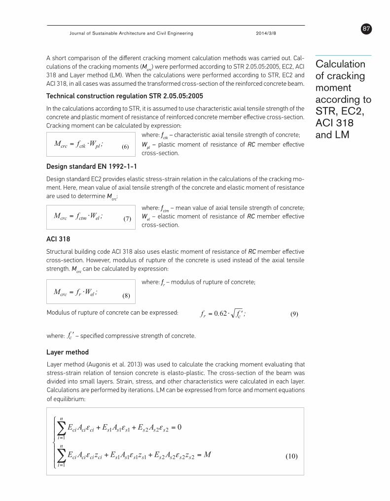
A short comparison of the different cracking moment calculation methods was carried out. Calculations of the cracking moments (Mcrc) were performed according to STR 2.05.05:2005, EC2, ACI 318 and Layer method (LM). When the calculations were performed according to STR, EC2 and ACI 318, in all cases was assumed the transformed cross-section of the reinforced concrete beam.
3.1. Technical construction regulation STR 2.05.05:2005 In the calculations according to STR, it is assumed to
use characteristic axial tensile strength of the concrete and plastic moment of resistance of reinforced concrete member effective cross-section. Cracking moment can be calculated by expression:
;WfM plctkcrc ⋅= (6) where: fctk – characteristic axial tensile strength of concrete;
Wpl – plastic moment of resistance of RC member effective cross-section.
3.2. Design standard EN 1992-1-1 Design standard EC2 provides elastic stress-strain
relation in the calculations of the cracking moment. Here, mean value of axial tensile strength of the concrete and elastic moment of resistance are used to determine Mcrc:
;WfM elctmcrc ⋅= (7)
where: fctm – mean value of axial tensile strength of concrete; Wel – elastic moment of resistance of RC member effective cross-section.
3.3. ACI 318 Structural building code ACI 318 also uses elastic
moment of resistance of RC member effective cross-section. However, modulus of rupture of the concrete is used instead of the axial tensile strength. Mcrc can be calculated by expression:
;WfM elrcrc ⋅= (8)
(2013). It can be observed that elasto-plastic deformations for high strength concrete occurs at much higher strain level than for normal strength concrete. When concrete behaviour is elastic, it is assumed that the deformation modulus of the concrete is equal to secant modulus of elasticity, and then the value of coefficient λc is equal to 1.
Variation of coefficient λc for different concrete classes
Table 1Summary of results for
concrete classes from C20/25 to C45/55
Table 2Summary of results for
concrete classes from C50/60 to C90/105
Characteristics C20/25 C25/30 C30/37 C35/45 C40/50 C45/55
fcm (MPa) 28 33 38 43 48 53
Ecm (MPa) 30000 31000 33000 34000 35000 36000
εc1= εc,lim 0.002 0.0021 0.0022 0.00225 0.0023 0.0024
εcu1 0.0035 0.0035 0.0035 0.0035 0.0035 0.0035
kel,c 0.01 0.10 0.30 0.30 0.40 0.40
λc,lim 0.467 0.507 0.523 0.562 0.596 0.613
kc=1-λc,lim 0.533 0.493 0.477 0.438 0.404 0.387
Characteristics C50/60 C55/67 C60/75 C70/85 C80/95 C90/105
fcm (MPa) 58 63 68 78 88 98
Ecm (MPa) 37000 38000 39000 41000 42000 44000
εc1= εc,lim 0.00245 0.0025 0.0026 0.0027 0.0028 0.0028
εcu1 0.0035 0.0032 0.003 0.0028 0.0028 0.0028
kel,c 0.50 0.50 0.55 0.60 0.65 0.65
λc,lim 0.640 0.663 0.671 0.705 0.748 0.795
kc=1-λc,lim 0.360 0.337 0.329 0.295 0.252 0.205
Fig. 2
87Journal of Sustainable Architecture and Civil Engineering 2014/3/8
values of approximate coefficients are given in Table 1 and Table 2.
To determine the limit strain of the compressive concrete at the peak stress, λc,lim coefficient is used. The approximate values of this coeficient vary from 0.467 to 0.613 for concrete classes from C20/25 to C45/55, and respectively from 0.640 to 0.795 for the concrete classes from C50/60 to C90/105. The same tencency as for coeffient kel,c remains that for ultra-high strength concrete the value of this coefficient could be even higher. Summary of the specific values of approximate coefficients are given in Table 1 and Table 2.
In Fig. 2. it is presented the variation of λc coefficient, depending on the class of the concrete. The similar values of these coefficients are calculated by Židonis (2013). It can be observed that elasto-plastic deformations for high strength concrete occurs at much higher strain level than for normal strength concrete. When concrete behaviour is elastic, it is assumed that the deformation modulus of the concrete is equal to secant modulus of elasticity, and then the value of coefficient λc is equal to 1.
Fig. 2. Variation of coefficient λc for different concrete classes
Table 1. Summary of results for concrete classes from C20/25 to C45/55 Characteristics C20/25 C25/30 C30/37 C35/45 C40/50 C45/55
fcm (MPa) 28 33 38 43 48 53 Ecm (MPa) 30000 31000 33000 34000 35000 36000 εc1= εc,lim 0.002 0.0021 0.0022 0.00225 0.0023 0.0024 εcu1 0.0035 0.0035 0.0035 0.0035 0.0035 0.0035 kel,c 0.01 0.10 0.30 0.30 0.40 0.40 λc,lim 0.467 0.507 0.540 0.562 0.596 0.613
kc=1-λc,lim 0.533 0.493 0.460 0.438 0.404 0.387 Table 2. Summary of results for concrete classes from C50/60 to C90/105
Characteristics C50/60 C55/67 C60/75 C70/85 C80/95 C90/105 fcm (MPa) 58 63 68 78 88 98 Ecm (MPa) 37000 38000 39000 41000 42000 44000 εc1= εc,lim 0.00245 0.0025 0.0026 0.0027 0.0028 0.0028 εcu1 0.0035 0.0032 0.003 0.0028 0.0028 0.0028 kel,c 0.50 0.50 0.55 0.60 0.65 0.65 λc,lim 0.640 0.663 0.671 0.705 0.748 0.795
kc=1-λc,lim 0.360 0.337 0.329 0.295 0.252 0.205
3. Calculation of cracking moment according to STR, EC2, ACI 318 and LM
A short comparison of the different cracking moment calculation methods was carried out. Calculations of the cracking moments (Mcrc) were performed according to STR 2.05.05:2005, EC2, ACI 318 and Layer method (LM). When the calculations were performed according to STR, EC2 and ACI 318, in all cases was assumed the transformed cross-section of the reinforced concrete beam.
3.1. Technical construction regulation STR 2.05.05:2005 In the calculations according to STR, it is assumed to
use characteristic axial tensile strength of the concrete and plastic moment of resistance of reinforced concrete member effective cross-section. Cracking moment can be calculated by expression:
;WfM plctkcrc ⋅= (6) where: fctk – characteristic axial tensile strength of concrete;
Wpl – plastic moment of resistance of RC member effective cross-section.
3.2. Design standard EN 1992-1-1 Design standard EC2 provides elastic stress-strain
relation in the calculations of the cracking moment. Here, mean value of axial tensile strength of the concrete and elastic moment of resistance are used to determine Mcrc:
;WfM elctmcrc ⋅= (7)
where: fctm – mean value of axial tensile strength of concrete; Wel – elastic moment of resistance of RC member effective cross-section.
3.3. ACI 318 Structural building code ACI 318 also uses elastic
moment of resistance of RC member effective cross-section. However, modulus of rupture of the concrete is used instead of the axial tensile strength. Mcrc can be calculated by expression:
;WfM elrcrc ⋅= (8)
Calculation of cracking moment according to STR, EC2, ACI 318 and LM
A short comparison of the different cracking moment calculation methods was carried out. Cal-culations of the cracking moments (Mcrc) were performed according to STR 2.05.05:2005, EC2, ACI 318 and Layer method (LM). When the calculations were performed according to STR, EC2 and ACI 318, in all cases was assumed the transformed cross-section of the reinforced concrete beam.
Technical construction regulation STR 2.05.05:2005
In the calculations according to STR, it is assumed to use characteristic axial tensile strength of the concrete and plastic moment of resistance of reinforced concrete member effective cross-section. Cracking moment can be calculated by expression:
where: fctk – characteristic axial tensile strength of concrete;
Wpl – plastic moment of resistance of RC member effective cross-section.
Design standard EN 1992-1-1
Design standard EC2 provides elastic stress-strain relation in the calculations of the cracking mo-ment. Here, mean value of axial tensile strength of the concrete and elastic moment of resistance are used to determine Mcrc:
where: fctm – mean value of axial tensile strength of concrete; Wel – elastic moment of resistance of RC member effective cross-section.
ACI 318
Structural building code ACI 318 also uses elastic moment of resistance of RC member effective cross-section. However, modulus of rupture of the concrete is used instead of the axial tensile strength. Mcrc can be calculated by expression:
where: fr – modulus of rupture of concrete;
Modulus of rupture of concrete can be expressed:
where: fr – modulus of rupture of concrete;
Modulus of rupture of concrete can be expressed:
;'f.fr ⋅= 620 (9)
where: f ’ – specified compressive strength of concrete.
3.4. Layer method Layer method was used to calculate the cracking
force and moment equations of equilibrium:
⎪⎪
⎩
⎪⎪
⎨
⎧
=++
=++
∑
∑
=
=
MzAEzAEzAE
AEAEAE
n
isssssssscicicici
n
isssssscicici
122221111
1222111 0
εεε
εεε
(10) where: Eci – deformation modulus of concrete of i layer; Aci – area of concrete of i layer, εci – strain of concrete in i layer (“+” in compression zone, “-” in tension zone); zci – arm of force acting in concrete i layer (distance from the center of the most tension layer to the center of i layer); Es1, Es2 – design value of modulus of elasticity of reinforcing steel; εs1, εs2 – strain in tension (“-”) and compression (“+”) reinforcement; zs1, zs2 – arm of force acting in reinforcement (distance from the center of the most tension layer to the center of reinforcement); M – external bending moment.
Expression (3) is given to calculate coefficient which evaluates elasto-plastic behaviour of compressive concrete. Good correlation was obtained between calculated stress-strain curve and EC2 stress-strain relation. However, to evaluate elasto-plastic behaviour of tension concrete in cracking moment calculations, more accurate expression was suggested. Coefficients λct can be calculated according to the experssion:
( )
( );
fE
f
el,ctct
ci,ctlim,ct
el,ctct
el,ctlim,ct
ct
⎟⎟⎠
⎞⎜⎜⎝
⎛
−
⋅−−+
⎟⎟⎠
⎞⎜⎜⎝
⎛
−
−−+
=
σ
ελ
σ
σλ
λ1
1
11
(11)
where: λct,lim – the limit value of coefficient which evaluates elasto-plastic deformations of tensile concrete, fctk – characteristic axial tensile strength of concrete; σct,el – the limit elastic stress of tensile concrete; εct,i – strain of tensile concrete in i layer; Ec – modulus of elasticity of concrete.
The parameters of the beams cross-sections are given below. Such parameters were used in order to compare calculated values of Mcrc with experimental values. Experimental values of the cracking moments were calculated according to the information (initial cracking load, loading scheme, etc.) given in Kheder et al. (2010) publication. Therefore, some data were used from these
scientists’ experimental research. Cross-sections of the beams are given in Fig. 3.
Three different types of the beams were used: • normal strength concrete beams (275(h)×175(b)); • high strength concrete beams (275(h)×175(b)); • composite beams from normal and high strength
concrete (90(h2)/185(h1)×175(b)). Normal strength concrete beams were strengthened by
high strength concrete layer in compression zone. Approximately 20 MPa normal strength concrete and about 70 MPa high strength concrete was used in Kheder et al. (2010) experiment.
The beams were double reinforced. Four types of reinforcement were used for beams.
• tension reinforcement: 2ø16, 3ø16 (as1 – 34 mm), 2ø25, 3ø25 (as1 – 38.5 mm), (Es1 – 205000 MPa),
• compression reinforcement: 2ø6 (not given in publication, so assumed that as2 – 34 and 38.5 mm), (Es2 – 210000 MPa).
Fig. 3. Parameters of beams cross-sections
Cylindrical compressive strength and modulus of elasticity of tested beams were used from Kheder et al. (2010) experiment. Tensile strength of the concrete was calculated according to EC2 expressions and it is presented in Table 3.
Table 3. Properties of tested concrete (Kheder et al. 2010)
Specimen No. fck (MPa) fctk (MPa) Ec (MPa) NSC/HSC NSC/HSC NSC/HSC
NSRC/402 23.6/– 1.728/– 24880/– NSRC/603 23/– 1.698/– 22540/– NSRC/982 21/– 1.598/– 21530/–
NSRC/1473 22/– 1.649/– 22000/– HSRC/402 –/65.4 –/3.148 –/38000 HSRC/603 –/71.7 –/3.256 –/39800 HSRC/982 –/74.9 –/3.308 –/40660
HSRC/1473 –/68.8 –/3.207 –/39000 NHSRC/402 22/71.4 1.649/3.251 23950/41870 NHSRC/603 22/71.1 1.649/3.246 23700/41520 NHSRC/982 21.2/68.3 1.609/3.198 22460/39850
NHSRC/1473 22.3/73.7 1.664/3.288 24210/42530 where: xxxx/y: xxxx – strength of concrete (N – normal,
H – high, NH – composite beam from normal and high strength of concrete); R – reinforced; y – area of tension reinforcement (mm2); fctk – characteristic axial tensile strength of concrete calculated according to EC2; fck – characteristic axial compressive strength of concrete; Ec – modulus of elasticity of concrete
c
c
where: fr – modulus of rupture of concrete;
Modulus of rupture of concrete can be expressed:
;'f.fr ⋅= 620 (9)
where: f ’ – specified compressive strength of concrete.
3.4. Layer method Layer method was used to calculate the cracking
moment evaluating that stress-strain relation of tension
:
⎪⎪
⎩
⎪⎪
⎨
⎧
=++
=++
∑
∑
=
=
MzAEzAEzAE
AEAEAE
n
isssssssscicicici
n
isssssscicici
122221111
1222111 0
εεε
εεε
(10) where: Eci – deformation modulus of concrete of i layer; Aci – area of concrete of i layer, εci – strain of concrete in i layer (“+” in compression zone, “-” in tension zone); zci – arm of force acting in concrete i layer (distance from the center of the most tension layer to the center of i layer); Es1, Es2 – design value of modulus of elasticity of reinforcing steel; εs1, εs2 – strain in tension (“-”) and compression (“+”) reinforcement; zs1, zs2 – arm of force acting in reinforcement (distance from the center of the most tension layer to the center of reinforcement); M – external bending moment.
Expression (3) is given to calculate coefficient which evaluates elasto-plastic behaviour of compressive concrete. Good correlation was obtained between calculated stress-strain curve and EC2 stress-strain relation. However, to evaluate elasto-plastic behaviour of tension concrete in cracking moment calculations, more accurate expression was suggested. Coefficients λct can be calculated according to the experssion:
( )
( );
fE
f
el,ctct
ci,ctlim,ct
el,ctct
el,ctlim,ct
ct
⎟⎟⎠
⎞⎜⎜⎝
⎛
−
⋅−−+
⎟⎟⎠
⎞⎜⎜⎝
⎛
−
−−+
=
σ
ελ
σ
σλ
λ1
1
11
(11)
where: λct,lim – the limit value of coefficient which evaluates elasto-plastic deformations of tensile concrete, fctk – characteristic axial tensile strength of concrete; σct,el – the limit elastic stress of tensile concrete; εct,i – strain of tensile concrete in i layer; Ec – modulus of elasticity of concrete.
The parameters of the beams cross-sections are given below. Such parameters were used in order to compare calculated values of Mcrc with experimental values. Experimental values of the cracking moments were calculated according to the information (initial cracking load, loading scheme, etc.) given in Kheder et al. (2010) publication. Therefore, some data were used from these
scientists’ experimental research. Cross-sections of the beams are given in Fig. 3.
Three different types of the beams were used: • normal strength concrete beams (275(h)×175(b)); • high strength concrete beams (275(h)×175(b)); • composite beams from normal and high strength
concrete (90(h2)/185(h1)×175(b)). Normal strength concrete beams were strengthened by
high strength concrete layer in compression zone. Approximately 20 MPa normal strength concrete and about 70 MPa high strength concrete was used in Kheder et al. (2010) experiment.
The beams were double reinforced. Four types of , 3ø16 (as1 – 34 mm),
( , (Es1 – 205000 MPa), : 2ø6 (not given in
publication, so assumed that as2 – 34 and 38.5 mm), (Es2 – 210000 MPa).
Fig. 3. Parameters of beams cross-sections
Cylindrical compressive strength and modulus of elasticity of tested beams were used from Kheder et al. (2010) experiment. Tensile strength of the concrete was calculated according to EC2 expressions and it is presented in Table 3.
Table 3. Properties of tested concrete (Kheder et al. 2010)
Specimen No. fck (MPa) fctk (MPa) Ec (MPa) NSC/HSC NSC/HSC NSC/HSC
NSRC/402 23.6/– 1.728/– 24880/– NSRC/603 23/– 1.698/– 22540/– NSRC/982 21/– 1.598/– 21530/–
NSRC/1473 22/– 1.649/– 22000/– HSRC/402 –/65.4 –/3.148 –/38000 HSRC/603 –/71.7 –/3.256 –/39800 HSRC/982 –/74.9 –/3.308 –/40660
HSRC/1473 –/68.8 –/3.207 –/39000 NHSRC/402 22/71.4 1.649/3.251 23950/41870 NHSRC/603 22/71.1 1.649/3.246 23700/41520 NHSRC/982 21.2/68.3 1.609/3.198 22460/39850
NHSRC/1473 22.3/73.7 1.664/3.288 24210/42530 where: xxxx/y: xxxx – strength of concrete (N – normal,
H – high, NH – composite beam from normal and high strength of concrete); R – reinforced; y – area of tension reinforcement (mm2); fctk – characteristic axial tensile strength of concrete calculated according to EC2; fck – characteristic axial compressive strength of concrete; Ec – modulus of elasticity of concrete
c
c
where: fr – modulus of rupture of concrete;
Modulus of rupture of concrete can be expressed:
;'f.fr ⋅= 620 (9)
where: f ’ – specified compressive strength of concrete.
3.4. Layer method Layer method was used to calculate the cracking
moment evaluating that stress-strain relation of tension concrete is elasto-plastic. The cross-section of the beam was
Calculations LM can be expressed from
:
⎪⎪
⎩
⎪⎪
⎨
⎧
=++
=++
∑
∑
=
=
MzAEzAEzAE
AEAEAE
n
isssssssscicicici
n
isssssscicici
122221111
1222111 0
εεε
εεε
(10) where: Eci – deformation modulus of concrete of i layer; Aci – area of concrete of i layer, εci – strain of concrete in i layer (“+” in compression zone, “-” in tension zone); zci – arm of force acting in concrete i layer (distance from the center of the most tension layer to the center of i layer); Es1, Es2 – design value of modulus of elasticity of reinforcing steel; εs1, εs2 – strain in tension (“-”) and compression (“+”) reinforcement; zs1, zs2 – arm of force acting in reinforcement (distance from the center of the most tension layer to the center of reinforcement); M – external bending moment.
Expression (3) is given to calculate coefficient which evaluates elasto-plastic behaviour of compressive concrete. Good correlation was obtained between calculated stress-strain curve and EC2 stress-strain relation. However, to evaluate elasto-plastic behaviour of tension concrete in cracking moment calculations, more accurate expression was suggested. Coefficients λct can be calculated according to the experssion:
( )
( );
fE
f
el,ctct
ci,ctlim,ct
el,ctct
el,ctlim,ct
ct
⎟⎟⎠
⎞⎜⎜⎝
⎛
−
⋅−−+
⎟⎟⎠
⎞⎜⎜⎝
⎛
−
−−+
=
σ
ελ
σ
σλ
λ1
1
11
(11)
where: λct,lim – the limit value of coefficient which evaluates elasto-plastic deformations of tensile concrete, fctk – characteristic axial tensile strength of concrete; σct,el – the limit elastic stress of tensile concrete; εct,i – strain of tensile concrete in i layer; Ec – modulus of elasticity of concrete.
The parameters of the beams cross-sections are given below. Such parameters were used in order to compare calculated values of Mcrc with experimental values. Experimental values of the cracking moments were calculated according to the information (initial cracking load, loading scheme, etc.) given in Kheder et al. (2010) publication. Therefore, some data were used from these
scientists’ experimental research. Cross-sections of the beams are given in Fig. 3.
Three different types of the beams were used: • normal strength concrete beams (275(h)×175(b)); • high strength concrete beams (275(h)×175(b)); • composite beams from normal and high strength
concrete (90(h2)/185(h1)×175(b)). Normal strength concrete beams were strengthened by
high strength concrete layer in compression zone. Approximately 20 MPa normal strength concrete and about 70 MPa high strength concrete was used in Kheder et al. (2010) experiment.
The beams were double reinforced. Four types of reinforcement were used for beams.
• tension reinforcement: 2ø16, 3ø16 (as1 – 34 mm), 2ø25, 3ø25 (as1 – 38.5 mm), (Es1 – 205000 MPa),
• compression reinforcement: 2ø6 (not given in publication, so assumed that as2 – 34 and 38.5 mm), (Es2 – 210000 MPa).
Fig. 3. Parameters of beams cross-sections
Cylindrical compressive strength and modulus of elasticity of tested beams were used from Kheder et al. (2010) experiment. Tensile strength of the concrete was calculated according to EC2 expressions and it is presented in Table 3.
Table 3. Properties of tested concrete (Kheder et al. 2010)
Specimen No. fck (MPa) fctk (MPa) Ec (MPa) NSC/HSC NSC/HSC NSC/HSC
NSRC/402 23.6/– 1.728/– 24880/– NSRC/603 23/– 1.698/– 22540/– NSRC/982 21/– 1.598/– 21530/–
NSRC/1473 22/– 1.649/– 22000/– HSRC/402 –/65.4 –/3.148 –/38000 HSRC/603 –/71.7 –/3.256 –/39800 HSRC/982 –/74.9 –/3.308 –/40660
HSRC/1473 –/68.8 –/3.207 –/39000 NHSRC/402 22/71.4 1.649/3.251 23950/41870 NHSRC/603 22/71.1 1.649/3.246 23700/41520 NHSRC/982 21.2/68.3 1.609/3.198 22460/39850
NHSRC/1473 22.3/73.7 1.664/3.288 24210/42530 where: xxxx/y: xxxx – strength of concrete (N – normal,
H – high, NH – composite beam from normal and high strength of concrete); R – reinforced; y – area of tension reinforcement (mm2); fctk – characteristic axial tensile strength of concrete calculated according to EC2; fck – characteristic axial compressive strength of concrete; Ec – modulus of elasticity of concrete
c
c
where: fr – modulus of rupture of concrete;
Modulus of rupture of concrete can be expressed:
;'f.fr ⋅= 620 (9)
where: f ’ – specified compressive strength of concrete.
3.4. Layer method Layer method was used to calculate the cracking
moment evaluating that stress-strain relation of tension
⎪⎪
⎩
⎪⎪
⎨
⎧
=++
=++
∑
∑
=
=
MzAEzAEzAE
AEAEAE
n
isssssssscicicici
n
isssssscicici
122221111
1222111 0
εεε
εεε
(10) where: Eci – deformation modulus of concrete of i layer; Aci – area of concrete of i layer, εci – strain of concrete in i layer (“+” in compression zone, “-” in tension zone); zci – arm of force acting in concrete i layer (distance from the center of the most tension layer to the center of i layer); Es1, Es2 – design value of modulus of elasticity of reinforcing steel; εs1, εs2 – strain in tension (“-”) and compression (“+”) reinforcement; zs1, zs2 – arm of force acting in reinforcement (distance from the center of the most tension layer to the center of reinforcement); M – external bending moment.
Expression (3) is given to calculate coefficient which evaluates elasto-plastic behaviour of compressive concrete. Good correlation was obtained between calculated stress-strain curve and EC2 stress-strain relation. However, to evaluate elasto-plastic behaviour of tension concrete in cracking moment calculations, more accurate expression was suggested. Coefficients λct can be calculated according to the experssion:
( )
( );
fE
f
el,ctct
ci,ctlim,ct
el,ctct
el,ctlim,ct
ct
⎟⎟⎠
⎞⎜⎜⎝
⎛
−
⋅−−+
⎟⎟⎠
⎞⎜⎜⎝
⎛
−
−−+
=
σ
ελ
σ
σλ
λ1
1
11
(11)
where: λct,lim – the limit value of coefficient which evaluates elasto-plastic deformations of tensile concrete, fctk – characteristic axial tensile strength of concrete; σct,el – the limit elastic stress of tensile concrete; εct,i – strain of tensile concrete in i layer; Ec – modulus of elasticity of concrete.
The parameters of the beams cross-sections are given below. Such parameters were used in order to compare calculated values of Mcrc with experimental values. Experimental values of the cracking moments were calculated according to the information (initial cracking load, loading scheme, etc.) given in Kheder et al. (2010) publication. Therefore, some data were used from these
scientists’ experimental research. Cross-sections of the beams are given in Fig. 3.
Three different types of the beams were used: • normal strength concrete beams (275(h)×175(b)); • high strength concrete beams (275(h)×175(b)); • composite beams from normal and high strength
concrete (90(h2)/185(h1)×175(b)). Normal strength concrete beams were strengthened by
high strength concrete layer in compression zone. Approximately 20 MPa normal strength concrete and about 70 MPa high strength concrete was used in Kheder et al. (2010) experiment.
, 3ø16 (as1 – 34 mm),
(as1 – 38.5 mm), (Es1 – 205000 MPa), : 2ø6 (not given in
publication, so assumed that as2 – 34 and 38.5 mm), (Es2 – 210000 MPa).
Fig. 3. Parameters of beams cross-sections
Cylindrical compressive strength and modulus of elasticity of tested beams were used from Kheder et al. (2010) experiment. Tensile strength of the concrete was calculated according to EC2 expressions and it is presented in Table 3.
Table 3. Properties of tested concrete (Kheder et al. 2010)
Specimen No. fck (MPa) fctk (MPa) Ec (MPa) NSC/HSC NSC/HSC NSC/HSC
NSRC/402 23.6/– 1.728/– 24880/– NSRC/603 23/– 1.698/– 22540/– NSRC/982 21/– 1.598/– 21530/–
NSRC/1473 22/– 1.649/– 22000/– HSRC/402 –/65.4 –/3.148 –/38000 HSRC/603 –/71.7 –/3.256 –/39800 HSRC/982 –/74.9 –/3.308 –/40660
HSRC/1473 –/68.8 –/3.207 –/39000 NHSRC/402 22/71.4 1.649/3.251 23950/41870 NHSRC/603 22/71.1 1.649/3.246 23700/41520 NHSRC/982 21.2/68.3 1.609/3.198 22460/39850
NHSRC/1473 22.3/73.7 1.664/3.288 24210/42530 where: xxxx/y: xxxx – strength of concrete (N – normal,
H – high, NH – composite beam from normal and high strength of concrete); R – reinforced; y – area of tension reinforcement (mm2); fctk – characteristic axial tensile strength of concrete calculated according to EC2; fck – characteristic axial compressive strength of concrete; Ec – modulus of elasticity of concrete
c
cwhere:
where: fr – modulus of rupture of concrete;
Modulus of rupture of concrete can be expressed:
;'f.fr ⋅= 620 (9)
where: f ’ – specified compressive strength of concrete.
divided into small layers. Strain, stress, and other characteristics were calculated in each layer. Calculations are performed by iterations. LM can be expressed from force and moment equations of equilibrium:
⎪⎪
⎩
⎪⎪
⎨
⎧
=++
=++
∑
∑
=
=
MzAEzAEzAE
AEAEAE
n
isssssssscicicici
n
isssssscicici
122221111
1222111 0
εεε
εεε
(10) where: Eci – deformation modulus of concrete of i layer; Aci – area of concrete of i layer, εci – strain of concrete in i layer (“+” in compression zone, “-” in tension zone); zci – arm of force acting in concrete i layer (distance from the center of the most tension layer to the center of i layer); Es1, Es2 – design value of modulus of elasticity of reinforcing steel; εs1, εs2 – strain in tension (“-”) and compression (“+”) reinforcement; zs1, zs2 – arm of force acting in reinforcement (distance from the center of the most tension layer to the center of reinforcement); M – external bending moment.
Expression (3) is given to calculate coefficient which evaluates elasto-plastic behaviour of compressive concrete. Good correlation was obtained between calculated stress-strain curve and EC2 stress-strain relation. However, to evaluate elasto-plastic behaviour of tension concrete in cracking moment calculations, more accurate expression was suggested. Coefficients λct can be calculated according to the experssion:
( )
( );
fE
f
el,ctct
ci,ctlim,ct
el,ctct
el,ctlim,ct
ct
⎟⎟⎠
⎞⎜⎜⎝
⎛
−
⋅−−+
⎟⎟⎠
⎞⎜⎜⎝
⎛
−
−−+
=
σ
ελ
σ
σλ
λ1
1
11
(11)
where: λct,lim – the limit value of coefficient which evaluates elasto-plastic deformations of tensile concrete, fctk – characteristic axial tensile strength of concrete; σct,el – the limit elastic stress of tensile concrete; εct,i – strain of tensile concrete in i layer; Ec – modulus of elasticity of concrete.
The parameters of the beams cross-sections are given below. Such parameters were used in order to compare calculated values of Mcrc with experimental values. Experimental values of the cracking moments were calculated according to the information (initial cracking load, loading scheme, etc.) given in Kheder et al. (2010) publication. Therefore, some data were used from these
scientists’ experimental research. Cross-sections of the beams are given in Fig. 3.
Three different types of the beams were used: • normal strength concrete beams (275(h)×175(b)); • high strength concrete beams (275(h)×175(b)); • composite beams from normal and high strength
concrete (90(h2)/185(h1)×175(b)). Normal strength concrete beams were strengthened by
high strength concrete layer in compression zone.
et al.
• tension reinforcement: 2ø16, 3ø16 (as1 – 34 mm),
2ø25, 3ø25 (as1 – 38.5 mm), (Es1 – 205000 MPa), • compression reinforcement: 2ø6 (not given in
publication, so assumed that as2 – 34 and 38.5 mm), (Es2 – 210000 MPa).
Fig. 3. Parameters of beams cross-sections
Cylindrical compressive strength and modulus of elasticity of tested beams were used from Kheder et al. (2010) experiment. Tensile strength of the concrete was calculated according to EC2 expressions and it is presented in Table 3.
Table 3. Properties of tested concrete (Kheder et al. 2010)
Specimen No. fck (MPa) fctk (MPa) Ec (MPa) NSC/HSC NSC/HSC NSC/HSC
NSRC/402 23.6/– 1.728/– 24880/– NSRC/603 23/– 1.698/– 22540/– NSRC/982 21/– 1.598/– 21530/–
NSRC/1473 22/– 1.649/– 22000/– HSRC/402 –/65.4 –/3.148 –/38000 HSRC/603 –/71.7 –/3.256 –/39800 HSRC/982 –/74.9 –/3.308 –/40660
HSRC/1473 –/68.8 –/3.207 –/39000 NHSRC/402 22/71.4 1.649/3.251 23950/41870 NHSRC/603 22/71.1 1.649/3.246 23700/41520 NHSRC/982 21.2/68.3 1.609/3.198 22460/39850
NHSRC/1473 22.3/73.7 1.664/3.288 24210/42530 where: xxxx/y: xxxx – strength of concrete (N – normal,
H – high, NH – composite beam from normal and high strength of concrete); R – reinforced; y – area of tension reinforcement (mm2); fctk – characteristic axial tensile strength of concrete calculated according to EC2; fck – characteristic axial compressive strength of concrete; Ec – modulus of elasticity of concrete
c
c
– specified compressive strength of concrete.
Layer method
Layer method (Augonis et al. 2013) was used to calculate the cracking moment evaluating that stress-strain relation of tension concrete is elasto-plastic. The cross-section of the beam was divided into small layers. Strain, stress, and other characteristics were calculated in each layer. Calculations are performed by iterations. LM can be expressed from force and moment equations of equilibrium:

Journal of Sustainable Architecture and Civil Engineering 2014/3/888
where: Eci – deformation modulus of concrete of i layer; Aci – area of concrete of i layer, εci – strain of concrete in i layer (“+” in compression zone, “-” in tension zone); zci – arm of force acting in concrete i layer (distance from the center of the most tension layer to the center of i layer); Es1, Es2 – design value of modulus of elasticity of reinforcing steel; εs1, εs2 – strain in tension (“-”) and compression (“+”) reinforcement; zs1, zs2 – arm of force acting in reinforcement (distance from the center of the most tension layer to the center of reinforcement); M – external bending moment.
Expression (3) is given to calculate coefficient which evaluates elasto-plastic behaviour of com-pressive concrete. Good correlation was obtained between calculated stress-strain curve and EC2 stress-strain relation. However, to evaluate elasto-plastic behaviour of tension concrete in crack-ing moment calculations, more accurate expression was suggested. Coefficients λct can be calcu-lated according to the experssion:
where: fr – modulus of rupture of concrete;
Modulus of rupture of concrete can be expressed:
;'f.fr ⋅= 620 (9)
where: f’ – specified compressive strength of concrete.
3.4. Layer method Layer method was used to calculate the cracking
moment evaluating that stress-strain relation of tension concrete is elasto-plastic. The cross-section of the beam was divided into small layers. Strain, stress, and other characteristics were calculated in each layer. Calculations are performed by iterations. LM can be expressed from force and moment equations of equilibrium:
⎪⎪
⎩
⎪⎪
⎨
⎧
=++
=++
∑
∑
=
=
MzAEzAEzAE
AEAEAE
n
isssssssscicicici
n
isssssscicici
122221111
1222111 0
εεε
εεε
(10) where: Eci – deformation modulus of concrete of i layer; Aci – area of concrete of i layer, εci – strain of concrete in i layer (“+” in compression zone, “-” in tension zone); zci – arm of force acting in concrete i layer (distance from the center of the most tension layer to the center of i layer); Es1, Es2 – design value of modulus of elasticity of reinforcing steel; εs1, εs2 – strain in tension (“-”) and compression (“+”) reinforcement; zs1, zs2 – arm of force acting in reinforcement (distance from the center of the most tension layer to the center of reinforcement); M – external bending moment.
Expression (3) is given to calculate coefficient which evaluates elasto-plastic behaviour of compressive concrete. Good correlation was obtained between calculated stress-strain curve and EC2 stress-strain relation. However, to evaluate elasto-plastic behaviour of tension concrete in cracking moment calculations, more accurate expression was suggested. Coefficients λct can be calculated according to the experssion:
(11)
where: λct,lim – the limit value of coefficient which evaluates elasto-plastic deformations of tensile concrete, fctk – characteristic axial tensile strength of concrete; σct,el – the limit elastic stress of tensile concrete; εct,i – strain of tensile concrete in i layer; Ec – modulus of elasticity of concrete.
The parameters of the beams cross-sections are given below. Such parameters were used in order to compare calculated values of Mcrc with experimental values. Experimental values of the cracking moments were calculated according to the information (initial cracking load, loading scheme, etc.) given in Kheder et al. (2010) publication. Therefore, some data were used from these
scientists’ experimental research. Cross-sections of the beams are given in Fig. 3.
Three different types of the beams were used: • normal strength concrete beams (275(h)×175(b)); • high strength concrete beams (275(h)×175(b)); • composite beams from normal and high strength
concrete (90(h2)/185(h1)×175(b)). Normal strength concrete beams were strengthened by
high strength concrete layer in compression zone. Approximately 20 MPa normal strength concrete and about 70 MPa high strength concrete was used in Kheder et al. (2010) experiment.
The beams were double reinforced. Four types of reinforcement were used for beams.
• tension reinforcement: 2ø16, 3ø16 (as1 – 34 mm), 2ø25, 3ø25 (as1 – 38.5 mm), (Es1 – 205000 MPa),
• compression reinforcement: 2ø6 (not given in publication, so assumed that as2 – 34 and 38.5 mm), (Es2 – 210000 MPa).
Fig. 3. Parameters of beams cross-sections
Cylindrical compressive strength and modulus of elasticity of tested beams were used from Kheder et al. (2010) experiment. Tensile strength of the concrete was calculated according to EC2 expressions and it is presented in Table 3.
Table 3. Properties of tested concrete (Kheder et al. 2010)
Specimen No. fck (MPa) fctk (MPa) Ec (MPa) NSC/HSC NSC/HSC NSC/HSC
NSRC/402 23.6/– 1.728/– 24880/– NSRC/603 23/– 1.698/– 22540/– NSRC/982 21/– 1.598/– 21530/–
NSRC/1473 22/– 1.649/– 22000/– HSRC/402 –/65.4 –/3.148 –/38000 HSRC/603 –/71.7 –/3.256 –/39800 HSRC/982 –/74.9 –/3.308 –/40660
HSRC/1473 –/68.8 –/3.207 –/39000 NHSRC/402 22/71.4 1.649/3.251 23950/41870 NHSRC/603 22/71.1 1.649/3.246 23700/41520 NHSRC/982 21.2/68.3 1.609/3.198 22460/39850
NHSRC/1473 22.3/73.7 1.664/3.288 24210/42530 where: xxxx/y: xxxx – strength of concrete (N – normal,
H – high, NH – composite beam from normal and high strength of concrete); R – reinforced; y – area of tension reinforcement (mm2); fctk – characteristic axial tensile strength of concrete calculated according to EC2; fck – characteristic axial compressive strength of concrete; Ec – modulus of elasticity of concrete
where: fr – modulus of rupture of concrete;
Modulus of rupture of concrete can be expressed:
;'f.fr ⋅= 620 (9)
where: f’ – specified compressive strength of concrete.
3.4. Layer method Layer method was used to calculate the cracking
moment evaluating that stress-strain relation of tension concrete is elasto-plastic. The cross-section of the beam was divided into small layers. Strain, stress, and other characteristics were calculated in each layer. Calculations are performed by iterations. LM can be expressed from force and moment equations of equilibrium:
⎪⎪
⎩
⎪⎪
⎨
⎧
=++
=++
∑
∑
=
=
MzAEzAEzAE
AEAEAE
n
isssssssscicicici
n
isssssscicici
122221111
1222111 0
εεε
εεε
(10) where: Eci – deformation modulus of concrete of i layer; Aci – area of concrete of i layer, εci – strain of concrete in i layer (“+” in compression zone, “-” in tension zone); zci – arm of force acting in concrete i layer (distance from the center of the most tension layer to the center of i layer); Es1, Es2 – design value of modulus of elasticity of reinforcing steel; εs1, εs2 – strain in tension (“-”) and compression (“+”) reinforcement; zs1, zs2 – arm of force acting in reinforcement (distance from the center of the most tension layer to the center of reinforcement); M – external bending moment.
Expression (3) is given to calculate coefficient which evaluates elasto-plastic behaviour of compressive concrete. Good correlation was obtained between calculated stress-strain curve and EC2 stress-strain relation. However, to evaluate elasto-plastic behaviour of tension concrete in cracking moment calculations, more accurate expression was suggested. Coefficients λct can be calculated according to the experssion:
( )
( );
fE
f
el,ctctk
ci,ctlim,ct
el,ctctk
el,ctlim,ct
ct
⎟⎟⎠
⎞⎜⎜⎝
⎛
−
⋅−−+
⎟⎟⎠
⎞⎜⎜⎝
⎛
−
−−+
=
σ
ελ
σ
σλ
λ1
1
11
(11)
where: λct,lim – the limit value of coefficient which evaluates elasto-plastic deformations of tensile concrete, fctk – characteristic axial tensile strength of concrete; σct,el – the limit elastic stress of tensile concrete; εct,i – strain of tensile concrete in i layer; Ec – modulus of elasticity of concrete.
The parameters of the beams cross-sections are given below. Such parameters were used in order to compare calculated values of Mcrc with experimental values. Experimental values of the cracking moments were calculated according to the information (initial cracking load, loading scheme, etc.) given in Kheder et al. (2010) publication. Therefore, some data were used from these
- beams are given in Fig. 3.
Three different types of the beams were used: • normal strength concrete beams (275(h)×175(b)); • high strength concrete beams (275(h)×175(b)); • composite beams from normal and high strength
concrete (90(h2)/185(h1)×175(b)). Normal strength concrete beams were strengthened by
high strength concrete layer in compression zone. Approximately 20 MPa normal strength concrete and about 70 MPa high strength concrete was used in Kheder et al. (2010) experiment.
The beams were double reinforced. Four types of reinforcement were used for beams.
• tension reinforcement: 2ø16, 3ø16 (as1 – 34 mm), 2ø25, 3ø25 (as1 – 38.5 mm), (Es1 – 205000 MPa),
• compression reinforcement: 2ø6 (not given in publication, so assumed that as2 – 34 and 38.5 mm), (Es2 – 210000 MPa).
Fig. 3. Parameters of beams cross-sections
Cylindrical compressive strength and modulus of elasticity of tested beams were used from Kheder et al. (2010) experiment. Tensile strength of the concrete was calculated according to EC2 expressions and it is presented in Table 3.
Table 3. Properties of tested concrete (Kheder et al. 2010)
Specimen No. fck (MPa) fctk (MPa) Ec (MPa) NSC/HSC NSC/HSC NSC/HSC
NSRC/402 23.6/– 1.728/– 24880/– NSRC/603 23/– 1.698/– 22540/– NSRC/982 21/– 1.598/– 21530/–
NSRC/1473 22/– 1.649/– 22000/– HSRC/402 –/65.4 –/3.148 –/38000 HSRC/603 –/71.7 –/3.256 –/39800 HSRC/982 –/74.9 –/3.308 –/40660
HSRC/1473 –/68.8 –/3.207 –/39000 NHSRC/402 22/71.4 1.649/3.251 23950/41870 NHSRC/603 22/71.1 1.649/3.246 23700/41520 NHSRC/982 21.2/68.3 1.609/3.198 22460/39850
NHSRC/1473 22.3/73.7 1.664/3.288 24210/42530 where: xxxx/y: xxxx – strength of concrete (N – normal,
H – high, NH – composite beam from normal and high strength of concrete); R – reinforced; y – area of tension reinforcement (mm2); fctk – characteristic axial tensile strength of concrete calculated according to EC2; fck – characteristic axial compressive strength of concrete; Ec – modulus of elasticity of concrete
where: fr – modulus of rupture of concrete;
Modulus of rupture of concrete can be expressed:
;'f.fr ⋅= 620 (9)
where: f’ – specified compressive strength of concrete.
3.4. Layer method Layer method was used to calculate the cracking
moment evaluating that stress-strain relation of tension concrete is elasto-plastic. The cross-section of the beam was divided into small layers. Strain, stress, and other characteristics were calculated in each layer. Calculations are performed by iterations. LM can be expressed from force and moment equations of equilibrium:
⎪⎪
⎩
⎪⎪
⎨
⎧
=++
=++
∑
∑
=
=
MzAEzAEzAE
AEAEAE
n
isssssssscicicici
n
isssssscicici
122221111
1222111 0
εεε
εεε
(10) where: Eci – deformation modulus of concrete of i layer; Aci – area of concrete of i layer, εci – strain of concrete in i layer (“+” in compression zone, “-” in tension zone); zci – arm of force acting in concrete i layer (distance from the center of the most tension layer to the center of i layer); Es1, Es2 – design value of modulus of elasticity of reinforcing steel; εs1, εs2 – strain in tension (“-”) and compression (“+”) reinforcement; zs1, zs2 – arm of force acting in reinforcement (distance from the center of the most tension layer to the center of reinforcement); M – external bending moment.
Expression (3) is given to calculate coefficient which evaluates elasto-plastic behaviour of compressive concrete. Good correlation was obtained between calculated stress-strain curve and EC2 stress-strain relation. However, to evaluate elasto-plastic behaviour of tension concrete in cracking moment calculations, more accurate expression was suggested. Coefficients λct can be calculated according to the experssion:
( )
( );
fE
f
el,ctctk
ci,ctlim,ct
el,ctctk
el,ctlim,ct
ct
⎟⎟⎠
⎞⎜⎜⎝
⎛
−
⋅−−+
⎟⎟⎠
⎞⎜⎜⎝
⎛
−
−−+
=
σ
ελ
σ
σλ
λ1
1
11
(11)
where: λct,lim – the limit value of coefficient which evaluates elasto-plastic deformations of tensile concrete, fctk – characteristic axial tensile strength of concrete; σct,el – the limit elastic stress of tensile concrete; εct,i – strain of tensile concrete in i layer; Ec – modulus of elasticity of concrete.
The parameters of the beams cross-sections are given below. Such parameters were used in order to compare calculated values of Mcrc with experimental values. Experimental values of the cracking moments were calculated according to the information (initial cracking load, loading scheme, etc.) given in Kheder et al. (2010) publication. Therefore, some data were used from these
scientists’ experimental research. Cross-sections of the beams are given in Fig. 3.
Three different types of the beams were used: • normal strength concrete beams (275(h)×175(b)); • high strength concrete beams (275(h)×175(b)); • composite beams from normal and high strength
b)). by
used in Kheder et al.
reinforcement were used for beams. • tension reinforcement: 2ø16, 3ø16 (as1 – 34 mm),
2ø25, 3ø25 (as1 – 38.5 mm), (Es1 – 205000 MPa), • compression reinforcement: 2ø6 (not given in
publication, so assumed that as2 – 34 and 38.5 mm), (Es2 – 210000 MPa).
Fig. 3. Parameters of beams cross-sections
Cylindrical compressive strength and modulus of elasticity of tested beams were used from Kheder et al. (2010) experiment. Tensile strength of the concrete was calculated according to EC2 expressions and it is presented in Table 3.
Table 3. Properties of tested concrete (Kheder et al. 2010)
Specimen No. fck (MPa) fctk (MPa) Ec (MPa) NSC/HSC NSC/HSC NSC/HSC
NSRC/402 23.6/– 1.728/– 24880/– NSRC/603 23/– 1.698/– 22540/– NSRC/982 21/– 1.598/– 21530/–
NSRC/1473 22/– 1.649/– 22000/– HSRC/402 –/65.4 –/3.148 –/38000 HSRC/603 –/71.7 –/3.256 –/39800 HSRC/982 –/74.9 –/3.308 –/40660
HSRC/1473 –/68.8 –/3.207 –/39000 NHSRC/402 22/71.4 1.649/3.251 23950/41870 NHSRC/603 22/71.1 1.649/3.246 23700/41520 NHSRC/982 21.2/68.3 1.609/3.198 22460/39850
NHSRC/1473 22.3/73.7 1.664/3.288 24210/42530 where: xxxx/y: xxxx – strength of concrete (N – normal,
H – high, NH – composite beam from normal and high strength of concrete); R – reinforced; y – area of tension reinforcement (mm2); fctk – characteristic axial tensile strength of concrete calculated according to EC2; fck – characteristic axial compressive strength of concrete; Ec – modulus of elasticity of concrete
where: fr – modulus of rupture of concrete;
Modulus of rupture of concrete can be expressed:
;'f.fr ⋅= 620 (9)
where: f’ – specified compressive strength of concrete.
3.4. Layer method Layer method was used to calculate the cracking
moment evaluating that stress-strain relation of tension concrete is elasto-plastic. The cross-section of the beam was divided into small layers. Strain, stress, and other characteristics were calculated in each layer. Calculations are performed by iterations. LM can be expressed from force and moment equations of equilibrium:
⎪⎪
⎩
⎪⎪
⎨
⎧
=++
=++
∑
∑
=
=
MzAEzAEzAE
AEAEAE
n
isssssssscicicici
n
isssssscicici
122221111
1222111 0
εεε
εεε
(10) where: Eci – deformation modulus of concrete of i layer; Aci – area of concrete of i layer, εci – strain of concrete in i layer (“+” in compression zone, “-” in tension zone); zci – arm of force acting in concrete i layer (distance from the center of the most tension layer to the center of i layer); Es1, Es2 – design value of modulus of elasticity of reinforcing steel; εs1, εs2 – strain in tension (“-”) and compression (“+”) reinforcement; zs1, zs2 – arm of force acting in reinforcement (distance from the center of the most tension layer to the center of reinforcement); M – external bending moment.
Expression (3) is given to calculate coefficient which evaluates elasto-plastic behaviour of compressive concrete. Good correlation was obtained between calculated stress-strain curve and EC2 stress-strain relation. However, to evaluate elasto-plastic behaviour of tension concrete in cracking moment calculations, more accurate expression was suggested. Coefficients λct can be calculated according to the experssion:
(
(f
f
,ctk
,ctct
⎜⎜⎝
⎛ −+
⎜⎜⎝
⎛ −+
=λ
λ
λ1
1
11
(11)
where: λct,lim – the limit value of coefficient which evaluates elasto-plastic deformations of tensile concrete, fctk – characteristic axial tensile strength of concrete; σct,el – the limit elastic stress of tensile concrete; εct,i – strain of tensile concrete in i layer; Ec – modulus of elasticity of concrete.
The parameters of the beams cross-sections are given below. Such parameters were used in order to compare calculated values of Mcrc with experimental values. Experimental values of the cracking moments were calculated according to the information (initial cracking load, loading scheme, etc.) given in Kheder et al. (2010) publication. Therefore, some data were used from these
scientists’ experimental research. Cross-sections of the beams are given in Fig. 3.
Three different types of the beams were used: • normal strength concrete beams (275(h)×175(b)); • high strength concrete beams (275(h)×175(b)); • composite beams from normal and high strength
concrete (90(h2)/185(h1)×175(b)). Normal strength concrete beams were strengthened by
high strength concrete layer in compression zone. Approximately 20 MPa normal strength concrete and about 70 MPa high strength concrete was used in Kheder et al. (2010) experiment.
The beams were double reinforced. Four types of reinforcement were used for beams.
• tension reinforcement: 2ø16, 3ø16 (as1 – 34 mm), 2ø25, 3ø25 (as1 – 38.5 mm), (Es1 – 205000 MPa),
• compression reinforcement: 2ø6 (not given in publication, so assumed that as2 – 34 and 38.5 mm), (Es2 – 210000 MPa).
Fig. 3. Parameters of beams cross-sections
Cylindrical compressive strength and modulus of elasticity of tested beams were used from Kheder et al. (2010) experiment. Tensile strength of the concrete was calculated according to EC2 expressions and it is presented in Table 3.
Table 3. Properties of tested concrete (Kheder et al. 2010)
Specimen No. fck (MPa) fctk (MPa) Ec (MPa) NSC/HSC NSC/HSC NSC/HSC
NSRC/402 23.6/– 1.728/– 24880/– NSRC/603 23/– 1.698/– 22540/– NSRC/982 21/– 1.598/– 21530/–
NSRC/1473 22/– 1.649/– 22000/– HSRC/402 –/65.4 –/3.148 –/38000 HSRC/603 –/71.7 –/3.256 –/39800 HSRC/982 –/74.9 –/3.308 –/40660
HSRC/1473 –/68.8 –/3.207 –/39000 NHSRC/402 22/71.4 1.649/3.251 23950/41870 NHSRC/603 22/71.1 1.649/3.246 23700/41520 NHSRC/982 21.2/68.3 1.609/3.198 22460/39850
NHSRC/1473 22.3/73.7 1.664/3.288 24210/42530 where: xxxx/y: xxxx – strength of concrete (N – normal,
H – high, NH – composite beam from normal and high strength of concrete); R – reinforced; y – area of tension reinforcement (mm2); fctk – characteristic axial tensile strength of concrete calculated according to EC2; fck – characteristic axial compressive strength of concrete; Ec – modulus of elasticity of concrete
where: λct,lim – the limit value of coef-ficient which evaluates elasto-plastic deformations of tensile concrete, fctk – characteristic axial tensile strength of concrete; σct,el – the limit elastic stress of tensile concrete; εct,i – strain of ten-sile concrete in i layer; Ec – modulus of elasticity of concrete.
The parameters of the beams cross-sections are given below. Such parameters were used in order to compare calculated values of Mcrc with experimental values. Experimental values of the cracking moments were calculated according to the information (initial cracking load, loading scheme, etc.) given in Kheder et al. (2010) publication. Therefore, some data were used from these scientists’ experimental research. Cross-sections of the beams are given in Fig. 3.
Fig. 3Parameters of beams
cross-sections
Three different types of the beams were used:
_ normal strength concrete beams (275(h)×175(b));
_ high strength concrete beams (275(h)×175(b));
_ composite beams from normal and high strength concrete (90(h2)/185(h1)×175(b)).
Normal strength concrete beams were strengthened by high strength concrete layer in compression zone. Ap-proximately 20 MPa normal strength concrete and about 70 MPa high strength concrete was used in Kheder et al. (2010) experiment.
The beams were double reinforced. Four types of rein-forcement were used for beams.
_ tension reinforcement: 2ø16, 3ø16 (as1 – 34 mm), 2ø25, 3ø25 (as1 – 38.5 mm), (Es1 – 205000 MPa),
_ compression reinforcement: 2ø6 (not given in publication, so assumed that as2 – 34 and 38.5 mm), (Es2 – 210000 MPa).
Cylindrical compressive strength and modulus of elas-ticity of tested beams were used from Kheder et al. (2010) experiment. Tensile strength of the concrete was calculated according to EC2 expressions and it is pre-sented in Table 3.
;
fE
f
el,ctct
ci,ctlim,ct
el,ctct
el,ctlim,ct
ct
1
1
11

89Journal of Sustainable Architecture and Civil Engineering 2014/3/8
Table 3Properties of tested concrete (Kheder et al. 2010)
Table 4Summary of experimental and calculated results (mean values of concrete properties were used in all calculations)
Specimen No.fcm (MPa) fctm (MPa) Ec (MPa)
NSC/HSC NSC/HSC NSC/HSC
NSRC/402 23.6/– 1.873/– 24880/–
NSRC/603 23/– 1.825/– 22540/–
NSRC/982 21/– 1.659/– 21530/–
NSRC/1473 22/– 1.743/– 22000/–
HSRC/402 –/65.4 –/4.283 –/38000
HSRC/603 –/71.7 –/4.453 –/39800
HSRC/982 –/74.9 –/4.534 –/40660
HSRC/1473 –/68.8 –/4.376 –/39000
NHSRC/402 22/71.4 1.743/4.445 23950/41870
NHSRC/603 22/71.1 1.743/4.437 23700/41520
NHSRC/982 21.2/68.3 1.676/4.363 22460/39850
NHSRC/1473 22.3/73.7 1.767/4.504 24210/42530
where: xxxx/y: xxxx – strength of concrete (N – normal, H – high, NH – composite beam from normal and high strength of concrete); R – reinforced; y – area of tension reinforcement (mm2); Ec – modulus of elasticity of concrete.
ResultsAnalysis of the cracking moment calculations was performed according to STR, EC2, ACI 318 and LM. All results were compared with the experimental research results (Kheder et al. 2010). Due to this reason, the mean values of concrete properties were used in the calculation methods given in STR, EC2 and ACI 318. When the calculations were performed according to the available regu-lations or other standards, it can be observed from the results presented in Table 4 and Fig. 4 that for all types of the beams, the closest to experimental results cracking moments were obtained according to STR and ACI 318. According to EC2 standard, larger errors were obtained. Calculated results for all types of the beams are smaller than experimental values.
Specimen No.
Cracking moment (kNm)
Experimental (Kheder et al.
2010)
Calculated (STR)
Calculated (EC2)
Calculated (ACI 318)
Calculated (LM (1),
λct,lim=λc,lim)
Calculated (LM (2),
λct,lim≠λc,lim)
NSRC/402 10.00 8.35 (0.84) 4.77 (0.48) 7.68 (0.77) 7.92 (0.79) 10.00 (1.00)
NSRC/603 10.46 8.83 (0.84) 5.05 (0.48) 8.23 (0.79) 8.88 (0.85) 10.46 (1.00)
NSRC/982 11.40 8.90 (0.78) 5.08 (0.45) 8.71 (0.76) 9.67 (0.85) 11.40 (1.00)
NSRC/1473 12.80 10.46 (0.82) 5.98 (0.47) 9.97 (0.78) 11.90 (0.93) 12.80 (1.00)
HSRC/402 18.86 18.10 (0.96) 10.34 (0.55) 12.11 (0.64) 13.64 (0.72) 18.86 (1.00)
HSRC/603 20.26 19.45 (0.96) 11.11 (0.55) 13.10 (0.65) 14.68 (0.72) 20.26 (1.00)
HSRC/982 21.20 20.80 (0.98) 11.88 (0.56) 14.06 (0.66) 15.88 (0.75) 21.20 (1.00)
HSRC/1473 22.60 21.82 (0.97) 12.47 (0.55) 14.65 (0.65) 17.45 (0.77) 22.60 (1.00)
NHSRC/402 11.86 8.73 (0.74) 4.99 (0.42) 8.33 (0.70) 8.34 (0.70) 10.31 (0.87)
NHSRC/603 12.33 9.33 (0.76) 5.33 (0.43) 8.90 (0.72) 9.35 (0.76) 10.82 (0.88)
NHSRC/982 13.26 10.01 (0.75) 5.72 (0.43) 9.74 (0.73) 10.76 (0.81) 12.60 (0.95)
NHSRC/1473 13.73 11.57 (0.84) 6.61 (0.48) 10.95 (0.80) 12.95 (0.94) 13.94 (1.02)

Journal of Sustainable Architecture and Civil Engineering 2014/3/890
Two cases of the calculations were performed using layer method. In the first case, calculations were performed assuming that the values of the coefficient λct,lim are equal to λc,lim (this coefficient was obtained in Section 2, see Table 1 and Table 2, the interpolated values of λc,lim were used de-pending on fcm). In the second case, λct,lim was expressed from the experimental research results.
CASE 1. The results of the calculations are given in Table 4. The assumptions were made that co-efficient λct,lim is equal to λc,lim, kel,t and kel,c are equal to 0.4 for NSC and 0.6 for HSC. The values of the calculated cracking moments were obtained smaller than experimental: NSRC (7 – 21%), HSRC (23 – 28%), NHSRC (6 – 30%). The largest errors were obtained for HSRC and NHSRC beams.
CASE 2. In this case, new approximate values of coefficient λct,lim were expressed from experi-mental data (NSRC and HSRC beams) for normal strength concrete (fcm ~21-23.6 MPa – λct,lim vary from 0.281 to 0.385) and for high strength concrete (fcm~65.4-74.9 MPa – λct,lim vary from 0.351 to 0.457). Assumption was made that coefficients kel,t and kel,c are equal to 0.4 for normal strength concrete and 0.6 for high strength concrete. λc,lim was used the same as in the case 1. It was as-sumed that for NSRC and HSRC beams Mcrc (calculated) is equal to Mcrc (experimental). Expressed coefficients were used to calculate the cracking moments of composite beams. Calculated values of Mcrc of NHSRC beams were obtained close to the experimentally determined values. The dif-ference between calculated and experimental values of NHSRC beams varies from 2 to 13%. In the calculations of the flexural members cracking moment, it is very important to know the real limit elastic strain of the tensile concrete and the limit strain of tensile concrete at the peak stress, however design standards provide these approximate values only for compressive concrete. Due to these reasons, coefficients kel,t and λct,lim can be corrected after more analysis.
According to the performed calculations, it can be seen that until the cracking moment, com-pression zone of the concrete beam behaves elastically (λc=1). However, the behaviour of tension concrete is quite mysterious, and it is difficult to estimate its real behaviour, therefore it should be noted that suggested coefficients are approximate.
Fig. 4Comparison of cracking
moments
Conclusions 1 Stress-strain curve calculated according to the expression (3) using kel,c and λc,lim coefficients has a good correlation with stress-strain relation given in design standard EC2. However, for
cracking moment calculation more accurate expression (11) was suggested.
2 The values of the cracking moments which were calculated according to STR and ACI 318 are closer to the experimental values as compared to the calculations according to EC2.
3 λct,lim coefficients, expressed from the experimentally determined cracking moments of NSC and HSC beams are approximate and can be corrected after more experimental analysis. It is
very important to know the real limit elastic strain of the tensile concrete and the limit strain at the peak tensile stress, which are not defined by design standards for the tensile concrete.
3. Results Analysis of the cracking moment calculations was
performed according to STR, EC2, ACI 318 and LM. All results were compared with the experimental research results (Kheder et al. 2010). Due to this reason, the mean values of concrete properties were used in the calculation methods given in STR, EC2 and ACI 318. When the calculations were performed according to the available regulations or other standards, it can be observed from the results presented in Table 4 and Fig. 4 that for all types of the beams, the closest to experimental results cracking moments were obtained according to STR and ACI 318. According to EC2 standard, larger errors were obtained. Calculated results for all types of the beams are smaller than experimental values.
Two cases of the calculations were performed using layer method. In the first case, calculations were performed assuming that the values of the coefficient λct,lim are equal to λc,lim (this coefficient was obtained in Section 2, see Table 1 and Table 2, the interpolated values of λc,lim were used depending on fcm). In the second case, λct,lim was expressed from the experimental research results.
Case 1. The results of the calculations are given in Table 4. The assumptions were made that coefficient λct,lim is equal to λc,lim, kel,t and kel,c are equal to 0.4 for NSC and 0.6 for HSC. The values of the calculated cracking moments were obtained smaller than experimental: NSRC (7 – 21%), HSRC (23 – 28%), NHSRC (6 – 30%). The largest errors were obtained for HSRC and NHSRC beams.
Case 2. In this case, new approximate values of coefficient λct,lim were expressed from experimental data (NSRC and HSRC beams) for normal strength concrete (fcm ~21-23.6 MPa – λct,lim vary from 0.281 to 0.385) and for high strength concrete (fcm~65.4-74.9 MPa – λct,lim vary from 0.351 to 0.457). Assumption was made that coefficients kel,t and kel,c are equal to 0.4 for normal strength concrete and 0.6 for high strength concrete. λc,lim was used the same as in the case 1. It was assumed that for NSRC and HSRC beams Mcrc (calculated) is equal to Mcrc (experimental). Expressed coefficients were used to calculate the cracking moments of composite beams. Calculated values of Mcrc of NHSRC beams were obtained close to the experimentally determined values. The difference between calculated and experimental values of NHSRC beams varies from 2 to 13%. In the calculations of the flexural members cracking moment, it is very important to know the real limit elastic strain of the tensile concrete and the limit strain of tensile concrete at the peak stress, however design standards provide these approximate values only for compressive concrete. Due to these reasons, coefficients kel,t and λct,lim can be corrected after more analysis.
According to the performed calculations, it can be seen that until the cracking moment, compression zone of the concrete beam behaves elastically (λc=1). However, the behaviour of tension concrete is quite mysterious, and it is difficult to estimate its real behaviour, therefore it should be noted that suggested coefficients are approximate.
Table 4. Summary of experimental and calculated results (mean values of concrete properties were used in all calculations)
Specimen No.
Cracking moment (kNm) Experimental
(Kheder et al. 2010) Calculated
(STR) Calculated
(EC2) Calculated (ACI 318)
Calculated (LM (1), λct,lim=λc,lim)
Calculated (LM (2), λct,lim≠λc,lim)
NSRC/402 10.00 8.35 (0.84) 4.77 (0.48) 7.68 (0.77) 7.92 (0.79) 10.00 (1.00) NSRC/603 10.46 8.83 (0.84) 5.05 (0.48) 8.23 (0.79) 8.88 (0.85) 10.46 (1.00) NSRC/982 11.40 8.90 (0.78) 5.08 (0.45) 8.71 (0.76) 9.67 (0.85) 11.40 (1.00)
NSRC/1473 12.80 10.46 (0.82) 5.98 (0.47) 9.97 (0.78) 11.90 (0.93) 12.80 (1.00) HSRC/402 18.86 18.10 (0.96) 10.34 (0.55) 12.11 (0.64) 13.64 (0.72) 18.86 (1.00) HSRC/603 20.26 19.45 (0.96) 11.11 (0.55) 13.10 (0.65) 14.68 (0.72) 20.26 (1.00) HSRC/982 21.20 20.80 (0.98) 11.88 (0.56) 14.06 (0.66) 15.88 (0.75) 21.20 (1.00)
HSRC/1473 22.60 21.82 (0.97) 12.47 (0.55) 14.65 (0.65) 17.45 (0.77) 22.60 (1.00) NHSRC/402 11.86 8.73 (0.74) 4.99 (0.42) 8.33 (0.70) 8.34 (0.70) 10.31 (0.87) NHSRC/603 12.33 9.33 (0.76) 5.33 (0.43) 8.90 (0.72) 9.35 (0.76) 10.82 (0.88) NHSRC/982 13.26 10.01 (0.75) 5.72 (0.43) 9.74 (0.73) 10.76 (0.81) 12.60 (0.95)
NHSRC/1473 13.73 11.57 (0.84) 6.61 (0.48) 10.95 (0.80) 12.95 (0.94) 13.94 (1.02)
Fig. 4. (PAKEISTI DIAGRAMAS!)
91Journal of Sustainable Architecture and Civil Engineering 2014/3/8
4 It is observed that partial use of high strength concrete in compression zone of the composite beams can increase the cracking moment as compared to the normal strength concrete beams.
TADAS ZINGAILA
PhD student
Kaunas University of Technology, Faculty of Civil Engineering and Architecture
Main research area Strength, Stability and Serviceability of Reinforced Concrete Structures
AddressStudentu st. 48, LT-51367, Kaunas, LithuaniaTel. +370 37 300473E-mail: [email protected]
MINDAUGAS AUGONIS
Associated professor
Kaunas University of Technology, Faculty of Civil Engineering and Architecture, Department of Building Structures
Main research area Durability of Engineering Structures, Strength and Stability of Reinforced Concrete Structures
AddressStudentu st. 48, LT-51367, Kaunas, Lithuania.Tel. +370 37 300473E-mail: [email protected]
About the authors
Acknow-ledgment
ACI Committee 318. 2005. Building code require-ments for structural concrete and commentary (ACI 318M-05). 436.
Augonis A., Zadlauskas S. 2013. Tampriai plas-tinių deformacijų įtaka gelžbetoninių stačiakam-pio skerspjūvio elementų pleišėjimo momentui ir deformacijoms. [The elastoplastic concrete strain influence on the cracking moment and deforma-tion of rectangular reinforced concrete elements]. Mechanika, 19(1), 5-11. http://dx.doi.org/10.5755/j01.mech.19.1.3619
EN 1992-1-1:2004. Eurocode 2: Design of concrete structures – Part 1-1: General rules and rules for buildings. 225.
Iravani S., MacGregor J. G. 1994. High performance concrete under high sustained compressive stress-es. Structural engineering report No. 200. Depart-ment of Civil Engineering, University of Alberta.
Kheder G. F., Al Kafaji J. M., Dhiab R. M. 2010. Flexural strength and cracking behavior of hybrid strength concrete beams. Materials and Structures, 43(8), 1097-1111. doi:10.1617/s11527-009-9569-9
Kumar M., Ma Z., Matovu M. Mechanical Proper-ties of High-Strength Concrete. Available at: http://www.acsu.buffalo.edu/~mkumar2/Wikiquake/Docs/ReportHSC.pdf (accessed 15 March 2014).
Lapko A., Sadowska-Buraczewska B., Tomasze-wicz A. 2005. Experimental and numerical analysis of flexural composite beams with partial use of high
Referencesstrength/high performance concrete. Journal of Civil Engineering and Management, 11(2), 115-120. http://dx.doi.org/10.1080/13923730.2005.9636340
Mosley W.H., Bungey J.H., Hulse R. 2007. Reinforced concrete design to Eurocode 2. 6th ed. Basingstoke, Palgrave Macmillan.
Sadowska-Buraczewska B., Lapko A. 2007. The concept of strengthening of compressive zone in RC beams using HPC-HSC. In: Proceedings of 9th In-ternational Conference: Modern building materials, structures and techniques, Vilnus, Lithuana, 752-757.
Shi C., Mo Y. L., Dhonde H. B. 2008. High performance concrete. In: Shi C., Mo Y. L. Engineering materials for technological needs. High-performance construction materials: Science and applications. Singapore, World Scientific Publishing Co. Pte. Ltd, 91-153.
STR 2.05.05:2005. Design of Concrete and Reinforced Concrete Structures. 123 p. (in Lithuanian).
Wight J.K., MacGregor J. G. 2008. Reinforced concrete. Mechanics & design. 5th ed. Prentice Hall, New Jersey.
Židonis I. Strength calculation method for cross-sec-tion of reinforced concrete flexural member using curvilinear concrete stress diagram of EC-2. In: Pro-ceedings of the 11th International Conference on Mod-ern Building Materials, Structures and Techniques (MBMST 2013), Vilnius, Lithuania. Procedia Engineer-ing 57, 1309-1318. http://dx.doi.org/10.1016/j.pro-eng.2013.04.165
Some data of experimental research were used from Kheder et al., 2010 publication.