Controlling flexural waves using subwavelength perfect ...
145
HAL Id: tel-02443214 https://tel.archives-ouvertes.fr/tel-02443214 Submitted on 17 Jan 2020 HAL is a multi-disciplinary open access archive for the deposit and dissemination of sci- entific research documents, whether they are pub- lished or not. The documents may come from teaching and research institutions in France or abroad, or from public or private research centers. L’archive ouverte pluridisciplinaire HAL, est destinée au dépôt et à la diffusion de documents scientifiques de niveau recherche, publiés ou non, émanant des établissements d’enseignement et de recherche français ou étrangers, des laboratoires publics ou privés. Controlling flexural waves using subwavelength perfect absorbers : application to Acoustic Black Holes Julien Leng To cite this version: Julien Leng. Controlling flexural waves using subwavelength perfect absorbers: application to Acoustic Black Holes. Acoustics [physics.class-ph]. Université du Maine, 2019. English. NNT : 2019LEMA1027. tel-02443214
-
Upload
khangminh22 -
Category
Documents
-
view
0 -
download
0
Transcript of Controlling flexural waves using subwavelength perfect ...

HAL Id: tel-02443214https://tel.archives-ouvertes.fr/tel-02443214
Submitted on 17 Jan 2020
HAL is a multi-disciplinary open accessarchive for the deposit and dissemination of sci-entific research documents, whether they are pub-lished or not. The documents may come fromteaching and research institutions in France orabroad, or from public or private research centers.
L’archive ouverte pluridisciplinaire HAL, estdestinée au dépôt et à la diffusion de documentsscientifiques de niveau recherche, publiés ou non,émanant des établissements d’enseignement et derecherche français ou étrangers, des laboratoirespublics ou privés.
Controlling flexural waves using subwavelength perfectabsorbers : application to Acoustic Black Holes
Julien Leng
To cite this version:Julien Leng. Controlling flexural waves using subwavelength perfect absorbers : application toAcoustic Black Holes. Acoustics [physics.class-ph]. Université du Maine, 2019. English. NNT :2019LEMA1027. tel-02443214

THESEDEDOCTORAT
LEMANSUNIVERSITE
COMUEUNIVERSITEBRETAGNELOIRE
ECOLEDOCTORALEN°602
Sciencespourl'Ingénieur
Discipline:60
Spécialité:Acoustique
JulienLENG
Controllingflexuralwavesusingsubwavelengthperfectabsorbers:
ApplicationtoAcousticBlackHoles
Manuscritdesoutenance
Unitéderecherche:Laboratoired’Acoustiquedel’UniversitéduMans(LAUM,UMRCNRS6613)
Thèsen°:2019LEMA1027
Soutenanceenvisagéele5novembre2019sousréservedel’autorisationdesrapporteurs
Rapporteurs: MorvanOUISSE Pr.–UniversitéBourgogneFranche-Comté(Besançon,France)
OlgaUMNOVA Reader–UniversityofSalford(Salford,Royaume-Uni)
Examinateurs: PhilippeROUX D.R.CNRS–InstitutdessciencesdelaTerre(Grenoble,France)
SergeiSOROKIN Pr.–AalborgUniversity(Aalborg,Danemark)
Directeur: FrançoisGAUTIER Pr.–LeMansUniversité(LeMans,France)
Co-directeur: RubenPICO Pr.–UniversitatPolitècnicadeValència(Gandia,Espagne)
Co-encadrant: VicentROMERO-GARCIA C.R.CNRS–LeMansUniversité(LeMans,France)
Co-encadrant: AdrienPELAT M.C.–LeMansUniversité(LeMans,France)


Académie de Nantes
Le Mans Université, FranceÉcole doctorale Sciences Pour l’Ingénieur
Doctoral Thesis
Controlling flexural waves usingsubwavelength perfect absorbers:
application to Acoustic Black Holes
by:
Julien Leng
A thesis submitted in partial fulfilment of the requirements for the degree of Doctor ofPhilosophy in Acoustics in the Acoustics Laboratory of Le Mans University UMR CNRS 6613
Defended on the 5th November 2019, subject to the authorisation of the reviewers, in front ofthe examining committee:
M. Ouisse Pr. (Université Bourgogne Franche-Comté) ReviewerO. Umnova Reader (University of Salford) ReviewerP. Roux D. R. CNRS (Institut des Sciences de la Terre) ExaminerS. Sorokin Pr. (Aalborg University) ExaminerF. Gautier Pr. (Le Mans Université) SupervisorR. Pico Pr. (Universitat Politècnica de València) Co-supervisorV. Romero-Garcia C. R. CNRS (Le Mans Université) Co-supervisorA. Pelat M. C. (Le Mans Université) Co-supervisor


Abstract
The development of vibration control methods adapted to light structures is a scientific andtechnological challenge over past decades due to increasingly stringent economic and ecologicalstandards. The classical passive solutions for vibration damping usually rely on adding massinto structures, therefore conflicting with the lightweight issues.
Meanwhile, recent promising studies in audible acoustics have focused on broadband waveabsorption at low frequencies by means of subwavelength perfect absorbers. Their design requiresthe fulfilment of two conditions: (i) increasing the density of states at low frequencies by usinglocal resonators, and (ii) matching the impedance with the background medium by controllingthe ratio between the inherent losses of the resonator and the leakage of energy due to theaperture of the resonator to the propagating medium. Particularly, the impedance matchingcorresponds to the situation in which the amount of inherent losses in the resonator equals theamount of energy leakage, and is known as the critical coupling condition. Such absorbers haveproven effective for the total absorption of the energy of an incident wave by audible acousticmetamaterials, and a generalisation of the method to elastodynamics fields could be of greatinterest to comply with the conflicting requirements for the vibration control of light structures.
This thesis aims at adapting the problem of perfect absorption for flexural waves in 1D and2D systems with local resonators by using the critical coupling condition. First, 1D systems withsimple geometries are studied to prove the efficiency of the method for flexural waves. This firstpreliminary study aims at opening up new avenues to the design of simple resonators for efficientflexural wave absorption, showing also the limits of absorption induced by the geometry used inthe study. The 1D systems are then complexified by considering the study of the critical cou-pling of 1D Acoustic Black Holes resonators. This motivated its interpretation via the conceptof critical coupling in order to provide the key features to future optimisation procedures ofsuch a type of termination. Then, the 1D perfect absorbers are extended to 2D, extending theformalism of the critical coupling condition to 2D systems. The perfect absorption of the firstaxisymmetric mode of a circular resonator embedded in an infinite thin plate is firstly analysed.The multiple scattering of 2D systems is analysed to consider configurations close to practicalapplications. To that end, an infinite array of penetrable and dissipative circular scatterers, em-bedded in an infinite or semi-infinite 2D thin plate, i.e. a metaplate, is considered. Through thisthesis, analytical models, full wave numerical simulations and experiments are used to validatethe physical behavior of the presented systems, showing good agreement between them.
Keywords: Passive wave control, Flexural waves, Metamaterial, Locally resonant structure,Perfect absorption, Critical coupling, Acoustic Black Hole.
3


Résumé
Le développement de méthodes de contrôle des vibrations à basse fréquence adaptées auxstructures légères est un défi scientifique et technologique des dernières décennies en raison descontraintes économiques et écologiques de plus en plus strictes. Les solutions passives classiquespour l’amortissement des vibrations reposent généralement sur l’ajout de masse dans les struc-tures, ce qui va à l’encontre des problèmes d’allègements.
Parallèlement, de récentes études prometteuses dans le domaine de l’acoustique audible sesont concentrées sur l’absorption large bande des ondes à basse fréquence au moyen d’absorbeursparfaits sub-longueurs d’onde. Leur conception nécessite de remplir deux conditions générales :(i) augmenter la densité d’état à basse fréquence en utilisant des résonateurs locaux, et (ii) adap-ter l’impédance au milieu de propagation en contrôlant le rapport entre les pertes inhérentes durésonateur et les fuites d’énergie dues à l’ouverture du résonateur vers le milieu de propagation.En particulier, l’adaptation d’impédance correspond à la situation dans laquelle la quantité deperte inhérente dans le résonateur est égale à celle des fuites d’énergie, et est connue sous le nomde condition de couplage critique. Ces absorbeurs ont prouvé leur efficacité pour l’absorptiontotale de l’énergie d’une onde incidente par des métamatériaux en acoustique audible, et unegénéralisation de la méthode pour le domaine élastodynamique pourrait être d’un grand intérêtpour répondre aux exigences contradictoires du contrôle des vibrations des structures légères àbasse fréquence.
Cette thèse vise à adapter le problème d’absorption parfaite des ondes de flexion dans dessystèmes 1D et 2D avec des résonateurs locaux en utilisant la condition de couplage critique. Lessystèmes étudiés sont complexifiés progressivement pour comprendre pas à pas les principauxmécanismes physiques de l’absorption parfaite de l’énergie des ondes de flexion. Les systèmes 1Dà géométries simples sont d’abord étudiés pour prouver l’efficacité de la méthode pour les ondesde flexion. Cette première étude préliminaire vise à ouvrir de nouvelles voies à la conception derésonateurs simples pour une absorption efficace des ondes de flexion, et montre également leslimites d’absorption induites par la géométrie utilisée dans ce type d’étude. Les systèmes 1D sontensuite complexifiés en considérant l’étude du couplage critique de Trou Noir Acoustique (TNA)1D. Ceci a motivé l’interprétation de l’effet TNA à l’aide du concept de couplage critique afin deprésenter des outils clés à de futures procédures d’optimisation pour ce type de terminaisons. Leformalisme de condition de couplage critique est ensuite étendu aux systèmes 2D. L’absorptionparfaite du premier mode axisymétrique d’un résonateur circulaire inséré dans une plaque minceinfinie est d’abord analysée. La diffusion multiple des systèmes 2D est analysée pour considérerdes configurations plus réalistes, proches d’une application industrielle. Pour cela, une infinitéde diffuseurs circulaires pénétrables insérés dans une plaque mince 2D infinie ou semi-infinie,
5

appelée métaplaque, est alors considérée. A travers cette thèse, des modèles analytiques, dessimulations numériques et des expériences, montrant un bon accord entre eux, sont présentésafin de valider le comportement physique des systèmes présentés.
Mots clés: Contrôle passif d’onde, Absorption parfaite, Onde de flexion, Couplage critique,Métamatériau, Trou Noir Acoustique, Structure localement résonante.
6

Remerciements
Ces travaux de thèse n’ont pu être possible sans la présence et le soutien d’un grand nombrede personnes que je souhaite vivement remercier dans les paragraphes suivants. Toutes ces per-sonnes font partie intégrante de cette thèse à mes yeux, et ont grandement contribué à la trèsriche expérience que j’ai vécue et aux rencontres que j’ai pu faire.
Je suis tout d’abord honoré d’avoir pu présenter ces travaux de thèse devant le jury présentlors de la soutenance. Je souhaite vivement remercier Olga Umnova et Morvan Ouisse pourl’intérêt qu’ils ont porté à ce travail en acceptant de le rapporter. Je remercie également SergeySorokin et Philippe Roux d’avoir assisté à la présentation de ce travail en tant qu’examinateurs.Je remercie particulièrement Philippe Roux d’avoir présidé le jury le jour de la soutenance, maisaussi d’avoir accepté de faire partie de mon Comité de Suivi Individuel lors de ces 3 années. Jeremercie sincèrement son écoute, ses remarques et ses conseils lors de chaque comité.
Ces travaux ont été effectués au sein du Laboratoire d’Acoustique de l’Université du Mans(LAUM), dont je tiens à remercier les directeurs Joël Gilbert (directeur jusqu’en 2016) et Pier-rick Lotton (directeur actuel), ainsi que tous les membres. Mes remerciements vont égalementà Le Mans ACoustique (LMAC) pour avoir accordé les financements permettant de réalisercette thèse de doctorat. Je remercie particulièrement Jana Le Coz, assistante de direction àLMAC, d’avoir mis à disposition tous les moyens nécessaires pour financer mes déplacementset le matériel pour les travaux expérimentaux. J’ai pu travailler et m’épanouir quotidiennementà l’Ecole Nationale Supérieure d’Ingénieurs du Mans (ENSIM) où mon bureau se situait. Jeremercie ainsi Pascal Leroux (directeur jusqu’en 2018) qui m’y a accueilli, Jean-François Tassin(directeur actuel) et tous les membres de l’ENSIM. J’adresse aussi mes remerciement à MathieuSecail-Geraud pour m’avoir formé à l’utilisation du matériel expérimental et pour ses conseils,à Julien Nicolas pour l’usinage des pièces. Je remercie également l’Universitat Politècnica deValència (UPV) de m’avoir accueilli lors de deux séjours très enrichissants à Gandia.
J’ai pu effectuer 3 ans d’enseignement durant cette thèse. J’ai ainsi eu l’occasion d’intégrerl’équipe d’enseignement en Licence Science Pour l’Ingénieur et à l’ENSIM. Je remercie parti-culièrement Laurent Simon, Bertrand Lihoreau, Christophe Ayrault, Frédéric Ablitzer, OmarAklouche et Justine Carpentier avec qui j’ai pu collaborer et qui ont beaucoup apporté à monexpérience, à ma vision de l’enseignement et qui ont attisé mon goût à cette discipline.
Je souhaite remercier chaleureusement ma direction de thèse pour la confiance qu’ils m’ontaccordée tout au long de ces 3 années. Je remercie François Gautier pour son accompagnementet ces conseils à travers nos discussions lors de réunions de travail qui m’ont été précieux. Je
7
tiens aussi à remercier son soutien lors de la dernière ligne droite de la thèse qui m’a permis defournir les derniers efforts nécessaires pour conclure ces travaux. Je remercie également AdrienPelat pour son implication et ses conseils qui ont contribué à l’aboutissement de cette thèse.Je remercie particulièrement son accueil et son implication lors de mon installation à l’ENSIM.Un grand merci à Rubén Picó Vila pour son enthousiasme à chaque réunion et nos discussionsscientifiques très enrichissantes. Je n’oublierai jamais l’incroyable accueil que Rubén et sa femmeEva m’ont accordé à bras ouverts, ainsi que leur bienveillance, lors de mes séjours à Gandia.Les discussions journalières que j’ai pu avoir seul à seul avec Rubén, aussi bien d’une heureque de dix minutes, sur des points scientifiques ou sur mon quotidien à Gandia, m’ont permisd’évoluer dans les meilleures conditions possible au sein de l’UPV. Je tiens aussi à adresser mesremerciements à Jean-Philippe Groby dans ce paragraphe dédié à ma direction de thèse. Malgréle fait que son nom n’y soit pas inscrit officiellement, il fait partie intégrante de la direction decette thèse à mes yeux. Merci à Jean-Philippe pour sa disponibilité, son soutien et toutes cesdiscussions scientifiques qui m’ont été plus que précieux pour aboutir à cette thèse. Il a aussi sutrouver les mots pour me réconforter et pour me redonner de la force lors d’une période de remiseen question et de doute de ma part. Je lui adresse pour cela mes plus sincères remerciements.Enfin, je souhaite remercier du fond du coeur Vicent Romero García pour tout ce qu’il a apportédans cette thèse. Je serai à jamais reconnaissant de son entière implication et sa disponibilité dudébut jusqu’à la fin de cette thèse. Sa présence constante à chaque réunion ainsi que nos séancesde travail seul à seul, où il a pu apporter de nombreux et précieux conseils, m’ont permis degarder cette rigueur scientifique tout au long de la thèse, et de me dépasser au quotidien. Vicentm’a aussi prouvé qu’une thèse ne se résume pas uniquement à de la science, mais est aussiune expérience humaine. Je souhaite exprimer ma profonde reconnaissance pour nos discussionssur mon avenir, ainsi que ses encouragements et son soutien lors de moments personnels difficiles.
Mon expérience en thèse n’aurait pas été la même sans les doctorants que j’ai pu cotoyerà l’ENSIM. Je remercie les "vieux" : Océane, Sylvain, Antoine,Omar, Justine, Torea, Thibault,Jules et Paul, mais aussi les "nouveaux", à savoir Guillaume, Jean-Baptiste, Erwan, Erwan etMeryem, pour leur sourire et l’animation qu’ils apportent dans la vie de laboratoire à l’EN-SIM. Un merci à mes collègues de bureau : Justine, Torea et Jules avec qui j’ai pu partagerdes moments drôles et réconfortants au quotidien. Mes remerciements vont aussi à Paul qui atoujours su être à mon écoute, et avec qui j’ai partagé les mêmes moments, aussi bien joyeuxque difficiles, de cette thèse. Nos séjours en congrès resteront de très bons souvenirs pour moi.Je remercie également les doctorants du côté de "l’UFR" : Samuel et Matthieu pour leur soutien.
Cette thèse a été ponctuée par une rencontre, celle avec Becci, qui a su m’accompagner auquotidien et partager les épreuves que j’ai traversées durant cette thèse. Le réconfort quotidienqu’elle a su m’apporter à travers sa patience, son sourire, sa bonne humeur et son soutien ontun prix inestimable à mes yeux. Je ne peux que la remercier infiniment.
Je remercie enfin ma famille : mes parents, mon frère Jérôme et ma soeur Johanna qui m’onttoujours entièrement soutenu dans tout ce que j’ai entrepris. Je remercie particulièrement mesparents pour toutes les valeurs qui m’ont inculqué et qui font que j’écris aujourd’hui ces lignes.
Encore merci à vous tous.
8

Table of contents
1 Introduction 13
1.1 Challenges of vibration control for light structures . . . . . . . . . . . . . . . . . 131.2 Overview of common methods for vibration control . . . . . . . . . . . . . . . . . 13
1.2.1 Active and semi-active control methods . . . . . . . . . . . . . . . . . . . 141.2.2 Passive damping methods . . . . . . . . . . . . . . . . . . . . . . . . . . . 15
1.3 Control of the flexural wave propagation using periodic structures . . . . . . . . 221.3.1 Diffraction regime : from photonic to platonic crystals . . . . . . . . . . . 231.3.2 Metamaterial regime . . . . . . . . . . . . . . . . . . . . . . . . . . . . . . 24
1.4 Acoustic subwavelength perfect absorption . . . . . . . . . . . . . . . . . . . . . . 251.5 Motivations and objectives of the work . . . . . . . . . . . . . . . . . . . . . . . . 26
1.5.1 Subwavelength absorber for flexural waves . . . . . . . . . . . . . . . . . . 271.5.2 Adapting the Acoustic Black Hole for perfect absorption of flexural waves 281.5.3 Layout of the thesis . . . . . . . . . . . . . . . . . . . . . . . . . . . . . . 29
2 Flexural wave absorption by open lossy resonators for the reflection and trans-
mission problems 31
2.1 Introduction . . . . . . . . . . . . . . . . . . . . . . . . . . . . . . . . . . . . . . . 312.2 Scattering problem for 1D configurations . . . . . . . . . . . . . . . . . . . . . . . 32
2.2.1 Mirror symmetric scatterer . . . . . . . . . . . . . . . . . . . . . . . . . . 332.2.2 Point symmetric scatterer . . . . . . . . . . . . . . . . . . . . . . . . . . . 342.2.3 Mirror asymmetric scatterer . . . . . . . . . . . . . . . . . . . . . . . . . . 342.2.4 Complex frequency plane . . . . . . . . . . . . . . . . . . . . . . . . . . . 35
2.3 Theoretical model for flexural waves . . . . . . . . . . . . . . . . . . . . . . . . . 352.3.1 Flexural wave propagation in uniform thin beams . . . . . . . . . . . . . . 352.3.2 Reflection coefficient in a pure reflection problem . . . . . . . . . . . . . . 362.3.3 Reflection and transmission coefficients in a 1D symmetric and reciprocal
transmission problem . . . . . . . . . . . . . . . . . . . . . . . . . . . . . 372.3.4 Viscoelastic losses in the resonator: the RKU model for beams . . . . . . 38
2.4 Limits of absorption for the reflection and transmission problems . . . . . . . . . 382.4.1 Reflection problem . . . . . . . . . . . . . . . . . . . . . . . . . . . . . . . 392.4.2 Transmission problem . . . . . . . . . . . . . . . . . . . . . . . . . . . . . 41
2.5 Experimental results . . . . . . . . . . . . . . . . . . . . . . . . . . . . . . . . . . 432.5.1 Experimental set-up . . . . . . . . . . . . . . . . . . . . . . . . . . . . . . 432.5.2 Experimental estimation of the reflection coefficient . . . . . . . . . . . . 442.5.3 Experimental evidence of perfect absorption for flexural waves . . . . . . 44
9

TABLE OF CONTENTS
2.6 Conclusions . . . . . . . . . . . . . . . . . . . . . . . . . . . . . . . . . . . . . . . 46
3 Interpretations of the ABH effect by using the complex frequency plane 49
3.1 Introduction . . . . . . . . . . . . . . . . . . . . . . . . . . . . . . . . . . . . . . . 493.2 Theoretical model for the reflection of flexural waves by a profiled termination . 50
3.2.1 Reflection problem . . . . . . . . . . . . . . . . . . . . . . . . . . . . . . . 513.2.2 Introducing viscoelastic losses in the system: the RKU model . . . . . . . 52
3.3 Analysis of RN in the complex frequency plane to interpret the ABH effect . . . 533.3.1 Analysis of lossless ABH terminations with different thickness profiles . . 533.3.2 Lossy case . . . . . . . . . . . . . . . . . . . . . . . . . . . . . . . . . . . . 55
3.4 Enhancement of the absorption of an ABH termination . . . . . . . . . . . . . . 563.4.1 Tuning the losses introduced by the coating layer . . . . . . . . . . . . . . 573.4.2 ABH termination with an added mass . . . . . . . . . . . . . . . . . . . . 58
3.5 Conclusions . . . . . . . . . . . . . . . . . . . . . . . . . . . . . . . . . . . . . . . 59
4 Design of the 2D resonant building block by using the critical coupling condi-
tion 61
4.1 Introduction . . . . . . . . . . . . . . . . . . . . . . . . . . . . . . . . . . . . . . . 614.2 Flexural wave propagation in a uniform thin plate in polar coordinate . . . . . . 62
4.2.1 Equation for flexural waves in a uniform thin plate . . . . . . . . . . . . . 634.2.2 General solution of the flexural motion equation in cylindrical coordinates 64
4.3 Scattering of a uniform circular inclusion in a thin plate . . . . . . . . . . . . . . 664.3.1 Viscoelastic losses in the resonator: the RKU model for plates . . . . . . . 674.3.2 Governing equations and their solutions . . . . . . . . . . . . . . . . . . . 684.3.3 Boundary conditions . . . . . . . . . . . . . . . . . . . . . . . . . . . . . . 68
4.4 Extension of the critical coupling condition in a 2D problem for the n = 0 axi-symmetric mode . . . . . . . . . . . . . . . . . . . . . . . . . . . . . . . . . . . . 704.4.1 Reflection coefficient in 2D scattering problems . . . . . . . . . . . . . . . 704.4.2 Analysis of τ0 in the complex frequency plane for the lossless case . . . . 71
4.5 Multilayer scattering of flexural waves by a 2D profiled scatterer . . . . . . . . . 754.5.1 The RKU model for the multi-layered resonator . . . . . . . . . . . . . . 764.5.2 Governing equations . . . . . . . . . . . . . . . . . . . . . . . . . . . . . . 774.5.3 Scattering matrix . . . . . . . . . . . . . . . . . . . . . . . . . . . . . . . . 78
4.6 Perfect absorption of 2D flexural waves for the n = 0 axisymmetric mode of a 2DABH . . . . . . . . . . . . . . . . . . . . . . . . . . . . . . . . . . . . . . . . . . . 78
4.7 Conclusions . . . . . . . . . . . . . . . . . . . . . . . . . . . . . . . . . . . . . . . 80
5 Scattering of flexural waves by a critically coupled array of 2D resonators 83
5.1 Scattering by an infinite row of circular inclusions. . . . . . . . . . . . . . . . . . 845.1.1 The incident wave winc . . . . . . . . . . . . . . . . . . . . . . . . . . . . 855.1.2 Quasi-periodicity . . . . . . . . . . . . . . . . . . . . . . . . . . . . . . . . 855.1.3 Lattice sum . . . . . . . . . . . . . . . . . . . . . . . . . . . . . . . . . . . 865.1.4 Boundary conditions and scattering coefficients . . . . . . . . . . . . . . . 875.1.5 Reflection and transmission coefficients . . . . . . . . . . . . . . . . . . . 88
5.2 Scattering by an infinite array of circular resonators . . . . . . . . . . . . . . . . 935.2.1 Transmission problem . . . . . . . . . . . . . . . . . . . . . . . . . . . . . 93
10

TABLE OF CONTENTS
5.2.2 Reflection problem . . . . . . . . . . . . . . . . . . . . . . . . . . . . . . . 935.3 Conclusions . . . . . . . . . . . . . . . . . . . . . . . . . . . . . . . . . . . . . . . 95
6 Conclusions and perspectives 99
6.1 Conclusions . . . . . . . . . . . . . . . . . . . . . . . . . . . . . . . . . . . . . . . 996.1.1 Subwavelength absorbers for flexural waves . . . . . . . . . . . . . . . . . 996.1.2 Interpretation of the ABH effect by using the complex frequency plane . . 100
6.2 Perspectives . . . . . . . . . . . . . . . . . . . . . . . . . . . . . . . . . . . . . . . 101
Appendices 103
A Published article 104
B Scattering of an uniform circular inclusion in a thin plate 117
B.0.1 Expression of the incident propagative plane wave . . . . . . . . . . . . . 117B.0.2 Expression of w0 and w1 . . . . . . . . . . . . . . . . . . . . . . . . . . . . 118B.0.3 Boundary conditions . . . . . . . . . . . . . . . . . . . . . . . . . . . . . . 118
C Computation of the scattering coefficients and the scattering field finside a
2D scatterer with varying properties 121
C.1 Expression of the scattered amplitudes inside the scatterer according to the scat-tering coefficients. . . . . . . . . . . . . . . . . . . . . . . . . . . . . . . . . . . . 121C.1.1 Computation of the scattering coefficients inside the scatterer . . . . . . . 122
D Mathematical tools for multiple scattering 125
D.1 Graf’s addition theorem . . . . . . . . . . . . . . . . . . . . . . . . . . . . . . . . 125D.2 Transformation of the Schlömilch series . . . . . . . . . . . . . . . . . . . . . . . 126
11


Chapter 1
Introduction
1.1 Challenges of vibration control for light structures
Weight reduction of structures is an important concern in the engineering domain. The eu-ropean transport industry is one example through its more stringent carbon emission standards,imposed by the European Union’s objective to further reduce CO2 emissions through vehicletechnology. These measures have obliged manufacturers to change their way of designing ve-hicles. The fuel consumption of a vehicle, and so its CO2 emissions, is directly related to itsmass: a heavy vehicle would need to consume more fuel to overcome forces resisting vehiclemotion during a driving cycle than a lighter one. However, the lightening of the structure maybe accompanied by an increase of vibration amplitude, which may be a source of structural da-mage as well as noise radiation. This structural damage usually corresponds to fatigue failureswhich are due to stresses coming from the dynamic loads of vibration on the structure. Theloads do not necessarily need to stress the components above their yield point to cause damages,however a high number of cycles of vibration is sufficient to cause a mechanical failure. Noiseradiation may be an even more significant problem as it may create undesirable effects on peopleand their hearing [1, 45]. This issue is therefore also a health concern: noise radiation may leadto a variety of effects including annoyance, reduced cognitive performance, sleep disturbanceand hearing loss of those who are exposed to it [45]. The mitigation of the vibration amplitudeto avoid all these inconveniences is nevertheless difficult to reconcile with the problematic ofweight reduction, showing that the development of vibration control methods adapted to lightstructures is a crucial issue.
1.2 Overview of common methods for vibration control
The usual ways to control vibrations rely on active, semi-active or passive methods [151].The physical mechanisms used in each of them are various and clearly different, but they canbe grouped into few categories:
— changing the stiffness or mass of the structure in order to shift its resonance frequenciesout of the range of the source frequency,
— reducing the vibration amplitude of the structure at its resonance frequencies,— Adding secondary sources to mitigate the primary one by using destructive interferences.
13

Introduction
This section aims at introducing the various damping methods. In particular, active and semi-active damping methods are briefly described below since this dissertation focuses only on passivedamping methods. The description of the systems in this section is done according to threefrequency ranges from the vibration point of view: the low, medium and high frequency ranges.Such frequencies ranges in vibration are not easy to define. However, a delimitation between eachrange can be made for any complex system by looking at the behaviour of its transfer function[136]. The low frequency range is characterised by a distinct resonant behaviour of the systemwith sharp and well defined resonance peaks in its transfer function. In the intermediary range,also called medium frequency range, the transfer function is sligthly smoothed and local groupsof resonance peaks are observed due to the increase of the modal overlap. In the high frequencyrange, a smooth behaviour of the transfer function is commonly noticed and the diffuse fieldassumptions are reached. These ranges can also be delimited using the Modal Overlap Factor(MOF), which is defined as the ratio between the modal bandwidth at half amplitude ∆-3dB andthe average modal spacing between two consecutive modes ∆fn:
MOF =∆-3dB
∆fn. (1.1)
The frequency ranges in vibrations may therefore be delimited as follows [54]:
— MOF < 30%: the low-frequency range in which the structure admits a resonant behaviour,— 30% < MOF < 100%: the mid-frequency range in which the modal overlap is higher,— 100% < MOF: the high-frequency range in which diffuse field assumptions are reached.
1.2.1 Active and semi-active control methods
Active damping methods are implemented by bonding piezoelectric transducers to a flexiblestructure using strong adhesive materials. These transducers can be used as actuators, sensors,or both. The transducers, when used as actuators strain when exposed to a voltage, and inver-sely produce a voltage when strained as sensors. A typical active damping method consists ofapplying a voltage to the actuator to minimise the unwanted vibration of the structure [9, 149].The voltage is controlled by a sensor which is most of the time identical to the actuator andcollocated on the structure to measure its vibration. The method has been developed for beams[60] and thin plates [58] and applications on reduced noise radiation [111] or vehicles have beenproposed [56, 150], among others.
The semi-active damping methods, also known as piezoelectric shunt-damping, use piezoe-lectric transducers which are shunted by a passive electric circuit that dissipates mechanicalenergy of the structure. The difference between active and semi-active methods is that no ac-tive control of the voltage is performed in semi-active method. The pioneering work of Hagoodand Von Flotow [87] showed that a single shunted piezo-electric patch simply made of a singleresistance (resistive circuit shunting) or a serie RL circuit (resonant circuit shunting) can beused to dissipate the mechanical energy of a structure at one given frequency. Numerous workshave then presented analysis of the efficiency of such systems for wave cancellation at a givenfrequency [46, 49], and methods of optimisation [13, 142] have been proposed. The extensionover broader frequency bands has also been developed by complexifying the shunting circuits[14, 15, 194], and has been applied to beam [12], thin plate [34] and plate [29] systems.
14

2. Overview of common methods for vibration control
The main interest of active and semi-active damping methods relies on the possibility totune the parameters according to the frequency. However, their implementation requires a largenumber of active elements inducing substantial design costs and sometimes maintenance issues,which restricts their industrial implementation.
1.2.2 Passive damping methods
a) Intrinsic damping
As a structure vibrates, forces appear in the material, resulting in losses by heat dissipationand therefore to vibration damping. This dissipation can be characterised for a given materialby a loss factor η. More precisely, η expresses the delay between stress and strain. Hence, theHooke’s law at the time t and in the formalism e−iωt reads as:
E =σ0
ǫ0eiη= E0e
−iη, η > 0,
where E is the complex Young’s modulus describing the damping properties of the material,σ0 the force applied to the material, ǫ0 its related strain, and the ratio σ0 over ǫ0 correspondsto the storage modulus or the lossless Young’s modulus E0 which describres the stiffness ofthe material. This complex Young’s modulus is also used in another form which is obtained byapplying the Taylor expansion of e−iη and by assuming low damping, such that:
E = E0(1 − iη),
where the real part of E represents the elastic effect and the imaginary part represents thedissipation. The damping representation by means of a complex Young’s modulus has been firstintroduced by Myklestad [131] and is now widely used to characterise and quantify dampingproperties of materials. A way to effectively reduce the vibration amplitude of a structure byusing its intrinsic properties would consist in choosing materials with a high damping factor η.Unfortunately, most of materials having a high damping factor have also a weak storage modulusand vice-versa. Materials with good intrinsic damping properties are therefore soft, which limitstheir industrial implementation where materials with a good mechanical strength are sought.This relation between E0 and η can be depicted in the form of an Ashby diagram as shown inFig. 1.1. Such a type of diagram is a scatter plot of materials according to two or more properties[7], and is useful to compare the ratio between different properties for the materials selection inmechanical design. The materials located at the top-left of the diagram in Fig. 1.1 correspond tosoft material with high loss factor ranging from polymeric foams to elastomers whereas materialslocated at the bottom-right correspond to stiff material with low loss factor such as ceramicsand alloys.
b) Viscoelastic materials
Another way to take advantage of the intrinsic damping property of materials is to applyadd-on type damping, which consists of gluing a viscoelastic material with a high loss factor onone side of the structure (Fig. 1.2). The bending of the structure produces extensional strains
15

Introduction
Figure 1.1 – Ashby diagram of the loss factor against the storage modulus [7]
in the viscoelastic layer in directions parallel to the structure surface, leading to energy storageand/or dissipation of vibration energy. This strategy ensures a good mechanical strength of thesystem by using a bearing structure, while introducing damping by means of the viscoelasticmaterial. These viscoelastic materials are mainly polymeric materials, ranging from natural orsynthetic rubber, through various adhesives to industrial plastics [102]. This damping mecha-nism has been first modeled by Oberst in the case of a simply supported beam layered by aviscoelastic material [135]. This model provides modal parameters of the first flexural modesof the composite system as well as its equivalent material and geometrical characteristics. Thishas been thereafter generalised by the Ross-Kerwin-Ungar (RKU) model for two layered andthree layered models [154, 178].The development of measurement methods of the dynamic pro-perties of damping materials have then emerged from the pioneering model of Oberst and RKU[173, 193]. These methods are not only limited to the characterisation of viscoelastic materialfor vibration applications, but are also used for porous materials in acoustic applications [95].Various applications using RKU and Oberst models have been proposed such as the designof omnidirectional broadband insulating devices [40] and of Acoustic Black Holes [106] or thestudy of tyre/road interaction noise [139], to cite a few. More advanced methods have also beenpresented for measuring the dynamic properties of composite materials, including Virtual FieldMethods [147] or Inverse Methods [186], as well as methods for characterising the vibrationalbehaviour of layered structure, such as higher-order theories [86, 152, 191] or dynamic stiffnessapproaches in Wave Finite Element method [38, 37], to name a few.
16

2. Overview of common methods for vibration control
Figure 1.2 – Plate with attached viscoelastic layer. (Add-on type damping) [179]
Figure 1.3 – Diagram of a stand-off layer damping system. [151]
Viscoelastic materials are mainly chosen in vibration control engineering. Commercial air-craft applications, for instance, use stand-off damping layers to provide damping treatment infuselages. Such a type of treatment is a variation of the add-on type method and consists inspacing the damping layer with the structure in order to increase the shear deformation in theviscoelastic layer and, as a consequence, the damping capacity of the treatment (see Fig 1.3).Another example is that of automotive companies which use laminate material [203], whichconsists of bonding two pieces of metal together with a viscoelastic adhesive. This damping me-thod differs from classic add-on treatments, since it consists of replacing the original panel witha new damping one. Figure 1.4 depicts the simulation of the vibration response of a car dashpanel by using Finite Element Method for two materials: laminate and steel. The damping effectof the laminate material is characterised by a smooth vibration response, and clearly contrastswith the resonant behaviour of the steel panel.
The use of viscoelastic material in industrial applications has proven effective. However, itrequires an addition of material most of the time, and as a consequence, mass to the structure,which is inconvenient on both an environmental and economic level.
c) Damping systems with graded properties
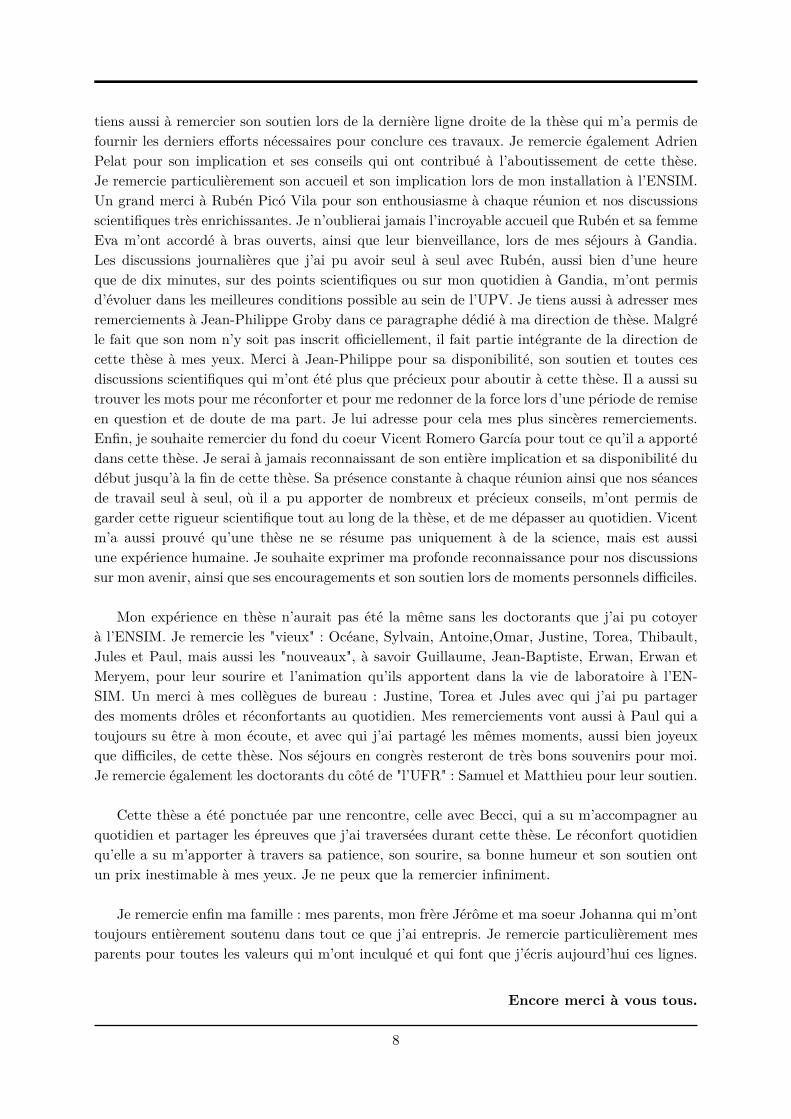
Materials with a graded impedance. Another approach to damp the vibration of struc-tures is the use of systems with graded properties. This has been treated first in the work ofVemula et al. [181], in which they proposed to gradually change the impedance at the edges ofa beam system along the propagation direction of flexural waves as shown in the left figure ofFig. 1.5. To do this, several beams with different materials are combined together leading toa decrease in impedance at the interfaces as the wave propagates toward the free end of thesystem. A large attenuation of the wave reflections at the edges of the structure is thereforeobtained (see the right figure of Fig.1.5). The attenuation efficiency is directly linked to the typeof impedance variation at the end of the beam. This attenuation is achieved over a wide band
17
Introduction
Figure 1.4 – FEM prediction of the vibration response of a car dash panel using laminatematerial (solid line) and steel (dashed line). [126]
Figure 1.5 – Diagram of a graded impedance interface at the edge of a steel bar [181] (left).Reflected energy by four configurations of graded edges of a steel bar: (· · · ·) steel bar; (- - - -)steel bar, Al; (– – – –) steel bar, Al, Lucite; (——) steel bar, Al, Lucite, Composite. (right)
of frequencies and is more efficient for higher frequencies. However, it is accompanied by a largeamplitude of the propagating waves, since the amplitude increases as the impedance decreasesdue to the conservation of the energy flux carried by the wave. The results have been obser-ved experimentally and explained by means of an analytical model with a S-matrix formulationbased on Mindlin and Kirchhoff theory for flexural waves. The method has thereafter been ex-tended to longitudinal waves by Chen et al. [35] where the impedance mismatch is controlledby means of shape memory alloy (SMA) inserts, which are smart materials that change pro-perties when heated. Other applications have also been proposed, such as wave cloaking [68]or non-destructive evaluation techniques [115]. In particular, Liew et al. studied in Ref. [115]the suppression of reflections at the boundaries of a beam waveguide by using Metal-PolymerFunctionally Graded Materials (FGM). FGM is a two-component composite whose compositionvaries from one component to the other in a continuous manner, as shown in Fig 1.6).
18

2. Overview of common methods for vibration control
Figure 1.6 – Picture of the Aluminium-Polycarbonate FGM used in Ref. [115] where light areasare aluminium while dark areas are polycarbonate.
Acoustic Black Holes. Using Euler-Bernoulli or thin beam theory, the bending waveimpedance of a beam is expressed as EIk2, where E is the Young’s modulus, I the secondmoment of area and k the wavenumber. Another way to obtain a system with graded impedancethan gradually changing the material is to modify k which is also dependent on the thicknessof the system. Thus, the impedance of the beam can be graded if the thickness is continouslychanged. From this statement, Mironov proposed to take advantage of the beam properties bycontinuously decreasing the thickness toward the beam edge along the propagation direction offlexural waves [127] (see Fig.1.5). This thickness decrease follows a power-law and vanishes atthe extremity of the beam. In the case where the varying thickness profile is expressed along thex-axis as h(x) = ǫxn, the wavenumber k of the beam can be written as
k = ǫ−1/2 4
√
12ρEω2
x−n/2, (1.2)
where ω is the circular frequency and ρ the mass density. The local phase velocity cφ and groupvelocity cγ therefore read as:
cφ =ω
k=
√ǫ 4
√
Eω2
12ρxn/2, (1.3)
cγ =∂ω
∂k=
√nǫ 4
√
Eω2
3ρx(n−1)/2. (1.4)
By tending x towards zero, or equivalently by tending h towards zero, cφ and cγ tend alsotowards zero. As a result, the flexural wave slows down by propagating along the terminationdue to the decrease of thickness until reaching a zero phase cφ and group cγ velocities at itsextremity. The wave is therefore trapped at the extremity of the beam and is not reflected back.This slowdown is accompanied by a large amplitude of the propagating waves due to the conser-vation of the energy flux. The amplitude at the beam extremity may therefore become infinitein the conservative case due to its zero thickness, creating a singular point at the extremity.This wave trapping system is the so called Acoustic Black Hole (ABH). Such an ideal system iscompact and lightweight since its does not require additional mass to provide absorption, butit needs a continuous decrease of the thickness until zero. The main limit of such a system inpractice is that the thickness profile must be truncated. This leads to a non-null thickness at itstip and therefore to a significant reflection of the flexural waves. Krylov proposed the additionof a thin layer of viscoelastic material along the ABH profile to make up for the truncation[107, 106]. The combination of the power-law shaped wedge and the effect of a thin absorbinglayer reduces significantly the wave reflection coefficient as compared to an uncovered ABH asshown in Fig. 1.8. He also showed the influence of the position of the truncation at the edge onthe reflection coefficient. A longer ABH provides better absorbing performances than a shorterone for a given thickness power-law. These studies led to other devices in which the ABH effect
19

Introduction
Figure 1.7 – Plate with a power-law tapered edge. x1 and h1 correspond to the coordinate ofthe ABH edge and its thickness in the practical case respectively. x0 is the coordinate of theABH edge in the ideal case where the thickness is null in this case [127].
Figure 1.8 – Frequency dependence of the reflection coefficient |R1| for a beam with an ABHtermination covered by a 700 µm absorbing film (solid curve) and 10 µm absorbing film (dash-dotted curve); with an ABH without absorbing film (dashed curve); and for a uniform beamwith 700 mm absorbing film (dotted curve). [79]
and the presence of losses damping are combined such as spiral ABHs [112] which provide asgood damping efficiency as classical ABHs with the same thickness profile while meeting theconstraint of space limitation, compound ABHs which produce more effective ABH effect whileensuring better structural rigidity [207], and ABH resonant beam dampers which use the ABH asdynamic vibration absorbers [208]. The reflection coefficient of 1D ABH has been widely studiedthrough various methods, including plane wave model [79], multimodal approaches [53], finitedifference [54], finite element methods [159] and wavelet decomposition [171], among others.Other strategies have also been employed to enhance the ABH performance, such as the useof extended platforms to facilitate practical implementations of the ABH [11, 170], the use ofconstrained damping layers [51] or the use of beam non-linearities [55].
Krylov extended later on the operating principle of the ABH to axi-symmetric circular fea-tures which consist of circular pits with power-law varying thickness [105] (see Fig. 1.9). Thesesystems can slow down and trap flexural waves similarly to 1D ABHs with omni-directional ab-sorbing properties. However, the 2D thickness profile of the ABH must be truncated in practice
20

2. Overview of common methods for vibration control
Figure 1.9 – Diagram of a typical 2D circular ABH with a radially dependent thickness profileh(r) and a central plateau. (adapted from [41])
similarly to the 1D ABH. Two cases can therefore be considered and have been firstly studiedby Aklouche et al. [3]: having a hole at the center of the practical ABH due to the truncation,or filling the hole with a plateau of thickness equal to the residual thickness of the truncation.The efficiency of 2D ABHs as flexural vibration dampers has been experimentally highlightedfor the first time as part of the thesis of Cuenca [47] and published in [21, 77, 79], thereafter. Thefocusing or trapping effect of 2D ABHs have been experimentally and numerically highlightedby Yan et al. in the ideal case, with a residual thickness and with a central plateau [201, 202].They showed that the weaker efficiency of an ABH with a central plateau is due to the fact thatonly a portion of the incident wave is focused in the ABH in this case. Aklouche et al. studiedthe scattering properties of an ABH whose thickness follows a second order power-law in aninfinite plate [4]. The results exhibited a cut-on wavenumber below which the trapping effectof the ABH is inefficient, showing the limits of such damping devices at low frequency. Otherkinds of applications using the 2D ABH system such as insulating [40] and lensing [41, 210] de-vices have been also proposed. Studies introducing multiple ABHs embedded in periodic latticeconfigurations have also been carried out. These lattices form platonic crystals and give rise tounusual wave propagation properties such as double refraction [209] or lensing [210], to cite afew. The concept of platonic crystals and their properties are developed later in this chapter.
The main damping effect of such 1D and 2D systems appears in the mid-frequency and high-frequency range, as shown in Fig. 1.8. As a consequence the damping effect at low frequenciesis weak and the ABH is not useful for a plethora of technological applications in which the lowfrequencies are the main source to be damped.
d) Tuned vibration absorbers
The use of Tuned Vibration Absorber (TVA) is also relevant to damp vibration. This de-vice was invented by Frahm in 1911 [76] and consists in adding a reaction mass and a resilientelement on the treated structure. In tonal applications, they are generally tuned to intereferewith the structural vibration at the disturbance frequency. This leads to an alteration of thefrequency response of the primary system and introduces another resonance in the compositesystem due to the additional degree of freedom provided by the TVA. Their design focuseson having a precise tuning of the mass and the damping to the disturbance frequency and oncontrolling the damping to an appropriate level in order to have reasonable displacement am-plitude of the TVA mass. The damping effect of such a system may be broadband when thestructure is lightly damped. TVA can be designed using the impedance coupling method [66]that uses the impedance of the TVA. This method avoids heavy computations of the complete
21
Introduction
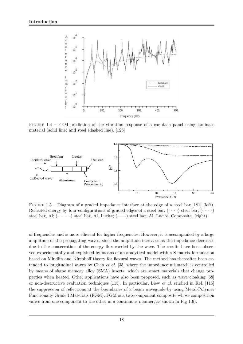
Figure 1.10 – Tuned Vibration Absorber attached to the end of a cantilever beam excitedby a sinusoidally varying force at its free end [167] (left) and transmissibility across the beamaccording to dimensionless angular frequencies with (solid line) and without TVA (dashed line)[167] (right). An additional resonance provided by the TVA can be noticed below the firstresonance frequency.
system since only the attachment point between the TVA and the background medium is com-puted. The simplest design of a TVA is a mass-spring oscillator with viscous damping on thestructure to be treated or a mass with a viscoelastic spring system as shown in Fig. 1.5. Severaldesign variations have been nonetheless proposed over the years such as a pendulum-type ab-sorber [6] to control vibration of an inverted pendulum type structure, multi-degree of freedomTVA which showed an improvement in the response of the conventional TVA by the introductionof a significant trough in the frequency response function [168] and broadband performances [22].
TVA can also be used in the case of infinite media rather than finite structures [23]. The de-vice is sometimes called Tuned Vibration Neutraliser (TVN) and aims to suppress propagatingwaves in the system rather than influence its resonant behaviour. It is then a scattering probleminstead of a modal problem. The tuning of the resonance frequency of an undamped TVN hasbeen analysed [23], showing that complete suppression of the flexural wave transmission can beachieved but a wave absorption of 50% can only be obtained with this kind of device [62].
TVA and TVN are very effective at reducing vibrations of industrial mechanical structureswith relatively low cost. However, the damping effect of such systems at low frequency requiresa large addition of mass, which leads again to the same problematics as mentioned above.
1.3 Control of the flexural wave propagation using periodic struc-
tures
The common methods described in the previous section lead to heavy and bulky solutions, orin the case of ABHs, to solution limited to the high frequency range. A new class of innovative
22

3. Control of the flexural wave propagation using periodic structures
materials based on a periodic modulation of their properties has meanwhile emerged. Thesepresent promising results which may offer solutions to ecologic, health and economic issues invibration control. This section aims at presenting an overview of periodic systems for controllingflexural waves. Two types of material regime are distinguished here: the diffraction regime dueto the periodic modulation of the material properties and the metamaterial regime due to theintroduction of local resonances in the material.
1.3.1 Diffraction regime : from photonic to platonic crystals
Brillouin observed in the mid 1950’s that the propagation of any type of wave motion througha periodically modulated material is governed by a dispersion relation in which the wave vectoris a periodic function of the frequency, producing band structures [25]. This observation pavedthe way to the design of photonic crystals in electromagnetic field. The pioneering work of Ya-blonovitch [200] and John [100] in the late 1980’s showed that such periodic systems presentbandgaps or stop bands, which correspond to frequency ranges in which wave propagation isforbidden. These works have been inspired by the quantum mechanical band theory in whichthe existence of energy bands and forbidden band have been highlighted. Unlike the energybands, the forbidden band or forbidden bandgaps correspond to particular energy ranges in asolid in which the electrons cannot propagate. The analogies between the electromagnetic equa-tions and those in acoustics and for elastic waves led to the emergence of phononic crystals afew years later presenting bandgaps for acoustic and elastic waves [109, 161]. The terminologyphonon defines a quantum of vibrational energy in an elastic medium. It is used in the contextof vibrations in crystal lattices in analogy to the notion of a photon in electromagnetics [94].Such acoustic periodic systems can provide sound attenuation in the frequency ranges of thebandgaps and applications in sonic barriers for the human audible frequency range have beenproposed by exploiting this property [82, 108, 110, 156], among others [57].
More recently, the properties of flexural waves in periodically-constrained thin elastic plateshave been studied and bandgaps for flexural waves have been observed [65, 124]. These band-gaps can decrease the vibrational response of the plate over certain frequency ranges similarlyto those of phononic crystals. McPhedran et al. proposed the name of platonic crystals [124] forthis type of structured system. In addition to these platonic crystals, periodic arrays of holesin plates [130, 184], periodically undulated plates [176] or inclusions of different materials [162]have been proposed. The study has also been applied to beam systems [176, 190] and to Lambwaves in plates [32, 99]. Several methodologies for band structure calculations of platonic crys-tals have been investigated such as multiple scattering [130], Finite Element [88], Super Cell[180] or Plane Wave Expansion (PWE) method [176].
For all fields of physics, the bandgaps of periodic structures are due to Bragg interferences,which are destructive ones encountered at particular frequency ranges. The frequency range andthe bandwidth of the gaps depend on the periodicity length scale a, which has to be comparableto the propagation wavelength λ. Thus, bandgaps at low frequencies require large and bulkystructures which is inconvenient for industrial applications. This scale dependency can howeverbe overcome by the use of locally resonant (LR) metamaterials on the sub-wavelength scale(λ >> a).
23

Introduction
1.3.2 Metamaterial regime
A metamaterial is broadly and briefly defined as an artificial media with unusual properties.This definition is generally used since it captures the spirit of the subject. However, there is noconsensus on the meaning of the words unusual and artificial and there is no definition that isuniversally accepted by everyone. Is a property defined as unusual by one person also unusualfor another? Does metamaterial always concern artificial media? Anyway, there is consensusthat the concept of metamaterial was first introduced in electromagnetics by Veselago in thelate 1960’s [182]. The refractive index value of a material had always been considered positiveup to his work. Veselago hypothesised that the refractive index may also be negative if both theelectric permittivity and the magnetic permeability of a material are negative. Materials withsuch properties are called left-handed material in reference to Fleming’s left-hand rule in elec-tromagnetism and can exhibit negative refractive index. Pendry et al. [145] proposed 30 yearslater left-handed materials by introducing local resonances in a periodic array. These resonancesare introduced by means of split-ring metallic cylinders put in a square array. By doing so, anegative effective permeability was observed in a bandgap around the resonance frequency of thecylinder. This resonance frequency is far below the first Bragg frequency of the array, meaningthat wave propagation in periodic media can be mitigated for wavelengths λ much longer thanthe lattice size a ( λ >> a) by using local resonances. This was validated experimentally bySmith et al. [164, 165] later on. These works were then extended for the control of elastic andacoustic wave propagation.
Liu et al. [119] proposed a locally resonant (LR) sonic crystal in which the local resonancesare introduced by rubber coated lead spheres. These spheres were embedded in an epoxy matrixand negative effective dynamic mass density was obtained for wavelengths that are two ordersof magnitude larger than the lattice size a. The negative effective mass density produces expo-nential attenuation of the incoming wave amplitude through the sample, generating thereforebandgaps at the resonance frequency of the local resonators. The local resonances can also giverise to other original phenomena such as invisibility cloaks [33].
New classes of metamaterials that are not based on resonant properties have also emergedthanks to manufacturing progresses such as auxetic metamaterials [129] with negative Poisson’sratio that contract in transverse directions under uniaxial compressive loads, pentamode me-tamaterials [103] with near-zero modulus that behave like fluids despite the fact that they aresolids, and origami inspired metamaterials [117], to cite a few.
The potential of LR materials to mitigate wave propagation at low frequency has aroused in-terest in the vibro-acoustic community to design devices for noise and vibration control. A widenumber of periodic systems have been designed in order to observe bandgaps in LR thin plates.Local resonances in plates can be introduced by means of inclusions or by adding resonators ontop of plate host structures. The 2D periodic arrangements of inclusions such as rubber discs [92],rubber-coated steel disc inclusions [104] or hemmed discs inclusions [195] have been investigated.Xiao et al. [197] and Claeys et al. [39] have analysed theoretically the potential of LR panelsto obtain low-frequency vibrational bandgaps by using idealised mass-spring resonators onto athin plate. Practicable resonators in LR plates have also been proposed beside the theoretical
24

4. Acoustic subwavelength perfect absorption
Figure 1.11 – LR plate with a 2D periodic array of silicon stub resonators proposed in [137] (left)and the corresponding averaged displacement field along the diagonal direction of the crystal. Asignificant attenuation of the transmitted wave field is observed at a particular frequency range,implying the presence of a BG at this frequency range. (right).
analyses with idealised mass-spring resonators. Wu et al. [183] proposed a LR plate consistingof a 2D periodic array of cylindrical aluminum stubbed resonators on a thin aluminum platehost structure to obtain flexural wave bandgaps. Oudich et al. [137] proposed silicone rubberstub resonators instead of aluminum ones (see Fig. 1.11). An attenuation at lower frequencieshas therefore been obtained thanks to the less stiff property of silicone rubber compared toaluminum. Assouar et al. [8] also added masses on top of the rubber stubs in order to broadenand shift the LR bandgap at lower frequency. Various LR plates have been proposed such as 2Dperiodic array of beam-like resonators attached to a thin plate [196] as shown in Fig. 1.12. Thesame investigations have also been applied to LR beams with idealised mass-spring and otherkinds of resonators [39, 118, 198].
A huge variety of original phenomena has also been observed in metamaterial plates similarlyto acoustic metamaterial such as negative refraction [166], flexural wave focusing [71] or confi-nement [69], cloaking [70], lensing [30, 71] or waveguiding using periodically graded structuredplates [31], among others.
For all fields, the bandgaps generated by locally resonant materials do not require periodicity,but arise from the addition of local sub-wavelength resonators to a hosting medium. Such mate-rials can be small, lightweight and can operate in the low frequency regime. They are thereforeof great interest since they can answer to both the current industrial problematic of dampingvibration at low frequency and the problem of vibration control adapted to light structures.
1.4 Acoustic subwavelength perfect absorption
Recent studies in audible acoustics have focused on wave absorption at low frequenciesby means of subwavelength locally resonant materials. In particular, the design of broadbandsubwavelength perfect absorbers, whose dimensions are much smaller than the wavelength of
25

Introduction
Figure 1.12 – LR plate with a 2D periodic array of beam-like resonators proposed in [196] (left)and out-of-plane vibration transmittance from a point in the middle of the crystal to another oneat the edge (right). The results shows an attenuation of the wave field and implies the presenceof a BG.
the frequency to be attenuated, have recently been proposed [84, 96, 98, 125, 153]. Such devicescan totally absorb the energy of an incident wave and require solving the two complex problems:(i) increasing the density of states at low frequencies and (ii) matching the impedance with thebackground medium. On the one hand, the use of local resonators is a successful approach forincreasing the density of states at low frequencies with reduced dimensions, as it has been shownin the field of metamaterials [42, 61, 67, 119, 140, 163, 174, 187]. On the other hand, the localresonators of such metamaterials are open and lossy ones. The field inside the local resonatorcan interact with an external wave field in the background medium through the interface thatconnects the resonator to the medium. This connection can be seen as an aperture throughwhich wave energy can leak out from one system to another (see left figure of Fig. 1.13). Theresonator is therefore considered as open to the background medium due to its energy leakageto the medium. Inherent losses can also be added inside the resonator by introducing an internalenergy dissipation source. The impedance matching of such metamaterials can be controlled bythe ratio between the inherent losses of the resonator and the leakage of energy [17]. Particularly,the impedance matching corresponds to the situation in which the amount of inherent lossesin the resonator equals the amount of energy leakage, and is known as the critical couplingcondition [205]. This situation occurs at the resonance frequency of the resonator and leads toa perfect absorption of the wave energy by the resonator at this specific frequency (see rightfigure of Fig. 1.13). This phenomenon has also been widely used to design perfect absorbers indifferent fields of physics [28, 199] other than acoustics.
1.5 Motivations and objectives of the work
The solutions proposed by the usual passive damping methods do not necessarily answerboth the problematic of damping vibration at low frequency and the problem of vibration controladapted to light structures. These methods either respond to one of these two problematics, butneglect the other. For example, they can provide a satisfactory solution to face the problematic
26

5. Motivations and objectives of the work
Figure 1.13 – (left) Diagram of the acoustic perfect absorber proposed in [153] made of aHelmholtz resonator loaded to a waveguide filled with air. The inherent losses in the resonatorare controlled with a porous material of thickness lp. The neck of the resonator of width Sn
plays the role here of the aperture between the resonator and the waveguide. (right) Evaluationof the absorption coefficient by the Helmholtz resonator of three different configurations withdifferent amount of losses. The solid line corresponds to the critical coupling situation in whichthe incident wave is totally absorbed by the resonator at its resonance frequency.
of damping vibration at low frequency, but imply heavy and/or bulky solutions. Conversely,these methods can comply to the lightweight constraint by taking advantage of the inherentproperties of the structure, but cannot achieve good performances at low frequency. This consti-tutes therefore a motivation for this work. The objective being to understand, analyse and design1D and 2D passive damping lightweight systems which can attenuate flexural vibrations at lowfrequencies, and more particularly at wavelengths much smaller than the characteristic lengthof the damping system.
1.5.1 Subwavelength absorber for flexural waves
Particular interest has been accorded to the design of subwavelength perfect absorbers. Suchabsorbers have proven their efficiency for the total absorption of the energy of an incident wavein audible acoustic metamaterials, and a generalisation of the method in elastodynamics fieldcould be of great interest owing to the constraints previously mentioned. Hence, this work aimsfirst of all at adapting the problem of perfect absorption for flexural waves in 1D elastic beamswith local resonators by using the critical coupling condition. The design of systems with simplegeometry are analysed to that purpose. They are composed of a main beam and an open re-sonator simply consisting of a reduction of the thickness of the main beam. The resonator isconsidered as open here since the field inside the resonator can interact with the one of the mainbeam through the aperture between both systems. A thin viscoelastic coating is also attachedto it. The composite resonators present therefore both energy leakage due to the aperture of theresonator to the main beam which can be controlled by changing the thickness of the beams, andinherent losses due to the viscoelastic damping which is controlled by changing the properties ofthe viscoelastic coating. The resonators are chosen first as an integral part of the main beam inorder to facilitate its implementation for the experimental validation of the method. Particularly,the absorption of energy is analysed by means of the Transfer Matrix Method (TMM) for the
27

Introduction
two scattering problems: the reflection and the transmission of flexural waves. An experimentalvalidation is also performed. This first preliminary study aims to open up new avenues to thedesign of simple resonators for efficient flexural wave absorption by means of the critical cou-pling condition, showing also the limits of absorption induced by the geometry used in the study.
The problem is then complexified by extending the method in the 2D case. To that end, aninfinite array of penetrable circular scatterers embedded in an infinite or semi-infinite 2D thinplate is considered thereafter. This system constitutes a 2D metaplate in which the penetrablescatterers compose its resonant block. A 2D preliminary study is presented in which the perfectabsorption of the first axisymmetric mode of a circular resonator embedded in an infinite thinplate is analysed. The resonator consists of a circular reduction of the thickness of the infiniteplate, and a thin viscoelastic coating is attached to the resonator similarly to the the 1D case.This composite scatterer presents therefore leakage and inherent losses which can be controlledsimilarly to the resonators presented in the 1D case. This analysis is done through the balancebetween the energy leakage and the inherent losses in the resonator for the particular case ofa concentric incident wave propagating towards the centre of the resonator. The composite isstudied by means of a semi-analytical model based on the scattering method and is comparedwith numerical results using FEM methods. The optimised 2D resonator is therefore embeddedin the form of an infinite array in a plate and two scattering problems are then studied byusing the multiple scattering method: the reflection problem in a semi-infinite plate and thetransmission problem in an infinite plate. This analysis aims at showing the adaptability of themethod for the case of 2D problems and at getting closer to a practical application.
1.5.2 Adapting the Acoustic Black Hole for perfect absorption of flexural
waves
The combination of the ABH effect and the presence of losses provides a good dampingperformance while reducing the weight of the initial structure. However, the efficiency of ABHdevices is weak in low frequencies, thus limiting their application. Despite this drawback, theABH effect remains of great interest in designing damping system by removing part of the sys-tem matter. This has acted as motivation to improve the absorbing efficiency of the ABH byusing the critical coupling condition. The combination of the ABH effect at high frequencies withthe perfect absorption obtained with the critical coupling condition at low frequencies wouldallow for a broadband absorber without adding mass in the system. To that end, a systemcomposed of a main beam terminated by an open resonator which corresponds to an ABH offinite length is analysed. A thin viscoelastic coating is also attached to the resonator creating acomposite material. The vibration response of the composite ABH is studied by discretising itwith constant thickness piecewise elements. The composite presents resonances, energy leakageand inherent losses in the same way as the simple resonator described in the previous section. Allthese properties fulfill the conditions to design a subwavelength perfect absorber as mentionedin the previous section without altering the initial ABH effect since this effect originates onlyfrom the geometry of the system.
A new physical insight of the ABH efficiency emerged through the study of the criticalcoupling of a 1D ABH. The ABH effect may be interpreted as a consequence of the critical
28

5. Motivations and objectives of the work
coupling at one resonance frequency of the ABH and of the broadband quasi-perfect absorptionat higher frequencies, thanks to the specific geometry of the resonator. This has motivated thiswork to interprete the Acoustic Black Hole effect based on the concept of critical coupling inorder to provide the key to future optimisation procedures of such a type of terminations. Twostrategies to optimise the absorption efficiency of an ABH termination at low frequency areproposed in this work, both consisting in applying the critical coupling condition. The firstconsists in tuning the losses introduced by the viscoelastic layer by shaping its thickness profilein order to achieve the critical coupling condition at several resonances of the ABH. The secondstrategy is based on the addition of a mass at the extremity of the ABH which decreases the firstresonance frequency of the ABH. The critical coupling is then applied at this specific frequencyto obtain a low frequency absorption by the termination. The approach of mass addition on aABH has already been investigated by Aklouche et al. [3]. The study presented in this thesisgives new perspectives of this approach by using the concept of critical coupling.
1.5.3 Layout of the thesis
This thesis is organised in the form of 5 chapters, the complexity of each of which is graduallyincreased to understand step by step the main physical mechanisms of the perfect absorption offlexural wave energy. The content of the chapters are as follows.
Chapter 5 presents a survey of usual methods for vibration damping, paying attention topassive damping methods. A description of the methods to control the propagation of flexuralwaves using periodic materials has been made afterwards. Finally the objectives, motivations,and a brief overview of the work have been given.
Chapter 2 is devoted to the problem of perfect absorption of flexural waves in 1D elasticbeams with simple local resonators by using the critical coupling condition for the two scatteringproblems: the reflection and the transmission of flexural waves. The design of an experimentalprototype and the measurement of its reflection and absorption coefficients in the reflectionproblem are also presented, and are compared with a numerical model using Finite ElementMethod (FEM). This chapter refers to the article [114] published in New Journal of Physics andpresented in Appendix.
Chapter 3 focuses on the link between the complex nature of the trapped modes within a1D ABH and its reflection coefficient troughs, in terms of depth and frequency width. Morespecifically, the purpose of Chapter 3 is to analyse first the absorbing efficiency of the ABHby using the critical coupling condition. Two strategies to optimise the absorption efficiency ofan ABH termination at low frequency are then proposed in this work, both consisting in ap-plying the critical coupling condition. All the analytical results are validated with a FEM model.
Chapter 4 concerns the design of the resonant blocks of a metaplate by using the criticalcoupling condition. A preliminary study is presented in which the perfect absorption of the firstaxisymmetric mode of a circular resonator embedded in an infinite thin plate is analysed. Thescattering of a resonator, consisting in a circular reduction of the thickness of the infinite plateon which a thin viscoelastic coating is attached, is studied. The problem is then complexified by
29

Introduction
studying the scattering of a penetrable scatterer with radially varying thickness. The analysis isdone by means of the multiple scattering method for multilayered systems.
Chapter 5 concerns the scattering of flexural waves by an infinite critically coupled array ofcircular inclusions embedded in a thin plate. This system composes a metaplate and the analysisof the absorbing efficency of this array is made for two configurations. The first configurationcorresponds to a 2D transmission problem in which the array is embedded in an infinite thinplate, wheras the second corresponds to a 2D reflexion problem in which the scattered field bythe array interacts with a simply supported plane boundary in a semi-infinite thin plate. Thescattered field by the array is studied by means of the multiple scattering theory and by usinga FEM model.
Chapter 6 gives the concluding remarks as well as perspectives for future works.
30

Chapter 2
Flexural wave absorption by open
lossy resonators for the reflection
and transmission problems
2.1 Introduction
The design of broadband subwavelength perfect absorbers has recently proven its efficiencyin audible acoustics [84, 96, 98, 125, 153]. Such devices have dimensions that are much smallerthan the wavelength of the frequency to be attenuated and can totally absorb the energy ofan incident wave provided that the critical coupling condition between the absorber and thebackground medium is fulfilled (see Section 1.4). The critical coupling condition is relevant forapplications in vibrations owing to the increasing need for damping materials at low frequenciesin several branches of industry [61]. Current passive solutions in this field are mainly based onthe use of viscoelastic coatings [172]. Another solution yields in TVAs [50, 24, 63] that is usedto control flexural waves in beams. The tuning of the resonance frequency of an undamped TVAhas been analysed [24], showing that complete suppression of the flexural wave transmission canbe achieved. In most cases, TVAs have been used to minimise the transmission of a propagatingwave [24], resulting in practice in heavy treatments at low frequencies. Less attention has beenpaid to the case of maximising the absorption in order to reduce simultaneously both the reflectedand transmitted waves.
The purpose of this chapter is to study the problem of perfect absorption of flexural waves in1D elastic beams with local resonators by using the critical coupling condition. Particularly, theabsorption of energy is analysed through the balance between the energy leakage and the inherentlosses in the resonators for the two scattering problems: the reflection and the transmission offlexural waves. The presented problem is related to the control of flexural waves in a beam usinga passive TVA but with a physical insight that allows the interpretation of the limits of theflexural wave absorption based on both the critical coupling condition and the symmetry ofthe excited resonances in the resonator. The analysed systems are composed of a main beamand an open resonator simply consisting in a thickness reduction of the main beam. A thinviscoelastic coating is attached to it, leading to a composite material whose loss may be tuned.This composite material is modeled with the Ross-Kerwin-Ungar (RKU) method for beams[154] and is embedded in the main beam. By tuning the losses, it is possible to analyse the
31

Flexural wave absorption by open lossy resonators for the reflection andtransmission problems
different limits in both scattering problems. In practice, this type of resonator results in simplergeometries than that of the TVA which consists of complicated combinations of mass springsystems simulating a point translational impedance.
The composite is studied by means of an analytical model based on the transfer matrixmethod. The analytical results, in accordance with the the experimental results, show the limitsof the maximal values for the flexural wave absorption and their physical interpretations in boththe reflection and transmission problems. The interpretations are based on the eigenvalues ofthe S-matrix for the propagating waves, represented in the complex frequency plane [153]. Anexperimental prototype is designed and measured for the reflection problem. The experimentalresults prove the perfect absorption of flexural waves and validate the analytical predictions.
The chapter is organised as follows. The study presents first a general scattering problem inSection 2.2 in order to show the relevance of the eigenvalues and eigenvectors of the scatteringmatrix to identify the situations of perfect absorption in the system. In Section 3.2, the theoreti-cal model used to analyse the 1D scattering problems of flexural wave is presented. The physicalanalysis of the absorption coefficient in the complex frequency plane are presented in Section 2.4.This analysis is based on an analytical model and the concept of critical coupling to obtain aperfect absorption of flexural waves. The experimental set-up used to validate the model for thereflection problem is then presented in Section 2.5 as well as the experimental methodology andresults. Finally, Section 2.6 summarises the main results and gives the concluding remarks.
2.2 Scattering problem for 1D configurations
The absorbing devices proposed in this chapter are studied by analysing their scatteringproperties. Scattering problems differ from usual modal analyses, since it deals with the scat-tering properties (reflection, transmission and absorption) of waves in the system instead ofstudying its resonant behaviour. The absorbers studied in this work are therefore embeddedin an infinite or semi-infinite medium according to the studied scattering problem, in order tomaximise the absorption of incident propagating waves. These media can be seen as waveguidesin the same way as in acoustics. This Section aims at presenting the two scattering problems in1D in order to show the relevance of the eigenvalues and eigenvectors of the scattering matrixto identify the situations of perfect absorption in the systems. The analysis of the problem isachieved in the far-field (x → ±∞), i.e. with propagative waves that are related to the carriedenergy. The reflection and transmission coefficients of the scattering matrix are therefore scalarin this Section. Two cases are presented. A general scattering problem is first treated with threetypes of scatterers: a mirror symmetric scatterer which corresponds to the one studied later inthis chapter, a point symmetric scatterer and a mirror asymmetric scatterer. The specific case ofthe reflection problem is then presented. The analysis of the scattering problems is based on [125].
Consider an one-dimensional and reciprocal scattering process. The relation between theamplitudes of the incoming (a, d), and outcoming (b, c) waves, on both sides of the scatterer Σ,as shown in Fig. 2.1(a), is given by
(
c
b
)
= S(f)
(
a
d
)
=
(
T R+
R− T
)(
a
d
)
, (2.1)
32

2. Scattering problem for 1D configurations
Σ
x = 0
x
ceikx
de−ikx
aeikx
be−ikx
x >> λx << −λ
Σ
x = 0
x
(T + R)eikx
+e−ikx
+eikx
(T + R)e−ikx
x >> λx << −λ Σ
x = 0
x
−(T − R)eikx
+e−ikx
−eikx
(T − R)e−ikx
x >> λx << −λ
(b)
(a)
(c)
Figure 2.1 – (a) Diagram of the scattering process. (b) Symmetric and (c) antisymmetricuncoupled sub-problems for the case of a mirror-symmetric scatterer Σ. The time convention ise−iωt. (adapted from [125])
where S(f) is the scattering matrix (S-matrix) of the propagative waves, f is the incident wavefrequency, T is the complex transmission coefficient, R− and R+ are the complex reflectioncoefficients for left (−) and right (+) incidence, respectively. In this chapter, the time depen-dence convention of the harmonic regime is e−iωt. The eigenvalues of the S-matrix ψ1,2 and theeigenvectors v1,2 of the system are expressed respectively as:
ψ1,2 = T ± [R−R+]1/2, (2.2)
and
v1 =
(
R+
−√R+R−
)
, v2 =
(√R+R−
R+
)
. (2.3)
A zero eigenvalue of the S-matrix corresponds to the case in which the incident waves can becompletely absorbed (b = c = 0). This case is called coherent perfect absorption (CPA) [36] andhappens when T = ±
√R−R+ and the incident waves a, d correspond to the relevant eigenvector.
For an one-sided incident wave, the absorption coefficient is defined as:
α± = 1 − |R±|2 − |T |2. (2.4)
2.2.1 Mirror symmetric scatterer
The scatterer Σ is considered as mirror symmetric. The reflection coefficients at both portsof Σ are equal in this case such that:
R+ = R− = R. (2.5)
The scattering problem can be reduced to two uncoupled sub-problems by choosing incidentwaves that are symmetric (see Fig. 2.1(b)) or antisymmetric (see Fig. 2.1(c)). The total reflectioncoefficients of both problems are therefore respectively:
Rs = T +R, Ra = T −R. (2.6)
33

Flexural wave absorption by open lossy resonators for the reflection andtransmission problems
In particular, the reflection and transmission coefficients of the initial problem in Fig. 2.1(a)can be expressed in terms of Rs and Ra as R = (Rs + Ra)/2, and T = (Rs − Ra)/2, while theeigenvalues of the S-matrix can be written as ψ1 = Rs and ψ2 = −Ra. For an one-sided incidentwave, the absorption coefficient defined in Eq. (2.4) can be written as:
α =αs + αa
2, (2.7)
where αs = 1 − |Rs|2 and αa = 1 − |Ra|2. The total absorption of an incident wave at a givenfrequency fmax by the scatterer (i.e. α(fmax) = 1) can therefore be achieved provided that thereflection coefficient of both sub-problems equals zero at fmax. This has been achieved in Ref.[148] for a mirror symmetric photonic crystal slab covered by a graphene layer and in Ref. [125]for an acoustic mirror symmetric scatterer composed of 2 helmholtz resonators.
2.2.2 Point symmetric scatterer
Σ is now considered as a point scatterer. The length of Σ is therefore reduced to one point atx = 0. This case is relevant to the study of absorption by TVA since such devices are attachedto the background medium at only one point. Imposing the continuity of the wave-field at thispoint [125] yields 1 +R = T and consequently to Ra = −1 according to Eq. (2.6). In this case,the scatterer Σ is transparent to antisymmetric incident waves since αa = 0. The absorptioncoefficient is then expressed as:
α =αs
2. (2.8)
As a consequence, the absorption of the scatterer for an one-sided incident wave at a givenfrequency fmax may not exceed 0.5. In the case where α(fmax) = 0.5, αs(fmax) = 1 which givesRs(fmax) = ψ1(fmax) = 0, and R(fmax) = −T (fmax) = 1/2. This case corresponds thereforeto the CPA of the two-incident waves problem for symmetric and in phase incoming waves atfmax, i.e., v2(fmax)/v1(fmax) = 1 [188].
2.2.3 Mirror asymmetric scatterer
Σ can be asymmetric in the most general case, such that:
R+ 6= R−. (2.9)
This problem corresponds to the one presented in Fig. 2.1(a) whose the corresponding eigenva-lues and eigenvectors are given in Eqs. (2.2) and (2.3) respectively. Therefore, Two absorptioncoefficients are defined in this case according to the direction where the incident wave is comingfrom and their expression is given in Eq. (2.4). The eigenvalues of the scattering matrix equalzero when T = ±
√R+R−. Thus, T = 0 and the system presents Unidirectional Perfect One-
side Absorption (UNPOA) provided that one of the reflection coefficients reaches zero. Fromthe analysis of the eigenvectors, the direction from which perfect absorption is obtained willcorrespond to the case of an eigenvector equal to (0, 0)T , where T is the transpose sign.
34

3. Theoretical model for flexural waves
(b)(a)
Figure 2.2 – Diagrams of the 1D configurations analysed for the reflection and transmissionproblems for flexural waves. (a) Configuration for the reflection problem. (b) Configuration forthe transmission problem.
2.2.4 Complex frequency plane
When the eigenvalues are evaluated in the complex frequency plane [153], poles and zeros canbe identified. The pole frequencies correspond to the resonances of the resonator while the zerofrequencies correspond to the perfect absorption configuration. Since the systems analysed in thiswork are invariant under time-reversal symmetry, the scattering matrix, as defined in Eq. (2.1),presents unitary property [128, 133] in the lossless case (i.e., without dissipative losses):
S∗S = I. (2.10)
The complex frequencies of the eigenvalue poles of the propagative S-matrix are complexconjugates of its zeros. Poles and zeros appear therefore symmetric with respect to the realfrequency axis in the lossless case.
2.3 Theoretical model for flexural waves
Two scattering problems are now presented in order to study the absorption of flexuralwaves by open lossy resonators in 1D systems. The first one is the reflection problem where theabsorption by a resonator made of a thinner composite beam located at the termination of asemi-infinite beam is studied (see Fig. 2.2(a)). The second one is the transmission problem wherethe absorption of the same resonator located between two semi-infinite beams is considered(see Fig. 2.2(b)). Both resonators correspond to mirror symmetric scatterers as described inthe previous section. The governing equations used in the model are first introduced in thissection. The two scattering problems are then presented. The analytical results shown for thetwo problems have been tested by numerical simulations, but not shown in this chapter forclarity of the figures. The analytical results are validated experimentally in Section 2.5 later on.
2.3.1 Flexural wave propagation in uniform thin beams
Consider a thin uniform beam whose neutral axis is denoted by the x-axis under Euler-Bernoulli assumptions. According to the Euler–Bernoulli or thin beam theory, the cross-sectionof the beam, initially orthogonal to its mean axis, remains planar and orthogonal to it, implyingtherefore that shear strains are neglected. Assuming Euler-Bernoulli conditions, the flexuraldisplacement W (x, t) = w(x)e−iωt, where ω is the angular frequency, satisfies [113]:
D∂4W (x, t)
∂x4+m
∂2W (x, t)∂t2
= 0, (2.11)
35

Flexural wave absorption by open lossy resonators for the reflection andtransmission problems
where D = EI is the flexural rigidity, E the Young modulus, I the second moment of area andm the linear mass. The solution of Eq. (2.11) can be written in the frequency domain as:
[
∂2
∂x2+ k2
] [
∂2
∂x2+ (−ik)2
]
w(x) = 0, (2.12)
where k is the wavenumber and k4 =mω2
D. Note that the wavenumber k is real and positive in
the lossless case and complex when damping is accounted for. The solution of Eq. (2.12) can beseparated in two parts such that:
w(x) = w1(x) + w2(x),
where w1(x) and w2(x) are solutions of the following equations respectively:
[
∂2
∂x2+ k2
]
w1(x) = 0, (2.13)
[
∂2
∂x2+ (−ik)2
]
w2(x) = 0. (2.14)
The first equation corresponds to the Helmholtz equation governing the propagating flexuralwaves, while the second equation is the modified Helmholtz equation governing the evanescentwaves which are near field waves, the amplitude of which decreases exponentially with distance.The solution of Eq. (2.11) is therefore the sum of the solutions of Eqs. (2.13) and (2.14) thatbeing the sum of four flexural waves:
w(x) = a+eikx + a+Ne
−kx + a−e−ikx + a−Ne
kx. (2.15)
The complex amplitudes of the propagative and evanescent waves are a and aN respectively,and the signs + and − denote the outgoing and ingoing waves respectively. The wave amplitudeis expressed in the vector form by convenience:
a+ =
[
a+
a+N
]
, a− =
[
a−
a−N
]
. (2.16)
The relation between wave amplitudes along a beam with a constant thickness are then describedby
a+(x0 + x) = f a+(x0) and a−(x0 + x) = f−1a−(x0), (2.17)
where the diagonal transfer matrix f is given by
f =
[
eikx 00 e−kx
]
. (2.18)
2.3.2 Reflection coefficient in a pure reflection problem
Consider an incident plane wave in the configuration described by Fig. 2.2(a), where thesystem is terminated by a free termination at one end. The displacement w at any point for
36

3. Theoretical model for flexural waves
x < 0 reads asw(x < 0) = a+ + a− = a+ + Rr · a+, (2.19)
where Rr denotes the reflection matrix of the resonant termination of the beam at x = 0. Theincident wave is transmitted into the resonant termination and reflected at its end, thereforethe matrix Rr can be evaluated, using the displacement continuity at the interface and at theboundary as [121]:
Rr = a−a+−1 = r12 + t12
(
(frf f)−1 − r21
)−1t21, (2.20)
where rij and tij represent the reflection and transmission matrices from section (i) to section (j)of the beam (see Fig. 2.2a). Considering continuity and equilibrium respectively at the sectionchange, these matrices are given by
tij =4∆
[
(1 + β)(1 + γ) (−1 − iβ)(1 − γ)(−1 + iβ)(1 − γ) (1 + β)(1 + γ)
]
, (2.21)
rij =2∆
[
−2(β2 − 1)γ + iβ(1 − γ)2 (1 − i)β(1 − γ2)(1 + i)β(1 − γ2) −2(β2 − 1)γ − iβ(1 − γ)2
]
, (2.22)
where β =kj
kiand γ =
Djk2j
Dik2i
correspond to the ratios of wavenumbers and bending wave im-
pedances, and ∆ = (1 + β)2(1 + γ)2 − (1 + β2)(1 − γ)2. The reflection matrix rf of the freetermination is given by
rf =
[
i (1 − i)(1 + i) −i
]
. (2.23)
Rr is thus a 2×2 matrix where the diagonal components correspond to the reflection coefficientsof the propagative and evanescent waves respectively. It is recalled that the study focuses onthe reflection of waves in the far-field (x → −∞), i.e., on the propagative waves that carry theenergy. Only Rr(1, 1) and Rr(2, 1) contribute to the reflected field in the abscence of evanescentincident wave. Moreover, RN(2, 1) vanishes in the far-field (x → −∞), as it corresponds tothe converted waves from propagative to evanescent waves during the reflexion process. Thefirst term of the reflection matrix Rr(1, 1) = Rr is therefore only considered. The absorptioncoefficient αR of propagating waves in the reflection problem can then be written as:
αr = 1 − |Rr|2, x → −∞. (2.24)
Note that Rr is simply equal to 1 for any purely real frequency in the lossless case, i.e. withoutdissipation, as the energy conservation is fulfilled.
2.3.3 Reflection and transmission coefficients in a 1D symmetric and reci-
procal transmission problem
The transmission problem of the structure shown in Fig. 2.2(b) is described in this section,considering b− = 0. Due to the symmetry of the resonator and assuming propagation in the linearregime, the problem is considered as symmetric and reciprocal. The reflection and transmissionmatrices Rt and Tt at x = 0 and x = L are used to define the displacements on each side of
37

Flexural wave absorption by open lossy resonators for the reflection andtransmission problems
the resonator, such as:w(x < 0) = a+ + a− = a+ + Rt · a+, (2.25)
w(x > L) = b+ = Tt · a+. (2.26)
Using the displacement continuity at x = 0 and x = L in a similar way as in the previous section,Rt and Tt are written as:
Rt = r12 + t12
(
(fr23f)−1 − r21
)−1t21, (2.27)
Tt = a−a+−1 = t23(I − (fr21f)r23)−1ft12. (2.28)
Therefore the absorption coefficient of the transmission problem is defined as:
αt = 1 − |Tt|2 − |Rt|2, x → ±∞ (2.29)
where Rt = Rt(1, 1) when x → −∞ and Tt = Tt(1, 1) when x → +∞.
2.3.4 Viscoelastic losses in the resonator: the RKU model for beams
The inherent losses of the resonator are introduced by a thin absorbing layer of thicknesshl as shown in Figs 2.2(a) and 2.2(b) and are considered frequency independent. The complexYoung Modulus of the absorbing layer is El(1 − iηl), where ηl is its loss factor. Using the RKUmodel for beams [154], this region is modeled as a single composite layer with a given effectivebending stiffness Dc written as:
Dc = E2I2
[
(1 − iη2) + ech3c(1 − iηl) +
3 + (1 + hc)2echc[1 − η2ηl − i(η2 + ηl)]1 + echc(1 − iηl)
]
, (2.30)
where the indices 2 and l stand for the parameters of the thin beam and of the absorbing layerrespectively, ec = El/E2 and hc = hl/h2. The wave number kc of the composite material can
then be written as k4c =
ρchω2
Dc, where h = hl + h2 and ρch = ρ2h2 + ρlhl.
2.4 Limits of absorption for the reflection and transmission pro-
blems
This section describes the limits of absorption for flexural waves in the reflection and trans-mission problem by using open, lossy and symmetric resonators. It provides tools to designabsorbers with a maximal absorption in both problems. For this purpose, the eigenvalues of thescattering matrix of the propagative waves are represented in the complex frequency plane as inRef. [153].The information given by this representation will be exploited to interpret the perfectabsorption in terms of the critical coupling condition. In particular, the concept of the zerosand poles of the reflection coefficient in the complex frequency plane is introduced through theanalysis of the reflection problems. The material and geometric parameters used in the followingsections are described in Tab. 2.1.
38

4. Limits of absorption for the reflection and transmission problems
Geometric parameters Material parametersMain beam h1 = 5 mm ρ = 2811 kg.m−3
b = 2 cm E = 71.4 GPaη = 0ν = 0.3
Resonator beam h2 = 0.217 mm ρ2 = 2811 kg.m−3
b2 = 2 cm E2 = 71.4 GPaL = 1.6 cm η2 = 0
ν2 = 0.3
Coating layer hl = 1.5 mm El = 6.86 × 10⁻³ GPabl = 2 cm ρl = 93.3 kg.m−3
Ll = 1.6 cm ηl
νl = 0.3
Table 2.1 – Geometric and material parameters of the studied systems. The value of ηl dependson the experimental set-up used, see the main text for the values used. b, b2 and bl correspondto the width of the system.
2.4.1 Reflection problem
a) Lossless case.
In the reflection problem, where no wave is transmitted, the reflection coefficient Rr repre-sents the scattering of the system. Thus, Rr corresponds directly to both the S-matrix and itsassociated eigenvalue (ψ = Rr). Its zeros correspond to the cases in which the incident wave istotally absorbed. In the lossless case, |Rr| = 1 for any purely real frequency and the pole-zeropairs appear at complex conjugate frequencies. Fig. 2.3(a) depicts log10(|Rr|) in the complexfrequency plane. The main beam, the resonator beam and the coating layer have the geometricand material parameters given in Tab. 2.1. Note that the Young moduli are purely real in thelossless case (η = η2 = ηl = 0). As shown in Section 2.2.4, the poles and zeros appear in pairsand are symmetric with respect to the real frequency axis. Moreover the value of |Rr| alongthe real frequency axis is equal to 1 since no energy is lost in the system and the incomingwave is completely reflected back. It is also worth noting that the imaginary part of the polein the lossless case represents the amount of energy leakage by the resonator through the mainbeam [153]. With the time dependence convention used in this chapter, the wave amplitude atthe resonance frequency decays as e−Im(ωpole)t. Thus the decay time τleak can be related with
the quality factor due to the leakage as Qleak =Re(ωpole)τleak
2=
Re(ωpole)2Im(ωpole)
, where the leakage
rate can be defined as Γleak = 1/τleak = Im(ωpole). The imaginary part of the poles and zerosincreases when the real part of the frequency increases, meaning that more energy leaks outthrough the resonator at high frequencies.
b) Lossy case.
For the sake of clarity, this section only focuses on the first pole-zero pair of the systempreviously described. The discussion can nevertheless be extended to any pole-zero pair of the
39
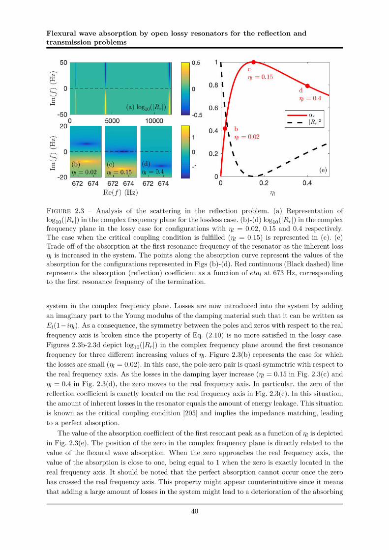
Flexural wave absorption by open lossy resonators for the reflection andtransmission problems
Figure 2.3 – Analysis of the scattering in the reflection problem. (a) Representation oflog10(|Rr|) in the complex frequency plane for the lossless case. (b)-(d) log10(|Rr|) in the complexfrequency plane in the lossy case for configurations with ηl = 0.02, 0.15 and 0.4 respectively.The case when the critical coupling condition is fulfilled (ηl = 0.15) is represented in (c). (e)Trade-off of the absorption at the first resonance frequency of the resonator as the inherent lossηl is increased in the system. The points along the absorption curve represent the values of theabsorption for the configurations represented in Figs (b)-(d). Red continuous (Black dashed) linerepresents the absorption (reflection) coefficient as a function of etal at 673 Hz, correspondingto the first resonance frequency of the termination.
system in the complex frequency plane. Losses are now introduced into the system by addingan imaginary part to the Young modulus of the damping material such that it can be written asEl(1−iηl). As a consequence, the symmetry between the poles and zeros with respect to the realfrequency axis is broken since the property of Eq. (2.10) is no more satisfied in the lossy case.Figures 2.3b-2.3d depict log10(|Rr|) in the complex frequency plane around the first resonancefrequency for three different increasing values of ηl. Figure 2.3(b) represents the case for whichthe losses are small (ηl = 0.02). In this case, the pole-zero pair is quasi-symmetric with respect tothe real frequency axis. As the losses in the damping layer increase (ηl = 0.15 in Fig. 2.3(c) andηl = 0.4 in Fig. 2.3(d), the zero moves to the real frequency axis. In particular, the zero of thereflection coefficient is exactly located on the real frequency axis in Fig. 2.3(c). In this situation,the amount of inherent losses in the resonator equals the amount of energy leakage. This situationis known as the critical coupling condition [205] and implies the impedance matching, leadingto a perfect absorption.
The value of the absorption coefficient of the first resonant peak as a function of ηl is depictedin Fig. 2.3(e). The position of the zero in the complex frequency plane is directly related to thevalue of the flexural wave absorption. When the zero approaches the real frequency axis, thevalue of the absorption is close to one, being equal to 1 when the zero is exactly located in thereal frequency axis. It should be noted that the perfect absorption cannot occur once the zerohas crossed the real frequency axis. This property might appear counterintuitive since it meansthat adding a large amount of losses in the system might lead to a deterioration of the absorbing
40

4. Limits of absorption for the reflection and transmission problems
Figure 2.4 – Representation of the perfect absorption for the reflection problem. (a), (b) showthe representation of the log10(|Rr|) for the lossless and lossy configurations respectively. (c)Red continuous and black dashed lines show the analytical absorption and reflection coefficientsfor the critical coupled configuration respectively.
properties of the structure.
c) Design of perfect absorbers for flexural wave in the reflection problem.
A theoretical design for the perfect absorption of flexural waves is shown in this sectionbased on the configuration represented in the Fig. 2.2(b) and the parameters given in Tab. 2.1.Considering that there is no inherent losses in the main beam and the resonator beam (η =η2 = 0), the loss factor of the coating layer has to be ηl = 0.15 to obtain a perfect absorptionat the first resonance frequency of the system. Figures 2.4(a)-2.4(b) depict log10(|Rr|) for thelossless and lossy configurations in the complex frequency plane respectively. Figure 2.4b showsparticularly the first pole-zero pair of the system in the perfect absorption configuration wherethe critical coupling condition is fulfilled, showing the zero exactly located on the real frequencyaxis. Figure 2.4c shows the corresponding absorption (red continuous line) and reflection (blackdashed line) coefficients according to real frequencies for the critical coupled configuration. Thesecoefficients are calculated with the analytical model described in previous sections. The incidentwave is totally absorbed at the first resonance frequency of the composite beam.
2.4.2 Transmission problem
For the transmission problem, the S-matrix is defined in Eq. (2.1) and has two eigenvaluesψ1,2. The scatterer being mirror symmetric, the problem can be reduced to two uncoupledsub-problems: a symmetric problem where ψs = Tt + Rt and an anti-symmetric, where ψa =Tt −Rt. ψs corresponds to the eigenvalue of the symmetric problem while ψa corresponds to theeigenvalue of the anti-symmetric problem. The absorption coefficient can also be expressed asα = (αs +αa)/2 where αs = 1− | ψs |2 and αa = 1− | ψa |2. Similarly to the reflection problem,
41

Flexural wave absorption by open lossy resonators for the reflection andtransmission problems
Figure 2.5 – Representation of the eigenvalues of the S-matrix for a transmission problem inthe lossless and lossy case. (a) and (b) Lossless case for log10(|ψs|) and log10(|ψa|) in the complexfrequency plane. (c) and (d) Lossy case for log10(|ψs|) and log10(|ψa|) in the complex frequencyplane. (e) Trade-off of the transmission (blue dotted line), reflection (black dashed line) andabsorption (red continuous line) for the maximum absorption of the first mode as the loss factorof the coating layer increases. (f) Red continuous, black dashed and blue dotted lines representthe absorption, reflection and transmission coefficients respectively for the half critically coupledconfiguration.
poles and zeros of ψs and ψa can be identified in the complex frequency plane. The followingsections focuses on the first resonant mode of the beam resonator, the displacement distributionof which is symmetric. The interpretation of the results can nevertheless be applied to the higherorder modes with anti-symmetric distributions of the displacement field. It is worth noting thatthe displacement distribution of the resonant modes changes from symmetric to anti-symmetricas the mode increases due to the geometry of the resonators [97].
a) Lossless case.
Figures 2.5(a) and 2.5(b) show the variation of log10(|ψs|) and log10(|ψa|) evaluated respec-tively in the complex frequency plane in the lossless case for the first resonant mode. The mainbeam, the resonator beam and the coating layer of the studied system have still the materialand geometric parameters of Tab. 2.1, where η = η2 = ηl = 0 in the lossless case. The symmetricand anti-symmetric problems exhibit pole-zero pairs similarly to the reflection problem in thelossless case. These pairs are also symmetrically positioned with respect to the real frequencyaxis. The absence of dissipation is shown along the real frequency axis where |Tt ± Rt| = 1 forany real frequency. This section focuses only on the first resonant mode which has a symme-tric distribution of the displacement field. Therefore, only the symmetric problem presents apole-zero pair at the corresponding resonance frequency, while the anti-symmetric one does not.
42

5. Experimental results
b) Lossy case.
Unlike the reflection problem, the condition for perfect absorption is stronger in the trans-mission one and needs to place the zeros of both ψs and ψa at the same frequency in the realfrequency axis. Once this condition is fulfilled, a+ and b− correspond to the relevant eigenvectorand the system satisfies the Coherent Perfect Absorption (CPA) condition [36, 187, 125]. Lossesare introduced in the system in the same way as for the reflection problem, i.e., by increasing theloss factor ηl of the material of the damping layer. Once the losses are introduced, the positionof the pole-zero pair of the symmetric eigenvalue in the complex frequency plane shifts towardsthe upper half space while the anti-symmetric problem remains unchanged without pole-zeropairs, as shown in Figs 2.5(c) and 2.5(d). Therefore, only the zero of the symmetric problemcan be placed on the real frequency axis, i.e., only half of the problem can be critically coupled.Figure 2.5(e) shows the dependence of the reflection, transmission and absorption coefficientson the inherent losses in the resonator for the first mode. The maximum absorption obtained is0.5 since only the symmetric problem is critically coupled (α = (αs +αa)/2 ≃ (1 + 0)/2 ≃ 1/2).
c) Design of maximal absorbers for flexural waves in the transmission problem.
Based on the results discussed previously, a configuration with maximal absorption for flexu-ral waves in the transmission problem is designed with the parameters given in Tab. 2.1. As forthe reflection problem, no inherent losses are considered in the main beam and the resonatorbeam (η = η2 = 0). The loss factor of the coating layer is ηl = 0.185. The reflection, transmis-sion and absorption for this configuration is analysed in Fig. 2.5(f), showing that the maximumabsorption is 0.5 at the resonance frequency of the beam. This result is in accordance with theones previously obtained [63, 187, 125], even if the resonator is not a point translational impe-dance. The absorption is limited to 0.5 since only one kind of geometry of resonant mode can beexcited. The problem is therefore half critically coupled. To obtain a higher absorption, otherstrategies based on breaking the symmetry of the resonator [98] or on the use of degenerateresonators are needed [204]. In these cases, both eigenvalues present poles and zeros located atthe same real frequencies. It would then be possible to fully critically couple the problem andso obtain a perfect absorption (i.e. α = 1) at the appropriate frequency.
2.5 Experimental results
This section presents the experimental results of the reflection coefficient [78, 52] for analuminum beam system with the configuration described in Section 2.4.1c).
2.5.1 Experimental set-up
The beam is held vertically in order to avoid static deformation due to gravity. The extremityat which the reflection coefficient is estimated is oriented towards the ground (see Fig. 2.6(a)).The used coating layer have been experimentally characterised showing an ηl = 0.15, which isthe value for which perfect absorption can be observed. A photograph of the resonator withthe coating layer is shown in Fig. 2.6(b). The measurements are performed along the beam at21 points equidistant of 5 mm and located on its neutral axis in order to avoid the torsionalcomponent. The measurement points are also located sufficiently far from the source and the
43

Flexural wave absorption by open lossy resonators for the reflection andtransmission problems
extremity of the beam to consider far-field assumption and neglect the contribution of evanescentwaves. In this case, far-field assumption is fulfilled at a distance lf from both the source and theresonator for which the evanescent wave loses 90 % of its initial magnitude. The low frequencylimit of the measurements is then estimated using the relation: e−klf = 0.1. The shaker excitesthe beam with a sweep sine. The displacement field versus frequency is obtained from themeasurements of the vibrometer at each measure point.
2.5.2 Experimental estimation of the reflection coefficient
Consider the flexural displacement W (xi, ω) measured at the point xi(i ∈ [0, 20]) for a givenangular frequency ω as
W (xi, ω) = A(ω)eikxi +B(ω)e−ikxi . (2.31)
The set of W (xi, ω) for each measurement point can be written in a matrix format [52] such as
W (x0, ω)W (x1, ω)W (x2, ω)
...W (x20, ω)
=
eikx0 e−ikx0
eikx1 e−ikx1
eikx2 e−ikx2
......
e(−ikx20) e(ikx20)
(
A(ω)B(ω)
)
, (2.32)
The amplitudes A(ω) and B(ω) can then be derived from Eq. (2.32) which forms an overdeter-mined system. From these amplitudes, the reflection coefficient of the propagative waves can bededuced for any ω as:
Rr(ω) =A(ω)B(ω)
. (2.33)
2.5.3 Experimental evidence of perfect absorption for flexural waves
Experimental results obtained with the experimental set-up are depicted in Fig. 2.6(c). Adrop of reflection is noticed at the first resonant frequency of the termination with a minimumvalue of |Rr|2 = 0.02 at 667 Hz for the experiment and |Rr|2 = 0 at 673 Hz for the analyticalresult. The gap between the analytical and experimental resonant frequency is 0.9%. This fre-quency shift between the model and the experiment is mainly due to the geometric uncertaintyin the resonator thickness, induced by the machining process. This geometrical uncertainty in-duces also an estimation uncertainty of the energy leakage of the resonator. The absorption isthen experimentally limited to αr = 0.98. Snapshots of the displacement response of the experi-mental system are presented in Figs 2.7 and 2.8 for two different frequencies, being f = 667Hzand f = 800Hz. A standing wave can be seen in the whole system in Fig. 2.7 since no perfectabsorption is provided by the resonator at this specific frequency at one end of the system anda free condition is imposed at the other end. A progressive wave propagating towards the re-sonator corresponding to the incident wave can be seen in Fig. 2.8. The incident wave is thenabsorbed by the resonator, avoiding therefore the standing wave. Evidence of perfect absorptionfor flexural waves by means of critical coupling is shown experimentally here.
44

5. Experimental results
Figure 2.6 – (a) Diagram of the experimental set-up. (b) Photograph of the resonator. (c) Blackcrosses and red open circles show respectively |Rr|2 and αr for the critical coupled configurationmeasured with the experimental set-up. Black dashed and red continuous lines show |Rr|2 andαr calculated with the analytical model.
Figure 2.7 – Snapshot of the displacement response of the beam system measured with theexperimental set-up at 800Hz. The critically coupled resonator is located on the left-hand of thebeam system.
45

Flexural wave absorption by open lossy resonators for the reflection andtransmission problems
Figure 2.8 – Snapshots of the displacement response of the beam system measured with theexperimental set-up at 667Hz. The critically coupled resonator is located on the left-hand of thebeam system.
2.6 Conclusions
Absorption of propagative flexural waves by means of simple beam structures is analysedin this chapter. The main mechanisms are interpreted in terms of both the critical couplingcondition and the symmetries of the resonances for both the reflection and the transmissionproblems. The positions of the zeros of the eigenvalues of the scattering matrix in the complexfrequency plane give informations on the possibility to obtain the perfect absorption. The perfectabsorption condition is fulfilled when these zeros are placed on the real frequency axis, meaningthat the inherent losses are completely compensating the energy leakage of the system. In thereflection problem, the physical conditions of the problem lead to perfect absorption at lowfrequencies. In this case a single symmetry for the resonance is excited and perfect absorptioncan be obtained when the inherent losses of the system balance the energy leakage of the system.In the transmission problem, the requirement to obtain perfect absorption is stronger than for thecase in reflection as two kinds of symmetry of the resonances are required to be critically coupledsimultaneously. In the case presented in this chapter, or in the general case of point translationalimpedances, dealing only with one type of symmetry for the resonant modes [63] limits theabsorption to 0.5. Two strategies are therefore needed to obtain the perfect absorption in thetransmission case: (i) breaking the symmetry of the resonator in order to treat the full problemwith a single type of symmetry of the resonance mode [98]; (ii) using degenerate resonators withtwo types of symmetries at the same frequency being critically coupled [204]. The resonatorused in this study has been chosen as an integral part of the main beam for experimental set-upreasons. However, the presented approach can be applied to any class of 1D resonant-systemprovided that the resonators are local, open and lossy ones. These properties of the resonator arethe essential points to achieve the perfect absorption at low frequency by solving the followingproblems: increasing the modal density at low frequencies and matching the impedance with the
46

6. Conclusions
background medium. The case studied in this chapter performs perfect absorption for a givenresonance frequency of the resonator. Its efficiency is therefore tonal. The next step of the workis to design a perfect absorber with a broadband efficiency. To that purpose, the geometry ofthe resonator is complexified by putting an ABH at the termination of a system.
47


Chapter 3
Interpretations of the ABH effect by
using the complex frequency plane
3.1 Introduction
The representation of the eigenvalues of the scattering matrix in the complex frequencyplane has been exploited to interpret and design perfect absorbers of flexural waves in Chapter 2and in [114]. In the case of a locally resonant termination, such as an ABH termination, thereflection coefficient represents the scattering matrix which is scalar in this kind of problem. Asa consequence, the reflection coefficient is the eigenvalue of the problem. Moreover, it has beenshown that the reflection coefficient presents pairs of zeros and poles in the complex frequencyplane [153, 114]. These zeros and poles are complex conjugates one with respect to the other inthe lossless case, thus being symmetric with respect to the real frequency plane. In the ideal caseof an ABH in which the thickness is zero, the reflection coefficient should present a continuousnumber of poles and zeros that coalesce at the real frequency axis. However, this situation isnot realistic since the thickness, despite its small value, is nonetheless always finite. In this case,infinite discrete symmetric pairs of poles and zeros appear in the complex frequency plane. Atthis stage, it is worth noting that the imaginary part of the pole represents the energy leakagebetween the ABH tip and the main beam as this kind of termination can be interpreted as anopen resonator [114].
The damping efficiency of these open resonators can be improved by making use of theinherent losses of the system. In doing so, by taping a layer of viscoelastic material along thethickness profile for instance, the zero and poles can be tuned in the frequency plane. Thus,as shown previously [153, 114], as the losses increase the pairs of zero/pole move along theimaginary frequency axis in the same direction, locating the zeros closer to the real frequencyaxis. In particular, perfect absorption of the incident wave can be achieved when the zero islocated on the real frequency axis, or physically speaking when the energy leakage is perfectlycompensated by the added losses, corresponding therefore to the critical coupling condition [205].Concurrently, it has been shown that the damping efficiency of a practical ABH, also called ABHeffect, can be significantly improved by adding a thin layer of viscoelastic material along the ABHprofile [106, 107]. The reflection coefficient of such a system has been studied both experimentally[52] and numerically by using various methods detailed in Section 1.2.2c). In general, the ABHeffect is characterised by drops of the reflection coefficient at specific frequencies corresponding
49

Interpretations of the ABH effect by using the complex frequency plane
to modes of the tapered zone [54]. However, it has not been shown in detail how the losses haveto be managed to obtain the perfect absorption of flexural waves.
This chapter focuses on this link between the complex nature of the trapped modes withina 1D ABH and its reflection coefficient drops, in terms of depth and frequency width. Morespecifically, the purpose of the chapter is to analyse first the absorbing efficiency of the ABH byusing the critical coupling condition. The absorption of the ABH termination can be controlledby tuning the losses introduced via the added viscoelastic coating and the geometry of the ABH.Two strategies to optimise the absorption efficiency of an ABH termination at low frequency arethen proposed in this chapter, both consisting in applying the critical coupling condition. Thefirst consists in tuning the losses introduced by the viscoelastic layer by shaping its thicknessprofile in order to achieve the critical coupling condition at several resonances of the ABH. Thesecond strategy is based on the addition of a mass at the extremity of the ABH which decreasesthe first resonance frequency of the ABH. The critical coupling is then applied at this specificfrequency to obtain a low frequency absorption by the termination.
The analysed system is composed of a main beam terminated by an open resonator whichcorresponds to an ABH of finite length. The ABH termination is discretised by constant thicknesspiecewise elements. A thin viscoelastic coating is also attached to the ABH creating a compositematerial. This composite material is modeled with the Ross-Kerwin-Ungar (RKU) method in thesame way as in Chapter 2. The vibration response of the composite ABH is studied by means ofthe Transfer Matrix Method (TMM) [121]. In particular, the eigenvalue of the scattering matrixS, for the propagating waves are analysed in the complex frequency plane [153, 114], providinginsightful interpretation on the absorption efficiency of the ABH. All the analytical results arevalidated against full wave numerical simulations by Finite Element Models, which have beenimplemented using 2D models of solid mechanics in COMSOL Multiphysics software.
The chapter is organised as follows. In Section 3.2, the theoretical model used to analyse thereflection of flexural wave by a profiled termination is presented for a 1D reflection problem. InSection 3.3, the physical interpretations of the ABH effect of a truncated ABH with a coatinglayer by using the complex frequency plane in the lossless and lossy cases are presented. Section3.4 proposes two strategies to optimise the absorption efficiency of an ABH termination at lowfrequency. The first consists in tuning the losses introduced by the added coating layer in orderto apply the critical coupling condition. The second strategy consists in adding a mass at theend of the ABH in order to introduce a degree of freedom in the low frequency regime, where theABH is not efficient. Finally, Section 3.5 summarises the main results and gives the concludingremarks.
3.2 Theoretical model for the reflection of flexural waves by a
profiled termination
This section describes the theoretical model used to study the absorption of flexural wavesby a 1D open, lossy, and profiled termination. The model is based on the TMM as proposed byMace [121] and previously used in Chapter 2 to interpret the perfect absorption of flexural wavesof a termination composed of a thin beam of uniform thickness. This method is applied hereto calculate the reflection coefficient of finite beam terminations described by N − 1 piecewiseconstant property profiles, as depicted in Fig. 3.1.
50

2. Theoretical model for the reflection of flexural waves by a profiled termination
z
−−hl−0−hn
−h0
x |Lt
|L0
|0
(a)
x|0
|1
∆x
|2
|N
|N−1
−hcht + hc
h0 + ht + hc(b)
a+
a−
Figure 3.1 – (a) Diagrams of the 1D reflection problem for flexural waves with an ABHtermination. (b) Spatial discretisation of the thickness profil of the ABH termination.
3.2.1 Reflection problem
Consider a time harmonic (e−iωt) incident plane wave that impinges the ABH terminationfrom the left (see Fig. 3.1(a)). The ABH is discretised into N − 1 beams of identical length ∆x,but of height hj , bending stiffness Dj = EIj where Ij = bh3
j/12 denotes the second moment of
area, b being the beam width, and wavenumbers (kj)4 =ρjhjω
2
Dj, j = 0, ..., N (see Fig. 3.1(b)).
The material of the main beam and the uncoated ABH termination is identical, with E itsYoung’s modulus and ρ its density. The losses are accounted for via a loss factor η, the Young’smodulus thus being E = E(1−iη). The possible variations of the loss factor against the frequencyare ignored in this study, and η is assumed to be constant. This assumption is reasonable inthe case of the aluminium beam studied in this chapter. The continuity and equilibrium of thedisplacement, slope, bending moment and shear force are considered at the interfaces betweeneach consecutive beam. Assuming the Euler-Bernoulli conditions, the flexural displacement w
in the main beam, i.e., for x > Lt, reads as
w = a+ + a− = (I + RN) · a+, (3.1)
where a are the complex amplitude vectors of the propagative and evanescent waves, the signs+ and − denote the ingoing and outgoing waves respectively, RN is the reflection matrix atx = Lt, i.e. at the interface between the main beam and the ABH termination, and I is theidentity matrix.
The expression of RN is a combination of reflection and transmission matrices at the inter-faces of all the discrete beams that form the termination. It is obtained iteratively starting fromthe reflection matrix of the free termination R0 = rfree given by
rfree =
[
−i (1 − i)(1 + i) −i
]
. (3.2)
51

Interpretations of the ABH effect by using the complex frequency plane
The iterative scheme takes the following form [121]
Rj = rj−1, j + tj−1, j((fj−1Rj−1fj−1)−1 − rj, j−1)−1tj, j−1, for j = 1 to N, (3.3)
where ri,j and ti,j are the reflection and transmission matrices from section i to section j respec-tively. Considering the continuity and equilibrium of the displacement, slope, bending momentand shear force, these matrices are given by
tij =4
∆ij
[
(1 + βij)(1 + γij) (−1 − iβij)(1 − γij)(−1 + iβij)(1 − γij) (1 + βij)(1 + γij)
]
, (3.4)
rij =2
∆ij
[
−2(β2ij − 1)γij + iβij(1 − γij)2 (1 − i)βij(1 − γ2
ij)(1 + i)βij(1 − γ2
ij) −2(β2ij − 1)γij − iβij(1 − γij)2
]
, (3.5)
where βij =kj
kiand γij =
Djk2j
Dik2i
correspond to the ratios of wavenumbers and bending wave
impedances, and ∆ij = (1 + βij)2(1 + γij)2 − (1 + β2ij)(1 − γij)2. The diagonal transfer matrix in
the uniform beams fj is expressed as
fj =
[
eikjx 00 e−kjx
]
. (3.6)
RN is thus a 2 × 2 matrix where the upper diagonal component corresponds to the reflectioncoefficient of the propagative wave. The study focuses on the term RN ⇔ RN(1, 1) that is theonly one related to the carried energy. It is recalled that only RN(1, 1) and RN(2, 1) contributeto the reflected field in the abscence of evanescent incident wave. Moreover, RN(2, 1) vanishes inthe far-field (x → −∞), as it corresponds to the converted waves from propagative to evanescentwaves during the reflexion process. As the configuration presented in this chapter correspondsto a reflection problem, no wave is transmitted by the termination. In this case, the scatteringmatrix collapses to a scalar which is the reflection coefficient. Therefore, the reflection coefficientRN represents the scattering of the system and corresponds directly to both the scatteringmatrix of the termination and its associated eigenvalue. The absorption coefficient αR can thusbe written as:
αr = 1 − |RN |2, x → −∞. (3.7)
3.2.2 Introducing viscoelastic losses in the system: the RKU model
A thin viscoelastic layer of identical material, and constant thickness piecewise hlj is now
added all along the termination length as shown in Fig. 3.1. Each discretised element of theviscoelastic layer coincides with those of the ABH. The losses are assumed to be frequencyindependent and characterised by a Young’s Modulus El(1 − iηl), where ηl is the loss factor ofthe viscoelastic material. Using the RKU model [154], the effective bending stiffness Dc
j of thej-th discretised composite beam of the coated tapered area is written as [79]:
Dcj = EIj
[
(1 − iη) + ech3c(1 − iηl) +
3 + (1 + hc)2echc[1 − ηηl − i(η + ηl)]1 + echc(1 − jηl)
]
, (3.8)
52

3. Analysis of RN in the complex frequency plane to interpret the ABH effect
where the indices j and l stand for the parameters of the uncoated j-th beam of the terminationand the absorbing layer respectively, ec = El/E and hc = hl
j/hj . In addition, the wave number
kcj of the j-th composite beam satisfies (kc
j)4 =ρc
jhcjω
2
Dcj
, where hcj = hl
j +hj is the total composite
height and ρcj = (ρjhj + ρlhl)/hc
j is the density.
3.3 Analysis of RN in the complex frequency plane to interpret
the ABH effect
The absorption of flexural waves by a discretised 1D ABH termination coated by a viscoelasticlayer is now analysed in the reflection problem. In this section, the thickness hl
j of the viscoelasticlayer is considered constant such that hl
j = hl, for j = 0, ..., N − 1 . The eigenvalue of thescattering matrix of the propagative wave reduces to RN in the current case and is analysed inthe complex frequency plane [114, 153]. The material properties and geometric parameters arealso given in Tab. 3.1.
Geometric parameters Material parametershN = 5 mm ρ = 2700 kg.m−3
Main beam b = 2 cm E = 70 GPaη = 0
h0 = 0.1125 mm ρj
b = 2 cm Dj
Acoustic Black Hole Lt = 20 cmL0 = 3 cmN = 201
hl = 0.7 mm El = 0.5 GPaCoating layer ρl = 950 kg.m−3
ηl
Table 3.1 – Geometric and material parameters of the studied systems. The value of the lossfactor ηl depends on the experimental set-up used. The parameter b corresponds to the widthof the system.
3.3.1 Analysis of lossless ABH terminations with different thickness profiles
Four configurations of termination with different thickness profiles of the uncoated ABH areanalysed in this section. The four thickness profiles differ from one another by their power-lawχ such that each profile equation reads as :
h(x) = hN
(
x
Lt
)χ
,∀x > L0. (3.9)
The analysed orders are linear (χ = 1), quadratic (χ = 2), cubic (χ = 3) and quartic (χ = 4)respectively and are depicted in Fig. 3.2(d). The reflection problem is analysed first for eachconfiguration in the lossless case. In this case, no dissipation is considered and Young moduli arepure real (η = ηl = 0). log10(|RN |) of the different thickness profiles are depicted in Fig. 3.2(a)-(d). For each profile order, the poles and zeros are symmetric by pair with respect to the real
53

Interpretations of the ABH effect by using the complex frequency plane
Figure 3.2 – (a)-(d) Representation of log10(|RN |) in the complex frequency plane for differentthickness profiles of ABH in the lossless case (linear, quadratic, cubic and quartic thicknessprofiles, respectively). (e) Thickness profiles of the ABH studied in (a)-(d).
frequency axis in the lossless case, i.e. the complex frequencies associated to one pair of poleand zero are complex conjugates one from the other. This symmetric distribution comes fromthe time invariance symmetry of the scattering matrix [153]. The pole frequencies correspondto the resonances of the ABH termination while the zero frequencies correspond to destructiveinterference phenomena. The value of |RN | along the real frequency axis is equal to 1 as expectedsince no energy is lost in the system and the incoming wave is completely reflected back (seeFig. 3.2(d)). Since the ABH terminations are open resonators, the imaginary part of the polesin the lossless case represents the amount of energy leaked by the resonator through the mainbeam as previously shown in Chapter 2 and in [153]. The quality factor of the resonances canbe given by Q = Re(ωp)
2Im(ωp) where ωp is the complex frequency of the pole.
By observing the general trend of the discrete distribution of poles and zeros, it is possibleto note that the imaginary part of the poles (and zeros) increases (decreases) when the realpart of the frequency increases, meaning that more energy leaks out through the resonator whenthe frequency increases. As a consequence, the quality factor of the resonances also decreasesas the frequency increases. Two different trends can also be observed according the thicknessprofiles. On the one hand, the density of poles increases with the order of the profile as shown inFigs. 3.2(a)-(d). On the other hand, the poles/zeros are closer to the real frequency axis as theorder of the profile increases, meaning that the modes are more trapped in the termination andthat the energy leakage is lower for higher profile orders. As a consequence, the quality factor
54

3. Analysis of RN in the complex frequency plane to interpret the ABH effect
Q of the modes increases with the order of the profile, leading to narrower poles and thus zeros.
The previous analysis corresponds to the lossless case. The next stage is to introduce lossesin order to shift the zeros to the real frequency axis and design efficient absorbing devices.This situation corresponds to the critical coupling condition at which the introduced lossescompensate the energy leakage of the system. Perfect absorption can therefore be observed inthat case. In order to do this, a compromise between the density of poles and the quality factormust first be made in order to choose the proper profile. If a low (high) profile order is chosen,the density of poles will be low (high) and the quality factor will be low (high), requiring a big(low) amount of losses to produce a rippled reflection spectrum with broad (narrow) reflectiondrops. The quadratic profile is chosen here, with χ = 2 which shows a reasonable density ofpoles with a leakage that can be compensated by realistic materials.
3.3.2 Lossy case
Losses are now introduced into the system by adding an imaginary part to the Young’smodulus of the damping material of the viscoelastic coating such that it reads as El(1 − iηl).Losses in the uncoated termination and the main beam are neglected (η = 0). In doing so, thesymmetry between the poles and zeros with respect to the real frequency axis is broken [153].Figures. 3.3(b)-(c) depict log10(|RN |) in the complex frequency plane for two different values ofηl, which have to be compared to the lossless case depicted in Fig. 3.3(a) (ηl = 0). As the lossesinduced by the damping layer increase (ηl = 2 in Fig. 3.3(b) and ηl = 4 in Fig. 3.3(c)), the zerosmove to the real frequency axis. Drops of |R|2 appear therefore in Fig. 3.3(d) associated to theresonance frequencies of the ABH termination. The closer to the real frequency axis the zeroin the complex frequency plane, the greater the drop of |R|2 with respect to the real frequencywith two distinct situations: either the zeros are located in the opposite half space of the polesand there is a lack of loss, or the zeros are located in the same half space as the poles and thereis an excess of loss. When the amount of losses exactly compensates the leakage of the system,the corresponding zero of the reflection coefficient is located on the real frequency axis, e.g. atRe(f)=3108 Hz in Fig. 3.3(b). This situation corresponds to the critical coupling condition [205]and implies the impedance matching between the main beam and the resonator, leading to aperfect absorption of the incident wave at this specific real frequency (see Fig. 3.3d). A goodagreement between the analytical and numerical results can also be observed in Fig. 2.4(d),therefore validating the analytical model presented in the previous sections.
An overlapping of the zeros on the real frequency axis is observed in Fig. 3.3(b) above thefrequency for which the coupling condition is satisfied (3108 Hz). This is due to the geometryof the resonator that leads to low quality factor resonances. The overlapping of the wide zerosresults in a broadband quasi-perfect absorption and |RN |2 ≃ 0 in this frequency range (seeFig. 3.3(d)). This result is one interpretation of the ABH effect at high frequency and is themain contribution of this work. The damping effect of a truncated ABH is the consequence ofthe critical coupling at one resonance frequency of the ABH and the broadband quasi-perfectabsorption at higher frequencies. The critical coupling, and as a consequence the ABH effectof truncated ABH, can be obtained for any power law of thickness profiles, providing thatthe impedance matching between the main beam and the ABH is achieved by compensatingthe energy leakage with additional dissipative losses from the viscoelastic layer. However, it isdifficult to compensate the leakage with realistic materials for profiles with χ < 2 due to the
55

Interpretations of the ABH effect by using the complex frequency plane
Figure 3.3 – (a)-(c) Representation of log10(|RN |) in the complex frequency plane for differentvalues of loss factor of the beam η and the viscous layer ηl. (d) Blue continuous, red dash-dottedand black dotted lines show the analytical reflection coefficient according to the real frequencyfor the configuration of (a),(b) and (c) respectively. Black and red circles show the numericalvalidations of configuration (b) and (c) respectively. (e) Zoom of the analytical curves of (d).
fact that poles and zeros are far from the real frequency axis in the complex frequency plane,as pointed out by Fig. 3.2(a). In practice, the critical coupling is therefore difficult to attainfor such a profile type. For practical application, one interesting goal is to design a system thatis critically coupled at the lowest resonance frequency as possible. However, this may requirea huge amount of losses, therefore increasing the mass of the system, possibly destroying thehigher frequency efficiency. Other strategies should therefore be developed.
3.4 Enhancement of the absorption of an ABH termination
This section proposes methods to enhance the absorption performance of an ABH termi-nation. These methods are based on the use of the complex frequency plane, and can also beapplied to any geometry of termination. Two methods are presented. The first one is based onthe spatial distribution of the losses introduced by the coating layer by gradually changing itsthickness, i.e. hl
j is also varying with hj , j = 0, ..., N − 1. The second one consists in slightlymodifying the geometry of the ABH, by adding a mass at the termination end. In this case,the critical coupling at the first zero of the termination may be obtained, leading to a perfectabsorption at low frequency.
56

4. Enhancement of the absorption of an ABH termination
0 0.02 0.04 0.06 0.08 0.1 0.12 0.14 0.16 0.18
-5
0
5
10-3
Figure 3.4 – Thickness profile of the ABH termination (grey) and the coating layer (black).
3.4.1 Tuning the losses introduced by the coating layer
An enhancement of the absorption properties of an ABH is proposed through tuning thedistribution of losses along the ABH termination. Except for the thickness of the coating layer,the geometric and material parameters of the ABH and the coating layer remain the same inthis study as in the previous sections (see Tab. 3.1). The thickness profile of the coating layer isshaped so that the losses introduced in the system efficiently compensate the leakage for eachresonance of the termination, producing a broadband absorption. The progressive variation oflosses is based on a similar phenomenon to graded materials [181]. The incoming wave reducesits speed progressively as it propagates through the ABH. The thickness of the coating layer(and thus the amount of losses) is tapered in such a way that the losses are higher where thewave travels faster. The thickness profile of the coating layer therefore decreases as well as theone of the beam as depicted in Fig. 3.4 and it is defined as:
hl(x) = 1.36 × h0
(
x
Lt
)2
,∀x > L0. (3.10)
Figures. 3.5(a)-(b) show the reflection coefficient of the ABH and the coating layer describedin Fig. 3.4 in the complex frequency plane in the lossless (η = 0, ηl = 0) and lossy (η = 0,ηl = 2) cases respectively. As the losses are introduced, the set of zeros are all aligned on thereal frequency axis. The critical coupling is therefore performed for each resonance frequency inthe analysed frequency band, leading to a total absorption of flexural waves at these particularfrequencies. In order to compare, Fig. 3.5(c)-(d) depict the reflection coefficient of the ABH witha coating layer of constant thickness hl = 4.7 mm in the complex frequency plane in the lossless(η = 0, ηl = 0) and the lossy cases (η = 0, ηl = 2) respectively. Both configurations are designedin such a way that they provide the same absorption performance at the first resonance frequencyf0 = 185.2 Hz of the termination in the lossy case. It is worth noting that the quality factorand the density of poles depend on the profile of the coating layer: the uniform coating layerprovides a smaller density of poles and smaller quality factors than the profiled one. Howeverlarger zeros in the complex frequency plane are present for the uniform profile (see Fig. 3.5(d)).
Contrary to the profiled case, the control of the position of a given zero in the uniformcase cannot be achieved independently from the others. This is due to the fact that the lossesintroduced in the model are frequency independent, and that the thickness of the coating layerand ηl are constant in this case (see Figs. 3.5(c)-(d)). As a result, the distribution of zeros forRe(f)> f0 is not perfectly aligned on the real frequency axis in the presence of a coating layer
57

Interpretations of the ABH effect by using the complex frequency plane
Figure 3.5 – (a)-(b) Representation of log10(|RN |) of the ABH with the profiled coating layerin the complex frequency plane for the lossless (η = 0, ηl = 0) and lossy (η = 0, ηl = 2) caserespectively. (c)-(d) Representation of log10(|RN |) of the ABH with a coating layer of constantthickness (hl = 4.7 mm) in the complex frequency plane for the lossless (η = 0, ηl = 0) and lossy(η = 0, ηl = 2) case respectively. (e) Blue dash-dotted line and black circles show the reflectioncoefficient of the ABH with a profiled coating layer according to the real frequencies. Red lineshows the analytical reflection coefficient of the ABH with a coating layer of constant thickness(hl = 4.7 mm). (f) Zoom of the analytical curves of (e).
of constant thickness (see the position of the fourth zero in Fig. 3.5(d)). This result highlightsthe relevance of using profiled coatings to control the position of the zeros independently fromthe others, and so to produce a cascade of perfect absorption peaks. The reflection coefficientsof these two types of ABH terminations are shown in Fig. 3.5(e). The profiled case showsseveral drops of |RN |2 corresponding to perfect absorptions. However, the uniform profile haswider peaks due to the lower quality factor of the poles of |RN |2. The analytical results of theABH with the profiled coating layer in Fig. 3.5(e) (blue dash-dotted line) are compared withnumerical results (red line). The analytical results of the ABH with the profiled coating layerin Fig. 3.5(e) (blue dash-dotted line) are compared with numerical results (red line). A goodagreement between both results is noticed.
3.4.2 ABH termination with an added mass
Another parametric analysis based on the complex frequency plane is proposed to improvethe absorbing performance of the ABH at low frequencies. The study is carried out by modifying
58

5. Conclusions
x|0
|1
|N
|N−1
z
−0
hlht + hl
h0 + ht + hl
−hm + hl
Figure 3.6 – Diagram of the spatial discretisation of the ABH with an added mass.
the geometry of the ABH. In particular, a mass is added at the termination end with a varyingthickness. The thickness hm of the mass varies from 0.2 mm to 5 mm. The termination+beamsystem is still discretised by N = 201 beams and the mass consists of increasing the thicknessof the 11 first beams of the termination (see Fig. 3.6). The geometric and material parametersof the ABH and the coating layer remain the same as in the previous section and are describedin Tab. 3.1. The lossy case is considered here and η = 0 and ηl = 2.
Figure. 3.7(a) depicts the reflection coefficient around its first zero in the complex frequencyplane for an ABH configuration without added mass. The path of the zero in the complexfrequency plane is also depicted according to the increase of the mass thickness in Fig. 3.7(b).As the mass thickness increases, the added mass effect in the termination increases too and thereal frequency of the zero decreases. Moreover, the zero moves to the real frequency axis as themass thickness increases. This is due to a localisation of the mode in the termination, leadingto a decrease in leakage and thus a decrease in the absolute value of the imaginary frequency ofthe zero. In particular, the zero of the reflection coefficient is located on the real frequency axisstarting from hm = hN/2. The critical coupling is therefore obtained and a perfect absorptionof the incident wave is observed at Re(f) = 80 Hz and Re(f) = 61.5 Hz for hm = hN/2 andhm = hN respectively (see Fig. 3.7(c)). The analytical results of Fig. 3.7(c) (black dotted, reddashed and blue line) are validated with numerical results (black, red and blue circles), sincea good agreement is observed between both models. It is worth noting that the addition ofmass does not deteriorate the absorbing properties of the ABH at high frequencies as seen inFig. 3.7(d). These results highlight the possibility to improve the absorption efficiency of an 1Dtermination by modifying its geometry and by analysing the position of the zeros of its reflectioncoefficient in the complex frequency plane.
3.5 Conclusions
Absorption of propagative flexural waves by means of an 1D ABH termination is analysed inthis chapter in the case of a reflection problem. The ABH effect is interpreted through the useof the complex frequency plane. The positions of the zeros of the eigenvalues of the scatteringmatrix in the complex frequency plane provide information on the absorption properties ofthe ABH. The ABH effect may be interpreted as a consequence of the critical coupling atone resonance frequency of the ABH and of the broadband quasi-perfect absorption at higherfrequencies, thanks to the specific geometry of the resonator. This point is the main conclusion ofthe chapter since it provides a physical explanation of the ABH efficiency. The understanding ofthis mechanism provides the key to future optimisation procedures of such types of termination.
59

Interpretations of the ABH effect by using the complex frequency plane
Figure 3.7 – (a) Representation of log10(|RN |) for the ABH in the complex frequency planearound its first zero. (b) Representation of log10(|RN |) in the complex frequency plane aroundits first zero in the case with an added mass of thickness hm = hl. White dashed line correspondsto the path of the zero when the thickness of the mass is increased. Blue, red and black circlesgive the positions of the zero for the configurations ABH (hm = ht), hm = h0/2 and hm = h0
respectively. (c) Blue continuous, red dashed and black dotted lines show the analytical reflectioncoefficient around the first real resonance frequency for the configurations shown with circles ofsame color in (b). Blue, red and black circles show the numerical validations. (d) Blue continuous,red dashed and black dotted lines show the analytical reflection coefficient according to the realfrequency for the configurations shown with circles of same color in (b).
Two methods are proposed to improve the absorption of a 1D ABH. The first consists in tuningthe losses introduced in the system by shaping the thickness profile of the coating layer. In doingso it is possible to control the losses introduced in the resonator according to the real frequency.The second method relies on the addition of a mass at the end of the ABH. The configurationof perfect absorption at the first resonance frequency of the resonator can be obtained andcontrolled according to the added mass by controlling the position of the corresponding zero inthe complex frequency plane.
60

Chapter 4
Design of the 2D resonant building
block by using the critical coupling
condition
4.1 Introduction
The critical coupling condition has been presented in the case of 1D beam systems, and hasbeen used to show the perfect absorption of flexural waves in the reflection problem in Chapters 2and 3. These scattering problems are characterised by a scattering matrix and its eigenvalues,and the position of the zeros of the scattering matrix eigenvalues in the complex frequency planegives informations on the possibility to obtain the critical coupling condition. It has been shownin previous chapters that the critical coupling condition is fulfilled when a zero is placed on thereal frequency axis, meaning that the inherent losses of the system are completely compensatingits energy leakage, producing therefore a perfect absorption peak at this specific frequency inthe reflection problem. Following this procedure, a perfect absorber at one given frequency ina reflection problem has been designed in Chapter 2 by means of a simple beam terminationon top of which a coating layer has been attached. Then, a 1D broadband absorber has beenobtained in Chapter 3 by using an ABH termination and by combining the concept of criticalcoupling with the ABH effect.
The next step of the study is to extend the perfect absorption of flexural waves in 2D systems.Flexural waves propagating in a thin plate are therefore considered instead of a beam, and theresonant inclusion consists of a penetrable circular scatterer embedded in an infinite or semi-infinite thin plate. This penetrable scatterer presents leakage and adding a coating layer on it,as done for 1D resonators in previous chapters, allows the control of its inherent losses. A directextension of the critical coupling condition in 2D can therefore be performed for the particularcase of a concentric incident wave propagating towards the centre of the scatter.
The purpose of this chapter is to study the problem of perfect absorption of flexural wavesin 2D thin plates with a local resonator by using the critical coupling condition. Particularly,the energy absorption of the first axisymmetric mode of a circular resonator is analysed throughthe balance between the energy leakage and the inherent losses of the resonator for the caseof a concentric incident wave propagating towards the centre of the resonator. The presentedproblem is related to the problem of perfect absorption of flexural waves in 1D elastic beams
61

Design of the 2D resonant building block by using the critical coupling condition
treated in Chapter 2. The analysed systems are composed of an infinite thin plate and an openresonator consisting in a circular reduction of the thickness of the plate. A thin viscoelasticcoating is attached to the resonator in order to introduce losses, leading to a composite materialwhose losses may be tuned. This composite material is modeled with the Ross-Kerwin-Ungar(RKU) model for plates [154] and is embedded in the hosting plate. By tuning the losses in thesame way as in Chapter 2, it is possible to analyse the scattering problem in 2D and designa 2D perfect absorber for a concentric incident wave. The composite is studied by means of asemi-analytical model based on the scattering method, and the interpretations are based on theeigenvalue of the S-matrix for the propagating waves, which is directly the reflection coefficient inthis case, represented in the complex frequency plane [153]. A numerical model based on FiniteElement formalism is also implemented and validates the analytical predictions. The resultsobtained in this chapter will be used to design a periodic array of penetrable circular scatterersembedded in an infinite or semi-infinite 2D thin plate. This system constitutes a metaplatewhose resonant building block is composed of the penetrable and dissipative scatterers. Thisproblem will be detailed in Chapter 5. The geometry of the resonator then becomes more complexby considering an axysimmetric profiled inclusion using the multilayer scattering approach. Itconsists of discretising the thickness profile of the resonator into a finite number of layers, andallows to compute the scattering coefficients as well as the propagative and evanescent fieldamplitudes at each layer. The study is applied in the case of a 2D ABH resonator and showsthe efficiency of the method for more complex axisymmetric inclusion.
The chapter is organised as follows. In order to introduce the notations, the study firstsummarises the governing polar equations and their solutions for the flexural wave propagationin a uniform thin plate in Section 4.2. In Section 4.3, the scattering problem of an concentricincident wave propagating towards the centre of a composite scatterer is treated. The extensionof the critical coupling condition for a 2D problem for the n = 0 axisymmetric mode of thescatterer is then applied in Section 4.4. The multilayer scattering problem of flexural waves bya 2D profiled scatterer is presented in Section 4.5. This allows to embed any kind of scattererwith radially varying properties in the hosting plate and shows the adaptibility of the methodfor more complex systems. This model is based on the multilayer scattering model [27]. Finally,Section 4.7 summarises the main results and gives the concluding remarks of the chapter.
4.2 Flexural wave propagation in a uniform thin plate in polar
coordinate
This section first aims at introducing the flexural motion equations of thin plates accor-ding to the Kirchhoff-Love assumptions. These assumptions possess analogue limitations as theEuler-Bernoulli model in beam theory. However, it is sufficient to cover most of the situationsencountered in engineering and are good first approximations to describe the phenomena offlexural wave propagation in thin plates. All these equations can be found in [81, 175, 113],among others. This section summarises them and defines notations for the main purpose of thischapter.
62

2. Flexural wave propagation in a uniform thin plate in polar coordinate
Figure 4.1 – Kinematic of the thin plate deformation (from [81]).
4.2.1 Equation for flexural waves in a uniform thin plate
A thin uniform plate according to the Kirchhoff-Love theory is now considered. The assump-tions given by this theory are the following [81]:
1. The thickness h of the plate is small compared to its other dimensions and the platepossesses a mean plane.
2. Only the transverse displacement w is considered.
3. The stresses in the transverse directions are neglected.
4. The cross-sections, initially orthogonal to the mean plane, remain plane and orthogonal(see Fig. 4.1), implying that transverse shear strains are neglected.
5. The displacements u and v represented in Fig. (4.1) in the mean plane result from twoeffects:— an initial uniform displacement field over the thickness which results from a loading
of the plate in its plane;— the rotation of the cross-section.
The differential equation of motion for the transverse displacement W (r, θ, t) of a plate inthe polar coordinate system (O, r, θ) is given by
D∆2W (r, θ, t) + ρh∂2W (r, θ, t)
∂t2= q, (4.1)
where D = Eh3
12(1−ν2)is the flexural rigidity, ρ the mass density, h the plate thickness and q the
external forces applied to the plate. In absence of external forces, Eq (4.1) can be expressed inthe harmonic domain with the time convention W (r, θ, t) = w(r, θ)e−iωt as:
∆2w(r, θ) − ρhω2
Dw(r, θ) = 0,
⇔ (∇2∇2 − k4)w(r, θ) = [∇2 + k2][∇2 − k2]w(r, θ) = 0, (4.2)
63
Design of the 2D resonant building block by using the critical coupling condition
where k4 = ρhω2
D is the wave number. The solution of Eq. (4.2) can be split in two parts:
w(r, θ) = wπ(r, θ) + wǫ(r, θ),
where wπ(r, θ) and wǫ(r, θ) are solutions of the following equations, respectively:
[∇2 + k2]wπ(r, θ) = 0, (4.3)
[∇2 − k2]wǫ(r, θ) = 0. (4.4)
The first equation corresponds to the Helmholtz equation in which wπ(r, θ) refers to the propa-gative waves, while the second equation is the modified Helmholtz equation where wǫ(r, θ) refersto the evanescent waves.
4.2.2 General solution of the flexural motion equation in cylindrical coordi-
nates
a) Expression of wπ
Equation (4.3) is now considered to compute wπ(r, θ). A variable separation is applied first,such that:
wπ(r, θ) = R(r)Θ(θ). (4.5)
By reinjecting Eq. (4.5) into Eq. (4.3) one can obtain:
(
∂2R
∂r2+
1r
∂R
∂r
)
Θ +R
r2
∂Θ∂θ
+ k2RΘ = 0. (4.6)
Equation. (4.6) can therefore be separated into two equations, a first one according to the radialfunction R and a second according to the angular function Θ:
∂2Θ∂θ2
+ α2Θ = 0,
∂2R
∂r2+
1r
∂R
∂r+
(
k2 − α2
r2
)
R = 0.(4.7)
The general solution of the equation satisfied by Θ takes the form of exponential functionse±iαθ. However, any point M in the plate having the polar coordinates (r, θ) coincides with thepoint having the polar coordinates (r, θ + 2nπ) where n ∈ Z. Since the wavefield is uniquelydefined at each point of the plate, the solution Θ is 2π-periodic, which implies that α = n ∈ Z.Furthermore, the differential equation satisfied by R with α = n ∈ Z is called the Bessel equationof integer order n ∈ Z. Any solution of this equation can be written as the linear combinationof two independent particular solutions called the Bessel functions of the first and second kind.The expressions of Θ and R can therefore be expressed as:
Θn(θ) = C1neinθ,
Rn(r) = C2nJn(kr) + C3nYn(kr),(4.8)
64

2. Flexural wave propagation in a uniform thin plate in polar coordinate
Figure 4.2 – Variation of In(x) and Kn(x) for several orders.
where Jn and Yn are the Bessel functions of the first and second kind, respectively. By reinjectingboth expressions of Eq. (4.8) into Eq. (4.5), the general solution wπ is given by:
wπ(r, θ) = [AJ,nJn(kr) +AY,nYn(kr)] einθ. (4.9)
The amplitudes AJ,n and AY,n are determined according to the boundary conditions of thestudied system. The Bessel functions Jn(kr) and Yn(kr) can be seen as standing decaying waves.This can be proven by writing their asymptotic limits as kr → ∞:
Jn(kr) →√
2πkr
cos(kr − φn) and Yn(kr) →√
2πkr
sin(kr − φn), (4.10)
where φn = nπ2 + π
4 . In the same way as the complex exponential functions are formed fromsine and cosine functions, the Hankel functions of first and second kind H(1)
n (kr) and H(2)n (kr)
can be expressed as function of Jn(kr) and Yn(kr), such that: H(1)n (kr) = Jn(kr) + iYn(kr) and
H(2)n (kr) = Jn(kr) − iYn(kr). As linear combinations of Bessel functions, the Hankel functions
also satisfy the Bessel equation, Eq. (4.7), such that:
wπ(r, θ) =[
AH(1),nH(1)n (kr) +AH(2),nH(2)
n (kr)]
einθ. (4.11)
H(1)n (kr) and H(2)
n (kr) can be seen as outgoing and ingoing propagating waves respectively ac-cording to the time convention e−iωt. This can also be proven by writing their asymptotic limitsas kr → ∞:
H(1)n (kr) →
√
2πkr
eikr−φn and H(2)n (kr) →
√
2πkr
e−ikr−φn . (4.12)
These functions will be of importance later in this chapter for the computation of the 2Dreflection coefficient, since it requires a decomposition of the fields into ingoing and outgoingwaves.
65

Design of the 2D resonant building block by using the critical coupling condition
∞ ∞
∞
∞
winc
w1
θr
x
y
a
Figure 4.3 – Diagram of the 2D scattering problem with a concentric incident wave propagatingtowards the centre of the resonator.
b) Expression of wǫ
The steps to express wǫ are similar to those for wπ except that a modified Bessel equationis obtained for the radial part. The solution is therefore expressed as a linear combination ofmodified Bessel functions of first and second kind In(x) = i−nJn(ix) and Kn(x) = πin+1
2 In(ix):
wǫ(r, θ) = [AI,nIn(kr) +AK,nKn(kr)] einθ, (4.13)
Again, the amplitudes AI,n and AK,n are determined according to the boundary conditions of thestudied system, and the computation procedure is equivalent to that of propagative amplitudes.Here, the modified Bessel functions describe the evanescent field in the plate as the shapes ofthe functions are similar to pure real exponential functions (see Fig.4.2).
4.3 Scattering of a uniform circular inclusion in a thin plate
A 2D scattering problem in an infinite thin plate is now presented in order to study theabsorption of flexural waves by a 2D open inclusion. This inclusion is also both uniform andcircular. This problem has already been treated by Pao and Mow [141] in the case of an incidentplane wave. The results for the limiting cases of a rigid inclusion and a cavity have been given byNorris and Vemula [134] and are summarised in Appendix B. This section concerns the particularscattering case of an concentric incident wave propagating towards the centre of a compositescatterer S of radius a (see Figs. 4.3 and 4.4). It aims at introducing the analytical equationsand their solutions used in the model to design a 2D perfect absorber. The plate properties aredenoted by the index 1 and the uncoated scatterer properties by the index 0. The expressionsof the displacement fields in the system are expressed with the polar coordinate system (O, r, θ)whose origin is aligned with the centre of the scatterer (see Fig. 4.3 and 4.4). The RKU modelfor a plate is first introduced in this section to model the composite material properties of theresonator. The governing equations of the problem and their solutions are then introduced. Theboundary conditions are finally presented in order to compute the amplitude of the fields.
66

3. Scattering of a uniform circular inclusion in a thin plate
a
(1) (0)
winc
w1 winc
w1
h1
h0
hl∞ ∞
O
z
Figure 4.4 – Side view of the scattering problem.
4.3.1 Viscoelastic losses in the resonator: the RKU model for plates
The inherent losses of the resonator are introduced by a thin absorbing layer of thicknesshl and are considered frequency independent. The complex Young’s Modulus of the absorbinglayer is El(1 − iηl) according to the chosen time convention, where ηl is its loss factor. Using theRKU model for a plate [154] , this region is modeled as a single composite layer with a giveneffective wave number kp
0 written as:
kp0 =
(
12ω2ρ0(1 − ν20)
E0h20
[
1 + ρprh
pr
(1 − iη0) + 1 − iηl)hprE
prαp
]
)1/4
, (4.14)
where the indices 0 and l stand for the parameters of the uncoated resonator and of the absorbinglayer respectively, ρp
r = ρl
ρ0, hp
r = hl
h0, Ep
r = El
E0and αp = 3 + 6hr + 4h2
r . The flexural bendingstiffness Dp
0 can then be written as
Dp0 =
h30
12(1 − ν20)E0 [(1 + hrErα) − j (η0 + νlhrErα)] . (4.15)
The mass density of the composite material corresponds to the mean value of the mass densityof the resonator and the absorbing layer, such that:
ρp0 =
ρ0h0 + ρlhl
hp0
, (4.16)
where hp0 = h0 + hl, and the Poisson coefficient of the composite is the same as the uncoated
resonator’s:νp
0 = ν0. (4.17)
67

Design of the 2D resonant building block by using the critical coupling condition
4.3.2 Governing equations and their solutions
The flexural displacement field in the plate w(r, θ) and in the composite scatterer wp0(r, θ)
are governed by the following equations respectively:
(∇2∇2 − k41)w(r, θ) = 0, ∀r > a,
(∇2∇2 − (kp0)4)wp
0(r, θ) = 0, ∀r < a.(4.18)
where k41 = ρ1h1ω2
D1, and (kp
0)4 is defined in Section 4.3.1. The displacement field w(r, θ) in theplate can be defined as the sum of the incident field winc(r, θ) and the scattered field w1(r, θ) byusing the superposition principle, such that:
w(r, θ) = winc(r, θ) + w1(r, θ). (4.19)
The incident field corresponds to a concentric wave of unitary amplitude which converges towardsthe centre of the scatterer. Therefore, its expression is given by a Hankel function of the secondkind at the order n = 0 according to Eq. (4.12) and the time convention used in this chapter:
winc(r) = AincH,0H(2)
0 (k1r), (4.20)
where AincH,0 = 1. The general expression of w1 and wp
0 is given by making the sum of Eq. (4.9)and Eq. 4.13 at the order n = 0. However, the scattered field at r > a must be represented byoutgoing waves and must satisfy the Sommerfeld radiation condition. This condition is fulfilledby H0(k1r) and K0(k1r), as shown in Section 4.2.2a), and the scattered field w1 in the plate isexpressed as:
w1 = AH,0H(1)0 (k1r) +AK,0K0(k1r), r > a. (4.21)
Furthermore, H0(kr) and K0(kr) are singular as r → 0. The displacement field wp0 in the com-
posite scatterer is then composed of a sum of a Bessel function and a modified Bessel functionof first kind at the order n = 0, such that:
wp0 = AJ,0J0(kp
0r) +AI,0I0(kp0r), r < a. (4.22)
It is reminded that these expressions correspond to the case of a concentric incident wave pro-pagating towards the centre of a composite scatterer (n = 0) and are a particular case of Norrisand Vemula’s work [134]. The generalisation of the expressions in the case of an incident planewave is summarised in Appendix B.
4.3.3 Boundary conditions
Now that the displacement fields have been expressed according to the polar coordinate sys-tem (O, r, θ), the boundary condition at the interface between the scatterer and the surroundingplate at r = a can be applied to compute the scattering coefficients AH,0, AK,0, AJ,0 and AI,0
from the incident amplitude AincH,0. Four boundary conditions at r = a are distinguished accor-
ding to the Khirchhoff theory, and by ignoring the discontinuities of the mean planes betweenthe inclusion and the surrounding plate:
— displacement continuityw = wp
0, (4.23)
68

3. Scattering of a uniform circular inclusion in a thin plate
— displacement normal derivative continuity
∂w
∂r=∂wp
0
∂r, (4.24)
— bending moment continuityM (w) = Mp
0 (wp0) , (4.25)
— (Kirchhoff) shear force continuity
V (w) = V p0 (wp
0) , (4.26)
with [175]
Mi(wi) = −Di∂2wi
∂r2−Diνi
(
1r
∂wi
∂r+
1r2
∂2wi
∂θ2
)
, (4.27)
and
Vi(wi) = −Di∂
∂r∇2wi −Di(1 − νi)
1r2
∂2
∂θ2
(
∂wi
∂r− wi
r
)
, (4.28)
where the index i can take the values 1 or p0, which denote the plate and the composite scatterer,
respectively. Applying these continuity conditions leads to the equation system [134]:
A0.x0 = B0, (4.29)
with
A0 =
H(1)0 (ε1) K0(ε1) −J0(εp
0) −I0(εp0)
H(1)0
′(ε1) K0
′(ε1) −κJ0′(εp
0) −κI0′(εp
0)S1
H0S1
K0−DSp
J0−DSp
I0
T 1H0
T 1K0
−DT pJ0
−DT pI0
,
x0 =
AH,0
AK,0
AJ,0
AI,0
, B0 = −
H(2)0 (ε1)
H(2)0
′(ε1)
S1
H(2)0
T 1
H(2)0
,
κ = kp0
k1, ε1 = k1a, εp
0 = kp0a = κε1 and D = Dp
0D1
.
SpXn
=[
n2(1 − ν0) ∓ εp0
2]
Xn(εp0) − (1 − ν0)εp
0X′n(εp
0), (4.30)
S1Xn
=[
n2(1 − ν1) ∓ ε21
]
Xn(ε1) − (1 − ν1)ε1X′n(ε1), (4.31)
T pXn
= n2(1 − ν0)Xn(εp0) −
[
n2(1 − ν0) ± (εp0)2]
X ′n(εp
0), (4.32)
T 1Xn
= n2(1 − ν1)Xn(ε1) −[
n2(1 − ν1) ± (ε1)2]
X ′n(ε1), (4.33)
Here, prime denotes ∂∂r . The upper sign in Eqs. (4.30)-(4.33) is taken when Xn = Jn or H(1)
n
69

Design of the 2D resonant building block by using the critical coupling condition
Geometric parameters Material parametersHost plate h1 = 5 mm ρ1 = 2800 kg.m−3
E1 = 70 GPaη1 = 0ν1 = 0.3
Inclusion h0 = 0.84 mm ρ0 = 2800 kg.m−3
a = 10 cm E0 = 70 GPaν0 = 0.3η0 = 0
Coating layer hl = 0.7 mm El = 0.5 GPaρl = 950 kg.m−3
νl = 0.3ηl
Table 4.1 – Geometric and material parameters of the studied systems. The value of ηl dependson the experimental set-up used, see main text for the values used.
while the lower sign is taken when Xn = In or Kn. The solution of the equation system (4.29)gives the scattering coefficients AH,0, AK,0, AJ,0 and AI,0 for n = 0. This system is still valid forany order n ∈ Z provided that the order is replaced for every Bessel and Hankel function.
4.4 Extension of the critical coupling condition in a 2D problem
for the n = 0 axisymmetric mode
This section describes the extension of the critical coupling condition in a 2D problem forthe n = 0 axisymmetric mode of a uniform circular scatterer. It provides tools to design absor-bers with a maximal absorption when the incident wave is concentric and defined by a Hankelfunction of the second kind at the order n = 0. For this purpose, the reflection coefficient ofthe propagative waves (r → ∞), which is the only reflection coefficient related to the carriedenergy, is first defined for the specific case of an incident wave propagating towards the centre ofthe scatterer. The incident wave is therefore described by a Hankel function of the second kind:winc = H(2)
n (k1r). The reflection coefficient is then represented in the complex frequency plane.The information given by this representation will be exploited to interpret the perfect absorptionin terms of the critical coupling condition, as introduced in Chapter 2. The concept of the zerosand poles of the reflection coefficient in the complex frequency plane is once again shown in thissection through the analysis of the reflection problem. The open resonator is represented by acircular reduction of the thickness of the plate, the material and geometric parameters of whichare described in Tab. 4.1.
4.4.1 Reflection coefficient in 2D scattering problems
The reflection coefficient describes how much an incident wave is reflected by a discontinuity.It is closely related to the transmission coefficient which corresponds to the amount of energythat is transmitted through the discontinuity. These coefficients can be easily defined for a 1D
70

4. Extension of the critical coupling condition in a 2D problem for the n = 0axisymmetric mode
reflection problem by doing the ratio between the reflected or transmitted wave amplitude overthe incident wave amplitude. Note that the incident wave interacts entirely with the discon-tinuity and the amount of its energy that is not reflected is transmitted or absorbed by thediscontinuity. These coefficients can be computed for 2D systems in which the discontinuity isa plane separating two media. In this case, the reflection coefficient corresponds to the amountof energy that is coming back to the medium where it comes from. However, the definition ofthe 2D reflection coefficient is not straightforward when the discontinuity separates a circularmedium from an infinite medium, since one part of the incident wave may not interact with thecircular medium and remain undisturbed. The term scattered wave instead of reflected wave istherefore used. The scattering-cross section Qsc is generally used to evaluate the energy deviatedor scattered by the scatterer. This quantity is defined as the ratio between the total energy fluxof the scattered field and the flux per unit length of the incident field [134] and is given by:
Qsc =12
∫ 2π
0| f(θ) |2 dθ, (4.34)
where f(θ) is the far-field (r → ∞) magnitude of the scattered field.
In the particular scattering problem of an incident wave propagating towards the centre ofa circular scatterer given by the expression of Eq. (4.20), the incident wave interacts completelywith the scatterer and its energy is either reflected or transmitted through the edge of thescatterer. The scattered field corresponds therefore to a reflected field and the scattering-crosssection is equivalent to a 2D reflection coefficent. In this case, the reflected field represents thefield that diverges from the centre of the scatterer. The reflection coefficient of the propagativewaves τ0 is then the ratio between the amplitude of the wave diverging from the scatterer centreover the amplitude of the wave converging towards the scatterer centre, such that:
τ0 =AH,0
AincH,0
. (4.35)
It is worth noting that even if the incident wave can be transmitted through the scatterer edge,this problem corresponds to a reflection problem and τ0 represents the scattering of the systemsince no wave is transmitted by the resonator itself.
4.4.2 Analysis of τ0 in the complex frequency plane for the lossless case
As mentioned in the previous section, the reflection coefficient τ0 represents the scatteringof the system in the reflection problem since no wave is transmitted by the resonator. Thus, τ0
corresponds directly to both the S-matrix and its associated eigenvalue, and its zeros correspondto the cases in which the incident wave is totally absorbed (see Section 2.2). In the lossless case,|τ0| = 1 for any purely real frequency and the pole-zero pairs appear at complex conjugatefrequencies. Figure 4.5 depicts log10(|τ0|) in the complex frequency plane for the lossless case.The plate, the resonator and the coating layer have the geometric and material parameters givenin Tab. 2.1. Note again that the Young’s moduli are purely real in the lossless case (η0 = η1 = ηl =0). Similarly to the case of a 1D beam resonator studied in Section 2.4.1a), the poles and zerosappear in pairs and are symmetric with respect to the real frequency axis. The imaginary partof the pole in the lossless case represents the amount of energy leakage by the resonator through
71

Design of the 2D resonant building block by using the critical coupling condition
500 1000 1500 2000 2500 3000 3500 4000 4500 5000
-150
-100
-50
0
50
100
150
-1
-0.5
0
0.5
1
Figure 4.5 – Representation of log10(|τ0|) in the complex frequency plane for the lossless case.The real frequency of each pole corresponds only to the resonance frequency of the axisymmetricmodes of the resonator since the incident wave imposes axisymmetric displacements at its edge.
the surrounding plate [153]. Moreover, the incident wave imposes axisymmetric displacementsat the edge of the resonator. The only modes that are excited are therefore the ones with anaxisymmetric modeshape. As a result, the real frequency of each pole in Fig 4.5 correspondsonly to the resonance frequency of one axisymmetric modes of the resonator.
a) Perfect absorption of 2D flexural waves for the n = 0 axisymmetric mode of a
uniform circular resonator
A theoretical design for the perfect absorption of flexural waves is shown in this section basedon the configuration represented in Fig. 4.3 and the parameters given in Tab. 4.1. Consideringthat there are no inherent losses in the resonator and the surrounding plate (η0 = η1 = 0),the loss factor of the coating layer has to be ηl = 2 to obtain a perfect absorption at the firstresonance frequency corresponding to the first axisymmetric mode (n = 0) of the resonator. Thisvalue has been found by increasing progressively the losses until attaining the perfect absorptionas the zero reaches the real frequency axis.
Figures 4.6(a)-4.6(b) depict log10(|τ0|) for the lossless and lossy configurations in the complexfrequency plane, respectively. In particular, Fig. 4.6(b) shows the first pole-zero pair of the systemin the perfect absorption configuration where the critical coupling condition is fulfilled, showingthe zero exactly located on the real frequency axis. This particular configuration corresponds tothe situation where the amount of inherent losses in the resonator equals the amount of energyleakage (see Section 2.4.1 for more details). Figure 4.6(c) shows the corresponding reflection (reddashed line) and absorption (black continuous line) coefficients and the scattering-cross section(blue dotted line) according to real frequencies for the critical coupled configuration. α ≈ 1and |τ0| ≈ 0 at the first resonance frequency of the composite inclusion (at Re(f) = 184.9 Hz),meaning that the incident wave is totally absorbed at this specific frequency. The analyticalreflection coefficient |τ0| is also compared in Fig. 4.6(c) with numerical results (magenta crossed
72

4. Extension of the critical coupling condition in a 2D problem for the n = 0axisymmetric mode
Figure 4.6 – Representation of the perfect absorption for the reflection problem. (a), (b) showthe representation of the log10(|τ0|) for the lossless and lossy configurations respectively. (c)Black continuous and red dashed lines show the analytical reflection and absorption coefficientsfor the critical coupled configuration respectively. Blue dotted line corresponds to the scatteringcross-section and the magenta crossed line corresponds to the reflection coefficient obtained usinga FEM model.
Figure 4.7 – Displacement response (in m) of the circular resonator embedded at the centre ofa circular plate for the critically coupled configuration (Re(f) = 184.9 Hz, ηl = 2), using a 2Daxisymmetric model of solid mechanics in COMSOL software. The concentric incident wave issimulated by imposing a load at the edge of the circular plate.
73

Design of the 2D resonant building block by using the critical coupling condition
100 150 200 250 300
0
0.05
0.1
0.15
0.2
0.25
0.3
0.35
Figure 4.8 – Representation of Qsc in the lossless (continuous black line) and lossy (red dashedline, ηl = 2) cases for an incident wave defined by a Bessel function of the first kind at the ordern = 0. The parameters of the inclusion are given in Tab. 4.1. The lossy case corresponds to thecritically coupled configuration of the inclusion when the incident wave is described by a Hankelfunction of the second kind H(2)
n (x).
line) obtained with a FEM model. The FEM model has been implemented by using a 2Daxisymmetric model of solid mechanics in COMSOL software. The geometry of the model iscomposed of a circular plate at the centre of which is placed the inclusion. The concentric incidentwave is simulated by imposing a load at the edge of the circular plate. A good agreement ofboth results can be noticed, which validates the analytic model. The scattering-cross section(blue dotted line) in Fig. 4.6(c) also has a zero value at the first resonance frequency of theinclusion. This result highlights that it is as relevant to use Qsc as τ0 to study the absorptionof the inclusion in the particular case of an incident wave converging towards the centre of theinclusion and described by a Hankel function of the second kind H(2)
n (x).
b) Remarks on the scattering-cross section
The previous section highlights that it is as relevant to use Qsc as τ0 to study the absorptionof the inclusion in the particular case of an incident wave converging towards the centre of theinclusion and described by a Hankel function of the second kind H(2)
n (x). However, most of thescattering problems are studied with an incident plane wave defined as a linear combination ofBessel functions of the first kind Jn(x). In this case, the study of absorption by using Qsc hasto be taken with precaution due to the properties of the Bessel function of the first kind. Toillustrate this point, the same scattering problem as presented in Fig. 4.3 is studied again exceptthat a Bessel function of the first kind at the order n = 0 is considered instead of a Hankelfunction of the second kind : winc = J0(k1r).
The parameters of the scatterer remain the same as before and are given in Tab. 4.1. The-refore, the scatterer should still totally absorb all the wave which converges toward its centre atRe(f) ≈ 184.9 Hz, as shown in Fig. 4.6c. Figure 4.8 depicts Qsc in the lossless (continuous black
74

5. Multilayer scattering of flexural waves by a 2D profiled scatterer
line) and lossy (red dashed line, ηl = 2) case. The lossy case corresponds to the critically coupledconfiguration of the inclusion when the incident wave is described by a Hankel function of thesecond kind H(2)
n (x). A maximum of Qsc in the lossy case instead of a minimum is observed atthe first resonance frequency of the scatterer in Fig. 4.8. The maximum of absorption can nolonger be observed as a minimum of Qsc. This result is due to the properties of the incidentwave J0(k1r), which can be expressed as a linear combination of a Hankel function of the firstkind and a Hankel function of the second kind, such that:
J0(k1r) =12
(
H(1)0 (k1r) + H(2)
0 (k1r))
. (4.36)
This means that J0(k1r) is composed of a converging and a diverging component according toEqs.(4.12). In this case, the definitions of τ0 and Qsc given in Section 4.4.1, are not equivalentanymore since the incident wave contains a diverging component. A reflection coefficient forthe propagative wave can nonetheless be computed in this case by separating the diverging andthe converging component of the incident field of (4.36). Considering again an incident wave ofunitary amplitude winc = J0(k1r), the total converging field wconv in the plate corresponds toone part of the incident wave and can be written as:
wconv =12
H(1)0 (k1r). (4.37)
The diverging field wdiv in the plate which corresponds to the scattered field and the other partof the incident wave, is expressed as:
wdiv =(
12
+AH,0
)
H(2)0 (k1r). (4.38)
The reflection coefficient τ ′0 takes therefore the form:
τ ′0 = 2AH,0 + 1. (4.39)
This observation can be extended to any order n ∈ Z of Bessel function and to the case of anincident plane wave. These results highlight that Qsc cannot be related to the absorption of ascatterer for a general scattering problem with an incident plane wave.
4.5 Multilayer scattering of flexural waves by a 2D profiled scat-
terer
Now, the problem becomes more complex by studying the scattering of a penetrable scattererS with a radially varying thickness profile and coated by a viscoelastic layer. The scatterer isperfectly bonded to the plate along the boundary rN . The model used for that purpose is themulti-layer scattering method, where the continuous variation of the parameters of the systemuncoated scatterer+infinite plate has been discretised in a finite number N of homogeneousaxisymmetric layers [27]. The layers are numbered, such that the surrounding plate correspondsto j = N and the core layer corresponds to j = 0. This method consists of a semi-analyticalapproach that provides the scattering coefficients of each layer. The uncoated layers are dis-tributed into concentric rings of identical length δr, but of radially varying height hj , bending
75

Design of the 2D resonant building block by using the critical coupling condition
(N)
winc
winc
w+N
(N − 1)
(N − 2)
(0) θr
∞ ∞hN
h0 rN
rL
z
w+N
Figure 4.9 – Diagram of the 2D scattering problem with a concentric incident wave propagatingtowards the centre of a resonator with radially varying thickness.
stiffness Dj =Eh3
j
12(1−ν2j
), and wavenumber k2
j = ω
√
ρhj
Dj, j = 0, ..., N as shown in Fig. 4.9. The
materials of the plate and the uncoated scatterer are identical, with E the Young’s modulus andρ its density. The losses are accounted for via a loss factor η, the Young’s modulus thus beingE = E(1 − iη). A concentric incident wave winc propagating in layer N toward the centre ofthe scatterer is considered. It is defined by a Hankel function of the second kind at the ordern = 0 as written in Eq. (4.20). The scatterer thickness varies between r0 < r < rN by followinga quadratic law, leading to an ABH thickness profile defined as:
h(rj) = hN
(
r
rN
)2
,∀r < rN . (4.40)
A plateau of constant thickness h0 is therefore considered for all r < r0 (see Fig. 4.9).
4.5.1 The RKU model for the multi-layered resonator
The inherent losses of the multi-layered resonator are introduced by a thin absorbing layerof thickness hl and are considered frequency independent similarly to previous sections. Thecomplex Young’s Modulus of the absorbing layer is still expressed as El(1− iηl). Using the RKUmodel [154] for a plate, each coated layer j is modeled as a single composite layer with a giveneffective wave number kp
j written as:
kpj =
(
12ω2ρj(1 − ν2j )
Ejh2j
[
1 + ρpj,rh
pj,r
(1 − iηj) + 1 − iηl)hpj,rE
pj,rα
p
])1/4
, (4.41)
where the indices j and l stand for the parameters of the uncoated j-th layer and of the absorbinglayer respectively, ρp
j,r = ρl
ρj, hp
j,r = hl
hj, Ep
j,r = El
Ejand αp = 3 + 6hr + 4h2
r . The flexural bending
76

5. Multilayer scattering of flexural waves by a 2D profiled scatterer
stiffness Dp1 can then be written as:
Dpj =
h3j
12(1 − ν2j )Ej [(1 + hj,rEj,rα) − j (ηj + νlhj,rEj,rα)] . (4.42)
The mass density of the composite material is expressed as:
ρpj =
ρjhj + ρlhl
hpj
, (4.43)
where hpj = hj + hl, and the Poisson coefficient of the composite is supposed to be the same as
the uncoated resonator’s:νp
j = νj . (4.44)
4.5.2 Governing equations
A polar coordinate system aligned with the centre of the inclusion is now considered. Theequation of flexural motion in the scatterer+plate system is still modeled by using the Kirchoff-Love approximation [81]. Assuming time harmonic behaviour (e−iωt) and no external forces, theequation of the flexural displacement wp
j at each coated ring can be written along the z-axis as:
[
∇2∇2 − (kpj )4]
wpj (r, θ) = 0. (4.45)
The flexural field wpj of the j-th coated layer is described as the sum of the field wp
j− transmitted
by the (j + 1)-th layer with the field wpj
+ scattered by the (j − 1)-th layer:
wpj = wp
j− + wp
j+ = A
(j)J,0J0(kp
j r) +A(j)I,0 I0(kp
j r) +A(j)H,0H(1)
0 (kpj r) +A
(j)K,0K0(kp
j r). (4.46)
The notation − describes a converging propagation of the fields towards the centre of S and +
denotes a diverging propagation. However, this definition is not valid for the layer 0 due to thesingularity of Hn(z) and Kn(z) when z = 0. The field of the layer 0 has then to be described as:
w0 = A(0)J,0J0(k0r) +A
(0)I,0 I0(k0r). (4.47)
The field of layer N , corresponding to the surrounding plate, is given by the sum of the incidentfield winc with the field w+
N scattered by the first layer of the scatterer:
wN = winc + w+N = Ainc
H,0H(2)0 (kNr) +A
(N)H,0 H(1)
0 (kNr) +A(N)K,0 K0(kNr). (4.48)
For the sake of clarity, the amplitudes A(j)J,0 and A(j)
I,0 are now gathered in a vector W−0,j =
A(j)J,0
A(j)I,0
,
and the amplitudes A(j)H,0 and A
(j)K,0 in W+
0,j =
A(j)H,0
A(j)K,0
.
77

Design of the 2D resonant building block by using the critical coupling condition
4.5.3 Scattering matrix
The scattering problem of a scatterer with radially varying properties cannot be studied byextending the problem of a uniform scatterer as shown in Section 4.4 due to the presence ofingoing and outgoing waves at each layer. A multilayer scattering approach is therefore adop-ted to characterise this problem. This approach gives the relation between the converging anddiverging amplitudes at each interface between two consecutive layers j and j + 1, such that:
(
W−0,j
W+0,j+1
)
=
(
T−0,j+1 R−
0,j+1
R+0,j+1 T+
0,j+1
)(
W−0,j+1
W+0,j
)
= Sj+1
(
W−0,j+1
W+0,j
)
, (4.49)
where Sj + 1 is the scattering matrix of interface j + 1, T−0,j+1 and T+
0,j+1 are respectively theconverging and diverging transmission coefficients at interface j + 1, and R−
0,j+1 and R+0,j+1 the
converging and diverging reflection coefficients. As the scattering problem implies propagativeand evanescent waves, the scattering matrix involves coefficients of size 2 × 2. The coefficientsare computed using the continuity conditions at each interface [40]. The steps to compute thescattering coefficients as well as the propagative and evanescent field amplitudes at each layerof the scatterer are detailed in Appendix C according to [27]. The reflection coefficient of thepropagative waves at each layer j may be defined as the ratio of the amplitude of the convergingpropagative wave in the j-th layer Aj
J,0 over the amplitude of the propagative scattered wave in
the j-th layer A(j)H,0, such that:
τ j0 =
AjJ,0
A(j)H,0
. (4.50)
The difference between τ j0 and the propagative term of R+
0,j is that the latter characterises thereflection of propagative and evanescent waves at a given interface j regardless of the other in-terfaces, while τ j
0 characterises the reflection of the propagative waves in the system composed ofj layers. The global reflection coefficient τN
0 of the ABH for the propagative waves is determinedby making the ratio of the incident wave amplitude Ainc
H,0 over the amplitude of the propagative
scattered wave in the plate A(N)H,0 and can be written as:
τN0 =
A(inc)H,0
A(N)H,0
. (4.51)
4.6 Perfect absorption of 2D flexural waves for the n = 0 axi-
symmetric mode of a 2D ABH
A theoretical design for the perfect absorption of flexural waves is shown in this section basedon the configuration represented in Fig. 4.10 and the parameters given in Tab. 4.2. Consideringthat there are no inherent losses in the uncoated resonator and the surrounding plate (η = 0),the loss factor of the coating layer has to be ηl = 0.35 to obtain a perfect absorption at the firstresonance frequency corresponding to the axisymmetric mode (n = 0) of the ABH. This valuehas been found, similarly to the case of a uniform circular resonator, by increasing progressivelythe losses until attaining the perfect absorption as the zero reaches the real frequency axis.
Figures 4.10(a)-4.10(b) depict log10(|τN0 |) for the lossless and lossy configurations in the com-
78

6. Perfect absorption of 2D flexural waves for the n = 0 axisymmetric mode of a2D ABH
Geometric parameters Material parametersHost plate hN = 5 mm ρ = 2800 kg.m−3
E = 70 GPaη = 0ν = 0.3
Acoustic Black Hole h0 = 0.2 mm ρj
r0 = 2 cm Dj
rN = 10 cmN = 151
Coating layer hl = 0.7 mm El = 0.5 GPaρl = 950 kg.m−3
ηl
νl = 0.3
Table 4.2 – Geometric and material parameters of the multi-layer scattering problem. Thevalue of ηl depends on the experimental set-up used, see main text for the values used.
Figure 4.10 – Representation of the perfect absorption for the reflection problem. (a), (b) showthe representation of the log10(|τN
0 |) for the lossless and lossy configurations respectively. (c)Black continuous and red dashed lines show the analytical reflection and absorption coefficientsfor the critical coupled configuration respectively. Blue dotted line corresponds to the scatteringcross-section and the magenta crossed line to the reflection coefficient obtained using a FEMmodel.
79

Design of the 2D resonant building block by using the critical coupling condition
Figure 4.11 – Displacement response of the ABH (in m) embedded at the centre of a circularplate for the critically coupled configuration (Re(f) = 580 Hz, ηl = 0.45), using a 2D axisymme-tric model of solid mechanics in COMSOL software. The concentric incident wave is simulatedby imposing a load at the edge of the circular plate.
plex frequency plane respectively. Similarly to Fig. 4.6(b), Fig. 4.10(b) shows the first pole-zeropair of the system in the perfect absorption configuration where the critical coupling conditionis fulfilled, showing the zero exactly located on the real frequency axis. Therefore, the amount ofinherent losses in the resonator equals the amount of energy leakage in this situation (see Sec-tion 2.4.1 for more details). Figure 4.10(c) shows the corresponding reflection (red dashed line)and absorption (black continuous line) coefficients and the scattering-cross section (blue dottedline) according to real frequencies for the critical coupled configuration. αN
0 ≈ 1 and |τN0 | ≈ 0
at the first resonance frequency of the composite inclusion (at Re(f) ≈ 580 Hz), meaning thatthe incident wave is totally absorbed at this specific frequency see (Fig.4.11) . The analyticreflection coefficient |τN
0 | is also compared in Fig. 4.10c with numerical results (magenta crossedline) obtained with a FEM model. The configuration of the FEM model is the same as for theSection a) except that an ABH is placed at the centre of the circular plate. Again, a good agree-ment of both results can be noticed, which validates the analytical model. The scattering-crosssection (blue dotted line) in Fig. 4.10c also has a zero value at the first resonance frequencyof the inclusion, showing also the perfect absorption at this frequency. These results show theadaptability of the method for any radially inhomogeneous structure.
4.7 Conclusions
The extension of the critical coupling condition in a 2D problem for the n = 0 axisymmetricmode of a 2D penetrable scatterer is analysed in this chapter. A first scattering problem of auniform circular inclusion with a concentric incident wave propagating towards the centre ofthe resonator is presented. Similarly to the 1D problem presented in Chapter 2, the positionin the complex frequency plane of the zeros of the eigenvalues of the scattering matrix of thepenetrable scatterer provides information on the possibility to obtain the perfect absorption.The perfect absorption condition is fulfilled when these zeros are placed on the real frequencyaxis, meaning that the inherent losses are completely compensating the energy leakage of the
80

7. Conclusions
system. The results also highlight that the scattering-cross section Qsc cannot be related to theabsorption of a scatterer for a general scattering problem with an incident plane wave due tothe properties of the Bessel functions that describe the incident wave. The adaptability of themethod for more complex geometries is shown by studying the scattering problem of an ABH,and is validated by means of FEM models. Again, the presented approach can be applied toany class of 2D resonant-systems provided that the resonators are local, open and lossy. Theproblems presented in this chapter are the preliminary steps to the extension of the problem ofperfect absorption of flexural waves in 2D metaplates in which inclusions or complex scatterers,such as ABHs, are embedded. The metaplates consist of an array of penetrable circular scatterersembedded in an infinite or semi-infinite 2D thin plate. The penetrable scatterers that composethe resonant building block of the metaplate are designed using the method presented in thischapter in order to maximise their absorption properties.
81


Chapter 5
Scattering of flexural waves by a
critically coupled array of 2D
resonators
The resonant block of the metaplate was previously designed in Chapter 4 making use of thecritical coupling conditions by solving the scattering of a concentric incident wave by a circularresonator embedded in an infinite plate. In order to get closer to practical problems encounteredin mechanical engineering, these resonant blocks are now periodically arranged to form an arrayto design the metaplate. If several resonators, or more generally obstacles, are considered, thefield scattered from one obstacle will induce further scattered fields from all the other obstacles,which will induce further scattered fields from all the other obstacles, and so on [122]. All theserecursive interactions of fields with two or more obstacles constitute what is called Multiplescattering, and a variety of mathematical techniques for solving such a problem exist: the maintechniques involve separation of variables, integral equations and T -matrices [122]. Note thatthe difference between multiple scattering and single scattering relies not only on the numberof obstacles that are in the system, but also on whether or not the interactions between thescattered field by each obstacles is accounted for. The single scattering can be considered whenthe spacing between the several obstacles is large compared to their size and the wavelength ofthe incident wave. In this case, the total scattered field is just the sum of the fields scattered bythe individual [obstacles], each of which is acted on by the [incident] field in isolation from theother [obstacles] [19].
The multiple scattering theory has been widely used in various fields of wave physics, fromelectromagnetisms, to water waves, acoustics and elastodynamics [122]. The studied obstaclescan be randomly [143] or periodically distributed. In this latter, a crystal or an array is formed.They can also be rigid as well as penetrable, involving elastic [123], porous [85] or poroelastic[5, 189] materials. Such systems with penetrable obstacles thus become locally resonant, presentoriginal properties, and are part of the metamaterial class as presented in Section 1.3.
This chapter focuses on the scattering of flexural waves by an infinite critically coupled arrayof circular inclusions embedded in a thin plate. More specifically, the purpose of the chapter isto analyse the absorbing efficiency of this array in two configurations. The first configuration
83

Scattering of flexural waves by a critically coupled array of 2D resonators
... ...
dx
Ω0c
Ω0Ω−1 Ω1
Γ0
e−1θ
e−1r
e1θ
e1r
e0θ
e0r
ex
eya
winc
er
eθ
r0
θ0O
O0
x0
y0
Figure 5.1 – Sketch of the 2D scattering problem by an infinite array of circular inclusions.
corresponds to a 2D transmission problem in which the array is embedded in an infinite thinplate, whereas the second corresponds to a 2D reflection problem in which the scattered fieldby the array interacts with a simply supported plane boundary in a semi-infinite thin plate.The excitation takes the form of an incident plane wave which is normal to the axis of thearray. The resonators consist of circular reductions of the thickness of the plate on which athin viscoelastic coating is attached. The resonator geometry and constitutive materials remainthe same as those of the resonators designed in Chapter 4. The scattered field by the array isstudied by means of the multiple scattering theory. In particular, the reflection, transmissionand absorption coefficients of the array are analysed for the propagating waves and are validatedusing a 3D semi-periodic FEM model of solid mechanics in COMSOL software.
This chapter is organised as follows. In Section 5.1, the scattering of an infinite array ofcircular inclusions is presented for the 2D transmission and reflection problem. Section 5.2 pre-sents and discuss the critically coupled transmission and reflection problems. Finally, Section5.3 summarises the main results and gives the concluding remarks.
5.1 Scattering by an infinite row of circular inclusions.
This section aims at presenting the semi-analytical model used to study the scattering pro-perties of an infinite array of circular inclusions coated by a viscoeslastic layer embedded in athin plate. The formalism consided in [157] is adapted here for flexural waves. A semi-infiniteunit cell Ω0
c of width dx is considered in a plate of constant thickness h, flexural rigidity D, andmass density ρ. This unit cell is attached to a global Cartesian coordinate system (O, ex, ey)and a polar coordinate system (O, er, eθ) (see Fig.5.1). The position vector according to thesecoordinate systems is written as x = xex + yey = rer + θeθ. A circular inclusion of radius a,thickness h0 and denoted by Ω0 is placed in the unit cell Ω0
c . The centre of Ω0 is located at thepoint x0 of coordinates x0 = x0ex +y0ey = dx/2ex +y0ey. A polar coordinate system (O0, e0
r , e0θ)
is also attached to the centre of the inclusion. The inclusion is coated by a viscoeslastic layer ofconstant thickness hl. This composite region is modeled by means of the RKU model introducedin Section 4.3.1. The infinite array consists of the dx-periodic repetition of the unit cell Ω0
c alongthe direction ex. The j-th repetition of the unit cell is denoted Ωj
c where j ∈ Z, and is included in
84

1. Scattering by an infinite row of circular inclusions.
the cartesian domain x ∈ [0 + jdx; dx + jdx] and y = y0. A polar coordinate system (Oj , ejr, e
jθ) is
attached to the centre of each circular inclusion Ωj of coordinates xj = xjex+yjey = rjer +θjeθ.The position vector according to the coordinate systems attached to each inclusion Ωj is writtenas rj = rjej
r + θjejθ.
5.1.1 The incident wave winc
The incident field winc is considered as a propagative plane wave of unitary amplitude andfrequency f propagating along the direction −ey (i.e. θinc = −π/2) in all this chapter. Thepropagation of the incident wave is therefore normal to the array, and can be written using thetime convention e−iωt as:
winc(x) = eik.x = e−iky, (5.1)
where k = −key is the wavevector and k =(
ρhω2
D
)1/4the wavenumber. The position vector x
can furthermore be expressed as x = xj + rj where rj = rj cos θjex + rj sin θjey. As a result,Eq. (5.1) becomes:
winc(x) = eikxje−ikrj sin θj
= eikxjeikrj cos(θj+ π2
), (5.2)
where eikxj plays the role of a complex amplitude which depends on the position xj of the centreof the inclusion Ωj in the global Cartesian coordinate system. The term eikrj cos(θj+ π
2) can be
expand upon Bessel functions using the Jacobi-Anger expansion [2], such that:
eikrj cos(θj+ π2
) =∑
n∈Z
(−1)nJn(krj)einθj
. (5.3)
The substitution of Eq. (5.3) in Eq. (5.1) leads to the following expansion of the incident fieldupon the Bessel functions in the polar coordinate system (Oj , ej
r, ejθ) attached to the inclusion
Ωj :winc(rj) =
∑
n∈Z
Ainc,jJ,n Jn(krj)einθj
(5.4)
withAinc,j
J,n = eikxj∑
n∈Z
(−1)n. (5.5)
The generalisation of these expressions to the case of an incident wave with an arbitrary incidentangle is given in Appendix B.0.1 .
5.1.2 Quasi-periodicity
The displacement field in the system is governed by the biharmonic equation of motion givenin Eq.(4.2), and is written as the sum of the incident wave winc and the scattered field wsc bythe array. The latter is the sum of the scattered fields wj
sc by each inclusion Ωj , thus the totaldisplacement field reads as:
w = winc + wsc = winc(x) +∑
j∈Z
wjsc(r
j). (5.6)
Each scattered field wjsc is first expanded upon outgoing propagating and evanescent waves in its
own cylindrical coordinate system using Hankel functions of the first kind and Bessel functions
85

Scattering of flexural waves by a critically coupled array of 2D resonators
of the second kind:
wjsc(r
j) =∑
n∈Z
[
AjH,nH(1)
n (krj) +AjK,nKn(krj)
]
einθj
, (5.7)
where AjH,n and Aj
K,n are the propagative and evanescent scattering coefficients of Ωj , respecti-vely. The number of scattering coefficients to determine can be reduced in this case by exploitingboth the quasi-periodicity of the array along ex and the normal plane incidence feature of the ex-citation, i.e., k = −key. Both conditions involve that the scattered coefficients of each inclusionare equal due to the Floquet-Bloch condition:
AjH,n = AH,n and Aj
K,n = AK,n j ∈ Z. (5.8)
Note that this relation is no more valid when the angle of the incident plane wave is arbitraryand that a phase-shift has to be accounted for via the Floquet-Bloch condition. As a consequenceof Eq (5.8), it is sufficient to determine the scattering coefficients of one inclusion Ωj to solvethe problem.
5.1.3 Lattice sum
The scattering coefficients of the inclusion Ω0 are now determined. The total scattered dis-placement field wsc takes therefore the following form:
wsc(rj) =∑
j∈Z
∑
n∈Z
[
A0H,nH(1)
n (krj) +A0K,nKn(krj)
]
einθj
. (5.9)
The Graf’s addition theorem is then used to express the scattered fields by each inclusion Ωj ,with j ∈ Z
∗, in the local polar coordinate system (O0, e0r , e
0θ) attached to Ω0 (see Appendix D.1
for more details on the Graf’s addition theorem):
wsc(r0) =∑
n∈Z
[
A0H,nH(1)
n (kr0) +A0K,nKn(kr0)
]
einθ0
+∑
n∈Z
∑
q∈Z
[
A0H,qS
Hn−qJn(kr0)einθ0
+A0K,qS
Kn−qIn(kr0)
]
einθ0, with r0 < dx − a ∩ Ω0
c ,
(5.10)and SH
n−q and SKn−q are written as:
SHn−q =
∑
j>0
H(1)n−q(kjd)
(
1 + (−1)n−q) , (5.11)
SKn−q =
∑
j>0
Kn−q(kjd) ((−1)n + (−1)q) . (5.12)
In particular, Eq. (5.11) is known as Lattice sum or Schlömilch serie. Such a serie arises naturallyin scattering problems where the scatterer is an infinite periodic structure and accounts for thecontribution of the fields scattered by Ωj , where j ∈ Z
∗, to the near-field close to Ω0 [116]. Theform of the serie as written in Eq. (5.11) is unsuitable for numerical computation due to its veryslow convergence. However, it can be transformed into another expression which is amenable
86

1. Scattering by an infinite row of circular inclusions.
for computation [116, 177](see Appendix D.2 for more details on the transformation of SHn−q).
Note that this slow convergence concerns only SHn−q and not SK
n−q, since Kn(x) is exponentiallydecaying with the increasing argument x. Using the appropriate expression of Schlömilch serie,the total displacement field in the polar coordinate system (O0, e0
r , e0θ) takes the following form
in the vicinity of Ω0 (r0 < dx − a ∩ Ω0c) :
w(r0) =∑
n∈Z
[
A0H,nH(1)
n (kr0) +A0K,nKn(kr0) +
(
Ainc,0J,n + A0
H,n
)
Jn(kr0) + A0K,nIn(kr0)
]
einθ0,
(5.13)where
A0H,n =
∑
q∈Z
A0H,qS
Hn−q and A0
K,n =∑
q∈Z
A0K,qS
Kn−q. (5.14)
5.1.4 Boundary conditions and scattering coefficients
The scattering coefficients of Ω0 are determined by means of the boundary conditions at theinterface Γ0 between the scatterer and the surrounding plate (see Fig. 5.1). Equation (5.13) issimilar to the expression of the displacement field in the case of the scattering by an isolatedinclusion. The procedure to apply the boundary conditions at Γ0 is therefore exactly the sameas presented in Section 4.3.3. Hence, applying the boundary conditions at Γ0 for a given ordern of Bessel function leads to the following equation system:
A0n.x
0n = B0
n.a0n, (5.15)
with
A0n =
H(1)n (ε) Kn(ε) −Jn(εp
0) −In(εp0)
H(1)n
′(ε) Kn
′(ε) −κ0J0′(εp
0) −κ0I0′(εp
0)SHn Sp
Kn−D0Sp
Jn−D0Sp
In
THn T pKn
−D0T pJn
−D0T pIn
,
x0n =
A0H,n
A0K,n
A0J,n
A0I,n
, B0n = −
Jn(ε) In(ε)Jn
′(ε) In′(ε)
SJn SIn
TJn TIn
, a0n =
(
Ainc,0J,n + A0
H,n
A0K,n
)
,
where κ0 = kp0/k, ε = ka, εp
0 = kp0a = κ0ε and D0 = Dp
0/D and
SiXn
=[
n2(1 − νi) ∓ ε2i
]
Xn(εi) − (1 − νi)εiX′n(εi), (5.16)
T iXn
= n2(1 − νi)Xn(εi) −[
n2(1 − νi) ± ε2i
]
X ′n(εi), (5.17)
where the indice i is either equal to p or is null. The upper sign in Eqs.(5.16) and Eq. (5.17)is taken when Xn = Jn or H(1)
n while the lower sign is taken when Xn = In or Kn. In the casewhere the scattered field is expanded upon N orders of Hankel functions and modified Besselfunctions of the second kind (n ∈ [−N ;N ], N ∈ Z), the scattering coefficients are determined
87

Scattering of flexural waves by a critically coupled array of 2D resonators
from Eq. (5.15) by solving the following system:
A0H
−N− T−N
11
∑
q∈Z
A0HqSH
−N−q − T−N12
∑
q∈Z
A0KqSK
−N−q = T−N11 Ainc,0
J,−N
A0K
−N− T−N
21
∑
q∈Z
A0HqSH
−N−q − T−N22
∑
q∈Z
A0KqSK
−N−q = T−N21 Ainc,0
J,−N
...A0
H0− T 0
11
∑
q∈Z
A0HqSH
0−q − T 012
∑
q∈Z
A0KqSK
0−q = T 011A
inc,0J,0
A0K0
− T 021
∑
q∈Z
A0HqSH
0−q − T 022
∑
q∈Z
A0KqSK
0−q = T 021A
inc,0J,0
...A0
HN− TN
11
∑
q∈Z
A0HqSH
N−q − TN12
∑
q∈Z
A0KqSK
N−q = TN11A
inc,0J,N
A0KN
− TN21
∑
q∈Z
A0HqSH
N−q − TN22
∑
q∈Z
A0KqSK
N−q = TN21A
inc,0J,N
, (5.18)
where
Tn =
Tn11 Tn
12
Tn21 Tn
22
Tn31 Tn
32
Tn41 Tn
42
=(
A0n
)−1· B0
n. (5.19)
The sums are truncated in practice to n ∈ [−N ;N ] by using the following numerical recipe [10]:
N = floor(4.05(ka)1/3 + ka) + 10, (5.20)
to ensure their convergence. Note that this truncation concerns only the Hankel functions of thefirst kind and the Bessel functions of the second kind in the scattered field, and that the latticesum which runs over the spatial repetition of the unit cell is evaluated independently of thistruncation.
5.1.5 Reflection and transmission coefficients
a) General expressions
The reflection and transmission coefficients of the array are now computed. These coefficientsprovide the global behaviour of the inclusion array submitted to an incident field in the Cartesiancoordinate system. To derive these coefficients, the system composed of the infinite plate andthe array is divided into 3 domains (see Fig. 5.2):
— Ωc corresponds to the array of dx-periodic repetitions of Ω0c ,
— Ω+ corresponds to the upper half-space, i.e., above the array, where the incident waveinitially propagates and is reflected from the array,
— Ω− corresponds to the lower half-space, i.e., below the array, where the transmitted wavespropagate away from the array.
The displacement fields w+ in Ω+ and w− in Ω− are then expanded upon plane waves. However,due to the dx-periodicity of the array, only the discret set of wavevectors kµ
xex ± kµy ex and
γµx ex ± γµ
y ex is admissible [18, 74], where the Bloch wavevector reduces to kµx = γµ
x = 2πµdx
because the incident wave is normal to the array, kµy =
√
k2 − kµx
2 and γµy =
√
(ik)2 − γµx
2 where
88

1. Scattering by an infinite row of circular inclusions.
... ...
Rpµ
T pµ
Ωc
Ω+
Ω−
A0Hn
A0Kn
Reµ
T eµ
2a
winc
Figure 5.2 – Sketch of the scattering coefficients, reflection coefficients and transmission coef-ficients in the scattering problem.
µ ∈ Z. Therefore, the expansion of the displacement fields upon Bloch waves are:
w+(x) =∑
µ∈Z
δµ0eikµ
x x−ikµy (y−(y0+a)) +Rp
µeikµ
x x+ikµy (y−(y0+a)) +Re
µeiγµ
x x+iγµy (y−(y0+a)), (x, y) ∈ Ω+
(5.21a)
w−(x) =∑
µ∈Z
T pµe
ikµx x−ikµ
y y−(y0−a)) + T eµe
iγµx x−iγµ
y (y−(y0−a)). (x, y) ∈ Ω−
(5.21b)
Rpµ, Re
µ, T pµ and T e
µ are the complex amplitudes of the propagative and evanescent outgoingplane waves radiated from the array in Ω±. The relation between the Bloch waves amplitudesRp
µ, Reµ, T p
µ and T eµ and the scattering coefficients A0
Hnand A0
Kndetermined from Eq. (5.18)
is derived by means of the Green-Kirchhoff Integral Theorem, which is detailed in [157]. Afterderivations, the Bloch wave amplitudes take the form:
Rpµ =
∑
n∈Z
A0HnKp+
µn e−ikµ
x x0+ikµy a, (5.22a)
Reµ =
∑
n∈Z
A0KnKe+
µn e−iγµ
x x0+iγµy a, (5.22b)
T pµ = δµ0e
ikµx x−ikµ
y (y−(y0+a)) +∑
n∈Z
A0HnKp−
µn e−ikµ
x x0+ikµy y0 , (5.22c)
T eµ =
∑
n∈Z
A0KnKe−
µn e−iγµ
x x0+iγµy y0 , (5.22d)
with
Kp±µn =
2(−i)n
dxkµyei±nθµ , (5.23a)
Ke±µn =
iπ
dxγµyei±nαµ , (5.23b)
where keiθµ = kµx + ikµ
y and γeiαµ = γµx + iγµ
y . Due to the unitary amplitude of the incident wave,the global reflection, transmission and absorption coefficient of the lattice can be expressed as
89

Scattering of flexural waves by a critically coupled array of 2D resonators
... ...
Ω+
fp+µfp−
µ
fe+µfe−
µA0
Hn
A0Kn
Γd
Γp
RpµRe
µ
winc
Ωc
y0 + a
ex
ey
Figure 5.3 – Sketch of the scattering problem with a simply supported plane.
[85]:
|RT |2 =∑
µ∈Z
Re(
kµy
)
k0y
∣
∣
∣Rpµ
∣
∣
∣
2, (5.24)
|TT |2 =∑
µ∈Z
Re(
kµy
)
k0y
∣
∣
∣T pµ
∣
∣
∣
2, (5.25)
αT = 1 − |RT |2 − |TT |2. (5.26)
b) Interaction of the array with a plane boundary
The interaction of the array with a plane boundary Γp parallel to the array and locatedat y = 0 is now studied (see Fig. 5.3). This study is possible thanks to the expansion of thescattered field wsc upon Bloch waves expressed in Eqs. (5.21a) and (5.21b). A simply supportedcondition is chosen here to avoid the conversion of wave types from propagative to evanescentand vice-versa [48], and so make the calculation easier. The incident wave remains the same asthe previous study and is still expressed by Eq. (5.1). The half-space Ω+ is now only considered.The displacement field w+ in Ω+ keeps the same form as in Eq. (5.21a). However, the expressionof the reflection coefficients differs from that of Eq. (5.22a) and 5.22b due to the presence of theplane boundary. The displacement field inside the unit cell Ω0
c takes the form:
w0c (x) =
∑
µ∈Z
fp+µ eikµ
x x+ikµy y + fp−
µ eikµx x−ikµ
y y + fe+µ eiγµ
x x+iγµy y + fe−
µ eiγµx x−iγµ
y y
+∑
n∈Z
A0HnKp±
µn e−ikµ
x x0±ikµy aeikµ
x x+±ikµy (y−(y0+a))
+A0KnKe±
µn e−iγµ
x x0∓iγµy aeiγµ
x x±iγµy (y−(y0+a)),
(5.27)
where the upper signs are taken when y > y0 + a and the lower signs when 0 < y < y0 − a. fp+µ
and fp−µ account for the amplitudes of the ingoing and outgoing propagative Bloch waves in Ω0
c ,respectively, whereas fe+
µ and fe−µ correspond to the amplitudes of the ingoing and outgoing
evanescent Bloch waves in Ω0c , respectively. The scattering coefficients in w+ as well as the waves
amplitudes of w0c are determined by means of the boundary conditions at Γd, Γp, and Γ0. The
90

1. Scattering by an infinite row of circular inclusions.
boundary conditions at Γp and the continuity conditions at Γd implies:
∫ dx
0w0
ce−ikν
xxdx =∫ dx
0w+e−ikν
xxdx
∫ dx
0
∂w0c
∂ye−ikν
xxdx =∫ dx
0
∂w+
∂ye−ikν
xxdx
, y ∈ Γd, (5.28)
and
∫ dx
0w0
ce−ikν
xxdx = 0∫ dx
0
∂2w0c
∂y2e−ikν
xxdx = 0, y ∈ Γp. (5.29)
Applying the boundary conditions at Γd, Γp and making use of the orthogonality relation∫ dx
0eikµ
x xe−ikνxxdx = 2πdxδνµ , the amplitudes fp+
µ , fp−µ , fe+
µ and fe−µ , and the propagative
and evanescent reflection coefficients Rpµ and Re
µ can be expressed as:
fp+µ = −δq0e
ikµy (y0+a) −
∑
n∈Z
A0HnKp−
µn e−ikµ
x x0+ikµy y0 , (5.30a)
fp−µ = δµ0e
ikµy (y0+a), (5.30b)
fe+µ = −
∑
n∈Z
A0KnKe−
µn e−iγµ
x x0+iγµy y0 , (5.30c)
fe−µ = 0, (5.30d)
Rpµ = −δµ0e
i2kµy (y0+a) +
∑
n∈Z
A0Hneikµ
y (y0+a)(Kp+µn e
−ikµx x0−ikµ
y y0 −Kp−µn e
−ikµx x0+ikµ
y y0), (5.30e)
Reµ =
∑
n∈Z
A0Kneiγµ
y (y0+a)(Ke+µn e
−iγµx x0−iγµ
y y0 −Ke−µn e
−ikµx x0+iγµ
y y0). (5.30f)
fp−µ and fe−
µ accounts therefore for the incident wave amplitudes in Ω0c , whereas fp+
µ and fe+µ
accounts for the reflection at Γp of the incident wave and the scattered field by Ω0. The scatteringcoefficients AHn and AKn of Ω0 are again determined by means of the boundary conditions at Γ0.However, it requires beforehand to expand the exponential terms of w0
c upon Bessel functionsin the coordinate system (O0, e0
r , e0θ) by using the Jacobi-Anger expansion, such that:
fp+µ eikµ
x x+ikµy y =
∑
n∈Z
F p+µn Jn(kr0)einθ0
, (5.31a)
fe+µ eiγµ
x x+iγµy y =
∑
n∈Z
F e+µn In(kr0)einθ0
. (5.31b)
with
F p+µn =
−δµ0eikµ
y (y0+a) −∑
m∈Z
A0HmKp−
µme−ikµ
x x0+ikµy y0
ine−inθµeikµx x0+ikµ
y y0 , (5.32a)
F e+µn = −
∑
m∈Z
A0KmKe−
µme−iγµ
x x0+iγµy y0(−1)ne−inαµeiγµ
x x0+iγµy y0 . (5.32b)
91

Scattering of flexural waves by a critically coupled array of 2D resonators
Hence, applying the boundary condition at Γ0 for a given order n of Bessel function leads to thefollowing equation system:
A0n.x
0n = B0
n.a0rn , (5.33)
with a0rn =
(
Ainc,0J,n + A0
H,n +∑
µ∈Z
F p+µn ; A0
K,n +∑
µ∈Z
F e+µn
)T
and where T is the transpose sign. If
the scattered field is expanded upon N orders of Hankel functions and modified Bessel functionsof the second kind, the scattering coefficients are determined from Eq. (5.33) by solving thefollowing system:
A0H
−N− T−N
11 SH−N − T−N
12 SK−N = T−N
11
Ainc,0J,−N −
∑
µ∈Z
δµ0eikµ
y (y0+a)i−NeiNθµeikµx x0+ikµ
y y0
A0K
−N− T−N
21 SH−N − T−N
22 SK−N = T−N
21
Ainc,0J,−N −
∑
µ∈Z
δµ0eikµ
y (y0+a)i−NeiNθµeikµx x0+ikµ
y y0
...
A0H0
− T 011SH
0 − T 012SK
0 = T 011
Ainc,0J,0 −
∑
µ∈Z
δµ0eikµ
y (y0+a)eikµx x0+ikµ
y y0
A0K0
− T 021SH
0 − T 022SK
0 = T 021
Ainc,0J,0 −
∑
µ∈Z
δµ0eikµ
y (y0+a)eikµx x0+ikµ
y y0
...
A0HN
− TN11SH
N − TN12SK
N = TN11
Ainc,0J,N −
∑
µ∈Z
δµ0eikµ
y (y0+a)iNe−iNθµeikµx x0+ikµ
y y0
A0KN
− TN21SH
N − TN22SK
N = TN21
Ainc,0J,N −
∑
µ∈Z
δµ0eikµ
y (y0+a)iNe−iNθµeikµx x0+ikµ
y y0
,
(5.34)with
SHn =
∑
q∈Z
A0Hq
SHn−q −
∑
µ∈Z
ei2kµy y0Kp−
µq ine−inθµ
, (5.35a)
SKn =
∑
q∈Z
A0Kq
SKn−q −
∑
µ∈Z
ei2γµy y0Ke−
µq (−1)ne−inθ0
. (5.35b)
The reflection and absorption coefficient of the lattice can then be expressed as:
|RR|2 =∑
µ∈Z
Re(
kµy
)
k0y
∣
∣
∣Rpµ
∣
∣
∣
2, (5.36)
αR = 1 − |RR|2. (5.37)
92

2. Scattering by an infinite array of circular resonators
5.2 Scattering by an infinite array of circular resonators
The following two scattering problems are now considered: the first one is named the trans-mission problem and involves both the reflection and transmission coefficients and the secondone is named the reflection problem by backed infinite array of circular resonators and onlyinvolves reflection. Both problems are depicted in Figs. 5.2 and 5.3, respectively. The resonatorsin both problems consist of homogeneous circular reductions of the plate thickness on top ofwhich a coating layer is placed, similarly to the resonators studied in Section 4.4. The geometryand material parameters of the composite resonators are the same as those in Section 4.4 whosevalues are detailed in Table 4.1. These resonators are critically coupled at their first axisymme-tric mode when excited by a converging wave. They also totally absorb this concentric incidentwave, when isolated, at the corresponding eigenfrequency: Re(f0) = 184.9Hz (see Chapter 4 formore details). The study focuses only on the reflection and transmission of waves in the far-field,(y → ±∞), that is to say, on the propagative waves that carry the energy. The expansion of thedisplacement fields upon Bloch waves is truncated such that µ ∈ [−20 : 20].
5.2.1 Transmission problem
The same configuration as in Fig. 5.2 is considered for the transmission problem with dx = 24cm. Therefore, the expansion of the scattered field upon the scattering coefficients A0
H,n andA0
K,n is truncated at N = 15 orders (n ∈ [−15 : 15]) by applying Eq. (5.20). The propagativereflection coefficients |RT |2, the transmission coefficient |TT |2 and the absorption coefficientαT = 1 − |RT |2 − |TT |2 are evaluated around the frequency Re(f0) = 184.9 Hz by using themultiple scattering model presented above. The lattice sums SH
n−q and SKn−q are also expanded
upon 2000 terms.Figure 5.4 depicts |RT |2, |TT |2 and αT = 1−|RT |2−|TT |2 using the multiple scattering model
and a FEM model. The FEM model is implemented by using a 3D model of solid mechanics inCOMSOL software. The geometry of the model is composed of one unit cell of the infinite arrayof circular inclusions. The periodicity along ex is simulated using Floquet conditions, whereasthe infinite length along ey with Perfectly Matched Layers (PML) (see Fig. 5.5). The incidentplane wave is simulated by imposing a load at an edge parallel to the axis of the array.
The absorption coefficient αT reaches 0.5 at most at Re(f) = 196Hz in Fig. 5.4. This fre-quency corresponds approximately to the resonance frequency of the first axi-symmetric modeof the composite resonators. These results are similar to those obtained in the 1D transmissionproblem presented in Section 2.4.2c). This absorption limit of 0.5 is, once again, due to the factthat a single symmetric mode is excited here and that the system is thus half critically coupled(see Chapter 2.2). The solutions to increase the absorption are the same as those presentedin Section 2.4.2c) which are: breaking the symmetry of the resonator[98] or using degenerateresonators[204]. A good agreement between the analytical and numerical results highlights theadaptibility of the critical coupling method applied to flexural waves for the 2D transmissionproblem.
5.2.2 Reflection problem
The configuration of Fig. 5.3 is now considered for the reflection problem. The width of theunit cell is dx = 24 cm, y0 = 12 cm and the expansion of the scattered field is still truncated such
93

Scattering of flexural waves by a critically coupled array of 2D resonators
100 120 140 160 180 200 220 240 260 280 300
0
0.2
0.4
0.6
0.8
1
Figure 5.4 – Representation of |RT |2,|TT |2 and αT around the first eigenfrequency of the cri-tically coupled resonators. Black dashed, blue dotted and red solid lines show the analyticaltransmission, reflection and absorption coefficients |RT |2,|TT |2 and αT respectively, whereasblack triangle, blue circles and red crossed lines correspond to the transmission, reflection andabsorption coefficients computed by means of a FEM model.
Figure 5.5 – 3D FEM model of the unit cell of the infinite array of inclusions used in COMSOLsoftware to numerically compute |RT |2, |TT |2 and αT . The periodicity along ex is simulatedusing Floquet conditions and the infinite length along ey with Perfectly Matched Layers (PML).
94

3. Conclusions
100 120 140 160 180 200 220 240 260 280 300
0
0.2
0.4
0.6
0.8
1
Figure 5.6 – Representation of |RR|2 and αR around the first eigenfrequency of the criticallycoupled resonators placed in unit cells of width dx = 24 cm and y0 = 12 cm. Black and red solidlines show the analytical reflection and absorption coefficients |RR|2 and αR respectively, whereasblack and red crossed lines correspond to the reflection and absorption coefficients computed bymeans of a FEM model respectively.
that n ∈ [−15 : 15]. The propagative reflection coefficient |RR|2 and the absorption coefficient αR
are evaluated around the frequency Re(f0) = 184.9Hz by using the multiple scattering modelwith a plane simple supported boundary presented above and by using a FEM model whoseconfiguration is depicted in Fig. 5.7. Note that the simply supported condition is simulated inthe FEM model by imposing a displacement equal to 0 along ez at the corresponding face.
Figure 5.6 depicts |RR|2 and αR around the first eigenfrequency of the resonators. The perfectabsorption is still not reached in this case since αR equals 0.92 at most at Re(f) = 196Hz.This may be explained by the interaction between the boundary and the resonator which alterthe resonant behaviour of the latter, and more particularly its inherent losses. The resonatorpositions are therefore slightly moved along ey axis in order to increase their absorbing efficiency.Figure 5.8 depicts |RR|2 and αR of the resonator array located at x0 = 12 cm and y0 = 16.3 cm inunit cells of width dx = 24 cm. An enhancement of the absorption is therefore noticed (αR = 0.98at Re(f) = 196 Hz). The frequency of the maximum of absorption is slightly modified due tothe coupling between the resonator and the boundary. These results highlight the adaptibilityof the critical coupling method applied to flexural waves for 2D reflection problem.
5.3 Conclusions
The absorption of a propagative flexural plane waves by an infinite array of circular resonatorsin 2D thin plates is analysed in this chapter. The absorbing efficiency of this system is analysedby means of the reflection, transmission and absorption coefficients using the multiple scatteringmethod for both the reflection and the transmission problems. In the transmission problem,the physical conditions imply only one type of symmetry of the resonant modes, and limit the
95

Scattering of flexural waves by a critically coupled array of 2D resonators
Figure 5.7 – 3D FEM model of the unit cell of the infinite array of inclusions used in COMSOLsoftware to numerically compute |RR|2 and αR. The periodicity along ex is simulated usingFloquet conditions and the semi-infinite length along ey with Perfectly Matched Layers (PML).The simply supported condition is simulated by imposing a displacement equal to 0 along ez atthe corresponding face.
100 120 140 160 180 200 220 240 260 280 300
0
0.2
0.4
0.6
0.8
1
Figure 5.8 – Representation of |RR|2 and αR around the first eigenfrequency of the criticallycoupled resonators centred in unit cells of width dx = 24 cm and y0 = 16.3 cm. Black and redsolid lines show the analytical reflection and absorption coefficients |RR|2 and αR respectively,whereas black and red crossed lines correspond to the reflection and absorption coefficientscomputed by means of a FEM model respectively.
96
3. Conclusions
absorption of the array to 0.5. The strategies to obtain a perfect absorption in the 2D case wouldbe the same as in the 1D case (see Chapter 2): (i) breaking the symmetry of the resonator inorder to treat the full problem with a single type of symmetry of the resonance mode [98]; (ii)using degenerate resonators with two types of symmetries at the same frequency [204]. In thereflection problem, perfect absorption is possible. To that purpose, the distance between theresonators and the boundary has to be slightly increased to reduce their coupling. The results ofthis chapter highlight the adaptibility of the critical coupling method applied to flexural wavesfor 2D problems. The resonators used in this chapter, the type of incident wave and the boundaryconditions have been chosen as simple as possible to show the adaptability of the method for2D problem and give the key feature for future designs of 2D subwavelength perfect absorbersfor flexural waves. Further studies could be considered by analysing the absorption of the arraysubmitted to several incidence angles and to other boundary conditions than simple supported.More complex axi-symmetric geometries, such as pits of power law profile as ABHs, could alsobe used by means of the method presented in Section 4.5. The absorbing mechanisms presentedin this chapter may also be combined with other mechanisms, such as bandgaps obtained byperiodically arranging the resonators along ex and ey.
97


Chapter 6
Conclusions and perspectives
The main objective of this thesis was to understand, analyse and design 1D and 2D passivedamping lightweight systems which can mitigate flexural waves at low frequencies, and moreparticularly with systems whose characteristic dimensions are much smaller than the wavelengthof the incident wave. Particular interest has been accorded to the design of subwavelength perfectabsorbers which have proven their efficiency in audible acoustic metamaterials, and the problemof subwavelength perfect absorption adapted for flexural waves has been investigated. The thesishas been constructed following a bottom-up approach based on the understanding of the criticalcoupling condition, which gives the rules for designing subwavelength perfect absorbers, and theextension of this particular condition to the case of flexural waves.
Among other damping systems, this thesis has paid attention to the Acoustic Black Holes(ABH). Such systems consist in continuously decreasing the thickness of the plate or beamby following a power-law, and provide good wave control and absorption at high frequencies.The thesis has investigated the combination of the ABH effect at high frequencies with thesubwavelength perfect absorption mechanisms obtained at low frequencies.
The main contributions presented in this dissertation are summarised below as well as pers-pectives for future works.
6.1 Conclusions
6.1.1 Subwavelength absorbers for flexural waves
The absorption of propagative flexural waves by means of simple composite beam structureshas firstly been discussed in Chapter 2. The mechanisms of energy absorption have been inter-preted in terms of both the critical coupling conditions and the symmetries of the resonancesfor both the reflection and the transmission problems. In particular, the complex frequencies ofthe zeros of the scattering matrix eigenvalues in the complex frequency plane has proven to bea relevant tool for determining the possibility of achieving perfect absorption. The condition ofperfect absorption is fulfilled when these zeros are placed on the real frequency axis, meaningthat the inherent losses are completely compensating the energy leakage of the system. Thiscondition is also called the critical coupling condition. The perfect absorption has been obtainedfor the reflection problem since it only involves a single symmetry of the resonances. In thetransmission problem, the requirement to obtain perfect absorption is stronger as two kinds ofsymmetries of the resonances are required to be critically coupled simultaneously. In the case
99

Conclusions and perspectives
presented in Chapter 2, dealing only with one type of symmetry for the resonant modes limitsthe absorption to 0.5. All the analytical results in Chapter 2 have been validated numericallyusing FEM models and an experimental validation of the reflection problem have also beenperformed. The presented approach can be applied to any class of 1D resonant-system providedthat the resonators are local, open and lossy ones. These properties of the resonator are theessential points to achieve the perfect absorption at low frequency in addition to solving the fol-lowing problems: increasing the modal density at low frequencies and matching the impedancewith the background medium. These results pave the way to the design of simple resonators forefficient flexural wave absorption by means of the critical coupling condition, showing also thelimits of absorption induced by the geometry used. More complex 1D geometries have also beenconsidered in Chapter 3 by using 1D composite ABHs, showing the adaptability of the method.
The extension of the critical coupling conditions in a 2D problem for the n = 0 axisymmetricmode of a 2D penetrable scatterer has been analysed in Chapter 4. A first scattering problemof an uniform circular inclusion with a concentric incident wave propagating towards the centreof the resonator has been presented, and the perfect absorption has been performed by fulfillingthe critical coupling condition similarly to a 1D system. The results have also highlighted thatthe scattering-cross section Qsc cannot be related to the absorption of a scatterer for a generalscattering problem with an incident plane wave due to the properties of the Bessel functions thatdescribe the incident wave. The adaptability of the method for more complex geometries hasthen been shown by studying the scattering problem of an ABH using a multilayer scatteringmodel, and has been validated by means of a FEM model. The presented approach can, onceagain, be adapted to any class of 2D resonant-systems provided that the resonators are local,open and lossy.
The 2D uniform circular resonator designed in Chapter 4 has been embedded in the formof an infinite array in a plate, also called metaplate, and two scattering problems have beenstudied by using the multiple scattering method: the reflection problem in a semi-infinite plateand the transmission problem in an infinite plate. In the transmission problem, the physicalconditions have, once again, implied only one type of symmetry of the resonant modes. Theabsorption of the array is therefore limited to 0.5 as for the 1D cases treated in Chapter 2. Inthe reflection problem, perfect absorption is possible at low frequencies. To that purpose, thedistance between the resonators and the boundary have been slightly increased due to theircoupling. These results highlight the adaptibility of the critical coupling method applied toflexural waves for 2D problems and give the key feature for future design of 2D subwavelengthperfect absorbers for flexural waves.
6.1.2 Interpretation of the ABH effect by using the complex frequency plane
A new physical insight of the ABH efficiency has emerged through the study of the criticalcoupling of a 1D ABH. The ABH effect has been interpreted through the use of the complexfrequency plane in Chapter 3. The geometry of the ABH leads to low quality factor resonancesand, as a consequence, to wide zeros of its scattering matrix eigenvalues in the complex frequencyplane. The ABH effect may therefore be interpreted as a consequence of the critical coupling atone resonance frequency of the ABH and of the broadband quasi-perfect absorption at higher
100

2. Perspectives
frequencies, thanks to the specific geometry of the resonator. This point is the main contributionof the dissertation on the ABH effect, and sheds new light on how to interpret the ABH effectin beams. The understanding of this mechanism provides a guidance tool for the design and theoptimisation of ABH terminations. Two methods have been proposed to improve the absorptionof 1D ABHs using the concept of critical coupling. The first consisted in tuning the lossesintroduced in the system by shaping the thickness profile of the coating layer. In doing so it ispossible to control the losses introduced in the resonator according to the real frequency. Thesecond method relies on the addition of a mass at the end of the ABH and was based on the workof Aklouche et al. [3]. The configuration of perfect absorption at the first resonance frequency ofthe resonator can be obtained and tuned according to the added mass by controlling the positionof the corresponding zero in the complex frequency plane.
6.2 Perspectives
Type of inherent losses. The problem of subwavelength perfect absorption adapted forflexural waves has been treated in this dissertation. One key point to obtain perfect absorption isto completely compensate the energy leakage of the system with its inherent losses. The inherentlosses of the resonators have been controlled in this thesis by placing a layer of viscoelastic mate-rial on them. The use of such materials may be labourious from the experimental point of view tocontrole precisely the amount of losses introduced into the system, since their properties dependon the temperature and on the way they are glued on the structure. Moreover, the modificationof the losses in the system implies to change the viscoelastic material which can also be arduous.The investigation for other methods to control more effectively the inherent losses of the resona-tors is therefore of great interest. The use of Shape Memory Polymers (SMP), whose propertiesare tuned by temperature control, would be relevant for instance. The damping properties ofsuch materials are strongly temperature dependent. In particular, SMP soften and become moredissipative when the increasing temperature reaches the glass transition temperature of the ma-terial. This particular temperature is localised in the transition state where the material changesfrom a glassy state to a rubbery state. The application of SMP in the case of a 1D reflectionproblem by an ABH termination has already been done in the work of Ouisse et al. [138]. Theirwork has shown the possibility to improve the acoustic black hole effect through the control ofthe SMP loss factor by varying the temperature. It would be interesting to combine these typesof material with the concept of perfect absorption treated in this dissertation for future designsof subwavelength perfect absorbers for flexural waves. Another kind of system that could beused is semi-active systems made of piezoelectric transducers whose damping properties can betuned according to the frequency. This strategy is investigated by Guillaume Raybaud in theframework of its PhD thesis in the Acoustic Laboratory of Le Mans University with the ProjectANR eTNAA -17-CE08-0035-01 (2017-2021) at the time of writing this dissertation.
Perfect absorption for the transmission problem. The absorption in the transmissionproblems treated in this thesis is limited to 0.5 since the physical conditions implied only onetype of symmetry of the resonant modes and lead to a half critically coupled problem. Severalstrategies based on breaking the symmetry of the resonator [98] or on the use of degenerateresonators [204] have been proposed in acoustics and have proven effective. In these cases,both eigenvalues of the scattering matrix present poles and zeros located at the same real
101

Conclusions and perspectives
frequencies. It would then be possible to fully critically couple the problem and so obtain aperfect absorption at the appropriate frequency. Such strategies could be adapted in the case offlexural waves in future works to obtain the perfect absorption for the transmission problem. Asimple way to break the symmetry of the resonator in the case of beam structures is to considera resonator made of two beams with different thicknesses, for instance. Perfect absorption fromdegenerated resonators can be obtained when the interaction of their transmission response leadsto destructive interferences, while their impedance matching to the propagating medium impliesno back scattering.
Multiple scattering problem. This thesis has dealt with scattering problem of flexuralwaves by a critically coupled array of 2D resonators. The angle of the incident wave and theboundary conditions have been chosen as simple as possible (an incident wave normal to the axisof the array and a simply supported condition have been considered) to show the adaptabilityof the method of perfect absorption for 2D problem. Further studies could be considered byanalysing the absorption of the array submitted to several incidence angles and to other boun-dary conditions than simple supported. More complex axi-symmetric geometries, such as ABHs,could also be used by means of the multi-layer scattering method presented in Section 4.5. Theabsorbing mechanisms presented in Chapter 5 may also be combined with other mechanisms,such as bandgaps obtained by periodically arranging the resonators along ex and ey. Finally,the interaction between the boundary and the resonators has not been further investigated dueto a lack of time. Further investigations on the influence of this interaction on the resonatorproperties could also be interesting for future design of metaplate.
102

Appendices
103

Appendix A
Published article
104

New J. Phys. 21 (2019) 053003 https://doi.org/10.1088/1367-2630/ab1761
PAPER
Limits of flexural wave absorption by open lossy resonators:
reflection and transmission problems
J Leng1, FGautier1, A Pelat1, R Picó2, J-PGroby1 andVRomero-García1
1 Laboratoire d’Acoustique de l’Université duMans, LAUM—UMR6613CNRS,LeMansUniversité, AvenueOlivierMessiaen, F-72085 LE
MANSCEDEX9, France2 Instituto para la Gestión Integral de zonasCosteras (IGIC),Universitat Politècnica deValència, Paranimf 1, E-46730, Gandia, Spain
E-mail: [email protected]
Keywords: perfect absorption, acousticmetamaterials, locally resonant structures
Supplementarymaterial for this article is available online
Abstract
The limits offlexural wave absorption by open lossy resonators are analytically and numerically
reported in this work for both the reflection and transmission problems. An experimental validation
for the reflection problem is presented. The reflection and transmission offlexural waves in 1D
resonant thin beams are analyzed bymeans of the transfermatrixmethod. The hypotheses, onwhich
the analyticalmodel relies, are validated by experimental results. The open lossy resonator, consisting
of afinite length beam thinner than themain beam, presents both energy leakage due to the aperture
of the resonators to themain beamand inherent losses due to the viscoelastic damping.Wave
absorption is found to be limited by the balance between the energy leakage and the inherent losses of
the open lossy resonator. The perfect compensation of these two elements is known as the critical
coupling condition and can be easily tuned by the geometry of the resonator. On the one hand, the
scattering in the reflection problem is represented by the reflection coefficient. A single symmetry of
the resonance is used to obtain the critical coupling condition. Therefore the perfect absorption can be
obtained in this case. On the other hand, the transmission problem is represented by two eigenvalues
of the scatteringmatrix, representing the symmetric and anti-symmetric parts of the full scattering
problem. In the geometry analyzed in this work, only one kind of symmetry can be critically coupled,
and therefore, themaximal absorption in the transmission problem is limited to 0.5. The results
shown in this work pave theway to the design of resonators for efficient flexural wave absorption.
1. Introduction
Recent studies in audible acoustics have focused onwave absorption at low frequencies bymeans of
subwavelength locally resonantmaterials. In particular, the design of broadband subwavelength perfect
absorbers, whose dimensions aremuch smaller than thewavelength of the frequency to be attenuated, has
recently been proposed [1–5]. Such devices can totally absorb the energy of an incident wave and require solving
the twofold but often contradictory problem: (i) increasing the density of states at low frequencies and (ii)
matching the impedancewith the backgroundmedium.On the one hand, the use of local resonators is a
successful approach for increasing the density of states at low frequencies with reduced dimensions, as it has
been shown in thefield ofmetamaterials [6–13]. On the other hand, the local resonators of suchmetamaterials
are open and lossy ones, implying energy leakage and inherent losses. In these systems the impedancematching
can be controlled by the ratio between the inherent losses of the resonator and the leakage of energy [14].
Particularly, the perfect compensation of the leakage by the losses is known as the critical coupling condition
[15] and has beenwidely used to design perfect absorbers in different fields of physics [16, 17] other than
acoustics.
OPEN ACCESS
RECEIVED
9 January 2019
REVISED
20March 2019
ACCEPTED FOR PUBLICATION
9April 2019
PUBLISHED
6May 2019
Original content from thisworkmay be used underthe terms of the CreativeCommonsAttribution 3.0licence.
Any further distribution ofthis workmustmaintainattribution to theauthor(s) and the title ofthework, journal citationandDOI.
©2019TheAuthor(s). Published by IOPPublishing Ltd on behalf of the Institute of Physics andDeutsche PhysikalischeGesellschaft
105

The critical coupling condition is also relevant for applications in vibrations owing to the increasing need for
dampingmaterials at low frequencies in several branches of industry [10]. Current passive solutions in thisfield
aremainly based on the use of viscoelastic coatings [18]. Another solution yields in the tuned vibration absorber
(TVA) [19–21] that is used to control flexural waves in beams. The tuning of the resonance frequency of an
undampedTVAhas been analyzed [20], showing that complete suppression of the flexural wave transmission
can be achieved. Inmost cases, TVAhave been used tominimize the transmission of a propagating wave [20],
resulting in practice in heavy treatments at low frequencies. Less attention has been paid to the case of
maximizing the absorption in order to reduce simultaneously both the reflected and transmitted waves.
The purpose of this work is to study the problemof perfect absorption offlexural waves in 1D elastic beams
with local resonators by using the critical coupling condition. Particularly, the absorption of energy is analyzed
through the balance between the energy leakage and the inherent losses in the resonators for the two scattering
problems: the reflection and the transmission offlexural waves. The presented problem is related to the control
offlexural waves in a beamusing a passive TVAbutwith a physical insight that allows the interpretation of the
limits of theflexural wave absorption based on both the critical coupling conditions and the symmetry of the
excited resonances in the resonator. The analyzed systems are composed of amain beam and an open resonator
simply consisting in a reduction of the thickness of themain beam. A thin viscoelastic coating is attached to it,
leading to a compositematerial whose lossmay be tuned. This compositematerial ismodeledwith the Ross–
Kerwin–Ungar (RKU)method [22] and is embedded in themain beam. By tuning the losses, it is possible to
analyze the different limits in both scattering problems. In practice, this type of resonator results in simpler
geometries than that of the TVAwhich consists of complicated combinations ofmass spring systems simulating
a point translational impedance.
The composite is studied bymeans of an analyticalmodel based on the transfermatrixmethod. The
analytical results, in accordance with the the experimental results, show the limits of themaximal values for the
flexural wave absorption and their physical interpretations in both the reflection and transmission problems.
The interpretations are based on the eigenvalues of the S-matrix for the propagatingwaves, represented in the
complex frequency plane [1]. An experimental prototype is designed andmeasured for the reflection problem.
The experimental results prove the perfect absorption offlexural waves and validate the analytical predictions.
Thework is organized as follows. In section 2, the theoreticalmodel used to analyze the 1D scattering
problems offlexural wave is presented. The physical analysis of the absorption coefficient in the complex
frequency plane are presented in section 3. This analysis is based on an analyticalmodel and the concept of
critical coupling to obtain a perfect absorption offlexural waves. The experimental set-up used to validate the
model for the reflection problem is then presented in section 4 aswell as the experimentalmethodology and
results. Finally, section 5 summarizes themain results and gives the concluding remarks.
2. Theoreticalmodels
This section describes the theoreticalmodel used to study the absorption offlexural waves by open lossy
resonators in 1D systems, following the approach ofMace [23]. The governing equations used in themodel are
first introduced. Two scattering problems are then presented. Thefirst one is the reflection problemwhere the
absorption by a resonatormade of a thinner composite beam located at the termination of a semi-infinite beam
is studied (figure 1(a)). The second one is the transmission problemwhere the absorption of the same resonator
located between two semi-infinite beams is considered (figure 1(b)). The analytical results shown for the two
problems have been tested by numerical simulations, but not shown in the article for clarity of the figures, later
on the analytical results are validated experimentally in the section 4.
2.1. Flexural wave propagation in uniformbeams
Consider a thin uniformbeamwhose neutral axis is denoted by the x-axis. Assuming Euler-Bernoulli
conditions, theflexural displacementw(x, t) satisfies [24]:
Figure 1.Diagrams of the 1D configurations analyzed for the reflection and transmission problems for flexural waves. (a)Configuration for the reflection problem. (b)Configuration for the transmission problem.
2
New J. Phys. 21 (2019) 053003 J Leng et al
Published article
106

Dw
xm
w
t0, 1
4
4
2
2
¶¶
+¶¶
= ( )
whereD=EI is theflexural rigidity, E the Youngmodulus, I the secondmoment of area andm the linearmass.
Assuming time harmonic solution of the form eiωt, whereω is the angular frequency, the solution of equation (1)
can bewritten in the frequency domain as the sumof four flexural waves:
w x a a a ae e e e . 2kxN
kx kxN
kxi i= + + ++ - + - - -( ) ( )
The complex amplitudes of the propagative and evanescent waves are a and aN respectively, and the signs+ and−
denote the outgoing and ingoingwaves respectively. The evanescent component is a nearfield component, the
amplitude of which decreases exponentially with distance. Theflexural wavenumber k is given by km
D4
2
= w,
which is real and positive in the lossless case and complexwhen damping is accounted for. Thewave amplitude is
expressed in the vector formby convenience:
a
a
aaa a, . 3
N N= =+
+
+-
--
⎡
⎣⎢
⎤
⎦⎥
⎡⎣⎢
⎤⎦⎥
( )
The relation betweenwave amplitudes along a beamwith a constant thickness are then described by
x x x xa fa x a f a xand , 40 00 01+ = + =+ + - - -( ) ( ) ( ) ( ) ( )
where the diagonal transfermatrix f is given by
fe 0
0 e. 5
kx
kx
i=
-
-
⎡
⎣⎢
⎤
⎦⎥ ( )
2.2. Reflection coefficient in a pure reflection problem
Consider an incident planewave in the configuration described by the figure 1(a), where the system is
terminated by a free termination at one end. The displacementw at any point for x<0 reads as
xw a a a R a0 , 6r< = + = ++ - + +( ) · ( )
whereRr denotes the reflectionmatrix of the resonant termination of the beam at x=0. The incident wave istransmitted into the resonant termination and reflected at its end, therefore thematrixRr can be evaluated, using
the displacement continuity at the interface and at the boundaries as [23]:
R a a r t fr f r t , 7r 12 12 f 21 211 1 1= = + -- +- - -(( ) ) ( )
where rij and tij represent the reflection and transmissionmatrices from sections (i)–(j) of the beam (see
figure 1(a)). Considering continuity and equilibrium respectively at the section change, thesematrices are given
by
t4 1 1 1 1i 1
1 i 1 1 1, 8ij
b g b gb g b g
=D
+ + - + -- - - + +
⎡
⎣⎢
⎤
⎦⎥
( )( ) ( )( )
( )( ) ( )( )( )
r2 2 1 1i 1 1 i 1
1 i 1 2 1 i 1, 9ij
2 2 2
2 2 2
b g b g b gb g b g b g
=D- - - - + -
- - - - + -
⎡
⎣⎢
⎤
⎦⎥
( ) ( ) ( ) ( )
( ) ( ) ( ) ( )( )
wherek
k
j
ib = and
D k
D k
j j
i i
2
2g = correspond to the ratios of wavenumbers and bendingwave impedances, and
Δ=(1+β)2(1+γ)2−(1+β2)(1−γ)2. The reflectionmatrix rf of the free termination is given by
ı ı
ı ır
1
1. 10f =
- +-
⎡
⎣⎢
⎤
⎦⎥
( )
( )( )
Rr is thus a 2×2matrix where the diagonal components correspond to the reflection coefficients of the
propagative and evanescent waves respectively. The study focuses on the reflection of waves in the far-field
(x -¥ ), i.e. on the propagative waves that carry the energy. Thefirst termof the reflectionmatrix
Rr(1,1)≡Rr is therefore only considered since R R R1, 2 , 2, 1 , 2, 2 0r r r( ) ( ) ( ) when x -¥. The absorption
coefficientαR of propagating waves in the reflection problem can then bewritten as:
R x1 , . 11r r2a = - -¥∣ ∣ ( )
In the lossless case, i.e. without dissipation,Rr is simply equal to 1 for any purely real frequency as the energy
conservation is fulfilled.
2.3. Reflection and transmission coefficients in a 1D symmetric and reciprocal transmission problem
The transmission problemof the structure shown infigure 1(b) is described in this section, considering b−=0.Due to the symmetry of the resonator and assuming propagation in the linear regime, the problem is considered
as symmetric and reciprocal. The reflection and transmissionmatricesRt andTt at x=0 and x=L are used to
3
New J. Phys. 21 (2019) 053003 J Leng et al
107
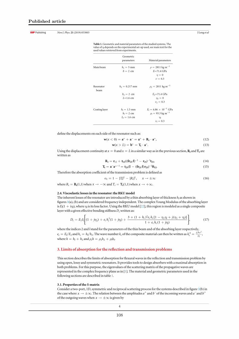
define the displacements on each side of the resonator such as:
xw a a a R a0 , 12t< = + = ++ - + +( ) · ( )
x Lw b T a . 13t> = =+ +( ) · ( )
Using the displacement continuity at x=0 and x=L in a similar way as in the previous section,Rt andTt are
written as
R r t fr f r t , 14t 12 23 21 21121 1= + -- -(( ) ) ( )
T a a t I fr f r ft . 15t 23 21 23 121 1= = -- +- -( ( ) ) ( )
Therefore the absorption coefficient of the transmission problem is defined as
T R x1 , 16t t t2 2a = - - ¥∣ ∣ ∣ ∣ ( )
whereRt=Rt(1,1)when x -¥ andTt=Tt(1,1)when x +¥.
2.4. Viscoelastic losses in the resonator: theRKUmodel
The inherent losses of the resonator are introduced by a thin absorbing layer of thickness hl as shown in
figures 1(a), (b) and are considered frequency independent. The complex YoungModulus of the absorbing layer
isEl(1+iηl), where ηl is its loss factor. Using the RKUmodel [22], this region ismodeled as a single composite
layer with a given effective bending stiffnessDcwritten as:
D E I j e h jh e h j
e h j1 1
3 1 1
1 1, 17c c c l
c c c l l
c c l
2 2 23
22 2h hh h h hh
= + + + ++ + - + +
+ +
⎡
⎣⎢
⎤
⎦⎥( ) ( )
( ) [ ( )]
( )( )
where the indices 2 and l stand for the parameters of the thin beamand of the absorbing layer respectively,
ec=El/E2 and hc=hl/h2. Thewave number kc of the compositematerial can then bewritten as kch
D
4 c
c
2
= r w,
where h=hl+h2 and ρch=ρ2h2+ρlhl.
3. Limits of absorption for the reflection and transmission problems
This section describes the limits of absorption forflexural waves in the reflection and transmission problemby
using open, lossy and symmetric resonators. It provides tools to design absorbers with amaximal absorption in
both problems. For this purpose, the eigenvalues of the scatteringmatrix of the propagative waves are
represented in the complex frequency plane as in [1]. Thematerial and geometric parameters used in the
following sections are described in table 1.
3.1. Properties of the S-matrix
Consider a two-port, 1D, symmetric and reciprocal scattering process for the systems described infigure 1(b) in
the casewhere x ¥. The relation between the amplitudes a+ and b−of the incomingwaves and a−and b+
of the outgoingwaveswhen x ¥ is given by
Table 1.Geometric andmaterial parameters of the studied systems. Thevalue of ηldepends on the experimental set-up used, seemain text for theused values retrieved from experiments.
Geometric
parameters Material parameters
Main beam h1=5 mm ρ=2811 kg m−3
b=2cm E=71.4 GPa
η=0
ν=0.3
Resonator
beam
h2=0.217 mm ρ2=2811 kg m−3
b2=2 cm E2=71.4 GPa
L=1.6 cm η2=0
ν2=0.3
Coating layer hl=1.5 mm El=6.86×10⁻³ GPa
bl=2 cm ρl=93.3 kg m−3
Ll=1.6 cm ηl
νl=0.3
4
New J. Phys. 21 (2019) 053003 J Leng et al
Published article
108
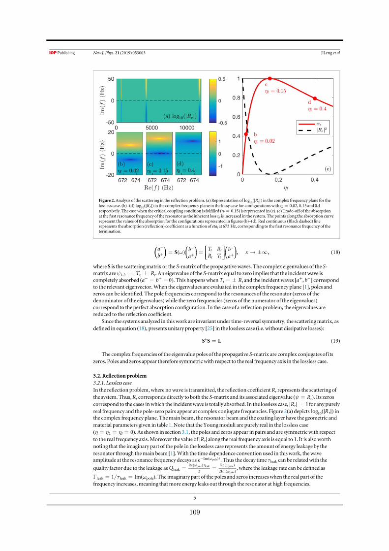
a
bb
a
T R
R Tb
axS , , 18t t
t tw= = ¥
-
+
-
+
-
+⎜ ⎟ ⎜ ⎟⎛
⎝
⎞
⎠
⎡
⎣⎢⎤
⎦⎥⎛
⎝
⎞
⎠( ) ( ) ( )
where S is the scatteringmatrix or the S-matrix of the propagative waves. The complex eigenvalues of the S-
matrix areψ1,2 = Tt ± Rt. An eigenvalue of the S-matrix equal to zero implies that the incident wave is
completely absorbed (a−=b+= 0). This happenswhenTt=±Rt and the incident waves [a+, b−] correspond
to the relevant eigenvector.When the eigenvalues are evaluated in the complex frequency plane [1], poles and
zeros can be identified. The pole frequencies correspond to the resonances of the resonator (zeros of the
denominator of the eigenvalues)while the zero frequencies (zeros of the numerator of the eigenvalues)
correspond to the perfect absorption configuration. In the case of a reflection problem, the eigenvalues are
reduced to the reflection coefficient.
Since the systems analyzed in this work are invariant under time-reversal symmetry, the scatteringmatrix, as
defined in equation (18), presents unitary property [25] in the lossless case (i.e. without dissipative losses):
S S I. 19* = ( )
The complex frequencies of the eigenvalue poles of the propagative S-matrix are complex conjugates of its
zeros. Poles and zeros appear therefore symmetric with respect to the real frequency axis in the lossless case.
3.2. Reflection problem
3.2.1. Lossless case
In the reflection problem,where nowave is transmitted, the reflection coefficientRr represents the scattering of
the system. Thus,Rr corresponds directly to both the S-matrix and its associated eigenvalue (ψ=Rr). Its zeros
correspond to the cases inwhich the incident wave is totally absorbed. In the lossless case, R 1r =∣ ∣ for any purely
real frequency and the pole-zero pairs appear at complex conjugate frequencies. Figure 2(a) depicts Rlog r10(∣ ∣) inthe complex frequency plane. Themain beam, the resonator beam and the coating layer have the geometric and
material parameters given in table 1.Note that the Youngmoduli are purely real in the lossless case
(η=η2=ηl=0). As shown in section 3.1, the poles and zeros appear in pairs and are symmetric with respect
to the real frequency axis.Moreover the value of Rr∣ ∣along the real frequency axis is equal to 1. It is alsoworth
noting that the imaginary part of the pole in the lossless case represents the amount of energy leakage by the
resonator through themain beam [1].With the time dependence convention used in this work, thewaveamplitude at the resonance frequency decays as e tIm polew- ( ) . Thus the decay time τleak can be relatedwith the
quality factor due to the leakage as Q leakRe
2
Re
2Im
pole leak pole
pole= =
w t w
w
( ) ( )
( ), where the leakage rate can be defined as
Γleak=1/τleak=Im(ωpole). The imaginary part of the poles and zeros increases when the real part of the
frequency increases,meaning thatmore energy leaks out through the resonator at high frequencies.
Figure 2.Analysis of the scattering in the reflection problem. (a)Representation of Rlog r10(∣ ∣) in the complex frequency plane for thelossless case. (b)–(d) Rlog r10(∣ ∣) in the complex frequency plane in the lossy case for configurationswith ηl=0.02, 0.15 and 0.4respectively. The casewhen the critical coupling condition is fulfilled (ηl=0.15) is represented in (c). (e)Trade-off of the absorptionat the first resonance frequency of the resonator as the inherent loss ηl is increased in the system. The points along the absorption curverepresent the values of the absorption for the configurations represented infigures (b)–(d). Red continuous (Black dashed) linerepresents the absorption (reflection) coefficient as a function of etal at 673 Hz, corresponding to thefirst resonance frequency of thetermination.
5
New J. Phys. 21 (2019) 053003 J Leng et al
109

3.2.2. Lossy case
For the sake of clarity, this section only focuses on the first pole-zero pair of the systempreviously described. The
discussion can nevertheless be extended to any pole-zero pair of the system in the complex frequency plane.
Losses are now introduced into the systemby adding an imaginary part to the Youngmodulus of the damping
material such that it can bewritten asEl(1+iηl).
As a consequence, the symmetry between the poles and zeroswith respect to the real frequency axis is
broken, since the property of equation (19) is nomore satisfied in the lossy case. Figures 2(b)–(d) depict
Rlog r10(∣ ∣) in the complex frequency plane around the first resonance frequency for three different increasing
values of ηl. Figure 2(b) represents the case forwhich the losses are small (ηl=0.02). In this case, the pole-zero
pair is quasi-symmetric with respect to the real frequency axis. As the losses in the damping layer increase
(ηl=0.15 infigure 2(c) and ηl=0.4 infigure 2(d)), the zeromoves to the real frequency axis. In particular, the
zero of the reflection coefficient is exactly located on the real frequency axis infigure 2(c). In this situation, the
amount of inherent losses in the resonator equals the amount of energy leakage. This situation is known as the
critical coupling condition [15] and implies the impedancematching, leading to a perfect absorption.
The value of the absorption coefficient of the first resonant peak as a function of ηl is depicted infigure 2(e).
The position of the zero in the complex frequency plane is directly related to the value of the flexural wave
absorption.When the zero approaches the real frequency axis, the value of the absorption is close to one, being
equal to 1when the zero is exactly located in the real frequency axis. It should be noted that the perfect
absorption cannot occur once the zero has crossed the real frequency axis. This propertymight appear
counterintuitive since itmeans that adding a large amount of losses in the systemmight lead to a deterioration of
the absorbing properties of the structure.
3.2.3. Design of perfect absorbers for flexural wave in the reflection problem
A theoretical design for the perfect absorption offlexural waves is shown in this section based on the
configuration represented in the figure 1(b) and the parameters given in table 1. Considering that there is no
inherent losses in themain beam and the resonator beam (η=η2=0), the loss factor of the coating layer has to
be ηl=0.15 to obtain a perfect absorption at the first resonance frequency of the system.
Figures 3(a), (b) depict Rlog r10(∣ ∣) for the lossless and lossy configurations in the complex frequency plane
respectively. Figure 3(b) shows particularly thefirst pole-zero pair of the system in the perfect absorption
configurationwhere the critical coupling condition is fulfilled, showing the zero exactly located on the real
frequency axis. Figure 3(c) shows the corresponding absorption (red continuous line) and reflection (black
dashed line) coefficients according to real frequencies for the critical coupled configuration. These coefficients
are calculatedwith the analyticalmodel described in previous sections. The incident wave is totally absorbed at
thefirst resonance frequency of the composite beam.
Figure 3.Representation of the perfect absorption for the reflection problem. (a), (b) Show the representation of the Rlog r10(∣ ∣) for thelossless and lossy configurations respectively. (c)Red continuous and black dashed lines show the analytical absorption and reflectioncoefficients for the critical coupled configuration respectively.
6
New J. Phys. 21 (2019) 053003 J Leng et al
Published article
110

3.3. Transmission problem
For the transmission problem, the S-matrix is defined in equation (18) and has two eigenvaluesψ1,2. The
scatterer beingmirror symmetric, the problem can be reduced to two uncoupled sub-problems: a symmetric
problemwhereψs=Tt+Rt and an anti-symmetric, whereψa=Tt−Rt.
ψs corresponds to the reflection coefficient of the symmetric problemwhileψa corresponds to the reflection
coefficient of the anti-symmetric problem. The absorption coefficient can also be expressed asα=(αs+αa)/2
where 1s s2a y= - ∣ ∣ and 1a a
2a y= - ∣ ∣ . Similarly to the reflection problem, poles and zeros ofψs andψa can
be identified in the complex frequency plane. The following sections focuses on the first resonantmode of the
beam resonator, the displacement distribution of which is symmetric. The interpretation of the results can
nevertheless be applied to the higher ordermodes with anti-symmetric distributions of the displacement field. It
is worth noting that the displacement distribution of the resonantmodes changes from symmetric to anti-
symmetric as themode increases due to the geometry of the resonators [26].
3.3.1. Lossless case
Figures 4(a) and (b) show the variation of log s10 y(∣ ∣) and log a10 y(∣ ∣) evaluated respectively in the complexfrequency plane in the lossless case for thefirst resonantmode. Themain beam, the resonator beam and the
coating layer of the studied systemhave still thematerial and geometric parameters of table 1, where
η=η2=etal=0 in the lossless case. The symmetric and anti-symmetric problems exhibit pole-zero pairs
similarly to the reflection problem in the lossless case. These pairs are also symmetrically positionedwith respect
to the real frequency axis. The absence of dissipation is shown along the real frequency axis where T R 1t t =∣ ∣
for any real frequency. This section focuses only on the first resonantmodewhich has a symmetric distribution
of the displacementfield. Therefore, only the symmetric problempresents a pole-zero pair at the corresponding
resonance frequency, while the anti-symmetric one does not.
3.3.2. Lossy case
Unlike the reflection problem, the condition for perfect absorption is stronger in the transmission one andneeds
to place the zeros of bothψs andψa at the same frequency in the real frequency axis. Once this condition is
fulfilled, a+ and b−correspond to the relevant eigenvector and the system satisfies the coherent perfect
absorption condition [2, 9, 27].
Losses are introduced in the system in the sameway as for the reflection problem, i.e. by increasing the loss
factor ηl of thematerial of the damping layer. Once the losses are introduced, the position of the pole-zero pair of
the symmetric eigenvalue in the complex frequency plane shifts towards the upper half spacewhile the anti-
symmetric problem remains unchangedwithout pole-zero pairs, as shown infigures 4(c) and (d). Therefore,
only the zero of the symmetric problem can be placed on the real frequency axis, i.e. only half of the problem can
be critically coupled. Figure 4(e) shows the dependence of the reflection, transmission and absorption coefficient
Figure 4.Representation of the eigenvalues of the S-matrix for a transmission problem in the lossless and lossy case. (a) and (b)Lossless case for log s10 y(∣ ∣) and log a10 y(∣ ∣) in the complex frequency plane. (c) and (d) Lossy case for log s10 y(∣ ∣) and log a10 y(∣ ∣) in thecomplex frequency plane. (e)Trade-off of the transmission (blue dotted line), reflection (black dashed line) and absorption (redcontinuous line) for themaximumabsorption of thefirstmode as the loss factor of the coating layer increases. (f)Red continuous,black dashed and blue dotted lines represent the absorption, reflection and transmission coefficients respectively for the half criticallycoupled configuration.
7
New J. Phys. 21 (2019) 053003 J Leng et al
111

on the inherent losses in the resonator for the firstmode. Themaximumabsorption obtained is 0.5 since only
the symmetric problem is critically coupled (α=(αs+αa)/2; (1+0)/2=1/2).
3.3.3. Design ofmaximal absorbers for flexural wave in the transmission problem
Based on the results discussed previously, a configurationwithmaximal absorption forflexural waves in the
transmission problem is designedwith the parameters given in table 1. As for the reflection problem, no inherent
losses are considered in themain beam and the resonator beam (η=η2=0). The loss factor of the coating layer
is ηl=2.21. The reflection, transmission and absorption for this configuration is analyzed infigure 4(f),
showing that themaximumabsorption is 0.5 at the resonance frequency of the beam. This result is in accordance
with the ones previously obtained [2, 9, 21], even if the resonator is not a point translational impedance. The
absorption is limited to 0.5 since only one kind of geometry of resonantmode can be excited. The problem is
therefore half critically coupled. To obtain a higher absorption, other strategies based on breaking the symmetry
of the resonator [5] or on the use of degenerate resonators are needed [28]. In these cases, both eigenvalues
present poles and zeros located at the same real frequencies. It would then be possible to fully critically couple the
problem and so obtain a perfect absorption (i.e.α=1) at the appropriate frequency.
4. Experimental results
This section presents the experimental results of the reflection coefficient [29, 30] for an aluminumbeam system
with the configuration described in section 3.2.3.
4.1. Experimental set-up
The beam is held vertically in order to avoid static deformation due to gravity. The extremity at which the
reflection coefficient is estimated is oriented towards the ground (seefigure 5(a)). The used coating layer have
been experimentally characterized showing an ηl=0.15, which is the value forwhich perfect absorption can be
observed. A photograph of the resonator with the coating layer is shown infigure 5(b). Themeasurements are
performed along the beamat 21 points equidistant of 5mmand located on its neutral axis in order to avoid the
torsional component. Themeasurement points are also located sufficiently far from the source and the
Figure 5. (a)Diagramof the experimental set-up. (b)Photograph of the resonator. (c)Black crosses and red open circles showrespectively Rr
2∣ ∣ andαr for the critical coupled configurationmeasuredwith the experimental set-up. Black dashed and redcontinuous lines show Rr
2∣ ∣ andαr calculatedwith the analyticalmodel.
8
New J. Phys. 21 (2019) 053003 J Leng et al
Published article
112

extremity of the beam to consider far-field assumption and neglect the contribution of evanescent waves. In this
case, far-field assumption is fulfilled at a distance lf fromboth the source and the resonator forwhich the
evanescent wave loses 90%of its initialmagnitude. The low frequency limit of themeasurements is thenestimated using e 0.1klf = . The shaker excites the beamwith a sweep sine. The displacement field versus
frequency is obtained from themeasurements of the vibrometer at eachmeasure point.
4.2. Experimental estimation of the reflection coefficient
Consider theflexural displacementW(xi,ω)measured at the point x i 0, 20i Î( [ ]) for a given angular frequency
ω as
W x A B, e e . 20ikx kxi ii iw w w= +-( ) ( ) ( ) ( )
The set ofW(xi,ω) for eachmeasurement point can bewritten in amatrix format [30] such as
W x
W x
W x
W x
A
B
,
,
,
,
e e
e e
e e
e e
. 21
kx kx
kx kx
kx kx
kx kx
0
1
2
20
i i
i i
i i
i i
0 0
1 1
2 2
20 20
www
w
ww
=
-
-
-
-
⎛
⎝
⎜⎜⎜⎜⎜
⎞
⎠
⎟⎟⎟⎟⎟
⎛
⎝
⎜⎜⎜⎜⎜
⎞
⎠
⎟⎟⎟⎟⎟
⎛
⎝⎜
⎞
⎠⎟
( )
( )
( )
( )
( )
( )( )
( ) ( )
( ) ( )
( ) ( )
( ) ( )
The amplitudesA(ω) andB(ω) can then be derived from equation (21)which forms an overdetermined system.
From these amplitudes, the reflection coefficient of the propagative waves can be deduced for anyω as:
RA
B. 22r w
ww
=( )( )
( )( )
4.3. Experimental evidence of perfect absorption forflexural waves
Experimental results obtainedwith the experimental set-up are depicted infigure 5(c). A drop of reflection is
noticed at thefirst resonant frequency of the terminationwith aminimumvalue of R 0.02r2 =∣ ∣ at 667 Hz for
the experiment and R 0r2 =∣ ∣ at 673 Hz for the analytical result. The gap between the analytical and
experimental resonant frequency is 0.9%. This frequency shift between themodel and the experiment ismainly
due to the geometric uncertainty in the resonator thickness, induced by themachining process. This geometrical
uncertainty induces also an estimation uncertainty of the energy leakage of the resonator. The absorption is then
experimentally limited toαr=0.98. Evidence of perfect absorption forflexural waves bymeans of critical
coupling is shown experimentally here.
Three experimental scans of thewhole beam at 500, 670 and 800 Hz have beenmeasured3. At 500 or 800 Hz
the reflection coefficient is very close to one. The standingwaves in themain beamare visible at these
frequencies. At 670 Hz, the termination absorbs totally the incident waves. There is therefore no standingwaves
and thewaves are propagating in themain beam.
5. Conclusions
Absorption of propagative flexural waves bymeans of simple beam structures is analyzed in this work. Themain
mechanisms are interpreted in terms of both the critical coupling conditions and the symmetries of the
resonances for both the reflection and the transmission problems. The positions of the zeros of the eigenvalues
of the scatteringmatrix in the complex frequency plane give informations on the possibility to obtain the perfect
absorption. The perfect absorption condition is fulfilledwhen these zeros are placed on the real frequency axis,
meaning that the inherent losses are completely compensating the energy leakage of the system. In the reflection
problem, the physical conditions of the problem lead to perfect absorption at low frequencies. In this case a
single symmetry for the resonance is excited and perfect absorption can be obtainedwhen the inherent losses of
the systembalance the energy leakage of the system. In the transmission problem, the requirement to obtain
perfect absorption is stronger than for the case in reflection as two kinds of symmetries of the resonances are
required to be critically coupled simultaneously. In the case presented in this work, or in the general case of point
translational impedances, dealing onlywith one type of symmetry for the resonantmodes [21] limits the
absorption to 0.5. Therefore for the perfect absorption in the transmission case, two strategies are needed: (i)
breaking the symmetry of the resonator in order to treat the full problemwith a single type of symmetry of the
resonancemode [5]; (ii) using degenerate resonators with two types of symmetries at the same frequency being
critically coupled [28]. The resonator used in this study has been chosen as an integral part of themain beam for
3See supplementarymaterial is available online at stacks.iop.org/NJP/21/053003/mmedia: videos 500 Hz.avi, 670 Hz.avi and 800 Hz.avi
9
New J. Phys. 21 (2019) 053003 J Leng et al
113

experimental set-up reasons. However, the presented approach can be applied to any class of 1D resonant-
systemprovided that the resonators are local, open and lossy ones. These properties of the resonator are the
essential points to achieve the perfect absorption at low frequency by solving the following problems: increasing
the density of states at low frequencies andmatching the impedancewith the backgroundmedium.
Acknowledgments
The authors thankMathieu Sécail-Geraud and JulienNicolas for the development of the experimental set-up.
Thework has been founded by the RFI LeMansAcoustic (Région Pays de la Loire)within the framework of the
Metaplaque project. This article is based uponwork fromCOST actionDENORMSCA15125, supported by
COST (EuropeanCooperation in Science andTechnology). Theworkwas partly supported by the Spanish
Ministry of Economy and Innovation (MINECO) and EuropeanUnion FEDER through project FIS2015-
65998-C2-2 and by project AICO/2016/060 byConsellería de Educación, Investigación, Cultura yDeporte de la
Generalitat Valenciana.
ORCID iDs
VRomero-García https://orcid.org/0000-0002-3798-6454
References
[1] Romero-García V, Theocharis G, RichouxO and PagneuxV 2016Use of complex frequency plane to design broadband and sub-
wavelength absorbers J. Acoust. Soc. Am. 139 3395–403
[2] Merkel A, Theocharis G, RichouxO, Romero-García V and PagneuxV 2015Control of acoustic absorption in one-dimensional
scattering by resonant scatterersApp. Phys. Lett. 107 244102
[3] Groby J-P, Pommier R andAurégan Y 2016Use of slow sound to design perfect and broadband passive sound absorbingmaterials
J. Acoust. Soc. Am. 139 1660–71
[4] JiménezN,HuangW,Romero-García V, PagneuxV andGroby J-P 2016Ultra-thinmetamaterial for perfect and quasi-
omnidirectional sound absorptionAppl. Phys. Lett. 109 121902
[5] JiménezN, Romero-García V, PagneuxV andGroby J-P 2017Rainbow-trapping absorbers: Broadband, perfect and asymmetric sound
absorption by subwavelength panels for transmission problems Sci. Rep. 7 13595
[6] FangN,XiD, Xu J, AmbatiM, SrituravanichW, SunC andZhangX 2006Ultrasonicmetamaterials with negativemodulusNat.Mater.
5 452
[7] Liu Z, ZhangX,MaoY, ZhuYY, Yang Z, ChanCT and Sheng P 2000 Locally resonant sonicmaterials Science 289 1734–6
[8] Skelton EA, Craster RV, Colombi A andColquitt D J 2018Themulti-physicsmetawedge: graded arrays onfluid-loaded elastic plates
and themechanical analogues of rainbow trapping andmode conversionNew J. Phys. 20 053017
[9] Wei P, CroënneC, TakChu S and Li J 2014 Symmetrical and anti-symmetrical coherent perfect absorption for acoustic wavesAppl.
Phys. Lett. 104 121902
[10] DuanY, Luo J,WangG,Hang ZH,HouB, Li J, Sheng P and Lai Y 2015Theoretical requirements for broadband perfect absorption of
acoustic waves by ultra-thin elasticmeta-films Sci. Rep. 5 12139
[11] Theocharis G, RichouxO, Romero-García V,Merkel A andTournat V 2014 Limits of slow sound propagation and transparency in
lossy, locally resonant periodic structuresNew J. Phys. 16 093017
[12] Colombi A, AgeevaV, SmithR J, Clare A, Patel R, ClarkM,Colquitt D, Roux P, Guenneau S andCraster RV 2017 Enhanced sensing
and conversion of ultrasonic rayleighwaves by elasticmetasurfaces Sci. Rep. 7 6750
[13] Pal R J andRuzzeneM2017 Edgewaves in plates with resonators: an elastic analogue of quantumvalley hall effectNew J. Phys. 19
025001
[14] BliokhKY, BliokhYP, Freilikher V, Savel’ev S andNori F 2008Colloquium: unusual resonators: plasmonics,metamaterials, and
randommediaRev.Mod. Phys. 80 1201
[15] Yariv A 2000 universal relations for coupling of optical power betweenmicroresonators and dielectric waveguides Electron. Lett. 36
321–2
[16] XuY, Li Y, Lee RK andYariv A 2000 Scattering-theory analysis of waveguide-resonator couplingPhys. Rev.E 62 7389
[17] CaiM, PainterO andVahala K J 2000Observation of critical coupling in afiber taper to a silica-microsphere whispering-gallerymode
systemPhys. Rev. Lett. 85 74
[18] TengT-L andHuN-K 2001Analysis of damping characteristics for viscoelastic laminated beamsComput.MethodAppl.M 190
3881–92
[19] DenHartog J P 1985Mechanical Vibrations (NewYork:Dover)
[20] BrennanM J 1999Control offlexural waves on a beamusing a tunable vibration neutraliser J. SoundVib. 222 389–407
[21] El-KhatibHM,Mace BR andBrennanM J 2005 Suppression of bendingwaves in a beamusing a tuned vibration absorber J. SoundVib.
288 1157–75
[22] RossD,Ungar E L andKerwin EM1960Damping of plate flexural vibrations bymeans of viscoelastic laminae Structural Damping
(Oxford: Pergamon) pp 49–57
[23] Mace BR 1984Wave reflection and transmission in beams J. SoundVib. 97 237–46
[24] Leissa AW1969TabulatedNumerical Results of Theories of Plate Vibration (Washington, DC:NASA)
[25] Norris AN1998Reflection and transmission of structural waves at an interface between doubly curved shellsActa Acust. United Ac. 84
1066–76
[26] JiménezN, Romero-García V, PagneuxV andGroby J-P 2017Quasiperfect absorption by subwavelength acoustic panels in
transmission using accumulation of resonances due to slow sound Phys. Rev.B 95 014205
10
New J. Phys. 21 (2019) 053003 J Leng et al
Published article
114

[27] ChongYD,Ge L, CaoH and StoneAD2010Coherent perfect absorbers: time-reversed lasersPhys. Rev. Lett. 105 053901
[28] YangM,MengC, FuC, Li Y, Yang Z and Sheng P 2015 Subwavelength total acoustic absorptionwith degenerate resonatorsAppl. Phys.
Lett. 107 104104
[29] Gautier F,MouletM-H and Pascal J-C 2006Reflection, transmission and coupling of longitudinal and flexural waves at beam
junctions. part i:measurementmethodsActa Acust. United Ac. 92 982–97
[30] Denis V, Gautier F, Pelat A and Poittevin J 2015Measurement andmodelling of the reflection coefficient of an acoustic black hole
termination J. SoundVib. 349 67–79
11
New J. Phys. 21 (2019) 053003 J Leng et al
115

Appendix B
Scattering of an uniform circular
inclusion in a thin plate
Chapter 4 deals with the particular scattering problem of a concentric incident wave conver-ging towards the centre of a circular scatterer. This appendix summarise a more general scatte-ring problem with an incident plane wave scattered by a cavity according to the work of Norrisand Vemula [134]. The scattered field of an incident plane wave winc by an isolated circular scat-terer S of radius a is considered. The material properties of the scatterer are assumed randomlydifferent from the surrounding plate. The scatterer properties are denoted by the subscript 0 andthe plate properties by the subscript 1. The expressions of the displacements field in the systemare expressed with the polar coordinate system (O, r, θ) whose the origin is aligned with thecentre of the scatterer. The flexural displacement field in the plate w(r, θ) and in the scattererw0(r, θ) are governed by the following equations respectively:
(∇2∇2 − k41)w(r, θ) = 0,
(∇2∇2 − k40)w0(r, θ) = 0,
(B.1)
where k40 = ρh0ω2
D0and k4
1 = ρ1h0ω2
D1. The displacement field w(r, θ) in the plate is defined as the
sum of an incident field winc(r, θ) and a scattered field w0(r, θ) such that:
w(r, θ) = winc(r, θ) + w1(r, θ). (B.2)
B.0.1 Expression of the incident propagative plane wave
The incident wave winc is considered as a propagative plane wave with unitary amplitudeand wave vector k1. Assuming that a cartesian coordinate system is aligned with the centre ofthe scatterer, the position vector reads as
x = xex + yey. (B.3)
winc can then be written as:winc(x) = eik·x, (B.4)
with k = k1xex+k1yey. To satisfy the first equation of B.1, the relation k21x+k2
1y = k21 must hold.
The wavenumber components can therefore be written in the form k1x = k1 cos(θinc) and k1x =
117

Scattering of an uniform circular inclusion in a thin plate
k1 sin(θinc), where the angle θinc characterises the direction of propagation of the incident wave,while the position vector reads in the polar coordinate system as x = r cos(θ)ex + r sin(θ)ey,.As a result, Eq.B.4 becomes from Eq.B.3 :
winc(r, θ) = eik1rcos(θ) cos(θinc)+sin(θ) sin(θinc) = eik1r cos(θ−θinc). (B.5)
This expression can be expand upon Bessel functions using the Jacobi-Anger expansion [2] suchthat:
winc(r, θ) =+∞∑
n=−∞
AincJ,nJn(k1r)einθ , r > a, (B.6)
where AincJ,n = ine−inθinc is the incident amplitude.
B.0.2 Expression of w0 and w1
The general expressions of w0 is given by summing Eq.4.9 and Eq. 4.13. However, as Hn(k0r)and Kn(k0r) are singular as r → 0, the displacement field w0 in the scatterer S is only composedof a linear combination of Bessel functions and modified Bessel functions of first kind such that:
w0 =+∞∑
n=−∞
[AJ,nJn(k0r) +AI,nIn(k0r)] einθ , r < a. (B.7)
Hn(k1r) and Kn(k1r) represents the outgoing waves in the system when r > a and satisfy theSommerfeld radiation condition as shown in Section 4.2.2. The scattered field w1 in the plate istherefore expressed as:
w1 =+∞∑
n=−∞
[AH,nHn(k1r) +AK,nKn(k1r)] einθ , r > a. (B.8)
B.0.3 Boundary conditions
Now that the displacement fields have been expressed according to the polar coordinate sys-tem (O, r, θ), the boundary condition at the interface between the scatterer and the surroundingplate ( at r = a) can be applied to compute the scattering coefficients AH,n, AK,n, AJ,n andAI,n from the incident amplitude Ainc
J,n. Four boundary conditions at r = a are distinguishedaccording to Khirchhoff theory:
— displacement continuityw(a, θ) = w0(a, θ), (B.9)
— displacement normal derivative continuity
∂w(a, θ),∂r
=∂w0(a, θ),
∂r, (B.10)
— bending moment continuity
M (w(a, θ)) = M0 (w1(a, θ)) , (B.11)
118

— the (Kirchhoff) shear force continuity
V (w(a, θ)) = V0 (w1(a, θ)) , (B.12)
with [175]
Mi(w) = −Di∂2w
∂r2−Diνi
(
1r
∂w
∂r+
1r2
∂2w
∂θ2
)
, (B.13)
and
Vi(w) = −Di∂
∂r∇2w −Di(1 − νi)
1r2
∂2
∂θ2
(
∂w
∂r− w
r
)
, (B.14)
where the subscripts i = 0, 1 denotes the scatterer and the plate respectively. Applying thesecontinuity conditions leads to the system of equations[134]:
An.xn = Bn.an (B.15)
where
An =
Hn(ε1) Kn(ε1) −Jn(ε0) −In(ε0)H’n(ε1) K’n(ε1) −κJ’n(ε0) −κI’n(ε0)S1
HnS1
Kn−DS0
Jn−DS0
In
T 1Hn
T 1Kn
−DT 0Jn
−DT 0In
xn =
AH,n
AK,n
AJ,n
AI,n
, Bn = −
Jn(ε1) In(ε1)J’n(ε1) I’n(ε1)S1
JnS1
In
T 1Jn
T 1In
, an =
(
AincJ,n
0
)
,
κ = k0k1
, ε1 = k1a, ε0 = k0a = κε1 et D = D1D0
.
SiXn
=[
n2(1 − νi) ∓ ε2i
]
Xn(εi) − (1 − νi)εiX′n(εi), (B.16)
T iXn
= n2(1 − νi)Xn(εi) −[
n2(1 − νi) ± ε2i
]
X ′n(εi), (B.17)
The upper sign in Eq. (B.16) and Eq. (B.17) is taken when Xn = Jn or Hn while the lower signis taken when Xn = In or Kn. The solution of the equation system (B.15) gives the scatteringcoefficients AH,n, AK,n, AJ,n and AI,n for a given function order n. In the case where the solutionis a linear combination of N order, the system has to be solved N times for each function order.
119


Appendix C
Computation of the scattering
coefficients and the scattering field
finside a 2D scatterer with varying
properties
Section 4.5 deals with the particular scattering problem of a concentric incident wave conver-ging towards the centre of a circular scatterer with radially varying thickness.This appendix aimsto show the computation steps to obtain the scattering coefficients as well as the propagativeand evanescent field amplitudes of a more general problem where the structure is radially ho-mogeneous, that is, its parameters depend only on the radial coordinate. The problem is alsogeneralized to any Bessel function order n ∈ Z. The model used to that purpose is the multilayerscattering method, where the continuous variation of the parameters has been discretized in anumber N of homogeneous cylindrically symmetric layers [27]. The layers are numbered suchthat the surrounding plate corresponds to j = N and the core layer corresponds to j = 0.
C.1 Expression of the scattered amplitudes inside the scatterer
according to the scattering coefficients.
The flexural amplitudes W−n,j et W+
n,j at layer j can be related to the incident wave fromthe recurrence relation of Eq. (4.49), such that:
W−n,j−1 = T−
n,j.W−n,j − R−
n,j.W+n,j−1 (C.1)
W+n,j = R+
n,j.W−n,j + T+
n,j.W+n,j−1 (C.2)
Defining the elastic ’impedance’ matrix Znj as the term which link the diverging field with theconverging field in the same layer (W+
n,j = Zn,j.W−n,j) and replacing this term in Eqs. (C.1) and
( C.2), one can obtain:
W−n,j−1 =
(
Id − R−n,j.Zn,j−1
)−1T−
n,j.W−n,j (C.3)
121

Computation of the scattering coefficients and the scattering field finside a 2Dscatterer with varying properties
W−n,j−1 =
(
T+n,j..Zn,j−1
)−1.(
Zn,j − R+n,j
)
.W−n,j. (C.4)
These two relations give a recursive relation between W−n,j−1 and W−
n,j and a second betweenZn,j and Zn,j−1 such that:
Zn,j = R+n,j + T+
n,j.Zn,j−1.Xn,j−1, (C.5)
Xn,j−1 =(
Id − R−n,c.Zn,j−1
)−1.T−
n,j, (C.6)
where W−n,j−1 = Xn,j−1.W
−n,j. Assuming that all the scattering coefficients are known, the first
iteration to compute all the Zn,j and Xn,j might be done between layer 1 and layer 0. Layer à0is described by a combination of Bessel and modified Bessel function of the first kind. Therefore,it is possible to write from Eqs.(C.1 ) and (C.2):
Xn,0 = T−n,1
Zn,0 = R+n,1
As a result, it might be possible to express the amplitude of all the converging and divergingfields as a function of the incident field outside the scatterer and its scattering coefficients, inthe same way as transfer functions.
C.1.1 Computation of the scattering coefficients inside the scatterer
The scattering coefficients are obtained applying the continuity conditions between eachinterface. These conditions are the same as presented in Section B.0.3 and have to satisfy twotypes of incidence: converging incidence and diverging incidence. The first case leads to thecomputation of a diverging reflection and a converging transmission, and the second one to aconverging reflection and a diverging transmission.
Converging incident wave: Applying the continuity conditions at the interface between thelayers j − 1 and j at r = rj−1 with a converging incident wave leads to the following equationsystem :
An,jxn,j = Bn,jan,j, (C.7)
where
An,j =
Hn(εj) Kn(εj) −Jn(εj−1) −In(εj−1)H’n(εj) K’n(εj) −κnJ’n(εj−1) −κlI’n(εj−1)Sj
HnSj
Kn−DjS
j−1Jn
−DjSl+1In
T jHn
T jKn
−DjTl+1Jn
−DjTl+1In
,
xn,j =
A(j)H,n
A(j)K,n
A(j−1)J,n
A(j−1)I,n
, Bn,j = −
Jn(εj) In(εj)J’n(εj) I’n(εj)Sj
JnSj
In
T jJn
T jIn
, an,j =
A(j)J,n
A(j)I,n
,
122

1. Expression of the scattered amplitudes inside the scatterer according to thescattering coefficients.
with κj = kj−1
kj, εj = kjrj−1, εj−1 = kl+1rj−1 et Dj = Dj−1
Dj. Note that the expression of an,j is
not valid when j = N in the case where the incident wave in the plate is defined with a Hankel
function of the second kind. In this case, an,N =
(
A(N)H,0
0
)
. Writing xn,j =
(
W+n,j
W−n,j−1
)
,an,j =(
W+n,j
)
, we get:
(C.7) ⇒(
W+n,j
W−n,j−1
)
=
(
R+n,j
T−n,j
)
(
W−n,j
)
(C.8)
These coefficients are directly computed from the material properties of the system and fromBessel, Hankel and modified Bessel functions. This means that the coefficients are totally inde-pendant of the field in the system.
Diverging incident wave: Applying the continuity conditions at the interface between thej-th and j− 1-th layers at r = rj−1 with a diverging incident wave leads to the following systemof equations :
A′n,jx
′n,j = B′
n,ja′n,j, (C.9)
where
A′n,j =
Jn(εj−1) In(εj−1) −Hn(εj) −Kn(εj)J’n(εj−1) I’n(εj−1) −κ1jH’n(εj) −κ1jK’n(εj)Sj−1
JnSj−1
In−Dj−1S
jHn
−Dj−1SjKn
T j−1Jn
T j−1In
−Dj−1TjHn
−Dj−1TjKn
x′n,j =
A(j−1)H,n
A(j−1)K,n
A(j)J,n
A(j)I,n
, B′n,j = −
Hn(εj−1) Kn(εj−1)H’n(εj−1) K’n(εj−1)Sj−1
HnSj−1
Kn
T j−1Hn
T j−1Kn
, a′n,j =
A(j−1)J,n
A(j−1)I,n
,
with κ1j = kj−1
kj, εj = kjRj−1, εj−1 = kj−1Rj−1 and Dj = Dj−1
Dj. As for (C.8), we can get from
(C.9):
(
W−n,j−1
W+n,j
)
=
(
R−n,j
T+n,j
)
.(
W+n,j
)
(C.10)
This system has no physical meaning when it is solved for layer 0, since the scattered fieldand the incident field are both described by a linear combination of Bessel and modified Besselfunctions. Furthermore, It is useless to compute the coefficient of layer 0 because they are notused to compute Xn et Zn.
123


Appendix D
Mathematical tools for multiple
scattering
Chapter 5 deals with multiple scattering problems with an infinite row of circular criticallycoupled resonators. This appendix aims to detail the mathematical tools used to study thisproblem.
D.1 Graf’s addition theorem
The Graf’s addition theorem is used in Chapter 5 to express all the fields scattered by eachinclusion Ωj , with j ∈ Z
∗, according to the local polar coordinate system (O0, e0r , e
0θ) attached to
Ω0. This theorem is a particular case of the Neumann’s addition theorem and allows to apply thecoordinate change of Bessel, Hankel and modified Bessel functions from one coordinate system toanother at a given order. Let’s consider two polar coordinate systems (O1, r1, θ1) and (O2, r2, θ2)whose origins are spaced at a distance b and angle βas shown in Fig. D.1.
The Graf’s addition theorem of Jn,In from the coordinate system (O1, r1, θ1) to (O2, r2, θ2)
Figure D.1 – Configuration of the two polar coordinate systems.
125

Mathematical tools for multiple scattering
takes the following form:
Sn(kr1)einθ1 =+∞∑
m=−∞
Sn−m(kb)ei(n−m)βSm(kr2)eimθ2 , (D.1)
where S = J or I. The expressions for the Hankel function Hn and modified Bessel function ofthe second kind Kn require to distinguish two cases according to whether the wave is convergentor divergent from the origin of the reference coordinate system
Hn(kr1)einθ1 =+∞∑
m=−∞
Hn−m(kb)ei(n−m)βJm(kr2)eimθ2 , r2 < b, (D.2)
Hn(kr1)einθ1 =+∞∑
m=−∞
Jn−m(kb)ei(n−m)βHm(kr2)eimθ2 , r2 > b, (D.3)
Kn(kr1)einθ1 =+∞∑
m=−∞
(−1)mKn−m(kb)ei(n−m)βIm(kr2)eimθ2 , r2 < b, (D.4)
Kn(kr1)einθ1 =+∞∑
m=−∞
(−1)n−mIn−m(kb)ei(n−m)βKm(kr2)einθ2 , r2 > b. (D.5)
D.2 Transformation of the Schlömilch series
The Schlömilch series arises naturally in scattering problems where the scatterer is an in-finite periodic structure. They account for the contribution of the fields scattered by all therepetitions of the inclusion to the near-field close to this inclusion. The form of the serie aswritten in Eq. 5.11 is unsuitable for numerical computation due to its very slow convergence.However, Linton and Twersky showed than it can be transformed into a new expression which isamenable to computation [116, 177]. This sections aims to summarise the transformations of theSchlömilch series that are used to treat the scattering problems of Chapter. 5. The Schlömilchserie encountered in Chapter. 5 concerns the Hankel function and takes the form:
SHn−q =
∑
j>0
H(1)n−q(kjd)
(
1 + (−1)n−q) . (D.6)
As H(1)q−n(kjd) = (−1)n−qH(1)
n−q(kjd), SHn−q = SH
q−n. Furthermore, the transformation of this serietakes several forms whether the order |n − q| is even, odd or 0 (see Ref. [116, 177] for moredetails on these conditions). If n− q = 0:
SH0 = −1 − 2i
pi
(
C + ln
(
kd
4π
))
+2
kd sin Φ0+∑
m∈Z
′(
2kd sin Φ0
+i
π|m|
)
, (D.7)
where Φm = arcos(
cos θinc + 2mπkd
)
and C is the Euler constant.If |n− q| is even,
SHn−q = 2 − (−1)N
∑
m∈Z
ei(n−q)sign(m)Φm
kd sin Φm+ 2iλN , (D.8)
126

2. Transformation of the Schlömilch series
where N = (n− q)/2, sign(m) is the signe of m with the convention sign(0) = +1 and
λN =1
2π
N∑
m=0
(−1)m22m(N +m− 1)!(2m)!(N −m)!
(
2πkd
)2m
B2m(0), (D.9)
with Bm the Bernoulli polynomial.If |n− q| is odd,
SHn−q = 2 − (−1)M i
∑
m∈Z
ei(2M−1)sign(m)Φm
kd sin Φm+ 2λM , (D.10)
where M = (n− q + 1)/2 and
λM =1π
M−1∑
m=0
(−1)m22m(M +m− 1)!(2m+ 1)!(M −m− 1)!
(
2πkd
)2m+1
B2m+1(0). (D.11)
127


References
[1] Science for environment policy: Noise abatement approaches. https://ec.europa.eu/
environment/integration/research/newsalert/pdf/noise_abatement_approaches_
FB17_en.pdf. Accessed: 2019-09-20.
[2] M. Abramowitz. Handbook of mathematical functions with formulas, graphs, and mathe-matical tables, nbs. Applied Math. Series, 55:232, 1964.
[3] O. Aklouche. Réduction des niveaux vibratoires d’un panneau au moyen de trous noirsacoustiques structurés en réseau périodique: conception d’une méta-plaque. PhD thesis,Université du Maine, 2017.
[4] O. Aklouche, A. Pelat, S. Maugeais, and F. Gautier. Scattering of flexural waves by apit of quadratic profile inserted in an infinite thin plate. Journal of Sound and Vibration,375:38–52, 2016.
[5] A. Alevizaki, R. Sainidou, P. Rembert, B. Morvan, and N. Stefanou. Phononic crystals ofporoelastic spheres. Physical Review B, 94(17):174306, 2016.
[6] N.D. Anh, H. Matsuhisa, L.D. Viet, and M. Yasuda. Vibration control of an invertedpendulum type structure by passive mass–spring-pendulum dynamic vibration absorber.Journal of Sound and Vibration, 307(1-2):187–201, 2007.
[7] M.F. Ashby. Acoustic metamaterials and phononic crystals. Butterworth Heinemann,2004.
[8] M. Badreddine Assouar, M. Senesi, M. Oudich, M. Ruzzene, and Z. Hou. Broadbandplate-type acoustic metamaterial for low-frequency sound attenuation. Applied PhysicsLetters, 101(17):173505, 2012.
[9] T. Bailey and J.E. Hubbard. Distributed piezoelectric-polymer active vibration control ofa cantilever beam. Journal of Guidance, Control, and Dynamics, 8(5):605–611, 1985.
[10] P.W. Barber and S.C. Hill. Light scattering by particles: computational methods, volume 2.World scientific, 1990.
[11] J.J. Bayod. Experimental study of vibration damping in a modified elastic wedge ofpower-law profile. Journal of Vibration and Acoustics, 133(6):061003, 2011.
[12] B.S. Beck, K.A. Cunefare, M. Ruzzene, and M. Collet. Experimental analysis of a cantileverbeam with a shunted piezoelectric periodic array. Journal of Intelligent Material Systemsand Structures, 22(11):1177–1187, 2011.
[13] J. Becker, O. Fein, M. Maess, and L. Gaul. Finite element-based analysis of shuntedpiezoelectric structures for vibration damping. Computers & structures, 84(31-32):2340–2350, 2006.
129

REFERENCES
[14] S. Behrens, S.O.R. Moheimani, and A.J. Fleming. Multiple mode current flowing passivepiezoelectric shunt controller. Journal of sound and vibration, 266(5):929–942, 2003.
[15] M. Berardengo, S. Manzoni, and A.M. Conti. Multi-mode passive piezoelectric shuntdamping by means of matrix inequalities. Journal of Sound and Vibration, 405:287–305,2017.
[16] J.L. Black, C.C. Mei, and M.C.G. Bray. Radiation and scattering of water waves by rigidbodies. Journal of Fluid Mechanics, 46(1):151–164, 1971.
[17] K.Y. Bliokh, Y.P. Bliokh, V. Freilikher, S. Savel’ev, and F. Nori. Colloquium: Unusualresonators: Plasmonics, metamaterials, and random media. Rev. Mod. Phys., 80(4):1201,2008.
[18] F. Bloch. Über die quantenmechanik der elektronen in kristallgittern. Zeitschrift fürphysik, 52(7-8):555–600, 1929.
[19] C.F. Bohren and D.R. Huffman. Absorption and scattering of light by small particles. JohnWiley & Sons, 2008.
[20] E.P. Bowyer and V.V. Krylov. Damping of flexural vibrations in turbofan blades usingthe acoustic black hole effect. Applied Acoustics, 76:359–365, 2014.
[21] E.P. Bowyer, D.J. O’Boy, V.V. Krylov, and F. Gautier. Experimental investigation ofdamping flexural vibrations in plates containing tapered indentations of power-law profile.Applied Acoustics, 74(4):553–560, 2013.
[22] M.J. Brennan. Characteristics of a wideband vibration neutralizer. Noise Control Engi-neering Journal, 45(5):201–207, 1997.
[23] M.J. Brennan. Control of flexural waves on a beam using a tunable vibration neutraliser.Journal of Sound and Vibration, 222(3):389–407, 1999.
[24] M.J. Brennan. Control of flexural waves on a beam using a tunable vibration neutraliser.Jour. Sound Vib., 222(3):389–407, 1999.
[25] L. Brillouin. Wave propagation in periodic structures: electric filters and crystal lattices.Courier Corporation, 2003.
[26] L.W. Cai and S.A. Hambric. Multiple scattering of flexural waves on thin plates. Journalof Vibration and Acoustics, 138(1):011009, 2016.
[27] L.W. Cai and J. Sánchez-Dehesa. Acoustical scattering by radially stratified scatterers.The Journal of the Acoustical Society of America, 124(5):2715–2726, 2008.
[28] M. Cai, O. Painter, and K.J. Vahala. Observation of critical coupling in a fiber taper toa silica-microsphere whispering-gallery mode system. Phys. Rev. Lett., 85(1):74, 2000.
[29] F. Casadei, B.S. Beck, K.A. Cunefare, and M. Ruzzene. Vibration control of plates throughhybrid configurations of periodic piezoelectric shunts. Journal of Intelligent Material Sys-tems and Structures, 23(10):1169–1177, 2012.
[30] G.J. Chaplain and R.V. Craster. Flat lensing by graded line meta-arrays. Physical ReviewB, 99(22):220102, 2019.
[31] G.J. Chaplain, M.P. Makwana, and R.V. Craster. Rayleigh–bloch, topological edge andinterface waves for structured elastic plates. Wave Motion, 86:162–174, 2019.
130

REFERENCES
[32] C. Charles, B. Bonello, and F. Ganot. Propagation of guided elastic waves in 2d phononiccrystals. Ultrasonics, 44:e1209–e1213, 2006.
[33] H. Chen and C.T. Chan. Acoustic cloaking in three dimensions using acoustic metamate-rials. Applied physics letters, 91(18):183518, 2007.
[34] S. Chen, G. Wang, J. Wen, and X. Wen. Wave propagation and attenuation in plates withperiodic arrays of shunted piezo-patches. Journal of Sound and Vibration, 332(6):1520–1532, 2013.
[35] T. Chen, M. Ruzzene, and A. Baz. Control of wave propagation in composite rodsusing shape memory inserts: theory and experiments. Journal of Vibration and control,6(7):1065–1081, 2000.
[36] Y.D. Chong, L. Ge, H. Cao, and A.D. Stone. Coherent perfect absorbers: time-reversedlasers. Physical review letters, 105(5):053901, 2010.
[37] D. Chronopoulos, M. Ichchou, B. Troclet, and O. Bareille. Efficient prediction of theresponse of layered shells by a dynamic stiffness approach. Composite Structures, 97:401–404, 2013.
[38] D. Chronopoulos, B. Troclet, O. Bareille, and M. Ichchou. Modeling the response ofcomposite panels by a dynamic stiffness approach. Composite Structures, 96:111–120,2013.
[39] C.C. Claeys, K. Vergote, P. Sas, and W. Desmet. On the potential of tuned resonatorsto obtain low-frequency vibrational stop bands in periodic panels. Journal of Sound andVibration, 332(6):1418–1436, 2013.
[40] A. Climente, D. Torrent, and J. Sánchez-Dehesa. Omnidirectional broadband insulatingdevice for flexural waves in thin plates. Journal of Applied Physics, 114(21):214903, 2013.
[41] A. Climente, D. Torrent, and J. Sánchez-Dehesa. Gradient index lenses for flexural wavesbased on thickness variations. Applied Physics Letters, 105(6):064101, 2014.
[42] A. Colombi, V. Ageeva, R.J. Smith, A. Clare, R. Patel, M. Clark, D. Colquitt, P. Roux,S. Guenneau, and R.V. Craster. Enhanced sensing and conversion of ultrasonic rayleighwaves by elastic metasurfaces. Sci. Rep., 7(6750), 2017.
[43] D. Colton and R. Kress. Inverse acoustic and electromagnetic scattering theory, volume 93.Springer Science & Business Media, 2012.
[44] L. Cremer and M. Heckl. Structure-borne sound: structural vibrations and sound radiationat audio frequencies. Springer Science & Business Media, 2013.
[45] M.J. Crocker. General introduction to noise and vibration effects on people and hearingconservation. Handbook of Noise and Vibration Control, pages 301–307, 2007.
[46] C. J Cross and S. Fleeter. Shunted piezoelectrics for passive control of turbomachineblading flow-induced vibrations. Smart materials and Structures, 11(2):239, 2002.
[47] J. Cuenca. Wave models for the flexural vibrations of thin plates-Model of the vibrationsof polygonal plates by the image source method-Vibration damping using the acoustic blackhole effect. PhD thesis, 2009.
[48] J. Cuenca, F. Gautier, and L. Simon. Harmonic green’s functions for flexural waves insemi-infinite plates with arbitrary boundary conditions and high-frequency approximationfor convex polygonal plates. Journal of Sound and Vibration, 331(6):1426–1440, 2012.
131

REFERENCES
[49] F. dell’Isola, C. Maurini, and M. Porfiri. Passive damping of beam vibrations throughdistributed electric networks and piezoelectric transducers: prototype design and experi-mental validation. Smart Materials and Structures, 13(2):299, 2004.
[50] J.P. Den Hartog. Mechanical vibrations. Courier Corporation, 1985.
[51] J. Deng, L. Zheng, P. Zeng, Y. Zuo, and O. Guasch. Passive constrained viscoelastic layersto improve the efficiency of truncated acoustic black holes in beams. Mechanical Systemsand Signal Processing, 118:461–476, 2019.
[52] V. Denis, F. Gautier, A. Pelat, and J. Poittevin. Measurement and modelling of thereflection coefficient of an acoustic black hole termination. J. Sound Vib., 349:67–79, 2015.
[53] V. Denis, A. Pelat, and F. Gautier. Scattering effects induced by imperfections on anacoustic black hole placed at a structural waveguide termination. Journal of Sound andVibration, 362:56–71, 2016.
[54] V. Denis, A. Pelat, F. Gautier, and B. Elie. Modal overlap factor of a beam with an acousticblack hole termination. Journal of Sound and Vibration, 333(12):2475–2488, 2014.
[55] V. Denis, A. Pelat, C. Touzé, and F. Gautier. Improvement of the acoustic black holeeffect by using energy transfer due to geometric nonlinearity. International Journal ofNon-Linear Mechanics, 94:134–145, 2017.
[56] J. Der Hagopian, L. Gaudiller, and B. Maillard. Hierarchial control of hydraulic ac-tive suspensions of a fast all-terrain military vehicle. Journal of Sound and Vibration,222(5):723–752, 1999.
[57] P.A. Deymier. Acoustic metamaterials and phononic crystals, volume 173. Springer Science& Business Media, 2013.
[58] E.K. Dimitriadis, C.R. Fuller, and C.A. Rogers. Piezoelectric actuators for distributedvibration excitation of thin plates. Journal of Vibration and Acoustics, 113(1):100–107,1991.
[59] P.A.M. Dirac. The lorentz transformation and absolute time. Physica, 19(1—12):888–896,1953.
[60] J.J. Dosch, D.J. Inman, and E. Garcia. A self-sensing piezoelectric actuator for collocatedcontrol. Journal of Intelligent material systems and Structures, 3(1):166–185, 1992.
[61] Y. Duan, J. Luo, G. Wang, Z.H. Hang, B. Hou, J. Li, P. Sheng, and Y. Lai. Theoreticalrequirements for broadband perfect absorption of acoustic waves by ultra-thin elastic meta-films. Sci. Rep., 5(12139), 2015.
[62] H.M. El-Khatib, B.R. Mace, and M.J. Brennan. Suppression of bending waves in a beamusing a tuned vibration absorber. Journal of Sound and Vibration, 288(4-5):1157–1175,2005.
[63] H.M. El-Khatib, B.R. Mace, and M.J. Brennan. Suppression of bending waves in a beamusing a tuned vibration absorber. J. Sound Vib., 288(4):1157–1175, 2005.
[64] S.l. Elliott and M.E. Johnson. Radiation modes and the active control of sound power. J.Acoust. Soc. Am., 94(4):2194–2204, 1993.
[65] D.V. Evans and R. Porter. Penetration of flexural waves through a periodically constrainedthin elastic plate in vacuo and floating on water. Journal of Engineering Mathematics,58(1-4):317–337, 2007.
132

REFERENCES
[66] D.J. Ewins. Modal testing: theory and practice, volume 15. Research studies press Letch-worth, 1984.
[67] N. Fang, D. Xi, J. Xu, M. Ambati, W. Srituravanich, C. Sun, and X. Zhang. Ultrasonicmetamaterials with negative modulus. Nat. Mater., 5(6):452, 2006.
[68] M. Farhat, S. Guenneau, and S. Enoch. Ultrabroadband elastic cloaking in thin plates.Physical review letters, 103(2):024301, 2009.
[69] M. Farhat, S. Guenneau, and S. Enoch. High directivity and confinement of flexural wavesthrough ultra-refraction in thin perforated plates. EPL (Europhysics Letters), 91(5):54003,2010.
[70] M. Farhat, S. Guenneau, S. Enoch, and A.B. Movchan. Cloaking bending waves propaga-ting in thin elastic plates. Physical Review B, 79(3):033102, 2009.
[71] M. Farhat, S. Guenneau, S. Enoch, A.B. Movchan, and G.G. Petursson. Focussing ben-ding waves via negative refraction in perforated thin plates. Applied Physics Letters,96(8):081909, 2010.
[72] P. A. Feurtado and S. C. Conlon. Investigation of boundary-taper reflection for acousticblack hole design. J. Noise Cont. Eng., 63(5):460, 2015.
[73] R.P Feynman and F.L. Vernon Jr. The theory of a general quantum system interactingwith a linear dissipative system. Annals of Physics, 24:118–173, 1963.
[74] G. Floquet. Sur les équations différentielles linéaires à coefficients périodiques. In Annalesscientifiques de l’École normale supérieure, volume 12, pages 47–88, 1883.
[75] S. Foucaud, G. Michon, Y. Gourinat, A. Pelat, and F. Gautier. Artificial cochlea andacoustic black hole travelling waves observation: Model and experimental results. Journalof Sound and Vibration, 333(15):3428–3439, 2014.
[76] H. Frahm. Device for damping vibrations of bodies., April 18 1911. US Patent 989,958.
[77] F. Gautier, J. Cuenca, V.V. Krylov, and L. Simon. Experimental investigation of theacoustic black hole effect for vibration damping in elliptical plates. Journal of the Acous-tical Society of America, 123(5):3318, 2008.
[78] F. Gautier, M.H. Moulet, and J.C. Pascal. Reflection, transmission and coupling of longi-tudinal and flexural waves at beam junctions. part i: measurement methods. Acta Acust.United Ac., 92(6):982–997, 2006.
[79] V.B. Georgiev, J. Cuenca, F. Gautier, L. Simon, and V.V. Krylov. Damping of structuralvibrations in beams and elliptical plates using the acoustic black hole effect. Journal ofsound and vibration, 330(11):2497–2508, 2011.
[80] M. Geradin and D. Rixen. Théorie des vibrations, applicationa la dynamique des structures2e édition, 1996.
[81] M. Géradin and D.J. Rixen. Mechanical vibrations: theory and application to structuraldynamics. John Wiley & Sons, 2014.
[82] C. Goffaux, F. Maseri, J.O. Vasseur, B. Djafari-Rouhani, and Ph. Lambin. Measurementsand calculations of the sound attenuation by a phononic band gap structure suitable foran insulating partition application. Applied physics letters, 83(2):281–283, 2003.
[83] J.P. Groby, W. Huang, A. Lardeau, and Y. Aurégan. The use of slow waves to designsimple sound absorbing materials. J. Appl. Phys., 117(12):124903, 2015.
133

REFERENCES
[84] J.P. Groby, R. Pommier, and Y. Aurégan. Use of slow sound to design perfect and broad-band passive sound absorbing materials. J. Acoust. Soc. Am., 139(4):1660–1671, 2016.
[85] J.P. Groby, A. Wirgin, and E. Ogam. Acoustic response of a periodic distribution ofmacroscopic inclusions within a rigid frame porous plate. Waves in Random and ComplexMedia, 18(3):409–433, 2008.
[86] J.L. Guyader and C. Lesueur. Acoustic transmission through orthotropic multilayeredplates, part i: Plate vibration modes. Journal of Sound and Vibration, 58(1):51–68, 1978.
[87] N.W. Hagood and A. von Flotow. Damping of structural vibrations with piezoelectricmaterials and passive electrical networks. Journal of Sound and Vibration, 146(2):243–268, 1991.
[88] S. Halkjær, O. Sigmund, and J.S. Jensen. Maximizing band gaps in plate structures.Structural and Multidisciplinary Optimization, 32(4):263–275, 2006.
[89] S.G. Haslinger, N.V. Movchan, A.B. Movchan, and R.C. McPhedran. Transmission, trap-ping and filtering of waves in periodically constrained elastic plates. Proceedings of theRoyal Society A: Mathematical, Physical and Engineering Sciences, 468(2137):76–93, 2011.
[90] O. Heaviside. Electromagnetic theory, volume 3. Cosimo, Inc., 2008.
[91] K.M. Ho, C.T. Chan, and C.M. Soukoulis. Existence of a photonic gap in periodic dielectricstructures. Physical Review Letters, 65(25):3152, 1990.
[92] J.C. Hsu and T.-T. Wu. Lamb waves in binary locally resonant phononic plates withtwo-dimensional lattices. Applied physics letters, 90(20):201904, 2007.
[93] W. Huang, H. Zhang, D.J. Inman, J. Qiu, C. ES Cesnik, and H. Ji. Low reflection effectby 3d printed functionally graded acoustic black holes. Journal of Sound and Vibration,450:96–108, 2019.
[94] M.I. Hussein, M.J. Leamy, and M. Ruzzene. Dynamics of phononic materials and struc-tures: Historical origins, recent progress, and future outlook. Applied Mechanics Reviews,66(4):040802, 2014.
[95] L. Jaouen, A. Renault, and M. Deverge. Elastic and damping characterizations of acous-tical porous materials: Available experimental methods and applications to a melaminefoam. Applied acoustics, 69(12):1129–1140, 2008.
[96] N. Jiménez, W. Huang, V. Romero-García, V. Pagneux, and J.P. Groby. Ultra-thin me-tamaterial for perfect and quasi-omnidirectional sound absorption. Appl. Phys. Lett.,109(12):121902, 2016.
[97] N. Jiménez, V. Romero-García, V. Pagneux, and J.-P. Groby. Quasiperfect absorption bysubwavelength acoustic panels in transmission using accumulation of resonances due toslow sound. Phys. Rev. B, 95:014205, 2017.
[98] N. Jiménez, V. Romero-García, V. Pagneux, and J.P. Groby. Rainbow-trapping absor-bers: Broadband, perfect and asymmetric sound absorption by subwavelength panels fortransmission problems. Sci. Rep., 7(1):13595, 2017.
[99] C. Jiu-Jiu, Q. Bo, and C. Jian-Chun. Complete band gaps for lamb waves in cubic thinplates with periodically placed inclusions. Chinese Physics Letters, 22(7):1706, 2005.
[100] S. John. Strong localization of photons in certain disordered dielectric superlattices. Phy-sical review letters, 58(23):2486, 1987.
134

REFERENCES
[101] M.E. Johnson and S.J. Elliott. Active control of sound radiation using volume velocitycancellation. J. Acoust. Soc. Am., 98(4):2174–2186, 1995.
[102] D. I.G. Jones. Handbook of viscoelastic vibration damping. John Wiley & Sons, 2001.
[103] M. Kadic, T. Bückmann, N. Stenger, M. Thiel, and M. Wegener. On the practicability ofpentamode mechanical metamaterials. Applied Physics Letters, 100(19):191901, 2012.
[104] A.O. Krushynska, V.G. Kouznetsova, and M.G.D. Geers. Towards optimal design of locallyresonant acoustic metamaterials. Journal of the Mechanics and Physics of Solids, 71:179–196, 2014.
[105] V.V. Krylov. Propagation of plate bending waves in the vicinity of one-and two-dimensional acoustic ‘black holes’. 2007.
[106] V.V. Krylov and F.J.B.S. Tilman. Acoustic ‘black holes’ for flexural waves as effectivevibration dampers. Journal of Sound and Vibration, 274(3-5):605–619, 2004.
[107] V.V. Krylov and R.E.T.B. Winward. Experimental investigation of the acoustic black holeeffect for flexural waves in tapered plates. Journal of Sound and Vibration, 300(1-2):43–49,2007.
[108] M.S. Kushwaha. Stop-bands for periodic metallic rods: Sculptures that can filter the noise.Applied Physics Letters, 70(24):3218–3220, 1997.
[109] M.S. Kushwaha, P. Halevi, L. Dobrzynski, and B. Djafari-Rouhani. Acoustic band struc-ture of periodic elastic composites. Physical review letters, 71(13):2022, 1993.
[110] C. Lagarrigue, J.P. Groby, and V. Tournat. Sustainable sonic crystal made of resonatingbamboo rods. The Journal of the Acoustical Society of America, 133(1):247–254, 2013.
[111] J.C. Lee and J.C. Chen. Active control of sound radiation from rectangular plates usingmultiple piezoelectric actuators. Applied Acoustics, 57(4):327–343, 1999.
[112] J.Y. Lee and W. Jeon. Vibration damping using a spiral acoustic black hole. The Journalof the Acoustical Society of America, 141(3):1437–1445, 2017.
[113] A. W. Leissa. Tabulated numerical results of theories of plate vibration. NASA, Washing-ton, DC, United States., 1969.
[114] J. Leng, F. Gautier, A. Pelat, R. Picó, J.P. Groby, and V. Romero-Garcia. Limits offlexural wave absorption by open lossy resonators: reflection and transmission problems.New Journal of Physics, 21(5):053003, 2019.
[115] C.K. Liew, M. Veidt, D.T. Chavara, A.J. Ruys, C. Young, and M. McCreery. Metal-polymer functionally graded materials for removing guided wave reflections at beam endboundaries. In Proceedings of the 5th Australasian Congress on Applied Mechanics, page539. Engineers Australia, 2007.
[116] C.M. Linton. Schlömilch series that arise in diffraction theory and their efficient compu-tation. Journal of Physics A: Mathematical and General, 39(13):3325, 2006.
[117] B. Liu, J.L. Silverberg, A.A. Evans, C.D. Santangelo, R.J. Lang, T.C. Hull, and I. Cohen.Topological kinematics of origami metamaterials. Nature Physics, 14(8):811, 2018.
[118] L. Liu and M.I. Hussein. Wave motion in periodic flexural beams and characterization ofthe transition between bragg scattering and local resonance. Journal of Applied Mechanics,79(1):011003, 2012.
135

REFERENCES
[119] X. Liu, Z.and Zhang, Y. Mao, Y.Y. Zhu, Z. Yang, Ch. T. Chan, and P. Sheng. Locallyresonant sonic materials. science, 289(5485):1734–1736, 2000.
[120] C.J. Luke and P.A. Martin. Fluid–solid interaction: acoustic scattering by a smooth elasticobstacle. SIAM Journal on Applied Mathematics, 55(4):904–922, 1995.
[121] B.R. Mace. Wave reflection and transmission in beams. J. Sound Vib., 97(2):237–246,1984.
[122] P.A. Martin. Multiple scattering: interaction of time-harmonic waves with N obstacles.Number 107. Cambridge University Press, 2006.
[123] R.C. McPhedran and A.B. Movchan. The rayleigh multipole method for linear elasticity.Journal of the Mechanics and Physics of Solids, 42(5):711–727, 1994.
[124] R.C. McPhedran, A.B. Movchan, and N.V. Movchan. Platonic crystals: Bloch bands,neutrality and defects. Mechanics of materials, 41(4):356–363, 2009.
[125] A. Merkel, G. Theocharis, O. Richoux, V. Romero-García, and V. Pagneux. Control ofacoustic absorption in one-dimensional scattering by resonant scatterers. App. Phys. Lett.,107(24):244102, 2015.
[126] Lezza A. Mignery. Designing automotive dash panels with laminated metal. SAE tran-sactions, pages 3349–3353, 1999.
[127] M.A. Mironov. Propagation of a flexural wave in a plate whose thickness decreasessmoothly to zero in a finite interval. Soviet Physics Acoustics-USSR, 34(3):318–319, 1988.
[128] M.H. Moulet. Les jonctions en mécanique vibratoire: représentation par matrice de diffu-sion et caractérisation expérimentale pour des poutres assemblées. PhD thesis, Universitédu Maine, 2003.
[129] D. Mousanezhad, S. Babaee, H. Ebrahimi, R. Ghosh, A.S. Hamouda, K. Bertoldi, andA. Vaziri. Hierarchical honeycomb auxetic metamaterials. Scientific reports, 5:18306,2015.
[130] A.B. Movchan, N.V. Movchan, and R.C. McPhedran. Bloch–floquet bending waves inperforated thin plates. Proceedings of the Royal Society A: Mathematical, Physical andEngineering Sciences, 463(2086):2505–2518, 2007.
[131] N.O. Myklestad. The concept of complex damping. Journal of Applied Mechanics-Transactions of the ASME, 19(3):284–286, 1952.
[132] Ahid D. Nashif, David I. G. Jones, and John P. Henderson. Vibration Damping,. NewYork : Wiley, 1985.
[133] A.N. Norris. Reflection and transmission of structural waves at an interface betweendoubly curved shells. Acta Acust. United Ac., 84(6):1066–1076, 1998.
[134] A.N. Norris and C. Vemula. Scattering of flexural waves on thin plates. Journal of soundand vibration, 181(1):115–125, 1995.
[135] H. Oberst and K. Frankenfeld. Über die dämpfung der biegeschwingungen dünner blechedurch fest haftende beläge. Acta Acustica united with Acustica, 2(6):181–194, 1952.
[136] R. Ohayon and C. Soize. Méthodes numériques avancées en vibroacoustique basses etmoyennes fréquences. Revue Européenne des éléments finis, 8(5-6):607–637, 1999.
136

REFERENCES
[137] M. Oudich, M. Senesi, M.B. Assouar, M. Ruzenne, J.H. Sun, B. Vincent, Z. Hou, andT.T. Wu. Experimental evidence of locally resonant sonic band gap in two-dimensionalphononic stubbed plates. Physical Review B, 84(16):165136, 2011.
[138] M. Ouisse, D. Renault, P. Butaud, and E. Sadoulet-Reboul. Damping control for impro-vement of acoustic black hole effect. Journal of Sound and Vibration, 454:63–72, 2019.
[139] D.J. O’Boy and A.P. Dowling. Tyre/road interaction noise—numerical noise prediction ofa patterned tyre on a rough road surface. Journal of Sound and Vibration, 323(1-2):270–291, 2009.
[140] R.J. Pal and M. Ruzzene. Edge waves in plates with resonators: an elastic analogue ofquantum valley hall effect. New J. Phys., 19(025001), 2017.
[141] Y.H. Pao and C.C. Mow. Diffraction of elastic waves and dynamic stress concentrations.crane, russak & company. Inc., New York, pages 601–612, 1973.
[142] J. Park and D.L. Palumbo. A new approach to identify optimal properties of shuntingelements for maximum damping of structural vibration using piezoelectric patches. 2004.
[143] W.J. Parnell and P.A. Martin. Multiple scattering of flexural waves by random configu-rations of inclusions in thin plates. Wave Motion, 48(2):161–175, 2011.
[144] J.B. Pendry. Negative refraction makes a perfect lens. Physical review letters, 85(18):3966,2000.
[145] J.B. Pendry, A.J. Holden, D.J. Robbins, and W.J. Stewart. Magnetism from conduc-tors and enhanced nonlinear phenomena. IEEE transactions on microwave theory andtechniques, 47(11):2075–2084, 1999.
[146] R. Penrose. A generalized inverse for matrices. In Mathematical proceedings of the Cam-bridge philosophical society, volume 51, pages 406–413. Cambridge University Press, 1955.
[147] F. Pierron, G. Vert, R. Burguete, S. Avril, R. Rotinat, and M.R. Wisnom. Identification ofthe orthotropic elastic stiffnesses of composites with the virtual fields method: sensitivitystudy and experimental validation. Strain, 43(3):250–259, 2007.
[148] J.R. Piper, V. Liu, and S. Fan. Total absorption by degenerate critical coupling. AppliedPhysics Letters, 104(25):251110, 2014.
[149] A. Preumont. Vibration control of active structures, volume 2. Springer, 1997.
[150] A. Preumont, A. François, P. De Man, N. Loix, and K. Henrioulle. Distributed sensorswith piezoelectric films in design of spatial filters for structural control. Journal of Soundand Vibration, 282(3-5):701–712, 2005.
[151] M.D. Rao. Recent applications of viscoelastic damping for noise control in automobilesand commercial airplanes. Journal of Sound and Vibration, 262(3):457–474, 2003.
[152] J.N. Reddy. A simple higher-order theory for laminated composite plates. Journal ofapplied mechanics, 51(4):745–752, 1984.
[153] V. Romero-García, G. Theocharis, O. Richoux, and V. Pagneux. Use of complex fre-quency plane to design broadband and sub-wavelength absorbers. J. Acoust. Soc. Am.,139(6):3395–3403, 2016.
[154] D. Ross, E.L. Ungar, and E.M. Kerwin. Damping of plate flexural vibrations by means ofviscoelastic laminae. Structural damping, pages 49–87, 1960.
137

REFERENCES
[155] J.E. Ruzicka. Structural damping. pages 49–57, 1960.
[156] J.V. Sanchez-Perez, C. Rubio, R. Martinez-Sala, R.l Sanchez-Grandia, and V. Go-mez. Acoustic barriers based on periodic arrays of scatterers. Applied Physics Letters,81(27):5240–5242, 2002.
[157] L. Schwan and J.-P. Groby. Fundamentals and Applications of Acoustic Metamaterials:From Seismic to Radio Frequency, volume 1, chapter Introduction to Multiple ScatteringTheory, pages 143–182. John Wiley & Sons, New Jersey, 2019.
[158] L. Schwan, O. Umnova, C. Boutin, and J.P. Groby. Nonlocal boundary conditions forcorrugated acoustic metasurface with strong near-field interactions. Journal of AppliedPhysics, 123(9):091712, 2018.
[159] M.R. Shepherd, P.A. Feurtado, and S.C. Conlon. Multi-objective optimization of acous-tic black hole vibration absorbers. The Journal of the Acoustical Society of America,140(3):EL227–EL230, 2016.
[160] M. Sigalas and E.N. Economou. Band structure of elastic waves in two dimensional sys-tems. Solid state communications, 86(3):141–143, 1993.
[161] M.M. Sigalas and E.N. Economou. Elastic and acoustic wave band structure. Journal ofSound Vibration, 158:377–382, 1992.
[162] M.M. Sigalas and E.N. Economou. Elastic waves in plates with periodically placed inclu-sions. Journal of Applied Physics, 75(6):2845–2850, 1994.
[163] E.A. Skelton, R.V. Craster, A. Colombi, and D.J. Colquitt. The multi-physics metawedge:graded arrays on fluid-loaded elastic plates and the mechanical analogues of rainbow trap-ping and mode conversion. New J. Phys., 20(053017), 2018.
[164] D.R. Smith, W.J. Padilla, D.C. Vier, S.C. Nemat-Nasser, and S. Schultz. Composite me-dium with simultaneously negative permeability and permittivity. Physical review letters,84(18):4184, 2000.
[165] D.R. Smith, D.C. Vier, N. Kroll, and S. Schultz. Direct calculation of permeability andpermittivity for a left-handed metamaterial. Applied Physics Letters, 77(14):2246–2248,2000.
[166] M.J.A. Smith, R.C. McPhedran, C.G. Poulton, and M.H. Meylan. Negative refractionand dispersion phenomena in platonic clusters. Waves in Random and Complex Media,22(4):435–458, 2012.
[167] J.C. Snowdon. Vibration of cantilever beams to which dynamic absorbers are attached.The Journal of the Acoustical Society of America, 39(5A):878–886, 1966.
[168] J.C. Snowdon. Dynamic vibration absorbers that have increased effectiveness. Journal ofEngineering for Industry, 96(3):940–945, 1974.
[169] J.Q. Sun, M.R. Jolly, and M.A. Norris. Passive, adaptive and active tuned vibrationabsorbers – a survey. J. Mech. Design, 117(B):234–242, 1995.
[170] L. Tang and L. Cheng. Enhanced acoustic black hole effect in beams with a modifiedthickness profile and extended platform. Journal of Sound and Vibration, 391:116–126,2017.
138

REFERENCES
[171] L. Tang, L. Cheng, H. Ji, and J. Qiu. Characterization of acoustic black hole effect usinga one-dimensional fully-coupled and wavelet-decomposed semi-analytical model. Journalof Sound and Vibration, 374:172–184, 2016.
[172] T.L. Teng and N.K. Hu. Analysis of damping characteristics for viscoelastic laminatedbeams. Comput. Method Appl. M., 190(29-30):3881–3892, 2001.
[173] American Society For Testing and Materials. Standard test method for measuring vibration-damping properties of materials. ASTM International, 2010.
[174] G. Theocharis, O. Richoux, V. Romero-García, A. Merkel, and V. Tournat. Limits of slowsound propagation and transparency in lossy, locally resonant periodic structures. New J.Phys., 16(9):093017, 2014.
[175] S.P. Timoshenko and S. Woinowsky-Krieger. Theory of plates and shells. McGraw-hill,1959.
[176] G. Trainiti, J.J. Rimoli, and M. Ruzzene. Wave propagation in periodically undulatedbeams and plates. International Journal of Solids and Structures, 75:260–276, 2015.
[177] V. Twersky. Elementary function representations of schlömilch series. Archive for RationalMechanics and Analysis, 8(1):323–332, 1961.
[178] E.E. Ungar. Loss factors of viscoelastically damped beam structures. The Journal of theAcoustical Society of America, 34(8):1082–1089, 1962.
[179] E.E. Ungar and Edward M. Kerwin Jr. Plate damping due to thickness deformations inattached viscoelastic layers. The Journal of the Acoustical Society of America, 36(2):386–392, 1964.
[180] J.O. Vasseur, P.A. Deymier, B. Djafari-Rouhani, Y. Pennec, and A.C. Hladky-Hennion.Absolute forbidden bands and waveguiding in two-dimensional phononic crystal plates.Physical Review B, 77(8):085415, 2008.
[181] C. Vemula, A.N. Norris, and G.D. Cody. Attenuation of waves in plates and bars usinga graded impedance interface at edges. Journal of Sound and Vibration, 196(1):107–127,1996.
[182] V.G. Veselago. The electrodynamics of substances with simultaneously negative values ofǫ and µ. Physics-Uspekhi, 10(4):509–514, 1968.
[183] T.T. W., Z.-G. Huang, T.C. Tsai, and T.C. Wu. Evidence of complete band gap andresonances in a plate with periodic stubbed surface. Applied Physics Letters, 93(11):111902,2008.
[184] Y.F. Wang, Y.S. Wang, and X.X. Su. Large bandgaps of two-dimensional phononic crystalswith cross-like holes. Journal of Applied Physics, 110(11):113520, 2011.
[185] Z. Wang and A.N. Norris. Waves in cylindrical shells with circumferential submembers: amatrix approach. Journal of Sound and Vibration, 181(3):463, 1995.
[186] T. Wassereau, F. Ablitzer, C. Pézerat, and J.L. Guyader. Experimental identification offlexural and shear complex moduli by inverting the timoshenko beam problem. Journalof Sound and Vibration, 399:86–103, 2017.
[187] P. Wei, C. Croënne, S. Tak Chu, and J. Li. Symmetrical and anti-symmetrical coherentperfect absorption for acoustic waves. Appl. Phys. Lett., 104(12):121902, 2014.
139

REFERENCES
[188] P. Wei, C. Croënne, Sai T.C., and Jensen Li. Symmetrical and anti-symmetrical coherentperfect absorption for acoustic waves. Applied Physics Letters, 104(12):121902, 2014.
[189] T. Weisser, J.P. Groby, O. Dazel, F. Gaultier, E. Deckers, S. Futatsugi, and L. Monteiro.Acoustic behavior of a rigidly backed poroelastic layer with periodic resonant inclusionsby a multiple scattering approach. The Journal of the Acoustical Society of America,139(2):617–629, 2016.
[190] J. Wen, G. Wang, D. Yu, H. Zhao, and Y. Liu. Theoretical and experimental investigationof flexural wave propagation in straight beams with periodic structures: Application to avibration isolation structure. Journal of Applied Physics, 97(11):114907, 2005.
[191] J.M. Whitney and C.T. Sun. A higher order theory for extensional motion of laminatedcomposites. Journal of Sound and Vibration, 30(1):85–97, 1973.
[192] M.L. Williams, R.F. Landel, and J.D. Ferry. The temperature dependence of relaxationmechanisms in amorphous polymers and other glass-forming liquids. Journal of the Ame-rican Chemical society, 77(14):3701–3707, 1955.
[193] J.L. Wojtowicki, L. Jaouen, and R. Panneton. New approach for the measurement ofdamping properties of materials using the oberst beam. Review of scientific instruments,75(8):2569–2574, 2004.
[194] S.Y. Wu. Method for multiple mode piezoelectric shunting with single pzt transducer forvibration control. Journal of intelligent material systems and structures, 9(12):991–998,1998.
[195] W. Xiao, G.W. Zeng, and Y.S. Cheng. Flexural vibration band gaps in a thin platecontaining a periodic array of hemmed discs. Applied Acoustics, 69(3):255–261, 2008.
[196] Y. Xiao, J. Wen, L. Huang, and X. Wen. Analysis and experimental realization of locallyresonant phononic plates carrying a periodic array of beam-like resonators. Journal ofPhysics D: Applied Physics, 47(4):045307, 2013.
[197] Y. Xiao, J. Wen, and X. Wen. Flexural wave band gaps in locally resonant thin plateswith periodically attached spring–mass resonators. Journal of Physics D: Applied Physics,45(19):195401, 2012.
[198] Y. Xiao, J. Wen, and X. Yu, D.and Wen. Flexural wave propagation in beams with perio-dically attached vibration absorbers: band-gap behavior and band formation mechanisms.Journal of Sound and Vibration, 332(4):867–893, 2013.
[199] Y. Xu, Y. Li, R.K. Lee, and A. Yariv. Scattering-theory analysis of waveguide-resonatorcoupling. Phys. Rev. E, 62(5):7389, 2000.
[200] E. Yablonovitch. Inhibited spontaneous emission in solid-state physics and electronics.Physical review letters, 58(20):2059, 1987.
[201] S. Yan, A.M. Lomonosov, and Z. Shen. Numerical and experimental study of lambwave propagation in a two-dimensional acoustic black hole. Journal of Applied Physics,119(21):214902, 2016.
[202] S.L. Yan, A.M. Lomonosov, and Z.H. Shen. Evaluation of an acoustic black hole’s structu-ral characteristics using laser-generated lamb waves. Laser Physics Letters, 13(2):025003,2016.
140

REFERENCES
[203] B. Yang, S. W. Nunez, T.E. Welch, and J.R. Schwaegler. Laminate dash ford taurus noiseand vibration performance. Technical report, SAE Technical Paper, 2001.
[204] M. Yang, C. Meng, C. Fu, Y. Li, Z. Yang, and P. Sheng. Subwavelength total acousticabsorption with degenerate resonators. Appl. Phys. Lett., 107(10):104104, 2015.
[205] A. Yariv. Universal relations for coupling of optical power between microresonators anddielectric waveguides. Electron. Lett., 36(4):321–322, 2000.
[206] L. Zhao and F. Semperlotti. Embedded acoustic black holes for semi-passive broadbandvibration attenuation in thin-walled structures. Journal of Sound and Vibration, 388:42–52, 2017.
[207] L. Zhou, T.and Tang, H. Ji, J. Qiu, and L. Cheng. Dynamic and static properties ofdouble-layered compound acoustic black hole structures. International Journal of AppliedMechanics, 9(05):1750074, 2017.
[208] T. Zhou and L. Cheng. A resonant beam damper tailored with acoustic black hole featuresfor broadband vibration reduction. Journal of Sound and Vibration, 430:174–184, 2018.
[209] H. Zhu and F. Semperlotti. Improving the performance of structure-embedded acousticlenses via gradient-index local inhomogeneities. International Journal of Smart and NanoMaterials, 6(1):1–13, 2015.
[210] H. Zhu and F. Semperlotti. Two-dimensional structure-embedded acoustic lenses basedon periodic acoustic black holes. Journal of Applied Physics, 122(6):065104, 2017.
141

Titre:Contrôledesondesdeflexionaumoyend’absorbeursparfaitssub-longueurd’onde:applicationauTrou
NoirAcoustique
Mots-clés:contrôlepassifd’onde,ondedeflexion,métamatériau,structurelocalementrésonante,absorption
parfaite,couplagecritique,trounoiracoustique
Résumé:Le contrôledes vibrations àbasse fréquence adapté aux structures légères estundéfi scientifique et
technologiqueenraisondecontrainteséconomiquesetécologiquesdeplusenplusstrictes.Derécentesétudesen
acoustique ont portées sur l’absorption totale d’ondes basses fréquences à l’aide d’absorbeurs parfaits sub-
longueurs d’onde. Ces métamatériaux sont obtenus en exploitant la condition de couplage critique. Une
généralisationdecetteméthodepour ledomaineélastodynamiqueseraitd’ungrand intérêtpourrépondreaux
exigencesducontrôledesvibrationsdestructureslégèresàbassefréquence.
Cettethèseviseàadapterleproblèmed’absorptionparfaitedesondesdeflexiondansdessystèmes1Det2Davec
desrésonateurslocauxenutilisantlaconditiondecouplagecritique.Uneétudepréliminairesurdessystèmes1Dà
géométriessimplessontd’abordproposée.Celle-ciproposeuneméthodedeconceptionderésonateurssimples
pouruneabsorptionefficacedesondesdeflexion.Unecomplexificationdusystème1Destensuiteconsidéréeavec
l’étudeducouplagecritiquedeTrouNoirAcoustique(TNA)1D.Ceciamotivél’interprétationdel’effetTNAàl’aide
duconceptdecouplagecritiqueafindeprésenterdesoutilsclésàdefuturesprocéduresd’optimisationpourcetype
determinaisons.Laconditiondecouplagecritiqueestensuiteétendueauxsystèmes2D.L’absorptionparfaitepar
lepremiermodeaxisymétriqued’unrésonateurcirculaire insérédansuneplaquemince infinieestanalysée.La
diffusionmultipleparunelignederésonateurscirculairesinsérésdansuneplaquemince2Dinfinieousemi-infinie,
appeléemétaplaque,estaussiconsidéréedansl’optiquedeserapprocherd’uneapplicationindustrielle.Atravers
cettethèse,desmodèlesanalytiques,dessimulationsnumériquesetdesexpériencessontprésentéspourvaliderle
comportementphysiquedessystèmesprésentés.
Title:Controllingflexuralwavesusingsubwavelengthperfectabsorbers:applicationtoAcousticBlackHoles
Keywords:Passivewavecontrol,flexuralwaves,metamaterials,locallyresonantstructures,perfectabsorption,
criticalcoupling,acousticBlackhole
Abstract: The vibration control adapted to light structures is a scientific and technological challenge due to
increasingly stringent economic and ecological standards. Meanwhile, recent studies in audible acoustics have
focusedonbroadbandwave absorption at low frequenciesbymeansof subwavelengthperfectabsorbers. Such
metamaterialscantotallyabsorbtheenergyofanincidentwave.Thegeneralisationofthismethodforapplications
inelastodynamicscouldbeofgreatinterestforthevibrationcontroloflightstructures.
This thesisaimsatadaptingtheperfectabsorptionproblemfor flexuralwavesin1Dand2Dsystemswithlocal
resonatorsusingthecriticalcouplingcondition.Astudyof1Dsystemswithsimplegeometriesisfirstproposed.This
providesmethodstodesignsimpleresonatorsforaneffectiveabsorptionofflexuralwaves.The1Dsystemsthen
becomemorecomplexbystudyingthecriticalcouplingof1DAcousticBlackHoles(ABH).TheABHeffectisthen
interpretedusingtheconceptofcriticalcoupling,andkeyfeaturesforfutureoptimisationproceduresofABHsare
presented. The critical coupling condition is then extended to 2D systems. The perfect absorption by the first
axisymmetricmodeofacircularresonatorinsertedinathinplateisanalysed.Multiplescatteringbyanarrayof
circularresonatorsinsertedinaninfiniteorsemi-infinite2Dthinplate,calledmetaplate,isalsoconsideredtoget
closetopracticalapplications.Throughthisthesis,analyticalmodels,numericalsimulationsandexperimentsare
showntovalidatethephysicalbehaviourofthesystemspresented.