Tension Members
35
T-1 These are found predominantly as members of plane or space trusses (2D & 3D), as members in transmission towers and as wind bracing (single or double) for single story or high rise steel structures. Among the common shapes used as tension members: r Flat bar Angle Double angle Starred Double channel Channel Latticed channels W-section (wide-flange) S-section (American Standard) Built-up box sections Cross-section of typical tension members. Cross-section of typical tension members.
Transcript of Tension Members
T-1
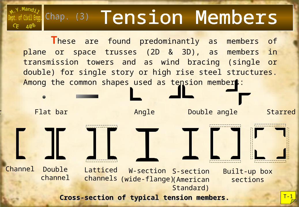
These are found predominantly as members of plane or space trusses (2D & 3D), as members in transmission towers and as wind bracing (single or double) for single story or high rise steel structures. Among the common shapes used as tension members:
Round bar Flat bar Angle Double angle Starred angle
Doublechannel
Channel Latticedchannels
W-section(wide-flange)
S-section(AmericanStandard)
Built-up boxsections
Cross-section of typical tension members.Cross-section of typical tension members.
T-2
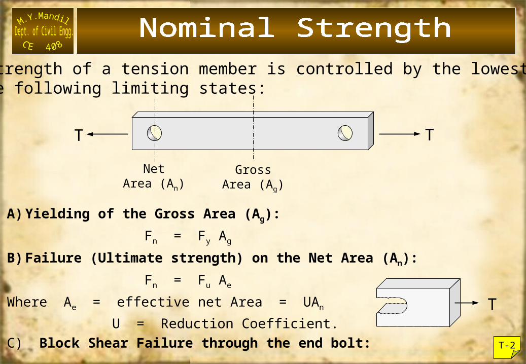
The strength of a tension member is controlled by the lowestof the following limiting states:
NetArea (An)
GrossArea (Ag)
T T
A)Yielding of the Gross Area (Ag): Fn = Fy Ag
B)Failure (Ultimate strength) on the Net Area (An): Fn = Fu Ae
Where Ae = effective net Area = UAn
U = Reduction Coefficient. C) Block Shear Failure through the end bolt:
T
T-3
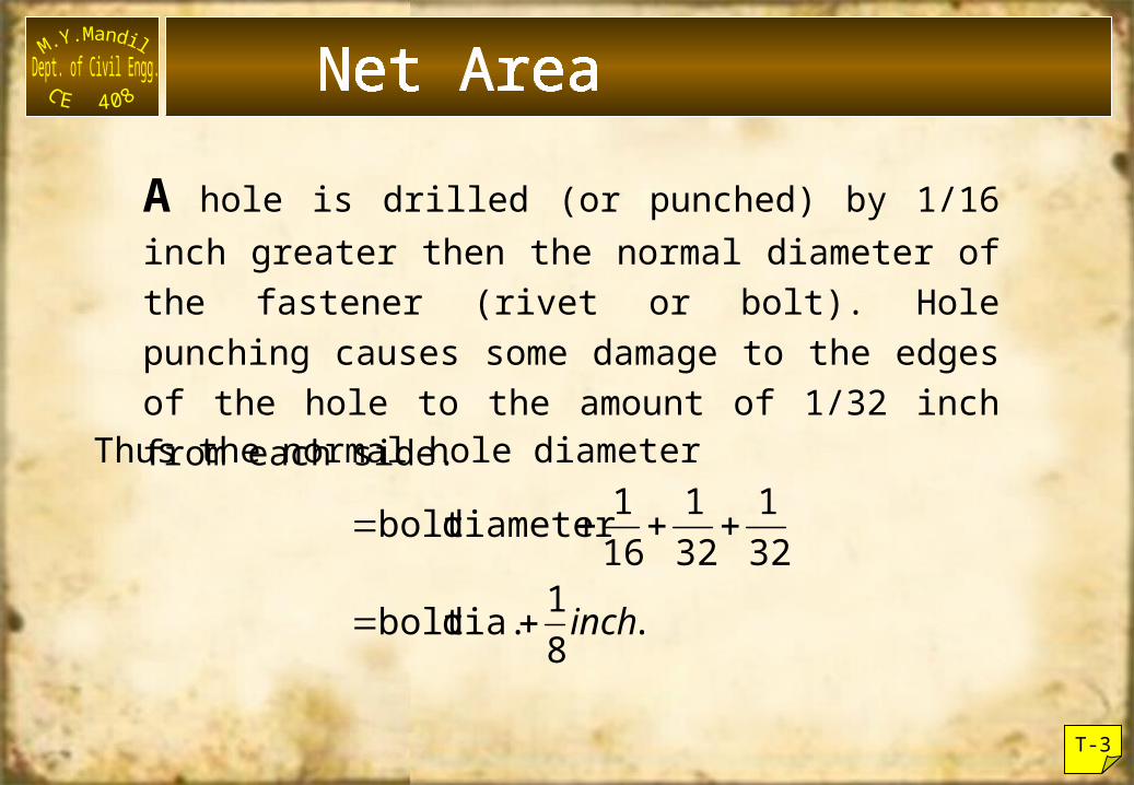
A hole is drilled (or punched) by 1/16 inch greater then the normal diameter of the fastener (rivet or bolt). Hole punching causes some damage to the edges of the hole to the amount of 1/32 inch from each side.Thus the normal hole diameter
.81 dia.bolt
321
321
161diameter bolt
inch
T-4
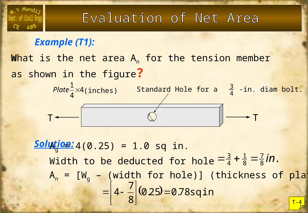
What is the net area An for the tension memberas shown in the figure?
Solution:
T T
Ag = 4(0.25) = 1.0 sq in.Width to be deducted for holeAn = [Wg – (width for hole)] (thickness of plate)
.in87
81
43
Standard Hole for a -in. diam bolt. 4344
1Plate (inches)
Example (T1):
in. sq. 78.025.0874
(a) (b)
T-5
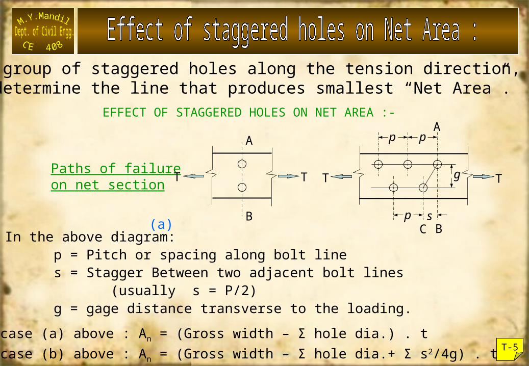
For a group of staggered holes along the tension direction, one must determine the line that produces smallest “Net Area”.
Paths of failureon net section
EFFECT OF STAGGERED HOLES ON NET AREA :-
T T
B
A
T T
s
g
A
Cp
p p
BIn the above diagram:p = Pitch or spacing along bolt lines = Stagger Between two adjacent bolt lines (usually s = P/2)g = gage distance transverse to the loading.
In case (a) above : An = (Gross width – Σ hole dia.) . tIn case (b) above : An = (Gross width – Σ hole dia.+ Σ s2/4g) . t
T-6
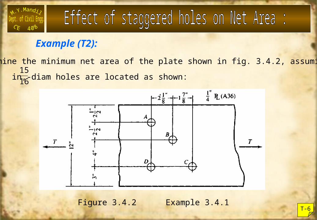
Determine the minimum net area of the plate shown in fig. 3.4.2, assuming in,-diam holes are located as shown:
Figure 3.4.2 Example 3.4.1
1615
Example (T2):
T-7
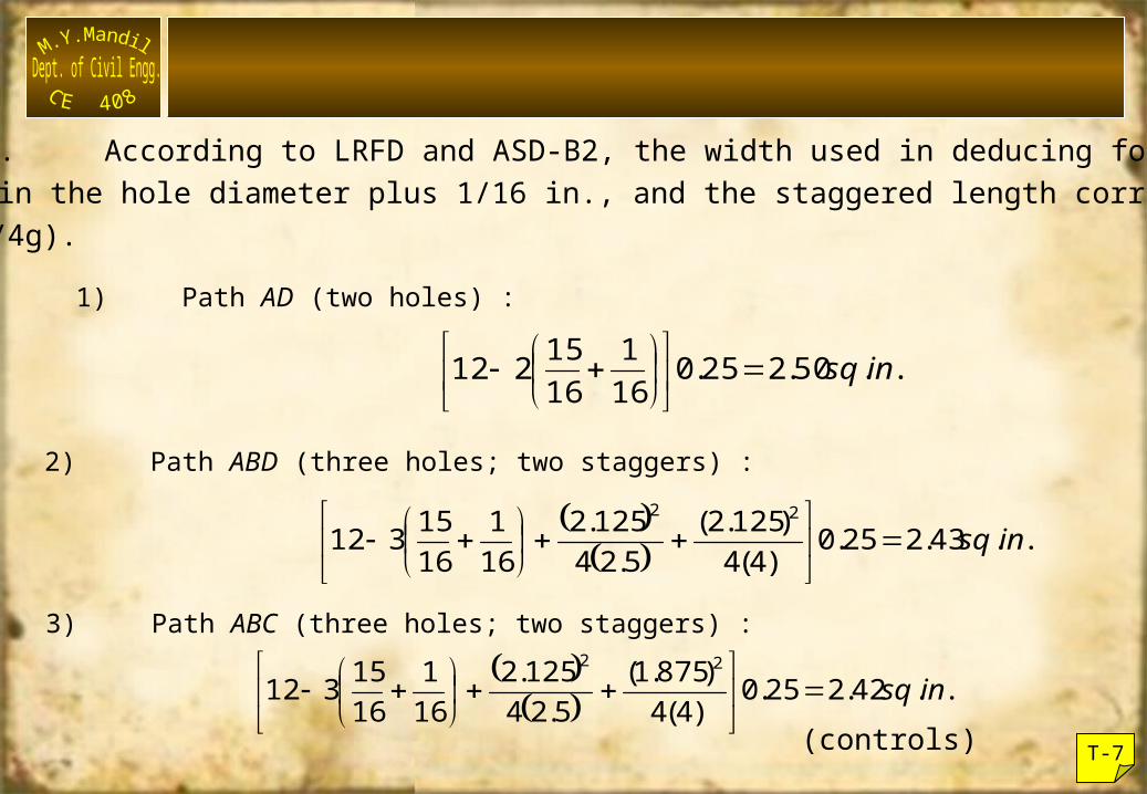
Solution. According to LRFD and ASD-B2, the width used in deducing forholes in the hole diameter plus 1/16 in., and the staggered length correctionIs (s2/4g).
.... insq502250161
1615212
1) Path AD (two holes) :
2) Path ABD (three holes; two staggers) :
....)(
).(.
. insq432250441252
5241252
161
1615312
22
....)(
).(.
. insq422250448751
5241252
161
1615312
22
3) Path ABC (three holes; two staggers) :
(controls)
T-8
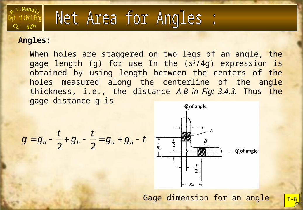
Angles:When holes are staggered on two legs of an angle, the gage length (g) for use In the (s2/4g) expression is obtained by using length between the centers of the holes measured along the centerline of the angle thickness, i.e., the distance A-B in Fig: 3.4.3. Thus the gage distance g is
tggtgtgg baba 22
Gage dimension for an angle
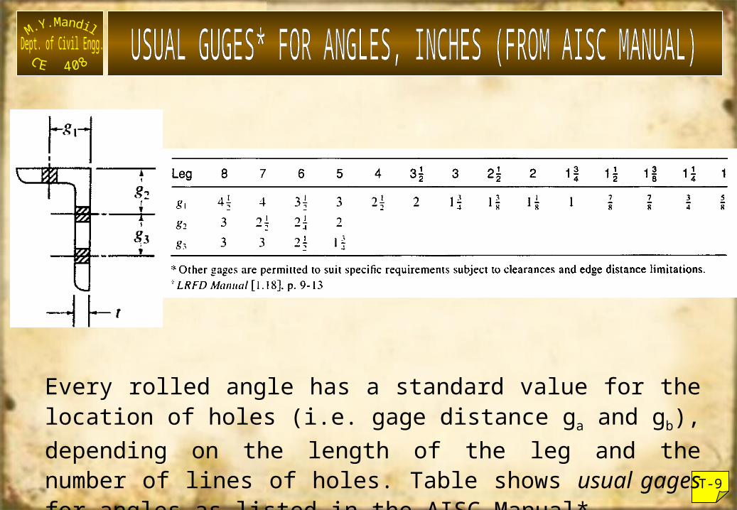
T-9
Every rolled angle has a standard value for the location of holes (i.e. gage distance ga and gb), depending on the length of the leg and the number of lines of holes. Table shows usual gages for angles as listed in the AISC Manual*.
T-10
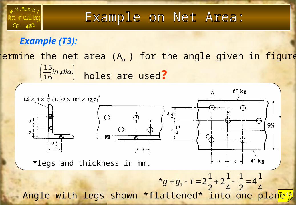
Determine the net area (An ) for the angle given in figure below
if holes are used?
Angle with legs shown *flattened* into one plane4142
14122
121 tgg*
*legs and thickness in mm.
.,1615 diain
Example (T3):
9½”
T-11
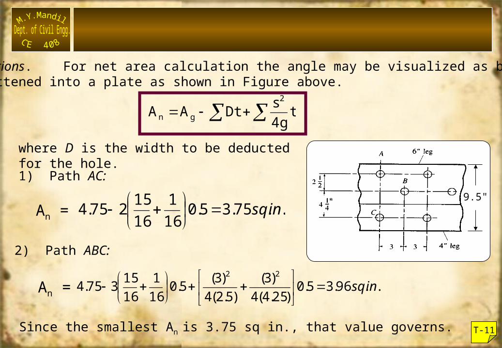
Solutions. For net area calculation the angle may be visualized as beingflattened into a plate as shown in Figure above.
t4gsDtAA2
gn
where D is the width to be deducted for the hole.1) Path AC:
2) Path ABC:
.. 75.35.0161
1615275.4 insq
.. 96.35.0)25.4(4)3(
)5.2(4)3(5.016
11615375.4
22insq
Since the smallest An is 3.75 sq in., that value governs.
An =
An =
9.5"
T-12
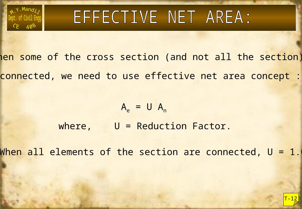
When some of the cross section (and not all the section) is
connected, we need to use effective net area concept :-
Ae = U An
where, U = Reduction Factor.
When all elements of the section are connected, U = 1.0.
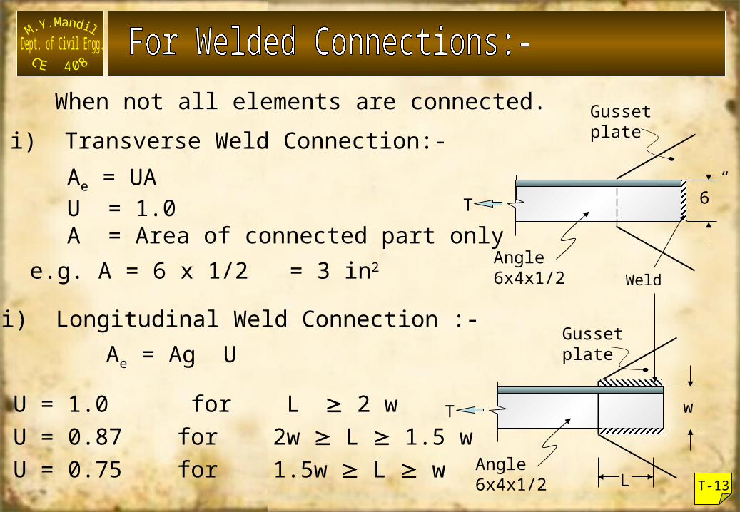
When not all elements are connected.i) Transverse Weld Connection:-
Ae = UAU = 1.0A = Area of connected part only
e.g. A = 6 x 1/2 = 3 in2
ii) Longitudinal Weld Connection :-Ae = Ag U
U = 1.0 for L 2 wU = 0.87 for 2w L 1.5 wU = 0.75 for 1.5w L w
6”
Gussetplate
Angle6x4x1/2
T
T-13
w
Gussetplate
Angle6x4x1/2
T
L
Weld
T-14
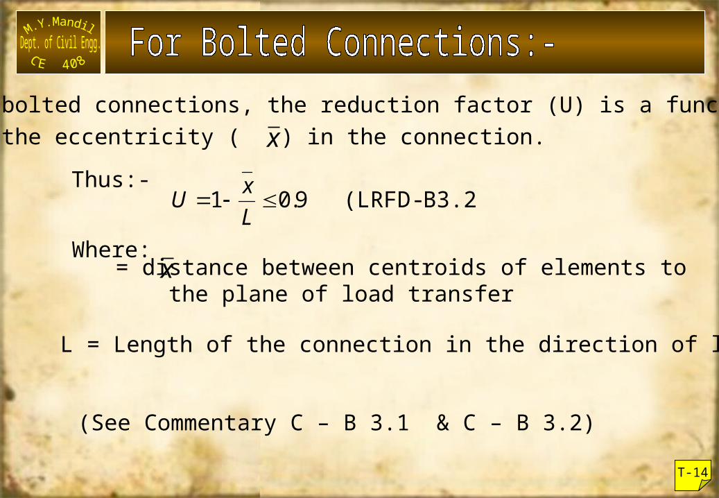
In bolted connections, the reduction factor (U) is a functionof the eccentricity ( ) in the connection.
B3.2) - (LRFD 9.01 LxU
Thus:-
Where:= distance between centroids of elements to the plane of load transfer
L = Length of the connection in the direction of load.
(See Commentary C – B 3.1 & C – B 3.2)
x
x
T-15
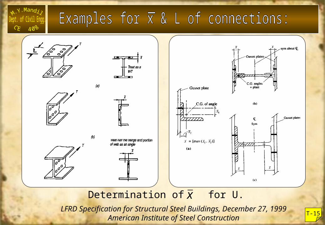
xDetermination of for U.LFRD Specification for Structural Steel Buildings, December 27, 1999
American Institute of Steel Construction
T-16
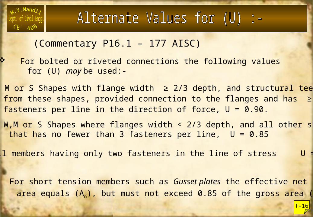
(Commentary P16.1 – 177 AISC) For bolted or riveted connections the following values for (U) may be used:-
a) W, M or S Shapes with flange width ≥ 2/3 depth, and structural tees cut from these shapes, provided connection to the flanges and has ≥ 3 fasteners per line in the direction of force, U = 0.90.
b) W,M or S Shapes where flanges width < 2/3 depth, and all other shapes, that has no fewer than 3 fasteners per line, U = 0.85
c) All members having only two fasteners in the line of stress U = 0.75
For short tension members such as Gusset plates the effective net area equals (An), but must not exceed 0.85 of the gross area (Ag).
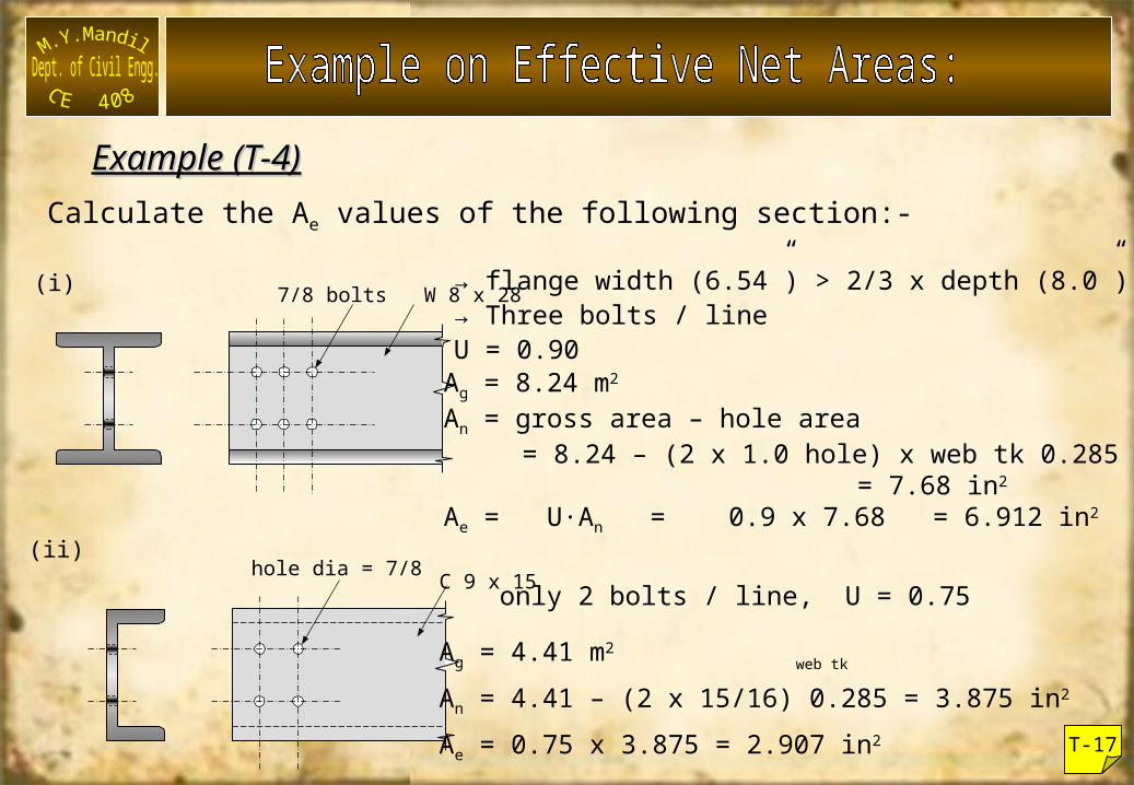
Example (T-4)Example (T-4)Calculate the Ae values of the following section:-
7/8 bolts W 8 x 28→ flange width (6.54”) > 2/3 x depth (8.0”)→ Three bolts / lineU = 0.90Ag = 8.24 m2
An = gross area – hole area = 8.24 – (2 x 1.0 hole) x web tk 0.285
= 7.68 in2
Ae = U·An = 0.9 x 7.68 = 6.912 in2
hole dia = 7/8 C 9 x 15only 2 bolts / line, U = 0.75
Ag = 4.41 m2
An = 4.41 – (2 x 15/16) 0.285 = 3.875 in2
Ae = 0.75 x 3.875 = 2.907 in2
(i)
(ii)
T-17
web tk
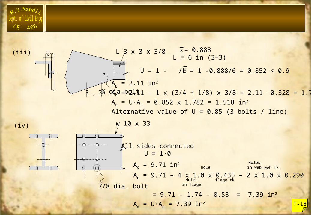
(iii) x L 3 x 3 x 3/8
3 3¾ dia bolt
x = 0.888L = 6 in (3+3)
xU = 1 - /L = 1 -0.888/6 = 0.852 < 0.9Ag = 2.11 in2
An = 2.11 – 1 x (3/4 + 1/8) x 3/8 = 2.11 -0.328 = 1.782 in2
Ae = U·An = 0.852 x 1.782 = 1.518 in2
Alternative value of U = 0.85 (3 bolts / line)
(iv) w 10 x 33
7/8 dia. bolt
All sides connectedU = 1·0
Ag = 9.71 in2
An = 9.71 – 4 x 1.0 x 0.435 – 2 x 1.0 x 0.290
= 9.71 – 1.74 - 0.58 = 7.39 in2
Ae = U·An = 7.39 in2
Holesin flage
flage tk
holeHolesin web web tk.
T-18
T-19
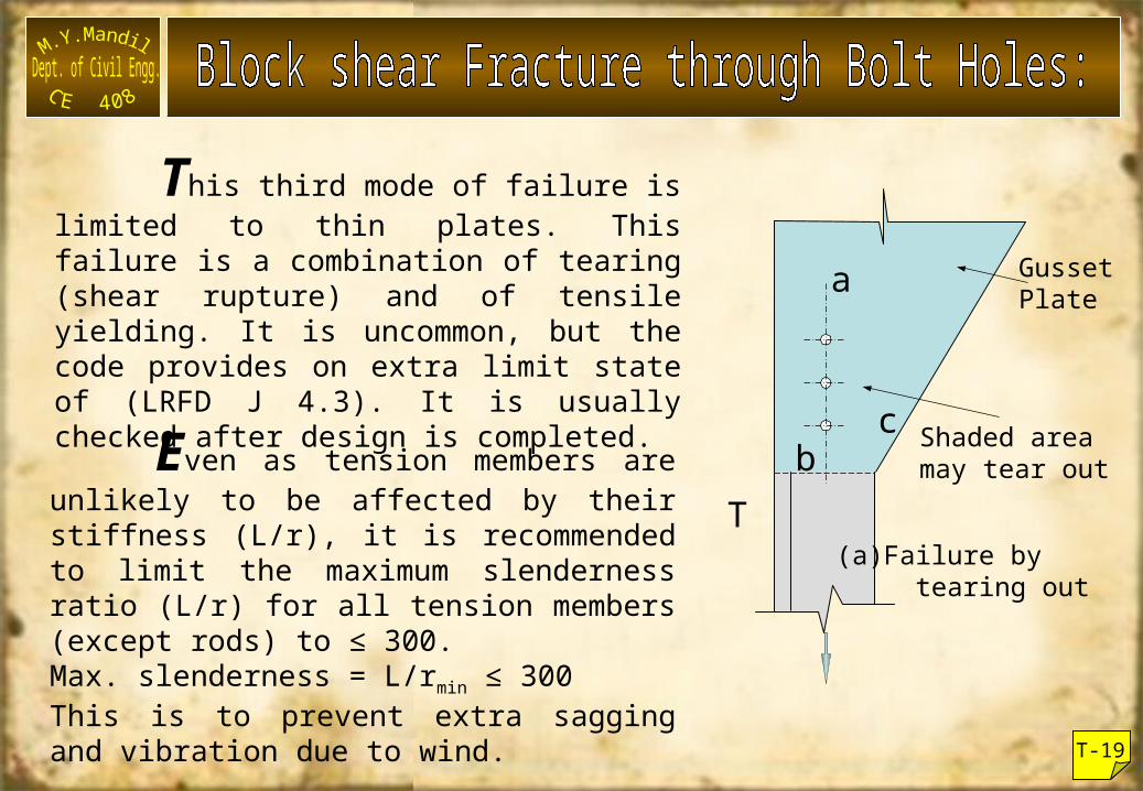
This third mode of failure is limited to thin plates. This failure is a combination of tearing (shear rupture) and of tensile yielding. It is uncommon, but the code provides on extra limit state of (LRFD J 4.3). It is usually checked after design is completed.
(a)Failure by tearing out
GussetPlate
Shaded areamay tear out
T
a
cbEven as tension members are
unlikely to be affected by their stiffness (L/r), it is recommended to limit the maximum slenderness ratio (L/r) for all tension members (except rods) to ≤ 300.Max. slenderness = L/rmin ≤ 300This is to prevent extra sagging and vibration due to wind.
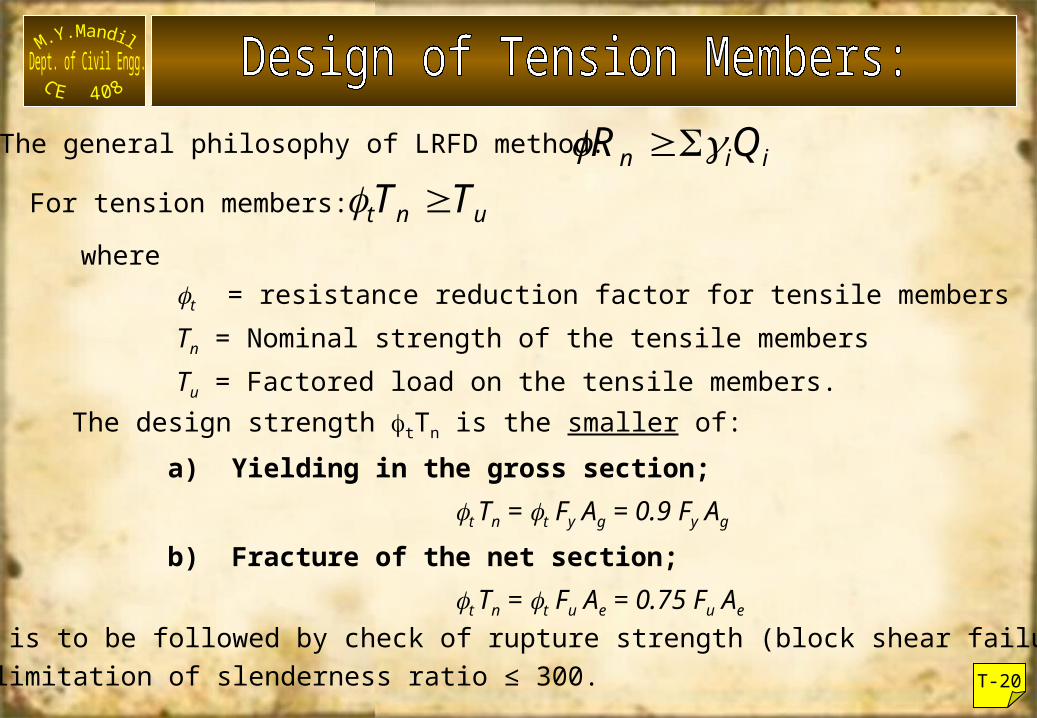
The general philosophy of LRFD method: iin QR For tension members: unt TT
wheret = resistance reduction factor for tensile membersTn = Nominal strength of the tensile membersTu = Factored load on the tensile members.
The design strength tTn is the smaller of:a) Yielding in the gross section;
t Tn = t Fy Ag = 0.9 Fy Ag
b) Fracture of the net section;t Tn = t Fu Ae = 0.75 Fu Ae
This is to be followed by check of rupture strength (block shear failure),and limitation of slenderness ratio ≤ 300. T-20
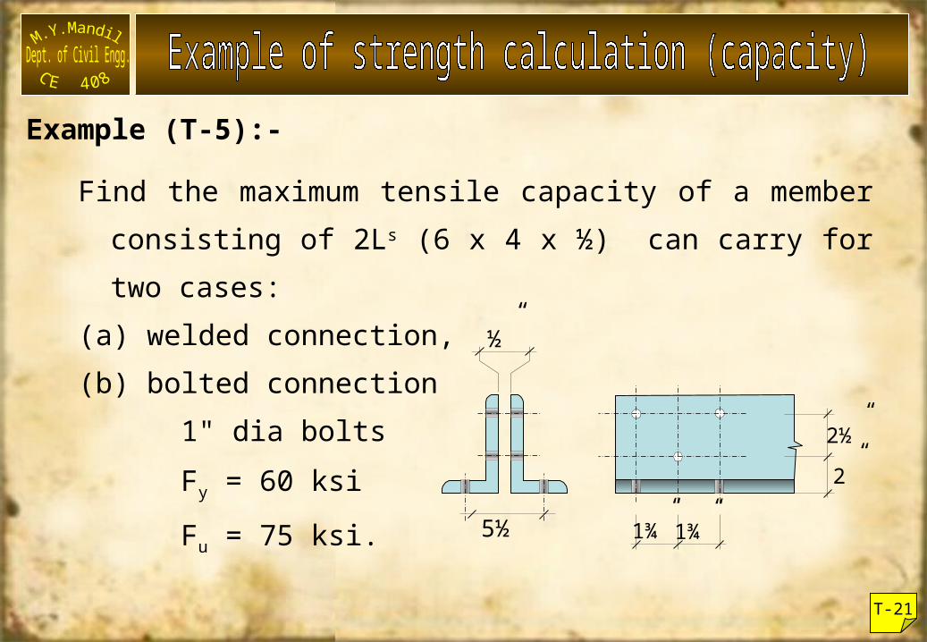
Example (T-5):-
Find the maximum tensile capacity of a member consisting of 2Ls (6 x 4 x ½) can carry for two cases:
(a) welded connection,(b) bolted connection 1" dia bolts Fy = 60 ksi Fu = 75 ksi.
½”
5½
2½” 2”
1¾” 1¾”
T-21
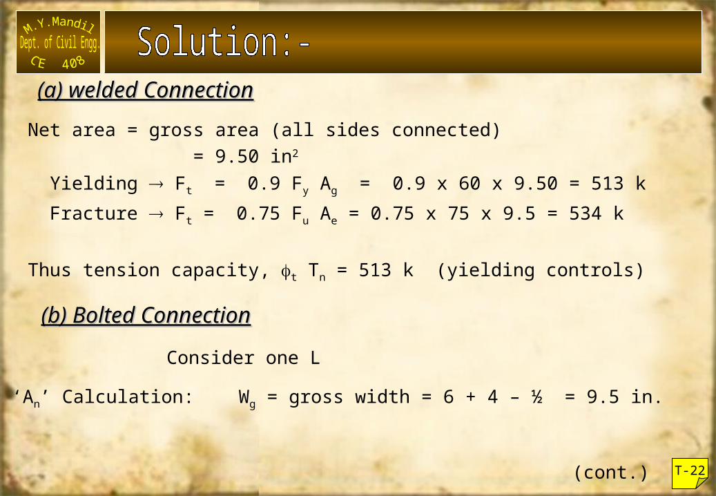
Net area = gross area (all sides connected) = 9.50 in2
Yielding Ft = 0.9 Fy Ag = 0.9 x 60 x 9.50 = 513 k Fracture Ft = 0.75 Fu Ae = 0.75 x 75 x 9.5 = 534 k
Thus tension capacity, t Tn = 513 k (yielding controls)
(a) welded Connection(a) welded Connection
(b) Bolted Connection(b) Bolted Connection
Consider one L
‘An’ Calculation: Wg = gross width = 6 + 4 – ½ = 9.5 in.
(cont.) T-22
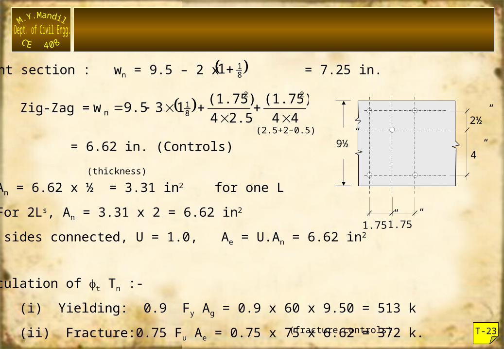
Straight section : wn = 9.5 – 2 x = 7.25 in. 811
= 6.62 in. (Controls)
(fracture controls)
An = 6.62 x ½ = 3.31 in2 for one L For 2Ls, An = 3.31 x 2 = 6.62 in2
All sides connected, U = 1.0, Ae = U.An = 6.62 in2
Calculation of t Tn :-(i) Yielding: 0.9 Fy Ag = 0.9 x 60 x 9.50 = 513 k(ii) Fracture:0.75 Fu Ae = 0.75 x 75 x 6.62 = 372 k.
(thickness)
T-23
Zig-Zag = 44(1.75)
2.54(1.75)139.5w
22
81
n
(2.5+2–0.5)2½”
4”
1.75” 1.75”
9½”
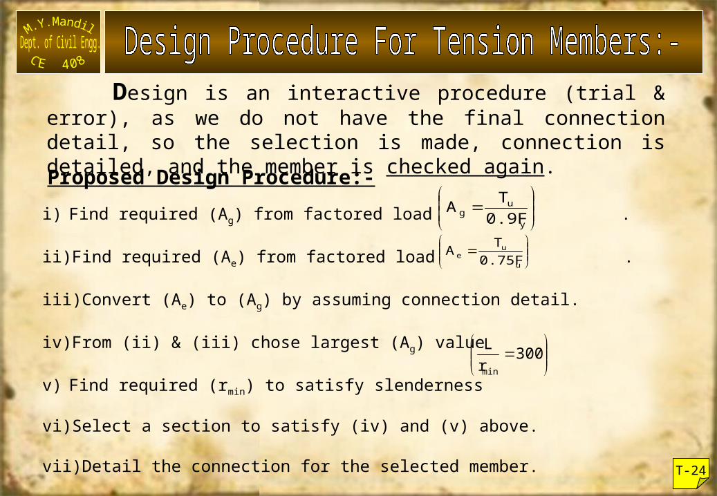
Design is an interactive procedure (trial & error), as we do not have the final connection detail, so the selection is made, connection is detailed, and the member is checked again.Proposed Design Procedure:-i) Find required (Ag) from factored load .
ii)Find required (Ae) from factored load .
iii)Convert (Ae) to (Ag) by assuming connection detail.
iv)From (ii) & (iii) chose largest (Ag) value
v) Find required (rmin) to satisfy slenderness
vi)Select a section to satisfy (iv) and (v) above.
vii)Detail the connection for the selected member.
viii)Re-check the member again.
y
ug 0.9F
TA
u
ue 0.75F
TA
300r
Lmin
T-24
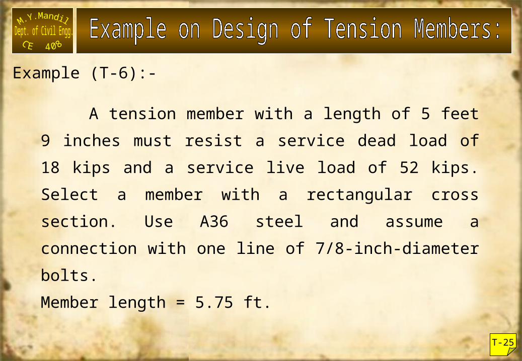
Example (T-6):-
A tension member with a length of 5 feet 9 inches must resist a service dead load of 18 kips and a service live load of 52 kips. Select a member with a rectangular cross section. Use A36 steel and assume a connection with one line of 7/8-inch-diameter bolts.Member length = 5.75 ft.
T-25
T-26
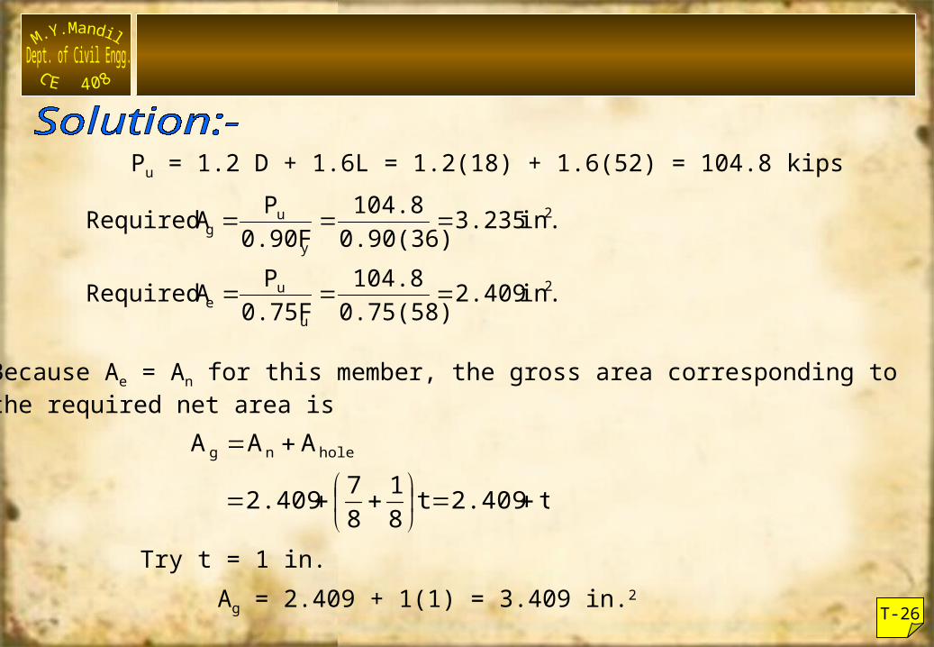
Pu = 1.2 D + 1.6L = 1.2(18) + 1.6(52) = 104.8 kips
2
u
ue
2
y
ug
in. 2.4090.75(58)104.8
0.75FP ARequired
in. 3.2350.90(36)104.8
0.90FP ARequired
Because Ae = An for this member, the gross area corresponding tothe required net area is
t2.409t81
872.409
AAA holeng
Try t = 1 in.Ag = 2.409 + 1(1) = 3.409 in.2
T-27
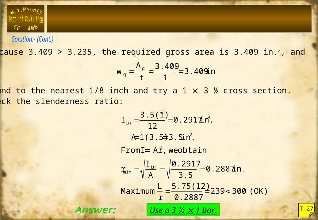
Because 3.409 > 3.235, the required gross area is 3.409 in.2, and
in. 3.40913.409
tAw g
g
Round to the nearest 1/8 inch and try a 1 3 ½ cross section.Check the slenderness ratio:
Use a 3 ½ 1 bar.
(OK) 3002390.28875.75(12)
rL Maximum
in. 0.28873.50.2917
AIr
obtain we, Ar I Fromin. 3.51(3.5) A
in. 0.2917123.5(1)I
minmin
2
2
43
min
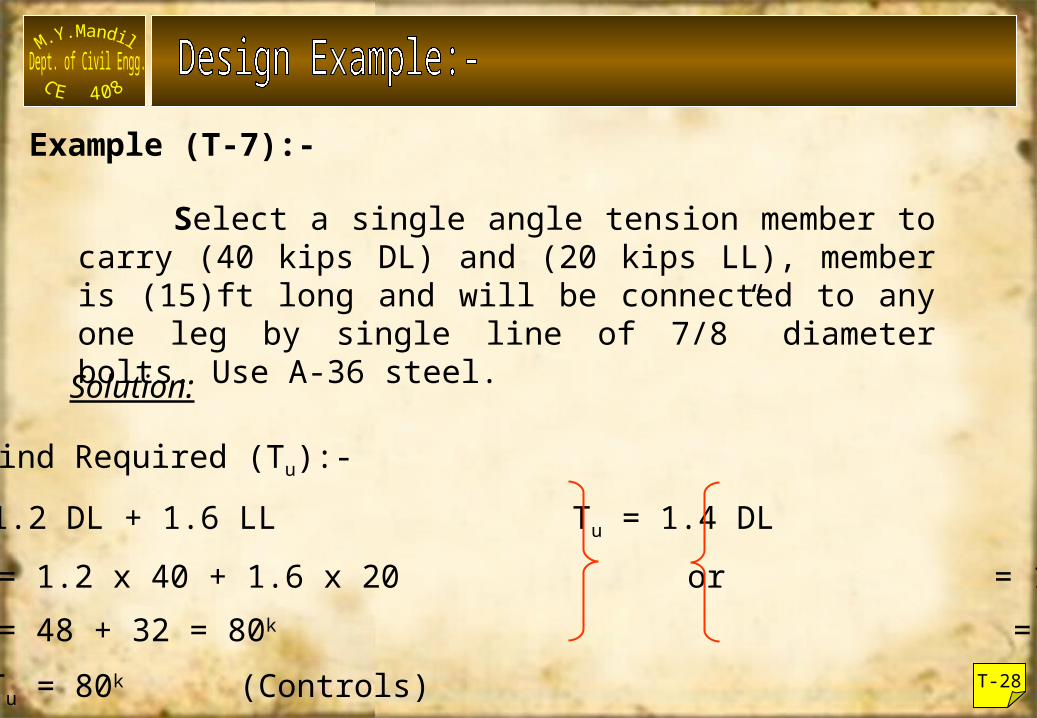
Select a single angle tension member to carry (40 kips DL) and (20 kips LL), member is (15)ft long and will be connected to any one leg by single line of 7/8” diameter bolts. Use A-36 steel.Solution:
Step 1) Find Required (Tu):-Tu = 1.2 DL + 1.6 LL Tu = 1.4 DL = 1.2 x 40 + 1.6 x 20 or = 1.4 x 40 = 48 + 32 = 80k = 56k
Tu = 80k (Controls) T-28
Example (T-7):-
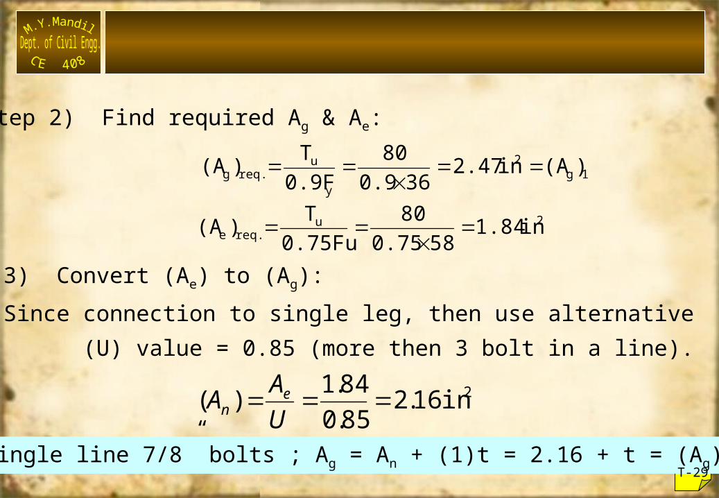
Step 2) Find required Ag & Ae:
1g2
y
ureq.g )(A in 2.47360.9
800.9FT)(A
2ureq.e in 1.84580.75
800.75FuT)(A
Step 3) Convert (Ae) to (Ag):Since connection to single leg, then use alternative
(U) value = 0.85 (more then 3 bolt in a line).2in 16.285.0
84.1)( UAA e
n
For single line 7/8” bolts ; Ag = An + (1)t = 2.16 + t = (Ag)2T-29
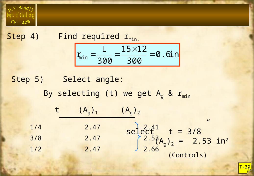
Step 4) Find required rmin.
in. 0.63001215
300Lrmin
Step 5) Select angle:By selecting (t) we get Ag & rmin
t (Ag)1 (Ag)2
1/4 2.47 2.413/8 2.47 2.531/2 2.47 2.66
select t = 3/8” (Ag)2 = 2.53 in2
T-30
(Controls)
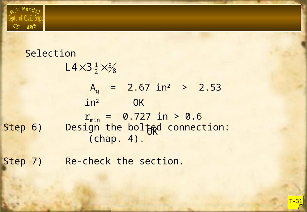
Selection832
13L4
Ag = 2.67 in2 > 2.53 in2 OKrmin = 0.727 in > 0.6 OKStep 6) Design the bolted connection:
(chap. 4).
Step 7) Re-check the section.
T-31
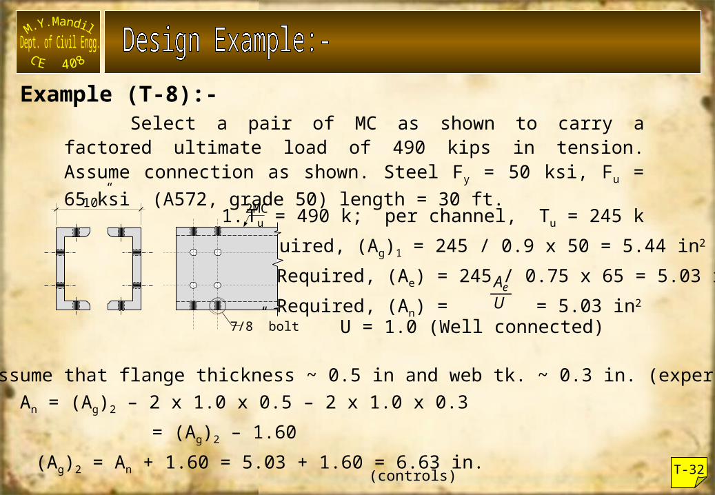
Select a pair of MC as shown to carry a factored ultimate load of 490 kips in tension. Assume connection as shown. Steel Fy = 50 ksi, Fu = 65 ksi (A572, grade 50) length = 30 ft.
1.Tu = 490 k; per channel, Tu = 245 k2.Required, (Ag)1 = 245 / 0.9 x 50 = 5.44 in2
Required, (Ae) = 245 / 0.75 x 65 = 5.03 in2
Required, (An) = = 5.03 in2UAe
3. Assume that flange thickness ~ 0.5 in and web tk. ~ 0.3 in. (experience !)An = (Ag)2 – 2 x 1.0 x 0.5 – 2 x 1.0 x 0.3
= (Ag)2 – 1.60 (Ag)2 = An + 1.60 = 5.03 + 1.60 = 6.63 in.(controls) T-32
10” 2MC
7/8” bolt U = 1.0 (Well connected)
Example (T-8):-
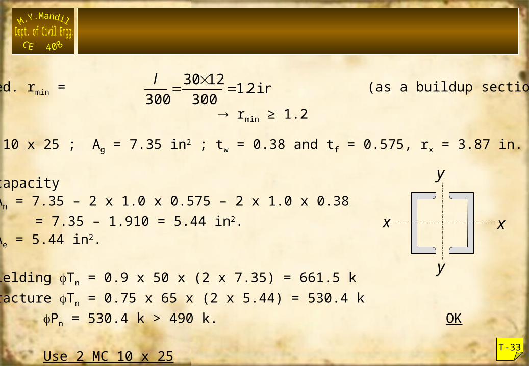
4.Required. rmin = (as a buildup section)
5.Try MC 10 x 25 ; Ag = 7.35 in2 ; tw = 0.38 and tf = 0.575, rx = 3.87 in.
6.Check capacityAn = 7.35 – 2 x 1.0 x 0.575 – 2 x 1.0 x 0.38 = 7.35 – 1.910 = 5.44 in2.
Ae = 5.44 in2.
(i) Yielding Tn = 0.9 x 50 x (2 x 7.35) = 661.5 k(ii) Fracture Tn = 0.75 x 65 x (2 x 5.44) = 530.4 k
Pn = 530.4 k > 490 k. OK
Use 2 MC 10 x 25
in 2.13001230
300
l
rmin ≥ 1.2
T-33
x
y
x
y
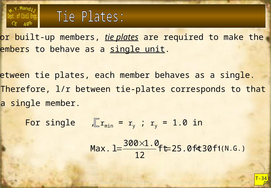
For built-up members, tie plates are required to make themembers to behave as a single unit.
Between tie plates, each member behaves as a single. Therefore, l/r between tie-plates corresponds to that for a single member.
For single , rmin = ry ; ry = 1.0 in
30ft.25.0ftft121.0300l Max.
T-34
(N.G.)
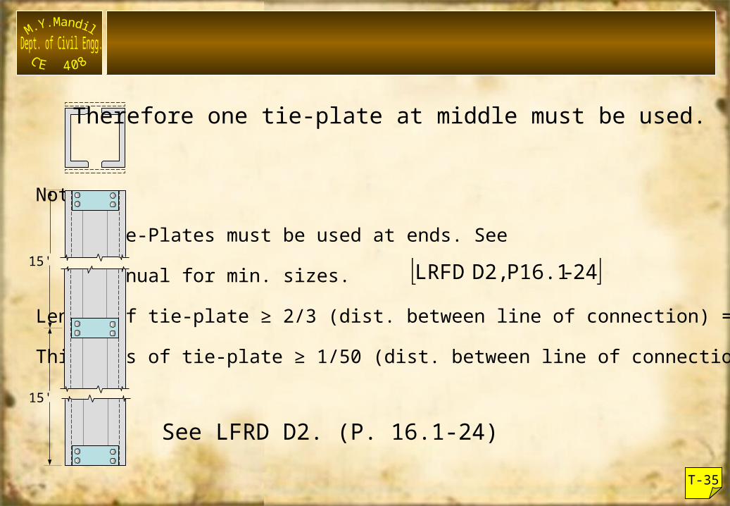
Note:
Tie-Plates must be used at ends. See
Manual for min. sizes.
Length of tie-plate ≥ 2/3 (dist. between line of connection) = 8"
Thickness of tie-plate ≥ 1/50 (dist. between line of connection) = 1/2"
T-35
15'
15'
Therefore one tie-plate at middle must be used.
See LFRD D2. (P. 16.1-24)
24-P16.1 D2, LRFD