M.B.A. Dual Specialization (Regulation 2019-20) - Annamalai ...
Upload
khangminh22Category
view
1download
0
TENSION MEMBERBY
Dr. R. Baskar, Ph.D(Struct.);FIE
Professor,
Dept. of Civil & Structural
Engineering
Annamalai University

SECTION 6 DESIGN OF TENSION MEMBERS
6.1Tension Members
6.2Design Strength due to Yielding of Gross Section
6.3Design Strength due to Rupture of Critical Section
6.3.1 Plates
6.3.2 Threaded Rods
6.3.3 Single Angles
6.3.4 Other Sections
6.4 Design Strength due to Block Shear
6.4.1 Bolted Connection
6.4.2 Welded Connection
P
P

The factored design tension T, in the members
T < Td
6.1 Tension Members
Td
Design strength of member
MinimumOf
Tdb
Tdn
TdgYielding of gross cross section
Rupture Strength of critical section
Rupture due to Block Shear
Section 6.2
Section 6.3
Section 6.4

Tdg = fy Ag /m0
mo = 1.1
6.2 Design Strength due to Yielding of Gross
Section

6.3 Design Strength due to Rupture of Critical
Section
6.3.1 Plates The design strength in tension of a plate, Tdn,
Tdn =0.9 fu An / m1 m1 =1.25
2
4i
n hi i
pA b nd t
g

6.3 Design Strength due to Rupture of Critical
Section
6.3.2 Threaded Rods
The design strength of threaded rods in tension, Tdn,
Tdn =0.9 fu An / m1

6.3.3 Single Angles The design strength, Tdn, as governed by
shear lag
Tdn = 0.9 fu Anc / m1 + Ago fy /m0
= 1.4 – 0.076 (w/t) (fu/fy) (bs/L ) [≈ 1.4-0.52(bs/L)]
Alternatively, the tearing strength of net section may be taken as
Tdn = An fu /m
6.3 Design Strength due to Rupture of Critical
Section
w
bs=w+w1w1bs=w
w

P
Distribution of forces due to shear lag
Tension carrying section
Rupture plane

Yielding due to gross cross section
Example

Example
Rupture Strength of critical section

Example
Rupture due to Block Shear

Tension member design: Example -1

Tension member design: Example -1 cont….
An (section 1 1) = (200 - 3 x 22) x 10= 1340 mm2 (governs)
An (section 1221)=[200 - 4 x 22 + (2 x 502) / (4 x 30)] x10
=1536.67 mm2
An (section 12321)=[200 – 5 x 22 + (4 x 502) / (4 x 30)] x 10
=1733.33 mm2
Factored design tension in members by
i) Yielding of gross section, Tdg =fy Ag / γm0
= (250 x 200 x 10) / 1.10
=454545.45 N
= 454.4 kN
Section 6.3.1
Section 6.2

Tension member design: Example -1 cont….
ii) Rupture of net section, Tdn = 0.9 fu An / γml
= (0.9 x 420 x 1340)/ 1.25
= 409752 N
= 409.8 kN
Check for minimum edge and end distance:
Provided minimum edge and end distance = 40 mm
which is greater than 32 mm (As per code)
The design tensile strength of the plate = 409.8 kN
The efficiency of the tension member, =(409.8x100)/(454.45)
= 90.17%
Section 6.3.1

Tension member design: Example -2
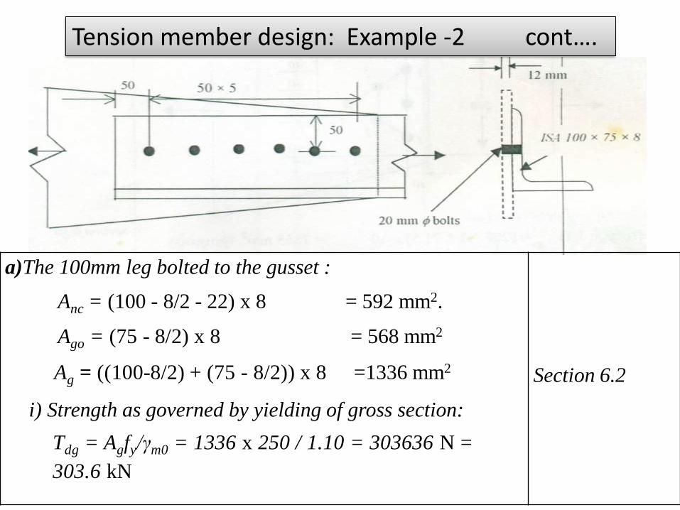
Tension member design: Example -2 cont….
a)The 100mm leg bolted to the gusset :
Anc = (100 - 8/2 - 22) x 8 = 592 mm2.
Ago = (75 - 8/2) x 8 = 568 mm2
Ag = ((100-8/2) + (75 - 8/2)) x 8 =1336 mm2
i) Strength as governed by yielding of gross section:
Tdg = Agfy/γm0 = 1336 x 250 / 1.10 = 303636 N =
303.6 kN
Section 6.2
Tension member design: Example -2 cont….
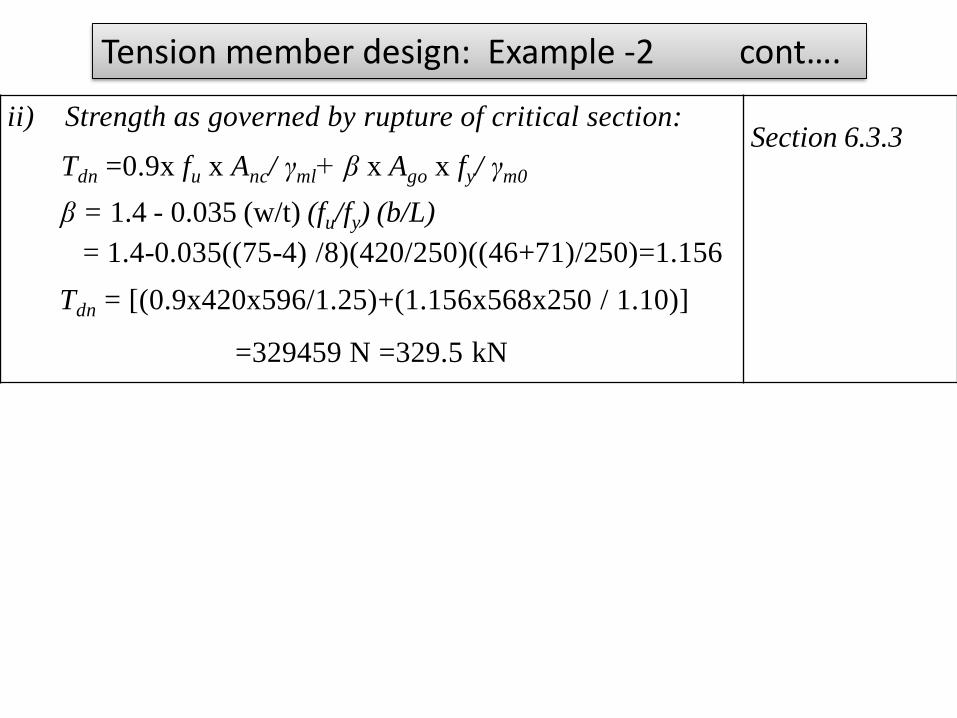
ii) Strength as governed by rupture of critical section:
Tdn =0.9x fu x Anc/ γml+ β x Ago x fy/ γm0
β = 1.4 - 0.035 (w/t) (fu/fy) (b/L)
= 1.4-0.035((75-4) /8)(420/250)((46+71)/250)=1.156
Tdn = [(0.9x420x596/1.25)+(1.156x568x250 / 1.10)]
=329459 N =329.5 kN
Section 6.3.3

Tension member design: Example -2 cont….
iii) Strength as governed by block shear:
Tdb = [(0.577 x fy x Avg/ γm0) + ( 0.9 x fu x Atn x fy/ γml)]
= [(0.577 x 250 x (5 x50 + 50) x 8/1.10)
+ (0.9 x 420x (50-22/2)x8/1.25)]
= 337407N = 337.4 kN
Tdb [(0.52 x fu x Avn / γml)+ (Atg fy / γm0)]
=[(0.52x 420x (5 x 50 + 50 -5.5 x 22) x 8/1.25)
+(50 x250 x 8/ 1.10)]
= 341108 N = 341.1 kN
The design tensile strength of angle member = 303.6 kN
The efficiency of the tension member = 303.6 x 1000
x100)/(1336 x250/1.10)=100 %
Section 6.4.2

Tension member design: Example -2 cont….
The 75 mm leg is bolted to the gusset:
An=(75 - 8/2 - 21.5) x 8= 396 mm2
A0=(100 - 8/2) x 8= 768 mm2
i) Strength as governed by yielding of gross section:
Tdg=Agfy/ymo = 1336 x 250 / 1.10= 303636.36 N
= 303.6 kN
ii) Strength as governed by tearing of net section:
Tdn =0.9 x fu x Anc/ γml + β x Ago x fy/ γm0
β = 1.4 — 0.035 (w/t) (fu/fy) (b/L)
= 1.4-0.035(100/8)(420/250)(125/250)=1.03
Tdn=0.9x420x396/1.25+1.03x768x250 / 1.15
=291715.6 N=291.7kN
Section 6.2
Section 6.3.3

Tension member design: Example -2 cont….
Strength as governed by block shear:
Tdb = [(0.577 x fy x Avg/ γm0) + ( 0.9 x fu x Atn x fy/ γml)]
=[(0.577x250x(5 x50+50)x8/1.10)
+ (0.9x420x(40-22/2)x8/1.25]
=384884.07 N
= 384.9 Kn
Tdb [(0.52 x fu x Avn / γml)+ (Atg fy / γm0)]
=[(0.52 x 420x (5x50 +50 -5.5 x 21.5)x8/1.25)
+(40x250x8/1.10)]
= 322926 N =322.9 kN
The design tensile strength of angle member = 290.4 kN
The efficiency of the tension member
=(290.4x1000x100)/(1336x250/1.10)
=100 %
Section 6.4.2

3.Design a tension member to carry a a load of 300 kN. The two angles placed
back to back with long leg outstanding are desirable. The length of the member is
2.9 m.
Given Data:
= 300 kN, Length = 2.9m
Solution
Area required from the consideration of yielding
=
(Refer table-5 of IS 800:2007)
Assume (partial safety factor) = 1.1
Assume (partial safety factor) = 1.25
= = 1320 mm²

Try 2 ISA 75 X 50 X 8mm thick which has gross area = 2 x 938 = 1876 mm²
Strength of 20 mm black bolts:
(a) In double shear =[ [ x 20² + 0.78 x 20² ] x x 20² ] x
x x = 103314 N
(b) Strength in bearing:
Taking e = 40 mm , p = 60 mm
Where , is smaller of , (- -0.25) , , 1.0 ;
is smaller of ,( - 0.25), ,1.0;
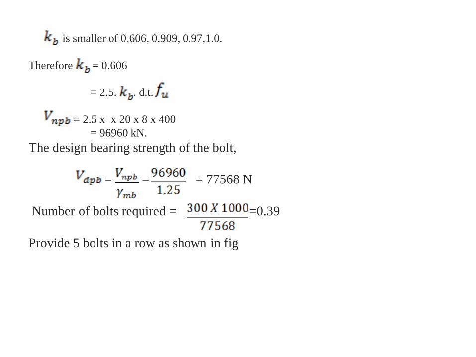
is smaller of 0.606, 0.909, 0.97,1.0.
Therefore = 0.606
= 2.5. . d.t.
= 2.5 x x 20 x 8 x 400
= 96960 kN.
The design bearing strength of the bolt,
= = = 77568 N
Number of bolts required = =0.39
Provide 5 bolts in a row as shown in fig

Checking the design
(a) Strength against yielding, =
=
= 426364 N > 300 x 1000

(b) Strength of plate in rupture , = +
Area of connected leg, = 2( ) x 8
= 784 mm²
Area of outstanding leg, = 2 x 8
=736 mm²
=1.4 - 0.076 x x x
=1.4 – 0.076 x x x

= 1.307
Therefore, = +
= +
=450062 >300000
(c) Strength against block shear failure
Per angle:
= (40 + 60 x 4) x 8 = 2240 mm²
= (40 + 60 x 4 - 4.5 x 22) x 8 = 1448 mm²

= (75 – 35) x 8 = 320 mm²
= (75 – 35 – 0.5 x 22) x 8 = 232 mm²
Strength against block failure of each angle is the smaller of the following
two values:
As per IS 800 – 2007 clause 6.4.1,
i) = +
= +
= 362410 N

ii) = +
= +
= 319515 N
Strength of two angles against block failure = 2 x 319515 N
= 639030 > 300000 N O.K.
Hence use 2 ISA 75 X50X8 mm with 5 bolts of 20 mm diameter.

4. A tie member in a bracing system consists of two angles 75x75x6 bolted
to a 10mm gusset one on each side using a single row of bolts [see given
fig.A] and tack bolted.Determine the tensile capacity of the member and the
number of bolts required to develop full capacity of the member. What will
be the capacity if the angles are connected on the same side of gusset plate
And tack bolted [see fig B].What is the effects on tensile strength if the
members are not tack bolted?
Connected to gusset Connected to the same side of
one on each side –(a) of the gusset – (b)

(c)
(d)
Solution:
(a) Two angles connected to the opposite side of the gusset as in
Fig (a)

(i) Design strength due to yielding of gross section
Tdg = fy (Ag/γm0)
Ag = 866 mm2 (for single angle)
Tdg= 250 x 2 x (866/1.10) x 10-3
Tdg= 393.64 kN.
(ii) The design strength governed by tearing at net section
Tdn = α An (fu/γml)
Assume a single line of four numbers of 20mm-diameter bolts
(α = 0.8)
An = [(75-6/2-22)6 + (75-6/2)6]2
An = (300+432)2=1464mm2
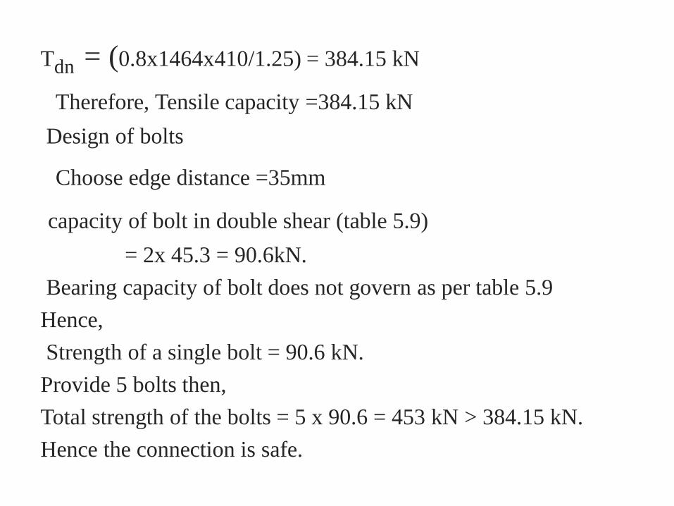
Tdn = (0.8x1464x410/1.25) = 384.15 kN
Therefore, Tensile capacity =384.15 kN
Design of bolts
Choose edge distance =35mm
capacity of bolt in double shear (table 5.9)
= 2x 45.3 = 90.6kN.
Bearing capacity of bolt does not govern as per table 5.9
Hence,
Strength of a single bolt = 90.6 kN.
Provide 5 bolts then,
Total strength of the bolts = 5 x 90.6 = 453 kN > 384.15 kN.
Hence the connection is safe.

Minimum spacing =2.5t = 2.5 x 20 = 50mm.
Hence ,provide a spacing of 50mm.
The arrangements of the bolts are shown in fig (c).
Check for block shear strength :(clause 6.4)
Block shear strength Tdb of connection will be taken as
Tdb1 =[( Avg fy /√3γmo)+ (0.9Atnfu/γml)]
or
Tdb2=[(0.9fuAvn /√3γml)+ (fyAtg/γm0)]
Whichever is smaller
Avg = (4 x 50 + 35)6 =1410mm2
Avn = (4 x 50 + 35)6 =1410mm2

Atn = (35.0 – 22/2)6 =144mm2
Atg = (35x6) = 210mm2
Tdb1= {[1410 x 250)/(√3 x 1.10)] +[0.9 x 144 x 410/1.25}]
x10-3
=227.5kN.
Tdb2= {[0.9 x 410 x 816)/(√3 x 1.25)] +[(250 x 210) 1.10]}x10-3
=186.8kN.
For double angle ,
Block shear strength = 2 x 186.8 = 373.6 kN.
Therefore,
Tensile capacity = 373.6 kN.(least of
393.64kN,384.14kN,373.6kN.)

(b) Two angles connected to the same side of the gusset plate (fig
–b)
(i) Design strength due to yielding of the gross section
= 394.64kN.
(ii) Design strength governed by tearing at the net section
= 384.14 kN.
Assuming 10 bolts of 20mm diameter ,five bolts in each
connected leg
Capacity of an M20 bolts in single shear = 45.3kN.
Total strength of bolts = 10 x 45.3 =453 kN >394.64kN.
Hence the connection is safe.
The arrangements of bolts is shown in fig (d).Since it is similar
to the arrangement shown in fig (c),the block shear strength will

the same i.e., 373.6kN.
Hence the tensile capacity =373.6kN.
The tensile capacity of both the arrangements (angles connected
on the same side and connected to the opposite side of gusset)
are same as per the code though the load application is eccentric
in this case .Moreover the number of bolts are ten whereas in
case (a) we used only five bolts since the bolts were in double
shear.
(c) If the angles are not tack bolted ,they behave as single
angles connected to gusset plate
In this case also the tensile capacity will be the same and we
have to use ten M20 bolts.This fact is confirmed by the test and
• FEM results stating that ‘ the net section strength of double
angles on opposite sides of the gusset and tack connected
adequately over the length is nearly the same as that of two
single angles acting individually.
• current design provisions indicating greater efficiency of such
double angles are not supported by the tests and FEM results.

5.Select a suitable angle section to carry a factored tensile force
of 210kN assuming a single row of M20 bolts and assuming
design strength as fy = 250 N/mm2.
Solution:
Approximate required area = 1.1 x 210 x 103/250 =924mm2
Choose 65 x 65 x 8 angle with A = 976 mm2
Strength governed by yielding = [976 x 250 /1.1]x10-3
= 221.81 kN
Anc= area of connected log = (65-4-22)x8 = 312 mm2
Ago= (65-4) x 8 = 488 mm2
Required number of M20 bolts (Table 5.9) = 170 /45.3 = 3.75
Provide four bolts at the pitch of 60mm.

Strength governed by rupture of critical section
Tdn = 0.9fuAnc/ γml + βAgofy/γmo
β = 1.4 - 0.076 x (65/8)(250 /410)(61 + 35)/(3x60)
= 1.199
Tdn = (0.9x410x312/ 1.25 + 1.199x488x250/1.10)x10-3
= 225.08 kN.
Alternatively,
Tdn = αAnfu/ γml
= [0.8 x (312 + 488) x 410 / 1.25]x10-3
= 209.92 kN.
Strength governed by block shear
Assuming an edge distance of 40mm.

Avg = 8x(3x60+40) = 1760mm2
Avg = 8 x (3 x 60 + 40 – 3.5x 22) =1144mm2
Atg = 8 x 35 =208mm2
Atn = 8 x (35 -0.5 x 22 ) = 192 mm2
Tdb1 = [ 1760 x 250 /(√3 x 1.1) + 0.9 x 410 x192/1.25]x10-3
= 287.61 kN.
Tdb1 = [ 0.9 x 410 x 1144 /(√3 x 1.25) + 250x 280 /1.1]x10-3
= 258.61 kN.
Tension capacity of the angle =209.92 ~ 210 kN.
Hence the angle is safe

Thank You
Copyright © 2022 FDOKUMEN