Unit -4 CAPACITIVE TRANSDUCERS - Annamalai University
25
Unit -4 CAPACITIVE TRANSDUCERS The capacitive transducers are commonly used for measurement of linear displacement
-
Upload
khangminh22 -
Category
Documents
-
view
0 -
download
0
Transcript of Unit -4 CAPACITIVE TRANSDUCERS - Annamalai University
Unit -4
CAPACITIVE TRANSDUCERS
The capacitive transducers are commonly used for measurement of linear displacement

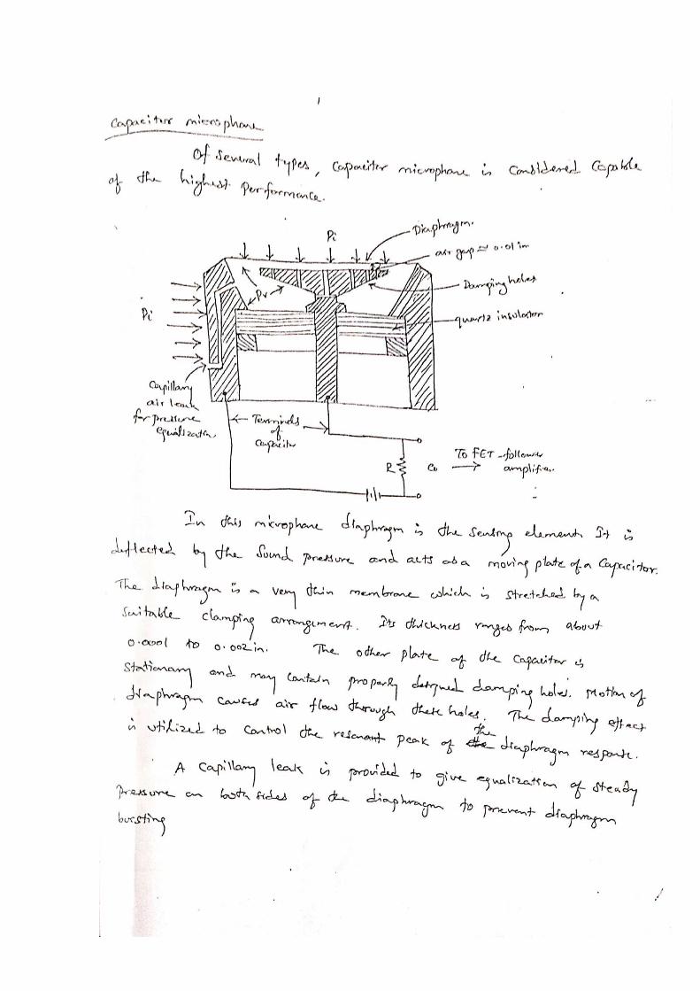
Microphone
A transducer that converts sound in to electrical signal

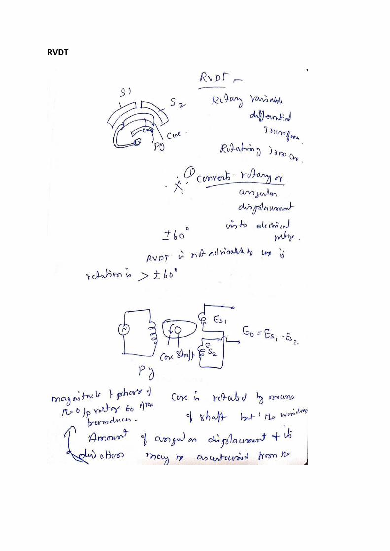
RVDT
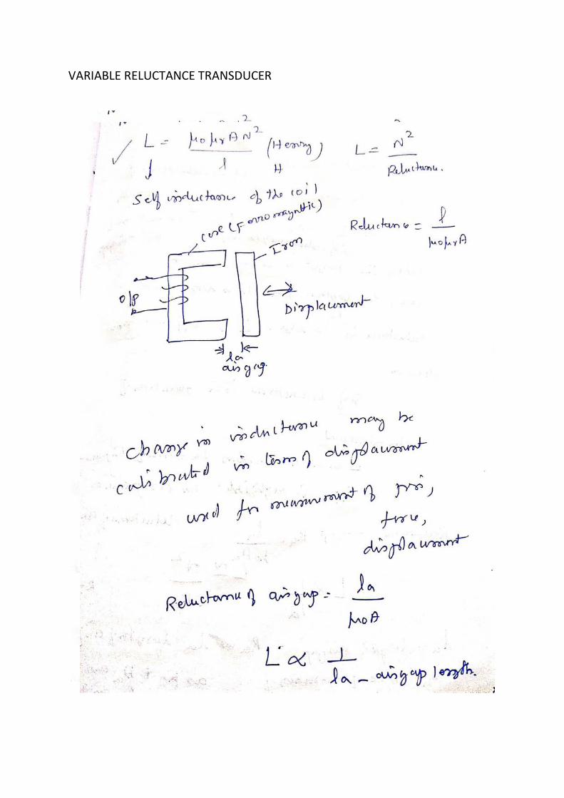
VARIABLE RELUCTANCE TRANSDUCER


UNIT -5 OPTICAL FIBERS
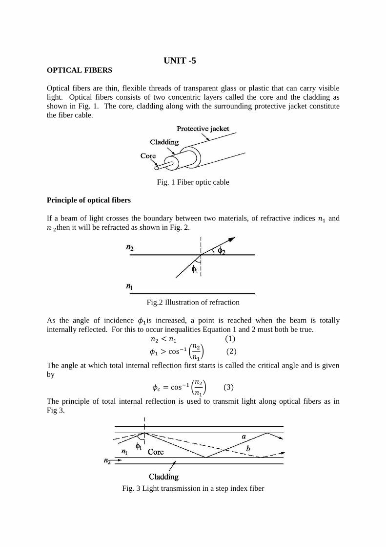
Optical fibers are thin, flexible threads of transparent glass or plastic that can carry visible
light. Optical fibers consists of two concentric layers called the core and the cladding as
shown in Fig. 1. The core, cladding along with the surrounding protective jacket constitute
the fiber cable.
Fig. 1 Fiber optic cable
Principle of optical fibers
If a beam of light crosses the boundary between two materials, of refractive indices 𝑛1 and
𝑛 2then it will be refracted as shown in Fig. 2.
Fig.2 Illustration of refraction
As the angle of incidence 𝜙1is increased, a point is reached when the beam is totally
internally reflected. For this to occur inequalities Equation 1 and 2 must both be true.
𝑛2 < 𝑛1 (1)
𝜙1 > cos−1 (𝑛2
𝑛1) (2)
The angle at which total internal reflection first starts is called the critical angle and is given
by
𝜙𝑐 = cos−1 (𝑛2
𝑛1) (3)
The principle of total internal reflection is used to transmit light along optical fibers as in
Fig 3.
Fig. 3 Light transmission in a step index fiber

Type of Configurations
There are basically two type of optical fibre sensor configurations as shown in Fig. 4. These
are
(a) Extrinsic sensors (or incoherent sensors)
(b) Intrinsic sensors (or coherent sensors)
The emitter, which may be a light emitting diode or a laser source, emits the light rays
through the fiber, which gent modulated due to the outer signal, which is to be measured.
The output fiber is connected to the detector, which converts the optical energy into electrical
energy. These detections work on the principle of creation of an electron-hole pair in
semiconductors or the release of electrons from the cathode of the photomultiplier tube. In
the case of the extrinsic sensor, as in Fig. 4 (a) in the intensity modulation of light takes place
outside the fibre, while in the case of Fig 4 (b) viz. Intrinsic sensor, it takes place within the
fibre. Examples of the two types of sensors are given in Fig. 5
Fig. 4 Types of Optical Fibre Sensor configurations
Fig. 5 (a) shows an extrinsic or external intensity modulator type of sensor in which the
position of the reflector due to motion to be measured may change, thus changing the light
intensity in the output fiber. This is detected by a detector.
In Fig. 5 (b) the fibre bending due to the pressure, which is the input variable, to be measured
induces radiation losses, changing the intensity at the output. This happens within the fibre
itself and hence the configuration is called as intrinsic type. This causes radiation of light
even at small deformation and is also called micro-bend sensor. In this type of sensor
configuration, apart from the intensity modulator, there may be phase or frequency
modulation, which after detection may be used for several modulator, there may be phase or
frequency modulation, which after detection may be used for several applications.
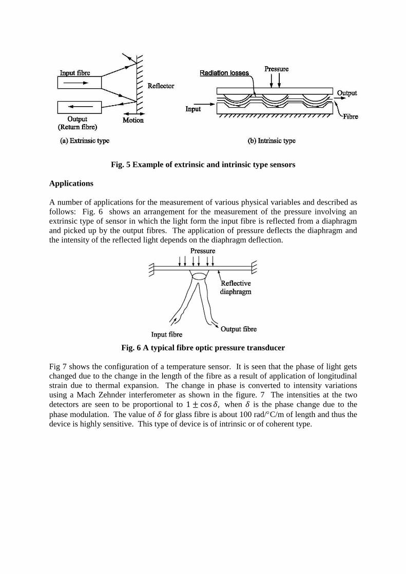
Fig. 5 Example of extrinsic and intrinsic type sensors
Applications
A number of applications for the measurement of various physical variables and described as
follows: Fig. 6 shows an arrangement for the measurement of the pressure involving an
extrinsic type of sensor in which the light form the input fibre is reflected from a diaphragm
and picked up by the output fibres. The application of pressure deflects the diaphragm and
the intensity of the reflected light depends on the diaphragm deflection.
Fig. 6 A typical fibre optic pressure transducer
Fig 7 shows the configuration of a temperature sensor. It is seen that the phase of light gets
changed due to the change in the length of the fibre as a result of application of longitudinal
strain due to thermal expansion. The change in phase is converted to intensity variations
using a Mach Zehnder interferometer as shown in the figure. 7 The intensities at the two
detectors are seen to be proportional to 1 ± cos 𝛿, when 𝛿 is the phase change due to the
phase modulation. The value of 𝛿 for glass fibre is about 100 rad/C/m of length and thus the
device is highly sensitive. This type of device is of intrinsic or of coherent type.
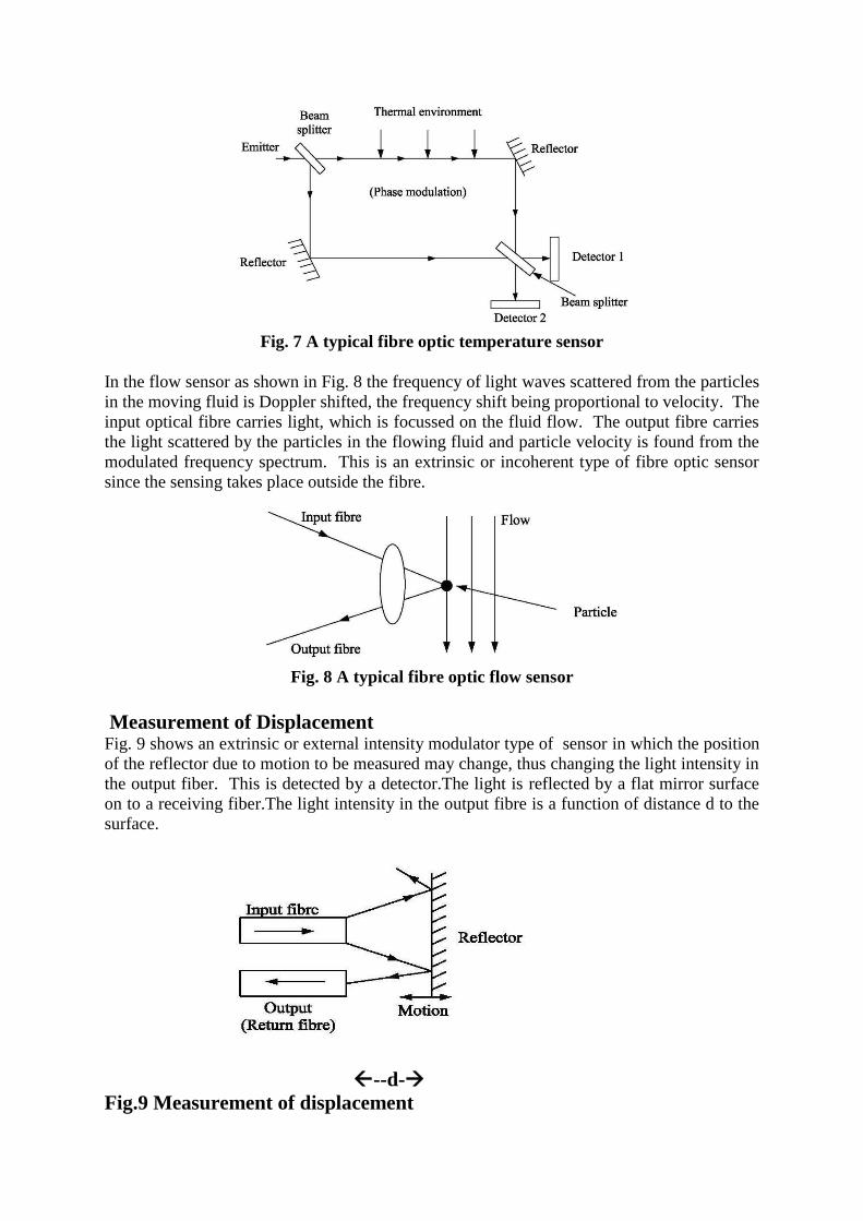
Fig. 7 A typical fibre optic temperature sensor
In the flow sensor as shown in Fig. 8 the frequency of light waves scattered from the particles
in the moving fluid is Doppler shifted, the frequency shift being proportional to velocity. The
input optical fibre carries light, which is focussed on the fluid flow. The output fibre carries
the light scattered by the particles in the flowing fluid and particle velocity is found from the
modulated frequency spectrum. This is an extrinsic or incoherent type of fibre optic sensor
since the sensing takes place outside the fibre.
Fig. 8 A typical fibre optic flow sensor
Measurement of Displacement Fig. 9 shows an extrinsic or external intensity modulator type of sensor in which the position
of the reflector due to motion to be measured may change, thus changing the light intensity in
the output fiber. This is detected by a detector.The light is reflected by a flat mirror surface
on to a receiving fiber.The light intensity in the output fibre is a function of distance d to the
surface.
--d-→
Fig.9 Measurement of displacement

Silicon micro sensor - Miniaturistation of sensor
Silicon is used as a base material for making micro sensor. Silicon is a good substrate for
incorporating the associated signal conditioning circuitry. The sensor along with the signal
conditioning electronic components are mounted on the same silicon substrate.
Usually a semi conductor(piezo resistive material) is diffused on the silicon substrate at the
region of maximum strain. The resistance of the piezo resistive material changes with strain
which with wheatstone bridge can given an output.
Diaphragm type siliconMicro pressure sensor
Smart sensors
The sensor having decision-making and communication logic added to the basic sensor, are
called smart or intelligent sensors. Some of the other features included in such sensor are
compensation for interfering inputs, linearization, self-test and calibration facility. There are
usually microcomputers and other elements on the same chip whenever possible.
For data acquisition used the smart pressure sensor, the functional diagram is as shown in
Fig. 10. If a piezo resistive sensor is used, as primary sensor for pressure, the main
interfering input is temperature and so a secondary temperature sensor is used to compensate
for the effect of temperature on resistance change. The memory of the microcontroller has
calibration data stored in it. The microcontroller is essentially a microprocessor with
input/output (I/O) facility.
Fig. 10 Data acquisition system using smart pressure sensor
IC temperature sensor
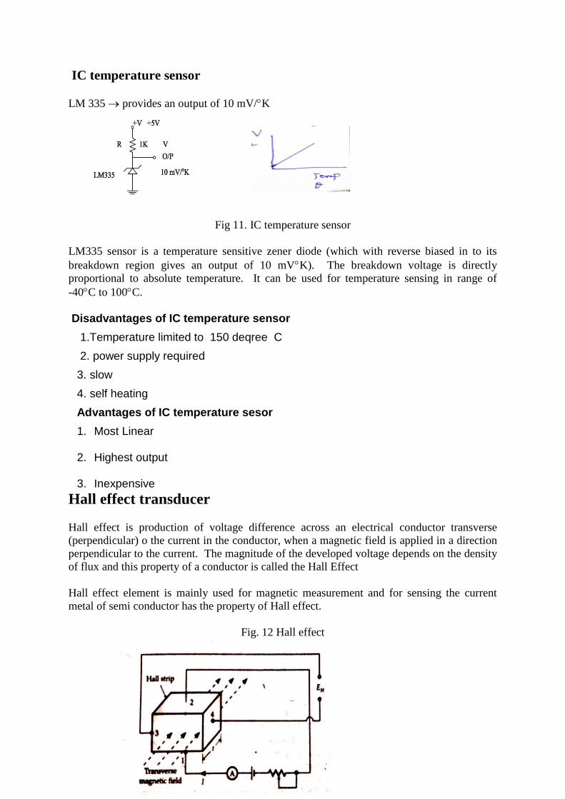
LM 335 → provides an output of 10 mV/K
Fig 11. IC temperature sensor
LM335 sensor is a temperature sensitive zener diode (which with reverse biased in to its
breakdown region gives an output of 10 mVK). The breakdown voltage is directly
proportional to absolute temperature. It can be used for temperature sensing in range of
-40C to 100C.
Disadvantages of IC temperature sensor
1.Temperature limited to 150 deqree C
2. power supply required
3. slow
4. self heating
Advantages of IC temperature sesor
1. Most Linear
2. Highest output
3. Inexpensive
Hall effect transducer
Hall effect is production of voltage difference across an electrical conductor transverse
(perpendicular) o the current in the conductor, when a magnetic field is applied in a direction
perpendicular to the current. The magnitude of the developed voltage depends on the density
of flux and this property of a conductor is called the Hall Effect
Hall effect element is mainly used for magnetic measurement and for sensing the current
metal of semi conductor has the property of Hall effect.
Fig. 12 Hall effect
Output voltage
𝐸𝐻 = 𝐾𝐻 𝐼𝐵/𝑡
Where 𝐾𝐻 Hall coefficient
𝑡 Thickness of strip in m
𝐼 Current in ampere
𝐵 flux density in 𝑊𝑏/𝑚2
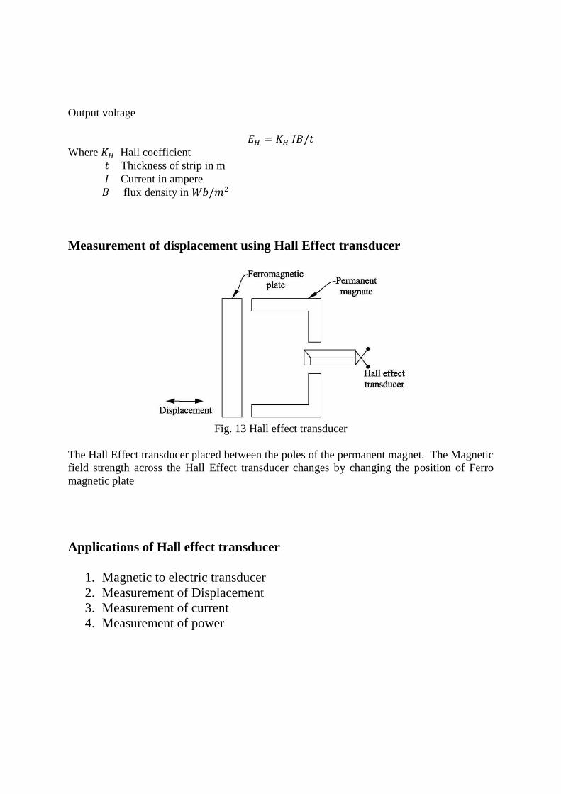
Measurement of displacement using Hall Effect transducer
Fig. 13 Hall effect transducer
The Hall Effect transducer placed between the poles of the permanent magnet. The Magnetic
field strength across the Hall Effect transducer changes by changing the position of Ferro
magnetic plate
Applications of Hall effect transducer
1. Magnetic to electric transducer
2. Measurement of Displacement
3. Measurement of current
4. Measurement of power