Transducers and conditioning (bf0236) - B&K | Sound and ...
188
BRÜEL & KJÆR TRANSDUCERS AND CONDITIONING CATALOGUE TRANSDUCERS AND CONDITIONING BRÜEL & KJÆR ISSUE 19
-
Upload
khangminh22 -
Category
Documents
-
view
0 -
download
0
Transcript of Transducers and conditioning (bf0236) - B&K | Sound and ...

BRÜEL & KJÆR
TRANSDUCERS AND CONDITIONING
CATALOGUE
TRAN
SDU
CERS AN
D CO
ND
ITION
ING
www.bksv.com
Brüel & Kjær Sound & Vibration Measurement A/S DK-2850 Nærum · DenmarkTelephone: +45 77 41 20 00 · Fax: +45 45 80 14 05 www.bksv.com · [email protected] representatives and service organizations worldwide
Who we are How we can help
BRÜEL &
KJÆR
ISSUE 19
BF
023
6 –
13
2
016-
01

WELCOME
Welcome to the Brüel & Kjær Transducer Catalogue covering ourfull range of transducer-based solutions including:• Microphones• Accelerometers• Preamplifiers• Hydrophones• Pressure transducers• Conditioning amplifiers• Force transducers• Impact hammers• Impedance heads• Non-contact transducers• Shakers and vibration exciters• Electroacoustic products and systems• Calibration products and systems• Cables and accessories
The instruments are grouped and sorted into tables that list themost important specifications to make it easy for you to select theright product for your particular measurement needs. Within themicrophone and accelerometer sections, you will also find pull-outtables to give you a complete overview and possibility to comparespecifications across transducer families.
The Whole Measurement Chain Brüel & Kjær’s advanced technological solutions and productscover the entire sound and vibration measurement chain, from asingle transducer to complete turnkey systems.
Products Our market-leading product portfolio covers all of the componentsand tools required for high-quality measurement and analysis ofsound and vibration. We are unique in the industry, allowing you tosource all of your components from one supplier.
Systems Our products are designed to fit together and cooperateintelligently. This simplifies the process of creating systemsoptimized to solve your specific issues.
Solutions In certain instances, we supply both the systems and highly-skilledengineers to operate them and supply analysis results – meaningyou can focus on your core business without worrying aboutoperating and maintaining equipment.
Services We offer a full range of services for our products and systemsincluding: installation, training, support, software updates,calibration, planned maintenance, repair and rental.
Brüel & Kjær is unique in the sound and vibration industry, producing all the elements for the most technologically advanced and complete sound and vibration solutions designed to save time and eliminate errors in the measurement process. In fact, Brüel & Kjær equipment and knowledge are behind thousands of achievements, from high-performance cars and smartphones to quieter airports, satellites and beyond – even helping with the Mars landings.
WANT TO FIND OUT MORE?
Customer-driven SolutionsOur most important skill is listening to the challenges customersmeet in their work processes, where increasing functionaldemands, time pressures, regulatory requirements and budgetconstraints mean that getting it right the first time is becomingevermore critical. Receptive dialogue allows us to fullyunderstand specific customer needs and develop long-termsound and vibration solutions.
Over the years, we have developed creative and technicallyadvanced solutions to innumerable customer problems, some ofwhich you can find on our website on: www.bksv.com/casestudies.
For intriguing features and news related to sound and vibration, youcan subscribe to our customer magazine Waves on: www.bksv.com/waves.
Events and TrainingIf you are interested in a more in-depth understanding of any of thesolutions and/or applications featured in this catalogue, pleaseconsider our specialist courses, events and webinars that go beyondconventional training and give you access to our world-leadingknowledge base. Full details of what is available and when can befound on: www.bksv.com/courses.
Near to YouBrüel & Kjær is a global company. We operate through our networkof sales offices and representatives in 55 countries. These localteams are supported by our global group of engineering specialists,who can advise on and solve all manner of sound and vibrationmeasurement and analysis problems. To augment our service, weregularly hold local courses and road-shows, and participate insound- and vibration-focused exhibitions and conferencesworldwide.
To contact a salesperson or support staff nearest you, see our list ofoffices and agents on: www.bksv.com/contact.

CONTENTS
INTR
OD
UC
TIO
NM
ICRO
PHO
NES
CO
UPL
ERS
CA
LIBR
ATI
ON
AC
CEL
ERO
MET
ERS
CO
ND
ITIO
NIN
GSE
RVIC
EA
PPEN
DIC
ES
Brüel & Kjær Transducers ............................................................................................................................................ 1
Our Development and Production Process .................................................................................................................. 2Our Implementation of TEDS ....................................................................................................................................... 3Ordering Transducers................................................................................................................................................... 4Customization .............................................................................................................................................................. 4Microphone Firsts ........................................................................................................................................................ 5Accelerometer Firsts .................................................................................................................................................... 6
Transducer Application Examples ................................................................................................................................ 7
Transducers for Aerospace and Defence Solutions...................................................................................................... 8Transducers for Automotive/Ground Vehicle Solutions ............................................................................................ 10Transducers for Telecom and Audio Solutions........................................................................................................... 12
Selecting the Right Microphone ................................................................................................................................. 15
Microphones ............................................................................................................................................................. 19
Definition of Given Microphone Specifications.......................................................................................................... 19Free‐field Microphones.............................................................................................................................................. 19Diffuse‐field Microphones.......................................................................................................................................... 21Pressure‐field Microphones ....................................................................................................................................... 22Multi‐field Microphone .............................................................................................................................................. 23Array Microphones..................................................................................................................................................... 24Low‐noise Microphones ............................................................................................................................................. 25Outdoor Microphones................................................................................................................................................ 26Laboratory Standard Microphones ............................................................................................................................ 27
Special Acoustic Transducers ..................................................................................................................................... 28
Transducers for Sound Intensity Analysis .................................................................................................................. 29Microphones for High‐intensity Testing..................................................................................................................... 31Hydrophones .............................................................................................................................................................. 32
Microphone Preamplifiers ......................................................................................................................................... 34
Brüel & Kjær Range of Microphone Preamplifiers ..................................................................................................... 35
Microphone Calibration ............................................................................................................................................. 37
Calibrators .................................................................................................................................................................. 37Sound Intensity Calibrators ....................................................................................................................................... 38Adaptors for Calibration ............................................................................................................................................ 39
More About Microphones ......................................................................................................................................... 40
TEDS Microphones ..................................................................................................................................................... 40Microphone Verification and Calibration................................................................................................................... 42
Microphone and Preamplifier Extension Cables ......................................................................................................... 43
Raw Cables ................................................................................................................................................................. 46More About Cables..................................................................................................................................................... 47
Microphone Accessories ............................................................................................................................................ 48
Adaptors ..................................................................................................................................................................... 48Corrector .................................................................................................................................................................... 48Windscreens............................................................................................................................................................... 49Nose Cones................................................................................................................................................................. 49Outdoor Protection .................................................................................................................................................... 50Preamplifier Holders .................................................................................................................................................. 50Tripods........................................................................................................................................................................ 50Miscellaneous ............................................................................................................................................................ 51
iwww.bksv.com/transducers

INTRO
DU
CTIO
NM
ICRO
PHO
NES
CO
UPLERS
AC
CELERO
METERS
CA
LIBRATIO
NC
ON
DITIO
NIN
GSERV
ICE
APPEN
DIC
ES
Selecting the Right Coupler ........................................................................................................................................ 53
Couplers .................................................................................................................................................................... 56
Artificial Ears and Mastoids........................................................................................................................................ 56Ear and Mouth Simulators for Telephone Testing ..................................................................................................... 60Head and Torso Simulators and Telephone Test Heads............................................................................................. 63Acoustic Test Accessories........................................................................................................................................... 66
Selecting the Right Accelerometer ............................................................................................................................. 69
Accelerometers ......................................................................................................................................................... 72
Definitions of Given Accelerometer Specifications .................................................................................................... 72Uniaxial Piezoelectric Charge Accelerometers........................................................................................................... 72Triaxial Piezoelectric Charge Accelerometers ............................................................................................................ 75Uniaxial CCLD Accelerometers ................................................................................................................................... 76Triaxial CCLD Accelerometers..................................................................................................................................... 82Amplified Piezoresistive Accelerometers ................................................................................................................... 84Connection Examples to Measurement and Analysis Devices................................................................................... 85
Non‐contact Transducers ........................................................................................................................................... 86
Non‐contact Transducers for Speed, Velocity and Displacement .............................................................................. 86
Force Transducers and Impact Hammers ................................................................................................................... 87
Force Transducers ...................................................................................................................................................... 87Force Transducer/Impact Hammer ........................................................................................................................... 88Impedance Heads ...................................................................................................................................................... 88Impact Hammers........................................................................................................................................................ 89
Modal and Vibration Exciters ..................................................................................................................................... 90
Modal and Vibration Test Solutions from Brüel & Kjær............................................................................................. 90
Accelerometer Accessories ........................................................................................................................................ 92
Clip Mounting............................................................................................................................................................. 92Mounting Blocks, Brackets and Adaptors .................................................................................................................. 95Other Accessories....................................................................................................................................................... 97
Accelerometer Mounting Solutions ......................................................................................................................... 103
Mounting Considerations......................................................................................................................................... 103Mounting of Type 4326‐A‐001 .................................................................................................................................104
Accelerometer Cables .............................................................................................................................................. 105
Brüel & Kjær Cables..................................................................................................................................................105Coaxial Cable Assemblies for Uniaxial Accelerometers............................................................................................106Coaxial Cable Assemblies for Triaxial Accelerometers .............................................................................................110Cable Assemblies for Industrial and Monitoring Applications .................................................................................112Cable Accessories .....................................................................................................................................................114Raw Cables ...............................................................................................................................................................115
Accelerometer Calibration ....................................................................................................................................... 119
Reference Accelerometers ....................................................................................................................................... 119Calibrators and Calibration Systems ........................................................................................................................ 120Vibration and Shock Calibration Exciters .................................................................................................................121Calibration Accessories ............................................................................................................................................121
Signal Conditioning .................................................................................................................................................. 123
Multi‐pin Signal Conditioners for Microphones ....................................................................................................... 123CCLD Signal Conditioners for Microphones and Accelerometers ............................................................................124Charge Signal Conditioners for Accelerometers....................................................................................................... 126What are the Benefits of Signal Conditioning? ........................................................................................................128
ii www.bksv.com/transducers

INTR
OD
UC
TIO
NM
ICRO
PHO
NES
CO
UPL
ERS
CA
LIBR
ATI
ON
AC
CEL
ERO
MET
ERS
CO
ND
ITIO
NIN
GSE
RVIC
EA
PPEN
DIC
ES
Calibration Systems ..................................................................................................................................................131
Primary Calibration Systems .................................................................................................................................... 131Secondary Calibration Systems................................................................................................................................ 132
Brüel & Kjær Service .................................................................................................................................................133
Brüel & Kjær Calibration and Repair Services .......................................................................................................... 134Calibration of Reference Equipment........................................................................................................................ 134Accredited Calibration ............................................................................................................................................. 134Traceable Calibration ............................................................................................................................................... 134Regular Calibration .................................................................................................................................................. 134Service Agreements ................................................................................................................................................. 135Rentals ..................................................................................................................................................................... 135Learn More .............................................................................................................................................................. 135
Glossary of Terms .....................................................................................................................................................137
Compliance with Standards ......................................................................................................................................143
General Compliance................................................................................................................................................. 143Relevant Microphone Standards ............................................................................................................................. 143
Dimensions ..............................................................................................................................................................144
Microphone Dimensions.......................................................................................................................................... 144Accelerometer Dimensions...................................................................................................................................... 147
Microphone Comparison Table .................................................................................................................................153
Charge Accelerometer Comparison Tables ................................................................................................................155
CCLD Accelerometer Comparison Tables ...................................................................................................................157
Piezoresistive Accelerometer Comparison Table .......................................................................................................163
Index.........................................................................................................................................................................165
iiiwww.bksv.com/transducers

INTRO
DU
CTIO
NM
ICRO
PHO
NES
CO
UPLERS
AC
CELERO
METERS
CA
LIBRATIO
NC
ON
DITIO
NIN
GSERV
ICE
APPEN
DIC
ES
iv www.bksv.com/transducers
BRÜEL & KJÆR TRANSDUCERS
Transducers have been a core part of Brüel & Kjær’s business formore than 70 years. The quality of our transducers is world‐renowned and is the result of our unique experience and knowledge,backed up by meticulous testing and quality control, which ensuresthat you get the performance and durability you expect.
But Brüel & Kjær goes beyond transducers. We are unique in theindustry, producing all of the elements for complete sound andvibration test systems. Our goal is to create the mosttechnologically advanced solutions, built to the highest quality anddesigned to save time and eliminate errors in the measurementprocess. We have an unequalled product range, but our realadvantage lies within our ability to supply complete solutions that
are targeted at optimizing our customers’ work processes, toprovide rapid, reliable results.
Creative Answers to Complex ProblemsBrüel & Kjær is founded on good ideas, hard work andentrepreneurship, and it is this passion for innovation and highquality that drives the company forward. Over the past couple ofyears, our innovations have strongly focused on helping you workfaster, smarter and easier by supporting the entire measurementand analysis process: from transducer to data acquisition, analysesand after‐sales care and services.
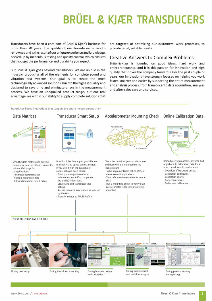
Transducer‐based innovations that support the entire measurement chain
Accelerometer Mounting CheckTransducer Smart SetupData Matrices
THESE SOLUTIONS CAN HELP YOU:
During test setup During transducer mounting During front-end setupand calibration
During measurementand real-time analysis
During post-processingand reporting
Check the health of your accelerometerand how well it is mounted on thetest structure- To be implemented in PULSE Reflex measurement applications- Take reference measurements in one click- Run a mounting check to verify if an accelerometer is loosely or correctly mounted
Immediately gain access, anytime andanywhere, to calibration data for all your transducers in one location:- Overview of hardware assets- Calibration certificates- Calibration charts- Correction curves- Order new calibration
Scan the data matrix code on yourtransducer to access the instrument’sunique Web page for:- Specifications- Technical documentation- Specific calibration data- Information about Smart Setup
Download the free app to your iPhoneto simplify and speed up test setups.If you use it with the data matrixcodes, setup is even easier:- Quickly catalogue transducer information, node IDs, component IDs and DOF directions- Create and edit transducer test setups- Access resource information as you set up the test- Transfer setups to PULSE Reflex
Online Calibration Data
bksv.com Accelerometers
Accelerometers
Brüel & Kjær Transducers 1www.bksv.com/transducers

Our Development and Production Process
Development from the BeginningWe determine the specification of a new transducer based on inputfrom our customers, their requirements, and our own productdevelopment plans. Using modern simulation and analytical tools,such as finite element models (FEM), we can, early in the process,begin to optimize the performance of the new design and reducedevelopment time so the first units reach customers faster.
After verifying the model, we construct several prototypes. Asthorough testing ensures long‐term stability, each prototype issubjected to the following tests – in addition to those against themathematical model:• Environmental testing – heat, humidity, etc.• EMC (electromagnetic compatibility)• Base strain• Measurement accuracy• Destructive testing
Ongoing testing, verification, and artificial aging ensure that thequality of the manufactured product is always maintained and thatthe excellent accuracy that Brüel & Kjær transducers are known for,is ensured.
Production: Test, Test and Test AgainEvery Brüel & Kjær transducer is thoroughly tested during itsproduction to ensure that its performance is within the specifiedparameters. Extremely high standards are met in our productionquality and this is reflected in our status as an ISO 9001 and EN 9100certified company. Depending on the type, a transducer can besubjected to between five and ten separate test procedures.
Our extensive in‐house test equipment gives our engineers thetools to quickly identify the root cause, fix the underlying problemand resume normal production to make timely delivery with thequality you expect from Brüel & Kjær.
Calibration Before Shipping An individual calibration is performed on each transducer duringproduction in our own calibration laboratory using a calibrationtechnique based on FFT analysis, which provides the resolutionneeded to detect certain types of problems. Our unique status asthe primary Danish standards lab reduces our traceability steps aswell the uncertainty in our calibrations.
Sharing Our KnowledgeThe information we gather during final testing is always available toyou via our detailed product datasheets. Each datasheet includesthe individual transducer’s sensitivity to external inputs as well asother specifications.
If you need more information, a support engineer is alwaysavailable by phone, on the Web or in person to answer yourquestion and share best practices. Additionally, we have a wealth ofinformation in our transducer handbooks, application notes andtechnical reviews, all available at www.bksv.com.
2 Brüel & Kjær Transducers www.bksv.com/transducers
Our Implementation of TEDSA wide range of TEDS (transducer electronic data sheet)transducers are available from Brüel & Kjær. TEDS is standardizedby the Institute of Electrical and Electronics Engineers (IEEE) and issupported by many front ends and conditioning amplifiersincluding Brüel & Kjær’s PULSE LAN‐XI data acquisition, VC‐LANvibration controllers, 16‐channel Conditioning Amplifier Type2694, the NEXUS line of conditioning amplifiers, and many more.
TEDS offers a number of benefits:• Plug and play facilities• Type, S/N, sensitivity and more read directly from the
transducer• Significantly reduced setup time• Practical elimination of cable routing errors
How Does TEDS Work?Basically the chip containing the TEDS data and TEDS interface is builtinto the transducer. TEDS data is updated during the measurementsystem’s boot sequence or whenever “update TEDS” is activated.
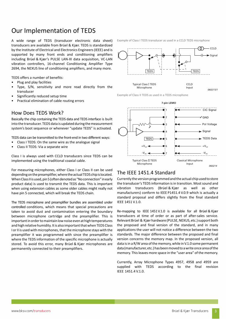
TEDS data can be transmitted to the front‐end in two different ways:• Class I TEDS: On the same wire as the analogue signal• Class II TEDS: Via a separate wire
Class I is always used with CCLD transducers since TEDS can beimplemented using the traditional coaxial cable.
For measuring microphones, either Class I or Class II can be useddepending on the preamplifier, where the actual TEDS chip is located.When Class II is used, pin 5 (often denoted as “No connection” in earlyproduct data) is used to transmit the TEDS data. This is importantwhen using extension cables as some older cables might really nothave pin 5 connected, which will break the TEDS chain.
The TEDS microphone and preamplifier bundles are assembled undercontrolled conditions, which means that special precautions aretaken to avoid dust and contamination entering the boundarybetween microphone cartridge and the preamplifier. This isimportant in order to maintain low noise even at high temperaturesand high relative humidity. It is also important that when TEDS ClassI or II is used with microphones, that the microphone stays with thepreamplifier it was programmed with since the preamplifier iswhere the TEDS information of the specific microphone is actuallystored. To avoid this error, many Brüel & Kjær microphones arepermanently connected to their preamplifiers.
Example of Class I TEDS transducer as used in a CCLD TEDS microphone
Example of Class II TEDS as used in a TEDS microphone
The IEEE 1451.4 StandardCurrently the version programmed and the actual chip used to storethe transducer’s TEDS information is in transition. Most sound andvibration transducers (Brüel & Kjær as well as othermanufacturers) conform to IEEE P1451.4 V.0.9 which is actually astandard proposal and differs slightly from the final standardIEEE 1451 V.1.0.
Re‐mapping to IEEE 1451V.1.0 is available for all Brüel & Kjærtransducers at time of order or as part of after‐sales service.Relevant Brüel & Kjær hardware (PULSE, NEXUS, etc.) support boththe proposed and final version of the standard, and in manyapplications the user will not notice a difference between the twostandards. The major difference between the proposed and finalversion concerns the memory map. In the proposed version, alldata is in a R/W area of the memory, while in V.1.0 some permanentdata (manufacturer, etc.) has been moved to a write once area of thememory. This leaves more space in the “user area” of the memory.
Currently, Array Microphone Types 4957, 4958 and 4959 aresupplied with TEDS according to the final revisionIEEE 1451.4 V.1.0.
TEDS TEDS
060215/1
CCLD
Signal
Typical Class l TEDSMicrophone
CCLDInput
--
TEDS
+Vcc
-Vcc
+Vcc
-Vcc
Pol Voltage
CIC Signal
TEDS Data
Signal
1
2
3
4
5
6
7
7-pin LEMO
Typical Class ll TEDSMicrophone
Classical MicrophoneInput
060214
––
GND
Brüel & Kjær Transducers 3www.bksv.com/transducers
TEDS TemplatesThe TEDS template defines the memory mapping of the TEDS chipand hence the “understanding” between transducer and front end.
A number of TEDS templates have been standardized by the IEEEand in addition to this, a number of non‐standard vendor specific
templates exist. The different TEDS templates are differentiated bydifferent ID numbers.
See TEDS Microphones for a listing of the templates used withBrüel&Kjær microphones and preamplifiers.
Ordering TransducersTo order from Brüel & Kjær, you just need to know an item’s ordernumber. For transducers and signal conditioners, these will be anumber preceded by the word “Type”. For example:• 1/2‐inch Prepolarized Microphone Type 4188• Miniature Triaxial CCLD Accelerometer Type 4520• Charge to CCLD Converter Type 2647
A transducer may have several models that vary from each other(different sensitivity, interface or accessories). This is denoted by aletter after the number, by a dash (‐) and three alphanumericcharacters, or a combination of a letter and then threealphanumeric characters, for example:• Charge to CCLD Converter Types 2647‐A, 2647‐B and 2647‐C• Miniature Triaxial CCLD Accelerometer Types 4520‐001 and
4502‐004• 1/2‐inch Free‐field Microphone including High‐temperature
Preamplifier Type 1706 with TEDS Type 4189‐H‐041
There are some general rules within transducer families relating tothe letter:• For CCLD accelerometers, a “B” in the type number indicates
that the transducer contains TEDS• For microphones:
– “A” or “H” in the type number indicates a CCLDpreamplifier with TEDS
– “B”, “C”, or “L” in the type number indicates a 7‐pinLEMO preamplifier with TEDS
For accessories, the order number is an alphanumeric code startingwith two letters. For example: • AO‐xxxx: Extension Cables • UA‐xxxx: Adaptor and Mounting Clips• YM‐xxxx: Adhesive Mounting Pads• YJ‐xxxx: Glue and Adhesives• QS‐xxxx: Glue and Adhesives
Each transducer has a product data sheet (PD) with orderinginformation – including all required accessories. You can findtransducer PDs on www.bksv.com.
CustomizationDespite the large number of transducers available in Brüel & Kjær’sstandard selection, special measurement situations can occurrequiring a transducer that cannot be met by our standard productrange. In order to effectively meet our customers’ needs, we offercustomized products.
We already have a broad portfolio of non‐standard productsdeveloped for special applications. For further details on whatBrüel & Kjær can offer for special applications, please contact yourlocal representative.
4 Brüel & Kjær Transducers www.bksv.com/transducers

Microphone Firsts
World’s first volume‐produced measurement microphones, Types 4131 (free‐
field) and 4132 (pressure‐field), developed, amongst others, by Dr. Per V. Brüel
1956 Type 4131
World’s first 1/8" measuring microphone.
Due to on‐going product improvements, this type is still available
1967 Type 4138
Brüel & Kjær is requested to produce a replacement for the Western Electric
WE 640 AA Reference Microphone. As a result, Type 4160 and later the ½"
Type 4180 were introduced (still the world de facto acoustical standards)
1975 Type 4160
Brüel & Kjær launches the world’s first high‐stability, measurement grade,
electret microphones
1980 Type 4155
Using advanced modelling and clever design, this microphone has a noise floor
of –2.5 dB(A), still unbeaten after nearly 30 years!
1984 Type 4179
Brüel & Kjær introduces probe microphone for measurement in extremely
confined spaces and up to more than 600 °C
1987 Type 4182
Falcon series is introduced. Featuring stainless steel, press‐fitted diaphragms,
these microphones result in a step change in microphone technology
1993 Type 4188
Falcon series at peak performance.
Type 4189 is probably the world’s most popular ½" free‐field microphone
1994 Type 4189
The world’s only one‐unit Sound Intensity Calibrator enables calibration
without dismantling the probe
2000 Type 4297
Surface Microphone – a Brüel&Kjær first: an “all titanium” sensor originally
developed for aerospace applications
2003 Type 4948
Surface Microphones now also find their way into the automotive industry,
where they break new frontiers in wind‐tunnel testing
2004 Type 4949
World’s first outdoor microphone where all parts exposed to the weather are
made from polymer materials
2005 Type 4952
Continuing the “all titanium” concept, this TEDS microphone has 1.1 V/Pa
sensitivity and a typical noise floor of 5.5 dB
2006 Type 4955
Multi‐field Microphone – world’s first ¼" measurement microphone that
guarantees accurate and error‐free measurements in both free and diffuse
fields and at any angle
2009 Type 4961
World’s first microphone preamplifier that can handle temperatures up to
+125 °C/+257 °F
2012 Type 1706
Access calibration data anytime. Calibration data is stored in the cloud for every
transducer serviced at a Brüel & Kjær calibration laboratory. Furthermore,
correction files for each individual microphone are accessible via the Web
2015Calibration in
the Cloud
5www.bksv.com/transducers
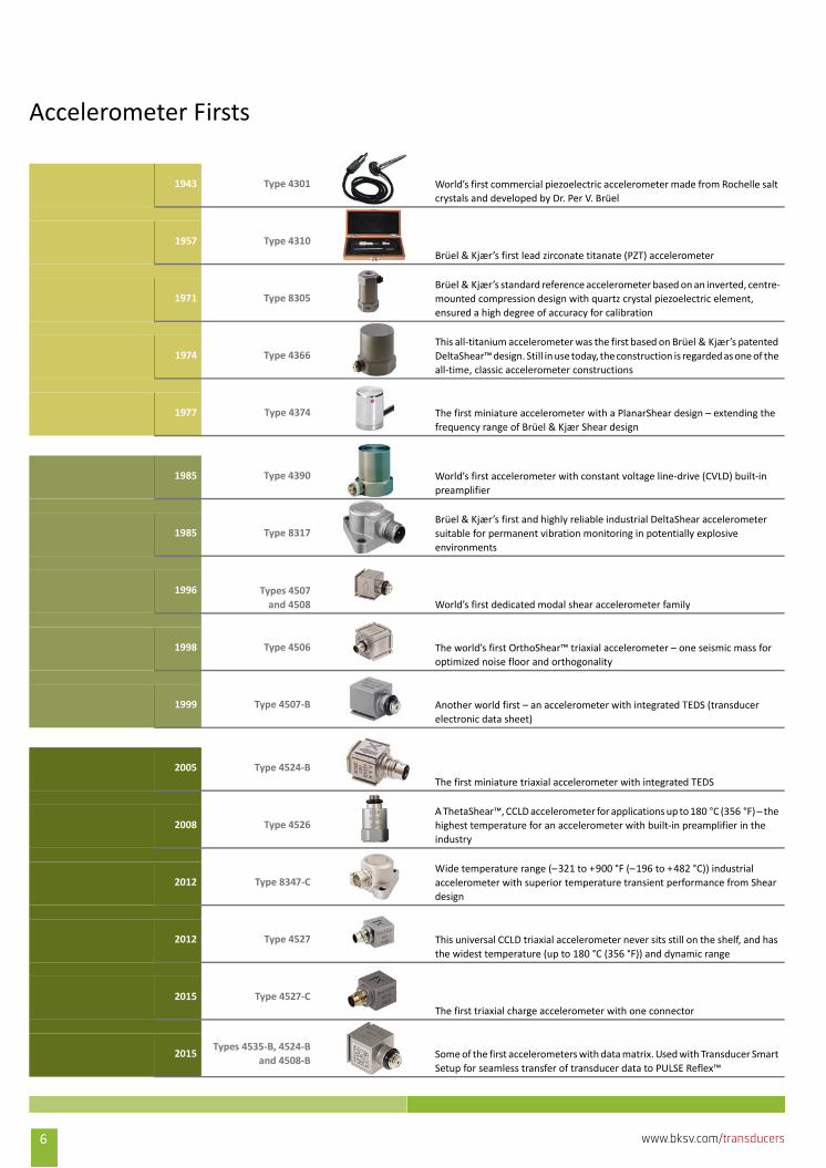
Accelerometer Firsts
World’s first commercial piezoelectric accelerometer made from Rochelle salt
crystals and developed by Dr. Per V. Brüel
1943 Type 4301
Brüel & Kjær’s first lead zirconate titanate (PZT) accelerometer
1957 Type 4310
Brüel & Kjær’s standard reference accelerometer based on an inverted, centre‐
mounted compression design with quartz crystal piezoelectric element,
ensured a high degree of accuracy for calibration
1971 Type 8305
This all‐titanium accelerometer was the first based on Brüel & Kjær’s patented
DeltaShear™ design. Still in use today, the construction is regarded as one of the
all‐time, classic accelerometer constructions
1974 Type 4366
The first miniature accelerometer with a PlanarShear design – extending the
frequency range of Brüel & Kjær Shear design
1977 Type 4374
World’s first accelerometer with constant voltage line‐drive (CVLD) built‐in
preamplifier
1985 Type 4390
Brüel & Kjær’s first and highly reliable industrial DeltaShear accelerometer
suitable for permanent vibration monitoring in potentially explosive
environments
1985 Type 8317
Types 4507
and 4508 World’s first dedicated modal shear accelerometer family
1996
The world’s first OrthoShear™ triaxial accelerometer – one seismic mass for
optimized noise floor and orthogonality
1998 Type 4506
Another world first – an accelerometer with integrated TEDS (transducer
electronic data sheet)
1999 Type 4507‐B
The first miniature triaxial accelerometer with integrated TEDS
2005 Type 4524‐B
A ThetaShear™, CCLD accelerometer for applications up to 180 °C (356 °F) – the
highest temperature for an accelerometer with built‐in preamplifier in the
industry
2008 Type 4526
Wide temperature range (–321 to +900 °F (–196 to +482 °C)) industrial
accelerometer with superior temperature transient performance from Shear
design
2012 Type 8347‐C
This universal CCLD triaxial accelerometer never sits still on the shelf, and has
the widest temperature (up to 180 °C (356 °F)) and dynamic range
2012 Type 4527
The first triaxial charge accelerometer with one connector
2015 Type 4527‐C
Some of the first accelerometers with data matrix. Used with Transducer Smart
Setup for seamless transfer of transducer data to PULSE Reflex™
2015Types 4535‐B, 4524‐B
and 4508‐B
6 www.bksv.com/transducers
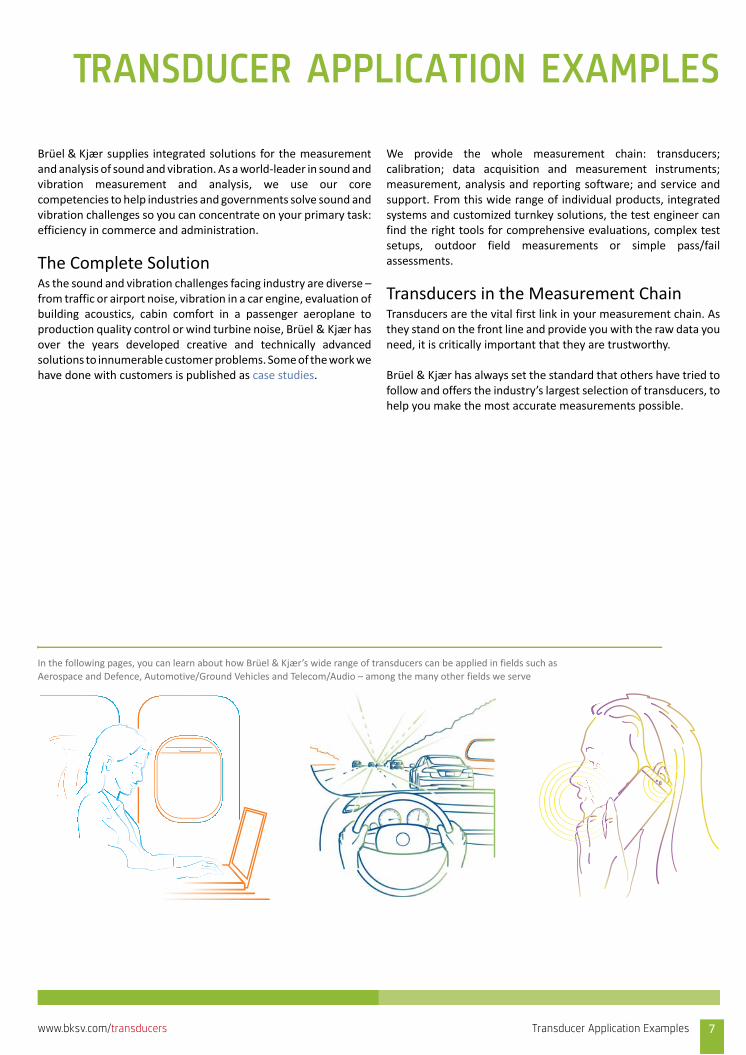
TRANSDUCER APPLICATION EXAMPLES
Brüel & Kjær supplies integrated solutions for the measurementand analysis of sound and vibration. As a world‐leader in sound andvibration measurement and analysis, we use our corecompetencies to help industries and governments solve sound andvibration challenges so you can concentrate on your primary task:efficiency in commerce and administration.
The Complete SolutionAs the sound and vibration challenges facing industry are diverse –from traffic or airport noise, vibration in a car engine, evaluation ofbuilding acoustics, cabin comfort in a passenger aeroplane toproduction quality control or wind turbine noise, Brüel & Kjær hasover the years developed creative and technically advancedsolutions to innumerable customer problems. Some of the work wehave done with customers is published as case studies.
We provide the whole measurement chain: transducers;calibration; data acquisition and measurement instruments;measurement, analysis and reporting software; and service andsupport. From this wide range of individual products, integratedsystems and customized turnkey solutions, the test engineer canfind the right tools for comprehensive evaluations, complex testsetups, outdoor field measurements or simple pass/failassessments.
Transducers in the Measurement ChainTransducers are the vital first link in your measurement chain. Asthey stand on the front line and provide you with the raw data youneed, it is critically important that they are trustworthy.
Brüel & Kjær has always set the standard that others have tried tofollow and offers the industry’s largest selection of transducers, tohelp you make the most accurate measurements possible.
In the following pages, you can learn about how Brüel & Kjær’s wide range of transducers can be applied in fields such as
Aerospace and Defence, Automotive/Ground Vehicles and Telecom/Audio – among the many other fields we serve
Transducer Application Examples 7www.bksv.com/transducers
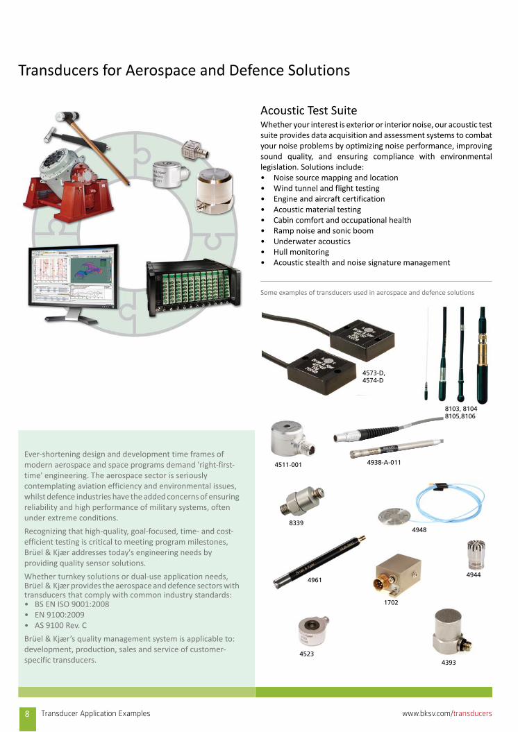
Transducers for Aerospace and Defence Solutions
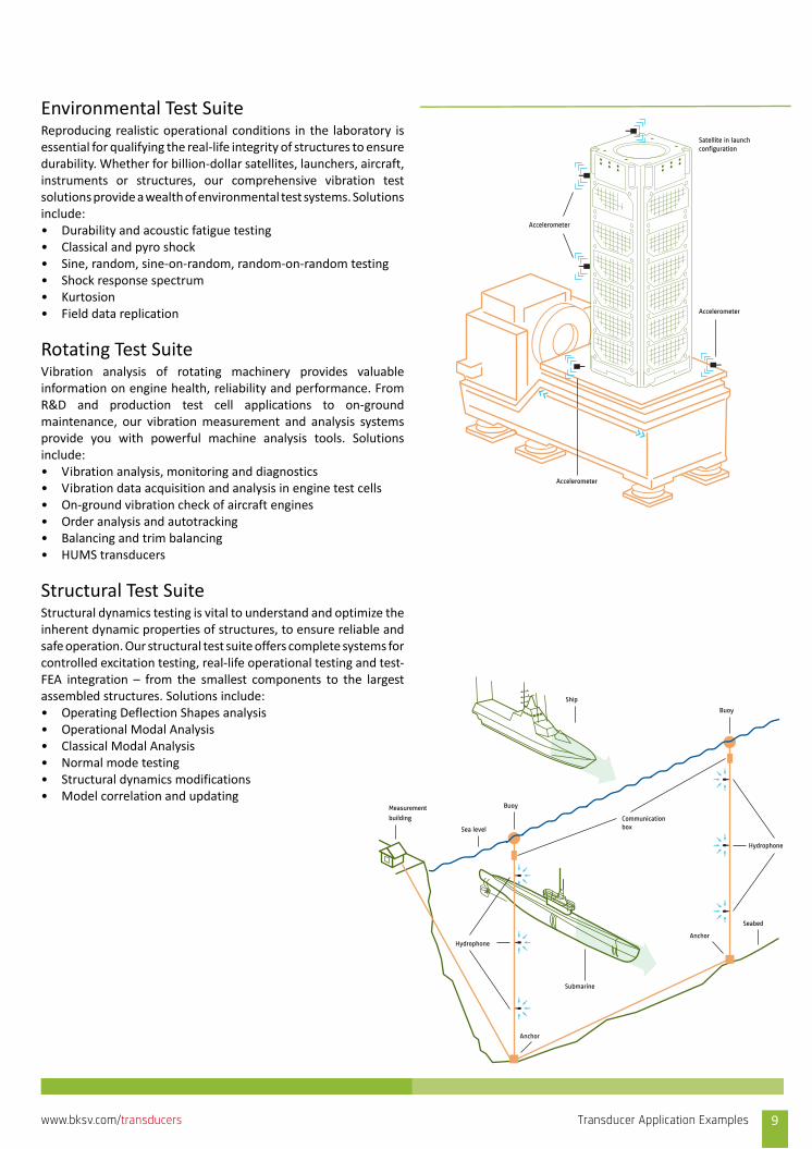
Acoustic Test SuiteWhether your interest is exterior or interior noise, our acoustic testsuite provides data acquisition and assessment systems to combatyour noise problems by optimizing noise performance, improvingsound quality, and ensuring compliance with environmentallegislation. Solutions include:• Noise source mapping and location • Wind tunnel and flight testing• Engine and aircraft certification• Acoustic material testing• Cabin comfort and occupational health• Ramp noise and sonic boom• Underwater acoustics• Hull monitoring• Acoustic stealth and noise signature management
Some examples of transducers used in aerospace and defence solutions
Ever‐shortening design and development time frames of modern aerospace and space programs demand 'right‐first‐time' engineering. The aerospace sector is seriously contemplating aviation efficiency and environmental issues, whilst defence industries have the added concerns of ensuring reliability and high performance of military systems, often under extreme conditions.
Recognizing that high‐quality, goal‐focused, time‐ and cost‐efficient testing is critical to meeting program milestones, Brüel & Kjær addresses today's engineering needs by providing quality sensor solutions.
Whether turnkey solutions or dual‐use application needs, Brüel & Kjær provides the aerospace and defence sectors with transducers that comply with common industry standards:• BS EN ISO 9001:2008• EN 9100:2009• AS 9100 Rev. C
Brüel & Kjær’s quality management system is applicable to: development, production, sales and service of customer‐specific transducers. 4393
4944
1702
4511-001
4523
83394948
4573-D, 4574-D
4938-A-011
8103, 81048105,8106
4961
8 Transducer Application Examples www.bksv.com/transducers
Buoy
Buoy
Ship
Submarine
Anchor
Hydrophone
Seabed
Sea level
Measurement
building
Anchor
Hydrophone
Communicationbox
Environmental Test SuiteReproducing realistic operational conditions in the laboratory isessential for qualifying the real‐life integrity of structures to ensuredurability. Whether for billion‐dollar satellites, launchers, aircraft,instruments or structures, our comprehensive vibration testsolutions provide a wealth of environmental test systems. Solutionsinclude:• Durability and acoustic fatigue testing• Classical and pyro shock• Sine, random, sine‐on‐random, random‐on‐random testing• Shock response spectrum• Kurtosion• Field data replication
Rotating Test SuiteVibration analysis of rotating machinery provides valuableinformation on engine health, reliability and performance. FromR&D and production test cell applications to on‐groundmaintenance, our vibration measurement and analysis systemsprovide you with powerful machine analysis tools. Solutionsinclude:• Vibration analysis, monitoring and diagnostics• Vibration data acquisition and analysis in engine test cells• On‐ground vibration check of aircraft engines• Order analysis and autotracking • Balancing and trim balancing• HUMS transducers
Structural Test SuiteStructural dynamics testing is vital to understand and optimize theinherent dynamic properties of structures, to ensure reliable andsafe operation. Our structural test suite offers complete systems forcontrolled excitation testing, real‐life operational testing and test‐FEA integration – from the smallest components to the largestassembled structures. Solutions include:• Operating Deflection Shapes analysis• Operational Modal Analysis• Classical Modal Analysis• Normal mode testing• Structural dynamics modifications• Model correlation and updating
Accelerometer
Satellite in launchconfiguration
Accelerometer
Accelerometer
Transducer Application Examples 9www.bksv.com/transducers
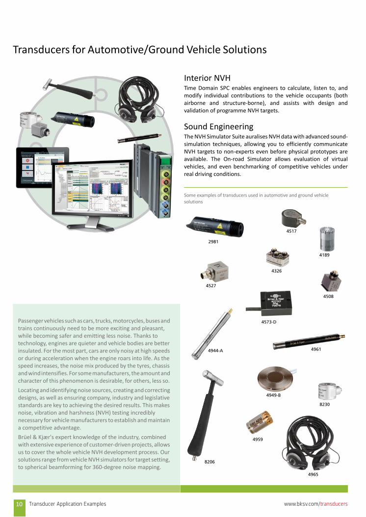
Transducers for Automotive/Ground Vehicle Solutions
Interior NVHTime Domain SPC enables engineers to calculate, listen to, andmodify individual contributions to the vehicle occupants (bothairborne and structure‐borne), and assists with design andvalidation of programme NVH targets.
Sound Engineering The NVH Simulator Suite auralises NVH data with advanced sound‐simulation techniques, allowing you to efficiently communicateNVH targets to non‐experts even before physical prototypes areavailable. The On‐road Simulator allows evaluation of virtualvehicles, and even benchmarking of competitive vehicles underreal driving conditions.
Some examples of transducers used in automotive and ground vehicle
solutions
Passenger vehicles such as cars, trucks, motorcycles, buses and trains continuously need to be more exciting and pleasant, while becoming safer and emitting less noise. Thanks to technology, engines are quieter and vehicle bodies are better insulated. For the most part, cars are only noisy at high speeds or during acceleration when the engine roars into life. As the speed increases, the noise mix produced by the tyres, chassis and wind intensifies. For some manufacturers, the amount and character of this phenomenon is desirable, for others, less so.
Locating and identifying noise sources, creating and correcting designs, as well as ensuring company, industry and legislative standards are key to achieving the desired results. This makes noise, vibration and harshness (NVH) testing incredibly necessary for vehicle manufacturers to establish and maintain a competitive advantage.
Brüel & Kjær's expert knowledge of the industry, combined with extensive experience of customer‐driven projects, allows us to cover the whole vehicle NVH development process. Our solutions range from vehicle NVH simulators for target setting, to spherical beamforming for 360‐degree noise mapping.
4965
4959
8206
8230
4949-B
4961
4573-D
4944-A
4527
4326
4508
4189
4517
2981
10 Transducer Application Examples www.bksv.com/transducers
Sound source
Sound source
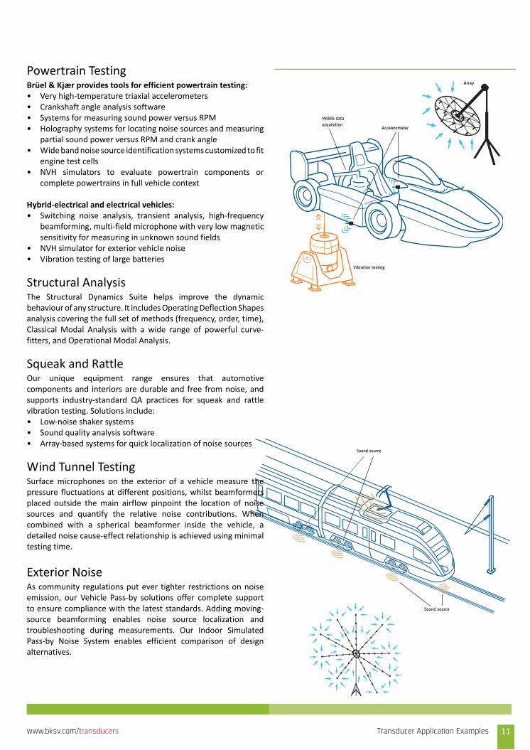
Powertrain TestingBrüel & Kjær provides tools for efficient powertrain testing:• Very high‐temperature triaxial accelerometers• Crankshaft angle analysis software• Systems for measuring sound power versus RPM• Holography systems for locating noise sources and measuring
partial sound power versus RPM and crank angle• Wide band noise source identification systems customized to fit
engine test cells• NVH simulators to evaluate powertrain components or
complete powertrains in full vehicle context
Hybrid‐electrical and electrical vehicles:• Switching noise analysis, transient analysis, high‐frequency
beamforming, multi‐field microphone with very low magneticsensitivity for measuring in unknown sound fields
• NVH simulator for exterior vehicle noise• Vibration testing of large batteries
Structural AnalysisThe Structural Dynamics Suite helps improve the dynamicbehaviour of any structure. It includes Operating Deflection Shapesanalysis covering the full set of methods (frequency, order, time),Classical Modal Analysis with a wide range of powerful curve‐fitters, and Operational Modal Analysis.
Squeak and RattleOur unique equipment range ensures that automotivecomponents and interiors are durable and free from noise, andsupports industry‐standard QA practices for squeak and rattlevibration testing. Solutions include:• Low‐noise shaker systems• Sound quality analysis software• Array‐based systems for quick localization of noise sources
Wind Tunnel TestingSurface microphones on the exterior of a vehicle measure thepressure fluctuations at different positions, whilst beamformersplaced outside the main airflow pinpoint the location of noisesources and quantify the relative noise contributions. Whencombined with a spherical beamformer inside the vehicle, adetailed noise cause‐effect relationship is achieved using minimaltesting time.
Exterior NoiseAs community regulations put ever tighter restrictions on noiseemission, our Vehicle Pass‐by solutions offer complete supportto ensure compliance with the latest standards. Adding moving‐source beamforming enables noise source localization andtroubleshooting during measurements. Our Indoor SimulatedPass‐by Noise System enables efficient comparison of designalternatives.
Vibration testing
Mobile data acquisition
Array
Accelerometer
Transducer Application Examples 11www.bksv.com/transducers
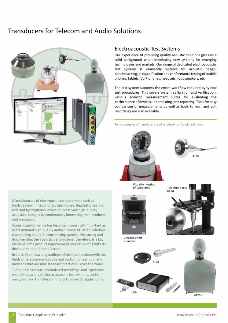
Transducers for Telecom and Audio Solutions
Electroacoustic Test SystemsOur experience of providing quality acoustic solutions gives us asolid background when developing new systems for emergingtechnologies and markets. Our range of dedicated electroacoustictest systems is eminently suitable for acoustic design,benchmarking, prequalification and conformance testing of mobilephones, tablets, VoIP phones, headsets, loudspeakers, etc.
The test system supports the entire workflow required by typicaltest procedures. This covers system calibration and verification,various acoustic measurement suites for evaluating theperformance of devices under testing, and reporting. Tools for easycomparison of measurements as well as tools to hear and editrecordings are also available.
Some examples of transducers used in telecom and audio solutions
Manufacturers of electroacoustic equipment such as loudspeakers, microphones, telephones, headsets, hearing aids and hydrophones deliver successively high‐quality acoustical designs by continuously innovating their products and processes.
Acoustic performance has become increasingly important as users demand high‐quality audio in every situation, whether reproducing sound or transmitting speech. Measuring and documenting the acoustic performance, therefore, is a key element in the product improvement process, during both its development and manufacture.
Brüel & Kjær has a long tradition of close connections with the fields of telecommunications and audio, pioneering many methods that are now standard practice all over the world.
Today, based on our accumulated knowledge and experience, we offer a variety of electroacoustic test systems, audio analyzers, and transducers for electroacoustic applications.
Vibration testing of telephone Telephone test
head
4185
Anechoic test chamber
4195
4128-C1704
12 Transducer Application Examples www.bksv.com/transducers
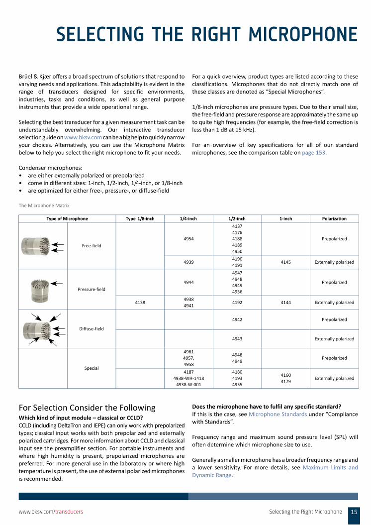
Phone
Ear simulator
Mouth simulator
Head and torso simulator
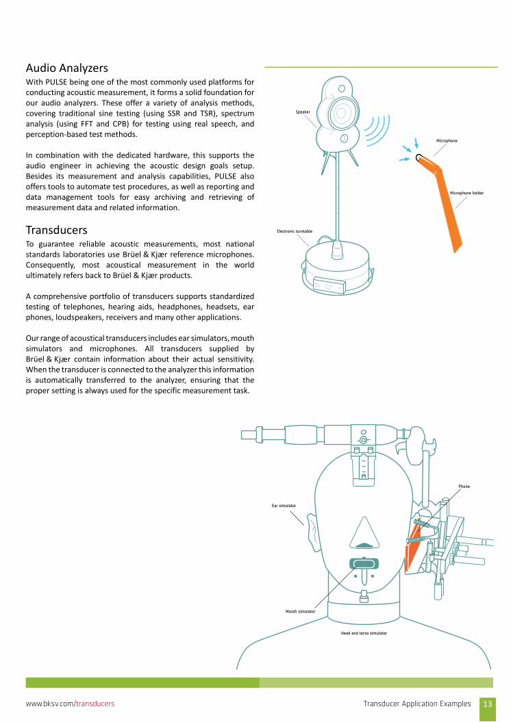
Audio AnalyzersWith PULSE being one of the most commonly used platforms forconducting acoustic measurement, it forms a solid foundation forour audio analyzers. These offer a variety of analysis methods,covering traditional sine testing (using SSR and TSR), spectrumanalysis (using FFT and CPB) for testing using real speech, andperception‐based test methods.
In combination with the dedicated hardware, this supports theaudio engineer in achieving the acoustic design goals setup.Besides its measurement and analysis capabilities, PULSE alsooffers tools to automate test procedures, as well as reporting anddata management tools for easy archiving and retrieving ofmeasurement data and related information.
TransducersTo guarantee reliable acoustic measurements, most nationalstandards laboratories use Brüel & Kjær reference microphones.Consequently, most acoustical measurement in the worldultimately refers back to Brüel & Kjær products.
A comprehensive portfolio of transducers supports standardizedtesting of telephones, hearing aids, headphones, headsets, earphones, loudspeakers, receivers and many other applications.
Our range of acoustical transducers includes ear simulators, mouthsimulators and microphones. All transducers supplied byBrüel & Kjær contain information about their actual sensitivity.When the transducer is connected to the analyzer this informationis automatically transferred to the analyzer, ensuring that theproper setting is always used for the specific measurement task.
Speaker
Electronic turntable
Microphone
Microphone holder
Transducer Application Examples 13www.bksv.com/transducers

14 Transducer Application Examples www.bksv.com/transducers
SELECTING THE RIGHT MICROPHONE
Brüel & Kjær offers a broad spectrum of solutions that respond tovarying needs and applications. This adaptability is evident in therange of transducers designed for specific environments,industries, tasks and conditions, as well as general purposeinstruments that provide a wide operational range.
Selecting the best transducer for a given measurement task can beunderstandably overwhelming. Our interactive transducerselection guide on www.bksv.com can be a big help to quickly narrowyour choices. Alternatively, you can use the Microphone Matrixbelow to help you select the right microphone to fit your needs.
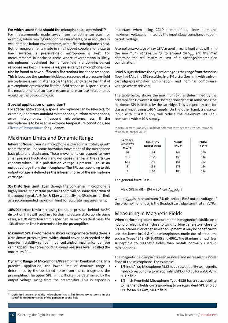
Condenser microphones:• are either externally polarized or prepolarized• come in different sizes: 1‐inch, 1/2‐inch, 1/4‐inch, or 1/8‐inch• are optimized for either free‐, pressure‐, or diffuse‐field
For a quick overview, product types are listed according to theseclassifications. Microphones that do not directly match one ofthese classes are denoted as “Special Microphones”.
1/8‐inch microphones are pressure types. Due to their small size,the free‐field and pressure response are approximately the same upto quite high frequencies (for example, the free‐field correction isless than 1 dB at 15 kHz).
For an overview of key specifications for all of our standardmicrophones, see the comparison table on page 153.
The Microphone Matrix
For Selection Consider the FollowingWhich kind of input module – classical or CCLD? CCLD (including DeltaTron and IEPE) can only work with prepolarizedtypes; classical input works with both prepolarized and externallypolarized cartridges. For more information about CCLD and classicalinput see the preamplifier section. For portable instruments andwhere high humidity is present, prepolarized microphones arepreferred. For more general use in the laboratory or where hightemperature is present, the use of external polarized microphonesis recommended.
Does the microphone have to fulfil any specific standard? If this is the case, see Microphone Standards under “Compliancewith Standards”.
Frequency range and maximum sound pressure level (SPL) willoften determine which microphone size to use.
Generally a smaller microphone has a broader frequency range anda lower sensitivity. For more details, see Maximum Limits andDynamic Range.
Type of Microphone Type 1/8‐inch 1/4‐inch 1/2‐inch 1‐inch Polarization
Free‐field
4954
4137
4176
4188
4189
4950
Prepolarized
49394190
41914145 Externally polarized
Pressure‐field
4944
4947
4948
4949
4956
Prepolarized
41384938
49414192 4144 Externally polarized
Diffuse‐field
4942 Prepolarized
4943 Externally polarized
Special
4961
4957,
4958
4948
4949Prepolarized
4187
4938‐WH‐1418
4938‐W‐001
4180
4193
4955
4160
4179Externally polarized
Selecting the Right Microphone 15www.bksv.com/transducers
For which sound field should the microphone be optimized*?For measurements made away from reflecting surfaces, forexample, when making outdoor measurements, or in acousticallywell‐damped indoor environments, a free‐field microphone is best.But for measurements made in small closed couplers, or close tohard surfaces, a pressure‐field microphone is best. Formeasurements in enclosed areas where reverberation is likely,microphones optimized for diffuse‐field (random‐incidence)response are best. In some cases, pressure type microphones canalso be found to have sufficiently flat random‐incidence response.This is because the random‐incidence response of a pressure‐fieldmicrophone is much flatter across the frequency range than that ofa microphone optimized for flat free‐field response. A special case isthe measurement of surface pressure where surface microphoneswould be the obvious choice.
Special application or condition?For special applications, a special microphone can be selected, forexample, laboratory standard microphones, outdoor microphones,array microphones, infrasound microphones, etc. If themicrophone is to be used in extreme temperature conditions, seeEffects of Temperature for guidance.
Maximum Limits and Dynamic RangeInherent Noise: Even if a microphone is placed in a “totally quiet”room there will be some Brownian movement of the microphoneback‐plate and diaphragm. These movements correspond to verysmall pressure fluctuations and will cause changes in the cartridgecapacity which – if a polarization voltage is present – cause anoutput voltage from the microphone. The SPL corresponding to thisoutput voltage is defined as the inherent noise of the microphonecartridge.
3% Distortion Limit: Even though the condenser microphone ishighly linear, at a certain pressure there will be some distortion ofthe output signal. At Brüel & Kjær we specify the 3% distortion limitas a recommended maximum limit for accurate measurements.
10% Distortion Limit: Increasing the sound pressure behind the 3%distortion limit will result in a further increase in distortion. In somecases, a 10% distortion limit is specified. In many practical cases, the10% distortion limit is determined by the preamplifier.
Maximum SPL: Due to mechanical forces acting on the cartridge there isa maximum pressure level which should never be exceeded or thelong‐term stability can be influenced and/or mechanical damagecan happen. The corresponding sound pressure level is called themaximum SPL.
Dynamic Range of Microphone/Preamplifier Combinations: In apractical application, the lower limit of dynamic range isdetermined by the combined noise from the cartridge and thepreamplifier. The upper SPL limit will often be determined by theoutput voltage swing from the preamplifier. This is especially
important when using CCLD preamplifiers, since here themaximum voltage is limited by the input stage compliance (open‐circuit) voltage.
A compliance voltage of, say, 28 V as used in many front ends will limitthe maximum voltage swing to around 14 Vpp and this maydetermine the real maximum limit of a cartridge/preamplifiercombination.
Brüel & Kjær defines the dynamic range as the range from the noisefloor in dBA to the SPL resulting in a 3% distortion limit with a givencartridge/preamplifier combination, and nominal compliancevoltage where relevant.
The table below shows the maximum SPL as determined by thepreamplifier. However, it must be mentioned that in some cases themaximum SPL is limited by the cartridge. This is especially true forclassical input using ±40 V supply. On the other hand, a classicalinput with ±14 V supply will reduce the maximum SPL 9 dBcompared with ±40 V supply.
Maximum measurable SPL in dB for different cartridge sensitivities, rounded to nearest integer value
The general formula is:
Max. SPL in dB = [94 + 20*log(Vmax/Sv)]
where Vmax is the maximum (3% distortion) RMS output voltage ofthe preamplifier and Sv is the (loaded) cartridge sensitivity in V/Pa.
Measuring in Magnetic FieldsWhen performing sound measurements in magnetic fields like on ahybrid or electrical car, close to wind turbine generators, close tobig MR scanners or other similar equipment, it may be beneficial touse the latest Brüel & Kjær microphones made out of titanium,such as Types 4948, 4949, 4955 and 4961. The titanium is much lesssusceptible to magnetic fields than metals normally used inmicrophones.
The magnetic field impact is seen as noise and increases the noisefloor of the microphone. For example:• 1/4‐inch Array Microphone 4958 has a susceptibility to magnetic
fields corresponding to an equivalent SPL of 40 dB for an 80 A/m,50 Hz field
• 1/2‐inch Free‐field Microphone Type 4189 has a susceptibilityto magnetic fields corresponding to an equivalent SPL of 6 dBSPL for an 80 A/m, 50 Hz field
* Optimized means that the microphone has a flat frequency response in thespecified frequency range of the particular sound field
Cartridge
Sensitivity
mV/Pa
CCLD ±7 V Output Swing
NEXUS
±40 V
PULSE
±14 V
50 134 149 140
31.6 138 153 144
12.5 146 161 152
3 158 173 164
1 168 183 174
16 Selecting the Right Microphone www.bksv.com/transducers
• Titanium microphone Types 4955 and 4961 have no detectableinfluence from an 80 A/m, 50 Hz magnetic field
The Effects of TemperatureWhat happens at high temperatures (above +80 °C)?• Electronic components may exceed their maximum junction
temperature. This is very serious and should be avoided• Prepolarized microphones may lose electret voltage. This will
result in permanent sensitivity loss, which means, externallypolarized microphones should always be used if high‐temperature tests are performed for longer periods of time
• The diaphragm tension will reduce. This means increasedsensitivity and changes in frequency response
• The cable jacket and other isolators may melt. While this is notbeautiful, it is not always catastrophic
• In practically all cases, an exponential increase in the inherentelectronic noise must be expected. The basic rule of thumb:Many temperature depending factors will double for every 10°temperature increase (Arrhenius' law)
Microphones are specified at 23 °C, and have a temperaturecoefficient that specifies how the microphone will behave withchanged temperature. This parameter tells something about themicrophone’s stability and quality. See the microphone’s productdata for information about its temperature coefficient.
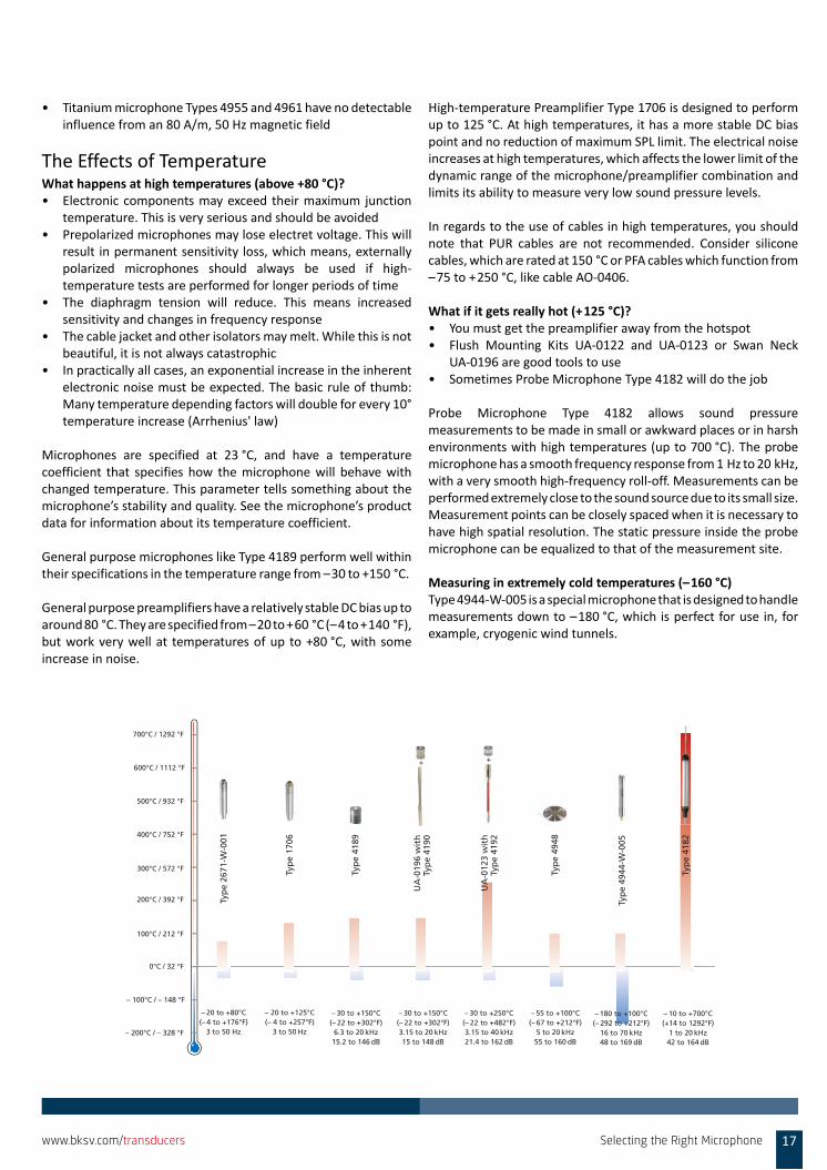
General purpose microphones like Type 4189 perform well withintheir specifications in the temperature range from –30 to +150 °C.
General purpose preamplifiers have a relatively stable DC bias up toaround 80 °C. They are specified from –20 to +60 °C (–4 to +140 °F),but work very well at temperatures of up to +80 °C, with someincrease in noise.
High‐temperature Preamplifier Type 1706 is designed to performup to 125 °C. At high temperatures, it has a more stable DC biaspoint and no reduction of maximum SPL limit. The electrical noiseincreases at high temperatures, which affects the lower limit of thedynamic range of the microphone/preamplifier combination andlimits its ability to measure very low sound pressure levels.
In regards to the use of cables in high temperatures, you shouldnote that PUR cables are not recommended. Consider siliconecables, which are rated at 150 °C or PFA cables which function from–75 to +250 °C, like cable AO‐0406.
What if it gets really hot (+125 °C)?• You must get the preamplifier away from the hotspot• Flush Mounting Kits UA‐0122 and UA‐0123 or Swan Neck
UA‐0196 are good tools to use• Sometimes Probe Microphone Type 4182 will do the job
Probe Microphone Type 4182 allows sound pressuremeasurements to be made in small or awkward places or in harshenvironments with high temperatures (up to 700 °C). The probemicrophone has a smooth frequency response from 1 Hz to 20 kHz,with a very smooth high‐frequency roll‐off. Measurements can beperformed extremely close to the sound source due to its small size.Measurement points can be closely spaced when it is necessary tohave high spatial resolution. The static pressure inside the probemicrophone can be equalized to that of the measurement site.
Measuring in extremely cold temperatures (–160 °C)Type 4944‐W‐005 is a special microphone that is designed to handlemeasurements down to –180 °C, which is perfect for use in, forexample, cryogenic wind tunnels.
– 200°C / – 328 °F
– 100°C / – 148 °F
0°C / 32 °F
100°C / 212 °F
200°C / 392 °F
300°C / 572 °F
400°C / 752 °F
500°C / 932 °F
600°C / 1112 °F
700°C / 1292 °F
Typ
e 41
89
– 30 to +150°C(– 22 to +302°F)
6.3 to 20 kHz15.2 to 146 dB
Typ
e 26
71-W
-001
– 20 to +80°C(– 4 to +176°F)
3 to 50 Hz
Typ
e 17
06
– 20 to +125°C(– 4 to +257°F)
3 to 50 Hz
UA
-019
6 w
ith
Typ
e 41
90
– 30 to +150°C(– 22 to +302°F)3.15 to 20 kHz15 to 148 dB
+
UA
-012
3 w
ith
Typ
e 41
92
– 30 to +250°C(– 22 to +482°F)3.15 to 40 kHz21.4 to 162 dB
+
Typ
e 49
48
– 55 to +100°C(– 67 to +212°F)
5 to 20 kHz55 to 160 dB
Typ
e 49
44-W
-005
– 180 to +100°C(– 292 to +212°F)
16 to 70 kHz48 to 169 dB
Typ
e 41
82
– 10 to +700°C(+14 to 1292°F)
1 to 20 kHz42 to 164 dB
Selecting the Right Microphone 17www.bksv.com/transducers
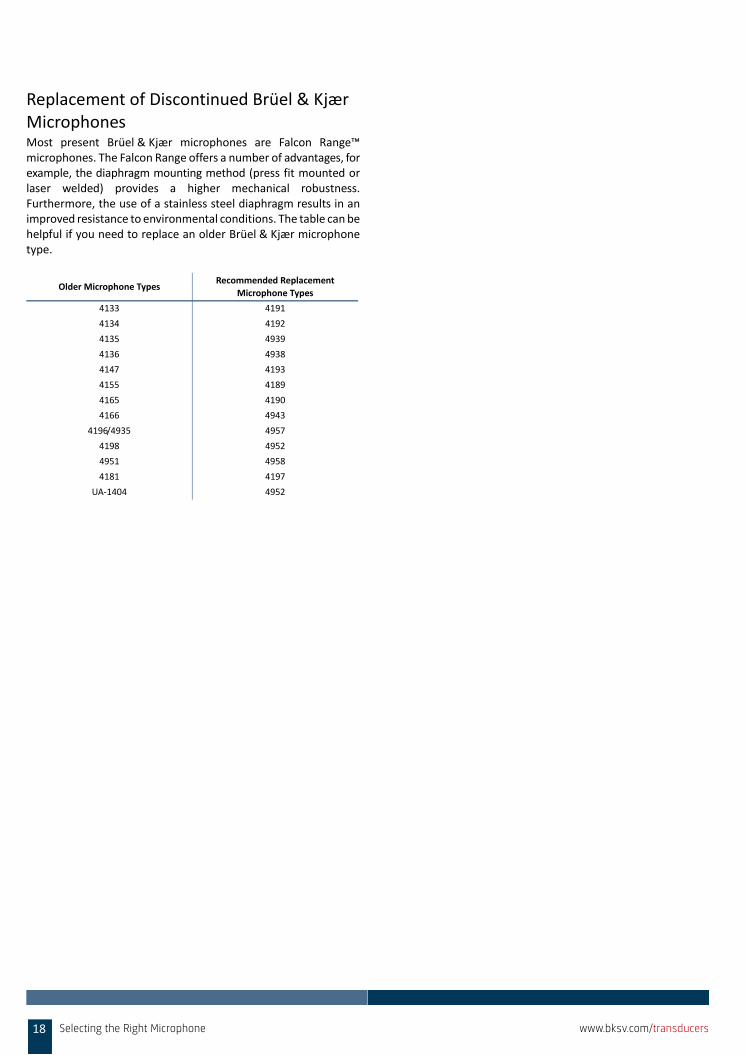
Replacement of Discontinued Brüel & Kjær MicrophonesMost present Brüel & Kjær microphones are Falcon Range™microphones. The Falcon Range offers a number of advantages, forexample, the diaphragm mounting method (press fit mounted orlaser welded) provides a higher mechanical robustness.Furthermore, the use of a stainless steel diaphragm results in animproved resistance to environmental conditions. The table can behelpful if you need to replace an older Brüel & Kjær microphonetype.
Older Microphone TypesRecommended Replacement
Microphone Types
4133 4191
4134 4192
4135 4939
4136 4938
4147 4193
4155 4189
4165 4190
4166 4943
4196/4935 4957
4198 4952
4951 4958
4181 4197
UA‐1404 4952
18 Selecting the Right Microphone www.bksv.com/transducers
MICROPHONES
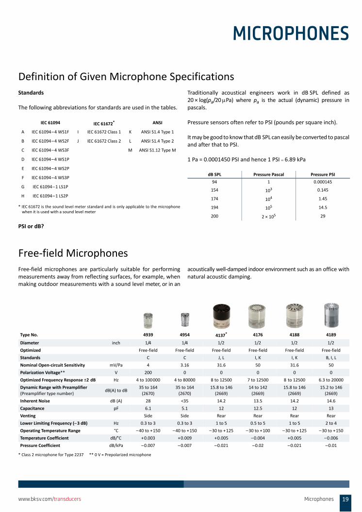
Definition of Given Microphone SpecificationsStandards
The following abbreviations for standards are used in the tables.
PSI or dB?
Traditionally acoustical engineers work in dB SPL defined as20 × log(pa/20 Pa) where pa is the actual (dynamic) pressure inpascals.
Pressure sensors often refer to PSI (pounds per square inch).
It may be good to know that dB SPL can easily be converted to pascaland after that to PSI.
1 Pa = 0.0001450 PSI and hence 1 PSI 6.89 kPa
Free‐field MicrophonesFree‐field microphones are particularly suitable for performingmeasurements away from reflecting surfaces, for example, whenmaking outdoor measurements with a sound level meter, or in an
acoustically well‐damped indoor environment such as an office withnatural acoustic damping.
IEC 61094 IEC 61672*
* IEC 61672 is the sound level meter standard and is only applicable to the microphonewhen it is used with a sound level meter
ANSI
A IEC 61094–4 WS1F I IEC 61672 Class 1 K ANSI S1.4 Type 1
B IEC 61094–4 WS2F J IEC 61672 Class 2 L ANSI S1.4 Type 2
C IEC 61094–4 WS3F M ANSI S1.12 Type M
D IEC 61094–4 WS1P
E IEC 61094–4 WS2P
F IEC 61094–4 WS3P
G IEC 61094–1 LS1P
H IEC 61094–1 LS2P
dB SPL Pressure Pascal Pressure PSI
94 1 0.000145
154 103 0.145
174 104 1.45
194 105 14.5
200 2 × 10⁵ 29
Type No. 4939 4954 4137* 4176 4188 4189
Diameter inch 1/4 1/4 1/2 1/2 1/2 1/2
Optimized Free‐field Free‐field Free‐field Free‐field Free‐field Free‐field
Standards C C J, L I, K I, K B, I, L
Nominal Open‐circuit Sensitivity mV/Pa 4 3.16 31.6 50 31.6 50
Polarization Voltage** V 200 0 0 0 0 0
Optimized Frequency Response ±2 dB Hz 4 to 100000 4 to 80000 8 to 12500 7 to 12500 8 to 12500 6.3 to 20000
Dynamic Range with Preamplifier
(Preamplifier type number) dB(A) to dB
35 to 164
(2670)
35 to 164
(2670)
15.8 to 146
(2669)
14 to 142
(2669)
15.8 to 146
(2669)
15.2 to 146
(2669)
Inherent Noise dB (A) 28 <35 14.2 13.5 14.2 14.6
Capacitance pF 6.1 5.1 12 12.5 12 13
Venting Side Side Rear Rear Rear Rear
Lower Limiting Frequency (–3 dB) Hz 0.3 to 3 0.3 to 3 1 to 5 0.5 to 5 1 to 5 2 to 4
Operating Temperature Range °C –40 to +150 –40 to +150 –30 to +125 –30 to +100 –30 to +125 –30 to +150
Temperature Coefficient dB/°C +0.003 +0.009 +0.005 –0.004 +0.005 –0.006
Pressure Coefficient dB/kPa –0.007 –0.007 –0.021 –0.02 –0.021 –0.01
* Class 2 microphone for Type 2237 ** 0 V = Prepolarized microphone
Microphones 19www.bksv.com/transducers
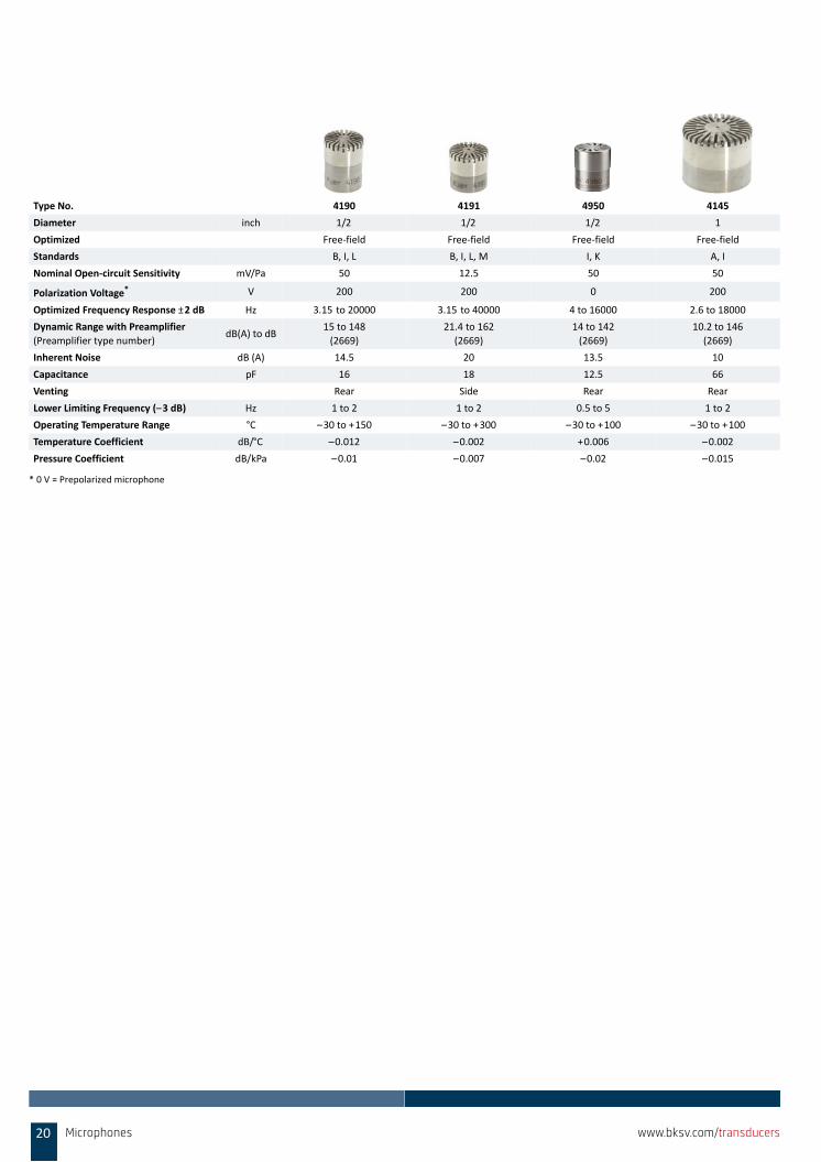
Type No. 4190 4191 4950 4145
Diameter inch 1/2 1/2 1/2 1
Optimized Free‐field Free‐field Free‐field Free‐field
Standards B, I, L B, I, L, M I, K A, I
Nominal Open‐circuit Sensitivity mV/Pa 50 12.5 50 50
Polarization Voltage* V 200 200 0 200
Optimized Frequency Response ±2 dB Hz 3.15 to 20000 3.15 to 40000 4 to 16000 2.6 to 18000
Dynamic Range with Preamplifier
(Preamplifier type number) dB(A) to dB
15 to 148
(2669)
21.4 to 162
(2669)
14 to 142
(2669)
10.2 to 146
(2669)
Inherent Noise dB (A) 14.5 20 13.5 10
Capacitance pF 16 18 12.5 66
Venting Rear Side Rear Rear
Lower Limiting Frequency (–3 dB) Hz 1 to 2 1 to 2 0.5 to 5 1 to 2
Operating Temperature Range °C –30 to +150 –30 to +300 –30 to +100 –30 to +100
Temperature Coefficient dB/°C –0.012 –0.002 +0.006 –0.002
Pressure Coefficient dB/kPa –0.01 –0.007 –0.02 –0.015
* 0 V = Prepolarized microphone
20 Microphones www.bksv.com/transducers
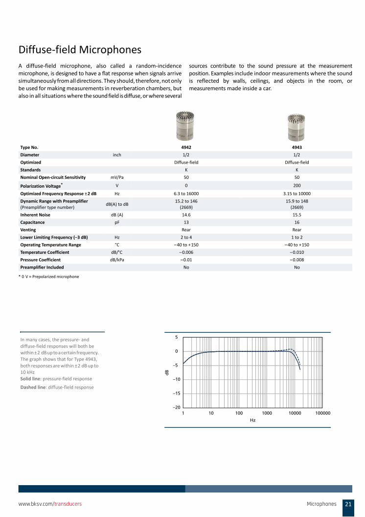
Diffuse‐field MicrophonesA diffuse‐field microphone, also called a random‐incidencemicrophone, is designed to have a flat response when signals arrivesimultaneously from all directions. They should, therefore, not onlybe used for making measurements in reverberation chambers, butalso in all situations where the sound field is diffuse, or where several
sources contribute to the sound pressure at the measurementposition. Examples include indoor measurements where the soundis reflected by walls, ceilings, and objects in the room, ormeasurements made inside a car.
Type No. 4942 4943
Diameter inch 1/2 1/2
Optimized Diffuse‐field Diffuse‐field
Standards K K
Nominal Open‐circuit Sensitivity mV/Pa 50 50
Polarization Voltage* V 0 200
Optimized Frequency Response ±2 dB Hz 6.3 to 16000 3.15 to 10000
Dynamic Range with Preamplifier
(Preamplifier type number) dB(A) to dB
15.2 to 146
(2669)
15.9 to 148
(2669)
Inherent Noise dB (A) 14.6 15.5
Capacitance pF 13 16
Venting Rear Rear
Lower Limiting Frequency (–3 dB) Hz 2 to 4 1 to 2
Operating Temperature Range °C –40 to +150 –40 to +150
Temperature Coefficient dB/°C –0.006 –0.010
Pressure Coefficient dB/kPa –0.01 –0.008
Preamplifier Included No No
* 0 V = Prepolarized microphone
5
0
–5
–10
–15
–201 10 100 1000 10000 100000
Hz
dB
In many cases, the pressure‐ and
diffuse‐field responses will both be within ±2 dB up to a certain frequency.
The graph shows that for Type 4943,
both responses are within ±2 dB up to 10 kHz
Solid line: pressure‐field response
Dashed line: diffuse‐field response
Microphones 21www.bksv.com/transducers
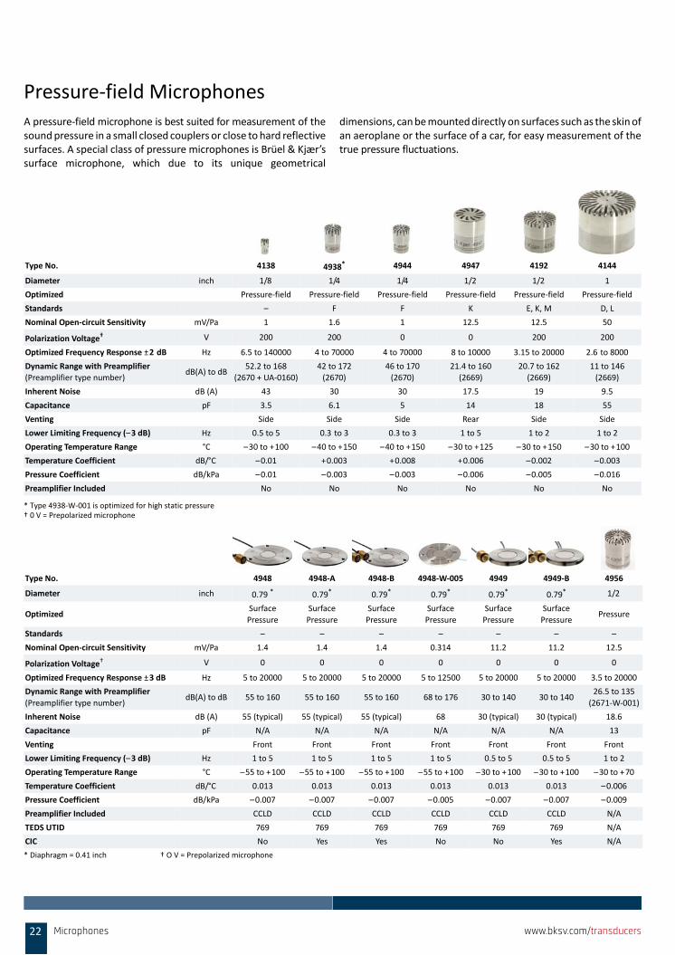
Pressure‐field MicrophonesA pressure‐field microphone is best suited for measurement of thesound pressure in a small closed couplers or close to hard reflectivesurfaces. A special class of pressure microphones is Brüel & Kjær’ssurface microphone, which due to its unique geometrical
dimensions, can be mounted directly on surfaces such as the skin ofan aeroplane or the surface of a car, for easy measurement of thetrue pressure fluctuations.
* Diaphragm = 0.41 inch † O V = Prepolarized microphone
Type No. 4138 4938* 4944 4947 4192 4144
Diameter inch 1/8 1/4 1/4 1/2 1/2 1
Optimized Pressure‐field Pressure‐field Pressure‐field Pressure‐field Pressure‐field Pressure‐field
Standards – F F K E, K, M D, L
Nominal Open‐circuit Sensitivity mV/Pa 1 1.6 1 12.5 12.5 50
Polarization Voltage† V 200 200 0 0 200 200
Optimized Frequency Response ±2 dB Hz 6.5 to 140000 4 to 70000 4 to 70000 8 to 10000 3.15 to 20000 2.6 to 8000
Dynamic Range with Preamplifier
(Preamplifier type number) dB(A) to dB
52.2 to 168
(2670 + UA‐0160)
42 to 172
(2670)
46 to 170
(2670)
21.4 to 160
(2669)
20.7 to 162
(2669)
11 to 146
(2669)
Inherent Noise dB (A) 43 30 30 17.5 19 9.5
Capacitance pF 3.5 6.1 5 14 18 55
Venting Side Side Side Rear Side Side
Lower Limiting Frequency (–3 dB) Hz 0.5 to 5 0.3 to 3 0.3 to 3 1 to 5 1 to 2 1 to 2
Operating Temperature Range °C –30 to +100 –40 to +150 –40 to +150 –30 to +125 –30 to +150 –30 to +100
Temperature Coefficient dB/°C –0.01 +0.003 +0.008 +0.006 –0.002 –0.003
Pressure Coefficient dB/kPa –0.01 –0.003 –0.003 –0.006 –0.005 –0.016
Preamplifier Included No No No No No No
* Type 4938‐W‐001 is optimized for high static pressure† 0 V = Prepolarized microphone
Type No. 4948 4948‐A 4948‐B 4948‐W‐005 4949 4949‐B 4956
Diameter inch 0.79 * 0.79* 0.79* 0.79* 0.79* 0.79* 1/2
OptimizedSurface
Pressure
Surface
Pressure
Surface
Pressure
Surface
Pressure
Surface
Pressure
Surface
PressurePressure
Standards – – – – – – –
Nominal Open‐circuit Sensitivity mV/Pa 1.4 1.4 1.4 0.314 11.2 11.2 12.5
Polarization Voltage† V 0 0 0 0 0 0 0
Optimized Frequency Response ±3 dB Hz 5 to 20000 5 to 20000 5 to 20000 5 to 12500 5 to 20000 5 to 20000 3.5 to 20000
Dynamic Range with Preamplifier
(Preamplifier type number) dB(A) to dB 55 to 160 55 to 160 55 to 160 68 to 176 30 to 140 30 to 140
26.5 to 135
(2671‐W‐001)
Inherent Noise dB (A) 55 (typical) 55 (typical) 55 (typical) 68 30 (typical) 30 (typical) 18.6
Capacitance pF N/A N/A N/A N/A N/A N/A 13
Venting Front Front Front Front Front Front Front
Lower Limiting Frequency (–3 dB) Hz 1 to 5 1 to 5 1 to 5 1 to 5 0.5 to 5 0.5 to 5 1 to 2
Operating Temperature Range °C –55 to +100 –55 to +100 –55 to +100 –55 to +100 –30 to +100 –30 to +100 –30 to +70
Temperature Coefficient dB/°C 0.013 0.013 0.013 0.013 0.013 0.013 –0.006
Pressure Coefficient dB/kPa –0.007 –0.007 –0.007 –0.005 –0.007 –0.007 –0.009
Preamplifier Included CCLD CCLD CCLD CCLD CCLD CCLD N/A
TEDS UTID 769 769 769 769 769 769 N/A
CIC No Yes Yes No No Yes N/A
22 Microphones www.bksv.com/transducers
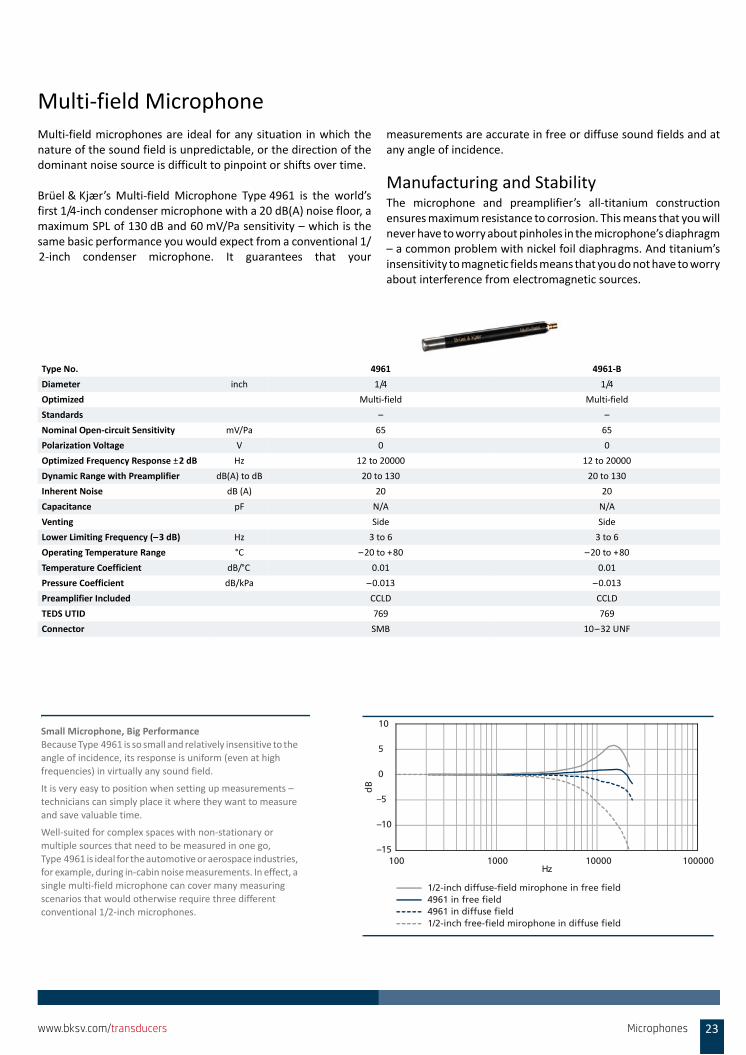
Multi‐field MicrophoneMulti‐field microphones are ideal for any situation in which thenature of the sound field is unpredictable, or the direction of thedominant noise source is difficult to pinpoint or shifts over time.
Brüel & Kjær’s Multi‐field Microphone Type 4961 is the world’sfirst 1/4‐inch condenser microphone with a 20 dB(A) noise floor, amaximum SPL of 130 dB and 60 mV/Pa sensitivity – which is thesame basic performance you would expect from a conventional 1/2‐inch condenser microphone. It guarantees that your
measurements are accurate in free or diffuse sound fields and atany angle of incidence.
Manufacturing and StabilityThe microphone and preamplifier’s all‐titanium constructionensures maximum resistance to corrosion. This means that you willnever have to worry about pinholes in the microphone’s diaphragm– a common problem with nickel foil diaphragms. And titanium’sinsensitivity to magnetic fields means that you do not have to worryabout interference from electromagnetic sources.
Type No. 4961 4961‐B
Diameter inch 1/4 1/4
Optimized Multi‐field Multi‐field
Standards – –
Nominal Open‐circuit Sensitivity mV/Pa 65 65
Polarization Voltage V 0 0
Optimized Frequency Response ±2 dB Hz 12 to 20000 12 to 20000
Dynamic Range with Preamplifier dB(A) to dB 20 to 130 20 to 130
Inherent Noise dB (A) 20 20
Capacitance pF N/A N/A
Venting Side Side
Lower Limiting Frequency (–3 dB) Hz 3 to 6 3 to 6
Operating Temperature Range °C –20 to +80 –20 to +80
Temperature Coefficient dB/°C 0.01 0.01
Pressure Coefficient dB/kPa –0.013 –0.013
Preamplifier Included CCLD CCLD
TEDS UTID 769 769
Connector SMB 10–32 UNF
1/2-inch free-field mirophone in diffuse field4961 in diffuse field4961 in free field1/2-inch diffuse-field mirophone in free field
–15
–10
–5
0
5
10
100 1000 10000 100000Hz
dB
Small Microphone, Big PerformanceBecause Type 4961 is so small and relatively insensitive to the
angle of incidence, its response is uniform (even at high
frequencies) in virtually any sound field.
It is very easy to position when setting up measurements –
technicians can simply place it where they want to measure
and save valuable time.
Well‐suited for complex spaces with non‐stationary or
multiple sources that need to be measured in one go,
Type 4961 is ideal for the automotive or aerospace industries, for example, during in‐cabin noise measurements. In effect, a
single multi‐field microphone can cover many measuring
scenarios that would otherwise require three different conventional 1/2‐inch microphones.
Microphones 23www.bksv.com/transducers
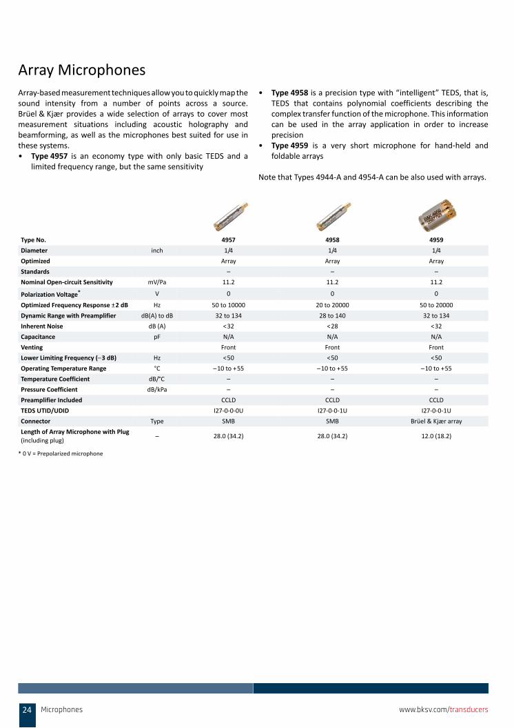
Array MicrophonesArray‐based measurement techniques allow you to quickly map thesound intensity from a number of points across a source.Brüel & Kjær provides a wide selection of arrays to cover mostmeasurement situations including acoustic holography andbeamforming, as well as the microphones best suited for use inthese systems.• Type 4957 is an economy type with only basic TEDS and a
limited frequency range, but the same sensitivity
• Type 4958 is a precision type with “intelligent” TEDS, that is,TEDS that contains polynomial coefficients describing thecomplex transfer function of the microphone. This informationcan be used in the array application in order to increaseprecision
• Type 4959 is a very short microphone for hand‐held andfoldable arrays
Note that Types 4944‐A and 4954‐A can be also used with arrays.
Type No. 4957 4958 4959
Diameter inch 1/4 1/4 1/4
Optimized Array Array Array
Standards – – –
Nominal Open‐circuit Sensitivity mV/Pa 11.2 11.2 11.2
Polarization Voltage* V 0 0 0
Optimized Frequency Response ±2 dB Hz 50 to 10000 20 to 20000 50 to 20000
Dynamic Range with Preamplifier dB(A) to dB 32 to 134 28 to 140 32 to 134
Inherent Noise dB (A) <32 <28 <32
Capacitance pF N/A N/A N/A
Venting Front Front Front
Lower Limiting Frequency (–3 dB) Hz <50 <50 <50
Operating Temperature Range °C –10 to +55 –10 to +55 –10 to +55
Temperature Coefficient dB/°C – – –
Pressure Coefficient dB/kPa – – –
Preamplifier Included CCLD CCLD CCLD
TEDS UTID/UDID I27‐0‐0‐0U I27‐0‐0‐1U I27‐0‐0‐1U
Connector Type SMB SMB Brüel & Kjær array
Length of Array Microphone with Plug
(including plug) – 28.0 (34.2) 28.0 (34.2) 12.0 (18.2)
* 0 V = Prepolarized microphone
24 Microphones www.bksv.com/transducers
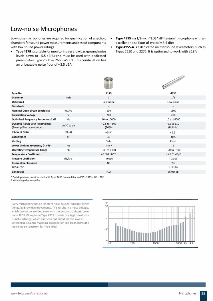
Low‐noise MicrophonesLow‐noise microphones are required for qualification of anechoicchambers for sound power measurements and test of componentswith low sound power ratings. • Type 4179 is suitable for monitoring very low background noise
levels down to –5.5 dB(A) and must be used with dedicatedpreamplifier Type 2660 or 2660‐W‐001. This combination hasan unbeatable noise floor of –2.5 dBA
• Type 4955 is a 1/2‐inch TEDS “all titanium” microphone with anexcellent noise floor of typically 5.5 dBA
• Type 4955‐A is a dedicated unit for sound level meters, such asTypes 2250 and 2270. It is optimized to work with ±18 V
Type No. 4179 4955
Diameter inch 1 1/2
Optimized Low‐noise Low‐noise
Standards – –
Nominal Open‐circuit Sensitivity mV/Pa 100 1100
Polarization Voltage V 200 200
Optimized Frequency Response ±2 dB Hz 10 to 10000 10 to 16000
Dynamic Range with Preamplifier
(Preamplifier type number) dB(A) to dB
–2.5 to +102
(2660)
6.5 to 110
(Built‐in)
Inherent Noise dB (A) –5.5* <6.5†
Capacitance pF 40 N/A
Venting Side Front
Lower Limiting Frequency (–3 dB) Hz 5 to 7 5
Operating Temperature Range °C –30 to +100 –20 to +100
Temperature Coefficient –0.004 dB/°C < ±0.01 dB/K
Pressure Coefficient dB/kPa –0.016 –0.013
Preamplifier Included No Yes
TEDS UTID 116289
Connector N/A LEMO 1B
* Cartridge alone, must be used with Type 2660 preamplifier and WH‐3315 + WL‐1302† With integral preamplifier
-20
-10
0
10dB
10 100 1000 10000 Hz LA
Every microphone has an inherent noise caused, amongst other things, by Brownian movements. This results in a noise voltage,
which cannot be avoided even with the best microphone. Low‐
noise TEDS Microphone Type 4955 consists of a high‐sensitivity ½‐inch cartridge, which has been optimized for the lowest
inherent noise, and a matching preamplifier. The graph shows the
typical noise spectrum for Type 4955
Microphones 25www.bksv.com/transducers
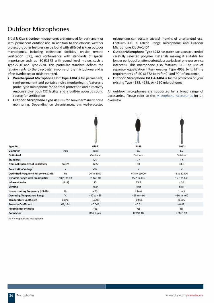
Outdoor MicrophonesBrüel & Kjær’s outdoor microphones are intended for permanent orsemi‐permanent outdoor use. In addition to the obvious weatherprotection, other features can be found with all Brüel & Kjær outdoormicrophones, including calibration facilities, on‐site remoteverification (CIC), and conformance with standards of specialimportance such as IEC 61672 with sound level meters such aType 2250 and Type 2270. This particular standard defines therequirements to the directivity response of the microphone and isoften overlooked or misinterpreted.• Weatherproof Microphone Unit Type 4184 is for permanent,
semi‐permanent and portable noise monitoring. It features aprobe type microphone for optimal protection and directivityresponse plus both CIC facility and a built‐in acoustic soundsource for verification
• Outdoor Microphone Type 4198 is for semi‐permanent noisemonitoring. Depending on circumstances, this well‐protected
microphone can sustain several months of unattended use.Features CIC, a Falcon Range microphone and OutdoorMicrophone Kit UA‐1404
• Outdoor Microphone Type 4952 has outer parts constructed ofcarefully selected polymer materials making it suitable forlonger periods of unattended outdoor use (at least one year serviceintervals). This microphone also features CIC. The use ofseparate equalization filters enables Type 4952 to fulfil therequirements of IEC 61672 both for 0° and 90° of incidence
• Outdoor Microphone Kit UA‐1404 is for the protection of yourexisting Type 4188, 4189, or 4190 microphones
All outdoor microphones are supported by a broad range ofaccessories. Please refer to the Microphone Accessories for anoverview.
Type No. 4184 4198 4952
Diameter inch Probe 1/2 1/2
Optimized Outdoor Outdoor Outdoor
Standards I, K I, K I, K
Nominal Open‐circuit Sensitivity mV/Pa 12.5 50 31.6
Polarization Voltage* V 200 0 0
Optimized Frequency Response ±2 dB Hz 20 to 8000 6.3 to 16000 8 to 12500
Dynamic Range with Preamplifier dB(A) to dB 25 to 140 15.2 to 146 15.8 to 146
Inherent Noise dB (A) 25 15.2 <16
Venting Rear Rear Rear
Lower Limiting Frequency (–3 dB) Hz <20 2 to 4 1 to 5
Operating Temperature Range °C –40 to +55 –25 to +60 –30 to +60
Temperature Coefficient dB/°C –0.005 –0.006 0.005
Pressure Coefficient dB/kPa –0.006 –0.01 –0.021
Preamplifier Included Yes Yes Yes
Connector B&K 7‐pin LEMO 1B LEMO 1B
* 0 V = Prepolarized microphone
26 Microphones www.bksv.com/transducers

Laboratory Standard MicrophonesThe most used laboratory standard microphones are Types 4160(1‐inch) and 4180 (1/2‐inch). These microphones have a well‐definedcavity in front of the diaphragm and are optimized for use incouplers and for maximum long‐term stability under referenceconditions. The proven long‐term stability is well below 0.1 dB peryear.
The most common way of performing primary calibration oflaboratory standard microphones is to use the reciprocitycalibration principle. Brüel & Kjær offers the world’s most usedreciprocity calibration apparatus, Type 5998, which is part ofReciprocity Calibration System Type 9699.
Type No. 4160 4180
Diameter inch 1 1/2
Optimized Calibration Calibration
Standards G H
Nominal Open‐circuit Sensitivity mV/Pa 47 12.5
Polarization Voltage V 200 200
Optimized Frequency Response ±2 dB Hz 2.6 to 8000 4 to 20000
Dynamic Range with Preamplifier
(Preamplifier type number) dB(A) to dB
10 to 146
(2673)
21 to 160
(2673)
Inherent Noise dB (A) 9.5 18
Capacitance pF 55 17.5
Venting Side Side
Lower Limiting Frequency (–3 dB) Hz 1 to 2 1 to 3
Operating Temperature Range °C –10 to +50 –30 to +100
Temperature Coefficient dB/°C –0.003 –0.002
Pressure Coefficient dB/kPa –0.00016 –0.00007
Preamplifier Included No No
–1
–0.8
–0.6
–0.4
–0.2
0
0.2
0.4
0.6
0.8
1
1990 1993 1995 1998 2001 2004 2006 2009 2012 2014
dB
Year
Measured stability of Brüel & Kjær
Laboratory Reference Microphone
Type 4180 over a 22‐year period
Microphones 27www.bksv.com/transducers
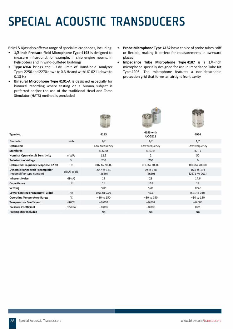
SPECIAL ACOUSTIC TRANSDUCERS
Brüel & Kjær also offers a range of special microphones, including:• 1/2‐inch Pressure‐field Microphone Type 4193 is designed to
measure infrasound, for example, in ship engine rooms, inhelicopters and in wind‐buffeted buildings
• Type 4964 brings the –3 dB limit of Hand‐held AnalyzerTypes 2250 and 2270 down to 0.3 Hz and with UC‐0211 down to0.13 Hz
• Binaural Microphone Type 4101‐A is designed especially forbinaural recording where testing on a human subject ispreferred and/or the use of the traditional Head and TorsoSimulator (HATS) method is precluded
• Probe Microphone Type 4182 has a choice of probe tubes, stiffor flexible, making it perfect for measurements in awkwardplaces
• Impedance Tube Microphone Type 4187 is a 1/4‐inchmicrophone specially designed for use in Impedance Tube KitType 4206. The microphone features a non‐detachableprotection grid that forms an airtight front cavity
Type No. 41934193 with
UC‐02114964
Diameter inch 1/2 1/2 1/2
Optimized Low‐frequency Low‐frequency Low‐frequency
Standards E, K, M E, K, M B, I, L
Nominal Open‐circuit Sensitivity mV/Pa 12.5 2 50
Polarization Voltage V 200 200 0
Optimized Frequency Response ±2 dB Hz 0.07 to 20000 0.13 to 20000 0.03 to 20000
Dynamic Range with Preamplifier
(Preamplifier type number) dB(A) to dB
20.7 to 161
(2669)
29 to 148
(2669)
16.5 to 134
(2671‐W‐001)
Inherent Noise dB (A) 19 29 14.6
Capacitance pF 18 118 14
Venting Side Side Rear
Lower Limiting Frequency (–3 dB) Hz 0.01 to 0.05 <0.1 0.01 to 0.05
Operating Temperature Range °C –30 to 150 –30 to 150 –30 to 150
Temperature Coefficient dB/°C –0.002 –0.002 –0.006
Pressure Coefficient dB/kPa –0.005 –0.005 0.01
Preamplifier Included No No No
Special Acoustic Transducers28 www.bksv.com/transducers
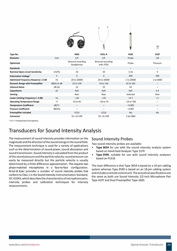
Transducers for Sound Intensity AnalysisThe measurement of sound intensity provides information on themagnitude and the direction of the sound energy in the sound field.The measurement technique is used for a variety of applicationssuch as the determination of sound power, sound absorption andsound transmission. Sound intensity is calculated from the productof the sound pressure and the particle velocity; sound pressure caneasily be measured directly but the particle velocity is usuallydetermined by a finite difference approximation. This requires twophase‐matched microphones in a face‐to‐face configuration.Brüel & Kjær provides a number of sound intensity probes thatconform to Class 1 in the Sound Intensity Instrumentation Standard,IEC 61043, which describes the characteristics of microphone pairs,intensity probes and calibration techniques for intensitymeasurements.
Sound Intensity ProbesTwo sound intensity probes are available: • Type 3654 for use with the sound intensity analysis system
based on Hand‐held Analyzer Type 2270• Type 3599, suitable for use with sound intensity analyzers
based on PULSE
The main difference is that Type 3654 is based on a 10‐pin cablingsystem whereas Type 3599 is based on an 18‐pin cabling systemand includes a remote control unit. The acoustical specifications arethe same as both use Sound Intensity 1/2‐inch Microphone PairType 4197 and Dual Preamplifier Type 2683.
Type No. 4965 4101‐A 4182 4187
Diameter inch 1/5 1/5 Probe 1/4
OptimizedBinaural recording
headphones
Binaural recording
with TEDSProbe Pressure
Standards – – – –
Nominal Open‐circuit Sensitivity mV/Pa 20 20 3.16 4
Polarization Voltage* V 0 0 200 200
Optimized Frequency Response ±2 dB Hz 20 to 20000 20 to 20000 1 to 20000 1 to 6400
Dynamic Range with Preamplifier dB(A) to dB 23 to 134 23 to 134 42 to 164 –
Inherent Noise dB (A) 23 23 42 –
Capacitance pF N/A N/A N/A 6.4
Venting Rear Rear Selected Rear
Lower Limiting Frequency (–3 dB) Hz <20 <20 <0.7 <1
Operating Temperature Range °C 10 to 40 –30 to 70 –10 to 700 –
Temperature Coefficient dB/°C – – –0.005 –
Pressure Coefficient dB/kPa – – –0.007 –
Preamplifier Included CCLD CCLD Yes No
Connector 10–32 UNF 10–32 UNF 7‐pin B&K
* 0 V = Prepolarized microphone
Special Acoustic Transducers 29www.bksv.com/transducers
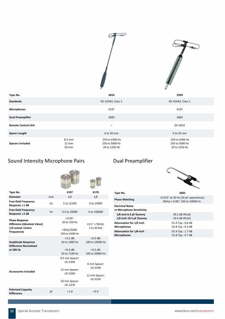
Sound Intensity Microphone Pairs Dual Preamplifier
Type No. 3654 3599
Standards IEC 61043, Class 1 IEC 61043, Class 1
Microphones 4197 4197
Dual Preamplifier 2683 2683
Remote Control Unit – ZH‐0632
Spacer Length 6 to 50 mm 6 to 50 mm
Spacers Included
8.5 mm
12 mm
50 mm
250 to 6300 Hz
250 to 5000 Hz
20 to 1250 Hz
250 to 6300 Hz
250 to 5000 Hz
20 to 1250 Hz
Type No. 4197 4178
Diameter inch 1/2 1/4
Free‐field Frequency
Response ±1 dBHz 5 to 12500 6 to 14000
Free‐field Frequency
Response ±2 dBHz 0.3 to 20000 4 to 100000
Phase Response
Difference (Absolute Value)
1/3‐octave Centre
Frequencies
<0.05°:
20 to 250 Hz
<f(Hz)/5000:
250 to 6300 Hz
±0.1° × f(kHz):
1 to 20 kHz
Amplitude Response
Difference Normalized
at 200 Hz
<0.2 dB:
20 to 1000 Hz
<0.4 dB:
20 to 7100 Hz
<0.3 dB:
100 to 10000 Hz
<0.5 dB:
100 to 20000 Hz
Accessories Included
8.5 mm Spacer:
UC‐5349
12 mm Spacer:
UC‐5269
50 mm Spacer:
UC‐5270
6 mm Spacer:
UC‐0196
12 mm Spacer:
UC‐0195
Polarized Capacity
DifferencepF <1.0 <0.3
Type No. 2683
Phase Matching<0.015° at 50 Hz (20 pF capacitance)
f(kHz) × 0.06°: 250 to 10000 Hz
Electrical Noise
re Microphone Sensitivity:
1/4‐inch 6.4 pF Dummy
1/2‐inch 19.5 pF Dummy
39.2 dB SPL(A)
19.4 dB SPL(A)
Attenuation for 1/2‐inch
Microphones
Ch.A Typ.: 0.6 dB
Ch.B Typ.: 0.3 dB
Attenuation for 1/4‐inch
Microphones
Ch.A Typ.: 1.7 dB
Ch.B Typ.: 0.7 dB
30 Special Acoustic Transducers www.bksv.com/transducers
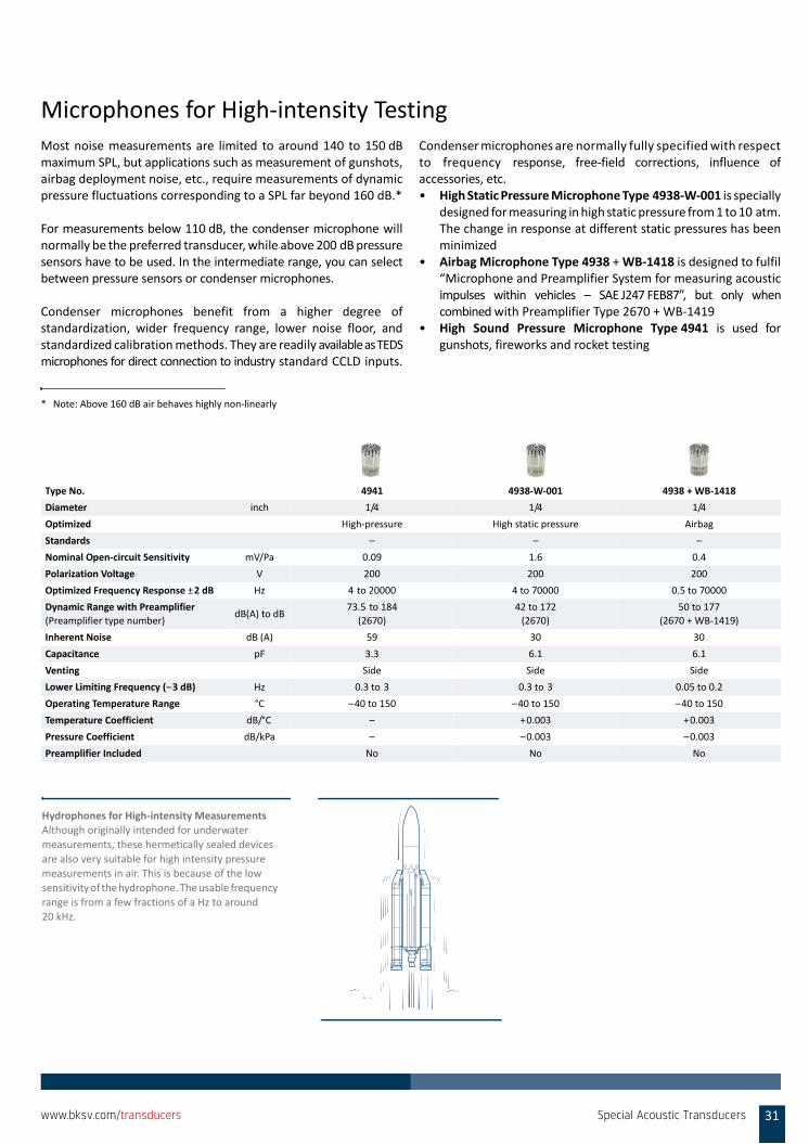
Microphones for High‐intensity TestingMost noise measurements are limited to around 140 to 150 dBmaximum SPL, but applications such as measurement of gunshots,airbag deployment noise, etc., require measurements of dynamicpressure fluctuations corresponding to a SPL far beyond 160 dB.*
For measurements below 110 dB, the condenser microphone willnormally be the preferred transducer, while above 200 dB pressuresensors have to be used. In the intermediate range, you can selectbetween pressure sensors or condenser microphones.
Condenser microphones benefit from a higher degree ofstandardization, wider frequency range, lower noise floor, andstandardized calibration methods. They are readily available as TEDSmicrophones for direct connection to industry standard CCLD inputs.
Condenser microphones are normally fully specified with respectto frequency response, free‐field corrections, influence ofaccessories, etc.• High Static Pressure Microphone Type 4938‐W‐001 is specially
designed for measuring in high static pressure from 1 to 10 atm.The change in response at different static pressures has beenminimized
• Airbag Microphone Type 4938 + WB‐1418 is designed to fulfil“Microphone and Preamplifier System for measuring acousticimpulses within vehicles – SAE J247 FEB87”, but only whencombined with Preamplifier Type 2670 + WB‐1419
• High Sound Pressure Microphone Type 4941 is used forgunshots, fireworks and rocket testing
* Note: Above 160 dB air behaves highly non‐linearly
Type No. 4941 4938‐W‐001 4938 + WB‐1418
Diameter inch 1/4 1/4 1/4
Optimized High‐pressure High static pressure Airbag
Standards – – –
Nominal Open‐circuit Sensitivity mV/Pa 0.09 1.6 0.4
Polarization Voltage V 200 200 200
Optimized Frequency Response ±2 dB Hz 4 to 20000 4 to 70000 0.5 to 70000
Dynamic Range with Preamplifier
(Preamplifier type number) dB(A) to dB
73.5 to 184
(2670)
42 to 172
(2670)
50 to 177
(2670 + WB‐1419)
Inherent Noise dB (A) 59 30 30
Capacitance pF 3.3 6.1 6.1
Venting Side Side Side
Lower Limiting Frequency (–3 dB) Hz 0.3 to 3 0.3 to 3 0.05 to 0.2
Operating Temperature Range °C –40 to 150 –40 to 150 –40 to 150
Temperature Coefficient dB/°C – +0.003 +0.003
Pressure Coefficient dB/kPa – –0.003 –0.003
Preamplifier Included No No No
Hydrophones for High‐intensity MeasurementsAlthough originally intended for underwater
measurements, these hermetically sealed devices
are also very suitable for high intensity pressure measurements in air. This is because of the low
sensitivity of the hydrophone. The usable frequency
range is from a few fractions of a Hz to around 20 kHz.
Special Acoustic Transducers 31www.bksv.com/transducers
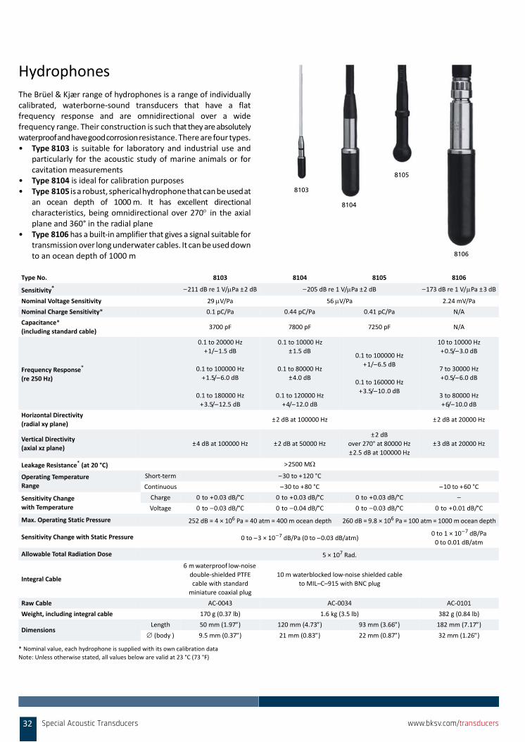
HydrophonesThe Brüel & Kjær range of hydrophones is a range of individuallycalibrated, waterborne‐sound transducers that have a flatfrequency response and are omnidirectional over a widefrequency range. Their construction is such that they are absolutelywaterproof and have good corrosion resistance. There are four types.• Type 8103 is suitable for laboratory and industrial use and
particularly for the acoustic study of marine animals or forcavitation measurements
• Type 8104 is ideal for calibration purposes• Type 8105 is a robust, spherical hydrophone that can be used at
an ocean depth of 1000m. It has excellent directionalcharacteristics, being omnidirectional over 270 in the axialplane and 360° in the radial plane
• Type 8106 has a built‐in amplifier that gives a signal suitable fortransmission over long underwater cables. It can be used downto an ocean depth of 1000 m
Note: Unless otherwise stated, all values below are valid at 23 °C (73 °F)
Type No. 8103 8104 8105 8106
Sensitivity*
* Nominal value, each hydrophone is supplied with its own calibration data
–211 dB re 1 V/Pa ±2 dB –205 dB re 1 V/Pa ±2 dB –173 dB re 1 V/Pa ±3 dB
Nominal Voltage Sensitivity 29 V/Pa 56 V/Pa 2.24 mV/Pa
Nominal Charge Sensitivity* 0.1 pC/Pa 0.44 pC/Pa 0.41 pC/Pa N/A
Capacitance*
(including standard cable)3700 pF 7800 pF 7250 pF N/A
Frequency Response*
(re 250 Hz)
0.1 to 20000 Hz
+1/–1.5 dB
0.1 to 100000 Hz
+1.5/–6.0 dB
0.1 to 180000 Hz
+3.5/–12.5 dB
0.1 to 10000 Hz
±1.5 dB
0.1 to 80000 Hz
±4.0 dB
0.1 to 120000 Hz
+4/–12.0 dB
0.1 to 100000 Hz
+1/–6.5 dB
0.1 to 160000 Hz
+3.5/–10.0 dB
10 to 10000 Hz
+0.5/–3.0 dB
7 to 30000 Hz
+0.5/–6.0 dB
3 to 80000 Hz
+6/–10.0 dB
Horizontal Directivity
(radial xy plane)±2 dB at 100000 Hz ±2 dB at 20000 Hz
Vertical Directivity
(axial xz plane)±4 dB at 100000 Hz ±2 dB at 50000 Hz
±2 dB
over 270° at 80000 Hz
±2.5 dB at 100000 Hz
±3 dB at 20000 Hz
Leakage Resistance* (at 20 °C) >2500 M
Operating Temperature
Range
Short‐term –30 to +120 °C
Continuous –30 to +80 °C –10 to +60 °C
Sensitivity Change
with Temperature
Charge 0 to +0.03 dB/°C 0 to +0.03 dB/°C 0 to +0.03 dB/°C –
Voltage 0 to –0.03 dB/°C 0 to –0.04 dB/°C 0 to –0.03 dB/°C 0 to +0.01 dB/°C
Max. Operating Static Pressure 252 dB = 4 × 10⁶ Pa = 40 atm = 400 m ocean depth 260 dB = 9.8 × 10⁶ Pa = 100 atm = 1000 m ocean depth
Sensitivity Change with Static Pressure 0 to –3 × 10⁻⁷ dB/Pa (0 to –0.03 dB/atm)0 to 1 × 10⁻⁷ dB/Pa
0 to 0.01 dB/atm
Allowable Total Radiation Dose 5 × 10⁷ Rad.
Integral Cable
6 m waterproof low‐noise
double‐shielded PTFE
cable with standard
miniature coaxial plug
10 m waterblocked low‐noise shielded cable
to MIL–C–915 with BNC plug
Raw Cable AC‐0043 AC‐0034 AC‐0101
Weight, including integral cable 170 g (0.37 lb) 1.6 kg (3.5 lb) 382 g (0.84 lb)
DimensionsLength 50 mm (1.97) 120 mm (4.73) 93 mm (3.66) 182 mm (7.17)
(body ) 9.5 mm (0.37) 21 mm (0.83) 22 mm (0.87) 32 mm (1.26)
8103
8104
8105
8106
32 Special Acoustic Transducers www.bksv.com/transducers
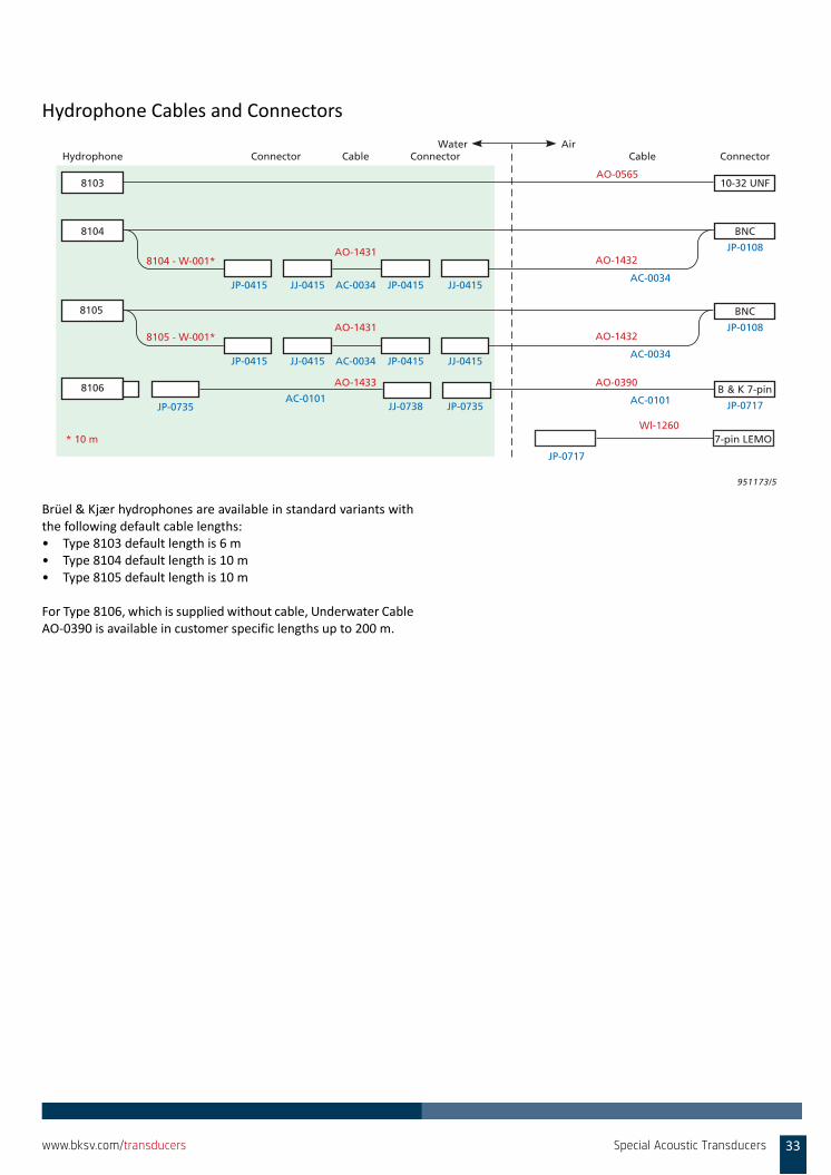
Hydrophone Cables and Connectors
Brüel & Kjær hydrophones are available in standard variants withthe following default cable lengths:• Type 8103 default length is 6 m• Type 8104 default length is 10 m• Type 8105 default length is 10 m
For Type 8106, which is supplied without cable, Underwater CableAO‐0390 is available in customer specific lengths up to 200 m.
951173/5
10-32 UNF8103
AC-0034AC-0034
AC-0034
AO-1432
AO-1432
AO-0390
ConnectorHydrophone ConnectorCable CableAirWater
Connector
8104 - W-001*
8105 - W-001*
* 10 m
AO-1431
AO-1431
AO-1433
AC-0101
AC-0034
JP-0735
BNC8104
BNC8105
B & K 7-pin
JJ-0415
AC-0101
JP-0415 JJ-0415JP-0415
JJ-0415 JP-0415 JJ-0415
JJ-0738 JP-0735
JP-0415
JP-0108
JP-0108
JP-0717
8106
AO-0565
7-pin LEMO
JP-0717
Wl-1260
Special Acoustic Transducers 33www.bksv.com/transducers

MICROPHONE PREAMPLIFIERS
A condenser microphone must be combined with a preamplifier toprovide impedance conversion, some filtering, and the capability todrive relatively long cables without significant signal degradation.
Preamplifiers are designed in accordance with two principles, eachhas its own special features:• Classical preamplifier design• CCLD preamplifier design
Classical PreamplifiersThe classical preamplifier has an easy to understand concept. It isbasically a unity gain amplifier with extremely high inputimpedance and very low input capacitance.• The supply voltage can be either ±15 V DC or a single 80 V DC.• The output signal has its own separate wire, as do the
polarization and CIC voltage.• Pin 5 is often used for transmission of TEDS data (so called Class
II TEDS).• CIC (Charge Injection Calibration) is possible by injecting a
signal (on pin 1 of the LEMO connector).
CCLD PreamplifiersDespite its origin in the vibration transducer world, the ConstantCurrent Line Drive (CCLD) principle is increasing in popularity in thearea of sound and measurement applications.
Different manufacturers market transducers using the CCLDprinciple under different names. The benefit of CCLD is that the samewire is used for both the signal and the supply current. Using ClassI TEDS, even the TEDS data can be transmitted over that same wire(using a level controlled electronic switch).
This enables the use of cost‐effective coaxial cables and BNCconnectors popularly used in general applications.
A CCLD input can be connected to a microphone, vibration sensor,or any other sensor with CCLD output. Due to the workingprinciple, the signal is superimposed on a DC voltage. This DC biasvoltage is typically around 12 V. Bias drift (over temperature ortime) will reduce the dynamic range.
Due to the lower DC supply voltage (typically 20 – 28 V DCcompliance voltage out of the front end), there are somerestrictions to the upper limit for a CCLD solution. Other limitationswith CCLD solutions include: confined to use with prepolarizedmicrophones only, and the unavailability of CIC. However in manypractical applications, this is happily accepted in order to get thebenefits of CCLD, that is, ease of use and inexpensive cables.
The DC bias voltage is often used by the front end to provide somesimple means of cable monitoring. A bias voltage below a certainvalue is interpreted as short circuit while a DC value above a certainvalue as open circuit.
Classical Versus CCLD Preamplifier
Classical CCLD
Output Voltage 55 Vp 7 Vp
Output Current 2 to 20 mA 3 to 20 mA
Noise <2 V 4 V
Distortion 80 dB 70 dB
Verification CIC/IVC No
IEEE 1451.4 Yes Yes
Cable Price Higher Lower
Connector LEMO BNC
Microphone Type Both Prepolarized only
Accelerometer Conditioning No Yes
Microphone Preamplifiers34 www.bksv.com/transducers
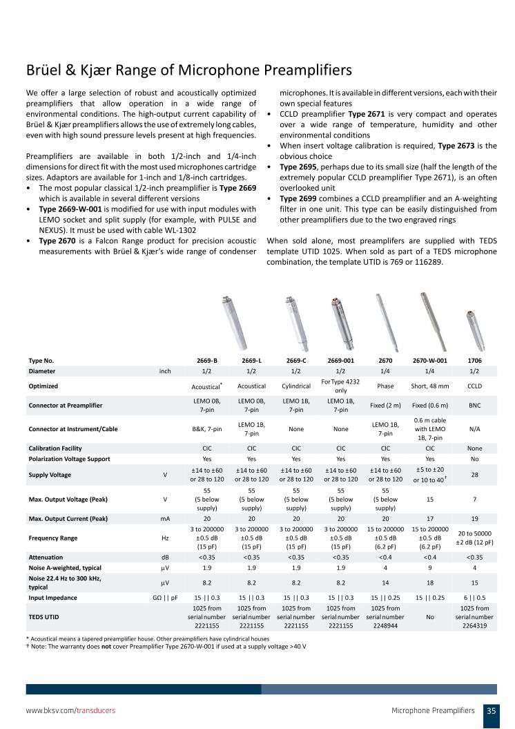
Brüel & Kjær Range of Microphone PreamplifiersWe offer a large selection of robust and acoustically optimizedpreamplifiers that allow operation in a wide range ofenvironmental conditions. The high‐output current capability ofBrüel & Kjær preamplifiers allows the use of extremely long cables,even with high sound pressure levels present at high frequencies.
Preamplifiers are available in both 1/2‐inch and 1/4‐inchdimensions for direct fit with the most used microphones cartridgesizes. Adaptors are available for 1‐inch and 1/8‐inch cartridges.• The most popular classical 1/2‐inch preamplifier is Type 2669
which is available in several different versions• Type 2669‐W‐001 is modified for use with input modules with
LEMO socket and split supply (for example, with PULSE andNEXUS). It must be used with cable WL‐1302
• Type 2670 is a Falcon Range product for precision acousticmeasurements with Brüel & Kjær’s wide range of condenser
microphones. It is available in different versions, each with theirown special features
• CCLD preamplifier Type 2671 is very compact and operatesover a wide range of temperature, humidity and otherenvironmental conditions
• When insert voltage calibration is required, Type 2673 is theobvious choice
• Type 2695, perhaps due to its small size (half the length of theextremely popular CCLD preamplifier Type 2671), is an oftenoverlooked unit
• Type 2699 combines a CCLD preamplifier and an A‐weightingfilter in one unit. This type can be easily distinguished fromother preamplifiers due to the two engraved rings
When sold alone, most preamplifers are supplied with TEDStemplate UTID 1025. When sold as part of a TEDS microphonecombination, the template UTID is 769 or 116289.
Type No. 2669‐B 2669‐L 2669‐C 2669‐001 2670 2670‐W‐001 1706
Diameter inch 1/2 1/2 1/2 1/2 1/4 1/4 1/2
Optimized Acoustical*
* Acoustical means a tapered preamplifier house. Other preamplifiers have cylindrical houses
Acoustical CylindricalFor Type 4232
onlyPhase Short, 48 mm CCLD
Connector at PreamplifierLEMO 0B,
7‐pin
LEMO 0B,
7‐pin
LEMO 1B,
7‐pin
LEMO 1B,
7‐pinFixed (2 m) Fixed (0.6 m) BNC
Connector at Instrument/Cable B&K, 7‐pinLEMO 1B,
7‐pinNone None
LEMO 1B,
7‐pin
0.6 m cable
with LEMO
1B, 7‐pin
N/A
Calibration Facility CIC CIC CIC CIC CIC CIC None
Polarization Voltage Support Yes Yes Yes Yes Yes Yes No
Supply Voltage V±14 to ±60
or 28 to 120
±14 to ±60
or 28 to 120
±14 to ±60
or 28 to 120
±14 to ±60
or 28 to 120
±14 to ±60
or 28 to 120
±5 to ±20
or 10 to 40†
† Note: The warranty does not cover Preamplifier Type 2670‐W‐001 if used at a supply voltage >40 V
28
Max. Output Voltage (Peak) V
55
(5 below
supply)
55
(5 below
supply)
55
(5 below
supply)
55
(5 below
supply)
55
(5 below
supply)
15 7
Max. Output Current (Peak) mA 20 20 20 20 20 17 19
Frequency Range Hz
3 to 200000
±0.5 dB
(15 pF)
3 to 200000
±0.5 dB
(15 pF)
3 to 200000
±0.5 dB
(15 pF)
3 to 200000
±0.5 dB
(15 pF)
15 to 200000
±0.5 dB
(6.2 pF)
15 to 200000
±0.5 dB
(6.2 pF)
20 to 50000
±2 dB (12 pF)
Attenuation dB <0.35 <0.35 <0.35 <0.35 <0.4 <0.4 <0.35
Noise A‐weighted, typical V 1.9 1.9 1.9 1.9 4 9 4
Noise 22.4 Hz to 300 kHz,
typicalV 8.2 8.2 8.2 8.2 14 18 15
Input Impedance GΩ || pF 15 || 0.3 15 || 0.3 15 || 0.3 15 || 0.3 15 || 0.25 15 || 0.25 6 || 0.5
TEDS UTID
1025 from
serial number
2221155
1025 from
serial number
2221155
1025 from
serial number
2221155
1025 from
serial number
2221155
1025 from
serial number
2248944
No
1025 from
serial number
2264319
Microphone Preamplifiers 35www.bksv.com/transducers
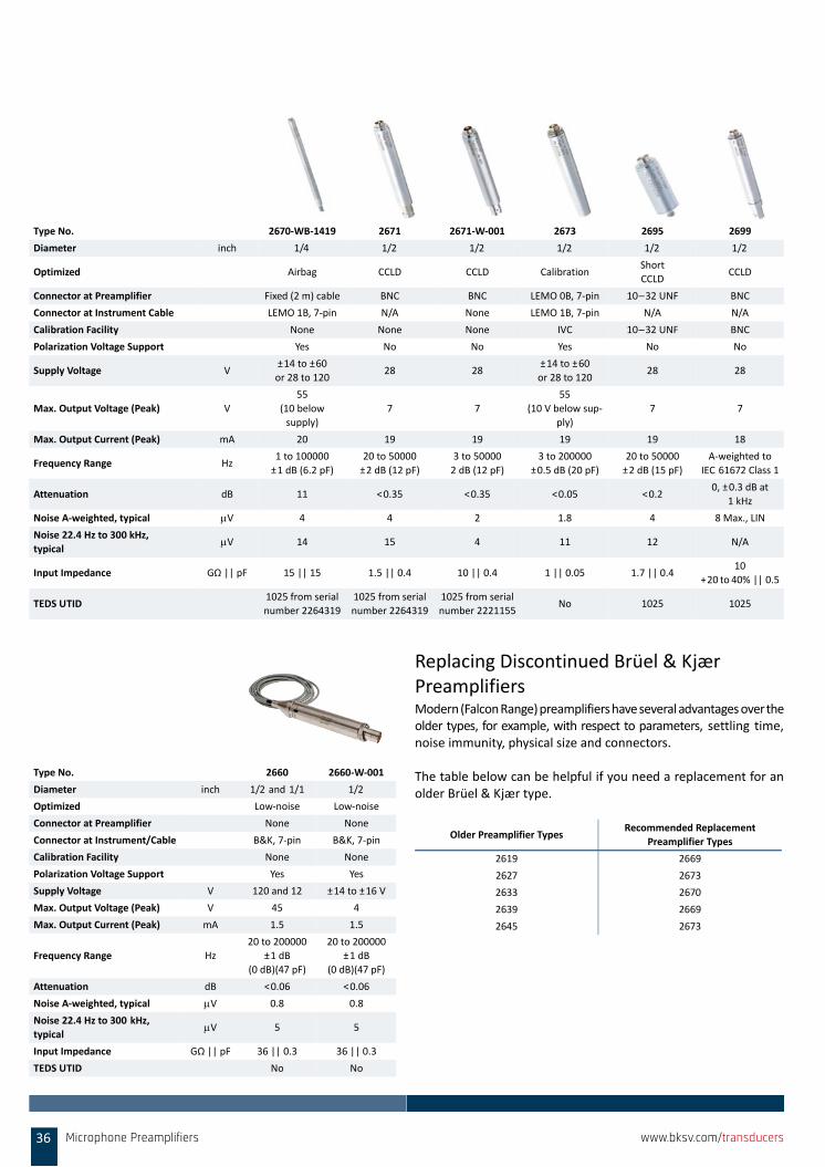
Replacing Discontinued Brüel & Kjær PreamplifiersModern (Falcon Range) preamplifiers have several advantages over theolder types, for example, with respect to parameters, settling time,noise immunity, physical size and connectors.
The table below can be helpful if you need a replacement for anolder Brüel & Kjær type.
Type No. 2670‐WB‐1419 2671 2671‐W‐001 2673 2695 2699
Diameter inch 1/4 1/2 1/2 1/2 1/2 1/2
Optimized Airbag CCLD CCLD CalibrationShort
CCLDCCLD
Connector at Preamplifier Fixed (2 m) cable BNC BNC LEMO 0B, 7‐pin 10–32 UNF BNC
Connector at Instrument Cable LEMO 1B, 7‐pin N/A None LEMO 1B, 7‐pin N/A N/A
Calibration Facility None None None IVC 10–32 UNF BNC
Polarization Voltage Support Yes No No Yes No No
Supply Voltage V±14 to ±60
or 28 to 12028 28
±14 to ±60
or 28 to 12028 28
Max. Output Voltage (Peak) V
55
(10 below
supply)
7 7
55
(10 V below sup‐
ply)
7 7
Max. Output Current (Peak) mA 20 19 19 19 19 18
Frequency Range Hz1 to 100000
±1 dB (6.2 pF)
20 to 50000
±2 dB (12 pF)
3 to 50000
2 dB (12 pF)
3 to 200000
±0.5 dB (20 pF)
20 to 50000
±2 dB (15 pF)
A‐weighted to
IEC 61672 Class 1
Attenuation dB 11 <0.35 <0.35 <0.05 <0.20, ±0.3 dB at
1 kHz
Noise A‐weighted, typical V 4 4 2 1.8 4 8 Max., LIN
Noise 22.4 Hz to 300 kHz,
typicalV 14 15 4 11 12 N/A
Input Impedance GΩ || pF 15 || 15 1.5 || 0.4 10 || 0.4 1 || 0.05 1.7 || 0.410
+20 to 40% || 0.5
TEDS UTID1025 from serial
number 2264319
1025 from serial
number 2264319
1025 from serial
number 2221155No 1025 1025
Type No. 2660 2660‐W‐001
Diameter inch 1/2 and 1/1 1/2
Optimized Low‐noise Low‐noise
Connector at Preamplifier None None
Connector at Instrument/Cable B&K, 7‐pin B&K, 7‐pin
Calibration Facility None None
Polarization Voltage Support Yes Yes
Supply Voltage V 120 and 12 ±14 to ±16 V
Max. Output Voltage (Peak) V 45 4
Max. Output Current (Peak) mA 1.5 1.5
Frequency Range Hz
20 to 200000
±1 dB
(0 dB)(47 pF)
20 to 200000
±1 dB
(0 dB)(47 pF)
Attenuation dB <0.06 <0.06
Noise A‐weighted, typical V 0.8 0.8
Noise 22.4 Hz to 300 kHz,
typicalV 5 5
Input Impedance GΩ || pF 36 || 0.3 36 || 0.3
TEDS UTID No No
Older Preamplifier TypesRecommended Replacement
Preamplifier Types
2619 2669
2627 2673
2633 2670
2639 2669
2645 2673
36 Microphone Preamplifiers www.bksv.com/transducers
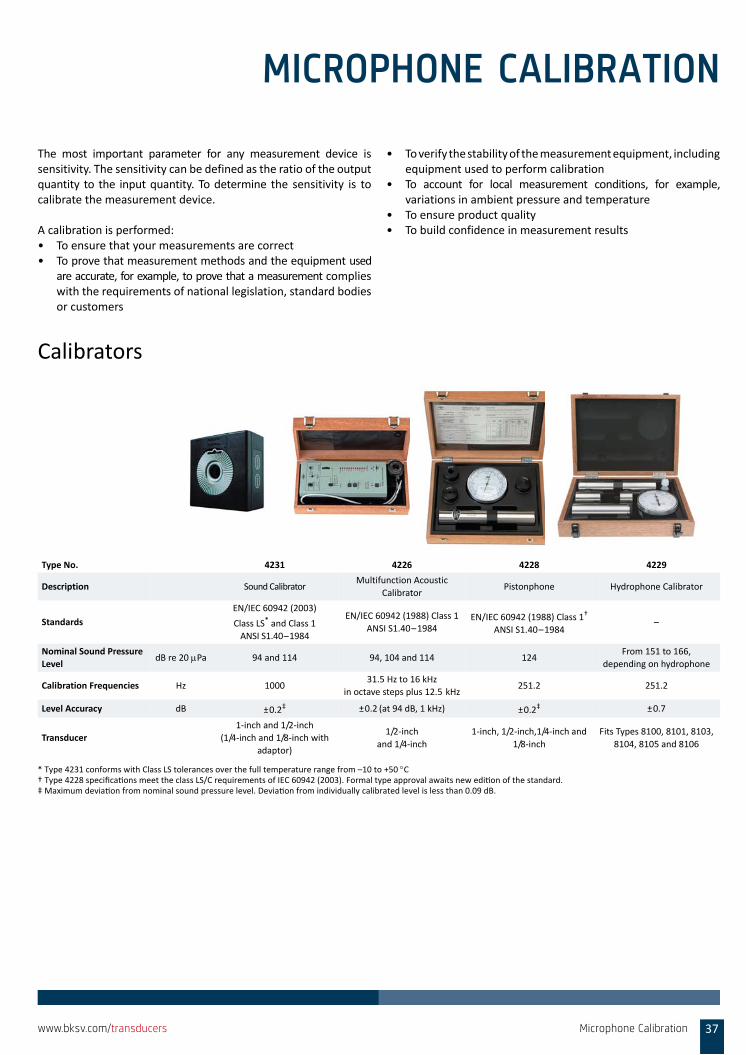
MICROPHONE CALIBRATION
The most important parameter for any measurement device issensitivity. The sensitivity can be defined as the ratio of the outputquantity to the input quantity. To determine the sensitivity is tocalibrate the measurement device.
A calibration is performed:• To ensure that your measurements are correct• To prove that measurement methods and the equipment used
are accurate, for example, to prove that a measurement complieswith the requirements of national legislation, standard bodiesor customers
• To verify the stability of the measurement equipment, includingequipment used to perform calibration
• To account for local measurement conditions, for example,variations in ambient pressure and temperature
• To ensure product quality• To build confidence in measurement results
Calibrators
Type No. 4231 4226 4228 4229
Description Sound CalibratorMultifunction Acoustic
CalibratorPistonphone Hydrophone Calibrator
Standards
EN/IEC 60942 (2003)
Class LS* and Class 1
ANSI S1.40–1984
* Type 4231 conforms with Class LS tolerances over the full temperature range from –10 to +50 C
EN/IEC 60942 (1988) Class 1
ANSI S1.40–1984EN/IEC 60942 (1988) Class 1†
ANSI S1.40–1984
† Type 4228 specifica ons meet the class LS/C requirements of IEC 60942 (2003). Formal type approval awaits new edi on of the standard.
–
Nominal Sound Pressure
LeveldB re 20 Pa 94 and 114 94, 104 and 114 124
From 151 to 166,
depending on hydrophone
Calibration Frequencies Hz 100031.5 Hz to 16 kHz
in octave steps plus 12.5 kHz251.2 251.2
Level Accuracy dB ±0.2‡
‡ Maximum devia on from nominal sound pressure level. Devia on from individually calibrated level is less than 0.09 dB.
±0.2 (at 94 dB, 1 kHz) ±0.2‡ ±0.7
Transducer
1‐inch and 1/2‐inch
(1/4‐inch and 1/8‐inch with
adaptor)
1/2‐inch
and 1/4‐inch
1‐inch, 1/2‐inch,1/4‐inch and
1/8‐inch
Fits Types 8100, 8101, 8103,
8104, 8105 and 8106
Microphone Calibration 37www.bksv.com/transducers
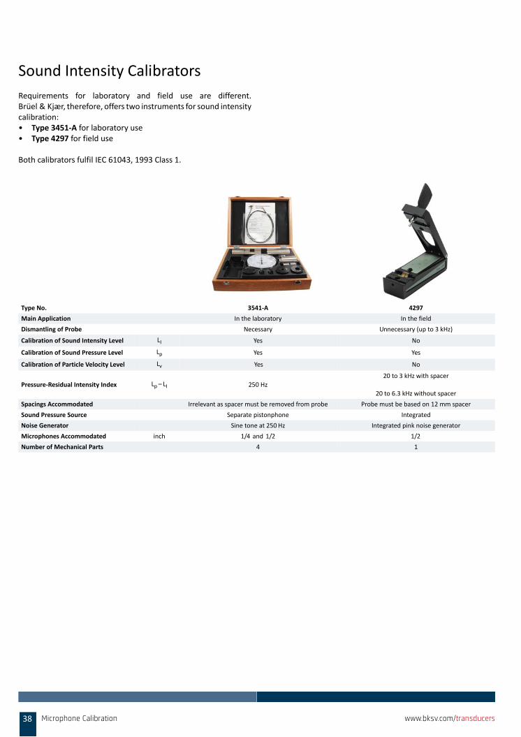
Sound Intensity Calibrators
Requirements for laboratory and field use are different.Brüel & Kjær, therefore, offers two instruments for sound intensitycalibration: • Type 3451‐A for laboratory use • Type 4297 for field use
Both calibrators fulfil IEC 61043, 1993 Class 1.
Type No. 3541‐A 4297
Main Application In the laboratory In the field
Dismantling of Probe Necessary Unnecessary (up to 3 kHz)
Calibration of Sound Intensity Level LI Yes No
Calibration of Sound Pressure Level Lp Yes Yes
Calibration of Particle Velocity Level Lv Yes No
Pressure‐Residual Intensity Index Lp – LI 250 Hz
20 to 3 kHz with spacer
20 to 6.3 kHz without spacer
Spacings Accommodated Irrelevant as spacer must be removed from probe Probe must be based on 12 mm spacer
Sound Pressure Source Separate pistonphone Integrated
Noise Generator Sine tone at 250Hz Integrated pink noise generator
Microphones Accommodated inch 1/4 and 1/2 1/2
Number of Mechanical Parts 4 1
38 Microphone Calibration www.bksv.com/transducers
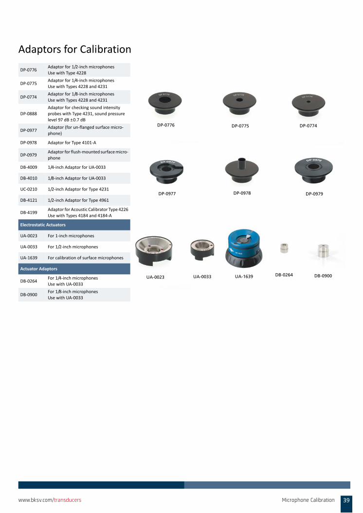
Adaptors for Calibration
DP‐0776Adaptor for 1/2‐inch microphones
Use with Type 4228
DP‐0775Adaptor for 1/4‐inch microphones
Use with Types 4228 and 4231
DP‐0774Adaptor for 1/8‐inch microphones
Use with Types 4228 and 4231
DP‐0888
Adaptor for checking sound intensity
probes with Type 4231, sound pressure
level 97 dB ±0.7 dB
DP‐0977Adaptor (for un‐flanged surface micro‐
phone)
DP‐0978 Adaptor for Type 4101‐A
DP‐0979Adaptor for flush‐mounted surface micro‐
phone
DB‐4009 1/4‐inch Adaptor for UA‐0033
DB‐4010 1/8‐inch Adaptor for UA‐0033
UC‐0210 1/2‐inch Adaptor for Type 4231
DB‐4121 1/2‐inch Adaptor for Type 4961
DB‐4199Adaptor for Acoustic Calibrator Type 4226
Use with Types 4184 and 4184‐A
Electrostatic Actuators
UA‐0023 For 1‐inch microphones
UA‐0033 For 1/2‐inch microphones
UA‐1639 For calibration of surface microphones
Actuator Adaptors
DB‐0264For 1/4‐inch microphones
Use with UA‐0033
DB‐0900For 1/8‐inch microphones
Use with UA‐0033
DP-0774DP-0775
DP-0977 DP-0978 DP-0979
DP-0776
UA-0023 UA-1639 DB-0900UA-0033 DB-0264
Microphone Calibration 39www.bksv.com/transducers
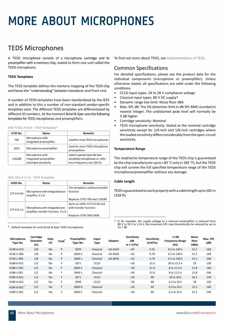
MORE ABOUT MICROPHONES
TEDS MicrophonesA TEDS microphone consists of a microphone cartridge and itspreamplifier with a memory chip, sealed to form one unit called theTEDS microphone.
TEDS Templates
The TEDS template defines the memory mapping of the TEDS chipand hence the “understanding” between transducer and front end.
A number of TEDS templates have been standardized by the IEEEand in addition to this a number of non‐standard vendor‐specifictemplates exist. The different TEDS templates are differentiated bydifferent ID numbers. At the moment Brüel&Kjær uses the followingtemplates for TEDS microphones and preamplifiers.
IEEE P1451.4 V.0.9 – TEDS Templates*
IEEE 1451.4 V.1.0 – TEDS Templates
To find out more about TEDS, see Implementation of TEDS.
Common SpecificationsFor detailed specifications, please see the product data for theindividual components (microphone or preamplifier). Unlessotherwise stated, all specifications are valid under the followingconditions:• CCLD input types: 24 to 28 V compliance voltage• Classical input types: 80 V DC supply† • Dynamic range low limit: Noise floor dBA • Max. SPL dB: The 3% distortion limit in dB SPL RMS rounded to
nearest integer. The undistorted peak level will normally be3 dB higher
• Cartridge sensitivity: Nominal• TEDS microphone sensitivity: Stated as the nominal cartridge
sensitivity except for 1/4‐inch and 1/8‐inch cartridges wherethe loaded sensitivity differs considerably from the open‐circuitsensitivity
Temperature Range
The read/write temperature range of the TEDS chip is guaranteedby the chip manufacturer up to +85 °C only (+185 °F), but the TEDSchip will survive the full specified temperature range of the TEDSmicrophone/preamplifier without any damage.
Cable Length
TEDS is guaranteed to work properly with a cable length up to 100 m(328 ft).
UTID No. Name Remarks
769Microphone with
integrated preamplifierUsed for most TEDS microphones
1025 Microphone preamplifier Used for most TEDS microphone
preamplifiers
116289
Microphone with
integrated preamplifier
extended sensitivity
Used in special cases like low‐
sensitivity microphones or refer‐
ence frequency not 250 Hz
* Default template for most Brüel & Kjær TEDS microphones
UDID No. Name Remarks
127‐0‐0‐0UMicrophone with integrated pre‐
amplifier, V.1.0
This template is without transfer
function
Replaces UTID 769 and 116289
127‐0‐0‐1UMicrophone with integrated pre‐
amplifier, transfer function, V.1.0
Same as UDID 127‐0‐0‐0U but
with transfer function
Replaces UTID 34013408
† If, for example, the supply voltage to a classical preamplifier is reduced from80 V to 28 V or ±14 V, the maximum SPL may theoretically be reduced by up to15.7 dB
Microphone
Type No.
Cartridge
Diameter
(in)
Data
CD Field*Preamplifier
Type No.
Input
TypeAdaptor
Sensitivity
(dB
re 1 V/Pa)
Sensitivity
(mV/Pa)
±2 dB
Frequency Range
(Hz)
Noise
floor
(dBA)
Max. SPL
(dB)
4138‐A‐015 1/8 No P 2670 Classical UA‐0160 –65 0.55 6.5 to 140 k 52.2 168
4138‐C‐006 1/8 No P 2669‐C Classical UA‐0036 –62 0.79 6.5 to 140 k 52.2 168
4138‐L‐006 1/8 No P 2669‐L Classical UA‐0036 –62 0.79 6.5 to 140 k 52.2 168
4188‐A‐021 1/2 No F 2671 CCLD –30 31.6 20 to 12.5 k 19 138
4188‐C‐001 1/2 No F 2669‐C Classical –30 31.6 8 to 12.5 k 15.8 146
4188‐L‐001 1/2 No F 2669‐L Classical –30 31.6 8 to 12.5 k 15.8 146
4189‐A‐021 1/2 Yes F 2671 CCLD –26 48 20 to 20 k 16.5 134
4189‐A‐031 1/2 Yes F 2699 CCLD –26 48 6.3 to 20 k 18 130
4189‐B‐001† 1/2 Yes F 2669‐B Classical –26 49 6.3 to 20 k 15.2 146
4189‐C‐001 1/2 Yes F 2669‐C Classical –26 49 6.3 to 20 k 15.2 146
More About Microphones40 www.bksv.com/transducers
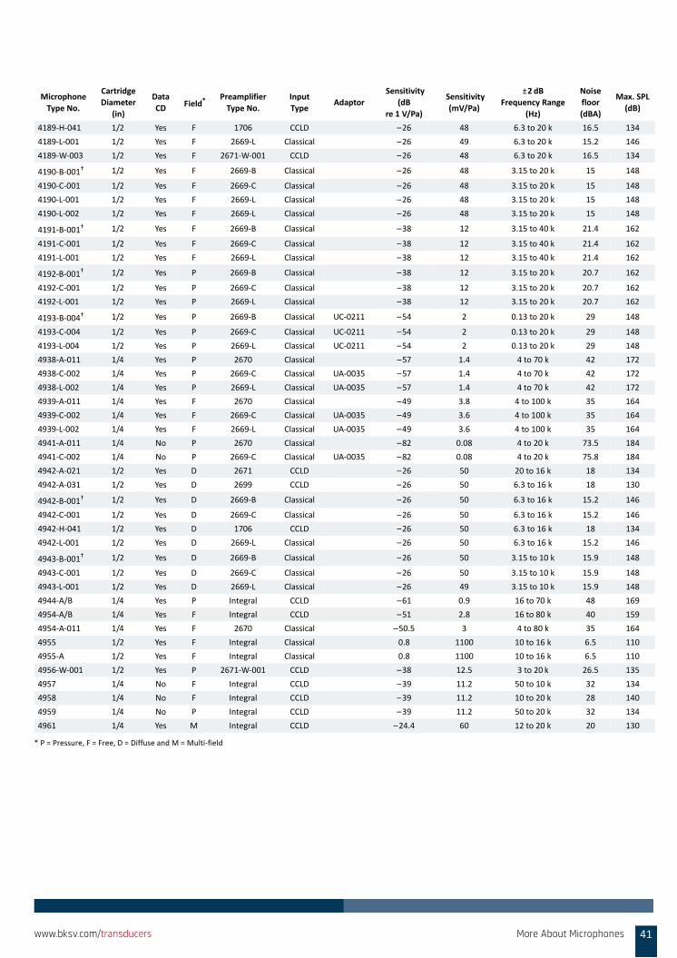
4189‐H‐041 1/2 Yes F 1706 CCLD –26 48 6.3 to 20 k 16.5 134
4189‐L‐001 1/2 Yes F 2669‐L Classical –26 49 6.3 to 20 k 15.2 146
4189‐W‐003 1/2 Yes F 2671‐W‐001 CCLD –26 48 6.3 to 20 k 16.5 134
4190‐B‐001† 1/2 Yes F 2669‐B Classical –26 48 3.15 to 20 k 15 148
4190‐C‐001 1/2 Yes F 2669‐C Classical –26 48 3.15 to 20 k 15 148
4190‐L‐001 1/2 Yes F 2669‐L Classical –26 48 3.15 to 20 k 15 148
4190‐L‐002 1/2 Yes F 2669‐L Classical –26 48 3.15 to 20 k 15 148
4191‐B‐001† 1/2 Yes F 2669‐B Classical –38 12 3.15 to 40 k 21.4 162
4191‐C‐001 1/2 Yes F 2669‐C Classical –38 12 3.15 to 40 k 21.4 162
4191‐L‐001 1/2 Yes F 2669‐L Classical –38 12 3.15 to 40 k 21.4 162
4192‐B‐001† 1/2 Yes P 2669‐B Classical –38 12 3.15 to 20 k 20.7 162
4192‐C‐001 1/2 Yes P 2669‐C Classical –38 12 3.15 to 20 k 20.7 162
4192‐L‐001 1/2 Yes P 2669‐L Classical –38 12 3.15 to 20 k 20.7 162
4193‐B‐004† 1/2 Yes P 2669‐B Classical UC‐0211 –54 2 0.13 to 20 k 29 148
4193‐C‐004 1/2 Yes P 2669‐C Classical UC‐0211 –54 2 0.13 to 20 k 29 148
4193‐L‐004 1/2 Yes P 2669‐L Classical UC‐0211 –54 2 0.13 to 20 k 29 148
4938‐A‐011 1/4 Yes P 2670 Classical –57 1.4 4 to 70 k 42 172
4938‐C‐002 1/4 Yes P 2669‐C Classical UA‐0035 –57 1.4 4 to 70 k 42 172
4938‐L‐002 1/4 Yes P 2669‐L Classical UA‐0035 –57 1.4 4 to 70 k 42 172
4939‐A‐011 1/4 Yes F 2670 Classical –49 3.8 4 to 100 k 35 164
4939‐C‐002 1/4 Yes F 2669‐C Classical UA‐0035 –49 3.6 4 to 100 k 35 164
4939‐L‐002 1/4 Yes F 2669‐L Classical UA‐0035 –49 3.6 4 to 100 k 35 164
4941‐A‐011 1/4 No P 2670 Classical –82 0.08 4 to 20 k 73.5 184
4941‐C‐002 1/4 No P 2669‐C Classical UA‐0035 –82 0.08 4 to 20 k 75.8 184
4942‐A‐021 1/2 Yes D 2671 CCLD –26 50 20 to 16 k 18 134
4942‐A‐031 1/2 Yes D 2699 CCLD –26 50 6.3 to 16 k 18 130
4942‐B‐001† 1/2 Yes D 2669‐B Classical –26 50 6.3 to 16 k 15.2 146
4942‐C‐001 1/2 Yes D 2669‐C Classical –26 50 6.3 to 16 k 15.2 146
4942‐H‐041 1/2 Yes D 1706 CCLD –26 50 6.3 to 16 k 18 134
4942‐L‐001 1/2 Yes D 2669‐L Classical –26 50 6.3 to 16 k 15.2 146
4943‐B‐001† 1/2 Yes D 2669‐B Classical –26 50 3.15 to 10 k 15.9 148
4943‐C‐001 1/2 Yes D 2669‐C Classical –26 50 3.15 to 10 k 15.9 148
4943‐L‐001 1/2 Yes D 2669‐L Classical –26 49 3.15 to 10 k 15.9 148
4944‐A/B 1/4 Yes P Integral CCLD –61 0.9 16 to 70 k 48 169
4954‐A/B 1/4 Yes F Integral CCLD –51 2.8 16 to 80 k 40 159
4954‐A‐011 1/4 Yes F 2670 Classical –50.5 3 4 to 80 k 35 164
4955 1/2 Yes F Integral Classical 0.8 1100 10 to 16 k 6.5 110
4955‐A 1/2 Yes F Integral Classical 0.8 1100 10 to 16 k 6.5 110
4956‐W‐001 1/2 Yes P 2671‐W‐001 CCLD –38 12.5 3 to 20 k 26.5 135
4957 1/4 No F Integral CCLD –39 11.2 50 to 10 k 32 134
4958 1/4 No F Integral CCLD –39 11.2 10 to 20 k 28 140
4959 1/4 No P Integral CCLD –39 11.2 50 to 20 k 32 134
4961 1/4 Yes M Integral CCLD –24.4 60 12 to 20 k 20 130
* P = Pressure, F = Free, D = Diffuse and M = Multi‐field
Microphone
Type No.
Cartridge
Diameter
(in)
Data
CD Field*
Preamplifier
Type No.
Input
TypeAdaptor
Sensitivity
(dB
re 1 V/Pa)
Sensitivity
(mV/Pa)
±2 dB
Frequency Range
(Hz)
Noise
floor
(dBA)
Max. SPL
(dB)
More About Microphones 41www.bksv.com/transducers
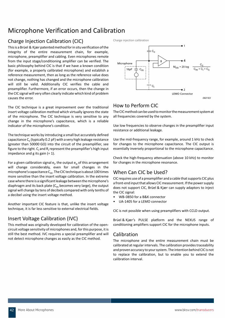
Microphone Verification and Calibration
Charge Injection Calibration (CIC)This is a Brüel & Kjær patented method for in situ verification of theintegrity of the entire measurement chain, for example,microphone, preamplifier and cabling. Even microphones remotefrom the input stage/conditioning amplifier can be verified. Thebasic philosophy behind CIC is that if we have a known condition(for example, a properly calibrated microphone) and establish areference measurement, then as long as the reference value doesnot change, nothing has changed and the microphone calibrationwill still be valid. Additionally CIC verifies the cable andpreamplifier. Furthermore, if an error occurs, then the change inthe CIC signal will very often clearly indicate which kind of problemcauses the error.
The CIC technique is a great improvement over the traditionalinsert voltage calibration method which virtually ignores the stateof the microphone. The CIC technique is very sensitive to anychange in the microphone’s capacitance, which is a reliableindicator of the microphone’s condition.
The technique works by introducing a small but accurately definedcapacitance Cc (typically 0.2 pF) with a very high leakage resistance(greater than 50000 GΩ) into the circuit of the preamplifier, seefigure to the right. Ci and Ri represent the preamplifier’s high inputimpedance and g its gain (= 1).
For a given calibration signal ei, the output eo of this arrangementwill change considerably, even for small changes in themicrophone’s capacitance Cm. The CIC technique is about 100 timesmore sensitive than the insert voltage calibration. In the extremecase where there is a significant leakage between the microphone’sdiaphragm and its back plate (Cm becomes very large), the outputsignal will change by tens of decibels compared with only tenths ofa decibel using the insert voltage method.
Another important CIC feature is that, unlike the insert voltagetechnique, it is far less sensitive to external electrical fields.
Insert Voltage Calibration (IVC)This method was originally developed for calibration of the open‐circuit voltage sensitivity of microphones and, for this purpose, it isstill the best method. IVC requires a special preamplifier and willnot detect microphone changes as easily as the CIC method.
Charge injection calibration
How to Perform CICThe CIC method can be used to monitor the measurement system atall frequencies covered by the system.
Use low frequencies to observe changes in the preamplifier inputresistance or additional leakage.
Use the mid‐frequency range, for example, around 1 kHz to checkfor changes to the microphone capacitance. The CIC output isessentially inversely proportional to the microphone capacitance.
Check the high‐frequency attenuation (above 10 kHz) to monitorfor changes in the microphone resonance.
When Can CIC be Used?CIC requires use of a preamplifier and a cable that supports CIC plusa front‐end input that allows CIC measurement. If the power supplydoes not support CIC, Brüel & Kjær can supply adaptors to injectthe CIC signal:• WB‐0850 for a B&K connector • UA‐1405 for a LEMO connector
CIC is not possible when using preamplifiers with CCLD output.
Brüel & Kjær’s PULSE platform and the NEXUS range ofconditioning amplifiers support CIC for the microphone inputs.
CalibrationThe microphone and the entire measurement chain must becalibrated at regular intervals. The calibration provides traceabilityand proven accuracy to your system. The intention behind CIC is notto replace the calibration, but to enable you to extend thecalibration interval.
Cc
CcCm + Ci + Cc
Mcic = 20 logCm16pF
Ci
1
4
2
LEMO Connector
Microphoneg
060183
42 More About Microphones www.bksv.com/transducers
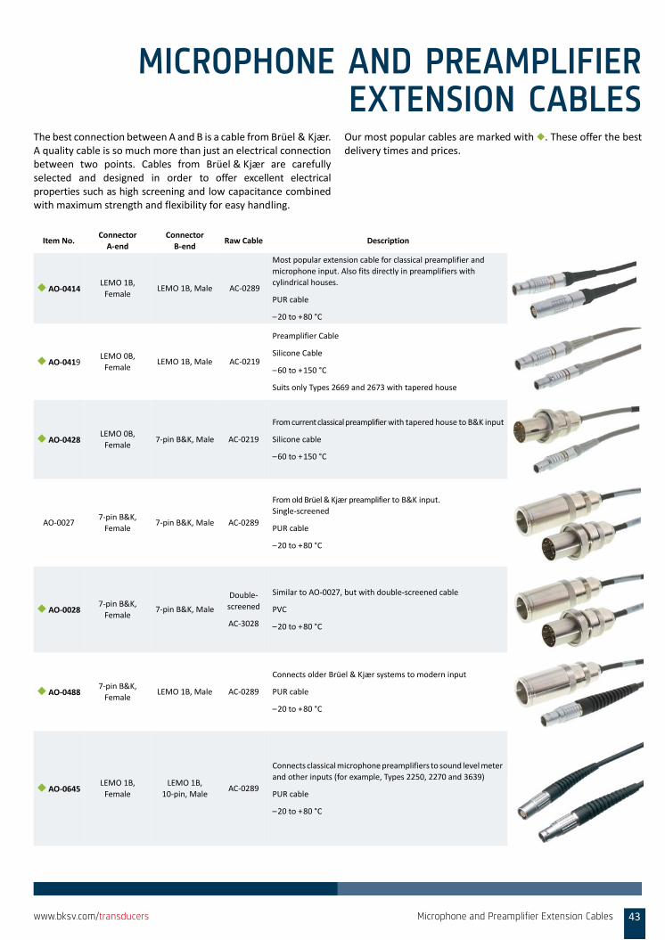
MICROPHONE AND PREAMPLIFIEREXTENSION CABLES
The best connection between A and B is a cable from Brüel & Kjær.A quality cable is so much more than just an electrical connectionbetween two points. Cables from Brüel & Kjær are carefullyselected and designed in order to offer excellent electricalproperties such as high screening and low capacitance combinedwith maximum strength and flexibility for easy handling.
Our most popular cables are marked with ◆. These offer the bestdelivery times and prices.
Item No.Connector
A‐end
Connector
B‐endRaw Cable Description
◆ AO‐0414LEMO 1B,
FemaleLEMO 1B, Male AC‐0289
Most popular extension cable for classical preamplifier and
microphone input. Also fits directly in preamplifiers with
cylindrical houses.
PUR cable
–20 to +80 °C
◆ AO‐0419LEMO 0B,
FemaleLEMO 1B, Male AC‐0219
Preamplifier Cable
Silicone Cable
–60 to +150 °C
Suits only Types 2669 and 2673 with tapered house
◆ AO‐0428LEMO 0B,
Female7‐pin B&K, Male AC‐0219
From current classical preamplifier with tapered house to B&K input
Silicone cable
–60 to +150 °C
AO‐00277‐pin B&K,
Female7‐pin B&K, Male AC‐0289
From old Brüel & Kjær preamplifier to B&K input.
Single‐screened
PUR cable
–20 to +80 °C
◆ AO‐00287‐pin B&K,
Female7‐pin B&K, Male
Double‐
screened
AC‐3028
Similar to AO‐0027, but with double‐screened cable
PVC
–20 to +80 °C
◆ AO‐04887‐pin B&K,
FemaleLEMO 1B, Male AC‐0289
Connects older Brüel & Kjær systems to modern input
PUR cable
–20 to +80 °C
◆ AO‐0645LEMO 1B,
Female
LEMO 1B,
10‐pin, MaleAC‐0289
Connects classical microphone preamplifiers to sound level meter
and other inputs (for example, Types 2250, 2270 and 3639)
PUR cable
–20 to +80 °C
Microphone and Preamplifier Extension Cables 43www.bksv.com/transducers
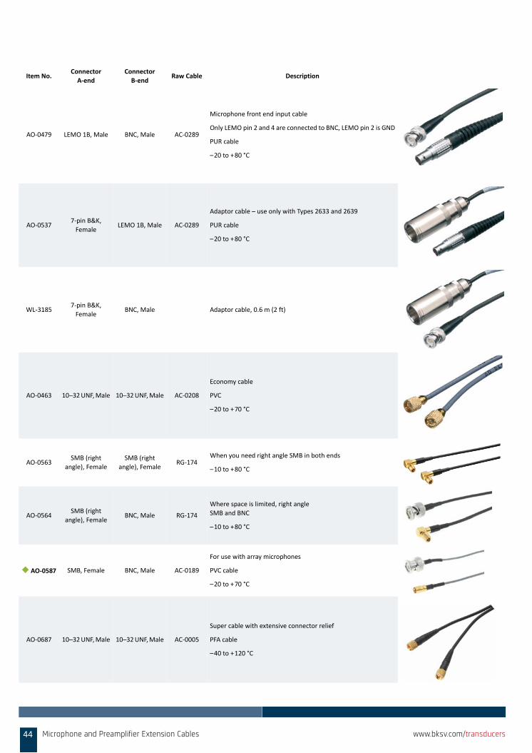
AO‐0479 LEMO 1B, Male BNC, Male AC‐0289
Microphone front end input cable
Only LEMO pin 2 and 4 are connected to BNC, LEMO pin 2 is GND
PUR cable
–20 to +80 °C
AO‐05377‐pin B&K,
FemaleLEMO 1B, Male AC‐0289
Adaptor cable – use only with Types 2633 and 2639
PUR cable
–20 to +80 °C
WL‐31857‐pin B&K,
FemaleBNC, Male Adaptor cable, 0.6 m (2 ft)
AO‐0463 10–32 UNF, Male 10–32 UNF, Male AC‐0208
Economy cable
PVC
–20 to +70 °C
AO‐0563SMB (right
angle), Female
SMB (right
angle), FemaleRG‐174
When you need right angle SMB in both ends
–10 to +80 °C
AO‐0564SMB (right
angle), FemaleBNC, Male RG‐174
Where space is limited, right angle
SMB and BNC
–10 to +80 °C
◆ AO‐0587 SMB, Female BNC, Male AC‐0189
For use with array microphones
PVC cable
–20 to +70 °C
AO‐0687 10–32 UNF, Male 10–32 UNF, Male AC‐0005
Super cable with extensive connector relief
PFA cable
–40 to +120 °C
Item No.Connector
A‐end
Connector
B‐endRaw Cable Description
44 Microphone and Preamplifier Extension Cables www.bksv.com/transducers
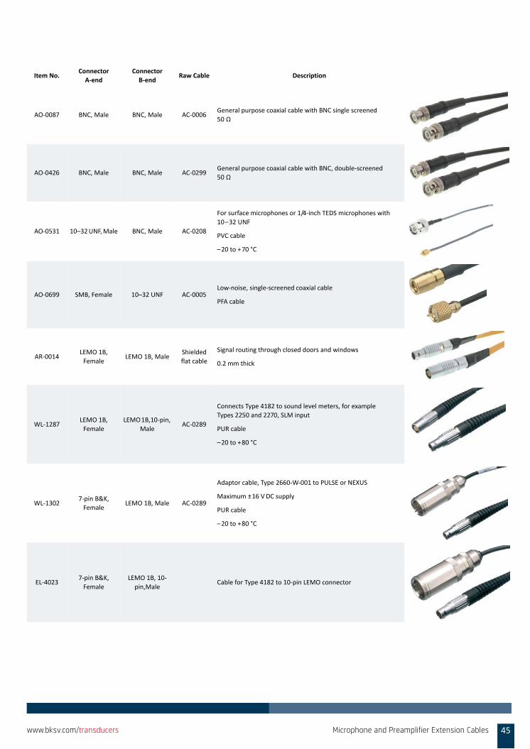
AO‐0087 BNC, Male BNC, Male AC‐0006General purpose coaxial cable with BNC single screened
50 Ω
AO‐0426 BNC, Male BNC, Male AC‐0299General purpose coaxial cable with BNC, double‐screened
50 Ω
AO‐0531 10–32 UNF, Male BNC, Male AC‐0208
For surface microphones or 1/4‐inch TEDS microphones with
10–32 UNF
PVC cable
–20 to +70 °C
AO‐0699 SMB, Female 10–32 UNF AC‐0005Low‐noise, single‐screened coaxial cable
PFA cable
AR‐0014LEMO 1B,
FemaleLEMO 1B, Male
Shielded
flat cable
Signal routing through closed doors and windows
0.2 mm thick
WL‐1287LEMO 1B,
Female
LEMO 1B,10‐pin,
MaleAC‐0289
Connects Type 4182 to sound level meters, for example
Types 2250 and 2270, SLM input
PUR cable
–20 to +80 °C
WL‐13027‐pin B&K,
FemaleLEMO 1B, Male AC‐0289
Adaptor cable, Type 2660‐W‐001 to PULSE or NEXUS
Maximum ±16 VDC supply
PUR cable
–20 to +80 °C
EL‐40237‐pin B&K,
Female
LEMO 1B, 10‐
pin,MaleCable for Type 4182 to 10‐pin LEMO connector
Item No.Connector
A‐end
Connector
B‐endRaw Cable Description
Microphone and Preamplifier Extension Cables 45www.bksv.com/transducers
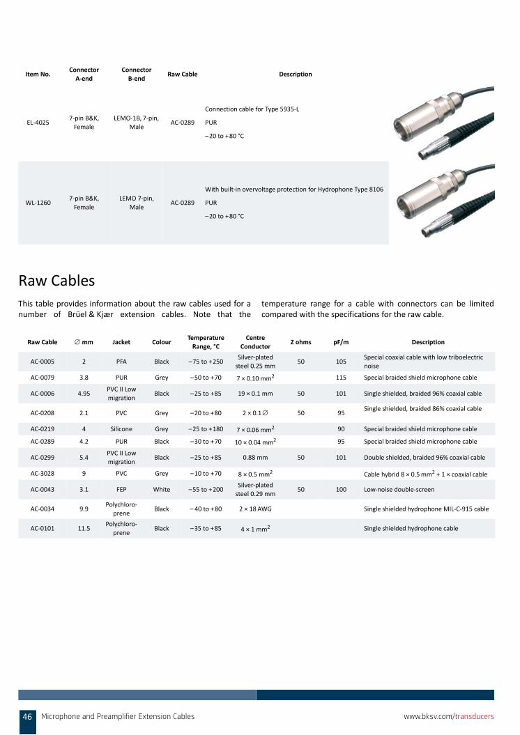
Raw CablesThis table provides information about the raw cables used for anumber of Brüel & Kjær extension cables. Note that the
temperature range for a cable with connectors can be limitedcompared with the specifications for the raw cable.
EL‐40257‐pin B&K,
Female
LEMO‐1B, 7‐pin,
MaleAC‐0289
Connection cable for Type 5935‐L
PUR
–20 to +80 °C
WL‐12607‐pin B&K,
Female
LEMO 7‐pin,
MaleAC‐0289
With built‐in overvoltage protection for Hydrophone Type 8106
PUR
–20 to +80 °C
Item No.Connector
A‐end
Connector
B‐endRaw Cable Description
Raw Cable mm Jacket ColourTemperature
Range, °C
Centre
ConductorZ ohms pF/m Description
AC‐0005 2 PFA Black –75 to +250Silver‐plated
steel 0.25 mm50 105
Special coaxial cable with low triboelectric
noise
AC‐0079 3.8 PUR Grey –50 to +70 7 × 0.10 mm2 115 Special braided shield microphone cable
AC‐0006 4.95PVC II Low
migrationBlack –25 to +85 19 × 0.1 mm 50 101 Single shielded, braided 96% coaxial cable
AC‐0208 2.1 PVC Grey –20 to +80 2 × 0.1 50 95Single shielded, braided 86% coaxial cable
AC‐0219 4 Silicone Grey –25 to +180 7 × 0.06 mm2 90 Special braided shield microphone cable
AC‐0289 4.2 PUR Black –30 to +70 10 × 0.04 mm2 95 Special braided shield microphone cable
AC‐0299 5.4PVC II Low
migrationBlack –25 to +85 0.88 mm 50 101 Double shielded, braided 96% coaxial cable
AC‐3028 9 PVC Grey –10 to +70 8 × 0.5 mm2 Cable hybrid 8 × 0.5mm2 + 1 × coaxial cable
AC‐0043 3.1 FEP White –55 to +200Silver‐plated
steel 0.29 mm50 100 Low‐noise double‐screen
AC‐0034 9.9Polychloro‐
preneBlack – 40 to +80 2 × 18 AWG Single shielded hydrophone MIL‐C‐915 cable
AC‐0101 11.5Polychloro‐
preneBlack –35 to +85 4 × 1 mm2 Single shielded hydrophone cable
46 Microphone and Preamplifier Extension Cables www.bksv.com/transducers
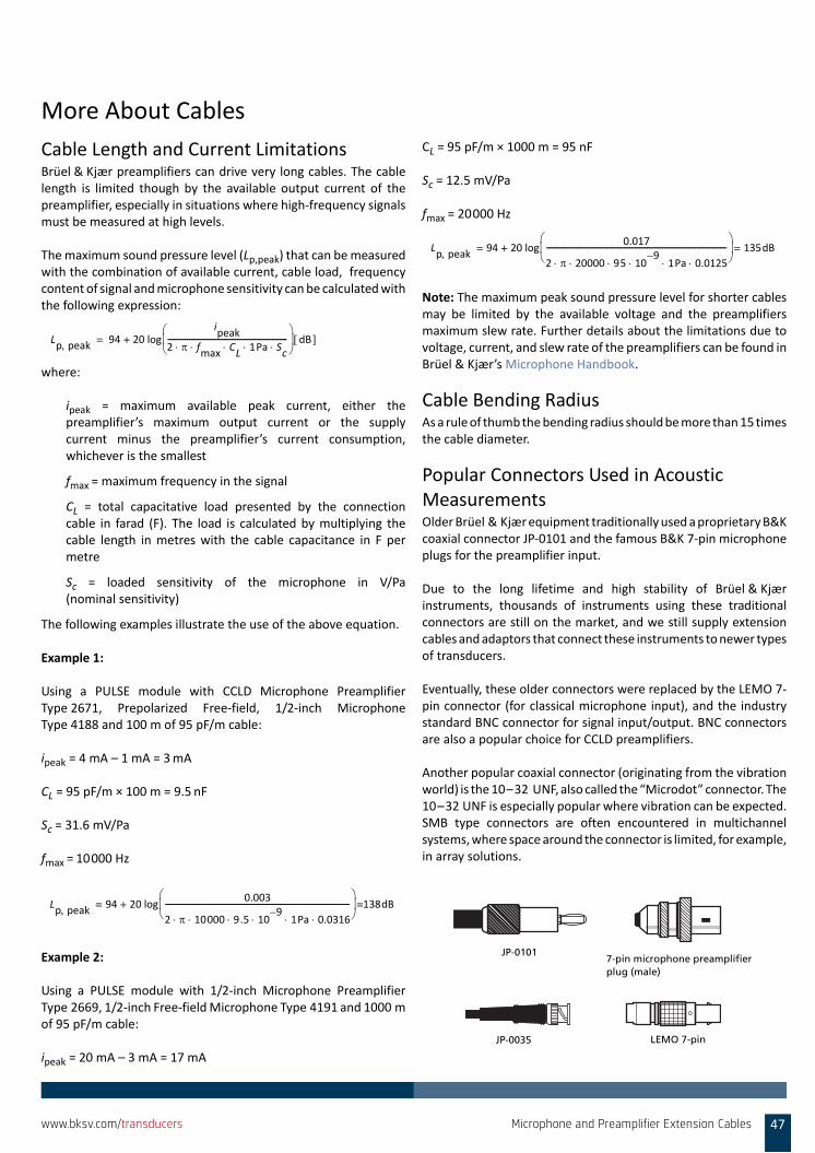
More About Cables
Cable Length and Current LimitationsBrüel & Kjær preamplifiers can drive very long cables. The cablelength is limited though by the available output current of thepreamplifier, especially in situations where high‐frequency signalsmust be measured at high levels.
The maximum sound pressure level (Lp,peak) that can be measuredwith the combination of available current, cable load, frequencycontent of signal and microphone sensitivity can be calculated withthe following expression:
where:
ipeak = maximum available peak current, either thepreamplifier’s maximum output current or the supplycurrent minus the preamplifier’s current consumption,whichever is the smallest
fmax = maximum frequency in the signal
CL = total capacitative load presented by the connectioncable in farad (F). The load is calculated by multiplying thecable length in metres with the cable capacitance in F permetre
Sc = loaded sensitivity of the microphone in V/Pa(nominal sensitivity)
The following examples illustrate the use of the above equation.
Example 1:
Using a PULSE module with CCLD Microphone PreamplifierType 2671, Prepolarized Free‐field, 1/2‐inch MicrophoneType 4188 and 100 m of 95 pF/m cable:
ipeak = 4 mA – 1 mA = 3mA
CL = 95 pF/m × 100 m = 9.5 nF
Sc = 31.6 mV/Pa
fmax = 10000 Hz
Example 2:
Using a PULSE module with 1/2‐inch Microphone PreamplifierType 2669, 1/2‐inch Free‐field Microphone Type 4191 and 1000 mof 95 pF/m cable:
ipeak = 20 mA – 3 mA = 17 mA
CL = 95 pF/m × 1000 m = 95 nF
Sc = 12.5 mV/Pa
fmax = 20000 Hz
Note: The maximum peak sound pressure level for shorter cablesmay be limited by the available voltage and the preamplifiersmaximum slew rate. Further details about the limitations due tovoltage, current, and slew rate of the preamplifiers can be found inBrüel & Kjær’s Microphone Handbook.
Cable Bending RadiusAs a rule of thumb the bending radius should be more than 15 timesthe cable diameter.
Popular Connectors Used in Acoustic MeasurementsOlder Brüel & Kjær equipment traditionally used a proprietary B&Kcoaxial connector JP‐0101 and the famous B&K 7‐pin microphoneplugs for the preamplifier input.
Due to the long lifetime and high stability of Brüel & Kjærinstruments, thousands of instruments using these traditionalconnectors are still on the market, and we still supply extensioncables and adaptors that connect these instruments to newer typesof transducers.
Eventually, these older connectors were replaced by the LEMO 7‐pin connector (for classical microphone input), and the industrystandard BNC connector for signal input/output. BNC connectorsare also a popular choice for CCLD preamplifiers.
Another popular coaxial connector (originating from the vibrationworld) is the 10–32 UNF, also called the “Microdot” connector. The10–32 UNF is especially popular where vibration can be expected.SMB type connectors are often encountered in multichannelsystems, where space around the connector is limited, for example,in array solutions.
Lp peak 94 20 log
ipeak
2 fmax
CL
1Pa Sc
--------------------------------------------------------------
dB +=
Lp peak 94 20 log
0.003
2 10000 9.5 109–
1Pa 0.0316 -----------------------------------------------------------------------------------------------
138dB=+=
Lp peak 94 20 log
0.017
2 20000 95 109–
1Pa 0.0125 ---------------------------------------------------------------------------------------------
135dB=+=
LEMO 7-pinJP-0035
JP-01017-pin microphone preamplifier plug (male)
Microphone and Preamplifier Extension Cables 47www.bksv.com/transducers
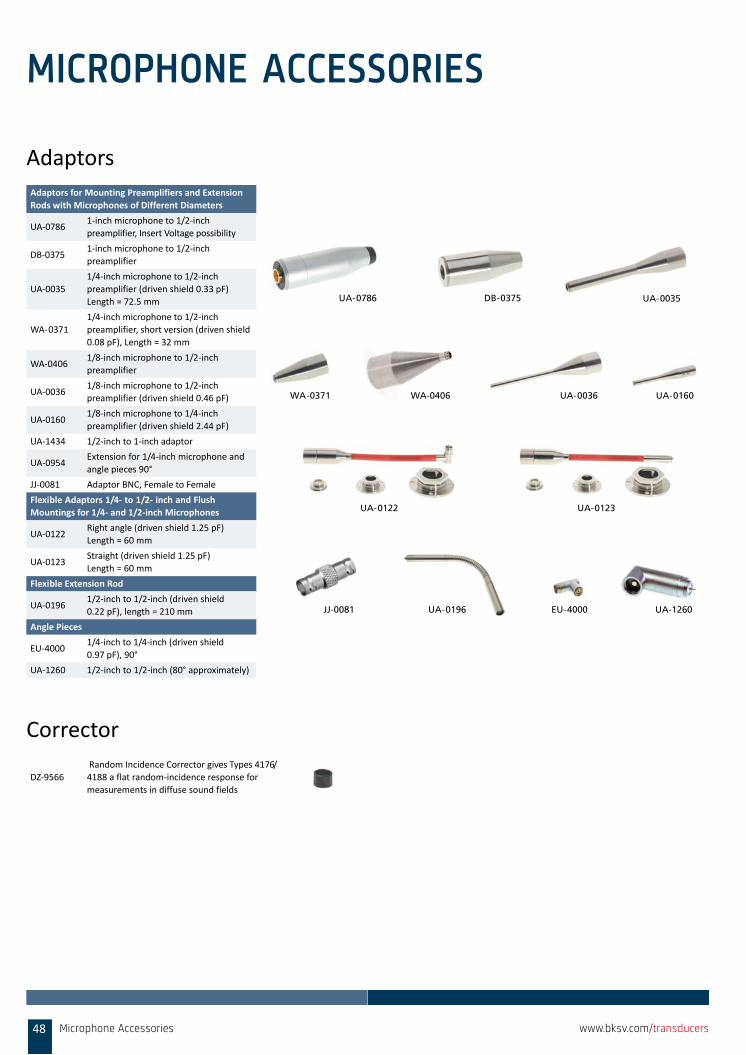
MICROPHONE ACCESSORIES
Adaptors
Corrector
Adaptors for Mounting Preamplifiers and Extension
Rods with Microphones of Different Diameters
UA‐07861‐inch microphone to 1/2‐inch
preamplifier, Insert Voltage possibility
DB‐03751‐inch microphone to 1/2‐inch
preamplifier
UA‐0035
1/4‐inch microphone to 1/2‐inch
preamplifier (driven shield 0.33 pF)
Length = 72.5 mm
WA‐0371
1/4‐inch microphone to 1/2‐inch
preamplifier, short version (driven shield
0.08 pF), Length = 32 mm
WA‐04061/8‐inch microphone to 1/2‐inch
preamplifier
UA‐00361/8‐inch microphone to 1/2‐inch
preamplifier (driven shield 0.46 pF)
UA‐0160 1/8‐inch microphone to 1/4‐inch
preamplifier (driven shield 2.44 pF)
UA‐1434 1/2‐inch to 1‐inch adaptor
UA‐0954Extension for 1/4‐inch microphone and
angle pieces 90°
JJ‐0081 Adaptor BNC, Female to Female
Flexible Adaptors 1/4‐ to 1/2‐ inch and Flush
Mountings for 1/4‐ and 1/2‐inch Microphones
UA‐0122Right angle (driven shield 1.25 pF)
Length = 60 mm
UA‐0123Straight (driven shield 1.25 pF)
Length = 60 mm
Flexible Extension Rod
UA‐01961/2‐inch to 1/2‐inch (driven shield
0.22 pF), length = 210 mm
Angle Pieces
EU‐40001/4‐inch to 1/4‐inch (driven shield
0.97 pF), 90°
UA‐1260 1/2‐inch to 1/2‐inch (80° approximately)
UA-0035
WA-0371
DB-0375UA-0786
UA-0036 UA-0160
UA-0122
UA-0196 EU-4000
WA-0406
JJ-0081 UA-1260
UA-0123
DZ‐9566
Random Incidence Corrector gives Types 4176/
4188 a flat random‐incidence response for
measurements in diffuse sound fields
Microphone Accessories48 www.bksv.com/transducers
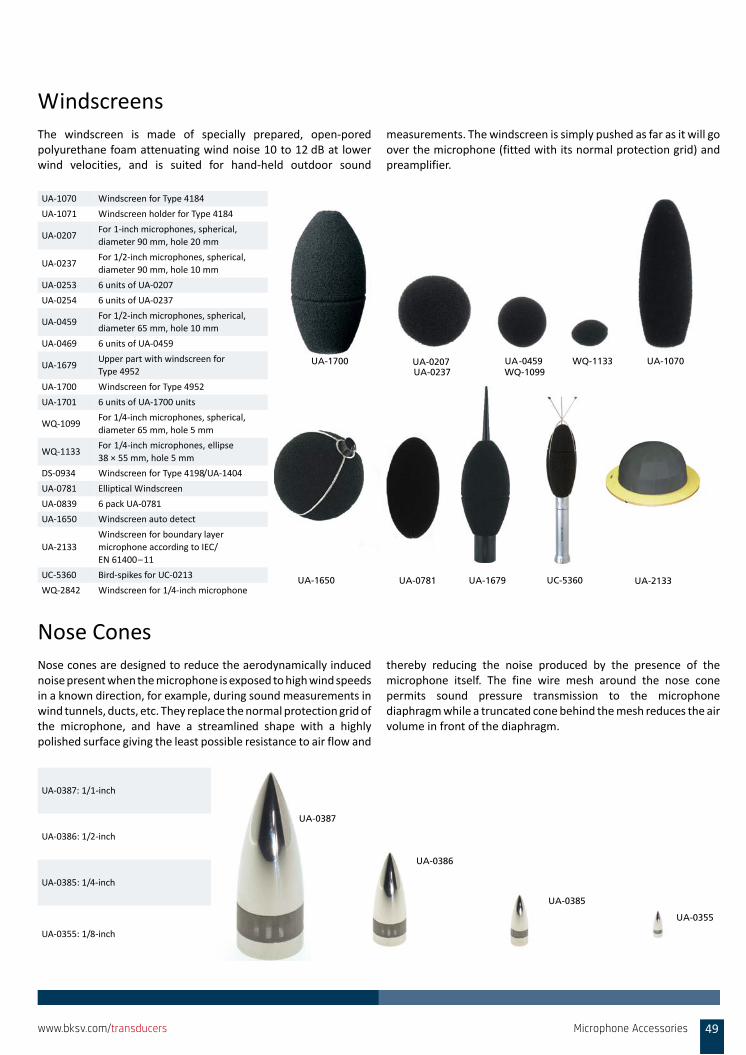
WindscreensThe windscreen is made of specially prepared, open‐poredpolyurethane foam attenuating wind noise 10 to 12 dB at lowerwind velocities, and is suited for hand‐held outdoor sound
measurements. The windscreen is simply pushed as far as it will goover the microphone (fitted with its normal protection grid) andpreamplifier.
Nose ConesNose cones are designed to reduce the aerodynamically inducednoise present when the microphone is exposed to high wind speedsin a known direction, for example, during sound measurements inwind tunnels, ducts, etc. They replace the normal protection grid ofthe microphone, and have a streamlined shape with a highlypolished surface giving the least possible resistance to air flow and
thereby reducing the noise produced by the presence of themicrophone itself. The fine wire mesh around the nose conepermits sound pressure transmission to the microphonediaphragm while a truncated cone behind the mesh reduces the airvolume in front of the diaphragm.
UA‐1070 Windscreen for Type 4184
UA‐1071 Windscreen holder for Type 4184
UA‐0207For 1‐inch microphones, spherical,
diameter 90 mm, hole 20 mm
UA‐0237For 1/2‐inch microphones, spherical,
diameter 90 mm, hole 10 mm
UA‐0253 6 units of UA‐0207
UA‐0254 6 units of UA‐0237
UA‐0459For 1/2‐inch microphones, spherical,
diameter 65 mm, hole 10 mm
UA‐0469 6 units of UA‐0459
UA‐1679Upper part with windscreen for
Type 4952
UA‐1700 Windscreen for Type 4952
UA‐1701 6 units of UA‐1700 units
WQ‐1099For 1/4‐inch microphones, spherical,
diameter 65 mm, hole 5 mm
WQ‐1133For 1/4‐inch microphones, ellipse
38 × 55 mm, hole 5 mm
DS‐0934 Windscreen for Type 4198/UA‐1404
UA‐0781 Elliptical Windscreen
UA‐0839 6 pack UA‐0781
UA‐1650 Windscreen auto detect
UA‐2133
Windscreen for boundary layer
microphone according to IEC/
EN 61400–11
UC‐5360 Bird‐spikes for UC‐0213
WQ‐2842 Windscreen for 1/4‐inch microphone
UA-0459UA-0207UA-0237
WQ-1133 UA-1070WQ-1099
UA-1700
UA-1650 UA-0781 UA-1679 UA-2133UC-5360
UA‐0387: 1/1‐inch
UA‐0386: 1/2‐inch
UA‐0385: 1/4‐inch
UA‐0355: 1/8‐inch
UA-0387
UA-0386
UA-0385
UA-0355
Microphone Accessories 49www.bksv.com/transducers
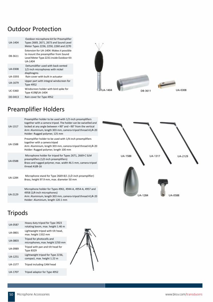
Outdoor Protection
Preamplifier Holders
Tripods
UA‐1404
Outdoor microphone kit for Preamplifier
Types 2669, 2671, 2673 and Sound Level
Meter Types 2236, 2250, 2260 and 2270
DB‐3611
Extension for UA‐1404: Makes it possible
to mount the preamplifier from Sound
Level Meter Type 2231 inside Outdoor Kit
UA‐1404
UA‐0308 Dehumidifier used with back‐vented
1/2‐inch microphones with nickel
diaphragmsUA‐0393 Rain cover with built in actuator
UA‐1679Upper part with integral windscreen for
Type 4952
UC‐5360Windscreen holder with bird spike for
Type 4198/UA‐1404
DD‐0413 Rain cover for Type 4952
UA‐1317
Preamplifier holder to be used with 1/2‐inch preamplifiers
together with a camera tripod. The holder can be swivelled and
locked at any angle between +90° and –90° from the vertical
Arm: Aluminium, length 303 mm, camera‐tripod thread A1/4‐20
Holder: Rugged polymer, 125 mm
UA‐1588
Preamplifier holder to be used with 1/4‐inch preamplifiers
together with a camera tripod
Arm: Aluminium, length 303 mm, camera‐tripod thread A1/4‐20
Holder: Rugged polymer, length 100 mm
UA‐0588
Microphone holder for tripod for Types 2671, 2669‐C SLM
preamplifiers (1/2‐inch preamplifiers)
Brass and rugged polymer, max. width 46.5 mm, camera‐tripod
thread A3/8‐16
UA‐1284 Microphone stand for Type 2669‐B/L (1/2‐inch preamplifier)
Brass, height 97.9 mm, max. diameter 50 mm
UA‐2129
Microphone holder for Types 4961, 4944‐A, 4954‐A, 4957 and
4958 (1/4‐inch microphones)
Arm: Aluminium, length 303 mm, camera‐tripod thread A1/4‐20
Holder: Aluminium, length 120.1 mm
UA‐0587Heavy duty tripod for Type 3923
rotating boom, max. height 1.46 m
UA‐0801Lightweight tripod with tilt head,
max. height 1332 mm
UA‐0803 Tripod for photocells and
microphones, max. height 1250 mm
UA‐0989Tripod with pan and tilt head for
Type 8329
UA‐1251Lightweight tripod for Type 2236,
compact, max. height 1.22 m
UA‐1577 Tripod including CAM head
UA‐1707 Tripod adaptor for Type 4952
UA-1404 UA-0308DB-3611
UA-1317UA-1588 UA-2129
UA-0588UA-1284
50 Microphone Accessories www.bksv.com/transducers
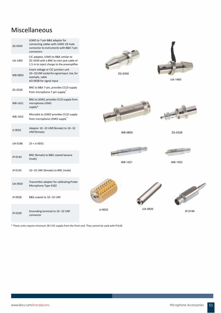
Miscellaneous
ZG‐0350
LEMO to 7‐pin B&K adaptor for
connecting cables with LEMO 1B male
connector to instruments with B&K 7‐pin
connectors
UA‐1405
CIC adaptor, LEMO to B&K similar to
ZG‐0350 with a BNC to mini‐jack cable of
1.5 m to inject charge to the preamplifier
WB‐0850
Insert voltage or CIC junction unit
10–32 UNF socket for signal input. Use, for
example, cable
AO‐0038 for signal input
ZG‐0328BNC to B&K 7‐pin, provides CCLD supply
from microphone 7‐pin supply*
* These units require minimum 28 VDC supply from the front end. They cannot be used with PULSE
WB‐1421
BNC to LEMO, provides CCLD supply from
microphone LEMO
supply*
WB‐1452Microdot to LEMO provides CCLD supply
from microphone LEMO supply*
JJ‐0032Adaptor 10–32 UNF(female) to 10–32
UNF(female)
UA‐0186 25 × JJ‐0032
JP‐0144BNC (female) to B&K coaxial banana
(male)
JP‐0145 10–32 UNF (female) to BNC (male)
UA‐0920Transmitter adaptor for calibrating Probe
Microphone Type 4182
JP‐0028 B&K coaxial to 10–32 UNF
JP‐0169Grounding terminal to 10–32 UNF
connector
UA-0920JJ-0032 JP-0144
ZG-0350
UA-1405
WB-0850 ZG-0328
WB-1421 WB-1452
Microphone Accessories 51www.bksv.com/transducers

52 Microphone Accessories www.bksv.com/transducers
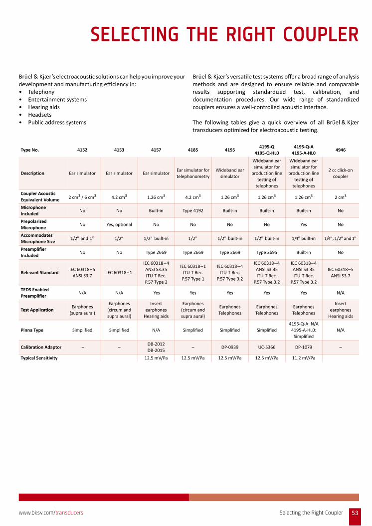
SELECTING THE RIGHT COUPLER
Brüel & Kjær’s electroacoustic solutions can help you improve yourdevelopment and manufacturing efficiency in:• Telephony • Entertainment systems • Hearing aids • Headsets • Public address systems
Brüel & Kjær’s versatile test systems offer a broad range of analysismethods and are designed to ensure reliable and comparableresults supporting standardized test, calibration, anddocumentation procedures. Our wide range of standardizedcouplers ensures a well‐controlled acoustic interface.
The following tables give a quick overview of all Brüel & Kjærtransducers optimized for electroacoustic testing.
Type No. 4152 4153 4157 4185 41954195‐Q
4195‐Q‐HL0
4195‐Q‐A
4195‐A‐HL04946
Description Ear simulator Ear simulator Ear simulatorEar simulator for
telephonometry
Wideband ear
simulator
Wideband ear
simulator for
production line
testing of
telephones
Wideband ear
simulator for
production line
testing of
telephones
2 cc click‐on
coupler
Coupler Acoustic
Equivalent Volume 2 cm3 / 6 cm3 4.2 cm3 1.26 cm3 4.2 cm3 1.26 cm3 1.26 cm3 1.26 cm3 2 cm3
Microphone
IncludedNo No Built‐in Type 4192 Built‐in Built‐in Built‐in No
Prepolarized
MicrophoneNo Yes, optional No No No No Yes No
Accommodates
Microphone Size1/2 and 1 1/2 1/2 built‐in 1/2 1/2 built‐in 1/2 built‐in 1/4 built‐in 1/4, 1/2 and 1
Preamplifier
IncludedNo No Type 2669 Type 2669 Type 2669 Type 2695 Built‐in No
Relevant StandardIEC 60318–5
ANSI S3.7IEC 60318–1
IEC 60318–4
ANSI S3.35
ITU‐T Rec.
P.57 Type 2
IEC 60318–1
ITU‐T Rec.
P.57 Type 1
IEC 60318–4
ITU‐T Rec.
P.57 Type 3.2
IEC 60318–4
ANSI S3.35
ITU‐T Rec.
P.57 Type 3.2
IEC 60318–4
ANSI S3.35
ITU‐T Rec.
P.57 Type 3.2
IEC 60318–5
ANSI S3.7
TEDS Enabled
PreamplifierN/A N/A Yes Yes Yes Yes Yes N/A
Test ApplicationEarphones
(supra aural)
Earphones
(circum and
supra aural)
Insert
earphones
Hearing aids
Earphones
(circum and
supra aural)
Earphones
Telephones
Earphones
Telephones
Earphones
Telephones
Insert
earphones
Hearing aids
Pinna Type Simplified Simplified N/A Simplified Simplified Simplified
4195‐Q‐A: N/A
4195‐A‐HL0:
Simplified
N/A
Calibration Adaptor – –DB‐2012
DB‐2015– DP‐0939 UC‐5366 DP‐1079 –
Typical Sensitivity 12.5 mV/Pa 12.5 mV/Pa 12.5 mV/Pa 12.5 mV/Pa 11.2 mV/Pa
Selecting the Right Coupler 53www.bksv.com/transducers
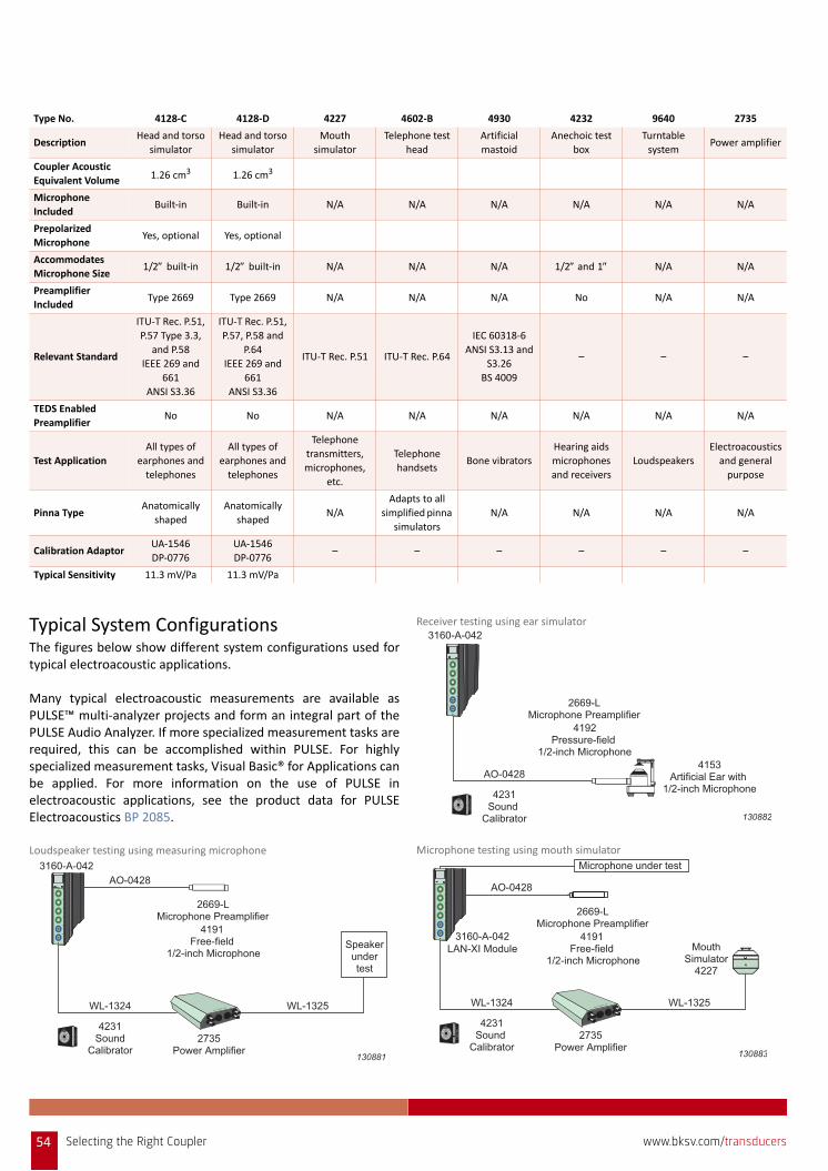
Typical System ConfigurationsThe figures below show different system configurations used fortypical electroacoustic applications.
Many typical electroacoustic measurements are available asPULSE™ multi‐analyzer projects and form an integral part of thePULSE Audio Analyzer. If more specialized measurement tasks arerequired, this can be accomplished within PULSE. For highlyspecialized measurement tasks, Visual Basic® for Applications canbe applied. For more information on the use of PULSE inelectroacoustic applications, see the product data for PULSEElectroacoustics BP 2085.
Loudspeaker testing using measuring microphone
Receiver testing using ear simulator
Microphone testing using mouth simulator
Type No. 4128‐C 4128‐D 4227 4602‐B 4930 4232 9640 2735
DescriptionHead and torso
simulator
Head and torso
simulator
Mouth
simulator
Telephone test
head
Artificial
mastoid
Anechoic test
box
Turntable
systemPower amplifier
Coupler Acoustic
Equivalent Volume 1.26 cm3 1.26 cm3
Microphone
IncludedBuilt‐in Built‐in N/A N/A N/A N/A N/A N/A
Prepolarized
MicrophoneYes, optional Yes, optional
Accommodates
Microphone Size1/2 built‐in 1/2 built‐in N/A N/A N/A 1/2 and 1 N/A N/A
Preamplifier
IncludedType 2669 Type 2669 N/A N/A N/A No N/A N/A
Relevant Standard
ITU‐T Rec. P.51,
P.57 Type 3.3,
and P.58
IEEE 269 and
661
ANSI S3.36
ITU‐T Rec. P.51,
P.57, P.58 and
P.64
IEEE 269 and
661
ANSI S3.36
ITU‐T Rec. P.51 ITU‐T Rec. P.64
IEC 60318‐6
ANSI S3.13 and
S3.26
BS 4009
– – –
TEDS Enabled
PreamplifierNo No N/A N/A N/A N/A N/A N/A
Test Application
All types of
earphones and
telephones
All types of
earphones and
telephones
Telephone
transmitters,
microphones,
etc.
Telephone
handsetsBone vibrators
Hearing aids
microphones
and receivers
Loudspeakers
Electroacoustics
and general
purpose
Pinna TypeAnatomically
shaped
Anatomically
shapedN/A
Adapts to all
simplified pinna
simulators
N/A N/A N/A N/A
Calibration AdaptorUA‐1546
DP‐0776
UA‐1546
DP‐0776– – – – – –
Typical Sensitivity 11.3 mV/Pa 11.3 mV/Pa
130881
2735Power Amplifier
4231Sound
Calibrator
2669-LMicrophone Preamplifier
4191 Free-field
1/2-inch Microphone
3160-A-042
WL-1324
AO-0428
WL-1325
Speakerundertest
4231Sound
Calibrator
3160-A-042
AO-04284153
Artificial Ear with 1/2-inch Microphone
2669-LMicrophone Preamplifier
4192Pressure-field
1/2-inch Microphone
130882
130883
2735Power Amplifier
4231Sound
Calibrator
+20d
BO
n&
Off
3160-A-042LAN-XI Module
WL-1324
AO-0428
WL-1325
MouthSimulator
4227
Microphone under test
2669-LMicrophone Preamplifier
4191 Free-field
1/2-inch Microphone
54 Selecting the Right Coupler www.bksv.com/transducers
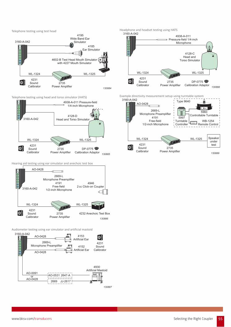
Telephone testing using test head
Telephone testing using head and torso simulator (HATS)
Hearing aid testing using ear simulator and anechoic test box
Audiometer testing using ear simulator and artificial mastoid
Headphone and headset testing using HATS
Example directivity measurement setup using turntable system
130884
2735Power Amplifier
4231Sound
Calibrator
3160-A-042
WL-1324 WL-1325
4185Ear Simulator
4195Wide Band Ear
Simulator
4602-B Test Head Mouth Simulatorwith 4227 Mouth Simulator
130885
2735Power Amplifier
4231Sound
Calibrator
+20d
B
On
&O
ff
WL-1324 WL-1325
B B B K
Brüel & Kjær
Head and Torso Simulator Type 4128
4128-D Head and Torso Simulator
4938-A-011 Pressure-field 1/4-inch Microphone
DP-0775Calibration Adaptor
3160-A-042
130886
2735Power Amplifier
4231Sound
Calibrator
3160-A-042
WL-1324
AO-0428
WL-1325
49462 cc Click-on Coupler
4232 Anechoic Test Box
2669-LMicrophone Preamplifier
4191 Free-field
1/2-inch Microphone
130887
4231Sound
Calibrator
2669-LMicrophone Preamplifier
3160-A-042
AO-0428
AO-0091or
AO-0428
AO-0428
4153Artificial Ear
4152Artificial Ear
4930Artificial Mastoid
AO-0531 2647-A
2669 JJ-2617
130888
2735Power Amplifier
4231Sound
Calibrator
+20d
B
On
&O
ff
3160-A-042
WL-1324 WL-1325
4128-CHead and
Torso Simulator
B B B K
Brüel & Kjær
Head and Torso Simulator Type 4128
DP-0775Calibration Adaptor
4938-A-011Pressure-field 1/4-inch
Microphone
130889
2735Power Amplifier
4231Sound
Calibrator
+20dB
On&
Off
3160-A-042
WL-1324
AO-0428
WL-1325
Type 9640
5960Controllable Turntable
5997Turntable Controller
WB-1254Remote Control
B K7/6-'89
Brüel & Kjær
Mode Enter
Start Stop
PowerOn
Turntable Controller Type 5949
2669-LMicrophone Preamplifier
4191 Free-field
1/2-inch Microphone
Speakerundertest
Selecting the Right Coupler 55www.bksv.com/transducers
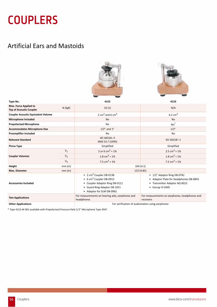
COUPLERS
Artificial Ears and Mastoids
Type No. 4152 4153
Max. Force Applied to
Top of Acoustic CouplerN (kgf) 10 (1) N/A
Coupler Acoustic Equivalent Volume 2 cm3 and 6 cm3 4.2 cm3
Microphone Included No No
Prepolarized Microphone No No*
Accommodates Microphone Size 1/2 and 1 1/2 Preamplifier Included No No
Relevant StandardIEC 60318–5
ANSI S3.7 (1995)IEC 60318–1
Pinna Type Simplified Simplified
Coupler Volumes
V1 2 or 6 cm3 = 1% 2.5 cm3 = 1%
V2 1.8 cm3 = 1% 1.8 cm3 = 1%
V3 7.5 cm3 = 1% 7.5 cm3 = 1%
Height mm (in) 104 (4.1)
Max. Diameter mm (in) 123 (4.85)
Accessories Included
• 2 cm3 Coupler DB‐0138
• 6 cm3 Coupler DB‐0913
• Coupler Adaptor Ring DB‐0111
• Guard Ring Adaptor DB‐1021
• Adaptor for SLM DB‐0962
• 1/2 Adaptor Ring DB‐0742• Adaptor Plate for Headphones DB‐0843
• Transmitter Adaptor AQ‐0015
• Earcap YJ‐0305
Test ApplicationsFor measurements on hearing aids, earphones and
headphones
For measurements on earphones, headphones and
receivers
Other Applications For verification of audiometers using earphones
* Type 4153‐W‐001 available with Prepolarized Pressure‐field 1/2 Microphone Type 4947
Couplers56 www.bksv.com/transducers
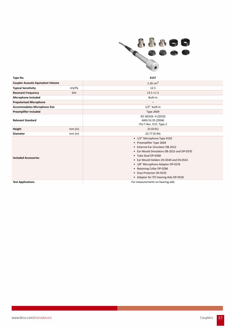
Type No. 4157
Coupler Acoustic Equivalent Volume 1.26 cm3
Typical Sensitivity mV/Pa 12.5
Resonant Frequency kHz 13.5 ±1.5
Microphone Included Built‐in
Prepolarized Microphone –
Accommodates Microphone Size 1/2 built‐in
Preamplifier Included Type 2669
Relevant Standard
IEC 60318–4 (2010)
ANSI S3.35 (2004)
ITU‐T Rec. P.57, Type 2
Height mm (in) 23 (0.91)
Diameter mm (in) 23.77 (0.94)
Included Accessories
• 1/2 Microphone Type 4192
• Preamplifier Type 2669
• External Ear Simulator DB‐2012
• Ear Mould Simulators DB‐2015 and DP‐0370
• Tube Stud DP‐0368
• Ear Mould Holders DS‐0540 and DS‐0541
• 1/4 Microphone Adaptor DP‐0276
• Retaining Collar DP‐0286
• Dust Protector DS‐0535
• Adaptor for ITE Hearing Aids DP‐0530
Test Applications For measurements on hearing aids
Couplers 57www.bksv.com/transducers
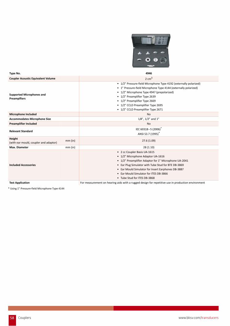
Type No. 4946
Coupler Acoustic Equivalent Volume 2 cm3
Supported Microphones and
Preamplfiers
• 1/2 Pressure‐field Microphone Type 4192 (externally polarized)
• 1 Pressure‐field Microphone Type 4144 (externally polarized)
• 1/2 Microphone Type 4947 (prepolarized)
• 1/2 Preamplifier Type 2639
• 1/2 Preamplifier Type 2669
• 1/2 CCLD Preamplifier Type 2695
• 1/2 CCLD Preamplifier Type 2671
Microphone Included No
Accommodates Microphone Size 1/4, 1/2 and 1
Preamplifier Included No
Relevant StandardIEC 60318–5 (2006)*
ANSI S3.7 (1995)*
Height
(with ear mould, coupler and adaptor)mm (in) 27.6 (1.09)
Max. Diameter mm (in) 28 (1.10)
Included Accessories
• 2 cc Coupler Basis UA‐1615
• 1/2 Microphone Adaptor UA‐1616
• 1/2 Preamplifier Adaptor for 1 Microphone UA‐2041
• Ear Plug Simulator with Tube Stud for BTE DB‐3869
• Ear Mould Simulator for Insert Earphones DB‐3887
• Ear Mould Simulator for ITES DB‐3866
• Tube Stud for ITES DB‐3868
Test Application For measurement on hearing aids with a rugged design for repetitive use in production environment
* Using 1 Pressure‐field Microphone Type 4144
58 Couplers www.bksv.com/transducers
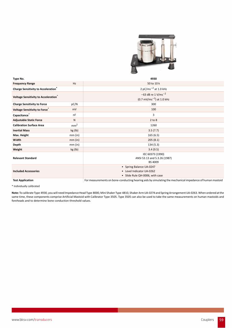
Type No. 4930
Frequency Range Hz 50 to 10 k
Charge Sensitivity to Acceleration* 2 pC/ms–2 at 1.0 kHz
Voltage Sensitivity to Acceleration* –63 dB re 1 V/ms–2
(0.7 mV/ms–2) at 1.0 kHz
Charge Sensitivity to Force pC/N 300
Voltage Sensitivity to Force* mV 100
Capacitance* nF 3
Adjustable Static Force N 2 to 8
Calibration Surface Area mm2 1260
Inertial Mass kg (lb) 3.5 (7.7)
Max. Height mm (in) 165 (6.5)
Width mm (in) 205 (8.1)
Depth mm (in) 134 (5.3)
Weight kg (lb) 3.4 (9.5)
Relevant Standard
IEC 60373 (1990)
ANSI S3.13 and S.3.26 (1987)
BS 4009
Included Accessories
• Spring Balance UA‐0247
• Level Indicator UA‐0262
• Slide Rule QH‐0006, with case
Test Application For measurements on bone‐conducting hearing aids by simulating the mechanical impedance of human mastoid
* Individually calibrated
Note: To calibrate Type 4930, you will need Impedance Head Type 8000, Mini Shaker Type 4810, Shaker Arm UA‐0274 and Spring Arrangement UA‐0263. When ordered at the
same time, these components comprise Artificial Mastoid with Calibrator Type 3505. Type 3505 can also be used to take the same measurements on human mastoids and
foreheads and to determine bone conduction threshold values.
Couplers 59www.bksv.com/transducers
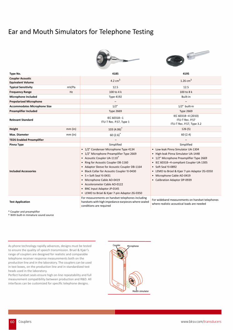
Ear and Mouth Simulators for Telephone Testing
Type No. 4185 4195
Coupler Acoustic
Equivalent Volume4.2 cm3 1.26 cm3
Typical Sensitivity mV/Pa 12.5 12.5
Frequency Range Hz 100 to 4 k 100 to 8 k
Microphone Included Type 4192 Built‐in
Prepolarized Microphone – –
Accommodates Microphone Size 1/2 1/2 built‐in
Preamplifier Included Type 2669 Type 2669
Relevant StandardIEC 60318–1
ITU‐T Rec. P.57, Type 1
IEC 60318–4 (2010)
ITU‐T Rec. P.57
ITU‐T Rec. P.57, Type 3.2
Height mm (in) 103 (4.06)* 126 (5)
Max. Diameter mm (in) 60 (2.6)* 60 (2.4)
TEDS Enabled Preamplifier – –
Pinna Type Simplified Simplified
Included Accessories
• 1/2 Condenser Microphone Type 4134
• 1/2 Microphone Preamplifier Type 2669
• Acoustic Coupler UA‐1110†
• Ring for Acoustic Coupler DB‐1160
• Adaptor Sleeve for Acoustic Coupler DB‐1164
• Black Collar for Acoustic Coupler YJ‐0430
• 5 × Soft Seal YJ‐0431
• Microphone Cable AO‐0419
• Accelerometer Cable AO‐0122
• BNC Input Adaptor JP‐0145
• LEMO to Brüel & Kjær 7‐pin Adaptor ZG‐0350
• Low‐leak Pinna Simulator UA‐1304
• High‐leak Pinna Simulator UA‐1448
• 1/2 Microphone Preamplifier Type 2669
• IEC 60318–4‐compliant Coupler UA‐1305
• Soft Seal YJ‐0892
• LEMO to Brüel & Kjær 7‐pin Adaptor ZG‐0350
• Microphone Cable AO‐0419
• Calibration Adaptor DP‐0939
Test Application
For measurements on handset telephones including
handsets with high impedance earpieces where sealed
conditions are required
For wideband measurements on handset telephones
where realistic acoustical loads are needed
* Coupler and preamplifier† With built‐in miniature sound source
Mouth simulator
MicrophoneCouplerAs phone technology rapidly advances, designs must be tested to ensure the quality of speech transmission. Bruel & Kjær’s
range of couplers are designed for realistic and comparable
telephone receiver response measurements both on the production line and in the laboratory. The couplers can be used
in test boxes, on the production line and in standardized test
heads used in the laboratory.Perfect handset seals ensure high on‐line repeatability and full
measurement compatibility between production and R&D. All
interfaces can be customized for specific telephone designs.
60 Couplers www.bksv.com/transducers
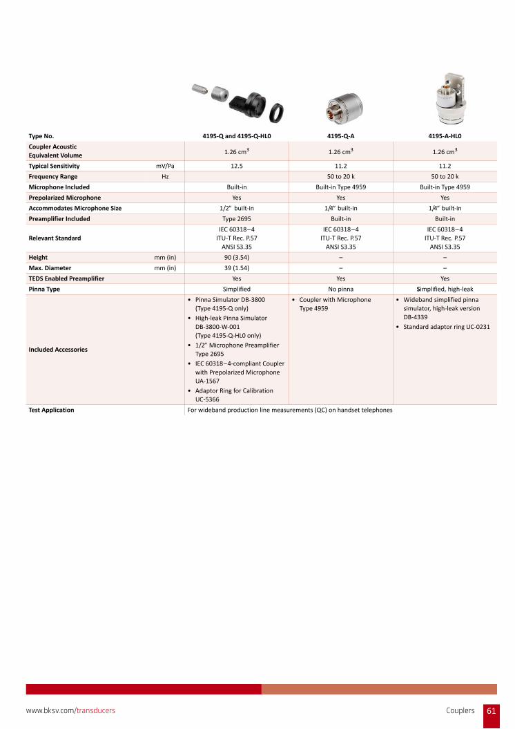
Type No. 4195‐Q and 4195‐Q‐HL0 4195‐Q‐A 4195‐A‐HL0
Coupler Acoustic
Equivalent Volume 1.26 cm3 1.26 cm3 1.26 cm3
Typical Sensitivity mV/Pa 12.5 11.2 11.2
Frequency Range Hz 50 to 20 k 50 to 20 k
Microphone Included Built‐in Built‐in Type 4959 Built‐in Type 4959
Prepolarized Microphone Yes Yes Yes
Accommodates Microphone Size 1/2 built‐in 1/4 built‐in 1/4 built‐in
Preamplifier Included Type 2695 Built‐in Built‐in
Relevant Standard
IEC 60318–4
ITU‐T Rec. P.57
ANSI S3.35
IEC 60318–4
ITU‐T Rec. P.57
ANSI S3.35
IEC 60318–4
ITU‐T Rec. P.57
ANSI S3.35
Height mm (in) 90 (3.54) – –
Max. Diameter mm (in) 39 (1.54) – –
TEDS Enabled Preamplifier Yes Yes Yes
Pinna Type Simplified No pinna Simplified, high‐leak
Included Accessories
• Pinna Simulator DB‐3800
(Type 4195‐Q only)
• High‐leak Pinna Simulator
DB‐3800‐W‐001
(Type 4195‐Q‐HL0 only)
• 1/2 Microphone Preamplifier
Type 2695
• IEC 60318–4‐compliant Coupler
with Prepolarized Microphone
UA‐1567
• Adaptor Ring for Calibration
UC‐5366
• Coupler with Microphone
Type 4959
• Wideband simplified pinna
simulator, high‐leak version
DB‐4339
• Standard adaptor ring UC‐0231
Test Application For wideband production line measurements (QC) on handset telephones
Couplers 61www.bksv.com/transducers

Type No. 4227 4227‐A*
Continuous Output Level
(measured 25 mm from lip ring )dB SPL
200 Hz to 2 kHz: Min. 110
100 Hz to 12 kHz: Min. 100
200 Hz to 2 kHz: Min. 110
100 Hz to 12 kHz: Min. 100
Distortion
(harmonic components up to 8 kHz at
94 dB SPL, 25 mm from lip ring)
200 Hz to 250 Hz: <2%
>250 Hz: <1%
200 Hz to 250 Hz: <2%
>250 Hz: <1%
Loudspeaker Max. Average Power† 10 W at 20 °C (68 °F) 0.8 Vrms
Loudspeaker Max. Pulsed Power 50 W for 2 seconds 1.5 Vrms for 2 seconds
Loudspeaker Impedance Ω 4 –
Relevant Standard ITU‐T P.51, IEEE 269 and IEEE 661 ITU‐T P.51, IEEE 269 and IEEE 661
Diameter mm (in) 104 (4.1) 104 (4.1)
Height mm (in) 104 (4.1) to top of lip ring 104 (4.1) to top of lip ring
Included Accessories
• Calibration Jig UA‐0901
• 2 × Lip Ring SO‐0005
• 1/4Plastic Microphone Dummy DA‐0150
• Calibration Jig UA‐0901
• 2 × Lip Ring SO‐0005
• 1/4Plastic Microphone Dummy DA‐0150
• Power Supply ZG‐0426, 100 to 240 V AC
Test Application For measurements on handset telephones with a realistic simulation of the human voice field
Other Applications Accurate reference source for near‐field testing of handsets and microphones
* Type 4227 and 4227‐A are similar, but Type 4227‐A has an integrated class D amplifier† With built‐in overload protection circuit
62 Couplers www.bksv.com/transducers
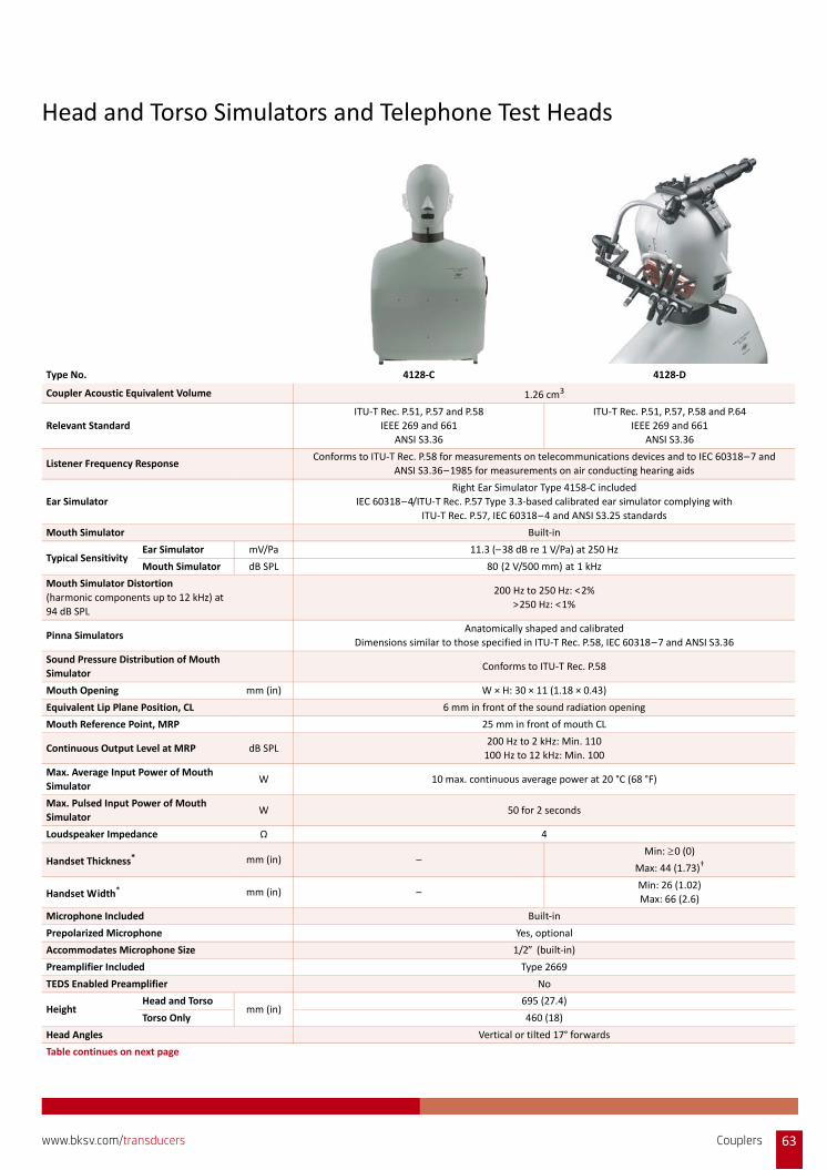
Head and Torso Simulators and Telephone Test Heads
Type No. 4128‐C 4128‐D
Coupler Acoustic Equivalent Volume 1.26 cm3
Relevant Standard
ITU‐T Rec. P.51, P.57 and P.58
IEEE 269 and 661
ANSI S3.36
ITU‐T Rec. P.51, P.57, P.58 and P.64
IEEE 269 and 661
ANSI S3.36
Listener Frequency ResponseConforms to ITU‐T Rec. P.58 for measurements on telecommunications devices and to IEC 60318–7 and
ANSI S3.36–1985 for measurements on air conducting hearing aids
Ear Simulator
Right Ear Simulator Type 4158‐C included
IEC 60318–4/ITU‐T Rec. P.57 Type 3.3‐based calibrated ear simulator complying with
ITU‐T Rec. P.57, IEC 60318–4 and ANSI S3.25 standards
Mouth Simulator Built‐in
Typical SensitivityEar Simulator mV/Pa 11.3 (–38 dB re 1 V/Pa) at 250 Hz
Mouth Simulator dB SPL 80 (2 V/500 mm) at 1 kHz
Mouth Simulator Distortion
(harmonic components up to 12 kHz) at
94 dB SPL
200 Hz to 250 Hz: <2%
>250 Hz: <1%
Pinna SimulatorsAnatomically shaped and calibrated
Dimensions similar to those specified in ITU‐T Rec. P.58, IEC 60318–7 and ANSI S3.36
Sound Pressure Distribution of Mouth
SimulatorConforms to ITU‐T Rec. P.58
Mouth Opening mm (in) W × H: 30 × 11 (1.18 × 0.43)
Equivalent Lip Plane Position, CL 6 mm in front of the sound radiation opening
Mouth Reference Point, MRP 25 mm in front of mouth CL
Continuous Output Level at MRP dB SPL200 Hz to 2 kHz: Min. 110
100 Hz to 12 kHz: Min. 100
Max. Average Input Power of Mouth
SimulatorW 10 max. continuous average power at 20 °C (68 °F)
Max. Pulsed Input Power of Mouth
SimulatorW 50 for 2 seconds
Loudspeaker Impedance Ω 4
Handset Thickness* mm (in) –Min: 0 (0)
Max: 44 (1.73)†
Handset Width* mm (in) –Min: 26 (1.02)
Max: 66 (2.6)
Microphone Included Built‐in
Prepolarized Microphone Yes, optional
Accommodates Microphone Size 1/2 (built‐in)
Preamplifier Included Type 2669
TEDS Enabled Preamplifier No
HeightHead and Torso
mm (in)695 (27.4)
Torso Only 460 (18)
Head Angles Vertical or tilted 17° forwards
Table continues on next page
Couplers 63www.bksv.com/transducers
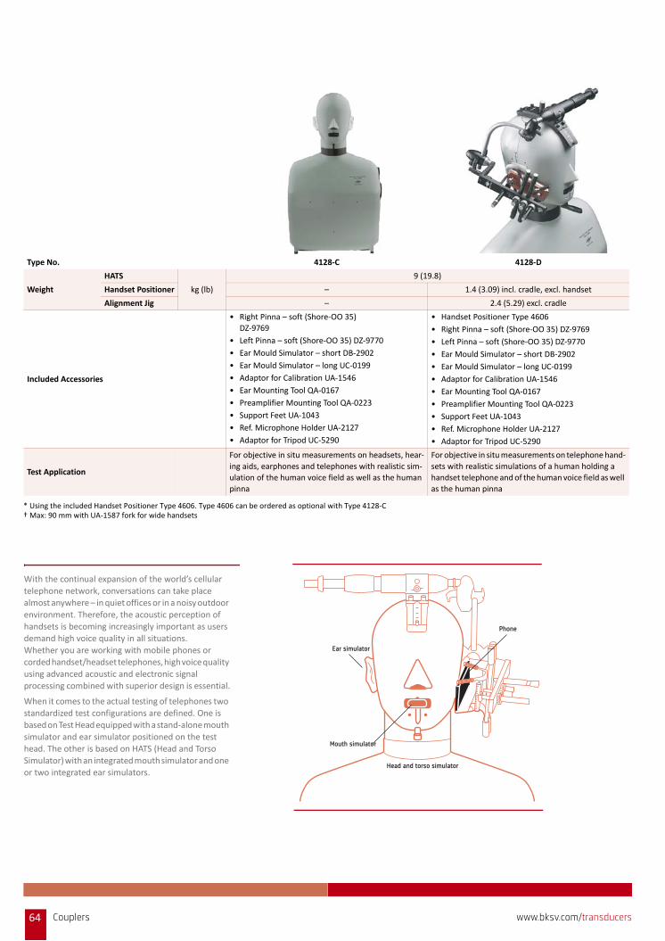
Weight
HATS
kg (lb)
9 (19.8)
Handset Positioner – 1.4 (3.09) incl. cradle, excl. handset
Alignment Jig – 2.4 (5.29) excl. cradle
Included Accessories
• Right Pinna – soft (Shore‐OO 35)
DZ‐9769
• Left Pinna – soft (Shore‐OO 35) DZ‐9770
• Ear Mould Simulator – short DB‐2902
• Ear Mould Simulator – long UC‐0199
• Adaptor for Calibration UA‐1546
• Ear Mounting Tool QA‐0167
• Preamplifier Mounting Tool QA‐0223
• Support Feet UA‐1043
• Ref. Microphone Holder UA‐2127
• Adaptor for Tripod UC‐5290
• Handset Positioner Type 4606
• Right Pinna – soft (Shore‐OO 35) DZ‐9769
• Left Pinna – soft (Shore‐OO 35) DZ‐9770
• Ear Mould Simulator – short DB‐2902
• Ear Mould Simulator – long UC‐0199
• Adaptor for Calibration UA‐1546
• Ear Mounting Tool QA‐0167
• Preamplifier Mounting Tool QA‐0223
• Support Feet UA‐1043
• Ref. Microphone Holder UA‐2127
• Adaptor for Tripod UC‐5290
Test Application
For objective in situ measurements on headsets, hear‐
ing aids, earphones and telephones with realistic sim‐
ulation of the human voice field as well as the human
pinna
For objective in situ measurements on telephone hand‐
sets with realistic simulations of a human holding a
handset telephone and of the human voice field as well
as the human pinna
* Using the included Handset Positioner Type 4606. Type 4606 can be ordered as optional with Type 4128‐C† Max: 90 mm with UA‐1587 fork for wide handsets
Type No. 4128‐C 4128‐D
Phone
Ear simulator
Mouth simulator
Head and torso simulator
With the continual expansion of the world’s cellular telephone network, conversations can take place
almost anywhere – in quiet offices or in a noisy outdoor
environment. Therefore, the acoustic perception of handsets is becoming increasingly important as users
demand high voice quality in all situations.
Whether you are working with mobile phones or corded handset/headset telephones, high voice quality
using advanced acoustic and electronic signal
processing combined with superior design is essential.
When it comes to the actual testing of telephones two standardized test configurations are defined. One is
based on Test Head equipped with a stand‐alone mouth
simulator and ear simulator positioned on the test head. The other is based on HATS (Head and Torso
Simulator) with an integrated mouth simulator and one
or two integrated ear simulators.
64 Couplers www.bksv.com/transducers
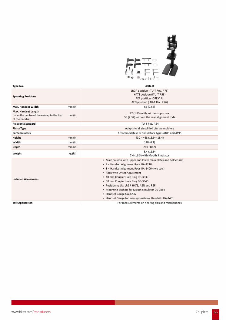
Type No. 4602‐B
Speaking Positions
LRGP position (ITU‐T Rec. P.76)
HATS position (ITU‐T P.58)
REF position (OREM A)
AEN position (ITU‐T Rec. P.76)
Max. Handset Width mm (in) 65 (2.56)
Max. Handset Length
(from the centre of the earcap to the top
of the handset)
mm (in)47 (1.85) without the stop screw
59 (2.32) without the rear alignment rods
Relevant Standard ITU‐T Rec. P.64
Pinna Type Adapts to all simplified pinna simulators
Ear Simulators Accommodates Ear Simulators Types 4185 and 4195
Height mm (in) 430 – 468 (16.9 – 18.4)
Width mm (in) 170 (6.7)
Depth mm (in) 260 (10.2)
Weight kg (lb)5.4 (11.9)
7.4 (16.3) with Mouth Simulator
Included Accessories
• Main column with upper and lower main plates and holder arm
• 2 × Handset Alignment Rods UA‐1210
• 8 × Handset Alignment Rods UA‐1400 (two sets)
• Rods with Offset Adjustment
• 40 mm Coupler Hole Ring DB‐3339
• 50 mm Coupler Hole Ring DB‐3340
• Positioning Jig: LRGP, HATS, AEN and REF
• Mounting Bushing for Mouth Simulator DS‐0884
• Handset Gauge UA‐1206
• Handset Gauge for Non‐symmetrical Handsets UA‐1401
Test Application For measurements on hearing aids and microphones
Couplers 65www.bksv.com/transducers
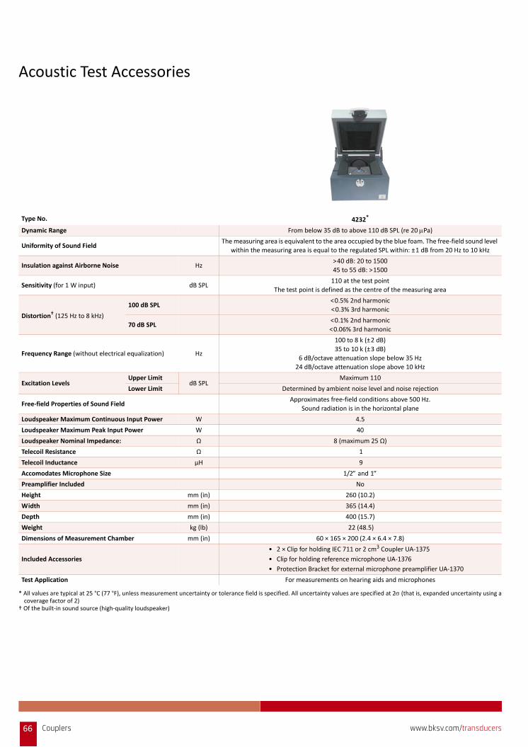
Acoustic Test Accessories
Type No. 4232*
Dynamic Range From below 35 dB to above 110 dB SPL (re 20 Pa)
Uniformity of Sound Field The measuring area is equivalent to the area occupied by the blue foam. The free‐field sound level
within the measuring area is equal to the regulated SPL within: ±1 dB from 20 Hz to 10 kHz
Insulation against Airborne Noise Hz>40 dB: 20 to 1500
45 to 55 dB: >1500
Sensitivity (for 1 W input) dB SPL110 at the test point
The test point is defined as the centre of the measuring area
Distortion† (125 Hz to 8 kHz)
100 dB SPL<0.5% 2nd harmonic
<0.3% 3rd harmonic
70 dB SPL<0.1% 2nd harmonic
<0.06% 3rd harmonic
Frequency Range (without electrical equalization) Hz
100 to 8 k (±2 dB)
35 to 10 k (±3 dB)
6 dB/octave attenuation slope below 35 Hz
24 dB/octave attenuation slope above 10 kHz
Excitation Levels Upper Limit
dB SPLMaximum 110
Lower Limit Determined by ambient noise level and noise rejection
Free‐field Properties of Sound Field Approximates free‐field conditions above 500 Hz.
Sound radiation is in the horizontal plane
Loudspeaker Maximum Continuous Input Power W 4.5
Loudspeaker Maximum Peak Input Power W 40
Loudspeaker Nominal Impedance: Ω 8 (maximum 25 Ω)
Telecoil Resistance Ω 1
Telecoil Inductance μH 9
Accomodates Microphone Size 1/2 and 1 Preamplifier Included No
Height mm (in) 260 (10.2)
Width mm (in) 365 (14.4)
Depth mm (in) 400 (15.7)
Weight kg (lb) 22 (48.5)
Dimensions of Measurement Chamber mm (in) 60 × 165 × 200 (2.4 × 6.4 × 7.8)
Included Accessories
• 2 × Clip for holding IEC 711 or 2 cm3 Coupler UA‐1375
• Clip for holding reference microphone UA‐1376
• Protection Bracket for external microphone preamplifier UA‐1370
Test Application For measurements on hearing aids and microphones
* All values are typical at 25 °C (77 °F), unless measurement uncertainty or tolerance field is specified. All uncertainty values are specified at 2 (that is, expanded uncertainty using acoverage factor of 2)
† Of the built‐in sound source (high‐quality loudspeaker)
66 Couplers www.bksv.com/transducers
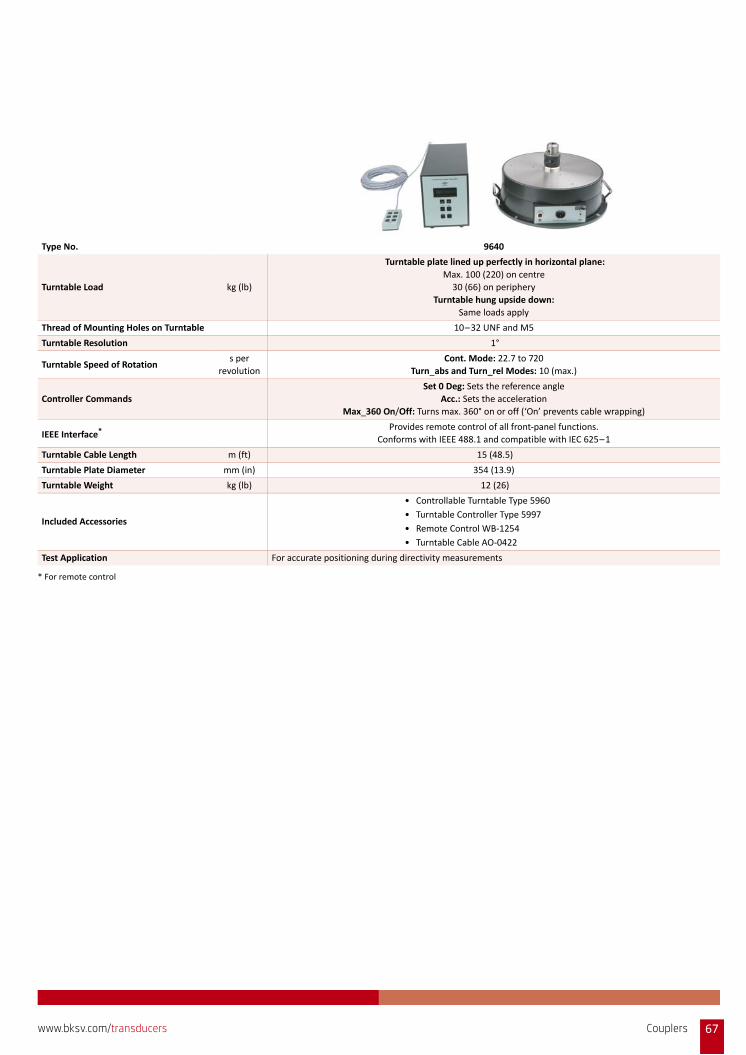
Type No. 9640
Turntable Load kg (lb)
Turntable plate lined up perfectly in horizontal plane:
Max. 100 (220) on centre
30 (66) on periphery
Turntable hung upside down:
Same loads apply
Thread of Mounting Holes on Turntable 10–32 UNF and M5
Turntable Resolution 1°
Turntable Speed of Rotation s per
revolution
Cont. Mode: 22.7 to 720
Turn_abs and Turn_rel Modes: 10 (max.)
Controller Commands
Set 0 Deg: Sets the reference angle
Acc.: Sets the acceleration
Max_360 On/Off: Turns max. 360° on or off (‘On’ prevents cable wrapping)
IEEE Interface* Provides remote control of all front‐panel functions.
Conforms with IEEE 488.1 and compatible with IEC 625–1
Turntable Cable Length m (ft) 15 (48.5)
Turntable Plate Diameter mm (in) 354 (13.9)
Turntable Weight kg (lb) 12 (26)
Included Accessories
• Controllable Turntable Type 5960
• Turntable Controller Type 5997
• Remote Control WB‐1254
• Turntable Cable AO‐0422
Test Application For accurate positioning during directivity measurements
* For remote control
Couplers 67www.bksv.com/transducers
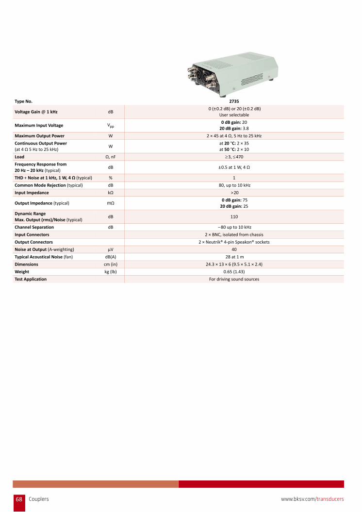
Type No. 2735
Voltage Gain @ 1 kHz dB 0 (±0.2 dB) or 20 (±0.2 dB)
User selectable
Maximum Input Voltage Vpp 0 dB gain: 20
20 dB gain: 3.8
Maximum Output Power W 2 × 45 at 4 Ω, 5 Hz to 25 kHz
Continuous Output Power
(at 4 Ω 5 Hz to 25 kHz) W
at 20 °C: 2 × 35
at 50 °C: 2 × 10
Load Ω, nF 3, 470Frequency Response from
20 Hz – 20 kHz (typical) dB ±0.5 at 1 W, 4 Ω
THD + Noise at 1 kHz, 1 W, 4 Ω (typical) % 1
Common Mode Rejection (typical) dB 80, up to 10 kHz
Input Impedance kΩ >20
Output Impedance (typical) mΩ 0 dB gain: 75
20 dB gain: 25
Dynamic Range
Max. Output (rms)/Noise (typical) dB 110
Channel Separation dB –80 up to 10 kHz
Input Connectors 2 × BNC, isolated from chassis
Output Connectors 2 × Neutrik® 4‐pin Speakon® sockets
Noise at Output (A‐weighting) μV 40
Typical Acoustical Noise (fan) dB(A) 28 at 1 m
Dimensions cm (in) 24.3 × 13 × 6 (9.5 × 5.1 × 2.4)
Weight kg (lb) 0.65 (1.43)
Test Application For driving sound sources
68 Couplers www.bksv.com/transducers

SELECTING THE RIGHT ACCELEROMETER
Brüel & Kjær offers a broad spectrum of solutions that respond tovarying needs and applications. This adaptability is evident in therange of transducers designed for specific environments,industries, tasks and conditions, as well as general purposeinstruments that provide a wide operational range.
Selecting the best transducer for a given measurement task can beunderstandably overwhelming. Our interactive transducerselection guide on www.bksv.com can be a big help to quickly narrowyour choices. Alternatively, see below for in‐depth guides and toolsso that you can select the right accelerometer to fit your needs.
Start by selecting the right accelerometer technology, then you canselect the right accelerometer type. From there, you can focus onthe measurement parameters (frequency range, dynamic range,etc).
TechnologiesAccelerometers use a spring‐mass system to generate a forceproportional to the vibration. Brüel & Kjær offers three types ofaccelerometers:• Piezoelectric charge accelerometers• Piezoelectric CCLD/DeltaTron/IEPE accelerometers• Piezoresistive accelerometers
Piezoelectric Charge AccelerometersThe force is applied to a piezoelectric (PE) element that produces acharge on its terminals proportional to the acceleration.
PE charge accelerometers are self‐generating and, therefore, donot require any external power sources. They are capable ofoperation at high temperatures, but are constrained by high outputimpedance requiring low‐noise cables and charge amplifiers tocondition the signal.
Piezoelectric CCLD AccelerometersCCLD accelerometers are PE charge accelerometers with integralpreamplifiers that have output signals in the form of lowimpedance voltage output.
Most Brüel & Kjær PE CCLD accelerometers are hermetically sealedto protect against environmental contamination, have lowsusceptibility to radio frequency electromagnetic radiation and lowimpedance output due to the built‐in amplifier. This allows the useof inexpensive coaxial cables.
Piezoresistive AccelerometersPiezoresistive accelerometers are based on MEMS technology. Thechange of electrical resistance in proportion to applied mechanicalstress on the springs retaining the seismic mass generates theoutput. The accelerometer includes integral mechanical stops andoffers outstanding ruggedness, while still maintaining an excellentsignal‐to‐noise ratio after the built‐in bridge amplifier.
This type of accelerometer, with a frequency response extendingdown to DC or constant acceleration, is ideal for measuring motion,low‐frequency vibration and long duration low‐level shock.
Compare TypesThe following table compares the performance of each technology,specification by specification.
For an overview of key specifications for all of our standardaccelerometers, see the comparison tables starting on page 155.
Piezoelectric (PE) Charge PE CCLD Piezoresistive (PR)
Weight (relative) Very low Very Low Low
Miniature Design Capability Yes Yes No
Useful Frequency Range Capability Very high Very high Low
Sensitivity to Vibration High High Low
Suitability for High Temperature Yes No No
DC Response No No Yes
TEDS No Yes No
Sensitivity to Environment Low Very low Low
Flat Phase Response at HF Yes Yes No
Suitability for Shock Measurements Medium Medium Low
Long Pulse (crash testing) No No Yes
High g Survivability, ruggedness Medium Medium Medium
Self‐generating Yes No No
Long Cables (low impedance output) No Yes Yes
Cryogenic Temperature Yes No No
Synonym Charge DeltaTron®, IEPE Bridge
Selecting the Right Accelerometer 69www.bksv.com/transducers

Measurement ParametersGenerally speaking, the most important parameters to consider arefrequency range and dynamic range.
The Lower Limiting Frequency Range This is normally the frequency where the response is 10% lowerthan the response at 159.2 Hz. For PE charge accelerometers, it isdetermined by the preamplifier used. For piezoelectric CCLD andpiezoresistive types, the lower limiting frequency can be specifiedprecisely because the preamplifier is built‐in.
The Upper Limiting Frequency RangeThis is the frequency where the response has changed 10%compared to the response at 159.2 Hz. It is normally 1/3 of themounted resonance frequency for undamped mass‐spring systemslike those in the PE transducers. Preamplifiers and damping ofpiezoresistive transducers can give many different responses.
With Brüel & Kjær's PULSE data acquisition systems, it is possible touse REq‐X to extend the usable frequency range, mainly the upperlimiting frequency range.
Residual Noise LevelThis is determined by noise generated by the sensing element andthe preamplifier. In most cases, this is largely determined by theelectronic noise. For low‐level vibration, low residual noise levelsare more important than high sensitivity because the high noisefloor of the sensor will mask the low‐level vibration.
Maximum Range/Full ScaleThis is determined by the maximum voltage swing possible if apreamplifier is included and the physical maximum stress level thatcan be sustained by the transducer structure without largedistortion or destruction. In the graph below, we use PiezoelectricCharge Accelerometer Type 4393 as an example to explain this.
Note: Noise RMS level in 1 Hz bandwidth
It is always important to select an accelerometer that has a broadermeasuring range than required.
The Effects of TemperatureWhat happens at high temperatures?Piezoelectric accelerometers are capable of vibration measurementsover a wide temperature range. However, due to the properties ofpiezoelectric materials, variations of both voltage and chargesensitivities, as well as impedance, will occur when theaccelerometer is operated at temperatures other than the reference.
As an example, the figure below shows the variation in capacitance,charge sensitivity and voltage sensitivity of piezoelectric materialPZ23, which is the material used in many Brüel & Kjæraccelerometers.
When using a piezoelectric accelerometer at high temperatures, itsactual sensitivity, taking into account the change in sensitivity dueto the increased operating temperature, can be determined usingthe “Temperature Coefficient of Sensitivity”, which is available onevery calibration chart.
The time required for the sensitivity to return to the one stated onthe calibration chart is not easy to determine, but it will partlydepend on the temperature to which the accelerometer was taken.In general, a period of 24 hours is required for an accelerometer toreturn to the calibrated sensitivity when it is immediately returnedto room temperature from a temperature close to its maximumoperating temperature.
Each accelerometer has a specified maximum operatingtemperature above which the piezoelectric element will begin todepolarize and cause a permanent change in sensitivity. This is250 °C for charge accelerometers with PZ23 piezoelectric material.
–30
–20
–10
0
10
20
30
40
50
60
–200 –150 –100 −50 0 50 100 150 200 250 300 350 400 450 500
Temperature Dependency of PZ23 and PZ101
Temperature (°C)
Rel
ativ
e A
mp
litu
de
(%) PZ23 Capacitance
PZ23 ChargePZ23 VoltagePZ101 Charge
70 Selecting the Right Accelerometer www.bksv.com/transducers
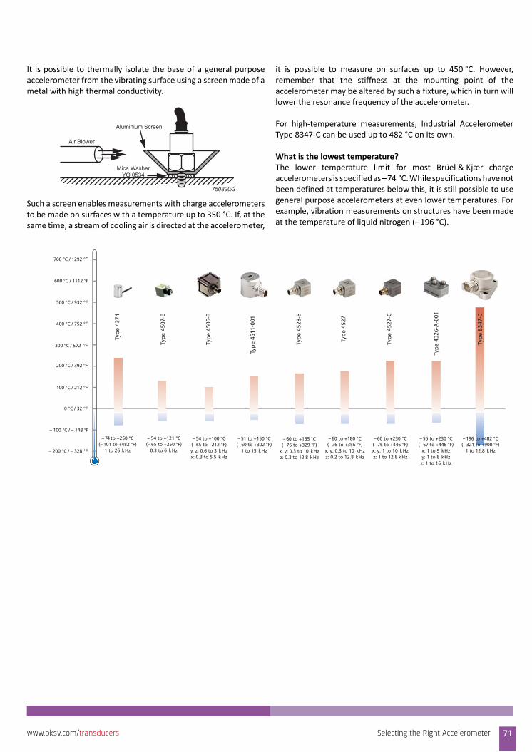
It is possible to thermally isolate the base of a general purposeaccelerometer from the vibrating surface using a screen made of ametal with high thermal conductivity.
Such a screen enables measurements with charge accelerometersto be made on surfaces with a temperature up to 350 °C. If, at thesame time, a stream of cooling air is directed at the accelerometer,
it is possible to measure on surfaces up to 450 °C. However,remember that the stiffness at the mounting point of theaccelerometer may be altered by such a fixture, which in turn willlower the resonance frequency of the accelerometer.
For high‐temperature measurements, Industrial AccelerometerType 8347‐C can be used up to 482 °C on its own.
What is the lowest temperature?The lower temperature limit for most Brüel & Kjær chargeaccelerometers is specified as –74 °C. While specifications have notbeen defined at temperatures below this, it is still possible to usegeneral purpose accelerometers at even lower temperatures. Forexample, vibration measurements on structures have been madeat the temperature of liquid nitrogen (–196 °C).
Air Blower
Aluminium Screen
750890/3
Mica WasherYO 0534
– 200 °C / – 328 °F
– 100 °C / – 148 °F
0 °C / 32 °F
100 °C / 212 °F
200 °C / 392 °F
300 °C / 572 °F
400 °C / 752 °F
500 °C / 932 °F
600 °C / 1112 °F
700 °C / 1292 °F
Typ
e 43
74
– 74 to +250 °C(– 101 to +482 °F)
1 to 26 kHz
Typ
e 45
07-B
– 54 to +121 °C(– 65 to +250 °F)
0.3 to 6 kHz
Typ
e 45
06-B
– 54 to +100 °C(– 65 to +212 °F)y, z: 0.6 to 3 kHzx: 0.3 to 5.5 kHz
Typ
e 45
11-0
01
– 51 to +150 °C(– 60 to +302 °F)
1 to 15 kHz
Typ
e 45
28-B
– 60 to +165 °C(– 76 to +329 °F)
x, y: 0.3 to 10 kHzz: 0.3 to 12.8 kHz
– 60 to +180 °C(– 76 to +356 °F)
x, y: 0.3 to 10 kHzz: 0.2 to 12.8 kHz
Typ
e 45
27
Typ
e 45
27-C
– 60 to +230 °C(– 76 to +446 °F)x, y: 1 to 10 kHzz: 1 to 12.8 kHz
Typ
e 43
26-A
-001
– 55 to +230 °C(– 67 to +446 °F)
x: 1 to 9 kHzy: 1 to 8 kHzz: 1 to 16 kHz
– 196 to +482 °C(– 321 to +900 °F)
1 to 12.8 kHz
Typ
e 83
47-C
Selecting the Right Accelerometer 71www.bksv.com/transducers

ACCELEROMETERS
Definitions of Given Accelerometer SpecificationsSensitivity • At 159.2 Hz• Units: pC/ms–2 (pC/g) or mV/ms–2 (mV/g)The output of the accelerometer at 159.2 Hz ( = 1000 s–1) with20 ms–2 RMS acceleration at room temperature. For CCLDaccelerometers the supply current is 4 mA.
Uni‐Gain types have a measured sensitivity within ±2% of apractical nominal value. Variable gain (V types) is within ±15%. Uni‐Gain and V type accelerometers have the same specifications andlong‐term stability. V types just have a relaxed sensitivity tolerance.
Frequency Range• ±10%• Unit: HzThe range within which the sensitivity does not deviate more than10% from the value at 159.2 Hz. The lower usable frequency rangeis determined by the lower limiting frequency of the amplifier usedor the frequency at which the temperature, cable and other noisesources make usage impractical (for charge types). The upperusable frequency range is normally determined by the mountedresonance frequency and in a few cases the upper frequency cut‐offof the amplifier or other structural resonances.
Mounted Resonance Frequency• Unit: kHzThe resonance frequency of an accelerometer being mounted on a180 gram steel block. For damped accelerometers no mountedresonance is given.
Operating Temperature Range• Unit: °C and °FThe temperature range within which the accelerometer can beused continuously.
Measuring Range (± peak)• Unit: gThe peak vibration range the accelerometer can measure with lessthan 1% distortion. At slightly higher amplitudes clipping might occur.
Maximum Non‐destructive Shock (± peak)• Unit: gThe peak shock the accelerometer can withstand repeatedlywithout being damaged. The shock duration shall be longer than 10times the reciprocal mounted resonance frequency.
Uniaxial Piezoelectric Charge AccelerometersA charge‐type piezoelectric accelerometer is a robust unit designedspecifically for high‐temperature vibration measurement onstructures and objects. Its unique sensor design allows highdynamic range, long‐term stability and ruggedness in the samepackage. For direct interchangeability and easy system calibration,
most Brüel & Kjær piezoelectric accelerometers are Uni‐Gaintypes.
For accelerometer dimensions go to page 147.
Type No. 4374 4517‐C 4517‐C‐003 4517‐C‐001 4385‐C 4375*
Weightgram
(oz)
0.75
(0.026)
0.6
(0.021)
0.85
(0.03)
1
(0.035)
1.9
(0.067)
2.4
(0.085)
Charge Sensitivity at 159.2 HzpC/ms–2
(pC/g)
0.15
(1.5)
0.18
(1.8)
0.18
(1.8)
0.18
(1.8)
0.005
(0.05)
0.316
(3.1)
Frequency Range (±10%)† Hz 1 to 26000 1 to 10000 1 to 9000 1 to 20000 1 to 50000 0.1 to 16500
Mounted Resonance Frequency kHz 85 80 >30 75 150000 55
Operating Temperature Range C –74 to +250 –51 to +177 –51 to +177 –51 to +177 –74 to +180 –74 to +250
F –101 to +482 –60 to +350 –60 to +350 –60 to +350 –101 to +356 –101 to +482
Measuring Range (peak) g 5000 1000 1000 1000 12000 5000
Maximum Non‐destructive Shock
(±peak)g 25000 5000 5000 5000 12000 25000
Connector 10–32 UNF 3–56 UNF 3–56 UNF 3–56 UNF M3 10–32 UNF
Mounting Adhesive Adhesive Adhesive Adhesive M5 Stud M3 Stud
* Uni‐Gain with ±2% sensitivity tolerance, V‐type with ±15% sensitivity tolerance† Lower frequency limit is determined by the amplifier used
Accelerometers72 www.bksv.com/transducers
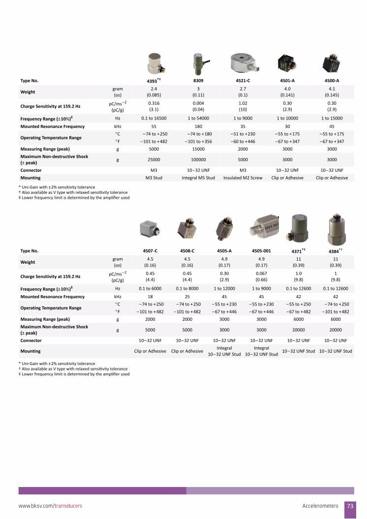
Type No. 4393*† 8309 4521‐C 4501‐A 4500‐A
Weightgram
(oz)
2.4
(0.085)
3
(0.11)
2.7
(0.1)
4.0
(0.141)
4.1
(0.145)
Charge Sensitivity at 159.2 Hz pC/ms–2
(pC/g)
0.316
(3.1)
0.004
(0.04)
1.02
(10)
0.30
(2.9)
0.30
(2.9)
Frequency Range (±10%)‡ Hz 0.1 to 16500 1 to 54000 1 to 9000 1 to 10000 1 to 15000
Mounted Resonance Frequency kHz 55 180 35 30 45
Operating Temperature RangeC –74 to +250 –74 to +180 –51 to +230 –55 to +175 –55 to +175
F –101 to +482 –101 to +356 –60 to +446 –67 to +347 –67 to +347
Measuring Range (peak) g 5000 15000 2000 3000 3000
Maximum Non‐destructive Shock
(±peak)g 25000 100000 5000 3000 3000
Connector M3 10–32 UNF M3 10–32 UNF 10–32 UNF
Mounting M3 Stud Integral M5 Stud Insulated M2 Screw Clip or Adhesive Clip or Adhesive
* Uni‐Gain with ±2% sensitivity tolerance† Also available as V type with relaxed sensi vity tolerance‡ Lower frequency limit is determined by the amplifier used
Type No. 4507‐C 4508‐C 4505‐A 4505‐001 4371*† 4384*†
Weightgram
(oz)
4.5
(0.16)
4.5
(0.16)
4.9
(0.17)
4.9
(0.17)
11
(0.39)
11
(0.39)
Charge Sensitivity at 159.2 Hz pC/ms–2
(pC/g)
0.45
(4.4)
0.45
(4.4)
0.30
(2.9)
0.067
(0.66)
1.0
(9.8)
1
(9.8)
Frequency Range (±10%)‡ Hz 0.1 to 6000 0.1 to 8000 1 to 12000 1 to 9000 0.1 to 12600 0.1 to 12600
Mounted Resonance Frequency kHz 18 25 45 45 42 42
Operating Temperature Range C –74 to +250 –74 to +250 –55 to +230 –55 to +230 –55 to +250 –74 to +250
F –101 to +482 –101 to +482 –67 to +446 –67 to +446 –67 to +482 –101 to +482
Measuring Range (peak) g 2000 2000 3000 3000 6000 6000
Maximum Non‐destructive Shock
(±peak)g 5000 5000 3000 3000 20000 20000
Connector 10–32 UNF 10–32 UNF 10–32 UNF 10–32 UNF 10–32 UNF 10–32 UNF
Mounting Clip or Adhesive Clip or AdhesiveIntegral
10–32 UNF Stud
Integral
10–32 UNF Stud10–32 UNF Stud 10–32 UNF Stud
* Uni‐Gain with ±2% sensitivity tolerance† Also available as V type with relaxed sensi vity tolerance‡ Lower frequency limit is determined by the amplifier used
Accelerometers 73www.bksv.com/transducers
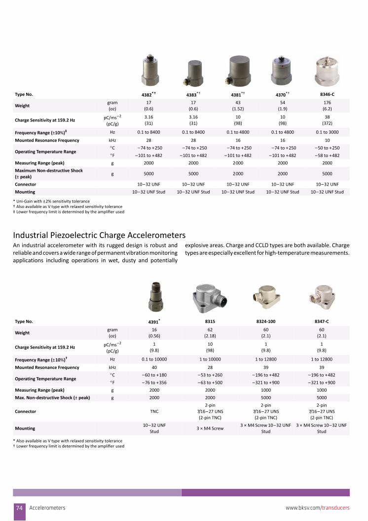
Industrial Piezoelectric Charge AccelerometersAn industrial accelerometer with its rugged design is robust andreliable and covers a wide range of permanent vibration monitoringapplications including operations in wet, dusty and potentially
explosive areas. Charge and CCLD types are both available. Chargetypes are especially excellent for high‐temperature measurements.
Type No. 4382*† 4383*† 4381*† 4370*† 8346‐C
Weightgram
(oz)
17
(0.6)
17
(0.6)
43
(1.52)
54
(1.9)
176
(6.2)
Charge Sensitivity at 159.2 Hz pC/ms–2
(pC/g)
3.16
(31)
3.16
(31)
10
(98)
10
(98)
38
(372)
Frequency Range (±10%)‡ Hz 0.1 to 8400 0.1 to 8400 0.1 to 4800 0.1 to 4800 0.1 to 3000
Mounted Resonance Frequency kHz 28 28 16 16 10
Operating Temperature RangeC –74 to +250 –74 to +250 –74 to +250 –74 to +250 –50 to +250
F –101 to +482 –101 to +482 –101 to +482 –101 to +482 –58 to +482
Measuring Range (peak) g 2000 2000 2000 2000 2000
Maximum Non‐destructive Shock
(±peak)g 5000 5000 2000 2000 5000
Connector 10–32 UNF 10–32 UNF 10–32 UNF 10–32 UNF 10–32 UNF
Mounting 10–32 UNF Stud 10–32 UNF Stud 10–32 UNF Stud 10–32 UNF Stud 10–32 UNF Stud
* Uni‐Gain with ±2% sensitivity tolerance† Also available as V type with relaxed sensi vity tolerance‡ Lower frequency limit is determined by the amplifier used
Type No. 4391*
* Also available as V type with relaxed sensitivity tolerance
8315 8324‐100 8347‐C
Weightgram
(oz)
16
(0.56)
62
(2.18)
60
(2.1)
60
(2.1)
Charge Sensitivity at 159.2 HzpC/ms–2
(pC/g)
1
(9.8)
10
(98)
1
(9.8)
1
(9.8)
Frequency Range (±10%)†
† Lower frequency limit is determined by the amplifier used
Hz 0.1 to 10000 1 to 10000 1 to 12800 1 to 12800
Mounted Resonance Frequency kHz 40 28 39 39
Operating Temperature RangeC –60 to +180 –53 to +260 –196 to +482 –196 to +482
F –76 to +356 –63 to +500 –321 to +900 –321 to +900
Measuring Range (peak) g 2000 2000 1000 1000
Max. Non‐destructive Shock (±peak) g 2000 2000 5000 5000
Connector TNC
2‐pin
7/16–27 UNS
(2‐pin TNC)
2‐pin
7/16–27 UNS
(2‐pin TNC)
2‐pin
7/16–27 UNS
(2‐pin TNC)
Mounting10–32 UNF
Stud3 × M4 Screw
3 × M4 Screw 10–32 UNF
Stud
3 × M4 Screw 10–32 UNF
Stud
74 Accelerometers www.bksv.com/transducers

Triaxial Piezoelectric Charge Accelerometers
Frequency response of Type 4527‐C using cable AO‐0526 (left) and cable AO‐0767 (right)
Type No. 4326‐A 4326‐A‐001 4326‐001 4321*†
* Uni‐Gain with ±2% sensitivity tolerance† Also available as V type with relaxed sensi vity tolerance
4527‐C
Description Triaxial TriaxialDielectric rigidity
>1000 VTriaxial Triaxial
Weightgram
(oz)
13
(0.46)
17
(0.6)
17
(0.6)
55
(1.94)
6
(0.21)
Charge Sensitivity at 159.2 Hz pC/ms–2
(pC/g)
0.30
(2.9)
0.30
(2.9)
0.30
(2.9)
1
(9.8)
0.316
(3.1)
X Frequency Range (±10%)‡
‡ Lower frequency limit is determined by the amplifier used
Hz 1 to 9000 1 to 9000 1 to 9000 0.1 to 12000 1 to 10000
Y Frequency Range (±10%)‡ Hz 1 to 8000 1 to 8000 1 to 8000 0.1 to 12000 1 to 10000
Z Frequency Range (±10%)‡ Hz 1 to 16000 1 to 16000 1 to 16000 0.1 to 12000 1 to 12800
Mounted Resonance Frequency kHzX:27, Y: 24,
Z: 48
X:27, Y: 24,
Z: 48
X:27, Y: 24,
Z: 48X, Y, Z: 40 X, Y: 30, Z: 42
Operating Temperature RangeC –55 to +175 –55 to +230 –55 to +230 –74 to +250 –60 to +230
F –67 to +347 –67 to +446 –67 to +446 –101 to +482 –76 to +446
Measuring Range (peak) g 3000 3000 3000 500
Maximum Non‐destructive Shock
(±peak)g 3000 3000 3000 1000 5100
Connector 10–32 UNF 10–32 UNF 10–32 UNF 10–32 UNF4‐pin,
1/4–28 UNF
MountingM2 Screw/M3 Stud/
Clip/Adhesive
M2 Screw/M3 Stud/
Clip/Adhesive
M2 Screw/M3 Stud/
Clip/Adhesive
10–32 UNF Stud/
M4 ScrewM3 Stud/Adhesive
0
0.2
0.4
0.6
0.8
1.0
1.2
1.4
1.6
1.8
5 50 500
Ou
tpu
t (p
C/m
s–2)
Frequency (Hz)
AO-0526, XAO-0526, YAO-0526, Z
0
0.2
0.4
0.6
0.8
1.0
1.2
1.4
1.6
1.8
5 50 500
Ou
tpu
t (p
C/m
s–2)
Frequency (Hz)
AO-0767, XAO-0767, YAO-0767, Z
160010
Accelerometers 75www.bksv.com/transducers

Uniaxial CCLD AccelerometersA CCLD accelerometer is designed specifically to make vibrationmeasurement easy because the needed preamplifier is built intothe accelerometer unit. It features low impedance output enabling
the use of inexpensive cable and can drive long cables. For directinterchangeability and easy system calibration, most Brüel & Kjærpiezoelectric accelerometers are Uni‐Gain types.
Type No. 4517 4517‐002 4516 4516‐001 4518 4518‐001
Weight (excluding cable)gram
(oz)
0.65
(0.02)
0.7
(0.035)
1.5
(0.053)
1.5
(0.053)
1.5
(0.053)
1.45
(0.051)
Sensitivity at 159.2 HzmV/ms–2
(mV/g)1.02 (10) 1.02 (10) 1.02 (10) 0.51 (5) 1.02 (10) 10.2 (100)
Frequency Range (±10%) Hz 1 to 20000 1 to 20000 1 to 20000 1 to 20000 1 to 20000 1 to 20000
Mounted Resonance Frequency kHz 80 80 60 60 60 60
Operating Temperature RangeC –51 to +121 –51 to +121 –51 to +121 –51 to +121 –51 to +121 –51 to +100
F –60 to +250 –60 to +250 –60 to +250 –60 to +250 –60 to +250 –60 to +212
Measuring Range (±peak) g 500 500 500 1000 500 50
Residual Noise Level* g 6000 6000 6000 6000 2000 900
Maximum Non‐destructive Shock
(±peak)g 5000 5000 5000 5000 3000 3000
Connector 3–56 3–5610–32 UNF
Female
10–32 UNF
Female M3 M3
Mounting Adhesive Adhesive Adhesive Adhesive Integral M3 Stud Integral M3 Stud
* Measured in specified frequency range
Type No. 4518‐002 4518‐003 4519 4519‐001 4519‐002 4519‐003
Weightgram
(oz)
1.45
(0.051)
1.45
(0.051)
1.6
(0.056)
1.6
(0.056)
1.5
(0.053)
1.5
(0.053)
Sensitivity at 159.2 HzmV/ms–2
(mV/g)
1.02
(10)
10.2
(100)
1.02
(10)
10.2
(100)
1.02
(10)
10.2
(100)
Frequency Range, (±10%) Hz 1 to 20000 1 to 20000 1 to 20000 1 to 20000 1 to 20000 1 to 20000
Mounted Resonance Frequency kHz 60 60 45 45 45 45
Operating Temperature RangeC –51 to +121 –51 to +100 –51 to +121 –51 to +100 –51 to +121 –51 to +100
F –60 to +250 –60 to +212 –60 to +250 –60 to +212 –60 to +250 –60 to +212
Measuring Range (±peak) g 500 50 500 50 500 50
Residual Noise Level*
* Measured in specified frequency range
g 2000 900 2000 900 2000 900
Maximum Non‐destructive Shock
(±peak)g 3000 3000 3000 3000 3000 3000
Connector M3 M3 M3 M3 M3 M3
Mounting Adhesive Adhesive Integral M3 Stud Integral M3 Stud Adhesive Adhesive
76 Accelerometers www.bksv.com/transducers
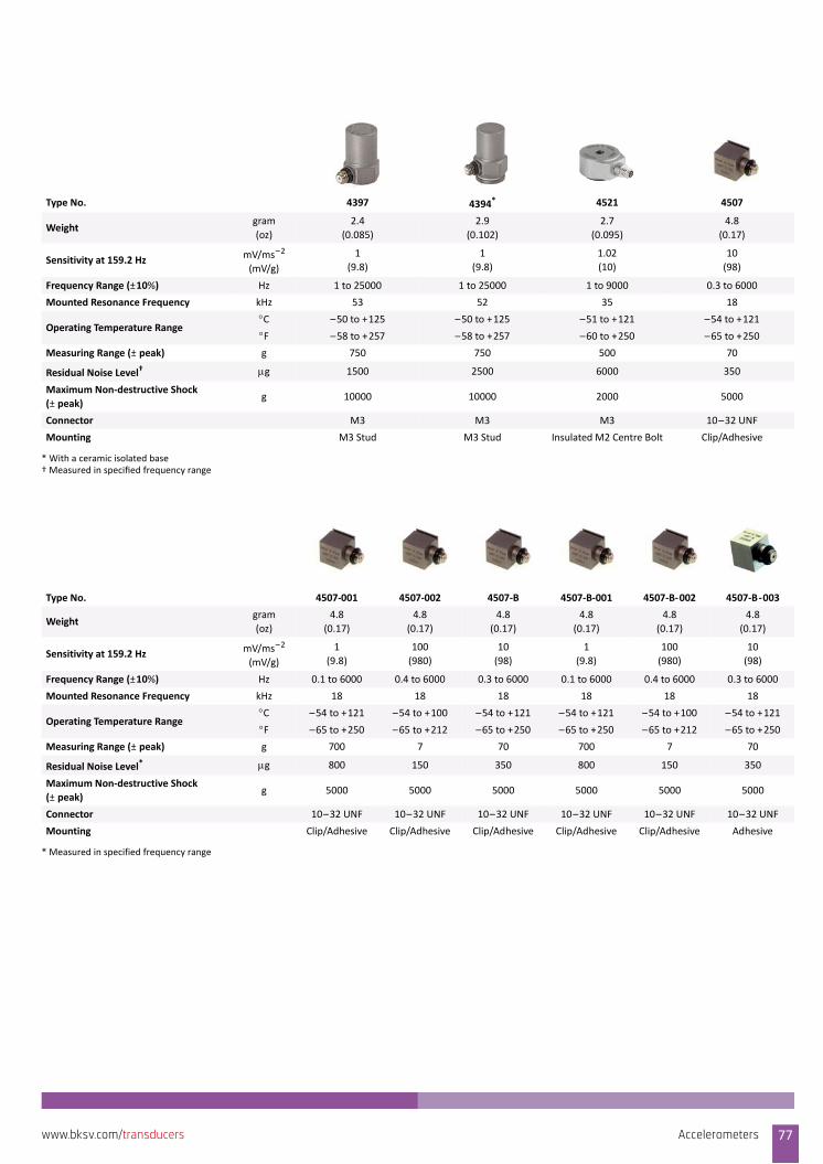
Type No. 4397 4394* 4521 4507
Weightgram
(oz)
2.4
(0.085)
2.9
(0.102)
2.7
(0.095)
4.8
(0.17)
Sensitivity at 159.2 Hz mV/ms–2
(mV/g)
1
(9.8)
1
(9.8)
1.02
(10)
10
(98)
Frequency Range (±10%) Hz 1 to 25000 1 to 25000 1 to 9000 0.3 to 6000
Mounted Resonance Frequency kHz 53 52 35 18
Operating Temperature RangeC –50 to +125 –50 to +125 –51 to +121 –54 to +121
F –58 to +257 –58 to +257 –60 to +250 –65 to +250
Measuring Range (±peak) g 750 750 500 70
Residual Noise Level† g 1500 2500 6000 350
Maximum Non‐destructive Shock
(±peak)g 10000 10000 2000 5000
Connector M3 M3 M3 10–32 UNF
Mounting M3 Stud M3 Stud Insulated M2 Centre Bolt Clip/Adhesive
* With a ceramic isolated base† Measured in specified frequency range
Type No. 4507‐001 4507‐002 4507‐B 4507‐B‐001 4507‐B‐002 4507‐B‐003
Weightgram
(oz)
4.8
(0.17)
4.8
(0.17)
4.8
(0.17)
4.8
(0.17)
4.8
(0.17)
4.8
(0.17)
Sensitivity at 159.2 Hz mV/ms–2
(mV/g)
1
(9.8)
100
(980)
10
(98)
1
(9.8)
100
(980)
10
(98)
Frequency Range (±10%) Hz 0.1 to 6000 0.4 to 6000 0.3 to 6000 0.1 to 6000 0.4 to 6000 0.3 to 6000
Mounted Resonance Frequency kHz 18 18 18 18 18 18
Operating Temperature RangeC –54 to +121 –54 to +100 –54 to +121 –54 to +121 –54 to +100 –54 to +121
F –65 to +250 –65 to +212 –65 to +250 –65 to +250 –65 to +212 –65 to +250
Measuring Range (±peak) g 700 7 70 700 7 70
Residual Noise Level*
* Measured in specified frequency range
g 800 150 350 800 150 350
Maximum Non‐destructive Shock
(±peak)g 5000 5000 5000 5000 5000 5000
Connector 10–32 UNF 10–32 UNF 10–32 UNF 10–32 UNF 10–32 UNF 10–32 UNF
Mounting Clip/Adhesive Clip/Adhesive Clip/Adhesive Clip/Adhesive Clip/Adhesive Adhesive
Accelerometers 77www.bksv.com/transducers
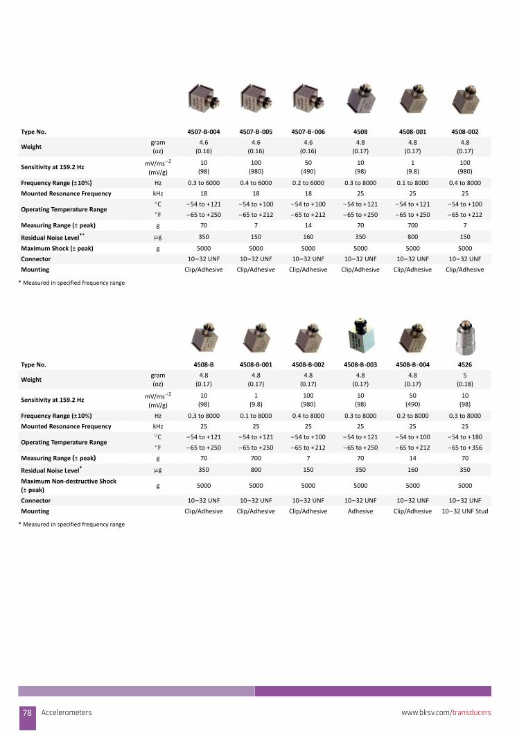
Type No. 4507‐B‐004 4507‐B‐005 4507‐B‐006 4508 4508‐001 4508‐002
Weightgram
(oz)
4.6
(0.16)
4.6
(0.16)
4.6
(0.16)
4.8
(0.17)
4.8
(0.17)
4.8
(0.17)
Sensitivity at 159.2 HzmV/ms–2
(mV/g)
10
(98)
100
(980)
50
(490)
10
(98)
1
(9.8)
100
(980)
Frequency Range (±10%) Hz 0.3 to 6000 0.4 to 6000 0.2 to 6000 0.3 to 8000 0.1 to 8000 0.4 to 8000
Mounted Resonance Frequency kHz 18 18 18 25 25 25
Operating Temperature RangeC –54 to +121 –54 to +100 –54 to +100 –54 to +121 –54 to +121 –54 to +100
F –65 to +250 –65 to +212 –65 to +212 –65 to +250 –65 to +250 –65 to +212
Measuring Range (±peak) g 70 7 14 70 700 7
Residual Noise Level** g 350 150 160 350 800 150
Maximum Shock (± peak) g 5000 5000 5000 5000 5000 5000
Connector 10–32 UNF 10–32 UNF 10–32 UNF 10–32 UNF 10–32 UNF 10–32 UNF
Mounting Clip/Adhesive Clip/Adhesive Clip/Adhesive Clip/Adhesive Clip/Adhesive Clip/Adhesive
* Measured in specified frequency range
Type No. 4508‐B 4508‐B‐001 4508‐B‐002 4508‐B‐003 4508‐B‐004 4526
Weightgram
(oz)
4.8
(0.17)
4.8
(0.17)
4.8
(0.17)
4.8
(0.17)
4.8
(0.17)
5
(0.18)
Sensitivity at 159.2 Hz mV/ms–2
(mV/g)
10
(98)
1
(9.8)
100
(980)
10
(98)
50
(490)
10
(98)
Frequency Range (±10%) Hz 0.3 to 8000 0.1 to 8000 0.4 to 8000 0.3 to 8000 0.2 to 8000 0.3 to 8000
Mounted Resonance Frequency kHz 25 25 25 25 25 25
Operating Temperature RangeC –54 to +121 –54 to +121 –54 to +100 –54 to +121 –54 to +100 –54 to +180
F –65 to +250 –65 to +250 –65 to +212 –65 to +250 –65 to +212 –65 to +356
Measuring Range (±peak) g 70 700 7 70 14 70
Residual Noise Level*
* Measured in specified frequency range
g 350 800 150 350 160 350
Maximum Non‐destructive Shock
(±peak)g 5000 5000 5000 5000 5000 5000
Connector 10–32 UNF 10–32 UNF 10–32 UNF 10–32 UNF 10–32 UNF 10–32 UNF
Mounting Clip/Adhesive Clip/Adhesive Clip/Adhesive Adhesive Clip/Adhesive 10–32 UNF Stud
78 Accelerometers www.bksv.com/transducers

Type No. 4526‐001 4526‐002 8339 8339‐001 4534‐B 4534‐B‐001
Weightgram
(oz)
5
(0.18)
5
(0.18)
5.8
(0.204)
5.8
(0.204)
8.6
(0.3)
8.6
(0.3)
Sensitivity at 159.2 HzmV/ms–2
(mV/g)
1
(9.8)
10
(98)
0.025
(0.25)
0.01
(0.1)
1
(9.8)
10
(98)
Frequency Range (±10%) Hz 0.1 to 8000 0.3 to 8000 1 to 20000 1 to 20000 0.2 to 12800 0.2 to 12800
Mounted Resonance Frequency kHz 25 25 >130 >130 38 38
Operating Temperature RangeC –54 to +180 –54 to +165 –51 to +121 –51 to +121 –55 to +125 –55 to +125
F –65 to +356 –65 to +329 –60 to +250 –60 to +250 –67 to +257 –67 to +257
Measuring Range (±peak) g 700 700 20000 50000 700 70
Residual Noise Level* g 800 350 150 350 500 130
Maximum Non‐destructive Shock
(±peak)g 5000 5000 80000 80000 10000 10000
Connector 10–32 UNF 10–32 UNF 10–32 UNF 10–32 UNF 10–32 UNF 10–32 UNF
Mounting 10–32 UNF Stud AdhesiveIntegral
10–32 UNF Stud
Integral
10–32 UNF Stud10–32 UNF Stud 10–32 UNF Stud
* Measured in specified frequency range
Type No. 4534‐B‐002 4534‐B‐004 4533‐B 4533‐B‐001 4533‐B‐002 4533‐B‐004
Weight gram8.6
(0.3)
8.6
(0.3)
8.6
(0.3)
8.6
(0.3)
8.6
(0.3)
8.6
(0.3)
Sensitivity at 159.2 Hz mV/ms–2
(mV/g)
50
(490)
5
(49)
1
(9.8)
10
(98)
50
(490)
5
(49)
Frequency Range (±10%) Hz 0.3 to 12800 0.2 to 12800 0.2 to 12800 0.2 to 12800 0.3 to 12800 0.2 to 12800
Mounted Resonance Frequency kHz 38 38 38 38 38 38
Operating Temperature RangeC –55 to +125 –55 to +125 –55 to +125 –55 to +125 –55 to +125 –55 to +125
F –67 to +257 –67 to +257 –67 to +257 –67 to +257 –67 to +257 –67 to +257
Measuring Range (±peak) g 14 140 700 70 14 140
Residual Noise Level*
* Measured in specified frequency range
g 100 140 500 130 100 140
Maximum Non‐destructive Shock
(±peak)g 10000 10000 10000 10000 10000 10000
Connector 10–32 UNF 10–32 UNF 10–32 UNF 10–32 UNF 10 –32 UNF 10–32 UNF
Mounting 10–32 UNF Stud 10–32 UNF Stud 10–32 UNF Stud 10–32 UNF Stud 10–32 UNF Stud 10–32 UNF Stud
Accelerometers 79www.bksv.com/transducers
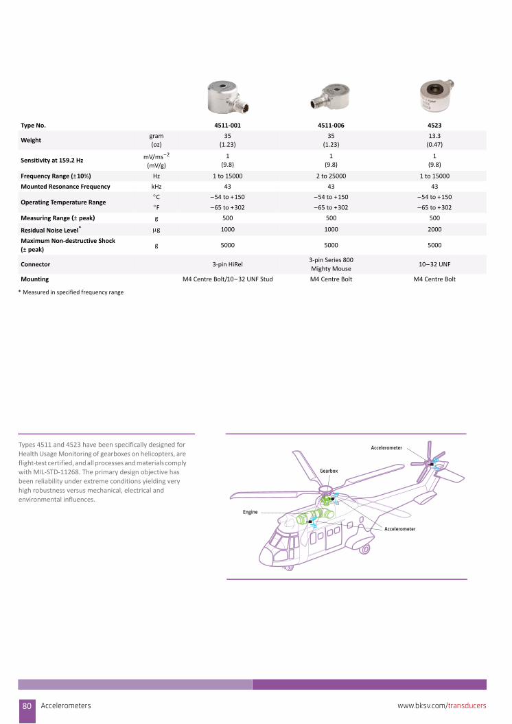
Type No. 4511‐001 4511‐006 4523
Weightgram
(oz)
35
(1.23)
35
(1.23)
13.3
(0.47)
Sensitivity at 159.2 HzmV/ms–2
(mV/g)
1
(9.8)
1
(9.8)
1
(9.8)
Frequency Range (±10%) Hz 1 to 15000 2 to 25000 1 to 15000
Mounted Resonance Frequency kHz 43 43 43
Operating Temperature RangeC –54 to +150 –54 to +150 –54 to +150
F –65 to +302 –65 to +302 –65 to +302
Measuring Range (±peak) g 500 500 500
Residual Noise Level* g 1000 1000 2000
Maximum Non‐destructive Shock
(±peak)g 5000 5000 5000
Connector 3‐pin HiRel3‐pin Series 800
Mighty Mouse10–32 UNF
Mounting M4 Centre Bolt/10–32 UNF Stud M4 Centre Bolt M4 Centre Bolt
* Measured in specified frequency range
Gearbox
Engine
Accelerometer
AccelerometerTypes 4511 and 4523 have been specifically designed for
Health Usage Monitoring of gearboxes on helicopters, are
flight‐test certified, and all processes and materials comply with MIL‐STD‐11268. The primary design objective has
been reliability under extreme conditions yielding very
high robustness versus mechanical, electrical and environmental influences.
80 Accelerometers www.bksv.com/transducers
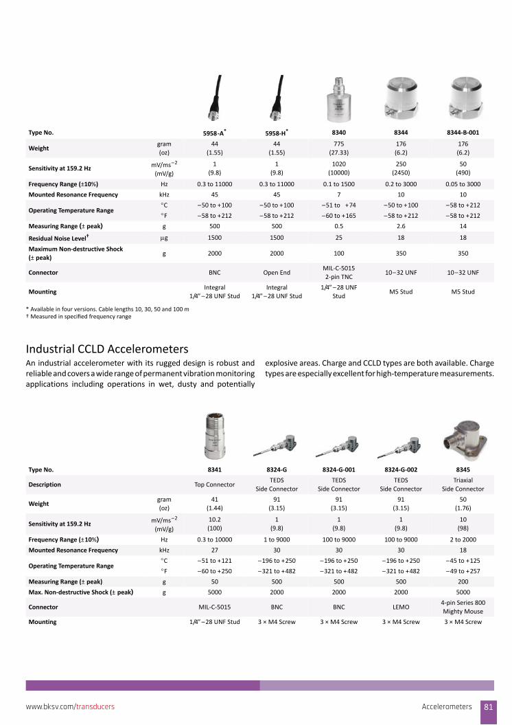
Industrial CCLD AccelerometersAn industrial accelerometer with its rugged design is robust andreliable and covers a wide range of permanent vibration monitoringapplications including operations in wet, dusty and potentially
explosive areas. Charge and CCLD types are both available. Chargetypes are especially excellent for high‐temperature measurements.
Type No. 5958‐A* 5958‐H* 8340 8344 8344‐B‐001
Weightgram
(oz)
44
(1.55)
44
(1.55)
775
(27.33)
176
(6.2)
176
(6.2)
Sensitivity at 159.2 Hz mV/ms–2
(mV/g)
1
(9.8)
1
(9.8)
1020
(10000)
250
(2450)
50
(490)
Frequency Range (±10%) Hz 0.3 to 11000 0.3 to 11000 0.1 to 1500 0.2 to 3000 0.05 to 3000
Mounted Resonance Frequency kHz 45 45 7 10 10
Operating Temperature RangeC –50 to +100 –50 to +100 –51 to +74 –50 to +100 –58 to +212
F –58 to +212 –58 to +212 –60 to +165 –58 to +212 –58 to +212
Measuring Range (±peak) g 500 500 0.5 2.6 14
Residual Noise Level† g 1500 1500 25 18 18
Maximum Non‐destructive Shock
(±peak)g 2000 2000 100 350 350
Connector BNC Open EndMIL‐C‐5015
2‐pin TNC10–32 UNF 10–32 UNF
MountingIntegral
1/4–28 UNF StudIntegral
1/4–28 UNF Stud1/4–28 UNF
StudM5 Stud M5 Stud
* Available in four versions. Cable lengths 10, 30, 50 and 100 m† Measured in specified frequency range
Type No. 8341 8324‐G 8324‐G‐001 8324‐G‐002 8345
Description Top ConnectorTEDS
Side Connector
TEDS
Side Connector
TEDS
Side Connector
Triaxial
Side Connector
Weightgram
(oz)
41
(1.44)
91
(3.15)
91
(3.15)
91
(3.15)
50
(1.76)
Sensitivity at 159.2 HzmV/ms–2
(mV/g)
10.2
(100)
1
(9.8)
1
(9.8)
1
(9.8)
10
(98)
Frequency Range (±10%) Hz 0.3 to 10000 1 to 9000 100 to 9000 100 to 9000 2 to 2000
Mounted Resonance Frequency kHz 27 30 30 30 18
Operating Temperature RangeC –51 to +121 –196 to +250 –196 to +250 –196 to +250 –45 to +125
F –60 to +250 –321 to +482 –321 to +482 –321 to +482 –49 to +257
Measuring Range (±peak) g 50 500 500 500 200
Max. Non‐destructive Shock (± peak) g 5000 2000 2000 2000 5000
Connector MIL‐C‐5015 BNC BNC LEMO4‐pin Series 800
Mighty Mouse
Mounting 1/4–28 UNF Stud 3 × M4 Screw 3 × M4 Screw 3 × M4 Screw 3 × M4 Screw
Accelerometers 81www.bksv.com/transducers
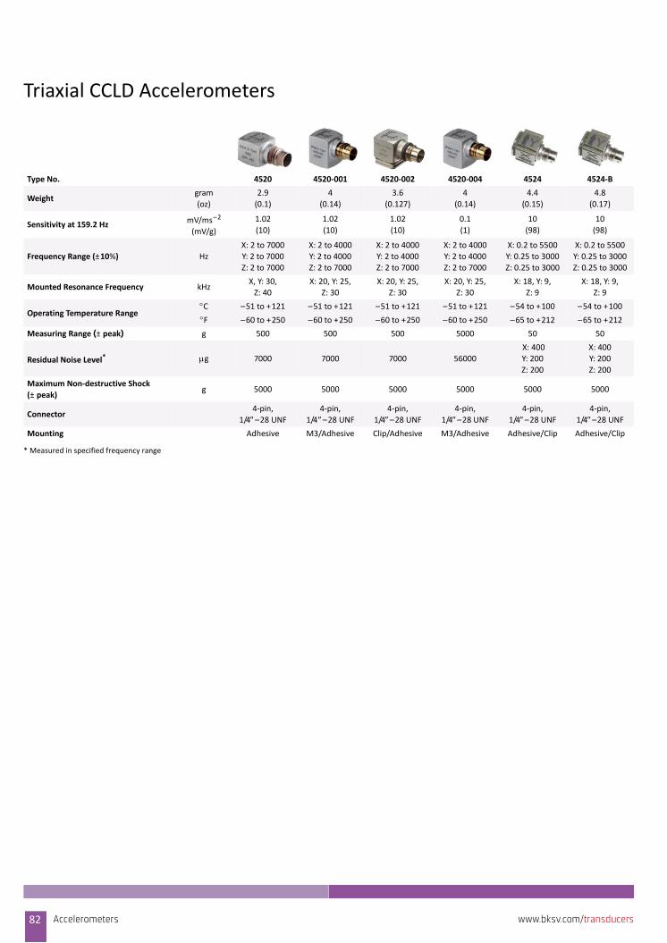
Triaxial CCLD Accelerometers
Type No. 4520 4520‐001 4520‐002 4520‐004 4524 4524‐B
Weightgram
(oz)
2.9
(0.1)
4
(0.14)
3.6
(0.127)
4
(0.14)
4.4
(0.15)
4.8
(0.17)
Sensitivity at 159.2 Hz mV/ms–2
(mV/g)
1.02
(10)
1.02
(10)
1.02
(10)
0.1
(1)
10
(98)
10
(98)
Frequency Range (±10%) Hz
X: 2 to 7000
Y: 2 to 7000
Z: 2 to 7000
X: 2 to 4000
Y: 2 to 4000
Z: 2 to 7000
X: 2 to 4000
Y: 2 to 4000
Z: 2 to 7000
X: 2 to 4000
Y: 2 to 4000
Z: 2 to 7000
X: 0.2 to 5500
Y: 0.25 to 3000
Z: 0.25 to 3000
X: 0.2 to 5500
Y: 0.25 to 3000
Z: 0.25 to 3000
Mounted Resonance Frequency kHzX, Y: 30,
Z: 40
X: 20, Y: 25,
Z: 30
X: 20, Y: 25,
Z: 30
X: 20, Y: 25,
Z: 30
X: 18, Y: 9,
Z: 9
X: 18, Y: 9,
Z: 9
Operating Temperature RangeC –51 to +121 –51 to +121 –51 to +121 –51 to +121 –54 to +100 –54 to +100
F –60 to +250 –60 to +250 –60 to +250 –60 to +250 –65 to +212 –65 to +212
Measuring Range (±peak) g 500 500 500 5000 50 50
Residual Noise Level* g 7000 7000 7000 56000
X: 400
Y: 200
Z: 200
X: 400
Y: 200
Z: 200
Maximum Non‐destructive Shock
(±peak)g 5000 5000 5000 5000 5000 5000
Connector4‐pin,
1/4–28 UNF4‐pin,
1/4–28 UNF4‐pin,
1/4–28 UNF4‐pin,
1/4–28 UNF4‐pin,
1/4–28 UNF4‐pin,
1/4–28 UNFMounting Adhesive M3/Adhesive Clip/Adhesive M3/Adhesive Adhesive/Clip Adhesive/Clip
* Measured in specified frequency range
82 Accelerometers www.bksv.com/transducers
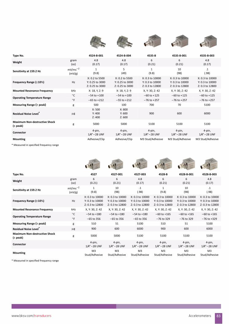
Type No. 4524‐B‐001 4524‐B‐004 4535‐B 4535‐B‐001 4535‐B‐003
Weightgram
(oz)
4.8
(0.17)
4.8
(0.17)
6
(0.21)
6
(0.21)
4.8
(0.17)
Sensitivity at 159.2 Hz mV/ms–2
(mV/g)
1
(9.8)
5
(49)
1
(9.8)
10
(98)
.1
(.98)
Frequency Range (±10%) Hz
X: 0.2 to 5500
Y: 0.25 to 3000
Z: 0.25 to 3000
X: 0.2 to 5500
Y: 0.25 to 3000
Z: 0.25 to 3000
X: 0.3 to 10000
Y: 0.3 to 10000
Z: 0.3 to 12800
X: 0.3 to 10000
Y: 0.3 to 10000
Z: 0.3 to 12800
X: 0.3 to 10000
Y: 0.3 to 10000
Z: 0.3 to 12800
Mounted Resonance Frequency kHz X: 18, Y, Z: 9 X: 18, Y, Z: 9 X, Y: 30, Z: 42 X, Y: 30, Z: 42 X, Y: 30, Z: 42
Operating Temperature RangeC –54 to +100 –54 to +100 –60 to +125 –60 to +125 –60 to +125
F –65 to +212 –55 to +212 –76 to +257 –76 to +257 –76 to +257
Measuring Range (±peak) g 500 100 700 70 5100
Residual Noise Level* g X: 500
Y: 400
Z: 400
X: 800
Y: 600
Z: 600
900 600 6000
Maximum Non‐destructive Shock
(±peak)g 5000 5000 5100 5100 5100
Connector4‐pin,
1/4–28 UNF4‐pin,
1/4–28 UNF4‐pin,
1/4–28 UNF4‐pin,
1/4–28 UNF4‐pin,
1/4–28 UNF
Mounting Adhesive/Clip Adhesive/Clip M3 Stud/Adhesive M3 Stud/Adhesive M3 Stud/Adhesive
* Measured in specified frequency range
Type No. 4527 4527‐001 4527‐003 4528‐B 4528‐B‐001 4528‐B‐003
Weightgram
(oz)
6
(0.21)
6
(0.21)
4.8
(0.17)
6
(0.21)
6
(0.21)
4.8
(0.17)
Sensitivity at 159.2 HzmV/ms–2
(mV/g)
1
(9.8)
10
(98)
.1
(.98)
1
(9.8)
10
(98)
.1
(.98)
Frequency Range (±10%) Hz
X: 0.3 to 10000
Y: 0.3 to 10000
Z: 0.3 to 12800
X: 0.3 to 10000
Y: 0.3 to 10000
Z: 0.3 to 12800
X: 0.3 to 10000
Y: 0.3 to 10000
Z: 0.3 to 12800
X: 0.3 to 10000
Y: 0.3 to 10000
Z: 0.3 to 12800
X: 0.3 to 10000
Y: 0.3 to 10000
Z: 0.3 to 12800
X: 0.3 to 10000
Y: 0.3 to 10000
Z: 0.3 to 12800
Mounted Resonance Frequency kHz X, Y: 30, Z: 42 X, Y: 30, Z: 42 X, Y: 30, Z: 42 X, Y: 30, Z: 42 X, Y: 30, Z: 42 X, Y: 30, Z: 42
Operating Temperature RangeC –54 to +180 –54 to +180 –54 to +180 –60 to +165 –60 to +165 –60 to +165
F –65 to 356 –65 to 356 –65 to 356 –76 to 329 –76 to 329 –76 to +329
Measuring Range (± peak) g 510 51 5100 510 51 5100
Residual Noise Level*
* Measured in specified frequency range
g 900 600 6000 900 600 6000
Maximum Non‐destructive Shock
(±peak)g 5000 5000 5100 5100 5100 5100
Connector4‐pin,
1/4–28 UNF4‐pin,
1/4–28 UNF4‐pin,
1/4–28 UNF4‐pin,
1/4–28 UNF4‐pin,
1/4–28 UNF4‐pin,
1/4–28 UNF
MountingM3
Stud/Adhesive
M3
Stud/Adhesive
M3
Stud/Adhesive
M3
Stud/Adhesive
M3
Stud/Adhesive
M3
Stud/Adhesive
Accelerometers 83www.bksv.com/transducers
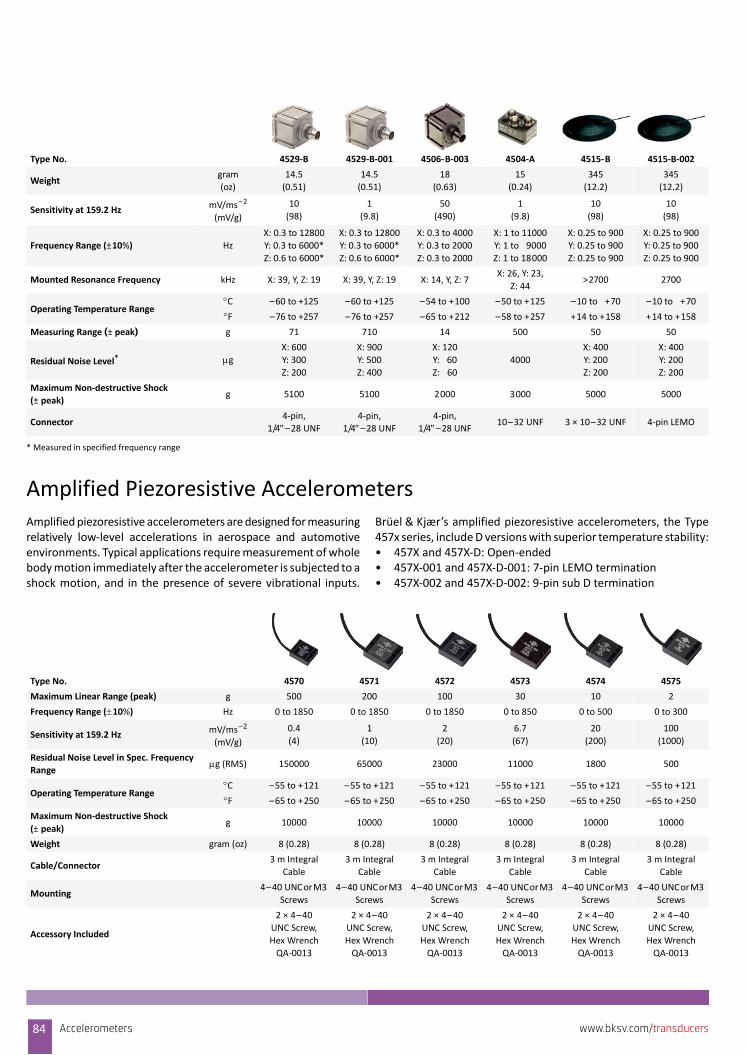
Amplified Piezoresistive AccelerometersAmplified piezoresistive accelerometers are designed for measuringrelatively low‐level accelerations in aerospace and automotiveenvironments. Typical applications require measurement of wholebody motion immediately after the accelerometer is subjected to ashock motion, and in the presence of severe vibrational inputs.
Brüel & Kjær’s amplified piezoresistive accelerometers, the Type457x series, include D versions with superior temperature stability:• 457X and 457X‐D: Open‐ended• 457X‐001 and 457X‐D‐001: 7‐pin LEMO termination• 457X‐002 and 457X‐D‐002: 9‐pin sub D termination
Type No. 4529‐B 4529‐B‐001 4506‐B‐003 4504‐A 4515‐B 4515‐B‐002
Weightgram
(oz)
14.5
(0.51)
14.5
(0.51)
18
(0.63)
15
(0.24)
345
(12.2)
345
(12.2)
Sensitivity at 159.2 Hz mV/ms–2
(mV/g)
10
(98)
1
(9.8)
50
(490)
1
(9.8)
10
(98)
10
(98)
Frequency Range (±10%) Hz
X: 0.3 to 12800
Y: 0.3 to 6000*
Z: 0.6 to 6000*
X: 0.3 to 12800
Y: 0.3 to 6000*
Z: 0.6 to 6000*
X: 0.3 to 4000
Y: 0.3 to 2000
Z: 0.3 to 2000
X: 1 to 11000
Y: 1 to 9000
Z: 1 to 18000
X: 0.25 to 900
Y: 0.25 to 900
Z: 0.25 to 900
X: 0.25 to 900
Y: 0.25 to 900
Z: 0.25 to 900
Mounted Resonance Frequency kHz X: 39, Y, Z: 19 X: 39, Y, Z: 19 X: 14, Y, Z: 7X: 26, Y: 23,
Z: 44>2700 2700
Operating Temperature RangeC –60 to +125 –60 to +125 –54 to +100 –50 to +125 –10 to +70 –10 to +70
F –76 to +257 –76 to +257 –65 to +212 –58 to +257 +14 to +158 +14 to +158
Measuring Range (± peak) g 71 710 14 500 50 50
Residual Noise Level* g X: 600
Y: 300
Z: 200
X: 900
Y: 500
Z: 400
X: 120
Y: 60
Z: 60
4000
X: 400
Y: 200
Z: 200
X: 400
Y: 200
Z: 200
Maximum Non‐destructive Shock
(±peak)g 5100 5100 2000 3000 5000 5000
Connector4‐pin,
1/4–28 UNF4‐pin,
1/4–28 UNF4‐pin,
1/4–28 UNF10–32 UNF 3 × 10–32 UNF 4‐pin LEMO
* Measured in specified frequency range
Type No. 4570 4571 4572 4573 4574 4575
Maximum Linear Range (peak) g 500 200 100 30 10 2
Frequency Range (10%) Hz 0 to 1850 0 to 1850 0 to 1850 0 to 850 0 to 500 0 to 300
Sensitivity at 159.2 HzmV/ms–2
(mV/g)
0.4
(4)
1
(10)
2
(20)
6.7
(67)
20
(200)
100
(1000)
Residual Noise Level in Spec. Frequency
Rangeg (RMS) 150000 65000 23000 11000 1800 500
Operating Temperature RangeC –55 to +121 –55 to +121 –55 to +121 –55 to +121 –55 to +121 –55 to +121
F –65 to +250 –65 to +250 –65 to +250 –65 to +250 –65 to +250 –65 to +250
Maximum Non‐destructive Shock
(±peak)g 10000 10000 10000 10000 10000 10000
Weight gram (oz) 8 (0.28) 8 (0.28) 8 (0.28) 8 (0.28) 8 (0.28) 8 (0.28)
Cable/Connector3 m Integral
Cable
3 m Integral
Cable
3 m Integral
Cable
3 m Integral
Cable
3 m Integral
Cable
3 m Integral
Cable
Mounting4–40 UNC or M3
Screws
4–40 UNC or M3
Screws
4–40 UNC or M3
Screws
4–40 UNC or M3
Screws
4–40 UNC or M3
Screws
4–40 UNC or M3
Screws
Accessory Included
2 × 4–40
UNC Screw,
Hex Wrench
QA‐0013
2 × 4–40
UNC Screw,
Hex Wrench
QA‐0013
2 × 4–40
UNC Screw,
Hex Wrench
QA‐0013
2 × 4–40
UNC Screw,
Hex Wrench
QA‐0013
2 × 4–40
UNC Screw,
Hex Wrench
QA‐0013
2 × 4–40
UNC Screw,
Hex Wrench
QA‐0013
84 Accelerometers www.bksv.com/transducers
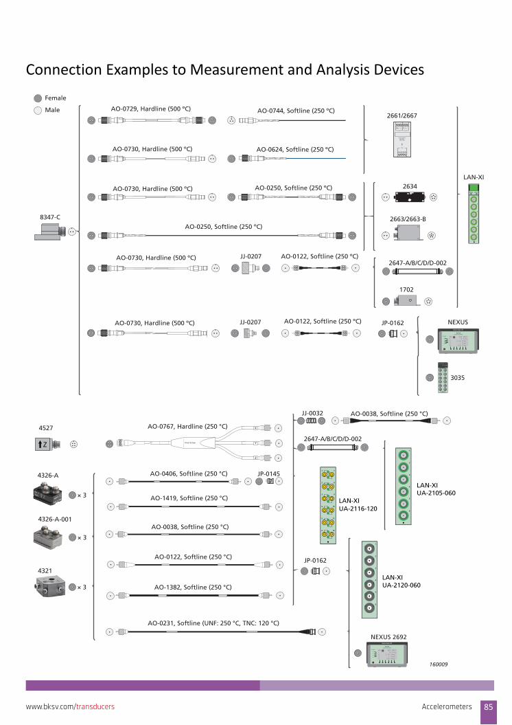
Connection Examples to Measurement and Analysis Devices
Charge AmplifierType 2661
Brüel & Kjær
Output Supply
Input
7 8 9 10
1 2 3 4 5 6
HI LO -24V 0
1
Conditioning Amplifier
NEXUS
Brüel B K7/6-'89& Kjær
Overload
Tacho
1
2
3
4
5
6
Status Control
Conditioning Amplifier
NEXUS
Brüel B K7/6-'89& Kjær
Overload
Female
Male AO-0729, Hardline (500 ºC) AO-0744, Softline (250 ºC)
AO-0730, Hardline (500 ºC) AO-0624, Softline (250 ºC)
AO-0730, Hardline (500 ºC)
8347-C
AO-0250, Softline (250 ºC)
AO-0730, Hardline (500 ºC)
AO-0122, Softline (250 ºC)JJ-0207
3035
1702
2663/2663-B
2634
2661/2667
LAN-XI
NEXUS
JJ-0207
AO-0730, Hardline (500 ºC)
AO-0250, Softline (250 ºC)
JP-0162
AO-0122, Softline (250 ºC)
160009
2647-A/B/C/D/D-002
× 3
4326-A
× 3
4326-A-001
× 3
4321
AO-0231, Softline (UNF: 250 °C, TNC: 120 °C)
AO-1382, Softline (250 °C)
AO-0122, Softline (250 °C)
AO-0038, Softline (250 °C)
AO-1419, Softline (250 °C)
AO-0406, Softline (250 °C) JP-0145
Z
Y
X
Brüel & Kjær
AO-0767, Hardline (250 °C)
JP-0162
JJ-0032 AO-0038, Softline (250 °C)
NEXUS 2692
1
2
3
4
5
6
LAN-XIUA-2105-060
1
2
3
4
5
6
7
8
9
10
11
12
LAN-XIUA-2116-120
LAN-XIUA-2120-060
1
2
3
4
5
6
4527
2647-A/B/C/D/D-002
Accelerometers 85www.bksv.com/transducers
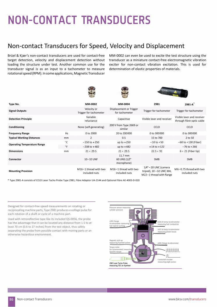
NON-CONTACT TRANSDUCERS
Non‐contact Transducers for Speed, Velocity and DisplacementBrüel & Kjær’s non‐contact transducers are used for contact‐freetarget detection, velocity and displacement detection withoutloading the structure under test. Another common use for thetransducer signal is as an input to a tachometer to measurerotational speed (RPM). In some applications, Magnetic Transducer
MM‐0002 can even be used to excite the test structure using thetransducer as a miniature contact‐free electromagnetic vibrationexciter for non‐contact vibration excitation. This is used fordetermination of elastic properties of materials.
Type No. MM‐0002 MM‐0004 2981 2981‐A*
Signal OutputsVelocity or
Trigger for tachometer
Displacement or Trigger
for tachometerTrigger for tachometer Trigger for tachometer
Detection PrincipleVariable
reluctanceCapacitive Visible laser and receiver
Visible laser and receiver
through fibre‐optic cable
Conditioning None (self‐generating)200 V from Type 2669 or
similarCCLD CCLD
Frequency Range Hz 0 to 2000 20 to 200000 0 to 300000 0 to 300000
Typical Working Distances mm 2 0.5 15 to 700 2 to 50
Operating Temperature Range C –150 to +250 up to +250 –10 to +50 –60 to +130 (Fiber)
F –238 to +482 up to +482 +14 to +122 –76 to +266
Dimensions mm 21 29.5 21 29.5 22.5 91 6 21 (Fiber tip)
Connector 10–32 UNF
11.7 mm
60 UNS (1/2 microphone)
SMB SMB
Mounting Provision M16–1 thread with two
included nuts
M16–1 thread with two
included nuts
1/4– 20 UNC (camera
tripod), 10 –32 UNF, M4,
M22–1 thread with flange
M6–0.75 thread with two
included nuts
* Type 2981‐A consists of CCLD Laser Tacho Probe Type 2981, Fibre Adaptor UA‐2144 and Optional Fibre AE‐4003‐D‐020
4393 Charge Accelerometer measuring fuel injector pulsing
4526 Hi-temp Accelerometer measuring fuel combustion
4527 Hi-temp Accelerometermeasuring piston knock
Pressure sensor measuringcylinder pressure
Magnetic pick-up measuring flywheel pulses
Torque meter (on dynamometer) measuring dynamic torque
2981 Laser Tacho Probe measuring TDC on flywheel
Crankshaft encoder measuring angle pulses
4326 Charge Accelerometer
Designed for contact‐free speed measurements on rotating or reciprocating machine parts, Type 2981 produces a voltage pulse for
each rotation of a shaft or cycle of a machine part.
Used with retroreflective tape like its included QS‐0056, the probe has the advantage that it can be located any distance from 1.5 to at
least 70 cm (0.6 to 27 inches) from the test object, thus safely
separating the probe from possible contact with moving parts or an otherwise hazardous environment.
Non-contact Transducers86 www.bksv.com/transducers
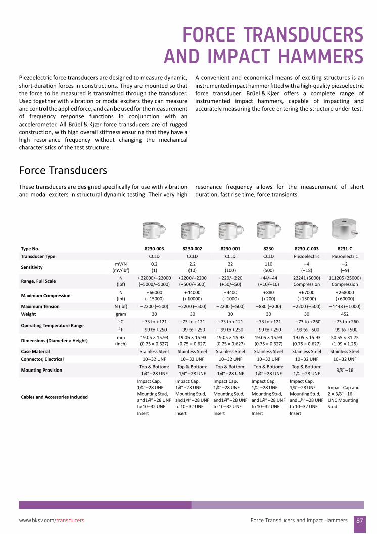
FORCE TRANSDUCERSAND IMPACT HAMMERS
Piezoelectric force transducers are designed to measure dynamic,short‐duration forces in constructions. They are mounted so thatthe force to be measured is transmitted through the transducer.Used together with vibration or modal exciters they can measureand control the applied force, and can be used for the measurementof frequency response functions in conjunction with anaccelerometer. All Brüel & Kjær force transducers are of ruggedconstruction, with high overall stiffness ensuring that they have ahigh resonance frequency without changing the mechanicalcharacteristics of the test structure.
A convenient and economical means of exciting structures is aninstrumented impact hammer fitted with a high‐quality piezoelectricforce transducer. Brüel & Kjær offers a complete range ofinstrumented impact hammers, capable of impacting andaccurately measuring the force entering the structure under test.
Force TransducersThese transducers are designed specifically for use with vibrationand modal exciters in structural dynamic testing. Their very high
resonance frequency allows for the measurement of shortduration, fast rise time, force transients.
Type No. 8230‐003 8230‐002 8230‐001 8230 8230‐C‐003 8231‐C
Transducer Type CCLD CCLD CCLD CCLD Piezoelectric Piezoelectric
Sensitivity mV/N
(mV/lbf)
0.2
(1)
2.2
(10)
22
(100)
110
(500)
–4
(–18)
–2
(–9)
Range, Full ScaleN
(lbf)
+22000/–22000
(+5000/–5000)
+2200/–2200
(+500/–500)
+220/–220
(+50/–50)
+44/–44
(+10/–10)
22241 (5000)
Compression
111205 (25000)
Compression
Maximum CompressionN
(lbf)
+66000
(+15000)
+44000
(+10000)
+4400
(+1000)
+880
(+200)
+67000
(+15000)
+268000
(+60000)
Maximum Tension N (lbf) –2200 (–500) –2200 (–500) –2200 (–500) –880 (–200) –2200 (–500) –4448 (–1000)
Weight gram 30 30 30 30 30 452
Operating Temperature Range C –73 to +121 –73 to +121 –73 to +121 –73 to +121 –73 to +260 –73 to +260
F –99 to +250 –99 to +250 –99 to +250 –99 to +250 –99 to +500 –99 to +500
Dimensions (Diameter × Height) mm
(inch)
19.05 × 15.93
(0.75 × 0.627)
19.05 × 15.93
(0.75 × 0.627)
19.05 × 15.93
(0.75 × 0.627)
19.05 × 15.93
(0.75 × 0.627)
19.05 × 15.93
(0.75 × 0.627)
50.55 × 31.75
(1.99 × 1.25)
Case Material Stainless Steel Stainless Steel Stainless Steel Stainless Steel Stainless Steel Stainless Steel
Connector, Electrical 10–32 UNF 10–32 UNF 10–32 UNF 10–32 UNF 10–32 UNF 10–32 UNF
Mounting ProvisionTop & Bottom:
1/4–28 UNFTop & Bottom:
1/4–28 UNFTop & Bottom:
1/4–28 UNFTop & Bottom:
1/4–28 UNFTop & Bottom:
1/4–28 UNF3/8–16
Cables and Accessories Included
Impact Cap,
1/4–28 UNF Mounting Stud,
and 1/4–28 UNF to 10–32 UNF
Insert
Impact Cap,
1/4–28 UNF Mounting Stud,
and 1/4–28 UNF to 10–32 UNF
Insert
Impact Cap,
1/4–28 UNF Mounting Stud,
and 1/4–28 UNF to 10–32 UNF
Insert
Impact Cap,
1/4–28 UNF Mounting Stud,
and 1/4–28 UNF to 10–32 UNF
Insert
Impact Cap,
1/4–28 UNF Mounting Stud,
and 1/4–28 UNF to 10–32 UNF
Insert
Impact Cap and
2 × 3/8–16 UNC Mounting
Stud
Force Transducers and Impact Hammers 87www.bksv.com/transducers
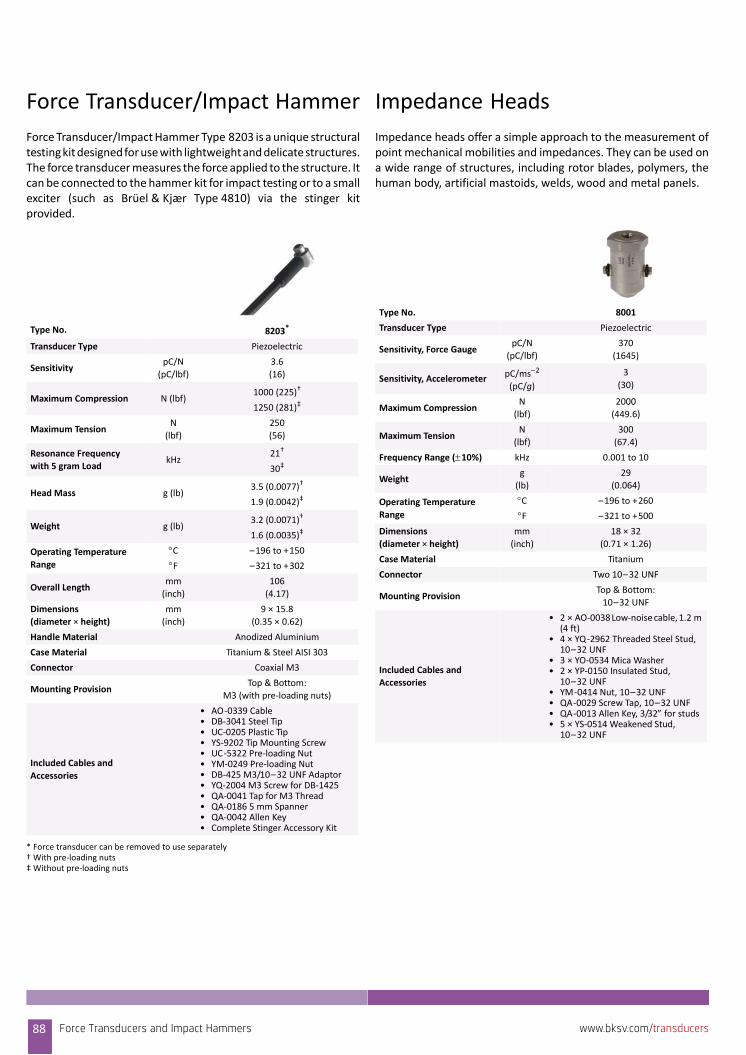
Force Transducer/Impact Hammer
Force Transducer/Impact Hammer Type 8203 is a unique structuraltesting kit designed for use with lightweight and delicate structures.The force transducer measures the force applied to the structure. Itcan be connected to the hammer kit for impact testing or to a smallexciter (such as Brüel & Kjær Type 4810) via the stinger kitprovided.
Impedance Heads
Impedance heads offer a simple approach to the measurement ofpoint mechanical mobilities and impedances. They can be used ona wide range of structures, including rotor blades, polymers, thehuman body, artificial mastoids, welds, wood and metal panels.
Type No. 8203*
* Force transducer can be removed to use separately
Transducer Type Piezoelectric
Sensitivity pC/N
(pC/lbf)
3.6
(16)
Maximum Compression N (lbf)1000 (225)†
1250 (281)‡
† With pre‐loading nuts‡ Without pre‐loading nuts
Maximum TensionN
(lbf)
250
(56)
Resonance Frequency
with 5 gram Load kHz
21†
30‡
Head Mass g (lb)3.5 (0.0077)†
1.9 (0.0042)‡
Weight g (lb)3.2 (0.0071)†
1.6 (0.0035)‡
Operating Temperature
Range
C –196 to +150
F –321 to +302
Overall Lengthmm
(inch)
106
(4.17)
Dimensions
(diameter × height)
mm
(inch)
9 × 15.8
(0.35 × 0.62)
Handle Material Anodized Aluminium
Case Material Titanium & Steel AISI 303
Connector Coaxial M3
Mounting ProvisionTop & Bottom:
M3 (with pre‐loading nuts)
Included Cables and
Accessories
• AO‐0339 Cable • DB‐3041 Steel Tip • UC‐0205 Plastic Tip• YS‐9202 Tip Mounting Screw• UC‐5322 Pre‐loading Nut • YM‐0249 Pre‐loading Nut • DB‐425 M3/10–32 UNF Adaptor• YQ‐2004 M3 Screw for DB‐1425• QA‐0041 Tap for M3 Thread• QA‐0186 5 mm Spanner• QA‐0042 Allen Key• Complete Stinger Accessory Kit
Type No. 8001
Transducer Type Piezoelectric
Sensitivity, Force GaugepC/N
(pC/lbf)
370
(1645)
Sensitivity, Accelerometer pC/ms–2
(pC/g)
3
(30)
Maximum CompressionN
(lbf)
2000
(449.6)
Maximum TensionN
(lbf)
300
(67.4)
Frequency Range (10%) kHz 0.001 to 10
Weightg
(lb)
29
(0.064)
Operating Temperature
Range
C –196 to +260
F –321 to +500
Dimensions
(diameter × height)
mm
(inch)
18 × 32
(0.71 × 1.26)
Case Material Titanium
Connector Two 10–32 UNF
Mounting ProvisionTop & Bottom:
10–32 UNF
Included Cables and
Accessories
• 2 × AO‐0038 Low‐noise cable, 1.2 m (4 ft)
• 4 × YQ‐2962 Threaded Steel Stud, 10–32 UNF
• 3 × YO‐0534 Mica Washer• 2 × YP‐0150 Insulated Stud,
10–32 UNF• YM‐0414 Nut, 10–32 UNF• QA‐0029 Screw Tap, 10–32 UNF• QA‐0013 Allen Key, 3/32 for studs• 5 × YS‐0514 Weakened Stud,
10–32 UNF
88 Force Transducers and Impact Hammers www.bksv.com/transducers
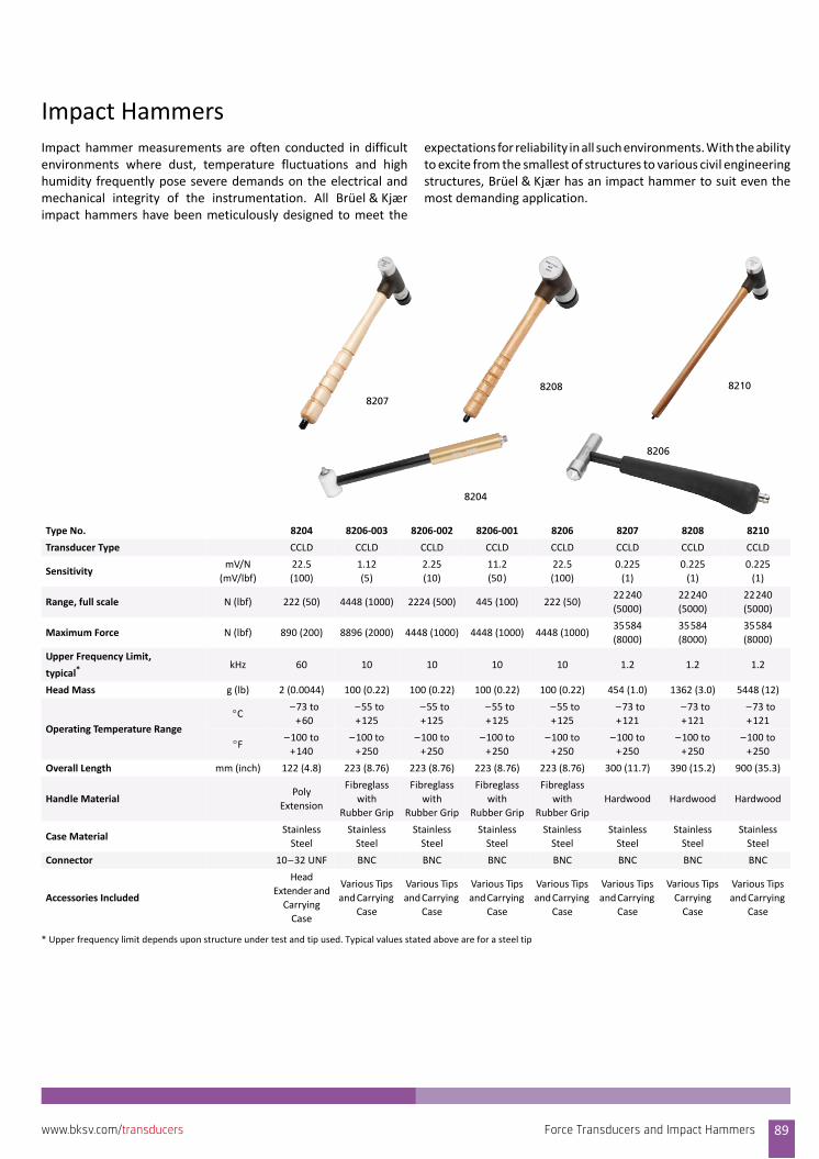
Impact HammersImpact hammer measurements are often conducted in difficultenvironments where dust, temperature fluctuations and highhumidity frequently pose severe demands on the electrical andmechanical integrity of the instrumentation. All Brüel & Kjærimpact hammers have been meticulously designed to meet the
expectations for reliability in all such environments. With the abilityto excite from the smallest of structures to various civil engineeringstructures, Brüel & Kjær has an impact hammer to suit even themost demanding application.
Type No. 8204 8206‐003 8206‐002 8206‐001 8206 8207 8208 8210
Transducer Type CCLD CCLD CCLD CCLD CCLD CCLD CCLD CCLD
Sensitivity mV/N
(mV/lbf)
22.5
(100)
1.12
(5)
2.25
(10)
11.2
(50)
22.5
(100)
0.225
(1)
0.225
(1)
0.225
(1)
Range, full scale N (lbf) 222 (50) 4448 (1000) 2224 (500) 445 (100) 222 (50)22240
(5000)
22240
(5000)
22240
(5000)
Maximum Force N (lbf) 890 (200) 8896 (2000) 4448 (1000) 4448 (1000) 4448 (1000)35584
(8000)
35584
(8000)
35584
(8000)
Upper Frequency Limit,
typical* kHz 60 10 10 10 10 1.2 1.2 1.2
Head Mass g (lb) 2 (0.0044) 100 (0.22) 100 (0.22) 100 (0.22) 100 (0.22) 454 (1.0) 1362 (3.0) 5448 (12)
Operating Temperature Range
C–73 to
+60
–55 to
+125
–55 to
+125
–55 to
+125
–55 to
+125
–73 to
+121
–73 to
+121
–73 to
+121
F–100 to
+140
–100 to
+250
–100 to
+250
–100 to
+250
–100 to
+250
–100 to
+250
–100 to
+250
–100 to
+250
Overall Length mm (inch) 122 (4.8) 223 (8.76) 223 (8.76) 223 (8.76) 223 (8.76) 300 (11.7) 390 (15.2) 900 (35.3)
Handle MaterialPoly
Extension
Fibreglass
with
Rubber Grip
Fibreglass
with
Rubber Grip
Fibreglass
with
Rubber Grip
Fibreglass
with
Rubber Grip
Hardwood Hardwood Hardwood
Case MaterialStainless
Steel
Stainless
Steel
Stainless
Steel
Stainless
Steel
Stainless
Steel
Stainless
Steel
Stainless
Steel
Stainless
Steel
Connector 10–32 UNF BNC BNC BNC BNC BNC BNC BNC
Accessories Included
Head
Extender and
Carrying
Case
Various Tips
and Carrying
Case
Various Tips
and Carrying
Case
Various Tips
and Carrying
Case
Various Tips
and Carrying
Case
Various Tips
and Carrying
Case
Various Tips
Carrying
Case
Various Tips
and Carrying
Case
* Upper frequency limit depends upon structure under test and tip used. Typical values stated above are for a steel tip
8204
8210
82078208
8206
Force Transducers and Impact Hammers 89www.bksv.com/transducers
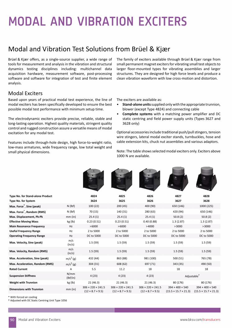
MODAL AND VIBRATION EXCITERS
Modal and Vibration Test Solutions from Brüel & KjærBrüel & Kjær offers, as a single‐source supplier, a wide range oftools for measurement and analysis in the vibration and structuraldynamics testing disciplines including: multichannel dataacquisition hardware, measurement software, post‐processingsoftware and software for integration of test and finite elementanalysis.
The family of exciters available through Brüel & Kjær range fromsmall permanent magnet exciters for vibrating small test objects tolarger floor‐mounted types for vibrating assemblies and largerstructures. They are designed for high force levels and produce aclean vibration waveform with low cross‐motion and distortion.
Modal Exciters Based upon years of practical modal test experience, the line ofmodal exciters has been specifically developed to ensure the bestpossible modal test performance with minimum setup time.
The electrodynamic exciters provide precise, reliable, stable andlong‐lasting operation. Highest quality materials, stringent qualitycontrol and rugged construction assure a versatile means of modalexcitation for any modal test.
Features include through‐hole design, high force‐to‐weight ratio,low‐mass armatures, wide frequency range, low total weight andsmall physical dimensions.
The exciters are available as:• Stand‐alone units supplied only with the appropriate trunnion,
blower (except Type 4824) and connecting cable• Complete systems with a matching power amplifier and DC
static centring and field power supply units (Types 3627 and3628 only)
Optional accessories include traditional push/pull stingers, tensionwire stingers, lateral modal exciter stands, turnbuckles, hose andcable extension kits, chuck nut assemblies and various adaptors.
Note: The table shows selected modal exciters only. Exciters above1000 N are available.
Type No. for Stand‐alone Product 4824 4825 4826 4827 4828
Type No. for System 3624 3625 3626 3627 3628
Max. Force*, Sine (peak) N (lbf) 100 (22) 200 (45) 400 (90) 650 (146) 1000 (225)
Max. Force*, Random (RMS) N (lbf) 70 (15) 140 (31) 280 (63) 420 (94) 650 (146)
Max. Displacement, Pk‐Pk mm (in) 25.4 (1) 25.4 (1) 25.4 (1) 50.8 (2) 50.8 (2)
Effective Moving Mass kg (lb) 0.23 (0.51) 0.23 (0.51) 0.40 (0.88) 1.3 (2.87) 1.3 (2.87)
Main Resonance Frequency Hz >6000 >6000 >4000 >3000 >3000
Useful Frequency Range Hz 2 to 5000 2 to 5000 2 to 5000 2 to 5000 2 to 5000
Operating Frequency Range Hz DC to 5000 DC to 5000 DC to 5000 DC to 5000 DC to 5000
Max. Velocity, Sine (peak)m/s
(in/s)1.5 (59) 1.5 (59) 1.5 (59) 1.5 (59) 1.5 (59)
Max. Velocity, Random (RMS)m/s
(in/s)1.5 (59) 1.5 (59) 1.5 (59) 1.5 (59) 1.5 (59)
Max. Acceleration, Sine (peak) m/s2 (g) 432 (44) 863 (88) 981 (100) 500 (51) 765 (78)
Max. Acceleration, Random (RMS) m/s2 (g) 304 (31) 608 (62) 697 (71) 343 (35) 490 (50)
Rated Current A 5.5 11.2 18 18 18
Suspension StiffnessN/mm
(lbf/in)4 (23) 4 (23) 4 (23) Adjustable†
Weight with Trunnion kg (lb) 21 (46.3) 21 (46.3) 21 (46.3) 80 (176) 80 (176)
Dimensions with Trunnion mm (in)306 × 220 × 241.5
(12 × 8.7 × 9.5)
306 × 220 × 241.5
(12 × 8.7 × 9.5)
306 × 220 × 241.5
(12 × 8.7 × 9.5)
394 × 400 × 540
(15.5 × 15.7 × 21.3)
394 × 400 × 540
(15.5 × 15.7 × 21.3)
* With forced air cooling† Adjusted with DC Static Centring Unit Type 1056
Modal and Vibration Exciters90 www.bksv.com/transducers
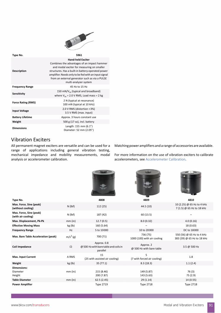
Vibration ExcitersAll permanent magnet exciters are versatile and can be used for arange of applications including general vibration testing,mechanical impedance and mobility measurements, modalanalysis or accelerometer calibration.
Matching power amplifiers and a range of accessories are available.
For more information on the use of vibration exciters to calibrateaccelerometers, see Accelerometer Calibration.
Type No. 5961
Description
Hand‐held Exciter
Combines the advantages of an impact hammer
and modal exciter for measuring on smaller
structures. Has a built‐in battery‐operated power
amplifier. Needs only to be fed with an input signal
from an external generator such as via a PULSE
multi‐analyzer system
Frequency Range 45 Hz to 15 Hz
Sensitivity150 mN/Vin (typical and broadband)
where Vin = 2.0 V RMS, Load mass = 2 kg
Force Rating (RMS)2 N (typical at resonance)
100 mN (typical at 10 kHz)
Input Voltage2.0 V RMS (distortion <3%)
3.5 V RMS (max. input)
Battery Lifetime Approx. 3 hours constant use
Weight 500 g (17 oz), incl. battery
Dimensions Length: 155 mm (6.1)Diameter: 52 mm (2.05)
Type No. 4808 4809 4810
Max. Force, Sine (peak)
(without cooling)N (lbf) 112 (25) 44.5 (10)
10 (2.25) @ 65 Hz to 4 kHz
7 (1.5) @ 65 Hz to 18 kHz
Max. Force, Sine (peak)
(with air cooling)N (lbf) 187 (42) 60 (13.5) –
Max. Displacement, Pk‐Pk mm (in) 12.7 (0.5) 8.0 (0.32) 4.0 (0.16)
Effective Moving Mass kg (lb) 160 (5.64) – 18 (0.63)
Frequency Range Hz 5 to 10000 10 to 20000 DC to 18000
Max. Bare Table Acceleration (peak) m/s2 (g) 700 (71)736 (75)
1000 (100) with air cooling
550 (56) @ 65 Hz to 4 kHz
383 (39) @ 65 Hz to 18 kHz
Coil Impedance Approx. 0.8
@ 500 Hz with bare table and coils in
parallel
Approx. 2
@ 500 Hz with bare table3.5 @ 500 Hz
Max. Input Current A RMS15
(25 with assisted air cooling)
5
(7 with forced air cooling)1.8
Weight kg (lb) 35 (77.1) 8.3 (18.3) 1.1 (2.4)
Dimensions:
Diameter
Height
mm (in) 215 (8.46)
200 (7.87)
149 (5.87)
143 (5.63)
76 (3)
75 (2.9)
Table Diameter mm (in) 62.5 (2.45) 29 (1.14) 14 (0.55)
Power Amplifier Type 2719 Type 2718 Type 2718
Modal and Vibration Exciters 91www.bksv.com/transducers
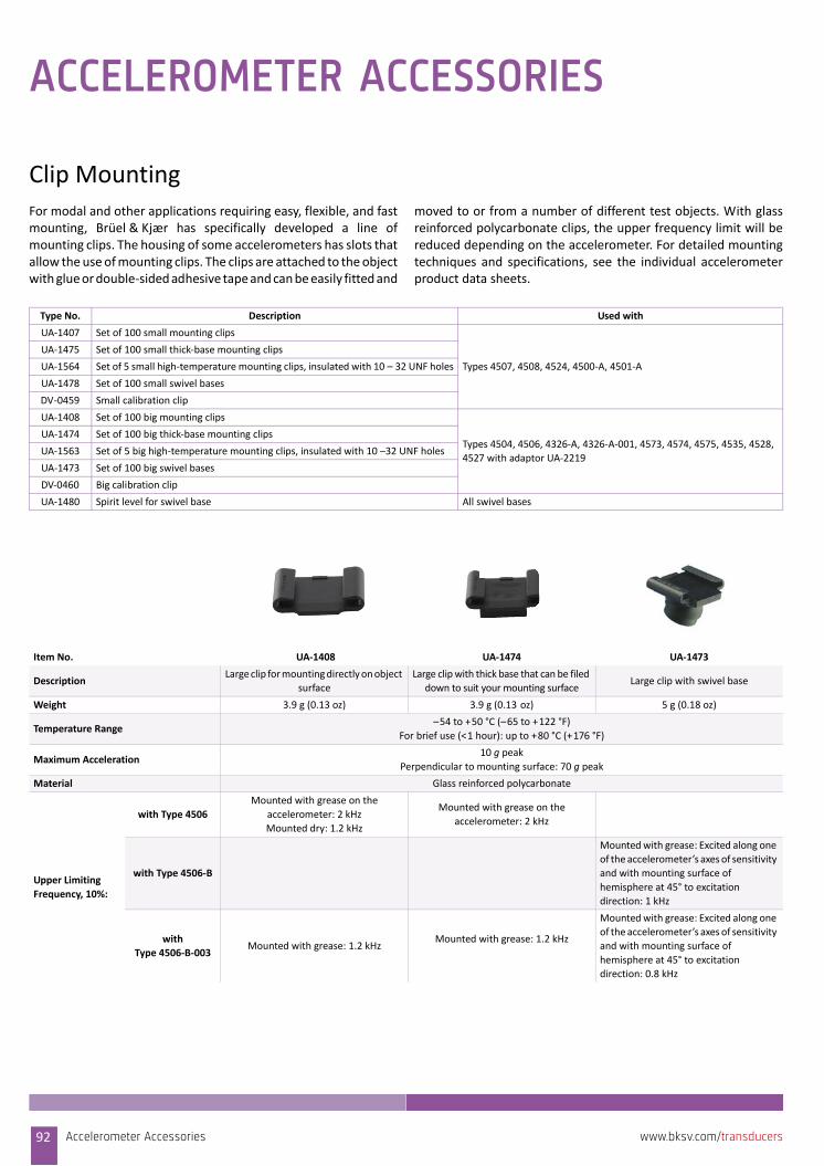
ACCELEROMETER ACCESSORIES
Clip MountingFor modal and other applications requiring easy, flexible, and fastmounting, Brüel & Kjær has specifically developed a line ofmounting clips. The housing of some accelerometers has slots thatallow the use of mounting clips. The clips are attached to the objectwith glue or double‐sided adhesive tape and can be easily fitted and
moved to or from a number of different test objects. With glassreinforced polycarbonate clips, the upper frequency limit will bereduced depending on the accelerometer. For detailed mountingtechniques and specifications, see the individual accelerometerproduct data sheets.
Type No. Description Used with
UA‐1407 Set of 100 small mounting clips
Types 4507, 4508, 4524, 4500‐A, 4501‐A
UA‐1475 Set of 100 small thick‐base mounting clips
UA‐1564 Set of 5 small high‐temperature mounting clips, insulated with 10 – 32 UNF holes
UA‐1478 Set of 100 small swivel bases
DV‐0459 Small calibration clip
UA‐1408 Set of 100 big mounting clips
Types 4504, 4506, 4326‐A, 4326‐A‐001, 4573, 4574, 4575, 4535, 4528,
4527 with adaptor UA‐2219
UA‐1474 Set of 100 big thick‐base mounting clips
UA‐1563 Set of 5 big high‐temperature mounting clips, insulated with 10 –32 UNF holes
UA‐1473 Set of 100 big swivel bases
DV‐0460 Big calibration clip
UA‐1480 Spirit level for swivel base All swivel bases
Item No. UA‐1408 UA‐1474 UA‐1473
DescriptionLarge clip for mounting directly on object
surface
Large clip with thick base that can be filed
down to suit your mounting surfaceLarge clip with swivel base
Weight 3.9 g (0.13 oz) 3.9 g (0.13 oz) 5 g (0.18 oz)
Temperature Range–54 to +50 °C (–65 to +122 °F)
For brief use (<1 hour): up to +80 °C (+176 °F)
Maximum Acceleration10 g peak
Perpendicular to mounting surface: 70 g peak
Material Glass reinforced polycarbonate
Upper Limiting
Frequency, 10%:
with Type 4506
Mounted with grease on the
accelerometer: 2 kHz
Mounted dry: 1.2 kHz
Mounted with grease on the
accelerometer: 2 kHz
with Type 4506‐B
Mounted with grease: Excited along one
of the accelerometer’s axes of sensitivity
and with mounting surface of
hemisphere at 45° to excitation
direction: 1 kHz
with
Type 4506‐B‐003Mounted with grease: 1.2 kHz
Mounted with grease: 1.2 kHz
Mounted with grease: Excited along one
of the accelerometer’s axes of sensitivity
and with mounting surface of
hemisphere at 45° to excitation
direction: 0.8 kHz
Accelerometer Accessories92 www.bksv.com/transducers
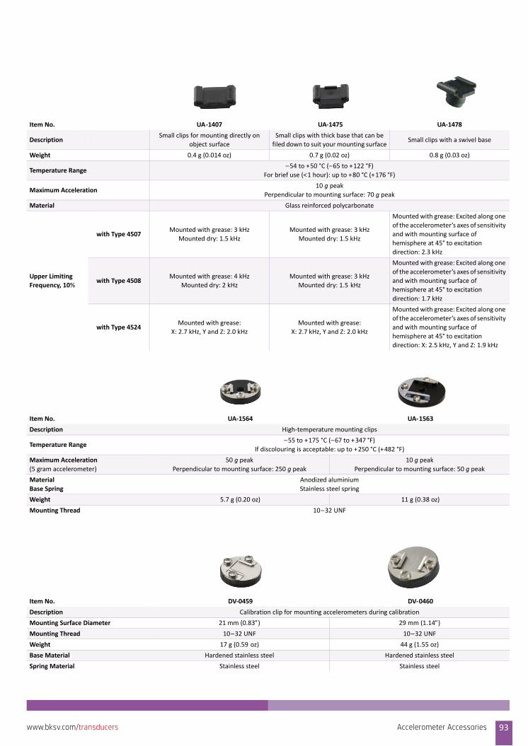
Item No. UA‐1407 UA‐1475 UA‐1478
DescriptionSmall clips for mounting directly on
object surface
Small clips with thick base that can be
filed down to suit your mounting surfaceSmall clips with a swivel base
Weight 0.4 g (0.014 oz) 0.7 g (0.02 oz) 0.8 g (0.03 oz)
Temperature Range–54 to +50 °C (–65 to +122 °F)
For brief use (<1 hour): up to +80 °C (+176 °F)
Maximum Acceleration10 g peak
Perpendicular to mounting surface: 70 g peak
Material Glass reinforced polycarbonate
Upper Limiting
Frequency, 10%
with Type 4507Mounted with grease: 3 kHz
Mounted dry: 1.5 kHz
Mounted with grease: 3 kHz
Mounted dry: 1.5 kHz
Mounted with grease: Excited along one
of the accelerometer’s axes of sensitivity
and with mounting surface of
hemisphere at 45° to excitation
direction: 2.3 kHz
with Type 4508Mounted with grease: 4 kHz
Mounted dry: 2 kHz
Mounted with grease: 3 kHz
Mounted dry: 1.5 kHz
Mounted with grease: Excited along one
of the accelerometer’s axes of sensitivity
and with mounting surface of
hemisphere at 45° to excitation
direction: 1.7 kHz
with Type 4524Mounted with grease:
X: 2.7 kHz, Y and Z: 2.0 kHz
Mounted with grease:
X: 2.7 kHz, Y and Z: 2.0 kHz
Mounted with grease: Excited along one
of the accelerometer’s axes of sensitivity
and with mounting surface of
hemisphere at 45° to excitation
direction: X: 2.5 kHz, Y and Z: 1.9 kHz
Item No. UA‐1564 UA‐1563
Description High‐temperature mounting clips
Temperature Range–55 to +175 °C (–67 to +347 °F)
If discolouring is acceptable: up to +250 °C (+482 °F)
Maximum Acceleration
(5 gram accelerometer)
50 g peak
Perpendicular to mounting surface: 250 g peak
10 g peak
Perpendicular to mounting surface: 50 g peak
Material
Base Spring
Anodized aluminium
Stainless steel spring
Weight 5.7 g (0.20 oz) 11 g (0.38 oz)
Mounting Thread 10–32 UNF
Item No. DV‐0459 DV‐0460
Description Calibration clip for mounting accelerometers during calibration
Mounting Surface Diameter 21 mm (0.83) 29 mm (1.14)
Mounting Thread 10–32 UNF 10–32 UNF
Weight 17 g (0.59 oz) 44 g (1.55 oz)
Base Material Hardened stainless steel Hardened stainless steel
Spring Material Stainless steel Stainless steel
Accelerometer Accessories 93www.bksv.com/transducers
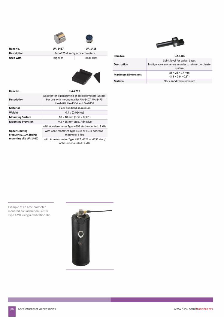
Item No. UA‐1417 UA‐1418
Description Set of 25 dummy accelerometers
Used with Big clips Small clips
Item No. UA‐2219
Description
Adaptor for clip mounting of accelerometers (25 pcs)
For use with mounting clips UA‐1407, UA‐1475,
UA‐1478, UA‐1564 and DV‐0459
Material Black anodized aluminium
Weight 0.4 g (0.014 oz)
Mounting Surface 10 × 10 mm (0.39 × 0.39)
Mounting Provision M3 × 15 mm stud, Adhesive
Upper Limiting
Frequency, 10% (using
mounting clip UA‐1407)
with Accelerometer Type 4393 stud‐mounted: 2 kHz
with Accelerometer Type 4533 or 4534 adhesive‐
mounted: 3 kHz
with Accelerometer Type 4527, 4528 or 4535 stud/
adhesive‐mounted: 1 kHz
Item No. UA‐1480
Description
Spirit level for swivel bases
To align accelerometers in order to retain coordinate
system
Maximum Dimensions85 × 23 × 17 mm
(3.3 × 0.9 × 0.6)Material Black anodized aluminium
Example of an accelerometer mounted on Calibration Exciter
Type 4294 using a calibration clip
94 Accelerometer Accessories www.bksv.com/transducers
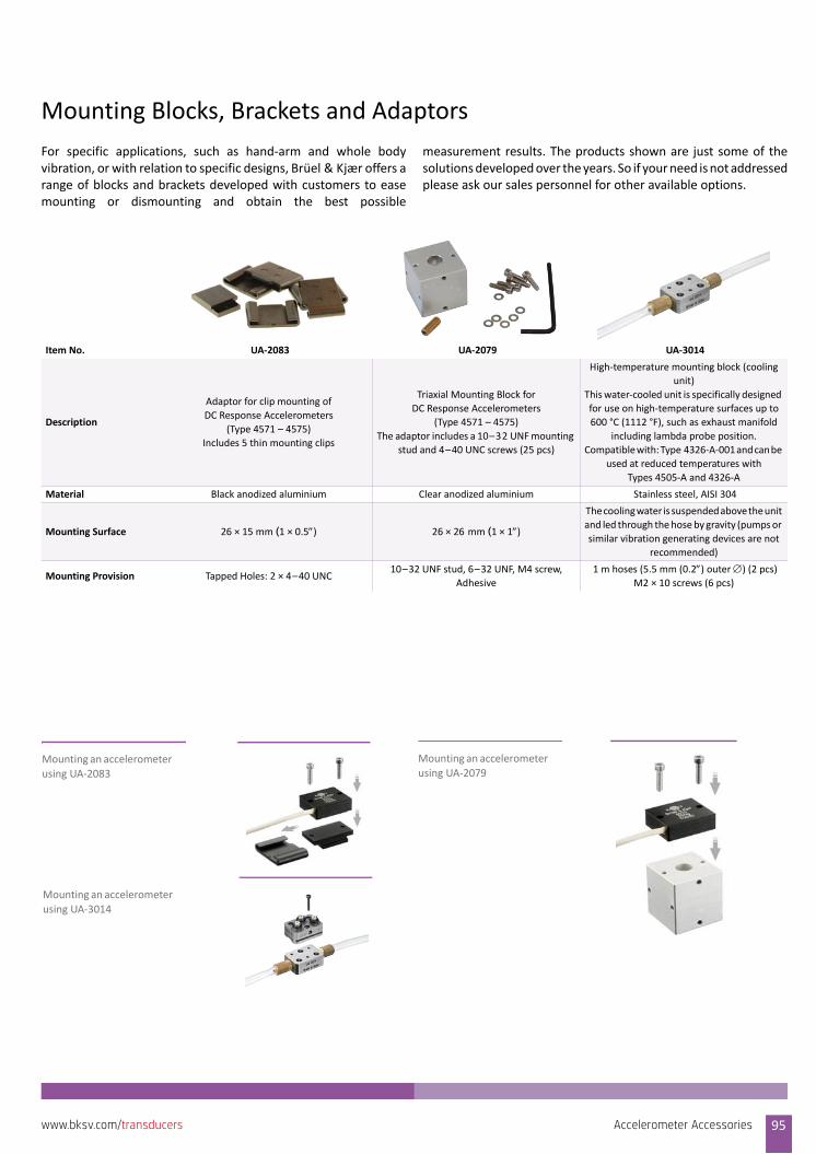
Mounting Blocks, Brackets and Adaptors
For specific applications, such as hand‐arm and whole bodyvibration, or with relation to specific designs, Brüel & Kjær offers arange of blocks and brackets developed with customers to easemounting or dismounting and obtain the best possible
measurement results. The products shown are just some of thesolutions developed over the years. So if your need is not addressedplease ask our sales personnel for other available options.
Item No. UA‐2083 UA‐2079 UA‐3014
Description
Adaptor for clip mounting of
DC Response Accelerometers
(Type 4571 – 4575)
Includes 5 thin mounting clips
Triaxial Mounting Block for
DC Response Accelerometers
(Type 4571 – 4575)
The adaptor includes a 10–32 UNF mounting
stud and 4–40 UNC screws (25 pcs)
High‐temperature mounting block (cooling
unit)
This water‐cooled unit is specifically designed
for use on high‐temperature surfaces up to
600 °C (1112 °F), such as exhaust manifold
including lambda probe position.
Compatible with: Type 4326‐A‐001 and can be
used at reduced temperatures with
Types 4505‐A and 4326‐A
Material Black anodized aluminium Clear anodized aluminium Stainless steel, AISI 304
Mounting Surface 26 × 15 mm (1 × 0.5) 26 × 26 mm (1 × 1)
The cooling water is suspended above the unit
and led through the hose by gravity (pumps or
similar vibration generating devices are not
recommended)
Mounting Provision Tapped Holes: 2 × 4–40 UNC10–32 UNF stud, 6–32 UNF, M4 screw,
Adhesive
1 m hoses (5.5 mm (0.2) outer ) (2 pcs)
M2 × 10 screws (6 pcs)
Mounting an accelerometer
using UA‐2083
Mounting an accelerometer
using UA‐2079
Mounting an accelerometer
using UA‐3014
Accelerometer Accessories 95www.bksv.com/transducers
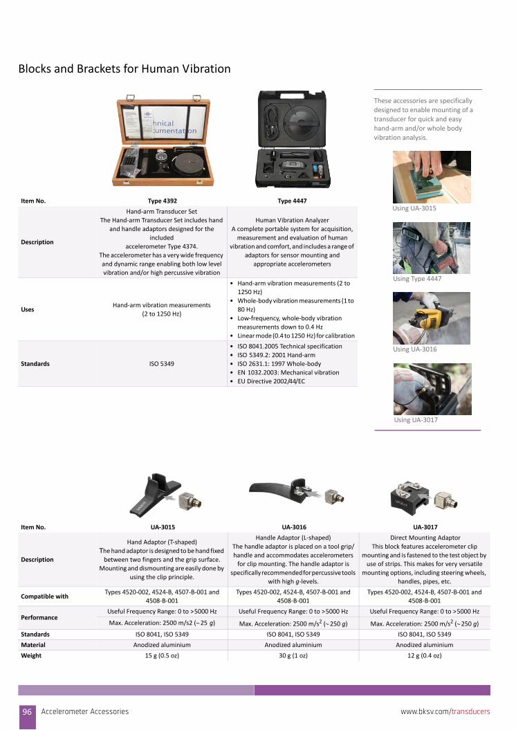
Blocks and Brackets for Human Vibration
Item No. Type 4392 Type 4447
Description
Hand‐arm Transducer Set
The Hand‐arm Transducer Set includes hand
and handle adaptors designed for the
included
accelerometer Type 4374.
The accelerometer has a very wide frequency
and dynamic range enabling both low level
vibration and/or high percussive vibration
Human Vibration Analyzer
A complete portable system for acquisition,
measurement and evaluation of human
vibration and comfort, and includes a range of
adaptors for sensor mounting and
appropriate accelerometers
UsesHand‐arm vibration measurements
(2 to 1250 Hz)
• Hand‐arm vibration measurements (2 to
1250 Hz)
• Whole‐body vibration measurements (1 to
80 Hz)
• Low‐frequency, whole‐body vibration
measurements down to 0.4 Hz
• Linear mode (0.4 to 1250 Hz) for calibration
Standards ISO 5349
• ISO 8041.2005 Technical specification
• ISO 5349.2: 2001 Hand‐arm
• ISO 2631.1: 1997 Whole‐body
• EN 1032.2003: Mechanical vibration
• EU Directive 2002/44/EC
Item No. UA‐3015 UA‐3016 UA‐3017
Description
Hand Adaptor (T‐shaped)
The hand adaptor is designed to be hand fixed between two fingers and the grip surface.
Mounting and dismounting are easily done by
using the clip principle.
Handle Adaptor (L‐shaped)
The handle adaptor is placed on a tool grip/
handle and accommodates accelerometers
for clip mounting. The handle adaptor is
specifically recommended for percussive tools
with high g‐levels.
Direct Mounting Adaptor
This block features accelerometer clip
mounting and is fastened to the test object by
use of strips. This makes for very versatile
mounting options, including steering wheels,
handles, pipes, etc.
Compatible withTypes 4520‐002, 4524‐B, 4507‐B‐001 and
4508‐B‐001
Types 4520‐002, 4524‐B, 4507‐B‐001 and
4508‐B‐001
Types 4520‐002, 4524‐B, 4507‐B‐001 and
4508‐B‐001
PerformanceUseful Frequency Range: 0 to >5000 Hz Useful Frequency Range: 0 to >5000 Hz Useful Frequency Range: 0 to >5000 Hz
Max. Acceleration: 2500 m/s2 (25 g) Max. Acceleration: 2500 m/s2 (250 g) Max. Acceleration: 2500 m/s2 (250 g)Standards ISO 8041, ISO 5349 ISO 8041, ISO 5349 ISO 8041, ISO 5349
Material Anodized aluminium Anodized aluminium Anodized aluminium
Weight 15 g (0.5 oz) 30 g (1 oz) 12 g (0.4 oz)
These accessories are specifically
designed to enable mounting of a transducer for quick and easy
hand‐arm and/or whole body
vibration analysis.
Using UA‐3015
Using Type 4447
Using UA‐3016
Using UA‐3017
96 Accelerometer Accessories www.bksv.com/transducers
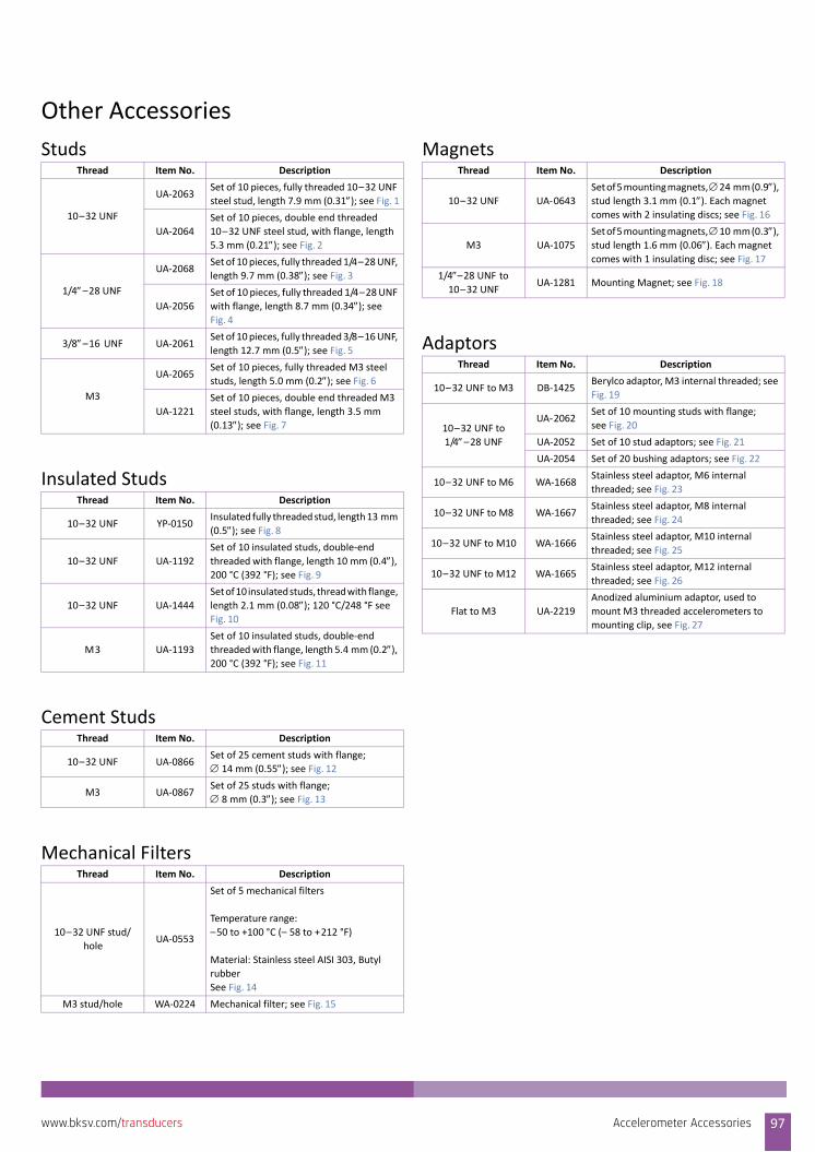
Other Accessories
Studs
Insulated Studs
Cement Studs
Mechanical Filters
Magnets
Adaptors
Thread Item No. Description
10–32 UNF
UA‐2063Set of 10 pieces, fully threaded 10–32 UNF
steel stud, length 7.9 mm (0.31); see Fig. 1
UA‐2064
Set of 10 pieces, double end threaded
10–32 UNF steel stud, with flange, length
5.3 mm (0.21); see Fig. 2
1/4–28 UNF
UA‐2068Set of 10 pieces, fully threaded 1/4–28 UNF,
length 9.7 mm (0.38); see Fig. 3
UA‐2056
Set of 10 pieces, fully threaded 1/4–28 UNF
with flange, length 8.7 mm (0.34); see Fig. 4
3/8–16 UNF UA‐2061Set of 10 pieces, fully threaded 3/8–16 UNF,
length 12.7 mm (0.5); see Fig. 5
M3
UA‐2065Set of 10 pieces, fully threaded M3 steel
studs, length 5.0 mm (0.2); see Fig. 6
UA‐1221
Set of 10 pieces, double end threaded M3
steel studs, with flange, length 3.5 mm
(0.13); see Fig. 7
Thread Item No. Description
10–32 UNF YP‐0150Insulated fully threaded stud, length 13 mm
(0.5); see Fig. 8
10–32 UNF UA‐1192
Set of 10 insulated studs, double‐end
threaded with flange, length 10 mm (0.4), 200 °C (392 °F); see Fig. 9
10–32 UNF UA‐1444
Set of 10 insulated studs, thread with flange,
length 2.1 mm (0.08); 120 °C/248 °F see Fig. 10
M3 UA‐1193
Set of 10 insulated studs, double‐end
threaded with flange, length 5.4 mm (0.2), 200 °C (392 °F); see Fig. 11
Thread Item No. Description
10–32 UNF UA‐0866Set of 25 cement studs with flange;
14 mm (0.55); see Fig. 12
M3 UA‐0867Set of 25 studs with flange;
8 mm (0.3); see Fig. 13
Thread Item No. Description
10–32 UNF stud/
holeUA‐0553
Set of 5 mechanical filters
Temperature range:
–50 to +100 °C (– 58 to +212 °F)
Material: Stainless steel AISI 303, Butyl
rubber
See Fig. 14
M3 stud/hole WA‐0224 Mechanical filter; see Fig. 15
Thread Item No. Description
10–32 UNF UA‐0643
Set of 5 mounting magnets, 24 mm (0.9), stud length 3.1 mm (0.1). Each magnet
comes with 2 insulating discs; see Fig. 16
M3 UA‐1075
Set of 5 mounting magnets, 10 mm (0.3), stud length 1.6 mm (0.06). Each magnet
comes with 1 insulating disc; see Fig. 17
1/4–28 UNF to 10–32 UNF
UA‐1281 Mounting Magnet; see Fig. 18
Thread Item No. Description
10–32 UNF to M3 DB‐1425Berylco adaptor, M3 internal threaded; see
Fig. 19
10–32 UNF to
1/4–28 UNF
UA‐2062Set of 10 mounting studs with flange;
see Fig. 20
UA‐2052 Set of 10 stud adaptors; see Fig. 21
UA‐2054 Set of 20 bushing adaptors; see Fig. 22
10–32 UNF to M6 WA‐1668Stainless steel adaptor, M6 internal
threaded; see Fig. 23
10–32 UNF to M8 WA‐1667Stainless steel adaptor, M8 internal
threaded; see Fig. 24
10–32 UNF to M10 WA‐1666Stainless steel adaptor, M10 internal
threaded; see Fig. 25
10–32 UNF to M12 WA‐1665Stainless steel adaptor, M12 internal
threaded; see Fig. 26
Flat to M3 UA‐2219
Anodized aluminium adaptor, used to
mount M3 threaded accelerometers to
mounting clip, see Fig. 27
Accelerometer Accessories 97www.bksv.com/transducers
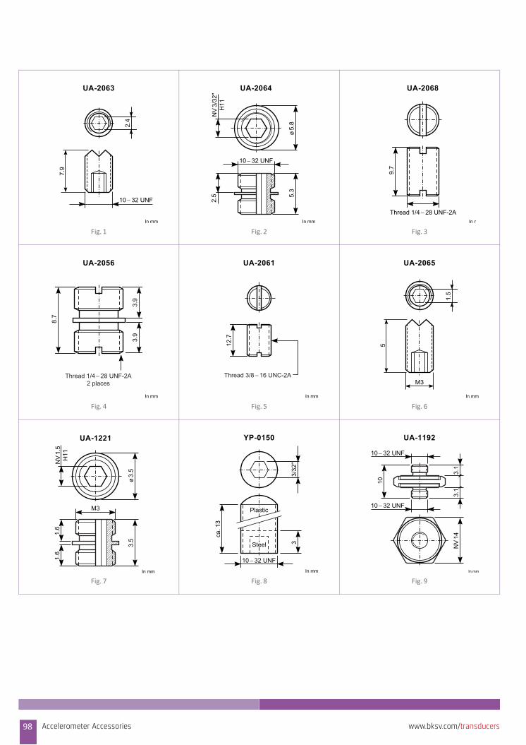
Fig. 1 Fig. 2 Fig. 3
Fig. 4 Fig. 5 Fig. 6
Fig. 7 Fig. 8 Fig. 9
2.4
UA-2063
In mm
7.9
10 − 32 UNF
UA-2064
NV
3/32
"H
11
ø5.
8
10 − 32 UNF
5.3
2.5
In mm
9.7
UA-2068
Thread 1/4 − 28 UNF-2AIn m
Thread 1/4 − 28 UNF-2A2 places
8.7
3.9
3.9
UA-2056
In mm
12.7
UA-2061
Thread 3/8 − 16 UNC-2A
In mm
1.5
UA-2065
In mm
5M3
NV
1.5
H11
ø3.
5
M3
3.5
1.6
1.6
UA-1221
In mm
3/32
"3
ca. 1
3
YP-0150
10 − 32 UNFIn mm
Steel
Plastic
UA-1192
In mm
10
10 − 32 UNF
10 − 32 UNF3.
13.
1N
V14
98 Accelerometer Accessories www.bksv.com/transducers
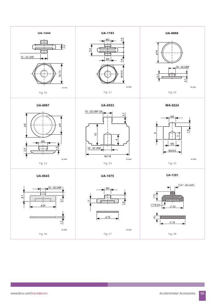
Fig. 10 Fig. 11 Fig. 12
Fig. 13 Fig. 14 Fig. 15
Fig. 16 Fig. 17 Fig. 18
UA-1444
NV
15
In mm
2.9
10 − 32 UNF
UA-1193
5.4
1.6
1.6
NV
8.5
M3
In mm
M3
UA-0866
In mm
ø14
3.1
2.1
10 − 32 UNF
ø8
2.5 1.
5
UA-0867
ø6
M3
In mm
UA-0553
In mmNV 18
10
10 − 32 UNF-2A
4
3.1
10 − 32 UNF
WA-0224
NV 8.5
6 1.6
In mm
M3
M3
3UA-0643
ø 24
8.1
3.1
1.1
10 − 32 UNF
In mm
UA-1075
ø 10
2
1.6
In mm
M3
∅ 35
(4)
(1/4”–28 UNF)
∅ 30
(13)
0.01
UA-1281
Accelerometer Accessories 99www.bksv.com/transducers
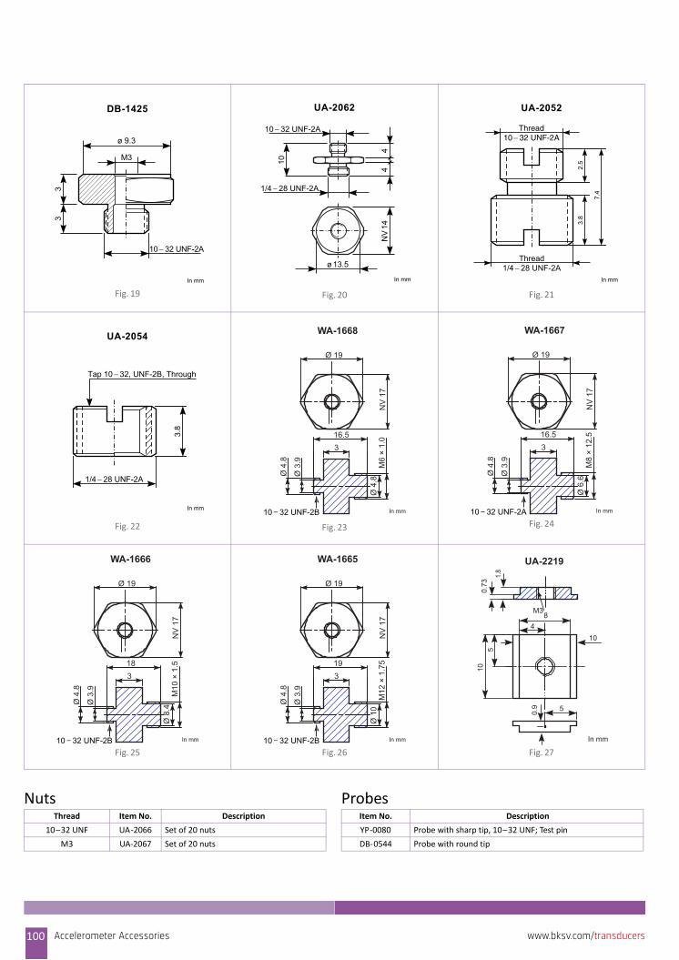
Nuts Probes
Fig. 19 Fig. 20 Fig. 21
Fig. 22 Fig. 23 Fig. 24
Fig. 25 Fig. 26 Fig. 27
DB-1425
ø 9.3
M3
33
10 − 32 UNF-2A
In mm
UA-2062
NV
14
1/4 − 28 UNF-2A
10 − 32 UNF-2A
ø 13.5
10In mm
44
3.8
7.4
2.5
UA-2052
Thread1/4 − 28 UNF-2A
Thread10 − 32 UNF-2A
In mm
3.8
UA-2054
1/4 − 28 UNF-2A
Tap 10 − 32, UNF-2B, Through
In mm
16.5
NV
17
M6
× 1.
0
10 − 32 UNF-2B
Ø 19
Ø 4
.8
3
Ø 4
.8
Ø 3
.9
WA-1668
In mm
16.5
NV
17
M8
× 12
.5
10 − 32 UNF-2A
Ø 19
Ø 6
.6
3
Ø 4
.8
Ø 3
.9
WA-1667
In mm
18
NV
17
M10
× 1
.5
10 − 32 UNF-2B
Ø 19
Ø 8
.4
3
Ø 4
.8
Ø 3
.9
WA-1666
In mm
19
NV
17
M12
× 1
.75
10 − 32 UNF-2B
Ø 19
Ø 1
0
3
Ø 4
.8
Ø 3
.9
WA-1665
In mm
5
In mm
0.73
1.8
M3
0.9
105
10
84
UA-2219
Thread Item No. Description
10–32 UNF UA‐2066 Set of 20 nuts
M3 UA‐2067 Set of 20 nuts
Item No. Description
YP‐0080 Probe with sharp tip, 10–32 UNF; Test pin
DB‐0544 Probe with round tip
100 Accelerometer Accessories www.bksv.com/transducers
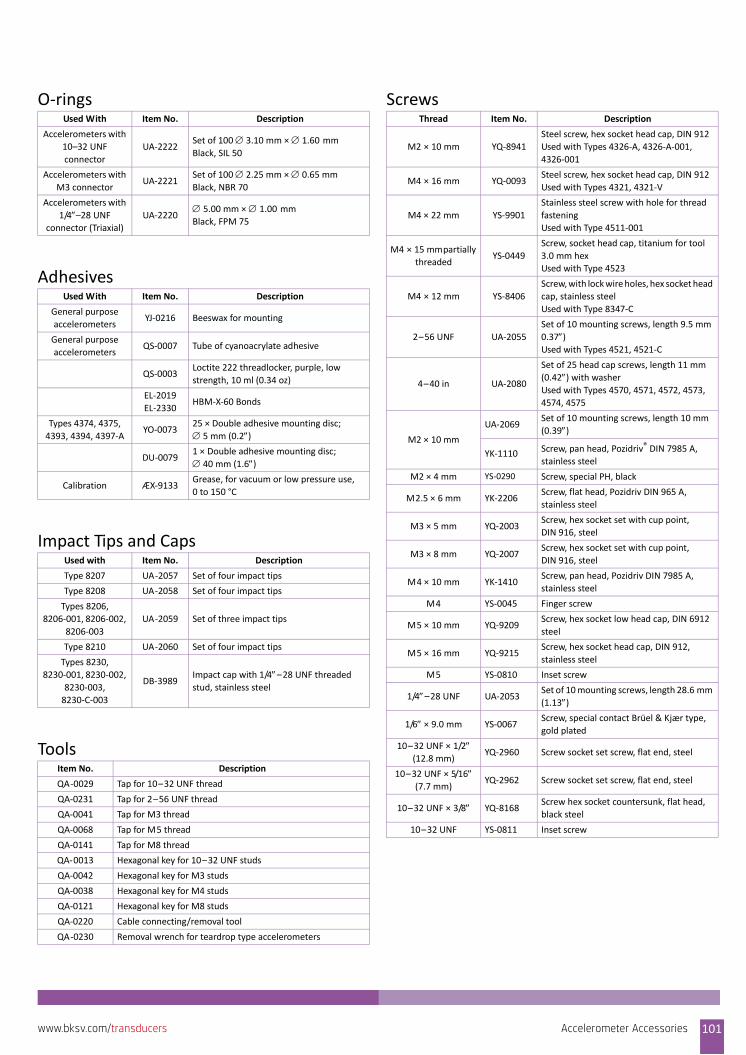
O‐rings
Adhesives
Impact Tips and Caps
Tools
ScrewsUsed With Item No. Description
Accelerometers with
10–32 UNF
connector
UA‐2222Set of 100 3.10 mm × 1.60 mm
Black, SIL 50
Accelerometers with
M3 connectorUA‐2221
Set of 100 2.25 mm × 0.65 mm
Black, NBR 70
Accelerometers with
1/4–28 UNF connector (Triaxial)
UA‐22205.00 mm × 1.00 mm
Black, FPM 75
Used With Item No. Description
General purpose
accelerometersYJ‐0216 Beeswax for mounting
General purpose
accelerometersQS‐0007 Tube of cyanoacrylate adhesive
QS‐0003Loctite 222 threadlocker, purple, low
strength, 10 ml (0.34 oz)
EL‐2019
EL‐2330HBM‐X‐60 Bonds
Types 4374, 4375,
4393, 4394, 4397‐AYO‐0073
25 × Double adhesive mounting disc;
5 mm (0.2)
DU‐00791 × Double adhesive mounting disc;
40 mm (1.6)
Calibration ÆX‐9133Grease, for vacuum or low pressure use,
0 to 150 °C
Used with Item No. Description
Type 8207 UA‐2057 Set of four impact tips
Type 8208 UA‐2058 Set of four impact tips
Types 8206,
8206‐001, 8206‐002,
8206‐003
UA‐2059 Set of three impact tips
Type 8210 UA‐2060 Set of four impact tips
Types 8230,
8230‐001, 8230‐002,
8230‐003,
8230‐C‐003
DB‐3989Impact cap with 1/4–28 UNF threaded stud, stainless steel
Item No. Description
QA‐0029 Tap for 10–32 UNF thread
QA‐0231 Tap for 2–56 UNF thread
QA‐0041 Tap for M3 thread
QA‐0068 Tap for M5 thread
QA‐0141 Tap for M8 thread
QA‐0013 Hexagonal key for 10–32 UNF studs
QA‐0042 Hexagonal key for M3 studs
QA‐0038 Hexagonal key for M4 studs
QA‐0121 Hexagonal key for M8 studs
QA‐0220 Cable connecting/removal tool
QA‐0230 Removal wrench for teardrop type accelerometers
Thread Item No. Description
M2 × 10 mm YQ‐8941
Steel screw, hex socket head cap, DIN 912
Used with Types 4326‐A, 4326‐A‐001,
4326‐001
M4 × 16 mm YQ‐0093Steel screw, hex socket head cap, DIN 912
Used with Types 4321, 4321‐V
M4 × 22 mm YS‐9901
Stainless steel screw with hole for thread
fastening
Used with Type 4511‐001
M4 × 15 mm partially
threadedYS‐0449
Screw, socket head cap, titanium for tool
3.0 mm hex
Used with Type 4523
M4 × 12 mm YS‐8406
Screw, with lock wire holes, hex socket head
cap, stainless steel
Used with Type 8347‐C
2–56 UNF UA‐2055
Set of 10 mounting screws, length 9.5 mm
0.37)Used with Types 4521, 4521‐C
4–40 in UA‐2080
Set of 25 head cap screws, length 11 mm
(0.42) with washerUsed with Types 4570, 4571, 4572, 4573,
4574, 4575
M2 × 10 mm
UA‐2069Set of 10 mounting screws, length 10 mm
(0.39)
YK‐1110 Screw, pan head, Pozidriv® DIN 7985 A,
stainless steel
M2 × 4 mm YS‐0290 Screw, special PH, black
M2.5 × 6 mm YK‐2206Screw, flat head, Pozidriv DIN 965 A,
stainless steel
M3 × 5 mm YQ‐2003Screw, hex socket set with cup point,
DIN 916, steel
M3 × 8 mm YQ‐2007Screw, hex socket set with cup point,
DIN 916, steel
M4 × 10 mm YK‐1410Screw, pan head, Pozidriv DIN 7985 A,
stainless steel
M4 YS‐0045 Finger screw
M5 × 10 mm YQ‐9209Screw, hex socket low head cap, DIN 6912
steel
M5 × 16 mm YQ‐9215Screw, hex socket head cap, DIN 912,
stainless steel
M5 YS‐0810 Inset screw
1/4–28 UNF UA‐2053Set of 10 mounting screws, length 28.6 mm
(1.13)
1/6 × 9.0 mm YS‐0067Screw, special contact Brüel & Kjær type,
gold plated
10–32 UNF × 1/2 (12.8 mm)
YQ‐2960 Screw socket set screw, flat end, steel
10–32 UNF × 5/16 (7.7 mm)
YQ‐2962 Screw socket set screw, flat end, steel
10–32 UNF × 3/8 YQ‐8168Screw hex socket countersunk, flat head,
black steel
10–32 UNF YS‐0811 Inset screw
Accelerometer Accessories 101www.bksv.com/transducers
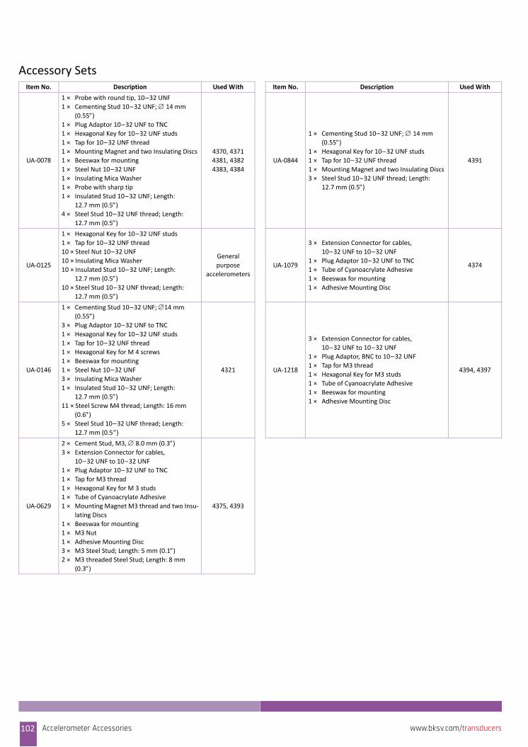
Accessory SetsItem No. Description Used With Item No. Description Used With
UA‐0078
1 × Probe with round tip, 10–32 UNF
1 × Cementing Stud 10–32 UNF; 14 mm
(0.55)1 × Plug Adaptor 10–32 UNF to TNC
1 × Hexagonal Key for 10–32 UNF studs
1 × Tap for 10–32 UNF thread
1 × Mounting Magnet and two Insulating Discs
1 × Beeswax for mounting
1 × Steel Nut 10–32 UNF
1 × Insulating Mica Washer
1 × Probe with sharp tip
1 × Insulated Stud 10–32 UNF; Length:
12.7 mm (0.5)4 × Steel Stud 10–32 UNF thread; Length:
12.7 mm (0.5)
4370, 4371
4381, 4382
4383, 4384
UA‐0844
1 × Cementing Stud 10–32 UNF; 14 mm
(0.55)1 × Hexagonal Key for 10–32 UNF studs
1 × Tap for 10–32 UNF thread
1 × Mounting Magnet and two Insulating Discs
3 × Steel Stud 10–32 UNF thread; Length:
12.7 mm (0.5)
4391
UA‐0125
1 × Hexagonal Key for 10–32 UNF studs
1 × Tap for 10–32 UNF thread
10 × Steel Nut 10–32 UNF
10 × Insulating Mica Washer
10 × Insulated Stud 10–32 UNF; Length:
12.7 mm (0.5)10 × Steel Stud 10–32 UNF thread; Length:
12.7 mm (0.5)
General
purpose
accelerometers
UA‐1079
3 × Extension Connector for cables,
10–32 UNF to 10–32 UNF
1 × Plug Adaptor 10–32 UNF to TNC
1 × Tube of Cyanoacrylate Adhesive
1 × Beeswax for mounting
1 × Adhesive Mounting Disc
4374
UA‐0146
1 × Cementing Stud 10–32 UNF; 14 mm
(0.55)3 × Plug Adaptor 10–32 UNF to TNC
1 × Hexagonal Key for 10–32 UNF studs
1 × Tap for 10–32 UNF thread
1 × Hexagonal Key for M 4 screws
1 × Beeswax for mounting
1 × Steel Nut 10–32 UNF
3 × Insulating Mica Washer
1 × Insulated Stud 10–32 UNF; Length:
12.7 mm (0.5)11 × Steel Screw M4 thread; Length: 16 mm
(0.6)5 × Steel Stud 10–32 UNF thread; Length:
12.7 mm (0.5)
4321 UA‐1218
3 × Extension Connector for cables,
10–32 UNF to 10–32 UNF
1 × Plug Adaptor, BNC to 10–32 UNF
1 × Tap for M3 thread
1 × Hexagonal Key for M3 studs
1 × Tube of Cyanoacrylate Adhesive
1 × Beeswax for mounting
1 × Adhesive Mounting Disc
4394, 4397
UA‐0629
2 × Cement Stud, M3, 8.0 mm (0.3)3 × Extension Connector for cables,
10–32 UNF to 10–32 UNF
1 × Plug Adaptor 10–32 UNF to TNC
1 × Tap for M3 thread
1 × Hexagonal Key for M 3 studs
1 × Tube of Cyanoacrylate Adhesive
1 × Mounting Magnet M3 thread and two Insu‐
lating Discs
1 × Beeswax for mounting
1 × M3 Nut
1 × Adhesive Mounting Disc
3 × M3 Steel Stud; Length: 5 mm (0.1)2 × M3 threaded Steel Stud; Length: 8 mm
(0.3)
4375, 4393
102 Accelerometer Accessories www.bksv.com/transducers
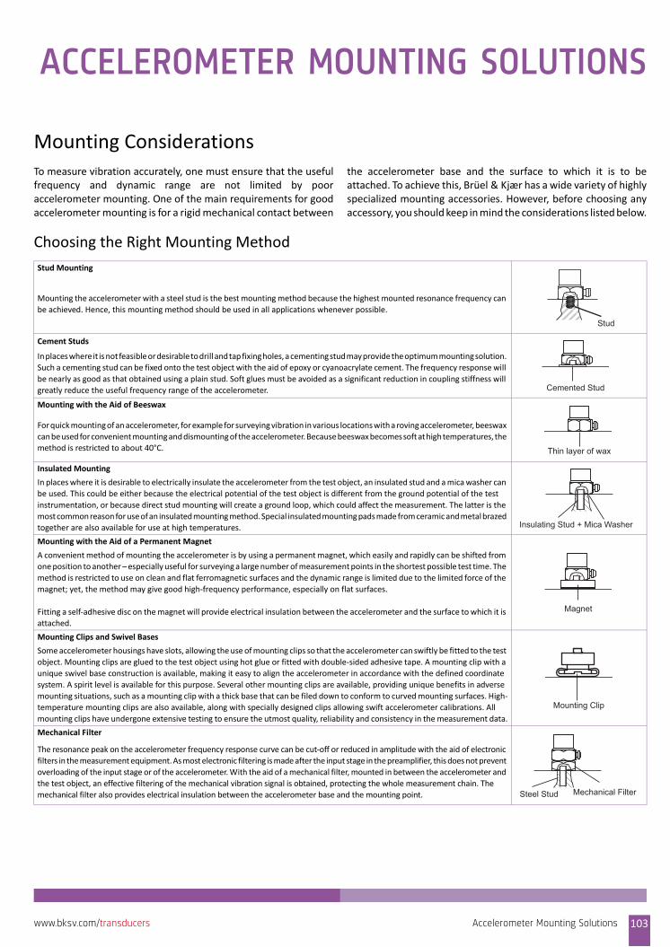
ACCELEROMETER MOUNTING SOLUTIONS
Mounting ConsiderationsTo measure vibration accurately, one must ensure that the usefulfrequency and dynamic range are not limited by pooraccelerometer mounting. One of the main requirements for goodaccelerometer mounting is for a rigid mechanical contact between
the accelerometer base and the surface to which it is to beattached. To achieve this, Brüel & Kjær has a wide variety of highlyspecialized mounting accessories. However, before choosing anyaccessory, you should keep in mind the considerations listed below.
Choosing the Right Mounting Method
Stud Mounting
Mounting the accelerometer with a steel stud is the best mounting method because the highest mounted resonance frequency can
be achieved. Hence, this mounting method should be used in all applications whenever possible.
Cement Studs
In places where it is not feasible or desirable to drill and tap fixing holes, a cementing stud may provide the optimum mounting solution.
Such a cementing stud can be fixed onto the test object with the aid of epoxy or cyanoacrylate cement. The frequency response will
be nearly as good as that obtained using a plain stud. Soft glues must be avoided as a significant reduction in coupling stiffness will
greatly reduce the useful frequency range of the accelerometer.
Mounting with the Aid of Beeswax
For quick mounting of an accelerometer, for example for surveying vibration in various locations with a roving accelerometer, beeswax
can be used for convenient mounting and dismounting of the accelerometer. Because beeswax becomes soft at high temperatures, the
method is restricted to about 40°C.
Insulated Mounting
In places where it is desirable to electrically insulate the accelerometer from the test object, an insulated stud and a mica washer can
be used. This could be either because the electrical potential of the test object is different from the ground potential of the test
instrumentation, or because direct stud mounting will create a ground loop, which could affect the measurement. The latter is the
most common reason for use of an insulated mounting method. Special insulated mounting pads made from ceramic and metal brazed
together are also available for use at high temperatures.
Mounting with the Aid of a Permanent Magnet
A convenient method of mounting the accelerometer is by using a permanent magnet, which easily and rapidly can be shifted from
one position to another – especially useful for surveying a large number of measurement points in the shortest possible test time. The
method is restricted to use on clean and flat ferromagnetic surfaces and the dynamic range is limited due to the limited force of the
magnet; yet, the method may give good high‐frequency performance, especially on flat surfaces.
Fitting a self‐adhesive disc on the magnet will provide electrical insulation between the accelerometer and the surface to which it is
attached.
Mounting Clips and Swivel Bases
Some accelerometer housings have slots, allowing the use of mounting clips so that the accelerometer can swiftly be fitted to the test
object. Mounting clips are glued to the test object using hot glue or fitted with double‐sided adhesive tape. A mounting clip with a
unique swivel base construction is available, making it easy to align the accelerometer in accordance with the defined coordinate
system. A spirit level is available for this purpose. Several other mounting clips are available, providing unique benefits in adverse
mounting situations, such as a mounting clip with a thick base that can be filed down to conform to curved mounting surfaces. High‐
temperature mounting clips are also available, along with specially designed clips allowing swift accelerometer calibrations. All
mounting clips have undergone extensive testing to ensure the utmost quality, reliability and consistency in the measurement data.
Mechanical Filter
The resonance peak on the accelerometer frequency response curve can be cut‐off or reduced in amplitude with the aid of electronic
filters in the measurement equipment. As most electronic filtering is made after the input stage in the preamplifier, this does not prevent
overloading of the input stage or of the accelerometer. With the aid of a mechanical filter, mounted in between the accelerometer and
the test object, an effective filtering of the mechanical vibration signal is obtained, protecting the whole measurement chain. The
mechanical filter also provides electrical insulation between the accelerometer base and the mounting point.
Stud
Cemented Stud
Thin layer of wax
Insulating Stud + Mica Washer
Magnet
Mounting Clip
Steel Stud Mechanical Filter
Accelerometer Mounting Solutions 103www.bksv.com/transducers
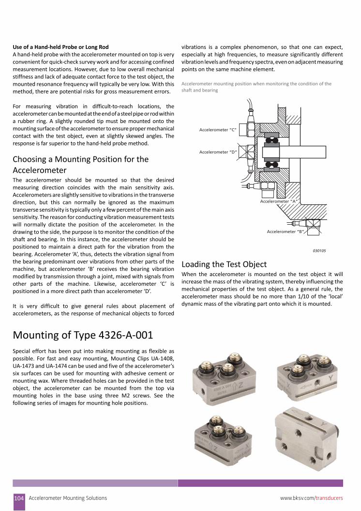
Use of a Hand‐held Probe or Long RodA hand‐held probe with the accelerometer mounted on top is veryconvenient for quick‐check survey work and for accessing confinedmeasurement locations. However, due to low overall mechanicalstiffness and lack of adequate contact force to the test object, themounted resonance frequency will typically be very low. With thismethod, there are potential risks for gross measurement errors.
For measuring vibration in difficult‐to‐reach locations, theaccelerometer can be mounted at the end of a steel pipe or rod withina rubber ring. A slightly rounded tip must be mounted onto themounting surface of the accelerometer to ensure proper mechanicalcontact with the test object, even at slightly skewed angles. Theresponse is far superior to the hand‐held probe method.
Choosing a Mounting Position for the AccelerometerThe accelerometer should be mounted so that the desiredmeasuring direction coincides with the main sensitivity axis.Accelerometers are slightly sensitive to vibrations in the transversedirection, but this can normally be ignored as the maximumtransverse sensitivity is typically only a few percent of the main axissensitivity. The reason for conducting vibration measurement testswill normally dictate the position of the accelerometer. In thedrawing to the side, the purpose is to monitor the condition of theshaft and bearing. In this instance, the accelerometer should bepositioned to maintain a direct path for the vibration from thebearing. Accelerometer ‘A’, thus, detects the vibration signal fromthe bearing predominant over vibrations from other parts of themachine, but accelerometer ‘B’ receives the bearing vibrationmodified by transmission through a joint, mixed with signals fromother parts of the machine. Likewise, accelerometer ‘C’ ispositioned in a more direct path than accelerometer ‘D’.
It is very difficult to give general rules about placement ofaccelerometers, as the response of mechanical objects to forced
vibrations is a complex phenomenon, so that one can expect,especially at high frequencies, to measure significantly differentvibration levels and frequency spectra, even on adjacent measuringpoints on the same machine element.
Accelerometer mounting position when monitoring the condition of the
shaft and bearing
Loading the Test ObjectWhen the accelerometer is mounted on the test object it willincrease the mass of the vibrating system, thereby influencing themechanical properties of the test object. As a general rule, theaccelerometer mass should be no more than 1/10 of the ‘local’dynamic mass of the vibrating part onto which it is mounted.
Mounting of Type 4326‐A‐001Special effort has been put into making mounting as flexible aspossible. For fast and easy mounting, Mounting Clips UA‐1408,UA‐1473 and UA‐1474 can be used and five of the accelerometer’ssix surfaces can be used for mounting with adhesive cement ormounting wax. Where threaded holes can be provided in the testobject, the accelerometer can be mounted from the top viamounting holes in the base using three M2 screws. See thefollowing series of images for mounting hole positions.
Accelerometer “C”
Accelerometer “D”
Accelerometer “A”
Accelerometer “B”
030105
104 Accelerometer Mounting Solutions www.bksv.com/transducers
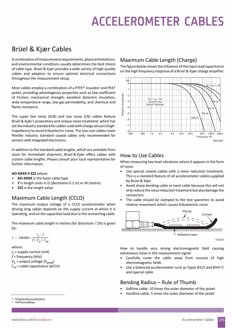
ACCELEROMETER CABLES
Brüel & Kjær CablesA combination of measurement requirements, physical limitations,and environmental conditions usually determines the best choiceof cable type. Brüel & Kjær provides a wide variety of high‐qualitycables and adaptors to ensure optimal electrical connectionsthroughout the measurement setup.
Most cables employ a combination of a PTFE* insulator and PFA†jacket, providing advantageous properties such as low coefficientof friction, mechanical strength, excellent dielectric insulation,wide temperature range, low gas permeability, and chemical andflame resistance.
The super low noise (SLN) and low noise (LN) cables featureBrüel & Kjær’s proprietary and unique noise treatment, which hasset the industry standard for cables used with charge sensors (high‐impedance) to avoid triboelectric noise. The low‐cost cables coverflexible industry standard coaxial cables only recommended forsensors with integrated electronics.
In addition to the standard cable lengths, which are available fromstock for immediate shipment, Brüel & Kjær offers cables withcustom cable lengths. Please consult your local representative forfurther information.
AO‐XXXX‐Y‐ZZZ where:• AO‐XXXX is the basic cable type• Y is length units in D (decimetre 0.1 m) or M (metre)• ZZZ is the length value
Maximum Cable Length (CCLD)The maximum output voltage of a CCLD accelerometer whendriving long cables depends on the supply current at which it isoperating, and on the capacitive load due to the connecting cable.
The maximum cable length in metres (for distortion 1%) is givenby:
where:Is = supply current (mA)f = frequency (kHz)Vo = output voltage (Vpeak)Cm = cable capacitance (pF/m)
Maximum Cable Length (Charge)The figure below shows the influence of the input load capacitanceon the high frequency response of a Brüel & Kjær charge amplifier.
How to Use CablesWhen measuring low level vibrations where it appears in the formof noise:• Use special coaxial cables with a noise reduction treatment.
This is a standard feature of all accelerometer cables suppliedby Brüel & Kjær
• Avoid sharp bending cable or twist cable because this will notonly reduce the noise reduction treatment but also damage theconnectors
• The cable should be clamped to the test specimen to avoidrelative movement which causes triboelectric noise
How to handle very strong electromagnetic field causingextraneous noise in the measurement signal:• Carefully route the cable away from sources of high
electromagnetic fields• Use a balanced accelerometer such as Types 8315 and 8347‐C
and special cable
Bending Radius – Rule of Thumb• Softline cable: 10 times the outer diameter of the jacket• Hardline cable: 5 times the outer diameter of the jacket
* Polytetrafluoroethylene† Perfluoroalkoxy
L 140000Is 1–
f Vo Cm‐‐‐‐‐‐‐‐‐‐‐‐‐‐‐‐‐‐‐‐‐‐‐‐‐‐‐‐‐‐‐=
1 k 10 k 100 k
+ 1
0
– 1
– 2
– 3
– 4
– 5
– 6
– 7
– 82 k 5 k 20 k 50 k 200 k200 500
dB
Rel
ativ
e A
mp
litu
de
10 nF
760378/2
Frequency Hz
0.1 to 1 nF
20 nF
50 nF
100 nF
“0.1” to “10”mV/Unit Out
Switch Settings
120336
Wrong
Adhesive tape
Correct
Accelerometer Cables 105www.bksv.com/transducers
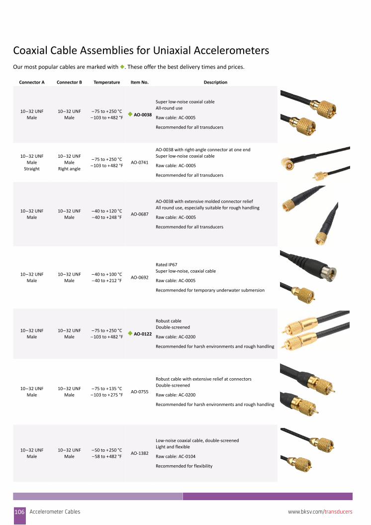
Coaxial Cable Assemblies for Uniaxial AccelerometersOur most popular cables are marked with ◆. These offer the best delivery times and prices.
Connector A Connector B Temperature Item No. Description
10–32 UNF
Male
10–32 UNF
Male
–75 to +250 °C
–103 to +482 °F◆ AO‐0038
Super low‐noise coaxial cable
All‐round use
Raw cable: AC‐0005
Recommended for all transducers
10–32 UNF
Male
Straight
10–32 UNF
Male
Right angle
–75 to +250 °C
–103 to +482 °FAO‐0741
AO‐0038 with right‐angle connector at one end
Super low‐noise coaxial cable
Raw cable: AC‐0005
Recommended for all transducers
10–32 UNF
Male
10–32 UNF
Male
–40 to +120 °C
–40 to +248 °FAO‐0687
AO‐0038 with extensive molded connector relief
All round use, especially suitable for rough handling
Raw cable: AC‐0005
Recommended for all transducers
10–32 UNF
Male
10–32 UNF
Male
–40 to +100 °C
–40 to +212 °FAO‐0692
Rated IP67
Super low‐noise, coaxial cable
Raw cable: AC‐0005
Recommended for temporary underwater submersion
10–32 UNF
Male
10–32 UNF
Male
–75 to +250 °C
–103 to +482 °F◆ AO‐0122
Robust cable
Double‐screened
Raw cable: AC‐0200
Recommended for harsh environments and rough handling
10–32 UNF
Male
10–32 UNF
Male
–75 to +135 °C
–103 to +275 °FAO‐0755
Robust cable with extensive relief at connectors
Double‐screened
Raw cable: AC‐0200
Recommended for harsh environments and rough handling
10–32 UNF
Male
10–32 UNF
Male
–50 to +250 °C
–58 to +482 °FAO‐1382
Low‐noise coaxial cable, double‐screened
Light and flexible
Raw cable: AC‐0104
Recommended for flexibility
106 Accelerometer Cables www.bksv.com/transducers
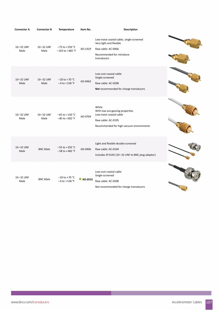
10–32 UNF
Male
10–32 UNF
Male
–75 to +250 °C
–103 to +482 °FAO‐1419
Low‐noise coaxial cable, single‐screenedVery light and flexible
Raw cable: AC‐0066
Recommended for miniature
transducers
10–32 UNF
Male
10–32 UNF
Male
–20 to +70 °C
–4 to +158 °FAO‐0463
Low‐cost coaxial cable
Single‐screened
Raw cable: AC‐0208
Not recommended for charge transducers
10–32 UNF
Male
10–32 UNF
Male
–65 to +150 °C
–85 to +302 °FAO‐0704
White
With low out‐gassing properties
Low‐noise coaxial cable
Raw cable: AC‐0195
Recommended for high vacuum environments
10–32 UNF
MaleBNC Male
–55 to +250 °C
–58 to +482 °FAO‐0406
Light and flexible double‐screened
Raw cable: AC‐0104
Includes JP‐0145 (10–32 UNF to BNC plug adaptor)
10–32 UNF
MaleBNC Male
–20 to +70 °C
–4 to +158 °F ◆ AO‐0531
Low‐cost coaxial cable
Single‐screened
Raw cable: AC‐0208
Not recommended for charge transducers
Connector A Connector B Temperature Item No. Description
Accelerometer Cables 107www.bksv.com/transducers
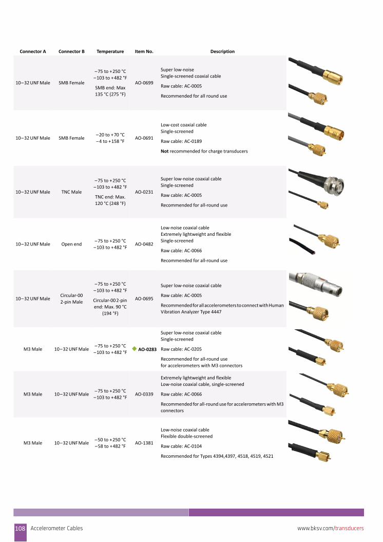
10–32 UNF Male SMB Female
–75 to +250 °C
–103 to +482 °F
SMB end: Max
135 °C (275 °F)
AO‐0699
Super low‐noise
Single‐screened coaxial cable
Raw cable: AC‐0005
Recommended for all round use
10–32 UNF Male SMB Female–20 to +70 °C
–4 to +158 °FAO‐0691
Low‐cost coaxial cable
Single‐screened
Raw cable: AC‐0189
Not recommended for charge transducers
10–32 UNF Male TNC Male
–75 to +250 °C
–103 to +482 °F
TNC end: Max.
120 °C (248 °F)
AO‐0231
Super low‐noise coaxial cable
Single‐screened
Raw cable: AC‐0005
Recommended for all‐round use
10–32 UNF Male Open end–75 to +250 °C
–103 to +482 °FAO‐0482
Low‐noise coaxial cable
Extremely lightweight and flexible
Single‐screened
Raw cable: AC‐0066
Recommended for all‐round use
10–32 UNF MaleCircular‐00
2‐pin Male
–75 to +250 °C
–103 to +482 °F
Circular‐00 2‐pin
end: Max. 90 °C
(194 °F)
AO‐0695
Super low‐noise coaxial cable
Raw cable: AC‐0005
Recommended for all accelerometers to connect with Human
Vibration Analyzer Type 4447
M3 Male 10–32 UNF Male–75 to +250 °C
–103 to +482 °F◆ AO‐0283
Super low‐noise coaxial cable
Single‐screened
Raw cable: AC‐0205
Recommended for all‐round use
for accelerometers with M3 connectors
M3 Male 10–32 UNF Male–75 to +250 °C
–103 to +482 °FAO‐0339
Extremely lightweight and flexible
Low‐noise coaxial cable, single‐screened
Raw cable: AC‐0066
Recommended for all‐round use for accelerometers with M3
connectors
M3 Male 10–32 UNF Male–50 to +250 °C
–58 to +482 °FAO‐1381
Low‐noise coaxial cable
Flexible double‐screened
Raw cable: AC‐0104
Recommended for Types 4394,4397, 4518, 4519, 4521
Connector A Connector B Temperature Item No. Description
108 Accelerometer Cables www.bksv.com/transducers

M3 Male 10–32 UNF Male–65 to +150 °C
–85 to +302 °FAO‐0703
White
With low out‐gassing properties
Super low‐noise coaxial cable
Raw cable: AC‐0195
Recommended for high vacuum environments
M3 Male BNC Male
–75 to +250 °C
–103 to +482 °F
BNC end: Max.
120 °C (248 °F)
◆ AO‐0641
Super low‐noise coaxial cable
Single‐screened
Raw cable: AC‐0205
Recommended for Types 4518, 4519, 4397, 4394, 4521
M3 Male SMB Female
–75 to +250 °C
–103 to +482 °F
SMB end: Max.
135 °C (275 °F)
AO‐0698
Super low‐noise
Single‐screened coaxial cable
Raw cable: AC‐0205
Recommended for Types 4518, 4519, 4397, 4394, 4521
3–56 UNF Male10–32 UNF
Female
–30 to +200 °C
–22 to +392 °F◆ AO‐0638
Low‐noise coaxial cable
Light and flexible
Recommended for miniature
transducers (Type 4517 family) with 3–56 UNF threaded
connector
3‐pin MIL‐C‐
5015
Female
Open end–75 to +250 °C
–103 to +482 °FAO‐0642
3‐wire (twisted) shielded cable
Electrically and environmentally robust
Raw cable: AC‐0294
Durable for permanent installations
Recommended for Type 4511‐001
Circular‐1B
FemaleCircular‐0B Male
–20 to +80 °C
–4 to +176 °FAO‐0700
For DC response transducers with 7‐pin circular LEMO
connector
PUR jacket
Recommended for Types 457x‐001 and 457x‐D‐001 and
differential amplifier Type 2697
Circular‐1B
FemaleCircular‐1B Male
–20 to +80 °C
–4 to +176 °FAO‐0414
Extension cable for DC response transducers with 7‐pin
circular LEMO connector
PUR jacket
Recommended for Types 457X‐001 and 457X‐D‐001 and
differential amplifier Type 2697
Series 800
3‐pin FemaleBNC Male
–75 to +150 °C
–103 to +302 °F
BNC end: max
135 °C (275 °F)
AO‐0746
Robust cable for permanent installation
Raw cable: AC‐0294
Recommended for Type 4511‐006
Connector A Connector B Temperature Item No. Description
Accelerometer Cables 109www.bksv.com/transducers
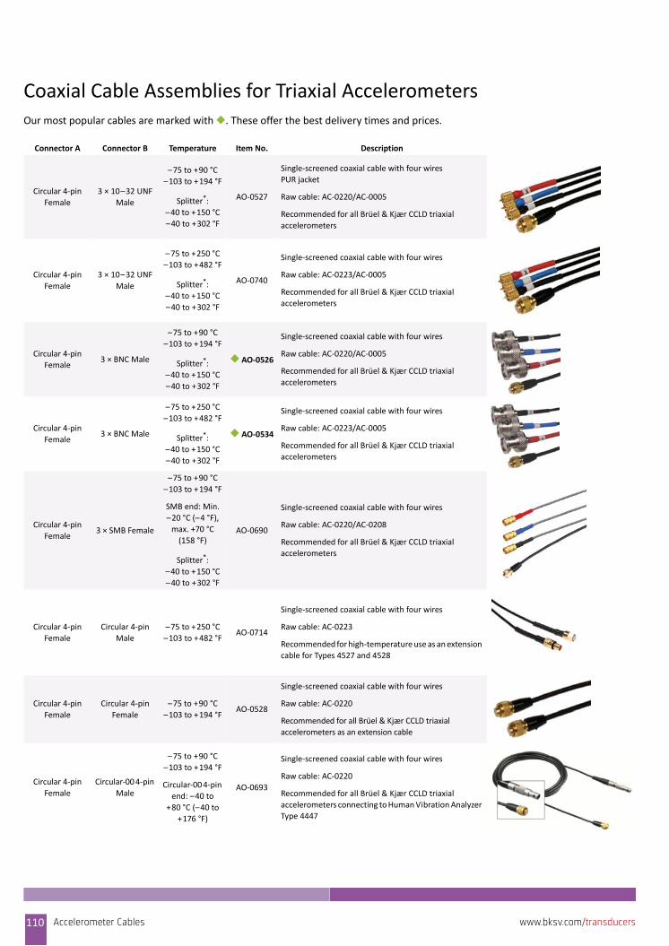
Coaxial Cable Assemblies for Triaxial AccelerometersOur most popular cables are marked with ◆. These offer the best delivery times and prices.
Connector A Connector B Temperature Item No. Description
Circular 4‐pin
Female
3 × 10–32 UNF
Male
–75 to +90 °C
–103 to +194 °F
Splitter*:
–40 to +150 °C
–40 to +302 °F
AO‐0527
Single‐screened coaxial cable with four wires
PUR jacket
Raw cable: AC‐0220/AC‐0005
Recommended for all Brüel & Kjær CCLD triaxial
accelerometers
Circular 4‐pin
Female
3 × 10–32 UNF
Male
–75 to +250 °C
–103 to +482 °F
Splitter*:
–40 to +150 °C
–40 to +302 °F
AO‐0740
Single‐screened coaxial cable with four wires
Raw cable: AC‐0223/AC‐0005
Recommended for all Brüel & Kjær CCLD triaxial
accelerometers
Circular 4‐pin
Female3 × BNC Male
–75 to +90 °C
–103 to +194 °F
Splitter*:
–40 to +150 °C
–40 to +302 °F
◆ AO‐0526
Single‐screened coaxial cable with four wires
Raw cable: AC‐0220/AC‐0005
Recommended for all Brüel & Kjær CCLD triaxial
accelerometers
Circular 4‐pin
Female3 × BNC Male
–75 to +250 °C
–103 to +482 °F
Splitter*:
–40 to +150 °C
–40 to +302 °F
◆ AO‐0534
Single‐screened coaxial cable with four wires
Raw cable: AC‐0223/AC‐0005
Recommended for all Brüel & Kjær CCLD triaxial
accelerometers
Circular 4‐pin
Female3 × SMB Female
–75 to +90 °C
–103 to +194 °F
SMB end: Min.
–20 °C (–4 °F),
max. +70 °C
(158 °F)
Splitter*:
–40 to +150 °C
–40 to +302 °F
AO‐0690
Single‐screened coaxial cable with four wires
Raw cable: AC‐0220/AC‐0208
Recommended for all Brüel & Kjær CCLD triaxial
accelerometers
Circular 4‐pin
Female
Circular 4‐pin
Male
–75 to +250 °C
–103 to +482 °FAO‐0714
Single‐screened coaxial cable with four wires
Raw cable: AC‐0223
Recommended for high‐temperature use as an extension
cable for Types 4527 and 4528
Circular 4‐pin
Female
Circular 4‐pin
Female
–75 to +90 °C
–103 to +194 °FAO‐0528
Single‐screened coaxial cable with four wires
Raw cable: AC‐0220
Recommended for all Brüel & Kjær CCLD triaxial
accelerometers as an extension cable
Circular 4‐pin
Female
Circular‐00 4‐pin
Male
–75 to +90 °C
–103 to +194 °F
Circular‐00 4‐pin
end: –40 to
+80 °C (–40 to
+176 °F)
AO‐0693
Single‐screened coaxial cable with four wires
Raw cable: AC‐0220
Recommended for all Brüel & Kjær CCLD triaxial
accelerometers connecting to Human Vibration Analyzer
Type 4447
110 Accelerometer Cables www.bksv.com/transducers

Circular 4‐pin
Female
Circular‐00 3‐pin
Male
–20 to +90 °C
–4 to +194 °FAO‐1454
Electrically and environmentally robust
Durable for permanent installations
Raw cable: AC‐0220
Circular‐00 4‐pin
Male
3 × 10–32 UNF
Male
–75 to +90 °C
–103 to +194°
Circular‐00 4‐pin
end: –40 to
+80 °C (–40 to
+176 °F)
Splitter*:
–40 to +150 °C
–40 to +302 °F
AO‐0694
Single‐screened coaxial cable with four wires
Raw cable: AC‐0220
Recommended for connecting accelerometers to Human
Vibration Analyzer Type 4447
3 × 10–32 UNF
Male
3 × 10–32 UNF
Male
–75 to +250 °C
–103 to +482 °F
Splitter*:
–40 to +150 °C
–40 to +302 °F
AO‐0688
4‐wire coaxial cable terminating in three single‐wire
coaxial cables at each end
Raw cable: AC‐0220/AC‐0223
Recommended for all Brüel & Kjær CCLD triaxial
accelerometers
2 × Circular 4‐pin
Female
Sub‐D 37‐pin
Female
–75 to +90 °C
–103 to +194 °FAO‐0536
Single‐screened coaxial cable with four wires for two
triaxial accelerometers
Raw cable: AC‐0220
Recommended for all Brüel & Kjær CCLD triaxial
accelerometers to PULSE multi‐analyzer
Serial‐800
4‐pin Female3 × BNC Male
–75 to +250 °C
–103 to +482 °F
Splitter*:
–40 to +150 °C
–40 to +302 °F
AO‐0745
Robust cable suitable for permanent monitoring
Raw cable: AC‐0294/AC‐0005
Recommended for Brüel & Kjær triaxial industrial
accelerometer Type 8345 family
3 × 10–32 UNF
Male3 × BNC Male
–75 to +250 °C
–103 to +482 °F
Splitter*:
–40 to +150 °C
–40 to +302 °F
AO‐0759
Low‐noise cable
Raw cable: AC‐0223/AC‐0005
Recommended for all transducers
M3 MaleCircular‐00
2‐pin Male
–50 to +105 °C
(–58 to +221 °F)AO‐0701
Low‐noise cable
Raw cable: AC‐0104
Recommended for connecting Brüel & Kjær triaxial
accelerometers with M3 connectors to Hand‐held
Analyzer Types 2250 and 2270
10–32 UNF MaleCircular‐00
2‐pin Male
–50 to +200 °C
(–58 to +392 °F)AO‐0702
Low‐noise cable
Raw cable: AC‐0104
Recommended for connecting Brüel & Kjær triaxial
accelerometers with 10–32 UNF connectors to Hand‐
held Analyzer Types 2250 and 2270
* Close‐up of cable splitter:
Connector A Connector B Temperature Item No. Description
Accelerometer Cables 111www.bksv.com/transducers
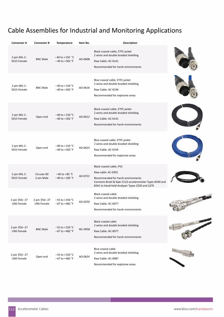
Cable Assemblies for Industrial and Monitoring Applications
Connector A Connector B Temperature Item No. Description
2‐pin MIL‐C‐
5015 FemaleBNC Male
–40 to +150 °C
–40 to +302 °FAO‐0608
Black coaxial cable, ETFE jacket
2 wires and double braided shielding
Raw Cable: AC‐0141
Recommended for harsh environments
2‐pin MIL‐C‐
5015 FemaleBNC Male
–40 to +150 °C
–40 to +302 °FAO‐0616
Blue coaxial cable, ETFE jacket
2 wires and double braided shielding
Raw Cable: AC‐0194
Recommended for explosive areas
2‐pin MIL‐C‐
5015 FemaleOpen end
–40 to +150 °C
–40 to +302 °FAO‐0612
Black coaxial cable, ETFE jacket
2 wires and double braided shielding
Raw Cable: AC‐0141
Recommended for harsh environments
2‐pin MIL‐C‐
5015 FemaleOpen end
–40 to +150 °C
–40 to +302 °FAO‐0623
Blue coaxial cable, ETFE jacket
2 wires and double braided shielding
Raw Cable: AC‐0194
Recommended for explosive areas
2‐pin MIL‐C‐
5015 Female
Circular‐00
2‐pin Male
–40 to +85 °C
–40 to +185 °FAO‐0722
Black coaxial cable, PVC
Raw cable: AC‐0201
Recommended for harsh environments
Connects Brüel & Kjær CCLD accelerometer Types 8340 and
8341 to Hand‐held Analyzer Types 2250 and 2270
2‐pin 7/16–27
UNS Female
2‐pin 7/16–27
UNS Female
–55 to +250 °C
–67 to +482 °FAO‐0250
Black coaxial cable
2 wires and double braided shielding
Raw Cable: AC‐0077
Recommended for harsh environments
2‐pin 7/16–27
UNS FemaleBNC Male
–55 to +250 °C
–67 to +482 °FWL‐0958
Black coaxial cable
2 wires and double braided shielding
Raw Cable: AC‐0077
Recommended for harsh environments
2‐pin 7/16–27
UNS Female Open end
–55 to +250 °C
–67 to +482 °FAO‐0624
Blue coaxial cable
2 wires and double braided shielding
Raw Cable: AC‐0087
Recommended for explosive areas
112 Accelerometer Cables www.bksv.com/transducers
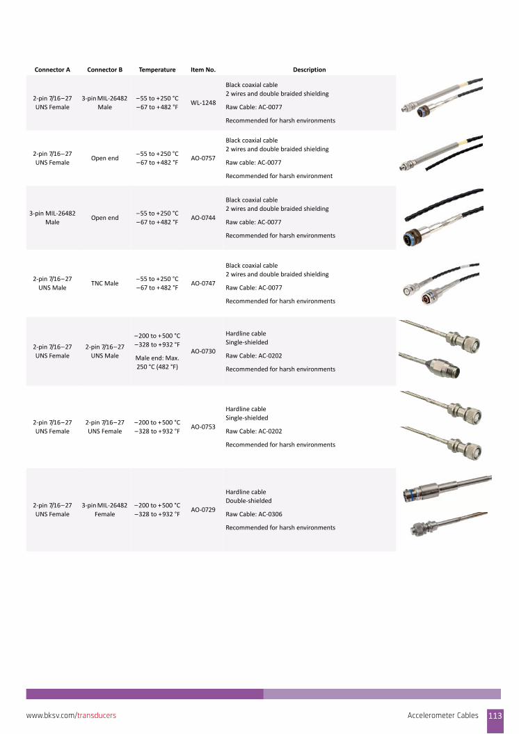
2‐pin 7/16–27
UNS Female
3‐pin MIL‐26482
Male
–55 to +250 °C
–67 to +482 °FWL‐1248
Black coaxial cable
2 wires and double braided shielding
Raw Cable: AC‐0077
Recommended for harsh environments
2‐pin 7/16–27
UNS Female Open end
–55 to +250 °C
–67 to +482 °FAO‐0757
Black coaxial cable
2 wires and double braided shielding
Raw cable: AC‐0077
Recommended for harsh environment
3‐pin MIL‐26482
MaleOpen end
–55 to +250 °C
–67 to +482 °FAO‐0744
Black coaxial cable
2 wires and double braided shielding
Raw cable: AC‐0077
Recommended for harsh environments
2‐pin 7/16–27
UNS MaleTNC Male
–55 to +250 °C
–67 to +482 °FAO‐0747
Black coaxial cable
2 wires and double braided shielding
Raw Cable: AC‐0077
Recommended for harsh environments
2‐pin 7/16–27
UNS Female
2‐pin 7/16–27
UNS Male
–200 to +500 °C
–328 to +932 °F
Male end: Max.
250 °C (482 °F)
AO‐0730
Hardline cable
Single‐shielded
Raw Cable: AC‐0202
Recommended for harsh environments
2‐pin 7/16–27
UNS Female
2‐pin 7/16–27
UNS Female
–200 to +500 °C
–328 to +932 °FAO‐0753
Hardline cable
Single‐shielded
Raw Cable: AC‐0202
Recommended for harsh environments
2‐pin 7/16–27
UNS Female
3‐pin MIL‐26482
Female
–200 to +500 °C
–328 to +932 °FAO‐0729
Hardline cable
Double‐shielded
Raw Cable: AC‐0306
Recommended for harsh environments
Connector A Connector B Temperature Item No. Description
Accelerometer Cables 113www.bksv.com/transducers
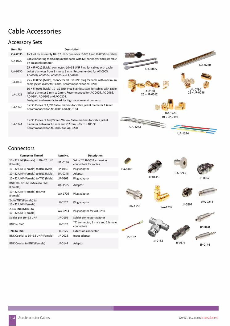
Cable Accessories
Accessory Sets
Connectors
Item No. Description
QA‐0035 Tool set for assembly 10–32 UNF connector JP‐0012 and JP‐0056 on cables
QA‐0220Cable mounting tool to mount the cable with M3 connector and assemble
on an accelerometer
UA‐0130
25 × JP‐0012 (Male) connector, 10–32 UNF Plug for cables with cable
jacket diameter from 1 mm to 3 mm. Recommended for AC‐0005,
AC‐0066, AC‐0104, AC‐0205 and AC‐0208
UA‐073025 × JP‐0056 (Male), connector 10–32 UNF plug for cable with maximum
cable jacket diameter 3 mm. Recommended for AC‐0200
UA‐1723
10 × JP‐0196 (Male) 10–32 UNF Plug Stainless steel for cables with cable
jacket diameter 1 mm to 2 mm. Recommended for AC‐0005, AC‐0066,
AC‐0104, AC‐0205 and AC‐0208.
Designed and manufactured for high vacuum environments
UA‐12433 × 30 Pieces of 1/2/3 Cable markers for cable jacket diameter 1.6 mm
Recommended for AC‐0205 and AC‐0104
UA‐1244
3 × 30 Pieces of Red/Green/Yellow Cable markers for cable jacket
diameter between 1.9 mm and 2.2 mm, –65 to +105 °C Recommended for AC‐0005 and AC‐0208
QA-0035QA-0220
UA-013025 × JP-0012
UA-073025 × JP-0056
UA-172310 × JP-0196
UA-1243
UA-1244
Connector Thread Item No. Description
10–32 UNF (Female) to 10–32 UNF
(Female)UA‐0186
Set of 25 JJ‐0032 extension
connectors for cables
10–32 UNF (Female) to BNC (Male) JP‐0145 Plug adaptor
10–32 UNF (Female) to BNC (Male) UA‐0245 Adaptor
10–32 UNF (Female) to TNC (Male) JP‐0162 Plug adaptor
B&K 10–32 UNF (Male) to BNC
(Female)UA‐1555 Adaptor
10–32 UNF (Female) to SMB
(Female)WA‐1705 Plug adaptor
2‐pin TNC (Female) to
10–32 UNF (Female)JJ‐0207 Plug adaptor
2‐pin TNC (Male) to
10–32 UNF (Female)WA‐0214 Plug adaptor for AO‐0250
Solder pin 10–32 UNF JP‐0192 Solder connector adaptor
BNC to BNC JJ‐0152“T” connector, 1 male and 2 female
connectors
TNC to TNC JJ‐0175 Extension connector
B&K Coaxial to 10–32 UNF (Female) JP‐0028 Input adaptor
B&K Coaxial to BNC (Female) JP‐0144 Adaptor
WA‐1705UA-1555JJ-0207
JJ‐0175
UA‐0186
JP‐0192
JP‐0145
JJ-0152
UA-0245
WA-0214
JP-0028
JP-0144
JP‐0162
114 Accelerometer Cables www.bksv.com/transducers

Raw Cables Illustrations of the individual cables follow – see the referencedfigure number in the table.
Some of the more unfamiliar jacket materials used are explainedhere:• PTFE: Insulation and sheathing material. Can be used for many
high‐temperature applications such as gas turbines, high‐voltage applications and many aerospace applicationsincluding use in vacuum environment
• PFA: Insulation and sheathing material. Can be used for high‐temperature industrial applications such as gas turbines. Lowhalogen
• ETFE: Insulation and sheathing material, chemically resistant,flame retardant, low smoke generation. Ideal for all round,general purpose use and radiation environment
• FEP: Good insulation material for cable jacket. It has excellentnon‐ageing characteristics and a broad useful temperaturerange
• PE: Insulation, dielectric (LDPE) or jacket material (HDPE). Thismaterial is light, tough, permanently flexible, has goodresistance to chemicals, non‐oxidising acids and aromaticsolvents, a low moisture absorption and good tensile and tearstrength
• PVC: Insulation or jacket material which exhibits the property ofhigh electrical resistivity, good dielectric strength, excellentmechanical toughness, superior resistance against oxygen,ozone, most common acids, alkalis and chemicals. Flameresistance, oil resistance and the temperature range depend onthe compound
• PUR: Extruded jacket. Exhibits extreme toughness and abrasionresistance
Raw Coaxial Cables for Piezoelectric and CCLD Accelerometers
Item No. DescriptionInsulator/
JacketScreen
Number of
Wires
Diameter Max. Temp Min. Temp Capacitance
pF/m
Impedance
mm inches °C °F °C °F
AC‐0005
(Fig. 28)Super low noise PTFE/PFA Single 1 2 0.08 +250 +482 –75 –103 106 60
AC‐0066
(Fig. 29)Low noise PTFE/PFA Single 1 1 0.04 +250 +482 –75 –103 106 50
AC‐0104
(Fig. 30)Low noise PTFE/PFA Double 1 1.6 0.06 +250 +482 –50 –58 100 50
AC‐0195
Flexible low
outgassing,
white
FEP/PTFE Single 1 1.70 0.06 +150 +302 –65 –85
AC‐0200
(Fig. 31)Super low noise PTFE/PFA Double 1 3.2 0.13 +250 +482 –75 –103 106 60
AC‐0205
(Fig. 32)Super low noise PTFE/PFA Single 1 1.5 0.06 +250 +482 –75 –103 110 50
AC‐0208
(Fig. 33)Flexible, grey PE/PVC Single 1 2 0.08 +70 +158 –20 –4 100 50
AC‐0220
(Fig. 34)Flexible ETFE/PUR Single 4 2.4 0.09 +90 +194 –75 –103 106 50
AC‐0223
(Fig. 35)Flexible ETFE/PTFE Single 4 2.1 0.09 +250 +482 –75 –103 106 50
AC‐0080
(Fig. 36)Spiral PUR/PFA Single 1 14 0.55 +85 +185 –40 –40 100 50
Accelerometer Cables 115www.bksv.com/transducers
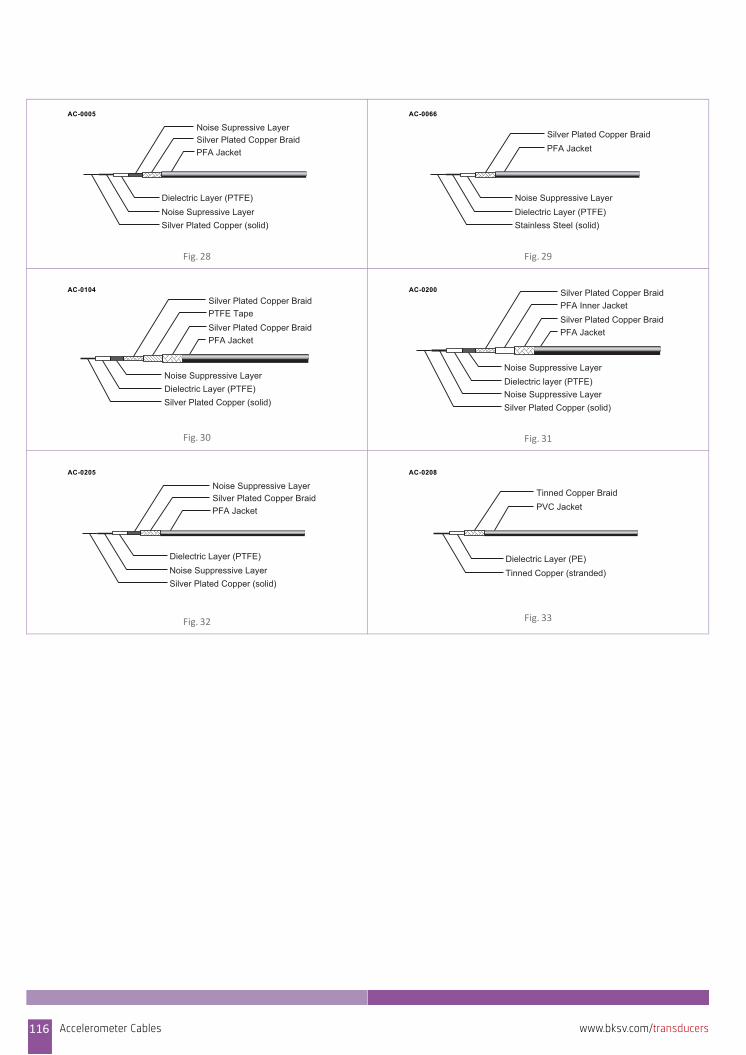
Fig. 28 Fig. 29
Fig. 30 Fig. 31
Fig. 32 Fig. 33
PFA Jacket
Noise Supressive LayerSilver Plated Copper Braid
Dielectric Layer (PTFE)Noise Supressive LayerSilver Plated Copper (solid)
AC-0005
PFA JacketSilver Plated Copper Braid
Noise Suppressive LayerDielectric Layer (PTFE)Stainless Steel (solid)
AC-0066
PFA JacketSilver Plated Copper Braid PTFE TapeSilver Plated Copper Braid
Noise Suppressive LayerDielectric Layer (PTFE)Silver Plated Copper (solid)
AC-0104
PFA JacketSilver Plated Copper BraidPFA Inner JacketSilver Plated Copper Braid
Noise Suppressive LayerDielectric layer (PTFE)Noise Suppressive LayerSilver Plated Copper (solid)
AC-0200
PFA Jacket
Noise Suppressive LayerSilver Plated Copper Braid
Dielectric Layer (PTFE)Noise Suppressive LayerSilver Plated Copper (solid)
AC-0205
PVC JacketTinned Copper Braid
Dielectric Layer (PE)Tinned Copper (stranded)
AC-0208
116 Accelerometer Cables www.bksv.com/transducers
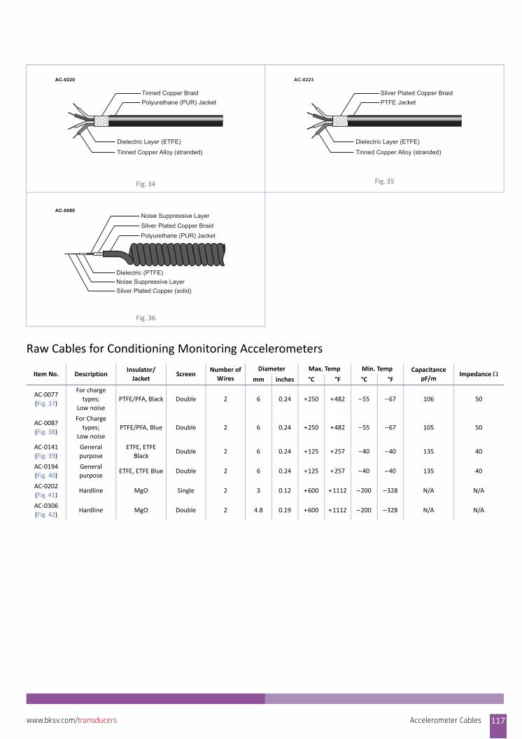
Raw Cables for Conditioning Monitoring Accelerometers
Fig. 34 Fig. 35
Fig. 36
Item No. DescriptionInsulator/
JacketScreen
Number of
Wires
Diameter Max. Temp Min. Temp Capacitance
pF/mImpedance
mm inches °C °F °C °F
AC‐0077
(Fig. 37)
For charge
types;
Low noise
PTFE/PFA, Black Double 2 6 0.24 +250 +482 –55 –67 106 50
AC‐0087
(Fig. 38)
For Charge
types;
Low noise
PTFE/PFA, Blue Double 2 6 0.24 +250 +482 –55 –67 105 50
AC‐0141
(Fig. 39)
General
purpose
ETFE, ETFE
BlackDouble 2 6 0.24 +125 +257 –40 –40 135 40
AC‐0194
(Fig. 40)
General
purposeETFE, ETFE Blue Double 2 6 0.24 +125 +257 –40 –40 135 40
AC‐0202
(Fig. 41)Hardline MgO Single 2 3 0.12 +600 +1112 –200 –328 N/A N/A
AC‐0306
(Fig. 42)Hardline MgO Double 2 4.8 0.19 +600 +1112 –200 –328 N/A N/A
Polyurethane (PUR) JacketTinned Copper Braid
Dielectric Layer (ETFE)
Tinned Copper Alloy (stranded)
AC-0220
PTFE JacketSilver Plated Copper Braid
Dielectric Layer (ETFE)
Tinned Copper Alloy (stranded)
AC-0223
Polyurethane (PUR) JacketSilver Plated Copper BraidNoise Suppressive Layer
Dielectric (PTFE)Noise Suppressive LayerSilver Plated Copper (solid)
AC-0080
Accelerometer Cables 117www.bksv.com/transducers
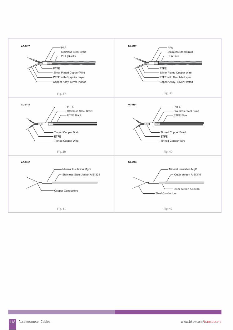
Fig. 37 Fig. 38
Fig. 39 Fig. 40
Fig. 41 Fig. 42
PFA (Black)Stainless Steel BraidPFA
PTFESilver Plated Copper Wire
PTFE with Graphite Layer
Copper Alloy, Silver Platted
AC-0077
PFA BlueStainless Steel BraidPFA
PTFESilver Plated Copper Wire
PTFE with Graphite Layer
Copper Alloy, Silver Platted
AC-0087
ETFE BlackStainless Steel BraidPTFE
Tinned Copper BraidETFETinned Copper Wire
AC-0141
ETFE BlueStainless Steel BraidPTFE
Tinned Copper BraidETFETinned Copper Wire
AC-0194
Stainless Steel Jacket AISI321
Mineral Insulation MgO
Copper Conductors
AC-0202
Outer screen AISI316
Mineral Insulation MgO
Steel Conductors
AC-0306
Inner screen AISI316
118 Accelerometer Cables www.bksv.com/transducers
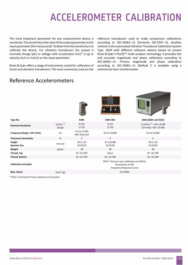
ACCELEROMETER CALIBRATION
The most important parameter for any measurement device issensitivity. The sensitivity is the ratio of the output parameter to theinput parameter (the measurand). To determine the sensitivity is tocalibrate the device. For vibration transducers the output isnormally charge (pC) or voltage with acceleration (m/s2 or g) orvelocity (m/s or inch/s) as the input parameter.
Brüel & Kjær offers a range of instruments suited for calibration ofshock and vibration transducers. The most commonly used are the
reference transducers used to make comparison calibrationsaccording to ISO 16063–21 (formerly ISO 5347–3). Anothersolution is the automated Vibration Transducer Calibration SystemType 3629 with different software options based on provenBrüel & Kjær’s PULSE™ multi‐analyzer technology. It provides fastand accurate magnitude and phase calibration according toISO 16063–21. Primary magnitude and phase calibrationaccording to ISO 16063–11 Method 3 is available using acommercial laser interferometer.
Reference Accelerometers
Type No. 8305 8305‐001 3506 (8305 and 2525)
Nominal Sensitivity pC/ms–2
(pC/g)
0.125
(1.23)
0.125
(1.23)1 mV/ms–2 +30/–20 dB
(10 mV/g +30/–20 dB)
Frequency Range ±10% limits Hz0.2 to 11500
with 20 g load0.2 to 10300 0.2 to 10300
Transverse Sensitivity % 2 2 2
Height
Spanner Sizemm (in)
29 (1.15)
16 (0.63)
22.3 (0.88)
16 (0.63)
29 (1.15)
16 (0.63)
Weight grams 40 26 40
Thread, Top 10–32 UNF None 10–32 UNF
Thread, Bottom 10–32 UNF 10–32 UNF 10–32 UNF
Calibration IncludedDPLA* Primary Laser Calibration at 160 Hz
Uncertainty ±0.5%
Frequency Response Curve
Max. Shock km/s2 (g) 10 (1000)
* DPLA is the Danish Primary Laboratory of Acoustics
Accelerometer Calibration 119www.bksv.com/transducers
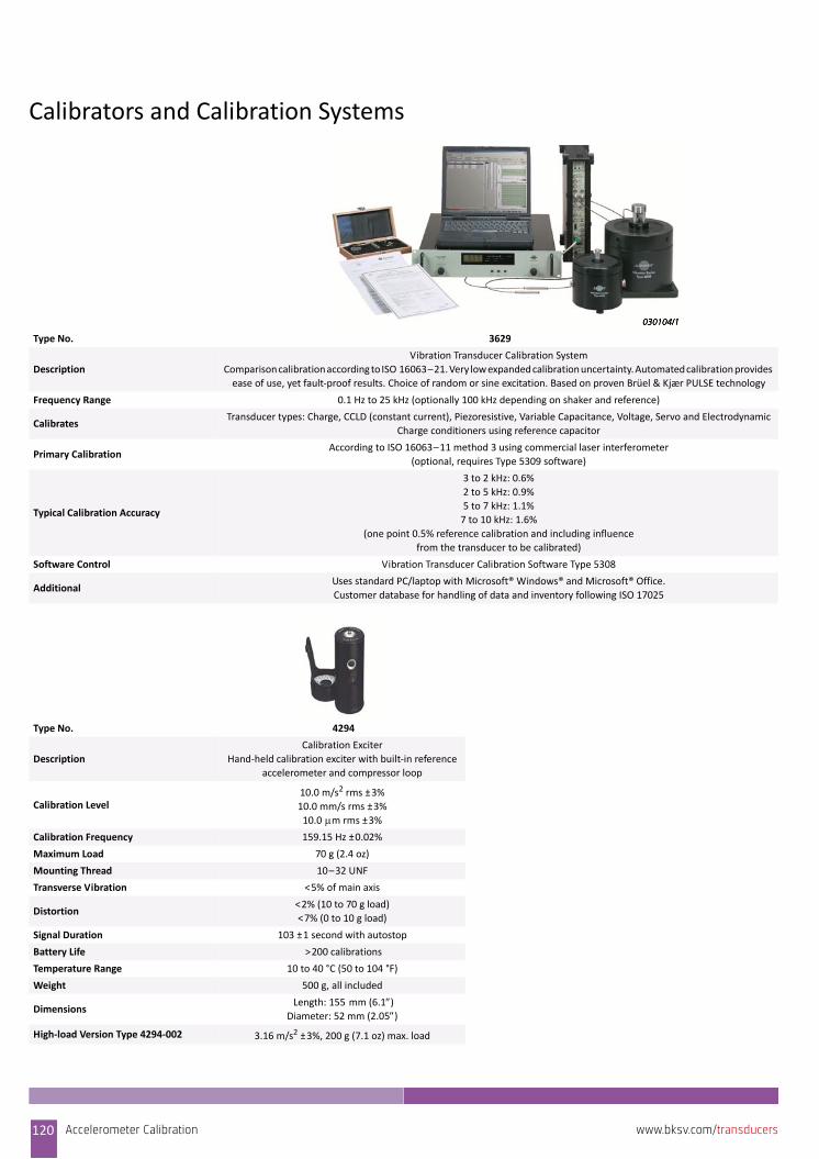
Calibrators and Calibration Systems
Type No. 3629
Description
Vibration Transducer Calibration System
Comparison calibration according to ISO 16063–21. Very low expanded calibration uncertainty. Automated calibration provides
ease of use, yet fault‐proof results. Choice of random or sine excitation. Based on proven Brüel & Kjær PULSE technology
Frequency Range 0.1 Hz to 25 kHz (optionally 100 kHz depending on shaker and reference)
Calibrates Transducer types: Charge, CCLD (constant current), Piezoresistive, Variable Capacitance, Voltage, Servo and Electrodynamic
Charge conditioners using reference capacitor
Primary Calibration According to ISO 16063–11 method 3 using commercial laser interferometer
(optional, requires Type 5309 software)
Typical Calibration Accuracy
3 to 2 kHz: 0.6%
2 to 5 kHz: 0.9%
5 to 7 kHz: 1.1%
7 to 10 kHz: 1.6%
(one point 0.5% reference calibration and including influence
from the transducer to be calibrated)
Software Control Vibration Transducer Calibration Software Type 5308
AdditionalUses standard PC/laptop with Microsoft® Windows® and Microsoft® Office.
Customer database for handling of data and inventory following ISO 17025
Type No. 4294
Description
Calibration Exciter
Hand‐held calibration exciter with built‐in reference
accelerometer and compressor loop
Calibration Level 10.0 m/s2 rms ±3%
10.0 mm/s rms ±3%
10.0 m rms ±3%
Calibration Frequency 159.15 Hz ±0.02%
Maximum Load 70 g (2.4 oz)
Mounting Thread 10–32 UNF
Transverse Vibration <5% of main axis
Distortion <2% (10 to 70 g load)
<7% (0 to 10 g load)
Signal Duration 103 ±1 second with autostop
Battery Life >200 calibrations
Temperature Range 10 to 40 °C (50 to 104 °F)
Weight 500 g, all included
Dimensions Length: 155 mm (6.1)Diameter: 52 mm (2.05)
High‐load Version Type 4294‐002 3.16 m/s2 ±3%, 200 g (7.1 oz) max. load
120 Accelerometer Calibration www.bksv.com/transducers
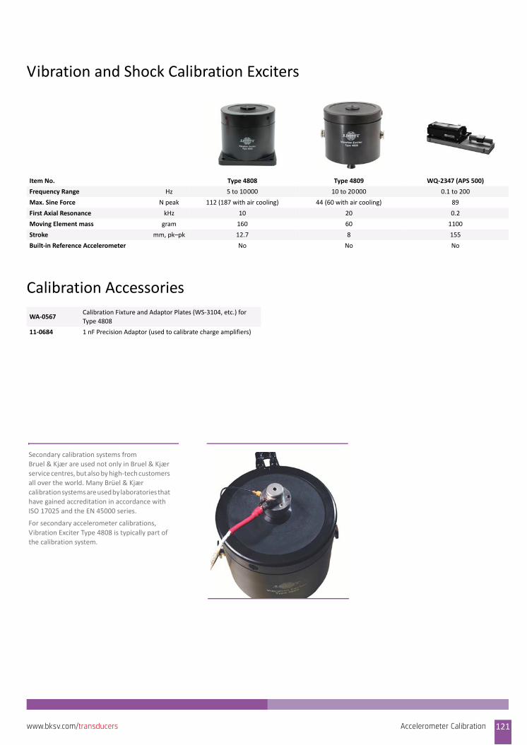
Vibration and Shock Calibration Exciters
Calibration Accessories
Item No. Type 4808 Type 4809 WQ‐2347 (APS 500)
Frequency Range Hz 5 to 10000 10 to 20000 0.1 to 200
Max. Sine Force N peak 112 (187 with air cooling) 44 (60 with air cooling) 89
First Axial Resonance kHz 10 20 0.2
Moving Element mass gram 160 60 1100
Stroke mm, pk–pk 12.7 8 155
Built‐in Reference Accelerometer No No No
WA‐0567Calibration Fixture and Adaptor Plates (WS‐3104, etc.) for
Type 4808
11‐0684 1 nF Precision Adaptor (used to calibrate charge amplifiers)
Secondary calibration systems from
Bruel & Kjær are used not only in Bruel & Kjær service centres, but also by high‐tech customers
all over the world. Many Brüel & Kjær
calibration systems are used by laboratories that have gained accreditation in accordance with
ISO 17025 and the EN 45000 series.
For secondary accelerometer calibrations,
Vibration Exciter Type 4808 is typically part of the calibration system.
Accelerometer Calibration 121www.bksv.com/transducers

122 Accelerometer Calibration www.bksv.com/transducers

SIGNAL CONDITIONING
Multi‐pin Signal Conditioners for MicrophonesMulti‐pin preamplifiers cover the widest range of acousticapplications. Signal conditioners condition the microphone signalsfrom the microphone preamplifiers. In this case, you must take intoaccount the preamplifier's supply voltage. For very high soundpressure level measurements, the conditioner's supply voltagemay limit the measurement system's maximum measurable level.The maximum measurable sound pressure level is a function ofseveral parameters:
• Frequency content of the sound• Sensitivity of microphone (including influence of polarization
voltage for externally polarized microphones)• Preamplifier’s voltage drop• Capacitance of cable between preamplifier and conditioner• Supply voltage and current from conditioner• Gain or attenuation in conditioner or preamplifier• Peak input range of data acquisition
Type No. 2250 2829 5935‐L 2690‐A 2691‐A
Description Hand‐held AnalyzerMicrophone
Conditioner
Microphone
Conditioner
NEXUS
Microphone
Conditioner
NEXUS
(Single Probe) Intensity
Conditioner
Channels Min./Max. 1 4 2 1/4 2
Preamplifier Supply Voltage ±18 ±50 24 ±14 and ±40 ±14 and ±40
Polarization Control 0 and 200 V 0 and 200 V 0, 28 and 200 V 0 and 200 V 0 and 200 V
Manual Control Yes No Yes Yes Yes
Computer Control Yes No No Yes Yes
Maximum Number of Channels
from One PC
Multiple from USB or
LAN port– – 99 per COM or USB port 99 per COM or USB port
CIC No Via external connector Via external connector No No
Maximum Frequency
(kHz at filters –5% point)20 – 100 100 100
A‐weighting Yes No Yes Yes Yes
B‐, C‐ and D‐weighting Yes (B‐ and C‐) No No Optional No
Adjustable Filters No No No Yes Yes
Alarms Yes – – – –
Maximum Gain × 1000 (60 dB) – × 316 (50 dB) × 10000 (80 dB) × 10000 (80 dB)
Minimum Gain × 0.01 (–60 dB) × 1 (0 dB) × 1 (0 dB) × 0.1 (–20 dB) × 0.1 (–20 dB)
Uni (Fine) Gain Adjustment Yes No YesYes, automatic from
TEDS
Yes, automatic from
TEDS
Reads TEDS No Via external connector No Yes Yes
Channels per 19 Rack – – 6 12 12
Mains (AC) Power Yes Yes Yes Yes Yes
Battery Power Yes No Yes Optional Optional
Signal Conditioning 123www.bksv.com/transducers
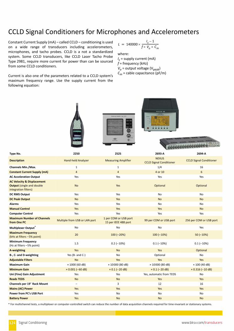
CCLD Signal Conditioners for Microphones and AccelerometersConstant Current Supply (mA) – called CCLD – conditioning is usedon a wide range of transducers including accelerometers,microphones, and tacho probes. CCLD is a not a standardizedsystem. Some CCLD transducers, like CCLD Laser Tacho ProbeType 2981, require more current for power than can be sourcedfrom some CCLD conditioners.
Current is also one of the parameters related to a CCLD system’smaximum frequency range. Use the supply current from thefollowing equation:
where:Is = supply current (mA)f = frequency (kHz)Vo = output voltage (Vpeak)Cm = cable capacitance (pF/m)
L 140000Is 1–
f Vo Cm‐‐‐‐‐‐‐‐‐‐‐‐‐‐‐‐‐‐‐‐‐‐‐‐‐‐‐
Type No. 2250 2525 2693‐A 2694‐A
Description Hand‐held Analyzer Measuring AmplifierNEXUS
CCLD Signal ConditionerCCLD Signal Conditioner
Channels Min./Max. 1 1 1/4 16
Constant Current Supply (mA) 4 4 4 or 10 6
AC Acceleration Output Yes Yes Yes Yes
AC Velocity & Displacement
Output (single and double
integration filters)
No Yes Optional Optional
DC RMS Output Yes Yes No No
DC Peak Output No Yes No No
Alarms Yes Yes No No
Manual Control Yes Yes Yes No
Computer Control Yes Yes Yes Yes
Maximum Number of Channels
from One PCMultiple from USB or LAN port
1 per COM or USB port
15 per IEEE 488 port99 per COM or USB port 256 per COM or USB port
Multiplexer Output*
* For multichannel tests, a multiplexer or computer‐controlled switch can reduce the number of data acquisition channels required for time‐invariant or stationary systems.
No No No Yes
Maximum Frequency
(kHz at filters –5% point)20 100 (–20%) 100 (–10%) 50 (–10%)
Minimum Frequency
(Hz at filters –5% point)1.5 0.2 (–10%) 0.1 (–10%) 0.1 (–10%)
A‐weighting Yes No Yes Optional
B‐, C‐ and D‐weighting Yes (B‐ and C‐) No Optional No
Adjustable Filters No Yes Yes Yes
Maximum Gain × 1000 (60 dB) × 10000 (80 dB) × 10000 (80 dB) × 100 (40 dB)
Minimum Gain × 0.001 (–60 dB) × 0.1 (–20 dB) × 0.1 (–20 dB) × 0.316 (–10 dB)
Uni (Fine) Gain Adjustment Yes Yes Yes, automatic from TEDS No
Reads TEDS No No Yes Yes
Channels per 19 Rack Mount – 3 12 16
Mains (AC) Power Yes Yes Yes Yes
Power from PC’s USB Port Yes No No No
Battery Power Yes No No No
124 Signal Conditioning www.bksv.com/transducers
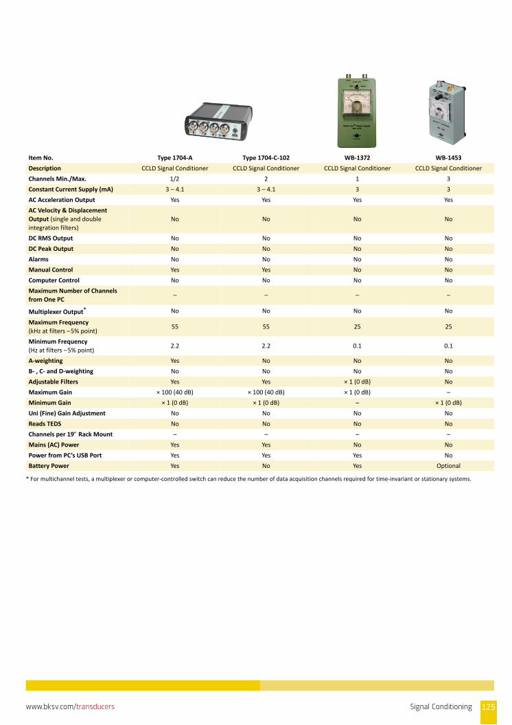
Item No. Type 1704‐A Type 1704‐C‐102 WB‐1372 WB‐1453
Description CCLD Signal Conditioner CCLD Signal Conditioner CCLD Signal Conditioner CCLD Signal Conditioner
Channels Min./Max. 1/2 2 1 3
Constant Current Supply (mA) 3 – 4.1 3 – 4.1 3 3
AC Acceleration Output Yes Yes Yes Yes
AC Velocity & Displacement
Output (single and double
integration filters)
No No No No
DC RMS Output No No No No
DC Peak Output No No No No
Alarms No No No No
Manual Control Yes Yes No No
Computer Control No No No No
Maximum Number of Channels
from One PC– – – –
Multiplexer Output* No No No No
Maximum Frequency
(kHz at filters –5% point)55 55 25 25
Minimum Frequency
(Hz at filters –5% point)2.2 2.2 0.1 0.1
A‐weighting Yes No No No
B‐ , C‐ and D‐weighting No No No No
Adjustable Filters Yes Yes × 1 (0 dB) No
Maximum Gain × 100 (40 dB) × 100 (40 dB) × 1 (0 dB) –
Minimum Gain × 1 (0 dB) × 1 (0 dB) – × 1 (0 dB)
Uni (Fine) Gain Adjustment No No No No
Reads TEDS No No No No
Channels per 19 Rack Mount – – – –
Mains (AC) Power Yes Yes No No
Power from PC’s USB Port Yes Yes Yes No
Battery Power Yes No Yes Optional
* For multichannel tests, a multiplexer or computer‐controlled switch can reduce the number of data acquisition channels required for time‐invariant or stationary systems.
Signal Conditioning 125www.bksv.com/transducers
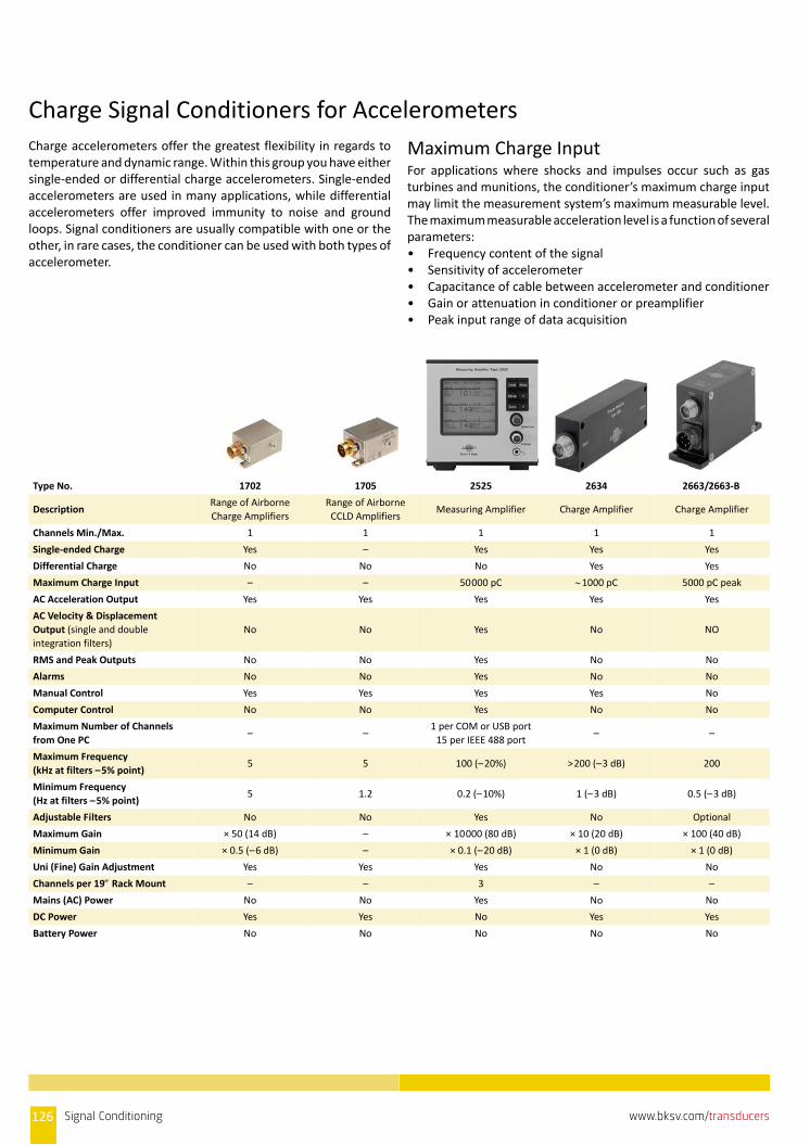
Charge Signal Conditioners for AccelerometersCharge accelerometers offer the greatest flexibility in regards totemperature and dynamic range. Within this group you have eithersingle‐ended or differential charge accelerometers. Single‐endedaccelerometers are used in many applications, while differentialaccelerometers offer improved immunity to noise and groundloops. Signal conditioners are usually compatible with one or theother, in rare cases, the conditioner can be used with both types ofaccelerometer.
Maximum Charge InputFor applications where shocks and impulses occur such as gasturbines and munitions, the conditioner’s maximum charge inputmay limit the measurement system’s maximum measurable level.The maximum measurable acceleration level is a function of severalparameters:• Frequency content of the signal• Sensitivity of accelerometer• Capacitance of cable between accelerometer and conditioner• Gain or attenuation in conditioner or preamplifier• Peak input range of data acquisition
Type No. 1702 1705 2525 2634 2663/2663‐B
DescriptionRange of Airborne
Charge Amplifiers
Range of Airborne
CCLD AmplifiersMeasuring Amplifier Charge Amplifier Charge Amplifier
Channels Min./Max. 1 1 1 1 1
Single‐ended Charge Yes – Yes Yes Yes
Differential Charge No No No Yes Yes
Maximum Charge Input – – 50000 pC 1000 pC 5000 pC peak
AC Acceleration Output Yes Yes Yes Yes Yes
AC Velocity & Displacement
Output (single and double
integration filters)
No No Yes No NO
RMS and Peak Outputs No No Yes No No
Alarms No No Yes No No
Manual Control Yes Yes Yes Yes No
Computer Control No No Yes No No
Maximum Number of Channels
from One PC– –
1 per COM or USB port
15 per IEEE 488 port– –
Maximum Frequency
(kHz at filters –5% point)5 5 100 (–20%) >200 (–3 dB) 200
Minimum Frequency
(Hz at filters –5% point)5 1.2 0.2 (–10%) 1 (–3 dB) 0.5 (–3 dB)
Adjustable Filters No No Yes No Optional
Maximum Gain × 50 (14 dB) – × 10000 (80 dB) × 10 (20 dB) × 100 (40 dB)
Minimum Gain × 0.5 (–6 dB) – × 0.1 (–20 dB) × 1 (0 dB) × 1 (0 dB)
Uni (Fine) Gain Adjustment Yes Yes Yes No No
Channels per 19 Rack Mount – – 3 – –
Mains (AC) Power No No Yes No No
DC Power Yes Yes No Yes Yes
Battery Power No No No No No
126 Signal Conditioning www.bksv.com/transducers
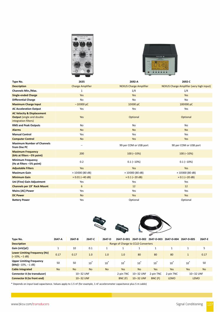
Type No. 2635 2692‐A 2692‐C
Description Charge Amplifier NEXUS Charge Amplifier NEXUS Charge Amplifier (very high input)
Channels Min./Max. 1 1/4 1/4
Single‐ended Charge Yes Yes Yes
Differential Charge No No No
Maximum Charge Input 10000 pC 10000 pC 100000 pC
AC Acceleration Output Yes Yes Yes
AC Velocity & Displacement
Output (single and double
integration filters)
Yes Optional Optional
RMS and Peak Outputs No No No
Alarms No No No
Manual Control Yes Yes Yes
Computer Control No Yes Yes
Maximum Number of Channels
from One PC– 99 per COM or USB port 90 per COM or USB port
Maximum Frequency
(kHz at filters –5% point)200 100 (–10%) 100 (–10%)
Minimum Frequency
(Hz at filters –5% point)0.2 0.1 (–10%) 0.1 (–10%)
Adjustable Filters Yes Yes Yes
Maximum Gain × 10000 (80 dB) × 10000 (80 dB) × 10000 (80 dB)
Minimum Gain × 0.01 (–40 dB) × 0.1 (–20 dB) × 0.1 (–20 dB)
Uni (Fine) Gain Adjustment Yes Yes Yes
Channels per 19 Rack Mount 6 12 12
Mains (AC) Power Yes Yes Yes
DC Power No Yes Yes
Battery Power Yes Optional Optional
Type No. 2647‐A 2647‐B 2647‐C 2647‐D 2647‐D‐001 2647‐D‐002 2647‐D‐003 2647‐D‐004 2647‐D‐005 2647‐E
Description Range of Charge to CCLD Converters
Gain (mV/pC) 1 10 0.1 1 1 1 1 1 1 5
Lower Limiting Frequency (Hz)
(–10%, –1 dB)0.17 0.17 1.0 1.0 1.0 80 80 80 1 0.17
Upper Limiting Frequency
(kHz)(–10%, –1 dB)50 50 10* 10* 10* 10* 10* 10* 10* 50
Cable Integrated No No No No Yes No Yes Yes Yes No
Connector A (to transducer) 10–32 UNF 2‐pin TNC 10–32 UNF 2‐pin TNC 2‐pin TNC 10–32 UNF
Connector B (to front end) 10–32 UNF BNC (F) 10–32 UNF BNC (F) LEMO LEMO
* Depends on input load capacitance. Values apply to 1.5 nF (for example, 1 nF accelerometer capacitance plus 5 m cable)
Signal Conditioning 127www.bksv.com/transducers

What are the Benefits of Signal Conditioning?Signal conditioning improves the performance and reliability of themeasurement system with a variety of functions such as signalamplification, attenuation, electrical isolation, filtering, poweringof your transducers, overload detection and Transducer ElectronicData Sheet (TEDS) support.
Brüel & Kjær provides a number of signal conditioning solutions.When determining which conditioner to use, you should considerthe type of transducer as well as the conditioner's benefits to themeasurement system, including the following critical features andcharacteristics. For further comparisons, see the individualconditioner's product data for in‐depth specifications.
Number of Channels For multichannel tests, having more channels in the signalconditioner makes for a simpler system (for example, one powersupply or battery for all the conditioned channels).
Channel Control For units with adjustable settings, manual control is the easiest wayto change configuration. In automated or multichannel systems,computer control offers big time savings.
For very large systems, it is desirable to control as many channels aspossible from a single PC.
Maximum and Minimum Frequency and Adjustable FiltersBesides needing to cover the measurement’s frequency range, aconditioner’s analogue filter can remove portions of the signaloutside the range of interest. For example, in‐vehiclemeasurements of sound often have very strong low‐frequencycontent below 20 Hz. A 20 Hz high‐pass filter will attenuate thesignal below the audio range which may improve the measurementsystem’s noise floor at mid to high frequencies.
Minimum and Maximum GainWhen using data acquisition equipment with adjustable inputranges, the noise floor of the complete measurement system (fromtransducer through conditioning to data acquisition) can beimproved by adding gain in the conditioner.
Uni (Fine) Gain Adjustment The sensitivity of a transducer in engineering units or volts typicallyvaries significantly between individual transducers. Compensatingfor the individual sensitivities using fine gain control in theconditioner removes this error.
Transducer Electronic Data Sheet (TEDS)Significant measurement errors can be automatically avoidedwhen the fine gain adjustment of the conditioner is read from thetransducer's built‐in Transducer Electronic Data Sheets (TEDS).
A TEDS microphone is sealed to the preamplifier with a calibration sticker
Multi‐unit DesignRack mounting is a convenient way of organizing laboratory‐basedmeasurement systems where all the conditioning and dataacquisition can be combined into one frame. For most signalconditioners, you can order an optional 19‐inch rack and/or a multi‐unit frame, with which one or more conditioner can be mounted.
Other Useful Features for Acoustic Transducers
Polarization ControlThe working principle of the condenser microphone is based on afixed charge. This charge is established, either with a very stableexternal polarization voltage, typically 200 V, via a large resistor, orby an electret layer deposited on the microphone’s backplate, inwhich case the external polarization voltage should be set to 0 V.
CICCharge Injection Calibration (CIC) is a technique for on‐lineverification of the integrity of the entire measurement chain, forexample, microphone, preamplifier and cabling. Even microphonesremote from the input stage/conditioning amplifier can be verified.The basic philosophy behind CIC is that if we have a knowncondition (for example, a properly calibrated microphone) andestablish a reference measurement, then as long as the referencevalue does not change, nothing has changed, for example, themicrophone calibration will still be valid. Additionally CIC verifiesthe cable and preamplifier.
128 Signal Conditioning www.bksv.com/transducers
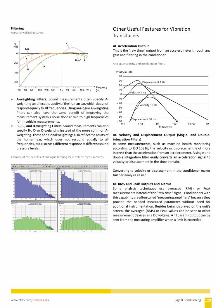
FilteringAcoustic weighting curves
• A‐weighting Filters: Sound measurements often specify A‐weighting to reflect the acuity of the human ear, which does notrespond equally to all frequencies. Using analogue A‐weightingfilters can also have the same benefit of improving themeasurement system’s noise floor at mid to high frequenciesfor in‐vehicle measurements.
• B‐, C‐, and D‐weighting Filters: Sound measurements can alsospecify B‐, C‐ or D‐weighting instead of the more common A‐weighting. These additional weightings also reflect the acuity ofthe human ear, which does not respond equally to allfrequencies, but also has a different response at different soundpressure levels.
Example of the benefits of analogue filtering for in‐vehicle measurements
Other Useful Features for Vibration Transducers
AC Acceleration OutputThis is the “raw time” output from an accelerometer through anygain and filtering in the conditioner.
Analogue velocity and acceleration filters
AC Velocity and Displacement Output (Single‐ and Double‐integration Filters)In some measurements, such as machine health monitoringaccording to ISO 10816, the velocity or displacement is of moreinterest than the acceleration from an accelerometer. A single anddouble integration filter easily converts an acceleration signal tovelocity or displacement in the time domain.
Converting to velocity or displacement in the conditioner makesfurther analysis easier.
DC RMS and Peak Outputs and AlarmsSome analysis techniques use averaged (RMS) or Peakmeasurements instead of the “raw time” signal. Conditioners withthis capability are often called “measuring amplifiers” because theyprovide the needed measured parameter without need foradditional instrumentation. Besides being displayed on the unit’sscreen, the averaged (RMS) or Peak values can be sent to othermeasurement devices as a DC voltage. A TTL alarm output can besent from the measuring amplifier when a limit is exceeded.
40
Vout/Vin (dB)
30 Displacement 1 Hz
Displacement 10 Hz
Velocity 1 Hz
Velocity 10 Hz
20
10
0
– 10
– 20
– 30
– 40
– 50
– 600.1 1 Hz 10
Frequency100 1 kHz 10
Signal Conditioning 129www.bksv.com/transducers

130 Signal Conditioning www.bksv.com/transducers

CALIBRATION SYSTEMS
Primary Calibration Systems
Microphone Reciprocity Calibration System
Reciprocity Calibration System Type 9699 performs reciprocitycalibration according to the method described in IEC 61094–2 todetermine the pressure sensitivity of microphones described inIEC 61094–1 (Laboratory Standard Microphones).
This system is intended for National Metrology Institutes and otherhigh‐level laboratories. It is a turnkey system for routinemeasurements that can be set up to meet the requirements of theuser. The system can work in a “normal” laboratory environmentwith no specific precautions with respect to background noise andvibration.
It is a very flexible system that can be used for calibration researchand at primary calibration laboratories, calibration service centresand larger organisations with their own calibration facilities.
Vibration Transducer Calibration System Vibration Transducer Calibration System Type 3629 together withLaser‐interferometric Calibration System Software Type 5309 aredesigned for absolute calibration of a variety of vibration and shocktransducers. The combined system is generally used by nationalprimary laboratories or as reference by clients utilising advancedtechnology.
The system performs absolute calibration according to the methoddescribed in ISO 16063–11:1999. Type 5309 uses Method 3, sineapproximation, and calibrates practically all transducer types:charge, CCLD (constant current supplied transducers),piezoresistive, variable capacitance, voltage, servo andelectrodynamic (for example, velocity pick‐ups).
Hydrophone Calibration System Hydrophone Calibration System Type 9718 performs free‐fieldcalibration in a water tank as described in IEC 60565.
The system is generally used by national primary laboratories or asreference by clients utilising advanced technology for calibration ofunderwater transducers both at the primary and secondary level.
Secondary calibration used by laboratories who need to calibratelarge numbers of hydrophones with minimum time consumption, isbased on the substitution principle and performed in two steps: • First: A calibration is performed by means of a known reference
hydrophone • Second: A calibration is performed with the unknown unit
under calibration
The measurement principle used is gated selective FFT for optimumsignal‐to‐noise ratio. The complex impedance can also bemeasured and reported.
The reciprocity system can perform calibration without use of areference transducer, this is called absolute calibration. Thereciprocity calibration is used for calibration of such referencetransducers.
Directivity Calibration SoftwareThe directivity calibration software option complementsHydrophone Calibration System Type 9718. The hydrophone to becalibrated is mounted on Turntable Type 9640 capable of handlingpayloads up to 100 kg. A rotation controller turns the turntable andprovides accurate information of the angle. For each angle, thehydrophone output is measured and printed in a polar plot. Thepolar plot may be repeated at different frequencies as needed.
Overview of Brüel & Kjær’s calibration system products
Hydrophones Instruments Accelerometers Microphones
Reciprocity Sound Level Meter
Comparison
Directivity
Octave Filter
Calibrator
Noise Dosimeter
Artificial Mastoid
Audiometer
Laser
Comparison
Shock 10k
Shock 100k
Low Frequency
Reciprocity
Comparison
Electrostatic Actuator
Phase Comparison
High Pressure
Infrasound
Coupler
Brüel & Kjær Calibration Systems
PULSE-based Sound level meter-based
Primary
Turnkey Systems:– Instructions on-screen– Printing of certificates– Uncertainty budgets
CALIBRATED
CA
LIB RATE D
Calibration Systems 131www.bksv.com/transducers

Secondary Calibration Systems
Shock and Vibration Transducer System Type 3629
With Comparison Calibration System Software Type 5308The system performs comparison calibration according to themethod described in ISO 16063–21:2003.
Vibration Transducer Calibration System Type 3629 and Type 5308software are designed for comparison calibration of a variety ofvibration and shock transducers and is generally used by calibrationservice centres and larger organisations with their own calibrationfacilities.
Type 3629 calibrates practically all transducer types – charge, CCLD(constant current supplied transducers), piezoresistive, variablecapacitance, voltage, servo and electrodynamic (for example,velocity pick‐ups).
With Shock Transducer Calibration Software Type 5310The calibration is performed in accordance with ISO 16063–22.
This system is normally used with a POP shock calibrator that worksat shock levels from 20 to 10000 g and shares a number of userinterface features and components with Comparison CalibrationSoftware Type 5308. For shocks below 100 g it is even possible touse a special feature to generate them on a shaker.
High‐shock Transducer Calibration The calibration is performed in accordance with ISO 16063–22using High Shock Transducer Calibration Software Type 5311.
It is normally used with a Hopkinson Bar that works at shock levelsfrom 10 to 100 kg and shares a number of user interface featuresand components with Comparison Calibration Software Type 5308.
Microphone Calibration System Type 9721
Microphone Calibration System Type 9721 can calibratemeasurement and laboratory standard microphones of commonlyused models and brands, including those that fulfil IEC standards61094–4 (Working Standards) and 61094–1 (LaboratoryStandards). Microphones of non‐standard dimensions can also becalibrated, but might require additional mechanical accessories.
Type 9721 is a general‐purpose microphone calibration system thatcalibrates microphones with or without preamplifiers inaccordance with IEC 61094–5 and IEC 61094–6.
The system is intended for calibration service centres and largerorganisations with their own calibration facilities. It is a flexible,turnkey system for routine measurements that can be set up tomeet the requirements of the user. The system can work in a“normal” laboratory environment with no specific precautionswith respect to background noise and vibration.
Option: • Phase Response Comparison Calibration with Application
Software WT‐9651 and coupler WA‐1544 or WA‐1545
132 Calibration Systems www.bksv.com/transducers
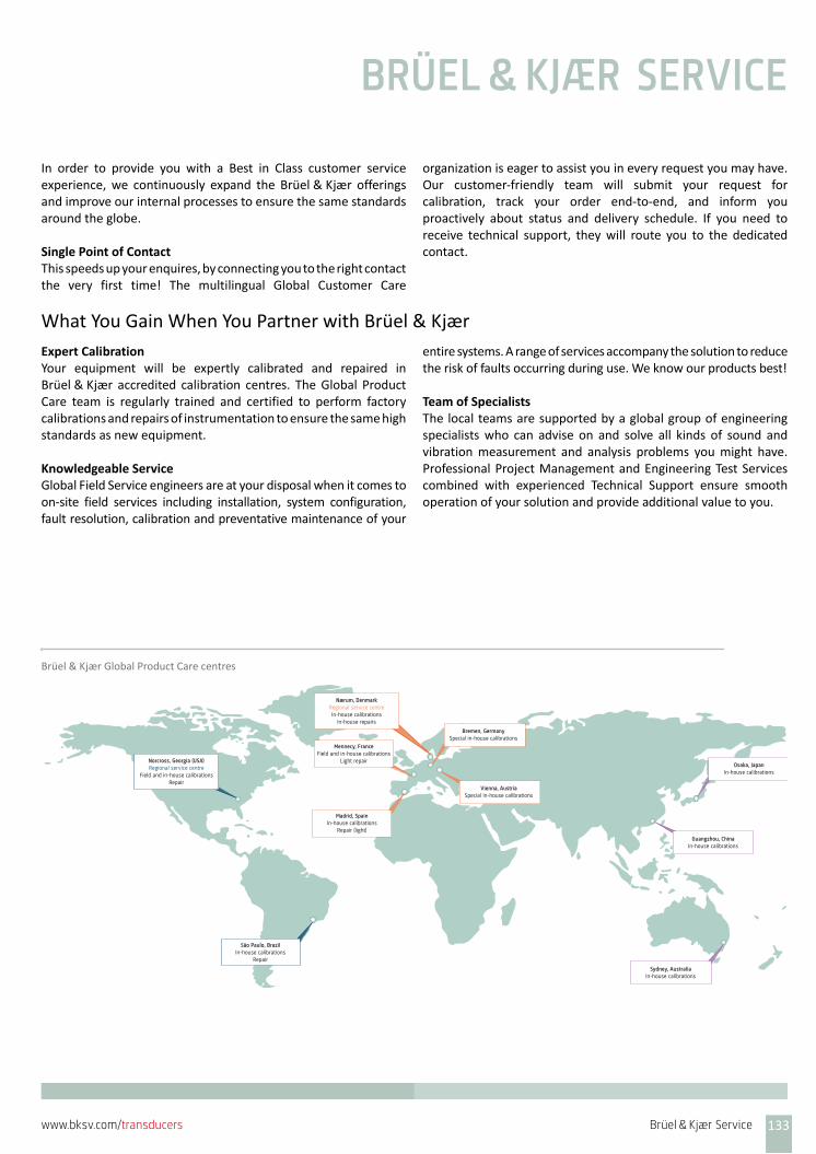
BRÜEL & KJÆR SERVICE
In order to provide you with a Best in Class customer serviceexperience, we continuously expand the Brüel & Kjær offeringsand improve our internal processes to ensure the same standardsaround the globe.
Single Point of ContactThis speeds up your enquires, by connecting you to the right contactthe very first time! The multilingual Global Customer Care
organization is eager to assist you in every request you may have.Our customer‐friendly team will submit your request forcalibration, track your order end‐to‐end, and inform youproactively about status and delivery schedule. If you need toreceive technical support, they will route you to the dedicatedcontact.
What You Gain When You Partner with Brüel & Kjær
Expert CalibrationYour equipment will be expertly calibrated and repaired inBrüel & Kjær accredited calibration centres. The Global ProductCare team is regularly trained and certified to perform factorycalibrations and repairs of instrumentation to ensure the same highstandards as new equipment.
Knowledgeable ServiceGlobal Field Service engineers are at your disposal when it comes toon‐site field services including installation, system configuration,fault resolution, calibration and preventative maintenance of your
entire systems. A range of services accompany the solution to reducethe risk of faults occurring during use. We know our products best!
Team of SpecialistsThe local teams are supported by a global group of engineeringspecialists who can advise on and solve all kinds of sound andvibration measurement and analysis problems you might have.Professional Project Management and Engineering Test Servicescombined with experienced Technical Support ensure smoothoperation of your solution and provide additional value to you.
Brüel & Kjær Global Product Care centres
Sydney, AustraliaIn-house calibrations
Guangzhou, ChinaIn-house calibrations
Osaka, JapanIn-house calibrations
Vienna, AustriaSpecial in-house calibrations
Madrid, SpainIn-house calibrations
Repair (light)
Bremen, GermanySpecial in-house calibrations
Mennecy, FranceField and in-house calibrations
Light repair
Nærum, DenmarkRegional service centreIn-house calibrations
In-house repairs
Norcross, Georgia (USA)Regional service centre
Field and in-house calibrationsRepair
São Paulo, BrazilIn-house calibrations
Repair
Brüel & Kjær Service 133www.bksv.com/transducers
Brüel & Kjær Calibration and Repair ServicesBrüel & Kjær’s 10 calibration centres perform more than 30,000high‐level, quality calibrations a year. The global team of highlyskilled calibration technicians:• Maintain an intimate knowledge of all Brüel & Kjær branded
products• Excel at carrying out a wide range of calibrations run on
dedicated test benches• Deliver complete calibration schedules
The calibration centres can also calibrate other manufacturer'sequipment.
Calibration of Reference EquipmentThere are two levels of reference calibration available atBrüel & Kjær: Primary Calibration – performed by Danish PrimaryLaboratory of Acoustics (DPLA) – and Secondary Calibration. Thelevel you select depends on the accuracy you require for yourreference equipment.
Primary Calibration DPLA annually performs hundreds of primary accreditedcalibrations of reference microphones and accelerometers for
metrology institutes, test houses, and industry organizationsrequiring high‐accuracy calibrations.
Secondary Calibration If your sensitivity requirements are not as high as primarycalibration, we recommend that you maintain your referenceequipment with annual accredited calibrations in one of our ISO/IEC 17025 accredited laboratories. This is, for example, performedfor industrial companies who perform in‐house calibrations, testsor any acoustic or vibration measurements.
Accredited CalibrationOur network of calibration centres operates within the EA and ILACguidelines for accreditation. Our ISO/IEC 17025 accreditations havebeen awarded by accreditation bodies that are signatories to theEA‐MLA and the ILAC‐MRA. This allows us to deliver the same highlevel of quality, competence and confidence, together withinternational recognition, wherever the accredited calibration isperformed.
Where accredited calibration is not available, Brüel & Kjær centresoffer Traceable Calibration.
Initial Accredited CalibrationSensitivity data are included with the delivery of every newBrüel & Kjær microphone and accelerometer. However, accreditedcalibration can be ordered, where required, to start themeasurement history from day one – for example, if stipulated byquality procedures, external audits or other requirements.
Traceable CalibrationYou can also order traceable calibration, which means that themeasurements are traceable to national standards – at the samelevel as accredited calibration, only without the formal third‐partyrecognition.
To optimize uptime and minimize costs, we recommend combiningcalibration with a Hardware Maintenance Agreement.
Regular CalibrationWhen you send in your accelerometers and microphones forcalibration regularly, you benefit from reliable measurement data;you can compare data over time, provide proof to customers, andfulfil your internal or external quality requirements.
To minimize the errors due to faulty or inaccurate measurementsand the related costs, we recommend annual calibration in one of
our ISO/IEC 17025 accredited laboratories. This will give you acontinuous calibration history to use as reference for internalrequirements, for audit purposes required by authorities or just asa request from your customers. You can also follow the history ofsensitivity for your equipment over a period of time and detect anyquestionable trends up‐front.
134 Brüel & Kjær Service www.bksv.com/transducers
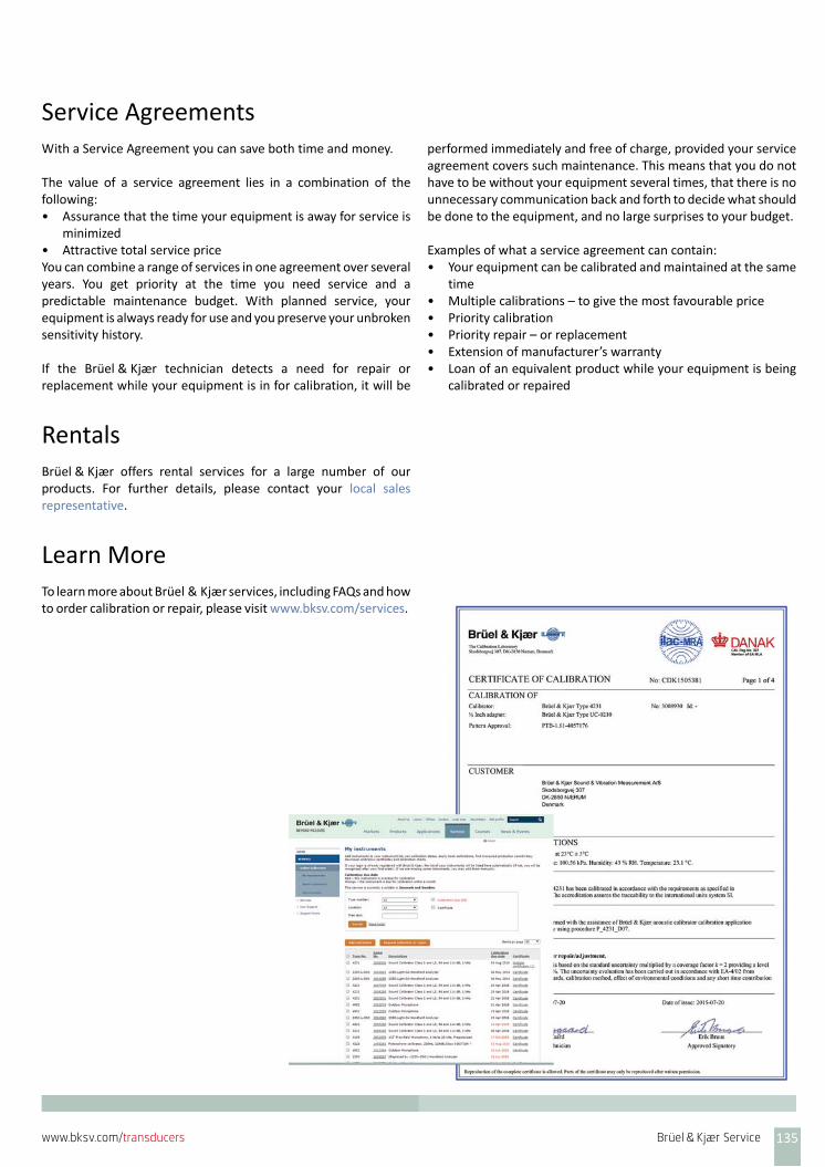
Service AgreementsWith a Service Agreement you can save both time and money.
The value of a service agreement lies in a combination of thefollowing:• Assurance that the time your equipment is away for service is
minimized• Attractive total service priceYou can combine a range of services in one agreement over severalyears. You get priority at the time you need service and apredictable maintenance budget. With planned service, yourequipment is always ready for use and you preserve your unbrokensensitivity history.
If the Brüel & Kjær technician detects a need for repair orreplacement while your equipment is in for calibration, it will be
performed immediately and free of charge, provided your serviceagreement covers such maintenance. This means that you do nothave to be without your equipment several times, that there is nounnecessary communication back and forth to decide what shouldbe done to the equipment, and no large surprises to your budget.
Examples of what a service agreement can contain:• Your equipment can be calibrated and maintained at the same
time• Multiple calibrations – to give the most favourable price• Priority calibration• Priority repair – or replacement• Extension of manufacturer’s warranty• Loan of an equivalent product while your equipment is being
calibrated or repaired
RentalsBrüel & Kjær offers rental services for a large number of ourproducts. For further details, please contact your local salesrepresentative.
Learn MoreTo learn more about Brüel & Kjær services, including FAQs and howto order calibration or repair, please visit www.bksv.com/services.
Brüel & Kjær Service 135www.bksv.com/transducers

136 Brüel & Kjær Service www.bksv.com/transducers

GLOSSARY OF TERMS
AbsorptionThe conversion of sound energy into another form of energy,usually heat when passing through an acoustical medium
Absorption coefficientRatio of sound absorbing effectiveness at a specific frequency, of aunit area of acoustical absorbent to a unit area of perfectlyabsorptive material
AccelerationVector quantity that describes the time‐derivative of velocity,mathematically: a = dv/dt. The SI unit is m/s2 (metres per secondsquared). In the imperial system, the unit g or more correctly gn isused, where the definition is that 1 gn 9.80665 m/s2
Acceleration can be oscillatory (and then often called vibration), inwhich case simple harmonic components can be defined by theacceleration amplitude (and frequency), or random, in which casethe rms acceleration (and bandwidth and probability densitydistribution) can be used to define the probability that theacceleration will have values within any given range. Accelerationsof short time duration are defined as transient accelerations. Non‐oscillatory accelerations are defined as sustained accelerations, ifof long duration, or as acceleration pulses, if of short duration.
In the case of time‐dependent accelerations various self‐explanatory modifiers, such as peak, average, and rms (root‐mean‐square), are often used. The time intervals over which the averageor root‐mean‐square values are taken should be indicated orimplied
AccelerometerA transducer that converts an input acceleration to an output(usually electrical) that is proportional to the input acceleration
AcousticsThe science of the production, control, transmission, reception andeffects of sound and of the phenomenon of hearing
Active sound fieldA sound field in which the particle velocity is in phase with thesound pressure. All acoustic energy is transmitted, none is stored. Aplane wave propagating in a free field is an example of a purelyactive sound field and constitutes the real part of complex soundfield
Ambient noiseAll‐pervasive noise associated with a given environment
AmplitudeThe instantaneous magnitude of an oscillating quantity such assound pressure. The peak amplitude is the maximum value.
In a vibrating object, amplitude is measured and expressed in threeways: Displacement, Velocity and Acceleration. Amplitude is alsothe y‐axis of the vibration time waveform and spectrum; it helpsdefine the severity of the vibration
Amplitude distributionA method of representing time‐varying noise by indicating thepercentage of time that the noise level is present in a series ofamplitude intervals
Anechoic roomA room whose boundaries effectively absorb all incident soundover the frequency range of interest, thereby creating essentiallyfree‐field conditions
Audibility thresholdThe sound pressure level, for a specified frequency at whichpersons with normal hearing begin to respond
Background noiseThe ambient noise level above which signals must be presented ornoise sources measured
CCLD (Constant Current Line Drive)Generic name for a constant current power supply foraccelerometers with built‐in electronics and for theseaccelerometers. Used in Brüel & Kjær analyzers and literature. Seealso DeltaTron
Charge amplifierAn amplifier that converts the charge output of a piezoelectricaccelerometer into a proportional low‐impedance voltage signal
Charge converterA device that converts a piezoelectric accelerometer’s high‐impedance charge output to a low‐impedance voltage proportionalto the charge input. A charge converter typically requires a constantcurrent power supply.
Also called ‘in‐line charge converter’
Complex intensityComplex intensity is the combined intensity and imaginaryintensity
Conditioning (signal conditioning)The conversion or alteration of an accelerometer signal to a suitableor desirable level, range or bandwidth. Signal conditioning includesamplification, filtering, differential applications, isolation,transducer tests and more
Glossary of Terms 137www.bksv.com/transducers
Cumulative distributionA method of representing time‐varying noise by indicating thepercentage of time that the noise level is present above (or below)a series of amplitude levels
Damping (1)The action of frictional or dissipative forces on a dynamic systemcausing the system to lose energy and reduce the amplitude ofmovement
Damping (2)Removal of echoes and reverberation by the use of soundabsorbing materials. Also called sound proofing
DC responseAccelerometers respond to a fairly wide frequency range, mostdown to 1 or 2 Hz. Some special accelerometers respond to zerofrequency and are, therefore, said to exhibit a ‘DC response’
Decibel scaleA linear numbering scale used to define a logarithmic amplitudescale, thereby compressing a wide range of amplitude values to asmall set of numbers
DeltaTron Brüel & Kjær’s proprietary name for accelerometers with built‐inelectronics and the constant current power supply for these.Brüel & Kjær also uses the generic name CCLD (Constant CurrentLine Drive). It corresponds to IEPE (Integrated Electronics PiezoElectric) often used for accelerometers requiring this kind of powersupply. Other similar proprietary names are ISOTRON®,PIEZOTRON® and ICP®.
Other types of accelerometers with different powering principlesexists, for example, Brüel & Kjær's CVLD (Constant Voltage LineDrive) that is used for maximum EMC immunity
DifferentiationIn vibration analysis, the three physical parameters, displacement,velocity and acceleration, are mathematically related.Differentiation is a mathematical operation that converts oneparameter to another (for example, a displacement signal to avelocity signal, or velocity signal to an acceleration signal). See alsoIntegration, which is the inverse of differentiation
DiffractionThe scattering of radiation at an object smaller than onewavelength and the subsequent interference of the scatteredwavefronts
Diffuse fieldA sound field in which the sound pressure level is the sameeverywhere and the flow of energy is equally probable in alldirections
Diffuse soundSound that is completely random in phase; sound which appears tohave no single source
Directivity factorThe ratio of the mean‐square pressure (or intensity) on the axis of atransducer at a certain distance to the mean‐square pressure (orintensity) which a spherical source radiating the same power wouldproduce at that point
DisplacementTime‐varying quantity that specifies the change in position of apoint on a body with respect to a reference frame. In the SI systemit is measured in metres (m). In the imperial system thousands of aninch is often used (mils)
Dynamic capabilityThe dynamic capability of an intensity measurement system isdetermined by adding normally 5 dB (for a measuring error lessthan 2 dB) to the Residual Intensity Index
Dynamic rangeRange of values that can be measured
Normally expressed as the ratio in dB between the smallest signallevel an instrument can sense to the largest signal it will acceptwithout an overload occurring. Modern vibration analysisinstrumentation can have a dynamic ranges up to 160 dB
ExcitationExternal force (or other input) applied to a system that causes thesystem to respond in some way
Far fieldDistribution of acoustic energy at a very much greater distancefrom a source than the linear dimensions of the source itself; theregion of acoustic radiation used to the source and in which thesound waves can be considered planar
FilterAn electrical circuit that intercepts input signals and blocks thosethat are above or below a specific frequency band or a mechanicalfilter that suppresses vibration amplitude levels at certainfrequencies
Forced vibrationVibration of a system due to an external time dependent force
Free fieldAn environment in which there are no reflective surfaces within thefrequency region of interest
Frequency responseResponse within a given frequency range when the complexsensitivity of the transducer for a given excitation is not constantover that range. Often given as the magnitude and phase
Frequency response functionFrequency‐dependent ratio of the motion‐response Fouriertransform to the Fourier transform of the excitation force of a linearsystem. Frequency response measurements are used extensively inmodal analysis of mechanical systems
138 Glossary of Terms www.bksv.com/transducers

gn (g)Standard acceleration due to gravity. The value was adopted in theInternational Service of Weights and Measures and confirmed in1913 by the 5th CGPM as the standard for acceleration due togravity.
• Unit: 9.80665 metres per second‐squared (9.80665 m/s2)• Symbol: gn (in vibration literature, this if often shorted to g but
should not be misunderstood as the gravitational forcementioned below)
This “standard value” (gn = 9.80665 m/s2 386.089 in/s2 32.1740 ft/s2) should be used for reduction to standard gravity ofmeasurements made in any location on Earth.
Frequently, the magnitude of acceleration is expressed in units ofgn.
Note: The actual acceleration produced by the force of gravity at orbelow the surface of the Earth varies with the latitude and elevationof the point of observation. This variable often is expressed usingthe symbol g. Caution should be exercised if this is done so as not tocreate an ambiguity with this use and the standard symbol for theunit of the gram
Ground loopIn instrumentation systems, such as vibration measurement datacollection systems, it is often required to mount a transducer on amachine whose structure or “ground” may have an electrical voltagepresent on it caused by current leakage in motor windings, etc. Thetransducer cable shield is normally connected to the housing, and isthen electrically connected to this voltage when the transducer ismounted. If the instrument to which the transducer is connected isconnected to a different ground, such as a power line neutral, thisdifference in the ground potentials will cause a current in the shield,and this will add interference to the measured signal. Theinterference will be at 50 or 60 Hz and harmonics, and it reduces thesignal to noise ratio of the measurement. This condition is called aground loop, and there are several ways to avoid it. One is to use aninsulating disc between the transducer and the machine, another isto use a battery operated instrument that is not connected to apower line
HarmonicsHarmonic vibration, the frequency of which is an integral multipleof the fundamental frequency
Hearing lossAn increase in the threshold of audibility due to disease, injury, ageor exposure to intense noise
Hertz (Hz)The unit of frequency representing cycles per second
High‐pass filterAn electrical circuit that intercepts input signals and blocks thosethat are below a specific frequency band. Besides eliminating low‐
frequency noise, a high‐pass filter separates a signal’s alternatingcomponents from its direct (DC) components
IEPE Integral Electronics Piezoelectric is a generic term for transducerswith built‐in electronics. A number of proprietary systems such asDeltaTron®, ISOTRON®, ICP® and PIEZOTRON® exist. See also CCLD
Imaginary intensityImaginary intensity is the non‐propagating part of the sound field(sometimes called the reactive part)
Impact testImpact testing provides a method of determining the frequencyresponse function of a structure. Accelerometers are placed on thestructure, and an object, such as a specially constructed impacthammer, is used to hit the structure. The hammer is instrumentedto measure the input force pulse, while the accelerometers pick upthe response of the structure. From this vibrational response, it isimportant to be aware of excitation frequencies that coincide withthe natural frequencies of the structure (resonances), as thesepoint to dangerous operating levels
Impedance, specific acousticThe complex ration of dynamic pressure to particle velocity at apoint in an acoustic medium.
Measured in rayls (1 rayl = 1 N ∙ S/m3)
Impedance, mechanicalThe complex ratio of force to velocity at a specified point anddegree‐of‐freedom in a mechanical system. It is a measure of howmuch a structure resists motion
InfrasoundSound at frequencies below the audible range, that is, below about16 Hz
IntegrationIntegration is the inverse of differentiation. See Differentiation
IntensityIntensity is the real part of the complex intensity and is thepropagating part of the sound field (sometimes called the active part)
IsolationA decreased tendency to respond to or transmit a sound throughthe use of resilient materials and structures
Leakage, spectralThe broadening of a peak in the frequency domain caused bywindow function with the Fourier transform
Leakage errorError in frequency description caused by truncation of signal.
Leakage can be reduced using time weighting functions such asHanning Window
Glossary of Terms 139www.bksv.com/transducers
Level (of a quantity)The logarithm of the ratio of the quantity to a reference of the samekind.
In vibration terminology, the term level is sometimes used todenote amplitude, average value, root‐mean‐square value, orratios of these values. Strictly speaking, these terms should not beused
Linear systemA system in which the magnitude of the response is proportional tothe magnitude of the excitation
LoudnessSubjective impression of the intensity of a sound
Low‐pass filterAn electrical circuit that intercepts input signals and blocks thosethat are above a specific frequency called the ‘cut‐off frequency’. Anexample is the anti‐aliasing filter
MaskingThe process by which threshold of audibility of one sound is raisedby the presence of another (masking) sound
Mobility (mechanical mobility)The complex ratio of the velocity, taken at a point in a mechanicalsystem, to the force, taken at the same or another point in thesystem. Mechanical mobility is the matrix inverse of mechanicalimpedance. It is a measure of how easily a structure is able to movein response to an applied force
Modal analysisVibration analysis method that characterizes a complex structuralsystem by its modes of vibration, that is, its natural frequencies,modal damping and mode shapes, and based on the principle ofsuperposition
Near fieldThat part of a sound field, usually within about two wavelengthsfrom a noise source, where there is no simple relationship betweensound level and distance
NewtonThe force required to accelerate a kg mass at 1 m/s2. Approximatelyequal to the gravitational force on a 100 g mass
Noise emission levelThe dB(A) level measured at a specified distance and direction froma noise source, in an open environment, above a specified type ofsurface. Generally follows the recommendation of a national orindustry standard
Noise reduction coefficient, NRCThe arithmetic average of the sound absorption coefficients of amaterial at 250, 500, 1000 and 2000 Hz
NoyA linear unit of noisiness or annoyance
Particle velocityThe velocity of air molecules about their rest position due to asound wave
Pascal, PaA unit of pressure corresponding to a force of 1 newton actinguniformly upon an area of 1 square metre. Hence: 1 Pa = 1 N/m2
PeakA measurement’s maximum instantaneous value (displacement,velocity, acceleration or voltage) in a given period. Peaks can beboth negative and positive in direction• Peak value• Peak magnitude • Positive peak value • Negative peak value
Note: A peak value of vibration is usually taken as the maximumdeviation of that vibration from the mean value. A positive peakvalue is the maximum positive deviation and a negative peak valueis the maximum negative deviation
Peak‐to‐peak value (of a vibration)Difference between the maximum positive and maximum negativevalues of a vibration during a specified interval
PhaseArgument of a complex vibration
Phase mismatch (in acoustic measurements)The relative phase mismatch between the two channels in anintensity measuring system
PhonThe loudness level of a sound. It is numerically equal to the soundpressure level of a 1 kHz free progressive wave, which is judged byreliable listeners to be as loud as the unknown sound
Pink noiseBroadband noise whose energy content is inversely proportional tofrequency (–3 dB per octave or –10 dB per decade)
Power spectrum levelThe level of the power is a band one hertz wide referred to a givenreference power
Pressure‐residual Intensity Index,
The pressure‐residual intensity index for a given measurementsystem is defined as the difference between the measured pressurelevel and the indicated sound intensity level when exactly the samesignal is fed into the two channels of an intensity analysing system
pI0
140 Glossary of Terms www.bksv.com/transducers

Random noiseNoise, whose instantaneous amplitude is not specified at anyinstant of time. Instantaneous amplitude can only be definedstatistically by an amplitude distribution function
Relative velocityThe rate of change of displacement. It is expressed in units ofdistance per unit of time. In terms of vibration signals, it would bemillimetres per second or inches per second.
In general, velocity is time‐dependent. A velocity is designated asrelative velocity if it is measured with respect to a reference frameother than the primary reference frame designated in a given case.The relative velocity between two points is the vector differencebetween the velocities of the two points. Velocity can be oscillatory,in which case simple harmonic components can be defined by thevelocity amplitude (and frequency), or random, in which case theroot‐mean‐square (rms) velocity (and band width and probabilitydensity distribution) can be used to define the probability that thevelocity will have values within any given range. Velocities of shorttime duration are defined as transient velocities. Non‐oscillatoryvelocities are defined as sustained velocities, if of long duration
Residual IntensityThe sound intensity level measured when the same signal is fed toboth channels of a sound intensity measuring system
Residual NoiseFor charge accelerometers, the noise is a function of thepreamplifier and given within the specified frequency range. Thespecified noise level is measured with NEXUS ConditioningAmplifier Type 2692‐001. For accelerometers with integratedelectronics, the noise is given within specified frequency range
ResonanceState of a system in forced oscillation when any change, howeversmall, in the frequency of excitation causes a decrease in a responseof the system
Resonance frequencyFrequency at which resonance exists
ReverberationThe persistence of sound in an enclosure after a sound source hasbeen stopped. Reverberation time is the time, in seconds, requiredfor sound pressure at a specific frequency to decay 60 dB after asound source is stopped
RMS (Root Mean Square)The square root of the arithmetic average of a set of squaredinstantaneous values
SabinA measure of sound absorption of a surface. One metric sabin isequivalent to 1 square metre of perfectly absorptive surface
SeismicWhen accelerated, a seismic transducer such as a piezoelectricaccelerometer or a velocity transducer, uses the inertial forceproduced by its seismic mass to generate a signal
Semi‐anechoic fieldA free field above a reflective plane
Sensitivity (of a transducer)Ratio of a specified output quantity to a specified input quantity.
For an accelerometer, sensitivity is expressed in millivolts orpicocoulombs per m/s2 or g (mV/ms–2 or mV/g, pC/ms–2 or pC/g).The sensitivity of a transducer is usually determined as a function offrequency using sinusoidal excitation
ShieldingEnclosure of test equipment and cables to prevent the occurrence ofnoise in a signal (such as interference, interaction or current leaks)
ShockSudden change of force, position, velocity or acceleration thatexcites transient disturbances in a system.
The change is normally considered sudden if it takes place in a timethat is short compared with the fundamental periods of concern
SoneA linear unit of loudness. The ration of loudness of a sound to thatof a 1 kHz tone 40 dB above the threshold of hearing
SoundEnergy that is transmitted by pressure waves in air or othermaterials and is the objective cause of the sensation of hearing.Commonly called noise if it is unwanted
Sound intensityThe rate of sound energy transmission per unit area in a specifieddirection
Sound levelThe level of sound measured with a sound level meter and one of itsweighting networks. When A‐weighting is used, the sound level isgiven in dB(A)
Sound level meter (SLM)An electronic instrument for measuring the RMS level of sound inaccordance with an accepted national or international standard
Sound powerThe total sound energy radiated by a source per unit time
Sound power levelThe fundamental measure of sound power. Defined as:
Where P is the RMS value of sound power in watts, and P0 is 1 pW
LW 10PP0‐‐‐‐‐‐log
dB=
Glossary of Terms 141www.bksv.com/transducers

Sound pressureA dynamic variation in atmospheric pressure. The pressure at apoint in space minus the static pressure at that point
Sound pressure levelThe fundamental measure of sound pressure. Defined as:
Where p is the RMS value (unless otherwise stated) of soundpressure in pascals, and p0 is 20 Pa for measurements in air
Sound transmission class, STCA single‐number rating for describing sound transmission loss of awall or partition
Sound transmission lossRatio of the sound energy emitted by an acoustical material orstructure to the energy incident upon the opposite side
Standing waveA periodic wave having a fixed distribution in space which is theresult of interference of progressive waves of the same frequencyand kind. Characterised by the existence of maxima and minimaamplitudes that are fixed in space
TransducerA device designed to convert energy from one form to another insuch a manner that the desired characteristics of the input energyappear at the output. Includes accelerometers, eddy currentprobes, loudspeakers, microphones and velocity transducers
Note 1: The output is usually electricalNote 2: The use of the term “pick‐up” is deprecated
Transient vibrationVibration that decays with time. This term is basically associatedwith mechanical shock
TriaxialThree axes. A triaxial accelerometer is a single instrument withthree sensing elements oriented to measure vibration in three axes
Triboelectric NoiseGenerated by movement in the cable’s components, resulting incharge or voltage noise signals. Mechanically induced noise is acritical and frequent concern when using charge accelerometers
TriggerAn electric impulse that is used as a timing reference, generally forpurposes of initiating a process or measurement
UltrasoundSound at frequencies above the audible range, that is, above about20 kHz
Uni‐Gain
The sensitivity of Uni‐Gain accelerometers are guaranteed withintight tolerances for easy interchangeability without recalibration.This designation indicates that the measured accelerometersensitivity has been adjusted during manufacture to within 2% of aconvenient value
VelocityThe rate of change of position or displacement in relation to timealong a specified axis
VibrationMechanical oscillations about an equilibrium point. Theoscillations may be periodic or random
WavelengthThe distance measured perpendicular to the wavefront in thedirection of propagation between two successive points in thewave, which are separated by one period. Equals the ratio of thespeed of sound in the medium to the fundamental frequency
Weighting networkAn electronic filter in a sound level meter which approximatesunder defined conditions the frequency response of the human ear.The A‐weighting network is most commonly used
White noiseBroadband noise having constant energy per unit of frequency
Lp 20=pp0‐‐‐‐‐‐log
dB
142 Glossary of Terms www.bksv.com/transducers
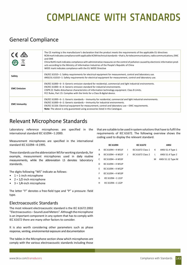
COMPLIANCE WITH STANDARDS
General Compliance
Relevant Microphone StandardsLaboratory reference microphones are specified in theinternational standard IEC 61094–1:2000.
Measurement microphones are specified in the internationalstandard IEC 61094–4:1995.
These standards use the abbreviation WS for working standards, forexample, measurement microphones used in daily routinemeasurements, while the abbreviation LS denotes laboratorystandards.
The digits following “WS” indicate as follows:• 1 = 1‐inch microphone• 2 = 1/2‐inch microphone• 3 = 1/4‐inch microphone
The letter “F” denotes a free‐field type and “P” a pressure‐ fieldtype.
Electroacoustic StandardsThe most relevant electroacoustic standard is the IEC 61672:2002“Electroacoustics – Sound Level Meters”. Although the microphoneis an important component in any system that has to comply withIEC 61672 there are many other factors to consider.
It is also worth considering other parameters such as phaseresponse, venting, environmental exposure and documentation
The tables in the Microphone section show which microphones arecomply with the various electroacoustic standards including those
that are suitable to be used in system solutions that have to fulfil therequirements of IEC 61672. The following overview shows thecoding used to display the relevant standard.
The CE marking is the manufacturer's declaration that the product meets the requirements of the applicable EU directives
RCM mark indicates compliance with applicable ACMA technical standards – that is, for telecommunications, radio communications, EMC
and EME
China RoHS mark indicates compliance with administrative measures on the control of pollution caused by electronic information prod‐
ucts according to the Ministry of Information Industries of the People’s Republic of China
WEEE mark indicates compliance with the EU WEEE Directive
SafetyEN/IEC 61010–1: Safety requirements for electrical equipment for measurement, control and laboratory use.
ANSI/UL 61010–1: Safety requirements for electrical equipment for measurement, control and laboratory use.
EMC Emission
EN/IEC 61000–6–3: Generic emission standard for residential, commercial and light industrial environments.
EN/IEC 61000–6–4: Generic emission standard for industrial environments.
CISPR 22: Radio disturbance characteristics of information technology equipment. Class B Limits.
FCC Rules, Part 15: Complies with the limits for a Class B digital device.
EMC Immunity
EN/IEC 61000–6–1: Generic standards – Immunity for residential, commercial and light industrial environments.
EN/IEC 61000–6–2: Generic standards – Immunity for industrial environments.
EN/IEC 61326: Electrical equipment for measurement, control and laboratory use – EMC requirements.
Note: The above is only guaranteed using accessories listed in this Catalogue.
IEC 61094 IEC 61672 ANSI
A IEC 61094 – 4 WS1F I IEC 61672 Class 1 K ANSI S1.4 Type 1
B IEC 61094 – 4 WS2F J IEC 61672 Class 2 L ANSI S1.4 Type 2
C IEC 61094 – 4 WS3F M ANSI S1.12 Type M
D IEC 61094 – 4 WS1P
E IEC 61094 – 4 WS2P
F IEC 61094 – 4 WS3P
G IEC 61094 –1 LS1P
H IEC 61094 –1 LS2P
Compliance with Standards 143www.bksv.com/transducers
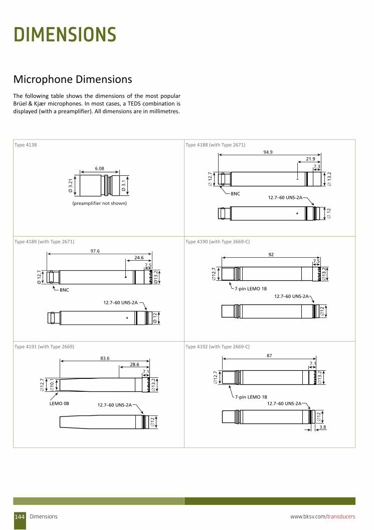
DIMENSIONS
Microphone DimensionsThe following table shows the dimensions of the most popularBrüel & Kjær microphones. In most cases, a TEDS combination isdisplayed (with a preamplifier). All dimensions are in millimetres.
Type 4138 Type 4188 (with Type 2671)
Type 4189 (with Type 2671) Type 4190 (with Type 2669‐C)
Type 4191 (with Type 2669) Type 4192 (with Type 2669‐C)
(preamplifier not shown)
Ø 3
.21
6.08
Ø 3
.1
12.7–60 UNS-2A
∅ 1
2
21.9
BNC
∅ 1
2.7
94.9
7.3
∅ 1
3.2
BNC
24.697.6
7.5
Ø 1
2.7
Ø13
.2
12.7–60 UNS-2A
Ø 1
2
12.7–60 UNS-2A
∅12
92
∅12
.7
∅13
.2
7.5
7-pin LEMO 1B
12.7–60 UNS-2A
∅12
28.683.6
∅12
.7
∅10
.1
7.1
∅13
.2
LEMO 0B 12.7–60 UNS-2A
3.8
∅12
∅12
.7
87
7.1
∅13
.2
7-pin LEMO 1B
Dimensions144 www.bksv.com/transducers
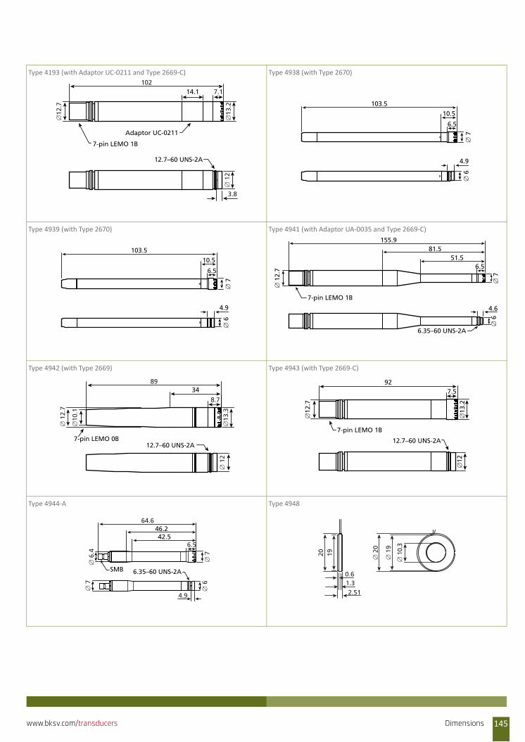
Type 4193 (with Adaptor UC‐0211 and Type 2669‐C) Type 4938 (with Type 2670)
Type 4939 (with Type 2670) Type 4941 (with Adaptor UA‐0035 and Type 2669‐C)
Type 4942 (with Type 2669) Type 4943 (with Type 2669‐C)
Type 4944‐A Type 4948
12.7–60 UNS-2A
∅ 1
2
3.8
Adaptor UC-0211
14.1
∅12
.7
∅13
.2
1027.1
7-pin LEMO 1B
103.5
6.5
10.5
∅ 7
4.9
∅ 6
103.5
6.5
10.5
∅ 7
4.9
∅ 6
6.35–60 UNS-2A
4.6
7-pin LEMO 1B
155.981.5
51.56.5
∅ 7
∅ 6
∅ 1
2.7
12.7–60 UNS-2A
34
7-pin LEMO 0B
∅ 1
2∅
13.3
8.7
89
∅ 1
2.7
∅10
.1
12.7–60 UNS-2A
∅12
92
∅12
.7
∅13
.2
7.5
7-pin LEMO 1B
6.35–60 UNS-2A
∅ 7
4.9
∅ 6
SMB
42.546.2
∅ 7
∅ 6
.4
64.6
6.5
∅ 2
0
∅ 1
9
1920
1.32.51
0.6
∅ 1
0.3
Dimensions 145www.bksv.com/transducers
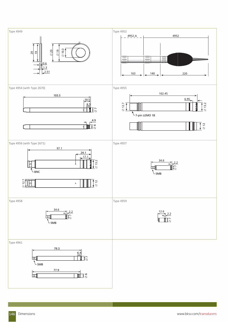
Type 4949 Type 4952
Type 4954 (with Type 2670) Type 4955
Type 4956 (with Type 2671) Type 4957
Type 4958 Type 4959
Type 4961
1920
1.3
2.51
0.6
∅ 2
0
∅ 1
9
∅ 1
0.3
220140163
49524952-A
103.5
6.5
10.5
∅ 7
4.9
∅ 6
102.45
6.95
∅ 1
3.2
∅ 1
2.7
∅ 1
2
7-pin LEMO 1B
∅ 1
2.7
∅ 1
2
24.1
97.1
17.1
∅ 1
3.2
BNC
34.62.2
∅ 7SMB
34.62.2
∅ 7
SMB
12.62.2
∅ 7
79.3
6.4
∅ 7
77.9
∅ 6
SMB
146 Dimensions www.bksv.com/transducers
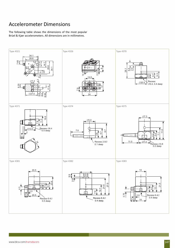
Accelerometer DimensionsThe following table shows the dimensions of the most popularBrüel & Kjær accelerometers. All dimensions are in millimetres.
Type 4321 Type 4326 Type 4370
Type 4371 Type 4374 Type 4375
Type 4381 Type 4382 Type 4383
34.128
.614.7
12.4
7.5
2
25.2
7.65
34.128.6
17.0
8.555.0
0.5
4.3
∅7.2
8.25
∅27.0
8.5 Y
14.67.
9
24
9.25 17
9
2.2
14.1
∅20.5
28.1 2.0
5.5
Recess: ∅6.4, 0.4 deep
8.0 9.7
12.3
19.6
11.5
7.8
∅13.5 Recess ∅6.40.5 deep
145.5
2
3.6 4.
7 6.77.0
∅5.0
Recess 2.0∅0.1 deep
∅7.3
11.0 ∅7.3Recess ∅3.8
0.2 deep
11.0
7.1
5.4
4.2
20.5
23.6
14.0
11.5
8.0
20.5
2.0
5.5
4.3
Recess 6.4∅0.5 deep
7.0 12
.1 21.5 27
.0
Recess 6.4∅0.4 deep.
2.0
5.5
14
21.5
12.1
9.2
7.0
Recess 6.4∅0.4 deep
14
2.0
5.5
3.75
147www.bksv.com/transducers

Type 4384 Type 4391 Type 4393
Type 4394 Type 4397 Type 4500
Type 4501 Type 4505 Type 4506
24.5
19
11.5
9.6
7.2
2
5.5
∅13.5Recess ∅6.4
0.5 deep
14
∅13.5
9.0
3.0
13.0 13.5 22
.3
8.9
Recess 6.4∅0.4 deep
∅15
31.2
7.3
2.5
0.7
7.3
Recess ∅3.80.2 deep
4.2 5.4 7.
1 11.0
o
∅7.3
Recess ∅3.70.35 deep
∅7.7 0.7
6.3
4.1
6.7 9.
6
2.5
x
14.0
∅7.3
Recess ∅3.70.35 deep
0.7
4.4
2.3
5.6 7.
9 12.4
2.5
xo
5.2
6
15.1
10
0.75
10
10
5.3
6.2
15.1
10
100.75
10
∅8.7
4.5
520
.5
∅8.7
4.3
7.8 7.414.5
2.2
17
17
148 www.bksv.com/transducers
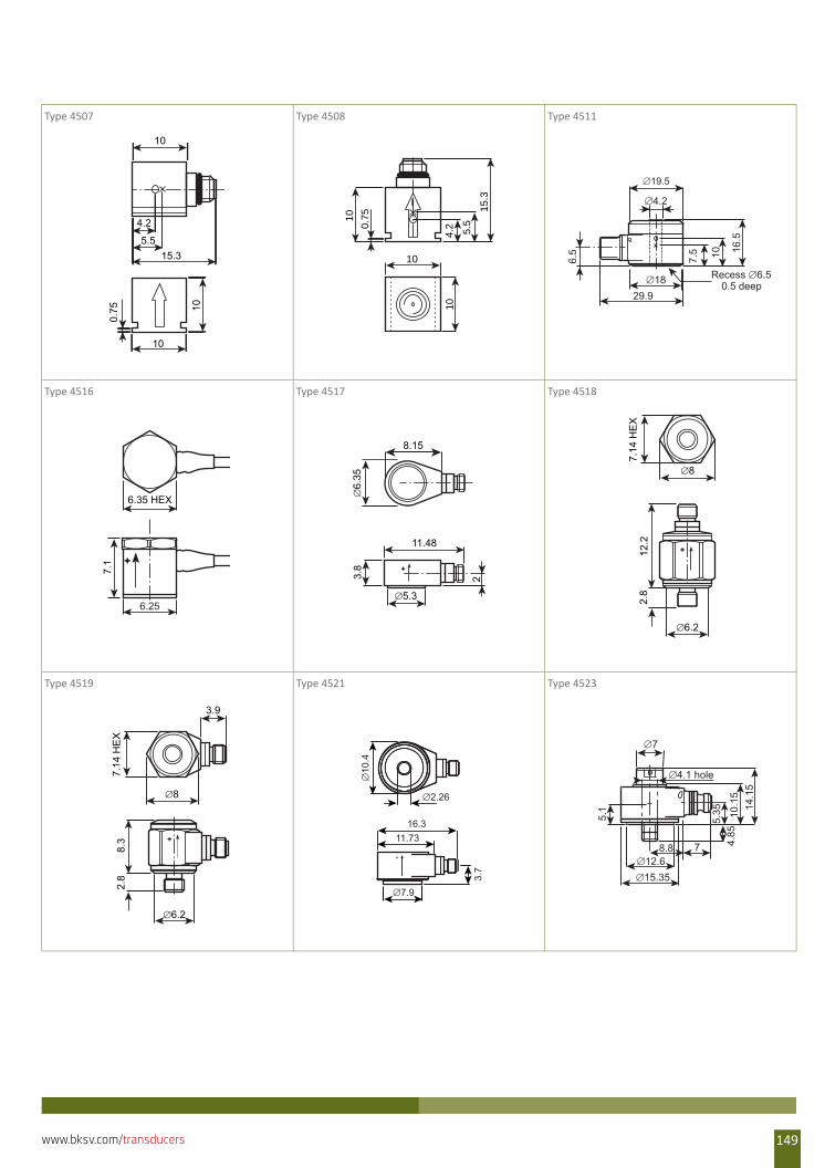
Type 4507 Type 4508 Type 4511
Type 4516 Type 4517 Type 4518
Type 4519 Type 4521 Type 4523
4.2
5.5
10
10
0.75
15.3
10
4.2 5.5
10
10
15.3
10
0.75
∅4.2
∅19.5
∅1829.9
7.5
6.5 16
.5
10
Recess ∅6.50.5 deep
7.1 +
6.35 HEX
6.25
8.15
11.48
∅6.
353.
8
2
∅5.3
+
∅8
7.14
HE
X∅6.2
12.2
2.8
+
∅6.2
8.3
2.8
∅8
+
3.9
7.14
HE
X
16.311.73
∅7.9
∅10
.4
∅2.26
+
3.7
∅714
.15
10.1
5
5.35
∅4.1 hole
5.1
∅12.6∅15.35
78.8 4.85
149www.bksv.com/transducers
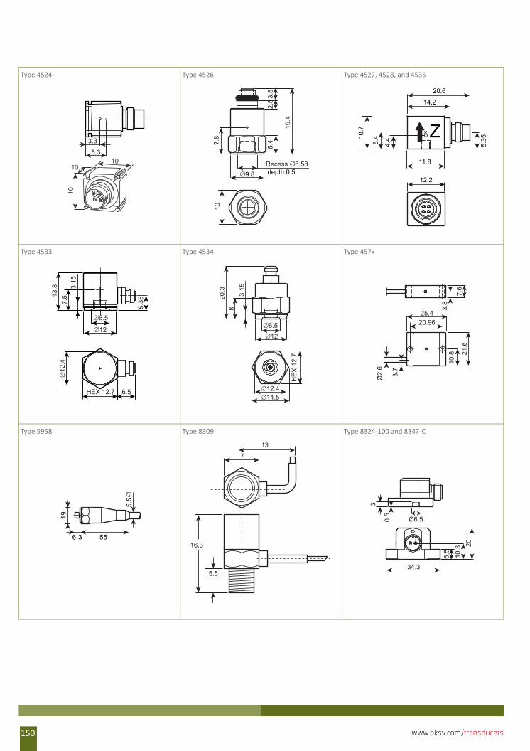
Type 4524 Type 4526 Type 4527, 4528, and 4535
Type 4533 Type 4534 Type 457x
Type 5958 Type 8309 Type 8324‐100 and 8347‐C
10
5.3
3.3
10
10
3.5
19.4
∅9.8
5.47.
810
2.5
Recess ∅6.58 depth 0.5
5.35
4.45.410
.7
12.2
Z
20.6
14.2
11.8
∅6.5
13.8
HEX 12.7
7.5
3.15
5.35
∅12
.4
6.5
∅12
20.3
HE
X 1
2.7
83.
15
∅6.5
∅12.4∅14.5
∅12
25.420.96
21.6
7.6
3.8
3.7
10.8
Ø2.
6
19
6.3 55
5.5
∅
16.3
5.5
13
7
Ø6.5
6.5
20
34.3
10.3
3
0.5
150 www.bksv.com/transducers
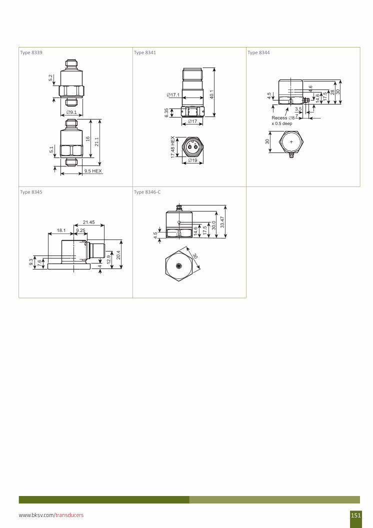
Type 8339 Type 8341 Type 8344
Type 8345 Type 8346‐C
5.2
16
21.1
5.1
9.5 HEX
∅9.1
40.1∅17.1
A B
∅19
17.4
8 H
EX
∅17
6.35
302817
.514
.64.
6
3.57Recess ∅8
x 0.5 deep
4.5
30
18.1 9.25
9.3
7.6
4
12.9 20
.4
21.4533
.47
30.0
17.5
14.6
4.5
30
151www.bksv.com/transducers

152 www.bksv.com/transducers
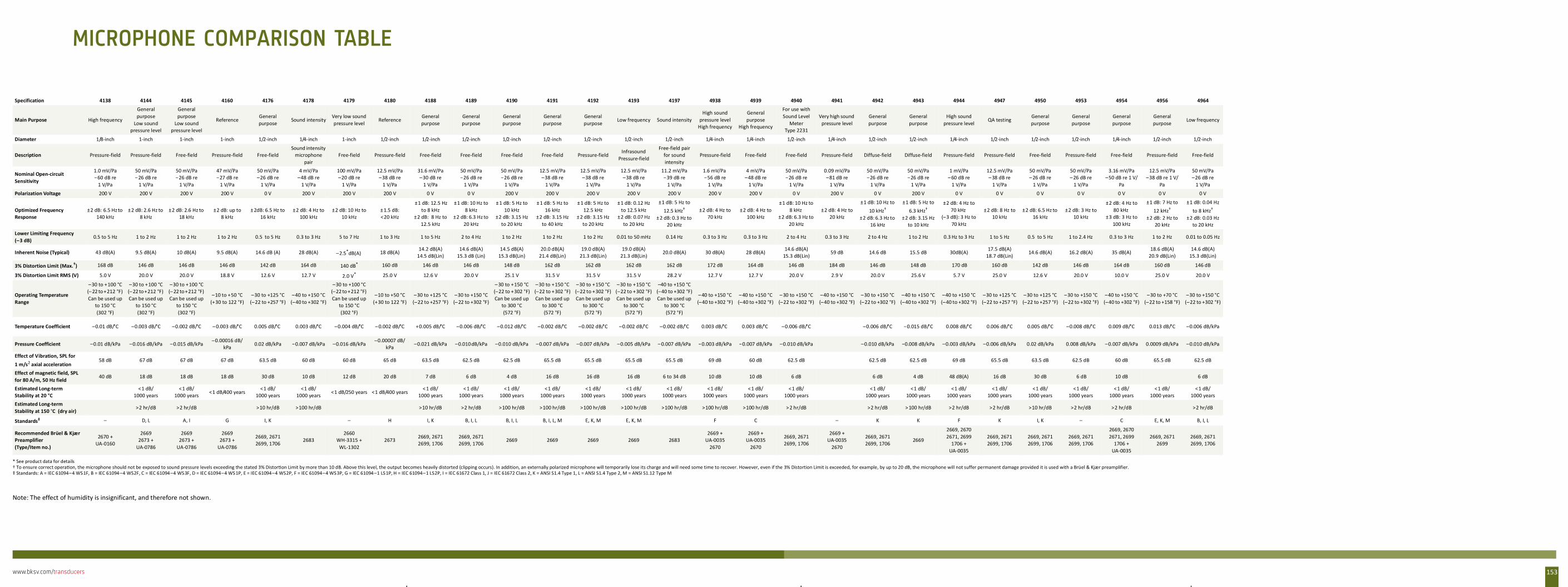
www.bksv.com/transducers 153
Note: The effect of humidity is insignificant, and therefore not shown.
Specification 4138 4144 4145 4160 4176 4178 4179 4180 4188 4189 4190 4191 4192 4193 4197 4938 4939 4940 4941 4942 4943 4944 4947 4950 4953 4954 4956 4964
Main Purpose High frequency
General purpose
Low sound pressure level
General purpose
Low sound pressure level
ReferenceGeneral purpose
Sound intensityVery low sound pressure level
ReferenceGeneral purpose
General purpose
General purpose
General purpose
General purpose
Low frequency Sound intensityHigh sound
pressure levelHigh frequency
General purpose
High frequency
For use with Sound Level
Meter Type 2231
Very high sound pressure level
General purpose
General purpose
High sound pressure level
QA testing General purpose
General purpose
General purpose
Generalpurpose
Low frequency
Diameter 1/8-inch 1-inch 1-inch 1-inch 1/2-inch 1/4-inch 1-inch 1/2-inch 1/2-inch 1/2-inch 1/2-inch 1/2-inch 1/2-inch 1/2-inch 1/2-inch 1/4-inch 1/4-inch 1/2-inch 1/4-inch 1/2-inch 1/2-inch 1/4-inch 1/2-inch 1/2-inch 1/2-inch 1/4-inch 1/2-inch 1/2-inch
Description Pressure-field Pressure-field Free-field Pressure-field Free-fieldSound intensity
microphone pair
Free-field Pressure-field Free-field Free-field Free-field Free-field Pressure-fieldInfrasound
Pressure-field
Free-field pair for sound intensity
Pressure-field Free-field Free-field Pressure-field Diffuse-field Diffuse-field Pressure-field Pressure-field Free-field Pressure-field Free-field Pressure-field Free-field
Nominal Open-circuit Sensitivity
1.0 mV/Pa−60 dB re
1 V/Pa
50 mV/Pa−26 dB re
1 V/Pa
50 mV/Pa−26 dB re
1 V/Pa
47 mV/Pa−27 dB re
1 V/Pa
50 mV/Pa–26 dB re
1 V/Pa
4 mV/Pa–48 dB re
1 V/Pa
100 mV/Pa–20 dB re
1 V/Pa
12.5 mV/Pa–38 dB re
1 V/Pa
31.6 mV/Pa–30 dB re
1 V/Pa
50 mV/Pa−26 dB re
1 V/Pa
50 mV/Pa−26 dB re
1 V/Pa
12.5 mV/Pa–38 dB re
1 V/Pa
12.5 mV/Pa–38 dB re
1 V/Pa
12.5 mV/Pa–38 dB re
1 V/Pa
11.2 mV/Pa−39 dB re
1 V/Pa
1.6 mV/Pa −56 dB re
1 V/Pa
4 mV/Pa–48 dB re
1 V/Pa
50 mV/Pa−26 dB re
1 V/Pa
0.09 mV/Pa–81 dB re
1 V/Pa
50 mV/Pa−26 dB re
1 V/Pa
50 mV/Pa−26 dB re
1 V/Pa
1 mV/Pa– 60 dB re
1 V/Pa
12.5 mV/Pa– 38 dB re
1 V/Pa
50 mV/Pa– 26 dB re
1 V/Pa
50 mV/Pa– 26 dB re
1 V/Pa
3.16 mV/Pa–50 dB re 1 V/
Pa
12.5 mV/Pa–38 dB re 1 V/
Pa
50 mV/Pa–26 dB re
1 V/PaPolarization Voltage 200 V 200 V 200 V 200 V 0 V 200 V 200 V 200 V 0 V 0 V 200 V 200 V 200 V 200 V 200 V 200 V 200 V 0 V 200 V 0 V 200 V 0 V 0 V 0 V 0 V 0 V 0 V 0 V
Optimized Frequency Response
±2 dB: 6.5 Hz to 140 kHz
±2 dB: 2.6 Hz to 8 kHz
±2 dB: 2.6 Hz to 18 kHz
±2 dB: up to 8 kHz
± 2dB: 6.5 Hz to 16 kHz
±2 dB: 4 Hz to 100 kHz
±2 dB: 10 Hz to 10 kHz
± 1.5 dB: <20 kHz
±1 dB: 12.5 Hz to 8 kHz
±2 dB: 8 Hz to 12.5 kHz
±1 dB: 10 Hz to 8 kHz
±2 dB: 6.3 Hz to 20 kHz
± 1 dB: 5 Hz to 10 kHz
±2 dB: 3.15 Hz to 20 kHz
± 1 dB: 5 Hz to 16 kHz
±2 dB: 3.15 Hz to 40 kHz
± 1 dB: 5 Hz to 12.5 kHz
± 2 dB: 3.15 Hz to 20 kHz
± 1 dB: 0.12 Hz to 12.5 kHz
±2 dB: 0.07 Hz to 20 kHz
±1 dB: 5 Hz to 12.5 kHz†
± 2 dB: 0.3 Hz to 20 kHz
±2 dB: 4 Hz to 70 kHz
±2 dB: 4 Hz to 100 kHz
±1 dB: 10 Hz to 8 kHz
±2 dB: 6.3 Hz to 20 kHz
±2 dB: 4 Hz to 20 kHz
±1 dB: 10 Hz to 10 kHz†
±2 dB: 6.3 Hz to 16 kHz
±1 dB: 5 Hz to 6.3 kHz†
±2 dB: 3.15 Hz to 10 kHz
±2 dB: 4 Hz to 70 kHz
(–3 dB): 3 Hz to 70 kHz
±2 dB: 8 Hz to 10 kHz
±2 dB: 6.5 Hz to 16 kHz
±2 dB: 3 Hz to 10 kHz
±2 dB: 4 Hz to 80 kHz
±3 dB: 3 Hz to 100 kHz
±1 dB: 7 Hz to 12 kHz†
±2 dB: 2 Hz to 20 kHz
±1 dB: 0.04 Hz to 8 kHz†
±2 dB: 0.03 Hz to 20 kHz
Lower Limiting Frequency (–3 dB)
0.5 to 5 Hz 1 to 2 Hz 1 to 2 Hz 1 to 2 Hz 0.5 to 5 Hz 0.3 to 3 Hz 5 to 7 Hz 1 to 3 Hz 1 to 5 Hz 2 to 4 Hz 1 to 2 Hz 1 to 2 Hz 1 to 2 Hz 0.01 to 50 mHz 0.14 Hz 0.3 to 3 Hz 0.3 to 3 Hz 2 to 4 Hz 0.3 to 3 Hz 2 to 4 Hz 1 to 2 Hz 0.3 Hz to 3 Hz 1 to 5 Hz 0.5 to 5 Hz 1 to 2.4 Hz 0.3 to 3 Hz 1 to 2 Hz 0.01 to 0.05 Hz
Inherent Noise (Typical) 43 dB(A) 9.5 dB(A) 10 dB(A) 9.5 dB(A) 14.6 dB (A) 28 dB(A) –2.5*dB(A)
* See product data for details
18 dB(A) 14.2 dB(A) 14.5 dB(Lin)
14.6 dB(A) 15.3 dB (Lin)
14.5 dB(A) 15.3 dB(Lin)
20.0 dB(A) 21.4 dB(Lin)
19.0 dB(A) 21.3 dB(Lin)
19.0 dB(A) 21.3 dB(Lin)
20.0 dB(A) 30 dB(A) 28 dB(A) 14.6 dB(A) 15.3 dB(Lin)
59 dB 14.6 dB 15.5 dB 30dB(A) 17.5 dB(A)18.7 dB(Lin)
14.6 dB(A) 16.2 dB(A) 35 dB(A) 18.6 dB(A) 20.9 dB(Lin)
14.6 dB(A) 15.3 dB(Lin)
3% Distortion Limit (Max.†)
† To ensure correct opera on, the microphone should not be exposed to sound pressure levels exceeding the stated 3% Distor on Limit by more than 10 dB. Above this level, the output becomes heavily distorted (clipping occurs). In addition, an externally polarized microphone will temporarily lose its charge and will need some time to recover. However, even if the 3% Distortion Limit is exceeded, for example, by up to 20 dB, the microphone will not suffer permanent damage provided it is used with a Brüel & Kjær preamplifier.
168 dB 146 dB 146 dB 146 dB 142 dB 164 dB 140 dB* 160 dB 146 dB 146 dB 148 dB 162 dB 162 dB 162 dB 162 dB 172 dB 164 dB 146 dB 184 dB 146 dB 148 dB 170 dB 160 dB 142 dB 146 dB 164 dB 160 dB 146 dB
3% Distortion Limit RMS (V) 5.0 V 20.0 V 20.0 V 18.8 V 12.6 V 12.7 V 2.0 V* 25.0 V 12.6 V 20.0 V 25.1 V 31.5 V 31.5 V 31.5 V 28.2 V 12.7 V 12.7 V 20.0 V 2.9 V 20.0 V 25.6 V 5.7 V 25.0 V 12.6 V 20.0 V 10.0 V 25.0 V 20.0 V
Operating Temperature Range
–30 to +100 °C (– 22 to +212 °F) Can be used up
to 150 °C (302 °F)
–30 to +100 °C (– 22 to +212 °F) Can be used up
to 150 °C (302 °F)
–30 to +100 °C (– 22 to +212 °F) Can be used up
to 150 °C (302 °F)
–10 to +50 °C(+30 to 122 °F)
–30 to +125 °C(–22 to +257 °F)
–40 to +150 °C(–40 to +302 °F)
–30 to +100 °C (–22 to +212 °F) Can be used up
to 150 °C (302 °F)
–10 to +50 °C(+30 to 122 °F)
–30 to +125 °C (–22 to +257 °F)
–30 to +150 °C (– 22 to +302 °F)
– 30 to +150 °C(–22 to +302 °F)Can be used up
to 300 °C (572 °F)
–30 to +150 °C(–22 to +302 °F)Can be used up
to 300 °C (572 °F)
–30 to +150 °C(–22 to +302 °F)Can be used up
to 300 °C (572 °F)
–30 to +150 °C(–22 to +302 °F)Can be used up
to 300 °C (572 °F)
–40 to +150 °C(–40 to +302 °F)Can be used up
to 300 °C (572 °F)
– 40 to +150 °C (–40 to +302 °F)
– 40 to +150 °C (–40 to +302 °F)
– 30 to +150 °C (–22 to +302 °F)
–40 to +150 °C (–40 to +302 °F)
–30 to +150 °C (–22 to +302 °F)
–40 to +150 °C (–40 to +302 °F)
–40 to +150 °C (–40 to +302 °F)
–30 to +125 °C (–22 to +257 °F)
–30 to +125 °C (–22 to +257 °F)
–30 to +150 °C (–22 to +302 °F)
–40 to +150 °C (–40 to +302 °F)
–30 to +70 °C (–22 to +158 °F)
–30 to +150 °C (–22 to +302 °F)
Temperature Coefficient –0.01 dB/°C –0.003 dB/°C –0.002 dB/°C – 0.003 dB/°C 0.005 dB/°C 0.003 dB/°C –0.004 dB/°C – 0.002 dB/°C +0.005 dB/°C –0.006 dB/°C –0.012 dB/°C –0.002 dB/°C –0.002 dB/°C –0.002 dB/°C –0.002 dB/°C 0.003 dB/°C 0.003 dB/°C –0.006 dB/°C –0.006 dB/°C −0.015 dB/°C 0.008 dB/°C 0.006 dB/°C 0.005 dB/°C –0.008 dB/°C 0.009 dB/°C 0.013 dB/°C –0.006 dB/kPa
Pressure Coefficient –0.01 dB/kPa –0.016 dB/kPa –0.015 dB/kPa–0.00016 dB/
kPa 0.02 dB/kPa −0.007 dB/kPa –0.016 dB/kPa–0.00007 dB/
kPa –0.021 dB/kPa –0.010dB/kPa –0.010 dB/kPa –0.007 dB/kPa –0.007 dB/kPa –0.005 dB/kPa – 0.007 dB/kPa −0.003 dB/kPa −0.007 dB/kPa –0.010 dB/kPa –0.010 dB/kPa −0.008 dB/kPa –0.003 dB/kPa –0.006 dB/kPa 0.02 dB/kPa 0.008 dB/kPa –0.007 dB/kPa 0.0009 dB/kPa –0.010 dB/kPa
Effect of Vibration, SPL for 1 m/s2 axial acceleration
58 dB 67 dB 67 dB 67 dB 63.5 dB 60 dB 60 dB 65 dB 63.5 dB 62.5 dB 62.5 dB 65.5 dB 65.5 dB 65.5 dB 65.5 dB 69 dB 60 dB 62.5 dB 62.5 dB 62.5 dB 69 dB 65.5 dB 63.5 dB 62.5 dB 60 dB 65.5 dB 62.5 dB
Effect of magnetic field, SPL for 80 A/m, 50 Hz field
40 dB 18 dB 18 dB 18 dB 30 dB 10 dB 12 dB 20 dB 7 dB 6 dB 4 dB 16 dB 16 dB 16 dB 6 to 34 dB 10 dB 10 dB 6 dB 6 dB 4 dB 48 dB(A) 16 dB 30 dB 6 dB 10 dB 6 dB
Estimated Long-term Stability at 20 °C
<1 dB/1000 years
<1 dB/1000 years <1 dB/400 years
<1 dB/1000 years
<1 dB/1000 years <1 dB/250 years <1 dB/400 years
< 1 dB/1000 years
< 1 dB/1000 years
<1 dB/1000 years
<1 dB/1000 years
<1 dB/1000 years
<1 dB/1000 years
<1 dB/1000 years
<1 dB/1000 years
<1 dB/1000 years
<1 dB/1000 years
<1 dB/1000 years
<1 dB/1000 years
<1 dB/1000 years
<1 dB/1000 years
<1 dB/1000 years
<1 dB/1000 years
<1 dB/1000 years
<1 dB/1000 years
<1 dB/1000 years
Estimated Long-term Stability at 150 °C (dry air)
>2 hr/dB >2 hr/dB >10 hr/dB >100 hr/dB >10 hr/dB >2 hr/dB >100 hr/dB >100 hr/dB >100 hr/dB >100 hr/dB >100 hr/dB >100 hr/dB >100 hr/dB > 2 hr/dB >2 hr/dB > 100 hr/dB >2 hr/dB >2 hr/dB >10 hr/dB >2 hr/dB >2 hr/dB >2 hr/dB
Standards‡
‡ Standards: A = IEC 61094–4 WS1F, B = IEC 61094 –4 WS2F, C = IEC 61094 –4 WS3F, D = IEC 61094–4 WS1P, E = IEC 61094–4 WS2P, F = IEC 61094–4 WS3P, G = IEC 61094 –1 LS1P, H = IEC 61094–1 LS2P, I = IEC 61672 Class 1, J = IEC 61672 Class 2, K = ANSI S1.4 Type 1, L = ANSI S1.4 Type 2, M = ANSI S1.12 Type M
– D, L A, I G I, K – H I, K B, I, L B, I, L B, I, L, M E, K, M E, K, M F C – K K F K I, K – C E, K, M B, I, L
Recommended Brüel & Kjær Preamplifier(Type/Item no.)
2670 + UA-0160
26692673 +
UA-0786
26692673 +
UA-0786
26692673 +
UA-0786
2669, 2671 2699, 1706
26832660
WH-3315 + WL-1302
2673 2669, 26712699, 1706
2669, 26712699, 1706
2669 2669 2669 2669 26832669 +
UA-00352670
2669 + UA-0035
2670
2669, 26712699, 1706
2669 + UA-0035
2670
2669, 26712699, 1706
2669
2669, 26702671, 2699
1706 + UA-0035
2669, 26712699, 1706
2669, 26712699, 1706
2669, 26712699, 1706
2669, 2670 2671, 2699
1706 + UA-0035
2669, 26712699
2669, 26712699, 1706
MICROPHONE COMPARISON TABLE

www.bksv.com/transducers154
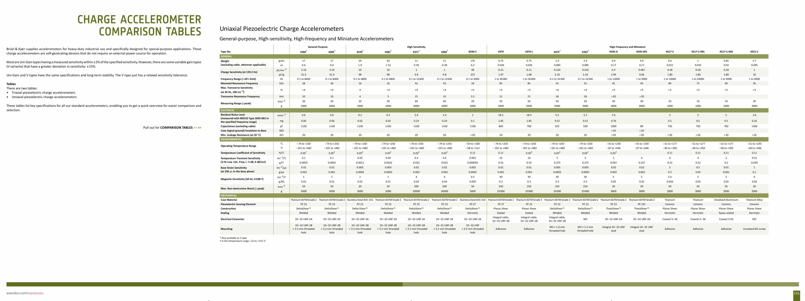
www.bksv.com/transducers 155
Brüel & Kjær supplies accelerometers for heavy-duty industrial use and specifically designed for special-purpose applications. Thesecharge accelerometers are self-generating devices that do not require an external power source for operation.
Most are Uni-Gain types having a measured sensitivity within ±2% of the specified sensitivity. However, there are some variable gain types(V variants) that have a greater deviation in sensitivity: ±15%.
Uni-Gain and V types have the same specifications and long-term stability. The V type just has a relaxed sensitivity tolerance.
TablesThere are two tables:• Triaxial piezoelectric charge accelerometers• Uniaxial piezoelectric charge accelerometers
These tables list key specifications for all our standard accelerometers, enabling you to get a quick overview for easier comparison andselection.
Pull out for COMPARISON TABLES >> >>
Uniaxial Piezoelectric Charge AccelerometersGeneral-purpose, High-sensitivity, High-frequency and Miniature Accelerometers
General Purpose High Sensitivity High Frequency and Miniature
Type No. 4382*
* Also available as V type
4383* 4370* 4381* 4371* 4384* 8346-C 4374 4374-L 4375* 4393* 4505-A 4505-001 4517-C 4517-C-001 4517-C-003 4521-C
GENERAL
Weight (excluding cable, wherever applicable)
gram 17 17 54 43 11 11 176 0.75 0.75 2.4 2.4 4.9 4.9 0.6 1 0.85 2.7oz 0.6 0.6 1.9 1.52 0.39 0.39 6.2 0.026 0.026 0.085 0.085 0.17 0.17 0.021 0.035 0.03 0.095
Charge Sensitivity (at 159.2 Hz)pC/ms–2 3.16 3.16 10 10 1 1 38 0.15 0.11 0.316 0.316 0.3 0.067 0.18 0.18 0.18 1
pC/g 31.0 31.0 98 98 9.8 9.8 372 1.47 1.08 3.10 3.10 2.94 0.66 1.80 1.80 1.80 10Frequency Range (± 10% limit) Hz 0.1 to 8400 0.1 to 8400 0.1 to 4800 0.1 to 4800 0.1 to 12600 0.1 to 12600 0.1 to 3000 1 to 26000 1 to 26000 0.1 to 16500 0.1 to 16500 1 to 12000 1 to 9000 1 to 10000 1 to 20000 1 to 9000 1 to 9000Mounted Resonance Frequency kHz 28 28 16 16 42 42 10 85 85 55 55 45 45 80 75 30 35Max. Transverse Sensitivity (at 30 Hz, 100 ms–2)
% <4 <4 4 <4 <4 <4 <5 <5 <5 <4 <4 <5 <5 <5 <5 <5 < 5
Transverse Resonance Frequency kHz 10 10 4 5 15 15 3.5 21 21 18 18 >20 > 20
Measuring Range (±peak)kms–2 20 20 20 20 60 60 20 50 50 50 50 30 30 10 10 10 20
g 2000 2000 2000 2000 6000 6000 2000 5000 5000 5000 5000 3000 3000 1000 1000 1000 2000ELECTRICALResidual Noise Level (measured with NEXUS Type 2692-001 in the specified frequency range)
mms–2 0.6 0.6 0.2 0.2 2.4 2.4 1 18.5 18.5 5.2 5.2 7.6 5 5 5 1.6
mg 0.06 0.06 0.02 0.02 0.24 0.24 0.1 1.85 1.85 0.52 0.52 0.76 0.5 0.5 0.5 0.16
Capacitance (excluding cable) pF 1100 1100 1100 1100 1100 1100 1100 800 700 625 590 1000 80 730 730 760 1300Case (signal ground) Insulation to Base MΩ >10 >10Min. Leakage Resistance (at 20 °C) GΩ 20 20 20 20 20 20 >20 20 20 20 20 >20 > 20 > 20 > 20 > 20 >20ENVIRONMENTAL
Operating Temperature Range°C – 74 to +250 – 74 to +250 –74 to +250 –74 to +250 –74 to +250 –74 to +250 –50 to +100 –74 to +250 –74 to +250 –74 to +250 –74 to +250 – 55 to +230 –55 to +230 –51 to +177 –51 to +177 –51 to +177 –51 to +230°F –101 to +482 –101 to +482 –101 to +482 –101 to +482 –101 to +482 –101 to +482 –58 to +212 – 101 to +482 – 101 to +482 – 101 to +482 –101 to +482 –67 to +446 –67 to +446 – 60 to +350 –60 to +350 –60 to +350 –60 to +446
Temperature Coefficient of Sensitivity %/°C 0.05†
† In the temperature range –25 to +125 °C
0.05‡ 0.05‡ 0.05‡ 0.05‡ 0.05‡ 0.12 0.11 0.05‡ 0.05‡ 0.05‡ 0.05‡ 0.11 0.11 0.11 0.11
Temperature Transient Sensitivity (3 Hz Low. Lim. Freq. (–3 dB, 6 dB/oct)
ms–2/°C 0.1 0.1 0.02 0.04 0.4 0.4 0.001 10 10 5 5 1 4 4 4 2 0.55
g/°F 0.0055 0.0055 0.0011 0.0022 0.022 0.022 0.000055 0.55 0.55 0.275 0.275 0.055 0.227 0.22 0.22 0.2 0.030
Base Strain Sensitivity (at 250 µε in the base plane)
ms–2/µε 0.01 0.01 0.003 0.003 0.02 0.02 0.002 0.01 0.01 0.005 0.005 0.02 0.02 5 0.5 0.01 1
g/µε 0.001 0.001 0.0003 0.0003 0.002 0.002 0.0002 0.001 0.001 0.0005 0.0005 0.002 0.002 0.5 0.05 0.001 0.1
Magnetic Sensitivity (50 Hz, 0.038 T)ms–2/T 1 1 1 1 4 4 0.5 30 30 30 30 5 5 5.6 5 5 6
g/kG 0.01 0.01 0.01 0.01 0.04 0.04 0.005 0.3 0.3 0.3 0.3 0.05 0.05 0.056 0.05 0.05 0.06
Max. Non-destructive Shock (± peak) kms–2 50 50 20 20 200 200 50 250 250 250 250 30 30 50 50 50 20
g 5000 5000 2000 2000 20000 20000 5000 25000 25000 25000 25000 3000 3000 5000 5000 5000 2000MECHANICALCase Material Titanium ASTM Grade 2 Titanium ASTM Grade 2 Stainless Steel AISI 316 Titanium ASTM Grade 2 Titanium ASTM Grade 2 Titanium ASTM Grade 2 Stainless Steel AISI 316 Titanium ASTM Grade 2 Titanium ASTM Grade 3 Titanium ASTM Grade 2 Titanium ASTM Grade 2 Titanium ASTM Grade 2 Titanium ASTM Grade 2 Titanium Titanium Anodized Aluminium Titanium AlloyPiezoelectric Sensing Element PZ 23 PZ 23 PZ 23 PZ 23 PZ 23 PZ 23 PZ 27 PZ 27 PZ 23 PZ 23 PZ 23 PZ 23 PZ 101 Ceramic Ceramic Ceramic CeramicConstruction DeltaShear™ DeltaShear™ Delta-Shear™ DeltaShear™ DeltaShear™ DeltaShear™ DeltaShear™ Planar Shear Planar Shear DeltaShear™ DeltaShear™ ThetaShear™ ThetaShear™ Planar Shear Planar Shear Planar Shear Planar ShearSealing Welded Welded Welded Welded Welded Welded Hermetic Sealed Sealed Welded Welded Welded Welded Hermetic Hermetic Epoxy sealed Hermetic
Electrical Connector 10–32 UNF-2A 10–32 UNF-2A 10–32 UNF-2A 10–32 UNF-2A 10–32 UNF-2A 10–32 UNF-2A 10–32 UNF-2AIntegral cable, 10–32 UNF-2B
Integral cable, 10–32 UNF-2B
Integral cable, 10–32 UNF-2B
M3 10–32 UNF-2A 10–32 UNF-2A Coaxial 3– 56 Coaxial 3– 56 Coaxial 3-56 M3
Mounting10–32 UNF-2B
× 3.2 mm threaded hole
10–32 UNF-2B × 3.2 mm threaded
hole
10–32 UNF-2B× 3.2 mm threaded
hole
10–32 UNF-2B× 3.2 mm threaded
hole
10–32 UNF-2B× 3.2 mm threaded
hole
10–32 UNF-2B× 3.2 mm threaded
hole
10– 32 UNF × 4.5 mm threaded
holeAdhesive Adhesive
M3 × 1.6 mm threaded hole
M3 × 2.2 mm threaded hole
Integral 10– 32 UNF stud
Integral 10–32 UNF stud
Adhesive Adhesive Adhesive Insulated M2 screw
CHARGE ACCELEROMETERCOMPARISON TABLES
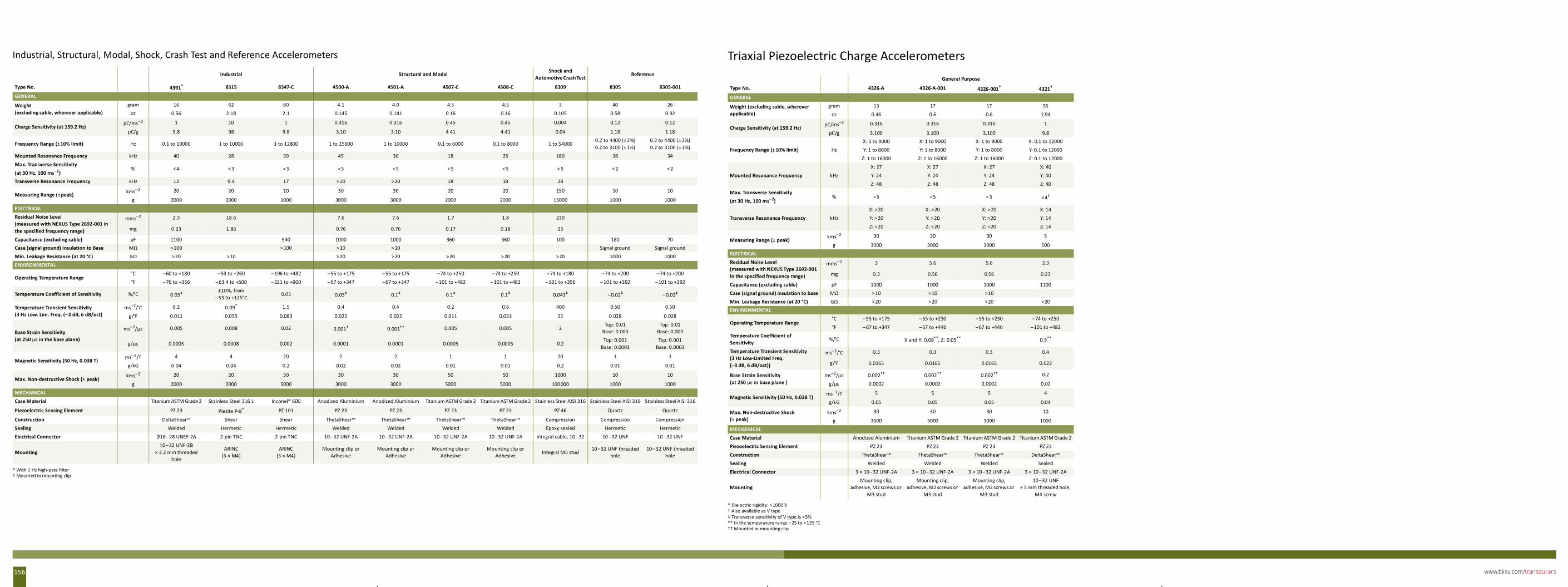
www.bksv.com/transducers156
Industrial, Structural, Modal, Shock, Crash Test and Reference Accelerometers
Industrial Structural and Modal Shock and Automotive Crash Test
Reference
Type No. 4391* 8315 8347-C 4500-A 4501-A 4507-C 4508-C 8309 8305 8305-001
GENERAL
Weight (excluding cable, wherever applicable)
gram 16 62 60 4.1 4.0 4.5 4.5 3 40 26oz 0.56 2.18 2.1 0.145 0.141 0.16 0.16 0.105 0.58 0.92
Charge Sensitivity (at 159.2 Hz)pC/ms–2 1 10 1 0.316 0.316 0.45 0.45 0.004 0.12 0.12
pC/g 9.8 98 9.8 3.10 3.10 4.41 4.41 0.04 1.18 1.18
Frequency Range (±10% limit) Hz 0.1 to 10000 1 to 10000 1 to 12800 1 to 15000 1 to 10000 0.1 to 6000 0.1 to 8000 1 to 540000.2 to 4400 (±2%) 0.2 to 3100 (±1%)
0.2 to 4400 (±2%) 0.2 to 3100 (±1%)
Mounted Resonance Frequency kHz 40 28 39 45 30 18 25 180 38 34Max. Transverse Sensitivity (at 30 Hz, 100 ms–2)
% <4 <3 <3 <5 <5 <5 <5 < 5 < 2 < 2
Transverse Resonance Frequency kHz 12 9.4 17 > 20 > 20 18 18 28
Measuring Range (±peak) kms–2 20 20 10 30 30 20 20 150 10 10
g 2000 2000 1000 3000 3000 2000 2000 15000 1000 1000ELECTRICALResidual Noise Level (measured with NEXUS Type 2692-001 in the specified frequency range)
mms–2 2.3 18.6 7.6 7.6 1.7 1.8 230
mg 0.23 1.86 0.76 0.76 0.17 0.18 23
Capacitance (excluding cable) pF 1100 540 1000 1000 360 360 100 180 70Case (signal ground) Insulation to Base MΩ >100 > 100 >10 > 10 Signal ground Signal groundMin. Leakage Resistance (at 20 °C) GΩ >20 >10 > 20 > 20 > 20 > 20 >20 1000 1000ENVIRONMENTAL
Operating Temperature Range°C – 60 to +180 –53 to +260 –196 to +482 –55 to +175 –55 to +175 –74 to +250 –74 to +250 –74 to +180 –74 to +200 –74 to +200°F –76 to +356 –63.4 to +500 –321 to +900 –67 to +347 –67 to +347 –101 to +482 –101 to +482 –101 to +356 –101 to +392 –101 to +392
Temperature Coefficient of Sensitivity %/°C 0.05‡ ±10%, from
–53 to +125°C0.03 0.05‡ 0.1‡ 0.1‡ 0.1‡ 0.043‡ –0.02‡ –0.02‡
Temperature Transient Sensitivity (3 Hz Low. Lim. Freq. (–3 dB, 6 dB/oct)
ms–2/°C 0.2 0.09*
* With 1 Hz high-pass filter
1.5 0.4 0.4 0.2 0.6 400 0.50 0.50
g/°F 0.011 0.055 0.083 0.022 0.022 0.011 0.033 22 0.028 0.028
Base Strain Sensitivity (at 250 µε in the base plane)
ms–2/µε 0.005 0.008 0.02 0.001†
† Mounted in moun ng clip
0.001†† 0.005 0.005 2Top: 0.01
Base: 0.003Top: 0.01
Base: 0.003
g/µε 0.0005 0.0008 0.002 0.0001 0.0001 0.0005 0.0005 0.2Top: 0.001
Base: 0.0003Top: 0.001
Base: 0.0003
Magnetic Sensitivity (50 Hz, 0.038 T)ms–2/T 4 4 20 2 2 1 1 20 1 1
g/kG 0.04 0.04 0.2 0.02 0.02 0.01 0.01 0.2 0.01 0.01
Max. Non-destructive Shock (± peak)kms–2 20 20 50 30 30 50 50 1000 10 10
g 2000 2000 5000 3000 3000 5000 5000 100000 1000 1000MECHANICALCase Material Titanium ASTM Grade 2 Stainless Steel 316 L Inconel® 600 Anodized Aluminium Anodized Aluminium Titanium ASTM Grade 2 Titanium ASTM Grade 2 Stainless Steel AISI 316 Stainless Steel AISI 316 Stainless Steel AISI 316
Piezoelectric Sensing Element PZ 23 Piezite P-8® PZ 101 PZ 23 PZ 23 PZ 23 PZ 23 PZ 46 Quartz Quartz
Construction DeltaShear™ Shear Shear ThetaShear™ ThetaShear™ ThetaShear™ ThetaShear™ Compression Compression CompressionSealing Welded Hermetic Hermetic Welded Welded Welded Welded Epoxy sealed Hermetic HermeticElectrical Connector 7/16–28 UNEF-2A 2-pin TNC 2-pin TNC 10–32 UNF-2A 10–32 UNF-2A 10–32 UNF-2A 10–32 UNF-2A Integral cable, 10– 32 10–32 UNF 10–32 UNF
Mounting10– 32 UNF-2B
× 3.2 mm threaded hole
ARINC (3 × M4)
ARINC (3 × M4)
Mounting clip or Adhesive
Mounting clip or Adhesive
Mounting clip or Adhesive
Mounting clip or Adhesive Integral M5 stud
10–32 UNF threaded hole
10–32 UNF threaded hole
Triaxial Piezoelectric Charge AccelerometersGeneral Purpose
Type No. 4326-A 4326-A-001 4326-001*
* Dielectric rigidity: >1000 V
4321†
† Also available as V type
GENERAL
Weight (excluding cable, wherever applicable)
gram 13 17 17 55oz 0.46 0.6 0.6 1.94
Charge Sensitivity (at 159.2 Hz) pC/ms–2 0.316 0.316 0.316 1
pC/g 3.100 3.100 3.100 9.8
Frequency Range (± 10% limit) HzX: 1 to 9000 X: 1 to 9000 X: 1 to 9000 X: 0.1 to 12000Y: 1 to 8000 Y: 1 to 8000 Y: 1 to 8000 Y: 0.1 to 12000
Z: 1 to 16000 Z: 1 to 16000 Z: 1 to 16000 Z: 0.1 to 12000
Mounted Resonance Frequency kHzX: 27 X: 27 X: 27 X: 40Y: 24 Y: 24 Y: 24 Y: 40Z: 48 Z: 48 Z: 48 Z: 40
Max. Transverse Sensitivity (at 30 Hz, 100 ms–2)
% <5 <5 < 5 <4‡
‡ Transverse sensi vity of V type is <5%
Transverse Resonance Frequency kHzX: >20 X: >20 X: > 20 X: 14Y: >20 Y: >20 Y: >20 Y: 14Z: >20 Z: >20 Z: >20 Z: 14
Measuring Range (± peak)kms–2 30 30 30 5
g 3000 3000 3000 500ELECTRICALResidual Noise Level (measured with NEXUS Type 2692-001 in the specified frequency range)
mms–2 3 5.6 5.6 2.3
mg 0.3 0.56 0.56 0.23
Capacitance (excluding cable) pF 1000 1000 1000 1100Case (signal ground) insulation to base MΩ >10 >10 >10Min. Leakage Resistance (at 20 °C) GΩ >20 >20 >20 >20ENVIRONMENTAL
Operating Temperature Range°C –55 to +175 –55 to +230 –55 to +230 –74 to +250°F – 67 to +347 –67 to +446 –67 to +446 –101 to +482
Temperature Coefficient of Sensitivity
%/°C X and Y: 0.08**, Z: 0.05**
** In the temperature range –25 to +125 °C
0.5**
Temperature Transient Sensitivity (3 Hz Low-Limited Freq. (–3 dB, 6 dB/oct))
ms–2/°C 0.3 0.3 0.3 0.4
g/°F 0.0165 0.0165 0.0165 0.022
Base Strain Sensitivity (at 250 µε in base plane )
ms–2/µε 0.002††
†† Mounted in moun ng clip
0.002†† 0.002†† 0.2
g/µε 0.0002 0.0002 0.0002 0.02
Magnetic Sensitivity (50 Hz, 0.038 T)ms–2/T 5 5 5 4
g/kG 0.05 0.05 0.05 0.04
Max. Non-destructive Shock (± peak)
kms–2 30 30 30 10
g 3000 3000 3000 1000MECHANICALCase Material Anodized Aluminium Titanium ASTM Grade 2 Titanium ASTM Grade 2 Titanium ASTM Grade 2Piezoelectric Sensing Element PZ 23 PZ 23 PZ 23 PZ 23Construction ThetaShear™ ThetaShear™ ThetaShear™ DeltaShear™Sealing Welded Welded Welded SealedElectrical Connector 3 × 10–32 UNF-2A 3 × 10–32 UNF-2A 3 × 10–32 UNF-2A 3 × 10–32 UNF-2A
MountingMounting clip,
adhesive, M2 screws or M3 stud
Mounting clip, adhesive, M2 screws or
M3 stud
Mounting clip, adhesive, M2 screws or
M3 stud
10–32 UNF× 5 mm threaded hole,
M4 screw
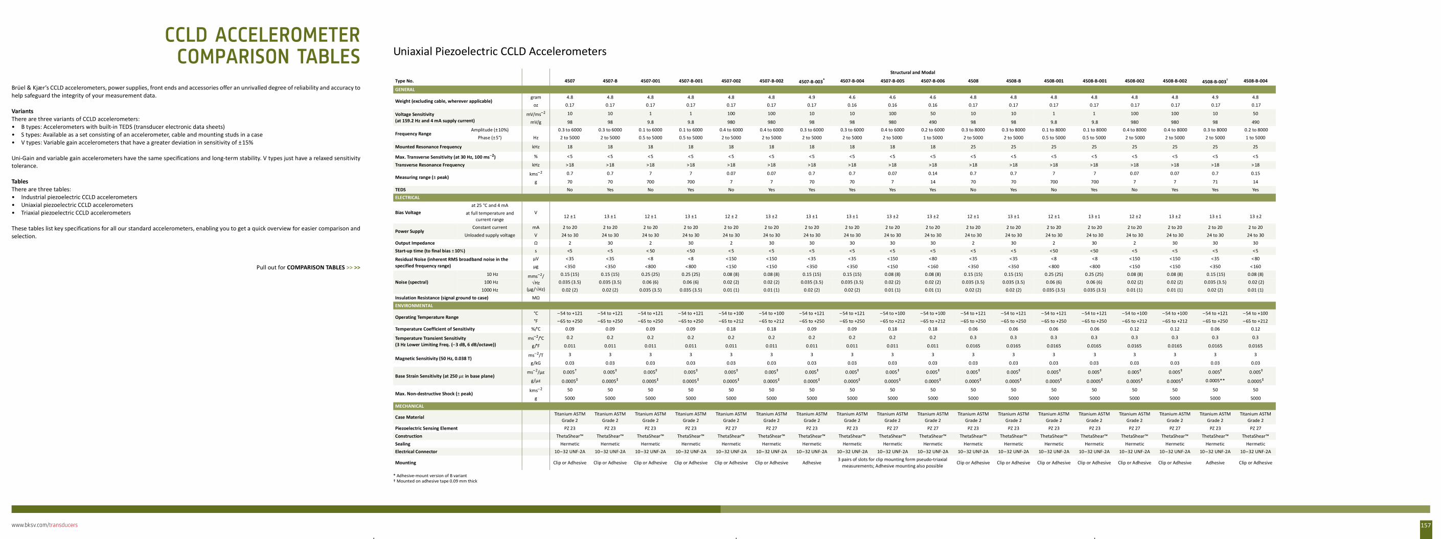
www.bksv.com/transducers 157
Brüel & Kjær’s CCLD accelerometers, power supplies, front ends and accessories offer an unrivalled degree of reliability and accuracy tohelp safeguard the integrity of your measurement data.
VariantsThere are three variants of CCLD accelerometers:• B types: Accelerometers with built-in TEDS (transducer electronic data sheets)• S types: Available as a set consisting of an accelerometer, cable and mounting studs in a case• V types: Variable gain accelerometers that have a greater deviation in sensitivity of ±15%
Uni-Gain and variable gain accelerometers have the same specifications and long-term stability. V types just have a relaxed sensitivitytolerance.
TablesThere are three tables:• Industrial piezoelectric CCLD accelerometers• Uniaxial piezoelectric CCLD accelerometers• Triaxial piezoelectric CCLD accelerometers
These tables list key specifications for all our standard accelerometers, enabling you to get a quick overview for easier comparison andselection.
Pull out for COMPARISON TABLES >> >>
Uniaxial Piezoelectric CCLD AccelerometersStructural and Modal
Type No. 4507 4507-B 4507-001 4507-B-001 4507-002 4507-B-002 4507-B-003*
* Adhesive-mount version of B variant
4507-B-004 4507-B-005 4507-B-006 4508 4508-B 4508-001 4508-B-001 4508-002 4508-B-002 4508-B-003† 4508-B-004
GENERAL
Weight (excluding cable, wherever applicable)gram 4.8 4.8 4.8 4.8 4.8 4.8 4.9 4.6 4.6 4.6 4.8 4.8 4.8 4.8 4.8 4.8 4.9 4.8
oz 0.17 0.17 0.17 0.17 0.17 0.17 0.17 0.16 0.16 0.16 0.17 0.17 0.17 0.17 0.17 0.17 0.17 0.17
Voltage Sensitivity (at 159.2 Hz and 4 mA supply current)
mV/ms–2 10 10 1 1 100 100 10 10 100 50 10 10 1 1 100 100 10 50
mV/g 98 98 9.8 9.8 980 980 98 98 980 490 98 98 9.8 9.8 980 980 98 490
Frequency RangeAmplitude (±10%) 0.3 to 6000 0.3 to 6000 0.1 to 6000 0.1 to 6000 0.4 to 6000 0.4 to 6000 0.3 to 6000 0.3 to 6000 0.4 to 6000 0.2 to 6000 0.3 to 8000 0.3 to 8000 0.1 to 8000 0.1 to 8000 0.4 to 8000 0.4 to 8000 0.3 to 8000 0.2 to 8000
Phase (±5°) Hz 2 to 5000 2 to 5000 0.5 to 5000 0.5 to 5000 2 to 5000 2 to 5000 2 to 5000 2 to 5000 2 to 5000 1 to 5000 2 to 5000 2 to 5000 0.5 to 5000 0.5 to 5000 2 to 5000 2 to 5000 2 to 5000 1 to 5000
Mounted Resonance Frequency kHz 18 18 18 18 18 18 18 18 18 18 25 25 25 25 25 25 25 25
Max. Transverse Sensitivity (at 30 Hz, 100 ms–2) % <5 <5 <5 <5 < 5 <5 <5 <5 <5 <5 <5 <5 <5 < 5 <5 <5 <5 <5
Transverse Resonance Frequency kHz >18 >18 >18 >18 >18 >18 >18 >18 > 18 >18 >18 >18 >18 >18 >18 >18 >18 > 18
Measuring range (± peak)kms–2 0.7 0.7 7 7 0.07 0.07 0.7 0.7 0.07 0.14 0.7 0.7 7 7 0.07 0.07 0.7 0.15
g 70 70 700 700 7 7 70 70 7 14 70 70 700 700 7 7 71 14TEDS No Yes No Yes No Yes Yes Yes Yes Yes No Yes No Yes No Yes Yes YesELECTRICAL
Bias Voltageat 25 °C and 4 mA
Vat full temperature and current range 12 ±1 13 ±1 12 ± 1 13 ±1 12 ± 2 13 ±2 13 ±1 13 ± 1 13 ±2 13 ±2 12 ±1 13 ±1 12 ±1 13 ±1 12 ±2 13 ±2 13 ± 1 13 ±2
Power SupplyConstant current mA 2 to 20 2 to 20 2 to 20 2 to 20 2 to 20 2 to 20 2 to 20 2 to 20 2 to 20 2 to 20 2 to 20 2 to 20 2 to 20 2 to 20 2 to 20 2 to 20 2 to 20 2 to 20
Unloaded supply voltage V 24 to 30 24 to 30 24 to 30 24 to 30 24 to 30 24 to 30 24 to 30 24 to 30 24 to 30 24 to 30 24 to 30 24 to 30 24 to 30 24 to 30 24 to 30 24 to 30 24 to 30 24 to 30Output Impedance Ω 2 30 2 30 2 30 30 30 30 30 2 30 2 30 2 30 30 30Start-up time (to final bias ± 10%) s <5 <5 < 50 <50 < 5 <5 <5 <5 <5 <5 <5 <5 <50 <50 <5 <5 <5 <5
Residual Noise (inherent RMS broadband noise in the specified frequency range)
µV <35 <35 <8 <8 <150 <150 <35 <35 <150 <80 <35 <35 <8 <8 <150 <150 <35 < 80µg <350 <350 <800 < 800 <150 <150 <350 <350 <150 <160 <350 <350 < 800 <800 <150 <150 <350 < 160
Noise (spectral)10 Hz mms–2/
√Hz(µg/√Hz)
0.15 (15) 0.15 (15) 0.25 (25) 0.25 (25) 0.08 (8) 0.08 (8) 0.15 (15) 0.15 (15) 0.08 (8) 0.08 (8) 0.15 (15) 0.15 (15) 0.25 (25) 0.25 (25) 0.08 (8) 0.08 (8) 0.15 (15) 0.08 (8)100 Hz 0.035 (3.5) 0.035 (3.5) 0.06 (6) 0.06 (6) 0.02 (2) 0.02 (2) 0.035 (3.5) 0.035 (3.5) 0.02 (2) 0.02 (2) 0.035 (3.5) 0.035 (3.5) 0.06 (6) 0.06 (6) 0.02 (2) 0.02 (2) 0.035 (3.5) 0.02 (2)
1000 Hz 0.02 (2) 0.02 (2) 0.035 (3.5) 0.035 (3.5) 0.01 (1) 0.01 (1) 0.02 (2) 0.02 (2) 0.01 (1) 0.01 (1) 0.02 (2) 0.02 (2) 0.035 (3.5) 0.035 (3.5) 0.01 (1) 0.01 (1) 0.02 (2) 0.01 (1)Insulation Resistance (signal ground to case) MΩENVIRONMENTAL
Operating Temperature Range°C –54 to +121 –54 to +121 –54 to +121 – 54 to +121 –54 to +100 –54 to +100 –54 to +121 –54 to +121 –54 to +100 –54 to +100 –54 to +121 –54 to +121 – 54 to +121 –54 to +121 –54 to +100 –54 to +100 –54 to +121 –54 to +100°F –65 to +250 –65 to +250 –65 to +250 –65 to +250 –65 to +212 –65 to +212 –65 to +250 – 65 to +250 –65 to +212 –65 to +212 –65 to +250 –65 to +250 – 65 to +250 –65 to +250 –65 to +212 –65 to +212 – 65 to +250 –65 to +212
Temperature Coefficient of Sensitivity %/°C 0.09 0.09 0.09 0.09 0.18 0.18 0.09 0.09 0.18 0.18 0.06 0.06 0.06 0.06 0.12 0.12 0.06 0.12
Temperature Transient Sensitivity (3 Hz Lower Limiting Freq. (–3 dB, 6 dB/octave))
ms–2/°C 0.2 0.2 0.2 0.2 0.2 0.2 0.2 0.2 0.2 0.2 0.3 0.3 0.3 0.3 0.3 0.3 0.3 0.3
g/°F 0.011 0.011 0.011 0.011 0.011 0.011 0.011 0.011 0.011 0.011 0.0165 0.0165 0.0165 0.0165 0.0165 0.0165 0.0165 0.0165
Magnetic Sensitivity (50 Hz, 0.038 T)ms–2/T 3 3 3 3 3 3 3 3 3 3 3 3 3 3 3 3 3 3
g/kG 0.03 0.03 0.03 0.03 0.03 0.03 0.03 0.03 0.03 0.03 0.03 0.03 0.03 0.03 0.03 0.03 0.03 0.03
Base Strain Sensitivity (at 250 µε in base plane)ms–2/µε 0.005†
† Mounted on adhesive tape 0.09 mm thick
0.005‡ 0.005‡ 0.005‡ 0.005‡ 0.005‡ 0.005‡ 0.005‡ 0.005‡ 0.005‡ 0.005‡ 0.005‡ 0.005‡ 0.005‡ 0.005‡ 0.005‡ 0.005‡ 0.005‡
g/µε 0.0005‡ 0.0005‡ 0.0005‡ 0.0005‡ 0.0005‡ 0.0005‡ 0.0005‡ 0.0005‡ 0.0005‡ 0.0005‡ 0.0005‡ 0.0005‡ 0.0005‡ 0.0005‡ 0.0005‡ 0.0005‡ 0.0005** 0.0005‡
Max. Non-destructive Shock (± peak)kms–2 50 50 50 50 50 50 50 50 50 50 50 50 50 50 50 50 50 50
g 5000 5000 5000 5000 5000 5000 5000 5000 5000 5000 5000 5000 5000 5000 5000 5000 5000 5000MECHANICAL
Case MaterialTitanium ASTM
Grade 2Titanium ASTM
Grade 2Titanium ASTM
Grade 2Titanium ASTM
Grade 2Titanium ASTM
Grade 2Titanium ASTM
Grade 2Titanium ASTM
Grade 2Titanium ASTM
Grade 2Titanium ASTM
Grade 2Titanium ASTM
Grade 2Titanium ASTM
Grade 2Titanium ASTM
Grade 2Titanium ASTM
Grade 2Titanium ASTM
Grade 2Titanium ASTM
Grade 2Titanium ASTM
Grade 2Titanium ASTM
Grade 2Titanium ASTM
Grade 2Piezoelectric Sensing Element PZ 23 PZ 23 PZ 23 PZ 23 PZ 27 PZ 27 PZ 23 PZ 23 PZ 27 PZ 27 PZ 23 PZ 23 PZ 23 PZ 23 PZ 27 PZ 27 PZ 23 PZ 27Construction ThetaShear™ ThetaShear™ ThetaShear™ ThetaShear™ ThetaShear™ ThetaShear™ ThetaShear™ ThetaShear™ ThetaShear™ ThetaShear™ ThetaShear™ ThetaShear™ ThetaShear™ ThetaShear™ ThetaShear™ ThetaShear™ ThetaShear™ ThetaShear™Sealing Hermetic Hermetic Hermetic Hermetic Hermetic Hermetic Hermetic Hermetic Hermetic Hermetic Hermetic Hermetic Hermetic Hermetic Hermetic Hermetic Hermetic Hermetic Electrical Connector 10–32 UNF-2A 10–32 UNF-2A 10–32 UNF-2A 10–32 UNF-2A 10–32 UNF-2A 10– 32 UNF-2A 10–32 UNF-2A 10–32 UNF-2A 10–32 UNF-2A 10–32 UNF-2A 10– 32 UNF-2A 10–32 UNF-2A 10–32 UNF-2A 10–32 UNF-2A 10–32 UNF-2A 10–32 UNF-2A 10–32 UNF-2A 10–32 UNF-2A
Mounting Clip or Adhesive Clip or Adhesive Clip or Adhesive Clip or Adhesive Clip or Adhesive Clip or Adhesive Adhesive3 pairs of slots for clip mounting form pseudo-triaxial
measurements; Adhesive mounting also possibleClip or Adhesive Clip or Adhesive Clip or Adhesive Clip or Adhesive Clip or Adhesive Clip or Adhesive Adhesive Clip or Adhesive
CCLD ACCELEROMETERCOMPARISON TABLES

www.bksv.com/transducers158
General-purpose and 360°Mounting Uniaxial CCLD AccelerometersMiniature and High Frequency General Purpose 360° Mounting
Type No. 4517 4517-002 4516 4516-001 4518 4518-002 4518-001 4518-003 4519 4519-002 4519-001 4519-003 4397-A 4394*
* Same as Type 4397-S with insulated base
4534-B 4534-B-001 4534-B-002 4534-B-004 4533-B 4533-B-001 4533-B-002 4533-B-004 4521 4523 4511-001 4511-006
GENERAL
Weight (excluding cable, wherever applicable)gram 0.65 0.7 1.5 1.5 1.5 1.45 1.5 1.45 1.6 1.5 1.6 1.5 2.4 2.9 8.6 8.6 8.6 8.6 8.6 8.6 8.6 8.6 4 13.3 35 29
oz 0.02 0.025 0.05 0.05 0.053 0.051 0.053 0.051 0.056 0.053 0.056 0.053 0.085 0.102 0.3 0.3 0.3 0.3 0.3 0.3 0.3 0.3 0.141 0.47 1.23 1.0
Voltage Sensitivity (at 159.2 Hz and 4 mA supply current)
mV/ms–2 1.02 1.02 1.02 0.51 1.02 1.02 10.2 10.2 1.02 1.02 10.2 10.2 1 1 1 10 50 5 1 10 50 5 0.98 1 1 1
mV/g 10 10 10 5 10 10 100 100 10 10 100 100 9.8 9.8 9.8 98 490 49 9.8 98 490 49 10 9.8 9.8 9.8
Frequency RangeAmplitude (±10%) 1 to 20000 1 to 20000 1 to 20000 1 to 20000 1 to 20000 1 to 20000 1 to 20000 1 to 20000 1 to 20000 1 to 20000 1 to 20000 1 to 20000 1 to 25000 1 to 25000 0.2 to 12800 0.2 to 12800 0.3 to 12800 0.2 to 12800 0.2 to 12800 0.2 to 12800 0.3 to 12800 0.2 to 12800 1 to 10000 1 to 15000 1 to 15000 2 to 25000
Phase (±5°) Hz 2 to 5000 2 to 5000 4 to 5000 4 to 5000 2 to 10000 4 to 10000 2 to 10000 4 to 10000 2 to 10000 2 to 10000 2 to 10000 5 to 10000 4 to 2500 4 to 2500 1 to 10000 1 to 5000 2 to 1500 1 to 5000 1 to 10000 1 to 5000 2 to 1500 1 to 5000 5 to 5000 2 to 10000 2 to 10000 2 to 10000
Mounted Resonance Frequency kHz 80 80 40 40 62 62 62 62 62 62 62 62 53 52 38 38 38 38 38 38 38 38 35 43 43 43
Max. Transverse Sensitivity (at 30 Hz, 100 ms–2) % < 5 <5 <5 <5 <5 <5 <5 <5 <5 < 5 <5 <5 <4 <4 <5 <5 <5 < 5 <5 <5 <5 <5 <5 <5 < 5 <5
Transverse Resonance Frequency kHz 17 15
Measuring range (± peak)kms–2 4.9 4.9 4.9 9.8 4.9 4.9 0.49 0.49 4.9 4.9 0.49 0.49 5 (7500 ms–2 when T <100 °C) 7 0.7 0.14 1.4 7 0.7 0.14 1.4 4.9 5 5 5
g 500 500 500 1000 500 500 50 50 500 500 50 50 500 (750 g when T <100 °C) 714 71 14 143 714 71 14 14.3 500 500 500 500TEDS No No No No No No No No No No No No No No Yes Yes Yes Yes Yes Yes Yes Yes No No No NoELECTRICAL
Bias Voltageat 25 °C and 4 mA
V10 ±1.5 10 ±1.5 10 ± 1.5 10 ±1.5 12 ±1 12 ±1 12 ±1 12 ±1 12 ±1 12 ±1 12 ±1 12 ±1 12 ±0.5 12 ±0.5 12 to 14 12 to 14 12 to 14 12 to 14 12 to 14 12 to 14 12 to 14 12 to 14 8.5 to 11.5 12 ±1 11 ± 0.5 12 ±1
at full temp. and curr. range 8 to 16 8 to 16 8 to 16 8 to 16 8 to 16 8 to 16 8 to 16 8 to 16 8 to 16 8 to 16 8 to 16 8 to 16 8 to 15 8 to 15 12 to 14 12 to 14 12 to 14 12 to 14 12 to 14 12 to 14 12 to 14 12 to 14 8 to 16 12 ±2 8.5 to 14 12 ±2
Power SupplyConstant current mA 2 to 10 2 to 10 2 to 10 2 to 10 2 to 10 2 to 10 2 to 10 2 to 10 2 to 10 2 to 10 2 to 10 2 to 10
2 to 10 (2 to 20 mA if T <100 °C)
2 to 20 2 to 20 2 to 20 2 to 20 2 to 20 2 to 20 2 to 20 2 to 20 2 to 20 2 to 20 2 to 20 2 to 20
Unloaded supply voltage V 24 to 30 24 to 30 24 to 30 24 to 30 24 to 30 24 to 30 24 to 30 24 to 30 24 to 30 24 to 30 24 to 30 24 to 30 24 to 30 24 to 30 21 to 32 21 to 32 21 to 32 21 to 32 21 to 32 21 to 32 21 to 32 21 to 32 24 to 30 18 to 30 18 to 30 23 to 32Output Impedance Ω 70 70 80 100 40 40 120 120 40 40 120 120 100 100 <15 <15 <15 <15 <15 <15 <15 <15 60 2 100 100Start-up time (to final bias ±10%) s <0.7 <0.7 <1 <1 < 0.3 <0.3 <4 <4 <0.3 <0.3 <1 <1 <5 <5 <30 <30 <30 < 30 <30 <30 <30 <30 <1 <5 < 2 <2
Residual Noise (inherent RMS broadband noise in the specified frequency range)
µV 60 60 60 30 20 20 90 90 20 20 90 90 <15 25 5 13 50 7 5 13 50 7 60 20 <10 <10µg 6000 6000 6000 6000 2000 2000 900 900 2000 2000 900 900 <1500 2500 500 130 100 140 500 130 100 140 6000 2000 <1000 < 1000
Noise (spectral)10 Hz
mms–2/√Hz(µg/√Hz)
7 (700) 7 (700) 7 (700) 7 (700) 1 (100) 1 (100) 0.4 (40) 0.4 (40) 1 (100) 1 (100) 0.4 (40) 0.4 (40) 0.79 (79) 1.3 (130) 0.25 (25) 0.15 (15) 0.11 (11) 0.14 (14) 0.25 (25) 0.15 (15) 0.11 (11) 0.14 (14) 0.9 (90) 1.6 (160) 1.6 (160) 100 Hz 0.7 (70) 0.7 (70) 1.5 (150) 1.5 (150) 0.3 (30) 0.3 (30) 0.1 (10) 0.1 (10) 0.3 (30) 0.3 (30) 0.1 (10) 0.1 (10) 0.21 (21) 0.45 (45) 0.07 (7) 0.025 (2.5) 0.022 (2.2) 0.03 (3) 0.07 (7) 0.025 (2.5) 0.022 (2.2) 0.03 (3) 0.15 (15) 0.5 (50) 0.5 (50)
1000 Hz 0.07 (7) 0.07 (7) 0.5 (50) 0.5 (50) 0.1 (10) 0.1 (10) 0.5 (50) 0.5 (50) 0.1 (10) 0.1 (10) 0.05 (5) 0.05 (5) 0.14 (14) 0.17 (17) 0.044 (4.4) 0.01 (1) 0.009 (0.9) 0.014 (1.4) 0.044 (4.4) 0.01 (1) 0.009 (0.9) 0.014 (1.4) 0.029 (2.9) 0.16 (16) 0.16 (16)Insulation Resistance (body to mounting surface) MΩ Case grounded Base isolated Case grounded Case grounded Case grounded Case grounded Case grounded Case grounded Case grounded Case grounded Case grounded Case grounded Base isolated Base isolated Base isolated Base isolated Base isolated Base isolated Base isolated Base isolated Base isolated Base isolated >100 >100 >100ENVIRONMENTAL
Operating Temperature Range°C –51 to +121 –51 to +121 –51 to +121 – 51 to +121 –51 to +121 –51 to +121 –51 to +100 –51 to +100 – 51 to +121 –51 to +121 –51 to +100 –51 to +100 –50 to +125 –50 to +125 –55 to +125 –55 to +125 –55 to +125 –55 to +125 – 55 to +125 –55 to +125 –55 to +125 –55 to +125 –51 to +121 – 54 to +150 –54 to +150 – 54 to +150°F –60 to +250 –60 to +250 –60 to +250 – 60 to +250 –60 to +250 –60 to +250 –60 to 212 –60 to 212 – 60 to +250 –60 to +250 –60 to 212 –60 to 212 –58 to +257 –58 to +257 –67 to +257 –67 to +257 – 67 to +257 –67 to +257 –67 to +257 –67 to +257 –67 to +257 –67 to +257 –60 to +250 –65 to +302 –65 to +302 –65 to +302
Temperature Coefficient of Sensitivity %/°C 0.05 0.05 0.11 0.11 0.2 0.07 0.07 0.07 0.23 0.23 0.23 0.23 0.05 0.04 0.11 0.11 0.11 0.11 0.11 0.11 0.11 0.11 0.11 0.09 0.09 0.09
Temperature Transient Sensitivity (3 Hz Lower Limiting Freq. (– 3 dB, 6 dB/octave)
ms–2/°C 0.3 0.3 0.1 0.1 0.3 0.3 0.3 0.3 0.3 0.3 0.3 0.3 2 2 0.02 0.02 0.02 0.02 0.02 0.02 0.02 0.02 0.21 0.2 1 1
g/°F 0.0165 0.0165 0.0055 0.0055 0.0165 0.0165 0.0165 0.0165 0.0165 0.0165 0.0165 0.0165 0.11 0.11 0.0011 0.0011 0.0011 0.0011 0.0011 0.0011 0.0011 0.0011 0.01155 0.011 0.055 0.055
Magnetic Sensitivity (50 Hz, 0.038 T)ms–2/T 40 40 20 1 5 5 9 9 5 5 12 12 50 10 3 3 3 3 3 3 3 3 6 24 20 20
g/kG 0.4 0.4 0.2 0.01 0.05 0.05 0.09 0.09 0.05 0.05 0.12 0.12 0.5 0.1 0.03 0.03 0.03 0.03 0.03 0.03 0.03 0.03 0.06 0.24 0.2 0.2
Base Strain Sensitivity (at 250 µε in base plane)ms–2/µε 0.8 0.5 0.1 0.1 0.1 0.1 0.1 0.1 0.1 0.1 0.1 0.1 0.005 0.005 0.03 0.03 0.03 0.03 0.03 0.03 0.03 0.03 0.06 0.2 0.05 0.2
g/µε 0.08 0.05 0.01 0.01 0.01 0.01 0.01 0.01 0.01 0.01 0.01 0.01 0.0005 0.0005 0.003 0.003 0.003 0.003 0.003 0.003 0.003 0.003 0.006 0.02 0.005 0.02
Max. Non-destructive Shock (± peak)kms–2 49 49 15 15 29 29 29 29 29 29 29 29 100 (axial) 50 (transverse) 100 100 100 100 100 100 100 100 20 51 51 51
g 5000 5000 1500 1500 3000 3000 3000 3000 3000 3000 3000 3000 10000 (axial) 5000 (transverse) 10000 10000 10000 10000 10000 10000 10000 10000 2000 5000 5000 5000MECHANICAL
Case Material Titanium Titanium Titanium Titanium Titanium Titanium Titanium Titanium Titanium Titanium Titanium TitaniumTitanium ASTM
Grade 2Titanium ASTM
Grade 2Titanium Titanium Titanium Titanium Titanium Titanium Titanium Titanium Titanium Stainless steel AISI 316-L Stainless steel AISI 316-L
Stainless steel AISI 316-LS
Piezoelectric Sensing Element Quartz Quartz Quartz Quartz Ceramic Ceramic Ceramic Ceramic Ceramic Ceramic Ceramic Ceramic PZ 23 PZ 23 PZ 23 PZ 23 PZ 23 PZ 23 PZ 23 PZ 23 PZ 23 PZ 23 Quartz PZ 23 PZ 23 PZ 23
Construction Planar Shear Planar Shear Planar Shear Planar Shear Planar Shear Planar Shear Planar Shear Planar Shear Planar Shear Planar Shear Planar Shear Planar Shear DeltaShear™ DeltaShear™ Shear Shear Shear Shear Shear Shear Shear Shear Planar ShearAnnular Shear, base
insulatedAnnular Shear, case
insulatedAnnular Shear, case
insulatedSealing Hermetic Hermetic Hermetic Hermetic Hermetic Hermetic Hermetic Hermetic Hermetic Hermetic Hermetic Hermetic Welded Welded Hermetic Hermetic Hermetic Hermetic Hermetic Hermetic Hermetic Hermetic Hermetic Hermetic Hermetic Hermetic
Electrical Connector Coaxial 3–56 Coaxial 3–56 10–32 UNF-2A 10–32 UNF-2A Coaxial M3 Coaxial M3 Coaxial M3 Coaxial M3 Coaxial M3 Coaxial M3 Coaxial M3 Coaxial M3 Coaxial M3 Coaxial M3 10–32 UNF 10–32 UNF 10–32 UNF 10–32 UNF 10–32 UNF 10–32 UNF 10–32 UNF 10–32 UNF M3 10– 32 UNF-2A 3-pin HiRel 3-pin Glenair® 800-series
Mounting Adhesive Adhesive Adhesive AdhesiveIntegral M3 stud ×
3.8 mm AdhesiveIntegral M3 stud ×
3.8 mm AdhesiveIntegral M3 stud ×
2.8 mm AdhesiveIntegral M3 stud ×
3.8 mm AdhesiveM3 × 2.4 mm threaded hole
M3 × 2 mm threaded hole
Stud mount, 10– 32 UNF internal thread, depth
3.8 mm
Stud mount, 10–32 UNF internal thread, depth
3.8 mm
Stud mount, 10–32 UNF internal thread, depth
3.8 mm
Stud mount, 10–32 UNF internal thread, depth
3.8 mm
10–32 UNF× 3.8 mm threaded hole
10–32 UNF× 3.8 mm threaded hole
10–32 UNF× 3.8 mm threaded hole
10–32 UNF× 3.8 mm threaded hole Insulated M2 centre bolt M4 centre bolt
M4 centre bolt or 10–32 UNF stud M4 centre bolt
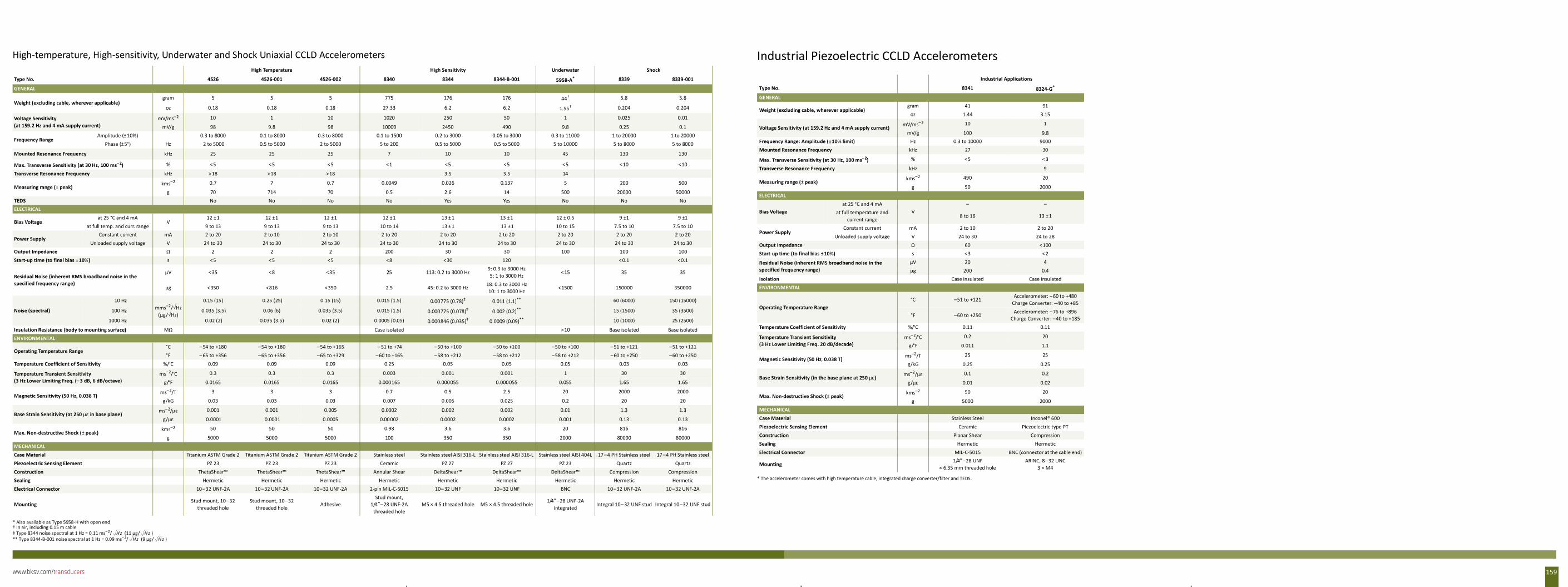
www.bksv.com/transducers 159
High-temperature, High-sensitivity, Underwater and Shock Uniaxial CCLD AccelerometersHigh Temperature High Sensitivity Underwater Shock
Type No. 4526 4526-001 4526-002 8340 8344 8344-B-001 5958-A*
* Also available as Type 5958-H with open end
8339 8339-001
GENERAL
Weight (excluding cable, wherever applicable)gram 5 5 5 775 176 176 44†
† In air, including 0.15 m cable
5.8 5.8
oz 0.18 0.18 0.18 27.33 6.2 6.2 1.55† 0.204 0.204
Voltage Sensitivity (at 159.2 Hz and 4 mA supply current)
mV/ms–2 10 1 10 1020 250 50 1 0.025 0.01
mV/g 98 9.8 98 10000 2450 490 9.8 0.25 0.1
Frequency RangeAmplitude (±10%) 0.3 to 8000 0.1 to 8000 0.3 to 8000 0.1 to 1500 0.2 to 3000 0.05 to 3000 0.3 to 11000 1 to 20000 1 to 20000
Phase (±5°) Hz 2 to 5000 0.5 to 5000 2 to 5000 5 to 200 0.5 to 5000 0.5 to 5000 5 to 10000 5 to 8000 5 to 8000
Mounted Resonance Frequency kHz 25 25 25 7 10 10 45 130 130
Max. Transverse Sensitivity (at 30 Hz, 100 ms–2) % <5 <5 <5 <1 <5 <5 <5 <10 <10
Transverse Resonance Frequency kHz >18 >18 >18 3.5 3.5 14
Measuring range (± peak)kms–2 0.7 7 0.7 0.0049 0.026 0.137 5 200 500
g 70 714 70 0.5 2.6 14 500 20000 50000TEDS No No No No Yes Yes No No NoELECTRICAL
Bias Voltageat 25 °C and 4 mA
V12 ±1 12 ±1 12 ±1 12 ±1 13 ± 1 13 ±1 12 ± 0.5 9 ±1 9 ±1
at full temp. and curr. range 9 to 13 9 to 13 9 to 13 10 to 14 13 ± 1 13 ±1 10 to 15 7.5 to 10 7.5 to 10
Power SupplyConstant current mA 2 to 20 2 to 10 2 to 10 2 to 20 2 to 20 2 to 20 2 to 20 2 to 20 2 to 20
Unloaded supply voltage V 24 to 30 24 to 30 24 to 30 24 to 30 24 to 30 24 to 30 24 to 30 24 to 30 24 to 30Output Impedance Ω 2 2 2 200 30 30 100 100 100Start-up time (to final bias ±10%) s <5 <5 <5 <8 <30 120 < 0.1 <0.1
Residual Noise (inherent RMS broadband noise in the specified frequency range)
µV <35 <8 <35 25 113: 0.2 to 3000 Hz9: 0.3 to 3000 Hz5: 1 to 3000 Hz
<15 35 35
µg < 350 <816 <350 2.5 45: 0.2 to 3000 Hz 18: 0.3 to 3000 Hz10: 1 to 3000 Hz
<1500 150000 350000
Noise (spectral)
10 Hzmms–2/√Hz
(µg/√Hz)
0.15 (15) 0.25 (25) 0.15 (15) 0.015 (1.5) 0.00775 (0.78)‡
‡ Type 8344 noise spectral at 1 Hz = 0.11 ms–2/ (11 µg/ )
0.011 (1.1)**
** Type 8344-B-001 noise spectral at 1 Hz = 0.09 ms–2/ (9 µg/ )
60 (6000) 150 (15000)
100 Hz 0.035 (3.5) 0.06 (6) 0.035 (3.5) 0.015 (1.5) 0.000775 (0.078)‡ 0.002 (0.2)** 15 (1500) 35 (3500)
1000 Hz 0.02 (2) 0.035 (3.5) 0.02 (2) 0.0005 (0.05) 0.000846 (0.035)‡ 0.0009 (0.09)** 10 (1000) 25 (2500)
Insulation Resistance (body to mounting surface) MΩ Case isolated >10 Base isolated Base isolatedENVIRONMENTAL
Operating Temperature Range°C – 54 to +180 –54 to +180 –54 to +165 – 51 to +74 –50 to +100 –50 to +100 –50 to +100 –51 to +121 –51 to +121°F – 65 to +356 –65 to +356 –65 to +329 –60 to +165 –58 to +212 –58 to +212 –58 to +212 –60 to +250 –60 to +250
Temperature Coefficient of Sensitivity %/°C 0.09 0.09 0.09 0.25 0.05 0.05 0.05 0.03 0.03
Temperature Transient Sensitivity (3 Hz Lower Limiting Freq. (– 3 dB, 6 dB/octave)
ms–2/°C 0.3 0.3 0.3 0.003 0.001 0.001 1 30 30
g/°F 0.0165 0.0165 0.0165 0.000165 0.000055 0.000055 0.055 1.65 1.65
Magnetic Sensitivity (50 Hz, 0.038 T)ms–2/T 3 3 3 0.7 0.5 2.5 20 2000 2000
g/kG 0.03 0.03 0.03 0.007 0.005 0.025 0.2 20 20
Base Strain Sensitivity (at 250 µε in base plane)ms–2/µε 0.001 0.001 0.005 0.0002 0.002 0.002 0.01 1.3 1.3
g/µε 0.0001 0.0001 0.0005 0.00002 0.0002 0.0002 0.001 0.13 0.13
Max. Non-destructive Shock (± peak)kms–2 50 50 50 0.98 3.6 3.6 20 816 816
g 5000 5000 5000 100 350 350 2000 80000 80000MECHANICALCase Material Titanium ASTM Grade 2 Titanium ASTM Grade 2 Titanium ASTM Grade 2 Stainless steel Stainless steel AISI 316-L Stainless steel AISI 316-L Stainless steel AISI 404L 17–4 PH Stainless steel 17–4 PH Stainless steelPiezoelectric Sensing Element PZ 23 PZ 23 PZ 23 Ceramic PZ 27 PZ 27 PZ 23 Quartz QuartzConstruction ThetaShear™ ThetaShear™ ThetaShear™ Annular Shear DeltaShear™ DeltaShear™ DeltaShear™ Compression CompressionSealing Hermetic Hermetic Hermetic Hermetic Hermetic Hermetic Hermetic Hermetic HermeticElectrical Connector 10–32 UNF-2A 10–32 UNF-2A 10–32 UNF-2A 2-pin MIL-C-5015 10– 32 UNF 10–32 UNF BNC 10–32 UNF-2A 10–32 UNF-2A
MountingStud mount, 10–32
threaded holeStud mount, 10–32
threaded holeAdhesive
Stud mount, 1/4″– 28 UNF-2A
threaded holeM5 × 4.5 threaded hole M5 × 4.5 threaded hole
1/4″–28 UNF-2A integrated
Integral 10– 32 UNF stud Integral 10–32 UNF stud
Hz HzHz Hz
Industrial Piezoelectric CCLD AccelerometersIndustrial Applications
Type No. 8341 8324-G*
* The accelerometer comes with high temperature cable, integrated charge converter/filter and TEDS.
GENERAL
Weight (excluding cable, wherever applicable)gram 41 91
oz 1.44 3.15
Voltage Sensitivity (at 159.2 Hz and 4 mA supply current) mV/ms–2 10 1
mV/g 100 9.8Frequency Range: Amplitude (±10% limit) Hz 0.3 to 10000 9000Mounted Resonance Frequency kHz 27 30
Max. Transverse Sensitivity (at 30 Hz, 100 ms–2) % <5 < 3
Transverse Resonance Frequency kHz 9
Measuring range (± peak)kms–2 490 20
g 50 2000ELECTRICAL
Bias Voltageat 25 °C and 4 mA
V– –
at full temperature and current range
8 to 16 13 ±1
Power SupplyConstant current mA 2 to 10 2 to 20
Unloaded supply voltage V 24 to 30 24 to 28Output Impedance Ω 60 <100Start-up time (to final bias ±10%) s <3 < 2
Residual Noise (inherent RMS broadband noise in the specified frequency range)
µV 20 4µg 200 0.4
Isolation Case insulated Case insulatedENVIRONMENTAL
Operating Temperature Range°C –51 to +121
Accelerometer: –60 to +480 Charge Converter: –40 to +85
°F –60 to +250Accelerometer: –76 to +896
Charge Converter: –40 to +185Temperature Coefficient of Sensitivity %/°C 0.11 0.11
Temperature Transient Sensitivity (3 Hz Lower Limiting Freq. 20 dB/decade)
ms–2/°C 0.2 20
g/°F 0.011 1.1
Magnetic Sensitivity (50 Hz, 0.038 T)ms–2/T 25 25
g/kG 0.25 0.25
Base Strain Sensitivity (in the base plane at 250 µε)ms–2/µε 0.1 0.2
g/µε 0.01 0.02
Max. Non-destructive Shock (± peak)kms–2 50 20
g 5000 2000MECHANICALCase Material Stainless Steel Inconel® 600Piezoelectric Sensing Element Ceramic Piezoelectric type PTConstruction Planar Shear CompressionSealing Hermetic HermeticElectrical Connector MIL-C-5015 BNC (connector at the cable end)
Mounting1/4″–28 UNF
× 6.35 mm threaded hole ARINC, 8–32 UNC
3 × M4
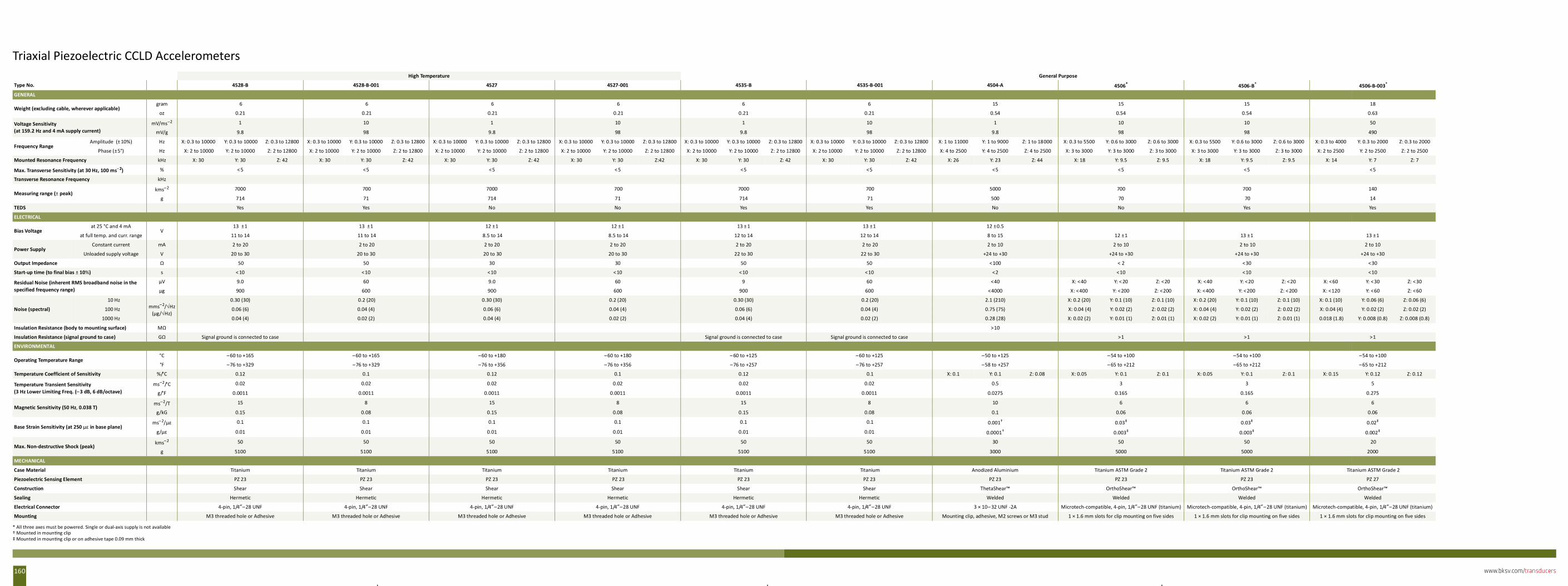
www.bksv.com/transducers160
Triaxial Piezoelectric CCLD AccelerometersHigh Temperature General Purpose
Type No. 4528-B 4528-B-001 4527 4527-001 4535-B 4535-B-001 4504-A 4506*
* All three axes must be powered. Single or dual-axis supply is not available
4506-B* 4506-B-003*
GENERAL
Weight (excluding cable, wherever applicable)gram 6 6 6 6 6 6 15 15 15 18
oz 0.21 0.21 0.21 0.21 0.21 0.21 0.54 0.54 0.54 0.63
Voltage Sensitivity (at 159.2 Hz and 4 mA supply current)
mV/ms–2 1 10 1 10 1 10 1 10 10 50
mV/g 9.8 98 9.8 98 9.8 98 9.8 98 98 490
Frequency RangeAmplitude (± 10%) Hz X: 0.3 to 10000 Y: 0.3 to 10000 Z: 0.3 to 12800 X: 0.3 to 10000 Y: 0.3 to 10000 Z: 0.3 to 12800 X: 0.3 to 10000 Y: 0.3 to 10000 Z: 0.3 to 12800 X: 0.3 to 10000 Y: 0.3 to 10000 Z: 0.3 to 12800 X: 0.3 to 10000 Y: 0.3 to 10000 Z: 0.3 to 12800 X: 0.3 to 10000 Y: 0.3 to 10000 Z: 0.3 to 12800 X: 1 to 11000 Y: 1 to 9000 Z: 1 to 18000 X: 0.3 to 5500 Y: 0.6 to 3000 Z: 0.6 to 3000 X: 0.3 to 5500 Y: 0.6 to 3000 Z: 0.6 to 3000 X: 0.3 to 4000 Y: 0.3 to 2000 Z: 0.3 to 2000
Phase (±5°) Hz X: 2 to 10000 Y: 2 to 10000 Z: 2 to 12800 X: 2 to 10000 Y: 2 to 10000 Z: 2 to 12800 X: 2 to 10000 Y: 2 to 10000 Z: 2 to 12800 X: 2 to 10000 Y: 2 to 10000 Z: 2 to 12800 X: 2 to 10000 Y: 2 to 10000 Z: 2 to 12800 X: 2 to 10000 Y: 2 to 10000 Z: 2 to 12800 X: 4 to 2500 Y: 4 to 2500 Z: 4 to 2500 X: 3 to 3000 Y: 3 to 3000 Z: 3 to 3000 X: 3 to 3000 Y: 3 to 3000 Z: 3 to 3000 X: 2 to 2500 Y: 2 to 2500 Z: 2 to 2500
Mounted Resonance Frequency kHz X: 30 Y: 30 Z: 42 X: 30 Y: 30 Z: 42 X: 30 Y: 30 Z: 42 X: 30 Y: 30 Z:42 X: 30 Y: 30 Z: 42 X: 30 Y: 30 Z: 42 X: 26 Y: 23 Z: 44 X: 18 Y: 9.5 Z: 9.5 X: 18 Y: 9.5 Z: 9.5 X: 14 Y: 7 Z: 7
Max. Transverse Sensitivity (at 30 Hz, 100 ms–2) % < 5 <5 <5 < 5 <5 <5 <5 <5 <5 <5
Transverse Resonance Frequency kHz
Measuring range (± peak)kms–2 7000 700 7000 700 7000 700 5000 700 700 140
g 714 71 714 71 714 71 500 70 70 14
TEDS Yes Yes No No Yes Yes No No Yes Yes
ELECTRICAL
Bias Voltageat 25 °C and 4 mA
V13 ±1 13 ±1 12 ±1 12 ±1 13 ± 1 13 ±1 12 ±0.5
at full temp. and curr. range 11 to 14 11 to 14 8.5 to 14 8.5 to 14 12 to 14 12 to 14 8 to 15 12 ±1 13 ±1 13 ±1
Power SupplyConstant current mA 2 to 20 2 to 20 2 to 20 2 to 20 2 to 20 2 to 20 2 to 10 2 to 10 2 to 10 2 to 10
Unloaded supply voltage V 20 to 30 20 to 30 20 to 30 20 to 30 22 to 30 22 to 30 +24 to +30 +24 to +30 +24 to +30 +24 to +30
Output Impedance Ω 50 50 30 30 50 50 <100 < 2 <30 <30
Start-up time (to final bias ± 10%) s < 10 <10 <10 <10 <10 <10 <2 <10 <10 <10
Residual Noise (inherent RMS broadband noise in the specified frequency range)
µV 9.0 60 9.0 60 9 60 <40 X: <40 Y: < 20 Z: <20 X: <40 Y: <20 Z: <20 X: <60 Y: <30 Z: <30
µg 900 600 900 600 900 600 <4000 X: <400 Y: <200 Z: <200 X: <400 Y: <200 Z: < 200 X: <120 Y: <60 Z: <60
Noise (spectral)
10 Hzmms–2/√Hz
(µg/√Hz)
0.30 (30) 0.2 (20) 0.30 (30) 0.2 (20) 0.30 (30) 0.2 (20) 2.1 (210) X: 0.2 (20) Y: 0.1 (10) Z: 0.1 (10) X: 0.2 (20) Y: 0.1 (10) Z: 0.1 (10) X: 0.1 (10) Y: 0.06 (6) Z: 0.06 (6)
100 Hz 0.06 (6) 0.04 (4) 0.06 (6) 0.04 (4) 0.06 (6) 0.04 (4) 0.75 (75) X: 0.04 (4) Y: 0.02 (2) Z: 0.02 (2) X: 0.04 (4) Y: 0.02 (2) Z: 0.02 (2) X: 0.04 (4) Y: 0.02 (2) Z: 0.02 (2)
1000 Hz 0.04 (4) 0.02 (2) 0.04 (4) 0.02 (2) 0.04 (4) 0.02 (2) 0.28 (28) X: 0.02 (2) Y: 0.01 (1) Z: 0.01 (1) X: 0.02 (2) Y: 0.01 (1) Z: 0.01 (1) 0.018 (1.8) Y: 0.008 (0.8) Z: 0.008 (0.8)
Insulation Resistance (body to mounting surface) MΩ >10
Insulation Resistance (signal ground to case) GΩ Signal ground is connected to case Signal ground is connected to case Signal ground is connected to case >1 >1 >1
ENVIRONMENTAL
Operating Temperature Range°C –60 to +165 –60 to +165 –60 to +180 –60 to +180 – 60 to +125 –60 to +125 –50 to +125 – 54 to +100 –54 to +100 –54 to +100
°F –76 to +329 –76 to +329 –76 to +356 –76 to +356 –76 to +257 –76 to +257 –58 to +257 – 65 to +212 –65 to +212 –65 to +212
Temperature Coefficient of Sensitivity %/°C 0.12 0.1 0.12 0.1 0.12 0.1 X: 0.1 Y: 0.1 Z: 0.08 X: 0.05 Y: 0.1 Z: 0.1 X: 0.05 Y: 0.1 Z: 0.1 X: 0.15 Y: 0.12 Z: 0.12
Temperature Transient Sensitivity (3 Hz Lower Limiting Freq. (– 3 dB, 6 dB/octave)
ms–2/°C 0.02 0.02 0.02 0.02 0.02 0.02 0.5 3 3 5
g/°F 0.0011 0.0011 0.0011 0.0011 0.0011 0.0011 0.0275 0.165 0.165 0.275
Magnetic Sensitivity (50 Hz, 0.038 T)ms–2/T 15 8 15 8 15 8 10 6 6 6
g/kG 0.15 0.08 0.15 0.08 0.15 0.08 0.1 0.06 0.06 0.06
Base Strain Sensitivity (at 250 µε in base plane)ms–2/µε 0.1 0.1 0.1 0.1 0.1 0.1 0.001†
† Mounted in moun ng clip
0.03‡
‡ Mounted in moun ng clip or on adhesive tape 0.09 mm thick
0.03‡ 0.02‡
g/µε 0.01 0.01 0.01 0.01 0.01 0.01 0.0001† 0.003‡ 0.003‡ 0.002‡
Max. Non-destructive Shock (peak)kms–2 50 50 50 50 50 50 30 50 50 20
g 5100 5100 5100 5100 5100 5100 3000 5000 5000 2000
MECHANICAL
Case Material Titanium Titanium Titanium Titanium Titanium Titanium Anodized Aluminium Titanium ASTM Grade 2 Titanium ASTM Grade 2 Titanium ASTM Grade 2
Piezoelectric Sensing Element PZ 23 PZ 23 PZ 23 PZ 23 PZ 23 PZ 23 PZ 23 PZ 23 PZ 23 PZ 27
Construction Shear Shear Shear Shear Shear Shear ThetaShear™ OrthoShear™ OrthoShear™ OrthoShear™
Sealing Hermetic Hermetic Hermetic Hermetic Hermetic Hermetic Welded Welded Welded Welded
Electrical Connector 4-pin, 1/4″–28 UNF 4-pin, 1/4″–28 UNF 4-pin, 1/4″–28 UNF 4-pin, 1/4″–28 UNF 4-pin, 1/4″–28 UNF 4-pin, 1/4″–28 UNF 3 × 10– 32 UNF -2A Microtech-compatible, 4-pin, 1/4″–28 UNF (titanium) Microtech-compatible, 4-pin, 1/4″–28 UNF (titanium) Microtech-compatible, 4-pin, 1/4″–28 UNF (titanium)
Mounting M3 threaded hole or Adhesive M3 threaded hole or Adhesive M3 threaded hole or Adhesive M3 threaded hole or Adhesive M3 threaded hole or Adhesive M3 threaded hole or Adhesive Mounting clip, adhesive, M2 screws or M3 stud 1 × 1.6 mm slots for clip mounting on five sides 1 × 1.6 mm slots for clip mounting on five sides 1 × 1.6 mm slots for clip mounting on five sides
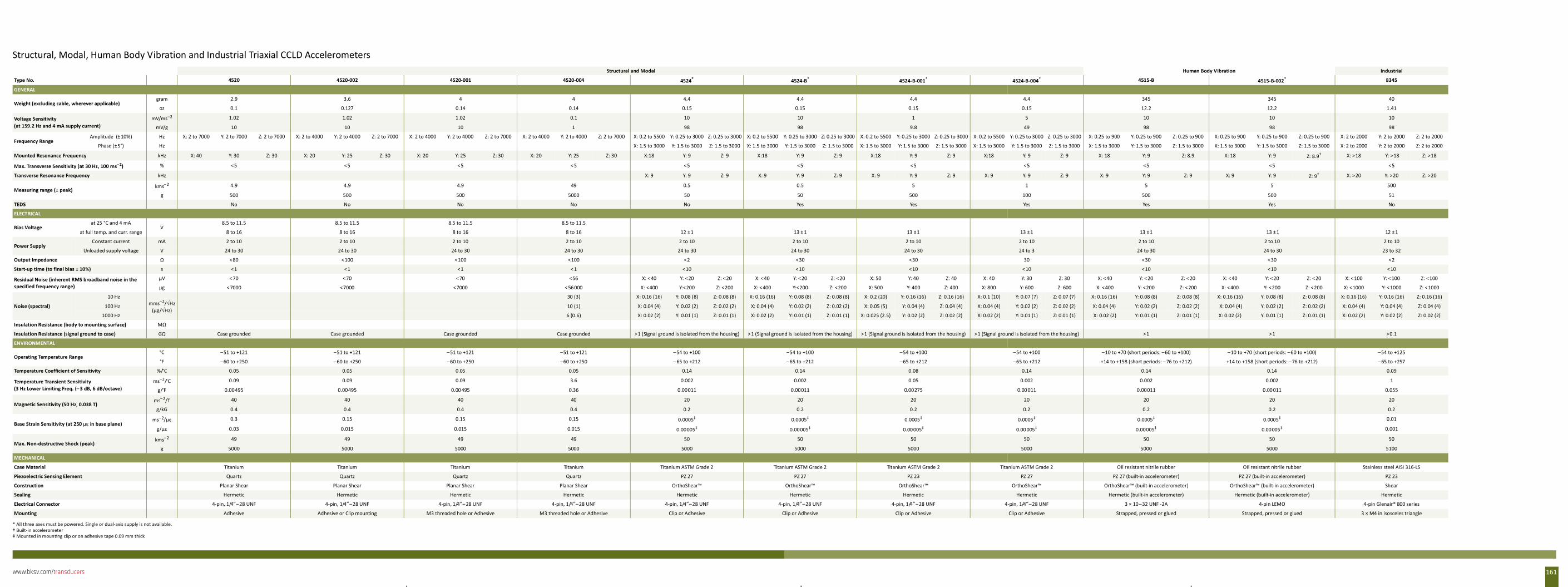
www.bksv.com/transducers 161
Structural, Modal, Human Body Vibration and Industrial Triaxial CCLD Accelerometers Structural and Modal Human Body Vibration Industrial
Type No. 4520 4520-002 4520-001 4520-004 4524*
* All three axes must be powered. Single or dual-axis supply is not available.
4524-B* 4524-B-001* 4524-B-004* 4515-B 4515-B-002* 8345
GENERAL
Weight (excluding cable, wherever applicable)gram 2.9 3.6 4 4 4.4 4.4 4.4 4.4 345 345 40
oz 0.1 0.127 0.14 0.14 0.15 0.15 0.15 0.15 12.2 12.2 1.41
Voltage Sensitivity (at 159.2 Hz and 4 mA supply current)
mV/ms–2 1.02 1.02 1.02 0.1 10 10 1 5 10 10 10
mV/g 10 10 10 1 98 98 9.8 49 98 98 98
Frequency RangeAmplitude (± 10%) Hz X: 2 to 7000 Y: 2 to 7000 Z: 2 to 7000 X: 2 to 4000 Y: 2 to 4000 Z: 2 to 7000 X: 2 to 4000 Y: 2 to 4000 Z: 2 to 7000 X: 2 to 4000 Y: 2 to 4000 Z: 2 to 7000 X: 0.2 to 5500 Y: 0.25 to 3000 Z: 0.25 to 3000 X: 0.2 to 5500 Y: 0.25 to 3000 Z: 0.25 to 3000 X: 0.2 to 5500 Y: 0.25 to 3000 Z: 0.25 to 3000 X: 0.2 to 5500 Y: 0.25 to 3000 Z: 0.25 to 3000 X: 0.25 to 900 Y: 0.25 to 900 Z: 0.25 to 900 X: 0.25 to 900 Y: 0.25 to 900 Z: 0.25 to 900 X: 2 to 2000 Y: 2 to 2000 Z: 2 to 2000
Phase (±5°) Hz X: 1.5 to 3000 Y: 1.5 to 3000 Z: 1.5 to 3000 X: 1.5 to 3000 Y: 1.5 to 3000 Z: 1.5 to 3000 X: 1.5 to 3000 Y: 1.5 to 3000 Z: 1.5 to 3000 X: 1.5 to 3000 Y: 1.5 to 3000 Z: 1.5 to 3000 X: 1.5 to 3000 Y: 1.5 to 3000 Z: 1.5 to 3000 X: 1.5 to 3000 Y: 1.5 to 3000 Z: 1.5 to 3000 X: 2 to 2000 Y: 2 to 2000 Z: 2 to 2000
Mounted Resonance Frequency kHz X: 40 Y: 30 Z: 30 X: 20 Y: 25 Z: 30 X: 20 Y: 25 Z: 30 X: 20 Y: 25 Z: 30 X:18 Y: 9 Z: 9 X:18 Y: 9 Z: 9 X:18 Y: 9 Z: 9 X:18 Y: 9 Z: 9 X: 18 Y: 9 Z: 8.9 X: 18 Y: 9 Z: 8.9†
† Built-in accelerometer
X: >18 Y: >18 Z: >18
Max. Transverse Sensitivity (at 30 Hz, 100 ms–2) % <5 <5 <5 < 5 <5 <5 <5 <5 <5 <5 <5
Transverse Resonance Frequency kHz X: 9 Y: 9 Z: 9 X: 9 Y: 9 Z: 9 X: 9 Y: 9 Z: 9 X: 9 Y: 9 Z: 9 X: 9 Y: 9 Z: 9 X: 9 Y: 9 Z: 9† X: >20 Y: >20 Z: >20
Measuring range (± peak)kms–2 4.9 4.9 4.9 49 0.5 0.5 5 1 5 5 500
g 500 500 500 5000 50 50 500 100 500 500 51
TEDS No No No No No Yes Yes Yes Yes Yes No
ELECTRICAL
Bias Voltageat 25 °C and 4 mA
V8.5 to 11.5 8.5 to 11.5 8.5 to 11.5 8.5 to 11.5
at full temp. and curr. range 8 to 16 8 to 16 8 to 16 8 to 16 12 ±1 13 ± 1 13 ±1 13 ±1 13 ±1 13 ±1 12 ±1
Power SupplyConstant current mA 2 to 10 2 to 10 2 to 10 2 to 10 2 to 10 2 to 10 2 to 10 2 to 10 2 to 10 2 to 10 2 to 10
Unloaded supply voltage V 24 to 30 24 to 30 24 to 30 24 to 30 24 to 30 24 to 30 24 to 30 24 to 3 24 to 30 24 to 30 23 to 32
Output Impedance Ω <80 <100 <100 <100 <2 <30 <30 30 <30 <30 <2
Start-up time (to final bias ± 10%) s <1 <1 <1 < 1 <10 <10 <10 <10 <10 <10 <10
Residual Noise (inherent RMS broadband noise in the specified frequency range)
µV <70 <70 <70 <56 X: <40 Y: <20 Z: <20 X: <40 Y: <20 Z: <20 X: 50 Y: 40 Z: 40 X: 40 Y: 30 Z: 30 X: <40 Y: <20 Z: <20 X: <40 Y: <20 Z: <20 X: <100 Y: <100 Z: <100
µg < 7000 <7000 <7000 < 56000 X: <400 Y:<200 Z: <200 X: < 400 Y:<200 Z: <200 X: 500 Y: 400 Z: 400 X: 800 Y: 600 Z: 600 X: <400 Y: <200 Z: < 200 X: < 400 Y: <200 Z: <200 X: <1000 Y: <1000 Z: <1000
Noise (spectral)
10 Hzmms–2/√Hz
(µg/√Hz)
30 (3) X: 0.16 (16) Y: 0.08 (8) Z: 0.08 (8) X: 0.16 (16) Y: 0.08 (8) Z: 0.08 (8) X: 0.2 (20) Y: 0.16 (16) Z: 0.16 (16) X: 0.1 (10) Y: 0.07 (7) Z: 0.07 (7) X: 0.16 (16) Y: 0.08 (8) Z: 0.08 (8) X: 0.16 (16) Y: 0.08 (8) Z: 0.08 (8) X: 0.16 (16) Y: 0.16 (16) Z: 0.16 (16)
100 Hz 10 (1) X: 0.04 (4) Y: 0.02 (2) Z: 0.02 (2) X: 0.04 (4) Y: 0.02 (2) Z: 0.02 (2) X: 0.05 (5) Y: 0.04 (4) Z: 0.04 (4) X: 0.04 (4) Y: 0.02 (2) Z: 0.02 (2) X: 0.04 (4) Y: 0.02 (2) Z: 0.02 (2) X: 0.04 (4) Y: 0.02 (2) Z: 0.02 (2) X: 0.04 (4) Y: 0.04 (4) Z: 0.04 (4)
1000 Hz 6 (0.6) X: 0.02 (2) Y: 0.01 (1) Z: 0.01 (1) X: 0.02 (2) Y: 0.01 (1) Z: 0.01 (1) X: 0.025 (2.5) Y: 0.02 (2) Z: 0.02 (2) X: 0.02 (2) Y: 0.01 (1) Z: 0.01 (1) X: 0.02 (2) Y: 0.01 (1) Z: 0.01 (1) X: 0.02 (2) Y: 0.01 (1) Z: 0.01 (1) X: 0.02 (2) Y: 0.02 (2) Z: 0.02 (2)
Insulation Resistance (body to mounting surface) MΩ
Insulation Resistance (signal ground to case) GΩ Case grounded Case grounded Case grounded Case grounded >1 (Signal ground is isolated from the housing) >1 (Signal ground is isolated from the housing) >1 (Signal ground is isolated from the housing) >1 (Signal ground is isolated from the housing) >1 >1 >0.1
ENVIRONMENTAL
Operating Temperature Range°C –51 to +121 –51 to +121 –51 to +121 –51 to +121 – 54 to +100 –54 to +100 –54 to +100 –54 to +100 –10 to +70 (short periods: –60 to +100) –10 to +70 (short periods: –60 to +100) –54 to +125
°F –60 to +250 –60 to +250 –60 to +250 –60 to +250 – 65 to +212 –65 to +212 –65 to +212 –65 to +212 +14 to +158 (short periods: – 76 to +212) +14 to +158 (short periods: –76 to +212) – 65 to +257
Temperature Coefficient of Sensitivity %/°C 0.05 0.05 0.05 0.05 0.14 0.14 0.08 0.14 0.14 0.14 0.09
Temperature Transient Sensitivity (3 Hz Lower Limiting Freq. (– 3 dB, 6 dB/octave)
ms–2/°C 0.09 0.09 0.09 3.6 0.002 0.002 0.05 0.002 0.002 0.002 1
g/°F 0.00495 0.00495 0.00495 0.36 0.00011 0.00011 0.00275 0.00011 0.00011 0.00011 0.055
Magnetic Sensitivity (50 Hz, 0.038 T)ms–2/T 40 40 40 40 20 20 20 20 20 20 20
g/kG 0.4 0.4 0.4 0.4 0.2 0.2 0.2 0.2 0.2 0.2 0.2
Base Strain Sensitivity (at 250 µε in base plane)ms–2/µε 0.3 0.15 0.15 0.15 0.0005‡
‡ Mounted in moun ng clip or on adhesive tape 0.09 mm thick
0.0005‡ 0.0005‡ 0.0005‡ 0.0005‡ 0.0005‡ 0.01
g/µε 0.03 0.015 0.015 0.015 0.00005‡ 0.00005‡ 0.00005‡ 0.00005‡ 0.00005‡ 0.00005‡ 0.001
Max. Non-destructive Shock (peak)kms–2 49 49 49 49 50 50 50 50 50 50 50
g 5000 5000 5000 5000 5000 5000 5000 5000 5000 5000 5100
MECHANICAL
Case Material Titanium Titanium Titanium Titanium Titanium ASTM Grade 2 Titanium ASTM Grade 2 Titanium ASTM Grade 2 Titanium ASTM Grade 2 Oil resistant nitrile rubber Oil resistant nitrile rubber Stainless steel AISI 316-LS
Piezoelectric Sensing Element Quartz Quartz Quartz Quartz PZ 27 PZ 27 PZ 23 PZ 27 PZ 27 (built-in accelerometer) PZ 27 (built-in accelerometer) PZ 23
Construction Planar Shear Planar Shear Planar Shear Planar Shear OrthoShear™ OrthoShear™ OrthoShear™ OrthoShear™ OrthoShear™ (built-in accelerometer) OrthoShear™ (built-in accelerometer) Shear
Sealing Hermetic Hermetic Hermetic Hermetic Hermetic Hermetic Hermetic Hermetic Hermetic (built-in accelerometer) Hermetic (built-in accelerometer) Hermetic
Electrical Connector 4-pin, 1/4″–28 UNF 4-pin, 1/4″–28 UNF 4-pin, 1/4″– 28 UNF 4-pin, 1/4″–28 UNF 4-pin, 1/4″–28 UNF 4-pin, 1/4″–28 UNF 4-pin, 1/4″–28 UNF 4-pin, 1/4″–28 UNF 3 × 10–32 UNF -2A 4-pin LEMO 4-pin Glenair® 800 series
Mounting Adhesive Adhesive or Clip mounting M3 threaded hole or Adhesive M3 threaded hole or Adhesive Clip or Adhesive Clip or Adhesive Clip or Adhesive Clip or Adhesive Strapped, pressed or glued Strapped, pressed or glued 3 × M4 in isosceles triangle

www.bksv.com/transducers162
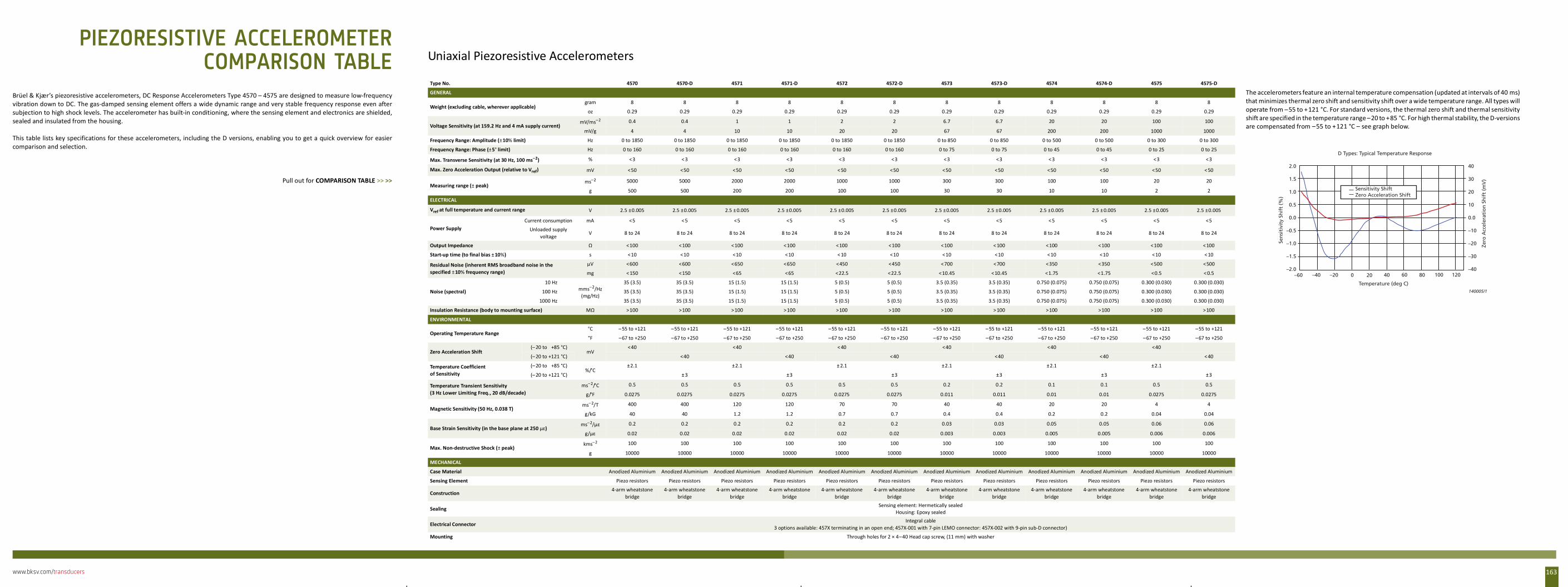
www.bksv.com/transducers 163
Brüel & Kjær’s piezoresistive accelerometers, DC Response Accelerometers Type 4570 – 4575 are designed to measure low-frequencyvibration down to DC. The gas-damped sensing element offers a wide dynamic range and very stable frequency response even aftersubjection to high shock levels. The accelerometer has built-in conditioning, where the sensing element and electronics are shielded,sealed and insulated from the housing.
This table lists key specifications for these accelerometers, including the D versions, enabling you to get a quick overview for easiercomparison and selection.
Pull out for COMPARISON TABLE >> >>
Uniaxial Piezoresistive Accelerometers
Type No. 4570 4570-D 4571 4571-D 4572 4572-D 4573 4573-D 4574 4574-D 4575 4575-D
GENERAL The accelerometers feature an internal temperature compensation (updated at intervals of 40 ms)that minimizes thermal zero shift and sensitivity shift over a wide temperature range. All types willoperate from –55 to +121 °C. For standard versions, the thermal zero shift and thermal sensitivityshift are specified in the temperature range –20 to +85 °C. For high thermal stability, the D-versionsare compensated from –55 to +121 °C – see graph below.
Weight (excluding cable, wherever applicable)gram 8 8 8 8 8 8 8 8 8 8 8 8
oz 0.29 0.29 0.29 0.29 0.29 0.29 0.29 0.29 0.29 0.29 0.29 0.29
Voltage Sensitivity (at 159.2 Hz and 4 mA supply current)mV/ms–2 0.4 0.4 1 1 2 2 6.7 6.7 20 20 100 100
mV/g 4 4 10 10 20 20 67 67 200 200 1000 1000
Frequency Range: Amplitude (±10% limit) Hz 0 to 1850 0 to 1850 0 to 1850 0 to 1850 0 to 1850 0 to 1850 0 to 850 0 to 850 0 to 500 0 to 500 0 to 300 0 to 300
Frequency Range: Phase (±5° limit) Hz 0 to 160 0 to 160 0 to 160 0 to 160 0 to 160 0 to 160 0 to 75 0 to 75 0 to 45 0 to 45 0 to 25 0 to 25
Max. Transverse Sensitivity (at 30 Hz, 100 ms–2) % <3 < 3 <3 <3 <3 <3 <3 <3 < 3 <3 <3 <3
Max. Zero Acceleration Output (relative to Vref) mV <50 <50 <50 <50 < 50 <50 <50 <50 <50 <50 <50 < 50
Measuring range (± peak)ms–2 5000 5000 2000 2000 1000 1000 300 300 100 100 20 20
g 500 500 200 200 100 100 30 30 10 10 2 2
ELECTRICAL
Vref at full temperature and current range V 2.5 ±0.005 2.5 ±0.005 2.5 ± 0.005 2.5 ±0.005 2.5 ±0.005 2.5 ±0.005 2.5 ±0.005 2.5 ±0.005 2.5 ±0.005 2.5 ± 0.005 2.5 ±0.005 2.5 ±0.005
Power SupplyCurrent consumption mA <5 < 5 <5 <5 <5 <5 <5 <5 < 5 <5 <5 <5
Unloaded supply voltage
V 8 to 24 8 to 24 8 to 24 8 to 24 8 to 24 8 to 24 8 to 24 8 to 24 8 to 24 8 to 24 8 to 24 8 to 24
Output Impedance Ω <100 <100 <100 <100 <100 <100 <100 < 100 <100 <100 <100 <100
Start-up time (to final bias ± 10%) s <10 <10 <10 <10 < 10 <10 <10 <10 <10 <10 <10 < 10
Residual Noise (inherent RMS broadband noise in the specified ±10% frequency range)
µV <600 <600 <650 <650 <450 <450 <700 <700 <350 <350 <500 <500
mg < 150 <150 <65 <65 <22.5 <22.5 <10.45 <10.45 <1.75 <1.75 <0.5 < 0.5
Noise (spectral)
10 Hzmms–2/Hz
(mg/Hz)
35 (3.5) 35 (3.5) 15 (1.5) 15 (1.5) 5 (0.5) 5 (0.5) 3.5 (0.35) 3.5 (0.35) 0.750 (0.075) 0.750 (0.075) 0.300 (0.030) 0.300 (0.030)
100 Hz 35 (3.5) 35 (3.5) 15 (1.5) 15 (1.5) 5 (0.5) 5 (0.5) 3.5 (0.35) 3.5 (0.35) 0.750 (0.075) 0.750 (0.075) 0.300 (0.030) 0.300 (0.030)
1000 Hz 35 (3.5) 35 (3.5) 15 (1.5) 15 (1.5) 5 (0.5) 5 (0.5) 3.5 (0.35) 3.5 (0.35) 0.750 (0.075) 0.750 (0.075) 0.300 (0.030) 0.300 (0.030)
Insulation Resistance (body to mounting surface) MΩ >100 >100 >100 >100 >100 >100 >100 > 100 >100 >100 >100 >100
ENVIRONMENTAL
Operating Temperature Range°C – 55 to +121 –55 to +121 –55 to +121 –55 to +121 –55 to +121 –55 to +121 –55 to +121 – 55 to +121 –55 to +121 –55 to +121 –55 to +121 –55 to +121
°F –67 to +250 –67 to +250 –67 to +250 –67 to +250 –67 to +250 –67 to +250 – 67 to +250 –67 to +250 –67 to +250 –67 to +250 –67 to +250 –67 to +250
Zero Acceleration Shift (– 20 to +85 °C)
mV<40 <40 < 40 <40 <40 <40
(– 20 to +121 °C) <40 <40 <40 <40 <40 < 40
Temperature Coefficient of Sensitivity
(– 20 to +85 °C)%/°C
±2.1 ±2.1 ± 2.1 ±2.1 ±2.1 ±2.1
(– 20 to +121 °C) ± 3 ±3 ±3 ±3 ±3 ±3
Temperature Transient Sensitivity (3 Hz Lower Limiting Freq., 20 dB/decade)
ms–2/°C 0.5 0.5 0.5 0.5 0.5 0.5 0.2 0.2 0.1 0.1 0.5 0.5
g/°F 0.0275 0.0275 0.0275 0.0275 0.0275 0.0275 0.011 0.011 0.01 0.01 0.0275 0.0275
Magnetic Sensitivity (50 Hz, 0.038 T)ms–2/T 400 400 120 120 70 70 40 40 20 20 4 4
g/kG 40 40 1.2 1.2 0.7 0.7 0.4 0.4 0.2 0.2 0.04 0.04
Base Strain Sensitivity (in the base plane at 250 µε)ms–2/µε 0.2 0.2 0.2 0.2 0.2 0.2 0.03 0.03 0.05 0.05 0.06 0.06
g/µε 0.02 0.02 0.02 0.02 0.02 0.02 0.003 0.003 0.005 0.005 0.006 0.006
Max. Non-destructive Shock (± peak)kms–2 100 100 100 100 100 100 100 100 100 100 100 100
g 10000 10000 10000 10000 10000 10000 10000 10000 10000 10000 10000 10000
MECHANICAL
Case Material Anodized Aluminium Anodized Aluminium Anodized Aluminium Anodized Aluminium Anodized Aluminium Anodized Aluminium Anodized Aluminium Anodized Aluminium Anodized Aluminium Anodized Aluminium Anodized Aluminium Anodized Aluminium
Sensing Element Piezo resistors Piezo resistors Piezo resistors Piezo resistors Piezo resistors Piezo resistors Piezo resistors Piezo resistors Piezo resistors Piezo resistors Piezo resistors Piezo resistors
Construction4-arm wheatstone
bridge4-arm wheatstone
bridge4-arm wheatstone
bridge4-arm wheatstone
bridge4-arm wheatstone
bridge4-arm wheatstone
bridge4-arm wheatstone
bridge4-arm wheatstone
bridge4-arm wheatstone
bridge4-arm wheatstone
bridge4-arm wheatstone
bridge4-arm wheatstone
bridge
SealingSensing element: Hermetically sealed
Housing: Epoxy sealed
Electrical ConnectorIntegral cable
3 options available: 457X terminating in an open end; 457X-001 with 7-pin LEMO connector: 457X-002 with 9-pin sub-D connector)
Mounting Through holes for 2 × 4–40 Head cap screw, (11 mm) with washer
Sensitivity ShiftZero Acceleration Shift
D Types: Typical Temperature Response
2.0
1.5
1.0
0.5
0.0
–0.5
–1.0
–1.5
–2.0
40
30
20
10
0.0
–10
–20
–30
–40
Temperature (deg C)
Sen
siti
vity
Sh
ift
(%)
Zero
Acc
eler
atio
n S
hif
t (m
V)
140005/1
–60 –40 –20 0 20 40 60 80 100 120
PIEZORESISTIVE ACCELEROMETERCOMPARISON TABLE

www.bksv.com/transducers164

INDEX
Numerics1056 .....................................................................................9011‐0684 ..............................................................................1211702 ...................................................................................1261704‐A ................................................................................1251704‐C‐102 .........................................................................1251705 ...................................................................................1261706 .........................................................................17, 35, 411nF precision adaptor ........................................................1212231 .....................................................................................502525 ...................................................................119, 124, 1262619 .....................................................................................362627 .....................................................................................362633 ...............................................................................36, 442634 ...................................................................................1262635 ...................................................................................1272639 .........................................................................36, 44, 582645 .....................................................................................362647‐A ................................................................................1272647‐B ................................................................................1272647‐C ................................................................................1272647‐D ................................................................................1272647‐D‐001 ........................................................................1272647‐D‐002 ........................................................................1272647‐D‐003 ........................................................................1272647‐D‐004 ........................................................................1272647‐D‐005 ........................................................................1272647‐E ................................................................................1272660 ...............................................................................25, 362660‐W‐001 .............................................................25, 36, 452663 ...................................................................................1262663‐B ................................................................................1262669 ..............19, 22, 28, 35, 36, 40, 41, 43, 50, 57, 58, 60, 632669‐001 ..............................................................................352669‐C ................................................................................1442669‐W‐001 .........................................................................352670 ......................................... 19, 22, 31, 35, 36, 40, 41, 1452670‐W‐001 .........................................................................352670‐WB‐1419 .....................................................................362671 ............................................... 35, 36, 40, 41, 50, 58, 1442671‐W‐001 ...................................................................28, 362673 ............................................................. 27, 35, 36, 43, 502683 ...............................................................................29, 302690‐A ................................................................................1232691‐A ................................................................................1232692‐A ................................................................................1272692‐C ................................................................................1272693‐A ................................................................................1242694 .......................................................................................32694‐A ................................................................................1242695 ................................................................... 35, 36, 58, 612697 ...................................................................................109
2699 ................................................................... 35, 36, 40, 412735 ............................................................................... 54, 682829 ...................................................................................1232981 .....................................................................................862981‐A ..................................................................................862cc click‐on coupler .............................................................583451‐A ..................................................................................383506 ...................................................................................1193599 ............................................................................... 29, 30360° mounting ...................................................................1583624 .....................................................................................903625 .....................................................................................903626 .....................................................................................903627 .....................................................................................903628 .....................................................................................903629 ........................................................... 119, 120, 131, 1323654 ............................................................................... 29, 304101‐A ...................................................................... 28, 29, 394128‐C ............................................................................ 54, 634128‐D ............................................................................ 54, 634130 .....................................................................................194133 .....................................................................................184134 ............................................................................... 18, 604135 .....................................................................................184136 .....................................................................................184137 ............................................................................... 15, 194138 ......................................................... 15, 22, 40, 144, 1534144 ................................................................. 15, 22, 58, 1534145 ....................................................................... 15, 20, 1534147 .....................................................................................184152 ............................................................................... 53, 564153 ............................................................................... 53, 564153‐W‐001 .........................................................................564155 .....................................................................................184157 ............................................................................... 53, 574158‐C ..................................................................................634160 ....................................................................... 15, 27, 1534165 .....................................................................................184166 .....................................................................................184176 ................................................................. 15, 19, 48, 1534178 ............................................................................. 30, 1534179 ....................................................................... 15, 25, 1534180 ....................................................................... 15, 27, 1534181 .....................................................................................184182 ............................................................. 17, 28, 29, 45, 514184 ......................................................................... 26, 39, 494184‐A ..................................................................................394185 ......................................................................... 53, 60, 654187 ......................................................................... 15, 28, 294188 ............................................. 15, 19, 26, 40, 48, 144, 1534189 ............................15, 16, 17, 18, 19, 26, 40, 41, 144, 1534190 ............................................. 15, 18, 20, 26, 41, 144, 153
165www.bksv.com/transducers
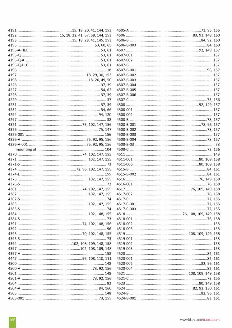
4191 ....................................................15, 18, 20, 41, 144, 1534192 ........................................ 15, 18, 22, 41, 57, 58, 144, 1534193 ....................................................15, 18, 28, 41, 145, 1534195 ..........................................................................53, 60, 654195‐A‐HLO ................................................................... 53, 614195‐Q ........................................................................... 53, 614195‐Q‐A ....................................................................... 53, 614195‐Q‐HL0 ................................................................... 53, 614196 ..................................................................................... 184197 ..................................................................18, 29, 30, 1534198 ....................................................................18, 26, 49, 504226 ............................................................................... 37, 394227 ............................................................................... 54, 624228 ............................................................................... 37, 394229 ..................................................................................... 374231 ............................................................................... 37, 394232 ............................................................................... 54, 664294 ............................................................................. 94, 1204297 ..................................................................................... 384321 ..............................................................75, 102, 147, 1564326 ............................................................................. 75, 1474326‐001 ........................................................................... 1564326‐A ..............................................................75, 92, 95, 1564326‐A‐001 .......................................................75, 92, 95, 156
mounting of ................................................................ 1044370 ..............................................................74, 102, 147, 1554371 ....................................................................102, 147, 1554371‐S .................................................................................. 734374 ........................................................72, 96, 102, 147, 1554374‐L ................................................................................ 1554375 ....................................................................102, 147, 1554375‐S .................................................................................. 724381 ..............................................................74, 102, 147, 1554382 ....................................................................102, 147, 1554382‐S .................................................................................. 744383 ....................................................................102, 147, 1554383‐S .................................................................................. 744384 ....................................................................102, 148, 1554384‐S .................................................................................. 734391 ..............................................................74, 102, 148, 1564392 ..................................................................................... 964393 ..............................................................70, 102, 148, 1554393‐S .................................................................................. 734394 ....................................................102, 108, 109, 148, 1584397 ............................................................102, 108, 109, 1484397‐A ............................................................................... 1584447 ..............................................................96, 108, 110, 1114500 ................................................................................... 1484500‐A ....................................................................73, 92, 1564501 ................................................................................... 1484501‐A ....................................................................73, 92, 1564504 ..................................................................................... 924504‐A ......................................................................... 84, 1604505 ................................................................................... 1484505‐001 ..................................................................... 73, 155
4505‐A ....................................................................73, 95, 1554506 ................................................................83, 92, 148, 1604506‐B ....................................................................84, 92, 1604506‐B‐003 ...................................................................84, 1604507 ......................................................................92, 149, 1574507‐001 ........................................................................... 1574507‐002 ........................................................................... 1574507‐B ............................................................................... 1574507‐B‐001 ...................................................................96, 1574507‐B‐002 ........................................................................ 1574507‐B‐003 ........................................................................ 1574507‐B‐004 ........................................................................ 1574507‐B‐005 ........................................................................ 1574507‐B‐006 ........................................................................ 1574507‐C ..........................................................................73, 1564508 ......................................................................92, 149, 1574508‐001 ........................................................................... 1574508‐002 ........................................................................... 1574508‐B ..........................................................................78, 1574508‐B‐001 .............................................................78, 96, 1574508‐B‐002 ...................................................................78, 1574508‐B‐003 ........................................................................ 1574508‐B‐004 ...................................................................78, 1574508‐B‐03 .............................................................................784508‐C ..........................................................................73, 1564511 ................................................................................... 1494511‐001 ..............................................................80, 109, 1584511‐006 ..............................................................80, 109, 1584515‐B ..........................................................................84, 1614515‐B‐002 ...................................................................84, 1614516 ......................................................................76, 149, 1584516‐001 ......................................................................76, 1584517 ..............................................................76, 109, 149, 1584517‐002 ......................................................................76, 1584517‐C ..........................................................................72, 1554517‐C‐001 ...................................................................72, 1554517‐C‐003 ...................................................................72, 1554518 ......................................................76, 108, 109, 149, 1584518‐001 ......................................................................76, 1584518‐002 ........................................................................... 1584518‐003 ........................................................................... 1584519 ............................................................108, 109, 149, 1584519‐001 ........................................................................... 1584519‐002 ........................................................................... 1584519‐003 ........................................................................... 1584520 ..............................................................................82, 1614520‐001 ......................................................................82, 1614520‐002 ................................................................82, 96, 1614520‐004 ......................................................................82, 1614521 ............................................................108, 109, 149, 1584521‐C ..........................................................................73, 1554523 ......................................................................80, 149, 1584524 ................................................................82, 92, 150, 1614524‐B ....................................................................82, 96, 1614524‐B‐001 ...................................................................83, 161
166 www.bksv.com/transducers
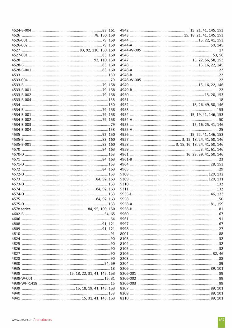
4524‐B‐004 ...................................................................83, 1614526 .....................................................................78, 150, 1594526‐001 ......................................................................79, 1594526‐002 ......................................................................79, 1594527 ....................................................... 83, 92, 110, 150, 1604527‐001 ......................................................................83, 1604528 .....................................................................92, 110, 1504528‐B ..........................................................................83, 1604528‐B‐001 ...................................................................83, 1604533 ...................................................................................1504533‐004 ..............................................................................794533‐B ..........................................................................79, 1584533‐B‐001 ...................................................................79, 1584533‐B‐002 ...................................................................79, 1584533‐B‐004 .........................................................................1584534 ...................................................................................1504534‐B ..........................................................................79, 1584534‐B‐001 ...................................................................79, 1584534‐B‐002 ...................................................................79, 1584534‐B‐003 ...........................................................................794534‐B‐004 .........................................................................1584535 .............................................................................92, 1504535‐B ..........................................................................83, 1604535‐B‐001 ...................................................................83, 1604570 .............................................................................84, 1634570‐D ................................................................................1634571 .............................................................................84, 1634571‐D ................................................................................1634572 .............................................................................84, 1634572‐D ................................................................................1634573 .......................................................................84, 92, 1634573‐D ................................................................................1634574 .......................................................................84, 92, 1634574‐D ................................................................................1634575 .......................................................................84, 92, 1634575‐D ................................................................................163457x series ..................................................... 84, 95, 109, 1504602‐B ............................................................................54, 654606 .....................................................................................644808 .............................................................................91, 1214809 .............................................................................91, 1214810 .....................................................................................914824 .....................................................................................904825 .....................................................................................904826 .....................................................................................904827 .....................................................................................904828 .....................................................................................904930 ...............................................................................54, 594935 .....................................................................................184938 ............................................. 15, 18, 22, 31, 41, 145, 1534938‐W‐001 ...................................................................15, 314938‐WH‐1418 .....................................................................154939 ................................................... 15, 18, 19, 41, 145, 1534940 ...................................................................................1534941 ......................................................... 15, 31, 41, 145, 153
4942 ......................................................... 15, 21, 41, 145, 1534943 ................................................... 15, 18, 21, 41, 145, 1534944 ................................................................. 15, 22, 41, 1534944‐A .......................................................................... 50, 1454944‐W‐005 .........................................................................174946 ............................................................................... 53, 584947 ........................................................... 15, 22, 56, 58, 1534948 ................................................................. 15, 16, 22, 1454948‐A ..................................................................................224948‐B ..................................................................................224948‐W‐005 .........................................................................224949 ................................................................. 15, 16, 22, 1464949‐B ..................................................................................224950 ....................................................................... 15, 20, 1534951 .....................................................................................184952 ........................................................... 18, 26, 49, 50, 1464953 ...................................................................................1534954 ......................................................... 15, 19, 41, 146, 1534954‐A ..................................................................................504955 ........................................................... 15, 16, 25, 41, 1464955‐A ..................................................................................254956 ......................................................... 15, 22, 41, 146, 1534957 ................................................. 3, 15, 18, 24, 41, 50, 1464958 ........................................... 3, 15, 16, 18, 24, 41, 50, 1464959 ................................................................... 3, 41, 61, 1464961 ..................................................... 16, 23, 39, 41, 50, 1464961‐B ..................................................................................234964 ............................................................................. 28, 1534965 .....................................................................................295308 ........................................................................... 120, 1325309 ........................................................................... 120, 1315310 ...................................................................................1325311 ...................................................................................1325935‐L .......................................................................... 46, 1235958 ...................................................................................1505958‐A .......................................................................... 81, 1595958‐H ..................................................................................815960 .....................................................................................675961 .....................................................................................915997 .....................................................................................675998 .....................................................................................278001 .....................................................................................888103 .....................................................................................328104 .....................................................................................328105 .....................................................................................328106 ............................................................................... 32, 468203 .....................................................................................888204 .....................................................................................898206 ............................................................................. 89, 1018206‐001 ..............................................................................898206‐002 ..............................................................................898206‐003 ..............................................................................898207 ............................................................................. 89, 1018208 ............................................................................. 89, 1018210 ............................................................................. 89, 101
167www.bksv.com/transducers
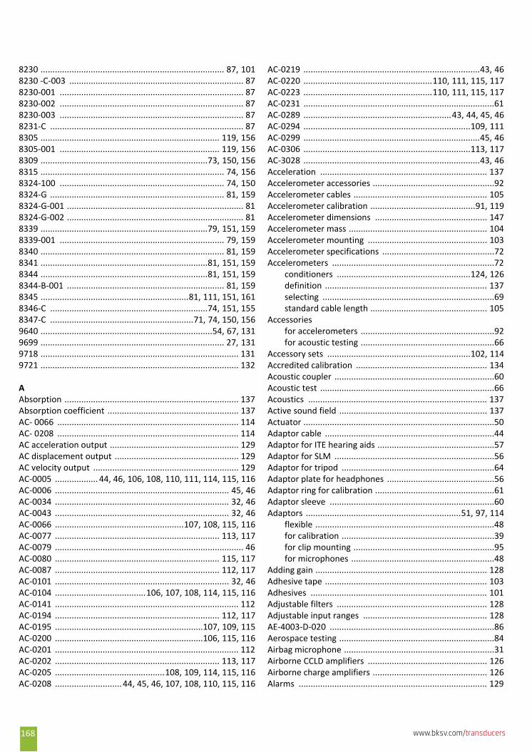
8230 ............................................................................. 87, 1018230 ‐C‐003 ......................................................................... 878230‐001 ............................................................................. 878230‐002 ............................................................................. 878230‐003 ............................................................................. 878231‐C ................................................................................. 878305 ........................................................................... 119, 1568305‐001 ................................................................... 119, 1568309 ......................................................................73, 150, 1568315 ............................................................................. 74, 1568324‐100 ..................................................................... 74, 1508324‐G ......................................................................... 81, 1598324‐G‐001 .......................................................................... 818324‐G‐002 .......................................................................... 818339 ......................................................................79, 151, 1598339‐001 ..................................................................... 79, 1598340 ............................................................................. 81, 1598341 ......................................................................81, 151, 1598344 ......................................................................81, 151, 1598344‐B‐001 .................................................................. 81, 1598345 ..............................................................81, 111, 151, 1618346‐C ..................................................................74, 151, 1558347‐C ............................................................71, 74, 150, 1569640 ........................................................................54, 67, 1319699 ............................................................................. 27, 1319718 ................................................................................... 1319721 ................................................................................... 132
AAbsorption ......................................................................... 137Absorption coefficient ....................................................... 137AC‐ 0066 ............................................................................ 114AC‐ 0208 ............................................................................ 114AC acceleration output ...................................................... 129AC displacement output .................................................... 129AC velocity output ............................................................. 129AC‐0005 .................. 44, 46, 106, 108, 110, 111, 114, 115, 116AC‐0006 ......................................................................... 45, 46AC‐0034 ......................................................................... 32, 46AC‐0043 ......................................................................... 32, 46AC‐0066 ......................................................107, 108, 115, 116AC‐0077 ..................................................................... 113, 117AC‐0079 ............................................................................... 46AC‐0080 ..................................................................... 115, 117AC‐0087 ..................................................................... 112, 117AC‐0101 ......................................................................... 32, 46AC‐0104 ......................................106, 107, 108, 114, 115, 116AC‐0141 ............................................................................. 112AC‐0194 ..................................................................... 112, 117AC‐0195 ..............................................................107, 109, 115AC‐0200 ..............................................................106, 115, 116AC‐0201 ............................................................................. 112AC‐0202 ..................................................................... 113, 117AC‐0205 ..............................................108, 109, 114, 115, 116AC‐0208 ............................44, 45, 46, 107, 108, 110, 115, 116
AC‐0219 ..........................................................................43, 46AC‐0220 ......................................................110, 111, 115, 117AC‐0223 ......................................................110, 111, 115, 117AC‐0231 ................................................................................61AC‐0289 ..............................................................43, 44, 45, 46AC‐0294 ......................................................................109, 111AC‐0299 ..........................................................................45, 46AC‐0306 ......................................................................113, 117AC‐3028 ..........................................................................43, 46Acceleration ...................................................................... 137Accelerometer accessories ...................................................92Accelerometer cables ........................................................ 105Accelerometer calibration ............................................91, 119Accelerometer dimensions ............................................... 147Accelerometer mass .......................................................... 104Accelerometer mounting .................................................. 103Accelerometer specifications ...............................................72Accelerometers ....................................................................72
conditioners ........................................................124, 126definition .................................................................... 137selecting ........................................................................69standard cable length ................................................. 105
Accessoriesfor accelerometers ........................................................92for acoustic testing ........................................................66
Accessory sets ............................................................102, 114Accredited calibration ....................................................... 134Acoustic coupler ...................................................................60Acoustic test .........................................................................66Acoustics ........................................................................... 137Active sound field .............................................................. 137Actuator ................................................................................50Adaptor cable .......................................................................44Adaptor for ITE hearing aids .................................................57Adaptor for SLM ...................................................................56Adaptor for tripod ................................................................64Adaptor plate for headphones .............................................56Adaptor ring for calibration ..................................................61Adaptor sleeve .....................................................................60Adaptors .................................................................51, 97, 114
flexible ...........................................................................48for calibration ................................................................39for clip mounting ...........................................................95for microphones ............................................................48
Adding gain ........................................................................ 128Adhesive tape .................................................................... 103Adhesives .......................................................................... 101Adjustable filters ............................................................... 128Adjustable input ranges .................................................... 128AE‐4003‐D‐020 .....................................................................86Aerospace testing .................................................................84Airbag microphone ...............................................................31Airborne CCLD amplifiers .................................................. 126Airborne charge amplifiers ................................................ 126Alarms ............................................................................... 129
168 www.bksv.com/transducers
Ambient noise ....................................................................137Amplified piezoresistive accelerometers .............................84Amplitude ..........................................................................137Amplitude distribution .......................................................137Analogue filtering ...............................................................129Anechoic room ...................................................................137Anechoic test box .....................................................54, 55, 66Angle pieces .........................................................................48AO‐0027 ...............................................................................43AO‐0028 ...............................................................................43AO‐0038 .................................................................51, 88, 106AO‐0087 ...............................................................................45AO‐0122 .......................................................................60, 106AO‐0231 .............................................................................108AO‐0250 .....................................................................112, 114AO‐0283 .............................................................................108AO‐0339 .......................................................................88, 108AO‐0390 ...............................................................................33AO‐0406 .......................................................................17, 107AO‐0414 .......................................................................43, 109AO‐0419 .........................................................................43, 60AO‐0422 ...............................................................................67AO‐0426 ...............................................................................45AO‐0428 ...............................................................................43AO‐0463 .......................................................................44, 107AO‐0479 ...............................................................................44AO‐0482 .............................................................................108AO‐0488 ...............................................................................43AO‐0526 .............................................................................110AO‐0527 .............................................................................110AO‐0528 .............................................................................110AO‐0531 .......................................................................45, 107AO‐0534 .............................................................................110AO‐0536 .............................................................................111AO‐0537 ...............................................................................44AO‐0563 ...............................................................................44AO‐0564 ...............................................................................44AO‐0587 ...............................................................................44AO‐0608 .............................................................................112AO‐0612 .............................................................................112AO‐0616 .............................................................................112AO‐0623 .............................................................................112AO‐0624 .............................................................................112AO‐0638 .............................................................................109AO‐0641 .............................................................................109AO‐0642 .............................................................................109AO‐0645 ...............................................................................43AO‐0687 .......................................................................44, 106AO‐0688 .............................................................................111AO‐0690 .............................................................................110AO‐0691 .............................................................................108AO‐0692 .............................................................................106AO‐0693 .............................................................................110AO‐0694 .............................................................................111AO‐0695 .............................................................................108
AO‐0698 .............................................................................109AO‐0699 ....................................................................... 45, 108AO‐0700 .............................................................................109AO‐0701 .............................................................................111AO‐0702 .............................................................................111AO‐0703 .............................................................................109AO‐0704 .............................................................................107AO‐0714 .............................................................................110AO‐0722 .............................................................................112AO‐0729 .............................................................................113AO‐0730 .............................................................................113AO‐0740 .............................................................................110AO‐0741 .............................................................................106AO‐0744 .............................................................................113AO‐0745 .............................................................................111AO‐0746 .............................................................................109AO‐0747 .............................................................................113AO‐0753 .............................................................................113AO‐0755 .............................................................................106AO‐0757 .............................................................................113AO‐0759 .............................................................................111AO‐1381 .............................................................................108AO‐1382 .............................................................................106AO‐1419 .............................................................................107AO‐1454 .............................................................................111Applications ...........................................................................7APS‐500 ..............................................................................121AQ‐0015 ...............................................................................56AR‐0014 ................................................................................45Array microphones ..............................................................24Artificial ears ........................................................................56Artificial mastoid ................................................ 54, 55, 56, 59Artificial mastoid with calibrator .........................................59Audibility threshold ............................................................137Audiometer testing ..............................................................55Automotive crash test accelerometers ..............................156Automotive testing ..............................................................84A‐weighting filters ..............................................................129ÆX‐9133 .............................................................................101
BB types ...............................................................................157Background noise ...............................................................137Beeswax ..................................................................... 101, 103Bending radius ...................................................................105Binaural microphone ..................................................... 28, 29Bird spike .............................................................................49Blocks ...................................................................................95Bone conduction threshold values ......................................59Brackets ...............................................................................95Brüel & Kjær transducer history ............................................5B‐weighting filters ..............................................................129
CCable
169www.bksv.com/transducers
length ........................................................................... 47limitations .................................................................... 47
Cable accessories ............................................................... 114Cable adaptor ...................................................................... 51Cable bending radius ........................................................... 47Cable connecting/removal tool ......................................... 101Cable length ......................................................................... 40Cable markers .................................................................... 114Cable mounting tool .......................................................... 114Cable splitter ..................................................................... 111Cables
for accelerometers ..................................................... 105for hydrophones ........................................................... 33for microphones ........................................................... 43for triaxial accelerometers ......................................... 110for uniaxial accelerometers ........................................ 106hardline ...................................................................... 113how to use .................................................................. 105industrial applications ................................................ 112insulation material ..................................................... 115insulator ..................................................................... 105jacket .......................................................................... 105jacket material ............................................................ 115maximum length ........................................................ 105raw ................................................................46, 115, 117sheathing material ..................................................... 115standard length .......................................................... 105
Calibration ..................................................................... 2, 133accelerometers ........................................................... 119accredited ................................................................... 134adaptors ....................................................................... 39initial ........................................................................... 134microphone .................................................................. 37reference equipment ................................................. 134regular ........................................................................ 134traceable .................................................................... 134
Calibration accessories ...................................................... 121Calibration clip ..................................................................... 93Calibration exciter ................................................94, 120, 121Calibration fixture .............................................................. 121Calibration jig ...................................................................... 62Calibration systems ................................................... 120, 131
primary ....................................................................... 131secondary ................................................................... 132
Calibrators ................................................................... 37, 120CCLD .................................................................................. 137CCLD accelerometers ................................................4, 69, 157
cables ......................................................................... 110industrial .............................................................. 81, 159maximum cable length ............................................... 105triaxial ................................................................... 82, 160uniaxial ................................................................. 76, 157
CCLD laser tacho probe ....................................................... 86CCLD preamplifiers ........................................................ 16, 34CCLD signal conditioners ........................................... 124, 125
Cement studs ...............................................................97, 103Certification ............................................................................2
ISO/IEC 17025 ............................................................ 134Channel control ................................................................. 128Charge accelerometers ................................................69, 155
industrial .................................................................... 156maximum cable length ............................................... 105triaxial ...................................................................75, 156uniaxial ..................................................................72, 155
Charge amplifier ................................................................ 137Charge amplifiers .......................................................126, 127Charge converter ............................................................... 137Charge injection calibration .........................................42, 128Charge signal conditioners ................................................ 126Charge to CCLD converters ................................................ 127CIC ................................................................................42, 128CIC adaptor ...........................................................................51Classical preamplifier ...........................................................34Click‐on coupler ....................................................................58Clip for holding coupler ........................................................66Clip for holding reference microphone ................................66Clip mounting .......................................................................92Coaxial cable assemblies ............................................106, 110Coaxial connectors ...............................................................47Cold temperatures ...............................................................17Collar for acoustic coupler ...................................................60Comparison calibration system software .......................... 132Comparison tables
CCLD accelerometers ................................................. 157charge accelerometers ............................................... 155microphones .............................................................. 153piezoresistive accelerometers .................................... 163
Complex intensity .............................................................. 137Compliance with standards ............................................... 143Conditioning ...................................................................... 137Conditioning amplifiers ..................................................... 123Conditioning monitoring accelerometers ......................... 117Connectors ........................................................................ 114Constant current line drive ............................................... 137Contact‐free target detection ..............................................86Controllable turntable ..........................................................67Converters
charge to CCLD ........................................................... 127Converting acceleration .................................................... 129Corrector ..............................................................................48
for microphones ............................................................48Coupler adaptor ring ............................................................56Coupler hole ring ..................................................................65Couplers .........................................................................22, 56
click‐on ..........................................................................58selecting ........................................................................53
Cumulative distribution ..................................................... 138Current limitations ...............................................................47Curved mounting surfaces ................................................ 103Customer care ................................................................... 133
170 www.bksv.com/transducers
Customization of transducers ................................................4C‐weighting filters ..............................................................129
DDA‐0150 ...............................................................................62Damping .............................................................................138Danish Primary Laboratory of Acoustics ....................119, 134DB‐0111 ...............................................................................56DB‐0138 ...............................................................................56DB‐0264 ...............................................................................39DB‐0375 ...............................................................................48DB‐0544 .............................................................................100DB‐0742 ...............................................................................56DB‐0843 ...............................................................................56DB‐0900 ...............................................................................39DB‐0913 ...............................................................................56DB‐0962 ...............................................................................56DB‐1021 ...............................................................................56DB‐1160 ...............................................................................60DB‐1164 ...............................................................................60DB‐1425 .................................................................88, 97, 100DB‐2012 ...............................................................................57DB‐2015 ...............................................................................57DB‐2902 ...............................................................................64DB‐3041 ...............................................................................88DB‐3339 ...............................................................................65DB‐3340 ...............................................................................65DB‐3611 ...............................................................................50DB‐3800 ...............................................................................61DB‐3800‐W‐001 ...................................................................61DB‐3866 ...............................................................................58DB‐3868 ...............................................................................58DB‐3869 ...............................................................................58DB‐3887 ...............................................................................58DB‐3989 .............................................................................101DB‐4009 ...............................................................................39DB‐4010 ...............................................................................39DB‐4121 ...............................................................................39DB‐4199 ...............................................................................39DB‐4339 ...............................................................................61DC response .......................................................................138DC response accelerometers .......................................95, 109DC RMS ouput ....................................................................129DC static centring unit ..........................................................90DD‐0413 ...............................................................................50Decibel scale ......................................................................138Dehumidifier ........................................................................50DeltaTron .....................................................................69, 138Depolarize ............................................................................70Development and production ................................................2Differential amplifier ..........................................................109Differentiation ....................................................................138Diffraction ..........................................................................138Diffuse field ............................................................15, 23, 138Diffuse sound .....................................................................138
Diffuse‐field microphones ....................................................21Dimensions ........................................................................144
accelerometers ...........................................................147microphones ...............................................................144
Direct mounting adaptor .....................................................96Directivity calibration software ..........................................131Directivity factor ................................................................138Directivity measurement .....................................................55Displacement .....................................................................138Displacement measurement ................................................86Distortion limit .....................................................................16Double integration filters ...................................................129DP‐0276 ...............................................................................57DP‐0286 ...............................................................................57DP‐0368 ...............................................................................57DP‐0370 ...............................................................................57DP‐0530 ...............................................................................57DP‐0774 ...............................................................................39DP‐0775 ...............................................................................39DP‐0776 ...............................................................................39DP‐0888 ...............................................................................39DP‐0977 ...............................................................................39DP‐0978 ...............................................................................39DP‐0979 ...............................................................................39DPLA ........................................................................... 119, 134DS‐0535 ................................................................................57DS‐0540 ................................................................................57DS‐0541 ................................................................................57DS‐0884 ................................................................................65DS‐0934 ................................................................................49DU‐0079 .............................................................................101Dual preamplifier ........................................................... 29, 30Dummy accelerometers .......................................................94Dust protector ......................................................................57Dusty areas .............................................................. 74, 81, 89DV‐0459 ......................................................................... 92, 93DV‐0460 ......................................................................... 92, 93D‐weighting filters ..............................................................129Dynamic capability .............................................................138Dynamic pressure ................................................................19Dynamic range ...................................................................138Dynamic range of microphones ...........................................16DZ‐9566 ................................................................................48DZ‐9769 ................................................................................64DZ‐9770 ................................................................................64
EEA‐MLA ..............................................................................134Ear mould holder .................................................................57Ear mould simulator ................................................. 57, 58, 64Ear mounting tool ................................................................64Ear plug simulator ................................................................58Ear simulator ................................................ 53, 55, 57, 60, 65
external .........................................................................57Earcap ..................................................................................56
171www.bksv.com/transducers
Effects of temperature .................................................. 17, 70EL‐2019 .............................................................................. 101EL‐2330 .............................................................................. 101EL‐4023 ................................................................................ 45EL‐4025 ................................................................................ 46Electroacoustic standards ................................................. 143Electroacoustic testing ........................................................ 53Electroacoustics
typical system configurations ....................................... 54Electronic filters ................................................................. 103Electrostatic actuators ......................................................... 39
adaptors ....................................................................... 39EN 9100 certified ................................................................... 2Engineering test services ................................................... 133ETFE cables ................................................................ 115, 117EU‐4000 ............................................................................... 48Excitation ........................................................................... 138Exciters ................................................................................ 90
calibration .................................................................. 121hand‐held ..................................................................... 91vibration ....................................................................... 91
Explosive areas .......................................................74, 81, 112Extension cables .................................................................. 43Extension rods ..................................................................... 48External ear simulator ......................................................... 57
FFalcon Range ................................................................. 18, 35Far field .............................................................................. 138FEP cables .................................................................... 46, 115Ferromagnetic surfaces ..................................................... 103Fibre adaptor ....................................................................... 86Filters ..................................................................128, 129, 138
electronic .................................................................... 103mechanical ........................................................... 97, 103
Flexible adaptors ................................................................. 48Flexible cables ................................................................... 115Flush mounting kit ............................................................... 17Force transducers .......................................................... 87, 88Forced vibration ................................................................ 138Free field .................................................................15, 23, 138Free‐field microphones ....................................................... 19Frequency range .................................................................. 72
lower limiting of accelerometers ................................. 70upper limiting of accelerometers ................................. 70
Frequency response .......................................................... 138Frequency response function ............................................ 138Front‐end support ................................................................. 3Full scale .............................................................................. 70
Gg, definition of ................................................................... 139General purpose accelerometers ...............155, 156, 158, 160General purpose microphones .......................................... 153Global field service ............................................................ 133
gn ....................................................................................... 139Ground loop ...................................................................... 139
cause .......................................................................... 103Grounding terminal ..............................................................51Guard ring adaptor ...............................................................56
HHand adaptor .......................................................................96Hand‐arm transducer set .....................................................96Hand‐arm vibration ..............................................................95Hand‐held analyzer ........................28, 29, 111, 112, 123, 124Hand‐held calibration exciter ............................................ 120Hand‐held exciter .................................................................91Hand‐held probe ............................................................... 104Handle adaptor .....................................................................96Handset alignment rods .......................................................65Handset gauge ......................................................................65Handset positioner ...............................................................64Hardline cables ...........................................................113, 117Hardware maintenance ..................................................... 135Harmonics ......................................................................... 139Harsh environments ...........................................106, 112, 113HATS ...................................................................28, 54, 55, 63HDPE cables ....................................................................... 115Head and torso simulators .................................28, 54, 55, 63Headphone testing ...............................................................55Headset testing ....................................................................55Hearing aid testing ...............................................................55Hearing loss ....................................................................... 139Hertz .................................................................................. 139Hexagonal key ................................................................... 101High humidity measurements ..............................................89High shock transducer calibration software ...................... 132High sound pressure level microphones ........................... 153High temperatures .........................................................17, 70High vacuum environments ...............................107, 109, 114High wind speeds .................................................................49High‐frequency accelerometers .................................155, 158High‐frequency microphones ............................................ 153High‐intensity testing ...........................................................31High‐leak pinna simulator ....................................................60High‐pass filter .................................................................. 139High‐sensitivity accelerometers .................................155, 159High‐shock transducer calibration .................................... 132High‐static pressure microphone .........................................31High‐temperature accelerometers .............................159, 160High‐temperature clips ........................................................92High‐temperature measurements ...........................74, 81, 95High‐temperature mounting block ......................................95Hopkinson bar ................................................................... 132Human body measurements ................................................88Human body vibration accelerometers ............................. 161Human vibration ...................................................................96Human vibration analyzer ............................96, 108, 110, 111Hydrophone calibration system ........................................ 131
172 www.bksv.com/transducers

Hydrophone calibrator .........................................................37Hydrophones ............................................................31, 32, 46
cables and connectors ..................................................33Hz, definition of ..................................................................139
IIEPE ....................................................................................139IEPE accelerometers .............................................................69ILAC‐MRA ...........................................................................134Imaginary intensity ............................................................139Impact caps ........................................................................101Impact hammers ......................................................87, 88, 89Impact test .........................................................................139Impact tips .........................................................................101Impedance ...................................................................88, 139Impedance heads .................................................................88Impedance tube microphone ...............................................28Industrial accelerometers
CCLD ..............................................................81, 159, 161charge ...................................................................74, 156
Industrial applications ........................................................112Infrasound ....................................................................28, 139Inherent noise ......................................................................16Initial calibration ................................................................134Input module ........................................................................15Insert voltage calibration .....................................................42Insulated mounting ............................................................103Insulated mounting pads ...................................................103Insulated studs .............................................................97, 103Insulator .....................................................................105, 115Integration .........................................................................139Intensity .............................................................................139Intensity conditioner ..........................................................123ISO 9001 certified ...................................................................2Isolation .............................................................................139IVC ........................................................................................42
JJacket .........................................................................105, 115Jacket material ...................................................................115JJ‐0032 ..........................................................................51, 114JJ‐0081 ..................................................................................48JJ‐0152 ................................................................................114JJ‐0175 ................................................................................114JJ‐0207 ................................................................................114JP‐0012 ...............................................................................114JP‐0028 .........................................................................51, 114JP‐0035 .................................................................................47JP‐0056 ...............................................................................114JP‐0101 .................................................................................47JP‐0144 .........................................................................51, 114JP‐0145 ........................................................... 51, 60, 107, 114JP‐0162 ...............................................................................114JP‐0169 .................................................................................51JP‐0192 ...............................................................................114
JP‐0196 ...............................................................................114Junction unit ........................................................................51
LLaboratory standard microphones ......................................27LAN‐XI support .......................................................................3Laser tacho probe ................................................................86Laser‐interferometric calibration system ..........................131LDPE cables ........................................................................115Leakage error .....................................................................139LEMO connector ..................................................................47Level indicator ......................................................................59Level quantity ....................................................................140Limitations to cable length ..................................................47Linear system .....................................................................140Lip ring .................................................................................62LIR ......................................................................................141LKO .....................................................................................140LN cables ............................................................................105Loading test object .............................................................104Local dynamic mass ...........................................................104Loudness ............................................................................140Loudspeaker testing .............................................................54Low noise cables ........................................ 105, 111, 115, 117Low noise microphones .......................................................25Low outgassing ...................................................................115Low sound pressure level microphones ............................153Low temperatures ................................................................71Lower limiting frequency range ...........................................70Low‐frequency microphones .............................................153Low‐leak pinna simulator .....................................................60Low‐pass filter ....................................................................140
MMachine health monitoring ...............................................129Magnetic fields .....................................................................16Magnetic transducer ............................................................86Magnets ...............................................................................97Main sensitivity axis ...........................................................104Masking ..............................................................................140Mastoids ........................................................................ 56, 59Maximum cable length ......................................................105Maximum charge input ......................................................126Maximum limits for microphones ........................................16Maximum SPL ......................................................................16Maximum transverse sensitivity ........................................104Measuring amplifier ................................................... 124, 126Measuring direction ...........................................................104Measuring range ..................................................................72Mechanical filters ......................................................... 97, 103Mechanical impedance ......................................................139Mechanical impedance measurements ...............................91Mechanical mobility ...........................................................140MEMS ...................................................................................69Microdot connector .............................................................47
173www.bksv.com/transducers

Microphone accessories ...................................................... 48Microphone adaptor ..................................................... 57, 58Microphone calibration ................................................. 37, 42Microphone calibration system ......................................... 132Microphone cartridge .......................................................... 16Microphone comparisons .................................................. 153Microphone conditioner ................................................... 123Microphone conditioners .................................................. 124Microphone dimensions .................................................... 144Microphone history ............................................................... 5Microphone holder .............................................................. 50Microphone holder for tripod ............................................. 50Microphone matrix .............................................................. 15Microphone pairs .......................................................... 29, 30Microphone preamplifiers ................................................... 34Microphone reciprocity calibration system ...................... 131Microphone stand ............................................................... 50Microphone standards ................................................ 19, 143Microphone testing ............................................................. 54Microphone verification ...................................................... 42Microphones
selecting ....................................................................... 15Miniature accelerometers ......................................... 155, 158Miniature transducers ............................................... 107, 109MM‐0002 ............................................................................. 86MM‐0004 ............................................................................. 86Mobility ............................................................................. 140Mobility measurements ...................................................... 91Modal accelerometers .......................................156, 157, 161Modal analysis ............................................................. 91, 140Modal exciters ............................................................... 87, 90Modal testing ...................................................................... 92Monitoring applications .................................................... 112Mounted resonance frequency ........................................... 72Mounting ........................................................................... 103
considerations ............................................................ 103method ....................................................................... 103position ....................................................................... 104surfaces ...................................................................... 103
Mounting blocks .................................................................. 95for human vibration ..................................................... 96high‐temperature ......................................................... 95triaxial ........................................................................... 95
Mounting brackets .............................................................. 95for human vibration ..................................................... 96
Mounting bushing for mouth simulator .............................. 65Mounting clips ........................................................92, 93, 103Mounting pads .................................................................. 103Mouth simulators .....................................................54, 60, 62Multi‐channel tests ............................................................ 128Multi‐field microphones ...................................................... 23Multifunction acoustic calibrator ........................................ 37Multi‐pin signal conditioners ............................................. 123Multi‐unit frame ................................................................ 128
NNear field ........................................................................... 140Newton .............................................................................. 140NEXUS conditioning amplifiers ...........3, 35, 45, 123, 124, 127NMT ......................................................................................43Noise emission level .......................................................... 140Noise reduction coefficient ............................................... 140Non‐contact transducers ......................................................86Nose cones ...........................................................................49Noy .................................................................................... 140NRC .................................................................................... 140Nuts ................................................................................... 100
OOperating temperature range ..............................................72Optimized microphone .........................................................16Optional fibre .......................................................................86Ordering
accessories ......................................................................4transducers .....................................................................4
O‐rings ............................................................................... 101Outdoor microphone kit .................................................26, 50Outdoor microphones ..........................................................26Outdoor protection for microphones ..................................50
PPa, definition of ................................................................. 140Particle velocity ................................................................. 140Pascal ................................................................................. 140PE accelerometers ................................................................69
industrial .............................................................156, 159triaxial ...................................................................75, 156uniaxial ..........................................................72, 155, 157
PE cables ............................................................................ 115Peak ................................................................................... 140Peak output ....................................................................... 129Peak‐to‐peak value ............................................................ 140Permanent installations .................................................... 109Permanent magnet ........................................................... 103Permanent magnet exciters ...........................................90, 91Permanent monitoring ...................................................... 111Permanent vibration monitoring ...................................74, 81PFA cables ..............................................17, 46, 105, 115, 117Phase ................................................................................. 140Phase mismatch ................................................................ 140Phase response comparison calibration ............................ 132Phon .................................................................................. 140Photocell tripod ....................................................................50Piezoelectric accelerometers ...............................................69
industrial .............................................................156, 159triaxial ...................................................................75, 156uniaxial ..........................................................72, 155, 157
Piezoelectric force transducers ......................................87, 88Piezoelectric material ...........................................................70Piezoresistive accelerometers ......................................69, 163
174 www.bksv.com/transducers
amplified .......................................................................84Pink noise ...........................................................................140Pinna ....................................................................................64Pinna simulator ....................................................................60Pistonphone .........................................................................37Plastic microphone dummy .................................................62Plastic tip ..............................................................................88Point mechanical mobilities .................................................88Polarization ..........................................................................15Polarization control ............................................................128Polychloroprene cables ........................................................46Polymers ..............................................................................88POP shock calibrator ..........................................................132Power amplifier ........................................................54, 68, 91Power spectrum level ........................................................140PR accelerometers .......................................................69, 163
amplified .......................................................................84Preamplifier cables ..............................................................43Preamplifier holders ............................................................50Preamplifier mounting tool ..................................................64Preamplifiers ........................................................................34Pre‐loading nut ....................................................................88Pressure field .......................................................................15Pressure residual intensity index .......................................140Pressure sensors ..................................................................19Pressure‐field microphones .................................................22Primary calibration .............................................................134Primary calibration systems ...............................................131Primary laser calibration ....................................................119Probe microphone ...............................................................28Probes ................................................................................100Product care .......................................................................133Protection bracket for external microphone preamplifier ..66PTFE cables .........................................................105, 115, 117PULSE audio analyzer ...........................................................54PULSE electroacoustics ........................................................54PULSE multi‐analyzer ...........................................................91PULSE platform .........29, 35, 42, 45, 47, 51, 54, 111, 119, 120PULSE support ........................................................................3PUR cables ..............................................................17, 46, 115Push/pull stingers ................................................................90PVC cables ....................................................................46, 115PZ23 .....................................................................................70
QQA testing microphones ....................................................153QA‐0013 .........................................................................84, 88QA‐0029 .............................................................................101QA‐0035 .............................................................................114QA‐0038 .............................................................................101QA‐0041 .......................................................................88, 101QA‐0042 .......................................................................88, 101QA‐0068 .............................................................................101QA‐0121 .............................................................................101QA‐0141 .............................................................................101
QA‐0167 ...............................................................................64QA‐0186 ...............................................................................88QA‐0220 ..................................................................... 101, 114QA‐0223 ...............................................................................64QA‐0230 .............................................................................101QH‐0006 ...............................................................................59QS‐0003 .............................................................................101QS‐0007 .............................................................................101QS‐0056 ...............................................................................86Qualification of anechoic chambers ....................................25
RRack mounting ...................................................................128Rain cover ............................................................................50Random incidence corrector ................................................48Random incidence microphone ...........................................21Random noise ....................................................................141Raw cables ........................................................... 46, 115, 117Receiver testing ...................................................................54Reciprocity calibration system ..................................... 27, 131Reference accelerometers ......................................... 119, 156Reference instrument calibration ......................................134Reference microphone ........................................................27Reference microphone holder .............................................64Reference microphones .....................................................153Regular calibration .............................................................134Relative velocity .................................................................141Remote control for turntable ...............................................67Removal wrench ................................................................101Rentals ...............................................................................135Repair service .....................................................................134Replacement of discontinued microphones ........................18Replacing discontinued preamplifiers ..................................36REq‐X ....................................................................................70Residual intensity ...............................................................141Residual noise ....................................................................141Residual noise level ..............................................................70Resonance ..........................................................................141Resonance frequency .........................................................141Retaining collar ....................................................................57Retroreflective tape .............................................................86Reverberation ....................................................................141RG‐174 .................................................................................44Ring for acoustic coupler .....................................................60RMS ....................................................................................141Root mean square ..............................................................141Rotating boom .....................................................................50Rotor blade measurements .................................................88Rough handling ..................................................................106Roving accelerometer ........................................................103
SS types ................................................................................157Sabin ..................................................................................141Screws ................................................................................101
175www.bksv.com/transducers
Secondary calibration ................................................ 132, 134Seismic ............................................................................... 141Self‐adhesive disc .............................................................. 103Semi‐anechoic field ........................................................... 141Sensitivity .................................................................... 72, 141Service ............................................................................... 133
engineering test ......................................................... 133repair .......................................................................... 134
Service agreements ........................................................... 135Severe vibrational inputs ..................................................... 84Sheathing material ............................................................ 115Shielding ............................................................................ 141Shock ................................................................................. 141Shock accelerometers ............................................... 156, 159Shock and vibration transducer system ............................ 132Shock exciters .................................................................... 121Shock transducer calibration software .............................. 132Signal conditioners
CCLD ........................................................................... 124charge ......................................................................... 126
Signal conditioning .................................................... 123, 137benefits ...................................................................... 128
Silicone cables ............................................................... 17, 46Simulators ............................................................................ 60
ear .......................................................................... 56, 57head and torso ............................................................. 63mouth ........................................................................... 62
Single integration filters .................................................... 129Single point of contact ....................................................... 133Slide rule .............................................................................. 59SLM .............................................................43, 45, 50, 56, 141SLN cables .......................................................................... 105SO‐0005 ............................................................................... 62Soft seal ............................................................................... 60Sone ................................................................................... 141Sound calibrator .................................................................. 37Sound field ........................................................................... 16Sound intensity .......................................................24, 30, 141Sound intensity calibrators .................................................. 38Sound intensity microphones ............................................ 153Sound intensity probes ........................................................ 29
remote control unit ...................................................... 30Sound level ........................................................................ 141Sound level meter (SLM) ................................................... 141Sound Level Meter Type 2231 ........................................... 153Sound level meters .............................................25, 43, 45, 50Sound power ..................................................................... 141Sound power level ............................................................. 141Sound power measurements .............................................. 25Sound pressure .................................................................. 142Sound pressure level ......................................................... 142Sound transmission class ................................................... 142Sound transmission loss .................................................... 142Sound, definition of ........................................................... 141Spacer .................................................................................. 30
Spanner ................................................................................88Special microphones ............................................................28Spectral leakage ................................................................ 139Speed measurement ............................................................86Spiral cable ........................................................................ 115Spirit level .....................................................................94, 103Spring balance ......................................................................59Stainless steel plug ............................................................ 114Standard
ANSI ............................................................................ 143ANSI S1.12 Type M ........................................................19ANSI S1.4 Type 1 ...........................................................19ANSI S1.4 Type 2 ...........................................................19ANSI S3.13 & S.3.26 (1987) ...........................................59ANSI S3.25 .....................................................................63ANSI S3.35 .....................................................................61ANSI S3.36 .....................................................................63ANSI S3.7 (1995) ......................................................56, 58AS 9100 Rev. C .................................................................8BS 4009 ..........................................................................59compliance ................................................................. 143electroacoustic ........................................................... 143EN 1032.2003 ................................................................96EN/IEC 60942 ................................................................37EU Directive 2002/44/EC ...............................................96IEC 60318 – 1 ...........................................................56, 60IEC 60318 – 4 ...........................................................61, 63IEC 60318 – 4 (2010) .....................................................60IEC 60318 – 5 .................................................................56IEC 60318 – 5 (2006) .....................................................58IEC 60318 – 7 .................................................................63IEC 60373 (1990) ...........................................................59IEC 60565 ................................................................... 131IEC 61043 ......................................................................29IEC 61043, 1993 Class 1 .................................................38IEC 61043, Class 1 ..........................................................30IEC 61094 ......................................................................19IEC 61094 – 1 (2000) .................................................. 143IEC 61094 – 1 (Laboratory Standards) ........................ 132IEC 61094 – 2 .............................................................. 131IEC 61094 – 4 (1995) .................................................. 143IEC 61094 – 4 (Working Standards) ............................ 132IEC 61094 – 5 .............................................................. 132IEC 61094 – 6 .............................................................. 132IEC 61672 ........................................................19, 26, 143IEC 61672 (2000) ........................................................ 143IEC 625 – 1 .....................................................................67IEC/EN 61400 – 11 .........................................................49IEEE 1451.4 ......................................................................3IEEE 1451.4 V.1.0 .......................................................3, 40IEEE 269 ...................................................................62, 63IEEE 488.1 ......................................................................67IEEE 661 ...................................................................62, 63IEEE P1451.4 V.0.9 ........................................................40ISO 10816 ................................................................... 129
176 www.bksv.com/transducers
ISO 16063 – 11 (1999) .................................................131ISO 16063 – 21 (2003) .................................................132ISO 16063 – 22 ............................................................132ISO 16063–11, Method 3 ....................................119, 120ISO 16063–21 ......................................................119, 120ISO 17025 ....................................................................120ISO 2631.1 (1997) .........................................................96ISO 5347–3 ..................................................................119ISO 5349 ........................................................................96ISO 5349.2 (2001) .........................................................96ISO 8041 ........................................................................96ISO 8041.2005 ...............................................................96ITU‐T P.51 ......................................................................62ITU‐T P.58 ......................................................................65ITU‐T Rec. P.51 ..............................................................63ITU‐T Rec. P.57 ........................................................60, 63ITU‐T Rec. P.57, Type 1 .................................................60ITU‐T Rec. P.57, Type 3.2 ..............................................60ITU‐T Rec. P.58 ..............................................................63ITU‐T Rec. P.64 ..............................................................63ITU‐T Rec. P.76 ..............................................................65microphone .................................................................143OREM A .........................................................................65SAE J247 FEB87 .............................................................31
Standard cable lengths .......................................................105Standing wave ....................................................................142STC .....................................................................................142Steel tip ................................................................................88Stinger accessory kit .............................................................88Structural accelerometers ..................................156, 157, 161Structural dynamic testing ...................................................87Structural testing kit .............................................................88Studs ....................................................................................97
mounting .....................................................................103Super low noise cables .......................................105, 109, 115Support feet .........................................................................64Surface microphones ...........................................................45Swan neck ............................................................................17Swivel bases ...........................................................92, 93, 103System configurations
for electroacoustic applications ....................................54
TTap .....................................................................................101Technical support ...............................................................133TEDS ........................................................................... 3, 4, 128
microphones .................................................................40templates ................................................................35, 40
TEDS templates ......................................................................4Telephone test heads ...............................................54, 63, 65Telephone testing ....................................................55, 60, 63Temperature ..................................................................17, 70Temperature coefficient ......................................................17Temperature coefficient of sensitivity .................................70Temperature range ..............................................................40
Temporary underwater submersion ..................................106Test head ..............................................................................55Test object loading .............................................................104Testing and verification ..........................................................2Thermally isolate accelerometer .........................................71Tip mounting screw .............................................................88Titanium microphones .........................................................16Tool set ..............................................................................114Tools ...................................................................................101Traceable calibration .........................................................134Transducer applications .........................................................7Transducer calibration ...........................................................2Transducer customization ......................................................4Transducer development and production .............................2Transducer electronic data sheet ..........................................3Transducer testing and verification .......................................2Transducer, definition of ...................................................142Transducers
for aerospace and defence solutions ..............................8for automotive/ground vehicle solutions .....................10for telecom and audio solutions ...................................12in the measurement chain ..............................................7
Transient vibration .............................................................142Transmitter adaptor .............................................................56Transverse direction ..........................................................104Triaxial accelerometers
cables ..........................................................................110CCLD ...................................................................... 82, 160charge ................................................................... 75, 156
Triaxial mounting block ........................................................95Triaxial, definition of ..........................................................142Triboelectric noise .............................................................142
cause ...........................................................................105Trigger ................................................................................142Trigger for tachometer .........................................................86Tube stud .............................................................................57Tube stud for ITES ................................................................58Turbulence screen ...............................................................48Turntable ............................................................................131Turntable cable ....................................................................67Turntable controller .............................................................67Turntable system ..................................................... 54, 55, 67Type 2231 ...........................................................................153Type 2236 .............................................................................50Type 2250 ................25, 26, 28, 43, 45, 50, 111, 112, 123, 124Type 2260 .............................................................................50Type 2270 ..........................25, 26, 28, 29, 43, 45, 50, 111, 112Type 3505 .............................................................................59Type 3639 .............................................................................43Type 3923 .............................................................................50Type numbers ........................................................................4
UUA‐ 1407 ..............................................................................93UA‐0023 ...............................................................................39
177www.bksv.com/transducers
UA‐0033 ............................................................................... 39UA‐0035 ..................................................................41, 48, 145UA‐0036 ............................................................................... 48UA‐0078 ............................................................................. 102UA‐0122 ......................................................................... 17, 48UA‐0123 ......................................................................... 17, 48UA‐0125 ............................................................................. 102UA‐0130 ............................................................................. 114UA‐0146 ............................................................................. 102UA‐0160 ....................................................................22, 40, 48UA‐0186 ....................................................................... 51, 114UA‐0196 ......................................................................... 17, 48UA‐0207 ............................................................................... 49UA‐0237 ............................................................................... 49UA‐0245 ............................................................................. 114UA‐0247 ............................................................................... 59UA‐0253 ............................................................................... 49UA‐0254 ............................................................................... 49UA‐0258 ............................................................................. 101UA‐0262 ............................................................................... 59UA‐0265 ............................................................................... 97UA‐0283 ............................................................................... 95UA‐0308 ............................................................................... 50UA‐0355 ............................................................................... 49UA‐0385 ............................................................................... 49UA‐0386 ............................................................................... 49UA‐0387 ............................................................................... 49UA‐0393 ............................................................................... 50UA‐0459 ............................................................................... 49UA‐0469 ............................................................................... 49UA‐0553 ......................................................................... 97, 99UA‐0587 ............................................................................... 50UA‐0588 ............................................................................... 50UA‐0629 ............................................................................. 102UA‐0643 ......................................................................... 97, 99UA‐0730 ............................................................................. 114UA‐0781 ............................................................................... 49UA‐0786 ............................................................................... 48UA‐0801 ............................................................................... 50UA‐0803 ............................................................................... 50UA‐0839 ............................................................................... 49UA‐0844 ............................................................................. 102UA‐0866 ......................................................................... 97, 99UA‐0867 ......................................................................... 97, 99UA‐0901 ............................................................................... 62UA‐0920 ............................................................................... 51UA‐0954 ............................................................................... 48UA‐0989 ............................................................................... 50UA‐1043 ............................................................................... 64UA‐1070 ............................................................................... 49UA‐1071 ............................................................................... 49UA‐1075 ......................................................................... 97, 99UA‐1079 ............................................................................. 102UA‐1110 ............................................................................... 60UA‐1192 ......................................................................... 97, 98
UA‐1193 ..........................................................................97, 99UA‐1206 ................................................................................65UA‐1210 ................................................................................65UA‐1218 ............................................................................. 102UA‐1221 ................................................................................98UA‐1243 ............................................................................. 114UA‐1244 ............................................................................. 114UA‐1251 ................................................................................50UA‐1260 ................................................................................48UA‐1281 ..........................................................................97, 99UA‐1284 ................................................................................50UA‐1304 ................................................................................60UA‐1305 ................................................................................60UA‐1317 ................................................................................50UA‐1370 ................................................................................66UA‐1375 ................................................................................66UA‐1376 ................................................................................66UA‐1400 ................................................................................65UA‐1401 ................................................................................65UA‐1404 ..............................................................18, 26, 49, 50UA‐1405 ................................................................................51UA‐1407 ................................................................................92UA‐1408 ................................................................................92UA‐1417 ................................................................................94UA‐1418 ................................................................................94UA‐1434 ................................................................................48UA‐1444 ..........................................................................97, 99UA‐1448 ................................................................................60UA‐1473 ................................................................................92UA‐1474 ................................................................................92UA‐1475 ..........................................................................92, 93UA‐1478 ..........................................................................92, 93UA‐1480 ..........................................................................92, 94UA‐1546 ................................................................................64UA‐1555 ............................................................................. 114UA‐1563 ..........................................................................92, 93UA‐1564 ..........................................................................92, 93UA‐1567 ................................................................................61UA‐1577 ................................................................................50UA‐1588 ................................................................................50UA‐1615 ................................................................................58UA‐1616 ................................................................................58UA‐1639 ................................................................................39UA‐1650 ................................................................................49UA‐1679 ..........................................................................49, 50UA‐1700 ................................................................................49UA‐1701 ................................................................................49UA‐1707 ................................................................................50UA‐1723 ............................................................................. 114UA‐2041 ................................................................................58UA‐2052 ........................................................................97, 100UA‐2053 ............................................................................. 101UA‐2054 ........................................................................97, 100UA‐2055 ............................................................................. 101UA‐2056 ..........................................................................97, 98
178 www.bksv.com/transducers
UA‐2057 .............................................................................101UA‐2059 .............................................................................101UA‐2060 .............................................................................101UA‐2061 .........................................................................97, 98UA‐2062 .......................................................................97, 100UA‐2063 ...............................................................................98UA‐2064 .........................................................................97, 98UA‐2065 ...............................................................................98UA‐2066 .............................................................................100UA‐2067 .............................................................................100UA‐2068 .........................................................................97, 98UA‐2069 .............................................................................101UA‐2080 .............................................................................101UA‐2127 ...............................................................................64UA‐2129 ...............................................................................50UA‐2133 ...............................................................................49UA‐2144 ...............................................................................86UA‐2219 ........................................................... 92, 94, 97, 100UA‐2220 .............................................................................101UA‐2221 .............................................................................101UA‐2222 .............................................................................101UA‐3014 ...............................................................................95UA‐3015 ...............................................................................96UA‐3016 ...............................................................................96UA‐3017 ...............................................................................96UC‐0195 ...............................................................................30UC‐0196 ...............................................................................30UC‐0199 ...............................................................................64UC‐0205 ...............................................................................88UC‐0210 ...............................................................................39UC‐0211 .................................................................28, 41, 145UC‐0213 ...............................................................................49UC‐5269 ...............................................................................30UC‐5270 ...............................................................................30UC‐5290 ...............................................................................64UC‐5322 ...............................................................................88UC‐5349 ...............................................................................30UC‐5360 .........................................................................49, 50UC‐5366 ...............................................................................61Ultrasound .........................................................................142Underwater accelerometers ..............................................159Underwater cable ........................................................33, 106Uni (fine) gain adjustment .................................................128Uniaxial accelerometers
cables ..........................................................................106CCLD ......................................................................76, 157charge ...................................................................72, 155piezoresistive ..............................................................163
Uni‐Gain ....................................................... 72, 142, 155, 157Upper‐limiting frequency range ...........................................70
VV types .......................................................................155, 157Variable gain ..............................................................155, 157VC‐LAN support ......................................................................3
Velocity ..............................................................................142Velocity and displacement detection ..................................86Velocity measurement .........................................................86Vibration definition ............................................................142Vibration exciters ............................................. 87, 90, 91, 121Vibration transducer calibration software .........................120Vibration transducer calibration system ............ 119, 120, 131
WWA‐0214 ............................................................................114WA‐0224 ........................................................................ 97, 99WA‐0371 ..............................................................................48WA‐0406 ..............................................................................48WA‐0567 ............................................................................121WA‐1544 ............................................................................132WA‐1545 ............................................................................132WA‐1665 ...................................................................... 97, 100WA‐1666 ...................................................................... 97, 100WA‐1667 ...................................................................... 97, 100WA‐1668 ...................................................................... 97, 100WA‐1705 ............................................................................114Waterborne sound transducers ...........................................32Wavelength ........................................................................142WB‐0850 ..............................................................................51WB‐1254 ..............................................................................67WB‐1372 ............................................................................125WB‐1418 ..............................................................................31WB‐1419 ..............................................................................31WB‐1421 ..............................................................................51WB‐1452 ..............................................................................51WB‐1453 ............................................................................125Weatherproof microphone ..................................................26Weighting network ............................................................142Wet areas ....................................................................... 74, 81WH‐3315 ..............................................................................25White noise ........................................................................142Whole body motion .............................................................84Whole body vibration ..........................................................95Wind tunnel testing .............................................................49Windscreen holder ......................................................... 49, 50Windscreens ........................................................................49WL‐0958 .............................................................................112WL‐1248 .............................................................................113WL‐1260 ...............................................................................46WL‐1287 ...............................................................................45WL‐1302 ................................................................... 25, 35, 45WL‐3185 ...............................................................................44WQ‐1099 ..............................................................................49WQ‐1133 ..............................................................................49WQ‐2347 ............................................................................121WQ‐2842 ..............................................................................49WT‐9651 .............................................................................132
YYJ‐0216 ...............................................................................101
179www.bksv.com/transducers
YJ‐0305 ................................................................................ 56YJ‐0430 ................................................................................ 60YJ‐0431 ................................................................................ 60YJ‐0892 ................................................................................ 60YK‐1110 ............................................................................. 101YK‐1410 ............................................................................. 101YK‐2206 ............................................................................. 101YM‐0249 .............................................................................. 88YM‐0414 .............................................................................. 88YO‐0073 ............................................................................. 101YO‐0534 ............................................................................... 88YP‐0080 ............................................................................. 100YP‐0150 ....................................................................88, 97, 98YQ‐0093 ............................................................................. 101YQ‐2003 ............................................................................. 101YQ‐2004 ............................................................................... 88YQ‐2007 ............................................................................. 101YQ‐2960 ............................................................................. 101YQ‐2962 ....................................................................... 88, 101YQ‐8168 ............................................................................. 101
YQ‐8941 ............................................................................. 101YQ‐9209 ............................................................................. 101YQ‐9215 ............................................................................. 101YS‐0045 .............................................................................. 101YS‐0067 .............................................................................. 101YS‐0290 .............................................................................. 101YS‐0449 .............................................................................. 101YS‐0514 .................................................................................88YS‐0810 .............................................................................. 101YS‐0811 .............................................................................. 101YS‐8406 .............................................................................. 101YS‐9202 .................................................................................88YS‐9901 .............................................................................. 101
ZZG‐0328 ................................................................................51ZG‐0350 ..........................................................................51, 60ZG‐0426 ................................................................................62ZH‐0632 ................................................................................30
180 www.bksv.com/transducers

WELCOME
Welcome to the Brüel & Kjær Transducer Catalogue covering ourfull range of transducer-based solutions including:• Microphones• Accelerometers• Preamplifiers• Hydrophones• Pressure transducers• Conditioning amplifiers• Force transducers• Impact hammers• Impedance heads• Non-contact transducers• Shakers and vibration exciters• Electroacoustic products and systems• Calibration products and systems• Cables and accessories
The instruments are grouped and sorted into tables that list themost important specifications to make it easy for you to select theright product for your particular measurement needs. Within themicrophone and accelerometer sections, you will also find pull-outtables to give you a complete overview and possibility to comparespecifications across transducer families.
The Whole Measurement Chain Brüel & Kjær’s advanced technological solutions and productscover the entire sound and vibration measurement chain, from asingle transducer to complete turnkey systems.
Products Our market-leading product portfolio covers all of the componentsand tools required for high-quality measurement and analysis ofsound and vibration. We are unique in the industry, allowing you tosource all of your components from one supplier.
Systems Our products are designed to fit together and cooperateintelligently. This simplifies the process of creating systemsoptimized to solve your specific issues.
Solutions In certain instances, we supply both the systems and highly-skilledengineers to operate them and supply analysis results – meaningyou can focus on your core business without worrying aboutoperating and maintaining equipment.
Services We offer a full range of services for our products and systemsincluding: installation, training, support, software updates,calibration, planned maintenance, repair and rental.
Brüel & Kjær is unique in the sound and vibration industry, producing all the elements for the most technologically advanced and complete sound and vibration solutions designed to save time and eliminate errors in the measurement process. In fact, Brüel & Kjær equipment and knowledge are behind thousands of achievements, from high-performance cars and smartphones to quieter airports, satellites and beyond – even helping with the Mars landings.
WANT TO FIND OUT MORE?
Customer-driven SolutionsOur most important skill is listening to the challenges customersmeet in their work processes, where increasing functionaldemands, time pressures, regulatory requirements and budgetconstraints mean that getting it right the first time is becomingevermore critical. Receptive dialogue allows us to fullyunderstand specific customer needs and develop long-termsound and vibration solutions.
Over the years, we have developed creative and technicallyadvanced solutions to innumerable customer problems, some ofwhich you can find on our website on: www.bksv.com/casestudies.
For intriguing features and news related to sound and vibration, youcan subscribe to our customer magazine Waves on: www.bksv.com/waves.
Events and TrainingIf you are interested in a more in-depth understanding of any of thesolutions and/or applications featured in this catalogue, pleaseconsider our specialist courses, events and webinars that go beyondconventional training and give you access to our world-leadingknowledge base. Full details of what is available and when can befound on: www.bksv.com/courses.
Near to YouBrüel & Kjær is a global company. We operate through our networkof sales offices and representatives in 55 countries. These localteams are supported by our global group of engineering specialists,who can advise on and solve all manner of sound and vibrationmeasurement and analysis problems. To augment our service, weregularly hold local courses and road-shows, and participate insound- and vibration-focused exhibitions and conferencesworldwide.
To contact a salesperson or support staff nearest you, see our list ofoffices and agents on: www.bksv.com/contact.

BRÜEL & KJÆR
TRANSDUCERS AND CONDITIONING
CATALOGUE
TRAN
SDU
CERS AN
D CO
ND
ITION
ING
www.bksv.com
Brüel & Kjær Sound & Vibration Measurement A/S DK-2850 Nærum · DenmarkTelephone: +45 77 41 20 00 · Fax: +45 45 80 14 05 www.bksv.com · [email protected] representatives and service organizations worldwide
Who we are How we can help
BRÜEL &
KJÆR
ISSUE 19
BF
023
6 –
13
2
016-
01