Air Conditioning & Refrigeration - SupplyHouse.com
450
Air Conditioning & Refrigeration Master Catalog Catalog CIC-2003-1/USA April 2003
-
Upload
khangminh22 -
Category
Documents
-
view
0 -
download
0
Transcript of Air Conditioning & Refrigeration - SupplyHouse.com

Air Conditioning &RefrigerationMaster Catalog
Catalog CIC-2003-1/USAApril 2003

Catalog CIC-2003-1/US Refrigeration & Air Conditioning Products
Parker Hannifin CorporationClimate & Industrial Controls GroupCleveland, OH
1
Table of Contents
Refrigeration & Air Conditioning ProductsMaster CatalogTable of Contents CONTINUED ON NEXT PAGE
Parker — Your Preferred Supplier ............................................................................................... ......... page 4Overview, Case History, Application Expertise, Why Parker?, PHconnect, EDI (Electronic Data Interchange)
Filter Dryers ......................................................................................................................................... page 17Introduction to Dryers, Loose-Filled Copper Dryers, Loose-Filled Spring-Loaded Copper Dryers, Service CopperDryers, Cu LLD® Series Solid-Core Copper Dryers, Copper Filter Dryer with Activated Alumina Core, CBF Bi-FlowCopper Dryers, Gold Label Steel Liquid Line Dryers (LLD), 410 Guidelines and Dryers, Sahara Series Dryers,Steel Bi-Flow Dryers (BF Series), Gold Label Steel Suction Line Filter Dryers, Replacement Dryer Shells & FilterCores
Pre-Filters, Oil Devices and Strainers ............................................................................................... page 49PF Series, SPD Series, LP Gas Filter, PRD-3, Oil Vapor Separator, POS 321 Oil Separator, Oil Reservoir, PS 033Oil trainer, Copper Strainers
Accumulators, Receivers, Tanks & Mufflers ..................................................................................... page 57Introduction to Accumulators, Steel Accumulators, Copper Accumulators, Receivers, Compensator Tanks, Mufflers
Sight Glass Moisture Indicators ........................................................................................................ page 71Sight Glasses and Moisture Indicators
Couplings ............................................................................................................................................ page 755400 Series Self-Sealing Steel Couplings, 5500 Series Self-Sealing Brass Couplings, 5700 Series One-Shot™Brass Couplings, RC04 Series Dual-Line ConnectAire™ Couplings, RC01C Series Automotive (R134a) ProcessCouplings, RC05 Multi-Purpose Process Couplings; FD57 Series Stub Kit Couplings
Service and Check Valves ................................................................................................................ page 113Frontseating Valves, RB01 Series Ball Valves, RB14 Series Flare Valves, RB8 Series Multi-Function Cooling-OnlyFlare Valves, RB9 Series Multi-Function Heat-Pump Flare Valves, Brass Shut-Off Valves, Check Valves
Parker — Yo
ur
Preferred
Su
pp
lierF
ilterD
ryers
Pre-F
ilters,O
il Devices
& S
trainers
Accu
m'to
rs,R
eceivers, Tanks
& M
ufflers
Sig
ht G
lassM
oistu
reIn
dicato
rsC
ou
plin
gs
Service an
dC
heck V
alves

Catalog CIC-2003-1/US Refrigeration & Air Conditioning Products
Parker Hannifin CorporationClimate & Industrial Controls GroupCleveland, OH
3
Table of Contents MORE ON PREVIOUS PAGET
XV
s & A
XV
sD
istribu
tors &
Flo
w C
on
trols
Valu
e-Ad
ded
Pro
du
cts&
Services
Refrig
eration
So
leno
id V
alvesG
eneral P
urp
ose
So
leno
id V
alves
Flo
-Co
n P
ressure
Reg
ulato
rs&
Valves
Ind
ustrial
Refrig
eration
Pro
du
cts
TXVs & AXVs ..................................................................................................................................... page 131Thermostatic Expansion Valves: S Series, I Series, EG Series, EGC Series, RE Series, H Series, HC Series, ECSeries, G Series, N Series, C Series, B5 Series; Constant Pressure (Automatic) Expansion Valves: 104A Series,104F Series, 139 Series, 204 Series, AT Series, A7 Series, AS Series, A1 Series, A2 Series, A3 Series, AE3Series, A4 Series, A6 Series; 625 Thermal Electric Valve
Distributors & Flow Controls ........................................................................................................... page 191Distributors, Flow Rater Assembly, Pistons, Angle Shut-Off Valve, Fittings
Value-Added Products and Services ............................................................................................... page 223(Also see pages 4 and 5 for value-added products and services)
Refrigeration Solenoid Valves.......................................................................................................... page 227Three-Way Hot Gas Defrost Valves; Solenoid Valves; R Series Valves; Jackes-Evans Solenoid Valves;Solenoid Valves for Secondary Coolants; Pulse Width Modulating Valves;
General Purpose Solenoid Valves ................................................................................................... page 275Two-Way Solenoid Valves; Three-Way Solenoid Valves; Four-Way Solenoid Valves; Special Purpose Valves;Media Compatibility; Flow, Steam and Air Capacities, Gold Ring™ General Purpose Solenoid Valves;Water Regulating Valves; Dual Acting Water Valves
Flo-Con Pressure Regulators & Valves ........................................................................................... page 285Product Overview; (S)PORT, (S)PORT-II Evaporator Pressure Regulators; A8, (S)PORT, and SC Suction Capacities; A8 and A9Pressure Regulators; CK4 Check Valve and Liquid Drain Capacities; Condensor Pressure Controls; A8 Liquid Drain Capacities andDischarge Capacities; CK4A Hot Gas Discharge and Condensor Bypass Capacities; Hot Gas Bypass; Hot Gas Bypass Capacities;Discharge Regulators for Supermarket Applications; Crankcase Pressure Regulators; SC Suction Solenoid Valves; S81/S82Solenoid Valves; Temperature Pressure Chart; Reference Material
Industrial Refrigeration Products .................................................................................................... page 347Pressure Regulators; Solenoid Valves; Gas Powered Valves; Check Valves; Safety Relief Valves; Hand Valves;Liquid Flow Regulators; Liquid Level Control; Miscellaneous

Parker Hannifin CorporationHydraulic Valve DivisionElyria, OH
FAILURE OR IMPROPER SELECTION OR IMPROPER USE OF THE PRODUCTS AND/OR SYSTEMS DESCRIBED HEREIN OR RELATED ITEMS CAN CAUSE DEATH, PERSONALINJURY AND PROPERTY DAMAGE.
This document and other information from Parker Hannifin Corporation, its subsidiaries and authorized distributors provide product and/or system options for further investigation byusers having technical expertise. It is important that you analyze all aspects of your application and review the information concerning the product or system in the current productcatalog. Due to the variety of operating conditions and applications for these products or systems, the user, through its own analysis and testing, is solely responsible for makingthe final selection of the products and systems and assuring that all performance, safety and warning requirements of the application are met.
The products described herein, including without limitation, product features, specifications, designs, availability and pricing, are subject to change by Parker Hannifin Corporationand its subsidiaries at any time without notice.
WARNING
Copyright 2003, Parker Hannifin Corporation, All Rights Reserved
The items described in this document are hereby offered for sale by Parker Hannifin Corporation, its subsidiaries or its authorized distributors. This offer and its acceptance aregoverned by the provisions stated in the “Offer of Sale”.
Offer of Sale

Parker Hannifin CorporationClimate & Industrial Controls GroupCleveland, OH
Catalog CIC-2003-1/US Parker — Your Preferred Supplier
4
Overview
Parker, Your Preferred SupplierFor refrigeration and air conditioning OEMs, wholesalersand contractors, Parker Hannifin offers a complete valuepackage that makes it the supplier of choice.
Product BreadthParker has assembled a formidable package ofrefrigeration and air conditioning products. As outlinedin the pages of this catalog, it is clear that no othersingle manufacturer offers a more comprehensiveselection. Customers seeking one stop shopping needlook no further. And while the current portfolio is impres-sive, Parker continues to expand its offering via internalproduct development and strategic acquisition.
Value-Added Systems,Assemblies and KitsBeyond components lie systems. To meet customers’overall application needs, Parker combines the best ofits product line to deliver customized kits, subsystems,manifolds and leak-free value-added assemblies. Theresult is maximum performance and total value.
Parker can add value to your units by creating uniqueassemblies designed to your specifications. Ourmanufacturing and assembling processes createvalue-added assemblies that include components andcustom-bent tubing to match the unique design of a unit.Components, such as valves, couplings, dryers, anddistributors, can be connected together with complexcustom-bent tubing providing a cost reduction.
Less inventory and fewer suppliers will be requiredwithin your facility by allowing Parker to manufactureyour assemblies. Each assembly is leak tested to ensureperformance and reduce warranty costs. Shippabledirectly to your assembly line, value-added assembliescan increase your line rates, maintain less scrap, andeliminate floor space and overhead. All assemblies areUL & CSA recognized.
Parker Value-Added Systems — Case HistoryParker recently engineered this subsystem for a makerof refrigerant recovery and reclaim units.
The results:◆ 105 separate parts combined into 1 subsystem and
supplied as 1 part number◆ 82 potential leak points reduced to 27◆ 50% less labor per finished unit◆ $257,000 annual cost savings for the customer◆ Many vendors to one
Value-added assemblywith pressure switch.
Value-added assemby combiningcopper dryer, TXV, check valveand distributor with feed tubes
AutomaticExpansion Valve
BrassFittings
SolenoidValves
Manifold
Filters
Seals
Accumulator
Solenoid valves can bemounted to a manifoldin any combination.

Catalog CIC-2003-1/US Parker — Your Preferred Supplier
Parker Hannifin CorporationClimate & Industrial Controls GroupCleveland, OH
5
Parker —
You
rP
referred S
up
plier
Overview
Globally CapableIn its quest to provide premier customer service, Parkeris everywhere. More than 48,000 employees work in200+ manufacturing locations and 150+ servicecenters. They work in 49 countries on 6 continentsand speak close to 100 languages. Another 8,200distributors and Parker Stores provide service andsupport. All Parker operating units connect globally viaan enterprise gateway. This portal provides customersand suppliers alike a mechanism to deal with thecompany's many locations as though they were asingle entity.
Lean Manufacturing Techniquesand “ Cost Outs”Throughout its 200+ manufacturing operations, Parkeremploys “lean” — a systematic methodology for elimi-nation of waste. Basic “lean rules” are present in allParker factories, including value stream mapping,one-piece flow manufacturing, visual controls, kaizenevents, internal kanban, and concurrent engineering.ISO, QS, and other certifications are also in place.Parker is pleased to work with its customers to identifypossible wastes in their own manufacturing processesto generate “cost out” ideas.
Technology LeadershipTechnology has long been at the heart of Parker’ssuccess. At a corporate level, Parker Central Engineeringleads the way. Using computer simulation and othertechniques, our army of engineers design peak perfor-mance into flow control, pneumatic, hydraulic, electro-mechanical, magnetic, thermal, and refrigerationsystems.
The Climate and Industrial Controls Group boasts itsown array of technology resources: a dedicated AppliedTechnology Center; test ammonia rigs and supermarketracks; environmental chambers; vibration, burst, andimpulse testing units; a fuel cell business unit; anddesign engineering staff at every division. The resultsare clear — more than 150 patents in climate andcontrol technology over the past 40 years.
e-Business CapabilitiesinPHorm product selection software, EDI (electronicdata interchange), Par-Zap bar coding technology,PHconnect for secured internet business to businesstransactions, and www.parker.com, one of the mostcomprehensive sites on the web.
Value-added assembly combiningsteel dryer, TXV and service valve.
Value-added assembly combiningcopper dryer, TXV and service valve.
Custom Kit featuring solenoidvalves, copper dryers,expansion valvesand distributors.
Pressure RegulatorMini Service Kit

Parker Hannifin CorporationClimate & Industrial Controls GroupCleveland, OH
Catalog CIC-2003-1/US Parker — Your Preferred Supplier
6
Parker knows that not all refrigeration and air conditioning applications are created equal. Wehave dedicated engineers and sales force with hundreds of years combined experience andknowledge in commercial, residential, industrial and supermarket systems.
Application Expertise:Residential and Commercial Air Conditioning
Residential and Commerical Air ConditioningApplication Expertise
Sight GlassMoistureIndicator
Suction LineFilter Dryer
Compressor
Shutoff/Service Valve
Suction LineAccumulator
House Exterior Wall
LiquidLine Dryer
ThermostaticExpansion Valve
CheckValve
RefrigerantCouplings
ThermostaticExpansion Valve
RefrigerantDistributor
CheckValve
SightGlass
LiquidLine
Dryer
Parker knows “the guts” of air conditioning systems better than anyone. That’s why global airconditioning equipment makers depend on Parker product breadth and engineering expertise.In return, these customers get customized, leak free subsystems that fit their applications perfectly.

Catalog CIC-2003-1/US Parker — Your Preferred Supplier
Parker Hannifin CorporationClimate & Industrial Controls GroupCleveland, OH
7
Parker —
You
rP
referred S
up
plier
Application Expertise:Supermarket Refrigeration
Supermarket RefrigerationApplication Expertise
Parker prevents and solves problems for supermarket store owners. Our technology ensures that FDAand other food safety temperature guidelines are met; minimizes the “energy penalty” that improperlydesigned competitive products can cause; and reduces maintenance and inventory costs by offeringstandard products that meet different application needs with simple interchangeable cartridges, kitsand adapters.
EvaporatorPressure Regulators
Hot GasSolenoid 3-Way Hot Gas
Defrost Solenoid
SolenoidValves
CheckValve
Ball ValvesReplaceableDryer Shell
& Core
EPRs
ReplaceableDryer Shell
& Core
SolenoidValves
Split Condenser
Solenoid ValvesSC Solenoid
Valve
HOT GAS MANIFOLD
SUCTION HEADER
DISCHARGE HEADER
AccumulatorAccumulator
Compressors
CheckValve
CheckValve
DischargePressureRegulator
CompressorBypass Regulator
LiquidLevel Probe
50% 50%
SolenoidValves
Split Condenser
50% 50%
Check Valves
Check Valves
Check Valve
Liquid DrainRegulator
Replaceable DryerShell & CoreMaster Liquid
Solenoid
Sight GlassMoisture Indicator
SolenoidValve Thermal
ExpansionValve
System LiquidSubcooling

Parker Hannifin CorporationClimate & Industrial Controls GroupCleveland, OH
Catalog CIC-2003-1/US Parker — Your Preferred Supplier
8
Application Expertise:Industrial Refrigeration
Industrial RefrigerationApplication Expertise
Parker keeps the world’s food supply safe. As the world’s population grows, so does its need for largescale, refrigerated food preparation and storage facilities. Food warehouses, meat plants, fisheries,dairies, breweries and wineries all rely on Parker Refrigerating Specialties (RS) brand componentsand systems. The result: food of the highest freshness, quality and safety.
HandExpansion
ValveLiquidSolenoid
Valve
GlobeValve
Strainer
Angle Valve
Air Unit Air Unit
Purge Valve
ReplaceableCore Filter
Dual ReliefValve Assembly
GlobeValve
OilSeparator
GlobeValve
Condenser
Back PressureRegulator
StrainerReseating
Relief ValveStrainer
Globe Valve
Dual ReliefValve Assembly
Liquid Level Control
Low Pressure Liquid Receiver
Angle Valve
AngleValve
Pump
LiquidSolenoid
Hand ExpansionValve
PurgeValve
CheckValve
ReplaceableCore Filter
High Pressure Liquid Receiver
Sight Glass
OilDrainValve
PurgeValve
PurgeValves
Compressor
ReplaceableCore Filter
GlobeValve
HandExpansion
ValveLiquid
SolenoidValve
Strainer
Angle Valve

Catalog CIC-2003-1/US Parker — Your Preferred Supplier
Parker Hannifin CorporationClimate & Industrial Controls GroupCleveland, OH
9
Parker —
You
rP
referred S
up
plier
Application Expertise:Commercial Refrigeration (Walk-In Cooler Application)
Commercial RefrigerationApplication Expertise
EvaporatorPressure Regulator
Equalizer Tube
Liquid LineSolenoid Valve
TXV
Evaporator Fan
TXV
Liquid LineManifold
Muffler
Hot GasDefrost Valve
Oil Reserve
Hot GasBypassValve
Manifold
Condenser
SightGlass
LiquidDesuperheater
Check Valve
Evaporator
Accumulator
Filter Dryer
PressureControl
VibrationDamper
Sol
enoi
d
CrankcaseHeater
Sight GlassCompressor
Shutoff Valve
Sol
enoi
d
Receiver
VibrationDamper
DryerSolenoidValve
Evaporator
From the kitchen to the cooler, Parker knows commercial refrigeration. The list of applications isdiverse… appliances, water fountains, ice machines, yogurt and ice cream machines, beveragedispensing, transport refrigeration, cryogenics, medicine, entertainment, specialty cooling…Thecommon factor? Dependable, energy efficient performance powered by Parker.

Parker Hannifin CorporationClimate & Industrial Controls GroupCleveland, OH
Catalog CIC-2003-1/US Parker — Your Preferred Supplier
10
Commercial RefrigerationApplication Expertise
Application Expertise:Commercial Refrigeration (Ice Machine Application)
Inverted IceCube Mold
DefrostManifold Distributor
TXV
AccumulatorWaterSpray
Water SupplySolenoid Valve
Ice Cube Bin
Full BinShutoffControl Drain
SuctionLine
PowerSource
CompressorCondenser
FilterDryer
Hot Gas BypassSolenoid Valve

Catalog CIC-2003-1/US Parker — Your Preferred Supplier
Parker Hannifin CorporationClimate & Industrial Controls GroupCleveland, OH
11
Parker —
You
rP
referred S
up
plier
PHconnect - Internet Customer ResourcePHconnect, Parker's online resource, enablesParker customers to do the following via theinternet:
• enter orders• check product inventory and availability• search product catalogs• check order status• track package shipment and delivery• check account status with Parker
PHconnect is available 24/7. Requirements includean internet connection and an account with ParkerHannifin. PHconnect is a FREE service. (Somecapabilities not available to all customers — con-tact your Parker sales rep for more information.)
To get started with PHconnect, copy the formbelow. Then complete and return it to theaddress below.
PHconnectWhy Parker?
PHconnect ApplicationCOMPANY NAME:
ADDRESS:
CITY/STATE/ZIP:
PHONE NUMBER (including area code):
YOUR COMPANY’S BILL-TO AND SHIP-TO LOCATIONS (PARKER SIX-DIGIT CUSTOMER CODES)FOR WHICH YOU ARE REQUESTING PHCONNECT
BILL-TO: SHIP-TO:
USER ADMINISTRATOR (should be main user at this location; can also grant access to PHconnect featuresto other users at this location)
NAME/TITLE: E-MAIL ADDRESS:
REQUESTED USER ID (i.e. Bobby123, LisaXYZ, etc.):
ADDITIONAL USERS:
1) NAME/TITLE: E-MAIL ADDRESS:
REQUESTED USER ID (i.e. Bobby123, LisaXYZ, etc.):
2) NAME/TITLE: E-MAIL ADDRESS:
REQUESTED USER ID (i.e. Bobby123, LisaXYZ, etc.):
PERSON COMPLETING THIS FORMBy signing and completing this document, I agree to the standard terms and conditions of use listed on the back of this form.
YOUR NAME (please print):
TITLE:
SIGNATURE: DATE:
PLEASE MAIL THIS FORM TO: OR FAX IT TO:
Parker Hannifin Corp. Fax: 1-216-896-4008Attention: PHconnectClimate & Industrial Controls Group6035 Parkland Blvd.Cleveland, OH 44124

Parker Hannifin CorporationClimate & Industrial Controls GroupCleveland, OH
Catalog CIC-2003-1/US Parker — Your Preferred Supplier
12
EDI — Electronic Data InterchangeParker's information strategy has evolved into acomprehensive hardware and software resource. Wewill continue to use our EDI resource as an electroniccommerce tool to enhance our customer servicecommitment.
Business Opportunities with EDIWith the increasing emphasis on customer service, EDIprovides the following benefits:• Allows users to transmit standard and paperless
business transactions electronically.• Increases accuracy and timeliness, resulting in
faster and more efficient transaction processing.• Reduces transaction costs.• Reduces inventory and storage.• Helps solve delivery problems.• Adds a competitive advantage perspective, and may
improve profits and market share by increased cashflow and enhanced planning.
• Offers potential cost savings due to high industryregard for EDI.
EDI is gaining as the preferred technology in receiv-ables/invoicing and the totally paperless evaluatedreceipts settlement (ERS). The invoicing module issimply the creation of an electronic invoice followingshipment of the goods, which streamlines paper savingand handling.
ERS goes even further in the payment of goods throughelectronic funds transfer. Upon recognizing the receiptof the material, the customer's computer recognizesthe obligation, and subsequently initiates a paymentfunds transfer (EFT) from its bank to the vendor's bankfor payment without involving an invoice.
Launching an electronic invoice at the same time as theproduct shipment creates an added benefit of advanceshipment notification. The distribution customer hasnotice of in-transit material, and upon receipt mayinitiate normal invoice processing.
The future of EDI calls for more time-sensitive trans-actions, the elimination of edit problems or errors,and less human intervention in business processingfunctions.
Value-added NetworksBefore information can be transmitted using EDI, datafrom the sender/user must first be translated into astandard format, and then communicated using thestandard format to a receiver. This communicationprocess takes place through either point-to-point
EDI (Electronic Data Interchange)Why Parker?
EDI (Electronic Data Interchange) is the computerapplication-to-computer application communication of astandard business transaction in a standard data format.EDI users eliminate unnecessary paperwork by exchang-ing information directly between computers and betweenapplications instead of by telephone, facsimile, or mail.
Previously, corporations used different computers andsystems, and the data communicated among thesecomputers had to be manually reformatted. Today, EDIuses computer network technology to provide datastorage, translation, and transmission among businesspartners. These services, which are not limited by hard-ware or software differences, convert a sender'sspeeds, codes, and document formats into formscompatible to the receiver.
EDI was first implemented in the transportation industryto help eliminate the large amounts of paperwork createdto move products and manage inventories. Before EDI,the industry had to manually trace shipping requestsand instructions from manufacturers, distributors, andcustomers. It has since been proven to be more effi-cient and less costly for both customers and suppliersto exchange such data electronically. Other industriesfollowed, and today EDI has widespread applicationand is a key part of worldwide electronic commerce.
Although many of these trading partnerships haveincompatible data formats, Parker is able to link withthem because of the national EDI standards developedby the American National Standard Institute's Accred-ited Standards Committee X.12 (ANSI X.12). Thesestandards provide a common language and format, andare supported by virtually all third-party networks andtranslation software distributors. Parker also belongsto the Automotive Industry Action Group (AIAG), theAerospace Industries Association (AIA), and othertrade associations that work to standardize andorganize the collective efforts of various manufacturersand suppliers in the area of electronic data interchange.
Parker is especially well-poised to take advantage ofEDI linkages because of its "Gateway Concept," inwhich Parker's internal communication network collectsand distributes information to the customer from asingle point. Conversely, customer transmitted informa-tion can be received at a single point and distributed toParker divisions via the internal network. The Gatewayprovides a single highway among all Parker divisionsand their customers, resulting in faster communicationspeed, added convenience to customers, and substan-tial cost savings for all parties involved.

Catalog CIC-2003-1/US Parker — Your Preferred Supplier
Parker Hannifin CorporationClimate & Industrial Controls GroupCleveland, OH
13
Parker —
You
rP
referred S
up
plier
connection or through a third-party communicationsservice. Point-to-point connection is only practicalin businesses that do not deal with multiple tradingpartners.
Third-party communication networks or Value-AddedNetworks (VANS) eliminate the need for extra hard-ware, software, telephone connections, or manpower.Most trading partners find it convenient to use third-party networks. VANs are service bureau companiesoffering mailbox functions to trading partners, allowingthem to receive and transmit their electronic transac-tions to multiple locations with minimal problems.
For instance, General Electric Information Services(GEIS) has a VAN called EDI*Express, which has alocal access network to which a person can subscribeand receive a mailbox. Parker directly subscribes toseveral VANs, and all of these third-party service pro-viders interconnect with virtually all other VANs.
The Role of Database IntegrationNow that we have discussed many of the elements inthe structure of EDI, it is important that you have anunderstanding of the content found within the EDIapplication structure. In other words, the ANSI standardsalone will not fully ensure acceptance of an electronicdocument; the data itself must be recognized by thedivisional application system and beefficiently applied within that systemstructure.
What this means is that if the datatransmitted within the ANSI formatdoes not conform to the divisionalapplication database, then additionalmanual processing would be re-quired. Since this would defeat thepurpose of EDI, it is mandatory thattrading partners use identical data(exact part numbers, prices, etc.)within their EDI processing.
For Original Equipment Manufactur-ers (OEMs), part numbers andprices agreed to by trading partnerdivisions must be precisely reflectedin the OEM database. In this way,the customer's database andParker's divisional EDI processingwill be tied together with commondata content.
Transactions that have beenimplemented within Parker divisionswith various trading partners includethose shown in the table at the right.
EDI (Electronic Data Interchange)Why Parker?
EDI Communication Guidelines
Communication• Parker uses a dial out capability only. Trading part-
ners do not have the ability to dial into Parker'smainframe computer.
• Therefore, Parker requires the use of a third-partynetwork (VAN) service to provide store-and-forwardcapability and compliance checking (see page 9formore information). A listing of Value-Added Net-works will be provided upon request.
Technical• A micro, mini, or mainframe computer must be avail-
able to implement EDI.• The computer must have communication capability;
that is, you must have at least a business telephoneline or the equivalent, as well as a modem.
• Parker communicates in a FTP protocol. The tradingpartners may use any protocol compatible with theirselected third-party network.
• Each trading partner must have the ability to com-municate data in the ANSI X.12 format. Internal useof the data is user-defined.
• Each trading partner should have sufficient errordetection capability to ensure compliance withinthe ANSI X.12 format. Trading partners agree onspecific field requirements within the ANSI format.
NOTE: Not all transactions are applicable to all trading partnerships.
ANSITrans EDIFACT Trans Send Receive152 * Statistical Government Information GR X810 INVOIC Invoice IN X X820 REMADV Remittance Advice RA X824 APERAK Application Advice AG X X830 DELFOR Material Release PS X X832 PRICAT Price/Sales Catalog SC X836 * Contract Award RQ X838 PARTIN Trading Partner Profile TD X840 REQQTE Request For Quote RQ X841 QLSPEC Tech Specifications SP X X842 NONCON Non conformance Report NC X843 QUOTES Response to RFQ RR X846 INVINQ Inventory Inquiry/Advice IB X X850 ORDERS Purchase Order PO X X853 * Carrier Routing RI X855 ORDRSP PO Acknowledgment PR X X856 DESADV or PRODEX Advance Shipment Notification SH X X860 ORDCHG PO Change PC X861 RECADV Receiving Advice RC X862 DELJIT Shipping Schedule SS X863 QALITY Quality Reporting RT X864 GENRAL Text TX X865 ORDRSP PO Change Acknowledgment CA X867 PROTRA Product Transfer and Resale Report PT X869 OSTENQ Order Status Inquiry RS X870 OSTRPT Order Status Report RS X997 CONTRL Functional Acknowledgment FA X X
Name

Parker Hannifin CorporationClimate & Industrial Controls GroupCleveland, OH
Catalog CIC-2003-1/US Parker — Your Preferred Supplier
14
EDI (Electronic Data Interchange)Why Parker?
• Trading partners must also have problem resolutioncapability, including the ability to retransmit data if itis found to be erroneous or lost due to transmissionproblems.
Other CommentsParker divisions use the EDI Gateway to managehundreds of trading partnerships.Translation of ANSIX.12 formatted data by Parker Hannifin into and out ofuser-defined records is done by using Sterling SoftwareCompany's Gentran EDI translation software. Theversion used at Parker was developed specifically fora mainframe computer running in the MVS operatingenvironment. The communications management soft-ware for Parker's computer system, which includes EDIcommunications activity, is Universal Link's U-LINKsoftware package. Parker's EDI Gateway acts as a ser-vice bureau to individual divisions for EDI processing.In this way, we can offer expanded EDI expertise to ourdivisions and their trading partner suppliers.
The Parker Communication NetworkAlmost 10,000 terminals worldwide are linked within theParker Communications Network to the various datacenters. This network linkage allows enterprise-basedsystems like the EDI Gateway to reach all divisions.Another advantage is central control of VAN accessand point-to-point communication management in oneplace for all divisions, regardless of location.
EDI AddressingTransactions must be addressed within our EDI systemin much the same way as when the transaction wasmanually executed.
Each division has its own unique DUN's number anduse the standard ANSI “01” qualifier.
The following addressing information refers to the ISAand GS segments, and is offered as an example ofParker's preferred addressing structure:
- ISA 01 + divisional DUN's number- GS divisional DUN's number
ISA05=Partner's qualifier (ANSI standard)ISA06=Partner DUN's number IDISA07=01 qualifierISA08=Divisional DUN's number
GS02=Partner's DUN's number/IDGS03=Parker's divisional DUN's number
Time-Sensitive EDIParker subscribes to the following public access VANs:• GEIS (General Electric Co.)• Advantis (IBM)
Numerous interconnections (to GEIS) are in use,including with Harbinger, AT&T's Easylink, Sterling, andindustry specific networks.
Mailboxes on the VANs are accessed several times aday, seven days a week for inbound traffic. Outbounddocuments, especially shipment notices, are launchedseveral times per hour to meet customer requirements.
Timing of EDI transaction traffic management is trans-parent to customers who rate our EDI performanceusing their own criteria.
The scope of Parker's EDI effort incorporates 50separate trading partner divisions doing electronicbusiness with our trading partner customers. There areover 1,400 trading partner linkages in place at Parker.Although one of our major information technologyinitiatives is to integrate EDI transaction activity intodivisional operating systems, not all divisions are atthe same level of development as others.
Management is fully committed to meeting our customers’EDI initiatives and strengthening the Parker-customerrelationship. The EDI Gateway staff is dedicated tocustomer service, so do not hesitate to call on us.

Catalog CIC-2003-1/US Parker — Your Preferred Supplier
Parker Hannifin CorporationClimate & Industrial Controls GroupCleveland, OH
15
Parker —
You
rP
referred S
up
plier
EDI (Electronic Data Interchange)Why Parker?
Getting Started With EDI
If you are new to EDI:Although we cannot provide EDI advice and counselthat is specifically tailored to your company, we canoffer you the following limited assistance in starting anEDI program:
1. An explanation of EDI2. An explanation of the transactions3. A discussion on choosing a third-party network4. A discussion on quantifying objectives and
determining what to expect from EDI
If you have an active program:If you have an established EDI program, there is verylittle preparation needed to begin trading with us onceyou have completed the Trading Partnership Agree-ment.
1. Advise us of your interest in becoming a tradingpartner and tell us which Parker divisions youwish to exchange information with.
2. Work with us to develop an implementationschedule.
3. Mutually define the functional and technicalparameters under which we will trade, includingyour third-party network subscription.
4. Participate in a pilot program, including testing ina parallel transaction trading environment.
5. Upon completion of the EDI implementationprocess, when both partners are confident intheir transaction trading capability, shut off thepaper process.
EDI ContactsBusiness Contact:
EDI Technical Resources ManagerCorporate IT Dept. Parker Hannifin Corporation6035 Parkland Blvd. Cleveland, Ohio 44124-4141(216) 896-3000
Technical Contact:EDI Senior Technical AnalystCorporate IT Dept. Parker Hannifin Corporation6035 Parkland Blvd. Cleveland, Ohio 44124-4141(216) 896-3000

Parker Hannifin CorporationClimate & Industrial Controls GroupCleveland, OH
Catalog CIC-2003-1/US Parker — Your Preferred Supplier
16
Notes

Catalog CIC-2003-1/US Filter Dryers
Parker Hannifin CorporationClimate & Industrial Controls GroupCleveland, OH
17
Filter
Dryers
Filter Dryers
Filter DryersTable of Contents
Introduction to Dryers ............................................................................................................. 19
Loose-Filled Copper Dryers .................................................................................................... 22
Loose-Filled Spring-Loaded Copper Dryers .......................................................................... 24
Service Copper Dryers ............................................................................................................ 27
Cu LLD® Series Solid-Core Copper Dryers ........................................................................... 29
CBF Bi-Flow Copper Dryers ................................................................................................... 31
Gold Label Steel Liquid Line Dryers (LLD) ............................................................................ 32
Sahara Series™ Liquid Line Dryers ....................................................................................... 36
R-410A Guidelines and Dryers ................................................................................................ 38
Steel Bi-Flow Dryers (BF Series) ............................................................................................ 41
Gold Label Steel Suction Line Filter Dryers, “The Original SLD ® ” ....................................... 42
Sahara Series™ Suction Line Dryers ..................................................................................... 45
Replacement Dryer Shells and Filter Cores ........................................................................... 46
Table of Contents

Parker Hannifin CorporationClimate & Industrial Controls GroupCleveland, OH
Catalog CIC-2003-1/US Filter Dryers
18
Notes
Catalog CIC-2003-1/US Filter Dryers
Parker Hannifin CorporationClimate & Industrial Controls GroupCleveland, OH
19
Filter
Dryers
Introduction to Dryers
Introduction to Dryers
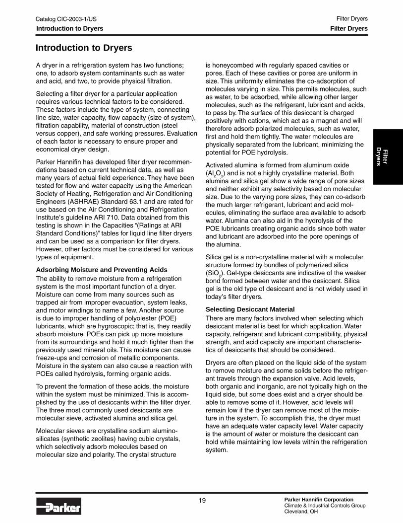
A dryer in a refrigeration system has two functions;one, to adsorb system contaminants such as waterand acid, and two, to provide physical filtration.
Selecting a filter dryer for a particular applicationrequires various technical factors to be considered.These factors include the type of system, connectingline size, water capacity, flow capacity (size of system),filtration capability, material of construction (steelversus copper), and safe working pressures. Evaluationof each factor is necessary to ensure proper andeconomical dryer design.
Parker Hannifin has developed filter dryer recommen-dations based on current technical data, as well asmany years of actual field experience. They have beentested for flow and water capacity using the AmericanSociety of Heating, Refrigeration and Air ConditioningEngineers (ASHRAE) Standard 63.1 and are rated foruse based on the Air Conditioning and RefrigerationInstitute’s guideline ARI 710. Data obtained from thistesting is shown in the Capacities “(Ratings at ARIStandard Conditions)” tables for liquid line filter dryersand can be used as a comparison for filter dryers.However, other factors must be considered for varioustypes of equipment.
Adsorbing Moisture and Preventing AcidsThe ability to remove moisture from a refrigerationsystem is the most important function of a dryer.Moisture can come from many sources such astrapped air from improper evacuation, system leaks,and motor windings to name a few. Another sourceis due to improper handling of polyolester (POE)lubricants, which are hygroscopic; that is, they readilyabsorb moisture. POEs can pick up more moisturefrom its surroundings and hold it much tighter than thepreviously used mineral oils. This moisture can causefreeze-ups and corrosion of metallic components.Moisture in the system can also cause a reaction withPOEs called hydrolysis, forming organic acids.
To prevent the formation of these acids, the moisturewithin the system must be minimized. This is accom-plished by the use of desiccants within the filter dryer.The three most commonly used desiccants aremolecular sieve, activated alumina and silica gel.
Molecular sieves are crystalline sodium alumino-silicates (synthetic zeolites) having cubic crystals,which selectively adsorb molecules based onmolecular size and polarity. The crystal structure
is honeycombed with regularly spaced cavities orpores. Each of these cavities or pores are uniform insize. This uniformity eliminates the co-adsorption ofmolecules varying in size. This permits molecules, suchas water, to be adsorbed, while allowing other largermolecules, such as the refrigerant, lubricant and acids,to pass by. The surface of this desiccant is chargedpositively with cations, which act as a magnet and willtherefore adsorb polarized molecules, such as water,first and hold them tightly. The water molecules arephysically separated from the lubricant, minimizing thepotential for POE hydrolysis.
Activated alumina is formed from aluminum oxide(Al
2O
3) and is not a highly crystalline material. Both
alumina and silica gel show a wide range of pore sizesand neither exhibit any selectivity based on molecularsize. Due to the varying pore sizes, they can co-adsorbthe much larger refrigerant, lubricant and acid mol-ecules, eliminating the surface area available to adsorbwater. Alumina can also aid in the hydrolysis of thePOE lubricants creating organic acids since both waterand lubricant are adsorbed into the pore openings ofthe alumina.
Silica gel is a non-crystalline material with a molecularstructure formed by bundles of polymerized silica(SiO
2). Gel-type desiccants are indicative of the weaker
bond formed between water and the desiccant. Silicagel is the old type of desiccant and is not widely used intoday’s filter dryers.
Selecting Desiccant MaterialThere are many factors involved when selecting whichdesiccant material is best for which application. Watercapacity, refrigerant and lubricant compatibility, physicalstrength, and acid capacity are important characteris-tics of desiccants that should be considered.
Dryers are often placed on the liquid side of the systemto remove moisture and some solids before the refriger-ant travels through the expansion valve. Acid levels,both organic and inorganic, are not typically high on theliquid side, but some does exist and a dryer should beable to remove some of it. However, acid levels willremain low if the dryer can remove most of the mois-ture in the system. To accomplish this, the dryer musthave an adequate water capacity level. Water capacityis the amount of water or moisture the desiccant canhold while maintaining low levels within the refrigerationsystem.
Filter Dryers
Parker Hannifin CorporationClimate & Industrial Controls GroupCleveland, OH
Catalog CIC-2003-1/US Filter Dryers
20
FIGURE 1
5
10
15
20
Wat
er c
apac
ity, w
eigh
t % Molecular Sieve
Activated Alumina
Silica Gel
Water in refrigerant, ppm by weight
TABLE 2
TABLE 3
TABLE 1
Introduction to Dryers Filter Dryers
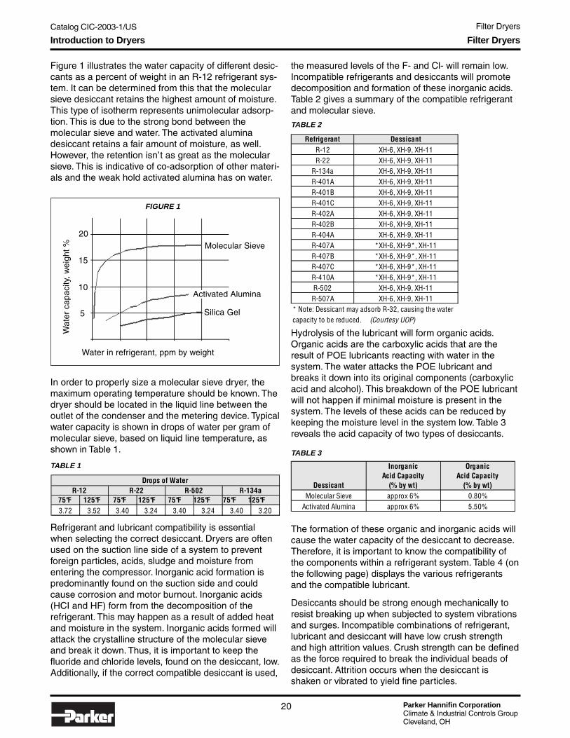
Figure 1 illustrates the water capacity of different desic-cants as a percent of weight in an R-12 refrigerant sys-tem. It can be determined from this that the molecularsieve desiccant retains the highest amount of moisture.This type of isotherm represents unimolecular adsorp-tion. This is due to the strong bond between themolecular sieve and water. The activated aluminadesiccant retains a fair amount of moisture, as well.However, the retention isn’t as great as the molecularsieve. This is indicative of co-adsorption of other materi-als and the weak hold activated alumina has on water.
Refrigerant and lubricant compatibility is essentialwhen selecting the correct desiccant. Dryers are oftenused on the suction line side of a system to preventforeign particles, acids, sludge and moisture fromentering the compressor. Inorganic acid formation ispredominantly found on the suction side and couldcause corrosion and motor burnout. Inorganic acids(HCI and HF) form from the decomposition of therefrigerant. This may happen as a result of added heatand moisture in the system. Inorganic acids formed willattack the crystalline structure of the molecular sieveand break it down. Thus, it is important to keep thefluoride and chloride levels, found on the desiccant, low.Additionally, if the correct compatible desiccant is used,
the measured levels of the F- and Cl- will remain low.Incompatible refrigerants and desiccants will promotedecomposition and formation of these inorganic acids.Table 2 gives a summary of the compatible refrigerantand molecular sieve.
The formation of these organic and inorganic acids willcause the water capacity of the desiccant to decrease.Therefore, it is important to know the compatibility ofthe components within a refrigerant system. Table 4 (onthe following page) displays the various refrigerantsand the compatible lubricant.
Desiccants should be strong enough mechanically toresist breaking up when subjected to system vibrationsand surges. Incompatible combinations of refrigerant,lubricant and desiccant will have low crush strengthand high attrition values. Crush strength can be definedas the force required to break the individual beads ofdesiccant. Attrition occurs when the desiccant isshaken or vibrated to yield fine particles.
Hydrolysis of the lubricant will form organic acids.Organic acids are the carboxylic acids that are theresult of POE lubricants reacting with water in thesystem. The water attacks the POE lubricant andbreaks it down into its original components (carboxylicacid and alcohol). This breakdown of the POE lubricantwill not happen if minimal moisture is present in thesystem. The levels of these acids can be reduced bykeeping the moisture level in the system low. Table 3reveals the acid capacity of two types of desiccants.
In order to properly size a molecular sieve dryer, themaximum operating temperature should be known. Thedryer should be located in the liquid line between theoutlet of the condenser and the metering device. Typicalwater capacity is shown in drops of water per gram ofmolecular sieve, based on liquid line temperature, asshown in Table 1.
75°F 125°F 75°F 125°F 75°F 125°F 75°F 125°F3.72 3.52 3.40 3.24 3.40 3.24 3.40 3.20
Drops of WaterR-12 R-22 R-502 R-134a
Refrigerant DessicantR-12 XH-6, XH-9, XH-11R-22 XH-6, XH-9, XH-11
R-134a XH-6, XH-9, XH-11R-401A XH-6, XH-9, XH-11R-401B XH-6, XH-9, XH-11R-401C XH-6, XH-9, XH-11R-402A XH-6, XH-9, XH-11R-402B XH-6, XH-9, XH-11R-404A XH-6, XH-9, XH-11R-407A *XH-6, XH-9*, XH-11R-407B *XH-6, XH-9*, XH-11R-407C *XH-6, XH-9*, XH-11R-410A *XH-6, XH-9*, XH-11R-502 XH-6, XH-9, XH-11R-507A XH-6, XH-9, XH-11
* Note: Dessicant may adsorb R-32, causing the watercapacity to be reduced. (Courtesy UOP)
Dessicant
InorganicAcid Capacity
(% by wt)
OrganicAcid Capacity
(% by wt)Molecular Sieve approx 6% 0.80%
Activated Alumina approx 6% 5.50%

Catalog CIC-2003-1/US Filter Dryers
Parker Hannifin CorporationClimate & Industrial Controls GroupCleveland, OH
21
Filter
Dryers
Introduction to Dryers Filter Dryers
Steel vs. CopperThe major differences in using steel versus copperdryers are the system sizes and applications. Copperdryers are normally used in smaller systems, systemswith less pressure fluctuations and lower vibrationtendencies. Some smaller systems do not require highfiltration capabilities; however, some of the smallersystems using the new refrigerants will require better
filtration. In order to meet these requirements a coredryer and dryers with additional filter media, besides ascreen, should be used. Also, copper is typically themost economical option for smaller systems. Becausecopper dryers are used for smaller applications, therefrigerant charge required will generally be smallerthan in the steel dryer. In order to determine how muchdesiccant is required to properly remove the moisturein a system, information regarding the total amount ofrefrigerant charge is required. When used in conjunc-tion with system horsepower, maximum operatingtemperature and maximum operating pressure, thetotal system moisture can be calculated. The totalsystem moisture information is used to determineadequate dryer capacity.
Information regarding operating pressure is required toadequately size the wall thickness of the dryer to attainthe ultimate burst pressure, for both copper and steel.In accordance with Underwriters Laboratories (UL) andthe Canadian Standards Association (CSA), the burstpressure is rated as five times the design workingpressure of the system, or as three times the designworking pressure of the system along with a fatiguestress test, as per UL 1995. Typically, for copper dryers,the design working pressure value can be correlatedto tube diameter and wall thickness in order to meetspecific UL specifications.
TABLE 4
Refrigerant LubricantR-12 Alkylbenzene and Mineral OilR-22 Alkylbenzene and Mineral Oil
R-134a POE (Polyolester)R-401A Alkylbenzene/POE (Polyolester)R-401B Alkylbenzene/POE (Polyolester)R-401C POE (Polyolester)R-402A Alkylbenzene/POE (Polyolester)R-402B Alkylbenzene/POE (Polyolester)R-404A POE (Polyolester)R-407A POE (Polyolester)R-407B POE (Polyolester)R-407C POE (Polyolester)R-410A POE (Polyolester)R-502 POE (Polyolester)R-507A POE (Polyolester)
Courtesy Allied Signal

Parker Hannifin CorporationClimate & Industrial Controls GroupCleveland, OH
Catalog CIC-2003-1/US Filter Dryers
22
Loose-Filled Copper Dryers
Parker's Loose-Filled Copper Dryers adsorb systemcontaminants and provide physical filtration to systemsbetween 1/4 and 2 tons. Applications include refrigera-tors, freezers, ice makers, beverage dispensers, watercoolers, cryogenics, and walk-in coolers.
Application
• Refrigeration systems between 1/4 and 2 tons.
Features and Benefits
• One-piece copper shells in 3/4" to 1" O.D., alongwith spun sweat connections in a variety of sizes,provide easy installation, simplified brazing, andcorrosion-resistance.
• Up to 30 grams of 100% molecular sieve providemaximum water adsorption.
• Dryers also available with standard chargingtubes, SAE flare fittings, stepped-tubes on theinlet/outlet, and coiled capillary or bent tubing tomatch the unique requirements of a unit.
Technical Information and Dimensions
3/4" O.D. Copper Dryer Water Capacities
3/4" O.D. Copper Dryer Data
Recommended tonnages: 1/4 to 1/2 tons dependingon application and system. Consult Parker.
One and two inlets are available as well as cap tube sizes on outlet from .081 to .125.
Loose-Filled Copper Dryers
DesignWorking Overall
Part Pressure Inlet Outlet LengthNo. PSI Inches Inches Inches
032099-00 360
.164 .159/ .258 .253
.091
.0864.63
032159-00 360 .164 .159
.091
.0864.50
032200-00 500 .195 .190
.081
.0764.37
032169-00 360 .197 .192
.092
.0874.75
Part No. 75° 125° 75° 125° 75° 125° 75° 125° 75° 125° 75° 125° 75° 125°032099-00 33.0 30.6 29.8 27.4 32.6 31.0 32.6 30.2 30.6 28.8 33.2 30.6 33.0 30.6032159-00 33.0 30.6 29.8 27.4 32.6 31.0 32.6 30.2 30.6 28.8 33.2 30.6 33.0 30.6032200-00 28.1 26.0 25.3 23.3 27.7 26.4 27.7 25.7 26.0 24.5 28.2 26.0 28.1 26.0032169-00 33.0 30.6 29.8 27.4 32.6 31.0 32.6 30.2 30.6 28.8 33.2 30.6 33.0 30.6
Part No. 75° 125° 75° 125° 75° 125° 75° 125° 75° 125° 75° 125° 75° 125°032099-00 32.8 30.6 24.2 22.2 24.2 22.2 26.2 23.6 19.8 17.4 30.4 28.6 32.8 30.8032159-00 32.8 30.6 24.2 22.2 24.2 22.2 26.2 23.6 19.8 17.4 30.4 28.6 32.8 30.8032200-00 27.9 26.0 20.6 18.9 20.6 18.9 22.3 20.1 16.8 14.8 25.8 24.3 27.9 26.2032169-00 32.8 30.6 24.2 22.2 24.2 22.2 26.2 23.6 19.8 17.4 30.4 28.6 32.8 30.8
Water Capacity in drops of water
Water Capacity in drops of waterR-407A R-407B R-407C R-410A
R-12 R-22 R-402B
R-404A R-502 R-507A
R-134a R-401A / B R-401C R-402A

Catalog CIC-2003-1/US Filter Dryers
Parker Hannifin CorporationClimate & Industrial Controls GroupCleveland, OH
23
Filter
Dryers
1" O.D. Copper Dryer Water Capacities
1" O.D. Copper Dryer Data
Recommended tonnages (part numbers 032083-00 and058066-00): 1/4 to 1/2 tons depending on application andsystem. Consult Parker.
Recommended tonnages (part number 057404-00):R-12 = 1/2; R-22 = 2; R-134a = 2; R401A = 2; R-404A = 1.3;R410A = 2; R-502 = 1.3; R-507A = 1.3
Dimensions
N/R = not recommended. Consult Parker for more information.
Loose-Filled Copper Dryers
Part No. 75° 125° 75° 125° 75° 125° 75° 125° 75° 125° 75° 125° 75° 125°032083-00 43.0 39.4 N/R N/R 40.3 37.7 N/R N/R N/R N/R N/R N/R N/R N/R058066-00 49.5 45.9 44.7 41.1 48.9 46.5 48.9 45.3 45.9 43.2 49.8 45.9 49.5 45.6057404-00 60.5 58.6 54.7 50.6 59.8 57.0 58.6 53.1 57.0 52.5 59.4 53.8 59.4 53.8
Part No. 75° 125° 75° 125° 75° 125° 75° 125° 75° 125° 75° 125° 75° 125°032083-00 N/R N/R N/R N/R N/R N/R N/R N/R N/R N/R N/R N/R N/R N/R058066-00 49.2 45.9 36.3 33.3 36.3 33.3 39.3 35.4 29.7 26.1 45.6 42.9 49.2 46.2057404-00 59.5 56.0 39.4 35.6 39.4 35.6 41.9 37.8 32.3 28.8 55.7 52.5 60.2 56.3
Water Capacity in drops of waterR-404A R-407A R-407B R-407C R-410A R-502 R-507A
Water Capacity in drops of waterR-12 R-22 R-134a R-401A / B R-401C R-402A R-402B
DesignWorking Overall
Part Pressure Inlet Outlet LengthNo. PSI Inches Inches Inches
032083-00 500 .250 .244
.098
.0934.00
058066-00 500
.380 .377/ .256 .253
.195
.1904.19
057404-00 500 .320 .315
.320
.3153.81

Parker Hannifin CorporationClimate & Industrial Controls GroupCleveland, OH
Catalog CIC-2003-1/US Filter Dryers
24
Loose-Filled Spring-LoadedCopper DryersParker's Loose-Filled Spring-Loaded Copper Dryersadsorb system contaminants and provide physicalfiltration to air conditioning and heat-pump systemsbetween 1/4 and 5 tons. Dryers are spring-loaded tocompact the sieve load, preventing attrition by move-ment of the sieve material.
Application• Air conditioning and heat-pump systems between
1/4 and 5 tons.
Features and Benefits• One-piece copper shells in 1" to 1-5/8" O.D.,
along with spun sweat connections in a variety ofsizes, provide easy installation, simplified brazing,and corrosion-resistance.
• Up to 90 grams of 100% molecular sieve providemaximum water adsorption. Specially formulatedsieve, XH-11, is compatible with R-410a applica-tions.
• Dryers also available with standard chargingtubes, SAE flare fittings, stepped-tubes on theinlet/outlet, and coiled capillary or bent tubing tomatch the unique requirements of a unit.
• Dryers are also available with fiberglass paddingfor filtration up to 20-30 microns.
Technical Information and Dimensions
1" O.D. Spring-Loaded Copper Dryer Data
Loose-Filled Spring-Loaded Copper Dryers
Design
Working OverallPart Pressure Inlet Outlet LengthNo. PSIG Inches Inches Inches
032231-00 500
.202
.192 /.381 .378
.133
.1284.25
054625-01 500 .256 .253
.256
.2534.38
056242-03 500 .383 .378
.383
.3784.38
053817-01 500 .378 .383
.378
.3835.69
PartNo. R-12 R-22 R-134A R-401A R-401B R-401C R-402A R-402B R-404A R-407A R-407B R-407C R-410A R-502 R-507A
032231-00054625-01 1.5 1.5 1.6 1.8 1.5 1.4 1 1.2 1.2 1.3 1.1 1.4 1.7 1.2 1.2056242-03 2.7 3.6 3.3 3.6 3.7 3.3 2.4 2.8 2.4 3.1 2.5 3.5 3.5 2.3 2.3053817-01 2.3 3 2.7 3 3.1 2.7 2 2.4 2 2.6 2.1 2.9 2.9 1.9 2
Recommended Tonnages: 1/2 to 1 tons depending on application and system. Consult Parker.
Maximum flow rateat 1 psig in tons

Catalog CIC-2003-1/US Filter Dryers
Parker Hannifin CorporationClimate & Industrial Controls GroupCleveland, OH
25
Filter
Dryers
1" O.D. Spring-Loaded Copper Dryer Water Capacities
One and two inlets are available as well as cap tube sizes on outlet from .125 to .50. All 1" dryers are U.L.recognized components, File #SA8570. Tonnage ratings will vary depending on the inlet and outlet requested.
Dimensions
1-3/16" O.D. Spring-Loaded Copper Dryer Data
1-3/16" O.D. Spring-Loaded Copper Dryer Water Capacities
One and two inlets are available as well as cap tube sizes on outlet from .125 to .50. All 1-3/16" dryers are U.L. recognizedcomponents, File #SA8570. Tonnage ratings will vary depending on the inlet and outlet requested.
Loose-Filled Spring-Loaded Copper Dryers
Part No. 75° 125° 75° 125° 75° 125° 75° 125° 75° 125° 75° 125° 75° 125°032231-00 33.0 30.6 29.8 27.4 32.6 31.0 32.6 30.2 32.8 30.8 33.2 30.6 33.2 30.6054625-01 51.0 49.4 46.2 42.7 50.5 48.1 49.4 44.8 49.4 44.8 49.4 44.8 49.4 44.8056242-03 51.0 49.4 46.2 42.7 50.5 48.1 49.4 44.8 49.4 44.8 49.4 44.8 49.4 44.8053817-01 94.5 91.5 85.5 79.0 93.5 89.0 91.5 83.0 91.5 83.0 91.5 83.0 91.5 83.0
Part No. 75° 125° 75° 125° 75° 125° 75° 125° 75° 125° 75° 125° 75° 125°032231-00 32.8 30.6 24.2 22.2 24.2 22.2 26.2 23.6 19.8 17.4 30.4 28.6 32.8 30.8054625-01 50.2 47.3 49.4 44.8 49.4 44.8 49.4 44.8 27.3 24.3 47.0 44.3 50.8 47.5056242-03 50.2 47.3 49.4 44.8 49.4 44.8 49.4 44.8 27.3 24.3 47.0 44.3 50.8 47.5053817-01 93.0 87.5 91.5 83.0 91.5 83.0 91.5 83.0 50.5 45.0 87.0 82.0 94.0 88.0
Water Capacity in drops of waterR-404A R-407A R-407B R-407C R-410A R-502 R-507A
Water Capacity in drops of waterR-12 R-22 R-134a R-401A / B R-401C R-402A R-402B
Design
Working OverallPart Pressure Inlet Outlet LengthNo. PSI Inches Inches Inches
056243-04 500 .508 .503
.508
.5035.13
056243-03 500 .383 .378
.383
.3785.13
053776-00 540 .384 .378
.384
.3787.00
PartNo. R-12 R-22 R-134A R-401A R-401B R-401C R-402A R-402B R-404A R-407A R-407B R-407C R-410A R-502 R-507A
056243-04 3.6 4.8 4.4 4.7 5 4.4 3.2 3.8 3.1 4.2 3.4 4.6 4.7 3.1 3.1056243-03 2.7 3.6 3.3 3.5 3.7 3.3 2.4 2.8 2.3 3.1 2.5 3.5 3.5 2.3 2.3053776-00 2.8 3.7 3.4 3.7 3.8 3.4 2.5 2.9 2.4 3.2 2.6 3.6 3.6 2.4 2.4
Maximum flow rateat 1 psig in tons
Part No. 75° 125° 75° 125° 75° 125° 75° 125° 75° 125° 75° 125° 75° 125°056243-04 94.5 91.5 85.5 79.0 93.5 89.0 91.5 83.0 89.0 82.0 92.8 84.0 92.8 84.0056243-03 94.5 91.5 85.5 79.0 93.5 89.0 91.5 83.0 89.0 82.0 92.8 84.0 92.8 84.0053776-00 170.1 164.7 153.9 142.2 168.3 160.2 164.7 149.4 160.2 147.6 167.0 151.2 167.0 151.2
Part No. 75° 125° 75° 125° 75° 125° 75° 125° 75° 125° 75° 125° 75° 125°056243-04 93.0 87.5 61.5 55.6 61.5 55.6 65.5 59.0 50.5 45.0 87.0 82.0 94.0 88.0056243-03 93.0 87.5 61.5 55.6 61.5 55.6 65.5 59.0 50.5 45.0 87.0 82.0 94.0 88.0053776-00 167.4 157.5 110.7 100.0 110.7 100.0 117.9 106.2 90.9 81.0 156.6 147.6 169.2 158.4
Water Capacity in drops of waterR-404A R-407A R-407B R-407C R-410A R-502 R-507A
Water Capacity in drops of waterR-12 R-22 R-134a R-401A / B R-401C R-402A R-402B

Parker Hannifin CorporationClimate & Industrial Controls GroupCleveland, OH
Catalog CIC-2003-1/US Filter Dryers
26
Dimensions
1-5/8" O.D. Spring-Loaded Copper Dryer Data
1-5/8" O.D. Spring-Loaded Copper Dryer Water Capacities
One and two inlets are available as well as cap tube sizes on outlet from .125 to .50. All 1-3/16" dryers are U.L.recognized components, File #SA8570. Tonnage ratings will vary depending on the inlet and outlet requested.
Loose-Filled Spring-Loaded Copper Dryers
Design
Working OverallPart Pressure Inlet Outlet LengthNo. PSI Inches Inches Inches
032040-00 500 .383 .378
.383
.3786.00
032145-00 500 .383 .378
.383
.3784.38
031805-03 500 .383 .378
.383
.3785.50
056244-01 500.383 .378
.383
.378 5.38
056156-01 500.253 .256
.253
.256 7.00
PartNo. R-12 R-22 R-134A R-401A R-401B R-401C R-402A R-402B R-404A R-407A R-407B R-407C R-410A R-502 R-507A
032040-00 4.4 5.8 5.3 5.8 6 5.3 3.9 4.6 3.8 5.1 4.1 5.6 5.7 3.8 3.8032145-00 3.5 4.7 4.3 4.6 4.8 4.3 3.2 3.7 3.1 4.1 3.3 4.5 4.6 3 3.1031805-03 3.8 5.1 4.7 5 5.3 4.6 3.4 4 3.3 4.5 3.6 4.9 5 3.3 3.3056244-01 3.7 5 4.5 4.9 5.2 4.6 3.4 3.9 3.2 4.4 3.5 4.8 4.8 3.2 3.2056156-01 1.3 1.8 1.6 1.8 1.9 1.6 1.2 1.4 1.2 1.6 1.3 1.7 1.7 1.2 1.2
Maximum flow rateat 1 psig in tons
Part No. 75° 125° 75° 125° 75° 125° 75° 125° 75° 125° 75° 125° 75° 125°032040-00 170.1 164.7 153.9 142.2 168.3 160.2 164.7 149.4 160.2 147.6 167.0 151.2 167.0 151.2032145-00 92.4 85.7 83.4 76.7 91.3 86.8 91.3 84.6 85.7 80.6 93.0 85.7 92.4 85.7031805-03 132.3 128.1 119.7 110.6 130.9 124.6 128.1 116.2 124.6 114.8 129.9 117.6 129.9 117.6056244-01 170.1 164.7 153.9 142.2 168.3 160.2 164.7 149.4 160.2 147.6 167.0 151.2 167.0 151.2056156-01 340.2 329.4 307.8 284.4 336.6 320.4 329.4 298.8 320.4 295.2 333.9 302.4 333.9 302.4
Part No. 75° 125° 75° 125° 75° 125° 75° 125° 75° 125° 75° 125° 75° 125°032040-00 167.4 157.5 110.7 100.0 110.7 100.0 117.9 106.2 90.9 81.0 156.6 147.6 169.2 158.4032145-00 91.8 85.7 67.8 62.2 67.8 62.2 73.4 66.1 55.4 48.7 85.1 80.1 91.8 86.2031805-03 130.2 122.5 86.1 77.8 86.1 77.8 91.7 82.6 70.7 63.0 121.8 114.8 131.6 123.2056244-01 167.4 157.5 110.7 100.0 110.7 100.0 117.9 106.2 90.9 81.0 156.6 147.6 169.2 158.4056156-01 334.8 315.0 221.4 200.0 221.4 200.0 235.8 212.4 181.8 162.0 313.2 295.2 338.4 316.8
Water Capacity in drops of waterR-12 R-22 R-134a R-401A / B R-401C R-402A R-402B
Water Capacity in drops of waterR-404A R-407A R-407B R-407C R-410A R-502 R-507A

Catalog CIC-2003-1/US Filter Dryers
Parker Hannifin CorporationClimate & Industrial Controls GroupCleveland, OH
27
Filter
Dryers
Service Copper Dryers
Parker’s Service Copper Dryers adsorb systemcontaminants and provide physical filtration to systems.The service copper dryers provide replacement oradditional dryers to systems as required.
Application
• Air conditioning, heat pump, and refrigerationsystems as matched with the unique unit.
Features and Benefits
• Worldwide OEM usage and acceptance to adddryers or match replacements with a variety ofunits.
• All copper construction for corrosion resistance,simplified brazing, and easy installation.
• 100% XH-9 molecular sieve is specially formu-lated for refrigerants and blends, including 134a,404A, and 507A for maximum water adsorption.
• Compatible with mineral oils and synthetics.
• UL recognized and CSA certified.
Technical Information
Copper Service Dryer Specifications
MMS-80/100
MMS-200
712
319
620
CO73S
Service Copper Dryers
Inlet OutletMRO Part Molecular Overall Tube Size Tube Size
Model No. No. Sieve Description Length OD / ID OD / IDMMS-80 058070-01 10g XH9 3/4" Non-directional 7 3/8" 1/4" / 3/16" 1/4" / 3/16"MMS-100 058198-01 10g XH9 3/4" directional 7 3/8" 1/4" / 3/16" 1/4" / 3/16"
1/4" / 3/16" 1/4" / 3/16"5/16" / 1/4" 5/16" / 1/4"3/8" / 5/16" 3/8" / 5/16"
712 032092-00 10g XH9 3/4" directional 8 1/2" 1/4" / 3/16" .089 / .092 cap. tube319 032144-00 30g XH9 1 3/16" directional 9 3/4" 5/16" OD .127 / .130619 032142-00 10g XH9 3/4" w/access valve 8 7/8" 1/4" / 3/16" .089 / .092 cap. tube620 032133-00 20g XH9 1" w/access valve 9 1/2" 5/16" / 1/4" .127 / .130 cap. tube621 032143-00 20g XH9 1" w/double inlet 9" 5/16" / 1/4" .127 / .130 cap. tube
CO73S 032145-00 28g XH9 1 5/8" directional 4 3/8" 3/8" ID 3/8" ID
10 1/2"MMS-200 032134-01 20g XH9 1" directionalstep down
MRO Part R-22 R-404AModel No. No. R-402 R-134a R-401A/B R-502, R-507A R-410AMMS-80 058070-01MMS-100 058198-01MMS-200 032134-01
712 032092-00319 032144-00619 032142-00620 032133-00621 032143-00
CO73S 032145-00 4 4 4 1/2 3 4 1/2
Recommended Tonnages
1/3 to 2 tons depending on application and system.Contact Parker for details.

Parker Hannifin CorporationClimate & Industrial Controls GroupCleveland, OH
Catalog CIC-2003-1/US Filter Dryers
28
Copper Service Dryer Water Capacities
Dimensions Service Copper Dryers
MRO OEMPart No. Part No. 75° 125° 75° 125° 75° 125° 75° 125° 75° 125° 75° 125° 75° 125°MMS-80 058070-01 33.0 30.6 29.8 27.4 32.6 31.0 32.6 30.2 30.6 28.8 33.2 30.6 33.0 30.4MMS-100 058198-01 33.0 30.6 29.8 27.4 32.6 31.0 32.6 30.2 30.6 28.8 33.2 30.6 33.0 30.4MMS-200 032134-01 66.0 61.2 59.6 54.8 65.2 62.0 65.2 60.4 61.2 57.6 66.4 61.2 66.0 60.8
712 032092-00 33.0 30.6 29.8 27.4 32.6 31.0 32.6 30.2 30.6 28.8 33.2 30.6 33.0 30.4319 032144-00 99.0 91.8 89.4 82.2 97.8 93 97.8 90.6 91.8 86.4 99.6 91.8 99.0 91.2619 032142-00 33.0 30.6 29.8 27.4 32.6 31 32.6 30.2 30.6 28.8 33.2 30.6 33.0 30.4620 032133-00 66.0 61.2 59.6 54.8 65.2 62.0 65.2 60.4 61.2 57.6 66.4 61.2 66.0 60.8621 032143-00 66.0 61.2 59.6 54.8 65.2 62 65.2 60.4 61.2 57.6 66.4 61.2 66.0 60.8
CO73S 032145-00 92.4 85.68 83.44 76.72 91.28 86.8 91.28 84.56 85.68 80.64 92.96 85.68 92.4 85.12
OEMPart No. Part No. 75° 125° 75° 125° 75° 125° 75° 125° 75° 125° 75° 125° 75° 125°MMS-80 058070-01 32.8 30.6 24.2 22.2 24.2 22.2 26.2 23.6 19.8 17.4 30.4 28.6 32.8 30.8MMS-100 058198-01 32.8 30.6 24.2 22.2 24.2 22.2 26.2 23.6 19.8 17.4 30.4 28.6 32.8 30.8MMS-200 032134-01 65.6 61.2 48.4 44.4 48.4 44.4 52.4 47.2 39.6 34.8 60.8 57.2 65.6 61.6
712 032092-00 32.8 30.6 24.2 22.2 24.2 22.2 26.2 23.6 19.8 17.4 30.4 28.6 32.8 30.8319 032144-00 98.4 91.8 72.6 66.6 72.6 66.6 78.6 70.8 59.4 52.2 91.2 85.8 98.4 92.4619 032142-00 32.8 30.6 24.2 22.2 24.2 22.2 26.2 23.6 19.8 17.4 30.4 28.6 32.8 30.8620 032133-00 65.6 61.2 48.4 44.4 48.4 44.4 52.4 47.2 39.6 34.8 60.8 57.2 65.6 61.6621 032143-00 65.6 61.2 48.4 44.4 48.4 44.4 52.4 47.2 39.6 34.8 60.8 57.2 65.6 61.6
CO73S 032145-00 91.84 85.68 67.76 62.16 67.76 62.16 73.36 66.08 55.44 48.72 85.12 80.08 91.84 86.24
Water Capacity in drops of waterR-404A R-407A R-407B R-407C R-410A R-502 R-507A
Water Capacity in drops of waterR-12 R-22 R-402BR-134a R-401A / B R-401C R-402A

Catalog CIC-2003-1/US Filter Dryers
Parker Hannifin CorporationClimate & Industrial Controls GroupCleveland, OH
29
Filter
Dryers
Technical Information
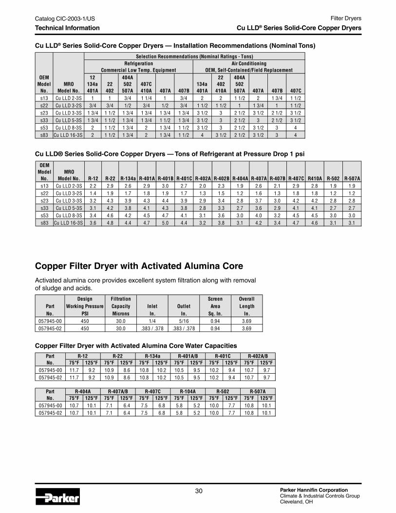
Cu LLD® Series Solid-Core Copper Dryers — Water Drop Capacity at ARI Conditions
Cu LLD® Series Solid-Core Copper Dryers
Parker's Solid-Core Copper Dryers adsorb systemcontaminants and provide physical filtration to systemsbetween 1/2 and 5 tons. Applications include air conditioning,heat pumps, and ice makers.
Application• Systems between 1/2 and 5 tons.
Base Product Part NumberCu LLD
Features and Benefits• One-piece copper shells in 1-3/16" to 2" O.D., along with
spun sweat connections in a variety of sizes, provide easyinstallation, simplified brazing, and corrosion-resistance.
• Standard 1, 2, 3, 5, and 8 cubic inch cores available in100% molecular sieve, 100% activated alumina, or blendsto provide maximum water adsorption. Specially formulatedcores in XH-11 are compatible with R-410a applications.
• Dryers also available with standard charging tubes, SAEflare fittings, stepped-tubes on the inlet/outlet, and coiledcapillary or bent tubing to match the unique requirementsof a unit.
Cu LLD® Series Solid-Core Copper Dryers
MRO OEM R-12 R-22 R-134a R-401A/B R-401C R-402A R-402BModel Model (15 ppm) (60 ppm) (50 ppm) (50 ppm) (50 ppm) (50 ppm) (50 ppm)
No. No. 75° F/125° F 75° F/125° F 75° F/125° F 75° F/125° F 75° F/125° F 75° F/125° F 75° F/125° FCu LLD 2-3S s13 31/28 28/24 31/27 30/26 29/25 30/26 30/26Cu LLD 3-2S s22 69/63 63/55 69/62 67/57 65/57 68/58 68/58Cu LLD 3-3S s23 69/63 63/55 69/62 67/57 65/57 68/58 68/58Cu LLD 5-3S s33 95/87 86/75 94/85 92/79 90/78 94/80 94/80Cu LLD 8-3S s53 166/152 150/131 165/147 161/137 157/136 163/139 163/139Cu LLD 16-3S s83 266/242 241/209 263/236 258.0 258/20 251/217 261/223
MRO OEM R-404A R-407A R-407B R-407C R-410A R-502 R-507AModel Model (50 ppm) (50 ppm) (50 ppm) (50 ppm) (50 ppm) (50 ppm) (50 ppm)
No. No. 75° F/125° F 75° F/125° F 75° F/125° F 75° F/125° F 75° F/125° F 75° F/125° F 75° F/125° FCu LLD 2-3S s13 30/27 20/17 20/17 21/18 17/14 28/25 31/27Cu LLD 3-2S s22 68/61 45/38 45/38 48/41 37/31 64/57 69/61Cu LLD 3-3S s23 68/61 45/38 45/38 48/41 37/31 64/57 69/61Cu LLD 5-3S s33 94/83 62/53 62/53 66/56 51/43 88/78 95/84Cu LLD 8-3S s53 164/145 108/92 33878 115/98 89/75 153/136 165/146Cu LLD 16-3S s83 261/223 262/232 173/147 173/147 142/119 245/217 265/233
Parker Hannifin CorporationClimate & Industrial Controls GroupCleveland, OH
Catalog CIC-2003-1/US Filter Dryers
30
Cu LLD® Series Solid-Core Copper Dryers — Tons of Refrigerant at Pressure Drop 1 psi
Technical Information
Cu LLD® Series Solid-Core Copper Dryers — Installation Recommendations (Nominal Tons)
Copper Filter Dryer with Activated Alumina CoreActivated alumina core provides excellent system filtration along with removalof sludge and acids.
Copper Filter Dryer with Activated Alumina Core Water Capacities
Cu LLD® Series Solid-Core Copper Dryers
Design Filtration Screen OverallPart Working Pressure Capacity Inlet Outlet Area LengthNo. PSI Microns In. In. Sq. In. In.
057945-00 450 30.0 1/4 5/16 0.94 3.69057945-02 450 30.0 .383 / .378 .383 / .378 0.94 3.69
PartNo. 75° F 125° F 75° F 125° F 75° F 125° F 75° F 125° F 75° F 125° F 75° F 125° F
057945-00 11.7 9.2 10.9 8.6 10.8 10.2 10.5 9.5 10.2 9.4 10.7 9.7057945-02 11.7 9.2 10.9 8.6 10.8 10.2 10.5 9.5 10.2 9.4 10.7 9.7
PartNo. 75° F 125° F 75° F 125° F 75° F 125° F 75° F 125° F 75° F 125° F 75° F 125° F
057945-00 10.7 10.1 7.1 6.4 7.5 6.8 5.8 5.2 10.0 7.7 10.8 10.1057945-02 10.7 10.1 7.1 6.4 7.5 6.8 5.8 5.2 10.0 7.7 10.8 10.1
R-401C R-402A/BR-12 R-22 R-134a R-401A/B
R-502 R-507AR-404A R-407A/B R-407C R-104A
OEM Model
No.MRO
Model No.
12134a401A
22402
404A502
507A407C410A 407A 407B
134a401A
22402
410A
404A502
507A 407A 407B 407Cs13 Cu LLD 2-3S 1 1 3/4 1 1/4 1 3/4 2 2 1 1/2 2 1 3/4 1 1/2s22 Cu LLD 3-2S 3/4 3/4 1/2 3/4 1/2 3/4 1 1/2 1 1/2 1 1 3/4 1 1 1/2s23 Cu LLD 3-3S 1 3/4 1 1/2 1 3/4 1 3/4 1 3/4 1 3/4 3 1/2 3 2 1/2 3 1/2 2 1/2 3 1/2s33 Cu LLD 5-3S 1 3/4 1 1/2 1 3/4 1 3/4 1 1/2 1 3/4 3 1/2 3 2 1/2 3 2 1/2 3 1/2s53 Cu LLD 8-3S 2 1 1/2 1 3/4 2 1 3/4 1 1/2 3 1/2 3 2 1/2 3 1/2 3 4s83 Cu LLD 16-3S 2 1 1/2 1 3/4 2 1 3/4 1 1/2 4 3 1/2 2 1/2 3 1/2 3 4
RefrigerationCommercial Low Temp. Equipment
Air ConditioningOEM, Self-Contained/Field Replacement
Selection Recommendations (Nominal Ratings - Tons)
OEM Model
No.MRO
Model No. R-12 R-22 R-134a R-401A R-401B R-401C R-402A R-402B R-404A R-407A R-407B R-407C R410A R-502 R-507As13 Cu LLD 2-3S 2.2 2.9 2.6 2.9 3.0 2.7 2.0 2.3 1.9 2.6 2.1 2.9 2.8 1.9 1.9s22 Cu LLD 3-2S 1.4 1.9 1.7 1.8 1.9 1.7 1.3 1.5 1.2 1.6 1.3 1.8 1.8 1.2 1.2s23 Cu LLD 3-3S 3.2 4.3 3.9 4.3 4.4 3.9 2.9 3.4 2.8 3.7 3.0 4.2 4.2 2.8 2.8s33 Cu LLD 5-3S 3.1 4.2 3.8 4.1 4.3 3.8 2.8 3.3 2.7 3.6 2.9 4.1 4.1 2.7 2.7s53 Cu LLD 8-3S 3.4 4.6 4.2 4.5 4.7 4.1 3.1 3.6 3.0 4.0 3.2 4.5 4.5 3.0 3.0s83 Cu LLD 16-3S 3.6 4.8 4.4 4.7 5.0 4.4 3.2 3.8 3.1 4.2 3.4 4.7 4.6 3.1 3.1

Catalog CIC-2003-1/US Filter Dryers
Parker Hannifin CorporationClimate & Industrial Controls GroupCleveland, OH
31
Filter
Dryers
CBF Bi-Flow Copper Dryers
Parker's Bi-Flow Copper Dryers adsorb systemcontaminants and provide physical filtration toheat-pump systems between 1-1/2 and 4-1/2 tons.
Application• Heat-pump systems between 1-1/2 and 4-1/2
tons.
Base Product Part NumberCBF
Features and Benefits• One-piece copper shell with 2" O.D., along with
spun sweat connections in a variety of sizes,provide easy installation, simplified brazing, andcorrosion-resistance.
• Standard 3 and 5 cubic inch cores available in100% molecular sieve to provide maximum wateradsorption. Specially formulated cores in XH-11are compatible with R-410a applications.
• Dryers also available with standard chargingtubes, SAE flare fittings, stepped-tubes on theinlet/outlet, and coiled capillary or bent tubing tomatch the unique requirements of a unit.
• Larger dryer with 8 cubic inch core in develop-ment providing higher holding capacities.
Copper Bi-Flow Dryer Data
Refrigerant Internal Holding Capacities for Copper Bi-Flow Dryer(refrigerant @ 100°F)
Copper Bi-Flow Dryer Water Drop Capacity at ARI Conditions
Technical Information CBF Bi-Flow Copper Dryers
All of these dryers have a .01 - .02 tube stop in the inlet and outlet.
Part No.Series R-12 R-22 R-134a R-401A/B R-401C R-402A R-402B R-404A R-407A R-407B R-407C R-410A R-502 R-507A
032284-050 7.16 6.47 6.55 6.37 5.60 5.90 6.02 5.55 6.11 6.20 6.12 5.64 6.54 5.56032284-080 9.05 8.18 8.28 8.05 7.08 7.46 7.61 7.02 7.72 7.83 7.73 7.13 8.27 7.03
R-12 R-22 R-134a R-401A R-402A/B R-404A R-407A R-407B R-407C R-410A R-502 R-507A Part No. (15 ppm) (60 ppm) (150 ppm) (50 ppm) (50 ppm) (50 ppm) (50 ppm) (50 ppm) (50 ppm) (50 ppm) (50 ppm) (50 ppm)Series 75° F/125° F 75° F/125° F 75° F/125° F 75° F/125° F 75° F/125° F 75° F/125° F 75° F/125° F 75° F/125° F 75° F/125° F 75° F/125° F 75° F/125° F 75° F/125° F
032284-050 143/130 129/112 141/127 138/118 140/120 141/124 93/79 93/79 101/84 81/64 132/117 142/125032284-080 229/209 207/180 226/202 221/189 224/191 225/199 149/126 149/126 161/134 129/102 210/187 227/200
PartNumber
OverallLength Core Inlet/Outlet
032284-052 7.04 3 cu in core 1/4" inlet and outlet032284-053 7.04 3 cu in core 3/8" inlet and outlet032284-082 7.98 5 cu in core 1/4" inlet and outlet032284-083 7.98 5 cu in core 3/8" inlet and outlet032284-084 7.98 5 cu in core 1/2" inlet and outlet032284-085 7.98 5 cu in core 5/8" inlet and outlet
Parker Hannifin CorporationClimate & Industrial Controls GroupCleveland, OH
Catalog CIC-2003-1/US Filter Dryers
32
Gold Label Steel Liquid Line Dryers - Water Drop Capacity at ARI Conditions
Refrigerant Holding Capacities for Gold Label Steel Liquid Line Dryers(in oz. of refrigerant @ 100° F)
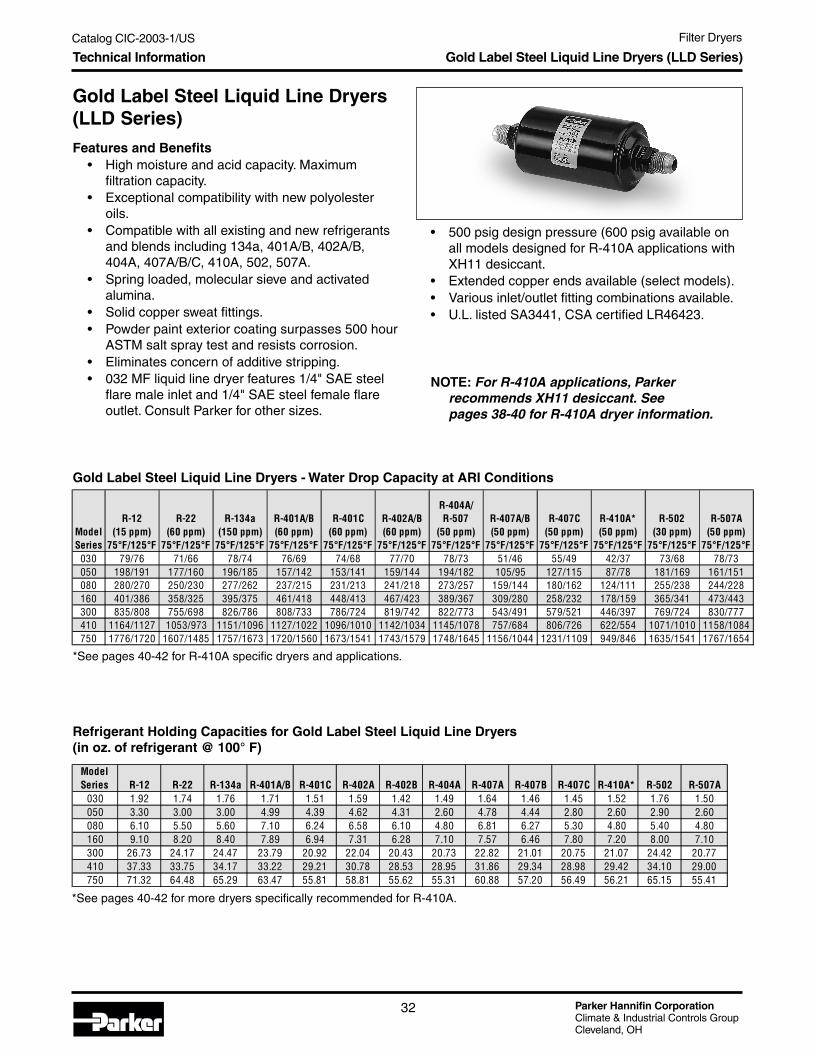
Gold Label Steel Liquid Line Dryers(LLD Series)
Features and Benefits• High moisture and acid capacity. Maximum
filtration capacity.• Exceptional compatibility with new polyolester
oils.• Compatible with all existing and new refrigerants
and blends including 134a, 401A/B, 402A/B,404A, 407A/B/C, 410A, 502, 507A.
• Spring loaded, molecular sieve and activatedalumina.
• Solid copper sweat fittings.• Powder paint exterior coating surpasses 500 hour
ASTM salt spray test and resists corrosion.• Eliminates concern of additive stripping.• 032 MF liquid line dryer features 1/4" SAE steel
flare male inlet and 1/4" SAE steel female flareoutlet. Consult Parker for other sizes.
*See pages 40-42 for R-410A specific dryers and applications.
Technical Information Gold Label Steel Liquid Line Dryers (LLD Series)
• 500 psig design pressure (600 psig available onall models designed for R-410A applications withXH11 desiccant.
• Extended copper ends available (select models).• Various inlet/outlet fitting combinations available.• U.L. listed SA3441, CSA certified LR46423.
NOTE: For R-410A applications, Parkerrecommends XH11 desiccant. Seepages 38-40 for R-410A dryer information.
*See pages 40-42 for more dryers specifically recommended for R-410A.
ModelSeries
R-12(15 ppm)
75° F/125° F
R-22(60 ppm)
75° F/125° F
R-134a(150 ppm)
75° F/125° F
R-401A/B(60 ppm)
75° F/125° F
R-401C(60 ppm)
75° F/125° F
R-402A/B(60 ppm)
75° F/125° F
R-404A/R-507
(50 ppm)75° F/125° F
R-407A/B(50 ppm)
75° F/125° F
R-407C(50 ppm)
75° F/125° F
R-410A*(50 ppm)
75° F/125° F
R-502(30 ppm)
75° F/125° F
R-507A(50 ppm)
75° F/125° F030 79/76 71/66 78/74 76/69 74/68 77/70 78/73 51/46 55/49 42/37 73/68 78/73050 198/191 177/160 196/185 157/142 153/141 159/144 194/182 105/95 127/115 87/78 181/169 161/151080 280/270 250/230 277/262 237/215 231/213 241/218 273/257 159/144 180/162 124/111 255/238 244/228160 401/386 358/325 395/375 461/418 448/413 467/423 389/367 309/280 258/232 178/159 365/341 473/443300 835/808 755/698 826/786 808/733 786/724 819/742 822/773 543/491 579/521 446/397 769/724 830/777410 1164/1127 1053/973 1151/1096 1127/1022 1096/1010 1142/1034 1145/1078 757/684 806/726 622/554 1071/1010 1158/1084750 1776/1720 1607/1485 1757/1673 1720/1560 1673/1541 1743/1579 1748/1645 1156/1044 1231/1109 949/846 1635/1541 1767/1654
ModelSeries R-12 R-22 R-134a R-401A/B R-401C R-402A R-402B R-404A R-407A R-407B R-407C R-410A* R-502 R-507A
030 1.92 1.74 1.76 1.71 1.51 1.59 1.42 1.49 1.64 1.46 1.45 1.52 1.76 1.50050 3.30 3.00 3.00 4.99 4.39 4.62 4.31 2.60 4.78 4.44 2.80 2.60 2.90 2.60080 6.10 5.50 5.60 7.10 6.24 6.58 6.10 4.80 6.81 6.27 5.30 4.80 5.40 4.80160 9.10 8.20 8.40 7.89 6.94 7.31 6.28 7.10 7.57 6.46 7.80 7.20 8.00 7.10300 26.73 24.17 24.47 23.79 20.92 22.04 20.43 20.73 22.82 21.01 20.75 21.07 24.42 20.77410 37.33 33.75 34.17 33.22 29.21 30.78 28.53 28.95 31.86 29.34 28.98 29.42 34.10 29.00750 71.32 64.48 65.29 63.47 55.81 58.81 55.62 55.31 60.88 57.20 56.49 56.21 65.15 55.41

Catalog CIC-2003-1/US Filter Dryers
Parker Hannifin CorporationClimate & Industrial Controls GroupCleveland, OH
33
Filter
Dryers
Gold Label Steel Liquid Line Dryers
Steel Liquid Line Dryer Dimensions
Dimensions Gold Label Steel Liquid Line Dryers (LLD Series)
ModelNo. I.D.
SystemCutoutLength
Diameterin
Inches
OverallLengthInches
ModelNo.
SAEFlare
SystemCutoutLength
Diameterin
Inches052S 1/4 3 7/8 2 3/8 4 3/8 052 1/4 4 7/8 2 3/8
0525S 5/16 3 3/4 2 3/8 4 3/8053S 3/8 3 11/16 2 3/8 4 3/8 053 3/8 5 1/4 2 3/8082S 1/4 4 3/4 2 3/8 5 1/4 082 1/4 5 5/8 2 3/8
0825S 5/16 4 5/8 2 3/8 5 1/4083S 3/8 4 9/16 2 3/8 5 1/4 083 3/8 6 2 3/8084S 1/2 4 1/2 2 3/8 5 3/8 084 1/2 6 3/8 2 3/8162S 1/4 5 3/8 2 3/8 5 7/8 162 1/4 6 5/16 2 3/8
1625S 5/16 5 5/16 2 3/8 5 7/8163S 3/8 5 3/16 2 3/8 5 15/16 163 3/8 6 3/4 2 3/8164S 1/2 5 1/8 2 3/8 6 1/16 164 1/2 7 2 3/8165S 5/8 5 1/8 2 3/8 6 5/16 165 5/8 7 1/4 2 3/8
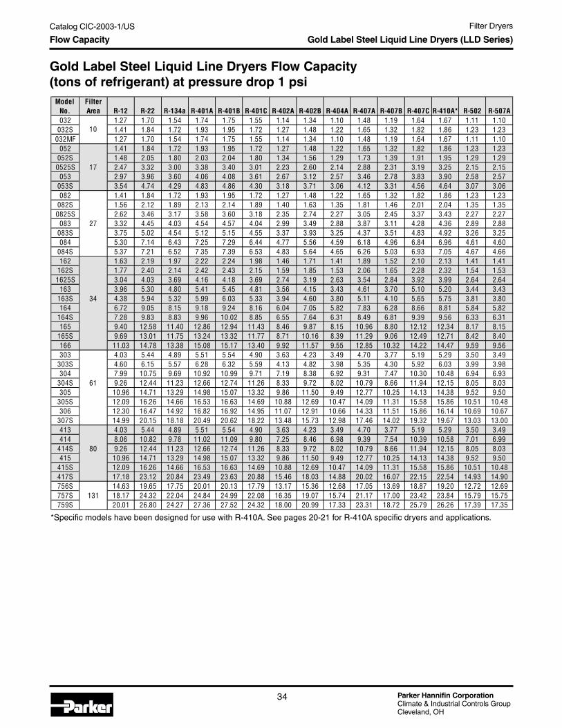
Parker Hannifin CorporationClimate & Industrial Controls GroupCleveland, OH
Catalog CIC-2003-1/US Filter Dryers
34
*Specific models have been designed for use with R-410A. See pages 20-21 for R-410A specific dryers and applications.
Flow Capacity Gold Label Steel Liquid Line Dryers (LLD Series)
ModelNo.
FilterArea R-12 R-22 R-134a R-401A R-401B R-401C R-402A R-402B R-404A R-407A R-407B R-407C R-410A* R-502 R-507A
032 1.27 1.70 1.54 1.74 1.75 1.55 1.14 1.34 1.10 1.48 1.19 1.64 1.67 1.11 1.10032S 1.41 1.84 1.72 1.93 1.95 1.72 1.27 1.48 1.22 1.65 1.32 1.82 1.86 1.23 1.23
032MF 1.27 1.70 1.54 1.74 1.75 1.55 1.14 1.34 1.10 1.48 1.19 1.64 1.67 1.11 1.10052 1.41 1.84 1.72 1.93 1.95 1.72 1.27 1.48 1.22 1.65 1.32 1.82 1.86 1.23 1.23
052S 1.48 2.05 1.80 2.03 2.04 1.80 1.34 1.56 1.29 1.73 1.39 1.91 1.95 1.29 1.290525S 17 2.47 3.32 3.00 3.38 3.40 3.01 2.23 2.60 2.14 2.88 2.31 3.19 3.25 2.15 2.15
053 2.97 3.96 3.60 4.06 4.08 3.61 2.67 3.12 2.57 3.46 2.78 3.83 3.90 2.58 2.57053S 3.54 4.74 4.29 4.83 4.86 4.30 3.18 3.71 3.06 4.12 3.31 4.56 4.64 3.07 3.06082 1.41 1.84 1.72 1.93 1.95 1.72 1.27 1.48 1.22 1.65 1.32 1.82 1.86 1.23 1.23
082S 1.56 2.12 1.89 2.13 2.14 1.89 1.40 1.63 1.35 1.81 1.46 2.01 2.04 1.35 1.350825S 2.62 3.46 3.17 3.58 3.60 3.18 2.35 2.74 2.27 3.05 2.45 3.37 3.43 2.27 2.27
083 27 3.32 4.45 4.03 4.54 4.57 4.04 2.99 3.49 2.88 3.87 3.11 4.28 4.36 2.89 2.88083S 3.75 5.02 4.54 5.12 5.15 4.55 3.37 3.93 3.25 4.37 3.51 4.83 4.92 3.26 3.25084 5.30 7.14 6.43 7.25 7.29 6.44 4.77 5.56 4.59 6.18 4.96 6.84 6.96 4.61 4.60
084S 5.37 7.21 6.52 7.35 7.39 6.53 4.83 5.64 4.65 6.26 5.03 6.93 7.05 4.67 4.66162 1.63 2.19 1.97 2.22 2.24 1.98 1.46 1.71 1.41 1.89 1.52 2.10 2.13 1.41 1.41
162S 1.77 2.40 2.14 2.42 2.43 2.15 1.59 1.85 1.53 2.06 1.65 2.28 2.32 1.54 1.531625S 3.04 4.03 3.69 4.16 4.18 3.69 2.74 3.19 2.63 3.54 2.84 3.92 3.99 2.64 2.64
163 3.96 5.30 4.80 5.41 5.45 4.81 3.56 4.15 3.43 4.61 3.70 5.10 5.20 3.44 3.43163S 34 4.38 5.94 5.32 5.99 6.03 5.33 3.94 4.60 3.80 5.11 4.10 5.65 5.75 3.81 3.80164 6.72 9.05 8.15 9.18 9.24 8.16 6.04 7.05 5.82 7.83 6.28 8.66 8.81 5.84 5.82
164S 7.28 9.83 8.83 9.96 10.02 8.85 6.55 7.64 6.31 8.49 6.81 9.39 9.56 6.33 6.31165 9.40 12.58 11.40 12.86 12.94 11.43 8.46 9.87 8.15 10.96 8.80 12.12 12.34 8.17 8.15
165S 9.69 13.01 11.75 13.24 13.32 11.77 8.71 10.16 8.39 11.29 9.06 12.49 12.71 8.42 8.40166 11.03 14.78 13.38 15.08 15.17 13.40 9.92 11.57 9.55 12.85 10.32 14.22 14.47 9.59 9.56303 4.03 5.44 4.89 5.51 5.54 4.90 3.63 4.23 3.49 4.70 3.77 5.19 5.29 3.50 3.49
303S 4.60 6.15 5.57 6.28 6.32 5.59 4.13 4.82 3.98 5.35 4.30 5.92 6.03 3.99 3.98304 7.99 10.75 9.69 10.92 10.99 9.71 7.19 8.38 6.92 9.31 7.47 10.30 10.48 6.94 6.93
304S 61 9.26 12.44 11.23 12.66 12.74 11.26 8.33 9.72 8.02 10.79 8.66 11.94 12.15 8.05 8.03305 10.96 14.71 13.29 14.98 15.07 13.32 9.86 11.50 9.49 12.77 10.25 14.13 14.38 9.52 9.50
305S 12.09 16.26 14.66 16.53 16.63 14.69 10.88 12.69 10.47 14.09 11.31 15.58 15.86 10.51 10.48306 12.30 16.47 14.92 16.82 16.92 14.95 11.07 12.91 10.66 14.33 11.51 15.86 16.14 10.69 10.67
307S 14.99 20.15 18.18 20.49 20.62 18.22 13.48 15.73 12.98 17.46 14.02 19.32 19.67 13.03 13.00413 4.03 5.44 4.89 5.51 5.54 4.90 3.63 4.23 3.49 4.70 3.77 5.19 5.29 3.50 3.49414 8.06 10.82 9.78 11.02 11.09 9.80 7.25 8.46 6.98 9.39 7.54 10.39 10.58 7.01 6.99
414S 80 9.26 12.44 11.23 12.66 12.74 11.26 8.33 9.72 8.02 10.79 8.66 11.94 12.15 8.05 8.03415 10.96 14.71 13.29 14.98 15.07 13.32 9.86 11.50 9.49 12.77 10.25 14.13 14.38 9.52 9.50
415S 12.09 16.26 14.66 16.53 16.63 14.69 10.88 12.69 10.47 14.09 11.31 15.58 15.86 10.51 10.48417S 17.18 23.12 20.84 23.49 23.63 20.88 15.46 18.03 14.88 20.02 16.07 22.15 22.54 14.93 14.90756S 14.63 19.65 17.75 20.01 20.13 17.79 13.17 15.36 12.68 17.05 13.69 18.87 19.20 12.72 12.69757S 131 18.17 24.32 22.04 24.84 24.99 22.08 16.35 19.07 15.74 21.17 17.00 23.42 23.84 15.79 15.75759S 20.01 26.80 24.27 27.36 27.52 24.32 18.00 20.99 17.33 23.31 18.72 25.79 26.26 17.39 17.35
10
Gold Label Steel Liquid Line Dryers Flow Capacity(tons of refrigerant) at pressure drop 1 psi
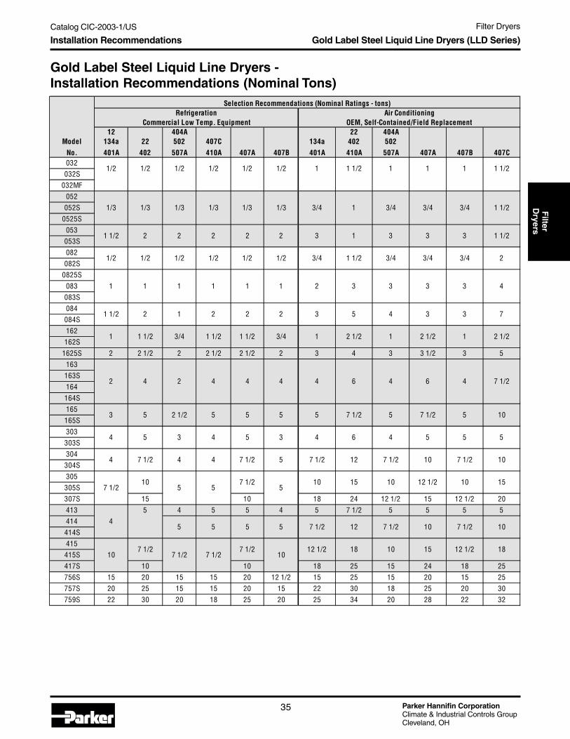
Catalog CIC-2003-1/US Filter Dryers
Parker Hannifin CorporationClimate & Industrial Controls GroupCleveland, OH
35
Filter
Dryers
Gold Label Steel Liquid Line Dryers -Installation Recommendations (Nominal Tons)
Installation Recommendations Gold Label Steel Liquid Line Dryers (LLD Series)
Selection Recommendations (Nominal Ratings - tons)Refrigeration Air Conditioning
Commercial Low Temp. Equipment OEM, Self-Contained/Field Replacement12 404A 22 404A
Model 134a 22 502 407C 134a 402 502No. 401A 402 507A 410A 407A 407B 401A 410A 507A 407A 407B 407C032032S
032MF052052S
0525S053053S082082S
0825S083083S084084S162162S
1625S 2 2 1/2 2 2 1/2 2 1/2 2 3 4 3 3 1/2 3 5163163S164164S165165S303303S304304S305305S307S 15 10 18 24 12 1/2 15 12 1/2 20413 5 4 5 5 4 5 7 1/2 5 5 5 5414414S415415S417S 10 10 18 25 15 24 18 25756S 15 20 15 15 20 12 1/2 15 25 15 20 15 25757S 20 25 15 15 20 15 22 30 18 25 20 30759S 22 30 20 18 25 20 25 34 20 28 22 32
3 7
2 4 2 4 4 4 4 6
3 5 4 31 1/2 1 2 2
3 3 3 41 1 2 31 1 1 1
3/4 3/4 3/4 1 1/2
1/2 1/2 1/2 1/2
1/3 1/3 1/3 1/3
1 1 1/21/2 1/2
1/3 1/3 3/4 1
1 1 1/21 1
1 1/2 2 2 2 2 2 3 1 3 3 3 1 1/2
3/4 1 1/21/2 1/2 1/21/2 1/2 3/4
2
1/2
2
23/4 3/4
1 1 1/2 3/4 1 1/2 1 1/2 3/4 1 2 1/2 1 2 1/2 1 2 1/2
4 6 4 7 1/2
5 52 1/2 5 5 5 7 1/2 5 7 1/2 5 10
4 5 3 4 5 3 4 6 4 5 5 5
4 7 1/2 4 4 7 1/2 5 7 1/2 12 7 1/2 10 7 1/2 10
7 1/2 10 155
10 12 1/2 10 15
7 1/2 12 105 5 5 5 7 1/2 10
1812 1/215
7 1/2
101812 1/27 1/27 1/210 7 1/2 7 1/2 10
4
7 1/2 5 510
3

Parker Hannifin CorporationClimate & Industrial Controls GroupCleveland, OH
Catalog CIC-2003-1/US Filter Dryers
36
Technical Information Sahara Series™ Liquid Line Dryers
Sahara Series™ Liquid Line Dryers
Available only from your local Parker wholesaler, theSahara Series is the right dryer at the right price. Itsideal moisture removal and contaminant filtrationproperties make it the perfect service replacementfor +40°F to 55°F suction line temperature R-22 airconditioning systems.*
*(Also suitable for some refrigeration applications to+15°F. Consult Parker for details).
Key Features & Benefits
• Excellent moisture and filtration capacity.• Compatible with POE's, PAG's, PVE's,
alkylbenzenes, and mineral oils.• Compatible with all existing and new refrigerants
and blends including R22, R134a, R401A/B,R402A/B, R404A, R502, R507A.(Also compatible with R410A. For maximumperformance with R410A, see Parker's specificline of R410A dryers in Catalog RAC-1).
• High moisture capacity desiccant.
need picture w New label
Water Capacity in Drops (Ratings at ARI Standard Conditions)
Refrigerant Holding Capacities (in oz. of refrigerant @ 100° F)
• Solid copper sweat fittings.• SAE Flare fittings available.• Powder paint exterior coating surpasses 500 hour
ASTM salt spray test and resists corrosion.• Eliminates concern of additive stripping.• 680 psig design pressure. U.L. File No. SA3441.
CSA listed LR46423.• Extended copper ends available (select
models).• Various inlet/outlet fitting combinations available.
Model
R12(15 ppm)75° /125°
R22(60 ppm)75° /125°
R134a(150 ppm)75° /125°
R401A(60 ppm)75° /125°
R401B(60 ppm)75° /125°
R402A(60 ppm)75° /125°
R402B(60 ppm)75° /125°
404A(50 ppm)75° /125°
R-502(30 ppm)75° /125°
507A(50 ppm)75° /125°
050 90/87 82/75 89/85 87/79 87/79 89/80 89/80 89/84 83/78 90/84080 117/113 106/97 115/110 113/102 113/102 115/104 115/104 115/108 107/101 116/109160 207/201 188/173 205/195 201/182 201/182 204/184 204/184 204/192 191/180 206/193
Model
InternalVolume
(In3) R12 R22 R134a R401A R401B R402A R402B R404A R407A R407B R410A R502 R507A050 5.56 8.59 7.77 7.87 7.65 8.13 7.09 7.23 6.66 7.33 7.44 3.20 7.85 3.15080 9.38 11.07 10.01 10.13 9.85 10.46 9.13 9.31 8.58 9.45 9.58 5.39 10.11 5.31160 13.09 12.64 11.43 11.57 11.25 11.95 10.42 10.63 9.80 10.79 10.93 7.52 11.54 7.42
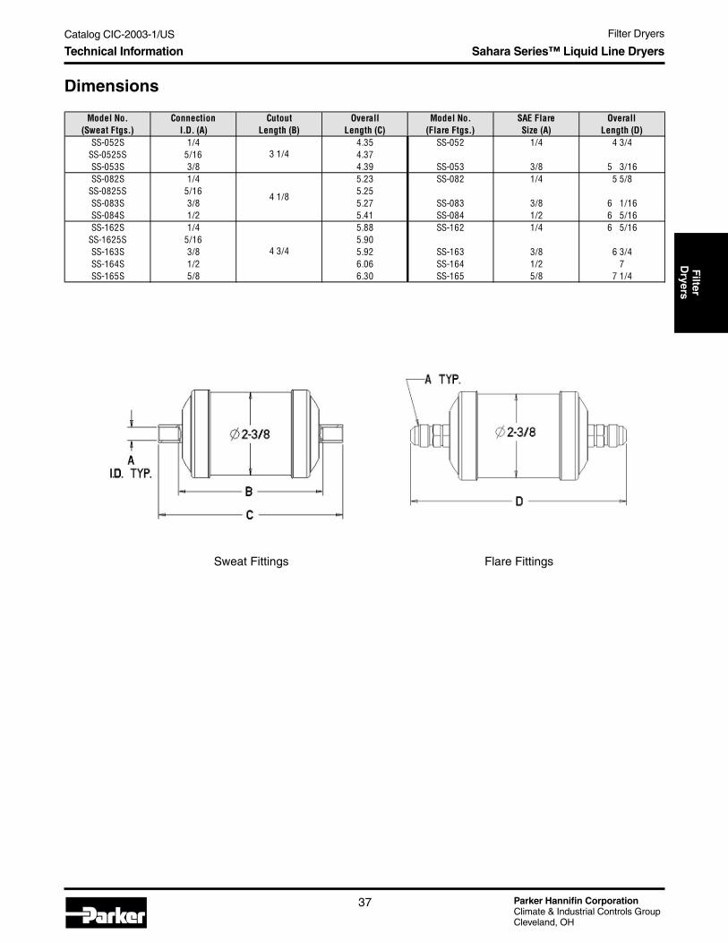
Catalog CIC-2003-1/US Filter Dryers
Parker Hannifin CorporationClimate & Industrial Controls GroupCleveland, OH
37
Filter
Dryers
Dimensions
Sweat Fittings Flare Fittings
Model No.(Sweat Ftgs.)
ConnectionI.D. (A)
CutoutLength (B)
OverallLength (C)
Model No.(Flare Ftgs.)
SAE FlareSize (A)
OverallLength (D)
SS-052S 1/4 4.35 SS-052 1/4 4 3/4SS-0525S 5/16 4.37SS-053S 3/8 4.39 SS-053 3/8 5 3/16SS-082S 1/4 5.23 SS-082 1/4 5 5/8
SS-0825S 5/16 5.25SS-083S 3/8 5.27 SS-083 3/8 6 1/16SS-084S 1/2 5.41 SS-084 1/2 6 5/16SS-162S 1/4 5.88 SS-162 1/4 6 5/16
SS-1625S 5/16 5.90SS-163S 3/8 5.92 SS-163 3/8 6 3/4SS-164S 1/2 6.06 SS-164 1/2 7SS-165S 5/8 6.30 SS-165 5/8 7 1/4
3 1/4
4 1/8
4 3/4
Technical Information Sahara Series™ Liquid Line Dryers

Parker Hannifin CorporationClimate & Industrial Controls GroupCleveland, OH
Catalog CIC-2003-1/US Filter Dryers
38
Guidelines for Parker Dryersand R-410A
Liquid line dryers are used in refrigeration systems toinsure removal of contaminants and protect systems.The new refrigerant and lubricant combinations thathave come in the wake of the regulation of CFCs andHCFCs have brought many changes to liquid line filterdryers. In particular, the introduction of Refrigerant410A and Polyol Ester (POE lubricants) for the phaseout of R-22 and mineral oil has created many designchallenges as far as water and solid contaminantremoval, refrigerant and lubricant compatibility andincreased working pressures of the systems.
The basic job of a liquid line filter dryer is to removewater and solid contaminants from a refrigerationsystem. Water can get into systems from varioussources. Some of these are leaks, improper cleaningand evacuation, polyolester (POE) lubricants and wind-ings in electric motors. This water has to be removed toprevent freeze-ups, corrosion, and possible hydrolysisof the ester lubricant. Solid contaminants, like copperoxide, carbon, braze particles, etc., can clog meteringdevices or cause problems in the compressor. They areremoved by filter media such as fiberglass pads,screens, and cores.
The new refrigerants and lubricants are excellent sol-vents. As a result, contaminants that R-22 and mineraloil left in place are now removed by HFC refrigerantssuch as R-410A/R-407C and POEs. Some of thesecommon contaminants are residual detergents fromcleaning, drawing compounds, rust preventatives, plas-ticizers and lubricant additives. These contaminantscan deposit in capillary tubes, restrictor orifices or TXVseats.
Polyolester lubricants are made by reacting organicacids with alcohols to form the ester chains that makeup the lubricant and water. This reaction is reversible,so under the right conditions, the lubricant can reactwith excess water to reverse the ester reaction anddecompose into the original organic acid and alcohol.The organic acid can then deposit in the expansiondevice, restricting the flow. This was not an issue withthe earlier HFC/CFC/mineral oil systems chemistry. Inaddition, polyolesters are hygroscopic so they canabsorb a large amount of water. Studies have shownthat activated alumina in the liquid line can play a rolein the hydrolysis of the polyolester.
Refrigerant blends that have R-32 (a component ofR-410A and R-407C) pose another issue for dryermanufacturers. R-32 is very close to water in terms ofmolecular size. This means that some desiccants canadsorb R-32 which lowers the water capacity of thedesiccant. The more immediate effect is that the com-position of the blend can change if there is enoughR-32 adsorbed.
The Parker SolutionAll of these factors have required changes in theinternal components of liquid line dryers. From theoutside, they remain the same but internally changeshave been made to accommodate the new refrigerantsand lubricants.
Filtration capacity in Parker liquid line dryers has beendesigned to insure that the dryer is able to handle thehigher levels of contaminants. The filtration capacity ofa Parker liquid line dryer and a comparably sized coreliquid line dryer is shown in Figure 1. When tested perASHRAE 63.1, allowing a maximum pressure dropof four psi, the core dryer reaches that level with the
Guidelines for Parker Dryers and R-410A R-410A Guidelines and Dryers
Standard Products for R-410A
• 100% molecular seiv e XH11 dessicant.• Ensures no degradation of the R032 within the
make-up of R-410A.• Parker has worked with the industry in establish-
ing a pink colored label on all products for usewith R-410A. Competitive products without pinklables should not be used and may cause systemdamage.
• See main liquid line and biflow dryer sections inthis catalog for dimensional data.
• Other sizes of R-410A specific dryers are avail-able. Consult Parker.
ModelARI Flow
Capacity @ 1 PSIRecommended
A/C Nominal Tons
Water Drop Capacity
in R-410A (50 ppm)75° F/125° F
053S-410A 4.64 4 86/77
083S-410A 4.92 5 131/117
163S-410A 5.75 5 254/226
303S-410A 6.03 6 446/397
BF163S-XF 3.5 5 197/176
Bi-Flow Dryers
Liquid Line Dryers

Catalog CIC-2003-1/US Filter Dryers
Parker Hannifin CorporationClimate & Industrial Controls GroupCleveland, OH
39
Filter
Dryers
FIGURE 1 - R410A Steel Liquid Line Dryer Filtration.(Note: 4 PSID is the baseline Parker uses whendetermining filtration capacity.)
FIGURE 2 - R410A Heat Pump Dryer Filtration. (Note: 4PSID is the baseline Parker uses when determiningfiltration capacity.)
Guidelines for Parker Dryers and R-410A R-410A Guidelines and Dryers
FIGURE 3 - Water capacity of different desiccants in R-22at 140°F. (Note: MOLSIV 4A-HX-6 is a trade name ofUOP.)
addition of seven grams of contaminant, while theParker dryer holds 23 grams before reaching the samepressure drop. At the same time, filtration capability,the ability to remove small particles, has not beencompromised. In the same test, Parker dryers havefiltration efficiencies up to 95%, which is a requirementfor R-410A dryers.
The same filtration performance has been designedinto bi-directional dryers for heat pumps. Figure 2shows the results of testing of a standard bi-directionaldryer and the Parker R-410A bi-directional dryer. Thestandard dryer holds 4 grams of contaminant while theR-410A specific dryer holds 36 grams of contaminantbefore reaching 4 psi pressure drop.
The desiccant (drying agent) used in the dryer had tobe developed to be able to adsorb water andexclude R-32. This new desiccant is UOP's XH11. Thisis the desiccant that is used exclusively in Parker's R-410A liquid line dryers. The pore openings are specifi-cally designed to adsorb moisture while excluding theR-32, lubricant and additives. This insures maximumwater capacity in the dryer and allows the water to bephysically separated from the POE lubricant to preventhydrolysis. Activated alumina on the other hand has
pore openings that will adsorb not only the water butthe R-32, POE lubricant and it's additives, which lowersit's drying capabilities and removes essential additive'sfrom the lubricant. It also gives the water and the lubri-cant a surface for the hydrolysis reaction since they canco-exist in the alumina's openings. The water is notphysically separated from the lubricant.
Figure 3 displays the water capacity of differentdesiccants in R-22. It can be seen from this graph thatmolecular sieve 4A-XH-6 has approximately 3-4 timeshigher water capacity than activated alumina and silicagel.
Figure 4 shows the water capacity for different molecu-lar sieve desiccants in R-410A. The steepness of theXH11 curve at low levels of water shows its high watercapacity at low water levels. This means that it takesless XH11 than other sieve desiccants to dry refriger-ants to low levels of water.
FIGURE 4 - Water capacity of different desiccants inR-410A at 125°F. (Note: XH-11 and HX-6 are trade namesof UOP.)

Parker Hannifin CorporationClimate & Industrial Controls GroupCleveland, OH
Catalog CIC-2003-1/US Filter Dryers
40
FIGURE 5 - Sealed tube test results.
Figure 5 displays the reaction of molecular sieveand activated alumina with a POE lubricant and HFCrefrigerant. After exposure of the desiccants to the POEand HFC refrigerant in a sealed glass tube for 14 daysand 180°F, the activated alumina showed organic acidlevels almost 40 times higher than that of molecularsieve. This is an indication of the breakdown of thelubricant. The fluoride levels were low indicating com-patibility with the refrigerant.
Parker liquid line dryers have been designed specificallyto meet the demands of the new HFC refrigerants.R-410A in particular, due to its higher pressures, requiredstronger construction to meet these working pressures.Parker liquid line dryers are UL listed for use withR-410A. This, in addition to increased filtration capaci-ties, water capacity and compatibility insure that Parkerliquid line dryers will provide R-410A systems maxi-mum protection which leads to long reliable operation.
Guidelines for Parker Dryers and R-410A R-410A Guidelines and Dryers

Catalog CIC-2003-1/US Filter Dryers
Parker Hannifin CorporationClimate & Industrial Controls GroupCleveland, OH
41
Filter
Dryers
Bi-flow Dryer Water Drop Capacity at ARI Conditions
Bi-flow Dryers — Dimensions
*NOTE: Model Series BF160-XF is recommended for R-410A applications.
Technical Information Steel Bi-Flow Filter Dryers (BF Series)
Steel Bi-Flow Filter Dryers —BF Series
The "BF" Series bi-flow dryer is designed specificallyfor heat pump or reverse cyle application. Externalcheck valves are not required since they are incorpo-rated within the filter dryer shell. The core design filtersout contaminant particles down to 25 microns.
Features and Benefits
• 100% copper sweat or nickel plated flare fittings.• Dessicant core provides reliable and effective
removal of solid contaminants, acid and moisture.• Model BF-163S-XF features XH11 desiccant
design for R-410A applications. Provides threetimes the filtration as the standard bi-flow.
• Core is cushioned in fiber gaskets to protect coreand to insure trouble-free performance.
• Powder paint exterior coating surpasses 500 hourASTM salt spray test and resists corrosion.
• U.L. listed file SA3441, CSA certified LR46423
System System SystemCutout Cutout Cutout
Model Number Fitting Size Length Length Length
Flare Sweat (Inches) "A" "B" "C" "D"
BF082S 1/4 4.10 5.27 2.50
BF083 BF083S 3/8 6.09 4.10 5.27 2.50
BF084 BF084S 1/2 6.35 4.10 5.41 2.50
BF162S 1/4 4.10 5.92 2.50
BF163 BF163S 3/8 6.75 4.75 5.92 2.50
BF163S-XF* 3/8 6.09 6.76 7.56 3.00
BF164 BF164S 1/2 7.00 4.75 6.06 2.50
BF165S 5/8 4.75 6.30 2.50
Refrigerant Holding Capacities for Bi-Flow Dryers (in oz. of refrigerant @ 100° F)Model Series R-12 R-22 R-134a R-401A R-401B R-401C R-402A R-402B R-404A R-407A R-407B R-407C R-410A R-502 R-507ABF080 8.17 7.39 7.48 7.27 7.27 6.39 6.74 6.87 6.34 6.97 7.07 6.98 6.44 7.46 6.34BF160 9.54 8.63 8.74 8.49 8.49 7.47 7.87 8.03 7.40 8.14 8.26 8.16 7.52 8.72 7.41
BF160-XF* 15.47 13.99 14.16 13.77 13.77 12.11 12.76 13.02 12.00 13.20 13.39 13.22 12.19 14.15 12.01
ModelSeries
R-12(15 ppm)
75° F/125° F
R-22(60 ppm)
75° F/125° F
R-134a(150 ppm)
75° F/125° F
R-401A/B(50 ppm)
75° F/125° F
R-401C(50 ppm)
75° F/125° F
R-402A(50 ppm)
75° F/125° F
R-402B(50 ppm)
75° F/125° FBF080 105/102 95/88 104/99 102/92 99/91 103/93 103/93BF160 148/144 134/124 147/140 144/130 140/129 146/132 146/132
BF160-XF* 186/180 168/155 184/175 180/163 175/161 182/165 182/165
ModelSeries
R-404A(50 ppm)
75° F/125° F
R-407A(50 ppm)
75° F/125° F
R-407B(50 ppm)
75° F/125° F
R-407C(50 ppm)
75° F/125° F
R-410A(50 ppm)
75° F/125° F
R-502(50 ppm)
75° F/125° F
R-507A(50 ppm)
75° F/125° FBF080 103/97 68/62 68/62 73/65 56/50 97/91 104/98BF160 146/137 97/87 97/87 103/93 79/71 137/129 148/138
BF160-XF* 183/172 142/128 142/128 197/176 197/176* 171/161 185/173
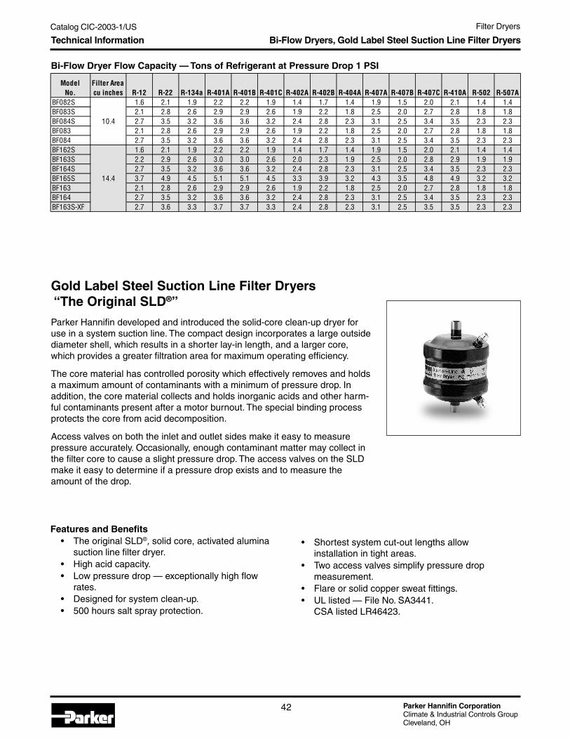
Parker Hannifin CorporationClimate & Industrial Controls GroupCleveland, OH
Catalog CIC-2003-1/US Filter Dryers
42
Bi-Flow Dryer Flow Capacity — Tons of Refrigerant at Pressure Drop 1 PSI
Technical Information Bi-Flow Dryers, Gold Label Steel Suction Line Filter Dryers
ModelNo.
Filter Areacu inches R-12 R-22 R-134a R-401A R-401B R-401C R-402A R-402B R-404A R-407A R-407B R-407C R-410A R-502 R-507A
BF082S 1.6 2.1 1.9 2.2 2.2 1.9 1.4 1.7 1.4 1.9 1.5 2.0 2.1 1.4 1.4BF083S 2.1 2.8 2.6 2.9 2.9 2.6 1.9 2.2 1.8 2.5 2.0 2.7 2.8 1.8 1.8BF084S 10.4 2.7 3.5 3.2 3.6 3.6 3.2 2.4 2.8 2.3 3.1 2.5 3.4 3.5 2.3 2.3BF083 2.1 2.8 2.6 2.9 2.9 2.6 1.9 2.2 1.8 2.5 2.0 2.7 2.8 1.8 1.8BF084 2.7 3.5 3.2 3.6 3.6 3.2 2.4 2.8 2.3 3.1 2.5 3.4 3.5 2.3 2.3BF162S 1.6 2.1 1.9 2.2 2.2 1.9 1.4 1.7 1.4 1.9 1.5 2.0 2.1 1.4 1.4BF163S 2.2 2.9 2.6 3.0 3.0 2.6 2.0 2.3 1.9 2.5 2.0 2.8 2.9 1.9 1.9BF164S 2.7 3.5 3.2 3.6 3.6 3.2 2.4 2.8 2.3 3.1 2.5 3.4 3.5 2.3 2.3BF165S 14.4 3.7 4.9 4.5 5.1 5.1 4.5 3.3 3.9 3.2 4.3 3.5 4.8 4.9 3.2 3.2BF163 2.1 2.8 2.6 2.9 2.9 2.6 1.9 2.2 1.8 2.5 2.0 2.7 2.8 1.8 1.8BF164 2.7 3.5 3.2 3.6 3.6 3.2 2.4 2.8 2.3 3.1 2.5 3.4 3.5 2.3 2.3BF163S-XF 2.7 3.6 3.3 3.7 3.7 3.3 2.4 2.8 2.3 3.1 2.5 3.5 3.5 2.3 2.3
Gold Label Steel Suction Line Filter Dryers “ The Original SLD® ”
Parker Hannifin developed and introduced the solid-core clean-up dryer foruse in a system suction line. The compact design incorporates a large outsidediameter shell, which results in a shorter lay-in length, and a larger core,which provides a greater filtration area for maximum operating efficiency.
The core material has controlled porosity which effectively removes and holdsa maximum amount of contaminants with a minimum of pressure drop. Inaddition, the core material collects and holds inorganic acids and other harm-ful contaminants present after a motor burnout. The special binding processprotects the core from acid decomposition.
Access valves on both the inlet and outlet sides make it easy to measurepressure accurately. Occasionally, enough contaminant matter may collect inthe filter core to cause a slight pressure drop. The access valves on the SLDmake it easy to determine if a pressure drop exists and to measure theamount of the drop.
Features and Benefits• The original SLD®, solid core, activated alumina
suction line filter dryer.• High acid capacity.• Low pressure drop — exceptionally high flow
rates.• Designed for system clean-up.• 500 hours salt spray protection.
• Shortest system cut-out lengths allowinstallation in tight areas.
• Two access valves simplify pressure dropmeasurement.
• Flare or solid copper sweat fittings.• UL listed — File No. SA3441.
CSA listed LR46423.

Catalog CIC-2003-1/US Filter Dryers
Parker Hannifin CorporationClimate & Industrial Controls GroupCleveland, OH
43
Filter
Dryers
Technical Information Gold Label Steel Suction Line Filter Dryers
Steel Suction Line Dryer Dimensions
ModelNo.
AOverall Length
Inches
BSystem Cutout
Length - InchesShell Diameter
InchesSLD 8-3V-HH 5.13 - 3SLD 8-3SV-HH 4.31 3.13 3SLD 8-4V-HH 5.38 - 3SLD 8-4SV-HH 4.44 3.13 3SLD 8-5SV-HH 4.66 3.16 3SLD 8-6SV-HH 4.72 3.16 3SLD 13-5V-HH 5.82 - 4SLD 13-5SV-HH 4.91 3.45 4SLD 13-6SV-HH 4.97 3.45 4SLD 13-7SV-HH 4.97 3.47 4SLD 13-9SV-HH 5.72 3.47 4SLD 27-7SV-HH 6.97 5.47 4SLD 27-9SV-HH 7.72 5.36 4SLD 54-11SV-HH 12 9.17 4SLD 54-13SV-HH 12 9.17 4
Steel Suction Line Dryer Water Drop Capacities at 65°F
Model No. Fitting Desiccant (Cu. In.) Filter Area (Sq. In.) 22 & 404A 134a & 407 401A & 410A 502 & 507A
SLD 8-3V-HH 3/8" SAE Flare 8 17.25 168 168 200 185
SLD 8-3SV-HH 3/8" Sweat 8 17.25 168 168 200 185
SLD 8-4V-HH 1/2" SAE Flare 8 17.25 168 168 200 185
SLD 8-4SV-HH 1/2" Sweat 8 17.25 168 168 200 185
SLD 8-5SV-HH 5/8" Sweat 8 17.25 168 168 200 185
SLD 8-6SV-HH 3/4" Sweat 8 17.25 168 168 200 185
SLD 13-5V-HH 5/8" SAE Flare 13 1/2 26 284 284 338 312
SLD 13-5SV-HH 5/8" Sweat 13 1/2 26 284 284 338 312
SLD 13-6SV-HH 3/4" Sweat 13 1/2 26 284 284 338 312
SLD 13-7SV-HH 7/8" Sweat 13 1/2 26 284 284 338 312
SLD 13-9SV-HH 1 1/8" Sweat 13 1/2 26 284 284 338 312
SLD 27-7SV-HH 7/8" Sweat 27 49 568 568 676 624
SLD 27-9SV-HH 1 1/8" Sweat 27 49 568 568 676 624
SLD 54-11SV-HH 1 3/8" Sweat 54 88 1136 1136 1352 1248
SLD 54-13SV-HH 1 5/8" Sweat 54 88 1136 1136 1352 1248

Parker Hannifin CorporationClimate & Industrial Controls GroupCleveland, OH
Catalog CIC-2003-1/US Filter Dryers
44
Steel Suction Line Filter Dryer Ratings and Capacities
Technical Information Gold Label Steel Suction Line Filter Dryers
Refrigerant 22 134a R-404A R-407A & R-407C
Evaporator Temp 40° F 20° F 0° F -20° F -40° F 40° F 20° F 0° F -20° F 40° F 20° F 0° F -20° F -40° F 40° F 20° F 0° F -20° F -40° F
Pressure Drop PSI 3 2 1.5 1 0.5 2.0 1.5 1.0 0.5 3.0 2.0 1.5 1.0 0.5 3.0 2.0 1.5 1.0 0.5
SLD 8-3V-HH 1.1 0.8 0.6 0.4 0.2 0.7 0.6 0.5 0.4 1.0 0.7 0.5 0.3 0.3 1.1 0.8 0.6 0.4 0.2
SLD 8-3SV-HH 1.2 0.9 0.7 0.5 0.3 0.8 0.7 0.6 0.5 1.0 0.8 0.6 0.4 0.5 1.2 0.9 0.7 0.5 0.3
SLD 8-4V-HH 2.3 1.6 1.1 0.7 0.4 1.5 1.2 0.9 0.7 2.0 1.4 0.9 0.6 0.6 2.2 1.6 1.1 0.7 0.4
SLD 8-4SV-HH 2.6 1.8 1.2 0.8 0.5 1.7 1.4 1.0 0.8 2.3 1.5 1.0 0.6 0.8 2.5 1.8 1.2 0.8 0.5
SLD 8-5SV-HH 3.9 2.6 1.8 1.2 0.6 2.5 2.0 1.5 1.1 3.4 2.2 1.5 1.0 1.0 3.8 2.6 1.8 1.2 0.6
SLD 8-6SV-HH 4.2 2.8 1.9 1.3 0.6 2.7 2.1 1.6 1.2 3.6 2.4 1.6 1.0 1.0 4.1 2.8 1.9 1.3 0.6
SLD 13-5V-HH 4.1 2.7 2.0 1.3 0.8 2.6 2.0 1.7 1.2 3.6 2.3 1.6 1.0 1.3 4.0 2.7 2.0 1.3 0.8
SLD 13-5SV-HH 5.0 3.0 2.5 1.5 1.0 3.2 2.3 2.1 1.4 4.3 2.5 2.1 1.2 1.6 4.9 3.0 2.5 1.5 1.0
SLD 13-6SV-HH 7.0 4.5 3.0 2.0 1.0 4.5 3.4 2.5 1.9 6.1 3.8 2.5 1.6 1.6 6.8 4.5 3.0 2.0 1.0
SLD 13-7SV-HH 7.0 4.5 3.0 2.0 1.0 4.5 3.4 2.5 1.9 6.1 3.8 2.5 1.6 1.6 6.8 4.5 3.0 2.0 1.0
SLD 13-9SV-HH 7.2 4.6 3.1 2.1 1.0 4.6 3.5 2.6 2.0 6.3 3.9 2.5 1.7 1.6 7.0 4.6 3.1 2.1 1.0
SLD 27-7SV-HH 10.0 8.0 5.0 3.0 2.0 6.4 6.0 4.2 2.9 8.7 6.8 4.1 2.4 3.2 9.7 7.9 5.0 3.1 2.1
SLD 27-9SV-HH 13.0 9.0 6.0 4.0 2.0 8.3 6.8 5.1 3.8 11.3 7.6 4.9 3.2 3.2 12.7 8.3 6.0 4.1 2.1
SLD 54-11SV-HH 20.0 13.5 9.5 6.5 3.5 12.8 10.2 8.0 6.2 17.4 11.4 7.8 5.2 5.7 19.5 13.4 9.5 6.6 3.6
SLD 54-13SV-HH 23.0 16.0 11.0 7.0 4.0 14.7 12.1 9.3 6.7 20.0 13.5 9.0 5.6 6.5 22.4 15.8 11.1 7.1 4.1
Refrigerant 407B R-410A 502 507A
Evaporator Temp 40° F 20° F 0° F -20° F -40° F 40° F 20° F 0° F -20° F -40° F 40° F 20° F 0° F -20° F -40° F 40° F 20° F 0° F -20° F -40° F
Pressure Drop PSI 3.0 2.0 1.5 1.0 0.5 3.0 2.0 1.5 1.0 0.5 3 2 1.5 1 0.5 3 2 1.5 1 0.5
SLD 8-3V-HH 0.1 0.8 0.6 0.4 0.2 1.4 0.6 0.5 0.3 0.1 0.9 0.6 0.4 0.3 0.2 1.0 0.7 0.5 0.3 0.2
SLD 8-3SV-HH 1.1 0.8 0.7 0.5 0.3 1.5 0.7 0.5 0.4 0.2 1.0 0.7 0.5 0.4 0.2 1.1 0.8 0.6 0.4 0.2
SLD 8-4V-HH 2.1 1.5 1.0 0.7 0.4 2.9 1.2 0.8 0.5 0.3 1.8 1.2 0.9 0.6 0.3 2.1 1.4 0.9 0.6 0.3
SLD 8-4SV-HH 2.4 1.7 1.1 0.8 0.5 3.2 1.4 0.9 0.6 0.4 2.0 1.3 1.0 0.7 0.4 2.3 1.6 1.0 0.7 0.4
SLD 8-5SV-HH 3.6 2.4 1.7 1.2 0.6 4.8 2.0 1.4 0.9 0.4 3.1 2.1 1.5 1.0 0.5 3.5 2.3 1.5 1.0 0.5
SLD 8-6SV-HH 3.9 2.6 1.8 1.3 0.6 5.2 2.1 1.4 1.0 0.4 3.3 2.3 1.6 1.1 0.5 3.8 2.5 1.6 1.1 0.5
SLD 13-5V-HH 3.8 2.5 1.9 1.3 0.8 5.1 2.1 1.5 1.0 0.6 3.2 2.3 1.6 1.0 0.6 3.7 2.4 1.7 1.1 0.6
SLD 13-5SV-HH 4.6 2.8 2.4 1.4 1.0 6.2 2.3 1.9 1.1 0.7 4.0 2.5 2.0 1.0 0.6 4.5 2.7 2.1 1.2 0.8
SLD 13-6SV-HH 6.5 4.2 2.9 1.9 1.0 8.7 3.4 2.3 1.5 0.7 5.0 3.5 2.5 1.5 1.0 6.3 4.0 2.6 1.7 0.8
SLD 13-7SV-HH 6.5 4.2 2.9 1.9 1.0 8.7 3.4 2.3 1.5 0.7 5.0 3.5 2.5 1.5 1.0 6.3 4.0 2.6 1.7 0.8
SLD 13-9SV-HH 6.7 4.3 2.9 2.0 1.0 8.9 3.5 2.3 1.6 0.7 5.1 3.6 2.6 1.5 1.0 6.4 4.1 2.6 1.7 0.8
SLD 27-7SV-HH 9.3 7.5 4.8 2.9 1.9 12.4 6.1 3.8 2.2 1.5 8.0 5.0 4.0 2.5 1.5 8.9 7.2 4.3 2.5 1.6
SLD 27-9SV-HH 12.1 8.5 5.7 3.9 1.9 16.1 6.9 4.5 3.0 1.5 10.0 7.0 5.0 3.0 2.0 11.6 8.1 5.1 3.3 1.6
SLD 54-11SV-HH 18.6 12.7 9.0 6.3 3.4 24.8 10.3 7.2 4.8 2.6 15.0 10.5 7.5 5.0 3.0 17.9 12.1 8.1 5.4 2.8
SLD 54-13SV-HH 21.4 15.1 10.5 6.7 3.9 28.5 12.2 8.3 5.2 2.9 18.0 12.5 9.0 6.0 3.0 20.6 14.3 9.4 5.8 3.2

Catalog CIC-2003-1/US Filter Dryers
Parker Hannifin CorporationClimate & Industrial Controls GroupCleveland, OH
45
Filter
Dryers
Technical Information Sahara Series™ Suction Line Dryers
Sahara Series™ Suction LineFilter Dryers
Parker Hannifin has expanded its line of suction linedryers to give contractors unmatched versatility inservicing air conditioning and refrigeration systems.The new Sahara Series suction line dryers come instandard lay-in length sizes and join Parker’s existingline of compact-size, Gold Label SLD suction linedryers. Contractors now have a full range of compactor standard size suction line dryers to choose from.
Features and Benefits• Standard lay-in length is a direct replacement on
OEM equipment where a compact size dryer isnot installed.
• Desiccant is especially suited for acid andmoisture removal in the system suction line.
• 30 cubic inch dryer.• Copper fittings for easy installation are standard,
as is an access port for checking system pressuredrop.
• Finished in black powder coat paint thatsurpasses 500-hour ASTM salt spray testand resists corrosion.
• Compatible with most standard refrigerants.
Ratings and water drop capacities unavailable at presstime. Contact Parker for details.
Sahara Series Suction Line Filter Dryer Dimensions
Model Length ConnectionSS-SLD30-5SV 9.25" 5/8"SS-SLD30-6SV 9.31" 3/4"SS-SLD30-7SV 9.31" 7/8"
∅AODF Typ.
Length ±0.13
(∅3.0)

Parker Hannifin CorporationClimate & Industrial Controls GroupCleveland, OH
Catalog CIC-2003-1/US Filter Dryers
46
Technical Information Replacement Dryer Shells and Filter Cores
Replacement Dryer Shellsand Filter Cores
Parker replacement filter cores and dryer shells are de-signed to provide flexibility over a widerange of applica-tions. All models are designed for use in both the liquidand suction line of refrigeration or air conditioning sys-tems. In single or multiple-core applications, cores maybe loaded individually for ease of installation in tightspots. A wide range of fittings for suction-line applica-tions and interchangeable laying-in dimensions withother manufactured models increase product versatility.
A new design of the internal assembly provides the ad-vantage of using the Parker PFE-48BF filter element,which removes solid contaminants such as copper ox-ides, chips and other metal fines. The new design isalso suited for using Parker dryer cores such as the Z-48 or the PCK-48HH, which provides removal of mois-ture, acid, wax and oil/flux paste.
Replaceable Core Shell Dimensions
No. of Connection Dimensions (inches)Shell Cores Size & Type A B C D E F
P485 1 5/8 ODF 9.14 5.52 3.18 0.63 0.63 4 3/4P487 1 7/8 ODF 9.45 5.83 3.49 0.88 0.88 4 3/4P489 1 1 1/8 ODF 9.45 5.83 3.49 1.00 1.00 4 3/4P4811 1 1 3/8 ODF 9.66 6.04 3.70 1.00 1.00 4 3/4P4813 1 1 5/8 ODF 9.65 6.03 3.69 1.00 1.00 4 3/4P4817 1 2 1/8 10.16 6.54 3.97 1.34 1.34 4 3/4P4821 1 2 5/8 ODF 10.34 6.22 4.16 1.50 1.50 4 3/4P967 2 7/8 ODF 14.95 11.33 3.49 0.88 0.88 4 3/4P969 2 1 1/8 ODF 14.95 11.33 3.49 1.00 1.00 4 3/4P9611 2 1 3/8 ODF 15.16 11.54 3.70 1.00 1.00 4 3/4P9613 2 1 5/8 ODF 15.15 11.53 3.69 1.00 1.00 4 3/4P9617 2 2 1/8 ODF 15.56 11.94 3.97 1.34 1.34 4 3/4P9621 2 2 5/8 ODF 15.75 11.63 4.16 1.50 1.50 4 3/4
P9625 2 3 1/8 ODF 15.93 10.57 4.37 1.75 1.75 4 3/4P1449 3 1 1/8 ODF 20.51 16.89 3.49 1.00 1.00 4 3/4P14411 3 1 3/8 ODF 20.72 17.10 3.70 1.00 1.00 4 3/4P14413 3 1 5/8 ODF 20.71 17.09 3.69 1.00 1.00 4 3/4P14417 3 2 1/8 ODF 21.56 17.63 3.97 1.34 1.34 4 3/4P19211 4 1 3/8 ODF 26.28 22.66 3.70 1.00 1.00 4 3/4P19213 4 1 5/8 ODF 26.27 22.65 3.69 1.00 1.00 4 3/4P19217 4 2 1/8 ODF 27.12 23.12 3.97 1.34 1.34 4 3/4
Features and Benefits
• Solid copper full flow fittings — 5/8" to 3 1/8".
• Powder paint exterior coating surpasses 500 hourASTM salt spray tests and resists corrosion.
• Aluminum end plates and stainless steel bolts.

Catalog CIC-2003-1/US Filter Dryers
Parker Hannifin CorporationClimate & Industrial Controls GroupCleveland, OH
47
Filter
Dryers
Filter Elements and Cores
Z-48 Super High Capacity Core
Most highly recommended for use with POEs. Formulated for use with the newrefrigerants, blends and synthetic polyolester oils. For hi-moisture, acid, sludgeand particulate removal. The Z-48 has 3 times the moisture capacity of stan-dard cores.
PCX-48 High Capacity Gold Label Core
For use in either liquid or suction line applications, the PCX-48 offers signifi-cantly higher moisture and acid capacity than standard cores. For systemswith excessive moisture concerns and polyolester oils.
PCK-48 Burnout/Clean-up Core
For use in either liquid or suction line applications, the PCK-48 is formulatedfor burnouts where wax is not the issue. It also provides general clean-up ofacids, varnishes, sludge and moisture.
PCK-48HH Charcoal Burnout Core
Formulated with charcoal to remove wax on low temperature systems even be-fore problems occur. The PCK-48HH can be used in either liquid or suction lineapplications and also removes acids, water, solids and sludge. Recommendedfor refrigerant reclaim/recovery units.
PCK-100 High Capacity Core
For use in either liquid or suction line applications, the PCK-100 provides thelowest pressure drop possible while retaining high filter capacity. The PCK-100offers high water and acid capacities to assure fast system clean-up. Ideal forcorrective or preventative maintenance programs.
PFE-48BF Parker Filter Element
For use in filtering out solid contaminants. Suitable for bi-directional applica-tions, this filter features low pressure drop and filtration capabilities down to 10microns. It is also interchangeable with other manufacturers’ filters.
Technical Information Replacement Dryer Shells and Filter Cores

Parker Hannifin CorporationClimate & Industrial Controls GroupCleveland, OH
Catalog CIC-2003-1/US Filter Dryers
48
Replacement Filter Core Dryer Water Drop Capacity at ARI Conditions
Selection Recommendations for System Sizing
Technical Information Replacement Dryer Shells and Filter Cores
ConnectionSize
No. of and Shell Cores Type R-134a R-22 R404A/R-507A R-134a R-22 R404A/R-507A R-134a R-22 R404A/R-507A
P485 1 5/8 ODF 8 10 8 8 10 8 12 15 10P487 1 7/8 ODF 11 15 10 11 14 10 15 20 13P489 1 1 1/8 ODF 11 15 10 13 17 10 20 25 15P4811 1 1 3/8 ODF 13 20 13 13 20 13 20 25 15P4813 1 1 5/8 ODF 15 20 15 15 20 15 22 27 20P4817 1 2 1/8 ODF 20 25 20 20 25 20 25 30 22P4821 1 2 5/8 ODF 20 25 20 20 25 20 25 30 22P967 2 7/8 ODF 20 25 15 20 25 15 27 35 20P969 2 1 1/8 ODF 25 33 20 25 33 20 33 40 25P9611 2 1 3/8 ODF 30 35 25 30 35 25 35 45 30P9613 2 1 5/8 ODF 35 40 30 35 40 30 40 50 35P9617 2 2 1/8 ODF 40 45 35 40 45 35 45 55 40P9621 2 2 5/8 ODF 40 45 35 40 45 35 45 55 40P9625 2 3 1/8 ODF 45 50 40 45 50 40 50 60 45P1449 3 1 1/8 ODF 30 40 30 30 40 30 40 55 35P14411 3 1 3/8 ODF 40 50 35 40 50 35 50 65 40P14413 3 1 5/8 ODF 50 50 40 45 55 40 55 70 45P14417 3 2 1/8 ODF 60 50 45 50 60 45 60 80 50P19211 4 1 3/8 ODF 50 70 45 50 70 45 60 80 50P19213 4 1 5/8 ODF 60 80 55 60 80 55 77 100 60P19217 4 2 1/8 ODF 65 85 60 65 85 60 80 105 65
Refrigeration Low Temp.& Commercial Installations
Air ConditioningField Replacement &
Field InstallationsOEM / Self Contained
Equipment
Core Model
R-12(15 ppm)
75° F/125° F
R-22(60 ppm)
75° F/125° F
R-134a(150 ppm)
75° F/125° F
R-401A/B(50 ppm)
75° F/125° F
R-401C(50 ppm)
75° F/125° F
R-402A(50 ppm)
75° F/125° F
R-402B(50 ppm)
75° F/125° FPCX-48 770/607 697/524 762/591 746/551 725/544 756/558 756/558
PCK-48HH 524/374 474/322 518/363 507/339 493/335 512/343 512/343PCK-48 607/447 549/386 600/435 587/406 571/401 596/411 596/411
Z-48 1833/1660 1659/1433 1814/1614 1775/1505 1726/1487 1799/1524 1799/1524PCK-100 1572/1235 1422/1066 1556/1201 1522/1120 1481/1107 1543/1134 1543/1134
Core Model
R-404A(50 ppm)
75° F/125° F
R-407A(50 ppm)
75° F/125° F
R-407B(50 ppm)
75° F/125° F
R-407C(50 ppm)
75° F/125° F
R-502(50 ppm)
75° F/125° F
R-507A(50 ppm)
75° F/125° FPCX-48 758/581 501/369 501/369 534/392 709/544 766/584
PCK-48HH 515/357 341/227 341/227 363/241 482/335 521/359PCK-48 597/428 395/272 395/272 420/288 559/401 604/430
Z-48 1804/1587 1193/1008 1193/1008 1270/1070 1688/1487 1823/1596PCK-100 1547/1181 1023/750 1023/750 1090/796 1447/1107 1564/1188
PCK-100 Core Installation Recommendations - Nominal Tons
Refrigeration Comm. Air Conditioning OEMs,and Low Temperature Self-contained, Split & Field Replacement
No. R-407b R-134a R-22 R-407aof Filter R-134a R-22 R-404a R-407c R-410a R-407c R-502
Cores Area R-401a R-407a R-507 R-410a R-407b R-410a R-507A3 294 75 100 60 65 100 125 803 294 80 110 65 70 105 130 854 392 110 130 100 125 130 150 1254 392 115 135 105 130 135 165 125

Catalog CIC-2003-1/US Pre-Filters, Oil Devices and Strainers
Parker Hannifin CorporationClimate & Industrial Controls GroupCleveland, OH
49
Pre-F
ilters,O
il Devices
& S
trainers
Table of Contents
Pre-Filters, Oil Devices and StrainersTable of Contents
PF Series ......................................................................................................................... page 51
SPD Series ...................................................................................................................... page 51
LP Gas Filter .................................................................................................................... page 51
PRD-3 Series ................................................................................................................... page 52
Oil Vapor Dryer Separator .............................................................................................. page 52
POS-321 Oil Separator ................................................................................................... page 53
Oil Reservoirs ................................................................................................................. page 53
PS-033 Oil Strainer ......................................................................................................... page 53
Copper Strainers ............................................................................................................ page 54
Pre-Filters, Oil Devices and Strainers

Parker Hannifin CorporationClimate & Industrial Controls GroupCleveland, OH
Catalog CIC-2003-1/US Pre-Filters, Oil Devices and Strainers
50
Notes

Catalog CIC-2003-1/US Pre-Filters, Oil Devices and Strainers
Parker Hannifin CorporationClimate & Industrial Controls GroupCleveland, OH
51
Pre-F
ilters,O
il Devices
& S
trainers
Technical Information PF Series, SPD Series, LP Gas Filter
Filters and Pre-FiltersParker provides a large selection of components for recovery, recycle and reclaim machines, protecting them fromthe many types of contaminants that are encountered during the servicing of systems.
SpecificationsFor LP Gas Filter, consult factory forinlet/outlet data and part numbers.
Specifications
PF SeriesThe PF 052 & PF 052MF are designed to provide a filtration levelof 15 microns. When installed on the inlet of your machine it canprevent costly damage by filtering solid contaminants out of therefrigerant before it enters your machine. The Parker pre-filter isfor temporary use only and should be changed after servicing amaximum of six to eight systems. Change out may be neededsooner depending on actual system conditions. Various fittingcombinations are available.
Features and Benefits• Female outlet fitting allows direct mounting to the machine.• Extended female end fitting provides valve handle clearance.• Male-to-male fittings allow connection to or between hoses.• Enlarged depth filtering area.• UL listed / CSA certified.
SPD SeriesThe SPD series is an enlarged version of the PF Series with dryingcapabilities. This Super Pre-Filter-Dryer should be installed at theinlet of the machine and used where there are concentrations ofcontaminants in the refrigerant. Moisture capacity of this unit sizeexceeds anything else currently available in the market. The SuperSPD series is the ideal solution when transferring large amounts ofrefrigerant for reclaim or recycle.
Features and Benefits• Super high capacity for acid and moisture removal.• Removes 504 drops of moisture vs. industry standard of 150
drops.• Available with either 1/4" SAE or 3/8" SAE flare connections.• Compatible with all HCFC, CFC and other refrigerants and
blends.
LP Gas Filter
Additives to LP gas can cause scaling and flaking of copper andaluminum tubing over a period of time. The Parker LP Gas Filtereffectively removes these contaminants
Features and Benefits• Special paint meets U.L. requirements for gas appliances.
Model Inlet OutletSPD-162 1/4" SAE male flare 1/4" SAE male flare
SPD-162MF 1/4" SAE male flare 1/4" SAE female flareSPD-163 3/8" SAE male flare 3/8" SAE male flare
Model Inlet OutletPF 052 1/4" SAE male flare 1/4" SAE male flare
PF 052MF 1/4" SAE male flare 1/4" SAE female flare
Specifications

Parker Hannifin CorporationClimate & Industrial Controls GroupCleveland, OH
Catalog CIC-2003-1/US Pre-Filters, Oil Devices and Strainers
52
Technical Information and Dimensions PRD-3 Series, Oil Vapor Dryer Separator
PRD-3 Series
Specifically designed for OEM recovery units that require 3/8" flareconnections and a larger cross sectional filter area. The PRD-3 filterdryer meets or exceeds OEM specifications providing both valueand efficiency.
Features and Benefits• High acid and high moisture capacity.• Enlarged filtration area.• 3/8" SAE male flare fittings on both ends.• Drop in replacement for ASD-28F3 or KH45LD010.• Compatible with all HCFC, CFC and other refrigerant blends.
Oil Vapor Dryer SeparatorThe Parker Vapor Dryer Separator (VDS Series) removes contami-nated oil from a system in addition to solids, acid and moisture. A1/4" SAE oil drain access fitting is located on the bottom to providea continuous means of measuring the amount of oil removed froma system, thereby indicating the amount needed to be replaced.The VDS holds up to four ounces of oil and is reusable for up to 50pounds of refrigerant, depending upon contamination levels. Forrigid or secure mounting, a side bracket is welded to the body. TheVDS can also be hung from a manifold gauge set with the wirestrap provided. A model is available with coalescing element forimproved oil separation.
Features and Benefits• Oil removal drain fitting.• Acid and moisture removal.• 3/8" SAE male flare fittings.• Inlet access valve fitting.• Mounting bracket.
Model Inlet OutletPRD-3 3/8" SAE male flare 3/8" SAE male flare
Specifications
Dimensions

Catalog CIC-2003-1/US Pre-Filters, Oil Devices and Strainers
Parker Hannifin CorporationClimate & Industrial Controls GroupCleveland, OH
53
Pre-F
ilters,O
il Devices
& S
trainers
Technical Information POS-321 Oil Separator, Oil Reservoirs, PS-033 Oil Strainer
POS-321 Oil Separator
The Parker oil separator removes oil from systemrefrigerant by means of a highly efficient coalescing filter. The filteris 98.5% efficient, filtering oil and particles down to 1/10 of a mi-cron while leaving a trace amount of oil necessary for adequatesystem lubrication. The separator is ideal for recovery and reclaimoperations.
Features and Benefits• 3.6 ounces/108 ml capacity.• Standard 1/8" npt connection size.• 1/4" or 3/8" flare or sweat connections optional.• For use with all CFC, HCFC and HFC refrigerants.• Design pressure of 500 psig / 3550 kPa / 35.5 bar.• U.L. listed SA5915.
Oil ReservoirsParker oil reservoirs are holding vessels for stand-byoil necessary for the operation of a system.
Features and Benefits• Two or three sight glass ports for oil level
monitoring.• 3/8" flare valve on the top and bottom shipped separately to
be adjusted per customer requirements. Allows isolation ofthe reservoir for addition or removal of oil from the tank.
• Vent port for connection to the suction line toprevent pressure build up in the reservoir.
• Available with mounting studs and brackets.• Other sizes available: 1/4 and 1/2 tons.
Model No.Parker
Part No.
Total Capacity
in Gallons
ACapacity Gallons
BCapacity Gallons
Length Inches
POR-2 089351-00 2 3/4 3/4 18POR-3 089379-00 3 3/4 3/4 23POR-4 089350-00 3 3/4 1 1/2 36
Specifications
PS-033 Oil StrainerParker oil strainers removes contaminant from the oil line bymeans of a 200 mesh filter screen.
Features and Benefits• Filtration area = 7.0 square inches.• 3/8" SAE steel male flare connections.• U.L. listed.• Design pressure of 500 psig (3550 kPa).

Parker Hannifin CorporationClimate & Industrial Controls GroupCleveland, OH
Catalog CIC-2003-1/US Pre-Filters, Oil Devices and Strainers
54
Technical Information and Dimensions Copper Strainers
Copper Strainers
Parker's Copper Strainers are used in refrigeration andair conditioning systems to filter sediment, to protectrefrigerant metering devices such as capillary tubing,and to protect other components such as valves andcompressors. Screen sizes are selected to ensure thatall targeted amounts and sizes of particles are trappedwithout causing substantial pressure drop.
Application
• Refrigeration and air conditioning systems.
Features and Benefits
• 1/2", 5/8", 3/4", 1", 1-3/16", 1-3/8" and 1-5/8" O.D.one-piece copper shells are available to matchthe system requirements of a unit.
• Bifurcated sweat connections in a variety of sizesprovide easy installation.
• Standard 100 and 150 mesh stainless steelscreens available that filter at 140 and 104microns, respectively; standard 120 mesh brassscreens that filter at 117 microns; other screensavailable upon request such as 20, 40 and 200mesh.
Recommended Screen Area
Strainer Dimensions
ModelNo.
Length(In.)
AreaSq. Inches
InletI.D.
OutletI.D. Screen
PS-2S 2.75 1 1/4 1/4 120 mesh brassPS-3S 2.75 1 3/8 3/8 120 mesh brassPS-4S 3 1 1/2 1/2 100 mesh stainless steelPS-5S 5.13 8.37 5/8 5/8 100 mesh stainless steelPS-7S 5.13 8.37 7/8 7/8 100 mesh stainless steelPS-9S 5.44 10.62 1.125 1 1/8 100 mesh stainless steelPS-11S 5.44 10.62 1.375 1 3/8 100 mesh stainless steelPS-13S 6 10.62 1.625 1 5/8 40 mesh stainless steel
Strainer Screen Dimensions
*Models in this chart are Standard Aftermarket Products
Low Temp. Med. Temp.Screen R-12 & R-12 &Area R-134a R-134a Low Temp. Air Cond.
Sq. In. 0° F or below 0° F or above R-22 R-220.8 1/8 hp 1/4 hp 1/8 hp 1/3 hp1.8 1/4 hp 1/3 hp 1/3 hp 1/2 hp2.2 1/3 hp 1/2 hp 1/2 hp 3/4 hp2.3 1/2 hp 3/4 hp 3/4 hp 1 hp5.2 1 1/2 hp 2 hp 1 1/2 hp 3 hp6 2 hp 3 hp 2 hp 5 hp
Particle SizeDiameter Maximum Screen Micron % Open
Mesh of Wire Diameter Material Size Area100 x 90 0.0045 0.0055 s.s. 140 30%120 x 108 0.0036 0.0046 brass 117 30%150 x 140 0.0026 0.0041 s.s. 104 37%

Catalog CIC-2003-1/US Pre-Filters, Oil Devices and Strainers
Parker Hannifin CorporationClimate & Industrial Controls GroupCleveland, OH
55
Pre-F
ilters,O
il Devices
& S
trainers
5/8" O.D. Copper Strainers — Standard Products
Design Working Filtration Screen Overall Parker Pressure Capacity Area Inlet Outlet Length
Part No. PSIG Microns Sq. In. Inches Inches Inches054139-00 500 140 0.75 1/4 .147-.152 2.25
Outlet Options
3/4" O.D. Copper Strainers
1" O.D. Copper Strainers
Inlet Options
Design Working Filtration Screen (B) (C) Overall Pressure Capacity Area Inlet Outlet Length
Part No. PSIG Microns Sq. In. Inch I.D. Inches I.D. In. (A)054816-03 500 117 0.88 1/4 1/4 2.75054816-06 500 117 0.88 3/8 5/16 2.75054816-01 500 117 0.88 3/8 3/8 OD 2.75054816-02 500 117 0.88 3/8 3/8 2.75054816-10 500 117 0.88 1/2 1/2 OD 2.75056822-00 500 140 0.88 1/2 1/2 3051163-01 500 140 4.55 3/8 3/8 5.75
Design Working Filtration Screen (B) (C) Overall Pressure Capacity Area Inlet Outlet Length
Part No. PSIG Microns Sq. In. Inch I.D. Inches I.D. In. (A)057073-01 500 140 1.96 3/8 8 @ 1/8 4.25
441601 360-540 104 1.96 3.8-4.3
STANDARD PRODUCT
MODIFIED STANDARDsee chart below
Outlet No. of Holes Outlet No. of Holes0.081 1 0.125 1, 2, 3, 4, 5, 6, 80.087 1 3/16 10.093 1 1/4 10.099 1 5/16 10.106 1, 2, 3, 4, 5, 6, 8 3/8 10.112 1 1/2 1
Inlet No. of Holes3/16 11/4 1, 25/16 1, 23/8 11/2 15/8 1
All strainers are Underwriters Laboratories recognized file SA-8570, guide cardSMGT-2 and Canadian Standards Association certified file No. LR-87950.
Copper StrainersDimensions

Parker Hannifin CorporationClimate & Industrial Controls GroupCleveland, OH
Catalog CIC-2003-1/US Pre-Filters, Oil Devices and Strainers
56
1-5/8" O.D. Copper Strainers
Outlet Options
1-3/16" O.D. Copper Strainers
Inlet Options
Design Working Filtration Screen (B) (C) Overall Pressure Capacity Area Inlet Outlet Length
Part No. PSIG Microns Sq. In. Inch I.D. Inches I.D. In. (A)058307-00 500 140 8.37 1/2 1/2 5.13
441901 500 104 2.32 5.8-6.5
STANDARD PRODUCT
MODIFIED STANDARDsee chart below
Outlet No. of Holes Outlet No. of Holes0.099 1, 2, 3, 4, 5, 6 1/4 10.106 1, 2, 4 5/16 10.112 1, 3, 4, 6 3/8 1, 20.125 1, 2 1/2 1
Inlet No. of Holes1/4 15/16 1, 23/8 1, 21/2 15/8 1
All 1-3/16" O.D. strainers are Underwriters Laboratories recognized file SA-8570,guide card SMGT-2 and Canadian Standards Association certified file No. LR-87950 Model 319.
All 1-5/8" O.D. strainers are Underwriters Laboratories recognizedfile SA-8570, guide card SMGT-2 and Canadian StandardsAssociation certified file No. LR-87950 Model 1638.
Design Working Filtration Screen (B) (C) Overall Pressure Capacity Area Inlet Outlet Length
Part No. PSIG Microns Sq. In. Inches I.D. Inches I.D. In. (A)053830-01 500 140 10.62 1/4 1/4 5.13054745-01 500 140 10.62 5/8 .617-.622 O.D. 5.44
A
B I.D. C I.D.
Copper StrainersDimensions

Catalog CIC-2003-1/US Accumulators, Receivers, Tanks and Mufflers
Parker Hannifin CorporationClimate & Industrial Controls GroupCleveland, OH
57
Accu
m'to
rs,R
eceivers, Tanks
& M
ufflers
Table of Contents
Accumulators, Receivers, Tanks and MufflersTable of Contents
Introduction to Accumulators ....................................................................................... page 59
Steel Suction Line Accumulators ................................................................................. page 61
Copper Accumulators .................................................................................................... page 64
Steel Receivers ............................................................................................................... page 67
Compensator Tanks ........................................................................................................ page 68
Copper Mufflers .............................................................................................................. page 69
Steel Mufflers .................................................................................................................. page 70
Accumulators, Receivers, Tanks and Mufflers
Parker Hannifin CorporationClimate & Industrial Controls GroupCleveland, OH
Catalog CIC-2003-1/US Accumulators, Receivers, Tanks and Mufflers
58
Notes

Catalog CIC-2003-1/US Accumulators, Receivers, Tanks and Mufflers
Parker Hannifin CorporationClimate & Industrial Controls GroupCleveland, OH
59
Accu
m'to
rs,R
eceivers, Tanks
& M
ufflers
The prime function of a suction line accumulator in a heatpump or refrigeration system is to catch and hold any unusedportion of the system charge. It must also prevent liquid slug-ging of the compressor and excessive refrigerant dilution of thecompressor oil.
The accumulator must return refrigerant and oil to thecompressor at a sufficient rate to maintain both systemoperating efficiency and proper crankcase oil level. To makesure these tasks are accomplished, system designers mustconsider the following items:
• The accumulator must have sufficient internalvolume.
• A properly sized and protected oil return orifice isrequired to ensure positive oil (and refrigerant) returnto the compressor.
• The pressure drop across the accumulator should beas low as possible for given inlet and outlet fitting sizes.
Oil return at minimum flow rate is controlled by the outlet U-tube size. Refrigerant and oil will be returned to the compressorby pressure drop across the orifice metering area and the liquidhead above the orifice. Other design requirements include:
• Safe working and burst pressures.• Agency approvals.• Salt spray, moisture, and corrosion resistance.
Figure 1 shows a typical accumulator with an inlet deflector.The shape of the deflector directs the inlet flow in a slightlydownward tangential direction.
The inlet to the U tube is located behind the inlet deflector toprevent liquid carry-over and is bell-shaped to reduce thesudden contraction loss of the high-velocity gas. The U-tubediameter is selected to minimize pressure drop at high flowrates yet provide adequate oil return at low flow rates.
A 50 x 60 mesh screen is installed to protect the small diameteroil return orifice.
An anti-siphon hole, provided near the outlet of the U tube,prevents liquid from siphoning into the outlet tubing and com-pressor during an off cycle.
A fusible alloy plug is generally a U.L. requirement. It is a safetydevice to protect against excessive pressures in the event of afire.
Accumulator Fine TuningAccumulator selection can be fine tuned for best performance.This involves the sizing of the accumulator, and the sizing of theorifice. The controlling factor for both is the type of metering de-vice used on the system, either a fixed orifice or a thermostaticexpansion valve.
In systems using a fixed orifice in the heatingmode, the accumulator holding capacity shouldbe about 70% of the system charge. Thisshould provide adequate holding capacityduring operation with blocked or fouled heatexchanger coils. The resulting high discharge/low suction pressure condition will push muchof the system charge into the accumulator. Theoil return orifice size should be small to preventexcess liquid refrigerant being returned to thecompressor. This would excessively reduce thecompressor discharge temperature, loweringheating performance. Parker recommends a0.040 inch diameter orifice as a good startingpoint for these systems.
In systems using an expansion valve, theaccumulator holding capacity should be about50% of the system charge. At startup and afterdefrost, the bulb of the expansion valve iswarm. This causes flooding of the evaporatorand brings the accumulator into play until thevalve regains control. The accumulator mustalso deal with off cycle refrigerant migration.At shut down, the accumulator is the coldestcomponent in the system. This results inmigration of liquid refrigerant to the lowertemperature accumulator. This type of systemneeds to get the refrigerant returned to circula-tion more quickly than the fixed orifice system.Parker recommends a 0.055 inch diameterorifice to allow quick return of liquid refrigerant.The recommended sizes of the orifices can befurther tested for optimum results. Parker hasthe ability to provide orifices in sizes smallerand larger to satisfy the characteristicsrequired by the customer.
Figure 1 - Typical accumulator with inlet deflectorbaffle.
Introduction to Accumulators
Introduction to Accumulators Accumulators

Parker Hannifin CorporationClimate & Industrial Controls GroupCleveland, OH
Catalog CIC-2003-1/US Accumulators, Receivers, Tanks and Mufflers
60
New RefrigerantsThe introduction of new refrigerants and oils hascreated new problems in the design of all system com-ponents and suction accumulators are no exception.As mentioned earlier, the accumulator is the coldestcomponent in the system. The new refrigerants and theoils they are used with may not be fully miscible in thetemperature range the accumulator normally operates.The oil and refrigerant can separate into oil rich andrefrigerant rich layers in the accumulator, with therefrigerant rich layer at the bottom. The oil return orificeis located in the now refrigerant rich layer.
Parker’s solution to this problem is to provide activemixing of the layers in the accumulator. This isaccomplished by the shape and positions of the inlet
deflector and outlet U-tube. The inlet flow stream isdirected tangentially into the liquid layers in the bottomof the accumulator. The resulting circulation of the liquidpast the off center U-tube forces a mixing of the oil andrefrigerant layers.
Field ReplacementParker recommends that the accumulator should bechanged when a compressor is replaced. The oldaccumulator may contain contaminants from the problemthat caused the compressor failure. There may also beconsiderable oil remaining from the first compressor if agradual loss of charge caused the failure. This amountcoupled with the oil in the replacement compressormay create an oil over charge condition.
Introduction to Accumulators Accumulators

Catalog CIC-2003-1/US Accumulators, Receivers, Tanks and Mufflers
Parker Hannifin CorporationClimate & Industrial Controls GroupCleveland, OH
61
Accu
m'to
rs,R
eceivers, Tanks
& M
ufflers
Steel Suction Line Accumulators
“U” Tube Style AccumulatorsThe Parker “U” tube accumulator design is a result ofextensive laboratory testing plus detailed investigationof the various accumulators currently available. It takesinto account all of the requirements essential for heatpump applications, including safe holding volume(relative to the system’s total charge), protected flowcontrol for positive refrigerant and oil return, and mini-mum pressure drop across the accumulator.
Parker offers standard accumulator models designedfor application on heat pump and refrigeration systemsfrom 1/4 through 12 tons. Liquid refrigerant holdingrequirements of suction accumulator may vary by appli-cation. Because of the diversity in heat pump systems,accumulator capacity selection should be determinedby actual testing. Consult Parker for assistance ifrequired.
Features & Benefits• Solid copper connections.• “U” tube design for maximum flow of refrigerant
and minimum oil entrapment.• Inlet flow deflector guides refrigerant toward wall
for smooth tangential flow and gradual expansion.• “U” tube entrance is positioned behind the inlet
flow deflector to prevent unwanted liquid refriger-ant from entering and damaging compressor.
• Metering orifice matched to system capacityassures optimum liquid refrigerant and oil flowback to compressor.
• Protective screen and orifice assembly on “U”tube protects against foreign particles andcontaminants affecting metering function.
• Fittings and “U” tube are matched to accumulatorholding capacity and total system charge for mini-mum pressure drop and maximum refrigerantflow.
• U.L. listed for 355 psig design pressure.File No. SA5172.
• Powder paint exterior coating surpasses 500 hourASTM salt spray tests.
• Integral 430°F Fuse Plugs (U.L. File No. SA5441).
Technical Information
Also available:Heat Exchanger Accumulator
• Can be made in all models of Parker's standardaccumulators.
• Copper heat exchange coil forsuperior heat exchange.
• Liquid line connections available in 3/8" I.D.
Dimensions and Flow DataRefer to the chart on the following page for dimensionvalues and flow data.
Steel Suction Line Accumulators

Parker Hannifin CorporationClimate & Industrial Controls GroupCleveland, OH
Catalog CIC-2003-1/US Accumulators, Receivers, Tanks and Mufflers
62
Steel Suction Line Accumulator Dimensions and Flow Data
1 Holding capacity of R-22 at 40°F. Divide by .7 to obtain recommended maximum system charge on fixed orifice systems. Consult Parker for availability.
Dimensions and Flow Data Steel Suction Line Accumulators
Recommended capacity in tons of refrigeration
22 & 404A 134a 401A 402A 407C 410A 502 & 507A
Length O.D.
PA3060-10-4 1/2" 10.35 3 35 40 2.00 0.35 1.67 0.30 1.42 0.25 1.97 1.01 1.97 0.46 1.93 1.44 1.48 0.27PA3060-10-5 5/8" 10.35 3 35 0 1.54 0.25 0.98 0.16 1.06 0.18 1.53 0.41 1.53 0.18 1.50 0.65 1.10 0.20
-20 1.33 0.21 0.69 0.11 0.90 0.15 1.32 0.25 1.32 0.11 1.30 0.42 0.93 0.16PA3060-15-5 5/8" 15.05 3 55 40 2.10 0.35 1.75 0.30 1.49 0.25 2.07 1.01 2.07 0.46 2.02 1.44 1.55 0.27
0 1.62 0.25 1.03 0.16 1.11 0.18 1.61 0.41 1.60 0.18 1.57 0.65 1.16 0.20-20 1.40 0.21 0.73 0.11 0.95 0.15 1.39 0.25 1.39 0.11 1.36 0.42 0.98 0.16
PA3060-15-6 3/4" 15.05 3 54 40 2.30 0.35 1.92 0.30 1.63 0.25 2.27 1.01 2.27 0.46 2.22 1.44 1.70 0.270 1.77 0.25 1.12 0.16 1.22 0.18 1.76 0.41 1.75 0.18 1.72 0.65 1.27 0.20
-20 1.53 0.21 0.80 0.11 1.04 0.15 1.52 0.25 1.52 0.11 1.49 0.42 1.07 0.16PA4065-9-5C 5/8" 9.62 4 60 40 2.96 0.35 2.47 0.30 2.10 0.25 2.92 1.01 2.92 0.46 2.85 1.44 2.19 0.27
0 2.28 0.25 1.44 0.16 1.57 0.18 2.27 0.41 2.26 0.18 2.21 0.65 1.63 0.20-20 1.98 0.21 1.03 0.11 1.34 0.15 1.97 0.25 1.96 0.11 1.93 0.42 1.39 0.16
PA4065-9-6C 3/4" 9 5/8" 4 58 40 3.00 0.35 2.53 0.30 2.10 0.25 2.96 1.01 2.96 0.46 2.89 1.44 2.20 0.280 2.30 0.25 1.48 0.16 1.60 0.18 2.29 0.41 2.28 0.18 2.23 0.65 1.70 0.20
-20 2.00 0.21 1.05 0.11 1.40 0.15 1.99 0.25 1.98 0.11 1.95 0.42 1.40 0.16PA5083-9-6C 3/4" 9.62 5 89 40 3.82 0.57 3.19 0.49 2.71 0.41 3.76 1.51 3.77 0.69 3.68 2.16 2.82 0.46
0 2.95 0.41 1.86 0.27 2.03 0.30 2.94 0.61 2.92 0.27 2.86 0.98 2.10 0.33-20 2.55 0.35 1.32 0.18 1.73 0.24 2.53 0.37 2.53 0.16 2.48 0.63 1.79 0.27
PA5083-9-7C 7/8" 9.63 5 86 40 3.90 0.57 3.21 0.49 2.70 0.41 3.84 1.51 3.85 0.69 3.76 2.16 2.80 0.460 3.00 0.41 1.88 0.27 2.00 0.30 2.98 0.61 2.97 0.27 2.91 0.98 2.10 0.33
-20 2.60 0.35 1.33 0.18 1.70 0.24 2.58 0.37 2.58 0.16 2.53 0.63 1.80 0.27PA5083-12-7C 7/8" 12.88 5 125 40 5.41 0.88 4.51 0.75 3.83 0.64 5.33 2.12 5.34 0.96 5.21 3.03 4.00 0.70
0 4.17 0.64 2.64 0.42 2.87 0.45 4.15 0.86 4.13 0.38 4.05 1.37 2.98 0.51-20 3.61 0.54 1.87 0.28 2.45 0.37 3.59 0.52 3.58 0.22 3.52 0.88 2.53 0.41
PA5083-11-7C 7/8" 11.33 5 108 40 4.38 0.57 3.21 0.43 3.10 0.41 4.32 1.51 4.32 0.69 4.22 2.16 3.23 0.460 3.37 0.41 1.88 0.24 2.32 0.30 3.35 0.61 3.34 0.27 3.27 0.98 2.41 0.33
-20 2.92 0.35 1.33 0.16 1.98 0.24 2.90 0.57 2.89 0.16 2.84 0.63 2.04 0.27PA5083-11-6C 3/4" 11.33 5 111 40 3.85 0.57 3.21 0.49 2.72 0.41 3.79 1.51 3.80 0.69 3.71 2.16 2.84 0.46
0 2.97 0.41 1.88 0.27 2.04 0.30 2.96 0.61 2.94 0.27 2.88 0.98 2.12 0.33-20 2.56 0.35 1.33 0.18 1.74 0.24 2.54 0.57 2.54 0.16 2.49 0.63 1.80 0.27
PA5083-15-7C 7/8" 15.34 5 156 40 6.20 0.88 5.17 0.75 4.39 0.64 6.11 2.12 6.12 0.96 5.97 3.03 4.58 0.700 4.78 0.64 3.03 0.42 3.29 0.45 4.76 0.86 4.73 0.38 4.64 1.37 3.41 0.51
-20 4.13 0.54 2.15 0.28 2.80 0.37 4.10 0.52 4.09 0.22 4.02 0.88 2.90 0.41PA5083-17-7C 7/8" 17.25 5 179 40 6.20 0.88 5.17 0.75 4.39 0.64 6.11 2.12 6.12 0.96 5.97 3.03 4.58 0.70
0 4.78 0.64 3.03 0.42 3.27 0.45 4.76 0.86 4.73 0.38 4.64 1.37 3.41 0.51-20 4.13 0.54 2.15 0.28 2.80 0.37 4.10 0.52 4.09 0.22 4.02 0.88 2.90 0.41
PA6125-15-9C 1 1/8" 15.00 6 211 40 9.00 3.00 8.83 1.97 6.10 1.90 8.87 3.45 8.88 1.57 8.67 4.93 7.30 3.000 5.60 2.00 5.62 0.82 3.70 1.20 5.57 1.40 5.55 0.62 5.44 2.23 4.50 2.00
-20 4.30 0.80 4.31 0.50 2.80 0.05 4.27 0.85 4.26 0.36 4.19 1.43 3.40 0.80PA6125-15-11C 1 3/8" 15.25 6 214 40 12.00 3.00 12.05 1.97 6.20 1.90 11.82 3.45 11.85 1.57 11.56 4.93 9.80 3.00
0 7.50 2.00 7.52 0.82 5.00 1.20 7.46 1.40 7.43 0.62 7.28 2.23 6.00 2.00-20 5.80 0.80 5.82 0.50 3.60 0.05 5.76 0.85 5.75 0.36 5.65 1.43 4.60 0.80
PA6125-18-9C 1 1/8" 18.00 6 264 40 8.80 3.00 8.84 1.97 6.00 1.90 8.67 3.45 8.69 1.57 8.48 4.93 7.20 3.000 5.50 2.00 5.52 0.82 3.70 1.20 5.47 1.40 5.45 0.62 5.34 2.23 4.40 2.00
-20 4.30 0.80 4.31 0.50 2.80 0.05 4.27 0.85 4.26 0.36 4.19 1.43 3.40 0.80PA6125-18-11C 1 3/8 18.00 6 267 40 11.00 3.00 11.05 1.97 7.50 1.90 10.84 3.45 10.86 1.57 10.59 4.93 9.10 3.00
0 7.00 2.00 7.02 0.82 4.60 1.20 6.96 1.40 6.93 0.62 6.80 2.23 5.50 2.00-20 5.40 0.80 5.42 0.50 3.50 0.05 5.37 0.85 5.35 0.36 5.26 1.43 4.20 0.80
PA6125-20-11C 1 3/8" 20.25 6 302 40 11.00 3.00 11.05 1.97 7.50 1.90 10.84 3.45 10.86 1.57 10.59 4.93 9.10 3.000 7.00 2.00 7.02 0.82 4.60 1.20 6.96 1.40 6.93 0.62 6.80 2.23 5.50 2.00
-20 5.40 0.80 5.42 0.50 3.50 0.05 5.37 0.85 5.35 0.36 5.26 1.43 4.20 0.80
Tons @ 1 pis
Min. Tons
Tons @ 1 pis
Min. Tons
Tons @ 1 pis
Min. Tons
Tons @ 1 psi
Min. Tons
Tons @ 1 pis
Min. Tons
Tons @1 psi
Min.Tons
Tons @ 1 psi
Min. Tons
Capacity1
(oz.)
Evap. Temp.
°F
Dimensions (Inches)
Model No.
Solder Fitting
Size

Catalog CIC-2003-1/US Accumulators, Receivers, Tanks and Mufflers
Parker Hannifin CorporationClimate & Industrial Controls GroupCleveland, OH
63
Accu
m'to
rs,R
eceivers, Tanks
& M
ufflers
Dimensions
Technical Information and Dimensions Stand Pipe Style Steel Accumulators
Stand Pipe Style Steel Accumulators
Features and Benefits• Available in 2-1/2", 3" and 4" diameters.• Copper and copper plated steel fittings• Standard fitting sizes: 3/4" and 7/8". Other sizes avail-
able upon request.• Dual, screened orifice design. Various orifice sizes
available.• U.L. listed file no. SA5172, CSA certified.
D I.D.
Inlet Outlet
070332-00 P3060-11-6C 2.25 11.00 3.00 3/4 3/4 0.060 typ. 41.5 in3
070333-00 P3060-13-7C 2.25 13.00 3.00 7/8 7/8 0.060 typ. 50.0 in3
070342-00 P3060-13-7C 2.25 13.00 3.00 7/8 7/8 0.035 typ. 50.0 in3
C Orifice (2x's) VolumePart No. Model No. A B

Parker Hannifin CorporationClimate & Industrial Controls GroupCleveland, OH
Catalog CIC-2003-1/US Accumulators, Receivers, Tanks and Mufflers
64
Vertical, Horizontal, and Stand-PipeCopper Accumulators
Parker's Vertical, Horizontal, and Stand-Pipe CopperAccumulators hold unused system charge to preventliquid slugging of the compressor and excessiverefrigerant dilution of the compressor oil. Copperaccumulators have extensive usage in low temperaturerefrigeration and heat-pump applications, along withsome residential air conditioning systems.
Application
• Low temperature refrigeration and heat-pumpapplications.
• Some residential air conditioning systems.
Features and Benefits
• Accumulators available in vertical (inlet and outleton same end), horizontal (inlet and outlet onopposite ends), and stand-pipe designs.
• Stand-pipe design can be made with or withoutan orifice to meter oil return to the compressor.
• Systems using a rotary compressor should usea stand-pipe accumulator including a screenedbaffle and an oil-return orifice for maximumsystem performance.
• A wide variety of O.D. and volume sizes aredesigned to meet the unique requirements of asystem.
• Bifurcated sweat connections in a variety of sizesprovide for easy installation.
Technical Information Vertical, Horizontal and Stand-Pipe Copper Accumulators

Catalog CIC-2003-1/US Accumulators, Receivers, Tanks and Mufflers
Parker Hannifin CorporationClimate & Industrial Controls GroupCleveland, OH
65
Accu
m'to
rs,R
eceivers, Tanks
& M
ufflers
1-1/8" Copper Accumulator
Design Working Overall Length Internal VolumePart No. Pressure PSIG Inlet (A) Outlet (B) Inches (C) (Cu. In.)
032185-00 500 3/8 1/4 8.25 1.97
Standard Nominal Sizes (Inches)
1-3/16" Copper Accumulator
Design Working Overall Length Internal VolumePart No. Pressure PSIG Inlet (A) Outlet (B) Inches (C) (Cu. In.)
056268-00 400 3/8 3/8 5 4.41051639-03 400 3/8 3/8 6.5 5.88056039-01 400 3/8 5/16 6.5 5.88056039-02 400 5/16 5/16 6.5 5.88
Standard Nominal Sizes (Inches)
1-3/8" Copper Accumulator
Design Working Overall Length Internal VolumePart No. Pressure PSIG Inlet (A) Outlet (B) Inches (C) (Cu. In.)
057375-00 300 3/8 3/8 7.06 2.77056380-01 300 3/8 3/8 6 6.86
Standard Nominal Sizes (Inches)
1-5/8" Copper Accumulator
Design Working Overall Length Internal VolumePart No. Pressure PSIG Inlet (A) Outlet (B) Inches (C) (Cu. In.)
056238-01 400 5/16 1/4 4 6.54056689-02 400 3/8 3/8 4 6.54057337-00 400 1/2 1/2 5 8.40057302-00 400 5/16 5/16 5.13 8.65057203-00 400 1/2 5/8 6 10.27057995-00 500 3/8 3/8 5.5 2.61056326-02 400 1/4 1/4 7 12.14056472-01 400 3/8 3/8 8 14.00056463-01 400 1/2 1/2 10 17.74056463-02 400 3/8 3/8 10 17.74
Standard Nominal Sizes (Inches)
2-1/4" Copper Accumulator
Parker Design Working Overall Length Internal VolumePart No. Pressure PSIG Inlet (A) Outlet (B) Inches (C) (Cu. In.)
032237-00 325 5/8 5/8 7.81 7.41
Standard Nominal Sizes (Inches)
Dimensions Vertical, Horizontal and Stand-Pipe Copper Accumulators
A B
C
A
C
B

Parker Hannifin CorporationClimate & Industrial Controls GroupCleveland, OH
Catalog CIC-2003-1/US Accumulators, Receivers, Tanks and Mufflers
66
1-1/8" Copper Stand Pipe Accumulator
Design Working Overall Length Internal VolumePart No. Pressure PSIG Inlet (A) Outlet (B) Inches (C) (Cu. In.)
032014-00 325 3/8 0.477 6.44 2.48071440-00 325 1/2 0.589 7.25 2.14
Standard Nominal Sizes (Inches)
1-7/8" Copper Stand Pipe Accumulator
2-1/4" Copper Stand Pipe Accumulator
Design Working Overall Length Internal VolumePart No. Pressure PSIG Inlet (A) Outlet (B) Inches (C) (Cu. In.)
071442-00 325 3/8 3/8 10.2 14.98
Standard Nominal Sizes (Inches)
Design Working Overall Length Internal VolumePart No. Pressure PSIG Inlet (A) Outlet (B) Inches (C) (Cu. In.)
032236-00 325 1/2 0.616 8.19 14.87
Standard Nominal Sizes (Inches)
Dimensions Vertical, Horizontal and Stand-Pipe Copper Accumulators
C
A
B
C
A
B
B
A
C

Catalog CIC-2003-1/US Accumulators, Receivers, Tanks and Mufflers
Parker Hannifin CorporationClimate & Industrial Controls GroupCleveland, OH
67
Accu
m'to
rs,R
eceivers, Tanks
& M
ufflers
Steel Receivers
Features and Benefits• Designed for refrigerant storage during normal operation and
system pump down.• Allows the system to adjust to varying system conditions and
loads.• Available in 4", 5" and 6" diameters (2 1/2" and 3" diameter
vertical receivers and horizontal receiver models available.Consult Parker).
• Available up to 36" in length.• Integral 430° F fuse plug.• Available options: sight glasses, moisture indicators, float
balls, valves, mounting brackets, belly bands, relief valveports.
• Valve is shipped unassembled.• PTFE gasket seal for valve.• UL file number SA5195 and CSA file number LR46423.
Dimensions
Technical Information and Dimensions Steel Receivers
Holding Capacity calculated at 90% system charge at 90°F for R-22 & R134a. For R- 404A & R-507 multiply by 0.9.
Model NumberDiameter(Inches)
AInlet
BOutlet
COverall Length
(Inches)HoldingCapacity
PR4095-10-2 4 1/4 SAE 1/4 SAE 10 4 LBS.PR5109-10-2 5 1/4 SAE 1/4 SAE 10 6 LBS.PR5109-10-3 5 3/8 SAE 3/8 SAE 10 6 LBS.PR6125-12-3 6 3/8 SAE 3/8 SAE 12 10 LBS.PR6125-18-4 6 1/2 SAE 1/2 SAE 18 16 LBS.

Parker Hannifin CorporationClimate & Industrial Controls GroupCleveland, OH
Catalog CIC-2003-1/US Accumulators, Receivers, Tanks and Mufflers
68
Compensator Tanks
A compensator tank is a mode dependentreceiver that can be used in a heat pumpsystem. As the heating mode does not requireas much refrigerant as the cooling mode, thecompensator tank stores the excess refrigerant.
Features and Benefits
• Available with 5/8", 3/4" and 7/8" suctionline connections — steel or copper sweat.
• Liquid connections - steel or copper sweat.
• Diameters of 3", 3 1/2" and 4" available.
• Various holding capacities available.
• Corrosion resistant paint gives 500 hoursalt spray protection.
• U.L. listed SA5915.
Dimensions
Compensator TankRefrigerant Holding Capacities
Technical Information and Dimensions Compensator Tanks
Model A B CSuction
Connections Liq. Line
FittingPR-3083-8-7C 8.25 13.00 3.00 7/8 I.D. x 7/8 O.D. 1/4 O.D.PR-3083-16-7C 16.00 21.25 3.00 7/8 I.D. x 7/8 O.D. 1/4 O.D.PR3083-12-6C 12.00 16.00 3.00 3/4 I.D. typ. 1/4 I.D.PR-35083-9-7C 9.38 14.55 3.50 7/8 I.D. x 7/8 O.D. 3/8 O.D.PR-35083-4-7C 4.28 8.93 3.50 7/8 I.D. x 7/8 O.D. 3/8 O.D.
22 134a 410APR3083-8-7C 45 29.60 30.06 26.35PR3083-16-7C 89 58.55 59.46 52.12PR3083-12-7C 66 43.42 44.09 38.65PR35083-9-7C 72 47.37 48.10 42.17PR35083-4-7C 31 20.39 20.71 18.16
Densities at 100°F in lb/ft 3 - 71.05 72.15 63.25
Holding Capacities (oz.)Model
Int. VolumeIn.3

Catalog CIC-2003-1/US Accumulators, Receivers, Tanks and Mufflers
Parker Hannifin CorporationClimate & Industrial Controls GroupCleveland, OH
69
Accu
m'to
rs,R
eceivers, Tanks
& M
ufflers
1-5/8" O.D. Copper Mufflers
Copper Mufflers
Parker's Copper Mufflers are used in refrigeration and airconditioning systems to provide noise attentuation associ-ated with pressure pulses from the compressor. The muffleris usually mounted vertically and flowing downward in thecompressor discharge line for efficient oil movement. Internalbaffles can be provided for additional dissipation of pressurepulsing.
Application• Refrigeration and air conditioning systems.
Features and Benefits• One-piece copper shells are available in 3/4", 1-3/16",
1-5/8" and 2" O.D. sizes to match the system require-ments of a unit.
• Sweat connections in a variety of sizes providefor easy installation.
• Internal steel baffles can be provided foradditional dissipation of pressure pulsing withthe 1-5/8" O.D. model. The number of bafflescan be specified according to customerrequirements.
Design Part Working Baffle Inlet Outlet OverallNo. Pressure (PSIG) Material Inches Inches Length
054801-01 500 2 C.R.S. 3/8 3/8 4.00054801-02 500 2 C.R.S. 1/2 1/2 4.00031798-00 500 None 3/8 3/8 4.38031780-00 500 None 1/2 1/2 4.38031686-01 500 None 3/8 3/8 8.00422801* 500 None 4.3 - 5.3various
*5/16", 1/4", 3/8", 1/2", and 5/8" outlet and inlet options withone hole are available.
Technical Information and Dimensions Copper Mufflers

Parker Hannifin CorporationClimate & Industrial Controls GroupCleveland, OH
Catalog CIC-2003-1/US Accumulators, Receivers, Tanks and Mufflers
70
Steel MufflersParker steel mufflers are designed to assist with today'sand future compressor related difficulties such as noisereduction due to compressor pulsation and/or turbulentgas flow or vibration through the discharge line.
Features and Benefits• UL/CSA listed for 500 psig design pressure.
(Selected models listed at 600 psig — consultParker for details.)
• 100% pure copper sweat fitting.• Extended end fittings available.• Fully welded construction.• Bi-directional flow.• Powder coated paint gives maximum corrosion
resistance of 500 hour salt spray protection.• Various fitting combinations and lengths available
upon request.• U.L. listed SA5918.
Dimensions
* B dimension does not include weld bead measurement, which is nominal.
Technical Information and Dimensions Steel Mufflers
Inlet (in.) Outlet (in.)PM25049-3-3C 3/8 3/8 2 1/2 3.36 4.36PM25049-3-4C 1/2 1/2 2 1/2 3.26 4.50PM25049-3-4C 1/2 1/2 2 1/2 5.08 6.08PR25083-X-YC 1/4 5/8 2 1/2 3.09 min - 11.0 max 3.09 min - 11.0 maxPR25083-2-3C 3/8 3/8 2 1/2 1.86 2.96PR25083-3-2C 1/4 1/4 2 1/2 3.32 4.32PR25083-3-3C 3/8 3/8 2 1/2 3.36 4.36PR25083-2-4C 1/2 1/2 2 1/2 2.66 3.09PR25083-3-4C 1/2 1/2 2 1/2 3.26 4.5PR25083-3-4C 1/2 1/2 2 1/2 5.08 6.08PR3083-X-YC 3/8 7/8 3 3.09 min - 11.0 max 3.09 min - 11.0 maxPR3083-4-3C 1/2 1/2 3 3.95 4.95PR3083-5-4C 1/2 1/2 3 8.13 9.13PM3083-5-4C 1/2 1/2 3 8.13 9.13PR3083-8-6C 7/8 7/8 3 8.94 10.32PR35083-5-7C 7/8 7/8 3 1/2 4.90 6.45PR35083-8-9C 1 1/8 1 1/8 3 1/2 8.44 10.87
DOverall
Length (in.)Model Number
AConnections B
Diameter (in.)
C System
Cutout Length

Catalog CIC-2003-1/US Sight Glass Moisture Indicators
Parker Hannifin CorporationClimate & Industrial Controls GroupCleveland, OH
71
Sig
ht G
lassM
oistu
reIn
dicato
rsSight Glass Moisture Indicators
Sight Glass Moisture IndicatorsTable of Contents
PSG Sight Glass and Moisture Indicator ..................................................................... page 73
Table of Contents

Parker Hannifin CorporationClimate & Industrial Controls GroupCleveland, OH
Catalog CIC-2003-1/US Sight Glass Moisture Indicators
72
Notes

Catalog CIC-2003-1/US Sight Glass Moisture Indicators
Parker Hannifin CorporationClimate & Industrial Controls GroupCleveland, OH
73
Sig
ht G
lassM
oistu
reIn
dicato
rs
PSG Sight Glassesand Moisture Indicators
Parker’s PSG Sight Glass and Moisture Indicatorprovides a quick visual diagnosis of refrigerant andmoisture levels within a system. The sight glassindicates if the system has the proper refrigerantlevel, a restricted dryer, or excessive pressure-drop.The moisture indicator recognizes moisture withinthe system. In conjunction, the sight glass & moistureindicator provide early warning that a potential failureexists resulting in corrosion, chemical damage,restricted flow, or even compressor failure.
Features and Benefits
• Etch-resistant glass with a simple colorcomparison provides easy viewing and quickdiagnostics.
• Flare models feature forged brass body andfittings for corrosion resistance.
• Sweat models feature copper fittings to permitsolder installation without disassembly.
• Leak-proof design is compact and short inlength to easily fit within a unit and provideaccuracy in performance.
• UL listed.
Technical Information and Dimensions
Dimensions
Model Fitting Fitting Overall Cut OutNo. Size Type Length (in.) Length (in.)
PSG-2 1/4" SAE Male Flare 3.42 —PSG-3 3/8" SAE Male Flare 3.56 —PSG-4 1/2" SAE Male Flare 3.82 —PSG-5 5/8" SAE Male Flare 4.06 —
PSG-2MF 1/4" Female Flare 3.05 —PSG-3MF 3/8" Female Flare 3.17 —PSG-4MF 1/2" Female Flare 3.39 —PSG-5MF 5/8" Female Flare 3.69 —PSG-10T Replacement indicator element and o-ring.PSG-2S 1/4" Sweat 4.88 4.19PSG-3S 3/8" Sweat 4.88 4.12PSG-4S 1/2" Sweat 4.88 3.87PSG-5S 5/8" Sweat 4.88 3.62PSG-7S 7/8" Sweat 6.25 4.73PSG-9S 1 1/8" Sweat 6.25 4.45PSG-11S 1 3/8" Sweat 7.97 6.03PSG-13S 1 5/8" Sweat 7.97 5.79PSG-17S 2 1/8" Sweat 7.97 5.47
Moisture Color Indications in PPM at Liquid Specific Temperatures
12 22 134a 401A 401B/C 404A 410A 502 507A
75°F 75°F 75°F 75°F 75°F 75°F 75°F 75°F 75°FDry Green below 5 below 30 below 35 below 120 below 50 below 40 below 69 below 10 below 33
Caution Yellow/Green 5 - 15 30-110 35-120 120-420 50-175 40-140 69-240 10-50 33-115Wet Yellow above 15 above 110 above 120 above 420 above 175 above 140 above 240 above 50 above 115
System Conditions
Indicator Color
System Refrigerant
Liquid Line Temperature
PSG Sight Glass and Moisture Indicator
Parker Hannifin CorporationClimate & Industrial Controls GroupCleveland, OH
Catalog CIC-2003-1/US Sight Glass Moisture Indicators
74
Notes

Catalog CIC-2003-1/US Couplings
Parker Hannifin CorporationClimate & Industrial Controls GroupCleveland, OH
75
Co
up
ling
sTable of Contents
CouplingsTable of Contents
Introduction to Parker Couplings ................................................................................. page 77
System Couplings
5400 Series Self-Sealing Steel Couplings ............................................................. page 78
5500 Series Self-Sealing Brass Couplings ............................................................ page 84
5700 Series One-Shot™ Brass Couplings ............................................................. page 93
RC04 Series Dual-Line ConnectAire™ Couplings .............................................. page 100
Process Couplings
RC01C Series Automotive (R134a) Couplings .................................................... page 103
RC05 Multi-Purpose Process Couplings ............................................................. page 105
FD57 Series Stub Kit Couplings ................................................................................. page 106
Couplings
Parker Hannifin CorporationClimate & Industrial Controls GroupCleveland, OH
Catalog CIC-2003-1/US Couplings
76
Notes

Catalog CIC-2003-1/US Couplings
Parker Hannifin CorporationClimate & Industrial Controls GroupCleveland, OH
77
Co
up
ling
sIntroduction Introduction to Parker Couplings
Introduction to Parker Couplings
Parker Hannifin has the broadest Coupling Productoffering in the market. Whether it's Quick Connect,Self-Sealing upon disconnection, Brass or SteelMaterial, Parker has what you need. With applicationsranging from room air-conditioners to cryogenic pumps,Parker has the product you are looking for.
This complete line approach allows Parker to developValue-Added Assemblies that will reduce SKUs anddecrease overall tack time. Combine this with theoutstanding services Parker offers and anything ispossible.
The Parker Advantage• Broadest product line• Technology leader• Value-Added Assembly• E-Commerce• Supply chain management
RC01C Series AutomotiveR134A Process Couplings
5500 SeriesSelf-SealingBrass Couplings
Coupling Assembly
Female Coupling Half
Male Coupling Half
RC05 Series Multi-PurposeProcess Couplings
5700 Series One-Shot™Brass Coupling

Parker Hannifin CorporationClimate & Industrial Controls GroupCleveland, OH
Catalog CIC-2003-1/US Couplings
78
5400 Series Self-SealingSteel CouplingsParker’s 5400 Self-Sealing Steel Couplings are usedin fluid-transfer applications for easy maintenance onrefrigeration and air conditioning systems. Applicationscan also include marine refrigeration and air condition-ing systems, along with cryogenic units.
Applications• General fluid-transfer applications• Marine refrigerant and air conditioning systems• Cryogenic systems
Base Product Part Number5400-S2 Male coupling half5400-S5 Female coupling half
Features and Benefits• Self-sealing upon disconnection maintains
minimum inclusion of air and loss of fluid.• Field repairable allowing an internal valve to be
replaced, if needed.• Steel coupling provides durability.• A variety of mechanical end connections
available, along with sweat connections, toprovide options for installation.
• Multiple sizes available, along with bulkheadmounting options, to match a coupling to a uniqueapplication.
Technical Information
Specifications
Agency ApprovalsU.L. listed; File No: SA2709
SpecificationsSee Chart below.All sizes are field repairable.Standard Material: Final seal – Neoprene™
Seal – Neoprene™Body – Zinc-plated steelAdapter – Steel or Brass
5400 Series Self-Sealing Steel Couplings
DashSize
PartDescription
Operating Pressure
(psi)
MinimumBurst
Pressure(psi)
AirInclusion
CC/Connect
MaximumFluid Loss
CC/Disconnect
StaticConnect
(psig)Coupled(oz./yr)
UncoupledWithout Cap/Plug(oz./yr)
UncoupledWith
Cap/Plug(oz./yr)
Vacuum(in. Hg.)
Rated Flow(gpm)
-4 Male half 2500 7500 0.1 0.05 150 < 0.25 < 0.5 < 0.25 - --4 Female half 500 1500 0.1 0.05 150 < 0.25 < 0.5 < 0.25 - --4 Whole coupling 3000 9000 0.1 0.05 150 < 0.25 < 0.5 < 0.25 28 14-8 Male half 1750 5200 0.1 0.1 150 < 0.25 < 0.5 < 0.25 - --8 Female half 400 1200 0.1 0.1 150 < 0.25 < 0.5 < 0.25 - --8 Whole coupling 1750 5200 0.1 0.1 150 < 0.25 < 0.5 < 0.25 28 14
-12 Male half 800 2100 0.3 0.1 150 < 0.25 < 0.5 < 0.25 - --12 Female half 400 1200 0.3 0.1 150 < 0.25 < 0.5 < 0.25 - --12 Whole coupling 700 2100 0.3 0.1 150 < 0.25 < 0.5 < 0.25 28 35-16 Male half 700 2100 0.05 0.2 150 < 0.25 < 0.5 < 0.25 - --16 Female half 300 900 0.05 0.2 150 < 0.25 < 0.5 < 0.25 - --16 Whole coupling 700 2100 0.05 0.2 150 < 0.25 < 0.5 < 0.25 28 75

Catalog CIC-2003-1/US Couplings
Parker Hannifin CorporationClimate & Industrial Controls GroupCleveland, OH
79
Co
up
ling
sPerformance Data
1
2
3
4
5
89
76
Press Drop Versus Flow
-4 -8 -12 -18
Gallons Per Minute Flow(Test Fluid MIL-H-5606 Hydraulic Oil at 100°F)
1 2 3 4 5 8 9
10
10 15 20 3025 3540 50 60 80 100
15
20
253035404550
76P
ress
ure
Dro
p (
psi
)
5400 Series Self-Sealing Steel Couplings
0
0.5 3.4
1.0 3.9
1.5 10.3
2.0 2.0
2.5 17.2
Liquid LinePressure Drop vs. Mass Flow
Refrigerant R22
5400-6-4
5400-6-8
5400-8-8
Refrigerant Mass Flow (Kg/Hr)
Refrigerant Mass Flow (Lbs/Hr)
3.0 20.7
3.5 24.1
4.0 27.6
4.5 31.0
5400-6-4 — 3/8" Coupling Body (-06) with 1/4" (-04) Copper Connection, R22
5400-6-8 — 3/8" Coupling Body (-06) with 1/2" (-08) Copper Connection, R22
5400-8-8 — 1/2" Coupling Body (-08) with 1/2" (-08) Copper Connection, R22
0 90 180 270 450 540 630 720 810 900360
41 82 122 204 245 286 327 368 408163
Pre
ssu
re D
rop
(P
SI)
Pre
ssu
re D
rop
(kP
a)
0
2 13.3
4 27.6
6 41.9
8 55.9
Suction LinePressure Drop vs. Mass Flow
Refrigerant R22
5400-8-8
5400-12-12
Refrigerant Mass Flow (Kg/Hr)
Refrigerant Mass Flow (Lbs/Hr)
10 69.9
12 83.8
14 97.8
5400-8-8 — 1/2" Coupling Body (-08) with ½" (-08) Copper Connection, R22
5400-12-12 — 3/4" Coupling Body (-12) with 3/4" (-12 Copper Connection, R22
0 90 180 270 450 540 630 720 810 900360
41 82 122 204 245 286 327 368 408163
Pre
ssu
re D
rop
(P
SI)
Pre
ssu
re D
rop
(kP
a)

Parker Hannifin CorporationClimate & Industrial Controls GroupCleveland, OH
Catalog CIC-2003-1/US Couplings
80
Dimension Data
5400-S2Male HalfNo Adapter
5400-S5Female HalfNo Adapter
5401-S17Male HalfBraze Tubing Adapter
5401-S14Female HalfBraze Tubing Adapter
5401Complete CouplingBraze Tubing Adapter
A
T2Thread
HHex
T1Thread
A
T2Thread
H1Hex
H2Hex
T1Thread
A
H1Hex
H3Hex
H2Hex
A
H1 Hex
A
H1Hex
H2Hex
H1Hex
5400 Series Self-Sealing Steel Couplings
Part Number Neoprene
Coupling Size
T1Thread A
H1Hex
T2Thread
5400-S2-4 -4 5/8 - 18UNF 1.08 0.75 1/2 - 205400-S2-8 -8 1 - 20UNEF 1.37 1.13 7/8 - 205400-S2-12 -12 1-7/16 - 16UN 1.74 1.63 1-1/4 - 185400-S2-16 -16 1-3/4 - 16UN 1.83 1.88 1-19/32 - 20NS
Coupling Size
T1Thread A
H1Hex
H2Hex
T2Thread
-4 1/2 - 20 1.13 0.75 0.63 5/8 - 18-8 7/8 - 20 1.63 1.19 1.00 1 - 20
-12 1-1/4 - 18 2.15 1.63 1.38 1-7/8 - 16-16 1-19/32 - 20NS 2.37 2.00 1.75 1-3/4 - 16UN
Part Number Neoprene
Coupling Size
CopperSize A
H1 Hex
H2Hex
H3Hex
5401-S17-4-4 -4-4 1/4 1.52 0.63 0.75 0.755401-S17-6-4 -6-4 3/8 1.52 0.63 0.75 0.755401-S17-6-8 -6-8 3/8 1.75 1.00 1.19 1.195401-S17-8-8 -8-8 1/2 1.75 1.00 1.19 1.195401-S17-10-8 -10-8 5/8 1.75 1.00 1.19 1.125401-S17-10-12 -10-12 5/8 2.47 1.38 1.56 1.625401-S17-12-12 12-12 3/4 2.47 1.38 1.56 1.625401-S17-14-12 14-12 7/8 2.47 1.38 1.56 1.625401-S17-14-16 14-16 7/8 2.80 1.75 2.00 1.885401-S17-16-16 16-16 1 2.80 1.75 2.00 1.885401-S17-18-16 18-16 1-1/8 2.80 1.75 2.00 1.88
Part Number Neoprene
Coupling Size
CopperSize A
H1 Hex
5401-S14-4-4 -4-4 1/4 1.57 0.635401-S14-6-4 -6-4 3/8 1.57 0.635401-S14-6-8 -6-8 3/8 2.00 1.005401-S14-8-8 -8-8 1/2 2.00 1.005401-S14-10-8 -10-8 5/8 2.00 1.005401-S14-10-12 -10-12 5/8 2.88 1.385401-S14-12-12 12-12 3/4 2.88 1.385401-S14-14-12 14-12 7/8 2.88 1.385401-S14-14-16 14-16 7/8 3.34 1.755401-S14-16-16 16-16 1 3.34 1.755401-S14-18-16 18-16 1-1/8 3.34 1.75
Part Number Neoprene
Coupling Size
Copper Size A
H1Hex
H2Hex
5401-4-4 4-4 1/4 2.82 0.63 0.755401-6-4 6-4 3/8 2.82 0.63 0.755401-6-8 6-8 3/8 3.37 1.00 1.195401-8-8 8-8 1/2 3.37 1.00 1.195401-10-8 10-8 5/8 3.37 1.00 1.195401-10-12 10-12 5/8 4.76 1.38 1.625401-12-12 12-12 3/4 4.76 1.38 1.625401-14-12 14-12 7/8 4.76 1.38 1.625401-14-16 14-16 7/8 5.52 1.75 1.885401-16-16 16-16 1 5.52 1.75 1.885401-18-16 18-16 1-1/8 5.52 1.75 1.885401-22-16 22-16 1-3/8 5.52 1.75 1.88

Catalog CIC-2003-1/US Couplings
Parker Hannifin CorporationClimate & Industrial Controls GroupCleveland, OH
81
Co
up
ling
sDimension Data 5400 Series Self-Sealing Steel Couplings
5410-No-No (No “ S” )Complete CouplingSAE 37° (JIC)
A
T1Thread
H1Hex
H1Hex
T1Thread
5410-S14-No-NoFemale HalfSAE 37° (JIC)
AT2
Thread
T1Thread
H1Hex
H2Hex
H3Hex
5410-S17-No-NoMale HalfSAE 37° (JIC)
T2Thread
A
H2Hex
H1Hex
T1Thread
Part Number Neoprene
Coupling Size
T1 Thread A
H1Hex
H2Hex
H3Hex
T2Thread
5410-S14-4-4 4-4 5/8 - 18UNF 1.13 0.75 0.63 0.63 7/16 - 20UNF5410-S14-6-4 6-4 5/8 - 18UNF 1.13 0.75 0.63 0.63 9/16 - 18UNF5410-S14-6-8 6-8 1 - 20UNEF 1.63 1.19 1.00 1.00 9/16 - 18UNF5410-S14-8-8 8-8 1 - 20UNEF 1.63 1.19 1.00 1.00 3/4 - 16UNF5410-S14-10-12 10-12 1-7/16 - 16UN 2.15 1.63 1.38 1.38 7/8 - 14UNF5410-S14-12-12 12-12 1-7/16 - 16UN 2.15 1.63 1.38 1.38 1-1/16 - 12UN5410-S14-16-16 16-16 1-3/4 - 16UN 2.37 2.00 1.75 1.75 1-5/16 - 12UN
Part Number Neoprene
Coupling Size
T1Thread A
H1Hex
5410-4-4 4-4 7/16 - 20UNF 3.54 0.635410-6-4 6-4 9/16 - 18UNF 3.56 0.635410-6-8 6-8 9/16 - 18UNF 4.23 1.005410-8-8 8-8 3/4 - 16UNF 4.44 1.005410-10-12 10-12 7/8 - 14UNF 5.33 1.385410-12-12 12-12 1-1/16 - 12UN 5.54 1.385410-16-16 16-16 1-5/16 - 12UN 5.89 1.75
Part Number Neoprene
Coupling Size
T1Thread A
H1 Hex
H2Hex
T2Thread
5410-S17-4-4 4-4 5/8 - 18UNF 1.88 0.75 0.63 7/16 - 20UNF5410-S17-6-4 6-4 5/8 - 18UNF 1.89 0.75 0.63 9/16 - 18UNF5410-S17-6-8 6-8 1 - 20UNEF 2.18 1.13 1.00 9/16 - 18UNF5410-S17-8-8 8-8 1 - 20UNEF 2.28 1.13 1.00 3/4 - 16UNF5410-S17-10-12 10-12 1-7/16 - 16UN 2.75 1.63 1.38 7/8 - 14UNF5410-S17-12-12 12-12 1-7/16 - 16UN 2.86 1.63 1.38 1-1/16 - 12UN5410-S17-16-16 16-16 1-3/4 - 16UN 2.99 1.88 1.75 1-5/16 - 12UN
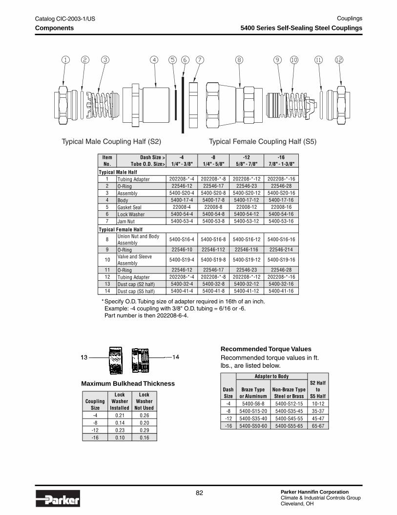
Parker Hannifin CorporationClimate & Industrial Controls GroupCleveland, OH
Catalog CIC-2003-1/US Couplings
82
Components
*Specify O.D. Tubing size of adapter required in 16th of an inch.Example: -4 coupling with 3/8" O.D. tubing = 6/16 or -6.Part number is then 202208-6-4.
Maximum Bulkhead Thickness
Recommended Torque ValuesRecommended torque values in ft.lbs., are listed below.
Typical Male Coupling Half (S2) Typical Female Coupling Half (S5)
5400 Series Self-Sealing Steel Couplings
Item Dash Size > -4 -8 -12 -16No. Tube O.D. Size> 1/4" - 3/8" 1/4" - 5/8" 5/8" - 7/8" 7/8" - 1-3/8"
Typical Male Half1 Tubing Adapter 202208-*-4 202208-*-8 202208-*-12 202208-*-162 O-Ring 22546-12 22546-17 22546-23 22546-283 Assembly 5400-S20-4 5400-S20-8 5400-S20-12 5400-S20-164 Body 5400-17-4 5400-17-8 5400-17-12 5400-17-165 Gasket Seal 22008-4 22008-8 22008-12 22008-166 Lock Washer 5400-54-4 5400-54-8 5400-54-12 5400-54-167 Jam Nut 5400-53-4 5400-53-8 5400-53-12 5400-53-16
Typical Female Half
8 Union Nut and Body Assembly
5400-S16-4 5400-S16-8 5400-S16-12 5400-S16-16
9 O-Ring 22546-10 22546-112 22546-116 22546-214
10 Valve and Sleeve Assembly
5400-S19-4 5400-S19-8 5400-S19-12 5400-S19-16
11 O-Ring 22546-12 22546-17 22546-23 22546-2812 Tubing Adapter 202208-*-4 202208-*-8 202208-*-12 202208-*-1613 Dust cap (S2 half) 5400-32-4 5400-32-8 5400-32-12 5400-32-1614 Dust cap (S5 half) 5400-41-4 5400-41-8 5400-41-12 5400-41-16
CouplingSize
LockWasher
Installed
Lock Washer
Not Used-4 0.21 0.26-8 0.14 0.20
-12 0.23 0.29-16 0.10 0.16
DashSize
Braze Typeor Aluminum
Non-Braze Type Steel or Brass
S2 Halfto
S5 Half-4 5400-S6-8 5400-S12-15 10-12-8 5400-S15-20 5400-S35-45 35-37-12 5400-S35-40 5400-S45-55 45-47-16 5400-S50-60 5400-S55-65 65-67
Adapter to Body

Catalog CIC-2003-1/US Couplings
Parker Hannifin CorporationClimate & Industrial Controls GroupCleveland, OH
83
Co
up
ling
s
Assembly Instructions
After tubing or hose has been connected toadapters (1) and (12), install adapter O-rings (2) and (11)*on adapters. Be sure O-rings are not twisted.
Generously lubricate adapter O-rings (2) and (11)with the system lubricant to prevent them from scuffing andtearing when coupling body is threaded on adapter.
Adapter to S2 male coupling half connection.
A. Lubricate poppet face with system lubricant. Insertpoppet valve assembly (3) into body (4). Tightenbody (4) on adapter (1).
B. After body and adapter make metal-to-metal contact,tighten by rotating body (4) 1/8" with respect toadapter (1) or torque to the value shown in the“Torque Values” table.
Adapter to S5 female coupling half connection.
A. Lubricate O-ring (9) liberally with system lubricant.Insert valve and sleeve assembly (10) into body (8).Tighten body (8) on adapter (12).
B. After body and adapter make metal-to-metal contact,tighten by rotating body (8) 1/8" with respect toadapter (12) or torque to the value shown in the“Torque Values” table.
Coupling connection.
A. Generously lubricate the gasket seal (5) on the5400-S2 male coupling half with the system lubricant.
B. Thread the union nut (8) onto the S2 male couplinghalf. Tighten union nut to torque values shown in the“Torque Values” table.
IMPORTANT - DO NOT rotate the S5 femalecoupling half body during connection.
C. After the coupling halves are seated, keep thebodies of the S2 male coupling half (4) and that ofthe S5 female coupling half (8) from rotating andtighten the union nut to the torque values shown inthe “Torque Values” table.
IMPORTANT - DO NOT rotate the S2 or S5 couplinghalf body during connection.
Bulkhead Mounting — S2 Half
Install lock washer (6) on S2 half, insert S2 malecoupling half through bulkhead, and tighten jam-nut (7) sothat lock-washer teeth are fully compressed.
Note: Lock washer (6) must be between hex of S2male half and bulkhead.
*IMPORTANT: Generous lubrication is required for all gaskets and O-rings. Lubrication should match system oil and be compatiblewith refrigerant system
Assembly Instructions and Accessories
Dust Cap and Dust PlugDustCap
DustPlug
Adapter SAE 37° (JIC)
Adapter — Braze
O-Ring Required
O-Ring Required
Accessories
5400 Series Self-Sealing Steel Couplings
Step 1
Step 2
Step 3
Step 4
Step 5
Step 1
CouplingSize
Dust Cap with Gasket
Dust Plug with Gasket
-4 5400-S6-4 5400-S8-4-8 5400-S6-8 5400-S8-8
-12 5400-S6-12 5400-S8-12-16 5400-S6-16 5400-S8-16
Part NumbersCoupling
ThreadSize
TubeO.D.
Size O-Ring Brass P Size-4 22546-12 202208-4-4B 1/2-20 1/4-8 22546-17 202208-8-8B 7/8-20 1/8-12 22546-23 202208-10-12B 1-1/4 - 18 5/8-16 22546-28 202208-14-16B 1-9/32 - 20 5/8
Part Numbers
CouplingThread
SizeTubeO.D.
Size O-Ring Brass Steel P Size-4 22546-12 202220-4-4B 202220-4-4S 7/16 - 20 1/4-4 22546-12 202220-6-4B 202220-6-4S 9/16 - 18 3/8-8 22546-17 202220-6-8B 202220-6-8S 9/16 - 18 3/8-8 22546-17 202220-8-8B 202220-8-8S 3/4 -16 1/2-12 22546-23 202220-10-12B 202220-10-12S 7/8 - 14 5/8-12 22546-23 202220-10-12B 202220-10-12S 1-1/16 - 12 3/4-16 22546-28 202220-16-16B 202220-16-16S 1-3/16 - 12 1
Part Numbers

Parker Hannifin CorporationClimate & Industrial Controls GroupCleveland, OH
Catalog CIC-2003-1/US Couplings
84
5500 Series Self-SealingBrass Coupling
Parker’s 5500 Self-Sealing Brass Couplings are usedin fluid-transfer applications for easy maintenance onrefrigeration and air conditioning systems. Applicationscan also include marine refrigeration and air condition-ing systems, along with split refrigeration and splitbeverage systems.
Application• Portable split-system air conditioners• Split refrigeration systems• Marine refrigeration systems• Refrigerated dry cleaning systems• Beverage systems
Base Product Part Number5502 Male coupling half5505 Female coupling half
Features and Benefits• Self-sealing upon disconnection maintains
minimum inclusion of air and loss of fluid.• Brass coupling provides corrosion resistance.• Final metal-to-metal seal provides low leakage.
Technical Information
Corrosion ResistantBrass body and copperconnections make corrosion-related problems almost non-existent.
EfficientFull flow/low pressuredrop design helps improveequipment efficiencies.
Superior SealingUnique self-sealing valving preventsrefrigerant loss when disconnected.Metal-to-metal final seal virtuallyeliminates refrigerant loss whenconnected.
ReliableStringent design standards, backedby years of experience, a wide rangeof existing coupling applications, andextensive testing under extremeoperating conditions, provide youwith the assurance that the productwill perform as specified.
Easy to Connect/DisconnectThread-together designallows easy connection anddisconnection while undersystem pressure.
Low Air Inclusionand Refrigerant LossValving is designed for low airinclusion and minimal refrigerant lossduring connection and disconnection.
Simplified InstallationCopper sweat connections simplify thefactory installation process (eliminatingthe need for flux and flux residue cleanup), saving you time and money.
• Copper-sweat connections provide basic endsfor brazing and eliminate the need for flux,simplifying the installation process.
• Panel mounting options are available for theunique needs of a unit.
Agency ApprovalsUL listed; File No: SA2709
5500 Series Self-Sealing Brass Coupling

Catalog CIC-2003-1/US Couplings
Parker Hannifin CorporationClimate & Industrial Controls GroupCleveland, OH
85
Co
up
ling
sTechnical Information
How it Operates
Disconnected
When disconnected, spring-loaded valve assembliesin the male and female coupling halves are sealed toprevent refrigerant loss and the inclusion of air orforeign materials. A spring in the male coupling halfpresses the bonded poppet against sealing surface “A”of the coupling body. Likewise, a spring in the femalecoupling half presses the sleeve against sealingsurface “B” of the stem valve head. An O-ring on thefemale sleeve prevents leakage between the sleeveand coupling body.
Partially Connected
As the two coupling halves are threaded together, seal-ing surface “C” of the male coupling body contacts thebonded seal of the female coupling’s sleeve assembly.
At the same time, the stem valve head in the femalecoupling assembly contacts the male coupling’s bondedpoppet, forcing air out of the coupling. During thisstage, both coupling halves are sealed, preventingleakage of refrigerant.
Fully Connected
Continued tightening of the union nut (female coupling)draws the couplings together, and opens the fluidpassage by forcing the male coupling’s poppet assem-bly and the female coupling’s sleeve assembly open.When fully coupled a metal ring located in the front ofthe male coupling, forms a leak-tight seal between thetwo coupling halves.
Female Coupling Half Male Coupling Half
Female Coupling Half Male Coupling Half
Female Coupling Half Male Coupling Half
Sealing Surface “ C”
Sealing Surface “ A”Sealing Surface “ B”
Metal Sealing Ring
5500 Series Self-Sealing Brass Coupling

Parker Hannifin CorporationClimate & Industrial Controls GroupCleveland, OH
Catalog CIC-2003-1/US Couplings
86
Technical Information
Specifications
* Protective metal cap/plug not available for -06 Coupling Body Size+ Due to the numerous manufacturers of refrigerant oils and continuous changes of additives, compatibility cannot be guaran-
teed. Contact Parker for compatibility of refrigerant oils not listed.
5500 Series Self-Sealing Brass Coupling
PRODUCT 5500 Series Self-Sealing Brass CouplingsOperating Temperature Range -40°F to 250°F (-40°C to +121°C)Operating Pressure Range, Connected
Male & Female Coupling-06, -08, -12 & -16 Body Sizes Vacuum to 750 psi (52 bar)
Operating Pressure Range, DisconnectedMale Coupling Half
-06, -08, -12 & -16 Body Sizes Vacuum to 750 psi (52 bar)Female Coupling Half
-06 & -08 Body Sizes Vacuum to 600 psi (41 bar)-12 Body Size Vacuum to 550 psi (40 bar)-16 Body Size Vacuum to 333 psi (23 bar)
Minimum Burst Pressure, ConnectedMale & Female Coupling
-06, -08, -12 & -16 Body Sizes 2,700 psi (186 bar)Minimum Burst Pressure, Disconnected
Male Coupling Half-06, -08, -12 & -16 Body Sizes 2,700 psi (186 bar)
Female Coupling Half-06 & -08 Body Size 1,800 psi (124 bar)-12 Body Size 1,650 psi (114 bar)-16 Body Size 1,000 psi (70 bar)
Maximum Air Inclusion (During Connection)Male & Female Coupling Halves
-06 Body Size 0.15 cc per connection-08 Body Size 0.10 cc per connection-12 Body Size 0.20 cc per connection-16 Body Size 0.40 cc per connection
Maximum Fluid Loss (During Disconnection)Male & Female Coupling Halves
-06 & -08 Body Sizes 0.10 cc per disconnection-12 Body Size 0.30 cc per disconnection-16 Body Size 0.20 cc per disconnection
MATERIALSCoupling Body Brass Bar per ASTM-B16, Alloy C3600Connections Refrigeration Grade Copper, per ASTM-B75, Alloy C12200Valve Stem Assembly (Female Coupling) Chromate Plated SteelBonded Poppet (Male Coupling) Neoprene™Bonded Sleeve (Female Coupling) Neoprene™
MATERIAL COMPATIBILITY+
Vibration Resistance Complies with UL 109External Leak Rate, Connected -06, -08, -12 & -16 Body Sizes
< 0.1 ounce (2.96 ml) of R22 refrigerant per year atOperating Pressure Range
External Leak Rate, Disconnected-06, -08, -12 & -16 Body Sizes Without Protective Metal Cap or Plug Installed
< 0.50 ounce (14.79 ml) of R22 refrigerant per year
-08, -12 & -16 Body Sizes With Protective Metal Cap or Plug Installed*
< 0.25 ounce (7.39 ml) of R22 refrigerant per year
All components, bonded poppet and sleeve, and valve stem O-Ring seal are compatible with these refrigerants and refrigerant oils: R22 & mineral oil, alkylbenzene oil, or polyolester oil R134a, R404a, R407c, R410a, or R507 & polyolester oil

Catalog CIC-2003-1/US Couplings
Parker Hannifin CorporationClimate & Industrial Controls GroupCleveland, OH
87
Co
up
ling
sTechnical Information
Flow Data
5500 Series Self-Sealing Brass Coupling
Liquid Line Pressure Drop vs. Mass FlowRefrigerant R22 and R410a
Refrigerant Mass Flow (Kg/Hr)
Refrigerant Mass Flow (Lbs/Hr)
41
0.5 3.4
0
1.0 3.9
1.5 10.3
2.0 13.8
2.5 17.2
3.0 20.7
3.5 24.1
4.0 27.6
4.5 31.0
900
82
180
122
270
204
450
245
540
286
630
327
720
368
810
408
900
163
360
Pre
ssu
re D
rop
(P
SI)
Pre
ssu
re D
rop
(kP
a)
5500-04-08 (R22)
5500
-04-
08 (R
410a
)
5500-08-08 (R22)
5500-06-06 (R22a)
5500-08-08 (R410a)
5500-06-06 (R410a)
5500-04-08 — 1/2" Coupling Body (-08) with 1/4" (-04) Copper Connection, R22
5500-06-06 — 3/8" Coupling Body (-06) with 3/8" (-06) Copper Connection, R22
5500-08-08 — 1/2" Coupling Body (-08) with 1/2" (-08) Copper Connection, R22
5500-04-08 — 1/2" Coupling Body (-08) with 1/4" (-04) Copper Connection, R410a
5500-06-06 — 3/8" Coupling Body (-06) with 3/8" (-06) Copper Connection, R410a
5500-08-08 — 1/2" Coupling Body (-08) with 1/2" (-08) Copper Connection, R410a
Suction Line Pressure Drop vs. Mass FlowRefrigerant R22 and R410a
Refrigerant Mass Flow (Kg/Hr)
Refrigerant Mass Flow (Lbs/Hr)
41
2
0
4
6
8
10
12
14
900
82
180
122
270
204
450
245
540
286
630
327
720
368
810
408
900
163
360
Pre
ssu
re D
rop
(P
SI)
5500-08-08 (R410a)
5500
-08-
08 (R
22)
5500-12-12 (R410a)
5500-16-16 (R22)5500-12-12 (R22)
5500
-06-
06 (R
410a
)
5500-06-06 — 3/8" Coupling Body (-06) with 3/8" (-06) Copper Connection, R22
5500-12-12 — 3/4" Coupling Body (-12) with 3/4" (-12) Copper Connection, R22
5500-08-08 — 1/2" Coupling Body (-08) with 1/2" (-08) Copper Connection, R22
5500-16-16 — 1" Coupling Body (-16) with 1" (16) Copper Connection, R22
5500-12-12 — 3/4" Coupling Body (-12) with 3/4" (-12) Copper Connection, R410a
5500-06-06 — 3/8" Coupling Body (-06) with 3/8" (-06) Copper Connection, R410a
5500-16-16 — 1" Coupling Body (-16) with 1" (16) Copper Connection, R410a
5500-08-08 — 1/2" Coupling Body (-08) with 1/2" (-08) Copper Connection, R410a
5500
-06-
06 (R
22)
5500-16-16 (R410a)
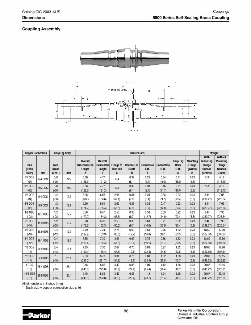
Parker Hannifin CorporationClimate & Industrial Controls GroupCleveland, OH
Catalog CIC-2003-1/US Couplings
88
Dimensions
Coupling Assembly
All dimensions in inches (mm)* Dash size = copper connection size x 16
5500 Series Self-Sealing Brass Coupling
Inch(Dash Size*) mm
Inch(Dash Size*) mm
OverallDisconnected
Length A
OverallConnected
Length B
Flange toTube End
C
ConnectionDepth
D
ConnectionI.D.
E
ConnectionO.D.
F
CouplingBodyO.D.
G
MountingFlange(Width)
H
WithMounting
FlangeOunces (Grams)
WithoutMounting
FlangeOunces (Grams)
1/4 ODS 3/8 5.06 4.77 0.32 0.25 0.34 0.71 0.23 N/A 4.18(-04) (-06) (128.5) (121.2) (8.1) (6.4) (8.6) (18.0) (5.8) (118.45)
3/8 ODS 3/8 5.06 4.77 0.32 0.38 0.46 0.71 0.23 N/A 4.18(-06) (-06) (128.5) (121.2) (8.1) (9.7) (11.7) (18.0) (5.8) (118.45)
1/4 ODS 1/2 6.95 6.56 2.64 0.31 0.25 0.38 0.92 0.23 8.44 7.96(-04) (-08) (176.5 (166.6) (67.1) (7.9) (6.4) (9.7) (23.4) (5.8) (239.27) (225.54)
3/8 ODS 1/2 6.90 6.51 2.62 0.31 0.38 0.47 0.92 0.23 8.44 7.96(-06) (-08) (174.2) (165.4) (66.5) (7.9) (9.7) (12.0) (23.4) (5.8) (239.27) (225.54)
1/2 ODS 1/2 6.86 6.47 2.58 0.38 0.50 0.59 0.92 0.23 8.44 7.96 (-08) (-08) (172.2) (164.3) (65.5) (9.7) (12.7) (14.9) (23.4) (5.8) (239.27) (225.54)
5/8 ODS 1/2 6.78 6.39 2.56 0.38 0.63 0.71 0.92 0.23 8.44 7.96 (-10) (-08) (172.2) (162.3) (65.0) (9.7) (16.0) (17.9) (23.4) (5.8) (239.27) (225.54)
5/8 ODS 3/4 7.79 7.24 2.71 0.50 0.63 0.75 1.32 0.23 18.60 17.90 (-10) (-12) (197.9) (183.9) (68.8) (12.7) (16.0) (19.1) (33.5) (5.8) (527.50) (507.34)
3/4 ODS 3/4 7.85 7.30 2.67 0.62 0.75 0.86 1.32 0.23 18.60 17.90 (-12) (-12) (199.4) (185.4) (67.8) (15.7) (19.1) (21.7) (33.5) (5.8) (527.50) (507.34)
7/8 ODS 3/4 7.85 7.30 2.67 0.75 0.88 0.97 1.32 0.23 18.60 17.90(-14) (-12) (199.4) (185.4) (67.8) (19.1) (22.4) (24.6) (33.5) (5.8) (527.50) (507.34)
7/8 ODS 1 9.33 8.73 3.34 0.75 0.88 1.02 1.68 0.23 29.87 29.15(-14) (-16) (237.0) (221.7) (84.8) (19.1) (22.4) (25.8) (42.7) (5.8) (846.72) (826.35)
1 ODS 1 9.46 8.86 3.42 0.88 1.00 1.12 1.68 0.23 29.87 29.15(-16) (-16) (240.3) (225.0) (86.9) (22.4) (25.4) (28.4) (42.7) (5.8) (846.72) (826.35)
1-1/8 ODS 1 9.45 8.85 3.42 0.88 1.13 1.24 1.68 0.23 29.87 29.15(-18) (-16) (240.0) (224.8) (86.9) (22.4) (28.7) (31.4) (42.7) (5.8) (846.72) (826.35)
N/A
N/A
Dimensions WeightCopper Connection Coupling Body
6.4 ODS
9.5 ODS
6.4 ODS
9.5 ODS
12.7 ODS
15.9 ODS
15.9 ODS
19.1 ODS
22.2 ODS
22.2 ODS
25.4 ODS
28.6 ODS
9.5
9.5
12.7
12.7
12.7
12.7
19.1
25.4
19.1
19.1
25.4
25.4

Catalog CIC-2003-1/US Couplings
Parker Hannifin CorporationClimate & Industrial Controls GroupCleveland, OH
89
Co
up
ling
sDimensions
Female Coupling Half
All dimensions in inches (mm)* Dash size = copper connection size x 16** "B" in the part number denotes a plastic plug. "S" in the part number denotes a steel plug.+ Dimension is across hex flats.
5500 Series Self-Sealing Brass Coupling
Inch(Dash Size*) mm
Inch(Dash Size*) mm Less Plug With Plug**
WithPlug
A BDepth
DI.D.
EO.D.
FO.D.
GHex +
H
WeightOunces(grams)
1/4 ODS 3/8 3.14 2.72 0.32 0.25 0.34 0.71 0.75 0.94 2.53(-04) (-06) (79.8) (69.1) (8.1) (6.4) (8.6) (18.0) (19.1) (23.9) (71.73)
3/8 ODS 3/8 3.14 2.72 0.32 0.38 0.46 0.71 0.75 0.94 2.53(-06) (-06) (79.8) (69.1) (8.1) (9.7) (11.7) (18.0) (19.1) (23.9) (71.73)
1/4 ODS 1/2 3.88 3.69 0.31 0.25 0.38 0.92 1.00 1.19 4.85(-04) (-08) (98.6) (93.7) (7.9) (6.4) (9.7) (23.4) (25.4) (30.2) (137.46)
1/4 ODS 1/2 4.04 3.69 0.31 0.25 0.38 0.92 1.00 1.19 4.85(-04) (-08) (102.86) (93.7) (7.9) (6.4) (9.7) (23.4) (25.4) (30.2) (137.46)
3/8 ODS 1/2 3.85 3.66 0.31 0.38 0.47 0.92 1.00 1.19 4.85(-06) (-08) (97.8) (93.0) (7.9) (9.7) (12.0) (23.4) (25.4) (30.2) (137.46)
3/8 ODS 1/2 4.01 3.66 0.31 0.38 0.47 0.92 1.00 1.19 4.85(-06) (-08) (101.9) (93.0) (7.9) (9.7) (12.0) (23.4) (25.4) (30.2) (137.46)
12 ODS 1/2 3.85 3.66 0.38 0.50 0.59 0.92 1.00 1.19 4.85 (-08) (-08) (97.8) (93.0) (9.7) (12.7) (14.9) (23.4) (25.4) (30.2) (137.46)
12 ODS 1/2 4.01 3.66 0.38 0.50 0.59 0.92 1.00 1.19 4.85 (-08) (-08) (101.9) (93.0) (9.7) (12.7) (14.9) (23.4) (25.4) (30.2) (137.46)
5/8 ODS 1/2 3.79 3.60 0.50 0.63 0.71 0.92 1.00 1.19 4.85 (-10) (-08) (96.3) (91.4) (12.7) (16.0) (17.9) (23.4) (25.4) (30.2) (137.46)
5/8 ODS 1/2 3.95 3.60 0.50 0.63 0.71 0.92 1.00 1.19 4.85 (-10) (-08) (100.3) (91.4) (12.7) (16.0) (17.9) (23.4) (25.4) (30.2) (137.46)
5/8 ODS 3/4 4.64 4.09 0.50 0.63 0.75 1.32 1.38 1.62 10.58 (-10) (-12) (117.9) (103.9) (12.7) (16.0) (19.1) (33.5) (35.1) (30.2) (299.98)
3/4 ODS 3/4 4.77 4.19 0.62 0.75 0.86 1.32 1.38 1.62 10.58 (-12) (-12) (121.2) (106.4) (15.7) (19.1) (21.7) (33.5) (35.1) (41.4) (299.98)
7/8 ODS 3/4 4.77 4.19 0.75 0.88 0.97 1.32 1.38 1.62 10.58(-14) (-12) (121.2) (106.4) (19.1) (22.4) (24.6) (33.5) (35.1) (41.4) (299.98)
7/8 ODS 1 5.48 4.96 0.75 0.88 1.02 1.68 1.69 2.00 18.34(-14) (-16) (139.2) (126.0) (19.1) (22.4) (25.8) (42.7) (42.9) (50.8) (519.91)
1 ODS 1 5.62 5.01 0.88 1.00 1.12 1.68 1.69 2.00 18.34(-16) (-16) (142.7) (127.3) (22.4) (25.4) (28.4) (42.7) (42.9) (50.8) (519.91)
1-1/8 ODS 1 5.52 5.00 0.88 1.13 1.24 1.68 1.69 2.00 18.34(-18) (-16) (140.2) (127.0) (22.4) (28.7) (31.4) (42.7) (42.9) (50.8) (519.91)
Retaining
Nut Hex +
J
DimensionsCopper Connection Coupling Body Part Number
6.4 ODS
9.5 ODS
6.4 ODS
6.4 ODS
9.5 ODS
9.5 ODS
12.7 ODS
12.7 ODS
15.9 ODS
15.9 ODS
15.9 ODS
19.1 ODS
22.2 ODS
22.2 ODS
25.4 ODS
28.6 ODS
9.5
9.5
12.7
12.7
12.7
12.7
12.7
12.7
12.7
12.7
19.1
19.1
19.1
25.4
25.4
25.4
N/A
N/A
5505-04-08
5505-04-08
5505-16-16
5505-18-16
5505-10-08
5505-10-08
5505-10-12
5505-12-12
5505-04B-08
5505-04S-08
5505-14-12
5505-14-16
5505-06-08
5505-06-08
5505-08-08
5505-08-08
5505-14S-16
5505-16S-16
5505-18S-16
5505-10S-08
5505-10S-12
5505-12S-12
5505-14S-12
Coupling Length Connection Coupling Body
5505-10B-08
5505-06B-08
5505-06S-08
5505-08B-08
5505-08S-08
5505-04B-06
5505-06B-06

Parker Hannifin CorporationClimate & Industrial Controls GroupCleveland, OH
Catalog CIC-2003-1/US Couplings
90
Dimensions
Male Coupling Half
All dimensions in inches (mm)* Dash size = copper connection size x 16** "B" in the part number denotes a plastic plug. "S" in the part number denotes a steel plug.+ Dimension is across hex flats.
5500 Series Self-Sealing Brass Coupling
Copper Connection
Inch(Dash Size*) mm
Inch(Dash Size*) mm Less Cap With Cap**
(with cap)
A BDepth
DI.D.
EO.D.
F O.D.
G
ThreadLength
H
Hex
Diameter +
J
ThreadSize
K
WeightOunces (Grams)
1/4 ODS 3/8 2.58 2.40 0.32 0.25 0.34 0.71 0.49 0.83 1.65(-04) (-06) (65.5) (61.0) (8.1) (6.4) (8.6) (18.0) (12.4) (21.1) (6.72)
3/8 ODS 3/8 2.58 2.40 0.32 0.38 0.46 0.71 0.49 0.83 1.65(-06) (-06) (65.5) (61.0) (8.1) (9.7) (11.7) (18.0) (12.4) (21.1) (6.72)
1/4 ODS 1/2 3.31 3.26 0.31 0.25 0.38 0.92 0.62 1.13 3.11(-04) (-08) (84.1) (82.8) (7.9) (6.4) (9.7) (23.4) (15.7) (28.7) (88.08)
1/4 ODS 1/2 3.47 3.26 0.31 0.25 0.38 0.92 0.62 1.13 3.11(-04) (-08) (88.1) (82.8) (7.9) (6.4) (9.7) (23.4) (15.7) (28.7) (88.08)
3/8 ODS 1/2 3.29 3.24 0.31 0.38 0.47 0.92 0.62 1.13 3.11(-06) (-08) (83.6) (82.3) (7.9) (9.7) (12.0) (23.4) (15.7) (28.7) (88.08)
3/8 ODS 1/2 3.45 3.24 0.31 0.38 0.47 0.92 0.62 1.13 3.11(-06) (-08) (87.6) (82.3) (7.9) (9.7) (12.0) (23.4) (15.7) (28.7) (88.08)
1/2 ODS 1/2 3.25 3.20 0.38 0.50 0.59 0.92 0.62 1.13 3.11 (-08) (-08) (82.6) (81.3) (9.7) (12.7) (14.9) (23.4) (15.7) (28.7) (88.08)
1/2 ODS 1/2 3.41 3.20 0.38 0.50 0.59 0.92 0.62 1.13 3.11 (-08) (-08) (86.6) (81.3) (9.7) (12.7) (14.9) (23.4) (15.7) (28.7) (88.08)
5/8 ODS 1/2 3.23 3.18 0.50 0.63 0.71 0.92 0.62 1.13 3.11 (-10) (-08) (82.0 (80.8) (12.7) (16.0) (17.9) (23.4) (15.7) (28.7) (88.08)
5/8 ODS 1/2 3.91 3.18 0.50 0.63 0.71 0.92 0.62 1.13 3.11 (-10) (-08) (99.3) (80.8) (12.7) (16.0) (17.9) (23.4) (15.7) (28.7) (88.08)
5/8 ODS 3/4 3.91 3.70 0.50 0.63 0.75 1.32 0.99 1.63 7.31 (-10) (-12) (117.9) (103.9) (12.7) (16.0) (19.1) (33.5) (25.1) (41.4) (207.36)
3/4 ODS 3/4 3.96 3.75 0.62 0.75 0.86 1.32 0.99 1.63 7.31 (-12) (-12) (100.6) (95.3) (15.7) (19.1) (21.7) (33.5) (25.1) (41.4) (207.36)
7/8 ODS 3/4 3.96 3.75 0.75 0.88 0.97 1.32 0.99 1.63 7.31(-14) (-12) (100.6) (95.3) (19.1) (22.4) (24.6) (33.5) (25.1) (41.4) (207.36)
7/8 ODS 1 4.68 4.37 0.75 0.88 1.02 1.68 1.03 1.88 10.81(-14) (-16) (118.9) (111.0) (19.1) (22.4) (25.8) (42.7) (26.2) (47.8) (306.44)1 ODS 1 4.76 4.45 0.88 1.00 1.12 1.68 1.03 1.88 10.81(-16) (-16) (120.9) (113.0) (22.4) (25.4) (28.4) (42.7) (26.2) (47.8) (306.44)
1-1/8 ODS 1 4.76 4.45 0.88 1.13 1.24 1.68 1.03 1.88 10.81(-18) (-16) (120.9) (113.0) (22.4) (28.7) (31.4) (42.7) (26.2) (47.8) (306.44)
5502-16S-16
5502-18S-16
5502-10S-08
5502-10S-12
5502-12S-12
5502-14S-12
5502-08B-08
5502-08S-08
5502-10B-08
5502-14S-16
5502-04B-08
5502-04S-08
5502-06B-08
5502-06S-08
5502-14-12
5502-14-16
5502-16-16
5502-18-16
5502-10-08
5502-10-08
5502-10-12
5502-12-12
22.2 ODS
25.4 ODS
N/A
N/A
5502-04-08
5502-04-08
5502-06-08
5502-06-08
5502-08-08
5502-08-08
15.9 ODS
15.9 ODS
19.1 ODS
22.2 ODS
28.6 ODS
6.4 ODS
9.5 ODS
6.4 ODS
6.4 ODS
9.5 ODS
9.5 ODS
12.7 ODS
12.7 ODS
15.9 ODS
19.1
25.4
25.4
25.4
12.7
12.7
19.1
19.1
1-3/4-16
1-3/4-16
9.5
9.5
12.7
12.7
12.7
12.7
12.7
12.7
1-7/16-16
1-7/16-16
1-7/16-16
1-3/4-16
1-20
1-20
1-20
1-20
1-20
1-20
1-20
1-20
Coupling Body Part Number**
M20-1.5
M20-1.5
5502-04B-06
5502-06B-06
Coupling Length Depth Coupling Body
Dimensions

Catalog CIC-2003-1/US Couplings
Parker Hannifin CorporationClimate & Industrial Controls GroupCleveland, OH
91
Co
up
ling
sAccessories
Protective Plugs(Bulk package,25/package)
Protective Caps(Bulk package,25/package)
Mounting Flange (Steel)
All dimensions in inches (mm)* Dash size = copper connection size x 16
All dimensions in inches (mm)* Dash size = copper connection size x 16
All dimensions in inches (mm)* Dash size = copper connection size x 16
5500 Series Self-Sealing Brass Coupling
Weight
(Dash Size*) mm
Part Number
Diameter A
CircleDiameter
DiameterC
Ounces (Grams)
3/8
(-06)
1/2 1.13 1.69 2.00 0.48
(-08) (28.7) (42.9) (50.8) (13.73)
3/4 1.63 2.12 2.50 0.71
(-12) (41.4) (53.9) (63.5) (20.16)
1 1.88 2.38 2.75 0.72
(-16) (47.8) (60.5) (69.9) (20.37)150-22-16
N/A N/A
Coupling Body Size
9.5
12.7
19.1
25.4
N/A
Dimensions
N/A N/A
150-22-12
150-22-08
Weight
(Dash Size*) mm
Part Number
LengthA
DiameterB
Ounces (Grams)
3/8 0.72 1.04 0.09
(-06) (18.3) (26.4) (2.68)
1/2 0.04 1.20 0.07
(-08) (9.9) (30.5) (1.90)
1/2 0.72 1.00 1.48
(-08) (18.3) (25.4) (41.92)
3/4 1.13 1.44 4.84
(-12) (28.7) (36.6) (137.34)
1 1.25 1.75 7.93
(-16) (31.8) (44.5) (224.76)5400-S8-16-BULK
5410-06-BULK
5410-08-BULK
5400-S8-08-BULK
5400-S8-12-BULK
Plastic
Steel
DimensionsCoupling Body Size
9.5
12.7
12.7
19.1
25.4
Weight
(Dash Size*) mm
PartNumber
Length A
Diameter B
Ounces(Grams)
3/8 0.55 0.93 0.04
(-06) (14.0) (23.6) (1.12)
1/2 0.50 1.01 0.06
(-08) (12.7) (25.7) (1.70)
1/2 0.56 1.13 1.08
(-08) (14.2) (28.7) (30.58)
3/4 0.56 1.63 2.38
(-12) (14.2) (41.4) (67.48)
1 0.75 2.00 4.98
(-16) (19.1) (50.8) (141.20)
DimensionsCoupling Body Size
9.5
12.7
12.7
Plastic
Steel
5409-06-BULK
5409-08-BULK
5400-S6-16-BULK
5400-S6-08-BULK
5400-S6-12-BULK19.1
25.4

Parker Hannifin CorporationClimate & Industrial Controls GroupCleveland, OH
Catalog CIC-2003-1/US Couplings
92
Ordering Information
How to Order
5502Coupling
Type
04Copper
Connection Size
BCap
Requirements
06CouplingBody Size
5500 Series Self-Sealing Brass Coupling
Product Type5502 = Male Coupling Half5505 = Female Coupling Half
-04 = 1/4" (6.4 mm)-06 = 3/8" (9.5 mm)-08 = 1/2" (12.7 mm)-10 = 5/8" (15.9 mm)-12 = 3/4" (19.1 mm)-14 = 7/8" (22.2 mm)-16 = 1" (25.4 mm)-18 = 1-1/8" (28.6 mm)
CopperConnection
(Denoted xx/16)-06 = 3/8" (9.5 mm)-08 = 1/2" (12.7 mm)-12 = 3/4" (19.1 mm)-16 = 1" (25.4 mm)
CouplingBody Size
(Denoted xx/16)
Cap0 = No CapB = Includes Plastic Protective Cap or PlugS = Includes Steel Protective Cap or Plug

Catalog CIC-2003-1/US Couplings
Parker Hannifin CorporationClimate & Industrial Controls GroupCleveland, OH
93
Co
up
ling
s
Specifications
* Protective metal cap/plug not available for -06 CouplingBody Size
+ Due to the numerous manufacturers of refrigerant oils andcontinuous changes of additives, compatibility cannot beguaranteed. Contact Parker for compatibility of refrigerantoils not listed.
5700 Series One-Shot™ Brass Couplings
Parker’s 5700 One-Shot Brass Couplings are used in fluid-transfer applications for easy installation on refrigeration andair conditioning systems. Applications typically include split airconditioning systems, split heat pumps, and manufacturedhomes.
Technical Information
Application• Split air conditioning systems• Split heat pumps• Manufactured homes
Base Product Part Number5780 Female coupling half without charge
port5781 Female coupling half with charge port5782 Male coupling half without charge port5783 Male coupling half with charge port
Features and Benefits• Single-use coupling contains a
diaphragm that is pierced uponconnection and folded back into thecoupling to provide a high flow pathand low pressure drop.
• Final metal-to-metal seal keeps airinclusion to a minimum.
• Brass coupling provides corrosionresistance.
• Copper-sweat connections provide basicends for brazing and eliminate the needfor flux, simplifying the installationprocess.
• Brass sweat connections and panel-mounting options are available for theunique needs of a unit.
• Male/female charge ports can beincluded for easy system diagnostics.
• Stub kits (FD57) are also available withcopper connections.
Agency ApprovalsUL listed; File No: SA2709
Specifications Notes:
5700 Series One-Shot™ Brass Couplings
PRODUCT: 5700 Series One Shot™ Brass CouplingOperating Temperature Range -40° F to 250° F (-40° C to +121° C)Operating Pressure Range, Connected
Male & Female Coupling-06, -08, -12 & -16 Body Sizes Vacuum to 750 psi (52 bar)
Operating Pressure Range, DisconnectedMale Coupling Half
-06, -08, -12 & -16 Body Sizes Vacuum to 750 psi (52 bar)Female Coupling Half
-06 & -08 Body Sizes Vacuum to 600 psi (41 bar)-12 Body Size Vacuum to 550 psi (40 bar)-16 Body Size Vacuum to 333 psi (23 bar)
Minimum Burst Pressure, ConnectedMale & Female Coupling
-06, -08, -12 & -16 Body Sizes 2,700 psi (186 bar)Minimum Burst Pressure, Disconnected
Male Coupling Half-06, -08, -12 & -16 Body Sizes 2,700 psi (186 bar)
Female Coupling Half-06 & -08 Body Size 1,800 psi (124 bar)-12 Body Size 1,650 psi (114 bar)-16 Body Size 1,000 psi (70 bar)
Maximum Air Inclusion (During Connection)Male & Female Coupling Halves
-06 Body Size 0.15 cc per connection-08 Body Size 0.10 cc per connection-12 Body Size 0.20 cc per connection-16 Body Size 0.40 cc per connection
Maximum Fluid Loss (During Disconnection)Male & Female Coupling Halves
-06 & -08 Body Sizes 0.10 cc per disconnection-12 Body Size 0.30 cc per disconnection-16 Body Size 0.20 cc per disconnection
MATERIALSCoupling Body Brass Bar per ASTM-B16, Alloy C3600
ConnectionsRefrigeration Grade Copper, per ASTM-B75, Alloy C12200
Valve Stem Assembly (Female Coupling) Chromate Plated SteelBonded Poppet (Male Coupling) Neoprene™Bonded Sleeve (Female Coupling) Neoprene™
MATERIAL COMPATIBILITY +
Vibration Resistance Complies with UL 109External Leak Rate, Connected -06, -08, -12 & -16 Body Sizes < 0.1 ounce (2.96 ml) of R22 refrigerant
per year at Operating Pressure RangeExternal Leak Rate, Disconnected
-06, -08, -12 & -16 Body Sizes Without Protective Metal Cap or Plug Installed
< 0.50 ounce (14.79 ml) of R22 refrigerant per year
-08, -12 & -16 Body Sizes With Protective Metal Cap or Plug Installed*
< 0.25 ounce (7.39 ml) of R22 refrigerant per year
All components, bonded poppet and sleeve, and valve stem O-Ring seal are compatible with these refrigerants and refrigerant oils: R22 & mineral oil, alkylbenzene oil, or polyolester oil R134a, R404a, R407c, R410a, or R507 & polyolester oil

Parker Hannifin CorporationClimate & Industrial Controls GroupCleveland, OH
Catalog CIC-2003-1/US Couplings
94
Technical Information
Pressure Drop Comparison
The graphs below show significant reduction in pressure drop and associated efficiency gains utilizing Parker5700 Series Couplings vs. standard base valves.
0.0
1.0
2.0
3.0
4.0
5.0
Pressure Drop vs. Mass Flow-8 Suction Line, Refrigerant -22
Pres
sure
Dro
p (p
si)
Refrigerant Mass Flow (Lbs/Hr)200 400300 500 600 700 800 900160
Key:-8 Straight Copper Tube-8 Typical Base ValveParker 5781-8-8 Coupling
0.0
1.0
2.0
3.0
4.0
5.0
Pressure Drop vs. Mass Flow-10 Suction Line, Refrigerant -22
Pres
sure
Dro
p (p
si)
Refrigerant Mass Flow (Lbs/Hr)200 400300 500 600 700 800 900160
Key:-10 Straight Copper Tube-10 Typical Base ValveParker 5781-10-11 Coupling
0.0
1.0
2.0
3.0
4.0
5.0
Pressure Drop vs. Mass Flow-12 Suction Line, Refrigerant -22
Pres
sure
Dro
p (p
si)
Refrigerant Mass Flow (Lbs/Hr)200 400300 500 600 700 800 900160
Key:-12 Straight Copper Tube-12 Typical Base ValveParker 5781-12-11 Coupling
0.0
1.0
2.0
3.0
4.0
5.0
Pressure Drop vs. Mass Flow-14 Suction Line, Refrigerant -22
Pres
sure
Dro
p (p
si)
Refrigerant Mass Flow (Lbs/Hr)200 400300 500 600 700 800 900160
Key:-14 Straight Copper Tube-14 Typical Base ValveParker 5781-14-12 Coupling
5700 Series One-Shot™ Brass Couplings

Catalog CIC-2003-1/US Couplings
Parker Hannifin CorporationClimate & Industrial Controls GroupCleveland, OH
95
Co
up
ling
sTechnical Information
Design and Operation
A complete 5780 Series Coupling consists of the combination of male and female coupling halves. Either couplinghalf is available with or without a charging port, depending on the particular application.
Coupling Halves Before Connection
Diaphragms in the coupling halves provide a seal thatprevents refrigerant loss before connection. The malehalf (right unit) contains a cutter blade, the metalrefrigerant sealing diaphragm and intermediatesynthetic rubber seal which prevent loss of refrigerantwhile the coupling is being connected. The female half(left unit) contains a metal diaphragm which is a leak-proof metal closure.
Coupling Halves Connected
Tightening the union nut draws the coupling halvestogether, piercing and folding both metal diaphragmsback and opening the fluid passage, thereby providingminimal restriction to flow. When fully coupled, a parentmetal seal forms a permanent leakproof joint betweenthe two coupling halves preventing the loss of refriger-ant to the atmosphere.
The cutaway views below show male and femalecoupling halves joined at 20%, 50%, and 100%connection. Note the way the cutter blades piercethe diaphragms and fold them back out of the flowpath. Also note the difference in the final sealing areabefore and after torquing.
20% connected 50% connected
100% connected
Final sealing areaconnected prior to torquing
Final sealing areaconnected after torquing
5700 Series One-Shot™ Brass Couplings

Parker Hannifin CorporationClimate & Industrial Controls GroupCleveland, OH
Catalog CIC-2003-1/US Couplings
96
Dimensions
5780-Size Female Half without Charge Port 5781-Size Female Half with Charge Port
5782-Size Male Half without Charge Port 5783-Size Male Half with Charge Port
5700 Series One-Shot™ Brass Couplings

Catalog CIC-2003-1/US Couplings
Parker Hannifin CorporationClimate & Industrial Controls GroupCleveland, OH
97
Co
up
ling
sInstallation Instructions
Use a double tip torch topromote even heating and reducebraze time.
Factory Brazing Instructions
Male-Half Installation Procedure
Male half (5782) should be mounted with the hex on the inside of the unit held in place with the appropriatemounting flange. Sheet metal opening, screw hole diameter, and mounting bolt circle dimensions are includedin the chart below.
All dimensions in inches.
5700 Series One-Shot™ Brass Couplings
Step 1 Step 2 Step 3
Step 4 Step 5 Step 6
Sparingly apply paste flux tothe copper tube.
Note: Liquid flux or excessive fluxcan run inside the coupling andcause corrosion.
Immerse the coupling(diaphragm end) into a flowing coolwater bath.• 5780 and 57781 female halves:
Water level should be halfway up thenut and the nut hex fully immersed.
• 5782 and 5783 male halves: Waterlevel should fully cover the threads.
After the alloy solidifies,quench the tubing and coupling toreduce the temperature below 400°F.Make sure the water does not enterthe open charge port in the 5781 or5783 half.
The couplings can besubjected to unit test pressures up to300 psig. If pressures in excess of 300psig are used, the protector caps andplugs should be installed
Protector caps and plugsshould be installed finger tight. Over-tightening can damage the diaphragm.The diaphragm and O-ring can belubricated with refrigerant oil prior toinstalling the protector caps or plugs asadded assurance of proper lubricationwhen connected at unit installation.
CouplingPart Number
Coupling Hex Size
RecommendedSheet Metal
OpeningFlange
Part NumberMounting Bolt
CircleScrew HoleDiameter
5782-Size-6 3/4" 0.656 5700-22-6 1.44 0.2015782-Size-6 3/4" 0.656 5700-22-6 1.44 0.1535782-Size-8 15/16" 0.969 FD67-1008-10 1.69 0.1535782-Size-10 1-1/16" 1.094 FD67-1110-10 1.69 0.2015782-Size-10 1-1/16" 1.094 FD67-1008-12 1.69 0.1535782-Size-11 1-1/8" 1.156 150-22-8 1.69 0.2015782-Size-11 1-1/8" 1.156 5700-22-10 1.69 0.1535782-Size-12 1-7/16" 1.469 FD57-1110-12 2.12 0.2015782-Size-12 1-7/16" 1.469 FD57-1111-12 2.12 0.153

Parker Hannifin CorporationClimate & Industrial Controls GroupCleveland, OH
Catalog CIC-2003-1/US Couplings
98
Installation Instructions
Installation and Reconnection Instructions
Braze coupling to clean copper tubing.
Install plastic dust plug.
Apply refrigeration oil to the diaphragm and threadsof the couplings on the indoor unit.
Connect the line set couplings finger tight. Do notuse a wrench. The O-ring will seal.
Repeat steps 3 and 4 on the outdoor unit.
Evacuate and charge the line set per themanufacturer's instructions. Retighten the charge port cap.
Tighten all four coupling connections with awrench until seated or a definite resistance is felt. Mark a lineon the swivel nut and unit. Using the line as a guide, tightenan additional 1/4 turn.
Leak check the braze and coupling joints. Followthe manufacturer's instructions for start up.
Reconnection Instructions
Upon disconnection, remove O-ring.
If O-ring is missing from groove, insure O-ring isnot lodged inside coupling halves and reconnect withoutO-ring.
Route the suction line and liquid line between theindoor and outdoor unit.
Remove protector caps and plugs.
Carefully wipe coupling seats and threadedsurfaces with a clean cloth, to prevent the inclusion of dirtor any foreign material in the system.
Note: The O-ring is only an intermediate seal during the initial connection of a precharged unit/line set combination. The O-ringis only used for sealing between the time the diaphragm is pierced and the final metal-to-metal seal is made.
The final leak-proof seal is a metal-to-metal connection made between the male and female coupling bodies.
Lubricate male half diaphragm and syntheticrubber seal with system-compatible refrigerant oil. Threadcoupling halves together by hand to insure proper mating ofthreads. Use proper size wrenches (on coupling body hexand on union nut) and tighten until coupling bodies sea" ora definite resistance is felt.
Using a marker, mark a line lengthwise fromthe coupling union nut to the bulkhead. Then tighten anadditional 1/4 turn; the misalignment of the line will showthe amount the coupling has been tightened. This final 1/4turn is necessary to insure the formation of a leakproof joint.
If a torque wrench is used, the following torque values arerecommended:
5700 Series One-Shot™ Brass Couplings
Step 1
Step 2
Step 3
Step 4
Step 5
Step 6
Step 1
Step 2
Step 3
Step 4
Step 5
Step 6
Step 7
Step 8
Step 7
CouplingSize Ft/Lbs
-6 10-12-10 35-45-11 35-45-12 55-65

Catalog CIC-2003-1/US Couplings
Parker Hannifin CorporationClimate & Industrial Controls GroupCleveland, OH
99
Co
up
ling
sAccessories and Ordering Information
Order Options
MountingFlange
MaleCoupling HalfFemale
Coupling Half
ChargingPort Cap
5700 Series One-Shot™ Brass Couplings
Female Coupling Half
Female Coupling Halfwith Charging
Male Coupling Halfwith Protector
Male Coupling Half with Charging
BasicCoupling
Size
O.D.TubeSize
withoutCharging Port
(Includes Plug)
Valve Port lessCap and Core
(Includes Plug)
Cap less Mounting
Flange
Valve Port lessCap and Core
(Includes Plug)
Bolt Hole Dia. 0.15
(#10 Screw)
Bolt Hole Port
(#14 Screw)
ChargingPortCap
Charging Valve Core
-6 1/4 5780-4-6 5781-4-6 5782-4-6 5783-4-6 5706-22-6 5700-22-6 221014-4B 222034-4-6 5/16 5780-5-6 5781-5-6 5782-5-6 5783-5-6 5706-22-6 5700-22-6 221014-4B 222034-4-6 3/8 5780-6-6 5781-6-6 5782-6-6 5783-6-6 5706-22-6 5700-22-6 221014-4B 222034-4-8 3/8 5780-6-8 5781-6-8 5782-6-8 – FD67-1008-10 – 221014-4B 222034-4-8 1/2 5780-8-8 5781-8-8 5782-8-8 – FD67-1008-10 – 221014-4B 222034-4-8 5/8 5780-10-8 5781-10-8 5782-10-8 – FD67-1008-10 – 221014-4B 222034-4-10 1/2 5780-8-10 5781-8-10 5782-8-10 5783-8-10 FD67-1008-12 FD57-1111-10 221014-4B 222034-4-10 5/8 5780-10-10 5781-10-10 5782-10-10 – FD67-1008-12 FD57-1111-10 221014-4B 222034-4-10 3/4 5780-12-10 5781-12-10 5782-12-10 5783-12-10 FD67-1008-12 FD57-1111-10 221014-4B 222034-4-11 1/2 5780-8-11 5781-8-11 5782-8-11 5783-8-11 5700-22-10 150-22-8 221014-4B 222034-4-11 5/8 5780-10-11 5781-10-11 5782-10-11 5783-10-11 5700-22-10 150-22-8 221014-4B 222034-4-11 3/4 5780-12-11 5781-12-11 5782-12-11 5783-12-11 5700-22-10 150-22-8 221014-4B 222034-4-11 7/8 5780-14-11 5781-14-11 5782-14-11 5783-14-11 5700-22-10 150-22-8 221014-4B 222034-4-12 3/4 5780-12-12 5781-12-12 5782-12-12 – FD57-1111-12 FD57-1110-12 221014-4B 222034-4-12 7/8 5780-14-12 5781-14-12 5782-14-12 – FD57-1111-12 FD57-1110-12 221014-4B 222034-4-12 1-1/8 5780-18-12 5781-18-12 5782-18-12 – FD57-1111-12 FD57-1110-12 221014-4B 222034-4
Mounting Flangesfor 5782 Couplings Only

Parker Hannifin CorporationClimate & Industrial Controls GroupCleveland, OH
Catalog CIC-2003-1/US Couplings
100
RC04 Series Dual-LineConnectAire™ CouplingsParker’s RC04 Dual-Line ConnectAire™ Couplingsare used in fluid-transfer applications for easy mainte-nance on refrigeration and air conditioning systems.Applications can also include portable air conditioners,split refrigeration systems, and mini-split air condition-ing & heat pump systems up to 2-tons.
Application• Split refrigeration systems• Mini-split air conditioning and heat pump systems
up to 2-tons• Portable air conditioners
Base Product Part NumberRC04-A01-6666 & A02-6666 Male CouplingRC04-B01-6666, B02-6666,
B04-6666 & B06-6565 Female Coupling
Features and Benefits• Simultaneously and quickly connects both liquid
and vapor lines without the use of tools.• Self-sealing upon disconnection maintains
minimum inclusion of air and loss of fluid.• Brass coupling provides corrosion resistance.• Copper-sweat connections provide basic ends
for brazing and eliminate the need for flux,simplifying the installation process.
• Panel mounting options are available for theunique needs of a unit.
Technical Information
Specifications
How it Works
A – Liquid Line (High Pressure) —Liquid or capillary lines.
B – Vapor Line (Low Pressure) —Flexible, stainless steel linewithcopper tube end for easyfactory installation.
C – Cover — Flexible protectivesleeve.
D – Condensate — Flexiblecondensate line for waterdrainage.
E – Electrical — Wiring harnessescustom-made to your exactspecifications.
C
A
D
E
B
C
Twin PVC chamber houses flexible liquidline(s), vapor line, electrical line, and waterlines for easy routing and line installation.
RC04 Series Dual-Line ConnectAire™ Couplings
Coupling Size -6
Maximum Operating Pressure bar (psi)
27.6(400)
Minimum Burst Pressure bar (psi)
137.9(2000)
Vacuum Microns 50
Air Inclusion Per. Valve (cc. max.)
0.025
Operating Temperature Range ° C (° F)
-40C to +121° C(-40° F to +250° F)
R22 Connected Leakage/Effusion Rating
<0.1 oz./yr.
Reusable Connections >1000

Catalog CIC-2003-1/US Couplings
Parker Hannifin CorporationClimate & Industrial Controls GroupCleveland, OH
101
Co
up
ling
sDimensions & Installation Instructions
Installation Instructions
Dimension Data
To Connect:
Ensure that the handle on the female coupling is ina reclined position away from the mating male coupling
Retract the “Release Sleeve” on Female Couplingand insert the mating male coupling, located on the outsideunit.
Release the “Release Sleeve” to the lock the malecoupling into places
Fold the female coupling handle towards themale coupling half and push until the handle seals behind the“Release Sleeve” and flat against the entire couplingassembly.
Connect the auxiliary electrical and condenserlines.
Connect the electrical power cord from the A/Cunit into the appropriate electrical wall outlet and start theA/C unit.
To Disconnect:
Shut down the A/C unit and unplug the electricalpower cord from the wall outlet.
Wait five minutes for the line pressure betweenthe indoor compressor unit and outdoor condensing unit toequalize.
Pull the female coupling handle up and toward thefemale coupling to the “full back” position.
Retract the “Release Sleeve” on the FemaleCoupling to release the male coupling half from the femalehalf.
Disconnect the auxiliary electrical and condenserlines.
The indoor compressor unit can now be moved toanother location.
RC04 Series Dual-Line ConnectAire™ Couplings
Step 1
Step 2
Step 3
Step 4
Step 5
Step 6
Step 1
Step 2
Step 3
Step 4
Step 5
Step 6

Parker Hannifin CorporationClimate & Industrial Controls GroupCleveland, OH
Catalog CIC-2003-1/US Couplings
102
Options
Female Mounting Option Protective Transition Boot
Male Half — Protective Cap for Male Half Female Half — Protective Plug for Female Half
RC04 Series Dual-Line ConnectAire™ Couplings

Catalog CIC-2003-1/US Couplings
Parker Hannifin CorporationClimate & Industrial Controls GroupCleveland, OH
103
Co
up
ling
s
Connection and Actuation – RC01C002 & RC01C003
1. Disconnected
2. Connected 3. Service Port Open 4. Service Port Closed
RC01C Series Automotive R134AProcess CouplingParker’s RC01C Automotive Process Coupling provideseasy evacuating and charging of HFC-134a mobileair conditioning systems.
Application• Evacuating and charging of HFC-134a
air conditioning systems
Base Product Part NumberRC01C-002 Lowside field service couplingRC01C-003 Highside field service coupling*See the following page for brass and plated partnumbers and configurations.
Features and Benefits• Safety feature prevents coupling from flowing
unless connected to service port.• Brass coupling, with or without plating, provides
corrosion resistance.• Red anodized knob on the high side and blue
anodized knob on the low side, along with distinctsizes, assist in preventing cross-contaminationbetween sections of the system.
Agency ApprovalsRC01C – UL recognized; File No. SA2709U.S. Patent No. RE34,781
Vacuum Compression
Technical Information
With flow equal to a 3/8" tube, Parker processcouplings evacuate refrigerant in one-sixth of thetime of current service ports.
0.0
500
1000
1500
2000
2500
Vacuum Compression2-1/2 Ton Split System
Mic
ron
Leve
l
Time (Minutes)2 4 10 126 8 14 16 18 20 22 24 26 28 300
Service Portwith Core
ParkerProcessCoupling
RC01C Series Automotive R134A Process Coupling
= Flow Path
System Side Part No.A
Ref.B
Ref.C
Ref.D
Ref.
Low Side RC01C002 1.89 1.08 1.31 1.25High Side RC01C003 1.87 1.05 1.31 1.25

Parker Hannifin CorporationClimate & Industrial Controls GroupCleveland, OH
Catalog CIC-2003-1/US Couplings
104
RC01C-003 Service Coupling AssemblyHigh Side, R134a
RC01C-002 Service Coupling AssemblyLow Side, R134a
Dimensions
1.71 Ref Open Position
1.05 Ref
M14X1.5– 6H Thread
Ø 1.25 RefØ 1.31 Ref
1.23 Ref.
1.75 Open Position
1.08 Ref
M14X1.5– 6H Thread
Ø 1.25 RefØ 1.31 Ref
1.23 Ref.
RC01C Series Automotive R134A Process Coupling
Finish Side Port System Side Part NumberBrass 14 mm Female Low Side RC01C-021Brass 14 mm Female High Side RC01C-022Brass 7/16" - 20 Male Low Side RC01C-023Brass 7/16" - 20 Male High Side RC01C-024
Finish Side Port System Side Part Number
Plated 14 mm Female Low Side RC01C-002Plated 14 mm Female High Side RC01C-003Plated 5/8" - 18 Male Low Side RC01C-006Plated 5/8" - 18 Male High Side RC01C-007Plated 7/16" - 20 Male Low Side RC01C-011Plated 7/16" - 20 Male High Side RC01C-012

Catalog CIC-2003-1/US Couplings
Parker Hannifin CorporationClimate & Industrial Controls GroupCleveland, OH
105
Co
up
ling
s
RC05 Series Multi-PurposeProcess Coupling
Parker’s RC05 Multi-Purpose Process Couplingprovides rapid in-plant processing of air conditioningand heat pump systems. A service adapter also pro-vides evacuation and charging of units in the field.
Application
• Residential split-system air conditioners and heatpumps.
• Packaged air conditioners and heat pumps.
• Ice making systems.
Base Product Part NumberRC05
Technical Information RC05 Series Multi-Purpose Process Coupling
RC05C-01-04-00A or B
ProcessPort
Coupling10mm
Valve Core
ProcessPort Cap
RC05C-01-04-04A or B
ProcessPort
Coupling
10mmValve Core
AdapterCap
Service PortAdapter with
PlungerInstalled
Features and Benefits
• Valve core is installed in the process portcoupling to eliminate accidental removal inthe field, reducing the potential for injury andrefrigerant loss.
• Optional adapter converts process coupling to astandard field service port, eliminating the needfor a separate service port and additional brazejoints.
• Distinct coupling interfaces, one for R-22 andone for R-410a, prevent cross-contaminationof refrigerant.
• Frontloaded valve core allows for easy brazingand high flow.
• Brass coupling provides corrosion resistance.
• Connects to a steel female coupling with a balllatch to provide consistent sealing and easyconnection/disconnection force.
• Compact design provides mounting flexibility,along with minimum inclusion of air and loss offluid.
Agency ApprovalsPatent pending.

Parker Hannifin CorporationClimate & Industrial Controls GroupCleveland, OH
Catalog CIC-2003-1/US Couplings
106
FD57-10835700 Series Coupling to Copper Tube
FD57-1127Commercial (Residential) Freon with Copper Tube Stub
FD57 Series Stub Kit Couplings
Application
• Factory precharged heat pump and split-type airconditioning systems.
Base Product Part NumberFD57 - XXXX - Copper size - coupling size
Features and Benefits
• Easy installation of replacement units.
• Direct copper braze capability.
Agency ApprovalsUL Recognized; File No. SDTW 2.SA2709
Technical Information & Dimensions FD57 Series Stub Kit Couplings
Part NumberThread
TA
Ref.B
Ref.C
Ref.D
Ref.E
Ref.FD57-1083-05-06 5/8-18 7.17 0.81 0.75 0.32 0.62FD57-1083-06-06 3/4-18 7.17 0.81 0.75 0.38 0.62FD57-1083-10-10 1-1/16-12 7.61 1.31 0.75 0.63 1.00FD57-1083-12-10 1-1/16-12 7.67 1.31 0.75 0.76 1.00FD57-1083-14-12 1-7/16-16 8.05 1.69 0.75 0.88 1.38FD57-1083-12-11 1-1/8-12 7.71 1.31 0.75 0.76 1.00
Part NumberThread
TA
Ref.B
Ref.C
Ref.D
Ref.E
Ref.FD57-1127-04-06 5/8-18 4.09 0.81 0.31 0.25 0.62FD57-1127-05-06 5/8-18 4.09 0.81 0.31 0.31 0.62FD57-1127-06-06 5/8-18 4.09 0.81 0.31 0.38 0.62FD57-1127-08-10 1-1/16-12 5.28 1.31 0.38 0.50 1.00FD57-1127-08-11 1-1/8-12 5.32 1.31 0.38 0.50 1.00FD57-1127-10-10 1-1/16-12 5.73 1.31 0.50 0.62 1.00FD57-1127-10-11 1-1/8-12 5.77 1.31 0.50 0.62 1.00FD57-1127-12-10 1-1/16-12 5.79 1.31 0.62 0.75 1.00FD57-1127-12-11 1-1/8-12 5.83 1.31 0.62 0.75 1.00FD57-1127-12-12 1-1/16-12 6.13 1.69 0.62 0.75 1.38

Catalog CIC-2003-1/US Couplings
Parker Hannifin CorporationClimate & Industrial Controls GroupCleveland, OH
107
Co
up
ling
s
FD57-10845700 Series Coupling Half with Charge Port toCopper Tube
Dimensions
FD57-112890° Commercial (Residential) Freon withCopper Tube Stub
"
FD57-1129Commercial (Residential) Freon withCharge Port and Copper Tube Stub
"
FD57 Series Stub Kit Couplings
Part NumberThread
TA
Ref.B
Ref.C
Ref.D
Ref.E
Ref.F
Ref.FD57-1128-04-06 5/8-18 1.92 0.81 2.37 0.31 0.25 0.62FD57-1128-05-06 5/8-18 2.30 0.81 2.16 0.31 0.31 0.62FD57-1128-06-06 5/8-18 2.30 0.81 2.16 0.31 0.38 0.62FD57-1128-08-10 1-1/16-12 2.81 1.31 2.94 0.38 0.50 1.00FD57-1128-08-11 1-1/8-12 2.85 1.31 2.94 0.38 0.50 1.00FD57-1128-10-10 1-1/16-12 2.86 1.31 3.34 0.50 0.62 1.00FD57-1128-10-11 1-1/8-12 2.90 1.31 3.34 0.50 0.62 1.00FD57-1128-12-10 1-1/16-12 2.92 1.31 3.34 0.62 0.75 1.00FD57-1128-12-11 1-1/8-12 2.96 1.31 3.34 0.62 0.75 1.00FD57-1128-12-12 1-1/16-12 3.26 1.69 3.34 0.62 0.75 1.38FD57-1128-14-11 1-1/8-12 3.56 1.31 2.97 0.75 0.88 1.00FD57-1128-14-12 1-1/16-12 3.86 1.69 2.97 0.75 0.88 1.38
Part NumberThread
TA
Ref.B
Ref.C
Ref.D
Ref.E
Ref.FD57-1084-05-06 5/8-18 7.42 0.81 0.75 0.312 0.62FD57-1084-06-06 5/8-18 7.42 0.81 0.75 0.375 0.62FD57-1084-10-10 1-1/16-12 7.86 1.31 0.75 0.625 1.00FD57-1084-12-10 1-1/16-12 7.92 1.31 0.75 0.750 1.00FD57-1084-14-12 1-7/16-16 8.30 1.69 0.75 0.875 1.38FD57-1084-14-11 1-1/8-12 8.00 1.31 0.75 0.875 1.00FD57-1084-12-11 1-1/8-12 7.96 1.31 0.75 0.750 1.00FD57-1084-10-11 1-1/8-12 7.90 1.31 0.75 0.625 1.00
Part NumberThread
TA
Ref.B
Ref.C
Ref.D
Ref.E
Ref.FD57-1129-04-06 5/8-18 4.34 0.81 0.31 0.25 0.62FD57-1129-05-06 5/8-18 4.34 0.81 0.31 0.31 0.62FD57-1129-06-06 5/8-18 4.34 0.81 0.31 0.38 0.62FD57-1129-08-10 1-1/16-12 5.53 1.31 0.38 0.50 1.00FD57-1129-08-11 1-1/8-12 5.57 1.31 0.38 0.50 1.00FD57-1129-10-10 1-1/16-12 5.98 1.31 0.50 0.62 1.00FD57-1129-10-11 1-1/8-12 6.02 1.31 0.50 0.62 1.00FD57-1129-12-10 1-1/16-12 6.04 1.31 0.62 0.75 1.00FD57-1129-12-11 1-1/8-12 6.08 1.31 0.62 0.75 1.00FD57-1129-12-12 1-1/16-12 6.38 1.69 0.62 0.75 1.38FD57-1129-14-11 1-1/8-12 4.03 1.31 0.75 0.88 1.00FD57-1129-14-12 1-1/16-12 4.03 1.69 0.75 0.88 1.38FD57-1129-18-11 1-1/8-12 4.03 1.31 0.91 1.12 1.00

Parker Hannifin CorporationClimate & Industrial Controls GroupCleveland, OH
Catalog CIC-2003-1/US Couplings
108
FD57-113090° Commercial (Residential) Freon withCharge Port and Copper Tube Stub
FD57-1157Commercial (Residential) Freon withCharge Port and Copper Tube Stub
Dimensions
FD57-1147Commercial (Residential) Freon withCharge Port and Copper Tube Stub
"
"
"
FD57 Series Stub Kit Couplings
Part NumberThread
TA
Ref.B
Ref.C
Ref.D
Ref.E
Ref.FD57-1147-06-06 5/8-18 4.34 0.81 0.31 0.38 0.62FD57-1147-06-11 1-1/8-12 4.50 1.31 0.31 0.38 1.00FD57-1147-08-10 1-1/16-12 5.53 1.31 0.38 0.50 1.00FD57-1147-08-12 1-7/16-12 5.89 1.69 0.38 0.50 1.38FD57-1147-10-12 1-7/16-12 6.31 1.69 0.38 0.62 1.38
Part NumberThread
TA
Ref.B
Ref.C
Ref.D
Ref.E
Ref.FD57-1157-05-06 5/8-18 5.55 0.81 0.31 5/16 0.62FD57-1157-06-06 5/8-18 5.55 0.81 0.31 3/8 0.62
Part NumberThread
TA
Ref.B
Ref.C
Ref.D
Ref.E
Ref.F
Ref.FD57-1130-04-06 5/8-18 2.18 0.81 2.37 0.31 0.25 0.62FD57-1130-05-06 5/8-18 2.55 0.81 2.16 0.31 0.31 0.62FD57-1130-06-06 5/8-18 2.55 0.81 2.16 0.31 0.38 0.62FD57-1130-08-10 1-1/16-12 3.06 1.31 2.94 0.38 0.50 1.00FD57-1130-08-11 1-1/8-12 3.10 1.31 2.94 0.38 0.50 1.00FD57-1130-10-10 1-1/16-12 3.11 1.31 3.34 0.50 0.62 1.00FD57-1130-10-11 1-1/8-12 3.15 1.31 3.34 0.50 0.62 1.00FD57-1130-12-10 1-1/16-12 3.17 1.31 3.34 0.62 0.75 1.00FD57-1130-12-11 1-1/8-12 3.21 1.31 3.34 0.62 0.75 1.00FD57-1130-12-12 1-1/16-12 3.51 1.69 3.34 0.62 0.75 1.38FD57-1130-14-11 1-1/8-12 3.81 1.31 2.97 0.75 0.88 1.00FD57-1130-14-12 1-1/16-12 4.11 1.69 2.97 0.75 0.88 1.38FD57-1130-18-11 1-1/8-12 3.81 1.31 3.45 0.91 1.12 1.00

Catalog CIC-2003-1/US Couplings
Parker Hannifin CorporationClimate & Industrial Controls GroupCleveland, OH
109
Co
up
ling
s
FD57-114890° Commercial (Residential) Freon withCharge Port and Copper Tube Stub
FD57-11155700 Series Coupling Half to Copper Tube
Dimensions
"
FD57-11315700 Series Coupling Half with Copper Tube Stub
FD57 Series Stub Kit Couplings
Part NumberThread
TA
Ref.B
Ref.C
Ref.D
Ref.E
Ref.F
Ref.FD57-1148-06-06 3/4-18 2.55 0.81 2.16 0.31 0.38 0.62FD57-1148-06-11 1-1/8-12 2.85 1.31 2.06 0.31 0.38 1.00FD57-1148-08-10 1-1/16-12 3.06 1.31 2.94 0.38 0.50 1.00FD57-1148-08-12 1-1/16-16 3.64 1.69 2.72 0.38 0.50 1.38FD57-1148-10-12 1-1/16-16 3.51 1.69 3.32 0.50 0.62 1.38
Part NumberThread
TA
Ref.B
Ref.C
Ref.D
Ref.FD57-1115-05-06 5/8-18 7.08 0.75 0.75 0.312FD57-1115-06-06 5/8-18 7.08 0.75 0.75 0.375FD57-1115-10-11 1-1/8-12 7.54 1.12 0.75 0.625FD57-1115-12-11 1-1/8-12 7.63 1.12 0.75 0.750FD57-1115-14-11 1-1/8-12 7.63 1.12 0.75 0.875FD57-1115-14-12 1-1/16-16 7.80 1.44 0.75 0.875FD57-1115-10-10 1-1/16-12 7.43 1.06 0.75 0.625
Part NumberThread
TA
Ref.B
Ref.C
Ref.D
Ref.FD57-1131-04-06 5/8-18 4.00 0.75 0.31 0.25FD57-1131-05-06 5/8-18 4.00 0.75 0.31 0.31FD57-1131-06-06 5/8-18 4.00 0.75 0.31 0.38FD57-1131-08-10 1-1/16-12 5.09 1.06 0.38 0.50FD57-1131-08-11 1-1/8-12 5.20 1.12 0.38 0.50FD57-1131-10-10 1-1/16-12 5.55 1.06 0.50 0.62FD57-1131-10-11 1-1/8-12 5.66 1.12 0.50 0.62FD57-1131-12-10 1-1/16-12 5.64 1.06 0.62 0.75FD57-1131-12-11 1-1/8-12 5.75 1.12 0.62 0.75FD57-1131-12-12 1-1/16-12 5.90 1.44 0.62 0.75FD57-1131-14-11 1-1/8-12 5.72 1.12 0.75 0.88FD57-1131-14-12 1-1/16-12 5.89 1.44 0.75 0.88

Parker Hannifin CorporationClimate & Industrial Controls GroupCleveland, OH
Catalog CIC-2003-1/US Couplings
110
FD57-11215700 Series Coupling Half with Charge Portto Copper Tube
FD57-113290° 5700 Series Coupling Half with Copper Tube Stub
FD57-11465700 Series Coupling Half with Copper Tube Stub
Dimensions
"
FD57 Series Stub Kit Couplings
Part NumberThread
TA
Ref.B
Ref.C
Ref.D
Ref.E
Ref.FD57-1132-04-06 5/8-18 1.84 0.75 2.37 0.31 0.25FD57-1132-05-06 5/8-18 2.21 0.75 2.16 0.31 0.31FD57-1132-06-06 5/8-18 2.21 0.75 2.16 0.31 0.38FD57-1132-08-10 1-1/16-12 2.62 1.06 2.94 0.38 0.50FD57-1132-08-11 1-1/8-12 2.73 1.12 2.94 0.38 0.50FD57-1132-10-10 1-1/16-12 2.68 1.06 3.34 0.50 0.62FD57-1132-10-11 1-1/8-12 2.79 1.12 3.34 0.50 0.62FD57-1132-12-10 1-1/16-12 2.77 1.06 3.34 0.62 0.75FD57-1132-12-11 1-1/8-12 2.88 1.12 3.34 0.62 0.75FD57-1132-12-12 1-1/16-12 3.03 1.44 3.34 0.62 0.75FD57-1132-14-11 1-1/8-12 3.45 1.12 2.97 0.75 0.88FD57-1132-14-12 1-1/16-12 3.62 1.44 2.97 0.75 0.88
Part NumberThread
TA
Ref.B
Ref.C
Ref.D
Ref.FD57-1146-06-06 3/4-18 3.14 0.87 0.38 0.75FD57-1146-06-11 1-1/8-12 3.30 1.30 0.38 1.12FD57-1146-08-10 1-1/16-12 3.22 1.23 0.50 1.06FD57-1146-08-12 1-1/16-16 3.53 1.66 0.50 1.44FD57-1146-10-12 1-1/16-16 3.65 1.66 0.62 1.44
Part NumberThread
TA
Ref.B
Ref.C
Ref.D
Ref.FD57-1121-05-06 5/8-18 7.33 0.62 0.75 0.312FD57-1121-06-06 5/8-18 7.33 0.62 0.75 0.375FD57-1121-10-11 1-1/8-12 7.84 1.12 0.75 0.625FD57-1121-12-11 1-1/8-12 7.84 1.12 0.75 0.750FD57-1121-14-11 1-1/8-12 7.85 1.12 0.75 0.875

Catalog CIC-2003-1/US Couplings
Parker Hannifin CorporationClimate & Industrial Controls GroupCleveland, OH
111
Co
up
ling
s
FD57-114590° Commercial (Residential) Freon with ChargePort and Copper Tube Stub
FD57-11585700 Series Coupling Half with Charge Port andCopper Tube Stub
FD57-1144Commercial (Residential) Freon with Charge Portand Copper Tube Stub
FD57-11335700 Series Coupling Half with Charge Port andCopper Tube Stub
"
"
"
"
Dimensions FD57 Series Stub Kit Couplings
Part NumberThread
TA
Ref.B
Ref.C
Ref.D
Ref.FD57-1158-05-06 5/8-18 5.46 0.62 0.31 5/16FD57-1158-06-06 5/8-18 5.46 0.62 0.31 3/8
Part NumberThread
TA
Ref.B
Ref.C
Ref.D
Ref.E
Ref.FD57-1144-05-06 5/8-18 4.34 0.81 0.31 0.31 0.62FD57-1144-12-11 1-1/8-18 6.08 1.31 0.62 0.75 1.00
Part NumberThread
TA
Ref.B
Ref.C
Ref.D
Ref.E
Ref.F
Ref.FD57-1145-10-11 1-1/8-12 3.15 1.31 3.34 0.50 0.62 1.00FD57-1145-12-11 1-1/8-12 4.71 1.31 4.50 0.62 0.75 1.00FD57-1145-14-11 1-1/8-12 3.81 1.31 2.97 0.75 0.88 1.00FD57-1145-18-11 1-1/8-12 3.81 1.31 3.45 0.91 1.12 1.00
Part NumberThread
TA
Ref.B
Ref.C
Ref.D
Ref.FD57-1133-05-06 5/8-18 4.25 0.62 0.31 0.31FD57-1133-06-06 5/8-18 4.25 0.62 0.31 0.38FD57-1133-10-11 1-1/8-12 5.96 1.12 0.5 0.62FD57-1133-12-11 1-1/8-12 5.96 1.12 0.62 0.75FD57-1133-14-11 1-1/8-12 5.94 1.12 0.75 0.88

Parker Hannifin CorporationClimate & Industrial Controls GroupCleveland, OH
Catalog CIC-2003-1/US Couplings
112
Notes

Parker Hannifin CorporationClimate & Industrial Controls GroupCleveland, OH
113
Catalog CIC-2003-1/US Service and Check ValvesS
ervice and
Ch
eck Valves
Table of Contents
Service and Check ValvesTable of Contents
Service Valves
Frontseating Valves ............................................................................................... page 115
RB01 Series Ball Valves ........................................................................................ page 117
Backseating Valves ................................................................................................ page 123
RB8 Series Multi-Function Cooling-Only Flare Valves ....................................... page 124
RB9 Series Multi-Function Heat-Pump Flare Valves .......................................... page 125
Check Valves
Copper Check Valves ............................................................................................. page 126
Soft-Seat Copper Check Valves ............................................................................ page 127
Brass Check Valves ............................................................................................... page 128
Service and Check Valves

Parker Hannifin CorporationClimate & Industrial Controls GroupCleveland, OH
114
Catalog CIC-2003-1/US Service and Check Valves
Notes

Parker Hannifin CorporationClimate & Industrial Controls GroupCleveland, OH
115
Catalog CIC-2003-1/US Service and Check ValvesS
ervice and
Ch
eck Valves
Frontseating ValvesParker’s Frontseating Valves are used as service valvesin split air-conditioning and heat-pump systems. Thevalves isolate sections of a system for servicing andprovide a means for charging refrigerant into a unit.
Application
• Residential split-system air conditioners and heatpumps
Agency ApprovalsU.L. recognized; File No: SA5188CSA approval; File No. LR86182-2
Technical Information
Specifications
* Brass Bar per ASTM-B16, Alloy C36000.** Due to the numerous manufacturers of refrigerant oils and
continuous changes of additives, compatibility can not beguaranteed. Please contact Parker for compatibility ofrefrigerants and refrigerant oils not listed.
Features and Benefits
• The simplest of service valves providing basicshut-off, charging, and evacuating capabilities.
• Captivated stem-design eliminates the traditionalretaining ring, reducing the potential for injury.
• Multiple end-configurations are available, alongwith assemblies, to meet the unique needs andflow patterns of a unit.
• Use of a standard Allen wrench providesactuation of the valve.
• Brass body and copper-connection tubes virtuallyeliminate corrosion-related problems.
• Copper-sweat connections provide basic endsfor brazing and eliminate the need for flux,simplifying the installation process.
• Flare connections also available as an alternativeto sweat connections.
Frontseating Valves
PRODUCT Frontseating ValvesOperating Temperature Range+ -40°F to +250°F (-40°C to +121°C)Operating Pressure Range Vacuum to 750 psiMinimum Burst Pressure 3,000 psi (207 bar)MATERIALSValve Body Brass*Valve Stem Brass*Valve Stem Cap Brass*Gauge Port Cap Brass* or PlasticCONNECTION TYPES AND MATERIALSSweat Wrought Copper per ASTM-B75, Alloy
C12200SAE 45° Flare Brass*
Vibration Resistance Complies with UL 109Corrosion Resistance Complies with ASTM B117External Leak Rate < 0.1 ounce of R22 refrigerant per year at
Operating Pressure Range
MATERIAL COMPATIBILITY**All components, including valve stem seal packaging and O-Rings are compatible with these refrigerants and refrigerant oils: R22 & mineral oil, alkylbenzene oil or polyolester oil R134a, R404a, R407c, R-410a or R507 & polyolester oil

Parker Hannifin CorporationClimate & Industrial Controls GroupCleveland, OH
116
Catalog CIC-2003-1/US Service and Check Valves
Factory Installation
Field Installation
Install the outdoor and indoor units per the manufacturer’s recommendations. Route the copper lines between theunits.
Installation Instructions
Attach the valveusing the mounting proce-dure that best suits theapplication. Clean the tubingto be brazed to the Parkerfrontseating valve.
Step 1 After brazing,quench the joint with a wetrag to cool the joint andremove any flux residue.
Flux the coppertubing and insert into thestub. Flux is not required if alow to zero-silver braze alloyis used. Braze the joint. Dueto the extended copper stubthe valve does not need tobe immersed in water orotherwise cooled duringbrazing.
Install a valvecore (part #222034-4) and avalve cap (part #221014-4B)on the charge port.
The tubing shouldbe cut square, so it is roundand free of burrs at the con-necting ends. Clean the tub-ing to prevent contaminantsfrom entering the system.
Wrap a wet ragaround the copper stubbefore brazing.
Flux the coppertubing and insert into thestub. (Flux is not required if alow to zero-silver braze alloyis used.) Braze the joint.
After brazing —quench the joint with a wetrag to cool the joint and re-move any flux residue.
This is not a backseating valve. To open the valveremove the valve cap with an adjustable wrench. Insert a3/16" or 5/16" hex wrench into the stem. Back out counter-clockwise until the valve stem incurs resistance.
Replace the valve cap finger tight then tighten anadditional 1/12 turn or 1/2 hex flat. A metal-to-metal seal isnow complete. Complete normal factory recommendedprocedures.
Step 2 Step 3 Step 4
Step 1 Step 2 Step 3 Step 4
Step 6Step 5
Frontseating Valves

Parker Hannifin CorporationClimate & Industrial Controls GroupCleveland, OH
117
Catalog CIC-2003-1/US Service and Check ValvesS
ervice and
Ch
eck Valves
RB01 Series Ball ValvesParker’s RB01 Ball Valves are used as service valvesin split air conditioning and heat-pump systems or incommercial refrigeration applications. The valves isolatesections of a system for servicing and provide a meansfor charging refrigerant into a unit.
Application• Residential and commercial air conditioning and
heat pumps• Commercial refrigeration
Base Product Part NumberRB01
Features and Benefits• Full-flow design provides low-pressure drop for
maximum system performance.• One quarter-turn, low-torque actuation allows the
valve to be open or closed providing simple andeasy servicing.
• Use of a standard crescent wrench provides simplequarter-turn actuation.
• Copper-sweat connections provide basic ends forbrazing and eliminate the need for flux, simplifyingthe installation process.
• Brass body and copper-connection tubes virtuallyeliminate corrosion-related problems.
Technical Information
• A unique copper-forming process is used tocaptivate the valve ball, seals, and spring,eliminating potential leak paths and providingconsistent and superior sealing.
• Pad and post-mounting are available to provideadditional support to the valve, if necessary.
• Multiple end-configurations are available, alongwith assemblies, to meet the unique needs of aunit.
Agency ApprovalsUL recognized; File No: SA5188
ReliableA unique copper forming process is used tocaptivate the valve ball, seals and spring,eliminating potential leak paths andproviding consistent and superior sealing.
Simple On/OffOne quarter-turn, low-torque actuationallows the valve to be fully open or closedproviding simple and easy servicing.
Easy InstallationCopper sweat connections simplify theinstallation process (eliminating the needfor flux and flux-residue cleanup), savingtime and money. Pad and post mountingis available if added support is needed.
Corrosion ResistantBrass body and copper connectiontubes virtually eliminate corrosionrelated problems.
Value-AddedValves can also be supplied as fully testedsubassemblies, complete with custom bent coppertubing and other required system components. Thistranslates to fewer braze joints, simplified assembly,and a lower installed cost.
EfficientFull-flow design provides low-pressure drop for maximumsystem performance
RB01 Series Ball Valves

Parker Hannifin CorporationClimate & Industrial Controls GroupCleveland, OH
118
Catalog CIC-2003-1/US Service and Check Valves
Flow DataSpecifications
* Due to the numerous manufacturers of refriger-ant oils and continuous changes of additives,compatibility can not be guaranteed. Pleasecontact Parker for compatibility of refrigerantsand refrigerant oils not listed.
Technical Information
0.00
0.10
0.20
0.30
0.40
0.50
0.60
0.70
0.08
0.90
1.00
Pressure Drop vs. Mass FlowRefrigerant R22
40°F Saturated Suction with 10°F Superheat
Pres
sure
Dro
p (p
si)
Refrigerant Mass Flow (Lbs/Hr)
Key:
200 400 600 800 1000 1200 1400 1600 1800 2000 2200 2400 2600 28000
5/8" Body, 5/8" Copper Sweat Connections5/8" Body, 3/4" Copper Sweat Connections7/8" Body, 7/8" (Factory) and 1-1/8" (Field) Copper Sweat Connections7/8" Body, 7/8" Copper Sweat Connections7/8" Body, 3/4" Copper Sweat Connections1-1/8" Body, 1-1/8" or 1-3/8" (Factory) and 1-3/8" (Field) Copper Sweat Connections1-1/8" Body, 1-1/8" Copper Sweat Connections
0.00
0.10
0.20
0.30
0.40
0.50
0.60
0.70
0.08
Pressure Drop vs. Mass FlowRefrigerant R410a
40° F Saturated Suction with 10° F Superheat
Pres
sure
Dro
p (p
si)
Refrigerant Mass Flow (Lbs/Hr)
Key:
200 400 600 800 1000 1200 1400 1600 1800 2000 2200 2400 2600 28000
5/8" Body, 5/8" Copper Sweat Connections5/8" Body, 3/4" Copper Sweat Connections7/8" Body, 7/8" (Factory) and 1-1/8" (Field) Copper Sweat Connections7/8" Body, 7/8" Copper Sweat Connections7/8" Body, 3/4" Copper Sweat Connections1-1/8" Body, 1-1/8" or 1-3/8" (Factory) and 1-3/8" (Field) Copper Sweat Connections1-1/8" Body, 1-1/8" Copper Sweat Connections
RB01 Series Ball Valves
PRODUCT RB01 Series Ball ValvesOperating Temperature Range
-40° F to +250° F (-40° C to +121° C)
Operating Pressure Range
Vacuum to 750 psi
Minimum Burst Pressure
3,000 psi (207 bar)
MATERIALSValve Body Brass per ASTM B16, Alloy C36000Ball Brass per ASTM B16, Alloy C36000Connections Wrought Copper, per ASTM-B75,
Alloy C12200Valve Stem Zinc Plated SteelValve Stem Seal Neoprene™ “ W” Type O-RingBall Seat Polyphenylene SulphideBall Seal PTFE or TFMValve Stem Cap Brass per ASTM B16, Alloy C36000Gauge Port Cap Brass per ASTM B16, Alloy C36000Gauge Port Valve Seals
PTFE and Neoprene™
Mounting Post or Pad
Brass per ASTM B16, Alloy C36000
MATERIAL COMPATIBILITY*
VibrationResistance
Complies with UL 109
Material Strength Complies with UL207 (Moist Ammonia Test)
External Leak Rate < 0.1 ounce of R22 refrigerant per year at 150 psi<0.25 ounce of R22 refrigerant per year at 600 psi with ball closed and valve stem cap removed
All components, including valve stem O-Ring seal, ball seat and ball seal, are generally compatible with the following refrigerants and refrigerant oils: R22 & mineral oil, alkylbenzene oil, or polyolester oil R134a, R404a, R407c, R410a or R507 & polyolester oil

Parker Hannifin CorporationClimate & Industrial Controls GroupCleveland, OH
119
Catalog CIC-2003-1/US Service and Check ValvesS
ervice and
Ch
eck Valves
Dimensions
Pad Mount
RB01-031, RB01-032, RB01-033
FieldConnection
FactoryConnection
1
3
5
All dimensions in inches (mm)
Factory Field
No. 1 Mtg Position with Right-Hand
Gauge Port
No. 3 Mtg Position with Left-Hand
Gauge Port
No. 5 Mtg Position with Left-Hand
Gauge Port
NominalBodySize A B D F G H J M N P S
U(AcrossFlats) V
W(AcrossFlats)
3/4" 3/4" 7/8 5.85 2.52 0.75 0.75 0.62 0.62 0.75 1.37 2.79 2.83 1.69 0.75 2.67 1.68ODS ODS (22.2) (148.6) (64.0) (19.0) (19.0) (15.7) (15.7) (19.0) (34.8) (70.9) (71.9) (42.9) (19.0) (67.8) (42.7)7/8" 7/8" 7/8 5.85 2.52 0.88 0.88 0.62 0.75 0.88 1.37 2.79 2.83 1.69 0.75 2.67 1.68ODS ODS (22.2) (148.6) (64.0) (22.4) (22.4) (15.7) (19.0) (22.4) (34.8) (70.9) (71.9) (42.9) (19.0) (67.8) (42.7)7/8" 1-1/8" 7/8 5.85 2.52 1.13 0.88 0.62 0.75 0.88 1.37 2.79 2.83 1.69 0.75 2.67 1.68ODS ODS (22.2) (148.6) (64.0) (28.7) (22.4) (15.7) (19.0) (22.4) (34.8) (70.9) (71.9) (42.9) (19.0) (67.8) (42.7)1-1/8" 1-1/8" 7/8 5.40 2.52 1.13 0.88 0.62 0.62 1.13 1.37 2.34 2.38 1.69 0.75 2.67 1.68ODS ODS (22.2) (137.2) (64.0) (28.7) (22.4) (15.7) (15.7) (28.7) (34.8) (59.4) (60.4) (42.9) (19.0) (67.8) (42.7)
Dimensions
RB01-033-121412
RB01-033-141414RB01-032-141414
RB01-032-121412
Connection
RB01-032-141418
RB01-032-181418
Part Numbers
RB01-033-141418
RB01-033-181418
RB01-031-141418
RB01-031-181418
RB01-031-121412
RB01-031-141414
RB01 Series Ball Valves

Parker Hannifin CorporationClimate & Industrial Controls GroupCleveland, OH
120
Catalog CIC-2003-1/US Service and Check Valves
Dimensions
Post Mount
RB01-034, RB01-035, RB01-036
FieldConnection
FactoryConnection
All dimensions in inches (mm)
1
3
5
Factory Field
No. 1 Mtg Positionwith Right-Hand
Gauge Port
No. 3 Mtg Positionwith Left-Hand
Gauge Port
No. 5 Mtg Positionwith Left-Hand
Gauge Port
NominalBodySize A B D F G H J M N R S
U(AcrossFlats) V
W(AcrossFlats)
5/8" 5/8" 5/8 5.86 2.53 0.63 0.62 0.50 0.50 0.63 1.50 2.81 0.80 1.55 0.75 2.30 1.31ODS ODS (15.9) (148.8) (64.3) (16.0) (15.7) (12.7) (12.7) (16.0) (38.1) (71.4) (20.3) (39.4) (19.0) (58.4) (33.3)3/4" 3/4" 5/8 5.86 2.53 0.75 0.75 0.62 0.62 0.75 1.50 2.81 0.80 1.55 0.75 2.30 1.31ODS ODS (15.9) (148.8) (64.3) (19.0) (19.0) (15.7) (15.7) (19.0) (38.1) (71.4) (20.3) (39.4) (19.0) (58.4) (33.3)3/4" 3/4" 7/8 5.85 2.52 0.75 0.75 0.62 0.62 0.75 1.37 2.79 0.62 1.69 0.75 2.67 1.68ODS ODS (22.2) (148.6) (64.0) (19.0) (19.0) (15.7) (15.7) (19.0) (34.8) (70.9) (15.7) (42.9) (19.0) (67.8) (42.7)7/8" 7/8" 7/8 5.85 2.52 0.88 0.88 0.62 0.75 0.88 1.37 2.79 0.62 1.69 0.75 2.67 1.68ODS ODS (22.2) (148.6) (64.0) (22.4) (22.4) (15.7) (19.0) (22.4) (34.8) (70.9) (15.7) (42.9) (19.0) (67.8) (42.7)7/8" 1-1/8" 7/8 5.85 2.52 1.13 0.88 0.62 0.75 0.88 1.37 2.79 0.62 1.69 0.75 2.67 1.68ODS ODS (22.2) (148.6) (64.0) (28.7) (22.4) (15.7) (19.0) (22.4) (34.8) (70.9) (15.7) (42.9) (19.0) (67.8) (42.7)1-1/8" 1-1/8" 7/8 5.40 2.52 1.13 0.88 0.62 0.62 1.13 1.37 2.34 0.62 1.69 0.75 2.67 1.68ODS ODS (22.2) (137.2) (64.0) (28.7) (22.4) (15.7) (15.7) (28.7) (34.8) (59.4) (15.7) (42.9) (19.0) (67.8) (42.7)1-1/8" 1-1/8" 1-1/8 8.00 3.56 1.13 1.12 0.75 0.75 1.13 2.19 3.60 0.62 2.21 0.94 3.17 2.00ODS ODS (28.6) (203.2) (90.4) (28.7) (28.4) (19.0) (19.0) (28.7) (55.6) (91.4) (15.7) (56.1) (23.9) (80.5) (50.8)1-1/8" 1-3/8" 1-1/8 8.00 3.56 1.38 1.12 0.75 0.75 1.13 2.19 3.60 0.62 2.21 0.94 3.17 2.00ODS ODS (28.6) (203.2) (90.4) (35.1) (28.4) (19.0) (19.0) (28.7) (55.6) (91.4) (15.7) (56.1) (23.9) (80.5) (50.8)1-3/8" 1-3/8" 1-1/8 7.92 3.56 1.38 1.12 0.75 0.75 1.38 2.19 3.52 0.62 2.21 0.94 3.17 2.00ODS ODS (28.6) (201.2) (90.4) (35.1) (28.4) (19.0) (19.0) (35.1) (55.6) (89.4) (15.7) (56.1) (23.9) (80.5) (50.8)
RB01-036-221822
RB01-036-181822
RB01-036-121412
RB01-036-121012
RB01-036-181818
RB01-036-181418
RB01-036-141418
RB01-036-141414
RB01-035-181818
RB01-035-181418
RB01-035-181822
RB01-035-221822
RB01-035-121012
RB01-035-121412
RB01-035-141414
RB01-035-141418
RB01-034-181418
RB01-034-181818
RB01-034-181822
RB01-034-221822
RB01-034-121012
RB01-034-121412
RB01-034-141414
RB01-034-141418
Connection Dimensions Part Numbers
RB01-034-101010 RB01-035-101010 RB01-036-101010
RB01 Series Ball Valves
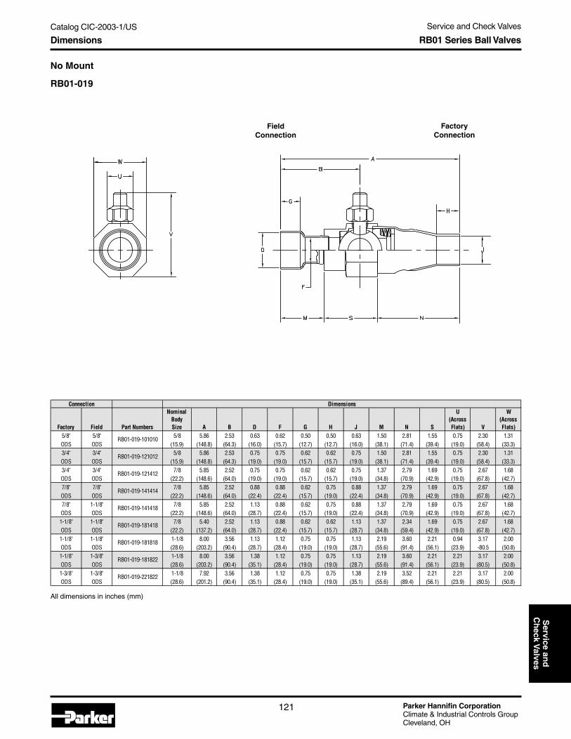
Parker Hannifin CorporationClimate & Industrial Controls GroupCleveland, OH
121
Catalog CIC-2003-1/US Service and Check ValvesS
ervice and
Ch
eck Valves
Dimensions
No Mount
RB01-019
All dimensions in inches (mm)
FieldConnection
FactoryConnection
Factory Field Part Numbers
NominalBodySize A B D F G H J M N S
U(AcrossFlats) V
W(AcrossFlats)
5/8" 5/8" 5/8 5.86 2.53 0.63 0.62 0.50 0.50 0.63 1.50 2.81 1.55 0.75 2.30 1.31ODS ODS (15.9) (148.8) (64.3) (16.0) (15.7) (12.7) (12.7) (16.0) (38.1) (71.4) (39.4) (19.0) (58.4) (33.3)3/4" 3/4" 5/8 5.86 2.53 0.75 0.75 0.62 0.62 0.75 1.50 2.81 1.55 0.75 2.30 1.31ODS ODS (15.9) (148.8) (64.3) (19.0) (19.0) (15.7) (15.7) (19.0) (38.1) (71.4) (39.4) (19.0) (58.4) (33.3)3/4" 3/4" 7/8 5.85 2.52 0.75 0.75 0.62 0.62 0.75 1.37 2.79 1.69 0.75 2.67 1.68ODS ODS (22.2) (148.6) (64.0) (19.0) (19.0) (15.7) (15.7) (19.0) (34.8) (70.9) (42.9) (19.0) (67.8) (42.7)7/8" 7/8" 7/8 5.85 2.52 0.88 0.88 0.62 0.75 0.88 1.37 2.79 1.69 0.75 2.67 1.68ODS ODS (22.2) (148.6) (64.0) (22.4) (22.4) (15.7) (19.0) (22.4) (34.8) (70.9) (42.9) (19.0) (67.8) (42.7)7/8" 1-1/8" 7/8 5.85 2.52 1.13 0.88 0.62 0.75 0.88 1.37 2.79 1.69 0.75 2.67 1.68ODS ODS (22.2) (148.6) (64.0) (28.7) (22.4) (15.7) (19.0) (22.4) (34.8) (70.9) (42.9) (19.0) (67.8) (42.7)1-1/8" 1-1/8" 7/8 5.40 2.52 1.13 0.88 0.62 0.62 1.13 1.37 2.34 1.69 0.75 2.67 1.68ODS ODS (22.2) (137.2) (64.0) (28.7) (22.4) (15.7) (15.7) (28.7) (34.8) (59.4) (42.9) (19.0) (67.8) (42.7)1-1/8" 1-1/8" 1-1/8 8.00 3.56 1.13 1.12 0.75 0.75 1.13 2.19 3.60 2.21 0.94 3.17 2.00ODS ODS (28.6) (203.2) (90.4) (28.7) (28.4) (19.0) (19.0) (28.7) (55.6) (91.4) (56.1) (23.9) -80.5 (50.8)1-1/8" 1-3/8" 1-1/8 8.00 3.56 1.38 1.12 0.75 0.75 1.13 2.19 3.60 2.21 2.21 3.17 2.00ODS ODS (28.6) (203.2) (90.4) (35.1) (28.4) (19.0) (19.0) (28.7) (55.6) (91.4) (56.1) (23.9) (80.5) (50.8)1-3/8" 1-3/8" 1-1/8 7.92 3.56 1.38 1.12 0.75 0.75 1.38 2.19 3.52 2.21 2.21 3.17 2.00ODS ODS (28.6) (201.2) (90.4) (35.1) (28.4) (19.0) (19.0) (35.1) (55.6) (89.4) (56.1) (23.9) (80.5) (50.8)
Connection
RB01-019-101010
RB01-019-121012
Dimensions
RB01-019-181818
RB01-019-181822
RB01-019-221822
RB01-019-121412
RB01-019-141414
RB01-019-141418
RB01-019-181418
RB01 Series Ball Valves

Parker Hannifin CorporationClimate & Industrial Controls GroupCleveland, OH
122
Catalog CIC-2003-1/US Service and Check Valves
Ordering Information
Available Options
How to Order
RB01ProductSeries
019Unique
Features
12Factory
Connection
10Body Size
12Field
Connection
Gauge Port LocationsViewed from theField Connection
* Provided with standard product offering
Mounting Type:
Pad Mount, Post-Stud Mount or No Mount
Gauge Port Location:
Left-Hand Gauge Port with Mounting Positions 2-5
Right-Hand Gauge Port with Mounting Positions 1-4
Ship Position:
Ball Open or Ball Closed*
Gauge Port Cap:
Brass* or Plastic
Available Options
FactoryConnection
(Denoted xx/16)10 = 5/8"12 = 3/4"14 = 7/8"18 = 1-1/8"22 = 1-3/8"
BodySize
(Denoted xx/16)10 = 5/8"14 = 7/8"18 = 1-1/8"
FieldConnection
(Denoted xx/16)10 = 5/8"12 = 3/4"14 = 7/8"18 = 1-1/8"22 = 1-3/8"
Customized tomounting and
gauge-portspecifications
RB01 Series Ball Valves

Parker Hannifin CorporationClimate & Industrial Controls GroupCleveland, OH
123
Catalog CIC-2003-1/US Service and Check ValvesS
ervice and
Ch
eck Valves
Backseating ValvesParker’s Backseating Valves are used as service valvesin air-conditioning and heat-pump systems. The valvesisolate sections of a system for servicing and provide ameans for charging refrigerant into a unit.
Application• Residential split-system air conditioners and heat
pumps
Technical Information Backseating Valves
Features and Benefits• Precision machining of the stem and valve seats,
as well as composite packing or o-ring stemseals, translates into reliable and repeatablesealing.
• Isolated chargeport minimizes refrigerant lossduring servicing.
• Brass body and copper connection tubes virtuallyeliminate corrosion-related problems.
• Copper-sweat connections provide basic endsfor brazing and eliminate the need for flux,simplifying the installation process.
• Multiple end configurations are available, alongwith assemblies, to meet the unique needs andflow patterns of a unit.
Valox® is a federally registered trademark of the General ElectricCompany.+ Frontseat maximum operating temperature for 1-3/8" valve body
is +210°F (+99C)* Brass Bar per ASTM-B16, Alloy C36000.** Due to the numerous manufacturers of refrigerant oils and
continuous changes of additives, compatibility can not beguaranteed. Please contact Parker for compatibility ofrefrigerants and refrigerant oils not listed.
PRODUCT Backseating ValvesOperating Temperature Range+ -40° F to +250° F (-40° C to +121° C)Operating Pressure Range Vacuum to 750 psiMinimum Burst Pressure 3,000 psi (207 bar)MATERIALSValve Body Machined Brass* or ForgedValve Stem Nickel-Plated Carbon Steel or 316L
Stainless SteelValve Stem Cap Valox® Cap with Neoprene™ "W" Gasket or
Brass* CapGauge Port Cap Valox® Cap with Neoprene™ "W" Gasket or
Brass* CapVALVE STEM SEAL MATERIALSPacking Nut Brass*Packing Composite (Arimid, Neoprene™ and TFE)O-Ring Neoprene™ "W"CONNECTION TYPES AND MATERIALSSweat Brass* or Wrought Copper per ASTM-B75,
Alloy C12200SAE 45° Flare Brass*RTS Brass* or 316L Stainless Steel
Vibration Resistance Complies with UL 109Corrosion Resistance Complies with ASTM B117External Leak Rate < 0.1 ounce of R22 refrigerant per year at
Operating Pressure Range
MATERIAL COMPATIBILITY**All components, including valve stem seal packaging and o-rings are compatible with these refrigerants and refrigerant oils: R22 & mineral oil, alkylbenzene oil or polyolester oil R134a, R404a, R407c, R-410a or R507 & polyolester oil

Parker Hannifin CorporationClimate & Industrial Controls GroupCleveland, OH
124
Catalog CIC-2003-1/US Service and Check Valves
RB8 Series Multi-FunctionCooling-Only Flare ValvesParker’s RB8 Multi-Function Flare Valves are used asservice valves in mini-split air conditioners. The valvesisolate sections of a system for servicing and provide ameans for charging refrigerant into a unit. The valvealso holds a restrictor and screen to meter refrigerantand filter debris, increasing system efficiency.
Application• Mini-split air conditioners
Base Product Part NumberRB8
Features and Benefits• Inclusion of a restrictor into the valve provides
precise refrigerant metering to increase efficiency.• Noise and vibration through the unit are reduced
by inclusion of the restrictor into the valve.• Inclusion of a screen into the valve filters dirt and
debris prior to entering the restrictor, maintainingfull flow and enhancing performance.
• Captivated stem-design holds the stem withinthe valve to prevent it from releasing when thecap is removed or the unit is serviced, reducingthe potential for injury.
• Combined functionality of valve, restrictor, andscreen reduces component inventory (shut-offvalve, field-access gage port, expansion device,filter screen or strainer, line-set connector, checkvalve, by-pass circuit, and capillary tubes) leadingto a reduction in overall installed cost.
• Combined functionality of valve, restrictor, andscreen also reduces space requirements withina unit and eliminates braze joints to reducepotential leaks paths.
• Patent-pending.
Agency ApprovalsPending UL approval.
Flow DataAvailable upon requested application.
Technical Information
Specifications
Teflon ® is a federally registered trademark of E.I. du Pont deNemours and Company.+ Pending UL testing and approval. Tests performed by Parker
indicate that operating and burst pressures can be achieved.* Brass Bar per ASTM-B16, Alloy C36000.** Due to the numerous manufacturers of refrigerant oils and
continuous changes of additives, compatibility cannot beguaranteed. Please contact Parker for compatibility ofrefrigerants and refrigerant oils not listed.
PRODUCT RB8 Series ValvesOperating Temperature Range -40° F to +250° F (-40° C to +121° C)Ambient Operating Temperature -40° F to +250° F (-40° C to +121° C)Operating Pressure Range Vacuum to 750 psi (52 bar)+
Minimum Burst Pressure 3,750 psi (259 bar)+
MATERIALSValve Body Brass*Connections Refrigeration Grade Copper, per ASTM-B75,
Alloy C12200Valve Stem Brass*Valve Stem Seal Neoprene™ “ W ” or HNBR O-RingValve Stem Cap Brass*Gauge Port Cap Brass* or Plastic with Neoprene™ “ W ”
or HNBR O-Ring SealGauge Port Valve Seals Neoprene™ & Teflon ® or
HNBR & Teflon ® SealsMATERIAL COMPATIBILITY** Neoprene™
HNBRVibration Resistance Complies with UL 109External Leak Rate < 0.1 ounce of R410a refrigerant per year at
Operating Pressure Range
– R22 & mineral oil, alkylbenzene oil or polyolester oil R134a, R404a, R407c, R-410a or R507 & polyolester oil– R-410a & polyvinylether oil or “ Hard ” Alkylbenzene oil
RB8 Series Multi-Function Cooling-Only Flare Valves

Parker Hannifin CorporationClimate & Industrial Controls GroupCleveland, OH
125
Catalog CIC-2003-1/US Service and Check ValvesS
ervice and
Ch
eck Valves
RB9 Series Multi-FunctionHeat-Pump Flare ValvesParker’s RB9 Multi-Function Flare Valves are used asservice valves in mini-split heat pumps. The valvesisolate sections of a system for servicing and providea means for charging refrigerant into a unit. The valvealso holds a restrictor and screen to meter refrigerantand filter debris, increasing system efficiency.
Application• Mini-split heat pumps
Base Product Part NumberRB9
Features and Benefits• Inclusion of a restrictor into the valve provides
precise refrigerant metering to increase efficiency.• Noise and vibration through the unit are reduced
by inclusion of the restrictor into the valve.• Inclusion of a screen into the valve filters dirt and
debris prior to entering the restrictor, maintainingfull flow and enhancing performance.
• Captivated stem-design holds the stem withinthe valve to prevent it from releasing when thecap is removed or the unit is serviced, reducingthe potential for injury.
• Combined functionality of valve, restrictor, andscreen reduces component inventory (shut-offvalve, field-access gage port, expansion device,filter screen or strainer, line-set connector, checkvalve, by-pass circuit, and capillary tubes) leadingto a reduction in overall installed cost.
• Combined functionality of valve, restrictor, andscreen also reduces space requirements withina unit and eliminates braze joints to reducepotential leaks paths.
• Patent-pending.
Agency ApprovalsPending UL approval.
Flow DataAvailable upon requested application.
Technical Information
Specifications
Teflon ® is a federally registered trademark of E.I. du Pont deNemours and Company.+ Pending UL testing and approval. Tests performed by Parker
indicate that operating and burst pressures can be achieved.* Brass Bar per ASTM-B16, Alloy C36000.** Due to the numerous manufacturers of refrigerant oils and
continuous changes of additives, compatibility cannot beguaranteed. Please contact Parker for compatibility ofrefrigerants and refrigerant oils not listed.
PRODUCT RB9 Series ValvesOperating Temperature Range -40° F to +250° F (-40° C to +121° C)Ambient Operating Temperature -40° F to +250° F (-40° C to +121° C)Operating Pressure Range Vacuum to 750 psi (52 bar)+
Minimum Burst Pressure 3,750 psi (259 bar)+
MATERIALSValve Body Brass*Connections Refrigeration Grade Copper, per ASTM-B75,
Alloy C12200Valve Stem Brass*Valve Stem Seal Neoprene™ “ W ” or HNBR O-RingValve Stem Cap Brass*Gauge Port Cap Brass* or Plastic with Neoprene™ “ W ”
or HNBR O-Ring SealGauge Port Valve Seals Neoprene™ & Teflon ® or
HNBR & Teflon ® SealsMATERIAL COMPATIBILITY** Neoprene™
HNBRVibration Resistance Complies with UL 109External Leak Rate < 0.1 ounce of R410a refrigerant per year at
Operating Pressure Range
– R22 & mineral oil, alkylbenzene oil or polyolester oil R134a, R404a, R407c, R-410a or R507 & polyolester oil– R-410a & polyvinylether oil or “ Hard ” Alkylbenzene oil
RB9 Series Multi-Function Heat-Pump Flare Valves

Parker Hannifin CorporationClimate & Industrial Controls GroupCleveland, OH
126
Catalog CIC-2003-1/US Service and Check Valves
Technical Information and Dimensions Copper Check Valves
Dimensions
Check ValvesCheck valves are designed to allow flow in one direction only. They are used to prevent backwards flow
through dryers and other devices that are designed for directional flow.
* Rated at 86°F liquid/5°F evaporator
SealPlug
RollGroove
SteelBall
BallCylinder
CopperTube
Female SystemSweat Overall Cutout Body
UL Connect Length Length Dia.Model No. Model in. in. in. in. 12 22 134a 401A/B 401C 402A 402B 404A 407A 407B 407C 410A 502 507A
CV4-6FS-6FS 3/8F 3/8 3.75 3.00 1/2 2.6 3.5 3.2 3.6 3.2 2.4 2.8 2.3 3.1 2.5 3.4 3.4 2.3 2.3CV5-8FS-8FS 1/2F 1/2 3.75 2.88 5/8 4.8 6.4 5.8 6.6 5.8 4.3 5.0 4.2 5.6 4.5 6.2 6.3 4.2 4.2
CV7-10FS-10FS 5/8F 5/8 4.5 3.50 7/8 9.0 12.0 10.9 12.3 11.0 8.1 9.5 7.8 10.5 8.4 11.6 11.8 7.8 7.8CV9-14FS-14FS 7/8F 7/8 4.5 3.50 1.13 18.6 24.8 22.5 25.4 22.6 16.7 19.5 16.1 21.6 17.4 23.9 24.3 16.1 16.1CV11-18FS-18FS 1 1/8F 1.125 5 4.00 1.38 48.8 65.0 59.1 66.7 59.3 43.9 51.2 42.2 56.8 45.6 62.9 64.0 42.4 42.3
Flow-tons* @ 1 psi pressure drop
Copper Ball Check Valves
Parker's Copper Ball Check Valves are used in refrig-eration and air conditioning systems to maintain flow inonly one direction. Internal components seat or “check,”preventing flow back through the valve. These productsare often used in conjunction with dryers or strainers toensure unidirectional flow, with compressors to preventliquid refrigerant from flooding back to the inlet, or insystem lines to redirect flow to another circuit.
Application• Refrigeration and air conditioning systems.
Features and Benefits• Stainless steel ball is contained in a one-piece
brass retainer within a copper tube to providecorrosion resistance and durability.
• Straight-flow design yields high flow for maximumsystem performance.
• Standard ball valves offer stainless steel-to-brassseating for low refrigerant leakage.
• Sweat connections in a variety of sizes providefor easy installation and simplified brazing.
• Spring-loaded designs are also available for nearhorizontal mounting applications.

Parker Hannifin CorporationClimate & Industrial Controls GroupCleveland, OH
127
Catalog CIC-2003-1/US Service and Check ValvesS
ervice and
Ch
eck Valves
Soft-Seat Copper Check Valves
Parker's Soft-Seat Copper Check Valves are used inrefrigeration and air conditioning systems to maintainflow in only one direction. Internal components seat or“check,” preventing flow back through the valve. Theseproducts are often used in conjunction with dryers orstrainers to ensure unidirectional flow, with compres-sors to prevent liquid refrigerant from flooding back tothe inlet, or in system lines to redirect flow to anothercircuit.
Application
• Refrigeration and air conditioning systems.
Features and Benefits
• Soft-seat valve features a Neoprene™ o-ring thatseals to a metal seat for low refrigerant leakage(10cc/min. compared to traditional check valveswith 750 cc/min.).
• Brass piston seat and steel piston providecorrosion resistance and durability.
• Sweat connections in a variety of sizes provide foreasy installation and simplified brazing.
Dimensions
PlasticPlug
O-ringBall Seat
Pistonand
O-Ring
Baffle
3.50" overall length
Female SystemSweat Overall Cutout Body
UL Connect Length Length Dia. FlowPart No. Model in. in. in. in. tons @ 1 psi pressure drop
274243-00 PCV525 5/16 3.5 2.81 0.525274243-01 PCV525 3/8 3.5 2.81 0.525274243-03 PCV525 1/2 3.5 3.10 0.525
TBD
Technical Information and Dimensions Soft-Seat Copper Check Valves

Parker Hannifin CorporationClimate & Industrial Controls GroupCleveland, OH
128
Catalog CIC-2003-1/US Service and Check Valves
Technical Information and Dimensions Brass Check Valves
3/8" Brass Check ValveFeatures and Benefits
• Poppet style valve incorporates o-ring sealingsurface.
• Brass body and piston resist corrosion.• Stainless steel spring resists corrosion.• Braze connections.
Dimensions
1/4" Brass Check Valve
Features and Benefits• Poppet style valve incorporates o-ring sealing
surface.• Brass body and piston resist corrosion.• Stainless steel spring resists corrosion.• Braze connections.
Dimensions

Parker Hannifin CorporationClimate & Industrial Controls GroupCleveland, OH
129
Catalog CIC-2003-1/US Service and Check ValvesS
ervice and
Ch
eck Valves
1/8" NPT Brass Check Valve
Features and Benefits
• Poppet style valve incorporates o-ring sealingsurface.
• Brass body and piston resist corrosion.
• Stainless steel spring resists corrosion.
• Female NPT threaded connections.
Dimensions
Technical Information and Dimensions Brass Check Valves

Parker Hannifin CorporationClimate & Industrial Controls GroupCleveland, OH
130
Catalog CIC-2003-1/US Service and Check Valves
Notes

Catalog CIC-2003-1/US
Parker Hannifin CorporationClimate & Industrial Controls GroupCleveland, OH
131
Service
& C
heck
Valves
Thermostatic and Constant Pressure (Automatic) Expansion ValvesT
XV
s & A
XV
sTable of Contents
Thermostatic Expansion Valves (TXVs) andConstant Pressure (Automatic) Expansion Valves (AXVs)Table of Contents
Visual Table of Contents .............................................................................................. page 132
Thermostatic Expansion Valves .................................................................................. page 134
Model Number Selection Guide ............................................................................ page 134
S Series ................................................................................................................... page 136
I Series .................................................................................................................... page 137
EG Series ................................................................................................................ page 138
EGC Series ............................................................................................................. page 139
RE Series ................................................................................................................ page 140
H Series .................................................................................................................. page 142
HC Series ................................................................................................................ page 142
EC Series ................................................................................................................ page 144
ECC Series ............................................................................................................. page 145
G Series .................................................................................................................. page 146
N Series .................................................................................................................. page 147
C Series .................................................................................................................. page 148
B5 Series ................................................................................................................ page 149
Pressure Temperature Chart ................................................................................. page 151
Capacity Tables ...................................................................................................... page 152
Applications ........................................................................................................... page 158
General Information ............................................................................................... page 158
Balanced Port Valves ............................................................................................. page 165
Valve Selection Procedure .................................................................................... page 166
Understanding Superheat .................................................................................... page 168
Constant Pressure (Automatic) Expansion Valves ................................................... page 170
104A Series ............................................................................................................ page 170
104F Series ............................................................................................................. page 170
139 Series EPR ....................................................................................................... page 171
A Series Valves ...................................................................................................... page 172U.S. Capacity Tables ......................................................................................... page 174Metric Capacity Tables ..................................................................................... page 176Technical Information ....................................................................................... page 178Applications ...................................................................................................... page 179
625 Series Thermal Electric Valve ........................................................................ page 181Applications ...................................................................................................... page 182Operation ........................................................................................................... page 185Installation ......................................................................................................... page 186Troubleshooting ................................................................................................ page 188Ratings .............................................................................................................. page 190
TXVs and AXVs

Parker Hannifin CorporationClimate & Industrial Controls GroupCleveland, OH
Catalog CIC-2003-1/US
132
Thermostatic and Constant Pressure (Automatic) Expansion Valves
S Series TXV - (page 136)Applications: Air Conditioning, HeatPumps, Dehumidifiers
I Series TXV - (page 137)Applications: Slush Machines, SaladBars, Vending Machines
EG Series TXV - (page 138)Applications: Supermarket Cases,Walk-in Freezers, Ice Machines
EGC Series TXV - (page 139)Applications: Supermarket Cases withhot gas defrost, Walk-in Freezers,Refrigeration
RE Series TXV - (page 140)Applications: Air Conditioning,Industrial Chillers, CommercialRefrigeration
H Series TXV - (page 142)Applications: Air Conditioning, HeatPumps, Bi-flow (Package Systems)
EC Series TXV - (page 144)Applications: Supermarket Cases,Transport Refrigeration, Walk-inCoolers
N Series TXV - (page 147)Applications: Low Profile Coolers, IceMachines, Beverage Dispensers
C Series TXV - (page 148)Applications: Rail and TransportRefrigeration, Supermarket Cases,Walk-in Coolers
104A Series AXV - (page 170)Applications: Ice Cream/SlushMachines, Hot Gas Bypass, FreezeProtection, Refrigerant Reclaim,Vending, Ice Machines
104F Series AXV - (page 170)Applications: Ice Cream/SlushMachines, Hot Gas Bypass, FreezeProtection, Refrigerant Reclaim,Vending, Ice Machines
Visual Table of Contents
Visual Table of Contents
HC Series TXV - (page 142)Applications: Air Conditioning, HeatPumps
G Series TXV - (page 146)Applications: Refrigerated Cases,Walk-in Freezers
TXVs and AXVs
ECC Series TXV - (page 145)Applications: Heat Pump Units, AirConditioning Units, Freezers, Walk-inBoxes, Refrigerated Cases
B5 Series TXV - (page 149)Applications: Air Conditioning,Refrigeration

Catalog CIC-2003-1/US
Parker Hannifin CorporationClimate & Industrial Controls GroupCleveland, OH
133
Service
& C
heck
Valves
Thermostatic and Constant Pressure (Automatic) Expansion ValvesT
XV
s & A
XV
s
AT Series AXV - (page 172)Applications: Ice Cream/SlushMachines, Hot Gas Bypass, FreezeProtection, Refrigerant Reclaim,PTAC/PTHP, High Cycle
A1 Series AXV - (page 172)Applications: Ice Cream/SlushMachines, Hot Gas Bypass, FreezeProtection, Refrigerant Reclaim,Vending, Ice Machines
A2 Series AXV - (page 173)Applications: Ice Cream/SlushMachines, Hot Gas Bypass, FreezeProtection, Refrigerant Reclaim,Vending, Ice Machines
A3 Series AXV - (page 173)Applications: Ice Cream/SlushMachines, Hot Gas Bypass, FreezeProtection, Refrigerant Reclaim,Vending, Ice Machines
AE3 Series AXV - (page 173)Applications: Ice Cream/SlushMachines, Hot Gas Bypass, FreezeProtection, Refrigerant Reclaim,Vending, Ice Machines
A4 Series AXV - (page 173)Applications: Ice Cream/SlushMachines, Hot Gas Bypass, FreezeProtection, Refrigerant Reclaim,Vending, Ice Machines
A7 Series AXV - (page 172)Applications: Ice Cream/SlushMachines, Hot Gas Bypass, FreezeProtection, Refrigerant Reclaim,PTAC/PTHP, High Cycle
AS Series AXV - (page 172)Applications: Ice Cream/SlushMachines, Hot Gas Bypass, FreezeProtection, Refrigerant Reclaim,Vending, Ice Machines
Visual Table of Contents
139 Series EPR - (page 171)Applications: Soft Serve Ice CreamMachines, Small Capacity EvaporatorPressure Control
625 Series Electric Valve - (page 181)Applications: Heat Pumps, FloodedEvaporator Systems, Multiple Evapora-tor Systems, Hot Gas, TemperatureRegulators
TXVs and AXVs

Parker Hannifin CorporationClimate & Industrial Controls GroupCleveland, OH
Catalog CIC-2003-1/US
134
Thermostatic and Constant Pressure (Automatic) Expansion Valves
TXV Model Number Selection Guide
S
MODEL
5
CAPACITY
(E)EXTERNAL EQUALIZER
OPTIONAL
V
REFRIGERANT
(E) for Externally EqualizedEvaporator pressure drop > 3 psi
BLANK for Internally EqualizedEvaporator pressure drop < 3 psior smaller tonnage evaporators
See page 163
CapacityParker's expansion valves offer arange of capacities from 1/8 ton to70 tons depending on valve series.See pages 152-157 for capacitytables.
S
I
RE
G N
EC
H(C)(A)C = internal check valve
A = adjustable
EG(C)C = internalcheck valve
Rainbow Charge™Refrigerant Designation
C
Model Number Selection Guide Thermostatic Expansion Valves
Refrigerant Color CodeR-12 - (yellow)R-22 - (green)R-502 - (purple)R-134a - (light blue)R-404A - (orange)
R-407C - (brown)R-410A - (rose)HP80 - (canary)HP81 - (olive)
J R-134a, R-401A (MP39), R-401B (MP66)V R-407C (AC9000), R-22
S R-125, R-404A (HP62), R-402A (HP80), R402B (HP81), R-507 (AZ50)
Z R-410A
B5

Catalog CIC-2003-1/US
Parker Hannifin CorporationClimate & Industrial Controls GroupCleveland, OH
135
Service
& C
heck
Valves
Thermostatic and Constant Pressure (Automatic) Expansion ValvesT
XV
s & A
XV
sModel Number Selection Guide Thermostatic Expansion Valves
X
CHARGE TYPE
100
M.O.P.
BBLEED
OPTIONAL
20BLEED
CAPACITY
Charge Type“W” (all-purpose) liquid charge maintains nearly “flat” superheatcontrol over a -40F° to +60F° (-40C° to +15C°) evaporator tem-perature range.“Z” (low temperature) charge provides fast pulldown benefits likea gas charge with the non-migrating benefits of a liquid charge;usable over a -40F° to 0F° (-40C° to -20C°) evaporator tempera-ture range.“X” (damped response) gas charge provides a pressure limiting(MOP) charge with anti-hunt characteristics over a -40F° to+60F° (-40C° to +15C°) evaporator temperature range.Notes: M.O.P. not available on "W" or "Z" charge.
*May not be used on systems in which bulb temperature will exceed 130° F(i.e. defrost). Contact Parker for pressure and temperature.
M.O.P.Maximum Operating Pressure
-40 -30 -20 -10 0 10 20 30 40 50 60
BleedDenoted by “B”.
Not available on all TXVs.See bleed capacity.
Used for equalizing systemduring off cycle (compressorunloading). Consult Parker.
See page 164.
Bleed CapacityCalculated based on nominalcapacity of valve specified bymanufacturer or Parker.Typically 30% or less.Calculated by:Desired Bypass Capacity x 100%Rated Valve Capacity
Rainbow Charge™RefrigerantDesignationJW, JX60VX100, VW, VX35, VZSW, SX35, SX110, SZKX200
VX100, JX60, SX110, KX200 Air Conditioning
VX35, SX35 Low Temp. Ref. VZ, SZ Low Temp. Ref.
VW, JW, SW All purpose liquid
Charge Operating Temperature Range
Evaporator Temperature °F

Parker Hannifin CorporationClimate & Industrial Controls GroupCleveland, OH
Catalog CIC-2003-1/US
136
Thermostatic and Constant Pressure (Automatic) Expansion Valves
Technical Information S Series
S SeriesParker’s S series is well suited for new or replacement installationson a variety of small to medium tonnage air-conditioning, heat pump,and refrigeration systems. A brass body with standard ODF solderconnections and balanced port construction lends itself to installationon systems requiring stability and control under low load and othervarying conditions.
Specifications
Notes:1. U.L. recognized for maximum operational pressure of 650 psig (45 bars).2. Maximum storage temperature 130°F (55°C).3. Consult Parker for pressure and temperature exceptions.4. Do not use “W” or “Z” liquid charges in applications where bulb temperatures can exceed 130°F (55°C). For these applications use type “X” MOP gas
charge only.
R-12 1/8 - 1/2 S 1/2J SE 1/2J 1/4 (3/8) 1/2 (3/8)R-134a 1/4 - 1 S 1J SE 1J 3/8 (1/4) 1/2 (3/8)R-401A 1 - 2 S 2J SE 2J 1/2 5/8 (7/8)R-401B 1 1/2 - 3 S 3J SE 3J 1/2 7/8 (5/8)
3 1/2 - 5 S 5J SE 5J 5/8 7/8R- 402B 1/8 - 1/2 S 1/2S SE 1/2S 1/4 (3/8) 1/2 (3/8)R- 404A 1/4 - 1 S 1S SE 1S W, Z, X110 3/8 (1/4) 3/8R-402A 1 - 2 S 2S SE 2S X35 1/2 5/8 (7/8)R- 502 1 1/2 - 4 S 4S SE 4S 1/2 7/8 (5/8)R- 507 4 1/2 - 6 S 6S SE 6S 5/8 7/8
1/5 - 3/4 S 3/4V S 3/4V 1/4 (3/8) 1/2 (3/8)1/2 - 1 1/2 S 1-1/2V SE 1-1/2V 3/8 (1/4) 1/2 (3/8)
R-22 1 1/2 - 3 S 3V SE 3V W, Z, X100 1/2 5/8 (7/8)R-407C 3 1/2- 5 S 5V SE 5V X35 1/2 7/8 (5/8)
5 1/2 - 7 1/2 S 7 1/2 SE 7-1/2V 5/8 7/88 - 10 S 10 SE 10V 5/8 7/8
1/2 - 1 1/2 S 1 1/2K SE 1 1/2K 3/8 1/21 1/2 - 3 S 3K SE 3K 3/8 1/2
R-410A K 3 1/2 - 5 S 5K SE 5K KX200 1/2 5/85 1/2 - 7 1/2 S 7K SE 7K 1/2 5/8
7 1/2 - 9 S 9K SE 9K 5/8 7/8
1/4" ODF (1/4" SAE)
Refrigerant
Outlet Connection
ODF (Optional)Inlet Connection ODF (Optional)
Externally Equalized
Models
Internally Equalized
ModelsRefrigerant Designation Capacity Range Tons
Rainbow Charges™
V
1/4" ODF (1/4" SAE)
1/4" ODF (1/4" SAE)
Equalizer Connection (Optional)
J
S
W, X60 1/4" ODF (1/4" SAE)
Applications• Air Conditioning• Heat Pumps• Commerical Refrigeration• Transport Refrigeration• Beverage Dispensers• Dehumidifiers• Ice Machines
Features and Benefits• 60" capillary tube with shock loop• Optional external equalizer• Stainless steel power element• Weight: .7 lbs. (.32 kg)• Optional bleed• Field adjustable superheat
Dimensions
* VX100, KX200 only
FittingInlet
AOutlet
B1/4 ODF 1.46 -3/8 ODF 1.69 1.691/2 ODF 1.46 1.465/8 ODF 1.57 1.577/8 ODF - 2.07

Catalog CIC-2003-1/US
Parker Hannifin CorporationClimate & Industrial Controls GroupCleveland, OH
137
Service
& C
heck
Valves
Thermostatic and Constant Pressure (Automatic) Expansion ValvesT
XV
s & A
XV
sI Series
I Series
The right angle I Series with pure copper connections is an idealcompact size brass valve where landscape and precise control is ofgreatest concern (as in fractional horsepower refrigeration systems).The superheat is factory set to optimize system performance for originalequipment applications.
Specifications
Notes:1. Maximum operational pressure 500 psig (35 bars) high side and 275 psig (19 bars) low side.2. Maximum storage temperature 130°F (55°C).3. Consult Parker for pressure and temperature exceptions.4. Do not use “W” or “Z” liquid charges in applications where bulb temperatures can exceed 130°F (55°C).
Technical Information
Applications• Salad Bars• Ice Machines• Slush Machines• Vending Machines• Beverage Dispensers• Back bar Reach-in Cases• Mobile/Self-contained Cases
Features and Benefits• Bottom Inlet• Stainless steel power element• 30" capillary tube• Factory set superheat• W, Z charges• Weight: 3.5 oz / 0.1 k
Dimensions
RefrigerantRefrigerant Designation
Nominal Capacity
Capacity Range
Model No. Internally Equalized
Rainbow Charges™
Inlet Connection
Outlet Connection
R-12R134aR-401A J 1/2 1/4 - 1/2 I 1/2J W 1/4" ODF 3/8" ODFR-401B 1 3/4 - 1 I 1J W
R-402AR-402BR-404A S 1/2 1/4 - 1/2 I 1/2S W, Z 1/4" ODF 3/8" ODFR-502 1 3/4 - 1 I 1S W, ZR-507R-22 1 1/2 - 1 I 1V W, Z
R-407C 2 1 1/2 - 2 I 2V W, Z1/4" ODF 3/8" ODFV

Parker Hannifin CorporationClimate & Industrial Controls GroupCleveland, OH
Catalog CIC-2003-1/US
138
Thermostatic and Constant Pressure (Automatic) Expansion Valves
Technical Information EG Series
EG SeriesThe EG series refrigeration right angle brass body expansion valveincorporates a new shock loop, stainless steel power element, and aremovable inlet strainer, making it an ideal choice for commericalrefrigeration and supermarket applications. New Rainbow Charges™are noted below for use on medium temperature (“W” charges), lowtemperature (“Z” charges) or MOP (“X” charges). See details on page 135.
Applications• Supermarket Cases• Self-contained Cases• Walk-in Coolers/Freezers• Ice Machines• Salad Bars• Transport Refrigeration
Specifications
Notes:1. Maximum operational pressure 500 psig (35 bars) high side and 275 psig (19 bars) low side.2. Maximum storage temperature 130°F (55°C).3. Consult Parker for pressure and temperature exceptions.4. Do not use “W” or “Z” liquid charges in applications where bulb temperatures can exceed 130°F (55°C). For these applications use type “X” MOP gas
charge only.
Serviceable Strainer for Sweat (ODF)
Torque to 30 in. lbs.
Use Parker replacementpart numbers
020393-00020411-00
Features and Benefits• Stainless steel power element• 30" capillary tube with shock loop• Removable inlet strainer• Field adjustable superheat• 1/4" ODF external equalizer• W, Z or MOP (X) charges available• Weight: 1.0 lbs / 0.45 kg
Dimensions
RefrigerantRefrigerant Designation
Nominal Capacity
Internally Equalized
Externally Equalized Rainbow Charges™
Inlet Connection
Outlet Connection
1/8 EG 1/8 J EGE 1/8 JR-12 1/4 EG 1/4 J EGE 1/4 J
R-134a 1/2 EG 1/2 J EGE 1/2 JR-401A 1 EG 1 J EGE 1 JR-401B 1 1/2 EG 1-1/2 J EGE 1-1/2 J
2 EG 2 J EGE 2 JR-402B 1/8 EG 1/8 S EGE 1/8 SR-404A 1/4 EG 1/4 S EGE 1/4 SR-402A 1/2 EG 1/2 S EGE 1/2 SR-502 1 EG 1 S EGE 1 SR-507 1 1/2 EG 1-1/2 S EGE 1-1/2 S
2 EG 2 S EGE 2 S1/4 EG 1/4 V EGE 1/4 V1/2 EG 1/2 V EGE 1/2 V1 EG 1 V EGE 1 V
1 1/2 EG 1-1/2 V EGE 1-1/2 V2 EG 2 V EGE 2 V
2 1/2 EG 2 1/2V EGE 2 1/2 V3 EG 3 V EGE 3 V
1/2" ODF
1/2" ODF
1/2" ODF
3/8" ODF
3/8" ODF
3/8" ODF
W, Z, X35, X110
W, Z, X35,X100
W, X60
R-22 R-407C
J
S
V
0.093 O.D. Capillary Tube
1.50
2.00
2.50
0.50 O.D.
2.20 1.83
Outlet
Inlet
1.44 1.46
120 Mesh Screen
Removable,Replaceable Screen

Catalog CIC-2003-1/US
Parker Hannifin CorporationClimate & Industrial Controls GroupCleveland, OH
139
Service
& C
heck
Valves
Thermostatic and Constant Pressure (Automatic) Expansion ValvesT
XV
s & A
XV
sTechnical Information EGC Series
Specifications
EGC SeriesThis valve is similar to the EG series except it incorporates aninternal check valve, providing reverse flow up to 2 tons for hotor cool gas defrost applications. This eliminates the need for anexternal check valve and related bypass plumbing. A brassbody, ODF solder connections, stainless steel power elementand a removable inlet strainer make installations easier. NewRainbow Charges™ listed below cover medium “W” tempera-ture charges, low “Z” temperature charges or MOP “X” charges.
Applications• Hot Gas Defrost• Cool Gas Defrost• Supermarket Cases• Back Shelf Storage Cases• Walk-in Coolers/Freezers• Salad Bars• Transport Refrigeration
Notes:1. Maximum operational pressure 500 psig (35 bars) high side and 275 psig (19 bars) low side.2. Maximum storage temperature 130°F (55°C)3. Consult Parker for pressure and temperature exceptions.4. Do not use “W” or “Z” liquid charges in applications where bulb temperatures can exceed 130°F (55°C). For these applications use type “X” MOP gas
charge only.
Hot gas bypasses txvorifice in defrost
CHECK VALVE SECTION
RefrigerantRefrigerant Designation
Nominal Capacity
Internally Equalized
Externally Equalized
Rainbow Charges™
Inlet Connection
Outlet Connection
1/8 EGC 1/8 J EGCE 1/8 JR-12 1/4 EGC 1/4 J EGCE 1/4 J
R-134a 1/2 EGC 1/2 J EGCE 1/2 JR-401A J 1 EGC 1 J EGCE 1 J 1/2" ODFR-401B 1 1/2 EGC 1-1/2 J EGCE 1-1/2 J
2 EGC 2 J EGCE 2 J1/8 EGC 1/8 S EGCE 1/8 S
R-402B 1/4 EGC 1/4 S EGCE 1/4 SR-404A 1/2 EGC 1/2 S EGCE 1/2 SR-402A S 1 EGC 1 S EGCE 1 S 1/2" ODFR-502 1 1/2 EGC 1-1/2 S EGCE 1-1/2 SR-507 2 EGC 2 S EGCE 2 S
1/4 EGC 1/4 V EGCE 1/4 V1/2 EGC 1/2 V EGCE 1/2 V1 EGC 1 V EGCE 1 V 1/2" ODF
V 1 1/2 EGC 1-1/2 V EGCE 1-1/2 V2 EGC 2 V EGCE 2 V
R-22 R-407C
3/8" ODF
3/8" ODF
3/8" ODF
W, Z, X35, X110
W, Z, X35, X100
W, X60
Dimensions 0.093 O.D. Capillary Tube
2.00
2.50
0.50 O.D.
2.201.83
Outlet
Inlet
1.44
Features and Benefits• Extended ODF connections• Balanced port design• 30" capillary tube with shock loop• Stainless steel power element• Field adjustable superheat• 1/4" ODF external equalizer• Rainbow charges available• Weight: 1.0 lbs / 0.45 kg

Parker Hannifin CorporationClimate & Industrial Controls GroupCleveland, OH
Catalog CIC-2003-1/US
140
Thermostatic and Constant Pressure (Automatic) Expansion Valves
Technical Information
Specifications
RE SeriesThe Parker RE series valve utilizes balanced port construc-tion to provide optimum operation on medium to large tonnageair conditioning and refrigeration systems. Two brass bodystyles with copper ODF connections and a removableRainbow Charged™ thermostatic power element providethe stability and control required in a variety of applications,especially where there are wide changes in load conditions.Body Style 1 has an R-22 nominal capacity up to 30 tons,while Body Style 2 extends the capacity range to 70 tons.
Applications• Air Conditioning• Process Chillers• Industrial Refrigeration• Transport Refrigeration
Features and Benefits• Balanced port design• Removable stainless steel power element• Field adjustable superheat• 1/4" sweat external equalizer• Rainbow Charges™• Weight: Body Style 1 - 1.7 lbs. / .77 kg
Body Style 2 - 2.5 lbs. / 1.13 kg• Forward or reverse flow• 60" capillary tube (120" optional)
Notes:1. Maximum operational pressure 500 psig (35 bars) high side and 275 psig (19 bars) low side.2. Maximum storage temperature 130°F (55°C)3. Consult Parker for pressure and temperature exceptions.4. Do not use “W” or “Z” liquid charges in applications where bulb temperatures can exceed 130°F (55°C). For these applications use type “X” MOP gas
charge only.
RE Series
RefrigerantRefrigerant
DesignationNominal Capacity
Body Style
Externally Equalized
Rainbow Charges�
Inlet Connection (Optional)
Outlet Connection
6 1 RE 6 J 5/8" 7/8"R-12 9 1 RE 9 J 7/8" 1-1/8"
R-134a 12 1 RE 12 J 7/8 (1-1/8") 1-3/8"R-401A 16 1 RE 16 J 1-1/8" 1-3/8"R-401B 23 2 RE 23 J 1-1/8" 1-3/8"
40 2 RE 40 J 1-1/8" 1-5/8"6 1 RE 6 S 5/8" 7/8"
R-402B 9 1 RE 9 S 7/8" 1-1/8"R-404A 12 1 RE 12 S 7/8 (1-1/8") 1-3/8"R-402A 21 1 RE 21 S 1-1/8" 1-3/8"R-502 30 2 RE 30 S 1-1/8" 1-3/8"R-507 45 2 RE 45 S 1-1/8" 1-5/8"
10 1 RE 10 V 5/8" 7/8"15 1 RE 15 V 7/8" 1-1/8"20 1 RE 20 V 7/8 (1-1/8") 1-3/8"30 1 RE 30 V 1 -1/8" 1-3/8"40 2 RE 40 V 1-1/8" 1-3/8"70 2 RE 70 V 1-1/8" 1-5/8"
W, X60
W, Z, X110, X35
W, Z, X100, X35
R-22R-407C
J
S
V
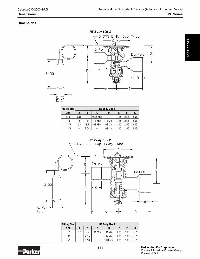
Catalog CIC-2003-1/US
Parker Hannifin CorporationClimate & Industrial Controls GroupCleveland, OH
141
Service
& C
heck
Valves
Thermostatic and Constant Pressure (Automatic) Expansion ValvesT
XV
s & A
XV
sDimensions RE Series
Fitting SizeODF A B C D E F G
5/8 1.55 – 0.36 Min – 1.45 2.56 2.067/8 2 2 .73 Min. .73 Min. 1.45 2.56 2.06
1 1/8 2.3 2.3 .93 Min. .93 Min. 1.45 2.56 2.061 3/8 – 2.68 – .93 Min. 1.45 2.56 2.06
RE Body Size 1
Fitting SizeODF A B C D E F G
1 1/8 2.7 2.7 .91 Min. .91 Min. 1.83 2.96 2.811 3/8 – 2.85 – .97 Min. 1.83 2.96 2.811 5/8 – 3.13 – 1.09 Min. 1.83 2.96 2.81
RE Body Size 2
Dimensions
RE Body Size 1
RE Body Size 2

Parker Hannifin CorporationClimate & Industrial Controls GroupCleveland, OH
Catalog CIC-2003-1/US
142
Thermostatic and Constant Pressure (Automatic) Expansion Valves
Technical Information H and HC Series
H Series and HC Series
The H series balanced port valve is designedspecifically for air conditioning and heat pumpsused in both air or water source systems. Itoffers features such as select indoor and/oroutdoor thermostatic Rainbow Charges™,bleeds, and a variety of connection styles forthe inlet, outlet, and external equalizer.
The HC series adds a built-in 5 ton check valvefor R-22, R-407C and R-410A heat pump appli-cations with either factory set or field adjustablesuperheat.
Applications• Air Conditioning Systems• Heat Pump Systems• Bi-flow (package) Systems
Features and Benefits• Stainless steel power element• Bypass bleeds available• Bi-directional metering available• Weight: 10.7 oz. (.30 kg)• Factory set or field adjustable superheat• Low pressure drop internal check valve
Specifications
Notes:1. U.L. recognized for maximum operational pressure of 650 psig (45 bars).2. Maximum storage temperature 130°F (55°C).3. Consult Parker for pressure and temperature exceptions.
RefrigerantRegfrigerantDesignation
CapacityRange
NominalCapacity
InternalEqualized
ExteriorEqualized
RainbowCharges
Bleed forOff CycleOperation
InletConnections
OutletConnections
1/2 - 1 1/2 1 - 1/2 HA 1-1/2V HAE 1 1/2V B1 1/2 - 3 3 HA 3V HAE 3V B 1/4, 3/8, 1/2 3/8,1/2,5/83 1/2 - 5 5 HA 5V HAE 5V B & 5/8" ODF & 7/8" ODF
5 1/2 - 7 1/2 7 1/2 - HAE 7 1/2V B flo-rater flo-rater 8 - 10 10 - HAE 10V B
R-407C1/2 - 1 1/2 1 1/2V HCA1-1/2V HCAE 1 1/2V B 1/4, 3/8, 1/2 3/8,1/2,5/81 1/2 - 3 3 HCA 3V HCAE 3V X100A, X100 B & 5/8" ODF & 7/8" ODF3 1/2 - 5 5 HCA 5V HCAE 5V B flo-rater flo-rater
1/2 - 1 1/2 1 1/2V HA 1-1/2K HAE 1 1/2K B 1 1/2 - 3 3 HA 3K HAE 3K B 1/4, 3/8, 1/2 3/8,1/2,5/8 3 1/2 - 5 5 HA 5K HAE 5K B & 5/8" ODF & 7/8" ODF
5 1/2 - 7 7 - HAE 7K B flo-rater flo-rater 7 1/2 - 9 9 - HAE 9K B
R-410A K1/2 - 1 1/2 1 1/2 HCA1-1/2K HCAE 1 1/2K B 1/4, 3/8, 1/2 3/8,1/2,5/8
1 - 2 2 HCA 2K HCAE 2K B & 5/8" ODF & 7/8" ODF 1 1/2 - 3 3 HCA 3K HCAE 3K B flo-rater flo-rater 3 1/2 - 5 5 HCA 5K HCAE 5K B
X200
X200
V
X-100A, X100
models with internal check valves - "C" designation
specific models with internal check valves - "C" designation

Catalog CIC-2003-1/US
Parker Hannifin CorporationClimate & Industrial Controls GroupCleveland, OH
143
Service
& C
heck
Valves
Thermostatic and Constant Pressure (Automatic) Expansion ValvesT
XV
s & A
XV
s
OptionalInlet Screen
Available
Dimensions
H and HC SeriesConnections - flo-rater
Inlet - 3/4" - 20Outlet - 3/4" - 20
H and& HC SeriesDimensions (inches)Connections (ODF)
Allows reverse flowin heating mode.
H and HC Series
Inlet/Outlet A B0.250 1.46 1.460.375 1.69 1.690.500 1.46 1.460.625 1.57 1.570.875 - 2.07
Dimensions

Parker Hannifin CorporationClimate & Industrial Controls GroupCleveland, OH
Catalog CIC-2003-1/US
144
Thermostatic and Constant Pressure (Automatic) Expansion Valves
Technical Information EC Series
EC SeriesThe EC series features extended ODF solder connections,brass body, and balanced port design. The new stainless steelpower element makes it suited for both refrigeration and airconditioning applications. Rainbow Charges™ are indicated inthe chart below for medium temperature “W” charges, low tem-perature “Z” charges or MOP “X” charge for those applications.
Specifications
Applications• Small Chillers• Heat Pump Units• Air Conditioning Units• Freezers• Walk-in Boxes• Refrigerated Cases• Mobile Refrigeration
Features and Benefits• Extended ODF connections• Balanced port design• 30" capillary tube with shock
loop• Stainless steel power element• Field adjustable superheat• 1/4" ODF external equalizer• Rainbow charges available• Weight: 1.0 lbs / 0.45 kg
Notes:1. Maximum operational pressure 500 psig (35 bars) high side and 275 psig (19 bars) low side.2. Maximum storage temperature 130°F (55°C) .3. Consult Parker for pressure and temperature exceptions.4. Do not use “W” or “Z” liquid charges in applications where bulb temperatures can exceed 130°F (55°C). For these applications use type “X” MOP gas
charge only.
RefrigerantRefrigerant Designation
Orifice Designation
Capacity Range
Internally Equalized
Externally Equalized
Rainbow Charges™
Inlet Connection
Outlet Connect
(Optional)Equalizer
ConnectionR-12 AA 1/8 - 1/2 EC-AA-J ECE-AA-J
R-134a A 1/4 - 1 EC-A-J ECE-A-JR-401A J B 1 - 2 EC-B-J ECE-B-JR-401B C 1 1/2 - 3 EC-C-J ECE-C-JR-402A AAR-402B A 1/8 - 1/2 EC-AA-S ECE-AA-SR-404A S B 1/4 - 1 EC-A-S ECE-A-SR-502 C 1 - 2 EC-B-S ECE-B-SR-507 1 1/2 - 4 EC-C-S ECE-C-S
AA 1/5 - 3/4 EC-AA-V ECE-AA-VR-22 V A 1/2 - 1 1/2 EC-A-V ECE-A-V 3/8" ODF 1/4" ODF
R-407C B 1 1/2 - 3 EC-B-V ECE-B-VC 3 1/2 - 5 EC-C-V ECE-C-V
1/2" ODF (5/8" ODF)
W, Z, X100 X35
1/2" ODF (5/8" ODF)
1/4" ODF
1/4" ODF3/8" ODF 1/2" ODF (5/8" ODF)
3/8" ODF
W, Z, X110 X35
W, X60
Dimensions

Catalog CIC-2003-1/US
Parker Hannifin CorporationClimate & Industrial Controls GroupCleveland, OH
145
Service
& C
heck
Valves
Thermostatic and Constant Pressure (Automatic) Expansion ValvesT
XV
s & A
XV
sTechnical Information ECC Series
ECC SeriesThe ECC series is similar to the EC series except it incorporates aninternal check valve, providing reverse flow of up to 2 tons for hot orcool gas defrost applications. This eliminates the need for an exter-nal check valve and related hot gas plumbing. A brass body, ODFsolder connections, and a removable inlet strainer make installa-tions easier. New Rainbow Charges™ are indicated in the chartbelow for medium temperature “W” charges, low temperature “Z”charges or MOP “X” charge for those applications.
Specifications
Applications• Heat Pump Units• Air Conditioning Units• Freezers• Walk-in Boxes• Refrigerated Cases
Notes:1. Maximum operational pressure 500 psig (35 bars) high side and 275 psig (19 bars) low side.2. Maximum storage temperature 130°F (55°C).3. Consult Parker for pressure and temperature exceptions.4. Do not use “W” or “Z” liquid charges in applications where bulb temperatures can exceed 130°F (55°C). For these applications use type “X” MOP gas
charge only.
Hot gas bypasses txvorifice in defrost
CHECK VALVE SECTION
RefrigerantRefrigerant Designation
Orifice Designation
Capacity Range
Internally Equalized
Externally Equalized
Rainbow Charges™
Inlet Connection
Outlet Connect (Optional)
Equalizer Connection
R-12 AA 1/8 - 1/2 ECC-AA-J ECCE-AA-JR-134a A 1/4 - 1 ECC-A-J ECCE-A-JR-401A J B 1 - 2 ECC-B-J ECCE-B-JR-401B C 1 1/2 - 3 ECC-C-J ECCE-C-JR-402A AAR-402B A 1/8 - 1/2 ECC-AA-S ECCE-AA-SR-404A S B 1/4 - 1 ECC-A-S ECCE-A-SR-502 C 1 - 2 ECC-B-S ECCE-B-SR-507 1 1/2 - 4 ECC-C-S ECCE-C-S
AA 1/5 - 3/4 ECC-AA-V ECCE-AA-VR-22 V A 1/2 - 1 1/2 ECC-A-V ECCE-A-V 3/8" ODF 1/4" ODF
R-407C B 1 1/2 - 3 ECC-B-V ECCE-B-VC 3 1/2 - 5 ECC-C-V ECCE-C-V
1/2" ODF (5/8" ODF optional)
W, Z, X100 X35
1/2" ODF (5/8" ODF optional)
1/4" ODF
1/4" ODF3/8" ODF1/2" ODF (5/8" ODF optional)
3/8" ODF
W, Z, X110 X35
W, X60
Features and Benefits• Extended ODF connections• Balanced port design• 30" capillary tube with shock loop• Stainless steel power element• Field adjustable superheat• 1/4" ODF external equalizer• Rainbow charges available• Weight: 1.0 lbs / 0.45 kg
Dimensions

Parker Hannifin CorporationClimate & Industrial Controls GroupCleveland, OH
Catalog CIC-2003-1/US
146
Thermostatic and Constant Pressure (Automatic) Expansion Valves
G SeriesThe G series features a brass body with SAE flare connections and isavailable internally or externally equalized through a 1/4" SAE male fitting.It provides accurate and stable control over changing loads, and is an idealselection for refrigeration and air conditioning systems. An array of RainbowCharges™ provide the necessary control and operation.
Applications• Small Refrigeration Machines• Slush Machines• Air Conditioning Units• Freezers• Walk-in Boxes• Refrigerated Cases
Specifications
Notes:1. Maximum operational pressure 500 psig (35 bars) high side
and 275 psig (19 bars) low side.2. Maximum storage temperature 130°F (55°C).3. Consult Parker for pressure and temperature exceptions.4. Do not use “W” or “Z” liquid charges in applications where bulb
temperatures can exceed 130°F (55°C). For these applicationsuse type “X” MOP gas charge only.
Technical Information G Series
Features and Benefits• 30" capillary tube with shock loop• Stainless steel power element• Field adjustable superheat• 1/4" SAE external equalizer• Inlet strainer• Rainbow Charges™ available• Weight: 1.0 lbs / 0.45 kg
Optional inlet screen available.
Use Parker part numbers:056813-00056820-00
Dimensions
RefrigerantRefrigerant Designation
Nominal Capacity
Internally Equalized
Externally Equalized
Rainbow Charges™
Inlet Connection (Optional)
Outlet Connection (Optional)
Equalizer Connection
1/8 G 1/8 J GE 1/8 J1/4 G 1/4 J GE 1/4 J
R-12 1/2 G 1/2 J GE 1/2 JR-134a 1 G 1 J GE 1 JR-401A J 1 1/2 G 1-1/2 J GE 1-1/2 JR-401B 2 G 2 J GE 2 J
2 1/2 G 2-1/2 J GE 2-1/2 J3 G 3 J GE 3 J 3/8" SAE & (1/2") 1/2" SAE & (5/8")5 G 5 J GE 5 J 1/2" SAE 5/8" SAE
1/8 G 1/8 S GE 1/8 S1/4 G 1/4 S GE 1/4 S1/2 G 1/2 S GE 1/2 S
R-402A 1 G 1 S GE 1 S 1/2" SAER-402B S 1-1/2 G 1-1/2 S GE 1-1/2 SR-404A 2 G 2 S GE 2 SR-502 2-1/2 G 2-1/2 S GE 2-1/2 SR-507 3 G 3 S GE 3 S
4 G 4S GE 4 S6 G 6 S GE 6 S 1/2" SAE 5/8" SAE
1/4 G 1/4 V GE 1/4 V1/2 G 1/2 V GE 1/2 V1 G 1 V GE 1 V
V 1 1/2 G 1-1/2 V GE1-1/2 V2 1/2 G 2 1/2 V GE 2 1/2V
2 G 2 V GE 2 V 3/8" SAE & (1/2")3 G 3 V GE 3 V 1/2" SAE & (5/8")4 G 4 V GE 4 V5 G 5 V GE 5 V 1/2" SAE 5/8" SAE8 G 8 V GE 8 V
1/4" SAE & (3/8")
(1/4" SAE)3/8" SAE
3/8" SAE 1/2" SAE
W, X60
W, Z, X110 X35
W, Z, X100 X35R-22
R-407C
1/4" SAE & (3/8")
1/2" SAE
3/8" SAE & 1/2"
1/4" SAE
1/4" SAE
1/4" SAE
1/2" SAE3/8" SAE
1/4" SAE & (3/8")
3/8" SAE & 1/4" SAE

Catalog CIC-2003-1/US
Parker Hannifin CorporationClimate & Industrial Controls GroupCleveland, OH
147
Service
& C
heck
Valves
Thermostatic and Constant Pressure (Automatic) Expansion ValvesT
XV
s & A
XV
s
N SeriesThis small flare brass valve series is ideally suited where space is at apremium. Its stainless steel power element and compact body has alwaysmade it the first choice for installation in commercial refrigeration systems.External equalized models are provided with a 30" capillary and 1/4" SAEflare nut, eliminating the need to run a separate equalizer line. Medium,low & MOP (X) charges are available as noted below.
Specifications
Applications• Low Profile Coolers• Beverage Dispensers• Beverage Boxes• Small Chillers• Ice Machines• Small Freezers
Notes:1. Maximum operational pressure 500 psig (35 bars) high side and 275 psig (19 bars) low side.2. Maximum storage temperature 130°F (55°C).3. Consult Parker for pressure and temperature exceptions.4. Do not use “W” or “Z” liquid charges in applications where bulb temperatures can exceed 130°F (55°C). For these applications use type “X” MOP gas
charge only.
Technical Information N Series
RefrigerantRefrigerant Designation
Nominal Capacity
Capacity Range
Internally Equalized
Externally Equalized
Rainbow Charges™
Inlet Connection
Outlet Connection
R-12R-134a 1/4 1/4 - 1/2 N 1/4 J 1/4 SAER-401A J 1/2 1/4 - 3/4 N 1/2 J W, X60 1/4 SAER-401B 2 1 - 2 N 2 J NE 2 J 3/8 SAER-402AR-402B 1/4 1/4 - 1/2 N 1/4 S 1/4 SAER-404A S 1/2 1/4 - 3/4 N 1/2 S W, Z, X110 1/4 & 3/8 SAER-502 2 1 - 2 N 2 S NE 2 S X35 3/8 SAER-507
1/4 1/4 - 1/2 N 1/4 V 1/4 SAE1/2 1/4 - 3/4 N 1/2 V W, Z, X1001 1/2 - 1 N 1 V X353 1 1/2 - 3 N 3 V NE 3 V 3/8 SAE
R-22 R-407C V 1/4 or 3/8 SAE
1/2 SAE
1/2 SAE
1/2 SAE
Features and Benefits• Compact body• Removable inlet screen• Factory set superheat• Accurate and stable control• Right angle configuration• 30" capillary tube• Weight: 5.0 oz. / .14 kg
Dimensions

Parker Hannifin CorporationClimate & Industrial Controls GroupCleveland, OH
Catalog CIC-2003-1/US
148
Thermostatic and Constant Pressure (Automatic) Expansion Valves
C SeriesThe C series incorporates a brass body with SAE flare fittings using bal-anced port construction, allowing operation over varying load conditions.Designed for use on small refrigeration and or air conditioning systems, theexternal equalized models are provided with a 1/4" SAE male connection.The new stainless steel power element element and shock loop providesadded benefits to all installations. A variety of Rainbow Charges™ addfurther flexibility for operation and selection.
Specifications
Applications• Small Refrigeration Systems• Slush Machines• Air Conditioning Units• Freezers• Walk-in Coolers• Refrigerated Cases• Rail & Transport Refrigeration
Notes:1. Maximum operational pressure 500 psig (35 bars) high side and 275 psig (19 bars) low side.2. Maximum storage temperature 130°F (55°C).3. Consult Parker for pressure and temperature exceptions.4. Do not use “W” or “Z” liquid charges in applications where bulb temperatures can exceed 130°F (55°C). For these applications use type “X” MOP gas
charge only.
Technical Information C Series
Features and Benefits• Balanced port• Stainless steel power element• Inlet strainer• 30" capillary tube with shock loop• Field adjustable superheat• 1/4" SAE external equalizer• Weight: 1.0 lbs / 0.45 kg
RefrigerantRefrigerant Designation
Orifice Designation
Capacity Range
Internally Equalized
Externally Equalized
Rainbow Charges™ Inlet Connection
Outlet Connection
Equalizer Connection
R-12 AA 1/8 - 1/2 C-AA-J CE-AA-JR-134a A 1/4 - 1 C-A-J CE-A-JR-401A J B 1 - 2 C-B-J CE-B-J W, X60R-401B C 1 1/2 - 3 C-C-J CE-C-JR-402A AA 1/8 -1/2 C-AA-S CE-AA-SR-402B A 1/4 - 1 C-A-S CE-A-SR-404A S B 1 - 2 C-B-S CE-B-S W, Z, X110 R-502 C 1 1/2 - 4 C-C-S CE-C-S X-35R-507
AA 1/5 - 3/4 C-AA-V CE-AA-V 1/4 SAE (3/8" optional)A 1/2 - 1 1/2 C-A-V CE-A-V W, Z, X100B 1 1/2 - 3 C-B-V CE-B-V X-35C 3 1/2- 5 C-C-V CE-C-V
1/2 SAE
1/2 SAE
3/8 SAER-22
R-407C V 1/2 SAE
1/4 SAE
1/4 SAE
1/2 SAE
1/4"SAE (3/8" optional)
3/8" SAE
1/4 SAE (3/8" optional)
3/8" SAE
Dimensions
Optional inlet screen available.Use Parker part numbers:
056813-0056820-00

Catalog CIC-2003-1/US
Parker Hannifin CorporationClimate & Industrial Controls GroupCleveland, OH
149
Service
& C
heck
Valves
Thermostatic and Constant Pressure (Automatic) Expansion ValvesT
XV
s & A
XV
sTechnical Information B5 Series
B5 Series
The new Parker B5 series is designed to work withinterchangeable orifice cartridges. This choice allowsthe highest accuracy and the easiest way to select thebetter flow into the system.
A special O-ring seal prevents leakage by the pin(saturated liquid from evaporator inlet) from sprayingon the lower side of the power element and affectingvalve operation. This also allows more versatility in bulbmounting location, as it is no longer a requirement tomount the bulb upstream of the external equalizerconnection (it can be mounted either upstream ordownstream) as there will be no flow ofrefrigerant.
Capillary tube on the top of the valve is brazedhorizontally in order to avoid any braking during theinstallation.
Applications
• Air Conditioning Systems
• Refrigeration
Features and Benefits
• Works with interchangeable orifice cartridges.
• Versatility in bulb mounting location.
• Provides precise control for a variety ofapplications.
• Adjustable superheat is factory set at 5°C.
• Nominal capacities range is from 0.5 up to 17.5kW (R22).
• Consult Parker for domestic availability.
Model Valve Body Copper TubeA2S 3/8" SAE 6 mm ODFA2SP 3/8" SAE 1/4" ODFA3S 3/8" SAE 10 mm ODFA3SP 3/8" SAE 3/8" ODF
*Adapters for Brazing Models
*See adaptors list at right.
Specifications and Dimensions
Model Equalization Inlet OutletExternal
Equalization
Dimensioned Drawing (Below)
B5 Internal 3/8" SAE 1/2" SAE – 1BE5 External 3/8" SAE 1/2" SAE 1/4" SAE 1B5/S Internal 3/8" SAE* 12 mm ODF – 2B5/SP Internal 3/8" SAE* 1/2" ODF – 2BE5/S External 3/8" SAE* 12 mm ODF 6 mm ODF 2
BE5/SP External 3/8" SAE* 1/2" ODF 1/4" ODF 2
(1) (2)

Parker Hannifin CorporationClimate & Industrial Controls GroupCleveland, OH
Catalog CIC-2003-1/US
150
Thermostatic and Constant Pressure (Automatic) Expansion Valves
Technical Information B5 Series
Valves Cartridges/Modelsand Nominal Capacities (kW)
Model R22 R134a R404ACx 0.5 0.4 0.38C0 1.0 0.9 0.7C1 2.5 1.8 1.6C2 3.5 2.6 2.1C3 5.2 4.6 4.2C4 8.0 6.7 6.0C5 10.5 8.6 7.7C6 15.5 10.5 9.1
Model Refrigerant May Be Used With MopCapillary
TubeV-NX100 R407C R22 100 1500 mmV-NW R407C R22 – 1500 mmJX60 R134a R12, R401A, R401B 60 1500 mmJW R134a R12, R401A, R401B – 1500 mmSX110 R404a R125, R502, R402A, R402B, R507 110 1500 mmSW R404a R125, R502, R402A, R402B, R507 1500 mm
Capacity Tables
R22 (kW) R134a (kW) R404A (kW)
2 4 6 8 10 12 14 16 2 4 6 8 10 2 4 6 8 10 12 14 16
CX 0.37 0.48 0.55 0.60 0.63 0.65 0.65 0.67 CX 0.34 0.43 0.47 0.50 0.51 CX 0.28 0.36 0.40 0.42 0.44 0.44 0.44 0.44C0 0.87 1.1 1.2 1.30 1.4 1.4 1.4 1.5 C0 0.71 0.86 0.93 0.97 0.98 C0 0.63 0.76 0.83 0.87 0.89 0.90 0.92 0.92C1 2.2 2.8 3.2 3.40 3.6 3.7 3.8 3.8 C1 1.50 1.86 2.05 2.15 2.19 C1 1.35 1.71 1.88 1.98 2.04 2.06 2.07 2.08C2 3.0 4.0 4.7 5.10 5.4 5.6 5.8 5.8 C2 2.03 2.63 2.96 3.14 3.23 C2 1.84 2.42 2.74 2.92 3.03 3.06 3.08 3.08C3 5.4 7.2 8.3 9.10 9.7 10.0 10.2 10.3 C3 3.64 4.71 5.29 5.61 5.77 C3 3.29 4.31 4.89 5.22 5.40 5.47 5.52 5.52C4 8.1 10.8 12.5 13.80 14.5 15.0 15.4 15.5 C4 5.40 6.98 7.84 8.32 8.55 C4 4.88 6.40 7.25 7.73 8.01 8.12 8.19 8.20C5 10.2 13.6 15.7 17.20 18.3 18.9 19.3 19.5 C5 6.86 8.85 9.93 10.8 10.9 C5 6.21 8.12 9.18 9.77 10.12 10.25 10.32 10.33C6 12.6 16.7 19.3 21.00 22.3 23.1 23.5 23.7 C6 8.42 10.8 12.1 12.8 13.2 C6 7.61 9.93 11.21 11.92 12.33 12.49 12.58 12.60
CX 0.37 0.48 0.55 0.59 0.63 0.65 0.66 0.66 CX 0.33 0.42 0.46 0.47 0.49 CX 0.27 0.35 0.39 0.40 0.41 0.41 0.41 0.42C0 0.84 1.0 1.2 1.30 1.3 1.4 1.4 1.4 C0 0.65 0.78 0.86 0.89 0.91 C0 0.58 0.71 0.78 0.81 0.83 0.83 0.83 0.84C1 1.9 2.4 2.7 3.00 3.1 3.2 3.3 3.3 C1 1.25 1.55 1.71 1.80 1.83 C1 1.13 1.43 1.61 1.68 1.72 1.72 1.72 1.72C2 2.6 3.4 4.0 4.30 4.6 4.8 4.9 5.0 C2 1.69 2.17 2.43 2.58 2.64 C2 1.53 2.00 2.28 2.42 2.50 2.52 2.52 2.51C3 4.6 6.1 7.1 7.80 8.2 8.5 8.7 8.8 C3 3.04 3.89 4.36 4.61 4.73 C3 2.75 3.59 4.08 4.34 4.47 4.49 4.49 4.48C4 6.9 9.1 10.5 11.50 12.2 12.7 13.0 13.2 C4 4.47 5.72 6.42 6.80 6.97 C4 4.05 5.30 6.00 6.4 6.59 6.65 6.66 6.65C5 8.8 11.6 13.3 14.60 15.5 16.1 16.4 16.6 C5 5.69 7.27 8.14 8.62 8.83 C5 5.17 6.73 7.62 8.11 8.35 8.40 8.43 8.40C6 10.8 14.2 16.3 17.80 18.9 19.6 20.0 20.2 C6 6.98 8.89 9.95 10.5 10.8 C6 6.33 8.23 9.31 9.9 10.19 10.26 10.28 10.26
CX 0.37 0.47 0.53 0.57 0.60 0.63 0.64 0.64 CX 0.30 0.38 0.43 0.44 0.44 CX 0.26 0.33 0.38 0.39 0.40 0.40 0.40 0.40C0 0.79 0.96 1.1 1.20 1.2 1.3 1.3 1.3 C0 0.59 0.70 0.77 0.81 0.82 C0 0.53 0.66 0.73 0.76 0.78 0.78 0.78 0.78C1 1.6 2.0 2.3 2.50 2.6 2.7 2.8 2.8 C1 1.01 1.25 1.39 1.46 1.49 C1 0.96 1.21 1.37 1.44 1.47 1.47 1.46 1.45C2 2.2 2.9 3.3 3.60 3.8 4.0 4.1 4.1 C2 1.38 1.75 1.95 2.06 2.11 C2 1.31 1.68 1.91 2.03 2.09 2.08 2.07 2.06C3 3.9 5.1 5.9 6.40 6.8 7.1 7.3 7.3 C3 2.48 3.13 3.49 3.69 3.77 C3 2.33 3.03 3.42 3.64 3.74 3.74 3.72 3.68C4 5.8 7.6 8.7 9.50 10.1 10.5 10.8 10.9 C4 3.63 4.59 5.12 5.42 5.55 C4 3.42 4.42 5.02 5.35 5.50 5.51 5.49 5.46C5 7.4 9.6 11.0 12.00 12.8 13.3 13.6 13.8 C5 4.62 5.83 6.51 6.88 7.05 C5 4.36 5.63 6.37 6.79 6.98 6.99 6.96 6.93C6 9.1 11.8 13.5 14.70 15.6 16.2 16.6 16.8 C6 5.66 7.12 7.95 8.40 8.61 C6 5.34 6.89 7.79 8.30 8.53 8.54 8.51 8.46
CX – 0.44 0.50 0.54 0.57 0.59 0.61 0.61 CX 0.28 0.35 0.39 0.41 0.42 CX – 0.31 0.35 0.37 0.38 0.37 0.38 0.38C0 – 0.88 1.00 1.10 1.1 1.2 1.2 1.2 C0 0.53 0.62 0.69 0.72 0.73 C0 – 0.59 0.67 0.70 0.71 0.71 0.71 0.71C1 – 1.7 1.9 2.00 2.2 2.3 2.3 2.3 C1 0.81 1.00 1.11 1.17 1.19 C1 – 0.99 1.11 1.18 1.22 1.22 1.21 1.19C2 – 2.4 2.7 2.90 3.1 3.2 3.3 3.3 C2 1.11 1.39 1.54 1.62 1.65 C2 – 1.36 1.54 1.64 1.68 1.70 1.67 1.65C3 – 4.2 4.8 5.20 5.5 5.8 5.9 6.0 C3 2.00 2.48 2.75 2.90 2.96 C3 – 2.44 2.75 2.96 3.03 3.04 3.01 2.96C4 – 6.2 7.1 7.70 8.2 8.5 8.7 8.8 C4 2.90 3.62 4.02 4.25 4.35 C4 – 3.55 4.02 4.34 4.45 4.48 4.45 4.40C5 – 7.9 9.0 9.80 10.3 10.8 11.0 11.2 C5 3.70 4.60 5.11 5.40 5.53 C5 – 4.52 5.12 5.51 5.66 5.70 5.65 5.59C6 – 9.6 11.0 11.90 12.6 13.1 13.5 13.7 C6 5.52 5.62 6.24 6.60 6.76 C6 – 5.53 6.26 6.73 6.91 6.97 6.91 6.84
CX – 0.40 0.45 0.49 0.52 0.55 0.56 0.57 CX 0.25 0.32 0.35 0.37 0.38 CX – – 0.32 0.34 0.36 0.35 0.35 0.34C0 – 0.79 0.90 0.96 1.0 1.1 1.1 1.1 C0 0.48 0.55 0.61 0.64 0.64 C0 – – 0.60 0.63 0.64 0.64 0.64 0.64C1 – 1.4 1.5 1.70 1.8 1.8 1.9 1.9 C1 0.66 0.80 0.88 0.93 0.95 C1 – – 0.90 0.96 0.99 0.98 0.97 0.95C2 – 1.9 2.2 2.70 2.5 2.6 2.6 2.7 C2 0.90 1.10 1.21 1.27 1.29 C2 – – 1.23 1.30 1.34 1.34 1.32 1.28C3 – 3.4 3.9 4.20 4.4 4.6 4.7 4.8 C3 1.60 1.97 2.17 2.28 2.32 C3 – – 2.20 2.34 2.42 2.41 2.38 2.33C4 – 5.0 5.7 6.20 6.5 6.8 7.0 7.1 C4 2.32 2.85 3.16 3.33 3.41 C4 – – 3.20 3.43 3.55 3.56 3.53 3.48C5 – 6.4 7.2 7.80 8.3 8.6 8.8 9.0 C5 2.95 3.63 4.02 4.24 4.34 C5 – – 4.08 4.36 4.52 4.55 4.49 4.43C6 – 7.8 8.8 9.60 10.1 10.5 10.8 11.0 C6 3.61 4.43 4.91 5.18 5.31 C6 – – 4.99 5.34 5.53 5.57 5.50 5.42
CX – – 0.42 0.45 0.48 0.50 0.52 0.53 CX 0.23 0.28 0.32 0.33 0.34 CX – – 0.29 0.31 0.32 0.31 0.32 0.31C0 – – 0.80 0.86 0.92 0.95 0.98 0.99 C0 0.44 0.50 0.54 0.56 0.57 C0 – – 0.53 0.55 0.56 0.56 0.56 0.54C1 – – 1.3 1.40 1.4 1.5 1.5 1.6 C1 0.54 0.65 0.72 0.76 0.77 C1 – – 0.71 0.76 0.78 0.77 0.76 0.74C2 – – 1.7 1.90 2.0 2.0 2.1 2.1 C2 0.74 0.89 0.98 1.02 1.04 C2 – – 0.96 1.01 1.04 1.04 1.02 0.99C3 – – 3.1 3.40 3.5 3.7 3.8 3.8 C3 1.32 1.60 1.75 1.84 1.86 C3 – – 1.72 1.83 1.88 1.88 1.84 1.79C4 – – 4.6 4.90 5.2 5.4 5.6 5.7 C4 1.90 2.31 2.55 2.68 2.74 C4 – – 2.50 2.68 2.77 2.78 2.75 2.70C5 – – 5.8 6.30 6.6 6.9 7.1 7.2 C5 2.42 2.94 3.24 3.42 3.49 C5 – – 3.19 3.41 3.54 3.55 3.50 3.44C6 – – 7.1 7.70 8.1 8.4 8.7 8.8 C6 2.95 3.59 3.96 4.18 4.28 C6 – – 3.90 4.18 4.33 4.36 4.30 4.22
Evaporator Temperature -20°C
Evaporator Temperature -30°C
Evaporator Temperature -40°C
Pressure Drop (bar)
Evaporator Temperature +10° C
Evaporator Temperature 0° C
Evaporator Temperature -10°C
Evaporator Temperature -20° C
Evaporator Temperature -30° C
Evaporator Temperature -40° C
Pressure Drop (bar)
Evaporator Temp. +10° C
Evaporator Temp. 0° C
Evaporator Temp. -10° C
Evaporator Temp. -20° C
Evaporator Temp. -30° C
Evaporator Temp. -40° C
Evaporator Temperature -10° C
Pressure Drop (bar)
Evaporator Temperature +10° C
Evaporator Temperature 0°C

Catalog CIC-2003-1/US
Parker Hannifin CorporationClimate & Industrial Controls GroupCleveland, OH
151
Service
& C
heck
Valves
Thermostatic and Constant Pressure (Automatic) Expansion ValvesT
XV
s & A
XV
sPressure Temperature Chart
How to Determine Superheat1. Determine suction pressure at the evaporator
outlet with gauge. On close coupledinstallations, suction pressure may be read atcompressor suction connection.
2. Use pressure temperature chart to determinesaturation temperature at observed suctionpressure.
3. Measure suction gas temperature on the line atthe expansion valve bulb's remotelocation.
4. Subtract saturation temperature (from Step 2)from suction gas temperature (from Step 3).The difference is the superheat of the suctiongas. (Example uses R-22).
Pressure Temperature Chart
Thermostatic Expansion Valves
Black figures = psigFigures in italics =inches Hg. Below 1 ATM
AZ-50 MP 39 HP 80 HP 62 FX 10 FX 56 AZ 20Temp R-12 R-22 R-123 R-134a R-502 R-507 R-717 R-401A R-402A R-404A R-408A R-409A R-410A
° F ° C Liquid Vapor Liquid Vapor Liquid Liquid Liquid Vapor-50 -45.6 15.4 6.2 29.2 18.4 0.2 1.0 14.4 - - - - 0.6 1.6 12.4 17.2 5.0-45 -42.8 13.3 2.7 29.0 16.6 1.9 3.0 11.8 - - - - 2.7 1.1 9.7 15.2 7.0-40 -40.0 11.0 0.5 28.9 14.7 4.1 5.5 8.8 8.1 13.2 6.8 6.3 5.0 3.3 6.8 13.1 11.6-35 -37.2 8.4 2.6 28.7 12.3 6.5 8.2 5.5 5.1 10.7 9.6 9.1 7.6 5.6 3.5 10.7 14.9-30 -34.4 5.5 4.9 28.4 9.7 9.2 11.1 1.7 1.7 7.9 12.6 12.1 10.4 8.2 0.0 8.1 18.5-25 -31.7 2.3 7.4 28.1 6.8 12.1 14.3 1.2 1.0 4.8 16.0 15.4 13.4 11.0 2.0 5.1 22.5-20 -28.9 0.6 10.1 27.8 3.6 15.3 17.8 3.5 3.0 1.4 19.6 18.9 16.8 14.1 4.1 1.9 26.9-15 -26.1 2.4 13.2 27.4 0.1 18.8 21.7 6.2 5.2 1.2 23.6 22.9 20.5 17.5 6.5 0.8 31.6-10 -23.3 4.5 16.4 27.0 2.0 22.6 25.8 9.0 7.7 3.3 27.9 27.1 24.5 21.2 9.0 2.8 36.8-5 -20.6 6.7 20.0 26.5 4.1 26.6 30.3 12.3 10.3 5.5 32.6 31.7 28.8 25.2 11.8 4.9 42.50 -17.8 9.1 24.0 25.9 6.5 31.1 35.2 15.6 13.2 8.0 37.6 36.7 33.5 29.5 14.8 7.2 48.65 -15.0 11.8 28.2 25.3 9.1 35.9 40.5 19.5 16.3 10.7 43.1 42.1 38.6 34.2 18.1 9.7 55.210 -12.2 14.6 32.7 24.6 11.9 41.0 46.1 23.7 19.7 13.7 49.0 48.0 44.0 39.3 21.7 12.5 62.315 -9.4 17.7 37.7 23.7 15.1 46.5 52.2 28.3 23.4 16.9 55.3 54.2 49.9 44.8 25.5 15.4 70.020 -6.7 21.0 43.0 22.8 18.4 52.5 58.8 33.4 27.4 20.4 62.1 60.9 56.2 50.7 29.6 18.7 78.325 -3.9 24.6 48.7 21.8 22.1 58.8 65.8 38.8 31.7 24.2 69.3 68.1 63.0 57.0 34.0 22.2 87.230 -1.1 28.4 54.9 20.7 26.1 65.6 73.3 44.9 36.4 28.3 77.1 75.8 70.3 63.7 38.7 26.0 96.835 1.7 32.5 61.4 19.5 30.4 72.8 81.3 51.4 41.3 32.8 85.4 84.0 78.1 71.0 43.8 30.1 107.040 4.4 36.9 68.5 18.1 35.1 80.5 89.8 58.4 46.6 37.6 94.2 92.8 86.4 78.7 49.2 34.5 118.045 7.2 41.6 76.0 16.6 40.0 88.7 98.9 66.1 52.4 42.7 104.0 102.0 95.2 87.0 54.9 39.2 130.050 10.0 46.7 84.0 15.0 45.4 97.4 109.0 74.3 58.5 48.2 114.0 112.0 104.7 95.8 61.0 44.3 142.055 12.8 52.0 92.5 13.1 51.2 107.0 119.0 83.2 65.0 54.1 124.0 123.0 114.7 105.1 67.6 49.8 156.060 15.6 57.7 101.6 11.2 57.4 116.4 130.0 92.6 71.9 60.4 136.0 134.0 125.3 115.1 74.5 55.6 170.065 18.3 63.7 111.0 9.0 64.0 127.0 141.0 102.8 79.3 67.2 147.0 146.0 136.6 125.6 81.8 61.9 185.070 21.1 70.1 121.4 6.6 71.1 138.0 154.0 113.8 87.1 74.4 160.0 158.0 148.6 136.8 89.5 68.6 201.075 23.9 76.9 132.0 4.0 78.6 149.0 167.0 125.5 95.4 82.1 173.0 171.0 161.2 148.7 97.7 75.8 217.080 26.7 84.1 144.0 1.2 86.7 161.0 180.0 138.0 104.0 90.2 187.0 185.0 174.6 161.2 106.4 83.4 235.085 29.4 91.7 156.0 0.9 95.1 174.0 195.0 151.4 114.0 98.9 202.0 200.0 188.8 174.4 115.5 91.5 254.090 32.2 99.7 168.4 2.5 104.2 187.4 210.0 165.5 123.0 108.0 218.0 215.0 203.7 188.4 125.2 100.2 274.095 35.0 108.0 182.0 4.2 113.8 201.0 226.0 180.6 134.0 118.0 233.0 232.0 219.4 203.1 135.3 109.4 295.0
100 37.8 117.0 196.0 6.1 124.1 216.2 244.0 196.7 145.0 128.0 251.0 249.0 235.9 218.7 146.0 119.2 317.0105 40.6 127.0 211.0 8.1 134.9 232.0 252.0 213.9 156.0 139.0 269.0 267.0 253.4 235.0 157.2 129.6 341.0110 43.3 136.0 226.4 10.3 146.3 247.9 281.0 231.8 169.0 151.0 288.0 286.0 271.7 252.1 169.0 140.6 365.0115 46.1 147.0 243.0 12.6 158.4 265.0 301.0 251.0 181.0 163.0 308.0 305.0 290.9 270.2 181.4 152.3 391.0120 48.9 158.0 260.0 15.1 171.1 282.7 322.0 271.1 195.0 176.0 238.0 326.0 311.1 289.1 194.4 164.7 418.0125 51.7 169.0 278.4 17.7 184.5 301.0 344.0 292.5 209.0 189.0 350.0 347.0 332.3 308.9 208.0 177.8 446.0130 54.4 181.0 296.8 20.6 198.7 320.8 368.0 314.9 224.0 203.0 372.0 370.0 354.5 329.7 222.3 191.6 476.0135 57.2 193.0 317.0 23.6 213.6 341.0 393.0 338.8 239.0 218.0 396.0 393.0 377.8 351.5 237.2 206.3 507.0140 60.0 207.0 337.3 26.8 229.3 362.6 419.0 363.5 255.0 234.0 420.0 418.0 402.2 374.3 252.9 221.8 539.0145 62.8 220.0 359.0 30.2 245.7 385.0 446.0 390.2 272.0 250.0 446.0 443.0 427.7 398.1 269.3 238.2 573.0150 65.6 235.0 381.0 33.8 263.0 408.4 475.0 417.4 299.0 267.0 472.0 470.0 454.4 423.0 293.0 286.4 608.0
Quick Alternate Refrigerant ReferenceASHRAE # Replaces NotesR-134a R-12 Close match to CFC-12
R-401A R-12 Close match to R-12
R-402A R-502/R-12 Higher discharge pressure than R-502
R-404A R-502/R-22 Close match to R-502 & R-22
R-407B R-502 Close match to R-502
R-407C R-22 Close match to R-22
R-408A R-502/R-22 Higher discharge pressure than R-502
R-409A R-12 Higher discharge pressure than R-12
R-410A R-22 Extremely higher discharge pressures
R-507 R-502/R-22 Close match to R-502
CONVERSION REFERENCETemperature °F = ((°C X 9) / 5) + 32 Meters = inches X 0.0254 Water PropertiesTemperature °C = ((°F - 32) * 5) / 9 Kilograms = lbs. X 0.4536 Weight of One Gallon =
8.34 LB. @ 68°FCOP = KW Out/KW In Cubic Feet = Gallons X 0.1337 Specific Heat = 1 BTU/LB/F°
EER = BTUH Out/Watts In Cubic Feet/Hr = GPM X 8.021 Qt = 500 X GPM X TD
BTU min = Kw X 56.92 kPa = Inches Hg X 3.39 1 ft. (head) = 0.433 PSI
BTU = KwH X 3,413 kPa = PSI X 6.89
BTUs = HP hrs X 2547 Atmospheres = PSI X .06804 PsychometricsBTU hour = Watts X 3.4129 Inches of Mercury = PSI X 2.037 Qs = 1.10 X TD X CFM
HP = Kw X 1.34 PSIA = PSIG + 14.7 Qt = 4.5 X HD X CFM
1 Ton (Refrigeration) = 12,000 BTU hour
Watts = HP X 745.7
Retrofits
New equipment
New equip. & retrofits
New equip. & retrofits
New equip. & retrofits
New equipment
Retrofits
ApplicationsNew equip. & retrofits
Retrofits
Retrofits

Parker Hannifin CorporationClimate & Industrial Controls GroupCleveland, OH
Catalog CIC-2003-1/US
152
Thermostatic and Constant Pressure (Automatic) Expansion Valves
R134a/R401A*/R401B*/R12* U.S. Extended Capacities in Tons
*Balanced port valves are designed to cover an operating range from 50% of nominal capacity up to110% of nominal capacity.
R134a/R401A*/R401B*/R12* Metric Extended Capacities in Kilowatts
* See page 160. Shaded areas are standard conditions.Liquid Refrigerant Temperature Correction Factor chart on the following page.
Capacity Tables Thermostatic Expansion Valves
3 4 6 7 8 10 4 6 7 8 10 11 4 6 7 8 10 11Nominal CapacityCapacity
(kW)Range*
(kW)G(E), EG(E) 1/2 0.39 0.45 0.55 0.59 0.63 0.71 0.43 0.53 0.58 0.62 0.69 0.72 0.41 0.51 0.55 0.58 0.65 0.68G(E), EG(E) 1 0.78 0.90 1.10 1.19 1.27 1.42 0.87 1.07 1.15 1.23 1.38 1.44 0.83 1.01 1.09 1.17 1.30 1.37G(E), EG(E) 2 1.55 1.79 2.20 2.37 2.54 2.84 1.74 2.13 2.30 2.46 2.75 2.89 1.65 2.02 2.18 2.33 2.61 2.74C(E), EC(E) AA 2 1/2-2 1.55 1.79 2.20 2.37 2.54 2.84 1.74 2.13 2.30 2.46 2.75 2.89 1.65 2.02 2.18 2.33 2.61 2.74
S(E) 2 1/2-2 1.55 1.79 2.20 2.37 2.54 2.84 1.74 2.13 2.30 2.46 2.75 2.89 1.65 2.02 2.18 2.33 2.61 2.74I 2 1-2 1.55 1.79 2.20 2.37 2.54 2.84 1.74 2.13 2.30 2.46 2.75 2.89 1.65 2.02 2.18 2.33 2.61 2.74N 3 1-3 2.33 2.69 3.30 3.56 3.80 4.25 2.61 3.20 3.45 3.69 4.13 4.33 2.48 3.03 3.27 3.50 3.91 4.10
G(E), EG(E) 4 3.11 3.59 4.39 4.75 5.07 5.67 3.48 4.26 4.60 4.92 5.50 5.77 3.30 4.04 4.37 4.67 5.22 5.47C(E), EC(E) A 4 1-4 3.11 3.59 4.39 4.75 5.07 5.67 3.48 4.26 4.60 4.92 5.50 5.77 3.30 4.04 4.37 4.67 5.22 5.47
S(E) 4 1-4 3.11 3.59 4.39 4.75 5.07 5.67 3.48 4.26 4.60 4.92 5.50 5.77 3.30 4.04 4.37 4.67 5.22 5.47I 4 3-4 3.11 3.59 4.39 4.75 5.07 5.67 3.48 4.26 4.60 4.92 5.50 5.77 3.30 4.04 4.37 4.67 5.22 5.47
G(E), EG(E) 5 4.66 5.38 6.59 7.12 7.61 8.51 5.22 6.39 6.90 7.38 8.25 8.66 4.95 6.06 6.55 7.00 7.83 8.21G(E), EG(E) 7 6.21 7.17 8.79 9.49 10.10 11.30 6.96 8.52 9.21 9.84 11.00 11.50 6.60 8.08 8.73 9.33 10.40 10.90C(E), EC(E) B 7 4-7 6.21 7.17 8.79 9.49 10.10 11.30 6.96 8.52 9.21 9.84 11.00 11.50 6.60 8.08 8.73 9.33 10.40 10.90S(E), N(E) 7 4-7 6.21 7.17 8.79 9.49 10.10 11.30 6.96 8.52 9.21 9.84 11.00 11.50 6.60 8.08 8.73 9.33 10.40 10.90
G(E) 9 7.77 8.97 11.00 11.90 12.70 14.20 8.70 10.70 11.50 12.30 13.80 14.40 8.25 10.10 10.90 11.70 13.00 13.70G(E) 11 9.32 10.80 13.20 14.20 15.20 17.00 10.40 12.80 13.80 14.80 16.50 17.30 9.90 12.10 13.10 14.00 15.70 16.40
C(E), EC(E) C 11 5-11 9.32 10.80 13.20 14.20 15.20 17.00 10.40 12.80 13.80 14.80 16.50 17.30 9.90 12.10 13.10 14.00 15.70 16.40S(E) 11 5-11 9.32 10.80 13.20 14.20 15.20 17.00 10.40 12.80 13.80 14.80 16.50 17.30 9.90 12.10 13.10 14.00 15.70 16.40G(E) 18 15.5 17.9 22.0 23.7 25.4 28.4 17.4 21.3 23.0 24.6 27.5 28.9 16.5 20.2 21.8 23.3 26.1 27.4S(E) D 18 12-18 15.5 17.9 22.0 23.7 25.4 28.4 17.4 21.3 23.0 24.6 27.5 28.9 16.5 20.2 21.8 23.3 26.1 27.4RE 21 18.6 21.5 26.4 28.5 30.4 34.0 20.9 25.6 27.6 29.5 33.0 34.6 19.8 24.3 26.2 28.0 31.3 32.8RE 32 28.0 32.3 39.5 42.7 45.7 51.0 31.3 38.4 41.4 44.3 49.5 51.9 29.7 36.4 39.3 42.0 47.0 49.3RE 42 37.3 43.0 52.7 56.9 60.9 68.1 41.8 51.1 55.2 59.1 66.0 69.2 39.6 48.5 52.4 56.0 62.6 65.7RE 56 49.7 57.4 70.3 75.9 81.2 90.8 55.7 68.2 73.7 78.7 88.0 92.3 52.8 64.7 69.9 74.7 83.5 87.6RE 81 72 83 101 109 117 130 80 98 106 113 127 133 76 93 100 107 120 126RE 141 124 143 176 190 203 227 139 170 184 197 220 231 132 162 175 187 209 219
OrificeValve Type
PRESSURE DROP (BAR)EVAPORATOR TEMP. (°C) 10°C 0° C -10° C
40 60 80 100 120 140 60 80 100 120 140 160 60 80 100 120 140 160Nominal CapacityCapacity
(tons)Range*(tons)
G(E), EG(E) 1/8 0.10 0.13 0.14 0.16 0.18 0.19 0.12 0.14 0.15 0.17 0.18 0.20 0.11 0.12 0.14 0.15 0.16 0.17G(E), EG(E) 1/4 0.20 0.25 0.29 0.32 0.35 0.38 0.24 0.28 0.31 0.34 0.37 0.39 0.21 0.25 0.27 0.30 0.32 0.35G(E), EG(E) 1/2 0.41 0.50 0.58 0.65 0.71 0.76 0.48 0.55 0.62 0.68 0.73 0.78 0.43 0.49 0.55 0.60 0.65 0.69C(E), EC(E) AA 1/2 1/8 - 1/2 0.41 0.50 0.58 0.65 0.71 0.76 0.48 0.55 0.62 0.68 0.73 0.78 0.43 0.49 0.55 0.60 0.65 0.69
S(E) 1/2 1/8 - 1/2 0.41 0.50 0.58 0.65 0.71 0.76 0.48 0.55 0.62 0.68 0.73 0.78 0.43 0.49 0.55 0.60 0.65 0.69I 1/2 1/4 - 1/2 0.41 0.50 0.58 0.65 0.71 0.76 0.48 0.55 0.62 0.68 0.73 0.78 0.43 0.49 0.55 0.60 0.65 0.69N 1/2 1/4 - 3/4 0.61 0.75 0.87 0.97 1.06 1.15 0.72 0.83 0.93 1.02 1.10 1.18 0.64 0.74 0.82 0.90 0.97 1.04
G(E), EG(E) 1 0.82 1.00 1.15 1.29 1.41 1.53 0.96 1.11 1.24 1.36 1.47 1.57 0.85 0.98 1.10 1.20 1.30 1.39C(E), EC(E) A 1 1/4 - 1 0.82 1.00 1.15 1.29 1.41 1.53 0.96 1.11 1.24 1.36 1.47 1.57 0.85 0.98 1.10 1.20 1.30 1.39
S(E) 1 1/4 - 1 0.82 1.00 1.15 1.29 1.41 1.53 0.96 1.11 1.24 1.36 1.47 1.57 0.85 0.98 1.10 1.20 1.30 1.39I 1 3/4 - 1 0.82 1.00 1.15 1.29 1.41 1.53 0.96 1.11 1.24 1.36 1.47 1.57 0.85 0.98 1.10 1.20 1.30 1.39
G(E), EG(E) 1 1/2 1.22 1.50 1.73 1.94 2.12 2.29 1.44 1.66 1.86 2.04 2.20 2.35 1.28 1.47 1.65 1.80 1.95 2.08G(E), EG(E) 2 1.63 2.00 2.31 2.58 2.83 3.06 1.92 2.22 2.48 2.72 2.93 3.14 1.70 1.96 2.19 2.40 2.60 2.78C(E), EC(E) B 2 1 - 2 1.63 2.00 2.31 2.58 2.83 3.06 1.92 2.22 2.48 2.72 2.93 3.14 1.70 1.96 2.19 2.40 2.60 2.78S(E), N(E) 2 1-2 1.63 2.00 2.31 2.58 2.83 3.06 1.92 2.22 2.48 2.72 2.93 3.14 1.70 1.96 2.19 2.40 2.60 2.78
G(E) 2 1/2 2.04 2.50 2.89 3.23 3.54 3.82 2.40 2.77 3.10 3.39 3.67 3.92 2.13 2.45 2.74 3.01 3.25 3.47G(E) 3 2.45 3.00 3.46 3.87 4.24 4.58 2.88 3.33 3.72 4.07 4.40 4.70 2.55 2.94 3.29 3.61 3.90 4.16
C(E), EC(E) C 3 1 1/2 - 3 2.45 3.00 3.46 3.87 4.24 4.58 2.88 3.33 3.72 4.07 4.40 4.70 2.55 2.94 3.29 3.61 3.90 4.16S(E) 3 1 1/2 - 3 2.45 3.00 3.46 3.87 4.24 4.58 2.88 3.33 3.72 4.07 4.40 4.70 2.55 2.94 3.29 3.61 3.90 4.16G(E) 5 4.08 5.00 5.77 6.45 7.07 7.64 4.80 5.54 6.20 6.79 7.33 7.84 4.25 4.91 5.49 6.01 6.49 6.94S(E) D 5 3 1/2 - 5 4.08 5.00 5.77 6.45 7.07 7.64 4.80 5.54 6.20 6.79 7.33 7.84 4.25 4.91 5.49 6.01 6.49 6.94RE 6 4.90 6.00 6.93 7.75 8.49 9.17 5.76 6.65 7.44 8.15 8.80 9.41 5.10 5.89 6.58 7.21 7.79 8.33RE 9 7.35 9.00 10.40 11.60 12.70 13.70 8.64 9.98 11.20 12.20 13.20 14.10 7.65 8.83 9.88 10.80 11.70 12.50RE 12 9.8 12.0 13.9 15.5 17.0 18.3 11.5 13.3 14.9 16.3 17.6 18.8 10.2 11.8 13.2 14.4 15.6 16.7RE 16 13.1 16.0 18.5 20.7 22.6 24.4 15.4 17.7 19.8 21.7 23.5 25.1 13.6 15.7 17.6 19.2 20.8 22.2RE 23 18.8 23.0 26.6 29.7 32.5 35.1 22.1 25.5 28.5 31.2 33.7 36.1 19.6 22.6 25.2 27.6 29.9 31.9RE 40 32.7 40.0 46.2 51.6 56.6 61.1 38.4 44.3 49.6 54.3 58.7 62.7 34.0 39.3 43.9 48.1 51.9 55.5
OrificeValveType
0° FEVAPORATOR TEMP. (° F)PRESSURE DROP (PSIG)
40°F 20° F

Catalog CIC-2003-1/US
Parker Hannifin CorporationClimate & Industrial Controls GroupCleveland, OH
153
Service
& C
heck
Valves
Thermostatic and Constant Pressure (Automatic) Expansion ValvesT
XV
s & A
XV
sCapacity Tables Thermostatic Expansion Valves
R410A Metric Extended Capacities in Kilowatts
Liquid Refrigerant Temperature Correction Factor* See page 160. Shaded areas are standard conditions.
Liquid Line Temp. 20° C 30° C 40° C 50° C 60° CMultiplier R-410A 1.18 1.12 1.06 1.00 0.94
8 11 14 17 20 22 8 11 14 17 20 22 8 11 14 17 20 22Nominal Capacity
ValveType Orifice
CapacitykW)
Range*(kW)
S(E) H(E) AA 6 2 - 6 5.12 6.00 6.77 7.46 8.09 8.49 5.01 5.88 6.63 7.31 7.93 8.32 4.91 5.76 6.50 7.16 7.77 8.15S(E) H(E) A 11 6 - 11 9.38 11.00 12.41 13.67 14.83 15.56 9.19 10.78 12.16 13.40 14.54 15.25 9.01 10.56 11.91 13.13 14.24 14.93S(E), H(E) B 18 12 - 18 15.35 18.00 20.31 22.38 24.27 25.46 15.04 17.64 19.90 21.93 23.79 24.95 14.74 17.28 19.49 21.48 23.30 24.44S(E) H(E) C 23 19 - 23 19.61 23.00 25.95 28.59 31.01 32.53 19.22 22.54 25.43 28.02 30.39 31.88 18.83 22.08 24.91 27.45 29.77 31.23S(E) H(E) D 31 24 - 31 26.44 31.00 34.97 38.54 41.80 43.84 25.91 30.38 34.27 37.77 40.96 42.96 25.38 29.76 33.57 37.00 40.13 42.09
PRESSURE DROP (PSIG)EVAPORATOR TEMP. (° C) 10° F -10°F0°F
R410A U.S. Extended Capacities in Tons
*Balanced port valves are designed to cover an operating range from 50% of nominal capacity up to10% of nominal capacity.Shaded areas are standard conditions.
Liquid Refrigerant Temperature Correction Factor
120 160 200 240 280 320 120 160 200 240 280 320 120 160 200 240 280 320Nominal Capacity
ValveType Orifice
Capacity (tons)
Range*(tons)
S(E) H(E) AA 1 1/2 1/2 - 1 1/2 1.30 1.50 1.68 1.84 1.98 2.12 1.27 1.47 1.64 1.80 1.94 2.08 1.22 1.41 1.58 1.73 1.87 1.99S(E) H(E) A 3 1 1/2 - 3 2.60 3.00 3.35 3.67 3.97 4.24 2.55 2.94 3.29 3.60 3.89 4.16 2.44 2.82 3.15 3.45 3.73 3.99S(E), H(E) B 5 3 1/2 - 5 4.33 5.00 5.59 6.12 6.61 7.07 4.24 4.90 5.48 6.00 6.48 6.93 4.07 4.70 5.25 5.76 6.22 6.65S(E) H(E) C 7 5 1/2 - 7 6.06 7.00 7.83 8.57 9.26 9.90 5.94 6.86 7.67 8.40 9.07 9.70 5.70 6.58 7.36 8.06 8.70 9.31S(E) H(E) D 9 7 1/2 - 9 7.79 9.00 10.06 11.02 11.91 12.73 7.64 8.82 9.86 10.80 11.67 12.47 7.33 8.46 9.46 10.36 11.19 11.96
EVAPORATOR TEMP. (° F) 40° FPRESSURE DROP (PSIG)
20°F 0° F
Liquid Line Temp. 70° F 80° F 90° F 100° F 110° F 120° F 130° F 140° FMultiplier R-410A 1.09 1.06 1.03 1.00 0.97 0.93 0.89 0.84
These ratings are based on vapor free 100°F liquid refrigerant entering the expansionvalve, and a maximum of 7°F change in superheat.
Liquid Refrigerant Temperature Correction Factor
Liquid Line Temp. 50° F 60° F 70° F 80° F 90° F 100° F 110° F 120° F 130° F 140° FMultiplier R-134a 1.33 1.27 1.21 1.11 1.07 1.00 0.93 0.87 0.81 0.71
Liquid Line Temp. 0° C 20° C 30° C 40° C 50° C 60° CMultiplier R-134a 1.33 1.21 1.09 1.00 0.85 0.71

Parker Hannifin CorporationClimate & Industrial Controls GroupCleveland, OH
Catalog CIC-2003-1/US
154
Thermostatic and Constant Pressure (Automatic) Expansion Valves
R22/R407C* U.S. Extended Capacities in Tons
Liquid Refrigerant Temperature Correction Factor
These ratings are based on vapor free 100°F liquid refrigerant entering the expansion valve, and a maximum of 7°F change in superheat.*Balanced port valves are designed to cover an operating range from 50% of nominal capacity up to 110% of nominal capacity.
* See page 160. Shaded areas are standard conditions.
Capacity Tables Thermostatic Expansion Valves
Liquid Line Temp. 50° F 60° F 70° F 80° F 90° F 100° F 110° F 120° F 130° F 140° FMultiplier R-22 1.30 1.24 1.18 1.12 1.06 1.00 0.94 0.88 0.82 0.77
75 100 125 150 175 200 75 100 125 150 175 200 75 100 125 150 175 200Valve Nominal CapacityType Orifice Capacity (tons) Range* (tons)
G(E), EG(E) 1/4 0.22 0.25 0.28 0.31 0.33 0.35 0.21 0.25 0.27 0.30 0.32 0.35 0.19 0.22 0.25 0.27 0.29 0.31G(E), EG(E) 1/2 0.43 0.50 0.56 0.61 0.66 0.71 0.42 0.49 0.55 0.60 0.65 0.69 0.38 0.44 0.49 0.54 0.58 0.62C(E), EC(E) AA 3/4 1/5-3/4 0.65 0.75 0.84 0.92 0.99 1.06 0.64 0.74 0.82 0.90 0.97 1.04 0.57 0.66 0.74 0.81 0.87 0.93
S(E) 3/4 1/5-3/4 0.65 0.75 0.84 0.92 0.99 1.06 0.64 0.74 0.82 0.90 0.97 1.04 0.57 0.66 0.74 0.81 0.87 0.93G(E), EG(E) 1 0.87 1.00 1.12 1.22 1.32 1.41 0.85 0.98 1.10 1.20 1.30 1.39 0.76 0.88 0.98 1.08 1.16 1.24
I, N 1 1/2-1 0.87 1.00 1.12 1.22 1.32 1.41 0.85 0.98 1.10 1.20 1.30 1.39 0.76 0.88 0.98 1.08 1.16 1.24G(E), EG(E) 1 1/2 1.30 1.50 1.68 1.84 1.98 2.12 1.27 1.47 1.64 1.80 1.94 2.08 1.14 1.32 1.48 1.62 1.75 1.87C(E), EC(E) A 1 1/2 1/2-1 1/2 1.30 1.50 1.68 1.84 1.98 2.12 1.27 1.47 1.64 1.80 1.94 2.08 1.14 1.32 1.48 1.62 1.75 1.87
S(E) 1 1/2 1/2-1 1/2 1.30 1.50 1.68 1.84 1.98 2.12 1.27 1.47 1.64 1.80 1.94 2.08 1.14 1.32 1.48 1.62 1.75 1.87G(E), EG(E) 2 1.73 2.00 2.24 2.45 2.65 2.83 1.70 1.96 2.19 2.40 2.59 2.77 1.52 1.76 1.97 2.16 2.33 2.49
I 2 1 1/2-2 1.73 2.00 2.24 2.45 2.65 2.83 1.70 1.96 2.19 2.40 2.59 2.77 1.52 1.76 1.97 2.16 2.33 2.49G(E), EG(E) 2 1/2 2.17 2.50 2.80 3.06 3.31 3.54 2.12 2.45 2.74 3.00 3.24 3.46 1.91 2.20 2.46 2.69 2.91 3.11G(E), EG(E) 3 2.60 3.00 3.35 3.67 3.97 4.24 2.55 2.94 3.29 3.60 3.89 4.16 2.29 2.64 2.95 3.23 3.49 3.73C(E), EC(E) B 3 1 1/2-3 2.60 3.00 3.35 3.67 3.97 4.24 2.55 2.94 3.29 3.60 3.89 4.16 2.29 2.64 2.95 3.23 3.49 3.73S(E), N(E) 3 1 1/2-3 2.60 3.00 3.35 3.67 3.97 4.24 2.55 2.94 3.29 3.60 3.89 4.16 2.29 2.64 2.95 3.23 3.49 3.73
G(E) 4 3.46 4.00 4.47 4.90 5.29 5.66 3.39 3.92 4.38 4.80 5.19 5.54 3.05 3.52 3.94 4.31 4.66 4.98G(E) 5 4.33 5.00 5.59 6.12 6.61 7.07 4.24 4.90 5.48 6.00 6.48 6.93 3.81 4.40 4.92 5.39 5.82 6.22
C(E), EC(E) C 5 3 1/2-5 4.33 5.00 5.59 6.12 6.61 7.07 4.24 4.90 5.48 6.00 6.48 6.93 3.81 4.40 4.92 5.39 5.82 6.22S(E) 5 3 1/2-5 4.33 5.00 5.59 6.12 6.61 7.07 4.24 4.90 5.48 6.00 6.48 6.93 3.81 4.40 4.92 5.39 5.82 6.22S(E) D 7 1/2 5 1/2-7 1/2 6.50 7.50 8.39 9.19 9.92 10.60 6.37 7.35 8.22 9.00 9.72 10.40 5.72 6.60 7.38 8.08 8.73 9.33G(E) 8 6.93 8.00 8.94 9.80 10.60 11.30 6.79 7.84 8.77 9.60 10.40 11.10 6.10 7.04 7.87 8.62 9.31 9.96S(E) 10 8-10 8.66 10.0 11.2 12.2 13.2 14.1 8.49 9.80 11.0 12.0 13.0 13.90 7.62 8.80 9.84 10.8 11.6 12.4RE 10 8.66 10.0 11.2 12.2 13.2 14.1 8.49 9.80 11.0 12.0 13.0 13.90 7.62 8.80 9.84 10.8 11.6 12.4RE 15 13.0 15.0 16.8 18.4 19.8 21.2 12.7 14.7 16.4 18.0 19.4 20.8 11.4 13.2 14.8 16.2 17.5 18.7RE 20 17.3 20.0 22.4 24.5 26.5 28.3 17.0 19.6 21.9 24.0 25.9 27.7 15.2 17.6 19.7 21.6 23.3 24.9RE 30 26.0 30.0 33.5 36.7 39.7 42.4 25.5 29.4 32.9 36.0 38.9 41.6 22.9 26.4 29.5 32.3 34.9 37.3RE 40 34.6 40.0 44.7 49.0 52.9 56.6 33.9 39.2 43.8 48.0 51.9 55.4 30.5 35.2 39.4 43.1 46.6 49.8RE 70 60.6 70.0 78.3 85.7 92.6 99.0 59.4 68.6 76.7 84.0 90.7 97.0 53.3 61.6 68.9 75.4 81.5 87.1
100 125 150 175 200 225 125 150 175 200 225 250 125 150 175 200 225 250Valve Nominal CapacityType Orifice Capacity (tons) Range* (tons)
G(E), EG(E) 1/4 0.19 0.21 0.23 0.24 0.26 0.28 0.17 0.19 0.20 0.22 0.23 0.24 0.11 0.13 0.14 0.14 0.15 0.16G(E), EG(E) 1/2 0.37 0.41 0.45 0.49 0.52 0.56 0.34 0.37 0.40 0.43 0.46 0.48 0.23 0.25 0.27 0.29 0.31 0.32C(E), EC(E) AA 3/4 1/5-3/4 0.56 0.62 0.68 0.73 0.78 0.83 0.51 0.56 0.61 0.65 0.69 0.72 0.34 0.38 0.41 0.43 0.46 0.49
S(E) 3/4 1/5-3/4 0.56 0.62 0.68 0.73 0.78 0.83 0.51 0.56 0.61 0.65 0.69 0.72 0.34 0.38 0.41 0.43 0.46 0.49G(E), EG(E) 1 0.74 0.83 0.91 0.98 1.05 1.11 0.68 0.75 0.81 0.86 0.92 0.96 0.46 0.50 0.54 0.58 0.62 0.65
I, N 1 1/2-1 0.74 0.83 0.91 0.98 1.05 1.11 0.68 0.75 0.81 0.86 0.92 0.96 0.46 0.50 0.54 0.58 0.62 0.65G(E), EG(E) 1 1/2 1.11 1.24 1.36 1.47 1.57 1.67 1.02 1.12 1.21 1.29 1.37 1.45 0.69 0.75 0.81 0.87 0.92 0.97C(E), EC(E) A 1 1/2 1/2-1 1/2 1.11 1.24 1.36 1.47 1.57 1.67 1.02 1.12 1.21 1.29 1.37 1.45 0.69 0.75 0.81 0.87 0.92 0.97
S(E) 1 1/2 1/2-1 1/2 1.11 1.24 1.36 1.47 1.57 1.67 1.02 1.12 1.21 1.29 1.37 1.45 0.69 0.75 0.81 0.87 0.92 0.97G(E), EG(E) 2 1.48 1.65 1.81 1.96 2.09 2.22 1.36 1.49 1.61 1.73 1.83 1.93 0.92 1.00 1.08 1.16 1.23 1.30
I 2 1 1/2-2 1.48 1.65 1.81 1.96 2.09 2.22 1.36 1.49 1.61 1.73 1.83 1.93 0.92 1.00 1.08 1.16 1.23 1.30G(E), EG(E) 2 1/2 1.85 2.07 2.27 2.45 2.62 2.78 1.71 1.87 2.02 2.16 2.29 2.41 1.15 1.26 1.36 1.45 1.54 1.62G(E), EG(E) 3 2.22 2.48 2.72 2.94 3.14 3.33 2.05 2.24 2.42 2.59 2.75 2.89 1.38 1.51 1.63 1.74 1.85 1.94C(E), EC(E) B 3 1 1/2-3 2.22 2.48 2.72 2.94 3.14 3.33 2.05 2.24 2.42 2.59 2.75 2.89 1.38 1.51 1.63 1.74 1.85 1.94S(E), N(E) 3 1 1/2-3 2.22 2.48 2.72 2.94 3.14 3.33 2.05 2.24 2.42 2.59 2.75 2.89 1.38 1.51 1.63 1.74 1.85 1.94
G(E) 4 2.96 3.31 3.63 3.92 4.19 4.44 2.73 2.99 3.23 3.45 3.66 3.86 1.83 2.01 2.17 2.32 2.46 2.59G(E) 5 3.70 4.14 4.53 4.89 5.23 5.55 3.41 3.74 4.03 4.31 4.58 4.82 2.29 2.51 2.71 2.90 3.08 3.24
C(E), EC(E) C 5 3 1/2-5 3.70 4.14 4.53 4.89 5.23 5.55 3.41 3.74 4.03 4.31 4.58 4.82 2.29 2.51 2.71 2.90 3.08 3.24S(E) 5 3 1/2-5 3.70 4.14 4.53 4.89 5.23 5.55 3.41 3.74 4.03 4.31 4.58 4.82 2.29 2.51 2.71 2.90 3.08 3.24S(E) D 7 1/2 5 1/2-7 1/2 5.55 6.21 6.80 7.34 7.85 8.33 5.12 5.60 6.05 6.47 6.86 7.23 3.44 3.77 4.07 4.35 4.61 4.86G(E) 8 5.92 6.62 7.25 7.83 8.37 8.88 5.46 5.98 6.46 6.90 7.32 7.72 3.67 4.02 4.34 4.64 4.92 5.19S(E) 10 8-10 7.40 8.27 9.06 9.79 10.50 11.10 6.82 7.47 8.07 8.63 9.15 9.64 4.58 5.02 5.42 5.80 6.15 6.48RE 10 7.40 8.27 9.06 9.79 10.50 11.10 6.82 7.47 8.07 8.63 9.15 9.64 4.58 5.02 5.42 5.80 6.15 6.48RE 15 11.1 12.4 13.6 14.7 15.7 16.7 10.2 11.2 12.1 12.9 13.7 14.5 6.88 7.53 8.14 8.70 9.23 9.72RE 20 14.8 16.5 18.1 19.6 20.9 22.2 13.6 14.9 16.1 17.3 18.3 19.3 9.2 10.0 10.8 11.6 12.3 13.0RE 30 22.2 24.8 27.2 29.4 31.4 33.3 20.5 22.4 24.2 25.9 27.5 28.9 13.8 15.1 16.3 17.4 18.5 19.4RE 40 29.6 33.1 36.3 39.2 41.9 44.4 27.3 29.9 32.3 34.5 36.6 38.6 18.3 20.1 21.7 23.2 24.6 25.9RE 70 51.8 57.9 63.4 68.5 73.3 77.7 47.7 52.3 56.5 60.4 64.1 67.5 32.1 35.2 38.0 40.6 43.1 45.4
-40° FPRESSURE DROP (PSIG)
-20° F
PRESSURE DROP (PSIG)
EVAPORATOR TEMP. (° F) -10° F
EVAPORATOR TEMP. (° F) 40° F 20° F 0° F

Catalog CIC-2003-1/US
Parker Hannifin CorporationClimate & Industrial Controls GroupCleveland, OH
155
Service
& C
heck
Valves
Thermostatic and Constant Pressure (Automatic) Expansion ValvesT
XV
s & A
XV
sCapacity Tables
R22/R407C* Metric Extended Capacities in Kilowatts
Liquid Refrigerant Temperature Correction Factor
* See page 160. Shaded areas are standard conditions.
Thermostatic Expansion Valves
Liquid Line Temp 10° C 20° C 30° C 40° C 50° C 60° CMultiplier R-22 1.30 1.21 1.10 1.00 0.89 0.78
5 7 9 10 12 14 5 7 9 10 12 14 7 9 10 12 14 16Valve Nominal CapacityType Orifice Capacity (kW) Range* (kW)
G(E), EG(E) 1 0.75 0.89 1.01 1.06 1.16 1.26 0.74 0.87 0.99 1.04 1.14 1.23 0.84 0.96 1.01 1.10 1.19 1.28G(E), EG(E) 2 1.50 1.78 2.01 2.12 2.33 2.51 1.47 1.74 1.97 2.08 2.28 2.46 1.69 1.91 2.02 2.21 2.39 2.55C(E), EC(E) AA 3 3/4-3 2.25 2.66 3.02 3.18 3.49 3.77 2.21 2.61 2.96 3.12 3.42 3.69 2.53 2.87 3.03 3.31 3.58 3.83
S(E) 3 3/4-3 2.25 2.66 3.02 3.18 3.49 3.77 2.21 2.61 2.96 3.12 3.42 3.69 2.53 2.87 3.03 3.31 3.58 3.83G(E), EG(E) 4 3.00 3.55 4.03 4.25 4.65 5.02 2.94 3.48 3.95 4.16 4.56 4.92 3.37 3.83 4.03 4.42 4.77 5.10
I, N 4 2-4 3.00 3.55 4.03 4.25 4.65 5.02 2.94 3.48 3.95 4.16 4.56 4.92 3.37 3.83 4.03 4.42 4.77 5.10G(E), EG(E) 5 4.50 5.33 6.04 6.37 6.98 7.54 4.41 5.22 5.92 6.24 6.84 7.38 5.06 5.74 6.05 6.63 7.16 7.65C(E), EC(E) A 5 2-5 4.50 5.33 6.04 6.37 6.98 7.54 4.41 5.22 5.92 6.24 6.84 7.38 5.06 5.74 6.05 6.63 7.16 7.65
S(E) 5 2-5 4.50 5.33 6.04 6.37 6.98 7.54 4.41 5.22 5.92 6.24 6.84 7.38 5.06 5.74 6.05 6.63 7.16 7.65G(E), EG(E) 7 6.00 7.10 8.06 8.49 9.30 10.00 5.88 6.96 7.89 8.32 9.12 9.85 6.75 7.65 8.07 8.84 9.54 10.20
I 7 5-7 6.00 7.10 8.06 8.49 9.30 10.00 5.88 6.96 7.89 8.32 9.12 9.85 6.75 7.65 8.07 8.84 9.54 10.20G(E), EG(E) 9 7.51 8.88 10.10 10.60 11.60 12.60 7.36 8.70 9.87 10.40 11.40 12.30 8.44 9.57 10.10 11.00 11.90 12.80G(E), EG(E) 11 9.01 10.70 12.10 12.70 14.00 15.10 8.83 10.40 11.80 12.50 13.70 14.80 10.10 11.50 12.10 13.30 14.30 15.30C(E), EC(E) B 11 5-11 9.01 10.70 12.10 12.70 14.00 15.10 8.83 10.40 11.80 12.50 13.70 14.80 10.10 11.50 12.10 13.30 14.30 15.30S(E), N(E) 11 5-11 9.01 10.70 12.10 12.70 14.00 15.10 8.83 10.40 11.80 12.50 13.70 14.80 10.10 11.50 12.10 13.30 14.30 15.30
G(E) 14 12.00 14.20 16.10 17.00 18.60 20.10 11.80 13.90 15.80 16.60 18.20 19.70 13.50 15.30 16.10 17.70 19.10 20.40G(E) 18 15.00 17.80 20.10 21.20 23.30 25.10 14.70 17.40 19.70 20.80 22.80 24.60 16.90 19.10 20.20 22.10 23.90 25.50
C(E), EC(E) C 18 12-18 15.00 17.80 20.10 21.20 23.30 25.10 14.70 17.40 19.70 20.80 22.80 24.60 16.90 19.10 20.20 22.10 23.90 25.50S(E) 18 12-18 15.00 17.80 20.10 21.20 23.30 25.10 14.70 17.40 19.70 20.80 22.80 24.60 16.90 19.10 20.20 22.10 23.90 25.50S(E) D 26 19-26 22.50 26.60 30.20 31.80 34.90 37.70 22.10 26.10 29.60 31.20 34.20 36.90 25.30 28.70 30.30 33.10 35.80 38.30G(E) 28 24.00 28.40 32.20 34.00 37.20 40.20 23.50 27.80 31.60 33.30 36.50 39.40 27.00 30.60 32.30 35.30 38.20 40.80S(E) 35 28-35 30.00 35.50 40.30 42.50 46.50 50.20 29.40 34.80 39.50 41.60 45.60 49.20 33.70 38.30 40.30 44.20 47.70 51.00RE 35 30.00 35.50 40.30 42.50 46.50 50.20 29.40 34.80 39.50 41.60 45.60 49.20 33.70 38.30 40.30 44.20 47.70 51.00RE 53 45.00 53.30 60.40 63.70 69.80 75.00 44.10 52.20 59.20 62.40 68.40 73.80 50.60 57.40 60.50 66.30 71.60 76.50RE 70 60.00 71.00 80.60 84.90 93.00 100.0 58.80 69.60 78.90 83.20 91.20 98.50 67.50 76.50 80.70 88.40 95.40 102.0RE 106 90.1 107.0 121.0 127.0 140.0 151.0 88.3 104.0 118.0 125.0 137.0 148.0 101.0 115.0 121.0 133.0 143.0 153.0RE 141 120.0 142.0 161.0 170.0 186.0 201.0 118.0 139.0 158.0 166.0 182.0 197.0 135.0 153.0 161.0 177.0 191.0 204.0RE 246 210.0 249.0 282.0 297.0 326.0 352.0 206.0 244.0 276.0 291.0 319.0 345.0 236.0 268.0 282.0 309.0 334.0 357.0
9 10 12 14 16 17 9 10 12 14 16 17 9 10 12 14 16 17Valve Nominal CapacityType Orifice Capacity (kW) Range* (kW)
G(E), EG(E) 1 0.82 0.86 0.94 1.02 1.09 1.12 0.60 0.64 0.70 0.75 0.81 0.83 0.40 0.42 0.47 0.50 0.54 0.55G(E), EG(E) 2 1.63 1.72 1.88 2.03 2.18 2.24 1.21 1.27 1.40 1.51 1.61 1.66 0.81 0.85 0.93 1.00 1.07 1.11C(E), EC(E) AA 3 3/4-3 2.45 2.58 2.83 3.05 3.26 3.36 1.81 1.91 2.09 2.26 2.42 2.49 1.21 1.27 1.40 1.51 1.61 1.66
S(E) 3 3/4-3 2.45 2.58 2.83 3.05 3.26 3.36 1.81 1.91 2.09 2.26 2.42 2.49 1.21 1.27 1.40 1.51 1.61 1.66G(E), EG(E) 4 3.26 3.44 3.77 4.07 4.35 4.48 2.42 2.55 2.79 3.01 3.22 3.32 1.61 1.70 1.86 2.01 2.15 2.21
I, N 4 2-4 3.26 3.44 3.77 4.07 4.35 4.48 2.42 2.55 2.79 3.01 3.22 3.32 1.61 1.70 1.86 2.01 2.15 2.21G(E), EG(E) 5 4.89 5.16 5.65 6.10 6.53 6.73 3.63 3.82 4.19 4.52 4.83 4.98 2.42 2.55 2.79 3.01 3.22 3.32C(E), EC(E) A 5 2-5 4.89 5.16 5.65 6.10 6.53 6.73 3.63 3.82 4.19 4.52 4.83 4.98 2.42 2.55 2.79 3.01 3.22 3.32
S(E) 5 2-5 4.89 5.16 5.65 6.10 6.53 6.73 3.63 3.82 4.19 4.52 4.83 4.98 2.42 2.55 2.79 3.01 3.22 3.32G(E), EG(E) 7 6.53 6.88 7.53 8.14 8.70 8.97 4.83 5.09 5.58 6.03 6.44 6.64 3.22 3.40 3.72 4.02 4.30 4.43
I 7 5-7 6.53 6.88 7.53 8.14 8.70 8.97 4.83 5.09 5.58 6.03 6.44 6.64 3.22 3.40 3.72 4.02 4.30 4.43G(E), EG(E) 9 8.16 8.60 9.42 10.20 10.90 11.20 6.04 6.37 6.98 7.54 8.06 8.30 4.03 4.25 4.65 5.02 5.37 5.54G(E), EG(E) 11 9.79 10.30 11.30 12.20 13.10 13.50 7.25 7.64 8.37 9.04 9.67 9.96 4.83 5.09 5.58 6.03 6.44 6.64C(E), EC(E) B 11 5-11 9.79 10.30 11.30 12.20 13.10 13.50 7.25 7.64 8.37 9.04 9.67 9.96 4.83 5.09 5.58 6.03 6.44 6.64S(E), N(E) 11 5-11 9.79 10.30 11.30 12.20 13.10 13.50 7.25 7.64 8.37 9.04 9.67 9.96 4.83 5.09 5.58 6.03 6.44 6.64
G(E) 14 13.1 13.8 15.1 16.3 17.4 17.9 9.67 10.20 11.20 12.10 12.90 13.30 6.44 6.79 7.44 8.04 8.59 8.86G(E) 18 16.3 17.2 18.8 20.3 21.8 22.4 12.1 12.7 14.0 15.1 16.1 16.6 8.06 8.49 9.30 10.0 10.7 11.1
C(E), EC(E) C 18 12-18 16.3 17.2 18.8 20.3 21.8 22.4 12.1 12.7 14.0 15.1 16.1 16.6 8.06 8.49 9.30 10.0 10.7 11.1S(E) 18 12-18 16.3 17.2 18.8 20.3 21.8 22.4 12.1 12.7 14.0 15.1 16.1 16.6 8.06 8.49 9.30 10.0 10.7 11.1S(E) D 26 19-26 24.5 25.8 28.3 30.5 32.6 33.6 18.1 19.1 20.9 22.6 24.2 24.9 12.1 12.7 14.0 15.1 16.1 16.6G(E) 28 26.1 27.5 30.1 32.6 34.8 35.9 19.3 20.4 22.3 24.1 25.8 26.6 12.9 13.6 14.9 16.1 17.2 17.7S(E) 35 28-35 32.6 34.4 37.7 40.7 43.5 44.8 24.2 25.5 27.9 30.1 32.2 33.2 16.1 17.0 18.6 20.1 21.5 22.1RE 35 32.6 34.4 37.7 40.7 43.5 44.8 24.2 25.5 27.9 30.1 32.2 33.2 16.1 17.0 18.6 20.1 21.5 22.1RE 53 48.9 51.6 56.5 61.0 65.3 67.3 36.3 38.2 41.9 45.2 48.3 49.8 24.2 25.5 27.9 30.1 32.2 33.2RE 70 65.3 68.8 75.3 81.4 87.0 89.7 48.3 50.9 55.8 60.3 64.4 66.4 32.2 34.0 37.2 40.2 43.0 44.3RE 106 97.9 103.0 113.0 122.0 131.0 135.0 72.5 76.4 83.7 90.4 96.7 99.6 48.3 50.9 55.8 60.3 64.4 66.4RE 141 131 138 151 163 174 179 97 102 112 121 129 133 64.4 67.9 74.4 80.4 85.9 88.6RE 246 228 241 264 285 305 314 169 178 195 211 226 232 113 119 130 141 150 155
PRESSURE DROP (BAR)
-10° CPRESSURE DROP (BAR)
EVAPORATOR TEMP. (° F) -20° C -30° C -40° C
EVAPORATOR TEMP. (° C) 10° C 0° C

Parker Hannifin CorporationClimate & Industrial Controls GroupCleveland, OH
Catalog CIC-2003-1/US
156
Thermostatic and Constant Pressure (Automatic) Expansion Valves
Capacity Tables Thermostatic Expansion Valves
R404A/R502*/R402A*, B*/R507* U.S. Extended Capacities in Tons
Liquid Refrigerant Temperature Correction Factor
These ratings are based on vapor free 100°F liquid refrigerant entering the expansion valve, and a maximum of 7°F change in superheat.*Balanced port valves are designed to cover an operating range from 50% of nominal capacity up to 110% of nominal capacity.
* See page 160. Shaded areas are standard conditions.
Liquid Line Temp. 50° F 60° F 70° F 80° F 90° F 100° F 110° F 120° F 130° F 140° FMultiplier R-404 1.43 1.33 1.24 1.17 1.08 1.00 0.91 0.83 0.73 0.64
75 100 125 150 175 200 75 100 125 150 175 200 75 100 125 150 175 200Valve Nominal CapacityType Orifice Capacity (tons) Range* (tons)
G(E), EG(E) 1/8 0.11 0.13 0.14 0.15 0.17 0.18 0.10 0.12 0.13 0.15 0.16 0.17 0.09 0.11 0.12 0.13 0.14 0.15G(E), EG(E) 1/4 0.22 0.25 0.28 0.31 0.33 0.35 0.21 0.24 0.27 0.29 0.32 0.34 0.19 0.22 0.24 0.27 0.29 0.31G(E), EG(E) 1/2 0.43 0.50 0.56 0.61 0.66 0.71 0.42 0.48 0.54 0.59 0.63 0.68 0.38 0.44 0.49 0.53 0.58 0.62C(E), EC(E) AA 1/2 1/8-1/2 0.43 0.50 0.56 0.61 0.66 0.71 0.42 0.48 0.54 0.59 0.63 0.68 0.38 0.44 0.49 0.53 0.58 0.62
S(E) 1/2 1/8-1/2 0.43 0.50 0.56 0.61 0.66 0.71 0.42 0.48 0.54 0.59 0.63 0.68 0.38 0.44 0.49 0.53 0.58 0.62I 1/2 1/4-1/2 0.43 0.50 0.56 0.61 0.66 0.71 0.42 0.48 0.54 0.59 0.63 0.68 0.38 0.44 0.49 0.53 0.58 0.62N 1/2 1/4-3/4 0.65 0.75 0.84 0.92 0.99 1.06 0.62 0.72 0.80 0.88 0.95 1.02 0.57 0.65 0.73 0.80 0.86 0.92
G(E), EG(E) 1 0.87 1.00 1.12 1.22 1.32 1.41 0.83 0.96 1.07 1.18 1.27 1.36 0.75 0.87 0.97 1.07 1.15 1.23C(E), EC(E) A 1 1/4-1 0.87 1.00 1.12 1.22 1.32 1.41 0.83 0.96 1.07 1.18 1.27 1.36 0.75 0.87 0.97 1.07 1.15 1.23
S(E) 1 1/4 -1 0.87 1.00 1.12 1.22 1.32 1.41 0.83 0.96 1.07 1.18 1.27 1.36 0.75 0.87 0.97 1.07 1.15 1.23I 1 3/4-1 0.87 1.00 1.12 1.22 1.32 1.41 0.83 0.96 1.07 1.18 1.27 1.36 0.75 0.87 0.97 1.07 1.15 1.23
G(E), EG(E) 1 1/2 1.30 1.50 1.68 1.84 1.98 2.12 1.25 1.44 1.61 1.76 1.90 2.04 1.13 1.31 1.46 1.60 1.73 1.85G(E), EG(E) 2 1.73 2.00 2.24 2.45 2.65 2.83 1.66 1.92 2.15 2.35 2.54 2.72 1.51 1.74 1.95 2.13 2.30 2.46C(E), EC(E) B 2 1 - 2 1.73 2.00 2.24 2.45 2.65 2.83 1.66 1.92 2.15 2.35 2.54 2.72 1.51 1.74 1.95 2.13 2.30 2.46S(E), N(E) 2 1.73 2.00 2.24 2.45 2.65 2.83 1.66 1.92 2.15 2.35 2.54 2.72 1.51 1.74 1.95 2.13 2.30 2.46
G(E) 3 2.60 3.00 3.35 3.67 3.97 4.24 2.49 2.88 3.22 3.53 3.81 4.07 2.26 2.61 2.92 3.20 3.45 3.69G(E) 4 3.46 4.00 4.47 4.90 5.29 5.66 3.33 3.84 4.29 4.70 5.08 5.43 3.01 3.48 3.89 4.26 4.60 4.92
C(E), EC(E) C 4 1 1/2-4 3.46 4.00 4.47 4.90 5.29 5.66 3.33 3.84 4.29 4.70 5.08 5.43 3.01 3.48 3.89 4.26 4.60 4.92S(E) 4 1 1/2-4 3.46 4.00 4.47 4.90 5.29 5.66 3.33 3.84 4.29 4.70 5.08 5.43 3.01 3.48 3.89 4.26 4.60 4.92G(E) 6 5.20 6.00 6.71 7.35 7.94 8.49 4.99 5.76 6.44 7.05 7.62 8.15 4.52 5.22 5.84 6.39 6.91 7.38C(E) D 6 4 1/2-6 5.20 6.00 6.71 7.35 7.94 8.49 4.99 5.76 6.44 7.05 7.62 8.15 4.52 5.22 5.84 6.39 6.91 7.38RE 6 5.20 6.00 6.71 7.35 7.94 8.49 4.99 5.76 6.44 7.05 7.62 8.15 4.52 5.22 5.84 6.39 6.91 7.38RE 9 7.79 9.00 10.10 11.00 11.90 12.70 7.48 8.64 9.66 10.60 11.40 12.20 6.78 7.83 8.75 9.59 10.40 11.10RE 12 10.4 12.0 13.4 14.7 15.9 17.0 10.0 11.5 12.9 14.1 15.2 16.3 9.0 10.4 11.7 12.8 13.8 14.8RE 21 18.2 21.0 23.5 25.7 27.8 29.7 17.5 20.2 22.5 24.7 26.7 28.5 15.8 18.3 20.4 22.4 24.2 25.8RE 30 26.0 30.0 33.5 36.7 39.7 42.4 24.9 28.8 32.2 35.3 38.1 40.7 22.6 26.1 29.2 32.0 34.5 36.9RE 45 39.0 45.0 50.3 55.1 59.5 63.6 37.4 43.2 48.3 52.9 57.1 61.1 33.9 39.2 43.8 47.9 51.8 55.4
100 125 150 175 200 225 125 150 175 200 225 250 125 150 175 200 225 250Valve Nominal CapacityType Orifice Capacity (tons) Range* (tons)
G(E), EG(E) 1/8 0.09 0.10 0.11 0.12 0.13 0.14 0.09 0.09 0.10 0.11 0.11 0.12 0.05 0.06 0.06 0.07 0.07 0.08G(E), EG(E) 1/4 0.19 0.21 0.23 0.24 0.26 0.28 0.17 0.19 0.20 0.22 0.23 0.24 0.11 0.12 0.13 0.14 0.15 0.15G(E), EG(E) 1/2 0.37 0.41 0.45 0.49 0.52 0.56 0.34 0.37 0.40 0.43 0.46 0.48 0.22 0.24 0.26 0.28 0.29 0.31C(E), EC(E) AA 1/2 1/8-1/2 0.37 0.41 0.45 0.49 0.52 0.56 0.34 0.37 0.40 0.43 0.46 0.48 0.22 0.24 0.26 0.28 0.29 0.31
S(E) 1/2 1/8-1/2 0.37 0.41 0.45 0.49 0.52 0.56 0.34 0.37 0.40 0.43 0.46 0.48 0.22 0.24 0.26 0.28 0.29 0.31I 1/2 1/4-1/2 0.37 0.41 0.45 0.49 0.52 0.56 0.34 0.37 0.40 0.43 0.46 0.48 0.22 0.24 0.26 0.28 0.29 0.31N 1/2 1/4-3/4 0.56 0.62 0.68 0.73 0.78 0.83 0.51 0.56 0.61 0.65 0.69 0.72 0.33 0.36 0.39 0.41 0.44 0.46
G(E), EG(E) 1 0.74 0.83 0.91 0.98 1.05 1.11 0.68 0.75 0.81 0.86 0.92 0.96 0.44 0.48 0.52 0.55 0.59 0.62C(E), EC(E) A 1 1/4-1 0.74 0.83 0.91 0.98 1.05 1.11 0.68 0.75 0.81 0.86 0.92 0.96 0.44 0.48 0.52 0.55 0.59 0.62
S(E) 1 1/4 -1 0.74 0.83 0.91 0.98 1.05 1.11 0.68 0.75 0.81 0.86 0.92 0.96 0.44 0.48 0.52 0.55 0.59 0.62I 1 3/4-1 0.74 0.83 0.91 0.98 1.05 1.11 0.68 0.75 0.81 0.86 0.92 0.96 0.44 0.48 0.52 0.55 0.59 0.62
G(E), EG(E) 1 1/2 1.11 1.24 1.36 1.47 1.57 1.67 1.02 1.12 1.21 1.29 1.37 1.45 0.65 0.72 0.77 0.83 0.88 0.92G(E), EG(E) 2 1.48 1.65 1.81 1.96 2.09 2.22 1.36 1.49 1.61 1.73 1.83 1.93 0.87 0.96 1.03 1.10 1.17 1.23C(E), EC(E) B 2 1-2 1.48 1.65 1.81 1.96 2.09 2.22 1.36 1.49 1.61 1.73 1.83 1.93 0.87 0.96 1.03 1.10 1.17 1.23S(E), N(E) 2 1-2 1.48 1.65 1.81 1.96 2.09 2.22 1.36 1.49 1.61 1.73 1.83 1.93 0.87 0.96 1.03 1.10 1.17 1.23
G(E) 3 2.22 2.48 2.72 2.94 3.14 3.33 2.05 2.24 2.42 2.59 2.75 2.89 1.31 1.43 1.55 1.65 1.76 1.85G(E) 4 2.96 3.31 3.63 3.92 4.19 4.44 2.73 2.99 3.23 3.45 3.66 3.86 1.74 1.91 2.06 2.21 2.34 2.47
C(E), EC(E) C 4 1 1/2-4 2.96 3.31 3.63 3.92 4.19 4.44 2.73 2.99 3.23 3.45 3.66 3.86 1.74 1.91 2.06 2.21 2.34 2.47S(E) 4 1 1/2-4 2.96 3.31 3.63 3.92 4.19 4.44 2.73 2.99 3.23 3.45 3.66 3.86 1.74 1.91 2.06 2.21 2.34 2.47G(E) 6 4.44 4.96 5.44 5.87 6.28 6.66 4.09 4.48 4.84 5.18 5.49 5.79 2.62 2.87 3.10 3.31 3.51 3.70C(E) D 6 4 1/2-6 4.44 4.96 5.44 5.87 6.28 6.66 4.09 4.48 4.84 5.18 5.49 5.79 2.62 2.87 3.10 3.31 3.51 3.70RE 6 4.44 4.96 5.44 5.87 6.28 6.66 4.09 4.48 4.84 5.18 5.49 5.79 2.62 2.87 3.10 3.31 3.51 3.70RE 9 6.66 7.45 8.16 8.81 9.42 9.99 6.14 6.72 7.26 7.76 8.24 8.68 3.92 4.30 4.64 4.96 5.27 5.55RE 12 8.88 9.93 10.9 11.7 12.6 13.3 8.18 8.97 9.68 10.40 11.00 11.60 5.23 5.73 6.19 6.62 7.02 7.40RE 21 15.5 17.4 19.0 20.6 22.0 23.3 14.3 15.7 16.9 18.1 19.2 20.3 9.2 10.0 10.8 11.6 12.3 12.9RE 30 22.2 24.8 27.2 29.4 31.4 33.3 20.5 22.4 24.2 25.9 27.5 28.9 13.1 14.3 15.5 16.5 17.6 18.5RE 45 33.3 37.2 40.8 44.1 47.1 50.0 30.7 33.6 36.3 38.8 41.2 43.4 19.6 21.5 23.2 24.8 26.3 27.7
-40° FPRESSURE DROP (PSIG)
PRESSURE DROP (PSIG)
EVAPORATOR TEMP. (° F) -10° F -20° F
EVAPORATOR TEMP. (° F) 40°F 20° F 0° F

Catalog CIC-2003-1/US
Parker Hannifin CorporationClimate & Industrial Controls GroupCleveland, OH
157
Service
& C
heck
Valves
Thermostatic and Constant Pressure (Automatic) Expansion ValvesT
XV
s & A
XV
s
R404A/R502*/R402A*, B/R507* Metric Extended Capacities in Kilowatts
Liquid Refrigerant Temperature Correction Factor
* See page 160. Shaded areas are standard conditions.
Capacity Tables Thermostatic Expansion Valves
Liquid Line Temp. 10° C 20° C 30° C 40° C 50° C 60° CMultiplier R404A 1.48 1.33 1.14 1.00 0.76 0.56
5 7 9 10 12 14 5 7 9 10 12 14 5 7 9 10 12 14Valve Nominal CapacityType Orifice Capacity (kW) Range*
G(E), EG(E) 1/2 0.38 0.45 0.51 0.54 0.59 0.64 0.36 0.43 0.49 0.51 0.56 0.61 0.34 0.41 0.46 0.49 0.53 0.58G(E), EG(E) 1 0.77 0.91 1.03 1.08 1.19 1.28 0.73 0.86 0.98 1.03 1.13 1.22 0.69 0.82 0.92 0.97 1.07 1.15G(E), EG(E) 2 1.53 1.81 2.05 2.16 2.37 2.56 1.45 1.72 1.95 2.06 2.25 2.43 1.38 1.63 1.85 1.95 2.13 2.31C(E), EC(E) AA 2 1/2-2 1.53 1.81 2.05 2.16 2.37 2.56 1.45 1.72 1.95 2.06 2.25 2.43 1.38 1.63 1.85 1.95 2.13 2.31
S(E) 2 1/2-2 1.53 1.81 2.05 2.16 2.37 2.56 1.45 1.72 1.95 2.06 2.25 2.43 1.38 1.63 1.85 1.95 2.13 2.31I 2 1-2 1.53 1.81 2.05 2.16 2.37 2.56 1.45 1.72 1.95 2.06 2.25 2.43 1.38 1.63 1.85 1.95 2.13 2.31N 3 1-3 2.30 2.72 3.08 3.25 3.56 3.84 2.18 2.58 2.93 3.08 3.38 3.65 2.07 2.45 2.77 2.92 3.20 3.46
G(E) ,EG(E) 4 3.06 3.62 4.11 4.33 4.74 5.12 2.91 3.44 3.90 4.11 4.51 4.87 2.76 3.26 3.70 3.90 4.27 4.61C(E), EC(E) A 4 1-4 3.06 3.62 4.11 4.33 4.74 5.12 2.91 3.44 3.90 4.11 4.51 4.87 2.76 3.26 3.70 3.90 4.27 4.61
S(E) 4 1-4 3.06 3.62 4.11 4.33 4.74 5.12 2.91 3.44 3.90 4.11 4.51 4.87 2.76 3.26 3.70 3.90 4.27 4.61I 4 3-4 3.06 3.62 4.11 4.33 4.74 5.12 2.91 3.44 3.90 4.11 4.51 4.87 2.76 3.26 3.70 3.90 4.27 4.61
G(E), EG(E) 5 4.59 5.43 6.16 6.49 7.11 7.68 4.36 5.16 5.85 6.17 6.76 7.30 4.13 4.89 5.55 5.85 6.40 6.92G(E), EG(E) 7 6.12 7.25 8.22 8.66 9.49 10.20 5.82 6.88 7.80 8.23 9.01 9.73 5.51 6.52 7.39 7.79 8.54 9.22C(E), EC(E) B 7 4-7 6.12 7.25 8.22 8.66 9.49 10.20 5.82 6.88 7.80 8.23 9.01 9.73 5.51 6.52 7.39 7.79 8.54 9.22S(E), N(E) 7 4-7 6.12 7.25 8.22 8.66 9.49 10.20 5.82 6.88 7.80 8.23 9.01 9.73 5.51 6.52 7.39 7.79 8.54 9.22
G(E) 11 9.18 10.9 12.3 13.0 14.2 15.4 8.7 10.3 11.7 12.3 13.5 14.6 8.3 9.8 11.1 11.7 12.8 13.8G(E) 14 12.2 14.5 16.4 17.3 19.0 20.5 11.6 13.8 15.6 16.5 18.0 19.5 11.0 13.0 14.8 15.6 17.1 18.4
C(E), EC(E) C 14 5-14 12.2 14.5 16.4 17.3 19.0 20.5 11.6 13.8 15.6 16.5 18.0 19.5 11.0 13.0 14.8 15.6 17.1 18.4S(E) 14 5-14 12.2 14.5 16.4 17.3 19.0 20.5 11.6 13.8 15.6 16.5 18.0 19.5 11.0 13.0 14.8 15.6 17.1 18.4G(E) 21 18.4 21.7 24.6 26.0 28.5 30.7 17.5 20.6 23.4 24.7 27.0 29.2 16.5 19.6 22.2 23.4 25.6 27.7C(E) D 21 16-21 18.4 21.7 24.6 26.0 28.5 30.7 17.5 20.6 23.4 24.7 27.0 29.2 16.5 19.6 22.2 23.4 25.6 27.7RE 21 18.4 21.7 24.6 26.0 28.5 30.7 17.5 20.6 23.4 24.7 27.0 29.2 16.5 19.6 22.2 23.4 25.6 27.7RE 32 27.6 32.6 37.0 39.0 42.7 46.1 26.2 31.0 35.1 37.0 40.6 43.8 24.8 29.3 33.3 35.1 38.4 41.5RE 42 36.7 43.5 49.3 52.0 56.9 61.5 34.9 41.3 46.8 49.4 54.1 58.4 33.1 39.1 44.4 46.8 51.2 55.3RE 74 64.3 76.1 86.3 90.9 99.6 108.0 61.1 72.3 81.9 86.4 94.6 102.0 57.9 68.5 77.6 81.8 89.6 96.8RE 106 91.8 109 123 130 142 154 87 103 117 123 135 146 83 98 111 117 128 138RE 158 138 163 185 195 213 231 131 155 176 185 203 219 124 147 166 175 192 207
7 9 10 12 14 16 9 10 12 14 16 17 9 10 12 14 16 17Valve Nominal CapacityType Orifice Capacity (kw) Range* (kW)
G(E), EG(E) 1/2 0.35 0.40 0.42 0.46 0.50 0.53 0.29 0.30 0.33 0.36 0.38 0.40 0.19 0.20 0.22 0.24 0.25 0.26G(E), EG(E) 1 0.71 0.80 0.84 0.92 1.00 1.07 0.58 0.61 0.66 0.72 0.77 0.79 0.38 0.40 0.44 0.47 0.51 0.52G(E), EG(E) 2 1.41 1.60 1.69 1.85 2.00 2.14 1.15 1.21 1.33 1.43 1.53 1.58 0.76 0.80 0.88 0.95 1.01 1.04C(E), EC(E) AA 1/2-2 1.41 1.60 1.69 1.85 2.00 2.14 1.15 1.21 1.33 1.43 1.53 1.58 0.76 0.80 0.88 0.95 1.01 1.04
S(E) 2 1/2-2 1.41 1.60 1.69 1.85 2.00 2.14 1.15 1.21 1.33 1.43 1.53 1.58 0.76 0.80 0.88 0.95 1.01 1.04I 2 1-2 1.41 1.60 1.69 1.85 2.00 2.14 1.15 1.21 1.33 1.43 1.53 1.58 0.76 0.80 0.88 0.95 1.01 1.04N 3 1-3 2.12 2.40 2.53 2.77 3.00 3.20 1.73 1.82 1.99 2.15 2.30 2.37 1.14 1.20 1.32 1.42 1.52 1.57
G(E) ,EG(E) 4 2.83 3.20 3.38 3.70 4.00 4.27 2.30 2.42 2.66 2.87 3.07 3.16 1.52 1.60 1.75 1.90 2.03 2.09C(E), EC(E) A 4 1-4 2.83 3.20 3.38 3.70 4.00 4.27 2.30 2.42 2.66 2.87 3.07 3.16 1.52 1.60 1.75 1.90 2.03 2.09
S(E) 4 1-4 2.83 3.20 3.38 3.70 4.00 4.27 2.30 2.42 2.66 2.87 3.07 3.16 1.52 1.60 1.75 1.90 2.03 2.09I 4 3-4 2.83 3.20 3.38 3.70 4.00 4.27 2.30 2.42 2.66 2.87 3.07 3.16 1.52 1.60 1.75 1.90 2.03 2.09
G(E), EG(E) 5 4.24 4.81 5.07 5.55 5.99 6.41 3.45 3.64 3.98 4.30 4.60 4.74 2.28 2.40 2.63 2.84 3.04 3.13G(E), EG(E) 7 5.65 6.41 6.75 7.40 7.99 8.54 4.60 4.85 5.31 5.74 6.13 6.32 3.04 3.20 3.51 3.79 4.05 4.18C(E), EC(E) B 7 4-7 5.65 6.41 6.75 7.40 7.99 8.54 4.60 4.85 5.31 5.74 6.13 6.32 3.04 3.20 3.51 3.79 4.05 4.18S(E), N(E) 7 4-7 5.65 6.41 6.75 7.40 7.99 8.54 4.60 4.85 5.31 5.74 6.13 6.32 3.04 3.20 3.51 3.79 4.05 4.18
G(E) 11 8.48 9.61 10.1 11.1 12.0 12.8 6.90 7.27 7.97 8.61 9.20 9.48 4.56 4.81 5.26 5.69 6.08 6.27G(E) 14 11.3 12.8 13.5 14.8 16.0 17.1 9.2 9.7 10.6 11.5 12.3 12.6 6.08 6.41 7.02 7.58 8.11 8.36
C(E), EC(E) C 14 5-14 11.3 12.8 13.5 14.8 16.0 17.1 9.2 9.7 10.6 11.5 12.3 12.6 6.08 6.41 7.02 7.58 8.11 8.36S(E) 14 5-14 11.3 12.8 13.5 14.8 16.0 17.1 9.2 9.7 10.6 11.5 12.3 12.6 6.08 6.41 7.02 7.58 8.11 8.36G(E) 21 17.0 19.2 20.3 22.2 24.0 25.6 13.8 14.5 15.9 17.2 18.4 19.0 9.12 9.61 10.5 11.4 12.2 12.5C(E) D 21 16-21 17.0 19.2 20.3 22.2 24.0 25.6 13.8 14.5 15.9 17.2 18.4 19.0 9.12 9.61 10.5 11.4 12.2 12.5RE 21 17.0 19.2 20.3 22.2 24.0 25.6 13.8 14.5 15.9 17.2 18.4 19.0 9.12 9.61 10.5 11.4 12.2 12.5RE 32 25.4 28.8 30.4 33.3 36.0 38.4 20.7 21.8 23.9 25.8 27.6 28.5 13.7 14.4 15.8 17.1 18.2 18.8RE 42 33.9 38.4 40.5 44.4 48.0 51.3 27.6 29.1 31.9 34.4 36.8 37.9 18.2 19.2 21.1 22.7 24.3 25.1RE 74 59.3 67.3 70.9 77.7 83.9 89.7 48.3 50.9 55.8 60.2 64.4 66.4 31.9 33.6 36.9 39.8 42.6 43.9RE 106 84.8 96.1 101 111 120 128 69.0 72.7 79.7 86.1 92.0 94.8 45.6 48.1 52.6 56.9 60.8 62.7RE 158 127 144 152 166 180 192 104 109 120 129 138 142 68 72 79 85 91 94
-40° CPRESSURE DROP (BAR)
PRESSURE DROP (BAR)
EVAPORATOR TEMP. (° C) -20° C -30° C
EVAPORATOR TEMP. (° C) 10° C 0° C -10° C
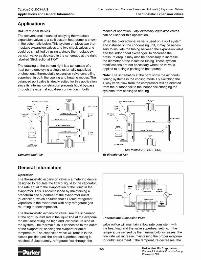
Parker Hannifin CorporationClimate & Industrial Controls GroupCleveland, OH
Catalog CIC-2003-1/US
158
Thermostatic and Constant Pressure (Automatic) Expansion Valves
Applications and General Information Thermostatic Expansion Valves
Applications
Bi-Directional ValvesThe conventional means of applying thermostaticexpansion valves to a split system heat pump is shownin the schematic below. This system employs two ther-mostatic expansion valves and two check valves andcould be simplified by using a single thermostatic ex-pansion valve as depicted in the schematic at the rightlabelled “Bi-directional TXV.”
The drawing at the bottom right is a schematic of aheat pump employing a single externally equalizedbi-directional thermostatic expansion valve controllingsuperheat in both the cooling and heating modes. Thebalanced port valve is ideally suited for this applicationsince its internal construction prevents liquid by-passthrough the external equalizer connection in both
Thermostatic Expansion Valve
modes of operation. Only externally equalized valvescan be used for this application.
When the bi-directional valve is used on a split systemand installed on the condensing unit, it may be neces-sary to insulate the tubing between the expansion valveand the indoor heat exchanger. To decrease thepressure drop, it may also be necessary to increasethe diameter of the insulated tubing. These systemmodifications are not necessary when the valve isapplied to a single packaged heat pump.
Note: The schematics at the right show the air condi-tioning systems in the cooling mode. By switching the4-way valve, flow from the compressor will be directedfrom the outdoor coil to the indoor coil changing thesystems from cooling to heating.
Conventional TXV Bi-directional TXV
Use models HC, EGC, ECC
General Information
OperationThe thermostatic expansion valve is a metering devicedesigned to regulate the flow of liquid to the vaporator,at a rate equal to the evaporation of the liquid in theevaporator. This is accomplished by maintaining apredetermined superheat at the evaporator outlet(suctionline) which ensures that all liquid refrigerantvaporizes in the evaporator with only refrigerant gasreturning to thecompressor.
The thermostatic expansion valve (see the schematicat the right) is installed in the liquid line at the evapora-tor inlet separating the high and low pressure side ofthe system. The thermal bulb is connected to the outletof the evaporator, sensing the evaporator outlettemperature. The expansion valve will remain in theclosed position until the preset superheat setting isreached. Subsequently, refrigerant flow through the
valve orifice will maintain a flow rate consistent withthe heat load and the valve superheat setting. If thetemperature sensed by the thermal bulb increases, theflow rate will increase, maintaining the proper evapora-tor outlet superheat. If the temperature decreases, the

Catalog CIC-2003-1/US
Parker Hannifin CorporationClimate & Industrial Controls GroupCleveland, OH
159
Service
& C
heck
Valves
Thermostatic and Constant Pressure (Automatic) Expansion ValvesT
XV
s & A
XV
sGeneral Information Thermostatic Expansion Valves
valve will stroke in the closing direction in response tothe reduced heat load on the evaporator, again main-taining the proper evaporator outlet superheat.
The superheated suction gas flows to the compressorwhere its pressure and temperature are increased dueto compression. The superheated discharge gas fromthe compressor then flows to the condenser whereheat isrejected, changing the gas into a high pressuresubcooled liquid. The liquid refrigerant then flows tothe expansion valve inlet and is metered into theevaporator at a flow rate necessary to maintain properevaporator superheat.
How To Determine Superheat1. Determine suction pressure at evaporator outlet
with gauge. On close coupled installations, suctionpressure may be read at compressor suctionconnection.
2. Use Pressure-Temperature Chart to determinesaturation temperature at observed suction pressure.For example, with an R-22 system: 54.9 psig = 30°F.
3. Measure temperature of suction gas at the expan-sion valve’s remote bulb location. For example: 40°F.
4. Subtract saturation temperature of 30°F (Step 2)from suction gas temperature of 40°F (Step 3). Thedifference, 10°F, is the superheat of the suction gas.
Determining Superheat
Superheat
Superheat is the temperature of refrigerant gas aboveits saturated vapor (dewpoint) temperature. Superheatas it relates to thermostatic expansion valves, can bebroken down into three categories:• Static Superheat – The amount of superheat neces-
sary to overcome the superheat spring force biasedin a closed position. Any additional superheat (force)would open the valve.
• Opening Superheat – The amount of superheatnecessary to open the valve to its rated capacity.
• Operating Superheat – The superheat at which thevalve operates at normal running conditions ornormal capacity. The operating superheat is the sumof the static and opening superheat. The figureat the right illustrates the three superheat catego-ries. The reserve capacity, as shown in the graph, is
important since it provides the ability to compensatefor occasional substantial increases in evaporatorload, intermittent flash gas, reduction in high sidepressure due to low ambient conditions, shortage ofrefrigerant, etc.
Valve SettingParker “sets” the thermostatic expansion valve super-heat at the static condition described above. Turningthe adjusting screw clockwise will increase the staticsuperheat. Conversely, turning the adjusting screwcounterclockwise will decrease the superheat. Parkervalves can also be adjusted at the operating point,indicated above. When a system is operating, anyadjustments made will change the operating superheat.The static superheat range of adjustment is 3°F to 18°F.One full turn clockwise will typically increase superheat2°F to 4°F.
NOTE: Refer to the valve’s installation bulletin forspecific directions on superheat adjustment.
ChargesPower elements may be system charged (chargedwith the same refrigerant used in the system) or crosscharged (refrigerant different from that used in thesystem).
“ W” ChargeThe Parker “W” liquid cross charge can be used withevaporator temperatures from -40°F to +60°F (-40°C to+15°C). Unlike conventional cross charges, the “W”charge maintains a nearly constant superheat through-out this range of evaporator temperatures. A liquidcharged bulb maintains control even when the powerelement is colder than the bulb.
“ Z” ChargeThe Parker “Z” low temperature liquid cross chargecan be used with evaporator temperatures from -40°Fto 0°F (-40°C to -20°C). The “Z” cross charge is de-signed specifically for low temperature applications;therefore, it can control the system so that the desired
Superheat Capacities

Parker Hannifin CorporationClimate & Industrial Controls GroupCleveland, OH
Catalog CIC-2003-1/US
160
Thermostatic and Constant Pressure (Automatic) Expansion Valves
Recommended Thermostatic Valve Charges
General Information Thermostatic Expansion Valves
Low Temp -40° F to 0° FRefrigeration (-40° C to -20° C)Commercial -40° F to +60° FRefrigeration (-40° C to +15° C)Low TempPressureLimiting
CommercialPressureLimiting
Air +30° F to +60° F VX100Conditioning (0° C to +15° C) VX100AHeat Pump -15° F to +60° F
(-30° C to +15° C)
-10° F to +60° F (-20° C to +15° C)
-40° F to 0° F (-40° C to -20° C)
Applicable Evaporator
Temperature Range ApplicationR-22
R-407CR-12
R-134aR-502
R-404A
–
VZ – SZ –
– SX35
SW
R-410A
KX200
KX200
–
VW JW
KX200VX100 JX60 SX110
VX35
VX100 – –
JX60 SX110
evaporator conditions are achieved more rapidly thanthe all purpose “W” liquid charge. Additionally, the“Z” charge prevents the possibility for compressorfloodback on startup due to higher operating super-heats at higher evaporator temperatures. Like the “W”charge, the “Z” liquid charged bulb maintains controleven when the valve power element is colder than thebulb.
Since the “Z” charge is designed specifically for lowtemperature applications, it does not exhibit “flat”superheat control over the entire operating range. Thischaracteristic decrease in superheat as the evaporatortemperature decreases allows the system to reach thedesired operating conditions quickly. Due to this “slope”in superheat control (see graph at the right below), it ispossible to optimize the operating superheat for anyparticular application by adjusting the valve after operat-ing conditions are achieved.
The graph at the right illustrates the typical superheatcontrol characteristics of Parker thermostatic valve bulbcharges.
Parker Thermostatic Bulb Charges
X ChargeThe Parker “X” anti-hunt gas cross charge can be usedwith evaporator temperatures from -40°F to +60°F(-40°C to +15°C). Every “X” charge is a pressurelimiting, or MOP (Maximum Operating Pressure), typecharge which limits flow on startup to prevent floodingand/or compressor overload. The approximate maxi-mum evaporator operating pressure is designated inpsig by the numbers which follow the “X”, e.g. “X60”has an approximate pressure limit of 60 psig. Due tothe pressure limiting characteristics of these charges,each charge is usable over a specific evaporatortemperature range which can be determined by refer-encing the MOP number and refrigerant type in thetable below.
Valves with an “X” type charge should not be usedwhere the power element could get colder than thethermal bulb. Migration of the bulb charge to the powerelement can occur causing a loss of valve control. Theonly exceptions to this are the R-22 type VX100 chargeand R-410A type KX200 charge, which are non-migrat-ing charges designed specifically for air-conditioning,heat pump and medium temperature applications.
Recommended thermostatic valve charges are listed inthe table at the right. A “–” indicates that a charge isnot available for an application.

Catalog CIC-2003-1/US
Parker Hannifin CorporationClimate & Industrial Controls GroupCleveland, OH
161
Service
& C
heck
Valves
Thermostatic and Constant Pressure (Automatic) Expansion ValvesT
XV
s & A
XV
s
The Parker Rainbow Charge™Multiple Use Thermostatic Charges for Alternative Refrigerants
Parker Rainbow Charges™ are designed to provide precise control for a complex variety of old and newrefrigerant applications. Rainbow Charge labeling visually indicates which refrigerants each valve is designedfor to simplify selection and reduce inventory. Rainbow Charge colors are consistent with industry standardrefrigerant identification, insuring that the right Rainbow Charges are chosen for the application See pages 134and 160 for more information on bulb charges.
General Information The Parker Rainbow Charge™
Charge May also be used withJW, JX60 (R-134a) R-12, R-401A (MP39), R-401B (MP66)
VW, VX35, VX100, VZ (R22) R-407C (AC9000)SW, SX35, SX110, SZ (R404A) R-125, R-502, R-402A (HP80), R-402B (HP81), R-507 (AZ50)
Use the following steps to determine the correct capacity valve for use withone of the alternative refrigerants listed above:
1. Choose an expansion valve, using the capacity tables, which meets therequirements of the application. For example, if applying an R-22 valve toan R-407C system, choose an appropriate R-22 valve using the conditionsof the R-407C system (choose appropriate evaporator temperature and valvepressure drop from R-22 capacity table).
2. Multiply the capacity found in the table by the appropriate factor below todetermine actual valve capacity with the new alternative.
From To Multiply by Special ConsiderationsR-134a R-12 0.80 Decrease superheat by approximately 5°R-134a R-401A (MP-39) 1.05 Adjust superheat only if necessaryR-134a R-401B (MP-66) 1.05 Adjust superheat only if necessaryR-22 R-407C (AC9000) 1.01 Increase superheat by approximately 5°
R-404A R-125 0.77 Decrease superheat by approximately 5° for -10° F evap or lowerR-404A R-502 1.02 Adjust superheat only if necessaryR-404A R-402A (HP-80) 1.00 Decrease superheat by approximately 5° for 20° F evap or lowerR-404A R-402B (HP-80) 1.10 Adjust superheat only if necessaryR-404A R-507 (AZ50) 0.98 Decrease superheat by approximately 5°
3. Correct the capacity determined in the previous step for liquid line temperature.
Refrigerant 0° 10° 20° 30° 40° 50° 60° 70° 80° 90° 100° 110° 120° 130° 140°R-134a 1.66 1.60 1.54 1.47 1.40 1.33 1.27 1.21 1.11 1.07 1.00 0.93 0.87 0.81 0.71R-401A (MP-39) 1.57 1.51 1.43 1.37 1.35 1.28 1.23 1.17 1.11 1.06 1.00 0.94 0.88 0.82 0.75R-401B (MP-66) 1.58 1.52 1.47 1.41 1.37 1.30 1.24 1.18 1.12 1.06 1.00 0.94 0.88 0.81 0.75R-407C (AC9000) 1.60 1.56 1.49 1.43 1.37 1.32 1.25 1.18 1.12 1.07 1.00 0.94 0.85 0.78 0.71R-125 2.14 2.00 1.91 1.79 1.71 1.58 1.47 1.38 1.26 1.12 1.00 0.88 0.73 0.57 0.40R-404A (HP62) 1.91 1.83 1.74 1.64 1.56 1.48 1.39 1.30 1.19 1.10 1.00 0.89 0.78 0.67 0.56R-402A (HP-80) 1.92 1.84 1.75 1.65 1.59 1.49 1.39 1.29 1.19 1.10 1.00 0.90 0.79 0.69 0.58R-402B (HP-81) 1.76 1.69 1.61 1.54 1.47 1.39 1.31 1.24 1.16 1.08 1.00 0.91 0.83 0.73 0.64R-507 (AZ50) 1.96 1.86 1.77 1.68 1.58 1.48 1.39 1.29 1.19 1.10 1.00 0.90 0.80 0.67 0.54
Degrees F

Parker Hannifin CorporationClimate & Industrial Controls GroupCleveland, OH
Catalog CIC-2003-1/US Thermostatic and Constant Pressure (Automatic) Expansion Valves
162
General Information Thermostatic Expansion Valves
Anti-Hunt Ballast Bulb (“X” Charge)The power element sensing bulb for an “X” charge containsan internal ballast material and the entire assembly isgas cross charged.
The combination of the cross charge and internal bal-last results in a variable rate time constant dampeningthat reduces or entirely eliminates undesirable systemhunt or instability caused by overfeeding or underfeed-ing the evaporator.
The top two graphs at the right illustrate the thermalballast time delay characteristics. The top graph showsthe bulb response to temperature change. The thermalbulb pressure will decrease rapidly when the tempera-ture is decreased from point A to B causing the valve tomodulate toward a lower flow position. As the tempera-ture is increased back to point A, considerably moretime is required to increase the thermal bulb pressure
The second graph is an illustration characterizing theoperating superheat variation of a typical refrigerationsystem. When the system load decreases, the suctionline temperature and flow decrease and the operating
Gas charge condensesat coldest point intodroplets of liquid.
Gas condenseson pore surface of block.
superheat rises rapidly. As the suction line temperatureincreases, the bulb pressure will slowly increase andthe operating superheat will decrease slowly to thepredetermined level. This results in a sawtooth waveform which minimizes the system floodback. Afterseveral cycles of continuous dampened amplitude, thesystem will operate at the predetermined superheatwith minimum suction line fluctuations (anti-hunt).
The bottom graph illustrates the operation of a non-ballast bulb charge. Since it will respond quickly in anopening and closing manner, the valve may overfeedand underfeed causing undesirable system fluctuationreferred to as hunt.
6
4
2
8
10
12
14
Ballast Bulb
(Sup
erhe
at °F
)
Time
Operating Superheat Variation of a Typical RefrigerationSystem
A
B
Bulb Response to Temperature Change
Bul
b Te
mpe
ratu
re
Closing Opening Time
Bulb Response to Temperature Change
BULB COLDER THANBALLAST BLOCK.
BALLAST BLOCKCOLDER THAN BULB.
2468
101214
Non-Ballast Bulb
(Sup
erhe
at °
F)
Operation of a Non-Ballast Bulb Charge

Catalog CIC-2003-1/US
Parker Hannifin CorporationClimate & Industrial Controls GroupCleveland, OH
163
Service
& C
heck
Valves
Thermostatic and Constant Pressure (Automatic) Expansion ValvesT
XV
s & A
XV
sGeneral Information Thermostatic Expansion Valves
Internally Equalized ValvesThe outlet pressure of an internally equalized valve istransmitted to the underside of the diaphragm throughan equalizer hole inside the valve body. Internallyequalized valves are used with evaporators that havea pressure drop of less than 3 psi.
The equalizer passageway is the communication linkfrom the evaporator to the underside of the diaphragm(F2). Internally equalized valves incorporate an internalcommunication passage from the outlet valve cavity tothe underside of the diaphragm. In applications wherethe pressure drop between the valve outlet and theevaporator outlet is negligible, internal equalizersare effective to communicate the actual evaporatorpressure to the underside of the diaphragm. In theschematic below, the F-1 force corresponding to refrig-erant R-22 at 37°F is 64 psig. The evaporator pressureF-2 is 52 psig at 28°F and the superheat spring forceF-3 is set for the balancing pressure of 12 psig. Thevalve is now in balance with 64 psig above and belowthe diaphragm and the superheat setting is 9°F.
Externally Equalized ValvesEmployment of an externally equalized valve is re-quired to control the evaporator at the proper superheatwhen the pressure drop of the evaporator is high, i.e.greater than 3 psig. The externally equalized valve willsense the pressure at the outlet of the evaporator. Inthe schematic below, the pressure under the diaphragmnow totals 64 psig (12 plus 52 psig). The thermal bulbpressure above the diaphragm force, F-1, also equals64 psig while the corresponding saturation temperatureis 37°F.
The superheat at the outlet of the evaporator is 9°F(37°F-28°F). The use of a valve with an externalequalizer has decreased the superheat from 16°F to9°F and restored the superheat to the original value of9°F with the same spring force of 12 psig.
The following schematic shows the application of aninternally equalized valve with a pressure drop of 10 psiacross the evaporator. The evaporator saturated inletpressure is 62 psig at 35°F. The superheat spring force(F-3) is set for an equivalent of 12 psig. The pressureunder the diaphragm for an internally equalized valvewould total 74 psig (12 + 62 psig). The remote thermalbulb force F-1 is 74 psig, for balanced conditions. Thisbulb pressure corresponds to a saturation temperatureof 44°F. The pressure at the outlet of the evaporator isonly 52 psig, 10 psig below the inlet pressure. The satu-ration temperature at 52 psig is 28°F. Use of an inter-nally equalized valve will result in a superheat of 16°F(44°F- 28°F) at the evaporator outlet. Accordingly, theinternally equalized valve used with a high pressuredrop evaporator will cause excessive superheat andcorresponding capacity loss.
Note: Never cap an external equalizer service port.
Refer to the evaporator manufacturer’s installation bul-letin or look for a service port near the outlet of theevaporator for external equalizer installation.
Internally Equalized Valve with 0 PSI Drop in Evaporator
R-22 Internally Equalized Valve with 10 PSI Drop inEvaporator
Externally Equalized Valve with 10 PSI Drop in Evaporator

Parker Hannifin CorporationClimate & Industrial Controls GroupCleveland, OH
Catalog CIC-2003-1/US Thermostatic and Constant Pressure (Automatic) Expansion Valves
164
General Information Thermostatic Expansion Valves
Off Cycle Unloading (Bleed)Internal bleed orifices are used to equalize the high andlow side pressures during the off cycle so that lowstarting torque compressors can start. Systems suchas air conditioners and heat pumps sometimes requirea TXV with internal bleed due to the frequent cyclingthat occurs.
Consult the factory if a bypass bleed is required.
The required bleed size is a function of high and lowside system volumes, refrigerant charge, and pressuredifference across the valve prior to shutdown. Thesevariables affect the equalization time required by a timedelay device or thermostat reset. Bleed sizes are usu-ally specified as a percentage of the nominal valve ca-pacity and can range from 5% to 50%, although 15% to30% is more commonly specified.
At the end of the valve model number, a letter “B” fol-lowed by digits indicates an internal bleed. These digitsrepresent the bleed capacity as a percentage of thevalve’s nominal capacity.
Example: SE5VX100B20 – Bleed orifice 20% of 5 tons,or 1 ton bypass bleed.
Because the internal bleed is an additional flow path inthe valve, adding a bleed will increase the capacity ofthe valve. Thus, a 5 ton valve with a 20% bleed is actu-ally capable of 6 tons. However, intentionally adding aninternal bleed to increase the capacity of a valve is notrecommended.
Bulb Location and InstallationSince the control response of the bulb is crucial for sat-isfactory operation, care should be taken in its mount-ing and positioning.• Always make sure the suction line is cleaned before
clamping the bulb in place.• On lines that are 1/2" O.D. or smaller, the bulb may
be installed on top of the line or side mounted (pref-erably at the 3 o’clock position).
• On lines that are 7/8" O.D. or larger, the remote bulbshould be installed at 45° or at approximately the 4or 8 o’clock position.
• Never mount a bulb on the bottom of suction linesbecause a mixture of refrigerant and oil may bepresent at that point, especially on smaller lines.
• It is good practice to insulate the bulb regardless ofthe refrigerant type. This ensures that the bulb willonly respond to the suction gas temperature and willnot be affected by condensation, ice formation orambient temperatures.
• Avoid mounting the bulb on vertical lines or close toreversing valves.
• The bulb should always be mounted between theevaporator outlet and the external equalizer connec-tion and should be as close to the evaporator outletas possible (generally 3 to 6 inches).
• On systems that have multiple evaporators, the bulbmust be mounted on the suction line of the evapora-tor which it controls. Do not mount the bulb on thecommon suction line.
• Install traps on vertical risers. (See the illustrationbelow.)
1/2" & smallersuction line
5/8" & largersuction line
on smaller lines,bulb may be mounted
on top
do not mountbulb on bottom
of line
Installation of Traps

Catalog CIC-2003-1/US
Parker Hannifin CorporationClimate & Industrial Controls GroupCleveland, OH
165
Service
& C
heck
Valves
Thermostatic and Constant Pressure (Automatic) Expansion ValvesT
XV
s & A
XV
sThermostatic Expansion ValvesBalanced Port Valves
Balanced Port Valves
Parker balanced port thermostatic expansion valvescan be applied to a broad range of air conditioning andrefrigeration systems. They exhibit exceptional perfor-mance over a wide variation in load on a specific sys-tem, or the same valve can be applied to a large rangeof application capacities.
Features of the balanced port valve include:• Fully balanced port design incorporating a patented
power piston.• Compensates for wide variations in high to low side
pressure.• Has sufficient capacity to allow for intermittent flash
gas.• Compensates for wide variations in evaporator load.• Compensates for changes in liquid line temperatures.• Compensates for wide variations in pressure drop
across the thermostatic expansion valve.
OperationConventional thermostatic expansion valves respond tofour forces (See the illustration at the right):Force 1 — Thermal bulb pressure times the diaphragm
effective area. This force acts on the top ofthe diaphragm which tends to open the valve.
Force 2 — Evaporator pressure times the diaphragmeffective area. This force acts on the under-side of the diaphragm. It tends to closethe valve. This force is transmitted to thediaphragm through the valve body withinternally equalized valves and through theexternal connection on externally equalizedvalves.
Force 3 — Superheat spring force which assists inclosing the valve.
Force 4 — High and low side pressure differentialtimes the port area. This differential pres-sure force tends to open the valve.
Balanced port valves respond to forces (F-1), (F-2) and(F-3) in a manner similar to conventional valves; how-ever, they take a unique approach to the (F-4) forcecreated by high and low side pressure differentials acrossthe ball and valve orifice. (See figure A.) The area ofthe Parker Power Piston® is equal to the area of theport diameter. This force is cancelled out as the pistonforce and the force across the port are equal and opposite.
As inlet pressure changes, the (F-4) force changes butalways remain equal and opposite and is cancelled out,therefore, variations in valve system pressures do not haveany effect on the static superheat setting of the valve.
The change in operation superheat is only affected byoperating changes in load requirements. In contrast,unbalanced (conventional) valves will also change
operating superheat due to the changes in inlet pres-sure (F-4). This additional superheat change increasesconsiderably as the port diameter and valve capacityincrease.
Assuming a port diameter of .250 inches and a highside pressure change of 100 psi, the change in forceof an unbalanced valve would be (100 x .049) or 4.9pounds. If the effective area of the diaphragm was 1.00square inch, the change in evaporator pressure wouldbe 4.0psig. If this example is applied to high side varia-tions of 100 to 200 psi, and all common refrigerantsare considered at evaporator temperatures from -20°Fto +40°F, it is possible that the superheat change couldvary 3.5°F to 22°F. This superheat change (not inher-ent in balanced valves) is in variations in load conditions.
Parker thermostatic expansion valves incorporate thepower piston (balanced port), which has been usedsuccessfully for over 30 years. The balanced portpower element assembly incorporates heavy duty dia-phragm housings and a high strength stainless steelflat diaphragm to withstand severe high pressures. Theassembly also includes a “buffer” ring for additionalsupport and subsequent additional endurance. The flatsteel diaphragm provides a smooth stroke without“snap.” The rugged stainless steel piston assemblyuses a proven Parker “O” Ring packing compound forrefrigerant use. The element is protected from any sys-tem contaminants by virtue of the piston seal on theParker Power Piston. Additionally, this seal preventsany leakage from the high to low side of the valve.
In the manufacturing process, secondary operationsare made on Parker valves that places the diaphragmat a specific position relative to neutral (weld point).This important manufacturing process insures uniformdiaphragm sensitivity. Through this unique manufactur-ing process, Parker valves essentially minimize the varia-tion in superheat change to attain a specific capacity.
Forces that Cause Conventional Thermostatic ExpansionValves Responses

Parker Hannifin CorporationClimate & Industrial Controls GroupCleveland, OH
Catalog CIC-2003-1/US Thermostatic and Constant Pressure (Automatic) Expansion Valves
166
Valve Selection Procedure Thermostatic Expansion Valves
Valve Selection Procedure
1. Determine application information.It is important to obtain specific system informationin order to choose the correct valve for a particularapplication. Listing this information will aid in makingchoices such as capacity, charge, and fitting configura-tion which will result in the best possible valve choicefor the application.• System refrigerant. Determine what refrigerant will
be used in the system.• Evaporator load or system capacity. Determine
the design system capacity.• Evaporator operating temperature/pressure.
Determine the design evaporator temperature andpressure. Evaporator temperature is usually speci-fied, or can be calculated by subtracting the “TD”temperature from the desired environment controltemperature. Evaporator pressure can be deter-mined by looking up the associated saturationpressure for the known evaporator temperature ina refrigerant table.
• Evaporator pressure drop, distributor pressuredrop. Determine any pressure drop which will occurafter the refrigerant exits the valve, such as distribu-tor pressure drop and evaporator pressure drop.
• Condenser operating pressure/liquid tempera-ture. Determine the condenser pressure and liquidtemperature. The liquid temperature can be deter-mined directly or by subtracting a desired subcoolingamount from the condenser design temperature.When determining the liquid pressure, consider anyfactors which may affect the pressure entering thevalve; such as friction losses, vertical lift, and pres-sure drop across system components such asdryers, sight glasses, and other valves.
2. Determine the required nominal capacity andcharge for the valve.
A.Evaporator temperatureB. Pressure DropC. Design System TonnageD. Valve Type
Refrigerant 20 ft. 6 m 40 ft. 12 m 60 ft. 18 mR-12 11 0.75 23 1.6 33 2.3R-22 10 0.69 20 1.4 30 2.1R-502 10 0.69 21 1.4 31 2.1R-134a 10 0.69 20 1.4 30 2.1R-404A 8.5 0.59 17 1.2 25 1.7
Vertical Lift Pressure Drop
• Connection configuration (fitting types, sizes,orientations.) Determine what style connections arebest suited for the application, SAE flare or ODFcopper.
• Valve adjustment requirements (adjustable,non-adjustable.) Determine whether or not fieldadjustment is required.
• Bypass bleed requirements. Determine if thesystem requires equalization of high and low sidepressures due to compressor starting limitations.Contact the factory if this is necessary.
Liquid Line Temp. 70°F 80°F 90°F 100°F 110°F 120°F 130°F 140°FMultiplier R-22 1.21 1.11 1.07 1.00 0.93 0.87 0.81 0.71
Selection of nominal capacity• Find the correct capacity table. Refer to capacity
table section and find the correct page for thesystem refrigerant in either English or metric units.
• Find the correct evaporator temperature sectionfor the application based on the design evaporatortemperature.
• Determine the pressure drop available acrossthe expansion valve. Deduct the evaporatorpressure from the condenser pressure, then deductpressure losses due to distributors, vertical lift,strainers, other valves, dryers in liquid line, and anysignificant friction losses in the evaporator andcondenser refrigerant lines.
• Find correct pressure drop column.• Find a capacity selection in that column which
most closely matches the desired system capacity.The usable capacity published in the table repre-sents the valve’s nominal capacity at a specificcondition. The system design capacity at that samecondition should be at least 50% of, but not morethan 10% over the selected valve’s capacity.
• Determine the correct type and capacity valve.Read across to the leftmost columns which describethe model(s) and nominal capacity which will bebest for the application.
• Correct table capacity for liquid line (subcooling)temperature. Subcooling will normally increaseboth system and valve capacities. Subcooling willalso increase the density of the liquid refrigerant,increase the enthalpy difference across the evapora-tor and prevent flash gas at the metering device.Flash gas severely reduces the refrigerant flowthrough the valve orifice, decreasing valve capacityand increasing operating superheat. Correct thesystem design capacity for liquid line temperaturewith the liquid temperature correction table locatedon that page.

Catalog CIC-2003-1/US
Parker Hannifin CorporationClimate & Industrial Controls GroupCleveland, OH
167
Service
& C
heck
Valves
Thermostatic and Constant Pressure (Automatic) Expansion ValvesT
XV
s & A
XV
sValve Selection Procedure Thermostatic Expansion Valves
Selection of charge• Refer to pages 159 and 160 for a full explanation
of charge selection.• Select a charge which is best suited for the
application. Type “W” charges are good all-purposecharges, “Z” charges are meant for low temperatureapplications, and “X” charges are for applicationsrequiring a pressure limit.
3. Choose the valve configuration which best suitsthe application.
• Select a model which best suits the needs of theapplication based on fitting type, size, and orienta-tion. Consider physical size and type of adjustmentavailable for each model.
• Determine whether an external equalizer isnecessary. Combined pressure drops of thedistributor and evaporator which exceed 3 psi willrequire an externally equalized valve for properoperation.
• Determine the full model number by combiningthe information.
Nomenclature (Example)
X X
OutletFitting Sizeand Type
1/2"SAE
InletFitting Sizeand Type
3/8"rSAE
MaximumOperatingPressure(MOP)
100Valve Charge
See pages134 and 157.
WZX
XRefrigerant
See pages134 and
157.
VNominalCapacityin Tons
3ExternalEqualizer
Omit forInternal
Equalizer
EExternalEqualizer
Size and Type
1/4"SAE/ODF
ValveModel
G
Example of Valve Selection Procedure
1. Determine application information. The followinginformation was obtained from system design con-straints. The example application is an R-22 freezerwhich operates continuously at a temperature of 15°F.The evaporator is rated at a 10° TD, therefore theevaporator temperature is approximately 5°F. There areno special pressure constraints on the compressor.• System refrigerant R-22
• System capacity 13,600 BTU/hr (1.13 tons)
• Evaporator temperature 5°FEvaporator pressure 28 psig
• Evaporator pressure lossesDistributor pressure drop 15 psi (estimated)Evaporator pressure drop 6 psi (estimated)
• Condenser pressure 225 psigLiquid line pressure losses 4 psi (estimated)Liquid temperature 90°F
• Connections required 3/8" SAE liquid line con.1/2" SAE evaporator con.
• Valve adjustmentrequirements Adjustable
• Bypass bleed requirements None
2. Determine the required nominal capacity andcharge for the valve.
Selection of nominal capacity• Find the correct capacity
table Correct R-22 table on p. 154
• Find the correct evaporator Refer to 0° evaporatorsection (closest to 5°Fdesign temp.)
• Determine available Condenser pressure 225 psigpressure drop Evaporator pressure - 28 psig
Total pressure drop 197 psig
Subtract lossesLiquid line - 4 psiDistributor - 15 psiEvaporator - 6 psiNet pressure drop 172 psi
• Find correct pressure Refer to 175 psi pressure dropdrop column column
• Find a capacity selection Find that there is a G(E)1valve rated at 1.16 tons
• Correct table capacity Refer to the liquid temperaturefor liquid temperature table for R-22 and find a factorcorrection of 1.08
1.16 tons x 1.08 = 1.23 tonsThis valve will be operating at92% capacity
Selection of charge• Select appropriate charge From evaporator temperature
range on page 135, choose VWcharge
3. Choose the valve configuration that's best forthe application
• Select valve model Choose the G(E)1 for thisexample.
• Determine if there is an Pressure drop after the expan-external eqaulizer sion valve is 11 psi (5 psi + 6
psi). It is necessary for the valveto be externally equalized,therefore the model number forthe valve will include the “E”.
• Determine the full model number; put the information together:
GE 1 VW 3/8"R SAE X 1/2" SAE X 1/4" SAE

Parker Hannifin CorporationClimate & Industrial Controls GroupCleveland, OH
Catalog CIC-2003-1/US Thermostatic and Constant Pressure (Automatic) Expansion Valves
168
Superheat & Hunting Thermostatic Expansion Valves
A common problem facing refrigeration and air condi-tioning service technicians and contractors is that ofsuperheat hunting by thermostatic expansion valves(TXVs). Here is a better understanding of a commonlyoverlooked cause of superheat hunting and how theproblem might be corrected.
Defining Superheat “ Hunting”Superheat hunting is a cyclical fluctuation in suctionsuperheat due to varying refrigerant flow rate in thesystem. Superheat hunting is the result of the expan-sion valve (see the illustration below) excessivelyopening and closing in an attempt to maintain aconstant operating condition. Hunting can be observedas regular fluctuations in suction temperature, and inextremes, suction pressure. Excessive hunting canreduce the capacity and efficiency of the system result-ing in uncomfortable conditions, loss of product, andwasted energy.
Tips for Understanding and Preventing Superheat Hunting in TXVs• Incorrect charge selection – The charge selected
does not have the necessary control characteristicsand / or dampening ability to stabilize operation.
• Undercharged system – Intermittent loss ofsubcooling is causing loss of expansion valvecapacity and resulting intermittent high superheat.
• Poor bulb contact – Loss or delay of temperaturesignal to bulb causes erratic and unpredictableoperation.
• An imbalanced heat exchanger (multi-circuitcoil) – An imbalance in the heat load on each circuitcreates a false temperature signal to the expansionvalve bulb and results in erratic operation. Since thisproblem is commonly overlooked in the field, acloser examination and a possible solution are inorder.
Balanced or Unbalanced Circuits?TXVs on Multi-Circuit Heat ExchangersTXVs respond, in part, to the temperature of the suc-tion line. At the expansion valve outlet, flow is dividedinto 2 or more paths (circuits) at the inlet of the evapo-rator by the distributor. These paths recombine as theyexit the evaporator into the suction manifold. (See theillustration below.)
Ideally, each circuit is equally loaded and absorbs anequivalent amount of heat. If one assumes the refriger-ant flow rate and heat load through each circuit isequal, then the superheat condition exiting each circuitwill be equal and when all of the flow streams recom-bine, the result is a “true” average condition of theevaporator suction gas. When one or more circuits hasa lighter heat load, some refrigerant from that circuitremains unevaporated when it exits the coil. When thisunevaporated liquid refrigerant combines with the othersuperheated flow streams, the recombined suction flow
Expansion Valve Flow
Common Reasons for TXV Hunting• Oversized valve – The expansion valve may be
oversized for the application or operating conditionof the system. If the valve capacity significantlyexceeds the requirements of the system, when thevalve attempts to adjust to system load it overcom-pensates because it is oversized.
A conventional balanced port thermostatic expansionvalve and the three forces it responds to:Force F1 – Thermal bulb pressure times the diaphragmeffective area. This force acts on the top of the diaphragmwhich tends to open the valve.Force F2 – Evaporator pressure times the diaphragmeffective area. This force acts on the underside of thediaphragm. It tends to close the valve. This force istransmitted to the diaphragm through the valve body withinternal equalized valves and through the external connectionin external equalized valves.Force F3 – Superheat spring force which assists in closing thevalve.

Catalog CIC-2003-1/US
Parker Hannifin CorporationClimate & Industrial Controls GroupCleveland, OH
169
Service
& C
heck
Valves
Thermostatic and Constant Pressure (Automatic) Expansion ValvesT
XV
s & A
XV
sSuperheat & Hunting Thermostatic Expansion Valves
no longer represents an average condition. The suctiontemperature where the bulb is mounted will be lowerthan the “true” average of the circuits if they were allproperly superheated.
Sensing a “cold” suction condition will cause the valveto close down because it is sensing a condition whichis not superheated enough; when the valve closesdown, it restricts flow to all circuits and eventually “driesout” the circuits which are is flooding. By this time, theremaining circuits have become highly superheateddue to the reduced flow rate. At the point the “flooding”circuit(s) begin to be superheated, the suction tempera-ture rises rapidly because there is no more liquidpresent to falsely reduce the suction temperature.
Sensing a now “warm” suction condition, the valveopens to decrease superheat and the lightly loadedcircuit begins to flood into the suction manifold again.Suction temperature drops rapidly again, the valvecloses down again, the sequence repeating in a cyclicalfashion.
Again, the ideal situation is to assume each circuit isequally loaded and absorbs an equivalent amount ofheat; in reality, this situation does not always occur.There are several reasons why circuits can becomeunevenly loaded:• Poor heat exchanger design – In this case, each
circuit is not of equal length and loading.• Poor refrigerant distribution – This problem
occurs due to the wrong choice of distributor orfeeder tubes, partially blocked passageways offeeder tubes, unequal feeder tube lengths, and/orkinked feeder tubes.
• Uneven air flow – Air flow across the evaporatoris reduced in some areas while increased in otherareas. Dirty coils or damaged coil fins can have asimilar effect on air flow.
Diagnosing a Hunting Problem:Is It the Heat Exchanger?Diagnosing a hunting problem due to an imbalancedheat exchanger requires measuring the exit tempera-ture of each circuit upstream of the suction manifold.To perform this process, average the temperatures of
all of the circuits upstream of the suction manifoldand compare this average temperature to the actualtemperature of the suction manifold close to where thebulb is mounted. If the average value of the circuit exittemperatures exceeds the actual suction temperaturevalue by more than 2°F, then there is likely one or morecircuit(s) which are not completely superheated (flood-ing). A closer examination of the individual circuittemperatures and the associated suction pressureshould reveal which circuit(s) are causing the problem.
One simple rule to remember is that the valve’sresponse will favor the circuit that is flooding. Becauseof this favorable response, a heat exchanger can beoperating at a reasonable exit superheat but still have asignificant loss in capacity because the expansion valveis responding to one or more flooding circuits while theother circuits remain highly superheated, and thushighly inefficient.
Correcting the ProblemCorrecting the problem can be a difficult task. First, theservice tech must recognize the cause of the problem.If not, the problem can only be compensated for andthis could mean a reduction in system performance.Here are some tips for correcting or compensating foran imbalanced heat exchanger:• If possible, examine and correct any problems with
air flow, coil circuitry, and distribution such that thecircuits are more evenly fed and loaded. The goalis a more consistent circuit exit temperature on allcircuits. One lightly loaded circuit may be tolerable ifthere are, for example, eight circuits. However, this isprobably not the case if there are only three.
• Adjust the superheat of the valve to a slightly highervalue. Attempting to control an evaporator near toor lower than 5°F operating superheat can exceedthe sensing capability of most expansion valvesand result in hunting and subsequent intermittentflooding.
• If practical, move the bulb farther downstream onthe suction line. Better mixing of the refrigerant priorto the bulb can “smooth” out the valve responsealthough capacity and efficiency may not improvesignificantly.

Parker Hannifin CorporationClimate & Industrial Controls GroupCleveland, OH
Catalog CIC-2003-1/US Thermostatic and Constant Pressure (Automatic) Expansion Valves
170
Technical Information Model 104A and 104F Constant Pressure Expansion Valves
Model 104A & 104F Constant Pressure Expansion Valves
104A
Capacities (BTU/hr) Model 104A
104FCapacities (BTU/hr) Model 104A
Model No. Device No. R-12 R-134a R-22 R-407CModel 104A
104A 104-505 14,000 24,000
Nominal Capacity (.120" Orifice)
.093" .120"R-12 R-134a 12,000 15,000R-407C R-22 18,000 24,000
Orifice SizeRefrigerant
Dimensions
Dimensions
Specifications• Hermetic construction.• Solder connections: High temperature type
1/4" O.D.F. inlet, 3/8" O.D.F. outlet (5/16" outletavailable).
• Valve opening point adjusting range: 0 to 90psig is standard for valves. A higher adjustmentrange is available.
• Adjusting screw: Set at a pre-determined pres-sure with sealant or lock nut.
• With or without bleed for offcycle unloading inall orifice sizes.
• Orifice sizes: .120" is standard; .093" and .140"orifices are available.
• Bleed sizes: B2 through B60 nicked seat type;B60 through B140 drilled by-pass type.
• Maximum Operating PressuresHigh Side: 500 psig (35 bars)Low Side: 300 psig (21 bars)
• Construction: Brass, copper and stainless steel.

Catalog CIC-2003-1/US
Parker Hannifin CorporationClimate & Industrial Controls GroupCleveland, OH
171
Service
& C
heck
Valves
Thermostatic and Constant Pressure (Automatic) Expansion ValvesT
XV
s & A
XV
sTechnical Information Model 139 EPR
Model 139 Evaporator Pressure Regulator (EPR)
Specifications• Solder Connections – 1/4" ODM
inlet, 1/4"ODF outlet.
• Adjustment Range – ConsultParker.
• Adjusting Screw – Set at pre-determinedpressure with sealant or locknut.
• Nominal Capacities – Forfractional horsepower compressors.For more detail consult Parker.
• Construction – All brass, copperand stainless steel.
• Maximum Operating Pressure –Consult Parker.
Dimensions

Parker Hannifin CorporationClimate & Industrial Controls GroupCleveland, OH
Catalog CIC-2003-1/US Thermostatic and Constant Pressure (Automatic) Expansion Valves
172
Model A1
Technical Information A Series Constant Pressure (Automatic) Valves
Model AT
A Series Constant Pressure Expansion Valves
Model A7 Model AS
* 1/2" x 3/8" SAE flare adapter available.** It is recommended that external equalizer type be used when pressure
drop through the evaporator and/or distributor exceeds 5 psi.
Specifications• 0-90 psig adjustment range.• Bypass bleeds available.• Construction: Brass, copper and stainless steel.• Optional external equalizer.• U.L. recognized for maximum operating pressure
of 500 psig high side, 225 psig low side.
ModelNo. Equalizer Inlet OutletA1 Internal 1/4" SAE 1/4" NPTFA2* Internal 1/4" SAE 1/2 SAEA3 Internal 3/8" SAE 1/2" SAE
AE3** External 3/8" SAE 1/2" SAEA4 Internal 1/4" SAE 1/2" SAEAS Internal 1/4" ODF 3/8" ODFA7 Internal 3/8" ODF 3/8" ODF
AT Internal1/4 SAE1/4 ODF
8 mm ODF
1/4 NPTF8 mm ODF
Connections

Catalog CIC-2003-1/US
Parker Hannifin CorporationClimate & Industrial Controls GroupCleveland, OH
173
Service
& C
heck
Valves
Thermostatic and Constant Pressure (Automatic) Expansion ValvesT
XV
s & A
XV
sTechnical Information
Model A2
Model A4
Model A3
Model AE3
A Series Constant Pressure (Automatic) Valves

Parker Hannifin CorporationClimate & Industrial Controls GroupCleveland, OH
Catalog CIC-2003-1/US Thermostatic and Constant Pressure (Automatic) Expansion Valves
174
R-22/R-407C* U.S. Extended Capacities in Tons
* See page 160.Shaded areas are standard conditions.
U.S. Capacity Tables Constant Pressure (Automatic) and EPR Valves
R-134a/R-401A/R-401B/R-12 U.S. Extended Capacities in Tons
Shaded areas are standard conditions.
Evaporator Temp. (°F)Pressure Drop (PSIG) 40 60 80 100 120 140 60 80 100 120 140 160 60 80 100 120 140 160
Valve Nominal CapacityType Orifice Capacity Range
A1, A2, A(E)3, AT B 2 1-2 1.63 2.00 2.31 2.58 2.83 3.06 1.90 2.19 2.45 2.69 2.90 3.10 1.70 1.96 2.19 2.40 2.60 2.78A4 1/2 1/4-3/4 0.61 0.75 0.87 0.97 1.06 1.15 0.71 0.82 0.92 1.01 1.09 1.16 0.64 0.74 0.82 0.90 0.97 1.04A7-AA AA 1/2 1/8-1/2 0.41 0.50 0.58 0.65 0.71 0.76 0.48 0.55 0.61 0.67 0.73 0.78 0.43 0.49 0.55 0.60 0.65 0.69A7-A A 1 1/4-1 0.82 1.00 1.15 1.29 1.41 1.53 0.95 1.10 1.23 1.34 1.45 1.55 0.85 0.98 1.10 1.20 1.30 1.39A7-B B 2 1-2 1.63 2.00 2.31 2.58 2.83 3.06 1.90 2.19 2.45 2.69 2.90 3.10 1.70 1.96 2.19 2.40 2.60 2.78A7-C C 3 1 1/2 - 3 2.45 3.00 3.46 3.87 4.24 4.58 2.85 3.29 3.68 4.03 4.35 4.65 2.55 2.94 3.29 3.61 3.90 4.16AS, ASB20 1 1/4-1 0.82 1.00 1.15 1.29 1.41 1.53 0.95 1.10 1.23 1.34 1.45 1.55 0.85 0.98 1.10 1.20 1.30 1.39104A .093 1 0.82 1.00 1.15 1.29 1.41 1.53 0.95 1.10 1.23 1.34 1.45 1.55 0.85 0.98 1.10 1.20 1.30 1.39104A, 104F .120 1 1/4 1.03 1.25 1.44 1.61 1.76 1.91 1.19 1.38 1.54 1.68 1.81 1.94 1.06 1.23 1.38 1.50 1.63 1.74104A, 104F .140 1 1/2 1.23 1.50 1.73 1.94 2.12 2.30 1.43 1.65 1.85 2.01 2.18 2.33 1.28 1.47 1.65 1.80 1.95 2.09Evaporator Temp. (°F)Pressure Drop (PSIG) 80 100 120 140 160 180 80 100 120 140 160 180 80 100 120 140 160 180
Valve Nominal CapacityType Orifice Capacity Range
A1, A2, A(E)3, AT B 2 1-2 1.64 1.83 2.01 2.17 2.32 2.46 1.34 1.50 1.64 1.77 1.89 2.01 0.88 0.98 1.07 1.16 1.24 1.32A4 1/2 1/4-3/4 0.61 0.69 0.75 0.81 0.87 0.92 0.50 0.56 0.62 0.66 0.71 0.75 0.33 0.37 0.40 0.44 0.47 0.49A7-AA AA 1/2 1/8-1/2 0.41 0.46 0.50 0.54 0.58 0.61 0.33 0.37 0.41 0.44 0.47 0.50 0.22 0.25 0.27 0.29 0.31 0.33A7-A A 1 1/4-1 0.82 0.92 1.00 1.08 1.16 1.23 0.67 0.75 0.82 0.89 0.95 1.00 0.44 0.49 0.54 0.58 0.62 0.66A7-B B 2 1-2 1.64 1.83 2.01 2.17 2.32 2.46 1.34 1.50 1.64 1.77 1.89 2.01 0.88 0.98 1.07 1.16 1.24 1.32A7-C C 3 1 1/2 - 3 2.46 2.75 3.01 3.25 3.48 3.69 2.01 2.25 2.46 2.66 2.84 3.01 1.32 1.47 1.61 1.74 1.86 1.97AS, ASB20 1 1/4-1 0.82 0.92 1.00 1.08 1.16 1.23 0.67 0.75 0.82 0.89 0.95 1.00 0.44 0.49 0.54 0.58 0.62 0.66Pressure Drop (PSIG) 40 60 80 100 120 140 60 80 100 120 140 160 60 80 100 120 140 160104A .093 1 0.82 0.92 1.00 1.08 1.16 1.23 0.67 0.75 0.82 0.89 0.95 1.00 0.44 0.49 0.54 0.58 0.62 0.66104A, 104F .120 1 1/4 1.03 1.15 1.25 1.35 1.45 1.54 0.84 0.94 1.03 1.11 1.19 1.25 0.55 0.61 0.60 0.73 0.78 0.83104A, 104F .140 1 1/2 1.23 1.38 1.50 1.62 1.74 1.85 1.01 1.13 1.23 1.34 1.43 1.50 0.66 0.74 0.81 0.87 0.93 0.99
40°F 20°F 0°F
-10°F -20°F -40°F
Evaporator Temp. (°F)Pressure Drop (PSIG) 75 100 125 150 175 200 75 100 125 150 175 200 75 100 125 150 175 200
Valve Nominal CapacityType Orifice Capacity Range
A1, A2, A(E)3, AT B 3 1 1/2-3 2.60 3.00 3.35 3.67 3.97 4.24 2.55 2.94 3.29 3.60 3.89 4.16 2.29 2.64 2.95 3.23 3.49 3.73A4 1 1/2-1 0.87 1.00 1.12 1.22 1.32 1.41 0.85 0.98 1.10 1.20 1.30 1.39 0.76 0.88 0.98 1.08 1.16 1.24A7-AA AA 3/4 1/5-3/4 0.65 0.75 0.84 0.92 0.99 1.06 0.64 0.74 0.82 0.90 0.97 1.04 0.57 0.66 0.74 0.81 0.87 0.93A7-A A 11/2 1/2-1 1/2 1.30 1.50 1.68 1.84 1.98 2.12 1.27 1.47 1.64 1.80 1.94 2.08 1.14 1.32 1.48 1.62 1.75 1.87A7-B B 3 11/2-3 2.60 3.00 3.35 3.67 3.97 4.24 2.55 2.94 3.29 3.60 3.89 4.16 2.29 2.64 2.95 3.23 3.49 3.73A7-C C 5 3 1/2-5 4.33 5.00 5.59 6.12 6.61 7.07 4.24 4.90 5.48 6.00 6.48 6.93 3.81 4.40 4.92 5.39 5.82 6.22AS, ASB20 11/2 1/2-1 1/2 1.30 1.50 1.68 1.84 1.98 2.12 1.27 1.47 1.64 1.80 1.94 2.08 1.14 1.32 1.48 1.62 1.75 1.87104A .093 1.5 1.30 1.50 1.68 1.84 1.98 2.12 1.27 1.47 1.64 1.80 1.94 2.08 1.14 1.32 1.48 1.62 1.75 1.87104A, 104F .120 2.0 1.63 2.00 2.10 2.30 2.48 2.65 1.59 1.84 2.05 2.25 2.43 2.60 1.43 1.65 1.85 2.03 2.19 2.34104A, 104F .140 2.5 1.95 2.50 2.52 2.76 2.97 3.18 1.91 2.21 2.46 2.70 2.91 3.12 1.71 1.98 2.22 2.43 2.63 2.81Evaporator Temp. (°F)Pressure Drop (PSIG) 100 125 150 175 200 225 125 150 175 200 225 250 125 150 175 200 225 250
Valve Nominal CapacityType Orifice Capacity Range
A1, A2, A(E)3, AT B 3 1 1/2-3 2.22 2.48 2.72 2.94 3.14 3.33 2.05 2.24 2.42 2.59 2.75 2.89 1.38 1.51 1.63 1.74 1.85 1.94A4 1 1/2-1 0.74 0.83 0.91 0.98 1.05 1.11 0.68 0.75 0.81 0.86 0.92 0.96 0.46 0.50 0.54 0.58 0.62 0.65A7-AA AA 3/4 1/5-3/4 0.56 0.62 0.68 0.73 0.78 0.83 0.51 0.56 0.61 0.65 0.69 0.72 0.34 0.38 0.41 0.43 0.46 0.49A7-A A 11/2 1/2-1 1/2 1.11 1.24 1.36 1.47 1.57 1.67 1.02 1.12 1.21 1.29 1.37 1.45 0.69 0.75 0.81 0.87 0.92 0.97A7-B B 3 1 1/2-3 2.22 2.48 2.72 2.94 3.14 3.33 2.05 2.24 2.42 2.59 2.75 2.89 1.38 1.51 1.63 1.74 1.85 1.94A7-C C 5 3 1/2-5 3.70 4.14 4.53 4.89 5.23 5.55 3.41 3.74 4.03 4.31 4.58 4.82 2.29 2.51 2.71 2.90 3.08 3.24AS, ASB20 11/2 1/2-1 1/2 1.11 1.24 1.36 1.47 1.57 1.67 1.02 1.12 1.21 1.29 1.37 1.45 0.69 0.75 0.81 0.87 0.92 0.97Pressure Drop (PSIG) 75 100 125 150 175 200 75 100 125 150 175 200 75 100 125 150 175 200104A .093 1.5 1.11 1.24 1.36 1.47 1.57 1.67 1.02 1.12 1.21 1.29 1.37 1.45 0.69 0.75 0.81 0.87 0.92 0.97104A, 104F .120 2.0 1.39 1.55 1.70 1.84 1.96 2.09 1.28 1.40 1.51 1.61 1.71 1.81 0.86 0.94 1.01 1.09 1.15 1.21104A, 104F .140 2.5 1.67 1.86 2.04 2.21 2.36 2.51 1.53 1.68 1.82 1.94 2.06 2.18 1.04 1.13 1.22 1.31 1.38 1.46
40°F 20°F 0°F
-10°F -20°F -40°F
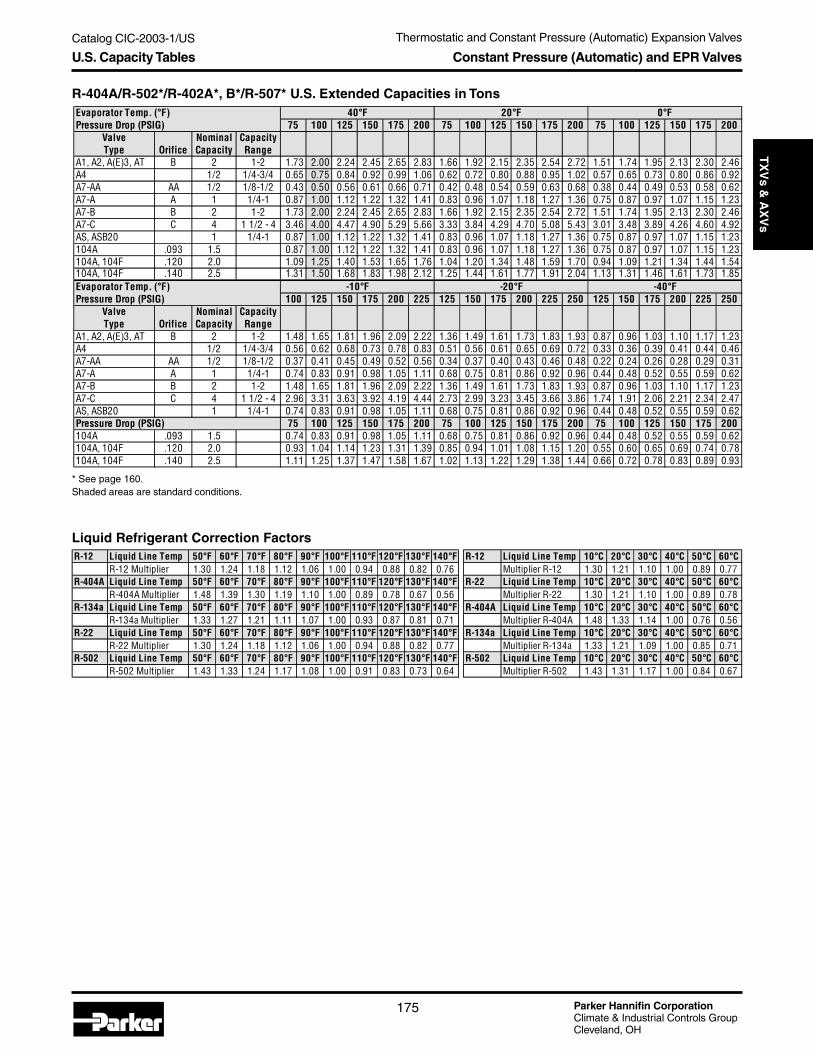
Catalog CIC-2003-1/US
Parker Hannifin CorporationClimate & Industrial Controls GroupCleveland, OH
175
Service
& C
heck
Valves
Thermostatic and Constant Pressure (Automatic) Expansion ValvesT
XV
s & A
XV
s
R-404A/R-502*/R-402A*, B*/R-507* U.S. Extended Capacities in Tons
* See page 160.Shaded areas are standard conditions.
U.S. Capacity Tables Constant Pressure (Automatic) and EPR Valves
Liquid Refrigerant Correction FactorsR-12 Liquid Line Temp 50°F 60°F 70°F 80°F 90°F 100°F 110°F 120°F 130°F 140°F
R-12 Multiplier 1.30 1.24 1.18 1.12 1.06 1.00 0.94 0.88 0.82 0.76R-404A Liquid Line Temp 50°F 60°F 70°F 80°F 90°F 100°F 110°F 120°F 130°F 140°F
R-404A Multiplier 1.48 1.39 1.30 1.19 1.10 1.00 0.89 0.78 0.67 0.56R-134a Liquid Line Temp 50°F 60°F 70°F 80°F 90°F 100°F 110°F 120°F 130°F 140°F
R-134a Multiplier 1.33 1.27 1.21 1.11 1.07 1.00 0.93 0.87 0.81 0.71R-22 Liquid Line Temp 50°F 60°F 70°F 80°F 90°F 100°F 110°F 120°F 130°F 140°F
R-22 Multiplier 1.30 1.24 1.18 1.12 1.06 1.00 0.94 0.88 0.82 0.77R-502 Liquid Line Temp 50°F 60°F 70°F 80°F 90°F 100°F 110°F 120°F 130°F 140°F
R-502 Multiplier 1.43 1.33 1.24 1.17 1.08 1.00 0.91 0.83 0.73 0.64
R-12 Liquid Line Temp 10°C 20°C 30°C 40°C 50°C 60°CMultiplier R-12 1.30 1.21 1.10 1.00 0.89 0.77
R-22 Liquid Line Temp 10°C 20°C 30°C 40°C 50°C 60°CMultiplier R-22 1.30 1.21 1.10 1.00 0.89 0.78
R-404A Liquid Line Temp 10°C 20°C 30°C 40°C 50°C 60°CMultiplier R-404A 1.48 1.33 1.14 1.00 0.76 0.56
R-134a Liquid Line Temp 10°C 20°C 30°C 40°C 50°C 60°CMultiplier R-134a 1.33 1.21 1.09 1.00 0.85 0.71
R-502 Liquid Line Temp 10°C 20°C 30°C 40°C 50°C 60°CMultiplier R-502 1.43 1.31 1.17 1.00 0.84 0.67
Evaporator Temp. (°F)Pressure Drop (PSIG) 75 100 125 150 175 200 75 100 125 150 175 200 75 100 125 150 175 200
Valve Nominal CapacityType Orifice Capacity Range
A1, A2, A(E)3, AT B 2 1-2 1.73 2.00 2.24 2.45 2.65 2.83 1.66 1.92 2.15 2.35 2.54 2.72 1.51 1.74 1.95 2.13 2.30 2.46A4 1/2 1/4-3/4 0.65 0.75 0.84 0.92 0.99 1.06 0.62 0.72 0.80 0.88 0.95 1.02 0.57 0.65 0.73 0.80 0.86 0.92A7-AA AA 1/2 1/8-1/2 0.43 0.50 0.56 0.61 0.66 0.71 0.42 0.48 0.54 0.59 0.63 0.68 0.38 0.44 0.49 0.53 0.58 0.62A7-A A 1 1/4-1 0.87 1.00 1.12 1.22 1.32 1.41 0.83 0.96 1.07 1.18 1.27 1.36 0.75 0.87 0.97 1.07 1.15 1.23A7-B B 2 1-2 1.73 2.00 2.24 2.45 2.65 2.83 1.66 1.92 2.15 2.35 2.54 2.72 1.51 1.74 1.95 2.13 2.30 2.46A7-C C 4 1 1/2 - 4 3.46 4.00 4.47 4.90 5.29 5.66 3.33 3.84 4.29 4.70 5.08 5.43 3.01 3.48 3.89 4.26 4.60 4.92AS, ASB20 1 1/4-1 0.87 1.00 1.12 1.22 1.32 1.41 0.83 0.96 1.07 1.18 1.27 1.36 0.75 0.87 0.97 1.07 1.15 1.23104A .093 1.5 0.87 1.00 1.12 1.22 1.32 1.41 0.83 0.96 1.07 1.18 1.27 1.36 0.75 0.87 0.97 1.07 1.15 1.23104A, 104F .120 2.0 1.09 1.25 1.40 1.53 1.65 1.76 1.04 1.20 1.34 1.48 1.59 1.70 0.94 1.09 1.21 1.34 1.44 1.54104A, 104F .140 2.5 1.31 1.50 1.68 1.83 1.98 2.12 1.25 1.44 1.61 1.77 1.91 2.04 1.13 1.31 1.46 1.61 1.73 1.85Evaporator Temp. (°F)Pressure Drop (PSIG) 100 125 150 175 200 225 125 150 175 200 225 250 125 150 175 200 225 250
Valve Nominal CapacityType Orifice Capacity Range
A1, A2, A(E)3, AT B 2 1-2 1.48 1.65 1.81 1.96 2.09 2.22 1.36 1.49 1.61 1.73 1.83 1.93 0.87 0.96 1.03 1.10 1.17 1.23A4 1/2 1/4-3/4 0.56 0.62 0.68 0.73 0.78 0.83 0.51 0.56 0.61 0.65 0.69 0.72 0.33 0.36 0.39 0.41 0.44 0.46A7-AA AA 1/2 1/8-1/2 0.37 0.41 0.45 0.49 0.52 0.56 0.34 0.37 0.40 0.43 0.46 0.48 0.22 0.24 0.26 0.28 0.29 0.31A7-A A 1 1/4-1 0.74 0.83 0.91 0.98 1.05 1.11 0.68 0.75 0.81 0.86 0.92 0.96 0.44 0.48 0.52 0.55 0.59 0.62A7-B B 2 1-2 1.48 1.65 1.81 1.96 2.09 2.22 1.36 1.49 1.61 1.73 1.83 1.93 0.87 0.96 1.03 1.10 1.17 1.23A7-C C 4 1 1/2 - 4 2.96 3.31 3.63 3.92 4.19 4.44 2.73 2.99 3.23 3.45 3.66 3.86 1.74 1.91 2.06 2.21 2.34 2.47AS, ASB20 1 1/4-1 0.74 0.83 0.91 0.98 1.05 1.11 0.68 0.75 0.81 0.86 0.92 0.96 0.44 0.48 0.52 0.55 0.59 0.62Pressure Drop (PSIG) 75 100 125 150 175 200 75 100 125 150 175 200 75 100 125 150 175 200104A .093 1.5 0.74 0.83 0.91 0.98 1.05 1.11 0.68 0.75 0.81 0.86 0.92 0.96 0.44 0.48 0.52 0.55 0.59 0.62104A, 104F .120 2.0 0.93 1.04 1.14 1.23 1.31 1.39 0.85 0.94 1.01 1.08 1.15 1.20 0.55 0.60 0.65 0.69 0.74 0.78104A, 104F .140 2.5 1.11 1.25 1.37 1.47 1.58 1.67 1.02 1.13 1.22 1.29 1.38 1.44 0.66 0.72 0.78 0.83 0.89 0.93
40°F 20°F 0°F
-10°F -20°F -40°F
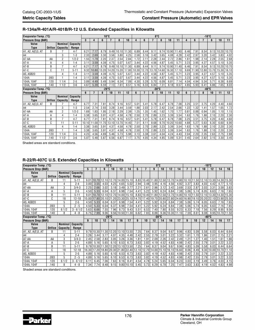
Parker Hannifin CorporationClimate & Industrial Controls GroupCleveland, OH
Catalog CIC-2003-1/US Thermostatic and Constant Pressure (Automatic) Expansion Valves
176
R-22/R-407C U.S. Extended Capacities in Kilowatts
Shaded areas are standard conditions.
Metric Capacity Tables Constant Pressure (Automatic) and EPR Valves
R-134a/R-401A/R-401B/R-12 U.S. Extended Capacities in Kilowatts
Shaded areas are standard conditions.
Evaporator Temp. (°C)Pressure Drop (BAR) 3 4 6 7 8 10 4 6 7 8 10 11 4 6 7 8 10 11
Valve Nominal CapacityType Orifice Capacity Range
A1, A2, A(E)3, AT B 7 4-7 6.21 7.17 8.79 9.49 10.10 11.30 6.89 8.44 9.11 9.74 10.90 11.40 6.46 7.91 8.54 9.13 10.20 10.70A4 3 1-3 2.33 2.69 3.30 3.56 3.80 4.25 2.58 3.16 3.42 3.65 4.08 4.28 2.42 2.97 3.20 3.42 3.83 4.02A7-AA AA 2 1/2-2 1.55 1.79 2.20 2.37 2.54 2.84 1.72 2.11 2.28 2.44 2.72 2.86 1.61 1.98 2.14 2.28 2.55 2.68A7-A A 4 1-4 3.11 3.59 4.39 4.75 5.07 5.67 3.44 4.22 4.56 4.87 5.45 5.71 3.23 3.95 4.27 4.57 5.10 5.35A7-B B 7 4-7 6.21 7.17 8.79 9.49 10.10 11.30 6.89 8.44 9.11 9.74 10.90 11.40 6.46 7.91 8.54 9.13 10.20 10.70A7-C C 11 5-11 9.32 10.80 13.20 14.20 15.20 17.00 10.30 12.70 13.70 14.60 16.30 17.10 9.69 11.90 12.80 13.70 15.30 16.10AS, ASB20 4 1-4 3.11 3.59 4.39 4.75 5.07 5.67 3.44 4.22 4.56 4.87 5.45 5.71 3.23 3.95 4.27 4.57 5.10 5.35104A .093 1 1-4 3.11 3.59 4.39 4.75 5.07 5.67 3.44 4.22 4.56 4.87 5.45 5.71 3.23 3.95 4.27 4.57 5.10 5.35104A, 104F .120 1 1/4 2-5 3.89 4.49 5.49 5.94 6.34 7.09 4.30 5.28 5.70 6.09 6.81 7.14 4.04 4.94 5.34 5.71 6.38 6.69104A, 104F .140 1 1/2 3-6 4.67 5.39 6.59 7.13 7.61 8.51 5.16 6.33 6.84 7.31 8.18 8.57 4.85 5.93 6.41 6.86 7.65 8.03Evaporator Temp. (°C)Pressure Drop (BAR) 6 7 8 10 11 12 6 7 8 10 11 12 6 7 8 10 11 12
Valve Nominal CapacityType Orifice Capacity Range
A1, A2, A(E)3, AT B 7 4-7 6.77 7.31 7.81 8.74 9.16 9.57 5.01 5.41 5.78 6.47 6.78 7.08 3.25 3.51 3.75 4.20 4.40 4.60A4 3 1-3 2.54 2.74 2.93 3.28 3.44 3.59 1.88 2.03 2.17 2.42 2.54 2.66 1.22 1.32 1.41 1.57 1.65 1.72A7-AA AA 2 1/2-2 1.69 1.83 1.95 2.18 2.29 2.39 1.25 1.35 1.45 1.62 1.70 1.77 0.81 0.88 0.94 1.05 1.10 1.15A7-A A 4 1-4 3.38 3.65 3.91 4.37 4.58 4.78 2.50 2.70 2.89 3.23 3.39 3.54 1.63 1.76 1.88 2.10 2.20 2.30A7-B B 7 4-7 6.77 7.31 7.81 8.74 9.16 9.57 5.01 5.41 5.78 6.47 6.78 7.08 3.25 3.51 3.75 4.20 4.40 4.60A7-C C 11 5-11 10.10 11.00 11.70 13.10 13.70 14.40 7.51 8.11 8.68 9.70 10.20 10.60 4.88 5.27 5.63 6.30 6.60 6.90AS, ASB20 4 1-4 3.38 3.65 3.91 4.37 4.58 4.78 2.50 2.70 2.89 3.23 3.39 3.54 1.63 1.76 1.88 2.10 2.20 2.30104A .093 1 1-4 3.38 3.65 3.91 4.37 4.58 4.78 2.50 2.70 2.89 3.23 3.39 3.54 1.63 1.76 1.88 2.10 2.20 2.30104A, 104F .120 1 1/4 2-5 4.23 4.56 4.89 5.46 5.73 5.98 3.13 3.38 3.61 4.04 4.24 4.43 2.04 2.20 2.35 2.63 2.75 2.88104A, 104F .140 1 1/2 3-6 5.07 5.48 5.87 6.56 6.87 7.17 3.75 4.05 4.34 4.85 5.09 5.31 2.45 2.64 2.82 3.15 3.30 3.45
10°C 0°C -10°C
-20°C -30°C -40°C
Evaporator Temp. (°C)Pressure Drop (BAR) 5 7 9 10 12 14 5 7 9 10 12 14 7 9 10 12 14 16
Valve Nominal CapacityType Orifice Capacity Range
A1, A2, A(E)3, AT B 11 5-11 9.01 10.70 12.10 12.70 14.00 15.10 8.83 10.40 11.80 12.50 13.70 14.80 10.10 11.50 12.10 13.30 14.30 15.30A4 4 2-4 3.00 3.55 4.03 4.25 4.65 5.02 2.94 3.48 3.95 4.16 4.56 4.92 3.37 3.83 4.03 4.42 4.77 5.10A7-AA AA 3 3/4-3 2.25 2.66 3.02 3.18 3.49 3.77 2.21 2.61 2.96 3.12 3.42 3.69 2.53 2.87 3.03 3.31 3.58 3.83A7-A A 5 2-5 4.50 5.33 6.04 6.37 6.98 7.54 4.41 5.22 5.92 6.24 6.84 7.38 5.06 5.74 6.05 6.63 7.16 7.65A7-B B 11 5-11 9.01 10.70 12.10 12.70 14.00 15.10 8.83 10.40 11.80 12.50 13.70 14.80 10.10 11.50 12.10 13.30 14.30 15.30A7-C C 18 12-18 15.00 17.80 20.10 21.20 23.30 25.10 14.70 17.40 19.70 20.80 22.80 24.60 16.90 19.10 20.20 22.10 23.90 25.50AS, ASB20 5 2-5 4.50 5.33 6.04 6.37 6.98 7.54 4.41 5.22 5.92 6.24 6.84 7.38 5.06 5.74 6.05 6.63 7.16 7.65104A .093 5 2 - 5 4.50 5.33 6.04 6.37 6.98 7.54 4.41 5.22 5.92 6.24 6.84 7.38 5.06 5.74 6.05 6.63 7.16 7.65104A, 104F .120 6 1/2 3 - 6 1/2 5.63 6.66 7.55 7.96 8.73 9.43 5.51 6.53 7.40 7.80 8.55 9.23 6.33 7.18 7.56 8.29 8.95 9.56104A, 104F .140 8 4 - 8 6.75 7.99 9.06 9.56 10.50 11.30 6.62 7.83 8.88 9.36 10.30 11.10 7.59 8.61 9.08 9.95 10.70 11.50Evaporator Temp. (°C)Pressure Drop (BAR) 9 10 12 14 16 17 9 10 12 14 16 17 9 10 12 14 16 17
Valve Nominal CapacityType Orifice Capacity Range
A1, A2, A(E)3, AT B 11 5-11 9.79 10.30 11.30 12.20 13.10 13.50 7.25 7.64 8.37 9.04 9.67 9.96 4.83 5.09 5.58 6.03 6.44 6.64A4 4 2-4 3.26 3.44 3.77 4.07 4.35 4.48 2.42 2.55 2.79 3.01 3.22 3.32 1.61 1.70 1.86 2.01 2.15 2.21A7-AA AA 3 3/4-3 2.45 2.58 2.83 3.05 3.26 3.36 1.81 1.91 2.09 2.26 2.42 2.49 1.21 1.27 1.40 1.51 1.61 1.66A7-A A 5 2-5 4.89 5.16 5.65 6.10 6.53 6.73 3.63 3.82 4.19 4.52 4.83 4.98 2.42 2.55 2.79 3.01 3.22 3.32A7-B B 11 5-11 9.79 10.30 11.30 12.20 13.10 13.50 7.25 7.64 8.37 9.04 9.67 9.96 4.83 5.09 5.58 6.03 6.44 6.64A7-C C 18 12-18 16.30 17.20 18.80 20.30 21.80 22.40 12.10 12.70 14.00 15.10 16.10 16.60 8.06 8.49 9.30 10.00 10.70 11.10AS, ASB20 5 2-5 4.89 5.16 5.65 6.10 6.53 6.73 3.63 3.82 4.19 4.52 4.83 4.98 2.42 2.55 2.79 3.01 3.22 3.32104A .093 5 2 - 5 4.89 5.16 5.65 6.10 6.53 6.73 3.63 3.82 4.19 4.52 4.83 4.98 2.42 2.55 2.79 3.01 3.22 3.32104A, 104F .120 6 1/2 3 - 6 1/2 6.11 6.45 7.06 7.63 8.16 8.41 4.54 4.78 5.24 5.65 6.04 6.23 3.03 3.19 3.49 3.76 4.03 4.15104A, 104F .140 8 4 - 8 7.34 7.74 8.48 9.15 9.80 10.10 5.45 5.73 6.29 6.78 7.25 7.47 3.63 3.83 4.19 4.52 4.83 4.98
10°C 0°C -10°C
-20°C -30°C -40°C

Catalog CIC-2003-1/US
Parker Hannifin CorporationClimate & Industrial Controls GroupCleveland, OH
177
Service
& C
heck
Valves
Thermostatic and Constant Pressure (Automatic) Expansion ValvesT
XV
s & A
XV
sMetric Capacity Tables Constant Pressure (Automatic) and EPR Valves
R-404A/R-502/R-402A, B/R-507 U.S. Extended Capacities in Kilowatts
Shaded areas are standard conditions.
Liquid Refrigerant Correction FactorsR-12 Liquid Line Temp 50°F 60°F 70°F 80°F 90°F 100°F 110°F 120°F 130°F 140°F
R-12 Multiplier 1.30 1.24 1.18 1.12 1.06 1.00 0.94 0.88 0.82 0.76R-404A Liquid Line Temp 50°F 60°F 70°F 80°F 90°F 100°F 110°F 120°F 130°F 140°F
R-404A Multiplier 1.48 1.39 1.30 1.19 1.10 1.00 0.89 0.78 0.67 0.56R-134a Liquid Line Temp 50°F 60°F 70°F 80°F 90°F 100°F 110°F 120°F 130°F 140°F
R-134a Multiplier 1.33 1.27 1.21 1.11 1.07 1.00 0.93 0.87 0.81 0.71R-22 Liquid Line Temp 50°F 60°F 70°F 80°F 90°F 100°F 110°F 120°F 130°F 140°F
R-22 Multiplier 1.30 1.24 1.18 1.12 1.06 1.00 0.94 0.88 0.82 0.77R-502 Liquid Line Temp 50°F 60°F 70°F 80°F 90°F 100°F 110°F 120°F 130°F 140°F
R-502 Multiplier 1.43 1.33 1.24 1.17 1.08 1.00 0.91 0.83 0.73 0.64
R-12 Liquid Line Temp 10°C 20°C 30°C 40°C 50°C 60°CMultiplier R-12 1.30 1.21 1.10 1.00 0.89 0.77
R-22 Liquid Line Temp 10°C 20°C 30°C 40°C 50°C 60°CMultiplier R-22 1.30 1.21 1.10 1.00 0.89 0.78
R-404A Liquid Line Temp 10°C 20°C 30°C 40°C 50°C 60°CMultiplier R-404A 1.48 1.33 1.14 1.00 0.76 0.56
R-134a Liquid Line Temp 10°C 20°C 30°C 40°C 50°C 60°CMultiplier R-134a 1.33 1.21 1.09 1.00 0.85 0.71
R-502 Liquid Line Temp 10°C 20°C 30°C 40°C 50°C 60°CMultiplier R-502 1.43 1.31 1.17 1.00 0.84 0.67
Evaporator Temp. (°C)Pressure Drop (BAR) 5 7 9 10 12 14 5 7 9 10 12 14 5 7 9 10 12 14
Valve Nominal CapacityType Orifice Capacity Range
A1, A2, A(E)3, AT B 7 4-7 6.06 7.17 8.14 8.58 9.39 10.10 5.88 6.96 7.89 8.32 9.11 9.84 5.58 6.60 7.48 7.89 8.64 9.33A4 3 1-3 2.27 2.69 3.05 3.22 3.52 3.80 2.21 2.61 2.96 3.12 3.42 3.69 2.09 2.48 2.81 2.96 3.24 3.50A7-AA AA 2 1/2-2 1.52 1.79 2.03 2.14 2.35 2.54 1.47 1.74 1.97 2.08 2.28 2.46 1.39 1.65 1.87 1.97 2.16 2.33A7-A A 4 1-4 3.03 3.59 4.07 4.29 4.70 5.07 2.94 3.48 3.95 4.16 4.56 4.92 2.79 3.30 3.74 3.94 4.32 4.67A7-B B 7 4-7 6.06 7.17 8.14 8.58 9.39 10.10 5.88 6.96 7.89 8.32 9.11 9.84 5.58 6.60 7.48 7.89 8.64 9.33A7-C C 14 5-14 12.1 14.3 16.3 17.2 18.8 20.3 11.8 13.9 15.8 16.6 18.2 19.7 11.2 13.2 15.0 15.8 17.3 18.7AS, ASB20 4 1-4 3.03 3.59 4.07 4.29 4.70 5.07 2.94 3.48 3.95 4.16 4.56 4.92 2.79 3.30 3.74 3.94 4.32 4.67104A .093 1 1-4 3.03 3.59 4.07 4.29 4.70 5.07 2.94 3.48 3.95 4.16 4.56 4.92 2.79 3.30 3.74 3.94 4.32 4.67104A, 104F .120 1 1/4 2-5 3.79 4.49 5.09 5.36 5.88 6.34 3.68 4.35 4.94 5.20 5.70 6.15 3.49 4.13 4.68 4.93 5.40 5.84104A, 104F .140 1 1/2 3-6 4.55 5.39 6.11 6.44 7.05 7.61 4.41 5.22 5.93 6.24 6.84 7.38 4.19 4.95 5.61 5.91 6.48 7.01Evaporator Temp. (°C)Pressure Drop (BAR) 7 9 10 12 14 16 9 10 12 14 16 17 9 10 12 14 16 17
Valve Nominal CapacityType Orifice Capacity Range
A1, A2, A(E)3, AT B 7 4-7 5.67 6.43 6.77 7.42 8.02 8.57 4.80 5.06 5.54 5.99 6.40 6.60 3.09 3.26 3.57 3.86 4.12 4.25A4 3 1-3 2.13 2.41 2.54 2.78 3.01 3.21 1.80 1.90 2.08 2.24 2.40 2.47 1.16 1.22 1.34 1.45 1.55 1.59A7-AA AA 2 1/2-2 1.42 1.61 1.69 1.86 2.00 2.14 1.20 1.26 1.39 1.50 1.60 1.65 0.77 0.81 0.89 0.96 1.03 1.06A7-A A 4 1-4 2.83 3.21 3.39 3.71 4.01 4.28 2.40 2.53 2.77 2.99 3.20 3.30 1.55 1.63 1.78 1.93 2.06 2.12A7-B B 7 4-7 5.67 6.43 6.77 7.42 8.02 8.57 4.80 5.06 5.54 5.99 6.40 6.60 3.09 3.26 3.57 3.86 4.12 4.25A7-C C 14 5-14 11.3 12.9 13.5 14.8 16.0 17.1 9.60 10.1 11.1 12.0 12.8 13.2 6.18 6.52 7.14 7.71 8.24 8.50AS, ASB20 4 1-4 2.83 3.21 3.39 3.71 4.01 4.28 2.40 2.53 2.77 2.99 3.20 3.30 1.55 1.63 1.78 1.93 2.06 2.12104A .093 1 1-4 2.83 3.21 3.39 3.71 4.01 4.28 2.40 2.53 2.77 2.99 3.20 3.30 1.55 1.63 1.78 1.93 2.06 2.12104A, 104F .120 1 1/4 2-5 3.54 4.01 4.24 4.64 5.01 5.35 3.00 3.16 3.46 3.74 4.00 4.13 1.94 2.04 2.23 2.41 2.58 2.65104A, 104F .140 1 1/2 3-6 4.25 4.82 5.09 5.57 6.02 6.42 3.60 3.80 4.16 4.49 4.80 4.95 2.33 2.45 2.67 2.90 3.09 3.18
10°C 0°C -10°C
-20°C -30°C -40°C

Parker Hannifin CorporationClimate & Industrial Controls GroupCleveland, OH
Catalog CIC-2003-1/US Thermostatic and Constant Pressure (Automatic) Expansion Valves
178
Constant Pressure (Automatic) and EPR ValvesTechnical Information
The constant pressure valve is a vital component ofmany refrigeration and A/C systems. It automaticallymeters refrigerant to the evaporator at a rate equal tocompressor pumping capacity.
The constant pressure valve contains a diaphragm,control spring (FS1), seat and valve needle or ball.The control spring, above the diaphragm, moves thediaphragm down. This moves the valve open.
The opposing force is provided by low side evaporatorpressure (FE) and a constant body spring force (FS2).This moves the valve closed. During the off cycle,evaporator pressure builds and overcomes springpressure. This keeps the valve closed until the next oncycle. At the start of the on cycle, the compressorquickly reduces evaporator pressure. When thispressure equals the control spring pressure, the valvebegins to open.
The valve opens when evaporator pressure is justbelow the control spring pressure setting. This is thevalve’s opening point, or setting.
BleedsBleed type valves permit pressures in the system toreach a balance point during the off cycle. At the nextrunning cycle, the motor starts under practically noload. This allows the use of low starting torque com-pressor motors.
The bleed type (or slotted orifice) valve has a small slotin the valve seat. This prevents complete close off atthe end of the machine’s-on cycle, permitting refriger-ant flow at a reduced rate.
Proper selection should result in a bleed and orificewhich will always have control over the refrigerant flowat all standard operating conditions. Application of alarger bleed will speed equalization time, but maycause the valve to lose control at high head pressureoperating conditions. Loss of control means all the flowwill be through the bleed and the valve will be closedbecause the bleed capacity matches the compressorcapacity.
How to Select Constant Pressure Expansion Valves1. Load on the system in Btu’s per hour or in tons
(12,000 Btu per hour equals 1 ton)2. System refrigerant3. Evaporator temperature or pressure4. Condensing temperature or pressure5. Pressure drop across the valve6. Off-cycle unloading, if required
Elevation Change and Valve SettingThe control spring in a constant pressure valve workswith atmospheric pressure to move the valve in anopening direction. Any substantial change in altitudeafter a valve has been adjusted will alter the low sideflow rate maintained by the valve.
If a low side gauge is available, adjust the valve toincrease the system pressure above the sea levelreading by the amount shown in the gauge pressurecorrection column of the table below.
Understanding the Constant Pressure Valve
Altitutde Gage Pressure Feet Inches Hg. psia correction (psia)
0 29.92 14.70 -500 29.38 14.70 -0.30
1000 28.86 14.19 -0.511500 28.33 13.91 -0.792000 27.82 13.58 -1.122500 27.32 13.41 -1.293000 26.82 13.20 -1.503500 26.33 12.92 -1.784000 25.84 12.70 -2.004500 25.37 12.44 -2.265000 24.90 12.23 -2.575500 24.43 12.01 -2.696000 23.98 11.78 -2.926500 23.53 11.55 -3.157000 23.09 11.33 -3.377500 22.65 11.10 -3.608000 22.22 10.92 -3.788500 21.80 10.70 -4.009000 21.39 10.50 -4.209500 20.98 10.30 -4.4010000 120.58 10.10 -4.60
Barametric Pressure

Catalog CIC-2003-1/US
Parker Hannifin CorporationClimate & Industrial Controls GroupCleveland, OH
179
Service
& C
heck
Valves
Thermostatic and Constant Pressure (Automatic) Expansion ValvesT
XV
s & A
XV
sConstant Pressure (Automatic) and EPR ValvesApplications
External EqualizerThe Parker Model AE3 is available with an externalequalizer. External equalizer models are recom-mended in applications where the pressure dropthrough the distributor and/or evaporator exceeds 5 psi.The outlet pressure of the evaporator is communicatedto the underside of the diaphragm through the externalequalizer line.
Freeze ProtectionParker constant pressure expansion valves can beused to prevent evaporator freezing, which may occurat low loads on small air conditioning applications. Thevalve is installed in parallel with the system expansiondevice to maintain a minimum evaporator pressurewhen flow through the main expansion device is insuffi-cient. An accumulator to protect the compressor fromliquid is recommended.
Constant Evaporator PressureParker constant pressure expansion valves maintain aconstant evaporator pressure for applications whenclose control of evaporator pressure and temperatureare required.
Constant Pressure and EPR Valve Applications

Parker Hannifin CorporationClimate & Industrial Controls GroupCleveland, OH
Catalog CIC-2003-1/US Thermostatic and Constant Pressure (Automatic) Expansion Valves
180
Constant Pressure (Automatic) and EPR ValvesApplications
Crankcase Pressure LimitingParker constant pressure expansion valves can beused to limit the maximum operating suction pressureto the compressor. The valve is adjusted to open at apredetermined outlet pressure while restricting flow athigher system inlet pressures in order to protect thecompressor. Non-bleed type valves are recommendedfor this type application.
EPR - Ice Cream MachineParker Model 139 EPRs are specifically designed forfractional horsepower evaporator applications whereprecise control of evaportor pressure is required whenusing a primary expansion device. A typical applicationis in a multiple evaporator system where differentevaporator pressures and temperatures are desired.The 139 EPR may be used to control at a higherevaporator pressure then is present at the compressorsuction.
Hot Gas Bypass to Evaporator InletConstant pressure expansion valves control hot gasbypass in systems where temperature is extremelycritical and load conditions vary widely – particularlylow loads. Installed between the discharge line and theevaporator, the valve controls pressure precisely. As theload drops, evaporator pressure decreases. It throttlesopen to maintain outlet pressure. This action maintainsthe temperature of the evaporator. This application mayalso be used as freeze protection.

Catalog CIC-2003-1/US
Parker Hannifin CorporationClimate & Industrial Controls GroupCleveland, OH
181
Service
& C
heck
Valves
Thermostatic and Constant Pressure (Automatic) Expansion ValvesT
XV
s & A
XV
sThermal Electric Va/vesTechnical Information
Nominal CapacitiesR-22 - 1/2 through 10 tonsR-134a - 1/3 through 7 tonsR-404a - 1/3 through 7 tons
Specifications• Refrigerant – Can be used with most
refrigerants except ammonia.• Voltage – 24 volts AC or DC (in
accordance with U.L. low voltageclass 2 specifications).
• Power – 4.13 watts at capacity rating.• Dielectric Strength – 500 RMS volts
minimum (1 lead to ground).• Resistance – 70 ohms.• Electrical Leads – 1/4" spade
connectors.• Valve Construction – Brass, copper,
and stainless steel.• Net Weight – 5 3/4 ounces.• Connections – 3/8" ODM x 5/8" ODF
Model 625 — Thermal Electric Valve
Model 625 — Liquid Sensing ThermistorSpecifications• Refrigerant – Can be used with all refrigerants except ammonia.• Max. power rating – 800 milliwatts in still air.• Max. temperature rating – 302°F (150°C).• Dielectric Strength – 500 RMS volts minimum (1 lead to ground).• Resistance – See device chart.• Leads – 22 gauge, 221°F (105°C) appliance wire pigtails.• Fitting material – Brass.• Net weight – 3/4 ounce.
Model 625 - Thermistor Suction Line Adapter
Standard ValvesOrifice Size Part Number
0.040 040925-0230.047 040925-0140.062 040925-0130.070 040925-0250.078 040925-0020.093 040925-0030.109 040925-0040.125 040925-0010.140 040925-0050.187 040925-028
Typical Applications
Thermistor Resistance
(77° F) SizeBonnet color and length
Part Number
Air ConditionersHeat PumpsMeat Cases
ChillersIce Makers
Low Temp Display CasesIce Cream FreezersCascade Systems Low Temp Blower
Coils
Special applications with extremely high load changes 100 ohms 1/4 mpt
Red 6" Leads 040930-519
50 ohms 1/4 mptGreen 6" Leads 040930-150
Suction line orrefrigerant tubing O.D.
Part Number
Suction line orrefrigerant tubing O.D.
Part Number
1/2" 040935-01 1 1/8" 040935-065/8" 040935-02 1 1/4" 040935-073/4" 040935-03 1 3/8" 040935-087/8" 040935-04 1 1/2" 040935-09
1 1/8" 040935-05 1 5/8" 040935-10

Parker Hannifin CorporationClimate & Industrial Controls GroupCleveland, OH
Catalog CIC-2003-1/US Thermostatic and Constant Pressure (Automatic) Expansion Valves
182
Thermal Electric ValvesApplications
Improving the Operating Performance and Cost ofHeat Pumps
Bi-directional operation makes the electric valve apopular heat pump control. One electric valve and oneor two thermistors reduce the number of componentsnormally used: two thermostatic types, two checkvalves and their connections.
• Application A: The first heat pump uses only onethermistor in the common suction line between thereversing valve and the compressor. This produces asaturated vapor entering the compressor.
• Application B: Two thermistors, wired in series withthe electric valve, are used in the second schematic.With this arrangement, suction gas entering thecompressor is slightly superheated due to heattransfer in the reversing valve.1. During cooling, thermistor #2 controls the electric
valve. Thermistor #1 is in the compressor dis-charge line. Thermistor #1 has no effect on valveoperation because it is sensing hot gas and self-heating to low resistance (full open).
2. In the heating cycle, thermistor #1 controls thevalve and thermistor #2 is located in the compres-sor discharge line. Compressor protection duringdefrost cycles is another advantage of thesystem.
Thermal Electric Valve Model 625 — Applications
Parker's thermal electric valve can be used for a variety of applications demanding control functions that are diffi-cult to accomplish with thermostatic expansion valves. When considering this valve for an application, considerthat the thermal electric valve inherently provides the following benefits:
Eliminating Super Heat in EvaporatorsThe thermal electric valve maintains zero degrees su-perheat in the evaporator at all loads. This means that10-15% more evaporator coil surface is available foradded cooling capacity.
• Approximately 10 percent additional coil capacity.• Rapid system unloading.• Controlled suction refrigerant quality or superheat.• Cool suction gas.• Similar capacity stroke from – 20°F (-29°C) through
+ 40°F (+4°C).• Reduction in valve inventory (no special bulb
charges, no external equalizers, no superheatsettings).
Compressor
625 Electric Valve
IndoorCoil
OutdoorCoil
BleedTube
4 WayValve
Thermistor
Accumulator
Heating
Cooling
(A)cooling
coolingheating
heating
(B)
Compressor
Thermistor 2
625 Electric ValveOutdoorCoil
IndoorCoil
BleedTube 4 Way
ValveAccumulator
24 Volts Line
Thermistor 1
Heating
Cooling
cooling
coolingheating
heating
Optional BleedConnection
625 ElectricValve
Evaporator Coil
Compressor
Condensor Coil
Receiver
24 Volts Line

Catalog CIC-2003-1/US
Parker Hannifin CorporationClimate & Industrial Controls GroupCleveland, OH
183
Service
& C
heck
Valves
Thermostatic and Constant Pressure (Automatic) Expansion ValvesT
XV
s & A
XV
sThermal Electric ValvesApplications
Maintaining a Flooded EvaporatorPlace the thermistor in an accumulator to controlthe level of liquid refrigerant.
Multiple Evaporator SystemsThe electric valve can increase the efficiencyand reduce the number of controls required. Puta 625 valve and thermistor on each evaporator.Thermostats can be used to maintain differenttemperatures, reducing requirements for pressureregulators and solenoids.
Hot Gas and/or Evaporator TemperatureRegulatorA special temperature sensing probe is mountedinside the refrigerated space. A solid state tempera-ture control amplifies the electrical signal of theprobe and controls the modulation of the electricvalve. As the temperature in the refrigerated spacedrops, voltage to the valve increases and the valveadmits hot refrigerant gas directly into the evaporator.
625ElectricValve
TemperatureSensor
Compressor Condenser
Receiver
625ElectricValve
RefrigeratedSpace
Evaporator
TemperatureControl
24 Volts
Thermistor
Thermistor
24 Volts
Evaporator
Evaporator
Evaporator
625ElectricValve
625ElectricValve
625ElectricValve
Thermistor
Compressor
24 Volts
Thermistor
Thermistor
Condenser
24 Volts
625ElectricValve
Evaporator
CondenserCompressor
Thermistor

Parker Hannifin CorporationClimate & Industrial Controls GroupCleveland, OH
Catalog CIC-2003-1/US Thermostatic and Constant Pressure (Automatic) Expansion Valves
184
Thermal Electric ValvesApplications
ChillersThis chiller design uses the thermistor as a liquidlevel control and the electric valve as a normalexpansion device.
Constant Pressure ControlWhen combined with a pressure or temperatureswitch, the electric valve can be used to controlevaporator pressure. The switch, which sensesevaporator pressure or temperature, closes whenthe evaporator drops below the set point. Theclosing of the switch energizes the electric valve.The resulting increase in refrigerant flow raisesevaporator pressure. The pressure switch thenopens and the valve modulates, maintaining theset point.
Pressure switches can be used to limit bothmaximum and minimum system pressure. Theseswitches can be placed anywhere in the systemto close the electric valve or limit its capacity whendesired levels of pressure or temperature arereached.
Pressure transducers and certain proportionalcontrollers can also be used to provide closerpressure control.
High and Low Pressure LimitCombine the thermistor with a pressure switch toautomatically convert the electric valve to a pres-sure limiting control. A high pressure limit switchprevents further increase when its pressure settingis reached. A low pressure limit switch prevents fur-ther decrease when its pressure setting is reached.A low pressure limit switch is wired in parallel withthe thermistor. This arrangement provides zero de-gree superheat between high and low pressure lim-its. Note that the compressor suction line is still al-lowed to superheat.
Evaporator
Condenser
ReceiverCompressor
625ElectricValve
24 Volts
Thermistor
LowPressureSwitch
HighPressureSwitch
Accumulator
CompressorCondenser
Chiller
625ElectricValve
Thermistor
24 Volts
Compressor
Evaporator
Condenser
Receiver
24 Volts
625ElectricValve
PressureSwitch

Catalog CIC-2003-1/US
Parker Hannifin CorporationClimate & Industrial Controls GroupCleveland, OH
185
Service
& C
heck
Valves
Thermostatic and Constant Pressure (Automatic) Expansion ValvesT
XV
s & A
XV
sThermal Electric ValvesOperation
Thermal Electric Valve Model 625 Operation
the bimetal heater inside the valve head and the bi-metal deflects upward. This deflection opens the valvemore.
The valve stays open until enough liquid refrigerant isfed into the evaporator to reduce superheat. Oncesuperheat is eliminated, wet refrigerant gas again con-tacts the thermistor. The wet gas cools the thermistor.The thermistor’s resistance increases and less voltageis sent to the valve. The valve moves toward closing.
Ambient EffectThe electric valve is calibrated to close in a 70°F(21°C) ambient when no voltage is applied. Above70°F (21°C) the valve opens and bleeds off refrigerant.The valve has a normal tendency to lose capacity at alower ambient temperature. The thermistor, however,compensates for these changes automatically.
Bleed ConnectionsIn many cases, the electric valve is manufactured witha third connection that bleeds off small quantities ofliquid refrigerant that may collect in the head of thevalve where the bimetal heater is located, which limitscapacity. With the bleed connection, full capacity of thevalve is available at all conditions. The bleed tube isalways connected to the system suction line.
Easy ServicingThe electric valve makes system analysis troubleshooting fast and easy. Service personnel need onlyattach a voltmeter to the electric valve and thermistor.The readings obtained from the voltmeter will tell howthe valve is operating at a glance. A simple check ofsystem conditions will indicate thermistor function andidentify problems elsewhere in the system.
The thermal electric valve is operated by, and respondsto, low voltage electricity. The valve’s operation issimple and easy to understand.
The operating partsof the valve areshown in the figureat the right. Theyare: a wire-boundbimetal heater anda spring-loadedneedle.
The amount of volt-age applied to theheater controls thedegree of the valveopening. At zerovoltage, the valve isclosed. As voltage isapplied, the heaterdeflects the bimetalupward. The stain-less steel needle follows the bimetal deflection andopens the valve. The more voltage applied to the valve,the greater the valve opening.
Because system pressure or temperature doesn't affectit, one valve will work for all applications from low tem-perature freezers to unitary air conditioners.
A special device, called a liquidsensing thermistor (shown here),regulates voltage to the electricvalve. The thermistor is installed inthe suction line at the exact pointwhere complete change of refriger-ant from liquid to gas is desired.Here, the thermistor reacts to theamount of liquid present in the re-frigerant as it leaves the evaporator.
The schematic at the top of the rightcolumn illustrates the operation ofthe thermistor and the electric valvewhen they are wired in series. When voltage is applied,the thermistor acts like a small heater. An increase inevaporator load causes superheat to increase. Thismeans the refrigerant changes to superheated gas atthe thermistor location. Because the gas is super-heated, there is no liquid present and the thermistorhas nothing to cool it. When exposed to dry refrigerantgas in this manner, the thermistor is heated to a hightemperature by the voltage applied to it and the resis-tance drops. This causes an increase in voltage across
Model 625 Thermal Electric Valve
Liquid SensingThermistor
Operation of the Thermistor and the Electric Valve when Theyare Wired in Series
OptionalBleedConnnection
625ElectricValve
Evaporator Coil
Compressor
Condenser Coil
Receiver

Parker Hannifin CorporationClimate & Industrial Controls GroupCleveland, OH
Catalog CIC-2003-1/US Thermostatic and Constant Pressure (Automatic) Expansion Valves
186
Thermal Electric ValvesInstallation Information
Mounting Position – The valve should be installedsuch that the thermal head is within 30° of an uprightposition to insure maximum capacity.
Sweat Soldering – The same precautions should beused when sweating this valve into a system thatwould normally be used with conventional valves toprevent excessive temperature build up (damp cloth –chill block – and so on).
Thermistor Suction Line Adapter – The thermistorshould be located flush, or slightly less, with the insidewall of the suction line. The 5/16" dimension shown inthe second illustration at the right will correctly locatethe thermistor assembly with the inside wall of the suc-tion line. Projection of the female adapter fittings, aswell as the thermistor assembly, into the suction lineshould be avoided (see the illustration at the right).
Thermistor Location & Sensing Positions – Theliquid sensing thermistor assembly can be used in anysuction line with a diameter of 1/2" or larger. It will workon both vertical and horizontal suction lines, but shouldnever be located where liquid refrigerant is likely toaccumulate or trap off. For instance; in a bottom U-Bend connecting two vertical risers (see the bottomgraphic at the right).
Since suction refrigerant flow depends upon manyfactors including suction line size, suction gas velocity,elbows, reducers, etc.; it is important to establish firmrules regarding the best location of the liquid sensingthermistor.
The following observations have been made on a widevariety of applications and have proven to be usefulguidelines for locating thermistor assemblies in suctionlines.1. High velocity suction locations are preferable over
low velocity locations.2. Smaller diameter suction locations are preferable
over larger diameter locations.3. Unless the flow pattern around an elbow or reducer
is well known or specifically designed for the liquidsensing thermistor assembly, it is best to stay atleast 6 inches away when locating downstream ofthem.
4. Vertical suction lines make excellent locations, buttrapping should be avoided as mentioned earlier(see the bottom graphic at the right).
(Continued on the following page.)
Thermal Electric Valve Model 625 Installation
Correct Placement of Thermistor Assembly into SuctionLine
Suction Line Identifying Location of ThermistorAssembly
Note: Use refrigerantcompatible pipe sealanton threads. Do not applysealant to end ofthermistor.
Correct and Incorrect Locations for ThermistorAssembly
Incorrect location
Correct locations
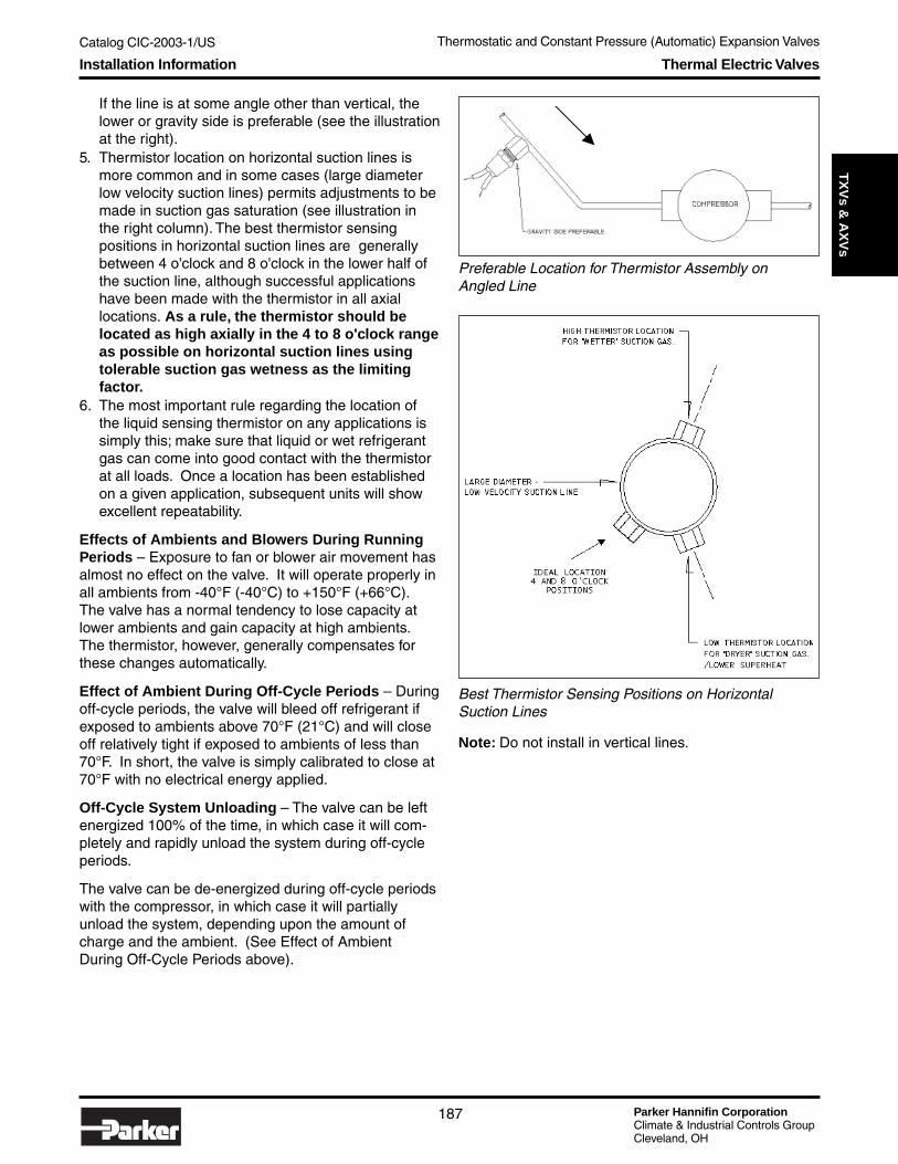
Catalog CIC-2003-1/US
Parker Hannifin CorporationClimate & Industrial Controls GroupCleveland, OH
187
Service
& C
heck
Valves
Thermostatic and Constant Pressure (Automatic) Expansion ValvesT
XV
s & A
XV
sThermal Electric ValvesInstallation Information
If the line is at some angle other than vertical, thelower or gravity side is preferable (see the illustrationat the right).
5. Thermistor location on horizontal suction lines ismore common and in some cases (large diameterlow velocity suction lines) permits adjustments to bemade in suction gas saturation (see illustration inthe right column). The best thermistor sensingpositions in horizontal suction lines are generallybetween 4 o'clock and 8 o'clock in the lower half ofthe suction line, although successful applicationshave been made with the thermistor in all axiallocations. As a rule, the thermistor should belocated as high axially in the 4 to 8 o'clock rangeas possible on horizontal suction lines usingtolerable suction gas wetness as the limitingfactor.
6. The most important rule regarding the location ofthe liquid sensing thermistor on any applications issimply this; make sure that liquid or wet refrigerantgas can come into good contact with the thermistorat all loads. Once a location has been establishedon a given application, subsequent units will showexcellent repeatability.
Effects of Ambients and Blowers During RunningPeriods – Exposure to fan or blower air movement hasalmost no effect on the valve. It will operate properly inall ambients from -40°F (-40°C) to +150°F (+66°C).The valve has a normal tendency to lose capacity atlower ambients and gain capacity at high ambients.The thermistor, however, generally compensates forthese changes automatically.
Effect of Ambient During Off-Cycle Periods – Duringoff-cycle periods, the valve will bleed off refrigerant ifexposed to ambients above 70°F (21°C) and will closeoff relatively tight if exposed to ambients of less than70°F. In short, the valve is simply calibrated to close at70°F with no electrical energy applied.
Off-Cycle System Unloading – The valve can be leftenergized 100% of the time, in which case it will com-pletely and rapidly unload the system during off-cycleperiods.
The valve can be de-energized during off-cycle periodswith the compressor, in which case it will partiallyunload the system, depending upon the amount ofcharge and the ambient. (See Effect of AmbientDuring Off-Cycle Periods above).
Best Thermistor Sensing Positions on HorizontalSuction Lines
Preferable Location for Thermistor Assembly onAngled Line
Note: Do not install in vertical lines.

Parker Hannifin CorporationClimate & Industrial Controls GroupCleveland, OH
Catalog CIC-2003-1/US Thermostatic and Constant Pressure (Automatic) Expansion Valves
188
Proper Wiring of Valve and Thermistor
Thermal Electric ValvesTroubleshooting
Troubleshooting
Testing For Proper OperationThe valve and thermistor should be wired in series asshown in the illustration below. All wiring should bemade in accordance with U.L. low voltage class 2codes.
Some Precautions1. Never apply more than the output of a 24 volt trans-
former to the valve circuit.2. Don't apply 24 volts directly across the thermistor
leads. It will short out the valve and damage thethermistor if both terminals of the electric valve aretouched with one volt-ohmmeter lead.
Initial Electrical CheckoutIf the electric valve and/or thermistor are suspected tobe inoperative, check the following:1. Are the electrical connections to the valve and ther-
mistor tight and correctly wired?If the connections are okay, continue to step 2.
2. With the transformer disconnected, make a simpleelectrical continuity check of the valve and ther-mistor using the volt-ohmmeter.
Service Gauge Manifold TestsIf no problem is found during the volt-ohmmeter tests,reconnect the power supply and connect a servicegauge manifold to the system. Then observe high andlow side pressures during the following tests:1. To see if the valve is closing:
Remove voltage to the valve by disconnecting anywire in the circuit.With the circuit open, low side pressure shouldbegin to drop. Wait three or four minutes, if thepressure does drop the valve is closing freely andis not clogged or sticking.
2. To see if the valve is opening:Remove the thermistor from the circuit by placing ajumper wire across the two thermistor leads. Thiswill send 24 volts directly to the valve.With 24 volts at the valve as the valve opens, lowside pressure should begin to increase. If low sidepressure does increase, the valve is opening prop-erly and is okay. Note that this kind of testing cannotbe done with a capillary tube system.With a thermostatic expansion valve system, thethermal bulb has to be removed from the suction lineand heated to see if the valve is opening properly.

Catalog CIC-2003-1/US
Parker Hannifin CorporationClimate & Industrial Controls GroupCleveland, OH
189
Service
& C
heck
Valves
Thermostatic and Constant Pressure (Automatic) Expansion ValvesT
XV
s & A
XV
s
Problem: Voltage to the valve is low, liquid is in thesuction line.Probable cause: Solder or other electricallyconductive material has clogged the thermistor.
Problem: Voltage to the valve is high, superheatedcondition at the thermistor location.Probable cause: Some contaminant is shorting thethermistor out of the circuit.
Problem: Voltage will not drop below 17 volts andgoes as high as 26 volts.Probable cause: Transformer output too high.
Valve ReplacementAlways replace a defective electric valve with an exactduplicate.
MountingIf possible, install the valve with the head within 30 de-grees of upright. This prevents any liquid from migrat-ing to the bimetal chamber where it could affect valveoperation.
If the valve is mounted with the head down, an electricvalve with a bleed tube connection must be used.
Bleed ConnectionThe third solder connection on solder-type electricvalves is the bleed connection. It prevents migration ofliquid refrigerant to the bimetal chamber. A valve with ableed tube must always be used on heat pumps.
Connect the bleed tube downstream of the thermistorin the system suction line as shown in the illustrationbelow. On heat pumps, connect the bleed tube to thecommon suction line.
Remember to use a chill block or wet cloths to protectthe valve body when soldering.
Valve RatingsThe following ratings are based on 100°F (38°C) vapor-free liquid refrigerant entering the valve.Refrigerant R-134a/R-12/R-401A, BTons of Refrigeration — Evaporator Temperatures °F/C
To determine valve ratings for other liquid refrigerant temperatures entering the valve, multiply the capacities listed above by the proper multiplierfactor listed.
Thermal Electric ValvesTroubleshooting
OptionalBleedConnection
625ElectricValve
Evaporator Coil
Compressor
Condenser Coil
Receiver
Part Orifice
Number Size 40 60 80 100 120 60 80 100 120 140 80 100 120 140 160 100 120 140 160 180
040925-023 .040 .274 .335 .387 .433 .476 .318 .368 .411 .450 .486 .335 .374 .410 .442 .473 .332 .364 .393 .420 .446040925-014 .047 .530 .650 .750 .840 .923 .618 .715 .798 .875 .945 .648 .725 .794 .857 .917 .642 .703 .760 .812 .862040925-013 .062 .735 .900 1.04 1.07 1.28 .860 .995 1.11 1.22 1.31 .905 1.01 1.11 1.20 1.28 .895 .980 1.06 1.13 1.20040925-025 .070 .875 1.07 1.24 1.39 1.52 1.00 1.16 1.30 1.42 1.53 1.04 1.16 1.27 1.37 1.46 1.00 1.09 1.18 1.26 1.34040925-002 .078 1.36 1.66 1.92 2.15 2.36 1.58 1.82 2.04 2.23 2.41 1.65 1.85 2.02 2.19 2.34 1.64 1.79 1.94 2.07 2.20040925-003 .093 1.87 2.29 2.65 2.96 3.26 2.15 2.49 2.78 3.04 3.29 2.26 2.53 2.77 2.99 3.20 2.21 2.42 2.61 2.79 2.96040925-004 .109 2.29 2.80 3.24 3.63 3.98 2.64 3.05 3.41 3.73 4.04 2.74 3.07 3.36 3.63 3.88 2.65 2.90 3.14 3.35 3.55040925-001 .125 2.65 3.25 3.75 4.20 4.61 3.05 3.53 3.94 4.31 4.66 3.14 3.51 3.84 4.15 4.44 3.03 3.32 3.58 3.83 4.06040925-005 .140 3.01 3.68 4.25 4.75 5.23 3.42 3.78 4.42 4.84 5.23 3.52 3.93 4.30 4.65 4.96 3.40 3.72 4.03 4.30 4.56040925-028 .187 4.42 5.41 6.25 7.00 7.68 5.04 5.83 6.51 7.13 7.70 5.17 5.78 6.33 6.84 7.32 5.00 5.47 5.92 6.32 6.71
1.07
1.00
0.93
Multiplier FactorLiquid Refrigerant Temp Entering Valve
110°F (43°C)
Liquid Refrigerant Temp Entering Valve
90°F (32°C)
100°F (38°C)
80°F (27°C)
PRESSURE DROP ACROSS VALVE (PSIG)
0.71
120°F (49°C)
130°F (54°C)
140°F (60°C)
0.87
0.81
Multiplier Factor
1.11
+20°F (-7°C) -10°F (-23°C) -40°F (-40°C)+40°F (+4°C)

Parker Hannifin CorporationClimate & Industrial Controls GroupCleveland, OH
Catalog CIC-2003-1/US Thermostatic and Constant Pressure (Automatic) Expansion Valves
190
Refrigerant R-404a/R-502/R-507C/R-402A,B/R-125Tons of Refrigeration — Evaporator Temperatures °F/C
Refrigerant R-22/R-407CTons of Refrigeration — Evaporator Temperatures °F/C
Thermal Electric ValvesRatings
-10°F (-23°C) -40°F (-40°C)Part Orifice
Number Size 75 100 125 150 175 100 125 150 175 200 125 150 175 200 225 150 175 200 225 250
040925-023 .040 .325 .374 .419 .461 .494 .355 .395 .435 .470 .502 .352 .386 .417 .446 .473 .334 .360 .386 .409 .431040925-014 .047 .629 .725 .811 .892 .956 .685 .765 .840 .907 .970 .681 .747 .807 .864 9.15 .647 .699 .747 .793 .836040925-013 .062 .876 1.01 1.13 1.24 1.33 .955 1.07 1.17 1.26 1.35 .948 1.04 1.12 1.20 1.27 .900 .973 1.04 1.10 1.16040925-025 .070 1.04 1.20 1.34 1.47 1.58 1.12 1.25 1.38 1.49 1.59 1.12 1.23 1.32 1.41 1.50 1.06 1.14 1.22 1.29 1.37040925-002 .078 1.61 1.86 2.08 2.29 2.45 1.75 1.96 2.15 2.32 2.48 1.75 1.92 2.07 2.22 2.35 1.66 1.79 1.92 2.03 2.14040925-003 .093 2.22 2.56 2.87 3.16 3.38 2.40 2.69 2.95 3.18 3.40 2.39 2.62 2.83 3.03 3.20 2.24 2.42 2.59 2.74 2.89040925-004 .109 2.71 3.13 3.50 3.85 4.13 2.93 3.27 3.59 3.87 4.14 2.88 3.16 3.41 3.65 3.86 2.67 2.88 3.08 3.27 3.45040925-001 .125 3.16 3.64 4.07 4.48 4.80 3.41 3.81 4.18 4.52 4.83 3.32 3.64 3.93 4.20 4.45 3.07 3.31 3.54 3.76 3.96040925-005 .140 3.56 4.11 4.60 5.06 5.42 3.81 4.26 4.67 5.05 5.39 3.70 4.06 4.38 4.69 4.96 3.43 3.70 3.96 4.20 4.42040925-028 .187 5.23 6.04 6.75 7.43 7.47 5.60 6.26 6.86 7.40 7.93 5.44 5.97 6.45 6.90 7.30 5.05 5.45 5.83 6.17 6.52
+40°F (+4°C) +20°F (+4°C)
80°F ( 27°C)
1.00
PRESSURE DROP ACROSS VALVE (PSIG)
0.91
Multiplier FactorLiquid Refrigerant Temperature Entering Valve
110°F (43°C)
Multiplier Factor
1.17
Liquid Refrigerant Temperature Entering Valve
100°F (38°C)
90°F (32°C) 1.08 0.88
0.82
0.77
120°F (49°C)
130°F (54°C)
140°F (60°C)
+20°F (-7°C) -10° F (-23° C) -40°F (-40°C)Part Orifice
Number Size 75 100 125 150 175 100 125 150 175 200 125 150 175 200 225 150 175 200 225 250
040925-023 .040 .486 .560 .626 .689 .740 .540 .604 .662 .715 .765 .556 .610 .659 .704 .746 .554 .598 .640 .678 .715040925-014 .047 .938 1.08 1.21 1.33 1.43 1.04 1.17 1.28 1.38 1.48 1.08 1.18 1.28 1.36 1.45 1.07 1.16 1.24 1.31 1.38040925-013 .062 1.31 1.51 1.69 1.86 2.00 1.46 1.63 1.79 1.93 2.07 1.50 1.65 1.78 1.91 2.02 1.50 1.62 1.73 1.84 1.94040925-025 .070 1.56 1.79 2.01 2.21 2.37 1.69 1.88 2.07 2.23 2.38 1.68 1.84 1.99 2.12 2.24 1.60 1.73 1.84 1.95 2.06040925-002 .078 2.39 2.75 3.08 3.39 3.63 2.66 2.97 3.26 3.52 3.76 2.73 3.00 3.24 3.46 3.67 2.72 2.94 3.14 3.33 3.51040925-003 .093 3.29 3.80 4.25 4.67 5.02 3.63 4.06 4.45 4.81 5.14 3.73 4.09 4.42 4.72 5.01 3.66 3.95 4.23 4.48 4.73040925-004 .109 4.05 4.67 5.23 5.76 6.17 4.47 5.00 5.48 5.93 6.34 4.55 5.00 5.40 5.77 6.12 4.42 4.77 5.11 5.41 5.71040925-001 .125 4.70 5.42 6.06 6.66 7.15 5.16 5.77 6.33 6.83 7.32 5.22 5.72 6.18 6.61 7.00 5.06 5.46 5.84 6.19 6.53040925-005 .140 5.34 6.16 6.89 7.58 8.12 5.82 6.51 7.14 7.71 8.25 5.87 6.44 6.95 7.44 7.88 5.69 6.15 6.57 6.97 7.34040925-028 .187 7.84 9.04 10.1 11.1 11.9 8.50 9.49 10.4 11.2 12.0 8.62 9.43 10.2 10.9 11.5 8.34 9.00 9.63 10.2 10.7
Liquid Refrigerant Temp Entering Valve
1.1280°F (27°C)
+40°F (+4°C)
100°F (38°C)
Multiplier Factor
PRESSURE DROP ACROSS VALVE (PSIG)
1.06
1.00
0.94
Multiplier FactorLiquid Refrigerant Temp Entering Valve
110°F (43°C)
0.77
120°F (49°C)
130°F (54°C)
140°F ( 60°C)
0.88
0.82
90°F (32°C)

Catalog CIC-2003-1/US Distributors and Flow Controls
Parker Hannifin CorporationClimate & Industrial Controls GroupCleveland, OH
191
Service
& C
heck
Valves
Distrib
uto
rs & F
low
Co
ntro
lsTable of Contents
Distributors and Flow ControlsTable of Contents
Refrigerant Distributors Introduction ......................................................................... page 193
Nozzle Type Distributors .............................................................................................. page 194
Flare Type Distributors with Nozzles .......................................................................... page 198
Heat Pump & Hot Gas Defrost Distributors ............................................................... page 199
Venturi Low Pressure Drop Distributors .................................................................... page 200
Flare Type Venturi Distributors .................................................................................... page 208
Parker Plus: Value-Added Components & Custom Brazing ..................................... page 209
Flo-Rater Style F ........................................................................................................... page 210
Flo-Rater Style A .......................................................................................................... page 211
Flo-Rater Style FD20 .................................................................................................... page 212
Flo-Rater Style M .......................................................................................................... page 213
Flo-Rater Style FD20D .................................................................................................. page 214
Flo-Rater Style FD20E .................................................................................................. page 214
Flo-Rater Style FD20F .................................................................................................. page 215
Manifolds ....................................................................................................................... page 216
Flo-Rater and Manifold Pistons ................................................................................... page 217
Selecting the Right Orifice for Your Flow Control ..................................................... page 218
O-Ring Adapter Fittings ............................................................................................... page 219
Type-O Fittings ............................................................................................................. page 220
Distributors and Flow Controls

Parker Hannifin CorporationClimate & Industrial Controls GroupCleveland, OH
Catalog CIC-2003-1/US Distributors and Flow Controls
192
Notes

Catalog CIC-2003-1/US Distributors and Flow Controls
Parker Hannifin CorporationClimate & Industrial Controls GroupCleveland, OH
193
Service
& C
heck
Valves
Distrib
uto
rs & F
low
Co
ntro
lsIntroduction Refrigerant Distributors
Refrigerant Distributors
Refrigerant distributors are of two basic designs, eachhaving certain merits that the design engineer mayregard as best for the application. Parker produces bothbasic types with the largest range of sizes, variationsand specials of any manufacturer. (Distributors aremade of brass unless aluminum is specified.)
The nozzle type distributor has a permanent orreplaceable sharp-edged orifice to mix the two-phasefluid before it enters the coil circuit passageways. Bychanging nozzles with different orifice sizes, one bodytype may be used for various refrigerants, loads, andalso for different numbers of circuit sizes.
The Venturi (low pressure drop) distributor has amachined, contoured throat on the approach side withdiverging circuit holes beyond the smallest section ofthe throat. There is no separate nozzle; therefore thepressure drop is less than the sharp-edged orificedistributor. The throat size is determined by the numberand size of the circuits and cannot be altered.
Nozzles for orifice type distributors for various suctiontemperatures in °F and refrigerants are listed in thetables starting on page 195. These numbers determinethe hole size.
Venturi Nozzle Type

Parker Hannifin CorporationClimate & Industrial Controls GroupCleveland, OH
Catalog CIC-2003-1/US Distributors and Flow Controls
194
Technical Information Nozzle Type Refrigerant Distributors
Nozzle Type DistributorsParker nozzle type distributors depend on the highpressure drop through the orifice and the resultingturbulence to provide equal distribution to all circuits.The illustration below shows that the approachingrefrigerant streamlines nearest the pipe wall (W), then itturns radial at the face of the nozzle towards the orifice.This radial flow continues past the edge of the orifice(X) and is moved through the orifice by the center massof the refrigerant. The refrigerant flow continuesthrough the orifice with a minimum jet area (Y) formingpast the nozzle. The uncontrolled expansion in the areajust past the nozzle causes a turbulent pattern (Z) to beset-up between the jet area (Y) and the walls, whichdissipates the velocity energy. UL Listing 11550.
Look at the nozzle sizing table on page 196. Locate therefrigerant that is being used across the top of thetable. Locate the temperature of the evaporator coilunder the desired refrigerant and go down the columnto the capacity of the coil. The required nozzle size isin the first column of the table to the left of the coilcapacity.
Specifying the Distributor BodyTo calculate the correct orifice size the followinginformation is needed:
1) the refrigerant type being used2) number of circuits in the evaporator coil3) the temperature of the evaporator coil4) the capacity of the evaporator coil
Calculating the Circuit Size TubeAfter gathering the above information, first calculate thecircuit capacity by dividing the evaporator coil capacityby the number of circuits in the evaporator coil.
Next calculate the circuit tube size by using theDistributor Tube Circuit Capacities Table on page 195.Find the columns that are headed by the refrigerantthat is being used. Under the correct refrigerant headerare columns of evaporator column temperatures. Godown the correct temperature column to the circuit ca-pacity previously calculated then go the last column onthe left to find the circuit tube size.
Calculating the Body TypeUsing the charts on pages 197-199 locate the columntitled "Maximum No. of Circuits" and go down the col-umn until the required circuit diameter and the requirednumber of circuits are found. The body number is in thefirst column. Look across the row to find the largest"Nozzle" orifice for that body to ensure that the bodycan support the required orifice. There may be a varietyof combinations that will work depending on the inletO.D. required. There is also a variety of inlet adaptersavailable such as added copper tubes with 1/2" or 5/8"45 degree flare nuts, expanded ends, or straight endsdepending on the body selected.
Flow through a nozzle device.No pressure recovery, high pressure drop.
Sizing Guidelines
Calculating the Orifice Size NeededTo calculate the correct orifice size needed therefrigerant that is being used, the temperature of theevaporator coil, and the capacity of the coil will needto be known.

Catalog CIC-2003-1/US Distributors and Flow Controls
Parker Hannifin CorporationClimate & Industrial Controls GroupCleveland, OH
195
Service
& C
heck
Valves
Distrib
uto
rs & F
low
Co
ntro
lsTechnical Information Nozzle Type Refrigerant Distributors
Distributor Tube Circuit Capacities Table
Distributor Loading vs. Pressure Drop
Refrigerants at various evaporator temperatures - Tons of RefrigerationCapacity per circuit at 10 psi pressure drop. See Distributor Loading vs. Pressure Drop table below for pressure drop at 50% to 200% of this rating.
40° 20° 0° -20° -40° 40° 20° 0° -20° -40° 40° 20° 0° -20° -40°5/32 0.19 0.14 0.11 0.08 0.06 0.26 0.21 0.16 0.12 0.09 0.18 0.13 0.10 0.07 0.053/16 0.40 0.30 0.23 0.17 0.13 0.53 0.44 0.33 0.24 0.20 0.37 0.28 0.22 0.15 0.121/4 0.80 0.60 0.45 0.33 0.25 1.10 0.89 0.67 0.49 0.39 0.73 0.58 0.43 0.31 0.23
5/16 1.60 1.20 0.90 0.66 0.50 2.20 1.70 1.30 0.98 0.79 1.50 1.10 0.83 0.62 0.463/8 2.80 2.10 1.60 1.20 0.88 3.70 2.90 2.20 1.70 1.40 2.50 2.00 1.50 1.10 0.80
RefrigerantTube Size
inches O.D.
Evaporating Temperature °F
R-12 / R-134a R-22 R-404A / R-502 / R-507
50° 60° 70° 80° 90° 100° 110° 120°2.10 1.83 1.59 1.37 1.17 1.00 0.85 0.72
Liquid Temperature °F Correction factor
*Correction Factors for Other Liquid Temperatures for Nozzle and Tubes
12 18 24 30 36 42 48 54 60 66 721.36 1.16 1.07 1.00 0.95 0.90 0.86 0.82 0.79 0.76 0.73
Tube Length - InchesCorrection Factor
**Correction factors for Other Distributor Tube Lengths
*100° liquid entering thermostatic expansion valve.**For tubing length of 30"
∆∆∆∆ P Nozzle psi
∆∆∆∆ P Tubes and Passages
∆∆∆∆ P Nozzle psi
∆∆∆∆ P Tubes and Passages psi
50 4 3 7 360 6 4 10 470 8 5 13 580 10 6 16 690 12 8 20 8
100 15 10 25 10110 18 12 30 12120 20 14 35 14130 22 16 38 16140 24 18 40 18150 27 21 43 21160 29 23 46 24170 31 25 49 27180 33 27 52 30190 36 29 54 32200 38 31 57 34
R-12 / R-134a R-22 & R-502Actual Load
as a Percent of Published Rating (corrected for Liquid
Temperature

Parker Hannifin CorporationClimate & Industrial Controls GroupCleveland, OH
Catalog CIC-2003-1/US Distributors and Flow Controls
196
Nozzle Type Refrigerant DistributorsNozzle Sizing Table
Nozzles & Retainer RingsNozzles and rings may be ordered separately. Informa-tion required for nozzles is the outside size of thenozzle, which is designated by a letter, and a numberwhich determines the orifice size. Nozzles are inter-changeable with several bodies. Rings may be orderedwith letter corresponding to the nozzle, i.e., “G” ringwould go with a distributor body that takes a “G” nozzleas listed.
NOTE: Nozzle size is approximately equal to thesystem compressor horsepower (i.e., nozzle 8 equalsapproximately 8 HP compressor).
Nozzle Sizing Table (Evaporator Temperature, °F)
Tapped holes availableon request. These holesdo not alter the functionof the nozzle and areseldom used.
X YL 0.401 0.187J 0.498 0.250G 0.735 0.250E 1.000 0.250C 1.120 0.250A 1.375 0.250
Nozzle Dimensions
40° 20° 0° -20° -40° 40° 20° 0° -20° -40° 40° 20° 0° -20° -40°
1/2 .35 .28 .22 .18 .16 .62 .48 .37 .28 .25 .40 .31 .22 .17 .133/4 .53 .44 .34 .27 .23 .92 .75 .61 .50 .37 .59 .47 .39 .30 .201 .72 .56 .47 .36 .30 1.3 1.06 .79 .63 .51 .83 .68 .50 .36 .26
1 1/2 1.1 .80 .70 .56 .46 1.9 1.6 1.3 1.0 .85 1.4 .95 .72 .53 .392 1.5 1.2 .96 .74 .61 2.5 2.1 1.7 1.3 1.1 1.8 1.5 .99 .76 .58
2 1/2 1.9 1.5 1.16 .92 .81 3.1 2.5 2.0 1.6 1.3 2.2 1.8 1.3 .94 .713 2.2 1.8 1.5 1.2 1.05 3.7 3.1 2.4 1.9 1.6 2.6 2.2 1.5 1.2 .844 2.9 2.3 1.9 1.5 1.3 5.0 4.1 3.2 2.6 2.1 3.4 2.8 2.1 1.6 1.25 3.7 2.9 2.3 1.9 1.7 6.2 4.9 4.0 3.1 2.6 4.2 3.4 2.5 1.9 1.46 4.4 3.5 2.8 2.3 2.0 7.3 5.7 4.7 3.7 3.0 5.2 4.0 2.9 2.3 1.78 5.9 4.6 3.6 3.0 2.5 9.7 7.4 6.1 4.7 3.8 6.5 5.4 3.9 3.1 2.3
10 7.3 5.8 4.5 3.6 3.1 11.6 9.3 7.4 5.3 4.4 8.3 6.6 4.5 3.6 2.612 8.7 6.9 5.4 4.2 3.4 14.3 11.2 8.8 6.7 5.6 10.1 8.0 5.6 4.2 3.215 10.8 8.2 6.6 5.2 4.5 17.7 13.7 10.8 8.2 6.6 12.2 9.8 7.3 5.3 4.517 12.3 9.4 7.5 6.1 5.1 20.0 15.9 12.2 9.2 7.9 13.9 11.4 7.8 6.6 5.220 14.5 11.0 8.8 6.9 5.7 23.8 18.5 14.5 11.1 9.2 17.0 13.5 9.5 7.7 5.925 18.0 13.8 11.0 8.7 7.5 30.6 23.7 18.3 14.0 11.3 22.0 17.0 12.2 9.5 7.830 21.5 16.2 12.1 11.0 9.0 35.2 28.0 21.0 16.0 13.4 26.0 19.0 13.8 10.6 9.635 25.8 19.5 15.3 12.8 12.0 42.0 33.0 25.5 21.0 16.0 21.0 23.0 16.8 13.4 10.740 29.4 22.6 19.2 15.6 12.8 46.7 37.7 31.7 23.0 19.0 34.0 25.5 19.6 14.9 11.850 37.0 28.2 23.2 18.4 16.0 62.3 48.0 37.0 29.0 24.0 45.0 34.0 25.0 19.0 15.9
Nozzle Number
Size
RefrigerantEvaporating Temperature °F
R-12 / R-134a R-22 R-404A / R-502 / R-507
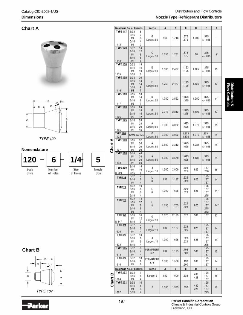
Catalog CIC-2003-1/US Distributors and Flow Controls
Parker Hannifin CorporationClimate & Industrial Controls GroupCleveland, OH
197
Service
& C
heck
Valves
Distrib
uto
rs & F
low
Co
ntro
lsDimensions Nozzle Type Refrigerant Distributors
Chart A
Chart B
Nomenclature
TYPE 107
Ch
art
BC
har
t A
BodyStyle
120Numberof Holes
6Size
of Holes
1/4NozzleSize
5— — —
TYPE 120
Nozzle A B C D E F5/32 83/16 71/4 6
5/16 41112 3/8 2
5/32 143/16 121/4 8
5/16 61113 3/8 4
5/32 193/16 151/4 10
1115 5/16 85/32 203/16 181/4 14
5/16 91116 3/8 7
3/16 181/4 14
5/16 91117 3/8 7
3/16 241/4 18
5/16 151126 3/8 12
3/16 281/4 24
5/16 201125 3/8 16TYPE 170 1.373 .375 1128 1.375 +/- .015
3/16 371/4 30
5/16 261127 3/8 20
3/16 401/4 34
5/16 301143 3/8 24
3/16 151/4 10
D-209 5/16 85/32 7 .1253/16 6 .1871/4 4 .187
5/32 10 .1253/16 8 .1871/4 6 .187
5/16 4 .2755/32 14 .1253/16 12 L .1871/4 8 8 1.156 1.753 .625 .187 14°
5/16 6 .2753/8 4 .312
TYPE 60 3/16 16 1.625 2.125 .872 .906 .187 23°
1/4 12D-147 5/16 9
TYPE 21 5/32 7 .125 3/16 6 .187
1620 1/4 4 .187TYPE 22 5/32 10 .125
3/16 8 .1871/4 6 .187
1622 5/16 4 .275TYPE 105 5/32 6 .125
3/16 4 .1871613 1/4 4 .187
TYPE 20 5/32 10 .1253/16 8 .187
1616 1/4 6 .187
Nozzle A B C D E FTYPE 107 5/32 7 .125
3/16 6 .1871604 1/4 4 .187TYPE 251 5/32 10 .125
3/16 8 .1871/4 6 .187
1607 5/16 4 .275
GLargest 50
Largest 6
1.3731.375
1.3731.375
1.6231.625
1.6231.625
1.1231.125
1.125
1.1231.125
1.125
14°
15°
14°
PERMANENT6 #
J Largest 10
1.000
.812
PERMANENT6 #
.625
35°
35°
14°
17°
25°1.375
1.281
1.438
25°
8°
15°
17°
11°
35°
.88
1.000
1.625
1.175
1.550
.873
.875
1.250
1.000
3.670
2.000
1.187
2.812
3.062
4.000
1.500
.812
1.781
2.437
2.437
2.562
3.312
C Largest 50
A Largest 50
1.156
1.500
1.750
1.750
A Largest 50
C Largest 50
3.500
L8
J Largest 10
Maximum No. of Circuits
A Largest 50
J Largest 10
G Largest 50
E Largest 50
E Largest 50
SAME AS 175
C Largest 50
TYPE 180
TYPE 209
TYPE 190
TYPE 23
TYPE 25
6
Maximum No. of Circuits
TYPE 117
TYPE 120
TYPE 150
TYPE 130
TYPE 140
TYPE 160
TYPE 175
1.718 .872.875
–G Largest 50
.375 +/- .015
.906
.375 +/- .015
.375 +/- .015
.375 +/- .015
.375 +/- .015
.375 +/- .015
1.6231.625
.375 +/- .015
3.000 3.062 1.375
2.313
3.000
1.125
.625
.623
.375 +/- .015
.375 +/- .015
.623
.625.187 .250
.625
.625
.623 .625
.623
.625
15°
1.000 1.375 .330 .430.428 15°
.812 1.000 .328 .430.428
.500.498.500
.623
.625
.498
.500
.625
.500
14°
TYPE 24 L8 1.000
1.187
1.625.625 .623 .625 14°
.812

Parker Hannifin CorporationClimate & Industrial Controls GroupCleveland, OH
Catalog CIC-2003-1/US Distributors and Flow Controls
198
Dimensions Flare-Type Distributors with Nozzles
Flare-Type Distributors with Nozzles(Regular or Frost Free Nut)
TypeLargest Orifice
Nozzle & Retainer Ring Size
Expansion Valve Outlet Connection
23-X-X-X-E60 7 5/32 1/2 SAE6 3/16 8 L MALE4 1/4 FLARE
1605107-X-X-X-E60 7 5/32 Permanent 1/2 SAE
6 3/16 4 Nozzle Not MALE4 1/4 Replaceable FLARE
160324-X-X-X-E28 10 5/32
8 3/166 1/4
1608 4 5/16251-X-X-X-E60 10 5/32 Permanent
8 3/16 Nozzle6 1/4 Not
1606 4 5/16 Replaceable213-X-X-X-E19 9 5/32
5/8 Flare 6 3/16 10 Nozzle J1104 6 1/4215-X-X-X-E19 10 5/32
5/8 Flare 8 3/16 10 Nozzle J1147 6 1/4
5/8 SAE Male Flare
Maximum No. of Circuits & Tube Size
L1/2 SAE MALE FLARE
1/2 SAE MALE FLARE
8
6
5/8 SAE Male Flare
Nomenclature
BodyStyle
120Number of
Circuits
XNozzleSize
X— — —
Size ofCircuits
XVarious Inlet
Adapter
E-60—
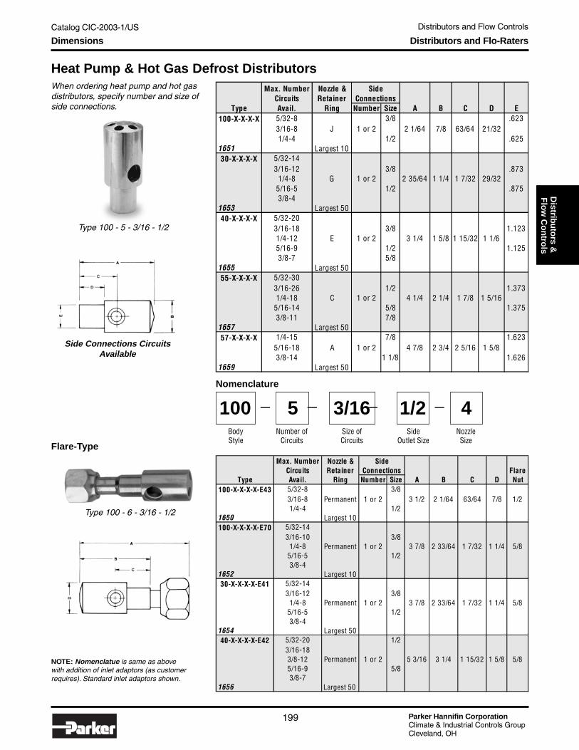
Catalog CIC-2003-1/US Distributors and Flow Controls
Parker Hannifin CorporationClimate & Industrial Controls GroupCleveland, OH
199
Service
& C
heck
Valves
Distrib
uto
rs & F
low
Co
ntro
lsDimensions Distributors and Flo-Raters
Heat Pump & Hot Gas Defrost Distributors
Side Connections CircuitsAvailable
When ordering heat pump and hot gasdistributors, specify number and size ofside connections.
Type 100 - 5 - 3/16 - 1/2
Flare-Type
NOTE: Nomenclatue is same as abovewith addition of inlet adaptors (as customerrequires). Standard inlet adaptors shown.
Type 100 - 6 - 3/16 - 1/2
Nomenclature
BodyStyle
100Number of
Circuits
5Side
Outlet Size
1/2— — —
Size ofCircuits
3/16 —
NozzleSize
4
Max. Number Nozzle &Circuits Retainer Flare
Type Avail. Ring Number Size A B C D Nut100-X-X-X-X-E43 5/32-8 3/8
3/16-8 Permanent 1 or 2 3 1/2 2 1/64 63/64 7/8 1/21/4-4 1/2
1650 Largest 10100-X-X-X-X-E70 5/32-14
3/16-10 3/81/4-8 Permanent 1 or 2 3 7/8 2 33/64 1 7/32 1 1/4 5/8
5/16-5 1/23/8-4
1652 Largest 1030-X-X-X-X-E41 5/32-14
3/16-12 3/81/4-8 Permanent 1 or 2 3 7/8 2 33/64 1 7/32 1 1/4 5/8
5/16-5 1/23/8-4
1654 Largest 5040-X-X-X-X-E42 5/32-20 1/2
3/16-183/8-12 Permanent 1 or 2 5 3/16 3 1/4 1 15/32 1 5/8 5/85/16-9 5/83/8-7
1656 Largest 50
SideConnections
Max. Number Nozzle &Circuits Retainer
Type Avail. Ring Number Size A B C D E100-X-X-X-X 5/32-8 3/8 .623
3/16-8 J 1 or 2 2 1/64 7/8 63/64 21/321/4-4 1/2 .625
1651 Largest 1030-X-X-X-X 5/32-14
3/16-12 3/8 .8731/4-8 G 1 or 2 2 35/64 1 1/4 1 7/32 29/32
5/16-5 1/2 .8753/8-4
1653 Largest 5040-X-X-X-X 5/32-20
3/16-18 3/8 1.1231/4-12 E 1 or 2 3 1/4 1 5/8 1 15/32 1 1/65/16-9 1/2 1.1253/8-7 5/8
1655 Largest 5055-X-X-X-X 5/32-30
3/16-26 1/2 1.3731/4-18 C 1 or 2 4 1/4 2 1/4 1 7/8 1 5/16
5/16-14 5/8 1.3753/8-11 7/8
1657 Largest 5057-X-X-X-X 1/4-15 7/8 1.623
5/16-18 A 1 or 2 4 7/8 2 3/4 2 5/16 1 5/83/8-14 1 1/8 1.626
1659 Largest 50
SideConnections
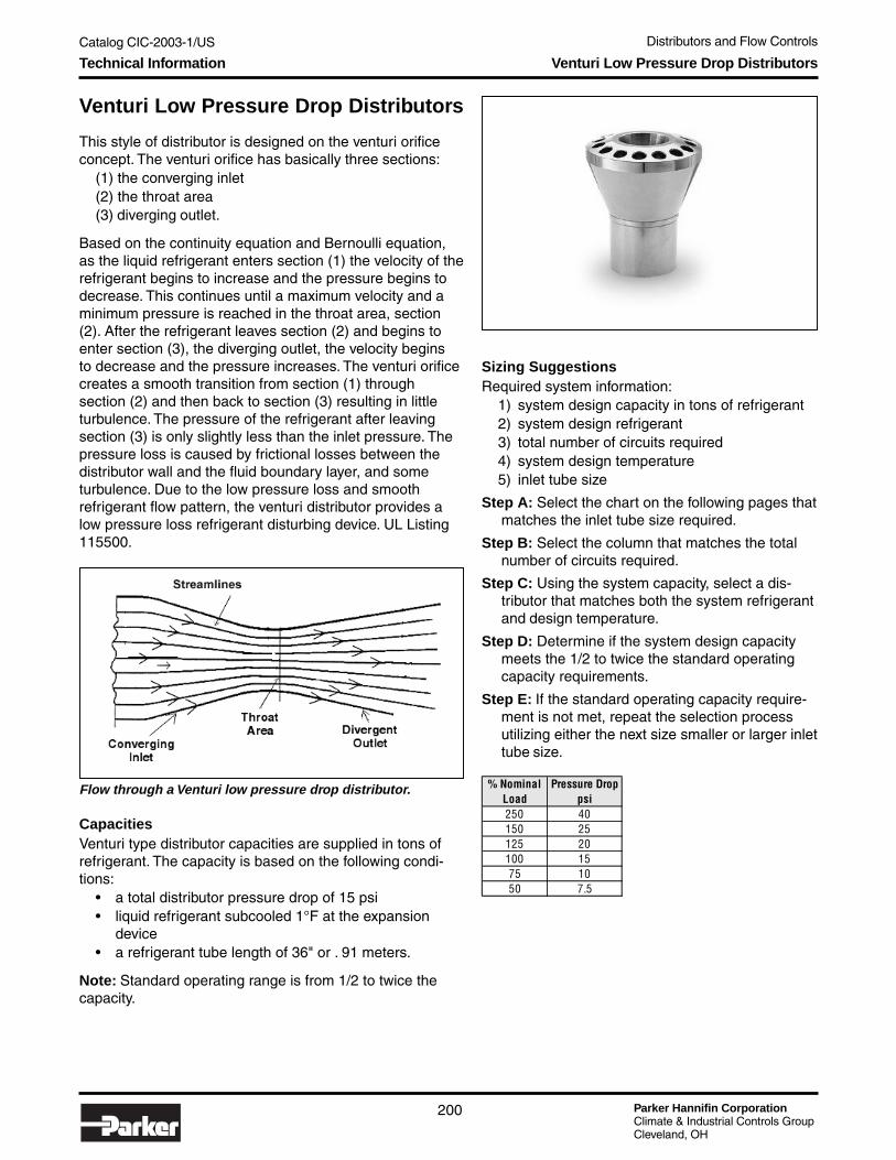
Parker Hannifin CorporationClimate & Industrial Controls GroupCleveland, OH
Catalog CIC-2003-1/US Distributors and Flow Controls
200
Technical Information Venturi Low Pressure Drop Distributors
Venturi Low Pressure Drop Distributors
This style of distributor is designed on the venturi orificeconcept. The venturi orifice has basically three sections:
(1) the converging inlet(2) the throat area(3) diverging outlet.
Based on the continuity equation and Bernoulli equation,as the liquid refrigerant enters section (1) the velocity of therefrigerant begins to increase and the pressure begins todecrease. This continues until a maximum velocity and aminimum pressure is reached in the throat area, section(2). After the refrigerant leaves section (2) and begins toenter section (3), the diverging outlet, the velocity beginsto decrease and the pressure increases. The venturi orificecreates a smooth transition from section (1) throughsection (2) and then back to section (3) resulting in littleturbulence. The pressure of the refrigerant after leavingsection (3) is only slightly less than the inlet pressure. Thepressure loss is caused by frictional losses between thedistributor wall and the fluid boundary layer, and someturbulence. Due to the low pressure loss and smoothrefrigerant flow pattern, the venturi distributor provides alow pressure loss refrigerant disturbing device. UL Listing115500.
Sizing SuggestionsRequired system information:
1) system design capacity in tons of refrigerant2) system design refrigerant3) total number of circuits required4) system design temperature5) inlet tube size
Step A: Select the chart on the following pages thatmatches the inlet tube size required.
Step B: Select the column that matches the totalnumber of circuits required.
Step C: Using the system capacity, select a dis-tributor that matches both the system refrigerantand design temperature.
Step D: Determine if the system design capacitymeets the 1/2 to twice the standard operatingcapacity requirements.
Step E: If the standard operating capacity require-ment is not met, repeat the selection processutilizing either the next size smaller or larger inlettube size.
Flow through a Venturi low pressure drop distributor. % Nominal Pressure DropLoad psi250 40150 25125 20100 1575 1050 7.5
CapacitiesVenturi type distributor capacities are supplied in tons ofrefrigerant. The capacity is based on the following condi-tions:
• a total distributor pressure drop of 15 psi• liquid refrigerant subcooled 1°F at the expansion
device• a refrigerant tube length of 36" or . 91 meters.
Note: Standard operating range is from 1/2 to twice thecapacity.

Catalog CIC-2003-1/US Distributors and Flow Controls
Parker Hannifin CorporationClimate & Industrial Controls GroupCleveland, OH
201
Service
& C
heck
Valves
Distrib
uto
rs & F
low
Co
ntro
ls
5/32" ODF Distributors
*Available with flare nut or ODM inlet connections.**For R-500 capacities, multiply R-12 capacities by 1.2.“F” available with flare nut only.
Technical Information Venturi Low Pressure Drop Distributors
Part # of
Number Outlets 40° 20° 0° -20° -40° 40° 20° 0° -20° -40° 40° 20° 0° -20° -40°
*4-2.5-2
*5-2.5-2
*4-2.5-3
*5-2.5-3
*4-2.5-4
*5-2.5-4
*4-2.5-5
*5-2.5-5
*4-2.5-6
*5-2.5-6
*4-2.5-7
*5-2.5-7
*4-2.5-8
*5-2.5-8
*4-2.5-9
*5-2.5-9
*4-2.5-10
*5-2.5-10 10 3.0 2.0 1.3 .84 .60 4.40 3.00 2.00 1.30 .90 2.25 1.53 .99 .63 .45
7-2.5-10
7-2.5-11 11 3.3 2.3 1.5 .92 .66 4.84 3.30 2.20 1.43 .99 2.47 1.68 1.08 .69 .49
F5-2.5-12
7-2.5-12
F5-2.5-13
7-2.5-13
F5-2.5-14
7-2.5-14
F5-2.5-15
7-2.5-15
7-2.5-16 16 4.8 3.3 2.1 1.3 .96 7.04 4.80 3.20 2.08 1.44 3.60 2.49 1.58 1.00 .72
7-2.5-17 17 5.1 3.5 2.2 1.4 1.0 7.48 5.10 3.50 2.21 1.54 3.82 2.61 1.68 1.06 .76
7-2.5-18 18 5.4 3.7 2.4 1.5 1.1 7.92 5.40 3.60 2.34 1.62 4.05 2.75 1.78 1.13 .81
7-2.5-19 19 5.7 3.9 2.5 1.6 1.1 8.36 5.70 3.80 2.47 1.71 4.27 2.90 1.83 1.19 .85
7-2.5-20 20 6.0 4.1 2.6 1.7 1.2 8.80 6.00 4.00 2.60 1.80 4.50 3.06 1.98 1.26 .90
7-2.5-21 21 6.3 4.3 2.8 1.8 1.3 9.25 6.30 4.20 2.73 1.89 4.72 3.21 2.07 1.32 .94
7-2.5-22 22 6.6 4.5 2.9 1.9 1.3 9.70 6.60 4.40 2.86 1.98 4.95 3.36 2.17 1.38 .99
7-2.5-23 23 6.9 4.7 3.0 1.9 1.4 10.15 6.90 4.60 2.99 2.07 5.17 3.51 2.27 1.44 1.03
7-2.5-24 24 7.2 4.9 3.2 2.0 1.4 10.6 7.20 4.80 3.12 2.16 5.40 3.67 2.37 1.51 1.08
Tons - R134a Tons - R22 Tons - R404A/R507
2 0.6 0.41 0.26 0.17 0.12 0.88 0.6 0.4 0.26 0.18 0.45 0.31 0.19 0.12 0.09
3 0.9 0.6 0.4 0.25 0.18 1.32 0.9 0.6 0.39 0.27 0.68 0.46 0.29 0.18 0.13
4 1.2 0.82 0.53 0.34 0.24 1.76 1.2 0.8 0.52 0.36 0.9 0.61 0.39 0.25 0.18
5 1.5 1 0.66 0.42 0.3 2.2 1.5 1 0.65 0.45 1.13 0.77 0.49 0.31 0.22
6 1.8 1.2 0.79 0.5 0.36 2.64 1.8 1.2 0.78 0.54 1.35 0.92 0.59 0.37 0.27
7 2.1 1.4 0.92 0.59 0.42 3.08 2.1 1.4 0.91 0.63 1.57 1.07 0.69 0.43 0.31
8 2.4 1.6 1.1 0.67 0.48 3.52 2.4 1.6 1.04 0.72 1.8 1.22 0.79 0.5 0.36
9 2.7 1.8 1.2 0.76 0.54 3.96 2.7 1.8 1.17 0.81 2.03 1.38 0.89 0.56 0.4
12 3.6 2.4 1.6 1 0.72 5.28 3.6 2.4 1.56 1.08 2.7 1.84 1.18 0.75 0.54
13 3.9 2.7 1.7 1.1 0.78 5.72 3.9 2.6 1.69 1.17 2.93 1.99 1.28 0.81 0.58
14 4.2 2.9 1.8 1.2 0.84 6.16 4.2 2.8 1.82 1.26 3.15 2.24 1.38 0.88 0.63
15 4.5 3.1 2 1.3 0.9 6.6 4.5 3 1.95 1.35 3.37 2.36 1.48 0.94 0.67

Parker Hannifin CorporationClimate & Industrial Controls GroupCleveland, OH
Catalog CIC-2003-1/US Distributors and Flow Controls
202
*Available with flare nut or ODM inlet connections.**For R-500 capacities, multiply R-12 capacities by 1.2.“F” available with flare nut only.
3/16" ODF Distributors
Technical Information Venturi Low Pressure Drop Distributors
Part # ofNumber Outlets 40° 20° 0° -20° -40° 40° 20° 0° -20° -40° 40° 20° 0° -20° -40°
3-3-2*4-3-2 2 1.20 .82 .54 .36 .25 1.80 1.20 .79 .53 .37 .90 .61 .40 .27 .18*5-3-23-3-3
*4-3-3 3 1.80 1.20 .82 .54 .38 2.60 1.80 1.20 .79 .55 1.40 .90 .61 .40 .28*5-3-33-3-4
*4-3-4 4 2.40 1.70 1.10 .72 .50 3.50 2.40 1.60 1.10 .76 1.80 1.30 .81 .54 .37*5-3-43-3-5
*4-3-5*5-3-57-3-53-3-6
*4-3-6*5-3-67-3-63-3-7
*4-3-7*5-3-77-3-7
*4-3-8*5-3-87-3-89-3-84-3-9
*5-3-97-3-99-3-9
*5-3-107-3-10 10.00 6.00 4.10 2.80 1.80 1.30 8.80 6.00 3.90 2.60 1.80 4.50 3.10 2.10 1.40 0.999-3-107-3-119-3-11*5-3-127-3-12 12 7.20 4.90 3.20 2.20 1.60 10.50 7.10 4.70 3.20 2.20 5.40 3.70 2.40 1.60 1.209-3-12F5-3-137-3-13 13 7.80 5.30 3.50 2.40 1.70 11.40 7.70 5.10 3.40 2.40 5.90 4.00 2.60 1.80 1.309-3-137-3-149-3-147-3-159-3-157-3-169-3-167-3-179-3-177-3-189-3-187-3-199-3-197-3-209-3-207-3-219-3-217-3-229-3-227-3-239-3-237-3-249-3-24
Tons - R134a Tons - R22 Tons - R404A/R507
5
.89 6.10 4.20
.643.0 2.0 1.3
1.703.6
1.00
4.20 2.90 1.90 1.30
4.80 3.20 2.20 1.40
2.40 1.80 1.30 0.812.70 0.56
.67
6 1.10 0.76 5.30 3.60 2.40 1.60 1.10
.47.90 4.40 3.00 2.00 1.30 .92 2.30 1.50 .99
.99 .662.80 1.80 1.30 3.10
3.20 2.10
2.20 1.40
1.10 .75
7
8 1.50 3.60 2.40 1.607.00 4.80
9 5.40 3.70 2.40 1.70 1.10 7.90 5.40 3.60 2.40 1.70 4.10 2.80 1.80 1.30 .85
11 6.60 4.40 3.00 2.00 1.40 9.60 6.50 4.30 2.90 2.00 5.00 3.30 2.30 1.50 1.10
14 8.40 5.80 3.80 2.50 1.80 12.30 8.30 5.50 3.70 2.60 6.30 4.30 2.90 1.90 1.40
15 9.00 6.10 4.10 2.80 1.90 13.10 8.90 5.90 4.00 2.80 6.80 4.60 3.10 2.10 1.50
16 9.60 6.50 4.30 2.90 2.00 14.00 9.50 6.30 4.20 2.90 7.20 4.90 3.20 2.20 1.50
17 10.20 7.00 4.60 3.10 2.20 14.90 10.10 6.70 4.50 3.10 7.70 5.20 3.40 2.30 1.60
18 10.80 7.30 4.90 3.20 2.30 15.80 10.70 7.10 4.70 3.30 8.10 5.50 3.70 2.40 1.70
19 11.40 7.80 5.20 3.50 2.40 16.60 11.30 7.50 5.00 3.50 8.60 5.90 3.90 2.60 1.80
20 12.00 8.20 5.40 3.60 2.50 17.50 11.90 7.90 5.30 3.70 9.00 6.10 4.10 2.70 1.90
21 12.60 8.50 5.60 3.70 2.60 18.40 12.50 8.30 5.50 3.90 9.40 6.40 4.30 2.80 2.00
22 13.20 9.00 5.90 4.00 2.80 19.20 13.10 8.70 5.80 4.00 9.90 6.70 4.50 2.90 2.10
23 13.80 9.40 6.10 4.10 2.90 20.10 13.70 9.10 6.00 4.20 10.30 7.00 4.70 3.00 2.20
24 14.40 9.80 6.50 4.30 3.00 21.00 14.30 9.50 6.30 4.40 10.80 7.40 4.90 3.20 2.30

Catalog CIC-2003-1/US Distributors and Flow Controls
Parker Hannifin CorporationClimate & Industrial Controls GroupCleveland, OH
203
Service
& C
heck
Valves
Distrib
uto
rs & F
low
Co
ntro
ls
*Available with flare nut or ODM inlet connections.**For R-500 capacities, multiply R-12 capacities by 1.2.“F” available with flare nut only.
1/4" ODF Distributors
Technical Information Venturi Low Pressure Drop Distributors
Part # ofNumber Outlets 40° 20° 0° -20° -40° 40° 20° 0° -20° -40° 40° 20° 0° -20° -40°*4-4-2*5-4-2 2 2.4 1.7 1.1 .70 .50 3.5 2.4 1.6 1.1 .76 1.8 1.3 .81 .54 .377-4-2
*4-4-3*5-4-3 3 3.6 2.4 1.7 1.1 .76 5.3 3.6 2.4 1.6 1.1 2.7 1.8 1.3 .81 .567-4-3
*4-4-4*5-4-4 4 4.8 3.2 2.2 1.4 1.0 7.0 4.8 3.2 2.1 1.5 3.6 2.4 1.6 1.1 .757-4-4
*4-4-5*5-4-5 5 6.0 4.1 2.8 1.8 1.3 8.8 6.0 3.9 2.6 1.8 4.5 3.1 2.1 1.4 .997-4-5
*4-4-6*5-4-67-4-69-4-67-4-7 7 8.4 5.8 3.8 2.5 1.8 10.5 7.1 4.7 3.2 2.2 5.4 3.7 2.4 1.6 1.29-4-75-4-87-4-8 8 9.6 6.5 4.3 2.9 2.0 14.0 9.5 6.3 4.2 2.9 7.2 4.9 3.2 2.2 1.59-4-85-4-97-4-99-4-9
11-4-97-4-109-4-10 10 12.0 8.2 5.4 3.6 2.5 17.5 11.9 7.9 5.3 3.7 9.0 6.1 4.1 2.7 1.911-4-107-4-1111-4-117-4-129-4-12 12 14.4 9.8 6.5 4.3 3.0 21.0 14.3 9.5 6.3 4.4 10.8 7.4 4.9 3.2 2.311-4-127-4-139-4-13 13 15.6 10.6 7.1 4.7 3.2 22.8 15.5 10.2 6.8 4.8 11.7 7.9 5.3 3.5 2.411-4-137-4-149-4-14 14 16.8 11.4 7.6 5.0 3.5 24.5 16.7 11.0 7.4 5.2 12.6 8.6 5.7 3.8 2.611-4-147-4-159-4-15 15 18.0 12.2 8.0 5.4 3.8 26.3 17.9 11.8 7.9 5.5 13.5 9.2 6.0 4.1 2.911-4-157-4-169-4-16 16 19.2 13.1 8.7 5.8 4.1 28.0 19.0 12.6 8.4 5.9 14.4 9.8 6.5 4.3 3.111-4-167-4-1711-4-177-4-1811-4-187-4-1911-4-197-4-2011-4-207-4-2111-4-217-4-2211-4-227-4-2311-4-237-4-2411-4-24
Tons - R134a Tons - R22 Tons - R404A/R507
20.4 13.9 9.2 6.1 4.3 29.8 20.2 13.4 8.9 6.3 15.3 10.4 6.9 4.6 3.2
21.6 14.6 9.7 6.5 4.6 31.5 21.4 14.2 9.5 6.6 16.2 11.0 7.3 4.9 3.4
22.8 15.5 10.3 6.8 4.8 33.3 22.6 15.0 10.0 7.0 17.1 11.6 7.7 5.1 3.6
24.0 16.3 10.8 7.2 5.0 35.0 23.8 15.8 10.5 7.4 18.0 12.2 8.1 5.4 3.8
25.2 17.2 11.4 7.6 5.3 36.8 25.0 16.6 11.1 7.7 18.9 12.9 8.6 5.7 4.0
26.4 18.0 11.9 7.9 5.5 38.5 26.2 17.3 11.6 8.1 19.8 13.5 8.9 5.9 4.1
27.6 18.7 12.5 8.3 5.8 40.3 27.4 18.1 12.1 8.5 20.7 14.0 9.4 6.2 4.3
28.8 19.6 13.0 8.6 6.0 42.0 28.6 18.9 12.6 8.8 21.6 14.7 9.7 6.5 4.5
22
23
24
17
18
19
20
21
11 13.2 9.0 6.0 4.0 2.8 19.3 13.1 8.7 5.8 4.1 9.9 6.8 4.5 3.0 2.1
10.79 10.8 7.3 4.9 3.2 2.3 15.8 1.77.1 4.7 3.3 8.1 5.5 3.7 2.4
6 7.2 4.9 3.2 2.2 1.6 10.5 7.1 4.7 3.2 2.2 5.4 3.7 2.4 1.6 1.2

Parker Hannifin CorporationClimate & Industrial Controls GroupCleveland, OH
Catalog CIC-2003-1/US Distributors and Flow Controls
204
5/16" ODF Distributors
*Available with flare nut or ODM inlet connections.“F” available with flare nut only.
Technical Information Venturi Low Pressure Drop Distributors
Part # ofNumber Outlets 40° 20° 0° -20° -40° 40° 20° 0° -20° -40° 40° 20° 0° -20° -40°*4-5-2*5-5-2 2 4.8 3.2 2.2 1.4 1.0 7.0 4.8 3.2 2.1 1.5 3.6 2.4 1.6 1.1 .757-5-2F4-5-3*5-5-3 3 7.2 4.9 3.2 2.2 1.6 10.5 7.1 4.7 3.2 2.2 5.4 3.7 2.4 1.6 1.27-5-3F4-5-4*5-5-4 4 9.6 6.5 4.3 2.9 2.0 14.0 9.5 6.3 4.2 2.9 7.2 4.9 3.2 2.2 1.57-5-47-5-59-5-57-5-69-5-69-5-7
11-5-79-5-8
11-5-811-5-9 9 21.6 14.6 9.7 6.5 4.6 31.5 21.4 14.2 9.5 6.6 16.2 11.0 7.3 4.9 3.411-5-10 10 24.0 16.3 10.8 7.2 5.0 35.0 23.8 15.8 10.5 7.4 18.0 12.2 8.1 5.4 3.811-5-11 11 26.4 18.0 11.9 7.9 5.5 38.5 26.2 17.3 11.6 8.1 19.8 13.5 8.9 5.9 4.111-5-12 12 28.8 19.6 13.0 8.6 6.0 42.0 28.6 18.9 12.6 8.8 21.6 14.7 9.7 6.5 4.511-5-13 13 31.2 21.2 14.0 9.4 6.6 45.5 30.9 20.5 13.7 9.6 23.4 15.9 10.5 7.0 5.011-5-14 14 33.6 22.8 15.1 10.1 7.1 49.0 33.3 22.1 14.7 10.3 25.2 17.1 11.3 7.6 5.311-5-15 15 36.0 24.5 16.2 10.8 7.6 52.5 35.7 23.6 15.8 11.0 27.0 18.4 12.2 8.1 5.713-5-16 16 38.4 26.2 17.3 11.5 8.0 56.0 38.1 25.2 16.8 11.8 28.8 19.6 13.0 8.6 6.013-5-17 17 40.8 27.7 18.4 12.2 8.5 59.5 40.4 26.8 17.8 12.5 30.6 20.8 13.8 9.1 6.413-5-18 18 43.2 29.4 19.4 13.0 9.1 63.0 42.8 28.4 18.9 13.2 32.4 22.1 14.6 9.7 6.813-5-19 19 45.6 31.0 20.5 13.7 9.6 66.5 45.2 29.9 20.0 14.0 34.2 23.2 15.4 10.3 7.213-5-20 20 48.0 32.6 21.6 14.4 10.1 70.0 47.6 31.4 21.0 14.7 36.0 24.5 16.2 10.8 7.713-5-21 21 50.4 34.3 22.7 15.1 10.6 73.5 50.0 32.9 22.0 15.4 37.8 25.7 17.0 11.3 7.913-5-22 22 52.8 36.0 23.8 15.8 11.0 77.0 52.5 34.4 23.1 16.1 39.6 27.0 17.8 11.9 8.3
9.8 6.5 4.3 3.112.6 8.4 5.9 14.45.8 4.1 28 198 19.2 13.1 8.6
8.6 5.7 3.8 2.611 7.4 5.2 12.65 3.5 34.5 16.77 16.8 11.4 7.6
7.4 4.9 3.2 2.39.5 6.3 4.4 10.84.3 3 21 14.36 14.4 9.8 6.5
6.1 4.1 2.7 1.97.9 5.3 3.7 93.6 2.5 17.5 11.95 12.0 8.2 5.4
Tons - R134a Tons - R22 Tons - R404A/R507

Catalog CIC-2003-1/US Distributors and Flow Controls
Parker Hannifin CorporationClimate & Industrial Controls GroupCleveland, OH
205
Service
& C
heck
Valves
Distrib
uto
rs & F
low
Co
ntro
ls
3/8" ODF Distributors
1/2" ODF Distributors
NOTE: Capacity shown is the total distributor capacity for the indicated number of outlets with 36" tubes. Ratingsare based on average condensing temperature, 15 psi drop across the distributor, and 1 degree F subcooledliquid entering the expansion valve.
*Available with flare nut or ODM inlet connections.“F” available with flare nut only.
*Available with flare nut or ODM inlet connections.“F” available with flare nut only.
Technical Information Venturi Low Pressure Drop Distributors
Part # of
Number Outlets 40° 20° 0° -20° -40° 40° 20° 0° -20° -40° 40° 20° 0° -20° -40°
F4-6-2 2 8.4 5.8 3.8 2.5 1.8 12.3 8.3 5.5 3.7 2.6 6.3 4.3 2.9 1.9 1.4
7-6-2
F5-6-3 3 12.6 8.5 5.6 3.8 2.6 18.4 12.5 8.3 5.5 3.9 9.5 6.4 4.2 2.9 2.0
7-6-3
F5-6-4 4 16.8 11.4 7.6 5.0 3.5 24.5 16.7 11.1 7.4 5.1 12.6 8.6 5.7 3.8 2.6
7-6-4
9-6-5 5 21.0 14.3 9.5 6.4 4.4 30.6 20.8 13.9 9.2 6.4 15.8 10.7 7.1 4.8 3.3
11-6-5
9-6-6 6 25.2 17.2 11.4 7.6 5.3 36.8 25.0 16.6 11.1 7.7 18.9 12.9 8.6 5.7 4.0
11-6-6
11-6-7 7 29.4 20.0 13.2 8.9 6.1 42.9 29.2 19.4 12.9 9.0 22.0 15.0 9.9 6.7 4.6
11-6-8 8 33.6 22.8 15.1 10.1 7.1 49.0 33.3 22.2 14.7 10.3 25.2 17.1 11.3 7.6 5.3
11-6-9 9 37.8 25.7 17.0 11.3 7.9 55.1 37.5 25.0 16.5 11.6 28.3 19.2 12.7 8.5 6.0
11-6-10 10 42.0 28.6 19.0 12.6 8.9 61.3 41.7 27.7 18.4 12.9 31.5 21.4 14.2 9.5 6.7
11-6-11 11 46.2 31.4 20.8 13.8 9.7 67.4 45.8 30.4 20.2 14.2 34.3 23.5 15.6 10.4 7.2
11-6-12 12 50.4 34.3 22.7 15.1 10.6 73.5 50.0 33.2 22.1 15.5 37.8 25.7 17.0 11.3 7.9
13-6-17 17 68.2 46.3 30.7 20.5 14.4 99.4 67.6 44.8 29.9 21.0 51.1 34.7 23.0 15.4 10.8
13-6-18 18 74.4 50.6 33.6 22.4 14.9 108.5 73.9 49.0 32.7 21.7 55.8 37.9 25.2 16.8 11.2
Tons - R134a Tons - R22 Tons - R404A/R507
Part # of
Number Outlets 40° 20° 0° -20° -40° 40° 20° 0° -20° -40° 40° 20° 0° -20° -40°
11-8-2 2 12.0 8.2 5.4 3.6 2.5 17.5 11.9 7.9 5.3 3.8 9.0 6.1 4.1 2.7 1.9
11-8-3 3 18.0 12.2 8.2 5.4 4.2 26.3 17.9 11.8 7.9 5.5 13.5 9.2 6.1 4.1 3.2
11-8-4 4 24.0 16.3 10.8 7.2 5.0 35.0 23.8 15.8 10.5 7.6 18.0 12.2 8.1 5.4 3.8
11-8-5 5 30.0 20.4 13.6 9.0 6.4 43.8 29.8 19.7 13.2 9.2 22.5 15.3 10.2 6.8 4.8
11-8-6 6 36.0 24.5 16.2 10.8 7.6 52.5 35.7 23.6 15.8 11.0 27.0 18.4 12.2 8.1 5.7
11-8-7 7 42.0 28.6 19.0 12.6 8.9 61.3 41.7 27.6 18.4 12.9 31.5 21.4 14.2 9.5 6.7
13-8-8 8 48.0 32.6 21.7 14.4 10.2 70.0 47.7 31.5 21.1 14.7 36.0 24.5 16.3 10.8 7.7
13-8-9 9 54.0 36.7 24.4 16.2 11.4 78.7 53.7 31.9 23.7 16.5 40.5 27.5 18.3 12.1 8.6
13-8-10 10 60.0 40.8 27.1 18.0 12.7 87.5 59.6 39.4 26.3 18.4 45.0 30.6 20.3 13.5 9.5
13-8-11 11 66.0 44.9 30.0 19.8 14.0 96.3 65.6 43.3 28.9 20.3 49.5 33.7 22.4 14.8 10.5
13-8-12 12 72.0 49.0 32.6 21.6 15.4 105.2 71.5 47.2 31.5 22.1 54.0 36.8 24.5 16.2 11.4
13-8-13 13 78.0 53.0 35.3 23.4 16.6 113.8 77.5 51.2 34.2 24.0 58.5 39.8 26.5 17.6 12.4
Tons - R134a Tons - R22 Tons - R404A/R507

Parker Hannifin CorporationClimate & Industrial Controls GroupCleveland, OH
Catalog CIC-2003-1/US Distributors and Flow Controls
206
Dimensions Venturi Low Pressure Drop Distributors
TypeA
Dia.B
Dia. CD
+/-.015 F3-3-23-3-33-3-43-3-53-3-63-3-8 1.000 1.380 .171 .3753-4-23-4-33-4-43-4-6
4-2-5-24-2.5-34-2.5-44-2.5-54-2.5-6 .688 1.022 .5054-2.5-8 .793 1.2634-2.5-9 .970 1.5304-3-24-3-34-3-4 .656 .9064-3-5 .750 1.0504-3-6 .812 1.1954-3-7 .875 1.3594-3-8 .970 1.5304-3-9 1.000 1.625
4-3-10 1.095 1.5624-3-12 1.250 2.0314-4-24-4-34-4-44-4-54-4-64-4-74-4-8
5-2.5-25-2.5-3 – .960 –5-2.5-45-2.5-55-2.5-65-2.5-75-2.5-8 1.4065-2.5-9
5-2.5-10 .899 1.4965-3-25-3-35-3-45-3-55-3-65-3-75-3-85-3-9
5-3-105-3-11 1.250 2.0315-3-12
–
.125
.393
.125
.630
.171 .393
.500
.234
.405
.440
.500
.234
.812
.375
.373
.812 1.236
1.236
.625
.623
.688 1.093
.837
– .887
.812 1.236
.937 1.433
– .708
.625 .909
–
.171.630
.625
.830
1.000
1.250
1.110
1.561
1.775
.500
.498
.812
.500
.171
TypeA
Dia.B
Dia. CD
+/-.015 F5-4-25-4-3 .812 1.2055-4-45-4-55-4-65-4-8 1.250 1.8755-4-9 1.280 2.030
5-4-10 1.416 2.5185-5-2 .875 1.165 .5675-5-3 .2975-5-45-6-2 1.125 1.738 .312 .625
7-2.5-107-2.5-117-2.5-127-2.5-137-2.5-147-2.5-157-2.5-167-2.5-187-2.5-207-2.5-24
7-3-57-3-67-3-77-3-87-3-9
7-3-107-3-117-3-127-3-137-3-147-3-157-3-167-3-177-3-187-3-197-3-207-3-247-4-27-4-37-4-47-4-57-4-67-4-77-4-8
1.609
.625
.623
.815
1.125
1.240
2.109
.875
.873
1.000 1.498
1.000 1.495
1.625 2.722
2.718
1.265
1.156
.890
1.000
1.492
3.650
.234
.125
.171
1.659
1.041
1.187
1.331
1.581
1.812
.630
.234 .630
.890
.875
.880
2.101
1.812
2.219
2.562
3 – 3 – 4
Size of Size of NumberInlet in Outlets in of1/8ths 1/16ths Outlets
Example of Type Number

Catalog CIC-2003-1/US Distributors and Flow Controls
Parker Hannifin CorporationClimate & Industrial Controls GroupCleveland, OH
207
Service
& C
heck
Valves
Distrib
uto
rs & F
low
Co
ntro
lsDimensions Venturi Low Pressure Drop Distributors
3 – 3 – 4
Size of Size of NumberInlet in Outlets in of1/8ths 1/16ths Outlets
Example of Type NumberType
ADia.
BDia. C
D +/-.015 F
7-4-97-4-107-4-117-4-127-4-137-4-14 1.800 2.698
7-4-157-4-167-4-177-4-187-4-197-4-207-4-217-4-227-4-237-4-247-5-2 .894 1.290 .875
7-5-37-5-47-5-57-5-67-6-27-6-37-6-49-3-89-3-9
9-3-109-3-119-3-129-3-139-3-149-3-159-3-169-3-179-3-189-3-199-3-209-3-219-3-229-3-239-3-249-4-6 – 1.878 –
9-4-79-4-89-4-9 1.285 2.075
9-4-10 1.375 2.206
9-4-119-4-129-4-13 2.000 1.031
9-4-149-4-159-4-169-5-59-5-6
1.250
1.543
1.930
1.063
.8803.550
1.416 2.247
2.188 .234
.297
1.036
1.250 1.777 .297
.234
1.285 1.935
1.567 2.505
1.9803.210
1.188 2.050
1.71
1.240 2.101
1.680 2.875
2.115 3.684
.880
1.036
1.036
.3121.930
.875
.873
1.125 1.123
1.701 2.698
2.313 3.378
2.705 3.813
1.250
TypeA
Dia.B
Dia. CD
+/-.015 F
9-5-79-5-89-6-59-6-6
11-4-811-4-9 1.156
11-4-1011-4-11 1.500 2.45811-4-1211-4-1311-4-14 1.183 2.99511-4-15 1.875 3.11911-4-16 1.988 3.29611-4-1711-4-1811-4-1911-4-2011-4-2111-4-2211-4-2311-4-2411-5-611-5-7 1.484 2.218
11-5-811-5-911-5-1011-5-1111-5-1211-5-1311-5-1411-5-1511-6-6 1.484 2.239
11-6-711-6-811-6-1011-6-1211-8-3 1.468 2.15611-8-411-8-511-8-611-8-713-5-1613-5-1713-5-1813-5-1913-5-2013-5-2113-5-2213-6-13 2.046 5.781 .35913-8-8 2.250 3.140 .35913-8-10 2.593 3.765 .48413-8-13 3.125 4.750 .484
1.280
1.161
1.156
1.156
2.671
3.239
1.161
.234
1.688 2.779
2.180 3.582
2.313
2.7051.161
1.156
4.015
3.649
.297
3.000 4.281
2.750 4.500
2.835 4.859
1.036
1.031
2.105
2.109
.297
.312
.359
.484
.247
2.687
2.705
1.890
1.3752.296
1.062
2.0625
1.625 1.623
1.125 1.123
4.138
1.938 3.033
1.415 2.328
1.438
1.453
1.375 1.373
2.313

Parker Hannifin CorporationClimate & Industrial Controls GroupCleveland, OH
Catalog CIC-2003-1/US Distributors and Flow Controls
208
Flare Type Venturi Distributors
Regular or Frost Free Nut
NOTE: To order distributor only drop prefix “F” andsubstitute inlet size. For example a distributor headto go into 1/2" O.D. copper would be .430 plus sizeof outlets in 1/16" and number of circuits. 430-3-4would go into 1/2" tubing and have four 3/16" feedertube sockets.
Dimensions Flare Type Venturi Distributors
Outlet Number Type A B C D ESize of Outlets Number Dia. Hex Dia.
3 F3-3-3 1/24 F3-3-4 1/25 F3-3-5 17/326 F3-3-6 17/322 F4-2.5-2 1 7/8 1/2 9/324 F4-2.5-4 2 13/64 43/64 7/16
5/32 5 F4-2.5-5 2 5/64 39/64 1/8 25/646 F4-2.5-6 2 13/16 43/64 7/168 F4-2.5-8 2 17/32 55/64 5/82 F4-3-2 1 29/32 35/64 5/163 F4-3-3 1 63/64 19/32 11/324 F4-3-4 11/645 F4-3-5 2 3/8 25/32 1 17/326 F4-3-68 F4-3-8 2 45/64 59/64 21/322 F4-4-2 2 7/64 25/32 13/323 F4-4-3
1/4 4 F4-4-4 15/645 F4-4-56 F4-4-62 F4-5-2 2 27/64 7/8 31/643 F4-5-3 2 23/32 1 1/64 19/64 41/64
3/8 2 F4-6-2 2 5/8 1 1/16 23/64 19/32
5/16
3/16
3/16 7/8
1
3/16
33/64
11/16
1 1/16 5/8
2 3/16 13/16
2 23/64 27/32
2 47/64
Outlet Number Type A B C D ESize of Outlets Number Dia Hex Dia
4 F5-2.5-46 F5-2.5-68 F5-2.5-8 2 17/32 25/32 1/8 35/649 F5-2.5-9 2 43/64 27/32 39/6412 F5-2.5-1213 F5-2.5-1314 F5-2.5-14 3 7/64 1 9/64 29/326 F5-3-6 2 29/64 51/64 17/328 F5-3-8 2 21/32 59/64 1 1/8 21/329 F5-3-9 2 27/32 1 11/64 47/64
3/16 10 F5-3-1012 F5-3-122 F5-4-23 F5-4-3 33/64
1/4 4 F5-4-4 15/645 F5-4-5 2 23/326 F5-4-62 F5-5-2 2 25/32 7/8 31/643 F5-5-3 2 23/32 1 1/64 41/64
5/32
5/16
2 23/64 21/32
3 5/16 1 7/32
3 7/64 1 15/64
53/642 27/64
7/16
11/161 1/64
19/64
15/16
31/32
3 – 3 – 4
Size of Size of NumberInlet in Outlets in of1/8ths 1/16ths Outlets
Example of Type Number

Catalog CIC-2003-1/US Distributors and Flow Controls
Parker Hannifin CorporationClimate & Industrial Controls GroupCleveland, OH
209
Service
& C
heck
Valves
Distrib
uto
rs & F
low
Co
ntro
ls
Flo-Rater Designs
Style F Flo-Raters• Most versatile and cost effective body style.• Accepts 5 fluted, 3 fluted and
double-headed piston styles.• Accepts TVXs — no brazing
needed.• 3 Sub-models for full range of
circuit quantities.• Flange mount available.• Full range of circuit sizes and quantities.• Easy field repliceable restrictor — no brazing
required.• Full line of inlet styles.• See page 210.
Style A Flo-Raters• Cost effective.• 3 sub-models for full range
of circuit quantities and sizes.• PTFE seal on body.• PTFE or neoprene seal on piston.• See page 211.
Style M Flo-Raters• Heavy duty quality.• Preferred by OEM users.• PTFE or neoprene seal on
piston.• See page 213.
Parker Plus: Value-Added Components & Custom Brazing
Dimensions Flo-Rater Designs
Parker Climate Controls Division produces up to 20million trouble-free braze joints a year for HVAC/Rcompanies worldwide. Our customers have discoveredthat Parker brazed products offer greater integritywhich results in lower on-line leaks and fewer fieldproblems. In addition, most cost evaluations proveParker is extremely cost effective when comparedwith in-house methods. Contact Parker for an on-siteevaluation.

Parker Hannifin CorporationClimate & Industrial Controls GroupCleveland, OH
Catalog CIC-2003-1/US Distributors and Flow Controls
210
Flo-Rater Style F
Flo-Rater Style F
ApplicationMeter refrigerant and distributetwo-phase refrigerant to a coil.Replaces capillary tubes, TXVsand check valves as a means ofmetering refrigerant flow throughair conditioning and heat pumpsystems.
Agency ApprovalsUL Recognized; File No: 7511US Patent No. 5,894,741
Features and Benefits• Most versatile and cost effective body style.• Accepts 5 fluted, 3 fluted and double-headed piston styles.• Accepts TVXs — no brazing required.• Flange mount available.• Full range of circuit sizes and quantities.• Easy field replaceable restrictor — no brazing required.• Full line of inlet styles.
Nomenclature
No. 8713602-17-1080 (Example)
InletStyle
See inletstyle chart.
PistonStyle
See piston stylechart.
Body Style
75 = 3/4" hex87 = 7/8" hex100 = 1" hex
Screen
0 = no screen1 = with screen
Numberof
Circuits
Lengthof Circuit
Tubesin Inches
Piston Size inThousandths
See pistonsize chart.
Size ofCircuitsDia. in1/16ths
— — — — — —1 3 — 6 02 17 1 8087F
Piston Types Available1 = 3 fluted, stepped hole,
PTFE gasket5 = 5 fluted, straight hole with no chamfer,
PTFE gasket6 = 5 fluted, straight hole with 45 x .010
chamfer, neoprene gasket9 = Doubleheaded piston
3 Flute 5 Flute Doubleheaded
Pistons Available
Most Common Inlet Types(Custom Designs Available)00 = No inlet piece included.26 = Flange with 3/8" O.D. x .028 wall x 2" long. With one end expanded to 3/8" I.D.35 = Flange with 3/8" O.D. x .028 wall with 90° bend and one end expanded to 3/8" I.D.
End Piece No. 26 ShownCustom Engineered
Models Available
Circuit Capacity List75 = 0-1/4, 5-3/16, 7-1/887 = 5-1/4, 7-3/16, 8-1/8100 = 6-1/4, 9-3/16, 12-1/8
Orifice SizingSee graphs on page 218.
75F Body 87F Body 100F Body
Technical and Ordering Information

Catalog CIC-2003-1/US Distributors and Flow Controls
Parker Hannifin CorporationClimate & Industrial Controls GroupCleveland, OH
211
Service
& C
heck
Valves
Distrib
uto
rs & F
low
Co
ntro
lsFlo-Rater Style A
Circuit Capacity List75 = 0-1/4, 5-3/16, 7-1/887 = 5-1/4, 7-3/16, 8-1/8100 = 6-1/4, 9-3/16, 12-1/8
Most Common Inlet Types(Custom Designs Available)00 = No inlet piece included.01 = Flange with 3/8" O.D. x .028 wall x 2" long. With one end expanded to 3/8" I.D.02 = Flange with 3/8" O.D. x .028 wall x 9" long. Straight.03 = Flange with 3/8" O.D. x .028 wall x 3.5" long. Straight.04 = Flange with 3/8" O.D. x .028 wall x 2.6" long. With one end expanded to 3/8" I.D.27 = Flange with 3/8" O.D. x .028 wall with 90° bend and one end expanded to 3/8" I.D.11 = Flange with 3/8" O.D. x .018 wall x 6.250" long. Straight.18 = Flange with 3/8" O.D. x .028 wall x with 90° bend. Straight.
Piston Types Available1 = 3 fluted, stepped hole,
PTFE gasket5 = 5 fluted, straight hole with no chamfer,
PTFE gasket6 = 5 fluted, straight hole with 45 x .010
chamfer, neoprene gasket
Technical and Ordering Information
Flo-Rater Style A
ApplicationMeter refrigerant and distributetwo-phase refrigerant to a coil.Replaces capillary tubes, TXVsand check valves as a means ofmetering refrigerant flow throughair conditioning and heat pumpsystems.
Agency ApprovalsUL Recognized; File No: 7511
Features and Benefits• Cost effective.• Full range of circuit sizes and quantities.• Easy field replaceable restrictor — no brazing required.• Accepts TXVs — no brazing required.• Accepts 5 and 3 fluted piston styles.• Flange mount available.• Full line of inlet styles.
Orifice SizingSee graphs on page 218.
Nomenclature
No. 8713602-17-1080 (Example)
InletStyle
See inletstyle chart.
PistonStyle
See piston stylechart.
Body Style
75 = 3/4" hex87 = 7/8" hex100 = 1" hex
Screen
0 = no screen1 = with screen
Numberof
Circuits
Lengthof Circuit
Tubesin Inches
Piston Size inThousandths
See pistonsize chart.
Size ofCircuitsDia. in1/16ths
— — — — — —1 3 — 6 02 17 1 8087
75 Body 87 Body 100 Body
End Piece No. 01 ShownCustom Engineered
Models Available
Pistons Available3 Flute (left)
5 Flute (right)

Parker Hannifin CorporationClimate & Industrial Controls GroupCleveland, OH
Catalog CIC-2003-1/US Distributors and Flow Controls
212
Flo-Rater Style FD20
Flo-Rater Style FD20
ApplicationMeter refrigerant and distributetwo-phase refrigerant to a coil.Replaces capillary tubes, TXVsand check valves as a means ofmetering refrigerant flow throughair conditioning and heat pumpsystems.
Agency ApprovalsUL Recognized; File No: 2709
Nomenclature
No. FD20G001B04065 (Style B Example)
— — ——
OrificeSize
065Number
of Outlets
04“ B” Style PistonFF1913-10-XXX
BBasic
Configuration
001FD20 Flow Control,
Fully Assembled
FD20G
Piston Type• “B” style bullet nose
Pistons AvailableChamfered
Features and Benefits• Cost effective.• Full range of circuit sizes and quantities.• Easy field replaceable restrictor — no brazing required.• Accepts TXVs — no brazing required.• Metal to metal seals (body and piston).• Flange mount available.• Full line of inlet styles.• Requires bullet nose piston FF1913-10-XXX
Most Common Inlet Types(Custom Designs Available)• Flange with 3/8" O.D. x .028 wall x 1" long.• Flange with 3/8" O.D. x .028 wall x 4.5" long. With one end expanded to 3/8" I.D.• Flange with 3/8" O.D. x .028 wall x 1" long. With 90° bend and one end expanded
to 3/8" I.D.FD20 Inlet
Custom EngineeredModels Available
Circuit Capacity• 2-10 circuits
75B Body (Style B) 100B Body (Style B)87B Body (Style B)
Orifice SizingSee graphs on page218.
Technical and Ordering Information

Catalog CIC-2003-1/US Distributors and Flow Controls
Parker Hannifin CorporationClimate & Industrial Controls GroupCleveland, OH
213
Service
& C
heck
Valves
Distrib
uto
rs & F
low
Co
ntro
lsFlo-Rater Style MTechnical and Ordering Information
Flo-Rater Style M
ApplicationMeter refrigerant and distributetwo-phase refrigerant to a coil.Replaces capillary tubes, TXVsand check valves as a means ofmetering refrigerant flow throughair conditioning and heat pumpsystems.
Agency ApprovalsUL Recognized; File No: 115500
Features and Benefits• Heavy duty design.• Full range of circuit sizes and quantities.• Easy field replaceable restrictor.• Accepts 5 and 3 fluted piston styles.• Full line of inlet styles.
Nomenclature
No. 43412-17-3080 (Style M Example)
Body Style
4L = 7/8" hex body w/ 1/2-20-2B thds
4 = 7/8" hex body w/1/2-24-2B thds
5 = 15/16" hex body6 = 15/16" hex
body (short)7 = 1-1/4" hex body
— — — — ——4Size ofCircuitsDia. in1/16ths
3Number
ofCircuits
4End Piece
Style
12Length
of CircuitTubes
in Inches
17Piston Style
See piston style chart.
3Piston Size inThousandths
See pistonsize chart.
080
Most Common Inlet Types(Custom Designs Available)00 = no inlet piece10 = 3/8" sweat12 = 3/8" sweat with tube brazed in25 = 1/4" flare38 = 3/8" flare50 = 1/2" flare70 = 3/8" flare with 90 degree 3/8" elbow
End Piece No. 12 ShownCustom Engineered
Models Available
Piston Types Available1 = 3 fluted, stepped hole, PTFE gasket5 = 5 fluted, straight hole with no chamfer,
PTFE gasket6 = 5 fluted, straight hole wiyh 45 x .010
chamfer, neoprene gasket
Pistons Available
3 Flute 5 Flute
Circuit Capacity List4MDB = 6-1/4, 8-3/16, 10-1/87MDB = 11-3/16
Orifice SizingSee graphs on page 218. 7 MDB Body4 MDB Body

Parker Hannifin CorporationClimate & Industrial Controls GroupCleveland, OH
Catalog CIC-2003-1/US Distributors and Flow Controls
214
Flo-Rater Style FD20D and FD20ETechnical Information
Flo-Rater Style FD20D
ApplicationDesigned to replace hard-to-handle and easilydamaged capillary tubing giving a more predictablepressure drop.
Agency ApprovalsUL Recognized; File No: 2709
Features and Benefits• Cost effective alternative to capillary tubes.• One piece design.• Versatility in length, end configuration, orifice size
and copper tube bend configuration.• Easy to handle and install.• Complete range of orifice sizes.
Flo-Rater Style FD20EApplicationDeveloped to solve space limitationproblems on Packaged TerminalHeat Pumps and mini-split systems.The FD20E utilizes two floatingorifices to replace two check valvesand two cap tubes along with up toeight braze joints with one easy toinstall self-contained unit requiringonly two braze joints.
Agency ApprovalsUL Recognized; File No: 2709US Patent No. 5,265,438
Features and Benefits• Cost effective alternative to capillary tubes, check
valves and strainers.• One piece design.• Bi-directional flow control/filter screen
combination.• Custom end configurations.• Complete range of orifice sizes.
Performance Specifications• Pressure up to 750 psi operating• Minimum burst pressure: 3750 psi• Operating temperature: +140°F to +250°F
(-40°C to +121°C)• Mass flow rates from 50 lb./hr. to 1200 lb./hr.• Restrictor sized from .020" to .105" (in .001"
increments)• End configurations: Male 1/4", 5/16", 3/8", 1/2"
Female 1/4", 5/16", 3/8", 1/2"
Orifice SizingSee graphs on page 218.
Performance Specifications• Pressure up to 750 psi operating• Minimum burst pressure: 3750 psi• Mass flow rates from 50 lb./hr. to 1200 lb./hr.• Restrictor sized from .030" to .105"
(in .001" increments)
Orifice SizingSee graphs on page 218.
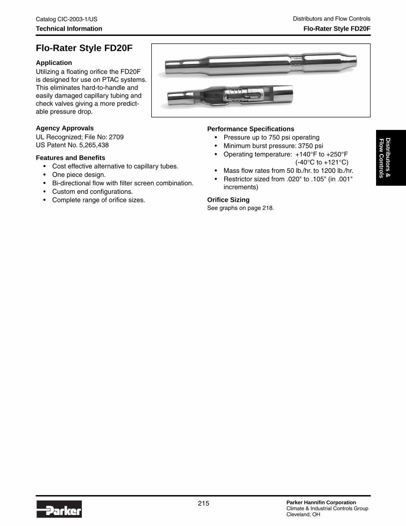
Catalog CIC-2003-1/US Distributors and Flow Controls
Parker Hannifin CorporationClimate & Industrial Controls GroupCleveland, OH
215
Service
& C
heck
Valves
Distrib
uto
rs & F
low
Co
ntro
ls
Flo-Rater Style FD20F
ApplicationUtilizing a floating orifice the FD20Fis designed for use on PTAC systems.This eliminates hard-to-handle andeasily damaged capillary tubing andcheck valves giving a more predict-able pressure drop.
Performance Specifications• Pressure up to 750 psi operating• Minimum burst pressure: 3750 psi• Operating temperature: +140°F to +250°F
(-40°C to +121°C)• Mass flow rates from 50 lb./hr. to 1200 lb./hr.• Restrictor sized from .020" to .105" (in .001"
increments)
Orifice SizingSee graphs on page 218.
Flo-Rater Style FD20FTechnical Information
Agency ApprovalsUL Recognized; File No: 2709US Patent No. 5,265,438
Features and Benefits• Cost effective alternative to capillary tubes.• One piece design.• Bi-directional flow with filter screen combination.• Custom end configurations.• Complete range of orifice sizes.

Parker Hannifin CorporationClimate & Industrial Controls GroupCleveland, OH
Catalog CIC-2003-1/US Distributors and Flow Controls
216
ManifoldsTechnical Information
Manifolds
ApplicationMeter refrigerant and distributetwo-phase refrigerant to a coil.Replaces capillary tubes, TXVsand check valves as a means ofmetering refrigerant flow throughair conditioning and heat pumpsystems.
Features and Benefits• Custom manifolds are available for optimizing evaporator and condensor coil performance. Individual
feeder legs can be equipped with fixed restrictors for air conditioning only or floating restrictors for heatpump applications.

Catalog CIC-2003-1/US Distributors and Flow Controls
Parker Hannifin CorporationClimate & Industrial Controls GroupCleveland, OH
217
Service
& C
heck
Valves
Distrib
uto
rs & F
low
Co
ntro
lsFlo-Rater and Manifold PistonsTechnical and Ordering Information
Flo-Rater and Manifold Pistons
Orifice SizingSee graphs on page 218.
— —
Piston Style: 5 Fluted (5)
0Orifice
Diameter inThousandths
0595OP
ApplicationsUse in body style F, A and M
Nomenclature
No. 5OPXXX0 (Example)
— —
Piston Style: Blunt Nose (10)ApplicationsUse in body style FD20
Nomenclature
No. FF1913-09-XXX (Example)
FF1913Orifice
Diameter inThousandths
05909
— —
Piston Style: Doubleheaded (9)ApplicationsUse in body style F
Nomenclature
No. 99OPXXX0 (Example)
99OPOrifice
Diameter inThousandths
059 0
— —
Piston Style: 3 Fluted (3)
0Orifice
Diameter inThousandths
059OP
ApplicationsUse in body style F, A and M
Nomenclature
No. OPXXX0 (Example)
Pistons AvailableChamfered

Parker Hannifin CorporationClimate & Industrial Controls GroupCleveland, OH
Catalog CIC-2003-1/US Distributors and Flow Controls
218
Flo-Raters and ManifoldsTechnical Information
Selecting the Right Orifice for Your Flow Control
You can use the following graphs to select the correct flow control for your applications:1) Determine the amount of subcooling desired.2) Select the graph closest to desired subcooling.3) Determine design inlet pressure = p.4) From the selected graph, choose the line with the appropriate pressure.5) Determine the required mass flow.6) Draw an imaginary straight line from the desired mass flow to the pressure line chosen,
then drop the imaginary line down to the orifice diameter axis.7) The orifice diameter can be read directly to the nearest thousandth (for example: 0.075 inch).

Catalog CIC-2003-1/US Distributors and Flow Controls
Parker Hannifin CorporationClimate & Industrial Controls GroupCleveland, OH
219
Service
& C
heck
Valves
Distrib
uto
rs & F
low
Co
ntro
lsO-Ring Adapter FittingsTechnical Information
O-Ring Adapter FittingsFeatures and Benefits
• Variations of length and tube connetions available.
Dimensions
Size O.D. O-RingPart Dash Brazed Tube A B C D E F G H J K L M N P Q R S Dash TNo. Size End Size ±.010 ±.010 ±.015 ±.010 ±.005 ±.003 ±.010 ±.010 ±.003 ±.005 ±.003 ±.005 ±.003 ±.003 ±.005 ±.005 ±.015 Size ThreadBJ-1 8-10 .500 .625 1.59 .375 .758 .688 .446 .506 1.09 1.13 .089 .103 .122 .020 .539 .522 .767 .082 .266 14 7/8 - 14BJ-2 10-10 .625 .625 1.59 .375 .758 .688 .446 .632 1.09 1.13 .089 .103 .122 .020 .539 .522 .767 .082 .266 14 7/8 - 14BJ-3 12-10 .750 .625 1.59 .375 .758 .688 .446 .757 1.09 1.13 .089 .103 .132 .020 .539 .522 .767 .089 .266 14 7/8 - 14BJ-4 14-10 .875 .625 1.59 .375 .758 .688 .446 .882 1.09 1.13 .089 .103 .132 .020 .539 .522 .767 .089 .266 14 7/8 - 14BJ-5 10-12 .625 .750 1.10 .438 .864 .812 .575 .632 1.19 1.250 .089 .103 .134 .020 .664 .664 .930 .094 .315 16 1-1/16-12BJ-6 14-12 .875 .750 1.10 .438 .864 .812 .609 .882 1.19 1.250 .089 .103 .134 .020 .664 .664 .930 .094 .315 16 1-1/16-12BJ-7 12-16 .750 1.000 2.03 .500 .911 .875 .695 .757 1.34 1.375 .089 .103 .134 .020 .913 .913 1.19 .094 .315 20 1-5/16-12BJ-8 16-14 .875 1.000 2.03 .500 .911 .875 .745 .882 1.34 1.375 .089 .103 .134 .020 .913 .913 1.19 .094 .315 20 1-5/16-12BJ-9 16-16 1.000 1.000 2.03 .500 .911 .875 .745 1.01 1.34 1.375 .089 .103 .134 .020 .913 .913 1.19 .094 .315 20 1-5/16-12
BJ-10 18-16 1.125 1.000 2.03 .500 .911 .875 .745 1.13 1.34 1.375 .089 .103 .134 .020 .913 .913 1.19 .094 .315 20 1-5/16-12BJ-11 18-20 1.125 1.250 2.20 .562 .958 1.000 .955 1.13 1.63 1.750 .089 .103 .159 .020 1.15 1.18 1.50 .118 .367 25 1-5/8-12BJ-20 1.375 1.375 2.19 .562 1.08 7/8 1.25 1.38 1.88 2.0 .111 .128 .181 .030 1.38 1.35 1.76 .121 .378 1-7/8-12BJ-12 22-20 1.375 1.250 2.20 .562 .958 1.000 .955 1.38 1.63 1.750 .089 .103 .159 .020 1.15 1.18 1.50 .118 .367 25 1-5/8-12

Parker Hannifin CorporationClimate & Industrial Controls GroupCleveland, OH
Catalog CIC-2003-1/US Distributors and Flow Controls
220
Type-O FittingsTechnical Information
Type-O FittingsFeatures and Benefits
• Modifications of these fittings are available upon request.• Add suffix “A” for aluminum, “S” for steel.
Male Inverted Swivel Nut Tube (O-Type)Material: Brass
Dimensions
Male Swivel Nut Tube (O-Type)Material: Brass
Dimensions
Min. Full Tube APart No. Thread Size Thread O.D. Hex. Max. Min. Max. Min. D G L R
4053 7/16-24 NS-2A .286 .250 .44 .258 .255 .378 .363 .34 .03 .54 .0324075 5/8-18 UNF-2A .356 .375 .62 .383 .380 .548 .533 .44 .06 .70 .032
4056 3/4-18 NS-2A .413 .500 .75 .508 .505 .673 .658 .51 .06 1.05 .0464080 7/8-18 NS-2A .429 .625 .88 .633 .630 .798 .783 .53 .06 .85 .0464076 1-1/16-16 UN-2A .500 .750 1.06 .761 .758 .976 .961 .60 .08 .94 .046
B Dia. C Dia.
Min. Full TubePart No. Thread Size Thread O.D. Hex. B C D E Max. Min. Max. Min. H L M
B115 7/16-20 UNF-2A .34 .250 .44 .189 .26 .44 .121 .370 .360 .271 .265 .198 .19 .254B116 5/8-18 UNF-2A .39 .375 .62 .281 .37 .48 .131 .550 .540 .439 .433 .338 .25 .379B117 3/4-16 UNF-2A .48 .500 .75 .406 .48 .56 .131 .666 .656 .563 .557 .462 .31 .504B118 7/8-14 UNF-2A .58 .625 .88 .500 .48 .70 .131 .780 .770 .672 .666 .571 .38 .629B119 1-1/16-14 UNF-2A .70 .750 1.06 .625 .48 .83 .131 .970 .960 .797 .791 .696 .44 .754
F Dia. G Dia.
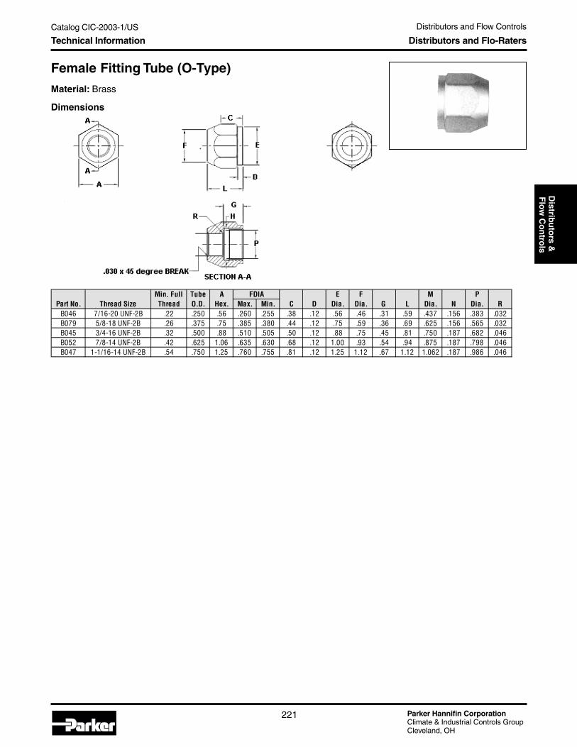
Catalog CIC-2003-1/US Distributors and Flow Controls
Parker Hannifin CorporationClimate & Industrial Controls GroupCleveland, OH
221
Service
& C
heck
Valves
Distrib
uto
rs & F
low
Co
ntro
lsDistributors and Flo-RatersTechnical Information
Female Fitting Tube (O-Type)
Material: Brass
Dimensions
Min. Full Tube A E F M PPart No. Thread Size Thread O.D. Hex. Max. Min. C D Dia. Dia. G L Dia. N Dia. R
B046 7/16-20 UNF-2B .22 .250 .56 .260 .255 .38 .12 .56 .46 .31 .59 .437 .156 .383 .032B079 5/8-18 UNF-2B .26 .375 .75 .385 .380 .44 .12 .75 .59 .36 .69 .625 .156 .565 .032B045 3/4-16 UNF-2B .32 .500 .88 .510 .505 .50 .12 .88 .75 .45 .81 .750 .187 .682 .046B052 7/8-14 UNF-2B .42 .625 1.06 .635 .630 .68 .12 1.00 .93 .54 .94 .875 .187 .798 .046B047 1-1/16-14 UNF-2B .54 .750 1.25 .760 .755 .81 .12 1.25 1.12 .67 1.12 1.062 .187 .986 .046
FDIA

Parker Hannifin CorporationClimate & Industrial Controls GroupCleveland, OH
Catalog CIC-2003-1/US Distributors and Flow Controls
222
Notes

Catalog CIC-2003-1/US Value-Added Products and Services
Parker Hannifin CorporationClimate & Industrial Controls GroupCleveland, OH
223
Valu
e-Ad
ded
Pro
du
cts&
Services
Table of Contents
Value-Added Products and ServicesTable of Contents
Value-Added Products and Services .......................................................................... page 225Also see pages 4 and 5 for value-added products and services.
Value-Added Products and Services

Parker Hannifin CorporationClimate & Industrial Controls GroupCleveland, OH
Catalog CIC-2003-1/US Value-Added Products and Services
224
Notes

Catalog CIC-2003-1/US Value-Added Products and Services
Parker Hannifin CorporationClimate & Industrial Controls GroupCleveland, OH
225
Valu
e-Ad
ded
Pro
du
cts&
Services
Value-Added Assemblies
Parker can add value to your units by creatingunique assemblies designed to your specifications.Our manufacturing and assembling processes createvalue-added assemblies that include componentsand custom-bent tubing to match the unique designof a unit.
Features and Benefits
• Components, such as valves,couplings, dryers, and distributors, can beconnected together with complex custom-bent tubing providing a cost reduction.
• Less inventory and fewer suppliers will berequired within your facility by allowingParker to manufacture your assemblies.
• Each assembly is leak tested to ensureperformance and reduce warranty costs.
• Shippable directly to yourassembly line, value-addedassemblies can increase yourline rates, maintain less scrap,and eliminate floor space andoverhead.
• UL & CSA recognized.
Technical Information Value-Added Assemblies

Parker Hannifin CorporationClimate & Industrial Controls GroupCleveland, OH
Catalog CIC-2003-1/US Value-Added Products and Services
226
Notes

Catalog CIC-2003-1/US Refrigeration Solenoid Valves
Parker Hannifin CorporationClimate & Industrial Controls GroupCleveland, OH
227
Refrig
eration
So
leno
id V
alvesTable of Contents
Refrigeration Solenoid ValvesTable of Contents
General Information ..................................................................................................... page 229
Introduction ............................................................................................................. page 229
Nomenclature, Ordering Information & Standard Voltages ................................ page 230
General Specifications ................................................................................................. page 231
Refrigeration Solenoid Valve ....................................................................................... page 233
R10 / R15 Series ...................................................................................................... page 233
R20 / R25 Series ...................................................................................................... page 236
R30 / R35 Series ...................................................................................................... page 239
R40 / R45 Series ...................................................................................................... page 242
R50 / R55 Series ...................................................................................................... page 245
Electrical Specifications .............................................................................................. page 248
Coil Enclosures ............................................................................................................ page 249
3-Way Hot Gas Defrost Specifications ....................................................................... page 250
Extended Capacity Tables Liquid Line, Suction Vapor & Hot Gas ........................... page 252
Technical Information .................................................................................................. page 254
Operating Principles .............................................................................................. page 254
Design Terminology, Identification & Agency Approvals .................................... page 255
Typical Applications ..................................................................................................... page 256
Pulse Width Modulating Valves ................................................................................... page 259
Technical Information ............................................................................................ page 259
Typical Applications ............................................................................................... page 260
HP Series and CS & DS Series .............................................................................. page 261
Capacity Tables ....................................................................................................... page 262
Solenoid Valves for Secondary Coolants ................................................................... page 263
Jackes-Evans Refrigeration Solenoid Valves (RB/ORB Series) ............................... page 265
Technical Information ............................................................................................ page 265
R Series/Jackes-Evans Cross Reference Chart .................................................. page 267
Electrical Characteristics ....................................................................................... page 271
Capacity Tables ....................................................................................................... page 272
Dimensions ............................................................................................................. page 273
Refrigeration Solenoid Valves

Parker Hannifin CorporationClimate & Industrial Controls GroupCleveland, OH
Catalog CIC-2003-1/US Refrigeration Solenoid Valves
228
Notes

Catalog CIC-2003-1/US Refrigeration Solenoid Valves
Parker Hannifin CorporationClimate & Industrial Controls GroupCleveland, OH
229
Refrig
eration
So
leno
id V
alvesIntroduction General Information
Introduction
The Parker Refrigeration Valves consist of a family ofdirect and pilot operated solenoid valves for liquid,suction and hot gas defrost application requirements.The valves are compatible with virtually all of today’scommercially available CFC, HCFC and HFC refriger-ants and blends. The Parker refrigeration valves meeta broad range of system needs including refrigeration,air conditioning and freezing applications. From smallfractional tonnage to large systems.
The portfolio is endowed with numerous benefitsincluding:• A full-line of normally closed and normally open
valves.• State of the art operator performance for long life,
ease of service and tighter system integrity.• Patent pending manual stem functionality.
• High pressure ratings to comply with newerrefrigerants.
• Extended end sweat connections enable brazinginstallation without disassembly.
• Complete line of high temperature watertight coildesigns suitable for all valves.
• AC & DC coils are interchangeable on all valve bodyversions.
The Parker Refrigeration Valves are constructed ofthe highest quality materials available for exceptionalquality, long life and reliability. All components havebeen rigorously qualified based on the internationalstandard ISO9001 / 2000 certification processesproviding rigorous standards for design, development,manufacturing and testing. High quality you’ve cometo expect from Parker.
Compatible with virtually all CVC,HFC and HCFC refrigerants and oils
Long life operator design with patentpending plunger for tight shutoff.
One-quarter or half-turn manual stem bypass for simpleevacuation at full flow capability with positive lockingfeature. Use of a standard wrench for ease of actuation.
Captured stem reducingpotential for injury.
Dual O-ring seals and cap for triple the externalleakage protection for consistent sealing.
Engineered thermoplastic sealsprovide reliability, long life andthermal stability at high temperatures.
All brass body and covervirtually eliminatescorrosion-related problems.
Totally encapsulated family of Class F & Hwatertight coils, UL Listed, CSA Certified.
Available in extended end copperconnections. Flare connectionsavailable on select models.
Specifically designed family of valves to meet thehigher pressure of today’s earth friendly refrigerants.

Parker Hannifin CorporationClimate & Industrial Controls GroupCleveland, OH
Catalog CIC-2003-1/US Refrigeration Solenoid Valves
230
Ordering Instructions & Standard Voltages General Information
Solenoid Valve Nomenclature
The numbering system allows every user an easy method to identify, select and understand the valve beingpurchased. The following table describes the numbering system
Nomenclature for Complete Valve Assemblies:
For combined Valve and Coil Assemblies:Step 1: Select the Valve catalog number based on the
application requirements as specified in the indi-vidual catalog section based on the connection type,port size, connection size and rating.
Step 2: Add the optional Manual Stem, if required.Step 3: Select the appropriate coil type and wattage
per the valve specification chart based on the sys-tem pressures. Either 10 watt or 22 watt coil.
Step 4: Use the Voltage Code to specify the correctvoltage.
Example:Step 1 & 2: To order a 2-way normally closed valve, 1/2
ODF connection, manual bypass option, R22, 5 tonliquid line rating, reference R20 valve catalog page.Select R20E84M.
Step 3 & 4: To order a junction box coil assembly, 10W,208-240VAC rating, reference coil assembly catalogpage. Select K1U3.
To order fully assembled valve with coil, simply add the2 part numbers together.
Example: R20E84M + K1U3 = R20E84MK1U3
For Valves Only:Valve assemblies can be ordered as separate items.Simply select the catalog valve number in steps 1 & 2above.
For Coil Assemblies:Coil Assemblies can be ordered as separate items.Simply begin the coil assembly part number using an“R” and follow steps 3 & 4 above.
Example: To select a junction box coil assembly,10W, 208-240VAC rating, reference coil assemblycatalog page. Specify RK1U3.
Standard Voltages
VoltageCode
DCVoltage
VoltageCode
ACVoltage
C1 12 VDC B2 24/60C2 24 VDC P3 120/60; 110/50
2K 208/60Q3 240/60; 220/50U3 208-240/60
Consult Parker for additional voltages that can be satis-fied with a new coil of a specific voltage.
TypeFamily
Configuration Connection Port SizeConnection
SizeOptional
Manual Stem Coil TypeCoil
Watts Voltage CodesRRefrigeration
1020304050
E – Ext EndF – Flare
Port sizes are measured in 1/32nds of an inch
Connection sizes are measured in 1/8ths of an inch
M D – DinJ – LeadedK – Junction BoxT – SpadeC – Conduit Hub
1-103-22
C1 12VDCC2 24VDCB2 24/602K 208/60P3 120/60Q3 240/60U3 208-240/60
(Reference electrical enclosure catalog page for a detailed description of each coil type)
(Reference standard voltages for a detailed description of each code)
Valve Assemblies Electrical Enclosures

Catalog CIC-2003-1/US Refrigeration Solenoid Valves
Parker Hannifin CorporationClimate & Industrial Controls GroupCleveland, OH
231
Refrig
eration
So
leno
id V
alvesGeneral Specifications General Specifications
General SpecificationsRefrigerants ............ R-22, R-134a, R-404a, R-507, etc.Maximum Safe Working Pressure ...................... 650psiOperating Temperature Range
Fluid .................................................. -20°F to 250°F(-30°C to 121°C) (10w ac)
Ambient for AC voltages ................... -20°F to 120°F(-30°C to 49°C)
Ambient for DC voltages ................... -20°F to 120°F(-30°C to 49°C)
(Valves not suitable for ammonia service)
UL Listed & CSA Certified with Standard Voltages:AC Voltages DC Voltages24/60 12 VDC110/50, 120/60 24VDC
208-240/60220/50, 240/60
Coil Enclosures: Reference Coil Enclosure page 249for Electrical Specifications
Normally Closed Valve Specifications
Reference individual catalog pages for specific valve numbers and connection sizes.
Normally Open Valve Specifications
Min
Ambient Temp.
°F
FluidTemp
°F Min
Ambient Temp.
°F
FluidTemp
°F
10w 22w 10w/22w 10w 22w 10w/22wR10 E2 & F2 5/64 0.13 0 450 120 250 0 200 395 120 250/240R10 E3 & F3 3/32 0.21 0 300 450 120 250/240 0 365 120 240R20 E4 & F4 1/8 0.40 1 450 120 250 1 250 120 240R20 E6 & F6 3/16 0.75 1 450 120 250 1 250 120 240R20 E8 & F8 1/4 1.09 1 450 120 250 1 250 120 240R30 E10 5/16 1.77 1 450 120 250 1 270 425 120 250/240R30 E12 3/8 1.86 1 450 120 250 1 270 425 120 250/240R30 E15 15/32 2.86 1 450 120 250 1 270 425 120 250/240R40 E18 9/16 4.40 1 450 120 250 1 270 425 120 250/240R40 E28 7/8 7.90 1 450 120 250 1 270 425 120 250/240R50 E32 1 12.30 1 280 400 120 250/240 1 160 120 240R50 E40 1-1/4 21.40 1 280 400 120 250/240 1 160 120 240
ValveSeries
PortSize CV
AC Operating Pressure Differential (psi)
Maximum AC Ratings
Maximum DC Ratings
DC Operating Pressure Differential (psi)
Min
Ambient Temp.
°F
FluidTemp
°F Min
Ambient Temp.
°F
FluidTemp
°F
10w 22w 22w 10w 22w 22wR15 E2 & F2 5/64 0.13 0 450 120 240 0 450 120 240R15 E3 & F3 3/32 0.21 0 450 120 240 0 450 120 240R25 E4 & F4 1/8 0.40 1 450 120 240 1 450 120 240R25 E6 & F6 3/16 0.75 1 450 120 240 1 450 120 240R25 E8 & F8 1/4 1.09 1 450 120 240 1 450 120 240R35 E10 5/16 1.77 1 450 120 240 1 450 120 240R35 E12 3/8 1.86 1 450 120 240 1 450 120 240R35 E15 15/32 2.86 1 450 120 240 1 450 120 240R45 E18 9/16 4.40 1 450 120 240 1 450 120 240R45 E28 7/8 7.90 1 450 120 240 1 450 120 240R55 E32 1 12.30 1 350 120 240 1 350 120 240R55 E40 1-1/4 21.40 1 350 120 240 1 350 120 240
Maximum DC Ratings
DC Operating Pressure Differential (psi)
ValveSeries
PortSize CV
AC Operating Pressure Differential (psi)
Maximum AC Ratings
Reference individual catalog pages for specific valve numbers and connection sizes.

Parker Hannifin CorporationClimate & Industrial Controls GroupCleveland, OH
Catalog CIC-2003-1/US Refrigeration Solenoid Valves
232
Ratings Summary General Specifications
Ratings Summary
* Reference individual catalog pages for specific valve numbers and connection sizes.1 Nominal capacities are based on ARI Standard 760 under the following system conditions:
Liquid line capacities are based on 40°F evaporator, 10°F superheat and 101°F condenser temperatures and pressure drop p across valve:p = 2 psi for R134ap = 3 psi for R-22, R-404a, R-507p = 5 psi for R410a
Suction vapor capacities of 40°F evaporator temperature plus 25°F superheat, 101°F condenser and 1 psi drop across valve.Rated hot gas capacities based on 40°F evaporator temperature plus 25°F superheat and 101°F condenser temperature and 2 psi drop.
2 For capacities at other ratings, refer to Extended Capacity tables.
R22 R134aR404aR507 R410a R22 R134a
R404aR507 R410a R22 R134a
R404aR507 R410a
R10/15 E2 & 0.73 0.56 0.49 0.87 0.08 0.06 0.08 0.1 0.14 0.12 0.13 0.16 R10/15 E3 & 1.18 0.91 0.79 1.4 0.12 0.09 0.11 0.15 0.2 0.17 0.19 0.24 R20/25 E4 & 2.09 1.62 1.41 2.49 0.21 0.16 0.2 0.26 0.36 0.31 0.34 0.43 R20/25 E6 & 3.8 2.95 2.56 4.53 0.4 0.31 0.37 0.5 0.67 0.57 0.64 0.8 R20/25 E8 & 5.53 4.29 3.73 6.61 0.59 0.45 0.54 0.73 0.98 0.84 0.93 1.18 R30/35 E10 8.42 6.53 5.67 10.1 0.95 0.72 0.87 1.17 1.58 1.35 1.5 1.9 R30/35 E12 10.8 8.38 7.27 12.9 1.15 0.88 1.05 1.42 1.92 1.64 1.82 2.3 R30/35 E15 16.2 12.5 10.9 19.3 1.46 1.11 1.34 1.8 2.43 2.08 2.31 2.92 R40/45 E18 24.9 19.3 16.7 29.7 2.72 2.08 2.49 3.36 4.53 3.88 4.31 5.45 R40/45 E28 44.0 34.1 29.6 52.5 4.64 3.56 4.26 5.74 7.75 6.64 7.38 9.31 R50/55 E32 69.2 53.7 46.6 82.6 5.33 4.08 4.89 8.79 11.9 10.2 11.3 14.3 R50/55 E40 120.7 93.6 81.3 144.1 8.06 6.17 7.4 15.3 17.9 15.4 17.1 24.9
ValveSeries*
Liquid Suction Hot GasNominal Capacity (Tons)1, 2

Catalog CIC-2003-1/US Refrigeration Solenoid Valves
Parker Hannifin CorporationClimate & Industrial Controls GroupCleveland, OH
233
Refrig
eration
So
leno
id V
alvesTechnical Information Series R10 and R15 Direct Acting Valves
Series R10 — 2-Way Direct Acting Normally Closed ValvesSeries R15 — 2-Way Direct Acting Normally Open Valves
Materials of ConstructionBody ..................................................................... BrassSeals .................................................................. Rulon®
Plunger .................................................... 430 StainlessSleeve Tube ............................................. 305 StainlessStop ......................................................... 430 StainlessSprings ........................................................... StainlessShading Ring ..................................................... CopperConnections ...........................Extended Ends - Copper
SAE Flare Ends AvailableManual Stem .......................... 430 Stainless (available)
Specifications
R10 Valve — Normally Closed
1 Reference Ratings Summary for nominal capacity system conditions.2 For capacities at other ratings, refer to Extended Capacity tables.Coils available separately. Use Coil “R” with “R” Series valves. Reference coil enclosure page 249 for electrical coil enclosure options.
R15 Valve — Normally Open
* Without Manual Bypass – Omit suffix “M” for the valve number.
R22 R134aR404aR507 R410a R22 R134a
R404aR507 R410a R22 R134a
R404aR507 R410a
R10E22M 1/4 ODFR10E23M 3/8 ODFR10E32M 1/4 ODFR10E33M 3/8 ODF
R10F32M 1/4 SAER10F33M 3/8 SAE
ValveNumber*
Nominal Liquid Suction Vapor Hot GasNominal Capacity (Tons)1, 2
Connection (Inches)
Port(Orifice)(Inches) Cv
3/32
0.13
0.21
0.73
Extended Ends
Flare Ends
5/64
3/32 1.18
0.56 0.49 0.87
1.400.790.91
0.08 0.06 0.08 0.10 0.14 0.12 0.13 0.16
0.240.190.170.200.150.110.090.12
0.09 0.110.21 1.18 0.91 0.79 0.240.15 0.20 0.17 0.191.40 0.12
R22 R134aR404aR507 R410a R22 R134a
R404aR507 R410a R22 R134a
R404aR507 R410a
R15E22 1/4 ODFR15E23 3/8 ODFR15E32 1/4 ODFR15E33 3/8 ODF
R15F32 1/4 SAER15F33 3/8 SAE
0.240.15 0.20 0.17 0.191.40 0.12 0.09 0.110.21 1.18 0.91 0.79
0.200.150.110.09
0.16
0.240.190.17
0.10 0.14 0.12 0.13
0.91
0.08 0.06 0.08
0.12
Extended Ends
Flare Ends
5/64
3/32 1.18
0.56 0.49 0.87
1.400.79
3/32
0.13
0.21
0.73
ValveNumber
Nominal Liquid Suction Vapor Hot GasNominal Capacity (Tons)1, 2
Connection(Inches)
Port(Orifice)(Inches) Cv

Parker Hannifin CorporationClimate & Industrial Controls GroupCleveland, OH
Catalog CIC-2003-1/US Refrigeration Solenoid Valves
234
Series R10 and R15 Direct Acting ValvesCall-Outs
Call-Outs
R10M
R15
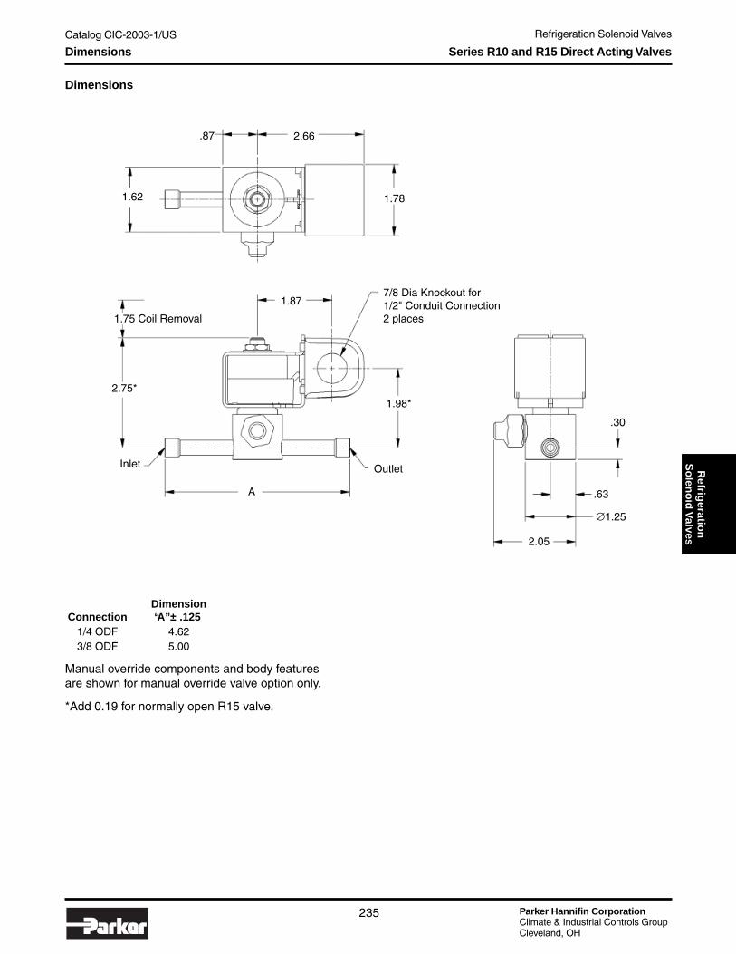
Catalog CIC-2003-1/US Refrigeration Solenoid Valves
Parker Hannifin CorporationClimate & Industrial Controls GroupCleveland, OH
235
Refrig
eration
So
leno
id V
alvesSeries R10 and R15 Direct Acting Valves
Dimensions
DimensionConnection “A” ± .125
1/4 ODF 4.623/8 ODF 5.00
Manual override components and body featuresare shown for manual override valve option only.
*Add 0.19 for normally open R15 valve.
Dimensions
2.66.87
1.62 1.78
1.877/8 Dia Knockout for1/2" Conduit Connection2 places
1.98*2.75*
A
Inlet Outlet
.30
.63
∅1.25
2.05
1.75 Coil Removal

Parker Hannifin CorporationClimate & Industrial Controls GroupCleveland, OH
Catalog CIC-2003-1/US Refrigeration Solenoid Valves
236
Technical Information Series R20 and R25 Pilot-Operated Valves
Series R20 — 2-Way Pilot-Operated Normally Closed ValvesSeries R25 — 2-Way Pilot-Operated Normally Open Valves
Materials of ConstructionBody ..................................................................... BrassSeals .................................................................. Rulon®
Plunger .................................................... 430 StainlessSleeve Tube ............................................. 305 StainlessStop ......................................................... 430 StainlessPiston ................................................................... BrassSprings ........................................................... StainlessShading Ring ..................................................... CopperConnections .......................... Extended Ends – Copper
SAE Flare AvailableManual Stem .......................... 430 Stainless (available)
Specifications
R20 Valve — Normally Closed
1 Reference Ratings Summary for nominal capacity system conditions.2 For capacities at other ratings, refer to Extended Capacity tables.Coils available separately. Use Coil “R” with “R” Series valves. Reference coil enclosure page 249 for electrical coil enclosure options.
R25 Valve — Normally Open
* Without Manual Bypass – Omit suffix “M” for the valve number.
R22 R134aR404aR507 R410a R22 R134a
R404aR507 R410a R22 R134a
R404aR507 R410a
R20E42M 1/4 ODFR20E43M 3/8 ODFR20E62M 1/4 ODFR20E63M 3/8 ODFR20E83M 3/8 ODFR20E84M 1/2 ODF
R20F42M 1/4 SAER20F43M 3/8 SAER20F63M 3/8 SAE 3/16 0.75 3.80 2.95 2.56 4.53 0.40 0.31 0.37 0.50 0.67 0.57 0.64 0.80R20F83M 3/8 SAER20F84M 1/2 SAE
1.180.73 0.98 0.84 0.931/4 1.09 5.53 4.29 3.73 6.61 0.59 0.45 0.54
1.181/4 1.09 5.53 4.29 3.73 6.61 0.59
1/8
ValveNumber*
Nominal Liquid Suction Vapor Hot GasNominal Capacity (Tons)1, 2
Connection (Inches)
Port(Orifice)(Inches) Cv
0.40
0.75
2.09
Extended Ends
1.62 1.41 2.49
4.532.562.95
Flare Fitting
1/8
3/16
0.45 0.54 0.73 0.98 0.84 0.93
3.80
0.21 0.16 0.20 0.26 0.36 0.31 0.34 0.43
0.800.640.570.670.500.370.310.40
0.16 0.200.40 2.09 1.62 1.41 2.49 0.21 0.430.26 0.36 0.31 0.34
R22 R134aR404aR507 R410a R22 R134a
R404aR507 R410a R22 R134a
R404aR507 R410a
R25E42 1/4 ODFR25E43 3/8 ODFR25E62 1/4 ODFR25E63 3/8 ODFR25E83 3/8 ODFR25E84 1/2 ODF
R25F42 1/4 SAER25F43 3/8 SAER25F63 3/8 SAE 3/16 0.75 3.80 2.95 2.56 4.53 0.40 0.31 0.37 0.50 0.67 0.57 0.64 0.80R25F83 3/8 SAER25F84 1/2 SAE
0.430.26 0.36 0.31 0.340.16 0.200.40 2.09 1.62 1.41 2.49 0.21
0.500.370.310.40 0.800.640.570.67
0.36 0.31 0.34 0.430.21 0.16 0.20 0.26
Flare Fitting
1/8
3/16
0.45 0.54 0.73 0.98 0.84 0.93
3.80
0.40
0.75
2.09
Extended Ends
1.62 1.41 2.49
4.532.562.95
ValveNumber
Nominal Liquid Suction Vapor Hot GasNominal Capacity (Tons)1, 2
Connection (Inches)
Port(Orifice)(Inches) Cv
0.54
1.181/4 1.09 5.53 4.29 3.73 6.61 0.59
1/8
3.73 6.61 0.59 0.451/4 1.09 5.53 4.29 1.180.73 0.98 0.84 0.93

Catalog CIC-2003-1/US Refrigeration Solenoid Valves
Parker Hannifin CorporationClimate & Industrial Controls GroupCleveland, OH
237
Refrig
eration
So
leno
id V
alvesCall-Outs Series R20 and R25 Pilot-Operated Valves
Call-Outs
R20M
R25

Parker Hannifin CorporationClimate & Industrial Controls GroupCleveland, OH
Catalog CIC-2003-1/US Refrigeration Solenoid Valves
238
Dimensions
DimensionConnection “A” ± .125
1/4 ODF 4.623/8 ODF 5.001/2 ODF 5.00
Manual override components and body featuresare shown for manual override valve option only.
For R25 valve dimensions, refer to R35 valvedimensions on page 241.
Dimensions Series R20 and R25 Pilot-Operated Valves
R20 Valve Shown
.87
1.62 1.78
2.66
1.87
7/8 Knockout For1/2" Conduit Connection2 PLCS
2.57
.57
∅1.25
A
Outlet
2.05Inlet
1.42
.32
3.19
1.75 Coil Removal

Catalog CIC-2003-1/US Refrigeration Solenoid Valves
Parker Hannifin CorporationClimate & Industrial Controls GroupCleveland, OH
239
Refrig
eration
So
leno
id V
alvesTechnical Information Series R30 and R35 Direct Acting Valves
Series R30 — 2-Way Pilot-Operated Normally Closed ValvesSeries R35 — 2-Way Pilot-Operated Normally Open Valves
Materials of ConstructionBody ..................................................................... BrassSeals .................................................................. Rulon®
Plunger .................................................... 430 StainlessSleeve Tube ............................................. 305 StainlessStop ......................................................... 430 StainlessPiston ................................................................... BrassSprings ........................................................... StainlessShading Ring ..................................................... CopperConnections ...........................Extended Ends - CopperManual Stem .......................... 430 Stainless (available)
Specifications
R30 Valve — Normally Closed
1 Reference Ratings Summary for nominal capacity system conditions.2 For capacities at other ratings, refer to Extended Capacity tables.Coils available separately. Use Coil “R” with “R” Series valves. Reference coil enclosure page 249 for electrical coil enclosure options.
R35 Valve — Normally Open
* Without Manual Bypass – Omit suffix “M” for the valve number.
R22 R134aR404aR507 R410a R22 R134a
R404aR507 R410a R22 R134a
R404aR507 R410a
R30E103M 3/8 ODFR30E104M 1/2 ODFR30E105M 5/8 ODFR30E124M 1/2 ODFR30E125M 5/8 ODFR30E127M 7/8 ODFR30E154M 1/2 ODFR30E155M 5/8 ODFR30E157M 7/8 ODF
2.9215/32 2.86 16.2 12.5 10.9 19.3 1.46
Hot GasNominal Capacity (Tons)1, 2
Connection (Inches)
Port(Orifice)(Inches) Cv
8.38
ValveNumber*
Nominal Liquid Suction Vapor
Extended Ends
6.53 5.67 10.1
1.8 2.43 2.08 2.31
5/16
3/8
1.11 1.34
10.8
1.77
1.86
8.42
12.97.27
0.95 0.72 0.87 1.17 1.58 1.35 1.5 1.9
2.31.821.641.921.421.050.881.15
R22 R134aR404aR507 R410a R22 R134a
R404aR507 R410a R22 R134a
R404aR507 R410a
R35E103 3/8 ODFR35E104 1/2 ODFR35E105 5/8 ODFR35E124 1/2 ODFR35E125 5/8 ODFR35E127 7/8 ODFR35E154 1/2 ODFR35E155 5/8 ODFR35E157 7/8 ODF
1.421.050.881.15 2.31.821.641.92
1.58 1.35 1.5 1.90.95 0.72 0.87 1.17
2.08 2.31
5/16
3/8
1.11 1.34
10.8
1.77
1.86
8.42
8.38
ValveNumber
Nominal Liquid Suction Vapor
Extended Ends
6.53 5.67 10.1
12.97.27
Hot GasNominal Capacity (Tons)1, 2
Connection (Inches)
Port(Orifice)(Inches) Cv
2.9215/32 2.86 16.2 12.5 10.9 19.3 1.46 1.8 2.43

Parker Hannifin CorporationClimate & Industrial Controls GroupCleveland, OH
Catalog CIC-2003-1/US Refrigeration Solenoid Valves
240
Call-Outs
Call-Outs
Series R30 and R35 Direct Acting Valves
R30M
R35

Catalog CIC-2003-1/US Refrigeration Solenoid Valves
Parker Hannifin CorporationClimate & Industrial Controls GroupCleveland, OH
241
Refrig
eration
So
leno
id V
alvesDimensions
Dimensions
Series R30 and R35 Direct Acting Valves
DimensionConnection “A” ± .125
3/8 ODF 4.621/2 ODF 5.005/8 ODF 5.507/8 ODF 7.12
Manual override components and body featuresare shown for manual override valve option only.
* Add 0.19 for normally open R35 valve.
R30 Valve Shown
1.75 Coil Removal
2.66 1.53
1.78.47
1.877/8 Knockout For1/2" Conduit Connection2 PLCS
2.20*
Outlet Inlet
3.71* 3.76*
1.36
1.341.83
1.00
#8-32 UNC-2B Thread2 PLCS
A
.74

Parker Hannifin CorporationClimate & Industrial Controls GroupCleveland, OH
Catalog CIC-2003-1/US Refrigeration Solenoid Valves
242
Technical Information Series R40 and R45 Pilot-Operated Valves
Series R40 — 2-Way Pilot-Operated Normally Closed ValvesSeries R45 — 2-Way Pilot-Operated Normally Open Valves
Materials of ConstructionBody ..................................................................... BrassSeals .................................................................. Rulon®
Plunger .................................................... 430 StainlessSleeve Tube ............................................. 305 StainlessStop ......................................................... 430 StainlessPiston ................................................................... BrassSprings ........................................................... StainlessShading Ring ..................................................... CopperConnections .......................... Extended Ends – CopperManual Stem .......................... 430 Stainless (available)
Specifications
R40 Valve — Normally Closed
1 Reference Ratings Summary for nominal capacity system conditions.2 For capacities at other ratings, refer to Extended Capacity tables.Coils available separately. Use Coil “R” with “R” Series valves. Reference coil enclosure page 249 for electrical coil enclosure options.
R45 Valve — Normally Open
* Without Manual Bypass – Omit suffix “M” for the valve number.
R22 R134aR404aR507 R410a R22 R134a
R404aR507 R410a R22 R134a
R404aR507 R410a
R40E185M 5/8 ODFR40E187M 7/8 ODFR40E189M 1-1/8 ODFR40E287M 7/8 ODFR40E289M 1-1/8 ODF
R40E2811M 1-3/8 ODF
Suction Vapor Hot GasNominal Capacity (Tons)1, 2
Connection (Inches)
Port(Orifice)(Inches) Cv
52.529.634.1
ValveNumber*
Nominal Liquid
Extended Ends
19.3 16.7 29.79/16
7/8 44.0
4.4
7.9
24.9 2.72 2.08 2.49 3.36 4.53 3.88 4.31 5.45
9.317.386.647.755.744.263.564.64
R22 R134aR404aR507 R410a R22 R134a
R404aR507 R410a R22 R134a
R404aR507 R410a
R45E185 5/8 ODFR45E187 7/8 ODFR45E189 1-1/8 ODFR45E287 7/8 ODFR45E289 1-1/8 ODF
R45E2811 1-3/8 ODF5.744.263.564.64 9.317.386.647.75
4.53 3.88 4.31 5.452.72 2.08 2.49 3.36
7/8 44.0
4.4
7.9
24.9
52.529.634.1
ValveNumber
Nominal Liquid
Extended Ends
19.3 16.7 29.79/16
Suction Vapor Hot GasNominal Capacity (Tons)1, 2
Connection (Inches)
Port(Orifice)(Inches) Cv

Catalog CIC-2003-1/US Refrigeration Solenoid Valves
Parker Hannifin CorporationClimate & Industrial Controls GroupCleveland, OH
243
Refrig
eration
So
leno
id V
alvesCall-Outs
Call-Outs
Series R40 and R45 Pilot-Operated Valves
R40M
R45

Parker Hannifin CorporationClimate & Industrial Controls GroupCleveland, OH
Catalog CIC-2003-1/US Refrigeration Solenoid Valves
244
Dimensions
DimensionConnection “A” ± .125
5/8 ODF 7.127/8 ODF 7.12
1-1/8 ODF 8.501-3/8 ODF 11.06
Manual override components and body features are shown for manualoverride valve option only.
* Add 0.19 for normally open R45 valve.
Dimensions Series R40 and R45 Pilot-Operated Valves
2.75
1.78
2.66
.85
1.75 Coil Removal1.87
7/8 Knockout For1/2" Conduit Connection2 PLCS
#8-32 UNC-2B Thread2 PLCS
2.60*
Outlet Inlet
4.72* 4.78*
2.23
1.36
2.861.72
1.00
A

Catalog CIC-2003-1/US Refrigeration Solenoid Valves
Parker Hannifin CorporationClimate & Industrial Controls GroupCleveland, OH
245
Refrig
eration
So
leno
id V
alvesTechnical Information Series R50 and R55 Direct Acting Valves
Series R50 — 2-Way Pilot-Operated Normally Closed ValvesSeries R55 — 2-Way Pilot-Operated Normally Open Valves
Materials of ConstructionBody ..................................................................... BrassSeals .................................................................. Rulon®
Plunger .................................................... 430 StainlessSleeve Tube ............................................. 305 StainlessStop ......................................................... 430 StainlessPiston ................................................................... BrassSprings ........................................................... StainlessShading Ring ..................................................... CopperConnections ...........................Extended Ends - CopperManual Stem .......................... 430 Stainless (available)
Specifications
R50 Valve — Normally Closed
1 Reference Ratings Summary for nominal capacity system conditions.2 For capacities at other ratings, refer to Extended Capacity tables.Coils available separately. Use Coil “R” with “R” Series valves. Reference coil enclosure page 249 for electrical coil enclosure options.
R55 Valve — Normally Open
* Without Manual Bypass – Omit suffix “M” for the valve number.
R22 R134aR404aR507 R410a R22 R134a
R404aR507 R410a R22 R134a
R404aR507 R410a
R50E329M 1-1/8 ODFR50E3211M 1-3/8 ODFR50E4013M 1-5/8 ODFR50E4017M 2-1/8 ODFR50E4021M 2-5/8 ODF
Suction Vapor Hot GasNominal Capacity (Tons)1, 2
Connection (Inches)
Port(Orifice)(Inches) Cv
144.181.393.6
ValveNumber*
Nominal Liquid
Extended Ends
53.7 46.6 82.61
1-1/4 120.7
12.3
21.4
69.2 5.33 4.08 4.89 8.79 11.9 10.2 11.3 14.3
24.917.115.417.915.37.46.178.06
R22 R134aR404aR507 R410a R22 R134a
R404aR507 R410a R22 R134a
R404aR507 R410a
R55E329 1-1/8 ODFR55E3211 1-3/8 ODFR55E4013 1-5/8 ODFR55E4017 2-1/8 ODFR55E4021 2-5/8 ODF
15.37.46.178.06 24.917.115.417.9
11.9 10.2 11.3 14.35.33 4.08 4.89 8.79
1-1/4 120.7
12.3
21.4
69.2
144.181.393.6
ValveNumber
Nominal Liquid
Extended Ends
53.7 46.6 82.61
Suction Vapor Hot GasNominal Capacity (Tons)1, 2
Connection (Inches)
Port(Orifice)(Inches) Cv

Parker Hannifin CorporationClimate & Industrial Controls GroupCleveland, OH
Catalog CIC-2003-1/US Refrigeration Solenoid Valves
246
Call-Outs
Call-Outs Series R50 and R55 Direct Acting Valves
R50M
R55

Catalog CIC-2003-1/US Refrigeration Solenoid Valves
Parker Hannifin CorporationClimate & Industrial Controls GroupCleveland, OH
247
Refrig
eration
So
leno
id V
alves
2.66 3.85
1.781.19
2.95*
7/8 Dia Knockout for1/2" conduit connection2PLCS
1.87
Outlet
5.45*
1.75 Coil Removal
Inlet
2.97
5.51*
1.73
3.93
A
1/4-20 UNC-2B Th'd2 PLCS
1.50
2.06
Dimensions
DimensionConnection “A” ± .1251-1/8 ODF 8.501-3/8 ODF 11.061-5/8 ODF 11.062-1/8 ODF 11.062-5/8 ODF 11.06
Manual override components and body featuresare shown for manual override valve option only.
Dimensions Series R50 and R55 Direct Acting Valves
*Add 0.19 for normally open R55 valve.

Parker Hannifin CorporationClimate & Industrial Controls GroupCleveland, OH
Catalog CIC-2003-1/US Refrigeration Solenoid Valves
248
Technical Information Electrical Specifications
Electrical Specifications
All Parker Refrigeration solenoid valves use standardcoil designs that are interchangeable on all valvebodies. They are available in a wide variety of standardvoltages and frequencies. Coils are labeled with electri-cal data providing easy identification.
ConstructionNumerous construction options are available includingjunction box housing, DIN terminals, conduit hubhousing and spade termination coils.
Encapsulated waterproof coils are standard on allvalves listed in the catalog. The special compound isabsolutely waterproof and impervious to oil, dust andmost corrosive fumes and vapors.
All coils are Class “F” or “H” rated for high temperatureapplication requirements. The coils are molded inaccordance with UL, NEMA, and other acceptedstandards.
Standard Coil Options
trates which wires to connect to each other for 120 or240 volt operation. Wiring and fusing must complywith prevailing local and national wiring codes andordinances.
Electrical Supply RequirementsThe solenoid coil must be connected to electrical linesof correct voltage and frequency as indicated on thecoil label. The supply circuits must be properly sized togive adequate voltage at the coil leads even when otherelectrical equipment is operating. The molded coil is de-signed to operate with line voltage from 85% to 110%of the coil rated voltage. Operating with a line voltageabove or below these limits may result in reduced coillife or coil burn out. Also, operating with line voltage be-low the limit will result in lowering the maximum operat-ing pressure differential (MOPD).
WiringCheck the electrical specifications of the coil to makesure they correspond to the available electrical service.Valves with four-wire dual voltage option have a wiringdiagram shown in the following figure. The figure illus-
Wiring for Dual-Voltage Coil
Conversion from AC to DC CoilsThe same valve assembly can be used for both ACand DC service requirements. AC and DC coils areinterchangeable. To convert a valve assembly from ACto DC service, select the appropriate DC coil wattageand voltage per the valve specification chart based onthe system pressure requirements.
Electrical DataTo determine the approximate Holding or Inrush Cur-rent for AC voltages including 24/60, 120/60, 208/60and 240/60 in amperes, divide the voltage into the VArating indicated in the AC Power Consumption tables.DC valves have no inrush current. The current rating inamperes are shown in the DC table. Figures are basedon nominal values and will vary slightly depending onoperating voltage and coil tolerances.
VAHolding
VAInrush
VAHolding
VAInrush
R10 Series 18 37 38 68R20 Series 19 43 40 78R30 Series 19 32 42 59R40 Series 19 32 42 59R50 Series 18 37 38 68
R15 Series 17 33 42 63R25 Series 16 33 42 63R35 Series 16 33 42 63R45 Series 16 33 42 63R55 Series 17 33 42 63
AC Power Consumption Ratings10 watt Coils 22 watt Coils
Valve SeriesNormally Closed Valves
Normally Open Valves
CoilType 12 VDC 24 VDC
R25 Series 16 33R35 Series 16 33R45 Series 16 33R55 Series 17 33
DC Current Comsumption Ratings (Amperes)
CoilType
StandardTermination Protection
Junction Box 6” lead length Junction box equipped with grounding screw provision
Conduit Hub 18” lead length2-wires
Type 1,2,3,3S,4,4X
DIN
DIN(terminations per
DIN 43650/ISO 4400 requirements)
Cable glad or 1/2" NPT connectors availablefor IP65 protection
Leaded 18" Lead length2-wires
Open frame enclosure where suitable
Spade 1/4" Male Open frame enclosure where suitable

Catalog CIC-2003-1/US Refrigeration Solenoid Valves
Parker Hannifin CorporationClimate & Industrial Controls GroupCleveland, OH
249
Refrig
eration
So
leno
id V
alvesTechnical Information Coil Enclosures
Coil Enclosures
Standard Features• Suitable for all Parker Refrigeration Solenoid Valves.• Encapsulated Waterproof designs.• Meets UL, CSA, NEMA & other acceptable
standards.
• Dual Frequency coil for AC voltages.• Dual Voltage coils available.• Easy installation with nut and washer.• UL and CSA approvals on “R” Series valves with
applicable “R” coil/enclosure combinations.
Junction Box Electrical Characteristics
Materials of ConstructionEncapsulant .............................Molded ThermoplasticMetal Enclosure ..........................Plated Carbon SteelConduit Cable ......................... 1/2" NPT with 6" leads
Coil Code Wattage ClassK1 10 FK3 22 H
Conduit Coil Electrical Characteristics
Materials of ConstructionEncapsulant .............................Molded ThermoplasticConduit & Yoke ...........................Plated Carbon SteelConduit Cable ....................... 1/2" NPT with 18" leadsSafety Code ........................................NEMA Type 4X
DIN Coil Electrical Characteristics
Materials of ConstructionEncapsulant .............................Molded ThermoplasticYoke ............................................Plated Carbon Steel
Spade Coil Electrical Characteristics
Materials of ConstructionEncapsulant .............................Molded ThermoplasticYoke ............................................Plated Carbon SteelConduit Cable ......................... 1/2" NPT with 6" leads
Leaded Coil Electrical Characteristics
Materials of ConstructionEncapsulant .............................Molded ThermoplasticLeaded Cable .............................................. 18" leadsYoke ............................................Plated Carbon Steel
Coil Code Wattage ClassC1 10 FC3 22 H
Coil Code Wattage ClassD1 10 FD3 22 H
Coil Code Wattage ClassT1 10 FT3 22 H
Coil Code Wattage ClassJ1 10 FJ3 22 H
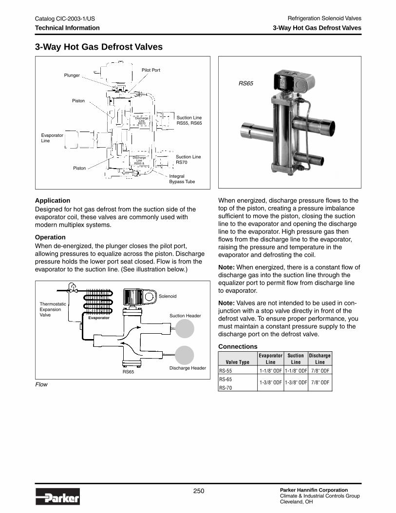
Parker Hannifin CorporationClimate & Industrial Controls GroupCleveland, OH
Catalog CIC-2003-1/US Refrigeration Solenoid Valves
250
Technical Information 3-Way Hot Gas Defrost Valves
3-Way Hot Gas Defrost Valves
RS65
ApplicationDesigned for hot gas defrost from the suction side of theevaporator coil, these valves are commonly used withmodern multiplex systems.
OperationWhen de-energized, the plunger closes the pilot port,allowing pressures to equalize across the piston. Dischargepressure holds the lower port seat closed. Flow is from theevaporator to the suction line. (See illustration below.)
Piston
Plunger
Piston
EvaporatorLine
Pilot Port
Suction LineRS55, RS65
Suction LineRS70
IntegralBypass Tube
When energized, discharge pressure flows to thetop of the piston, creating a pressure imbalancesufficient to move the piston, closing the suctionline to the evaporator and opening the dischargeline to the evaporator. High pressure gas thenflows from the discharge line to the evaporator,raising the pressure and temperature in theevaporator and defrosting the coil.
Note: When energized, there is a constant flow ofdischarge gas into the suction line through theequalizer port to permit flow from discharge lineto evaporator.
Note: Valves are not intended to be used in con-junction with a stop valve directly in front of thedefrost valve. To ensure proper performance, youmust maintain a constant pressure supply to thedischarge port on the defrost valve.
Flow
ThermostaticExpansionValve
Evaporator
Solenoid
Suction Header
RS65Discharge Header
Connections
DischargeLine
RS70
DischargeLine
RS55 &
Valve TypeEvaporator
LineSuction
LineDischarge
Line
RS-55 1-1/8" ODF 1-1/8" ODF 7/8" ODF
RS-65
RS-701-3/8" ODF 1-3/8" ODF 7/8" ODF

Catalog CIC-2003-1/US Refrigeration Solenoid Valves
Parker Hannifin CorporationClimate & Industrial Controls GroupCleveland, OH
251
Refrig
eration
So
leno
id V
alvesTechnical Information 3-Way Hot Gas Defrost Valves
General Specifications for Refrigerant Solenoid ValvesMinimum Operating
Pressure Differential ......................... 10 psi (.7 bars)Maximum Opening
Pressure Differential ...................... 300 psi (21 bars)(Discharge to Evaporator)
Design Pressure (SWP) .................................. 500 psigOperating Temperatures
Fluid ................................................ -20°F to +240°F(-30°C to +115°C)
Ambient .......................................... -20°F to +120°F(-30°C to +50°C)
U.L. Listed and CSA certified on standard AC voltages.Coils: See page 249.
*AZ-50 & HP-62 are products of Allied Signal & DuPont respectively.
RS55 Suction Line Capacities - Tons
20° 10° 0° -10° -20° -40°R-12 2.9 2.6 2.3 2.0 1.7 1.3R-22 4.4 4.0 3.5 3.1 2.7 2.0R-502 3.5 3.1 2.8 2.4 2.1 1.6R-134a 4.2 3.7 3.2 2.8 2.4 1.7R-404a (HP-62)* 3.9 3.5 3.1 2.8 2.4 1.8R-507 (AZ-50)* 3.9 3.5 3.1 2.8 2.4 1.8
Capacities Tons @ 1 psi
Pressure DropEvaporator Temperatures in ° F
*AZ-50 & HP-62 are products of Allied Signal & DuPont respectively.
RS65, RS70 Suction Line Capacities - Tons
20° 10° 0° -10° -20° -40°R-12 6.9 6.1 5.4 4.7 4.0 3.0R-22 10.5 9.4 8.4 7.4 6.5 4.9R-502 8.4 7.4 6.6 5.8 5.0 3.7R-134a 10.0 8.8 7.6 6.6 5.6 4.0R-404a (HP-62)* 9.4 8.4 7.4 6.6 5.8 4.3R-507 (AZ-50)* 9.4 8.4 7.4 6.6 5.8 4.3
Capacities Tons @ 1 psi
Pressure DropEvaporator Temperatures in ° F

Parker Hannifin CorporationClimate & Industrial Controls GroupCleveland, OH
Catalog CIC-2003-1/US Refrigeration Solenoid Valves
252
Extended Capacity Tables
Extended Capacity Tables
R22
1 psi 2 psi 3 psi 4 psi 5 psi 40°F 20°F 0°F 20°F 40°F 2 psi 5 psi 10 psi 25 psi 50 psi 100 psiR10/15 E2 0.42 0.59 0.73 0.83 0.94 0.08 0.07 0.05 0.04 0.03 0.14 0.23 0.34 0.50 0.77 1.25R10/15 E3 & F3 0.68 0.96 1.18 1.35 1.52 0.12 0.10 0.07 0.06 0.04 0.20 0.34 0.51 0.73 1.12 1.84R20/25 E4 & F4 1.21 1.71 2.09 2.40 2.70 0.21 0.17 0.13 0.10 0.08 0.36 0.60 0.90 1.30 2.00 3.27R20/25 E6 & F6 2.19 3.10 3.80 4.35 4.90 0.40 0.32 0.25 0.19 0.14 0.67 1.13 1.68 2.44 3.74 6.12R20/25 E8 & F8 3.19 4.52 5.53 6.33 7.14 0.59 0.47 0.36 0.28 0.21 0.98 1.66 2.46 3.58 5.49 8.98R30/35 E10 4.86 6.88 8.42 9.64 10.87 0.95 0.75 0.59 0.45 0.33 1.58 2.67 3.97 5.77 8.85 14.47R30/35 E12 6.23 8.82 10.80 12.70 13.94 1.15 0.91 0.71 0.54 0.40 1.92 3.24 4.82 7.00 10.74 17.56R30/35 E15 9.33 13.20 16.20 18.50 20.90 1.46 1.16 0.90 69.00 0.51 2.43 4.11 6.11 8.88 13.60 22.30R40/45 E18 14.40 20.30 24.90 28.50 32.10 2.72 2.16 1.69 1.29 0.95 4.53 7.66 11.40 16.60 25.40 41.50R40/45 E28 25.40 35.90 44.00 50.40 56.80 4.64 3.70 2.89 2.20 1.63 7.75 13.10 19.50 28.30 43.40 71.00R50/55 E32 39.90 56.50 69.20 79.20 89.30 5.33 4.24 3.31 2.52 1.87 11.90 20.00 29.80 36.80 56.50 92.40R50/55 E40 69.70 98.50 120.70 138.20 155.80 8.06 6.41 5.01 3.81 2.83 17.90 30.30 45.10 49.10 75.30 123.20
Suction Line Capacities Discharge Line CapacitiesLiquid CapacititiesTons at Pressure Drop
Across Valve in psiTons at 1 psi Pressure Drop
and Evaporating Temperature of: Pressure Drop Across ValveValve Series
R134
1 psi 2 psi 3 psi 4 psi 5 psi 40°F 20°F 0°F 20°F 40°F 2 psi 5 psi 10 psi 25 psi 50 psi 100 psiR10/15 E2 0.40 0.56 0.69 0.79 0.89 0.06 0.05 0.04 0.03 0.02 0.12 0.20 0.29 0.46 0.74 1.31R10/15 E3 & F3 0.65 0.91 1.12 1.28 1.44 0.09 0.07 0.05 0.04 0.03 0.17 0.29 0.43 0.68 1.09 1.92R20/25 E4 & F4 1.15 1.62 1.99 2.27 2.56 0.16 0.13 0.09 0.07 0.05 0.31 0.52 0.77 1.21 1.94 3.42R20/25 E6 & F6 2.08 2.95 3.61 4.13 4.66 0.31 0.23 0.18 0.13 0.09 0.57 0.97 1.44 2.26 3.64 6.39R20/25 E8 & F8 3.04 4.29 5.26 6.02 6.79 0.45 0.34 0.26 0.19 0.14 0.84 1.42 2.11 3.31 5.33 9.37R30/35 E10 4.62 6.53 8.00 9.16 10.33 0.72 0.56 0.42 0.30 0.22 1.35 2.29 3.40 5.34 8.59 15.10R30/35 E12 5.92 8.38 10.26 11.75 13.25 0.88 0.67 0.50 0.37 0.26 1.64 2.78 4.13 6.47 10.40 18.30R30/35 E15 8.86 12.50 15.40 17.30 19.80 1.11 0.85 0.64 0.46 0.34 2.08 3.52 5.23 8.21 13.20 23.20R40/45 E18 13.60 19.30 23.60 27.00 30.50 2.08 1.59 1.19 0.87 0.63 3.88 6.56 9.76 15.30 24.70 43.30R40/45 E28 24.10 34.10 41.80 47.90 54.00 3.56 2.72 2.04 1.48 1.07 6.64 11.20 16.70 26.20 42.20 74.10R50/55 E32 37.90 53.70 65.70 75.20 84.80 4.08 3.13 2.34 1.70 1.64 10.20 17.20 25.60 34.10 54.80 96.40R50/55 E40 66.20 93.60 114.70 131.30 148.00 6.17 4.73 3.53 2.57 1.86 15.40 26.00 38.60 45.40 73.10 128.60
Valve Series
Liquid Capacitities Suction Line Capacities Discharge Line CapacitiesTons at Pressure Drop
Across Valve in psiTons at 1 psi Pressure Drop
and Evaporating Temperature of: Pressure Drop Across Valve
Liquid Capacity based on 40°F evaporator temperature, 10°F superheat temperature and 100°F condenser temperature.Suction line capacity based on 100° condenser temperature, 25°F superheat temperature.Hot Gas bypass capacity based on isentropic compression from 40°F evaporator plus 25°F superheat to 100°F condenser plus 50°F superheat.
EvaporatorTemperature°F 40 30 20 10 0 -10 -20 -30 -40
Liquid Temperature °F 90 100 110 120 130
Correction Factor 1.00 0.96 0.92 0.88 0.84 0.80 0.77 0.74 0.71 Correction Factor 1.05 1.00 0.95 0.90 0.86
Temperature Correction Factors
Liquid Capacity based on 40°F evaporator temperature, 10°F superheat temperature and 100°F condenser temperature.Suction line capacity based on 100° condenser temperature, 25°F superheat temperature.Hot Gas bypass capacity based on isentropic compression from 40°F evaporator plus 25°F superheat to 100°F condenser plus 50°F superheat.

Catalog CIC-2003-1/US Refrigeration Solenoid Valves
Parker Hannifin CorporationClimate & Industrial Controls GroupCleveland, OH
253
Refrig
eration
So
leno
id V
alves
R410a
1 psi 2 psi 3 psi 4 psi 5 psi 40°F 20°F 0°F 20°F 40°F 2 psi 5 psi 10 psi 25 psi 50 psi 100 psiR10/15 E2 0.28 0.40 0.49 0.56 0.63 0.08 0.06 0.04 0.03 0.02 0.13 0.22 0.33 0.49 0.78 1.36R10/15 E3 & F3 0.46 0.65 0.79 0.90 1.02 0.11 0.09 0.07 0.05 0.03 0.19 0.32 0.48 0.71 1.15 2.00R20/25 E4 & F4 0.81 1.15 1.41 1.61 1.82 0.20 0.15 0.12 0.09 0.06 0.34 0.57 0.85 1.27 2.04 3.56R20/25 E6 & F6 1.48 2.09 2.56 2.93 3.30 0.37 0.29 0.22 0.16 0.12 0.64 1.08 1.60 2.38 3.81 6.66R20/25 E8 & F8 2.15 3.04 3.73 4.27 4.81 0.54 0.42 0.32 0.24 0.17 0.93 1.58 2.34 3.49 5.59 9.77R30/35 E10 3.27 4.63 5.67 6.49 7.32 0.87 0.68 0.51 0.38 0.27 1.50 2.54 3.78 5.62 9.01 15.80R30/35 E12 4.20 5.94 7.27 8.33 9.39 1.05 0.82 0.62 0.46 0.33 1.82 3.08 4.59 6.82 10.90 19.10R30/35 E15 6.28 8.88 10.90 12.50 14.10 1.34 1.04 0.79 0.58 0.42 2.31 3.91 5.82 8.65 13.80 24.20R40/45 E18 9.66 13.70 16.70 19.20 21.60 2.49 1.94 1.47 1.09 0.79 4.31 7.29 10.80 16.10 25.90 45.20R40/45 E28 17.10 24.20 29.60 33.90 38.20 4.26 3.31 2.52 1.86 1.34 7.38 12.50 18.60 27.60 44.20 77.30R50/55 E32 26.90 38.00 46.60 53.40 60.10 4.89 3.80 2.89 2.14 1.54 11.30 19.10 28.40 35.90 57.50 100.50R50/55 E40 46.90 66.40 81.30 93.10 104.90 7.40 5.75 4.36 3.23 2.33 17.10 28.80 42.90 47.90 76.70 134.00
Valve Series
Liquid Capacitities Suction Line Capacities Discharge Line CapacitiesTons at Pressure Drop
Across Valve in psiTons at 1 psi Pressure Drop
and Evaporating Temperature of: Pressure Drop Across Valve
Extended Capacity Tables (Continued)
R404a and R507
Extended Capacity Tables
1 psi 2 psi 3 psi 4 psi 5 psi 40°F 20°F 0°F 20°F 40°F 2 psi 5 psi 10 psi 25 psi 50 psi 100 psiR10/15 E2 0.39 0.55 0.67 0.77 0.87 0.10 0.08 0.06 0.05 0.04 0.16 0.28 0.41 0.70 0.84 1.31R10/15 E3 & F3 0.63 0.89 1.09 1.25 1.40 0.15 0.12 0.09 0.07 0.05 0.24 0.41 0.61 1.03 1.24 1.93R20/25 E4 & F4 1.12 1.58 1.93 2.21 2.49 0.26 0.21 0.16 0.13 0.09 0.43 0.73 1.08 1.82 2.20 3.43R20/25 E6 & F6 2.03 2.87 3.51 4.02 4.53 0.50 0.39 0.31 0.24 0.17 0.80 1.36 2.02 3.41 4.12 6.42R20/25 E8 & F8 2.95 4.18 5.12 5.86 6.61 0.73 0.58 0.45 0.34 0.26 1.18 1.99 2.96 5.00 6.04 9.41R30/35 E10 4.49 6.35 7.78 8.94 10.10 1.17 0.93 0.72 0.56 0.41 1.90 3.21 4.77 8.07 9.75 15.20R30/35 E12 5.77 8.16 9.99 11.50 12.90 1.42 1.13 0.88 0.67 0.50 2.30 3.89 5.79 9.79 11.80 18.40R30/35 E15 8.63 12.20 14.90 17.10 19.30 1.80 1.43 1.11 0.86 0.64 2.92 4.94 7.34 12.40 15.00 23.30R40/45 E18 13.30 18.80 23.00 26.50 29.70 3.36 2.67 2.07 1.59 1.18 5.45 9.20 13.70 23.10 28.00 43.50R40/45 E28 23.50 33.20 40.70 46.60 52.50 5.74 4.57 3.55 2.73 2.03 9.31 15.70 23.40 39.60 47.80 74.40R50/55 E32 37.00 52.20 64.00 73.30 82.60 8.79 6.99 5.43 4.17 3.10 14.30 24.10 35.80 60.60 73.20 113.90R50/55 E40 64.40 91.10 111.60 127.90 144.10 15.30 12.20 9.47 7.28 5.41 24.90 42.00 62.50 105.70 127.60 198.60
Valve Series
Liquid Capacitities Suction Line Capacities Discharge Line CapacitiesTons at Pressure Drop
Across Valve in psiTons at 1 psi Pressure Drop
and Evaporating Temperature of: Pressure Drop Across Valve
EvaporatorTemperature°F 40 30 20 10 0 -10 -20 -30 -40
Liquid Temperature °F 90 100 110 120 130
Correction Factor 1.00 0.96 0.92 0.88 0.84 0.80 0.77 0.74 0.71 Correction Factor 1.05 1.00 0.95 0.90 0.86
Temperature Correction Factors
Liquid Capacity based on 40°F evaporator temperature, 10°F superheat temperature and 100°F condenser temperature.Suction line capacity based on 100° condenser temperature, 25°F superheat temperature.Hot Gas bypass capacity based on isentropic compression from 40°F evaporator plus 25°F superheat to 100°F condenser plus 50°F superheat.
Liquid Capacity based on 40°F evaporator temperature, 10°F superheat temperature and 100°F condenser temperature.Suction line capacity based on 100° condenser temperature, 25°F superheat temperature.Hot Gas bypass capacity based on isentropic compression from 40°F evaporator plus 25°F superheat to 100°F condenser plus 50°F superheat.

Parker Hannifin CorporationClimate & Industrial Controls GroupCleveland, OH
Catalog CIC-2003-1/US Refrigeration Solenoid Valves
254
Coil De-energizedValve Closed
Operating Principles
IntroductionSolenoid valves are highly engineered products whichcan be used in many diverse and unique system appli-cations. This section provides a brief overview of thecomponents and functional varieties of solenoid valves.
General Information
Valve Construction and Basic OperationA solenoid valve is an electronically operated device. Itis used to control the flow of liquids or gases in a posi-tive, fully-closed or fully-open mode. The valve is com-monly used to replace a manual valve or where remotecontrol is desirable. A solenoid is operated by openingand closing an orifice in a valve body which permits orprevents flow through the valve. The orifice is openedor closed through the use of a plunger that is raised orlowered within a sleeve tube by energizing the coil. Thebottom of the plunger contains a compatible sealingmaterial, which closes off the orifice in the body, stop-ping flow through the valve.
The solenoid assembly consists of a coil, plunger andsleeve assembly. In a normally closed valve, a plungerreturn spring holds the plunger against the orifice, pre-venting flow through the valve. When the coil is ener-gized, a magnetic field is produced raising the plungerallowing flow through the valve. In a normally openvalve, when the coil is energized, the plunger seals offthe orifice stopping flow through the valve.
Operating Principles Technical Information
Two-Way Solenoid ValvesTwo way valves control flow in one direction. They maybe direct operated or pilot operated.
Direct Operated Solenoid ValvesDirect operated solenoid valves function to directlyopen or close the main valve orifice, which is the onlyflow path in the valve. Direct operated valves are usedin systems requiring low flow capacities or in applica-tions with low pressure differential across the valveorifice. The sealing surface that opens and closes themain valve orifice is connected to the solenoid plunger.The valve operates from zero pressure differential tomaximum rated pressure differential (MOPD) regard-less of line pressure. Pressure drop across the valve isnot required to hold the valve open.
Coil EnergizedValve Open
Pilot Operated ValvesPilot operated valves are the most widely used solenoidvalves. Pilot operated valves utilize system line pres-sure to open and close the main orifice in the valvebody. In a piston style valve, the main orifice is heldclosed with a piston seal pressed against the mainorifice by the combined fluid pressure and springpressure. In a normally closed valve, the piston isshifted or opened when the pilot operator is energized.This allows process fluid behind the piston to evacuatethrough the valve outlet. At this point, the system linepressure moves the piston opening the main orifice ofthe valve allowing high capacity flow through the valve.When energizing the coil of a normally open valve, fluidpressure builds up behind the piston forcing the pistonto seal the main orifice of the valve.
Coil De-energizedValve Closed
Coil EnergizedValve Open

Catalog CIC-2003-1/US Refrigeration Solenoid Valves
Parker Hannifin CorporationClimate & Industrial Controls GroupCleveland, OH
255
Refrig
eration
So
leno
id V
alvesDesign Terminology, Identification and Agency Approvals Technical Information
Design Terminology
Continuous Duty – A rating given to a valve that canbe energized continuously without overheating.
Correction Factor – A mathematical relationship re-lated to a fluids specific gravity used to convert specificflows from a standard media to the media in question.
Current drain – The amount of current (expressed inamperes) that flows through the coil of a solenoid valvewhen it is energized.
Cv Factor – A mathematical factor that represents thequantity of water, in gallons per minute, that will passthrough a valve with a 1 psi pressure drop across the valve.
Flow – Movement of fluid created by a pressure differential.
Flow Capacity – the quantity of fluid that will passthrough a valve under a given set of temperature andpressure conditions.
Manual Stem – A mechanical device that permits themanual opening or closing of a valve in the case ofemergency or power failure. A manual stem is availableon all normally closed valves.
Maximum Operating Pressure Differential (MOPD) –The maximum pressure difference between the inletand outlet pressures of the valve must not be ex-ceeded, allowing the solenoid to operate in both theenergized and de-energized positions.
Minimum Operating Pressure Differential – Theminimum pressure difference between the inlet andoutlet pressures required for proper operation. Thisminimum operating pressure differential must be main-tained throughout the operating cycle of pilot operatedvalves to assure proper shifting from the closed posi-tion to the open position and visa versa. In the absenceof the minimum operating pressure, the valve mayclose or will not fully open.
Orifice – The main opening through which fluid flows.
Safe Working Pressure – The maximum pressure avalve may be exposed to without experiencing anydamage. The valve does not have to be operable at thispressure, but merely withstand the pressure withoutdamage.
IdentificationValve IdentificationAll Parker valves are identified with a valve nameplate.The nameplate indicates the valve type and size, maxi-mum operating pressure differential (MOPD) and safeworking pressure (SWP). In addition, the nameplatealso specifies the appropriate electrical specificationsfor agency compliance.
Example (shown at right):R20E84 ......................................... Valve NumberMOPD...................................Maximum Operating
Pressure Differential (psi)SWP ........................ Safe Working Pressure (psi)AgencyRequirement ....................... Assembly consists of
“R” body and “R” Coil
Coil IdentificationAll Parker coil enclosures are identified with a label.The label indicates the coil part number, voltage andfrequency.
Example (shown below):RK1U3 ..................... Coil Enclosure Part Number208 / 60 ............................... Voltage & Frequency
and ............................... Agency Approved
Agency ApprovalsThe Parker Refrigeration Valves are approved byUnderwriter’s Laboratories (UL) and certified by theCanadian Standards Association (CSA). Agencyapproval is specified based on assembly of anapproved valve and coil enclosure assembly.
UL File Number: MH15507CSA File Number: LR64702 legacy file
Valve Identification Coil Identification
ASTMDesignation
Commercial Designationsand/or Trade Names
PTFE Rulon® AR
R Series Seal Material Designations
Rulon® AR is a Furon-Advanced PolymersDivision trademark.

Parker Hannifin CorporationClimate & Industrial Controls GroupCleveland, OH
Catalog CIC-2003-1/US Refrigeration Solenoid Valves
256
Typical Applications
Typical Applications
Evaporator Temperature Control
A solenoid valve installed in the liquid line as closeto the evaporator as possible, in conjunction witha narrow differential thermostat, is an excellenttemperature control. By mounting the thermostatbulb in the supply or discharge air across theevaporator, the temperature swing is limited onlyby the differential of the thermostat.
This type of temperature control can be used on asingle or multiple evaporator system and is particu-larly useful on multiplexed systems with evaporatorsat different temperatures.
Defrost Pump Down
In situations where the condensing unit is installed in alow ambient, such as on a rooftop in northern climates,and the evaporator is operating at a temperature abovethe ambient, a pump down solenoid valve should be used.This allows the pressure control to be set at a cut out of 1to 2 psi and the cut in to be set at a pressure below thepressure corresponding to the ambient temperature. Thiswill insure that the condensing unit will start after coolingdown during the defrost.
When a system has a defrost pump down solenoid valve,a thermostat should be used in series with the time clockdefrost to control the temperature of the space or fixture.An alternative to the thermostat would be an evaporatorpressure regulator.
Note: System diagrams are for illustrative purposes andare intended to show application of solenoid valves only.
Heat Reclaim Systems
There are basically 2 types of heat reclaim systems: Theseries system and the parallel system.
In the series system, during normal operation, the dis-charge gas is condensed completely in the condenser.During the heating mode, the normally opened solenoidvalve closes off the condenser and the normally closedsolenoid opens to allow the discharge gas to flow into theheat reclaim coil. Complete condensation can occur in theheat reclaim coil if so designed, but manufacturers oftenprefer to take advantage of all the sensible heat availablebut only part of the latent heat, depending on the con-denser for complete condensation.
Thermostatic Control of Evaporator Temperature
Thermostatic Control of Two Separate Evaporators
Pump Down Defrost with Low Ambient Conditions

Catalog CIC-2003-1/US Refrigeration Solenoid Valves
Parker Hannifin CorporationClimate & Industrial Controls GroupCleveland, OH
257
Refrig
eration
So
leno
id V
alvesTypical Applications
In the parallel systems there are, in effect, two separatecondensers. During normal operation, the condenseris used for complete condensation of the dischargegas. In the heat reclaim mode the discharge gas iscompletely condensed in the heat reclaim coil thusmaximizing the use of both sensible and latent heat.Some manufacturers recommend installing a 1/4" linefrom the heat reclaim coil, at its lowest point, back tothe receiver to insure the proper drainage of oil and liq-uid refrigerant during the off cycle. Other manufacturerssuggest the installation of a pressure control, to insurethat the system will switch from the heat reclaim modeto the condenser in the event of fan stoppage orclogged filters.
Split Evaporator — Humidity Control
There are often times when the air temperature is satis-factory but the humidity level is too high. This can beremedied by using only half the evaporator to dehu-midify the air without excessive cooling and the additionof auxiliary heat. This can best be accomplisehd by us-ing a normally open solenoid valve on one half of theevaporator controlled by a humidistat.
Heat Reclaim System (Series)
Heat Reclaim System (Parallel)
Split Coil Air Conditioning Dehumidification System
Hot Gas Defrost System
Hot gas defrost offers an excellent alternative to electricor air defrost. In this system the hot compressor dischargegas is routed to the outlet of the evaporator. This hotgas warms the evaporator, thaws any frost that hasaccumulated, condenses into a liquid and flows intothe common liquid line to feed the other evaporators.
In order for this system to work properly, check valvesmust be installed to allow flow around the expansionvalves. A pressure reducing valve should be used in theliquid line to provide a pressure differential between thecondensed refrigerant leaving the defrosting evaporatorand the common liquid line.
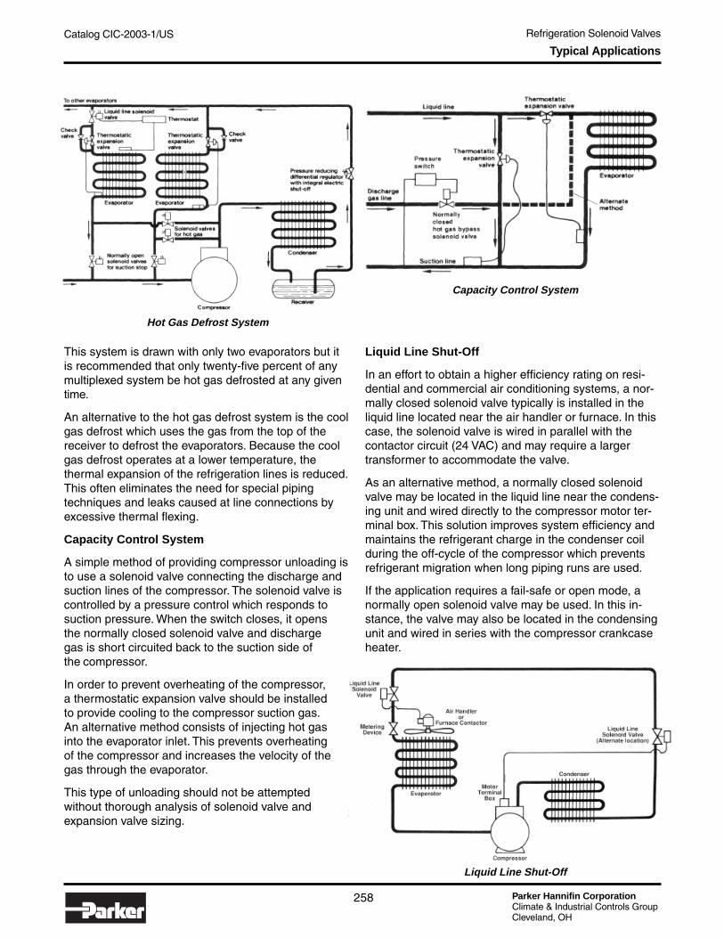
Parker Hannifin CorporationClimate & Industrial Controls GroupCleveland, OH
Catalog CIC-2003-1/US Refrigeration Solenoid Valves
258
Typical Applications
This system is drawn with only two evaporators but itis recommended that only twenty-five percent of anymultiplexed system be hot gas defrosted at any giventime.
An alternative to the hot gas defrost system is the coolgas defrost which uses the gas from the top of thereceiver to defrost the evaporators. Because the coolgas defrost operates at a lower temperature, thethermal expansion of the refrigeration lines is reduced.This often eliminates the need for special pipingtechniques and leaks caused at line connections byexcessive thermal flexing.
Capacity Control System
A simple method of providing compressor unloading isto use a solenoid valve connecting the discharge andsuction lines of the compressor. The solenoid valve iscontrolled by a pressure control which responds tosuction pressure. When the switch closes, it opensthe normally closed solenoid valve and dischargegas is short circuited back to the suction side ofthe compressor.
In order to prevent overheating of the compressor,a thermostatic expansion valve should be installedto provide cooling to the compressor suction gas.An alternative method consists of injecting hot gasinto the evaporator inlet. This prevents overheatingof the compressor and increases the velocity of thegas through the evaporator.
This type of unloading should not be attemptedwithout thorough analysis of solenoid valve andexpansion valve sizing.
Liquid Line Shut-Off
In an effort to obtain a higher efficiency rating on resi-dential and commercial air conditioning systems, a nor-mally closed solenoid valve typically is installed in theliquid line located near the air handler or furnace. In thiscase, the solenoid valve is wired in parallel with thecontactor circuit (24 VAC) and may require a largertransformer to accommodate the valve.
As an alternative method, a normally closed solenoidvalve may be located in the liquid line near the condens-ing unit and wired directly to the compressor motor ter-minal box. This solution improves system efficiency andmaintains the refrigerant charge in the condenser coilduring the off-cycle of the compressor which preventsrefrigerant migration when long piping runs are used.
If the application requires a fail-safe or open mode, anormally open solenoid valve may be used. In this in-stance, the valve may also be located in the condensingunit and wired in series with the compressor crankcaseheater.
Hot Gas Defrost System
Capacity Control System
Liquid Line Shut-Off
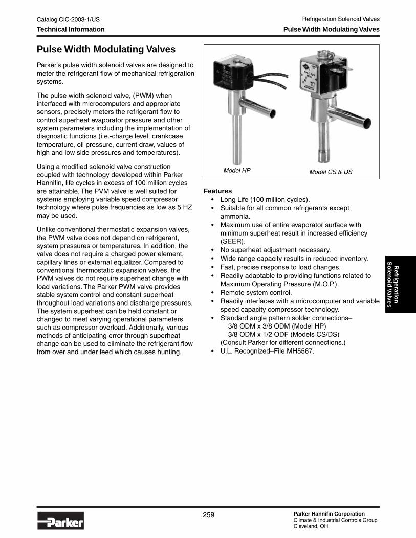
Catalog CIC-2003-1/US Refrigeration Solenoid Valves
Parker Hannifin CorporationClimate & Industrial Controls GroupCleveland, OH
259
Refrig
eration
So
leno
id V
alves
Model CS & DS
Pulse Width Modulating Valves
Parker’s pulse width solenoid valves are designed tometer the refrigerant flow of mechanical refrigerationsystems.
The pulse width solenoid valve, (PWM) wheninterfaced with microcomputers and appropriatesensors, precisely meters the refrigerant flow tocontrol superheat evaporator pressure and othersystem parameters including the implementation ofdiagnostic functions (i.e.-charge level, crankcasetemperature, oil pressure, current draw, values ofhigh and low side pressures and temperatures).
Using a modified solenoid valve constructioncoupled with technology developed within ParkerHannifin, life cycles in excess of 100 million cyclesare attainable. The PVM valve is well suited forsystems employing variable speed compressortechnology where pulse frequencies as low as 5 HZmay be used.
Unlike conventional thermostatic expansion valves,the PWM valve does not depend on refrigerant,system pressures or temperatures. In addition, thevalve does not require a charged power element,capillary lines or external equalizer. Compared toconventional thermostatic expansion valves, thePWM valves do not require superheat change withload variations. The Parker PWM valve providesstable system control and constant superheatthroughout load variations and discharge pressures.The system superheat can be held constant orchanged to meet varying operational parameterssuch as compressor overload. Additionally, variousmethods of anticipating error through superheatchange can be used to eliminate the refrigerant flowfrom over and under feed which causes hunting.
Features• Long Life (100 million cycles).• Suitable for all common refrigerants except
ammonia.• Maximum use of entire evaporator surface with
minimum superheat result in increased efficiency(SEER).
• No superheat adjustment necessary.• Wide range capacity results in reduced inventory.• Fast, precise response to load changes.• Readily adaptable to providing functions related to
Maximum Operating Pressure (M.O.P.).• Remote system control.• Readily interfaces with a microcomputer and variable
speed capacity compressor technology.• Standard angle pattern solder connections–
3/8 ODM x 3/8 ODM (Model HP)3/8 ODM x 1/2 ODF (Models CS/DS)
(Consult Parker for different connections.)• U.L. Recognized– File MH5567.
Model HP
Technical Information Pulse Width Modulating Valves

Parker Hannifin CorporationClimate & Industrial Controls GroupCleveland, OH
Catalog CIC-2003-1/US Refrigeration Solenoid Valves
260
Pulse Width Modulating ValvesTypical Applications
Typical Applications
Superheat Control
Using appropriate temperature sensors, the tempera-ture difference between the inlet and outlet of theevaporator will define a temperature which is related di-rectly to superheat. Flooding is present if the tempera-ture difference is zero. Adjustments to actual superheatmust be made when the system has large evaporatorpressure drops.
Evaporator Temperature Control
In addition to the superheat control, the microcomput-ers could include a sensor to control the evaporatortemperature or pressure.
Superheat can also be measured directly by sensingthe temperature and pressure at the evaporator outlet.In this case the pressure sensor could be a pressuretransducer.
Superheat & Evaporator Temperature ControlUsing Three Temperature SensorsSuperheat Control Using the
Temperature & Pressure of Evaporator Outlet
Superheat Control Using Two Temperature Sensors

Catalog CIC-2003-1/US Refrigeration Solenoid Valves
Parker Hannifin CorporationClimate & Industrial Controls GroupCleveland, OH
261
Refrig
eration
So
leno
id V
alves
HP Series
Model HP Mechanical SpecificationsSafe Working Pressure .................................. 500 PSIGBurst Pressure............................................. 2500 PSIGOperating Pressure Differential ........... See table belowOperating Temperature ........................ -20°F to +240°FStorage Temperature ......................................... +180°FCapacities ................. See capacity tables on page 262
Technical Information Pulse Width Modulating Valves
CS/DS Series
Model CS & DS Mechanical SpecificationsSafe Working Pressure .............................. 500 PSIGBurst Pressure......................................... 2500 PSIGOperating Pressure Differential ....... See table belowOperating Temperature .................... -20°F to +240°FStorage Temperature ..................................... +180°FCapacities ............. See capacity tables on page 262
Electrical SpecificationsOperating Voltages ........ See table
at rightInsulation System ............. Class FTerminals ..........Spade, 18" LeadsEnclosures .............. Open frame,
Conduit hub, Junction Box
Model MOPDOrifice
(IN)
Expansion Capacity
Tons (R22)
HP120 300 1/64 1/4
HP130 300 1/32 1/2
HP145 300 3/64 3/4
HP160 300 1/16 1
DC Coils: H-23 (8.5w)
24V, 12V
Electrical Characteristics
AC Rectified Coils: H-23R (9.5w)
24V/60Hz, 24V/50Hz, 110-120V/50-60Hz220-240V/50-60Hz
Electrical SpecificationsOperating Voltages ........ See table
at rightInsulation System ............. Class FTerminals ......... Spade, 18" Leads,
D.I.N.Enclosures .............. Open frame,
Conduit hub
Model MOPDOrifice
(IN)
Expansion Capacity
Tons (R22)
CS1073 300 5/64 1-1/2
CS1085 300 3/32 2
DS1100 300 7/64 3
DS1120 300 1/8 5D-23R(16.0W)
24V/60Hz, 24V/50Hz, 110-120V/50-60Hz220-240V/50-60Hz
Electrical Characteristics
AC Rectified Coils: C-23R (11.2w)
24V/60Hz, 24V/50Hz, 110-120V/50-60Hz220-240V/50-60Hz

Parker Hannifin CorporationClimate & Industrial Controls GroupCleveland, OH
Catalog CIC-2003-1/US Refrigeration Solenoid Valves
262
Capacity Tables
R-12 US Extended Capacities in MBTU/H
R-22 US Extended Capacities in MBTU/H
R-404a US Extended Capacities in MBTU/H
Liquid Refrigerant Temperature Correction Factor Duty Cycle Correction Factor
Note: All capacities shown are based on 100°F liquid entering the valve, 40°F saturated evaporatortemperature and 50% duty cycle during steady-state operation. Nominal capacities are shaded.
Liquid LineTemp. °F 50 60 70 80 90 100 110 120 130 140
Multiplier R-12 1.30 1.24 1.18 1.12 1.06 1.00 0.94 0.88 0.81 0.75Multiplier R-22 1.29 1.23 1.17 1.12 1.06 1.00 0.94 0.88 0.82 0.76
Multiplier R-404a 1.56 1.45 1.34 1.23 1.12 1.00 0.88 0.75 0.62 0.48Multiplier R-134a 1.35 1.28 1.21 1.14 1.07 1.00 0.93 0.86 0.78 0.71
Duty Cycle
Correction Factor
30% 0.7040% 0.850% 160% 1.170% 1.280% 1.490% 1.5
100% 1.7
EvaporatorTemp. °FPressure
Drop (PSIG) 40 60 80 100 120 140 60 80 100 120 140 160 80 100 120 140 160 180Orifice
HP120 1/64 0.68 0.84 0.97 1.08 1.18 1.28 0.71 0.82 0.92 1.01 1.09 1.16 0.37 0.41 0.45 0.49 0.52 0.55HP130 1/32 1.20 1.47 1.70 1.90 2.08 2.25 1.25 1.44 1.61 1.77 1.91 2.04 0.65 0.72 0.79 0.85 0.91 0.97HP145 3/64 2.47 3.02 3.49 3.90 4.27 4.61 2.57 2.97 3.32 3.63 3.92 4.19 1.33 1.48 1.62 1.75 1.87 1.33HP160 1/16 4.14 5.06 5.85 6.54 7.16 7.74 4.31 4.97 5.56 6.09 6.58 7.03 2.22 2.48 2.72 2.94 3.14 3.33CS1073 5/64 7.23 8.86 10.23 11.43 12.52 13.53 7.53 8.69 9.72 10.65 11.50 12.29 3.89 4.34 4.76 5.14 5.50 5.83CS1085 3/32 9.40 11.51 13.29 14.86 16.28 17.59 9.79 11.30 12.63 13.84 14.95 15.98 5.05 5.65 6.19 6.68 7.14 7.58DS1100 7/64 11.57 14.16 16.36 18.29 20.03 21.64 12.04 13.90 15.54 17.03 18.39 19.66 6.22 6.95 7.81 8.22 8.79 9.32DS1120 1/8 13.13 16.08 18.57 20.76 22.74 24.56 13.67 15.78 17.64 19.33 20.88 22.32 7.05 7.89 8.64 9.33 9.98 10.58
ValveType
40° 0° -40°
EvaporatorTemp. °FPressure
Drop (PSIG) 40 60 80 100 120 140 60 80 100 120 140 160 80 100 120 140 160 180Orifice
HP120 1/64 1.39 1.61 1.80 1.97 2.13 2.28 1.23 1.42 1.58 1.74 1.87 2.00 0.74 0.81 0.87 0.93 0.99 1.04HP130 1/32 2.45 2.83 3.16 3.47 3.74 4.00 2.16 2.49 2.78 3.05 3.29 3.52 1.30 1.42 1.53 1.64 1.74 1.83HP145 3/64 5.03 5.81 6.50 7.12 7.69 8.22 4.43 5.11 5.72 6.26 6.76 7.23 2.66 2.92 3.15 3.37 3.57 3.77HP160 1/16 8.44 9.74 10.89 11.93 12.88 13.77 7.42 8.57 9.58 10.50 11.34 12.12 4.46 4.89 5.28 5.65 5.99 6.31CS1073 5/64 14.75 17.03 19.04 20.86 22.53 24.08 12.98 14.99 16.76 18.35 19.83 21.19 7.81 8.55 9.24 9.87 10.47 11.04CS1085 3/32 19.17 22.14 24.75 27.12 29.29 31.31 16.87 19.48 21.78 23.86 25.77 27.55 10.15 11.12 12.01 12.84 13.62 14.35DS1100 7/64 23.59 27.24 30.56 33.36 36.04 38.52 20.76 23.97 26.80 29.36 31.71 33.90 12.49 13.68 14.77 15.79 16.75 17.66DS1120 1/8 26.78 30.92 34.57 37.87 40.90 43.73 23.56 27.21 30.42 33.32 35.99 38.48 14.17 15.53 16.77 17.93 19.02 20.04
ValveType
40° 0° -40°
EvaporatorTemp. °FPressure
Drop (PSIG) 40 60 80 100 120 140 60 80 100 120 140 160 80 100 120 140 160 180Orifice
HP120 1/64 0.92 1.06 1.19 1.30 1.41 1.50 0.78 0.90 1.01 1.11 1.19 1.28 1.00 0.49 0.53 0.57 0.61 0.64HP130 1/32 1.62 1.87 2.09 2.29 2.47 2.64 1.37 1.59 1.78 1.94 2.10 2.25 0.79 0.87 0.94 1.00 1.06 1.12HP145 3/64 3.32 3.83 4.29 4.70 5.07 5.42 2.82 3.26 3.64 3.99 4.31 4.61 1.63 1.78 1.93 2.06 2.19 2.30HP160 1/16 5.57 6.43 7.19 7.87 8.50 9.09 4.73 5.46 6.11 6.69 7.23 7.73 2.73 2.99 3.23 3.45 3.66 3.86CS1073 5/64 9.73 11.24 12.57 13.77 14.87 15.90 8.27 9.55 10.68 11.70 12.64 13.51 1.00 5.23 5.65 6.04 6.41 6.75CS1085 3/32 12.65 14.61 16.34 17.90 19.33 20.67 10.76 12.42 13.89 15.21 16.43 17.57 6.21 6.80 7.35 7.85 8.33 8.78DS1100 7/64 15.57 17.98 20.10 22.02 23.78 25.43 13.23 15.28 17.09 18.72 20.22 21.61 7.64 8.37 9.04 9.66 10.25 10.80DS1120 1/8 17.67 20.41 22.82 24.99 27.00 28.86 15.02 17.35 19.39 21.24 22.95 24.53 8.67 9.50 10.26 10.97 11.63 12.26
ValveType
40° 0° -40°
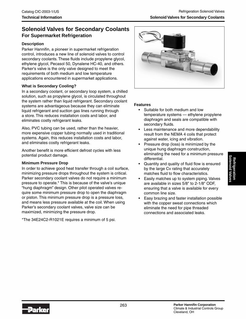
Catalog CIC-2003-1/US Refrigeration Solenoid Valves
Parker Hannifin CorporationClimate & Industrial Controls GroupCleveland, OH
263
Refrig
eration
So
leno
id V
alvesTechnical Information Solenoid Valves for Secondary Coolants
Solenoid Valves for Secondary CoolantsFor Supermarket Refrigeration
DescriptionParker Hannifin, a pioneer in supermarket refrigerationcontrol, introduces a new line of solenoid valves to controlsecondary coolants. These fluids include propylene glycol,ethylene glycol, Pecasol 50, Dynalene HC-40, and others.Parker's valve is the only valve designed to meet therequirements of both medium and low temperatureapplications encountered in supermarket applications.
What is Secondary Cooling?In a secondary coolant, or secondary loop system, a chilledsolution, such as propylene glycol, is circulated throughoutthe system rather than liquid refrigerant. Secondary coolantsystems are advantageous because they can eliminateliquid refrigerant and suction gas lines running througha store. This reduces installation costs and labor, andeliminates costly refrigerant leaks.
Also, PVC tubing can be used, rather than the heavier,more expensive copper tubing normally used in traditionalsystems. Again, this reduces installation costs and labor,and eliminates costly refrigerant leaks.
Another benefit is more efficient defrost cycles with lesspotential product damage.
Minimum Pressure DropIn order to achieve good heat transfer through a coil surface,minimizing pressure drops throughout the system is critical.Parker secondary coolant valves do not require a minimumpressure to operate.* This is because of the valve's unique“hung diaphragm” design. Other pilot operated valves re-quire some minimum pressure drop to open the diaphragmor piston. This minimum pressure drop is a pressure loss,and means less pressure available at the coil. When usingParker’s secondary coolant valves, valve size can bemaximized, minimizing the pressure drop.
*The 34E24C2-R1021E requires a minimum of 5 psi.
Features• Suitable for both medium and low
temperature systems — ethylene propylenediaphragm and seals are compatible withsecondary fluids.
• Less maintenance and more dependabilityresult from the NEMA 4 coils that protectagainst water, icing and vibration.
• Pressure drop (loss) is minimized by theunique hung diaphragm construction,eliminating the need for a minimum pressuredifferential.
• Quantity and quality of fluid flow is ensuredby the large Cv rating that accuratelymatches fluid to flow characteristics.
• Easily matches up to system piping. Valvesare available in sizes 5/8" to 2-1/8" ODF,ensuring that a valve is available for everycommon line size.
• Easy brazing and faster installation possiblewith the copper sweat connections whicheliminate the need for pipe threadedconnections and associated leaks.

Parker Hannifin CorporationClimate & Industrial Controls GroupCleveland, OH
Catalog CIC-2003-1/US Refrigeration Solenoid Valves
264
Technical Information Solenoid Valves for Secondary Coolants
General SpecificationsValve Description: 2 way hung diaphragm normally closed valve with brass forged body and EPDM trim material
VoltageWire Length
(inches)Coil
Part No.24 VAC 18 CF4C01-R1021120 VAC 18 CF4C05-R1021208 VAC 18 CF4C10-R1021240 VAC 18 CF4C15-R1021120 VAC 36 CF4E05-R1021208 VAC 36 CF4E10-R1021
CoilType .....................................NEMA 4, 4X (3 wire leads)Power .............................................................. 11 wattsCurrent
Inrush .............................................................. 53 vaHolding ............................................................ 20 va
Manual lift stems are available only on normally closed valves. Add suffix “M” to end of part no. to specify(example: 14E23C2-R1021EM).
ValveMaximum Fluid Temperature ............... -40°F to +180°F
(-40°C to +82°C)Valve Body ............................................... Forged brassConnections ............................................. ODF CopperPlunger and Pole Piece ......................... Stainless SteelEnclosure Tube ...................................... Stainless SteelSprings .................................................. Stainless SteelDiaphragm .......................................................... EPDMSeals .................................................................. EPDMSafe Working Pressure:
10-26 Series ............................................... 250 psig34 Series .................................................... 225 psig
Dimensions
Models 10E to 26E
Model 34E
Normally ClosedPart No. Cv MOPD
OrificeSize A B C D E F G
10E23C2-R1021E 4 0-150 psi 5/8" 5/8" 11/16" 4-1/16" 2-5/16" 3-1/4" 6-1/2" 1/2"14E23C2-R1021E 5 0-150 psi 3/4" 7/8" 11/16" 4-1/16" 2-5/16" 3-5/8" 8-3/4" 3/4"18E23C2-R1021E 5 0-150 psi 3/4" 1-1/8" 11/16" 4-1/16" 2-5/16" 4-1/4" 10-5/16" 15/16"22EH5C2-R1021E 12.2 0-50 psi 1" 1-3/8" 13/16" 4-1/2" 3-1/8" 4-11/16" 9-3/8" 15/16"26EH5C2-R1021E 12.2 0-50 psi 1" 1-5/8" 13/16" 4-1/2" 3-1/8" 4-11/16" 9-3/8" 15/16"34E24C2-R1021E 22.5 5-125 psi 1-1/4" 2-1/8" 1-3/8" 4" 2-3/16" 5-9/16" 11-1/16" 11/32"
Normally OpenPart No. Cv MOPD
OrificeSize A B C D E F G
10E23O2-R1021E 4 0-150 psi 5/8" 5/8" 11/16" 4-1/16" 2-5/16" 3-1/4" 6-1/2" 1/2"14E23O2-R1021E 5 0-150 psi 3/4" 7/8" 11/16" 4-1/16" 2-5/16" 3-5/8" 8-3/4" 3/4"18E23O2-R1021E 5 0-150 psi 3/4" 1-1/8" 11/16" 4-1/16" 2-5/16" 4-1/4" 10-5/16" 15/16"34E24O2-R1021E 22.5 5-125 psi 1-1/2" 2-1/8" 1-3/8" 4" 2-3/16" 5-9/16" 11-1/16" 11/32"

Catalog CIC-2003-1/US Refrigeration Solenoid Valves
Parker Hannifin CorporationClimate & Industrial Controls GroupCleveland, OH
265
Refrig
eration
So
leno
id V
alvesTechnical Information Jackes-Evans Refrigeration Solenoid Valves
Jackes-Evans RefrigerationSolenoid Valves (RB/ORB Series)
Refrigerant Solenoid Valve Features
Stainlesssteelplunger
Totally encapsulatedClass F coil, UL
Listed, CSACertified
Pivoted-edgediaphragm operation
for lower pressuredrop
Available in extendedend copper, sweat, flareand pipe connections
Manual bypassfor simplesystemevacuation
PTFE diaphragm for reliability,long life, tight seating
Solenoid Coil Operation
MagneticField
Attractor
Coil
Plunger
Frame orcoil housing
Pilot Operated Valve, Normally Closed Shown
Coil De-energized, Valve Closed Coil Energized, Valve Open
Coil
EqualizerOrifice
Plunger
ClosedDiaphragm
Pilot Orifice
Coil
EqualizerOrifice
Plunger
DiaphragmPilot Orifice
Open
Direct Operated Solenoid Valve, Normall Closed Shown
Coil De-energized, Valve Closed
Plunger Attractor
Coil
ReturnSpring Orifice
Plunger
Coil
ReturnSpring
Attractor
Orifice
Coil Energized, Valve Open
Note: Parker Jackes-Evans refrigeration solenoidvalves are being discontinued. For all newapplications, see pages 229-262 of this catalogfor new and improved R Series refrigerationsolenoid valves. See page 267 for the R Series/Jackes-Evans Cross Reference chart.
Operating Principles
What is a Solenoid Valve?The solenoid valve is an electronically operateddevice. It is used to control the flow of liquids orgases in a positive, fully-closed or fully-open mode.The valve is commonly used to replace a manualvalve or where remote control is desirable. Solenoidvalves are operated by a variety of electricalswitches. Among them are automatic temperature,pressure and time switches or manual switches.
When energized, the solenoid coil provides a strongmagnetic force which pulls a steel plunger up intothe plunger tube. This opens the valve orifice in anormally closed valve, permitting the flow of liquidsor gases.
Two-Way Solenoid ValvesTwo way valves control flow in one direction. Theymay be direct operated or pilot operated, normallyclosed or normally open.
Direct Operated Solenoid Valves(See illustration at the right.)
Are used in systems requiring low flow capacitiesor in applications with low pressure differentialacross the valve orifice. The sealing surface thatopens and closes the main valve orifice is con-nected to the solenoid plunger. The valve operatesfrom zero pressure differential to maximum ratedpressure differential (MOPD) regardless of linepressure. Pressure drop across the valve is notrequired to hold the valve open.
Pilot Operated Valves(See illustration at the right.)
Pilot operated valves are the most widely usedsolenoid valves. The pilot orifice is much larger thanthe equalizer orifice. When the coil is energized, theplunger lifts off the pilot orifice. The pressure abovethe diaphragm is reduced to the outlet pressureof the valve. The resulting pressure differentialacross the diaphragm creates a force which liftsthe diaphragm off the main port, opening the valve.

Parker Hannifin CorporationClimate & Industrial Controls GroupCleveland, OH
Catalog CIC-2003-1/US Refrigeration Solenoid Valves
266
Technical Information Jackes-Evans Refrigeration Solenoid Valves
Ordering Information
Valve AssemblyTo order a solenoid valve assembly less the coil,specify valve model number as defined above.
Examples: RB21ME7 (normally closed)ORB21E7 (normally open)
The valve body assembly, identification plate and coilretainer are all included.
Coil AssembliesTo order coil assembly only, specify the coil type,voltage and frequency.
Examples: R-23, 120V-60Hz (normally closed)OR-23, 120V-60Hz (normally open)
Valve Component DataUnless otherwise stated, the components used inJackes-Evans Solenoid Valves are as follows:
Body: Forged or Bar Stock BrassInternal Parts: Stainless SteelSprings: Stainless SteelPilot Seats: NeopreneDiaphragms: PTFE
Applications/CompatibilityJackes-Evans Refrigeration Solenoid Valves aredesigned for typical liquid line, suction line, discharge
line and hot gas valve applications and are compatiblewith virtually all of today’s CFC, HFC, and HCFC refrig-erants and blends.*These valves are not designed forammonia applications.
*For R-123 applications, different seals must be used – Please consultParker.
Valve & Coil (Factory Assembled)To order a complete valve coil assembly specify thevalve model number with the coil type, voltage andfrequency.
Example: RB21ME7 with R-23-120V-60Hz
Parts KitsAll currently manufactured Jackes-Evans valves arecompletely serviceable. If it is necessary to replace oneinternal part, all internal parts should also be replacedat that time. Therefore, standard service kits include theplunger assembly, diaphragm assembly and bonnetseal. Bonnet assemblies are also available but seldomneed replacement.
PackagingWhen placing your order, specify individual or bulkpackaging. If this information is not specified, it be-comes Parker’s option.
Note: Parker Jackes-Evans refrigeration solenoid valves are being discontinued. For all new applications, see pages 229-262 ofthis catalog for new and improved R Series refrigeration solenoid valves. See page 267 for the R Series/Jackes-Evans CrossReference chart.
When the coil is de-energized, the pilot orifice is closed.The inlet pressure through the equalizer orifice equal-izes the pressure above and below the diaphragm. Thediaphragm resets, closing the valve.
MOPD (Maximum Opening Pressure Differential)The MOPD between the inlet and outlet pressure of thevalve must not be exceeded or the valve will not open.Conversely, if the valve is applied to a system whenminimum operating pressure differential is notachieved, the valve will not open fully. These values arelisted in the specifications for each type of valve.
Nomenclature
Example: RB21ME7…R23-120/60
Coil Nomenclature
R-23= NormallyClosed Valves
OR-23= NormallyOpen Valves
R23-120/60Connection Size
Size of EndConnection
in eighths (inches)
Example:3 = 3/8”
13 = 1-5/8”
7Connection
E - Ext. EndF - Flare
EBypass
M - ManualBypass
(not appli-cable
to normallyopen valves)
MNominalCapacity
Tonnage (R-12)1 = 1 Ton3 = 3 Ton6 = 6 Ton9 = 9 Ton
15 = 15 Ton21 = 21 Ton41 = 41 Ton81 = 81 Ton
21Body
Material
B - Brass
BType
R - Refrigeration(normally closed)
*An O prefix (“ OR” )denotes normally open
R*

Catalog CIC-2003-1/US Refrigeration Solenoid Valves
Parker Hannifin CorporationClimate & Industrial Controls GroupCleveland, OH
267
Refrig
eration
So
leno
id V
alvesTechnical Information Jackes-Evans Refrigeration Solenoid Valves
R Series Refrigeration ValvesCross Reference Chart
(to former Jackes-Evans RB Series Valves)
Table shown with extended end part numbers. Consult Parker for flare versions.
Note: Parker Jackes-Evans refrigeration solenoid valves are being discontinued. For all new applications, see pages 229-262 ofthis catalog for new and improved R Series refrigeration solenoid valves. See page 267 for the R Series/Jackes-Evans CrossReference chart.
Port / Orifice Size
Existing Parker /
Jackes-Evans Model
NEW Parker
Part Number Connections
Existing Parker /
Jackes-Evans Model
NEW Parker
Part Number0.078 NEW R10E22 1/4 ODF NEW R15E22
R10E23 3/8 ODF R15E233/32 RB1E2 R10E32 1/4 ODF ORB1E2 R15E32
RB1E3 R10E33 3/8 ODF ORB1E3 R15E331/8 NEW R20E42 1/4 ODF NEW R25E42
R20E43 3/8 ODF R25E433/16 NEW R20E62 1/4 ODF NEW R25E62
R20E63 3/8 ODF R20E631/4 RB3E2 1/4 ODF ORB3E2
RB3E3 R20E83 3/8 ODF ORB3E3 R25E83RB3E4 R20E84 1/2 ODF ORB3E4 R25E84
0.315 NEW R30E103 3/8 ODF NEW R35E103R30E104 1/2 ODF R35E104R30E105 5/8 ODF R35E105
0.375 RB6E4 R30E124 1/2 ODF ORB6E4 R35E124RB6E5 R30E125 5/8 ODF ORB6E5 R35E125
R30E127 7/8 ODF R35E1270.468 RB9E4 R30E154 1/2 ODF ORB9E4 R35E154
RB9E5 R30E155 5/8 ODF ORB9E5 R35E155RB9E7 R30E157 7/8 ODF ORB9E7 R35E157
0.562 RB15E5 R40E185 5/8 ODF ORB15E5 R45E185RB15E7 R40E187 7/8 ODF ORB15E7 R45E187RB15E9 R40E189 1-1/8 ODF ORB15E9 R45E189
0.875 RB21E7 R40E287 7/8 ODF ORB21E7 R45E287RB21E9 R40E289 1-1/8 ODF ORB21E9 R45E289
R40E2811 1-3/8 ODF R45E28111 RB41E9 R50E329 1-1/8 ODF ORB41E9 R55E329
RB41E11 R50E3211 1-3/8 ODF ORB41E11 R55E32111-1/4 R50E4011 1-3/8 ODF R55E4011
RB81E13 R50E4013 1-5/8 ODF ORB81E13 R55E4013RB81E17 R50E4017 2-1/8 ODF ORB81E17 R55E4017
R50E4021 2-5/8 ODF R55E4021
Normally Closed Valves Normally Open Valves

Parker Hannifin CorporationClimate & Industrial Controls GroupCleveland, OH
Catalog CIC-2003-1/US Refrigeration Solenoid Valves
268
UPDATED
SEE PAGES 229-262
Technical Information Jackes-Evans Refrigeration Solenoid Valves
*Nominal capacity R12 @ 2 psi liquid pressure drop.
General SpecificationsDesign Pressure (SWP) ................... 500 psig (34 bars)Maximum Opening
Pressure DifferentialNormally Closed .......................... 300 psig (21 bars)
Minimum OpeningPressure DifferentialValve Type RB1 ........................................... zero psiValve Types RB3, RB6 & RB9 .......................... 1 psi
Coil .................................... All Jackes-Evans RB SeriesSolenoid Valves use the same size
coil regardless of the valve type or style.For further information, refer to page 271.
Operating TemperaturesFluid ................................................ -20°F to +240°F
(-30°C to +115°C)Ambient .......................................... -20°F to +120°F
(-30°C to +50°C)U.L. Listed with standard AC and DC voltagesCSA Certified on standard AC and DC voltagesDimensions .............................................See page 273
RB1E3 RB3F2 RB9ME5
1 to 9 Tons (Normally Closed)
Note: Parker Jackes-Evans refrigeration solenoidvalves are being discontinued. For all newapplications, see pages 229-262 of this catalog fornew and improved R Series refrigeration solenoidvalves. See page 267 for the R Series/Jackes-EvansCross Reference chart.
RB6E4
R-12 R-22 R-502 R-134a R-507/R-404a**RB1F2 1/4" SAERB1E2 1/4" ODFRB1E3 3/8" ODFRB3F2 1/4" SAERB3E2 1/4" ODFRBF3F 3/8" SAERB3E3 3/8" ODF
RB3ME3 3/8" ODFRB3E4 1/2" ODF
RB3ME4 1/2" ODFRB6F4 1/2" SAERB6E4 1/2" ODF
RB6ME4 1/2" ODFRB6E5 5/8" ODF
RB6ME5 5/8" ODFRB9F4 1/2" SAERB9E4 1/2" ODF
RB9ME4 1/2" ODFRB9F5 5/8" SAERB9E5 5/8" ODF
RB9ME5 5/8" ODF
12.09.3RB9
8.1 5.6 3/8"
15/32"7.811.3
RB6 6.0 7.5 5.8
1.0 7/64"1.0
1/4"2.84.0
RB1 1.0 1.0 1.0
3.04.53.5RB3
8.5
ValveSeries
Nominal Capacity (Tons)* Model Number Port Size
Connection Size

Catalog CIC-2003-1/US Refrigeration Solenoid Valves
Parker Hannifin CorporationClimate & Industrial Controls GroupCleveland, OH
269
Refrig
eration
So
leno
id V
alvesTechnical Information Jackes-Evans Refrigeration Solenoid Valves
10 to 83 Tons (Normally Closed)
General SpecificationsDesign Pressure (SWP) ................... 500 psig (34 bars)Maximum Opening
Pressure DifferentialNormally Closed .......................... 300 psig (21 bars)
Minimum OpeningPressure DifferentialValve Types RB15, RB21 & RB41 .................... 1 psiValve Types RB81 ............................................. 2 psi
Coil .................................... All Jackes-Evans RB SeriesSolenoid Valves use the same size
coil regardless of the valve type or style.For further information, refer to page 271.
Operating TemperaturesFluid ................................................ -20°F to +240°F
(-30°C to +115°C)Ambient .......................................... -20°F to +120°F
(-30°C to +50°C)U.L. Listed with standard AC and DC voltagesCSA Certified on standard AC and DC voltagesDimensions .............................................See page 273
*Nominal capacity R12 @ 2 psi liquid pressure drop.
RB21ME7 RB81ME13RB15E5
UPDATED
SEE PAGES 229-262
R-12 R-22 R-502 R-134a R-507/R-404a**RB15E5 5/8" ODF
RB15ME5 5/8" ODFRB15E7 7/8" ODF
RB15ME7 7/8" ODFRB15E9 11/8" ODFRB21E7 7/8" ODF
RB21ME7 7/8" ODFRB21E9 11/8" ODF
RB21ME9 11/8" ODFRB41E9 11/8" ODF
RB41ME9 11/8" ODFRB41E11 13/8" ODF
RB41ME11 13/8" ODFRB81E13 15/8" ODF
RB81ME13 15/8" ODFRB81E17 21/8" ODF
RB81ME17 21/8" ODF
42 29 1"
18262030
RB15 14 19 13
RB81 1017210783 1 1/4"70
23RB21
RB41 37 48 33
17 12 9/16"
7/8"
Connection Size
ValveSeries
Nominal Capacity (Tons)* Model Number Port Size
Note: Parker Jackes-Evans refrigeration solenoidvalves are being discontinued. For all newapplications, see pages 229-262 of this catalog fornew and improved R Series refrigeration solenoidvalves. See page 267 for the R Series/Jackes-EvansCross Reference chart.

Parker Hannifin CorporationClimate & Industrial Controls GroupCleveland, OH
Catalog CIC-2003-1/US Refrigeration Solenoid Valves
270
*Nominal capacity R12 @ 2 psi liquid pressure drop.
1 to 83 Tons (Normally Open)
General SpecificationsDesign Pressure (SWP) .................... 500 psig (4 bars)Maximum Opening
Pressure DifferentialNormally Open ............................ 250 psig (17 bars)
Minimum OpeningPressure DifferentialValve Type ORB1 ......................................... zero psiValve Types ORB3, ORB21& ORB9, ORB15, ORB21 & ORB41 ................. 1 psiValve Type ORB81 ............................................ 2 psi
Coil ................................. All Jackes-Evans ORB SeriesSolenoid Valves use the same size
coil regardless of the valve type or style.For further information, refer to page 271.
Operating TemperaturesFluid ................................................ -20°F to +240°F
(-30°C to +115°C)Ambient .......................................... -20°F to +120°F
(-30°C to +50°C)U.L. Listed with standard AC and DC voltagesCSA Certified on standard AC and DC voltagesDimensions .............................................See page 273
Technical Information Jackes-Evans Solenoid Valves
ORB6E5ORB3F3 ORB41E9 ORB81E13
UPDATED
SEE PAGES 229-262
R-12 R-22 R-502 R-134a R-507/R-404a**ORB1F2 1/4" SAEORB1E2 1/4" ODFORB1E3 3/8" ODFORB3F2 1/4" SAEORB3F3 3/8" SAEORB3E3 3/8" ODFORB3E4 1/2" ODFORB6F4 1/2" SAEORB6E4 1/2" ODFORB6E5 5/8" ODFORB9E4 1/2" ODFORB9F5 5/8" SAEORB9E5 5/8" ODFORB15E5 5/8" ODFORB15E7 7/8" ODF
ORB21 23.0 30.0 20.0 26.0 18.0 ORB21E7 7/8" 7/8" ODFORB41E9 11/8" ODF
ORB41E11 13/8" ODFORB81E13 15/8" ODFORB81E17 21/8" ODF
48.037.0ORB41 1"29.042.033.0
15/32"
ORB15 14.0 19.0 13.0 17.0 12.0 9/16"
12.0 8.5 11.3 7.3
3.5ORB3
ORB9 9.3
7/64"
1/4"2.84.0
ORB1 1.0 1.0 1.0
101.0 70.0 1 1/4"ORB81 83.0 107.0 72.0
3/8"5.8
3.04.5
6.0ORB6 7.5
Connection Size
ValveSeries
Nominal Capacity (Tons)* Model Number Port Size
8.1 5.6
1.0 1.0
Note: Parker Jackes-Evans refrigeration solenoidvalves are being discontinued. For all newapplications, see pages 229-262 of this catalog fornew and improved R Series refrigeration solenoidvalves. See page 267 for the R Series/Jackes-EvansCross Reference chart.

Catalog CIC-2003-1/US Refrigeration Solenoid Valves
Parker Hannifin CorporationClimate & Industrial Controls GroupCleveland, OH
271
Refrig
eration
So
leno
id V
alves
All Jackes-Evans RB Series Solenoid Valves use thesame size coil regardless of the valve type or style.They are available in a wide variety of voltages andfrequencies in addition to the standard coils, listed inthe table below. Coils are labeled with electrical dataproviding easy identification.
ConstructionAll solenoid coils are supplied with junction box housingas standard. Also available from the factory are conduitboss housings, spade terminal coils and DIN terminalcoils. For specific coil options consult the factory.
Encapsulated for Long LifeEncapsulated waterproof coils are standard on allvalves listed in this catalog. The special compound isabsolutely waterproof, and impervious to oil, dust andmost corrosive fumes and vapors.
All coils used in Parker Jackes-Evans solenoid valvesare Class “F” molded and are constructed in accor-dance with UL, IEEE, NEMA and other acceptedstandards.
Electrical components of AC and DC coils are testedin accordance with ASTM D2307-78 and become arecognized component under U.L. 1446. The procedureproduces data which concludes that a coil with 20,000hours continuous operation will perform within thesame specifications as a new coil.
Electrical Supply RequirementsThe solenoid coil must be connected to electrical linesof correct voltage and frequency as indicated on thecoil label. The supply circuits must be properly sized togive adequate voltage at the coil leads even when otherelectrical equipment is operating. The molded coil is de-signed to operate with line voltage from 85% to 100%of coil rated voltage. Operating with a line voltageabove or below these limits may result in coil burn-out.Also operating with line voltage below the limit will defi-nitely result in lowering the valve maximum operatingpressure differential (MOPD).
Electrical Characteristics Jackes-Evans Refrigeration Solenoid Valves
Junction Box Conduit Boss Spade DIN
Fuse CapacitiesWhere electrical codes require individual fusing of eachvalve, fuse capacities should not exceed 3 amperes forvoltages below 50 volts, and 2 amperes for voltagesabove 50 volts.
Standard Coil Options (R-23/OR-23)
For other coil options contact the factory.
Type Standard Termination
Junction Box 6" Length, 2/64" Thick Insulated Wire
Conduit Boss 24" Length, 2/64" Thick Insulated Wire
Spade 1/4" Male
DIN DIN
Electrical Data
D.C. Coils have no inrush current.For other voltages and frequencies contact the factory.
Wiring for Dual-Voltage Coil
Watts VA Holding VA Inrush111111
120-240-/50-60
240-480/50-60
16 2.6716 1.3316 0.6724VDC
Volts/Frequency (Hz)
DUAL
24/50-60110-120/50-60208-240/50-60
Coil Types R-23/OR-23
11
6 VDC12 VDC
15 36
N/A
Note: Parker Jackes-Evans refrigeration solenoid valves are being discontinued. For all new applications, see pages 229-262 ofthis catalog for new and improved R Series refrigeration solenoid valves. See page 267 for the R Series/Jackes-Evans CrossReference chart.

Parker Hannifin CorporationClimate & Industrial Controls GroupCleveland, OH
Catalog CIC-2003-1/US Refrigeration Solenoid Valves
272
Notes:1. Liquid capacity based on 40°F evaporator 10°F superheat, 101°F
condenser.2. Suction line capacity for specified evaporator temperature plus 25°F
superheat, 101°F condenser and 1 psi pressure drop across valve.
3. Hot gas bypass capacity based on isometric compression from 40°Fevaporator plus 25°F superheat to 101°F condenser plus 50°F super-heat.
4. For information on other alternative refrigerants, contact the factory.
Temperature Correction Factors
Capacity Tables Jackes-Evans Refrigeration Solenoid Valves
Evaporator Temperature °F 40 30 20 10 0 -10 -20 -30 -40
Liquid Temperature °F 90 100 110 120 130
Correction Factor 1.00 0.96 0.92 0.88 0.84 0.80 0.77 0.74 0.71 Correction Factor 1.05 1.00 0.95 0.90 0.86
1 psi 2 psi 3 psi 5 psi 40° 20° 0° -20° -40° 2 psi 5 psi 25 psi 10 psi 50 psi 100 psiRB1 0.53 0.76 0.95 1.20 0.08 0.07 0.05 0.05 0.04 0.14 0.22 0.31 0.47 0.63 0.70RB3 2.40 3.50 4.40 5.80 0.33 0.26 0.21 0.18 0.14 0.63 0.99 1.40 2.10 2.80 3.10RB6 4.30 6.00 7.40 9.80 0.58 0.45 0.37 0.31 0.24 1.10 1.80 2.50 3.80 5.00 5.50RB9 6.60 9.30 11.00 15.00 0.94 0.76 0.60 0.53 0.41 1.80 2.80 3.90 5.90 7.90 8.70RB15 10.00 14.00 17.00 22.00 1.40 1.10 0.91 0.81 0.63 2.70 4.20 5.90 9.00 12.00 13.00RB21 16.00 23.00 28.00 36.00 2.20 1.80 1.40 1.20 0.94 4.10 6.50 9.10 14.00 19.00 20.00RB41 26.00 37.00 45.00 58.00 3.20 2.60 2.00 1.80 1.40 6.80 11.00 15.00 23.00 31.00 34.00RB81 59.00 83.00 102.00 132.00 7.60 6.00 4.70 3.50 2.60 17.00 27.00 38.00 58.00 77.00 96.00RB1 0.69 0.98 1.20 1.60 0.12 0.10 0.08 0.06 0.05 0.20 0.32 0.45 0.70 0.96 1.30RB3 3.00 4.50 5.70 7.50 0.48 0.39 0.31 0.25 0.20 0.92 1.40 2.00 3.10 4.30 5.70RB6 5.10 7.50 9.50 12.60 0.81 0.65 0.54 0.43 0.34 1.50 2.40 3.40 5.40 7.30 9.60RB9 8.60 12.00 15.00 20.00 1.40 1.10 0.90 0.71 0.55 2.60 4.00 5.70 8.80 12.00 16.00RB15 13.00 19.00 24.00 32.00 2.10 1.70 1.40 1.10 0.86 3.90 6.10 8.60 13.00 18.00 24.00RB21 20.00 30.00 36.00 48.00 3.30 2.70 2.20 1.70 1.30 6.00 9.50 13.00 21.00 28.00 37.00RB41 33.00 48.00 60.00 79.00 4.70 3.80 3.10 2.40 1.90 9.90 16.00 22.00 34.00 47.00 61.00RB81 76.00 107.00 131.00 169.00 11.40 9.30 7.30 5.70 4.30 26.00 40.00 57.00 88.00 121.00 159.00RB1 0.47 0.67 0.83 1.10 0.10 0.08 0.06 0.05 0.03 0.16 0.26 0.36 0.56 0.77 1.00RB3 2.10 3.00 3.80 5.10 0.39 0.31 0.24 0.19 0.15 0.73 1.10 1.60 2.50 3.50 4.60RB6 4.10 5.80 7.10 9.20 0.61 0.49 0.38 0.30 0.23 1.10 1.80 2.60 4.00 5.60 7.30RB9 5.80 8.50 10.00 14.00 1.10 0.88 0.71 0.54 0.42 2.00 3.20 4.50 7.10 9.70 13.00RB15 8.90 13.00 16.00 21.00 1.70 1.30 1.10 0.83 0.65 3.10 4.90 6.90 11.00 15.00 19.00RB21 14.00 20.00 24.00 32.00 2.60 2.10 1.70 1.30 1.00 4.80 7.60 11.00 16.00 23.00 30.00RB41 22.00 33.00 41.00 54.00 3.80 3.00 2.40 1.80 1.40 7.90 12.00 17.00 27.00 37.00 50.00RB81 51.00 72.00 89.00 115.00 9.10 7.30 5.70 4.30 3.20 20.00 32.00 44.00 69.00 95.00 126.00RB1 0.63 0.89 1.10 1.40 0.10 0.09 0.07 0.07 — 0.18 0.30 0.41 0.62 0.82 0.92RB3 2.80 4.00 4.90 6.30 0.43 0.34 0.29 0.25 — 0.82 1.30 1.80 2.80 3.70 4.00RB6 5.70 8.10 9.90 12.80 0.76 0.59 0.49 0.41 — 1.50 2.40 3.30 5.00 6.60 7.20RB9 8.00 11.30 13.90 17.90 1.20 1.00 0.80 0.70 — 2.40 3.70 5.10 7.70 7.90 11.40RB15 12.00 17.00 21.00 27.00 1.80 1.40 1.20 1.10 — 2.50 5.50 7.70 12.00 16.00 17.00RB21 19.00 26.00 32.00 42.00 2.90 2.40 1.80 1.60 — 5.40 8.50 12.00 18.00 25.00 26.00RB41 29.00 42.00 51.00 66.00 4.20 3.40 2.60 2.40 — 8.90 14.00 20.00 30.00 41.00 45.00RB81 71.00 101.00 124.00 160.00 11.30 8.80 6.60 4.90 — 27.00 42.00 59.00 90.00 121.00 151.00RB1 0.43 0.61 0.75 0.97 0.11 0.09 0.07 0.05 0.04 0.18 0.28 0.40 0.62 0.85 1.20RB3 2.00 2.80 3.40 4.40 0.43 0.35 0.28 0.22 0.18 0.82 1.20 1.80 2.80 3.80 5.10RB6 3.90 5.60 6.80 8.80 0.72 0.58 0.48 0.38 0.30 1.30 2.10 3.00 4.80 6.50 8.50RB9 5.50 7.80 9.50 12.30 1.20 0.98 0.80 0.63 0.49 2.30 3.60 5.10 7.80 10.70 14.20RB15 8.30 11.70 14.30 18.50 1.90 1.50 1.20 0.98 0.77 3.50 5.40 7.70 11.60 16.00 21.00RB21 12.80 18.00 22.00 29.00 2.90 2.40 2.00 1.50 1.20 5.30 8.50 11.60 18.70 25.00 33.00RB41 20.00 29.00 35.00 45.00 4.20 3.40 2.80 2.10 1.70 8.80 14.00 20.00 30.00 42.00 54.00RB81 49.00 70.00 85.00 110.00 10.10 8.30 6.50 5.00 3.80 23.00 36.00 51.00 78.00 108.00 142.00
Discharge Line Capacities3
R-12
R-22
R-502
R-507 &
R-404a
Model Number
Liquid Line Capacities1 Suction Line Capacities2
R-134a
Note: Parker Jackes-Evans refrigeration solenoid valves are being discontinued. For all new applications, see pages 229-262 ofthis catalog for new and improved R Series refrigeration solenoid valves. See page 267 for the R Series/Jackes-Evans CrossReference chart.

Catalog CIC-2003-1/US Refrigeration Solenoid Valves
Parker Hannifin CorporationClimate & Industrial Controls GroupCleveland, OH
273
Refrig
eration
So
leno
id V
alves
All Dimensions in Inches
Extended EndSweat (ODF)
NPT
Notes: Normally open valve: Add 1/2 inch to overall height of valve.Allow 2 inches above valve to remove coil assembly.
Dimensions Jackes-Evans Refrigeration Solenoid Valves
SAE Flare
Typical EndView
Overall Length
Inlet to Centerline
Centerline to Top
Centerline to Bottom
Centerline to end of Junction
BoxMaximum
Width
Mounting Hole
Centerline
Mounting Hole Thread Dimensions
Inside Lay-in Length
A B C D E F G H J K LRB1P2 1/4 NPT 2.12 1.06 2.97 0.50 1.88 1.84 2.59 1.88 0.75 8-32 N.A.RB1P3 3/8 NPT 2.12 1.06 2.97 0.50 1.88 1.84 2.59 1.88 0.75 8-32 N.A.RB1E2 1/4 ODF 4.62 2.31 2.97 0.50 1.88 1.84 2.59 1.88 0.75 8-32 3.94RB1E3 3/8 ODF 4.62 2.31 2.97 0.5 1.88 1.84 2.59 1.88 0.75 8-32 3.94RB1F2 1/4 SAE 3.50 1.75 2.97 0.50 1.88 1.84 2.59 1.88 0.75 8-32 N.A.RB3P2 1/4 NPT 2.12 1.06 3.28 0.50 2.17 1.84 2.59 1.88 0.75 8-32 N.A.RB3P3 3/8 NPT 2.12 1.06 3.28 0.50 2.17 1.84 2.59 1.88 0.75 8-32 N.A.RB3E3 3/8 ODF 4.62 2.31 3.28 0.50 2.17 1.84 2.59 1.88 0.75 8-32 3.94RB3E4 1/2 ODF 5.00 2.50 3.28 0.50 2.17 1.84 2.59 1.88 0.75 8-32 4.22RB3F2 1/4 SAE 3.50 1.75 3.28 0.50 2.17 1.84 2.59 1.88 0.75 8-32 N.A.RB3F3 3/8 SAE 3.50 1.75 3.28 0.50 2.17 1.84 2.59 1.88 0.75 8-32 N.A.RB6E4 1/2 ODF 5.00 2.50 3.34 0.50 2.23 1.84 2.59 1.88 0.75 8-32 4.22RB6E5 5/8 ODF 6.50 3.25 3.34 0.50 2.23 1.84 2.59 1.88 0.75 8-32 5.50RB6F4 1/2 SAE 3.94 1.97 3.34 0.50 2.23 1.84 2.59 1.88 0.75 8-32 N.A.RB9P3 3/8 NPT 2.94 1.28 3.31 0.84 2.09 1.84 2.59 2.19 1.50 10-24 N.A.RB9P4 1/2 NPT 2.94 1.28 3.31 0.84 2.09 1.84 2.59 2.19 1.50 10-24 N.A.RB9E4 1/2 ODF 5.66 2.83 3.31 0.84 2.22 1.84 2.59 2.19 1.50 10-24 4.88RB9E5 5/8 ODF 6.87 3.44 3.31 0.84 2.22 1.84 2.59 2.19 1.50 10-24 5.88RB9F5 5/8 SAE 3.94 1.97 3.31 0.84 2.09 1.84 2.59 2.19 1.50 10-24 N.A.
RB15P4 1/2 NPT 3.44 1.45 3.34 0.56 2.25 1.84 2.59 2.44 N.A. N.A. N.A.RB15E5 5/8 ODF 6.87 3.44 3.34 0.84 2.25 1.84 2.59 2.44 1.50 10-24 5.88RB21P6 3/4 NPT 3.84 1.66 3.45 0.69 2.41 1.84 2.59 2.84 N.A. N.A. N.A.RB21E7 7/8 ODF 7.50 3.67 3.45 1.00 2.41 1.84 2.59 2.84 1.75 1/4-20 5.97RB41P8 1 NPT 4.44 1.95 4.62 0.84 3.55 1.84 2.59 3.19 N.A. N.A. N.A.RB41E9 1-1/8 ODF 10.06 5.03 3.93 1.16 2.84 1.84 2.59 3.19 1.75 1/4-20 8.22RB81E13 1-5/8 ODF 11.06 5.53 6.32 1.10 5.39 1.84 2.59 N.A. N.A. N.A. 8.87RB81E17 2-1/8 ODF 11.06 5.53 6.32 1.10 5.39 1.84 2.59 N.A. N.A. N.A. 8.87
Valve Type
Centerline to Centerline of Junction Box
Connection Sizes
in Inches
Note: Parker Jackes-Evans refrigeration solenoid valves are being discontinued. For all new applications, see pages 229-262 ofthis catalog for new and improved R Series refrigeration solenoid valves. See page 267 for the R Series/Jackes-Evans CrossReference chart.

Parker Hannifin CorporationClimate & Industrial Controls GroupCleveland, OH
Catalog CIC-2003-1/US Refrigeration Solenoid Valves
274
Notes
Catalog CIC-2003-1/US General Purpose Solenoid Valves
Parker Hannifin CorporationClimate & Industrial Controls GroupCleveland, OH
275
Gen
eral Pu
rpo
seS
olen
oid
Valves
Table of Contents
General Purpose Solenoid ValvesTable of Contents
Two-Way Solenoid Valves ............................................................................................ page 277
Three-Way Solenoid Valves ......................................................................................... page 278
Four-Way Solenoid Valves ........................................................................................... page 278
Special Purpose Valves ................................................................................................ page 279
Gold Ring™ General Purpose Solenoid Valves ......................................................... page 280
Water Regulating Valves .............................................................................................. page 282
Dual Acting Water Valves ............................................................................................. page 283
General Purpose Solenoid Valves

Parker Hannifin CorporationClimate & Industrial Controls GroupCleveland, OH
Catalog CIC-2003-1/US General Purpose Solenoid Valves
276
Notes
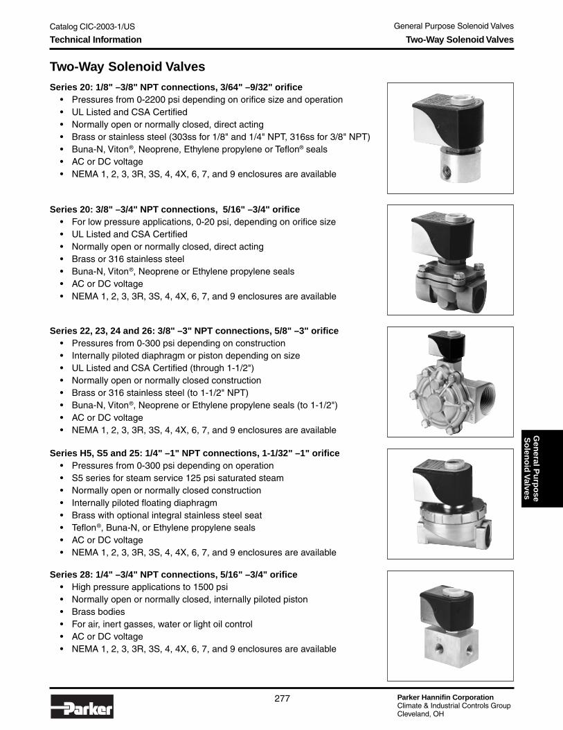
Catalog CIC-2003-1/US General Purpose Solenoid Valves
Parker Hannifin CorporationClimate & Industrial Controls GroupCleveland, OH
277
Gen
eral Pu
rpo
seS
olen
oid
Valves
Series H5, S5 and 25: 1/4" – 1" NPT connections, 1-1/32" – 1" orifice• Pressures from 0-300 psi depending on operation• S5 series for steam service 125 psi saturated steam• Normally open or normally closed construction• Internally piloted floating diaphragm• Brass with optional integral stainless steel seat• Teflon® , Buna-N, or Ethylene propylene seals• AC or DC voltage• NEMA 1, 2, 3, 3R, 3S, 4, 4X, 6, 7, and 9 enclosures are available
Series 20: 3/8" – 3/4" NPT connections, 5/16" – 3/4" orifice• For low pressure applications, 0-20 psi, depending on orifice size• UL Listed and CSA Certified• Normally open or normally closed, direct acting• Brass or 316 stainless steel• Buna-N, Viton® , Neoprene or Ethylene propylene seals• AC or DC voltage• NEMA 1, 2, 3, 3R, 3S, 4, 4X, 6, 7, and 9 enclosures are available
Series 20: 1/8" – 3/8" NPT connections, 3/64" – 9/32" orifice• Pressures from 0-2200 psi depending on orifice size and operation• UL Listed and CSA Certified• Normally open or normally closed, direct acting• Brass or stainless steel (303ss for 1/8" and 1/4" NPT, 316ss for 3/8" NPT)• Buna-N, Viton® , Neoprene, Ethylene propylene or Teflon® seals• AC or DC voltage• NEMA 1, 2, 3, 3R, 3S, 4, 4X, 6, 7, and 9 enclosures are available
Series 28: 1/4" – 3/4" NPT connections, 5/16" – 3/4" orifice• High pressure applications to 1500 psi• Normally open or normally closed, internally piloted piston• Brass bodies• For air, inert gasses, water or light oil control• AC or DC voltage• NEMA 1, 2, 3, 3R, 3S, 4, 4X, 6, 7, and 9 enclosures are available
Technical Information Two-Way Solenoid Valves
Series 22, 23, 24 and 26: 3/8" – 3" NPT connections, 5/8" – 3" orifice• Pressures from 0-300 psi depending on construction• Internally piloted diaphragm or piston depending on size• UL Listed and CSA Certified (through 1-1/2")• Normally open or normally closed construction• Brass or 316 stainless steel (to 1-1/2" NPT)• Buna-N, Viton® , Neoprene or Ethylene propylene seals (to 1-1/2")• AC or DC voltage• NEMA 1, 2, 3, 3R, 3S, 4, 4X, 6, 7, and 9 enclosures are available
Two-Way Solenoid Valves

Parker Hannifin CorporationClimate & Industrial Controls GroupCleveland, OH
Catalog CIC-2003-1/US General Purpose Solenoid Valves
278
Series 30: 1/8" – 1/4" NPT connections, 3/64" – 11/64" orifice• Pressures from 0-250 psi depending on orifice size and operation• UL Listed and CSA Certified• Normally open, normally closed, or universal construction• Direct acting• Brass or 303 stainless steel• Buna-N, Viton® , Neoprene, Ethylene propylene or Teflon® seals• AC or DC voltage• NEMA 1, 2, 3, 3R, 3S, 4, 4X, 6, 7, and 9 enclosures are available
Series 35 and 38: 1/4" – 3/8" NPT connections, 3/32" – 9/32" pressureorifice, 1/4" – 11/32" exhaust orifice
• Quick exhaust• Pressures from 5-200 psi depending on construction• Normally open, normally closed, or universal construction• Internally pilot operated• Brass bodies, 303 stainless steel available (series 35)• Buna-N or Viton® seals• AC or DC voltage• NEMA 1, 2, 3, 3R, 3S, 4, 4X, 6, 7, and 9 enclosures are available
Series 34: 3/8" – 3/4" NPT connections, 5/8" pressure & exhaust orifices• Pressures from 10-250 psi depending on construction• Normally open or normally closed construction• Internally pilot operated diaphragms• Brass bodies• Buna-N, Viton® , Neoprene or Ethylene propylene seals• AC or DC voltage• NEMA 1, 2, 3, 3R, 3S, 4, 4X, 6, 7, and 9 enclosures are available
Series 48: 1/4" NPT connections, 1/16" pressure orifices, 3/32" exhaustorifices
• Pressures from 10-150 psi• Internally pilot operated• UL Approved• Brass bodies, Buna-N seals• AC or DC voltage• NEMA 1, 2, 3, 3R, 3S, 4, 4X, 6, 7, and 9 enclosures are available
Three-Way Solenoid Valves
Technical Information Three-Way and Four-Way Solenoid Valves
Four-Way Solenoid Valves

Catalog CIC-2003-1/US General Purpose Solenoid Valves
Parker Hannifin CorporationClimate & Industrial Controls GroupCleveland, OH
279
Gen
eral Pu
rpo
seS
olen
oid
Valves
Long Life – Quiet Operating Valves 1/4" – 1-1/2" NPT connections,1/8" – 1-1/4" orifice
• Pressures from 0-175 psi depending on construction• Brass with Buna-N, Viton® , Neoprene or Ethylene propylene seals• Design life of 5 million cycles for diaphragm valves and 20 million cycles
for direct acting valves• Normally open or normally closed construction• AC or DC voltage
Cryogenic Valves: 1/8" – 1" NPT connections, 3/64" – 1" orifice• Pressures from 0-500 psi depending on construction• 2-way, normally closed or normally open• Brass or 303 stainless steel depending on construction• For liquid CO
2 and other cryogenic fluids to -320°F (-196°C)
• Teflon® or urethane standard seals; Kel-F seal for bubbletight shutoff• AC or DC voltage• NEMA 1, 2, 3, 3R, 3S, 4, 4X, 6, 7 and 9 enclosures are available
Vacuum Service Valves: 1/4" – 1" NPT connections, 9/32" – 1" orifice• Suitable for vacuum service to 10-6 torrs• Brass with degassed Buna-N or Viton seals• Normally open or normally closed construction• AC or DC voltage• NEMA 1, 2, 3, 3R, 3S, 4, 4X, 6, 7 and 9 enclosures are available
Special Purpose Valves Designed for Specific Applications
Enclosure/Coil Terminal Combinations
Condensed listingof NEMA Enclosures
*With Suitable Connector
Technical Information Special Purpose Valves
Screw (K) Spade (S) D.I.N. (H) 6" Leads 18" Leads 24" Leads 36" LeadsStrain Relief (C) X X XExplosion Proof (E) X X XGeneral Purpose (G) X X X316 SS Explosion Proof (M) X X XOpen Frame (O) X X X X XEncapsulated D.I.N. (P) XSplice Box (S) X316 SS Submersible (U) X X XSubmersible Splice Box (W) X X XExplosion Proof W/Ground Lead (Y) X X X316 SS Explosion Proof W/Ground Wire (Z) X X XGold Ring II™ (4) X
Coil TerminationEnclosures
NEMAType
Gold Ring™Enclosure Code
1 C, G, P, S, GP1 43 4
3R 43S 44 P,* 44X 46 W7 E, M, Y, Z9 E, M, Y, Z
Industrial Valve Seal Material DesignationsASTM Designation Commercial Designations and/or Trade Names
NBR Buna-N, NitrileFKM Fluorinated Hydrocarbon, Viton®
EPDM Ethylene PropylenePTFE Teflon® , Rulon® ARCR Neoprene
Viton® and Teflon® are Dupont Co. trademarks.Rulon® AR is a Furon-Advanced Polymers Division trademark.

Parker Hannifin CorporationClimate & Industrial Controls GroupCleveland, OH
Catalog CIC-2003-1/US General Purpose Solenoid Valves
280
Gold Ring™ General PurposeIndustrial Solenoid Valves
ApplicationsParker's Gold Ring™ line of brass body general purpose solenoid valvesinclude the two, three and four-way products for use in a variety of applica-tions. The valves are used in situations where the need exists to electricallycontrol the flow of a fluid or gas.
Functions• Normally Closed — energize to open pressure port. De-energized,
closed.• Normally Open — energize to close pressure port. De-energized, open.• Universal three-way valves — Can be installed for either normally
closed, or normally open operation. Universal mode of operation is alsosuitable for flow selection (pressure at port 2 and 3) or diversion(pressure at port 1).
Standard Materials of Construction• Body-Brass; Seals-NBR, EPDM or PTFE as noted• Plunger and Pole Piece-430FR Stainless Steel• Plunger Tube-305 Stainless Steel• Springs-302 Stainless Steel• Shading Coil-Copper (Brass Bodies)• Disc Holder-Celcon
Electrical Characteristics• AC- 110/120-50/60, 220/240-50/60 (other voltages available on request)• UL Listed and CSA Certified.
Technical Information Gold Ring™ General Purpose Industrial Solenoid Valves
Temperature Ratings(media as listed)• AC Voltages: 200°F max.• DC Voltages: 150°F max.• Ambient: 32-77°F (standard)• For temperature variations,
consult Parker.
How to OrderSelect valve part number and coil(wattage must match).Example: 04F48S2106ACFAF4C05(For complete information on Gold RingValves, see Parker Catalog 7300A.)
Air Inert Gas Water
Light Oil300 SSU
1/8 1/8 0.34 0 155 180 140 180 6.0 02F20C1108AAF1/4 1/8 0.35 0 300 300 200 180 11.0 04F20C1108ACF1/4 5/32 0.50 0 150 150 145 180 11.0 04F20C2110ACF
3/8 5/8 3.00 5 200 135 135 180 6.0 06F22C2140AAF1/2 5/8 4.00 0 150 150 150 180 11.0 08F23C2140ACF1/2 5/8 4.00 5 200 135 135 180 6.0 08F22C2140AAF3/4 3/4 5.00 0 150 150 150 180 11.0 12F23C2148ACF3/4 3/4 5.00 5 200 135 135 180 6.0 12F22C2148AAF3/4 3/4 6.50 5 250 150 100 180 6.0 12F24C2148AAF1 1 13.00 5 150 150 100 180 6.0 16F24C2164AAF
1 1/4 1 1/8 15.00 5 150 125 100 180 6.0 20F24C2172AAF1 1/2 1 1/4 22.50 5 150 125 100 180 6.0 24F24C2180AAF
2 2 43.00 5 145 145 145 180 11.0 32F24C2199ACF
1/4 1/8 0.35 0 130 110 100 180 11 04F20O1108ACF3/8 5/8 3.00 0 150 150 150 180 11.0 06F23O2140ACF1/2 5/8 4.00 0 150 150 150 180 11.0 08F23O2140ACF3/4 3/4 5.50 0 150 150 150 180 11.0 12F23O2148ACF
ACWatt
ValvePart Number
Operation: Two-Way Normally Closed (Energize to Open) (valve is standard w/ urethane disc.)
Operation: Two-Way Normally Closed (Energize to Open)
Operation: Two-Way Normally Open (Energize to Close)
Operating Pressure Differential Max. (MOPD) PSI
NPT Orifice CvMin. PSI
Max.Temp
°F
Two-Way Solenoid Valves

Catalog CIC-2003-1/US General Purpose Solenoid Valves
Parker Hannifin CorporationClimate & Industrial Controls GroupCleveland, OH
281
Gen
eral Pu
rpo
seS
olen
oid
Valves
Technical Information Gold Ring™ General Purpose Industrial Solenoid Valves
Four-Way Solenoid Valves
Air Inert Gas Water
Light Oil300 SSU
1/4 1/16 | 3/32 0.09 10 150 150 150 180 11.0 04F48S2106ACFOperation: Four-Way Universal (Pressure at P)
NPTOrifice
Pilot/Exhaust Cv
Operating Pressure Differential Max.Temp
° FAC
WattValve
Part NumberMin. PSI
Max. (MOPD) PSI
Three-Way Solenoid Valves
Air Inert Gas Water
Light Oil300 SSU
1/4 3/32 0.12 0 150 150 150 200 11.0 04F30C2106ACF
1/4 1/16 0.09 0 125 130 130 200 11.0 04F30U2104ACF
1/4 3/32 0.12 0 140 140 140 200 11.0 04F30O2106ACF
Min. PSI
Max. (MOPD) PSI
Operation: Three-Way Normally Closed (Pressure at 2, Energize to Open)
Operation: Three-Way Universal (Pressure at any port)
Operation: Three-Way Normally Open (Pressure at 3, Energize to Close)
NPT Orifice Cv
Operating Pressure Differential Max.Temp
° FAC
WattValve
Part Number
Coil AvailabilityDescription
6 Watt, Class 155, Type 4, 4X, 18 inch leads, 110/50 120/60 AC6 Watt, Class 155, Type 4, 4X, 18 inch leads, 220/50 240/60 AC
11 Watt, Class 155, Type 4, 4X, 18 inch leads, 110/50 120/60 AC11 Watt, Class 155, Type 4, 4X, 18 inch leads, 220/50 240/60 AC11 Watt, Class 180, Type 4, 4X, 18 inch leads, 110/50 120/60 AC11 Watt, Class 180, Type 4, 4X, 18 inch leads, 220/50 240/60 AC
CF4C15CH4C05CH4C15
AF4C05AF4C15CF4C05
Coil Number
Two-Way Steam & Hot Water Solenoid Valves
Air Inert Gas Water
3/8 1/2 3.00 1 50 - 2,4 300 11.0 06FS5C2332ACF1/2 1/2 3.6 1 50 - 2,4 300 11.0 08FS5C2332ACF1/2 1/2 3.6 1 125 - 3 353 11.0 08FS5C2432ACH1/2 5/8 4.00 0 50 150 4 300 11.0 08FS3C2340ACF3/4 3/4 7.4 1 50 - 2,4 300 11.0 12FS5C2348ACF3/4 3/4 7.4 1 125 - 3 353 11.0 12FS5C2448ACH3/4 3/4 5.00 0 50 150 4 300 11.0 12FS3C2348ACF
Max. (MOPD) PSI
NotesOperation: Steam & Hot Water Two-Way Normally Closed (Energize to Open)
NPT Orifice Cv
Operating Pressure Differential Max.Temp
° FAC
WattValve
Part NumberMin. PSI
Notes:1) Valve contains stainless steel valve body.2) Valve contains stainless steel seat and ethylene propylene elastomers.3) Valve contains stainless steel seat and Teflon elastomers.4) Valves with ethylene propylene elastomers are limited to 50 psi and 300°F. Do not use a higher pressure steam with pres-
sure reducing valve since this may result in super heated steam.

Parker Hannifin CorporationClimate & Industrial Controls GroupCleveland, OH
Catalog CIC-2003-1/US General Purpose Solenoid Valves
282
Water Regulating Valves
Features• Compact size simplifies installation.• Self-cleaning – sliding block wipes orifice clean every cycle.• Easy to adjust – Simple screw type pressure adjustment.
Adjusting stem is easily accessible.• Diaphragm type nitrile seals keep water in main valve body.
Water does not come in contact with either spring orbellows. Elastomer seals are nylon reinforced.
• Extra large bellows is built for extra long life.• Choice of capillary lengths – 32" and 48" are standard.• Choice for capillary terminals – 1/4" flare nut, 1/4"
refrigerant access valve or ODM solder.• Non-corrosive materials used throughout – stainless steel
orifice, Teflon® reinforced slide, forged brass body.• No chatter, because operation is not affected by inlet
pressure.• Wide operating range – 65 to 300 psig. One valve for all
common refrigerants.• Manual flushing capability – all 3 valve sizes.
General SpecificationsOperating Head Pressure Range .................. 65 psig to 300 psig
(Model 65A) Bellows Stop isstandard in all devices.
Maximum Water Pressure ................................................ 150 psiHead Pressure Connection ............... 32" capillary with 1/4" flare
nut is standard. Other lengthsand terminals available.
N.P.T. Water Connection ....................................3/8" – 1/2" – 3/4"
MaterialsMain Valve ................................................... Sliding Rulon® BlockMain Valve Seat ....................................................Stainless SteelInternal Parts .......................................Brass and Stainless SteelSprings .......................................................... Plated Spring SteelValve Body ............................................................. Forged BrassValve Bellows ................ Heavy-duty phosphor bronze and brassWater Seals ........................................... Double Diaphragm Type
Model 65A Pressure Actuated Water RegulatingValve
Ordering Information
Technical Information Water Regulating Valves
ModelNo.
DeviceNo.
FemaleNPT
65A 65-101 3/8"
65A 65-501 1/2"
65A 65-502 3/4"

Catalog CIC-2003-1/US General Purpose Solenoid Valves
Parker Hannifin CorporationClimate & Industrial Controls GroupCleveland, OH
283
Gen
eral Pu
rpo
seS
olen
oid
Valves
Dual Acting Water Valve
Features• Does the Work of Two Valves — The Model 265 handles
both the heating and cooling cycles of water source heatpumps so that a separate valve for each cycle is unneces-sary. As a result, cost is reduced, efficiency increased, andmaintenance simplified.
• Easy to adjust The conveniently located outer stem ad-justs for heating, and an inner screw adjusts for cooling toset valve opening points.
• Self-CleaningThe Model 265 works well even in dirty water. The slidingvalve block wipes the orifice clean after every cycle. There-fore, dirt can’t accumulate.
• Fights Corrosion Every part of the Model 265 that istouched by water is stainless steel or brass. The slidingblock is Rulon® .
• Non-Chattering Operation is not affected by inlet pressure,so there are no disturbing chattering sounds.
• Leak-Resistant The valve diaphragm has double seals toprevent leakage.
General SpecificationsSensing Pressure Range ......................................... 0 to 300 PSIClosed Plateau ...................................... 50-214 PSIG, AdjustableMaximum Water Pressure .............................................150 PSIGSensing Pressure Connection ............. 32" Capillary; solder, flare
or refrigerant access valve.
MaterialsValve Body .............................................................. Forged BrassValve Gate .................................................... Sliding Rulon® BlockValve Seat ........................................ Stainless Steel Orifice PlateDiaphragm Seals ................................................................. NitrileOther Internal Parts .............................................. Stainless SteelPressure Bellows ................................ Heavy Duty Two-Ply BrassAdjusting Springs ...................................... Plated Stainless Steel
Model 265 For Water Source Heat Pumps
Ordering InformationUse the chart below to choose the ParkerDual Acting Water Valve device number thatfits your application.
*Models with mounting bracketShaded models available special order
Technical Information Dual Acting Water Valves
Inlet and Outlet
ModelNo.
DeviceNo.
265-002
*265-009
265-102
*265-109
1/2" NPT 265
3/4" NPT 265

Flo-Con Pressure Regulators and Valves
Parker Hannifin CorporationClimate & Industrial Controls GroupCleveland, OH
285
Catalog CIC-2003-1/USF
lo-C
on
Pressu
reR
egu
lators
& V
alves
Flo-Con Pressure Regulators and ValvesTable of Contents
Product Overview ......................................................................................................... page 286
(S)PORT and (S)PORT-II Evaporator Pressure Regulators ....................................... page 288
A8, (S)PORT and SC Suction Capacities .................................................................... page 290
A8 Pressure Regulators ............................................................................................... page 298
A9 Pressure Regulators ............................................................................................... page 300
CK4 Check Valve ........................................................................................................... page 301
CK4 Liquid Drain Capacities ....................................................................................... page 302
Condenser Pressure Controls .................................................................................... page 306
A8 Liquid Drain Capacities .......................................................................................... page 308
A8 Discharge Capacities ............................................................................................. page 312
CK4A Hot Gas Discharge Capacities ......................................................................... page 320
A9 and A8_0 Condenser Bypass Capacities ............................................................. page 328
Hot Gas Bypass ............................................................................................................ page 336
Hot Gas Bypass Capacities ......................................................................................... page 338
Discharge Regulators for Supermarket Applications ............................................... page 340
Crankcase Pressure Regulators ................................................................................. page 341
SC Suction Solenoid Valves ........................................................................................ page 342
S81/S82 Solenoid Valves .............................................................................................. page 344
Abbreviations and Terminology .................................................................................. page 346
Table of Contents Flo-Con Pressure Regulators and Valves

Parker Hannifin CorporationClimate & Industrial Controls GroupCleveland, OH
Flo-Con Pressure Regulators and Valves
286
Catalog CIC-2003-1/US
Product Overview
Product OverviewWith more than 30 years of commercial refrigeration control valve design and manufacturing experience, theParker Refrigerating Specialties product line has evolved to include a wide variety of regulators, solenoid valves,and in-line check valves designed for precise and reliable control in both supermarket and field built halocarbonsystems. Included in this expanded family of refrigeration components are high capacity pilot operated regulatorsand solenoid valves in extended port and connection size combinations. The highest capacity non-flangedregulators and solenoid valves available in the industry are included in this unique combination of control valves.Considering their application in larger systems, one control valve may be used in place of a competitor's parallelvalve combination in some instances.
Parker Refrigerating Specialties commercial pilot operated regulators are modular by design, and are superiorto direct operated valves in their ability to maintain a precise control of set point, despite changes in load. With aparabolic plug design as a standard feature throughout this line of regulators, a linear relationship exists betweenthe main valve opening and the valve's capacity. The result is a steady set point and precise control, even atvarying or low flow conditions.
As an added benefit, Parker Refrigerating Specialties pilot operated solenoid valves in the SC and S8 seriesutilize the same bodies, cartridges, and solenoid coil assemblies as their (S)PORT and A8 regulator counterparts.In many instances, capacities can be changed by simply changing cartridges, a feature common throughout bothlines of regulators and solenoid valves.
Parker Refrigerating Specialties product bulletins are also available for all valve types covered throughout thissection . Product bulletins cover a variety of details such as dimensions, cutaway views, and specific informationrelated to valve operation, which is not included within the context of this catalog. Product bulletin numbers arereferenced in the selection guide matrix on page 284 and are readily available upon request.
A8 Pressure RegulatorsInitially introduced as the A7, the current A8 pressure regulator is designed with flexibilityin mind, covering both high and low side applications in commercial refrigeration sys-tems. A dual range spring, standard in all A8 regulators (with the exception of thedifferential version), allows the valve to control at any set point within a 10" Hg to 400 psi(250mm Hg to 27.6 bar) pressure range. Three body sizes define the A8 line. The A8A isthe smallest of the three, the A81 covers the mid-range applications, and the A82 is thelargest. Along with the standard A8 inlet pressure regulator, optional variations includeinlet regulators with electric shut off features (A8AS, A81S, A82S) and wide opening orbypass features (A8_B). In addition, outlet pressure regulators (A8_OE), outlet regulatorswith electric shut-off features (A8_OES), differential pressure regulators (A8_L), anddifferential regulators with wide opening features (A8_BL) round out the product line.Eight different “port” sizes (or capacity cartridges) are available in the A8 family of regulators with connection sizesranging from 7/8" (22mm) up to 2-5/8" (66mm). All A8 regulators are ductile iron bodied valves with brazed coppercouplings. Valve cartridges are also made of ductile iron. A water resistant class “H” coil enclosed in a generalpurpose coil housing is supplied as standard with any A8 regulator version. Solenoid coils can be supplied eitherwith twin leads or with DIN connectors.
(S)PORT / (S)PORT II Pressure RegulatorsThe (S)PORT and (S)PORT-II pressure regulators are a unique line of valves designedspecifically for evaporator pressure control in commercial supermarket applications. All(S)PORT regulators are designed to control in a pressure range of 10" Hg to 120 psig(250mm Hg to 8.3 bar). The original (S)PORT, introduced several years ago, continues tobe manufactured with a ductile iron body and cartridge assembly. The (S)PORT-II, amore recent addition to the line, is made of completely corrosion resistant materials in-cluding aluminum bronze bodies and cartridge assemblies, and stainless steel bolts andadjusting stems. (S)PORT regulators are available in three common versions typicallyapplied on low side applications: A standard upstream pressure regulator, or PORT, a
Flo-Con Pressure Regulators and Valves

Flo-Con Pressure Regulators and Valves
Parker Hannifin CorporationClimate & Industrial Controls GroupCleveland, OH
287
Catalog CIC-2003-1/USF
lo-C
on
Pressu
reR
egu
lators
& V
alvesProduct Overview
regulator combined with an electric shut-off feature, or (S)PORT, and a unique combination of electric shut andbypass feature, the (S)PORT-B. The (S)PORT version is typically applied on a refrigeration circuit utilizing hot gasfor defrosting purposes, while the (S)PORT-B offers the same capability in addition to a wide opening, or bypassfeature, for quick pull down during start up or after a circuit's hot gas defrost period has been terminated. A waterresistant class F coil and open frame coil housing is standard on the (S)PORT regulator line. Solenoid coils withDIN connectors can also be supplied.
S8 Solenoid ValvesS8 solenoid valves are flexible by design, suitable for discharge gas applications or asa liquid feed valve. S8 solenoid valves can also be applied on a low side (suction line)application. If (S)PORT pressure regulators are being considered, however, on a super-market rack system for example, the Refrigerating Specialties “SC” solenoid valve wouldbe a better option (see description below) as suction shut-off devices. Overall, the designof the S8 solenoid valve with regards to its major components, complements that of theA8 regulator. That is, the valve bodies, cartridge assemblies, solenoid operators, andsolenoid coils are identical to those used on the A8 regulator line. The same class “H”coil and general purpose coil housing which are standard throughout the A8 regulator line are supplied with theS8 solenoid. Along with the A8 line of regulators, solenoid coils with DIN connectors are also available.
SC Solenoid ValvesThe "SC" line of solenoid valves were designed to complement (S)PORT pressureregulators in both appearance and construction. Components such as valve bodies,cartridges, solenoid operators, and solenoid coils are interchangeable between theSC solenoid and (S)PORT regulator lines of valves. Like the (S)PORT regulator, theSC solenoid is available with either ductile iron materials (both body and cartridge) orcorrosion resistant aluminum bronze materials. With the (S)PORT regulator and SCsolenoid combination, any suction line control requirement can be satisfied while main-taining reliable performance and common appearance. The SC line of solenoids utilizesthe same water resistant class F coil and open frame coil housing which is standard withthe (S)PORT line of regulators.
A9 Pressure RegulatorsA9 outlet pressure regulators utilize a compact design unique to the RefrigeratingSpecialties line of regulators, and are applied most typically as hot gas bypass orreceiver pressure control valves. Four port sizes ranging from 3/8" (9mm) through 1-1/8"(28mm) are available. Utilizing a pilot operated design for stable control of set point, theA9E is typically used as a hot gas bypass regulator. The A9E regulator, when used in ahot gas bypass application, is externally equalized to suction pressure, or the pressurebeing controlled. Through years of reliable performance, it has become a standard on avariety of OEM equipment where precise suction pressure control is required for stablesystem operation. The A9, an internally equalized regulator which senses and controlsimmediate downstream pressure, is typically applied as a receiver pressure control valvefor those systems using regulators for condenser pressure control on air cooled condensers.
CK4A In Line Check ValvesCK4A in line check valves are versatile spring closing disc check valves, used for mosthot gas and liquid line applications. The CK4 series of check valves are a flanged familyof check valves, utilizing a gasketed refrigeration style tongue-and-groove ODS flangefor commercial applications. Eight port sizes are available ranging from 1/2" (13mm)through 4" (100mm). Up through and including the 2" port size valve, three differentODS connection sizes are available for each port size valve to accommodate a reducedcapacity valve in larger lines. All valves are made to tight seat leakage specifications,utilizing a lapped metal-to-metal seat design. The pressure drop required to open thevalve fully is about .75 psi. Because of it's spring closing design, CK4 check valves canbe intalled in both vertical and horizontal pipe lines.
Flo-Con Pressure Regulators and Valves

Parker Hannifin CorporationClimate & Industrial Controls GroupCleveland, OH
Flo-Con Pressure Regulators and Valves
288
Catalog CIC-2003-1/US
Features and Benefits• Highest capacity commercial regulator in the
industry.• Sweat-in-place without disassembly.• Interchangeable capacity cartridges.• Low pressure drop.• Manual opening stem.• Variations include electric shut-off along with
bypass and shut-off feature.• (S)PORT-II with corrosion resistant aluminum
bronze construction.• All stainless steel bolts, stem, locking nut, piston
and plug.• Dual voltage 208/240/60 Hz coil.
Specifications• Design pressure (M.R.P.): 450 psig (31.0 bar)• Minimum fluid temperature -40°F (-40°C)• Operating range: 10" Hg to 120 psig (250 mm Hg
to 8.3 bar)• UL listed (except 50 Hz versions), file SA5473• CSA certified, file LR20991-14
(S)PORT and (S)PORT-II Evaporator Pressure Regulators
NOTE: (S)PORT-II regulators have same port/ connection combinations as standard (S)PORT regulators but are not available in the 13, 17, or 21port size versions.
Valve Nomenclature
(S)PORT Port/Connection Size Combinations
Technical Information (S)PORT Evaporator Pressure Regulators
Standard Voltages• 120V/60Hz, 110V/50Hz• 208V/240V/60Hz, 220V/50Hz• 240V/50Hz• 240V/60Hz, 220V/50Hz (DIN)• 240V/50Hz (DIN)
Port Sizein Eighthsof an Inch
BypassFeature
Inlet Pressure“Tap” or Fitting
AluminumBronzeVersion
ElectricShut-Off
Open on Riseof Inlet
Pressure
Parker Connection Sizein Eighthsof an Inch
S P OR T ΙΙΙΙΙΙΙΙΙΙ B 7 11
Type Port Size Connection Sizes Available(S)PORT or 03 (3/8", 9mm) 07, 09, 11, 13, 17 (7/8" /22mm, 1-1/8" /28mm, 1-3/8" /35mm, 1-5/8"/42mm, 2-1/8"/54mm)(S)PORT-II 05 (5/8" 15mm) 07, 09, 11, 13, 17 (7/8" /22mm, 1-1/8" /28mm, 1-3/8" /35mm, 1-5/8"/42mm, 2-1/8"/54mm)
07 (7/8", 22mm) 07, 09, 11, 13, 17 (7/8" /22mm, 1-1/8" /28mm, 1-3/8" /35mm, 1-5/8"/42mm, 2-1/8"/54mm)09 (1-1/8", 28mm) 07, 09, 11, 13, 17 (7/8" /22mm, 1-1/8" /28mm, 1-3/8" /35mm, 1-5/8"/42mm, 2-1/8"/54mm)11 (1-3/8", 35mm) 09, 11, 13, 17 (1-1/8"/28mm, 1-3/8" /35mm, 1-5/8" /42mm, 2-1/8" /54mm)
(S)PORT 13 (1-5/8", 42mm) 13, 17, 21 (1-5/8" /42mm, 2-1/8" /54mm, 2-5/8" /66mm) 17 (2-1/8", 54mm) 17, 21 (2-1/8" /54mm, 2-5/8" /66mm)21 (2-5/8", 66mm) 21 (2-5/8", 66mm)

Flo-Con Pressure Regulators and Valves
Parker Hannifin CorporationClimate & Industrial Controls GroupCleveland, OH
289
Catalog CIC-2003-1/USF
lo-C
on
Pressu
reR
egu
lators
& V
alves
Description: Unlike other Parker Refrigerating Special-ties regulators, (S)PORT regulators utilize a uniquenumbering system identifying port & connection sizevalues in eighths of an inch (see previous page). Forexample, a 7/8" port size by 1-1/8" connection sizevalve would be identified as a (S)PORT 07-09, with thevalves port size being the first numerical value in thedescription (in eighths of an inch), and the connectionsize being the second value. All (S)PORT cartridgesare externally stamped with the plug or port size usingthis same numbering system for field identification pur-poses. (S)PORT evaporator pressure regulators areavailable in two versions, each with their own distinctmaterial characteristics; the original (S)PORT, and the(S)PORT-II. The original (S)PORT utilizes a ductile ironbody with brazed copper couplings along with a ductileiron cartridge assembly. The original (S)PORT is avail-able in eight port sizes ranging from a 3/8" (03) to2-5/8" (21) and with connection sizes up to 2-5/8" (21).A 1/4" SAE flare access fitting is standard on theupsteam side of the valve‘s cartridge assembly. Anopen frame, class F leaded coil is provided as standardwith all (S)PORT regulators. A class H coil with DINconnector is also available with certain voltages.
The (S)PORT-II, a more recent introduction, is madecompletely with corrosion resistant materials. Both thebody and cartridge are an aluminum-bronze material,with the adapter and bonnet being aluminum. In addi-tion, stainless steel bonnet bolts and adjusting stemsare standard on all (S)PORT-II regulators. In contrast tothe original (S)PORT, five port sizes are offered withthe (S)PORT-II style of regulator, ranging from 3/8" (03)to 1-3/8" (11). The same open-frame coil housing whichis standard on the (S)PORT is supplied with the(S)PORT-II. The access fitting on the (S)PORT-II islocated on the upstream side of the valve body, andpositioned to easily connect a gauge fitting for servic-ing. The (S)PORT-II design specifically targets therigorous application of a commercial evaporatorpressure regulator — particularly those applicationswith hot gas defrost circuits. The corrosion resistantdesign of the (S)PORT-II is capable of withstanding thecooling and heating cycles to which these types ofregulators are continually exposed.
All (S)PORT regulators are designed to be applied as alow side (evaporator) pressure regulator only. They arecapable of being set to control pressures within a 10" to120 psig (250mm Hg through 8.3 bar) range. For highside regulator applications, the Refrigerating Special-ties A8 regulator should be considered.
Variations: PORT or PORT-II: Standard Inlet pressureregulator. (S)PORT or (S)PORT-II: Inlet pressureregulator with an electric shut-off feature. (S)PORT-B or(S)PORT-II-B. Inlet pressure regulator with an electricshut-off and electric wide opening, (or bypass) feature.
Installation: (S)PORT regulators use a spring loadedsolenoid plunger design which assists the plunger inclosing off tightly against the solenoid pilot seat regard-less of position or orientation. The regulator can there-fore be installed in either a horizontal or vertical pipeline regardless of the type of (S)PORT valve beinginstalled (i.e. with or without a pilot solenoid).
When brazing in line, typically a wet cloth wrappedaround the valve body is recommended to dissipateheat. If a valve is disassembled prior to installation,always have the correct gasket/ O-ring kit availablefor reassembly. The internal cartridge-to-body O-ringwill need to be replaced prior to reassembly.
Adjustment: Adjustment of a regulators set point re-quires that the pressure being controlled be monitoredby an accurate pressure gauge. Turning the valves ad-justing screw clockwise (into the bonnet) compressesthe range spring and subsequently raises the valves setpoint. Conversely, turning the adjusting stem counter-clockwise will decrease the valves set point. Adjustingthe set point of a (S)PORT regulator must be madewith the solenoid energized, and the manual openingstem turned in. The inlet side solenoid only is requiredto be energized to adjust the set point on a (S)PORT-B.Depending on system design and system conditions,the pressure gauge may reflect some delay before achange in a regulator’s set point actually results in achange in the pressure being maintained.
Electrical: All (S)PORT regulator versions utilize amolded water resistant class “F” solenoid coil with openframe housing as standard. A class “H” DIN coil is alsoavailable with certain voltages. Coils are designed tooperate with line voltage from 85% to 110% of ratedcoil voltage. Operating with a coil voltage above orbelow these limits may result in coil burnout. Also, oper-ating with a coil voltage below this limit will result inlowering the valves maximum opening pressure differ-ential, or MOPD. Power consumption during normaloperation will be 10 watts or less. The 208/240/60 Hzwide voltage range coil used on all (S)PORT regulatorsis rated at 280 MOPD. All other coils are rated at 300MOPD.
Ordering Guide: Specify valve type (PORT, (S)PORT,(S)PORT-II, etc.), port and connection size in eighthsof an inch (port size indicated first), and voltage, ifapplicable.
Technical Information (S)PORT Evaporator Pressure Regulators

Parker Hannifin CorporationClimate & Industrial Controls GroupCleveland, OH
Flo-Con Pressure Regulators and Valves
290
Catalog CIC-2003-1/US
Capacities are based on 100°F liquid, 10°F superheat at valve inlet, and are maximum for the conditions listed. For each 10°F liquid is below 100°F,INCREASE capacity values by 4%. (*Sizing charts are also for Crankcase Pressure Regulators in sizes to 2 1/8 port only.)
NOTE: Due to conditions encountered with refrigeration circuits utilizing hot gas for defrosting purposes, amaximum pressure drop of 3 psi should be used in the regulator selection process. If a pressure drop of morethan 3 psi is considered, the regulator could become restrictive after the termination of a defrost cycle, therebyrequiring an extended pull down period. The shaded areas of the suction tables designate regulator capacitiesabove a 3 psi pressure drop, and should not be considered for these types of systems.
A8, (S)PORT & SC Suction Capacities (Tons) R22
Suction Capacities A8, (S)PORT and SC
03 05 07 09 11 13 17 21Evap Temp °F Pres Drop 3/8" 5/8" 7/8" 1-1/8" 1-3/8" 1-5/8" 2-1/8" 2-5/8"Evap Pres. psig psi 9 mm 15 mm 22 mm 28 mm 35 mm 42 mm 54 mm 66 mm50° F 1 0.74 1.88 2.65 3.37 5.97 8.90 15.66 20.0684 psig 3 1.26 3.20 4.53 5.77 10.20 15.22 26.77 34.25
5 1.59 4.08 5.77 7.36 12.99 19.41 34.09 43.6010 2.15 5.55 7.91 10.11 17.75 26.58 46.55 59.45
40° F 1 0.67 1.70 2.40 3.06 5.42 8.08 14.22 18.2068.5 psig 3 1.14 2.90 4.10 5.23 9.24 13.79 24.24 31.01
5 1.44 3.68 5.22 6.66 11.73 17.53 30.79 39.3610 1.92 4.98 7.11 9.09 15.92 23.87 41.76 53.30
30° F 1 0.61 1.54 2.17 2.77 4.90 7.31 12.86 16.4654.9 psig 3 1.02 2.61 3.70 4.72 8.33 12.43 21.85 27.95
5 1.29 3.31 4.69 5.99 10.55 15.77 27.67 35.3610 1.70 4.43 6.34 8.12 14.19 21.30 37.21 47.46
20° F 1 0.55 1.39 1.96 2.49 4.41 6.58 11.57 14.8243.0 psig 3 0.92 2.34 3.32 4.23 7.47 11.16 19.59 25.06
5 1.15 2.95 4.19 5.36 9.42 14.10 24.71 31.5710 1.49 3.91 5.62 7.20 12.54 18.85 32.88 41.89
10° F 1 0.49 1.24 1.75 2.23 3.95 5.89 10.37 13.2732.7 psig 3 0.81 2.09 2.96 3.78 6.66 9.95 17.46 22.33
5 1.01 2.61 3.72 4.76 8.35 12.51 21.91 27.9810 1.29 3.41 4.92 6.33 10.96 16.51 28.74 36.57
0° F 1 0.43 1.11 1.56 1.99 3.52 5.25 9.24 11.8223.9 psig 3 0.72 1.85 2.62 3.35 5.89 8.81 15.46 19.76
5 0.88 2.30 3.28 4.20 7.35 11.01 19.27 24.5810 1.09 2.93 4.27 5.49 9.46 14.29 24.79 31.50
-10° F 1 0.38 0.98 1.38 1.76 3.12 4.65 8.18 10.4716.4 psig 3 0.63 1.62 2.31 2.95 5.18 7.75 13.58 17.34
5 0.76 1.99 2.86 3.67 6.39 9.60 16.77 21.3810 0.91 2.47 3.64 4.70 8.02 12.17 21.02 26.64
-20° F 1 0.34 0.86 1.22 1.55 2.74 4.09 7.19 9.2010.1 psig 3 0.54 1.41 2.01 2.57 4.50 6.75 11.81 15.08
5 0.65 1.71 2.47 3.17 5.50 8.27 14.41 18.3410 0.73 2.04 3.04 3.94 6.65 10.14 17.41 21.98
-30° F 1 0.29 0.75 1.06 1.36 2.39 3.57 6.28 8.034.8 psig 3 0.46 1.21 1.73 2.22 3.87 5.81 10.15 12.95
5 0.54 1.44 2.09 2.70 4.65 7.02 12.18 15.4710 0.56 1.61 2.46 3.22 5.32 8.19 13.93 17.49
-40° F 1 0.25 0.65 0.92 1.18 2.07 3.10 5.43 6.950.5 psig 3 0.39 1.02 1.47 1.89 3.28 4.94 8.60 10.95
5 0.43 1.18 1.74 2.25 3.84 5.83 10.07 12.7510 0.43 1.23 1.90 2.52 4.06 6.31 10.63 13.34

Flo-Con Pressure Regulators and Valves
Parker Hannifin CorporationClimate & Industrial Controls GroupCleveland, OH
291
Catalog CIC-2003-1/USF
lo-C
on
Pressu
reR
egu
lators
& V
alves
Capacities are based on 40°C liquid, 5°C superheat at valve inlet, and are maximum for the conditions listed. For each 5°C liquid is below 40°C,INCREASE capacity values by 7%. (*Sizing charts are also for Crankcase Pressure Regulators in sizes to 2 1/8 port only.)
NOTE: Due to conditions encountered with refrigeration circuits utilizing hot gas for defrosting purposes, amaximum pressure drop of .20 bar should be used in the regulator selection process. If a pressure drop of morethan .20 bar is considered, the regulator could become restrictive after the termination of a defrost cycle, therebyrequiring an extended pull down period. The shaded areas of the suction tables designate regulator capacitiesabove a .20 bar pressure drop, and should not be considered for these types of systems.
Suction Capacities A8, (S)PORT and SC
A8, (S)PORT & SC Suction Capacities (Kilowatts) R2203 05 07 09 11 13 17 21
Evap Temp °C Pres Drop 3/8" 5/8" 7/8" 1-1/8" 1-3/8" 1-5/8" 2-1/8" 2-5/8"Evap Pres. Bar bar 9 mm 15 mm 22 mm 28 mm 35 mm 42 mm 54 mm 66 mm10° C 0.07 2.57 6.53 9.20 11.71 20.76 30.95 54.47 69.745.8 bar 0.2 4.27 10.88 15.37 19.59 34.65 51.70 90.91 116.34
0.4 5.88 15.07 21.35 27.25 48.04 71.78 126.04 161.160.8 7.86 20.39 29.11 37.24 65.23 97.77 171.09 218.37
5° C 0.07 2.36 5.98 8.43 10.74 19.03 28.37 49.93 63.934.8 bar 0.2 3.90 9.95 14.07 17.93 31.70 47.30 83.16 106.41
0.4 5.35 13.73 19.48 24.87 43.80 65.49 114.92 146.900.8 7.08 18.44 26.39 33.79 59.07 88.62 154.91 197.59
0° C 0.07 2.15 5.46 7.70 9.81 17.38 25.91 45.59 58.374 bar 0.2 3.55 9.06 12.82 16.34 28.87 43.10 75.74 96.90
0.4 4.84 12.45 17.69 22.59 39.74 59.44 104.25 133.210.8 6.32 16.56 23.78 30.48 53.13 79.80 139.31 177.56
-5° C 0.07 1.96 4.97 7.01 8.93 15.82 23.59 41.51 53.143.2 bar 0.2 3.22 8.22 11.64 14.84 26.20 39.13 68.74 87.93
0.4 4.35 11.23 15.99 20.43 35.89 53.72 94.14 120.250.8 5.60 14.77 21.29 27.32 47.46 71.41 124.44 158.45
-10° C 0.07 1.77 4.51 6.36 8.11 14.35 21.41 37.66 48.212.6 bar 0.2 2.90 7.43 10.53 13.43 23.68 35.38 62.14 79.46
0.4 3.89 10.08 14.38 18.39 32.24 48.30 84.56 107.960.8 4.90 13.05 18.91 24.31 42.05 63.40 110.23 140.19
-15° C 0.07 1.60 4.07 5.75 7.32 12.96 19.33 34.01 43.531.98 bar 0.2 2.60 6.67 9.47 12.08 21.29 31.82 55.84 71.39
0.4 3.45 8.98 12.84 16.44 28.75 43.12 75.40 96.190.8 4.23 11.40 16.62 21.42 36.83 55.68 96.53 122.56
-20° C 0.07 1.44 3.66 5.17 6.59 11.65 17.38 30.57 39.121.46 bar 0.2 2.32 5.96 8.46 10.81 19.02 28.45 49.89 63.75
0.4 3.03 7.93 11.38 14.59 25.43 38.20 66.68 84.990.8 3.58 9.80 14.43 18.65 31.81 48.27 83.35 105.59
-25° C 0.07 1.28 3.27 4.62 5.89 10.42 15.55 27.34 34.981.0 bar 0.2 2.05 5.28 7.52 9.61 16.88 25.27 44.27 56.54
0.4 2.62 6.93 9.99 12.83 22.27 33.52 58.39 74.340.8 2.95 8.27 12.32 15.98 26.98 41.15 70.66 89.23
-30° C 0.07 1.14 2.91 4.11 5.24 9.26 13.83 24.30 31.090.63 bar 0.2 1.79 4.64 6.63 8.48 14.86 22.27 38.96 49.73
0.4 2.24 5.97 8.67 11.16 19.26 29.07 50.49 64.180.8 2.35 6.78 10.28 13.42 22.31 34.27 58.37 73.39
-40° C 0.07 0.88 2.25 3.19 4.07 7.18 10.73 18.83 24.070.04 bar 0.2 1.32 3.47 5.00 6.42 11.16 16.78 29.26 37.26
0.4 1.51 4.19 6.22 8.07 13.66 20.80 35.78 45.230.8 1.49 4.24 6.50 8.56 13.99 21.61 36.59 45.92

Parker Hannifin CorporationClimate & Industrial Controls GroupCleveland, OH
Flo-Con Pressure Regulators and Valves
292
Catalog CIC-2003-1/US
Suction Capacities A8, (S)PORT and SC
Capacities are based on 100°F liquid, 10°F superheat at valve inlet, and are maximum for the conditions listed. For each 10°F liquid is below 100°F,INCREASE capacity values by 4%. (*Sizing charts are also for Crankcase Pressure Regulators in sizes to 2 1/8 port only.)
NOTE: Due to conditions encountered with refrigeration circuits utilizing hot gas for defrosting purposes, amaximum pressure drop of 3 psi should be used in the regulator selection process. If a pressure drop of morethan 3 psi is considered, the regulator could become restrictive after the termination of a defrost cycle, therebyrequiring an extended pull down period. The shaded areas of the suction tables designate regulator capacitiesabove a 3 psi pressure drop, and should not be considered for these types of systems.
A8, (S)PORT & SC Suction Capacities (Tons) R134a03 05 07 09 11 13 17 21
Evap Temp °F Pres Drop 3/8" 5/8" 7/8" 1-1/8" 1-3/8" 1-5/8" 2-1/8" 2-5/8"Evap Pres. psig psi 9 mm 15 mm 22 mm 28 mm 35 mm 42 mm 54 mm 66 mm50° F 1 0.58 1.47 2.07 2.64 4.67 6.96 12.25 15.6845.4 psig 3 0.97 2.48 3.51 4.48 7.90 11.80 20.73 26.51
5 1.21 3.12 4.44 5.67 9.96 14.91 26.14 33.3910 1.57 4.13 5.94 7.61 13.25 19.92 34.74 44.25
40° F 1 0.51 1.31 1.84 2.35 4.16 6.20 10.91 13.9735.1 psig 3 0.86 2.20 3.11 3.97 7.00 10.47 18.38 23.49
5 1.06 2.75 3.92 5.01 8.79 13.16 23.05 29.4310 1.35 3.58 5.18 6.65 11.52 17.36 30.20 38.43
30° F 1 0.46 1.16 1.64 2.08 3.69 5.50 9.67 12.3826.1 psig 3 0.75 1.93 2.75 3.51 6.17 9.23 16.18 20.68
5 0.92 2.40 3.43 4.39 7.69 11.53 20.16 25.7210 1.14 3.06 4.46 5.74 9.89 14.95 25.93 32.93
20° F 1 0.40 1.02 1.44 1.84 3.25 4.85 8.52 10.9018.4 psig 3 0.65 1.69 2.40 3.07 5.39 8.07 14.14 18.07
5 0.79 2.08 2.98 3.82 6.66 10.00 17.47 22.2710 0.94 2.58 3.79 4.89 8.36 12.68 21.90 27.75
10° F 1 0.35 0.89 1.26 1.61 2.84 4.25 7.46 9.5511.9 psig 3 0.56 1.46 2.08 2.67 4.67 7.00 12.25 15.64
5 0.67 1.77 2.56 3.29 5.70 8.58 14.95 19.0410 0.75 2.12 3.15 4.09 6.91 10.54 18.09 22.85
0° F 1 0.30 0.78 1.10 1.40 2.47 3.69 6.49 8.306.5 psig 3 0.48 1.25 1.79 2.29 4.00 6.01 10.50 13.39
5 0.56 1.49 2.17 2.79 4.81 7.26 12.61 16.0210 0.57 1.68 2.55 3.34 5.53 8.51 14.48 18.19
-10° F 1 0.26 0.67 0.95 1.21 2.13 3.19 5.59 7.152.0 psig 3 0.40 1.05 1.52 1.95 3.39 5.09 8.88 11.30
5 0.45 1.23 1.80 2.33 3.98 6.03 10.41 13.2010 0.46 1.27 1.98 2.62 4.22 6.58 11.03 13.74
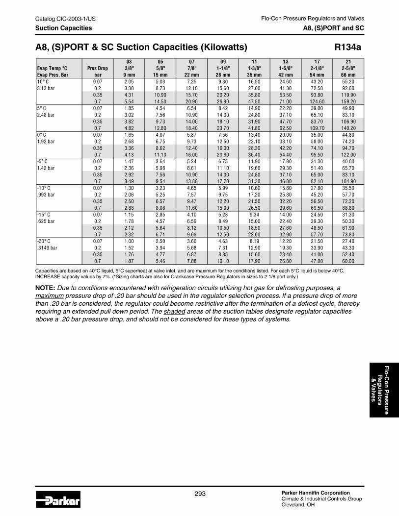
Flo-Con Pressure Regulators and Valves
Parker Hannifin CorporationClimate & Industrial Controls GroupCleveland, OH
293
Catalog CIC-2003-1/USF
lo-C
on
Pressu
reR
egu
lators
& V
alvesSuction Capacities A8, (S)PORT and SC
Capacities are based on 40°C liquid, 5°C superheat at valve inlet, and are maximum for the conditions listed. For each 5°C liquid is below 40°C,INCREASE capacity values by 7%. (*Sizing charts are also for Crankcase Pressure Regulators in sizes to 2 1/8 port only.)
NOTE: Due to conditions encountered with refrigeration circuits utilizing hot gas for defrosting purposes, amaximum pressure drop of .20 bar should be used in the regulator selection process. If a pressure drop of morethan .20 bar is considered, the regulator could become restrictive after the termination of a defrost cycle, therebyrequiring an extended pull down period. The shaded areas of the suction tables designate regulator capacitiesabove a .20 bar pressure drop, and should not be considered for these types of systems.
A8, (S)PORT & SC Suction Capacities (Kilowatts) R134a03 05 07 09 11 13 17 21
Evap Temp °C Pres Drop 3/8" 5/8" 7/8" 1-1/8" 1-3/8" 1-5/8" 2-1/8" 2-5/8"Evap Pres. Bar bar 9 mm 15 mm 22 mm 28 mm 35 mm 42 mm 54 mm 66 mm10° C 0.07 2.05 5.03 7.25 9.30 16.50 24.60 43.20 55.203.13 bar 0.2 3.38 8.73 12.10 15.60 27.60 41.30 72.50 92.60
0.35 4.31 10.90 15.70 20.20 35.80 53.50 93.80 119.900.7 5.54 14.50 20.90 26.90 47.50 71.00 124.60 159.20
5° C 0.07 1.85 4.54 6.54 8.42 14.90 22.20 39.00 49.902.48 bar 0.2 3.02 7.56 10.90 14.00 24.80 37.10 65.10 83.10
0.35 3.82 9.73 14.00 18.10 31.90 47.70 83.70 106.900.7 4.82 12.80 18.40 23.70 41.80 62.50 109.70 140.20
0° C 0.07 1.65 4.07 5.87 7.56 13.40 20.00 35.00 44.801.92 bar 0.2 2.68 6.75 9.73 12.50 22.10 33.10 58.00 74.20
0.35 3.36 8.62 12.40 16.00 28.30 42.20 74.10 94.700.7 4.13 11.10 16.00 20.60 36.40 54.40 95.50 122.00
-5° C 0.07 1.47 3.64 5.24 6.75 11.90 17.80 31.30 40.001.42 bar 0.2 2.36 5.98 8.61 11.10 19.60 29.30 51.40 65.70
0.35 2.92 7.56 10.90 14.00 24.80 37.10 65.00 83.100.7 3.49 9.54 13.80 17.70 31.30 46.80 82.10 104.90
-10° C 0.07 1.30 3.23 4.65 5.99 10.60 15.80 27.80 35.50.993 bar 0.2 2.06 5.25 7.57 9.75 17.20 25.80 45.20 57.70
0.35 2.50 6.57 9.47 12.20 21.50 32.20 56.50 72.200.7 2.88 8.08 11.60 15.00 26.50 39.60 69.50 88.80
-15° C 0.07 1.15 2.85 4.10 5.28 9.34 14.00 24.50 31.30.625 bar 0.2 1.78 4.57 6.59 8.49 15.00 22.40 39.30 50.30
0.35 2.12 5.64 8.12 10.50 18.50 27.60 48.50 61.900.7 2.32 6.71 9.68 12.50 22.00 32.90 57.70 73.80
-20° C 0.07 1.00 2.50 3.60 4.63 8.19 12.20 21.50 27.40.3149 bar 0.2 1.52 3.94 5.68 7.31 12.90 19.30 33.90 43.30
0.35 1.76 4.77 6.87 8.85 15.60 23.40 41.00 52.400.7 1.87 5.46 7.88 10.10 17.90 26.80 47.00 60.00

Parker Hannifin CorporationClimate & Industrial Controls GroupCleveland, OH
Flo-Con Pressure Regulators and Valves
294
Catalog CIC-2003-1/US
Suction Capacities A8, (S)PORT and SC
Capacities are based on 100°F liquid, 10°F superheat at valve inlet, and are maximum for the conditions listed. For each 10°F liquid is below 100°F,INCREASE capacity values by 4%. (*Sizing charts are also for Crankcase Pressure Regulators in sizes to 2 1/8 port only.)
NOTE: Due to conditions encountered with refrigeration circuits utilizing hot gas for defrosting purposes, amaximum pressure drop of 3 psi should be used in the regulator selection process. If a pressure drop of morethan 3 psi is considered, the regulator could become restrictive after the termination of a defrost cycle, therebyrequiring an extended pull down period. The shaded areas of the suction tables designate regulator capacitiesabove a 3 psi pressure drop, and should not be considered for these types of systems.
A8, (S)PORT & SC Suction Capacities (Tons) R404a03 05 07 09 11 13 17 21
Evap Temp °F Pres Drop 3/8" 5/8" 7/8" 1-1/8" 1-3/8" 1-5/8" 2-1/8" 2-5/8"Evap Pres. psig psi 9 mm 15 mm 22 mm 28 mm 35 mm 42 mm 54 mm 66 mm50° F 1 0.63 1.60 2.26 2.87 5.09 7.59 13.36 17.10104.7 psig 3 1.08 2.74 3.87 4.93 8.71 13.00 22.87 29.26
5 1.37 3.49 4.94 6.30 11.12 16.60 29.17 37.3210 1.85 4.78 6.80 8.68 15.26 22.84 40.03 51.14
40° F 1 0.56 1.43 2.02 2.57 4.55 6.79 11.95 15.3086.4 psig 3 0.96 2.44 3.45 4.40 7.78 11.61 20.42 26.13
5 1.22 3.11 4.40 5.62 9.91 14.80 25.99 33.2410 1.64 4.23 6.03 7.71 13.52 20.25 35.47 45.29
30° F 1 0.50 1.27 1.80 2.29 4.05 6.04 10.64 13.6270.3 psig 3 0.85 2.17 3.07 3.91 6.91 10.31 18.13 23.19
5 1.07 2.75 3.90 4.98 8.77 13.11 23.02 29.4310 1.43 3.72 5.31 6.79 11.89 17.83 31.19 39.80
20° F 1 0.45 1.13 1.59 2.03 3.59 5.36 9.43 12.0756.2 psig 3 0.75 1.92 2.71 3.46 6.10 9.11 16.01 20.48
5 0.94 2.42 3.44 4.39 7.72 11.55 20.26 25.9010 1.24 3.24 4.64 5.94 10.38 15.58 27.21 34.70
10° F 1 0.39 0.99 1.40 1.79 3.16 4.72 8.30 10.6344.0 psig 3 0.66 1.68 2.38 3.03 5.35 8.00 14.04 17.96
5 0.82 2.11 3.00 3.84 6.75 10.09 17.69 22.6110 1.06 2.79 4.01 5.15 8.96 13.47 23.49 29.92
0° F 1 0.34 0.87 1.23 1.57 2.78 4.14 7.28 9.3233.5 psig 3 0.57 1.46 2.08 2.65 4.67 6.98 12.25 15.66
5 0.71 1.83 2.61 3.34 5.85 8.77 15.35 19.6010 0.90 2.38 3.44 4.42 7.66 11.54 20.07 25.53
-10° F 1 0.30 0.76 1.07 1.37 2.42 3.61 6.34 8.1124.5 psig 3 0.49 1.27 1.80 2.30 4.04 6.04 10.60 13.54
5 0.60 1.57 2.25 2.87 5.03 7.54 13.18 16.8110 0.74 1.99 2.91 3.74 6.44 9.73 16.87 21.42
-20° F 1 0.26 0.66 0.93 1.18 2.09 3.12 5.48 7.0116.8 psig 3 0.42 1.08 1.54 1.97 3.46 5.18 9.08 11.59
5 0.51 1.33 1.91 2.45 4.26 6.41 11.18 14.2510 0.60 1.64 2.41 3.12 5.31 8.06 13.91 17.61
-30° F 1 0.22 0.56 0.80 1.01 1.79 2.67 4.70 6.0110.4 psig 3 0.35 0.92 1.31 1.67 2.93 4.39 7.68 9.81
5 0.42 1.11 1.60 2.06 3.56 5.37 9.34 11.8810 0.46 1.30 1.95 2.53 4.26 6.51 11.15 14.06
-40° F 1 0.19 0.48 0.68 0.86 1.52 2.27 3.99 5.105.0 psig 3 0.29 0.76 1.09 1.40 2.45 3.67 6.41 8.17
5 0.34 0.90 1.32 1.70 2.92 4.41 7.64 9.7010 0.34 0.99 1.52 1.99 3.27 5.06 8.56 10.73

Flo-Con Pressure Regulators and Valves
Parker Hannifin CorporationClimate & Industrial Controls GroupCleveland, OH
295
Catalog CIC-2003-1/USF
lo-C
on
Pressu
reR
egu
lators
& V
alvesSuction Capacities A8, (S)PORT and SC
Capacities are based on 40°C liquid, 5°C superheat at valve inlet, and are maximum for the conditions listed. For each 5°C liquid is below 40°C,INCREASE capacity values by 7%. (*Sizing charts are also for Crankcase Pressure Regulators in sizes to 2 1/8 port only.)
NOTE: Due to conditions encountered with refrigeration circuits utilizing hot gas for defrosting purposes, amaximum pressure drop of .20 bar should be used in the regulator selection process. If a pressure drop of morethan .20 bar is considered, the regulator could become restrictive after the termination of a defrost cycle, therebyrequiring an extended pull down period. The shaded areas of the suction tables designate regulator capacitiesabove a .20 bar pressure drop, and should not be considered for these types of systems.
A8, (S)PORT & SC Suction Capacities (Kilowatts) R404a03 05 07 09 11 13 17 21
Evap Temp °C Pres Drop 3/8" 5/8" 7/8" 1-1/8" 1-3/8" 1-5/8" 2-1/8" 2-5/8"Evap Pres. Bar bar 9 mm 15 mm 22 mm 28 mm 35 mm 42 mm 54 mm 66 mm10° C 0.07 2.15 5.46 7.70 9.80 17.37 25.90 45.59 58.378.1 bar 0.2 3.59 9.13 12.88 16.42 29.05 43.33 76.22 97.55
0.4 4.95 12.67 17.94 22.89 40.38 60.32 105.95 135.510.8 6.67 17.25 24.58 31.43 55.15 82.59 144.66 184.72
5° C 0.07 1.94 4.93 6.96 8.86 15.69 23.40 41.18 52.737.0 bar 0.2 3.23 8.23 11.62 14.81 26.19 39.08 68.73 87.95
0.4 4.44 11.39 16.14 20.60 36.32 54.27 95.28 121.830.8 5.94 15.41 22.00 28.15 49.31 73.90 129.32 165.06
0° C 0.07 1.75 4.44 6.27 7.98 14.14 21.08 37.10 47.506.0 bar 0.2 2.90 7.39 10.45 13.32 23.55 35.14 61.78 79.05
0.4 3.97 10.20 14.47 18.47 32.54 48.64 85.35 109.110.8 5.25 13.69 19.60 25.09 43.86 65.80 115.01 146.70
-5° C 0.07 1.57 3.99 5.62 7.16 12.68 18.91 33.28 42.605.1 bar 0.2 2.59 6.61 9.35 11.92 21.07 31.45 55.27 70.71
0.4 3.53 9.08 12.90 16.48 28.99 43.36 76.05 97.170.8 4.61 12.07 17.34 22.22 38.73 58.18 101.55 129.43
-10° C 0.07 1.40 3.56 5.02 6.39 11.32 16.88 29.70 38.034.3 bar 0.2 2.30 5.88 8.33 10.62 18.75 27.99 49.18 62.90
0.4 3.11 8.03 11.43 14.61 25.66 38.42 67.32 85.980.8 3.99 10.55 15.21 19.52 33.90 51.01 88.88 113.16
-15° C 0.07 1.24 3.16 4.46 5.68 10.06 15.00 26.40 33.793.6 bar 0.2 2.03 5.20 7.37 9.41 16.59 24.79 43.53 55.66
0.4 2.72 7.06 10.07 12.88 22.57 33.82 59.20 75.570.8 3.42 9.12 13.22 17.00 29.39 44.32 77.03 97.95
-20° C 0.07 1.10 2.80 3.95 5.03 8.91 13.29 23.38 29.923.0 bar 0.2 1.79 4.58 6.50 8.30 14.62 21.86 38.36 49.03
0.4 2.36 6.16 8.81 11.28 19.72 29.59 51.73 65.990.8 2.89 7.80 11.38 14.67 25.20 38.12 66.04 83.84
-25° C 0.07 0.97 2.46 3.48 4.43 7.84 11.69 20.56 26.312.5 bar 0.2 1.56 4.00 5.69 7.27 12.78 19.12 33.52 42.83
0.4 2.03 5.32 7.64 9.79 17.06 25.63 44.73 57.000.8 2.38 6.55 9.65 12.47 21.25 32.27 55.68 70.51
-30° C 0.07 0.84 2.15 3.04 3.88 6.85 10.22 17.97 22.992.0 bar 0.2 1.34 3.47 4.94 6.31 11.08 16.59 29.06 37.11
0.4 1.71 4.54 6.55 8.41 14.58 21.96 38.24 48.670.8 1.91 5.37 8.03 10.42 17.56 26.81 45.98 58.03
-40° C 0.07 0.63 1.60 2.27 2.90 5.11 7.64 13.42 17.161.3 bar 0.2 0.96 2.52 3.61 4.62 8.07 12.11 21.16 26.97
0.4 1.15 3.13 4.60 5.94 10.15 15.39 26.60 33.720.8 1.14 3.24 5.07 6.70 10.81 16.85 28.25 35.19

Parker Hannifin CorporationClimate & Industrial Controls GroupCleveland, OH
Flo-Con Pressure Regulators and Valves
296
Catalog CIC-2003-1/US
Suction Capacities A8, (S)PORT and SC
Capacities are based on 100°F liquid, 10°F superheat at valve inlet, and are maximum for the conditions listed. For each 10°F liquid is below 100°F,INCREASE capacity values by 4%. (*Sizing charts are also for Crankcase Pressure Regulators in sizes to 2 1/8 port only.)
NOTE: Due to conditions encountered with refrigeration circuits utilizing hot gas for defrosting purposes, amaximum pressure drop of 3 psi should be used in the regulator selection process. If a pressure drop of morethan 3 psi is considered, the regulator could become restrictive after the termination of a defrost cycle, therebyrequiring an extended pull down period. The shaded areas of the suction tables designate regulator capacitiesabove a 3 psi pressure drop, and should not be considered for these types of systems.
A8, (S)PORT & SC Suction Capacities (Tons) R50703 05 07 09 11 13 17 21
Evap Temp °F Pres Drop 3/8" 5/8" 7/8" 1-1/8" 1-3/8" 1-5/8" 2-1/8" 2-5/8"Evap Pres. psig psi 9 mm 15 mm 22 mm 28 mm 35 mm 42 mm 54 mm 66 mm50° F 1 0.66 1.66 2.34 2.98 5.29 7.88 13.88 17.77109 psig 3 1.12 2.85 4.02 5.12 9.06 13.51 23.77 30.42
5 1.42 3.63 5.13 6.55 11.56 17.26 30.34 38.8110 1.93 4.97 7.07 9.04 15.89 23.77 41.67 53.24
40° F 1 0.59 1.49 2.10 2.68 4.74 7.07 12.44 15.9389.8 psig 3 1.00 2.55 3.60 4.58 8.11 12.09 21.27 27.22
5 1.27 3.24 4.59 5.85 10.33 15.42 27.09 34.6510 1.71 4.41 6.29 8.04 14.11 21.13 37.01 47.26
30° F 1 0.52 1.33 1.88 2.39 4.23 6.31 11.11 14.2373.3 psig 3 0.89 2.27 3.21 4.09 7.22 10.78 18.94 24.24
5 1.12 2.88 4.08 5.20 9.17 13.71 24.07 30.7710 1.50 3.89 5.56 7.11 12.45 18.67 32.66 41.69
20° F 1 0.47 1.18 1.67 2.13 3.76 5.61 9.88 12.6458.8 psig 3 0.79 2.01 2.84 3.62 6.40 9.55 16.79 21.47
5 0.99 2.54 3.60 4.60 8.10 12.11 21.26 27.1710 1.31 3.40 4.88 6.24 10.91 16.37 28.60 36.48
10° F 1 0.41 1.05 1.48 1.88 3.33 4.96 8.73 11.1846.1 psig 3 0.69 1.77 2.50 3.19 5.64 8.42 14.78 18.91
5 0.86 2.23 3.17 4.04 7.11 10.63 18.65 23.8210 1.12 2.95 4.24 5.44 9.46 14.22 24.81 31.62
0° F 1 0.36 0.92 1.30 1.65 2.93 4.36 7.68 9.8335.2 psig 3 0.60 1.55 2.19 2.80 4.93 7.37 12.93 16.54
5 0.75 1.94 2.76 3.53 6.19 9.26 16.23 20.7210 0.95 2.52 3.65 4.68 8.12 12.23 21.28 27.08
-10° F 1 0.32 0.80 1.13 1.44 2.56 3.81 6.71 8.5825.8 psig 3 0.52 1.34 1.90 2.43 4.28 6.40 11.22 14.34
5 0.64 1.67 2.38 3.05 5.33 7.99 13.98 17.8410 0.79 2.13 3.09 3.98 6.86 10.37 17.98 22.84
-20° F 1 0.27 0.70 0.98 1.25 2.22 3.31 5.81 7.4417.8 psig 3 0.45 1.15 1.64 2.09 3.68 5.51 9.65 12.32
5 0.54 1.42 2.03 2.60 4.54 6.82 11.91 15.1810 0.64 1.75 2.58 3.33 5.69 8.63 14.91 18.89
-30° F 1 0.23 0.60 0.85 1.08 1.91 2.85 5.00 6.4011.1 psig 3 0.38 0.98 1.40 1.79 3.13 4.69 8.20 10.47
5 0.45 1.19 1.71 2.20 3.81 5.74 9.99 12.7210 0.50 1.41 2.10 2.73 4.60 7.01 12.03 15.19
-40° F 1 0.20 0.51 0.72 0.92 1.62 2.43 4.26 5.455.5 psig 3 0.31 0.82 1.17 1.50 2.62 3.94 6.88 8.77
5 0.36 0.97 1.42 1.82 3.14 4.74 8.23 10.4510 0.37 1.08 1.65 2.16 3.57 5.50 9.34 11.72

Flo-Con Pressure Regulators and Valves
Parker Hannifin CorporationClimate & Industrial Controls GroupCleveland, OH
297
Catalog CIC-2003-1/USF
lo-C
on
Pressu
reR
egu
lators
& V
alvesSuction Capacities A8, (S)PORT and SC
Capacities are based on 40°C liquid, 5°C superheat at valve inlet, and are maximum for the conditions listed. For each 5°C liquid is below 40°C,INCREASE capacity values by 7%. (*Sizing charts are also for Crankcase Pressure Regulators in sizes to 2 1/8 port only.)
NOTE: Due to conditions encountered with refrigeration circuits utilizing hot gas for defrosting purposes, amaximum pressure drop of .20 bar should be used in the regulator selection process. If a pressure drop of morethan .20 bar is considered, the regulator could become restrictive after the termination of a defrost cycle, therebyrequiring an extended pull down period. The shaded areas of the suction tables designate regulator capacitiesabove a .20 bar pressure drop, and should not be considered for these types of systems.
A8, (S)PORT & SC Suction Capacities (Kilowatts) R50703 05 07 09 11 13 17 21
Evap Temp °C Pres Drop 3/8" 5/8" 7/8" 1-1/8" 1-3/8" 1-5/8" 2-1/8" 2-5/8"Evap Pres. Bar bar 9 mm 15 mm 22 mm 28 mm 35 mm 42 mm 54 mm 66 mm10° C 0.07 2.25 5.70 8.03 10.23 18.13 27.03 47.58 60.927.5 bar 0.2 3.74 9.53 13.45 17.14 30.32 45.24 79.57 101.83
0.4 5.18 13.24 18.74 23.90 42.18 63.00 110.67 141.550.8 6.98 18.04 25.70 32.85 57.67 86.35 151.27 193.19
5° C 0.07 2.03 5.16 7.28 9.27 16.42 24.48 43.09 55.176.3 bar 0.2 3.38 8.61 12.16 15.50 27.42 40.91 71.94 92.07
0.4 4.66 11.93 16.91 21.57 38.04 56.84 99.80 127.620.8 6.24 16.17 23.07 29.51 51.72 77.50 135.65 173.16
0° C 0.07 1.84 4.66 6.57 8.37 14.83 22.11 38.91 49.825.26 bar 0.2 3.04 7.76 10.97 13.98 24.71 36.88 64.83 82.96
0.4 4.17 10.71 15.20 19.40 34.17 51.08 89.65 114.600.8 5.53 14.41 20.61 26.39 46.14 69.21 121.01 154.38
-5° C 0.07 1.65 4.19 5.91 7.53 13.34 19.89 35.00 44.814.3 bar 0.2 2.73 6.96 9.84 12.55 22.17 33.10 58.18 74.43
0.4 3.72 9.57 13.59 17.36 30.54 45.68 80.13 102.400.8 4.87 12.75 18.30 23.45 40.89 61.42 107.24 136.70
-10° C 0.07 1.48 3.76 5.30 6.75 11.95 17.82 31.36 40.143.5 bar 0.2 2.43 6.22 8.80 11.22 19.80 29.57 51.96 66.46
0.4 3.29 8.50 12.09 15.45 27.15 40.63 71.21 90.970.8 4.25 11.19 16.12 20.69 35.96 54.09 94.28 120.08
-15° C 0.07 1.32 3.35 4.73 6.02 10.66 15.89 27.96 35.802.8 bar 0.2 2.16 5.52 7.82 9.97 17.59 26.28 46.16 59.03
0.4 2.89 7.50 10.69 13.67 23.97 35.91 62.87 80.270.8 3.66 9.73 14.08 18.10 31.32 47.21 82.10 104.44
-20° C 0.07 1.17 2.97 4.20 5.34 9.46 14.11 24.82 31.772.1 bar 0.2 1.90 4.87 6.91 8.82 15.54 23.23 40.77 52.12
0.4 2.52 6.56 9.38 12.01 21.01 31.51 55.10 70.300.8 3.10 8.35 12.17 15.67 26.97 40.76 70.68 89.75
-25° C 0.07 1.03 2.62 3.70 4.72 8.35 12.45 21.90 28.031.6 bar 0.2 1.66 4.27 6.07 7.75 13.63 20.39 35.76 45.70
0.4 2.17 5.69 8.16 10.46 18.24 27.40 47.84 60.980.8 2.58 7.05 10.37 13.40 22.87 34.69 59.92 75.92
-30° C 0.07 0.90 2.30 3.25 4.14 7.32 10.92 19.20 24.562.1 bar 0.2 1.44 3.71 5.28 6.75 11.86 17.75 31.10 39.72
0.4 1.84 4.87 7.02 9.02 15.66 23.56 41.05 52.270.8 2.08 5.82 8.67 11.25 19.00 28.97 49.76 62.86
-40° C 0.07 0.68 1.73 2.45 3.12 5.51 8.22 14.44 18.470.38 bar 0.2 1.04 2.72 3.90 4.99 8.71 13.08 22.85 29.13
0.4 1.25 3.41 4.99 6.44 11.03 16.70 28.89 36.650.8 1.25 3.58 5.58 7.36 11.94 18.55 31.20 38.95

Parker Hannifin CorporationClimate & Industrial Controls GroupCleveland, OH
Flo-Con Pressure Regulators and Valves
298
Catalog CIC-2003-1/US
A8 Pressure Regulators
Features and Benefits• Dual range spring for flexibility in application.• Highest capacity commercial regulator in the
industry.• Molded Class H coil construction.• Internally pilot operated.• Manual opening stem.• Interchangeable capacity cartridges.• Inlet, outlet, or differential control capability.• Sweat-in place without disassembly.• Inlet access fitting as standard.• Electric shut-off and electric wide open variations.• Excellent regulation at light loads.• DIN coil assemblies available.
Specifications• Control range: 10" Hg to 400 psig (250mm Hg to
27.6 bar).• Minimum fluid temperature: -40°F (-40°C).• Design Pressure (M.R.P.): 450 psig (31.0 bar).• UL listed (except 50 Hz version), file # SA5473.• CSA certified, file LR20991-14.
A8 Valve Nomenclature
A8 Port/Connection Size Combinations
Valve Types: A8A, A81, A82. All are inlet pressure regulators.Optional adapter functions are as follows:
Technical Information A8 Pressure Regulators
Standard Voltages• 120V/60Hz, 110V/50Hz• 240V/60Hz, 220V/50Hz• 208V/60Hz• 240V/60Hz, 220V/50Hz (DIN)• 240V/50Hz (DIN)
Port Sizein Inches
7/8"BodySize
AValveFamily
A8Optional Variation
(see chart)
BLConnection Size
in Inches
1 1/8"
“ S” Suffix Inlet Regulator with Electric Shut-Off“ B” Suffix Inlet Regulator with Electric Bypass Feature“ L” Suffix Differential Pressure Regulator“ BL” Suffix Differential Regulator with Electric Bypass Feature“ OE” Suffix Outlet Pressure Regulator“ OES” Suffix Outlet Pressure Regulator with Electric Shut-Off
Valve Type Port Size Available Connection SizesA8A 3/8" (9mm) 5/8", 7/8", 1-1/8" (15mm, 22mm, 28mm)A8A 5/8" (15mm) 5/8", 7/8", 1-1/8" (15mm, 22mm, 28mm)A8A 7/8" (22mm) 7/8", 1-1/8" (22mm, 28mm)A81 5/8" (15mm) 1-1/8", 1-3/8" (28mm, 35mm)A81 7/8" (22mm) 1-1/8", 1-3/8", 1-5/8", 2-1/8" (28mm, 35mm, 42mm, 54mm) A81 1-1/8" (28mm) 1-1/8", 1-3/8", 1-5/8", 2-1/8" (28mm, 35mm, 42mm, 54mm)A81 1-3/8" (35mm) 1-1/8", 1-3/8", 1-5/8", 2-1/8" (28mm, 35mm, 42mm, 54mm)A82 1-5/8" (42mm) 1-5/8", 2-1/8", 2-5/8" (42mm, 54mm, 66mm)A82 2-1/8" (54mm) 1-5/8", 2-1/8", 2-5/8" (42mm, 54mm, 66mm)A82 2-5/8" (66mm) 1-5/8", 2-1/8", 2-5/8" (42mm, 54mm, 66mm)

Flo-Con Pressure Regulators and Valves
Parker Hannifin CorporationClimate & Industrial Controls GroupCleveland, OH
299
Catalog CIC-2003-1/USF
lo-C
on
Pressu
reR
egu
lators
& V
alves
Installation: For those A8 regulators having an intregalpilot solenoid feature, the solenoid operators utilize aspring loaded solenoid plunger design, which assiststhe plunger in closing off tightly against the solenoidpilot seat regardless of position or orientation. Theregulator can therefore be installed in either a horizon-tal or vertical pipe line regardless of valve variation.Those A8 regulators that have no pilot solenoid canalso be installed in a similar manner.
When brazing in line, typically a wet cloth wrappedaround the valve body is recommended to dissipateheat. If a valve is disassembled prior to installation,always have the correct gasket/ O-ring kit availablefor reassembly. The internal cartridge-to-body O-ringwill need to be replaced prior to reassembly.
Adjustment: Adjustment of a regulator's set point re-quires that the pressure being controlled be monitoredby an accurate pressure gauge. Turning the valve's ad-justing screw clockwise (into the bonnet) compressesthe range spring and subsequently raises the valvesset point. Conversely, turning the adjusting stemcounter-clockwise will decrease the valve's set point.Adjusting the set point of an A8AS, A81S, or A82Sregulator must be made with the solenoid energized,and the manual opening stem turned in . The adjust-ment of an A8AB, A81B, or A82B must be made withthe solenoid de-energized, and the manual openingstem turned in.
Electrical: All A8 regulator versions utilize a moldedwater resistant class “H” solenoid coil with a “generalpurpose” coil housing as standard. A class “H” DINcoil is also available with certain voltages. Coils aredesigned to operate with line voltage from 85% to110% of rated coil voltage. Operating with a coil voltageabove or below these limits may result in coil burnout.Also, operating with a coil voltage below this limit willresult in lowering the valves' maximum opening pres-sure differential, or MOPD.
Ordering Guide: Specify valve type, port and connec-tion size, and voltage, if applicable.
Technical Information A8 Pressure Regulators
Description/Variations: A8 Pressure regulators canconveniently be identified by three primary types: inlet,outlet, and differential regulator versions. Inlet pressureregulators open on a rise in inlet pressure above thevalves set point, and close when the inlet pressuredrops below the valve's set point.
Outlet pressure regulators maintain a constant outlet ordownstream pressure. Outlet regulators will open whenoutlet pressure falls below the valves set point andclose when the outlet pressure is above it’s set point.
Differential pressure regulators will open when thepressure difference across the regulator is greater thanthe valves set point. Conversely, they will close whenthe pressure difference across the valve is below thevalve's set point.
In addition, these three categories of valves, inlet,outlet, and differential, can also have optional variationsadded to the basic regulator, such as an electric shut-off feature, or bypass (electric wide opening) feature.Please refer to the inside front cover of this condensedcatalog for a complete listing of all A8 regulator varia-tions and their typical applications.
Pressure Ranges: All A8 series inlet and outletpressure regulators feature a wide pressure range, 10"Hg to 400 psig (250mm Hg to 27.6 bar), thus allowingflexibility in application. Differential pressure regulatorsoffer a single range spring capable of being set withina range of 0 to 120 psig (0 to 8.3 bar). Since it is thepressure difference across the valve which is beingcontrolled with any differential regulator version (notinlet pressure), this range is appropriate for any appli-cation, whether applied on the low side or high side ofthe system. For example, discharge regulators willcertainly be exposed to pressures exceeding 120 psigunder normal operation. However, they are most typi-cally set to control at about a 25 psi differential for hotgas supply purposes for defrost. Since this 25 psi setpoint easily falls within the range of this regulator, it isan appropriate pressure range for the application.
NOTE: For A8 valve suction capacity tables, please reference pages 290-297 of this catalog.

Parker Hannifin CorporationClimate & Industrial Controls GroupCleveland, OH
Flo-Con Pressure Regulators and Valves
300
Catalog CIC-2003-1/US
A9 Pressure Regulators
Features and Benefits• Pilot operated for precise control of set point.• External or internal equalizer.• Available with integral electric shut-off.• Sweat-in place without disassembly.• Molded class H coil construction.• DIN coil assemblies available.
Specifications• Two pressure ranges:
Range A = 10" Hg vacuum to 120 psig(250 mm hg to 8.3 bar) (hot gas bypass range).Range B = 80 psig to 220 psig (5.6 to 15.2 bar)(typical application - receiver pressure regulator).
• Minimum fluid temperature: -40° F (-40° C).• Design pressure (M.R.P.): 450 psig (31.0 bar)• All models UL listed, file # SA5473.• CSA certified A9S & A9SE, file # LR20991-14.
A9 Port/Connection Size Combinations
A9 Valve Nomenclature
Technical Information A9 Pressure Regulators
Description: The A9 family of pilot operated outletpressure regulators are ductile iron bodied valves withbrazed copper couplings. The A9 is “internally equal-ized” to outlet pressure by means of a small channel orpassage drilled through the outlet of the adapter whicheffectively communicates downstream pressure to thepilot section of the valve. The regulator therefore reactsto and controls the immediate outlet pressure of thecontrol valve. When used as a receiver pressure regula-tor, range “B” should be designated when ordering.
The A9E is an “externally equalized” outlet pressureregulator and is usually applied as a hot gas bypassregulator. For those applications where the dischargegas is introduced into the inlet of the evaporator, anA9E is typically used with a small pilot line connected
ValveFamily
A9Integral Solenoid/Electric Shut-Off
SExternallyEqualized
EPort Sizein Inches
5/8"Connection Size
in Inches
7/8"
from the compressor suction to the external fitting onthe regulator. Installed in this manner the valve sensesand responds to compressor suction pressure whilepiped to feed discharge gas to the inlet of the evapora-tor. Since it is the suction pressure that the regulator isresponding to and ultimately controlling, a range “A”regulator should be designated when ordering an A9Eor A9SE for this application.
Installation: A9 regulators can be mounted either in avertical or horizontal line with the refrigerant flow in the di-rection of the arrow on the body. These regulators may besoldered into the line without disassembly. A wet clothshould be wrapped around the valve and the solderingflame should be directed away from the valve body.
Adjustment: Loosen the adjusting stem seal nut andturn the adjusting stem clockwise to raise the set pointof the regulator. Turn the adjusting stem counter clock-wise (into the bonnet) compresses the range spring andsubsequently raises the valve's set point. Conversely,turning the adjusting stem counterclockwise will de-crease the valve's set point. For a range “A” valve, onecomplete turn of the adjusting stem will result in achange in set point of about 16 psi (1.1 bar). One com-plete turn of the adjusting stem on a range “B” regulatorwill change the set point approximately 25psi (1.7 bar).The set point adjustment of an A9S or A9SE must bemade with the pilot solenoid energized.
Electrical: A9S and A9SE regulators utilize a moldedwater resistant Class “H” solenoid coil with a generalpurpose coil housing which meets NEMA 3R and 4requirements. A class “H” DIN coil is also available withcertain voltages. Power consumption during normaloperation will be 11 watts or less. The coils are designedto operate with a line voltage from 85% to 110% of ratedcoil voltage. Operating with a line voltage above or be-low these limits may result in coil burn out.
Ordering Guide: Specify valve type, range, port andconnection size. If shut off (“S”) variation is included,specify voltage and frequency.
Standard Voltages• 120V/60Hz, 110V/50Hz• 240V/60Hz, 220V/50Hz• 208V/60Hz• 240V/60Hz, 220V/50Hz
(DIN)• 240V/50Hz (DIN)
Port Size Available Connection Sizes3/8” (9mm) 5/8” , 7/8” , 1-1/8” (15mm, 22mm, 28mm)5/8” (15mm) 5/8” , 7/8” , 1-1/8” (15mm, 22mm, 28mm)7/8” (22mm) 5/8", 7/8” , 1-1/8” (15mm, 22mm, 28mm)1-1/8” (28mm) 1-1/8” (28mm)
A9 Outlet Pressure Regulator
A9SOutlet Pressure Regulator with Electric Shut-Off Feature
A9E Externally Equalized Outlet Pressure Regulator
A9SEExternally Equalized Outlet Pressure Regulator with Electric Shut-Off Feature

Flo-Con Pressure Regulators and Valves
Parker Hannifin CorporationClimate & Industrial Controls GroupCleveland, OH
301
Catalog CIC-2003-1/USF
lo-C
on
Pressu
reR
egu
lators
& V
alves
CK4 Check Valve
Features and Benefits• Spring-loaded, in-line check valve.• Compact size, mounts in any position.• A minimum pressure difference of .75 psi
(.05 bar) required to fully open valve.• Several ODS connection sizes available for most
port size valves.• Positive spring closing action.• Lapped, metal to metal stainless steel or chrome
plated seat.• Various flanged connections available.
Specifications• Design pressure (MRP): 500 psig, (32 bar).• Minimum fluid temperature: -40°F (-40°C).• UL listed, file # SA5473.• CSA certified, file # LR20991-14.
CK4 Valve Nomenclature
CK4 Port/Connection Size Combinations
Technical Information CK4 Check Valve
FlangedBody Style
4APort Size
4CheckValve
CK
Description: CK4A check valves allow flow in onedirection only, and will prevent backward flow ofrefrigerant should the outlet pressure increase evenslightly above the valve’s inlet pressure. The CK4Acheck valve is a flanged spring closing valve whichutilizes a corrosion resistant, stainless steel orchrome plated lapped seat. This material and typeof construction ensures reliable closing action andminimum seat leakage.
Typical applications for large commercial refrigerationsystems include condenser liquid drain check valves,and condenser bypass lines. As a bypass checkvalve, it is usually installed downstream of a receiverpressure regulator. In this application, the CK4Acheck valve prevents back-flow through the receiverpressure regulator and into the discharge line in theevent of a system shut-down.
CK4A check valves utilize mating flanges. In mostinstances, ODS flanges with copper couplingsprovide various connection sizes to match the valveto the line. The flanges used are two bolt refrigerationstyle (tongue and groove) on all valves up to andincluding 1" (25mm) port size, and four bolt on 1-1/4"(32mm) through 4" (100mm) port size.
Installation: Because of their spring closing con-struction, CK4A check valves can be mounted in anyposition in either a vertical or horizontal line. Thevalve must be installed with the arrow pointing in thedirection of flow. After installing the CK4A between it’sflanges, tighten the flange bolts evenly.
Ordering Guide: Specify the CK4A port size and theconnection size of the ODS flange.
ValveType Port Size Available ODS Flange Connection Sizes
CK4A-2 1/2" (13mm) 1/2", 5/8", 7/8" (13mm, 15mm, 22mm)CK4A-3 3/4" (20mm) 7/8", 1-1/8", 1-3/8" (22mm, 28mm, 35mm)CK4A-4 1" (25mm) 1-1/8", 1-3/8", 1-5/8" (28mm, 35mm, 42mm)CK4A-6 1-1/4" (32mm) 1-3/8", 1-5/8", 2-1/8" (35mm, 42mm, 54mm)CK4A-8 2" (50mm) 1-5/8", 2-1/8", 2-5/8" (42mm, 54mm, 66mm)CK4A-9 2-1/2" (65mm) 2-5/8", 3-1/8" (66mm, 78mm)CK4A-0 3" (75mm) 3-1/8", 3-5/8" (78mm, 91mm)
CK4A-16 4" (100mm) 4-1/8" (103mm)

Parker Hannifin CorporationClimate & Industrial Controls GroupCleveland, OH
Flo-Con Pressure Regulators and Valves
302
Catalog CIC-2003-1/US
NOTE: Shading is for readability purposes only.
Liquid Drain Capacities CK4 Check Valve
CK4A Liquid Drain Capacities (Tons) R22
CK4A Liquid Drain Capacities (Tons) R134a
NOTE: Shading is for readability purposes only.
Cond Temp CK4A2 CK4A3 Ck4A4 CK4A6 CK4A8 CK4A9 CK4A0 CK4A16Sat pres Evap Pres Drop 1/2" 3/4" 1" 1-1/4" 2" 2-1/2" 3" 4"(psig) Temp psi 13 mm 20 mm 25 mm 32 mm 50 mm 65 mm 75 mm 100 mm75° F -40° F 0.75 9.9 20.7 37.9 55.3 134.0 203.8 326.2 611.5(132) 3 19.8 41.4 75.7 110.7 267.9 407.7 652.3 1223.1
0° F 0.75 10.5 21.9 40.1 58.6 141.9 216.0 345.6 648.03 21.0 43.8 80.2 117.3 283.9 432.0 691.2 1295.9
40° F 0.75 11.0 23.0 42.1 61.6 149.0 226.8 362.8 680.33 22.0 46.0 84.2 123.1 298.0 453.6 725.7 1360.7
95° F -40° F 0.75 8.9 18.6 34.1 49.9 120.7 183.7 294.0 551.2(182) 3 17.8 37.3 68.2 99.7 241.5 367.5 587.9 1102.4
0° F 0.75 9.5 19.8 36.3 53.1 128.6 195.7 313.0 587.03 19.0 39.7 72.7 106.2 257.1 391.3 626.1 1173.9
40° F 0.75 10.0 20.9 38.3 56.0 135.5 206.2 330.0 618.73 20.0 41.8 76.6 112.0 271.1 412.5 660.0 1237.5
115° F -40° F 0.75 7.9 16.6 30.3 44.3 107.3 163.2 261.2 489.7(243) 3 15.9 33.1 60.6 88.6 214.5 326.5 522.4 979.4
0° F 0.75 8.5 17.7 32.5 47.5 115.0 174.9 279.9 524.83 17.0 35.5 65.0 95.0 229.9 349.9 559.8 1049.6
40° F 0.75 9.0 18.8 34.4 50.3 121.8 185.3 296.5 555.93 18.0 37.6 68.8 100.6 243.5 370.6 593.0 1111.8
Cond Temp CK4A2 CK4A3 Ck4A4 CK4A6 CK4A8 CK4A9 CK4A0 CK4A16(Sat pres) Evap Pres Drop 1/2" 3/4" 1" 1-1/4" 2" 2-1/2" 3" 4"psig Temp psi 13 mm 20 mm 25 mm 32 mm 50 mm 65 mm 75 mm 100 mm75° F -40° F 0.75 8.9 18.6 34.1 49.8 120.6 183.5 293.6 550.5(78.6) 3 17.8 37.2 68.2 99.6 241.2 367.0 587.2 1101.0
0° F 0.75 9.7 20.4 37.3 54.5 131.9 200.7 321.1 602.03 19.5 40.7 74.5 108.9 263.7 401.3 642.1 1204.0
40° F 0.75 10.5 22.0 40.3 58.9 142.7 217.2 347.5 651.53 21.1 44.1 80.7 117.9 285.4 434.3 695.0 1303.0
95° F -40° F 0.75 7.9 16.4 30.0 43.9 106.2 161.7 258.6 485.0(113.8) 3 15.7 32.8 60.0 87.8 212.5 323.3 517.3 969.9
0° F 0.75 8.7 18.1 33.2 48.5 117.3 178.5 285.6 535.63 17.3 36.2 66.3 96.9 234.6 357.0 571.3 1071.1
40° F 0.75 9.5 19.8 36.2 52.9 128.0 194.8 311.6 584.23 18.9 39.5 72.3 105.7 256.0 389.5 623.2 1168.5
115° F -40° F 0.75 6.8 14.2 25.9 37.9 91.7 139.5 223.2 418.6(158.4) 3 13.6 28.3 51.8 75.7 183.4 279.0 446.5 837.1
0° F 0.75 7.6 15.8 29.0 42.4 102.6 156.1 249.7 468.23 15.2 31.7 58.0 84.7 205.1 312.1 499.4 936.4
40° F 0.75 8.4 17.4 31.9 46.7 113.0 172.0 275.2 516.03 16.7 34.9 63.9 93.4 226.0 344.0 550.4 1031.9

Flo-Con Pressure Regulators and Valves
Parker Hannifin CorporationClimate & Industrial Controls GroupCleveland, OH
303
Catalog CIC-2003-1/USF
lo-C
on
Pressu
reR
egu
lators
& V
alves
NOTE: Shading is for readability purposes only.
Liquid Drain Capacities CK4 Check Valve
CK4A Liquid Drain Capacities (Kilowatts) R22
CK4A Liquid Drain Capacities (Kilowatts) R134a
NOTE: Shading is for readability purposes only.
Cond Temp CK4A2 CK4A3 Ck4A4 CK4A6 CK4A8 CK4A9 CK4A0 CK4A16(Sat pres) Evap Pres Drop 1/2" 3/4" 1" 1-1/4" 2" 2-1/2" 3" 4"bar Temp bar 13 mm 20 mm 25 mm 32 mm 50 mm 65 mm 75 mm 100 mm25° C -40° C 0.05 33.7 70.3 128.8 188.2 455.6 693.3 1109.2 2079.8(9.2) 0.21 69.0 144.1 263.9 385.6 933.7 1420.8 2273.3 4262.4
-20° C 0.05 35.5 74.1 135.8 198.4 480.4 731.0 1169.7 2193.10.21 72.8 152.0 278.2 406.7 984.5 1498.2 2397.1 4494.6
0° C 0.05 37.2 77.6 142.1 207.7 502.8 765.1 1224.2 2295.40.21 76.2 159.0 291.2 425.6 1030.4 1568.0 2508.8 4704.1
30° C -40° C 0.05 32.2 67.2 123.0 179.7 435.1 662.1 1059.3 1986.2(10.9) 0.21 65.9 137.6 252.0 368.3 891.6 1356.8 2170.9 4070.4
-20° C 0.05 34.0 71.0 129.9 189.9 459.7 699.5 1119.2 2098.50.21 69.6 145.4 266.2 389.1 942.1 1433.6 2293.7 4300.7
0° C 0.05 35.6 74.4 136.2 199.0 481.9 733.3 1173.3 2199.90.21 73.0 152.4 279.1 407.9 987.6 1502.8 2404.6 4508.5
35° C -40° C 0.05 30.6 64.0 117.1 171.2 414.4 630.6 1009.0 1891.8(12.6) 0.21 62.8 131.1 240.0 350.8 849.3 1292.3 2067.7 3877.0
-20° C 0.05 32.4 67.7 124.0 181.2 438.8 667.7 1068.4 2003.20.21 66.5 138.8 254.1 371.4 899.3 1368.5 2189.5 4105.4
0° C 0.05 34.1 71.1 130.2 190.3 460.8 701.3 1122.0 2103.80.21 69.8 145.8 266.9 390.1 944.4 1437.2 2299.4 4311.5
Cond Temp CK4A2 CK4A3 Ck4A4 CK4A6 CK4A8 CK4A9 CK4A0 CK4A16(Sat pres) Evap Pres Drop 1/2" 3/4" 1" 1-1/4" 2" 2-1/2" 3" 4"bar Temp bar 13 mm 20 mm 25 mm 32 mm 50 mm 65 mm 75 mm 100 mm25° C -40° C 0.05 30.2 63.1 115.4 168.7 408.5 621.6 994.6 1864.9(5.5) 0.21 61.9 129.2 236.6 345.8 837.2 1273.9 2038.3 3821.8
-20° C 0.05 32.8 68.4 125.3 183.2 443.5 674.8 1079.7 2024.50.21 67.2 140.3 256.8 375.4 908.8 1383.0 2212.8 4149.0
0° C 0.05 35.3 73.7 134.9 197.1 477.3 726.3 1162.0 2178.80.21 72.3 151.0 276.4 404.0 978.1 1488.4 2381.5 4465.3
30° C -40° C 0.05 28.5 59.6 109.1 159.5 386.2 587.7 940.3 1763.1(6.7) 0.21 58.5 122.2 223.7 326.9 791.5 1204.4 1927.0 3613.2
-20° C 0.05 31.1 65.0 118.9 173.8 420.9 640.5 1024.8 1921.50.21 63.8 133.1 243.8 356.3 862.6 1312.6 2100.2 3937.9
0° C 0.05 33.6 70.1 128.4 187.7 454.4 691.5 1106.5 2074.60.21 68.8 143.8 263.2 384.7 931.3 1417.3 2267.6 4251.8
35° C -40° C 0.05 26.9 56.1 102.8 150.3 363.8 553.6 885.7 1660.7(7.8) 0.21 55.1 115.1 210.7 307.9 745.5 1134.5 1815.2 3403.4
-20° C 0.05 29.4 61.5 112.5 164.5 398.2 606.0 969.5 1817.90.21 60.3 126.0 230.6 337.1 816.1 1241.8 1986.9 3725.5
0° C 0.05 31.9 66.6 121.9 178.2 431.5 656.6 1050.6 1969.80.21 65.4 136.5 249.9 365.2 884.3 1345.6 2153.0 4036.9

Parker Hannifin CorporationClimate & Industrial Controls GroupCleveland, OH
Flo-Con Pressure Regulators and Valves
304
Catalog CIC-2003-1/US
NOTE: Shading is for readability purposes only.
Liquid Drain Capacities CK4 Check Valve
CK4A Liquid Drain Capacities (Tons) R404a
CK4A Liquid Drain Capacities (Tons) R507
NOTE: Shading is for readability purposes only.
Cond Temp CK4A2 CK4A3 Ck4A4 CK4A6 CK4A8 CK4A9 CK4A0 CK4A16(Sat pres) Evap Pres Drop 1/2" 3/4" 1" 1-1/4" 2" 2-1/2" 3" 4"psig Temp psi 13 mm 20 mm 25 mm 32 mm 50 mm 65 mm 75 mm 100 mm75° F -40° F 0.75 6.6 13.8 25.3 37.0 89.6 136.3 218.0 408.8(161.2) 3 13.2 27.6 50.6 74.0 179.1 272.6 436.1 817.7
0° F 0.75 7.4 15.5 28.3 41.4 100.3 152.6 244.1 457.73 14.8 31.0 56.7 82.8 200.5 305.2 488.2 915.5
40° F 0.75 8.1 17.0 31.1 45.5 110.1 167.6 268.1 502.73 16.3 34.0 62.2 91.0 220.2 335.2 536.2 1005.5
95° F -40° F 0.75 5.5 11.5 21.0 30.7 74.3 113.0 180.8 339.1(219.4) 3 11.0 22.9 42.0 61.4 148.6 226.1 361.7 678.2
0° F 0.75 6.3 13.1 23.9 35.0 84.7 128.9 206.3 386.83 12.5 26.2 47.9 70.0 169.4 257.8 412.6 773.5
40° F 0.75 7.0 14.6 26.7 39.0 94.3 143.5 229.7 430.63 13.9 29.1 53.3 77.9 188.7 287.1 459.3 861.3
115° F -40° F 0.75 4.3 9.0 16.4 24.0 58.2 88.5 141.7 265.6(290.9) 3 8.6 18.0 32.9 48.1 116.4 177.1 283.3 531.2
0° F 0.75 5.0 10.5 19.3 28.2 68.3 103.9 166.3 311.83 10.1 21.1 38.6 56.4 136.6 207.8 332.6 623.5
40° F 0.75 5.7 12.0 21.9 32.1 77.6 118.1 188.9 354.33 11.5 24.0 43.9 64.1 155.2 236.2 377.9 708.5
Cond Temp CK4A2 CK4A3 Ck4A4 CK4A6 CK4A8 CK4A9 CK4A0 CK4A16(Sat pres) Evap Pres Drop 1/2" 3/4" 1" 1-1/4" 2" 2-1/2" 3" 4"psig Temp psi 13 mm 20 mm 25 mm 32 mm 50 mm 65 mm 75 mm 100 mm75° F -40° F 0.75 6.6 13.7 25.1 36.6 88.7 134.9 215.9 404.8(167.0) 3 13.1 27.4 50.1 73.2 177.3 269.8 431.7 809.5
0° F 0.75 7.3 15.2 27.9 40.7 98.6 150.1 240.2 450.33 14.6 30.5 55.8 81.5 197.3 300.2 480.4 900.7
40° F 0.75 8.0 16.7 30.5 44.6 108.1 164.5 263.1 493.43 16.0 33.4 61.1 89.3 216.1 328.9 526.2 986.7
95° F -40° F 0.75 5.5 11.6 21.2 30.9 74.9 114.0 182.3 341.9(226.0) 3 11.1 23.1 42.3 61.9 149.8 227.9 364.7 683.8
0° F 0.75 6.3 13.1 23.9 35.0 84.6 128.8 206.0 386.33 12.5 26.1 47.8 69.9 169.3 257.6 412.1 772.7
40° F 0.75 6.9 14.5 26.5 38.7 93.8 142.8 228.4 428.33 13.9 29.0 53.0 77.5 187.6 285.5 456.8 856.5
115° F -40° F 0.75 4.5 9.3 17.1 25.0 60.5 92.1 147.3 276.2(301.0) 3 8.9 18.7 34.2 50.0 121.0 184.2 294.7 552.5
0° F 0.75 5.2 10.8 19.8 28.9 69.9 106.4 170.3 319.33 10.3 21.6 39.5 57.8 139.9 212.9 340.6 638.7
40° F 0.75 5.8 12.2 22.3 32.6 78.9 120.0 192.0 360.03 11.7 24.3 44.6 65.1 157.7 240.0 384.0 719.9

Flo-Con Pressure Regulators and Valves
Parker Hannifin CorporationClimate & Industrial Controls GroupCleveland, OH
305
Catalog CIC-2003-1/USF
lo-C
on
Pressu
reR
egu
lators
& V
alves
NOTE: Shading is for readability purposes only.
Liquid Drain Capacities CK4 Check Valve
CK4A Liquid Drain Capacities (Kilowatts) R404a
CK4A Liquid Drain Capacities (Kilowatts) R507
NOTE: Shading is for readability purposes only.
Cond Temp CK4A2 CK4A3 Ck4A4 CK4A6 CK4A8 CK4A9 CK4A0 CK4A16(Sat pres) Evap Pres Drop 1/2" 3/4" 1" 1-1/4" 2" 2-1/2" 3" 4"bar Temp bar 13 mm 20 mm 25 mm 32 mm 50 mm 65 mm 75 mm 100 mm25° C -40° C 0.05 22.2 46.4 85.0 124.3 300.9 457.9 732.6 1373.6(11.2) 0.21 45.6 95.2 174.3 254.7 616.6 938.4 1501.4 2815.1
-20° C 0.05 24.7 51.6 94.4 138.0 334.1 508.5 813.6 1525.40.21 50.6 105.7 193.5 282.8 684.8 1042.1 1667.3 3126.2
0° C 0.05 27.0 56.4 103.2 150.8 365.1 555.6 889.0 1666.90.21 55.3 115.5 211.5 309.1 748.3 1138.7 1822.0 3416.2
30° C -40° C 0.05 20.5 42.8 78.4 114.5 277.3 421.9 675.1 1265.8(13.1) 0.21 42.0 87.7 160.6 234.7 568.2 864.7 1383.5 2594.1
-20° C 0.05 22.9 47.9 87.7 128.1 310.2 472.0 755.2 1415.90.21 47.0 98.1 179.6 262.5 635.6 967.3 1547.6 2901.8
0° C 0.05 25.2 52.6 96.3 140.8 340.8 518.6 829.8 1555.90.21 51.6 107.8 197.4 288.5 698.5 1062.9 1700.6 3188.6
35° C -40° C 0.05 18.7 39.1 71.5 104.6 253.2 385.2 616.4 1155.7(15.1) 0.21 38.3 80.1 146.6 214.3 518.8 789.5 1263.2 2368.6
-20° C 0.05 21.1 44.1 80.7 118.0 285.6 434.7 695.5 1304.00.21 43.3 90.4 165.4 241.8 585.4 890.8 1425.3 2672.5
0° C 0.05 23.4 48.8 89.3 130.5 315.9 480.8 769.2 1442.30.21 47.9 99.9 183.0 267.4 647.5 985.3 1576.5 2955.9
Cond Temp CK4A2 CK4A3 Ck4A4 CK4A6 CK4A8 CK4A9 CK4A0 CK4A16(Sat pres) Evap Pres Drop 1/2" 3/4" 1" 1-1/4" 2" 2-1/2" 3" 4"bar Temp bar 13 mm 20 mm 25 mm 32 mm 50 mm 65 mm 75 mm 100 mm25° C -40° C 0.05 22.1 46.1 84.3 123.3 298.5 454.2 726.7 1362.5(11.6) 0.21 45.2 94.4 172.9 252.6 611.6 930.8 1489.2 2792.3
-20° C 0.05 24.3 50.8 93.1 136.0 329.4 501.2 802.0 1503.70.21 49.9 104.2 190.8 278.8 675.0 1027.2 1643.5 3081.7
0° C 0.05 26.5 55.4 101.4 148.2 358.8 546.0 873.6 1637.90.21 54.3 113.5 207.8 303.7 735.3 1118.9 1790.3 3356.8
30° C -40° C 0.05 20.5 42.8 78.3 114.5 277.1 421.7 674.7 1265.1(13.5) 0.21 42.0 87.7 160.5 234.6 567.9 864.2 1382.8 2592.7
-20° C 0.05 22.7 47.5 87.0 127.1 307.7 468.2 749.2 1404.70.21 46.6 97.3 178.2 260.5 630.6 959.6 1535.4 2878.8
0° C 0.05 24.9 52.0 95.2 139.1 336.8 512.5 820.0 1537.50.21 51.0 106.5 195.1 285.1 690.2 1050.3 1680.5 3150.9
35° C -40° C 0.05 18.9 39.4 72.2 105.5 255.5 388.8 622.1 1166.5(15.6) 0.21 38.7 80.8 148.0 216.3 523.7 796.9 1275.0 2390.6
-20° C 0.05 21.1 44.1 80.8 118.0 285.7 434.8 695.7 1304.50.21 43.3 90.4 165.5 241.9 585.6 891.1 1425.8 2673.4
0° C 0.05 23.2 48.5 88.9 129.9 314.5 478.5 765.7 1435.60.21 47.6 99.5 182.1 266.2 644.5 980.7 1569.2 2942.2

Parker Hannifin CorporationClimate & Industrial Controls GroupCleveland, OH
Flo-Con Pressure Regulators and Valves
306
Catalog CIC-2003-1/US
Condenser Pressure Control
For Air Cooled CondensersParker Refrigerating Specialties and Flo-Con regulatorsprovide the wide range of adjustment of condenserand receiver pressures required for the most efficientoperation of large air-cooled condenser systems. Theregulators are an integral part of the refrigerationsystem and provide direct control of condenser andreceiver pressures to achieve satisfactory systemoperation with minimum energy consumption.
Condenser pressure control is needed for one or moreof the following reasons:1. To maintain sufficient receiver pressure to insure
flow of an adequate amount of liquid to the evapora-tor for proper temperature control and adequaterefrigeration capacity.
2. To permit start up during cold weather conditions byquickly developing adequate receiver pressure.
3. To provide an ample supply of hot gas for defrosts,reheat or heat reclamation systems.
4. To prevent flash gas in the liquid lines. With nopressure control, at very low ambient temperaturesthe cold liquid may be at almost saturated conditionsbecause of the low condensing pressure. The lack ofsub-cooling may cause the liquid to evaporate whenthe liquid lines pass through warm areas or wherepressure drops take place (filters, valves, etc.). Thepresence of flash vapor would affect the perfor-mance of expansion valves, eroding seats, causingirregular flow, and reducing capacity.
Types of systemsTwo systems of variable condenser pressure controlare shown on the opposite page. Figure 1 shows aLiquid Drain Control Method using a regulator in theliquid line to provide the desired condenser pressure.
This method is ideal for large capacity systems sincea smaller regulator is required for liquid line than fordischarge line.
Figure 2 shows a Discharge Gas Control Methodusing a regulator in the discharge line. In both cases abypass regulator is used to control the receiver pres-sure by feeding it with high-pressure gas as necessary.
This method is particularly suitable for systems requir-ing hot gas defrost, heat reclaim, and for ease of startup of systems with a cold receiver.
Valve FunctionsValve A in Figure 1 is an Inlet Pressure Regulator inthe liquid drain line from the condenser, and sensesthe condenser pressure. The regulator closes as thecondenser pressure drops below the set point, thusback flooding the condenser and reducing the insidesurface area available for condensing.
Valve B in Figures 1 and 2 is an Outlet PressureRegulator in the bypass line from compressordischarge to the condenser liquid drain line. This valvesenses the receiver pressure and opens when thepressure drops below the set point, thus maintainingthe receiver pressure.
Valve C in Figures 1 and 2 is an In-line Check valvein the liquid drain line to prevent higher pressure frombacking up into the condenser during low ambientconditions when the compressor is idle.
Valve D in Figure 2 is an Inlet Pressure Regulator in thecompressor discharge line. This regulator senses thedischarge pressure and closes as the pressure dropsbelow the set point, thus maintaining the dischargepressure at the desired level.
Technical Information Condenser Pressure Control
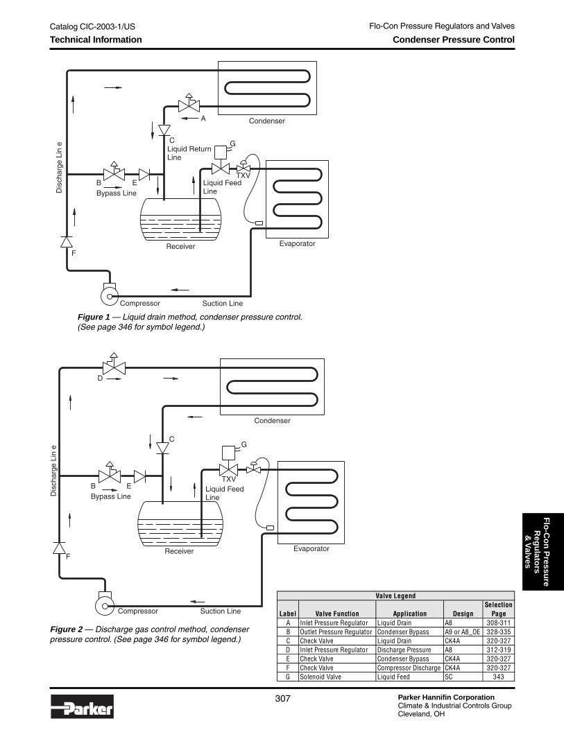
Flo-Con Pressure Regulators and Valves
Parker Hannifin CorporationClimate & Industrial Controls GroupCleveland, OH
307
Catalog CIC-2003-1/USF
lo-C
on
Pressu
reR
egu
lators
& V
alves
Figure 1 — Liquid drain method, condenser pressure control.(See page 346 for symbol legend.)
Figure 2 — Discharge gas control method, condenserpressure control. (See page 346 for symbol legend.)
Technical Information Condenser Pressure Control
Label Valve Function Application DesignSelection
PageA Inlet Pressure Regulator Liquid Drain A8 308-311B Outlet Pressure Regulator Condenser Bypass A9 or A8_OE 328-335C Check Valve Liquid Drain CK4A 320-327D Inlet Pressure Regulator Discharge Pressure A8 312-319E Check Valve Condenser Bypass CK4A 320-327F Check Valve Compressor Discharge CK4A 320-327G Solenoid Valve Liquid Feed SC 343
Valve Legend
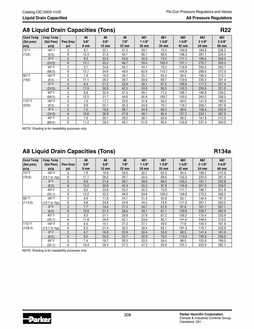
Parker Hannifin CorporationClimate & Industrial Controls GroupCleveland, OH
Flo-Con Pressure Regulators and Valves
308
Catalog CIC-2003-1/US
NOTE: Shading is for readability purposes only.
Liquid Drain Capacities A8 Pressure Regulators
A8 Liquid Drain Capacities (Tons) R22
A8 Liquid Drain Capacities (Tons) R134a
NOTE: Shading is for readability purposes only.
Cond Temp Evap Temp A8 A8 A8 A81 A81 A82 A82 A82(Sat pres) (Sat Pres) Pres Drop 3/8" 5/8" 7/8" 1-1/8" 1-3/8" 1-5/8" 2-1/8" 2-5/8"psig psig psi 9 mm 15 mm 22 mm 28 mm 35 mm 42 mm 54 mm 66 mm75° F -40° F 3 8.7 22.1 31.2 39.7 70.4 104.8 184.6 236.5(132) (0.5) 6 12.4 31.3 44.1 56.1 99.5 148.3 261.1 334.4
0° F 3 9.3 23.5 33.0 42.0 74.5 111.1 195.6 250.5(24.0) 6 13.1 33.2 46.7 59.4 105.4 157.1 276.7 354.340° F 3 9.7 24.6 34.7 44.1 78.3 116.6 205.4 263.1(68.5) 6 13.7 34.8 49.0 62.4 110.7 164.9 290.5 372.0
95° F -40° F 3 7.9 19.9 28.1 35.7 63.4 94.5 166.4 213.1(182) (0.5) 6 11.1 28.2 39.7 50.6 89.7 133.6 235.3 301.4
0° F 3 8.4 21.2 29.9 38.1 67.5 100.6 177.2 227.0(24.0) 6 11.9 30.0 42.3 53.8 95.5 142.3 250.6 321.040° F 3 8.8 22.4 31.5 40.1 71.2 106.1 186.8 239.2(68.5) 6 12.5 31.7 44.6 56.8 100.7 150.0 264.2 338.3
115° F -40° F 3 7.0 17.7 25.0 31.8 56.3 84.0 147.9 189.4(243) (0.5) 6 9.9 25.1 35.3 44.9 79.7 118.7 209.1 267.8
0° F 3 7.5 19.0 26.7 34.0 60.4 90.0 158.4 202.9(24.0) 6 10.6 26.9 37.8 48.1 85.4 127.2 224.1 287.040° F 3 7.9 20.1 28.3 36.1 64.0 95.3 167.8 215.0(68.5) 6 11.2 28.5 40.1 51.0 90.4 134.8 237.4 304.0
Cond Temp Evap Temp A8 A8 A8 A81 A81 A82 A82 A82(Sat pres) (Sat Pres) Pres Drop 3/8" 5/8" 7/8" 1-1/8" 1-3/8" 1-5/8" 2-1/8" 2-5/8"psig psig psi 9 mm 15 mm 22 mm 28 mm 35 mm 42 mm 54 mm 66 mm75° F -40° F 3 7.9 19.9 28.0 35.7 63.3 94.4 166.2 212.9(78.6) (14.7 in. hg) 6 11.1 28.2 39.7 50.5 89.6 133.5 235.0 301.0
0° F 3 8.6 21.8 30.7 39.0 69.3 103.2 181.7 232.8(6.5) 6 12.2 30.8 43.4 55.2 97.9 145.9 257.0 329.240° F 3 9.3 23.6 33.2 42.3 75.0 111.7 196.7 251.9(35.1) 6 13.2 33.3 46.9 59.8 106.0 158.0 278.2 356.3
95° F -40° F 3 6.9 17.6 24.7 31.5 55.8 83.1 146.4 187.5(113.8) (14.7 in. hg) 6 9.8 24.8 34.9 44.5 78.9 117.6 207.1 265.2
0° F 3 7.7 19.4 27.3 34.7 61.6 91.8 161.7 207.1(6.5) 6 10.8 27.4 38.6 49.1 87.1 129.8 228.7 292.940° F 3 8.3 21.1 29.8 37.9 67.2 100.2 176.4 225.9(35.1) 6 11.8 29.9 42.1 53.6 95.1 141.6 249.5 319.5
115° F -40° F 3 6.0 15.1 21.3 27.1 48.2 71.8 126.4 161.8(158.4) (14.7 in. hg) 6 8.5 21.4 30.2 38.4 68.1 101.5 178.7 228.9
0° F 3 6.7 16.9 23.9 30.4 53.9 80.3 141.4 181.0(6.5) 6 9.5 24.0 33.7 42.9 76.2 113.5 199.9 256.040° F 3 7.4 18.7 26.3 33.5 59.4 88.5 155.8 199.5(35.1) 6 10.4 26.4 37.2 47.3 83.9 125.1 220.3 282.1

Flo-Con Pressure Regulators and Valves
Parker Hannifin CorporationClimate & Industrial Controls GroupCleveland, OH
309
Catalog CIC-2003-1/USF
lo-C
on
Pressu
reR
egu
lators
& V
alves
NOTE: Shading is for readability purposes only.
Liquid Drain Capacities A8 Pressure Regulators
A8 Liquid Drain Capacities (Kilowatts) R22
A8 Liquid Drain Capacities (Kilowatts) R134a
NOTE: Shading is for readability purposes only.
Cond Temp Evap Temp A8 A8 A8 A81 A81 A82 A82 A82(Sat Pres) (Sat Pres) Pres Drop 3/8" 5/8" 7/8" 1-1/8" 1-3/8" 1-5/8" 2-1/8" 2-5/8"bar bar bar 9 mm 15 mm 22 mm 28 mm 35 mm 42 mm 54 mm 66 mm25° C -40° C 0.2 29.7 75.3 106.0 134.9 239.3 356.5 627.9 804.2(9.2) (0.0) 0.4 42.0 106.4 149.9 190.8 338.4 504.2 888.0 1137.3
-20° C 0.2 31.3 79.4 111.7 142.2 252.3 376.0 662.1 848.0(1.4) 0.4 44.3 112.2 158.0 201.2 356.8 531.7 936.4 1199.30° C 0.2 32.8 83.1 117.0 148.9 264.1 393.5 693.0 887.5(4.0) 0.4 46.4 117.5 165.4 210.5 373.5 556.5 980.0 1255.2
30° C -40° C 0.2 28.4 71.9 101.2 128.8 228.5 340.5 599.6 768.0(10.9) (0.0) 0.4 40.1 101.7 143.1 182.2 323.2 481.5 848.0 1086.1
-20° C 0.2 30.0 75.9 106.9 136.1 241.4 359.8 633.6 811.4(1.4) 0.4 42.4 107.4 151.2 192.5 341.4 508.8 896.0 1147.50° C 0.2 31.4 79.6 112.1 142.7 253.1 377.1 664.2 850.6(4.0) 0.4 44.4 112.6 158.5 201.8 357.9 533.3 939.3 1203.0
35° C -40° C 0.2 27.0 68.5 96.4 122.7 217.6 324.3 571.1 731.5(12.6) (0.0) 0.4 38.2 96.8 136.3 173.5 307.8 458.6 807.7 1034.5
-20° C 0.2 28.6 72.5 102.1 129.9 230.5 343.4 604.8 774.6(1.4) 0.4 40.5 102.5 144.3 183.7 325.9 485.7 855.3 1095.40° C 0.2 30.1 76.1 107.2 136.4 242.0 360.6 635.1 813.5(4.0) 0.4 42.5 107.7 151.6 193.0 342.3 510.0 898.2 1150.4
Cond Temp Evap Temp A8 A8 A8 A81 A81 A82 A82 A82(Sat Pres) (Sat Pres) Pres Drop 3/8" 5/8" 7/8" 1-1/8" 1-3/8" 1-5/8" 2-1/8" 2-5/8"bar bar bar 9 mm 15 mm 22 mm 28 mm 35 mm 42 mm 54 mm 66 mm25° C -40° C 0.2 26.6 67.5 95.0 120.9 214.5 319.7 563.0 721.1(5.5) (373 mm hg) 0.4 37.7 95.4 134.4 171.0 303.4 452.1 796.2 1019.8
-20° C 0.2 28.9 73.3 103.2 131.3 232.9 347.1 611.2 782.8(91.4 mm hg) 0.4 40.9 103.6 145.9 185.7 329.4 490.8 864.4 1107.1
0° C 0.2 31.1 78.9 111.0 141.3 250.7 373.5 657.8 842.5(1.9) 0.4 44.0 111.5 157.0 199.8 354.5 528.2 930.3 1191.5
30° C -40° C 0.2 25.2 63.8 89.8 114.3 202.8 302.2 532.3 681.7(6.7) (373 mm hg) 0.4 35.6 90.2 127.0 161.7 286.9 427.4 752.7 964.1
-20° C 0.2 27.5 69.5 97.9 124.6 221.1 329.4 580.1 743.0(91.4 mm hg) 0.4 38.8 98.3 138.5 176.2 312.6 465.8 820.4 1050.7
0° C 0.2 29.6 75.1 105.7 134.6 238.7 355.7 626.3 802.2(1.9) 0.4 41.9 106.2 149.5 190.3 337.5 503.0 885.8 1134.5
35° C -40° C 0.2 23.7 60.1 84.6 107.7 191.1 284.7 501.4 642.1(7.8) (373 mm hg) 0.4 33.6 85.0 119.7 152.3 270.2 402.6 709.1 908.1
-20° C 0.2 26.0 65.8 92.6 117.9 209.1 311.6 548.8 702.9(91.4 mm hg) 0.4 36.7 93.0 131.0 166.7 295.8 440.7 776.2 994.1
0° C 0.2 28.1 71.3 100.4 127.8 226.6 337.7 594.7 761.7(1.9) 0.4 39.8 100.8 141.9 180.7 320.5 477.6 841.0 1077.2

Parker Hannifin CorporationClimate & Industrial Controls GroupCleveland, OH
Flo-Con Pressure Regulators and Valves
310
Catalog CIC-2003-1/US
NOTE: Shading is for readability purposes only.
Liquid Drain Capacities A8 Pressure Regulators
A8 Liquid Drain Capacities (Tons) R404a
A8 Liquid Drain Capacities (Tons) R507
NOTE: Shading is for readability purposes only.
Cond Temp Evap Temp A8 A8 A8 A81 A81 A82 A82 A82(Sat Pres) (Sat Pres) Pres Drop 3/8" 5/8" 7/8" 1-1/8" 1-3/8" 1-5/8" 2-1/8" 2-5/8"psig psig psi 9 mm 15 mm 22 mm 28 mm 35 mm 42 mm 54 mm 66 mm75° F -40° F 3 5.8 14.8 20.8 26.5 47.0 70.1 123.4 158.1(161.2) (2.7) 6 8.3 20.9 29.5 37.5 66.5 99.1 174.6 223.6
0° F 3 6.5 16.6 23.3 29.7 52.7 78.5 138.2 177.0(33.5) 6 9.2 23.4 33.0 42.0 74.5 111.0 195.4 250.340° F 3 7.2 18.2 25.6 32.6 57.8 86.2 151.8 194.4(86.4) 6 10.2 25.7 36.2 46.1 81.8 121.9 214.6 274.9
95° F -40° F 3 4.8 12.3 17.3 22.0 39.0 58.1 102.4 131.1(219.4) (2.7) 6 6.9 17.4 24.4 31.1 55.2 82.2 144.8 185.4
0° F 3 5.5 14.0 19.7 25.1 44.5 66.3 116.8 149.5(33.5) 6 7.8 19.8 27.9 35.5 62.9 93.8 165.1 211.540° F 3 6.2 15.6 21.9 27.9 49.5 73.8 130.0 166.5(86.4) 6 8.7 22.0 31.0 39.5 70.1 104.4 183.9 235.5
115° F -40° F 3 3.8 9.6 13.5 17.2 30.6 45.5 80.2 102.7(290.9) (2.7) 6 5.4 13.6 19.1 24.4 43.2 64.4 113.4 145.2
0° F 3 4.5 11.3 15.9 20.2 35.9 53.4 94.1 120.6(33.5) 6 6.3 16.0 22.5 28.6 50.7 75.6 133.1 170.540° F 3 5.1 12.8 18.1 23.0 40.8 60.7 107.0 137.0(86.4) 6 7.2 18.1 25.5 32.5 57.6 85.9 151.3 193.7
Cond Temp Evap Temp A8 A8 A8 A81 A81 A82 A82 A82(Sat Pres) (Sat Pres) Pres Drop 3/8" 5/8" 7/8" 1-1/8" 1-3/8" 1-5/8" 2-1/8" 2-5/8"psig psig psi 9 mm 15 mm 22 mm 28 mm 35 mm 42 mm 54 mm 66 mm75° F -40° F 3 5.8 14.6 20.6 26.3 46.6 69.4 122.2 156.5(167.0) (5.5) 6 8.2 20.7 29.2 37.1 65.9 98.1 172.8 221.3
0° F 3 6.4 16.3 22.9 29.2 51.8 77.2 136.0 174.1(35.2) 6 9.1 23.0 32.5 41.3 73.3 109.2 192.3 246.340° F 3 7.0 17.9 25.1 32.0 56.8 84.6 148.9 190.8(89.8) 6 10.0 25.3 35.6 45.3 80.3 119.6 210.6 269.8
95° F -40° F 3 4.9 12.4 17.4 22.2 39.3 58.6 103.2 132.2(226.0) (5.5) 6 6.9 17.5 24.6 31.4 55.6 82.9 146.0 187.0
0° F 3 5.5 14.0 19.7 25.1 44.4 66.2 116.6 149.4(35.2) 6 7.8 19.8 27.8 35.4 62.9 93.7 164.9 211.340° F 3 6.1 15.5 21.8 27.8 49.3 73.4 129.3 165.6(89.8) 6 8.7 21.9 30.9 39.3 69.7 103.8 182.8 234.2
115° F -40° F 3 3.9 10.0 14.1 17.9 31.8 47.4 83.4 106.8(301.0) (5.5) 6 5.6 14.1 19.9 25.3 44.9 67.0 117.9 151.1
0° F 3 4.6 11.6 16.3 20.7 36.7 54.7 96.4 123.5(35.2) 6 6.5 16.3 23.0 29.3 52.0 77.4 136.3 174.640° F 3 5.1 13.0 18.3 23.3 41.4 61.7 108.7 139.2(89.8) 6 7.3 18.4 25.9 33.0 58.6 87.3 153.7 196.8
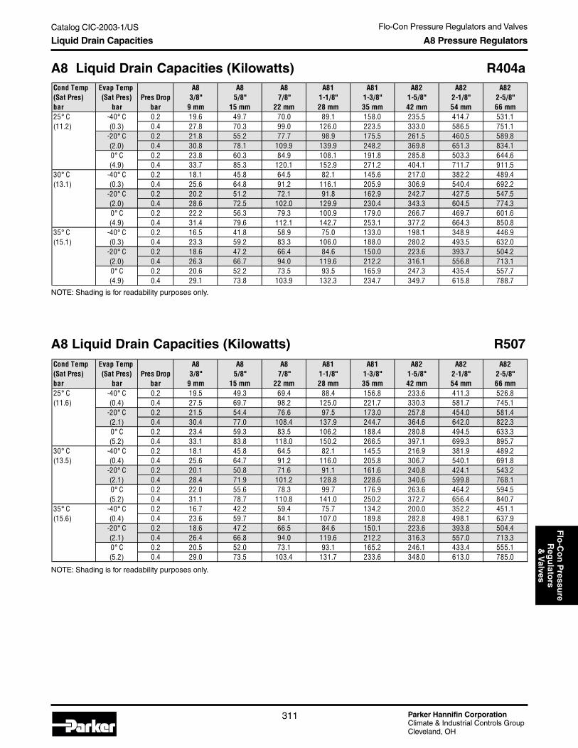
Flo-Con Pressure Regulators and Valves
Parker Hannifin CorporationClimate & Industrial Controls GroupCleveland, OH
311
Catalog CIC-2003-1/USF
lo-C
on
Pressu
reR
egu
lators
& V
alves
NOTE: Shading is for readability purposes only.
Liquid Drain Capacities A8 Pressure Regulators
A8 Liquid Drain Capacities (Kilowatts) R404a
A8 Liquid Drain Capacities (Kilowatts) R507
NOTE: Shading is for readability purposes only.
Cond Temp Evap Temp A8 A8 A8 A81 A81 A82 A82 A82(Sat Pres) (Sat Pres) Pres Drop 3/8" 5/8" 7/8" 1-1/8" 1-3/8" 1-5/8" 2-1/8" 2-5/8"bar bar bar 9 mm 15 mm 22 mm 28 mm 35 mm 42 mm 54 mm 66 mm25° C -40° C 0.2 19.6 49.7 70.0 89.1 158.0 235.5 414.7 531.1(11.2) (0.3) 0.4 27.8 70.3 99.0 126.0 223.5 333.0 586.5 751.1
-20° C 0.2 21.8 55.2 77.7 98.9 175.5 261.5 460.5 589.8(2.0) 0.4 30.8 78.1 109.9 139.9 248.2 369.8 651.3 834.10° C 0.2 23.8 60.3 84.9 108.1 191.8 285.8 503.3 644.6(4.9) 0.4 33.7 85.3 120.1 152.9 271.2 404.1 711.7 911.5
30° C -40° C 0.2 18.1 45.8 64.5 82.1 145.6 217.0 382.2 489.4(13.1) (0.3) 0.4 25.6 64.8 91.2 116.1 205.9 306.9 540.4 692.2
-20° C 0.2 20.2 51.2 72.1 91.8 162.9 242.7 427.5 547.5(2.0) 0.4 28.6 72.5 102.0 129.9 230.4 343.3 604.5 774.30° C 0.2 22.2 56.3 79.3 100.9 179.0 266.7 469.7 601.6(4.9) 0.4 31.4 79.6 112.1 142.7 253.1 377.2 664.3 850.8
35° C -40° C 0.2 16.5 41.8 58.9 75.0 133.0 198.1 348.9 446.9(15.1) (0.3) 0.4 23.3 59.2 83.3 106.0 188.0 280.2 493.5 632.0
-20° C 0.2 18.6 47.2 66.4 84.6 150.0 223.6 393.7 504.2(2.0) 0.4 26.3 66.7 94.0 119.6 212.2 316.1 556.8 713.10° C 0.2 20.6 52.2 73.5 93.5 165.9 247.3 435.4 557.7(4.9) 0.4 29.1 73.8 103.9 132.3 234.7 349.7 615.8 788.7
Cond Temp Evap Temp A8 A8 A8 A81 A81 A82 A82 A82(Sat Pres) (Sat Pres) Pres Drop 3/8" 5/8" 7/8" 1-1/8" 1-3/8" 1-5/8" 2-1/8" 2-5/8"bar bar bar 9 mm 15 mm 22 mm 28 mm 35 mm 42 mm 54 mm 66 mm25° C -40° C 0.2 19.5 49.3 69.4 88.4 156.8 233.6 411.3 526.8(11.6) (0.4) 0.4 27.5 69.7 98.2 125.0 221.7 330.3 581.7 745.1
-20° C 0.2 21.5 54.4 76.6 97.5 173.0 257.8 454.0 581.4(2.1) 0.4 30.4 77.0 108.4 137.9 244.7 364.6 642.0 822.30° C 0.2 23.4 59.3 83.5 106.2 188.4 280.8 494.5 633.3(5.2) 0.4 33.1 83.8 118.0 150.2 266.5 397.1 699.3 895.7
30° C -40° C 0.2 18.1 45.8 64.5 82.1 145.5 216.9 381.9 489.2(13.5) (0.4) 0.4 25.6 64.7 91.2 116.0 205.8 306.7 540.1 691.8
-20° C 0.2 20.1 50.8 71.6 91.1 161.6 240.8 424.1 543.2(2.1) 0.4 28.4 71.9 101.2 128.8 228.6 340.6 599.8 768.10° C 0.2 22.0 55.6 78.3 99.7 176.9 263.6 464.2 594.5(5.2) 0.4 31.1 78.7 110.8 141.0 250.2 372.7 656.4 840.7
35° C -40° C 0.2 16.7 42.2 59.4 75.7 134.2 200.0 352.2 451.1(15.6) (0.4) 0.4 23.6 59.7 84.1 107.0 189.8 282.8 498.1 637.9
-20° C 0.2 18.6 47.2 66.5 84.6 150.1 223.6 393.8 504.4(2.1) 0.4 26.4 66.8 94.0 119.6 212.2 316.3 557.0 713.30° C 0.2 20.5 52.0 73.1 93.1 165.2 246.1 433.4 555.1(5.2) 0.4 29.0 73.5 103.4 131.7 233.6 348.0 613.0 785.0

Parker Hannifin CorporationClimate & Industrial Controls GroupCleveland, OH
Flo-Con Pressure Regulators and Valves
312
Catalog CIC-2003-1/US
Discharge Capacities A8 Pressure Regulators
A8 Discharge Capacities (Tons) R22Cond Temp Evap Temp A8A A8A A8A A81 A81 A82 A82 A82(Sat Pres) (Sat Pres) Discharge Pres Drop 3/8" 5/8" 7/8" 1-1/8" 1-3/8" 1-5/8" 2-1/8" 2-5/8"
psig psig Temp °F psi 9 mm 15 mm 22 mm 28 mm 35 mm 42 mm 54 mm 66 mm75° F -40° F 140° 3 1.5 3.8 5.3 6.8 12.0 17.9 31.4 40.2(132) (0.5) 180° 1.4 3.6 5.1 6.5 11.4 17.1 30.0 38.4
220° 1.4 3.5 4.9 6.2 11.0 16.4 28.8 36.9140° 6 2.1 5.3 7.5 9.6 16.9 25.2 44.3 56.7180° 2.0 5.1 7.2 9.1 16.1 24.1 42.3 54.2220° 1.9 4.9 6.9 8.8 15.5 23.1 40.7 52.0
75° F 0° F 140° 3 1.6 4.0 5.6 7.2 12.7 18.9 33.3 42.6(132) (24.0) 180° 1.5 3.8 5.4 6.8 12.1 18.1 31.8 40.7
220° 1.4 3.7 5.2 6.6 11.6 17.4 30.6 39.1140° 6 2.2 5.6 7.9 10.1 17.9 26.7 47.0 60.1180° 2.1 5.4 7.6 9.7 17.1 25.5 44.9 57.4220° 2.0 5.2 7.3 9.3 16.4 24.5 43.1 55.1
75° F 40° F 140° 3 1.6 4.2 5.9 7.5 13.3 19.9 34.9 44.7(132) (68.5) 180° 1.6 4.0 5.6 7.2 12.7 19.0 33.4 42.7
220° 1.5 3.8 5.4 6.9 12.2 18.2 32.1 41.1140° 6 2.3 5.9 8.3 10.6 18.8 28.1 49.3 63.1180° 2.2 5.6 8.0 10.2 18.0 26.8 47.1 60.3220° 2.1 5.4 7.7 9.8 17.2 25.7 45.3 57.9
95° F -40° F 140° 3 1.6 4.1 5.8 7.4 13.0 19.4 34.2 43.8(182) (0.5) 180° 1.5 3.9 5.5 7.0 12.4 18.4 32.4 41.5
220° 1.5 3.7 5.2 6.7 11.8 17.6 31.0 39.7140° 6 2.3 5.8 8.2 10.4 18.4 27.5 48.3 61.8180° 2.2 5.5 7.7 9.9 17.5 26.1 45.8 58.6220° 2.1 5.2 7.4 9.4 16.7 24.9 43.8 56.1
95° F 0° F 140° 3 1.7 4.4 6.1 7.8 13.9 20.7 36.4 46.6(182) (24.0) 180° 1.6 4.1 5.8 7.4 13.2 19.6 34.5 44.2
220° 1.6 4.0 5.6 7.1 12.6 18.8 33.1 42.3140° 6 2.4 6.2 8.7 11.1 19.6 29.2 51.4 65.8180° 2.3 5.8 8.2 10.5 18.6 27.7 48.8 62.4220° 2.2 5.6 7.9 10.1 17.8 26.5 46.7 59.7
95° F 40° F 140° 3 1.8 4.6 6.5 8.3 14.6 21.8 38.4 49.1(182) (68.5) 180° 1.7 4.4 6.2 7.8 13.9 20.7 36.4 46.6
220° 1.6 4.2 5.9 7.5 13.3 19.8 34.8 44.6140° 6 2.5 6.5 9.2 11.7 20.7 30.8 54.2 69.4180° 2.4 6.2 8.7 11.1 19.6 29.2 51.4 65.8220° 2.3 5.9 8.3 10.6 18.8 28.0 49.2 63.0
115° F -40° F 140° 3 1.7 4.4 6.2 7.9 14.0 20.9 36.8 47.1(243) (0.5) 180° 1.6 4.1 5.8 7.4 13.2 19.6 34.5 44.2
220° 1.5 3.9 5.5 7.1 12.5 18.6 32.8 42.0140° 6 2.4 6.2 8.8 11.2 19.8 29.6 52.0 66.5180° 2.3 5.8 8.2 10.5 18.6 27.7 48.8 62.4220° 2.2 5.6 7.8 10.0 17.7 26.4 46.4 59.3
115° F 0° F 140° 3 1.9 4.7 6.7 8.5 15.0 22.4 39.4 50.5(243) (24.0) 180° 1.7 4.4 6.2 8.0 14.1 21.0 37.0 47.3
220° 1.7 4.2 5.9 7.6 13.4 20.0 35.2 45.0140° 6 2.6 6.7 9.4 12.0 21.2 31.7 55.7 71.3180° 2.5 6.3 8.8 11.3 19.9 29.7 52.3 66.9220° 2.3 5.9 8.4 10.7 18.9 28.2 49.7 63.6
115° F 40° F 140° 3 2.0 5.0 7.1 9.0 15.9 23.7 41.7 53.4(243) (68.5) 180° 1.8 4.7 6.6 8.4 14.9 22.3 39.2 50.2
220° 1.8 4.5 6.3 8.0 14.2 21.2 37.3 47.7140° 6 2.8 7.1 10.0 12.7 22.5 33.6 59.0 75.5180° 2.6 6.6 9.4 11.9 21.1 31.5 55.4 70.9220° 2.5 6.3 8.9 11.3 20.1 29.9 52.6 67.4

Flo-Con Pressure Regulators and Valves
Parker Hannifin CorporationClimate & Industrial Controls GroupCleveland, OH
313
Catalog CIC-2003-1/USF
lo-C
on
Pressu
reR
egu
lators
& V
alvesDischarge Capacities A8 Pressure Regulators
A8 Discharge Capacities (Kilowatts) R22Cond Temp Evap Temp A8A A8A A8A A81 A81 A82 A82 A82(Sat Pres) (Sat Pres) Discharge Pres Drop 3/8" 5/8" 7/8" 1-1/8" 1-3/8" 1-5/8" 2-1/8" 2-5/8"
bar bar Temp °C bar 9 mm 15 mm 22 mm 28 mm 35 mm 42 mm 54 mm 66 mm25° C -40° C 60° 0.2 5.1 13.0 18.4 23.4 41.5 61.9 108.9 139.4(9.2) (0.0) 80° 4.9 12.5 17.6 22.5 39.8 59.4 104.4 133.7
100° 4.7 12.1 17.0 21.7 38.4 57.2 100.7 128.960° 0.4 7.2 18.4 26.0 33.2 58.6 87.5 153.8 196.880° 6.9 17.6 24.9 31.8 56.2 83.9 147.5 188.7
100° 6.7 17.0 24.0 30.6 54.2 80.8 142.1 181.825° C -20° C 60° 0.2 5.4 13.8 19.4 24.7 43.8 65.3 114.8 147.0(9.2) (1.4) 80° 5.2 13.2 18.6 23.7 42.0 62.6 110.1 141.0
100° 5.0 12.7 17.9 22.9 40.5 60.3 106.2 135.960° 0.4 7.6 19.4 27.4 35.0 61.8 92.3 162.2 207.580° 7.3 18.6 26.3 33.5 59.3 88.5 155.5 198.9
100° 7.0 17.9 25.4 32.3 57.1 85.2 149.8 191.725° C 0° C 60° 0.2 5.7 14.4 20.3 25.9 45.8 68.3 120.2 153.9(9.2) (4.0) 80° 5.4 13.8 19.5 24.8 43.9 65.5 115.3 147.6
100° 5.2 13.3 18.8 23.9 42.3 63.1 111.1 142.260° 0.4 8.0 20.3 28.7 36.6 64.7 96.6 169.7 217.280° 7.6 19.5 27.5 35.1 62.0 92.6 162.7 208.2
100° 7.4 18.8 26.5 33.8 59.8 89.2 156.8 200.730° C -40° C 60° 0.2 5.3 13.6 19.1 24.4 43.2 64.3 113.2 145.0(10.9) (0.0) 80° 5.1 13.0 18.3 23.3 41.3 61.6 108.3 138.7
100° 4.9 12.5 17.6 22.4 39.7 59.2 104.2 133.460° 0.4 7.5 19.1 27.1 34.5 61.0 91.0 160.0 204.780° 7.2 18.3 25.9 33.0 58.3 87.0 153.0 195.8
100° 6.9 17.6 24.9 31.7 56.1 83.7 147.2 188.330° C -20° C 60° 0.2 5.6 14.3 20.2 25.7 45.6 68.0 119.6 153.2(10.9) (1.4) 80° 5.4 13.7 19.3 24.6 43.6 65.0 114.4 146.5
100° 5.2 13.2 18.6 23.7 42.0 62.6 110.1 141.060° 0.4 7.9 20.2 28.6 36.4 64.4 96.1 169.0 216.380° 7.6 19.3 27.3 34.8 61.6 91.9 161.6 206.8
100° 7.3 18.6 26.3 33.5 59.3 88.5 155.5 199.030° C 0° C 60° 0.2 5.9 15.0 21.2 27.0 47.8 71.3 125.4 160.6(10.9) (4.0) 80° 5.7 14.4 20.3 25.8 45.7 68.2 120.0 153.6
100° 5.4 13.8 19.5 24.8 44.0 65.6 115.4 147.860° 0.4 8.3 21.2 30.0 38.2 67.5 100.8 177.2 226.780° 8.0 20.3 28.7 36.5 64.6 96.4 169.5 216.8
100° 7.7 19.5 27.6 35.1 62.1 92.7 163.0 208.635° C -40° C 60° 0.2 5.5 14.1 19.8 25.3 44.8 66.7 117.4 150.3(12.6) (0.0) 80° 5.3 13.4 18.9 24.1 42.7 63.6 112.0 143.4
100° 5.1 12.9 18.2 23.1 41.0 61.1 107.5 137.760° 0.4 7.8 19.9 28.1 35.8 63.2 94.3 165.9 212.380° 7.4 18.9 26.7 34.1 60.3 89.9 158.2 202.4
100° 7.1 18.2 25.7 32.7 57.9 86.4 151.8 194.335° C -20° C 60° 0.2 5.9 14.9 21.0 26.8 47.4 70.7 124.4 159.2(12.6) (1.4) 80° 5.6 14.2 20.0 25.5 45.2 67.4 118.6 151.8
100° 5.4 13.6 19.2 24.5 43.4 64.7 113.9 145.860° 0.4 8.3 21.0 29.7 37.9 67.0 99.9 175.7 224.880° 7.9 20.0 28.3 36.1 63.8 95.2 167.5 214.3
100° 7.6 19.2 27.2 34.6 61.3 91.4 160.8 205.835° C 0° C 60° 0.2 6.2 15.6 22.1 28.1 49.8 74.2 130.6 167.2(12.6) (4.0) 80° 5.9 14.9 21.0 26.8 47.5 70.8 124.5 159.4
100° 5.6 14.3 20.2 25.7 45.6 68.0 119.6 153.160° 0.4 8.7 22.1 31.2 39.8 70.3 104.9 184.5 236.180° 8.3 21.1 29.7 37.9 67.0 100.0 175.9 225.1
100° 7.9 20.2 28.6 36.4 64.4 96.0 168.9 216.1

Parker Hannifin CorporationClimate & Industrial Controls GroupCleveland, OH
Flo-Con Pressure Regulators and Valves
314
Catalog CIC-2003-1/US
Discharge Capacities A8 Pressure Regulators
A8 Discharge Capacities (Tons) R134aCond Temp Evap Temp A8A A8A A8A A81 A81 A82 A82 A82(Sat Pres) (Sat Pres) Discharge Pres Drop 3/8" 5/8" 7/8" 1-1/8" 1-3/8" 1-5/8" 2-1/8" 2-5/8"
psig psig Temp °F psi 9 mm 15 mm 22 mm 28 mm 35 mm 42 mm 54 mm 66 mm75° F -40° F 140° 3 1.1 2.9 4.1 5.2 9.2 13.7 24.1 30.8(78.6) (14.7 in. hg) 180° 1.1 2.8 3.9 5.0 8.8 13.1 23.0 29.5
220° 1.0 2.7 3.7 4.8 8.4 12.6 22.2 28.4140° 6 1.6 4.1 5.8 7.3 12.9 19.3 33.9 43.4180° 1.5 3.9 5.5 7.0 12.4 18.5 32.5 41.5220° 1.5 3.7 5.3 6.8 11.9 17.8 31.2 39.9
75° F 0° F 140° 3 1.2 3.2 4.5 5.7 10.0 15.0 26.3 33.7(78.6) (6.5) 180° 1.2 3.0 4.3 5.4 9.6 14.3 25.2 32.2
220° 1.1 2.9 4.1 5.2 9.2 13.8 24.2 31.0140° 6 1.7 4.4 6.3 8.0 14.2 21.2 37.1 47.5180° 1.7 4.2 6.0 7.7 13.5 20.2 35.5 45.4220° 1.6 4.1 5.8 7.4 13.0 19.4 34.1 43.6
75° F 40° F 140° 3 1.3 3.4 4.8 6.1 10.9 16.2 28.5 36.5(78.6) (35.1) 180° 1.3 3.3 4.6 5.9 10.4 15.5 27.3 34.9
220° 1.2 3.1 4.4 5.7 10.0 14.9 26.2 33.6140° 6 1.9 4.8 6.8 8.7 15.3 22.9 40.2 51.4180° 1.8 4.6 6.5 8.3 14.6 21.9 38.4 49.1220° 1.7 4.4 6.3 8.0 14.1 21.0 36.9 47.2
95° F -40° F 140° 3 1.2 3.1 4.4 5.6 9.9 14.8 26.0 33.2(113.8) (14.7 in. hg) 180° 1.2 3.0 4.2 5.3 9.4 14.0 24.7 31.6
220° 1.1 2.8 4.0 5.1 9.0 13.4 23.6 30.3140° 6 1.7 4.4 6.2 7.9 14.0 20.8 36.6 46.8180° 1.6 4.2 5.9 7.5 13.3 19.8 34.8 44.5220° 1.6 4.0 5.6 7.2 12.7 19.0 33.3 42.6
95° F 0° F 140° 3 1.3 3.4 4.8 6.2 10.9 16.3 28.7 36.7(113.8) (6.5) 180° 1.3 3.3 4.6 5.9 10.4 15.5 27.2 34.9
220° 1.2 3.1 4.4 5.6 9.9 14.8 26.1 33.4140° 6 1.9 4.8 6.8 8.7 15.4 23.0 40.4 51.7180° 1.8 4.6 6.5 8.3 14.6 21.9 38.4 49.1220° 1.7 4.4 6.2 7.9 14.0 20.9 36.8 47.1
95° F 40° F 140° 3 1.5 3.7 5.3 6.7 11.9 17.8 31.3 40.0(113.8) (35.1) 180° 1.4 3.6 5.0 6.4 11.3 16.9 29.7 38.0
220° 1.3 3.4 4.8 6.1 10.9 16.2 28.5 36.4140° 6 2.1 5.3 7.5 9.5 16.8 25.1 44.1 56.4180° 2.0 5.0 7.1 9.0 16.0 23.8 41.9 53.6220° 1.9 4.8 6.8 8.7 15.3 22.8 40.1 51.3
115° F -40° F 140° 3 1.3 3.3 4.6 5.9 10.4 15.6 27.4 35.1(158.4) (14.7 in. hg) 180° 1.2 3.1 4.4 5.5 9.8 14.6 25.8 33.0
220° 1.2 2.9 4.1 5.3 9.4 14.0 24.5 31.4140° 6 1.8 4.6 6.6 8.4 14.8 22.0 38.7 49.6180° 1.7 4.4 6.2 7.9 13.9 20.7 36.4 46.6220° 1.6 4.1 5.9 7.5 13.2 19.7 34.7 44.3
115° F 0° F 140° 3 1.4 3.7 5.2 6.6 11.7 17.4 30.7 39.3(158.4) (6.5) 180° 1.4 3.5 4.9 6.2 11.0 16.4 28.8 36.9
220° 1.3 3.3 4.6 5.9 10.5 15.6 27.5 35.2140° 6 2.0 5.2 7.3 9.3 16.5 24.7 43.3 55.5180° 1.9 4.9 6.9 8.8 15.5 23.2 40.7 52.1220° 1.8 4.6 6.6 8.4 14.8 22.1 38.8 49.6
115° F 40° F 140° 3 1.6 4.0 5.7 7.3 12.9 19.2 33.8 43.3(158.4) (6.5) 180° 1.5 3.8 5.4 6.8 12.1 18.1 31.8 40.7
220° 1.4 3.6 5.1 6.5 11.5 17.2 30.3 38.7140° 6 2.2 5.7 8.1 10.3 18.2 27.2 47.8 61.1180° 2.1 5.4 7.6 9.7 17.1 25.5 44.9 57.4220° 2.0 5.1 7.2 9.2 16.3 24.3 42.7 54.7

Flo-Con Pressure Regulators and Valves
Parker Hannifin CorporationClimate & Industrial Controls GroupCleveland, OH
315
Catalog CIC-2003-1/USF
lo-C
on
Pressu
reR
egu
lators
& V
alvesDischarge Capacities A8 Pressure Regulators
A8 Discharge Capacities (Kilowatts) R134aCond Temp Evap Temp A8A A8A A8A A81 A81 A82 A82 A82(Sat Pres) (Sat Pres) Discharge Pres Drop 3/8" 5/8" 7/8" 1-1/8" 1-3/8" 1-5/8" 2-1/8" 2-5/8"
bar bar Temp °C bar 9 mm 15 mm 22 mm 28 mm 35 mm 42 mm 54 mm 66 mm25° C -40° C 60° 0.2 3.9 10.0 14.1 18.0 31.8 47.4 83.4 106.7(5.5) (373 mm hg) 80° 3.8 9.6 13.5 17.2 30.5 45.5 80.0 102.4
100° 3.6 9.2 13.1 16.6 29.4 43.9 77.2 98.860° 0.4 5.5 14.0 19.9 25.4 44.8 66.9 117.4 150.180° 5.3 13.5 19.1 24.4 43.0 64.2 112.7 144.1
100° 5.1 13.0 18.4 23.5 41.4 61.9 108.7 139.025° C -20° C 60° 0.2 4.3 10.8 15.3 19.5 34.5 51.5 90.5 115.8(5.5) (91.4 mm hg) 80° 4.1 10.4 14.7 18.7 33.1 49.4 86.9 111.2
100° 3.9 10.0 14.2 18.1 31.9 47.7 83.8 107.360° 0.4 5.9 15.2 21.6 27.6 48.6 72.6 127.5 163.080° 5.7 14.6 20.7 26.4 46.6 69.7 122.3 156.4
100° 5.5 14.1 20.0 25.5 45.0 67.2 118.0 150.925° C 0° C 60° 0.2 4.6 11.7 16.5 21.0 37.1 55.4 97.4 124.6(5.5) (1.9) 80° 4.4 11.2 15.8 20.2 35.6 53.2 93.5 119.7
100° 4.2 10.8 15.3 19.4 34.4 51.3 90.2 115.560° 0.4 6.4 16.4 23.2 29.7 52.3 78.1 137.2 175.480° 6.1 15.7 22.3 28.5 50.2 75.0 131.7 168.3
100° 5.9 15.2 21.5 27.5 48.4 72.3 127.0 162.430° C -40° C 60° 0.2 4.1 10.3 14.6 18.6 32.9 49.0 86.2 110.4(6.7) (373 mm hg) 80° 3.9 9.9 14.0 17.8 31.5 47.0 82.6 105.7
100° 3.7 9.5 13.5 17.1 30.3 45.2 79.6 101.860° 0.4 5.7 14.5 20.6 26.3 46.4 69.3 121.7 155.680° 5.4 13.9 19.7 25.2 44.4 66.3 116.5 149.0
100° 5.2 13.4 19.0 24.2 42.8 63.9 112.2 143.430° C -20° C 60° 0.2 4.4 11.3 15.9 20.2 35.8 53.4 94.0 120.3(6.7) (91.4 mm hg) 80° 4.2 10.8 15.2 19.4 34.3 51.2 90.0 115.2
100° 4.1 10.4 14.7 18.7 33.0 49.3 86.7 111.060° 0.4 6.2 15.9 22.5 28.6 50.5 75.5 132.6 169.680° 5.9 15.2 21.5 27.4 48.4 72.3 126.9 162.3
100° 5.7 14.6 20.7 26.4 46.6 69.6 122.2 156.330° C 0° C 60° 0.2 4.8 12.2 17.2 21.9 38.7 57.7 101.5 129.9(6.7) (1.9) 80° 4.6 11.6 16.4 20.9 37.0 55.3 97.2 124.4
100° 4.4 11.2 15.8 20.2 35.7 53.2 93.6 119.860° 0.4 6.7 17.1 24.2 30.9 54.6 81.5 143.2 183.180° 6.4 16.4 23.2 29.6 52.2 78.0 137.1 175.3
100° 6.2 15.8 22.4 28.5 50.3 75.1 132.0 168.835° C -40° C 60° 0.2 4.2 10.7 15.0 19.2 33.9 50.6 89.0 113.9(7.8) (373 mm hg) 80° 4.0 10.2 14.4 18.3 32.4 48.3 85.0 108.7
100° 3.8 9.8 13.8 17.6 31.1 46.4 81.7 104.560° 0.4 5.9 15.0 21.2 27.1 47.8 71.4 125.5 160.680° 5.6 14.3 20.3 25.9 45.7 68.2 119.8 153.2
100° 5.4 13.8 19.5 24.9 43.9 65.5 115.1 147.335° C -20° C 60° 0.2 4.6 11.7 16.5 21.0 37.1 55.4 97.4 124.7(7.8) (91.4 mm hg) 80° 4.4 11.1 15.7 20.0 35.4 52.9 93.0 119.0
100° 4.2 10.7 15.1 19.3 34.1 50.8 89.4 114.460° 0.4 6.4 16.4 23.3 29.7 52.4 78.2 137.4 175.880° 6.1 15.7 22.2 28.3 50.0 74.6 131.1 167.7
100° 5.9 15.1 21.3 27.2 48.0 71.7 126.0 161.235° C 0° C 60° 0.2 5.0 12.6 17.8 22.7 40.2 60.0 105.5 135.1(7.8) (1.9) 80° 4.7 12.1 17.0 21.7 38.4 57.3 100.8 129.0
100° 4.6 11.6 16.4 20.9 36.9 55.1 96.9 124.060° 0.4 7.0 17.8 25.2 32.1 56.7 84.7 148.9 190.480° 6.7 17.0 24.1 30.7 54.2 80.9 142.1 181.8
100° 6.4 16.3 23.1 29.5 52.1 77.7 136.6 174.7

Parker Hannifin CorporationClimate & Industrial Controls GroupCleveland, OH
Flo-Con Pressure Regulators and Valves
316
Catalog CIC-2003-1/US
Discharge Capacities A8 Pressure Regulators
A8 Discharge Capacities (Tons) R404Cond Temp Evap Temp A8A A8A A8A A81 A81 A82 A82 A82(Sat Pres) (Sat Pres) Discharge Pres Drop 3/8" 5/8" 7/8" 1-1/8" 1-3/8" 1-5/8" 2-1/8" 2-5/8"
psig psig Temp °F psi 9 mm 15 mm 22 mm 28 mm 35 mm 42 mm 54 mm 66 mm75° F -40° F 140° 3 1.2 3.2 4.5 5.7 10.1 15.1 26.5 33.9(161.2) (2.7) 180° 1.2 3.0 4.3 5.4 9.6 14.3 25.2 32.3
220° 1.1 2.9 4.1 5.2 9.2 13.7 24.1 30.9140° 6 1.8 4.5 6.3 8.1 14.3 21.3 37.5 47.9180° 1.7 4.3 6.0 7.7 13.6 20.2 35.6 45.5220° 1.6 4.1 5.8 7.3 13.0 19.4 34.1 43.6
75° F 0° F 140° 3 1.4 3.6 5.0 6.4 11.3 16.9 29.7 38.0(161.2) (33.5) 180° 1.3 3.4 4.8 6.1 10.8 16.0 28.2 36.1
220° 1.3 3.2 4.6 5.8 10.3 15.4 27.0 34.6140° 6 2.0 5.0 7.1 9.0 16.0 23.9 41.9 53.7180° 1.9 4.8 6.7 8.6 15.2 22.7 39.8 51.0220° 1.8 4.6 6.4 8.2 14.5 21.7 38.1 48.8
75° F 40° F 140° 3 1.5 3.9 5.5 7.0 12.4 18.5 32.6 41.7(161.2) (86.4) 180° 1.5 3.7 5.2 6.7 11.8 17.6 31.0 39.7
220° 1.4 3.6 5.0 6.4 11.3 16.9 29.7 38.0140° 6 2.2 5.5 7.8 9.9 17.6 26.2 46.1 58.9180° 2.1 5.2 7.4 9.4 16.7 24.9 43.8 56.0220° 2.0 5.0 7.1 9.0 16.0 23.8 41.9 53.6
95° F -40° F 140° 3 1.3 3.2 4.6 5.8 10.3 15.3 27.0 34.5(219.4) (2.7) 180° 1.2 3.0 4.3 5.5 9.7 14.4 25.4 32.5
220° 1.1 2.9 4.1 5.2 9.2 13.7 24.1 30.9140° 6 1.8 4.6 6.5 8.2 14.5 21.7 38.2 48.8180° 1.7 4.3 6.1 7.7 13.7 20.4 35.9 45.9220° 1.6 4.1 5.8 7.3 13.0 19.4 34.1 43.6
95° F 0° F 140° 3 1.5 3.7 5.2 6.6 11.7 17.5 30.8 39.4(219.4) (33.5) 180° 1.4 3.5 4.9 6.2 11.0 16.4 28.9 37.1
220° 1.3 3.3 4.7 5.9 10.5 15.6 27.5 35.2140° 6 2.0 5.2 7.4 9.4 16.6 24.7 43.5 55.7180° 1.9 4.9 6.9 8.8 15.6 23.3 40.9 52.4220° 1.8 4.7 6.6 8.4 14.8 22.1 38.9 49.8
95° F 40° F 140° 3 1.6 4.1 5.8 7.4 13.1 19.5 34.3 43.9(219.4) (86.4) 180° 1.5 3.9 5.4 6.9 12.3 18.3 32.2 41.3
220° 1.4 3.7 5.2 6.6 11.7 17.4 30.7 39.2140° 6 2.3 5.8 8.2 10.4 18.5 27.6 48.5 62.0180° 2.1 5.5 7.7 9.8 17.4 25.9 45.6 58.3220° 2.0 5.2 7.3 9.3 16.5 24.6 43.3 55.4
115° F -40° F 140° 3 1.2 3.2 4.5 5.7 10.0 15.0 26.4 33.7(290.4) (2.7) 180° 1.1 2.9 4.1 5.2 9.3 13.8 24.3 31.1
220° 1.1 2.7 3.9 4.9 8.7 13.0 22.9 29.3140° 6 1.8 4.5 6.3 8.0 14.2 21.2 37.3 47.7180° 1.6 4.1 5.8 7.4 13.1 19.5 34.4 44.0220° 1.5 3.9 5.5 7.0 12.3 18.4 32.3 41.4
115° F 0° F 140° 3 1.5 3.7 5.2 6.7 11.8 17.6 30.9 39.6(290.4) (33.5) 180° 1.3 3.4 4.8 6.1 10.9 16.2 28.5 36.5
220° 1.3 3.2 4.5 5.8 10.2 15.3 26.9 34.4140° 6 2.1 5.2 7.4 9.4 16.7 24.9 43.8 56.0180° 1.9 4.8 6.8 8.7 15.4 22.9 40.3 51.6220° 1.8 4.5 6.4 8.2 14.5 21.6 38.0 48.6
115° F 40° F 140° 3 1.7 4.2 5.9 7.6 13.4 20.0 35.1 45.0(290.4) (86.4) 180° 1.5 3.9 5.5 7.0 12.4 18.4 32.4 41.5
220° 1.4 3.7 5.2 6.6 11.6 17.3 30.5 39.1140° 6 2.3 6.0 8.4 10.7 19.0 28.3 49.7 63.7180° 2.2 5.5 7.7 9.9 17.5 26.1 45.8 58.7220° 2.0 5.2 7.3 9.3 16.4 24.5 43.1 55.2

Flo-Con Pressure Regulators and Valves
Parker Hannifin CorporationClimate & Industrial Controls GroupCleveland, OH
317
Catalog CIC-2003-1/USF
lo-C
on
Pressu
reR
egu
lators
& V
alvesDischarge Capacities A8 Pressure Regulators
A8 Discharge Capacities (Kilowatts) R404Cond Temp Evap Temp A8A A8A A8A A81 A81 A82 A82 A82(Sat Pres) (Sat Pres) Discharge Pres Drop 3/8" 5/8" 7/8" 1-1/8" 1-3/8" 1-5/8" 2-1/8" 2-5/8"
bar bar Temp °C bar 9 mm 15 mm 22 mm 28 mm 35 mm 42 mm 54 mm 66 mm25° C -40° C 60° 0.2 4.3 10.9 15.4 19.6 34.7 51.7 91.0 116.5(11.2) (0.3) 80° 4.1 10.4 14.7 18.7 33.1 49.4 86.8 111.2
100° 3.9 10.0 14.1 17.9 31.8 47.4 83.4 106.860° 0.4 6.0 15.4 21.7 27.7 49.0 73.1 128.5 164.580° 5.8 14.7 20.7 26.4 46.7 69.7 122.6 156.9
100° 5.5 14.1 19.9 25.4 44.9 66.9 117.7 150.625° C -20° C 60° 0.2 4.8 12.1 17.1 21.7 38.5 57.4 101.1 129.4(11.2) (2.0) 80° 4.5 11.6 16.3 20.8 36.8 54.8 96.4 123.5
100° 4.4 11.1 15.6 19.9 35.3 52.6 92.6 118.560° 0.4 6.7 17.1 24.1 30.8 54.4 81.2 142.7 182.780° 6.4 16.3 23.0 29.4 51.9 77.4 136.2 174.2
100° 6.1 15.6 22.1 28.2 49.8 74.3 130.7 167.325° C 0° C 60° 0.2 5.2 13.2 18.7 23.8 42.1 62.8 110.4 141.4(11.2) (4.9) 80° 5.0 12.6 17.8 22.7 40.2 59.9 105.4 134.9
100° 4.8 12.1 17.1 21.8 38.6 57.5 101.2 129.560° 0.4 7.3 18.7 26.4 33.6 59.5 88.7 156.0 199.680° 7.0 17.8 25.2 32.1 56.7 84.6 148.8 190.4
100° 6.7 17.1 24.2 30.8 54.4 81.2 142.8 182.830° C -40° C 60° 0.2 4.3 11.0 15.5 19.8 35.0 52.2 91.8 117.5(13.1) (0.3) 80° 4.1 10.5 14.7 18.8 33.3 49.6 87.3 111.7
100° 3.9 10.0 14.1 18.0 31.9 47.5 83.6 107.060° 0.4 6.1 15.5 21.9 28.0 49.4 73.8 129.7 166.080° 5.8 14.8 20.8 26.6 47.0 70.1 123.3 157.8
100° 5.5 14.1 20.0 25.4 45.0 67.1 118.0 151.130° C -20° C 60° 0.2 4.8 12.3 17.3 22.1 39.1 58.4 102.7 131.5(13.1) (2.0) 80° 4.6 11.7 16.5 21.0 37.2 55.5 97.6 125.0
100° 4.4 11.2 15.8 20.1 35.6 53.1 93.5 119.760° 0.4 6.8 17.4 24.5 31.3 55.3 82.5 145.1 185.780° 6.5 16.5 23.3 29.7 52.6 78.4 137.9 176.5
100° 6.2 15.8 22.3 28.5 50.3 75.1 132.0 169.030° C 0° C 60° 0.2 5.3 13.5 19.1 24.3 43.0 64.1 112.9 144.5(13.1) (4.9) 80° 5.1 12.9 18.1 23.1 40.9 61.0 107.3 137.4
100° 4.8 12.3 17.4 22.1 39.2 58.4 102.8 131.560° 0.4 7.5 19.1 27.0 34.4 60.8 90.7 159.5 204.180° 7.1 18.1 25.6 32.7 57.8 86.2 151.5 193.9
100° 6.8 17.4 24.5 31.3 55.3 82.5 145.1 185.735° C -40° C 60° 0.2 4.3 11.0 15.6 19.8 35.1 52.3 92.1 117.9(15.1) (0.3) 80° 4.1 10.4 14.7 18.7 33.2 49.5 87.1 111.5
100° 3.9 10.0 14.0 17.9 31.7 47.3 83.2 106.560° 0.4 6.1 15.6 22.0 28.1 49.6 74.0 130.2 166.780° 5.8 14.7 20.8 26.5 46.9 70.0 123.1 157.6
100° 5.5 14.1 19.9 25.3 44.8 66.8 117.5 150.435° C -20° C 60° 0.2 4.9 12.4 17.5 22.3 39.6 59.0 103.9 133.0(15.1) (2.0) 80° 4.6 11.8 16.6 21.1 37.5 55.8 98.3 125.8
100° 4.4 11.2 15.8 20.2 35.8 53.3 93.8 120.160° 0.4 6.9 17.6 24.8 31.7 56.0 83.5 146.9 188.180° 6.5 16.6 23.5 29.9 52.9 79.0 138.9 177.8
100° 6.2 15.9 22.4 28.6 50.5 75.4 132.6 169.735° C 0° C 60° 0.2 5.4 13.8 19.4 24.7 43.8 65.3 114.9 147.1(15.1) (4.9) 80° 5.1 13.0 18.4 23.4 41.4 61.8 108.7 139.2
100° 4.9 12.4 17.5 22.3 39.6 59.0 103.8 132.960° 0.4 7.6 19.5 27.5 35.0 61.9 92.4 162.5 208.080° 7.2 18.4 26.0 33.1 58.6 87.4 153.7 196.7
100° 6.9 17.6 24.8 31.6 55.9 83.4 146.7 187.7

Parker Hannifin CorporationClimate & Industrial Controls GroupCleveland, OH
Flo-Con Pressure Regulators and Valves
318
Catalog CIC-2003-1/US
Discharge Capacities A8 Pressure Regulators
A8 Discharge Capacities (Tons) R507Cond Temp Evap Temp A8A A8A A8A A81 A81 A82 A82 A82(Sat Pres) (Sat Pres) Discharge Pres Drop 3/8" 5/8" 7/8" 1-1/8" 1-3/8" 1-5/8" 2-1/8" 2-5/8"
psig psig Temp °F psi 9 mm 15 mm 22 mm 28 mm 35 mm 42 mm 54 mm 66 mm75° F -40° F 140° 3 1.3 3.2 4.5 5.8 10.2 15.2 26.8 34.3(167.0) (5.5) 180° 1.2 3.1 4.3 5.5 9.7 14.5 25.5 32.6
220° 1.2 2.9 4.1 5.3 9.3 13.9 24.4 31.2140° 6 1.8 4.5 6.4 8.2 14.4 21.5 37.8 48.4180° 1.7 4.3 6.1 7.8 13.7 20.5 36.0 46.0220° 1.6 4.1 5.8 7.4 13.1 19.6 34.4 44.1
75° F 0° F 140° 3 1.4 3.6 5.0 6.4 11.4 16.9 29.8 38.2(167.0) (35.2) 180° 1.3 3.4 4.8 6.1 10.8 16.1 28.3 36.3
220° 1.3 3.3 4.6 5.8 10.3 15.4 27.1 34.8140° 6 2.0 5.0 7.1 9.1 16.0 23.9 42.1 53.9180° 1.9 4.8 6.8 8.6 15.2 22.8 40.0 51.2220° 1.8 4.6 6.5 8.3 14.6 21.8 38.3 49.0
75° F 40° F 140° 3 1.5 3.9 5.5 7.0 12.4 18.6 32.7 41.8(167.0) (89.8) 180° 1.5 3.7 5.2 6.7 11.8 17.6 31.0 39.7
220° 1.4 3.6 5.0 6.4 11.3 16.9 29.7 38.1140° 6 2.2 5.5 7.8 9.9 17.6 26.2 46.1 59.0180° 2.1 5.2 7.4 9.4 16.7 24.9 43.8 56.1220° 2.0 5.0 7.1 9.0 16.0 23.9 42.0 53.7
95° F -40° F 140° 3 1.3 3.3 4.7 6.0 10.6 15.7 27.7 35.5(226.0) (5.5) 180° 1.2 3.1 4.4 5.6 9.9 14.8 26.1 33.4
220° 1.2 3.0 4.2 5.3 9.5 14.1 24.8 31.8140° 6 1.8 4.7 6.6 8.4 14.9 22.2 39.1 50.1180° 1.7 4.4 6.2 7.9 14.0 20.9 36.8 47.1220° 1.6 4.2 5.9 7.6 13.4 19.9 35.1 44.9
95° F 0° F 140° 3 1.5 3.7 5.3 6.7 11.9 17.8 31.3 40.1(226.0) (35.2) 180° 1.4 3.5 5.0 6.3 11.2 16.7 29.5 37.7
220° 1.3 3.4 4.7 6.0 10.7 15.9 28.1 35.9140° 6 2.1 5.3 7.5 9.5 16.9 25.1 44.2 56.6180° 2.0 5.0 7.0 9.0 15.9 23.7 41.6 53.3220° 1.9 4.7 6.7 8.5 15.1 22.5 39.6 50.7
95° F 40° F 140° 3 1.6 4.2 5.9 7.5 13.2 19.7 34.7 44.4(226.0) (89.8) 180° 1.5 3.9 5.5 7.0 12.4 18.6 32.7 41.8
220° 1.5 3.7 5.3 6.7 11.9 17.7 31.1 39.8140° 6 2.3 5.9 8.3 10.6 18.7 27.9 49.0 62.7180° 2.2 5.5 7.8 9.9 17.6 26.2 46.1 59.0220° 2.1 5.3 7.4 9.5 16.7 25.0 43.9 56.2
115° F -40° F 140° 3 1.3 3.3 4.7 6.0 10.6 15.8 27.8 35.7(301.0) (5.5) 180° 1.2 3.1 4.4 5.5 9.8 14.6 25.8 33.0
220° 1.1 2.9 4.1 5.2 9.3 13.8 24.3 31.1140° 6 1.9 4.7 6.7 8.5 15.0 22.4 39.4 50.4180° 1.7 4.4 6.2 7.8 13.9 20.7 36.4 46.6220° 1.6 4.1 5.8 7.4 13.1 19.5 34.4 44.0
115° F 0° F 140° 3 1.5 3.9 5.4 6.9 12.3 18.3 32.2 41.2(301.0) (35.2) 180° 1.4 3.6 5.0 6.4 11.3 16.9 29.8 38.1
220° 1.3 3.4 4.7 6.0 10.7 16.0 28.1 36.0140° 6 2.1 5.5 7.7 9.8 17.4 25.9 45.6 58.3180° 2.0 5.0 7.1 9.1 16.0 23.9 42.1 53.9220° 1.9 4.8 6.7 8.5 15.1 22.6 39.7 50.8
115° F 40° F 140° 3 1.7 4.3 6.1 7.8 13.8 20.6 36.3 46.5(301.0) (89.8) 180° 1.6 4.0 5.7 7.2 12.8 19.1 33.6 43.0
220° 1.5 3.8 5.3 6.8 12.1 18.0 31.7 40.6140° 6 2.4 6.1 8.7 11.1 19.6 29.2 51.3 65.7180° 2.2 5.7 8.0 10.2 18.1 27.0 47.5 60.7220° 2.1 5.4 7.6 9.6 17.1 25.4 44.8 57.3

Flo-Con Pressure Regulators and Valves
Parker Hannifin CorporationClimate & Industrial Controls GroupCleveland, OH
319
Catalog CIC-2003-1/USF
lo-C
on
Pressu
reR
egu
lators
& V
alvesDischarge Capacities A8 Pressure Regulators
A8 Discharge Capacities (Kilowatts) R507Cond Temp Evap Temp A8A A8A A8A A81 A81 A82 A82 A82(Sat Pres) (Sat Pres) Discharge Pres Drop 3/8" 5/8" 7/8" 1-1/8" 1-3/8" 1-5/8" 2-1/8" 2-5/8"
bar bar Temp °C bar 9 mm 15 mm 22 mm 28 mm 35 mm 42 mm 54 mm 66 mm25° C -40° C 60° 0.2 4.3 11.0 15.6 19.8 35.1 52.3 92.1 117.9(11.6) (0.4) 80° 4.1 10.5 14.9 18.9 33.5 50.0 87.9 112.6
100° 4.0 10.1 14.3 18.2 32.2 48.0 84.5 108.160° 0.4 6.1 15.6 22.0 28.0 49.6 74.0 130.1 166.580° 5.8 14.9 21.0 26.8 47.3 70.6 124.1 158.8
100° 5.6 14.3 20.2 25.7 45.4 67.8 119.3 152.625° C -20° C 60° 0.2 4.8 12.2 17.2 21.9 38.7 57.8 101.6 130.1(11.6) (2.1) 80° 4.6 11.6 16.4 20.9 37.0 55.1 97.0 124.2
100° 4.4 11.2 15.8 20.1 35.5 53.0 93.2 119.460° 0.4 6.7 17.2 24.3 30.9 54.7 81.7 143.6 183.780° 6.4 16.4 23.2 29.5 52.2 77.9 137.0 175.3
100° 6.2 15.8 22.3 28.4 50.2 74.9 131.6 168.425° C 0° C 60° 0.2 5.2 13.3 18.7 23.8 42.2 62.9 110.7 141.7(11.6) (5.2) 80° 5.0 12.7 17.9 22.7 40.3 60.1 105.7 135.3
100° 4.8 12.2 17.2 21.9 38.7 57.7 101.6 130.060° 0.4 7.3 18.7 26.4 33.7 59.6 88.9 156.4 200.180° 7.0 17.9 25.2 32.2 56.9 84.9 149.2 191.0
100° 6.7 17.2 24.2 30.9 54.6 81.5 143.4 183.430° C -40° C 60° 0.2 4.4 11.2 15.8 20.1 35.7 53.2 93.6 119.8(13.5) (0.4) 80° 4.2 10.7 15.0 19.2 33.9 50.6 89.0 114.0
100° 4.0 10.2 14.4 18.4 32.5 48.5 85.3 109.360° 0.4 6.2 15.8 22.4 28.5 50.4 75.2 132.3 169.380° 5.9 15.1 21.3 27.1 47.9 71.5 125.7 160.9
100° 5.7 14.4 20.4 26.0 45.9 68.5 120.5 154.230° C -20° C 60° 0.2 4.9 12.4 17.6 22.4 39.6 59.1 103.9 133.0(13.5) (2.1) 80° 4.7 11.8 16.7 21.3 37.7 56.2 98.8 126.5
100° 4.5 11.4 16.0 20.4 36.1 53.8 94.8 121.360° 0.4 6.9 17.6 24.8 31.6 56.0 83.5 146.9 187.980° 6.6 16.7 23.6 30.1 53.2 79.4 139.6 178.7
100° 6.3 16.0 22.6 28.8 51.0 76.1 133.8 171.330° C 0° C 60° 0.2 5.4 13.6 19.2 24.5 43.3 64.6 113.7 145.6(13.5) (5.2) 80° 5.1 13.0 18.3 23.3 41.2 61.5 108.2 138.5
100° 4.9 12.4 17.5 22.3 39.5 58.9 103.7 132.860° 0.4 7.6 19.2 27.2 34.6 61.3 91.4 160.7 205.780° 7.2 18.3 25.8 32.9 58.2 86.9 152.8 195.6
100° 6.9 17.5 24.8 31.6 55.8 83.3 146.5 187.435° C -40° C 60° 0.2 4.5 11.3 16.0 20.4 36.1 53.8 94.6 121.1(15.6) (0.4) 80° 4.2 10.7 15.1 19.3 34.1 50.9 89.6 114.7
100° 4.0 10.3 14.5 18.4 32.6 48.7 85.6 109.660° 0.4 6.3 16.0 22.6 28.8 51.0 76.0 133.7 171.180° 6.0 15.1 21.4 27.3 48.2 71.9 126.5 161.9
100° 5.7 14.5 20.4 26.0 46.1 68.7 120.9 154.835° C -20° C 60° 0.2 5.0 12.7 17.9 22.8 40.3 60.1 105.8 135.5(15.6) (2.1) 80° 4.7 12.0 16.9 21.5 38.2 56.9 100.2 128.2
100° 4.5 11.5 16.2 20.6 36.5 54.4 95.8 122.660° 0.4 7.0 17.9 25.3 32.2 57.0 85.0 149.5 191.480° 6.7 16.9 23.9 30.5 53.9 80.4 141.5 181.1
100° 6.4 16.2 22.9 29.1 51.5 76.9 135.2 173.135° C 0° C 60° 0.2 5.5 13.9 19.7 25.0 44.4 66.2 116.4 149.1(15.6) (5.2) 80° 5.2 13.2 18.6 23.7 42.0 62.6 110.2 141.1
100° 5.0 12.6 17.8 22.7 40.2 59.9 105.4 134.960° 0.4 7.7 19.7 27.8 35.4 62.7 93.5 164.5 210.680° 7.3 18.6 26.3 33.5 59.3 88.5 155.7 199.3
100° 7.0 17.8 25.2 32.1 56.7 84.6 148.8 190.5

Parker Hannifin CorporationClimate & Industrial Controls GroupCleveland, OH
Flo-Con Pressure Regulators and Valves
320
Catalog CIC-2003-1/US
Discharge Capacities CK4A Check Valves
CK4A Hot Gas Discharge Capacities (Tons) R22Cond Temp Evap Temp(Sat Pres) (Sat Pres) Discharge Pres Drop 1/2" 3/4' 1" 1-1/4" 2" 2-1/2" 3" 4"
psig psig Temp °F psi 13 mm 20 mm 25 mm 32 mm 50 mm 65 mm 75 mm 100 mm75° F -40° F 140° 0.75 1.7 3.5 6.4 9.4 22.8 34.7 55.5 104.0(132) (0.5) 180° 1.6 3.4 6.2 9.0 21.8 33.1 53.0 99.4
220° 1.5 3.2 5.9 8.6 20.9 31.9 51.0 95.6140° 3 3.4 7.0 12.8 18.8 45.4 69.1 110.6 207.4180° 3.2 6.7 12.3 17.9 43.4 66.0 105.7 198.1220° 3.1 6.4 11.8 17.2 41.7 63.5 101.5 190.4
75° F 0° F 140° 0.75 1.8 3.7 6.8 10.0 24.1 36.7 58.8 110.2(132) (24.0) 180° 1.7 3.6 6.5 9.5 23.1 35.1 56.2 105.3
220° 1.6 3.4 6.3 9.2 22.2 33.8 54.0 101.3140° 3 3.6 7.4 13.6 19.9 48.1 73.2 117.2 219.7180° 3.4 7.1 13.0 19.0 46.0 70.0 111.9 209.9220° 3.3 6.8 12.5 18.3 44.2 67.2 107.6 201.7
75° F 40° F 140° 0.75 1.9 3.9 7.2 10.5 25.4 38.6 61.7 115.7(132) (68.5) 180° 1.8 3.7 6.8 10.0 24.2 36.9 59.0 110.6
220° 1.7 3.6 6.6 9.6 23.3 35.4 56.7 106.3140° 3 3.7 7.8 14.3 20.9 50.5 76.9 123.0 230.7180° 3.6 7.5 13.6 19.9 48.3 73.5 117.5 220.4220° 3.4 7.2 13.1 19.2 46.4 70.6 113.0 211.8
95° F -40° F 140° 0.75 1.8 3.8 7.0 10.2 24.8 37.7 60.4 113.2(182) (0.5) 180° 1.7 3.6 6.7 9.7 23.5 35.8 57.3 107.5
220° 1.7 3.5 6.4 9.3 22.5 34.3 54.9 102.9140° 3 3.7 7.6 14.0 20.4 49.5 75.3 120.4 225.8180° 3.5 7.2 13.3 19.4 46.9 71.4 114.3 214.3220° 3.3 6.9 12.7 18.6 44.9 68.4 109.4 205.1
95° F 0° F 140° 0.75 2.0 4.1 7.5 10.9 26.4 40.2 64.3 120.5(182) (24.0) 180° 1.9 3.9 7.1 10.4 25.1 38.1 61.0 114.4
220° 1.8 3.7 6.8 9.9 24.0 36.5 58.4 109.5140° 3 3.9 8.1 14.9 21.8 52.7 80.2 128.3 240.5180° 3.7 7.7 14.1 20.7 50.0 76.1 121.7 228.2220° 3.5 7.4 13.5 19.8 47.8 72.8 116.5 218.4
95° F 40° F 140° 0.75 2.1 4.3 7.9 11.5 27.8 42.4 67.8 127.1(182) (68.5) 180° 2.0 4.1 7.5 10.9 26.4 40.2 64.3 120.6
220° 1.9 3.9 7.1 10.4 25.3 38.5 61.6 115.5140° 3 4.1 8.6 15.7 22.9 55.5 84.5 135.2 253.5180° 3.9 8.1 14.9 21.8 52.7 80.2 128.3 240.6220° 3.7 7.8 14.3 20.8 50.4 76.7 122.8 230.2
115° F -40° F 140° 0.75 2.0 4.1 7.5 11.0 26.7 40.6 64.9 121.7(243) (0.5) 180° 1.9 3.9 7.1 10.3 25.0 38.1 61.0 114.3
220° 1.8 3.7 6.7 9.8 23.8 36.2 58.0 108.7140° 3 3.9 8.2 15.0 22.0 53.3 81.0 129.7 243.1180° 3.7 7.7 14.1 20.6 50.0 76.1 121.7 228.2220° 3.5 7.3 13.4 19.6 47.5 72.3 115.7 216.9
115° F 0° F 140° 0.75 2.1 4.4 8.1 11.8 28.6 43.5 69.6 130.5(243) (24.0) 180° 2.0 4.1 7.6 11.1 26.8 40.8 65.3 122.5
220° 1.9 3.9 7.2 10.5 25.5 38.8 62.1 116.5140° 3 4.2 8.8 16.1 23.6 57.1 86.8 138.9 260.5180° 4.0 8.3 15.1 22.1 53.6 81.5 130.4 244.5220° 3.8 7.9 14.4 21.0 50.9 77.5 124.0 232.5
115° F 40° F 140° 0.75 2.2 4.7 8.6 12.5 30.3 46.1 73.7 138.2(243) (68.5) 180° 2.1 4.4 8.0 11.7 28.4 43.2 69.2 129.7
220° 2.0 4.2 7.6 11.2 27.0 41.1 65.8 123.4140° 3 4.5 9.3 17.1 25.0 60.4 92.0 147.2 276.0180° 4.2 8.8 16.0 23.4 56.7 86.3 138.1 259.0220° 4.0 8.3 15.2 22.3 53.9 82.1 131.3 246.3

Flo-Con Pressure Regulators and Valves
Parker Hannifin CorporationClimate & Industrial Controls GroupCleveland, OH
321
Catalog CIC-2003-1/USF
lo-C
on
Pressu
reR
egu
lators
& V
alvesDischarge Capacities CK4A Check Valves
CK4A Hot Gas Discharge Capacities (Kilowatts) R22Cond Temp Evap Temp(Sat Pres) (Sat Pres) Discharge Pres Drop 1/2" 3/4' 1" 1-1/4" 2" 2-1/2" 3" 4"
bar bar Temp °C bar 13 mm 20 mm 25 mm 32 mm 50 mm 65 mm 75 mm 100 mm25° C -40° C 60° 0.05 5.8 12.2 22.3 32.7 79.1 120.3 192.5 360.9(9.2) (0.0) 80° 5.6 11.7 21.4 31.3 75.8 115.4 184.7 346.2
100° 5.4 11.3 20.7 30.2 73.1 111.3 178.0 333.860° 0.21 11.9 24.9 45.6 66.7 161.4 245.6 392.9 736.780° 11.4 23.9 43.7 63.9 154.8 235.5 376.8 706.5
100° 11.0 23.0 42.2 61.6 149.2 227.0 363.2 681.025° C -20° C 60° 0.05 6.2 12.9 23.6 34.4 83.4 126.9 203.0 380.6(9.2) (1.4) 80° 5.9 12.3 22.6 33.0 80.0 121.7 194.7 365.1
100° 5.7 11.9 21.8 31.8 77.1 117.3 187.7 351.960° 0.21 12.6 26.3 48.1 70.3 170.2 258.9 414.3 776.880° 12.1 25.2 46.1 67.4 163.2 248.3 397.3 745.0
100° 11.6 24.3 44.5 65.0 157.3 239.3 383.0 718.025° C 0° C 60° 0.05 6.4 13.5 24.7 36.0 87.3 132.8 212.5 398.3(9.2) (4.0) 80° 6.2 12.9 23.7 34.6 83.7 127.4 203.8 382.1
100° 6.0 12.5 22.8 33.3 80.7 122.8 196.5 368.460° 0.21 13.2 27.5 50.3 73.6 178.1 271.0 433.6 813.080° 12.6 26.4 48.3 70.5 170.8 259.9 415.8 779.7
100° 12.2 25.4 46.5 68.0 164.6 250.5 400.8 751.530° C -40° C 60° 0.05 6.1 12.7 23.2 33.9 82.2 125.0 200.1 375.1(10.9) (0.0) 80° 5.8 12.1 22.2 32.5 78.6 119.6 191.4 358.9
100° 5.6 11.7 21.4 31.3 75.7 115.1 184.2 345.460° 0.21 12.4 25.9 47.4 69.3 167.8 255.4 408.7 766.280° 11.9 24.8 45.4 66.3 160.6 244.3 390.9 733.0
100° 11.4 23.8 43.7 63.8 154.5 235.1 376.2 705.330° C -20° C 60° 0.05 6.4 13.4 24.5 35.9 86.8 132.1 211.4 396.4(10.9) (1.4) 80° 6.1 12.8 23.5 34.3 83.1 126.4 202.3 379.2
100° 5.9 12.3 22.6 33.0 80.0 121.7 194.7 365.060° 0.21 13.1 27.4 50.1 73.2 177.3 269.9 431.8 809.680° 12.5 26.2 47.9 70.1 169.6 258.1 413.0 774.4
100° 12.1 25.2 46.1 67.4 163.2 248.4 397.4 745.230° C 0° C 60° 0.05 6.7 14.0 25.7 37.6 91.0 138.5 221.6 415.5(10.9) (4.0) 80° 6.4 13.4 24.6 36.0 87.1 132.5 212.0 397.6
100° 6.2 12.9 23.7 34.6 83.8 127.5 204.1 382.660° 0.21 13.7 28.7 52.5 76.8 185.9 282.9 452.6 848.780° 13.1 27.4 50.3 73.5 177.8 270.6 433.0 811.9
100° 12.6 26.4 48.4 70.7 171.1 260.4 416.6 781.235° C -40° C 60° 0.05 6.3 13.1 24.1 35.2 85.2 129.6 207.4 388.9(12.6) (0.0) 80° 6.0 12.5 23.0 33.6 81.3 123.7 197.8 371.0
100° 5.8 12.0 22.1 32.2 78.0 118.8 190.0 356.360° 0.21 12.9 26.9 49.2 71.9 174.1 265.0 424.0 795.080° 12.3 25.6 46.9 68.6 166.1 252.7 404.3 758.1
100° 11.8 24.6 45.1 65.9 159.5 242.7 388.3 728.035° C -20° C 60° 0.05 6.7 13.9 25.5 37.3 90.2 137.3 219.6 411.8(12.6) (1.4) 80° 6.4 13.3 24.3 35.5 86.0 130.9 209.5 392.8
100° 6.1 12.8 23.4 34.1 82.6 125.8 201.2 377.360° 0.21 13.6 28.5 52.1 76.2 184.4 280.6 449.0 841.880° 13.0 27.1 49.7 72.6 175.8 267.6 428.1 802.8
100° 12.5 26.1 47.7 69.7 168.9 257.0 411.1 770.935° C 0° C 60° 0.05 7.0 14.6 26.8 39.1 94.7 144.2 230.7 432.5(12.6) (4.0) 80° 6.7 13.9 25.5 37.3 90.4 137.5 220.0 412.5
100° 6.4 13.4 24.5 35.8 86.8 132.1 211.3 396.260° 0.21 14.3 29.9 54.7 80.0 193.7 294.7 471.5 884.180° 13.6 28.5 52.2 76.3 184.7 281.0 449.6 843.1
100° 13.1 27.4 50.1 73.2 177.3 269.9 431.8 809.6
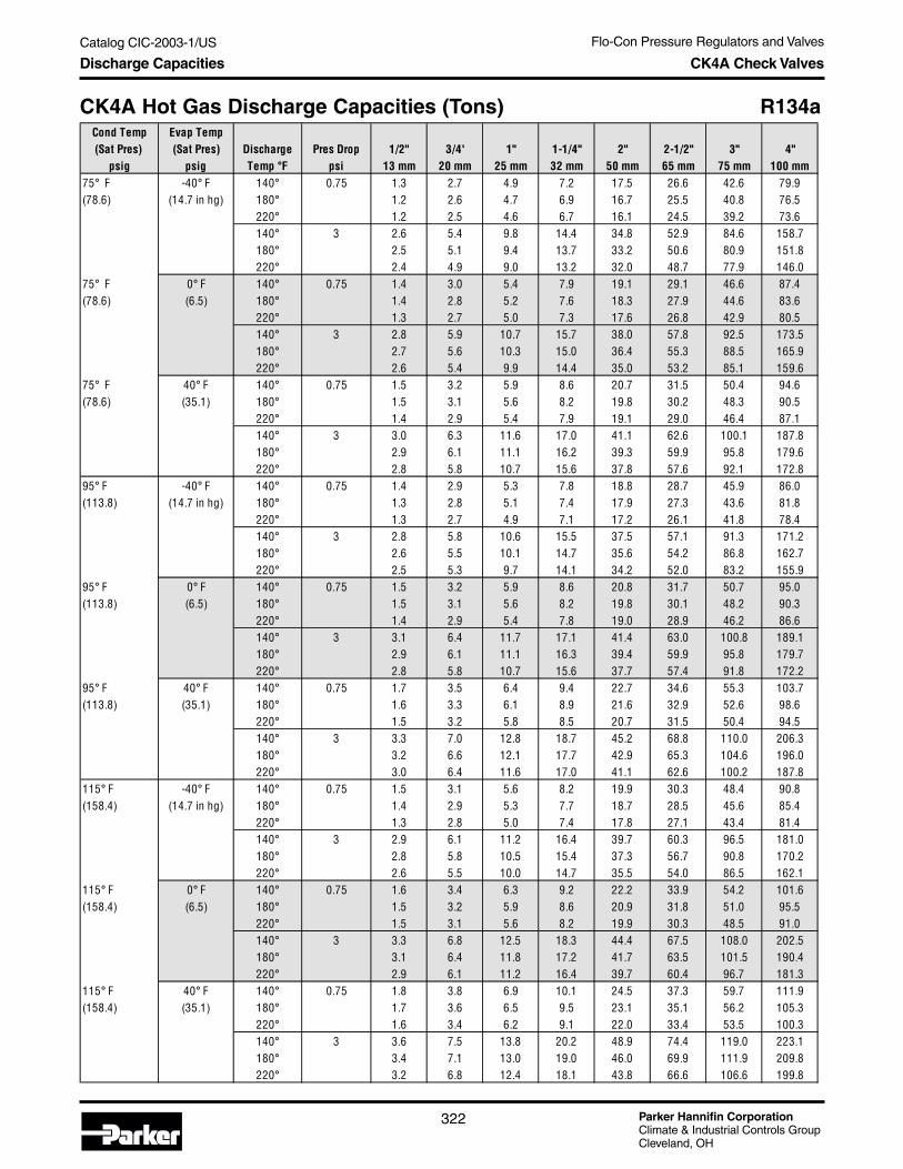
Parker Hannifin CorporationClimate & Industrial Controls GroupCleveland, OH
Flo-Con Pressure Regulators and Valves
322
Catalog CIC-2003-1/US
Discharge Capacities CK4A Check Valves
CK4A Hot Gas Discharge Capacities (Tons) R134aCond Temp Evap Temp(Sat Pres) (Sat Pres) Discharge Pres Drop 1/2" 3/4' 1" 1-1/4" 2" 2-1/2" 3" 4"
psig psig Temp °F psi 13 mm 20 mm 25 mm 32 mm 50 mm 65 mm 75 mm 100 mm75° F -40° F 140° 0.75 1.3 2.7 4.9 7.2 17.5 26.6 42.6 79.9(78.6) (14.7 in hg) 180° 1.2 2.6 4.7 6.9 16.7 25.5 40.8 76.5
220° 1.2 2.5 4.6 6.7 16.1 24.5 39.2 73.6140° 3 2.6 5.4 9.8 14.4 34.8 52.9 84.6 158.7180° 2.5 5.1 9.4 13.7 33.2 50.6 80.9 151.8220° 2.4 4.9 9.0 13.2 32.0 48.7 77.9 146.0
75° F 0° F 140° 0.75 1.4 3.0 5.4 7.9 19.1 29.1 46.6 87.4(78.6) (6.5) 180° 1.4 2.8 5.2 7.6 18.3 27.9 44.6 83.6
220° 1.3 2.7 5.0 7.3 17.6 26.8 42.9 80.5140° 3 2.8 5.9 10.7 15.7 38.0 57.8 92.5 173.5180° 2.7 5.6 10.3 15.0 36.4 55.3 88.5 165.9220° 2.6 5.4 9.9 14.4 35.0 53.2 85.1 159.6
75° F 40° F 140° 0.75 1.5 3.2 5.9 8.6 20.7 31.5 50.4 94.6(78.6) (35.1) 180° 1.5 3.1 5.6 8.2 19.8 30.2 48.3 90.5
220° 1.4 2.9 5.4 7.9 19.1 29.0 46.4 87.1140° 3 3.0 6.3 11.6 17.0 41.1 62.6 100.1 187.8180° 2.9 6.1 11.1 16.2 39.3 59.9 95.8 179.6220° 2.8 5.8 10.7 15.6 37.8 57.6 92.1 172.8
95° F -40° F 140° 0.75 1.4 2.9 5.3 7.8 18.8 28.7 45.9 86.0(113.8) (14.7 in hg) 180° 1.3 2.8 5.1 7.4 17.9 27.3 43.6 81.8
220° 1.3 2.7 4.9 7.1 17.2 26.1 41.8 78.4140° 3 2.8 5.8 10.6 15.5 37.5 57.1 91.3 171.2180° 2.6 5.5 10.1 14.7 35.6 54.2 86.8 162.7220° 2.5 5.3 9.7 14.1 34.2 52.0 83.2 155.9
95° F 0° F 140° 0.75 1.5 3.2 5.9 8.6 20.8 31.7 50.7 95.0(113.8) (6.5) 180° 1.5 3.1 5.6 8.2 19.8 30.1 48.2 90.3
220° 1.4 2.9 5.4 7.8 19.0 28.9 46.2 86.6140° 3 3.1 6.4 11.7 17.1 41.4 63.0 100.8 189.1180° 2.9 6.1 11.1 16.3 39.4 59.9 95.8 179.7220° 2.8 5.8 10.7 15.6 37.7 57.4 91.8 172.2
95° F 40° F 140° 0.75 1.7 3.5 6.4 9.4 22.7 34.6 55.3 103.7(113.8) (35.1) 180° 1.6 3.3 6.1 8.9 21.6 32.9 52.6 98.6
220° 1.5 3.2 5.8 8.5 20.7 31.5 50.4 94.5140° 3 3.3 7.0 12.8 18.7 45.2 68.8 110.0 206.3180° 3.2 6.6 12.1 17.7 42.9 65.3 104.6 196.0220° 3.0 6.4 11.6 17.0 41.1 62.6 100.2 187.8
115° F -40° F 140° 0.75 1.5 3.1 5.6 8.2 19.9 30.3 48.4 90.8(158.4) (14.7 in hg) 180° 1.4 2.9 5.3 7.7 18.7 28.5 45.6 85.4
220° 1.3 2.8 5.0 7.4 17.8 27.1 43.4 81.4140° 3 2.9 6.1 11.2 16.4 39.7 60.3 96.5 181.0180° 2.8 5.8 10.5 15.4 37.3 56.7 90.8 170.2220° 2.6 5.5 10.0 14.7 35.5 54.0 86.5 162.1
115° F 0° F 140° 0.75 1.6 3.4 6.3 9.2 22.2 33.9 54.2 101.6(158.4) (6.5) 180° 1.5 3.2 5.9 8.6 20.9 31.8 51.0 95.5
220° 1.5 3.1 5.6 8.2 19.9 30.3 48.5 91.0140° 3 3.3 6.8 12.5 18.3 44.4 67.5 108.0 202.5180° 3.1 6.4 11.8 17.2 41.7 63.5 101.5 190.4220° 2.9 6.1 11.2 16.4 39.7 60.4 96.7 181.3
115° F 40° F 140° 0.75 1.8 3.8 6.9 10.1 24.5 37.3 59.7 111.9(158.4) (35.1) 180° 1.7 3.6 6.5 9.5 23.1 35.1 56.2 105.3
220° 1.6 3.4 6.2 9.1 22.0 33.4 53.5 100.3140° 3 3.6 7.5 13.8 20.2 48.9 74.4 119.0 223.1180° 3.4 7.1 13.0 19.0 46.0 69.9 111.9 209.8220° 3.2 6.8 12.4 18.1 43.8 66.6 106.6 199.8

Flo-Con Pressure Regulators and Valves
Parker Hannifin CorporationClimate & Industrial Controls GroupCleveland, OH
323
Catalog CIC-2003-1/USF
lo-C
on
Pressu
reR
egu
lators
& V
alvesDischarge Capacities CK4A Check Valves
CK4A Hot Gas Discharge Capacities (Kilowatts) R134aCond Temp Evap Temp(Sat Pres) (Sat Pres) Discharge Pres Drop 1/2" 3/4' 1" 1-1/4" 2" 2-1/2" 3" 4"
bar bar Temp °C bar 13 mm 20 mm 25 mm 32 mm 50 mm 65 mm 75 mm 100 mm25° C -40° C 60° 0.05 4.5 9.3 17.1 25.0 60.6 92.2 147.4 276.5(5.5) (373 mm hg) 80° 4.3 9.0 16.4 24.0 58.2 88.5 141.6 265.5
100° 4.1 8.7 15.9 23.2 56.1 85.4 136.6 256.260° 0.21 9.1 19.0 34.8 50.9 123.2 187.5 300.1 562.680° 8.7 18.3 33.4 48.9 118.3 180.0 288.1 540.1
100° 8.4 17.6 32.3 47.1 114.1 173.7 277.9 521.125° C -20° C 60° 0.05 4.9 10.1 18.6 27.2 65.7 100.0 160.1 300.1(5.5) (91.4 mm hg) 80° 4.7 9.7 17.8 26.1 63.1 96.1 153.7 288.2
100° 4.5 9.4 17.2 25.2 60.9 92.7 148.3 278.160° 0.21 9.9 20.7 37.8 55.3 133.8 203.6 325.8 610.880° 9.5 19.8 36.3 53.1 128.4 195.5 312.7 586.4
100° 9.2 19.1 35.0 51.2 123.9 188.6 301.7 565.725° C 0° C 60° 0.05 5.2 10.9 20.0 29.2 70.8 107.7 172.3 323.0(5.5) (1.9) 80° 5.0 10.5 19.2 28.1 67.9 103.4 165.4 310.2
100° 4.8 10.1 18.5 27.1 65.6 99.8 159.6 299.360° 0.21 10.6 22.2 40.7 59.5 144.0 219.1 350.6 657.480° 10.2 21.3 39.1 57.1 138.2 210.4 336.6 631.1
100° 9.9 20.6 37.7 55.1 133.4 203.0 324.7 608.930° C -40° C 60° 0.05 4.6 9.7 17.7 25.9 62.7 95.3 152.5 286.0(6.7) (373 mm hg) 80° 4.4 9.3 17.0 24.8 60.0 91.3 146.1 274.0
100° 4.3 8.9 16.3 23.9 57.8 88.0 140.8 264.060° 0.21 9.4 19.7 36.1 52.7 127.6 194.2 310.7 582.580° 9.0 18.9 34.5 50.5 122.2 185.9 297.5 557.8
100° 8.7 18.2 33.3 48.6 117.7 179.1 286.6 537.330° C -20° C 60° 0.05 5.0 10.5 19.3 28.2 68.3 103.9 166.3 311.7(6.7) (91.4 mm hg) 80° 4.8 10.1 18.5 27.0 65.4 99.5 159.3 298.6
100° 4.7 9.7 17.8 26.0 63.0 95.9 153.5 287.760° 0.21 10.3 21.5 39.3 57.4 139.1 211.6 338.6 634.880° 9.8 20.6 37.6 55.0 133.2 202.7 324.2 608.0
100° 9.5 19.8 36.3 53.0 128.3 195.2 312.3 585.630° C 0° C 60° 0.05 5.4 11.4 20.8 30.5 73.7 112.2 179.5 336.6(6.7) (1.9) 80° 5.2 10.9 20.0 29.2 70.6 107.5 172.0 322.4
100° 5.0 10.5 19.2 28.1 68.1 103.6 165.7 310.760° 0.21 11.1 23.2 42.4 62.0 150.1 228.5 365.6 685.480° 10.6 22.2 40.6 59.4 143.8 218.8 350.1 656.4
100° 10.2 21.4 39.1 57.2 138.5 210.8 337.2 632.335° C -40° C 60° 0.05 4.8 10.0 18.3 26.7 64.6 98.3 157.3 294.9(7.8) (373 mm hg) 80° 4.6 9.5 17.4 25.5 61.7 93.9 150.3 281.7
100° 4.4 9.2 16.8 24.5 59.3 90.3 144.5 270.960° 0.21 9.7 20.3 37.2 54.4 131.7 200.4 320.7 601.380° 9.3 19.4 35.5 51.9 125.8 191.4 306.2 574.1
100° 8.9 18.7 34.2 49.9 120.9 184.0 294.4 552.035° C -20° C 60° 0.05 5.2 10.9 20.0 29.2 70.7 107.6 172.2 322.9(7.8) (91.4 mm hg) 80° 5.0 10.4 19.1 27.9 67.6 102.8 164.5 308.4
100° 4.8 10.0 18.4 26.8 65.0 98.9 158.2 296.660° 0.21 10.7 22.3 40.7 59.6 144.2 219.4 351.0 658.280° 10.2 21.2 38.9 56.9 137.7 209.5 335.2 628.5
100° 9.8 20.4 37.4 54.7 132.4 201.4 322.3 604.235° C 0° C 60° 0.05 5.7 11.8 21.7 31.7 76.6 116.6 186.6 349.8(7.8) (1.9) 80° 5.4 11.3 20.7 30.2 73.2 111.4 178.2 334.2
100° 5.2 10.9 19.9 29.1 70.4 107.1 171.4 321.360° 0.21 11.5 24.1 44.2 64.5 156.2 237.7 380.4 713.280° 11.0 23.0 42.2 61.6 149.2 227.0 363.2 681.0
100° 10.6 22.1 40.5 59.2 143.4 218.2 349.2 654.7

Parker Hannifin CorporationClimate & Industrial Controls GroupCleveland, OH
Flo-Con Pressure Regulators and Valves
324
Catalog CIC-2003-1/US
Discharge Capacities CK4A Check Valves
CK4A Hot Gas Discharge Capacities (Tons) R404aCond Temp Evap Temp(Sat Pres) (Sat Pres) Discharge Pres Drop 1/2" 3/4' 1" 1-1/4" 2" 2-1/2" 3" 4"
psig psig Temp °F psi 13 mm 20 mm 25 mm 32 mm 50 mm 65 mm 75 mm 100 mm75° F -40° F 140° 0.75 1.4 3.0 5.4 7.9 19.2 29.3 46.8 87.8(161.2) (2.7) 180° 1.4 2.8 5.2 7.6 18.3 27.8 44.5 83.5
220° 1.3 2.7 5.0 7.2 17.5 26.7 42.6 80.0140° 3 2.8 5.9 10.8 15.8 38.4 58.4 93.4 175.1180° 2.7 5.6 10.3 15.1 36.5 55.5 88.8 166.4220° 2.6 5.4 9.9 14.4 34.9 53.1 85.0 159.3
75° F 0° F 140° 0.75 1.6 3.3 6.1 8.9 21.5 32.8 52.5 98.3(161.2) (33.5) 180° 1.5 3.2 5.8 8.5 20.5 31.2 49.9 93.5
220° 1.4 3.0 5.5 8.1 19.6 29.8 47.7 89.5140° 3 3.2 6.6 12.1 17.7 42.9 65.4 104.6 196.1180° 3.0 6.3 11.5 16.9 40.8 62.1 99.4 186.3220° 2.9 6.0 11.0 16.1 39.1 59.5 95.1 178.4
75° F 40° F 140° 0.75 1.7 3.7 6.7 9.8 23.7 36.0 57.6 108.0(161.2) (86.4) 180° 1.7 3.5 6.4 9.3 22.5 34.2 54.8 102.7
220° 1.6 3.3 6.1 8.9 21.5 32.8 52.4 98.3140° 3 3.5 7.3 13.3 19.5 47.2 71.8 114.8 215.3180° 3.3 6.9 12.7 18.5 44.8 68.2 109.2 204.7220° 3.2 6.6 12.1 17.7 42.9 65.3 104.5 195.9
95° F -40° F 140° 0.75 1.4 3.0 5.5 8.1 19.6 29.8 47.6 89.3(219.4) (2.7) 180° 1.4 2.8 5.2 7.6 18.4 28.0 44.8 84.1
220° 1.3 2.7 5.0 7.2 17.5 26.7 42.6 80.0140° 3 2.9 6.0 11.0 16.1 39.1 59.4 95.1 178.3180° 2.7 5.7 10.4 15.2 36.7 55.9 89.5 167.7220° 2.6 5.4 9.9 14.4 34.9 53.2 85.1 159.5
95° F 0° F 140° 0.75 1.6 3.4 6.3 9.2 22.3 34.0 54.3 101.9(219.4) (33.5) 180° 1.6 3.2 5.9 8.7 21.0 32.0 51.1 95.9
220° 1.5 3.1 5.6 8.3 20.0 30.4 48.6 91.2140° 3 3.3 6.9 12.6 18.4 44.5 67.8 108.5 203.4180° 3.1 6.5 11.8 17.3 41.9 63.8 102.0 191.3220° 2.9 6.2 11.3 16.5 39.9 60.7 97.0 182.0
95° F 40° F 140° 0.75 1.8 3.8 7.0 10.3 24.8 37.8 60.5 113.4(219.4) (86.4) 180° 1.7 3.6 6.6 9.7 23.4 35.6 56.9 106.7
220° 1.6 3.4 6.3 9.2 22.2 33.9 54.2 101.6140° 3 3.7 7.7 14.0 20.5 49.6 75.5 120.8 226.4180° 3.4 7.2 13.2 19.3 46.7 71.0 113.6 213.0220° 3.3 6.8 12.5 18.3 44.4 67.5 108.0 202.6
115° F -40° F 140° 0.75 1.4 2.9 5.4 7.9 19.1 29.1 46.5 87.2(290.4) (2.7) 180° 1.3 2.7 5.0 7.3 17.6 26.8 42.9 80.5
220° 1.2 2.6 4.7 6.9 16.6 25.3 40.4 75.8140° 3 2.8 5.9 10.8 15.8 38.2 58.1 92.9 174.2180° 2.6 5.4 10.0 14.5 35.2 53.6 85.7 160.8220° 2.5 5.1 9.4 13.7 33.2 50.5 80.7 151.4
115° F 0° F 140° 0.75 1.7 3.5 6.3 9.3 22.4 34.1 54.6 102.4(290.4) (33.5) 180° 1.5 3.2 5.9 8.6 20.7 31.5 50.4 94.5
220° 1.4 3.0 5.5 8.1 19.5 29.7 47.5 89.0140° 3 3.3 6.9 12.7 18.5 44.8 68.2 109.1 204.5180° 3.1 6.4 11.7 17.1 41.3 62.9 100.6 188.7220° 2.9 6.0 11.0 16.1 38.9 59.2 94.8 177.7
115° F 40° F 140° 0.75 1.9 3.9 7.2 10.5 25.5 38.8 62.0 116.3(290.4) (86.4) 180° 1.7 3.6 6.6 9.7 23.5 35.8 57.3 107.4
220° 1.6 3.4 6.3 9.2 22.2 33.7 53.9 101.2140° 3 3.8 7.9 14.4 21.0 50.9 77.5 123.9 232.4180° 3.5 7.3 13.3 19.4 47.0 71.5 114.4 214.4220° 3.3 6.8 12.5 18.3 44.2 67.3 107.7 201.9

Flo-Con Pressure Regulators and Valves
Parker Hannifin CorporationClimate & Industrial Controls GroupCleveland, OH
325
Catalog CIC-2003-1/USF
lo-C
on
Pressu
reR
egu
lators
& V
alvesDischarge Capacities CK4A Check Valves
CK4A Hot Gas Discharge Capacities (Kilowatts) R404aCond Temp Evap Temp(Sat Pres) (Sat Pres) Discharge Pres Drop 1/2" 3/4' 1" 1-1/4" 2" 2-1/2" 3" 4"
bar bar Temp °C bar 13 mm 20 mm 25 mm 32 mm 50 mm 65 mm 75 mm 100 mm25° C -40° C 60° 0.05 4.9 10.2 18.7 27.3 66.1 100.5 160.9 301.6(11.2) (0.3) 80° 4.7 9.7 17.8 26.0 63.1 96.0 153.5 287.9
100° 4.5 9.3 17.1 25.0 60.6 92.2 147.5 276.560° 0.21 10.0 20.8 38.1 55.7 134.9 205.3 328.5 615.980° 9.5 19.9 36.4 53.2 128.7 195.9 313.4 587.7
100° 9.1 19.1 34.9 51.1 123.6 188.1 300.9 564.325° C -20° C 60° 0.05 5.4 11.3 20.7 30.3 73.4 111.6 178.6 334.9(11.2) (2.0) 80° 5.2 10.8 19.8 28.9 70.0 106.6 170.5 319.7
100° 5.0 10.4 19.0 27.8 67.3 102.3 163.7 307.060° 0.21 11.1 23.1 42.3 61.9 149.8 228.0 364.8 683.980° 10.6 22.1 40.4 59.0 143.0 217.5 348.1 652.6
100° 10.1 21.2 38.8 56.7 137.3 208.9 334.2 626.625° C 0° C 60° 0.05 5.9 12.4 22.7 33.1 80.2 122.0 195.2 366.0(11.2) (4.9) 80° 5.7 11.8 21.6 31.6 76.5 116.5 186.3 349.4
100° 5.4 11.3 20.8 30.4 73.5 111.8 178.9 335.560° 0.21 12.1 25.3 46.3 67.6 163.7 249.1 398.6 747.480° 11.5 24.1 44.2 64.5 156.2 237.7 380.4 713.2
100° 11.1 23.2 42.4 62.0 150.0 228.3 365.2 684.830° C -40° C 60° 0.05 4.9 10.3 18.8 27.5 66.6 101.4 162.2 304.2(13.1) (0.3) 80° 4.7 9.8 17.9 26.2 63.4 96.4 154.3 289.3
100° 4.5 9.4 17.2 25.1 60.7 92.4 147.8 277.160° 0.21 10.1 21.0 38.5 56.2 136.1 207.2 331.5 621.580° 9.6 20.0 36.6 53.5 129.4 197.0 315.1 590.9
100° 9.2 19.1 35.0 51.2 124.0 188.6 301.8 565.930° C -20° C 60° 0.05 5.5 11.5 21.1 30.8 74.5 113.4 181.5 340.2(13.1) (2.0) 80° 5.2 10.9 20.0 29.3 70.9 107.9 172.6 323.6
100° 5.0 10.5 19.2 28.0 67.9 103.3 165.3 310.060° 0.21 11.3 23.5 43.0 62.9 152.3 231.7 370.8 695.280° 10.7 22.3 40.9 59.8 144.8 220.3 352.5 660.9
100° 10.2 21.4 39.2 57.3 138.7 211.0 337.6 633.030° C 0° C 60° 0.05 6.1 12.6 23.1 33.8 81.9 124.6 199.4 373.9(13.1) (4.9) 80° 5.8 12.0 22.0 32.2 77.9 118.5 189.6 355.5
100° 5.5 11.5 21.1 30.8 74.6 113.5 181.7 340.660° 0.21 12.4 25.8 47.3 69.1 167.3 254.7 407.5 764.080° 11.8 24.6 45.0 65.7 159.1 242.1 387.3 726.3
100° 11.3 23.5 43.1 62.9 152.4 231.9 371.0 695.635° C -40° C 60° 0.05 4.9 10.3 18.9 27.6 66.8 101.6 162.6 304.8(15.1) (0.3) 80° 4.7 9.8 17.9 26.1 63.2 96.2 153.9 288.5
100° 4.5 9.3 17.1 24.9 60.3 91.8 146.9 275.560° 0.21 10.1 21.1 38.6 56.4 136.6 207.8 332.5 623.580° 9.6 19.9 36.5 53.4 129.2 196.6 314.6 589.8
100° 9.1 19.0 34.9 51.0 123.4 187.7 300.4 563.235° C -20° C 60° 0.05 5.6 11.6 21.3 31.1 75.3 114.6 183.4 343.9(15.1) (2.0) 80° 5.3 11.0 20.2 29.5 71.3 108.5 173.6 325.5
100° 5.0 10.5 19.2 28.1 68.1 103.6 165.8 310.960° 0.21 11.4 23.8 43.6 63.7 154.1 234.5 375.2 703.580° 10.8 22.5 41.2 60.2 145.8 221.8 354.9 665.5
100° 10.3 21.5 39.3 57.5 139.2 211.8 338.9 635.435° C 0° C 60° 0.05 6.2 12.9 23.6 34.4 83.3 126.8 202.9 380.4(15.1) (4.9) 80° 5.8 12.2 22.3 32.6 78.9 120.0 192.0 360.0
100° 5.6 11.6 21.3 31.1 75.3 114.6 183.4 343.860° 0.21 12.6 26.3 48.2 70.4 170.5 259.4 415.0 778.280° 11.9 24.9 45.6 66.6 161.2 245.4 392.6 736.1
100° 11.4 23.8 43.5 63.6 153.9 234.3 374.8 702.8

Parker Hannifin CorporationClimate & Industrial Controls GroupCleveland, OH
Flo-Con Pressure Regulators and Valves
326
Catalog CIC-2003-1/US
Discharge Capacities CK4A Check Valves
CK4A Hot Gas Discharge Capacities (Tons) R507Cond Temp Evap Temp(Sat Pres) (Sat Pres) Discharge Pres Drop 1/2" 3/4' 1" 1-1/4" 2" 2-1/2" 3" 4"
psig psig Temp °F psi 13 mm 20 mm 25 mm 32 mm 50 mm 65 mm 75 mm 100 mm75° F -40° F 140° 0.75 1.4 3.0 5.5 8.0 19.4 29.6 47.3 88.8(167) (5.5) 180° 1.4 2.9 5.2 7.6 18.5 28.1 45.0 84.4
220° 1.3 2.7 5.0 7.3 17.7 27.0 43.1 80.9140° 3 2.9 6.0 11.0 16.0 38.8 59.0 94.4 176.9180° 2.7 5.7 10.4 15.2 36.8 56.1 89.7 168.2220° 2.6 5.4 10.0 14.6 35.3 53.7 86.0 161.2
75° F 0° F 140° 0.75 1.6 3.3 6.1 8.9 21.6 32.9 52.7 98.8(167) (35.2) 180° 1.5 3.2 5.8 8.5 20.6 31.3 50.1 93.9
220° 1.5 3.0 5.6 8.1 19.7 30.0 48.0 90.0140° 3 3.2 6.7 12.2 17.8 43.1 65.6 105.0 196.9180° 3.0 6.3 11.6 16.9 41.0 62.4 99.8 187.2220° 2.9 6.1 11.1 16.2 39.3 59.8 95.6 179.3
75° F 40° F 140° 0.75 1.8 3.7 6.7 9.8 23.7 36.1 57.7 108.2(167) (87.8) 180° 1.7 3.5 6.4 9.3 22.5 34.3 54.9 102.9
220° 1.6 3.3 6.1 8.9 21.6 32.9 52.6 98.6140° 3 3.5 7.3 13.4 19.5 47.2 71.9 115.0 215.7180° 3.3 6.9 12.7 18.6 44.9 68.3 109.4 205.0220° 3.2 6.6 12.2 17.8 43.0 65.5 104.8 196.4
95° F -40° F 140° 0.75 1.5 3.1 5.7 8.3 20.1 30.6 48.9 91.7(226) (5.5) 180° 1.4 2.9 5.3 7.8 18.9 28.8 46.1 86.4
220° 1.3 2.8 5.1 7.4 18.0 27.4 43.9 82.3140° 3 3.0 6.2 11.3 16.6 40.1 61.0 97.6 183.0180° 2.8 5.8 10.7 15.6 37.7 57.4 91.9 172.3220° 2.7 5.5 10.2 14.9 36.0 54.7 87.5 164.1
95° F 0° F 140° 0.75 1.7 3.5 6.4 9.4 22.7 34.6 55.3 103.7(226) (35.2) 180° 1.6 3.3 6.0 8.8 21.4 32.5 52.1 97.6
220° 1.5 3.1 5.8 8.4 20.4 31.0 49.6 93.0140° 3 3.3 7.0 12.8 18.7 45.3 68.9 110.3 206.8180° 3.2 6.6 12.1 17.6 42.7 64.9 103.9 194.7220° 3.0 6.3 11.5 16.8 40.6 61.8 98.9 185.5
95° F 40° F 140° 0.75 1.9 3.9 7.1 10.4 25.2 38.3 61.3 114.9(226) (87.8) 180° 1.8 3.7 6.7 9.8 23.7 36.1 57.7 108.2
220° 1.7 3.5 6.4 9.3 22.6 34.4 55.0 103.1140° 3 3.7 7.8 14.2 20.7 50.2 76.4 122.3 229.2180° 3.5 7.3 13.4 19.5 47.3 72.0 115.1 215.9220° 3.3 7.0 12.7 18.6 45.0 68.5 109.7 205.6
115° F -40° F 140° 0.75 1.5 3.1 5.7 8.3 20.2 30.7 49.1 92.1(301) (5.5) 180° 1.4 2.9 5.3 7.7 18.7 28.4 45.5 85.3
220° 1.3 2.7 5.0 7.3 17.6 26.8 42.9 80.5140° 3 3.0 6.2 11.4 16.7 40.3 61.4 98.2 184.1180° 2.8 5.8 10.5 15.4 37.3 56.8 90.9 170.3220° 2.6 5.4 10.0 14.5 35.2 53.6 85.7 160.7
115° F 0° F 140° 0.75 1.7 3.6 6.6 9.6 23.3 35.5 56.8 106.5(301) (35.2) 180° 1.6 3.3 6.1 8.9 21.6 32.9 52.6 98.6
220° 1.5 3.1 5.8 8.4 20.4 31.0 49.6 93.1140° 3 3.4 7.2 13.2 19.3 46.6 71.0 113.5 212.9180° 3.2 6.7 12.2 17.8 43.1 65.6 105.0 196.9220° 3.0 6.3 11.5 16.8 40.7 61.9 99.1 185.8
115° F 40° F 140° 0.75 1.9 4.1 7.4 10.9 26.3 40.0 64.0 120.1(301) (89.8) 180° 1.8 3.8 6.9 10.1 24.3 37.0 59.3 111.1
220° 1.7 3.5 6.5 9.5 23.0 35.0 55.9 104.9140° 3 3.9 8.1 14.9 21.7 52.6 80.0 128.0 240.0180° 3.6 7.5 13.7 20.1 48.6 74.0 118.4 222.0220° 3.4 7.1 13.0 19.0 45.9 69.8 111.7 209.4
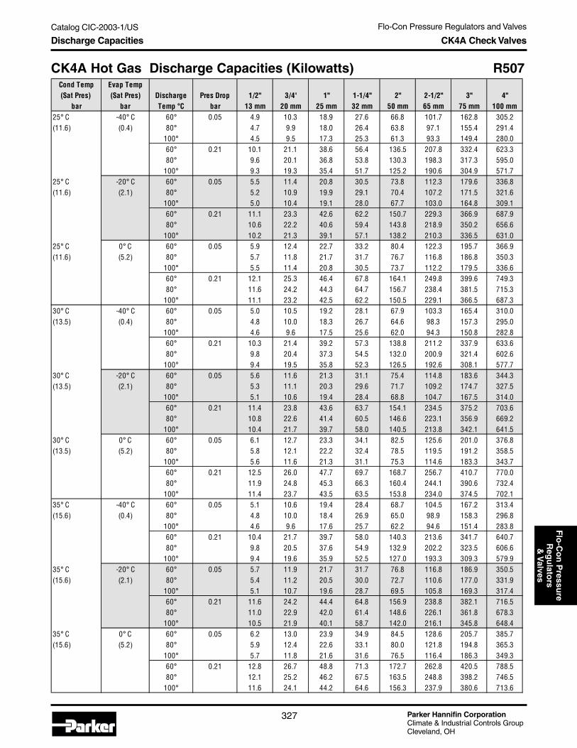
Flo-Con Pressure Regulators and Valves
Parker Hannifin CorporationClimate & Industrial Controls GroupCleveland, OH
327
Catalog CIC-2003-1/USF
lo-C
on
Pressu
reR
egu
lators
& V
alvesDischarge Capacities CK4A Check Valves
CK4A Hot Gas Discharge Capacities (Kilowatts) R507Cond Temp Evap Temp(Sat Pres) (Sat Pres) Discharge Pres Drop 1/2" 3/4' 1" 1-1/4" 2" 2-1/2" 3" 4"
bar bar Temp °C bar 13 mm 20 mm 25 mm 32 mm 50 mm 65 mm 75 mm 100 mm25° C -40° C 60° 0.05 4.9 10.3 18.9 27.6 66.8 101.7 162.8 305.2(11.6) (0.4) 80° 4.7 9.9 18.0 26.4 63.8 97.1 155.4 291.4
100° 4.5 9.5 17.3 25.3 61.3 93.3 149.4 280.060° 0.21 10.1 21.1 38.6 56.4 136.5 207.8 332.4 623.380° 9.6 20.1 36.8 53.8 130.3 198.3 317.3 595.0
100° 9.3 19.3 35.4 51.7 125.2 190.6 304.9 571.725° C -20° C 60° 0.05 5.5 11.4 20.8 30.5 73.8 112.3 179.6 336.8(11.6) (2.1) 80° 5.2 10.9 19.9 29.1 70.4 107.2 171.5 321.6
100° 5.0 10.4 19.1 28.0 67.7 103.0 164.8 309.160° 0.21 11.1 23.3 42.6 62.2 150.7 229.3 366.9 687.980° 10.6 22.2 40.6 59.4 143.8 218.9 350.2 656.6
100° 10.2 21.3 39.1 57.1 138.2 210.3 336.5 631.025° C 0° C 60° 0.05 5.9 12.4 22.7 33.2 80.4 122.3 195.7 366.9(11.6) (5.2) 80° 5.7 11.8 21.7 31.7 76.7 116.8 186.8 350.3
100° 5.5 11.4 20.8 30.5 73.7 112.2 179.5 336.660° 0.21 12.1 25.3 46.4 67.8 164.1 249.8 399.6 749.380° 11.6 24.2 44.3 64.7 156.7 238.4 381.5 715.3
100° 11.1 23.2 42.5 62.2 150.5 229.1 366.5 687.330° C -40° C 60° 0.05 5.0 10.5 19.2 28.1 67.9 103.3 165.4 310.0(13.5) (0.4) 80° 4.8 10.0 18.3 26.7 64.6 98.3 157.3 295.0
100° 4.6 9.6 17.5 25.6 62.0 94.3 150.8 282.860° 0.21 10.3 21.4 39.2 57.3 138.8 211.2 337.9 633.680° 9.8 20.4 37.3 54.5 132.0 200.9 321.4 602.6
100° 9.4 19.5 35.8 52.3 126.5 192.6 308.1 577.730° C -20° C 60° 0.05 5.6 11.6 21.3 31.1 75.4 114.8 183.6 344.3(13.5) (2.1) 80° 5.3 11.1 20.3 29.6 71.7 109.2 174.7 327.5
100° 5.1 10.6 19.4 28.4 68.8 104.7 167.5 314.060° 0.21 11.4 23.8 43.6 63.7 154.1 234.5 375.2 703.680° 10.8 22.6 41.4 60.5 146.6 223.1 356.9 669.2
100° 10.4 21.7 39.7 58.0 140.5 213.8 342.1 641.530° C 0° C 60° 0.05 6.1 12.7 23.3 34.1 82.5 125.6 201.0 376.8(13.5) (5.2) 80° 5.8 12.1 22.2 32.4 78.5 119.5 191.2 358.5
100° 5.6 11.6 21.3 31.1 75.3 114.6 183.3 343.760° 0.21 12.5 26.0 47.7 69.7 168.7 256.7 410.7 770.080° 11.9 24.8 45.3 66.3 160.4 244.1 390.6 732.4
100° 11.4 23.7 43.5 63.5 153.8 234.0 374.5 702.135° C -40° C 60° 0.05 5.1 10.6 19.4 28.4 68.7 104.5 167.2 313.4(15.6) (0.4) 80° 4.8 10.0 18.4 26.9 65.0 98.9 158.3 296.8
100° 4.6 9.6 17.6 25.7 62.2 94.6 151.4 283.860° 0.21 10.4 21.7 39.7 58.0 140.3 213.6 341.7 640.780° 9.8 20.5 37.6 54.9 132.9 202.2 323.5 606.6
100° 9.4 19.6 35.9 52.5 127.0 193.3 309.3 579.935° C -20° C 60° 0.05 5.7 11.9 21.7 31.7 76.8 116.8 186.9 350.5(15.6) (2.1) 80° 5.4 11.2 20.5 30.0 72.7 110.6 177.0 331.9
100° 5.1 10.7 19.6 28.7 69.5 105.8 169.3 317.460° 0.21 11.6 24.2 44.4 64.8 156.9 238.8 382.1 716.580° 11.0 22.9 42.0 61.4 148.6 226.1 361.8 678.3
100° 10.5 21.9 40.1 58.7 142.0 216.1 345.8 648.435° C 0° C 60° 0.05 6.2 13.0 23.9 34.9 84.5 128.6 205.7 385.7(15.6) (5.2) 80° 5.9 12.4 22.6 33.1 80.0 121.8 194.8 365.3
100° 5.7 11.8 21.6 31.6 76.5 116.4 186.3 349.360° 0.21 12.8 26.7 48.8 71.3 172.7 262.8 420.5 788.580° 12.1 25.2 46.2 67.5 163.5 248.8 398.2 746.5
100° 11.6 24.1 44.2 64.6 156.3 237.9 380.6 713.6

Parker Hannifin CorporationClimate & Industrial Controls GroupCleveland, OH
Flo-Con Pressure Regulators and Valves
328
Catalog CIC-2003-1/US
Condensor Bypass Capacities A8 and A9 Pressure Regulators
A9 and A8_0 Condenser Bypass Capacities (Tons) R22Cond Temp Ev. Temp Pres A9 A9 A9 A9 A8AOE A8AOE A8AOE A81OE A81OE A82OE A82OE(Sat pres) (Sat Pres) Discharge Drop 3/8" 5/8" 7/8" 1-1/8" 3/8" 5/8" 7/8" 1-1/8" 1-3/8" 1-5/8" 2-1/8"
psig psig Temp °F psi 9 mm 15 mm 22 mm 28 mm 9 mm 15 mm 22 mm 28 mm 35 mm 42 mm 54 mm75° F -40° F 140° 10 3.5 9.9 28.1 39.8 14.4 36.9 52.4 66.9 117.8 176.0 308.9(132) (5.5) 180° 3.6 10.1 28.7 40.6 14.8 38.0 54.0 68.9 121.4 181.4 318.4
220° 3.7 10.3 29.3 41.5 15.1 38.9 55.2 70.4 124.1 185.5 325.5140° 15 4.3 12.3 35.0 49.9 17.9 46.2 65.8 84.1 147.6 221.1 387.3180° 4.4 12.5 35.7 50.9 18.4 47.6 67.8 86.7 152.2 227.9 399.2220° 4.5 12.8 36.5 52.0 18.8 48.7 69.3 88.7 155.6 233.0 408.1
75° F 0° F 140° 10 3.7 10.5 29.8 42.2 15.3 39.2 55.6 70.9 124.9 186.8 327.7(132) (35.2) 180° 3.8 10.7 30.4 43.1 15.7 40.4 57.3 73.1 128.7 192.5 337.8
220° 3.9 10.9 31.1 44.0 16.1 41.3 58.5 74.7 131.6 196.8 345.3140° 15 4.6 13.0 37.1 53.0 18.9 49.0 69.8 89.2 156.5 234.4 410.6180° 4.7 13.3 37.8 54.0 19.5 50.5 71.9 91.9 161.3 241.6 423.2220° 4.8 13.6 38.7 55.2 20.0 51.6 73.5 94.0 164.9 247.0 432.6
75° F 40° F 140° 10 3.9 11.0 31.4 44.4 16.0 41.1 58.4 74.5 131.3 196.3 344.4(132) (87.8) 180° 4.0 11.2 32.0 45.3 16.5 42.4 60.2 76.8 135.3 202.3 355.0
220° 4.1 11.5 32.7 46.2 16.9 43.4 61.5 78.5 138.3 206.8 362.9140° 15 4.8 13.7 39.0 55.6 19.9 51.4 73.3 93.7 164.4 246.3 431.3180° 4.9 13.9 39.8 56.7 20.5 53.0 75.6 96.6 169.5 253.8 444.6220° 5.0 14.2 40.6 58.0 21.0 54.2 77.2 98.7 173.3 259.5 454.5
95° F -40° F 140° 10 2.9 8.1 23.0 32.4 11.7 30.0 42.5 54.3 95.8 143.0 251.2(182) (5.5) 180° 2.9 8.2 23.4 32.9 12.1 30.9 43.7 55.8 98.5 147.1 258.3
220° 3.0 8.4 23.9 33.6 12.3 31.5 44.7 57.0 100.6 150.2 263.8140° 15 3.5 9.9 28.4 40.2 14.5 37.3 53.0 67.6 119.0 178.0 312.1180° 3.6 10.1 28.9 41.0 14.9 38.3 54.4 69.5 122.4 183.0 321.0220° 3.7 10.3 29.5 41.8 15.2 39.2 55.6 71.0 125.0 186.9 327.9
95° F 0° F 140° 10 3.1 8.6 24.5 34.5 12.5 32.0 45.4 57.9 102.2 152.6 268.0(182) (35.2) 180° 3.1 8.8 24.9 35.1 12.9 32.9 46.7 59.5 105.0 156.9 275.5
220° 3.2 8.9 25.5 35.9 13.2 33.7 47.7 60.8 107.3 160.2 281.5140° 15 3.8 10.6 30.2 42.9 15.4 39.7 56.5 72.1 126.9 189.7 332.8180° 3.8 10.8 30.8 43.7 15.9 40.9 58.1 74.1 130.4 195.1 342.2220° 3.9 11.0 31.4 44.6 16.2 41.7 59.3 75.7 133.3 199.3 349.6
95° F 40° F 140° 10 3.2 9.1 25.9 36.4 13.2 33.8 47.9 61.1 107.8 161.1 282.9(182) (87.8) 180° 3.3 9.2 26.3 37.1 13.6 34.8 49.3 62.8 110.9 165.6 290.9
220° 3.4 9.4 26.9 37.9 13.9 35.5 50.3 64.2 113.2 169.1 297.1140° 15 4.0 11.2 31.9 45.3 16.3 41.9 59.6 76.1 133.8 200.2 351.1180° 4.1 11.4 32.5 46.1 16.8 43.1 61.3 78.2 137.6 205.9 361.1220° 4.1 11.6 33.2 47.0 17.1 44.0 62.6 79.9 140.6 210.3 368.8
115° F -40° F 140° 10 2.4 6.8 19.3 27.1 9.9 25.2 35.7 45.5 80.3 119.9 210.7(243) (5.5) 180° 2.5 6.9 19.6 27.5 10.1 25.8 36.5 46.5 82.2 122.7 215.7
220° 2.5 7.0 20.0 28.1 10.3 26.3 37.2 47.5 83.9 125.2 220.0140° 15 3.0 8.4 23.8 33.6 12.2 31.2 44.2 56.4 99.4 148.5 260.8180° 3.0 8.5 24.1 34.1 12.5 31.9 45.2 57.7 101.8 152.1 267.0220° 3.1 8.6 24.6 34.7 12.7 32.6 46.2 58.9 103.8 155.1 272.4
115° F 0° F 140° 10 2.6 7.3 20.7 29.2 10.6 27.1 38.3 48.8 86.3 128.8 226.3(243) (35.2) 180° 2.6 7.4 21.0 29.6 10.9 27.7 39.2 50.0 88.3 131.8 231.7
220° 2.7 7.5 21.4 30.1 11.1 28.3 40.0 51.0 90.1 134.5 236.3140° 15 3.2 9.0 25.5 36.1 13.1 33.5 47.4 60.5 106.7 159.5 279.9180° 3.2 9.1 25.9 36.6 13.4 34.3 48.6 62.0 109.3 163.3 286.6220° 3.3 9.3 26.4 37.3 13.6 35.0 49.5 63.2 111.5 166.6 292.4
115° F 40° F 140° 10 2.8 7.7 22.0 30.9 11.3 28.7 40.6 51.8 91.6 136.7 240.2(243) (87.8) 180° 2.8 7.8 22.3 31.4 11.5 29.4 41.6 53.0 93.7 139.9 245.9
220° 2.9 8.0 22.8 32.0 11.8 30.0 42.4 54.1 95.6 142.7 250.8140° 15 3.4 9.5 27.1 38.3 13.8 35.5 50.3 64.2 113.2 169.2 297.0180° 3.4 9.7 27.5 38.8 14.2 36.3 51.5 65.7 115.9 173.2 304.1220° 3.5 9.8 28.0 39.6 14.5 37.1 52.6 67.1 118.2 176.7 310.2

Flo-Con Pressure Regulators and Valves
Parker Hannifin CorporationClimate & Industrial Controls GroupCleveland, OH
329
Catalog CIC-2003-1/USF
lo-C
on
Pressu
reR
egu
lators
& V
alvesCondensor Bypass Capacities A8 and A9 Pressure Regulators
A9 and A8_0 Condenser Bypass Capacities (Kilowatts) R22Cond Temp Ev. Temp Pres A9 A9 A9 A9 A8AOE A8AOE A8AOE A81OE A81OE A82OE A82OE(Sat Pres) (Sat Pres) Discharge Drop 3/8" 5/8" 7/8" 1-1/8" 3/8" 5/8" 7/8" 1-1/8" 1-3/8" 1-5/8" 2-1/8"
bar bar Temp °C psi 9 mm 15 mm 22 mm 28 mm 9 mm 15 mm 22 mm 28 mm 35 mm 42 mm 54 mm25° C -40° C 60° 0.7 12.9 36.1 103.0 145.7 52.6 135.1 191.7 244.7 431.1 644.4 1130.8(9.2) (0.4) 80° 13.1 36.8 104.9 148.4 53.6 137.6 195.2 249.2 438.9 656.2 1151.5
100° 13.4 37.5 107.0 151.3 54.7 140.3 199.1 254.1 447.6 669.1 1174.360° 1 15.5 43.8 124.9 178.0 63.8 164.7 234.5 299.8 526.4 788.0 1380.780° 15.8 44.6 127.2 181.3 65.0 167.7 238.9 305.3 536.0 802.5 1406.1
100° 16.1 45.5 129.8 184.9 66.2 171.1 243.6 311.3 546.7 818.4 1434.025° C -20° C 60° 0.7 13.6 38.1 108.7 153.8 55.6 142.6 202.3 258.3 455.0 680.1 1193.5(9.2) (2.1) 80° 13.8 38.8 110.7 156.6 56.6 145.2 206.0 263.0 463.3 692.5 1215.4
100° 14.1 39.6 112.9 159.7 57.7 148.1 210.1 268.2 472.4 706.2 1239.460° 1 16.4 46.2 131.8 187.8 67.3 173.8 247.4 316.2 555.3 831.3 1456.680° 16.7 47.1 134.2 191.3 68.5 177.0 252.0 322.0 565.5 846.6 1483.4
100° 17.0 48.0 136.9 195.1 69.9 180.5 257.0 328.4 576.7 863.4 1512.825° C 0° C 60° 0.7 14.2 40.0 113.9 161.1 58.2 149.4 211.9 270.5 476.5 712.3 1250.1(9.2) (5.2) 80° 14.5 40.7 116.0 164.0 59.3 152.1 215.8 275.5 485.2 725.4 1273.0
100° 14.8 41.5 118.3 167.3 60.4 155.1 220.1 280.9 494.8 739.7 1298.260° 1 17.2 48.4 138.0 196.7 70.4 181.9 259.1 331.1 581.4 870.4 1525.180° 17.5 49.3 140.6 200.3 71.7 185.3 263.8 337.2 592.1 886.4 1553.1
100° 17.8 50.2 143.3 204.2 73.2 189.0 269.1 343.9 603.8 904.0 1583.930° C -40° C 60° 0.7 11.6 32.6 92.9 131.1 47.5 121.6 172.4 220.0 387.9 579.7 1017.7(10.9) (0.4) 80° 11.8 33.2 94.5 133.4 48.3 123.8 175.5 223.9 394.8 589.9 1035.7
100° 12.1 33.8 96.4 136.0 49.2 126.2 178.9 228.2 402.4 601.3 1055.860° 1 14.0 39.4 112.2 159.4 57.3 147.6 209.9 268.2 471.5 705.4 1236.880° 14.2 40.1 114.2 162.3 58.3 150.3 213.6 272.9 479.9 717.9 1258.8
100° 14.5 40.8 116.5 165.4 59.5 153.2 217.8 278.2 489.2 731.9 1283.230° C -20° C 60° 0.7 12.3 34.5 98.2 138.7 50.2 128.7 182.4 232.7 410.3 613.1 1076.5(10.9) (2.1) 80° 12.5 35.1 100.0 141.2 51.1 130.9 185.6 236.8 417.6 623.9 1095.5
100° 12.8 35.8 101.9 143.9 52.1 133.5 189.2 241.4 425.7 636.1 1116.760° 1 14.8 41.6 118.7 168.6 60.6 156.1 222.0 283.5 498.5 745.9 1307.780° 15.1 42.3 120.8 171.6 61.7 158.9 225.9 288.5 507.3 759.1 1330.9
100° 15.3 43.2 123.1 174.9 62.9 162.0 230.3 294.1 517.2 773.8 1356.830° C 0° C 60° 0.7 12.9 36.2 103.1 145.5 52.7 135.0 191.4 244.2 430.5 643.3 1129.5(10.9) (5.2) 80° 13.1 36.8 104.9 148.1 53.6 137.4 194.8 248.5 438.1 654.7 1149.5
100° 13.4 37.5 107.0 151.0 54.7 140.1 198.5 253.3 446.6 667.4 1171.860° 1 15.5 43.6 124.5 176.8 63.6 163.7 232.8 297.4 522.9 782.3 1371.680° 15.8 44.4 126.7 180.0 64.7 166.6 236.9 302.6 532.2 796.2 1395.9
100° 16.1 45.3 129.1 183.5 66.0 169.9 241.5 308.5 542.5 811.7 1423.135° C -40° C 60° 0.7 10.6 29.7 84.6 119.3 43.3 110.7 156.8 200.0 352.9 527.2 925.9(12.6) (0.4) 80° 10.8 30.2 86.1 121.3 44.0 112.6 159.4 203.4 358.9 536.0 941.5
100° 11.0 30.8 87.7 123.6 44.8 114.7 162.5 207.2 365.6 546.2 959.360° 1 12.7 35.8 102.0 144.6 52.1 134.0 190.3 243.0 427.6 639.5 1121.880° 13.0 36.4 103.8 147.0 53.0 136.2 193.5 247.1 434.9 650.3 1140.8
100° 13.2 37.1 105.7 149.8 54.0 138.8 197.2 251.7 443.1 662.6 1162.435° C -20° C 60° 0.7 11.2 31.5 89.7 126.5 45.9 117.4 166.3 212.1 374.2 559.0 981.8(12.6) (2.1) 80° 11.4 32.0 91.3 128.6 46.6 119.4 169.1 215.7 380.5 568.4 998.3
100° 11.7 32.6 93.0 131.0 47.5 121.6 172.3 219.7 387.7 579.1 1017.160° 1 13.5 37.9 108.1 153.2 55.2 142.0 201.7 257.5 453.2 677.8 1188.980° 13.7 38.6 110.0 155.8 56.2 144.4 205.1 261.8 460.9 689.2 1209.0
100° 14.0 39.3 112.1 158.8 57.2 147.1 209.0 266.8 469.6 702.3 1232.035° C 0° C 60° 0.7 11.8 33.1 94.3 133.0 48.2 123.4 174.8 223.0 393.4 587.7 1032.2(12.6) (5.2) 80° 12.0 33.7 95.9 135.2 49.0 125.5 177.7 226.7 400.0 597.5 1049.5
100° 12.2 34.3 97.8 137.8 50.0 127.9 181.1 231.0 407.6 608.8 1069.360° 1 14.2 39.9 113.6 161.1 58.0 149.2 211.9 270.6 476.3 712.3 1249.580° 14.4 40.5 115.6 163.8 59.0 151.8 215.5 275.2 484.4 724.3 1270.6
100° 14.7 41.3 117.8 166.9 60.2 154.6 219.6 280.4 493.5 738.0 1294.7

Parker Hannifin CorporationClimate & Industrial Controls GroupCleveland, OH
Flo-Con Pressure Regulators and Valves
330
Catalog CIC-2003-1/US
Condensor Bypass Capacities A8 and A9 Pressure Regulators
A9 and A8_0 Condenser Bypass Capacities (Tons) R134aCond Temp Ev. Temp Pres A9 A9 A9 A9 A8AOE A8AOE A8AOE A81OE A81OE A82OE A82OE(Sat pres) (Sat Pres) Discharge Drop 3/8" 5/8" 7/8" 1-1/8" 3/8" 5/8" 7/8" 1-1/8" 1-3/8" 1-5/8" 2-1/8"
psig psig Temp °F psi 9 mm 15 mm 22 mm 28 mm 9 mm 15 mm 22 mm 28 mm 35 mm 42 mm 54 mm75° F -40° F 140° 10 2.4 6.9 19.6 28.0 10.0 25.9 36.9 47.2 82.8 124.0 217.1(78.6) (5.5) 180° 2.5 7.1 20.3 29.1 10.6 27.4 39.0 49.9 87.5 131.1 229.5
220° 2.6 7.4 21.1 30.2 11.0 28.4 40.5 51.8 90.8 136.1 238.3140° 15 3.0 8.6 24.5 35.6 12.5 32.7 47.0 60.3 105.1 157.9 275.5180° 3.1 8.9 25.4 36.9 13.2 34.6 49.7 63.8 111.1 166.9 291.2220° 3.2 9.2 26.4 38.3 13.7 35.9 51.6 66.2 115.3 173.2 302.3
75° F 0° F 140° 10 2.7 7.5 21.4 30.7 10.9 28.3 40.4 51.7 90.7 135.8 237.8(78.6) (35.2) 180° 2.8 7.8 22.2 31.8 11.6 30.0 42.7 54.7 95.8 143.6 251.4
220° 2.9 8.1 23.1 33.0 12.0 31.1 44.4 56.8 99.5 149.1 260.9140° 15 3.3 9.4 26.8 38.9 13.6 35.8 51.4 66.0 114.9 172.6 301.2180° 3.4 9.7 27.8 40.4 14.4 37.8 54.4 69.7 121.4 182.5 318.4220° 3.5 10.1 28.8 41.9 15.0 39.3 56.4 72.4 126.0 189.4 330.5
75° F 40° F 140° 10 2.9 8.1 23.2 33.2 11.9 30.7 43.8 56.0 98.2 147.2 257.7(78.6) (87.8) 180° 3.0 8.4 24.1 34.5 12.5 32.5 46.3 59.2 103.8 155.6 272.4
220° 3.1 8.8 25.0 35.8 13.0 33.7 48.1 61.5 107.8 161.5 282.7140° 15 3.6 10.1 29.0 42.1 14.7 38.7 55.7 71.4 124.3 186.8 325.9180° 3.7 10.5 30.1 43.7 15.6 40.9 58.8 75.5 131.4 197.5 344.5220° 3.8 10.9 31.2 45.3 16.2 42.5 61.1 78.3 136.4 205.0 357.6
95° F -40° F 140° 10 2.0 5.5 15.8 22.4 8.0 20.7 29.5 37.6 66.2 99.0 173.6(113.8) (5.5) 180° 2.0 5.7 16.3 23.2 8.5 21.9 31.1 39.7 69.8 104.4 183.1
220° 2.1 5.9 16.9 24.0 8.8 22.7 32.2 41.2 72.4 108.3 189.9140° 15 2.4 6.8 19.5 28.0 10.0 25.9 36.9 47.3 82.8 124.1 217.1180° 2.5 7.1 20.2 29.0 10.5 27.3 39.0 49.9 87.3 130.9 229.0220° 2.6 7.3 21.0 30.1 10.9 28.3 40.4 51.7 90.6 135.8 237.5
95° F 0° F 140° 10 2.2 6.1 17.5 24.8 8.9 22.9 32.6 41.7 73.3 109.6 192.2(113.8) (35.2) 180° 2.3 6.3 18.1 25.7 9.4 24.2 34.4 43.9 77.3 115.6 202.7
220° 2.3 6.6 18.7 26.6 9.8 25.1 35.7 45.6 80.2 119.9 210.3140° 15 2.7 7.6 21.6 31.0 11.0 28.6 40.8 52.3 91.5 137.2 240.0180° 2.8 7.8 22.4 32.1 11.6 30.2 43.1 55.1 96.5 144.7 253.2220° 2.9 8.1 23.2 33.3 12.0 31.3 44.7 57.2 100.1 150.1 262.6
95° F 40° F 140° 10 2.4 6.7 19.1 27.1 9.7 25.1 35.7 45.5 80.1 119.8 210.1(113.8) (87.8) 180° 2.5 6.9 19.8 28.1 10.3 26.5 37.6 48.0 84.5 126.4 221.6
220° 2.6 7.2 20.5 29.1 10.7 27.4 39.0 49.8 87.6 131.1 229.9140° 15 2.9 8.3 23.6 33.8 12.0 31.2 44.6 57.1 99.9 149.8 262.0180° 3.0 8.5 24.4 35.0 12.7 32.9 47.1 60.2 105.4 158.0 276.4220° 3.1 8.9 25.3 36.3 13.2 34.2 48.8 62.4 109.3 163.9 286.7
115° F -40° F 140° 10 1.6 4.6 13.0 18.4 6.6 17.0 24.2 30.8 54.3 81.2 142.6(158.4) (5.5) 180° 1.7 4.7 13.4 19.0 7.0 17.9 25.4 32.4 57.1 85.3 149.8
220° 1.7 4.9 13.9 19.6 7.2 18.5 26.3 33.5 59.1 88.4 155.1140° 15 2.0 5.6 16.1 22.9 8.2 21.2 30.1 38.5 67.6 101.2 177.4180° 2.1 5.8 16.6 23.6 8.6 22.2 31.7 40.4 71.1 106.4 186.4220° 2.1 6.0 17.2 24.5 8.9 23.0 32.8 41.9 73.6 110.2 193.1
115° F 0° F 140° 10 1.8 5.1 14.6 20.6 7.5 19.1 27.1 34.6 61.1 91.2 160.2(158.4) (35.2) 180° 1.9 5.3 15.1 21.3 7.8 20.1 28.5 36.4 64.1 95.8 168.3
220° 2.0 5.5 15.6 22.1 8.1 20.8 29.5 37.7 66.4 99.3 174.3140° 15 2.2 6.3 18.0 25.7 9.2 23.7 33.8 43.2 75.9 113.5 199.0180° 2.3 6.5 18.6 26.5 9.7 24.9 35.5 45.4 79.7 119.3 209.1220° 2.4 6.8 19.3 27.4 10.0 25.8 36.8 47.0 82.6 123.6 216.6
115° F 40° F 140° 10 2.0 5.7 16.2 22.8 8.3 21.2 30.0 38.3 67.5 100.9 177.1(158.4) (87.8) 180° 2.1 5.9 16.7 23.6 8.7 22.2 31.5 40.2 70.9 106.0 186.1
220° 2.2 6.1 17.3 24.4 9.0 23.0 32.7 41.7 73.5 109.8 192.7140° 15 2.5 7.0 19.9 28.3 10.2 26.2 37.3 47.7 83.8 125.4 219.7180° 2.6 7.2 20.6 29.3 10.7 27.6 39.2 50.1 88.0 131.7 230.9220° 2.7 7.5 21.3 30.3 11.1 28.5 40.6 51.9 91.2 136.5 239.2

Flo-Con Pressure Regulators and Valves
Parker Hannifin CorporationClimate & Industrial Controls GroupCleveland, OH
331
Catalog CIC-2003-1/USF
lo-C
on
Pressu
reR
egu
lators
& V
alvesCondensor Bypass Capacities A8 and A9 Pressure Regulators
A9 and A8_0 Condenser Bypass Capacities (Kilowatts) R134aCond Temp Ev. Temp Pres A9 A9 A9 A9 A8AOE A8AOE A8AOE A81OE A81OE A82OE A82OE(Sat Pres) (Sat Pres) Discharge Drop 3/8" 5/8" 7/8" 1-1/8" 3/8" 5/8" 7/8" 1-1/8" 1-3/8" 1-5/8" 2-1/8"
bar bar Temp °C psi 9 mm 15 mm 22 mm 28 mm 9 mm 15 mm 22 mm 28 mm 35 mm 42 mm 54 mm25° C -40° C 60° 0.7 8.9 25.1 71.6 102.3 36.5 94.6 134.9 172.5 302.5 453.1 793.3(5.5) (0.4) 80° 9.2 25.9 74.0 105.9 37.8 97.8 139.6 178.5 312.9 468.8 820.7
100° 9.5 26.8 76.6 109.6 39.1 101.3 144.4 184.7 323.8 485.1 849.460° 1 10.7 30.5 87.3 126.4 44.5 116.4 167.1 214.1 373.4 560.8 979.180° 11.1 31.6 90.3 130.8 46.0 120.4 172.9 221.6 386.3 580.2 1013.0
100° 11.5 32.7 93.4 135.4 47.6 124.6 178.9 229.3 399.8 600.5 1048.425° C -20° C 60° 0.7 9.6 27.2 77.8 111.2 39.7 102.8 146.6 187.5 328.7 492.4 862.0(5.5) (2.1) 80° 10.0 28.2 80.4 115.0 41.0 106.3 151.7 193.9 340.0 509.4 891.9
100° 10.3 29.2 83.3 119.0 42.5 110.0 156.9 200.7 351.9 527.2 923.060° 1 11.6 33.1 94.7 137.2 48.2 126.3 181.3 232.4 405.2 608.6 1062.680° 12.1 34.3 98.0 142.0 49.9 130.7 187.6 240.4 419.3 629.7 1099.4
100° 12.5 35.5 101.4 146.9 51.7 135.3 194.2 248.8 433.9 651.7 1137.825° C 0° C 60° 0.7 10.4 29.3 83.7 119.8 42.7 110.7 157.9 201.9 354.0 530.3 928.5(5.5) (5.2) 80° 10.8 30.4 86.6 123.9 44.2 114.5 163.3 208.9 366.2 548.7 960.6
100° 11.1 31.4 89.7 128.2 45.8 118.5 169.0 216.2 379.0 567.8 994.160° 1 12.5 35.6 101.9 147.6 51.9 135.9 195.1 250.1 436.0 654.9 1143.380° 13.0 36.9 105.4 152.7 53.7 140.6 201.9 258.7 451.1 677.5 1182.9
100° 13.4 38.2 109.1 158.1 55.6 145.6 208.9 267.7 466.9 701.2 1224.230° C -40° C 60° 0.7 8.0 22.5 64.1 91.3 32.7 84.4 120.2 153.7 269.8 404.0 707.8(6.7) (0.4) 80° 8.2 23.2 66.2 94.4 33.8 87.3 124.3 158.9 279.0 417.7 731.9
100° 8.5 24.0 68.5 97.6 35.0 90.3 128.6 164.4 288.7 432.1 757.260° 1 9.6 27.2 77.7 111.9 39.6 103.2 147.7 189.2 330.6 496.0 867.180° 9.9 28.1 80.4 115.7 41.0 106.7 152.8 195.6 341.9 512.9 896.7
100° 10.3 29.1 83.1 119.7 42.4 110.4 158.1 202.4 353.7 530.7 927.730° C -20° C 60° 0.7 8.7 24.5 69.9 99.6 35.7 92.2 131.2 167.7 294.5 440.9 772.5(6.7) (2.1) 80° 9.0 25.3 72.3 103.0 36.9 95.3 135.7 173.4 304.5 455.9 798.8
100° 9.3 26.2 74.8 106.6 38.2 98.6 140.4 179.4 315.0 471.6 826.460° 1 10.5 29.6 84.7 122.0 43.2 112.5 161.0 206.2 360.4 540.7 945.280° 10.8 30.7 87.6 126.1 44.7 116.3 166.5 213.2 372.7 559.1 977.4
100° 11.2 31.7 90.6 130.5 46.2 120.4 172.3 220.6 385.6 578.4 1011.230° C 0° C 60° 0.7 9.4 26.5 75.6 107.7 38.6 99.6 141.8 181.3 318.3 476.6 835.0(6.7) (5.2) 80° 9.7 27.4 78.2 111.3 39.9 103.0 146.7 187.4 329.2 492.8 863.4
100° 10.1 28.3 80.9 115.2 41.3 106.6 151.7 193.9 340.5 509.8 893.360° 1 11.3 32.0 91.5 131.7 46.6 121.5 173.9 222.6 389.2 583.9 1020.780° 11.7 33.1 94.6 136.2 48.2 125.6 179.8 230.2 402.4 603.8 1055.4
100° 12.1 34.3 97.9 140.9 49.9 130.0 186.0 238.2 416.4 624.6 1091.935° C -40° C 60° 0.7 7.2 20.3 58.0 82.4 29.6 76.3 108.4 138.5 243.5 364.3 638.8(7.8) (0.4) 80° 7.5 21.0 59.9 85.1 30.6 78.8 112.0 143.1 251.6 376.4 660.1
100° 7.7 21.7 62.0 88.0 31.6 81.5 115.8 148.0 260.2 389.3 682.660° 1 8.7 24.6 70.1 100.5 35.8 92.8 132.5 169.6 297.0 445.1 778.980° 9.0 25.4 72.4 103.8 37.0 95.9 137.0 175.2 306.9 460.0 804.9
100° 9.3 26.2 74.9 107.4 38.2 99.2 141.6 181.2 317.3 475.6 832.335° C -20° C 60° 0.7 7.9 22.3 63.6 90.3 32.5 83.6 118.9 151.9 267.1 399.6 700.6(7.8) (2.1) 80° 8.2 23.0 65.7 93.3 33.6 86.4 122.9 156.9 276.0 412.8 723.9
100° 8.5 23.8 68.0 96.5 34.7 89.4 127.0 162.3 285.4 426.9 748.660° 1 9.5 26.9 76.8 110.1 39.2 101.7 145.2 185.7 325.3 487.6 853.280° 9.8 27.8 79.4 113.7 40.5 105.1 150.0 191.9 336.1 503.8 881.6
100° 10.2 28.7 82.1 117.6 41.9 108.6 155.1 198.4 347.6 521.0 911.735° C 0° C 60° 0.7 8.6 24.2 69.0 98.0 35.2 90.8 129.0 164.8 289.9 433.6 760.3(7.8) (5.2) 80° 8.9 25.0 71.3 101.3 36.4 93.8 133.3 170.3 299.5 448.0 785.6
100° 9.2 25.9 73.7 104.7 37.7 97.0 137.9 176.1 309.7 463.3 812.460° 1 10.3 29.2 83.3 119.3 42.5 110.2 157.4 201.3 352.7 528.6 925.080° 10.7 30.1 86.0 123.3 43.9 113.9 162.6 208.0 364.4 546.2 955.8
100° 11.0 31.2 89.0 127.5 45.4 117.8 168.2 215.1 376.8 564.8 988.4

Parker Hannifin CorporationClimate & Industrial Controls GroupCleveland, OH
Flo-Con Pressure Regulators and Valves
332
Catalog CIC-2003-1/US
Condensor Bypass Capacities A8 and A9 Pressure Regulators
A9 and A8_0 Condenser Bypass Capacities (Tons) R404aCond Temp Ev. Temp Pres A9 A9 A9 A9 A8AOE A8AOE A8AOE A81OE A81OE A82OE A82OE(Sat pres) (Sat Pres) Discharge Drop 3/8" 5/8" 7/8" 1-1/8" 3/8" 5/8" 7/8" 1-1/8" 1-3/8" 1-5/8" 2-1/8"
psig psig Temp °F psi 9 mm 15 mm 22 mm 28 mm 9 mm 15 mm 22 mm 28 mm 35 mm 42 mm 54 mm75° F -40° F 140° 10 2.2 6.2 17.7 25.0 9.1 23.2 32.9 42.0 74.0 110.6 194.2(161.2) (5.5) 180° 2.3 6.5 18.5 26.1 9.6 24.7 35.0 44.7 78.7 117.6 206.5
220° 2.4 6.8 19.2 27.2 10.0 25.7 36.5 46.6 82.1 122.7 215.3140° 15 2.8 7.8 22.2 31.5 11.3 29.2 41.5 53.0 93.2 139.5 244.5180° 2.9 8.1 23.1 32.8 12.0 31.0 44.2 56.4 99.1 148.4 260.1220° 3.0 8.4 24.1 34.2 12.5 32.4 46.0 58.8 103.4 154.7 271.2
75° F 0° F 140° 10 2.5 7.0 19.9 28.1 10.2 26.1 37.0 47.2 83.2 124.4 218.3(161.2) (35.2) 180° 2.6 7.3 20.8 29.3 10.8 27.8 39.3 50.2 88.5 132.2 232.2
220° 2.7 7.6 21.6 30.5 11.3 28.9 41.0 52.3 92.3 137.9 242.1140° 15 3.1 8.7 24.9 35.4 12.7 32.8 46.6 59.5 104.6 156.6 274.4180° 3.2 9.1 25.9 36.9 13.5 34.8 49.6 63.3 111.3 166.5 291.9220° 3.4 9.5 27.0 38.4 14.1 36.3 51.7 66.0 116.0 173.6 304.3
75° F 40° F 140° 10 2.7 7.7 21.9 31.0 11.2 28.7 40.8 52.0 91.7 137.0 240.5(161.2) (87.8) 180° 2.9 8.0 22.9 32.3 11.9 30.6 43.3 55.3 97.5 145.7 255.8
220° 3.0 8.4 23.8 33.7 12.4 31.9 45.2 57.7 101.7 151.9 266.7140° 15 3.4 9.6 27.4 38.9 14.0 36.0 51.3 65.5 115.1 172.3 302.0180° 3.6 10.0 28.5 40.6 14.9 38.3 54.5 69.7 122.4 183.2 321.1220° 3.7 10.4 29.7 42.3 15.5 40.0 56.9 72.6 127.7 191.0 334.9
95° F -40° F 140° 10 1.6 4.6 13.0 18.4 6.7 17.0 24.1 30.8 54.3 81.1 142.5(219.4) (5.5) 180° 1.7 4.8 13.5 19.0 7.1 18.0 25.5 32.5 57.4 85.8 150.7
220° 1.8 4.9 14.1 19.8 7.3 18.8 26.6 33.9 59.8 89.3 156.9140° 15 2.0 5.7 16.2 23.0 8.3 21.3 30.2 38.6 68.0 101.6 178.3180° 2.1 5.9 16.9 23.8 8.8 22.5 32.0 40.8 71.9 107.5 188.6220° 2.2 6.2 17.5 24.8 9.1 23.5 33.3 42.5 74.8 111.9 196.3
95° F 0° F 140° 10 1.9 5.3 15.0 21.1 7.7 19.6 27.7 35.3 62.4 93.2 163.7(219.4) (35.2) 180° 2.0 5.5 15.5 21.9 8.1 20.7 29.3 37.4 66.0 98.5 173.2
220° 2.0 5.7 16.2 22.8 8.4 21.6 30.5 38.9 68.7 102.6 180.2140° 15 2.3 6.5 18.6 26.3 9.5 24.4 34.7 44.2 77.9 116.5 204.4180° 2.4 6.8 19.3 27.3 10.1 25.8 36.7 46.8 82.4 123.2 216.3220° 2.5 7.1 20.1 28.4 10.5 26.9 38.2 48.7 85.8 128.3 225.1
95° F 40° F 140° 10 2.1 5.9 16.8 23.6 8.6 21.9 31.0 39.5 69.8 104.3 183.2(219.4) (87.8) 180° 2.2 6.1 17.4 24.5 9.1 23.2 32.8 41.8 73.9 110.3 193.8
220° 2.3 6.4 18.1 25.5 9.4 24.1 34.1 43.5 76.9 114.8 201.7140° 15 2.6 7.3 20.8 29.4 10.6 27.3 38.7 49.4 87.1 130.2 228.5180° 2.7 7.6 21.6 30.5 11.2 28.9 41.0 52.3 92.1 137.7 241.7220° 2.8 7.9 22.5 31.8 11.7 30.1 42.6 54.4 95.9 143.3 251.6
115° F -40° F 140° 10 1.2 3.3 9.4 13.2 4.8 12.3 17.4 22.1 39.1 58.4 102.7(290.4) (5.5) 180° 1.2 3.4 9.7 13.6 5.0 12.9 18.2 23.2 41.0 61.1 107.5
220° 1.3 3.5 10.0 14.1 5.2 13.4 18.9 24.1 42.5 63.5 111.6140° 15 1.5 4.1 11.7 16.5 6.0 15.4 21.8 27.7 49.0 73.1 128.4180° 1.5 4.2 12.1 17.0 6.3 16.1 22.8 29.1 51.3 76.6 134.5220° 1.6 4.4 12.5 17.6 6.5 16.7 23.6 30.2 53.2 79.5 139.6
115° F 0° F 140° 10 1.4 3.9 11.2 15.7 5.7 14.6 20.7 26.3 46.5 69.5 122.1(290.4) (35.2) 180° 1.4 4.1 11.5 16.2 6.0 15.3 21.6 27.6 48.7 72.7 127.9
220° 1.5 4.2 12.0 16.8 6.2 15.9 22.4 28.6 50.6 75.5 132.7140° 15 1.7 4.9 13.9 19.6 7.1 18.2 25.8 32.9 58.1 86.8 152.4180° 1.8 5.0 14.3 20.2 7.5 19.1 27.0 34.5 60.8 90.8 159.6220° 1.9 5.2 14.9 20.9 7.7 19.8 28.0 35.8 63.1 94.3 165.6
115° F 40° F 140° 10 1.6 4.5 12.9 18.0 6.6 16.8 23.7 30.2 53.4 79.7 140.1(290.4) (87.8) 180° 1.7 4.6 13.2 18.6 6.9 17.5 24.8 31.6 55.9 83.4 146.6
220° 1.7 4.8 13.7 19.2 7.1 18.2 25.7 32.8 58.0 86.6 152.2140° 15 2.0 5.6 15.9 22.5 8.1 20.9 29.5 37.7 66.5 99.3 174.4180° 2.1 5.8 16.4 23.1 8.5 21.8 30.9 39.4 69.6 104.0 182.6220° 2.1 6.0 17.0 24.0 8.9 22.7 32.1 40.9 72.2 107.9 189.5

Flo-Con Pressure Regulators and Valves
Parker Hannifin CorporationClimate & Industrial Controls GroupCleveland, OH
333
Catalog CIC-2003-1/USF
lo-C
on
Pressu
reR
egu
lators
& V
alvesCondensor Bypass Capacities A8 and A9 Pressure Regulators
A9 and A8_0 Condenser Bypass Capacities (Kilowatts) R404aCond Temp Ev. Temp Pres A9 A9 A9 A9 A8AOE A8AOE A8AOE A81OE A81OE A82OE A82OE(Sat Pres) (Sat Pres) Discharge Drop 3/8" 5/8" 7/8" 1-1/8" 3/8" 5/8" 7/8" 1-1/8" 1-3/8" 1-5/8" 2-1/8"
bar bar Temp °C psi 9 mm 15 mm 22 mm 28 mm 9 mm 15 mm 22 mm 28 mm 35 mm 42 mm 54 mm25° C -40° C 60° 0.7 8.0 22.4 63.9 90.1 32.6 83.6 118.5 151.2 266.7 398.5 699.6(11.2) (0.4) 80° 8.3 23.3 66.3 93.6 33.9 86.8 123.1 157.0 276.9 413.7 726.4
100° 8.6 24.2 68.9 97.3 35.2 90.2 127.9 163.2 287.7 429.9 754.860° 1 9.7 27.3 77.8 110.5 39.7 102.4 145.5 185.9 326.9 489.1 857.580° 10.1 28.3 80.8 114.8 41.3 106.3 151.1 193.0 339.4 507.8 890.4
100° 10.5 29.4 84.0 119.3 42.9 110.4 157.0 200.6 352.7 527.7 925.225° C -20° C 60° 0.7 8.9 25.0 71.1 100.4 36.4 93.2 132.1 168.5 297.1 443.9 779.4(11.2) (2.1) 80° 9.2 25.9 73.9 104.3 37.8 96.7 137.1 175.0 308.5 460.9 809.3
100° 9.6 26.9 76.8 108.4 39.2 100.5 142.5 181.8 320.5 479.0 840.960° 1 10.8 30.4 86.6 123.0 44.2 113.9 161.9 206.8 363.7 544.1 954.080° 11.2 31.5 89.9 127.7 45.9 118.3 168.1 214.8 377.6 565.0 990.6
100° 11.6 32.8 93.4 132.7 47.7 122.9 174.7 223.2 392.4 587.1 1029.325° C 0° C 60° 0.7 9.8 27.3 77.9 110.0 39.8 102.1 144.7 184.6 325.5 486.3 853.9(11.2) (5.2) 80° 10.1 28.4 80.9 114.2 41.4 106.0 150.2 191.7 337.9 505.0 886.6
100° 10.5 29.5 84.1 118.7 43.0 110.1 156.1 199.2 351.1 524.7 921.260° 1 11.8 33.2 94.7 134.6 48.4 124.6 177.2 226.4 398.0 595.5 1044.080° 12.3 34.5 98.4 139.8 50.2 129.4 184.0 235.0 413.3 618.3 1084.1
100° 12.7 35.8 102.2 145.2 52.2 134.5 191.2 244.2 429.4 642.5 1126.430° C -40° C 60° 0.7 6.9 19.3 55.1 77.6 28.1 72.0 102.0 130.1 229.6 342.9 602.3(13.1) (0.4) 80° 7.2 20.0 57.1 80.5 29.2 74.7 105.8 134.9 238.0 355.6 624.5
100° 7.4 20.8 59.3 83.5 30.3 77.5 109.8 140.1 247.1 369.1 648.460° 1 8.4 23.5 66.9 94.8 34.2 87.9 124.8 159.3 280.5 419.4 735.880° 8.7 24.3 69.4 98.3 35.4 91.1 129.4 165.2 290.8 434.9 762.9
100° 9.0 25.3 72.0 102.1 36.8 94.6 134.3 171.5 301.9 451.5 792.030° C -20° C 60° 0.7 7.8 21.7 61.9 87.2 31.6 80.9 114.6 146.2 257.9 385.2 676.6(13.1) (2.1) 80° 8.0 22.5 64.1 90.4 32.8 83.9 118.8 151.5 267.4 399.4 701.5
100° 8.3 23.4 66.6 93.8 34.0 87.1 123.3 157.3 277.6 414.7 728.360° 1 9.4 26.3 75.1 106.4 38.3 98.6 140.0 178.7 314.6 470.4 825.380° 9.7 27.3 77.8 110.3 39.8 102.2 145.1 185.3 326.2 487.8 855.7
100° 10.1 28.3 80.8 114.5 41.3 106.1 150.7 192.4 338.6 506.4 888.430° C 0° C 60° 0.7 8.5 23.9 68.2 96.1 34.9 89.2 126.3 161.1 284.3 424.7 745.9(13.1) (5.2) 80° 8.9 24.8 70.7 99.6 36.1 92.5 131.0 167.1 294.8 440.3 773.4
100° 9.2 25.8 73.4 103.4 37.5 96.0 136.0 173.4 306.0 457.1 802.960° 1 10.3 29.0 82.7 117.1 42.2 108.5 154.1 196.8 346.4 518.0 908.780° 10.7 30.1 85.7 121.4 43.8 112.5 159.8 204.0 359.2 537.1 942.2
100° 11.1 31.2 89.0 126.1 45.5 116.8 165.9 211.8 372.9 557.6 978.235° C -40° C 60° 0.7 6.0 16.7 47.7 67.1 24.4 62.3 88.2 112.4 198.5 296.5 520.9(15.1) (0.4) 80° 6.2 17.3 49.3 69.4 25.2 64.5 91.2 116.4 205.5 306.8 539.0
100° 6.4 18.0 51.2 72.0 26.2 66.9 94.6 120.7 213.1 318.2 559.060° 1 7.2 20.3 57.9 81.8 29.6 75.9 107.6 137.4 242.1 361.8 635.080° 7.5 21.0 59.9 84.7 30.6 78.5 111.4 142.2 250.5 374.4 657.2
100° 7.8 21.8 62.1 87.8 31.7 81.4 115.5 147.4 259.8 388.3 681.535° C -20° C 60° 0.7 6.8 19.0 54.1 76.1 27.7 70.7 100.0 127.6 225.2 336.3 590.9(15.1) (2.1) 80° 7.0 19.7 56.0 78.8 28.6 73.1 103.5 132.0 233.1 348.1 611.6
100° 7.3 20.4 58.1 81.7 29.7 75.9 107.4 136.9 241.7 361.0 634.260° 1 8.2 23.0 65.5 92.7 33.5 85.9 121.9 155.6 274.2 409.8 719.380° 8.5 23.8 67.8 95.9 34.7 88.9 126.2 161.0 283.7 424.1 744.4
100° 8.8 24.7 70.4 99.5 35.9 92.2 130.8 167.0 294.3 439.8 772.035° C 0° C 60° 0.7 7.5 21.1 60.1 84.5 30.7 78.5 111.1 141.7 250.1 373.5 656.3(15.1) (5.2) 80° 7.8 21.8 62.2 87.5 31.8 81.2 115.0 146.6 258.9 386.6 679.2
100° 8.1 22.6 64.5 90.7 33.0 84.2 119.2 152.0 268.5 400.9 704.360° 1 9.1 25.5 72.7 102.8 37.2 95.3 135.2 172.6 304.1 454.6 797.880° 9.4 26.4 75.3 106.4 38.5 98.7 140.0 178.6 314.7 470.4 825.7
100° 9.8 27.4 78.0 110.3 39.9 102.3 145.1 185.2 326.4 487.9 856.3

Parker Hannifin CorporationClimate & Industrial Controls GroupCleveland, OH
Flo-Con Pressure Regulators and Valves
334
Catalog CIC-2003-1/US
Condensor Bypass Capacities A8 and A9 Pressure Regulators
A9 and A8_0 Condenser Bypass Capacities (Tons) R507Cond Temp Ev. Temp Pres A9 A9 A9 A9 A8AOE A8AOE A8AOE A81OE A81OE A82OE A82OE(Sat pres) (Sat Pres) Discharge Drop 3/8" 5/8" 7/8" 1-1/8" 3/8" 5/8" 7/8" 1-1/8" 1-3/8" 1-5/8" 2-1/8"
psig psig Temp °F psi 9 mm 15 mm 22 mm 28 mm 9 mm 15 mm 22 mm 28 mm 35 mm 42 mm 54 mm75° F -40° F 140° 10 2.3 6.4 18.4 25.9 9.4 24.0 34.1 43.5 76.6 114.5 201.0(167) (5.5) 180° 2.4 6.7 19.2 27.1 10.0 25.7 36.4 46.4 81.9 122.4 214.9
220° 2.5 7.0 20.1 28.3 10.5 26.8 38.0 48.5 85.6 127.8 224.5140° 15 2.8 8.0 22.8 32.5 11.7 30.1 42.8 54.6 96.0 143.7 251.9180° 3.0 8.4 23.9 34.0 12.5 32.1 45.7 58.4 102.7 153.6 269.3220° 3.1 8.8 25.0 35.5 13.0 33.6 47.8 61.0 107.2 160.5 281.3
75° F 0° F 140° 10 2.6 7.2 20.5 28.9 10.5 26.8 38.0 48.5 85.6 127.9 224.6(167) (35.2) 180° 2.7 7.5 21.4 30.3 11.2 28.7 40.7 51.9 91.5 136.7 240.1
220° 2.8 7.9 22.4 31.6 11.7 30.0 42.5 54.2 95.6 142.8 250.8140° 15 3.2 8.9 25.5 36.2 13.0 33.5 47.7 60.9 107.1 160.3 281.0180° 3.3 9.3 26.7 37.9 13.9 35.9 51.0 65.2 114.5 171.4 300.4220° 3.5 9.8 27.9 39.6 14.5 37.5 53.3 68.1 119.6 179.0 313.9
75° F 40° F 140° 10 2.8 7.9 22.5 31.8 11.5 29.5 41.8 53.3 94.1 140.6 246.8(167) (87.8) 180° 2.9 8.3 23.6 33.2 12.3 31.5 44.7 57.0 100.6 150.2 263.8
220° 3.1 8.6 24.6 34.7 12.9 32.9 46.7 59.6 105.1 157.0 275.6140° 15 3.5 9.8 28.0 39.8 14.3 36.8 52.4 66.9 117.6 176.0 308.5180° 3.6 10.3 29.3 41.6 15.3 39.4 56.0 71.5 125.7 188.1 329.8220° 3.8 10.7 30.6 43.5 16.0 41.1 58.5 74.7 131.3 196.5 344.5
95° F -40° F 140° 10 1.8 5.0 14.1 19.8 7.2 18.4 26.1 33.2 58.7 87.6 154.0(226) (5.5) 180° 1.8 5.2 14.7 20.7 7.7 19.6 27.8 35.4 62.5 93.3 164.0
220° 1.9 5.4 15.3 21.6 8.0 20.5 29.0 36.9 65.2 97.4 171.1140° 15 2.2 6.1 17.5 24.7 8.9 22.9 32.5 41.5 73.1 109.3 191.8180° 2.3 6.4 18.2 25.8 9.5 24.4 34.7 44.2 77.9 116.5 204.4220° 2.4 6.7 19.0 26.9 9.9 25.5 36.2 46.1 81.3 121.5 213.3
95° F 0° F 140° 10 2.0 5.6 16.0 22.6 8.2 20.9 29.6 37.8 66.7 99.7 175.1(226) (35.2) 180° 2.1 5.9 16.7 23.5 8.7 22.3 31.6 40.3 71.1 106.2 186.6
220° 2.2 6.1 17.5 24.5 9.1 23.3 32.9 42.0 74.2 110.8 194.7140° 15 2.5 7.0 19.9 28.1 10.1 26.0 36.9 47.1 83.0 124.1 217.9180° 2.6 7.3 20.7 29.3 10.8 27.7 39.3 50.2 88.5 132.3 232.1220° 2.7 7.6 21.6 30.6 11.3 28.9 41.1 52.4 92.3 138.0 242.2
95° F 40° F 140° 10 2.2 6.3 17.9 25.1 9.1 23.3 33.0 42.1 74.3 111.0 195.1(226) (87.8) 180° 2.3 6.5 18.6 26.2 9.7 24.9 35.2 44.9 79.2 118.3 207.8
220° 2.4 6.8 19.4 27.3 10.2 25.9 36.7 46.8 82.6 123.4 216.8140° 15 2.8 7.8 22.1 31.2 11.3 29.0 41.1 52.4 92.4 138.1 242.4180° 2.9 8.1 23.0 32.6 12.0 30.9 43.8 55.9 98.4 147.2 258.3220° 3.0 8.4 24.0 34.0 12.6 32.2 45.7 58.3 102.7 153.5 269.5
115° F -40° F 140° 10 1.3 3.7 10.7 15.0 5.5 13.9 19.7 25.1 44.3 66.1 116.3(301) (5.5) 180° 1.4 3.9 11.1 15.5 5.8 14.7 20.8 26.5 46.9 70.0 123.0
220° 1.4 4.0 11.5 16.2 6.0 15.3 21.7 27.6 48.8 72.8 128.1140° 15 1.7 4.7 13.2 18.7 6.8 17.3 24.5 31.3 55.2 82.5 144.9180° 1.7 4.8 13.7 19.4 7.2 18.3 26.0 33.1 58.4 87.3 153.3220° 1.8 5.0 14.3 20.1 7.5 19.1 27.0 34.5 60.8 90.9 159.6
115° F 0° F 140° 10 1.6 4.4 12.5 17.5 6.4 16.3 23.0 29.3 51.8 77.3 136.0(301) (35.2) 180° 1.6 4.5 12.9 18.2 6.8 17.2 24.3 31.0 54.8 81.8 143.8
220° 1.7 4.7 13.5 18.9 7.0 17.9 25.3 32.3 57.1 85.2 149.7140° 15 1.9 5.4 15.5 21.8 7.9 20.2 28.6 36.5 64.4 96.2 169.0180° 2.0 5.6 16.0 22.6 8.4 21.4 30.3 38.6 68.2 101.8 178.8220° 2.1 5.9 16.7 23.5 8.7 22.3 31.5 40.2 71.0 106.0 186.2
115° F 40° F 140° 10 1.8 5.0 14.2 19.9 7.3 18.5 26.1 33.3 58.9 87.9 154.5(301) (87.8) 180° 1.8 5.2 14.7 20.6 7.7 19.6 27.6 35.2 62.3 93.0 163.5
220° 1.9 5.4 15.3 21.5 8.0 20.4 28.8 36.7 64.9 96.8 170.2140° 15 2.2 6.2 17.5 24.7 9.0 22.9 32.5 41.4 73.1 109.2 191.8180° 2.3 6.4 18.2 25.6 9.5 24.3 34.4 43.8 77.4 115.5 203.0220° 2.4 6.6 18.9 26.7 9.9 25.3 35.8 45.6 80.5 120.3 211.3

Flo-Con Pressure Regulators and Valves
Parker Hannifin CorporationClimate & Industrial Controls GroupCleveland, OH
335
Catalog CIC-2003-1/USF
lo-C
on
Pressu
reR
egu
lators
& V
alvesCondensor Bypass Capacities A8 and A9 Pressure Regulators
A9 and A8_0 Condenser Bypass Capacities (Kilowatts) R507Cond Temp Ev. Temp Pres A9 A9 A9 A9 A8AOE A8AOE A8AOE A81OE A81OE A82OE A82OE(Sat Pres) (Sat Pres) Discharge Drop 3/8" 5/8" 7/8" 1-1/8" 3/8" 5/8" 7/8" 1-1/8" 1-3/8" 1-5/8" 2-1/8"
bar bar Temp °C psi 9 mm 15 mm 22 mm 28 mm 9 mm 15 mm 22 mm 28 mm 35 mm 42 mm 54 mm25° C -40° C 60° 0.7 8.3 23.4 66.6 94.0 34.0 87.2 123.6 157.7 278.1 415.5 729.6(11.6) (0.4) 80° 8.7 24.4 69.4 98.0 35.5 90.9 128.8 164.3 289.8 433.0 760.3
100° 9.1 25.4 72.3 102.0 37.0 94.7 134.2 171.2 301.9 451.0 792.060° 1 10.1 28.4 80.9 114.8 41.3 106.3 151.1 193.0 339.5 507.8 890.580° 10.5 29.6 84.3 119.6 43.0 110.8 157.5 201.2 353.8 529.3 928.1
100° 10.9 30.8 87.8 124.6 44.8 115.4 164.1 209.5 368.5 551.3 966.825° C -20° C 60° 0.7 9.2 25.9 73.8 104.1 37.7 96.6 136.9 174.6 307.9 460.1 807.9(11.6) (2.1) 80° 9.6 27.0 76.9 108.5 39.3 100.6 142.6 182.0 320.9 479.5 841.9
100° 10.0 28.1 80.1 113.0 40.9 104.8 148.6 189.5 334.3 499.4 877.060° 1 11.2 31.4 89.4 127.0 45.7 117.6 167.1 213.5 375.5 561.7 985.080° 11.6 32.7 93.2 132.3 47.6 122.6 174.2 222.5 391.3 585.4 1026.5
100° 12.1 34.1 97.1 137.8 49.6 127.7 181.4 231.7 407.6 609.8 1069.325° C 0° C 60° 0.7 10.1 28.3 80.6 113.7 41.2 105.5 149.5 190.7 336.3 502.4 882.3(11.6) (5.2) 80° 10.5 29.5 84.0 118.5 42.9 109.9 155.8 198.7 350.5 523.6 919.4
100° 10.9 30.7 87.5 123.4 44.7 114.5 162.2 207.0 365.0 545.4 957.760° 1 12.2 34.2 97.6 138.5 49.8 128.3 182.4 232.9 409.7 612.9 1074.780° 12.7 35.7 101.7 144.4 51.9 133.7 190.1 242.8 427.0 638.7 1120.0
100° 13.2 37.2 105.9 150.4 54.1 139.3 198.0 252.9 444.8 665.3 1166.730° C -40° C 60° 0.7 7.3 20.6 58.6 82.5 29.9 76.6 108.5 138.4 244.2 364.7 640.7(13.5) (0.4) 80° 7.6 21.4 61.0 85.9 31.2 79.8 113.0 144.1 254.3 379.8 667.1
100° 8.0 22.3 63.5 89.5 32.5 83.1 117.6 150.0 264.7 395.4 694.560° 1 8.9 24.9 70.9 100.5 36.2 93.1 132.2 168.8 297.1 444.3 779.580° 9.2 25.9 73.9 104.6 37.7 97.0 137.7 175.7 309.4 462.6 811.7
100° 9.6 27.0 76.9 108.9 39.3 101.0 143.3 183.0 322.1 481.7 845.130° C -20° C 60° 0.7 8.2 22.9 65.3 92.0 33.4 85.4 120.9 154.3 272.2 406.6 714.3(13.5) (2.1) 80° 8.5 23.9 68.0 95.8 34.8 88.9 125.9 160.6 283.5 423.4 743.7
100° 8.9 24.9 70.8 99.8 36.2 92.6 131.1 167.2 295.1 440.8 774.360° 1 9.9 27.7 79.0 111.9 40.4 103.7 147.2 187.9 330.9 494.8 868.080° 10.3 28.9 82.3 116.5 42.0 108.0 153.3 195.7 344.6 515.2 903.9
100° 10.7 30.0 85.7 121.3 43.8 112.4 159.6 203.7 358.7 536.4 941.130° C 0° C 60° 0.7 9.0 25.2 71.7 101.0 36.7 93.8 132.8 169.4 298.9 446.5 784.3(13.5) (5.2) 80° 9.4 26.2 74.7 105.2 38.2 97.7 138.3 176.4 311.3 464.9 816.6
100° 9.7 27.3 77.8 109.5 39.7 101.7 144.0 183.6 324.0 484.0 850.260° 1 10.8 30.4 86.7 122.7 44.3 113.7 161.5 206.2 363.0 542.7 952.280° 11.3 31.7 90.2 127.8 46.1 118.4 168.2 214.7 378.0 565.2 991.6
100° 11.7 33.0 94.0 133.1 48.0 123.3 175.1 223.5 393.5 588.4 1032.335° C -40° C 60° 0.7 6.5 18.2 51.7 72.8 26.5 67.6 95.6 122.0 215.4 321.6 565.0(15.6) (0.4) 80° 6.8 18.9 53.8 75.7 27.5 70.3 99.5 126.8 224.0 334.4 587.7
100° 7.0 19.7 56.0 78.8 28.6 73.1 103.5 132.0 233.0 347.9 611.460° 1 7.8 22.0 62.6 88.4 32.0 82.0 116.3 148.4 261.6 391.0 686.380° 8.1 22.8 65.1 92.0 33.3 85.3 121.0 154.4 272.1 406.7 713.8
100° 8.5 23.8 67.7 95.7 34.6 88.7 125.9 160.6 283.1 423.1 742.635° C -20° C 60° 0.7 7.3 20.4 58.1 81.8 29.7 76.0 107.5 137.1 242.1 361.4 635.1(15.6) (2.1) 80° 7.6 21.2 60.5 85.1 30.9 79.0 111.8 142.6 251.8 375.9 660.5
100° 7.9 22.1 62.9 88.5 32.2 82.2 116.3 148.3 261.9 391.1 687.160° 1 8.8 24.6 70.2 99.3 35.9 92.1 130.6 166.6 293.6 438.9 770.480° 9.1 25.6 73.1 103.3 37.3 95.8 135.8 173.3 305.4 456.5 801.3
100° 9.5 26.7 76.0 107.4 38.8 99.6 141.3 180.3 317.8 474.9 833.635° C 0° C 60° 0.7 8.1 22.6 64.2 90.4 32.8 83.9 118.8 151.5 267.4 399.3 701.7(15.6) (5.2) 80° 8.4 23.5 66.8 94.0 34.2 87.3 123.5 157.5 278.2 415.3 729.8
100° 8.7 24.4 69.5 97.8 35.5 90.8 128.5 163.9 289.4 432.1 759.260° 1 9.7 27.2 77.5 109.6 39.6 101.6 144.1 183.9 324.1 484.4 850.380° 10.1 28.3 80.6 114.0 41.2 105.7 149.9 191.3 337.1 503.9 884.4
100° 10.5 29.4 83.9 118.6 42.9 110.0 155.9 199.0 350.7 524.2 920.1

Parker Hannifin CorporationClimate & Industrial Controls GroupCleveland, OH
Flo-Con Pressure Regulators and Valves
336
Catalog CIC-2003-1/US
Hot Gas Bypass
Hot gas bypass is a method of compressor capacitycontrol that has been utilized in the refrigeration andair conditioning industry for many years. A significantnumber of refrigeration and air conditioning systemsoperate at full capacity no more than 20% of theirrunning time. As a result, many compressors operatingabove fifteen horsepower are equipped with cylinderunloading devices whereby the capacity of the com-pressor can effectively be reduced. The need for auto-matic hot gas bypass becomes evident, however, forthose systems having compressors that do not possesscylinder unloading, or for those systems with unloadingcapability, but without or lacking suction pressurecontrol between the last stage of unloading and 0%capacity.
A hot gas bypass system is designed to artificiallyload the compressor upon a decrease in evaporatorload for one or more of the following reasons:
• To prevent the operation of the compressor atunacceptably low suction pressures, which couldresult in oil pumping, compressor cycling, tem-perature variation, and eventual compressor ormotor failure.
• To prevent a significant drop in evaporator tem-perature where constant conditions are required.
• To prevent the frosting of the evaporator coil,which can cause a loss of capacity due to therestricted air flow.
Basic hot gas bypass systems are illustrated in Figures3 and 4.
A portion of the refrigerant discharge gas is bypassedaround the condenser and thermostatic expansionvalve, effectively reducing the flow of refrigerantavailable for cooling. In addition to the reduction inrefrigeration effect due to the reduced liquid refrigerantflow through the condenser and expansion valve, theheat content of the hot gas bypassed compared to thesuction gas will add load, further reducing the refrigera-tion effect of the evaporator.
Compressor suction pressure is the principal conditionbeing controlled with any hot gas bypass system.Therefore, whenever discharge gas is introduced intothe inlet of the evaporator by means of a hot gas by-pass regulator, the regulator must be used with anexternal equalizer connected to the compressor suctionmain, and at a point downstream of any evaporatorpressure regulator which may be used. In this manner,any pressure drop conditions due to distributors, evapo-rator circuiting, or valves will not affect the operation ofthe hot gas bypass regulator.
The two commercial regulators recommended for hotgas bypass applications are the Refrigerating Special-ties A9E, and A8_OE series. The A9E is physically thesmaller of the two valve types, covering port sizes of
3/8" through 1-1/8", and was originally designed spe-cifically for hot gas bypass applications. The A8 seriescovers three different body sizes, the A8AOE, A81OE,and A82OE, and cover a much larger capacity range,with port sizes as large as 2 1/8".
Technical Information Hot Gas Bypass

Flo-Con Pressure Regulators and Valves
Parker Hannifin CorporationClimate & Industrial Controls GroupCleveland, OH
337
Catalog CIC-2003-1/USF
lo-C
on
Pressu
reR
egu
lators
& V
alves
Figure 3 - Hot gas bypass to entrance of evaporator. (See page 346 for symbols legend).
Figure 4 - Hot gas bypass to suction with liquid injection. (See page 346 for symbols legend).
Technical Information Hot Gas Bypass
Label Valve Function Application DesignSelection
PageA Outlet Pressure Regulator Hot Gas Bypass A9 or A8_OE 338-339B Solenoid Valve Liquid Feed SC 343
Valve Legend

Parker Hannifin CorporationClimate & Industrial Controls GroupCleveland, OH
Flo-Con Pressure Regulators and Valves
338
Catalog CIC-2003-1/US
Hot Gas Bypass Capacities Flo-Con Pressure Regulators and Valves
Hot Gas Bypass Capacities (Tons) R507
Hot Gas Bypass Capacities (Tons) R404a
Hot Gas Bypass Capacities (Tons) R134a
Hot Gas Bypass Capacities (Tons) R22
Cond Discharge A9 A9 A9 A9 A8_OE A8_OE A8_OE A8_OE A8_OE A8_OE A8_OETemp' Temp 3/8 5/8 7/8 1-1/8 3/8 5/8 7/8 1-1/8 1-3/8 1-5/8 2-1/8
86° F 140° F 1.5 4.6 13.2 21.1 6.6 18.9 28.5 37.1 62.0 95.0 162.3180° F 1.7 4.9 14.3 22.9 7.2 20.5 30.8 40.2 67.2 102.9 175.8220° F 1.8 5.3 15.4 24.6 7.7 22.0 33.2 43.2 72.2 110.6 189.0
100° F 140° F 1.7 5.1 14.8 24.0 7.5 21.3 32.6 42.9 70.3 108.6 183.8180° F 1.9 5.6 16.3 26.3 8.2 23.3 35.8 47.0 77.0 119.1 201.6220° F 2.1 6.1 17.6 28.5 8.9 25.3 38.8 51.0 83.5 129.1 218.5
110° F 140° F 1.9 5.5 15.9 25.7 8.0 22.8 35.0 46.1 75.3 116.3 196.9180° F 2.1 6.1 17.6 28.5 8.9 25.3 38.8 51.1 83.5 129.0 218.4220° F 2.3 6.7 19.3 31.1 9.7 27.6 42.4 55.8 91.2 141.0 238.6
120° F 140° F 2.0 5.8 16.7 27.0 8.4 24.0 36.8 48.5 79.2 122.3 207.1180° F 2.2 6.5 18.8 30.5 9.5 27.0 41.5 54.6 89.3 137.9 233.5220° F 2.4 7.2 20.8 33.6 10.5 29.8 45.8 60.3 98.5 152.2 257.7
Cond Discharge A9 A9 A9 A9 A8AOE A8AOE A8AOE A81OE A81OE A82OE A82OETemp' Temp 3/8 5/8 7/8 1-1/8 3/8 5/8 7/8 1-1/8 1-3/8 1-5/8 2-1/8
86° F 140° F 1.5 4.4 12.6 20.2 6.3 18.0 27.2 35.5 59.2 90.8 155.0180° F 1.6 4.7 13.6 21.8 6.9 19.5 29.4 38.3 63.9 98.0 167.3220° F 1.7 5.1 14.6 23.4 7.4 20.9 31.5 41.1 68.6 105.2 179.6
100° F 140° F 1.6 4.9 14.0 22.7 7.1 20.1 30.8 40.5 66.4 102.6 173.6180° F 1.8 5.3 15.3 24.8 7.7 22.0 33.7 44.3 72.5 112.1 189.7220° F 1.9 5.7 16.6 26.8 8.4 23.8 36.5 48.0 78.6 121.4 205.5
110° F 140° F 1.7 5.1 14.9 24.0 7.5 21.3 32.7 43.1 70.3 108.7 184.0180° F 1.9 5.7 16.4 26.5 8.3 23.6 36.1 47.6 77.8 120.1 203.4220° F 2.1 6.2 17.9 29.0 9.0 25.7 39.5 52.0 85.0 131.3 222.2
120° F 140° F 1.8 5.3 15.4 24.9 7.8 22.1 33.9 44.6 72.9 112.7 190.7180° F 2.0 6.0 17.3 28.0 8.7 24.9 38.1 50.2 82.0 126.8 214.6220° F 2.2 6.6 19.1 31.0 9.6 27.5 42.1 55.5 90.7 140.1 237.2
Cond Discharge A9 A9 A9 A9 A8AOE A8AOE A8AOE A81OE A81OE A82OE A82OETemp' Temp 3/8 5/8 7/8 1-1/8 3/8 5/8 7/8 1-1/8 1-3/8 1-5/8 2-1/8
86° F 140° F 1.0 2.8 8.2 13.2 4.1 11.8 17.9 23.4 38.8 59.7 101.5180° F 1.0 3.0 8.7 14.1 4.4 12.5 19.0 24.9 41.3 63.5 108.0220° F 1.1 3.2 9.2 14.9 4.7 13.3 20.2 26.4 43.7 67.3 114.4
100° F 140° F 1.1 3.3 9.6 15.5 4.8 13.8 21.1 27.9 45.5 70.3 119.1180° F 1.2 3.6 10.3 16.6 5.2 14.8 22.7 29.8 48.8 75.3 127.6220° F 1.3 3.8 11.0 17.7 5.5 15.7 24.1 31.8 52.0 80.3 135.9
110° F 140° F 1.2 3.7 10.6 17.2 5.4 15.3 23.4 30.8 50.4 77.8 131.7180° F 1.3 4.0 11.5 18.5 5.8 16.5 25.2 33.2 54.3 83.9 142.0220° F 1.4 4.2 12.3 19.8 6.2 17.6 27.0 35.6 58.1 89.8 152.1
120° F 140° F 1.4 4.0 11.6 18.8 5.9 16.7 25.6 33.7 55.1 85.2 144.2180° F 1.5 4.4 12.6 20.5 6.4 18.2 27.8 36.7 59.9 92.6 156.7220° F 1.6 4.7 13.6 22.0 6.9 19.5 30.0 39.5 64.5 99.7 168.7
Cond. Discharge A9 A9 A9 A9 A8AOE A8AOE A8AOE A81OE A81OE A82OE A82OETemp. Temp 3/8 5/8 7/8 1-1/8 3/8 5/8 7/8 1-1/8 1-3/8 1-5/8 2-1/8
86° F 140° F 1.4 4.1 12.0 19.1 6.0 17.1 25.8 33.6 56.2 86.0 147.0180° F 1.5 4.3 12.4 19.9 6.3 17.8 26.8 34.9 58.4 89.4 152.8220° F 1.5 4.5 12.9 20.6 6.5 18.5 27.8 36.2 60.6 92.7 158.6
100° F 140° F 1.6 4.8 13.8 22.3 7.0 19.8 30.3 39.8 65.3 100.9 170.9180° F 1.7 5.0 14.4 23.3 7.3 20.7 31.7 41.6 68.3 105.5 178.7220° F 1.8 5.2 15.0 24.3 7.6 21.6 33.1 43.4 71.2 110.0 186.3
110° F 140° F 1.8 5.2 15.1 24.4 7.6 21.7 33.2 43.8 71.5 110.5 187.0180° F 1.9 5.5 15.9 25.7 8.0 22.8 34.9 46.0 75.1 116.1 196.5220° F 1.9 5.7 16.6 26.9 8.4 23.8 36.5 48.1 78.7 121.5 205.8
120° F 140° F 1.9 5.7 16.4 26.5 8.2 23.5 36.0 47.5 77.5 119.8 202.8180° F 2.0 6.0 17.3 28.0 8.7 24.8 38.1 50.2 81.9 126.6 214.4220° F 2.1 6.3 18.2 29.4 9.2 26.1 40.0 52.8 86.2 133.2 225.5
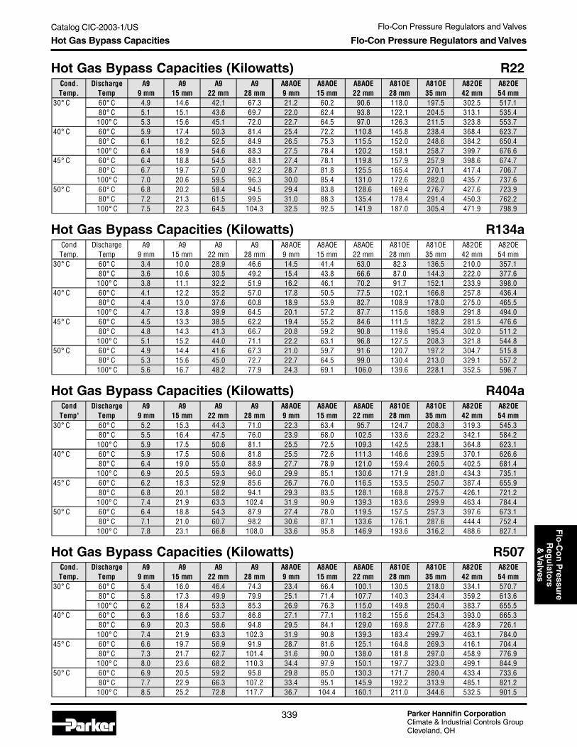
Flo-Con Pressure Regulators and Valves
Parker Hannifin CorporationClimate & Industrial Controls GroupCleveland, OH
339
Catalog CIC-2003-1/USF
lo-C
on
Pressu
reR
egu
lators
& V
alvesHot Gas Bypass Capacities Flo-Con Pressure Regulators and Valves
Hot Gas Bypass Capacities (Kilowatts) R507
Hot Gas Bypass Capacities (Kilowatts) R404a
Hot Gas Bypass Capacities (Kilowatts) R134a
Hot Gas Bypass Capacities (Kilowatts) R22
Cond. Discharge A9 A9 A9 A9 A8AOE A8AOE A8AOE A81OE A81OE A82OE A82OETemp. Temp 9 mm 15 mm 22 mm 28 mm 9 mm 15 mm 22 mm 28 mm 35 mm 42 mm 54 mm
30° C 60° C 5.4 16.0 46.4 74.3 23.4 66.4 100.1 130.5 218.0 334.1 570.7 80° C 5.8 17.3 49.9 79.9 25.1 71.4 107.7 140.3 234.4 359.2 613.6
100° C 6.2 18.4 53.3 85.3 26.9 76.3 115.0 149.8 250.4 383.7 655.540° C 60° C 6.3 18.6 53.7 86.8 27.1 77.1 118.2 155.6 254.3 393.0 665.3 80° C 6.9 20.3 58.6 94.8 29.5 84.1 129.0 169.8 277.6 428.9 726.1
100° C 7.4 21.9 63.3 102.3 31.9 90.8 139.3 183.4 299.7 463.1 784.045° C 60° C 6.6 19.7 56.9 91.9 28.7 81.6 125.1 164.8 269.3 416.1 704.4 80° C 7.3 21.7 62.7 101.4 31.6 90.0 138.0 181.8 297.0 458.9 776.9
100° C 8.0 23.6 68.2 110.3 34.4 97.9 150.1 197.7 323.0 499.1 844.950° C 60° C 6.9 20.5 59.2 95.8 29.8 85.0 130.3 171.7 280.4 433.4 733.6 80° C 7.7 22.9 66.3 107.2 33.4 95.1 145.9 192.2 313.9 485.1 821.2
100° C 8.5 25.2 72.8 117.7 36.7 104.4 160.1 211.0 344.6 532.5 901.5
Cond Discharge A9 A9 A9 A9 A8AOE A8AOE A8AOE A81OE A81OE A82OE A82OETemp' Temp 9 mm 15 mm 22 mm 28 mm 9 mm 15 mm 22 mm 28 mm 35 mm 42 mm 54 mm
30° C 60° C 5.2 15.3 44.3 71.0 22.3 63.4 95.7 124.7 208.3 319.3 545.3 80° C 5.5 16.4 47.5 76.0 23.9 68.0 102.5 133.6 223.2 342.1 584.2
100° C 5.9 17.5 50.6 81.1 25.5 72.5 109.3 142.5 238.1 364.8 623.140° C 60° C 5.9 17.5 50.6 81.8 25.5 72.6 111.3 146.6 239.5 370.1 626.6 80° C 6.4 19.0 55.0 88.9 27.7 78.9 121.0 159.4 260.5 402.5 681.4
100° C 6.9 20.5 59.3 96.0 29.9 85.1 130.6 171.9 281.0 434.3 735.145° C 60° C 6.2 18.3 52.9 85.6 26.7 76.0 116.5 153.5 250.7 387.4 655.9 80° C 6.8 20.1 58.2 94.1 29.3 83.5 128.1 168.8 275.7 426.1 721.2
100° C 7.4 21.9 63.3 102.4 31.9 90.9 139.3 183.6 299.9 463.4 784.450° C 60° C 6.4 18.8 54.3 87.9 27.4 78.0 119.5 157.5 257.3 397.6 673.1 80° C 7.1 21.0 60.7 98.2 30.6 87.1 133.6 176.1 287.6 444.4 752.4
100° C 7.8 23.1 66.8 108.0 33.6 95.8 146.9 193.6 316.2 488.6 827.1
Cond Discharge A9 A9 A9 A9 A8AOE A8AOE A8AOE A81OE A81OE A82OE A82OETemp. Temp 9 mm 15 mm 22 mm 28 mm 9 mm 15 mm 22 mm 28 mm 35 mm 42 mm 54 mm
30° C 60° C 3.4 10.0 28.9 46.6 14.5 41.4 63.0 82.3 136.5 210.0 357.1 80° C 3.6 10.6 30.5 49.2 15.4 43.8 66.6 87.0 144.3 222.0 377.6
100° C 3.8 11.1 32.2 51.9 16.2 46.1 70.2 91.7 152.1 233.9 398.040° C 60° C 4.1 12.2 35.2 57.0 17.8 50.5 77.5 102.1 166.8 257.8 436.4 80° C 4.4 13.0 37.6 60.8 18.9 53.9 82.7 108.9 178.0 275.0 465.5
100° C 4.7 13.8 39.9 64.5 20.1 57.2 87.7 115.6 188.9 291.8 494.045° C 60° C 4.5 13.3 38.5 62.2 19.4 55.2 84.6 111.5 182.2 281.5 476.6 80° C 4.8 14.3 41.3 66.7 20.8 59.2 90.8 119.6 195.4 302.0 511.2
100° C 5.1 15.2 44.0 71.1 22.2 63.1 96.8 127.5 208.3 321.8 544.850° C 60° C 4.9 14.4 41.6 67.3 21.0 59.7 91.6 120.7 197.2 304.7 515.8 80° C 5.3 15.6 45.0 72.7 22.7 64.5 99.0 130.4 213.0 329.1 557.2
100° C 5.6 16.7 48.2 77.9 24.3 69.1 106.0 139.6 228.1 352.5 596.7
Cond. Discharge A9 A9 A9 A9 A8AOE A8AOE A8AOE A81OE A81OE A82OE A82OETemp. Temp 9 mm 15 mm 22 mm 28 mm 9 mm 15 mm 22 mm 28 mm 35 mm 42 mm 54 mm
30° C 60° C 4.9 14.6 42.1 67.3 21.2 60.2 90.6 118.0 197.5 302.5 517.1 80° C 5.1 15.1 43.6 69.7 22.0 62.4 93.8 122.1 204.5 313.1 535.4
100° C 5.3 15.6 45.1 72.0 22.7 64.5 97.0 126.3 211.5 323.8 553.740° C 60° C 5.9 17.4 50.3 81.4 25.4 72.2 110.8 145.8 238.4 368.4 623.7 80° C 6.1 18.2 52.5 84.9 26.5 75.3 115.5 152.0 248.6 384.2 650.4
100° C 6.4 18.9 54.6 88.3 27.5 78.4 120.2 158.1 258.7 399.7 676.645° C 60° C 6.4 18.8 54.5 88.1 27.4 78.1 119.8 157.9 257.9 398.6 674.7 80° C 6.7 19.7 57.0 92.2 28.7 81.8 125.5 165.4 270.1 417.4 706.7
100° C 7.0 20.6 59.5 96.3 30.0 85.4 131.0 172.6 282.0 435.7 737.650° C 60° C 6.8 20.2 58.4 94.5 29.4 83.8 128.6 169.4 276.7 427.6 723.9 80° C 7.2 21.3 61.5 99.5 31.0 88.3 135.4 178.4 291.4 450.3 762.2
100° C 7.5 22.3 64.5 104.3 32.5 92.5 141.9 187.0 305.4 471.9 798.9

Parker Hannifin CorporationClimate & Industrial Controls GroupCleveland, OH
Flo-Con Pressure Regulators and Valves
340
Catalog CIC-2003-1/US
The Parker Refrigerating Specialties Division has builta reputation as a principal supplier of reliable, high sidecontrol valves to the supermarket industry. One of themore critical applications on a commercial refrigerationsystem where hot gas is utilized for defrosting pur-poses is the use of a regulator in the discharge line.Refrigerating Specialties types A81BL or A82BL havebecome a standard for many supermarket rack manu-facturers specifically for this application.
The “BL” version of an A8 regulator in a dischargeapplication serves two functions. The valve is either ina wide open (or bypassed) position with it’s solenoidenergized to facilitate a minimum pressure dropthrough the valve when no refrigeration circuits arecalling for defrost. In this mode, the valve essentiallyis acting as a low pressure drop solenoid in an openedposition. When a refrigeration circuit begins a defrostsequence however, the solenoid on the dischargeA8_BL regulator is de-energized (via the defrostprogram), thereby converting the valve into a differen-tial pressure regulator.
A differential regulator communicates outlet pressureinto the valve’s bonnet in order to compensate rangespring pressure with downstream pressure. The setpoint of the valve thus becomes the sum of springpressure plus outlet pressure. Whatever the rangespring pressure is set for effectively becomes the pres-sure difference the valve will maintain from its inlet tooutlet. If, for example, the regulator was set to maintaina 25 psi set point, the valve will regulate and maintainan upstream pressure 25 psi higher than it’s down-stream pressure, regardless of fluctuations in down-stream pressure. In this application, the regulator
Discharge Regulators for Supermarket Applications
ensures that the hot gas pressure supplied to a circuitfor defrost purposes will be high enough to overcomethe pressure drop through the supply line, the lossesthrough valves and fittings, and through the evaporatorcoil. The defrost condensate exits the evaporator and isthen introduced, at an elevated pressure, back into theliquid line.
Because each system may vary due to any number ofdesign considerations, the A81BL and A82BL regula-tors are field adjustable. The regulator can therefore beadjusted to determine the most efficient set point whileensuring that each evaporator defrosts in a timely andthorough manner.
For larger systems that exceed the capacity of the A8regulator line, Refrigerating Specialties offers a highercapacity flanged valve for discharge applications, theA4AB or A4ABL.
For sizing, please see “Discharge Capacities” on pages312 – 319.
Figure 5 - Discharge regulator forsupermarket applications. (See page 346 for symbols legend.)
Technical Information Discharge Regulators
Label Valve Function Application DesignSelection
PageA Inlet Pressure Regulator Discharge Pressure A8 312-319B Solenoid Valve Liquid Feed SC 343
Valve Legend
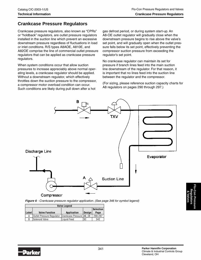
Flo-Con Pressure Regulators and Valves
Parker Hannifin CorporationClimate & Industrial Controls GroupCleveland, OH
341
Catalog CIC-2003-1/USF
lo-C
on
Pressu
reR
egu
lators
& V
alves
Crankcase Pressure Regulators
Crankcase pressure regulators, also known as “CPRs”or “holdback” regulators, are outlet pressure regulatorsinstalled in the suction line which prevent an excessivedownstream pressure regardless of fluctuations in loador inlet conditions. R/S types A8AOE, A810E, andA82OE comprise the line of commercial outlet pressureregulators that can be applied as crankcase pressureregulators.
When system conditions occur that allow suctionpressures to increase appreciably above normal oper-ating levels, a crankcase regulator should be applied.Without a downstream regulator, which effectivelythrottles down the suction pressure to the compressor,a compressor motor overload condition can occur.Such conditions are likely during pull down after a hot
gas defrost period, or during system start-up. AnA8-OE outlet regulator will gradually close when thedownstream pressure begins to rise above the valve’sset point, and will gradually open when the outlet pres-sure falls below its set point, effectively preventing thecompressor suction pressure from exceeding theregulator’s set point.
No crankcase regulator can maintain its set forpressure if branch lines feed into the main suctionline downstream of the regulator. For that reason, itis important that no lines feed into the suction linebetween the regulator and the compressor.
(For sizing, please reference suction capacity charts forA8 regulators on pages 290 through 297.)
Figure 6 - Crankcase pressure regulator application. (See page 346 for symbol legend)
Technical Information Crankcase Pressure Regulators
Label Valve Function Application DesignSelection
PageA Outlet Pressure Regulator Crankcase Pressure A8_OE 290-297B Solenoid Valve Liquid Feed SC 342
Valve Legend

Parker Hannifin CorporationClimate & Industrial Controls GroupCleveland, OH
Flo-Con Pressure Regulators and Valves
342
Catalog CIC-2003-1/US
Description: The SC series of commercial solenoidswas developed as a flexible, low pressure drop, suctionline solenoid valve, in a wide range of port and connec-tion sizes. With cartridge (port) sizes available up to2-5/8" (66mm) in size, SC solenoids offer the greatestcapacity of any non-flanged commercial solenoid in theindustry. The unique design of the SC solenoid is amirror image of the (S)PORT regulator line, utilizing thesame cartridges, solenoid coil assemblies, bodies, and
SC Suction Solenoid ValvesKey Features and Benefits
• Highest capacity non-flanged valve in the industry.• Available with 208V/240V/60Hz wide range voltage
coil.• Low pressure drop, internally pilot operated.• All stainless steel bolts, stem, piston and plug.• Manual opening stem.• Sweat in place without disassembly.• Molded class “F” coil construction.• DIN coil assemblies available.• Interchangeable capacity cartridges. Same as those
used on (S)PORT EPRs.
Specifications• Design pressure (M.R.P.): 450 psig (31.0 bar).• Maximum opening pressure differential (MOPD):
300 psig (20.7 bar). (Except 208/240V/60Hz widevoltage range coil).
• Minimal fluid temperature: -40°F (-40°C).• UL listed (except 50Hz), file SA5473.• CSA certified, file LR20991-14.
Valve Nomenclature
SC Port/Connection Size Combinations*
*NOTE: Completely corrosion resistant SC-II solenoids with aluminum bronze bodies and cartridge assemblies have same port/connection combinations as standard SC solenoids, but are not available in the 13, 17, or 21 port size versions.
internal parts as those used in the construction of the(S)PORT regulators. With this flexible line of suction linesolenoids complementing the complete line of (S)PORTregulators, a wide range of high capacity,suction line refrigeration control valves are now avail-able from a single source.
Along with (S)PORT regulators, SC solenoids aremanufactured with ductile iron bodied valves withbrazed copper couplings, and are suitable for most
Technical Information SC Suction Solenoid Valves
Standard Voltages• 120V/60Hz, 110V/50Hz• 208V/240V/60Hz, 220V/50Hz• 240V/50Hz• 240V/60Hz, 220V/50Hz (DIN)• 240V/50Hz (DIN)
Connection Sizein Eighthsof an Inch
Port Sizein Eighthsof an Inch
SuctionSolenoid
BodySize
11111 or 2SC
Type Port Size Connection Sizes Available03 (3/8", 9mm) 07, 09, 11,13, 17 (7/8"/22mm, 1-1/8"/28mm, 1-3/8"/35mm, 1-5-8"/42mm, 2-1/8"/54mm)
05 (5/8" 15mm) 07, 09, 11,13, 17 (7/8"/22mm, 1-1/8"/28mm, 1-3/8"/35mm, 1-5-8"/42mm, 2-1/8"/54mm)
07 (7/8", 22mm) 07, 09, 11,13, 17 (7/8"/22mm, 1-1/8"/28mm, 1-3/8"/35mm, 1-5-8"/42mm, 2-1/8"/54mm)
09 (1-1/8", 28mm) 07, 09, 11,13, 17 (7/8"/22mm, 1-1/8"/28mm, 1-3/8"/35mm, 1-5-8"/42mm, 2-1/8"/54mm)
11 (1-3/8", 35mm) 09, 11,13, 17 (1-1/8"/28mm, 1-3/8"/35mm, 1-5-8"/42mm, 2-1/8"/54mm)13 (1-5/8", 42mm) 13, 17, 21 (1-5/8" /42mm, 2-1/8" /54mm, 2-5/8" /66mm)
SC2 17 (2-1/8", 54mm) 17, 21 (2-1/8" /54mm, 2-5/8" /66mm)21 (2-5/8", 66mm) 21 (2-5/8", 66mm)
SC1or
SC-II

Flo-Con Pressure Regulators and Valves
Parker Hannifin CorporationClimate & Industrial Controls GroupCleveland, OH
343
Catalog CIC-2003-1/USF
lo-C
on
Pressu
reR
egu
lators
& V
alves
NOTE: For SC valve suction capacity tables, please reference pages 290-297 of this catalog.
common commercial refrigerants along with certainoils. The SC solenoid may be opened by means of amanual opening stem for servicing or in case of anelectrical power failure.
The SC-II series of valves are manufactured with com-pletely corrosion resistant materials including aluminumbronze bodies and cartridge assemblies, and stainlesssteel adapter bolts. Cartridges, and solenoids are inter-changeable with the (S)PORT-II regulator line.
Variations: SC1/ SC-II Solenoids: Five port sizes, from3/8" (9mm) through 1-3/8" (35mm). SC2 Solenoid: threeport sizes, from 1-5/8" (42mm) through 2-5/8" (66mm).
Installation: SC solenoid valves can be mounted eitherin a vertical or horizontal line with the refrigerant flow inthe direction of the arrow on the body. These valvesmay be soldered into the line without disassembly.When brazing in line, typically a wet cloth wrappedaround the valve body is recommended to dissipateheat. If a valve is disassembled prior to installation,always have the correct gasket/ O-ring kit available
for reassembly. The internal cartridge-to-body O-ringwill need to be replaced prior to reassembly.
Electrical: SC commercial solenoid valves utilize amolded water resistant Class “F” solenoid coil with anopen frame coil housing that meets NEMA 3R and 4requirements. A class “H” DIN coil is also available withcertain voltages. Power consumption during normaloperation will be 10.2 watts or less.
All coils except for the 208/240V/60Hz version operatewith a 300 psi (20.7 bar) maximum opening pressuredifferential (MOPD). The 208/240V/60Hz coil operateswith a 280 psi (19.3 bar) MOPD.
All coils are designed to operate with a line voltagefrom 85% to 110% of rated coil voltage. Operating witha line voltage above or below these limits may result incoil burn out.
Ordering Guide: Specify valve type (SC1, SC-II orSC2), port and connection size, coil voltage, andfrequency.
Technical Information SC Suction Solenoid Valves
SC1/SC2 Liquid Capacities in Evaporator TonsBased on 100°F Condensing, 40°F Evaporator and no flashing through the valve for the pressure drop listed.
SC1/SC2 Liquid Capacities in Evaporator KilowattsBased on 37.7°C Condensing, 4.4°C Evaporator and no flashing through the valve for the pressure drop listed.
R22 R22 R134a R134a R404A R404A R507 R507Port 2 psi 4 psi 2 psi 4 psi 2 psi 4 psi 2 psi 4 psiSize pr drop pr drop pr drop pr drop pr drop pr drop pr drop pr drop
03 (3/8") 6 9 6 9 4 6 4 605 (5/8") 14 20 13 19 9 12 9 1307 (7/8") 22 31 21 29 14 19 14 20
09 (1-1/8") 35 50 33 47 22 31 23 3211 (1-3/8") 49 69 46 65 30 43 32 4513 (1-5/8") 78 110 73 104 48 68 50 7117 (2-1/8") 117 165 110 156 72 102 76 10721 (2-5/8") 156 220 147 207 96 136 101 143
R22 R22 R134a R134a R404A R404A R507 R507Port 0.14 bar 0.27 bar 0.14 bar 0.27 bar 0.14 bar 0.27 bar 0.14 bar 0.27 barSize pr drop pr drop pr drop pr drop pr drop pr drop pr drop pr drop
03 (9mm) 23 32 21 30 14 20 15 2105 (15mm) 50 71 47 67 31 44 32 4607 (22mm) 78 110 73 103 48 68 50 7109 (28mm) 123 174 116 164 76 107 80 11311 (35mm) 172 243 162 229 106 150 111 15713 (42mm) 274 387 258 365 169 239 177 25117 (54mm) 411 581 387 547 253 358 266 37621 (66mm) 548 775 516 729 338 477 354 501

Parker Hannifin CorporationClimate & Industrial Controls GroupCleveland, OH
Flo-Con Pressure Regulators and Valves
344
Catalog CIC-2003-1/US
S8 Port/Connection Size Combinations
S81/S82 Solenoid Valves
Features• Highest capacity non-flanged solenoid valve in
the industry.• Low pressure drop.• Manual opening stem.• Sweat in place without disassembly.• Molded class “H” coil construction.• DIN coil assemblies available.• Inlet pressure access fitting.• Interchangeable capacity cartridges.
Specifications• Maximum opening pressure differential (MOPD):
300 psig (20.7 bar).• Minimum fluid temperature: -40°F (-40°C).• Design pressure (M.R.P.): 450 psig (31.0 bar).• UL listed, file SA5473.• CSA certified, file LR20991-14.
Valve Nomenclature
Technical Information S81/S82 Solenoid Valves
Standard Voltages• 120V/60Hz, 110V/50Hz• 240V/60Hz, 220V/50Hz• 208V/60Hz• 240V/60Hz, 220V/50Hz (DIN)• 240V/50Hz (DIN)
Solenoid
S8Port Sizein Inches
7/8"Connection Size
in Inches
1 1/8"1 or 2Body Size
Valve Type Port Size Available Connection SizesS81 3/8" (9mm) 7/8", 1-1/8",1-3/8” (22mm, 28mm,35mm)S81 5/8" (15mm) 7/8", 1-1/8",1-3/8” (22mm, 28mm,35mm)S81 7/8" (22mm) 7/8", 1-1/8",1-3/8” (22mm, 28mm,35mm)S81 1-1/8" (28mm) 1-1/8", 1-3/8", 1-5/8" (28mm, 35mm, 42mm)S81 1-3/8" (35mm) 1-3/8", 1-5/8", 2-1/8" (35mm, 42mm, 54mm)S82 1-5/8" (42mm) 1-5/8", 2-1/8", 2-5/8" (42mm, 54mm, 66mm)S82 2-1/8" (54mm) 2-1/8", 2-5/8" (54mm, 66mm)S82 2-5/8" (66mm) 2-5/8" (66mm)

Flo-Con Pressure Regulators and Valves
Parker Hannifin CorporationClimate & Industrial Controls GroupCleveland, OH
345
Catalog CIC-2003-1/USF
lo-C
on
Pressu
reR
egu
lators
& V
alves
Installation: S8 solenoid valves can be mounted eitherin a vertical or horizontal line with the refrigerant flow inthe direction of the arrow on the body. These valvesmay be soldered into the line without disassembly. Awet cloth should be wrapped around the valve and thesoldering flame should be directed away from the valvebody.
If a valve is disassembled prior to installation, alwayshave the correct gasket/O-ring kit available for reas-sembly. The internal cartridge-to-body O-ring will needto be replaced prior to reassembly
Electrical: S8 commercial solenoid valves utilize amolded water resistant Class “H” solenoid coil with ageneral purpose coil housing which meets NEMA 3Rand 4 requirements. A class “H” DIN coil is also avail-able with certain voltages. Power consumption duringnormal operation will be 10.2 watts or less. The coilsare designed to operate with a line voltage from 85% to110% of rated coil voltage. Operating with a line voltageabove or below these limits may result in coil burn out.
Ordering Guide: Specify valve type (S81 or S82), portand connection size, and coil voltage and frequency.
Technical Information S81/S82 Solenoid Valves
Description: The S8 series of commercial solenoidswas developed as a versatile, general purpose, com-mercial refrigeration valve, capable of being applied inmost liquid, hot gas, or suction applications. Withcartridge (port) sizes available up to 2-5/8" (66mm) insize, S8 solenoids offer the greatest capacity of anynon-flanged commercial solenoid in the industry. Theunique design of the S8 solenoid is a mirror image ofthe A8 regulator line, utilizing the same cartridges,solenoid coil assemblies, bodies, and internal parts asthose used in the construction of the A8’s. With thisflexible line of commercial solenoids complementingthe complete line of commercial A8 regulators, a wideoffering of high capacity commercial refrigerationcontrol valves are now available from a single source.
Similar to the A8 regulators, S8 solenoids are manufac-tured with ductile iron bodies with brazed copper cou-plings, and are suitable for most common commercialrefrigerants along with certain oils. The S8 solenoidmay be opened by means of a manual opening stemfor servicing or in case of an electrical power failure.
Variations: S81 Solenoid: Five port sizes, from 3/8"(9mm) through 1-3/8". S82 Solenoid: Three port sizes,from 1-5/8" through 2-5/8".
NOTE: For S81 / S82 valve suction capacity tables, please reference pages 290-297 of this catalog.
S81/S82 Liquid Capacities in Evaporator TonsBased on 100°F Condensing, 40°F Evaporator and no flashing through the valve for the pressure drop listed.
S81/S82 Liquid Capacities in Evaporator KilowattsBased on 37.7°C Condensing, 4.4°C Evaporator and no flashing through the valve for the pressure drop listed.
R22 R22 R134a R134a R404a R404a R507 R507Port 2 psi 4 psi 2 psi 4 psi 2 psi 4 psi 2 psi 4 psiSize pr drop pr drop pr drop pr drop pr drop pr drop pr drop pr drop3/8" 6 9 6 9 4 6 4 65/8" 14 20 13 19 9 12 9 137/8" 22 31 21 29 14 19 14 20
1-1/8" 35 50 33 47 22 31 23 321-3/8" 49 69 46 65 30 43 32 451-5/8" 78 110 73 104 48 68 50 712-1/8" 117 165 110 156 72 102 76 1072-5/8" 156 220 147 207 96 136 101 143
R22 R22 R134a R134a R404a R404a R507 R507Port 0.14 bar 0.27 bar 0.14 bar 0.27 bar 0.14 bar 0.27 bar 0.14 bar 0.27 barSize pr drop pr drop pr drop pr drop pr drop pr drop pr drop pr drop9mm 23 32 21 30 14 20 15 2115mm 50 71 47 67 31 44 32 4622mm 78 110 73 103 48 68 50 7128mm 123 174 116 164 76 107 80 11335mm 172 243 162 229 106 150 111 15742mm 274 387 258 365 169 239 177 25154mm 411 581 387 547 253 358 266 37666mm 548 775 516 729 338 477 354 501

Parker Hannifin CorporationClimate & Industrial Controls GroupCleveland, OH
Flo-Con Pressure Regulators and Valves
346
Catalog CIC-2003-1/US
Abbreviations and Terminology
Abbreviations and Terminology
AbbreviationsA (Amp) AmpereBTU/hr British Thermal Units per HourBTU/min. British Thermal Units per Minute°C Degrees Celsius or Centigradecm2 (sq. cm) Square centimetersCPR Crankcase Pressure RegulatorCSA Canadian Standards Association°F Degrees FahrenheitEPR Evaporator Pressure regulatorft (') Feetin (") Incheshg MercuryHz Hertz (frequency, cycles per second)ID Inside diameterkcal/h Kilocalories per hourkg Kilogramkg/cm2 Kilogram per square centimeterkw Kilowattslbs Poundslbs/min Pounds per minutem Meterm3/h Cubic meters per hourmm Millimetermm hg Millimeters mercury equivalent vacuumMOPD Maximum Opening Pressure DifferentialNEMA National Electrical Manufacturers AssociationNPT National Pipe ThreadOD Outside DiameterODS Outside Diameter Sweat or tubing O.D.,
which can be soldered into fittingpsi Pounds per square inchpsig Pounds per square inch gaugesq. cm (cm2) Square centimetersSWP Safe Working PressureTXV Thermostatic Expansion ValveUL Underwriters Laboratories, Inc.V Volts
Explanation of TerminologyDesign pressure (SWP): The maximum allowable
working pressure for which a valve or regulatoris designed.
Evaporator temperature: Saturated temperaturein the evaporator.
Maximum fluid temperature: The highestnormally allowable internal temperature fora particular valve.
Maximum Opening Pressure Differential: Themaximum difference between the pressure atthe valve inlet and the pressure at the valveoutlet at which a solenoid will open consistently(MOPD).
Minimum fluid temperature: The lowest normallyallowable internal temperature for a particularvalve assuming a clean, oil-free fluid and theabsence of thermal or pressure shock.
Net weight: The weight of a particular valve. Doesnot include shipping cartons.
Pressure drop: The pressure difference betweenthe pressure at the valve inlet and the pressureat the valve outlet.
Shock: A sudden, violent increase in pressure;can be caused by a rapid change in tempera-ture, pressure, velocity, or direction.
Valve or regulator capacity: All capacities aremaximum for the conditions listed at eachtable. No “reserve capacity” is included in thiscatalog.
Conversions to metric:1 ton = 200 BTU/min1 ton = 3024kcal/hr1 kw = .2844 ton1 kw = 56.89 BTU/min1 kw = 860 kcal/hr1 bar = 1.0197 kg/cm2
1 bar = 14.5 psi1 ATM = .98 bar = 14.7 psi
Control Valve Symbols and Functions
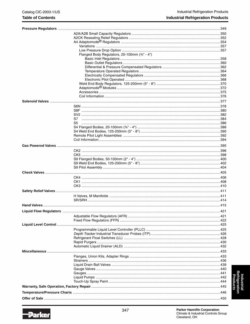
Catalog CIC-2003-1/US Industrial Refrigeration Products
Parker Hannifin CorporationClimate & Industrial Controls GroupCleveland, OH
347
Ind
ustrial
Refrig
eration
Pro
du
cts
Pressure Regulators .........................................................................................................................................................................349
A2A/A2B Small Capacity Regulators ............................................................................................350A2CK Reseating Relief Regulators ...............................................................................................352A4 Adaptomode® Regulators .......................................................................................................354
Variations .................................................................................................................................357Low Pressure Drop Option ......................................................................................................357Flanged Body Regulators, 20-100mm (¾" - 4")
Basic Inlet Regulators ........................................................................................................358Basic Outlet Regulators .....................................................................................................360Differential & Pressure Compensated Regulators ............................................................362Temperature Operated Regulators ....................................................................................364Electrically Compensated Regulators ...............................................................................366Electronic Pilot Operated ...................................................................................................368
Weld End Body Regulators, 125-200mm (5" - 8") ..................................................................370Adaptomode® Modules ...........................................................................................................372Accessories ..............................................................................................................................375Coil Information ........................................................................................................................376
Solenoid Valves .................................................................................................................................................................................377S6N ................................................................................................................................................378S8F ................................................................................................................................................380SV2 ................................................................................................................................................382S7 ................................................................................................................................................384S5 ................................................................................................................................................386S4 Flanged Bodies, 20-100mm (¾" - 4") ......................................................................................388S4 Weld End Bodies, 125-200mm (5" - 8") ...................................................................................390Remote Pilot Light Assemblies .....................................................................................................392Coil Information ..............................................................................................................................394
Gas Powered Valves ..........................................................................................................................................................................395
CK2 ................................................................................................................................................396CK5 ................................................................................................................................................398S9 Flanged Bodies, 50-100mm (2" - 4") .......................................................................................400S9 Weld End Bodies, 125-200mm (5" - 8") ...................................................................................402S9 Pilot Assembly ..........................................................................................................................404
Check Valves ......................................................................................................................................................................................405
CK4 ................................................................................................................................................406CK1 ................................................................................................................................................408CK3 ................................................................................................................................................410
Safety Relief Valves ...........................................................................................................................................................................411
H Valves, M Manifolds ...................................................................................................................411SR/SRH ..........................................................................................................................................414
Hand Valves ........................................................................................................................................................................................415
Liquid Flow Regulators ....................................................................................................................................................................421Adjustable Flow Regulators (AFR) ................................................................................................421Fixed Flow Regulators (FFR) ........................................................................................................422
Liquid Level Control ..........................................................................................................................................................................425
Programmable Liquid Level Controller (PLLC) .............................................................................425Depth Tracker Industrial Transducer Probes (ITP) ........................................................................426Refrigerant Float Switches (LL) ....................................................................................................428Rapid Purgers ................................................................................................................................430Automatic Liquid Drainer (ALD) ....................................................................................................432
Miscellaneous ....................................................................................................................................................................................433
Flanges, Union Kits, Adapter Rings ..............................................................................................433Strainers .........................................................................................................................................436Liquid Drain Ball Valves .................................................................................................................439Gauge Valves .................................................................................................................................440Gauges ...........................................................................................................................................441Liquid Pumps ................................................................................................................................. 442Touch-Up Spray Paint ....................................................................................................................444
Warranty, Safe Operation, Factory Repair ......................................................................................................................................445
Temperature/Pressure Charts .........................................................................................................................................................446
Offer of Sale .......................................................................................................................................................................................450
Industrial Refrigeration ProductsTable of Contents

Parker Hannifin CorporationClimate & Industrial Controls GroupCleveland, OH
Catalog CIC-2003-1/US Industrial Refrigeration Products
348
How to Use this SectionThis section is organized by product group. For mostsections, the first page is an overview. Specifications andselection guides given in table form provide comparison ofthe different valves and aid in selecting a specific product.Each type is then presented individually, giving additionalinformation such as description, flows, materials ofconstruction, dimensions and ordering information.
In order to bring Refrigerating Specialties model numbersinto a format that will enable product ordering from theParker online system, model coding has been developedfor use with all of our product series.
Each character of a model number has significance. Amodel number can be built by selecting an option for eachcategory in the model code and inserting the code givenfor that option into the model number. An example isshown at the top of every model code. With only a fewexceptions, you must always enter something for eachcategory, even if it only indicates that you do not want thatoption.
It is now possible to order flanges, coils, strainers, checkvalves, etc. with the valve within one model number. Beaware that you could build a model number that is notvalid by selecting flange connections that do not apply to
General Information
WARNINGFAILURE OR IMPROPER SELECTION OR IMPROPER USE OF THE PRODUCTS AND/OR SYSTEMS DESCRIBED HEREIN ORRELATED ITEMS CAN CAUSE DEATH, PERSONAL INJURY AND PROPERTY DAMAGE.
This document and other information from Parker Hannifin Corporation, its subsidiaries and authorized distributors provide product and/orsystem options for further investigation by users having technical expertise. It is important that you analyze all aspects of your application,including consequences of any failure, and review the information concerning the product or system in the current product catalog. Due tothe variety of operating conditions and applications for these products or systems, the user, through its own analysis and testing, is solelyresponsible for making the final selection of the products and systems and assuring that all performance, safety and warning requirementsof the application are met.
The products described herein, including without limitation, product features, specifications, designs, availability and pricing, are subject tochange by Parker Hannifin Corporation and its subsidiaries at any time without notice.
!
The items described in this document are hereby offered for sale by Parker Hannifin Corporation, its subsidiaries or its authorizeddistributors. This offer and its acceptance are governed by the provisions stated in the full "Offer of Sale" at the end of this document.
Copyright 2002, Parker Hannifin Corporation, All Rights Reserved
Offer of Sale
that size valve or voltages that cannot be provided on that styleof coil, etc. Please use the reference tables to view the optionlimitations.
Our most commonly ordered options are offered in the catalog.However, there are many other possibilities. If you requiresomething not shown in the catalog, please call us or send ane-mail to [email protected].
New ProductsProducts appearing in our catalog for the first time are:
• A2CK reseating relief regulator
• CK5 gas powered suction stop valves
• Hand valves with extended bonnets
• PLLC programmable controller andDepthTracker transducer probes
• Rapid purgers
• Gauge valves
• Liquid drain ball valves
• Compact class "H" coils
• Female flanges
• SR/SRH safety relief valve
• Open and hermatic liquid pumps
Industrial Refrigeration Products

Catalog CIC-2003-1/US
Parker Hannifin CorporationClimate & Industrial Controls GroupCleveland, OH
349
Industrial Refrigeration Products: Pressure RegulatorsIn
du
strialR
efrigeratio
nP
rod
ucts
Pressure Setting Ranges
Approx.Set Point Pressure Change Factory Set Point
Code Range per Turn of (unless otherwiseAdjusting Screw specified)
A 0 - 10.3 bar 1.7 bar 2.8 bar(0 - 150 PSIG) (25 PSI) (40 PSIG)
V 500mm Hg to 8.3 bar 1.7 bar 1.0 bar(20" Hg to 120 PSIG) (25 PSI) (15 PSIG)
D 5.2 to 19.3 bar 3.7 bar 9.7 bar(75 to 280 PSIG) (53 PSI) (140 PSIG)
Pressure RegulatorsThe Refrigerating Specialties family of pressureregulators includes valves that control inlet,outlet or differential pressure. Each regulator isavailable with an assortment of additionalvariations which enable one regulator to performseveral functions.
The Type A2 are compact, small capacityregulators. The Type A4 are heavy-duty, high-flow regulators available in flanged body style insizes 20-100mm (¾" - 4") and weld end bodystyle in sizes 125-200mm (5" - 8"). TheAdaptomode® system makes it possible toorder the regulator and modules separately forstock or field conversion.
Gauge valves and gauges may be purchasedwith the regulator or separately (see pages440-441).
SpecificationsType A2A A2B A2CK A4 A4 A4
Port Sizemm 20-32 40-100 125-200
inch ¾" - 1¼" 15⁄8" - 4" 5" - 8"
Seat Metal-to-Metal Lapped Lapped(PTFE on A4K) Metal-to-Metal Metal-to-Metal
Pilot Seat Chrome Plated Chrome Plated Chrome Plated Chrome Plated Chrome Plated Chrome PlatedLapped Lapped Lapped Lapped Lapped Lapped
Metal-to-Metal Metal-to-Metal Metal-to-Metal Metal-to-Metal Metal-to-Metal Metal-to-Metal
Body MaterialGray Gray Gray Gray Gray CastIron Iron Iron Iron Iron Steel
Body Connection Flanged Flanged Flanged Flanged Flanged Weld End
Flow Kv 1.28 0.43 (Inlet) 6.2 - 15 28.6 - 116 171 - 471
Cv 1.5 0.5 7.2 - 17.5 33.4 - 135 200 - 550
Fluid Temperature °C -45° to 105° -45° to 105° -45° to 105° -45° to 105° -50° to 105° -50° to 105°
°F -50° to 220 -50° to 220° -50° to 220° -50° to 220° -60° to 220° -60° to 220°
OperationDirect Direct Direct
Pilot Pilot PilotDiaphragm Diaphragm Diaphragm
Bulletin for Reference 21-02 21-02 21-03 See Page 356 See Page 356 23-20
A2
A420-100mm(¾" - 4")
A4125-200mm
(5" - 8")
For variations "K" and "BK", the set point isfactory set and sealed. Standard set pointfor each range is shown in the table to theleft. A custom setting may be specified byadding the set point in PSIG preceded by a"-" at the end of the model number, i.e. -90.Set point must be valid for the rangeselected.
Overview Pressure Regulators

Parker Hannifin CorporationClimate & Industrial Controls GroupCleveland, OH
Catalog CIC-2003-1/US
350
Industrial Refrigeration Products: Pressure Regulators
Type A2 Compact Regulators
● Compact, direct diaphragm operated● Maximum rated pressure (MRP): 27.6 bar (400 PSIG)● Flanged connections: FPT, SW, WN, ODS● Available with close coupled strainer● Stainless steel diaphragm
DescriptionThe A2 type pressure regulators are compact, directdiaphragm operated, for use with refrigerant liquid or vapor.The regulators can be used with ammonia, R-22, R-134a,R-404A, R-507, certain other refrigerants, oil and otherapproved fluids with similar pressure, temperature andcorrosion characteristics. The regulators are for use insystems where a small inlet or outlet pressure regulator isneeded.
MaterialsBody .......................................................................Gray ironSeat ...............................................................Chrome platedDiaphragm .................................. Stainless steel preformed
SpecificationsMaximum Fluid Temperature ........................ 105°C (220°F)Minimum Fluid Temperature ........................... -45°C (-50°F)Design Pressure (MRP) ....................... 27.6 bar (400 PSIG)
Application Guide
Type Function Operation Typical Applications
A2B Control inlet pressure Regulate at preset inlet pressure 1. Small capacity back pressure regulator
A2A Inlet regulator, greater capacityField adjustable 2. Small capacity defrost relief regulatorOpen on rise in inlet pressure
Regulate at preset outlet pressure 1. Gas pressure reducing regulatorA2BO Control outlet pressure Field adjustable 2. Liquid or oil pressure reducing regulator
Open on drop in outlet pressure
Selection GuideRanges Available Connections Available Flow Coefficient➂
Type Description (Std. is Bold) Style: FPT, SW, WN Kv Cv
A2B Small Capacity Back Pressure Regulator V, A, D 0.43 0.5A2BK➀ Relief, Give pressure setting A, D ¼", 3⁄8", ½", ¾" 0.34 0.4A2BP Differential Regulator for ext. connection A, D 0.43 0.5A2BM Electrically Compensated V, A, D
A2BT Temperature Operated Regulator 1, 2 ¼", 3⁄8", ½", ¾"
A2A Small Capacity Back Pressure Regulator A, D ¼", 3⁄8", ½", ¾" 1.28 1.5
A2BO1➁ 0.09 0.1A2BO2➁ Small Capacity Outlet Pressure Regulator V, D ¼", 3⁄8", ½", ¾" 0.17 0.2A2BO4➁ 0.43 0.5
➀ The A2BK Reseating Relief Regulator can be used for variousrelief to low side applications including cold liquid line sectionswhere buildup of dangerous hydrostatic pressure is possible.See “Safe Operation”.
➁ For external pressure connection, specify A2BO1E, A2BO2E orA2BO4E.
➂ Flow coefficients are for standard range.
CAUTION:When ordering a Type A2 regulator to be used as a pilotregulator for an A4R, the size of the A4R main regulatormust be considered. For 20-50mm (¾" - 2") A4R, order anA2B2 or A2BO2E. For 65-200mm (2½" - 8") A4R, order anA2B or A2BO4E.
WARNING!ODS flanges not suitable for use with ammonia.
!
!
Technical Information

Catalog CIC-2003-1/US
Parker Hannifin CorporationClimate & Industrial Controls GroupCleveland, OH
351
Industrial Refrigeration Products: Pressure RegulatorsIn
du
strialR
efrigeratio
nP
rod
ucts
Type A2 Compact Regulators
Dimensions
How to Order Type A2 RegulatorsRegulators can be specified by using the symbols in the chart below to develop a model number. Select only those symbols thatrepresent the features desired, and place them in the sequence indicated by the example at the top of the chart.
Inlet Outlet Gauge SetType Variation Range Flange Flange Gauge Valve Strainer Point
Flange Type Size
X No Flange 00 None
F FPT (IPS) 02* ¼"S SW (IPS) 03 3⁄8"W WN (IPS) 04 ½"
06 ¾"K ODS 04 ½"
05 5⁄8"07 7⁄8"
D DIN 10 10mmWeld Neck 15 15mm
20 20mm* FPT only.
Strainer
N No StrainerS w/Strainer
Variations (see Note)
Blank Inlet Regulator, No Variation2 A2B Inlet Regulator, 0.17 KvE External Pressure ConnectionK Reseating ReliefM* Electrically Compensated (Select Motor)P 1:1 Pneumatically (Pressure) Compensated3P 3:1 Pneumatically (Pressure) CompensatedT Temperature OperatedH Inlet Regulator w/Handwheel
O1 Outlet, 0.09 KvO2 Outlet, 0.17 KvO4 Outlet, 0.43 Kv
O1E Outlet External, 0.09 KvO2E Outlet External, 0.17 KvO4E Outlet External, 0.43 Kv
Note: Only “T” variation is available with A2A.
Type
A2A Inlet, 1.28 KvA2B Inlet, 0.43 Kv
Body
N No ValveA 1/4" Angle
173mm (6.8")
211mm (8.3")
73mm (2.9")117mm (4.6")
PUSH PIN
THERMAL ELEMENT
DIAPHRAGM
241mm (9.5")
117mm (4.6")
73mm (2.9") 102mm (4")
19mm (0.75")
CAPILLARYLENGTH = 6m (20 FT)
177mm (7")
A2A, A2B A2*T
*Motor Style (“M” Variation Only)
H Motor Hardware OnlyHoneywell Motors
1 24V 50/60Hz Std. Cam w/120V transformerA 24V 50/60Hz Std, Cam w/240V transformer2 24V 50/60Hz Low Rise Cam w/120V transformerB 24V 50/60Hz Low Rise Cam w/240V transformer3 4-20 mA, 120V 50/60Hz, Standard Cam4 4-20 mA, 120V 50/60Hz, Low Rise Cam5 4-20 mA, 240V 50/60Hz, Standard Cam6 220V 50Hz Std. Cam7 220V 50Hz Low Rise Cam
Refrigerant
0 No Gauge7 R-7171 R-134a2 R-224 R-404A5 R-507
Pressure Range*
A 0 to 10.3 Bar (0 to 150 PSIG)D 5.2 to 19.3 Bar (75 to 280 PSIG)V 500mm Hg to 8.3 Bar (20" Hg to 120 PSIG)
Temperature Range (“T” Variation only)1 -30° to +30°C (-20° to +80°F)2 +20° to +60°C (60° to 140°F)
* See Selection Guide table for pressure rangeavailability. Not available with "T" variation.
*Motor Style, Continued (“M” Variation only)
Penn Motors8 24V 50/60Hz Std. Cam w/120V transformerC 24V 50/60Hz Std. Cam w/240V transformer9 24V 50/60Hz Low Rise Cam w/120V transformerD 24V 50/60Hz Low Rise Camw/240V transformer
Gauge Size, Range, Type
N No GaugeA 2½" English, Low PressureB 3½" English, Low PressureC 2½" English, High PressureD 3½" English, High PressureE 2½" Metric, Low PressureF 3½" Metric, Low PressureG 2½" Metric, High PressureH 3½" Metric, High Pressure
Custom Set Point(Var. “K” Only)
Setting in PSIGwithin the values forthe range selected
A2B T 1 F03 F03 A2 A S –
Dimensions and How to Order

Parker Hannifin CorporationClimate & Industrial Controls GroupCleveland, OH
Catalog CIC-2003-1/US
352
Industrial Refrigeration Products: Pressure Regulators
Type A2CK Relief Regulators
● Compact, direct diaphragm operated● Maximum rated pressure (MRP): 27.6 bar (400 PSIG)● Flanged connections: FPT, SW, WN, ODS● Available with close coupled strainer
DescriptionThe A2CK pressure relief regulator is direct diaphragmoperated, for use with refrigerant liquid or vapor. Theregulators can be used with ammonia, R-22, R-134a,R-507 and other common refrigerants. This regulator isused in systems where a small direct operated valve isrequired as a safety device to relieve “trapped” liquid lines inthe event that a hydrostatic pressure condition develops.The A2CK should not be piped or applied as ASME certifiedsafety relief valve for use on pressure vessels.
The A2CK utilizes a special pilot seat designed to providefor a higher flow rate (Cv) than the A2BK relief regulator.Additionally, with a relatively small ratio of diaphragm topilot seat area, it is designed to open and regulate refriger-ant flow quickly through the pilot seat once its set point hasbeen reached. The design of the valve allows for this “quickrelease” feature. However, it does not offer the same typeof controlled response which may be required for a stan-dard regulator application. For those applications where asmall regulator is needed for accurate upstream pressurecontrol, an A2A or A2B direct operated regulator should beconsidered.
The A2CK is factory set and sealed with a lead seal prior toshipment. Since the valve should be used exclusively as asmall internal relief valve, it is designed with the “D” rangeadjusting spring only. Set points must fall in the 75 to 280PSIG (5 to 19 bar) range.
MaterialsBody Material ......................................................... Gray ironSeat Material ................................................Chrome platedDiaphragm Material ...................................... Stainless steel
SpecificationsMaximum Fluid Temperature ........................ 105°C (220°F)Minimum Fluid Temperature ........................... -45°C (-50°F)Design Pressure (MRP) ....................... 27.6 bar (400 PSIG)Flow Coefficient ....................................................... 1.14 Cv
Dimensions
173mm (6.8")
211mm (8.3")
73mm (2.9")117mm (4.6")
Technical Information

Catalog CIC-2003-1/US
Parker Hannifin CorporationClimate & Industrial Controls GroupCleveland, OH
353
Industrial Refrigeration Products: Pressure RegulatorsIn
du
strialR
efrigeratio
nP
rod
ucts
Type A2CK Compact Relief Regulators
How to Order A2CK Compact Relief RegulatorsRegulators can be specified by using the symbols in the chart below to develop a model number. Select only those symbols thatrepresent the features desired, and place them in the sequence indicated by the example at the top of the chart.
Inlet Outlet Gauge SetType Variation Range Flange Flange Gauge Valve Strainer Point
Range
D 5.2-19.3 Bar(75-280 PSIG)
Variation
K Reseating ReliefRegulator
Custom Set Point
xxx Setting in PSIGbetween 75 and280. Standardfactory setting is140.
A2C K D F03 F03 C1 A S – 125
Body
N No ValveA 1/4" Angle
Refrigerant
0 None7 R-7171 R-134a2 R-224 R-404A5 R-507
Gauge Size, Range, Type
N No GaugeA 2½" English, Low PressureB 3½" English, Low PressureC 2½" English, High PressureD 3½" English, High PressureE 2½" Metric, Low PressureF 3½" Metric, Low PressureG 2½" Metric, High PressureH 3½" Metric, High Prsesure
Flange Type Size
X No Flange 00 NoneF FPT (IPS) 02* ¼"S SW (IPS) 03 3⁄8"W WN (IPS) 04 ½"
06 ¾"
K ODS 04 ½"05 5⁄8"07 7⁄8"
D DIN 10 10mmWeld Neck 15 15mm
20 20mm
* FPT only.
Strainer
N No StrainerS w/Strainer
WARNING!ODS flanges not suitablefor use with ammonia.
!
How to Order

Parker Hannifin CorporationClimate & Industrial Controls GroupCleveland, OH
Catalog CIC-2003-1/US
354
Industrial Refrigeration Products: Pressure Regulators
● Pilot operated for precise control
● Characterized modulating plug for stable controlunder low flow conditions
● Many control variations are possible
● Convertible to other variations
● Optional close coupled strainers up to 100mm (4")
● Manual opening stem
● Easy to service
DescriptionThese compact, heavy-duty, pilot-operated regulators aresuitable for use with Ammonia, R-22, R-134a, R-404A,R-507 and other common refrigerants and fluids approvedfor use in refrigeration systems.
The A4 family of regulators includes valves that controlinlet, outlet or differential pressure. Each regulator isavailable with an assortment of additional variations whichenable one regulator to perform several functions. Themost common arrangements are shown on pages 354-358.
Port sizes 20-100mm (3/4" to 4") are flanged body valves.Port sizes 125 -200mm (5" - 8") are weld end body valves.
Ordering TipsA4 regulators with variations are normally ordered factoryassembled and tested. However, the A4Z regulators andthe Adaptomode® modules shown on pages 372-374 areavailable separately for stock or field conversions.
Flanges are generally ordered with the regulator and arespecified as part of the model number. Male flanges areprovided for both inlet and outlet. Flanges may also beordered separately from pages 433-435.
The A4R regulators are available for remote pilot operation.The pilot regulator (A2B) and pilot solenoid must be orderedseparately.
Variations B, S and D, alone or in combination with othervariations, require a selection of voltage, coil and pilot light.For variations with two solenoids, each selection applies toboth. Not all voltages are available for each type of coil and/or pilot light. Refer to the table on page 376 for availability. Forother variations, enter “0” into those fields of the model code.
A4 regulators are generally ordered with an upstreamstrainer to prevent entrance of foreign materials into thevalve and the rest of the system.
Back flow through these regulators will occur when outletpressure exceeds inlet pressure by several PSI. To avoidbackflow under these conditions, order the check valveoption to install downstream of the regulator.
Regulators will be set to standard set points for the selectedrange (see page 349). For variations “K” and “BK”, acustom setting can be indicated at the end of the modelnumber by adding the value in PSI preceded by a “-”,i.e. -100. For Range V, indicate PSI as above, or inchesHg by adding the setting in inches preceded by “-Hg”, i.e.-Hg10.
A4 Adaptomode® Series
MaterialsBody: 20-100mm.................... Gray Iron (ASTM A126 Class B) 125-100mm........................ Cast Steel (A-352 GR, LCB)Seat .................................................. Lapped Metal to Metal except A4K 20-32mm (¾" to 1¼") ......................... PTFEPilot Seat ............................................ Chrome Plated SteelDiaphragm ................................ Stainless Steel, Preformed
SpecificationsMaximum Fluid Temperature ........................ 105°C (220°F)Minimum Fluid Temperature: 20-32mm (¾" to 1¼") ................................ -45°C (-50°F) 40-200mm (15⁄8" to 8") ................................ -50°C (-60°F)Design Pressure (MRP) ......................... 27.6 bar (400 psig)
Flow Coefficients
Flanged Body Style20-100mm Ports
Weld EndBody Style125-200mm
Ports
Port Flow Reduced Capacity Plugs
Size Coefficient 50% 35% 17%Kv (Cv) Kv (Cv) Kv (Cv) Kv (Cv)
20 6.2 (7.2) 3.1 (3.6) 1.0 (1.2)
25 8.6 (10.0)
32 15.0 (17.5) 5.2 (6.1)
40 28.6 (33.4) 10.0 (11.7)
50 42.4 (49.5)
65 60.0 (70.0) 21.0 (24.5)
75 86.0 (100.0) 30.0 (35.0)
100 116.0 (135.0) 41.0 (48.0)
125 171.0 (200.0)
150 308.0 (360.0)
200 471.0 (550.0)
Technical Information

Catalog CIC-2003-1/US
Parker Hannifin CorporationClimate & Industrial Controls GroupCleveland, OH
355
Industrial Refrigeration Products: Pressure RegulatorsIn
du
strialR
efrigeratio
nP
rod
ucts
Application GuideThere are many possible combinations of A4 regulator variations. The electric shut-off (S), electric wide-opening (B) anddual pressure (D) variations are often combined with each other. Or they may be used in combination with the compensated(M, P, 3P and T), outlet pressure (O) or differential pressure (L) regulators. Remote configurations of most variations areavailable using the A4R regulator separate from pilot controls.
A4 Adaptomode® Series
The most common variations of the Type A4 regulator appear on thefollowing pages. For other combinations, please consult Parker.
VariationType
Type Function Operation Typical ApplicationsSuffix
Basic regulator —
Electric shut-off S
Electric wide opening B
Dual Pressure D
Reseating relief K
Outlet pressureregulator O
Differential pressureregulator L
Electricallycompensated M
Pneumaticallycompensated P, 3P
Temperature Toperated
Electronic pilotoperated J
Externally equalized E
Main regulator forRremote pilot
Basic regulatorZassembly
Control inlet pressure
Control inlet pressureor shut off regulator
Control inlet pressureor wide openregulator
Dual pressure control
Reseating reliefregulator
Control outletpressure
Control pressuredifference acrossregulator
Motor changespressure set-point
Air pressure changesset-point (1:1 ratio);A4A3P for 3:1 ratio
Temperature bulbcontrols regulatoropening
Electronic signalcontrols regulatoropening
Control at externalpressure sensedremote from valve
Main regulator iscontrolled byseparate pilots
Complete regulatorassembly to whichmodules can beadded.
Operates at present inlet pressure.Can be field adjusted. Opens onrising inlet pressure.
Regulates when electricallyenergized; closed when notenergized.
Regulates when not electricallyenergized; wide open whenenergized.
Regulates at lower pressurewhen electrically energized; athigher pressure when not ener-gized.
Open wide above set point.Repeatedly reseats afteroperation.
Regulates at preset outletpressure.Can be field adjusted.Opens on a drop in outlet pressure.
Regulates pressure difference ator below a pre-set amount.
Potentiometer or solid state typethermostat readjusts set-point tomatch evaporator temperature toa varying load.
Pneumatic thermostat readjustsset-point to match evaporatortemperature to a varying load.
Increase in temperature opensregulator; decrease in temperaturecloses regulator. Also reverse actingwith “O” variation.
Pilot position is proportional toelectronic signal.
Same as standard regulatorexcept controlled pressure issensed away from regulator.
Main regulator modulates,closes or opens in response toremote pilots.
Can be built into most of theA4A variation regulators.Has a Modudapter® and twoModuplates® .
A4
A4S
A4B
A4D
A4K
A4OA4OE
A4L
A4M
A4PA43P
A4TA4OT
A4OTE
A4J
A4EA4OEetc.
A4R
A4Z
1. Evaporator pressure control2. Condenser pressure control3. Any inlet pressure control
1. Open for temperature control2. Closed for defrosting
1. Wide open for maximum cooling2. Regulating for defrost3. Regulating for temperature
control.
1. Higher pressure for defrost2. Higher pressure for temperature
control.3. Internal pressure relief.
1. Defrost relief2. Non-atmospheric relief3. High to low relief
1. Crankcase pressure regulation2. Hot gas bypass; booster loading3. Receiver pressure control
1. Liquid pump relief regulator2. Reduce liquid or vapor line
pressure
1. Precise control of processcooling
2. Liquid chillers3. For load change compensation
1. Precise control of processcooling
2. Liquid chillers3. For load change compensation
1. Process cooling systems2. Liquid chillers3. Systems with load change4. Heat reclaim
1. Precise control2. Liquid chiller3. System with load change
1. Low Pressure drop (A4AE)2. Hot gas bypass (A4AOE)
1. Simple inventory of regulatorand pilots
2. Convenient placement of pilots3. Unusual pilots or circuits
Versatile unit for inventory alongwith Modules on pages 372-374.
Technical Information

Parker Hannifin CorporationClimate & Industrial Controls GroupCleveland, OH
Catalog CIC-2003-1/US
356
Industrial Refrigeration Products: Pressure Regulators
A4 Adaptomode® Series
A4ZInlet with Modudapter®
A4KRelief
A4PPressure Compensated
A4SElectric Shut-Off
A4BElectric Wide Opening A4D
Dual Pressure
A4Basic Inlet
A4OBasic Outlet
A4LDifferential Pressure
A4MElectrically Compensated
A4JSElectronic Pilot Operated
A4OTTemperature Operated
Technical Information

Catalog CIC-2003-1/US
Parker Hannifin CorporationClimate & Industrial Controls GroupCleveland, OH
357
Industrial Refrigeration Products: Pressure RegulatorsIn
du
strialR
efrigeratio
nP
rod
ucts
A4 Adaptomode® Series
Ordering Information Required
Catalog Pressure Voltage, Pilot Set Temp. BulletinAdded Variation Code Pages* Range(s) Coil Light Motor Point Range Number
Electric Shut-Off S 356-357 ● ★ ★ 23-06
Electric Wide Opening B 356-357 ● ★ ★ 23-06
Dual Pressure Regulator D 356-357 ●● ★ ★ 23-06
Reseating Relief Regulator K1 356-357 ● ● 23-05
Outlet Pressure Regulator O 358-359 ● 23-07
Differential Pressure Regulator L2 360-361 ● 23-10
Electrically Compensated M3 364-365 ● ● 23-11
1:1 Pneumatically Compensated P 360-361 ● 23-08
3:1 Pneumatically Compensated 3P 360-361 ● 23-08
Temperature Operated T 362-363 ● 23-09
Electronic Pilot Operated J4 366-367 ● 23-12
Externally Equalized E 356-357 ● 23-05
Main Regulator for Remote Pilot R 356-357 23-05
Complete Regulator AssemblyZ5 12-13 ● 23-06
w/ Modudapter® & 2 Moduplates®
Regulator Variations
NOTES:1 Factory set and tagged. Standard 4.9 bar (70 PSIG)
2 Determine range from pressure difference required
3 Thermostats available to order separately
4 Includes a Landis & Staefa M2FP03GX direct operated proportional solenoid as pilot valve.Order I/O module and controller within model number. Transformer may be ordered separately.
5 See pages 372-374 for Adaptomode modules sold separately.
* Page numbers reference information for flanged body regulators, 20-100mm (¾" to 4").For weld end bodies, 125-200mm (5" - 8"), see pages 370-371.
Low Pressure Drop Option (LPD)With the conventional evaporator regulator, a minimumof 2 PSI pressure across the main valve is required forthe valve to be fully open. The Low Pressure Dropfeature added to a Type A4 inlet or outlet pressureregulator permits full flow modulation with prsesuredrops down to 1/2 PSI.
The principle of operation for the LPD is to providehigh pressure refrigerant to the A2BOP pilot inlet line.Reduce this high pressure to a lower pressure andcontrol it to follow the main regulator upstreampressure always at a fixed differential (approximately5 PSI). Use this controlled following pressure throughthe pilot circuit and to the top of the piston, where it willoperate the main valve independently of the main linepressure drop. The controlled following pressure fromthe A2BOP must be enough higher than the upstreampressure to provide reliable operation at all times, butnot so high at any time as to cause excessive leakage,which would reduce evaporator capacity.
All Type A4 Regulating Valves arranged for LPDoperation must also be sized for LPD operation.The capacity of a regulator at 1/2 PSI pressure dropwill be 50% of the capacity at 2 PSI pressure drop forthe same inlet conditions.
The basic LPD assembly includes:• Compensated pressure regulator (A2BOP)• Gauge valves:
2 with inlet regulator, 3 with outlet regulator• 760mm Hg to 10.5 bar (30" Hg to 150 lb.) gauges:
2 with inlet regulator, 3 with outlet regulator
NOTE: Not available with Variations E, L, K or R.
PISTON
A4E
A2BOP
SCHEMATICFLOW DIAGRAM
OF PILOT GAS CIRCUIT
INLET
HIGH PRESSURE GAS
A4E INLETPRESSUREPILOT(WITHOUTINTERNALFEED OFINLETPRESSURE)
GAUGES INCLUDEDSPECIFYREFRIGERANT
1/4" MIN. PIPE SIZEKEEP LESS THAN3m (10') LONG
A2BOP PILOT
1/2" MIN PIPE SIZE
HIGH PRESSURE LIQUID FREE GAS
KEY:FIELD PIPING AND VALVESNOT INCLUDED WITH REGULATOR
★ See Table on Page 376for available voltages for
coils and pilot lights.
Technical Information

Parker Hannifin CorporationClimate & Industrial Controls GroupCleveland, OH
Catalog CIC-2003-1/US
358
Industrial Refrigeration Products: Pressure Regulators
A4 Adaptomode® Series
Dimensions
Basic Inlet Regulators, 20-100mm (¾" - 4")A4 inlet regulators open on a rise in inlet pressure abovethe set point and close on a drop in inlet pressure below theset point. The inlet pressure set point is not appreciablyaffected by variations in outlet pressure.
Regulators are pilot operated using upstream pressure forthe opening force and requires a minimum 0.14 bar (2 psig)pressure drop to fully open. They modulate the flow ofrefrigerant gas or liquid to maintain constant upstream (orinlet) pressure as set-for, despite load fluctuations.
A4BA4SA4ZA4D
The A4D dual pressure regulator is capable of regulatingat two different set points using a pair of pilot regulatorscontrolled by a solenoid valve. A4DD regulates three setpoints (low/mid range/high).
The A4K reseating relief regulator is factory set andsealed at a specified set-point.
The A4AR is a main valve only and will control pressuresas determined by the remote pilot(s) piped to it.
See Pages 370-371 for weld end body regulators.
A4A4EA4K
OVERALL VALVE DIMENSIONSPort Size 20mm & 25mm 32mm 40mm & 50mm 65mm 75mm 100mm
(3/4" & 1") (1-1/4") (1-5/8" & 2") (2-1/2") (3") (4") DIMENSION mm inches mm inches mm inches mm inches mm inches mm inches
A4 Basic 392 15.4 410 16.1 464 18.2 483 19.0 597 23.5 653 25.7A A4R 241 9.5 254 10.0 307 12.1 325 12.8 432 17.0 478 18.8
A4S, B, Z 392 15.4 410 16.6 484 16.2 483 19.0 597 23.5 653 25.7A4D 429 16.9 447 17.6 500 19.7 513 20.2 632 24.9 685 27.0
B 148 5.8 162 6.3 177 6.9 181 7.1 273 10.7 292 11.5C 164 6.2 203 8.0 251 9.9 252 9.9 311 12.2 359 14.1H 117 4.6 117 4.6 140 5.5 159 6.2 176 7.0 222 8.8J 98 3.9 178 7.0 251 9.9 314 12.4 314 12.4 363 14.3
K 112 4.4 112 4.4 117 4.6 124 4.9 142 5.6 157 6.2L 122 4.8 122 4.8 135 5.3 133 5.2 122 4.8 152 6.0M 138 5.4 138 5.4 140 5.5 150 5.9 170 6.6 190 7.7
OVERALL LENGTH DIMENSIONS WITH FLANGEFPT & SW 3/4" 216 8.5 1-1/4" 256 10.1 1-1/2" 307 12.1
D* FOR PIPE 1" 216 8.51-1/2" 256 10.1 2" 307 12.1
2-1/2" 331 13.0 3" 389 15.3 4" 450 17.7SIZES 1-1/4" 216 8.5WN FOR 3/4" 254 10.0 1-1/4" 300 11.8 1-1/2" 364 14.3
E* FOR PIPE 1" 261 10.31-1/2" 304 12.0 2" 371 14.6
2-1/2" 401 15.8 3" 478 18.8 4" 571 22.5SIZES 1-1/4" 261 10.3ODS FOR 7/8" 239 9.4 1-3/8" 269 10.6 1-5/8" 358 14.1
2-5/8" 348 13.7 3-1/8" 414 16.3F* TUBE 1-1/8" 239 9.4 1-5/8" 279 11.0 2-1/8" 338 13.3
4-1/8" 503 19.8SIZES 1-3/8" 231 9.1
2-1/8" 305 12.0 2-5/8" 358 14.1 3-1/8" 389 15.3 3-5/8" 432 17.01-5/8" 239 9.4
H
K
L A4DOnly
E
F
Weld NeckFlange
ODSFlangeB
C
D
A(A4S,A4B,A4Z)
JAdd for StrainerFPT
SW
A(A4D)
H
A
JAdd for Strainer
C
D FPTSW
Add for removal ofCover and Piston
N
B
A
B
C
D
JAdd for Strainer
H
E
F
Weld NeckFlange
ODSFlange
A4R
Technical Information

Catalog CIC-2003-1/US
Parker Hannifin CorporationClimate & Industrial Controls GroupCleveland, OH
359
Industrial Refrigeration Products: Pressure RegulatorsIn
du
strialR
efrigeratio
nP
rod
ucts
How to Order Basic Inlet RegulatorsRegulators can be specified by using the symbols in the chart below to develop a model number. Select only those symbols thatrepresent the features desired, and place them in the sequence indicated by the example at the top of the chart.
A4 Adaptomode® Series
Port Size
020 20mm (3/4")025 25mm (1")032 32mm (1-1/4")040 40mm (1-1/2")050 50mm (2")065 65mm (2-1/2")075 75mm (3")100 100mm (4")
Function
Blank Basic Inlet RegulatorS Electric Shut-OffB Electric Wide Opening
BS Electric Wide Opening &Shut-Off
D Dual Pressure (Low/High)DD Dual Pressure
(Low/Mid/High)DS Dual Pressure &
Electric Shut-OffDB Dual Pressure &
Electric Wide OpeningE Externally Equalized
ES Externally Equalized &Electric Shut-Off
K Reseating ReliefBK Electric Wide Opening &
Reseating ReliefR Main Regulator only
(Order Remote PilotSeparately)
Z Basic Regulatorwith Modudapter® &2 Moduplates®
Low CoilPort Reduced Inlet Outlet Gauge Press. Voltage, Pilot Lens CheckSize Type Variation Range Capacity Flange Flange Gauge Valve Drop Style Light Color Strainer Valve
Reduced CapacityPlugs (See page 8)
0 Full Capacity1 17%3 35%5 50%
Pressure Range*
A 0-10.3 Bar(0-150 PSIG)
D 5.2-19.3 Bar(75-280 PSIG)
V 500mm Hg to 8.3 Bar(20 in Hg to 120 PSIG)
X No Range (A4R only)
Flange Type Connection
X Less 00 NoneFlanges
F FPT (IPS) 06 ¾"S SW (IPS) 08 1"W Weld Neck (IPS) 10 1¼"
12 1½"16 2"20 2½"24 3"32 4"
K ODS (US) 07 7/8"09 11/8"11 13/8"
Not suitable 13 15/8"for use with 17 21/8"ammonia. 21 25/8"
25 31/8"29 35/8"33 41/8"
D DIN Weld Neck Enter sizeM Insert Metric from tableC EC-Br Copper below.
See Availability Table! LPD?
0 No1 Yes
Strainer?
N NoS Yes
Remote Pilot Light▲
0 None1 PLT-1 (NEMA 1)2 PLT-2 (NEMA 4)5 PLT-5
▲ With coils 1, 3 & 8 only.See table on page 376 forvoltages.
Lens Color
0 NoneG Green (std)R RedA AmberW White
Check Valve
0 None1 w/CK-14 w/CK-4
020 A4 E V 0 F08 F08 A2 A 0 12 0 0 S 4
Gauge Valve
N No ValveA 1/4" Angle Body
Refrigerant
0 No Gauge7 R-7171 R-134a2 R-224 R-404A5 R-507
Gauge Size, Range, Type
N No GaugeA 2½" Low Pressure, EnglishB 3½" Low Pressure, EnglishC 2½" High Pressure, EnglishD 3½" High Pressure, EnglishE 2½" Low Pressure, MetricF 3½" Low Pressure, MetricG 2½" High Pressure, MetricH 3½" High Pressure, Metric
Flange Availability & WeightsTable shows flange size codes available by flange type for each port size code
Flange Connections Available Weight
Port FPT (IPS) Socket Weld (IPS) ODS (US) DIN Insert EC-Br CopperRegulator w/Flanges w/Str. & Flg.
Code Weld Neck (IPS) Weld Neck Metric kg lb kg lb kg lb
020 06 08 10 06 08 10 07 09 11 20 25 32 20 25 32 18 20 26 30 9.1 20 10 22 14 29
025 06 08 10 06 08 10 07 09 11 20 25 32 20 25 32 18 20 26 30 9.1 20 10 22 14 29
032 10 12 10 12 11 13 17 32 40 50 30 36 42 13 28 14 31 21 46
040 12 16 12 16 13 17 21 40 50 28 62 31 68 45 100
050 12 16 12 16 13 17 21 40 50 28 62 31 68 45 100
065 20 21 25 65 75 34 75 39 85 65 144
075 24 25 29 75 47 104 54 120 81 179
100 32 33 A0 72 159 80 177 132 291
* For dual pressure variations (D, DS,DB), specify a pressure range for eachpilot regulator (low/high), i.e. AD. ForA4DD, specify low/mid/high, i.e., VAD.
Coil Style ★★★★★
0 No Coil or Housing1 Encapsulated
w/36" LeadsL* Encapsulated w/36"
Leads & Pilot Light2 Encapsulated
w/DIN ConnectorD* Encapsulated
w/DIN Connector& Pilot Light
3 Ind. Open Framew/18" Leads
5 Explosion Proof8 Compact C,D Operator
w/18" Leads9 Compact C,D Operator
w/DIN Connector
★★★★★ See page 376 for availablecoils by voltage.
* Integral pilot light. Lens colordesignated separately
Standard1 120/60R 120/6/602 208/60S 208/6/603 240/60T 240/6/604 440/606 115/507 230/50U 230/6/508 240/50
Non-StandardA 24/60B 288/60C 480/60D 24/50E 42/50F 48/50G 12V DCH 24V DCK 48V DCW 120V DCJ 230V DCP 115/6/50Q 440/6/60
Coil Voltage
0 No Coil
How to Order

Parker Hannifin CorporationClimate & Industrial Controls GroupCleveland, OH
Catalog CIC-2003-1/US
360
Industrial Refrigeration Products: Pressure Regulators
Basic Outlet Regulators, 20-100mm (¾" - 4")
A4 Adaptomode® Series
Outlet regulators modulate flow of refrigerant gas or liquidto maintain a constant downstream pressure as set-for,despite fluctuations in load. The regulator will graduallyclose when downstream pressure begins to rise above thesetting and will gradually open when pressure begins to fallbelow the setting.
A4 Regulators are pilot operated using upstream pressurefor the opening force and requires a minimum 0.14 bar (2psig) pressure drop to fully open.
A4AO, A4AOE
A4AOS, A4AOES
The regulator cannot maintain set-for pressure ifuncontrolled branch pipe lines feed into the mainpipeline downstream of the A4AO Regulator.
These valves are generally ordered with close coupledstrainer to prevent entrance of foreign material into thevalve and the rest of the system.
See Pages 370-371 for weld end body regulators.
OVERALL VALVE DIMENSIONSPort Size 20mm & 25mm 32mm 40mm & 50mm 65mm 75mm 100mm
(3/4" & 1") (1-1/4") (1-5/8" & 2") (2-1/2") (3") (4") DIMENSION mm inches mm inches mm inches mm inches mm inches mm inchesA 454 17.9 472 18.6 525 20.7 538 21.2 657 25.9 710 28.4B 148 5.8 162 6.3 177 6.9 181 7.1 273 10.7 292 11.5C* 177 6.7 216 8.5 264 10.4 264 10.4 324 12.7 352 14.6H 117 4.6 117 4.6 140 5.5 159 6.2 178 7.0 222 8.8J 98 3.9 178 7.0 251 9.9 314 12.4 314 12.4 363 14.3K 112 4.4 112 4.4 117 4.6 124 4.9 142 5.6 157 6.2L 122 4.8 122 4.8 135 5.3 133 5.2 122 4.8 152 6.0
OVERALL LENGTH DIMENSIONS WITH FLANGES*Subtract 13mm (0.5") from C, D, E & F Dimensions for E Variation
FPT & SW 3/4" 229 9.0 1-1/4" 269 10.6 1-1/2" 320 12.6D* FOR PIPE 1" 229 9.0
1-1/2" 269 10.6 2" 320 12.62-1/2" 344 13.5 3" 402 15.8 4" 463 18.2
SIZES 1-1/4" 229 9.0
WN FOR 3/4" 267 10.5 1-1/4" 313 12.3 1-1/2" 377 14.8E* FOR PIPE 1" 274 10.8
1-1/2" 317 12.5 2" 384 15.12-1/2" 414 16.1 3" 491 19.3 4" 584 23.0
SIZES 1-1/4" 274 10.8ODS FOR 7/8" 252 9.9 1-3/8" 282 11.1 1-5/8" 371 14.6
2-5/8" 361 14.2 3-1/8" 427 16.8F* TUBE 1-1/8" 252 9.9 1-5/8" 292 11.5 2-1/8" 351 13.8
4-1/8" 516 20.3SIZES 1-3/8" 244 9.6
2-1/8" 318 12.5 2-5/8" 371 14.6 3-1/8" 402 15.8 3-5/8" 445 17.51-5/8" 252 9.9
H
E
F
WELD NECKFLANGE
ODS SOLDERFLANGE B
C
D
JADD FORSTRAINER
SUBTRACT 13mm(1/2") FOR OE
FPTSW
ALLOW 75mm (3") ABOVE VALVETO OPERATE ADJUSTING STEM
ALLOW 25mm (1")BELOW VALVE TO OPERATE
MANUAL OPENING STEM
A
WELD NECKFLANGE
ODS SOLDERFLANGE
F
E
H
L
K A
J
D
B
CADD FORSTRAINER
SUBTRACT 13mm(1/2") FOR OSE
FPTSW
ALLOW 75mm (3") ABOVE VALVETO OPERATE ADJUSTING STEM
ALLOW 25mm (1")BELOW VALVE TO OPERATE
MANUAL OPENING STEM
Technical Information

Catalog CIC-2003-1/US
Parker Hannifin CorporationClimate & Industrial Controls GroupCleveland, OH
361
Industrial Refrigeration Products: Pressure RegulatorsIn
du
strialR
efrigeratio
nP
rod
ucts
How to Order Outlet RegulatorsRegulators can be specified by using the symbols in the chart below to develop a model number. Select only those symbols thatrepresent the features desired, and place them in the sequence indicated by the example at the top of the chart.
A4 Adaptomode® Series
Variation
O Basic Outlet RegulatorOS w/ Electric Shut-OffOB w/ Electric Wide Opening
OBS w/ Electric Wide Opening& Shut-Off
OD w/ Dual PressureOE Externally Equalized
OES Externally Equalized &Electric Shut-Off
Pressure Range*
D 5.2-19.3 Bar(75-280 PSIG)
V 500mm Hg to 8.3 Bar(20 in Hg to 120 PSIG)
*For dual pressure variation (OD),enter pressure range for each pilotregulator, i.e. VD (low/high).
Port Size
020 20mm (3/4")025 25mm (1")032 32mm (1-1/4")040 40mm (1-1/2")050 50mm (2")065 65mm (2-1/2")075 75mm (3")100 100mm (4")
Low CoilPort Reduced Inlet Outlet Gauge Press. Voltage, Pilot Lens CheckSize Type Variation Range Capacity Flange Flange Gauge Valve Drop Style Light Color Strainer Valve
Reduced CapacityPlugs (see page 8)
0 Full Capacity1 17%3 35%5 50%
Flange Type Connection
X Less 00 NoneFlanges
F FPT (IPS) 06 ¾"S SW (IPS) 08 1"W Weld Neck (IPS) 10 1¼"
12 1½"16 2"20 2½"24 3"32 4"
K ODS (US) 07 7/8"09 11/8"11 13/8"
Not suitable 13 15/8"for use with 17 21/8"ammonia. 21 25/8"
25 31/8"29 35/8"33 41/8"
D DIN Weld Neck Enter sizeM Insert Metric from tableC EC-Br Copper below.
See Availability Table!
020 A4 OE V 0 F08 F08 A2 A 0 21 0 0 S 4
Refrigerant
0 No Gauge7 R-7171 R-134a2 R-224 R-404a5 R-507
Gauge Size, Range, Type
0 No GaugeA 2½" Low Pressure, EnglishB 3½" Low Pressure, EnglishC 2½" High Pressure, EnglishD 3½" High Pressure, EnglishE 2½" Low Pressure, MetricF 3½" Low Pressure, MetricG 2½" High Pressure, MetricH 3½" High Pressure, Metric
Flange Availability & WeightsTable shows flange size codes available by flange type for each port size code
Flange Connections Available Weight
Port FPT (IPS) Socket Weld (IPS) ODS (US) DIN Insert EC-Br CopperRegulator w/Flanges w/Str. & Flg.
Code Weld Neck (IPS) Weld Neck Metric kg lb kg lb kg lb
020 06 08 10 06 08 10 07 09 11 20 25 32 20 25 32 18 20 26 30 9.1 20 10 22 14 29
025 06 08 10 06 08 10 07 09 11 20 25 32 20 25 32 18 20 26 30 9.1 20 10 22 14 29
032 10 12 10 12 11 13 17 32 40 50 30 36 42 13 28 14 31 21 46
040 12 16 12 16 13 17 21 40 50 28 62 31 68 45 100
050 12 16 12 16 13 17 21 40 50 28 62 31 68 45 100
065 20 21 25 65 75 34 75 39 85 65 144
075 24 25 29 75 47 104 54 120 81 179
100 32 33 A0 72 159 80 177 132 291
LPD?
0 No1 Yes
Strainer?
N NoS Yes
Remote Pilot Light▲
0 None1 PLT-1 (NEMA 1)2 PLT-2 (NEMA 4)5 PLT-5
▲ With coils 1, 3 & 8 only.See table on page 376 forvoltages.
Lens Color
0 No Pilot LightG Green (std)R RedA AmberW White
Check Valve
0 None1 w/CK-14 w/CK-4
Body
N No ValveA 1/4" Angle Body
Coil Style ★★★★★
0 No Coil or Housing1 Encapsulated
w/36" LeadsL* Encapsulated w/36"
Leads & Pilot Light2 Encapsulated
w/DIN ConnectorD* Encapsulated
w/DIN Connector& Pilot Light
3 Ind. Open Framew/18" Leads
5 Explosion Proof8 Compact C,D Operator
w/18" Leads9 Compact C,D Operator
w/DIN Connector
★★★★★ See page 376 for availablecoils by voltage.
* Integral pilot light. Lens colordesignated separately
Standard1 120/60R 120/6/602 208/60S 208/6/603 240/60T 240/6/604 440/606 115/507 230/50U 230/6/508 240/50
Non-StandardA 24/60B 288/60C 480/60D 24/50E 42/50F 48/50G 12V DCH 24V DCK 48V DCW 120V DCJ 230V DCP 115/6/50Q 440/6/60
Coil Voltage
0 No Coil
How to Order
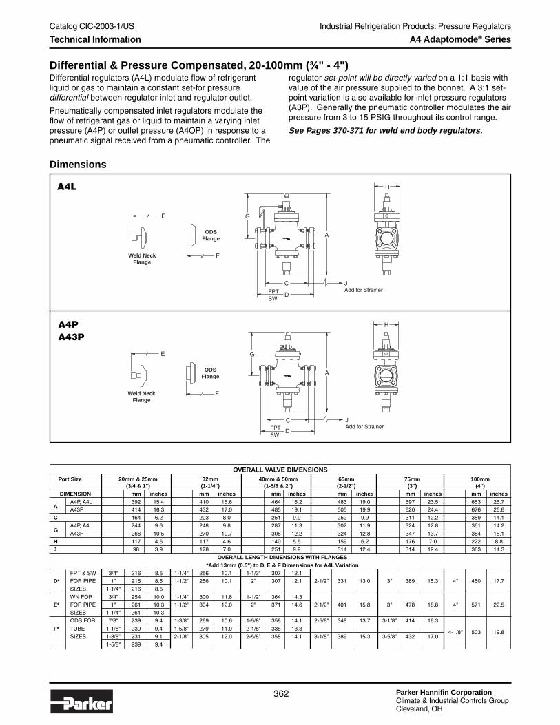
Parker Hannifin CorporationClimate & Industrial Controls GroupCleveland, OH
Catalog CIC-2003-1/US
362
Industrial Refrigeration Products: Pressure Regulators
Differential & Pressure Compensated, 20-100mm (¾" - 4")
A4 Adaptomode® Series
A4L
A4PA43P
Differential regulators (A4L) modulate flow of refrigerantliquid or gas to maintain a constant set-for pressuredifferential between regulator inlet and regulator outlet.
Pneumatically compensated inlet regulators modulate theflow of refrigerant gas or liquid to maintain a varying inletpressure (A4P) or outlet pressure (A4OP) in response to apneumatic signal received from a pneumatic controller. The
regulator set-point will be directly varied on a 1:1 basis withvalue of the air pressure supplied to the bonnet. A 3:1 set-point variation is also available for inlet pressure regulators(A3P). Generally the pneumatic controller modulates the airpressure from 3 to 15 PSIG throughout its control range.
See Pages 370-371 for weld end body regulators.
Dimensions
A
G
C
D
H
FPTSW
JAdd for Strainer
F
E
Weld NeckFlange
ODSFlange
A
G
C
D
H
JAdd for Strainer
F
E
Weld NeckFlange
ODSFlange
FPTSW
OVERALL VALVE DIMENSIONSPort Size 20mm & 25mm 32mm 40mm & 50mm 65mm 75mm 100mm
(3/4 & 1") (1-1/4") (1-5/8 & 2") (2-1/2") (3") (4") DIMENSION mm inches mm inches mm inches mm inches mm inches mm inches
AA4P, A4L 392 15.4 410 15.6 464 16.2 483 19.0 597 23.5 653 25.7A43P 414 16.3 432 17.0 485 19.1 505 19.9 620 24.4 676 26.6
C 164 6.2 203 8.0 251 9.9 252 9.9 311 12.2 359 14.1
GA4P, A4L 244 9.6 248 9.8 287 11.3 302 11.9 324 12.8 361 14.2
A43P 266 10.5 270 10.7 308 12.2 324 12.8 347 13.7 384 15.1H 117 4.6 117 4.6 140 5.5 159 6.2 176 7.0 222 8.8J 98 3.9 178 7.0 251 9.9 314 12.4 314 12.4 363 14.3
OVERALL LENGTH DIMENSIONS WITH FLANGES*Add 13mm (0.5") to D, E & F Dimensions for A4L Variation
FPT & SW 3/4" 216 8.5 1-1/4" 256 10.1 1-1/2" 307 12.1D* FOR PIPE 1" 216 8.5 1-1/2" 256 10.1 2" 307 12.1 2-1/2" 331 13.0 3" 389 15.3 4" 450 17.7
SIZES 1-1/4" 216 8.5WN FOR 3/4" 254 10.0 1-1/4" 300 11.8 1-1/2" 364 14.3
E* FOR PIPE 1" 261 10.3 1-1/2" 304 12.0 2" 371 14.6 2-1/2" 401 15.8 3" 478 18.8 4" 571 22.5SIZES 1-1/4" 261 10.3ODS FOR 7/8" 239 9.4 1-3/8" 269 10.6 1-5/8" 358 14.1 2-5/8" 348 13.7 3-1/8" 414 16.3
F* TUBE 1-1/8" 239 9.4 1-5/8" 279 11.0 2-1/8" 338 13.34-1/8" 503 19.8
SIZES 1-3/8" 231 9.1 2-1/8" 305 12.0 2-5/8" 358 14.1 3-1/8" 389 15.3 3-5/8" 432 17.01-5/8" 239 9.4
Technical Information

Catalog CIC-2003-1/US
Parker Hannifin CorporationClimate & Industrial Controls GroupCleveland, OH
363
Industrial Refrigeration Products: Pressure RegulatorsIn
du
strialR
efrigeratio
nP
rod
ucts
How to Order Differential & Pressure Compensated RegulatorsRegulators can be specified by using the symbols in the chart below to develop a model number. Select only those symbols thatrepresent the features desired, and place them in the sequence indicated by the example at the top of the chart.
A4 Adaptomode® Series
Variation
L DifferentialBL Differential &
Electrical Wide OpeningP Inlet Reg., 1:1 Pneumatic
CompensationPB Inlet Reg., Wide Opening &
1:1 Pneumatic Comp.PS Inlet Reg., Electric Shut-Off
& 1:1 Pneumatic Comp.PE Inlet Reg.,
Externally Equalized &1:1 Pneumatic Comp.
3P Inlet Reg., 3:1 PneumaticCompensation
3PS Inlet Reg., Electric Shut-Off& 3:1 Pneumatic Comp.
OP Outlet Reg., 1:1 PneumaticCompensation
OPS Outlet Reg.,Electric Shut-Off &1:1 Pneumatic Comp.
Port Size
020 20mm (3/4")025 25mm (1")032 32mm (1-1/4")040 40mm (1-1/2")050 50mm (2")065 65mm (2-1/2")075 75mm (3")100 100mm (4")
Low CoilPort Reduced Inlet Outlet Gauge Press. Voltage, Pilot Lens CheckSize Type Variation Range Capacity Flange Flange Gauge Valve Drop Style Light Color Strainer Valve
Reduced CapacityPlugs (see page 8)
0 Full Capacity1 17%3 35%5 50%
Pressure Range
A* 0-10.3 Bar(0-150 PSIG)
D 5.2-19.3 Bar(75-280 PSIG)
V 500mm Hg to 8.3 Bar(20 in Hg to 120 PSIG)
* Not available on outlet regulators(OP, OPS).
Flange Type Connection
X Less 00 NoneFlanges
F FPT (IPS) 06 ¾"S SW (IPS) 08 1"W Weld Neck (IPS) 10 1¼"
12 1½"16 2"20 2½"24 3"32 4"
K ODS (US) 07 7/8"09 11/8"11 13/8"
Not suitable 13 15/8"for use with 17 21/8"ammonia. 21 25/8"
25 31/8"29 35/8"33 41/8"
D DIN Weld Neck Enter sizeM Insert Metric from tableC EC-Br Copper below.
See Availability Table!
020 A4 BL VA 0 F08 F08 2A A1 0 21 0 0 S 4
Gauge Size, Range, Type
0 No GaugeA 2½" Low Pressure, EnglishB 3½" Low Pressure, EnglishC 2½" High Pressure, EnglishD 3½" High Pressure, EnglishE 2½" Low Pressure, MetricF 3½" Low Pressure, MetricG 2½" High Pressure, MetricH 3½" High Pressure, Metric
Flange Availability & WeightsTable shows flange size codes available by flange type for each port size code
Flange Connections Available Weight
Port FPT (IPS) Socket Weld (IPS) ODS (US) DIN Insert EC-Br CopperRegulator w/Flanges w/Str. & Flg.
Code Weld Neck (IPS) Weld Neck Metric kg lb kg lb kg lb
020 06 08 10 06 08 10 07 09 11 20 25 32 20 25 32 18 20 26 30 9.1 20 10 22 14 29
025 06 08 10 06 08 10 07 09 11 20 25 32 20 25 32 18 20 26 30 9.1 20 10 22 14 29
032 10 12 10 12 11 13 17 32 40 50 30 36 42 13 28 14 31 21 46
040 12 16 12 16 13 17 21 40 50 28 62 31 68 45 100
050 12 16 12 16 13 17 21 40 50 28 62 31 68 45 100
065 20 21 25 65 75 34 75 39 85 65 144
075 24 25 29 75 47 104 54 120 81 179
100 32 33 A0 72 159 80 177 132 291
LPD?
0* No1* Yes
* N/A with "L"variation.
Strainer?
N NoS Yes
Remote Pilot Light▲
0 None1 PLT-1 (NEMA 1)2 PLT-2 (NEMA 4)5 PLT-5
▲ With coils 1, 3 & 8 only.See table on page 376 forvoltages.
Lens Color
0 No Pilot LightG Green (std)R RedA AmberW White
Check Valve
0 None1 w/CK-14 w/CK-4
Gauge Valve
N No ValveA 1/4" Angle Body
Coil Style ★★★★★
0 No Coil or Housing1 Encapsulated
w/36" LeadsL* Encapsulated w/36"
Leads & Pilot Light2 Encapsulated
w/DIN ConnectorD* Encapsulated
w/DIN Connector& Pilot Light
3 Ind. Open Framew/18" Leads
5 Explosion Proof8 Compact C,D Operator
w/18" Leads9 Compact C,D Operator
w/DIN Connector
★★★★★ See page 376 for availablecoils by voltage.
* Integral pilot light. Lens colordesignated separately
Standard1 120/60R 120/6/602 208/60S 208/6/603 240/60T 240/6/604 440/606 115/507 230/50U 230/6/508 240/50
Non-StandardA 24/60B 288/60C 480/60D 24/50E 42/50F 48/50G 12V DCH 24V DCK 48V DCW 120V DCJ 230V DCP 115/6/50Q 440/6/60
Coil Voltage
0 No Coil
Refrigerant
0 No Gauge7 R-7171 R-134a2 R-224 R-404A5 R-507
How to Order

Parker Hannifin CorporationClimate & Industrial Controls GroupCleveland, OH
Catalog CIC-2003-1/US
364
Industrial Refrigeration Products: Pressure Regulators
Temperature Operated Regulators (20-100mm)
A4 Adaptomode® Series
The temperature compensated pressure regulator differsfrom the conventional pressure regulator in that rather thanmaintaining a previously set constant pressure, thisregulator modulates pressure in accordance with thedemands of the load. The regulator will vary its pressure setpoint as load demand varies as sensed by the thermal bulb.This valve responds to temperature changes only.
See Pages 370-371 for weld end body regulators.
Dimensions
OVERALL VALVE DIMENSIONSPort Size 20mm & 25mm 32mm 40mm & 50mm 65mm 75mm 100mm
(3/4" & 1") (1-1/4") (1-5/8" & 2") (2-1/2") (3") (4") DIMENSION mm inches mm inches mm inches mm inches mm inches mm inchesA 378 14.9 396 15.6 450 17.7 470 18.5 582 23.0 665 26.2C 164 6.2 203 8.0 251 9.9 252 9.9 311 12.2 359 14.1G 244 9.6 248 9.8 287 11.3 302 11.9 324 12.8 361 14.2H 117 4.6 117 4.6 140 5.5 159 6.2 176 7.0 222 8.8J 98 3.9 178 7.0 251 9.9 314 12.4 314 12.4 363 14.3
OVERALL LENGTH DIMENSIONS WITH FLANGES*Add 13mm (0.5") to D, E & F Dimensions for A4OT Variation
FPT & SW 3/4" 216 8.5 1-1/4" 256 10.1 1-1/2" 307 12.1 2-1/2" 331 13.0 3" 389 15.3
D* FOR PIPE 1" 216 8.5 1-1/2" 256 10.1 2" 307 12.1 4" 450 17.7SIZES 1-1/4" 216 8.5WN FOR 3/4" 254 10.0 1-1/4" 300 11.8 1-1/2" 364 14.3
E* FOR PIPE 1" 261 10.3 1-1/2" 304 12.0 2" 371 14.6 2-1/2" 401 15.8 3" 478 18.8 4" 571 22.5SIZES 1-1/4" 261 10.3ODS FOR 7/8" 239 9.4 1-3/8" 269 10.6 1-5/8" 358 14.1 2-5/8" 348 13.7 3-1/8" 414 16.3
F* TUBE 1-1/8" 239 9.4 1-5/8" 279 11.0 2-1/8" 338 13.34-1/8" 503 19.8
SIZES 1-3/8" 231 9.1 2-1/8" 305 12.0 2-5/8" 358 14.1 3-1/8" 389 15.3 3-5/8" 432 17.01-5/8" 239 9.4
H
Weld NeckFlange
E
F
ODSFlange
G
A
JAdd for Strainer
C
D
8.6" A4T9.5" A4OT
A4T, A4OT
Temperature Module
Technical Information

Catalog CIC-2003-1/US
Parker Hannifin CorporationClimate & Industrial Controls GroupCleveland, OH
365
Industrial Refrigeration Products: Pressure RegulatorsIn
du
strialR
efrigeratio
nP
rod
ucts
How to Order Temperature Operated RegulatorsRegulators can be specified by using the symbols in the chart below to develop a model number. Select only those symbols thatrepresent the features desired, and place them in the sequence indicated by the example at the top of the chart.
A4 Adaptomode® Series
Function
Direct: Opens on Rise in Temp.T Temperature Operated
TS Shut-Off &Temperature Operated
TB Wide Opening &Temperature Operated
DT Dual Pressure &Temperature Operated
DTB Wide Opening, DualPressure & Temp. Op.
DTS Shut-Off, Dual Pressure &Temperature Operated
Inverse: Closes on Rise in Temp.OT Temperature Operated
OET Temperature Operated,Externally Equalized
OTS Temperature Operated& Electric Shut-Off
Port Size
020 20mm (3/4")025 25mm (1")032 32mm (1-1/4")040 40mm (1-1/2")050 50mm (2")065 65mm (2-1/2")075 75mm (3")100 100mm (4")
Low CoilPort Reduced Inlet Outlet Gauge Limit Voltage, Pilot Lens CheckSize Type Variation Range Capacity Flange Flange Gauge Valve Reg. Style Light Color Strainer Valve
Reduced CapacityPlugs (see page 8)
0 Full Capacity1 17%3 35%5 50%
Range
1 Low Temperature:-30° to +30°C (-20° to +80°F)
2 High Temperature:+20° to +60°C (+60° to +140°F)
For "D" Variations (Temp + Pressure)3 Low Temperature + Range A4 Low Temperature + Range D5 Low Temperature + Range V6 High Temperature + Range D
Flange Type Connection
X Less 00 NoneFlanges
F FPT (IPS) 06 ¾"S SW (IPS) 08 1"W Weld Neck (IPS) 10 1¼"
12 1½"16 2"20 2½"24 3"32 4"
K ODS (US) 07 7/8"09 11/8"11 13/8"
Not suitable 13 15/8"for use with 17 21/8"ammonia. 21 25/8"
25 31/8"29 35/8"33 41/8"
D DIN Weld Neck Enter sizeM Insert Metric from tableC EC-Br Copper below.
See Availability Table!
020 A4 OTS 1 0 F08 F08 A2 A 0 21 0 0 S 4
Refrigerant
0 No Gauge7 R-7171 R-134a2 R-224 R-404a5 R-507
Gauge Size, Range, Type
0 No GaugeA 2½" Low Pressure, EnglishB 3½" Low Pressure, EnglishC 2½" High Pressure, EnglishD 3½" High Pressure, EnglishE 2½" Low Pressure, MetricF 3½" Low Pressure, MetricG 2½" High Pressure, MetricH 3½" High Pressure, Metric
Flange Availability & WeightsTable shows flange size codes available by flange type for each port size code
Flange Connections Available Weight
Port FPT (IPS) Socket Weld (IPS) ODS (US) DIN Insert EC-Br CopperRegulator w/Flanges w/Str. & Flg.
Code Weld Neck (IPS) Weld Neck Metric kg lb kg lb kg lb
020 06 08 10 06 08 10 07 09 11 20 25 32 20 25 32 18 20 26 30 9.1 20 10 22 14 29
025 06 08 10 06 08 10 07 09 11 20 25 32 20 25 32 18 20 26 30 9.1 20 10 22 14 29
032 10 12 10 12 11 13 17 32 40 50 30 36 42 13 28 14 31 21 46
040 12 16 12 16 13 17 21 40 50 28 62 31 68 45 100
050 12 16 12 16 13 17 21 40 50 28 62 31 68 45 100
065 20 21 25 65 75 34 75 39 85 65 144
075 24 25 29 75 47 104 54 120 81 179
100 32 33 100 72 159 80 177 132 291
Low LimitRegulator
0 No1 Yes
Strainer?
N NoS Yes
Remote Pilot Light▲
0 None1 PLT-1 (NEMA 1)2 PLT-2 (NEMA 4)5 PLT-5
▲ With coils 1, 3 & 8 only.See table on page 376 forvoltages.
Lens Color
0 No Pilot LightG Green (std)R RedA AmberW White
Check Valve
0 None1 w/CK-14 w/CK-4
Gauge Valve
N No ValveA 1/4" Angle Body
Coil Style ★★★★★
0 No Coil or Housing1 Encapsulated
w/36" LeadsL* Encapsulated w/36"
Leads & Pilot Light2 Encapsulated
w/DIN ConnectorD* Encapsulated
w/DIN Connector& Pilot Light
3 Ind. Open Framew/18" Leads
5 Explosion Proof8 Compact C,D Operator
w/18" Leads9 Compact C,D Operator
w/DIN Connector
★★★★★ See page 376 for availablecoils by voltage.
* Integral pilot light. Lens colordesignated separately
Standard1 120/60R 120/6/602 208/60S 208/6/603 240/60T 240/6/604 440/606 115/507 230/50U 230/6/508 240/50
Non-StandardA 24/60B 288/60C 480/60D 24/50E 42/50F 48/50G 12V DCH 24V DCK 48V DCW 120V DCJ 230V DCP 115/6/50Q 440/6/60
Coil Voltage
0 No Coil
How to Order

Parker Hannifin CorporationClimate & Industrial Controls GroupCleveland, OH
Catalog CIC-2003-1/US
366
Industrial Refrigeration Products: Pressure Regulators
Electrically Compensated Regulators, 20-100mm (¾" - 4")
A4 Adaptomode® Series
Type A4M electrically compensated inlet pressure regulatorsmodulate the flow of refrigerant gas or liquid to maintain a varyingupstream (Inlet) pressure in response to an electrical signalapplied to a low-voltage motor mounted on a regulator pilot.A4OM regulators modulate outlet pressure.
See pages 370-371 for weld end body regulators.
Dimensions
H Max.
191mm(7.5")
F
ODSFlange
Weld NeckFlange
E
G
B
C
A
D
OVERALL VALVE DIMENSIONSPort Size 20mm & 25mm 32mm 40mm & 50mm 65mm 75mm 100mm
(3/4" & 1") (1-1/4") (1-5/8" & 2") (2-1/2") (3") (4") DIMENSION mm inches mm inches mm inches mm inches mm inches mm inches
A4M 597 23.5 615 24.2 668 26.3 688 27.1 803 31.6 859 33.8A
A4OM 620 22.4 638 23.1 691 25.2 711 26.0 826 32.5 882 34.7B 148 5.8 162 6.3 177 6.9 181 7.1 273 10.7 292 11.5C 164 6.2 203 8.0 251 9.9 252 9.9 311 12.2 359 14.1
A4M 449 17.7 453 17.9 491 19.4 507 20.0 530 20.9 566 22.3G
A4OM 472 18.6 476 18.8 514 20.3 530 20.9 553 21.8 589 23.2H 117 4.6 117 4.6 140 5.5 159 6.2 176 7.0 222 8.8
OVERALL LENGTH DIMENSIONS WITH FLANGES*Add 13mm (0.5") to D, E & F Dimensions for A4OM Variation
FPT & SW 3/4" 216 8.5 1-1/4" 256 10.1 1-1/2" 307 12.1
D* FOR PIPE 1" 216 8.5 1-1/2" 256 10.1 2" 307 12.1 2-1/2" 331 13.0 3" 389 15.3 4" 450 17.7SIZES 1-1/4" 216 8.5WN FOR 3/4" 254 10.0 1-1/4" 300 11.8 1-1/2" 364 14.3
E* FOR PIPE 1" 261 10.3 1-1/2" 304 12.0 2" 371 14.6 2-1/2" 401 15.8 3" 478 18.8 4" 571 22.5SIZES 1-1/4" 261 10.3ODS FOR 7/8" 239 9.4 1-3/8" 269 10.6 1-5/8" 358 14.1 2-5/8" 348 13.7 3-1/8" 414 16.3
F* TUBE 1-1/8" 239 9.4 1-5/8" 279 11.0 2-1/8" 338 13.34-1/8" 503 19.8
SIZES 1-3/8" 231 9.1 2-1/8" 305 12.0 2-5/8" 358 14.1 3-1/8" 389 15.3 3-5/8" 432 17.01-5/8" 239 9.4
A4M
Technical Information

Catalog CIC-2003-1/US
Parker Hannifin CorporationClimate & Industrial Controls GroupCleveland, OH
367
Industrial Refrigeration Products: Pressure RegulatorsIn
du
strialR
efrigeratio
nP
rod
ucts
A4 Adaptomode® Series
How to Order Electrically Compensated RegulatorsRegulators can be specified by using the symbols in the chart below to develop a model number. Select only those symbols thatrepresent the features desired, and place them in the sequence indicated by the example at the top of the chart.
Variationction
M Inlet RegulatorMS With Electric Shut-OffBM WithElectric Wide OpeningDM With Dual PressureOM Electrically Compensated
Outlet RegulatorOMS Outlet Regulator with
Electric Shut-Off
Port Size
020 20mm (3/4")025 25mm (1")032 32mm (1-1/4")040 40mm (1-1/2")050 50mm (2")065 65mm (2-1/2")075 75mm (3")100 100mm (4")
Low CoilPort Reduced Inlet Outlet Gauge Press. Voltage, Pilot Lens CheckSize Type Variation Range Capacity Flange Flange Gauge Valve Drop Style Light Color Strainer Valve
Reduced CapacityPlug (see page 8)
0 Full Capacity1 17%3 35%5 50%
Flange Type Connection
X Less 00 NoneFlanges
F FPT (IPS) 06 ¾"S SW (IPS) 08 1"W Weld Neck (IPS) 10 1¼"
12 1½"16 2"20 2½"24 3"32 4"
K ODS (US) 07 7/8"09 11/8"11 13/8"
Not suitable 13 15/8"for use with 17 21/8"ammonia. 21 25/8"
25 31/8"29 35/8"33 41/8"
D DIN Weld Neck Enter sizeM Insert Metric from tableC EC-Br Copper below.
See Availability Table!
020 A4 OMS1 D 0 F08 F08 A2 A 0 21 0 0 S 4
Refrigerant
0 No Gauge7 R-7171 R-134a2 R-224 R-404a5 R-507
Gauge Size, Range, Type
0 No GaugeA 2½" Low Pressure, EnglishB 3½" Low Pressure, EnglishC 2½" High Pressure, EnglishD 3½" High Pressure, EnglishE 2½" Low Pressure, MetricF 3½" Low Pressure, MetricG 2½" High Pressure, MetricH 3½" High Pressure, Metric
Flange Availability & WeightsTable shows flange size codes available by flange type for each port size code
Flange Connections Available Weight
Port FPT (IPS) Socket Weld (IPS) ODS (US) DIN Insert EC-Br CopperRegulator w/Flanges w/Str. & Flg.
Code Weld Neck (IPS) Weld Neck Metric kg lb kg lb kg lb
020 06 08 10 06 08 10 07 09 11 20 25 32 20 25 32 18 20 26 30 9.1 20 10 22 14 29
025 06 08 10 06 08 10 07 09 11 20 25 32 20 25 32 18 20 26 30 9.1 20 10 22 14 29
032 10 12 10 12 11 13 17 32 40 50 30 36 42 13 28 14 31 21 46
040 12 16 12 16 13 17 21 40 50 28 62 31 68 45 100
050 12 16 12 16 13 17 21 40 50 28 62 31 68 45 100
065 20 21 25 65 75 34 75 39 85 65 144
075 24 25 29 75 47 104 54 120 81 179
100 32 33 A0 72 159 80 177 132 291
Pressure Range*
A** 0-10.3 Bar (0-150 PSIG)D 5.2-19.3 Bar (75-280 PSIG)V 500mm Hg to 8.3 Bar
(20 in Hg to 120 PSIG)
Motor Style
H Motor Hardware OnlyHoneywell Motors
1 24V 50/60Hz Std. Cam,120V Transformer
A Option 1 with 240V Transformer2 24V 50/60Hz Low Rise Cam,
120V TransformerB Option 2 with 240V Transformer3 4-20 mA, 120V 50/60Hz
Standard Cam4 4-20 mA, 120V 50/60Hz
Low Rise Cam5 4-20 mA, 240V 50/60Hz
Standard Cam6 220V 50Hz Std. Cam7 220V 50Hz Low Rise Cam
Penn Motors8 24V 50/60Hz Std. Cam,
120V TransformerC Option 8 with 240V Transformer9 24V 50/60Hz Low Rise Cam,
120 V TransformerD Option 9 with 240V Transformer
*For DM variation, indicate range for eachpilot, i.e. AD (low/high).** Not available with OM or OMS variation.
LPD
0 N/A
Strainer?
N NoS Yes
Remote Pilot Light▲
0 None1 PLT-1 (NEMA 1)2 PLT-2 (NEMA 4)5 PLT-5
▲ With coils 1, 3 & 8 only.See table on page 376 forvoltages.
Lens Color
0 No Pilot LightG Green (std)R RedA AmberW White
Check Valve
0 None1 w/CK-14 w/CK-4
Body
N No ValveA 1/4" Angle Body
Coil Style ★★★★★
0 No Coil or Housing1 Encapsulated
w/36" LeadsL* Encapsulated w/36"
Leads & Pilot Light2 Encapsulated
w/DIN ConnectorD* Encapsulated
w/DIN Connector& Pilot Light
3 Ind. Open Framew/18" Leads
5 Explosion Proof8 Compact C,D Operator
w/18" Leads9 Compact C,D Operator
w/DIN Connector
★★★★★ See page 376 for availablecoils by voltage.
* Integral pilot light. Lens colordesignated separately
Standard1 120/60R 120/6/602 208/60S 208/6/603 240/60T 240/6/604 440/606 115/507 230/50U 230/6/508 240/50
Non-StandardA 24/60B 288/60C 480/60D 24/50E 42/50F 48/50G 12V DCH 24V DCK 48V DCW 120V DCJ 230V DCP 115/6/50Q 440/6/60
Coil Voltage
0 No Coil
How to Order

Parker Hannifin CorporationClimate & Industrial Controls GroupCleveland, OH
Catalog CIC-2003-1/US
368
Industrial Refrigeration Products: Pressure Regulators
Electronic Pilot Operated Regulators, 20-100mm (¾" - 4")Type A4J electronic pilot operated regulators utilize aLandis & Staefa M2FP03GX direct operated proportionalsolenoid as a pilot valve to modulate the flow of pilotpressure to the top of the regulator's piston. The positioningof the electronic pilot actuator is proportional to the input
A4J
Dimensions
signal supplied to the electronic valve. Two separate controlmodules are available which respond to the supply signalfrom an external controller which senses the medium beingcooled.
Type A4J is not available in 125-200mm (5" - 8") sizes.
F
ODSFlange
Weld NeckFlange
EC
B
A
D
G
A4 Adaptomode® Series
Electronic AccessoriesFor use with “J” variation regulators
Controllers Part #
4-20 mA ............................. 1056240-18 VDC ........................... 105625
Transformer Part #
240/24 ................................ 301787120/24 ................................ 301788
OVERALL VALVE DIMENSIONSPort Size 20mm & 25mm 32mm 40mm & 50mm 65mm 75mm 100mm
(3/4" & 1") (1-1/4") (1-5/8" & 2") (2-1/2") (3") (4") DIMENSION mm inches mm inches mm inches mm inches mm inches mm inchesA 432 17.0 450 17.7 503 19.8 523 20.6 635 25.0 693 27.3B 148 5.8 162 6.3 177 6.9 181 7.1 273 10.7 292 11.5C 164 6.2 203 8.0 251 9.9 252 9.9 311 12.2 359 14.1G 259 10.2 284 1132 325 12.8 343 13.5 366 14.4 401 15.6H 117 4.6 117 4.6 140 5.5 159 6.2 176 7.0 222 8.8
OVERALL LENGTH DIMENSIONS WITH FLANGES
FPT & SW 3/4" 216 8.5 1-1/4" 256 10.1 1-1/2" 307 12.1D* FOR PIPE 1" 216 8.5 1-1/2" 256 10.1 2" 307 12.1 2-1/2" 331 13.0 3" 389 15.3 4" 450 17.7
SIZES 1-1/4" 216 8.5WN FOR 3/4" 254 10.0 1-1/4" 300 11.8 1-1/2" 364 14.3
E* FOR PIPE 1" 261 10.3 1-1/2" 304 12.0 2" 371 14.6 2-1/2" 401 15.8 3" 478 18.8 4" 571 22.5SIZES 1-1/4" 261 10.3ODS FOR 7/8" 239 9.4 1-3/8" 269 10.6 1-5/8" 358 14.1 2-5/8" 348 13.7 3-1/8" 414 16.3
F* TUBE 1-1/8" 239 9.4 1-5/8" 279 11.0 2-1/8" 338 13.34-1/8" 503 19.8
SIZES 1-3/8" 231 9.1 2-1/8" 305 12.0 2-5/8" 358 14.1 3-1/8" 389 15.3 3-5/8" 432 17.01-5/8" 239 9.4
Technical Information

Catalog CIC-2003-1/US
Parker Hannifin CorporationClimate & Industrial Controls GroupCleveland, OH
369
Industrial Refrigeration Products: Pressure RegulatorsIn
du
strialR
efrigeratio
nP
rod
ucts
How to Order Electronic Pilot Operated RegulatorsRegulators can be specified by using the symbols in the chart below to develop a model number. Select only those symbols thatrepresent the features desired, and place them in the sequence indicated by the example at the top of the chart.
Function
J Electronic Pilot OperatedJS Electronic Pilot Operated
with Electric Shut-OffDJ Electronic Pilot Operated
with Dual Pressure
Port Size
020 20mm (3/4")025 25mm (1")032 32mm (1-1/4")040 40mm (1-1/2")050 50mm (2")065 65mm (2-1/2")075 75mm (3")100 100mm (4")
Low CoilPort Reduced Inlet Outlet Gauge Press. Voltage, Pilot Lens CheckSize Type Variation Range Capacity Flange Flange Gauge Valve Drop Style Light Color Strainer Valve
Reduced CapacityPlugs (see page 8)
0 Full Capacity1 17%3 35%5 50%
Flange Type Connection
X Less 00 NoneFlanges
F FPT (IPS) 06 ¾"S SW (IPS) 08 1"W Weld Neck (IPS) 10 1¼"
12 1½"16 2"20 2½"24 3"32 4"
K ODS (US) 07 7/8"09 11/8"11 13/8"
Not suitable 13 15/8"for use with 17 21/8"ammonia. 21 25/8"
25 31/8"29 35/8"33 41/8"
D DIN Weld Neck Enter sizeM Insert Metric from tableC EC-Br Copper below.
See Availability Table!
020 A4 J1 A 0 F08 F08 A2 A 0 21 0 0 S 4
Refrigerant
0 No Gauge7 R-7171 R-134a2 R-224 R-404a5 R-507
Gauge Size, Range, Type
0 No GaugeA 2½" Low Pressure, EnglishB 3½" Low Pressure, EnglishC 2½" High Pressure, EnglishD 3½" High Pressure, EnglishE 2½" Low Pressure, MetricF 3½" Low Pressure, MetricG 2½" High Pressure, MetricH 3½" High Pressure, Metric
Flange Availability & WeightsTable shows flange size codes available by flange type for each port size code
Flange Connections Available Weight
Port FPT (IPS) Socket Weld (IPS) ODS (US) DIN Insert EC-Br CopperRegulator w/Flanges w/Str. & Flg.
Code Weld Neck (IPS) Weld Neck Metric kg lb kg lb kg lb
020 06 08 10 06 08 10 07 09 11 20 25 32 20 25 32 18 20 26 30 9.1 20 10 22 14 29
025 06 08 10 06 08 10 07 09 11 20 25 32 20 25 32 18 20 26 30 9.1 20 10 22 14 29
032 10 12 10 12 11 13 17 32 40 50 30 36 42 13 28 14 31 21 46
040 12 16 12 16 13 17 21 40 50 28 62 31 68 45 100
050 12 16 12 16 13 17 21 40 50 28 62 31 68 45 100
065 20 21 25 65 75 34 75 39 85 65 144
075 24 25 29 75 47 104 54 120 81 179
100 32 33 A0 72 159 80 177 132 291
Pressure Range*
A 0-10.3 Bar (0-150 PSIG)D 5.2-19.3 Bar (75-280 PSIG)V 500mm Hg to 8.3 Bar
(20 in Hg to 120 PSIG)
*For dual pressure variation (DJ),enter pressure range for each pilotregulator, i.e. VA (low/high).
I/O Control Module
1 4-20 mA I/O Module2 4-20 mA with Controller3 4-20 mA with Controller and
120/24 Transformer4 4-20 mA with Controller and
240/24 Transformer5 0-10 VDC I/O Module6 0-10 VDC with Controller7 0-10 VDC with Controller and
120/24 Transformer8 0-10 VDC with Controller and
240/24 Transformer
A4 Adaptomode® Series
LPD
0 No
Strainer
N NoS Yes
Remote Pilot Light▲
0 None1 PLT-1 (NEMA 1)2 PLT-2 (NEMA 4)5 PLT-5
▲ With coils 1, 3 & 8 only.See table on page 376 forvoltages.
Lens Color
0 No Pilot LightG Green (std)R RedA AmberW White
Check Valve
0 None1 w/CK-14 w/CK-4
Gauge Valve
N No ValveA 1/4" Angle Body
Coil Style ★★★★★
0 No Coil or Housing1 Encapsulated
w/36" LeadsL Encapsulated w/36"
Leads & Pilot Light*2 Encapsulated
w/DIN ConnectorD Encapsulated
w/DIN Connector& Pilot Light*
3 Ind. Open Framew/18" Leads
5 Explosion Proof8 Compact C,D Operator
w/18" Leads9 Compact C,D Operator
w/DIN Connector
★★★★★ See page 376 for availablecoils by voltage.
* Integral pilot light. Lens colordesignated separately
Standard1 120/60R 120/6/602 208/60S 208/6/603 240/60T 240/6/604 440/606 115/507 230/50U 230/6/508 240/50
Non-StandardA 24/60B 288/60C 480/60D 24/50E 42/50F 48/50G 12V DCH 24V DCK 48 VDCW 120V DCJ 230V DCP 115/6/50Q 440/6/60
Coil Voltage
0 No Coil
How to Order

Parker Hannifin CorporationClimate & Industrial Controls GroupCleveland, OH
Catalog CIC-2003-1/US
370
Industrial Refrigeration Products: Pressure Regulators
A4 Adaptomode® Series
Weld End Regulators, 125-200mm (5" - 8")
TABLE OF DIMENSIONS125 (5") 150 (6") 200 (8")
DIMENSIONS TYPE mm inches mm inches mm inchesA4, A4E, A4P 438 17.25 514 20.25 572 22.50A4R 414 16.25 489 19.25 546 21.50
A A4S, A4B 476 18.75 552 21.75 610 24.00A4D 502 19.75 578 22.75 635 25.00A4OE 463 18.25 539 21.25 597 23.50
B 114 4.50 152 6.00 197 7.750C 190 7.50 254 10.00 356 14.00
D 381 15.00 483 19.00 622 24.50E 318 12.50 394 15.50 451 17.75F 273 10.75 349 13.75 406 16.00G 305 12.00 381 15.00 438 17.25H 267 10.50 318 12.50 381 15.00K 100 4.00 100 4.00 100 4.00L 140 5.50 140 5.50 140 5.50
A4A4EA4P
A4R A4OE
A4BA4SA4D
These heavy duty, cast steel bodied pressure regulatorsweld directly in the line and do not require flanges. As withthe flanged body regulators, they are pilot operated and usethe same modules to configure many variations.
These valves can be ordered with the R/S strainer to bewelded directly to the inlet of any regulator.
Dimensions
A
C
G
AG
D
A
B
G
H
E
NOTE:
Allow 75mm (3") overhead clearancefor access to adjusting stem.
Allow 100mm (4") overhead clearancefor coil or seal cap removal.
L K
A(A4D)
A(A4B,A4S)
K
L
H
Technical Information

Catalog CIC-2003-1/US
Parker Hannifin CorporationClimate & Industrial Controls GroupCleveland, OH
371
Industrial Refrigeration Products: Pressure RegulatorsIn
du
strialR
efrigeratio
nP
rod
ucts
A4 Adaptomode® Series
How to Order Weld End RegulatorsRegulators can be specified by using the symbols in the chart below to develop a model number. Select only those symbols thatrepresent the features desired, and place them in the sequence indicated by the example at the top of the chart.
Port Size
125 125mm (5")150 150mm (6")200 200mm (8")
LPD/ CoilPort Gauge Low Limit Voltage, Pilot LensSize Type Variation Range Gauge Valve Regulator Style Light Color Strainer
Pressure Range*
A** 0-10.3 Bar(0-150 PSIG)
D 5.2-19.3 Bar(75-280 PSIG)
V 500mm Hg to 8.3 Bar(20 in Hg to 120 PSIG)
0 No Range (A4R only)
Temperature Range("T" Variation only)
1 Low Temperature:-30° to +30°C(-20° to +80°F)
2 High Temperature:+20° to +60°C(+60° to +140°F)
* Dual pressure regulators(“D”variations) require a range foreach pilot regulator, i.e. AD(low/high).
** Not available for outlet regulators.
Low Pressure Drop(Variations B, S, BS, D,
P, 3P, PB, PS,OE, OES only)
0 No LPD1 With LPD
Low Limit Regulator(Variation T only)
0 No Low Limit Reg.1 With Low Limit Reg.
150 A4 BS A A2 A 0 21 0 0 S
Variation(For a differential regulator,
use variation "P")
Blank Basic Inlet RegulatorB Electric Wide OpeningS Electric Shut-Off
BS Electric Wide Opening &Shut-Off
D Dual PressureE Externally EqualizedK Reseating Relief
BK Electric Wide Opening &Reseating Relief
M Electrically CompensatedMS Electrically Compensated
with Electric Shut-OffBM Electrically Compensated
with Electric Wide OpenDM Dual Pressure,
Electrically CompensatedP 1:1 Pressure Compensated
PB 1:1 Compensation andElectric Wide Opening
PS 1:1 Compensation andElectric Shut-Off
3P 3:1 Pressure CompensatedR Main Regulator only
(Order Remote PilotSeparately)
T Temperature CompensatedZ Basic Inlet Regulator
with Modudapter® andTwo Moduplates®
OE Basic Outlet RegulatorOES Outlet Regulator with
Electric Shut-Off
Body
N No ValveA 1/4" Angle Body
Refrigerant
0 No Gauge7 R-7171 R-134a2 R-224 R-404A5 R-507
Gauge Size, Range, Type
0 No GaugeA 2½" Low Pressure, EnglishB 3½" Low Pressure, EnglishC 2½" High Pressure, EnglishD 3½" High Pressure, EnglishE 2½" Low Pressure, MetricF 3½" Low Pressure, MetricG 2½" High Pressure, MetricH 3½" High Pressure, Metric
Weights
Port Less Strainer w/Strainer
Code kg lb kg lb
125 54 120 99 220
150 98 215 176 390
200 159 350 294 650
Motor Style (for M, MS, BM and DM only)
H Motor Hardware OnlyHoneywell Motors
1 24V 50/60Hz Std. Cam,120V Transformer
A Option 1 with 240V Transformer2 24V 50/60Hz Low Rise Cam,
120V TransformerB Option 2 with 240V Transformer3 4-20 mA, 120V 50/60Hz
Standard Cam4 4-20 mA, 120V 50/60Hz
Low Rise Cam5 4-20 mA, 240V 50/60Hz
Standard Cam6 220V 50Hz Std. Cam7 220V 50Hz Low Rise Cam
Penn Motors8 24V 50/60Hz Std. Cam,
120V TransformerC Option 8 with 240V Transformer9 24V 50/60Hz Low Rise Cam,
120V TransformerD Option 9 with 240V Transformer
Strainer?
N NoS Yes
Remote Pilot Light▲
0 None1 PLT-1 (NEMA 1)2 PLT-2 (NEMA 4)5 PLT-5
▲ With coils 1, 3 & 8 only.See table on page 376 forvoltages.
Lens Color
0 No Pilot LightG Green (std)R RedA AmberW White
Coil Style ★★★★★
0 No Coil or Housing1 Encapsulated
w/36" LeadsL* Encapsulated w/36"
Leads & Pilot Light2 Encapsulated
w/DIN ConnectorD* Encapsulated
w/DIN Connector& Pilot Light
3 Ind. Open Framew/18" Leads
5 Explosion Proof8 Compact C,D Operator
w/18" Leads9 Compact C,D Operator
w/DIN Connector
★★★★★ See page 376 for availablecoils by voltage.
* Integral pilot light. Lens colordesignated separately
Standard1 120/60R 120/6/602 208/60S 208/6/603 240/60T 240/6/604 440/606 115/507 230/50U 230/6/508 240/50
Non-StandardA 24/60B 288/60C 480/60D 24/50E 42/50F 48/50G 12V DCH 24V DCK 48V DCW 120V DCJ 230V DCP 115/6/50Q 440/6/60
Coil Voltage
0 No Coil
How to Order
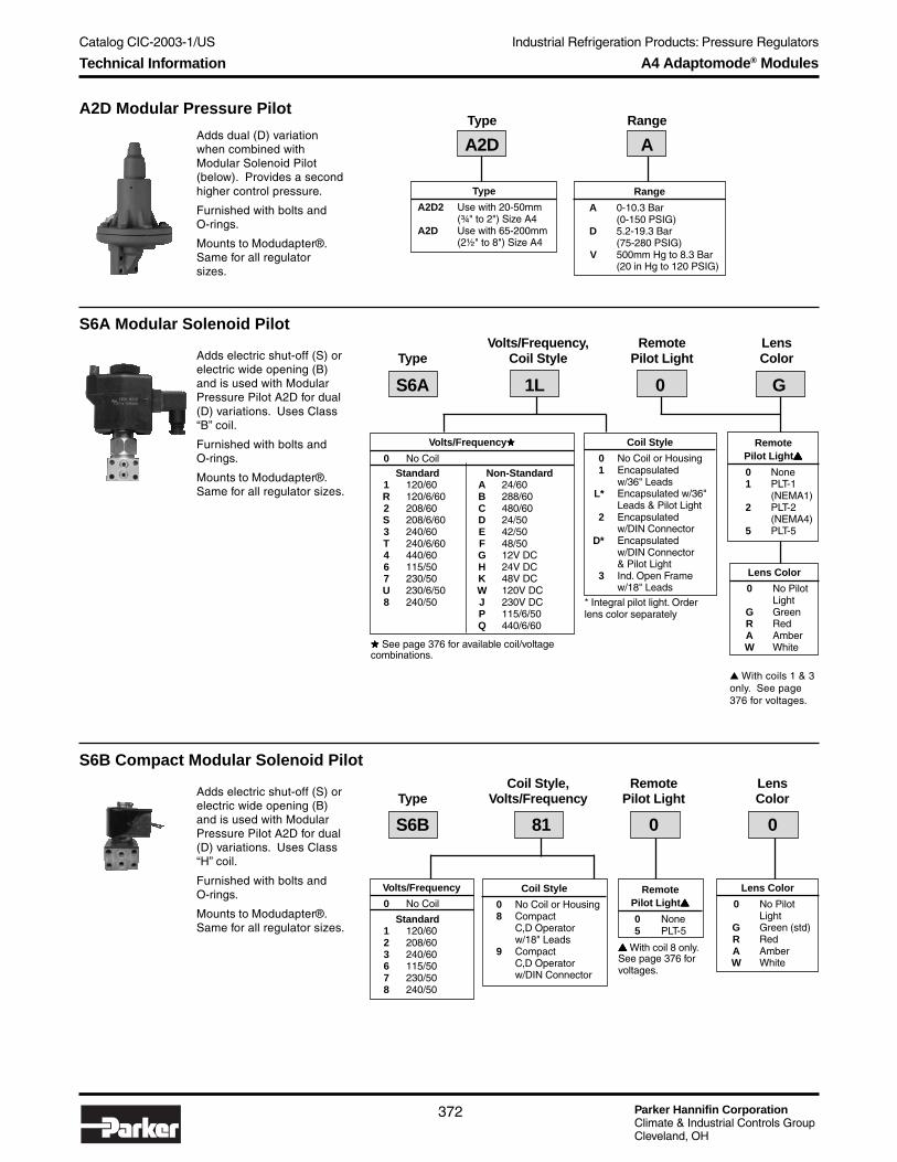
Parker Hannifin CorporationClimate & Industrial Controls GroupCleveland, OH
Catalog CIC-2003-1/US
372
Industrial Refrigeration Products: Pressure Regulators
A4 Adaptomode® Modules
Adds electric shut-off (S) orelectric wide opening (B)and is used with ModularPressure Pilot A2D for dual(D) variations. Uses Class“B” coil.
Furnished with bolts andO-rings.
Mounts to Modudapter® .Same for all regulator sizes.
S6A Modular Solenoid PilotVolts/Frequency, Remote Lens
Type Coil Style Pilot Light Color
Lens Color
0 No PilotLight
G GreenR RedA AmberW White
Adds dual (D) variationwhen combined withModular Solenoid Pilot(below). Provides a secondhigher control pressure.
Furnished with bolts andO-rings.
Mounts to Modudapter® .Same for all regulatorsizes.
A2D Modular Pressure PilotType Range
Adds electric shut-off (S) orelectric wide opening (B)and is used with ModularPressure Pilot A2D for dual(D) variations. Uses Class“H” coil.
Furnished with bolts andO-rings.
Mounts to Modudapter® .Same for all regulator sizes.
S6B Compact Modular Solenoid PilotCoil Style, Remote Lens
Type Volts/Frequency Pilot Light Color
RemotePilot Light▲▲▲▲▲
0 None5 PLT-5
▲▲▲▲▲ With coil 8 only.See page 376 forvoltages.
Lens Color
0 No PilotLight
G Green (std)R RedA AmberW White
S6B 81 0 0
RemotePilot Light▲▲▲▲▲
0 None1 PLT-1
(NEMA1)2 PLT-2
(NEMA4)5 PLT-5
S6A 1L 0 G
Coil Style
0 No Coil or Housing1 Encapsulated
w/36" LeadsL* Encapsulated w/36"
Leads & Pilot Light2 Encapsulated
w/DIN ConnectorD* Encapsulated
w/DIN Connector& Pilot Light
3 Ind. Open Framew/18" Leads
* Integral pilot light. Orderlens color separately
Standard1 120/60R 120/6/602 208/60S 208/6/603 240/60T 240/6/604 440/606 115/507 230/50U 230/6/508 240/50
Non-StandardA 24/60B 288/60C 480/60D 24/50E 42/50F 48/50G 12V DCH 24V DCK 48V DCW 120V DCJ 230V DCP 115/6/50Q 440/6/60
Volts/Frequency★★★★★
0 No Coil
★★★★★ See page 376 for available coil/voltagecombinations.
Coil Style
0 No Coil or Housing8 Compact
C,D Operatorw/18" Leads
9 CompactC,D Operatorw/DIN Connector
Standard1 120/602 208/603 240/606 115/507 230/508 240/50
Volts/Frequency
0 No Coil
Type
A2D2 Use with 20-50mm(¾" to 2") Size A4
A2D Use with 65-200mm(2½" to 8") Size A4
Range
A 0-10.3 Bar(0-150 PSIG)
D 5.2-19.3 Bar(75-280 PSIG)
V 500mm Hg to 8.3 Bar(20 in Hg to 120 PSIG)
A2D A
▲ With coils 1 & 3only. See page376 for voltages.
Technical Information

Catalog CIC-2003-1/US
Parker Hannifin CorporationClimate & Industrial Controls GroupCleveland, OH
373
Industrial Refrigeration Products: Pressure RegulatorsIn
du
strialR
efrigeratio
nP
rod
ucts
A4 Adaptomode® Modules
The special adapter to which themodular solenoid pilot, modularpressure pilot and Moduplate arebolted.
The Series Modudapter (SMD) isused with special regulators such asA4DS, A4BDS, etc.
Furnished with bolts and gaskets.(Standard part of regulators withS, B, D and Z variations)
NOTE:Use SMD65 for all 125-200mm(5" - 8") A4 regulators.
Modudapter® (MD, SMD)Type Use with Regulator Size Part Number
MD25 20-25mm (¾"-1") 200591
MD32 32mm (1¼") 200593
MD50 40-50mm (15/8"-2") 200595
MD65 65mm (2½") 200597
MD75 75mm (3") 200599
MD100 100mm (4") 200606
Series Modudapter®
SMD65 20-65mm (¾"-2½")200564125-200mm (5" - 8")
SMD100 75-100mm (3"-4") 200566
Provides blankoff or cross-over ofpilot circuit on Type A4S or Type A4B.
Attaches to Modudapter. Same for allregulator sizes.
Furnished with bolts and threeO-rings.
Moduplate® (MP)
A pilot seat with vacuum rangecartridge. Will change A range A4,A2B or A2D to vacuum range:500mm Hg to 8.3 bar(20 in Hg to 120 PSIG).
Same for all regulator sizes.
Furnished with diaphragm andnecessary gasket.
Vacuum Cartridge (VC)
To order, specify Part # 200518.
To order, specify Part # 202004.
An auxiliary adapter whichconverts A4 inlet regulatorsto outlet regulators with OEvariation.
Furnished with all internalparts, bolts and gaskets.
Outlet Regulator Kit (OR)
Use with Port Sizes Part Number
20-50mm (¾"- 2") 200516
65-200mm (2½"- 8") 200517
Technical Information

Parker Hannifin CorporationClimate & Industrial Controls GroupCleveland, OH
Catalog CIC-2003-1/US
374
Industrial Refrigeration Products: Pressure Regulators
Converts to electriccompensation (M) variationany A4 Series regulator.Standard in A range.Combine with VC vacuumcartridge for V range.
Furnished with bonnet, allinternal parts, cam, bolts,gaskets, motor andtransformer with 24 Voltsecondary to operatemotor.
Same for all ports.
Motor Bonnet Kit (MB)
Motor Style
H Motor Hardware OnlyHoneywell Motors
1 24V 50/60Hz Std. Cam with 120V TransformerA 24V 50/60Hz Std. Cam with 240V Transformer2 24V 50/60Hz Low Rise Cam with 120V TransformerB 24V 50/60Hz Low Rise Cam with 240V Transformer3 4-20 mA, 120V 50/60Hz Standard Cam4 4-20 mA, 120V 50/60Hz Low Rise Cam5 4-20 mA, 240V 50/60Hz Standard Cam6 220V 50Hz Standard Cam7 220V 50Hz Low Rise Cam
Penn Motors8 24V 50/60Hz Std. Cam with 120V TransformerC 24V 50/60Hz Std. Cam with 240V Transformer9 24V 50/60Hz Low Rise Cam with 120V TransformerD 24V 50/60Hz Low Rise Cam with 240V Transformer
Type Motor Style
MB 3
A4 Adaptomode® Modules
Converts any A4, A4O or A2 Seriesregulator to 1:1 Pressure Compensa-tion (P) variation . Standard in Arange. Use with Type VC vacuumcartridge for V range.
Also available 3:1 pressure compen-sation (3P) variation.
Furnished with ¼" FPT bonnetconnection for air or refrigerantpressure, bolts and gaskets. 3:1 kitincludes above plus auxiliary adapter.
Same for all port sizes.
Pressure Bonnet Kit (PK)
Converts to temperature operated(T and OT) variation any A4 regulator.
Low range: -30° to 30°C(-20° to 80°F)
High range: 20° to 60°C(60° to 140°F)
Furnished as complete bonnetassembly including 15.9 x 133.4mm(5/8" x 3¼") bulb, 6m (20 ft.) capillary,bolts, gaskets and O-rings. Consultfactory for 33' capillary.
Kit for A4OT (¾" to 4" only) includestubing assembly for downstreamconnection.
Temperature Bonnet Kit (TB)
Type Part Number
PK1 (1:1) 200520
PK3 (3:1) 200519
Part # Part #Use with Port Sizes Low Range High Range
20-50mm (¾"-2") 200622 202098
65-200mm (2½"-8") 200624 202097
Direct Acting (Cooling)
Part # Part #Use with Port Sizes Low Range High Range
20-200mm (¾"-8") 202096 202099
Reverse Acting (Heating)
Technical Information
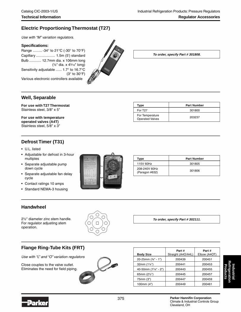
Catalog CIC-2003-1/US
Parker Hannifin CorporationClimate & Industrial Controls GroupCleveland, OH
375
Industrial Refrigeration Products: Pressure RegulatorsIn
du
strialR
efrigeratio
nP
rod
ucts
Regulator Accessories
Electric Proportioning Thermostat (T27)
Use with “M” variation regulators.
Specifications:Range ......... -34° to 21°C (-30° to 70°F)Capillary ................... 1.5m (5') standardBulb ............ 12.7mm dia. x 106mm long
(½" dia. x 43⁄16" long)Sensitivity adjustable ...... 1.7° to 16.7°C
(3° to 30°F)Various electronic controllers available
Defrost Timer (T31)• U.L. listed
• Adjustable for defrost in 3-hourmultiples
• Separate adjustable pumpdown cycle
• Separate adjustable fan delaycycle
• Contact ratings 10 amps
• Standard NEMA-3 housing
Well, Separable
For use with T27 ThermostatStainless steel, 3/8" x 5"
For use with temperatureoperated valves (A4T)Stainless steel, 5/8" x 3"
To order, specify Part # 301808.
Type Part Number
For T27 301800
For TemperatureOperated Valves 203237
Type Part Number
115V 60Hz 301805
208-240V 60Hz301806(Paragon #632)
Handwheel
2½" diameter zinc stem handle.For regulator adjusting stemoperation.
Flange Ring-Tube Kits (FRT)
Use with “L” and “O” variation regulators
Close couples to the valve outlet.Eliminates the need for field piping.
Part # Part #Body Size Straight (A4O/A4L) Elbow (A4OT)
20-25mm (¾" - 1") 200439 200451
32mm (1¼") 200441 200453
40-50mm (15⁄8" - 2") 200443 200455
65mm (2½") 200445 200457
75mm (3") 200447 200459
100mm (4") 200449 200461
To order, specify Part # 302111.
Technical Information

Parker Hannifin CorporationClimate & Industrial Controls GroupCleveland, OH
Catalog CIC-2003-1/US
376
Industrial Refrigeration Products: Pressure Regulators
Encapsulated w/Leads 1 B ● ● ● ● ● ● ● ● ● ● ● ●
Encapsulated w/Leads & Integral Pilot Light L B ● ● ● ●
Encapsulated w/DIN Connector 2 B ● ● ● ● ● ●
Encapsulated w/DIN & Integral Pilot Light D B ● ● ● ● ●
Industrial Open Frame w/Leads 3 B ● ● ● ● ● ● ● ● ● ● ● ● ● ● ● ● ● ● ● ● ● ●
Explosion Proof 5 — ● ● ● ● ● ● ● ● ●
Compact C,D Operator w/Leads 8 H ● ● ● ● ● ●
Compact C,D Operator w/DIN Connector 9 H ● ● ● ● ● ●
PLT-1 (NEMA 1) ● ● ● ● ● ●
PLT-2 (NEMA 4) ● ● ● ● ● ●
PLT-5 (NEMA 4) ● ● ●
Solenoid Coils
Class “ B” Coil (S6A)The molded water resistantClass “B” solenoid coil, availableon most Refrigerating Special-ties solenoid valves, is designedfor long life and powerfulopening force. The standard coilhousing meets NEMA 3R and 4requirements. This sealedconstruction can withstanddirect contact with moisture andice. The coil housing farexceeds the requirements of NEMA Standard ICS.1-110.57salt spray test for rust resistance.
By definition, Class “B” coil construction will permit coiltemperatures, as measured by resistance method, as highas 130°C (266°F). Final coil temperatures are a function ofboth fluid and ambient temperatures. The higher fluidtemperatures require lower ambient temperatures so the
maximum coil temperature is not exceeded. Conversely,low fluid temperatures permit higher ambient temperatures.
The supply circuits must be properly sized to give adequatevoltage at the coil even when other electrical equipment isoperating. The coil is designed to operate with line voltagefrom 85% to 110% of rated coil voltage. Power consump-tion during normal operation will be 33 watts or less.
Standard Encapsulated Coils
For other voltages, contact factory. On transformer coil, the 6 voltleads are always black.
Class “ H” Coil (S6B)The Refrigerating SpecialtiesDivision molded water resistantClass “H” coil is designed forlong life and powerful openingforce. The Class “H” coilconstruction will permit coiltemperatures, as measured byresistance method, as high as180°C (365°F).
The supply circuits must be properly sized to give adequatevoltage at the coil leads even when other electrical equip-ment is operating. The coil is designed to operate at 15%
Inrush Holding FuseCurrent Current Size
Volts/Hertz Leads (Amps) (Amps) (Amps)
120/60 Blue 1.18 0.46 1
208/60 Blue and Red 0.63 0.26 1
240/60 Red 0.60 0.23 1
115/50 Yellow and Blue 1.22 0.21 1
230/50 Yellow 0.65 0.26 1
Watt Volt AmperageCoil Type Rating Holding Inrush
Standard AC10.5 23 37Class “ H”
Standard AC Coilwith 6v Secondary 11.0 26 38Pilot Light
under voltage. Operating with line voltage below the limitwill result in lowering the valve opening pressure differen-tial.
Currents
VoltagesCoils are available from stock with most standard voltages (see table below). Non-standard voltages(shown in the shaded area of table) are available as special order. Coils are also available with 6Vsecondary voltage for use with remote pilot lights PLT-1 and PLT-2. Consult factory for other voltages.
NOTE: Pilot lights cannot be used with explosion proof or unleaded coils.
Cod
e
Cla
ss
120/
60
120/
6/60
208/
60
208/
6/60
240/
60
240/
6/60
440/
60
115/
50
230/
50
230/
6/50
240/
50
24/6
0
288/
60
480/
60
24/5
0
42/5
0
48/5
0
12V
DC
24V
DC
48V
DC
120V
DC
230V
DC
115/
6/50
440/
6/60
Available Voltages forCoils and Pilot Lights
Technical Information

Catalog CIC-2003-1/US
Parker Hannifin CorporationClimate & Industrial Controls GroupCleveland, OH
377
Industrial Refrigeration Products: Solenoid ValvesIn
du
strialR
efrigeratio
nP
rod
ucts
Common SpecificationsDesign Pressure (MRP) ............ 27.6 Bar (400 psig) SV2 only .............................. 31.0 Bar (450 psig)Maximum Fluid Temperature ............. 105°C (220°F)Standard Coil Housing ................... NEMA 3R and 4Explosion Proof Housing .......... NEMA Type 4 and 7
Solenoid ValvesThe Refrigerating Specialties family of solenoidvalves includes direct operated and pilot operatedvalves. Selections for most refrigeration applica-tions are available – liquid, suction, hot gas andcompressor unloading. Low or no pressuredifferential, equalizing and vent solenoid in sizesup to 50mm (2").
Explosion proof SV2X and S4X hazardousenvironment type solenoids carry NEMA Type 4and 7 classification.
Coils are stocked in standard voltages. Non-standard voltages may be special ordered. Seetable on page 394 or consult factory.
SpecificationsType S6N S8F S7 SV2 S5 S5 S4 S4 S4
Port Sizemm 5 13 20-25 13-32 32 40-75 20-32 40-100 125-200
inch 3⁄16" ½" ¾" - 1" ½" - 1¼" 1¼" 15⁄8" - 3" ¾" - 1¼" 15⁄8" - 4" 5" - 8"
Seat Material PTFE PTFE PTFE PTFE PTFE Metal PTFE Metal Metal
Body MaterialDuctile Ductile Gray Ductile Gray Gray Gray Gray Cast
Iron Iron Iron Iron Iron Iron Iron Iron Steel
Minimum Pressure bar 0 0.7 0 .24 0.07 0.07 0.14 0.28 0.14Drop to Open Wide psi 0 1 0 3.5 1 1 4 2 2
Minimum Fluid °C -50° -50° -30° -45° -30° -30° -45° -50° -50°Temperature °F -60° -60° -25° -50° -25° -25° -50° -60° -60°
OperationDirect Spring Electrically Spring Gravity Gravity Spring Spring Spring
Operated Closing Held Open Closing Closing Closing Closing Closing Closing
Bulletin for Reference 30-90 30-91 30-92 30-06 30-93 30-93 30-94 30-94 30-05
Selection Guide
Refrigerant VALVE MOST RECOMMENDED – Listed by Port Size
Valve Refrigerant Temperature 5mm 13mm 20mm 25mm 32mm 40mm 50mm 65mm 75mm 100mm 125-200mm
Type Application Range 3⁄⁄⁄⁄⁄16" ½" ¾" 1" 1¼" 15⁄⁄⁄⁄⁄8" 2" 2½" 3" 4" 5"- 8"
Conventional warmS6N
S8F S4 S4 S4S4 S4 S4 S4 S4 S4high pressure SV2 SV2 SV2 SV2
Solenoid Liquid Above -50°C (-60°F) S6N S8F — — — S4 S4 S4 S4 S4 S4
Above -45°C (-50°F) S6NS8F S4 S4 S4
S4 S4 S4 S4 S4 S4SV2 SV2 SV2 SV2
Suction* Above -30°C (-25°F) S6N S8F S7 S7 S5 S5 S5 S5 S5 S4 S4
Hot GasBelow 105°C (220°F) S6N
S8F S4 S4 S4S4 S4 S4 S4 S4 S4Defrost SV2 SV2 SV2 SV2
Solenoid BypassCompressor Below 105°C (220°F) S6N S8F S7 S7 S4E S4E S4E S4E S4E S4E —Unloading
*Also see Gas Powered Suction Valves.
S4WeldEnd
S7
S6NS8F
SV2
S5
Overview Solenoid Valves

Parker Hannifin CorporationClimate & Industrial Controls GroupCleveland, OH
Catalog CIC-2003-1/US
378
Industrial Refrigeration Products: Solenoid Valves
Type S6N
● Coil Housing Surpasses NEMA Salt Spray Test● Accepts Either Open Frame or Totally Encapsulated
Coils● Direct Acting, Normally Closed Operation● Replaceable Teflon Seat● Manual Opening Stem● Stainless Steel Needle● Pilot Light Available● Maximum Opening Pressure Difference (MOPD)
is 20.7 Bar (300 psi)
DescriptionThis compact, heavy duty, direct-acting solenoid valve issuitable for industrial refrigerants for liquid lines, refrigerantoil lines, and as a pilot valve to actuate remote gas poweredvalves and other pilot actuated devices. The plunger-needleassembly is also used with most other RefrigeratingSpecialties industrial solenoid valves. This valve is usuallyordered with a close-coupled stainless steel screen strainer.(See page 436 for strainer information).
FPTor SWFlange
WN orODSFlange
61mm(2.41")
160mm(6.29")
115 mm (4.51")
76mm (3.00")FPT or SW
WN93mm(3.69")
1/2 ODS101mm(4.00")
5/8 ODS114mm(4.50")
7/8 ODS136mm(5.37")
115mm (4.51")
160mm(6.29")
98mm(3.86")
127mm (5.00")FPT or SW
37mm (1.47")FPT or SW
FPT or SWFlange
WN or ODSFlange
B
A
MaterialsBody ...................................................... Plated Ductile IronSeat ........................................................................... PTFENeedle .........................................................Stainless Steel
SpecificationsMinimum Pressure Dropto Open Wide .................................................0 bar (0 PSI)Minimum Fluid Temperature ........................ -50°C (-60°F)Coil (See page 394) .............................. Class “B” HousingFlow Coefficient ......................................... 0.5 Kv (0.6 Cv)
Dimensions
Flange 1/2 ODS 5/8 ODS 7/8 ODS
A 144mm 152mm 165mm 187mm(5.69") (6.00") (6.50") (7.37")
B 46mm 50mm 56mm 67mm(1.81") (1.97") (2.22") (2.66")
S6N without Strainer S6N with Strainer
Technical Information

Catalog CIC-2003-1/US
Parker Hannifin CorporationClimate & Industrial Controls GroupCleveland, OH
379
Industrial Refrigeration Products: Solenoid ValvesIn
du
strialR
efrigeratio
nP
rod
ucts
Type S6N
How to OrderType S6N solenoid valves can be specified by using the symbols in the chart below to develop a model number. Select only thosesymbols that represent the features desired, and place them in the sequence indicated by the example at the top of the chart.
Port Inlet Outlet Coil Voltage, Pilot Lens CheckSize Type Flange Flange Style Light Color Strainer Valve
Port Size
005 5mm (3/16")
Flange Type Connection
X Less 00 NoneFlanges
F FPT (IPS) 02▲▲▲▲▲ 1/4"S SW (IPS) 03 3/8"W WN (IPS) 04 1/2"
06 3/4"
K ODS (US) 04 1/2"05 5/8"07 7/8"
▲ FPT only
Strainer
N No StrainerS w/Strainer
Remote Pilot Light ◆
0 None1 PLT-1 (NEMA 1)2 PLT-2 (NEMA 4)5 PLT-5
◆ With coils 1 & 3 only. Seepage 394 for voltages.
Lens Color
0 No Remote LightG Green (std)R RedA AmberW White
Weight:Less Strainer ...........................................2.5 kg (5 lbs)With Strainer ...........................................3.3 kg (7 lbs)
Check Valve
0 None4 w/CK4
005 S6N F04 F04 12 0 0 S 4
Coil Style ★★★★★
0 No Coil or Housing
1 Encapsulatedw/36" Leads
L* Encapsulated w/36"Leads & Pilot Light
2 Encapsulatedw/DIN Connector
D* Encapsulatedw/DIN Connector& Pilot Light
3 Ind. Open Framew/18" Leads
★ See page 394 for availablecoil style/voltagecombinations.
* Integral pilot light. Lens colordesignated separately
Coil Voltage
0 No Coil
Standard1 120/60R 120/6/602 208/60S 208/6/603 240/60T 240/6/604 440/606 115/507 230/50U 230/6/508 240/50
Non-StandardA 24/60B 288/60C 480/60D 24/50E 42/50F 48/50G 12V DCH 24V DCJ 230V DCK 48 V DCP 115/6/50Q 440/6/60
WARNING!ODS flanges not suitablefor use with ammonia.
!
How to Order

Parker Hannifin CorporationClimate & Industrial Controls GroupCleveland, OH
Catalog CIC-2003-1/US
380
Industrial Refrigeration Products: Solenoid Valves
Type S8F
● Coil Housing Surpasses NEMA Salt Spray Test● Accepts Either Open Frame or Totally Encapsulated
Coils● Replaceable Piston Plug Assembly● Stainless Steel Needle● Pilot Light Available● Manual Opening Stem● Maximum Opening Pressure Difference (MOPD)
is 20.7 Bar (300 psi)
DescriptionThis compact, heavy duty, pilot-operated solenoid valve issuitable for industrial refrigeration for liquid, suction and hotgas lines, and refrigerant oil lines. The plunger-needleassembly is also used with most other RefrigeratingSpecialties industrial solenoid valves. This valve is usuallyordered with a close-coupled stainless steel screen strainer.(See page 436 for strainer information).
MaterialsBody ...................................................... Plated Ductile IronSeat ........................................................................... PTFENeedle .........................................................Stainless Steel
SpecificationsMinimum Pressure Dropto Open Wide .............................................. 0.7 bar (1 PSI)Minimum Fluid Temperature ......................... -50°C (-60°F)Coil (see page 394) .............................. Class “B” HousingFlow Coefficient ......................................... 2.3 Kv (2.7 Cv)
Dimensions
Flange 1/2 ODS 5/8 ODS 7/8 ODS
A 144mm 152mm 165mm 187mm(5.69") (6.00") (6.50") (7.37")
B 46mm 50mm 56mm 67mm(1.81") (1.97") (2.22") (2.66")
115mm (4.51)
160mm(6.29)
76mm (3.00)FPT or SW
WN93mm(3.69")
1/2 ODS101mm(4.00")
5/8 ODS114mm(4.50")
7/8 ODS136mm(5.37")
61mm(2.41")
FPTor SWFlange
WN orODSFlange
FPT or SW37mm (1.47)
B
FPT or SW127 mm (5.00)
98mm(3.86)
160mm(6.29)
115mm (4.51)
FPT or SW Flange
WN or ODS Flange
AS8F without Strainer
S8F with Strainer
Technical Information

Catalog CIC-2003-1/US
Parker Hannifin CorporationClimate & Industrial Controls GroupCleveland, OH
381
Industrial Refrigeration Products: Solenoid ValvesIn
du
strialR
efrigeratio
nP
rod
ucts
Strainer
N No StrainerS w/Strainer
Type S8F
How to OrderType S8F solenoid valves can be specified by using the symbols in the chart below to develop a model number. Select only thosesymbols that represent the features desired, and place them in the sequence indicated by the example at the top of the chart.
Port Inlet Outlet Coil Voltage, Pilot Lens CheckSize Type Flange Flange Style Light Color Strainer Valve
Port Size
013 13mm (½")
Flange Type Connection
X Less 00 NoneFlanges
F FPT (IPS) 02▲ 1/4"S SW (IPS) 03 3/8"W Weld Neck (IPS) 04 1/2"
06 3/4"K ODS (US) 04 1/2"
05 5/8"07 7/8"
D DIN Weld Neck 10 10mm15 15mm20 20mm
▲ FPT only.
Remote Pilot Light◆
0 None1 PLT-1 (NEMA 1)2 PLT-2(NEMA 4)5 PLT-5
◆ With coils 1 & 3 only. Seepage 394 for voltages.
Lens Color
0 No Remote LightG Green (std)R RedA AmberW White
Weight:Less Strainer ..................................................2.5 kg (5 lbs)With Strainer ..................................................3.3 kg (7 lbs)
Check Valve
0 None4 w/CK4
013 S8F F04 F04 R1 2 G S 0
Coil Style
0 No Coil or Housing
1 Encapsulatedw/36" Leads
L* Encapsulated w/36"Leads & Pilot Light
2 Encapsulatedw/DIN Connector
D* Encapsulatedw/DIN Connector& Pilot Light
3 Ind. Open Framew/18" Leads
* Integral pilot light. Lens colordesignated separately
Coil Voltage★★★★★
0 No Coil
Standard1 120/60R 120/6/602 208/60S 208/6/603 240/60T 240/6/604 440/606 115/507 230/50U 230/6/508 240/50
Non-StandardA 24/60B 288/60C 480/60D 24/50E 42/50F 48/50G 12V DCH 24V DCJ 230V DCK 48V DCP 115/6/50Q 440/6/60
★ See table on page 394for available coil style/voltage combinations.
WARNING!ODS flanges not suitablefor use with ammonia.
!
How to Order
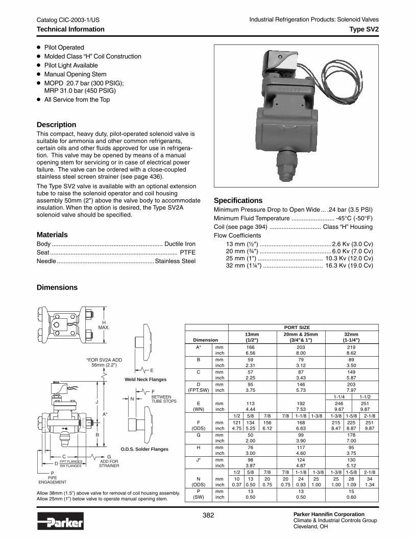
Parker Hannifin CorporationClimate & Industrial Controls GroupCleveland, OH
Catalog CIC-2003-1/US
382
Industrial Refrigeration Products: Solenoid Valves
Type SV2
● Pilot Operated● Molded Class “H” Coil Construction● Pilot Light Available● Manual Opening Stem● MOPD 20.7 bar (300 PSIG);
MRP 31.0 bar (450 PSIG)● All Service from the Top
DescriptionThis compact, heavy duty, pilot-operated solenoid valve issuitable for ammonia and other common refrigerants,certain oils and other fluids approved for use in refrigera-tion. This valve may be opened by means of a manualopening stem for servicing or in case of electrical powerfailure. The valve can be ordered with a close-coupledstainless steel screen strainer (see page 436).
The Type SV2 valve is available with an optional extensiontube to raise the solenoid operator and coil housingassembly 50mm (2") above the valve body to accommodateinsulation. When the option is desired, the Type SV2Asolenoid valve should be specified.
MaterialsBody ................................................................. Ductile IronSeat ........................................................................... PTFENeedle .........................................................Stainless Steel
SpecificationsMinimum Pressure Drop to Open Wide ... .24 bar (3.5 PSI)Minimum Fluid Temperature ......................... -45°C (-50°F)Coil (see page 394) .............................. Class “H” HousingFlow Coefficients
13 mm (½") ..........................................2.6 Kv (3.0 Cv)20 mm (¾") ..........................................6.0 Kv (7.0 Cv)25 mm (1") ...................................... 10.3 Kv (12.0 Cv)32 mm (1¼") ................................... 16.3 Kv (19.0 Cv)
Dimensions
HMAX.
*FOR SV2A ADD56mm (2.2")
Weld Neck Flanges
O.D.S. Solder Flanges
N
FBETWEENTUBE STOPS
E
GADD FORSTRAINER
PPIPE
ENGAGEMENT
C
D FPT FLANGESSW FLANGES
J
A*
B
Allow 38mm (1.5”) above valve for removal of coil housing assembly.Allow 25mm (1”) below valve to operate manual opening stem.
PORT SIZE13mm 20mm & 25mm 32mm
Dimension (1/2") (3/4"& 1") (1-1/4")
A* mm 166 203 219inch 6.56 8.00 8.62
B mm 59 79 89inch 2.31 3.12 3.50
C mm 57 87 149inch 2.25 3.43 5.87
D mm 95 146 203(FPT,SW) inch 3.75 5.73 7.97
1-1/4 1-1/2E mm 113 192 246 251
(WN) inch 4.44 7.53 9.67 9.871/2 5/8 7/8 7/8 1-1/8 1-3/8 1-3/8 1-5/8 2-1/8
F mm 121 134 156 168 215 225 251(ODS) inch 4.75 5.25 6.12 6.63 8.47 8.87 9.87
G mm 50 99 178inch 2.00 3.90 7.00
H mm 76 117 95inch 3.00 4.60 3.75
J* mm 98 124 130inch 3.87 4.87 5.12
1/2 5/8 7/8 7/8 1-1/8 1-3/8 1-3/8 1-5/8 2-1/8N mm 10 13 20 20 24 25 25 28 34
(ODS) inch 0.37 0.50 0.75 0.75 0.93 1.00 1.00 1.09 1.34P mm 13 13 15
(SW) inch 0.50 0.50 0.60
Technical Information

Catalog CIC-2003-1/US
Parker Hannifin CorporationClimate & Industrial Controls GroupCleveland, OH
383
Industrial Refrigeration Products: Solenoid ValvesIn
du
strialR
efrigeratio
nP
rod
ucts
Type SV2
How to OrderType SV2 solenoid valves can be specified by using the symbols in the chart below to develop a model number. Select only thosesymbols that represent the features desired, and place them in the sequence indicated by the example at the top of the chart.
Port Inlet Outlet Coil Voltage, Pilot Lens CheckSize Type Variation Flange Flange Style Light Color Strainer Valve
Flange Type Connection
X Less 00 NoneFlanges
F FPT (IPS) 02 ¼"S SW (IPS) 03 3/8"W Weld Neck (IPS) 04 ½"
06 ¾"08 1"10 1¼"12 1½"
K ODS (US) 04 ½"05 5/8"07 7/8"09 11/8"11 13/8"13 15/8"17 21/8”
D DIN Weld Neck Enter sizeM Insert Metric from tableC EC-Br Copper below.
*See table below for availability
Strainer
N No StrainerS w/Strainer
Remote Pilot Light
0 None1 PLT-1(NEMA 1)2 PLT-2 (NEMA 4)5 PLT-5
◆ With coil 6 only. See page394 for voltages.
Lens Color
0 No Remote LightG Green (std)R RedA AmberW White
Flange Availability & WeightsTable shows flange size codes available by flange type for each port size code
Flange Connections Available Weight
Port FPT (IPS)Socket Weld (IPS)
ODS (US) DIN Weld Neck Insert Metric EC-Br CopperLess Strainer With Strainer
Code Weld Neck (IPS) kg lb kg lb
013 02 03 04 06 03 04 06 04 05 07 10 15 20 1.8 4 2.7 6
020 06 08 10 06 08 10 07 09 11 20 25 32 20 25 32 18 20 26 30 4.0 9 7.2 16
025 06 08 10 06 08 10 07 09 11 20 25 32 20 25 32 18 20 26 30 4.0 9 7.2 16
032 10 12 10 12 11 13 17 32 40 50 30 36 42 6.8 15 13.5 30
Not all flange sizes areavailable for each port size.See Flange Availability tablefor allowable combinations.
Check Valve
0 None1* w/CK14 w/CK4
* N/A on Size 013
Port Size
013 13mm (½")020 20mm (¾")025 25mm (1")032 32mm (1¼")
Variation
Blank Standard ValveA w/Extension Tube
020 SV2 A F08 F08 12 1 G S 1
Coil Voltage
0 No CoilStandard
1 120/60R 120/6/602 208/60S 208/6/603 240/60T 240/6/606 115/507 230/508 240/50
Non-StandardA 24/60C 480/60D 24/50H 24V DCW 120V DC
Coil Style★★★★★
0 No Coil5 Explosion Proof6 Compact A,B Operator
w/18" Leads7 Compact A,B Operator
w/DIN Connector
★ See table on page 394 foravailable coil style/voltagecombinations.
WARNING!ODS flanges not suitablefor use with ammonia.
!
How to Order

Parker Hannifin CorporationClimate & Industrial Controls GroupCleveland, OH
Catalog CIC-2003-1/US
384
Industrial Refrigeration Products: Solenoid Valves
Type S7
● Positive Lift, Held Open Electrically● Standard Coil Housing Meets NEMA 3R and NEMA 4 –
Rain Tight● Coil Housing Surpasses NEMA Salt Spray Test● Gray Iron Body, PTFE Seat● Molded Class “B” Coil Construction● Pilot Light Available● Stainless Steel Needle● Manual Opening Stem● MRP 27.6 bar (400 PSIG)
DescriptionThis heavy duty solenoid valve is suitable for ammonia andother common refrigerants, certain oils and other fluidsapproved for use in refrigeration. The S7 is a pilot operated,positive lift valve. The valve may be opened by means of amanual opening stem for servicing or in case of electricalpower failure.
It is advisable to install a strainer upstream of each valve toprevent entrance of foreign material into the valves and therest of the system. Refrigerating Specialties strainers areavailable to close-couple to valve inlets (see page 436).
MaterialsBody .....................................................................Gray IronSeat ........................................................................... PTFENeedle .........................................................Stainless Steel
SpecificationsMinimum Pressure Dropto Open Wide .................................................0 bar (0 PSI)Minimum Fluid Temperature ........................ -30°C (-25°F)Coil (See page 394) .............................. Class “B” HousingFlow Coefficients
20 mm (¾") ......................................... 6.8 Kv (8.0 Cv)25 mm (1") ........................................ 8.6 Kv (10.0 Cv)
Dimensions
HMAX.
PPIPE
ENGAGEMENT 18”REF.
J
A
N
F BETWEENTUBE STOPS
E
WELD NECKFLANGES
O.D.S. SOLDERFLANGES
B
C
D
ADD FORSTRAINER98mm (3.9”)
FPT FLANGESSW FLANGES
A B C D E F H J N P(FPT, SW) (WN) (ODS) (ODS) (SW)
MM INCH MM INCH MM INCH MM INCH MM INCH MM INCH MM INCH MM INCH MM INCH MM INCH
282 11.1 102 4.0 157 6.2 216 8.5 261 10.3 239 9.4 117 4.6 180 7.1 25 1.0 13 0.5
Technical Information

Catalog CIC-2003-1/US
Parker Hannifin CorporationClimate & Industrial Controls GroupCleveland, OH
385
Industrial Refrigeration Products: Solenoid ValvesIn
du
strialR
efrigeratio
nP
rod
ucts
Type S7
How to OrderType S7 solenoid valves can be specified by using the symbols in the chart below to develop a model number. Select only thosesymbols that represent the features desired, and place them in the sequence indicated by the example at the top of the chart.
Port Inlet Outlet Coil Voltage, Pilot Lens CheckSize Type Flange Flange Style Light Color Strainer Valve
Strainer
N No StrainerS w/Strainer
Remote Pilot Light◆
0 None1 PLT-1 (NEMA 1)2 PLT-2 (NEMA 4)5 PLT-5
◆ With coils 1 & 3 only. Seepage 394 for voltages.
Lens Color
0 No Pilot LightG Green (std)R RedA AmberW White
Port Size*
020 20mm (¾")025 25mm (1")050 50mm (2")
Flange Availability & WeightsTable shows flange size codes available by flange type for each port size code
Flange Connections Available Weight
Port FPT (IPS)Socket Weld (IPS)
ODS (US) DIN Weld Neck Insert Metric EC-Br CopperLess Strainer With Strainer
Code Weld Neck (IPS) kg lb kg lb
020 06 08 10 06 08 10 07 09 11 20 25 32 20 25 32 18 20 26 30 5.8 12 9 19
025 06 08 10 06 08 10 07 09 11 20 25 32 20 25 32 18 20 26 30 5.8 12 9 19
050 12 16 12 16 13 17 21 40 50 29 63 43 95
Check Valve
0 None1 w/CK14 w/CK4
020 S7 F08 F08 11 0 0 S 0
Flange Type Connection
X Less 00 NoneFlanges
F FPT (IPS) 06 ¾"S SW (IPS) 08 1"W Weld Neck (IPS) 10 1¼"
12 1½"16 2"
K ODS (US) 07 7/8"09 11/8"11 13/8"13 15/8"17 21/8"21 25/8"
D DIN Weld Neck Enter sizeM Insert Metric from tableC EC-Br Copper below.
Not all flange types and sizesare available for each port size.See Flange Availability tablefor allowable combinations.
Coil Style★★★★★
0 No Coil or Housing
1 Encapsulatedw/36" Leads
L Encapsulated w/36"Leads & Pilot Light*
2 Encapsulatedw/DIN Connector
D Encapsulatedw/DIN Connector& Pilot Light*
3 Ind. Open Framew/18" Leads
★ See page 394 for availablecoil style/voltagecombinations.* Integral pilot light. Lenscolor designated separately.
Coil Voltage
0 No Coil
Standard1 120/60R 120/6/602 208/60S 208/6/603 240/60T 240/6/604 440/606 115/507 230/50U 230/6/508 240/50
Non-StandardA 24/60B 288/60C 480/60D 24/50E 42/50F 48/50G 12V DCH 24V DCJ 230V DCK 48V DCP 115/6/50Q 440/6/60
WARNING!ODS flanges not suitablefor use with ammonia.
!
How to Order
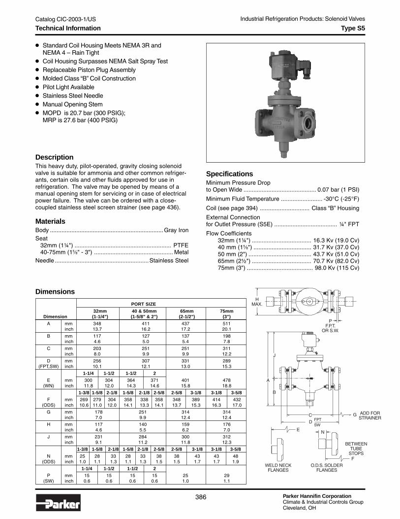
Parker Hannifin CorporationClimate & Industrial Controls GroupCleveland, OH
Catalog CIC-2003-1/US
386
Industrial Refrigeration Products: Solenoid Valves
Type S5
● Standard Coil Housing Meets NEMA 3R andNEMA 4 – Rain Tight
● Coil Housing Surpasses NEMA Salt Spray Test● Replaceable Piston Plug Assembly● Molded Class “B” Coil Construction● Pilot Light Available● Stainless Steel Needle● Manual Opening Stem● MOPD is 20.7 bar (300 PSIG);
MRP is 27.6 bar (400 PSIG)
DescriptionThis heavy duty, pilot-operated, gravity closing solenoidvalve is suitable for ammonia and other common refriger-ants, certain oils and other fluids approved for use inrefrigeration. The valve may be opened by means of amanual opening stem for servicing or in case of electricalpower failure. The valve can be ordered with a close-coupled stainless steel screen strainer (see page 436).
MaterialsBody .....................................................................Gray IronSeat 32mm (1¼") ........................................................... PTFE 40-75mm (15⁄8" - 3") ................................................ MetalNeedle .........................................................Stainless Steel
SpecificationsMinimum Pressure Dropto Open Wide ............................................ 0.07 bar (1 PSI)
Minimum Fluid Temperature ......................... -30°C (-25°F)
Coil (see page 394) .............................. Class “B” Housing
External Connectionfor Outlet Pressure (S5E) ...................................... ¼" FPT
Flow Coefficients32mm (1¼") .................................... 16.3 Kv (19.0 Cv)40 mm (15⁄8") ................................... 31.7 Kv (37.0 Cv)50 mm (2") ...................................... 43.7 Kv (51.0 Cv)65mm (2½") .................................... 70.7 Kv (82.0 Cv)75mm (3") ........................................ 98.0 Kv (115 Cv)
PORT SIZE
32mm 40 & 50mm 65mm 75mm Dimension (1-1/4") (1-5/8" & 2") (2-1/2") (3")
A mm 348 411 437 511inch 13.7 16.2 17.2 20.1
B mm 117 127 137 198inch 4.6 5.0 5.4 7.8
C mm 203 251 251 311inch 8.0 9.9 9.9 12.2
D mm 256 307 331 289(FPT,SW) inch 10.1 12.1 13.0 15.3
1-1/4 1-1/2 1-1/2 2
E mm 300 304 364 371 401 478(WN) inch 11.8 12.0 14.3 14.6 15.8 18.8
1-3/8 1-5/8 2-1/8 1-5/8 2-1/8 2-5/8 2-5/8 3-1/8 3-1/8 3-5/8
F mm 269 279 304 358 338 358 348 389 414 432(ODS) inch 10.6 11.0 12.0 14.1 13.3 14.1 13.7 15.3 16.3 17.0
G mm 178 251 314 314inch 7.0 9.9 12.4 12.4
H mm 117 140 159 176inch 4.6 5.5 6.2 7.0
J mm 231 284 300 312inch 9.1 11.2 11.8 12.3
1-3/8 1-5/8 2-1/8 1-5/8 2-1/8 2-5/8 2-5/8 3-1/8 3-1/8 3-5/8
N mm 25 28 33 28 33 38 38 43 43 48(ODS) inch 1.0 1.1 1.3 1.1 1.3 1.5 1.5 1.7 1.7 1.9
1-1/4 1-1/2 1-1/2 2
P mm 15 15 15 15 25 29(SW) inch 0.6 0.6 0.6 0.6 1.0 1.1
J
A
B
C
DSWFPT
G
N
F
HMAX.
PF.P.T.
OR S.W.
O.D.S. SOLDERFLANGES
WELD NECKFLANGES
E
BETWEENTUBE
STOPS
ADD FORSTRAINER
Dimensions
Technical Information

Catalog CIC-2003-1/US
Parker Hannifin CorporationClimate & Industrial Controls GroupCleveland, OH
387
Industrial Refrigeration Products: Solenoid ValvesIn
du
strialR
efrigeratio
nP
rod
ucts
Type S5
How to OrderType S5 solenoid valves can be specified by using the symbols in the chart below to develop a model number. Select only thosesymbols that represent the features desired, and place them in the sequence indicated by the example at the top of the chart.
Strainer
N No StrainerS w/Strainer
Remote Pilot Light◆
0 None1 PLT-1 (NEMA 1)2 PLT-2 (NEMA 4)5 PLT-5
◆ With coils 1 & 3 only. Seepage 394 for voltages.
Lens Color
0 No Pilot LightG Green (std)R RedA AmberW White
Port Size
032 32mm (1¼")040 40mm (15/8")050 50mm (2")065 65mm (2½")075 75mm (3")
Port Inlet Outlet Coil Voltage, Pilot Lens CheckSize Type Variation Flange Flange Style Light Color Strainer Valve
Flange Type Connection
X Less 00 NoneFlanges
F FPT (IPS) 10 1¼"S SW (IPS) 12 1½"W Weld Neck (IPS) 16 2"
20 2½"24 3"
K ODS (US) 11 13/8"13 15/8"17 21/8"21 25/8"25 31/8"29 35/8"
D DIN Weld Neck Enter sizeM Insert Metric from tableC EC-Br Copper below.
Not all flange types and sizesare available for each port size.See Flange Availability tablefor allowable combinations.
Flange Availability & WeightsTable shows flange size codes available by flange type for each port size code
Flange Connections Available Weight
Port FPT (IPS)Socket Weld (IPS)
ODS (US) DIN Weld Neck Insert Metric EC-Br CopperLess Strainer With Strainer
Code Weld Neck (IPS) kg lb kg lb
032 10 12 10 12 11 13 17 32 40 50 30 36 42 14 30 21 46
040 12 16 12 16 13 17 21 40 50 29 63 43 95
050 12 16 12 16 13 17 21 40 50 29 63 43 95
065 20 21 25 65 75 37 81 64 140
075 24 25 29 75 53 116 80 175
Check Valve
0 None1 w/CK14 w/CK4
Variation
Blank StandardE External Actuating
Pressure Supply
050 S5 F12 F12 11 0 0 S 0
Coil Style★
0 No Coil or Housing
1 Encapsulatedw/36" Leads
L Encapsulated w/36"Leads & Pilot Light*
2 Encapsulatedw/DIN Connector
D Encapsulatedw/DIN Connector& Pilot Light*
3 Ind. Open Framew/18" Leads
★ See page 394 for availablecoil style/voltagecombinations.* Integral pilot light. Lens colordesignated separately
Coil Voltage
0 No Coil
Standard1 120/60R 120/6/602 208/60S 208/6/603 240/60T 240/6/604 440/606 115/507 230/50U 230/6/508 240/50
Non-StandardA 24/60B 288/60C 480/60D 24/50E 42/50F 48/50G 12V DCH 24V DCJ 230V DCK 48V DCP 115/6/50Q 440/6/60
WARNING!ODS flanges not suitablefor use with ammonia.
!
How to Order

Parker Hannifin CorporationClimate & Industrial Controls GroupCleveland, OH
Catalog CIC-2003-1/US
388
Industrial Refrigeration Products: Solenoid Valves
● Standard Coil Housing Meets NEMA 3R and NEMA 4 –Rain Tight
● Coil Housing Surpasses NEMA Salt Spray Test● Molded Class “B” Coil Construction● Pilot Light Available● Stainless Steel Needle● Manual Opening Stem● MOPD is 20.7 bar (300 PSIG);
MRP is 27.6 bar (400 PSIG)
DescriptionThis heavy duty solenoid valve is suitable for ammonia andother common refrigerants, certain oils and other fluidsapproved for use in refrigeration. The S4 is a pilot operatedvalve that may be opened by means of the manual openingstem for servicing or in case of electrical power failure.
MaterialsBody .....................................................................Gray IronSeat .........................PTFE (13-32mm), Metal (40-100mm)Needle .........................................................Stainless Steel
SpecificationsMinimum Pressure Drop to Open Wide
20-32mm (¾" - 1¼") ......................... 0.14 bar (2 PSI)40-100mm (15⁄8" - 4") ........................ 0.28 bar (4 PSI)
Minimum Fluid Temperature20-32mm (¾" - 1¼") ............................. -45°C (-50°F)40-100mm (15⁄8" - 4") ............................ -50°C (-60°F)
Coil (See page 394) .............................. Class “B” Housing
Type S4 (20-100mm)
PORT SIZE
20mm (3/4") 32mm 40 & 50mm 65mm 75mm 100mm Dimension & 25mm (1") (1-1/4") (1-5/8" & 2") (2-1/2") (3") (4")
A mm 376 394 442 467 579 645inch 14.8 15.5 17.4 18.4 22.8 25.4
B mm 148 162 177 181 273 292inch 5.8 6.3 6.9 7.1 10.7 11.5
C mm 164 203 251 251 311 339inch 6.2 8.0 9.9 9.9 12.2 14.1
D mm 216 256 307 331 389 450(FPT,SW) inch 8.5 10.1 12.1 13.0 15.3 17.7
1¼ 1½ 1½ 2
E mm 261 300 304 364 371 401 478 571(WN) inch 10.3 11.8 12.0 14.3 14.6 15.8 18.8 22.5
13/8 15/8 21/8 15/8 21/8 25/8 25/8 31/8 31/8 35/8
F mm 239 269 279 304 358 338 358 348 389 414 432 303(ODS) inch 9.4 10.6 11.0 12.0 14.1 13.3 14.1 13.7 15.3 16.3 17.0 19.8
G mm 98 178 251 314 314 363inch 3.9 7.0 9.9 12.4 12.4 14.3
H mm 117 117 140 159 176 222inch 4.6 4.6 5.5 6.2 7.0 8.8
J mm 224 231 284 300 312 353inch 8.8 9.1 11.2 11.8 12.3 13.9
13/8 15/8 21/8 15/8 21/8 25/8 25/8 31/8 31/8 35/8 41/8
N mm 25 25 28 33 28 33 38 38 43 43 48 55(ODS) inch 1.0 1.0 1.1 1.3 1.1 1.3 1.5 1.5 1.7 1.7 1.9 2.2
1-1/4 1-1/2 1-1/2 2
P mm 13 15 15 15 15 25 29 32(SW) inch 0.5 0.6 0.6 0.6 0.6 1.0 1.1 1.3
Flow Coefficients20 mm (¾") ......................................... 6.2 Kv (7.2 Cv)25 mm (1") ........................................ 8.6 Kv (10.0 Cv)32mm (1¼") .................................... 15.0 Kv (17.5 Cv)40 mm (15⁄8") ................................... 28.6 Kv (33.4 Cv)50 mm (2") ...................................... 42.4 Kv (49.5 Cv)65 mm (2½") ................................... 59.9 Kv (70.0 Cv)75 mm (3") ....................................... 86.0 Kv (100 Cv)100 mm (4") ...................................... 139 Kv (162 Cv)
PPIPE ENGAGEMENT
HMAX.
J
B
A
C
D
G
(FPT FLANGES)(SW FLANGES)
ADD FORSTRAINER
NFBETWEENTUBESTOPS
E
WELD NECKFLANGES
O.D.S. SOLDERFLANGES
Dimensions
Note: Allow 100mm (4") above valve for removal of coilhousing and coil.
Technical Information

Catalog CIC-2003-1/US
Parker Hannifin CorporationClimate & Industrial Controls GroupCleveland, OH
389
Industrial Refrigeration Products: Solenoid ValvesIn
du
strialR
efrigeratio
nP
rod
ucts
Type S4 (20-100mm)
How to OrderType S4 solenoid valves can be specified by using the symbols in the chart below to develop a model number. Select only thosesymbols that represent the features desired, and place them in the sequence indicated by the example at the top of the chart.
Port Inlet Outlet Coil Voltage, Pilot Lens CheckSize Type Variation Flange Flange Style Light Color Strainer Valve
Strainer
N No StrainerS w/Strainer
Remote Pilot Light▲
0 None1 PLT-1 (NEMA 1)2 PLT-2 (NEMA 4)5 PLT-5
▲ With coil styles 1 and 3 only.See page 394 for voltages.
Lens Color
0 No Pilot LightG Green (std)R RedA AmberW White
Flange Availability & WeightsTable shows flange size codes available by flange type for each port size code
Flange Connections Available Weight
Port FPT (IPS)Socket Weld (IPS)
ODS (US) DIN Weld Neck Insert Metric EC-Br CopperLess Strainer With Strainer
Code Weld Neck (IPS) kg lb kg lb
020 06 08 10 06 08 10 07 09 11 20 25 32 20 25 32 18 20 26 30 10 21 13 28
025 06 08 10 06 08 10 07 09 11 20 25 32 20 25 32 18 20 26 30 10 21 13 28
032 10 12 10 12 11 13 17 32 40 50 30 36 42 15 33 22 48
040 12 16 12 16 13 17 21 40 50 31 67 45 99
050 12 16 12 16 13 17 21 40 50 31 67 45 99
065 20 21 25 65 75 38 75 66 144
075 24 25 29 75 55 121 82 180
100 32 33 A0 75 164 127 278
Flange Type Connection
X Less 00 NoneFlanges
F FPT (IPS) 06 ¾"S SW (IPS) 08 1"W Weld Neck (IPS) 10 1¼"
12 1½"16 2"20 2½"24 3"32 4"
K ODS (US) 07 7/8"09 11/8"11 13/8"13 15/8"17 21/8"21 25/8"25 31/8"29 35/8"33 41/8"
D DIN Weld Neck Enter sizeM Insert Metric from tableC EC-Br Copper below.
Not all flange types and sizesare available for each port size.See Flange Availability tablefor allowable combinations.
Check Valve
0 None1 w/CK14 w/CK4
Variation
Blank StandardE External Actuating
Pressure SupplySC Slow Closing
Port Size
020 20mm (¾")025 25mm (1")032 32mm (1¼")040 40mm (15/8")050 50mm (2")065 65mm (2½")075 75mm (3")100 100mm (4")
020 S4 X F08 F08 15 0 0 S 0
Coil Style
0 No Coil1 Encapsulated
w/36" LeadsL Encapsulated w/36"
Leads & Pilot Light*2 Encapsulated
w/DIN ConnectorD Encapsulated
w/DIN Connector& Pilot Light*
3 Ind. Open Framew/18" Leads
5 Explosion Proof
* Integral pilot light. Lens colordesignated separately
Volts/Frequency★
0 No CoilStandard
1 120/60R 120/6/602 208/60S 208/6/603 240/60T 240/6/604 440/606 115/507 230/50U 230/6/508 240/50
Non-StandardA 24/60B 288/60C 480/60D 24/50E 42/50F 48/50G 12V DCH 24V DCJ 230V DCK 48V DCP 115/6/50Q 440/6/60
★ See page 394 for coilavailability.
WARNING!ODS flanges not suitablefor use with ammonia.
!
How to Order

Parker Hannifin CorporationClimate & Industrial Controls GroupCleveland, OH
Catalog CIC-2003-1/US
390
Industrial Refrigeration Products: Solenoid Valves
● Pilot Operated● Welds directly in the Line – No Flanges● Removable Seat is Serviceable from Top Side● Streamlined Fluid Flow Pattern● Cast Steel Body, ASTM No. A352 Grade LCB● PTFE Pilot Seat● Molded Class “B” Coil Construction● Manual Opening Stem● MOPD 20.7 bar (300 PSIG); MRP 27.6 bar (400 PSIG)
DescriptionThese heavy duty, spring closing solenoid valves aresuitable for control of ammonia and other common refriger-ants, certain oils and other fluids approved for use inrefrigeration valves. They weld directly in the line and donot require flanges. The Type S4W are pilot operated valvesusing upstream pressure for the moving force, and require aminimum of 0.21 bar (3 psi) pressure drop to fully open.The valves are normally closed.
MaterialsBody ........................ Cast Steel (ASTM A352 Grade LCB)Seat ............................................................................ MetalNeedle .........................................................Stainless Steel
Type S4 (125-200mm)
Dimension125mm 150mm 200mm
(5") (6") (8")
Amm 451 527 584
inch 17.75 20.75 23.00
Bmm 114 152 197
inch 4.50 6.00 7.75
Hmm 565 679 781
inch 22.25 26.75 30.75
Lmm 381 483 622
inch 15.00 19.00 24.50
Wmm 267 318 381
inch 10.50 12.50 15.00
SpecificationsMinimum Pressure Dropto Open Wide ............................................ 0.21 bar (3 PSI)
Temperature Range ............. -45° to 105°C (-50° to 220°F)
Coil (see page 394) .............................. Class “B” Housing
Flow Coefficients125 mm (5") ...................................... 171 Kv (200 Cv)150 mm (6") ...................................... 308 Kv (360 Cv)200 mm (8") ...................................... 471 Kv (550 Cv)
Dimensions
A
H
B
L W
Technical Information

Catalog CIC-2003-1/US
Parker Hannifin CorporationClimate & Industrial Controls GroupCleveland, OH
391
Industrial Refrigeration Products: Solenoid ValvesIn
du
strialR
efrigeratio
nP
rod
ucts
How to OrderType S4 solenoid valves can be specified by using the symbols in the chart below to develop a model number. Select only thosesymbols that represent the features desired, and place them in the sequence indicated by the example at the top of the chart.
Port Coil Voltage, Pilot LensSize Type Variation Style Light Color Strainer
Port Size
125 125mm (5")150 150mm (6")200 200mm (8")
Type S4 (125-200mm)
Strainer
N No StrainerS w/Strainer
Remote Pilot Light▲
0 None1 PLT-1 (NEMA 1)2 PLT-2 (NEMA 4)5 PLT-5
▲ With coil styles 1 and 3 only.See page 394 for voltages.
Lens Color
0 No Pilot LightG Green (std)R RedA AmberW White
Connections & Weights
Connections Available Weight
Port Weld EndLess Strainer With Strainer
Code kg lb kg lb
125 5" 54 120 99 218
150 6" 98 215 177 380
200 8" 159 350 295 650
Variation
Blank StandardE External Actuating
Pressure Supply
150 S4 1R 2 G S
Coil Style
0 No Coil or Housing1 Encapsulated
w/36" Leads
L Encapsulated w/36"Leads & Pilot Light*
2 Encapsulatedw/DIN Connector
D Encapsulatedw/DIN Connector& Pilot Light*
3 Ind. Open Framew/18" Leads
5 Explosion Proof
* Integral pilot light. Lens colordesignated separately.
Coil Voltage★
0 No Coil
Standard1 120/60R 120/6/602 208/60S 208/6/603 240/60T 240/6/604 440/606 115/507 230/50U 230/6/508 240/50
Non-StandardA 24/60B 288/60C 480/60D 24/50E 42/50F 48/50G 12V DCH 24V DCJ 230V DCK 48V DCP 115/6/50Q 440/6/60
★ See page 394 foravailable voltage/coilcombinations.
How to Order

Parker Hannifin CorporationClimate & Industrial Controls GroupCleveland, OH
Catalog CIC-2003-1/US
392
Industrial Refrigeration Products: Solenoid Valves
Remote Pilot Light Assembly
● Pilot Light Assembly is Completely Self-Contained● Gives Visual Observation of Solenoid Valve Operation● Standard Conduit Box or Weatherproof Design
DescriptionThe PLT-1 assembly is completely self-contained, consist-ing of a standard conduit box with multiple knockouts forconnecting to the R/S coil housing cover. The pilot light is astandard 6-volt bulb.
The PLT-2 pilot light assembly is completely self-contained,consisting of a cast aluminum conduit box with 1/2" FPTconnections, a gasket sealed cover and a moisture sealedpilot light. The light is a standard 6-volt bulb.
Transformer coils can be furnished for 120, 208, 240 volts60 Hertz and 115 and 230 volts 50 Hertz – all with a 6-voltsecondary winding.
The PLT-5 pilot lights wire directly to line voltage. The bulbis 6 Watts for 120V applications and 10 Watts for 208/240Vapplications. The large base uses an S6 double contactbayonet bulb. No special transformer coil is required. ThePLT-5 weatherproof unit has a cast aluminum box withstamped aluminum cover and rubber gasket. The assemblyuses rubber washers to maintain weatherproof conditionand is designed for outdoor use.
Ordering Information
PLT-1
PLT-5PLT-2
LensType Voltage Color
Voltage
1★ 6V Secondary2◆ 120/603◆ 208/60 or
240/60
★ PLT-1 & PLT-2 only◆ PLT-5 only
Lens Color
G Green (std)R RedA AmberW White
PLT-2 1 G
Type
PLT-1 Transformer Style,NEMA1
PLT-2 Transformer Style,NEMA 4
PLT-5 Direct Wired,Weatherproof
Technical Information and How to Order

Catalog CIC-2003-1/US
Parker Hannifin CorporationClimate & Industrial Controls GroupCleveland, OH
393
Industrial Refrigeration Products: Solenoid ValvesIn
du
strialR
efrigeratio
nP
rod
ucts
External Pilot Light Assembly
NUT
LOCKWASHER
O-RING SEALSO-RING SEALS
VIEW A ENLARGED
1/2-14 NPTBOTH SIDES
GASKET
COVER
LIGHT
98.4mm(3.875")
95mm(3.750")
CONDUIT BOX
LENS
1/2-14 NPTBOTH SIDES
COVER101mm(3.974") CONNECT LEADS
FROM SOLENOIDCOIL TO TERMINALSOF THE PILOT LIGHT
GASKET98.4mm (3.875")
LIGHT
WASHER
NUT
ENLARGED VIEW
PLT-1
PLT-2
PLT-5
SOLENOID COIL HOUSING
CONNECT 6 VOLT LEADS FROMSOLENOID COIL TO TERMINALS
OF PILOT LIGHT.
6-VOLT BULBLENS
ESCUTCHEON RINGNUT & LOCKWASHER
CONDUIT BOX
PILOT LIGHT BASE
CONDUIT BOX COVERCONDUITNIPPLE
1/2"CONDUITLOCK NUT
1/2"
Technical Information

Parker Hannifin CorporationClimate & Industrial Controls GroupCleveland, OH
Catalog CIC-2003-1/US
394
Industrial Refrigeration Products: Solenoid Valves
Cod
e
Cla
ss
120/
60
120/
6/60
208/
60
208/
6/60
240/
60
240/
6/60
440/
60
115/
50
230/
50
230/
6/50
240/
50
24/6
0
288/
60
480/
60
24/5
0
42/5
0
48/5
0
12V
DC
24V
DC
120V
DC
230V
DC
48V
DC
115/
6/50
440/
6/60
Electrical Coil Information
Class “ B” CoilThe molded water resistant Class “B” solenoid coil, avail-able on most Refrigerating Specialties solenoid valves, isdesigned for long life and powerful opening force. Thestandard coil housing meets NEMA 3R and 4 requirements.This sealed construction can withstand direct contact withmoisture and ice. The coil housing far exceeds the require-ments of NEMA Standard ICS.1-110.57 salt spray test forrust resistance.
By definition, Class “B” coil construction will permit coiltemperatures, as measured by resistance method, as highas 130°C (266°F). Final coil temperatures are a function ofboth fluid and ambient temperatures. The higher fluidtemperatures require lower ambient temperatures so themaximum coil temperature is not exceeded. Conversely,low fluid temperatures permit higher ambient temperatures.
The supply circuits must be properly sized to give adequatevoltage at the coil even when other electrical equipment isoperating. The coil is designed to operate with line voltagefrom 85% to 110% of rated coil voltage. Power consump-tion during normal operation will be 33 watts or less.
Standard Encapsulated Coils
For other voltages, contact factory. On transformer coil, the 6 voltleads are always black.
Class “ H” Coil (SV2 only)The Refrigerating Specialties Division molded waterresistant Class “H” coil is designed for long life and powerfulopening force. The Class “H” coil construction will permitcoil temperatures, as measured by resistance method, ashigh as 180°C (365°F).
The supply circuits must be properly sized to give adequatevoltage at the coil leads even when other electrical equip-ment is operating. The coil is designed to operate at 15%under voltage. Operating with line voltage below the limitwill result in lowering the valve opening pressure differen-tial.
Inrush Holding FuseCurrent Current Size
Volts/Hertz Leads (Amps) (Amps) (Amps)
120/60 Blue 1.18 0.46 1
208/60 Blue and Red 0.63 0.26 1
240/60 Red 0.60 0.23 1
115/50 Yellow and Blue 1.22 0.21 1
230/50 Yellow 0.65 0.26 1
Watt Volt AmperageCoil Type Rating Holding Inrush
Standard AC10.5 23 37Class “ H”
Standard AC Coilwith 6v Secondary 11.0 26 38Pilot Light
Currents
VoltagesCoils are available from stock with most standard voltages(see table below). Non-standard voltages (shown in shadedarea of table) can be special ordered. Coils are alsoavailable with 6V secondary voltage for use with remotepilot lights PLT-1 and PLT-2.
Available Voltages forCoils and Pilot LightsEncapsulated w/Leads 1 B ● ● ● ● ● ● ● ● ● ● ● ●
Encapsulated w/Leads & Integral Pilot Light L B ● ● ● ●
Encapsulated w/DIN Connector 2 B ● ● ● ● ● ●
Encapsulated w/DIN & Integral Pilot Light D B ● ● ● ●
Industrial Open Frame w/Leads 3 B ● ● ● ● ● ● ● ● ● ● ● ● ● ● ● ● ● ● ● ● ● ●
Explosion Proof 5 – ● ● ● ● ● ● ● ● ●
Compact A,B Operator w/Leads 6 H ■ ■ ● ● ■ ■ ● ● ● ● ■ ● ●
Compact A,B Operator w/DIN 7 H ■ ● ■ ● ● ● ● ■ ●
PLT-1 (NEMA 1) ● ● ● ● ● ●
PLT-2 (NEMA 4) ● ● ● ● ● ●
PLT-5 (NEMA 4) ● ● ●
NOTE: Pilot lights cannot be used with explosion proof orunleaded (DIN connector) coils.
■ These voltages for the Class “H” coils are120/60-110/50, 240/60-220/50, 480/60-440/50.
Technical Information
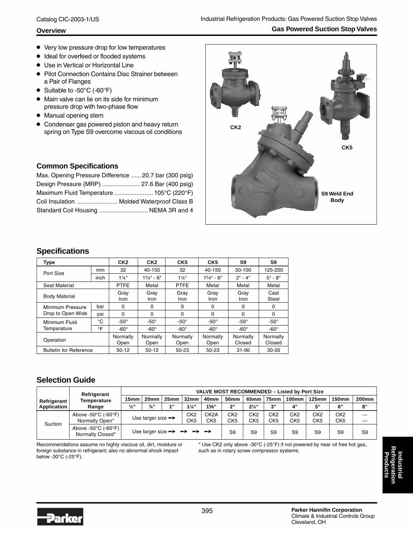
Catalog CIC-2003-1/US Industrial Refrigeration Products: Gas Powered Suction Stop Valves
Parker Hannifin CorporationClimate & Industrial Controls GroupCleveland, OH
395
Ind
ustrial
Refrig
eration
Pro
du
cts
Selection Guide Refrigerant VALVE MOST RECOMMENDED – Listed by Port Size
Refrigerant Temperature 15mm 20mm 25mm 32mm 40mm 50mm 65mm 75mm 100mm 125mm 150mm 200mm
Application Range ½" ¾" 1" 1¼" 15⁄⁄⁄⁄⁄8" 2" 2½" 3" 4" 5" 6" 8"
Above -50°C (-60°F)Use larger size ➙
CK2 CK2A CK2 CK2 CK2 CK2 CK2 CK2 —
SuctionNormally Open* CK5 CK5 CK5 CK5 CK5 CK5 CK5 CK5 —
Above -50°C (-60°F)Use larger size ➙ ➙ ➙ ➙ S9 S9 S9 S9 S9 S9 S9Normally Closed*
Recommendations assume no highly viscous oil, dirt, moisture orforeign substance in refrigerant; also no abnormal shock impactbelow -30°C (-25°F).
Common SpecificationsMax. Opening Pressure Difference ...... 20.7 bar (300 psig)Design Pressure (MRP) ...................... 27.6 Bar (400 psig)Maximum Fluid Temperature ....................... 105°C (220°F)Coil Insulation ........................ Molded Waterproof Class BStandard Coil Housing ............................. NEMA 3R and 4
Gas Powered Suction Stop Valves
* Use CK2 only above -30°C (-25°F) if not powered by near oil free hot gas,such as in rotary screw compressor systems.
S9 Weld EndBody
● Very low pressure drop for low temperatures● Ideal for overfeed or flooded systems● Use in Vertical or Horizontal Line● Pilot Connection Contains Disc Strainer between
a Pair of Flanges● Suitable to -50°C (-60°F)● Main valve can lie on its side for minimum
pressure drop with two-phase flow● Manual opening stem● Condenser gas powered piston and heavy return
spring on Type S9 overcome viscous oil conditions
SpecificationsType CK2 CK2 CK5 CK5 S9 S9
Port Sizemm 32 40-150 32 40-150 50-100 125-200
inch 1¼" 15⁄8" - 6" 1¼" 15⁄8" - 6" 2" - 4" 5" - 8"
Seat Material PTFE Metal PTFE Metal Metal Metal
Body MaterialGray Gray Gray Gray Gray CastIron Iron Iron Iron Iron Steel
Minimum Pressure bar 0 0 0 0 0 0Drop to Open Wide psi 0 0 0 0 0 0
Minimum Fluid °C -50° -50° -50° -50° -50° -50°Temperature °F -60° -60° -60° -60° -60° -60°
OperationNormally Normally Normally Normally Normally Normally
Open Open Open Open Closed Closed
Bulletin for Reference 50-12 50-12 50-23 50-23 31-90 30-05
CK2
CK5
Overview

Parker Hannifin CorporationClimate & Industrial Controls GroupCleveland, OH
Catalog CIC-2003-1/US Industrial Refrigeration Products: Gas Powered Suction Stop Valves
396
Type CK2
● Normally Open● Low Pressure Drop● Heavy Return Spring● Manual Opening Stem● Use in Vertical or Horizontal Line● Main Valve Can be Installed on Side● Maximum Rated Pressure (MRP): 27.6 bar (400 psig)
DescriptionThese piston type, pressure powered, normally open, heavyduty valves are built with control valve precision. All areequipped with flanges and manual lift stem. The 32mm(1¼") port size has a PTFE main seat; 40 mm (15/8") portand larger have a metal to metal seat.
SpecificationsMinimum Pressure Dropto Open Wide ................................................. 0 bar (0 PSI)Minimum Fluid Temperature ......................... -50°C (-60°F)Coil (See page 376) .............................. Class “B” HousingFlow Coefficient
32mm (1¼") ....................................... 16.3 Kv (19.0 Cv)40mm (15/8") ..................................... 31.7 Kv (37.0 Cv)50mm (2") .......................................... 43.7 Kv (51.0 Cv)65mm (2½") ....................................... 70.2 Kv (82.0 Cv)75mm (3") ............................................ 103 Kv (120 Cv)100mm (4") .......................................... 171 Kv (200 Cv)125mm (5") .......................................... 244 Kv (285 Cv)150mm (6") .......................................... 342 Kv (400 Cv)
DIMENSIONAL DATA
PORT SIZE A B C D E F G H J
mm inch mm inch mm inch mm inch mm inch mm inch mm inch mm inch mm inch mm inch
32 1¼ 312.7 12.31 122 4.8 203 8.0 96.5 3.8 86.4 3.4 304 12.0 256 10.1 15 0.6 33 1.3
40 15/8 359.9 14.17 139.7 5.5 251 9.9 129.5 5.1 129.5 5.1 371 14.6 307 12.1 15 0.6 38 1.5
50 2 359.9 14.17 139.7 5.5 251 9.9 129.5 5.1 129.5 5.1 371 14.6 307 12.1 15 0.6 38 1.5
65 2½ 396.5 15.6 142.2 5.6 251 9.9 160 6.3 147.3 5.8 401 15.8 331 13.0 25 1.0 43 1.7
75 3 475.0 18.7 216 8.5 311 12.2 167.6 6.6 167.6 6.6 478 18.8 389 15.3 29 1.1 48 1.9
100 4 518.2 20.4 217 8.6 359 14.1 208.3 8.2 190.5 7.5 571 22.5 450 17.7 32 1.3 55 2.2
125 5 586.7 23.15 298.4 11.7 381 15.0 198.1 7.8 228.6 9.0 576.6 22.7 485 19.1 30.5 1.2 — —
150 6 628.6 24.7 355.6 14.0 514.3 20.2 180.3 7.1 294.6 11.6 706.1 27.8 617 24.3 35.6 1.4 — —
Dimensions
G FPTSW
C
B
D
A EMAX.
HF.P.T. OR S.W.
FW.N.
FLANGES
JODS
SOLDERFLANGES
MaterialsBody .....................................................................Gray IronSeat
32mm (1¼") .......................................................... PTFE40-150mm (15/8”-6") ............................................ Metal
Needle .........................................................Stainless Steel
Technical Information and Dimensions

Catalog CIC-2003-1/US Industrial Refrigeration Products: Gas Powered Suction Stop Valves
Parker Hannifin CorporationClimate & Industrial Controls GroupCleveland, OH
397
Ind
ustrial
Refrig
eration
Pro
du
ctsType CK2
How to OrderType CK2 solenoid valves can be specified by using the symbols in the chart below to develop a model number. Select only thosesymbols that represent the features desired, and place them in the sequence indicated by the example at the top of the chart.
Strainer
N No StrainerS w/Strainer
Lens Color
0 No Pilot LightG Green (std)R RedA AmberW White
Port Inlet Outlet Pilot Pilot Coil Voltage Pilot LensSize Type Flange Flange Connection Option Coil Style Light Color Strainer
NOTE: Where pilot solenoid valve is designatedin this model code, its companion flanges will besupplied to correspond to pilot connection asselected within this model number. Customermay designate pilot style “0” and order pilotsolenoid valve separately.
Port Size
032 32mm (1¼")040 40mm (15/8")050 50mm (2")065 65mm (2½")075 75mm (3")100 100mm (4")125 125mm (5")150 150mm (6")
Flange Type Connection
X Less 00 NoneFlanges
F FPT (IPS) 10 1¼"S SW (IPS) 12 1½"W Weld Neck (IPS) 16 2"
20 2½"24 3"32 4"40 5"48 6"
K ODS (US) 11 13/8"13 15/8"17 21/8"21 25/8"25 31/8"29 35/8"33 41/8"
D DIN Weld Neck Enter sizefrom table
C EC-Br Copper below.
Not all flange types and sizesare available for each port size.See Flange Availability tablefor allowable combinations.
Pilot Option
0 No Pilot Solenoid1 Pilot Solenoid only2 Pilot Solenoid
w/Strainer
Flange Availability & WeightsTable shows flange size codes available by flange type for each port size code
Flange Connections Available Weight
Port FPT (IPS)Socket Weld (IPS)
ODS (US) DIN Weld Neck EC-Br CopperLess Flanges With Flanges
Code Weld Neck (IPS) kg lb kg lb
032 10 12 10 12 11 13 17 32 40 50 30 36 42 13 28 15 33
040 12 16 12 16 13 17 21 40 50 25 55 28 60
050 12 16 12 16 13 17 21 40 50 25 55 28 60
065 20 21 25 65 75 34 74 36 79
075 24 25 29 75 47 104 50 109
100 32 33 A0 71 157 74 162
125 40 128 282 131 287
150 48 204 450 207 455
050 CK2 F12 F12 F03 1 12 0 0 S
Pilot Strainer Connection*
Flange Type Connection
F FPT (IPS) 02★ ¼"S SW (IPS) 03 3/8"W Weld Neck 04 ½"
(IPS) 06 ¾"K ODS (US) 04 ½"
05 5/8"07 7/8"
*Must be specified even if pilotsolenoid is not ordered. Seenote below.★FPT only.
Remote Pilot Light ▲
0 None1 PLT-1 (NEMA 1)2 PLT-2 (NEMA 4)5 PLT-5
▲ Available with coils 1 & 3only. See table on page 376for voltages.
Coil Style★
0 No Coil or Housing1 Encapsulated
w/36" Leads
L Encapsulated w/36"Leads & Pilot Light*
2 Encapsulatedw/DIN Connector
D Encapsulatedw/DIN Connector& Pilot Light*
3 Ind. Open Framew/18" Leads
★ See table on page 376 forcoil style/voltagecombinations.* Integral pilot light. Lens colordesignated separately
Coil Voltage
0 No CoilStandard
1 120/60R 120/6/602 208/60S 208/6/603 240/60T 240/6/604 440/606 115/507 230/50U 230/6/508 240/50
Non-StandardA 24/60B 288/60C 480/60D 24/50E 42/50F 48/50G 12V DCH 24V DCJ 230V DCP 115/6/50Q 440/6/60
WARNING!ODS flanges not suitablefor use with ammonia.
!
How to Order

Parker Hannifin CorporationClimate & Industrial Controls GroupCleveland, OH
Catalog CIC-2003-1/US Industrial Refrigeration Products: Gas Powered Suction Stop Valves
398
Type CK5
● Normally Open● Low Pressure Drop● Manual Opening Stem● Integrated Pilot Solenoid on 32mm to 100mm
(1 -1/4" to 4") Sizes● Use in Vertical or Horizontal Line● Can be Installed on Side● Maximum Rated Pressure (MRP): 27.6 bar (400 psig)
DescriptionThese piston-type, discharge gas powered, normally open,heavy duty valves are built with control precision. The32mm through 100mm (1¼" through 4") port size valves areequipped with an attached modular pilot solenoid, A2D pilotregulator, and manual lift stem. The 125mm and 150mm(5" and 6") port size versions of this unique suction stopvalve utilize a larger capacity, remotely piped pilot operatedsolenoid, the R/S type S8F. In addition, the pilot regulatorfor these two larger sized valves is mounted on top of valvewith the strainer disc assembly piped into the side of theadapter.
MaterialsBody .....................................................................Gray IronSeat
32mm (1¼") .......................................................... PTFE40-150mm (15¤ 8"-6") ........................................... Metal
Needle .........................................................Stainless Steel
SpecificationsMinimum Pressure Dropto Open Wide ................................................. 0 bar (0 PSI)Minimum Fluid Temperature ......................... -50°C (-60°F)Coil (See page 376) .............................. Class “H” HousingFlow Coefficient
32mm (1¼") ....................................... 16.3 Kv (19.0 Cv)40mm (15¤ 8") .................................... 31.7 Kv (37.0 Cv)50mm (2") .......................................... 43.7 Kv (51.0 Cv)65mm (2½") ....................................... 70.2 Kv (82.0 Cv)75mm (3") ............................................ 103 Kv (120 Cv)100mm (4") .......................................... 171 Kv (200 Cv)125mm (5") .......................................... 244 Kv (285 Cv)150mm (6") .......................................... 342 Kv (400 Cv)
Dimensions
Dimension 1-1/4" 1-5/8" 2" 2-1/2" 3" 4" 5" 6"
A 17.6 19.7 19.7 20.2 24.9 27 23.2 26.8
B 8.4 7.7
C 8 9.9 9.9 9.9 12.1 14.1 15 20.2
D 6.3 6.9 6.9 7.1 10.7 11.5 11.7 14
E 4.6 5.5 5.5 6.2 7 8.8 9 11.6
F 4.4 4.6 4.6 4.9 5.6 6.2
G 5.4 5.5 5.5 5.9 6.6 7.7
H 4.8 5.3 5.3 5.2 4.8 5.5
E
A
B
D
C
A
C
D
E
F
G
H
32-100mm Body(1¼" - 4")
125-150mm Body(5" - 6")
Technical Information and Dimensions

Catalog CIC-2003-1/US Industrial Refrigeration Products: Gas Powered Suction Stop Valves
Parker Hannifin CorporationClimate & Industrial Controls GroupCleveland, OH
399
Ind
ustrial
Refrig
eration
Pro
du
ctsType CK5
How to OrderType CK5 valves can be specified by using the symbols in the chart below to develop a model number. Select only those symbolsthat represent the features desired, and place them in the sequence indicated by the example at the top of the chart.
Strainer
N No StrainerS w/Strainer
Lens Color
0 No Pilot LightG Green (std)R RedA AmberW White
Port Inlet Outlet Pilot Pilot Coil Voltage, Pilot LensSize Type Flange Flange Connection Option Coil Style Light Color Strainer
NOTE: For sizes 125 and 150 only: Where pilotsolenoid valve is designated by this model code, itscompanion flanges will be supplied to correspondto pilot connection as selected within this modelnumber. Customer may designate pilot style “0”and order S8F pilot solenoid valve separately.
Port Size
032 32mm (1¼")040 40mm (15/8")050 50mm (2")065 65mm (2½")075 75mm (3")100 100mm (4")125 125mm (5")150 150mm (6")
Flange Type Connection
X Less 00 NoneFlanges
F FPT (IPS) 10 1¼"S SW (IPS) 12 1½"W Weld Neck (IPS) 16 2"
20 2½"24 3"32 4"40 5"48 6"
K ODS (US) 11 13/8"13 15/8"17 21/8"21 25/8"25 31/8"29 35/8"33 41/8"
D DIN Weld Neck Enter sizefrom table
C EC-Br Copper below.
Not all flange types and sizesare available for each port size.See Flange Availability tablefor allowable combinations.
050 CK5 F16 F16 F03 1 12 0 0 S
Flange Availability & WeightsTable shows flange size codes available by flange type for each port size code
Pilot Strainer Connection*
Flange Type Connection
F FPT (IPS) 02★ ¼"S SW (IPS) 03 3/8"W Weld Neck 04 ½"
(IPS) 06 ¾"
K ODS (US) 04 ½"05 5/8"07 7/8"
*Must be specified even if pilotsolenoid is not ordered.★FPT only.
Flange Connections Available Weight
Port FPT (IPS)Socket Weld (IPS)
ODS (US) DIN Weld Neck EC-Br CopperLess Flanges With Flanges
Code Weld Neck (IPS) kg lb kg lb
032 10 12 10 12 11 13 17 32 40 50 30 36 42 13 28 15 33
040 12 16 12 16 13 17 21 40 50 25 55 28 60
050 12 16 12 16 13 17 21 40 50 25 55 28 60
065 20 21 25 65 75 34 74 36 79
075 24 25 29 75 47 104 50 109
100 32 33 A0 71 157 74 162
125 40 128 282 131 287
150 48 204 450 207 455
Remote Pilot Light▲
0 None1 PLT-1 (NEMA 1)2 PLT-2 (NEMA 4)5 PLT-5
▲ With coils 1, 3 & 8 only. Seepage 376 for voltages.
Pilot Option
0* No Pilot Solenoid1 With Pilot Solenoid2* With Pilot Solenoid
and Strainer
* Available with 5" and 6" valvesonly. See note below.
Coil Style (32-100mm)
0 No Coil or Housing8 Compact C, D Operator
w/18" Leads9 Compact C, D Operator
w/DIN Connector
Coil Style (125-150mm)
0 No Coil or Housing1 Encapsulated
w/36" LeadsL Encapsulated w/36"
Leads & Pilot Light*2 Encapsulated
w/DIN ConnectorD Encapsulated w/DIN
Connector & Pilot Light*
3 Ind. Open Framew/18" Leads
* Integral pilot light. Lens colordesignated separately
Standard1 120/60R 120/6/602 208/60S 208/6/603 240/60T 240/6/604 440/606 115/507 230/50U 230/6/508 240/50
Non-StandardA 24/60B 288/60C 480/60D 24/50E 42/50F 48/50G 12V DCH 24V DCJ 230V DCP 115/6/50Q 440/6/60
Coil Voltage★★★★★
0 No Coil
★ See table on page 376 for coil style/voltagecombinations.
WARNING!ODS flanges not suitablefor use with ammonia.
!
How to Order

Parker Hannifin CorporationClimate & Industrial Controls GroupCleveland, OH
Catalog CIC-2003-1/US Industrial Refrigeration Products: Gas Powered Suction Stop Valves
400
Type S9 Flanged Body
● Port Sizes 50-100mm (2" - 4")● Low Pressure Drop for Low Temperature Operation● Suitable to -50°C (-60°F)● Can Be Installed in Vertical or Horizontal Position● Manual Opening Feature● Maximum Rated Pressure (MRP): 27.6 bar (400 PSIG)
DescriptionThis heavy duty gas powered valve is suitable for Ammonia,R-22, R404a, and R507, other refrigerants, certain oils andother fluids approved for use in refrigeration. They are pilotoperated semi-steel bodied valves. The valves may beopened by means of the manual opening stem for servicingor in case of electrical power failure.
The Type S9 is a pilot operated valve but uses an externalsource of higher pressure gas to operate the valve, and,therefore requires no minimum pressure drop to open. Theexternal gas pressure must be at least 0.69 bar (10 psi)above valve internal upstream pressure for positive open-ing. This valve is normally closed.
SpecificationsMinimum Pressure Dropto Open Wide ................................................. 0 bar (0 PSI)Minimum Fluid Temperature ......................... -50°C (-60°F)Coil (See page 376) .............................. Class “B” HousingFlow Coefficient
50mm (2") .......................................... 38.5 Kv (45.0 Cv)65mm (2½") ....................................... 55.6 Kv (65.0 Cv)75mm (3") ........................................... 85.6 Kv (100 Cv)100mm (4") .......................................... 154 Kv (180 Cv)
Dimensions
MaterialsBody .....................................................................Gray IronSeat ............................................................................ Metal
N
FBetween TubeStops
E
GAdd forStrainer
Allow 25mm (1.0") below valveto operate manual opening stem
D
CFPTSW
A
B
82.5mm(3.25") 3/8" FPT
(Std)
PressurePilotSolenoid
241mm(9.5")
160mm (6.3")
178mm (7.0")
305mm (12.0")
140mm(5.5")
BleedPilotSolenoid
3/8" FPT(Std.)
H
Allow 100mm (4.0") above valvefor removal of coil knob & coil.
Dimension 50mm (2") 65mm (2-1/2") 75mm (3") 100mm (4")
A MM 429 455 570 615
INCH 16.9 17.9 22.4 24.2
B MM 175 180 269 292
INCH 6.9 7.1 10.6 11.5
C MM 251 251 311 366
INCH 9.9 9.9 12.2 14.4
D MM 307 331 389 450
(FPT,SW) INCH 12.1 13.0 15.3 17.7
CONN. 1-1/2 2 2-1/2 3 4
E MM 364 371 401 478 571
(WN) INCH 14.3 14.6 15.8 18.8 22.5
CONN. 1-5/8 2-1/8 2-5/8 2-5/8 3-1/8 3-1/8 3-5/8 4-1/8
F MM 358 338 358 348 389 414 432 503
(ODS) INCH 14.1 13.3 14.1 13.7 15.3 16.3 17 19.8
G MM 251 314 314 363
INCH 9.9 12.4 12.4 14.3
H MM 140 159 176 222
INCH 5.5 6.2 7.0 8.8
J MM 254 274 300 323
INCH 10.0 10.8 11.8 12.7
CONN. 1-5/8 2-1/8 2-5/8 2-5/8 3-1/8 3-1/8 3-5/8 4-1/8
N MM 28 33 38 38 43 43 48 55
(ODS) INCH 1.1 1.3 1.5 1.5 1.7 1.7 1.9 2.2
Technical Information and Dimensions
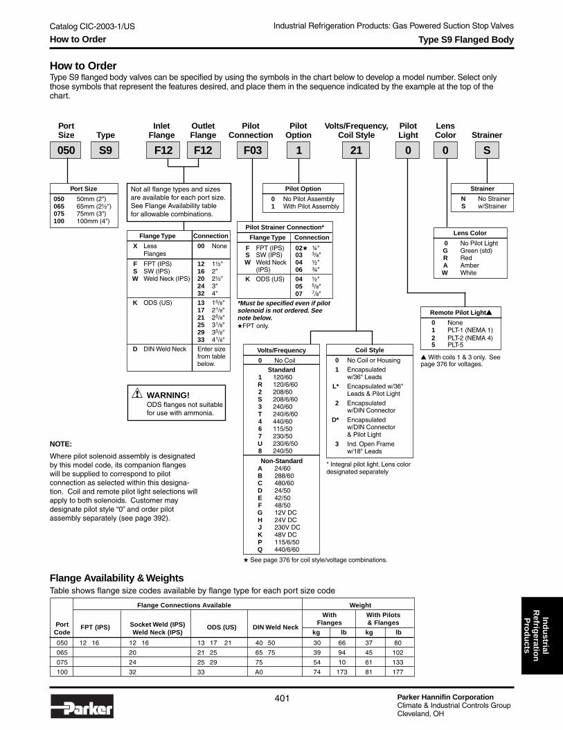
Catalog CIC-2003-1/US Industrial Refrigeration Products: Gas Powered Suction Stop Valves
Parker Hannifin CorporationClimate & Industrial Controls GroupCleveland, OH
401
Ind
ustrial
Refrig
eration
Pro
du
cts
How to OrderType S9 flanged body valves can be specified by using the symbols in the chart below to develop a model number. Select onlythose symbols that represent the features desired, and place them in the sequence indicated by the example at the top of thechart.
Type S9 Flanged Body
Strainer
N No StrainerS w/Strainer
Lens Color
0 No Pilot LightG Green (std)R RedA AmberW White
Port Inlet Outlet Pilot Pilot Volts/Frequency, Pilot LensSize Type Flange Flange Connection Option Coil Style Light Color Strainer
NOTE:
Where pilot solenoid assembly is designatedby this model code, its companion flangeswill be supplied to correspond to pilotconnection as selected within this designa-tion. Coil and remote pilot light selections willapply to both solenoids. Customer maydesignate pilot style “0” and order pilotassembly separately (see page 392).
Remote Pilot Light▲▲▲▲▲
0 None1 PLT-1 (NEMA 1)2 PLT-2 (NEMA 4)5 PLT-5
▲ With coils 1 & 3 only. Seepage 376 for voltages.
Port Size
050 50mm (2")065 65mm (2½")075 75mm (3")100 100mm (4")
Flange Type Connection
X Less 00 NoneFlanges
F FPT (IPS) 12 1½"S SW (IPS) 16 2"W Weld Neck (IPS) 20 2½"
24 3"32 4"
K ODS (US) 13 15/8"17 21/8"21 25/8"25 31/8"29 35/8"33 41/8"
D DIN Weld Neck Enter sizefrom tablebelow.
Not all flange types and sizesare available for each port size.See Flange Availability tablefor allowable combinations.
050 S9 F12 F12 F03 1 21 0 0 S
Flange Availability & WeightsTable shows flange size codes available by flange type for each port size code
Flange Connections Available Weight
With With PilotsPort FPT (IPS) Socket Weld (IPS) ODS (US) DIN Weld Neck
Flanges & Flanges
Code Weld Neck (IPS) kg lb kg lb
050 12 16 12 16 13 17 21 40 50 30 66 37 80
065 20 21 25 65 75 39 94 45 102
075 24 25 29 75 54 10 61 133
100 32 33 A0 74 173 81 177
Pilot Strainer Connection*
Flange Type Connection
F FPT (IPS) 02★ ¼"S SW (IPS) 03 3/8"W Weld Neck 04 ½"
(IPS) 06 ¾"
K ODS (US) 04 ½"05 5/8"07 7/8"
*Must be specified even if pilotsolenoid is not ordered. Seenote below.★FPT only.
Pilot Option
0 No Pilot Assembly1 With Pilot Assembly
Coil Style
0 No Coil or Housing1 Encapsulated
w/36" LeadsL* Encapsulated w/36"
Leads & Pilot Light
2 Encapsulatedw/DIN Connector
D* Encapsulatedw/DIN Connector& Pilot Light
3 Ind. Open Framew/18" Leads
* Integral pilot light. Lens colordesignated separately
Volts/Frequency
0 No CoilStandard
1 120/60R 120/6/602 208/60S 208/6/603 240/60T 240/6/604 440/606 115/507 230/50U 230/6/508 240/50
Non-StandardA 24/60B 288/60C 480/60D 24/50E 42/50F 48/50G 12V DCH 24V DCJ 230V DCK 48V DCP 115/6/50Q 440/6/60
★ See page 376 for coil style/voltage combinations.
WARNING!ODS flanges not suitablefor use with ammonia.
!
How to Order

Parker Hannifin CorporationClimate & Industrial Controls GroupCleveland, OH
Catalog CIC-2003-1/US Industrial Refrigeration Products: Gas Powered Suction Stop Valves
402
● Port Sizes 125-200mm (5" - 8")● Pilot Operated● Welds directly in the Line – No Flanges● Removable Seat is Serviceable from Top Side● Coil Size Same as Most Other R/S Valves● Streamlined Fluid Flow Pattern● Cast Steel Body, ASTM No. A352 Grade LCB● PTFE Pilot Seat● Molded Class “B” Coil Construction● Manual Opening Stem● Maximum Rated Pressure (MRP): 27.6 bar (400 PSIG)
DescriptionThese heavy duty, normally closed, gas powered valves aresuitable for control of ammonia and other common refriger-ants, certain oils and other fluids approved for use inrefrigeration.
The Type S9 are pilot operated but use an external sourceof higher pressure gas to operate the valve and, therefore,require no minimum pressure drop to open. The externalgas pressure must be at least 0.71 bar (10 psi) above valveinternal upstream pressure for positive opening.
The S9 valve can be ordered without a pilot assembly andthe pilot assembly ordered separately (see page 392).
MaterialsBody ................................................................... Cast SteelSeat ............................................................................ Metal
Type S9 Weld End Body
Dimensions
A
H
B
W
Dimension125mm 150mm 200mm
(5") (6") (8")
Bmm 114 152 197
inch 4.50 6.00 7.75
Cmm 597 673 730
inch 23.50 26.50 28.75
Kmm 711 825 927
inch 28.00 32.50 36.50
Lmm 381 483 622
inch 15.00 19.00 24.50
Wmm 267 318 381
inch 10.50 12.50 15.00
SpecificationsMinimum Pressureto Open Wide .......................................... 0.71 bar (10 PSI)Fluid Temperature Range .... -45° to 100°C (-50° to 220°F)Coil (See page 376) .............................. Class “B” HousingFlow Coefficients
125 mm (5") ...................................... 171 Kv (200 Cv)150 mm (6") ...................................... 308 Kv (360 Cv)200 mm (8") ...................................... 471 Kv (550 Cv)
Technical Information and Dimensions

Catalog CIC-2003-1/US Industrial Refrigeration Products: Gas Powered Suction Stop Valves
Parker Hannifin CorporationClimate & Industrial Controls GroupCleveland, OH
403
Ind
ustrial
Refrig
eration
Pro
du
ctsType S9 Weld End Body
How to OrderType S9 weld end body valves can be specified by using the symbols in the chart below to develop a model number. Select onlythose symbols that represent the features desired, and place them in the sequence indicated by the example at the top of thechart.
Port Pilot Pilot Coil Voltage, Pilot LensSize Type Connection Assembly Coil Style Light Color Strainer
Port Size
125 125mm (5")150 150mm (6")200 200mm (8")
Strainer
N No StrainerS w/Strainer
Remote Pilot Light▲
0 None1 PLT-1 (NEMA 1)2 PLT-2 (NEMA 4)5 PLT-5
*Lens Color
0 No Pilot LightG Green (std)R RedA AmberW White
Pilot Assembly
0 No Pilot Assembly1 With Pilot Assembly
150 S9 F03 1 12 0 0 S
Pilot Strainer Connection*
Flange Type Connection
F FPT (IPS) 02★ ¼"S SW (IPS) 03 3/8"W Weld Neck 04 ½"
(IPS) 06 ¾"
K ODS (US) 04 ½"05 5/8"07 7/8"
*Must be specified even if pilotsolenoid is not ordered. Seenote below.★FPT only.
Weight
Port Less Pilots With Pilots
Code kg lb kg lb
125 60 134 150 234
150 103 229 182 404
200 163 372 304 672
▲ With coils 1 & 3 only. Seepage 376 for voltages.
NOTE:
Where pilot solenoid assembly is designated by thismodel code, its companion flanges will be supplied tocorrespond to pilot connection as selected within thisdesignation. Coil and remote pilot light selections willapply to both solenoids. Customer may designatepilot style “0” and order pilot assembly separately(see page 392).
Weights
Coil Style
0 No Coil or Housing
1 Encapsulatedw/36" Leads
L Encapsulated w/36"Leads & Pilot Light*
2 Encapsulatedw/DIN Connector
D Encapsulatedw/DIN Connector& Pilot Light*
3 Ind. Open Framew/18" Leads
* Integral pilot light. Lens colorselected separately
Coil Voltage
0 No Coil
Standard1 120/60R 120/6/602 208/60S 208/6/603 240/60T 240/6/604 440/606 115/507 230/50U 230/6/508 240/50
Non-StandardA 24/60B 288/60C 480/60D 24/50E 42/50F 48/50G 12V DCH 24V DCJ 230V DCK 24V DCP 115/6/50Q 440/6/60
★ See page 376 for coilstyle/voltage combinations.
WARNING!ODS flanges not suitablefor use with ammonia.
!
How to Order

Parker Hannifin CorporationClimate & Industrial Controls GroupCleveland, OH
Catalog CIC-2003-1/US Industrial Refrigeration Products: Gas Powered Suction Stop Valves
404
S9 Pilot Assembly
DescriptionThe S9 Pilot Assembly can be ordered separately from thevalve for stock or field assembly. Assembly includes a S6Npressure pilot solenoid with close coupled strainer, a S6Nbleed pilot solenoid, required piping and flange connections.See Note below.
The 50mm (2") S9 valve uses a 050 size assembly. Valves65mm (2½") and larger use the 065 size assembly.
Coil Voltage, Pilot LensSize Type Flanges Coil Style Light Color
Size
050 Use with 50mm (2")S9 valve
065 Use with 65 - 200mm(2½"- 8") S9 valves
Remote Pilot Lights▲
0 None1 PLT-1 (NEMA 1)2 PLT-2 (NEMA 4)5 PLT-5
Lens Color
0 No Pilot LightG Green (std)R RedA AmberW White
065 PS9 F03 12 0 0
Flange Type Connection
F FPT (IPS) 02★ ¼"S SW (IPS) 03 3/8"W Weld Neck 04 ½"
(IPS) 06 ¾"
K ODS (US) 04 ½"05 5/8"07 7/8"
★FPT only.
Size kg lb
050 60 134
065 103 229
▲ With coils 1 & 3 only. Seepage 376 for voltages.
How to OrderType S9 pilot assembly can be specified by using the symbols in the chart below to develop a model number. Select only thosesymbols that represent the features desired, and place them in the sequence indicated by the example at the top of the chart.
Weights
Coil Style
0 No Coil or Housing1 Encapsulated
w/36" Leads
L* Encapsulated w/36"Leads & Pilot Light
2 Encapsulatedw/DIN Connector
D* Encapsulatedw/DIN Connector& Pilot Light
3 Ind. Open Framew/18" Leads
* Integral pilot light. Lens colorselected separately
★ See page 376 for coilstyle/voltage combinations.
Coil Voltage★
0 No CoilStandard
1 120/60R 120/6/602 208/60S 208/6/603 240/60T 240/6/604 440/606 115/507 230/50U 230/6/508 240/50
Non-StandardA 24/60B 288/60C 480/60D 24/50E 42/50F 48/50G 12V DCH 24V DCJ 230V DCK 24V DCP 115/6/50Q 440/6/60
NOTES:
1. Flanges connected to the piping suppliedare standard 3/8" FPT. Flanges selectedwithin the model number will be suppliedfor both inlet and outlet of the assembly.
2. Coil and remote pilot light selections willbe provided for both pilot solenoids.
82.5mm(3.25")
PressurePilotSolenoid
241mm(9.5")
160mm (6.3")
178mm (7.0")
305mm (12.0")
140mm(5.5")
BleedPilotSolenoid
3/8" FPT(Std.)
Pressure Pilot Solenoidwith Strainer
Bleed Pilot Solenoid
WARNING!ODS flanges not suitablefor use with ammonia.
!
Technical Information and How to Order

Catalog CIC-2003-1/US Industrial Refrigeration Products: Check Valves
Parker Hannifin CorporationClimate & Industrial Controls GroupCleveland, OH
405
Ind
ustrial
Refrig
eration
Pro
du
ctsCheck Valves
CK413-100mm
(½" - 4")
CK1
CK4125-200mm
(5" - 8")
SpecificationsType CK4A CK4A CK4A CK1 CK1 CK3
Port Sizemm 13 20-100 125-200 20-32 40-150 —
inch ½" ¾" - 4" 5" - 8" ¾"- 1¼" 15/8" - 6" ½ - 1 FPT
Seat MaterialStainless Stainless Stainless
PTFEMetal to
PTFESteel Steel Steel Metal
Body Material Steel Ductile Iron Ductile Iron Gray Iron Gray Iron Steel
Design Pressure bar 34.5 34.5 34.5 20.7 20.7 20.7
(MRP) psi 500 500 500 300 300 300
Fluid Temperature °C -55° to 105° -55° to 105° -55° to 105° -30° to 105° -30° to 105° -30° to 105°Limits °F -60° to 220° -60° to 220° -60° to 220° -25° to 220° -25° to 220° -25° to 220°
Close Coupling to Valve* Yes Yes No Yes Up to 100mm No
Close Coupled Inlet Strainer Yes Yes No Yes Up to 100mm No
Minimum Pressure bar 0.05 0.05 0.05 0.03 0.03 0.34Drop to Open Wide psi 0.75 0.75 0.75 0.5 0.5 5
Bulletin for Reference 50-16 50-16 50-20 50-10 50-10 50-13
*Close coupling using male adapter ring to outlet of R/S control valves.
Selection GuideType Port Sizes Typical Applications Mounting
CK4 13-200mm 1. Liquid lines Any position(½" - 8") 2. High speed compressor discharge lines
(Not recommended for slow speed compressor discharge lines)3. Pump discharge lines4. Suction lines down to -55°C (-60°F)5. Hot gas lines from pan to evaporator6. Defrost relief regulator venting to an imtermediate pressure7. Prevent receiver pressure from backing up into a cold condenser8. Prevent liquid returning to compressor during shutdown9. Prevent liquid from flowing down into drain pan
10. Prevent reverse flow in suction line due to unusual load conditions
CK1 20-150mm 1. Slow speed compressor discharge lines(¾" - 6") 2. Liquid lines
3. Suction lines down to -30°C (-25°F)4. Side port applications on screw compressors
CK3 1/2 to 1 FPT 1. Hot gas lines from pan to evaporator Any position2. Liquid lines
NOTE: Notrecommendedfor side portapplicationson screwcompressors
Horizontal lines withopening stem in thevertical position
CK3
Overview

Parker Hannifin CorporationClimate & Industrial Controls GroupCleveland, OH
Catalog CIC-2003-1/US Industrial Refrigeration Products: Check Valves
406
Type CK4
● UL Listed (Thru 3" Size)● Installs in any position● Compact and lightweight● In-Line flanged valves● Design Pressure (MRP): 34.5 bar (500 psi)
DescriptionThese compact valves are spring closing with a lapped,stainless steel or chrome plated seat for positive closingaction and low leakage. A minimum pressure difference of0.05 bar (0.75 psi) is required to hold the valve in the openposition. Removable seat plate with combination O-ring andmetal-to-metal knife edge seal allows the valve to bedisassembled for maintenance. They may be ordered with amale adapter ring for close-coupling to other RefrigeratingSpecialties valves and may be installed in any position.
MaterialsBody .................... Steel (15mm), Ductile Iron (20-200mm)Seat ............................................................. Stainless steel
SpecificationsDesign Pressure (MRP) ........................ 34.5 bar (500 PSI)Fluid Temperature Range .... -55° to 105°C (-60° to 220°F)Flow Coefficients
13 mm (½") .......................................... 2.9 Kv (3.4 Cv)20 mm (¾") .......................................... 6.1 Kv (7.1 Cv)25 mm (1") ............................................ 11 Kv (13 Cv)32 mm (1¼") ......................................... 16 Kv (19 Cv)50mm (2") ............................................. 40 Kv (46 Cv)65mm (2½") .......................................... 60 Kv (70 Cv)75mm (3") ............................................. 96 Kv(112 Cv)100mm (4") ......................................... 180 Kv(210 Cv)
125mm (5") ......................................... 240 Kv(280 Cv)150mm (6") ......................................... 389 Kv(455 Cv)200mm (8") ......................................... 670 Kv(783 Cv)
Dimensions
PORT SIZE Dimension 13mm 20-25mm 32mm 50mm 65mm 75mm 100m
(1/2") (3/4 - 1") (1-1/4") (2") (2-1/2") (3") (4")
Amm 75 113 95 114 148 148 179inch 29.3 4.43 3.75 4.50 5.81 5.81 7.06
Bmm 38 62 95 114 148 148 179inch 1.50 2.43 3.75 4.50 5.81 5.81 7.06
Cmm 27 32 50 60 70 81 89inch 1.06 1.25 2 2.37 2.75 3.19 3.50
D mm 63 59 79 114 145 157 177(FPT, SW) inch 2.47 2.32 3.10 4.47 5.72 6.16 6.97
Conn.Size 3/8, 1/2, 3/4 3/4" 1" 1-1/4" 1-1/4" 1-1/2" 1-1/2" 2" 2-1/2" 3" 4"
E mm 82 97 117 117 126 136 171 177 215 245 298 inch 3.22 3.82 4.61 4.61 4.97 5.35 6.72 6.97 8.47 9.66 11.72
Conn.Size 1/2 5/8 7/8 7/8 1-1/8 1-3/8 1-5/8 1-3/8 1-5/8 2-1/8 1-5/8 2-1/8 2-5/8 2-5/8 3-1/8 3-1/8 3-5/8 4-1/8
F mm 76 82 98 99 193 99.5 111 119 130 159 193 177 205 203 250 228 248 285 inch 2.98 3.22 3.85 3.88 4.07 3.91 4.36 4.69 5.12 6.26 7.57 6.95 8.08 7.98 9.82 8.95 9.76 11.2
N mm 9 13 29 20 24 25 28 25 28 34 28 34 37 37 42 42 48 55 inch .37 .50 .75 .75 .93 .96 1.09 .96 1.09 1.34 1.09 1.34 1.46 1.46 1.65 1.65 1.90 2.15
P mm 13 13 15 15 25 29 32 inch .50 .50 .60 .60 1.0 1.1 1.3
P
N
F
EB
A
C
D FPTSW
13 - 100mm Size
13-100mm(1/2" - 4")
125-200mm(5" - 8")
Technical Information and Dimensions

Catalog CIC-2003-1/US Industrial Refrigeration Products: Check Valves
Parker Hannifin CorporationClimate & Industrial Controls GroupCleveland, OH
407
Ind
ustrial
Refrig
eration
Pro
du
cts
Flange Connections Available Weight
Port FPT (IPS)Socket Weld (IPS)
ODS (US) DIN Weld Neck Insert Metric EC-Br CopperLess Flanges With Flanges
Code Weld Neck (IPS) kg lb kg lb
013 02 03 04 06 03 04 06 04 05 07 10 15 20 0.5 1 0.9 2
020 06 08 10 06 08 10 07 09 11 20 25 32 20 25 32 18 20 26 30 0.9 2 2.3 5
025 06 08 10 06 08 10 07 09 11 20 25 32 20 25 32 18 20 26 30 0.9 2 2.3 5
032 10 12 10 12 11 13 17 32 40 50 30 36 42 2.5 5 3 8
050 12 16 12 16 13 17 21 40 50 3.2 7 5.9 13
065 20 21 25 65 75 5.4 12 10 22
075 24 25 29 75 7.3 16 12 26
100 32 33 A0 15 34 24 53
How to OrderType CK4 solenoid valves can be specified by using the symbols in the chart below to develop a model number. Select only thosesymbols that represent the features desired, and place them in the sequence indicated by the example at the top of the chart.
Type CK4
Flange Availability & WeightsTable shows flange size codes available by flange type for each port size code
300# ANSI Flange Connections Available Weight
Port Code (150# available for certain applications. Consult factory.) Less Flanges With ANSI Flanges
mm inch Slip-on (IPS) Weld Neck (IPS) kg lbs kg lbs
125 5" 40 40 20 45 50 110
150 6" 48 48 28 62 67 147
200 8" 64 64 44 96 105 231
125 - 200mm Size
Port Inlet OutletSize Type Flange Flange
Flange Type Connection
X Less Flanges 00 NoneR Less Flanges,
w/Male AdapterRing
F FPT (IPS) 02★ ¼"S SW (IPS) 03 3/8"W Weld Neck (IPS) 04 ½"
06 ¾"08 1"10 1¼"12 1½"16 2"20 2½"24 3"32 4"
★ FPT only.
Not all flange types and connections are available for each portsize. See Flange Availability table for allowable combinations.
050 CK4 F12 F12
Dimensions
Flange Type Connection
K ODS (US) 04 ½"05 5/8"07 7/8"09 11/8"
Not suitable 11 13/8"for use with 13 15/8"ammonia. 17 21/8"
21 25/8"25 31/8"29 35/8"33 41/8"
D DIN Weld Neck Enter sizeM Insert Metric in mmC EC-Br Copper from table
below.
Y ANSI Slip-On 40 5"(IPS) 48 6"
Z ANSI Weld Neck 64 8"(IPS)
Valve Valve Flange Diameter of
Nominal Length Diameter Outside Diameter Bolt Circle
Pipe Size Inches mm Inches mm Inches mm Inches mm # of Bolts
125 mm (5") 4.125 104.8 8.375 212.7 11 279 9.25 235 8
150 mm (6") 4.625 117.5 9.750 247.7 12.5 318 10.62 270 12
200 mm (8") 5.625 142.9 12.000 304.8 15 381 13.00 330 12
Port Size
013 13mm (½")020 20mm (¾")025 25mm (1")032 32mm (1¼")050 50mm (2")065 65mm (2½")075 75mm (3")100 100mm (4")125 125mm (5")150 150mm (6")200 200mm (8")
Dimensions and How to Order

Parker Hannifin CorporationClimate & Industrial Controls GroupCleveland, OH
Catalog CIC-2003-1/US Industrial Refrigeration Products: Check Valves
408
Type CK1
● Rugged, Heavy Duty● Low Pressure Drop● Piston Type Gravity Closing● Flanged, horizontal mounting● Design Pressure(MRP): 27.6 bar (400 psig)● Manual Opening Stem
DescriptionThese piston type, gravity closing, heavy duty check valvesare suitable for Ammonia, R-22, R-134a, R-404A, R-507,other refrigerants, certain oils and other fluids approved foruse in refrigeration. All CK1 check valves are flanged andare suitable for mounting only in horizontal lines withopening stem in the vertical position. They have a manualopening stem for manual operation. They may be orderedwith a male adapter ring (through 4" size) for close coupling.A minimum pressure difference of .03 bar (0.5 psi) isrequired to open the valve.
MaterialsBody .....................................................................Gray IronSeat .........................PTFE (20-32mm), Metal (40-150mm)
SpecificationsDesign Pressure (MRP) ........................ 27.6 bar (400 PSI)Fluid Temperature Range .... -30° to 105°C (-25° to 220°F)Flow Coefficients
20 mm (¾") .......................................... 8.1 Kv (9.5 Cv)25 mm (1") ........................................... 8.6 Kv (10 Cv)32 mm (1¼") ......................................... 16 Kv (19 Cv)40mm (15/8") ........................................ 32 Kv (37 Cv)50mm (2") ............................................. 44 Kv (51 Cv)65mm (2½") .......................................... 70 Kv (82 Cv)75mm (3") ........................................... 103 Kv(120 Cv)100mm (4") ......................................... 171 Kv(200 Cv)125mm (5") ......................................... 244 Kv(285 Cv)150mm (6") ......................................... 342 Kv(400 Cv)
DIMENSIONAL DATA
PORT SIZE A B C D E F G H J
mm in. mm in. mm in. mm in. mm in. mm in. mm in. mm in. mm in. mm in.
20, 25 ¾, 1 191 7.5 102 4.0 158 6.2 89 3.5 117 4.6 239 9.4 216 8.5 13 .5 265 10.4
32 1¼ 219 8.6 122 4.8 203 8.0 96.5 3.8 117 4.6 305 12.0 256 10.1 15 .6 320 12.6
40, 50 15/8, 2 270 10.6 139.7 5.5 251 9.9 129.5 5.1 129.5 5.1 371 14.6 307 12.1 15 .6 414 16.3
65 2½ 303 11.9 142.2 5.6 251 9.9 160 6.3 147.3 5.8 401 15.8 331 13.0 25 1.0 424 16.7
75 3 384 15.1 216 8.5 311 12.2 167.6 6.6 167.6 6.6 478 18.8 389 15.3 29 1.1 500 19.7
100 4 427 16.8 217 8.6 366 14.1 208.3 8.2 190.5 7.5 571 22.5 450 17.7 32 1.3 615 24.2
125 5 496 19.5 298.4 11.7 381 15.0 198.1 7.8 228.6 9.0 576.6 22.7 485 19.1 30.5 1.2 — —
150 6 537 21.1 355.6 14.0 514.3 20.2 180 7.1 294.6 11.6 706.1 27.8 617 24.3 35.6 1.4 — —
Dimensions
WN FlangesF
HFPT or SW
EMAX.
JODS Solder Flanges
A
B
D
C
GFPTSW
Technical Information and Dimensions

Catalog CIC-2003-1/US Industrial Refrigeration Products: Check Valves
Parker Hannifin CorporationClimate & Industrial Controls GroupCleveland, OH
409
Ind
ustrial
Refrig
eration
Pro
du
ctsType CK1
How to OrderType CK1 check valves can be specified by using the symbols in the chart below to develop a model number. Select only thosesymbols that represent the features desired, and place them in the sequence indicated by the example at the top of the chart.
Flange Type Connection
X Less Flanges 00 NoneR Less Flanges,
w/Male AdapterRing
F FPT (IPS) 06 ¾"S SW (IPS) 08 1"W Weld Neck (IPS) 10 1¼"
12 1½"16 2"20 2½"24 3"32 4"40 5"48 6"
K ODS (US) 07 7/8"09 11/8"11 13/8"13 15/8"17 21/8"21 25/8"25 31/8"29 35/8"33 41/8"
D DIN Weld Neck Enter sizeM Insert Metric from tableC EC-Br Copper below.
Strainer
N No StrainerS w/Strainer
Port Size
020 20mm (¾")025 25mm (1")032 32mm (1¼")040 40mm (15/8")050 50mm (2")065 65mm (2½")075 75mm (3")100 100mm (4")125 125mm (5")150 150mm (6")
050 CK1 F12 F12 S
Port Inlet OutletSize Type Flange Flange Strainer
Flange Availability & WeightsTable shows flange size codes available by flange type for each port size code
Flange Connections Available Weight
Port FPT (IPS)Socket Weld (IPS)
ODS (US) DIN Weld Neck Insert Metric EC-Br CopperLess Flanges With Flanges
Code Weld Neck (IPS) kg lb kg lb
020 06 08 10 06 08 10 07 09 11 20 25 32 20 25 32 18 20 26 30 4.5 10 5.9 13
025 06 08 10 06 08 10 07 09 11 20 25 32 20 25 32 18 20 26 30 5.0 11 6.4 14
032 10 12 10 12 11 13 17 32 40 50 30 36 42 10 22 12 26
040 12 16 12 16 13 17 21 40 50 21 47 24 53
050 12 16 12 16 13 17 21 40 50 21 47 24 53
065 20 21 25 65 75 28 62 33 72
075 24 25 29 75 42 92 45 102
100 32 33 A0 62 136 70 154
125 40 109 239 137 279
150 48 182 400 200 440
Not all flange sizes areavailable for each port size.See Flange Availability tablefor allowable combinations.
WARNING!ODS flanges not suitablefor use with ammonia.
!
How to Order
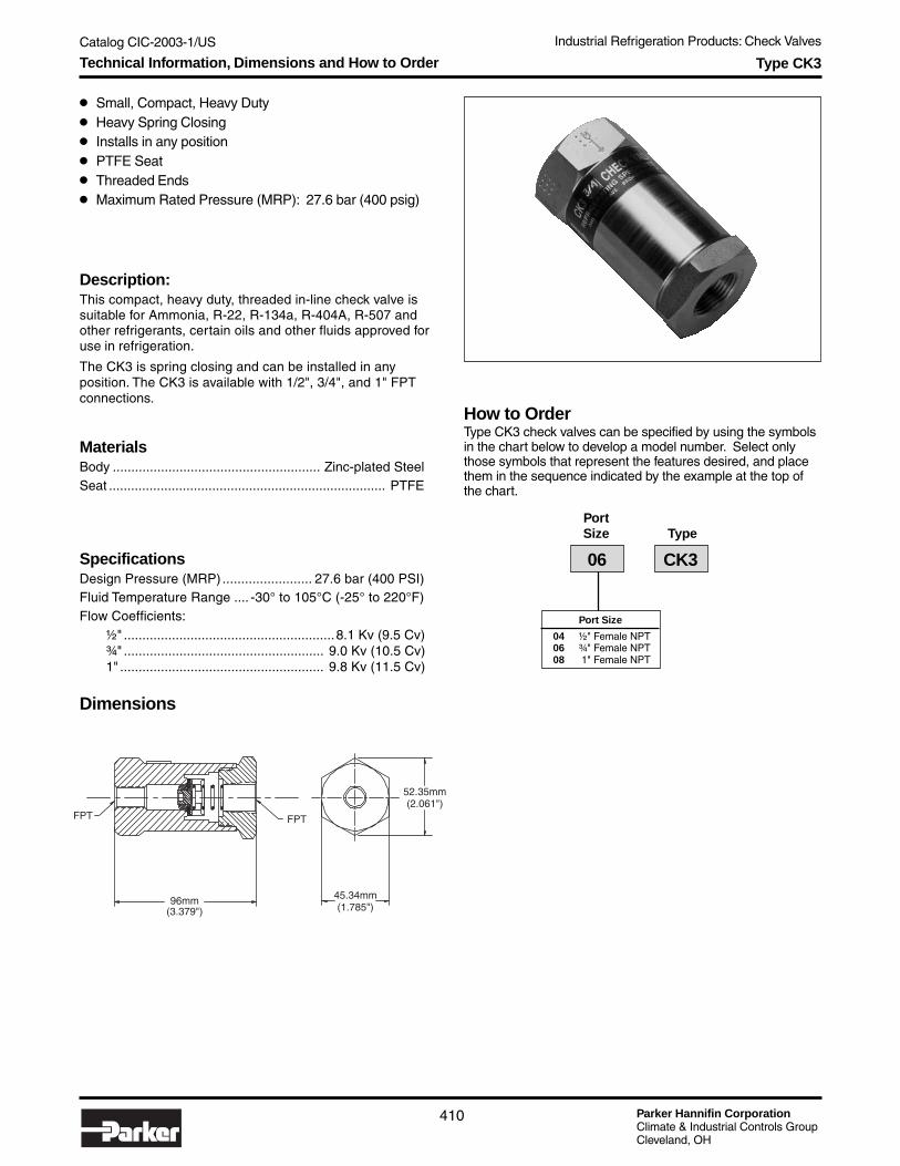
Parker Hannifin CorporationClimate & Industrial Controls GroupCleveland, OH
Catalog CIC-2003-1/US Industrial Refrigeration Products: Check Valves
410
Type CK3
● Small, Compact, Heavy Duty● Heavy Spring Closing● Installs in any position● PTFE Seat● Threaded Ends● Maximum Rated Pressure (MRP): 27.6 bar (400 psig)
Description:This compact, heavy duty, threaded in-line check valve issuitable for Ammonia, R-22, R-134a, R-404A, R-507 andother refrigerants, certain oils and other fluids approved foruse in refrigeration.
The CK3 is spring closing and can be installed in anyposition. The CK3 is available with 1/2", 3/4", and 1" FPTconnections.
MaterialsBody ........................................................ Zinc-plated SteelSeat ........................................................................... PTFE
SpecificationsDesign Pressure (MRP) ........................ 27.6 bar (400 PSI)Fluid Temperature Range .... -30° to 105°C (-25° to 220°F)Flow Coefficients:
½" .........................................................8.1 Kv (9.5 Cv)¾" ...................................................... 9.0 Kv (10.5 Cv)1" ....................................................... 9.8 Kv (11.5 Cv)
52.35mm(2.061")
FPTFPT
96mm(3.379")
45.34mm(1.785")
Dimensions
How to OrderType CK3 check valves can be specified by using the symbolsin the chart below to develop a model number. Select onlythose symbols that represent the features desired, and placethem in the sequence indicated by the example at the top ofthe chart.
Port Size
04 ½" Female NPT06 ¾" Female NPT08 1" Female NPT
PortSize Type
06 CK3
Technical Information, Dimensions and How to Order
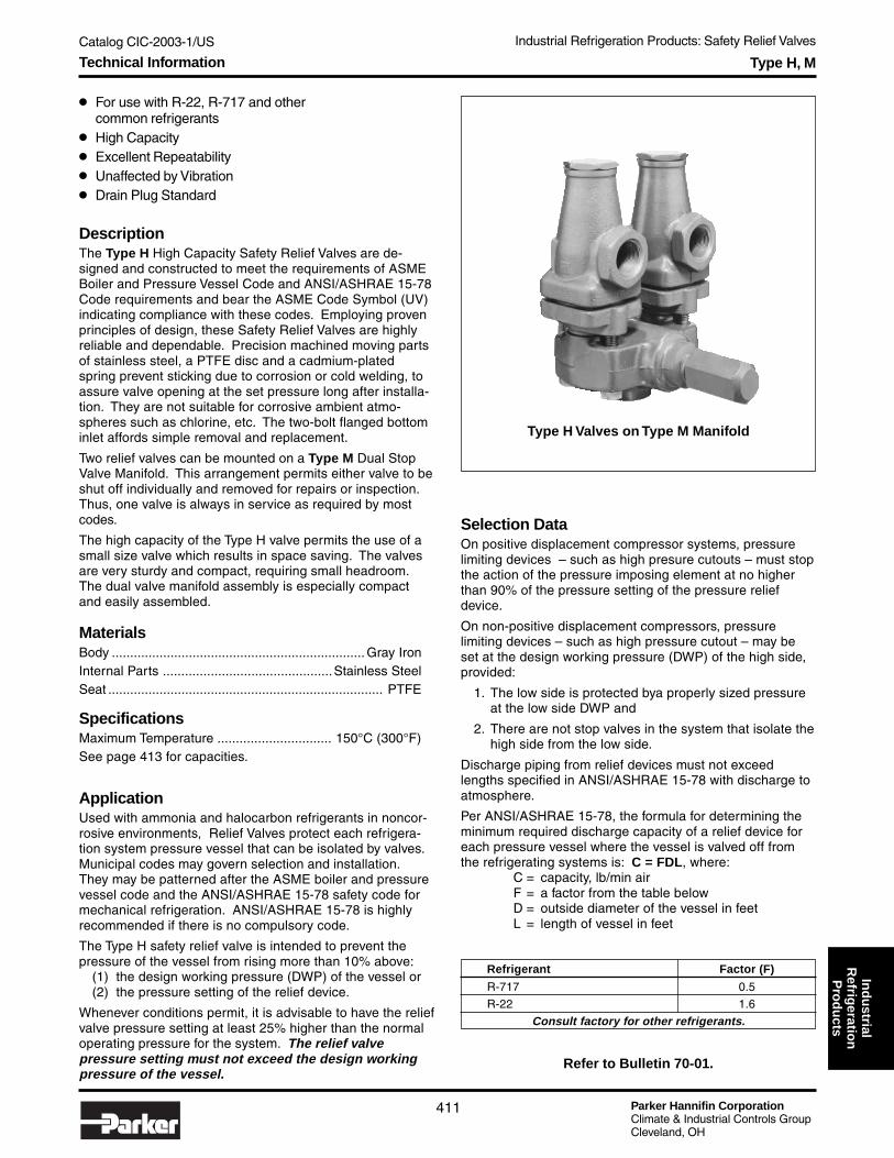
Catalog CIC-2003-1/US Industrial Refrigeration Products: Safety Relief Valves
Parker Hannifin CorporationClimate & Industrial Controls GroupCleveland, OH
411
Ind
ustrial
Refrig
eration
Pro
du
ctsType H, M
● For use with R-22, R-717 and othercommon refrigerants
● High Capacity● Excellent Repeatability● Unaffected by Vibration● Drain Plug Standard
DescriptionThe Type H High Capacity Safety Relief Valves are de-signed and constructed to meet the requirements of ASMEBoiler and Pressure Vessel Code and ANSI/ASHRAE 15-78Code requirements and bear the ASME Code Symbol (UV)indicating compliance with these codes. Employing provenprinciples of design, these Safety Relief Valves are highlyreliable and dependable. Precision machined moving partsof stainless steel, a PTFE disc and a cadmium-platedspring prevent sticking due to corrosion or cold welding, toassure valve opening at the set pressure long after installa-tion. They are not suitable for corrosive ambient atmo-spheres such as chlorine, etc. The two-bolt flanged bottominlet affords simple removal and replacement.
Two relief valves can be mounted on a Type M Dual StopValve Manifold. This arrangement permits either valve to beshut off individually and removed for repairs or inspection.Thus, one valve is always in service as required by mostcodes.
The high capacity of the Type H valve permits the use of asmall size valve which results in space saving. The valvesare very sturdy and compact, requiring small headroom.The dual valve manifold assembly is especially compactand easily assembled.
MaterialsBody ..................................................................... Gray IronInternal Parts ..............................................Stainless SteelSeat ........................................................................... PTFE
SpecificationsMaximum Temperature ............................... 150°C (300°F)See page 413 for capacities.
ApplicationUsed with ammonia and halocarbon refrigerants in noncor-rosive environments, Relief Valves protect each refrigera-tion system pressure vessel that can be isolated by valves.Municipal codes may govern selection and installation.They may be patterned after the ASME boiler and pressurevessel code and the ANSI/ASHRAE 15-78 safety code formechanical refrigeration. ANSI/ASHRAE 15-78 is highlyrecommended if there is no compulsory code.
The Type H safety relief valve is intended to prevent thepressure of the vessel from rising more than 10% above:
(1) the design working pressure (DWP) of the vessel or(2) the pressure setting of the relief device.
Whenever conditions permit, it is advisable to have the reliefvalve pressure setting at least 25% higher than the normaloperating pressure for the system. The relief valvepressure setting must not exceed the design workingpressure of the vessel.
Selection DataOn positive displacement compressor systems, pressurelimiting devices – such as high presure cutouts – must stopthe action of the pressure imposing element at no higherthan 90% of the pressure setting of the pressure reliefdevice.
On non-positive displacement compressors, pressurelimiting devices – such as high pressure cutout – may beset at the design working pressure (DWP) of the high side,provided:
1. The low side is protected bya properly sized pressureat the low side DWP and
2. There are not stop valves in the system that isolate thehigh side from the low side.
Discharge piping from relief devices must not exceedlengths specified in ANSI/ASHRAE 15-78 with discharge toatmosphere.
Per ANSI/ASHRAE 15-78, the formula for determining theminimum required discharge capacity of a relief device foreach pressure vessel where the vessel is valved off fromthe refrigerating systems is: C = FDL, where:
C = capacity, lb/min airF = a factor from the table belowD = outside diameter of the vessel in feetL = length of vessel in feet
Refrigerant Factor (F)
R-717 0.5
R-22 1.6
Consult factory for other refrigerants.
Type H Valves on Type M Manifold
Refer to Bulletin 70-01.
Technical Information

Parker Hannifin CorporationClimate & Industrial Controls GroupCleveland, OH
Catalog CIC-2003-1/US Industrial Refrigeration Products: Safety Relief Valves
412
Dual Stop Valve ManifoldCompanion Mounting Flange (Male)
Companion Mounting Flange (Female)
Bottom InletType Connection Size
M2 ¾" FPT
M3 1" FPT
M4 1½" FPT
Note: Bolts supplied with manifold.
Size Oval TypeFlange Tongue Inlet Valve
Pattern Connection Applicable
½" ¾" FPT H2
¾" 1" FPT H3
1¼" 1¼" FPT H4, H5
1¼" 1½" FPT H4, H5
Note: Flange with bolts only. Gaskets supplied with Relief Valve.
Size Oval TypeFlange Tongue Inlet Valve
Pattern Connection Applicable
½" ¾" FPT H2
¾" 1" FPT H3
1¼" 1¼" FPT H4, H5
1¼" 1½" FPT H4, H5
Note: Flange with bolts only. Gaskets supplied with Relief Valve.
DimensionH2 H3 H4 H5
mm inch mm inch mm inch mm inch
A 251 9.87 295 11.62 340 13.37 371 14.62
B 152 6.00 187 7.37 211 8.31 224 8.81
C 171 6.75 219 8.62 273 10.75 318 12.50
D 137 5.37 127 5.00 117 4.62 111 4.37
E 102 4.00 127 5.00 165 6.50 165 6.50
F 273 10.75 283 11.12 298 11.75 298 11.75
G 187 7.37 188 7.41 192 7.56 192 7.56
H 166 6.53 202 7.97 237 9.34 266 10.46
I 193 7.59 229 9.03 267 10.53 296 11.65
K 96 3.77 120 4.72 137 5.40 151 5.93
L 102 4.00 102 4.00 122 4.81 122 4.81
M 70 2.75 92 3.62 108 4.25 152 6.00
N 49 1.94 62 2.43 75 2.94 81 3.19
Inlet 20 ¾ 25 1 32 1¼ 32 1¼
Outlet 25 1 32 1¼ 40 1½ 50 2
Type H, M
Dimensions
M N
J
K
LINLET
OUTLET
INLET
CE
H
A
D
OUTLET
B
F
GSingle Valve Manifold with
Two Valves
Dimensions

Catalog CIC-2003-1/US Industrial Refrigeration Products: Safety Relief Valves
Parker Hannifin CorporationClimate & Industrial Controls GroupCleveland, OH
413
Ind
ustrial
Refrig
eration
Pro
du
cts
How to OrderSafety relief valves and manifolds can be specified by using the symbols in the chart below to develop a model number. Selectonly those symbols that represent the features desired, and place them in the sequence indicated by the example at the top of thechart.
Type H, M
MANIFOLD FORSINGLE VALVE ONLY TWO VALVES
Connections Capacity ConnectionsCompanion ReliefMounting Valve Pressure Lbs. Manifold Relief
Valve Flange Outlet Setting Per Min SCFM Inlet ValveType (Inlet) FPT (psig) Air Air Bottom Outlet
50 23 30275 32 422
100 41 541125 50 661 Type M2
½" Port 1" 150 60 780 Manifold 1"H2 Provides FPT 175 69 899 Provides FPT
¾" FPT 200 78 1019 ¾" FPT225 87 1138250 96 1257275 105 1377300 114 1496
50 38 49875 53 694
100 68 890125 83 1087 Type M3
¾" Port 1¼" 150 98 1283 Manifold 1¼"H3 Provides FPT 175 113 1479 Provides FPT
1" FPT 200 128 1676 1" FPT225 143 1872250 158 2068275 173 2265300 188 2461
50 57 74475 79 1037
100 101 1330125 124 1624 Type M4
1" Port 1½" 150 146 1917 Manifold 1½"H4 Provides FPT 175 169 2211 Provides FPT
1¼" FPT 200 191 2504 1½" FPT225 213 2798250 236 3091275 258 3385300 281 3678
50 95 124275 132 1732
100 170 2222125 207 2712 Type M4
1¼" Port 150 244 3202 Manifold 2"H5 Provides 175 282 3692 Provides FPT
1¼" FPT 2" 200 319 4182 1½" FPT225 357 4672250 394 5162275 431 5653300 469 6143
Type (See Table Above)
H2 H2 ValveH3 H3 ValveH4 H4 ValveH5 H5 ValveM2 M2 ManifoldM3 M3 ManifoldM4▲▲▲▲▲ M4 Manifold
▲ ▲ ▲ ▲ ▲ Fits H4 & H5 Valves
Inlet Flange
X Less Flange1★★★★★ Male Companion Flange2▲▲▲▲▲ Female Companion Flange3▲▲▲▲▲ Male plus Female
Companion Flanges
★★★★★ For Single Valves only.▲▲▲▲▲ For Mainfolds only.
◆ Standard settings shown. Othersettings between 50 and 300 PSIare available at additional cost.
Inlet Connection PressureType Flange Size Setting
Specifications
Note:Pressure settingsand capacitiesapply only whenthe valve isdischarging toatmosphericpressure.
Connection Size
0 Less Flange2 3/4" FPT (H2 only)3 1" FPT (H3 only)4 1¼" FPT (H4 & H5 only)5 1½" FPT (H4 & H5 only)
H2 1 1 – 100
Pressure Setting◆
Blank Manifold50 50 PSI 3.5 Bar75 75 PSI 5.2 Bar
100 100 PSI 6.9 Bar125 125 PSI 8.6 Bar150 150 PSI 10.3 Bar175 175 PSI 12.1 Bar200 200 PSI 13.8 Bar225 225 PSI 15.5 Bar250 250 PSI 17.2 Bar275 275 PSI 19.0 Bar300 300 PSI 20.7 Bar
Technical Information and How to Order

Parker Hannifin CorporationClimate & Industrial Controls GroupCleveland, OH
Catalog CIC-2003-1/US Industrial Refrigeration Products: Safety Relief Valves
414
Type SR/SRH
DescriptionThe type SR and SRH Safety Relief Valves are designedand constructed in strict accordance to the requirementsof ASME Boiler and Pressure Vessel Code and certifiedby the National Board of Boiler and Pressure VesselInspectors. Each valve is accurately set and sealed at thefactory and bear the UV and NB symbols. Employingproven principles of design, these safety relief valves arehighly reliable and dependable. Precision machinedstainless steel internal parts and a PTFE seat disk helpprevent sticking due to corrosion and assure valveopening at the set pressure long after installation.
SR Connection sizes are ½" FPT inlet with ¾" or 1" FPToutlet or a ¾" inlet with 1 ¼" or 1 ½" outlet.
SRH series valves are available with a ½" inlet and ¾" or1" outlet or a ¾" inlet and 1" outlet.
● SR Series designed to meet ASHRAE 15 2001 require-ments for new system installations
● SRH Series designed to meet ASHRAE 15 1994 (orearlier) system requirements
● Certified by the National Board of Boilers and PressureVessel Inspectors
● All stainless steel internal parts● PTFE seat● Accurate and dependable● Pressure relief settings from 10.3 - 27.6 bar
(150 - 400 psig)
Technical Information
Type SR Safety Relief Valves
Relief ReliefValve Valve ValveType Inlet Outlet
SR1 1/2" FPT 3/4" FPT
SR2 1/2" FPT 1" FPT
SR3 3/4" FPT 1-1/4" FPT
SR4 3/4" FPT 1-1/2" FPT
Type SRH Safety Relief Valves
Relief ReliefValve Valve ValveType Inlet Outlet
SRH1 1/2" FPT 3/4" FPT
SRH2 1/2" FPT 1" FPT
SRH3 3/4" FPT 1" FPT
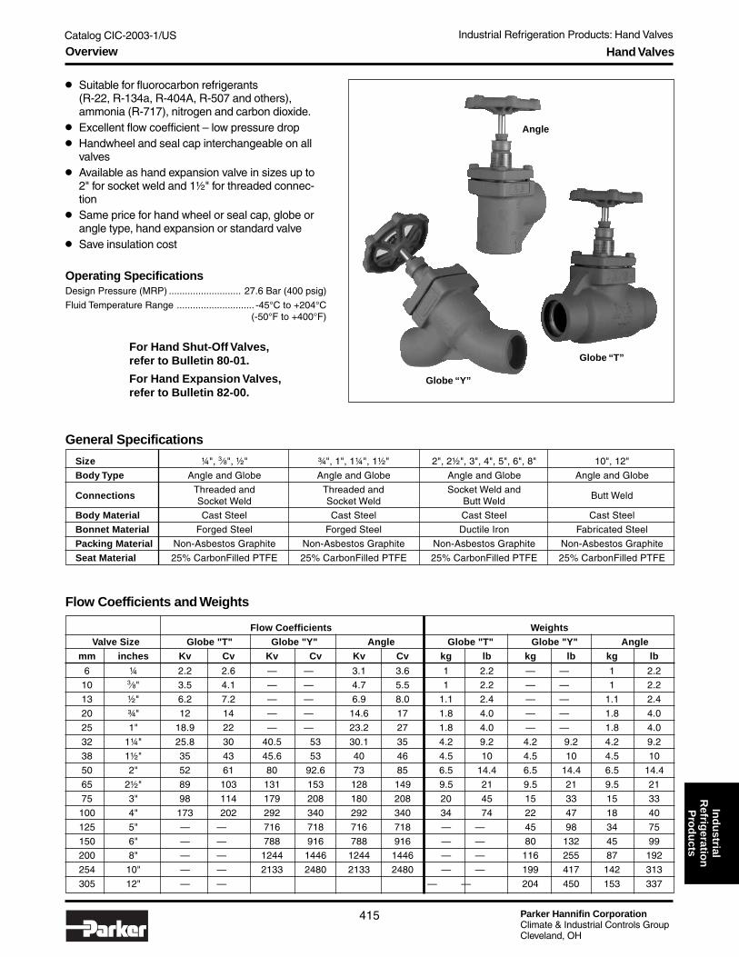
Catalog CIC-2003-1/US Industrial Refrigeration Products: Hand Valves
Parker Hannifin CorporationClimate & Industrial Controls GroupCleveland, OH
415
Ind
ustrial
Refrig
eration
Pro
du
ctsHand Valves
Operating SpecificationsDesign Pressure (MRP) ........................... 27.6 Bar (400 psig)
Fluid Temperature Range ............................. -45°C to +204°C(-50°F to +400°F)
● Suitable for fluorocarbon refrigerants(R-22, R-134a, R-404A, R-507 and others),ammonia (R-717), nitrogen and carbon dioxide.
● Excellent flow coefficient – low pressure drop● Handwheel and seal cap interchangeable on all
valves● Available as hand expansion valve in sizes up to
2" for socket weld and 1½" for threaded connec-tion
● Same price for hand wheel or seal cap, globe orangle type, hand expansion or standard valve
● Save insulation cost
Size ¼", 3⁄8", ½" ¾", 1", 1¼", 1½" 2", 2½", 3", 4", 5", 6", 8" 10", 12"
Body Type Angle and Globe Angle and Globe Angle and Globe Angle and Globe
ConnectionsThreaded and Threaded and Socket Weld and
Butt WeldSocket Weld Socket Weld Butt Weld
Body Material Cast Steel Cast Steel Cast Steel Cast Steel
Bonnet Material Forged Steel Forged Steel Ductile Iron Fabricated Steel
Packing Material Non-Asbestos Graphite Non-Asbestos Graphite Non-Asbestos Graphite Non-Asbestos Graphite
Seat Material 25% CarbonFilled PTFE 25% CarbonFilled PTFE 25% CarbonFilled PTFE 25% CarbonFilled PTFE
General Specifications
Flow Coefficients and Weights
Flow Coefficients Weights Valve Size Globe "T" Globe "Y" Angle Globe "T" Globe "Y" Angle
mm inches Kv Cv Kv Cv Kv Cv kg lb kg lb kg lb
6 ¼ 2.2 2.6 — — 3.1 3.6 1 2.2 — — 1 2.2
10 3⁄8" 3.5 4.1 — — 4.7 5.5 1 2.2 — — 1 2.2
13 ½" 6.2 7.2 — — 6.9 8.0 1.1 2.4 — — 1.1 2.4
20 ¾" 12 14 — — 14.6 17 1.8 4.0 — — 1.8 4.0
25 1" 18.9 22 — — 23.2 27 1.8 4.0 — — 1.8 4.0
32 1¼" 25.8 30 40.5 53 30.1 35 4.2 9.2 4.2 9.2 4.2 9.2
38 1½" 35 43 45.6 53 40 46 4.5 10 4.5 10 4.5 10
50 2" 52 61 80 92.6 73 85 6.5 14.4 6.5 14.4 6.5 14.4
65 2½" 89 103 131 153 128 149 9.5 21 9.5 21 9.5 21
75 3" 98 114 179 208 180 208 20 45 15 33 15 33
100 4" 173 202 292 340 292 340 34 74 22 47 18 40
125 5" — — 716 718 716 718 — — 45 98 34 75
150 6" — — 788 916 788 916 — — 80 132 45 99
200 8" — — 1244 1446 1244 1446 — — 116 255 87 192
254 10" — — 2133 2480 2133 2480 — — 199 417 142 313
305 12" — — — — 204 450 153 337
For Hand Shut-Off Valves,refer to Bulletin 80-01.
For Hand Expansion Valves,refer to Bulletin 82-00.
Angle
Globe “ T”
Globe “ Y”
Overview

Parker Hannifin CorporationClimate & Industrial Controls GroupCleveland, OH
Catalog CIC-2003-1/US Industrial Refrigeration Products: Hand Valves
416
Hand Valves
● ASTM 352 LCB Cast Steel Body (1/4" thru 12")● Stainless Steel Stem● Optional Stainless Steel Trim● Reliable Back Seating● Bolted Bonnets (1/4" thru 12")● 25% Carbon Filled PTFE Seat Material● Linear Flow “Y” Pattern Globe Body (1-1/4" thru 12")
for Low Pressure Drop● Extended Bonnets for Thicker Insulation● Handwheel and Seal Cap Interchangeable
on Same Valve
DescriptionThis complete line of steel bodied valves with bolt-onbonnets is designed and built to maintain reliability both inthe seating and back seating functions. This entire line issupplied with stainless steel stems and backseatingcapability. Corrosion resistant, high-grade stainless steeltrim is available upon request. A unique carbon filled PTFEseat is standard throughout the line, lending durability to theseating surface. In addition a dual O-ring stem packingdesign along with a stem packing seal is standard on allvalves from 1/4" thru 12". This innovative design seals boththe valve stem and bonnet bore with independent O-rings,which are captured in a carbon PTFE carrier. The additionof the packing provides for backup sealing capability in theunlikely event of an O-ring failure.
MachinedBonnetBore
Carbon PTFEWashers
PackingNut
Carbon PTFEO-Ring Carrier
Non-asbestosGraphitePacking
Standard Bonnet Extended Bonnet
TaperedPlug
ExtendedBonnet
for Low TempInsulation
T-Handle
Trim OptionsStandard mild steel trim includes Grade 5 Steel bonnetbolts, mild steel packing nut and Type 304 Stainless stem.The stainless steel trim option utilizes 316 Stainless Steelbonnet bolts, packing nut and stem to provide corrosionresistance for selected exposed parts.
Extended BonnetAn extended bonnet is available for selected sizes andstyles of hand valves (see Availability Table). This designsupports 3" thick insulation above bonnet bolts for valvesthrough 3" size and 4" thick insulation for 4" size valves. Allextended bonnet valves incorporate 316 Stainless Steelbonnet bolts, stem, packing nut, extension boss and bossretainer.
Hand Expansion ValvesHand expansion valves are the same as shut-off valvesexcept they feature a tapered plug for throttling action.Handle options are a T-handle or seal cap.
Hand Expansion Valve
Technical Information

Catalog CIC-2003-1/US Industrial Refrigeration Products: Hand Valves
Parker Hannifin CorporationClimate & Industrial Controls GroupCleveland, OH
417
Ind
ustrial
Refrig
eration
Pro
du
ctsHand Valves
How to OrderHand valves can be specified by using the symbols in the chart below to develop a model number. Select only those symbols thatrepresent the features desired, and place them in the sequence indicated by the example at the top of the chart.
Port Connection Body Trim OperatorSize Type Style Style Option Option
Port Size
006 6mm (¼")010 10mm (3⁄8")013 13mm (½")020 20mm (¾")025 25mm (1")032 32mm (1¼")038 38mm (1½")050 50mm (2")065 65mm (2½")075 75mm (3")100 100mm (4")125 125mm (5")150 150mm (6")200 200mm (8")254 250mm (10")305 304mm (12")
050 HS F T T S
Body and Connection AvailabilityTable shows body and connection styles available for each port size code.Hand expansion valves are not available in sizes within the shaded area.
Port FPT Socket Weld Butt Weld
Code Angle Globe "T" Angle Globe “ T” Globe “ Y” Angle Globe “ T” Globe “ Y”
006 ★ ★ ★ ★
010 ★ ★ ★ ★
013 ● ● ● ●
020 ● ● ● ●
025 ● ● ● ●
032 ● ● ● ● ★ ● ★
038 ● ● ● ● ★ ● ★
050 ● ● ★ ● ★
065 ● ● ★ ● ★
075 ● ★ ● ● ★
100 ● ★ ● ● ★
125 ★ ★
150 ★ ★
200 ★ ★
254 ★ ★
305 ★ ★
Trim Options
N NoneT Stainless Steel Trim
(Standard Bonnet)E* Extended Bonnet and
Stainless Steel Trim
* Not available with Globe “Y” bodyand selected sizes in other bodystyles. Refer to chart below.
Handle Options
H Handwheel (Type HS only)S Seal CapT T-Handle (Type HE only)C Handwheel with Chain
Note: Port sizes are notavailable in every body style.Refer to chart below foravailable combinations.
★ Not available with extended bonnet.
Valve Type
HE* Hand ExpansionHS Hand Shut-Off
* Available in port sizes 006to 050 only.
Dimensions on next pages.
Connection
F FPTB Butt WeldS Socket Weld
Body Style
A AngleT Globe “T”Y Globe “Y”
How to Order

Parker Hannifin CorporationClimate & Industrial Controls GroupCleveland, OH
Catalog CIC-2003-1/US Industrial Refrigeration Products: Hand Valves
418
Hand Valves
Threaded Connection (FPT), Standard Bonnet
Threaded Connection (FPT), Extended Bonnet
L
H
H1
D
L1
H H1
L
Angle Globe
Valve Size L L1 H H1 D L H H1 D
1/4", 3/8", 1/2" 1.75 1.75 4.50 6.00 2.50 3.75 5.75 6.88 2.50
3/4", 1" 1.50 2.00 5.75 6.50 4.00 3.88 5.75 6.50 4.00
1¼", 1½" 1.63 2.50 8.00 8.50 5.40 5.00 8.00 8.50 5.40
L1
L
H H1
D
L
H
H1
D
Angle Globe
Valve Size L L1 H H1 D L H H1 D
1/2" 1.75 1.75 7.25 8.75 2.50 3.75 7.25 8.75 2.50
3/4", 1" 1.50 2.00 8.50 9.50 4.00 3.88 8.50 9.50 4.00
1¼" 2.75 2.75 9.25 10.75 5.40 7.00 9.25 10.75 5.40
1½" 2.75 2.75 9.25 10.75 5.40 8.25 9.25 10.75 5.40
Angle Globe "T"
Angle Globe "T"
Dimensions

Catalog CIC-2003-1/US Industrial Refrigeration Products: Hand Valves
Parker Hannifin CorporationClimate & Industrial Controls GroupCleveland, OH
419
Ind
ustrial
Refrig
eration
Pro
du
ctsHand Valves
L
H1H
D
L
HH1
D
L1
L
H H1
Socket Weld Connection, Standard Bonnet
Angle Globe "T" Globe "Y"Valve Size L L1 H H1 D L H H1 D L H H1 D
1/4", 3/8", 1/2" 1.75 4.75 4.50 6.00 2.50 3.75 5.75 6.88 2.50 N/A¾", 1" 1.50 2.00 5.75 6.50 4.00 3.88 5.75 6.50 4.00 N/A1¼" 2.75 2.75 7.88 8.25 5.40 7.00 8.88 11.00 5.50 6.38 8.25 7.88 5.401½" 2.75 2.75 7.88 8.25 5.40 8.25 10.00 12.25 5.40 6.38 8.25 7.88 5.402" 3.12 3.12 8.38 8.63 5.40 8.25 10.00 12.25 5.40 8.00 9.50 8.63 5.40
2½" 3.75 3.75 9.00 9.25 5.40 9.75 13.75 14.25 5.40 9.25 10.50 9.50 5.403" 3.88 3.88 10.75 11.38 6.70 N/A 11.50 12.38 11.63 6.754" 4.50 4.50 11.63 12.00 6.75 N/A 13.88 13.75 12.63 6.75
Angle Globe "T" Globe "Y"
Socket Weld Connection, Extended Bonnet
Angle Globe
Valve Size L L1 H H1 D L H H1 D
1/2" 1.75 1.75 7.25 8.75 2.50 3.75 7.25 8.75 2.50
3/4", 1" 1.50 2.00 8.50 9.50 4.00 3.88 8.50 9.50 4.00
1¼" 2.75 2.75 9.00 10.50 5.40 7.00 9.00 10.50 5.40
1½" 2.75 2.75 9.00 10.50 5.40 8.25 9.00 10.50 5.40
2" 3.12 3.12 10.25 11.25 5.40 8.25 10.25 11.25 5.40
2½" 3.75 3.75 10.50 11.50 5.40 9.75 10.50 11.50 5.40
3" 3.88 3.88 11.00 12.50 6.75 N/A
4" 4.50 4.50 12.75 14.25 6.75 N/A
L1
L
H H1
D
L
H
H1
D
Angle Globe "T"
Dimensions

Parker Hannifin CorporationClimate & Industrial Controls GroupCleveland, OH
Catalog CIC-2003-1/US Industrial Refrigeration Products: Hand Valves
420
Hand Valves
D
H1
L
H
L1
L
H H1
L
HH1
D
Butt Weld Connection, Standard Bonnet
Angle Globe "T" Globe "Y"Valve Size L L1 H H1 D L H H1 D L H H1 D
1¼" 2.75 2.75 7.75 8.25 5.40 N/A 7.25 8.25 8.12 5.401½" 2.63 2.63 8.12 9.12 5.40 N/A 7.63 8.25 8.12 5.402" 3.00 3.00 8.50 8.75 5.40 N/A 8.12 9.75 8.75 5.40
2½" 3.63 3.88 11.12 11.75 6.75 N/A 9.63 10.75 9.50 5.403" 3.63 3.88 11.12 11.75 6.75 11.00 12.50 14.00 6.75 11.25 12.88 11.88 6.754" 4.62 5.00 11.38 12.00 6.75 12.50 14.00 15.50 6.75 12.25 13.25 12.25 6.755" 6.00 6.00 13.00 15.00 12.00 N/A 19.00 20.25 18.00 12.006" 6.38 6.38 14.50 15.50 12.00 N/A 22.00 21.68 18.68 12.008" 7.88 7.88 17.00 18.00 12.00 N/A 28.25 25.00 23.00 12.0010" 9.75 9.75 25.75 27.25 16.50 N/A 35.00 35.00 32.00 16.5012" 10.50 10.50 25.50 28.75 16.50 N/A 41.00 35.62 33.62 16.50
Butt Weld Connection, Extended Bonnet
L1
L
H H1
D
L
H
H1
D
Angle Globe "T" Globe "Y"
Angle Globe
Valve Size L L1 H H1 D L H H1 D
1¼" 2.75 2.75 9.00 10.50 5.40 N/A
1½" 2.63 2.63 9.00 10.50 5.40 N/A
2" 3.00 3.00 10.00 11.00 5.40 N/A
2½" 3.63 3.63 10.50 11.50 5.40 N/A
3" 3.88 3.88 11.25 12.75 6.75 11.50 13.00 14.50 6.75
4" 4.50 4.50 12.75 14.25 6.75 13.00 15.25 16.75 6.75
Angle Globe "T"
Dimensions

Catalog CIC-2003-1/US Industrial Refrigeration Products: Liquid Flow Regulators
Parker Hannifin CorporationClimate & Industrial Controls GroupCleveland, OH
421
Ind
ustrial
Refrig
eration
Pro
du
cts
How to OrderType AFR automatic flow regulators can be specified by using the symbols in the chart below to develop a model number. Selectonly those symbols that represent the features desired, and place them in the sequence indicated by the example at the top of thechart.
Type AFR (Adjustable Flow)
● External Adjustment● Easy Setting Scale● Eliminates System Balancing● Integral Check Valve● “Frost Free” Neck
DescriptionThis precision built, heavy duty, self-contained, iron bodiedAutomatic Flow Regulator is used as a liquid control devicefor Ammonia Overfeed Systems. This adjustable flowregulator, once set, maintains a constant flow rate of liquidto the evaporator; it also serves as a check valve to preventback flow into the liquid line from the evaporator duringpressure reversals such as occur during hot gas defrost.
Refer to Bulletin 41-10.
Dimensions
Application NoteAn AFR flow regulator is designed to maintain an approxi-mately constant liquid refrigerant delivery rate into theevaporator. However, it is not an expansion device capableof controlling vapor or two-phase flow. Design conditions,which allow for the formation of flash gas as liquid flowsthrough the regulator, can cause the AFR to chatter andresult in irregular liquid delivery.
This feed device should be applied only where sufficientliquid subcooling exists to ensure that its outlet pressure willnever be reduced to less than the liquid’s saturation vaporpressure. AFR’s are not recommended for application ingas displacement systems or where controlled pressurereceivers deliver liquid to the evaporators.
SpecificationsMaximum Rated Pressure (MRP) ......... 27.6 bar (400 psi)Pressure drop range ............... 0.35 to 3.5 bar (5 to 50 psi)Operating temperature ........ - 40° to 38°C (- 40° to 100°F)
32mm(1.25")
104mm(4.1")
317mm(12.47")
Max.
186mm (7.31")3/8, 1/2 or 3/4 FPT or SW
218mm (8.56")3/8, 1/2 or 3/4 WN
79mm(3.12")
WeightsLess flanges ....................... 3.6 kg (8 lb)With flanges ....................... 4.1 kg (9 lb)With strainer & flanges ....... 5.0 kg (11 lb)
Flange Type Connection
X Less Flanges 00 None
F FPT (IPS) 03 3/8"S SW (IPS) 04 ½"W Weld Neck (IPS) 06 ¾"
D DIN Weld Neck 10 10mm15 15mm20 20mm
Strainer
N No StrainerS w/Strainer
AFR F04 F04 S
Inlet OutletType Flange Flange Strainer
Technical Information, Dimensions and How to Order

Parker Hannifin CorporationClimate & Industrial Controls GroupCleveland, OH
Catalog CIC-2003-1/US Industrial Refrigeration Products: Liquid Flow Regulators
422
Type FFR (Fixed Flow)
● Eliminates System Balancing● Overcomes Flow Fluctuations● Permits evaporator optimization
DescriptionThe Fixed Flow Regulator is used as a liquid flow controldevice for Liquid Recirculation Systems and is suitable foruse with R-22 and Ammonia. The regulator establishes andmaintains a constant flow rate determined only by theselected orifice number and independent of initial pressuredrop or changes in the inlet or outlet pressure.
MaterialsBody ...................................... ASTM 126 Class B cast iron
Piston .......................................................... Stainless steel
Flow Orifice and Valve Body Cap .............................. Steel
SpecificationsMaximum Rated Pressure (MRP) ......... 27.6 bar (400 psi)
Pressure drop range ............... 0.35 to 3.5 bar (5 to 50 psi)Higher pressure drops up to 300 psi will not harm theregulator but can cause poor flow control.
Operating temperature ........ - 40° to 38°C (- 40° to 100°F)
Refer to Bulletin 41-15.
How to OrderType FFR fixed flow regulators can be specified by using the symbols in the chart below to develop a model number. Select onlythose symbols that represent the features desired, and place them in the sequence indicated by the example at the top of thechart.
Strainer
N No StrainerS w/Strainer
Orifice Inlet OutletType Number Flange Flange Strainer
Orifice Number*
04 406 610 1015 1520 2030 3040 4060 6080 80
* Orifice numberindicates nominal tonsammonia.
FFR 10 K05 K05 S
Flange Type Connection
X Less Flanges 00 NoneR Less Flanges,
w/Male AdapterRing
F FPT (IPS) 03 3/8"S SW (IPS) 04 ½"W Weld Neck (IPS) 06 ¾"K ODS (US) 04 ½"
05 5/8"07 7/8"
D DIN Weld Neck 10 10mm15 15mm20 20mm
Application NoteThe FFR does not provide a check valve feature and willpermit flow in the opposite direction; therefore, for hot gasdefrost applications, or any other application where thepressure in the evaporator may occasionally exceed thepressure in the low pressure liquid line, a check valve mustbe installed upstream.
WeightsLess flanges ....................... 1.4 kg (3 lb)With flanges ....................... 1.8 kg (4 lb)With strainer & flanges ....... 2.7 kg (6 lb)
WARNING!ODS flanges not suitablefor use with ammonia.
!
Technical Information and How to Order
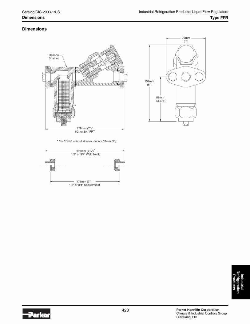
Catalog CIC-2003-1/US Industrial Refrigeration Products: Liquid Flow Regulators
Parker Hannifin CorporationClimate & Industrial Controls GroupCleveland, OH
423
Ind
ustrial
Refrig
eration
Pro
du
ctsType FFR
Dimensions
OptionalStrainer
152mm(6")
86mm(3.375")
76mm(3")
178mm (7")1/2" or 3/4" FPT
197mm (7¾")1/2" or 3/4" Weld Neck
*
*
* For FFR-2 without strainer, deduct 51mm (2").
178mm (7")1/2" or 3/4" Socket Weld
Dimensions

Parker Hannifin CorporationClimate & Industrial Controls GroupCleveland, OH
Catalog CIC-2003-1/US Industrial Refrigeration Products: Liquid Flow Regulators
424
Notes

Catalog CIC-2003-1/US Industrial Refrigeration Products: Liquid Level Control
Parker Hannifin CorporationClimate & Industrial Controls GroupCleveland, OH
425
Ind
ustrial
Refrig
eration
Pro
du
ctsProgrammable Liquid Level Controller
● Oversized keypad on front panel for programming● Easy to read enlarged LED digital display● 5 programmable 6 amp fused relays● Level simulation mode facilitates control wiring check
and test● Large enclosure with separable terminal blocks accom-
modate up to 14 gage wire● Plug-in style terminal blocks with recessed screws● Conventional intstrument wiring from controller to probe● 120/240 V 60 Hz or 110/220 V, 50 Hz Power● 4-20 mA Output Signal
PurposeThe Programmable Liquid Level Control provides remoteliquid level management for industrial refrigeration. ThePLLC is designed for use specifically with Parker's DepthTracker transducer liquid level probe. The PLLC provides thepower source for the current loop of the probe. The trans-ducer probe is used to provide a current signal proportionalto the vertical liquid level in a standpipe or vessel. The PLLCserving as a switching mechanism also converts the returnsignal and performs up to 5 programmable relay functions.
DimensionsUnit is 9½" high by 6¾" wide by 2" deep.
PLLC
Strain Relief
1" Conduit Knockout
Channels:1 High Red2 Level Control3 Level Control4 Low Green5 Low Red How to Order
PLLC
ProgrammableLiquid LevelController
WiringThe separable terminal blocks on the PLLC will accommo-date up to 14 gage wire. The Line Voltage Input can beeither 120/240V 60Hz or 110/220V 50Hz. The PLLCprovides the power source for the current loop of thetransducer probe. The programmable relays are individually5 amp fused. Relays are equipped with normally open andclosed terminals and can be wired as either. The maximumrecommended distance between PLLC and probe is 5000 ft.
Refer to Bulletin 61-50.
Weight1.8 kg (4 lb)
Technical Information, Dimensions and How to Order

Parker Hannifin CorporationClimate & Industrial Controls GroupCleveland, OH
Catalog CIC-2003-1/US Industrial Refrigeration Products: Liquid Level Control
426
Depth Tracker Transducer Probes
DescriptionThe Depth Tracker Liquid Level Industrial Transducer Probe(ITP) is used to provide a current signal proportional to thevertical liquid level. A remote programmable controller(PLLC) or microprocessor functioning as a switchingmechanism can convert the signal transmitted.
This device is for use with refrigerant R-717 (ammonia) only.It may be used with liquid temperatures in a range of-77° to 57°C (-107° to 135°F). The minimum ambient forcircuit board enclosure is -29°C (-20°F).
● Probe lengths: 2, 3, 4, 5, 6, 7, 8, 10 & 12 feet● Integrated construction achieved by molding the PTFE
sleeve directly to the center rod● Electrical connection via 3/4” conduit boss or jacketed
communications cable of suitable temperature/moistureprotection
● Fully potted circuit board● Local or remote digital read-out options● Optional display riser accommodates column insulation● Unique probelok connection option● Factory pre-calibrated for ammonia for 0-100% level
output in 4" IPS Standpipe. The electronics may be re-calibrated in the field to permit viewing of liquid level overany segment representing more than 40% of the probe’soverall length.
● All wetted parts are stainless steel construction toprevent corrosion
Dimensions
Sight Glasses
Level Column
R/SStandpipeCap
Weld
Globe Valvew/HorizontalStem
Globe Valvew/HorizontalStem
Weld
Optional Oil Drain
Allow for Insulation Space
102mm (4")Min.
25.4mm (1")
100% Level(From Factory)
ProbeLength
25.4mm (1")Non-SensingArea of Probe
16mm (.625")
51mm(2")
0% Level(From Factory)
MinimumTube
Length*
*Minimum Tube Length = Probe Length + 60mm (2.375")
Probe with Local Display and Riser
Technical Information and Dimensions
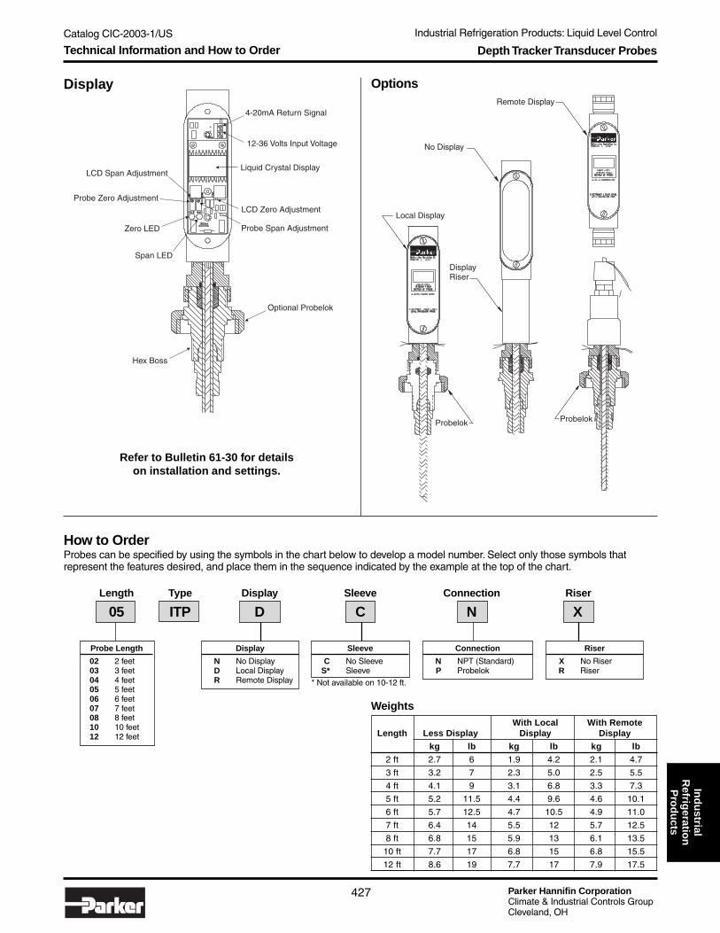
Catalog CIC-2003-1/US Industrial Refrigeration Products: Liquid Level Control
Parker Hannifin CorporationClimate & Industrial Controls GroupCleveland, OH
427
Ind
ustrial
Refrig
eration
Pro
du
ctsDepth Tracker Transducer Probes
How to OrderProbes can be specified by using the symbols in the chart below to develop a model number. Select only those symbols thatrepresent the features desired, and place them in the sequence indicated by the example at the top of the chart.
Options
Hex Boss
Optional Probelok
Zero LED
Span LED
LCD Span Adjustment
LCD Zero Adjustment
Liquid Crystal Display
4-20mA Return Signal
12-36 Volts Input Voltage
Probe Span Adjustment
Probe Zero Adjustment
Display
Local Display
No Display
Remote Display
DisplayRiser
ProbelokProbelok
Refer to Bulletin 61-30 for detailson installation and settings.
WeightsWith Local With Remote
Length Less Display Display Display
kg lb kg lb kg lb
2 ft 2.7 6 1.9 4.2 2.1 4.7
3 ft 3.2 7 2.3 5.0 2.5 5.5
4 ft 4.1 9 3.1 6.8 3.3 7.3
5 ft 5.2 11.5 4.4 9.6 4.6 10.1
6 ft 5.7 12.5 4.7 10.5 4.9 11.0
7 ft 6.4 14 5.5 12 5.7 12.5
8 ft 6.8 15 5.9 13 6.1 13.5
10 ft 7.7 17 6.8 15 6.8 15.5
12 ft 8.6 19 7.7 17 7.9 17.5
Connection
N NPT (Standard)P Probelok
Sleeve
C No SleeveS* Sleeve
* Not available on 10-12 ft.
Probe Length
02 2 feet03 3 feet04 4 feet05 5 feet06 6 feet07 7 feet08 8 feet10 10 feet12 12 feet
Display
N No DisplayD Local DisplayR Remote Display
Riser
X No RiserR Riser
Length Type Display Sleeve Connection Riser
05 ITP D C N X
Technical Information and How to Order

Parker Hannifin CorporationClimate & Industrial Controls GroupCleveland, OH
Catalog CIC-2003-1/US Industrial Refrigeration Products: Liquid Level Control
428
Refrigerant Float Switch
● Hermetically Sealed, Fused Switch Assembly● Transparent Switch Housing for Visual Observation● Magnetically Actuated, Mechanically Operated● Single Stage, Single Pole, Double Throw Switch● Float Controlled● Rugged Construction● Switch Assembly Fully Rotatable to Suit Installation● Large Available Differential Minimizes Short Cycling or
Actuation of Switch by Liquid Surges● Types LL, LLC, LLS, LLSC, LLA, LLAC are
U.L. Listed and CSA Certified● DIN Connector Standard except on Explosion Proof
Versions
DescriptionRefrigerant float switches are suitable for use with Ammo-nia, R22, R134a, R404a, R507 and other common refriger-ants. This float controlled, magnetically actuated, mechani-cally operated switch assembly can maintain close controlof liquid level. The rugged construction makes it relativelyinsensitive to disturbances of the refrigeration system orvibration of the attached pipe lines.
The electrical switch, which is fused, and the operatingmechanism are encapsulated within a transparent housing,which HERMETICALLY SEALS the moving parts and switchfrom ambient conditions and yet allows observation of theswitching motion for determination of the liquid level.
Types LLC, LLSC, LLAC are U.L. listed for outdoor service.Types LLX, LLXS and LLAX are not fused.
ApplicationsTo control liquid level in:
● liquid overfeed accumulators● flooded surge drums● flooded shell & tube chillers● high and low pressure receivers● intercoolers● transfer vessels● low or high level monitor
MaterialsStandard Chamber ................................................... SteelFloat Ball .....................................................Stainless Steel
SpecificationsDesign Pressure (MRP) ........................ 27.6 bar (400 PSI)Fluid Temperature Range ...... -45° to 65°C (-50° to 150°F)Ambient Temperature ............ -45° to 50°C (-50° to 120°F)Switch ........................... SPDT, Snap-acting, non-mercury
Rating ................. 120/240VAC, 10 Amp, 240 VA Pilot Duty
Fluid Specific Gravity Range ........................... 0.57 to 1.70
Differential ............................ Adjustable 13-50 mm (½"-2")Factory set at 50mm (2")
Chamber Connections .................... ¾" FPTor 1" Butt Weld
Replaceable Fuse Style Bag ................... 7 Amp, 240 VAC
Refer to Bulletin 61-10.
LL LLS
Technical Information

Catalog CIC-2003-1/US Industrial Refrigeration Products: Liquid Level Control
Parker Hannifin CorporationClimate & Industrial Controls GroupCleveland, OH
429
Ind
ustrial
Refrig
eration
Pro
du
cts
How to OrderRefrigerant Float Switches can be specified by using the symbols in the chart below to develop a model number. Select only thosesymbols that represent the features desired, and place them in the sequence indicated by the example at the top of the chart.
Weight
Type kg lbs
LL, LLS 5.9 13
LLA 5.9 13
LLAC, LLAX 6.4 14
LLC, LLSC 6.4 14
LLX, LLXS 6.4 14
Refrigerant Float Switch
AccessoriesItem Part Number
Permanent Magnet for external operationof switch assembly 201513
Replacement Conduit Boss 050100
Top Switch Quick Disconnect 050421Assembly Expl. Proof, Conduit 050101
Dimensions
Standard model:
Hermetically sealed, clearplastic switch enclosure;tank connections combinationfitting 3/4" FPT or 1" butt weld;mounted side and bottom;mild steel.
Type
Blank Standard modelC With Metal CoverS With side, side and bottom connectionsSC With side, side and bottom connections
and Metal CoverX Explosion Proof▲XS Explosion Proof with side, side and bottom
connections▲A Low Temperature★AC Low Temperature with Metal Cover★AX Low Temperature, Explosion Proof▲★
▲ Not UL approved★ Stainleess steel, temperature to -75°C (-100°F)
Type Variations
LL S
Optional Metal Cover
Allow 229mm (9.0")for switch removal
13mm(0.5")
544mm(21.4")
206mm(8.1")
146mm(5.7")
114mm(4.5")
Dimensions and How to Order

Parker Hannifin CorporationClimate & Industrial Controls GroupCleveland, OH
Catalog CIC-2003-1/US Industrial Refrigeration Products: Liquid Level Control
430
Rapid Purger
● High Capacity● 4 to 32 purge points● Stainless steel insulated enclosure
(32" L x 20" H x 8" D)● 316 – L stainless steel shell and tube heat exchanger.● All stainless steel interior flange and pipe connections.
DescriptionRapid Purgers remove incondensibles from refrigerationsystems. Included as standard on the purger:
Check valvesGauge valvesIsolation valvesLiquid level switchVapor vent floatWater bubblerTemperature controllerLiquid drainerPressure regulator
Controllers are available with 4 and 8 purge points (mini-micro) or 8, 16, 24 or 32 purge points (microprocessor) andcan be easily adapted to any ammonia refrigeration plant.Five unique modes of operation allow maximum efficiencywith minimal operator adjustments: automatic mode,automatic detection mode, scheduled purging mode,manual mode and remote mode.
Pressure Voltage Control PurgeType Range Refrigerant (Control Panel & Coils) Enclosure Points
How to OrderRapid purgers can be specified by using the symbols in the chart below to develop a model number. Select only those symbolsthat represent the features desired, and place them in the sequence indicated by the example at the top of the chart.
Refer to Bulletin 75-00.
(Shown with side of enclosure removed)
Purge Points
00 None – Corresponds toManual or Central PlantControlled
04 Four, Mini-Micro Controlonly
08 Eight, Either Mini-Micro orMicroprocessor Control
16 Sixteen, MicroprocessorControl only
24 Twenty-four, MicroprocessorControl only
32 Thirty-two, MicroprocessorControl only
Control/Enclosure
E Mini-Micro for4 to 8 Purge Points(Requires Field Wiring)
S Microprocessor Controlfor 8 or more PurgePoints (SeparateMounting, RequiresField Wiring)
C Remote Central PlantControl. IncludesInsulated StainlessEnclosure and LocalElectrical Controls
Voltage
0 Manual orExplosionProof
1 120V 60Hz2 240V 60Hz
3 240V 50Hz
Pressure Range
L Low Range:System suctioninches Hg to 14 PSI
H High Range:System suction15-30 PSI
Refrigerant
7 Ammonia
RP H 7 1 S 08
Technical Information and How to Order

Catalog CIC-2003-1/US Industrial Refrigeration Products: Liquid Level Control
Parker Hannifin CorporationClimate & Industrial Controls GroupCleveland, OH
431
Ind
ustrial
Refrig
eration
Pro
du
ctsRapid Purger
Notes:
Purger styles that could encounter standby or power failureconditions such that vessel pressure could go high, shouldalways be equipped with relief valves.
In the case of the Mini-Micro or the Microprocessor Control-ler, the control panel is always shipped separately and ismounted in close proximity of the Rapid Purger or at aremote location such as a refrigeration control room. Referto Purger Bulletin 75-00 for additional information.
Refer to Rapid Purger Controller system information manualfor specific operating and programming information. TheMini-Micro and Microprocessor are different manuals.
When ordering a purger with a microprocessor controllerwith option of condenser fan control and pump cycling,consult factory for additional information.
940mm (37")
813mm (32")
508mm(20")
864mm(34")
AmmoniaGauge
Hand ValveLiquid Line
Pressure Switch
Hand ValvePurge Gas Line
Pressure Regulator
Liquid Drainer
WaterBubbler
TemperatureController
S6NSolenoid Valve
HeatExchanger
CheckValvew/DiscStrainer
Vapor VentFloat
PressureCheckValve
Dimensions
Dimensions

Parker Hannifin CorporationClimate & Industrial Controls GroupCleveland, OH
Catalog CIC-2003-1/US Industrial Refrigeration Products: Liquid Level Control
432
Automatic Liquid Drainer (ALD)
● Drains Liquid Only● Stops Flow of Vapor● Prevents Vapor Lockup● Built-in Strainer● No Small Orifices● Resists Wire Drawing● Includes Pilot Light● Manual Opening Stem
DescriptionUsed to drain liquid from defrosting evaporators or heatrecovery condensors into a lower pressure portion of thesystem. Permits flow of liquid refrigerant only. Prevents flowof vapor refrigerant.
All are heavy duty devices intended for use with Ammonia,R-22, R-134a, R-404A, R-507 and other common refriger-ants.
The Type ALD is a combination of a Type LLS Float Switch,a Type S8F Solenoid Valve with Strainer and Pilot LightAssembly, a 3/4" Hand Expansion Valve, and a 1/4" FPTHand Expansion Bleed Valve as well as necessary pipe andfittings, complete for field assembly. Inlet is combination¾" FPT or 1" butt weld. Outlet is ¾" FPT.
The rate of flow of refrigerant vapor (or liquid) through thevent valve is dependent upon the pressure differencebetween the float chamber and the Type ALD outletpressure. It is also possible for the ALD to maintain aconstant flow if the rate of liquid flow into the float chamberis equal to that leaving it.
The ALD can be manually drained by using the manualopening stem on the Type S8F solenoid valve.
Refer to Bulletin 62-01.
Dimensions
Pilot LensType Coil Voltage Coil Style Light Color
Ordering Information
Lens Color
G Green (std)R RedA AmberW White
Remote Pilot Light
1 PLT-1 (NEMA 1)2 PLT-2 (NEMA 4)
ALD R 1 2 G
3/4" FPToutletconnection
48 cm(18.9")
3/4" FPT or1" WN inletconnection
3/4"or 1"pipe
54 cm(21.4")
Coil Style
1 Encapsulatedw/36" Leads
3 Industrial Open Framew/18" Leads
StandardR 120/6/60S 208/6/60T 240/6/60U* 230/6/50
Coil Voltage
Non-StandardP* 115/6/50Q* 440/6/60
* Available with industrial open frame coil only.
Technical Information, Dimensions and How to Order

Catalog CIC-2003-1/US
Parker Hannifin CorporationClimate & Industrial Controls GroupCleveland, OH
433
Industrial Refrigeration Products: MiscellaneousIn
du
strialR
efrigeratio
nP
rod
ucts
Flanges
Flange TypesFlanges are sold individually and are available in maletongue type to fit sizes 5-150mm (1/2" to 6") and femalegroove type to fit sizes 5-100mm (1/2" to 4").
The following connection styles are available:
● Female Pipe Thread (FPT)● Socket Weld (SW)● Weld Neck (WN). Metric WN flanges also available in
connection sizes ranging from 15 to 100mm. Consultfactory for details.
● Outside Diameter Sweat (ODS) steel flanges with integralcopper couplings to fit and solder over copper tubing.ODS flanges are not suitable for use with R-717(ammonia).
● ANSI flat face flanges are available from 125-200mm(5" - 8") for use with the CK4 check valve.
● Slip-On Socket I.D. ANSI Flat Face● Weld Neck ANSI Flat Face
Flanges for sizes 5-25mm (3⁄16" to 1") are a 2-bolt oval style.Flanges for sizes 32-100mm (1¼" - 4") are a 4-bolt squarestyle. Flanges for sizes 125-150mm (5" - 6") are an 8-boltround style and are available as male type only.
Flange Union KitsFlange union kits are available to join male and femaleflanges of the same size (see page 435).
Flange and Pipe Dimensions
US Pipe Sizes Equivalent Socket Weld Weld Neck ANSI Slip-On ANSI Weld Neck Nominal Actual O.D. Metric Steel Tubing Flange I.D. Flange O.D. Socket I.D. Neck O.D.
Inch mm inch NW OD mm mm Inch mm inch mm inch mm inch
1/4" 13.72 0.540 8 13.5 14.22 0.560 13.72 0.540 — — — —
3/8" 17.14 0.675 10 17.2 17.65 0.695 17.14 0.675 — — — —
1/2" 21.34 0.840 15 21.3 21.84 0.860 21.34 0.840 — — — —
3/4" 26.67 1.050 20 26.9 27.81 1.090 26.67 1.050 — — — —
1" 33.40 1.315 25 33.7 34.67 1.365 33.40 1.315 — — — —
1¼" 42.16 1.660 32 42.4 43.31 1.705 42.16 1.660 — — — —
1½" 48.26 1.900 50 48.3 59.02 1.930 48.25 1.900 — — — —
2" 60.32 2.375 50 60.3 62.10 2.445 60.3 2.375 — — — —
2½" 73.02 2.875 65 76.1 74.80 2.945 73.03 2.875 — — — —
3" 88.90 3.500 80 88.9 90.81 3.575 88.90 3.500 — — — —
4" 114.30 4.500 100 114.3 116.20 4.575 114.30 4.500 — — — —
5" 141.30 5.563 125 139.7 144.00 5.670 141.30 5.563 144.14 5.675 141.30 5.563
6" 168.28 6.625 150 165.1 170.90 6.730 168.28 6.625 171.07 6.735 168.28 6l625
8" — — — — — — — — 221.87 8.735 219.08 8.625
5-25mm(3/16" to 1")
Oval
32-100mm(1¼" to 4")
Square
125-150mm(5" to 6")Round
WELD
SOLDER
FPTFemalePipe Thread
SWSocketWeld
WNWeldNeck
ODSCopper
2-Bolt Flanges (FPT, SW, WN, ODS)
4-Bolt Flanges (SW, WN, ODS)Also available in FPT
Technical Information and Dimensions

Parker Hannifin CorporationClimate & Industrial Controls GroupCleveland, OH
Catalog CIC-2003-1/US
434
Industrial Refrigeration Products: Miscellaneous
Connection Sizes Available
Flange FPT (IPS) Socket Weld (IPS) ODS (US) DIN Weld Neck ANSI Flat Face**
Size Weld Neck (IPS) Weld Neck Slip-on
013 02 03 04 06 02 03 04 06 04 05 07 10 15 20
025 06 08 10 06 08 10 07 09 11 20 25 32
032 10 12 10 12 11 13 17 32 40 50
050 12 16 12 16 13 17 21 40 50
065 20 21 25 65 75
075 24 25 29 75
100 32 33 A0
125* 40 40 40
150* 48 48 48
200* 64 64
*Female flange not available ** For CK4 only
How to Order FlangesFlanges can be specified by using the symbols in the chart below to develop a model number. Select only those symbols thatrepresent the features desired, and place them in the sequence indicated by the example at the top of the chart.
Flange Connection Connection ConnectionSize Type Style Type Size
Flange Size
013 Fits Port Sizes 5 & 13mm(3/16" & 1/2")
025 Fits Port Sizes 20 & 25mm(3/4" & 1")
032 Fits Port Size 32mm (1¼")050 Fits Port Sizes 40 & 50mm
(15/8" & 2")065 Fits Port Size 65mm (2½")075 Fits Port Size 75mm (3")100 Fits Port Size 100mm (4")125* Fits Port Size 125mm (5"150* Fits Port Size 150mm (6")200 Fits Port Size 200mm (8")
Connection Size
ODS04 ½"05 5/8"07 7/8"09 11/8"11 13/8"13 15/8"17 21/8"21 25/8"25 31/8"29 35/8"33 41/8"
DIN Weld NeckSelect size inmm from table
below.
FPT, SW, WN, ANSI02 ¼"03 3/8"04 ½"06 ¾"08 1"10 1¼"12 1½"16 2"20 2½"24 3"32 4"40 5"48 6"64 8"
Connection Size Availability
025 FL M F 08
Flanges
Connection Type
F FPT (Female PipeThread)
S SW (Socket Weld)W WN (Weld Neck)K ODS (Outside
Diameter Sweat)D DIN Weld Neck
Y SO (Slip On)Z WN (Weld Neck)
Connection Style
M MaleTongue
F FemaleGroove
N ANSI Flat Face
Flange Used on R/S Net Weight for Each Flange
Number Port Sizes FPT, SW WN ODS ANSISize mm inch kg lbs kg lbs kg lbs kg lbs
013 5 & 13 3/16" & 1/2" 0.14 0.3 0.23 0.5 0.14 0.3 — —
025 20 & 25 3/4" & 1" 0.68 1.5 0.77 1.7 0.73 1.6 — —
032 32 1-1/4" 0.68 1.5 0.91 2.0 0.73 1.6 — —
050 40 & 50 1-5/8" & 1" 1.4 3.0 1.4 3.0 1.5 3.3 — —
065 65 2-1/2" 2.3 5.0 3.0 6.5 2.5 5.5 — —
075 75 3" 2.3 5.0 3.0 6.5 2.5 5.5 — —
100 100 4" 4.1 9.0 6.8 15.0 4.5 9.9 — —
125 125 5" 9.1 20.0 11.4 25.0 — — 29.5 65
150 150 6" 9.1 20.0 11.4 25.0 — — 38.6 85
200 200 8" — — — — — — 61.4 135
Weights
Check table for available style/type/size combinations!
WARNING!ODS flanges not suitablefor use with ammonia.
!
How to Order

Catalog CIC-2003-1/US
Parker Hannifin CorporationClimate & Industrial Controls GroupCleveland, OH
435
Industrial Refrigeration Products: MiscellaneousIn
du
strialR
efrigeratio
nP
rod
ucts
Flange Union Kits & Adapter Rings
Adapter RingsAdapter rings are furnished with two matching flangegaskets.
Male Adapter RingsAre used to close couple CK-4A or CK-1 CheckValves to the outlet of R/S Control Valves.
Flange Union KitsFlange Union Kits are used to combine a male and afemale flange within the same flange size code. UnionKits are available for flange sizes up to 100.
The kit consists of a flange gasket and the appropriatebolts for the flange size.
Order flanges separately.
Flange Union KitSize Part Number
013 206213
025 206214
032 206215
050 206216
065 206217
075 206218
100 206219
Union Kits
Female Adapter RingsAre used in unions of two Male Flanges.
MALE ADAPTER RING FEMALE ADAPTER RING
How to Order How to Order
Type Part Number
MAR-13 200095
MAR-25 200089
MAR-32 200090
MAR-50 200091
MAR-65 200092
MAR-75 200093
MAR-100 200094
Type Part Number
FAR-13 200111
FAR-25 200112
FAR-32 200113
FAR-50 200114
FAR-65 200115
FAR-75 200116
FAR-100 200117
Technical Information and How to Order

Parker Hannifin CorporationClimate & Industrial Controls GroupCleveland, OH
Catalog CIC-2003-1/US
436
Industrial Refrigeration Products: Miscellaneous
Type RS Strainers
● Stainless Steel (60 Mesh) Screen● 3/8" FPT Drain Connection 20-100mm (3/4" to 8") for
Safe Cleaning in Line; 1/4" FPT for 13mm (1/2")● Ample Screen Area● Low Pressure Drop● Can Be Close Coupled to Inlet of any R/S Valve with
Same Port Size● Durable Filter Bags available 20-100mm (3/4" thru 4")
to Aid System Clean-Up● Design Pressure (MRP): 27.6 Bar (400 PSIG)
DescriptionStrainers are suitable for use with Ammonia, R-22, R-134a,R404A, R-507 and other common refrigerants
These industrial type Refrigerant Strainers with stainlesssteel screen are designed especially for the protection of R/Scontrol valves from foreign materials present in refrigerationsystems. The fine stainless screen mesh will collect particlesas small as .006" in diameter. Generous available screenarea allows maximum dirt capacity at minimum pressuredrop.
The use of a strainer is extremely important upon start-upof a new refrigeration system where dirt, scale and weldparticles may be present in the system and are disturbedand circulated when air testing or upon system start-up. Alsowhen an existing system is revised, any settled dirt or foreignmatter may be disturbed and circulated throughout thesystem. It is not safe to omit strainers ahead of the controlvalves unless there is a certainty that the system will alwaysbe clean.
If particles are too small to be removed by the strainer, it issuggested that a R/S filter bag be installed where applicable,periodically cleaned and removed when necessary.
1"
5" - 8"
RETAINING RING
BASKET NECK
BAGFilter Bag
Body Screen Area ScreenSize Material Sq. cm Sq. in. Material013 Gray Iron 39 6
025 Gray Iron 116 18
032 Gray Iron 230 36
050 Gray Iron 500 78
065, 075 Gray Iron 570 88
100 Gray Iron 794 123
125 Cast Steel 790 123
150 Cast Steel 1410 218
200 Cast Steel 1750 272
Specifications
StainlessSteel withOpenings
0.23 x 0.23mm(0.009" x 0.009")
0.2mm(0.0075")
Wire(60 Mesh)
When used with R/S control valves, the strainer may bebolted directly to the inlet side of the valve to be protected.Standard R/S flange nuts and bolts are used to connect thestrainer male outlet flange to the valve female inlet flange.Consequently, only one pair of R/S standard male compan-ion flanges is needed for a close coupled strainer and valvecombination. Refer to Bulletin 00-10.
½"1¼" - 4"
13mm (½") ............................ 3.0 Kv ......... 2.6 Cv25mm (1") ............................. 9.4 Kv ......... 8.1 Cv32mm (1¼") ........................ 16.3 Kv ....... 14.0 Cv50mm (2") ........................... 67.7 Kv ....... 58.2 Cv65mm (2½") ......................... 112 Kv .......... 96 Cv75mm (3") ............................ 112 Kv .......... 96 Cv100mm (4") .......................... 170 Kv ........ 146 Cv125mm (5") .......................... 216 Kv ........ 185 Cv150mm (6") .......................... 362 Kv ........ 311 Cv200mm (8") .......................... 710 Kv ........ 610 Cv
Flow Coefficients
Technical Information

Catalog CIC-2003-1/US
Parker Hannifin CorporationClimate & Industrial Controls GroupCleveland, OH
437
Industrial Refrigeration Products: MiscellaneousIn
du
strialR
efrigeratio
nP
rod
ucts
Filter Bag KitsBody Size Kit Number
013 Not Available
025 201701
032 201702
050 201703
065, 075 202513
100 202514
Type RS Strainers
How to Order
Inlet OutletBody Size Type Flange Flange
025 RS F08 F08
013 13mm (½")025 25mm (1")032 32mm (1¼")050 50mm (2")065 65mm (2½")075 75mm (3")100 100mm (4")125 125mm (5")150 150mm (6")200 200mm (8")
Used with Available Connection Codes Weight
Port Size (Bold Type Indicates Standard Size) Less Flanges With Flanges
Size mm inch ODS FPT, SW, WN DIN Weld Neck kg lbs kg lb
013 5 & 13 C\zn & ½ 04, 05, 07 02*, 03, 04, 06 10, 15, 20 0.9 2 1.4 3
025 20 & 25 ¾ & 1 07, 09, 11 06, 08, 10 20, 25, 32 3.2 7 4.5 10
032 32 1¼ 11, 13, 17 10, 12 32, 40, 50 6.8 15 8.2 18
050 40 & 50 1B\,, 2 13, 17, 21 12, 16 40, 50 15 32 17 38
065 65 2½ 21, 25 20 (no FPT) 65, 75 24 53 29 63
075 75 3 25, 29 24 (no FPT) 75 24 53 29 63
100 100 4 33 32 (no FPT) A0 52 114 60 132
125 125 5 N/A N/A N/A 45 100 — —
150 150 6 N/A N/A N/A 79 175 — —
200 200 8 N/A N/A N/A 136 300 — —
Not all flange types and sizes areavailable for each body size. SeeConnection Availability Table forallowable combinations.
Connection Availability
Note:
When flanges are specified in themodel number, a male flange isprovided for the inlet and a femaleflange for the outlet. If flanges areordered separately (Code X - LessFlanges), a male and female shouldbe ordered. See page 434.
Flange Type Connection
X Less 00 NoneFlanges
F FPT (IPS) 02 ¼"S SW (IPS) 03 3/8"W Weld Neck (IPS) 04 ½"
06 ¾"08 1"10 1¼"12 1½"16 2"20 2½"24 3"32 4"
K ODS (US) 04 ½"05 5/8"07 7/8"09 11/8"
Not suitable 11 13/8"for use with 13 15/8"ammonia. 17 21/8"
21 25/8"25 31/8"29 35/8"33 41/8"
D DIN Weld Neck Size in mm.See tablebelow.
* FPT only
How to Order
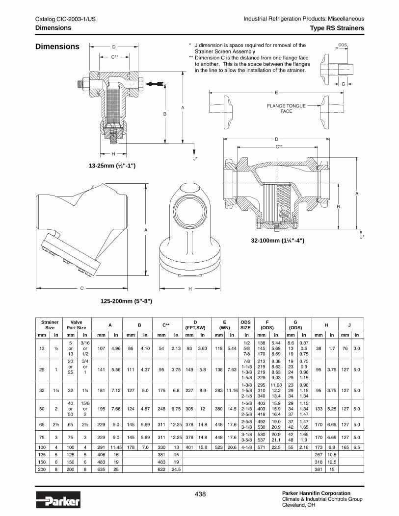
Parker Hannifin CorporationClimate & Industrial Controls GroupCleveland, OH
Catalog CIC-2003-1/US
438
Industrial Refrigeration Products: Miscellaneous
Type RS Strainers
Dimensions * J dimension is space required for removal of theStrainer Screen Assembly
** Dimension C is the distance from one flange faceto another. This is the space between the flangesin the line to allow the installation of the strainer.
Strainer ValveA B C**
D E ODS F GH JSize Port Size (FPT,SW) (WN) SIZE (ODS) (ODS)
mm in mm in mm in mm in mm in mm in mm in in mm in mm in mm in mm in
5 3/16 1/2 138 5.44 8.6 0.3713 ½ or or 107 4.96 86 4.10 54 2.13 93 3.63 119 5.44 5/8 145 5.69 13 0.5 38 1.7 76 3.0
13 1/2 7/8 170 6.69 19 0.75
20 3/4 7/8 213 8.38 19 0.75
25 1or or
141 5.56 111 4.37 95 3.75 149 5.8 138 7.631-1/8 219 8.63 23 0.9
95 3.75 127 5.025 1 1-3/8 219 8.63 24 0.961-5/8 229 9.03 29 1.15
1-3/8 295 11.63 23 0.9632 1¼ 32 1¼ 181 7.12 127 5.0 175 6.8 227 8.9 283 11.16 1-5/8 310 12.2 29 1.15 95 3.75 127 5.0
2-1/8 340 13.4 34 1.34
40 15/8 1-5/8 403 15.9 29 1.1550 2 or or 195 7.68 124 4.87 248 9.75 305 12 380 14.5 2-1/8 403 15.9 34 1.34 133 5.25 127 5.0
50 2 2-5/8 418 16.4 37 1.47
65 2½ 65 2½ 229 9.0 145 5.69 311 12.25 378 14.8 448 17.62-5/8 492 19.0 37 1.47
170 6.69 127 5.03-1/8 530 20.9 42 1.65
75 3 75 3 229 9.0 145 5.69 311 12.25 378 14.8 448 17.63-1/8 530 20.9 42 1.65
170 6.69 127 5.03-5/8 537 21.1 48 1.9
100 4 100 4 291 11.45 178 7.0 330 13 401 15.8 523 20.6 4-1/8 571 22.5 55 2.16 173 6.8 165 6.5
125 5 125 5 406 16 381 15 267 10.5
150 6 150 6 483 19 483 19 318 12.5
200 8 200 8 635 25 622 24.5 381 15
13-25mm (½"-1")
32-100mm (1¼"-4")
125-200mm (5"-8")
H
BA
J*
D
C**
G
FODS
E
FLANGE TONGUEFACE
B
A
D
C**
J*
C
A
H
Dimensions

Catalog CIC-2003-1/US
Parker Hannifin CorporationClimate & Industrial Controls GroupCleveland, OH
439
Industrial Refrigeration Products: MiscellaneousIn
du
strialR
efrigeratio
nP
rod
ucts
Liquid Drain Ball Valves
● Spring Return to Close● RPTFE Stuffing Box Ring● All Components of Lever are Stainless Steel● Nitride Corrosion Protection● Blow-out Proof Stem Design● Adjustable Packing Gland● Investment Cast Components● Multifill Seats
DescriptionThese carbon steel ball valves have a “deadman” springreturn handle. Operating torque is approximately threetimes standard valve torque. Connections are threaded NPT.
MaterialsBody .................................................................... A216-WCB
“Deadman” Handle .........................................Stainless Steel
Ball ................................................. A108-CS Chrome Plated
Stem Packing and Seat ................................... Multifill PTFE
Body Seal ..................................................................... PTFE
Retainer, Gland Nut and Stem ................................ A108-CS
SpecificationsWOG ...................................................... 138 bar (2000 psig)
Cold Non-Shock ......... 10.3 bar (150 psig) Saturated Steam,to 737mm (29 inches) Hg vacuum service
Federal Specifications ............................. WW-V-35C, Type II
Dimensions
SizeA B C D
mm inch mm inch mm inch mm inch
1/2" 12.7 .50 28 1.12 57 2.25 178 7.00
3/4" 17 .68 38 1.50 76 3.00 178 7.00
1" 22 .87 43 1.68 86 3.37 178 7.00
D
A
B
C
Ordering Information
Part # Part #Size Carbon Steel Stainless Steel Weight1/2" 206548 206551 0.6 kg (1.31 lb)
3/4" 206549 206552 0.9 kg (1.98 lb)
1" 206550 206553 1.1 kg (2.35 lb)
Technical Information and How to Order

Parker Hannifin CorporationClimate & Industrial Controls GroupCleveland, OH
Catalog CIC-2003-1/US
440
Industrial Refrigeration Products: Miscellaneous
Unibody Gauge Valves
Angle Body
How to Order Unibody Gauge ValvesGauge valves can be ordered separately by using the symbols in the chart below to develop a model number. Select only thosesymbols that represent the features desired, and place them in the sequence indicated by the example at the top of the chart.
Unibody Body Inlet Extension ConnectionValve Size Style Connection on Inlet Style Seal Cap
Inlet
M MPT*F FPT
*Globe body withMPT inlet musthave extension.
Valve Size
V2 1/4" BodyV3 3/8" Body
Seal Cap
A Aluminum(V3 only)
P Plastic(V2 only)
V2 A M 00 N A
Style
A AngleG Globe
● ASTM Forged Steel Body● Stainless Steel Stem● Angle or Globe Body● Extended length available on inlet
DescriptionThis line of rugged all steel bodied tiny hand valves aredesigned to seat tight and permit isolation of small systemcomponents. The stainless steel stem has the safety featureof being non-removable. The angle bodied valve and theglobe body employ the same features. The optional MPT orFPT inlet connection and variable extended lengths areprovided on both body sizes.
These multiple use small hand valves are normally mountedto pipe line components and lead to a gauge or instrumentline. Flow rate are not generally of consideration exceptwhere valve is employed as a drain device or on remotepiloted control valves
The valve is manually closed to prevent venting or to permitdownstream component servicing. When manually opened,the inlet pressure source is equalized to the downstreamside. This supports draining, venting, purging or componentisolation.
MaterialsBody .............................................. Forged steel, zinc platedPacking Nut .................................................................. SteelStem .................................. Stainless steel, 1/4" square flatsStem Packing ................................................. Graphite baseSeal Cap ...............................................................AluminumSeal Cap O-ring .................................................... Neoprene
SpecificationsMaximum Rated Pressure (MRP) ......................... 450 PSIGFluid Temperature Range ....... -40° to 115°C (-40° to 240°F)Gauge Port ............................................................. 1/4" FPT
Refer to Bulletin 84-00.
3.760
3.964
4.263
3.999
Dimensions
2.763
3.310
2.479
3.339
V2 V3
Extension on Inlet*
00 None or Female V2 V3
10 2.50" 13 3.25"13 3.25" 16 4.00"15 3.75" 20 5.00"21 5.25" 24 6.00"26 6.50" 28 7.00"30 7.50" 32 8.00"34 8.50"
* Available on MPT inlet only.
Connection
N NPT
Globe Body with Extension on Inlet
Technical Information, Dimensions and How to Order

Catalog CIC-2003-1/US
Parker Hannifin CorporationClimate & Industrial Controls GroupCleveland, OH
441
Industrial Refrigeration Products: MiscellaneousIn
du
strialR
efrigeratio
nP
rod
ucts
● All gauges have adjustable pointer● All gauges utilize stainless steel housing and
polycarbonate window over face● 2½" and 3½" gauges incorporate flutter prevention
mechanism● 2½" and 3½" gauges are ASME Grade B
3%/2%/3% Max. Error● 6" gauges are ASME Grade A 1% Max. Error
DescriptionAll refrigerant gauges are combination pressure/saturationtemperature gauges with pressure range appropriate to highside or low side duty for the refrigerants listed.
The 2½" and 3½" gauges are bottom connected 1/4" MPT.The 6" gauges are panel mount, back connected, 1/4" MPT.
MaterialsSocket and Bourdon:Gauges for Halocarbon Duty ........................ Bronze & BrassGauges for Ammonia Duty ............................ Stainless Steel
Pressure Ranges
Imperial Units Metric UnitsRefrigerant (Temp in °F) (Temp in °C)
High Side Low Side High Side Low SidePressure Range Pressure Range Pressure Range Pressure Range
R717 (Ammonia) 30" Vac - 300 PSIG 30" Vac - 150 PSIG 760mm - 25 Bar 760mm - 10.5 Bar
R134a 30" Vac - 300 PSIG 30" Vac - 300 PSIG 760mm - 21.5 Bar 760mm - 21.5 Bar
R22 30" Vac - 500 PSIG 30" Vac - 150 PSIG 760mm - 35 Bar 760mm - 10.5 Bar
R-404A30" Vac - 500 PSIG 30" Vac - 150 PSIG 760mm - 35 Bar 760mm - 10.5 Baror R-507
How to Order Refrigerant GaugesGauges can be specified by using the symbols in the chart below to develop a model number. Select only those symbols thatrepresent the features desired, and place them in the sequence indicated by the example at the top of the chart.
Refrigerant Face Pressure UnitGauge Diameter Refrigerant Range System
Refrigerant
7 Ammonia (R-717)1 R-134a2 R-224 R-404A or R-507
Pressure Range
L Low Pressure RangeH High Pressure Range
RG 25 2 L B
Gauges
Unit System
M MetricB Imperial
Face Diameter
25 2.5 inches35 3.5 inches60 6.0 inches
Technical Information and How to Order

Parker Hannifin CorporationClimate & Industrial Controls GroupCleveland, OH
Catalog CIC-2003-1/US
442
Industrial Refrigeration Products: Miscellaneous
New Products
Open Refrigerant Pumps
Motors and valves shown are not included.
GP Pump Advantages● Proven over decades of use● Designed exclusively for the delivery of primary or
secondary refrigerants● Driven by standard electric motor● Ability to handle liquid/vapor mixture● High pressure increase, low flow rate● Strong construction● Low maintenance
The Pump Design● Open impellers● Lateral channels● Wide channels● Twin axial face seals
Consult Parker for ordering information.
Technical Information

Catalog CIC-2003-1/US
Parker Hannifin CorporationClimate & Industrial Controls GroupCleveland, OH
443
Industrial Refrigeration Products: MiscellaneousIn
du
strialR
efrigeratio
nP
rod
ucts
New Products
Advantages of HRP pumps
1. Unrivalled SafetyIn contrast to most common hermetic pumps the statorhousing of HRP pumps is designed to withstand highnominal pressure. If the motor “stator can” leaks in theevent of an accident, no refrigerant will escape.
2. Good quality liquid deliveryThe advanced design of the impeller-guide ring construc-tion enables the pump to deliver a relatively high amount ofvapor with the liquid flow. This is achieved without inter-rupting the constant delivery of the liquid. (The liquidvolume flow will of course decrease with the increase ofvapor volume.) In contrast to most other hermetic pumpsthe vapor that is generated while cooling the motor isvented to the discharge side without reducing the pumpcapacity.
3. Covering a wide rangeAll HRP pump models are suitable for the commonrefrigerants. The HRP 3232 is also especially designed tobe used with CO2 as a primary or secondary refrigerant.Due to the pump performance characteristic curve, eachpump covers a wide range of applications.
4. Simple protectionThe built-in temperature cut-out protects the pump againstoverheating and must be connected into the control systemwith the standard overload protection equipment. It isrecommended to install a pressure differential switch or aflow switch on the discharge side of the pump.
5. No orifices or degassing lines requiredThe HRP pumps do not require any Q-max or Q-minorifices. The internal design of the pump incorporates aninternal pressure equalization that enables the pump todepressurize quickly to the suction side during standstill,therefore eliminating the need for additional degassinglines.
6. Strong constructionThe open execution of the impellers applies only smallaxial forces. The transformer oil protects the motor againstmoisture and provides good thermal conductivity.
7. Proven bearing designWith our extensive experience we have developed animproved low-wear bearing design. By monitoring theelectrical resistance at the sensor contact, it is possible todetect for bearing wear while pump is at standstill.
Hermetic Refrigerant Pumps
8. Low maintenanceWhen the correct installation instructions are observed andcarried out the pump will run for many trouble-free yearswithout requiring maintenance. The strong conical filter inthe pump suction inlet should be checked after commis-sioning. Note no other filters in the suction pipework arerequired. In the event of the pump filling with oil, it can bedrained through screw plugs.
9. Suspended installationDue to formation of ice around the pump, the suspendedinstallation is preferred to foot mounting. This also allowsfor easy access to service the conical filter and to installinga condensate drip tray.
Consult Parker for ordering information.
Technical Information
Parker Hannifin CorporationClimate & Industrial Controls GroupCleveland, OH
Catalog CIC-2003-1/US
444
Industrial Refrigeration Products: Miscellaneous
Spray Touch-up Paint
Same blue paint pigment to match Refrigerating SpecialtiesDivision's new factory enhanced, corrosion resistant paint.
● Meets Auto Industry Salt Spray Test Standards● Water Based Low VOL● EHS Compliant● Quick Drying
Note: For overseas shipments, consult factory.
11 oz. Can .......... Order Part Number 309210
Technical Information

Catalog CIC-2003-1/US
Parker Hannifin CorporationClimate & Industrial Controls GroupCleveland, OH
445
Industrial Refrigeration Products: MiscellaneousIn
du
strialR
efrigeratio
nP
rod
ucts
WarrantiesAll Refrigerating Specialties products are warrantedagainst defect in workmanship and materials for a periodof one year from date of shipment from originating factory.This warranty is in force only when products are properlyinstalled, field assembled, maintained and operated in useand service, as specifically stated in Refrigerating Special-ties Catalogs or Bulletins for normal refrigeration applica-tions, unless otherwise approved in writing by Refrigerat-ing Specialties Division. Defective products, or partsthereof, returned to the factory with transportation chargesprepaid, and found to be defective by factory inspection,will be replaced or repaired at Refrigerating Specialtiesoption, free of charge, F.O.B. factory. Warranty does notcover products which have been altered, repaired in thefield, damaged in transit or have suffered accidents,misuse or abuse. Products disabled by dirt or otherforeign substances will not be considered defective.
THE EXPRESS WARRANTY SET FORTH ABOVECONSTITUTES THE ONLY WARRANTY APPLICABLETO REFRIGERATING SPECIALTIES PRODUCTS, ANDIS IN LIEU OF ALL OTHER WARRANTIES, EXPRESSEDOR IMPLIED, WRITTEN OR ORAL, INCLUDING ANYWARRANTY OF MERCHANTABILITY OR FITNESS FORA PARTICULAR PURPOSE AND IN NO EVENT ISREFRIGERATING SPECIALTIES RESPONSIBLE FORANY CONSEQUENTIAL DAMAGES OF ANY NATUREWHATSOEVER. No employee, agent, dealer or otherperson is authorized to give any warranties on behalf ofRefrigerating Specialties, nor to assume, for RefrigeratingSpecialties, any other liability in connection with any of itsproducts.
For More InformationConsult our web site www.parker.com/refspec forthe most current bulletins and catalog information on allour products.
Safe OperationPeople doing any work on a refrigeration system must bequalified and completely familiar with the system and theRefrigerating Specialties Division valves involved, or all otherprecautions will be meaningless. This includes reading andunderstanding pertinent Refrigerating Specialties Divisionproduct bulletins and Bulletin RSB prior to installation orservicing work.
Where cold refrigerant liquid lines are used, it is necessary thatcertain precautions by taken to avoid damage which couldresult from liquid expansion. Temperature increase in a pipingsection full of solid liquid will cause high pressure due to theexpanding liquid which can possibly rupture a gasket, pipe orvalve. All hand valves isolating such sections should bemarked, warning against accidental closing, and must not beclosed until the liquid is removed. (Tags are available for thispurpose from the factory.) Check valves must never beinstalled upstream of solenoid valves or regulators with electricshut-off, nor should hand valves upstream of solenoid valves ordownstream of check valves be closed until the liquid has beenremoved. It is advisable to properly install relief devices in anysection where liquid expansion could take place.
Avoid all piping or control arrangements which might producethermal or pressure shock.
For the protection of people and products, all refrigerant mustbe removed from the section to be worked on before a valvestrainer or other device is opened or removed.
Flanges with ODS connections are not suitable for ammoniaservice.
General Information
Factory Repair and RebuildingFor the convenience of our customers, we have a standardfactory repair and rebuilding service. Repairable returnedregulators are disassembled, cleaned, sandblasted, worn partsreplaced, reassembled and repainted. For quickest service, itis advisable that this be done during the off peak season.
Industrial Refrigeration Products

Parker Hannifin CorporationClimate & Industrial Controls GroupCleveland, OH
Catalog CIC-2003-1/US
446
Industrial Refrigeration Products: Miscellaneous
MP39 HP80 HP62 FX10 FX56 AZ20 AZ-50 Temp. R-401A R-402A R-404A R-408A R409A R-410A R-22 R-123 R-134a R-502 R-507 R-717
°F °C Liquid Vapor Liquid Vapor Liquid Liquid Liquid Vapor
-50 -45.6 — — — — 0.6 1.6 12.4 17.2 5.0 6.2 29.2 18.4 0.2 1.0 14.4
-45 -42.8 — — — — 2.7 1.1 9.7 15.2 7.0 2.7 29.0 16.6 1.9 3.0 11.8
-40 -40.0 8.1 13.2 6.8 6.3 5.0 3.3 6.8 13.1 11.6 0.5 28.9 14.7 4.1 5.5 8.8
-35 -37.2 5.1 10.7 9.6 9.1 7.6 5.6 3.5 10.7 14.9 2.6 28.7 12.3 6.5 8.2 5.5
-30 -34.4 1.7 7.9 12.6 12.1 10.4 8.2 0.0 8.1 18.5 4.9 28.4 9.7 9.2 11.1 1.7
-25 -31.7 1.0 4.8 16.0 15.4 13.4 11.0 2.0 5.1 22.5 7.4 28.1 6.8 12.1 14.3 1.2
-20 -28.9 3.0 1.4 19.6 18.9 16.8 14.1 4.1 1.9 26.9 10.1 27.8 3.6 15.3 17.8 3.5
-15 -26.1 5.2 1.2 23.6 22.9 20.5 17.5 6.5 0.8 31.6 13.2 27.4 0.1 18.8 21.7 6.2
-10 -23.3 7.7 3.3 27.9 27.1 24.5 21.2 9.0 2.8 36.8 16.4 27.0 2.0 22.6 25.8 9.0
-5 -20.6 10.3 5.5 32.6 31.7 28.8 25.2 11.8 4.9 42.5 20.0 26.5 4.1 26.6 30.3 12.3
0 -17.8 13.2 8.0 37.6 36.7 33.5 29.5 14.8 7.2 48.6 24.0 25.9 6.5 31.1 35.2 15.6
5 -15.0 16.3 10.7 43.1 42.1 38.6 34.2 18.1 9.7 55.2 28.2 25.3 9.1 35.9 40.5 19.5
10 -12.2 19.7 13.7 49.0 48.0 44.0 39.3 21.7 12.5 62.3 32.7 24.6 11.9 41.0 46.1 23.7
15 -9.4 23.4 16.9 55.3 54.2 49.9 44.8 25.5 15.4 70.0 37.7 23.7 15.1 46.5 52.2 28.3
20 -6.7 27.4 20.4 62.1 60.9 56.2 50.7 29.6 18.7 78.3 43.0 22.8 18.4 52.5 58.8 33.4
25 -3.9 31.7 24.2 69.3 68.1 63.0 57.0 34.0 22.2 87.2 48.7 21.8 22.1 58.8 65.8 38.8
30 -1.1 36.4 28.3 77.1 75.8 70.3 63.7 38.7 26.0 96.8 54.9 20.7 26.1 65.6 73.3 44.9
35 1.7 41.3 32.8 85.4 84.0 78.1 71.0 43.8 30.1 107.0 61.4 19.5 30.4 72.8 81.3 51.4
40 4.4 46.6 37.6 94.2 92.8 86.4 78.7 49.2 34.5 118.0 68.5 18.1 35.1 80.5 89.8 58.4
45 7.2 52.4 42.7 104.0 102.0 95.4 87.0 54.9 39.2 130.0 76.0 16.6 40.0 88.7 98.9 66.1
50 10.0 58.5 48.2 114.0 112.0 104.7 95.8 61.0 44.3 142.0 84.0 15.0 45.4 97.4 109.0 74.3
55 12.8 65.0 54.1 124.0 123.0 114.7 105.1 67.6 49.8 156.0 92.5 13.1 51.2 107.0 119.0 83.2
60 15.6 71.9 60.4 136.0 134.0 125.3 115.1 74.5 55.6 170.0 101.6 11.2 57.4 116.4 130.0 92.6
65 18.3 79.3 67.2 147.0 146.0 136.6 125.6 81.8 61.9 185.0 111.0 9.0 64.0 127.0 141.0 102.8
70 21.1 87.1 74.4 160.0 158.0 148.6 136.8 89.5 68.6 201.0 121.4 6.6 71.1 138.0 154.0 113.8
75 23.9 95.4 82.1 173.0 171.0 161.2 148.7 97.7 75.8 217.0 132.0 4.0 78.6 149.0 167.0 125.5
80 26.7 104.0 90.2 187.0 185.0 174.6 161.2 106.4 83.4 235.0 144.0 1.2 86.7 161.0 180.0 138.0
85 29.4 114.0 98.9 202.0 200.0 188.8 174.4 115.5 91.5 254.0 156.0 0.9 95.1 174.0 195.0 151.4
90 32.2 123.0 108.0 218.0 215.0 203.7 188.4 125.2 100.2 274.0 168.4 2.5 104.2 187.4 210.0 165.5
95 35.0 134.0 118.0 233.0 232.0 219.4 203.1 135.3 109.4 295.0 182.0 4.2 113.8 201.0 226.0 180.6
100 37.8 145.0 128.0 251.0 249.0 235.9 218.7 146.0 119.2 317.0 196.0 6.1 124.1 216.2 244.0 196.7
105 40.6 156.0 139.0 269.0 267.0 253.4 235.0 157.2 129.6 341.0 211.0 8.1 134.9 232.0 252.0 213.9
110 43.3 169.0 151.0 288.0 286.0 271.7 252.1 169.0 140.6 365.0 226.4 10.3 146.3 247.9 281.0 231.8
115 46.1 181.0 163.0 308.0 305.0 290.9 270.2 181.4 152.3 391.0 243.0 12.6 158.4 265.0 301.0 251.0
120 48.9 195.0 176.0 238.0 326.0 311.1 289.1 194.4 164.7 418.0 260.0 15.1 171.1 282.7 322.0 271.1
125 51.7 209.0 189.0 350.0 347.0 332.3 308.9 208.0 177.8 446.0 278.4 17.7 184.5 301.0 344.0 292.5
130 54.4 224.0 203.0 372.0 370.0 354.5 329.7 222.3 191.6 476.0 296.8 20.6 198.7 320.8 368.0 314.9
135 57.2 239.0 218.0 396.0 393.0 377.8 351.5 237.2 206.3 507.0 317.0 23.6 213.6 341.0 393.0 338.8
140 60.0 255.0 234.0 420.0 418.0 402.2 374.3 252.9 221.8 539.0 337.3 26.8 229.3 362.6 419.0 363.5
145 62.8 272.0 250.0 446.0 443.0 427.7 398.1 269.3 238.2 573.0 359.0 30.2 245.7 385.0 446.0 390.2
150 65.6 299.0 267.0 472.0 470.0 454.4 423.0 293.0 286.4 608.0 381.0 33.8 263.0 408.4 475.0 417.4
Italics = inches Hg. Below 1 ATM
Pressure in PSIG
Temperature Pressure Data Industrial Refrigeration Products

Catalog CIC-2003-1/US
Parker Hannifin CorporationClimate & Industrial Controls GroupCleveland, OH
447
Industrial Refrigeration Products: MiscellaneousIn
du
strialR
efrigeratio
nP
rod
ucts
MP39 HP80 HP62 FX10 FX56 AZ20 AZ-50 Temp. R-401A R-402A R-404A R-408A R409A R-410A R-22 R-123 R-134a R-502 R-507 R-717
°F °C Liquid Vapor Liquid Vapor Liquid Liquid Liquid Vapor
-50 -45.6 — — — — 0.0 0.1 315.0 436.9 0.3 157.5 741.7 467.4 5.1 0.1 365.8
-45 -42.8 — — — — 0.2 0.1 246.4 386.1 0.5 68.6 736.6 421.6 0.1 0.2 299.7
-40 -40.0 205.7 335.3 0.5 0.4 0.3 0.2 172.7 332.7 0.8 0.0 734.1 373.4 0.3 0.4 223.5
-35 -37.2 129.5 271.8 0.7 0.6 0.5 0.4 88.9 271.8 1.0 0.2 729.0 312.4 0.4 0.6 139.7
-30 -34.4 43.2 200.7 0.9 0.8 0.7 0.6 0.0 205.7 1.3 0.3 721.4 246.4 0.6 0.8 43.2
-25 -31.7 0.1 121.9 1.1 1.1 0.9 0.8 0.1 129.5 1.6 0.5 713.7 172.7 0.8 1.0 0.1
-20 -28.9 0.2 35.6 1.4 1.3 1.2 1.0 0.3 48.3 1.9 0.7 706.1 91.4 1.1 1.2 0.2
-15 -26.1 0.4 0.1 1.6 1.6 1.4 1.2 0.4 0.1 2.2 0.9 696.0 2.5 1.3 1.5 0.4
-10 -23.3 0.5 0.2 1.9 1.9 1.7 1.5 0.6 0.2 2.5 1.1 685.8 0.1 1.6 1.8 0.6
-5 -20.6 0.7 0.4 2.2 2.2 2.0 1.7 0.8 0.3 2.9 1.4 673.1 0.3 1.8 2.1 0.8
0 -17.8 0.9 0.6 2.6 2.5 2.3 2.0 1.0 0.5 3.4 1.7 657.9 0.4 2.1 2.4 1.1
5 -15.0 1.1 0.7 3.0 2.9 2.7 2.4 1.2 0.7 3.8 1.9 642.6 0.6 2.5 2.8 1.3
10 -12.2 1.4 0.9 3.4 3.3 3.0 2.7 1.5 0.9 4.3 2.3 624.8 0.8 2.8 3.2 1.6
15 -9.4 1.6 1.2 3.8 3.7 3.4 3.1 1.8 1.1 4.8 2.6 602.0 1.0 3.2 3.6 2.0
20 -6.7 1.9 1.4 4.3 4.2 3.9 3.5 2.0 1.3 5.4 3.0 579.1 1.3 3.6 4.1 2.3
25 -3.9 2.2 1.7 4.8 4.7 4.3 3.9 2.3 1.5 6.0 3.4 553.7 1.5 4.1 4.5 2.7
30 -1.1 2.5 2.0 5.3 5.2 4.8 4.4 2.7 1.8 6.7 3.8 525.8 1.8 4.5 5.1 3.1
35 1.7 2.8 2.3 5.9 5.8 5.4 4.9 3.0 2.1 7.4 4.2 495.3 2.1 5.0 5.6 3.5
40 4.4 3.2 2.6 6.5 6.4 6.0 5.4 3.4 2.4 8.1 4.7 459.7 2.4 5.6 6.2 4.0
45 7.2 3.6 2.9 7.2 7.0 6.6 6.0 3.8 2.7 9.0 5.2 421.6 2.8 6.1 6.8 4.6
50 10.0 4.0 3.3 7.9 7.7 7.2 6.6 4.2 3.1 9.8 5.8 381.0 3.1 6.7 7.5 5.1
55 12.8 4.5 3.7 8.6 8.5 7.9 7.2 4.7 3.4 10.8 6.4 332.7 3.5 7.4 8.2 5.7
60 15.6 5.0 4.2 9.4 9.2 8.6 7.9 5.1 3.8 11.7 7.0 284.5 4.0 8.0 9.0 6.4
65 18.3 5.5 4.6 10.1 10.1 9.4 8.7 5.6 4.3 12.8 7.7 228.6 4.4 8.8 9.7 7.1
70 21.1 6.0 5.1 11.0 10.9 10.2 9.4 6.2 4.7 13.9 8.4 167.6 4.9 9.5 10.6 7.8
75 23.9 6.6 5.7 11.9 11.8 11.1 10.3 6.7 5.2 15.0 9.1 101.6 5.4 10.3 11.5 8.7
80 26.7 7.2 6.2 12.9 12.8 12.0 11.1 7.3 5.8 16.2 9.9 30.5 6.0 11.1 12.4 9.5
85 29.4 7.9 6.8 13.9 13.8 13.0 12.0 8.0 6.3 17.5 10.8 0.1 6.6 12.0 13.4 10.4
90 32.2 8.5 7.4 15.0 14.8 14.0 13.0 8.6 6.9 18.9 11.6 0.2 7.2 12.9 14.5 11.4
95 35.0 9.2 8.1 16.1 16.0 15.1 14.0 9.3 7.5 20.3 12.6 0.3 7.8 13.9 15.6 12.5
100 37.8 10.0 8.8 17.3 17.2 16.3 15.1 10.1 8.2 21.9 13.5 0.4 8.6 14.9 16.8 13.6
105 40.6 10.8 9.6 18.6 18.4 17.5 16.2 10.8 8.9 23.5 14.6 0.6 9.3 16.0 17.4 14.8
110 43.3 11.7 10.4 19.9 19.7 18.7 17.4 11.7 9.7 25.2 15.6 0.7 10.1 17.1 19.4 16.0
115 46.1 12.5 11.2 21.2 21.0 20.1 18.6 12.5 10.5 27.0 16.8 0.9 10.9 18.3 20.8 17.3
120 48.9 13.4 12.1 16.4 22.5 21.5 19.9 13.4 11.4 28.8 17.9 1.0 11.8 19.5 22.2 18.7
125 51.7 14.4 13.0 24.1 23.9 22.9 21.3 14.3 12.3 30.8 19.2 1.2 12.7 20.8 23.7 20.2
130 54.4 15.4 14.0 25.7 25.5 24.4 22.7 15.3 13.2 32.8 20.5 1.4 13.7 22.1 25.4 21.7
135 57.2 16.5 15.0 27.3 27.1 26.1 24.2 16.4 14.2 35.0 21.9 1.6 14.7 23.5 27.1 23.4
140 60.0 17.6 16.1 29.0 28.8 27.7 25.8 17.4 15.3 37.2 23.3 1.8 15.8 25.0 28.9 25.1
145 62.8 18.8 17.2 30.8 30.6 29.5 27.5 18.6 16.4 39.5 24.8 2.1 16.9 26.6 30.8 26.9
150 65.6 20.6 18.4 32.6 32.4 31.3 29.2 20.2 19.8 41.9 26.3 2.3 18.1 28.2 32.8 28.8
Pressure in Bar
Italics = mm Hg. Below 1 ATM
Temperature Pressure Data Industrial Refrigeration Products

Offer of Sale
The items described in this document are hereby offered for sale at prices to be established by Parker Hannifin Corporation, its subsidiaries and its authorizeddistributors. This offer and its acceptance by any customer (“Buyer”) shall be governed by all of the following Terms and Conditions. Buyer’s order for any itemdescribed in its document, when communicated to Parker Hannifin Corporation, its subsidiary or an authorized distributor (“Seller”) verbally or in writing, shallconstitute acceptance of this offer.
1. Term and Conditions of Sale: All descriptions, quotations, proposals, offers,acknowledgments, acceptances and sales of Seller’s products are subject toand shall be governed exclusively by the terms and conditions stated herein.Buyer’s acceptance of any offer to sell is limited to these terms and conditions.Any terms or conditions in addition to, or inconsistent with those stated herein,proposed by Buyer in any acceptance of an offer by Seller, are hereby objectedto. No such additional, different or inconsistent terms and conditions shall be-come part of the contract between Buyer and Seller unless expressly acceptedin writing by Seller. Seller’s acceptance of any offer to purchase by Buyer isexpressly conditional upon Buyer’s assent to all the terms and conditions statedherein, including any terms in addition to, or inconsistent with those contained inBuyer’s offer. Acceptance of Seller’s products shall in all events constitute suchassent.
2. PAYMENT-To approved accounts: Invoices dated 1 st to 15th, 1 % discountif paid by the 25th of same month; invoices dated 16th to the end of month, 1%discount if paid by the 10th of next following month. All invoices shall be due netwithin 30 days after date of invoice. Any claims by Buyer for omissions or short-ages in a shipment shall be waived unless Seller receives notice thereof within30 days after Buyer’s receipt of the shipment.
3. Delivery: Unless otherwise provided on the face hereof, delivery shall bemade F.O.B. Seller’s plant. Regardless of the method of delivery, however, risk ofloss shall pass to Buyer upon Seller’s delivery to a carrier. Any delivery datesshown are approximate only and Seller shall have no liability for any delays indelivery.
4. Warranty: Seller warrants that the items sold hereunder shall be free fromdefects in material or workmanship for a period of 365 days from the date ofshipment to Buyer, or 2,000 hours of use, whichever expires first. THIS WAR-RANTY COMPRISES THE SOLE AND ENTIRE WARRANTY PERTAINING TOITEMS PROVIDED HEREUNDER. SELLER MAKES NO OTHER WARRANTY,GUARANTEE, OR REPRESENTATION OF ANY KIND WHATSOEVER. ALLOTHER WARRANTIES, INCLUDING BUT NOT LIMITED TO, MERCHANTABIL-ITY AND FITNESS FOR PURPOSE, WHETHER EXPRESS, IMPLIED, OR ARIS-ING BY OPERATION OF LAW, TRADE USAGE, OR COURSE OF DEALINGARE HEREBY DISCLAIMED. NOTWITHSTANDING THE FOREGOING, THEREARE NO WARRANTIES WHATSOEVER ON ITEMS BUILT OR ACQUIREDWHOLLY OR PARTIALLY, TO BUYER’S DESIGNS OR SPECIFICATIONS.
5. Limitation Of Remedy: SELLER’S LIABILITY ARISING FROM OR IN ANYWAY CONNECTED WITH THE ITEMS SOLD OR THIS CONTRACT SHALL BELIMITED EXCLUSIVELY TO REPAIR OR REPLACEMENT OF THE ITEMS SOLDOR REFUND OF THE PURCHASE PRICE PAID BY BUYER, AT SELLER’SSOLE OPTION. IN NO EVENT SHALL SELLER BE LIABLE FOR ANY INCI-DENTAL, CONSEQUENTIAL OR SPECIAL DAMAGES OF ANY KIND OR NA-TURE WHATSOEVER, INCLUDING BUT NOT LIMITED TO LOST PROFITSARISING FROM OR IN ANY WAY CONNECTED WITH THIS AGREEMENT ORITEMS SOLD HEREUNDER, WHETHER ALLEGED TO ARISE FROM BREACHOF CONTRACT, EXPRESS OR IMPLIED WARRANTY, OR IN TORT, INCLUD-ING WITHOUT LIMITATION, NEGLIGENCE, FAILURE TO WARN OR STRICTLIABILITY.
6. Changes, Reschedules and Cancellations: Buyer may request to modifythe designs or specifications for the items sold hereunder as well as the quanti-ties and delivery dates thereof, or may request to cancel all or part of this order,however, no such requested modification or cancellation shall become part ofthe contract between Buyer and Seller unless accepted by Seller in a writtenamendment to this Agreement. Acceptance of any such requested modificationor cancellation shall be at Seller’s discretion, and shall be upon such terms andconditions as Seller may require. Quantity increases, received after orders areacknowledged, will be priced separately as new orders. Quantity decreases,received after orders are acknowledged, will subject the order to repricing, if thedecreases affect the original pricing guidelines.
7. Special Tooling: A tooling charge may be imposed for any special tooling,including without limitation, dies, fixtures, molds and patterns, acquired tomanufacture items sold pursuant to this contract. Such special tooling shall beand remain Seller’s property notwithstanding payment of any charges thereforby Buyer. In no event will Buyer acquire any interest in apparatus belonging toSeller which is utilized in the manufacture of the items sold hereunder, even ifsuch apparatus has been specially converted or adapted for such manufactureand notwithstanding any charges paid by Buyer therefor. Unless otherwise agreed.
Seller shall have the right to after, discard or otherwise dispose of any specialtooling or other property in its sole discretion at any time.
8. Buyer’s Property: Any designs, tools, patterns, materials, drawings, confiden-tial information or equipment furnished by Buyer or any other items which be-come Buyer’s property, may be considered obsolete and may be destroyed bySeller after two (2) consecutive years have elapsed without Buyer placing anorder for the items which are manufactured using such property. Seller shall notbe responsible for any loss or damage to such property while it is in Seller’spossession or control.
9. Taxes: Unless otherwise indicated on the face hereof, all prices and chargesare exclusive of excise, sales, use, property, occupational or like taxes whichmay be imposed by any taxing authority upon the manufacture, sale or deliveryof the items sold hereunder. If any such taxes must be paid by Seller or if Selleris liable for the collection of such tax, the amount thereof shall be in addition tothe amounts for the items sold. Buyer agrees to pay all such taxes or to reim-burse Seller therefore upon receipt of its invoice. If Buyer claims exemption fromany sales, use or other tax imposed by any taxing authority, Buyer shall saveSeller harmless from and against any such tax, together with any interest orpenalties thereon which may be assessed if the items are held to be taxable.
10. Indemnity For Infringement of Intellectual Property Rights: Seller shallhave no liability for infringement of any patents, trademarks, copyrights, tradedress, trade secrets or similar rights except as provided in this Part 10. Seller willdefend and indemnify Buyer against allegations of infringement of U.S. patents,U.S. trademarks, copyrights, trade dress and trade secrets (hereinafter “Intellec-tual Property Rights”). Seller will defend at its expense and will pay the cost ofany settlement or damages awarded in an action brought against Buyer basedon an allegation that an item sold pursuant to this contract infringes the Intellec-tual Property Rights of a third party. Seller’s obligation to defend and indemnifyBuyer is contingent on Buyer notifying Seller within ten (10) days after Buyerbecomes aware of such allegations of infringement, and Seller having sole con-trol over the defense of any allegations or actions including all negotiations forsettlement or compromise. If an item sold hereunder is subject to a claim that itinfringes the Intellectual Property Rights of a third party, Seller may, at its soleexpense and option, procure for Buyer the right to continue using said item,replace or modify said item so as to make it noninfringing, or offer to acceptreturn of said item and return the purchase price less a reasonable allowance fordepreciation. Notwithstanding the foregoing, Seller shall have no liability for claimsof infringement based on information provided by Buyer, or directed to itemsdelivered hereunder for which the designs are specified in whole or part by Buyer,or infringements resulting from the modification, combination or use in a systemof any item sold hereunder. The foregoing provisions of this Part 10 shall consti-tute Seller’s sole and exclusive liability and Buyer’s sole and exclusive remedyfor infringement or Intellectual Property Rights.
If a claim is based on information provided by Buyer or if the design for an itemdelivered hereunder is specified in whole or in part by Buyer, Buyer shall defendand indemnify Seller for all costs, expenses or judgments resulting from anyclaim that such item infringes any patent, trademark, copyright, trade dress, tradesecret or any similar right.
11. Force Majeure: Seller does not assume the risk of and shall not be liable fordelay or failure to perform any of Seller’s obligations by reason or circumstancesbeyond the reasonable control of Seller (hereinafter ‘Events of Force Majeure’).Events of Force Majeure shall include without limitation, accidents, acts of God,strikes or labor disputes, acts, laws, rules or regulations of any government orgovernment agency, fires, floods, delays or failures in delivery of carriers or sup-pliers, shortages of materials and any other cause beyond Seller’s control.
12. Entire Agreement/Governing Law: The terms and conditions set forth herein,together with any amendments, modifications and any different terms or condi-tions expressly accepted by Seller in writing, shall constitute the entire Agree-ment concerning the items sold, and there are no oral or other representationsor agreements which pertain thereto. This agreement shall be governed in allrespects by the law of the State of Ohio. No actions arising out of the sale of theitems sold hereunder or this Agreement may be brought by either party morethan two (2) years after the cause of action accrues.
Parker Hannifin CorporationClimate & Industrial Controls GroupCleveland, OH
Catalog CIC-2003-1/US
448

Parker’s CharterTo be a leading worldwide manufacturer of compo-nents and systems for the builders and users ofdurable goods. More specifically, we will design,market and manufacture products controlling motion,flow and pressure. We will achieve profitable growththrough premier customer service.
Product InformationNorth American customers seeking product infor-mation, the location of a nearby distributor, or repairservices will receive prompt attention by calling theParker Product Information Center at our toll-freenumber: 1-800-C-PARKER (1-800-272-7537). Inthe UK, a similar service is available by calling0500-103-203.
Fluid ConnectorsParker designs, manufacturesand markets rigid and flexibleconnectors, and associatedproducts used in pneumaticand fluid systems.
HydraulicsParker designs, producesand markets a full spectrumof hydraulic components andsystems to builders and usersof industrial and mobilemachinery and equipment.
AutomationParker is a leading supplierof pneumatic and electro-mechanical componentsand systems to automationcustomers worldwide.
SealsParker designs, manufacturesand distributes industrial andcommercial sealing devicesand related products by pro-viding superior quality andtotal customer satisfaction.
FiltrationParker designs, manufacturesand markets quality filtrationand clarification products,providing customers with thebest value, quality, technicalsupport, and global availabil-ity.
InstrumentationParker is a global leader in thedesign, manufacture and dis-tribution of high-quality criticalflow components for worldwideprocess instrumentation, ultra-high-purity, medical andanalytical applications.
About Parker Hannifin CorporationParker Hannifin is a leading global motion-controlcompany dedicated to delivering premier customerservice. A Fortune 500 corporation listed on the NewYork Stock Exchange (PH), our components and sys-tems comprise over 1,400 product lines that controlmotion in some 1,000 industrial and aerospacemarkets. Parker is the only manufacturer to offer itscustomers a choice of hydraulic, pneumatic, andelectromechanical motion-control solutions. OurCompany has the largest distribution network in itsfield, with over 7,500 distributors serving more than400,000 customers worldwide.
Parker Hannifin Corporation6035 Parkland Blvd.Cleveland, Ohio 44124-4141Telephone: (216) 896-3000Fax: (216) 896-4000Web site: www.parker.com
Parker Hannifin Corporation
AerospaceParker is a leader in the devel-opment, design, manufactureand servicing of control systemsand components for aerospaceand related high-technologymarkets, while achievinggrowth through premiercustomer service.
Climate &Industrial ControlsParker designs, manufacturesand sells system controls andprotectors to refrigeration andair-conditioning customersworldwide. Parker alsoprovides solenoid valves,process control valves, andgerotors for a multitude ofindustrial applications.

Catalog CIC-2003-15M, 4/03, PL
Contact Information
Parker Hannifin CorporationClimate and Industrial Controls GroupWorld Headquarters6035 Parkland Blvd.Cleveland, OH 44124 USATel: (216) 896-3000Fax: (216) 896-4000www.parker.com/cig
Parker Hannifin CorporationClimate and Industrial Controls GroupAftermarket Customer Service2445 South 25th AvenueBroadview, IL 60155-3891 USATel: (800) 742-2681Fax: (800) 241-2872www.parker.com/coolparts
In South America:Parker Refrigeration DivisionParker Atenas Industria e Exportacao LTDA.Rod. Anhanguera, Km. 25,3 - PerusSão Paulo, SP, Brazil 05276-967Tel: 55-11-3917-1222Fax: 55-11-3917-4727
In Europe:Parker Hannifin SPAVIA E FERMI, 520060 GESSATE (MI) ItalyTel: 011-39-951251Fax: 011-39-02-9538-2051
In Asia:Parker Korea, Ltd.6th Floor, DAE HWA Venture Plaza169 Samsung-Dong, Kangnam-KUSeoul, Korea 135-882Tel: 011-82-2-559-0434Fax: 011-82-2-556-8187