REFRIGERATION AND AIRCONDITIONING - mrcet.ac.in
59
REFRIGERATION AND AIRCONDITIONING
-
Upload
khangminh22 -
Category
Documents
-
view
1 -
download
0
Transcript of REFRIGERATION AND AIRCONDITIONING - mrcet.ac.in
REFRIGERATION AND
AIRCONDITIONING

REFRIGERATION AND AIR CONDITIONING
UNIT- 2
Vapour compression system: simple cycle -comparison with Carnot cycle -
theoretical, actual and reactive - COP effect of operating parameters on COP
- wet, dry and superheated compression - under cooling - actual cycle
representation on TS and PH diagrams simple problems. Advanced vapour
compression systems - multistage vapour compression systems - flash
chamber multiple compression and evaporation systems cascading - simple
problems.
UNIT-3
Vapour absorption systems: simple, cycles - actual cycle - ammonia water
and lithium bromide water systems - COP - electrolux system. Refrigerant
and their properties: Nomenclature - suitability of refrigerants for various
applications - unconventional refrigeration methods- Vortex tube, steam-jet,
magnetic (cryogenics) refrigeration and thermoelectric refrigeration - applied
refrigeration house hold refrigerators - unit air conditioners and water coolers
- ice plant cold storage.

UNIT– II
Vapour Compression Refrigeration Systems
2.1 Introduction
A vapour compression refrigeration system is an improved type of air
refrigeration system in which a suitable working substance, termed as refrigerant, is
used. It condenses and evaporates at temperatures and pressures close to the
atmospheric conditions. The refrigerants, usually, used for this purpose are ammonia
(NH3), carbon dioxide (CO2) and sulphur dioxide (SO2). The refrigerant used, does
not leave the system, but is circulated throughout the system alternately condensing
and evaporating. In evaporating, the refrigerant absorbs its latent heat from the brine
(salt water) which is used for circulating it around the cold chamber. While
condensing, it gives out its latent heat to the circulating water of the cooler. The
vapour compression refrigeration system is, therefore a latent heat pump, as it pumps
its latent heat from the brine and delivers it to the cooler.
The vapour compression refrigeration system is now-a-days used for all
purpose refrigeration. It is generally used for all industrial purposes from a small
domestic refrigerator to a big air conditioning plant.
2.2 Advantages and Disadvantages of vapour Compression Refrigeration
System over Air Refrigeration System
Following are the advantages and disadvantages of the vapour compression
refrigeration system over air refrigeration system:
Advantages
1. It has smaller size for the given capacity of refrigeration.
2. It has less running cost.
3. It can be employed over a large range of temperatures.
4. The coefficient of performance is quite high.
Disadvantages
1. The initial cost is high
26

2. The prevention of leakage of the refrigerant is the major problem in
vapour compression system
2.3 Mechanism of a Simple Vapour Compression Refrigeration System
Fig. 2.1 shows the achematic diagram of a simple vapour compression
refrigeration system. It consists of the following five essential parts :
1. Compressor. The low pressure and temperature vapou refrigerant from
evaporator is drawn into the compressor through the inlet or suction valve A, where
it is compresses to a high pressure and temperature. This high pressure and
temperature vapour refrigerant is discharge the condenser through the delivery or
discharge valve B.
2. Condenser. The condenser or cooler consists of coils of pipe in which the
high pressure and temperature vapour refrigerant is cooled and condensed. The
refrigerant, while passing through the condenser, gives up its latent heat to the
surrounding condensing medium which is normally air or water.
27

3. Receiver. The condensed liquid refrigerant from the condenser is stored in
a vessel known as receiver from where it is supplied to the evaporator through the
expansion valve or refrigerant control valve.
4. Expansion valve. It is also called throttle valve or refrigerant control
valve. The function of the expansion valve is to allow the liquid refrigerant under
high pressure and temperature to pass at a controlled rate after reducing its pressure
and temperature. Some of the liquid refrigerant evaporates as it passes through the
expansion valve, but the greater portion is vaporised in the evaporator at the low
pressure and temperature.
5. Evaporator. An evaporator consists of coils of pipe in which the liquid-
vapour refrigerant at low pressure and temperature is evaporated and changed into
vapour refrigerant at low pressure and temperature. In evaporating, the liquid vapour
refrigerant absorbs its latent heat of vaporisation from the medium (air, water or
brine) which is to be cooled.
Note : In any compression refrigeration system, there are two different
pressure conditions. One is called the high pressure side and other is known as low
pressure side. The high pressure side includes the discharge line (i.e. piping from the
evaporator to the suction valve A).
2.4 Pressure-Enthalpy (p-h) Chart
28

Fig 2.2 pressure enthalpy [p-h] chart
The most convenient chart for studying the behavior of a refrigerant is the p-
h chart, in which the vertical ordinates represent pressure and horizontal ordinates
represent enthalpy (i.e. total heat). A typical chart is shown in Fig. 2.2, in which a
few important lines of the complete chart are drawn. The saturated liquid line and the
saturated vapour line merge into one another at the critical point. A saturated liquid is
one which has a temperature equal to the saturation temperature corresponding to its
pressure. The space to the left of the saturated liquid line will, therefore, be sub-
cooled liquid region. The space between the liquid and the vapour lines is called wet
vapour region and to the right of the saturated vapour line is a superheated vapour
region.
In the following pages, we shall drawn the p-h chart along with the T-s
diagram of the cycle.
2.5 Types of Vapour Compression Cycles
We have already discussed that vapour compression cycle essentially
consists of compression, condensation, throttling and evaporation. Many scientists
have focussed their attention to increase the coefficient of performance of the cycle.
Through there are many cycles, yet the following are important from the subject
point of view :
1. Cycle with dry saturated vapour after compression,
2. Cycle with wet vapour after compression,
3. Cycle with superheated vapour after compression,
4. Cycle with superheated vapour before compression, and
5. Cycle with undercooling or subcooling of refrigerant.
Now we shall discuss all the above mentioned cycles, one by one, in the
following pages.
2.6 Theoretical Vapour Compression Cycle with Dry Saturated
Vapour after Compression
29
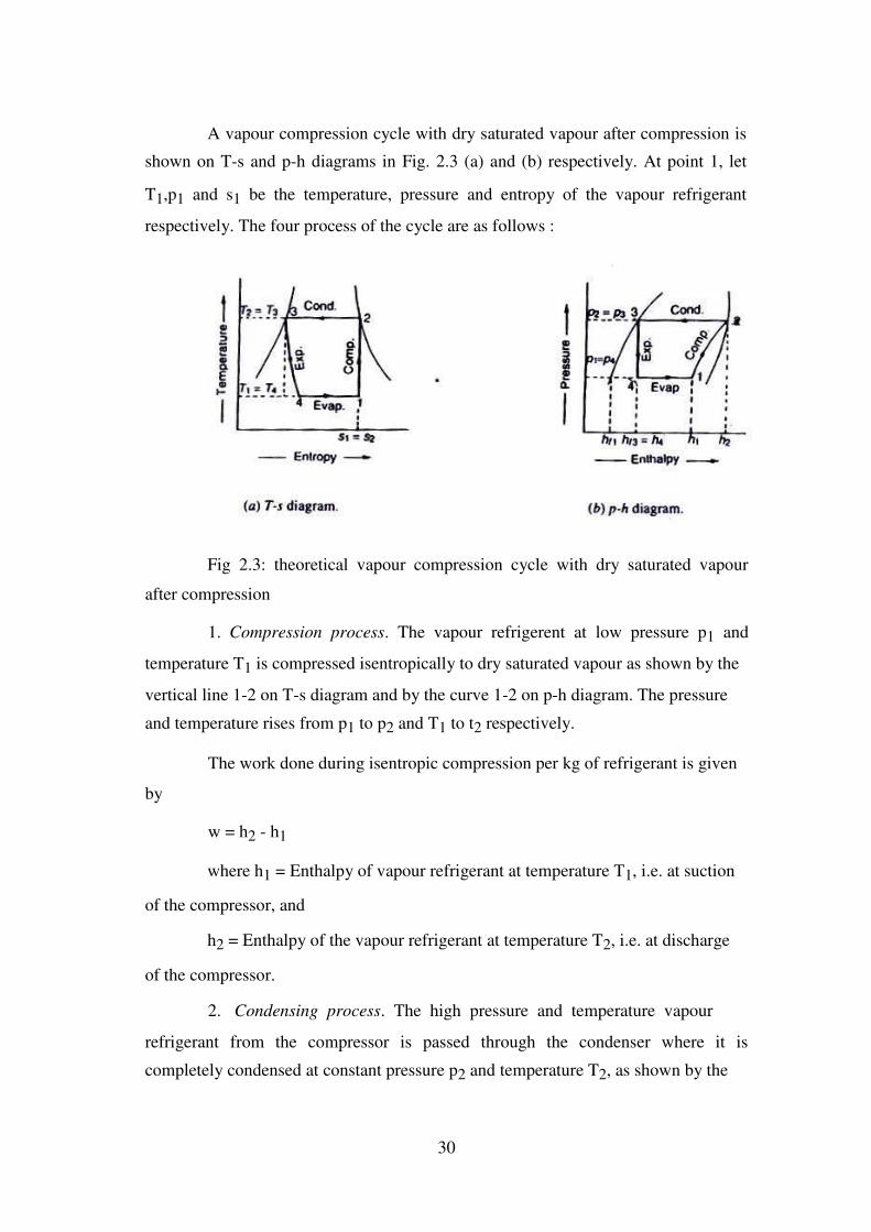
A vapour compression cycle with dry saturated vapour after compression is
shown on T-s and p-h diagrams in Fig. 2.3 (a) and (b) respectively. At point 1, let
T1,p1 and s1 be the temperature, pressure and entropy of the vapour refrigerant
respectively. The four process of the cycle are as follows :
Fig 2.3: theoretical vapour compression cycle with dry saturated vapour
after compression
1. Compression process. The vapour refrigerent at low pressure p1 and
temperature T1 is compressed isentropically to dry saturated vapour as shown by the
vertical line 1-2 on T-s diagram and by the curve 1-2 on p-h diagram. The pressure
and temperature rises from p1 to p2 and T1 to t2 respectively.
The work done during isentropic compression per kg of refrigerant is given
by
w = h2 - h1
where h1 = Enthalpy of vapour refrigerant at temperature T1, i.e. at suction
of the compressor, and
h2 = Enthalpy of the vapour refrigerant at temperature T2, i.e. at discharge
of the compressor.
2. Condensing process. The high pressure and temperature vapour
refrigerant from the compressor is passed through the condenser where it is
completely condensed at constant pressure p2 and temperature T2, as shown by the
30

horizontal line 2-3 on T-s and p-h diagrams. The vapour refrigerant is changed into
liquid refrigerant. The refrigerant, while passing through the condenser, gives its
latent heat to the surrounding condensing medium.
3. Expansion process. the liquid refrigerant at pressure p3 = p2 and
temperature T3 = T2 is expanded by *throttling process through the expansion valve
to a low pressure p4 = p1 and temperature T4 = T1, as shown by the curve 3-4 on T-s
diagram and by the vertical line 3-4 on p-h diagram. We have already discussed that
some of the liquid refrigerant evaporates as it passes through the expansion valve, but
the greater portion is vaporised in the evaporator. We know that during the throttling
process, no heat is absorbed or rejected by the liquid refrigerant.
Notes : (a) In case an expansion cylinder is used in place of throttle or
expansion valve to expand the liquid refrigerant, then the refrigerant will expand
isentropically as shown by dotted vertical line on T-s diagram in Fig. 2.3 (a). The
isentropic expansion reduces the external work being expanded in running the
compressor and increases the refrigerating effect. Thus, the net result of using the
expansion cylinder is to increase the coefficient of performance.
Since the expansion cylinder system of expanding the liquid refrigerant is
quite complicated and involves greater initial cost, therefore its use is not justified for
small gain in cooling capacity. Moreover, the flow rate of the refrigerant can be
controlled with throttle valve which is not possible in case of expansion cylinder
which has a fixed cylinder volume.
(b) In modern domestic refrigerators, a capillary (small bore tube) is used in
place of an expansion valve.
4. Vaporising process. The liquid-vapour mixture of the refrigerant at
pressure p4 = p1 and temperature T4 = T1 is evaporated and changed into vapour
refrigerant at constant pressure and temperature, as shown by the horizontal line 4-1
on T-s and p-h diagrams. During evaporation, the liquid-vapour refrigerant absorbs
its latent heat of vaporisation from the medium (air, water or brine) which is to be
cooled. This heat which is absorbed by the refrigerant is called refrigerating effect
and it is briefly written as RE. The process of vaporisation continues upto point 1
which is the starting point and thus the cycle is completed.
31

We know that the refrigerating effect or the heat absorbed or extracted by
the liquid-vapour refrigerant during evaporation per kg of refrigerant is given by
RE h1 h4 h1 hf 3 ... ( hf 3 = h4)
where hf 3 = Sensible heat at temperature T3, i.e. enthalpy of liquid
refrigerant leaving the condenser.
It may be noticed from the cycle that the liquid-vapour refrigerant has
extracted heat during evaporation and the work will be done by the compressor for
isentropic compression of the high pressure and temperature vapour refrigerant.
Coefficient of performance,
C.O.P. = Refrigerating effect = h1 h4 = h1 hf3
Work done h 2
h h 2
h
1 1
Example 2.1 In an ammonia vapour compression system, the pressure in the
evaporator is 2 bar. Ammonia at exit is 0.85 dry and at entry its dryness fraction is
0.19. During compression, the work done per kg of ammonia is 150 kJ. Calculate the
C.O.P. and the volume of vapour entering the compressor per minute, if the rate of
ammonia circulation is 4.5 kg/min. The latent heat and specific volume at 2 bar are
1325 kJ/kg and 0.58 m3/kg respectively.
Solution. Given : p1 = p4 = 2 bar ; x1 = 0.85 ; x4 = 0.19 ; w = 150 kJ/kg ; ma
= 4.5 kg/min; hfg = 1325 kJ/kg ; vg = 0.58
m3/kg C.O.P.
The T-s and p-h diagrams are shown in Fig.4.3 (a) and (b) respectively.
Since the ammonia vapour at entry to the evaporator (i.e. at point 4) has
dryness fraction (x4) equal to 0.19, therefore enthalpy at point 4,
h4 x4 hfg 0.19 1325 251.75 kJ/kg
Similarly, enthaipy of ammonia vapour at exit i.e. at point 1,
h1 x1 hfg 0.85 1325 1126.25 kJ/kg
Heat extracted from the evaporator or refrigerating effect,
32

RE h1 h4 1126.25 -251.75 = 874.5 kJ/kg
We know that work done during compression,
w = 150 kJ/kg
C.O.P. = RE/w = 874.5/150 = 5.83 Ans.
Volume of vapour entering the compressor per minute
We know that volume of vapour entering the compressor per minute
= Mass of refrigerant / min × Specific volume
= ma vg 4.5 0.58 2.61 m3 / min Ans.
Example 2.2. The temperature limits of an ammonia refrigerating system
are 25oC and -10
oC. If the gas is dry at the end of compression, calculate the
coefficient of performance of the cycle assuming no undercooling of the liquid
ammonia. Use the following table for properties of ammonia:
Temperature Liquid heat Latent heat Liquid entropy
(oC) (kJ/kg) (kJ/kg) (kJ/kg K)
25 298.9 1166.94 1.1242
-10 135.37 1297.68 0.5443
Solution. Given : T T 25o C 25 273 298 K ; T1 = T4 = -10
oC =
2 3
263K ;
hf3 = h4 = 298.9 kJ/kg ; hfg2 = 1166.94 kJ/kg ; sf2 = 1.1242 kJ/kg K ; hf1 = 135.37
kJ/kg ; hfg1 = 1297.68 kJ/kg ; sf1 = 0.5443 kJ/kg K
The T-s and p-h diagrams are shown in Fig. 2. 4 (a) and (b) respectively.
Let x1 = Dryness fraction at point 1.
We know that entropy at point 1, Fig.
s
x1
hfg1
0.5443 x 1297.68
s f 1
1
1 T1
263
33

= 0.5443 + 4.934 x1
Similarly, entropy at point 2,
s2 s f 2 hfg2
0.5443 1166.94
5.04
T2 298
Since the entropy at point 1 is equal to entropy at point 2, therefore equating
equations (i) and (ii) 0.5443 + 4.934 x1 = 5.04 or x1 = 0.91
We know that enthalpy at point 1,
h1 = hf1 + x1 hfg1 = 135.37 + 0.91 × 1297.68 = 1316.26
kJ/kg and enthalpy at point 2,
h2 = hf2 + hfg2 = 298.9 + 1166.94 = 1465.84 kJ/kg
Coefficient of performance of the cycle
=
h1
hf 3
1316.26 298.9 6.8 Ans.
h 2 h 1465.84 1316.26
1
Example 2.3. A vapour compression refrigerator works between the
pressure limits of 60 bar and 25 bar. The working fluid is just dry at the end of
compression and there is no under-cooling of the liquid before the expansion valve.
Determine : 1. C.O.P. of the cycle ; and 2. Capacity of the refrigerator if the fluid
flow is at the rate of 5 kg/min.
Data :
34

Pressure Saturation Enthalpy (kJ/kg) Entropy (kJ/kg K)
(bar) temperature
Liquid Vapour Liquid Vapour
(K)
60 295 151.96 293.29 0.554 1.0332
25 261 56.32 322.58 0.226 1.2464
Solution. Given : p2 = p= = 60 bar ; p1 = p4 = 25 bar ; T2 = T3 = 295 K ; T1
= T4 = 261 K ; hf3 = h4 = 151.96 kJ/kg ; hf1 = 56.32 kJ/kg ; hg2 = h2 293.29 kJ/kg ; hg1
= 322.58 kJ/kg ; sf2 = 0.554 kJ/kg K ; sf1 = 0.226 kJ/kg K ; sg2 = 1.0332 kJ/kg K; sg1
= 1.2464 kJ/kg K
Fig 2.5
1. C.O.P. of the cycle
The T-s and p-h diagrams are shown in Fig. 2.5 (a) and (b) respectively.
Let x1 = Dryness fraction of the vapour refrigerant entering the compressor
at point 1.
We know that entropy at point 1,
s1 s f 1 x1sfg1 s f 1 x1 sg1sf 1 ...(sg1 = sf1 + sfg1 )
= 0.226 + x (1.2464 - 0.226) = 0.226 + 1.0204 x ... (i) 1 1
and entropy at point 2, s2 = 1.0332 kJ/kg K ... (Given) ... (ii)
35
Since the entropy at point 1 is equal to entropy at point 2, therefore equating
equations (i) and (ii),
0.226 + 1.0204 x1 = 1.0332 or x1 = 0.791
we know that enthalpy at point 1,
h1 hf 1 x1hfg1 hf 1 x1 hg1 ff 1 ... ( hg1 = hf1 + hfg1)
= 56.32 + 0.791 (322.58 - 56.32) = 266.93 kJ/kg
C.O.P. of the cycle
= h1 hf 3
266.93 151.96 4.36 Ans.
h 2 h 293.29 266.93
1
2. Capacity of the refrigerator
We know that the heat extracted or refrigerating effect produced per kg of
refrigerant
= h1 - hf3 = 266.93 - 151.93 = 114.97 kJ/kg
Since the fluid flow is at the rate of 5 kg/min, therefore total heat extracted
= 5 × 114.97 = 574.85 kJ/min
Capacity of the refrigerator
= 574.85 2.74 TR Ans. ...( 1 TR = 210 kJ/min)
210
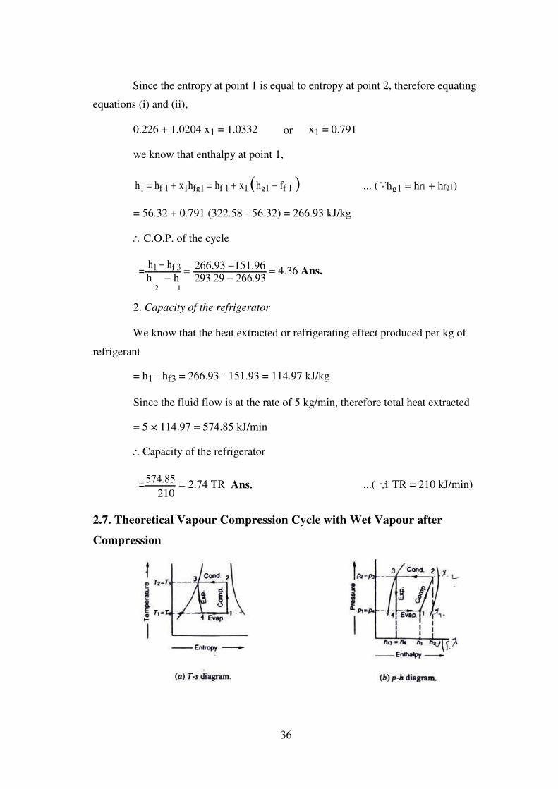
2.7. Theoretical Vapour Compression Cycle with Wet Vapour after
Compression
36

A vapour compression cycle with wet vapour after compression is shown on
T-s and p-h diagrams in Fig. 2.6 (a) and (b) respectively. In this cycle, the enthalpy at
point 2 is found out with the help of dryness fraction at this point. The dryness
fraction at points 1 and 2 may be obtained by equating entropies at points 1 and 2.
Now the coefficient of performance may be found out as usual from the
relation,
C.O.P. =
Refrigerating effect =
h1
hf 3
Work done h 2 h
1
Compound Vapour Compression Refrigeration Systems
Introduction
In the previous chapter, we have discussed the simple vapour compression
refrigeration system in which the low pressure vapour refrigerant from the evaporator
is compressed in a single stage (or a single compressor) and then delivered to a
condenser at a high pressure. But sometimes, the vapour refrigerant is required to be
delivered at a very high pressure as in the case of low temperature refrigerating
systems. In such cases either we should compress the vapour refrigerant by
employing a single stage compressor with a very high pressure ratio between the
condenser and evaporator or compress it in two or more compressors placed is series.
The compression carried out in two or more compressors is called compound or
multistage compression.
In vapour compression refrigeration systems, the major operating cost is the
energy input to the system in the form of mechanical work. Thus any method of
increasing coefficient of performance is advantageous so long as it does not involve
too heavy an increase in other operating expenses, as well as initial plant cost and
consequent maintenance.
Since the coefficient of performance of a refrigeration system is the ratio of
refrigerating effect to the compression work, therefore the coefficient of performance
can be increased either by increasing the refrigerating effect or by decreasing the
compression work. A little consideration will show that in a vapour compression
system, the compression work is greatly reduced if the refrigerant is compressed very
37

close to the saturated vapour line. This can be achieved by compressing the
refrigerant in more stages with intermediate intercooling. But it is economical only
where the pressure ratio is considerable as would be the case when very low
evaporator temperatures are desired or when high condenser temperature may be
required. The compound compression is generally economical in large plants.
The refrigerating effect can be increased by maintaining the condition of the
refrigerant in more liquid state at the entrance to the evaporator. This can be achieved
by expanding the refrigerant very close to the saturated liquid line. It may be noted
that by subcooling the refrigerant and by removing the flashed vapour, as they are
during multistage expansion, the expansion can be brought close to the liquid line.
2.2 Advantages of Compound (or Multi-stage) Vapour Compression with
Intercooler
Following are the main advantages of compound or multistage compression
over single stage compression:
I. The work done per kg of refrigerant is reduced in compound compression
with intercooler as compared to single stage compression for the same delivery
pressure.
2. It improves the volumetric efficiency for the given pressure ratio.
3. The sizes of the two cylinders (i.e., high pressure and low pressure) may
be adjusted to suit the volume and pressure of the refrigerant.
4. It reduces the leakage loss considerably.
5. It gives more uniform torque, and hence a smaller size flywheel is
needed.
6. It provides effective lubrication because of lower temperature range.
7. It reduces the cost of compressor.
2.3 Types of Compound Vapour Compression with Intercooler
In compound compression vapour refrigeration systems, the superheated
vapour refrigerant leaving the first stage of compression is cooled by suitable method
before being fed to the second stage of compression and so on. Such type of cooling
38

the refrigerant is called intercooling. Though there are many types of compound
compression with intercoolers, yet the following are important from the subject point
of view:
I. Two stage compression with liquid intercooler.
2. Two stage compression with water intercooler.
3. Two stage compression with water intercooler, liquid subcooler and
liquid flash chamber.
4. Two stage compression with water intercooler, liquid subcooler and flash
intercooler.
5. Three stage compression with flash chambers.
6. Three stage compression with water intercoolers.
7. Three stage compression with flash intercoolers.
The above mentioned types are now discussed, in detail, one by one in the
following pages.
2.4 Two Stage Compression with Liquid Intercooler
The arrangement of a two stage compression with liquid intercooler is
shown in Fig. 2.7 (a). The corresponding p-h diagram is shown in Fig. 2.7 (b).
The various points on the p-h diagram are plotted as discussed below:
I. First of all, draw a horizontal pressure line representing the evaporator
pressure PE (or suction pressure of low pressure compressor) which intersects the
saturated vapour line at point 1. At this point, the saturated vapour is supplied to the
low pressure compressor. Let, at point I, the enthalpy of the saturated vapour is h1
and entropy sv1
2. The saturated vapour refrigerant admitted at point 1 is compressed
isentropically in the low pressure compressor and delivers the refrigerant in a
superheated state. The pressure rises from PE to P2 The curve 1-2 represents the
isentropic compression in the low pressure compressor. In order to obtain point 2,
draw a line from point 1, with entropy equal to svl, along the constant entropy line
39
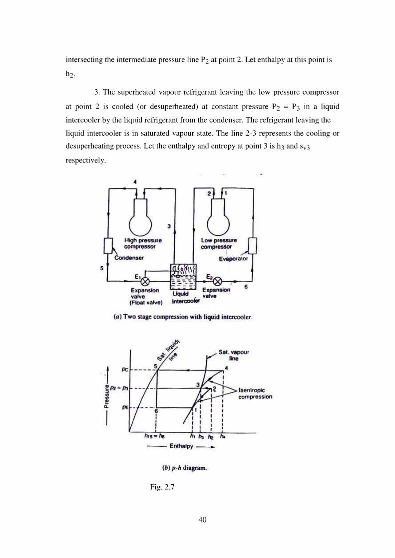
intersecting the intermediate pressure line P2 at point 2. Let enthalpy at this point is
h2.
3. The superheated vapour refrigerant leaving the low pressure compressor
at point 2 is cooled (or desuperheated) at constant pressure P2 = P3 in a liquid
intercooler by the liquid refrigerant from the condenser. The refrigerant leaving the
liquid intercooler is in saturated vapour state. The line 2-3 represents the cooling or
desuperheating process. Let the enthalpy and entropy at point 3 is h3 and sv3
respectively.
Fig. 2.7
40
4. The dry saturated vapour refrigerant is now supplied to high pressure
compressor where it is compressed isentropically from intermediate or interocooler
pressure P2 to condensor pressure pc. The curve 3-4 represents the isentropic
compression in the high pressure compressor. The point 4 on the p-h diagram is
obtained by drawing a line of entropy equal to sv3 along the constant entropy line as
shown in Fig. 2.1 (b). Let the enthalpy of superheated vapour refrigerant at point 4 is
h4.
5. The superheated vapour refrigerant leaving the high pressure compressor
at point 4 is now passed through the condenser at constant pressure Pc as shown by a
horizontal line 4-5. The condensing process 4-5 changes the state of refrigerant from
superheated vapour to saturated liquid.
6. The high pressure saturated liquid refrigerant from the condensor is
passed to the intercooler where some of liquid refrigerant evaporates in
desuperheating the superheated vapour refrigerant from the low pressure compressor.
In order to make up for the liquid evaporated, i.e. to maintain a constant liquid level,
an expansion valve E1 which acts as a float valve, is provided.
7. The liquid refrigerant from the intercooler is first expanded in an
expansion valve E2 and then evaporated in the evaporator to saturated vapour
condition, as shown in Fig. 2.1(b).
Let
ml = Mass of refrigerant passing through the evaporator (or low pressure
compressor) in kg/min, and
m2 = Mass of refrigerant passing through the condenser (or high pressure
compressor) in kg/min.
The high pressure compressor in a given system will compress the mass of
refrigerant from low pressure compressor (ml) and the mass of liquid evaporated in
the liquid intercooler during cooling or de superheating of superheated vapour
refrigerant from low pressure compressor. If m3 is the mass of liquid evaporated in
the intercooler, then
m3= m2 - ml
41
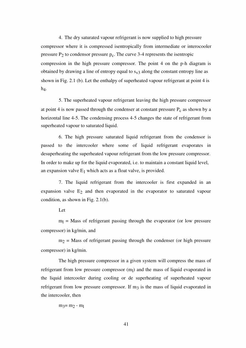
The value of m2 may be obtained by considering the thermal equilibrium for
the liquid intercooler as shown in Fig. 2.2, i.e .,
Heat taken by the liquid intercooler = Heat given by the liquid intercooler
Fig2.8. Thermal equilibrium for liquid intercooler.
or m2 hf5 + m1 h2 = m1 h6 + m2 h3
m2 m1 h2 h6
m1 h2 hf 5
... ( h6 = hf5)
h3 hf 5
h3 hf 5
and mass of liquid refrigerant evaporated in the intercooler,
* m
3 m
2 m m1 h2 hf5 m m1 h2 h3
1 h3
hf 5
1 h3
hf 5
We know that refrigerating effect,
RE = ml (hl - hf) = ml (hl - hf5) = 210 Q kJ/min
where Q is the load on the evaporator in tonne of refrigeration.
Total work done in both the compressors,
W = ml (h2 - h1) + m2 (h4 - h3)
Power required to drive the system,
P
m1
h2
h1
m2
h4
h3
kW 60
and C.O.P. of the system
42

= R E = m1 h1 hf 5 210 Q
W m1 h2 h1 m2 h4 h3 P 60
Notes: 1. In case of ammonia, when liquid refrigerant is used for
intercooling, the total power requirement will decrease. It is due to the fact that the
mass of liquid evaporated during intercooling is extremely small because of its high
latent heat of vaporisation and the constant entropy lines of ammonia become very
flat in the superheat region. Thus the intercooling by liquid refrigerant is commonly
used in multi-stage ammonia plants, because of less power requirement.
2. In case of refrigerant R-12, when liquid refrigerant is used for
intercooling, the total power requirements may actually increase. It is due to the fact
that the latent heat of vaporisation is small and the constant entropy line of R-12 does
not change very much with the temperature. Thus in R-12 systems, the saving in
work by performing the compression close to the saturated vapour line does not
compensate for the increased mass flow rate through the high stage compressor.
Therefore, intercooling by liquid refrigerant in R-12 systems is never employed.
Example 2.1. Calculate the power needed to compress 20 kg / min of
ammonia from saturated vapour at 1.4 bar to a condensing pressure of 10 bar by two-
stage compression with intercooling by liquid refrigerant at 4 bar. Assume saturated
liquid to leave the condenser and dry saturted vapours to leave the evaporator. Use
the p-h chart.
Determine, also, the power needed when intercooling is not employed.
Solution. Given : m1 = 20 kg/min ; PE = 1.4 bar ; pC = 10 bar ; p2 = p3 = 4
bar
43

Fig. 2.9
The p-h diagram for a two stage compression with intercooling by liquid
refrigerant is shown in Fig. 2.9. The various values for ammonia as read from the p-h
diagram are as follows:
Enthalpy of saturated vapour refrigerant entering the low pressure
compressor at point 1, h1 = 1400 kJ/kg
Entropy of saturated vapour refrigerant entering the low pressure
compressor at point 1, Sl = 5.75 kJ/kg K
Enthalpy of superheated vapour refrigerant leaving the low pressure
compressor at point 2, h2 = 1527 kJ/kg
Enthalpy of saturated vapour refrigerant leaving the intercooler or entering
the high pressure compressor at point 3,
h3 = 1428 kJ/kg
Entropy of saturated vapour refrigerant leaving the intercooler or entering
the high pressure compressor at point 3,
s3 = 5.39 kJ/kg K
Enthalpy of superheated vapour refrigerant leaving the high pressure
compressor at point 4, h4 = 1550 kJ/kg
Enthalpy of saturated liquid refrigerant passing through the condenser at
point 5, hf5 = h6 = 284 kJ/kg
44
We know that mass of refrigerant passing through the condenser (or high
pressure compressor),
m2 = m1 h2 hf5 = 201527 284 = 21.73 kg/min
h3 hf 5 1428 284
Work done in low pressure compressor,
WL = m1 (h2 - h1) = 20 (1527 - 1400) = 2540
kJ/min Work done in high pressure compressor,
WH = m2 (h4 - h3) = 21.73 (1550 - 1428) = 2651
kJ/min and total work done in both the compressors,
W = WL + WH = 2540 + 2651 = 5191 kJ/min
Power needed = 5191/60 = 86.5 kW Ans.
Power needed when intercooling is not employed
When intercooling is not employed, the compression of refrigerant will
follow the path 1-2 in the low pressure compressor and 2-2' in the high pressure
compressor. In such a case,
Work done in the high pressure compressor,
WH = mi (h2'- h2) = 20 (1676- 1527) = 2980 kJ /min
... ( From p-h diagram, h2' = 1676 kJ/kg)
and total work done is both the compressors,
W = WL + WH = 2540 + 2980 = 5520 kJ/min
Power needed = 5520/60 = 92 kW Ans.
Example 2.2. Calculate the power needed to compress 20 kg/min of R-12
from saturated vapour at 1.4 bar to a condensing pressure of 10 bar by two-stage
compression with intercooling by liquid refrigerant at 4 bar. Assume saturated liquid
to leave the condenser and dry saturated vapours to leave the evaporator.
Use the p-h chart. Sketch the cycle on a skeleton p-h chart and label the
values of enthalpy at salient points.
45

Solution. Given: ml = 20 kg/min; PE = 1.4 bar; Pc = 10 bar; P2 = P3 = 4 bar
The p-h diagram for a two-stage compression with intercooling by liquid
refrigerant is shown in Fig. 5.4. The various values for R-12 as read from the p-h
diagram are as follows :..
Enthalpy of saturated vapour refrigerant entering the low pressure
compressor at point 1, h1= 178 kJ/kg
Entropy of saturated vapour refrigerant entering the low pressure
compressor at point 1, sl = 0.71 kJ/kg K
Fig. 2.10
Enthalpy of superheated vapour refrigerant leaving the low pressure
compressor at point 2, h2 = 195 kJ/kg
Enthalpy of saturated vapour refrigerant leaving the intercooler or entering
the high pressure compressor at point 3,
h3=191 kJ/kg
Entropy of saturated vapour refrigerant entering the high pressure
compressor at point 3, s3 = 0.695 kJ/kg K
Enthalpy of superheated vapour refrigerant leaving the high pressure
compressor at point 4, h4 = 210 kJ/kg K
46

Enthalpy of saturated liquid refrigerant leaving the condenser at point 5, hf5
= h6 = 77 kJ/kg
We know that mass of refrigerant passing through the condenser (or high
pressure compressor),
m2 = m1 h2 hf5
= 20195 77
= 20.7 kg/min
h3
hf 5 191 77
Work done in low pressure compressor,
WL = ml (h2 - h1) = 20 (195 - 178) = 340 kJ/min
Work done in high pressure compressor,
WH= m2 (h4- h3) = 20.7 (210-191) = 393
kJ/min We know that refrigerating effect,
RE = m (h1- hf6) = 210 Q kJ/min
C.O.P. of the system
= R E
= m h1 hf 6 =
210 Q
h
2 1
h
4
h
3
P 60
W h
Example 2.3. The following data refer to a two stage compression ammonia
refrigerating system with water intercooler.
Condenser pressure = 14 bar; Evaporator pressure = 2 bar; Intercooler
pressure = 5 bar; Load on the evaporator = 2 TR
If the temperature of the de-superheated vapour and sub-cooled liquid
refrigerant are limited to 30oC, find (a) the power required to drive the system, and
(b) CO.P. of the system.
Solution. Given : Pc = 14 bar ; PE = 2 bar ; P2 = P3 = 5 bar ; Q = 10 TR ; t3
= t6 = 30° C
The p-h diagram for a two stage compression system with water intercooler
is shown in Fig. 2.11. The various values as read from the p-h diagram for ammonia
are as follows:
47
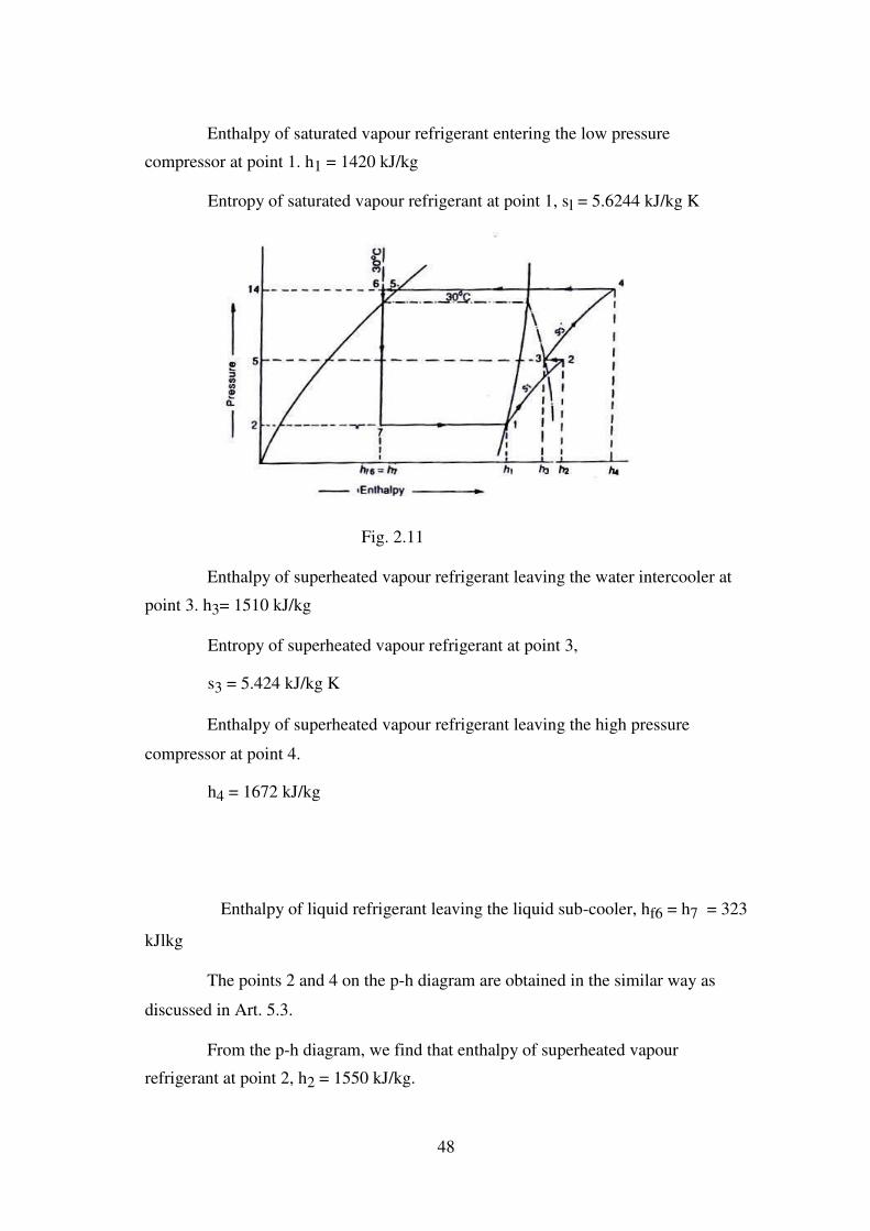
Enthalpy of saturated vapour refrigerant entering the low pressure
compressor at point 1. h1 = 1420 kJ/kg
Entropy of saturated vapour refrigerant at point 1, sl = 5.6244 kJ/kg K
Fig. 2.11
Enthalpy of superheated vapour refrigerant leaving the water intercooler at
point 3. h3= 1510 kJ/kg
Entropy of superheated vapour refrigerant at point 3,
s3 = 5.424 kJ/kg K
Enthalpy of superheated vapour refrigerant leaving the high pressure
compressor at point 4.
h4 = 1672 kJ/kg
Enthalpy of liquid refrigerant leaving the liquid sub-cooler, hf6 = h7 = 323
kJlkg
The points 2 and 4 on the p-h diagram are obtained in the similar way as
discussed in Art. 5.3.
From the p-h diagram, we find that enthalpy of superheated vapour
refrigerant at point 2, h2 = 1550 kJ/kg.
48
(a) Power required to drive the system
We know that mass of refrigerant circulating through the system,
m =
210 Q
=
210 10
= 1.91kg/min
h h f 6
1420 323
1
Total work done in both the compressors,
w= m [(h2 - h1) + (h4 - h3)]
= 1.91 [(1550- 1420) + (1672 - 1510) = 557.7 kJ/min
Power required to drive the system,
(b) CO.P. of system
We know that refrigerating effect of the system,
RE = 210Q = 2l0 × 10 = 2100 kJ/min
:. C.O.P. of the system
= R
WE
= 557.2100
7 = 3.76 Ans.
2.6 Two Stage Compression with Water Intercooler, Liquid Sub-cooler
and Liquid Flash Chamber
The arrangement of a two stage compression with water intercooler, liquid
sub-cooler and liquid flash chamber is shown in Fig. 2.12 (a). The corresponding p-h
diagram is shown in Fig. 2.7 (b). The various processes, in this system, are as
follows:
I. The saturated vapour refrigerant at the evaporator pressure PE is admitted
to low pressure compressor at point I. In this compressor, the refrigerant is
compressed isentropically from evaporator pressure PE to water intercooler (or flash
chamber)
pressure PF as shown by the curve 1-2 in Fig. 2.12 (b).
49

2. The superheated vapour refrigerant leaving the low pressure compressor
at point 2 is now passed through the water intercooler at constant pressure PF in order
to reduce the degree of superheat (i.e., from temperature t2 to t3 ). The line 2-3
represents the water intercooling or de-superheating process.
3. The superheated vapour refrigerant leaving the water intercooler at point
3 is mixed with the vapour refrigerant supplied by the flash chamber at point 9. The
condition of refrigerant after mixing is shown by point 4 which is in superheated
state. Let the temperature at this point is t4.
4. The superheated vapour refrigerant admitted at point 4 to the high
pressure compressor is compressed isentropically from the intercooler or flash
chamber pressure PF to condenser pressure Pc as shown by the curve 4-5. The
temperature rises from t4 to t5.
5. The superheafed vapour leaving the high pressure compressor at pressure
Pc is passed through a condenser at constant pressure as shown by a horizontal line 5-
6. The condensing process 5-6 changes the state of refrigerant from superheated
vapour to saturated liquid.
50

Fig 2.12
6. The saturated liquid refrigerant from the condenser is now cooled in
liquid sub-cooler to a temperature, say t7. The line 6-7 represents a sub-cooling
process.
7. The liquid refrigerant leaving the sub-cooler at pressure Pc is expanded in
an expansion valve E1 to a pressure equal to the flash chamber pressure PF, as shown
by vertical line 7-8. The expanded refrigerant which is a mixture of vapour and liquid
refrigerants is admitted to a flash chamber at point 8. The flash chamber separates the
51

vapour and liquid refrigerants at pressure PF. The vapour refrigerant from the flash
chamber at point 9 is mixed with the refrigerant from the water intercooler. The
liquid refrigerant from the flash chamber at Point 10 is further expanded in an
expansion valve E2 as shown by the vertical line 10-11.
8. The liquid refrigerant leaving the expansion valve E2 is evaporated in the
evaporator at the evaporator pressure PE (usually 2 bar) as shown by the horizontal
line 11-1 in Fig. 2.12 (b).
Let m2 = Mass of refrigerant passing through the condenser (or high
pressure compressor), and
m3 = Mass of vapour refrigerant formed in the flash chamber.
:. Mass of refrigerant passing through the evaporator (or low pressure
compressor),
ml = m2-m3
If Q tonne of refrigeration is the load on the evaporator, then the mass of
refrigerant passing through the evaporator,
m1= 210 Q
210 Q kg/min ...( h11 = hf10)
h h h h f 10
1 11 1
Now let us consider the thermal equilibrium of the flash chamber. Since the
flash chamber is an insulated vessel, therefore there is no heat exchange between the
flash chamber and atmosphere. In other words, the heat taken and given by the flash
chamber are same. Mathematically,
Heat taken by the flash chamber
= Heat given by the flash chamber
m2 h8 = m3 h9 + ml hf10
= m3 h9 + (m2- m3) hf10 ...( m1 = m2 - m2)
m2 (h8 - hf10) = m3 (h9 - hf10)
h 8 h
f 10 m2
h f 7
hf
m3 = m2 10 ...( h8 = hf7) ... (i)
h9
hf 10
h9
hf 10
52
The vapour refrigerant from the water intercooler (represented by point 3) is
mixed with vapour refrigerant m3 from the flash chamber (represented by point 9) at
the same pressure before entering the high pressure compressor. The enthalpy of the
mixed refrigerant (represented by point 4) may be calculated by using the equation,
m2 h4 = m3 h9 + ml h3
= m3 h9 + (m2 - m3) h3
We know that refrigerating effect of the system,
RE = ml (h1 - hll) = 210 Q kJ/min
Work done in low pressure compressor,
WL = ml (h2 - hl)
Work done in high pressure compressor,
WH = m2 (h5 - h4)
Total workdone in both the compressors,
W = WL + WH = m1 ( (h2 - hl) + m2 (h5 - h4)
Power required to drive the system,
p =
m1
h2
h1
m2
h5
h4 kW
60
and C.O.P. of the system
R
E m1 h 2 h11 210 Q
=
=
=
W m1 h 2 h1 m 2 h 5 h4 p 60
Note: Since the mass of vapour refrigerant m, is cooled in the water
intercooler from condition 2 to 3, therefore cooling capacity of the intercooler
= ml (h2 -h3)
Example 2.4. A two stage compression ammonia refrigeration system
operates between overall pressure limits of 14 bar and 2 bar. the temperature of the
desuperheated vapour and subcooled liquid refrigerant are limited to 30oC. The flash
53

tank separates dry vapour at 5 bar pressure and the liquid refrigerant then expands to
2 bar.
Estimate the C.O.P. of the machine and power required to drive the
compresor, if the mechanical effficiency of the drive is 80% and load on the
evaporator is 10 TR.
Solution. Given :Pc = 14 bar; PE = 2 bar; PF = 5 bar; t3 = t7 = 30o C ; m =
80% = 0.8 ; Q = 10TR
The p-h diagram for a two-stage compression system with given conditions
is shown in Fig. 5.8. The values as read from p-h diagram for ammonia, are as
follows:
Fig 2.13
Enthalpy of saturated vapour refrigerant entering the low pressure
compressor at point 1. hi = 1420 kJ/kg
Entropy of saturated vapour refrigerant entering the low pressure
compressor at point 1. s1 = 5.6244 kJ/kg K
Enthalpy of superheated vapour refrigerant leaving the low pressure
compressor at point 2, h2 =1550 kJ/kg
54
Enthalpy of superheated vapour refrigerant leaving the water intercooler at
point 3. h3 = 1510 kJ/kg
Enthalpy of saturated vapour refrigerant leaving the flash tank at point 9,
h9 = 1432 kJ/kg
Enthalpy of liquid refrigerant leaving the subcooler at point 7,
hf7 = h8 = 323 kJ/kg
Enthalpy of saturated liquid refrigerant leaving the second expansion valve
at point 10, hf10 = hll = 198 kJ/kg
Let m2 = Mass of refrigerant passing through the condenser.
We know that mass of the vapour refrigerant formed in the flash tank,
h8
hf 10 323 198
m3 = m2 = m2
= 0.l m2 ... (i)
hf 10
h9 1432 198
and mass of refrigerant passing through the evaporator,
ml = m2 - m3 =
210 Q
=
210 10
= 1.72 kg/min ... (ii)
h h f 10
1420 198
1
From equations (i) and (ii),
m2 - 0.1 m2 = 1.72 or m2 = 1.9 kg/min
m3 = 0.l m2 = 0.l × 1.9 = 0.19 kg/min
The desuperheated vapour refrigerant (m2 - m3) as represented by point 3 is
mixed with the vapour refrigerant from the flash tank as represented by point 9. The
enthalpy of the mixed refrigerant entering the high pressure compressor as
represented by point 4 is given by
m2 h4 = m3 h9 + (m2 - m3) h3
= 0.1 m2 h9 + (m2 - 0.1 m2) h3 ... [From equation (i)]
or h4 = 0.1 × h9 + 0.9 × h3 = 0.1 × 1432+ 0.9 × 1510 = 1502 kJ/kg
We see from p-h diagram that at point 4 (intersection of pressure 5 bar and
enthalpy 1502 kJ/kg), the entropy is s4 = 5.51 kJ/kg K. Now from point 4, draw a line
55

of entropy equal to 5.51 kJ/kg K along the constant entropy line which intersects the
condenser pressure (14 bar) line at point 5. Thus, the point 5 is located. From p-h
diagram, we find that enthalpy of refrigerant leaving the high pressure compressor at
point 5 is
h5= 1650 kJ/kg
C.O.P. of the machine
We know that refrigerating effect
= ml (hl - hf10) = 210 Q = 210 × 10 = 2100
kJ/min Work done in both the compressors
= ml (h2 - h1) + m2 (h5 - h4)
= 1.72 (1550 - 1420) + 1.9 (1650- 1502)
= 223.6 + 281.2 = 504.8 kJ/min
Since the mechanical efficiency of the drive is 80%, therefore actual work
done in both the compressors
= 504.8/0.8 = 631 kJ/min
Actual C.O.P = Refrigerating effect
= 2100
= 3.32 Ans.Actual work done631
Power required to drive the compressors
We know that power required to drive the compressors
= Actual work done
= 631
= 10.5 kW Ans.
60 60
2.7 Two Stage Compression with Water Intercooler, Liquid Sub-cooler
and Flash Intercooler
A two stage compression with water intercooler, liquid sub-cooler and flash
intercooler is shown in Fig. 2.9 (a). The corresponding p-h diagram is shown in Fig.
5.9 (b).
56

Fig 2.14
We have seen in the previous article that when the vapour refrigerant from
the low pressure compressor is passed through the water intercooler, its temperature
does not reduce to the saturated vapour line or even very near to it, before admitting
it to the high pressure compressor [ Refer point 4 of Fig. 2.12 (b)]. In fact, with water
cooling there may be no saving of work in compression. But the improvement in
performance and the reduction in compression work may be achieved by using a
flash chamber as an intercooler as well as flash separator, as shown in Fig. 2.14 (a).
The corresponding p-h diagram is shown in Fig. 2.14 (b). The various processes, in
this system, are as follows:
1. The saturated vapour refrigerant at the evaporator pressure PE is admitted
to the low pressure compressor at point 1. In this compressor, the refrigerant is
57
compressed isentropically from evaporator pressure PE to the flash intercooler
pressure PF,as shown by the curve 1-2 in Fig2.14 (b).
2. The superheated vapour refrigerant leaving the low pressure compressor
at point 2 is now passed through the water intercooler at constant pressure PF, in
order to reduce the degree of superheat ( i.e. from temperature t2 to t3). The line 2-3
represents the water intercooling or desuperheating process.
3. The superheated vapour refrigerant leaving the water intercooler at point
3 is passed through a flash intercooler which cools the superheated vapour refrigerant
to saturated vapour refrigerant as shown by the line 3-4. The cooling of superheated
vapour refrigerant is done by the evaporation of a part of the liquid refrigerant from
the flash intercooler placed at point 8.
4. The saturated vapour refrigerant leaving the flash intercooler enters the
high pressure compressor at point 4 where it is compressed isentropically from flash
intercooler pressure PF to condenser pressure PC, as shown by the curve 4-5.
5. The superheated vapour refrigerant leaving the high pressure compressor
at pressure Pc is passed through a condenser at constant pressure. The condensing
process as shown by line 5-6 changes the state of refrigerant from superheated
vapour to saturated liquid.
6. The saturated liquid refrigerant leaving the condenser at point 6 is now
cooled at constant pressure Pc in the liquid sub-cooler to a temperature t7 as shown in
Fig. 2.9 (b). The line 6-7 shows the sub-cooling process.
7. The liquid refrigerant leaving the sub-cooler at point 7 is expanded in an
expansion valve E1 to a pressure equal to the flash intercooler pressure PF , as shown
by the vertical line 7-8. The expanded refrigerant (which is a mixture of vapour and
liquid refrigerant) is admitted to flash intercooler at point 8 which also acts as a flash
separator.
8. The liquid refrigerant leaving the flash intercooler at point 9 is passed
through the second expansion valve E2 (process 9-10) and then evaporated in the
evaporator as shown by the horizontal line 10-1.
Let m1 = Mass of the refrigerant passing through the evaporator or low
58
pressure compressor), and
m2 = Mass of the refrigerant passing through the condenser (or high
pressure compressor).
If Q tonne of refrigeration is the load on the evaporator, then the mass of
refrigerant passing through the evaporator is given by,
m1 = 210 Q
= 210 Q
kg/min ... ( h10 = hf9)
h h h h f 9
1 10 1
Now for the thermal equilibrium of the flash intercooler, Heat taken by the
flash intercooler
= Heat given by the flash intercooler
m2 h8 + m1 h3 = m2 h4 + m1 hf9
m1(h3 - hf9) = m2 (h4 -h8)
m2 h
3 h
f 9 h
3 h
f 9
= m1 = m1 kg/min
h4 h8
h4
hf 7
We know that refrigerating effect,
RE = ml (hl - h10) = ml (hl - hf9) = 210 Q kJ/min
and work done in both the compressors,
W = Work done in L.P. compressor + Work done in H.P. compressor
= ml (h2 - hl) + m2 (h5- h4)
Power required to drive the system,
p
m1
h2
h1
m2
h5
h4
kW 60
and coefficient of performance of the system,
R E m1 h1 hf 9 210 Q
C.O.P. =
=
=
W m1 h 2 h1 m 2 h 5 h4 P 60
59

MODULE – III
Vapour Absorption Refrigeration Systems
3.1 Introduction
The vapour absorption refrigeration system is one of the oldest method of
producing refrigerating effect. The principle of vapour absorption was first
discovered by Michael Faraday in 1824 while performing a set of experiments to
liquify certain gases. The first vapour absorption refrigeration machine was
developed by a French scientist Ferdinand Carre in 1860. This system may be used in
both the domestic and large industrial refrigerating plants. The refrigerant, commonly
used in a vapour absorption system, is ammonia.
The vapour absorption system uses heat energy, instead of mechanical
energy as in vapour compression systems, in order to change the conditions of the
refrigerant required for the operation of the refrigeration cycle. We have discussed in
the previous chapters that the function of a compressor, in a vapour compression
system, is to withdraw the vapour refrigerant from the evaporator. It then raises its
temperature and pressure higher than the cooling agent in the condenser so that the
higher pressure vapours can reject heat in the condenser. The liquid refrigerant
leaving the condenser is now ready to expand to the evaporator conditions again.
In the vapour absorption system, the compressor is replaced by an absorber,
a pump, a generator and a pressure reducing valve. These components in vapour
absorption system perform the same function as that of a compressor in vapour
compression system. In this system, the vapour refrigerant from the evaporator is
drawn into an absorber where it is absorbed by the weak solution of the refrigerant
forming a strong solution. This strong solution is pumped to the generator where it is
heated by some external source. During the heating process, the vapour refrigerant is
driven off by the solution and enters into the condenser where it is liquefied. The
liquid refrigerant then flows into the evaporator and thus the cycle is completed.
3.2 Simple Vapour Absorption System -

The simple vapour absorption system, as shown in Fig. 3.1, consists of an
absorber, a pump, a generator and a pressure reducing valve to replace the
compressor of vapour compression system. The other components of the system are
condenser, receiver, expansion valve and evaporator as in the vapour compression
system.
Fig 3.1 Simple vapour absorbtion system
. In this system, the low pressure ammonia vapour leaving the evaporator
enters the absorber where it is absorbed by the cold water in the absorber. The water
has the ability to absorb very large quantities of ammonia vapour and the solution
thus formed, is known as aqua-ammonia. The absorption of ammonia vapour in
water lowers the pressure in the absorber which in turn draws more ammonia vapour
from the evaporator and thus raises the temperature of solution. Some form of
cooling arrangement (usually water cooling) is employed in the absorber to remove
the heat of solution evolved there. This is necessary in order to increase the
absorption capacity of water, because at higher temperature water absorbs less
ammonia vapour. The strong solution thus formed in the absorber is pumped to the
generator by the liquid pump. The pump increases the pressure of the solution upto
10 bar.
The *strong solution of ammonia in the generator is heated by some external
source such as gas or steam. During the heating process, the ammonia vapour is
driven off the solution at high pressure leaving behind the hot weak ammonia
solution in the generator. This weak ammonia solution flows back to the absorber at
low pressure after passing through the pressure reducing valve. The high pressure
ammonia vapour from the generator is condensed in the condenser to a high pressure
liquid ammonia. This liquid ammonia is passed to the expansion valve through the
receiver and then to the evaporator. This completes the simple vapour absorption
cycle.
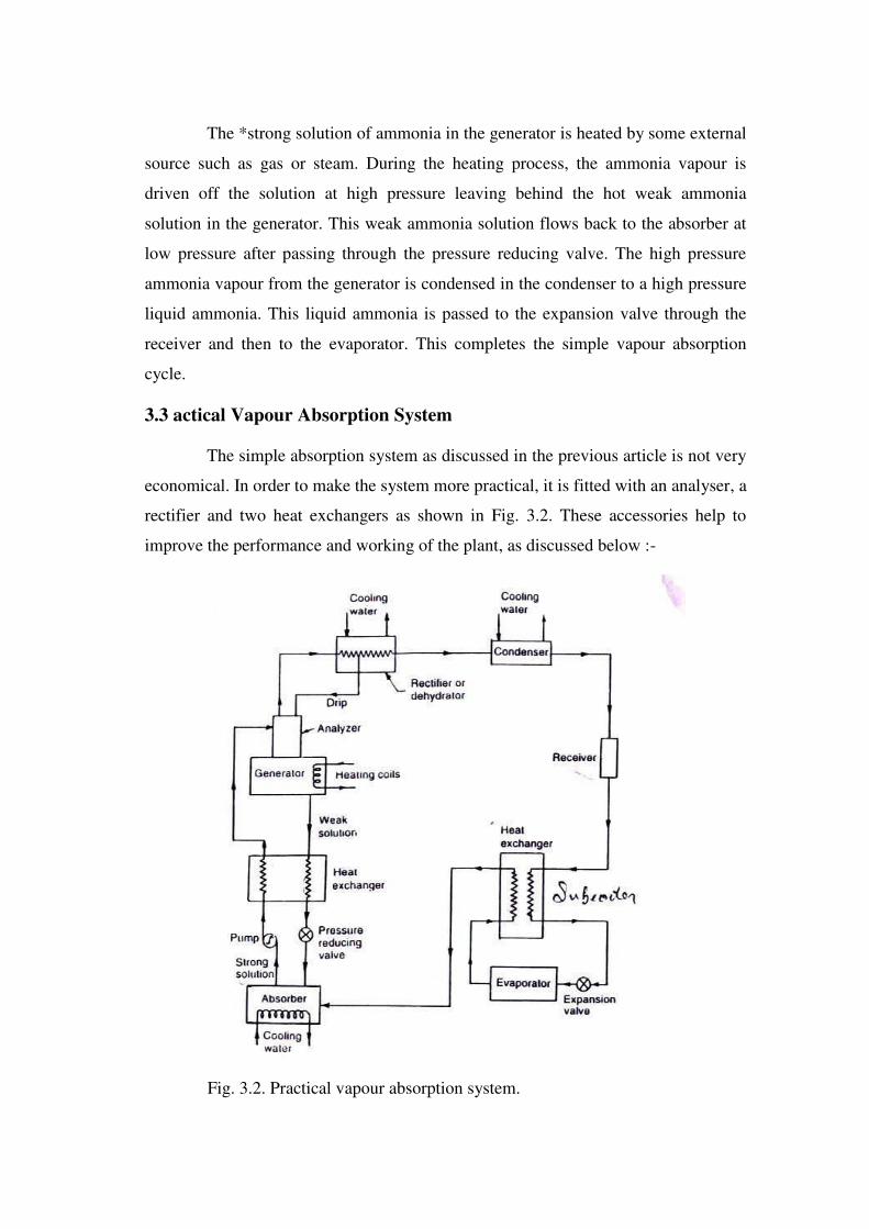
3.3 actical Vapour Absorption System
The simple absorption system as discussed in the previous article is not very
economical. In order to make the system more practical, it is fitted with an analyser, a
rectifier and two heat exchangers as shown in Fig. 3.2. These accessories help to
improve the performance and working of the plant, as discussed below :-
Fig. 3.2. Practical vapour absorption system.
1. Analyser. When ammonia is vaporised in the generator, some water is
also vaporised and will flow into the condenser along with the ammonia vapours in
the simple system. If these unwanted water particles are not removed before entering
into the condenser, they will enter into the expansion valve where they freeze and
choke the pipe line. In order to remove these unwanted particles flowing to the
condenser, an analyser is used. The analyser may be built as an integral part of the
generator or made as a separate piece of equipment. It consists of a series of trays
mounted above the generator. The strong solution from the absorber and the aqua
from the rectifier are introduced at the top of the analyser and flow downward over
the trays and into the generator. In this way, considerable liquid surface area is
exposed to the vapour rising from the generator. The vapour is cooled and most of
the water vapour condenses, so that mainly ammonia vapour leaves the top of the
analyser. Since the aqua is heated by the vapour, less external heat is required in the
generator.
2. Rectifier. In case the water vapours are not completely removed in the
analyser, a closed type vapour cooler called rectifier (also known as dehydrator) is
used. It is generally water cooled and may be of the double pipe, shell and coil or
shell and tube type. Its function is to cool further the ammonia vapours leaving the
analyser so that the remaining water vapours are condensed. Thus, only dry or
anhydrous ammonia vapours flow to the condenser. The condensate from the rectifier
is returned to the top of the analyser by a drip return pipe.
3. Heat exchangers. The heat exchanger provided between the pump and the
generator is used to cool the weak hot solution returning from the generator to the
absorber. The heat removed from the weak solution raises the temperature of the
strong solution leaving the pump and going to analyser and generator. This operation
reduces the heat supplied to the generator and the amount of cooling required for the
absorber. Thus the economy of the plant increases.
The heat exchanger provided between the condenser and the evaporator may
also be called liquid sub-cooler. In this heat exchanger, the liquid refrigerant leaving
the condenser is sub- cooled by the low temperature ammonia vapour from the

evaporator as shown in Fig. 7.2. This sub-cooled liquid is now passed to the
expansion valve and then to the evaporator.
In this system, the net refrigerating effect is the heat absorbed by the
refrigerant in the evaporator. The total energy supplied to the system is the sum of
work done by the pump and the heat supplied in the generator. Therefore, the
coefficient of performance of the system is given by
Heat absorbed in evaporator
C.O.P. = Work done by pump + Heat supplied in generator
3.4 Advantages of Vapour Absorption Refrigeration System over Vapour
Compression Refrigeration System
Following are the advantages of vapour absorption system over vapour
compression system:
1. In the vapour absorption system, the only moving part of the entire
system is a pump which has a small motor. Thus, the operation of this system is
essentially quiet and is subjected to little wear.
The vapour compression system of the same capacity has more wear, tear
and noise due to moving parts of the compressor.
2. The vapour absorption system uses heat energy to change the condition of
the refrigerant from the evaporator. The vapour compression system uses mechanical
energy to change the condition of the refrigerant from the evaporator.
3. The vapour absorption systems are usually designed to use steam, either
at high pressure or low pressure. The exhaust steam from furnaces and solar energy
may also be used. Thus this system can be used where the electric power is difficult
to obtain or is very expensive.
4. The vapour absorption systems can operate at reduced evaporator
pressure and temperature by increasing the steam pressure to the generator, with little
decrease in capacity. But the capacity of vapour compression system drops rapidly
with lowered evaporator pressure.

5. The load variations does not effect the performance of a vapour
absorption system. The load variations are met by controlling the quantity of aqua
circulated and the quantity of steam supplied to the generator.
The performance of a vapour compression system at partial loads is poor.
6. In the vapour absorption system, the liquid refrigerant leaving the
evaporator has no bad effect on the system except that of reducing the refrigerating
effect. In the vapour compression system, it is essential to superheat the vapour
refrigerant leaving the evaporator so that no liquid may enter the compressor.
7. The vapour absorption systems can be built in capacities well above 1000
tonnes of refrigeration each which is the largest size for single compressor units.
8. The space requirements and automatic control requirements favour the
absorption system more and more as the desired evaporator temperature drops.
3.5 Coefficient of Performance of an Ideal Vapour
Absorption Refrigeration System
We have discussed earlier that in an ideal vapour absorption refrigeration
system,
(a) the heat (QG) is given to the refrigerant in the generator,
(b) the heat (Qc) is discharged to the atmosphere or cooling water from the
condenser and absorber.
(c) the heat (QE) is absorbed by the refrigerant in the evaporator, and
(d) the heat (Qp) is added to the refrigerant due to pump work.
Neglecting the heat due to pump work (Qp), we have according to First Law
of Thermodynamics,
QC QG QE
... (i)
Let
TG = Temperature at which heat (QG) is given to the generator,

Tc = Temperature at which heat (QC) is discharged to atmosphere or cooling
water from the condenser and absorber, and
TE = Temperature at which heat (QE) is absorbed in the evaporator.
Since the vapour absorption system can be considered as a perfectly
reversible system, therefore the initial entropy of the system must be equal to the
entropy of the system after the change in its condition.
Q G
QE
QC TG TE TC
= Q
G
QE
TC
or Q G QG
Q E
QE
T
T T
T
G C C E
T T T T Q
G CG Q
E EC
T
G
TC
TC
TE
Q = Q
T
E
T
C
T
G
T
C GE
TC TE TC TG
T T T T =
Q
E C E G C T
T T T
C E G C
T T T =
Q
E C E G
TE
TG
TC
...(ii)
... [ From equation (i) ]
... (iii)
Maximum coefficient of performance of the system is given by
(C.O.P.)max = QE =
QE
Q G
T T T
QE C E G
T T T
E G C
T T T =
E G C ...(iv)
TC
TE TG
It may noted that,

TE
I. The expression is the C.O.P. of a Carnot refrigerator working
TC
TE
between the temperature limits of T E and T C.
T T
2. The expression G C is the efficiency of a Carnot engine working
TG
between the temperature limits of TG and TC.
Thus an ideal vapour absorption refrigeration system may be regarded as a
combination of a Carnot engine and a Carnot refrigerator. The maximum C.O.P. may
be written as
(C.O.P.)max = (C.O.P)carnot × carnot
In case the heat is discharged at different temperatures in condenser and
absorber, then
T T T
(C.O.P.)max = E G C
T T T
C E G
where TA= Temperature at which heat is discharged in the absorber.
Example 3.1. In a vapour absorption refrigeration system, heating, cooling
and refrigeration takes place at the temperatures of 100o C, 20
o C and _5° C
respectively. Find the maximum C.O.P. of the system.
Solution. Given: TG = 100oC = 100 + 273 = 373 K ; Tc = 20
oC = 20 + 273
= 293 K ; T E = - 5° C = - 5 + 273 = 268 K
We know that maximum C.O.P. of the system
T T T 268 373 293
=
E G C = 2.3 Ans.
TG
373
TC
TE 293 268
Example 3.2. In an absorption type refrigerator, the heat is supplied to NH3
generator by condensing steam at 2 bar and 90% dry. The temperature in the
refrigerator is to be maintained at - 5° C. Find the maximum C.O.P. possible.

If the refrigeration load is 20 tonnes and actual C.O.P. is 10% of the
maximum C.O.P ., find the mass of steam required per hour. Take temperature of the
atmosphere as 30oC.
Solution. Given: p = 2 bar; x = 90% = 0.9; TE = -5°C = -5 + 273 = 268 K ;
Q = 20 TR; Actual C.O.P. = 70% of maximum C.O.P. ; TC = 30° C = 30 + 273 = 303
K
Maximum C.O.P.
From steam tables, we find that the saturation temperature of steam at a
pressure of 2 bar is
TG = 120.2° C = 120.2 + 273 = 393.2 K
We know that maximum C.O.P.
T T T
= E G C = T T T
C E G
268 393 303 = 1.756 Ans.
303 268 393.2
Mass of steam required per hour
We know that actual C.O.P.
= 70% of maximum C.O.P. = 0.7 × 1.756 = 1.229
Actual heat supplied
= Refrigeration load
= 20 210
= 3417.4 kJ/min
Actual C.O.P. 1.229
Assuming that only latent heat of steam is used for heating purposes,
therefore from steam tables, the latent heat of steam at 2 bar is
hfg = 2201.6 kJ/kg
Mass of steam required per hour
= Actual heat supplied = 3417.4 = 1.552 kg/min= 93.12 kg/h Ans.
2201.6
x × hfg
3.6 Domestic Electrolux (Ammonia Hydrogen) Refrigerator

The domestic absorption type refrigerator was invented by two Swedish
engineers Carl Munters and Baltzer Von Platan in 1925 while they were studying for
their under-graduate course of Royal Institute of Technology in Stockholm. The idea
was first developed by the ‘Electrolux Company’ of Luton, England.
Fig. 3.3. Domestic electrolux type refrigerator.
This type of refrigerator is also called three-fluids absorption system. The
main purpose of this system is to eliminate the pump so that in the absence of moving
parts. the machine becomes noise-less. The three fluids used in this sytem are
ammonia, hydrogen and water. The ammonia is used as a refrigerant because it
possesses most of the desirable properties. It is toxic. but due to absence of moving
parts, there is very little changes for the leakage and the total amount of refrigeration
used is small. The hydrogen being the lightest gas. is used to increase the rate of
evaporation of the liquid ammonia passing through the evaporator. The hydrogen is
also non-corrosive and insoluble in water. This is used in the low-pressure side of the
system. The water is used as a solvent because it has the ability to absorb ammonia
readily. The principle of operation of a domestic electolux type refrigerator. as shown
in Fig. 3.3. is discussed below:
The strong ammonia solution from the absorber through heat exchanger is
heated in the generator by applying heat from an external source usually a gas burner.
During this heating process, ammonia vapours are removed from the solution

and passed to the condenser. A rectifirer or a water separator fitted before the
condenser removes water vapour carried with the ammonia vapours. so that dry
ammonia vapours are supplied to the condenser. These water vapours,. f not
removed, they will enter into the evaporator causing freezing and choking of the
machine . The hot weak solution left behind in the generator flow to the absorber
through the heat excl anger. This hot weak solution while passing through the
exchanger is cooled. The heat removed by the weak solution is utilised in raising the
temperature of strong solution passing through the heat exchanger. In this way, the
absorption is accelerated and the improvement in the performance of a plant is
achieved.
The ammonia vapours in the condenser are condensed by using external
cooling source. The liquid refrigerant leaving the condenser flows under gravity to
the evaporator where it meets the hydrogen gas. The hydrogen gas which is being fed
to the evaporator permit the liquid ammonia to evaporate at a low pressure and
temperature according to Dalton's principle. During the process of evaporation, the
ammonia absorbs latent heat from the refrigerated space and thus produces cooling
effect.
The mixture of ammonia vapour and hydrogen is passed to the absorber
where ammonia is absorbed in water while the hydrogen rises to the top and flows
hack to the evaporator. This completes the cycle. The coefficient of performance of
this refrigerator is given by :
C.O.P. = Heat absorbed in the evaporator
Heat supplied in the generator
Notes: 1. The hydrogen gas only circulates from the absorber to the
evaporator and back.
2. The whole cycle is carried out entirely by gravity flow of the refrigerant.
3. It can not be used for industrial purposes as the C.O.P. of the system is
very low.
3.7 Lithium Bromide Absorption Refrigeration System
The lithium-bromide absorption refrigeration system uses a solution of
lithium bromide in water. In this system, the *water is being used as a refrigerant
whereas lithium bromide, which is a highly hydroscopic salt, as an absorbent. The
lithium bromide solution has a strong affinity for water vapour because of its very
low vapour pressure. Since lithium bromide solution is corrosive, therefore inhibitors
should be added in order to protect the metal parts of the system against corrosion.
Lithium chromate is often uged as a corrosion inhibitor. This system is very popular
for air conditioning in which low refrigeration temperatures (not below 0° C)** are
required.
Fig. 3.4 shows a lithium bromide vapour absorption system. In this system.
the absorber and the evaporator are placed in one shell which operates at the same
low pressure of the system. The generator and condenser are placed in another shell
which operates at the same high pressure of the system. The principle of operation of
this system is discussed below :
The water for air-conditioning coils or process requirements is chilled as it is
pumped through the chilled-water tubes in.the evaporator by giving up heat to the
refrigerant water sprayed over the tubes. Since the pressure inside the evaporator is
maintained very low, therefore, the refrigerant waterevaporates. The water vapours
thus formed will be absorbed by the strong lithium-bromide solution which is
sprayed in the absorber. In absorbing the water vapour, the lithium bromide solution
helps in maintaining very low pressure (high vacuum) needed in the evaporator, and
the solution becomes weak. This weak solution is pumped by a pump to the generator
where it is heated up by using steam or hot water in the heating coils. A portion of
water is evaporated by the heat and the solution now becomes more strong. This
strong solution is passed through the heat exchanger and then sprayed in the absorber
as discussed above. The weak solution of lithium bromide from the absorber to the
generator is also passed through the heat exchanger. This weak solution gets heat
from the strong solution in the heat exchanger, thus reducing the quantity of steam
required to heat the weak solution in the generator.

Fig. 3.4. Lithium-Bromide absorption refrigeration system.
The refrigerant water vapours formed in the generator due to heating of
solution are passed to the condenser where they are cooled and condensed by the
cooling water flowing through the condenser water tubes. The cooling water for
condensing is pumped from the cooling water pond or tower. This cooling water first
enters the absorber where it takes away the heat of condensation and dilution. The
condensate from the condenser is supplied to the evaporator to compensate the water
vapour formed in the evaporator. The pressure reducing valve reduces the pressure of
condensate from the condenser pressure to the evaporator pressure. The cooled water
from the evaporator is pumped and sprayed in the evaporator in order to cool the
water for air conditioning flowing through the chilled tubes. This completes the
cycle.
Note: The pressure difference between the generator and the absorber and
the gravity due to the height difference of the two shells is utilised to create the
pressure for the spray.
6.8 Steam Jet Refrigeration System:
Control valve
Steam nozzle
Thermocompresser
Steam ejector
boiler
Water returned A.C-plant
Vapor
Spray Condenser
Flash chamber
Pump Cold water to A.C-plant
Pump Make-up-water
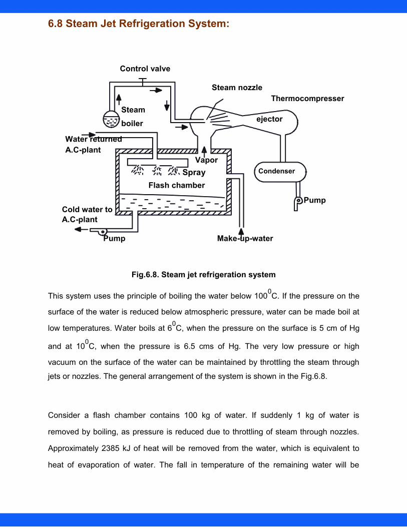
Fig.6.8. Steam jet refrigeration system
This system uses the principle of boiling the water below 1000C. If the pressure on the
surface of the water is reduced below atmospheric pressure, water can be made boil at
low temperatures. Water boils at 60C, when the pressure on the surface is 5 cm of Hg
and at 100C, when the pressure is 6.5 cms of Hg. The very low pressure or high
vacuum on the surface of the water can be maintained by throttling the steam through
jets or nozzles. The general arrangement of the system is shown in the Fig.6.8.
Consider a flash chamber contains 100 kg of water. If suddenly 1 kg of water is
removed by boiling, as pressure is reduced due to throttling of steam through nozzles.
Approximately 2385 kJ of heat will be removed from the water, which is equivalent to
heat of evaporation of water. The fall in temperature of the remaining water will be
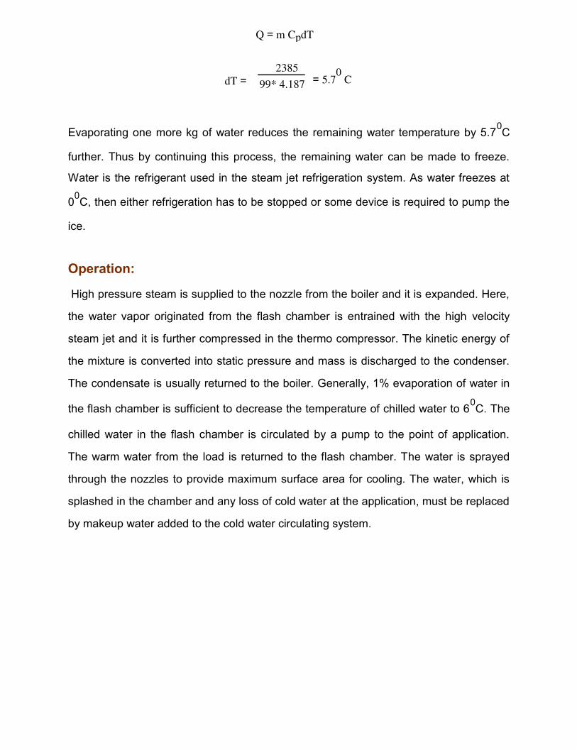
Q = m CpdT
dT = 2385
= 5.70 C 99* 4.187
Evaporating one more kg of water reduces the remaining water temperature by 5.70C
further. Thus by continuing this process, the remaining water can be made to freeze.
Water is the refrigerant used in the steam jet refrigeration system. As water freezes at
00C, then either refrigeration has to be stopped or some device is required to pump the
ice.
Operation:
High pressure steam is supplied to the nozzle from the boiler and it is expanded. Here,
the water vapor originated from the flash chamber is entrained with the high velocity
steam jet and it is further compressed in the thermo compressor. The kinetic energy of
the mixture is converted into static pressure and mass is discharged to the condenser.
The condensate is usually returned to the boiler. Generally, 1% evaporation of water in
the flash chamber is sufficient to decrease the temperature of chilled water to 60C. The
chilled water in the flash chamber is circulated by a pump to the point of application.
The warm water from the load is returned to the flash chamber. The water is sprayed
through the nozzles to provide maximum surface area for cooling. The water, which is
splashed in the chamber and any loss of cold water at the application, must be replaced
by makeup water added to the cold water circulating system.
Indian Institute of Technology Madras Refrigeration Cycles Prof. U.S.P Prof.

Advantages:
a) It is flexible in operation; cooling capacity can be easily and quickly changed.
b) It has no moving parts as such it is vibration free.
c) It can be installed out of doors.
d) The weight of the system per ton of refrigerating capacity is less.
e) The system is very reliable and maintenance cost is less.
f) The system is particularly adapted to the processing of cold water used in
rubber mills,, distilleries, paper mills, food processing plants, etc.
g) This system is particularly used in air-conditioning installations, because of
the complete safety of water as refrigerant and ability to adjust quickly to load
variations and no hazard from the leakage of the refrigerant.
Disadvantages:
a) The use of direct evaporation to produce chilled water is usually limited as
tremendous volume of vapor is to be handled.
b) About twice as much heat must be removed in the condenser of steam jet per
ton of refrigeration compared with the vapor compression system.
c) The system is useful for comfort air-conditioning, but it is not practically
feasible for water temperature below 40C

Thermoelectric Refrigeration
Thermoelectric cooling uses the Peltier effect to create a heat flux between the junctions of
two different types of materials.
This effect is commonly used in camping and portable coolers and for cooling electronic
components and small instruments.
Applying a DC voltage difference across the thermoelectric module, an electric current will
pass through the module and heat will be absorbed from one side and released at the opposite
side. One module face, therefore, will be cooled while the opposite face simultaneously is
heated.
On the other hand, maintaining a temperature difference between the two junctions of the
module, a voltage difference will be generated across the module and an electrical power is
delivered.
Thermoelectricity is based upon following basic principles:
1. SEEBECK EFFECT
2. PELTIER EFFECT
3. THOMSON EFFECT
4. JOULE EFFECT
5. FOURIER EFFECT
Peltier effect
When a current is made to flow through a junction between two conductors A and B, heat may be
generated (or removed) at the junction. The Peltier heat generated at the junction per unit time, Q , is
equal to;
Q α I Q = πabI
πab = πa - πb
where (πa & πb) is the Peltier coefficient of conductor A & B, and I is the electric current (from A
to B).
BASIC MECHANISM OF THERMOELECTRICS
Bismuth telluride (a semiconductor), is sandwiched between two conductors, usually copper.
A semiconductor (called a pellet) is used because they can be optimized for pumping heat and because
the type of charge carriers within them can be chosen. The semiconductor in this examples N type
(doped with electrons) therefore, the electrons move towards the positive end of the battery. The
semiconductor is soldered to two conductive materials, like copper. When the voltage is applied heat
is transported in the direction of current flow
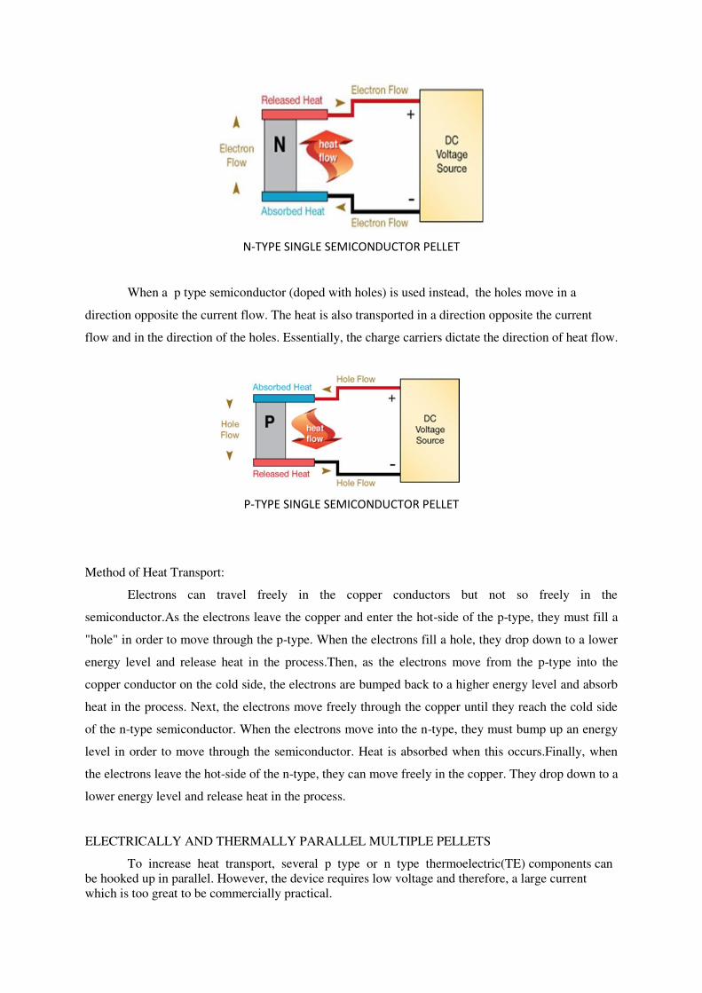
N-TYPE SINGLE SEMICONDUCTOR PELLET
When a p type semiconductor (doped with holes) is used instead, the holes move in a
direction opposite the current flow. The heat is also transported in a direction opposite the current
flow and in the direction of the holes. Essentially, the charge carriers dictate the direction of heat flow.
P-TYPE SINGLE SEMICONDUCTOR PELLET
Method of Heat Transport:
Electrons can travel freely in the copper conductors but not so freely in the
semiconductor.As the electrons leave the copper and enter the hot-side of the p-type, they must fill a
"hole" in order to move through the p-type. When the electrons fill a hole, they drop down to a lower
energy level and release heat in the process.Then, as the electrons move from the p-type into the
copper conductor on the cold side, the electrons are bumped back to a higher energy level and absorb
heat in the process. Next, the electrons move freely through the copper until they reach the cold side
of the n-type semiconductor. When the electrons move into the n-type, they must bump up an energy
level in order to move through the semiconductor. Heat is absorbed when this occurs.Finally, when
the electrons leave the hot-side of the n-type, they can move freely in the copper. They drop down to a
lower energy level and release heat in the process.
ELECTRICALLY AND THERMALLY PARALLEL MULTIPLE PELLETS
To increase heat transport, several p type or n type thermoelectric(TE) components can
be hooked up in parallel. However, the device requires low voltage and therefore, a large current
which is too great to be commercially practical.

THERMALLY PARALLEL AND ELECTRICALLT IN SERIES MULTIPLE PELLETS
The TE components can be put in series but the heat transport abilities are diminished because
the interconnecting between the semiconductors creates thermal shorting.
Vortex tube refrigeration system
A vortex tube is a thermal device, which generates two streams at different
temperature from a single injection. Injected into the vortex tube tangentially, the compressed
gas is then divided into two parts and exhausted from the exits at temperatures lower and
higher than the inlet gas, respectively. In this way, cold and hot streams are generated by only
the vortex tube without any additional components. Figure 1 shows the structure of a counter-
flow vortex tube as well as the proposed flow behaviour inside the tube. Importantly, as the
vortex tube contains no other part inside the tube, the separation of two streams at different
temperature by the vortex tube can only be attributed by the effects of fluid dynamics.
On comparison with other industry-based technologies, the significant advantages of the
vortex tube, such as having no moving parts, being small, low in cost, maintenance free and
having adjustable instant cold and hot streams, encourage the on-going investigations into the
mechanism of this simple device, with the objective of improving the tube performance and
identifying of the primary factors underlying its operation.

Flow structure in a counter-flow vortex tube
Several hypothesises have been proposed for the basic of the temperature separation,
but a well-accepted explanation has not been forthcoming due to the complex flow
mechanisms inside a vortex tube. The adiabatic compression and expansion caused by the
turbulent eddies, form the basic for the temperature separation, and provide a theoretical
prediction of the temperatures based on the pressures at the exits. However, compression of
the working fluid cannot be considered as the reason for the temperature rise, because the
pressure inside a vortex tube is always lower than the inlet pressure. The generation of hot and cold streams in a vortex tube and is based on partial stagnation and
mixture due to the nature of the multi-circulation occurring in the rear part of the tube, and the
pressure gradient near the injection port.
Visualizations of theflow structure,and measurements ofthe velocity
componentsinbothair-andwater-operatedvortextubes,showthattheflow to be divided into
two streams at different temperatures.
The cooling effect in a vortex tube
Flow structure inside a counter-flow vortex tube
The cooling effect of a vortex tube is the result of the sudden expansion of the working fluid
near the injection port. When the fluid is injected into the vortex tube, the main part of the
fluid rotates and moves along the periphery towards the hot end. Near the injection point, the
inner part of the peripheral flow turns back and moves towards the cold exit. A cold core is
formed near the injection due to the pressure gradient of the forced vortex, and the
temperature drops due to the decreased pressure of the working fluid in this cold core. The
flow behaviour in the cold part of a vortex tube can be seen in Figure , which shows the
inwards turn back of the inner flow and the cold core.

Pulse tube refrigerator
The pulse tube refrigerator (PTR) or pulse tube cryocooler is a developing technology
that emerged largely in the early 1980s with a series of other innovations in the broader field
of thermoacoustics. In contrast with other cryocoolers (e.g. Stirlingcryocooler and GM-
refrigerators), this cryocooler can be made without moving parts in the low temperature part
of the device, making the cooler suitable for a wide variety of applications.
Uses
Pulse tube cryocoolers are used in industrial applications such
as semiconductor fabrication and in military applications such as for the cooling of infrared
sensors. Pulse tubes are also being developed for cooling of astronomical detectors where
liquid cryogens are typically used, such as the Atacama Cosmology Telescope or the Qubic
experiment (an interferometer for cosmology studies). PTRs are used as precoolers
of dilution refrigerators. Pulse tubes will be particularly useful in space-based
telescopes where it is not possible to replenish the cryogens as they are depleted. It has also
been suggested that pulse tubes could be used to liquefy oxygen on Mars.
Here the so-called Stirling-type single-orifice pulse-tube refrigerator will be treated
operating with an ideal gas (helium) as the working fluid. Figure 1 represents the Stirling-
type single-orifice Pulse-Tube Refrigerator (PTR). From left to right the components are:
a compressor, with a piston moving back and forth at room temperature TH;
a heat exchanger X1 where heat is released to the surroundings;
a regenerator consisting of a porous medium with a large specific heat,The porous
medium can be stainless steel wire mesh, copper wire mesh, phosphor bronze wire
mesh or lead balls or lead shot or (rarely) earthen materials to produce very low
temperature;
a heat exchanger X2 where the useful cooling power is delivered at the low
temperature TL;
a tube, often called "the pulse tube";
a heat exchanger X3 at room temperature where heat is released to the surroundings;
a flow resistance (often called orifice);
a buffer volume (a large closed volume at practically constant pressure).

The part in between X1 and X3 is thermally insulated from the surroundings, usually by
vacuum. The cooler is filled with helium at a pressure ranging from 10 to 30 bar. The
pressure varies gradually and the velocities of the gas are low. So the name "pulse" tube
cooler is misleading, since there are no pulses in the system.
Operation
The piston moves periodically from left to right and back. As a result, the gas also moves
from left to right and back while the pressure within the system increases and decreases. If
the gas from the compressor space moves to the right it enters the regenerator with
temperature TH and leaves the regenerator at the cold end with temperature TL, hence heat is
transferred into the regenerator material. On its return the heat stored within the regenerator is
transferred back into the gas.
The thermal environment of a gas element near X2 that moves back and forth in the system
changes when it passes the heat exchanger. In the regenerator and in the heat exchanger the
heat contact between the gas and its surrounding material is good. Here the temperature of the
gas is practically the same as of the surrounding medium. However, in the pulse tube the gas
element is thermally isolated (adiabatic), so, in the pulse tube, the temperature of the gas
elements varies with the pressure.
Figure 2: Left: (near X2): a gas element enters the pulse tube with temperature TL and leaves
it with a lower temperature. Right: (near X3): a gas element enters the tube with
temperature TH and leaves it with a higher temperature.
Look at figure 1 and consider gas molecules close to X3 (at the hot end) which move in and
out of the pulse tube. Molecules flow into the tube when the pressure in the tube is low (it is
sucked into the tube via X3 coming from the orifice and the buffer). At the moment of
entering the tube it has the temperature TH. Later in the cycle the same mass of gas is pushed
out from the tube again when the pressure inside the tube is high. As a consequence its
temperature will be higher than TH. In the heat exchanger X3 it releases heat and cools down
to the ambient temperature TH.
At the cold end of the pulse tube there is the opposite effect: here gas enters the tube via
X2 when the pressure is high with temperature TL and return when the pressure is low with a
temperature below TL. They take up heat from X2: this gives the desired cooling effect.
Thermionic refrigeration system
Production of low temperature dry ice refrigeration system
Raw Materials
The only raw material used in the manufacture of dry ice is carbon dioxide. This raw material
is the byproduct of the refinement of gases emitted during the manufacture or refinement of
other products. Most carbon dioxide used in the manufacture of dry ice in the United States is
derived from refinement of gases given off during the refinement of petroleum and ammonia.
The carbon dioxide emitted during these processes is sucked off and "scrubbed" to remove
impurities for food grade carbon dioxide that will eventually become dry ice.