
POWER PLANT ENGINEERING (R17A0326) - mrcet.ac.in
185
www.mrcet.ac.in POWER PLANT ENGINEERING (R17A0326) 4 th Year B. Tech I- sem, Mechanical Engineering
-
Upload
khangminh22 -
Category
Documents
-
view
3 -
download
0
Transcript of POWER PLANT ENGINEERING (R17A0326) - mrcet.ac.in

www.mrcet.ac.in
POWER PLANT ENGINEERING
(R17A0326) 4th Year B. Tech I- sem, Mechanical Engineering
DEPARTMENT OF MECHANICAL ENGINEERING
COURSE OBJECTIVES
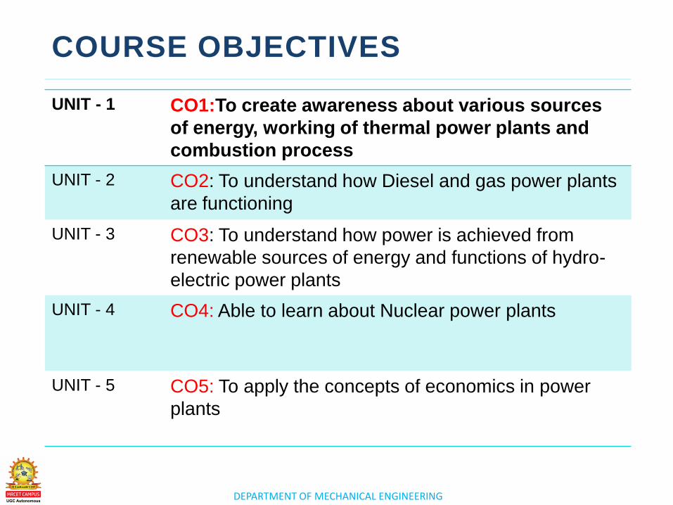
UNIT - 1 CO1:To create awareness about various sources
of energy, working of thermal power plants and
combustion process
UNIT - 2 CO2: To understand how Diesel and gas power plants
are functioning
UNIT - 3
CO3: To understand how power is achieved from
renewable sources of energy and functions of hydro-
electric power plants
UNIT - 4 CO4: Able to learn about Nuclear power plants
UNIT - 5 CO5: To apply the concepts of economics in power
plants
www.mrcet.ac.in
UNIT 1
CO1:To create awareness about various sources of energy,
working of thermal power plants and combustion process
C O A L B A S E D T H E R M A L P O W E R
P L A N T S
DEPARTMENT OF MECHANICAL ENGINEERING
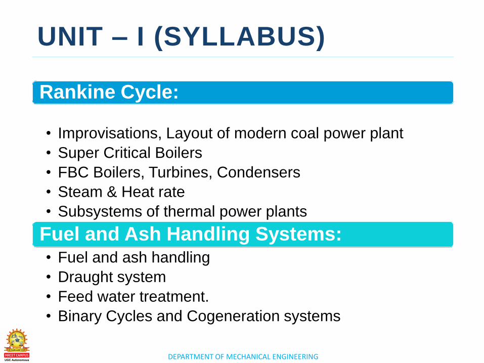
UNIT – I (SYLLABUS)
Rankine Cycle:
• Improvisations, Layout of modern coal power plant
• Super Critical Boilers
• FBC Boilers, Turbines, Condensers
• Steam & Heat rate
• Subsystems of thermal power plants
Fuel and Ash Handling Systems: • Fuel and ash handling
• Draught system
• Feed water treatment.
• Binary Cycles and Cogeneration systems
DEPARTMENT OF MECHANICAL ENGINEERING
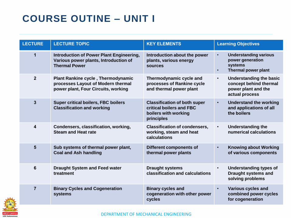
COURSE OUTINE – UNIT I
LECTURE LECTURE TOPIC KEY ELEMENTS Learning Objectives
1 Introduction of Power Plant Engineering,
Various power plants, Introduction of
Thermal Power
Introduction about the power
plants, various energy
sources
• Understanding various
power generation
systems
• Thermal power plant
2 Plant Rankine cycle , Thermodynamic
processes Layout of Modern thermal
power plant, Four Circuits, working
Thermodynamic cycle and
processes of Rankine cycle
and thermal power plant
• Understanding the basic
concept behind thermal
power plant and the
actual process
3 Super critical boilers, FBC boilers
Classification and working
Classification of both super
critical boilers and FBC
boilers with working
principles
• Understand the working
and applications of all
the boilers
4 Condensers, classification, working,
Steam and Heat rate
Classification of condensers,
working, steam and heat
calculations
• Understanding the
numerical calculations
5 Sub systems of thermal power plant,
Coal and Ash handling
Different components of
thermal power plants
• Knowing about Working
of various components
6 Draught System and Feed water
treatment
Draught systems
classification and calculations
• Understanding types of
Draught systems and
solving problems
7 Binary Cycles and Cogeneration
systems
Binary cycles and
cogeneration with other power
cycles
• Various cycles and
combined power cycles
for cogeneration
www.mrcet.ac.in
LECTURE 1
Introduction of Power
Plant Engineering, Various
power plants, Introduction
of Thermal Power
DEPARTMENT OF MECHANICAL ENGINEERING
LECTURE 1
• Introduction to Power Plant
Engineering
• Various Power Plants
• Introduction to Thermal Power
Introduction to Power Plant
Engineering, Various power
plants, Introduction to
Thermal Power
TOPICS TO BE COVERED
DEPARTMENT OF MECHANICAL ENGINEERING
INTRODUCTION TO POWER PLANT ENGINEERING
– A power plant is an industrial facility used to generate
electric power with the help of one or more generators
which converts different energy sources into electric
power.
– A power plant or a power generating station, is basically
an industrial location that is utilized for the generation and
distribution of electric power in mass scale, usually in the
order of several 1000 Watts. These are generally located at
the sub-urban regions or several kilometers away from the
cities or the load centers, because of its requisites like
huge land and water demand, along with several operating
constraints like the waste disposal etc.
DEPARTMENT OF MECHANICAL ENGINEERING
INTRODUCTION TO POWER PLANT ENGINEERING
– Electricity is produced at a an electric power plant. Some
fuel source, such as coal, oil, natural gas,
or nuclear energy produces heat. The heat is used to boil
water to create steam. The steam under high pressure is
used to spin a turbine.
– For this reason, a power generating station has to not only
take care of efficient generation but also the fact that the
power is transmitted efficiently over the entire distance
and that’s why, the transformer switch yard to regulate
transmission voltage also becomes an integral part of the
power plant.
DEPARTMENT OF MECHANICAL ENGINEERING
INTRODUCTION TO POWER PLANT ENGINEERING
– At the center of it, however, nearly all power generating
stations has an AC generator or an alternator, which is
basically a rotating machine that is equipped to convert
energy from the mechanical domain (rotating turbine)
into electrical domain by creating relative motion
between a magnetic field and the conductors.
DEPARTMENT OF MECHANICAL ENGINEERING
INTRODUCTION TO POWER PLANT ENGINEERING
The energy source harnessed to turn the generator shaft
varies widely, and is chiefly dependent on the type of fuel
used.
Types of Power Plants
A power plant can be of several types depending mainly
on the type of fuel used. A power generating station can be
broadly classified in to 5 types mentioned below.
– Thermal Power Plants
– Diesel Engine Power Plants
– Gas Turbine Power Plants
– Nuclear Power Plants
– Hydro Electric Power Plants
DEPARTMENT OF MECHANICAL ENGINEERING
INTRODUCTION TO POWER PLANT ENGINEERING
Introduction to Thermal Power and Thermal Power
Station:
Thermal Power Station
A thermal power station or a coal fired thermal power plant
is the most conventional method of generating electric
power with reasonably high efficiency. It uses coal as the
primary fuel to boil the water available to superheated steam
for driving the steam turbine.
The steam turbine is then mechanically coupled to an
alternator rotor, the rotation of which results in the
generation of electric power. Generally in India, bituminous
coal or brown coal are used as fuel of boiler which has
volatile content ranging from 8 to 33% and ash content 5 to
16 %. To enhance the thermal efficiency of the plant, the
coal is used in the boiler in its pulverized form.
DEPARTMENT OF MECHANICAL ENGINEERING
INTRODUCTION TO POWER PLANT ENGINEERING
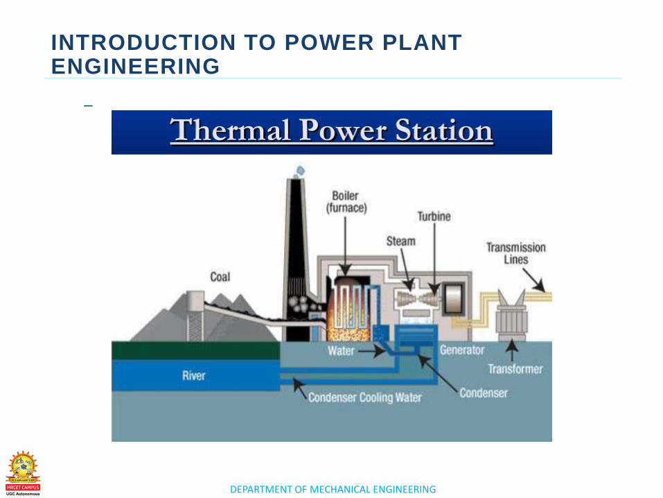
In coal fired thermal power plant, steam is obtained in very
high pressure inside the steam boiler by burning the
pulverized coal. This steam is then super heated in the
super heater to extreme high temperature. This super
heated steam is then allowed to enter into the turbine, as the
turbine blades are rotated by the pressure of the steam.
The turbine is mechanically coupled with alternator in a
way that its rotor will rotate with the rotation of turbine
blades. After entering into the turbine, the steam pressure
suddenly falls leading to corresponding increase in the
steam volume. After having imparted energy into the turbine
rotors, the steam is made to pass out of the turbine blades
into the steam condenser of turbine. In the condenser, cold
water at ambient temperature is circulated with the help of
pump which leads to the condensation of the low pressure
wet steam.
DEPARTMENT OF MECHANICAL ENGINEERING
INTRODUCTION TO POWER PLANT ENGINEERING
In thermal power plants, the heat energy obtained
from combustion of solid fuel (mostly coal) is used to
convert water into steam, this steam is at high
pressure and temperature. This steam is used to rotate
the turbine blade turbine shaft is connected to the
generator.
DEPARTMENT OF MECHANICAL ENGINEERING
INTRODUCTION TO POWER PLANT ENGINEERING
–
DEPARTMENT OF MECHANICAL ENGINEERING
INTRODUCTION TO POWER PLANT ENGINEERING
DEPARTMENT OF MECHANICAL ENGINEERING
INTRODUCTION TO POWER PLANT ENGINEERING

www.mrcet.ac.in
THANK YOU

www.mrcet.ac.in
LECTURE 2
Introduction - Resultants of Force System
DEPARTMENT OF MECHANICAL ENGINEERING
LECTURE 2
• Rankine Cycle
• Thermodynamic processes
• Layout of Modern thermal power
plant
• Four Circuits
• Working
Introduction to
Rankine Cycle
TOPICS TO BE COVERED
DEPARTMENT OF MECHANICAL ENGINEERING
RANKINE CYCLE
– Introduction
• Rankine cycle
– Thermodynamic Processes
– Layout of Modern Thermal Power Plant
– Four Circuits
– Working
DEPARTMENT OF MECHANICAL ENGINEERING
RANKINE CYCLE
DEPARTMENT OF MECHANICAL ENGINEERING
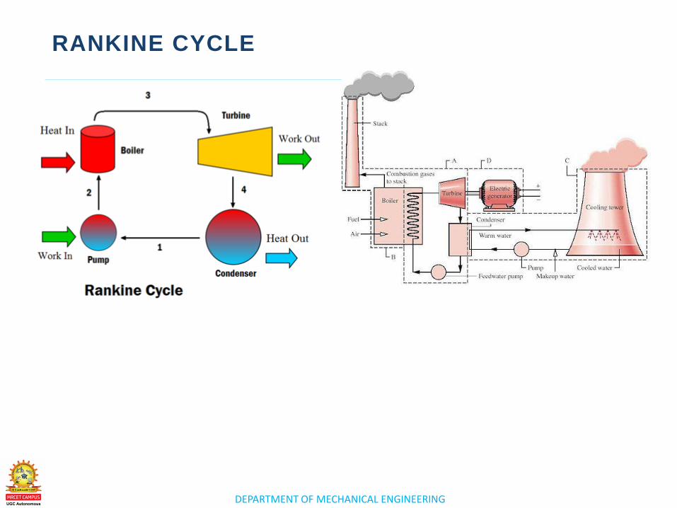
• The Rankine cycle or Rankine Vapor Cycle is the
process widely used by power plants such as coal-fired
power plants or nuclear reactors. In this mechanism, a
fuel is used to produce heat within a boiler, converting
water into steam which then expands through a turbine
producing useful work.
• The Rankine cycle is a model used to predict the
performance of steam turbine systems. It was also used
to study the performance of reciprocating steam
engines. The Rankine cycle is an idealized
thermodynamic cycle of a heat engine that converts
heat into mechanical work while undergoing phase
change.
DEPARTMENT OF MECHANICAL ENGINEERING
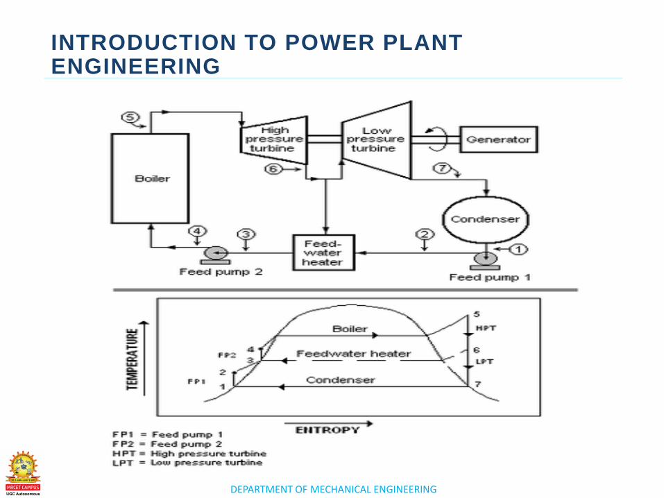
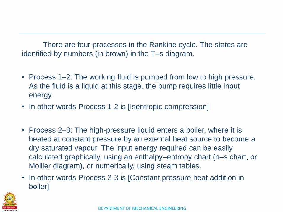
There are four processes in the Rankine cycle. The states are
identified by numbers (in brown) in the T–s diagram.
• Process 1–2: The working fluid is pumped from low to high pressure.
As the fluid is a liquid at this stage, the pump requires little input
energy.
• In other words Process 1-2 is [Isentropic compression]
• Process 2–3: The high-pressure liquid enters a boiler, where it is
heated at constant pressure by an external heat source to become a
dry saturated vapour. The input energy required can be easily
calculated graphically, using an enthalpy–entropy chart (h–s chart, or
Mollier diagram), or numerically, using steam tables.
• In other words Process 2-3 is [Constant pressure heat addition in
boiler]
DEPARTMENT OF MECHANICAL ENGINEERING
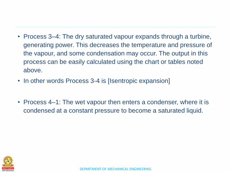
• Process 3–4: The dry saturated vapour expands through a turbine,
generating power. This decreases the temperature and pressure of
the vapour, and some condensation may occur. The output in this
process can be easily calculated using the chart or tables noted
above.
• In other words Process 3-4 is [Isentropic expansion]
• Process 4–1: The wet vapour then enters a condenser, where it is
condensed at a constant pressure to become a saturated liquid.
DEPARTMENT OF MECHANICAL ENGINEERING
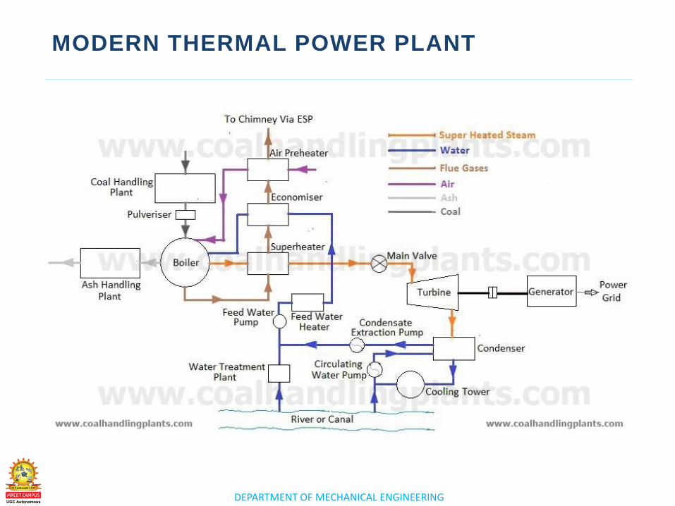
MODERN THERMAL POWER PLANT
DEPARTMENT OF MECHANICAL ENGINEERING
FOUR CIRCUITS
• Coal and Ash circuit
• Water and steam circuit
• Air and flue gas circuit
• Cooling water circuit
(PDF)

www.mrcet.ac.in
THANK YOU

www.mrcet.ac.in
LECTURE 3
Introduction - Resultants of Force System
DEPARTMENT OF MECHANICAL ENGINEERING
LECTURE 3
o Super critical boilers
o FBC boilers
o Classification and working
Super critical
boilers, FBC boilers
Classification and
working
TOPICS TO BE COVERED
DEPARTMENT OF MECHANICAL ENGINEERING
SUPER CRITICAL BOILERS
Supercritical Boilers
• B&W's supercritical and ultra-supercritical boiler designs offer
the flexibility and reliability to meet the most demanding steam
generation needs of our customers.
• At supercritical pressures, steam turbine efficiency improves
significantly compared to the typical subcritical cycle. Ultra-
supercritical steam conditions provide even greater efficiency
improvements. The combination of utilizing supercritical throttle
pressures along with an increase in throttle temperatures results in
cost reductions in fuel usage and handling, flue gas treatment and
ash disposal. B&W's supercritical and ultra-supercritical boilers
are designed to take full advantage of variable pressure turbine
operation.
DEPARTMENT OF MECHANICAL ENGINEERING
SUPER CRITICAL BOILERS
Specific advantages include:
• For a given output, lower fuel consumption, and thus lower carbon
emissions, than other less efficient systems
• The load change rate capability of the system is not restricted by
the turbine
• Steam temperature at the inlet and outlet of the reheater is nearly
constant over a wide load range
• The boiler feed water pump power is significantly reduced at lower
loads
• Short startup times
• Higher plant efficiency over the entire load range (PDF
attachment)
DEPARTMENT OF MECHANICAL ENGINEERING
FBC BOILERS
Fluidized bed combustion (FBC) is a combustion technology used to
burn solid fuels. ... Limestone is used to precipitate out sulfate during
combustion, which also allows more efficient heat transfer from the
boiler to the apparatus used to capture the heat energy (usually
water tubes).
Fluidized Bed Combustion takes place when the forced draught fan
supplies air to the Furnace of the Boiler. In the furnace, sand is (used
for Bubbling phenomenon) placed on the Bed and is heated before
fluidization, the air enters the bed from the nozzles fitted on the
Furnace Bed. (PDF ATTACHMENT)

www.mrcet.ac.in
THANK YOU

www.mrcet.ac.in
LECTURE 4
Introduction - Resultants of Force System
DEPARTMENT OF MECHANICAL ENGINEERING
LECTURE 4
o Condensers
o Classification, working
o Steam and Heat rate
Condensers,
classification,
working, Steam and
Heat rate
TOPICS TO BE COVERED
DEPARTMENT OF MECHANICAL ENGINEERING
CONDENSERS
• A condenser is designed to transfer heat from a working fluid (e.g.
water in a steam power plant) to a secondary fluid or the
surrounding air. The condenser relies on the efficient heat transfer
that occurs during phase changes, in this case during the
condensation of a vapor into a liquid.
• Inside the condenser, the refrigerant vapor is compressed and
forced through a heat exchange coil, condensing it into a liquid and
rejecting the heat previously absorbed from the cool indoor area.
The condenser's heat exchanger is generally cooled by a fan
blowing outside air through it.
DEPARTMENT OF MECHANICAL ENGINEERING
• The function of the condenser is to condense exhaust steam from
the steam turbine by rejecting the heat of vaporisation to the
cooling water passing through the condenser. The temperature of
the condensate determines the pressure in the steam/condensate
side of the condenser
• The main difference between the compressor and condenser is
indicated by their names, respectively. In a nutshell, the
compressor compresses and the condenser condenses. ... Keep in
mind, the refrigerant is a gas as it travels through the compressor –
still a gas, yet slightly altered in order to be made into liquid vapor.
DEPARTMENT OF MECHANICAL ENGINEERING
• The evaporator coil contains cold refrigerant that absorbs heat
from your air. The condenser coil is where the refrigerant goes to
get rid of this heat so it can come back to absorb more. The
evaporator coil is located indoors, inside or near your air handler.
• A/C condenser is a radiator positioned between the car's grille and
the radiator for the motor. In the condenser, the gaseous refrigerant
sheds heat and returns to a liquid state. In other words, the
condenser condenses the refrigerant from a gas to a liquid.
DEPARTMENT OF MECHANICAL ENGINEERING
• Initially the refrigerant is sent to compressor where its pressure is
raised. Next the refrigerant flows through the condenser(The black
wire casing you see on back of your refrigerator), where it
condenses from vapor form to liquid form(by convection), giving off
heat in the process.
Classification
• Water cooled
• Air cooled and
• Evaporative (PDF)

www.mrcet.ac.in
THANK YOU

www.mrcet.ac.in
LECTURE 5
Introduction - Resultants of Force System

DEPARTMENT OF MECHANICAL ENGINEERING
LECTURE 5
o Sub systems of thermal power
plant
o Coal and Ash handling
Sub systems of
thermal power
plant, Coal and Ash
handling
TOPICS TO BE COVERED
DEPARTMENT OF MECHANICAL ENGINEERING
SUB SYSTEMS OF THERMAL POWER PLANT
• Boiler make-up water treatment plant and storage.
• Fuel preparation system.
• Barring gear.
• Oil system.
• Generator cooling.
• Generator high-voltage system.
• Monitoring and alarm system.
• Battery-supplied emergency lighting and communication.
DEPARTMENT OF MECHANICAL ENGINEERING
COAL AND ASH HANDLING
• Ash handling refers to the method of collection, conveying,
interim storage and load out of various types of ash residue left
over from solid fuel combustion processes. The most common
types of ash resulting from the combustion of coal, wood and other
solid fuels. bottom ash.
• INPLANT COAL HANDLING The In-Plant coal handling
system deals with feeding of coal from live storage to the furnace.
It includes various equipment's for transfer of coal like belt
conveyor, screw conveyor etc. & the equipment needed to weigh
the quantity of coal for feed.
DEPARTMENT OF MECHANICAL ENGINEERING
COAL AND ASH HANDLING
• When burning solid fuel, typically coal, which contains a significant
amount of ash, an ash handling system is essential to keep the
boiler in service. ... This ash is collected in hoppers in the flue gas
path and removed from the gases leaving the boiler by electrostatic
precipitators or bag houses.
• PDF Attachment

www.mrcet.ac.in
THANK YOU

www.mrcet.ac.in
LECTURE 6
Introduction - Resultants of Force System
DEPARTMENT OF MECHANICAL ENGINEERING
LECTURE 6
o Draught System
o Feed water treatment
Draught System
and Feed water
treatment
TOPICS TO BE COVERED

DEPARTMENT OF MECHANICAL ENGINEERING
DRAUGHT SYSTEM
• Boiler draught is the pressure difference required to maintain
constant flow of air into the furnace and to discharge the flue gases
to the atmosphere through a chimney. Thus, boiler draught is one
of the most essential system.
• Boiler draught may be defined as the small difference between the
pressure of outside air and that of gases within a furnace or
chimney at the grate level, which causes the flow of air/hot flue
gases to take place through the boiler. Draught is maintained
inside boilers using fans.
DEPARTMENT OF MECHANICAL ENGINEERING
DRAUGHT SYSTEM
• PDF ATTACHMENT
DEPARTMENT OF MECHANICAL ENGINEERING
FEED WATER TREATMENT
• Boiler Feed Water Treatment for Industrial Boilers and Power
Plants. In the steam boiler industry, high purity feed water is
required to ensure proper operation of steam generation systems.
When a boiler is used to run a steam turbine, turbine blade erosion
is reduced due to higher purity steam generated.
• Boiler water is treated to prevent scaling, corrosion, foaming, and
priming. Chemicals are put into boiler water through the chemical
feed tank to keep the water within chemical range. These
chemicals are mostly oxygen scavengers and phosphates.

DEPARTMENT OF MECHANICAL ENGINEERING
FEED WATER TREATMENT
Coagulation and chemical precipitation
• After all the large objects are removed from the original water
source, various chemicals are added to a reaction tank to remove
the bulk suspended solids and other various contaminants
• A boiler feed water treatment system is a system made up of
several individual technologies that address your specific boiler
feed water treatment needs.
DEPARTMENT OF MECHANICAL ENGINEERING
FEED WATER TREATMENT
Treating boiler feed water is essential for both high- and low-
pressure boilers. Ensuring the correct treatment is implemented
before problems such as fouling, scaling, and corrosion occur, will go
a long way in avoiding costly replacements/upgrades down the line.
An efficient and well-designed boiler feed water treatment
system should be able to:
• Efficiently treat boiler feed water and remove harmful impurities
prior to entering the boiler
• Promote internal boiler chemistry control
• Maximize use of steam condensate
• Control return-line corrosion
• Avoid plant downtime and boiler failure
• Prolong equipment service life
DEPARTMENT OF MECHANICAL ENGINEERING
FEED WATER TREATMENT
• A boiler feed water treatment system might be made up of the
technologies necessary to remove problematic dissolved solids,
suspended solids, and organic material, including any number
of the following:
• Iron: either soluble or insoluble, iron can deposit on boiler parts
and tubes, damage downstream equipment, and affect the quality
of certain manufacturing processes
• Copper: can cause deposits to settle in high-pressure turbines,
decreasing their efficiency and requiring costly cleaning or
equipment change-outs
• Silica: if not removed to low levels, especially in high-pressure
boilers, silica can cause extremely hard scaling
DEPARTMENT OF MECHANICAL ENGINEERING
FEED WATER TREATMENT
• Calcium: can cause scaling in several forms depending on the
chemistry of the boiler feed water (e.g. calcium silicate, calcium
phosphate, etc.)
• Magnesium: if combined with phosphate, magnesium can stick to
the interior of the boiler and coat tubes, attracting more solids and
contributing to scale
• Aluminum: deposits as scale on the boiler interior and can react
with silica to increase the likelihood of scaling
• Hardness: also causes deposits and scale on boiler parts and
piping
• Dissolved gasses: chemical reactions due to the presence of
dissolved gases such as oxygen and carbon dioxide can cause
severe corrosion on boiler pipes and parts

www.mrcet.ac.in
THANK YOU

www.mrcet.ac.in
LECTURE 7
Introduction - Resultants of Force System
DEPARTMENT OF MECHANICAL ENGINEERING
LECTURE 7
o Binary Cycles
o Cogeneration systems
Binary Cycles and
Cogeneration
systems
TOPICS TO BE COVERED
DEPARTMENT OF MECHANICAL ENGINEERING
BINARY CYCLES
DEPARTMENT OF MECHANICAL ENGINEERING
BINARY CYCLES
DEPARTMENT OF MECHANICAL ENGINEERING
BINARY CYCLES
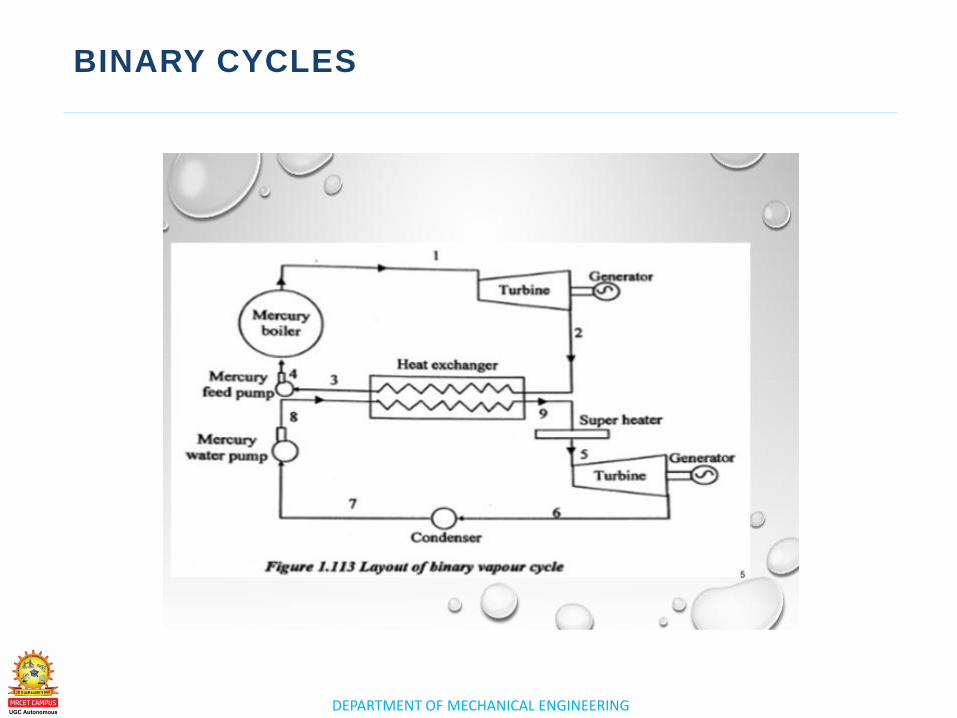
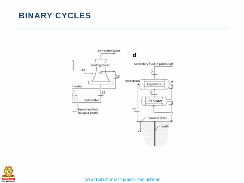
Binary Cycle Power Plant
• Low to moderately heated (below 400°F) geothermal fluid and a
secondary (hence, "binary") fluid with a much lower boiling point
that water pass through a heat exchanger. Binary cycle power
plants are closed-loop systems, and virtually nothing (except water
vapor) is emitted to the atmosphere.
• A binary cycle power plant is a type of geothermal power plant that
allows cooler geothermal reservoirs to be used than is necessary
for dry steam and flash steam plants
DEPARTMENT OF MECHANICAL ENGINEERING
BINARY CYCLES
• Binary Power Plants. Binary plants, like dry-steam and flash-steam
plants, make use of naturally sourced hot steam generated by
activity from within the Earth's core. All geothermal plants convert
thermal energy to mechanical energy, then finally to electrical
energy.
• The vapor exiting the turbine is then condensed by cold air
radiators or cold water and cycled back through the heat
exchanger. A binary vapor cycle is defined in thermodynamics as a
power cycle that is a combination of two cycles, one in a high
temperature region and the other in a lower temperature region.
DEPARTMENT OF MECHANICAL ENGINEERING
COGENERATION SYSTEMS
DEPARTMENT OF MECHANICAL ENGINEERING
COGENERATION SYSTEMS
DEPARTMENT OF MECHANICAL ENGINEERING
COGENERATION SYSTEMS
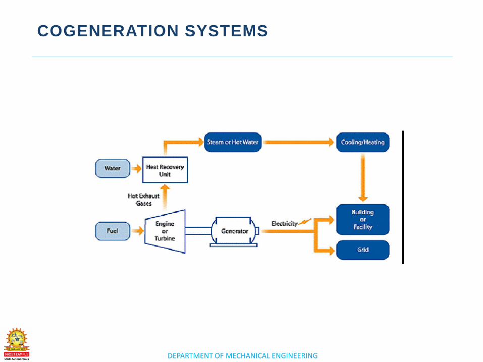
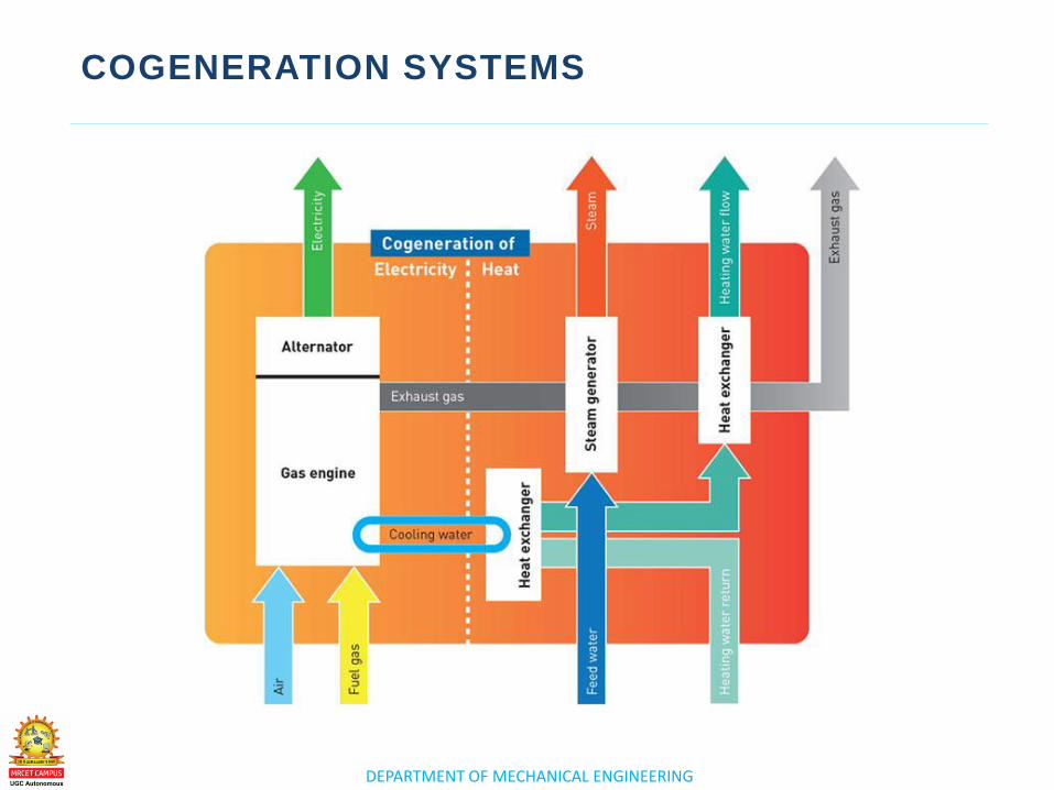
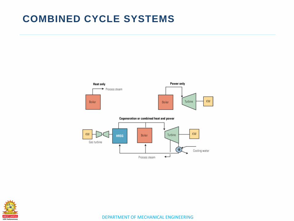
• Cogeneration—also known as combined heat and power,
distributed generation, or recycled energy—is the simultaneous
production of two or more forms of energy from a single fuel
source. Cogeneration power plants often operate at 50 to 70
percent higher efficiency rates than single-generation facilities
• A conventional power plant makes electricity by a fairly inefficient
process. A fossil fuel such as oil, coal, or natural gas is burned in a
giant furnace to release heat energy. ... Cogeneration (the
alternative name for CHP) simply means that the electricity and
heat are made at the same time.
DEPARTMENT OF MECHANICAL ENGINEERING
COGENERATION SYSTEMS
• Cogeneration is a more efficient use of fuel because otherwise-
wasted heat from electricity generation is put to some productive
use.This is also called combined heat and power district heating.
Small CHP plants are an example of decentralized energy.
• Cogeneration is the process of producing electricity from steam (or
other hot gases) and using the waste heat as steam in chemical
processes. In contrast, a stand-alone power-producing plant
typically converts less than 40% of the heat energy of fuel (coal,
natural gas, nuclear, etc.) into electricity.

DEPARTMENT OF MECHANICAL ENGINEERING
ASSIGNMENT QUESTIONS

www.mrcet.ac.in
THANK YOU

www.mrcet.ac.in
POWER PLANT ENGINEERING
(R17A0326) 4th Year B. Tech I- sem, Mechanical Engineering

DEPARTMENT OF MECHANICAL ENGINEERING
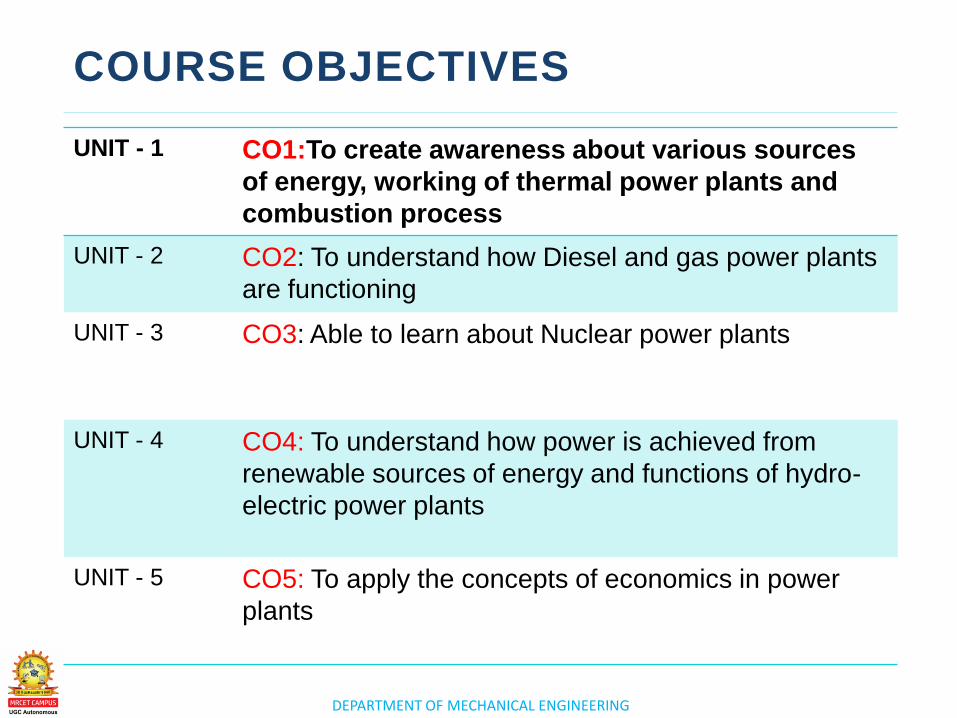
COURSE OBJECTIVES
UNIT - 1 CO1:To create awareness about various sources
of energy, working of thermal power plants and
combustion process
UNIT - 2 CO2: To understand how Diesel and gas power plants
are functioning
UNIT - 3
CO3: To understand how power is achieved from
renewable sources of energy and functions of hydro-
electric power plants
UNIT - 4 CO4: Able to learn about Nuclear power plants
UNIT - 5 CO5: To apply the concepts of economics in power
plants
www.mrcet.ac.in
UNIT 2
CO2:To understand how Diesel and gas power plants are
functioning
D I E S E L , G A S T U R B I N E A N D
C O M B I N E D C Y C L E P O W E R P L A N T S
DEPARTMENT OF MECHANICAL ENGINEERING
UNIT – II (SYLLABUS)
DIESEL AND GAS TURBINE POWER PLANTS
• Otto, Diesel, Dual & Brayton Cycle
• Analysis & Optimization.
• Components of Diesel and Gas Turbine power plants
COMBINED CYCLE POWER PLANTS:
• Combined Cycle Power Plants.
• Integrated Gasifier based Combined Cycle systems.
DEPARTMENT OF MECHANICAL ENGINEERING
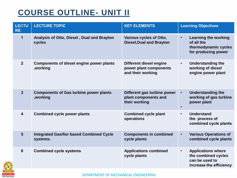
COURSE OUTLINE- UNIT II
LECTU
RE
LECTURE TOPIC KEY ELEMENTS Learning Objectives
1 Analysis of Otto, Diesel , Dual and Brayton
cycles
Various cycles of Otto,
Diesel,Dual and Brayton
• Learning the working
of all the
thermodynamic cycles
for producing power
2 Components of diesel engine power plants
,working
Different diesel engine
power plant components
and their working
• Understanding the
working of diesel
engine power plant
3 Components of Gas turbine power plants
,working
Different gas turbine power
plant components and
their working
• Understanding the
working of gas turbine
power plant
•
4 Combined cycle power plants Combined cycle plant
operations
• Understand
the process of
combined cycle plants
5 Integrated Gasifier based Combined Cycle
systems.
Components in combined
cycle plants
• Various Operations of
combined cycle plants
6 Combined cycle systems Applications combined
cycle plants
• Applications where
the combined cycles
can be used to
increase the efficiency
www.mrcet.ac.in
LECTURE 1
Analysis of Otto, Diesel ,
Dual and Brayton cycles
DEPARTMENT OF MECHANICAL ENGINEERING
LECTURE 1
o Analysis of Otto, Diesel , Dual and
Brayton cycles
Analysis of Otto, Diesel ,
Dual and Brayton cycles
TOPICS TO BE COVERED
DEPARTMENT OF MECHANICAL ENGINEERING
OTTO CYCLE
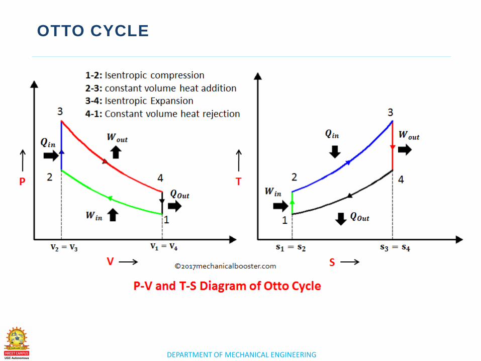
. An Otto cycle is an idealized thermodynamic
cycle that describes the functioning of a
typical spark ignition piston engine. It is the
thermodynamic cycle most commonly found in
automobile engines.
An Otto cycle is an idealized thermodynamic
cycle that describes the functioning of a
typical spark ignition piston engine. It is the
thermodynamic cycle most commonly found in
automobile engines.
DEPARTMENT OF MECHANICAL ENGINEERING
OTTO CYCLE
– .
DEPARTMENT OF MECHANICAL ENGINEERING
DIESEL CYCLE
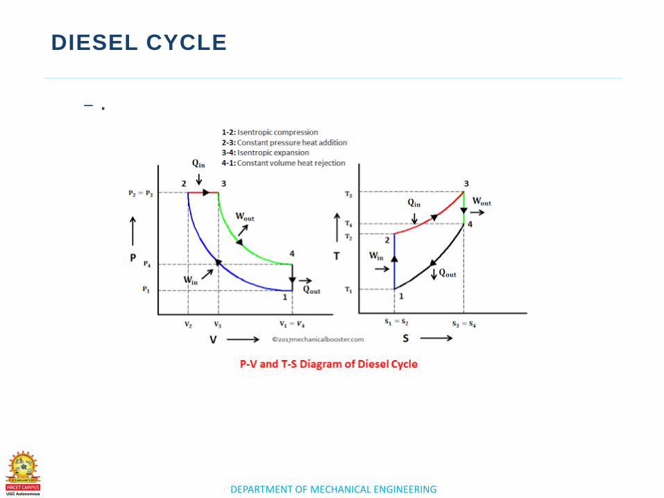
. The Diesel cycle is a combustion process of a
reciprocating internal combustion engine. In it, fuel is
ignited by heat generated during the compression of
air in the combustion chamber, into which fuel is then
injected.
The Diesel cycle is a combustion process of a
reciprocating internal combustion engine. In it, fuel is
ignited by heat generated during the compression of
air in the combustion chamber, into which fuel is then
injected. This is in contrast to igniting the fuel-air
mixture with a spark plug as in the Otto cycle engine.
DEPARTMENT OF MECHANICAL ENGINEERING
DIESEL CYCLE
– .
DEPARTMENT OF MECHANICAL ENGINEERING
DUAL CYCLE
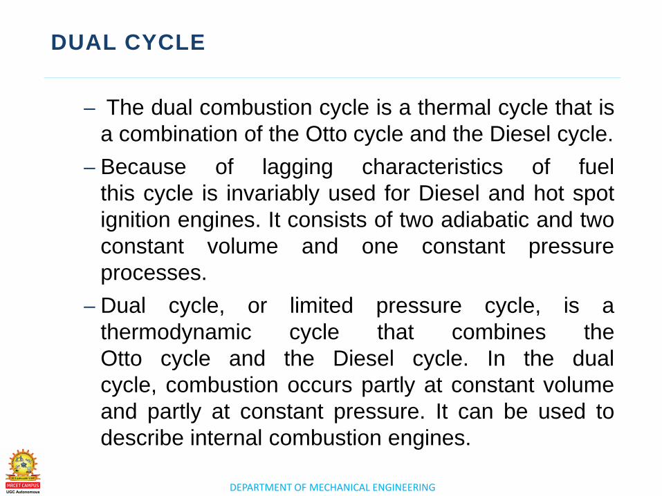
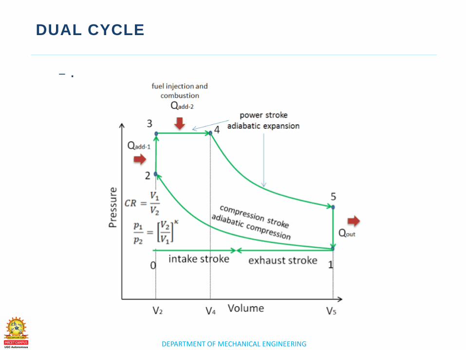
– The dual combustion cycle is a thermal cycle that is
a combination of the Otto cycle and the Diesel cycle.
– Because of lagging characteristics of fuel
this cycle is invariably used for Diesel and hot spot
ignition engines. It consists of two adiabatic and two
constant volume and one constant pressure
processes.
– Dual cycle, or limited pressure cycle, is a
thermodynamic cycle that combines the
Otto cycle and the Diesel cycle. In the dual
cycle, combustion occurs partly at constant volume
and partly at constant pressure. It can be used to
describe internal combustion engines.
DEPARTMENT OF MECHANICAL ENGINEERING
DUAL CYCLE
– .
DEPARTMENT OF MECHANICAL ENGINEERING
BRAYTON CYCLE
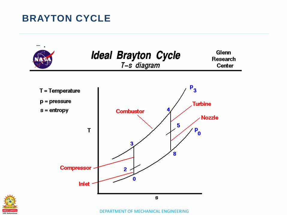
– The Brayton cycle is a thermodynamic cycle named after George Brayton that describes the workings of a constant-pressure heat engine. The original Brayton engines used a piston compressor and piston expander, but more modern gas turbine engines and air breathing jet engines also follow the Brayton cycle.
– Brayton cycle. A thermodynamic cycle using constant pressure, heat addition and rejection. Fuel and a compressor are used to heat and increase the pressure of a gas; the gas expands and spins the blades of a turbine, which, when connected to a generator, generates electricity.
DEPARTMENT OF MECHANICAL ENGINEERING
BRAYTON CYCLE
– .

www.mrcet.ac.in
THANK YOU

www.mrcet.ac.in
LECTURE 2
Introduction - Resultants of Force System
DEPARTMENT OF MECHANICAL ENGINEERING
LECTURE 2
o Components of diesel engine power
plants
o working
Components of
diesel engine
power plants
,working
TOPICS TO BE COVERED
DEPARTMENT OF MECHANICAL ENGINEERING
DIESEL ENGINE POWER PLANT
– A Diesel Power Plant is wherein the prime mover of
an alternator is a diesel engine. Using a diesel
engine has its own pros and cons. Installation and
operation are easier as compared to other power
plants.
– In a diesel power station, diesel engine is used as
the prime mover. The diesel burns inside the engine
and the products of this combustion act as
the working fluid to produce mechanical energy.
The diesel engine drives alternator which converts
mechanical energy into electrical energy.
DEPARTMENT OF MECHANICAL ENGINEERING
DIESEL ENGINE POWER PLANT
DEPARTMENT OF MECHANICAL ENGINEERING
DIESEL ENGINE POWER PLANT
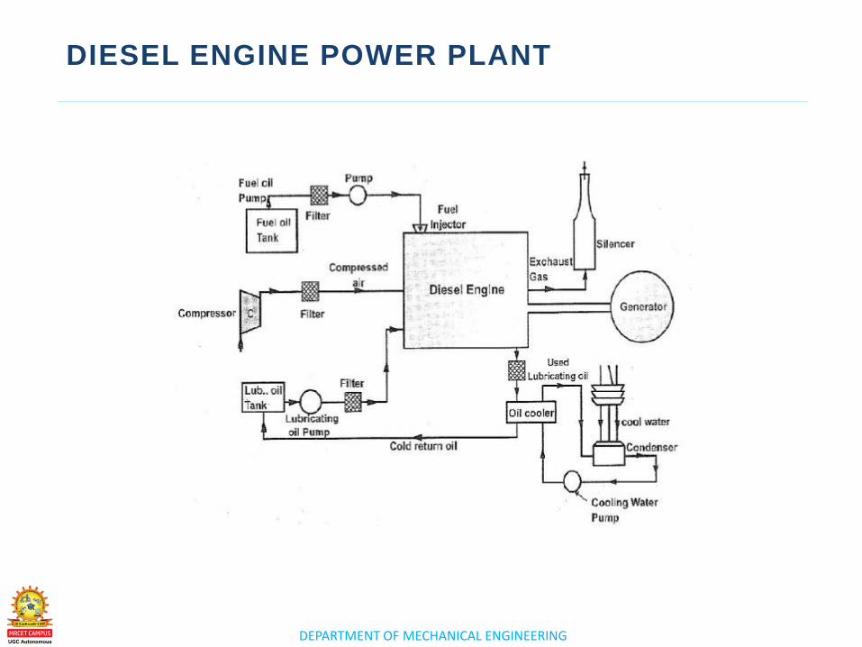
Component s of Diesel Power Plants–Lecture Notes
– Engine.
– Air Intake System.
– Engine Starting system.
– Fuel System.
– Exhaust System.
– Cooling System.
– Lubricating System.
PDF attachment

www.mrcet.ac.in
THANK YOU

www.mrcet.ac.in
LECTURE 3
Introduction - Resultants of Force System
DEPARTMENT OF MECHANICAL ENGINEERING
LECTURE 3
o Components of Gas turbine
power plants
o working
Components of
Gas turbine power
plants ,working
TOPICS TO BE COVERED
DEPARTMENT OF MECHANICAL ENGINEERING
GAS TURBINE POWER PLANT
Gas turbine power plant
The combustion (gas) turbines being installed in many of
today's natural-gas-fueled power plants are complex
machines, but they basically involve three main sections:
The compressor, which draws air into the engine,
pressurizes it, and feeds it to the combustion chamber at
speeds of hundreds of miles per hour.
Gas turbines are used to power aircraft, trains,
ships, electrical generators, pumps, gas compressors,
and tanks.
DEPARTMENT OF MECHANICAL ENGINEERING
GAS TURBINE POWER PLANT LAYOUT
DEPARTMENT OF MECHANICAL ENGINEERING
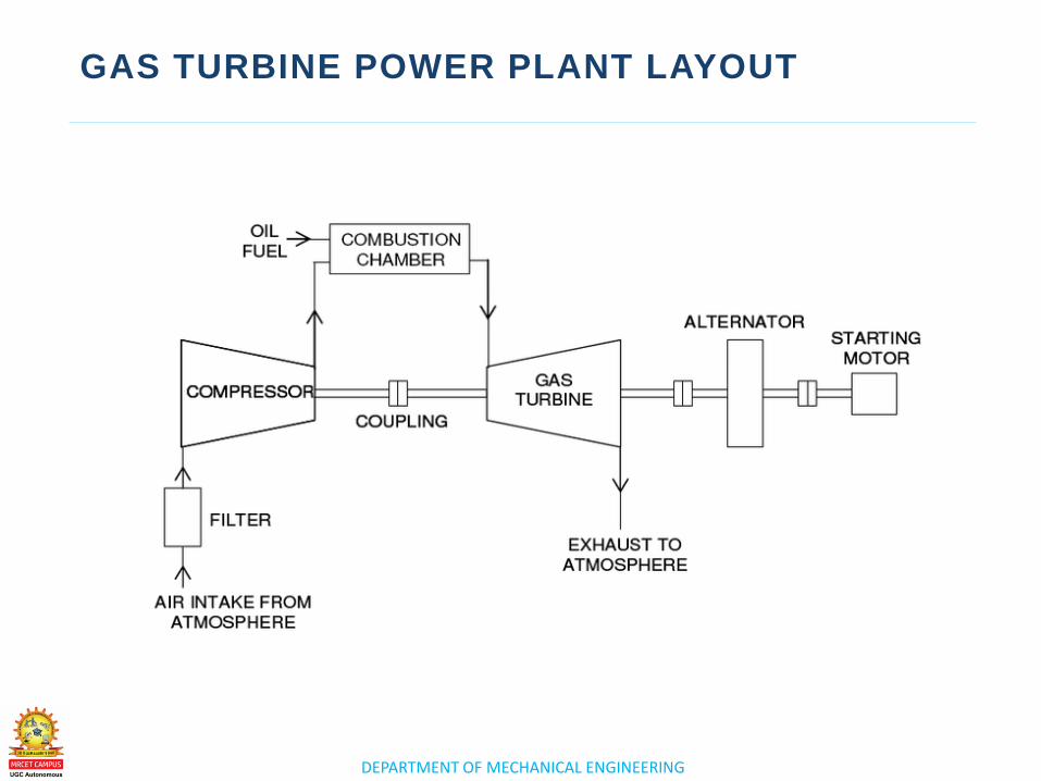
GAS TURBINE POWER PLANT
The gas turbine is made up of the following
components:
• An air compressor.
• A combustor.
• A power turbine, which produces the power to drive the
air compressor and the output shaft.
PDF attachment

www.mrcet.ac.in
THANK YOU

www.mrcet.ac.in
LECTURE 4
Introduction - Resultants of Force System
DEPARTMENT OF MECHANICAL ENGINEERING
LECTURE 4
o Combined cycle power plants
Combined cycle
power plants
TOPICS TO BE COVERED
DEPARTMENT OF MECHANICAL ENGINEERING
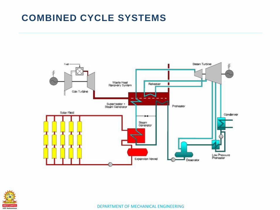
COMBINED CYCLE POWER PLANTS
– A combined cycle power plant is an assembly of heat engines that work in tandem from the same source of heat, converting it into mechanical energy. On land, when used to make electricity the most common type is called a combined cycle gas turbine plant.
– A combined-cycle power plant uses both a gas and a steam turbine together to produce up to 50 percent more electricity from the same fuel than a traditional simple-cycle plant. The waste heat from the gas turbine is routed to the nearby steam turbine, which generates extra power.
DEPARTMENT OF MECHANICAL ENGINEERING
COMBINED CYCLE POWER PLANTS
– A Combined Cycle Power Plant produces
high power outputs at high efficiencies (up to 55%)
and with low emissions. In a Conventional power
plant we are getting 33% electricity only and
remaining 67% as waste.
– The major components of a combined cycle plant
are a gas turbine, a heat recovery steam generator,
a steam turbine, and balance of plant systems.
DEPARTMENT OF MECHANICAL ENGINEERING
COMBINED CYCLE POWER PLANTS
– A combined-cycle power plant uses both a gas and
a steam turbine together to produce up to 50
percent more electricity from the same fuel than a
traditional simple-cycle plant. The waste heat from
the gas turbine is routed to the nearby steam
turbine, which generates extra power.
– Co-generations uses waste heat for many different
processes, such as space heating or drying.
Combined-cycle power generation is a two-cycle
electricity generation process that uses the heat
from the first cycle to run a second cycle.
– PDF attachment
DEPARTMENT OF MECHANICAL ENGINEERING
COMBINED CYCLE POWER PLANTS

www.mrcet.ac.in
THANK YOU

www.mrcet.ac.in
LECTURE 5
Introduction - Resultants of Force System
DEPARTMENT OF MECHANICAL ENGINEERING
LECTURE 5
o Integrated Gasifier based
Combined Cycle systems
Integrated Gasifier
based Combined
Cycle systems
TOPICS TO BE COVERED
DEPARTMENT OF MECHANICAL ENGINEERING
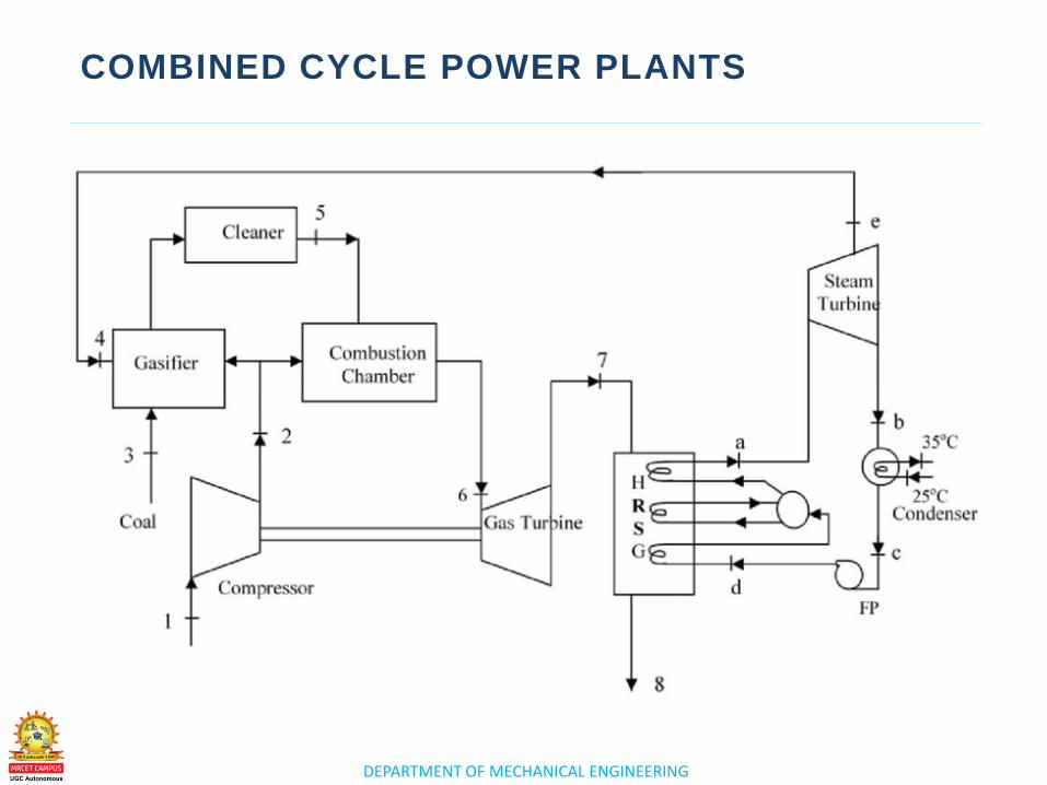
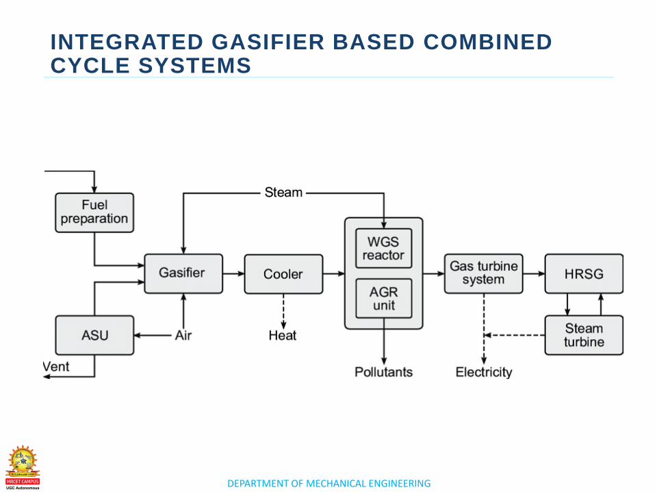
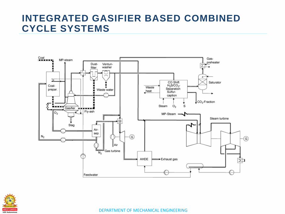
INTEGRATED GASIFIER BASED COMBINED CYCLE SYSTEMS
– An integrated gasification combined cycle is a
technology that uses a high pressure gasifier to turn
coal and other carbon based fuels into pressurized
gas—synthesis gas. It can then remove impurities
from the syngas prior to the power generation
cycle.
– Integrated coal gasification combined cycle
(IGCC) power plants are a next-
generation thermal power system with significantly
enhanced power generation efficiency and environmental
performance due to its combination with coal gasification
and the Gas Turbine Combined Cycle (GTCC) system.
•
DEPARTMENT OF MECHANICAL ENGINEERING
INTEGRATED GASIFIER BASED COMBINED CYCLE SYSTEMS
– A combined-cycle power plant uses both a gas and
a steam turbine together to produce up to 50
percent more electricity from the same fuel than a
traditional simple-cycle plant. The waste heat from
the gas turbine is routed to the nearby steam
turbine, which generates extra power.
– Combined Cycle Gas Turbines (CCGT)are a form of
highly efficient energy generation technology that
combines a gas-fired turbine with a steam turbine.
DEPARTMENT OF MECHANICAL ENGINEERING
INTEGRATED GASIFIER BASED COMBINED CYCLE SYSTEMS
DEPARTMENT OF MECHANICAL ENGINEERING
INTEGRATED GASIFIER BASED COMBINED CYCLE SYSTEMS

www.mrcet.ac.in
THANK YOU

www.mrcet.ac.in
LECTURE 6
Introduction - Resultants of Force System

DEPARTMENT OF MECHANICAL ENGINEERING
LECTURE 6
o Combined cycle systems Combined cycle
systems
TOPICS TO BE COVERED
DEPARTMENT OF MECHANICAL ENGINEERING
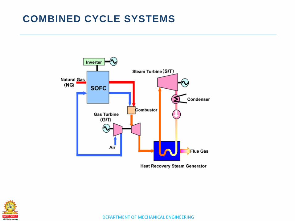
COMBINED CYCLE SYSTEMS
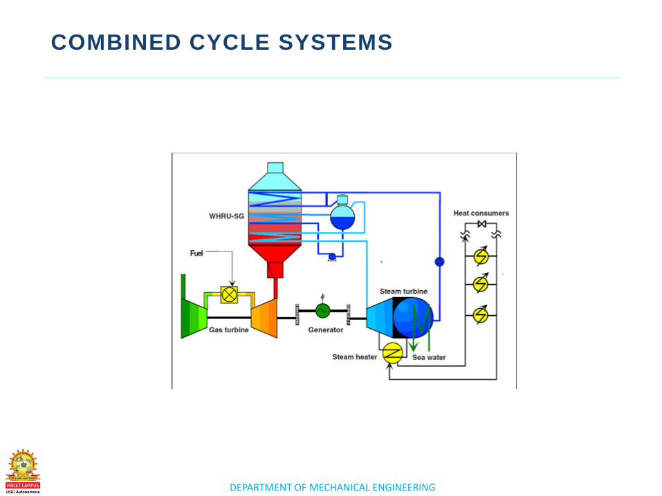
DEPARTMENT OF MECHANICAL ENGINEERING
COMBINED CYCLE SYSTEMS
DEPARTMENT OF MECHANICAL ENGINEERING
COMBINED CYCLE SYSTEMS
DEPARTMENT OF MECHANICAL ENGINEERING
COMBINED CYCLE SYSTEMS

DEPARTMENT OF MECHANICAL ENGINEERING
ASSIGNMENT QUESTIONS

DEPARTMENT OF MECHANICAL ENGINEERING
ASSIGNMENT QUESTIONS

www.mrcet.ac.in
THANK YOU

www.mrcet.ac.in
POWER PLANT ENGINEERING
(R17A0326) 4th Year B. Tech I- sem, Mechanical Engineering
DEPARTMENT OF MECHANICAL ENGINEERING
COURSE OBJECTIVES
UNIT - 1 CO1:To create awareness about various sources
of energy, working of thermal power plants and
combustion process
UNIT - 2 CO2: To understand how Diesel and gas power plants
are functioning
UNIT - 3
CO3: Able to learn about Nuclear power plants
UNIT - 4 CO4: To understand how power is achieved from
renewable sources of energy and functions of hydro-
electric power plants
UNIT - 5 CO5: To apply the concepts of economics in power
plants
www.mrcet.ac.in
UNIT 3
CO3:To Able to learn about Nuclear power plants
N U C L E A R P O W E R P L A N T S
DEPARTMENT OF MECHANICAL ENGINEERING
UNIT-III (SYLLABUS)
NUCLEAR POWER PLANTS
• Basics of Nuclear Engineering, Layout and subsystems of Nuclear Power Plants
• Working of Nuclear Reactors : Boiling Water Reactor (BWR), Pressurized Water Reactor (PWR), Canada Deuterium- Uranium reactor (CANDU), Breeder, Gas Cooled and Liquid Metal Cooled Reactors.
• Safety measures for Nuclear Power plants.
NUCLEAR POWER PLANTS
DEPARTMENT OF MECHANICAL ENGINEERING
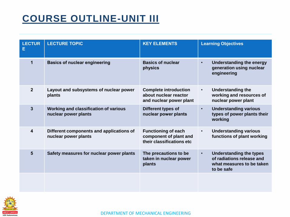
COURSE OUTLINE-UNIT III
LECTUR
E
LECTURE TOPIC KEY ELEMENTS Learning Objectives
1 Basics of nuclear engineering Basics of nuclear
physics
• Understanding the energy
generation using nuclear
engineering
2 Layout and subsystems of nuclear power
plants
Complete introduction
about nuclear reactor
and nuclear power plant
• Understanding the
working and resources of
nuclear power plant
3 Working and classification of various
nuclear power plants
Different types of
nuclear power plants
• Understanding various
types of power plants their
working
4 Different components and applications of
nuclear power plants
Functioning of each
component of plant and
their classifications etc
• Understanding various
functions of plant working
5 Safety measures for nuclear power plants The precautions to be
taken in nuclear power
plants
• Understanding the types
of radiations release and
what measures to be taken
to be safe
www.mrcet.ac.in
LECTURE 1
Basics of Nuclear
Engineering
DEPARTMENT OF MECHANICAL ENGINEERING
LECTURE 1
o Basics of Nuclear Engineering Basics of Nuclear
Engineering
TOPICS TO BE COVERED
DEPARTMENT OF MECHANICAL ENGINEERING
BASICS OF NUCLEAR ENGINEERING
Nuclear power is a clean and efficient way of boiling water to make steam, which turns turbines to produce electricity. Nuclear power plants use low-enriched uranium fuel to produce electricity through a process called fission—the splitting of uranium atoms in a nuclear reactor.
The process in which nuclear energy is produced in the
result of a series of steps:
• Splitting of Atoms. Uranium atoms, in the form of ceramic-
coated pellets, are placed in a reactor core.
• Absorption. Control rods are used to absorb the free floating
neurons released during the fission process.
• Heat.
• Water and Piping.
DEPARTMENT OF MECHANICAL ENGINEERING
BASICS OF NUCLEAR ENGINEERING
DEPARTMENT OF MECHANICAL ENGINEERING
BASICS OF NUCLEAR ENGINEERING
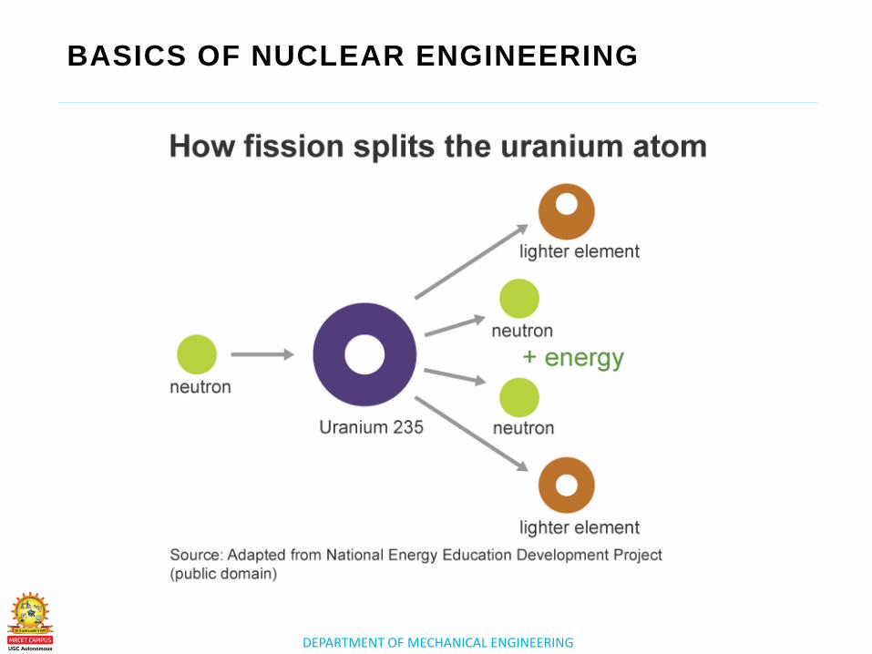
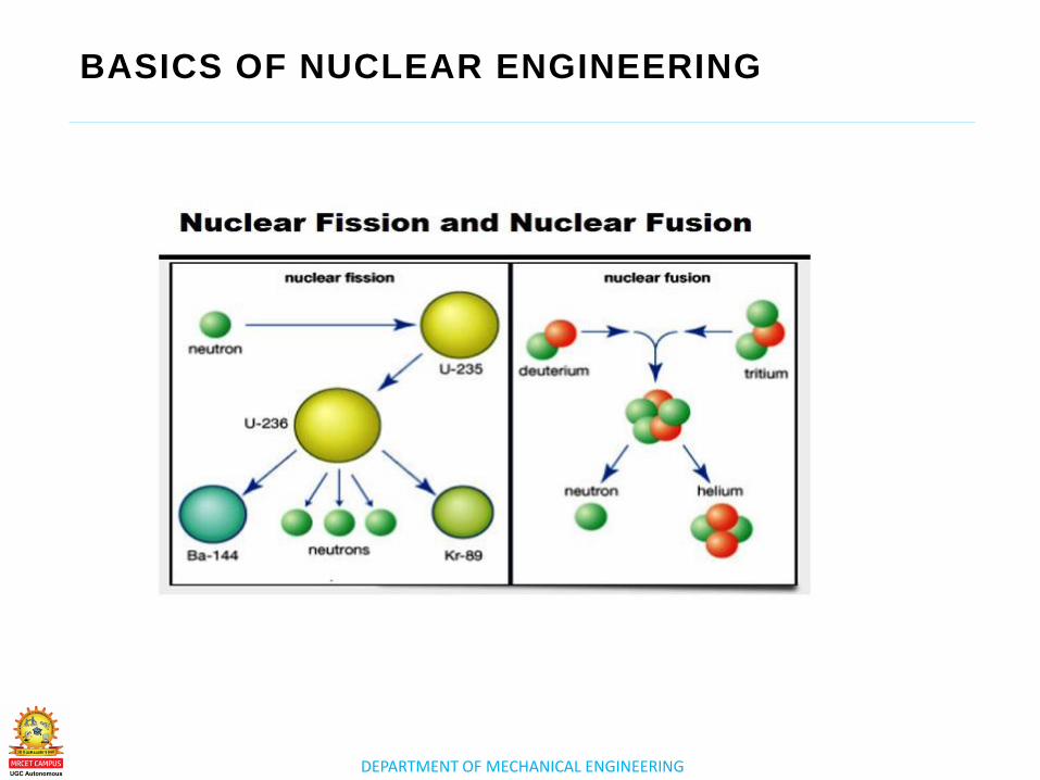
Nuclear fission products are the atomic fragments
left after a large atomic nucleus undergoes nuclear
fission. Typically, a large nucleus like that of uranium
fissions by splitting into two smaller nuclei, along with
a few neutrons, the release of heat energy (kinetic
energy of the nuclei), and gamma rays.
Fusion only produces more energy than it consumes
in small nuclei (in stars, Hydrogen & its isotopes
fusing into Helium). The energy released when 4
Hydrogen nuclei (= protons) fuse (there are some
decays involved as well) into a Helium nucleus is
around 27 Million Electron Volts (MeV), or about 7
MeV per nucleon.
DEPARTMENT OF MECHANICAL ENGINEERING
BASICS OF NUCLEAR ENGINEERING
DEPARTMENT OF MECHANICAL ENGINEERING
BASICS OF NUCLEAR ENGINEERING
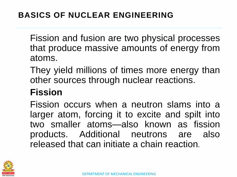
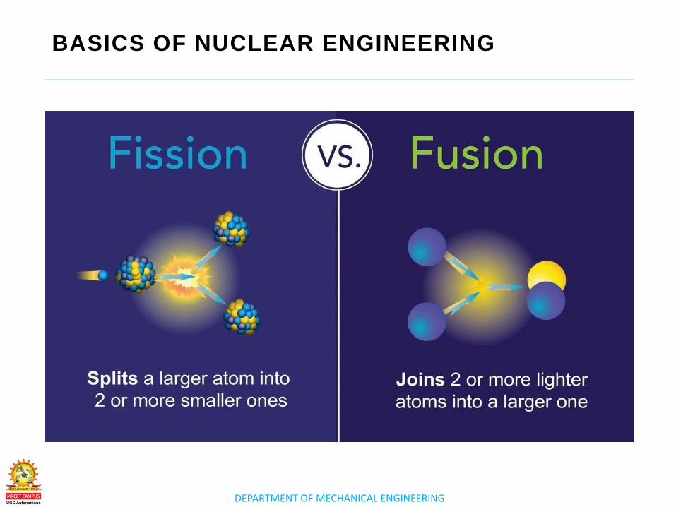
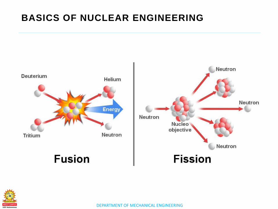
Fission and fusion are two physical processes that produce massive amounts of energy from atoms.
They yield millions of times more energy than other sources through nuclear reactions.
Fission
Fission occurs when a neutron slams into a larger atom, forcing it to excite and spilt into two smaller atoms—also known as fission products. Additional neutrons are also released that can initiate a chain reaction.
DEPARTMENT OF MECHANICAL ENGINEERING
BASICS OF NUCLEAR ENGINEERING
DEPARTMENT OF MECHANICAL ENGINEERING
BASICS OF NUCLEAR ENGINEERING
When each atom splits, a tremendous amount of energy is
released.
Uranium and plutonium are most commonly used for fission
reactions in nuclear power reactors because they are easy to
initiate and control
The energy released by fission in these reactors heats water into
steam. The steam is used to spin a turbine to produce carbon-free
electricity.
DEPARTMENT OF MECHANICAL ENGINEERING
BASICS OF NUCLEAR ENGINEERING
DEPARTMENT OF MECHANICAL ENGINEERING
BASICS OF NUCLEAR ENGINEERING
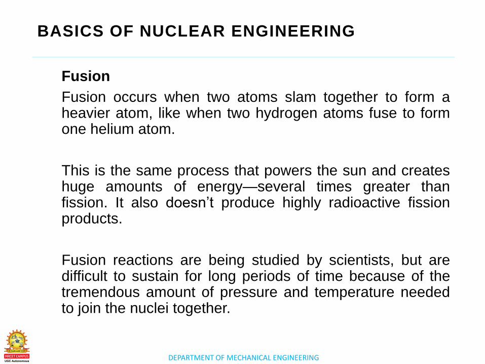
Fusion
Fusion occurs when two atoms slam together to form a heavier atom, like when two hydrogen atoms fuse to form one helium atom.
This is the same process that powers the sun and creates huge amounts of energy—several times greater than fission. It also doesn’t produce highly radioactive fission products.
Fusion reactions are being studied by scientists, but are difficult to sustain for long periods of time because of the tremendous amount of pressure and temperature needed to join the nuclei together.
DEPARTMENT OF MECHANICAL ENGINEERING
BASICS OF NUCLEAR ENGINEERING
DEPARTMENT OF MECHANICAL ENGINEERING
BASICS OF NUCLEAR ENGINEERING
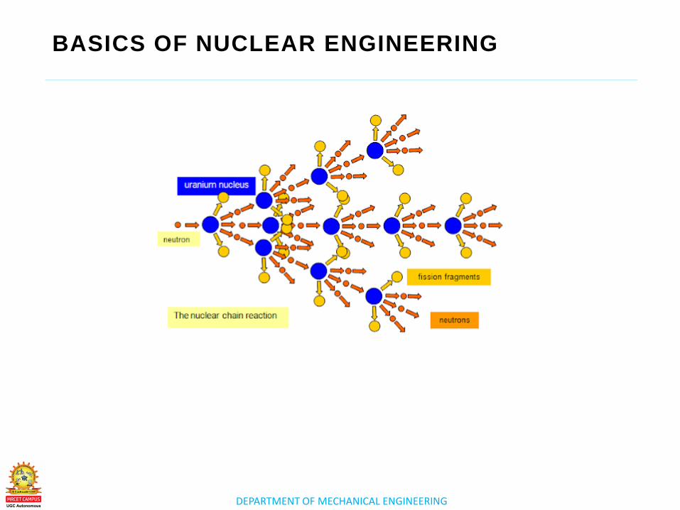
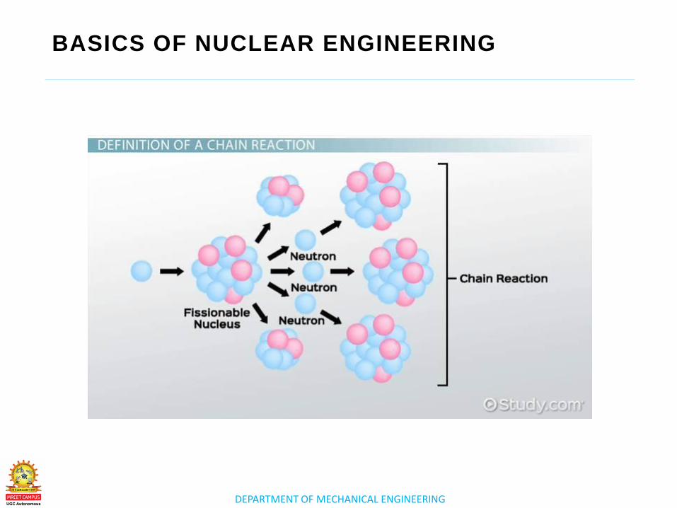
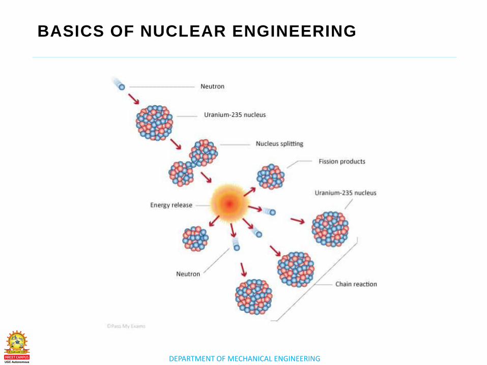
Chain Reaction
A self-sustaining reaction in which the fission
of nuclei of one generation of nuclei produces
particles that cause the fission of at least an
equal number of nuclei of the succeeding
generation.
For example, a single neutron causes the
nucleus of a uranium atom to undergo fission.
In the process, two or three more neutrons
are released.
DEPARTMENT OF MECHANICAL ENGINEERING
BASICS OF NUCLEAR ENGINEERING
DEPARTMENT OF MECHANICAL ENGINEERING
BASICS OF NUCLEAR ENGINEERING
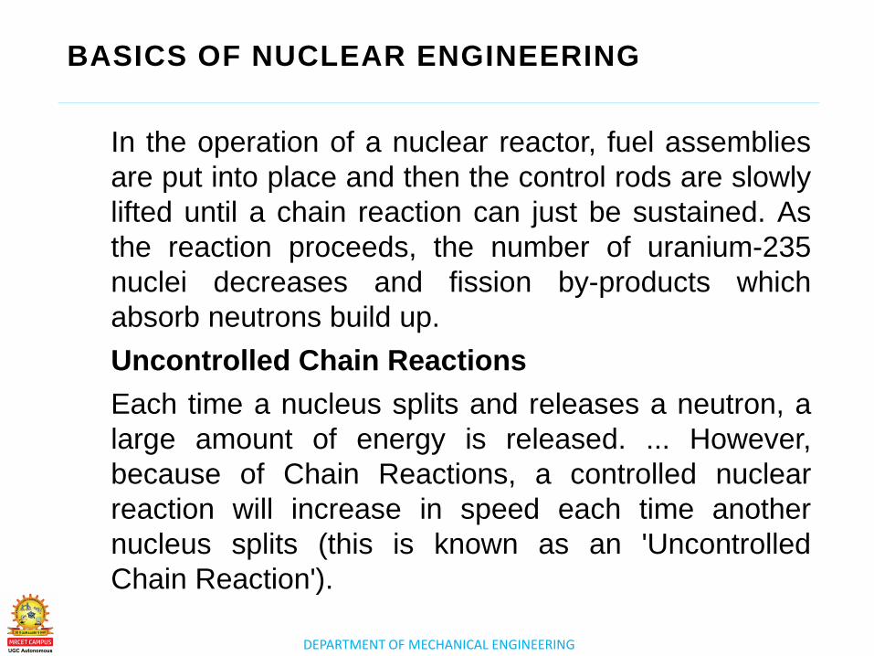
In the operation of a nuclear reactor, fuel assemblies
are put into place and then the control rods are slowly
lifted until a chain reaction can just be sustained. As
the reaction proceeds, the number of uranium-235
nuclei decreases and fission by-products which
absorb neutrons build up.
Uncontrolled Chain Reactions
Each time a nucleus splits and releases a neutron, a
large amount of energy is released. ... However,
because of Chain Reactions, a controlled nuclear
reaction will increase in speed each time another
nucleus splits (this is known as an 'Uncontrolled
Chain Reaction').
DEPARTMENT OF MECHANICAL ENGINEERING
BASICS OF NUCLEAR ENGINEERING
DEPARTMENT OF MECHANICAL ENGINEERING
BASICS OF NUCLEAR ENGINEERING
Water, heavy water, and graphite are good materials
for slowing down neutrons, and atoms with heavy
nuclei have good neutron capture cross-sections and
can absorb neutrons quickly. These materials are
used in control rods.
Nuclear Chain Reactions. A chain reaction refers to a
process in which neutrons released in fission produce
an additional fission in at least one further nucleus.
This nucleus in turn produces neutrons, and the
process repeats. The process may be controlled
(nuclear power) or uncontrolled (nuclear weapons).
DEPARTMENT OF MECHANICAL ENGINEERING
BASICS OF NUCLEAR ENGINEERING
The only way to control or stop a nuclear chain
reaction is to stop the neutrons from splitting more
atoms. Control rods made of a neutron-absorbing
element such as boron reduce the number of free
neutrons and take them out of the reaction.

www.mrcet.ac.in
THANK YOU

www.mrcet.ac.in
LECTURE 2
Introduction - Resultants of Force System
DEPARTMENT OF MECHANICAL ENGINEERING
LECTURE 2
o Layout and subsystems of
nuclear power plants
Layout and
subsystems of
nuclear power
plants
TOPICS TO BE COVERED
DEPARTMENT OF MECHANICAL ENGINEERING
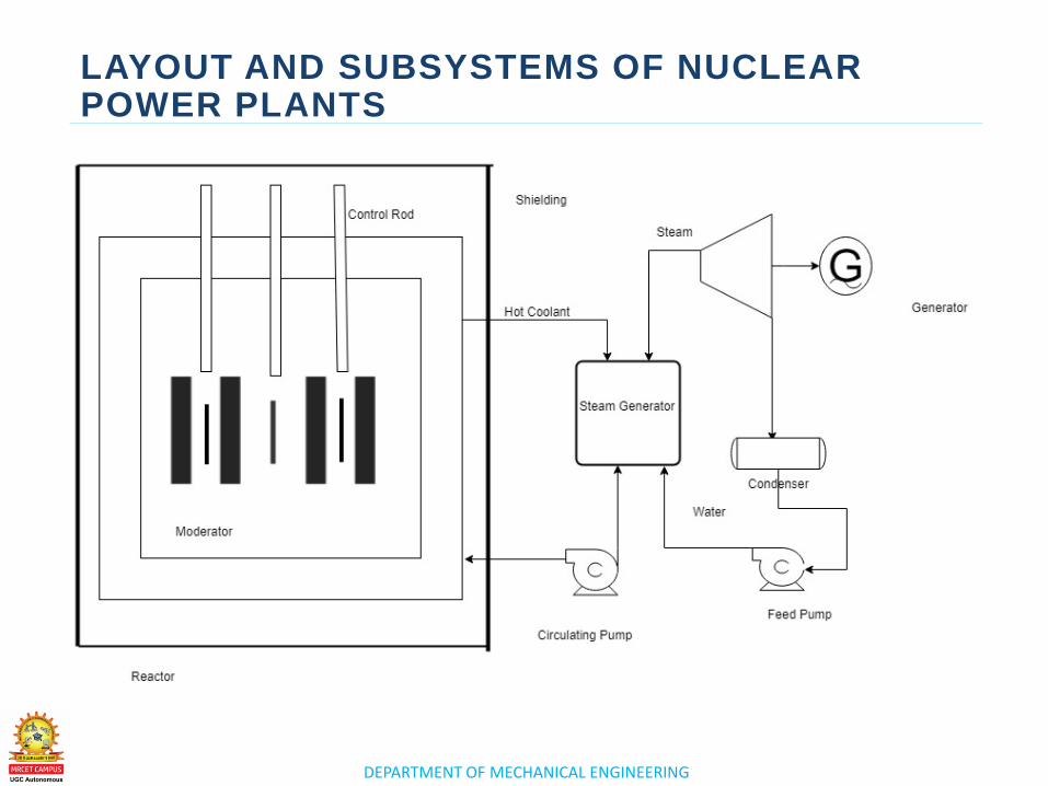
LAYOUT AND SUBSYSTEMS OF NUCLEAR POWER PLANTS
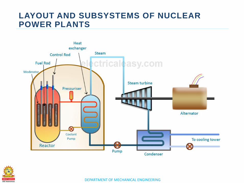
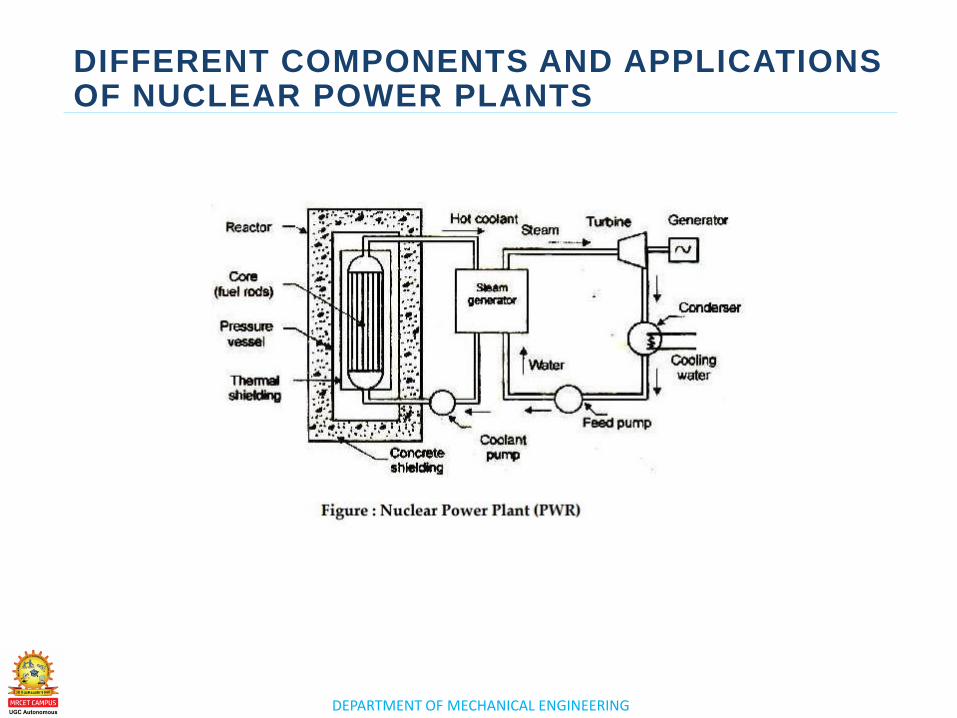
–A nuclear power plant is a thermal power
station in which the heat source is
a nuclear reactor. As is typical of
thermal power stations, heat is used to
generate steam that drives a steam turbine
connected to a generator that produces
electricity.
DEPARTMENT OF MECHANICAL ENGINEERING
LAYOUT AND SUBSYSTEMS OF NUCLEAR POWER PLANTS
DEPARTMENT OF MECHANICAL ENGINEERING
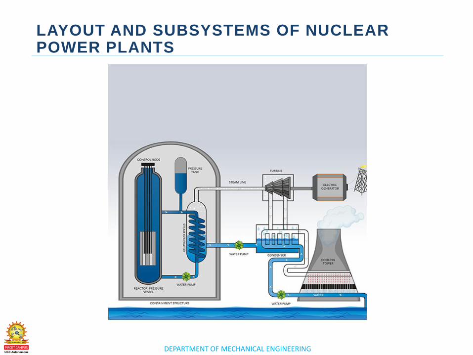
LAYOUT AND SUBSYSTEMS OF NUCLEAR POWER PLANTS Nuclear Power
Nuclear energy originates from the splitting
of uranium atoms – a process called fission. This
generates heat to produce steam, which is used
by a turbine generator to generate electricity.
Because nuclear power plants do not burn fuel,
they do not produce greenhouse gas emissions.
DEPARTMENT OF MECHANICAL ENGINEERING
LAYOUT AND SUBSYSTEMS OF NUCLEAR POWER PLANTS
DEPARTMENT OF MECHANICAL ENGINEERING
LAYOUT AND SUBSYSTEMS OF NUCLEAR POWER PLANTS
DEPARTMENT OF MECHANICAL ENGINEERING
LAYOUT AND SUBSYSTEMS OF NUCLEAR POWER PLANTS
–A nuclear reactor, formerly known as an
atomic pile, is a device used to initiate and
control a self-sustained nuclear chain
reaction. Nuclear reactors are used at
nuclear power plants for electricity
generation and in nuclear marine propulsion.

www.mrcet.ac.in
THANK YOU

www.mrcet.ac.in
LECTURE 3
Introduction - Resultants of Force System
DEPARTMENT OF MECHANICAL ENGINEERING
LECTURE 3
o Working and classification of
various nuclear power plants
Working and
classification of
various nuclear
power plants
TOPICS TO BE COVERED
DEPARTMENT OF MECHANICAL ENGINEERING
CLASSIFICATION OF VARIOUS NUCLEAR POWER PLANTS
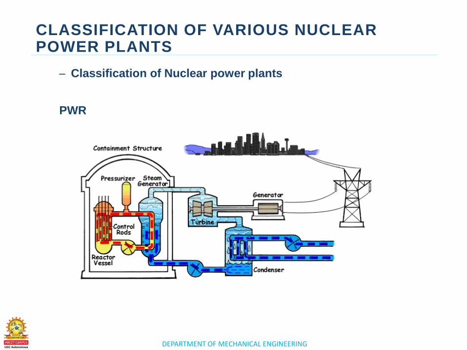
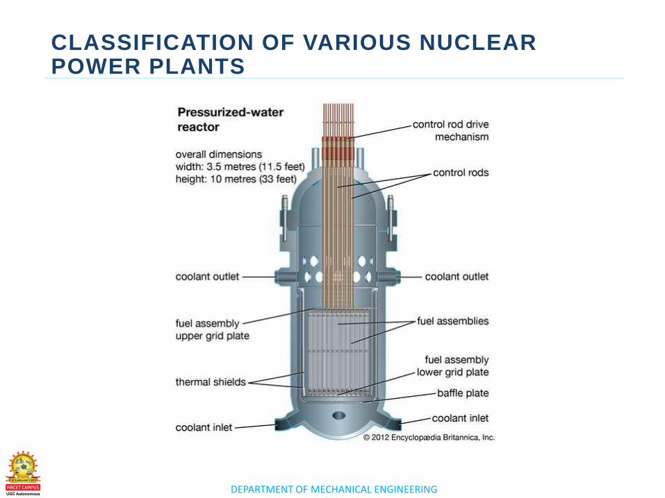
– Classification of Nuclear power plants
PWR
DEPARTMENT OF MECHANICAL ENGINEERING
CLASSIFICATION OF VARIOUS NUCLEAR POWER PLANTS
DEPARTMENT OF MECHANICAL ENGINEERING
CLASSIFICATION OF VARIOUS NUCLEAR POWER PLANTS
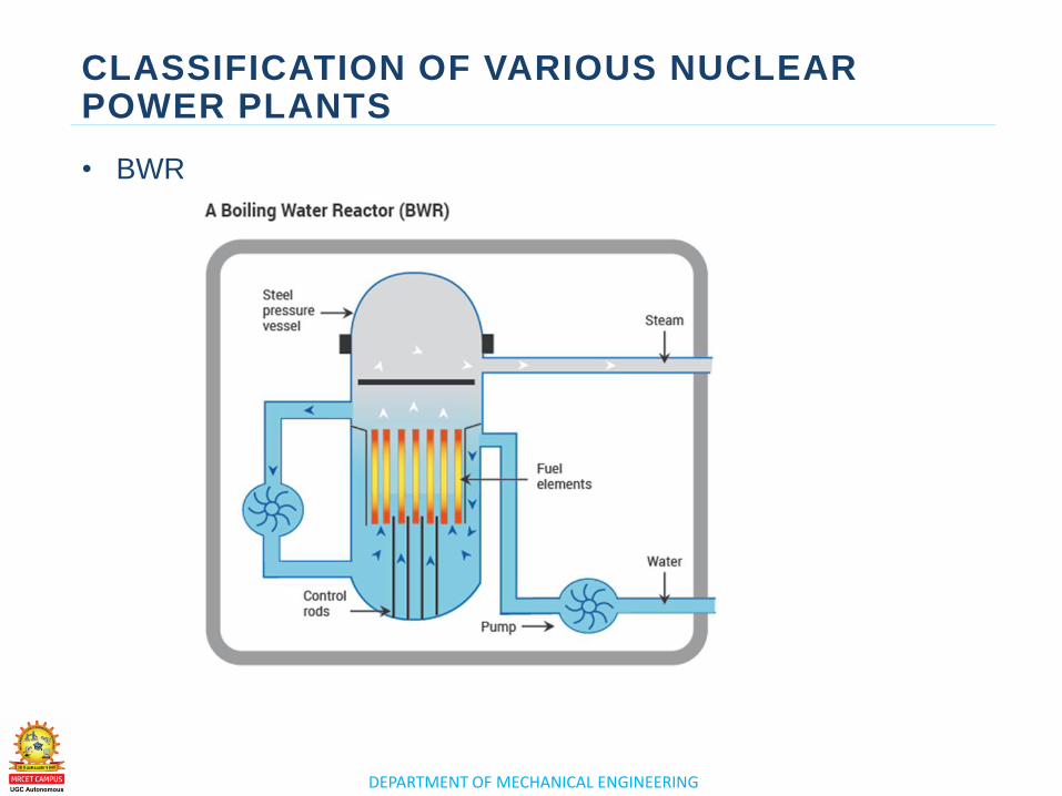
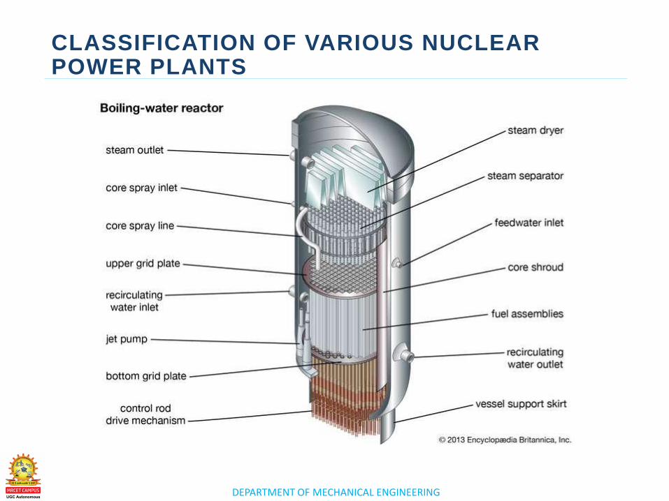
• BWR
DEPARTMENT OF MECHANICAL ENGINEERING
CLASSIFICATION OF VARIOUS NUCLEAR POWER PLANTS
DEPARTMENT OF MECHANICAL ENGINEERING
CLASSIFICATION OF VARIOUS NUCLEAR POWER PLANTS
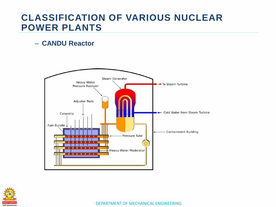
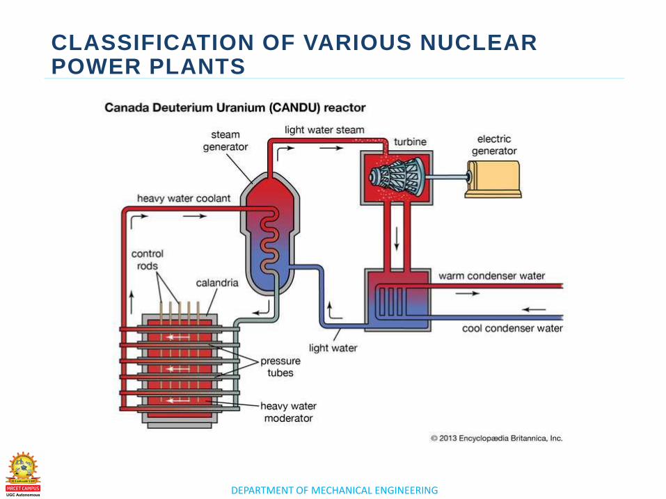
– CANDU Reactor
DEPARTMENT OF MECHANICAL ENGINEERING
CLASSIFICATION OF VARIOUS NUCLEAR POWER PLANTS
DEPARTMENT OF MECHANICAL ENGINEERING
CLASSIFICATION OF VARIOUS NUCLEAR POWER PLANTS
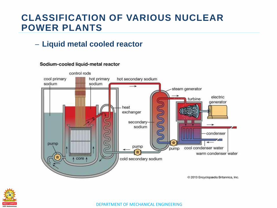
– Liquid metal cooled reactor
DEPARTMENT OF MECHANICAL ENGINEERING
CLASSIFICATION OF VARIOUS NUCLEAR POWER PLANTS
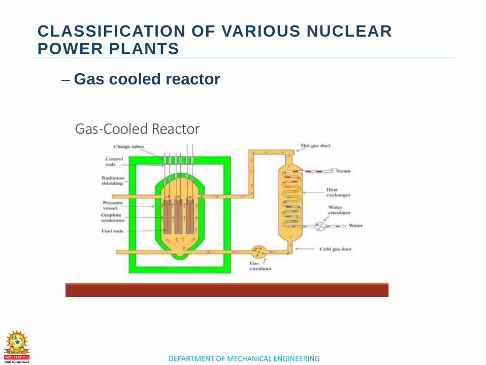
– Gas cooled reactor
DEPARTMENT OF MECHANICAL ENGINEERING
CLASSIFICATION OF VARIOUS NUCLEAR POWER PLANTS

www.mrcet.ac.in
THANK YOU

www.mrcet.ac.in
LECTURE 4
Introduction - Resultants of Force System
DEPARTMENT OF MECHANICAL ENGINEERING
LECTURE 4
o Different components and
applications of nuclear power
plants
Different
components and
applications of
nuclear power
plants
TOPICS TO BE COVERED
DEPARTMENT OF MECHANICAL ENGINEERING
DIFFERENT COMPONENTS AND APPLICATIONS OF NUCLEAR POWER PLANTS
Main components of nuclear power plants:
i) Moderators
In any chain reaction, the neutrons produced are fast moving
neutrons. These are less effective in causing fission of U235 and
they try to escape from the reactor. It is thus implicit that speed of
these neutrons must be reduced if their effectiveness is carrying
out fission is to be increased. This is done by making these
neutrons collide with lighter nuclei of other materials, which does
not absorb these neutrons but simply scatter them. Each collision
causes loss of energy and thus the speed of neutrons is
reduced. Such a material is called a ‘Moderator’.The neutrons
thus slowed down are easily captured by the fuel element at the
chain reaction proceeds slowly.
DEPARTMENT OF MECHANICAL ENGINEERING
DIFFERENT COMPONENTS AND APPLICATIONS OF NUCLEAR POWER PLANTS
ii) Reflectors
Some of the neutrons produced during fission will be partly
absorbed by the fuel elements, moderator, coolant and other
materials. The remaining neutrons will try to escape from the
reactor and will be lost. Such losses are minimized by
surrounding (lining) the reactor core with a material called a
reflector which will reflect the neutrons back to the core. They
improve the neutron economy. Economy: Graphite, Beryllium.
DEPARTMENT OF MECHANICAL ENGINEERING
DIFFERENT COMPONENTS AND APPLICATIONS OF NUCLEAR POWER PLANTS
iii) Shielding
During Nuclear fission ¥, b, g particles and neutrons are also produced. They are harmful to human life. Therefore it is necessary to shield the reactor with thick layers of lead, or concrete to protect both the operating personnel as well as environment from radiation hazards.
iv) Cladding
In order to prevent the contamination of the coolant by fission products, the fuel element is covered with a protective coating. This is known as cladding. Control rods are used to control the reaction to prevent it from becoming violent. They control the reaction by absorbing neutrons. These rods are made of boron or cadmium. Whenever the reaction needs to be stopped, the rods are fully inserted and placed against their seats and when the reaction is to be started the rods are pulled out.
DEPARTMENT OF MECHANICAL ENGINEERING
DIFFERENT COMPONENTS AND APPLICATIONS OF NUCLEAR POWER PLANTS
v) Coolant
The main purpose of the coolant in the reactor is to transfer the heat produced inside the reactor. The same heat carried by the coolant is used in the heat exchanger for further utilization in the power generation.
Some of the desirable properties of good coolant are listed below
1. It must not absorb the neutrons.
2. It must have high chemical and radiation stability
3. It must be non-corrosive.
4. It must have high boiling point (if liquid) and low melting point (if solid)
5. It must be non-oxidising and non-toxic.
DEPARTMENT OF MECHANICAL ENGINEERING
DIFFERENT COMPONENTS AND APPLICATIONS OF NUCLEAR POWER PLANTS
The above-mentioned properties are essential to keep the
reactor core in safe condition as well as for the better functioning
of the content.
6. It must also have high density, low viscosity, high conductivity
and high specific heat. These properties are essential for better
heat transfer and low pumping power.
The water, heavy water, gas (He, CO2), a metal in liquid form
(Na) and an organic liquid are used as coolants.
The coolant not only carries large amounts of heat from the core
but also keeps the fuel assemblies at a safe temperature to avoid
their melting and destruction.
DEPARTMENT OF MECHANICAL ENGINEERING
DIFFERENT COMPONENTS AND APPLICATIONS OF NUCLEAR POWER PLANTS
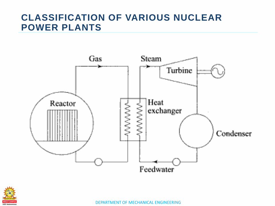
vi) Nuclear reactor
A nuclear reactor may be regarded as a substitute for the boiler
fire box of a steam power plant. Heat is produced in the reactor
due to nuclear fission of the fuel U235 The heat liberated in the
reactor is taken up by the coolant circulating through the core.
Hot coolant leaves the reactor at top and flows into the steam
generator (boiler).
Radiation hazards and Shielding
The reactor is a source of intense radioactivity. These radiations
are very harmful to human life. It requires strong control to
ensure that this radioactivity is not released into the atmosphere
to avoid atmospheric pollution. A thick concrete shielding and a
pressure vessel are provided to prevent the escape of these
radiations to atmosphere
DEPARTMENT OF MECHANICAL ENGINEERING
DIFFERENT COMPONENTS AND APPLICATIONS OF NUCLEAR POWER PLANTS
DEPARTMENT OF MECHANICAL ENGINEERING
DIFFERENT COMPONENTS AND APPLICATIONS OF NUCLEAR POWER PLANTS
vii) Steam generator
The steam generator is fed with feed water which is converted into steam by the heat of the hot coolant. The purpose of the coolant is to transfer the heat generated in the reactor core and use it for steam generation. Ordinary water or heavy water is a common coolant.
viii) Turbine
The steam produced in the steam generator is passed to the turbine and work is done by the expansion of steam in the turbine.
ix) Coolant pump and Feed pump
The steam from the turbine flows to the condenser where cooling water is circulated. Coolant pump and feed pump are provided to maintain the flow of coolant and feed water respectively.
DEPARTMENT OF MECHANICAL ENGINEERING
DIFFERENT COMPONENTS AND APPLICATIONS OF NUCLEAR POWER PLANTS Advantages of nuclear power plant
1. It can be easily adopted where water and coal resources are not available.
2. The nuclear power plant requires very small quantity of fuel. Hence fuel transportation cost is less.
3. Space requirement is less compared to other power plants of equal capacity.
4. It is not affected by adverse weather conditions.
5. Fuel storage facilities are not needed as in the case of the thermal power plant.
6. Nuclear power plants will converse the fossils fuels (coal, petroleum) for other energy needs.
7. Number of workmen required at nuclear plant is far less than thermal plant.
8. It does not require large quantity of water.
DEPARTMENT OF MECHANICAL ENGINEERING
DIFFERENT COMPONENTS AND APPLICATIONS OF NUCLEAR POWER PLANTS
Disadvantages
1. Radioactive wastes, if not disposed of carefully, have adverse effect on the health of workmen and the population surrounding the plant.
2. It is not suitable for varying load condition.
3. It requires well-trained personnel.
4. It requires high initial cost compared to hydro or thermal power plants.

www.mrcet.ac.in
THANK YOU

www.mrcet.ac.in
LECTURE 5
Introduction - Resultants of Force System
DEPARTMENT OF MECHANICAL ENGINEERING
LECTURE 5
o Safety measures for nuclear
power plants
Safety measures
for nuclear power
plants
TOPICS TO BE COVERED
DEPARTMENT OF MECHANICAL ENGINEERING
SAFETY MEASURES FOR NUCLEAR POWER PLANTS
– The biggest concern associated with a nuclear
power accident is the negative effects that exposure
to radiation can have on the human body. It is
interesting to note that we are exposed to radiation
naturally just by living our lives. Natural background
radiation comes from outer space, and even
radiates up from the ground below us. You may also
have been exposed to a medical procedure, such as
a CT scan, X-ray or nuclear medicine, such as an
MRI, that utilized different types of radiation to
diagnose problems or treat a disease.
DEPARTMENT OF MECHANICAL ENGINEERING
SAFETY MEASURES FOR NUCLEAR POWER PLANTS
The design considerations that have a bearing on radiation protection in
NPPs include:
– Proper design, plant layout and adequate shielding:
– Limits of air contamination levels in different zones of the plant:
– Source control by proper selection of materials/components:
– Design limit for collective dose:
Health Concerns
• The biggest concern associated with a nuclear power accident is the
negative effects that exposure to radiation can have on the human body. ...
However, if a person were exposed to significant amounts of radiation over
a period of time, this exposure could damage body cells and lead to
cancer.
DEPARTMENT OF MECHANICAL ENGINEERING
SAFETY MEASURES FOR NUCLEAR POWER PLANTS
– If a person were to be exposed to an acute dose of high-levels of radiation, the result would be radiation sickness. Radiation sickness is defined as illness caused by exposure to a large dose of radiation over a short period of time. Symptoms may include skin burns, nausea, vomiting, diarrhea, hair loss, general weakness and possibly death.
– In addition to personal health concerns, there are also environmental health concerns associated with nuclear power generation. Nuclear power plants use water from local lakes and rivers for cooling. Local water sources are used to dissipate this heat, and the excess water used to cool the reactor is often released back into the waterway at very hot temperatures. This water can also be polluted with salts and heavy metals, and these high temperatures, along with water pollutants, can disrupt the life of fish and plants within the waterway.
DEPARTMENT OF MECHANICAL ENGINEERING
SAFETY MEASURES FOR NUCLEAR POWER PLANTS
– PDF attachement

www.mrcet.ac.in
THANK YOU