
Air-insulated medium voltage secondary distribution switchgear
Upload
khangminh22Category
view
3download
0
MALLA REDDY COLLEGE OF ENGINEERING &
TECHNOLOGY
(Autonomous Institution – UGC, Govt. of India)
Recognized under 2(f) and 12 (B) of UGC ACT 1956
(Affiliated to JNTUH, Hyderabad, Approved by AICTE - Accredited by NBA & NAAC – ‘A’
Grade - ISO 9001:2015 Certified)
Maisammaguda, Dhulapally (Post Via. Kompally), Secunderabad – 500100, Telangana State,
India
DEPARTMENT OF ELECTRICAL & ELECTRONICS
ENGINEERING
Digital Notes on
SWITCHGEAR & PROTECTION (R18A0218)
for
B.Tech (EEE) – IV YEAR – I SEMESTER
Prepared by
DR. KAMALAMOORTHY N, PROF / EEE

S.NO
TITLE PAGE.NO
UNIT – I CIRCUIT BREAKERS
1. Introduction to Fundamentals of Power system Protection 01
2. Restriking Phenomenon & Elementary principles of arc
interruption, 09
3. Arc interruption theories
12
4. Recovery, Restriking Voltage and Recovery voltages
Average and Max. RRRV 13
5. Current Chopping 17
6. Resistance Switching 19
7. CB ratings and Specifications 27
8. Types of circuit breakers 30
9. Oil Circuit breakers, 31
10. Air Blast Circuit Breakers 40
11. SF6 circuit breakers. 43
12. Vacuum circuit breakers 45
UNIT- II ELECTROMAGNETIC & STATIC RELAYS:
13. Introduction to relays 48
14. Attracted armature type relay 49
15. Balanced Beam relay 50

16. Induction Disc and Induction Cup relays. 51
17. Relays Classification 55
18. Instantaneous DMT & IDMT Relays 55
19. Directional relays 56
20. Differential Relays 58
21. Percentage Differential Relays 59
22. Impedance relay 63
23. Reactance relay 66
24. Mho and Off‐Set Mho relays 68
25. Static Relays 72
UNIT ‐ III: GENERATOR & TRANSFORMER PROTECTION
26. Introduction 73
27. Protection of Alternators 74
28. Merz-Price circulating current scheme 75
29. Modified differential protection for alternators 78
30. Balanced earth-fault protection 79
31. Stator inter-turn protection 80
32. Protection of transformers 82

33. Percentage Differential Protection 82
34. Buchholtz relay Protection 86
UNIT‐IV:
FEEDER AND BUS‐BAR PROTECTION & GROUNDING:
35. Introduction 88
36. Differential protection 89
37. Time-graded overcurrent protection 90
38. Differential pilot-wire protection 93
39. Translay Relay 95
40. Three‐zone distance relay protection using Impedance
relays. 97
41. Carrier Current Protection of Lines 98
42. Phase-Comparison Carrier Protection: 101
43. Protection of Bus bars 104
44. Differential protection of Busbar 105
45. Voltage Differential Protection Relay 106
46. Grounding & its Types 107
47. System Grounding 109
48. Neutral Grounding 114
49. Solid Grounding 116

50. Resistance Grounding 118
51. Reactance Grounding 119
52. Peterson coil Grounding 120
53. Voltage Transformer Earthing 122
UNIT ‐V:
PROTECTION AGAINST OVER VOLTAGES
54. Introduction 125
55. Generation of Over Voltages in Power Systems 125
56. Protection against Lightning over Voltages 127
57. Valve type Arrester 129
58. Zinc‐Oxide Lighting Arresters 132
59. Insulation Coordination 136
60. Volt‐Time Characteristics 137
61. BIL 139
62. Standard Impulse Test Wave 139
63. Lightning Arrester Types 140
64. Rod gap arrester 142
65. Horn gap arrester 142
66. Multi gap arrester: 143

67. Expulsion type lightning arrester 144
68. Valve type lightning arrester 145

UNIT – I: CIRCUIT BREAKERS
R18 - SWITCHGEAR & PROTECTION Page 1
UNIT – I
CIRCUIT BREAKERS
Fundamentals of Power System Protection
The purpose of an Electric Power System is to generate and supply electrical energy to
consumers. The power system should be designed and managed to deliver this energy to the
utilization points with both reliability and economically
The capital investment involved in power system for the generation, transmission and
distribution is so great that the proper precautions must be taken to ensure that the equipment not
only operates as nearly as possible to peak efficiency, but also must be protected from accidents
The normal path of the electric current is from the power source through copper (or aluminium)
conductors in generators, transformers and transmission lines to the load and it is confined to this
path by insulation. The insulation, however, may break down, either by the effect of temperature
and age or by a physical accident, so that the current then follows an abnormal path generally
known as Short Circuit or Fault
Any abnormal operating state of a power system is known as FAULT. Faults in general consist
of short circuits as well as open circuits. Open circuit faults are less frequent than short circuit
faults, and often they are transformed in to short circuits by subsequent events.

UNIT – I: CIRCUIT BREAKERS
R18 - SWITCHGEAR & PROTECTION Page 2
Consequences of occurrence of Faults
Faults are of two types
• Short circuit fault- current
• Open circuit fault- voltage
In terms of seriousness of consequences of a fault , short circuits are of far greater
concern than open circuits, although some open circuits present some potential
hazards to personnel
Classification of short circuited Faults
• Three phase faults (with or without earth connection)
• Two phase faults (with or without earth connection)
• Single phase to earth faults Classification of Open Circuit Faults
• Single Phase open Circuit
• Two phase open circuit
• Three phase open circuit
Consequences
• Damage to the equipment due to abnormally large and unbalanced currents and low
voltages produced by the short circuits
• Explosions may occur in the equipments which have insulating oil, particularly
during short circuits. This may result in fire and hazardous conditions to personnel
and equipments
• Individual generators with reduced voltage in a power station or a group of
generators operating at low voltage may lead to loss of synchronism, subsequently
resulting in islanding.
• Risk of synchronous motors in large industrial premises falling out of step and tripping out.
The general layout of a protection system may be viewed as given in the following figure

UNIT – I: CIRCUIT BREAKERS
R18 - SWITCHGEAR & PROTECTION Page 3
Zones and types of Protection system
Zones of Protection system
• An electric power system is divided into several zones of protection. Each zone of protection,
contains one or more components of a power system in addition to two circuit breakers.
• When a fault occurs within the boundary of a particular zone, then the protection system
responsible for the protection of the zone acts to isolate (by tripping the Circuit Breakers) every
equipment within that zone from the rest of the system.
• The circuit Breakers are inserted between the component of the zone and the rest of the power
system. Thus, the location of the circuit breaker helps to define the boundaries of the zones of
protection.
• Different neighboring zones of protection are made to overlap each other, which ensure that no
part of the power system remains without protection. However, occurrence of the fault with in
the overlapped region will initiate a tripping sequence of different circuit breakers so that the
minimum necessary to disconnect the faulty element

UNIT – I: CIRCUIT BREAKERS
R18 - SWITCHGEAR & PROTECTION Page 4
Types of Protection (Primary and Back-up Protection)

UNIT – I: CIRCUIT BREAKERS
R18 - SWITCHGEAR & PROTECTION Page 5
Primary Protection
The primary protection scheme ensures fast and selective clearing of any fault within the
boundaries of the circuit element, that the zone is required to protect. Primary Protection as a
rule is provided for each section of an electrical installation.
However, the primary protection may fail. The primary cause of failure of the Primary
Protection system are enumerated below.
• Current or voltage supply to the relay.
• D.C. tripping voltage supply
• Protective relays
• Tripping circuit
• Circuit Breaker
Back-up Protection
Back-up protection is the name given to a protection which backs the primary protection
whenever the later fails in operation. The back-up protection by definition is slower than the
primary protection system. The design of the back-up protection needs to be coordinated
with the design of the primary protection and essentially it is the second line of defence after
the primary protection system.
Protection System Requirements and some basic terminologies used
The fundamental requirements for a protection system are as follows:
Reliability: It is the ability of the protection system to operate correctly. The reliability
feature has two basic elements, which are dependability and security. The dependability
feature demands the certainty of a correct operation of the designed system, on occurrence of
any fault. Similarly, the security feature can be defined as the ability of the designed system
to avoid incorrect operation during faults. A comprehensive statistical method based
reliability study is required before the protection system may be commissioned. The factors
which affect this feature of any protection system depends on some of the following few
factors.

UNIT – I: CIRCUIT BREAKERS
R18 - SWITCHGEAR & PROTECTION Page 6
a) Quality of Component used
b) Maintenance schedule
c) The supply and availability of spare parts and stocks
d) The design principle
e) Electrical and mechanical stress to which the protected part of the
system is subjected to.
Speed: Minimum operating time to clear a fault in order to avoid damage to equipment. The
speed of the protection system consists primarily of two time intervals of interest.
• The Relay Time : This is the time between the instant of occurrence of
the fault to the instant at which the relay contacts open.
• The Breaker Time: This is the time between the instant of closing of
relay contacts to the instant of final arc extinction inside the
medium and removal of the fault.
Selectivity: This feature aims at maintaining the continuity of supply system by disconnecting
the minimum section of the network necessary to isolate the fault. The property of selective
tripping is also known as ―discrimination‖. This is the reason for which the entire system is
divided into several protective zones so that minimum protion of network is isolated with
accuracy. Two examples of utilization of this feature in a relaying scheme are as follows
• Time graded systems
• Unit systems
Sensitivity: The sensitivity of a relay refers to the smallest value of the actuating quantity at
which the relay operates detecting any abnormal condition. In case of an overcurrent
relay, mathematically this can be defined as the ratio between the short circuit fault current
(Is) and the relay operating current (Io). The value of Io , should not be too small or large so
that the relay is either too sensitive or slow in responding.
Stability: It is the quality of any protection system to remain stable within a set of defined
operating scenarios and procedures. For example the biased differential scheme of
differential protection is more stable towards switching transients compared to the more

UNIT – I: CIRCUIT BREAKERS
R18 - SWITCHGEAR & PROTECTION Page 7
simple and basic Merz Price scheme in differential protection
Adequacy: It is economically unviable to have a 100% protection of the entire system in
concern. Therefore, the cost of the designed protection system varies with the criticality and
importance of the protected zone. The protection system for more critical portions is
generally costly, as all the features of a good protection system is maximized here. But a
small motor can be protected by a simple thermally operated relay, which is simple and
cheap. Therefore, the cost of the protection system should be adequate in its cost.
Some basic terminologies used in protection system
Some basic terminologies commonly used in the protection system are enlisted below.
i) Measuring Relay
ii) Fault Clearing Time
iii) Auxiliary relay
iv) Relay Time
v) Pick up value
vi) Reset Value
vii) Drop out
viii) Reach ( under and over reaches)
ix) Relay Burden
x) Unit/ Non unit protection
xi) All or Nothing relay

UNIT – I: CIRCUIT BREAKERS
R18 - SWITCHGEAR & PROTECTION Page 8
CIRCUIT BREAKER
Introduction:
During the operation of power system, it is often desirable and necessary to
switch on or off the various circuits (e.g., transmission lines, distributors, generating
plants etc.) under both normal and abnormal conditions. In earlier days, this function
used to be performed by a switch and a fuse placed in series with the circuit. However,
such a means of control presents two disadvantages.
1. Firstly, when a fuse blows out, it takes quite some time to replace it and restore supply
to the customers.
2. Secondly, a fuse cannot successfully interrupt heavy fault currents that result from
faults on modern high- voltage and large capacity circuits.
Due to these disadvantages, the use of switches and fuses is limited to low voltage and
small capacity circuits where frequent operations are not expected e.g., for switching and
protection of distribution transformers, lighting circuits, branch circuits of distribution
lines etc.
With the advancement of power system, the lines and other equipment operate at very
high voltages and carry large currents. The arrangement of switches along with fuses
cannot serve the desired function of switchgear in such high capacity circuits. This
necessitates employing a more dependable means of control such as is obtained by the use
of circuit breakers.
A circuit breaker can make or break a circuit either manually or automatically under all conditions viz., no-load, full- load and short-circuit conditions.
This characteristic of the circuit breaker has made it very useful equipment for
switching and protection of various parts of the power system.
A circuit breaker is a piece of equipment which can
(i) Make or break a circuit either manually or by remote control under normal
conditions.
(ii) Break a circuit automatically under fault conditions
(iii) Make a circuit either manually or by remote control under fault conditions
Thus a circuit breaker incorporates manual (or remote control) as well as automatic
control for switching functions. The latter control employs relays and operates only under
fault conditions.

UNIT – I: CIRCUIT BREAKERS
R18 - SWITCHGEAR & PROTECTION Page 9
OPERATING PRINCIPLE:
A circuit breaker essentially consists of fixed and moving contacts, called
Electrodes. Under normal operating conditions, these contacts remain closed and will not
open automatically until and unless the system becomes faulty. Of course, the contacts
can be opened manually or by remote control whenever desired. When a fault occurs on
any part of the system, the trip coils of the circuit breaker get energized and the moving
contacts are pulled apart by some mechanism, thus opening the circuit.
❖ When the contacts of a circuit breaker are separated under fault conditions, an
arc is struck between them. The current is thus able to continue until the discharge ceases.
❖ The production of arc not only delays the current interruption process but it also generates enormous heat which may cause damage to the system or to the circuit breaker itself.
❖ Therefore, the main problem in a circuit breaker is to extinguish the arc within the shortest possible time so that heat generated by it may not reach a dangerous value.
Arc Phenomenon:
When a short circuit occurs, a heavy current flows through the contacts of the
circuit breaker before they are opened by the protective system. At the instant when the
contacts begin to separate, the contact area decreases rapidly and large fault current
causes increased current density and hence rise in temperature. The heat produced in the
medium between contacts (usually the medium is oil or air) Is sufficient to ionize the air
or vaporize and ionize the oil. The ionized air or vapor acts as conductor and an arc is
struck between the contacts.
❖ The potential difference between the contacts is quite small and is just sufficient to
maintain the arc.
❖ The arc provides a low resistance path and consequently the current in the circuit
remains UN interrupted so long as the arc persists.
❖ During the arcing period, the current flowing between the contacts depends upon the
arc resistance. The greater the arc resistance, the smaller the current that flows between the contacts.
The arc resistance depends upon the following factors:
1. Degree of ionization- the arc resistance increases with the decrease in the number
of ionized particles between the contacts.
2. Length of the arc— the arc resistance increases with the length of the arc i.e.,
separation of contacts.
3. Cross-section of arc— the arc resistance increases with the decrease in area of X-
section of the arc.

UNIT – I: CIRCUIT BREAKERS
R18 - SWITCHGEAR & PROTECTION Page 10
Principles of Arc Extinction:
Before discussing the methods of arc extinction, it is necessary to examine the
factors responsible for the maintenance of arc between the contacts. These are:
1. Potential difference between the contacts.
2. Ionized particles between contacts taking these in turn.
❖ When the contacts have a small separation, the Potential difference between them is
sufficient to maintain the arc. One way to extinguish the arc is to separate the contacts to such a distance that Potential difference becomes inadequate to maintain the arc. However, this method is impracticable in high voltage system where a separation of many meters may be required.
❖ The ionized particles between the contacts tend to maintain the arc. If the arc path is
demonized, the arc extinction will be facilitated. This may be achieved by cooling the arc or by bodily removing the ionized particles from the space between the contacts.
Methods of Arc Extinction (or) Interruption:
There are two methods of extinguishing the arc in circuit breakers viz.
1. High resistance method.
2. Low resistance or current zero method
High resistance method:
In this method, arc resistance is made to increase with time so that current is
reduced to a value insufficient to maintain the arc. Consequently, the current is
interrupted or the arc is extinguished.
❖ The principal disadvantage of this method is that enormous energy is dissipated in the
arc. Therefore, it is employed only in D.C. circuit breakers and low-capacity a.c.
circuit breakers.
The resistance of the arc may be increased by:
1. Lengthening the arc: The resistance of the arc is directly proportional to its length.
The length of the arc can be increased by increasing the gap between contacts.
2. Cooling the arc: Cooling helps in the deionization of the medium between the
contacts. This increases the arc resistance. Efficient cooling may be obtained by a
gas blast directed along the arc.
3. Reducing X-section of the arc: If the area of X-section of the arc is reduced, the
voltage necessary to maintain the arc is increased. In other words, the resistance of
the arc path is increased. The cross-section of the arc can be reduced by letting the
arc pass through a narrow opening or by having smaller area of contacts.

UNIT – I: CIRCUIT BREAKERS
R18 - SWITCHGEAR & PROTECTION Page 11
4. Splitting the arc: The resistance of the arc can be increased by splitting the arc into
a number of smaller arcs in series. Each one of these arcs experiences the effect of
lengthening and cooling. The arc may be split by introducing some conducting plates
between the contacts.
Low resistance or Current zero method:
In this method is employed for arc extinction in a.c. circuits only. In this method,
arc resistance is kept low until current is zero where the arc extinguishes naturally and is
prevented from restriking in spite of the rising voltage across the contacts. All Modern
high power a.c. circuit breakers employ this method for arc extinction.
❖ In an a.c. system, current drops to zero after every half-cycle. At every current zero, the arc extinguishes for a brief moment.
❖ Now the medium between the contacts contains ions and electrons so that it has small dielectric strength and can be easily broken down by the rising contact voltage known as restriking voltage.
❖ If such a breakdown does occur, the arc will persist for another half cycle.
❖ If immediately after current zero, the dielectric strength of the medium between contacts is built up more rapidly than the voltage across the contacts, the arc fails to restrike and the current will be interrupted.
The rapid increase of dielectric strength of the medium near current zero can be
achieved by:
❖ Causing the ionized particles in the space between contacts to recombine into neutral molecules.
❖ Sweeping the ionized particles away and replacing them by un ionized particles.
Therefore, the real problem in a.c. arc interruption is to rapidly de ionize the
medium between contacts as soon as the current becomes zero so that the rising contact
voltage or restriking voltage cannot breakdown the space between contacts.
The de-ionization of the medium can be achieved by:
1. Lengthening of the gap: The dielectric strength of the medium is proportional to the
length of the gap between contacts. Therefore, by opening the contacts rapidly,
higher dielectric strength of the medium can be achieved.
2. High pressure: If the pressure in the vicinity of the arc is increased, the density of
the particles constituting the discharge also increases. The increased density of
particles causes higher rate of de-ionization and consequently the dielectric strength
of the medium between contacts is increased.

UNIT – I: CIRCUIT BREAKERS
R18 - SWITCHGEAR & PROTECTION Page 12
3. Cooling: Natural combination of ionized particles takes place more rapidly if they
are allowed to cool. Therefore, dielectric strength of the medium between the
contacts can be increased by cooling the arc.
4. Blast effect: If the ionized particles between the contacts are swept away and
replaced by UN ionized particles, the dielectric strength of the medium can be
increased considerably. This may be achieved by a gas blast directed along the
discharge or by forcing oil into the contact space.
There are two theories to explain the Zero current interruption of the Arc:
1. Recovery rate theory (Slepain‗s Theory)
2. Energy balance theory (Cassie‗s Theory)
Recovery rate theory (Slepain’s Theory):
The arc is a column of ionized gases. To extinguish the arc, the electrons and
ions are to be removed from the gap immediately after the current reaches a natural
zero. Ions and electrons can be removed either by recombining them in to neutral
molecules or by sweeping them away by inserting insulating medium (gas or liquid)
into the gap. The arc is interrupted if ions are removed from the gap recovers its
dielectric strength is compared with the rate at which the restriking voltage (transient
voltage) across the gap rises. If the dielectric strength increases more rapidly than the
restriking voltage, the arc is extinguished. If the restriking voltage rises more rapidly
than the dielectric strength, the ionization persists and breakdown of the gap occurs,
resulting in an arc for another half cycle.

UNIT – I: CIRCUIT BREAKERS
R18 - SWITCHGEAR & PROTECTION Page 13
Energy balance theory (Cassie’s Theory):
The space between the contacts contains some ionized gas immediately after
current zero and hence, it has a finite post –zero moment, power is zero because restriking
voltage is zero. When the arc is finally extinguished, the power gain becomes zero, the gap is
fully de-ionized and its resistance is infinitely high. In between these two limits, first the
power increases, reaches a maximum value, then decreases and finitely reaches zero value as
shown in figure. Due to the rise of restriking voltage and associated current, energy is
generated in the space between the contacts. The energy appears in the form of heat. The
circuit breaker is designed to remove this generated heat as early as possible by cooling the
gap, giving a blast air or flow of oil at high velocity and pressure. If the rate of removal of
heat is faster than the rate of heat generation the arc is extinguished. If the rate of heat
generation is more than the rate of heat dissipation, the space breaks down again resulting in
an arc for another half cycle.
Important Terms:
The following are the important terms much used in the circuit breaker analysis:
1. Arc Voltage:
It is the voltage that appears across the contacts of the circuit breaker during the
arcing period. As soon as the contacts of the circuit breaker separate, an arc is formed.
The voltage that appears across the contacts during arcing period is called the arc
voltage. Its value is low except for the period the fault current is at or near zero current
point. At current zero, the arc voltage rises rapidly to peak value and this peak voltage
tends to maintain the current flow in the form of arc.
2. Restriking voltage:
It is the transient voltage that appears across the contacts at or near current zero

UNIT – I: CIRCUIT BREAKERS
R18 - SWITCHGEAR & PROTECTION Page 14
during arcing period. At current zero, a high-frequency transient voltage appears across
the contacts and is caused by the rapid distribution of energy between the magnetic and
electric fields associated with the plant and transmission lines of the system. This
transient voltage is known as restriking voltage (Fig. 19.1).
The current interruption in the circuit depends upon this voltage. If the restriking
voltage rises more rapidly than the dielectric strength of the medium between the
contacts, the arc will persist for another half-cycle. On the other hand, if the dielectric
strength of the medium builds up more rapidly than the restriking voltage, the arc fails to
restrike and the current will be interrupted.
3. Recovery voltage:
It is the normal frequency (50 Hz) R.M.S. voltage that appears across the
contacts of the circuit breaker after final arc extinction. It is approximately equal to the
system voltage.
When contacts of circuit breaker are opened, current drops to zero after every
half cycle. At some current zero, the contacts are separated sufficiently apart and
dielectric strength of the medium between the contacts attains a high value due to the
removal of ionized particles. At such an instant, the medium between the contacts is
strong enough to prevent the breakdown by the restriking voltage. Consequently, the
final arc extinction takes place and circuit current is interrupted. Immediately after final
current interruption, the voltage that appears across the contacts has a transient part (See
Fig.19.1). However, these transient oscillations subside rapidly due to the damping effect
of system resistance and normal circuit voltage appears across the contacts. The voltage
across the contacts is of normal frequency and is known as recovery voltage.

UNIT – I: CIRCUIT BREAKERS
R18 - SWITCHGEAR & PROTECTION Page 15
Expression for Restriking voltage and RRRV:
The power system contains an appreciable amount of inductance and some
capacitance. When a fault occurs, the energy stored in the system can be considerable.
Interruption of fault current by a circuit breaker will result in most of the stored energy
dissipated within the circuit breaker, the remainder being dissipated during oscillatory
surges in the system. The oscillatory surges are undesirable and, therefore, the circuit
breaker must be designed to dissipate as much of the stored energy as possible.
Fig. 19.17 (i) shows a short-circuit occurring on the transmission line. Fig 19.17 (ii)
shows its equivalent circuit where L is the inductance per phase of the system up to the
point of fault and C is the capacitance per phase of the system. The resistance of the
system is neglected as it is generally small.
Rate of rise of re-striking voltage:
It is the rate of increase of re-striking voltage and is abbreviated by R.R.R.V. usually;
the voltage is in kV and time in microseconds so that R.R.R.V. is in kV/µ sec.
Consider the opening of a circuit breaker under fault conditions Shown in
simplified form in Fig. 19.17(ii) above. Before current interruption, the capacitance C is
short-circuited by the fault and the short-circuit current through the breaker is limited by
Inductance L of the system only. Consequently, the short-circuit current will lag the
voltage by 90º as shown in Fig. 19.18, where I Represents the short-circuit current and ea
represents the arc voltage. It may be seen that in this condition, the *entire generator
voltage appears across inductance L.

UNIT – I: CIRCUIT BREAKERS
R18 - SWITCHGEAR & PROTECTION Page 16
When the contacts are opened and the arc finally extinguishes at some current
zero, the generator voltage e is suddenly applied to the inductance and capacitance in
series.
This L - C combination forms an oscillatory circuit and produces a transient of frequency:
fn =1/2Π √LC
The voltage across the capacitance which is the voltage across the contacts of the
circuit breaker can be calculated in terms of L, C, fn and system voltage. The
mathematical expression for transient condition is as follows.
As vc(t) = 0 at t=0, constant = 0
vc(t) = E(1-coswnt) or Restriking voltage
The maximum value of restriking voltage = 2Epeak = 2 X Peak value of system voltage
The rate of rise of restriking voltage (RRRV) = (1 − cos wn t)
= wn E sinwnt
The maximum value of RRRV= wn E = wn Epeak
Which appears across the capacitor C and hence across the contacts of the circuit
breaker. This transient voltage, as already noted, is known as re-striking voltage and may
reach an instantaneous peak value twice the peak phase-neutral voltage i.e. 2 Em . The
system losses cause the oscillations to decay fairly rapidly but the
initial overshoot increases the possibility of re-striking the arc.

UNIT – I: CIRCUIT BREAKERS
R18 - SWITCHGEAR & PROTECTION Page 17
It is the rate of rise of re-striking voltage (R.R.R.V.) which decides whether the arc will re
strike or not. If
R.R.R.V. is greater than the rate of rise of dielectric strength between the contacts, the arc
will re-strike. However, the arc will fail to re-strike if R.R.R.V. is less than the rate of
increase of dielectric strength between the contacts of the breaker.
The value of R.R.R.V. depends up on:
1. Recovery voltage
2. Natural frequency of oscillations
For a short-circuit occurring near the power station bus-bars, C being small, the
natural frequency fn will be high. Consequently, R.R.R.V. will attain a large value. Thus
the worst condition for a circuit breaker would be that when the fault takes place near the
bus-bars.
CURRENT CHOPPING:
It is the phenomenon of current interruption before the natural current zero is
reached. Current chopping mainly occurs in air-blast circuit breakers because they retain
the same extinguishing power irrespective of the magnitude of the current to be
interrupted. When breaking low currents (e.g., transformer magnetizing current) with
such breakers, the powerful de-ionizing effect of air-blast causes the current to fall
abruptly to zero well before the natural current zero is reached. This phenomenon is
known as current chopping and results in the production of high voltage transient across
the contacts of the circuit breaker as discussed below:
Consider again Fig. 19.17 (ii) repeated as Fig. 19.19 (i). Suppose the arc current
is i when it is chopped down to zero value as shown by point a in Fig. 19.19 (ii). As the
chop occurs at current i, therefore, the energy stored in inductance is L i2
/2.
This energy will be transferred to the capacitance C, charging the latter to a prospective voltage e given by:
Li2
= Cv2
(or) v = i L volts
2 2 C
The prospective voltage e is very high as compared to the dielectric strength gained by the
gap so that the breaker restrike. As the de-ionizing force is still in action, therefore, chop
occurs again but the arc current this time is smaller than the previous case. This induces a
lower prospective voltage to re-ignite the arc. In fact, several chops may occur until a low

UNIT – I: CIRCUIT BREAKERS
R18 - SWITCHGEAR & PROTECTION Page 18
enough current is interrupted which produces insufficient induced voltage to re-strike across
the breaker gap. Consequently, the final interruption of current takes place.
Excessive voltage surges due to current chopping are prevented by shunting the
contacts of the breaker with a resistor (resistance switching) such that re ignition is
unlikely to occur. This is explained in Art 19.19.
Capacitive current breaking:
Another cause of excessive voltage surges in the circuit breakers is the
interruption of capacitive currents. Examples of such instances are opening of an
unloaded long transmission line, disconnecting a capacitor bank used for power factor
improvement etc. Consider the simple equivalent circuit of an unloaded transmission line
shown in Fig.19.20. Such a line, although unloaded in the normal sense, will actually
carry a capacitive current I on account of appreciable amount of capacitance C between
the line and the earth.
Let us suppose that the line is opened by the circuit breaker at the instant when
line capacitive current is zero [point 1 in Fig. 19.21. At this instant, the generator voltage
V g will be maximum (i.e. V gm) lagging behind the current by 90º. The opening of the
line leaves a standing charge on it (i.e., end B of the line) and the capacitor C1 is charged
to V gm. However, the generator end of the line (i.e., end A of the line) continues its
normal sinusoidal variations. The voltage V r across the circuit breaker will be the
difference between the voltages on the respective sides. Its initial value is zero (point 1)
and increases slowly in the beginning. But half a cycle later [point R in Fig. 19.21], the

UNIT – I: CIRCUIT BREAKERS
R18 - SWITCHGEAR & PROTECTION Page 19
potential of the circuit breaker contact ‗A ‗ becomes maximum negative which causes
the voltage across the breaker (V r) to become 2 V gm. This voltage may be sufficient to
restrike the arc. The two previously separated parts of the circuit will now be joined by
an arc of very low resistance. The line capacitance discharges at once to reduce the
voltage across the circuit breaker, thus setting up high frequency transient. The peak
value of the initial transient will be twice the voltage at that instant i.e., −4 V gm. This
will cause the transmission voltage to swing to −4V gm to + V gm i.e., −3V gm.
The re-strike arc current quickly reaches its first zero as it varies at natural
frequency. The voltage on the line is now −3 Vgm and once again the two halves of the
circuit are separated and the line is isolated at this potential. After about half a cycle
further, the aforesaid events are repeated even on more formidable scale and the line may
be left with a potential of 5V gm above earth potential. Theoretically, this phenomenon
may proceed infinitely increasing the voltage by successive increment of 2 times V gm.
While the above description relates to the worst possible conditions, it is obvious
that if the gap breakdown strength does not increase rapidly enough, successive re-
strikes can build up a dangerous voltage in the open circuit line. However, due to leakage
and corona loss, the maximum voltage on the line in such cases is limited to 5 V gm.
RESISTANCE SWITCHING:
It has been discussed above that current chopping, capacitive current breaking
etc. give rise to severe voltage oscillations. These excessive voltage surges during circuit
interruption can be prevented by the use of shunt resistance R connected across the
circuit breaker contacts as shown in the equivalent circuit in Fig. 19.22. This is known as
resistance switching.

UNIT – I: CIRCUIT BREAKERS
R18 - SWITCHGEAR & PROTECTION Page 20
Referring to Fig. 19.22, when a fault occurs, the contacts of the circuit breaker
are opened and an arc is struck between the contacts. Since the contacts are shunted by
resistance R, a part of arc current flows through this resistance. This results in the
decrease of arc current and an increase in the rate of de-ionization of the arc path.
Consequently, the arc resistance is increased. The increased arc resistance leads to a
further increase in current through shunt resistance. This process continues until the arc
current becomes so small that it fails to maintain the arc. Now, the arc is extinguished
and circuit current is interrupted.

UNIT – I: CIRCUIT BREAKERS
R18 - SWITCHGEAR & PROTECTION Page 21

UNIT – I: CIRCUIT BREAKERS
R18 - SWITCHGEAR & PROTECTION Page 22
The shunt resistor also helps in limiting the oscillatory growth of re-striking voltage. It can
be proved mathematically that natural frequency of oscillations (or) the frequency of
damped oscillation of the circuit shown in Fig. 19.22 is given by:
The effect of shunt resistance R is to prevent the oscillatory growth of re-striking voltage
and cause it to grow exponentially up to recovery voltage. This is being most effective when
the value of R is so chosen that the circuit is critically damped. The value of R required for
critical damping is 0.5 . Fig. 19.23 shows the oscillatory growth and exponential growth
when the circuit is critically damped.
To sum up, resistors across breaker contacts may be used to perform one or more of the
following functions:

UNIT – I: CIRCUIT BREAKERS
R18 - SWITCHGEAR & PROTECTION Page 23
❖ To reduce the rate of rise of re-striking voltage and the peak value of re-striking
voltage.
❖ To reduce the voltage surges due to current chopping and capacitive current breaking.
❖ To ensure even sharing of re-striking voltage transient across the various breaks in
multi break circuit breakers.
❖ It may be noted that value of resistance required to perform each function is usually
different. However, it is often necessary to compromise and make one resistor do
more than one of these functions.
Switchgear Components:
The following are some important components common to most of the circuit
breakers:
1. Bushings
2. Circuit breaker contacts
3. Instrument transformers
4. Bus-bars and conductors
Bushings:
When a high voltage conductor passes through a metal sheet or frame which is at
earth potential, the necessary insulation is provided in the form of bushing. The primary
function of the bushing is to prevent electrical breakdown between the enclosed
conductor and the surrounding earthed metal work. Fig. 19.13 (i) shows the use of
bushing for a plain-break oil circuit breaker. The high voltage conductor passes through

UNIT – I: CIRCUIT BREAKERS
R18 - SWITCHGEAR & PROTECTION Page 24
the bushing made of some insulating material (e.g., porcelain, steatite). Although there
are several types of bushing (e.g., condenser type, oil filled etc.), they perform the same
function of insulating the conductor from earthed tank. The failure of the bushing can
occur in two ways. Firstly, the breakdown may be caused by puncture i.e., dielectric
failure of the insulating material of the bushing. Secondly, the breakdown may occur in
the form of a flash-over between the exposed conductor at either end of the bushing and
the earthed metal. Fig. 19.13 (ii) illustrates these two possibilities. The bushings are so
designed that flash-over takes place before they get punctured. It is because the puncture
generally renders the bushing insulation unserviceable and incapable of withstanding the
normal voltage. On the other hand, a flash-over may result in comparatively harmless
burning of the surface of the bushing which can then continue to give adequate service
pending replacement.
Circuit breaker contacts:
The circuit breaker contacts are required to carry normal as well as short-circuit
current. In carrying the normal current, it is desirable that the temperature should not rise
above the specified limits and that there should be low voltage drop at the point of
contact. In carrying breaking and making short-circuit currents, the chief effects to be
dealt with are melting and Vaporization by the heat of the arc and those due to
electromagnetic forces. Therefore, the design of contacts is of considerable importance
for satisfactory operation of the circuit breakers. There are three types of circuit breaker
contacts viz.
UNIT – I: CIRCUIT BREAKERS
R18 - SWITCHGEAR & PROTECTION Page 25
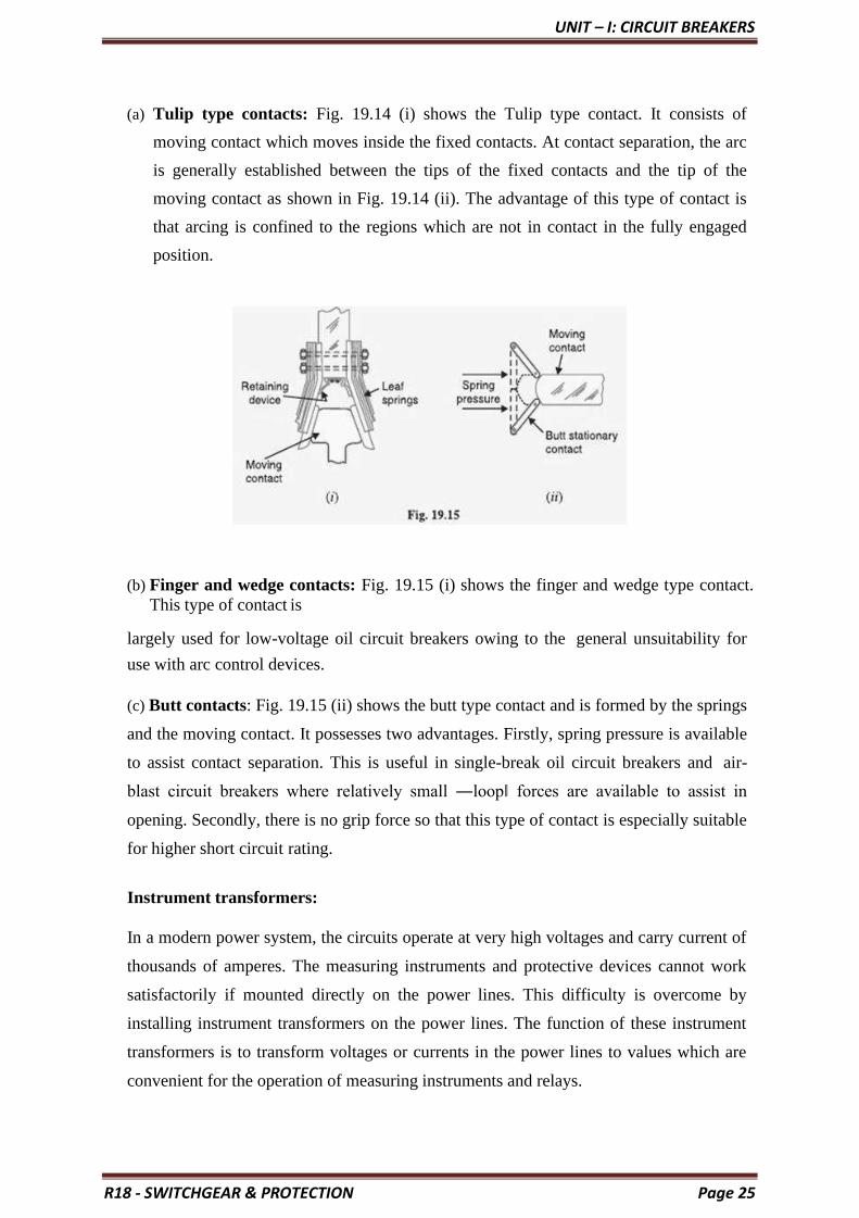
(a) Tulip type contacts: Fig. 19.14 (i) shows the Tulip type contact. It consists of
moving contact which moves inside the fixed contacts. At contact separation, the arc
is generally established between the tips of the fixed contacts and the tip of the
moving contact as shown in Fig. 19.14 (ii). The advantage of this type of contact is
that arcing is confined to the regions which are not in contact in the fully engaged
position.
(b) Finger and wedge contacts: Fig. 19.15 (i) shows the finger and wedge type contact.
This type of contact is
largely used for low-voltage oil circuit breakers owing to the general unsuitability for
use with arc control devices.
(c) Butt contacts: Fig. 19.15 (ii) shows the butt type contact and is formed by the springs
and the moving contact. It possesses two advantages. Firstly, spring pressure is available
to assist contact separation. This is useful in single-break oil circuit breakers and air-
blast circuit breakers where relatively small ―loop‖ forces are available to assist in
opening. Secondly, there is no grip force so that this type of contact is especially suitable
for higher short circuit rating.
Instrument transformers:
In a modern power system, the circuits operate at very high voltages and carry current of
thousands of amperes. The measuring instruments and protective devices cannot work
satisfactorily if mounted directly on the power lines. This difficulty is overcome by
installing instrument transformers on the power lines. The function of these instrument
transformers is to transform voltages or currents in the power lines to values which are
convenient for the operation of measuring instruments and relays.

UNIT – I: CIRCUIT BREAKERS
R18 - SWITCHGEAR & PROTECTION Page 26
There are two types of instrument transformers viz.
1. Current transformer (C.T.)
2. Potential transformer (P.T.)
The primary of current transformer is connected in the power line. The secondary
winding provides for
the instruments and relays a current which is a constant fraction of the current in the line
similarly, a potential transformer is connected with its primary in the power line. The
secondary provides for the instruments and relays a voltage which is a known fraction of
the line voltage. Fig. 19.16 shows the use of instrument transformers. The
*potential transformer rated 66,000/110V provides a voltage supply for the potential
coils of voltmeter and wattmeter. The current transformer rated 1000/5 A supplies
current to the current coils of wattmeter and ammeter.
The use of instrument transformers permits the following advantages:
(a) They isolate the measuring instruments and relays from high-voltage power circuits.
(b) The leads in the secondary circuits carry relatively small voltages and currents.
This permits to use wires of smaller size with minimum insulation.
UNIT – I: CIRCUIT BREAKERS
R18 - SWITCHGEAR & PROTECTION Page 27
Bus-bars and conductors: The current carrying members in a circuit breaker consist of
fixed and moving contacts and the conductors connecting these to the points external to
the breaker. If the switchgear is of outdoor type, these connections are connected directly
to the overhead lines. In case of indoor switchgear, the incoming conductors to the
circuit breaker are connected to the bus bars.
Circuit Breaker Ratings:
A circuit breaker may be called upon to operate under all conditions. However,
major duties are imposed on the circuit breaker when there is a fault on the system in
which it is connected. Under fault conditions, a circuit breaker is required to perform the
following three duties:
(i) It must be capable of opening the faulty circuit and breaking the fault current.
(ii) It must be capable of being closed on to a fault.
(iii) It must be capable of carrying fault current for a short time while another circuit
breaker (in series) is clearing the fault.
Corresponding to the above mentioned duties, the circuit breakers have three ratings viz.
1. Breaking capacity
2. Making capacity and
3. Short-time capacity.
Breaking capacity: It is current (r.m.s.) that a circuit breaker is capable of breaking at
given recovery voltage and under specified conditions (e.g., power factor, rate of rise of
restriking voltage).
The breaking capacity is always stated at the r.m.s. value of fault Current at the
instant of contact separation. When a fault occurs, there is considerable asymmetry in the
fault current due to the Presence of a d.c. component. The d.c. component dies away
rapidly, a typical decrement factor being 0·8 per cycle. Referring to
Fig. 19.24, the contacts are separated at DD´ At this instant, the fault current has

UNIT – I: CIRCUIT BREAKERS
R18 - SWITCHGEAR & PROTECTION Page 28
x = maximum value of a.c. component y = d.c. component
Symmetrical breaking current = r.m.s. value of a.c. component = x2
Asymmetrical breaking current = r.m.s. value of total current = y2
It is a common practice to express the breaking capacity in MVA by taking into account the
rated breaking current and rated service voltage. Thus, if I is the rated breaking current in
amperes and V is the rated service line voltage in volts, then for a 3-phase circuit,
Breaking capacity = 3X10⁻⁶ MVA
In India (or Britain), it is a usual practice to take breaking current equal to the symmetrical
breaking current. However, American practice is to take breaking current equal to
asymmetrical breaking current. Thus the American rating given to a circuit breaker is higher
than the Indian or British rating.
It seems to be illogical to give breaking capacity in MVA since it is obtained from the
product of Short- circuit current and rated service voltage. When the short-circuit current is
flowing, there is only a small voltage across the breaker contacts, while the service voltage
appears across the contacts only after the current has been interrupted. Thus MVA rating is
the product of two quantities which do not exist simultaneously in the circuit.
Therefore, the *agreed international standard of specifying breaking capacity is defined as
the rated symmetrical breaking current at a rated voltage.
MAKING CAPACITY:
There is always a possibility of closing or making the circuit under short circuit conditions.
The capacity of a breaker to ―make‖ current depends upon its ability to withstand and close
successfully against the effects of electromagnetic forces. These forces are proportional to
the square of maximum instantaneous current on closing. Therefore, making capacity is

UNIT – I: CIRCUIT BREAKERS
R18 - SWITCHGEAR & PROTECTION Page 29
stated in terms of a peak value of current instead of r.m.s. value.
The peak value of current (including d.c. component) during the first cycle of
current wave after the closure of circuit breaker is known as making capacity.
It may be noted that the definition is concerned with the first cycle of current wave on
closing the circuit breaker. This is because the maximum value of fault current possibly
occurs in the first cycle only when maximum asymmetry occurs in any phase of the breaker.
In other words, the making current is equal to the maximum value of asymmetrical current.
To find this value, we must multiply symmetrical breaking current by √2 to convert this
from r.m.s. to peak, and then by 1·8 to include the ―doubling effect‖ of maximum
asymmetry. The total multiplication factor becomes √2 X 1·8 = 2·55.
Making capacity =2·55 X Symmetrical breaking capacity
SHORT-TIME RATING:
It is the period for which the circuit breaker is able to carry fault current while
remaining closed. Sometimes a fault on the system is of very temporary nature and persists
for 1 or 2 seconds after which the fault is automatically cleared. In the interest of continuity
of supply, the breaker should not trip in such situations. This means that circuit breakers
should be able to carry high current safely for some specified period while remaining closed
i.e., they should have proven short-time rating. How ever, if the fault persists for duration
longer than the specified time limit, the circuit breaker will trip, disconnecting the faulty
section.
The short-time rating of a circuit breaker depends upon its ability to withstand The
electromagnetic force effects and The temperature rise.
The oil circuit breakers have a specified limit of 3 seconds when the ratio of symmetrical
breaking current to the rated normal current does not exceed 40. However, if this ratio is
more than 40, then the specified limit is 1 second.
Normal current rating:
It is the r.m.s. value of current which the circuit breaker is capable of carrying continuously
at its rated frequency under specified conditions. The only limitation in this case is the
temperature rise of current-carrying parts.

UNIT – I: CIRCUIT BREAKERS
R18 - SWITCHGEAR & PROTECTION Page 30
CIRCUIT BREAKER
CLASSIFICATION OF CIRCUIT BREAKERS:
There are several ways of classifying the circuit breakers. However, the most general way of
classification is on the basis of medium used for arc extinction. The medium used for arc
extinction is usually oil, air, sulphur hexafluoride (SF6) or vacuum. Accordingly, circuit
breakers may be classified into:
1. Oil circuit breakers: which employ some insulating oil (e.g., transformer oil) for
arc extinction?
2. Air-blast circuit breakers: in which high pressure air-blast is used for
extinguishing the arc.
3. Sulphur hexafluoride circuit breakers: in which sulphur hexafluoride (SF6)
gas is used for arc extinction.
4. Vacuum circuit breakers: in which vacuum is used for arc extinction.
Each type of circuit breaker has its own advantages and disadvantages. In the following
sections, we shall discuss the construction and working of these circuit breakers with special
emphasis on the way the arc extinction is facilitated.
Oil Circuit Breakers:
In such circuit breakers, some insulating oil (e.g., transformer oil) is used as an arc
quenching medium. The contacts are opened under oil and an arc is struck between them.
The heat of the arc evaporates the surrounding oil and dissociates it into a substantial
volume of gaseous hydrogen at high pressure. The hydrogen gas occupies a volume about
one thousand times that of the oil decomposed. The oil is, therefore, pushed away from the
arc and an expanding hydrogen gas bubble surrounds the arc region and adjacent portions of
the contacts (See Fig. 19.2). The arc extinction is facilitated mainly by two processes.
Firstly, the hydrogen gas has high heat conductivity and cools the arc, thus aiding the de-
ionization of the medium between the contacts. Secondly, the gas sets up turbulence in the
oil and forces it into the space between contacts, thus eliminating the arcing products from
the arc path. The result is that arc is extinguished and circuit current †interrupted.

UNIT – I: CIRCUIT BREAKERS
R18 - SWITCHGEAR & PROTECTION Page 31
The advantages of oil as an arc quenching medium are:
1. It absorbs the arc energy to decompose the oil into gases which have excellent
cooling properties.
2. It acts as an insulator and permits smaller clearance between live conductors and
earthed components.
3. The surrounding oil presents cooling surface in close proximity to the arc.
The disadvantages of oil as an arc quenching medium are:
1. It is inflammable and there is a risk of a fire.
2. It may form an explosive mixture with air
3. The arcing products (e.g., carbon) remain in the oil and its quality deteriorates
with successive operations. This necessitates periodic checking and replacement
of oil.
Types of Oil Circuit Breakers:
The oil circuit breakers find extensive use in the power system. These can be
classified into the following types:
1. Bulk oil circuit breakers
2. Low oil circuit breakers
Bulk oil circuit breakers:
Which use a large quantity of oil. The oil has to serve two purposes. Firstly, it extinguishes
the arc during opening of contacts and secondly, it insulates the current conducting parts
from one another and from the earthed tank. Such circuit breakers may be classified into:
1. Plain break oil circuit breakers
2. Arc control oil circuit breakers.
In the former type, no special means is available for controlling the arc and the contacts are
directly exposed to the whole of the oil in the tank. However, in the latter type, special arc
control devices are employed to get the beneficial action of the arc as efficiently as possible.

UNIT – I: CIRCUIT BREAKERS
R18 - SWITCHGEAR & PROTECTION Page 32
Plain Break Oil Circuit Breakers:
A plain-break oil circuit breaker involves the simple process of separating the contacts
under the whole of the oil in the tank. There is no special system for arc control other than
the increase in length caused by the separation of contacts. The arc extinction occurs when a
certain critical gap between the contacts is reached. The plain- break oil circuit breaker is
the earliest type from which all other circuit breakers have developed. It has a very simple
construction. It consists of fixed and moving contacts enclosed in a strong weather-tight
earthed tank containing oil up to a certain level and an air cushion above the oil level. The
air cushion provides sufficient room to allow for the reception of the arc gases without the
generation of unsafe pressure in the dome of the circuit breaker. It also absorbs the
mechanical shock of the upward oil movement. Fig. 19.3 shows a double break plain oil
circuit breaker. It is called a double break because it provides two breaks in series.
Under normal operating conditions, the fixed and moving contacts remain closed and the
breaker carries the normal circuit Current. When a fault occurs, the moving contacts are
pulled down by the protective system and an arc is struck which vaporizes the oil mainly
into hydrogen gas.
The arc extinction is facilitated by the following processes:
❖ The hydrogen gas bubble generated around the arc cools the arc column and aids the
deionization of the medium between the contacts.
❖ The gas sets up turbulence in the oil and helps in eliminating the arcing products from
the arc path.
❖ As the arc lengthens due to the separating contacts, the dielectric strength of the

UNIT – I: CIRCUIT BREAKERS
R18 - SWITCHGEAR & PROTECTION Page 33
medium is increased.
❖ The result of these actions is that at some critical gap length, the arc is extinguished
and the circuit current is interrupted.
Disadvantages:
There is no special control over the arc other than the increase in length by separating the moving contacts. Therefore, for successful Interruption, Long arc length is necessary.
❖ These breakers have long and inconsistent arcing times.
❖ These breakers do not permit high speed interruption.
Due to these disadvantages, plain-break oil circuit breakers are used only for low voltage
applications where high breaking-capacities are not important. It is a usual practice to use
such breakers for low capacity installations for Voltages not exceeding 11 kV.
ARC CONTROL OIL CIRCUIT BREAKERS:
In case of plain-break oil circuit breaker discussed above, there is very little artificial control
over the arc. Therefore, comparatively long arc length is essential in order that turbulence in
the oil caused by the gas may assist in quenching it. However, it is necessary and desirable
that final arc extinction should occur while the contact gap is still short. For this purpose,
some arc control is incorporated and the breakers are then called arc control circuit breakers.
There are two types of such breakers, namely:
1. Self-blast oil circuit breakers— in which arc control is provided by internal
means i.e. the arc itself is employed for its own extinction efficiently.
2. Forced-blast oil circuit breakers— in which arc control is provided by
mechanical means external to the circuit breaker.
Self-blast oil circuit breakers:
In this type of circuit breaker, the gases produced during arcing are confined to a small
volume by the use of an insulating rigid pressure chamber or pot surrounding the contacts.
Since the space available for the arc gases is restricted by the chamber, a very high pressure
is developed to force the oil and gas through or around the arc to extinguish it. The
magnitude of pressure developed depends upon the value of fault current to be interrupted.
As the pressure is generated by the arc itself, therefore, such breakers are some times called
self-generated pressure oil circuit breakers.

UNIT – I: CIRCUIT BREAKERS
R18 - SWITCHGEAR & PROTECTION Page 34
The pressure chamber is relatively cheap to make and gives reduced final arc extinction gap
length and arcing time as against the plain-break oil circuit breaker. Several designs of
pressure chambers (sometimes called explosion pots) have been developed and a few of
them are described below:
Plain explosion pot:
It is a rigid cylinder of insulating material and encloses the fixed and moving contacts (See
Fig. 19.4). The moving contact is a cylindrical rod passing through a restricted opening
(called throat) at the bottom. When a fault occurs, the contacts get separated and an arc is
struck between them. The heat of the arc decomposes oil into a gas at very high pressure in
the pot. This high pressure forces the oil and gas through and round the arc to extinguish it.
If the final arc extinction does not take place while the moving contact is still within the pot,
it occurs immediately after the moving contact leaves the pot. It is because emergence of the
moving contact from the pot is followed by a violent rush of gas and oil through the throat
producing rapid extinction.
The principal limitation of this type of pot is that it cannot be used for very low or for very
high fault currents. With low fault currents, the pressure developed is small, thereby
increasing the arcing time. On the other hand, with high fault currents, the gas is produced
so rapidly that explosion pot is liable to burst due to high pressure. For this reason, plain
explosion pot operates well on moderate short-circuit currents only where the rate of gas
evolution is moderate
Cross jet explosion pot:
This type of pot is just a modification of plain explosion pot and is illustrated in Fig. 19.5. It
is made of insulating material and has channels on one side which act as arc splitters. The
arc splitters help in increasing the arc length, thus facilitating arc extinction. When a fault

UNIT – I: CIRCUIT BREAKERS
R18 - SWITCHGEAR & PROTECTION Page 35
occurs, the moving contact of the circuit breaker begins to separate. As the moving contact
is withdrawn, the arc is initially struck in the top of the pot. The gas generated by the arc
exerts pressure on the oil in the back passage. When the moving contact uncovers the arc
splitter ducts, fresh oil is forced *across the arc path. The arc is, therefore, driven sideways
into the ―arc splitters‖ which increase the arc length, causing arc extinction.
The cross-jet explosion pot is quite efficient for interrupting heavy fault currents. However,
for low fault currents, the gas pressure is †small and consequently the pot does not give a
satisfactory operation.
Self-compensated explosion pot:
This type of pot is essentially a combination of plain explosion pot and cross jet explosion
pot. Therefore, it can interrupt low as well as heavy short circuit currents with reasonable
accuracy. Fig. 19.6 shows the schematic diagram of self-compensated explosion pot. It
consists of two chambers; the upper chamber is the cross-jet explosion pot with two arc
splitter ducts while the lower one is the plain explosion pot. When the short- circuit current
is heavy, the rate of generation of gas is very high and the device behaves as a cross-jet
explosion pot. The arc extinction takes place when the moving contact uncovers the first or
second arc splitter duct. However, on low short-circuit currents, the rate of gas generation is
small and the tip of the moving contact has the time to reach the lower chamber. During this
time, the gas builds up sufficient pressure as there is very little leakage through arc splitter
ducts due to the obstruction offered by the arc path and right angle bends. When the moving
contact comes out of the throat, the arc is extinguished by plain pot action.
It may be noted that as the severity of the short circuit current increases, the device operates
less and less as a plain explosion pot and more and more as a cross-jet explosion pot. Thus
the tendency is to make the control self- compensating over the full range of fault currents to
be interrupted.

UNIT – I: CIRCUIT BREAKERS
R18 - SWITCHGEAR & PROTECTION Page 36
Forced-blast oil circuit breakers:
In the self-blast oil circuit breakers discussed above, the arc itself generates the necessary
pressure to force the oil across the arc path. The major limitation of such breakers is that
arcing times tend to be long and inconsistent when operating against currents considerably
less than the rated currents. It is because the gas generated is much reduced at low values of
fault currents. This difficulty is overcome in forced-blast oil circuit breakers in which the
necessary pressure is generated by external mechanical means independent of the fault
currents to be broken.
In a forced -blast oil circuit breaker, oil pressure is created by the piston-cylinder
arrangement. The movement of the piston is mechanically coupled to the moving contact.
When a fault occurs, the contacts get separated by the protective system and an arc is struck
between the contacts. The piston forces a jet of oil towards the contact gap to extinguish the
arc. It may be noted that necessary oil pressure produced does not in any way depend upon
the fault current to be broken.
Advantages:
❖ Since oil pressure developed is independent of the fault current to be interrupted, the
performance at low currents is more consistent than with self-blast oil circuit breakers.
❖ The quantity of oil required is reduced considerably.
Low Oil Circuit Breakers:
In the bulk oil circuit breakers discussed so far, the oil has to perform two functions. Firstly,
it acts as an arc quenching medium and secondly, it insulates the live parts from earth. It has
been found that only a small percentage of oil is actually used for arc extinction while the
major part is utilized for insulation purposes. For this reason, the quantity of oil in bulk oil
circuit breakers reaches a very high figure as the system voltage increases. This not only
increases the expenses, tank size and weight of the breaker but it also increase the fire risk
and maintenance problems.

UNIT – I: CIRCUIT BREAKERS
R18 - SWITCHGEAR & PROTECTION Page 37
The fact that only a small percentage of oil (about 10% of total) in the bulk
oil circuit breaker is actually used for arc extinction leads to the question as to why the
remainder of the oil, that is not immediately surrounding the device, should not be omitted
with consequent saving in bulk, weight and fire risk. This led to the development of low-oil
circuit breaker. A low oil circuit breaker employs solid materials for insulation purposes and
uses a small quantity of oil which is just sufficient for arc extinction. As regards quenching
the arc, the oil behaves identically in bulk as well as low oil circuit breaker. By using
UNIT – I: CIRCUIT BREAKERS
R18 - SWITCHGEAR & PROTECTION Page 38
suitable arc control devices, the arc extinction can be further facilitated in a low oil circuit
breaker.
Construction:
Fig 19.7 shows the cross section of a single phase low oil circuit breaker. There are two
compartments separated from each other but both filled with oil. The upper chamber is the
circuit breaking chamber while the lower one is the supporting chamber. The two chambers
are separated by a partition and oil from one chamber is prevented from mixing with the
other chamber. This arrangement permits two advantages. Firstly, the circuit breaking
chamber requires a small volume of oil which is just enough for arc extinction. Secondly,
the amount of oil to be replaced is reduced as the oil in the supporting chamber does not get
contaminated by the arc.
Supporting chamber:
It is a porcelain chamber mounted on a metal chamber. It is filled with oil which is
physically separated from the oil in the circuit breaking compartment. The oil inside the
supporting chamber and the annular space formed between the porcelain insulation and
bakelised paper is employed for insulation purposes only.
Circuit-breaking chamber:
It is a porcelain enclosure mounted on the top of the supporting compartment. It is filled
with oil and has the following parts:
1. upper and lower fixed contacts
2. Moving contact
3. Turbulator
The moving contact is hollow and includes a cylinder which moves down over a fixed
piston. The turbulator is an arc control device and has both axial and radial vents. The axial
venting ensures the interruption of low currents whereas radial venting helps in the
interruption of heavy currents.
Top chamber:
It is a metal chamber and is mounted on the circuit-breaking chamber. It provides expansion
space for the oil in the circuit breaking compartment. The top chamber is also provided with
a separator which prevents any loss of oil by centrifugal action caused by circuit breaker
operation during fault conditions.

UNIT – I: CIRCUIT BREAKERS
R18 - SWITCHGEAR & PROTECTION Page 39
Operation:
Under normal operating conditions, the moving contact remains engaged with the upper
fixed contact. When a fault occurs, the moving contact is pulled down by the tripping
springs and an arc is struck. The arc energy vaporizes the oil and produces gases under high
pressure. This action constrains the oil to pass through a central hole in the moving contact
and results in forcing series of oil through the respective passages of the tabulator. The
process of tabulation is orderly one, in which the sections of the arc are successively
quenched by the effect of separate streams of oil moving across each section in turn and
bearing away its gases.
A low oil circuit breaker has the following advantages over a bulk oil circuit breaker:
1. It requires lesser quantity of oil.
2. It requires smaller space.
3. There is reduced risk of fire.
4. Maintenance problems are reduced.
A low oil circuit breaker has the following disadvantages as compared to a bulk oil
circuit breaker:
1. Due to smaller quantity of oil, the degree of carbonization is increased.
2. There is a difficulty of removing the gases from the contact space in time.
3. The dielectric strength of the oil deteriorates rapidly due to high degree of
carbonization.
Maintenance of Oil Circuit Breakers:
The maintenance of oil circuit breaker is generally concerned with the checking of contacts
and dielectric strength of oil. After a circuit breaker has interrupted fault currents a few
times or load currents several times, its contacts may get burnt by arcing and the oil may
lose some of its dielectric strength due to carbonization. This results in the reduced
rupturing capacity of the breaker. There fore, it is a good practice to inspect the circuit
breaker at regular intervals of 3 or 6 months.
During inspection of the breaker, the following points should be kept in view:
❖ Check the current carrying parts and arcing contacts. If the burning is severe, the
contacts should be replaced.
❖ Check the dielectric strength of the oil. If the oil is badly discolored, it should be changed or reconditioned. The oil in good condition should withstand 30 kV for one minute in a standard oil testing cup with 4 mm gap between electrodes.
❖ Check the insulation for possible damage. Clean the surface and remove carbon

UNIT – I: CIRCUIT BREAKERS
R18 - SWITCHGEAR & PROTECTION Page 40
deposits with a strong and dry fabric.
❖ Check the oil level.
❖ Check closing and tripping mechanism.
Air-Blast Circuit Breakers:
These breakers employ a high pressure *air-blast as an arc quenching medium. The contacts
are opened in a flow of air-blast established by the opening of blast valve. The air-blast cools
the arc and sweeps away the arcing products to the atmosphere. This rapidly increases the
dielectric strength of the medium between contacts and prevents from re-establishing the arc.
Consequently, the arc is extinguished and flow of current is interrupted.
An air-blast circuit breaker has the following advantages over an oil circuit breaker:
1. The risk of fire is eliminated.
2. The arcing products are completely removed by the blast whereas the oil
deteriorates with successive operations; the expense of regular oil replacement is
avoided.
3. The growth of dielectric strength is so rapid that final contact gap needed for arc
extinction is very small. This reduces the size of the device.
4. The arcing time is very small due to the rapid buildup of dielectric strength
between contacts. Therefore, the arc energy is only a fraction of that in oil circuit
breakers, thus resulting in less burning of contacts.
5. Due to lesser arc energy, air-blast circuit breakers are very suitable for conditions
where frequent operation is required.
6. The energy supplied for arc extinction is obtained from high pressure air and is
independent of the current to be interrupted.
The use of air as the arc quenching medium offers the following disadvantages:
1. The air has relatively inferior arc extinguishing properties.
2. The air-blast circuit breakers are very sensitive to the variations in the rate of rise of
re strikingvoltage.
3. Considerable maintenance is required for the compressor plant which supplies the air-blast.
4. The air blast circuit breakers are finding wide applications in high voltage
installations.
5. Majority of the circuit breakers for voltages beyond 110 kV are of this type.

UNIT – I: CIRCUIT BREAKERS
R18 - SWITCHGEAR & PROTECTION Page 41
Types of Air-Blast Circuit Breakers:
Depending upon the direction of air-blast in relation to the arc, air-blast circuit breakers
are classified into:
1. Axial-blast type in which the air-blast is directed along the arc path as shown in
Fig. 19.8(i).
2. Cross-blast type in which the air-blast is directed at right angles to the arc path as shown in Fig. 19.8 (ii).
3. Radial-blast type in which the air-blast is directed radially as shown in Fig. 19.8
(iii).
Axial-blast air circuit breaker:
Fig 19.9 shows the essential components of a typical axial blast air circuit breaker. The
fixed and moving contacts are held in the closed position by spring pressure under normal
conditions. The air reservoir is connected to the arcing chamber through an air valve. This
valve remains closed under normal conditions but opens automatically by the tripping
impulse when a fault occurs on the system.
When a fault occurs, the tripping impulse causes opening of the air valve which connects the

UNIT – I: CIRCUIT BREAKERS
R18 - SWITCHGEAR & PROTECTION Page 42
circuit breaker reservoir to the arcing chamber. The high pressure air entering the arcing
chamber pushes away the moving contact against spring pressure. The moving contact is
separated and an arc is struck. At the same time, high pressure air blast flows along the arc
and takes away the ionized gases along with it. Consequently, the arc is extinguished and
current flow is interrupted.
t may be noted that in such circuit breakers, the contact separation required for interruption
is generally small (1·75 cm or so). Such a small gap may constitute inadequate clearance for
the normal service voltage. Therefore, an isolating switch is incorporated as a part of this
type of circuit breaker. This switch opens immediately after fault interruption to provide the
necessary clearance for insulation.
Cross-blast air breaker:
In this type of circuit breaker, an air-blast is directed at right angles to the arc. The cross-
blast lengthens and forces the arc into a suitable chute for arc extinction. Fig. 19.10 shows
the essential parts of a typical cross- blast Air circuit breaker. When the moving contact is
withdrawn, an arc is struck between the fixed and moving contacts. The high pressure cross-
blast Forces the arc into a chute consisting of arc splitters and baffles. The splitters serve to
increase the length of the arc and baffles give improved cooling. The result is that arc is
extinguished and flow of Current is interrupted. Since blast pressure is same for all currents,
the inefficiency at low currents is eliminated. The final gap for interruption is great enough
to give normal insulation clearance so that a series isolating switch is not necessary.
SULPHUR HEXAFLUORIDE (SF6) CIRCUIT BREAKERS:

UNIT – I: CIRCUIT BREAKERS
R18 - SWITCHGEAR & PROTECTION Page 43
In such circuit breakers, sulphur hexafluoride (SF6) gas is used as the arc quenching
medium. The SF6 is an electro-negative gas and has a strong tendency to absorb free
electrons. The contacts of the breaker are opened in a high pressure flow of SF6 gas and an
arc is struck between them. The conducting free electrons in the arc are rapidly captured by
the gas to form relatively immobile negative ions. This loss of conducting electrons in the
arc quickly builds up enough insulation strength to extinguish the arc. The SF6 circuit
breakers have been found to be very effective for high power and high voltage service.
Construction:
Fig. 19.11 shows the parts of a typical SF6 circuit breaker. It consists of fixed and moving
contacts enclosed in a chamber (called arc interruption chamber) containing SF6 gas. This
chamber is connected to SF6 gas reservoir. When the contacts of breaker are opened, the
valve mechanism permits a high pressure SF6 gas from the reservoir to flow towards the arc
interruption chamber. The fixed contact is a hollow cylindrical current carrying contact
fitted with an arc horn. The moving contact is also a hollow cylinder with rectangular holes
in the sides to permit the SF6 gas to let out through these holes after flowing along and
across the arc. The tips of fixed contact, moving contact and arcing horn are coated with
UNIT – I: CIRCUIT BREAKERS
R18 - SWITCHGEAR & PROTECTION Page 44
copper-tungsten arc resistant material. Since SF6 gas is Costly, it is reconditioned and
reclaimed by suitable auxiliary system after each operation of the breaker.
Working:
In the closed position of the breaker, the contacts remain surrounded by SF6 gas at a pressure
of about 2·8 kg/cm. When the breaker operates, the moving contact is pulled apart and an arc
is struck between the contacts. The movement of the moving contact is synchronized with the
opening of a valve which permits SF6 gas at 14 kg/cm pressure from the reservoir to the arc
interruption chamber. The high pressure flow of SF6 rapidly absorbs the free electrons in the
arc path to form immobile negative ions which are ineffective as charge carriers. The result is
that the medium between the contacts quickly builds up high dielectric strength and causes
the extinction of the arc. After the breaker operation (i.e., after arc extinction), the valve is
closed by the action of a set of springs.
Advantages:
Due to the superior arc quenching properties of SF6 gas, the SF6 circuit breakers have many
advantages over oil or air circuit breakers. Some of them are listed below:
1. Due to the superior arc quenching property of SF6, such circuit breakers have very
short arcing time.
2. Since the dielectric strength of SF6 gas is 2 to 3 times that of air, such breakers can
interrupt much larger currents.
3. The SF6 circuit breaker gives noiseless operation due to its closed gas circuit and
no exhaust to atmosphere unlike the air blast circuit breaker
4. The closed gas enclosure keeps the interior dry so that there is no moisture problem.
5. There is no risk of fire in such breakers because SF6 gas is non-inflammable.
6. There are no carbon deposits so that tracking and insulation problems are eliminated.
7. The SF6 breakers have low maintenance cost, light foundation requirements and
minimum auxiliary equipment.
8. Since SF6 breakers are totally enclosed and sealed from atmosphere, they are
particularly suitable where explosion hazard exists e.g., coal mines.
Disadvantages:
1. SF6 breakers are costly due to the high cost of SF6.
2. Since SF6 gas has to be reconditioned after every operation of the breaker,
additional equipment is required for this purpose.
Applications:

UNIT – I: CIRCUIT BREAKERS
R18 - SWITCHGEAR & PROTECTION Page 45
A typical SF6 circuit breaker consists of interrupter units each capable of dealing with
currents up to 60 kA and voltages in the range of 50—80 kV. A number of units are
connected in series according to the system voltage. SF6 circuit breakers have been
developed for voltages 115 kV to 230 kV, power ratings 10 MVA to 20 MVA and
interrupting time less than 3 cycles.
VACUUM CIRCUIT BREAKERS (VCB):
In such breakers, vacuum (degree of vacuum being in the range from 10 to 10 torr) is used
as the arc quenching medium. Since vacuum offers the highest insulating strength, it has far
superior arc quenching properties than any other medium. For example, when contacts of a
breaker are opened in vacuum, the interruption occurs at first current zero with dielectric
strength between the contacts building up at a rate thousands of times higher than that
obtained with other circuit breakers.
Principle:
The production of arc in a vacuum circuit breaker and its extinction can be explained as
follows:
When the contacts of the breaker are opened in vacuum (10 to 10 torr), an arc is produced
between the contacts by the ionization of metal vapours of contacts. However, the arc is
quickly extinguished because the metallic vapours, electrons and ions produced during arc
rapidly condense on the surfaces of the circuit breaker contacts, resulting in quick recovery
of dielectric strength. The reader may note the salient feature of vacuum as an arc quenching
medium. As soon as the arc is produced in vacuum, it is quickly extinguished due to the fast
rate of recovery of dielectric strength in vacuum.
Construction:
Fig. 19.12 shows the parts of a typical vacuum circuit breaker. It consists of fixed contact,
moving contact and arc shield mounted inside a vacuum chamber. The movable member is
connected to the control mechanism by stainless steel bellows. This enables the permanent
sealing of the vacuum chamber so as to eliminate the possibility of leak. A glass vessel or
ceramic vessel is used as the outer insulating body. The arc shield prevents the deterioration
of the internal dielectric strength by preventing metallic vapours falling on the inside surface
of the outer insulating cover.

UNIT – I: CIRCUIT BREAKERS
R18 - SWITCHGEAR & PROTECTION Page 46
Working:
When the breaker operates, the moving contact separates from the fixed contact
and an arc is struck between the contacts. The production of arc is due to the ionization
of metal ions and depends very much upon the material of contacts. The arc is quickly
extinguished because the metallic vapours, electrons and ions produced during arc are
diffused in a short time and seized by the surfaces of moving and fixed members and
shields. Since vacuum has very fast rate of recovery of dielectric strength, the arc
extinction in a vacuum breaker occurs with a short contact separation (say 0·625 cm).
Vacuum circuit breakers have the following advantages:
1. They are compact, reliable and have longer life.
2. There is no generation of gas during and after operation.
3. They can interrupt any fault current. The outstanding feature of a V C B is that it
can break any heavy fault current perfectly just before the contacts reach the
definite open position.
4. They require little maintenance and are quiet in operation.

UNIT – I: CIRCUIT BREAKERS
R18 - SWITCHGEAR & PROTECTION Page 47
5. They have low arc energy.
6. They have low inertia and hence require smaller power for control mechanism.
Applications:
For a country like India, where distances are quite large and accessibility to
remote areas difficult, the installation of such outdoor, maintenance free circuit breakers
should prove a definite advantage. Vacuum circuit breakers are being employed for
outdoor applications ranging from 22 kV to 66 kV. Even with limited rating of say 60 to
100 MVA, they are suitable for a majority of applications in rural areas.

UNIT – II: ELECTROMAGNETIC & STSTIC RELAYS
R18 - SWITCHGEAR & PROTECTION Page 48
UNIT - II
ELECTROMAGNETIC AND STATIC RELAYS

UNIT – II: ELECTROMAGNETIC & STSTIC RELAYS
R18 - SWITCHGEAR & PROTECTION Page 49

UNIT – II: ELECTROMAGNETIC & STSTIC RELAYS
R18 - SWITCHGEAR & PROTECTION Page 50

UNIT – II: ELECTROMAGNETIC & STSTIC RELAYS
R18 - SWITCHGEAR & PROTECTION Page 51

UNIT – II: ELECTROMAGNETIC & STSTIC RELAYS
R18 - SWITCHGEAR & PROTECTION Page 52

UNIT – II: ELECTROMAGNETIC & STSTIC RELAYS
R18 - SWITCHGEAR & PROTECTION Page 53

UNIT – II: ELECTROMAGNETIC & STSTIC RELAYS
R18 - SWITCHGEAR & PROTECTION Page 54

UNIT – II: ELECTROMAGNETIC & STSTIC RELAYS
R18 - SWITCHGEAR & PROTECTION Page 55

UNIT – II: ELECTROMAGNETIC & STSTIC RELAYS
R18 - SWITCHGEAR & PROTECTION Page 56

UNIT – II: ELECTROMAGNETIC & STSTIC RELAYS
R18 - SWITCHGEAR & PROTECTION Page 57

UNIT – II: ELECTROMAGNETIC & STSTIC RELAYS
R18 - SWITCHGEAR & PROTECTION Page 58
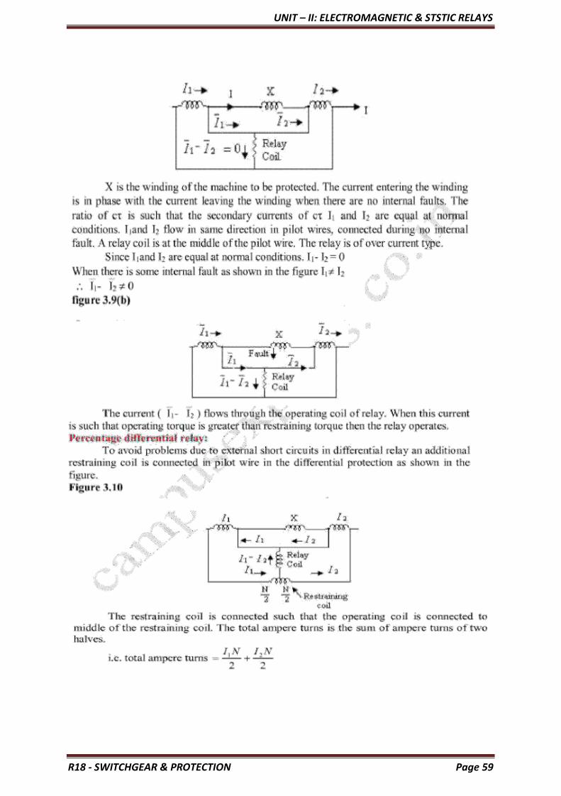
UNIT – II: ELECTROMAGNETIC & STSTIC RELAYS
R18 - SWITCHGEAR & PROTECTION Page 59

UNIT – II: ELECTROMAGNETIC & STSTIC RELAYS
R18 - SWITCHGEAR & PROTECTION Page 60
UNIT – II: ELECTROMAGNETIC & STSTIC RELAYS
R18 - SWITCHGEAR & PROTECTION Page 61

UNIT – II: ELECTROMAGNETIC & STSTIC RELAYS
R18 - SWITCHGEAR & PROTECTION Page 62

UNIT – II: ELECTROMAGNETIC & STSTIC RELAYS
R18 - SWITCHGEAR & PROTECTION Page 63

UNIT – II: ELECTROMAGNETIC & STSTIC RELAYS
R18 - SWITCHGEAR & PROTECTION Page 64

UNIT – II: ELECTROMAGNETIC & STSTIC RELAYS
R18 - SWITCHGEAR & PROTECTION Page 65

UNIT – II: ELECTROMAGNETIC & STSTIC RELAYS
R18 - SWITCHGEAR & PROTECTION Page 66
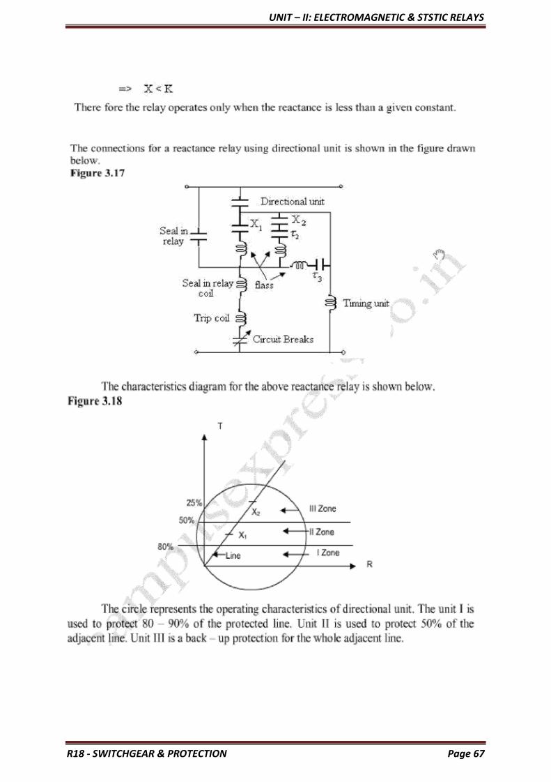
UNIT – II: ELECTROMAGNETIC & STSTIC RELAYS
R18 - SWITCHGEAR & PROTECTION Page 67

UNIT – II: ELECTROMAGNETIC & STSTIC RELAYS
R18 - SWITCHGEAR & PROTECTION Page 68

UNIT – II: ELECTROMAGNETIC & STSTIC RELAYS
R18 - SWITCHGEAR & PROTECTION Page 69

UNIT – II: ELECTROMAGNETIC & STSTIC RELAYS
R18 - SWITCHGEAR & PROTECTION Page 70

UNIT – II: ELECTROMAGNETIC & STSTIC RELAYS
R18 - SWITCHGEAR & PROTECTION Page 71

UNIT – II: ELECTROMAGNETIC & STSTIC RELAYS
R18 - SWITCHGEAR & PROTECTION Page 72
UNIT – III: PROTECTION OF GENERATORS & TRANSFORMERS
R18 - SWITCHGEAR & PROTECTION Page 73
UNIT- III
PROTECTION OF GENERATORS AND TRANSFORMERS
Protection of Alternators
The generating units, especially the larger ones, are relatively few in number and higher in individual cost than most other equipments. Therefore, it is desirable and necessary to provide protection to cover the wide range of faults which may occur in the modern generating plant.
Some of the important faults which may occur on an alternator are: (i) failure of prime-mover (ii) failure of field (iii) overcurrent (iv) Over speed
unbalanced (v) overvoltage (vi) loading (vii) stator winding faults
(i) Failure of prime-mover. When input to the prime-mover fails, the alternator runs as a synchronous motor and draws some current from the supply system. This motoring condition is known as ―inverted running‖.
(a) In case of turbo-alternator sets, failure of steam supply may cause inverted running. If the steam supply is gradually restored, the alternator will pick up load without disturbing the system. If the steam failure is likely to be prolonged, the machine can be safely isolated by the control room attendant since this condition is relatively harmless. There-fore, automatic protection is not required.
(b) In case of hydro-generator sets, protection against inverted running is achieved by pro- viding mechanical devices on the water-wheel. When the water flow drops to an insufficient rate to maintain the electrical output, the alternator is disconnected from the system. Therefore, in this case also electrical protection is not necessary.
(c) Diesel engine driven alternators, when running inverted, draw a considerable amount of power from the supply system and it is a usual practice to provide protection against motoring in order to avoid damage due to possible mechanical seizure. This is achieved by applying reverse power relays to the alternators which *isolate the latter during their motoring action. It is essential that the reverse power relays have time-delay in operation in order to prevent inadvertent tripping during system disturbances caused by faulty synchronizing and phase swinging.
(ii) Failure of field. The chances of field failure of alternators are undoubtedly very rare.
Even if it does occur, no immediate damage will be caused by permitting the alternator
to run without a field for a short-period. It is sufficient to rely on the control room
attendant to disconnect the faulty alternator manually from the system bus-bars.
Therefore, it is a universal practice not to provide †automatic protection against this
contingency.
(iii) Overcurrent. It occurs mainly due to partial breakdown of winding insulation or due to
overload on the supply system. Overcurrent protection for alternators is considered
unnecessary because of the following reasons :
(a) The modern tendency is to design alternators with very high values of internal impedance so that they will stand a complete short-circuit at their terminals for sufficient time without serious overheating. On the occurrence of an overload, the alternators can be disconnected manually.
(b) The disadvantage of using overload protection for alternators is that such a protection might disconnect the alternators from the power plant bus on account of some

UNIT – III: PROTECTION OF GENERATORS & TRANSFORMERS
R18 - SWITCHGEAR & PROTECTION Page 74
momentary troubles outside the plant and, therefore, interfere with the continuity of electric service.
* During inverted running (or motoring), there is a reversal of power flow in the stator windings. This causes the operation of reverse power relay.
† This is the case with attendant stations. However, in unattended stations, the use of a field-failure relay may be justified.
(iv) Over speed. The chief cause of over speed is the sudden loss of all or the major part of load on the alternator. Modern alternators are usually provided with mechanical centrifugal devices mounted on their driving shafts to trip the main valve of the prime- mover when a dangerous over speed occurs.
(v) Over-voltage. The field excitation system of modern alternators is so designed that over- voltage conditions at normal running speeds cannot occur. However, overvoltage in an alternator occurs when speed of the prime-mover increases due to sudden loss of the alternator load.
In case of steam-turbine driven alternators, the control governors are very sensitive to speed variations. They exercise a continuous check on over speed and thus prevent the occurrence of over-voltage on the generating unit. Therefore, over-voltage protection is not provided on turbo-alternator sets.
In case of hydro-generator, the control governors are much less sensitive and an appreciable time may elapse before the rise in speed due to loss of load is checked. The over-
voltage during this time may reach a value which would over-stress the stator windings and
insulation breakdown may occur. It is, therefore, a usual practice to provide over-voltage protection on hydro-generator units. The over-voltage relays are operated from a voltage
supply derived from the generator terminals. The relays are so arranged that when the generated voltage rises 20% above the normal value, they operate to
• trip the main circuit breaker to disconnect the faulty alternator from the system
• disconnect the alternator field circuit
(vi) Unbalanced loading. Unbalanced loading means that there are different phase currents
in the alternator. Unbalanced loading arises from faults to earth or faults between phases
on the circuit external to the alternator. The unbalanced currents, if allowed to persist, may either severely burn the mechanical fixings of the rotor core or damage the field
winding.
Fig. 22.1 shows the schematic arrangement for the protection of alternator against unbalanced loading. The scheme comprises three line current transformers, one mounted in each phase, having their secondaries connected in parallel. A relay is connected in parallel across the transformer secondaries. Under normal operating conditions, equal currents flow through the different phases of the alternator and their algebraic sum is zero.
Therefore, the sum of the cur-rents flowing in the secondaries is also zero and no current flows through the operating coil of the relay. However, if unbalancing occurs, the currents induced in the secondaries will be different and the resultant of these currents will flow through the relay. The operation of the relay will trip the circuit breaker to disconnect the alternator from the system.

UNIT – III: PROTECTION OF GENERATORS & TRANSFORMERS
R18 - SWITCHGEAR & PROTECTION Page 75
(i) Stator winding faults. These faults occur mainly due to the insulation failureof the stator windings. The main types of stator winding faults, in order of importance are:
• Fault between phase and ground Principles of Power System
• Fault between phases
• Inter-turn fault involving turns of the same phase winding
The stator winding faults are the most dangerous and are likely to cause considerable damage
to the expensive machinery. Therefore, automatic protection is absolutely necessary to clear
such faults in the quickest possible time in order to minimize the *extent of damage. For
protection of alternators against such faults, differential method of protection (also known as
Merz - Price system) is most commonly employed due to its greater sensitivity and
reliability. This system of protection is dis-cussed in the following section.
DIFFERENTIAL PROTECTION OF ALTERNATORS
The most common system used for the protection of stator winding faults employs
circulating-current principle (Refer back to Art. 21.18). In this scheme of protection, currents
at the two ends of the protected section are compared. Under normal operating conditions,
these currents are equal but may become unequal on the occurrence of a fault in the protected
section. The difference of the currents under fault conditions is arranged to pass through the
operating coil of the relay. The relay then closes its contacts to isolate protected section from
the system. This form of protection is also known as Merz-Price circulating current scheme.
SCHEMATIC ARRANGEMENT: Fig. 22.2 shows the schematic arrangement of current
differential protection for a 3-phase alternator. Identical current transformer pairs CT1and
CT2 are placed on either side of each phase of the stator windings. The secondaries of each
set of current transformers are connected in star; the two neutral points and the corresponding
terminals of the two star groups being connected together by means of a four-core pilot cable.
Thus there is an independent path for the currents circulating in each pair of current
transformers and the corresponding pilot P.
* If the stator winding fault is not cleared quickly, it may lead to
* (i) burning of stator coils
(ii) burning and welding-up of stator laminations
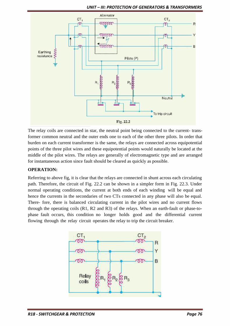
UNIT – III: PROTECTION OF GENERATORS & TRANSFORMERS
R18 - SWITCHGEAR & PROTECTION Page 76
The relay coils are connected in star, the neutral point being connected to the current- trans-
former common neutral and the outer ends one to each of the other three pilots. In order that
burden on each current transformer is the same, the relays are connected across equipotential
points of the three pilot wires and these equipotential points would naturally be located at the
middle of the pilot wires. The relays are generally of electromagnetic type and are arranged
for instantaneous action since fault should be cleared as quickly as possible.
OPERATION:
Referring to above fig, it is clear that the relays are connected in shunt across each circulating
path. Therefore, the circuit of Fig. 22.2 can be shown in a simpler form in Fig. 22.3. Under
normal operating conditions, the current at both ends of each winding will be equal and
hence the currents in the secondaries of two CTs connected in any phase will also be equal.
There- fore, there is balanced circulating current in the pilot wires and no current flows
through the operating coils (R1, R2 and R3) of the relays. When an earth-fault or phase-to-
phase fault occurs, this condition no longer holds good and the differential current
flowing through the relay circuit operates the relay to trip the circuit breaker.

UNIT – III: PROTECTION OF GENERATORS & TRANSFORMERS
R18 - SWITCHGEAR & PROTECTION Page 77
(i) Suppose an earth fault occurs on phase R due to breakdown of its insulation to earth as
shown in Fig. 22.2. The current in the affected phase winding will flow through the core and
frame of the machine to earth, the circuit being completed through the neutral earthing
resistance. The currents in the secondaries of the two CTs in phase R will become unequal
and the difference of the two currents will flow through the corresponding relay coil (i.e.
R1), returning via the neutral pilot. Consequently, the relay operates to trip the circuit
breaker.
(ii) Imagine that now a short-circuit fault occurs between the phases Y and B as shown in Fig.
The short-circuit current circulates via the neutral end connection through the two
windings and through the fault as shown by the dotted arrows. The currents in the
secondaries of two CTs in each affected phase will become unequal and the differential
current will flow through the operating coils of the relays (i.e. R2 and R3) connected in
these phases. The relay then closes its contacts to trip the circuit breaker.
It may be noted that the relay circuit is so arranged that its energizing causes
(i) Opening of the breaker connecting the alternator to the bus-bars and
(ii) Opening of the field circuit of the alternator.
It is a prevailing practice to mount current transformers CT1 in the neutral connections
(usually in the alternator pit) and current transformers CT2 in the switch-gear equipment. In
some cases, the alternator is located at a considerable distance from the switchgear. As the
relays are located close to the circuit breaker, therefore, it is not convenient to connect the
relay coils to the actual physical mid-points of the pilots. Under these circumstances,
balancing resistances are inserted in the shorter lengths of the pilots so that the relay tapping
points divide the whole secondary impedance of two sets of CTs into equal portions. This
arrangement is shown in Fig. 22.4. These resistances are usually adjustable in order to obtain
the exact balance.
LIMITATIONS:
• The two circuits for alternator protection shown above have their own limitations.
• It is a general practice to use neutral earthing resistance in order to limit the
destructive effects of earth-fault currents.
• In such a situation, it is impossible to protect whole of the stator windings of a star-
connected alternator during earth-faults. When an earth-fault occurs near the neutral
point, there

UNIT – III: PROTECTION OF GENERATORS & TRANSFORMERS
R18 - SWITCHGEAR & PROTECTION Page 78
may be insufficient voltage across the short-circuited portion to drive the necessary current
round the fault circuit to operate the relay. The magnitude of unprotected zone depends upon
the value of earthing resistance and relay setting.
Makers of protective gear speak of protecting 80% of the winding‖ which means that faults in
the 20% of the winding near the neutral point cannot cause tripping i.e. this portion is
unprotected. It is a usual practice to protect only 85% of the winding because the chances of
an earth fault occurring near the neutral point are very rare due to the uniform insulation of
the winding throughout.
MODIFIED DIFFERENTIAL PROTECTION FOR ALTERNATORS
If the neutral point of a star-connected alternator is earthed through a high resistance,
protection schemes shown in Fig. 22.2 or 22.4 will not provide sufficient sensitivity for
earth-faults. It is be-cause the high earthing resistance will limit the earth-fault currents to a
low value, necessitating relays with low current settings if adequate portion of the generator
winding is to be protected. However, too low a relay setting is undesirable for reliable
stability on heavy through phase-faults. In order to overcome this difficulty, a modified form
of differential protection is used in which the setting of earth faults is reduced without
impairing stability.
The modified arrangement is shown in Fig. 22.5. The modifications affect only the relay connections and consist in connecting two relays for phase-fault protection and the third for earth-fault protection only. The two phase elements (PC and PA) and balancing resistance (BR) are connected in star and the earth relay (ER) is connected between this star point and the fourth wire of circulating current pilot-circuit.
OPERATION: Under normal operating conditions, currents at the two ends of each stator
winding will be equal. Therefore, there is a balanced circulating current in the phase pilot
wires and no current flows through the operating coils of the relays. Consequently, the relays
remain inoperative.
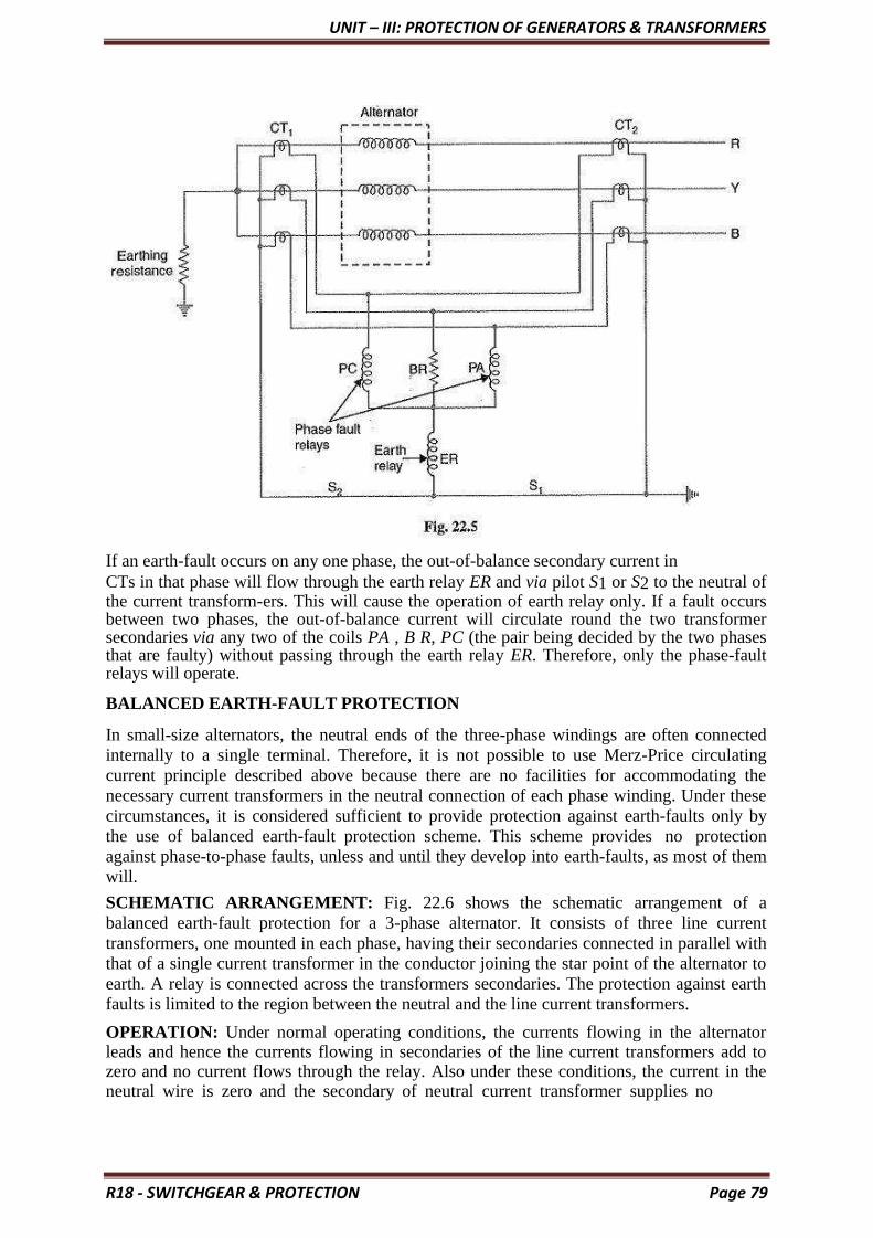
UNIT – III: PROTECTION OF GENERATORS & TRANSFORMERS
R18 - SWITCHGEAR & PROTECTION Page 79
If an earth-fault occurs on any one phase, the out-of-balance secondary current in
CTs in that phase will flow through the earth relay ER and via pilot S1 or S2 to the neutral of the current transform-ers. This will cause the operation of earth relay only. If a fault occurs between two phases, the out-of-balance current will circulate round the two transformer secondaries via any two of the coils PA , B R, PC (the pair being decided by the two phases that are faulty) without passing through the earth relay ER. Therefore, only the phase-fault relays will operate.
BALANCED EARTH-FAULT PROTECTION
In small-size alternators, the neutral ends of the three-phase windings are often connected
internally to a single terminal. Therefore, it is not possible to use Merz-Price circulating
current principle described above because there are no facilities for accommodating the
necessary current transformers in the neutral connection of each phase winding. Under these
circumstances, it is considered sufficient to provide protection against earth-faults only by
the use of balanced earth-fault protection scheme. This scheme provides no protection
against phase-to-phase faults, unless and until they develop into earth-faults, as most of them
will.
SCHEMATIC ARRANGEMENT: Fig. 22.6 shows the schematic arrangement of a
balanced earth-fault protection for a 3-phase alternator. It consists of three line current
transformers, one mounted in each phase, having their secondaries connected in parallel with
that of a single current transformer in the conductor joining the star point of the alternator to
earth. A relay is connected across the transformers secondaries. The protection against earth
faults is limited to the region between the neutral and the line current transformers.
OPERATION: Under normal operating conditions, the currents flowing in the alternator leads and hence the currents flowing in secondaries of the line current transformers add to zero and no current flows through the relay. Also under these conditions, the current in the neutral wire is zero and the secondary of neutral current transformer supplies no

UNIT – III: PROTECTION OF GENERATORS & TRANSFORMERS
R18 - SWITCHGEAR & PROTECTION Page 80
current to the relay. If an earth-fault develops at F2 external to the protected zone, the sum of
the currents at the terminals of the alternator is exactly equal to the current in the neutral
connection and hence no current flows through the relay. When an earth-fault occurs at F1 or
within the protected zone, these currents are no longer equal and the differential current flows
through the operating coil of the relay. The relay then closes its contacts to disconnect the
alternator from the system.
STATOR INTER-TURN PROTECTION
Merz-price circulating-current system protects against phase-to-ground and phase-to- phase faults.

UNIT – III: PROTECTION OF GENERATORS & TRANSFORMERS
R18 - SWITCHGEAR & PROTECTION Page 81
It does not protect against turn-to-turn fault on the same phase winding of the stator. It is because the current that this type of fault produces flows in a local circuit between the turns involved and does not create a difference between the currents entering and leaving the winding at its two ends where current transformers are applied. However, it is usually considered unnecessary to provide protection for inter- turn faults because they invariably develop into earth- faults.
In single turn generator (e.g.large steam-turbine generators), there is no necessity of
protection against inter-turn faults. However, inter-turn protection is provided for multi-turn
generators such as hydro- electric generators. These generators have double- winding
armatures (i.e. each phase winding is divided into two halves) owing to the very heavy
currents which they have to carry. Advantage may be taken of this necessity to protect inter-
turn faults on the same winding.
Fig. 22.7 shows the schematic arrangement of circulating-current and inter-turn protection of
a 3-phase double wound generator. The relays RC provide protection against phase-to-
ground and phase-to-phase faults whereas relays R1 provide protection against inter-turn
faults.
Fig. 22.8 shows the duplicate stator windings S1 and S2 of one phase only with a
provision against inter-turn faults. Two current transformers are connected on the circulating-
current principle. Under normal conditions, the currents in the stator windings S1 and S2 are
equal and so will be the currents in the secondaries of the two CTs. The secondary current
round the loop then is the same at all points and no current flows through the relay R1. If a
short-circuit develops between adjacent turns, say on S1, the currents in the stator windings
S1 and S2 will no longer be equal. Therefore, unequal currents will be induced in the
secondaries of CTs and the difference of these two currents flows through the relay R1. The
relay then closes its contacts to clear the generator from the system

UNIT – III: PROTECTION OF GENERATORS & TRANSFORMERS
R18 - SWITCHGEAR & PROTECTION Page 82
TRANSFORMER PROTECTION

UNIT – III: PROTECTION OF GENERATORS & TRANSFORMERS
R18 - SWITCHGEAR & PROTECTION Page 83

UNIT – III: PROTECTION OF GENERATORS & TRANSFORMERS
R18 - SWITCHGEAR & PROTECTION Page 84

UNIT – III: PROTECTION OF GENERATORS & TRANSFORMERS
R18 - SWITCHGEAR & PROTECTION Page 85

UNIT – III: PROTECTION OF GENERATORS & TRANSFORMERS
R18 - SWITCHGEAR & PROTECTION Page 86
BUCHHOLZ RELAY:
Buchholz Relay is a gas-actuated relay installed in oil immersed transformers for
protection against all kinds of faults. Named after its inventor, Buchholz, it is used to give an
alarm in case of incipient (i.e. slow-developing) faults in the transformer and to disconnect
the transformer from the supply in the event of severe internal faults. It is usually installed in
the pipe connecting the conservator to the main tank as shown in Fig. 22.11. It is a universal
practice to use Buchholz relays on all such oil immersed transformers having ratings
in excess of 750 kVA.
Construction: Fig. 22.12 shows the constructional details of a Buchholz relay. It takes the
form of a domed vessel placed in the connecting pipe between the main tank and the
conservator. The device has two elements. The upper element consists of a mercury type
switch attached to a float. The lower element contains a mercury switch mounted on a hinged
type flap located in the direct path of the flow of oil from the transformer to the conservator.
The upper element closes an alarm circuit during incipient faults whereas the lower element
is arranged to trip the circuit breaker in case of severe internal faults.

UNIT – III: PROTECTION OF GENERATORS & TRANSFORMERS
R18 - SWITCHGEAR & PROTECTION Page 87
OPERATION:
The operation of Buchholz relay is as follows
(i) In case of incipient faults within the transformer, the heat due to fault causes the
decomposition of some transformer oil in the main tank. The products of decomposition
contain more than 70% of hydrogen gas. The hydrogen gas being light tries to go into the
conservator and in the process gets entrapped in the upper part of relay chamber. When a pre-
determined amount of gas gets accumulated, it exerts sufficient pressure on the float to cause
it to tilt and close the contacts of mercury switch attached to it. This completes the alarm
circuit to sound an alarm.
(ii) If a serious fault occurs in the transformer, an enormous amount of gas is generated in the
main tank. The oil in the main tank rushes towards the conservator via the Buchholz relay
and in doing so tilts the flap to close the contacts of mercury switch. This completes the trip
circuit to open the circuit breaker controlling the transformer.
Advantages of Buchholz Relay:
• It is the simplest form of transformer protection.
• It detects the incipient faults at a stage much earlier than is possible with other forms
of protection.
Disadvantages of Buchholz Relay:
• It can only be used with oil immersed transformers equipped with conservator tanks.
• The device can detect only faults below oil level in the transformer. Therefore,
separate protection is needed for connecting cables.

UNIT – IV: FEEDERS & BUSBARS PROTECTION AND GROUNDING
R18 - SWITCHGEAR & PROTECTION Page 88
UNIT – IV
FEEDERS & BUSBARS PROTECTION AND GROUNDING
Protection is provided to isolate the faulty busbar. The busbar zone, for the purpose of
protection, includes not only the busbars themselves but also the isolating switches, circuit
breakers and the associated connections. In the event of fault on any section of the busbar, all
the circuit equipments connected to that section must be tripped out to give complete
isolation.
The standard of construction for busbars has been very high, with the result that bus faults are
extremely rare. However, the possibility of damage and service interruption from even a rare
bus fault is so great that more attention is now given to this form of protection. Improved
relaying methods have been developed, reducing the possibility of incorrect operation. The
two most commonly used schemes for busbar protection are:
• Differential protection
• Fault bus protection
DIFFERENTIAL PROTECTION:
The basic method for busbar protection is the differential scheme in which currents
entering and leaving the bus are totalised. During normal load condition, the sum of these
currents is equal to zero. When a fault occurs, the fault current upsets the balance and
produces a differential current to operate a relay.
Fig. 23.1 shows the single line diagram of current differential scheme for a station busbar.
The busbar is fed by a generator and supplies load to two lines. The secondaries of current
transformers in the generator lead, in line 1 and in line 2 are all connected in parallel. The
protective relay is connected across this parallel connection.
All CTs must be of the same ratio in the scheme regardless of the capacities of the various
circuits. Under normal load conditions or external fault conditions, the sum of the currents
entering the bus is equal to those leaving it and no current flows through the relay. If a fault
occurs within the protected zone, the currents entering the bus will no longer be equal to
those leaving it. The difference of these currents will flow through the relay and cause the
opening of the generator, circuit breaker and each of the line circuit breakers.

UNIT – IV: FEEDERS & BUSBARS PROTECTION AND GROUNDING
R18 - SWITCHGEAR & PROTECTION Page 89
FAULT BUS PROTECTION:
It is possible to design a station so that the faults that develop are mostly earth-faults.
This can be achieved by providing earthed metal barrier (known as fault bus) surrounding
each conductor throughout its entire length in the bus structure. With this arrangement, every
fault that might occur must involve a connection between a conductor and an earthed metal
part. By directing the flow of earth-fault current, it is possible to detect the faults and
determine their location. This type of protection is known as fault bus protection.
Fig. 23.2 shows the schematic arrangement of fault bus protection. The metal supporting
structure or fault bus is earthed through a current transformer. A relay is connected across the
secondary of this CT. Under normal operating conditions, there is no current flow from fault
bus to ground and the relay remains inoperative. A fault involving a connection between a
conductor and earthed sup- porting structure will result in current flow to ground through the
fault bus, causing the relay to operate. The operation of relay will trip all breakers connecting
equipment to the bus.
PROTECTION OF LINES
The probability of faults occurring on the lines is much more due to their greater length and exposure to atmospheric conditions. This has called for many protective schemes which have no application to the comparatively simple cases of alternators and transformers. The requirements of line protection are:
(i) In the event of a short circuit, the circuit breaker closest to the fault should open, all other circuit breakers remaining in a closed position.
(ii) In case the nearest breaker to the fault fails to open, back-up protection should be provided by the adjacent circuit breakers.
(iii) The relay operating time should be just as short as possible in order to preserve system stability, without unnecessary tripping of circuits.
The protection of lines presents a problem quite different from the protection of station
apparatus such as generators, transformers and busbars. While differential protection is
ideal method for lines, it is much more expensive to use. The two ends of a line may be
several kilometres apart and to compare the two currents, a costly pilot-wire circuit is
required. This expense may be justified but in general less costly methods are used. The

UNIT – IV: FEEDERS & BUSBARS PROTECTION AND GROUNDING
R18 - SWITCHGEAR & PROTECTION Page 90
common methods of line protection are:
(i) Time-graded overcurrent protection
(ii) Differential protection
(iii) Distance protection
Fig. 23.3 shows the symbols indicating the various types of relay
TIME-GRADED OVERCURRENT PROTECTION
In this scheme of overcurrent protection, time discrimination is incorporated. In other words,
the time setting of relays is so graded that in the event of fault, the smallest possible part of
the system is isolated. We shall discuss a few important cases.
RADIAL FEEDER: The main characteristic of a radial system is that power can flow only
in one direction, from generator or supply end to the load. It has the disadvantage that
continuity of supply cannot be maintained at the receiving end in the event of fault. Time-
graded protection of a radial feeder can be achieved by using
(i) definite time relays and (ii) inverse time relays.
Using definite time relays. Fig. 23.4 shows the overcurrent protection of a radial feeder by
definite time relays. The time of operation of each relay is fixed and is independent of the
operating current. Thus relay D has an operating time of 0·5 second while for other relays,
time delay* is successively increased by 0·5 second. If a fault occurs in the section DE, it
will be cleared in 0·5 second by the relay and circuit breaker at D because all other relays
have higher operating time. In this way only section DE of the system will be isolated. If the
relay at D fails to trip, the relay at C will operate after a time delay of 0·5 second i.e. after 1
second from the occurrence of fault.
The disadvantage of this system is that if there are a number of feeders in series, the tripping
time for faults near the supply end becomes high (2 seconds in this case). However, in most
cases, it is necessary to limit the maximum tripping time to 2 seconds. This disadvantage can
be overcome to a reasonable extent by using inverse-time relays.

UNIT – IV: FEEDERS & BUSBARS PROTECTION AND GROUNDING
R18 - SWITCHGEAR & PROTECTION Page 91
Inverse Time
Relay
(i) Using inverse time relays. Fig. 23.5 shows overcurrent protection of a radial feeder using
inverse time relays in which operating time is inversely proportional to the operating current.
With this arrangement, the farther the circuit breaker from the generating station, the shorter
is its relay operating time. The three relays at A, B and C are assumed to have inverse-time
characteristics. A fault in section BC will give relay times which will allow breaker at B to
trip out before the breaker at A.
1. Parallel feeders. Where continuity of supply is particularly necessary, two parallel feeders
may be installed. If a fault occurs on one feeder, it can be disconnected from the system and
continuity of supply can be maintained from the other feeder. The parallel feeders cannot* be
protected by non-directional overcurrent relays only. It is necessary to use directional relays
also and to grade the time setting of relays for selective tripping’s.
Fig. 23.6 shows the system where two feeders are connected in parallel between the

UNIT – IV: FEEDERS & BUSBARS PROTECTION AND GROUNDING
R18 - SWITCHGEAR & PROTECTION Page 92
generating station and the sub-station. The protection of this system requires that
(i) Each feeder has a non-directional overcurrent relay at the generator end. These relays
should have inverse-time characteristic.
(ii) Each feeder has a reverse power or directional relay at the sub-station end. These
relays should be instantaneous type and operate only when power flows in the reverse
direction i.e. in the direction of arrow at P and Q.
Suppose an earth fault occurs on feeder 1 as shown in Fig. 23.6. It is desired that only circuit
breakers at A and P should open to clear the fault whereas feeder 2 should remain intact to
maintain the continuity of supply. In fact, the above arrangement accomplishes this job. The
shown fault is fed via two routes, viz.
• Directly from feeder 1 via the relay A
• From feeder 2 via B, Q, sub-station and P
Therefore, power flow in relay Q will be in normal direction but is reversed in the relay P.
This causes the opening of circuit breaker at P. Also the relay A will operate while relay B
remains inoperative. It is because these relays have inverse-time characteristics and current
flowing in relay A is in excess of that flowing in relay B. In this way only the faulty feeder is
isolated.
2. Ring main system:
In this system, various power stations or sub-stations are interconnected by alternate
routes, thus forming a closed ring. In case of damage to any section of the ring, that section
may be disconnected for repairs, and power will be supplied from both ends of the ring,
thereby maintaining continuity of supply.
Fig. 23.7 shows the single line diagram of a typical ring main system consisting of one
generator G supplying four sub-stations S1, S2, S3 and S4. In this arrangement, power can
flow in both directions under fault conditions. Therefore, it is necessary to grade in both
directions round the ring and also to use directional relays. In order that only faulty section of
the ring is isolated under fault conditions, the types of relays and their time settings should be
as follows:
(i) The two lines leaving the generating station should be equipped with non- directional
overcurrent relays (relays at A and J in this case).
(ii) At each sub-station, reverse power or directional relays should be placed in both

UNIT – IV: FEEDERS & BUSBARS PROTECTION AND GROUNDING
R18 - SWITCHGEAR & PROTECTION Page 93
incoming and outgoing lines (relays at B, C, D, E, F, G, H and I in this case).
(iii) There should be proper relative time-setting of the relays. As an example, going
round the loop G S 1 S2 S3 S4 G ; the outgoing relays (viz at A , C, E, G and I) are
set with decreasing time limits e.g.
A = 2·5 sec, C = 2 sec, E = 1·5 sec G = 1 sec and I = 0·5 sec similarly, going round
the loop in the opposite direction (i.e. along G S4 S3 S2 S1 G), the outgoing relays (J, H, F,
D and B) are also set with a decreasing time limit e.g.
J = 2·5 sec, H = 2 sec, F = 1·5 sec, D = 1 sec, B = 0·5 sec.
Suppose a short circuit occurs at the point as shown in Fig. 23.7. In order to ensure
selectivity, it is desired that only circuit breakers at E and F should open to clear the fault
whereas other sections of the ring should be intact to maintain continuity of supply.
In fact, the above arrangement accomplishes this job. The power will be fed to the fault via
two routes viz (i) from G around S1 and S2 and (ii) from G around S4 and S3. It is clear that
relays at A, B, C and D as well as J, I, H and G will not trip. Therefore, only relays at E and F
will operate before any other relay operates because of their lower time-setting
DIFFERENTIAL PILOT-WIRE PROTECTION
The differential pilot-wire protection is based on the principle that under normal conditions,
the current entering one end of a line is equal to that leaving the other end. As soon as a fault
occurs between the two ends, this condition no longer holds and the difference of incoming
and outgoing currents is arranged to flow through a relay which operates the circuit breaker
to isolate the faulty line. There are several differential protection schemes in use for the lines.
However, only the following two schemes will be discussed:
* Merz-Price voltage balance system
* Translay scheme
1. MERZ-PRICE VOLTAGE BALANCE SYSTEM:
Fig. 23.8 shows the single line diagram of Merz-Price voltage balance system
for the protection of a 3-phase line. Identical current transformers are placed in each phase at

UNIT – IV: FEEDERS & BUSBARS PROTECTION AND GROUNDING
R18 - SWITCHGEAR & PROTECTION Page 94
both ends of the line. The pair of CTs in each line is connected in series with a relay in such a
way that under normal conditions, their secondary voltages are equal and in opposition i.e.
they balance each other.
Under healthy conditions, current entering the line at one-end is equal to that leaving it at the
other end. Therefore, equal and opposite voltages are induced in the secondaries of the CTs at
the two ends of the line. The result is that no current flows through the relays. Suppose a fault
occurs at point F on the line as shown in Fig. 23.8. This will cause a greater current to flow
through CT1 than through CT2. Consequently, their secondary voltages become unequal and
circulating current flows through the pilot wires and relays. The circuit breakers at both ends
of the line will trip out and the faulty line will be isolated
Fig. 23.9 shows the connections of Merz-Price voltage balance scheme for all the three
phases of the line.
Advantages
• This system can be used for ring mains as well as parallel feeders.
• This system provides instantaneous protection for ground faults. This decreases the
possibility of these faults involving other phases.
• This system provides instantaneous relaying which reduces the amount of damage to
over-head conductors resulting from arcing faults.
Disadvantages
• Accurate matching of current transformers is very essential.
• If there is a break in the pilot-wire circuit, the system will not operate.
• This system is very expensive owing to the greater length of pilot wires required.
• In case of long lines, charging current due to pilot-wire capacitance* effects may be
sufficient to cause relay operation even under normal conditions.
• This system cannot be used for line voltages beyond 33 kV because of constructional
difficulties in matching the current transformers.

UNIT – IV: FEEDERS & BUSBARS PROTECTION AND GROUNDING
R18 - SWITCHGEAR & PROTECTION Page 95
2. TRANSLAY SCHEME.
This system is similar to voltage balance system except that here balance or
opposition is between the voltages induced in the secondary windings wound on the relay
magnets and not between the secondary voltages of the line current transformers. This
permits to use current transformers of normal design and eliminates one of the most serious
limitations of original voltage balance system, namely; its limitation to the system operating
at voltages not exceeding 33 kV.
The application of Translay scheme for a single phase line has already been discussed in Art.
21.20. This can be extended to 3-phase system by applying one relay at each end of each
phase of the 3-phase line. However, it is possible to make further simplification by
combining currents derived from all phases in a single relay at each end, using the principle
of summation transformer (See Fig. 23.10). A summation transformer is a device that
reproduces the polyphase line currents as a single-phase quantity. The three lines CTs are
connected to the tapped primary of summation transformer. Each line CT energizes a
different number of turns (from line to neutral) with a resulting single phase output. The use
of summation transformer permits two advantages viz (i) primary windings 1 and 2 can be
used for phase faults whereas winding 3 can be used for earth fault (ii) the number of pilot
wires required is only two.
SCHEMATIC ARRANGEMENT:
The Translay scheme for the protection of a 3-phase line is shown in Fig. 23.11. The
relays used in the scheme are essentially overcurrent induction type relays. Each relay has
two electromagnetic elements. The upper element carries a winding (11 or 11 a) which is
energised as a summation transformer from the secondaries of the line CTs connected in the
phases of the line to be protected. The upper element also carries a secondary winding (12 or
12 a) which is connected is series with the operating winding (13 or 13 a) on the lower
magnet. The secondary windings 12, 12 a and operating windings 13, 13 a are connected in

UNIT – IV: FEEDERS & BUSBARS PROTECTION AND GROUNDING
R18 - SWITCHGEAR & PROTECTION Page 96
series in such a way that voltages induced in them oppose each other. Note that relay discs
and tripping circuits have been omitted in the diagram for clarity.
This drawback is overcome in the Beard-Hunter system. In this system, each pilot- wire is
surrounded by an insulated metallic sheath with a break half-way along its length. Half the
pilot charging current thus comes from the sending end and half from the receiving end.
Therefore, voltage applied to the relay at the sending end is balanced by an equal voltage at
the receiving end.
OPERATION:
When the feeder is sound, the currents at its two ends are equal so that the secondary
currents in both sets of CTs are equal. Consequently, the currents flowing in the relay
primary wind-ing 11 and 11 a will be equal and they will induce equal voltages in the
secondary windings 12 and 12a. Since these windings are connected in opposition, no current
flows in them or in the operating windings 13 and 13a. In the event of a fault on the protected
line, the line current at one end must carry a greater current than that at the other end. The
result is that voltages induced in the secondary windings 12 and 12 a will be different and the
current will flow through the operating coils 13, 13a and the pilot circuit. Under these
conditions, both upper and lower elements of each relay are energised and a forward torque
acts on the each relay disc. The operation of the relays will open the circuit breakers at both
ends of the line.
❖ Suppose a fault F occurs between phases R and Y and is fed from both sides as shown
in Fig. 23.11. This will energise only section 1 of primary windings 11 and 11a and
induce voltages in the secondary windings 12 and 12a. As these voltages are now

UNIT – IV: FEEDERS & BUSBARS PROTECTION AND GROUNDING
R18 - SWITCHGEAR & PROTECTION Page 97
additive*, therefore, current will circulate through operating coils 13, 13a and the
pilot circuit. This will cause the relay contacts to close and open the circuit breakers
at both ends. A fault between phases Y and B energises section 2 of primary windings
11 and 11a whereas that between R and B will energise the sections 1 and 2.
❖ Now imagine that an earth fault occurs on phase R. This will energise sections 1, 2
and 3 of the primary windings 11 and 11a. Again if fault is fed from both ends, the
voltages induced in the secondary windings 12 and 12a are additive and cause a
current to flow through the operating coils 13, 13a. The relays, therefore, operate to
open the circuit breakers at both ends of the line. In the event of earth fault on phase Y
, sections 2 and 3 of primary winding 11 and 11a will be energised and cause the
relays to operate. An earth fault on phase B will energise only section 3 of relay
primary windings 11 and 11a.
Advantages
❖ The system is economical as only two pilot wires are
required for the protection of a 3-phase line.
❖ Current transformers of normal design can be used.
❖ Pilot wire capacitance currents do not affect the operation of relays.
❖ Because the fault is being fed from both sides.
DISTANCE PROTECTION
Both time-graded and pilot-wire systems are not suitable for the protection of very
long high voltage transmission lines. The former gives an unduly long time delay in fault
clearance at the generating station end when there are more than four or five sections and the
pilot-wire system becomes too expensive owing to the greater length of pilot wires required.
This has led to the development of distance protection in which the action of relay depends
upon the distance (or impedance) between the point where the relay is installed and the point
of fault. This system provides discrimination protection with-out employing pilot wires.
The principle and operation of distance relays have already been discussed in chapter
21. We shall now consider its application for the protection of transmission lines. Fig. 23.12
(i) shows a simple system consisting of lines in series such that power can flow only from left
to right.
The relays at A, B and C are set to operate for impedance less than Z1, Z2 and Z3 respectively.
Suppose a fault occurs between sub- stations B and C, the f a u l t
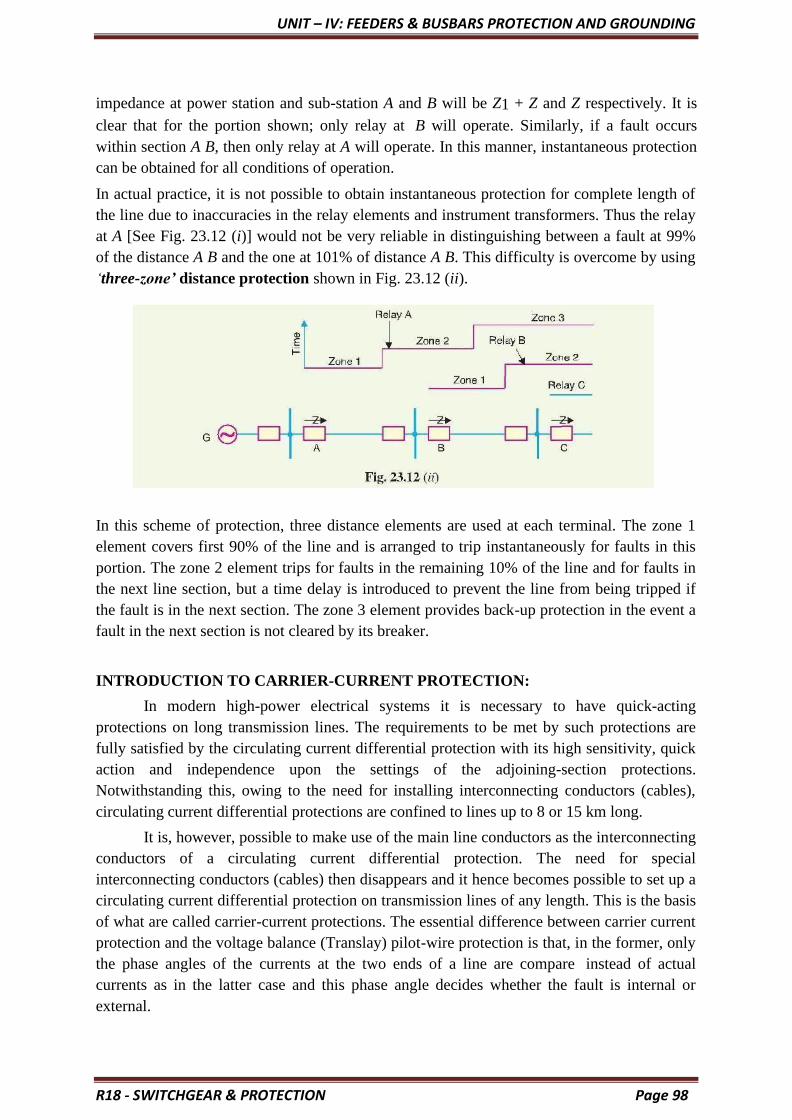
UNIT – IV: FEEDERS & BUSBARS PROTECTION AND GROUNDING
R18 - SWITCHGEAR & PROTECTION Page 98
impedance at power station and sub-station A and B will be Z1 + Z and Z respectively. It is
clear that for the portion shown; only relay at B will operate. Similarly, if a fault occurs
within section A B, then only relay at A will operate. In this manner, instantaneous protection
can be obtained for all conditions of operation.
In actual practice, it is not possible to obtain instantaneous protection for complete length of
the line due to inaccuracies in the relay elements and instrument transformers. Thus the relay
at A [See Fig. 23.12 (i)] would not be very reliable in distinguishing between a fault at 99%
of the distance A B and the one at 101% of distance A B. This difficulty is overcome by using
‘three-zone’ distance protection shown in Fig. 23.12 (ii).
In this scheme of protection, three distance elements are used at each terminal. The zone 1
element covers first 90% of the line and is arranged to trip instantaneously for faults in this
portion. The zone 2 element trips for faults in the remaining 10% of the line and for faults in
the next line section, but a time delay is introduced to prevent the line from being tripped if
the fault is in the next section. The zone 3 element provides back-up protection in the event a
fault in the next section is not cleared by its breaker.
INTRODUCTION TO CARRIER-CURRENT PROTECTION:
In modern high-power electrical systems it is necessary to have quick-acting
protections on long transmission lines. The requirements to be met by such protections are
fully satisfied by the circulating current differential protection with its high sensitivity, quick
action and independence upon the settings of the adjoining-section protections.
Notwithstanding this, owing to the need for installing interconnecting conductors (cables),
circulating current differential protections are confined to lines up to 8 or 15 km long.
It is, however, possible to make use of the main line conductors as the interconnecting
conductors of a circulating current differential protection. The need for special
interconnecting conductors (cables) then disappears and it hence becomes possible to set up a
circulating current differential protection on transmission lines of any length. This is the basis
of what are called carrier-current protections. The essential difference between carrier current
protection and the voltage balance (Translay) pilot-wire protection is that, in the former, only
the phase angles of the currents at the two ends of a line are compare instead of actual
currents as in the latter case and this phase angle decides whether the fault is internal or
external.

UNIT – IV: FEEDERS & BUSBARS PROTECTION AND GROUNDING
R18 - SWITCHGEAR & PROTECTION Page 99
To make possible the transmission of commercial-frequency (50 Hz) load current,
and at the same time use the main line conductors as the interconnecting conductors of the
differential protection, it is necessary to use a current of higher frequency in order to be able
to transmit current impulses from one end of the line to the other. High frequency signals in
the range of 50 kHz to 400 kHz, commonly known as the carrier, are transmitted over the
conductors of the protected line.
To inject the carrier signal and to restrict it within the protected section of the line
suitable coupling apparatus and line traps are used at both ends of the protected section. This
obviously makes this protection scheme quite expensive and justifies its application only in
transmission lines of 110kV and above.
The main elements of the carrier channel are:
(i) Transmitter
(ii) Receiver
(iii) Coupling equipment and
(iv) Line trap.
Here we need not to go through the details of carrier current transmitters or receivers,
all we need to know is that when a voltage of positive polarity is impressed on the control
circuit of transmitter, it generates a high frequency output voltage. This output voltage is
impressed between one phase conductor of the transmission line and the earth.
Each carrier-current receiver receives carrier current from its local transmitter as well
as from the transmitter at the distant end of the line. In effect, the receiver converts the
received carrier current into a dc voltage that can be used in a relay or other circuit to perform
any desired function. The voltage is zero when carrier current is not being received.
Line trap unit is inserted between the bus-bar and connection of coupling capacitor to
the line. It is a parallel LC network tuned to resonance at the high frequency. It hence
presents high impedance to the high-frequency carrier current, but relatively low impedance
(less than 0.1 Ω) to the power-frequency (50 Hz) current. Traps are employed to confine the
carrier currents to the protected section so as to avoid interference with or from other
adjacent carrier current channels, and also to avoid loss of the carrier current signal in
adjoining power circuits for any reason whatsoever, external short circuit being a principal
reason. Consequently, carrier current can flow only along the line section between the traps.
The coupling capacitor (CC) connects the high frequency (carrier) equipment to one
of the line conductors and simultaneously serves to isolate the carrier equipment from the
high power-line voltage. It presents a relatively low reactance to the high frequency currents
(about 150 Ω at 500 kHz) and a high reactance to the power frequency (about 1.5 M Ω at 50
Hz). To reduce impedance further a low inductance is connected in series with the coupling
capacitors to provide a resonance at carrier frequency.
It is thus evident that the commercial-frequency current will be able to flow only
through the line conductors, while the high-frequency carrier current will circulate, when the
receiver-transmitter operate, over the line conductor fitted with the high-frequency traps,
through the coupling capacitors and through ground (the return conductor).

UNIT – IV: FEEDERS & BUSBARS PROTECTION AND GROUNDING
R18 - SWITCHGEAR & PROTECTION Page 100
Methods of Carrier-Current Protection:
There are different methods of carrier current protection and basic forms of carrier
protection are:
(i) Directional Comparison Protection and
(ii) Phase-Comparison Carrier Protection.
(i) Directional Comparison Protection:
The protection operates on the basis of comparison of the fault-power flow directions
at the two ends of the protected line. Operation takes place only when the flow of power at
both ends of the line is in the bus-to-line direction, a condition which will evidently only
arise in event of a fault on the protected section of the line. With directional- comparison
relaying, the carrier pilot informs the equipment at one end of the line how a directional relay
at the other end responds to a short circuit.
The conditions for internal and external faults are illustrated in Fig. 5.17. The relays
at both ends of the protected section respond to fault power flowing away from the bus
(tripping direction). For faults in the protected section, power flows in the tripping direction
at both ends. For external faults power flow will be in opposite directions. A simple signal
through carrier pilot is transmitted from one end to the other during faults.
The pilot scheme can be employed for transmitting either blocking, or permitting
signals. Thus possible carrier protections are of two types viz., carrier-blocking scheme and
carrier-permitting scheme.
In a carrier-blocking protection scheme, the presence of carrier prevents or blocks
operation of the protection. Carrier is, therefore, transmitted only upon the occurrence of a
fault and is employed to prevent tripping in the event of an external fault. In carrier-
permitting scheme the presence of carrier permits operation of the protection. The carrier
blocking scheme is more reliable than carrier- permitting scheme. This is because a failure in
the carrier-permitting signal equipment will mean a failure in isolating the fault, whereas a
failure in carrier-blocking signal equipment isolates the section on which no fault exists.
However, such false operation is preferable to the failure to clear a faulted section.
In a carrier-permitting protection scheme, normally no pilot signal is transmitted from
any terminal. Should a short circuit occur in an immediately adjacent line section, a pilot
signal is transmitted from any terminal where short-circuit current flows out of the line (i.e.,
in the non-tripping direction). While any station is transmitting a pilot signal, tripping is

UNIT – IV: FEEDERS & BUSBARS PROTECTION AND GROUNDING
R18 - SWITCHGEAR & PROTECTION Page 101
blocked at all other stations. But should a short circuit occur on the protected section of the
line, no pilot signal is transmitted and tripping occurs at any terminal where short-circuit
current flows. Therefore, the pilot is blocking pilot, since the reception of a pilot signal is not
required of permit tripping.
Directional comparison protection scheme (carrier blocking type) is illustrated in Fig.
5.18. The operation of the directional element provided on each breaker is indicated by the
arrow arid the non- operation by the letter O. Occurrence of fault activates relays on each of
the breakers near the fault. This relay unless blocked from operation, causes tripping of
breakers. The blocking signal is controlled by the directional relays on each breaker, and is
transmitted from one end of a protected section to the other by carrier.
If a directional element determines that the fault is external to the protected section, a signal
is transmitted blocking the operation of breakers at both ends of the section. In case the
directional elements at both ends determine that fault is in the protected section, no blocking
signal is transmitted from either end, and both breakers trip. The sequence of event for a fault
at F is made clear by illustration in Fig. 5.18.
At breaker 1 the directional element shows that the fault may be in the section 1-2.
This breaker trips if no blocking signal is received. No blocking signal is transmitted to
breaker 2. At breaker 2 the directional element shows that the fault is not in section 1-2. A
carrier signal is transmitted that blocks tripping of both the breakers 1 and 2.
At breakers 3 and 4 the directional elements show that the fault may be in section 3-4.
No blocking signal is transmitted and after a very short time delay (1 to 3 cycles), both the
breakers 3 and 4 trip.
(ii) Phase-Comparison Carrier Protection:
Phase-comparison relaying equipment uses its pilot to compare the phase relation
between current entering in the protected zone and the current leaving the protected zone.
The current magnitudes are not compared. Phase comparison protection provides only main
or primary protection, backup protection must be provided in addition.

UNIT – IV: FEEDERS & BUSBARS PROTECTION AND GROUNDING
R18 - SWITCHGEAR & PROTECTION Page 102
Figure 5.19 shows schematically the principal elements of the equipment provided at
both ends of a two-terminal transmission line, employing a carrier-current pilot. As in ac
wire-pilot protection, the transmission-line CTs feed a network that transforms the CT output
currents into a single-phase sinusoidal output voltage. This voltage is applied to a carrier-
current transmitter and to a ‘comparer’.
The output of a carrier-current receiver is also applied to the comparer. The comparer
controls the operation of an auxiliary relay for tripping the transmission-line circuit breaker.
These elements provide means for transmitting and receiving carrier-current signals for
comparing at each end of the relative phase relations of the transmission-line current at both
ends of the line
For examining the relations between the network output voltages at both ends of the
line and also the carrier-current signals that are transmitted during external and internal fault
conditions refer to Fig. 5.20. For an external fault at point D in Fig. 5.20, the network output
voltages at stations A and B (waves a and c) are 180° out of phase.
This is because the connections of CTs at the two stations are reversed. Since an ac
voltage is used to control the transmitter, carrier-current is transmitted only during the half
cycles of the voltage wave when the polarity is positive. The carrier-current signals
transmitted from stations A and B (waves b and d) are displaced in time, so that there is
always a carrier-current signal being sent from one end or the other.
For internal fault at point C, the network output voltage at station B reverses because
of reversal of power-line currents at station B, the carrier-current signals (waves b and d) are
concurrent, and there is no signal from either station every other half cycle.
Phase-comparison relaying acts to block tripping at both terminals whenever the
carrier- current signals are displaced in time so that there is little or no time interval when a
signal is not being transmitted from one end or the other. When the carrier-current signals are
approximately concurrent, tripping will occur whenever there is sufficient short-circuit
current flowing. This is shown in Fig. 5.21 where network output voltages are superimposed,
and the related tripping and blocking tendencies are illustrated.

UNIT – IV: FEEDERS & BUSBARS PROTECTION AND GROUNDING
R18 - SWITCHGEAR & PROTECTION Page 103
As shown in Figs. 5.20 and 5.21, the equipment at one station transmits a blocking carrier-
current signal during one half cycle, and then stops transmitting and tries to trip during the
next half cycle, if carrier current is not received from the other end of the line during this half
cycle, the equipment operates to trip its breaker. But, if carrier current is received from the
other end of the line during the interval when the local carrier-current transmitter is idle,

UNIT – IV: FEEDERS & BUSBARS PROTECTION AND GROUNDING
R18 - SWITCHGEAR & PROTECTION Page 104
tripping does not occur.
Advantages of Carrier-Current Protection:
Carrier current over the power line provides simultaneous tripping of circuit breakers
at both ends of the line in one to three cycles. Thereby high speed fault clearing is obtained,
which improves the power system stability. Besides, there are several other advantages of
carrier-current protection.
These are:
1. Fast, simultaneous operation of circuit breakers at both ends.
2. Auto-reclosing simultaneous reclosing signal is sent thereby simultaneous (1 to 3
cycles) reclosing of circuit breaker is obtained.
3. Fast clearing prevents shocks to systems.
4. Tripping due to synchronising power surges does not occur, yet during internal
fault clearing is obtained.
5. For simultaneous faults, carrier-current protection provides easy discrimination.
6. Carrier-current relaying is best suited for fast relaying in conjunction with modern
fast circuit breakers.
7. No separate wires are required for signalling, as the power lines themselves carry
power as well as communication signalling. Hence the capital and operating costs are
smaller.
The main application of power line carrier has been for the purpose of supervisory
control, telephone communication, telemetering and relaying.
BUS-BAR PROTECTION
When the fault occurs on the bus bars whole of the supply is interrupted, and all the
healthy feeders are disconnected. The majority of the faults is single phase in nature, and
these faults are temporary. The bus zone fault occurs because of various reasons likes failure
of support insulators, failure of circuit breakers, foreign object accidentally falling across the
bus bar, etc., for removing the bus fault, all the circuits connecting to the faulty section needs
to be open.
The most commonly used schemes for bus zone protection are:
• Backup protection
• Differential Overcurrent Protection
o Circulating current protection
o Voltage Overvoltage Protection
• Frame leakage protection.
BACKUP PROTECTION FOR BUS-BARS
This is the simple way of protecting the bus-bar from the fault. The fault occurs on the bus-
bar because of the supplying system. So the backup protection is provided to the supply
system. The figure below shows the simple arrangement for the protection of bus-bar. The

UNIT – IV: FEEDERS & BUSBARS PROTECTION AND GROUNDING
R18 - SWITCHGEAR & PROTECTION Page 105
bus A is protected by the distance protection of the bus B. If the fault occurs on A, then the B
will operate. The operating times of the relay will be 0.4 seconds.
The bus-bar protection system has few disadvantages likes the protection system is slow.
Such system is mainly used for the protection of the transmission lines. But as the protection
system is very economical, thereby it is also used for the bus-bar protection.
This protective scheme is not used for small switchgear system. The backup protection
system has many disadvantages likes delayed in action, disconnections of more circuits for
two or more transmission line requires etc.
FRAME LEAKAGE OR FAULT- BUS PROTECTION
This method insulates the bus-supporting structure and its switchgear from the ground,
interconnecting all the framework, circuit breakers tanks, etc. and provided a single ground
tank connection through a CT that feeds an overcurrent relay. The overcurrent relay controls
a multi-contact auxiliary relay that trips the breakers of all circuits connected to the bus.
In such type of protection, the only metal supporting structure or fault-bus is grounded
through a CT, secondary of which is connected to an overcurrent relay. Under normal
operating condition, the relay remains inoperative, but fault involving a connection between a
conductor and the ground supporting structure will result in current flow to ground through
the fault bus, causing the relay to operate. The operation of the relay will trip all the breakers
connecting equipment to the bus.
DIFFERENTIAL OVER CURRENT PROTECTION
Current Differential Protection
The current differential protection scheme works on the principle of the circulating
current which states that the current enters into the bus-bar is equal to the current leaving the
bus-bar. The sum of the incoming and outgoing junction is equal to zero. If the sum of
current is not equal to zero, then the fault occurs in the system. The differential protection
scheme is used both for the protection of the phase-to-phase fault and for the ground fault

UNIT – IV: FEEDERS & BUSBARS PROTECTION AND GROUNDING
R18 - SWITCHGEAR & PROTECTION Page 106
Schematic diagram of bus differential protection relay is shown in the figure below. The
current transformers are placed on both the incoming and the outgoing end of the bus-bar.
The secondary terminals of the current transformer are parallel connected to each other.
summation current of the current transformer flows through the operating coil of the relay.
The current flows through the relay coils indicates the short circuit current present on the
secondary of the CTs. Thus, the relay sends the signal to the circuit breakers to open the
contacts.
The drawback of such types of the scheme is that the iron cored current transformer causes
the fault operation of the relay at the time of the external fault.
VOLTAGE DIFFERENTIAL PROTECTION RELAY
In this scheme, the coreless CTs are used. The linear couplers are used for increases
the number of turns on the secondary sides of the CTs. The secondary relays connected in
series with the help of the pilot wires. The relay coil is also connected in series with the
second terminal.
When the system is free from fault or external fault occurs on the system, the sum of
secondary current of CTs becomes zero. On the occurrence of the internal fault, the fault

UNIT – IV: FEEDERS & BUSBARS PROTECTION AND GROUNDING
R18 - SWITCHGEAR & PROTECTION Page 107
current flows the differential relay. The relay becomes operative and gives command to the
circuit breaker to open their contacts. Thus, protects the system from damage.
GROUNDING
Neutral Grounding
In power system, *grounding or earthing means connecting frame of electrical
equipment (non-current carrying part) or some electrical part of the system (e.g. neutral point
in a star- connected system, one conductor of the secondary of a transformer etc.) to earth i.e.
soil. This connection to earth may be through a conductor or some other circuit element (e.g.
a resistor, a circuit breaker etc.) depending up on the situation. Regardless of the method of
connection to earth, grounding or earthing offers two principal advantages. First, it provides
protection to the power system. For example, if the neutral point of a star-connected system
is grounded through a circuit breaker and phase to earth fault occurs on any one line, a large
fault current will flow through the circuit breaker. The circuit breaker will open to isolate the
faulty line. This protects the power system from the harmful effects of the fault. Secondly,
earthing of electrical equipment (e.g. domestic appliances, hand-held tools, industrial motors
etc.) ensures the safety of the persons handling the equipment. For example, if insulation
fails, there will be a direct contact of the live conductor with the metallic part (i.e.frame) of
the equipment. Any person in contact with the metallic part of this equipment will be
subjected to a dangerous electrical shock which can be fatal. In this chapter, we shall discuss
the importance of grounding or earthing in the line of power system with special emphasis on
neutral grounding.
Grounding or Earthing:
The process of connecting the metallic frame (i.e. non-current carrying part) of electrical
equipment or some electrical part of the system (e.g. neutral point in a star-connected system,
one conductor of the secondary of a transformer etc.) to earth (i.e. soil) is called grounding or
earthing. It is strange but true that grounding of electrical systems is less understood aspect of
power system. Nevertheless, it is a very important subject. If grounding is done
systematically in the line of the power system, we can effectively prevent accidents and
damage to the equipment of the power system and at the same time continuity of supply can
be maintained.
Grounding or earthing may be classified as:
❖ Equipment grounding
❖ System grounding.
Equipment grounding deals with earthing the non-current-carrying metal parts of the
electrical equipment. On the other hand, system grounding means earthing some part of the
electrical system e.g. earthing of neutral point of star-connected system in generating stations
and sub-stations. Equipment Grounding the process of connecting non-current-carrying metal

UNIT – IV: FEEDERS & BUSBARS PROTECTION AND GROUNDING
parts (i.e. metallic enclosure) of the electrical equipment to earth (i.e. soil) in such a way that
in case of insulation failure, the enclosure effectively remains at earth potential is called
equipment grounding.
We are frequently in touch with electrical equipment of all kinds, ranging from
domestic appliances and hand-held tools to industrial motors. We shall illustrate the
need of effective equipment grounding by considering a single-phase circuit
composed of a 230 V source connected to a motor M as shown in Fig. 26.1. Note that
neutral is solidly grounded at the service entrance. In the interest of easy
understanding, we shall divide the discussion into three heads viz.
1. Ungrounded enclosure
2. Enclosure connected to neutral wire
3. Ground wire connected to enclosure.
Ungrounded enclosure:
Fig. 26.1 shows the case of ungrounded metal enclosure. If a person touches the metal
enclosure, nothing will happen if the equipment is functioning correctly. But if the
winding insulation becomes faulty, the resistance R e between the motor and
enclosure drops to a low value (a few hundred ohms or less). A person having a body
resistance Rb would complete the current path as shown in Fig. 26.1.
If Re is small (as is usually the case when insulation failure of winding occurs), the leakage
current IL through the person‘s body could be dangerously high. As a result, the person
would get severe electric shock which may be fatal. Therefore, this system is unsafe.
(ii) Enclosure connected to neutral wire. It may appear that the above problem can be solved
byconnecting the enclosure to the grounded neutral wire as shown in Fig. 26.2. Now the
leakage current IL flows from the motor, through the enclosure and straight back to the
neutral wire (See Fig. 26.2). Therefore, the enclosure remains at earth potential.
Consequently, the operator would not experience any electric shock.
R17 - SWITCHGEAR & PROTECTION drafted by Dr. KAMAL Page 108

UNIT – IV: FEEDERS & BUSBARS PROTECTION AND GROUNDING
R18 - SWITCHGEAR & PROTECTION Page 109
The trouble with this method is that the neutral wire may become open either accidentally or
due to a faulty installation. For example, if the switch is inadvertently in series with the
neutral rather than the live wire (See Fig. 26.3), the motor can still be turned on and off.
However, if some- one touched the enclosure while the motor is off, he would receive a
severe electric shock (See Fig. 26.3). It is because when the motor is off, the potential of the
enclosure rises to that of the live conductor.
(iii) Ground wire connected to enclosure. To get rid of this problem, we install a third wire,
called ground wire, between the enclosure and the system ground as shown in Fig. 26.4.
The ground wire may be bare or insulated. If it is insulated, it is coloured green.
Electrical outlets have three contacts — one for live wire, one for neutral wire and
one for ground wire.
SYSTEM GROUNDING:
The process of connecting some electrical part of the power system (e.g. neutral point
of a star-connected system, one conductor of the secondary of a transformer etc.) to
earth (i.e. soil) is called system grounding.
The system grounding has assumed considerable importance in the fast expanding
power system. By adopting proper schemes of system grounding, we can achieve
many advantages including protection, reliability and safety to the power system
network. But before discussing the various aspects of neutral grounding, it is desirable
to give two examples to appreciate the need of system grounding.
Fig. 26.5 (i) shows the primary winding of a distribution transformer connected

UNIT – IV: FEEDERS & BUSBARS PROTECTION AND GROUNDING
R18 - SWITCHGEAR & PROTECTION Page 110
between the line and neutral of a 11 kV line. If the secondary conductors are
ungrounded, it would appear that a person could touch either secondary conductor
without harm because there is no ground return. However, this is not true. Referring
to Fig. 26.5, there is capacitance C1 between primary and secondary and capacitance
C2 between secondary and ground. This capacitance coupling can produce a high
voltage between the secondary lines and the ground. Depending upon the relative
magnitudes of C1 and C2, it may be as high as 20% to 40% of the primary voltage. If
a person touches either one of the secondary wires, the resulting capacitive current
IC flowing through the body could be dangerous even in case of small transformers
[See Fig. 26.5(ii)]. For example, if IC is only 20 mA, the person may get a fatal
electric shock.
If one of the secondary conductors is grounded, the capacitive coupling almost
reduces to zero and so is the capacitive current IC. As a result, the person will experience
no electric shock. This explains the importance of system grounding.
(ii) Let us now turn to a more serious situation. Fig. 26.6 (i) shows the primary winding of
a distribution transformer connected between the line and neutral of a 11 kV line. The
secondary conductors are ungrounded. Suppose that the high voltage line (11 kV in this
case) touches the 230 V conductor as shown in Fig. 26.6 (i). This could be caused by an
internal fault in the transformer or by a branch or tree falling across the 11 kV and 230 V
lines. Under these circumstances, a very high voltage is imposed between the secondary
conductors and ground. This would immediately puncture the 230 V insulation, causing a
massive flashover. This flashover could occur anywhere on the secondary network,
possibly inside a home or factory. Therefore, ungrounded secondary in this case is a
potential fire hazard and may produce grave accidents under abnormal conditions.

UNIT – IV: FEEDERS & BUSBARS PROTECTION AND GROUNDING
R18 - SWITCHGEAR & PROTECTION Page 111
If one of the secondary lines is grounded as shown in Fig. 26.6(ii), the accidental contact
between a 11 kV conductor and a 230 V conductor produces a dead short. The short-circuit
current (i.e. fault current) follows the dotted path shown in Fig. 26.6 (ii). This large current
will blow the fuse on the 11 kV side, thus disconnecting the transformer and secondary
distribution system from the 11 kV line. This explains the importance of system grounding in
the line of the power system.
UNGROUNDED NEUTRAL SYSTEM:
In an ungrounded neutral system, the neutral is not connected to the ground i.e. the
neutral is isolated from the ground. Therefore, this system is also called isolated neutral
system or free neutral system. Fig. 26.7 shows ungrounded neutral system. The line
conductors have capacitances between one another and to ground. The former are delta-
connected while the latter are star-connected. The delta-connected capacitances have little
effect on the grounding characteristics of the system (i.e. these capacitances do not effect the
earth circuit) and, therefore, can be neglected. The circuit then reduces to the one shown in
Fig. 26.8(i).

UNIT – IV: FEEDERS & BUSBARS PROTECTION AND GROUNDING
R18 - SWITCHGEAR & PROTECTION Page 112
Circuit behavior under normal conditions:
Let us discuss the behavior of ungrounded neutral system under normal conditions (i.e. under
steady state and balanced conditions). The line is assumed to be perfectly transposed so that
each conductor has the same capacitance to ground.
Therefore, CR = CY = CB = C (say). Since the phase voltages V RN, V YN and V BN have
the same magnitude (of course, displaced 120° from one another), the capacitive currents IR,
IY and IB will have the same value i.e.
IR = IY = IB = V ph/XC in magnitude
Where Vph = Phase voltage (i.e. line-to-neutral voltage) XC = Capacitive reactance of the
line to ground
The capacitive currents IR, IY and IB lead their respective phase voltages VRN, VYN and
VBN by 90° as shown in the phasor diagram in Fig. 26.8(ii). The three capacitive currents
are equal in magnitude and are displaced 120° from each other. Therefore, their phasor sum
is zero. As a result, no current flows to ground and the potential of neutral is the same as the
ground potential. Therefore, ungrounded neutral system poses no problems under normal
conditions. However, as we shall see, currents and voltages are greatly influenced during
fault conditions. Circuit behavior under single line to ground-fault. Let us discuss the
behavior of un grounded neutral system when single line to ground fault occurs. Suppose line
to ground fault occurs in line B at some point F. The *circuit then becomes as shown in Fig.
26.9(i). The capacitive currents IR and IY flow through the lines R and Y respectively. The
voltages driving IR and IY are VBR and VBY respectively. Note that VBR and VBY are the
line voltages [See Fig. 26.9 (ii)]. The paths of IR and IY are essentially capacitive. Therefore,

UNIT – IV: FEEDERS & BUSBARS PROTECTION AND GROUNDING
R18 - SWITCHGEAR & PROTECTION Page 113
IR leads VBR by 90° and IY leads VBY by 90° as shown in Fig. 26.9 (ii). The capacitive
fault current IC in line B is the phasor sum of IR and IY.
Therefore, when single line to ground fault occurs on an ungrounded neutral system, the
following effects are produced in the system:
❖ The potential of the faulty phase becomes equal to ground potential. However, the
voltages of the two remaining healthy phases rise from their normal phase voltages to
full line value this may result in insulation breakdown.

UNIT – IV: FEEDERS & BUSBARS PROTECTION AND GROUNDING
R18 - SWITCHGEAR & PROTECTION Page 114
❖ The capacitive current in the two healthy phases increase to 3 times the normal value.
❖ The capacitive fault current (IC) becomes 3 times the normal per phase capacitive
current.
❖ This system cannot provide adequate protection against earth faults. It is because the
capacitive fault current is small in magnitude and cannot operate protective devices.
❖ The capacitive fault current IC flows into earth, experience shows that IC in excess of
4A is sufficient to maintain an arc in the ionized path of the fault. If this current is
once maintained, it may exist even after the earth fault is cleared. This phenomenon
of *persistent arc is called arcing ground. Due to arcing ground, the system capacity
is charged and discharged in a cyclic order. This set up high frequency oscillations on
the whole system and the phase voltage of healthy conductors
may rise to 5 to 6 times its normal value. The over voltages in healthy conductors may
damage the insulation in the line. Due to above disadvantages, ungrounded neutral system is
not used these days. The modern high voltage 3-phase systems employ grounded neutral
owing to a number of advantages.
NEUTRAL GROUNDING
The process of connecting neutral point of 3-phase system to earth (i.e. soil) either
directly or through some circuit element (e.g. resistance, reactance etc.) is called neutral
grounding.
Neutral grounding provides protection to personal and equipment. It is because during earth
fault, the current path is completed through the earthed neutral and the protective devices
(e.g. a fuse etc.) operate to isolate the faulty conductor from the rest of the system. This point
is illustrated in Fig. 26.10.
Fig. 26.10 shows a 3-phase, star-connected system with neutral earthed (i.e. neutral point is
connected to soil).
Suppose a single line to ground fault occurs in line R-phase at point F. This will cause the
current to flow through ground path as shown in Fig. 26.10. Note that current flows from
UNIT – IV: FEEDERS & BUSBARS PROTECTION AND GROUNDING
R18 - SWITCHGEAR & PROTECTION Page 115
R- phase to earth, then to neutral point N and back to R-phase. Since the impedance of the
current path is low, a large current flows through this path. This large current will blow the
fuse in R-phase and isolate the faulty line R. This will protect the system from the harmful
effects (e.g. damage to equipment, electric shock to personnel etc.) of the fault. One
important feature of grounded neutral is that the potential difference between the live
conductor and ground will not exceed the phase voltage of the system i.e. it will remain
nearly constant.
Advantages of Neutral Grounding
The following are the advantages of neutral grounding:
• Voltages of the healthy phases do not exceed line to ground voltages i.e. they remain
nearly constant.
• The high voltages due to arcing grounds are eliminated.
• The protective relays can be used to provide protection against earth faults. In case
earth fault occurs on any line, the protective relay will operate to isolate the faulty
line.
• The over voltages due to lightning are discharged to earth.
• It provides greater safety to personnel and equipment.
• It provides improved service reliability.
• Operating and maintenance expenditures are reduced.
Note: It is interesting to mention here that ungrounded neutral has the following
advantages:
• In case of earth fault on one line, the two healthy phases will continue to
supply load for a short period.
• Interference with communication lines is reduced because of the absence of
zero sequence currents.
• The advantages of ungrounded neutral system are of negligible importance as
compared to the advantages of the grounded neutral system. Therefore,
modern 3-phase systems operate with grounded neutral points.
METHODS OF NEUTRAL GROUNDING:
The methods commonly used for grounding the neutral point of a 3-phase system are :
1. Solid or effective grounding
2. Resistance grounding
3. Reactance grounding
4. Peterson-coil grounding

UNIT – IV: FEEDERS & BUSBARS PROTECTION AND GROUNDING
R18 - SWITCHGEAR & PROTECTION Page 116
The choice of the method of grounding depends upon many factors including
the size of the system, system voltage and the scheme of protection to be used.
SOLID GROUNDING:
When the neutral point of a 3-phase system (e.g. 3-phase generator, 3-phase
transformer etc.) is directly *connected to earth (i.e. soil) through a wire of negligible
resistance and reactance, it is called solid grounding or effective grounding. Fig. 26.11
shows the solid grounding of the neutral point. Since the neutral point is directly connected
to earth through a wire, the neutral point is held at Fig. 26.11 earth potential under all
conditions. Therefore, under fault conditions, the voltage of any conductor to earth will not
exceed the normal phase voltage of the system.
UNIT – IV: FEEDERS & BUSBARS PROTECTION AND GROUNDING
R18 - SWITCHGEAR & PROTECTION Page 117
The solid grounding of neutral point has the following advantages:
• The neutral is effectively held at earth potential.
• When earth fault occurs on any phase, the resultant capacitive current IC is in phase
• opposition to the fault current IF. The two currents completely cancel each other.
Therefore, no arcing ground or over voltage conditions can occur. Consider a line to
ground fault in line B as shown in Fig. 26.12. The capacitive currents flowing in the
healthy phases R and Y are IR and IY respectively. The resultant capacitive current
IC is the phasor sum of IR and IY. In addition to these capacitive currents, the power
source also supplies the fault current IF.
• This fault current will go from fault point to earth, then to neutral point N and back to
the fault point through the faulty phase. The path of IC is capacitive and that of IF is
*inductive.
• The two currents are in phase opposition and completely cancel each other.
Therefore, no arcing ground phenomenon or over-voltage conditions can occur.
• When there is an earth fault on any phase of the system, the phase to earth voltage of
the faulty phase becomes zero. However, the phase to earth voltages of the remaining
two healthy phases remain at normal phase voltage because the potential of the
neutral is fixed at earth potential. This permits to insulate the equipment for phase
voltage. Therefore, there is a saving in the cost of equipment.
• It becomes easier to protect the system from earth faults which frequently occur on
the system. When there is an earth fault on any phase of the system, large fault
current flows between the fault point and the grounded neutral. This permits the easy
operation of earth fault relay.
The following are the disadvantages of solid grounding:
• Since most of the faults on an overhead system are phase to earth faults, the system
has to bear a large number of severe shocks. This causes the system to become
unstable.
• The solid grounding results in heavy earth fault currents. Since the fault has to be
cleared by the circuit breakers, the heavy earth fault currents may cause the burning
of circuit breaker contacts.
• The increased earth fault current results in greater interference in the neighboring
communication lines.
Applications:
Solid grounding is usually employed where the circuit impedance is sufficiently high
so as to keep the earth fault current within safe limits. This system of grounding is used for
voltages upto 33 kV with total power capacity not exceeding 5000 kVA.

UNIT – IV: FEEDERS & BUSBARS PROTECTION AND GROUNDING
R18 - SWITCHGEAR & PROTECTION Page 118
RESISTANCE GROUNDING:
In order to limit the magnitude of earth fault current, it is a common practice
to connect the neutral point of a 3-phase system to earth through a resistor. This is
called resistance grounding.
When the neutral point of a 3-phase system (e.g. 3-phase generator, 3-phase
transformer etc.) is connected to earth (i.e. soil) through a resistor, it is called resistance
grounding. Fig. 26.13 shows the grounding of neutral point through a **resistor R. The
value of R should neither be very low nor very high. If the value of earthing resistance R is
very low, the earth fault current will be large and the system becomes similar to the solid
grounding system. On the other hand, if the earthing resistance R is very high, the system
conditions become similar to ungrounded neutral system. The value of R is so chosen such
that the earth fault current is limited to safe value but still sufficient to permit the operation
of earth fault protection system. In practice, that value of R is selected that limits the earth
fault current to 2 times the normal full load current of the earthed generator or transformer.

UNIT – IV: FEEDERS & BUSBARS PROTECTION AND GROUNDING
R18 - SWITCHGEAR & PROTECTION Page 119
The following are the advantages of resistance earthing:
By adjusting the value of R, the arcing grounds can be minimised. Suppose earth fault occurs
in phase B as shown in Fig. 26.14. The capacitive currents IR and IY flow in the healthy
phases R and Y respectively. The fault current IF lags behind the phase voltage of the faulted
phase by a certain angle depending upon the earthing resistance R and the reactance of the
system upto the point of fault. The fault current IF can be resolved into two components viz.
(a) IF1 in phase with the faulty phase voltage.
(b) IF2 lagging behind the faulty phase voltage by 90°.
1. The lagging component IF2 is in phase opposition to the total capacitive current IC.
If the value
of earthing resistance R is so adjusted that IF2 = IC, the arcing ground is
completely
eliminated and the operation of the system becomes that of solidly grounded
system. However, if R is so adjusted that IF2 < IC, the operation of the system
becomes that of ungrounded neutral system.
2. The earth fault current is small due to the presence of earthing resistance.
Therefore, interference with communication circuits is reduced.
3. It improves the stability of the system.
The following are the disadvantages of resistance grounding:
1. Since the system neutral is displaced during earth faults, the equipment has to be
insulated for higher voltages.
2. This system is costlier than the solidly grounded system.
3. A large amount of energy is produced in the earthing resistance during earth faults.
Sometimes it becomes difficult to dissipate this energy to atmosphere.
Applications:
It is used on a system operating at voltages between 2.2 kV and 33 kV with power
source capacity more than 5000 kVA.
REACTANCE GROUNDING:
In this system, a reactance is inserted between the neutral and ground as shown in Fig.
26.15. The purpose of reactance is to limit the earth fault current. By changing the earthing
reactance, the earth fault current can change to obtain the conditions similar to that of solid
grounding.

UNIT – IV: FEEDERS & BUSBARS PROTECTION AND GROUNDING
R18 - SWITCHGEAR & PROTECTION Page 120
This method is not used these days because of the following disadvantages:
• In this system, the fault current required to operate the protective device is higher than
that of resistance grounding for the same fault conditions.
• High transient voltages appear under fault conditions.
ARC SUPPRESSION COIL GROUNDING (OR RESONANT GROUNDING):
We have seen that capacitive currents are responsible for producing arcing grounds.
These capacitive currents flow because capacitance exists between each line and earth. If
inductance L of appropriate value is connected in parallel with the capacitance of the system,
the fault current IF flowing through L will be in phase opposition to the capacitive current IC
of the system. If L is so adjusted that IL = IC, then resultant current in the fault will be zero.
This condition is known as resonant grounding. When the value of L of arc suppression coil
is such that the fault current IF exactly balances the capacitive current IC, it is called resonant
grounding.
CIRCUIT DETAILS:
An arc suppression coil (also called Peterson coil) is an iron-cored coil connected
between the neutral and earth as shown in Fig. 26.16(i). The reactor is provided with tappings
to change the inductance of the coil. By adjusting the tappings on the coil, the coil can be
tuned with the capacitance of the system i.e. resonant grounding can be achieved.
OPERATION:
Fig. 26.16(i) shows the 3-phase system employing Peterson coil grounding. Suppose
line to ground fault occurs in the line B at point F. The fault current IF and capacitive
currents IR and IY will flow as shown in Fig. 26.16 (i). Note that IF flows through the
Peterson coil (or Arc suppression coil) to neutral and back through the fault. The total
capacitive current IC is the phasor sum of IR and IY as shown in phasor diagram in Fig.
26.16(ii).

UNIT – IV: FEEDERS & BUSBARS PROTECTION AND GROUNDING
R18 - SWITCHGEAR & PROTECTION Page 121
The voltage of the faulty phase is applied across the arc suppression coil. Therefore, fault
current IF lags the faulty phase voltage by 90°. The current IF is in phase opposition to
capacitive current IC [See Fig. 26.16(ii)]. By adjusting the tappings on the Peterson coil, the
resultant current in the fault can be reduced. If inductance of the coil is so adjusted that
IL=IC, then resultant current in the fault will be zero. Value of L for resonant grounding. For
resonant grounding, the system behaves as an ungrounded neutral system. Therefore, full line
voltage appears across capacitors CR and CY .

UNIT – IV: FEEDERS & BUSBARS PROTECTION AND GROUNDING
R18 - SWITCHGEAR & PROTECTION Page 122
Exp. (i) gives the value of inductance L of the arc suppression coil for resonant grounding
The Peterson coil grounding has the following advantages:
1. The Peterson coil is completely effective in preventing any damage by an arcing
ground.
2. The Peterson coil has the advantages of ungrounded neutral system.
The Peterson coil grounding has the following disadvantages :
1. Due to varying operational conditions, the capacitance of the network changes from
time to time. Therefore, inductance L of Peterson coil requires readjustment.
2. The lines should be transposed.
VOLTAGE TRANSFORMER EARTHING:
In this method of neutral earthing, the primary of a single-phase voltage
transformer is connected between the neutral and the earth as shown in Fig. 26.17. A low
resistor in series with a relay is connected across the secondary of the voltage transformer.
The voltage transformer provides a high reactance in the neutral earthing circuit and
operates virtually as an ungrounded neutral system. An earth fault on any phase produces a
voltage across the relay. This causes the operation of the protective device.
The following are the advantages of voltage transformer earthing :
1. The transient over voltages on the system due to switching and arcing
grounds are reduced. It is because voltage transformer provides high
reactance to the earth path.
2. This type of earthing has all the advantages of ungrounded neutral system.

UNIT – IV: FEEDERS & BUSBARS PROTECTION AND GROUNDING
R18 - SWITCHGEAR & PROTECTION Page 123
3. Arcing grounds are eliminated.
The following are the disadvantages of voltage transformer earthing:
1. When earth fault occurs on any phase, the line voltage appears across line to earth
capacitances. The system insulation will be overstressed.
2. The earthed neutral acts as a reflection point for the travelling waves through the
machine winding. This may result in high voltage build up.
Applications:
The use of this system of neutral earthing is normally confined to generator
equipments which are directly connected to step-up power transformers.
GROUNDING TRANSFORMER:
We sometimes have to create a neutral point on a 3-phase, 3-wire system (e.g. delta
connection etc.) to change it into 3-phase, 4-wire system. This can be done by means of a
grounding transformer. It is a core type transformer having three limbs built in the same
fashion as that of the power trans former. Each limb of the transformer has two identical
windings wound differentially (i.e. directions of current in the two windings on each limb are
opposite to each other) as shown in
Fig. 26.18. Under normal operating conditions, the total flux in each limb is negligibly small.
Therefore, the transformer draws very small magnetizing current
Fig. 26.19 shows the use of grounding transformer to create neutral point N. If we connect a

UNIT – IV: FEEDERS & BUSBARS PROTECTION AND GROUNDING
R18 - SWITCHGEAR & PROTECTION Page 124
single- phase load between one line and neutral, the load current I divide into three equal
currents in each winding. Because the currents are equal, the neutral point stays fixed and the
line to neutral voltages remain balanced as they would be on a regular 4-wire system. In
practice, the single-phase loads are distributed as evenly as possible between the three phases
and neutral so that unbalanced load current I is relatively small.
The impedance of grounding transformer is quite low. Therefore, when line to earth fault
occurs, the fault current will be quite high. The magnitude of fault current is limited by
inserting a resistance (not shown in the figure) in the neutral circuit. Under normal
conditions, only iron losses will be continuously occurring in the grounding transformer.
However, in case of fault, the high fault current will also produce copper losses in the
transformer. Since the duration of the fault current is generally between 30-60 seconds, the
copper losses will occur only for a short interval.
Grounding Practice:
1. Once the grounding is normally provided at each voltage level. Between
generation and distribution, there are various voltage levels. It desirable to
have ground available at each voltage level.
2. The generation is normally provided with resistance grounding and
synchronous capacitors are provided with reactance grounding.
3. Where several generators are connected to a common neutral bus. The bus is
connected to ground through a single grounding device. Disconnect switches
can be used to ground the desired generators to the neutral bus.
4. Where the several generators are operating in parallel, only one generator
neutral is grounded. This is done to avoid the interference of zero sequence
components. Normally two grounds are available in a station but only one is
used at a time. The other is used when the first generator is out of service.
5. For low voltages up to 600 volts and for high voltages above 33 KV solid
grounding is used whereas for medium voltage between 3.3 KV and 33 KV
resistance or reactance grounding is used.

UNIT – V: PROTECTION AGAINST OVER VOLTAGES
R18 - SWITCHGEAR & PROTECTION Page 125
UNIT ‐ V
PROTECTION AGAINST OVER VOLTAGES

UNIT – V: PROTECTION AGAINST OVER VOLTAGES
R18 - SWITCHGEAR & PROTECTION Page 126

UNIT – V: PROTECTION AGAINST OVER VOLTAGES
R18 - SWITCHGEAR & PROTECTION Page 127

UNIT – V: PROTECTION AGAINST OVER VOLTAGES
R18 - SWITCHGEAR & PROTECTION Page 128
Fig
-8.1

UNIT – V: PROTECTION AGAINST OVER VOLTAGES
R18 - SWITCHGEAR & PROTECTION Page 129

UNIT – V: PROTECTION AGAINST OVER VOLTAGES
R18 - SWITCHGEAR & PROTECTION Page 130
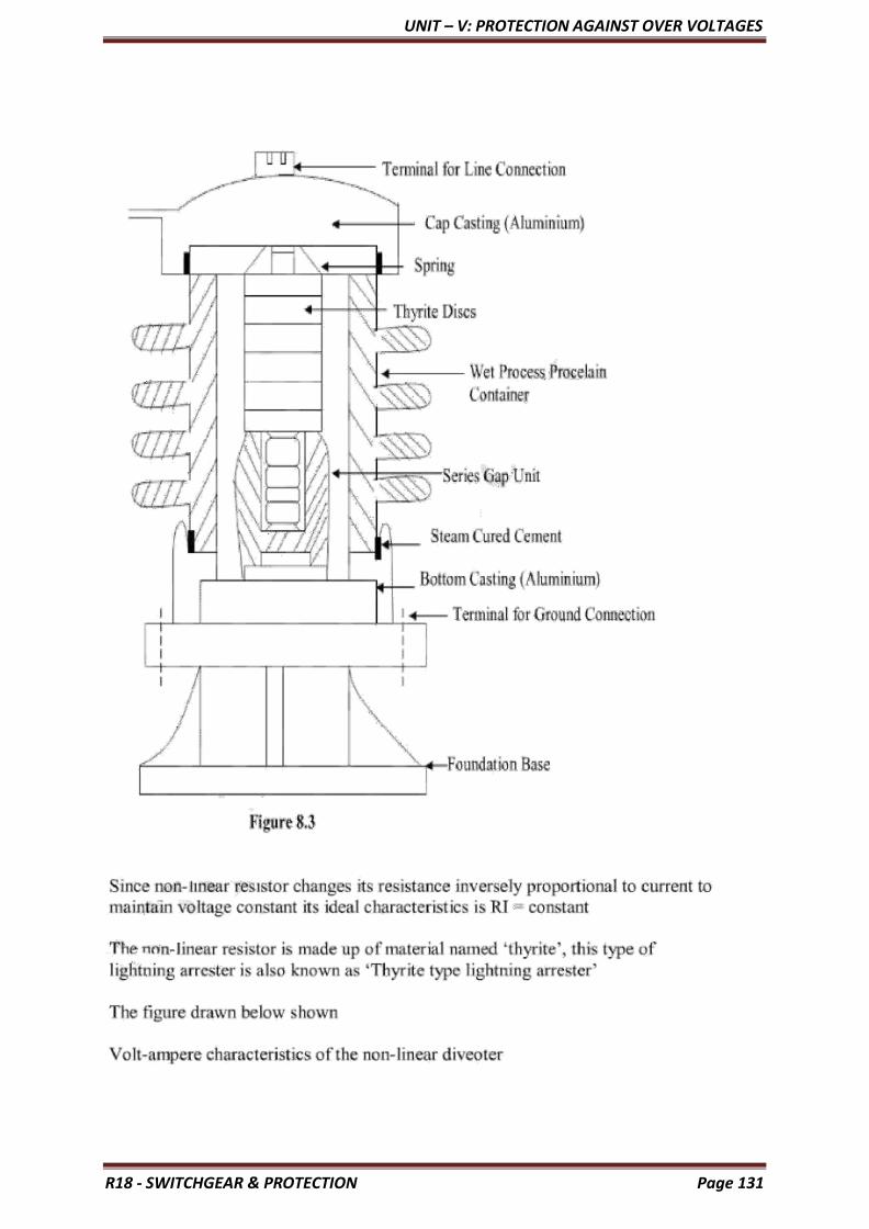
UNIT – V: PROTECTION AGAINST OVER VOLTAGES
R18 - SWITCHGEAR & PROTECTION Page 131

UNIT – V: PROTECTION AGAINST OVER VOLTAGES
R18 - SWITCHGEAR & PROTECTION Page 132

UNIT – V: PROTECTION AGAINST OVER VOLTAGES
R18 - SWITCHGEAR & PROTECTION Page 133

UNIT – V: PROTECTION AGAINST OVER VOLTAGES
R18 - SWITCHGEAR & PROTECTION Page 134

UNIT – V: PROTECTION AGAINST OVER VOLTAGES
R18 - SWITCHGEAR & PROTECTION Page 135
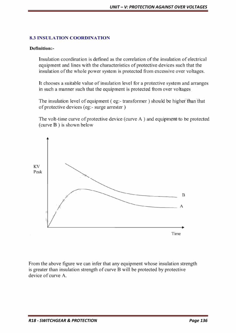
UNIT – V: PROTECTION AGAINST OVER VOLTAGES
R18 - SWITCHGEAR & PROTECTION Page 136

UNIT – V: PROTECTION AGAINST OVER VOLTAGES
R18 - SWITCHGEAR & PROTECTION Page 137

UNIT – V: PROTECTION AGAINST OVER VOLTAGES
R18 - SWITCHGEAR & PROTECTION Page 138

UNIT – V: PROTECTION AGAINST OVER VOLTAGES
R18 - SWITCHGEAR & PROTECTION Page 139

UNIT – V: PROTECTION AGAINST OVER VOLTAGES
R18 - SWITCHGEAR & PROTECTION Page 140
Surge Diverter | Lightning Arrester Types:
The earthing screen and ground wires can well protect the electrical system against
direct lightning strokes but they fail to provide protection against travelling waves which may
reach the terminal apparatus. The Lightning Arresters or surge diverter provide protection
against such surges.
A lightning arresters or a surge diverter is a protective device which conducts
the high voltage surges on the power system to the ground.

UNIT – V: PROTECTION AGAINST OVER VOLTAGES
R18 - SWITCHGEAR & PROTECTION Page 141
Lightning Arrester Working:
Fig. 24.8 (i) shows the basic form of a surge diverter. It consists of a spark gap in
series with a non-linear resistor. One end of the diverter is connected to the terminal of the
equipment to be protected and the other end is effectively grounded. The length of the gap is
so set that normal line voltage is not enough to cause an arc across the gap but a dangerously
high voltage will break down the air insulation and form an arc. The property of the non-
linear resistance is that its resistance decreases as the voltage (or current) increases and vice-
versa. This is clear from the *volt/amp characteristic of the resistor shown in Fig. 24.8 (ii).
The action of the lightning arresters or surge diverter is as under:
• Under normal operation, the lightning arrester is off the line i.e. it conducts no current to
earth or the gap is non-conducting.
• On the occurrence of overvoltage, the air insulation across the gap breaks down and an arc is
formed, providing a low resistance path for the surge to the ground. In this way, the excess
charge on the line due to the surge is harmlessly conducted through the arrester to the ground
instead of being sent back over the line.
• It is worthwhile to mention the function of non-linear resistor in the operation of arrester. As
the gap sparks over due to overvoltage, the arc would be a short circuit on the power system
and may cause power-follow current in the arrester. Since the characteristic of the resistor is
to offer high resistance to high voltage (or current), it prevents the effect of a short circuit.
After the surge is over, the resistor offers high resistance to make the gap non-conducting.
Two things must be taken care of in the design of lightning arresters. Firstly, when the
Surge Diverter is over, the arc in gap should cease. If the arc does not go out, the current
would continue to flow through the resistor and both resistor and gap may be destroyed.
Secondly, I R drop (where I is the surge current) across the arrester when carrying surge
current should not exceed the breakdown strength of the insulation of the equipment to be
protected.
Types of Lightning Arresters:
There are several Types of Lightning Arresters in general use. They differ only in
constructional details but operate on the same principle viz. providing low resistance path for
the surges to the ground. We shall discuss the following Types of Lightning Arresters:
1. Rod Gap Arrester
2. Horn Gap Arrester
3. Multi Gap Arrester
4. Expulsion Type Lightning Arrester
5. Valve Type Lightning Arrester
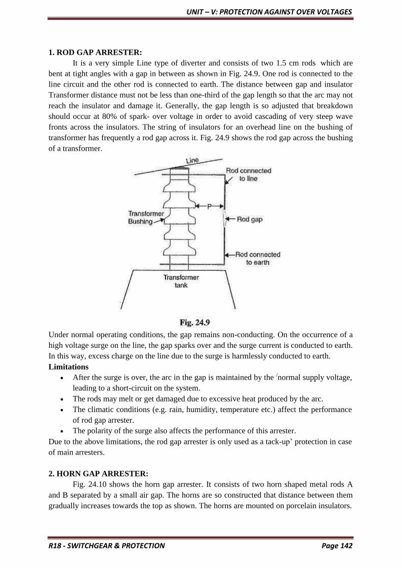
UNIT – V: PROTECTION AGAINST OVER VOLTAGES
R18 - SWITCHGEAR & PROTECTION Page 142
1. ROD GAP ARRESTER:
It is a very simple Line type of diverter and consists of two 1.5 cm rods which are
bent at tight angles with a gap in between as shown in Fig. 24.9. One rod is connected to the
line circuit and the other rod is connected to earth. The distance between gap and insulator
Transformer distance must not be less than one-third of the gap length so that the arc may not
reach the insulator and damage it. Generally, the gap length is so adjusted that breakdown
should occur at 80% of spark- over voltage in order to avoid cascading of very steep wave
fronts across the insulators. The string of insulators for an overhead line on the bushing of
transformer has frequently a rod gap across it. Fig. 24.9 shows the rod gap across the bushing
of a transformer.
Under normal operating conditions, the gap remains non-conducting. On the occurrence of a
high voltage surge on the line, the gap sparks over and the surge current is conducted to earth.
In this way, excess charge on the line due to the surge is harmlessly conducted to earth.
Limitations
• After the surge is over, the arc in the gap is maintained by the /normal supply voltage,
leading to a short-circuit on the system.
• The rods may melt or get damaged due to excessive heat produced by the arc.
• The climatic conditions (e.g. rain, humidity, temperature etc.) affect the performance
of rod gap arrester.
• The polarity of the surge also affects the performance of this arrester.
Due to the above limitations, the rod gap arrester is only used as a tack-up’ protection in case
of main arresters.
2. HORN GAP ARRESTER:
Fig. 24.10 shows the horn gap arrester. It consists of two horn shaped metal rods A
and B separated by a small air gap. The horns are so constructed that distance between them
gradually increases towards the top as shown. The horns are mounted on porcelain insulators.

UNIT – V: PROTECTION AGAINST OVER VOLTAGES
R18 - SWITCHGEAR & PROTECTION Page 143
One end of horn is connected to the line through a resistance R and choke coil L while the
other end is effectively grounded. The resistance R helps in limiting the follow current to a
small value. The choke coil is so designed that it offers small reactance at normal power
frequency but a very high reactance at transient frequency. Thus the choke does not allow the
transients to enter the apparatus to be protected. The gap between the horns is so adjusted that
normal supply voltage is not enough to cause an arc across the gap.
Under normal conditions, the gap is non-conducting i.e. normal supply voltage is
insufficient to initiate the arc between the gap. On the occurrence of an overvoltage, spark-
over takes place across the small gap G. The heated air around the arc and the magnetic effect
of the arc cause the arc to travel up the gap. The arc moves progressively into positions 1, 2
and 3. At some position of the arc (perhaps position 3), the distance may be too great for the
voltage to maintain the arc. Consequently, the arc is extinguished. The excess charge on the
line is thus, conducted through the arrester to the ground.
Advantages
• The arc is self-clearing. Therefore, this type of arrester does not cause short-circuiting
of the system after the Surge Diverter is over as in the case of rod gap.
• Series resistance helps in limiting the follow current to a small value.
Limitations
• The bridging of gap by some external agency (e.g. birds) can render the device
useless.
• The setting of horn gap is likely to change due to corrosion or pitting. This adversely
affects the performance of the arrester.
• The time of operation is comparatively long, say about 3 seconds. In view of the very
short operating time of modern protective gear for feeders, this time is far long.
Due to the above limitations, this type of arrester is not reliable and can only be used as a
second line of defense like the rod gap arrester.
3. MULTI GAP ARRESTER:
Fig. 24.11 shows the multigap arrester. It consists of a series of metallic (generally
alloy of zinc) cylinders insulated from one another and separated by small intervals of air

UNIT – V: PROTECTION AGAINST OVER VOLTAGES
R18 - SWITCHGEAR & PROTECTION Page 144
gaps. The first cylinder (i.e. A) in the series is connected to the line and the other,to the
ground through a series resistance. The series resistance limits the power arc. By the
inclusion of series resistance, the degree of protection against travelling waves is reduced. In
order to overcome this difficulty, some of the gaps (B to C in Fig. 24.11) are shunted by a
resistance.
Under normal conditions, the point B is at earth potential and the normal supply
voltage is unable to break down the series gaps. On the occurrence of an overvoltage, the
breakdown of series gaps A to B occurs. The heavy current after breakdown will choose the
straight – through path to earth via the shunted gaps B and C, instead of the alternative path
through the shunt resistance. When the surge is over, the arcs B to C go out and any power
current following the Surge Diverter is limited by the two resistances (shunt resistance and
series resistance) which are now in series. The current is too small to maintain the arcs in the
gaps A to B and normal conditions are restored. Such arresters can be employed where
system voltage does not exceed 33 kV.
4. EXPULSION TYPE LIGHTNING ARRESTER:
This Expulsion Type Lightning Arrester is also called ‘protector tube’ and is
commonly used on system operating at voltages upto 33 kV.

UNIT – V: PROTECTION AGAINST OVER VOLTAGES
R18 - SWITCHGEAR & PROTECTION Page 145
Fig. 24.12 (i) shows the essential parts of an Expulsion Type Lightning Arrester. It essentially
consists of a rod gap AA’ in series with a second gap enclosed within the fibre tube. The gap
in the fibre tube is formed by two electrodes. The upper electrode is connected to rod gap and
the lower electrode to the earth. One expulsion arrester is placed tinder each line conductor.
Fig. 24.12 (II) shows the installation of expulsion arrester on an overhead line. On the
occurrence of an overvoltage on the line, the series gap AA’ is spanned and an arc is struck
between the electrodes in the tube. The heat of the arc vaporises some of the fibre of tube
walls, resulting in the production of a neutral gas. In an extremely short time, the gas builds
up high pressure and is expelled through the lower electrode which is hollow. As the gas
leaves the tube violently, it carries away ionised air around the arc. This de-ionising effect is
generally so strong that arc goes out at a current zero and will not be re-established.
Advantages
• They are not very expensive.
• They are improved form of rod gap arresters as they block the flow of power
frequency follow currents,
• They can be easily installed.
Limitations
• An expulsion type arrester can perform only limited number of operations as during
each operation some of the fibre material is used up.
• This type of arrester cannot be mounted in an enclosed equipment due to the
discharge of gases during operation.
• Due to the poor volt/amp characteristic of the arrester, is not suitable for the
protection of expensive equipment.
5. VALVE TYPE LIGHTNING ARRESTER:
Valve type arresters incorporate non-linear resistors and are extensively used on
systems operating at high voltages. Fig. 24.13 (i) shows the various parts of a valve type
arrester. It consists of two assemblies (i) series spark gaps and (ii) non-linear resistor discs
(made of material such as thyrite or metrosil) in series.
(i) The spark gap is a multiple assembly consisting of a number of identical spark gaps in
Each gap consists of two electrodes with a fixed gap spacing. The voltage distribution across
the gaps is linearised by means of additional resistance elements (called grading resistors)
across the gaps. The spacing of the series gaps is such that it will withstand the normal circuit
voltage. However, an overvoltage will cause the gap to breakdown, causing the surge current
to ground via the non-linear resistors.
(ii) The non-linear resistor discs are made of an inorganic compound such as Thyrite or
Metrosil. These discs are connected in series. The non-linear resistors have the property of
offering a high resistance to current flow when normal system voltage is applied, but a low
resistance to the flow of high-surge currents. In other words, the resistance of these non-linear
elements decreases with the increase in current through them and vice-versa.

UNIT – V: PROTECTION AGAINST OVER VOLTAGES
R18 - SWITCHGEAR & PROTECTION Page 146
Working: Under normal conditions, the normal system voltage is insufficient to cause the
breakdown of air gap assembly. On the occurrence of an overvoltage, the breakdown of the
series spark gap takes place and the surge current is conducted to earth via the non-linear
resistors. Since the magnitude of surge current is very large, the non-linear elements will
offer a very low resistance to the passage of Surge Diverter. The result is that the surge will
rapidly go to earth instead of being sent back over the line. When the surge is over, the non-
linear resistors assume high resistance to stop the flow of current.
Advantages
• They provide very effective protection (especially for transformers and cables) against
• They operate very rapidly taking less than a second.
• The impulse ratio is practically unity.
Limitations
• They may fail to check the surges of very steep wave front from reaching the terminal
this calls for additional steps to check steep-fronted waves.
• Their performance is adversely affected by the entry of moisture into the enclosure.
This necessitates effective sealing of the enclosure at all times.
Applications
According to their application, the valve type arresters are classified as (i) station type and (ii)
line type. The station type arresters are generally used for the protection of important
equipment in power stations operating on voltages upto 220 kV or higher. The line type
arresters are also used for stations handling voltages upto 66 kV
Copyright © 2022 FDOKUMEN