Air-insulated medium voltage secondary distribution switchgear
98
UniSec Air-insulated medium voltage secondary distribution switchgear Medium voltage products
-
Upload
khangminh22 -
Category
Documents
-
view
6 -
download
0
Transcript of Air-insulated medium voltage secondary distribution switchgear
UniSecAir-insulated medium voltage secondary distribution switchgear
Medium voltage products

3
6 1. General characteristics
11 2. Typical units
35 3. Main components
56 4. Protection and automation devices
69 5. Marine applications
73 6. IEC classification
74 7. Internal arc withstand capacity
77 8. Installation information
86 9. Dimensional drawings
90 10. Configuration software
91 11. Recycling
92 12. Applications
Index

4
UniSec – A superior switchgear range
Ultimately convenient Wherever your business is, UniSec always provides the most direct route to solving your technical and market challenges.
Always the optimum solution for different needsUniSec brings the most versatile switchgear to the market, with a very broad portfolio of functional units.Fewer parts, all standardized and modularized, require less service training and fewer competences.Comfortable access for cable connection; simple solutions for panel connectivity; easily removable circuit-breakers.The design enables customization, even at the later project stages, and easy modifications, fast replacement and upgrading of main accessories.UniSec brings you state-of-the-art control, monitoring and protection technology. From low-end self-powered protection relays to high-end configurable terminals, available for all applications.
Absolutely trustworthyWhen people’s lives are on the line, they need to know that safety and reliability are always UniSec’s main concern.
Reliable and SafeReliability and service continuity are assured.UniSec’s long life-cycle is assured by extensive product testing and an unrivalled global service network. The metallic partitions between busbars and cable compartments is a further safety and service continuity feature.Personnel safety is paramount. Safety features protect your investment. The UniSec range is fully designed and type tested according to the IEC standard no. 62271-200, and has a high internal arc withstand capability rating.Optional arc-protection solutions integrated in protection relays limit the negative effects of the internal arc.
UniSec is the result of ABB’s quest for continuous innovation, following a vision to meet ever-changing market needs. It provides long-term technical solutions for a world of applications. Safety and reliability, user-friendly specifications and installation, and sustainability have been the driving forces in its development.
5
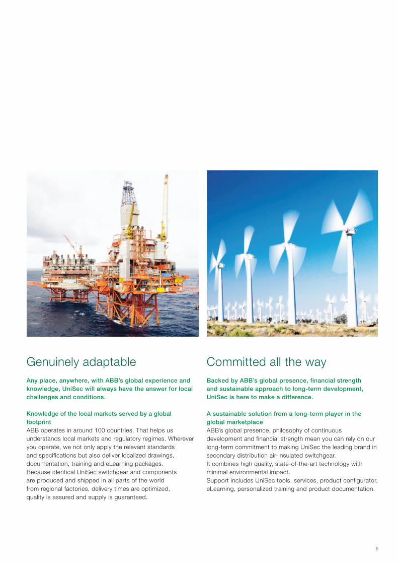
Genuinely adaptableAny place, anywhere, with ABB’s global experience and knowledge, UniSec will always have the answer for local challenges and conditions.
Knowledge of the local markets served by a global footprintABB operates in around 100 countries. That helps us understands local markets and regulatory regimes. Wherever you operate, we not only apply the relevant standards and specifications but also deliver localized drawings, documentation, training and eLearning packages.Because identical UniSec switchgear and components are produced and shipped in all parts of the world from regional factories, delivery times are optimized, quality is assured and supply is guaranteed.
Committed all the wayBacked by ABB’s global presence, financial strength and sustainable approach to long-term development, UniSec is here to make a difference.
A sustainable solution from a long-term player in the global marketplaceABB’s global presence, philosophy of continuous development and financial strength mean you can rely on our long-term commitment to making UniSec the leading brand in secondary distribution air-insulated switchgear.It combines high quality, state-of-the-art technology with minimal environmental impact.Support includes UniSec tools, services, product configurator, eLearning, personalized training and product documentation.

VD4/R-SEC HD4/R-SEC Vmax/Sec VSC/PVD4/Sec
6
1. General characteristics
Switchgear electrical characteristics
Rated voltage kV 12 17.5 24
Test voltage (50-60 Hz x 1 min) kV 28 38 50
Impulse withstand voltage kV 75 95 125
Rated frequency Hz 50-60 50-60 50-60
Rated main busbar current A 630/800/1250 630/800/1250 630/1250
Rated current of apparatus:
– VD4/R-Sec - HD4/R-Sec removable circuit-breaker
– GSec gas switch-disconnector
– Vmax/Sec withdrawable circuit-breaker
– VD4/Sec withdrawable circuit-breaker
– VSC/P withdrawable vacuum contactor
A
A
A
A
A
630/800
630/800
630/1250
–
400
630/800
630/800
630/1250
–
–
630
630
–
630/1250
–
Rated short time withstand current kA (3s) 16/20 (4)/25 (1) (2) 16/20 (4)/25 (2) 16/20 (4)
Peak current kA 40/52.5/63 40/52.5/63 40/52.5
Internal arc withstand current (IAC AFLR) (3) kA (1s) 12.5/16/21/25 (2) 12.5/16/21/25 (2) 12.5/16/21
(1) 25 kA 2s for units “no withdrawable circuit-breaker” (2) For withdrawable circuit-breaker (3) On request “No internal arc” (4) Contact ABB for 21 kA
Designed for all applicationsUniSec is the new ABB air-insulated switchgear, LSC2A-PM for panels with switch-disconnector, LSC2B-PM for panels with withdrawable circuit-breaker up to 17.5 kV and LSC2B-PI at 24 kV, in accordance with the loss of service continuity definitions and standard IEC 62271-200.
UniSec offers the following features: − Air insulation of all live parts − SF6 switch-disconnector − Removable and withdrawable vacuum and SF6 circuit-breakers − Withdrawable vacuum contactor − LSC2A service continuity classification − Withdrawable circuit-breaker and contactor class LSC2B
service continuity classification − Complete range of functional units and accessories − Large selection of state-of-the-art protection relays,
integrated on removable circuit-breakers or separately mounted for protection, control and measurement functions.
Reference StandardsThe switchgear and the main equipment it contains comply with the following standards:
− IEC 62271-1 for the general application − IEC/EN 62271-200 for the switchgear. With reference to
the classifications established by the standards, UniSec switchgear is defined as described below:- continuity of service classification: LSC2A and LSC2B- classification of the segregations: PM (metallic partition)
and PI (insulation partition) for withdrawable circuit-breakers at 24 kV only
− IEC 62271-102 for the earthing switch − IEC 62271-100 for the circuit-breakers − IEC 60071-2 for insulation co-ordination − IEC 60470 for the contactors − IEC 60265-1 for the switch disconnectors − IEC 60529 for the protection classes − IEEE 693 Seismic qualification testing of the switchgear.

7
Available versions– Arc fault tested in accordance with standard IEC 62271-200
in the IAC AFL arc proof version on two sides (front and lateral) 12.5 kA and IAC AFLR arc proof version on three sides (front, lateral, rear) 12.5 kA, 16 kA and 21 kA; 25 kA for panels with withdrawable circuit-breakers up to 17.5 kV
– Seismic withstand version in accordance with standard IEEE 693
– Marine version. Available apparatus
− GSec type gas switch-disconnector − VD4/R-Sec removable vacuum circuit-breakers
− HD4/R-Sec removable SF6 gas circuit-breakers − Vmax/Sec withdrawable circuit-breaker up to 17.5 kV − VD4/Sec withdrawable vacuum circuit-breaker at 24 kV − VSC/P withdrawable vacuum contactor.
Normal service conditions − Storage temperature: –5 °C ... +70 °C (*)
− Range of ambient temperature: –5 °C ... +40 °C (*)
− Maximum relative humidity without condensation: 95 % − Minimum relative humidity without condensation: 5 % − Altitude: <1000 m above the sea level (**).
Degrees of protectionThe protection classes of the switchgear comply with IEC 60529 standards.UniSec switchgear is generally supplied with the following standard protection classes:
− For IP 3X enclosure (***) − For IP 2X partition between compartments − For IP 3X mechanical operating equipment.
Surface treatmentUniSec units are made of pre-galvanized sheet. The doors of the front panels and the switch-disconnector cover are painted grey RAL 7035 with gloss finish.
Fields of application − Medium voltage secondary power distribution − Transformer substations − Control and protection of feeders and power transformers − Infrastructures, data centers, Small Power Generation − Airports − Hospitals and shopping centres − Industries, renewable energy systems − Marine.
Technical documentationFor in-depth information about technical and application aspects of the apparatus used in UniSec switchgear, please request the following publications:
− VD4/R-Sec - VD4/Sec circuit-breaker 1VCP000263 − HD4/Sec circuit-breaker 1VCP000028 − Vmax/Sec circuit-breaker 1VCP000408 − VSC/P contactor 1VCP000165 − Current transformers 1VLC000501 − Voltage transformers 1VLC000572 − REF601 1MDS07202 − REF610 1MRS756029 − REF615 1MRS756379 − REF630 1MRS756382
(*) Contact ABB for -25 °C operating temperatures and -40 °C storage temperatures.
(**) For higher altitudes, contact ABB. (***) For higher degrees of protection, contact ABB.
8
1. General characteristics
Design concept Each unit is constructed entirely using pre-galvanized metal sheets. Each unit consists of several compartments, which are described in the following paragraphs. The busbar compartment is placed along the whole length of the switchgear. Each unit has holes for fixing to the floor and is provided with bottom closure fitted with openings for medium voltage cable passage.All the units fitted with a door have a mechanical interlock which only allows door opening under safe conditions. There is a metal wiring duct in each unit to segregate the low voltage circuits from the medium voltage circuits.
Compartments Each unit consists of several power compartments: cable compartment [8], busbar compartment [4] and apparatus compartment [9].The compartments are metal segregated from each other by means of the switch-disconnector or by means of shutters [10] in the case of withdrawable circuit-breakers. The units can be fitted with an auxiliary circuit compartment [7], where all the instruments and wiring are fitted.Arc-proof switchgear is normally provided with a duct for evacuation of the gases produced by an arc. All the units are accessible from the front and the maintenance and service operations can therefore also be carried out with the switchgear mounted against a wall.
Main busbarsThe busbar compartment contains the main busbar system connected to the fixed upper contacts of the switch-disconnector. The main busbars are made of electrolytic copper up to 1250 A. The system consists of flat busbars.The section of the busbars is:1x30x10 mm for 630 A1x40x10 mm for 800 A2x40x10 mm for 1250 A
Earthing busbarThe earthing busbar is made of electrolytic copper. It runs lengthwise right round the switchgear, thereby providing maximum personnel and plant safety. The section of the earthing busbars is 75 mm2.
Switch-disconnector The switch-disconnector compartment contains a GSec type of 3-position SF6-insulated switch-disconnector.The contacts of the switch-disconnector are housed in an enclosure made of two materials: the top part is a mouldedresin case to guarantee the insulation level; the bottom part is made of stainless steel to guarantee metallic partitions and earthing between the busbar compartment and the cable compartment.This metallic partition (classification PM - Metallic Partitions according to the IEC 62271-200 Standard) guaranteesmaximum safety for personnel in the case of intervention in the cable compartment even with the busbar energized, for example to replace the fuses or to check the cables.
Earthing switchEach incoming/outgoing unit can be equipped with an earthing switch for earthing the cables.This same device can be used for earthing the busbar system. It can also be installed directly on the main busbar system in a dedicated cubicle (busbar application).The earthing switch has short-circuit making capacity (with the exception of units with fuses).The earthing switch is operated from the front of the switchgear.The position of the earthing switch can be identified from the front of the switchgear by means of a mechanical indicator.
Cable compartment The switch-disconnector compartment creates a metal partition between the cable and busbar compartment. It can contain different apparatus according to the specific unit.

2
1
3
4
6
17
8
5
7
5
4
10
8
74
9
8
9
Terminals The cable compartment contains the terminals for connection of the power cables to the lower fixed isolating contacts of the apparatus. The terminals are made of electrolytic copper and have flat busbars for the whole range of currents.
LV compartment for auxiliary circuitsAll the units include an LV compartment in which the low voltage components, protection equipment, measuring, remote control and data transmission devices can be mounted.3 types of LV compartments are available.•Standard LV compartment The standard LV compartment is always present. Low
voltage components, terminals, push-buttons, lamps and sensors can be installed inside.
• Wide LV compartment This compartment is used when, besides the low voltage
components, a protection relay such as REF 601, REF 610, REF 615 or REF542plus with sensors is required.
•Big LV compartment This compartment is used when protection relays and
measuring instruments, or particularly bulky relays such as REF630, REF542plus or REF 541 are required.
The protection relays, secondary wiring and terminal boxes are installed in this compartment.The compartment dimensions are given in chapter 9.
Mechanism compartmentThis compartment contains the operating mechanism of the switch-disconnector and earthing switch, the mechanical interlocks and the position indicators. The auxiliary contacts, trip coils and voltage indicators are also mounted in this compartment.
CablesSingle-pole or three-pole cables up to a maximum of two per phase can be used, depending on the rated voltage, the unit dimensions and the cross section of the cables.The three-pole cables must be branched under the floor so that they can be mounted on each phase.The switchgear can be mounted against the wall in the station as the cables are easily accessible from the front.Consult chapter 8 for further details.
1 − Switch-disconnector 2 − Fuses3 − Circuit-breaker4 − Busbar compartment5 − Mechanism compartment 6 − Circuit-breaker operating mechanism7 − LV compartment for auxiliary circuits8 − Cable compartment9 − Apparatus compartment10 − Metallic shutters for panels up to 17.5 kV and insulating shutters up to 24 kV

10
InterlocksUniSec switchgear is fitted with all the interlocks and accessories needed to guarantee a high level of safety and reliability both for the installation and operators.Safety interlocks can either be those provided as standard or special versions available on request.The former are required by the standards and are therefore necessary to guarantee the correct operation sequence. The latter can be supplied on request and their integration must be considered during the installation and maintenance stage.Their presence guarantees the highest level of reliability even in the case of an accidental error and allows what ABB defines as an “error-free” system of interlocks.
Key interlocksThe use of key interlocks is very important in realising the interlocking logics between units of the same switchgear, orof other medium, low and high voltage switchgear. The logics
are realised by means of keys exchange boxes or by ringed keys.The earthing switch closing and opening operations can be locked by means of key interlocks, which can only be disabled with the earthing switch in an opposed position to the lock to be made.The key lock can also be applied to the earthing switch of busbar applications. The keys that can be used for the interlock can be: standard ABB, Ronis or Profalux.
PadlocksThe apparatus and cable compartment doors can be locked in the closed position by means of padlocks. A padlock can be installed on the GSec switch-disconnector so as to lock the position on the line side and/or earth side.The switchgear is preset for use of padlocks with a 4 to 8 mm diameter.
1. General characteristics
11
2. Typical units
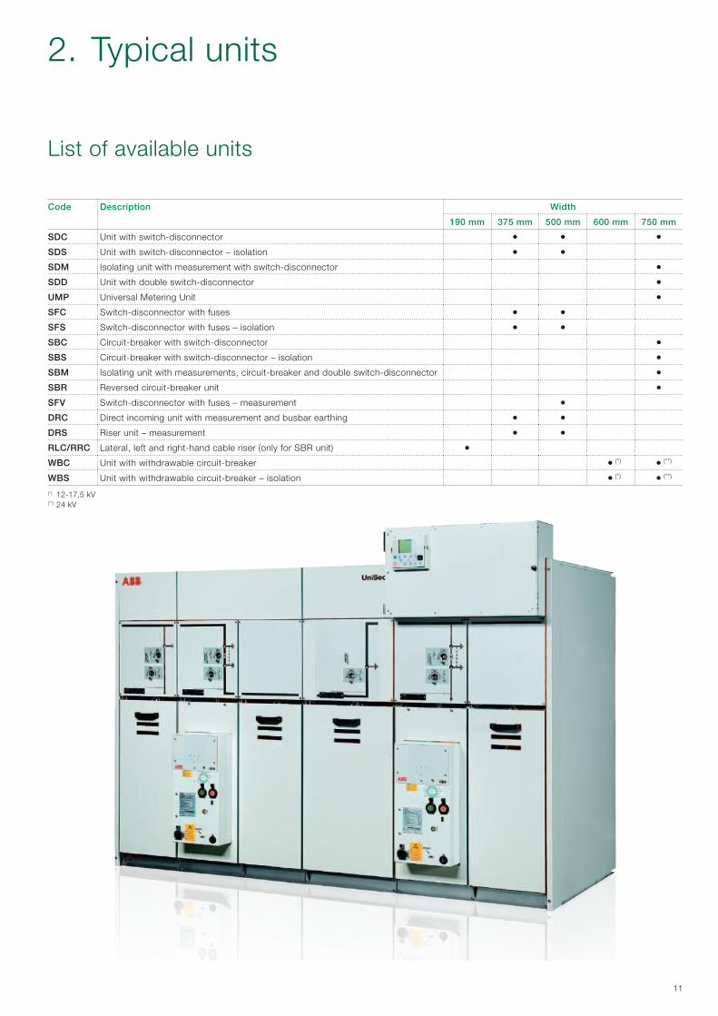
List of available units
Code Description Width
190 mm 375 mm 500 mm 600 mm 750 mm
SDC Unit with switch-disconnector • • •SDS Unit with switch-disconnector – isolation • •SDM Isolating unit with measurement with switch-disconnector •SDD Unit with double switch-disconnector •UMP Universal Metering Unit •SFC Switch-disconnector with fuses • •SFS Switch-disconnector with fuses – isolation • •SBC Circuit-breaker with switch-disconnector •SBS Circuit-breaker with switch-disconnector – isolation •SBM Isolating unit with measurements, circuit-breaker and double switch-disconnector •SBR Reversed circuit-breaker unit •SFV Switch-disconnector with fuses – measurement •DRC Direct incoming unit with measurement and busbar earthing • •DRS Riser unit – measurement • •RLC/RRC Lateral, left and right-hand cable riser (only for SBR unit) •WBC Unit with withdrawable circuit-breaker • (*) • (**)
WBS Unit with withdrawable circuit-breaker – isolation • (*) • (**)
(*) 12-17,5 kV(**) 24 kV

A
12
Units available in the 375 mm, 500 mm and 750 mm widths.The switch-disconnector unit with cable is mainly used as an incoming, ring or branch unit. The basic unit is equippedwith a 3-position switch-disconnector. The 3-position switch-disconnector can be in one of three positions: “closed”,“open” or “earthed”, therefore preventing incorrect operations.Access to the cable compartment is possible in the “earthed” position. Inspection of cable connections and fault indicators, when used, is easily carried out through the front-door window.
Un Ir Ik
kV A kA
12 630/800 12.5/16 (1)/20 (2)/25 (3) (3s)
17.5 630/800 12.5/16 (1)/20 (2) (3s)
24 630 12.5/16 (1)/20 (2) (3s)
(1) 630 A, 16 kA 3s for double spring operating mechanism(2) Contact ABB for 21 kA(3) 25 kA (2s)
SDC – Unit with switch-disconnector
Panel width Weight
mm (*) kg
375 140 (1)
500 160 (1)
750 185 (2)
(*) Consult chap. 9 for the overall dimensions (1) Without CT (2) Without CT or VT
Reference Standard equipment Main accessories
GSec Switch-disconnector
3-position switch-disconnector 4 change-over contacts signalling closed - earthed indication
Mechanical operating mechanism with position indicators Digital or analog pressure gauge with optional alarm contacts
Integrated voltage indicator Motor operator mechanism
Shunt opening release
Shunt closing release
Undervoltage coil
Unit
Integrated standard auxiliary circuit compartment DIN or ring core current transformer (except 375 mm panels)
Mechanical interlocks Accessories for internal arc classification
Busbars Wiring duct for auxiliary cable passage
Cable compartment closure Anti-condensation heater
Cable terminals Internal lighting
Support for cable connections Key interlocks
Earthing bar Short-circuit indicator
Padlocks
Surge arresters
Wide and big low voltage compartment
Voltage transformer (except 375 mm panels)
Terminals for parallel cables (except 375 mm panels)
Riser frame H = 300 mm
2. Typical units
A
13
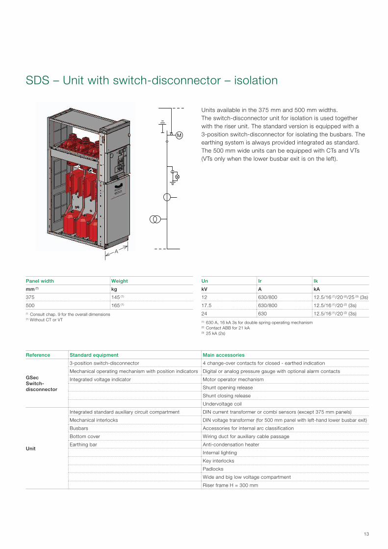
Un Ir Ik
kV A kA
12 630/800 12.5/16 (1)/20 (2)/25 (3) (3s)
17.5 630/800 12.5/16 (1)/20 (2) (3s)
24 630 12.5/16 (1)/20 (2) (3s)
(1) 630 A, 16 kA 3s for double spring operating mechanism(2) Contact ABB for 21 kA(3) 25 kA (2s)
SDS – Unit with switch-disconnector – isolation
Panel width Weight
mm (*) kg
375 145 (1)
500 165 (1)
(*) Consult chap. 9 for the overall dimensions (1) Without CT or VT
Units available in the 375 mm and 500 mm widths.The switch-disconnector unit for isolation is used together with the riser unit. The standard version is equipped with a3-position switch-disconnector for isolating the busbars. The earthing system is always provided integrated as standard.The 500 mm wide units can be equipped with CTs and VTs (VTs only when the lower busbar exit is on the left).
Reference Standard equipment Main accessories
GSec Switch-disconnector
3-position switch-disconnector 4 change-over contacts for closed - earthed indication
Mechanical operating mechanism with position indicators Digital or analog pressure gauge with optional alarm contacts
Integrated voltage indicator Motor operator mechanism
Shunt opening release
Shunt closing release
Undervoltage coil
Unit
Integrated standard auxiliary circuit compartment DIN current transformer or combi sensors (except 375 mm panels)
Mechanical interlocks DIN voltage transformer (for 500 mm panel with left-hand lower busbar exit)
Busbars Accessories for internal arc classification
Bottom cover Wiring duct for auxiliary cable passage
Earthing bar Anti-condensation heater
Internal lighting
Key interlocks
Padlocks
Wide and big low voltage compartment
Riser frame H = 300 mm
A
14
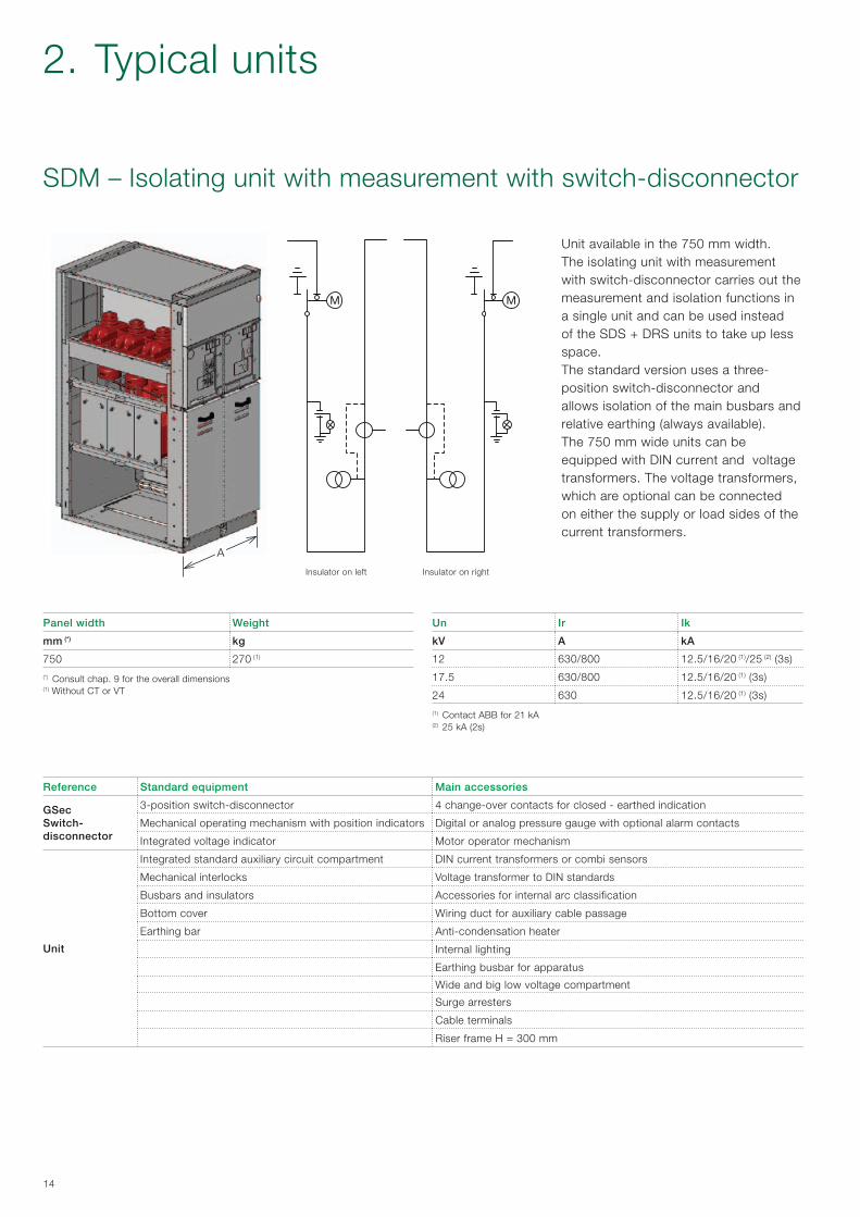
SDM – Isolating unit with measurement with switch-disconnector
Unit available in the 750 mm width.The isolating unit with measurement with switch-disconnector carries out the measurement and isolation functions in a single unit and can be used instead of the SDS + DRS units to take up less space.The standard version uses a three-position switch-disconnector and allows isolation of the main busbars and relative earthing (always available).The 750 mm wide units can be equipped with DIN current and voltage transformers. The voltage transformers, which are optional can be connected on either the supply or load sides of the current transformers.
Un Ir Ik
kV A kA
12 630/800 12.5/16/20 (1)/25 (2) (3s)
17.5 630/800 12.5/16/20 (1) (3s)
24 630 12.5/16/20 (1) (3s)
(1) Contact ABB for 21 kA(2) 25 kA (2s)
Panel width Weight
mm (*) kg
750 270 (1)
(*) Consult chap. 9 for the overall dimensions (1) Without CT or VT
Reference Standard equipment Main accessories
GSec Switch-disconnector
3-position switch-disconnector 4 change-over contacts for closed - earthed indication
Mechanical operating mechanism with position indicators Digital or analog pressure gauge with optional alarm contacts
Integrated voltage indicator Motor operator mechanism
Unit
Integrated standard auxiliary circuit compartment DIN current transformers or combi sensors
Mechanical interlocks Voltage transformer to DIN standards
Busbars and insulators Accessories for internal arc classification
Bottom cover Wiring duct for auxiliary cable passage
Earthing bar Anti-condensation heater
Internal lighting
Earthing busbar for apparatus
Wide and big low voltage compartment
Surge arresters
Cable terminals
Riser frame H = 300 mm
Insulator on left Insulator on right
2. Typical units

A
15
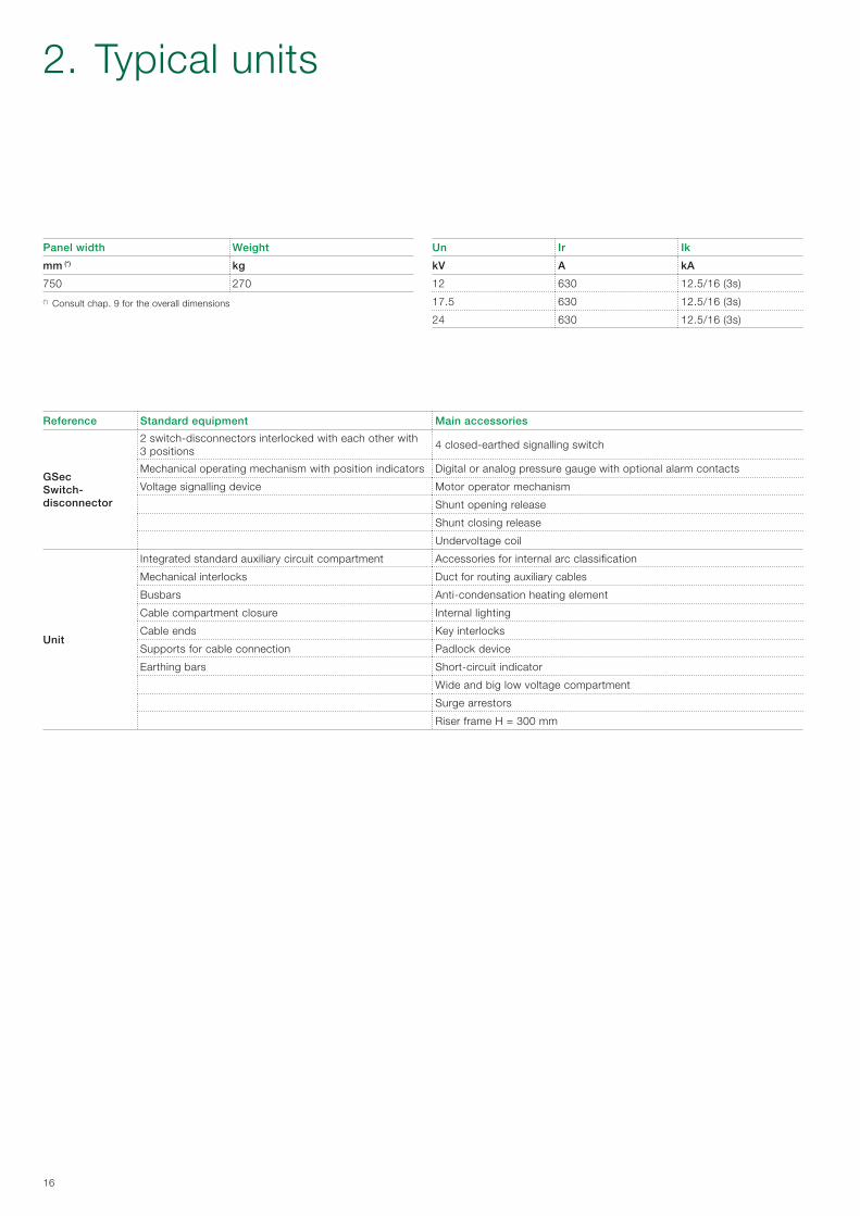
SDD – Unit with double switch-disconnector
Unit available in the 750 mm width and included 2 disconnectors mechanically interlocked with each other.Unit suitable for switching two main medium voltage lines or between a main line and an auxiliary line (e.g. electric generating set).The mechanical interlock of the two disconnectors guarantees the utmost reliability and prevents the operator from committing errors since the disconnectors cannot be earthed at the same time.The disconnector switching operations can be performed in the manual mode (by means of a lever and/or push-buttons) or by means of a motor and/or opening/closing coils (locally and/or via remote control).Switching between the two lines can occur automatically or in the semi-automatic mode by means of a monitoring system that controls the operation of the disconnectors (SCADA).The original situation can be reset either automatically or in the manual mode.The logic of the interlock of the SDD unit is given in the table below.
Lh disconnector position (main line)
Rh disconnector position(secondary line)
Closed Open Earth Closed Open Earth
• •• •• •• •
• •
16
2. Typical units
Un Ir Ik
kV A kA
12 630 12.5/16 (3s)
17.5 630 12.5/16 (3s)
24 630 12.5/16 (3s)
Panel width Weight
mm (*) kg
750 270
(*) Consult chap. 9 for the overall dimensions
Reference Standard equipment Main accessories
GSec Switch-disconnector
2 switch-disconnectors interlocked with each other with 3 positions
4 closed-earthed signalling switch
Mechanical operating mechanism with position indicators Digital or analog pressure gauge with optional alarm contacts
Voltage signalling device Motor operator mechanism
Shunt opening release
Shunt closing release
Undervoltage coil
Unit
Integrated standard auxiliary circuit compartment Accessories for internal arc classification
Mechanical interlocks Duct for routing auxiliary cables
Busbars Anti-condensation heating element
Cable compartment closure Internal lighting
Cable ends Key interlocks
Supports for cable connection Padlock device
Earthing bars Short-circuit indicator
Wide and big low voltage compartment
Surge arrestors
Riser frame H = 300 mm
A
17
Un Ir Ik
kV A kA
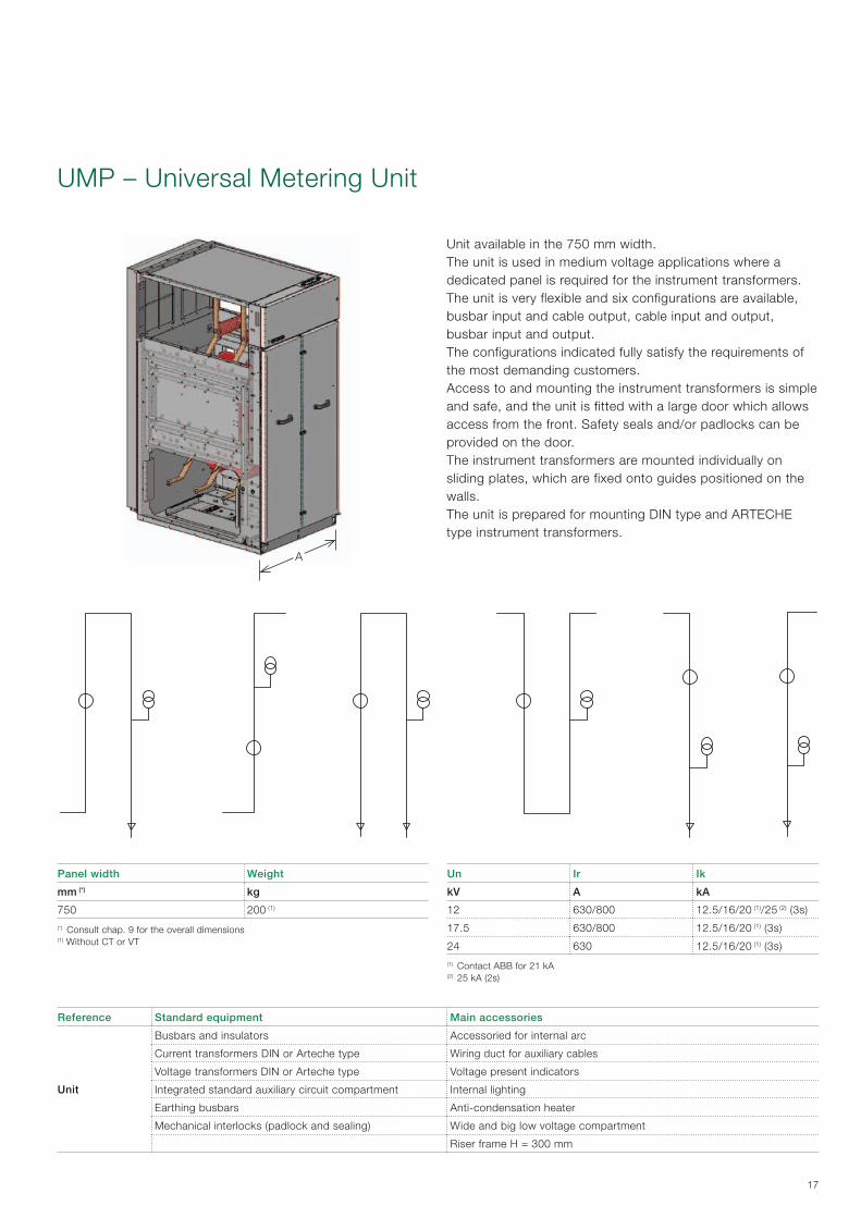
12 630/800 12.5/16/20 (1)/25 (2) (3s)
17.5 630/800 12.5/16/20 (1) (3s)
24 630 12.5/16/20 (1) (3s)
(1) Contact ABB for 21 kA(2) 25 kA (2s)
UMP – Universal Metering Unit
Panel width Weight
mm (*) kg
750 200 (1)
(*) Consult chap. 9 for the overall dimensions (1) Without CT or VT
Unit available in the 750 mm width.The unit is used in medium voltage applications where a dedicated panel is required for the instrument transformers.The unit is very flexible and six configurations are available, busbar input and cable output, cable input and output, busbar input and output.The configurations indicated fully satisfy the requirements of the most demanding customers.Access to and mounting the instrument transformers is simple and safe, and the unit is fitted with a large door which allows access from the front. Safety seals and/or padlocks can be provided on the door.The instrument transformers are mounted individually on sliding plates, which are fixed onto guides positioned on the walls.The unit is prepared for mounting DIN type and ARTECHE type instrument transformers.
Reference Standard equipment Main accessories
Unit
Busbars and insulators Accessoried for internal arc
Current transformers DIN or Arteche type Wiring duct for auxiliary cables
Voltage transformers DIN or Arteche type Voltage present indicators
Integrated standard auxiliary circuit compartment Internal lighting
Earthing busbars Anti-condensation heater
Mechanical interlocks (padlock and sealing) Wide and big low voltage compartment
Riser frame H = 300 mm

A
18
Units available in the 375 mm and 500 mm widths.The fused SFC type of switch-disconnector unit is mainly used for transformer protection. The unit is equipped with a3-position switch-disconnector and with an earthing switch. To earth the fuses, the integrated earthing switch acts on the on the supply side, whereas a separate earthing switch acts on the load side of the fuses. A double-spring operating mechanism is used with automatic fuse tripping. Access to the cable compartment is possible in the “earthed” position. Inspection of the cable connections and fault indicators, when used, is easily carried out through the front door window.
Un Ir Ik IkAp (*) Fuses
kV A kA kAp A
12 630/800 12.5/16/20 (1)/25 (2) (3s) 5 125
17.5 630/800 12.5/16/20 (1) (3s) 5 80
24 630 12.5/16/20 (1) (3s) 5 80
(*) Making capacity EF 230(1) Contact ABB for 21 kA(2) 25 kA (2s)
SFC – Switch-disconnector with fuses
Panel width Weight
mm (*) kg
375 145 (1)
500 165 (1)
(*) Consult chap. 9 for the overall dimensions (1) Without fuses
Reference Standard equipment Main accessories
GSec Switch-disconnector
3-position switch-disconnector 4 change-over contacts for closed - earthed indication
Mechanical operating mechanism with position indicators Digital or analog pressure gauge with optional alarm contacts
Integrated voltage indicator Motor operator mechanism
Shunt opening release
Shunt closing release
Undervoltage coil
1 contact for indicating fuse blown
Unit
Integrated standard auxiliary circuit compartment Accessories for internal arc classification
Mechanical interlocks Wiring duct for auxiliary cable passage
Release indicator for fuse blown Anti-condensation heater
Busbars Internal lighting
Lower earthing switch on load side of fuses (EF 230) DIN Standard fuses (1)
Base for fuses Key interlock
Cable terminals Padlocks
Cable connection support Wide and big low voltage compartment
Earthing bar Riser frame H = 300 mm
(1) DIN Fuses: 292 and 442 mm at 12-17.5 kV 442 mm at 24 kV
2. Typical units
A
19
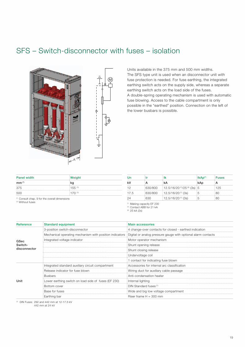
Units available in the 375 mm and 500 mm widths.The SFS type unit is used when an disconnector unit with fuse protection is needed. For fuse earthing, the integrated earthing switch acts on the supply side, whereas a separate earthing switch acts on the load side of the fuses.A double-spring operating mechanism is used with automatic fuse blowing. Access to the cable compartment is only possible in the “earthed” position. Connection on the left of the lower busbars is possible.
Un Ir Ik IkAp(*) Fuses
kV A kA kAp A
12 630/800 12.5/16/20 (1)/25 (2) (3s) 5 125
17.5 630/800 12.5/16/20 (1) (3s) 5 80
24 630 12.5/16/20 (1) (3s) 5 80
(*) Making capacity EF 230(1) Contact ABB for 21 kA(2) 25 kA (2s)
SFS – Switch-disconnector with fuses – isolation
Panel width Weight
mm (*) kg
375 155 (1)
500 170 (1)
(*) Consult chap. 9 for the overall dimensions (1) Without fuses
Reference Standard equipment Main accessories
GSec Switch-disconnector
3-position switch-disconnector 4 change-over contacts for closed - earthed indication
Mechanical operating mechanism with position indicators Digital or analog pressure gauge with optional alarm contacts
Integrated voltage indicator Motor operator mechanism
Shunt opening release
Shunt closing release
Undervoltage coil
1 contact for indicating fuse blown
Unit
Integrated standard auxiliary circuit compartment Accessories for internal arc classification
Release indicator for fuse blown Wiring duct for auxiliary cable passage
Busbars Anti-condensation heater
Lower earthing switch on load side of fuses (EF 230) Internal lighting
Bottom cover DIN Standard fuses (1)
Base for fuses Wide and big low voltage compartment
Earthing bar Riser frame H = 300 mm
(1) DIN Fuses: 292 and 442 mm at 12-17.5 kV 442 mm at 24 kV

A
20
Unit available in the 750 mm width.The SBC type unit is made for control and protection of distribution lines, networks, motors, transformers, capacitor banks, etc. The unit can be equipped with a vacuum or SF6 gas circuit-breaker. The circuit-breaker is mounted on a rail and fixed to the busbars. A 3-position switch-disconnector fitted with an earthing switch is provided for the isolating operations, mounted between the circuit-breaker and the busbars.The door is mechanically interlocked with the switch-disconnector earthing position to ensure personnel safety. Theunit is designed to be equipped with CTs and VTs (dimensions to DIN standards, see main components). Alternatively, a circuit-breaker with integrated current sensor and relay is available.
Un Ir Ik IkAp(*)
kV A kA kAp
12 630/800 12.5/16/20 (1)/25 (2) (3s) 31.5/40/50 (1)/63
17.5 630/800 12.5/16/20 (1) (3s) 31.5/40/50 (1)
24 630 12.5/16/20 (1) (3s) 31.5/40/50 (1)
(*) Making capacity ES 230(1) Contact ABB for 21 kA/52.5 kAp(2) 25 kA (2s)
SBC – Circuit-breaker with switch-disconnector
Panel width Weight
mm (*) kg
750 335 (1)
(*) Consult chap. 9 for the overall dimensions (1) Without CT or VT
Reference Standard equipment Main accessories
GSec Switch-disconnector
3-position switch-disconnector 4 change-over contacts for closed – earthed indication
Mechanical operating mechanism with position indicator Digital or analog pressure gauge with optional alarm contacts
Integrated voltage indicator Motor operator mechanism
VD4 - HD4 Circuit-breaker
Opening device with mechanical signalling and opening and closing pushbuttons
Motor operator mechanism
Removable vacuum or gas circuit-breaker REF601 relay and current sensors on-board
Unit
Integrated standard auxiliary circuit compartment DIN current transformers or combi sensors
Mechanical interlocks Voltage transformer to DIN standards
Busbars Accessories for internal arc classification
Cable compartment closure Wiring duct for auxiliary cable passage
Cable terminals Anti-condensation heater
Cable connection supports Internal lighting
Earthing switch on the cables (ES 230) Wide range of protection relays
Earthing busbar Key interlocks
Padlock
Surge arresters (not with VT’s)
Terminals for parallel cables
Wide and big low voltage compartment
Riser frame H = 300 mm
2. Typical units

A
21
Unit available in the 750 mm width.The switch-disconnector unit with circuit-breaker for isolation is used together with the riser unit. The standard units are equipped with a 3-position switch-disconnector in series with a circuit-breaker for isolating the busbar. The unit is equipped with a vacuum or SF6 gas circuit-breaker. The circuit-breaker is mounted on a rail and fixed to the busbars. The switch-disconnector earthing system is always integrated.The door is mechanically interlocked with the switch-disconnector earthed position to ensure personnel safety. The unit is designed to be equipped with CTs (DIN Standard dimensions). Alternatively, a circuit-breaker with integrated current sensor and relay is available.
Un Ir Ik IkAp(*)
kV A kA kAp
12 630/800 12.5/16/20 (1)/25 (2) (3s) 31.5/40/50 (1)/63
17.5 630/800 12.5/16/20 (1) (3s) 31.5/40/50 (1)
24 630 12.5/16/20 (1) (3s) 31.5/40/50 (1)
(*) Making capacity ES 230(1) Contact ABB for 21 kA/52.5 kAp(2) 25 kA (2s)
SBS – Circuit-breaker with switch-disconnector – isolation
Panel width Weight
mm (*) kg
750 355 (1)
(*) Consult chap. 9 for the overall dimensions (1) Without CT
Reference Standard equipment Main accessories
GSec Switch-disconnector
3-position switch-disconnector 4 change-over contacts for closed – earthed indication
Mechanical operating mechanism with position indicator Digital or analog pressure gauge with optional alarm contacts
Integrated voltage indicator Motor operator mechanism
VD4 - HD4 Circuit-breaker
Opening device with mechanical signalling and opening and closing pushbuttons
Motor operator mechanism
Removable vacuum or gas circuit-breaker REF601 relay and current sensors on-board
Unit
Integrated standard auxiliary circuit compartment DIN current transformers or combi sensors
Mechanical interlocks Accessories for internal arc classification
Busbars Wiring duct for auxiliary cable passage
Earthing switch on the cables (ES 230) Anti-condensation heater
Bottom closure Internal lighting
Earthing busbar Wide range of protection relays
Key interlocks
Padlock
Wide and big low voltage compartment
Riser frame H = 300 mm
A
22
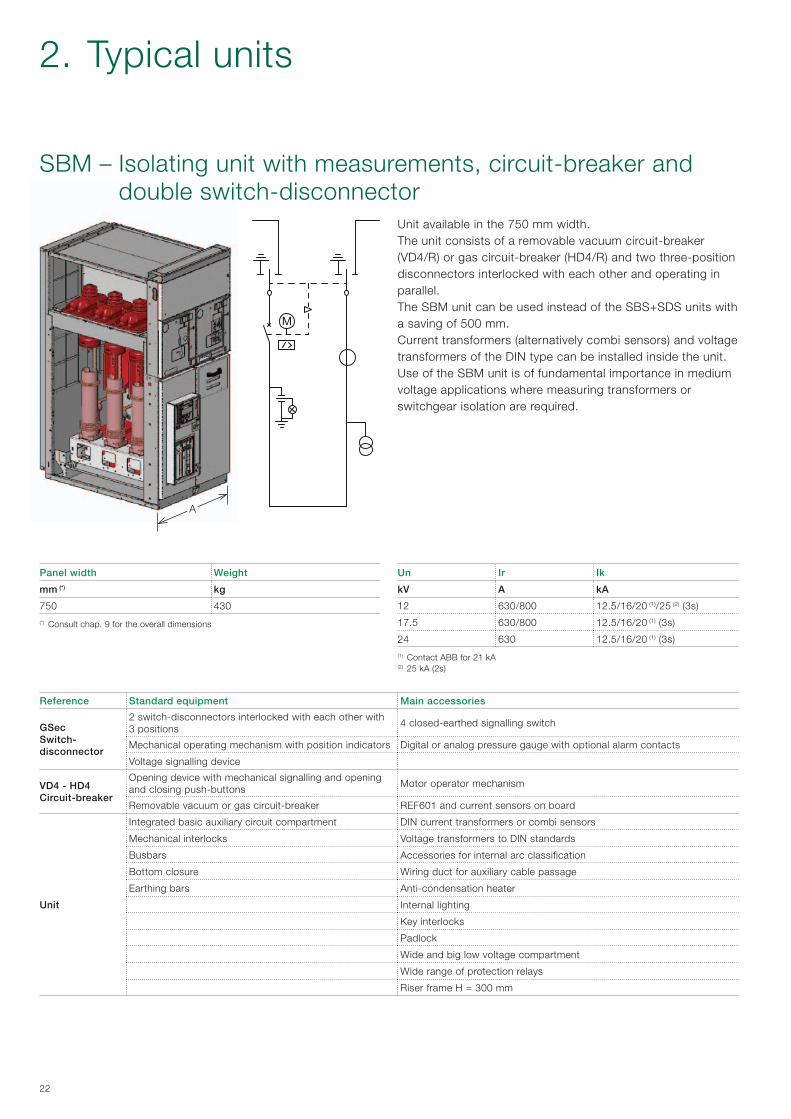
Unit available in the 750 mm width.The unit consists of a removable vacuum circuit-breaker (VD4/R) or gas circuit-breaker (HD4/R) and two three-position disconnectors interlocked with each other and operating in parallel.The SBM unit can be used instead of the SBS+SDS units with a saving of 500 mm. Current transformers (alternatively combi sensors) and voltage transformers of the DIN type can be installed inside the unit.Use of the SBM unit is of fundamental importance in medium voltage applications where measuring transformers or switchgear isolation are required.
SBM – Isolating unit with measurements, circuit-breaker and double switch-disconnector
Un Ir Ik
kV A kA
12 630/800 12.5/16/20 (1)/25 (2) (3s)
17.5 630/800 12.5/16/20 (1) (3s)
24 630 12.5/16/20 (1) (3s)
(1) Contact ABB for 21 kA(2) 25 kA (2s)
Panel width Weight
mm (*) kg
750 430
(*) Consult chap. 9 for the overall dimensions
Reference Standard equipment Main accessories
GSec Switch-disconnector
2 switch-disconnectors interlocked with each other with 3 positions
4 closed-earthed signalling switch
Mechanical operating mechanism with position indicators Digital or analog pressure gauge with optional alarm contacts
Voltage signalling device
VD4 - HD4 Circuit-breaker
Opening device with mechanical signalling and opening and closing push-buttons
Motor operator mechanism
Removable vacuum or gas circuit-breaker REF601 and current sensors on board
Unit
Integrated basic auxiliary circuit compartment DIN current transformers or combi sensors
Mechanical interlocks Voltage transformers to DIN standards
Busbars Accessories for internal arc classification
Bottom closure Wiring duct for auxiliary cable passage
Earthing bars Anti-condensation heater
Internal lighting
Key interlocks
Padlock
Wide and big low voltage compartment
Wide range of protection relays
Riser frame H = 300 mm
2. Typical units
A
23
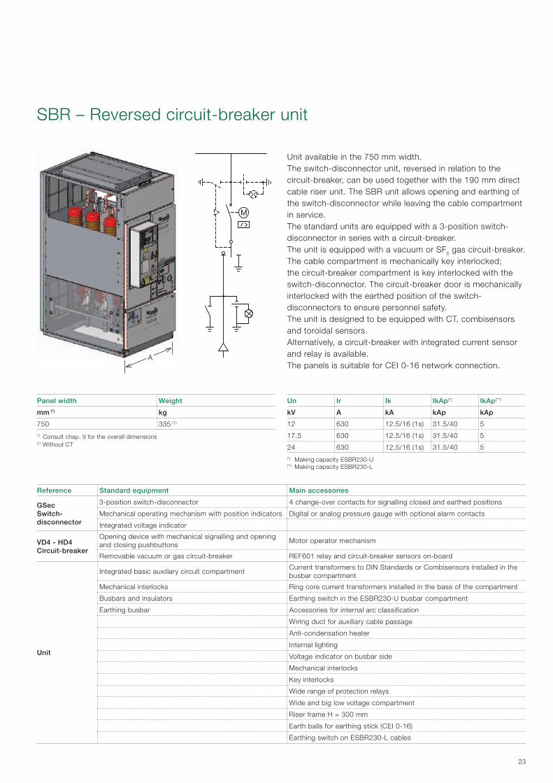
Un Ir Ik IkAp(*) IkAp(**)
kV A kA kAp kAp
12 630 12.5/16 (1s) 31.5/40 5
17.5 630 12.5/16 (1s) 31.5/40 5
24 630 12.5/16 (1s) 31.5/40 5(*) Making capacity ESBR230-U(**) Making capacity ESBR230-L
SBR – Reversed circuit-breaker unit
Panel width Weight
mm (*) kg
750 335 (1)
(*) Consult chap. 9 for the overall dimensions (1) Without CT
Unit available in the 750 mm width.The switch-disconnector unit, reversed in relation to the circuit-breaker, can be used together with the 190 mm direct cable riser unit. The SBR unit allows opening and earthing of the switch-disconnector while leaving the cable compartment in service.The standard units are equipped with a 3-position switch-disconnector in series with a circuit-breaker.The unit is equipped with a vacuum or SF6 gas circuit-breaker. The cable compartment is mechanically key interlocked; the circuit-breaker compartment is key interlocked with the switch-disconnector. The circuit-breaker door is mechanically interlocked with the earthed position of the switch-disconnectors to ensure personnel safety. The unit is designed to be equipped with CT, combisensors and toroidal sensors.Alternatively, a circuit-breaker with integrated current sensor and relay is available.The panels is suitable for CEI 0-16 network connection.
Reference Standard equipment Main accessories
GSec Switch-disconnector
3-position switch-disconnector 4 change-over contacts for signalling closed and earthed positions
Mechanical operating mechanism with position indicators Digital or analog pressure gauge with optional alarm contacts
Integrated voltage indicator
VD4 - HD4 Circuit-breaker
Opening device with mechanical signalling and opening and closing pushbuttons
Motor operator mechanism
Removable vacuum or gas circuit-breaker REF601 relay and circuit-breaker sensors on-board
Unit
Integrated basic auxiliary circuit compartmentCurrent transformers to DIN Standards or Combisensors installed in the busbar compartment
Mechanical interlocks Ring core current transformers installed in the base of the compartment
Busbars and insulators Earthing switch in the ESBR230-U busbar compartment
Earthing busbar Accessories for internal arc classification
Wiring duct for auxiliary cable passage
Anti-condensation heater
Internal lighting
Voltage indicator on busbar side
Mechanical interlocks
Key interlocks
Wide range of protection relays
Wide and big low voltage compartment
Riser frame H = 300 mm
Earth balls for earthing stick (CEI 0-16)
Earthing switch on ESBR230-L cables
A
24
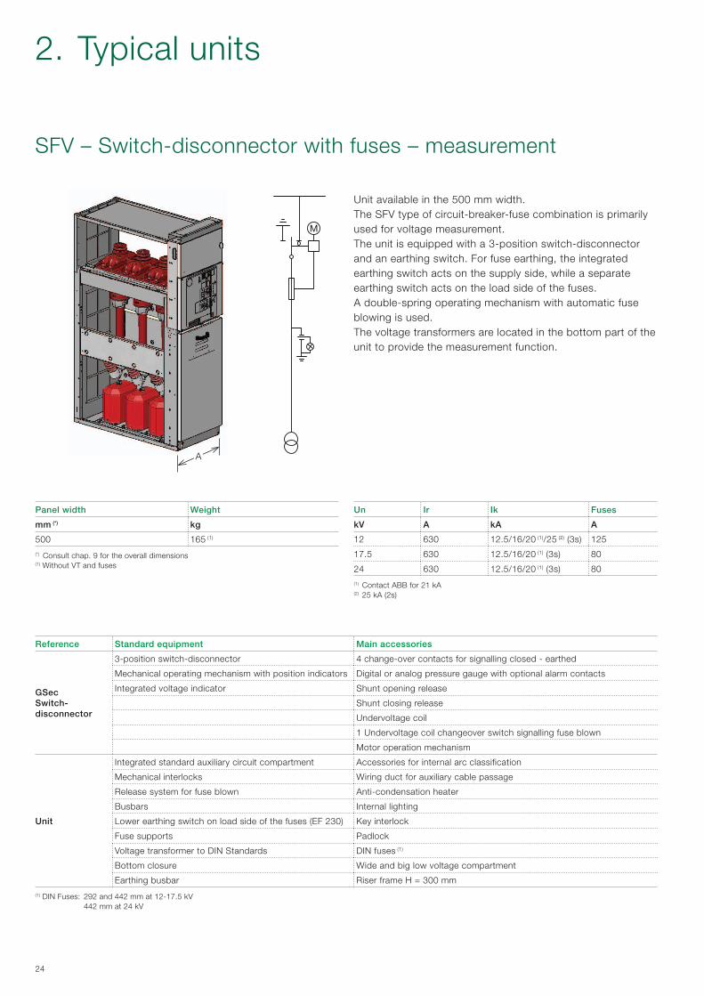
Unit available in the 500 mm width.The SFV type of circuit-breaker-fuse combination is primarily used for voltage measurement. The unit is equipped with a 3-position switch-disconnector and an earthing switch. For fuse earthing, the integrated earthing switch acts on the supply side, while a separate earthing switch acts on the load side of the fuses. A double-spring operating mechanism with automatic fuse blowing is used. The voltage transformers are located in the bottom part of the unit to provide the measurement function.
Un Ir Ik Fuses
kV A kA A
12 630 12.5/16/20 (1)/25 (2) (3s) 125
17.5 630 12.5/16/20 (1) (3s) 80
24 630 12.5/16/20 (1) (3s) 80
(1) Contact ABB for 21 kA(2) 25 kA (2s)
SFV – Switch-disconnector with fuses – measurement
Panel width Weight
mm (*) kg
500 165 (1)
(*) Consult chap. 9 for the overall dimensions (1) Without VT and fuses
Reference Standard equipment Main accessories
GSec Switch-disconnector
3-position switch-disconnector 4 change-over contacts for signalling closed - earthed
Mechanical operating mechanism with position indicators Digital or analog pressure gauge with optional alarm contacts
Integrated voltage indicator Shunt opening release
Shunt closing release
Undervoltage coil
1 Undervoltage coil changeover switch signalling fuse blown
Motor operation mechanism
Unit
Integrated standard auxiliary circuit compartment Accessories for internal arc classification
Mechanical interlocks Wiring duct for auxiliary cable passage
Release system for fuse blown Anti-condensation heater
Busbars Internal lighting
Lower earthing switch on load side of the fuses (EF 230) Key interlock
Fuse supports Padlock
Voltage transformer to DIN Standards DIN fuses (1)
Bottom closure Wide and big low voltage compartment
Earthing busbar Riser frame H = 300 mm
(1) DIN Fuses: 292 and 442 mm at 12-17.5 kV 442 mm at 24 kV
2. Typical units
A
25
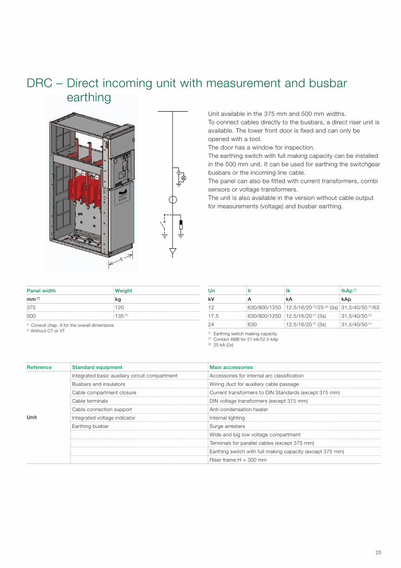
DRC – Direct incoming unit with measurement and busbar earthing
Panel width Weight
mm (*) kg
375 120
500 135 (1)
(*) Consult chap. 9 for the overall dimensions (1) Without CT or VT
Unit available in the 375 mm and 500 mm widths.To connect cables directly to the busbars, a direct riser unit is available. The lower front door is fixed and can only beopened with a tool.The door has a window for inspection.The earthing switch with full making capacity can be installed in the 500 mm unit. It can be used for earthing the switchgear busbars or the incoming line cable.The panel can also be fitted with current transformers, combi sensors or voltage transformers.The unit is also available in the version without cable output for measurements (voltage) and busbar earthing.
Reference Standard equipment Main accessories
Unit
Integrated basic auxiliary circuit compartment Accessories for internal arc classification
Busbars and insulators Wiring duct for auxiliary cable passage
Cable compartment closure Current transformers to DIN Standards (except 375 mm)
Cable terminals DIN voltage transformers (except 375 mm)
Cable connection support Anti-condensation heater
Integrated voltage indicator Internal lighting
Earthing busbar Surge arresters
Wide and big low voltage compartment
Terminals for parallel cables (except 375 mm)
Earthing switch with full making capacity (except 375 mm)
Riser frame H = 300 mm
Un Ir Ik IkAp (*)
kV A kA kAp
12 630/800/1250 12.5/16/20 (1)/25 (2) (3s) 31,5/40/50 (1)/63
17.5 630/800/1250 12.5/16/20 (1) (3s) 31,5/40/50 (1)
24 630 12.5/16/20 (1) (3s) 31,5/40/50 (1)
(*) Earthing switch making capacity (1) Contact ABB for 21 kA/52.5 kAp(2) 25 kA (2s)
A
26
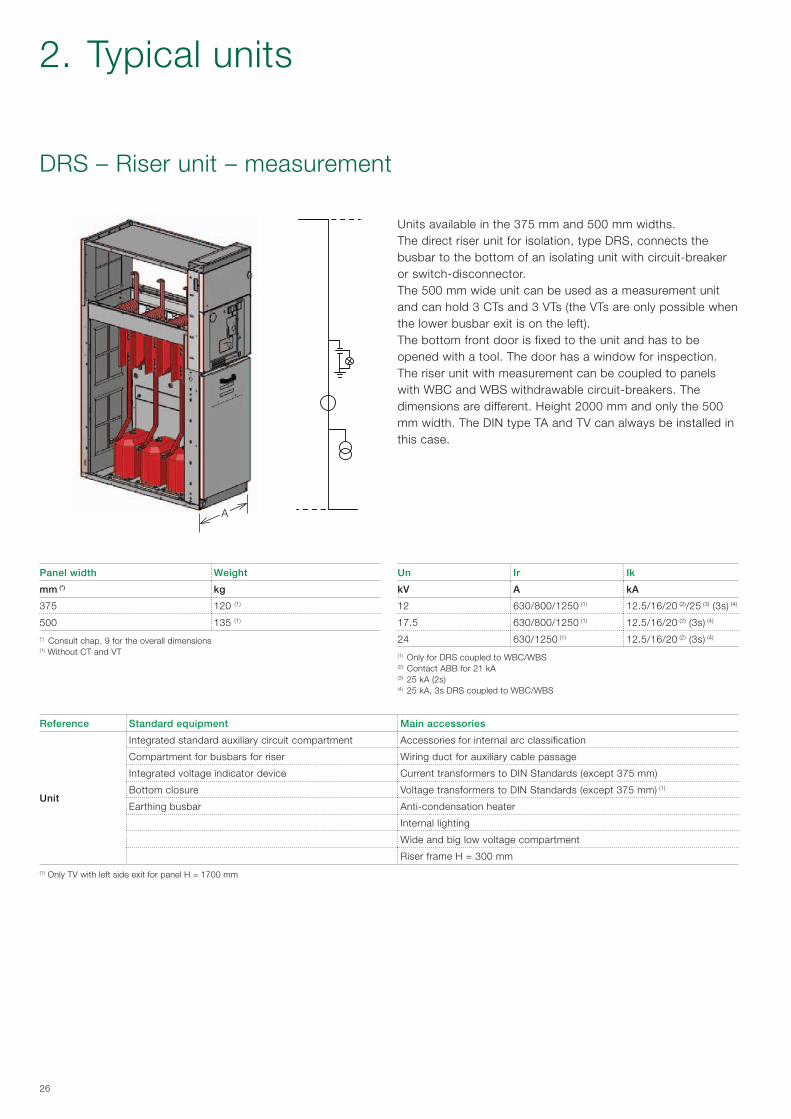
Un Ir Ik
kV A kA
12 630/800/1250 (1) 12.5/16/20 (2)/25 (3) (3s) (4)
17.5 630/800/1250 (1) 12.5/16/20 (2) (3s) (4)
24 630/1250 (1) 12.5/16/20 (2) (3s) (4)
(1) Only for DRS coupled to WBC/WBS (2) Contact ABB for 21 kA(3) 25 kA (2s)(4) 25 kA, 3s DRS coupled to WBC/WBS
DRS – Riser unit – measurement
Panel width Weight
mm (*) kg
375 120 (1)
500 135 (1)
(*) Consult chap. 9 for the overall dimensions (1) Without CT and VT
Units available in the 375 mm and 500 mm widths.The direct riser unit for isolation, type DRS, connects the busbar to the bottom of an isolating unit with circuit-breaker or switch-disconnector. The 500 mm wide unit can be used as a measurement unit and can hold 3 CTs and 3 VTs (the VTs are only possible when the lower busbar exit is on the left). The bottom front door is fixed to the unit and has to be opened with a tool. The door has a window for inspection.The riser unit with measurement can be coupled to panels with WBC and WBS withdrawable circuit-breakers. The dimensions are different. Height 2000 mm and only the 500 mm width. The DIN type TA and TV can always be installed in this case.
Reference Standard equipment Main accessories
Unit
Integrated standard auxiliary circuit compartment Accessories for internal arc classification
Compartment for busbars for riser Wiring duct for auxiliary cable passage
Integrated voltage indicator device Current transformers to DIN Standards (except 375 mm)
Bottom closure Voltage transformers to DIN Standards (except 375 mm) (1)
Earthing busbar Anti-condensation heater
Internal lighting
Wide and big low voltage compartment
Riser frame H = 300 mm
(1) Only TV with left side exit for panel H = 1700 mm
2. Typical units

B
AC
RLC
B
AC
RRC
27
RLC/RRC – Lateral, left and right-hand cable riser (only for SBR unit)
Unit available in the 190 mm width.
Un Ir Ik
kV A kA
12 630 12/16 (1s)
17.5 630 12/16 (1s)
24 630 12/16 (1s)
Panel width Weight
mm A x B x C kg
190 x 1700 x 1070 80

A
C
B
28
WBC / WBS − Unit with withdrawable circuit-breaker
Control of the earthing switch is carried out from the front of the switchgear with manual operation.The position of the earthing switch can be seen from the front of the unit through an inspection window in the feeder compartment door.
Monoblocs and shutters The three-pole monoblocs are located in the apparatus compartment. The fixed contacts for connection of the circuit-breaker to the busbar and cable compartment are housed inside the monoblocs.Metallic shutters for panels up to 17.5 kV and insulated shutters for 24 kV are automatically operated when the circuit-breaker switches from the withdrawn position to the connected position, and vice versa.
CablesSingle-pole or three-pole cables can be used up to a maximum cross section of 630 mm2. The cables are accessible from the front of the compartments as well, so the switchgear can be places right against the wall.
Gas exhaust ductThe units with withdrawable circuit-breakers can be equipped, like all the other units, with:
− gas exhaust duct positioned above the switchgear. The gas exhaust duct runs the whole length of the switchgear. With this solution, the hot gases and incandescent particles produced by any internal arcs are normally evacuated out of the room;
− absorbent gas filters positioned on the rear of each unit. With this solution, the hot gases and incandescent particles produced by any internal arc are discharged into the room.
High electrical characteristics The design of the unit with withdrawable circuit-breaker allows high electrical performances. Increasingly innovative components together with a consolidated solution have made it possible to obtain switchgear with high performances.
− Short-circuit current up to 25 kA for 3s − Internal arc withstand capability on the 4 sides (front,
sides and rear) 25 kA for 1s for panels up to 17.5 kV and 21 kA for 1s for panels at 24 kV in the following two configurations for exhausting the gas after an internal arc:- with absorbent gas filters (gases inside the room)
25 kA at 12-17.5 kV and 16 kA at 24 kV- with gas duct (gases outside the room)
25 kA at 12-17.5 kV and 21 kA at 24 kV.
The units with withdrawable circuit-breaker are suitable for secondary distribution applications where high performances are required and they guarantee:• servicecontinuity• safety• highelectricalcharacteristics.
Service continuityThe units with withdrawable circuit-breaker are classified according to IEC 62271-200 Standards.
LSC2B Classification Compartments busbars [A], cables [B] and apparatus [C] are physically and electrically segregated.This category defines the possibility of accessing the circuit-breaker compartment with the busbars and cables live.
Partition between compartmentsThe busbar, line and apparatus compartments are segregated from each other by continuous metal partitions and by metal shutters (PM) for panels up to 17.5 kV, and by insulated shutters (PI) for panels at 24 kV.
Earthing switchThe earthing switch is with short-circuit making capacity.The incoming/outgoing units are equipped with an earthing device to earth the cables. In the bus-tie unit, the earthing switch has the function of earthing a section of the main busbars.
2. Typical units

29
Interlocking units for the LSC2B-PM units
Standard safety interlocks (compulsory)
Type Description Condition
1A Apparatus racking-in/out Apparatus in the "open" position
B Closing of the apparatus Truck in determinate position
2A Racking-in of the apparatus Multi-contact apparatus plug connected
B Removal of the apparatus multi-contact plug Truck in test position
3A Closing of the earthing switch Truck in test position
B Racking-in of the apparatus Earthing switch in the "open" position
4A Opening of the apparatus compartment door Truck in test position
B Apparatus racking-in Apparatus compartment door closed
5A Opening of the feeder compartment door Earthing switch in the "closed" position
B Opening of the earthing switch Feeder compartment door closed
Keys The use of key interlocks is of great importance in making interlocking logics between units of the same switchgear or with other medium and/or low voltage switchgear.The logics are made by means of distributors or by ringing the keys themselves.
Keys (on request)
1 Lock on apparatus racking-in Can only be removed if the truck is in the withdrawn position
2 Lock on earthing switch closing Can only be removed if the earthing switch is open
3 Lock on switch-disconnector opening Can only be removed if the earthing switch is closed
4 Insertion of the apparatus racking-in/out lever Can always be removed
5 Insertion of the earthing switch operating lever Can always be removed
Padlocks
1 Insertion of the apparatus racking-in/out lever
2 Shutter opening and closing
Locking magnet (on request)
1 Apparatus racking-in/out
2 Earthing switch opening and closing
3 Apparatus compartment door opening
Accessory devices
Fail-safe on the shutters The device locks the shutters when the apparatus is removed from the compartment.The operator cannot open the shutters manually. The shutters can only be activated by the apparatus truck or by the service trucks.
Apparatus compatibility matrix - switchgear unit
The multi-contact apparatus plug and relative switchgear unit socket are fitted with a mechanical matrix, which makes apparatus racking-in impossible in a switchgear unit with inappropriate rated current.
Circuit-breaker mechanical operating mechanism
The apparatus compartment is fitted with a mechanical devices which makes it possible to operate closing and/or opening of the circuit-breakers directly by means of the front control pushbuttons, keeping the door closed.The commands can be given with the circuit-breakers in the service and withdrawn position.
SafetyLike all the UniSec units, the units with withdrawable circuit-breakers are fitted with the interlocks and accessories needed to ensure the highest level of safety and reliability for the plant and for the operators.
InterlocksThere are two types of safety interlocks in the unit:
− standard, foreseen by the standards and therefore necessary to guarantee the sequence of operations;
− locks provided on request. The presence of these must be envisaged according to the plant service and maintenance procedures.

A
30
WBC – Unit with withdrawable circuit-breaker LSC2B-PM/PI
Un Ir Ik IkAp(*)
kV A kA kAp
12 400 (1)/630/1250 16/20 (2)/25 (3s) 40/50 (2)/63
17.5 630/1250 16/20 (2)/25 (3s) 40/50 (2)/63
24 630/1250 16/20 (2) 40/50 (2)
(*) Making capacity EWB(1) Solution with VSC/P contactor(2) Contact ABB for 21 kA/52.5 kAp
Panel width Weight
mm (*) kg
600 (12-17.5 kV PM) 600 (1)
750 (24 kV PI) 750 (1)
(*) Consult chap. 9 for the overall dimensions (1) Without CT or VT
Reference Standard equipment Main accessories
Apparatus
Opening device with mechanical signalling and opening and closing pushbuttons
Motor operator mechanism
Withdrawable circuit-breaker (Vmax/Sec up to 17.5 kV and VD4/Sec at 24 kV) or vacuum contactor (VSC/P up to 12 kV)
Unit
Integrated standard auxiliary circuit compartment DIN current transformers or combi sensors
Mechanical interlocks Voltage transformer to DIN standards with or without fuses (*)
Busbars and insulators Accessories for internal arc classification
Cable terminals Wiring duct for auxiliary cable passage
Cable connection support Apparatus and/or cable compartment anti-condensation heater
Earthing busbar Apparatus and/or cable compartment internal lighting
Metal or insulated shutters Wide range of protection relays
Earthing switch on cable side Mechanical interlocks
Voltage indicator lamp on cable side Key interlocks
Locking magnets
Voltage indicators on busbar side
Surge arresters
Cable connection up to 630 mm2 for 12-17.5 kV and 400 mm2 for 24 kV
Mechanical "on-off" pushbuttons on the circuit-breaker door
5NO + 5NC auxiliary contacts on the earthing switch
Wide low voltage compartment(*) IEC 60282-1 type fuses
Unit available in the 600 mm (12-17 kV) and 750 mm (24 kV)width.The WBC unit, with withdrawable circuit-breaker or contactor, is used for control and protection of plants such as airports, railways, underground railways and industries, where service continuity, high safety levels and high electrical characteristics are major requirements.VSC/P contactors are apparatus suitable for operating in AC and are normally used to control users requiring a high number of hourly operations.The VSC/P contactors are used for controlling electrical apparatus in industry, in the service sector, etc.They are suitable for control and protection of motors, transformers, power factor correction banks, switching systems, etc. Fitted with suitable fuses, they can be used in circuits with fault levels up to 1000 MVA.
2. Typical units

31
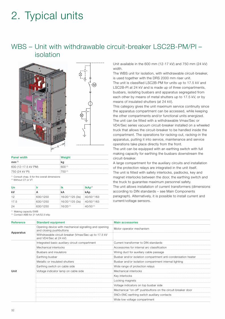
The circuit-breakers Vmax/Sec and VD4/Sec are used in electrical distribution for control and protection of cables, overhead lines, transformer and distribution substations, motors, transformers, generators and capacitor banks. The unit is classified LSC2B-PM for units up to 17.5 kV and LSC2B-PI at 24 kV and is made up of three compartments, busbars, cables and apparatus segregated from each other by means of metal shutters (up to 17.5 kV) or insulated shutters (at 24 kV). This category gives the unit maximum service continuity since it is possible to access the apparatus compartment while keeping the other compartments and/or functional units energized.The apparatus is installed on a truck with wheels, which allows it to be racked into the compartment. The apparatus racking-in/out, putting into service, maintenance and service operations take place directly from the front. It is possible to fit the unit with an earthing switch on the cable side with full making capacity.A large compartment for the auxiliary circuits and installation of the protection relays are integrated in the unit itself.The unit is fitted with safety interlocks, padlocks, key and magnet interlocks between the door, the earthing switch and the truck to guarantee maximum personnel safety.The unit allows installation of current and voltage transformers (dimensions according to DIN standards – see Main Components paragraph). Alternatively, it is possible to install current and current/voltage sensors.
A
32
Un Ir Ik IkAp(*)
kV A kA kAp
12 630/1250 16/20 (1)/25 (3s) 40/50 (1)/63
17.5 630/1250 16/20 (1)/25 (3s) 40/50 (1)/63
24 630/1250 16/20 (1) 40/50 (1)
(*) Making capacity EWB(1) Contact ABB for 21 kA/52.5 kAp
Panel width Weight
mm (*) kg
600 (12-17.5 kV PM) 600 (1)
750 (24 kV PI) 750 (1)
(*) Consult chap. 9 for the overall dimensions (1) Without CT or VT
Reference Standard equipment Main accessories
Apparatus
Opening device with mechanical signalling and opening and closing pushbuttons
Motor operator mechanism
Withdrawable circuit-breaker (Vmax/Sec up to 17.5 kV and VD4/Sec at 24 kV)
Unit
Integrated basic auxiliary circuit compartment Current transformer to DIN standards
Mechanical interlocks Accessories for internal arc classification
Busbars and insulators Wiring duct for auxiliary cable passage
Earthing busbar Busbar and/or isolation compartment anti-condensation heater
Metallic or insulated shutters Busbar and/or isolation compartment internal lighting
Earthing switch on cable side Wide range of protection relays
Voltage indicator lamp on cable side Mechanical interlocks
Key interlocks
Locking magnets
Voltage indicators on top busbar side
Mechanical "on-off" pushbuttons on the circuit-breaker door
5NO+5NC earthing switch auxiliary contacts
Wide low voltage compartment
WBS – Unit with withdrawable circuit-breaker LSC2B-PM/PI – isolation
Unit available in the 600 mm (12-17 kV) and 750 mm (24 kV) width.The WBS unit for isolation, with withdrawable circuit-breaker, is used together with the DRS 2000 mm riser unit.The unit is classified LSC2B-PM for units up to 17.5 kV and LSC2B-PI at 24 kV and is made up of three compartments, busbars, isolating busbars and apparatus segregated from each other by means of metal shutters up to 17.5 kV, or by means of insulated shutters (at 24 kV).This category gives the unit maximum service continuity since the apparatus compartment can be accessed, while keeping the other compartments and/or functional units energized.The unit can be fitted with a withdrawable Vmax/Sec or VD4/Sec series vacuum circuit-breaker installed on a wheeled truck that allows the circuit-breaker to be handled inside the compartment. The operations for racking-out, racking-in the apparatus, putting it into service, maintenance and service operations take place directly from the front. The unit can be equipped with an earthing switch with full making capacity for earthing the busbars downstream the circuit-breaker.A large compartment for the auxiliary circuits and installation of the protection relays are integrated in the unit itself.The unit is fitted with safety interlocks, padlocks, key and magnet interlocks between the door, the earthing switch and the truck to guarantee maximum personnel safety.The unit allows installation of current transformers (dimensions according to DIN standards – see Main Components paragraph). Alternatively, it is possible to install current and current/voltage sensors.
2. Typical units

2000
500
1700
33
The panels cannot be directly coupled owing to the difference in height of the WBC-WBS compartments – H = 2000 mm and the panels with switch-disconnector (GSec) – H = 1700 mm.Adapter panels have been created for this type of compartment so as to allow the busbars to be connected. The height of the adapter panel is H = 2000 mm. The adapter panel keeps all the characteristics of a standard panel and can therefore be used as an incoming/outgoing unit.
Coupling to panels with withdrawable circuit-breaker and switch-disconnector (GSec)
The available adapter panels are:
Unit Width (mm)
SDC, SFV, SFC 500
SBC (Contact ABB) 750
An adapter panel allowing UniSec switchgear to be coupled to the other ABB switchgear (UniMix and UniSwitch) is available on request.
34
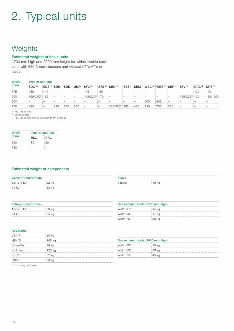
WeightsEstimated weights of basic units1700 mm high and 2000 mm height for withdrawable basic units with 630 A main busbars and without CT‘s VT‘s or fuses. Width(mm)
Type of unit (kg)
SDC (1) SDS (1) SDM SDD UMP SFC (2) SFS (2) SBC (1) SBS (1) SBM WBC (1) WBS (1) SBR (1) SFV (2) DRC (1) DRS (1)
375 140 145 – – – 145 155 – – – – – – – 120 120
500 160/220(*) 165 – – – 165/225(*) 170 – – – – – – 165/225(*) 135 135/160(*)
600 – – – – – – – – – – 600 600 – – – –
750 185 – 185 270 200 – – 335/380(*) 355 430 750 750 335 – – –(1) No CTs or VTs(2) Without fuse(*) H = 2000 mm can be coupled to WBC/WBS
Width(mm)
Type of unit (kg)
RLC RRC
190 80 80
750 – –
Current transformers
12/17.5 kV 22 kg
24 kV 33 kg
Voltage transformers
12/17.5 kV 20 kg
24 kV 35 kg
Apparatus
VD4/R 90 kg
HD4/R 105 kg
Vmax/Sec 98 kg
VD4/Sec 125 kg
VSC/P 52 kg (*)
GSec 38 kg(*) Excluding the fuses
Fuses
3 fuses 19 kg
Gas exhaust ducts (1700 mm high)
Width 375 14 kg
Width 500 17 kg
Width 750 30 kg
Gas exhaust ducts (2000 mm high)
Width 500 25 kg
Width 600 38 kg
Width 750 45 kg
Estimated weight of components
2. Typical units

35
The special geometry of the contacts and the material used, as well as the limited duration and low voltage of the arc,guarantee minimum contact wear and long life. Furthermore, the vacuum prevents their oxidation and contamination.
Standard equipment1 Closing pushbutton2 Opening pushbutton3 Operation counter4 Mechanical indicators for circuit-breaker opening/closing5 Manual spring charging crank lever6 Mechanical indicator of the charged/discharged state of
the closing springs 7 Kit 1: set of five open/closed auxiliary contacts.
Un = 24…250 V AC-DC8 Kit 2: shunt opening release (M01). Allow remote opening
of the apparatus.
Characteristics
Un 24 - 30 - 48 - 60 - 110 - 125 - 132 - 220 - 250 V–
Un 48 - 60 - 110 - 120 - 127 - 220...240 V~ 50 Hz
Un 110 - 120 - 127 - 220 - 240 V~ 60 Hz
Operating limits 70…110 % Un
Inrush power (Ps) DC 200 W; AC = 200 VA
Inrush time about 100 ms
Inrush upkeep time (Pc) DC = 5 W; AC = 5 VA
Opening time 40...60 ms
Insulation voltage 2000 V 50 Hz (for 1 min)
9 Kit 3: key lock in open position with different or identical keys.
VD4/R-Sec technical data
Rated voltage 12 kV 17.5 kV 24 kV
Rated frequency [Hz] 50/60 50/60 50/60
Rated impulse withstand voltage [kV] 75 95 125
Rated test voltage at power frequency [kV] 28 38 50
Rated current [A] 630/800 630/800 630
Breaking capacity [kA] 12/16/20(1)/25(2) 12/16/20(1) 12/16/20(1)
Making capacity [kA] 30/40/50/63 30/40/50 30/40/50
Short-circuit duration [s] 3 3 3
Pole centre distance [mm] 230 230 230
(1) Contact ABB for 21 kA(2) 25 kA - 2s
3. Main components
The VD4/R-Sec vacuum circuit-breaker has been specially designed for UniSec switchgear. The circuit-breaker capacity is sufficient for any conditions arising from operation of the apparatus as well as from system components under normal service and fault conditions.Vacuum circuit-breakers have particular advantages for use in power systems where frequent operations with normal operating currents are required. VD4/R vacuum circuit-breakers are equipped with a stored-energy spring operating mechanism suitable for the normal operating sequence, and also for the auto-reclosing sequence (O-0.3s-CO-15s-CO). They have high operating reliability and long life.The circuit-breaker poles include vacuum interrupters installed in tubular epoxy resin insulators.
Breaking techniqueThe current-breaking process in a vacuum circuit-breaker differs from all other circuit-breakers, which use an oil or gas arc quenching medium. After separation of the current-carrying contacts, the contact material has to generate the charge carriers required to pass the current through the natural zero vacuum by itself. For normal currents up to about 10 kA this effect is described as a “diffuse vacuum arc”. Without special measures, contraction of the diffuse vacuum arc occurs at higher levels, resulting in overheating and general erosion of the contacts.These effects are avoided by magnetically forced movement of the plasma arc due to the spiral geometry of the contacts. Since high dielectric strength can be reached in the vacuum, even with minimum distances, interruption of the circuit is also guaranteed when separation of the contacts takes place a few milliseconds before passage of the current through natural zero.
VD4/R-Sec removable vacuum circuit-breaker Standard IEC 62271-100

36
Vacuum circuit-breaker accessories
Spring charging motor operator (MS)This device automatically changes the operating mechanism springs after the closing operation.
Characteristics
Un 24...30 - 48...60 - 110...130 - 220...250 V–
Un 100 ...130 - 220...250 V~ 50/60 Hz
Operating limits 85-110 % Un
Inrush power (Ps) DC = 600 W; AC = 600 VA
Rated power (Pn) DC = 200 W; AC = 200 VA
Inrush time 0.2 s
Charging time 6-7 s
Insulation voltage 2000 V 50 Hz (for 1 min)
Shunt closing release (MC)This is an electromechanical device which, following energization of an electromagnet, activates the operating mechanism lever making the circuit-breaker close.
Characteristics
Un 24 - 30 - 48 - 60 - 110 - 125 - 132 - 220 - 250 V–
Un 48 - 60 - 110 - 120...127 - 220...240 V~ 50 Hz
Un 110 - 120 - 127 - 220 - 240 V~ 60 Hz
Operating limits 70…110 % Un
Inrush power (Ps) DC 200 W; AC = 200 VA
Inrush time about 100 ms
Inrush upkeep time (Pc) DC = 5 W; AC = 5 VA
Closing time 40...80 ms
Insulation voltage 2000 V 50 Hz (for 1 min)
Additional shunt opening release (M02)This is an electromechanical device which, following energization of an electromagnet, activates the operating mechanism lever making the circuit-breaker open.
Characteristics
Un 24 - 30 - 48 - 60 - 110 - 125 - 132 - 220 - 250 V–
Un 48 - 60 - 110 - 120 - 127 - 220...240 V~ 50 Hz
Un 110 - 120 - 127 - 220 - 240 V~ 60 Hz
Operating limits 70…110 % Un
Inrush power (Ps) DC 200 W; AC = 200 VA
Inrush time about 100 ms
Inrush upkeep time (Pc) DC = 5 W; AC = 5 VA
Opening time 40...60 ms
Insulation voltage 2000 V 50 Hz (for 1 min)
Undervoltage release (MU)This release opens the circuit-breaker when there is a sharp reduction or cut in the power supply voltage.
Characteristics
Un 24 - 30 - 48 - 60 - 110 - 125 - 220 - 250 V–
Un 48 - 60 - 110 - 120 - 127 - 220...240 V~ 50 Hz
Un 110 - 120...127 - 220...240 V~ 60 Hz
Operating limits – circuit-breaker opening: 35-70 % Un
– circuit-breaker closing: 85-110 % Un
Inrush power (Ps) DC 200 W; AC = 200 VA
Inrush time about 100 ms
Inrush upkeep time (Pc) DC = 5 W; AC = 5 VA
Opening time 60...80 ms
Insulation voltage 2000 V 50 Hz (for 1 min)
3. Main components

37
HD4/R-Sec removable gas circuit-breakerStandard IEC 62271-100
HD4/R-Sec SF6 medium voltage circuit-breakers have been specifically designed for installation in UniSec units, and are equipped with right-hand lateral operating mechanism. They use SF6 gas to extinguish the electric arc and as the insulating means. They are constructed using the separate pole technique. The operating mechanism is the ESH type with stored energy and free release, with closing and opening independent of operator action. Remote control is possible by adding electrical accessories. Construction is compact, sturdy and of limited weight. The HD4/R-Sec circuit-breakers are systems with sealed-for-life pressure (IEC 60271-1 Standards).
Breaking techniqueSF6 is an inert gas with excellent insulating properties. Thanks to its special thermal and chemical stability, SF6 maintains its characteristics for a long time, ensuring a high level of reliability for the circuit-breakers.The blasting and cooling effect of SF6 and the special shape of the contacts, gradually quenches the electric arc and rapidly restores the dielectric properties, without re-ignition. This process results in very low overvoltage values and short arc duration. These characteristics make HD4/R-Sec circuit-breaker ideal for MV distribution substations.
Standard equipment 1 Closing pushbutton2 Opening pushbutton3 Operation counter4 Mechanical indicators for circuit-breaker opening/closing5 Manual spring charging crank lever6 Mechanical indicator for closing springs charged/discharged7 Kit 1: set of five open/closed auxiliary contacts.
Un = 24…250 V AC-DC
8 Kit 2: shunt opening release (M01). Allows remote opening of the apparatus.
Electrical characteristic
Inrush power 125 VA/W
Voltages available 24-30-48-60-110-125-132-220-250 V–
48-110-120-127-220-230-240 V 50 Hz
110-120-127-220-230-240 V 60 Hz
9 Kit 3: key lock in open position with different or identical keys.
Two-level pressure switch − First level - intervention for low pressure: the indication
is given when the gas pressure drops from 380 kPa absolute to an absolute value of 310 kPa.
− Second level - intervention for insufficient pressure: the indication is given when the gas pressure drops to below the 280 kPa absolute value.
The pressure switch must be requested at the time of ordering because it must be mounted and tested in the factory.
Circuit-breaker locking device with signalling lamps for insufficient SF6 gas pressureThis device can only be supplied for circuit-breakers provided with a pressure switch.The locking circuit is an optional application and can only be installed by ABB.The following configurations are available:A - Circuit for automatic circuit-breaker opening with three
signalling lamps.B - Circuit for locking the circuit-breaker in the position it is
found in, with three signalling lamps.
HD4/R-Sec technical data
Rated voltage 12 kV 17.5 kV 24 kV
Rated frequency [Hz] 50/60 50/60 50/60
Rated impulse withstand voltage [kV] 75 95 125
Rated test voltage at power frequency [kV] 28 38 50
Rated current [A] 630/800 630/800 630
Breaking capacity [kA] 12/16/20(1)/25(2) 12/16/20(1) 12/16/20(1)
Making capacity [kA] 30/40/50/63 30/40/50 30/40/50
Short-circuit duration [s] 3 3 3
Pole centre distances [mm] 230 230 230
(1) Contact ABB for 21 kA(2) 25 kA - 2s

38
Gas circuit-breaker accessories
Spring charging motor operator (MS)This device automatically changes the operating mechanism springs after the closing operation.
Electrical characteristics
Inrush power 1500 VA / W
Continuous power 400 VA / W
Charging time from 7 to 10 s.
Voltages available 24-30-48-60-110-125-220 V–24-30-48-60-110-120-127-220-230-240 V 50 Hz
110-120-127-220-230-240 V 60 Hz
Shunt closing release (MC)This is an electromechanical device which, following energization of an electromagnet, activates the operating mechanism release lever making the circuit-breaker close.
Electrical characteristics
Inrush power 250 VA / W
Continuous power 5 VA / W
Voltages available 24-30-48-60-110-125-132-220-250 V–24-30-48-60-110-120-127-220-230-240 V 50 Hz
110-120-127-220-230-240 V 60 Hz
Additional shunt opening release (M02)This is an electromechanical device which, following energization of an electromagnet, activates the operating mechanism lever making the circuit-breaker open.
Electrical characteristics
Inrush power 125 VA / W
Voltages available 24-30-48-60-110-125-132-220-250 V–48-110-120-127-220-230-240 V 50 Hz
110-120-127-220-230-240 V 60 Hz
Undervoltage release (MU)This release opens the circuit-breaker when there is a sharp reduction or cut in the power supply voltage.
Electrical characteristics
Inrush power 250 VA / W
Continuous power 5 VA / W
Voltages available 24-30-48-60-110-125-132-220-250 V–24-48-60-110-120-127-220-230-240 V 50 Hz
110-120-127-220-230-240 V 60 Hz
3. Main components

39
General informationThe Vmax medium voltage circuit-breakers consist of an insulating monobloc in which three vacuum interrupters are housed. The monobloc and operating mechanism are fixed onto a frame. The vacuum interrupters, one per pole, house the contacts and make up the interruption chamber.
Insulating monoblocThe Vmax circuit-breaker structure consists of a single insulating monobloc, where the three vacuum interrupters are housed. The monobloc and mechanical stored energy operating mechanism are fixed onto a solid metallic frame. The structure is very compact and guarantees solidity and sturdiness.The reduced contact run and the limited mass, limit the energy required for the operations, ensuring extremely low wear of the system which needs little maintenance.The vacuum interrupters of the Vmax medium voltage circuit-breakers are the same as those used in other types of circuit-breakers (VD4, VM1, etc.). They have the characteristic of breaking the current, generating overvoltages of negligible value, and restoring the dielectric properties very rapidly.
Operating mechanismThe Vmax series is fitted with a stored energy operating mechanism of simple concept and use, derived from the same mechanical operating mechanism as the VD4 series. The operating mechanism has free release and guarantees opening and closing operations independent of the operator. The operating mechanism spring system can be recharged both manually and by means of a geared motor.
Vmax/Sec withdrawable vacuum circuit-breakerStandard IEC 62271-100
Apparatus opening and closing can be carried out by means of pushbuttons located on the front of the operating mechanism or by means of the electrical releases (closing, opening and undervoltage).The circuit-breakers are always fitted with an anti-pumping device to eliminate the possibility of repeated opening and closing sequences following simultaneous and maintained opening and closing commands (local and/or remote).
TruckThe poles and operating mechanism are fixed onto a metallic support and handling truck. The truck has a system of wheels which allows the circuit-breaker racking-in and out operations inside the switchgear compartment, with the door closed.The truck allows efficient circuit-breaker earthing by means of the metal structure of the switchgear.
Apparatus-operator interfaceThe front part of the circuit-breaker is the apparatus interface towards the operator. It is fitted with the following accessories:
− opening pushbutton − closing pushbutton − operation counter − indicator of the circuit-breaker open and closed state − indicator of the operating mechanism springs charged and
discharged state − device for manually charging the operating mechanism
springs − selector for exclusion of the undervoltage release (optional).
Vmax/Sec electric characteristics
Rated voltage 12 kV 17.5 kV
Rated frequency [Hz] 50/60 50/60
Rated impulse withstand voltage [kV] 75 95
Rated test voltage at power frequency [kV] 28 38
Rated current [A] 630/1250 630/1250
Breaking capacity [kA] 16/20/25 16/20/25
Making capacity [kA] 40/50/63 40/50/63
Short-circuit duration [s] 3 3
Pole centre distance [mm] 150 150

40
The VD4 medium voltage circuit-breaker interrupters use vacuum to extinguish the electric arc and as the insulating medium.Thanks to the unequalled properties of vacuum and the breaking technique used, current interruption takes place without arc chopping and without overvoltages. Restoration of the dielectric properties following interruption is extremely rapid.The VD4 circuit-breakers are used for protection of cables, overhead lines, motors, transformers, generators and capacitor banks.
PolesThe VD4 medium voltage circuit-breakers use vacuum interrupters embedded in poles.Embedding the interrupter in the pole makes the circuit-breaker particularly sturdy and protects the interrupter itself against shocks, deposits of dust and humidity.The vacuum interrupter houses the contacts and provides theinterruption chamber.ABB circuit-breakers use the most advanced vacuum breaking techniques: with radial magnetic flow for circuit-breakers with medium-low ratings and with axialmagnetic flow for those with high breaking capacity.Both techniques guarantee even distribution of the arc rootsover the whole surface of the contacts, allowing optimum performance at all current values.The structure of a vacuum interrupter is relatively simple. The housing is made up of a ceramic insulator closed at the ends by stainless steel covers. The contacts are made of pure copper and sintered chrome and are welded to the copper
VD4/Sec withdrawable vacuum circuit-breakerStandard IEC 62271-100
terminals. A metallic bellows allows movement of the moving contact-terminal group, at the same time guaranteeing that the vacuum is maintained in the interrupter. The interrupter components are welded in an environment under a very strong vacuum to guarantee a vacuum of less than 10-5 Pa in the interrupter.This means that the interrupter does not any ionisable material. In any case, on detachment of the contacts, an electric arc is generated which only consists of the melted and vaporised material of the contact.A metallic shield is integrated inside the interrupter to capture the metallic vapours given off during interruption, as well as for controlling the electric field. The particular shape of the contacts generates a magnetic field which forces the arc to rotate and to involve a much wider surface than that of a fixed contact arc.Apart from limiting the thermal stress on the contacts, this makes contact erosion negligible and, above all, allows the interruption process to be controlled even with very high short-circuit currents.The electric arc remains supported by the external energy until the current passes through its natural zero.The ABB vacuum interrupters are zero current interrupters and are free of any re-striking phenomena.The rapid reduction of the current density and fast condensation of the metallic vapours, that happens at the at the instant that the current passes through zero, allow the maximum dielectric strength between the interrupter contacts to be re-established within a few milliseconds. Supervision of the vacuum level is not necessary as the circuit-breaker poles are sealed-for-life and do not require any maintenance.
VD4/Sec electric characteristics
Rated voltage 24 kV
Rated frequency [Hz] 50/60
Rated impulse withstand voltage [kV] 125
Rated test voltage at power frequency [kV] 50
Rated current [A] 630/1250
Breaking capacity [kA] 16/20/25
Making capacity [kA] 50/63
Short-circuit duration [s] 3
Pole centre distance [mm] 210
3. Main components

41
Operating mechanismThe VD4 circuit-breaker is fitted with a mechanical storedenergy type operating mechanism.The trip free mechanism allows opening and closing operations independent of the operator.The operating mechanism spring system can be recharged either manually or by means of a geared motor. The apparatuscan be opened and closed by means of the pushbuttons onthe front of the operating mechanism or by means of electricreleases (shunt closing, shunt opening and undervoltage).The circuit-breakers are always fitted with an anti-pumpingdevice to eliminate the possibility of simultaneous opening and closing commands, closing commands with springs discharged or with the main contacts not yet in their run-end position.
TruckThe poles and operating mechanism are fixed onto a metalsupport and handling truck.The truck is provided with a wheel system which makesthe operations for racking the apparatus into and out of theswitchgear unit possible with the door closed. The truck allows efficient earthing of the circuit-breaker by means of the metallic structure of the switchgear unit.The vacuum circuit-breaker truck can be motor-operated.The racking-out and racking-in operations can be carried outby means of electrical controls, either locally by the operator or by a remote system.
Apparatus-operator interfaceThe front part of the circuit-breaker provides the user interface.It features the following equipment:
− ON pushbutton − OFF pushbutton − Operation counter − Indicator of the circuit-breaker open and closed state − Indicator of the charged or discharged state of the
operating mechanism springs − Manual charging device for the operating mechanism
springs − Override selector of the undervoltage release (optional).

42
Vmax/Sec and VD4/Sec circuit-breaker accessories
Shunt opening release (M01)This device allows remote opening control of the apparatus.Its electrical characteristics and operation are indicated in table 1.
Motor operator for spring charging (MS)This device automatically charges the operating mechanism springs after the closing operation.Its electrical characteristics and operation are indicated in table 1.
Shunt closing release (MC)This release is an electromechanical device which, following energization o fan electromagnet, activates the operating mechanism lever making the circuit-breaker close.Its electrical characteristics and operation are indicated in table 1.
Additional shunt opening release (M02)This is an electromechanical device which, following energization of an electromagnet, activates the operating mechanism lever making the circuit-breaker open.Its electrical characteristics and operation are indicated in table 1.
Undervoltage release (MU)This release opens the circuit-breaker when there is a sharp reduction or cut in the power supply voltage.Its electrical characteristics and operation are indicated in table 1.
Electrical characteristics
Un24 - 30 - 48 - 60 - 110 - 132 - 220 - 250 V DC-AC (50-60 Hz)
Operating limits
MO1-MO2-MC 65...120 % Un
MU 35...85 % Un
RL1 85...110 % Un
Operatingtime
MO1-MO2 33,5...60 ms
MC 45...80 ms
MU 60...60 ms
Power on inrush (Ps) < 150 W
Inrush duration 150 ms
Upkeep power (Pc) 3 W
Insulation voltage 2000 V 50-60 Hz (for 1 min)
Table 1
3. Main components
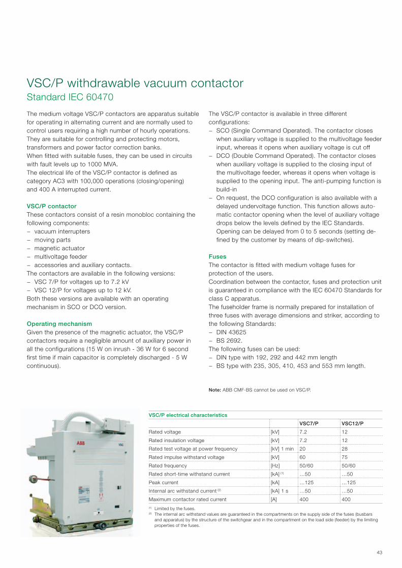
43
The medium voltage VSC/P contactors are apparatus suitable for operating in alternating current and are normally used to control users requiring a high number of hourly operations. They are suitable for controlling and protecting motors, transformers and power factor correction banks.When fitted with suitable fuses, they can be used in circuits with fault levels up to 1000 MVA.The electrical life of the VSC/P contactor is defined as category AC3 with 100,000 operations (closing/opening)and 400 A interrupted current.
VSC/P contactorThese contactors consist of a resin monobloc containing the following components:
− vacuum interrupters − moving parts − magnetic actuator − multivoltage feeder − accessories and auxiliary contacts.
The contactors are available in the following versions: − VSC 7/P for voltages up to 7.2 kV − VSC 12/P for voltages up to 12 kV.
Both these versions are available with an operating mechanism in SCO or DCO version.
Operating mechanismGiven the presence of the magnetic actuator, the VSC/P contactors require a negligible amount of auxiliary power in all the configurations (15 W on inrush - 36 W for 6 second first time if main capacitor is completely discharged - 5 W continuous).
The VSC/P contactor is available in three different configurations:
− SCO (Single Command Operated). The contactor closes when auxiliary voltage is supplied to the multivoltage feeder input, whereas it opens when auxiliary voltage is cut off
− DCO (Double Command Operated). The contactor closes when auxiliary voltage is supplied to the closing input of the multivoltage feeder, whereas it opens when voltage is supplied to the opening input. The anti-pumping function is build-in
− On request, the DCO configuration is also available with a delayed undervoltage function. This function allows auto-matic contactor opening when the level of auxiliary voltage drops below the levels defined by the IEC Standards. Opening can be delayed from 0 to 5 seconds (setting de-fined by the customer by means of dip-switches).
FusesThe contactor is fitted with medium voltage fuses for protection of the users.Coordination between the contactor, fuses and protection unit is guaranteed in compliance with the IEC 60470 Standards for class C apparatus.The fuseholder frame is normally prepared for installation of three fuses with average dimensions and striker, according to the following Standards:
− DIN 43625 − BS 2692.
The following fuses can be used: − DIN type with 192, 292 and 442 mm length − BS type with 235, 305, 410, 453 and 553 mm length.
Note: ABB CMF-BS cannot be used on VSC/P.
VSC/P electrical characteristics
VSC7/P VSC12/P
Rated voltage [kV] 7.2 12
Rated insulation voltage [kV] 7.2 12
Rated test voltage at power frequency [kV] 1 min 20 28
Rated impulse withstand voltage [kV] 60 75
Rated frequency [Hz] 50/60 50/60
Rated short-time withstand current [kA] (1) …50 …50
Peak current [kA] …125 …125
Internal arc withstand current (2) [kA] 1 s …50 …50
Maximum contactor rated current [A] 400 400
(1) Limited by the fuses.(2) The internal arc withstand values are guaranteed in the compartments on the supply side of the fuses (busbars
and apparatus) by the structure of the switchgear and in the compartment on the load side (feeder) by the limiting properties of the fuses.
VSC/P withdrawable vacuum contactorStandard IEC 60470

44
The fuseholder frames are fitted with an automatic opening device even in the case of only a single fuse blowing.This device does not allow contactor closing when even a single fuse is missing.The ABB range of fuses for transformer protection is called CEF, while the one for motor and capacitor banks is CMF.
StandardsIEC 60470 for the contactorIEC 60282-1 for the fuses
Maximum performances of the contactor with fuses
3.6 kV 7.2 kV 12 kV
Motors kW 1000 1800 3000
Transformers kVA 2000 2500 2500
Capacitor banks kVAR 1000 1800 3000
Maximum fuse load current
Feeder Transformers Motors Capacitor single bank
Rated voltage Fuse Maximum load Fuse Maximum load Fuse Maximum load
3.6 kV 200 A 160 A 315 A 250 A 450 A 250 A
7.2 kV 200 A 160 A 315 A 250 A 355 A 250 A
12 kV 200 A 160 A 200 A 160 A 200 A 160 A
Note: fuse size is indicative, for fuse selection please consult contactor technical catalogue.
3. Main components
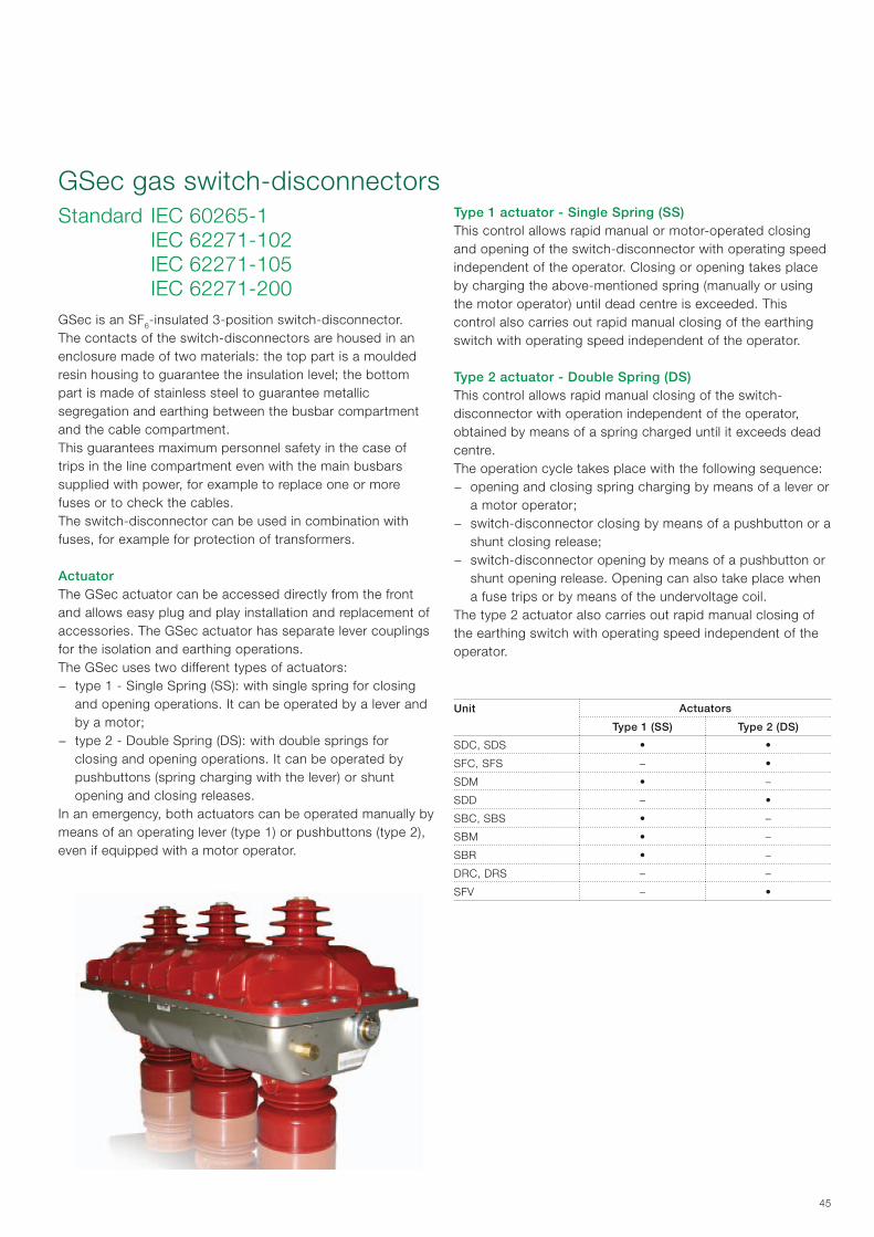
45
Standard IEC 60265-1 IEC 62271-102 IEC 62271-105 IEC 62271-200GSec is an SF6-insulated 3-position switch-disconnector.The contacts of the switch-disconnectors are housed in an enclosure made of two materials: the top part is a mouldedresin housing to guarantee the insulation level; the bottom part is made of stainless steel to guarantee metallic segregation and earthing between the busbar compartment and the cable compartment.This guarantees maximum personnel safety in the case of trips in the line compartment even with the main busbarssupplied with power, for example to replace one or more fuses or to check the cables.The switch-disconnector can be used in combination with fuses, for example for protection of transformers.
ActuatorThe GSec actuator can be accessed directly from the front and allows easy plug and play installation and replacement of accessories. The GSec actuator has separate lever couplings for the isolation and earthing operations.The GSec uses two different types of actuators:
− type 1 - Single Spring (SS): with single spring for closing and opening operations. It can be operated by a lever and by a motor;
− type 2 - Double Spring (DS): with double springs for closing and opening operations. It can be operated by pushbuttons (spring charging with the lever) or shunt opening and closing releases.
In an emergency, both actuators can be operated manually by means of an operating lever (type 1) or pushbuttons (type 2), even if equipped with a motor operator.
GSec gas switch-disconnectorsType 1 actuator - Single Spring (SS)This control allows rapid manual or motor-operated closing and opening of the switch-disconnector with operating speed independent of the operator. Closing or opening takes place by charging the above-mentioned spring (manually or using the motor operator) until dead centre is exceeded. This control also carries out rapid manual closing of the earthing switch with operating speed independent of the operator.
Type 2 actuator - Double Spring (DS)This control allows rapid manual closing of the switch-disconnector with operation independent of the operator, obtained by means of a spring charged until it exceeds dead centre.The operation cycle takes place with the following sequence:
− opening and closing spring charging by means of a lever or a motor operator;
− switch-disconnector closing by means of a pushbutton or a shunt closing release;
− switch-disconnector opening by means of a pushbutton or shunt opening release. Opening can also take place when a fuse trips or by means of the undervoltage coil.
The type 2 actuator also carries out rapid manual closing of the earthing switch with operating speed independent of the operator.
Unit Actuators
Type 1 (SS) Type 2 (DS)
SDC, SDS • •
SFC, SFS – •
SDM • –
SDD – •
SBC, SBS • –
SBM • –
SBR • –
DRC, DRS – –
SFV – •

46
GSec actuator tripping times Single spring motor operating mechanism or manual control
1
0T1 T2
Tc To
T1 T3
Tc (motorized closing time) = T1(spring charging motor) + T2 (closing time) < 5 sec To (motorized opening time) = T1(spring charging motor) + T3 (opening time) < 5 secTc/To (manual) = depending on the operator for the spring charging phase0 = disconnector in “open” position1 = disconnector in “closed” position
Manual double spring operating mechanism (with or without coils)
1
0T1 T2 To
Tc
Tc (manual closing time) = T1 + T2T1 (springs charging) = depending on the operatorT2 (closing) = 0.3 secTo (opening) = 0.3 sec0 = disconnector in “open” position1 = disconnector in “closed” position
The opening/closing operations can be carried out by means of pushbuttons or coils (if remote control is used).
Double spring motor operator (coils always included)
1
0
Tc
ToT1 T2
Tc (motorized closing time) = T1 (springs charging motor) + T2 (closing time) < 7 secTo (opening) = 0.3 sec0 = disconnector in “open” position1 = disconnector in “closed” position
GSec motor operating device (MOD)MOD (Motor Operating Device) is the GSec switch-disconnector device which controls the spring loading motor and opening and closing coils (the opening and closing coils are only present in the type 2 actuator).The MOD is an electronic device which includes protection and diagnostic functions, improving reliability, availability and overall safety of the system.The MOD includes a local panel interface (HMI), binary inputs and outputs for remote operations and overcurrent protection functions for the motor and the coils.The diagnostic functions are available locally by means of the local HMI panel interface, or remotely by means of the binary inputs and outputs.The MOD carries out the opening and closing operations of the switch-disconnector while earthing only takes place manually.
Local interface (HMI)The GSec switch-disconnector can be operated locally by means of two pushbuttons available on the local HMI interface.A third pushbutton allows the possibility to change from local to remote control, indicating this by means of two LEDs (L or R). When the MOD is in local mode, the binary control inputs are disabled.The remaining LEDs allow the Ready, Alarm and Communication information to be seen.
Binary inputsThe binary inputs include the opening and closing commands.The trip threshold is set to 85% of the rated voltage. The minimum impulse time required for the command to be carried out is 300 ms.Different settings can be made available on request. For further information, please contact ABB.Both the opening and closing inputs provide feedback on the state of the diagnostics and protection functions.It is possible to have a TCS (Trip Circuit Supervision) device connected to one of these binary inputs, which generates an alarm in the case of a fault in the GSec switch-disconnector.
3. Main components
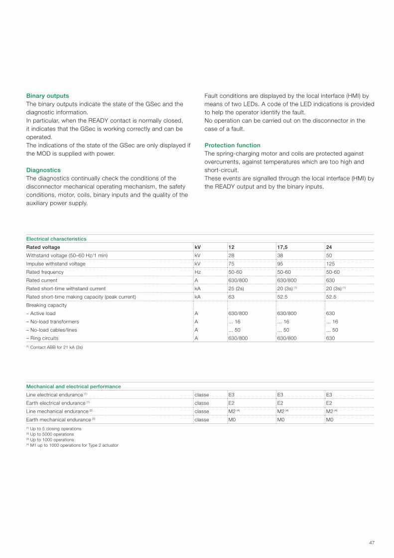
47
Binary outputsThe binary outputs indicate the state of the GSec and the diagnostic information.In particular, when the READY contact is normally closed, it indicates that the GSec is working correctly and can be operated. The indications of the state of the GSec are only displayed if the MOD is supplied with power.
DiagnosticsThe diagnostics continually check the conditions of the disconnector mechanical operating mechanism, the safetyconditions, motor, coils, binary inputs and the quality of the auxiliary power supply.
Fault conditions are displayed by the local interface (HMI) by means of two LEDs. A code of the LED indications is provided to help the operator identify the fault.No operation can be carried out on the disconnector in the case of a fault.
Protection function The spring-charging motor and coils are protected against overcurrents, against temperatures which are too high andshort-circuit.These events are signalled through the local interface (HMI) by the READY output and by the binary inputs.
Electrical characteristics
Rated voltage kV 12 17,5 24
Withstand voltage (50–60 Hz/1 min) kV 28 38 50
Impulse withstand voltage kV 75 95 125
Rated frequency Hz 50-60 50-60 50-60
Rated current A 630/800 630/800 630
Rated short-time withstand current kA 25 (2s) 20 (3s) (1) 20 (3s) (1)
Rated short-time making capacity (peak current) kA 63 52.5 52.5
Breaking capacity
– Active load A 630/800 630/800 630
– No-load transformers A ... 16 ... 16 ... 16
– No-load cables/lines A ... 50 ... 50 ... 50
– Ring circuits A 630/800 630/800 630
(1) Contact ABB for 21 kA (3s)
Mechanical and electrical performance
Line electrical endurance (1) classe E3 E3 E3
Earth electrical endurance (1) classe E2 E2 E2
Line mechanical endurance (2) classe M2 (4) M2 (4) M2 (4)
Earth mechanical endurance (3) classe M0 M0 M0
(1) Up to 5 closing operations (2) Up to 5000 operations (3) Up to 1000 operations (4) M1 up to 1000 operations for Type 2 actuator
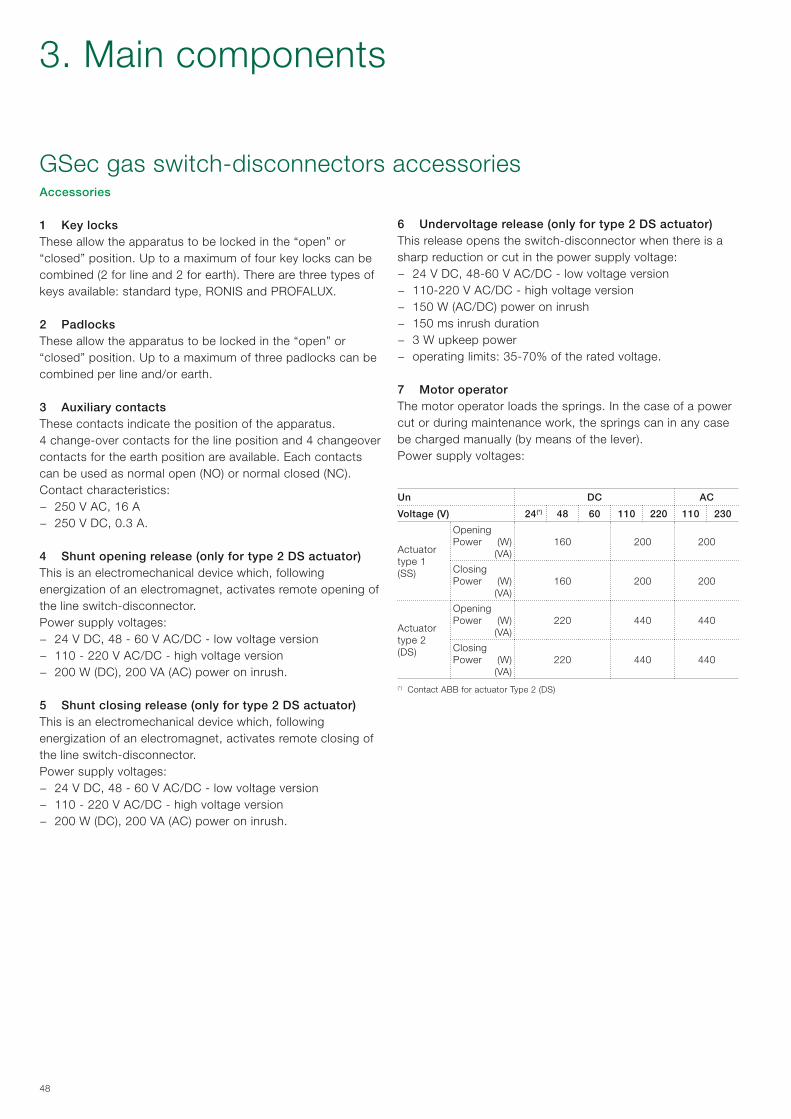
48
Accessories
1 Key locksThese allow the apparatus to be locked in the “open” or “closed” position. Up to a maximum of four key locks can be combined (2 for line and 2 for earth). There are three types of keys available: standard type, RONIS and PROFALUX.
2 PadlocksThese allow the apparatus to be locked in the “open” or “closed” position. Up to a maximum of three padlocks can be combined per line and/or earth.
3 Auxiliary contactsThese contacts indicate the position of the apparatus.4 change-over contacts for the line position and 4 changeover contacts for the earth position are available. Each contacts can be used as normal open (NO) or normal closed (NC).Contact characteristics:
− 250 V AC, 16 A − 250 V DC, 0.3 A.
4 Shunt opening release (only for type 2 DS actuator)This is an electromechanical device which, following energization of an electromagnet, activates remote opening of the line switch-disconnector.Power supply voltages:
− 24 V DC, 48 - 60 V AC/DC - low voltage version − 110 - 220 V AC/DC - high voltage version − 200 W (DC), 200 VA (AC) power on inrush.
5 Shunt closing release (only for type 2 DS actuator)This is an electromechanical device which, following energization of an electromagnet, activates remote closing of the line switch-disconnector.Power supply voltages:
− 24 V DC, 48 - 60 V AC/DC - low voltage version − 110 - 220 V AC/DC - high voltage version − 200 W (DC), 200 VA (AC) power on inrush.
6 Undervoltage release (only for type 2 DS actuator)This release opens the switch-disconnector when there is a sharp reduction or cut in the power supply voltage:
− 24 V DC, 48-60 V AC/DC - low voltage version − 110-220 V AC/DC - high voltage version − 150 W (AC/DC) power on inrush − 150 ms inrush duration − 3 W upkeep power − operating limits: 35-70% of the rated voltage.
7 Motor operator The motor operator loads the springs. In the case of a power cut or during maintenance work, the springs can in any case be charged manually (by means of the lever).Power supply voltages:
Un DC AC
Voltage (V) 24(*) 48 60 110 220 110 230
Actuator type 1(SS)
Opening Power (W)
(VA)160 200 200
Closing Power (W)
(VA)160 200 200
Actuator type 2 (DS)
Opening Power (W)
(VA)220 440 440
Closing Power (W)
(VA)220 440 440
(*) Contact ABB for actuator Type 2 (DS)
GSec gas switch-disconnectors accessories
3. Main components
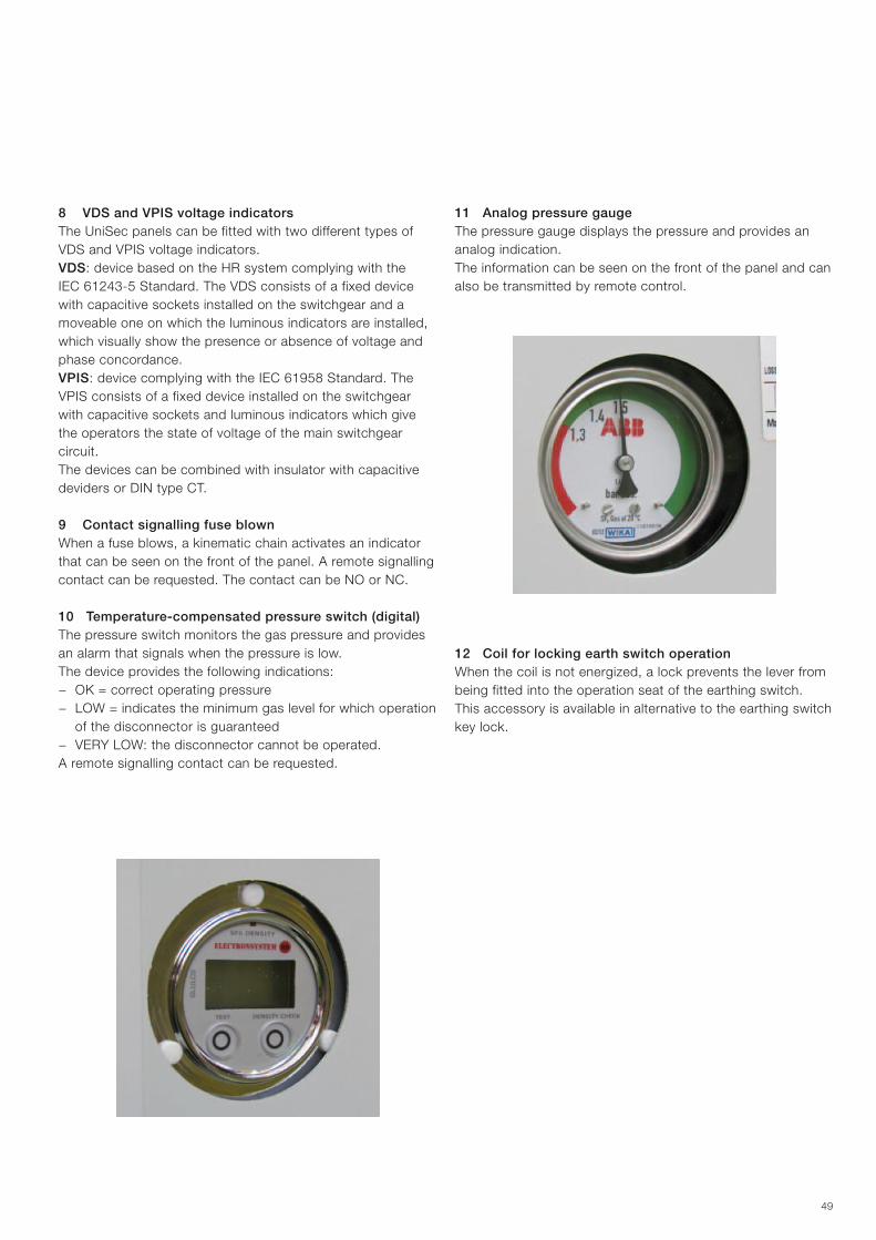
49
8 VDS and VPIS voltage indicatorsThe UniSec panels can be fitted with two different types of VDS and VPIS voltage indicators.VDS: device based on the HR system complying with the IEC 61243-5 Standard. The VDS consists of a fixed device with capacitive sockets installed on the switchgear and a moveable one on which the luminous indicators are installed, which visually show the presence or absence of voltage and phase concordance.VPIS: device complying with the IEC 61958 Standard. The VPIS consists of a fixed device installed on the switchgear with capacitive sockets and luminous indicators which give the operators the state of voltage of the main switchgear circuit.The devices can be combined with insulator with capacitive deviders or DIN type CT.
9 Contact signalling fuse blownWhen a fuse blows, a kinematic chain activates an indicator that can be seen on the front of the panel. A remote signalling contact can be requested. The contact can be NO or NC.
10 Temperature-compensated pressure switch (digital)The pressure switch monitors the gas pressure and provides an alarm that signals when the pressure is low.The device provides the following indications:
− OK = correct operating pressure − LOW = indicates the minimum gas level for which operation
of the disconnector is guaranteed − VERY LOW: the disconnector cannot be operated.
A remote signalling contact can be requested.
11 Analog pressure gaugeThe pressure gauge displays the pressure and provides an analog indication.The information can be seen on the front of the panel and can also be transmitted by remote control.
12 Coil for locking earth switch operationWhen the coil is not energized, a lock prevents the lever from being fitted into the operation seat of the earthing switch.This accessory is available in alternative to the earthing switch key lock.

50
Selection of fuses for transformer protection
Transformer rated voltage
[kV]
Transformer power [kVA] Fuse ratedvoltage
[kV]25 50 75 100 125 160 200 250 315 400 500 630 800 1000 1250 1600
CEF Fuse In [A]
3 16 25 25 40 40 50 63 80 100 125 – – – – – –
3.6/7.25 10 16 25 25 25 40 40 50 63 80 100 125 – – – –
6 6 16 16 25 25 25 40 40 50 63 80 100 125 – – –
10 6 10 16 16 16 20 20 25 31.5 40 50 63 80 100 125 –12
12 6 6 10 16 16 16 20 20 25 40 40 50 63 80 100 125
15 6 6 10 10 16 16 16 20 20 25 40 40 50 63 80 80 17.5
20 6 6 6 10 10 16 16 16 20 20 25 31.5 40 50 63 8024
24 6 6 6 6 10 10 16 16 16 20 20 25 40 40 50 63
Three fuses (one fuse for each phase) for transformer protection can be connected in series with the switch-disconnector. Selection of the fuse according to the voltage and power of the transformer must be made in conformity with the data indicated in the table.
Transformer protection and fuse selection When the disconnectors are used to control transformer protection, a special type of current-limiting fuses are used which guarantee selectivity with other protection devices and can take the high transformer connection currents without deterioration.In this case, the protection against overcurrents on the medium voltage side of the transformer is not indispensable since this task is taken on by the protection provided on the low voltage side. The protection on the medium voltage side can be entrusted just to the fuse, which must be selected taking into account the no-load connection current, which can take on values of or greater than 10 times the rated current according to the power of the transformer and to the type of punched sheets used (hot rolled sheet or sheet with orientated crystals).The maximum connection current occurs when circuit-breaker closing takes place in correspondence with voltage passage through zero.Another outcome to be guaranteed is protection against faults of the low voltage winding and of the connection tract of this to the circuit-breaker placed on the secondary winding, avoiding the use of fuses with rated current which is too high, in order to ensure rapid tripping even under these fault conditions.
A rapid check of the short-circuit currents at the transformer secondary terminals and on the supply side of the circuit-breaker on the secondary when placed at a significant distance, allows the trip time to be checked on the fuse melting curve.The usage table given below takes the required conditions into account, i.e. sufficiently high rated current to avoiduntimely fuse blowing during the no-load connection stage and, in any case, of a value which guarantees protection ofthe machine against faults on the low voltage side.
ABB CEF fuses for transformer protection Standard IEC 60282-1/DIN 43625
3. Main components
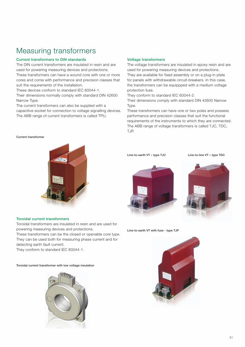
51
Current transformers to DIN standardsThe DIN current transformers are insulated in resin and are used for powering measuring devices and protections.These transformers can have a wound core with one or more cores and come with performance and precision classes that suit the requirements of the installation.These devices conform to standard IEC 60044-1.Their dimensions normally comply with standard DIN 42600 Narrow Type.The current transformers can also be supplied with a capacitive socket for connection to voltage signalling devices.The ABB range of current transformers is called TPU.
Measuring transformers
Current transformer
Toroidal current transformer with low voltage insulation
Toroidal current transformersToroidal transformers are insulated in resin and are used for powering measuring devices and protections.These transformers can be the closed or openable core type.They can be used both for measuring phase current and for detecting earth fault current.They conform to standard IEC 60044-1.
Voltage transformersThe voltage transformers are insulated in epoxy resin and are used for powering measuring devices and protections.They are available for fixed assembly or on a plug-in plate for panels with withdrawable circuit-breakers. In this case, the transformers can be equippped with a medium voltage protection fuse.They conform to standard IEC 60044-2.Their dimensions comply with standard DIN 42600 Narrow Type.These transformers can have one or two poles and possess performance and precision classes that suit the functional requirements of the instruments to which they are connected.The ABB range of voltage transformers is called TJC, TDC, TJP.
Line-to-earth VT – type TJC Line-to-line VT – type TDC
Line-to-earth VT with fuse - type TJP
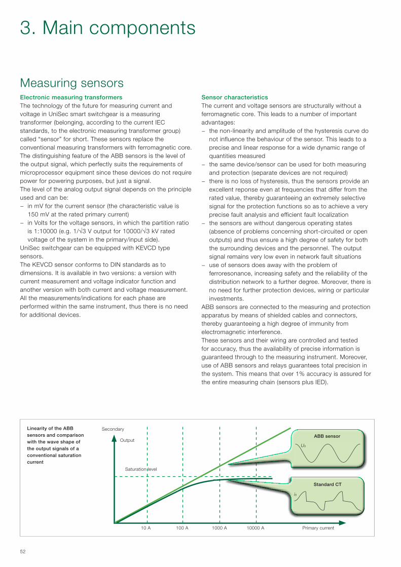
52
Electronic measuring transformersThe technology of the future for measuring current and voltage in UniSec smart switchgear is a measuring transformer (belonging, according to the current IEC standards, to the electronic measuring transformer group) called “sensor” for short. These sensors replace the conventional measuring transformers with ferromagnetic core.The distinguishing feature of the ABB sensors is the level of the output signal, which perfectly suits the requirements of microprocessor equipment since these devices do not require power for powering purposes, but just a signal.The level of the analog output signal depends on the principle used and can be:
− in mV for the current sensor (the characteristic value is 150 mV at the rated primary current)
− in Volts for the voltage sensors, in which the partition ratio is 1:10000 (e.g. 1/√3 V output for 10000/√3 kV rated voltage of the system in the primary/input side).
UniSec switchgear can be equipped with KEVCD type sensors. The KEVCD sensor conforms to DIN standards as to dimensions. It is available in two versions: a version with current measurement and voltage indicator function and another version with both current and voltage measurement. All the measurements/indications for each phase are performed within the same instrument, thus there is no need for additional devices.
Measuring sensorsSensor characteristicsThe current and voltage sensors are structurally without a ferromagnetic core. This leads to a number of important advantages:
− the non-linearity and amplitude of the hysteresis curve do not influence the behaviour of the sensor. This leads to a precise and linear response for a wide dynamic range of quantities measured
− the same device/sensor can be used for both measuring and protection (separate devices are not required)
− there is no loss of hysteresis, thus the sensors provide an excellent reponse even at frequencies that differ from the rated value, thereby guaranteeing an extremely selective signal for the protection functions so as to achieve a very precise fault analysis and efficient fault localization
− the sensors are without dangerous operating states (absence of problems concerning short-circuited or open outputs) and thus ensure a high degree of safety for both the surrounding devices and the personnel. The output signal remains very low even in network fault situations
− use of sensors does away with the problem of ferroresonance, increasing safety and the reliability of the distribution network to a further degree. Moreover, there is no need for further protection devices, wiring or particular investments.
ABB sensors are connected to the measuring and protection apparatus by means of shielded cables and connectors, thereby guaranteeing a high degree of immunity from electromagnetic interference. These sensors and their wiring are controlled and tested for accuracy, thus the availability of precise information is guaranteed through to the measuring instrument. Moreover, use of ABB sensors and relays guarantees total precision in the system. This means that over 1% accuracy is assured for the entire measuring chain (sensors plus IED).
Linearity of the ABB sensors and comparison with the wave shape of the output signals of a conventional saturation current
is
Us
Secondary
Output
Saturation level
10 A 100 A 1000 A 10000 A Primary current
ABB sensor
Standard CT
3. Main components
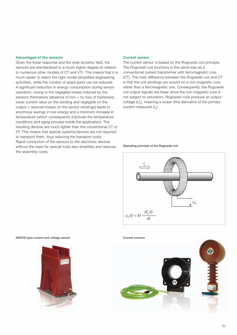
US
Ip
53
Current sensors
Advantages of the sensorsGiven the linear response and the wide dynamic field, the sensors are standardized to a much higher degree (in relation to numerous other models of CT and VT). This means that it is much easier to select the right model (simplified engineering activities), while the number of spare parts can be reduced.A significant reduction in energy consumption during sensor operation, owing to the negligible losses induced by the sensors themselves (absence of iron = no loss of hysteresis; lower current value on the winding and negligible on the output = reduced losses on the sensor windings) leads to enormous savings in lost energy and a minimum increase in temperature (which consequently improves the temperature conditions and aging process inside the application). The resulting devices are much lighter than the conventional CT or VT. This means that special systems/devices are not required to transport them, thus reducing the transport costs.Rapid connection of the sensors to the electronic devices without the need for special tools also simplifies and reduces the assembly costs.
KEDCD type current and voltage sensor
Current sensorThe current sensor is based on the Rogowski coil principle. The Rogowski coil functions in the same way as a conventional current transformer with ferromagnetic core (CT). The main difference between the Rogowski coil and CT is that the coil windings are wound on a non-magnetic core rather than a ferromagnetic one. Consequently, the Rogowski coil output signals are linear since the non-magnetic core is not subject to saturation. Rogowski coils produce an output voltage (US), meaning a scalar time derivative of the primary current measured (IP).
Operating principle of the Rogowski coil
uS (t) = M –––––––dip (t)
dt
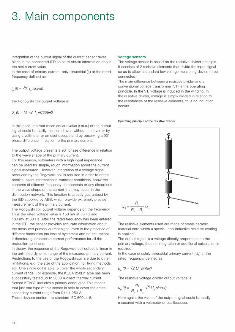
US = ––––––– Up
R2
R1 + R2
54
Integration of the output signal of the current sensor takes place in the connected IED so as to obtain information about the real current value.In the case of primary current, only sinusoidal (Ip) at the rated frequency defined as:
ip (t) = √2 Ip sin(ωt)
the Rogowski coil output voltage is
us (t) = M √2 Ip ωcos(ωt)
In this case, the root mean square value (r.m.s.) of the output signal could be easily measured even without a converter by using a voltmeter or an oscilloscope and by observing a 90° phase difference in relation to the primary current.
The output voltage presents a 90° phase difference in relation to the wave shape of the primary current.For this reason, voltmeters with a high input impedance can be used for simple, rough information about the current signal measured. However, integration of a voltage signal produced by the Rogowski coil is required in order to obtain precise, exact information in transient conditions, know the contents of different frequency components or any distortions in the wave shape of the current that may occur in the distribution network. This function is already guaranteed by the IED supplied by ABB, which provide extremely precise measurement of the primary current.The Rogowski coil output voltage depends on the frequency.Thus the rated voltage value is 150 mV at 50 Hz and 180 mV at 60 Hz. After the rated frequency has been entered in the IED, the sensor provides accurate information about the measured primary current signal even in the presence of different harmonics (no loss of hysteresis and no saturation). It therefore guarantees a correct performance for all the protection functions.In theory, the response of the Rogowski coil output is linear in the unlimited dynamic range of the measured primary current. Restrictions to the use of the Rogowski coil are due to other limitations, e.g. the size of the application, for fixing methods, etc. One single coil is able to cover the whole secondary current range. For example, the KECA 250B1 type has been successfully tested up to 2000 A direct thermal current. Sensor KEVCD includes a primary conductor. This means that just one type of this sensor is able to cover the entire secondary current range from 0 to 1,250 A.These devices conform to standard IEC 60044-8.
Voltage sensors The voltage sensor is based on the resistive divider principle. It consists of 2 resistive elements that divide the input signal so as to allow a standard low voltage measuring device to be connected.The main difference between a resistive divider and a conventional voltage transformer (VT) is the operating principle. In the VT, voltage is induced in the winding. In the resistive divider, voltage is simply divided in relation to the resistances of the resistive elements, thus no induction occurs.
Operating principle of the resistive divider
The resistive elements used are made of stable ceramic material onto which a special, non-inductive resistive coating is applied.The output signal is a voltage directly proportional to the primary voltage, thus no integration or additional calculation is required. In the case of solely sinusoidal primary current (UP) at the rated frequency, defined as:
The resistive voltage divider output voltage is:
Here again, the value of the output signal could be easily measured with a voltmeter or oscilloscope.
up (t) = √2 Up sin(ωt)
up (t) = ––––––– √2 Up sin(ωt)R2
R1 + R2
3. Main components
55
The standard distribution ratio used in ABB sensors is 10000/1. This ensures that the output signal is sufficient and reliable for a further calculation in the IED.Voltmeters with a high input impedance can be used to obtain information about the measured voltage signal. However, ABB IED must be used, since the relative connection has been tested and checked.The resistive divider has neither ferromagnetic core nor winding. This means that, unlike the TV, there is no risk of ferroresonance and no need for further damping devices. Use of these dividers increases the safety and reliability of the network to a considerable extent, as well as the safety of the personnal in all circumstances. There are no problems or dangers if the secondary terminals short-circuit. Moreover, the sensor can even remain connected when the switchgear is subjected to power-frequency tests.The resistive divider functions perfectly during transients which, besides direct current, also include other frequency
components (absence of a ferromagnetic core in the divider eliminates the risk of saturation at different frequencies). This allows an undistorted assessment of the transients to be made, as well as a precise analysis of the protection functions. Besides allowing the DC components to be measured during transients, the resistive divider also enables the direct component of the voltage to be measured with precision.In view of the linear response and absence of saturation, just one single divider is enough to cover the entire voltage range, from 0 to 24 kV. Nonetheless, it may be necessary to consider other mechanical or dimensional/distance requirements for different voltage levels in the case of one single main voltage sensor. For this reason, the KEVCD sensor is available in two different height sizes, in accordance with the dimensions established by the DIN standards. The chosen sensor version can also be used for voltage levels that are lower than the maximum rated primary voltage.These devices conform to standard IEC 60044-7.

56
4. Protection and automation devices
The safety of the personnel is of prime importance when modern medium voltage switchgear is developed. This is why UniSec switchgear has been designed and tested to withstand the internal arc produced by a short-circuit current of the same level as the maximum permissible short-time withstand current.Tests have shown that the metal enclosure of UniSec switchgear is able to protect personnel working near the switchgear itself if a fault evolves until an internal arc ignites. An internal arc is a very improbable fault although theoretically, it can be caused by various factors, such as:
− defective insulation owing to deteriorated components. This can be due to adverse environmental conditions and a strongly polluted atmosphere
− over-voltage of atmospheric origin or caused by the operation of some component or other
− inadequately trained personnel − breakage or tampering with the safety interlocks − overheating in the contact zones due to the presence of
corrosive substances or loose connections − intrusion of small animals into the switchgear (e.g. through
the cable input) − materials left inside the switchgear during maintenance work.
The characteristics of UniSec switchgear strongly reduce the probability of these faults occurring. However, some cannot be completely prevented.The energy produced by the internal arc produces the following phenomena:
− increase in the internal pressure − temperature increase − visual and acoustic effects − mechanical stress on the switchgear structure − melting, decomposition and vaporization of the materials.
Unless they are adequately kept under control, these phenomena can affect the personnel in a very serious way, causing injuries (due to shock waves, parts that are thrown up and doors that open) and burns (due to the emission of hot gas).
SafetyThe purpose of the internal arc resistance test is to make sure that the cubicle doors remain closed, that none of the components detach from the switchgear even when the pressure is very high, and that incandescent gas or flames are unable to escape, thereby guaranteeing safe conditions for the personnel who work in the vicinity of the switchgear.The test is also performed in order to ensure that holes are not made in the accessible external parts of the enclosure and, lastly, that all the connections to the earthing circuit continue to be efficient and able to guarantee safe conditions for persons who access the switchgear after a fault.Standard IEC 62271-200 establishes the methods for performing the test and the criteria with which the switchgear must comply.UniSec switchgear fully conforms to all the five criteria indicated in the IEC standard.The parameters of each specific installation establish that the elimination of hot gas and incandescent particles must be checked with particular care so as to guarantee and maintain safe conditions for the personnel.
Fault limiting systemsThe structure of UniSec switchgear provides complete passive protection against the effects of internal arc faults for 1 second up to 25 kA. ABB has also developed active protection systems able to provide the following important benefits:
− fault detection and extinguishing, generally within less than 100 ms, which improves the stability of the network
− less damage to the equipment − the switchgear remains out of sevice for a shorter time.
Active internal arc protection can be achieved by installing various types of sensors in the different compartments. These devices are able to detect the immediate effects of the fault and release the circuit-breakers in the selective mode.The fault limiting systems are based on sensors that take advantage of the pressure or light generated by the internal arc fault to as to allow the faulty line to disconnect.

57
TVOCThis system consists of an electronic monitoring device housed in the low voltage cubicle, to which optic sensors are connected. These latter are distributed amongst the power cubicles and are connected to the device by means of optic fibers.The device causes the circuit-breakers to open when a preset level of light is exceeded.Current transformers can also be connected to the monitoring device to prevent the system from being tripped by occasional light created by external factors (a camera flash, reflected external light, etc.).The protection module only transmits the opening command to the circuit-breaker if it receives the light signal and that of short-circuit current at the same time.The total release time is 62 ms (2 ms TVOC + 60 ms the circuit-breaker).
REA This system provides the same functions as the TVOC system. It consists of a central unit (REA 101) and an optional extension unit (REA 103, 105, 107), allowing customized selective release solutions to be created. The total release time is 62.5 ms (2.5 ms REA + 60 ms the circuit-breaker).
Electric arc protection with IEDOn request, the IED (Intelligent Electronic Devices) REF615, RET615, REM615 and REF610 can be equipped with rapid and selective electric arc protection. This arc fault protection system has two or three channels for supervising electric arcs in the circuit-breaker cubicles, line and busbars of the switchgear.The total release time is 72 ms (12 ms IED + 60 ms the circuit-breaker).
REA 101 electric arc protection unit with REA 103, REA 105 and REA 107 extensions
Typical configuration with REA 101 and subunit 103
TVOC electric arc protection unit
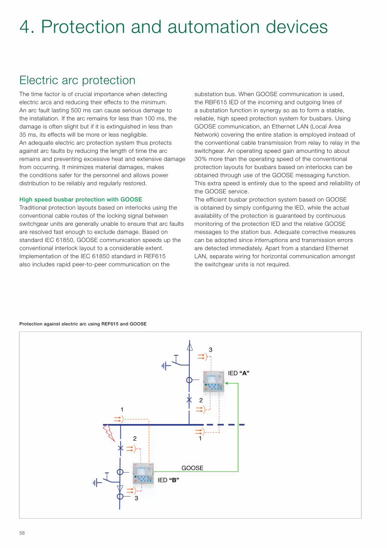
1.
2.
3.
1.
2.
3.
IED “B” “B”
IED “A” “A”
GOOSE message
58
The time factor is of crucial importance when detecting electric arcs and reducing their effects to the minimum. An arc fault lasting 500 ms can cause serious damage to the installation. If the arc remains for less than 100 ms, the damage is often slight but if it is extinguished in less than 35 ms, its effects will be more or less negligible.An adequate electric arc protection system thus protects against arc faults by reducing the length of time the arc remains and preventing excessive heat and extensive damage from occurring. It minimizes material damages, makes the conditions safer for the personnel and allows power distribution to be reliably and regularly restored.
High speed busbar protection with GOOSETraditional protection layouts based on interlocks using the conventional cable routes of the locking signal between switchgear units are generally unable to ensure that arc faults are resolved fast enough to exclude damage. Based on standard IEC 61850, GOOSE communication speeds up the conventional interlock layout to a considerable extent. Implementation of the IEC 61850 standard in REF615 also includes rapid peer-to-peer communication on the
Electric arc protectionsubstation bus. When GOOSE communication is used, the RBF615 IED of the incoming and outgoing lines of a substation function in synergy so as to form a stable, reliable, high speed protection system for busbars. Using GOOSE communication, an Ethernet LAN (Local Area Network) covering the entire station is employed instead of the conventional cable transmission from relay to relay in the switchgear. An operating speed gain amounting to about 30% more than the operating speed of the conventional protection layouts for busbars based on interlocks can be obtained through use of the GOOSE messaging function. This extra speed is entirely due to the speed and reliability of the GOOSE service.The efficient busbar protection system based on GOOSE is obtained by simply configuring the IED, while the actual availability of the protection is guaranteed by continuous monitoring of the protection IED and the relative GOOSE messages to the station bus. Adequate corrective measures can be adopted since interruptions and transmission errors are detected immediately. Apart from a standard Ethernet LAN, separate wiring for horizontal communication amongst the switchgear units is not required.
Protection against electric arc using REF615 and GOOSE
4. Protection and automation devices
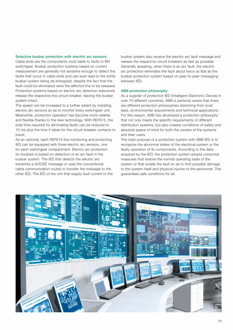
59
busbar system also receive the electric arc fault message and release the respective circuit-breakers as fast as possible. Generally speaking, when there is an arc fault, the electric arc protection eliminates the fault about twice as fast as the busbar protection system based on peer-to-peer messaging between IED.
ABB protection philosophyAs a supplier of protection IED (Intelligent Electronic Device) in over 70 different countries, ABB is perfectly aware that there are different protection philosophies stemming from local laws, environmental requirements and technical applications. For this reason, ABB has developed a protection philosophy that not only meets the specific requirements of different distribution systems, but also creates conditions of safety and absolute peace of mind for both the owners of the systems and their users.The main purpose of a protection system with ABB IED is to recognize the abnormal states of the electrical system or the faulty operation of its components. According to the data acquired by the IED, the protection system adopts corrective measures that restore the normal operating state of the system or that isolate the fault so as to limit possible damage to the system itself and physical injuries to the personnel. This guarantees safe conditions for all.
Selective busbar protection with electric arc sensorsCable ends are the components most liable to faults in MV switchgear. Busbar protection systems based on current measurement are generally not sensitive enough to detect the faults that occur in cable ends and can even lead to the entire busbar system being de-energized, despite the fact that the fault could be eliminated were the affected line to be released. Protection systems based on electric arc detection selectively release the respective line circuit-breaker, leaving the busbar system intact.The speed can be increased to a further extent by installing electric arc sensors so as to monitor every switchgear unit. Meanwhile, protection operation has become more reliable and flexible thanks to the new technology. With REF615, the total time required for eliminating faults can be reduced to 10 ms plus the time it takes for the circuit-breaker contacts to travel.As an optional, each REF615 line monitoring and protecting IED can be equipped with three electric arc sensors, one for each switchgear compartment. Electric arc protection for busbars is based on detection of an arc fault in the busbar system. The IED that detects the electric arc transmits a GOOSE message or uses the conventional cable communication routes to transfer the message to the other IED. The IED of the unit that supply fault current to the
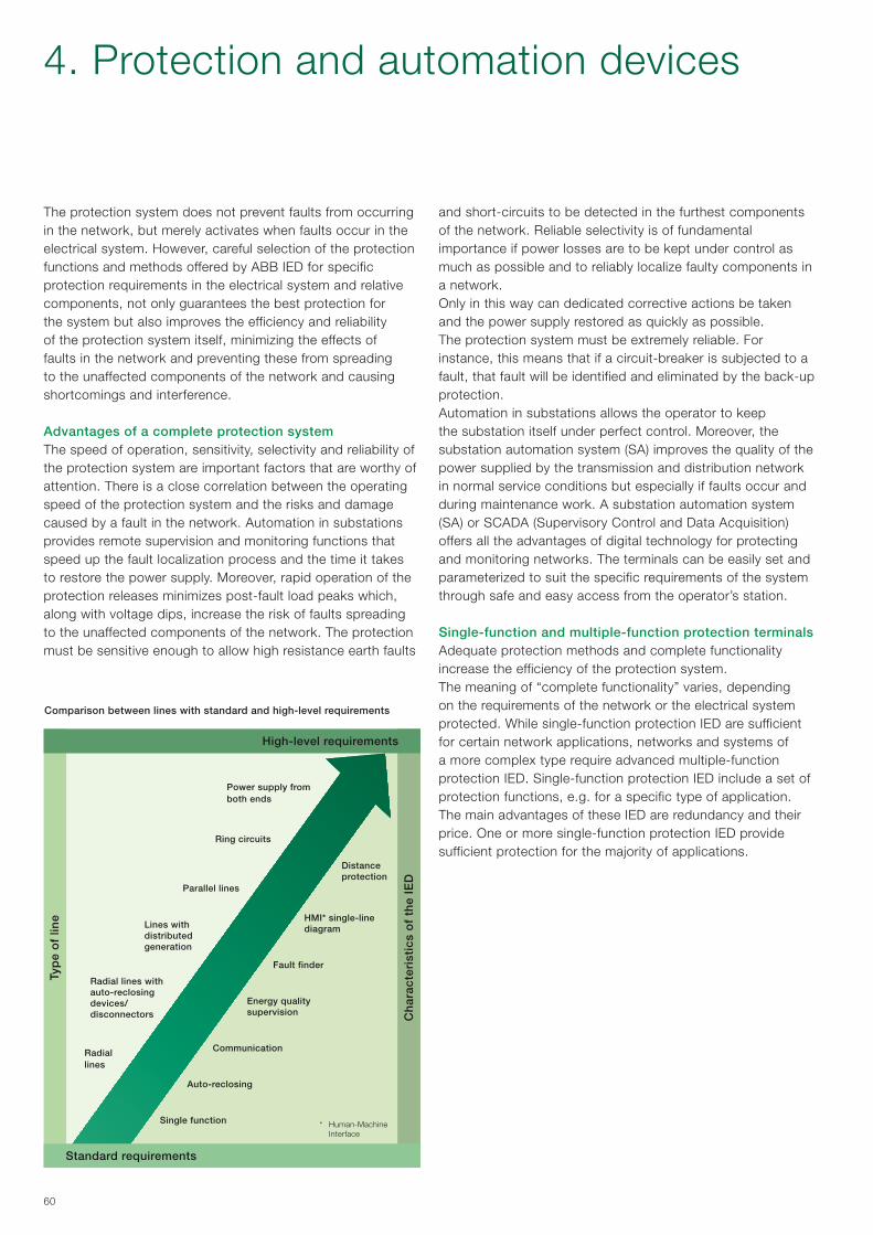
60
The protection system does not prevent faults from occurring in the network, but merely activates when faults occur in the electrical system. However, careful selection of the protection functions and methods offered by ABB IED for specific protection requirements in the electrical system and relative components, not only guarantees the best protection for the system but also improves the efficiency and reliability of the protection system itself, minimizing the effects of faults in the network and preventing these from spreading to the unaffected components of the network and causing shortcomings and interference.
Advantages of a complete protection systemThe speed of operation, sensitivity, selectivity and reliability of the protection system are important factors that are worthy of attention. There is a close correlation between the operating speed of the protection system and the risks and damage caused by a fault in the network. Automation in substations provides remote supervision and monitoring functions that speed up the fault localization process and the time it takes to restore the power supply. Moreover, rapid operation of the protection releases minimizes post-fault load peaks which, along with voltage dips, increase the risk of faults spreading to the unaffected components of the network. The protection must be sensitive enough to allow high resistance earth faults
and short-circuits to be detected in the furthest components of the network. Reliable selectivity is of fundamental importance if power losses are to be kept under control as much as possible and to reliably localize faulty components in a network. Only in this way can dedicated corrective actions be taken and the power supply restored as quickly as possible.The protection system must be extremely reliable. For instance, this means that if a circuit-breaker is subjected to a fault, that fault will be identified and eliminated by the back-up protection.Automation in substations allows the operator to keep the substation itself under perfect control. Moreover, the substation automation system (SA) improves the quality of the power supplied by the transmission and distribution network in normal service conditions but especially if faults occur and during maintenance work. A substation automation system (SA) or SCADA (Supervisory Control and Data Acquisition) offers all the advantages of digital technology for protecting and monitoring networks. The terminals can be easily set and parameterized to suit the specific requirements of the system through safe and easy access from the operator’s station.
Single-function and multiple-function protection terminalsAdequate protection methods and complete functionality increase the efficiency of the protection system. The meaning of “complete functionality” varies, depending on the requirements of the network or the electrical system protected. While single-function protection IED are sufficient for certain network applications, networks and systems of a more complex type require advanced multiple-function protection IED. Single-function protection IED include a set of protection functions, e.g. for a specific type of application. The main advantages of these IED are redundancy and their price. One or more single-function protection IED provide sufficient protection for the majority of applications.
High-level requirements
Typ
e o
f lin
e
Ch
arac
teri
stic
s o
f th
e IE
D
Standard requirements
Power supply from both ends
Ring circuits
Parallel lines
Lines with distributed generation
Radial lines with auto-reclosing devices/disconnectors
Radial lines
Distance protection
HMI* single-line diagram
Fault finder
Energy quality supervision
Communication
Auto-reclosing
Single function * Human-Machine Interface
Comparison between lines with standard and high-level requirements
4. Protection and automation devices

61
In medium voltage networks, distribution automation means protection, control, measurement and supervision of utility substations and industrial electrical plants. The purpose of distribution automation is to improve safety, reliability and performance of the power distribution process.The main purpose of a relay protection system is to recognize any abnormal states in the electrical system or anomalous operation of the system components. Based on the information gathered, the protection system will initiate corrective actions to restore the system to its normal operating state.The protection relay does not prevent network faults from occurring, but is only activated when there is an anomaly in the electrical system. However, careful selection of protection functions and methods improves the performance and reliability of the protection system, thus minimizing the effects of network faults and preventing the fault in question from spreading to healthy parts of the network.The modern and IEC 61850 compliant intelligent electronic devices (IEDs) allow efficient use of the most sophisticated protection schemes in secondary distribution as well.
Distribution protection and controlFeeder Protection in secondary distribution The feeder protection applications can be roughly divided into two categories, namely standard (1) applications using basic current based protection, and high requirement (2) applications use a protection based on current and voltage, as well as various combinations between the two.The selected protection scheme has to fulfil the specific application requirements regarding sensitivity, selectivity and operating speed. The protection requirements are mainly determined by the physical structure of the network. In most cases the above requirements can be fulfilled with non-directional/directional overcurrent relays.The purpose of the overvoltage and undervoltage protection system is to monitor the voltage level of the network. If the voltage level deviates from the target value by more than the permitted margin for a pre-established period of time, the voltage protection system limits the duration of the anomaly and the consequences thereof.Our range IEDs has been selected so that they meet all feeder protection requirements in secondary distribution applications, from the simplest to the more complex.
By combining the respective functional locks in A and B standard configurations, REF615 can be used in a wide range of secondary distribution applications. The F standard configuration, fitted with additional protection functions, is also available.

62
Recommended distribution protection and control productsREF601REF601 is a digital feeder protection relay, designed for protection and control of utility and industrial power systems.The relay guarantees basic short-circuit, overcurrent and earth fault protection in networks with the neutral earthed directly, earthed by means of a resistance and in those with isolated neutral. The phase currents are measured by Rogowski coil type current sensors and earth-fault current can be internally calculated or measured with conventional current transformers. ABB offers two sensors:
− KECA (Rogowski coil type) mounted around the MV cables − KEVCR mounted on board the circuit-breaker.
The REF601 relay can be mounted on-board the VD4/R-Sec and HD4/R-Sec circuit-breaker or in the auxiliary contact compartment.Two types of relay are available:
− REF601 according to IEC Standards − REF601 according to the CEI 0-16 Standard for the Italian
market.
Auxiliary supply voltage: 24…240 V AC/DC
WARNING!If relay REF601 is supplied by means of a UPS (Uninterruptible Power Supply) with modified sine wave, a transformer must be used to limit the power supply voltage (peak voltage) to within the values specified for the relay itself.The recommended characteristics of the transformer are:
− Rated power: 20 VA − Output voltage of the secondary: 30...150 V a.c.
For further information, contact ABB.
4. Protection and automation devices

63
RE- 610 SeriesThe 610 series includes IEDs for line protection, motor protection and voltage monitoring of systems in general. The plug-in design of the 610 series facilitates switchgear commissioning and allows fast and safe insertion and withdrawal of the IED “plug-in” units.The 610 series numerical feeder protection IEDs support a wide rage of communication protocols, including IEC 61850, IEC 60870-5-103, Modbus and Profibus.• REF610isaprotectionrelaymainlydesignedforprotection
of incoming and outgoing feeders in MV distribution substations. REF610 can also be used as back-up protection for motors, transformers and generators, in industrial as well as in utility applications. The integrated protection functions, including three-threshold overcurrent protection and a two-threshold non-directional earth-fault, make REF610 relay a valid protection system against overcurrent and earth faults.
• REM610isanIEDforprotection,measurementandmonitoring of medium-sized and large asynchronous LV motors and small and medium-sized HV asynchronous motors in the manufacturing and process industry. The REM610 is also used for protection of cable feeders and distribution transformers, providing the benefits of thermal overload protection as well as phase overcurrent, earth-fault and phase unbalance protection.
• REU610isdesignedfordistributionsubstationbusbarovervoltage and undervoltage protection, feeder and power transformer overvoltage protection, motor undervoltage protection, and capacitor bank protection and monitoring. In power systems with isolated neutral, it is also used for non-discriminative earth-fault protection based on residual voltage measurement.
Auxiliary power supply voltage:High: 110 - 240 V AC 110 - 250 V DCLow: 24 - 60 V DC

64
RE- 615 SeriesFitted with the latest protection technology and complying with the IEC 61850 Standard for substation communication, the ABB 615 series of protection and control IEDs are the ideal choice for the protection and control of distribution substations. Strict implementation of the IEC 61850 substation communication Standard in the 615 series IEDs covers both vertical and horizontal communication, including GOOSE messaging and parameter setting according to the IEC 61850-8-1 Standard.• REF615providesgeneralprotectionforoverheadlines,
cable feeders and distribution substation busbar systems. It can be adapted for both isolated neutral networks and networks with the neutral earthed by means of resistance or impedance.
• REM615isadedicatedmotorprotectionandcontrolIED,perfectly aligned for protection, control, measurement and monitoring of asynchronous motors in the manufacturing and process industry.
• RET615isadedicatedIEDforprotectionandcontroloftransformers designed for power transformers, unit and step-up transformers including power generator-transformer blocks in utility and industrial power distribution systems.
• RED615isalineresidualcurrentIEDwhichcan,inparticular, be used for applications requiring highly selective feeder protection (unit protection).
RED615 maintains selectivity even in cases where the fault current has a variable magnitude and can be fed from several sources. This usually occurs in closed loop, ring and meshed networks. In addition to protection, all 615 series IEDs offer the functionality needed for local and remote control of a circuit-breaker.
• REU615isanIEDavailableintwopredefinedconfigurations called A and B, destined for two of the most common applications. Configuration A is preset for protections based on voltage and frequency for applications in industrial and utility power systems, including distributed power generation networks. Configuration B is preset for automatic voltage adjustment functions for transformers fitted with an on load tap changer.
Configurations A and B also allow circuit-breaker control with measurement and supervision functions.
Apart from protection, all the 615 series of IEDs offer the functionality required for local and remote circuit-breaker control.
Auxiliary power supply voltage:High: 100 - 110 - 120 - 220 - 240 V 50/60 Hz 46 - 60 - 115 - 220 - 250 V DCLow: 24 - 30 - 48 - 60 V DC
4. Protection and automation devices
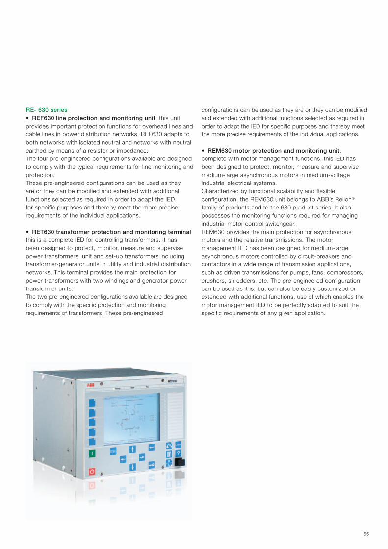
65
RE- 630 series• REF630 line protection and monitoring unit: this unit provides important protection functions for overhead lines and cable lines in power distribution networks. REF630 adapts to both networks with isolated neutral and networks with neutral earthed by means of a resistor or impedance. The four pre-engineered configurations available are designed to comply with the typical requirements for line monitoring and protection. These pre-engineered configurations can be used as they are or they can be modified and extended with additional functions selected as required in order to adapt the IED for specific purposes and thereby meet the more precise requirements of the individual applications.
• RET630 transformer protection and monitoring terminal: this is a complete IED for controlling transformers. It has been designed to protect, monitor, measure and supervise power transformers, unit and set-up transformers including transformer-generator units in utility and industrial distribution networks. This terminal provides the main protection for power transformers with two windings and generator-power transformer units. The two pre-engineered configurations available are designed to comply with the specific protection and monitoring requirements of transformers. These pre-engineered
configurations can be used as they are or they can be modified and extended with additional functions selected as required in order to adapt the IED for specific purposes and thereby meet the more precise requirements of the individual applications.
• REM630 motor protection and monitoring unit: complete with motor management functions, this IED has been designed to protect, monitor, measure and supervise medium-large asynchronous motors in medium-voltage industrial electrical systems.Characterized by functional scalability and flexible configuration, the REM630 unit belongs to ABB’s Relion® family of products and to the 630 product series. It also possesses the monitoring functions required for managing industrial motor control switchgear. REM630 provides the main protection for asynchronous motors and the relative transmissions. The motor management IED has been designed for medium-large asynchronous motors controlled by circuit-breakers and contactors in a wide range of transmission applications, such as driven transmissions for pumps, fans, compressors, crushers, shredders, etc. The pre-engineered configuration can be used as it is, but can also be easily customized or extended with additional functions, use of which enables the motor management IED to be perfectly adapted to suit the specific requirements of any given application.
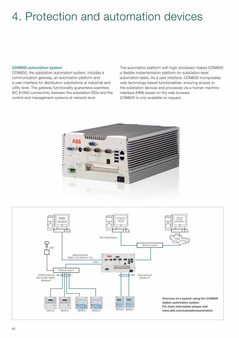
REMOTEACCESS -
ENGINEERING
DISTRIBUTEDCONTROLSYSTEM
Ethernet switch
Ethernet switch
WANOPC Client/Server
TCP/IP protocols(IEC 61850, DNP3,
Modbus®)
Serial protocol(Modbus®)
LAN 1
GPS
REF601 REF601REF615 REF615REF610 REF610
EMS/SCADA
Serial protocols(DNP3, IEC 60870-5-101)
66
COM600 automation system COM600, the substation automation system, includes a communication gateway, an automation platform anda user interface for distribution substations at industrial and utility level. The gateway functionality guarantees seamless IEC 61850 connectivity between the substation IEDs and the control and management systems at network level.
Overview of a system using the COM600 station automation system.For more information please visit www.abb.com/substationautomation
The automation platform with logic processor makes COM600 a flexible implementation platform for substation-level automation tasks. As a user interface, COM600 incorporates web technology based functionalities, ensuring access to the substation devices and processes via a human machine interface (HMI) based on the web browser.COM600 is only available on request.
4. Protection and automation devices
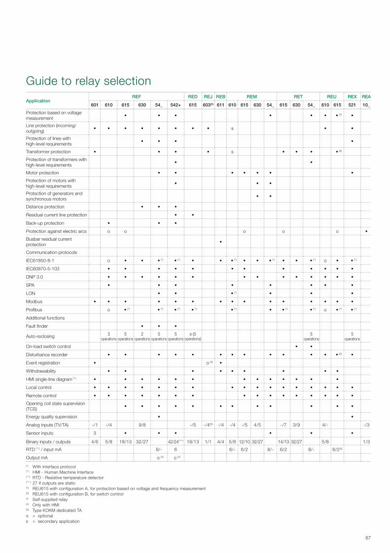
67
Guide to relay selection
ApplicationREF RED REJ REB REM RET REU REX REA
601 610 615 630 54_ 542+ 615 603(3) 611 610 615 630 54_ 615 630 54_ 610 615 521 10_
Protection based on voltage measurement
• • • • • • • (1) •
Line protection (incoming/outgoing)
• • • • • • • • s • •
Protection of lines with high-level requirements
• • • •
Transformer protection • • • • s • • • • (2)
Protection of transformers with high-level requirements
• •
Motor protection • • • • • • •
Protection of motors with high-level requirements
• • •
Protection of generators and synchronous motors
• •
Distance protection • • •
Residual current line protection • •
Back-up protection • • •
Protection against electric arcs o o o o o •
Busbar residual current protection
•
Communication protocols
IEC61850-8-1 o • • • (*) • (*) • • • (*) • • • (*) • • • (*) o • • (*)
IEC60870-5-103 • • • • • • • • • • • •
DNP 3.0 • • • • • • • • • • • • • •
SPA • • • • • • • •
LON • • • (*) • • •
Modbus • • • • • • • • • • • • • • •
Profibus o • (*) • (*) • (*) • (*) • (*) • • (*) • (*) o • (*) • (*)
Additional functions
Fault finder • • •
Auto-reclosing 3operations
5operations
2operations
5operations
5operations
o (5operations)
5operations
5operations
On-load switch control • •
Disturbance recorder • • • • • • • • • • • • • (2) •
Event registration • o (4) •
Withdrawability • • • • • • • • •
HMI single-line diagram (**) • • • • • • • • • • • • •
Local control • • • • • • • • • • • • • • • • •
Remote control • • • • • • • • • • • • • • • •
Opening coil state supervision (TCS)
• • • • • • • • • • • •
Energy quality supervision • •
Analog inputs (TV/TA) -/1 -/4 9/8 -/5 -/4(5) -/4 -/4 -/5 4/5 -/7 3/9 4/- -/3
Sensor inputs 3 • • • • • •
Binary inputs / outputs 4/6 5/8 18/13 32/27 42/24(****) 18/13 1/1 4/4 5/8 12/10 32/27 14/13 32/27 5/8 1/3
RTD (***) / input mA 8/- 6 6/- 6/2 8/- 6/2 8/- 6/2(2)
Output mA o (4) o (4)
(*) With interface protocol(**) HMI - Human Machine Interface(***) RTD - Resistive temperature detector(****) 27 if outputs are static(1) REU615 with configuration A, for protection based on voltage and frequency measurement(2) REU615 with configuration B, for switch control(3 Self-supplied relay(4) Only with HMI(5) Type KOKM dedicated TAo = optional s = secondary application

68
Automatic change-over systemThe purpose of automatic change-over systems is to assure continuity of service by providing the users with interruption-free power.All this is achieved thanks to systems of various kinds, based on different techniques.The most common of these are listed below with their respective average change-over times:
− Delayed: 1500 ms − Residual voltage dependant: 400-1200 ms − Synchronized (ATS): 200-500 ms − High speed (HSTS): 30-120 ms
The first two systems are the simplest and can also be created with conventional logic and instruments. They provide medium change-over times and can thus be used in systems where voltage dips do not create particularly critical conditions.The other two systems (ATS – Automatic Transfer System and HSTS – High Speed Transfer System) require highly technological microprocessor equipment.They guarantee fast change-over times and can be used for systems whose process is particularly critical. This is because, unless they are extremely fast, change-over operations cause serious faults or stop the processes themselves.ABB is able to provide all kinds of change-over systems, from the simplest to the most complex.
ATSThe REF542plus unit can be used in medium-voltage switchgear to control automatic and manual change-over processes between two different incoming lines.The time required for automatic change-over processes performed by means of the REF542plus unit is between 200 and 300 thousandths of a second (including the time it takes to operate the circuit-breakers).This time may vary within the indicated range depending on the complexity of the change-over logic in the software.Adequately programmed, switchgear equipped with REF542plus forms a complete and efficient system able to handle the change-over process between one power supply system and another alternative one, or to re-configure the network and switch from double radial distribution to a simpler system in a fully automatic way.The same operation can also be performed in the manual mode from a remote control station or from the front of the switchgear under the supervision of the user personnel.Manual change-over involves passing paralleling: by means of the synchronism monitoring function (synchro-check – code 25) implemented by the REF542plus unit. The supply lines are closed at the same time as the voltage vectors synchronize, to be subsequently disconnected once change-over has occurred. Additional instrumentation is not required for the applications described above.
Single-line diagram of the UniSec switchgear with REF542plus architecture able to perform automatic and manual switching besides switchgear measurements and protections
4. Protection and automation devices

69
DescriptionThe shipping market can be divided into four different segments:
− passenger ships (cruise liners and ferries) − industrial vessels (tankers, drillships, oil tankers, freighters,
etc.) − platforms (oil platforms and rigs) − the navy.
In this sort of application, the temperature range, vibrations and buoyancy are particularly aggravating conditions that affect the functionality of the instruments on board, such as switchgear.ABB is the leading manufacturer of air-insulated switchgear for applications installed by all the major shipyards (in Brazil, China, Denmark, Finland, France, Germany, Japan, Korea, Italy, Norway, Singapore, Spain, United Kingdom and the United States).
UniSec is the new ABB switchgear for 7.2-12 kV marine applications (option for 17.5 kV).Over 10,000 ABB panels installed in vessels of all types, are in service throughout the world. Shipping Registers and end customers (shipyards or shipowners) need switchgear manufactured in compliance with the Shipping Register test requirements for the equipment on board.This is why tests are performed to ensure compliance with the main provisions established by the Shipping Registers: DNV, LR, RINA, BV, GL and ABS.To ensure the necessary structures and liveable conditions, large electric generating systems and monitoring equipment must be concentrated into very small spaces.UniSec switchgear is available in the single level version and provides a wide range of apparatus and monitoring units suitable for marine applications.
5. Marine applications
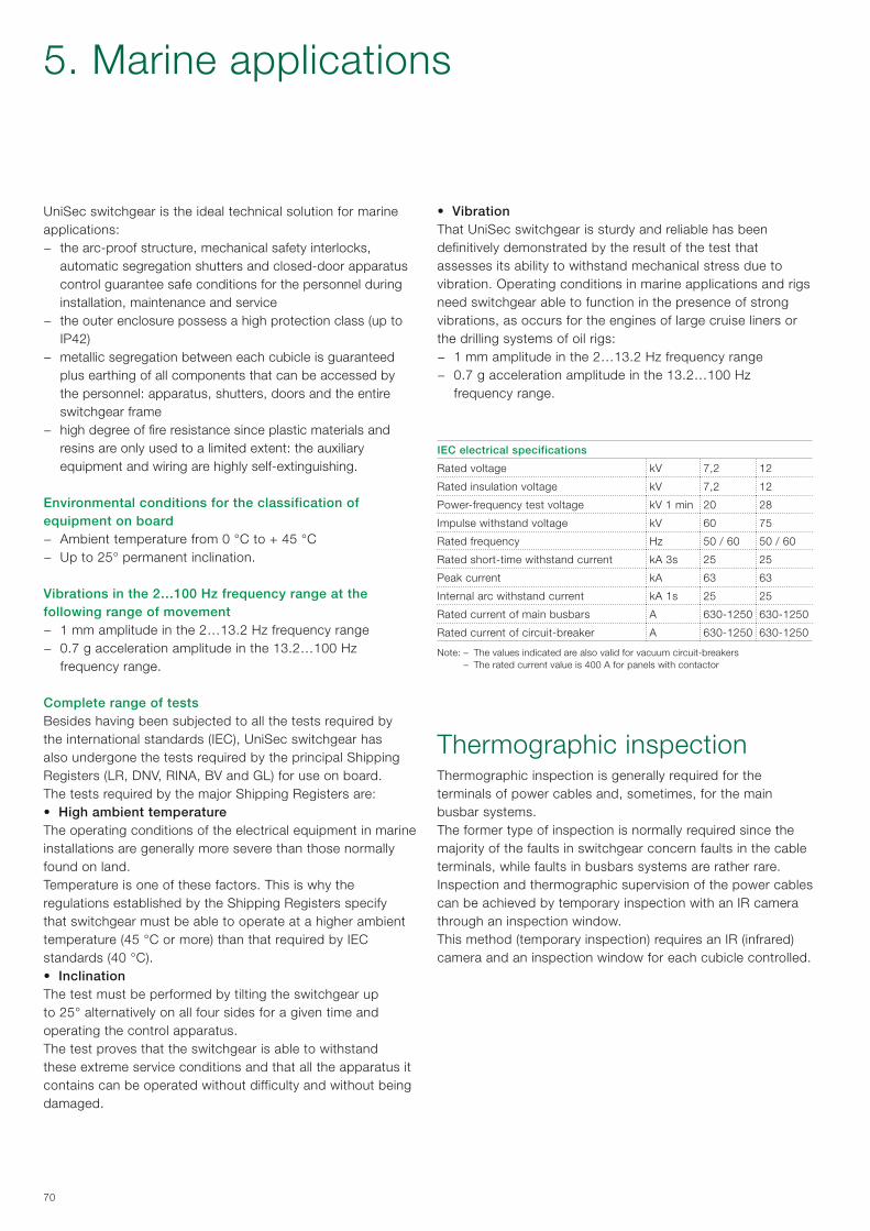
70
UniSec switchgear is the ideal technical solution for marine applications:
− the arc-proof structure, mechanical safety interlocks, automatic segregation shutters and closed-door apparatus control guarantee safe conditions for the personnel during installation, maintenance and service
− the outer enclosure possess a high protection class (up to IP42)
− metallic segregation between each cubicle is guaranteed plus earthing of all components that can be accessed by the personnel: apparatus, shutters, doors and the entire switchgear frame
− high degree of fire resistance since plastic materials and resins are only used to a limited extent: the auxiliary equipment and wiring are highly self-extinguishing.
Environmental conditions for the classification of equipment on board
− Ambient temperature from 0 °C to + 45 °C − Up to 25° permanent inclination.
Vibrations in the 2…100 Hz frequency range at the following range of movement
− 1 mm amplitude in the 2…13.2 Hz frequency range − 0.7 g acceleration amplitude in the 13.2…100 Hz
frequency range.
Complete range of testsBesides having been subjected to all the tests required by the international standards (IEC), UniSec switchgear has also undergone the tests required by the principal Shipping Registers (LR, DNV, RINA, BV and GL) for use on board.The tests required by the major Shipping Registers are:• High ambient temperatureThe operating conditions of the electrical equipment in marine installations are generally more severe than those normally found on land.Temperature is one of these factors. This is why the regulations established by the Shipping Registers specify that switchgear must be able to operate at a higher ambient temperature (45 °C or more) than that required by IEC standards (40 °C).• InclinationThe test must be performed by tilting the switchgear up to 25° alternatively on all four sides for a given time and operating the control apparatus.The test proves that the switchgear is able to withstand these extreme service conditions and that all the apparatus it contains can be operated without difficulty and without being damaged.
• VibrationThat UniSec switchgear is sturdy and reliable has been definitively demonstrated by the result of the test that assesses its ability to withstand mechanical stress due to vibration. Operating conditions in marine applications and rigs need switchgear able to function in the presence of strong vibrations, as occurs for the engines of large cruise liners or the drilling systems of oil rigs:
− 1 mm amplitude in the 2…13.2 Hz frequency range − 0.7 g acceleration amplitude in the 13.2…100 Hz
frequency range.
IEC electrical specifications
Rated voltage kV 7,2 12
Rated insulation voltage kV 7,2 12
Power-frequency test voltage kV 1 min 20 28
Impulse withstand voltage kV 60 75
Rated frequency Hz 50 / 60 50 / 60
Rated short-time withstand current kA 3s 25 25
Peak current kA 63 63
Internal arc withstand current kA 1s 25 25
Rated current of main busbars A 630-1250 630-1250
Rated current of circuit-breaker A 630-1250 630-1250
Note: – The values indicated are also valid for vacuum circuit-breakers – The rated current value is 400 A for panels with contactor
Thermographic inspectionThermographic inspection is generally required for the terminals of power cables and, sometimes, for the main busbar systems.The former type of inspection is normally required since the majority of the faults in switchgear concern faults in the cable terminals, while faults in busbars systems are rather rare.Inspection and thermographic supervision of the power cables can be achieved by temporary inspection with an IR camera through an inspection window.This method (temporary inspection) requires an IR (infrared) camera and an inspection window for each cubicle controlled.
5. Marine applications

71
“Shore connection” panelOne of these measures is the “shore-to-ship” supply system, which does away with the problem of pollution and the emission of polluting particles as well as the noise and vibrations produced by moored vessels.The UniSec Shore Connection panel is supplied in the form of a ready-to-use substation equipped with both a power module and monitoring module.Depending on how the system is configured and the requirements on board, the substation can be fitted with cable connectors housed on its front or with openings for incoming cables through the substation floor.All the equipment is manufactured and tested in the factory according to international standards and the Shipping Register classifications.
When moored at the quayside, ships keep their power generating systems running so as to supply their normal processes and users and this creates a strongly localized and considerable source of pollution. In harbours with heavy shipping traffic, this practice leads to a negative impact on both the environment and on the health of the surrounding local communities.Since global trade is continually expanding, emissions from ships are becoming an environmental problem of growing proportions. Nowadays, sustainability is a prime issue in the marine industry and strong measures are being adopted on many different fronts so as to drastically reduce these emissions.
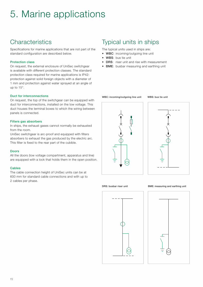
72
CharacteristicsSpecifications for marine applications that are not part of the standard configuration are described below.
Protection classOn request, the external enclosure of UniSec switchgear is available with different protection classes. The standard protection class required for marine applications is IP42: protection against solid foreign objects with a diameter of 1 mm and protection against water sprayed at an angle of up to 15°.
Duct for interconnectionsOn request, the top of the switchgear can be equipped with duct for interconnections, installed on the low voltage. This duct houses the terminal boxes to which the wiring between panels is connected.
Filters gas absorbersIn ships, the exhaust gases cannot normally be exhausted from the room.UniSec switchgear is arc-proof and equipped with filters absorbers to exhaust the gas produced by the electric arc.This filter is fixed to the rear part of the cubible.
DoorsAll the doors (low voltage compartment, apparatus and line) are equipped with a lock that holds them in the open position.
CablesThe cable connection height of UniSec units can be at 600 mm for standard cable connections and with up to 2 cables per phase.
Typical units in shipsThe typical units used in ships are:• WBC: incoming/outgoing line unit • WBS: bus tie unit• DRS: riser unit and rise with measurement• BME: busbar measuring and earthing unit
WBC: incoming/outgoing line unit
BME: measuring and earthing unit
WBS: bus tie unit
DRS: busbar riser unit
5. Marine applications

73
The IEC 62271-200 Standard has introduced some new aspects regarding definitions and classifications of MV switchgear.One of the most significant changes introduced by this Standard is elimination of classification of switchgear into metal-enclosed, divided into compartments and with units. Switchgear classification has been revised taking the user’s point of view into account, in particular for some aspects such as switchgear operation and maintenance, according to the requirements and expectations of good substation management, from installation to disposal. In this context, “loss of service continuity” has been chosen as a fundamental criterion for the user.
According to the updated standards, UniSec switchgear can be defined as follows:1. Compartment with access controlled by an interlock,
containing high-voltage parts, designed to be opened for normal operation and/or normal maintenance, where access is controlled by integral configuration of the switchgear and controlgear.
6. IEC classification
2. Compartment with procedure-based access, containing high-voltage parts, designed to be opened for normal operation and/or normal maintenance, where access is controlled by a suitable procedure associated with a lock.
3. Service continuity class The busbar and cable compartments are physically and
electrically partitioned. This category defines the possibility of opening a main circuit compartment whilst keeping other compartments and/or functional units energised.
4. Partition class Controlgear with continuous metal partitions, intended to
be earthed, between the compartment with free access and the main circuit live parts.
The metal partitions or metal parts of these must be connected to the earthing point of the functional unit.
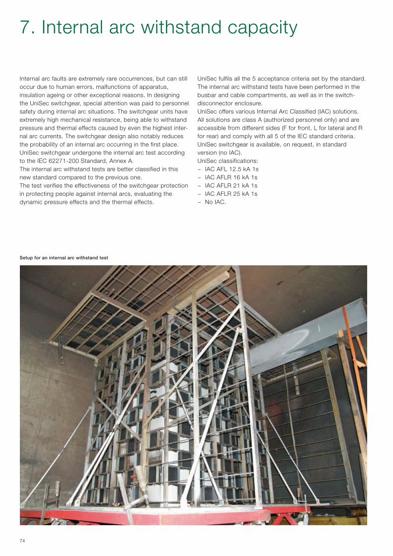
74
7. Internal arc withstand capacity
Internal arc faults are extremely rare occurrences, but can still occur due to human errors, malfunctions of apparatus,insulation ageing or other exceptional reasons. In designing the UniSec switchgear, special attention was paid to personnel safety during internal arc situations. The switchgear units have extremely high mechanical resistance, being able to withstand pressure and thermal effects caused by even the highest inter-nal arc currents. The switchgear design also notably reduces the probability of an internal arc occurring in the first place. UniSec switchgear undergone the internal arc test according to the IEC 62271-200 Standard, Annex A.The internal arc withstand tests are better classified in this new standard compared to the previous one.The test verifies the effectiveness of the switchgear protection in protecting people against internal arcs, evaluating the dynamic pressure effects and the thermal effects.
Setup for an internal arc withstand test
UniSec fulfils all the 5 acceptance criteria set by the standard. The internal arc withstand tests have been performed in the busbar and cable compartments, as well as in the switch-disconnector enclosure.UniSec offers various Internal Arc Classified (IAC) solutions.All solutions are class A (authorized personnel only) and are accessible from different sides (F for front, L for lateral and R for rear) and comply with all 5 of the IEC standard criteria.UniSec switchgear is available, on request, in standard version (no IAC).UniSec classifications:
− IAC AFL 12.5 kA 1s − IAC AFLR 16 kA 1s − IAC AFLR 21 kA 1s − IAC AFLR 25 kA 1s − No IAC.
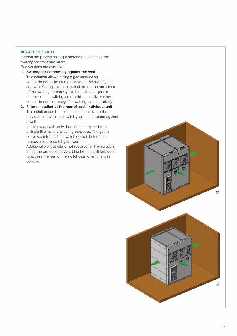
[1]
[2]
75
IAC AFL 12.5 kA 1sInternal arc protection is guaranteed on 3 sides of the switchgear, front and lateral.Two versions are available:1. Switchgear completely against the wall This solution allows a single gas exhausting
compartment to be created between the switchgear and wall. Closing plates installed on the top and sides of the switchgear convey the incandescent gas to the rear of the switchgear into this specially created compartment (see image for switchgear installation).
2. Filters installed at the rear of each individual unit This solution can be used as an alternative to the
previous one when the switchgear cannot stand against a wall.
In this case, each individual unit is equipped with a single filter for arc-proofing purposes. The gas is conveyed into the filter, which cools it before it is relased into the switchgear room.
Additional work at site is not required for this solution. Since the protection is AFL (3 sides) it is still forbidden
to access the rear of the switchgear when this is in service.
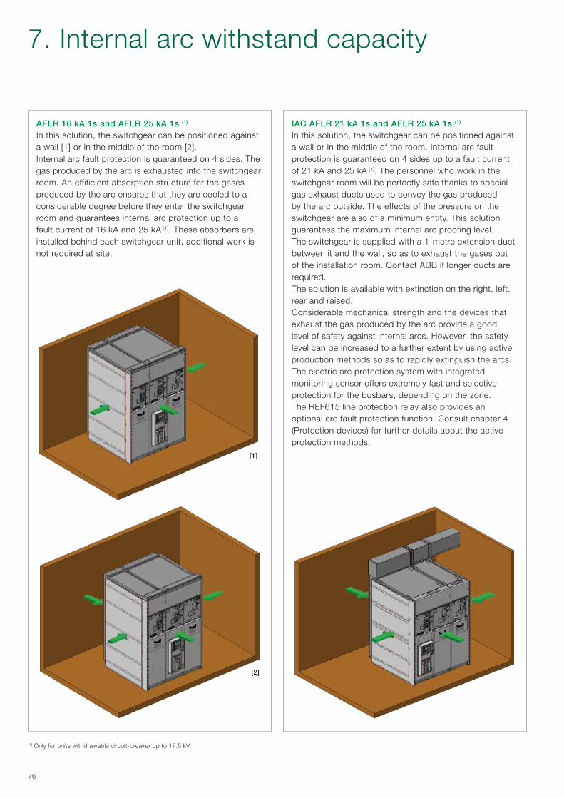
[1]
[2]
76
IAC AFLR 21 kA 1s and AFLR 25 kA 1s (1)
In this solution, the switchgear can be positioned against a wall or in the middle of the room. Internal arc fault protection is guaranteed on 4 sides up to a fault current of 21 kA and 25 kA (1). The personnel who work in the switchgear room will be perfectly safe thanks to special gas exhaust ducts used to convey the gas produced by the arc outside. The effects of the pressure on the switchgear are also of a minimum entity. This solution guarantees the maximum internal arc proofing level. The switchgear is supplied with a 1-metre extension duct between it and the wall, so as to exhaust the gases out of the installation room. Contact ABB if longer ducts are required.The solution is available with extinction on the right, left, rear and raised.Considerable mechanical strength and the devices that exhaust the gas produced by the arc provide a good level of safety against internal arcs. However, the safety level can be increased to a further extent by using active production methods so as to rapidly extinguish the arcs.The electric arc protection system with integrated monitoring sensor offers extremely fast and selective protection for the busbars, depending on the zone.The REF615 line protection relay also provides an optional arc fault protection function. Consult chapter 4 (Protection devices) for further details about the active protection methods.
(1) Only for units withdrawable circuit-breaker up to 17.5 kV
AFLR 16 kA 1s and AFLR 25 kA 1s (1)
In this solution, the switchgear can be positioned against a wall [1] or in the middle of the room [2]. Internal arc fault protection is guaranteed on 4 sides. The gas produced by the arc is exhausted into the switchgear room. An effificient absorption structure for the gases produced by the arc ensures that they are cooled to a considerable degree before they enter the switchgear room and guarantees internal arc protection up to a fault current of 16 kA and 25 kA (1). These absorbers are installed behind each switchgear unit, additional work is not required at site.
7. Internal arc withstand capacity

1070
1700
1000 min (*)
400
min
2100
min
150
30m
in
2100
min
1700
70 1070 1000 min (*)
400
min
150 min
30m
in
77
8. Installation information
Switchgear roomThe installation room must be prepared according to the switchgear dimensions and version. Observance of the distances indicated guarantees correct and safe operation
Room layout
of the equipments. For installation conditions other than those indicated, please consult ABB.
Distances from the walls of the installation room with gas absorbers, solution IAC A-FL 12.5 kA 1s against the wall.
Minimum distances from the walls of the installation room with gas absorbers, solution IAC A-FL 12.5 kA 1s with filters installed on each individual unit.
(*) 1300 mm at least for panels with circuit-breaker
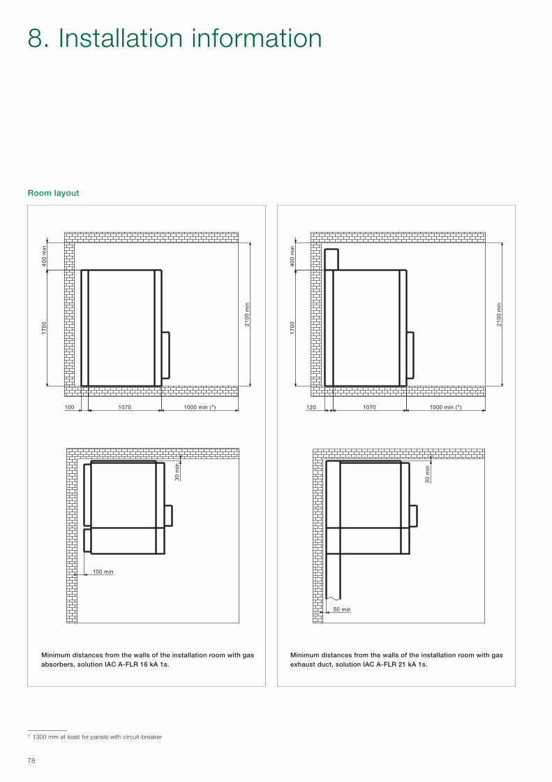
2100
min
1700
100 1070 1000 min (*)
400
min
100 min
30m
in
2100
min
1070 1000 min (*)
400
min
1700
120
50 min
30m
in
78
Room layout
Minimum distances from the walls of the installation room with gas absorbers, solution IAC A-FLR 16 kA 1s.
Minimum distances from the walls of the installation room with gas exhaust duct, solution IAC A-FLR 21 kA 1s.
(*) 1300 mm at least for panels with circuit-breaker
8. Installation information

30m
in
50 min
1200 min120 1200/1300
2600
min
600
min
2000
2000
100 1200/1300 1200 min
400
min
2400
min
50 min
30m
in
79
Room layout for unit with withdrawable circuit-breaker
Minimum distances from the walls of the installation room with gas absorbers. Class AFLR.
Minimum distances from the walls of the installation room with gas exhaust ducts. Class AFLR.
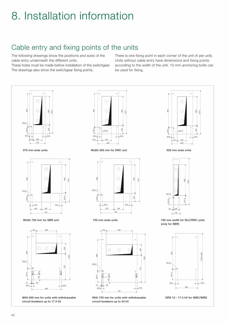
10
37
43,5
375
77,5 220
20
26
92
43,5
Ø12,5
15
8,5
80
0
10
37
43,5
500
97,5 230
Ø12,5
15
8,5
80
0
20
26
92
43,5
30
1.5 81
10
12
5
Ø12,5
43.5
75
32
30
80
0
25
12
00
600
400 100
43.5
301
.5 81
10
125
Ø12.5
43.5
77
32
30
800
25
13
00
550 100
750
43.5
12
00
/13
00
500
Ø12,5
30
1.5
80
0
43,5 43,5
10
37
150
25 100
Ø12,5
15
8,5
20
7,5
69
2
10
37
43,5
750
327 230
Ø12,5
15
8,5
80
0
20
26
92
43,5
10
37
43,5
750
265 220
Ø12,5
15
8,5
80
0
20
7,5
69
2
43,5
10
37
43,5
500
140 220
Ø12,5
15
8,5
80
0
20
26
92
43,5
80
Cable entry and fixing points of the unitsThere is one fixing point in each corner of the unit (4 per unit). Units without cable entry have dimensions and fixing points according to the width of the unit. 10 mm anchoring bolts can be used for fixing.
The following drawings show the positions and sizes of the cable entry underneath the different units.These holes must be made before installation of the switchgear. The drawings also show the switchgear fixing points.
375 mm wide units
190 mm width for RLC/RRC units (only for SBR)
750 mm wide units
DRS 12 - 17.5 kV for WBC/WBS
Width 500 mm for DRC unit
With 600 mm for units with withdrawable circuit-breakers up to 17.5 kV
With 750 mm for units with withdrawable circuit-breakers up to 24 kV
500 mm wide units
Width 750 mm for SBR unit
8. Installation information
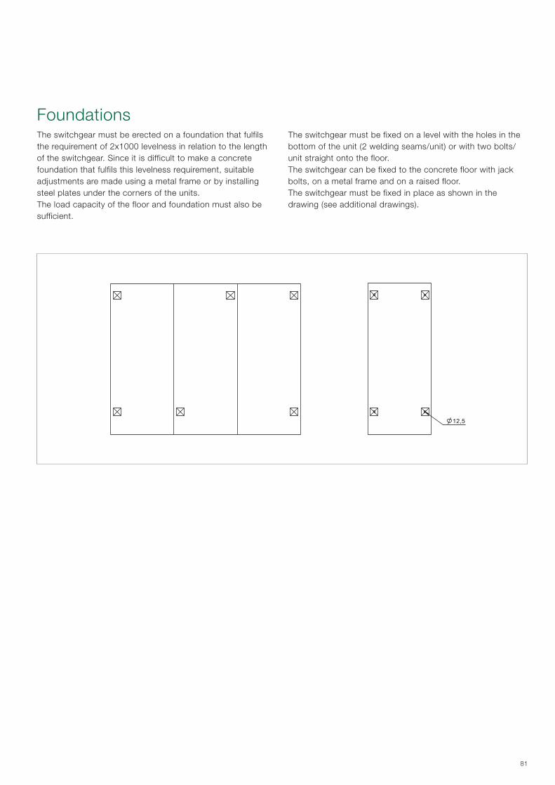
12,5
81
FoundationsThe switchgear must be fixed on a level with the holes in the bottom of the unit (2 welding seams/unit) or with two bolts/unit straight onto the floor.The switchgear can be fixed to the concrete floor with jack bolts, on a metal frame and on a raised floor.The switchgear must be fixed in place as shown in the drawing (see additional drawings).
The switchgear must be erected on a foundation that fulfils the requirement of 2x1000 levelness in relation to the length of the switchgear. Since it is difficult to make a concrete foundation that fulfils this levelness requirement, suitable adjustments are made using a metal frame or by installing steel plates under the corners of the units. The load capacity of the floor and foundation must also be sufficient.

82
Medium voltage cable lengths and locations
Details
190 mm width 375 mm width 500 mm width 600 mm width 750 mm width
A (mm) B (mm) A (mm) B (mm) A (mm) B (mm) A (mm) B (mm) A (mm) B (mm)
SDC Basic – – 915 210 915 275 – – – –
SDC With CT – – – – 525 275 – – 525 275
SDM Basic – – – – – – – – 525(1) 275(1)
SDD Basic – – – – – – – – 918 185
SFC 292 mm fuse – – 600 200 600 230 – – – –
SFC 442 mm fuse – – 450 200 450 230 – – – –
SBC Basic – – – – – – – – 500 310
WBC Basic or with CT – – – – – – 600 150(2) 600 165
DRC Basic – – 500 165 668 255 – – – –
DRC With CT – – – – 530 275 – – – –
SBR Basic – – – – – – – – 400 390
RLC/RRC Basic 1495 310 – – – – – – – –
(1) With optional cable terminal(2) Distance between the side wall of the panel and the first cable connection
RLC unit
Medium voltage cable positions and lengths The lengths of the medium voltage cables used (distance between the cable connection point and the floor) depend on the units and accessories.
The following drawings and table show the cable lengths and locations for the various units.
8. Installation information
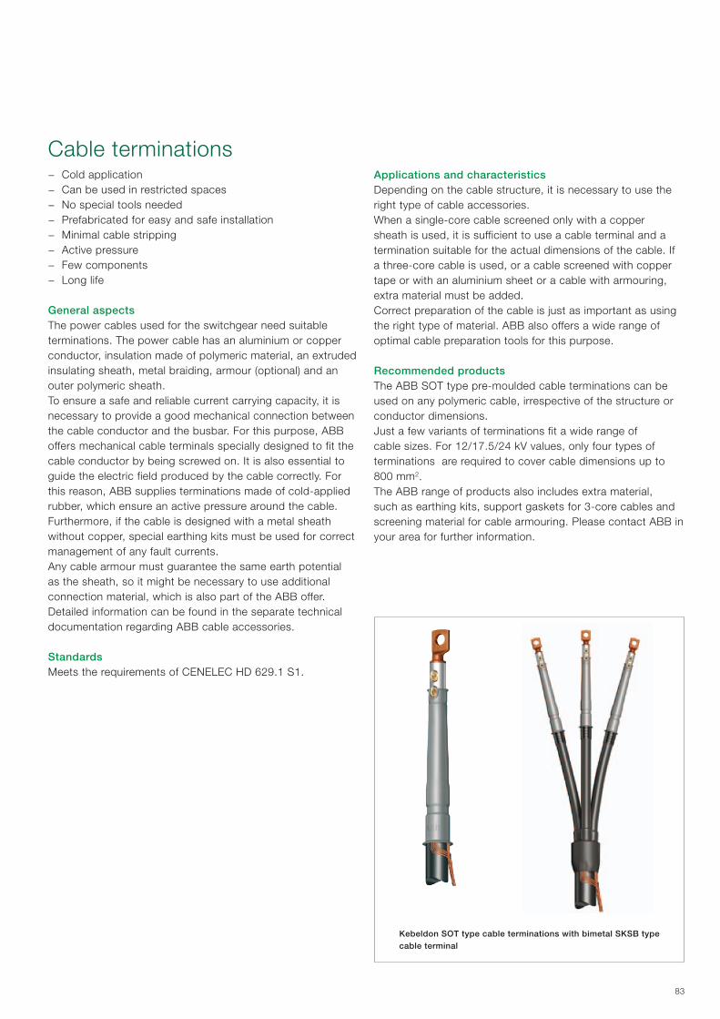
83
Cable terminations − Cold application − Can be used in restricted spaces − No special tools needed − Prefabricated for easy and safe installation − Minimal cable stripping − Active pressure − Few components − Long life
General aspectsThe power cables used for the switchgear need suitable terminations. The power cable has an aluminium or copper conductor, insulation made of polymeric material, an extruded insulating sheath, metal braiding, armour (optional) and an outer polymeric sheath.To ensure a safe and reliable current carrying capacity, it is necessary to provide a good mechanical connection between the cable conductor and the busbar. For this purpose, ABB offers mechanical cable terminals specially designed to fit the cable conductor by being screwed on. It is also essential to guide the electric field produced by the cable correctly. For this reason, ABB supplies terminations made of cold-applied rubber, which ensure an active pressure around the cable. Furthermore, if the cable is designed with a metal sheath without copper, special earthing kits must be used for correct management of any fault currents.Any cable armour must guarantee the same earth potential as the sheath, so it might be necessary to use additional connection material, which is also part of the ABB offer. Detailed information can be found in the separate technical documentation regarding ABB cable accessories.
Standards Meets the requirements of CENELEC HD 629.1 S1.
Applications and characteristics Depending on the cable structure, it is necessary to use the right type of cable accessories.When a single-core cable screened only with a copper sheath is used, it is sufficient to use a cable terminal and a termination suitable for the actual dimensions of the cable. If a three-core cable is used, or a cable screened with copper tape or with an aluminium sheet or a cable with armouring, extra material must be added.Correct preparation of the cable is just as important as using the right type of material. ABB also offers a wide range of optimal cable preparation tools for this purpose. Recommended products The ABB SOT type pre-moulded cable terminations can be used on any polymeric cable, irrespective of the structure or conductor dimensions. Just a few variants of terminations fit a wide range of cable sizes. For 12/17.5/24 kV values, only four types of terminations are required to cover cable dimensions up to 800 mm2.The ABB range of products also includes extra material, such as earthing kits, support gaskets for 3-core cables and screening material for cable armouring. Please contact ABB in your area for further information.
Kebeldon SOT type cable terminations with bimetal SKSB type cable terminal

E A B
CD
84
Kits complete with screw cable terminal Cable termination, including bimetal screw cable terminal for Al and Cu conductors.The cable terminal is equipped with shear-off bolts.
Designation Weight Designation Weight XLPE-Ø Conduction (12 kV) Conduction (24 kV)
Indoor termination 3-core / 3 x single-core
kg/kit Indoor termination single-phase kit
kg/kit mm mm2 mm2
SOT 241 A-3 0.60 SOT 241 A 0.20 11-15 10-35 10
SOT 241-3 0.60 SOT 241 0.19 15-28 50-185 25-120
SOT 242-3 0.70 SOT 242 0.23 24-39 240-500 150-300
SOT 242 B-3 0.90 SOT 242 B 0.30 38-54 630 500-630
Designation Weight Designation Weight Conduction (12 kV) Conduction (24 kV)
Indoor termination 1-core / 1 x single-core
kg/kit 3-core / 3 x single-corefor indoors
kg/kit mm2 mm2
SOT 241A S1 0.35 SOT 241A-3 S1 1.05 16-35 16
SOT 241 S1 0.34 SOT 241-3 S1 1.02 50-70 25-70
SOT 241 S2 0.44 SOT 241-3 S2 1.32 95-150 95-120
SOT 241 S3 0.59 SOT 241-3 S3 1.50 185 –
SOT 242 S2 0.48 SOT 242-3 S2 1.44 – 150
SOT 242 S3 0.63 SOT 242-3 S3 1.89 240 185-240
SOT 242 S4 0.98 SOT 242-3 S4 2.94 300-400 300-400
SOT 242B S5 1.78 SOT 242B-3 S5 5.25 500-630 500-630
Designation I L
mm
SOT 241/242/242 B 235 min 300
Designation Al or Cu conductor Tightening torque
Dimensions Weightkg/itemsector
shapedround max Ø A B C D (Ø) E (Ø)
mm2 mm2 mm mm
SKSB 70-12 25-70 16-70 11 15(*) 90 103 25 13 21.5 0.15
SKSB 150-12 95 95-150 16 20(*) 103 118 30 13 27 0.25
SKSB 240-12 120-185 185-240 20 30(*) 125 140 30 13 33.5 0.40
SKSB 400-16 240 300-400 25.5 40(*) 166 185 37 17 41.5 0.75
SKSB 630-16 – 500-630 33 45(*) 201 227 55 17 49 1.45
(*) The bolt will be sheared of at the right tightening torque
8. Installation information

85
Cable connections
Panels Width Max number of cables
Max cross section of cables (mm2)
SDC 375 1 300
500 2 300
1 630
750 2 300
SDD 750 1 300
SFC 375 1 95
500 1 95
SBC 750 2 300
1 630
SBR 750 1 300
DRC 375 1 300
500 1 630
WBC 600 2 400
1 630
750 2 400
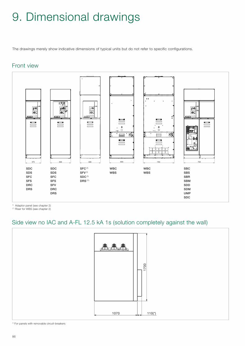
375 500 750600 750500
SDC SDC SFC (*) WBC WBC SBCSDS SDS SFV (*) WBS WBS SBSSFC SFC SDC (*) SBRSFS SFS DRS (**) SBMDRC SFV SDDDRS DRC SDM DRS UMP SDC
1070 110(*)
1700
86
Front view
9. Dimensional drawings
Side view no IAC and A-FL 12.5 kA 1s (solution completely against the wall)
The drawings merely show indicative dimensions of typical units but do not refer to specific configurations.
(*) For panels with removable circuit-breakers
(*) Adaptor panel (see chapter 2)(**) Riser for WBS (see chapter 2)

110(*)
17
00
70 1070
110(*)1070
17
00
100
87
Side view IAC A-FL 12.5 kA, with filters
Side view IAC A-FLR 16 kA, with filters
(*) For panels with removable circuit-breakers
(*) For panels with removable circuit-breakers
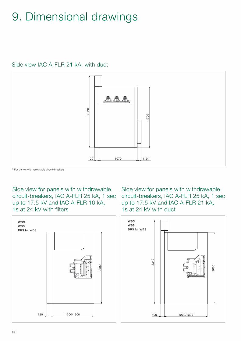
120 1200/1300
20
00
100 1200/1300
20
002
34
0
1070 110(*)120
20
20
17
00
88
WBCWBSDRS for WBS
WBCWBSDRS for WBS
Side view IAC A-FLR 21 kA, with duct
Side view for panels with withdrawable circuit-breakers, IAC A-FLR 25 kA, 1 sec up to 17.5 kV and IAC A-FLR 16 kA, 1s at 24 kV with filters
Side view for panels with withdrawable circuit-breakers, IAC A-FLR 25 kA, 1 sec up to 17.5 kV and IAC A-FLR 21 kA, 1s at 24 kV with duct
9. Dimensional drawings
(*) For panels with removable circuit-breakers

125
28
0
17
00
1070
A
235
58
0
20
00
1070 110
B
20
00
500
1070 110
58
0
C
2300
750
350
1101200/1300
B
235
2000
450
1200/1300
A
89
Low voltage compartments available
Solutions for panels with GSec
Solutions for panels with withdrawable circuit-breakers
A = Standard B = Wide C = Big
A = Standard B = Wide

90
UniSec Pro
10. Configuration software
UniSec Pro has been developed to be a tender and switchgear design tool. It also helps design offices to design and plan projects. A designer version is also available. Please contact your local ABB representative.
− Projects are stored online, enabling statistics and follow-up.
− Online site for projects, feedback, news, installation files, etc.
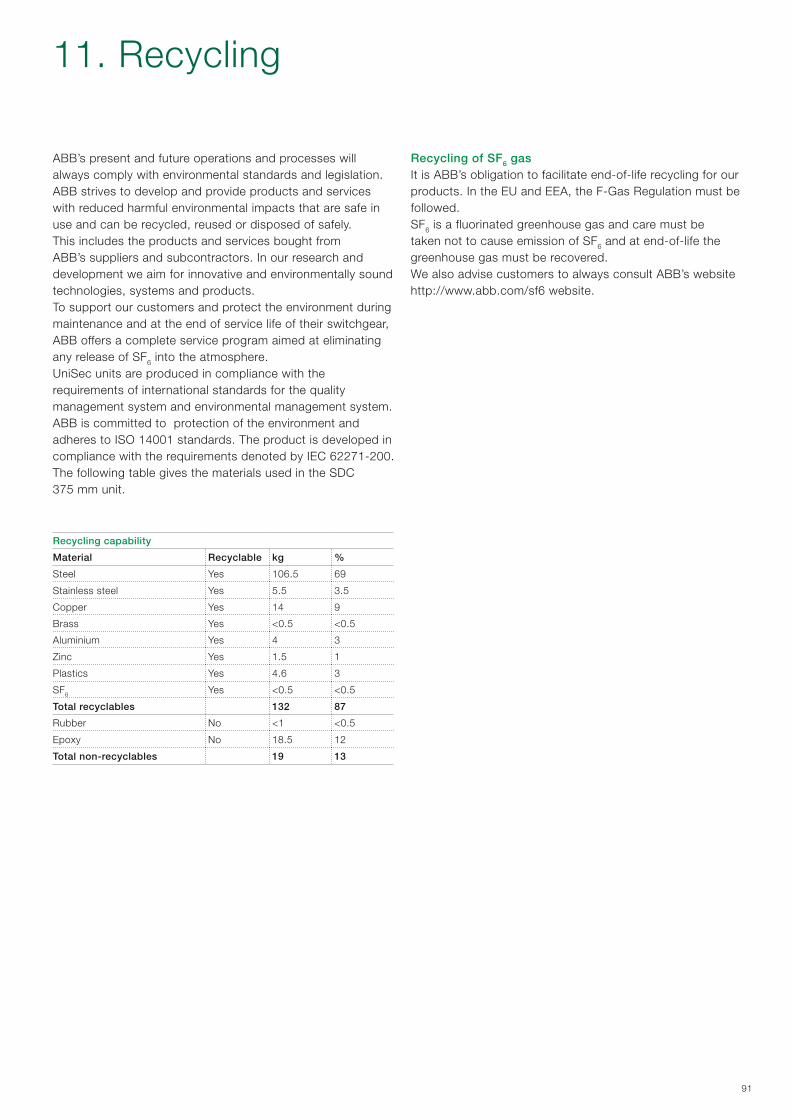
91
ABB’s present and future operations and processes will always comply with environmental standards and legislation.ABB strives to develop and provide products and services with reduced harmful environmental impacts that are safe in use and can be recycled, reused or disposed of safely.This includes the products and services bought from ABB’s suppliers and subcontractors. In our research and development we aim for innovative and environmentally sound technologies, systems and products.To support our customers and protect the environment during maintenance and at the end of service life of their switchgear, ABB offers a complete service program aimed at eliminating any release of SF6 into the atmosphere.UniSec units are produced in compliance with the requirements of international standards for the quality management system and environmental management system.ABB is committed to protection of the environment and adheres to ISO 14001 standards. The product is developed in compliance with the requirements denoted by IEC 62271-200.The following table gives the materials used in the SDC 375 mm unit.
Recycling capability
Material Recyclable kg %
Steel Yes 106.5 69
Stainless steel Yes 5.5 3.5
Copper Yes 14 9
Brass Yes <0.5 <0.5
Aluminium Yes 4 3
Zinc Yes 1.5 1
Plastics Yes 4.6 3
SF6 Yes <0.5 <0.5
Total recyclables 132 87
Rubber No <1 <0.5
Epoxy No 18.5 12
Total non-recyclables 19 13
Recycling of SF6 gasIt is ABB’s obligation to facilitate end-of-life recycling for our products. In the EU and EEA, the F-Gas Regulation must be followed.SF6 is a fluorinated greenhouse gas and care must be taken not to cause emission of SF6 and at end-of-life the greenhouse gas must be recovered.We also advise customers to always consult ABB’s websitehttp://www.abb.com/sf6 website.
11. Recycling
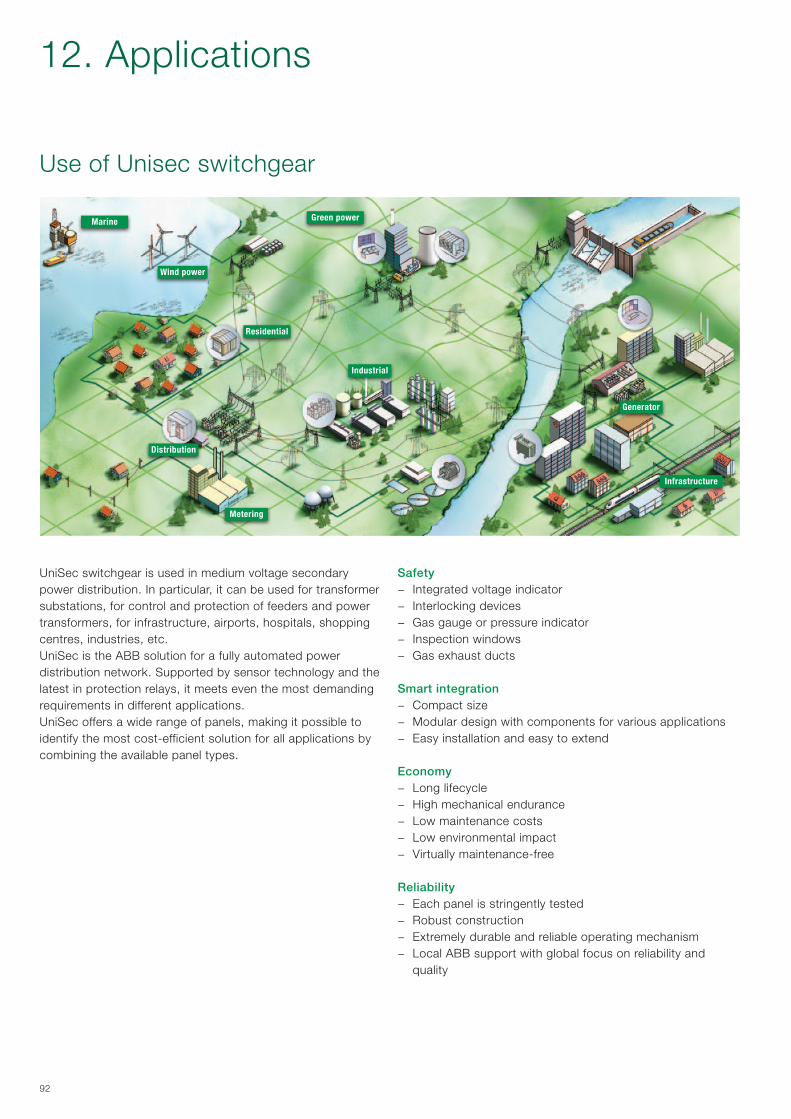
92
12. Applications
Use of Unisec switchgear
UniSec switchgear is used in medium voltage secondary power distribution. In particular, it can be used for transformer substations, for control and protection of feeders and power transformers, for infrastructure, airports, hospitals, shopping centres, industries, etc.UniSec is the ABB solution for a fully automated power distribution network. Supported by sensor technology and thelatest in protection relays, it meets even the most demanding requirements in different applications.UniSec offers a wide range of panels, making it possible to identify the most cost-efficient solution for all applications by combining the available panel types.
Safety − Integrated voltage indicator − Interlocking devices − Gas gauge or pressure indicator − Inspection windows − Gas exhaust ducts
Smart integration − Compact size − Modular design with components for various applications − Easy installation and easy to extend
Economy − Long lifecycle − High mechanical endurance − Low maintenance costs − Low environmental impact − Virtually maintenance-free
Reliability − Each panel is stringently tested − Robust construction − Extremely durable and reliable operating mechanism − Local ABB support with global focus on reliability and
quality
Wind power
Residential
Distribution
Metering
Industrial
Generator
Infrastructure
Green powerMarine
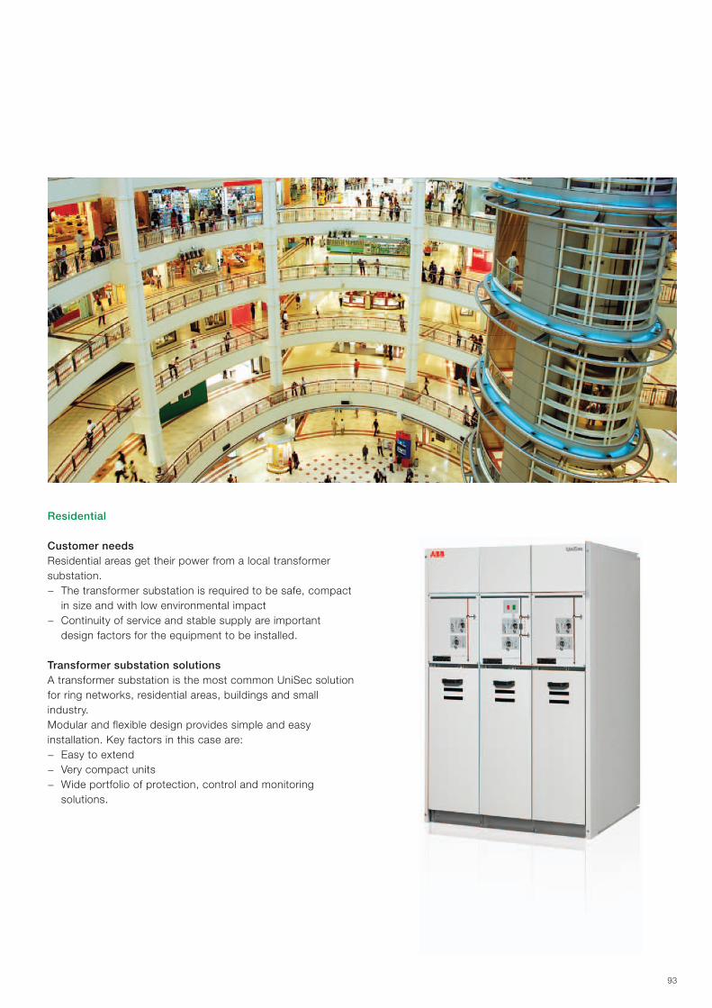
93
Residential
Customer needsResidential areas get their power from a local transformer substation.
− The transformer substation is required to be safe, compact in size and with low environmental impact
− Continuity of service and stable supply are important design factors for the equipment to be installed.
Transformer substation solutionsA transformer substation is the most common UniSec solution for ring networks, residential areas, buildings and small industry.Modular and flexible design provides simple and easy installation. Key factors in this case are:
− Easy to extend − Very compact units − Wide portfolio of protection, control and monitoring
solutions.
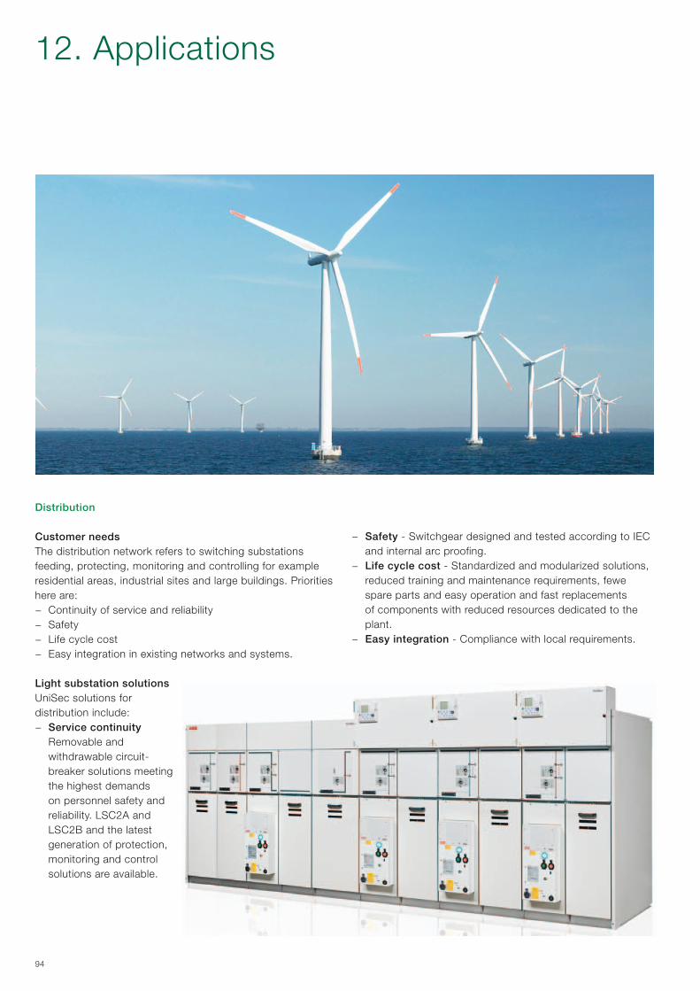
94
Distribution
Customer needsThe distribution network refers to switching substations feeding, protecting, monitoring and controlling for example residential areas, industrial sites and large buildings. Priorities here are:
− Continuity of service and reliability − Safety − Life cycle cost − Easy integration in existing networks and systems.
Light substation solutionsUniSec solutions for distribution include:
− Service continuity Removable and withdrawable circuit-breaker solutions meeting the highest demands on personnel safety and reliability. LSC2A and LSC2B and the latest generation of protection, monitoring and control solutions are available.
− Safety - Switchgear designed and tested according to IEC and internal arc proofing.
− Life cycle cost - Standardized and modularized solutions, reduced training and maintenance requirements, fewe spare parts and easy operation and fast replacements of components with reduced resources dedicated to the plant.
− Easy integration - Compliance with local requirements.
12. Applications
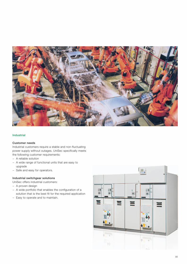
95
Industrial
Customer needsIndustrial customers require a stable and non-fluctuating power supply without outages. UniSec specifically meets the following customer requirements:
− A reliable solution − A wide range of functional units that are easy to
upgrade − Safe and easy for operators.
Industrial switchgear solutionsUniSec offers industrial customers:
− A proven design − A wide portfolio that enables the configuration of a
solution that is the best fit for the required application − Easy to operate and to maintain.
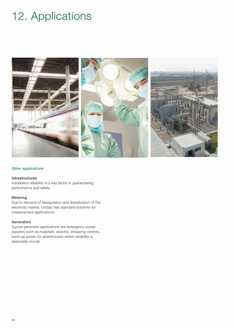
96
Other applications
InfrastructuresInstallation reliability is a key factor in guaranteeing performance and safety.
MeteringDue to demand of deregulation and liberalization of the electricity market, UniSec has standard solutions formeasurement applications.
GeneratorsTypical generator applications are emergency power supplies such as hospitals, airports, shopping centres,back-up power for greenhouses where reliability is absolutely crucial.
12. Applications


Your sales contact: www.abb.com/contacts More product information: www.abb.com/productguide
Contact us
The data and illustrations are not binding. We reserve the right to make changes in the course of technical development of the product.
© Copyright 2012 ABB.All rights reserved.
1VFM
2000
03 –
Rev
. I,
en –
201
2.09
(Pro
duc
t ca
talo
gue)
(mt)