UPGRADE EMERGENCY SWITCHGEAR AND DISTRIBUTION
558
UPGRADE EMERGENCY SWITCHGEAR AND DISTRIBUTION Project 512-17-101 U.S. Department of Veterans Affairs Baltimore VA Medical Center 10 North Greene Street Baltimore, MD 21201 100% Construction Documents Phase Design Specifications July 19, 2019 1635-2 Woodside Drive, Woodbridge, VA 22191-3045 • 703-643-2952 • FAX 703-497-2905
-
Upload
khangminh22 -
Category
Documents
-
view
1 -
download
0
Transcript of UPGRADE EMERGENCY SWITCHGEAR AND DISTRIBUTION
UPGRADE EMERGENCY SWITCHGEAR AND DISTRIBUTION
Project 512-17-101
U.S. Department of Veterans Affairs Baltimore VA Medical Center
10 North Greene Street Baltimore, MD 21201
100% Construction Documents Phase Design Specifications
July 19, 2019
1635-2 Woodside Drive, Woodbridge, VA 22191-3045 • 703-643-2952 • FAX 703-497-2905

Upgrade Emergency Switchgear and Distribution Project#:512-17-101
VAMC Baltimore, MD
DEPARTMENT OF VETERANS AFFAIRSVHA MASTER SPECIFICATIONS
TABLE OF CONTENTS Section 00 01 10
DIVISION 00 - SPECIAL SECTIONS DATE
00 01 15 List of Drawing Sheets 07-15
DIVISION 01 - GENERAL REQUIREMENTS
01 00 00 General Requirements 12-1801 32 16.15 Project Schedules (Small Projects – Design/Bid/Build 04-1301 33 23 Shop Drawings, Product Data, and Samples 05-1701 35 26 Safety Requirements 02-1701 42 19 Reference Standards 05-1601 45 00 Quality Control 03-1901 45 29 Testing Laboratory Services 11-1801 45 35 Special Inspections 03-1901 57 19 Temporary Environmental Controls 01-1101 58 16 Temporary Interior Signage 07-1501 74 19 Construction Waste Management 09-1301 91 00 General Commissioning Requirements 10-15
DIVISION 02 – EXISTING CONDITIONS
02 41 00 Demolition 08-17
DIVISION 03 – CONCRETE
03 30 53 (Short-Form) Cast-in-Place Concrete 02-16
DIVISION 05 – METALS
05 12 00 Structural Steel Framing 11-1805 50 00 Metal Fabrications 08-18
DIVISION 07 - THERMAL AND MOISTURE PROTECTION
07 84 00 Firestopping 02-16
DIVISION 08 - OPENINGS
08 11 13 Hollow Metal Doors and Frames 08-1608 71 00 Door Hardware 01-16
DIVISION 09 – FINISHES
09 91 00 Painting 01-16DIVISION 21- FIRE SUPPRESSION
00 01 10-1

Upgrade Emergency Switchgear and Distribution Project#:512-17-101
VAMC Baltimore, MD
21 08 00 Commissioning of Fire Suppression System 11-1621 13 16 Dry-Pipe Sprinkler Systems 01-15
DIVISION 22 – PLUMBING
22 05 11 Common Work Results for Plumbing 07-1622 07 11 Plumbing Insulation 09-15
DIVISION 23 – HEATING, VENTILATING, AND AIR CONDITIONING (HVAC)
23 05 11 Common Work Results for HVAC 08-1723 05 93 Testing, Adjusting, and Balancing for HVAC 02-1523 34 00 HVAC Fans 02-15
DIVISION 26 – ELECTRICAL
26 05 11 Requirements for Electrical Installations 01-1626 05 19 Low-Voltage Electrical Power Conductors and Cables 01-1726 05 26 Grounding and Bonding for Electrical Systems 01-1726 05 33 Raceway and Boxes for Electrical Systems 01-1826 05 73 Overcurrent Protective Device Coordination Study 01-1826 08 00 Commissioning of Electrical Systems 11-1626 23 00 Low-Voltage Switchgear 01-1726 23 13 Generator Paralleling Controls 01-1726 24 16 Panelboards 01-1826 25 11 Busways 01-1726 27 26 Wiring Devices 01-1826 29 11 Motor Controllers 01-1826 29 21 Enclosed Switches and Circuit Breakers 01-1726 32 13 Engine Generators 01-1826 36 23 Automatic Transfer Switches 01-1726 41 00 Facility Lightning Protection 01-1726 43 13 Surge Protective Devices 01-1726 51 00 Interior Lighting 01-18
DIVISION 28 – ELECTRONIC SAFETY AND SECURITY
28 31 00 Fire Detection and Alarm 10-11
00 01 10-2
Upgrade Emergency Switchgear and Distribution Project#:512-17-101
VAMC Baltimore, MD
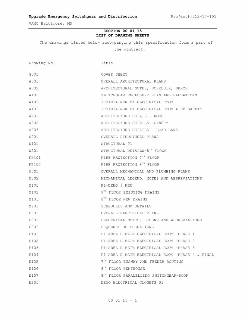
SECTION 00 01 15 LIST OF DRAWING SHEETS
The drawings listed below accompanying this specification form a part of
the contract.
Drawing No. Title
G001 COVER SHEET
A001 OVERALL ARCHITECTURAL PLANS
A002 ARCHITECTURAL NOTES, SCHEDULE, SPECS
A101 SWITCHGEAR ENCLOSURE PLAN AND ELEVATIONS
A102 1PD101A NEW P1 ELECTRICAL ROOM
A103 1PD101A NEW P1 ELECTRICAL ROOM-LIFE SAFETY
A201 ARCHITECTURE DETAIL - ROOF
A202 ARCHITECTURE DETAILS -CANOPY
A203 ARCHITECTURE DETAILS – LOAD BANK
S001 OVERALL STRUCTURAL PLANS
S101 STRUCTURAL 01
S201 STRUCTURAL DETAILS-8TH FLOOR
FP101 FIRE PROTECTION 7TH FLOOR
FP102 FIRE PROTECTION 8TH FLOOR
M001 OVERALL MECHANICAL AND PLUMBING PLANS
M002 MECHANICAL LEGEND, NOTES AND ABBREVIATIONS
M101 P1-DEMO & NEW
M102 8TH FLOOR EXISTING DRAINS
M103 8TH FLOOR NEW DRAINS
M201 SCHEDULES AND DETAILS
E001 OVERALL ELECTRICAL PLANS
E002 ELECTRICAL NOTES, LEGEND AND ABBREVIATIONS
E003 SEQUENCE OF OPERATIONS
E101 P1-AREA D MAIN ELECTRICAL ROOM –PHASE 1
E102 P1-AREA D MAIN ELECTRICAL ROOM –PHASE 2
E103 P1-AREA D MAIN ELECTRICAL ROOM –PHASE 3
E104 P1-AREA D MAIN ELECTRICAL ROOM –PHASE 4 & FINAL
E105 7TH FLOOR BUSWAY AND FEEDER ROUTING
E106 8TH FLOOR PENTHOUSE
E107 8TH FLOOR PARALELLING SWITCHGEAR-ROOF
E201 DEMO ELECTRICAL CLOSETS 01
00 01 15 - 1

Upgrade Emergency Switchgear and Distribution Project#:512-17-101
VAMC Baltimore, MD
E202 DEMO ELECRICAL CLOSETS 02
E203 NEW ELECTRICAL CLOSETS 01
E204 NEW ELECTRICAL CLOSETS 02
E301 NORMAL SWITCHGEAR D ELEVATIONS
E302 ELECTRICAL DETAILS
E303 PARALLELING SWITCHGEAR CONTROL WIRING DIAGRAM
E401 ONE LINE DIAGRAM SWITCHBOARD EXISTING
E402 ONE LINE DIAGRAM SWITCHBOARD PHASE 1
E403 ONE LINE DIAGRAM SWITCHBOARD PHASE 2
E404 ONE LINE DIAGRAM SWITCHBOARD PHASE 3
E405 ONE LINE DIAGRAM SWITCHBOARD FINAL
E406 ONE LINE GENERATOR PARALLELING SWITCHBOARD PHASE 1
E407 ONE LINE GENERATOR PARALLELING SWITCHBOARD PHASE 2
E408 ONE LINE GENERATOR PARALLELING SWITCHBOARD PHASE 3
E409 ONE LINE GENERATOR PARALLELING SWITCHBOARD PHASE 4
E501 PARTIAL EMERGENCY RISER DIAGRAM AREAS A&D
E601 ELECTRICAL SCHEDULES
E602 ELECTRICAL PANEL SCHEDULES
- - - END - - -
00 01 15 - 2

Upgrade Emergency Switchgear and Distribution Project#:512-17-101
VAMC Baltimore, MD
01 00 00 -1
SECTION 01 00 00
GENERAL REQUIREMENTS
1.1 SAFETY REQUIREMENTS
Refer to section 01 35 26, SAFETY REQUIREMENTS for safety and infection
control requirements.
1.2 GENERAL INTENTION
A. Contractor shall completely prepare site for building operations,
including demolition and removal of existing structures, and furnish
labor and materials and perform work for the Upgrade of Emergency
Switchgear and Distribution Design at the VA Medical Center in
Baltimore Maryland as required by drawings and specifications.
B. It is the requirement of this project for the Contractor to have the
means of temporary emergency power to supply the Hospital power in case
the outage is beyond the allowable time. All electrical contractors
must have the requisite qualifications to work on high voltage
electrical systems, to include switchgear.
C. Visits to the site by Bidders may be made in accordance with what is
listed in the solicitation and at the discretion of the Contracting
Officer.
D. Offices of ROMEM Aqua Systems Company, Inc., as Architect-Engineers,
will render certain technical services during construction. Such
services shall be considered as advisory to the Government and shall
not be construed as expressing or implying a contractual act of the
Government without affirmations by Contracting Officer or his duly
authorized representative.
E. Before placement and installation of work subject to tests by testing
laboratory retained by the General Contractor, the Contractor shall
notify the COR in sufficient time to enable testing laboratory
personnel to be present at the site in time for proper taking and
testing of specimens and field inspection. Such prior notice shall be
not less than three work days unless otherwise designated by the COR.
F. All employees of general contractor and subcontractors shall comply
with VA security management program and obtain permission of the VA
police, be identified by project and employer, and restricted from
unauthorized access.
G. The Key Personnel assigned by the contractor for the performance of
work on this contract shall be acceptable to VA in terms of personal
and professional conduct and technical knowledge. Should the
assignment to this contract of any person by the contractor be deemed

Upgrade Emergency Switchgear and Distribution Project#:512-17-101
VAMC Baltimore, MD
01 00 00 -2
to conflict with the interests of VA, or in the event performance is
deemed to be unsatisfactory at any time during the life of the
contract, the Contracting Officer may notify the contractor and request
the person be removed from the assignment. The reason for removal will
be documented and a request to receive key personnel replacement within
three (3) business days of the notification will be made. Replacement
of key personnel qualifications shall be equal to or greater than those
of the key personnel being replaced. Employment and staffing
difficulties will not be justification for failure to meet established
schedules. The contractor is required to submit a resume with
qualifications for the proposed replacement which shall be approved by
the COR and CO prior to the replacement starting work.
1.3 STATEMENT OF BID ITEM(S)
A. ITEM I, Construction of new indoor electrical room: Work includes
construction of a new concrete masonry unit 2-hour fire rated interior
room to housed new distribution panels and alternate transfer switches
to replace existing Emergency Switchboard D in Electrical Room IPD101
and associated electrical, mechanical, and plumbing work to conditioned
this room as described in plans and specifications. Work includes
necessary removal of existing structures and construction and certain
other items.
ITEM II, New Power Distribution Equipment, New Riser, and New Paralleling
Switchgears: Work includes all labor, material, equipment and
supervision to perform the required electrical construction work on
this project including installation of new transfer switches and new
distribution panels, new riser, and replacement of normal switchgear D
in electrical room IPD101 in P1 Level. The work also include the
installation of a new enclosed paralleling switchgear on the roof of
the 8th floor and the busway work to connect the new paralleling
switchgear to the new riser in the electrical room in P1 per the plans
and specifications.
The Contractor must furnish all structural work required to retrofit
the existing steel frame structure underneath the steel deck roof to
support the resultant loads of the new paralleling switchgear,
enclosure and related equipment contained within, and concrete
equipment pad, and to support a new load bank and concrete equipment
pad as specify in the design drawings and specifications. .

Upgrade Emergency Switchgear and Distribution Project#:512-17-101
VAMC Baltimore, MD
01 00 00 -3
ITEM III, HVAC and Fire Protection Upgrades and Plumbing relocation: Work
includes all labor, material, equipment and supervision to perform the
required mechanical construction work on this project including,
modification to the existing HVAC ductwork serving for electrical room
IPD101 in P1 Level and relocation of exhaust fan in the electrical
switchgear room 8A102, upgrade to fire suppression system to provide a
dry sprinkler system to the new paralleling switchgear enclosure on the
8th floor roof, and plumbing relocation of roof drain and steam pipe on
roof of eight floor as shown on plans and specifications.
1.4 SPECIFICATIONS AND DRAWINGS FOR CONTRACTOR
A. Drawings and contract documents may be obtained from the website where
the solicitation is posted. Additional copies will be at Contractor's
expense.
1.5 CONSTRUCTION SECURITY REQUIREMENTS
A. Security Plan:
1. The security plan defines both physical and administrative security
procedures that will remain effective for the entire duration of the
project.
2. The General Contractor is responsible for assuring that all sub-
contractors working on the project and their employees also comply
with these regulations.
B. Security Procedures:
1. General Contractor’s employees shall not enter the project site
without appropriate badge. They may also be subject to inspection
of their personal effects when entering or leaving the project site.
2. Before starting work the General Contractor shall give one week’s
notice to the Contracting Officer so that security arrangements can
be provided for the employees. This notice is separate from any
notices required for utility shutdown described later in this
section.
3. No photography of VA premises is allowed without written permission
of the Contracting Officer.
4. VA reserves the right to close down or shut down the project site
and order General Contractor’s employees off the premises in the
event of a national emergency. The General Contractor may return to
the site only with the written approval of the Contracting Officer.
C. Key Control:

Upgrade Emergency Switchgear and Distribution Project#:512-17-101
VAMC Baltimore, MD
01 00 00 -4
1. The General Contractor shall provide duplicate keys and lock
combinations to the Contracting officers representative (COR) for
the purpose of security inspections of every area of project
including tool boxes and parked machines and take any emergency
action.
2. The General Contractor shall turn over all permanent lock cylinders
to the VA locksmith for permanent installation. See Section 08 71
00, DOOR HARDWARE and coordinate.
D. Document Control:
1. Before starting any work, the General Contractor/Sub Contractors
shall submit an electronic security memorandum describing the
approach to following goals and maintaining confidentiality of
“sensitive information”.
2. The General Contractor is responsible for safekeeping of all
drawings, project manual and other project information. This
information shall be shared only with those with a specific need to
accomplish the project.
3. Certain documents, sketches, videos or photographs and drawings may
be marked “Law Enforcement Sensitive” or “Sensitive Unclassified”.
Secure such information in separate containers and limit the access
to only those who will need it for the project. Return the
information to the Contracting Officer upon request.
4. These security documents shall not be removed or transmitted from
the project site without the written approval of Contracting
Officer.
5. All paper waste or electronic media such as CD’s and diskettes shall
be shredded and destroyed in a manner acceptable to the VA.
6. Notify Contracting Officer and Site Security Officer immediately
when there is a loss or compromise of “sensitive information”.
7. All electronic information shall be stored in specified location
following VA standards and procedures using an Engineering Document
Management Software (EDMS).
a. Security, access and maintenance of all project drawings, both
scanned and electronic shall be performed and tracked through the
EDMS system.
b. “Sensitive information” including drawings and other documents
may be attached to e-mail provided all VA encryption procedures
are followed.

Upgrade Emergency Switchgear and Distribution Project#:512-17-101
VAMC Baltimore, MD
01 00 00 -5
E. Motor Vehicle Restrictions
1. Vehicle authorization request shall be required for any vehicle
entering the site and such request shall be submitted 24 hours
before the date and time of access. Access shall be restricted to
picking up and dropping off materials and supplies.
2. A limited number of (2 to 5) permits shall be issued for General
Contractor and its employees for parking in designated areas only.
1.6 OPERATIONS AND STORAGE AREAS
A. The Contractor shall confine all operations (including storage of
materials) on Government premises to areas authorized or approved by
the Contracting Officer. The Contractor shall hold and save the
Government, its officers and agents, free and harmless from liability
of any nature occasioned by the Contractor's performance.
B. Temporary buildings (e.g., storage sheds, shops, offices) and utilities
may be erected by the Contractor only with the approval of the
Contracting Officer and shall be built with labor and materials
furnished by the Contractor without expense to the Government. The
temporary buildings and utilities shall remain the property of the
Contractor and shall be removed by the Contractor at its expense upon
completion of the work. With the written consent of the Contracting
Officer, the buildings and utilities may be abandoned and need not be
removed.
C. The Contractor shall, under regulations prescribed by the Contracting
Officer, use only established roadways, or use temporary roadways
constructed by the Contractor when and as authorized by the Contracting
Officer. When materials are transported in prosecuting the work,
vehicles shall not be loaded beyond the loading capacity recommended by
the manufacturer of the vehicle or prescribed by any Federal, State, or
local law or regulation. When it is necessary to cross curbs or
sidewalks, the Contractor shall protect them from damage. The
Contractor shall repair or pay for the repair of any damaged curbs,
sidewalks, or roads.
D. Working space and space available for storing materials shall be as
determined by the COR
E. Workers are subject to rules of Medical Center applicable to their
conduct.
F. Execute work so as to interfere as little as possible with normal
functioning of Medical Center as a whole, including operations of

Upgrade Emergency Switchgear and Distribution Project#:512-17-101
VAMC Baltimore, MD
01 00 00 -6
utility services, fire protection systems and any existing equipment,
and with work being done by others. Use of equipment and tools that
transmit vibrations and noises through the building structure, are not
permitted in buildings that are occupied, during construction, jointly
by patients or medical personnel, and Contractor's personnel, except as
permitted by COR where required by limited working space.
1. Do not store materials and equipment in other than assigned areas.
2. Schedule delivery of materials and equipment to immediate
construction working areas within buildings in use by Department of
Veterans Affairs in quantities sufficient for not more than two work
days. Provide unobstructed access to Medical Center areas required
to remain in operation.
3. Where access by Medical Center personnel to vacated portions of
buildings is not required, storage of Contractor's materials and
equipment will be permitted subject to fire and safety requirements.
G. Phasing:
The Medical Center must maintain its operation 24 hours a day 7 days a
week. Therefore, any interruption in service must be scheduled and
coordinated with the COR to ensure that no lapses in operation occur.
It is the CONTRACTOR'S responsibility to develop a work plan and
schedule detailing, at a minimum, the procedures to be employed, the
equipment and materials to be used, the interim life safety measure to
be used during the work, and a schedule defining the duration of the
work with milestone subtasks. The work to be outlined shall include,
but not be limited to:
To ensure such executions, Contractor shall furnish the COR with a
schedule of approximate phasing on which the Contractor intends to
accomplish work in each specific area of site, building or portion
thereof. In addition, Contractor shall notify the COR two weeks in
advance of the proposed date of starting work in each specific area of
site, building or portion thereof. Arrange such phasing to ensure
accomplishment of this work in successive phases mutually agreeable to
Medical Center Director, COR and Contractor.
Contractor shall take all measures and provide all material
necessary for protecting existing equipment and property in affected
areas of construction against dust and debris, so that equipment and
affected areas to be used in the Medical Centers operations will not
be hindered. Contractor shall permit access to Department of

Upgrade Emergency Switchgear and Distribution Project#:512-17-101
VAMC Baltimore, MD
01 00 00 -7
Veterans Affairs personnel and patients through other construction
areas which serve as routes of access to such affected areas and
equipment. These routes whether access or egress shall be isolated
from the construction area by temporary partitions and have walking
surfaces, lighting etc to facilitate patient and staff access.
Coordinate alteration work in areas occupied by Department of
Veterans Affairs so that Medical Center operations will continue
during the construction period.
H. Construction Fence: Before construction operations begin, Contractor
shall provide a chain link construction fence, 2.1m (seven feet)
minimum height, around the construction area indicated on the drawings.
Provide gates as required for access with necessary hardware, including
hasps and padlocks. Fasten fence fabric to terminal posts with tension
bands and to line posts and top and bottom rails with tie wires spaced
at maximum 375mm (15 inches). Bottom of fences shall extend to 25mm
(one inch) above grade. Remove the fence when directed by the COR.
I. When a building and/or construction site is turned over to Contractor,
Contractor shall accept entire responsibility including upkeep and
maintenance therefore:
1. Contractor shall maintain a minimum temperature of 4 degrees C (40
degrees F) at all times, except as otherwise specified.
2. Contractor shall maintain in operating condition existing fire
protection and alarm equipment. In connection with fire alarm
equipment, Contractor shall make arrangements for pre-inspection of
site with Fire Department or Company (Department of Veterans Affairs
or municipal) whichever will be required to respond to an alarm from
Contractor's employee or watchman.
J. Utilities Services: Maintain existing utility services for Medical
Center at all times. Provide temporary facilities, labor, materials,
equipment, connections, and utilities to assure uninterrupted services.
Where necessary to cut existing water, steam, gases, sewer or air
pipes, or conduits, wires, cables, etc. of utility services or of fire
protection systems and communications systems (including telephone),
they shall be cut and capped at suitable places where shown; or, in
absence of such indication, where directed by the COR.
1. No utility service such as water, gas, steam, sewers or electricity,
or fire protection systems and communications systems may be
interrupted without prior approval of Resident Engineer and/or the

Upgrade Emergency Switchgear and Distribution Project#:512-17-101
VAMC Baltimore, MD
01 00 00 -8
COR. Electrical work shall be accomplished with all affected
circuits or equipment de-energized. When an electrical outage cannot
be accomplished, work on any energized circuits or equipment shall
not commence without a detailed work plan, the Medical Center
Director’s prior knowledge and written approval. Refer to
specification Sections 26 05 11, REQUIREMENTS FOR ELECTRICAL
INSTALLATIONS, 27 05 11 REQUIREMENTS FOR COMMUNICATIONS
INSTALLATIONS and 28 05 00, COMMON WORK RESULTS FOR ELECTRONIC
SAFETY AND SECURITY for additional requirements.
2. Contractor shall submit a request to interrupt any such services to
the COR, in writing, 7 days in advance of proposed interruption.
Request shall state reason, date, exact time of, and approximate
duration of such interruption.
3. Contractor will be advised (in writing) of approval of request, or
of which other date and/or time such interruption will cause least
inconvenience to operations of the Medical Center. Interruption time
approved by Medical Center may occur at other than Contractor's
normal working hours.
4. Major interruptions of any system must be requested, in writing, at
least 15 calendar days prior to the desired time and shall be
performed as directed by the COR.
5. In case of a contract construction emergency, service will be
interrupted on approval of the COR. Such approval will be confirmed
in writing as soon as practical.
6. Whenever it is required that a connection fee be paid to a public
utility provider for new permanent service to the construction
project, for such items as water, sewer, electricity, gas or steam,
payment of such fee shall be the responsibility of the Government
and not the Contractor.
K. Abandoned Lines: All service lines such as wires, cables, conduits,
ducts, pipes and the like, and their hangers or supports, which are to
be abandoned but are not required to be entirely removed, shall be
sealed, capped or plugged at the main, branch or panel they originate
from. The lines shall not be capped in finished areas, but shall be
removed and sealed, capped or plugged in ceilings, within furred
spaces, in unfinished areas, or within walls or partitions; so that
they are completely behind the finished surfaces.

Upgrade Emergency Switchgear and Distribution Project#:512-17-101
VAMC Baltimore, MD
01 00 00 -9
L. To minimize interference of construction activities with flow of
Medical Center traffic, comply with the following:
1. Keep roads, walks and entrances to grounds, to parking and to
occupied areas of buildings clear of construction materials, debris
and standing construction equipment and vehicles.
2. Method and scheduling of required cutting, altering and removal of
existing roads, walks and entrances must be approved by the COR.
M. Coordinate the work for this contract with other construction
operations as directed by the COR. This includes the scheduling of
traffic and the use of roadways, as specified in Article, USE OF
ROADWAYS.
1.7 ALTERATIONS
A. Survey: Before any work is started, the Contractor shall make a
thorough survey with the COR and a representative of VA Supply Service,
of areas of buildings in which alterations occur and areas which are
anticipated routes of access, and furnish a report, signed by both, to
the Contracting Officer. This report shall list by rooms and spaces:
1. Existing condition and types of resilient flooring, doors, windows,
walls and other surfaces not required to be altered throughout
affected areas of building.
2. Existence and conditions of items such as plumbing fixtures and
accessories, electrical fixtures, equipment, venetian blinds,
shades, etc., required by drawings to be either reused or relocated,
or both.
3. Shall note any discrepancies between drawings and existing
conditions at site.
4. Shall designate areas for working space, materials storage and
routes of access to areas within buildings where alterations occur
and which have been agreed upon by Contractor and the COR.
B. Any items required by drawings to be either reused or relocated or
both, found during this survey to be nonexistent, or in opinion of the
COR and/or Supply Representative, to be in such condition that their
use is impossible or impractical, shall be furnished and/or replaced by
Contractor with new items in accordance with specifications which will
be furnished by Government. Provided the contract work is changed by
reason of this subparagraph B, the contract will be modified
accordingly, under provisions of clause entitled "DIFFERING SITE

Upgrade Emergency Switchgear and Distribution Project#:512-17-101
VAMC Baltimore, MD
01 00 00 -10
CONDITIONS" (FAR 52.236-2) and "CHANGES" (FAR 52.243-4 and VAAR
852.236-88).
C. Re-Survey: Thirty days before expected partial or final inspection
date, the Contractor and the COR together shall make a thorough re-
survey of the areas of buildings involved. They shall furnish a report
on conditions then existing, of resilient flooring, doors, windows,
walls and other surfaces as compared with conditions of same as noted
in first condition survey report:
1. Re-survey report shall also list any damage caused by Contractor to
such flooring and other surfaces, despite protection measures; and,
will form basis for determining extent of repair work required of
Contractor to restore damage caused by Contractor's workers in
executing work of this contract.
D. Protection: Provide the following protective measures:
1. Wherever existing roof surfaces are disturbed they shall be
protected against water infiltration. In case of leaks, they shall
be repaired immediately upon discovery.
2. Temporary protection against damage for portions of existing
structures and grounds where work is to be done, materials handled
and equipment moved and/or relocated.
3. Protection of interior of existing structures at all times, from
damage, dust and weather inclemency. Wherever work is performed,
floor surfaces that are to remain in place shall be adequately
protected prior to starting work, and this protection shall be
maintained intact until all work in the area is completed.
1.8 DISPOSAL AND RETENTION
A. Materials and equipment accruing from work removed and from demolition
of buildings or structures, or parts thereof, shall be disposed of as
follows:
1. Reserved items which are to remain property of the Government are
noted on drawings as items to be stored. Items that remain property
of the Government shall be removed or dislodged from present
locations in such a manner as to prevent damage which would be
detrimental to re-installation and reuse. Store such items where
directed by the COR.
2. Items not reserved shall become property of the Contractor and be
removed by Contractor from the Medical Center.

Upgrade Emergency Switchgear and Distribution Project#:512-17-101
VAMC Baltimore, MD
01 00 00 -11
3. Items of portable equipment and furnishings located in rooms and
spaces in which work is to be done under this contract shall remain
the property of the Government. When rooms and spaces are vacated by
the Department of Veterans Affairs during the alteration period,
such items which are NOT required by drawings and specifications to
be either relocated or reused will be removed by the Government in
advance of work to avoid interfering with Contractor's operation.
1.9 RESTORATION
A. Remove, cut, alter, replace, patch and repair existing work as
necessary to install new work. Except as otherwise shown or specified,
do not cut, alter or remove any structural work, and do not disturb any
ducts, plumbing, steam, gas, or electric work without approval of the
COR. Existing work to be altered or extended and that is found to be
defective in any way, shall be reported to the COR before it is
disturbed. Materials and workmanship used in restoring work, shall
conform in type and quality to that of original existing construction,
except as otherwise shown or specified.
B. Upon completion of contract, deliver work complete and undamaged.
Existing work (walls, ceilings, partitions, floors, mechanical and
electrical work, lawns, paving, roads, walks, etc.) disturbed or
removed as a result of performing required new work, shall be patched,
repaired, reinstalled, or replaced with new work, and refinished and
left in as good condition as existed before commencing work.
C. At Contractor's own expense, Contractor shall immediately restore to
service and repair any damage caused by Contractor's workers to
existing piping and conduits, wires, cables, etc., of utility services
or of fire protection systems and communications systems (including
telephone) which are not scheduled for discontinuance or abandonment.
D. Expense of repairs to such utilities and systems not shown on drawings
or locations of which are unknown will be covered by adjustment to
contract time and price in accordance with clause entitled "CHANGES"
(FAR 52.243-4 and VAAR 852.236-88) and "DIFFERING SITE CONDITIONS" (FAR
52.236-2).
1.10 AS-BUILT DRAWINGS
A. The contractor shall maintain two full size sets of as-built drawings
which will be kept current during construction of the project, to
include all contract changes, modifications and clarifications.

Upgrade Emergency Switchgear and Distribution Project#:512-17-101
VAMC Baltimore, MD
01 00 00 -12
B. All variations shall be shown in the same general detail as used in the
contract drawings. To ensure compliance, as-built drawings shall be
made available for the COR review, as often as requested.
C. Contractor shall deliver two approved completed sets of as-built
drawings in the electronic version (scanned PDF) to the COR within 15
calendar days after each completed phase and after the acceptance of
the project by the COR.
D. Paragraphs A, B, & C shall also apply to all shop drawings.
1.11 WARRANTY MANAGEMENT
A. Warranty Management Plan: Develop a warranty management plan which
contains information relevant to FAR 52.246-21 Warranty of Construction
at least 30 days before the planned pre-warranty conference, coordinate
with the COR the number of sets of the warranty management plan to be
submitted. Include within the warranty management plan all required
actions and documents to assure that the Government receives all
warranties to which it is entitled. The plan must be in narrative form
and contain sufficient detail to render it suitable for use by future
maintenance and repair personnel, whether tradesman, or of engineering
background, not necessarily familiar with this contract. The term
“status” as indicated below must include due date and whether item has
been submitted or was approved. Warranty information made available
during the construction phase must be submitted to the Contracting
Officer for approval prior to each monthly invoice for payment.
Assemble approved information in a binder and turn over to the
Government upon acceptance of the work. The construction warranty
period will begin on the date of the project acceptance and continue
for the product warranty period. A joint 4 month and 9 month warranty
inspection will be conducted, measured from time of acceptance, by the
Contactor and the Contracting Officer. Include in the warranty
management plan, but not limited to, the following:
1. Roles and responsibilities of all personnel associated with the
warranty process, including points of contact and telephone numbers
within the company of the Contractor, subcontractors, manufacturers
or suppliers involved.
2. Furnish with each warranty the name, address and telephone number of
each of the guarantor’s representatives nearest project location.
3. Listing and status of delivery of all Certificates of Warranty for
extended warranty items, to include roofs, HVAC balancing, pumps,

Upgrade Emergency Switchgear and Distribution Project#:512-17-101
VAMC Baltimore, MD
01 00 00 -13
motors, transformers and for all commissioned systems such as fire
protection and alarm systems, sprinkler systems and lightning
protection systems, etc.
4. A list for each warranted equipment item, feature of construction or
system indicating:
a. Name of item.
b. Model and serial numbers.
c. Location where installed.
d. Name and phone numbers of manufacturers and suppliers.
e. Name and phone numbers of manufacturers or suppliers.
f. Names, addresses and phone numbers of sources of spare parts.
g. Warranties and terms of warranty. Include one-year overall
warranty of construction, including the starting date of warranty
of construction. Items which have extended warranties must be
indicated with separate warranty expiration dates.
h. Starting point and duration of warranty period.
i. Summary of maintenance procedures required to continue the
warranty in force.
j. Cross-reference to specific pertinent Operation and Maintenance
manuals.
k. Organizations, names and phone numbers of persons to call for
warranty service.
l. Typical response time and repair time expected for various
warranted equipment.
5. The plans for attendance at the 4 and 9-month post construction
warranty inspections conducted by the government.
6. Procedure and status of tagging of all equipment covered by extended
warranties.
7. Copies of instructions to be posted near selected pieces of
equipment where operation is critical for warranty and/or safety
reasons.
B. Performance Bond: The Performance Bond must remain effective throughout
the construction period.
1. In the event the Contractor fails to commence and diligently pursue
any construction warranty work required, the Contracting Officer
will have the work performed by others, and after completion of the
work, will charge the remaining construction warranty funds of

Upgrade Emergency Switchgear and Distribution Project#:512-17-101
VAMC Baltimore, MD
01 00 00 -14
expenses incurred by the Government while performing the work,
including, but not limited to administrative expenses.
2. In the event sufficient funds are not available to cover the
construction warranty work performed by the Government at the
contractor’s expenses, the Contracting Officer will have the right
to recoup expenses from the bonding company.
3. Following oral or written notification of required construction
warranty repair work, the Contractor shall respond in a timely
manner. Written verification will follow oral instructions. Failure
to respond will be cause for the Contracting Officer to proceed
against the Contractor.
C. Pre-Warranty Conference: Prior to contract completion, and at a time
designated by the Contracting Officer, the Contractor shall meet with
the Contracting Officer to develop a mutual understanding with respect
to the requirements of this section. Communication procedures for
Contractor notification of construction warranty defects, priorities
with respect to the type of defect, reasonable time required for
Contractor response, and other details deemed necessary by the
Contracting Officer for the execution of the construction warranty will
be established/ reviewed at this meeting. In connection with these
requirements and at the time of the Contractor’s quality control
completion inspection, furnish the name, telephone number and address
of a licensed and bonded company which is authorized to initiate and
pursue construction warranty work action on behalf of the Contractor.
This point of contract will be located within the local service area of
the warranted construction, be continuously available and be responsive
to Government inquiry on warranty work action and status. This
requirement does not relieve the Contractor of any of its
responsibilities in conjunction with other portions of this provision.
D. Contractor’s Response to Construction Warranty Service Requirements:
Following oral or written notification by the Contracting Officer, the
Contractor shall respond to construction warranty service requirements
in accordance with the “Construction Warranty Service Priority List”
and the three categories of priorities listed below. Submit a report on
any warranty item that has been repaired during the warranty period.
Include within the report the cause of the problem, date reported,
corrective action taken, and when the repair was completed. If the
Contractor does not perform the construction warranty within the

Upgrade Emergency Switchgear and Distribution Project#:512-17-101
VAMC Baltimore, MD
01 00 00 -15
timeframe specified, the Government will perform the work and back
charge the construction warranty payment item established.
1. First Priority Code 1. Perform onsite inspection to evaluate
situation, and determine course of action within 4 hours, initiate
work within 6 hours and work continuously to completion or relief.
2. Second Priority Code 2. Perform onsite inspection to evaluate
situation, and determine course of action within 8 hours, initiate
work within 24 hours and work continuously to completion or relief.
3. Third Priority Code 3. All other work to be initiated within 3 work
days and work continuously to completion or relief.
4. The “Construction Warranty Service Priority List” is as follows:
Code 1-Life Safety Systems
a. Fire suppression systems.
b. Fire alarm system(s).
Code 1 Doors
a. Interior, exterior personnel doors or hardware, not functioning
properly, causing security, fire or safety problem.
Code 3-Doors
a. Interior/exterior personnel doors or hardware not functioning
properly.
Code 1-Electrical
a. Power failure (entire area or any building operational after 1600
hours).
b. Security lights.
c. Smoke detectors.
Code 2-Electrical
a. Power failure (no power to a room or part of building).
b. Receptacles and lights not operational (in a room or part of
building).
Code 3-Electrical
a. Exterior lights not operational.
Code 1-Heat
a. Power failure affecting heat.
Code 2-Plumbing
Code 1-Roof Leaks
a. Damage to property is occurring.
Code 3

Upgrade Emergency Switchgear and Distribution Project#:512-17-101
VAMC Baltimore, MD
01 00 00 -16
a. All work not listed above.
E. Warranty Tags: At the time of installation, tag each warranted item
with a durable, oil and water-resistant tag approved by the Contracting
Officer. Attach each tag with a copper wire and spray with a silicone
waterproof coating. Also submit two record copies of the warranty tags
showing the layout and design. The date of acceptance and the QC
signature must remain blank until the project is accepted for
beneficial occupancy. Show the following information on the tag.
1.12 USE OF ROADWAYS
A. For hauling, use only established public roads and roads on Medical
Center property and, when authorized by the COR, such temporary roads
which are necessary in the performance of contract work. Temporary
roads shall be constructed and restoration performed by the Contractor
at Contractor's expense. When necessary to cross curbing, sidewalks, or
similar construction, they must be protected by well-constructed
bridges.
1.13 TEMPORARY USE OF MECHANICAL AND ELECTRICAL EQUIPMENT
A. Use of new installed mechanical and electrical equipment to provide
heat, ventilation, plumbing, light and power will be permitted subject
to written approval and compliance with the following provisions:

Upgrade Emergency Switchgear and Distribution Project#:512-17-101
VAMC Baltimore, MD
01 00 00 -17
1. Permission to use each unit or system must be given by the COR in
writing. If the equipment is not installed and maintained in
accordance with the written agreement and following provisions, the
COR will withdraw permission for use of the equipment.
2. Electrical installations used by the equipment shall be completed in
accordance with the drawings and specifications to prevent damage to
the equipment and the electrical systems, i.e. transformers, relays,
circuit breakers, fuses, conductors, motor controllers and their
overload elements shall be properly sized, coordinated and adjusted.
Installation of temporary electrical equipment or devices shall be
in accordance with NFPA 70, National Electrical Code, (2014
Edition), Article 590, Temporary Installations. Voltage supplied to
each item of equipment shall be verified to be correct and it shall
be determined that motors are not overloaded. The electrical
equipment shall be thoroughly cleaned before using it and again
immediately before final inspection including vacuum cleaning and
wiping clean interior and exterior surfaces.
3. Units shall be properly lubricated, balanced, and aligned.
Vibrations must be eliminated.
4. Automatic temperature control systems for preheat coils shall
function properly and all safety controls shall function to prevent
coil freeze-up damage.
5. The air filtering system utilized shall be that which is designed
for the system when complete, and all filter elements shall be
replaced at completion of construction and prior to testing and
balancing of system.
6. All components of heat production and distribution system, metering
equipment, condensate returns, and other auxiliary facilities used
in temporary service shall be cleaned prior to use; maintained to
prevent corrosion internally and externally during use; and cleaned,
maintained and inspected prior to acceptance by the Government.
Boilers, pumps, feedwater heaters and auxiliary equipment must be
operated as a complete system and be fully maintained by operating
personnel. Boiler water must be given complete and continuous
chemical treatment.
B. Prior to final inspection, the equipment or parts used which show wear
and tear beyond normal, shall be replaced with identical replacements,
at no additional cost to the Government.

Upgrade Emergency Switchgear and Distribution Project#:512-17-101
VAMC Baltimore, MD
01 00 00 -18
C. This paragraph shall not reduce the requirements of the mechanical and
electrical specifications sections.
D. Any damage to the equipment or excessive wear due to prolonged use will
be repaired replaced by the contractor at the contractor’s expense.
1.14 TEMPORARY USE OF EXISTING ELEVATORS
A. Use of existing elevator for handling building materials and
Contractor's personnel will be permitted subject to following
provisions:
1. Contractor makes all arrangements with the COR for use of
elevators. The COR will ascertain that elevators are in proper
condition. Contractor may use VA elevators as coordinated through
the project and for special nonrecurring time intervals when
permission is granted. Personnel for operating elevators will not be
provided by the Department of Veterans Affairs.
2. Contractor covers and provides maximum protection of following
elevator components:
a. Entrance jambs, heads soffits and threshold plates.
b. Entrance columns, canopy, return panels and inside surfaces of
car enclosure walls.
c. Finish flooring.
3. Government will accept hoisting ropes of elevator and rope of each
speed governor if they are worn under normal operation. However, if
these ropes are damaged by action of foreign matter such as sand,
lime, grit, stones, etc., during temporary use, they shall be
removed and replaced by new hoisting ropes at the contractors
expense.
4. If brake lining of elevators are excessively worn or damaged during
temporary use, they shall be removed and replaced by new brake
lining at the contractors expense.
5. All parts of main controller, starter, relay panel, selector, etc.,
worn or damaged during temporary use shall be removed and replaced
with new parts at the contractors expense, if recommended by
elevator inspector after elevator is released by Contractor.
6. Place elevator in condition equal, less normal wear, to that
existing at time it was placed in service of Contractor as approved
by Contracting Officer.

Upgrade Emergency Switchgear and Distribution Project#:512-17-101
VAMC Baltimore, MD
01 00 00 -19
1.15 TEMPORARY USE OF NEW ELEVATORS
A. The Contractor and his personnel shall be permitted use of new
elevator(s) subject to the following provisions:
1. Contractor shall make arrangements with the COR for use of
elevator(s). Contractor may obtain elevator(s) for exclusive use.
2. Prior to the use of elevator(s), the Contractor shall have the
elevator(s) inspected and accepted by an ASME accredited, certified
elevator safety inspector. The acceptance report shall be submitted
to the COR.
3. Submit to the COR the schedule and procedures for maintaining
equipment. Indicate the day or days of the week and total hours
required for maintenance. A report shall be submitted to the COR
monthly indicating the type of maintenance conducted, hours used,
and any repairs made to the elevator(s).
4. The Contractor shall be responsible for enforcing the maintenance
procedures as per VA and manufacturers recommendations and
requirements.
5. During temporary use of elevator(s) all repairs, equipment
replacement and cost of maintenance shall be the responsibility of
the Contractor.
6. Personnel for operating elevator(s) shall not be provided by the
Department of Veterans Affairs.
7. Contractor shall cover and provide maximum protection of the entire
elevator(s) installation.
8. The Contractor shall arrange for the elevator company to perform
operation of the elevator(s) so that an ASME accredited, certified
elevator safety inspector can evaluate the equipment. The Contractor
shall be responsible for any costs of the elevator company.
9. All elevator(s) parts worn or damaged during temporary use shall be
removed and replaced with new parts at the contractors expense. This
shall be determined by an ASME accredited certified elevator safety
inspector after temporary use and before acceptance by the
Government. Submit report to the COR \ for approval.
10. Elevator shall be tested as required by the testing section of the
elevator(s) specifications before acceptance by the Department of
Veterans Affairs. The Contractor shall be responsible for all cost
associated with testing and inspection.

Upgrade Emergency Switchgear and Distribution Project#:512-17-101
VAMC Baltimore, MD
01 00 00 -20
1.16 TEMPORARY TOILETS
A. Provide where directed, (for use of all Contractor's workers) ample
temporary sanitary toilet accommodations with suitable sewer and water
connections; or, when approved by the COR, provide suitable dry closets
where directed. Keep such places clean and free from flies, and all
connections and appliances connected therewith are to be removed prior
to completion of contract, and premises left perfectly clean.
1.17 AVAILABILITY AND USE OF UTILITY SERVICES
A. The Government shall make all reasonably required amounts of utilities
available to the Contractor from existing outlets and supplies, as
specified in the contract. The amount to be paid by the Contractor for
chargeable electrical services shall be the prevailing rates charged to
the Government. The Contractor shall carefully conserve any utilities
furnished without charge.
B. The Contractor, at Contractor's expense and in a workmanlike manner, in
compliance with code and as satisfactory to the Contracting Officer,
shall install and maintain all necessary temporary connections and
distribution lines, and all meters required to measure the amount of
electricity used for the purpose of determining charges. Before final
acceptance of the work by the Government, the Contractor shall remove
all the temporary connections, distribution lines, meters, and
associated paraphernalia and repair restore the infrastructure as
required.
C. Contractor shall install meters at Contractor's expense and furnish the
Medical Center a monthly record of the Contractor's usage of
electricity as hereinafter specified.
D. Heat: Furnish temporary heat necessary to prevent injury to work and
materials through dampness and cold. Use of open salamanders or any
temporary heating devices which may be fire hazards or may smoke and
damage finished work, will not be permitted. Maintain minimum
temperatures as specified for various materials:
1. Obtain heat by connecting to Medical Center heating distribution
system.
E. Electricity (for Construction and Testing): Furnish all temporary
electric services.
1. Obtain electricity by connecting to the Medical Center electrical
distribution system. The Contractor shall meter and pay for
electricity required for electric cranes and hoisting devices,

Upgrade Emergency Switchgear and Distribution Project#:512-17-101
VAMC Baltimore, MD
01 00 00 -21
electrical welding devices and any electrical heating devices
providing temporary heat. Electricity for all other uses is
available at no cost to the Contractor. The contractor shall furnish
a temporary Power Generator for testing and transitioning of new
electrical equipment to back-up power during outages. The specific
location of the temporary generators will be determined by the VA
COR.
F. Water (for Construction and Testing): Furnish temporary water service.
1. Obtain water by connecting to the Medical Center water distribution
system. Provide reduced pressure backflow preventer at each
connection as per code. Water is available at no cost to the
Contractor.
2. Maintain connections, pipe, fittings and fixtures and conserve
water-use so none is wasted. Failure to stop leakage or other wastes
will be cause for revocation (at the COR discretion) of use of
water from Medical Center's system.
G. Fuel: Natural and LP gas and burner fuel oil required for boiler
cleaning, normal initial boiler-burner setup and adjusting, and for
performing the specified boiler tests will be furnished by the
Government. Fuel required for prolonged boiler-burner setup,
adjustments, or modifications due to improper design or operation of
boiler, burner, or control devices shall be furnished and paid by the
Contractor at Contractor's expense.
1.18 TESTS
A. As per specification section 23 05 93 the contractor shall provide a
written testing and commissioning plan complete with component level,
equipment level, sub-system level and system level breakdowns. The
plan will provide a schedule and a written sequence of what will be
tested, how and what the expected outcome will be. This document will
be submitted for approval prior to commencing work. The contractor
shall document the results of the approved plan and submit for approval
with the as built documentation.
B. Pre-test mechanical and electrical equipment and systems and make
corrections required for proper operation of such systems before
requesting final tests. Final test will not be conducted unless
pre-tested.
C. Conduct final tests required in various sections of specifications in
presence of an authorized representative of the Contracting Officer.

Upgrade Emergency Switchgear and Distribution Project#:512-17-101
VAMC Baltimore, MD
01 00 00 -22
Contractor shall furnish all labor, materials, equipment, instruments,
and forms, to conduct and record such tests.
D. Mechanical and electrical systems shall be balanced, controlled and
coordinated. A system is defined as the entire system which must be
coordinated to work together during normal operation to produce results
for which the system is designed. For example, air conditioning supply
air is only one part of entire system which provides comfort conditions
for a building. Other related components are return air, exhaust air,
steam, chilled water, refrigerant, hot water, controls and electricity,
etc. Another example of a system which involves several components of
different disciplines is a boiler installation. Efficient and
acceptable boiler operation depends upon the coordination and proper
operation of fuel, combustion air, controls, steam, feedwater,
condensate and other related components.
E. All related components as defined above shall be functioning when any
system component is tested. Tests shall be completed within a
reasonably period of time during which operating and environmental
conditions remain reasonably constant and are typical of the design
conditions.
F. Individual test result of any component, where required, will only be
accepted when submitted with the test results of related components and
of the entire system.
1.19 INSTRUCTIONS
A. Contractor shall furnish Maintenance and Operating manuals (hard copies
and electronic) and verbal instructions when required by the various
sections of the specifications and as hereinafter specified.
B. Manuals: Maintenance and operating manuals and one compact disc (four
hard copies and one electronic copy each) for each separate piece of
equipment shall be delivered to the COR coincidental with the delivery
of the equipment to the job site. Manuals shall be complete, detailed
guides for the maintenance and operation of equipment. They shall
include complete information necessary for starting, adjusting,
maintaining in continuous operation for long periods of time and
dismantling and reassembling of the complete units and sub-assembly
components. Manuals shall include an index covering all component parts
clearly cross-referenced to diagrams and illustrations. Illustrations
shall include "exploded" views showing and identifying each separate
item. Emphasis shall be placed on the use of special tools and

Upgrade Emergency Switchgear and Distribution Project#:512-17-101
VAMC Baltimore, MD
01 00 00 -23
instruments. The function of each piece of equipment, component,
accessory and control shall be clearly and thoroughly explained. All
necessary precautions for the operation of the equipment and the reason
for each precaution shall be clearly set forth. Manuals must reference
the exact model, style and size of the piece of equipment and system
being furnished. Manuals referencing equipment similar to but of a
different model, style, and size than that furnished will not be
accepted.
C. Instructions: Contractor shall provide qualified, factory-trained
manufacturers' representatives to give detailed training to assigned
Department of Veterans Affairs personnel in the operation and complete
maintenance for each piece of equipment. All such training will be at
the job site. These requirements are more specifically detailed in the
various technical sections. Instructions for different items of
equipment that are component parts of a complete system, shall be given
in an integrated, progressive manner. All instructors for every piece
of component equipment in a system shall be available until
instructions for all items included in the system have been completed.
This is to assure proper instruction in the operation of inter-related
systems. All instruction periods shall be at such times as scheduled by
the COR and shall be considered concluded only when the COR is
satisfied in regard to complete and thorough coverage. The contractor
shall submit a course outline with associated material to the COR for
review and approval prior to scheduling training to ensure the subject
matter covers the expectations of the VA and the contractual
requirements. The Department of Veterans Affairs reserves the right to
request the removal of, and substitution for, any instructor who, in
the opinion of the COR , does not demonstrate sufficient qualifications
in accordance with requirements for instructors above.
1.20 RELOCATED EQUIPMENT AND ITEMS
A. Contractor shall disconnect, dismantle as necessary, remove and
reinstall in new location, all existing equipment and items indicated
by symbol "R" or otherwise shown to be relocated by the Contractor.
B. Perform relocation of such equipment or items at such times and in such
a manner as directed by the COR.
C. Suitably cap existing service lines, such as steam, condensate return,
water, drain, gas, air, vacuum and/or electrical, at the main whenever
such lines are disconnected from equipment to be relocated. Remove

Upgrade Emergency Switchgear and Distribution Project#:512-17-101
VAMC Baltimore, MD
01 00 00 -24
abandoned lines in finished areas and cap as specified herein before
under paragraph "Abandoned Lines".
D. Provide all mechanical and electrical service connections, fittings,
fastenings and any other materials necessary for assembly and
installation of relocated equipment; and leave such equipment in proper
operating condition.
E. Contractor shall employ services of an installation engineer, who is an
authorized representative of the manufacturer of this equipment to
supervise assembly and installation of existing equipment, required to
be relocated.
F. All service lines such as noted above for relocated equipment shall be
in place at point of relocation ready for use before any existing
equipment is disconnected. Make relocated existing equipment ready for
operation or use immediately after reinstallation.
1.21 CONSTRUCTION SIGN
A. Provide a Construction Sign where directed by the COR. All wood
members shall be of framing lumber. Cover sign frame with 0.7 mm (24
gage) galvanized sheet steel nailed securely around edges and on all
bearings. Provide three 100 by 100 mm (4 inch by 4 inch) posts (or
equivalent round posts) set 1200 mm (four feet) into ground. Set bottom
of sign level at 900 mm (three feet) above ground and secure to posts
with through bolts. Make posts full height of sign. Brace posts with 50
x 100 mm (two by four inch) material as directed.
B. Paint all surfaces of sign and posts two coats of white gloss paint.
Border and letters shall be of black gloss paint, except project title
which shall be blue gloss paint.
C. Maintain sign and remove it when directed by the COR.
D. Detail Drawing of construction sign showing required legend and other
characteristics of sign is attached hereto and made a part of this
specification.
1.22 SAFETY SIGN
A. Provide a Safety Sign where directed by COR. Face of sign shall be 19
mm (3/4 inch) thick exterior grade plywood. Provide two 100 mm by 100
mm (four by four inch) posts extending full height of sign and 900 mm
(three feet) into ground. Set bottom of sign level at 1200 mm (four
feet) above ground.

Upgrade Emergency Switchgear and Distribution Project#:512-17-101
VAMC Baltimore, MD
01 00 00 -25
B. Paint all surfaces of Safety Sign and posts with one prime coat and two
coats of white gloss paint. Letters and design shall be painted with
gloss paint of colors noted.
C. Maintain sign and remove it when directed by COR.
D. A sample of Standard Detail Drawing Number SD10000-02(Found on VA TIL)
of safety sign showing required legend and other characteristics of
sign will be provided to the Contractor by the COR at the Notice to
Proceed and Kickoff meeting. All safety signs and posters must be
approved by the VA COR.
E. Post the number of accident free days on a daily basis.
1.23 PHOTOGRAPHIC DOCUMENTATION
A. During the construction period through completion, provide photographic
documentation of construction progress and at selected milestones
including electronic indexing, navigation, storage and remote access to
the documentation, as per these specifications. The commercial
photographer or the subcontractor used for this work shall meet the
following qualifications:
1. Demonstrable minimum experience of three (3) years in operation
providing documentation and advanced indexing/navigation systems
including a representative portfolio of construction projects of
similar type, size, duration and complexity as the Project.
2. Demonstrable ability to service projects throughout North America,
which shall be demonstrated by a representative portfolio of active
projects of similar type, size, duration and complexity as the
Project.
B. Photographic documentation elements:
1. Each digital image shall be taken with a professional grade camera
with minimum size of 6 megapixels (MP) capable of producing
200x250mm (8 x 10 inch) prints with a minimum of 2272 x 1704 pixels
and 400x500mm (16 x 20 inch) prints with a minimum 2592 x 1944
pixels.
2. Indexing and navigation system shall utilize actual AUTOCAD
construction drawings, making such drawings interactive on an on-
line interface. For all documentation referenced herein, indexing
and navigation must be organized by both time (date-stamped) and
location throughout the project.

Upgrade Emergency Switchgear and Distribution Project#:512-17-101
VAMC Baltimore, MD
01 00 00 -26
3. Documentation shall combine indexing and navigation system with
inspection-grade digital photography designed to capture actual
conditions throughout construction and at critical milestones.
Documentation shall be accessible on-line through use of an internet
connection. Documentation shall allow for secure multiple-user
access, simultaneously, on-line.
4. Before construction, the building pad, adjacent streets, roadways,
parkways, driveways, curbs, sidewalks, landscaping, adjacent
utilities and adjacent structures surrounding the building pad and
site shall be documented. Overlapping photographic techniques shall
be used to ensure maximum coverage. Indexing and navigation
accomplished through interactive architectural drawings. If site
work or pad preparation is extensive, this documentation may be
required immediately before construction and at several pre-
determined intervals before building work commences.
5. Construction progress for all trades shall be tracked at pre-
determined intervals, but not less than once every thirty (30)
calendar days (“Progressions”). Progression documentation shall
track both the exterior and interior construction of the building.
Exterior Progressions shall track 360 degrees around the site and
each building. Interior Progressions shall track interior
improvements beginning when stud work commences and continuing until
Project completion.
6. As-built condition of pre-foundation utilities and site utilities
shall be documented prior to pouring footers, placing concrete
and/or backfilling. This process shall include all underground and
in-slab utilities within the building(s) envelope(s) and utility
runs in the immediate vicinity of the building(s) envelope(s). This
may also include utilities enclosed in slab-on-deck in multi-story
buildings. Overlapping photographic techniques shall be used to
ensure maximum coverage. Indexing and navigation accomplished
through interactive site utility plans.
7. As-built conditions of mechanical, electrical, plumbing and all
other systems shall be documented post-inspection and pre-
insulation, sheet rock or dry wall installation. This process shall
include all finished systems located in the walls and ceilings of
all buildings at the Project. Overlapping photographic techniques

Upgrade Emergency Switchgear and Distribution Project#:512-17-101
VAMC Baltimore, MD
01 00 00 -27
shall be used to ensure maximum coverage. Indexing and navigation
accomplished through interactive architectural drawings.
8. As-built conditions of exterior skin and elevations shall be
documented with an increased concentration of digital photographs as
directed by the COR in order to capture pre-determined focal
points, such as waterproofing, window flashing, radiused steel work,
architectural or Exterior Insulation and Finish Systems (EIFS)
detailing. Overlapping photographic techniques shall be used to
ensure maximum coverage. Indexing and navigation accomplished
through interactive elevations or elevation details.
9. As-built finished conditions of the interior of each building
including floors, ceilings and walls shall be documented at
certificate of occupancy or equivalent, or just prior to occupancy,
or both, as directed by the COR. Overlapping photographic
techniques shall be used to ensure maximum coverage. Indexing and
navigation accomplished through interactive architectural drawings.
10. Miscellaneous events that occur during any Contractor site visit, or
events captured by the Department of Veterans Affairs independently,
shall be dated, labeled and inserted into a Section in the
navigation structure entitled “Slideshows,” allowing this
information to be stored in the same “place” as the formal scope.
11. Customizable project-specific digital photographic documentation of
other details or milestones. Indexing and navigation accomplished
through interactive architectural plans.
12. Monthly (29 max) exterior progressions (360 degrees around the
project) and slideshows (all elevations and building envelope). The
slideshows allow for the inclusion of Department of Veterans Affairs
pictures, aerial photographs, and timely images which do not fit
into any regular monthly photopath.
13. Weekly (21 Max) Site Progressions - Photographic documentation
capturing the project at different stages of construction. These
progressions shall capture underground utilities, excavation,
grading, backfill, landscaping and road construction throughout the
duration of the project.
14. Regular (8 max) interior progressions of all walls of the entire
project to begin at time of substantial framed or as directed by the
COR through to completion.

Upgrade Emergency Switchgear and Distribution Project#:512-17-101
VAMC Baltimore, MD
01 00 00 -28
15. Detailed Exact-Built of all Slabs for all project slab pours just
prior to placing concrete or as directed by the COR.
16. Detailed Interior exact built overlapping photos of the entire
building to include documentation of all mechanical, electrical and
plumbing systems in every wall and ceiling, to be conducted after
rough-ins are complete, just prior to insulation and or drywall, or
as directed by the COR.
17. Finished detailed Interior exact built overlapping photos of all
walls, ceilings, and floors to be scheduled by the COR prior to
occupancy.
18. In event a greater or lesser number of images than specified above
are required by the COR , adjustment in contract price will be made
in accordance with clause entitled "CHANGES" (FAR 52.243-4 and VAAR
852.236-88).
C. Images shall be taken by a commercial photographer and must show
distinctly, at as large a scale as possible, all parts of work embraced
in the picture.
D. Coordination of photo shoots is accomplished through the COR.
Contractor shall also attend construction team meetings as necessary.
Contractor’s operations team shall provide regular updates regarding
the status of the documentation, including photo shoots concluded, the
availability of new Progressions or Exact-Builts viewable on-line and
anticipated future shoot dates.
E. Contractor shall provide all on-line domain/web hosting, security
measures, and redundant server back-up of the documentation.
F. Contractor shall provide technical support related to using the system
or service.
G. Upon completion of the project, final copies of the documentation (the
“Permanent Record”) with the indexing and navigation system embedded
(and active) shall be provided in an electronic media format, typically
a DVD or external hard-drive. Permanent Record shall have Building
Information Modeling (BIM) interface capabilities. On-line access
terminates upon delivery of the Permanent Record.
1.24 HISTORIC PRESERVATION
Where the Contractor or any of the Contractor's employees, prior to, or
during the construction work, are advised of or discover any possible
archeological, historical and/or cultural resources, the Contractor

Upgrade Emergency Switchgear and Distribution Project#:512-17-101
VAMC Baltimore, MD
01 00 00 -29
shall immediately notify the COR verbally, and then with a written
follow up.
1.25 COORDINATION DRAWIGNS
A. Prepare coordination drawings according to requirements in individual
Sections, and additionally where installation is not completely shown on
Shop Drawings, where limited space availability necessitates coordination,
or if coordination is required to facilitate integration of products and
materials fabricated or installed by more than one entity.
1. Coordination drawings shall reflect scheduling of construction
operations in sequence required to obtain the best results where
installation of one part of the Work depends on installation of other
components, before or after its own installation.
2. Coordination drawings shall reflect coordinated installation of
different components with other contractors to ensure maximum
accessibility for required maintenance, service, and repair.
3. Coordination drawings shall reflect adequate provisions to accommodate
items scheduled for later installation.
4. Coordination drawings shall reflect, where availability of space is
limited, coordinated installation of different components to ensure
maximum performance and accessibility for required maintenance,
service, and repair of all components, including mechanical and
electrical.
5. Requirement for submittal of coordination drawings includes but is not
limited to:
a. Switchgear
b. Busways
c. Automatic Transfer Switches
d. Panelboards
e. Transformers
f. Enclosed Switches and Circuit Breakers
g. Pull and Junction Boxes
6. Project-specific information, drawn accurately to a scale large enough
to indicate and resolve conflicts. Do not base coordination drawings
on standard printed data. Include the following information, as
applicable:
a. Use applicable Drawings as a basis for preparation of
coordination drawings. Prepare sections, elevations, and details

Upgrade Emergency Switchgear and Distribution Project#:512-17-101
VAMC Baltimore, MD
01 00 00 -30
as needed to describe relationship of various systems and
components.
b. Indicate functional and spatial relationships of components of
architectural, structural, mechanical, plumbing and electrical
systems.
c. Indicate required installation sequences.
d. Indicate dimensions shown on the Drawings. Specifically note
dimensions that appear to be in conflict with submitted equipment
and minimum clearance requirements. Provide alternate sketches to
Architect indicating proposed resolution of such conflicts.
Minor dimension changes and difficult installations will not be
considered changes to the Contract.
7. Comply with shop drawing submittal requirements specified in Division
01 33 23 Section 1.5 "Submittal Preparation."
a. Coordination drawings are submitted for information only. They
will not be reviewed, except as described in section B.8
“Review”.
B. Coordination Drawing Organization: Organize coordination drawings as
follows:
1. Floor Plans: Show architectural and structural elements, and
mechanical, plumbing, fire-protection, fire-alarm, and electrical Work.
Supplement plan drawings with section drawings where required to
adequately represent the Work.
2. Indicate areas of conflict between light fixtures and other components.
3. Structural Penetrations: Indicate penetrations and openings required
for all disciplines.
4. Indicate slab edge locations and sizes and locations of embedded items
for metal fabrications, sleeves, anchor bolts, bearing plates, angles,
door floor closers, slab depressions for floor finishes, curbs and
housekeeping pads, and similar items.
5. Mechanical and Plumbing Work: Show the following:
a. Sizes and bottom elevations of existing and new ductwork and
piping, including insulation, bracing, flanges, and support
systems.
6. Electrical Work: Show the following:
a. Runs of vertical and horizontal conduit 1-1/4 inches (32 mm) in
diameter and larger.

Upgrade Emergency Switchgear and Distribution Project#:512-17-101
VAMC Baltimore, MD
01 00 00 -31
b. Light fixture, exit light, emergency battery pack, smoke
detector, and other fire-alarm locations.
c. Panel board, switchboard, switchgear, transformer, automatic
transfer switches, and busway.
d. Location and size of pull boxes and junction boxes, dimensioned
from column center lines.
7. Fire-Protection System: Show the following:
a. Locations of standpipes, mains piping, branch lines, pipe drops,
and sprinkler heads.
8. Review: Architect will review coordination drawings to confirm that the
Work is being coordinated, but not for the details of the coordination,
which are Contractor's responsibility. If Architect determines that
coordination drawings are not being prepared in sufficient scope or
detail, or are otherwise deficient, Architect will so inform Contractor,
who shall make changes as directed and resubmit.
C. Coordination Digital Data Files: Prepare coordination digital data files
according to the following requirements:
1. File Preparation Format: DWG, operating in Microsoft Windows operating
system.
2. File Submittal Format: Submit coordination drawing files using Portable
Data File (PDF) format.
- - - E N D - - -

Upgrade Emergency Switchgear and Distribution Project#:512-17-101
VAMC Baltimore, MD
01 32 16.15 - 1
SECTION 01 32 16.15
PROJECT SCHEDULES
PART 1- GENERAL
1.1 DESCRIPTION:
A. The Contractor shall develop a Critical Path Method (CPM) plan and
schedule demonstrating fulfillment of the contract requirements
(Project Schedule), and shall keep the Project Schedule up-to-date in
accordance with the requirements of this section and shall utilize the
plan for scheduling, coordinating and monitoring work under this
contract (including all activities of subcontractors, equipment vendors
and suppliers). Conventional Critical Path Method (CPM) technique shall
be utilized to satisfy both time and cost applications.
1.2 CONTRACTOR'S REPRESENTATIVE:
A. The Contractor shall designate an authorized representative responsible
for the Project Schedule including preparation, review and progress
reporting with and to the Contracting Officer's Representative (COTR).
B. The Contractor's representative shall have direct project control and
complete authority to act on behalf of the Contractor in fulfilling the
requirements of this specification section.
C. The Contractor’s representative shall have the option of developing the
project schedule within their organization or to engage the services of
an outside consultant. If an outside scheduling consultant is
utilized, Section 1.3 of this specification will apply.
1.3 CONTRACTOR'S CONSULTANT:
A. The Contractor shall submit a qualification proposal to the COTR,
within 10 days of bid acceptance. The qualification proposal shall
include:
1. The name and address of the proposed consultant.
2. Information to show that the proposed consultant has the
qualifications to meet the requirements specified in the preceding
paragraph.
3. A representative sample of prior construction projects, which the
proposed consultant has performed complete project scheduling
services. These representative samples shall be of similar size and
scope.
B. The Contracting Officer has the right to approve or disapprove the
proposed consultant, and will notify the Contractor of the VA decision
within seven calendar days from receipt of the qualification proposal.
Upgrade Emergency Switchgear and Distribution Project#:512-17-101
VAMC Baltimore, MD
01 32 16.15 - 2
In case of disapproval, the Contractor shall resubmit another
consultant within 10 calendar days for renewed consideration. The
Contractor shall have their scheduling consultant approved prior to
submitting any schedule for approval.
1.4 COMPUTER PRODUCED SCHEDULES
A. The contractor shall provide monthly, to the Department of Veterans
Affairs (VA), all computer-produced time/cost schedules and reports
generated from monthly project updates. This monthly computer service
will include: three copies of up to five different reports (inclusive
of all pages) available within the user defined reports of the
scheduling software approved by the Contracting Officer; a hard copy
listing of all project schedule changes, and associated data, made at
the update and an electronic file of this data; and the resulting
monthly updated schedule in PDM format. These must be submitted with
and substantively support the contractor’s monthly payment request and
the signed look ahead report. The COTR shall identify the five
different report formats that the contractor shall provide.
B. The contractor shall be responsible for the correctness and timeliness
of the computer-produced reports. The Contractor shall also responsible
for the accurate and timely submittal of the updated project schedule
and all CPM data necessary to produce the computer reports and payment
request that is specified.
C. The VA will report errors in computer-produced reports to the
Contractor’s representative within ten calendar days from receipt of
reports. The Contractor shall reprocess the computer-produced reports
and associated diskette(s), when requested by the Contracting Officer’s
representative, to correct errors which affect the payment and schedule
for the project.
1.5 THE COMPLETE PROJECT SCHEDULE SUBMITTAL
A. Within 45 calendar days after receipt of Notice to Proceed, the
Contractor shall submit for the Contracting Officer's review; three
blue line copies of the interim schedule on sheets of paper 765 x 1070
mm (30 x 42 inches) and an electronic file in the previously approved
CPM schedule program. The submittal shall also include three copies of
a computer-produced activity/event ID schedule showing project
duration; phase completion dates; and other data, including event cost.
Each activity/event on the computer-produced schedule shall contain as
a minimum, but not limited to, activity/event ID, activity/event

Upgrade Emergency Switchgear and Distribution Project#:512-17-101
VAMC Baltimore, MD
01 32 16.15 - 3
description, duration, budget amount, early start date, early finish
date, late start date, late finish date and total float. Work
activity/event relationships shall be restricted to finish-to-start or
start-to-start without lead or lag constraints. Activity/event date
constraints, not required by the contract, will not be accepted unless
submitted to and approved by the Contracting Officer. The contractor
shall make a separate written detailed request to the Contracting
Officer identifying these date constraints and secure the Contracting
Officer’s written approval before incorporating them into the network
diagram. The Contracting Officer’s separate approval of the Project
Schedule shall not excuse the contractor of this requirement. Logic
events (non-work) will be permitted where necessary to reflect proper
logic among work events, but must have zero duration. The complete
working schedule shall reflect the Contractor's approach to scheduling
the complete project. The final Project Schedule in its original form
shall contain no contract changes or delays which may have been
incurred during the final network diagram development period and shall
reflect the entire contract duration as defined in the bid documents.
These changes/delays shall be entered at the first update after the
final Project Schedule has been approved. The Contractor should provide
their requests for time and supporting time extension analysis for
contract time as a result of contract changes/delays, after this
update, and in accordance with Article, ADJUSTMENT OF CONTRACT
COMPLETION.
D. Within 30 calendar days after receipt of the complete project interim
Project Schedule and the complete final Project Schedule, the
Contracting Officer or his representative, will do one or both of the
following:
1. Notify the Contractor concerning his actions, opinions, and
objections.
2. A meeting with the Contractor at or near the job site for joint
review, correction or adjustment of the proposed plan will be
scheduled if required. Within 14 calendar days after the joint
review, the Contractor shall revise and shall submit three blue line
copies of the revised Project Schedule, three copies of the revised
computer-produced activity/event ID schedule and a revised
electronic file as specified by the Contracting Officer. The revised

Upgrade Emergency Switchgear and Distribution Project#:512-17-101
VAMC Baltimore, MD
01 32 16.15 - 4
submission will be reviewed by the Contracting Officer and, if found
to be as previously agreed upon, will be approved.
E. The approved baseline schedule and the computer-produced schedule(s)
generated there from shall constitute the approved baseline schedule
until subsequently revised in accordance with the requirements of this
section.
F. The Complete Project Schedule shall contain approximately 50 work
activities/events.
1.6 WORK ACTIVITY/EVENT COST DATA
A. The Contractor shall cost load all work activities/events except
procurement activities. The cumulative amount of all cost loaded work
activities/events (including alternates) shall equal the total contract
price. Prorate overhead, profit and general conditions on all work
activities/events for the entire project length. The contractor shall
generate from this information cash flow curves indicating graphically
the total percentage of work activity/event dollar value scheduled to
be in place on early finish, late finish. These cash flow curves will
be used by the Contracting Officer to assist him in determining
approval or disapproval of the cost loading. Negative work
activity/event cost data will not be acceptable, except on VA issued
contract changes.
B. The Contractor shall cost load work activities/events for guarantee
period services, test, balance and adjust various systems in accordance
with the provisions in Article, FAR 52.232 – 5 (PAYMENT UNDER
FIXED-PRICE CONSTRUCTION CONTRACTS) and VAAR 852.236 – 83 (PAYMENT
UNDER FIXED-PRICE CONSTRUCTION CONTRACTS).
C. In accordance with FAR 52.236 – 1 (PERFORMANCE OF WORK BY THE
CONTRACTOR) and VAAR 852.236 – 72 (PERFORMANCE OF WORK BY THE
CONTRACTOR), the Contractor shall submit, simultaneously with the cost
per work activity/event of the construction schedule required by this
Section, a responsibility code for all activities/events of the project
for which the Contractor's forces will perform the work.
D. The Contractor shall cost load work activities/events for all BID ITEMS
including ASBESTOS ABATEMENT. The sum of each BID ITEM work shall equal
the value of the bid item in the Contractors' bid.

Upgrade Emergency Switchgear and Distribution Project#:512-17-101
VAMC Baltimore, MD
01 32 16.15 - 5
1.7 PROJECT SCHEDULE REQUIREMENTS
A. Show on the project schedule the sequence of work activities/events
required for complete performance of all items of work. The Contractor
Shall:
1. Show activities/events as:
a. Contractor's time required for submittal of shop drawings,
templates, fabrication, delivery and similar pre-construction
work.
b. Contracting Officer's and Architect-Engineer's review and
approval of shop drawings, equipment schedules, samples,
template, or similar items.
c. Interruption of VA Facilities utilities, delivery of Government
furnished equipment, and rough-in drawings, project phasing and
any other specification requirements.
d. Test, balance and adjust various systems and pieces of equipment,
maintenance and operation manuals, instructions and preventive
maintenance tasks.
e. VA inspection and acceptance activity/event with a minimum
duration of five work days at the end of each phase and
immediately preceding any VA move activity/event required by the
contract phasing for that phase.
2. Show not only the activities/events for actual construction work for
each trade category of the project, but also trade relationships to
indicate the movement of trades from one area, floor, or building,
to another area, floor, or building, for at least five trades who
are performing major work under this contract.
3. Break up the work into activities/events of a duration no longer
than 20 work days each or one reporting period, except as to
non-construction activities/events (i.e., procurement of materials,
delivery of equipment, concrete and asphalt curing) and any other
activities/events for which the COTR may approve the showing of a
longer duration. The duration for VA approval of any required
submittal, shop drawing, or other submittals will not be less than
20 work days.
4. Describe work activities/events clearly, so the work is readily
identifiable for assessment of completion. Activities/events labeled
"start," "continue," or "completion," are not specific and will not
be allowed. Lead and lag time activities will not be acceptable.

Upgrade Emergency Switchgear and Distribution Project#:512-17-101
VAMC Baltimore, MD
01 32 16.15 - 6
5. The schedule shall be generally numbered in such a way to reflect
either discipline, phase or location of the work.
B. The Contractor shall submit the following supporting data in addition
to the project schedule:
1. The appropriate project calendar including working days and
holidays.
2. The planned number of shifts per day.
3. The number of hours per shift.
Failure of the Contractor to include this data shall delay the review
of the submittal until the Contracting Officer is in receipt of the
missing data.
C. To the extent that the Project Schedule or any revised Project Schedule
shows anything not jointly agreed upon, it shall not be deemed to have
been approved by the COTR. Failure to include any element of work
required for the performance of this contract shall not excuse the
Contractor from completing all work required within any applicable
completion date of each phase regardless of the COTR’s approval of the
Project Schedule.
D. Compact Disk Requirements and CPM Activity/Event Record Specifications:
Submit to the VA an electronic file(s) containing one file of the data
required to produce a schedule, reflecting all the activities/events of
the complete project schedule being submitted.
1.8 PAYMENT TO THE CONTRACTOR:
A. Monthly, the contractor shall submit an application and certificate for
payment using // VA Form 10-6001a // or //the AIA application and
certificate for payment documents G702 & G703 // reflecting updated
schedule activities and cost data in accordance with the provisions of
the following Article, PAYMENT AND PROGRESS REPORTING, as the basis
upon which progress payments will be made pursuant to Article, FAR
52.232 – 5 (PAYMENT UNDER FIXED-PRICE CONSTRUCTION CONTRACTS) and VAAR
852.236 – 83 (PAYMENT UNDER FIXED-PRICE CONSTRUCTION CONTRACTS). The
Contractor shall be entitled to a monthly progress payment upon
approval of estimates as determined from the currently approved updated
project schedule. Monthly payment requests shall include: a listing of
all agreed upon project schedule changes and associated data; and an
electronic file (s) of the resulting monthly updated schedule.

Upgrade Emergency Switchgear and Distribution Project#:512-17-101
VAMC Baltimore, MD
01 32 16.15 - 7
B. Approval of the Contractor’s monthly Application for Payment shall be
contingent, among other factors, on the submittal of a satisfactory
monthly update of the project schedule.
1.9 PAYMENT AND PROGRESS REPORTING
A. Monthly schedule update meetings will be held on dates mutually agreed
to by the COTR and the Contractor. Contractor and their CPM consultant
(if applicable) shall attend all monthly schedule update meetings. The
Contractor shall accurately update the Project Schedule and all other
data required and provide this information to the COTR three work days
in advance of the schedule update meeting. Job progress will be
reviewed to verify:
1. Actual start and/or finish dates for updated/completed
activities/events.
2. Remaining duration for each activity/event started, or scheduled to
start, but not completed.
3. Logic, time and cost data for change orders, and supplemental
agreements that are to be incorporated into the Project Schedule.
4. Changes in activity/event sequence and/or duration which have been
made, pursuant to the provisions of following Article, ADJUSTMENT OF
CONTRACT COMPLETION.
5. Completion percentage for all completed and partially completed
activities/events.
6. Logic and duration revisions required by this section of the
specifications.
7. Activity/event duration and percent complete shall be updated
independently.
B. After completion of the joint review, the contractor shall generate an
updated computer-produced calendar-dated schedule and supply the
Contracting Officer’s representative with reports in accordance with
the Article, COMPUTER PRODUCED SCHEDULES, specified.
C. After completing the monthly schedule update, the contractor’s
representative or scheduling consultant shall rerun all current period
contract change(s) against the prior approved monthly project schedule.
The analysis shall only include original workday durations and schedule
logic agreed upon by the contractor and resident engineer for the
contract change(s). When there is a disagreement on logic and/or
durations, the Contractor shall use the schedule logic and/or durations
provided and approved by the resident engineer. After each rerun

Upgrade Emergency Switchgear and Distribution Project#:512-17-101
VAMC Baltimore, MD
01 32 16.15 - 8
update, the resulting electronic project schedule data file shall be
appropriately identified and submitted to the VA in accordance to the
requirements listed in articles 1.4 and 1.7. This electronic submission
is separate from the regular monthly project schedule update
requirements and shall be submitted to the resident engineer within
fourteen (14) calendar days of completing the regular schedule update.
Before inserting the contract changes durations, care must be taken to
ensure that only the original durations will be used for the analysis,
not the reported durations after progress. In addition, once the final
network diagram is approved, the contractor must recreate all manual
progress payment updates on this approved network diagram and
associated reruns for contract changes in each of these update periods
as outlined above for regular update periods. This will require
detailed record keeping for each of the manual progress payment
updates.
D. Following approval of the CPM schedule, the VA, the General Contractor,
its approved CPM Consultant, RE office representatives, and all
subcontractors needed, as determined by the SRE, shall meet to discuss
the monthly updated schedule. The main emphasis shall be to address
work activities to avoid slippage of project schedule and to identify
any necessary actions required to maintain project schedule during the
reporting period. The Government representatives and the Contractor
should conclude the meeting with a clear understanding of those work
and administrative actions necessary to maintain project schedule
status during the reporting period. This schedule coordination meeting
will occur after each monthly project schedule update meeting utilizing
the resulting schedule reports from that schedule update. If the
project is behind schedule, discussions should include ways to prevent
further slippage as well as ways to improve the project schedule
status, when appropriate.
1.10 RESPONSIBILITY FOR COMPLETION
A. If it becomes apparent from the current revised monthly progress
schedule that phasing or contract completion dates will not be met, the
Contractor shall execute some or all of the following remedial actions:
1. Increase construction manpower in such quantities and crafts as
necessary to eliminate the backlog of work.

Upgrade Emergency Switchgear and Distribution Project#:512-17-101
VAMC Baltimore, MD
01 32 16.15 - 9
2. Increase the number of working hours per shift, shifts per working
day, working days per week, the amount of construction equipment, or
any combination of the foregoing to eliminate the backlog of work.
3. Reschedule the work in conformance with the specification
requirements.
B. Prior to proceeding with any of the above actions, the Contractor shall
notify and obtain approval from the COTR for the proposed schedule
changes. If such actions are approved, the representative schedule
revisions shall be incorporated by the Contractor into the Project
Schedule before the next update, at no additional cost to the
Government.
1.11 CHANGES TO THE SCHEDULE
A. Within 30 calendar days after VA acceptance and approval of any updated
project schedule, the Contractor shall submit a revised electronic file
(s) and a list of any activity/event changes including predecessors and
successors for any of the following reasons:
1. Delay in completion of any activity/event or group of
activities/events, which may be involved with contract changes,
strikes, unusual weather, and other delays will not relieve the
Contractor from the requirements specified unless the conditions are
shown on the CPM as the direct cause for delaying the project beyond
the acceptable limits.
2. Delays in submittals, or deliveries, or work stoppage are
encountered which make rescheduling of the work necessary.
3. The schedule does not represent the actual prosecution and progress
of the project.
4. When there is, or has been, a substantial revision to the
activity/event costs regardless of the cause for these revisions.
B. CPM revisions made under this paragraph which affect the previously
approved computer-produced schedules for Government furnished
equipment, vacating of areas by the VA Facility, contract phase(s) and
sub phase(s), utilities furnished by the Government to the Contractor,
or any other previously contracted item, shall be furnished in writing
to the Contracting Officer for approval.
C. Contracting Officer's approval for the revised project schedule and all
relevant data is contingent upon compliance with all other paragraphs
of this section and any other previous agreements by the Contracting
Officer or the VA representative.

Upgrade Emergency Switchgear and Distribution Project#:512-17-101
VAMC Baltimore, MD
01 32 16.15 - 10
D. The cost of revisions to the project schedule resulting from contract
changes will be included in the proposal for changes in work as
specified in FAR 52.243 – 4 (Changes) and VAAR 852.236 – 88 (Changes –
Supplemental), and will be based on the complexity of the revision or
contract change, man hours expended in analyzing the change, and the
total cost of the change.
E. The cost of revisions to the Project Schedule not resulting from
contract changes is the responsibility of the Contractor.
1.12 ADJUSTMENT OF CONTRACT COMPLETION
A. The contract completion time will be adjusted only for causes specified
in this contract. Request for an extension of the contract completion
date by the Contractor shall be supported with a justification, CPM
data and supporting evidence as the COTR may deem necessary for
determination as to whether or not the Contractor is entitled to an
extension of time under the provisions of the contract. Submission of
proof based on revised activity/event logic, durations (in work days)
and costs is obligatory to any approvals. The schedule must clearly
display that the Contractor has used, in full, all the float time
available for the work involved in this request. The Contracting
Officer's determination as to the total number of days of contract
extension will be based upon the current computer-produced
calendar-dated schedule for the time period in question and all other
relevant information.
B. Actual delays in activities/events which, according to the computer-
produced calendar-dated schedule, do not affect the extended and
predicted contract completion dates shown by the critical path in the
network, will not be the basis for a change to the contract completion
date. The Contracting Officer will within a reasonable time after
receipt of such justification and supporting evidence, review the facts
and advise the Contractor in writing of the Contracting Officer's
decision.
C. The Contractor shall submit each request for a change in the contract
completion date to the Contracting Officer in accordance with the
provisions specified under FAR 52.243 – 4 (Changes) and VAAR 852.236 –
88 (Changes – Supplemental). The Contractor shall include, as a part of
each change order proposal, a sketch showing all CPM logic revisions,
duration (in work days) changes, and cost changes, for work in question
Upgrade Emergency Switchgear and Distribution Project#:512-17-101
VAMC Baltimore, MD
01 32 16.15 - 11
and its relationship to other activities on the approved network
diagram.
D. All delays due to non-work activities/events such as RFI’s, WEATHER,
STRIKES, and similar non-work activities/events shall be analyzed on a
month by month basis.
- - - E N D - - -

Upgrade Emergency Switchgear and Distribution Project#:512-17-101
VAMC Baltimore, MD
01 33 23 - 1
SECTION 01 33 23
SHOP DRAWINGS, PRODUCT DATA, AND SAMPLES
PART 1 – GENERAL
1.1 DESCRIPTION
A. This specification defines the general requirements and procedures for
submittals. A submittal is information submitted for VA review to
establish compliance with the contract documents.
B. Detailed submittal requirements are found in the technical sections of
the contract specifications. The Contracting Officer may request
submittals in addition to those specified when deemed necessary to
adequately describe the work covered in the respective technical
specifications at no additional cost to the government.
C. VA approval of a submittal does not relieve the Contractor of the
responsibility for any error which may exist. The Contractor is
responsible for fully complying with all contract requirements and the
satisfactory construction of all work, including the need to check,
confirm, and coordinate the work of all subcontractors for the project.
Non-compliant material incorporated in the work will be removed and
replaced at the Contractor’s expense.
1.2 DEFINITIONS
A. Preconstruction Submittals: Submittals which are required prior to
issuing contract notice to proceed or starting construction. For
example, Certificates of insurance; Surety bonds; Site-specific safety
plan; Construction progress schedule; Schedule of values; Submittal
register; List of proposed subcontractors.
B. Shop Drawings: Drawings, diagrams, and schedules specifically prepared
to illustrate some portion of the work. Drawings prepared by or for
the Contractor to show how multiple systems and interdisciplinary work
will be integrated and coordinated.
C. Product Data: Catalog cuts, illustrations, schedules, diagrams,
performance charts, instructions, and brochures, which describe and
illustrate size, physical appearance, and other characteristics of
materials, systems, or equipment for some portion of the work. Samples
of warranty language when the contract requires extended product
warranties.

Upgrade Emergency Switchgear and Distribution Project#:512-17-101
VAMC Baltimore, MD
01 33 23 - 2
D. Samples: Physical examples of materials, equipment, or workmanship that
illustrate functional and aesthetic characteristics of a material or
product and establish standards by which the work can be judged. Color
samples from the manufacturer's standard line (or custom color samples
if specified) to be used in selecting or approving colors for the
project. Field samples and mock-ups constructed to establish standards
by which the ensuing work can be judged.
E. Design Data: Calculations, mix designs, analyses, or other data
pertaining to a part of work.
F. Test Reports: Report which includes findings of a test required to be
performed by the Contractor on an actual portion of the work. Report
which includes finding of a test made at the job site or on sample taken
from the job site, on portion of work during or after installation.
G. Certificates: Document required of Contractor, or of a manufacturer,
supplier, installer, or subcontractor through Contractor. The purpose
is to document procedures, acceptability of methods, or personnel
qualifications for a portion of the work.
H. Manufacturer's Instructions: Pre-printed material describing
installation of a product, system, or material, including special
notices and MSDS concerning impedances, hazards, and safety precautions.
I. Manufacturer's Field Reports: Documentation of the testing and
verification actions taken by manufacturer's representative at the job
site on a portion of the work, during or after installation, to confirm
compliance with manufacturer's standards or instructions. The
documentation must indicate whether the material, product, or system has
passed or failed the test.
J. Operation and Maintenance Data: Manufacturer data that is required to
operate, maintain, troubleshoot, and repair equipment, including
manufacturer's help, parts list, and product line documentation. This
data shall be incorporated in an operations and maintenance manual.
K. Closeout Submittals: Documentation necessary to properly close out a
construction contract. For example, Record Drawings and as-built
drawings. Also, submittal requirements necessary to properly close out
a phase of construction on a multi-phase contract.
1.3 SUBMITTAL REGISTER
A. The submittal register will list items of equipment and materials for
which submittals are required by the specifications. This list may not

Upgrade Emergency Switchgear and Distribution Project#:512-17-101
VAMC Baltimore, MD
01 33 23 - 3
be all inclusive and additional submittals may be required by the
specifications. The Contractor is not relieved from supplying
submittals required by the contract documents but which have been
omitted from the submittal register.
B. The submittal register will serve as a scheduling document for
submittals and will be used to control submittal actions throughout the
contract period.
C. The VA will provide the initial submittal register in electronic
format. Thereafter, the Contractor shall track all submittals by
maintaining a complete list, including completion of all data columns,
including dates on which submittals are received and returned by the
VA.
D. The Contractor shall update the submittal register as submittal actions
occur and maintain the submittal register at the project site until
final acceptance of all work by Contracting Officer.
E. The Contractor shall submit formal monthly updates to the submittal
register in electronic format. Each monthly update shall document
actual submission and approval dates for each submittal.
1.4 SUBMITTAL SCHEDULING
A. Submittals are to be scheduled, submitted, reviewed, and approved prior
to the acquisition of the material or equipment.
B. Coordinate scheduling, sequencing, preparing, and processing of
submittals with performance of work so that work will not be delayed by
submittal processing. Allow time for potential resubmittal.
C. No delay costs or time extensions will be allowed for time lost in late
submittals or resubmittals.
D. All submittals are required to be approved prior to the start of the
specified work activity.
1.5 SUBMITTAL PREPARATION
A. Each submittal is to be complete and in sufficient detail to allow ready
determination of compliance with contract requirements.
B. Collect required data for each specific material, product, unit of work,
or system into a single submittal. Prominently mark choices, options,
and portions applicable to the submittal. Partial submittals will not be
accepted for expedition of construction effort. Submittal will be
returned without review if incomplete.

Upgrade Emergency Switchgear and Distribution Project#:512-17-101
VAMC Baltimore, MD
01 33 23 - 4
C. If available product data is incomplete, provide Contractor-prepared
documentation to supplement product data and satisfy submittal
requirements.
D. All irrelevant or unnecessary data shall be removed from the submittal
to facilitate accuracy and timely processing. Submittals that contain
the excessive amount of irrelevant or unnecessary data will be returned
with review.
E. Provide a transmittal form for each submittal with the following
information:
1. Project title, location and number.
2. Construction contract number.
3. Date of the drawings and revisions.
4. Name, address, and telephone number of subcontractor, supplier,
manufacturer, and any other subcontractor associated with the
submittal.
5. List paragraph number of the specification section and sheet number
of the contract drawings by which the submittal is required.
6. When a resubmission, add alphabetic suffix on submittal description.
For example, submittal 18 would become 18A, to indicate
resubmission.
7. Product identification and location in project.
F. The Contractor is responsible for reviewing and certifying that all
submittals are in compliance with contract requirements before
submitting for VA review. Proposed deviations from the contract
requirements are to be clearly identified. All deviations submitted must
include a side by side comparison of item being proposed against item
specified. Failure to point out deviations will result in the VA
requiring removal and replacement of such work at the Contractor's
expense.
G. Stamp, sign, and date each submittal transmittal form indicating action
taken.
H. Stamp used by the Contractor on the submittal transmittal form to certify
that the submittal meets contract requirements is to be similar to the
following:

Upgrade Emergency Switchgear and Distribution Project#:512-17-101
VAMC Baltimore, MD
01 33 23 - 5
| CONTRACTOR |
| |
| (Firm Name) |
| |
| |
| |
| Approved |
| |
| |
| Approved with corrections as noted on submittal data and/or |
| attached sheets(s) |
| |
| |
| |
| SIGNATURE: |
| |
| TITLE: |
| |
| DATE: |
| |
| |
1.6 SUBMITTAL FORMAT AND TRANSMISSION
A. Provide submittals in electronic format, with the exception of material
samples. Use PDF as the electronic format, unless otherwise specified
or directed by the Contracting Officer.
B. Compile the electronic submittal file as a single, complete document.
Name the electronic submittal file specifically according to its
contents.
C. Electronic files must be of sufficient quality that all information is
legible. Generate PDF files from original documents so that the text
included in the PDF file is both searchable and can be copied. If
documents are scanned, Optical Character Resolution (OCR) routines are
required.
Upgrade Emergency Switchgear and Distribution Project#:512-17-101
VAMC Baltimore, MD
01 33 23 - 6
D. All electronic documents should be sent through an FTP File Sharing
system. The Contractor is responsible for setting up, providing, and
maintaining this system for the duration of the contract.
E. Provide hard copies of submittals when requested by the Contracting
Officer. Up to 3 additional hard copies of any submittal may be
requested at the discretion of the Contracting Officer, at no additional
cost to the VA.
1.7 SAMPLES
A. Submit two sets of physical samples showing range of variation, for
each required item.
B. Where samples are specified for selection of color, finish, pattern, or
texture, submit the full set of available choices for the material or
product specified.
C. When color, texture, or pattern is specified by naming a particular
manufacturer and style, include one sample of that manufacturer and
style, for comparison.
D. Before submitting samples, the Contractor is to ensure that the
materials or equipment will be available in quantities required in the
project. No change or substitution will be permitted after a sample
has been approved.
E. The VA reserves the right to disapprove any material or equipment which
previously has proven unsatisfactory in service.
F. Physical samples supplied maybe requested back for use in the project
after reviewed and approved.
1.8 OPERATION AND MAINTENANCE DATA
A. Submit data specified for a given item within 30 calendar days after the
item is delivered to the contract site.
B. In the event the Contractor fails to deliver O&M Data within the time
limits specified, the Contracting Officer may withhold from progress
payments 50 percent of the price of the item with which such O&M Data
are applicable.
1.9 TEST REPORTS
SRE may require specific test after work has been installed or
completed which could require contractor to repair test area at no
additional cost to contract.
Upgrade Emergency Switchgear and Distribution Project#:512-17-101
VAMC Baltimore, MD
01 33 23 - 7
1.10 VA REVIEW OF SUBMITTALS AND RFIS
A. The VA will review all submittals for compliance with the technical
requirements of the contract documents. The Architect-Engineer for this
project will assist the VA in reviewing all submittals and determining
contractual compliance. Review will be only for conformance with the
applicable codes, standards and contract requirements.
B. Period of review for submittals begins when the VA COR receives
submittal from the Contractor.
C. Period of review for each resubmittal is the same as for initial
submittal.
D. VA review period is 15 working days for submittals.
E. VA review period is 10 working days for RFIs.
F. The VA will return submittals to the Contractor with the following
notations:
1. "Approved": authorizes the Contractor to proceed with the work
covered.
2. "Approved as noted": authorizes the Contractor to proceed with the
work covered provided the Contractor incorporates the noted comments
and makes the noted corrections.
3. "Disapproved, revise and resubmit": indicates noncompliance with
the contract requirements or that submittal is incomplete. Resubmit
with appropriate changes and corrections. No work shall proceed for
this item until resubmittal is approved.
4. "Not reviewed": indicates submittal does not have evidence of being
reviewed and approved by Contractor or is not complete. A submittal
marked "not reviewed" will be returned with an explanation of the
reason it is not reviewed. Resubmit submittals after taking
appropriate action.
1.11 APPROVED SUBMITTALS
A. The VA approval of submittals is not to be construed as a complete
check, and indicates only that the general method of construction,
materials, detailing, and other information are satisfactory.
B. VA approval of a submittal does not relieve the Contractor of the
responsibility for any error which may exist. The Contractor is
responsible for fully complying with all contract requirements and the
satisfactory construction of all work, including the need to check,
confirm, and coordinate the work of all subcontractors for the project.
Upgrade Emergency Switchgear and Distribution Project#:512-17-101
VAMC Baltimore, MD
01 33 23 - 8
Non-compliant material incorporated in the work will be removed and
replaced at the Contractor’s expense.
C. After submittals have been approved, no resubmittal for the purpose of
substituting materials or equipment will be considered unless
accompanied by an explanation of why a substitution is necessary.
D. Retain a copy of all approved submittals at project site, including
approved samples.
1.12 WITHHOLDING OF PAYMENT
Payment for materials incorporated in the work will not be made if
required approvals have not been obtained.
- - - E N D - - -

Upgrade Emergency Switchgear and Distribution Project#:512-17-101
VAMC Baltimore, MD
SECTION 01 35 26 SAFETY REQUIREMENTS
1.1 APPLICABLE PUBLICATIONS: A. Latest publications listed below form part of this Article to extent
referenced. Publications are referenced in text by basic designations
only.
B. American Society of Safety Engineers (ASSE):
A10.1-2011...........Pre-Project & Pre-Task Safety and Health
Planning
A10.34-2012..........Protection of the Public on or Adjacent to
Construction Sites
A10.38-2013..........Basic Elements of an Employer’s Program to
Provide a Safe and Healthful Work Environment
American National Standard Construction and
Demolition Operations
C. American Society for Testing and Materials (ASTM): E84-2013.............Surface Burning Characteristics of Building
Materials
D. The Facilities Guidelines Institute (FGI):
FGI Guidelines-2010Guidelines for Design and Construction of
Healthcare Facilities
E. National Fire Protection Association (NFPA):
10-2013..............Standard for Portable Fire Extinguishers
30-2012..............Flammable and Combustible Liquids Code
51B-2014.............Standard for Fire Prevention During Welding,
Cutting and Other Hot Work
70-2014..............National Electrical Code
70B-2013.............Recommended Practice for Electrical Equipment
Maintenance
70E-2015 ............Standard for Electrical Safety in the Workplace
99-2012..............Health Care Facilities Code
241-2013.............Standard for Safeguarding Construction,
Alteration, and Demolition Operations
F. The Joint Commission (TJC)
TJC Manual ..........Comprehensive Accreditation and Certification
Manual
G. U.S. Nuclear Regulatory Commission
10 CFR 20 ...........Standards for Protection Against Radiation
H. U.S. Occupational Safety and Health Administration (OSHA):
01 35 26 -1

Upgrade Emergency Switchgear and Distribution Project#:512-17-101
VAMC Baltimore, MD
29 CFR 1904 .........Reporting and Recording Injuries & Illnesses
29 CFR 1910 .........Safety and Health Regulations for General
Industry
29 CFR 1926 .........Safety and Health Regulations for Construction
Industry
CPL 2-0.124..........Multi-Employer Citation Policy
I. VHA Directive 2005-007 1.2 DEFINITIONS:
A. Critical Lift. A lift with the hoisted load exceeding 75% of the
crane’s maximum capacity; lifts made out of the view of the operator
(blind picks); lifts involving two or more cranes; personnel being
hoisted; and special hazards such as lifts over occupied facilities,
loads lifted close to power-lines, and lifts in high winds or where
other adverse environmental conditions exist; and any lift which the
crane operator believes is critical.
B. OSHA “Competent Person” (CP). One who is capable of identifying existing
and predictable hazards in the surroundings and working conditions which
are unsanitary, hazardous or dangerous to employees, and who has the
authorization to take prompt corrective measures to eliminate them (see 29
CFR 1926.32(f)).
C. "Qualified Person" means one who, by possession of a recognized degree,
certificate, or professional standing, or who by extensive knowledge,
training and experience, has successfully demonstrated his ability to
solve or resolve problems relating to the subject matter, the work, or
the project.
D. High Visibility Accident. Any mishap which may generate publicity or
high visibility.
E. Accident/Incident Criticality Categories:
No impact – near miss incidents that should be investigated but are not
required to be reported to the VA;
Minor incident/impact – incidents that require first aid or result in
minor equipment damage (less than $5000). These incidents must be
investigated but are not required to be reported to the VA;
Moderate incident/impact – Any work-related injury or illness that
results in:
1. Days away from work (any time lost after day of
injury/illness onset);
2. Restricted work;
01 35 26 -2

Upgrade Emergency Switchgear and Distribution Project#:512-17-101
VAMC Baltimore, MD
3. Transfer to another job;
4. Medical treatment beyond first aid;
5. Loss of consciousness;
6. A significant injury or illness diagnosed by a physician or
other licensed health care professional, even if it did not
result in (1) through (5) above or,
7. any incident that leads to major equipment damage (greater
than $5000).
These incidents must be investigated and are required to be reported to
the VA;
Major incident/impact – Any mishap that leads to fatalities,
hospitalizations, amputations, and losses of an eye as a result of
contractors’ activities. Or any incident which leads to major property
damage (greater than $20,000) and/or may generate publicity or high
visibility. These incidents must be investigated and are required to be
reported to the VA as soon as practical, but not later than 2 hours
after the incident.
F. Medical Treatment. Treatment administered by a physician or by
registered professional personnel under the standing orders of a
physician. Medical treatment does not include first aid treatment even
through provided by a physician or registered personnel.
1.3 REGULATORY REQUIREMENTS: A. In addition to the detailed requirements included in the provisions of
this contract, comply with 29 CFR 1926, comply with 29 CFR 1910 as
incorporated by reference within 29 CFR 1926, comply with ASSE A10.34,
and all applicable federal, state, and local laws, ordinances,
criteria, rules and regulations . Submit matters of interpretation of
standards for resolution before starting work. Where the requirements
of this specification, applicable laws, criteria, ordinances,
regulations, and referenced documents vary, the most stringent
requirements govern except with specific approval and acceptance by the
Resident Engineer and Facility Safety Officer or Contracting Officer
Representative or Government Designated Authority.
1.4 ACCIDENT PREVENTION PLAN (APP): A. The APP (aka Construction Safety & Health Plan) shall interface with
the Contractor's overall safety and health program. Include any
portions of the Contractor's overall safety and health program
referenced in the APP in the applicable APP element and ensure it is
01 35 26 -3

Upgrade Emergency Switchgear and Distribution Project#:512-17-101
VAMC Baltimore, MD
site-specific. The Government considers the Prime Contractor to be the
"controlling authority" for all worksite safety and health of each
subcontractor(s). Contractors are responsible for informing their
subcontractors of the safety provisions under the terms of the contract
and the penalties for noncompliance, coordinating the work to prevent
one craft from interfering with or creating hazardous working
conditions for other crafts, and inspecting subcontractor operations to
ensure that accident prevention responsibilities are being carried out.
B. The APP shall be prepared as follows: 1. Written in English by a qualified person who is employed by the
Prime Contractor articulating the specific work and hazards
pertaining to the contract (model language can be found in ASSE
A10.33). Specifically articulating the safety requirements found
within these VA contract safety specifications.
2. Address both the Prime Contractors and the subcontractors work
operations.
3. State measures to be taken to control hazards associated with materials, services, or equipment provided by suppliers.
4. Address all the elements/sub-elements and in order as follows: a. SIGNATURE SHEET. Title, signature, and phone number of the
following:
1) Plan preparer (Qualified Person such as corporate safety staff
person or contracted Certified Safety Professional with
construction safety experience);
2) Plan approver (company/corporate officers authorized to
obligate the company);
3) Plan concurrence (e.g., Chief of Operations, Corporate Chief
of Safety, Corporate Industrial Hygienist, project manager or
superintendent, project safety professional). Provide
concurrence of other applicable corporate and project
personnel (Contractor).
b. BACKGROUND INFORMATION. List the following:
1) Contractor;
2) Contract number;
3) Project name;
4) Brief project description, description of work to be
performed, and location; phases of work anticipated (these
will require an AHA).
01 35 26 -4

Upgrade Emergency Switchgear and Distribution Project#:512-17-101
VAMC Baltimore, MD
c. STATEMENT OF SAFETY AND HEALTH POLICY. Provide a copy of current
corporate/company Safety and Health Policy Statement, detailing
commitment to providing a safe and healthful workplace for all
employees. The Contractor’s written safety program goals,
objectives, and accident experience goals for this contract
should be provided.
d. RESPONSIBILITIES AND LINES OF AUTHORITIES. Provide the following:
1) A statement of the employer’s ultimate responsibility for the
implementation of his SOH program;
2) Identification and accountability of personnel responsible for
safety at both corporate and project level. Contracts
specifically requiring safety or industrial hygiene personnel
shall include a copy of their resumes.
3) The names of Competent and/or Qualified Person(s) and proof of
competency/qualification to meet specific OSHA
Competent/Qualified Person(s) requirements must be attached.;
4) Requirements that no work shall be performed unless a
designated competent person is present on the job site;
5) Requirements for pre-task Activity Hazard Analysis (AHAs);
6) Lines of authority;
7) Policies and procedures regarding noncompliance with safety
requirements (to include disciplinary actions for violation of
safety requirements) should be identified;
e. SUBCONTRACTORS AND SUPPLIERS. If applicable, provide procedures
for coordinating SOH activities with other employers on the job
site:
1) Identification of subcontractors and suppliers (if known);
2) Safety responsibilities of subcontractors and suppliers.
f. TRAINING.
1) Site-specific SOH orientation training at the time of initial
hire or assignment to the project for every employee before
working on the project site is required.
2) Mandatory training and certifications that are applicable to
this project (e.g., explosive actuated tools, crane operator,
rigger, crane signal person, fall protection, electrical
lockout/NFPA 70E, machine/equipment lockout, confined space,
etc…) and any requirements for periodic
retraining/recertification are required.
01 35 26 -5

Upgrade Emergency Switchgear and Distribution Project#:512-17-101
VAMC Baltimore, MD
3) Procedures for ongoing safety and health training for
supervisors and employees shall be established to address
changes in site hazards/conditions.
4) OSHA 10-hour training is required for all workers on site and
the OSHA 30-hour training is required for Trade Competent
Persons (CPs)
g. SAFETY AND HEALTH INSPECTIONS.
1) Specific assignment of responsibilities for a minimum daily
job site safety and health inspection during periods of work
activity: Who will conduct (e.g., “Site Safety and Health
CP”), proof of inspector’s training/qualifications, when
inspections will be conducted, procedures for documentation,
deficiency tracking system, and follow-up procedures.
2) Any external inspections/certifications that may be required
(e.g., contracted CSP or CSHT)
h. ACCIDENT/INCIDENT INVESTIGATION & REPORTING. The Contractor shall
conduct mishap investigations of all Moderate and Major as well
as all High Visibility Incidents. The APP shall include
accident/incident investigation procedure and identify person(s)
responsible to provide the following to the Project Manager and
Facility Safety Officer or Contracting Officer Representative:
1) Exposure data (man-hours worked);
2) Accident investigation reports;
3) Project site injury and illness logs.
i. PLANS (PROGRAMS, PROCEDURES) REQUIRED. Based on a risk assessment
of contracted activities and on mandatory OSHA compliance
programs, the Contractor shall address all applicable
occupational, patient, and public safety risks in site-specific
compliance and accident prevention plans. These Plans shall
include but are not be limited to procedures for addressing the
risks associates with the following:
1) Emergency response;
2) Contingency for severe weather;
3) Fire Prevention;
4) Medical Support;
5) Posting of emergency telephone numbers;
6) Prevention of alcohol and drug abuse;
7) Site sanitation(housekeeping, drinking water, toilets);
01 35 26 -6
Upgrade Emergency Switchgear and Distribution Project#:512-17-101
VAMC Baltimore, MD
8) Night operations and lighting;
9) Hazard communication program;
10) Welding/Cutting “Hot” work;
11) Electrical Safe Work Practices (Electrical LOTO/NFPA 70E);
12) General Electrical Safety;
13) Hazardous energy control (Machine LOTO);
14) Site-Specific Fall Protection & Prevention;
15) Excavation/trenching;
16) Asbestos abatement;
17) Lead abatement;
18) Crane Critical lift;
19) Respiratory protection;
20) Health hazard control program;
21) Radiation Safety Program;
22) Abrasive blasting;
23) Heat/Cold Stress Monitoring;
24) Crystalline Silica Monitoring (Assessment);
25) Demolition plan (to include engineering survey);
26) Formwork and shoring erection and removal;
27) PreCast Concrete;
28) Public (Mandatory compliance with ANSI/ASSE A10.34-2012).
C. Submit the APP to the Contracting Officer Representative for review for
compliance with contract requirements in accordance with Section 01 33
23, SHOP DRAWINGS, PRODUCT DATA AND SAMPLES 15 calendar days prior to
the date of the preconstruction conference for acceptance. Work cannot
proceed without an accepted APP.
D. Once accepted by the Contracting Officer Representative, the APP and
attachments will be enforced as part of the contract. Disregarding the
provisions of this contract or the accepted APP will be cause for
stopping of work, at the discretion of the Contracting Officer in
accordance with FAR Clause 52.236-13, Accident Prevention, until the
matter has been rectified.
E. Once work begins, changes to the accepted APP shall be made with the
knowledge and concurrence of the Resident Engineer, project
superintendent, project overall designated OSHA Competent Person, and
facility Safety Officer , Contracting Officer Representative or
Government Designated Authority. Should any severe hazard exposure,
i.e. imminent danger, become evident, stop work in the area, secure the
01 35 26 -7

Upgrade Emergency Switchgear and Distribution Project#:512-17-101
VAMC Baltimore, MD
area, and develop a plan to remove the exposure and control the hazard.
Notify the Contracting Officer within 24 hours of discovery.
Eliminate/remove the hazard. In the interim, take all necessary action
to restore and maintain safe working conditions in order to safeguard
onsite personnel, visitors, the public and the environment.
1.5 ACTIVITY HAZARD ANALYSES (AHAS): A. AHAs are also known as Job Hazard Analyses, Job Safety Analyses, and
Activity Safety Analyses. Before beginning each work activity
involving a type of work presenting hazards not experienced in previous
project operations or where a new work crew or sub-contractor is to
perform the work, the Contractor(s) performing that work activity shall
prepare an AHA (Example electronic AHA forms can be found on the US
Army Corps of Engineers web site)
B. AHAs shall define the activities being performed and identify the work sequences, the specific anticipated hazards, site conditions,
equipment, materials, and the control measures to be implemented to
eliminate or reduce each hazard to an acceptable level of risk.
C. Work shall not begin until the AHA for the work activity has been
accepted by the Facility Safety Officer or Contracting Officer
Representative and discussed with all engaged in the activity,
including the Contractor, subcontractor(s), and Government on-site
representatives at preparatory and initial control phase meetings.
1. The names of the Competent/Qualified Person(s) required for a
particular activity (for example, excavations, scaffolding, fall
protection, other activities as specified by OSHA and/or other State
and Local agencies) shall be identified and included in the AHA.
Certification of their competency/qualification shall be submitted
to the Government Designated Authority (GDA) for acceptance prior to
the start of that work activity.
2. The AHA shall be reviewed and modified as necessary to address
changing site conditions, operations, or change of
competent/qualified person(s).
a. If more than one Competent/Qualified Person is used on the AHA
activity, a list of names shall be submitted as an attachment to
the AHA. Those listed must be Competent/Qualified for the type of
work involved in the AHA and familiar with current site safety
issues.
01 35 26 -8

Upgrade Emergency Switchgear and Distribution Project#:512-17-101
VAMC Baltimore, MD
b. If a new Competent/Qualified Person (not on the original list) is
added, the list shall be updated (an administrative action not
requiring an updated AHA). The new person shall acknowledge in
writing that he or she has reviewed the AHA and is familiar with
current site safety issues.
3. Submit AHAs to the Contracting Officer Representative for review for
compliance with contract requirements in accordance with Section 01
33 23, SHOP DRAWINGS, PRODUCT DATA AND SAMPLES for review at least
15 calendar days prior to the start of each phase. Subsequent AHAs
as shall be formatted as amendments to the APP. The analysis should
be used during daily inspections to ensure the implementation and
effectiveness of the activity's safety and health controls.
4. The AHA list will be reviewed periodically (at least monthly) at the
Contractor supervisory safety meeting and updated as necessary when
procedures, scheduling, or hazards change.
5. Develop the activity hazard analyses using the project schedule as
the basis for the activities performed. All activities listed on the
project schedule will require an AHA. The AHAs will be developed by
the contractor, supplier, or subcontractor and provided to the prime
contractor for review and approval and then submitted to the
Contracting Officer Representative.
1.6 PRECONSTRUCTION CONFERENCE: A. Contractor representatives who have a responsibility or significant
role in implementation of the accident prevention program, as required
by 29 CFR 1926.20(b)(1), on the project shall attend the
preconstruction conference to gain a mutual understanding of its
implementation. This includes the project superintendent, subcontractor
superintendents, and any other assigned safety and health
professionals.
B. Discuss the details of the submitted APP to include incorporated plans,
programs, procedures and a listing of anticipated AHAs that will be
developed and implemented during the performance of the contract. This
list of proposed AHAs will be reviewed at the conference and an
agreement will be reached between the Contractor and the Contracting
Officer's representative as to which phases will require an analysis.
In addition, establish a schedule for the preparation, submittal,
review, and acceptance of AHAs to preclude project delays.
01 35 26 -9

Upgrade Emergency Switchgear and Distribution Project#:512-17-101
VAMC Baltimore, MD
C.Deficiencies in the submitted APP will be brought to the attention of
the Contractor within 14 days of submittal, and the Contractor shall
revise the plan to correct deficiencies and re-submit it for
acceptance. Do not begin work until there is an accepted APP.
1.7 “SITE SAFETY AND HEALTH OFFICER” (SSHO) AND “COMPETENT PERSON” (CP): A. The Prime Contractor shall designate a minimum of one SSHO at each
project site that will be identified as the SSHO to administer the
Contractor's safety program and government-accepted Accident Prevention
Plan. Each subcontractor shall designate a minimum of one CP in
compliance with 29 CFR 1926.20 (b)(2) that will be identified as a CP
to administer their individual safety programs.
B. Further, all specialized Competent Persons for the work crews will be supplied by the respective contractor as required by 29 CFR 1926 (i.e.
Asbestos, Electrical, Cranes, & Derricks, Demolition, Fall Protection,
Fire Safety/Life Safety, Ladder, Rigging, Scaffolds, and
Trenches/Excavations).
C. These Competent Persons can have collateral duties as the subcontractor’s superintendent and/or work crew lead persons as well as
fill more than one specialized CP role (i.e. Asbestos, Electrical,
Cranes, & Derricks, Demolition, Fall Protection, Fire Safety/Life
Safety, Ladder, Rigging, Scaffolds, and Trenches/Excavations).
D. The SSHO or an equally-qualified Designated Representative/alternate will maintain a presence on the site during construction operations in
accordance with FAR Clause 52.236-6: Superintendence by the Contractor.
CPs will maintain presence during their construction activities in
accordance with above mentioned clause. A listing of the designated
SSHO and all known CPs shall be submitted prior to the start of work as
part of the APP with the training documentation and/or AHA as listed in
Section 1.8 below.
E. The repeated presence of uncontrolled hazards during a contractor’s
work operations will result in the designated CP as being deemed
incompetent and result in the required removal of the employee in
accordance with FAR Clause 52.236-5: Material and Workmanship,
Paragraph (c).
1.8 TRAINING: A. The designated Prime Contractor SSHO must meet the requirements of all
applicable OSHA standards and be capable (through training, experience,
and qualifications) of ensuring that the requirements of 29 CFR 1926.16
01 35 26 -10

Upgrade Emergency Switchgear and Distribution Project#:512-17-101
VAMC Baltimore, MD
and other appropriate Federal, State and local requirements are met for
the project. As a minimum the SSHO must have completed the OSHA 30-hour
Construction Safety class and have five (5) years of construction
industry safety experience or three (3) years if he/she possesses a
Certified Safety Professional (CSP) or certified Construction Safety
and Health Technician (CSHT) certification or have a safety and health
degree from an accredited university or college.
B. All designated CPs shall have completed the OSHA 30-hour Construction
Safety course within the past 5 years.
C. In addition to the OSHA 30 Hour Construction Safety Course, all CPs
with high hazard work operations such as operations involving asbestos,
electrical, cranes, demolition, work at heights/fall protection, fire
safety/life safety, ladder, rigging, scaffolds, and
trenches/excavations shall have a specialized formal course in the
hazard recognition & control associated with those high hazard work
operations. Documented “repeat” deficiencies in the execution of safety
requirements will require retaking the requisite formal course.
D. All other construction workers shall have the OSHA 10-hour Construction
Safety Outreach course and any necessary safety training to be able to
identify hazards within their work environment.
E. Submit training records associated with the above training requirements
to the Contracting Officer Representative for review for compliance
with contract requirements in accordance with Section 01 33 23, SHOP
DRAWINGS, PRODUCT DATA AND SAMPLES 15 calendar days prior to the date
of the preconstruction conference for acceptance.
F. Prior to any worker for the contractor or subcontractors beginning
work, they shall undergo a safety briefing provided by the SSHO or
his/her designated representative. As a minimum, this briefing shall
include information on the site-specific hazards, construction limits,
VAMC safety guidelines, means of egress, break areas, work hours,
locations of restrooms, use of VAMC equipment, emergency procedures,
accident reporting, etc... Documentation shall be provided to the
Resident Engineer that individuals have undergone contractor’s safety
briefing.
G. Ongoing safety training will be accomplished in the form of weekly
documented safety meeting.
01 35 26 -11

Upgrade Emergency Switchgear and Distribution Project#:512-17-101
VAMC Baltimore, MD
1.9 INSPECTIONS: A. The SSHO shall conduct frequent and regular safety inspections (daily)
of the site and each of the subcontractors CPs shall conduct frequent
and regular safety inspections (daily) of the their work operations as
required by 29 CFR 1926.20(b)(2). Each week, the SSHO shall conduct a
formal documented inspection of the entire construction areas with the
subcontractors’ “Trade Safety and Health CPs” present in their work
areas. Coordinate with, and report findings and corrective actions
weekly to the Contracting Officer Representative.
B. A Certified Safety Professional (CSP) with specialized knowledge in
construction safety or a certified Construction Safety and Health
Technician (CSHT) shall randomly conduct a monthly site safety
inspection. The CSP or CSHT can be a corporate safety professional or
independently contracted. The CSP or CSHT will provide their
certificate number on the required report for verification as
necessary.
1. Results of the inspection will be documented with tracking of the
identified hazards to abatement.
2. The Contracting Officer Representative will be notified immediately
prior to start of the inspection and invited to accompany the
inspection.
3. Identified hazard and controls will be discussed to come to a mutual
understanding to ensure abatement and prevent future reoccurrence.
4. A report of the inspection findings with status of abatement will be
provided to the Contracting Officer Representative within one week
of the onsite inspection.
1.10 ACCIDENTS, OSHA 300 LOGS, AND MAN-HOURS: A. The prime contractor shall establish and maintain an accident
reporting, recordkeeping, and analysis system to track and analyze all
injuries and illnesses, high visibility incidents, and accidental
property damage (both government and contractor) that occur on site.
Notify the Contracting Officer Representative as soon as practical, but
no more than four hours after any accident meeting the definition of a
Moderate or Major incidents, High Visibility Incidents, , or any
weight handling and hoisting equipment accident. Within notification
include contractor name; contract title; type of contract; name of
activity, installation or location where accident occurred; date and
time of accident; names of personnel injured; extent of property
01 35 26 -12
Upgrade Emergency Switchgear and Distribution Project#:512-17-101
VAMC Baltimore, MD
damage, if any; extent of injury, if known, and brief description of
accident (to include type of construction equipment used, PPE used,
etc.). Preserve the conditions and evidence on the accident site until
the Facility Safety Officer or Contracting Officer Representative
determine whether a government investigation will be conducted.
B. Conduct an accident investigation for all Minor, Moderate and Major
incidents as defined in paragraph DEFINITIONS, and property damage
accidents resulting in at least $20,000 in damages, to establish the
root cause(s) of the accident. Complete the VA Form 2162 (or
equivalent), and provide the report to the Contracting Officer
Representative within 5 calendar days of the accident. The Contracting
Officer Representative will provide copies of any required or special
forms.
C. A summation of all man-hours worked by the contractor and associated
sub-contractors for each month will be reported to the Contracting
Officer Representative monthly.
D. A summation of all Minor, Moderate, and Major incidents experienced on
site by the contractor and associated sub-contractors for each month
will be provided to the Contracting Officer Representative monthly.
The contractor and associated sub-contractors’ OSHA 300 logs will be
made available to the Contracting Officer Representative as requested.
1.11 PERSONAL PROTECTIVE EQUIPMENT (PPE): A. PPE is governed in all areas by the nature of the work the employee is
performing. For example, specific PPE required for performing work on
electrical equipment is identified in NFPA 70E, Standard for Electrical
Safety in the Workplace.
B. Mandatory PPE includes: 1. Hard Hats – unless written authorization is given by the Contracting
Officer Representative in circumstances of work operations that have
limited potential for falling object hazards such as during
finishing work or minor remodeling. With authorization to relax the
requirement of hard hats, if a worker becomes exposed to an overhead
falling object hazard, then hard hats would be required in
accordance with the OSHA regulations.
2. Safety glasses - unless written authorization is given by the
Contracting Officer Representative in circumstances of no eye
hazards, appropriate safety glasses meeting the ANSI Z.87.1 standard
must be worn by each person on site.
01 35 26 -13

Upgrade Emergency Switchgear and Distribution Project#:512-17-101
VAMC Baltimore, MD
3. Appropriate Safety Shoes – based on the hazards present, safety
shoes meeting the requirements of ASTM F2413-11 shall be worn by
each person on site unless written authorization is given by the
Contracting Officer Representative in circumstances of no foot
hazards.
4. Hearing protection - Use personal hearing protection at all times in
designated noise hazardous areas or when performing noise hazardous
tasks.
1.12 INFECTION CONTROL
A. Infection Control is critical in all medical center facilities.
Interior construction activities causing disturbance of existing dust,
or creating new dust, must be conducted within ventilation-controlled
areas that minimize the flow of airborne particles into patient areas.
Exterior construction activities causing disturbance of soil or creates
dust in some other manner must be controlled. B. An AHA associated with infection control will be performed by VA
personnel in accordance with FGI Guidelines (i.e. Infection Control
Risk Assessment (ICRA)). The ICRA procedure found on the American
Society for Healthcare Engineering (ASHE) website will be utilized.
Risk classifications of Class II or lower will require approval by the
Resident Engineer and Facility Safety Officer and/or Contracting
Officer Representative before beginning any construction work. Risk
classifications of Class III or higher will require a permit before
beginning any construction work. Infection Control permits will be
issued by the Project Engineer. The Infection Control Permits will be
posted outside the appropriate construction area. More than one permit
may be issued for a construction project if the work is located in
separate areas requiring separate classes. The primary project scope
area for this project is: Class [____}, however, work outside the
primary project scope area may vary. The designated VA Infections
Office will provide the classification at the request of the Contractor
after Kickoff meeting. The required infection control precautions with
each class are as follows:
1. Class I requirements:
a. During Construction Work:
1) Notify the Resident Engineer and Facility Safety Officer
and/or Contracting Officer Representative or Government
Designated Authority.
01 35 26 -14

Upgrade Emergency Switchgear and Distribution Project#:512-17-101
VAMC Baltimore, MD
2) Execute work by methods to minimize raising dust from
construction operations.
3) Ceiling tiles: Immediately replace a ceiling tiles displaced
for visual inspection.
b. Upon Completion:
1) Clean work area upon completion of task
2) Notify the Resident Engineer and Facility Safety Officer
and/or Contracting Officer Representative or Government
Designated Authority.
2. Class II requirements:
a. During Construction Work:
1) Notify the Resident Engineer and Facility Safety Officer
and/or Contracting Officer Representative or Government
Designated Authority.
2) Provide active means to prevent airborne dust from dispersing
into atmosphere such as wet methods or tool mounted dust
collectors where possible.
3) Water mist work surfaces to control dust while cutting.
4) Seal unused doors with duct tape.
5) Block off and seal air vents.
6) Remove or isolate HVAC system in areas where work is being
performed.
b. Upon Completion:
1) Wipe work surfaces with cleaner/disinfectant.
2) Contain construction waste before transport in tightly covered
containers.
3) Wet mop and/or vacuum with HEPA filtered vacuum before leaving
work area.
4) Upon completion, restore HVAC system where work was performed
5) Notify the Resident Engineer and Facility Safety Officer
and/or Contracting Officer Representative or Government
Designated Authority.
3. Class III requirements:
a. During Construction Work:
1) Obtain permit from the Resident Engineer and Facility
SafetyOfficer and/or Contracting Officer Representative or
Government Designated Authority.
01 35 26 -15
Upgrade Emergency Switchgear and Distribution Project#:512-17-101
VAMC Baltimore, MD
2) Remove or Isolate HVAC system in area where work is being done
to prevent contamination of duct system.
3) Complete all critical barriers i.e. sheetrock, plywood,
plastic, to seal area from non-work area or implement control
cube method (cart with plastic covering and sealed connection
to work site with HEPA vacuum for vacuuming prior to exit)
before construction begins. Install construction barriers and
ceiling protection carefully, outside of normal work hours.
4) Maintain negative air pressure, 0.01 inches of water gauge,
within work site utilizing HEPA equipped air filtration units
and continuously monitored with a digital display, recording
and alarm instrument, which must be calibrated on
installation, maintained with periodic calibration and
monitored by the contractor.
5) Contain construction waste before transport in tightly covered
containers.
6) Cover transport receptacles or carts. Tape covering unless
solid lid.
b. Upon Completion:
1) Do not remove barriers from work area until completed project
is inspected by the Resident Engineer and Facility Safety
Officer and/or Contracting Officer Representative or
Government Designated Authority and thoroughly cleaned by the
VA Environmental Services Department.
2) Remove construction barriers and ceiling protection carefully
to minimize spreading of dirt and debris associated with
construction, outside of normal work hours.
3) Vacuum work area with HEPA filtered vacuums.
4) Wet mop area with cleaner/disinfectant.
5) Upon completion, restore HVAC system where work was performed.
6) Return permit to the Resident Engineer and Facility Safety
Officer and/or Contracting Officer Representative or
Government Designated Authority.
4. Class IV requirements:
a. During Construction Work:
1) Obtain permit from the Resident Engineer and Facility Safety
Officerand/or Contracting Officer Representative or
Government Designated Authority.
01 35 26 -16

Upgrade Emergency Switchgear and Distribution Project#:512-17-101
VAMC Baltimore, MD
2) Isolate HVAC system in area where work is being done to
prevent contamination of duct system.
3) Complete all critical barriers i.e. sheetrock, plywood,
plastic, to seal area from non work area or implement control
cube method (cart with plastic covering and sealed connection
to work site with HEPA vacuum for vacuuming prior to exit)
before construction begins. Install construction barriers and
ceiling protection carefully, outside of normal work hours.
4) Maintain negative air pressure, 0.01 inches of water gauge,
within work site utilizing HEPA equipped air filtration units
and continuously monitored with a digital display, recording
and alarm instrument, which must be calibrated on
installation, maintained with periodic calibration and
monitored by the contractor.5) Seal holes, pipes, conduits,
and punctures.
6) Construct anteroom and require all personnel to pass through
this room so they can be vacuumed using a HEPA vacuum cleaner
before leaving work site or they can wear cloth or paper
coveralls that are removed each time they leave work site.
7) All personnel entering work site are required to wear shoe
covers. Shoe covers must be changed each time the worker
exits the work area.
b. Upon Completion:
1) Do not remove barriers from work area until completed project
is inspected by the Resident Engineer and Facility Safety
Officer and/or Contracting Officer Representative or
Government Designated Authority with thorough cleaning by the
VA Environmental Services Dept.
2) Remove construction barriers and ceiling protection carefully
to minimize spreading of dirt and debris associated with
construction, outside of normal work hours.
3) Contain construction waste before transport in tightly covered
containers.
4) Cover transport receptacles or carts. Tape covering unless
solid lid.
5) Vacuum work area with HEPA filtered vacuums.
6) Wet mop area with cleaner/disinfectant.
7) Upon completion, restore HVAC system where work was performed.
01 35 26 -17
Upgrade Emergency Switchgear and Distribution Project#:512-17-101
VAMC Baltimore, MD
8) Return permit to the Resident Engineer and Facility Safety
Officer and/or Contracting Officer Representative or
Government Designated Authority.
C. Barriers shall be erected as required based upon classification (Class III & IV requires barriers) and shall be constructed as follows:
1. Class III and IV - closed door with masking tape applied over the
frame and door is acceptable for projects that can be contained in a
single room.
2. Construction, demolition or reconstruction not capable of
containment within a single room must have the following barriers
erected and made presentable on hospital occupied side:
a. Class III & IV (where dust control is the only hazard, and an
agreement is reached with the Resident Engineer and Medical
Center) - Airtight plastic barrier that extends from the floor to
ceiling. Seams must be sealed with duct tape to prevent dust and
debris from escaping
b. Class III & IV - Drywall barrier erected with joints covered or
sealed to prevent dust and debris from escaping.
c. Class III & IV - Seal all penetrations in existing barrier
airtight
d. Class III & IV - Barriers at penetration of ceiling envelopes,
chases and ceiling spaces to stop movement air and debris
e. Class IV only - Anteroom or double entrance openings that allow
workers to remove protective clothing or vacuum off existing
clothing
f. Class III & IV - At elevators shafts or stairways within the
field of construction, overlapping flap minimum of two feet wide
of polyethylene enclosures for personnel access.
D. Products and Materials: 1. Sheet Plastic: Fire retardant polystyrene, 6-mil thickness meeting
local fire codes
2. Barrier Doors: Self Closing Two-hour fire-rated solid core wood in
steel frame, painted
3. Dust proof two-hour fire-rated drywall
4. High Efficiency Particulate Air-Equipped filtration machine rated at
95% capture of 0.3 microns including pollen, mold spores and dust
particles. HEPA filters should have ASHRAE 85 or other prefilter to
extend the useful life of the HEPA. Provide both primary and
01 35 26 -18

Upgrade Emergency Switchgear and Distribution Project#:512-17-101
VAMC Baltimore, MD
secondary filtrations units. Maintenance of equipment and
replacement of the HEPA filters and other filters will be in
accordance with manufacturer’s instructions.
5. Exhaust Hoses: Heavy duty, flexible steel reinforced; Ventilation
Blower Hose
6. Adhesive Walk-off Mats: Provide minimum size mats of 24 inches x 36
inches
7. Disinfectant: Hospital-approved disinfectant or equivalent product
8. Portable Ceiling Access Module
E. Before any construction on site begins, all contractor personnel
involved in the construction or renovation activity shall be educated
and trained in infection prevention measures established by the medical
center.
F. A dust control program will be establish and maintained as part of the contractor’s infection preventive measures in accordance with the FGI
Guidelines for Design and Construction of Healthcare Facilities. Prior
to start of work, prepare a plan detailing project-specific dust
protection measures with associated product data, including periodic
status reports, and submit to Project Engineer and Facility CSC for
review for compliance with contract requirements in accordance with
Section 01 33 23, SHOP DRAWINGS, PRODUCT DATA AND SAMPLES.
G. Medical center Infection Control personnel will monitor for airborne disease (e.g. aspergillosis) during construction. A baseline of
conditions will be established by the medical center prior to the start
of work and periodically during the construction stage to determine
impact of construction activities on indoor air quality with safe
thresholds established.
H. In general, the following preventive measures shall be adopted during
construction to keep down dust and prevent mold.
1. Contractor shall verify that construction exhaust to exterior is not
reintroduced to the medical center through intake vents, or building
openings. HEPA filtration is required where the exhaust dust may
reenter the medical center.
2. Exhaust hoses shall be exhausted so that dust is not reintroduced to the medical center.
3. Adhesive Walk-off/Carpet Walk-off Mats shall be used at all interior
transitions from the construction area to occupied medical center
01 35 26 -19

Upgrade Emergency Switchgear and Distribution Project#:512-17-101
VAMC Baltimore, MD
area. These mats shall be changed as often as required to maintain
clean work areas directly outside construction area at all times.
4. Vacuum and wet mop all transition areas from construction to the
occupied medical center at the end of each workday. Vacuum shall
utilize HEPA filtration. Maintain surrounding area frequently.
Remove debris as it is created. Transport these outside the
construction area in containers with tightly fitting lids.
5. The contractor shall not haul debris through patient-care areas
without prior approval of the Resident Engineer and the Medical
Center. When, approved, debris shall be hauled in enclosed dust
proof containers or wrapped in plastic and sealed with duct tape. No
sharp objects should be allowed to cut through the plastic. Wipe
down the exterior of the containers with a damp rag to remove dust.
All equipment, tools, material, etc. transported through occupied
areas shall be made free from dust and moisture by vacuuming and
wipe down.
6. There shall be no standing water during construction. This includes water in equipment drip pans and open containers within the
construction areas. All accidental spills must be cleaned up and
dried within 12 hours. Remove and dispose of porous materials that
remain damp for more than 72 hours.
7. At completion, remove construction barriers and ceiling protection carefully, outside of normal work hours. Vacuum and clean all
surfaces free of dust after the removal.
I. Final Cleanup:
1. Upon completion of project, or as work progresses, remove all
construction debris from above ceiling, vertical shafts and utility
chases that have been part of the construction.
2. Perform HEPA vacuum cleaning of all surfaces in the construction
area. This includes walls, ceilings, cabinets, furniture (built-in
or free standing), partitions, flooring, etc.
3. All new air ducts shall be cleaned prior to final inspection.
J. Exterior Construction
1. Contractor shall verify that dust will not be introduced into the
medical center through intake vents, or building openings. HEPA
filtration on intake vents is required where dust may be introduced.
2. Dust created from disturbance of soil such as from vehicle movement
will be wetted with use of a water truck as necessary
01 35 26 -20
Upgrade Emergency Switchgear and Distribution Project#:512-17-101
VAMC Baltimore, MD
3. All cutting, drilling, grinding, sanding, or disturbance of
materials shall be accomplished with tools equipped with either
local exhaust ventilation (i.e. vacuum systems) or wet suppression
controls. 1.13 TUBERCULOSIS SCREENING
A. Contractor shall provide written certification that all contract
employees assigned to the work site have had a pre-placement tuberculin
screening within 90 days prior to assignment to the worksite and been
found have negative TB screening reactions. Contractors shall be
required to show documentation of negative TB screening reactions for
any additional workers who are added after the 90-day requirement
before they will be allowed to work on the work site. NOTE: This can
be the Center for Disease Control (CDC) and Prevention and two-step
skin testing or a Food and Drug Administration (FDA)-approved blood
test.
1. Contract employees manifesting positive screening reactions to the
tuberculin shall be examined according to current CDC guidelines
prior to working on VHA property.
2. Subsequently, if the employee is found without evidence of active
(infectious) pulmonary TB, a statement documenting examination by a
physician shall be on file with the employer (construction
contractor), noting that the employee with a positive tuberculin
screening test is without evidence of active (infectious) pulmonary
TB.
3. If the employee is found with evidence of active (infectious)
pulmonary TB, the employee shall require treatment with a subsequent
statement to the fact on file with the employer before being allowed
to return to work on VHA property.
1.14 FIRE SAFETY
A. Fire Safety Plan: Establish and maintain a site-specific fire protection program in accordance with 29 CFR 1926. Prior to start of
work, prepare a plan detailing project-specific fire safety measures,
including periodic status reports, and submit to the Facility Safety
Officer and Contracting Officer Representative for review for
compliance with contract requirements in accordance with Section 01 33
23, SHOP DRAWINGS, PRODUCT DATA AND SAMPLES. This plan may be an
element of the Accident Prevention Plan.
01 35 26 -21
Upgrade Emergency Switchgear and Distribution Project#:512-17-101
VAMC Baltimore, MD
B. Site and Building Access: Maintain free and unobstructed access to
facility emergency services and for fire, police and other emergency
response forces in accordance with NFPA 241.
C. Separate temporary facilities, such as trailers, storage sheds, and
dumpsters, from existing buildings and new construction by distances in
accordance with NFPA 241. For small facilities with less than 6 m (20
feet) exposing overall length, separate by 3m (10 feet).
D. Temporary Heating and Electrical: Install, use and maintain
installations in accordance with 29 CFR 1926, NFPA 241 and NFPA 70.
E. Means of Egress: Do not block exiting for occupied buildings, including
paths from exits to roads. Minimize disruptions and coordinate with
Contracting Officer Representative.
F. Egress Routes for Construction Workers: Maintain free and unobstructed
egress. Inspect daily. Report findings and corrective actions weekly to
the Contracting Officer Representative.
G. Fire Extinguishers: Provide and maintain extinguishers in construction
areas and temporary storage areas in accordance with 29 CFR 1926, NFPA
241 and NFPA 10.
H. Flammable and Combustible Liquids: Store, dispense and use liquids in
accordance with 29 CFR 1926, NFPA 241 and NFPA 30.
I. Standpipes: Install and extend standpipes up with each floor in
accordance with 29 CFR 1926 and NFPA 241. Do not charge wet standpipes
subject to freezing until weather protected.
J. Sprinklers: Install, test and activate new automatic sprinklers prior
to removing existing sprinklers.
K. Existing Fire Protection: Do not impair automatic sprinklers, smoke and
heat detection, and fire alarm systems, except for portions immediately
under construction, and temporarily for connections. Provide fire watch
for impairments more than 4 hours in a 24-hour period. Request
interruptions in accordance with Article, OPERATIONS AND STORAGE AREAS,
and coordinate with the Contracting Officer Representative. All
existing or temporary fire protection systems (fire alarms, sprinklers)
located in construction areas shall be tested as coordinated with the
medical center. Parameters for the testing and results of any tests
performed shall be recorded by the medical center and copies provided
to the Resident Engineer.
01 35 26 -22

Upgrade Emergency Switchgear and Distribution Project#:512-17-101
VAMC Baltimore, MD
L. Smoke Detectors: Prevent accidental operation. Remove temporary covers
at end of work operations each day. Coordinate with Contracting Officer
Representative. M. Hot Work: Perform and safeguard hot work operations in accordance with
NFPA 241 and NFPA 51B. Coordinate with Facility Safety Office.
Contractor to obtain permits from Facility Safety Officer in advance,
on each instance of hot work operations, and comply with all OSHA abd
AWS guidelines. . Designate contractor's responsible project-site fire
prevention program manager to permit hot work.
N. Fire Hazard Prevention and Safety Inspections: Inspect entire
construction areas weekly. Coordinate with, and report findings and
corrective actions weekly to Contracting Officer Representative.
O. Smoking: Smoking is prohibited in and adjacent to construction areas
inside existing buildings and additions under construction. In separate
and detached buildings under construction, smoking is prohibited except
in designated smoking rest areas.
P. Dispose of waste and debris in accordance with NFPA 241. Remove from
buildings daily.
Q. If required, submit documentation to the Facility Safety Office, COR,
or other Government Designated Authority that personnel have been
trained in the fire safety aspects of working in areas with impaired
structural or compartmentalization features.
1.15 ELECTRICAL A. All electrical work shall comply with NFPA 70 (NEC), NFPA 70B, NFPA
70E, 29 CFR Part 1910 Subpart J – General Environmental Controls, 29
CFR Part 1910 Subpart S – Electrical, and 29 CFR 1926 Subpart K in
addition to other references required by contract.
B. All qualified persons performing electrical work under this contract
shall be licensed journeyman or master electricians. All apprentice
electricians performing under this contract shall be deemed unqualified
persons unless they are working under the immediate supervision of a
licensed electrician or master electrician.
C. All electrical work will be accomplished de-energized and in the
Electrically Safe Work Condition ( refer to NFPA 70E for Work Involving
Electrical Hazards, including Exemptions to Work Permit). Any
Contractor, subcontractor or temporary worker who fails to fully comply
with this requirement is subject to immediate termination in accordance
with FAR clause 52.236-5(c). Only in rare circumstance where achieving
01 35 26 -23

Upgrade Emergency Switchgear and Distribution Project#:512-17-101
VAMC Baltimore, MD
an electrically safe work condition prior to beginning work would
increase or cause additional hazards, or is infeasible due to equipment
design or operational limitations is energized work permitted. The
Chief of Facilities Managementand Facility Safety Officer in
conjunction with the Contracting Officer Representative with approval
of the Medical Center Director will make the determination if the
circumstances would meet the exception outlined above. An AHA and
permit specific to energized work activities will be developed,
reviewed, and accepted by the VA prior to the start of that activity.
1. Development of a Hazardous Electrical Energy Control Procedure is
required prior to de-energization. A single Simple Lockout/Tagout
Procedure for multiple work operations can only be used for work
involving qualified person(s) de-energizing one set of conductors or
circuit part source. Task specific Complex Lockout/Tagout
Procedures are required at all other times.
2. Verification of the absence of voltage after de-energization and
lockout/tagout is considered “energized electrical work” (live work)
under NFPA 70E, and shall only be performed by qualified persons
wearing appropriate shock protective (voltage rated) gloves and arc
rate personal protective clothing and equipment, using Underwriters
Laboratories (UL) tested and appropriately rated contact electrical
testing instruments or equipment appropriate for the environment in
which they will be used.
3. Personal Protective Equipment (PPE) and electrical testing
instruments will be readily available for inspection by the Facility
Safety Officer and/or Contracting Officer Representative or
Government Designated Authority.
D. Before beginning any electrical work, an Activity Hazard Analysis (AHA)
will be conducted to include Shock Hazard and Arc Flash Hazard analyses
(NFPA Tables can be used only as a last alterative and it is strongly
suggested a full Arc Flash Hazard Analyses be conducted). Work shall
not begin until the AHA for the work activity and permit for energized
work has been reviewed and accepted by the Facility Safety Officer or
Contracting Officer Representative and discussed with all engaged in
the activity, including the Contractor, subcontractor(s), and
Government on-site representatives at preparatory and initial control
phase meetings.
01 35 26 -24
Upgrade Emergency Switchgear and Distribution Project#:512-17-101
VAMC Baltimore, MD
E. Ground-fault circuit interrupters. GFCI protection shall be provided
where an employee is operating or using cord- and plug-connected tools
related to construction activity supplied by 125-volt, 15-, 20-, or 30-
ampere circuits. Where employees operate or use equipment supplied by
greater than 125-volt, 15-, 20-, or 30- ampere circuits, GFCI
protection or an assured equipment grounding conductor program shall be
implemented in accordance with NFPA 70E - 2015, Chapter 1, Article
110.4(C)(2)..
1.16 FALL PROTECTION A. The fall protection (FP) threshold height requirement is 6 ft (1.8 m)
for ALL WORK, unless specified differently or the OSHA 29 CFR 1926
requirements are more stringent, to include steel erection activities,
systems-engineered activities (prefabricated) metal buildings,
residential (wood) construction and scaffolding work.
1. The use of a Safety Monitoring System (SMS) as a fall protection
method is prohibited.
2. The use of Controlled Access Zone (CAZ) as a fall protection method
is prohibited.
3. A Warning Line System (WLS) may ONLY be used on floors or flat or
low-sloped roofs (between 0 - 18.4 degrees or 4:12 slope) and shall
be erected around all sides of the work area (See 29 CFR 1926.502(f)
for construction of WLS requirements). Working within the WLS does
not require FP. No worker shall be allowed in the area between the
roof or floor edge and the WLS without FP. FP is required when
working outside the WLS.
4. Fall protection while using a ladder will be governed by the OSHA
requirements.
1.17 SCAFFOLDS AND OTHER WORK PLATFORMS A. All scaffolds and other work platforms construction activities shall
comply with 29 CFR 1926 Subpart L.
B. The fall protection (FP) threshold height requirement is 6 ft (1.8 m)
as stated in Section 1.16.
C. The following hierarchy and prohibitions shall be followed in selecting
appropriate work platforms.
1. Scaffolds, platforms, or temporary floors shall be provided for all
work except that can be performed safely from the ground or similar
footing.
01 35 26 -25

Upgrade Emergency Switchgear and Distribution Project#:512-17-101
VAMC Baltimore, MD
2. Ladders less than 20 feet may be used as work platforms only when
use of small hand tools or handling of light material is involved.
3. Ladder jacks, lean-to, and prop-scaffolds are prohibited.
4. Emergency descent devices shall not be used as working platforms.
D. Contractors shall use a scaffold tagging system in which all scaffolds
are tagged by the Competent Person. Tags shall be color-coded: green
indicates the scaffold has been inspected and is safe to use; red
indicates the scaffold is unsafe to use. Tags shall be readily visible,
made of materials that will withstand the environment in which they are
used, be legible and shall include:
1. The Competent Person’s name and signature;
2. Dates of initial and last inspections.
E. Mast Climbing work platforms: When access ladders, including masts
designed as ladders, exceed 20 ft (6 m) in height, positive fall
protection shall be used.
1.18 CRANES A. All crane work shall comply with 29 CFR 1926 Subpart CC.
B. Prior to operating a crane, the operator must be licensed, qualified or
certified to operate the crane. Thus, all the provisions contained
with Subpart CC are effective and there is no “Phase In” date.
C. A detailed lift plan for all lifts shall be submitted to the Project
Manager and Facility Safety Officer and/or other Government Designated
Authority 14 days prior to the scheduled lift complete with route for
truck carrying load, crane load analysis, siting of crane and path of
swing and all other elements of a critical lift plan where the lift
meets the definition of a critical lift. Critical lifts require a more
comprehensive lift plan to minimize the potential of crane failure
and/or catastrophic loss. The plan must be reviewed and accepted by the
General Contractor before being submitted to the VA for review. The
lift will not be allowed to proceed without prior acceptance of this
document.
D. Crane operators shall not carry loads
1. over the general public or VAMC personnel
2. over any occupied building unless
a. the top two floors are vacated
b. or overhead protection with a design live load of 300 psf is
provided
01 35 26 -26
Upgrade Emergency Switchgear and Distribution Project#:512-17-101
VAMC Baltimore, MD
1.19 CONTROL OF HAZARDOUS ENERGY (LOCKOUT/TAGOUT) A. All installation, maintenance, and servicing of equipment or machinery
shall comply with 29 CFR 1910.147 except for specifically referenced
operations in 29 CFR 1926 such as concrete & masonry equipment
[1926.702(j)], heavy machinery & equipment [1926.600(a)(3)(i)], and
process safety management of highly hazardous chemicals (1926.64).
Control of hazardous electrical energy during the installation,
maintenance, or servicing of electrical equipment shall comply with
Section 1.15 to include NFPA 70E and other VA specific requirements
discussed in the section.
1.20 CONFINED SPACE ENTRY A. All confined space entry shall comply with 29 CFR 1926, Subpart AA
except for specifically referenced operations in 29 CFR 1926 such as
excavations/trenches [1926.651(g)].
B. A site-specific Confined Space Entry Plan (including permitting
process) shall be developed and submitted to the Facility Safety
Officer and/or other Government Designated Authority.
1.21 WELDING AND CUTTING As specified in section 1.14, Hot Work: Perform and safeguard hot work
operations in accordance with NFPA 241 and NFPA 51B. Coordinate with
Facility Safety Officer, Contracting Officer Representative or other
Government Designated Authority. Obtain permits from , Facility Safety
Officer and/or other Government Designated Authority in advance, on
each instance of hot works, and comply with all OSHA and AWS
regulations. .
1.22 LADDERS A. All Ladder use shall comply with 29 CFR 1926 Subpart X.
B. All portable ladders shall be of sufficient length and shall be placed
so that workers will not stretch or assume a hazardous position.
C. Manufacturer safety labels shall be in place on ladders
D. Step Ladders shall not be used in the closed position
E. Top steps or cap of step ladders shall not be used as a step
F. Portable ladders, used as temporary access, shall extend at least 3 ft
(0.9 m) above the upper landing surface.
1. When a 3 ft (0.9-m) extension is not possible, a grasping device
(such as a grab rail) shall be provided to assist workers in
mounting and dismounting the ladder.
01 35 26 -27
Upgrade Emergency Switchgear and Distribution Project#:512-17-101
VAMC Baltimore, MD
2. In no case shall the length of the ladder be such that ladder
deflection under a load would, by itself, cause the ladder to slip
from its support.
G. Ladders shall be inspected for visible defects on a daily basis and
after any occurrence that could affect their safe use. Broken or
damaged ladders shall be immediately tagged "DO NOT USE," or with
similar wording, and withdrawn from service until restored to a
condition meeting their original design.
1.23 FLOOR & WALL OPENINGS A. All floor and wall openings shall comply with 29 CFR 1926 Subpart M.
B. Floor and roof holes/openings are any that measure over 2 in (51 mm) in
any direction of a walking/working surface which persons may trip or
fall into or where objects may fall to the level below. Skylights
located in floors or roofs are considered floor or roof hole/openings.
C. All floor, roof openings or hole into which a person can accidentally
walk or fall through shall be guarded either by a railing system with
toeboards along all exposed sides or a load-bearing cover. When the
cover is not in place, the opening or hole shall be protected by a
removable guardrail system or shall be attended when the guarding
system has been removed, or other fall protection system.
1. Covers shall be capable of supporting, without failure, at least
twice the weight of the worker, equipment and material combined.
2. Covers shall be secured when installed, clearly marked with the word
“HOLE”, “COVER” or “Danger, Roof Opening-Do Not Remove” or color-
coded or equivalent methods (e.g., red or orange “X”). Workers must
be made aware of the meaning for color coding and equivalent
methods.
3. Roofing material, such as roofing membrane, insulation or felts,
covering or partly covering openings or holes, shall be immediately
cut out. No hole or opening shall be left unattended unless covered.
4. Non-load-bearing skylights shall be guarded by a load-bearing
skylight screen, cover, or railing system along all exposed sides.
5. Workers are prohibited from standing/walking on skylights.
- - - E N D - - -
01 35 26 -28

Upgrade Emergency Switchgear and Distribution Project#:512-17-101
VAMC Baltimore, MD
01 42 19 - 1
SECTION 01 42 19
REFERENCE STANDARDS
PART 1 - GENERAL
1.1 DESCRIPTION
This section specifies the availability and source of references and
standards specified in the project manual under paragraphs APPLICABLE
PUBLICATIONS and/or shown on the drawings.
1.2 AVAILABILITY OF SPECIFICATIONS LISTED IN THE GSA INDEX OF FEDERAL
SPECIFICATIONS, STANDARDS AND COMMERCIAL ITEM DESCRIPTIONS FPMR PART 101-29
(FAR 52.211-1) (AUG 1998)
A. The GSA Index of Federal Specifications, Standards and Commercial Item
Descriptions, FPMR Part 101-29 and copies of specifications, standards,
and commercial item descriptions cited in the solicitation may be
obtained for a fee by submitting a request to – GSA Federal Supply
Service, Specifications Section, Suite 8100, 470 East L’Enfant Plaza,
SW, Washington, DC 20407, Telephone (202) 619-8925, Facsimile (202)
619-8978.
B. If the General Services Administration, Department of Agriculture, or
Department of Veterans Affairs issued this solicitation, a single copy
of specifications, standards, and commercial item descriptions cited in
this solicitation may be obtained free of charge by submitting a
request to the addressee in paragraph (a) of this provision. Additional
copies will be issued for a fee.
1.3 AVAILABILITY FOR EXAMINATION OF SPECIFICATIONS NOT LISTED IN THE GSA
INDEX OF FEDERAL SPECIFICATIONS, STANDARDS AND COMMERCIAL ITEM DESCRIPTIONS
(FAR 52.211-4) (JUN 1988)
The specifications and standards cited in this solicitation can be
examined at the following location:
DEPARMENT OF VETERANS AFFAIRS
Office of Construction & Facilities Management
Facilities Quality Service (00CFM1A)
425 Eye Street N.W, (sixth floor)
Washington, DC 20001
Telephone Numbers: (202) 632-5249 or (202) 632-5178
Between 9:00 AM - 3:00 PM
1.4 AVAILABILITY OF SPECIFICATIONS NOT LISTED IN THE GSA INDEX OF FEDERAL
SPECIFICATIONS, STANDARDS AND COMMERCIAL ITEM DESCRIPTIONS (FAR 52.211-3)
(JUN 1988)
The specifications cited in this solicitation may be obtained from the
associations or organizations listed below.
Upgrade Emergency Switchgear and Distribution Project#:512-17-101
VAMC Baltimore, MD
01 42 19 - 2
AA Aluminum Association Inc.
http://www.aluminum.org
AABC Associated Air Balance Council
http://www.aabchq.com
AAMA American Architectural Manufacturer's Association
http://www.aamanet.org
AAN American Nursery and Landscape Association
http://www.anla.org
AASHTO American Association of State Highway and Transportation
Officials
http://www.aashto.org
AATCC American Association of Textile Chemists and Colorists
http://www.aatcc.org
ACGIH American Conference of Governmental Industrial Hygienists
http://www.acgih.org
ACI American Concrete Institute
http://www.aci-int.net
ACPA American Concrete Pipe Association
http://www.concrete-pipe.org
ACPPA American Concrete Pressure Pipe Association
http://www.acppa.org
ADC Air Diffusion Council
http://flexibleduct.org
AGA American Gas Association
http://www.aga.org
AGC Associated General Contractors of America
http://www.agc.org
AGMA American Gear Manufacturers Association, Inc.
http://www.agma.org
AHAM Association of Home Appliance Manufacturers
http://www.aham.org
AIA American Institute of Architects
http://www.aia.org
AISC American Institute of Steel Construction
http://www.aisc.org
AISI American Iron and Steel Institute
http://www.steel.org

Upgrade Emergency Switchgear and Distribution Project#:512-17-101
VAMC Baltimore, MD
01 42 19 - 3
AITC American Institute of Timber Construction
http://www.aitc-glulam.org
AMCA Air Movement and Control Association, Inc.
http://www.amca.org
ANLA American Nursery & Landscape Association
http://www.anla.org
ANSI American National Standards Institute, Inc.
http://www.ansi.org
APA The Engineered Wood Association
http://www.apawood.org
ARI Air-Conditioning and Refrigeration Institute
http://www.ari.org
ASAE American Society of Agricultural Engineers
http://www.asae.org
ASCE American Society of Civil Engineers
http://www.asce.org
ASHRAE American Society of Heating, Refrigerating, and
Air-Conditioning Engineers
http://www.ashrae.org
ASME American Society of Mechanical Engineers
http://www.asme.org
ASSE American Society of Sanitary Engineering
http://www.asse-plumbing.org
ASTM American Society for Testing and Materials
http://www.astm.org
AWI Architectural Woodwork Institute
http://www.awinet.org
AWS American Welding Society
http://www.aws.org
AWWA American Water Works Association
http://www.awwa.org
BHMA Builders Hardware Manufacturers Association
http://www.buildershardware.com
BIA Brick Institute of America
http://www.bia.org
CAGI Compressed Air and Gas Institute
http://www.cagi.org

Upgrade Emergency Switchgear and Distribution Project#:512-17-101
VAMC Baltimore, MD
01 42 19 - 4
CGA Compressed Gas Association, Inc.
http://www.cganet.com
CI The Chlorine Institute, Inc.
http://www.chlorineinstitute.org
CISCA Ceilings and Interior Systems Construction Association
http://www.cisca.org
CISPI Cast Iron Soil Pipe Institute
http://www.cispi.org
CLFMI Chain Link Fence Manufacturers Institute
http://www.chainlinkinfo.org
CPMB Concrete Plant Manufacturers Bureau
http://www.cpmb.org
CRA California Redwood Association
http://www.calredwood.org
CRSI Concrete Reinforcing Steel Institute
http://www.crsi.org
CTI Cooling Technology Institute
http://www.cti.org
DHI Door and Hardware Institute
http://www.dhi.org
EGSA Electrical Generating Systems Association
http://www.egsa.org
EEI Edison Electric Institute
http://www.eei.org
EPA Environmental Protection Agency
http://www.epa.gov
ETL ETL Testing Laboratories, Inc.
http://www.et1.com
FAA Federal Aviation Administration
http://www.faa.gov
FCC Federal Communications Commission
http://www.fcc.gov
FPS The Forest Products Society
http://www.forestprod.org
GANA Glass Association of North America
http://www.cssinfo.com/info/gana.html/

Upgrade Emergency Switchgear and Distribution Project#:512-17-101
VAMC Baltimore, MD
01 42 19 - 5
FM Factory Mutual Insurance
http://www.fmglobal.com
GA Gypsum Association
http://www.gypsum.org
GSA General Services Administration
http://www.gsa.gov
HI Hydraulic Institute
http://www.pumps.org
HPVA Hardwood Plywood & Veneer Association
http://www.hpva.org
ICBO International Conference of Building Officials
http://www.icbo.org
ICEA Insulated Cable Engineers Association Inc.
http://www.icea.net
\ICAC Institute of Clean Air Companies
http://www.icac.com
IEEE Institute of Electrical and Electronics Engineers
http://www.ieee.org\
IMSA International Municipal Signal Association
http://www.imsasafety.org
IPCEA Insulated Power Cable Engineers Association
NBMA Metal Buildings Manufacturers Association
http://www.mbma.com
MSS Manufacturers Standardization Society of the Valve and Fittings
Industry Inc.
http://www.mss-hq.com
NAAMM National Association of Architectural Metal Manufacturers
http://www.naamm.org
NAPHCC Plumbing-Heating-Cooling Contractors Association
http://www.phccweb.org.org
NBS National Bureau of Standards
See - NIST
NBBPVI National Board of Boiler and Pressure Vessel Inspectors
http://www.nationboard.org
NEC National Electric Code
See - NFPA National Fire Protection Association

Upgrade Emergency Switchgear and Distribution Project#:512-17-101
VAMC Baltimore, MD
01 42 19 - 6
NEMA National Electrical Manufacturers Association
http://www.nema.org
NFPA National Fire Protection Association
http://www.nfpa.org
NHLA National Hardwood Lumber Association
http://www.natlhardwood.org
NIH National Institute of Health
http://www.nih.gov
NIST National Institute of Standards and Technology
http://www.nist.gov
NLMA Northeastern Lumber Manufacturers Association, Inc.
http://www.nelma.org
NPA National Particleboard Association
18928 Premiere Court
Gaithersburg, MD 20879
(301) 670-0604
NSF National Sanitation Foundation
http://www.nsf.org
NWWDA Window and Door Manufacturers Association
http://www.nwwda.org
OSHA Occupational Safety and Health Administration
Department of Labor
http://www.osha.gov
PCA Portland Cement Association
http://www.portcement.org
PCI Precast Prestressed Concrete Institute
http://www.pci.org
PPI The Plastic Pipe Institute
http://www.plasticpipe.org
PEI Porcelain Enamel Institute, Inc.
http://www.porcelainenamel.com
PTI Post-Tensioning Institute
http://www.post-tensioning.org
RFCI The Resilient Floor Covering Institute
http://www.rfci.com
RIS Redwood Inspection Service
See - CRA

Upgrade Emergency Switchgear and Distribution Project#:512-17-101
VAMC Baltimore, MD
01 42 19 - 7
RMA Rubber Manufacturers Association, Inc.
http://www.rma.org
SCMA Southern Cypress Manufacturers Association
http://www.cypressinfo.org
SDI Steel Door Institute
http://www.steeldoor.org
SOI Secretary of the Interior
http://www.cr.nps.gov/local-law/arch_stnds_8_2.htm
IGMA Insulating Glass Manufacturers Alliance
http://www.igmaonline.org
SJI Steel Joist Institute
http://www.steeljoist.org
SMACNA Sheet Metal and Air-Conditioning Contractors
National Association, Inc.
http://www.smacna.org
SSPC The Society for Protective Coatings
http://www.sspc.org
STI Steel Tank Institute
http://www.steeltank.com
SWI Steel Window Institute
http://www.steelwindows.com
TCA Tile Council of America, Inc.
http://www.tileusa.com
TEMA Tubular Exchange Manufacturers Association
http://www.tema.org
TPI Truss Plate Institute, Inc.
583 D'Onofrio Drive; Suite 200
Madison, WI 53719
(608) 833-5900
UBC The Uniform Building Code
See ICBO
UL Underwriters' Laboratories Incorporated
http://www.ul.com
ULC Underwriters' Laboratories of Canada
http://www.ulc.ca
WCLIB West Coast Lumber Inspection Bureau
6980 SW Varns Road, P.O. Box 23145

Upgrade Emergency Switchgear and Distribution Project#:512-17-101
VAMC Baltimore, MD
01 42 19 - 8
Portland, OR 97223
(503) 639-0651
WRCLA Western Red Cedar Lumber Association
P.O. Box 120786
New Brighton, MN 55112
(612) 633-4334
WWPA Western Wood Products Association
http://www.wwpa.org
- - - E N D - - -

Upgrade Emergency Switchgear and Distribution Project#:512-17-101
VAMC Baltimore, MD
SECTION 01 45 00 QUALITY CONTROL
PART 1 - GENERAL
1.1 DESCRIPTION
This section specifies requirements for Contractor Quality Control
(CQC) for Design-Bid-Build (DBB) or Design-Build (DB) construction
projects. This section can be used for both project types.
1.2 APPLICABLE PUBLICATIONS
A. The publication listed below form a part of this specification to the
extent referenced. The publications are referred to within the text by
the basic designation only.
B. ASTM International (ASTM)
1. D3740 - (2012a) Minimum Requirements for Agencies Engaged in the Testing and/or Inspection of Soil and Rock as Used in Engineering
Design and Construction
2. E329 - (2014a) Standard Specification for Agencies Engaged in the Testing and/or Inspection of Materials Used in Construction
1.3 SUBMITTALS
Government approval is required for all submittals. CQC inspection
reports shall be submitted under this Specification section and follow
the [Applicable CQC Control Phase (Preparatory, Initial, or Follow-
Up)]: [Applicable Specification section] naming convention.
1. Preconstruction Submittals a. Interim CQC Plan
b. CQC Plan
c. Additional Requirements for Design Quality Control (DQC) Plan
2. Design Data
a. Discipline-Specific Checklists
b. Design Quality Control
3. Test Reports
a. Verification Statement PART 2 PRODUCTS – NOT USED
PART 3 - EXECUTION
3.1 GENERAL REQUIREMENTS
Establish and maintain an effective quality control (QC) system that
complies with the FAR Clause 52.246.12 titled “Inspection of
Construction”. QC consists of plans, procedures, and organization
01 45 00 - 1

Upgrade Emergency Switchgear and Distribution Project#:512-17-101
VAMC Baltimore, MD
necessary to produce an end product which complies with the Contract
requirements. The QC system covers all design and construction
operations, both onsite and offsite, and be keyed to the proposed
design and construction sequence. The project superintendent will be
held responsible for the quality of work and is subject to removal by
the Contracting Office or Authorized designee for non-compliance with
the quality requirements specified in the Contract. In this context the
highest level manager responsible for the overall construction
activities at the site, including quality and production is the project
superintendent. The project superintendent maintains a physical
presence at the site at all times and is responsible for all
construction and related activities at the site, except as otherwise
acceptable to the Contracting Officer.
3.2 CQC PLAN:
A. Submit no later than 10 days to the CO or Designee to determine during
Constructability review – 15 days after receipt of Notice to Proceed
(NTP) the CQC Plan proposed to implement the requirements of the FAR
Clause 52.246.12 titled “Inspection of Construction”. The Government
will consider an Interim CQC Plan for the first 30 days to match
timeline established immediately above 21 days of operation, which must
be accepted within 10 business days of NTP. Design and/or construction
will be permitted to begin only after acceptance of the CQC Plan or
acceptance of an Interim plan applicable to the particular feature of
work to be started. Work outside of the accepted Interim CQC Plan will
not be permitted to begin until acceptance of a CQC Plan or another
Interim CQC Plan containing the additional work scope is accepted.
B. Content of the CQC Plan: Include, as a minimum, the following to cover
all design and construction operations, both onsite and offsite,
including work by subcontractors, designers of record consultants,
architects/engineers (A/E), fabricators, suppliers, and purchasing
agents:
1. A description of the QC organization, including a chart showing
lines of authority and acknowledgement that the CQC staff will
implement the three phase control system for all aspects of the work
specified. Include a CQC System Manager that reports to the project
superintendent.
01 45 00 - 2

Upgrade Emergency Switchgear and Distribution Project#:512-17-101
VAMC Baltimore, MD
2. The name, qualifications (in resume format) duties,
responsibilities, and authorities of each person assigned a CQC
function.
3. A copy of the letter to the CQC System Manager signed by an
authorized official of the firm which describes the responsibilities
and delegates sufficient authorities to adequately perform the
functions of the CQC System Manager, including authority to stop
work which is not in compliance with the Contract. Letters of
direction to all other various quality control representatives
outlining duties, authorities, and responsibilities will to the
Contracting Officer or Authorized designee. be issued by the CQC
System Manager. Furnish copies of these letters
4. Procedures for scheduling, reviewing, certifying, and managing
submittals including those of subcontractors, designers of record,
consultants, A/E’s offsite fabricators, suppliers and purchasing
agents. These procedures must be in accordance with Section 01 33 23
Shop Drawings, Product Data, and Samples.
5. Control, verification, and acceptance of testing procedures for each
specific test to include the test name, specification paragraph
requiring test, feature of work to be tested, test frequency, and
person responsible for each test. (Laboratory facilities approved by
the Contracting Officer or Authorized designee are required to be
used)
6. Procedures for tracking Preparatory, Initial, and Follow-Up control
phases and control, verification, and acceptance tests including
documentation.
7. Procedures for tracking design and construction deficiencies from
identification through acceptable corrective action. Establish
verification procedures that identified deficiencies have been
corrected.
8. Reporting procedures, including proposed reporting formats.
9. A list of the definable features of work. A definable feature of
work is a task which is separate and distinct from other tasks has
separate control requirements, and is identified by different trades
or disciplines, or it is work by the same trade in a different
environment. Although each section of specifications can generally
be considered as a definable feature of work, there are frequently
01 45 00 - 3

Upgrade Emergency Switchgear and Distribution Project#:512-17-101
VAMC Baltimore, MD
more than one definable feature under a particular section. This
list will be agreed upon during the Coordination meeting.
10. Coordinate schedule work with Special Inspections required by Section 01 45 35 Special Inspections, the Statement of Special
Inspections and Schedule of Special Inspections. Where the
applicable Code issue by the International Code Council (ICC) calls
for inspections by the Building Official, the Contractor must
include the inspections in the CQC Plan and must perform the
inspections required by the applicable ICC. The Contractor must
perform these inspections using independent qualified inspectors.
Include the Special Inspection Plan requirements in the CQC Plan.
C. Additional Requirements for Design Quality Control (DQC) Plan: The
following additional requirements apply to the DQC Plan for DB projects
only and not DBB projects:
1. Submit and maintain a DQC Plan as an effective QC program which
assures that all services required by this contract are performed
and provided in a manner that meets professional architectural and
engineering quality standards. As a minimum, all documents must be
technically reviewed by competent, independent reviewers identified
in the DQC Plan. The same element that produced the product may not
perform the independent technical review (ITR). Correct errors and
deficiencies in the design documents prior to submitting them to the
Government.
2. Include the design schedule in the master project schedule, showing
the sequence of events involved in carrying out the project design
tasks within the specific Contract period. This should be at a
detailed level of scheduling sufficient to identify all major design
tasks, including those that control the flow of work. Include review
and correction periods associated with each item. This should be a
forward planning as well as a project monitoring tool. The schedule
reflects calendar days and not dates for each activity. If the
schedule is changed, submit a revised schedule reflecting the change
within 7 calendar days. Include in the DQC Plan the discipline-
specific checklists to be used during the design and quality control
of each submittal. Submit at each design phase as part of the
project documentation these completed discipline-specific
checklists.
01 45 00 - 4

Upgrade Emergency Switchgear and Distribution Project#:512-17-101
VAMC Baltimore, MD
3. Implement the DQC Plan by a DQC Manager who has the responsibility
of being cognizant of and assuring that all documents on the project
have been coordinated. This individual must be a person who has
verifiable engineering or architectural design experience and is a
Professional Engineer or Registered Architect within the state of
Construction location. Notify the Contracting Officer or Authorized
designee, in writing, of the name of the individual, and the name of
an alternate person assigned to the position.
D. Acceptance of Plan: Acceptance of the Contractor’s plan is required
prior to the start of design and construction. Acceptance is
conditional and will be predicated on satisfactory performance during
the design and construction. The Government reserves the right to
require the Contractor to make changes in the CQC Plan and operations
including removal of personnel as necessary, to obtain the quality
specified.
E. Notification of Changes: After acceptance of the CQC Plan, notify the Contracting Officer or Authorized designee in writing of any proposed
change. Proposed changes are subject to acceptance by the Government
prior to implementation by the Contractor.
3.3 COORDINATION MEETING:
After the Preconstruction Conference Post-award Conference before start
of design or construction, and prior to acceptance by the Government of
the CQC Plan, meet with the Contracting Officer or Authorized designee
to discuss the Contractor’s quality control system. Submit the CQC Plan
a minimum of 5 business days prior to the Coordination Meeting. During
the meeting, a mutual understanding of the system details must be
developed, including the forms for recording the CC operations, design
activities (if applicable), control activities, testing, administration
of the system for both onsite and offsite work, and the
interrelationship of Contractor’s Management and control with the
Government’s Quality Assurance. Minutes of the meeting will be
prepared by the Government, signed by both the Contractor and
Contracting Officer or Authorized designee and will become a part of
the contract file. There can be occasions when subsequent conferences
will be called by either party to reconfirm mutual understandings or
address deficiencies in the CQC system or procedures which can require
corrective action by the Contractor.
01 45 00 - 5

Upgrade Emergency Switchgear and Distribution Project#:512-17-101
VAMC Baltimore, MD
3.4 QUALITY CONTROL ORGANIZATION:
A. Personnel Requirements: The requirements for the CQC organization are a
Safety and Health Manager, CQC System Manager, a Design Quality Manager
(if applicable), and sufficient number of additional qualified
personnel to ensure safety and Contract compliance. The Safety and
Health Manager shall satisfy the requirements of Specification 01 35 26
Safety Requirements and reports directly to a senior project (or
corporate) official independent from the CQC System Manager. The Safety
and Health Manager will also serve as a member of the CQC Staff.
Personnel identified in the technical provisions as requiring
specialized skills to assure the required work is being performed
properly will also be included as part of the CQC organization. The
Contractor’s CQC staff maintains a presence at the site at all times
during progress of the work and have complete authority and
responsibility to take any action necessary to ensure Contract
compliance. The CQC staff will be subject to acceptance by the
Contracting Officer or Authorized designee. Provide adequate office
space, filing systems, and other resources as necessary to maintain an
effective and fully functional CQC organization. Promptly complete and
furnish all letters, material submittals, shop drawings submittals,
schedules and all other project documentation to the CQC organization.
The CQC organization is responsible to maintain these documents and
records at the site at all times, except as otherwise acceptable to the
Government.
B. CQC System Manager: Identify as CQC System Manager an individual within
the onsite work organization that is responsible for overall management
of CQC and has the authority to act in all CQC matters for the
Contractor. The CQC system Manager is required to be a construction
person with a minimum of PM or SRE to determine qualifications based
on project complexity at construction review years in related work.
This CQC System manager is on the site at all times during construction
and is employed by the General Contractor. The CQC System Manger is
assigned as CQC System Manager but has duties as project superintendent
in addition to quality control. Identify in the plan an alternate to
serve in the event of the CDQC System Manager’s absence. The
requirements for the alternate are the same as the CQC System Manager.
01 45 00 - 6

Upgrade Emergency Switchgear and Distribution Project#:512-17-101
VAMC Baltimore, MD
C. CQC Personnel: In addition to CQC personnel specified elsewhere in the
contract, provide as part of the CQC organization specialized personnel
to assist in the CQC System Manager for the following areas, as
applicable: electrical, mechanical, civil, structural, environmental,
architectural, materials technician submittals clerk, Commissioning
Agent/LEED specialist, and low voltage systems. These individuals or
specified technical companies are employees of the prime or
subcontractor; have the necessary education or experience in accordance
with the Experience Matrix listed herein. These individuals can perform
other duties but need to be allowed sufficient time to perform the
specialized personnel’s assigned quality controls duties as described
in the CQC Plan. A single person can cover more than one area provided
that the single person is qualified to perform QC activities in each
designated and that workload allows.
EXPERIENCE MATRIX
Area Qualifications
Civil
Graduate Civil Engineer or Construction Manager with 2 years experience in the type of work being performed on this project or technician with 5 years related experience.
Mechanical
Graduate Mechanical Engineer with 2 years experience or construction professional with 5 years of experience supervising mechanical features of work in the field with a construction company.
Electrical
Graduate Electrical Engineer with 2 years related experience or construction professional with 5 years of experience supervising electrical features of work in the field with a construction company.
Structural
Graduate Civil Engineer (with Structural Track or Focus), Structural Engineer, or Construction Manager with 2 years experience or construction professional with 5 years experience supervising structural features of work in the field with a construction company.
01 45 00 - 7

Upgrade Emergency Switchgear and Distribution Project#:512-17-101
VAMC Baltimore, MD
Area Qualifications
Architectural Graduate Architect with 2 years experience or construction professional with 5 years of related experience.
Environmental Graduate Environmental Engineer with 3 years experience.
Submittals Submittal Clerk with 1 year experience.
Concrete, Pavement, and Soils Materials Technician with 2 years experience for the appropriate area.
Testing, Adjusting, and Balancing (TAB) Specialist must be a member of AABC or an experienced technicaion of the firm certified by the NEBB.
Design Quality Control Manager Registered Architect or Professional Engineer
D. Additional Requirements: In addition to the above experience and
education requirements, the CQC System Manager and Alternate CQC System
Manager are required to have completed the Construction Quality
Management (CQM) for Construction course. If the CQC System Manager
does not have a current specification, obtain the CQM for Contractors
course identification within 90 days of award. This course is
periodically offered by the Naval Facilities Engineering Command and
the Army Corps of Engineers. Contact the Contracting Officer or
Authorized designee for information on the next scheduled class.
E. Organizational Changes: Maintain the CQC staff at full strength at all
times. When it is necessary to make changes to the CQC staff, revise
the CQC Plan to reflect the changes and submit the changes to the
Contracting Officer or Authorized designee for acceptance.
01 45 00 - 8

Upgrade Emergency Switchgear and Distribution Project#:512-17-101
VAMC Baltimore, MD
3.5 SUBMITTALS AND DELIVERABLES: Submittals have to comply with the
requirements in Section 01 33 23 Shop Drawings, Product Data, and
Samples. The CQC organization is responsible for certifying that all
submittals and deliverables are in compliance with the contract
requirements. When Section 01 91 00 General Commissioning Requirements
is included in the contract, the submittals required by the section
have to be coordinated with the Section 01 33 23 Shop Drawings, Product
Data, and Samples to ensure adequate time is allowed for each type of
submittal required.
3.6 CONTROL:
A. CQC is the means by which the Contractor ensures that the construction,
to include that of subcontractors and suppliers, complies with the
requirements of the contract. At least three phases of control are
required to be conducted by the CQC System Manager for each definable
feature of the construction work as follows:
1. Preparatory Phase: This phase is performed prior to beginning work
on each definable feature of work after all required
plans/documents/materials are approved/accepted, and after copies
are at the work site. This phase includes:
a. A review of each paragraph of applicable specifications,
references codes, and standards. Make available during the
preparatory inspection a copy of those sections of referenced
codes and standards applicable to that portion of the work to be
accomplished in the field. Maintain and make available in the
field for use by Government personnel until final acceptance of
the work.
b. Review of the Contract drawings.
c. Check to assure that all materials and equipment have been
tested, submitted, and approved.
d. Review of provisions that have been made to provide required
control inspection and testing.
e. Review Special Inspections required by Section 01 45 35 Special
Inspections, that Statement of Special Inspections and the
Schedule of Specials Inspections.
f. Examination of the work area to assure that all required
preliminary work has been completed and is in compliance with
the Contract.
01 45 00 - 9

Upgrade Emergency Switchgear and Distribution Project#:512-17-101
VAMC Baltimore, MD
g. Examination of required materials, equipment, and sample work to
assure that they are on hand conform to approved shop drawings
or submitted data, and are properly stored.
h. Review of the appropriate Activity Hazard Analysis (AHA) to
assure safety requirements are met.
i. Discussion of procedures for controlling quality of the work including repetitive deficiencies. Document construction
tolerances and workmanship standards – contract defined or
industry standard if not contract defined - for that feature of
work.
j. Check to ensure that the portion of the plan for the work to be
performed has been accepted by the Contracting Officer.
k. Discussion of the initial control phase.
l. The Government needs to be notified at least 48 hours or 2
business days in advance of beginning the Preparatory control
phase. Include a meeting conducted by the CQC System Manager and
attended by the superintendent, other CQC personnel (as
applicable), and the foreman responsible for the definable
feature. Document the results of the Preparatory phase actions
by separate minutes prepared by the CQC System Manager and
attach to the daily CQC report. Instruct applicable workers as
to the acceptable level of workmanship required in order to meet
contract specifications.
B. Initial Phase: This phase is accomplished at the beginning of a
definable feature of work. Accomplish the following:
1. Check work to ensure that it is in full compliance with contract
requirements. Review minutes of the Preparatory meeting.
2. Verify adequacy of controls to ensure full contract compliance.
Verify the required control inspection and testing is in compliance
with the contract.
3. Establish level of workmanship and verify that it meets minimum
acceptable workmanship standards. Compare with required sample
panels as appropriate.
4. Resolve all differences.
5. Check safety to include compliance with an upgrading of the safety
plan and activity hazard analysis. Review the activity analysis with
each worker.
01 45 00 - 10

Upgrade Emergency Switchgear and Distribution Project#:512-17-101
VAMC Baltimore, MD
6. The Government needs to be notified at least 48 hours or 2 business
days in advance of beginning the initial phase for definable
features of work. Prepare separate minutes of this phase by the CQC
System Manager and attach to the daily CQC report. Indicate the
exact location of initial phase for definable feature of work for
future reference and comparison with Follow-Up phases.
7. The initial phase for each definable feature of work is repeated for
each new crew to work onsite, or any time acceptable specified
quality standards are not being met.
8. Coordinate scheduled work with Special Inspections required by
Section 01 45 35 Special Inspections, the Statement of Special
Inspections, and the Schedule of Special Inspections.
C. Follow-Up Phase: Perform daily checks to assure control activities,
including control testing, are providing continued compliance with
contract requirements until the completion of the particular feature of
work. Record the checks in the CQC documentation. Conduct final Follow-
Up checks and correct all deficiencies prior to the start of additional
features of work which may be affected by the deficient work. Do not
build upon nor conceal non-conforming work. Coordinate scheduled work
with Special Inspections required by Section 01 45 35 Special
Inspections, the Statement of Special Inspections, and the Schedule of
Special Inspections
D. Additional Preparatory and Initial Phases on the same definable
features of work if: the quality ongoing work is unacceptable; if there
are changes in the applicable CQC staff, onsite production supervision
or work crew; if work on a definable feature is resumed after a
substantial period of inactivity, or if other problems develop.
3.7 TESTS
A. Testing Procedure: Perform specified or required tests to verify that
control measures are adequate to provide a product which conforms to
contract requirements. Upon request, furnish to the Government
duplicate samples of test specimens for possible testing by the
Government. Testing includes operation and acceptance test when
specified. Procure the services of a Department of Veteran Affairs
approved testing laboratory or establish an approved testing laboratory
at the project site. Perform the following activities and record and
provide the following data:
01 45 00 - 11

Upgrade Emergency Switchgear and Distribution Project#:512-17-101
VAMC Baltimore, MD
1. Verify that testing procedures comply with contract requirements.
2. Verify that facilities and testing equipment are available and
comply with testing standards.
3. Check test instrument calibration data against certified standards.
4. Verify that recording forms and test identification control number
system, including all of the test documentation requirements, have
been prepared.
5. Record results of all tests taken, both passing and failing on the
CQC report for the date taken. Specification paragraph reference,
location where tests were taken, and the unique sequential control
number identifying the test. If approved by the Contracting Officer
or Authorized designee, actual test reports are submitted later with
a reference to the test number and date taken. Provide an
information copy of tests performed by an offsite or commercial test
facility directly to the Contracting Officer or Authorized designee.
Failure to submit timely test reports as stated results in
nonpayment for related work performed and disapproval of the test
facility for this Contract.
B. Testing Laboratories: All testing laboratories must be validated
through the procedures contained in Specification section 01 45 29
Testing Laboratory Services.
1. Capability Check: The Government reserves the right to check
laboratory equipment in the proposed laboratory for compliance with
the standards set forth in the contract specifications and to check
the laboratory technician’s testing procedures and techniques.
Laboratories utilized for testing soils, concrete, asphalt and steel
is required to meet criteria detailed in ASTM D3740 and ASTM E329.
2. Capability Recheck: If the selected laboratory fails the capability
check, the Contractor will be assessed a charge equal to value of
recheck to reimburse the Government for each succeeding recheck of
the laboratory or the checking of a subsequently selected
laboratory. Such costs will be deducted from the Contract amount due
the Contractor.
C. Onsite Laboratory: The Government reserves the right to utilize the
Contractor’s control testing laboratory and equipment to make assurance
tests, and to check the Contractor’s testing procedures, techniques,
and test results at no additional cost to the Government.
01 45 00 - 12

Upgrade Emergency Switchgear and Distribution Project#:512-17-101
VAMC Baltimore, MD
3.8 COMPLETION INSPECTION
A. Punch-Out Inspection: Conduct an inspection of the work by the CQC
system Manager near the end of the work, or any increment of the work
established by a time stated FAR 52.211-10 – Commencement, Prosecution,
and Completion of Work, or by the specifications. Prepare and include
in the CQC documentation a punch list of items which do not conform to
the approved drawings and specifications. Include within the list of
deficiencies the estimated date by which the deficiencies will be
corrected. Make a second inspection the CQC System Manager or staff to
ascertain that all deficiencies have been corrected. Once this is
accomplished, notify the Government that the facility is ready for the
Government Pre-Final Inspection.
52.211-10 -- Commencement, Prosecution, and Completion of Work.
As prescribed in 11.404(b), insert the following clause in solicitations and contracts when a fixed-price construction contract is contemplated. The clause may be changed to accommodate the issuance of orders under indefinite-delivery contracts for construction.
Commencement, Prosecution, and Completion of Work (Apr 1984)
The Contractor shall be required to: (a) commence work under this contract within _________ // Contracting Officer insert number// calendar days after the date the Contractor receives the notice to proceed, (b) prosecute the work diligently, and (c) complete the entire work ready for use not later than ______________.* The time stated for completion shall include final cleanup of the premises.
(End of Clause)
* The Contracting Officer shall specify either a number of days after the date the contractor receives the notice to proceed, or a calendar date.
Alternate I (Apr 1984). If the completion date is expressed as a specific calendar date, computed on the basis of the contractor receiving the notice to proceed by a certain day, add the following paragraph to the basic clause:
The completion date is based on the assumption that the successful offeror will receive the notice to proceed by_______________ // Contracting Officer insert date //. The completion date will be extended by the number of calendar days after the above date that the Contractor receives the notice to proceed, except to the extent that the delay in issuance of the notice to proceed results from the failure of the Contractor to execute the contract and give the required performance and payment bonds within the time specified in the offer.
01 45 00 - 13

Upgrade Emergency Switchgear and Distribution Project#:512-17-101
VAMC Baltimore, MD
B. Pre-Final Inspection: The Government will perform the Pre-Final
Inspection to verify that the facility is complete and ready to be
occupied. A Government Pre-Final Punch List may be developed as a
result of this inspection. Ensure that all items on this list have been
corrected before notifying the Government, so that a Final Acceptance
Inspection with the customer can be scheduled. Correct any items noted
on the Pre-Final Inspection in a timely manner. These inspections and
any deficiency corrections required by this paragraph need to be
accomplished within the time slated for completion of the entire work
or any particular increment of the work if the project is divided into
increments by separate construction completion dates.
C. Final Acceptance Inspection: The Contractor’s QC Inspection personnel, plus the superintendent or other primary management person, and the
Contracting Officer’s Authorized designee is required to be in
attendance at the Final Acceptance Inspection. Additional Government
personnel can also be in attendance. The Final Acceptance Inspection
will be formally scheduled by the Contracting Officer’s or Authorized
designee based upon results of the Pre-Final Inspection. Notify the
Contracting Officer through the Resident Engineer office at least 14
days prior to the Final Acceptance Inspection and include the
Contractor’s assurance that all specific items previously identified to
the Contractor as being unacceptable, along with all remaining work
performed under the contract, will be complete and acceptable by the
date schedule for the Final Acceptance Inspection. Failure of the
Contractor to have all contract work acceptably complete for this
inspection will be cause for the Contracting Officer to bill the
Contractor for the Government’s additional inspection cost in
accordance with FAR Clause 52.246-12 titled “Inspection of
Construction”. 3.9 DOCUMENTATION
A. Quality Control Activities: Maintain current records providing factual
evidence that required QC activities and tests have been performed.
Include in these records the work of subcontractors and suppliers on an
acceptable form that includes, as a minimum, the following information:
1. The name and area of responsibility of the Contractor/Subcontractor
2. Operating plant/equipment with hours worked, idle, or down for
repair.
01 45 00 - 14

Upgrade Emergency Switchgear and Distribution Project#:512-17-101
VAMC Baltimore, MD
3. Work performed each day, giving location, description, and by whom.
When Network Analysis (NAS) is used, identify each phase of work
performed each day by NAS activity number.
4. Test and control activities performed with results and references to
specification/drawing requirements. Identify the Control Phase
(Preparatory, Initial, and/or Follow-Up). List deficiencies noted,
along with corrective action.
5. Quantity of materials received at the site with statement as to
acceptability, storage, and reference to specification/drawing
requirements.
6. Submittals and deliverables reviewed, with Contract reference, by
whom, and action taken.
7. Offsite surveillance activities, including actions taken.
8. Job safety evaluations stating what was checked, results, and
instructions or corrective actions.
9. Instructions given/received and conflicts in plans and
specifications.
10. Provide documentation of design quality control activities. For independent design reviews, provide, as a minimum, identification of
the Independent Technical Reviewer (ITR) team, the ITR review
comments, responses, and the record of resolution of the comments.
B. Verification Statement: Indicate a description of trades working on the
project; the number of personnel working; weather conditions
encountered; and any delays encountered. Cover both conforming and
deficient features and include a statement that equipment and materials
incorporated in the work and workmanship comply with the Contract.
Furnish the original and one copy of these records in report form to
the Government daily with 1 week after the date covered by the report,
except that reports need not be submitted for days on which no work is
performed. As a minimum, prepare and submit on report for every 7 days
of no work and on the last day of a no work period. All calendar days
need to be accounted for throughout the life of the contract. The first
report following a day of no work will be for that day only. Reports
need to be signed and dated by the CQC System Manager. Include copies
of test reports and copies of reports prepared by all subordinate QC
personnel within the CQC System Manager Report.
01 45 00 - 15

Upgrade Emergency Switchgear and Distribution Project#:512-17-101
VAMC Baltimore, MD
3.10 SAMPLE FORMS
014500 Referenced Example Form Templa
3.11 NOTIFICATION OF NONCOMPLIANCE: The Contracting Officer or Authorized
designee will notify the Contractor of any detected noncompliance with
the foregoing requirements. The Contractor should take immediate
corrective action after receipt of such notice. Such notice, when
delivered to the Contractor at the work site will be deemed sufficient
for the purpose of notification. If the Contractor fails or refuses to
comply promptly, the Contracting Officer can issue an order stopping
all or part of the work until satisfactory corrective action has been
taken. No part of the time lost due to such stop orders will be made
the subject of claim for extension of time or for excess costs or
damages by the Contractor.
--- End of Section ---
01 45 00 - 16

Upgrade Emergency Switchgear and Distribution Project#:512-17-101
VAMC Baltimore, MD
01 45 29 - 1
SECTION 01 45 29
TESTING LABORATORY SERVICES
PART 1 - GENERAL
1.1 DESCRIPTION:
This section specifies materials testing activities and inspection
services required during project construction to be provided by a
Testing Laboratory retained by the General Contractor.
1.2 APPLICABLE PUBLICATIONS:
A. The publications listed below form a part of this specification to the
extent referenced. The publications are referred to in the text by the
basic designation only.
B. American Society for Testing and Materials (ASTM):
C31/C31M-10.............Standard Practice for Making and Curing
Concrete Test Specimens in the Field
C33/C33M-11a............Standard Specification for Concrete Aggregates
C39/C39M-12.............Standard Test Method for Compressive Strength
of Cylindrical Concrete Specimens
C136-06.................Standard Test Method for Sieve Analysis of Fine
and Coarse Aggregates
C138/C138M-10b..........Standard Test Method for Density (Unit Weight),
Yield, and Air Content (Gravimetric) of
Concrete
C140-12.................Standard Test Methods for Sampling and Testing
Concrete Masonry Units and Related Units
C143/C143M-10a..........Standard Test Method for Slump of Hydraulic
Cement Concrete
C172/C172M-10...........Standard Practice for Sampling Freshly Mixed
Concrete
C173/C173M-10b..........Standard Test Method for Air Content of freshly
Mixed Concrete by the Volumetric Method
C330/C330M-09...........Standard Specification for Lightweight
Aggregates for Structural Concrete
C567/C567M-11...........Standard Test Method for Density Structural
Lightweight Concrete

Upgrade Emergency Switchgear and Distribution Project#:512-17-101
VAMC Baltimore, MD
01 45 29 - 2
C780-11.................Standard Test Method for Pre-construction and
Construction Evaluation of Mortars for Plain
and Reinforced Unit Masonry
C1019-11................Standard Test Method for Sampling and Testing
Grout
C1064/C1064M-11.........Standard Test Method for Temperature of Freshly
Mixed Portland Cement Concrete
C1077-11c...............Standard Practice for Agencies Testing Concrete
and Concrete Aggregates for Use in Construction
and Criteria for Testing Agency Evaluation
C1314-11a...............Standard Test Method for Compressive Strength
of Masonry Prisms
E329-11c................Standard Specification for Agencies Engaged in
Construction Inspection, Testing, or Special
Inspection
E543-09.................Standard Specification for Agencies Performing
Non-Destructive Testing
E605-93(R2011)..........Standard Test Methods for Thickness and Density
of Sprayed Fire Resistive Material (SFRM)
Applied to Structural Members
E1155-96(R2008).........Determining FF Floor Flatness and FL Floor
Levelness Numbers
F3125/F3125M-15.........Standard Specification for High Strength
Structural Bolts, Steel and Alloy Steel, Heat
Treated, 120 ksi (830 MPa) and 150 ksi (1040
MPa) Minimum Tensile Strength, Inch and Metric
Dimensions
1.3 REQUIREMENTS:
A. Accreditation Requirements: Construction materials testing laboratories
must be accredited by a laboratory accreditation authority and will be
required to submit a copy of the Certificate of Accreditation and Scope
of Accreditation. The laboratory’s scope of accreditation must include
the appropriate ASTM standards (i.e.; E329, C1077, D3666, D3740, A880,
E543) listed in the technical sections of the specifications.
Laboratories engaged in Hazardous Materials Testing shall meet the
requirements of OSHA and EPA. The policy applies to the specific
laboratory performing the actual testing, not just the “Corporate
Office.”

Upgrade Emergency Switchgear and Distribution Project#:512-17-101
VAMC Baltimore, MD
01 45 29 - 3
B. Inspection and Testing: Testing laboratory shall inspect materials and
workmanship and perform tests described herein and additional tests
requested by Resident Engineer. When it appears materials furnished, or
work performed by Contractor fail to meet construction contract
requirements, Testing Laboratory shall direct attention of Resident
Engineer and/or COR to such failure.
C. Written Reports: Testing laboratory shall submit test reports to
Resident Engineer, Contractor, unless other arrangements are agreed to
in writing by the Resident Engineer and/or COR. Submit reports of tests
that fail to meet construction contract requirements on colored paper.
D. Verbal Reports: Give verbal notification to Resident Engineer and /or
COR immediately of any irregularity.
PART 2 - PRODUCTS (NOT USED)
PART 3 - EXECUTION
3.1 CONCRETE:
A. Batch Plant Inspection and Materials Testing:
1. Perform continuous batch plant inspection until concrete quality is
established to satisfaction of Resident Engineer with concurrence of
Contracting Officer and perform periodic inspections thereafter as
determined by Resident Engineer.
2. Periodically inspect and test batch proportioning equipment for
accuracy and report deficiencies to Resident Engineer.
3. Sample and test mix ingredients as necessary to insure compliance
with specifications.
4. Sample and test aggregates daily and as necessary for moisture
content. Test the dry rodded weight of the coarse aggregate whenever
a sieve analysis is made, and when it appears there has been a
change in the aggregate.
5. Certify, in duplicate, ingredients and proportions and amounts of
ingredients in concrete conform to approved trial mixes. When
concrete is batched or mixed off immediate building site, certify
(by signing, initialing or stamping thereon) on delivery slips
(duplicate) that ingredients in truck-load mixes conform to
proportions of aggregate weight, cement factor, and water-cement
ratio of approved trial mixes.
Upgrade Emergency Switchgear and Distribution Project#:512-17-101
VAMC Baltimore, MD
01 45 29 - 4
B. Field Inspection and Materials Testing:
1. Provide a technician at site of placement at all times to perform
concrete sampling and testing.
2. Review the delivery tickets of the ready-mix concrete trucks
arriving on-site. Notify the Contractor if the concrete cannot be
placed within the specified time limits or if the type of concrete
delivered is incorrect. Reject any loads that do not comply with the
Specification requirements. Rejected loads are to be removed from
the site at the Contractor’s expense. Any rejected concrete that is
placed will be subject to removal.
3. Take concrete samples at point of placement in accordance with ASTM
C172. Mold and cure compression test cylinders in accordance with
ASTM C31. Make at least three cylinders for each 40 m3 (50 cubic
yards) or less of each concrete type, and at least three cylinders
for any one day's pour for each concrete type. // After good
concrete quality control has been established and maintained as
determined by Resident Engineer make three cylinders for each 80 m3
(100 cubic yards) or less of each concrete type, and at least three
cylinders from any one day's pour for each concrete type. // Label
each cylinder with an identification number. Resident Engineer may
require additional cylinders to be molded and cured under job
conditions.
4. Perform slump tests in accordance with ASTM C143. Test the first
truck each day, and every time test cylinders are made. Test pumped
concrete at the hopper and at the discharge end of the hose at the
beginning of each day’s pumping operations to determine change in
slump.
5. Determine the air content of concrete per ASTM C173. For concrete
required to be air-entrained, test the first truck and every 20 m3
(25 cubic yards) thereafter each day. For concrete not required to
be air-entrained, test every 80 m3 (100 cubic yards) at random. For
pumped concrete, initially test concrete at both the hopper and the
discharge end of the hose to determine change in air content.
6. If slump or air content fall outside specified limits, make another
test immediately from another portion of same batch.
7. Perform unit weight tests in compliance with ASTM C138 for normal
weight concrete and ASTM C567 for lightweight concrete. Test the
first truck and each time cylinders are made.

Upgrade Emergency Switchgear and Distribution Project#:512-17-101
VAMC Baltimore, MD
01 45 29 - 5
8. Notify laboratory technician at batch plant of mix irregularities
and request materials and proportioning check.
9. Verify that specified mixing has been accomplished.
10. Environmental Conditions: Determine the temperature per ASTM C1064
for each truckload of concrete during hot weather and cold weather
concreting operations:
a. When ambient air temperature falls below 4.4 degrees C (40
degrees F), record maximum and minimum air temperatures in each
24 hour period; record air temperature inside protective
enclosure; record minimum temperature of surface of hardened
concrete.
b. When ambient air temperature rises above 29.4 degrees C (85
degrees F), record maximum and minimum air temperature in each 24
hour period; record minimum relative humidity; record maximum
wind velocity; record maximum temperature of surface of hardened
concrete.
11. Inspect the reinforcing steel placement, including bar size, bar
spacing, top and bottom concrete cover, proper tie into the chairs,
and grade of steel prior to concrete placement. Submit detailed
report of observations.
12. Observe conveying, placement, and consolidation of concrete for
conformance to specifications.
13. Observe condition of formed surfaces upon removal of formwork prior
to repair of surface defects and observe repair of surface defects.
14. Observe curing procedures for conformance with specifications,
record dates of concrete placement, start of preliminary curing,
start of final curing, end of curing period.
15. Observe preparations for placement of concrete:
a. Inspect handling, conveying, and placing equipment, inspect
vibrating and compaction equipment.
b. Inspect preparation of construction, expansion, and isolation
joints.
16. Observe preparations for protection from hot weather, cold weather,
sun, and rain, and preparations for curing.
17. Observe concrete mixing:
a. Monitor and record amount of water added at project site.
b. Observe minimum and maximum mixing times.
18. Measure concrete flatwork for levelness and flatness as follows:

Upgrade Emergency Switchgear and Distribution Project#:512-17-101
VAMC Baltimore, MD
01 45 29 - 6
a. Perform Floor Tolerance Measurements FF and FL in accordance with
ASTM E1155. Calculate the actual overall F- numbers using the
inferior/superior area method.
b. Perform all floor tolerance measurements within 48 hours after
slab installation and prior to removal of shoring and formwork.
c. Provide the Contractor and the Resident Engineer with the results
of all profile tests, including a running tabulation of the
overall FF and FL values for all slabs installed to date, within
72 hours after each slab installation.
19. Other inspections:
a. Grouting under base plates.
b. Grouting anchor bolts and reinforcing steel in hardened concrete.
C. Laboratory Tests of Field Samples:
1. Test compression test cylinders for strength in accordance with ASTM
C39. For each test series, test one cylinder at 7 days and one
cylinder at 28 days. Use remaining cylinder as a spare tested as
directed by Resident Engineer. Compile laboratory test reports as
follows: Compressive strength test shall be result of one cylinder,
except when one cylinder shows evidence of improper sampling,
molding or testing, in which case it shall be discarded and strength
of spare cylinder shall be used.
2. Make weight tests of hardened lightweight structural concrete in
accordance with ASTM C567.
3. Furnish certified compression test reports (duplicate) to Resident
Engineer. In test report, indicate the following information:
a. Cylinder identification number and date cast.
b. Specific location at which test samples were taken.
c. Type of concrete, slump, and percent air.
d. Compressive strength of concrete in MPa (psi).
e. Weight of lightweight structural concrete in kg/m3 (pounds per
cubic feet).
f. Weather conditions during placing.
g. Temperature of concrete in each test cylinder when test cylinder
was molded.
h. Maximum and minimum ambient temperature during placing.
i. Ambient temperature when concrete sample in test cylinder was
taken.
j. Date delivered to laboratory and date tested.

Upgrade Emergency Switchgear and Distribution Project#:512-17-101
VAMC Baltimore, MD
01 45 29 - 7
3.2 MASONRY:
A. Mortar Tests:
1. Laboratory compressive strength test:
a. Comply with ASTM C780.
b. Obtain samples during or immediately after discharge from batch
mixer.
c. Furnish molds with 50 mm (2 inch), 3 compartment gang cube.
d. Test one sample at 7 days and 2 samples at 28 days.
2. Two tests during first week of operation; one test per week after
initial test until masonry completion.
B. Grout Tests:
1. Laboratory compressive strength test:
a. Comply with ASTM C1019.
b. Test one sample at 7 days and 2 samples at 28 days.
c. Perform test for each 230 m2 (2500 square feet) of masonry.
C. Masonry Unit Tests:
1. Laboratory Compressive Strength Test:
a. Comply with ASTM C140.
b. Test 3 samples for each 460 m2 (5000 square feet) of wall area.
D. Prism Tests: For each type of wall construction indicated, test masonry
prisms per ASTM C1314 for each 460 m2 (5000 square feet) of wall area.
Prepare one set of prisms for testing at 7 days and one set for testing
at 28 days.
3.14 STRUCTURAL STEEL:
A. General: Provide shop and field inspection and testing services to
certify structural steel work is done in accordance with contract
documents. Welding shall conform to AWS D1.1 Structural Welding Code.
B. Prefabrication Inspection:
1. Review design and shop detail drawings for size, length, type and
location of all welds to be made.
2. Approve welding procedure qualifications either by pre-qualification
or by witnessing qualifications tests.
3. Approve welder qualifications by certification or retesting.
4. Approve procedure for control of distortion and shrinkage stresses.
5. Approve procedures for welding in accordance with applicable
sections of AWS D1.1.
C. Fabrication and Erection:

Upgrade Emergency Switchgear and Distribution Project#:512-17-101
VAMC Baltimore, MD
01 45 29 - 8
1. Weld Inspection:
a. Inspect welding equipment for capacity, maintenance and working
condition.
b. Verify specified electrodes and handling and storage of
electrodes in accordance with AWS D1.1.
c. Inspect preparation and assembly of materials to be welded for
conformance with AWS D1.1.
d. Inspect preheating and interpass temperatures for conformance
with AWS D1.1.
e. Verify that correction of rejected welds are made in accordance
with AWS D1.1.
f. Testing and inspection do not relieve the Contractor of the
responsibility for providing materials and fabrication procedures
in compliance with the specified requirements.
2. Bolt Inspection:
a. Inspect high-strength bolted connections in accordance AISC
Specifications for Structural Joints Using ASTM F3125 Bolts.
b. Bolts installed by turn-of-nut tightening may be inspected with
calibrated wrench when visual inspection was not performed during
tightening.
c. Snug Tight Connections: Inspect 10 percent of connections
verifying that plies of connected elements have been brought into
snug contact.
d. Inspect field erected assemblies; verify locations of structural
steel for plumbness, level, and alignment.
D. Submit inspection reports, record of welders and their certification,
and identification, and instances of noncompliance to Resident
Engineer.
3.15 STEEL DECKING:
A. Provide field inspection of welds of metal deck to the supporting
steel, and testing services to insure steel decking has been installed
in accordance with contract documents and manufacturer’s requirements.
B. Qualification of Field Welding: Qualify welding processes and welding
operators in accordance with “Welder Qualification” procedures of AWS
D1.1. Refer to the “Plug Weld Qualification Procedure” in Part 3 “Field
Quality Control.”
C. Submit inspection reports, certification, and instances of
noncompliance to Resident Engineer and/or COR.

Upgrade Emergency Switchgear and Distribution Project#:512-17-101
VAMC Baltimore, MD
01 45 29 - 9
3.17 SPRAYED-ON FIREPROOFING:
A. Provide field inspection and testing services to certify sprayed-on
fireproofing has been applied in accordance with contract documents.
B. Obtain a copy of approved submittals from Resident Engineer.
C. Use approved installation in test areas as criteria for inspection of
work.
D. Test sprayed-on fireproofing for thickness and density in accordance
with ASTM E605.
1. Thickness gauge specified in ASTM E605 may be modified for pole
extension so that overhead sprayed material can be reached from
floor.
E. Location of test areas for field tests as follows:
1. Thickness: Select one bay per floor, or one bay for each 930 m2
(10,000 square feet) of floor area, whichever provides for greater
number of tests. Take thickness determinations from each of
following locations: Metal deck, beam, and column.
2. Density: Take density determinations from each floor, or one test
from each 930 m2 (10,000 square feet) of floor area, whichever
provides for greater number of tests, from each of the following
areas: Underside of metal deck, beam flanges, and beam web.
F. Submit inspection reports, certification, and instances of
noncompliance to Resident Engineer.
3.18 TYPE OF TEST:
Approximate Number of Tests Required
A. Concrete:
Making and Curing Concrete Test Cylinders (ASTM C31) _____
Compressive Strength, Test Cylinders (ASTM C39) _____
Concrete Slump Test (ASTM C143) _____
Concrete Air Content Test (ASTM C173) _____
Unit Weight, Lightweight Concrete (ASTM C567) _____
Aggregate, Normal Weight: Gradation (ASTM C33) _____
Deleterious Substances (ASTM C33) _____
Soundness (ASTM C33) _____
Abrasion (ASTM C33) _____
Aggregate, Lightweight Gradation (ASTM C330) _____

Upgrade Emergency Switchgear and Distribution Project#:512-17-101
VAMC Baltimore, MD
01 45 29 - 10
Deleterious Substances (ASTM C330) _____
Unit Weight (ASTM C330) _____
Flatness and Levelness Readings (ASTM E1155) (number of days) _____
1 may day total for all concrete testing.
I. Masonry:
Making and Curing Test Cubes (ASTM C109) _____
Compressive Strength, Test Cubes (ASTM C109) _____
Sampling and Testing Mortar, Comp. Strength (ASTM C780) _____
Sampling and Testing Grout, Comp. Strength (ASTM C1019) _____
Masonry Unit, Compressive Strength (ASTM C140) _____
Prism Tests (ASTM C1314) _____
J. Structural Steel:
Ultrasonic Testing of Welds (ASTM E164) _____
Magnetic Particle Testing of Welds (ASTM E709) _____
Radiographic Testing of Welds (ASTM E94) _____
__1 man day total for all masonry testing.
K. Sprayed-On Fireproofing:
Thickness and Density Tests (ASTM E605) __1__
L. Inspection:
Technical Personnel (Man-days) ___2__
- - - E N D - - -

Upgrade Emergency Switchgear and Distribution Project#:512-17-101
VAMC Baltimore, MD
01 45 35-1
SECTION 01 45 35
SPECIAL INSPECTIONS
PART 1 - GENERAL
1.1 DESCRIPTION
A. This guide specification will be applicable to both new buildings and existing building rehabilitations/renovations. In addition to the
Special Inspection and testing specified requirements, a registered
design professional must perform structural observations during
construction. All observed deficiencies will be immediately reported to
the Contracting Officer. The registered design professional performing
these observations will be a representative of the Designer of Record
(DOR) for the building being constructed.
B. Structural observations are required for the following project
conditions per IBC Chapter 17:
1. Seismic Design Category D, E or F; and assigned to Risk Cat III, IV
or V.
2. Seismic Design Category D, E or F; and with a height greater than
22860 mm 75 ft.
3. Seismic Design Category E, assigned to Risk Category I or II and the
building is greater than two stories above grade plane.
4. Nominal design wind speed in excess of 49 m/sec 110 mph; and
assigned to Risk Cat III, IV or V.
5. Nominal design wind speed in excess of 49 m/sec 110 mph; and with a
height greater than 23 m 75 ft.
1.2 APPLICABLE PUBLICATIONS
A. The publication listed below form a part of this specification to the
extent referenced. The publications are referred to within the text by
the basic designation only.
B. American Society of Civil Engineers (ASCE)
1. ASCE 7 - (2010; Errata 2011; Supp 2 2013) Minimum Design Loads for Buildings and Other Structures
C. International Code Council (ICC)
2. ICC IBC - (2015) International Building Code

Upgrade Emergency Switchgear and Distribution Project#:512-17-101
VAMC Baltimore, MD
01 45 35-2
1.3 GENERAL REQUIREMENTS
A. Perform Special Inspections in accordance with the Statement of Special Inspections, Schedule of Special Inspections and Chapter 17 of ICC IBC.
The Statement of Special Inspections and Schedule of Special Inspections
are included as an attachment to this specification. Special Inspections
are to be performed by an independent third party and are intended to
ensure that the work of the prime contractor is in accordance with the
Contract Documents and applicable building codes. Special inspections do
not take the place of the three phases of control inspections performed
by the Contractor's QC Manager or any testing and inspections required
by other sections of the specifications.
B. Structural observations will be performed by the Government. The contractor must provide notification to the Contracting Officer 14 days
prior to the following points of construction that structural
observations need to occur:
1. The Government shall perform structural observations during
construction on the following dates //____// when welding of steel
joists to the structural beams under the roof location of the new
paralleling switchgear.
2. The Government shall perform structural observations during
construction on the following dates when paralleling switchgear is
lifted and placed on roof.
1.4 DEFINITIONS
A. Continuous Special Inspections – The constant monitoring of specific
tasks by a special inspector. These inspections must be carried out
continuously over the duration of the particular tasks.
B. Periodic Special Inspections – Special Inspections by the special
inspector who is intermittently present where the work to be inspected
has been or is being performed. Specific time interval on a specific
Special Inspection should be indicated on the Schedule of Special
Inspections.
C. Perform – Perform these Special Inspections tasks for each welded joint
or member.
D. Observe – Observe these Special Inspections items on a random daily
basis. Operations need not be delayed pending these inspections.
E. Special Inspector (SI) – A qualified person retained by the contractor
and approved by the Contracting Officer as having the competence
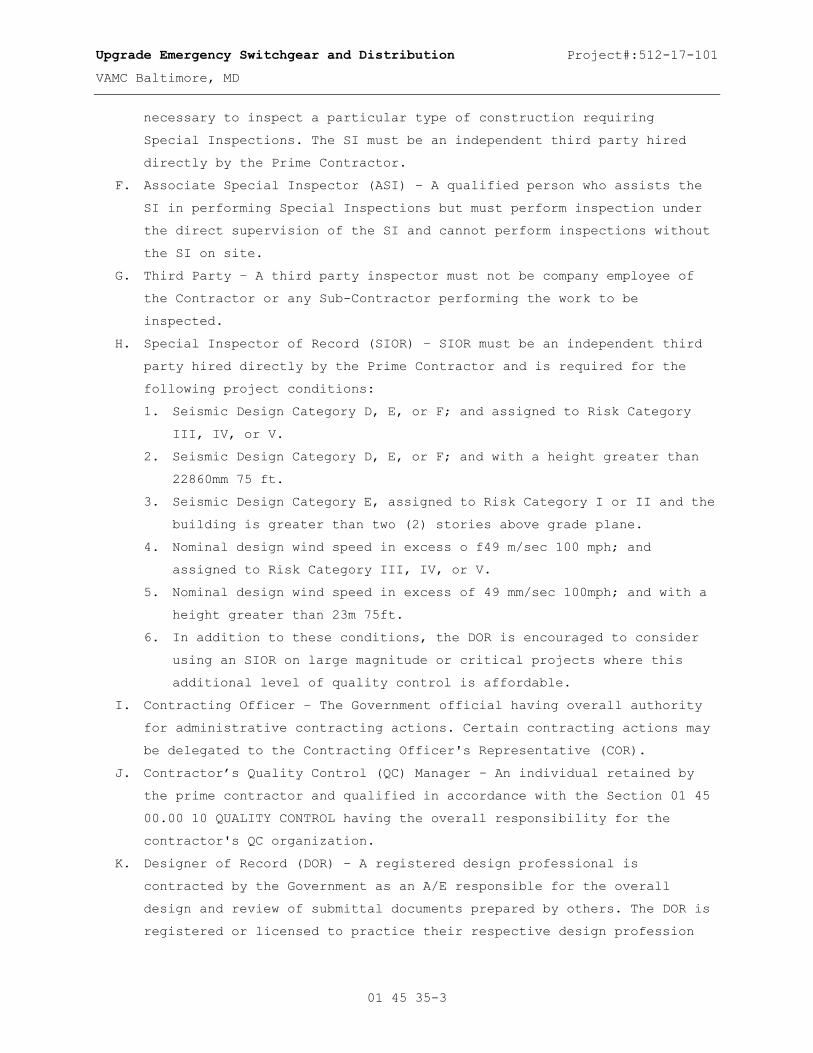
Upgrade Emergency Switchgear and Distribution Project#:512-17-101
VAMC Baltimore, MD
01 45 35-3
necessary to inspect a particular type of construction requiring
Special Inspections. The SI must be an independent third party hired
directly by the Prime Contractor.
F. Associate Special Inspector (ASI) – A qualified person who assists the
SI in performing Special Inspections but must perform inspection under
the direct supervision of the SI and cannot perform inspections without
the SI on site.
G. Third Party – A third party inspector must not be company employee of
the Contractor or any Sub-Contractor performing the work to be
inspected.
H. Special Inspector of Record (SIOR) – SIOR must be an independent third
party hired directly by the Prime Contractor and is required for the
following project conditions:
1. Seismic Design Category D, E, or F; and assigned to Risk Category
III, IV, or V.
2. Seismic Design Category D, E, or F; and with a height greater than
22860mm 75 ft.
3. Seismic Design Category E, assigned to Risk Category I or II and the
building is greater than two (2) stories above grade plane.
4. Nominal design wind speed in excess o f49 m/sec 100 mph; and
assigned to Risk Category III, IV, or V.
5. Nominal design wind speed in excess of 49 mm/sec 100mph; and with a
height greater than 23m 75ft.
6. In addition to these conditions, the DOR is encouraged to consider
using an SIOR on large magnitude or critical projects where this
additional level of quality control is affordable.
I. Contracting Officer – The Government official having overall authority
for administrative contracting actions. Certain contracting actions may
be delegated to the Contracting Officer's Representative (COR).
J. Contractor’s Quality Control (QC) Manager – An individual retained by
the prime contractor and qualified in accordance with the Section 01 45
00.00 10 QUALITY CONTROL having the overall responsibility for the
contractor's QC organization.
K. Designer of Record (DOR) – A registered design professional is
contracted by the Government as an A/E responsible for the overall
design and review of submittal documents prepared by others. The DOR is
registered or licensed to practice their respective design profession
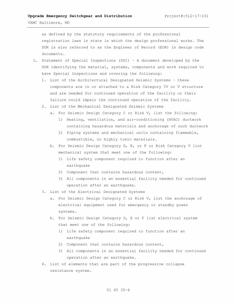
Upgrade Emergency Switchgear and Distribution Project#:512-17-101
VAMC Baltimore, MD
01 45 35-4
as defined by the statutory requirements of the professional
registration laws in state in which the design professional works. The
DOR is also referred to as the Engineer of Record (EOR) in design code
documents.
L. Statement of Special Inspections (SSI) – A document developed by the
DOR identifying the material, systems, components and work required to
have Special Inspections and covering the following:
1. List of the Architectural Designated Seismic Systems – these
components are in or attached to a Risk Category IV or V structure
and are needed for continued operation of the facility or their
failure could impair the continued operation of the facility.
2. List of the Mechanical Designated Seismic Systems
a. For Seismic Design Category C or Risk V, list the following:
1) Heating, ventilation, and air-conditioning (HVAC) ductwork
containing hazardous materials and anchorage of such ductwork
2) Piping systems and mechanical units containing flammable,
combustible, or highly toxic materials.
b. For Seismic Design Category D, E, or F or Risk Category V list
mechanical system that meet one of the following:
1) Life safety component required to function after an
earthquake
2) Component that contains hazardous content,
3) All components in an essential facility needed for continued
operation after an earthquake.
3. List of the Electrical Designated Systems
a. For Seismic Design Category C or Risk V, list the anchorage of
electrical equipment used for emergency or standby power
systems.
b. For Seismic Design Category D, E or F list electrical system
that meet one of the following:
1) Life safety component required to function after an
earthquake
2) Component that contains hazardous content,
3) All components in an essential facility needed for continued
operation after an earthquake.
4. List of elements that are part of the progressive collapse
resistance system.

Upgrade Emergency Switchgear and Distribution Project#:512-17-101
VAMC Baltimore, MD
01 45 35-5
a. Provide a description of the following as they apply:
1) Elements of the tie force system consisting of internal
longitudinal and transverse, vertical, and peripheral ties.
2) Elements of the alternate path system.
3) Elements having enhanced local resistance. The Statement of
Special Inspections and the Schedule of Special Inspections
will be included as an attachment to this specification
a) Schedule of Special Inspections – A schedule which lists
each of the required Special Inspections, the extent to
which each Special Inspections is to be performed, and the
required frequency for each in accordance with ICC IBC
Chapter 17. Template found here:
SECTION 01 45 35 Schedule of SI Template.docx
SECTION 01 45 35 Statement of SI Template 8MAR18.xlsx
b) Designated Seismic System – Those nonstructural components that require design in accordance with ASCE 7 Chapter 13
and for which the component importance factor, Ip, is
greater than 1.0. This designation applies to systems that
are required to be operational following the Design
Earthquake for RC I - IV structures and following the MCER
for RC V structures. All systems in RC V facilities
designated as MC-1 in accordance with UFC 3-310-04 are
considered part of the Designated Seismic Systems. //
Designated Seismic Systems will be identified by Owner and
will have an Importance Factor Ip = 1.5 //
b. Submittals: Government approval is required for all submittals.
CQC Special Inspection reports shall be submitted under this
Specification section and follow the [Special Inspection]:
[Applicable Specification section or description] naming
convention. Submit the following:
1) SD-01 Preconstruction Submittals;
2) SIOR Letter of Acceptance;
3) Special Inspections Project Manual;

Upgrade Emergency Switchgear and Distribution Project#:512-17-101
VAMC Baltimore, MD
01 45 35-6
4) Special Inspections Agency's Written Practices
5) NDT Procedures and Equipment’ Calibration Records;
6) SD-06 Test Reports;
7) Special Inspections
8) Daily Reports;
9) Special Inspections; Biweekly Reports;
10) SD-07 Certificates; 11) Fabrication Plant
12) Steel Truss Plant;
13) Wood Truss Plant; 14) AC472 Accreditation;
15) Steel Joist Institute Membership; 16) Precast Concrete Institute (PCI) Certified Plant;
17) Certificate of Compliance;
18) Special Inspector of Record Qualifications; 19) Special Inspector Qualifications;
20) Qualification Records for NDT technicians; 21) SD-11 Closeout Submittals;
22) Interim Final Report of Special Inspections;
23) Comprehensive Final Report of Special Inspections; c. Special Inspector Qualifications: Submit qualifications for each
SI, ASI, and the SIOR from the following certifying
associations: Associated Air Balance Council (AABC); American
Concrete Institute (ACI); Association of the Wall and Ceiling
Industry (AWCI); American Welding Society (AWS); Factory Mutual
(FM); International Code Council (ICC); Nondestructive Testing
(NDT); National Institute for Certification in Engineering
Technologies (NICET); Precast/Prestressed Concrete Institute
(PCI); Post-Tensioning Institute (PTI); Underwriters
Laboratories (UL). Qualifications should be in accordance with
the following minimums // ; PM or SRE can restrict
qualifications to the higher standards shown if multiple options
are shown for a role based on complexity of project //.
QUALIFICATIONS
Area Special Inspector Associated Special
Inspector SIOR
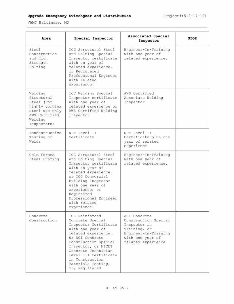
Upgrade Emergency Switchgear and Distribution Project#:512-17-101
VAMC Baltimore, MD
01 45 35-7
Area Special Inspector Associated Special
Inspector SIOR
Steel
Construction
and High
Strength
Bolting
ICC Structural Steel
and Bolting Special
Inspector certificate
with on year of
related experience,
or Registered
Professional Engineer
with related
experience.
Engineer-In-Training
with one year of
related experience.
Welding
Structural
Steel (For
highly complex
steel use only
AWS Certified
Welding
Inspectors)
ICC Welding Special
Inspector certificate
with one year of
related experience or
AWS Certified Welding
Inspector
AWS Certified
Associate Welding
Inspector
Nondestructive
Testing of
Welds
NDT Level II
Certificate
NDT Level II
Certificate plus one
year of related
experience
Cold Formed
Steel Framing
ICC Structural Steel
and Bolting Special
Inspector certificate
with on year of
related experience,
or ICC Commercial
Building Inspector
with one year of
experience; or
Registered
Professional Engineer
with related
experience.
Engineer-In-Training
with one year of
related experience.
Concrete
Construction
ICC Reinforced
Concrete Special
Inspector Certificate
with one year of
related experience,
or ACI Concrete
Construction Special
Inspector, or NICET
Concrete Technician
Level III Certificate
in Construction
Materials Testing,
or, Registered
ACI Concrete
Construction Special
Inspector in
Training, or
Engineer-In-Training
with one year of
related experience

Upgrade Emergency Switchgear and Distribution Project#:512-17-101
VAMC Baltimore, MD
01 45 35-8
Area Special Inspector Associated Special
Inspector SIOR
Professional Engineer
with related
experience
Prestressed
Concrete
Construction
ICC Pre-stressed
Special Inspector
Certificate with one
year of related
experience, or PCI
Quality Control
Technician/ Inspector
Level II Certificate
with one
year of related
experience, or
Registered
Professional Engineer
with related
experience.
PCI Quality Control
Technician/ Inspector
Level I Certificate
with one year of
related experience,
or Engineer-In-
Training with one
year of related
experience
Post-Tensioned
Concrete
Construction
PTI Level 2 Unbonded
PT Inspector
Certificate, or
Registered
Professional Engineer
with related
experience
PTI Level 1 Unbonded
PT Inspector
Certificate with one
year of related
experience, or
Engineer-In-Training
with one year of
related experience
Masonry
Construction
ICC Structural
Masonry Special
Inspector Certificate
with one year of
related experience,
or Registered
Professional Engineer
with related
experience
Engineer-In-Training
with one year of
related experience
Wood ICC Commercial
Building Inspector
Certificate with one
year of related
experience, or ICC
Residential Building
Inspector with on
year of experience,
or Registered
Professional Engineer
with related
experience
Engineer-In-Training
with one year of
related experience

Upgrade Emergency Switchgear and Distribution Project#:512-17-101
VAMC Baltimore, MD
01 45 35-9
Area Special Inspector Associated Special
Inspector SIOR
Verification
of Site Soil
Condition,
Fill
Placement, and
Load-Bearing
Requirements
ICC Soils Special
Inspector Certificate
with one year of
related experience,
or NICET Soils
Technician Level II
Certificate in
Construction Material
Testing, or NICET
Geotechnical
Engineering
Technician Level II
Construction or
Generalist
Certificate, or
Geologist-In-Training
with one year of
related experience,
or Registered
Professional Engineer
with related
experience
NICET Soils
Technician Level I
Certificate in
Construction Material
Testing with one year
of related
experience, or NICET
Geotechnical
Engineering
Technician Level I
Construction, or
Generalist
Certificate with one
year of related
experience, or
Engineer-In-Training
with one year of
related experience
Deep
Foundations
NICET Soils
Technician Level II
Certificate in
Construction Material
Testing, or NICET
Geotechnical
Engineering
Technician Level II
Construction or
Generalist
Certificate, or
Geologist-In-Training
with one year of
related experience,
or Registered
Professional Engineer
with related
experience
NICET Soils
Technician Level I
Certificate in
Construction Material
Testing with one year
of related
experience, or NICET
Geotechnical
Engineering
Technician Level I
Construction or
Generalist
Certificate with one
year of related
experience, or
Engineer-In-Training
with one year of
related experience
Sprayed Fire
Resistant
Manual
ICC Spray-applied
Fireproofing Special
Inspector
Certificate, or ICC
Fire Inspector I
Certificate with one
year of related
experience, or
Registered
Engineer-In-Training
with one year of
related experience

Upgrade Emergency Switchgear and Distribution Project#:512-17-101
VAMC Baltimore, MD
01 45 35-10
Area Special Inspector Associated Special
Inspector SIOR
Professional Engineer
with related
experience
Mastic and
Intumescent
Fire Resistant
Coatings
ICC Spray-applied
Fireproofing Special
Inspector
Certificate, or ICC
Fire Inspector I
Certificate with one
year of related
experience, or
Registered
Professional Engineer
with related
experience
Engineer-In-Training
with one year of
related experience.
Exterior
Insulation and
Finish Systems
(EIFS)
AWCI EIFS Inspector
Certificate, or
Exterior Design
Institute
Certificate, or
Registered
Professional Engineer
with related
experience
Engineer-In-Training
with one year of
related experience
Fire-Resistant
Penetrations
and Joints
Passed the UL
Firestop Exam with
one year of related
experience, or Passed
the FM Firestop Exam
with one year of
related experience,
or Registered
Professional Engineer
with related
experience
Engineer-In-Training
with one year of
related experience.
Smoke Control AABC Technician
Certification with
one year of related
experience, or
Registered
Professional Engineer
with related
experience
Engineer-In-Training
with one year of
related experience.
SIOR Registered
Professional
Engineer

Upgrade Emergency Switchgear and Distribution Project#:512-17-101
VAMC Baltimore, MD
01 45 35-11
PART 2 - PRODUCTS
2.1 FABRICATORS SPECIAL INSPECTION
A. Special Inspections of fabricator's work performed in the fabricator's
shop is required to be inspected in accordance with the Statement of
Special Inspections and the Schedule of Special Inspections unless the
fabricator is certified by the approved agency to perform such work
without Special Inspections. Submit the applicable certification(s)
from the following list to the Contracting Officer for information to
allow work performed in the fabricator's shop to not be subjected to
Special Inspections.
B. The following certifications meet the requirements for fabricator approval in accordance with paragraph 1704.2.5.2 of IBC:
1. American Institute of Steel Construction (AISC) Certified Fabrication Plant, Category STD.
2. Truss Plate Institute (TPI) steel truss plate quality assurance
program certification.
3. Truss Plate Institute (TPI) wood truss plate quality assurance
program certification.
4. International Accreditation Service, AC472 Accreditation Steel Joist
Institute Membership
5. Precast Concrete Institute (PCI) Certified Plant, Group C C. At the completion of fabrication, submit a certificate of compliance,
to be included with the comprehensive final report of Special
Inspections, stating that the materials supplied and work performed by
the fabricator are in accordance the construction documents.
PART 3 - EXECUTION
3.1 RESPONSIBILIES MATRIX
Inspector Responsibility Condition
SIOR a. Supervise all Special Inspectors required by the contract documents and the IBC.
b. Submit a SIOR Letter of Acceptance to the Contracting Officer attesting to acceptance of
the duties of SIOR, signed and sealed by the
SIOR.
c. Verify the qualifications of all of the Special
Applicable
when SIOR is
required

Upgrade Emergency Switchgear and Distribution Project#:512-17-101
VAMC Baltimore, MD
01 45 35-12
Inspector Responsibility Condition
Inspectors.
d. Verify the qualifications of fabricators.
SIOR e. Submit Special Inspections agency's written practices for the monitoring and control of the
agency's operations to include the following:
1. The agency's procedures for the selection and administration of inspection personnel,
describing the training, experience and
examination requirements for qualifications
and certification of inspection personnel.
2. The agency's inspection procedures, including general inspection, material
controls, and visual welding inspection.
f. Submit qualification records for nondestructive testing (NDT) technicians designated for the
project. Submit NDT procedures and equipment
calibration records for NDT to be performed and
equipment to be used for the project.
Applicable
when SIOR is
required and
when the
structural
design is
required to
follow
AISC341 for
seismic
design of
steel
structures
SIOR g. Prepare a Special Inspections Project Manual, which will cover the following:
1. Roles and responsibilities of the following individuals during Special Inspections: SIOR,
SI, General Contractor, Subcontractors, QC
Manager, and DOR.
2. Organizational chart and/or communication plan, indicating lines of communication
3. Contractor's internal plan for scheduling inspections. Address items such as timeliness
of inspection requests, who to contact for
inspection requests, and availability of
alternate inspectors. Contractor's internal
plan for scheduling inspections. Address
items such as timeliness of inspection
requests, who to contact for inspection
requests, and availability of alternate
inspectors.
4. Indicate the government reporting procedures. 5. Propose forms or templates to be used by SI
and SIOR to document inspections.
6. Indicate procedures for tracking nonconforming work and verification that
corrective work is complete.
7. Indicate how the SIOR and/or SI will participate in weekly QC meetings.
8. Indicate how Special Inspections of shop fabricated items will be handled when the
Applicable
when SIOR is
required

Upgrade Emergency Switchgear and Distribution Project#:512-17-101
VAMC Baltimore, MD
01 45 35-13
Inspector Responsibility Condition
fabricator's shop is not certified per
paragraph FABRICATOR SPECIAL INSPECTIONS.
9. Include a section in the manual that covers each specific item requiring Special
Inspections that is indicated on the Schedule
of Special Inspections. Provide names and
qualifications of each special inspector who
will be performing the Special Inspections
for each specific item. Provide detail on how
the Special Inspections are to be carried out
for each item so that the expectations are
clear for the General Contractor and the
Subcontractor performing the work. Make a
copy of the Special Inspections Project
Manual available on the job site during
construction. Submit a copy of the Special
Inspections Project Manual for approval.
h. Attend coordination and mutual understanding meeting where the information in the Special
Inspections Project Manual will be reviewed to
verify that all parties have a clear
understanding of the Special Inspections
provisions and the individual duties and
responsibilities of each party.
i. Maintain a 3- ring binder for the Special Inspector's daily and biweekly reports and the
Special Inspections Project Manual. This file
must be located in a conspicuous place in the
project trailer/office to allow review by the
Contracting Officer and the DOR.
j. Submit a copy of the Special Inspector's daily reports to the QC Manager.
k. Discrepancies that are observed during Special Inspections must be reported to the QC Manager
for correction. If discrepancies are not
corrected before the special inspector leaves
the site the observed discrepancies must be
documented in the daily report.
l. Submit a biweekly Special Inspections report until all work requiring Special Inspections is
complete. A report is required for each biweekly
period in which Special Inspections activity
occurs, and must include the following:
1. A brief summary of the work performed during the reporting time frame.
2. Changes and/or discrepancies with the drawings, specifications, and mechanical or
electrical component certification if they
require seismic systems, that were observed
during the reporting period.

Upgrade Emergency Switchgear and Distribution Project#:512-17-101
VAMC Baltimore, MD
01 45 35-14
Inspector Responsibility Condition
3. Discrepancies which were resolved or
corrected.
4. A list of nonconforming items requiring
resolution.
5. All applicable test results including
nondestructive testing reports.
QC Manager a. If there is no SIOR, QC Manager must Supervise
all Special Inspectors required by the contract
documents and the IBC; Verify the qualifications
of all of the Special Inspectors; Verify the
qualifications of fabricators; Maintain a 3-
ring binder for the Special Inspector's daily
and biweekly reports. This file must be located
in a conspicuous place in the project
trailer/office to allow review by the
Contracting Officer and the DOR.
Applicable
when SIOR is
not required
QC Manager b. Maintain a rework items list that includes
discrepancies noted on the Special Inspectors
daily report.
n/a
Special
Inspectors
a. Inspect all elements of the project for which
the special inspector is qualified to inspect
and are identified in the Schedule of Special
Inspections.
b. Attend preparatory phase meetings related to the
Definable Feature of Work (DFOW) for which the
special inspector is qualified to inspect.
n/a
Special
Inspectors
c. Submit Special Inspections agency's written
practices for the monitoring and control of the
agency's operations to include the following:
1. The agency's procedures for the selection and
administration of inspection personnel,
describing the training, experience and
examination requirements for qualifications
and certification of inspection personnel.
2. The agency's inspection procedures, including
general inspection, material controls, and
visual welding inspection.
d. Submit qualification records for nondestructive
testing (NDT) technicians designated for the
project.
e. Submit NDT procedures and equipment calibration
records for NDT to be performed and equipment to
be used for the project.]
Applicable
when SIOR is
NOT required
and when the
structural
design is
required to
follow AISC
341 for
seismic
design of
steel
structures

Upgrade Emergency Switchgear and Distribution Project#:512-17-101
VAMC Baltimore, MD
01 45 35-15
Inspector Responsibility Condition
Special
Inspectors
f. Submit a copy of the daily reports to the QC Manager.
g. Discrepancies that are observed during Special Inspections must be reported to the QC Manager
for correction. If discrepancies are not
corrected before the special inspector leaves
the site the observed discrepancies must be
documented in the daily report.
h. Submit a biweekly Special Inspection Report until all inspections are complete. A report is
required for each biweekly period in which
Special Inspections activity occurs, and must
include the following:
1. A brief summary of the work performed during the reporting time frame
2. Changes and/or discrepancies with the drawings, specifications, and mechanical or
electrical component certification if they
require seismic systems that were observed
during the reporting period.
3. Discrepancies which were resolved or corrected.
4. A list of nonconforming items requiring resolution.
5. All applicable test result including nondestructive testing reports.
j. At the completion of the project submit a comprehensive final report of Special
Inspections that documents the Special
Inspections completed for the project and
corrections of all discrepancies noted in the
daily reports. The comprehensive final report of
Special Inspections must be signed, dated and
indicate the certification of the special
inspector qualifying them to conduct the
inspection.
Applicable
when SIOR is
not required
Special
Inspectors
k. Submit daily reports to the SIOR Applicable
when SIOR is
required
3.2 DEFECTIVE WORK
Check work as it progresses, but failure to detect any defective work
or materials must in no way prevent later rejection if defective work
or materials are discovered, nor obligate the Government to accept such
work.
Upgrade Emergency Switchgear and Distribution Project#:512-17-101
VAMC Baltimore, MD
01 45 35-16
-- End of Section –

Upgrade Emergency Switchgear and Distribution Project#:512-17-101
VAMC Baltimore, MD
01 57 19- 1
SECTION 01 57 19
TEMPORARY ENVIRONMENTAL CONTROLS
PART 1 - GENERAL
1.1 DESCRIPTION
A. This section specifies the control of environmental pollution and damage
that the Contractor must consider for air, water, and land resources. It
includes management of visual aesthetics, noise, solid waste, radiant
energy, and radioactive materials, as well as other pollutants and
resources encountered or generated by the Contractor. The Contractor is
obligated to consider specified control measures with the costs included
within the various contract items of work.
B. Environmental pollution and damage is defined as the presence of
chemical, physical, or biological elements or agents which:
1. Adversely effect human health or welfare,
2. Unfavorably alter ecological balances of importance to human life,
3. Effect other species of importance to humankind, or;
4. Degrade the utility of the environment for aesthetic, cultural, and
historical purposes.
C. Definitions of Pollutants:
1. Chemical Waste: Petroleum products, bituminous materials, salts,
acids, alkalis, herbicides, pesticides, organic chemicals, and
inorganic wastes.
2. Debris: Combustible and noncombustible wastes, such as leaves, tree
trimmings, ashes, and waste materials resulting from construction or
maintenance and repair work.
3. Sediment: Soil and other debris that has been eroded and transported
by runoff water.
4. Solid Waste: Rubbish, debris, garbage, and other discarded solid
materials resulting from industrial, commercial, and agricultural
operations and from community activities.
5. Surface Discharge: The term "Surface Discharge" implies that the
water is discharged with possible sheeting action and subsequent soil
erosion may occur. Waters that are surface discharged may terminate
in drainage ditches, storm sewers, creeks, and/or "water of the
United States" and would require a permit to discharge water from the
governing agency.
6. Rubbish: Combustible and noncombustible wastes such as paper, boxes,
glass and crockery, metal and lumber scrap, tin cans, and bones.

Upgrade Emergency Switchgear and Distribution Project#:512-17-101
VAMC Baltimore, MD
01 57 19- 2
7. Sanitary Wastes:
a. Sewage: Domestic sanitary sewage and human and animal waste.
b. Garbage: Refuse and scraps resulting from preparation, cooking,
dispensing, and consumption of food.
1.2 QUALITY CONTROL
A. Establish and maintain quality control for the environmental protection
of all items set forth herein.
B. Record on daily reports any problems in complying with laws,
regulations, and ordinances. Note any corrective action taken.
1.3 REFERENCES
A. The publications listed below form a part of this specification to the
extent referenced. The publications are referred to in the text by basic
designation only.
B. U.S. National Archives and Records Administration (NARA):
33 CFR 328..............Definitions
1.4 SUBMITTALS
A. In accordance with Section, 01 33 23, SHOP DRAWINGS, PRODUCT DATA, AND
SAMPLES, furnish the following:
1. Environmental Protection Plan: After the contract is awarded and
prior to the commencement of the work, the Contractor shall meet with
the Resident Engineer and/or COR to discuss the proposed
Environmental Protection Plan and to develop mutual understanding
relative to details of environmental protection. Not more than 20
days after the meeting, the Contractor shall prepare and submit to
the Resident Engineer and/or COR, and the Contracting Officer for
approval, a written and/or graphic Environmental Protection Plan
including, but not limited to, the following:
a. Name(s) of person(s) within the Contractor's organization who is
(are) responsible for ensuring adherence to the Environmental
Protection Plan.
b. Name(s) and qualifications of person(s) responsible for
manifesting hazardous waste to be removed from the site.
c. Name(s) and qualifications of person(s) responsible for training
the Contractor's environmental protection personnel.
d. Description of the Contractor's environmental protection personnel
training program.
e. A list of Federal, State, and local laws, regulations, and permits
concerning environmental protection, pollution control, noise
control and abatement that are applicable to the Contractor's

Upgrade Emergency Switchgear and Distribution Project#:512-17-101
VAMC Baltimore, MD
01 57 19- 3
proposed operations and the requirements imposed by those laws,
regulations, and permits.
f. Methods for protection of features to be preserved within
authorized work areas including trees, shrubs, vines, grasses,
ground cover, landscape features, air and water quality, fish and
wildlife, soil, historical, and archeological and cultural
resources.
g. Procedures to provide the environmental protection that comply
with the applicable laws and regulations. Describe the procedures
to correct pollution of the environment due to accident, natural
causes, or failure to follow the procedures as described in the
Environmental Protection Plan.
h. Permits, licenses, and the location of the solid waste disposal
area.
i. Drawings showing locations of any proposed temporary excavations
or embankments for haul roads, material storage areas, structures,
sanitary facilities, and stockpiles of excess or spoil materials.
j. Environmental Monitoring Plans for the job site including land,
water, air, and noise.
k. Work Area Plan showing the proposed activity in each portion of
the area and identifying the areas of limited use or nonuse. Plan
should include measures for marking the limits of use areas.
B. Approval of the Contractor's Environmental Protection Plan will not
relieve the Contractor of responsibility for adequate and continued
control of pollutants and other environmental protection measures.
1.5 PROTECTION OF ENVIRONMENTAL RESOURCES
9. Handle and dispose of solid wastes in such a manner that will prevent
contamination of the environment. Place solid wastes (excluding
clearing debris) in containers that are emptied on a regular
schedule. Transport all solid waste off Government property and
dispose of waste in compliance with Federal, State, and local
requirements.
10. Store chemical waste away from the work areas in corrosion resistant
containers and dispose of waste in accordance with Federal, State,
and local regulations.
11. Handle discarded materials other than those included in the solid
waste category as directed by the Resident Engineer.
E. Protection of Air Resources: Keep construction activities under
surveillance, management, and control to minimize pollution of air
resources. Burning is not permitted on the job site. Keep activities,
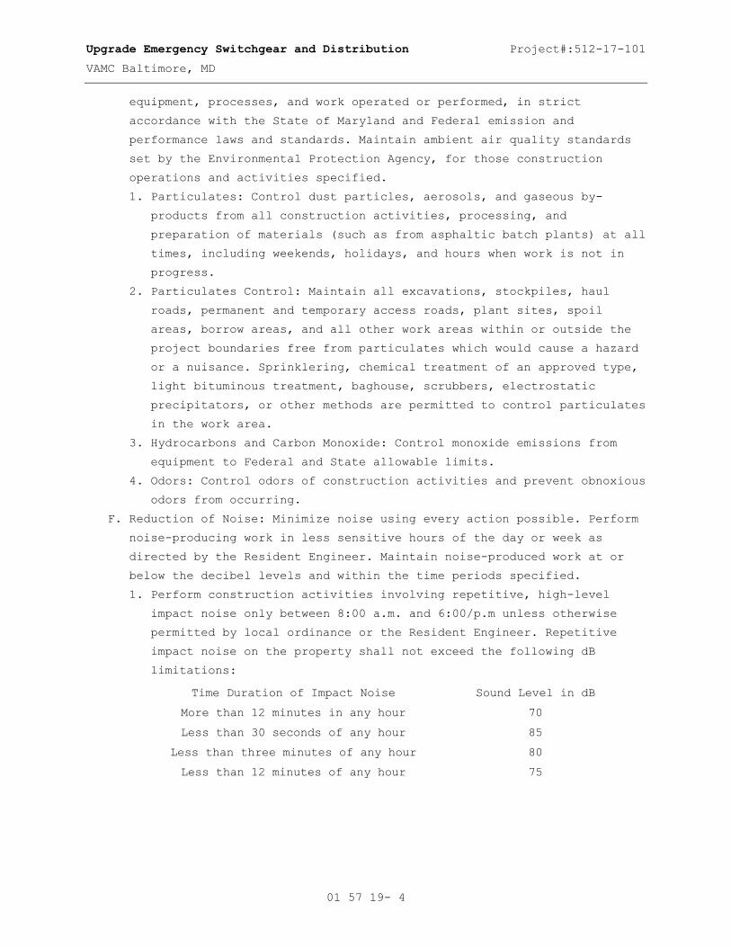
Upgrade Emergency Switchgear and Distribution Project#:512-17-101
VAMC Baltimore, MD
01 57 19- 4
equipment, processes, and work operated or performed, in strict
accordance with the State of Maryland and Federal emission and
performance laws and standards. Maintain ambient air quality standards
set by the Environmental Protection Agency, for those construction
operations and activities specified.
1. Particulates: Control dust particles, aerosols, and gaseous by-
products from all construction activities, processing, and
preparation of materials (such as from asphaltic batch plants) at all
times, including weekends, holidays, and hours when work is not in
progress.
2. Particulates Control: Maintain all excavations, stockpiles, haul
roads, permanent and temporary access roads, plant sites, spoil
areas, borrow areas, and all other work areas within or outside the
project boundaries free from particulates which would cause a hazard
or a nuisance. Sprinklering, chemical treatment of an approved type,
light bituminous treatment, baghouse, scrubbers, electrostatic
precipitators, or other methods are permitted to control particulates
in the work area.
3. Hydrocarbons and Carbon Monoxide: Control monoxide emissions from
equipment to Federal and State allowable limits.
4. Odors: Control odors of construction activities and prevent obnoxious
odors from occurring.
F. Reduction of Noise: Minimize noise using every action possible. Perform
noise-producing work in less sensitive hours of the day or week as
directed by the Resident Engineer. Maintain noise-produced work at or
below the decibel levels and within the time periods specified.
1. Perform construction activities involving repetitive, high-level
impact noise only between 8:00 a.m. and 6:00/p.m unless otherwise
permitted by local ordinance or the Resident Engineer. Repetitive
impact noise on the property shall not exceed the following dB
limitations:
Time Duration of Impact Noise Sound Level in dB
More than 12 minutes in any hour 70
Less than 30 seconds of any hour 85
Less than three minutes of any hour 80
Less than 12 minutes of any hour 75
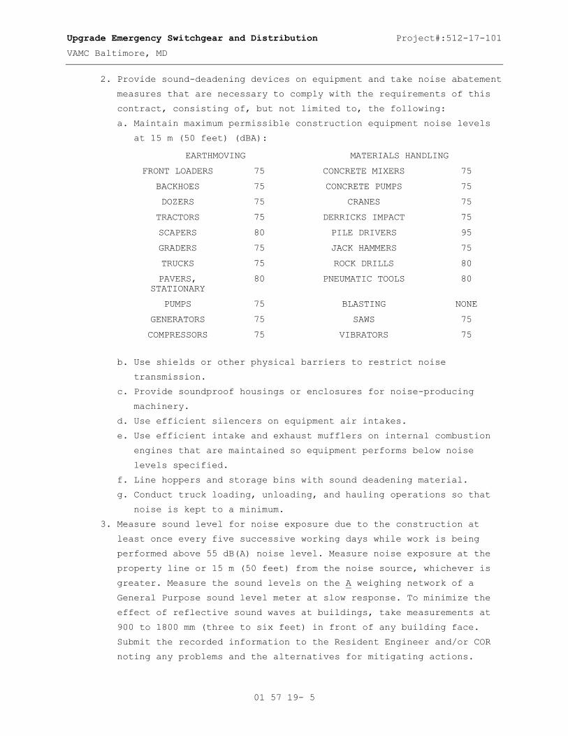
Upgrade Emergency Switchgear and Distribution Project#:512-17-101
VAMC Baltimore, MD
01 57 19- 5
2. Provide sound-deadening devices on equipment and take noise abatement
measures that are necessary to comply with the requirements of this
contract, consisting of, but not limited to, the following:
a. Maintain maximum permissible construction equipment noise levels
at 15 m (50 feet) (dBA):
EARTHMOVING MATERIALS HANDLING
FRONT LOADERS 75 CONCRETE MIXERS 75
BACKHOES 75 CONCRETE PUMPS 75
DOZERS 75 CRANES 75
TRACTORS 75 DERRICKS IMPACT 75
SCAPERS 80 PILE DRIVERS 95
GRADERS 75 JACK HAMMERS 75
TRUCKS 75 ROCK DRILLS 80
PAVERS,
STATIONARY
80 PNEUMATIC TOOLS 80
PUMPS 75 BLASTING NONE
GENERATORS 75 SAWS 75
COMPRESSORS 75 VIBRATORS 75
b. Use shields or other physical barriers to restrict noise
transmission.
c. Provide soundproof housings or enclosures for noise-producing
machinery.
d. Use efficient silencers on equipment air intakes.
e. Use efficient intake and exhaust mufflers on internal combustion
engines that are maintained so equipment performs below noise
levels specified.
f. Line hoppers and storage bins with sound deadening material.
g. Conduct truck loading, unloading, and hauling operations so that
noise is kept to a minimum.
3. Measure sound level for noise exposure due to the construction at
least once every five successive working days while work is being
performed above 55 dB(A) noise level. Measure noise exposure at the
property line or 15 m (50 feet) from the noise source, whichever is
greater. Measure the sound levels on the A weighing network of a
General Purpose sound level meter at slow response. To minimize the
effect of reflective sound waves at buildings, take measurements at
900 to 1800 mm (three to six feet) in front of any building face.
Submit the recorded information to the Resident Engineer and/or COR
noting any problems and the alternatives for mitigating actions.

Upgrade Emergency Switchgear and Distribution Project#:512-17-101
VAMC Baltimore, MD
01 57 19- 6
G. Restoration of Damaged Property: If any direct or indirect damage is
done to public or private property resulting from any act, omission,
neglect, or misconduct, the Contractor shall restore the damaged
property to a condition equal to that existing before the damage at no
additional cost to the Government. Repair, rebuild, or restore property
as directed or make good such damage in an acceptable manner.
H. Final Clean-up: On completion of project and after removal of all
debris, rubbish, and temporary construction, Contractor shall leave the
construction area in a clean condition satisfactory to the Resident
Engineer. Cleaning shall include off the station disposal of all items
and materials not required to be salvaged, as well as all debris and
rubbish resulting from demolition and new work operations.
- - - E N D - - -

Upgrade Emergency Switchgear and Distribution Project#:512-17-101
VAMC Baltimore, MD
01 58 16 - 1
SECTION 01 58 16
TEMPORARY INTERIOR SIGNAGE
PART 1 GENERAL
DESCRIPTION
This section specifies temporary interior signs.
PART 2 PRODUCTS
2.1 TEMPORARY SIGNS
A. Fabricate from 50 Kg (110 pound) mat finish white paper.
B. Cut to 100 mm (4-inch) wide by 300 mm (12 inch) long size tag.
C. Punch 3 mm (1/8-inch) diameter hole centered on 100 mm (4-inch)
dimension of tag. Edge of Hole spaced approximately 13 mm (1/2-inch)
from one end on tag.
D. Reinforce hole on both sides with gummed cloth washer or other suitable
material capable of preventing tie pulling through paper edge.
E. Ties: Steel wire 0.3 mm (0.0120-inch) thick, attach to tag with twist
tie, leaving 150 mm (6-inch) long free ends.
PART 3 EXECUTION
3.1 INSTALLATION
A. Install temporary signs attached to room door frame or room door knob,
lever, or pull for doors on corridor openings.
B. Mark on signs with felt tip marker having approximately 3 mm (1/8-inch)
wide stroke for clearly legible numbers or letters.
C. Identify room with numbers as designated on floor plans.
3.2 LOCATION
A. Install on doors that have room, corridor, and space numbers shown.
B. Doors that do not require signs are as follows:
1. Corridor barrier doors (cross-corridor) in corridor with same
number.
2. Folding doors or partitions.
3. Toilet or bathroom doors within and between rooms.
4. Communicating doors in partitions between rooms with corridor
entrance doors.
5. Closet doors within rooms.
C. Replace missing, damaged, or illegible signs.
- - - E N D - - -

Upgrade Emergency Switchgear and Distribution Project#:512-17-101
VAMC Baltimore, MD
01 74 19 - 1
MODIFICATION
06-01-12 CONTENT REVISED IN REFERENCE TO REQUIREMENT FOR RECYCLING OF
CONSTRUCTION AND DEMOLITION WASTE.

Upgrade Emergency Switchgear and Distribution Project#:512-17-101
VAMC Baltimore, MD
01 74 19 - 2
SECTION 01 74 19
CONSTRUCTION WASTE MANAGEMENT
PART 1 – GENERAL
1.1 DESCRIPTION
A. This section specifies the requirements for the management of non-
hazardous building construction and demolition waste.
B. Waste disposal in landfills shall be minimized to the greatest extent
possible. Of the inevitable waste that is generated, as much of the
waste material as economically feasible shall be salvaged, recycled or
reused.
C. Contractor shall use all reasonable means to divert construction and
demolition waste from landfills and incinerators, and facilitate their
salvage and recycle not limited to the following:
1. Waste Management Plan development and implementation.
2. Techniques to minimize waste generation.
3. Sorting and separating of waste materials.
4. Salvage of existing materials and items for reuse or resale.
5. Recycling of materials that cannot be reused or sold.
D. At a minimum the following waste categories shall be diverted from
landfills:
1. Soil.
2. Inerts (eg, concrete, masonry and asphalt).
3. Clean dimensional wood and palette wood.
4. Green waste (biodegradable landscaping materials).
5. Engineered wood products (plywood, particle board and I-joists,
etc).
6. Metal products (eg, steel, wire, beverage containers, copper, etc).
7. Cardboard, paper and packaging.
8. Bitumen roofing materials.
9. Plastics (eg, ABS, PVC).
10. Carpet and/or pad.
11. Gypsum board.
12. Insulation.
13. Paint.
14. Fluorescent lamps.
1.2 RELATED WORK
A. Section 02 41 00, DEMOLITION.

Upgrade Emergency Switchgear and Distribution Project#:512-17-101
VAMC Baltimore, MD
01 74 19 - 3
B. Section 01 00 00, GENERAL REQUIREMENTS.
C. Lead Paint: Section 02 83 33.13, LEAD BASED PAINT REMOVAL AND DISPOSAL.
1.3 QUALITY ASSURANCE
A. Contractor shall practice efficient waste management when sizing,
cutting and installing building products. Processes shall be employed
to ensure the generation of as little waste as possible. Construction
/Demolition waste includes products of the following:
1. Excess or unusable construction materials.
2. Packaging used for construction products.
3. Poor planning and/or layout.
4. Construction error.
5. Over ordering.
6. Weather damage.
7. Contamination.
8. Mishandling.
9. Breakage.
B. Establish and maintain the management of non-hazardous building
construction and demolition waste set forth herein. Conduct a site
assessment to estimate the types of materials that will be generated by
demolition and construction.
C. Contractor shall develop and implement procedures to recycle
construction and demolition waste to a minimum of 50 percent.
D. Contractor shall be responsible for implementation of any special
programs involving rebates or similar incentives related to recycling.
Any revenues or savings obtained from salvage or recycling shall accrue
to the contractor.
E. Contractor shall provide all demolition, removal and legal disposal of
materials. Contractor shall ensure that facilities used for recycling,
reuse and disposal shall be permitted for the intended use to the
extent required by local, state, federal regulations. The Whole
Building Design Guide website http://www.wbdg.org/tools/cwm.php
provides a Construction Waste Management Database that contains
information on companies that haul, collect, and process recyclable
debris from construction projects.
F. Contractor shall assign a specific area to facilitate separation of
materials for reuse, salvage, recycling, and return. Such areas are to

Upgrade Emergency Switchgear and Distribution Project#:512-17-101
VAMC Baltimore, MD
01 74 19 - 4
be kept neat and clean and clearly marked in order to avoid
contamination or mixing of materials.
G. Contractor shall provide on-site instructions and supervision of
separation, handling, salvaging, recycling, reuse and return methods to
be used by all parties during waste generating stages.
H. Record on daily reports any problems in complying with laws,
regulations and ordinances with corrective action taken.
1.4 TERMINOLOGY
A. Class III Landfill: A landfill that accepts non-hazardous resources
such as household, commercial and industrial waste resulting from
construction, remodeling, repair and demolition operations.
B. Clean: Untreated and unpainted; uncontaminated with adhesives, oils,
solvents, mastics and like products.
C. Construction and Demolition Waste: Includes all non-hazardous resources
resulting from construction, remodeling, alterations, repair and
demolition operations.
D. Dismantle: The process of parting out a building in such a way as to
preserve the usefulness of its materials and components.
E. Disposal: Acceptance of solid wastes at a legally operating facility
for the purpose of land filling (includes Class III landfills and inert
fills).
F. Inert Backfill Site: A location, other than inert fill or other
disposal facility, to which inert materials are taken for the purpose
of filling an excavation, shoring or other soil engineering operation.
G. Inert Fill: A facility that can legally accept inert waste, such as
asphalt and concrete exclusively for the purpose of disposal.
H. Inert Solids/Inert Waste: Non-liquid solid resources including, but not
limited to, soil and concrete that does not contain hazardous waste or
soluble pollutants at concentrations in excess of water-quality
objectives established by a regional water board, and does not contain
significant quantities of decomposable solid resources.
I. Mixed Debris: Loads that include commingled recyclable and non-
recyclable materials generated at the construction site.
J. Mixed Debris Recycling Facility: A solid resource processing facility
that accepts loads of mixed construction and demolition debris for the
purpose of recovering re-usable and recyclable materials and disposing
non-recyclable materials.

Upgrade Emergency Switchgear and Distribution Project#:512-17-101
VAMC Baltimore, MD
01 74 19 - 5
K. Permitted Waste Hauler: A company that holds a valid permit to collect
and transport solid wastes from individuals or businesses for the
purpose of recycling or disposal.
L. Recycling: The process of sorting, cleansing, treating, and
reconstituting materials for the purpose of using the altered form in
the manufacture of a new product. Recycling does not include burning,
incinerating or thermally destroying solid waste.
1. On-site Recycling – Materials that are sorted and processed on site
for use in an altered state in the work, i.e. concrete crushed for
use as a sub-base in paving.
2. Off-site Recycling – Materials hauled to a location and used in an
altered form in the manufacture of new products.
M. Recycling Facility: An operation that can legally accept materials for
the purpose of processing the materials into an altered form for the
manufacture of new products. Depending on the types of materials
accepted and operating procedures, a recycling facility may or may not
be required to have a solid waste facilities permit or be regulated by
the local enforcement agency.
N. Reuse: Materials that are recovered for use in the same form, on-site
or off-site.
O. Return: To give back reusable items or unused products to vendors for
credit.
P. Salvage: To remove waste materials from the site for resale or re-use
by a third party.
Q. Source-Separated Materials: Materials that are sorted by type at the
site for the purpose of reuse and recycling.
R. Solid Waste: Materials that have been designated as non-recyclable and
are discarded for the purposes of disposal.
S. Transfer Station: A facility that can legally accept solid waste for
the purpose of temporarily storing the materials for re-loading onto
other trucks and transporting them to a landfill for disposal, or
recovering some materials for re-use or recycling.
1.5 SUBMITTALS
A. In accordance with Section 01 33 23, SHOP DRAWINGS, PRODUCT DATA, and
SAMPLES, furnish the following:

Upgrade Emergency Switchgear and Distribution Project#:512-17-101
VAMC Baltimore, MD
01 74 19 - 6
B. Prepare and submit to the Contracting Officer Representative a written
demolition debris management plan. The plan shall include, but not be
limited to, the following information:
1. Procedures to be used for debris management.
2. Techniques to be used to minimize waste generation.
3. Analysis of the estimated job site waste to be generated:
a. List of each material and quantity to be salvaged, reused,
recycled.
b. List of each material and quantity proposed to be taken to a
landfill.
4. Detailed description of the Means/Methods to be used for material
handling.
a. On site: Material separation, storage, protection where
applicable.
b. Off site: Transportation means and destination. Include list of
materials.
1) Description of materials to be site-separated and self-hauled
to designated facilities.
2) Description of mixed materials to be collected by designated
waste haulers and removed from the site.
c. The names and locations of mixed debris reuse and recycling
facilities or sites.
d. The names and locations of trash disposal landfill facilities or
sites.
e. Documentation that the facilities or sites are approved to
receive the materials.
C. Designated Manager responsible for instructing personnel, supervising,
documenting and administer over meetings relevant to the Waste
Management Plan.
D. Monthly summary of construction and demolition debris diversion and
disposal, quantifying all materials generated at the work site and
disposed of or diverted from disposal through recycling.
1.6 APPLICABLE PUBLICATIONS
A Publications listed below form a part of this specification to the
extent referenced. Publications are referenced by the basic designation
only. In the event that criteria requirements conflict, the most
stringent requirements shall be met.

Upgrade Emergency Switchgear and Distribution Project#:512-17-101
VAMC Baltimore, MD
01 74 19 - 7
B. U.S. Green Building Council (USGBC):
LEED Green Building Rating System for New Construction
1.7 RECORDS
Maintain records to document the quantity of waste generated; the
quantity of waste diverted through sale, reuse, or recycling; and the
quantity of waste disposed by landfill or incineration. Records shall
be kept in accordance with the LEED Reference Guide and LEED Template.
PART 2 - PRODUCTS
2.1 MATERIALS
A. List of each material and quantity to be salvaged, recycled, reused.
B. List of each material and quantity proposed to be taken to a landfill.
C. Material tracking data: Receiving parties, dates removed,
transportation costs, weight tickets, tipping fees, manifests,
invoices, net total costs or savings.
PART 3 - EXECUTION
3.1 COLLECTION
A. Provide all necessary containers, bins and storage areas to facilitate
effective waste management.
B. Clearly identify containers, bins and storage areas so that recyclable
materials are separated from trash and can be transported to respective
recycling facility for processing.
C. Hazardous wastes shall be separated, stored, disposed of according to
local, state, federal regulations.
3.2 DISPOSAL
A. Contractor shall be responsible for transporting and disposing of
materials that cannot be delivered to a source-separated or mixed
materials recycling facility to a transfer station or disposal facility
that can accept the materials in accordance with state and federal
regulations.
B. Construction or demolition materials with no practical reuse or that
cannot be salvaged or recycled shall be disposed of at a landfill or
incinerator.
3.3 REPORT
A. With each application for progress payment, submit a summary of
construction and demolition debris diversion and disposal including
beginning and ending dates of period covered.

Upgrade Emergency Switchgear and Distribution Project#:512-17-101
VAMC Baltimore, MD
01 74 19 - 8
B. Quantify all materials diverted from landfill disposal through salvage
or recycling during the period with the receiving parties, dates
removed, transportation costs, weight tickets, manifests, invoices.
Include the net total costs or savings for each salvaged or recycled
material.
C. Quantify all materials disposed of during the period with the receiving
parties, dates removed, transportation costs, weight tickets, tipping
fees, manifests, invoices. Include the net total costs for each
disposal.
- - - E N D - - -

Upgrade Emergency Switchgear and Distribution Project#:512-17-101
VAMC Baltimore, MD
01 91 00 - 1
SECTION 01 91 00
GENERAL COMMISSIONING REQUIREMENTS
PART 1 - GENERAL
1.1 COMMISSIONING DESCRIPTION
A. This Section 01 91 00 GENERAL COMMISSIONING REQUIREMENTS shall form the
basis of the construction phase commissioning process and procedures.
The Commissioning Agent shall add, modify, and refine the commissioning
procedures, as approved by the Department of Veterans Affairs (VA), to
suit field conditions and actual manufacturer's equipment, incorporate
test data and procedure results, and provide detailed scheduling for
all commissioning tasks.
B. Various sections of the project specifications require equipment
startup, testing, and adjusting services. Requirements for startup,
testing, and adjusting services specified in the Division 7, Division
21, Division 22, Division 23, Division 26, Division 27, Division 28,
and Division 31 series sections of these specifications are intended to
be provided in coordination with the commissioning services and are not
intended to duplicate services. The Contractor shall coordinate the
work required by individual specification sections with the
commissioning services requirements specified herein.
C. Where individual testing, adjusting, or related services are required
in the project specifications and not specifically required by this
commissioning requirements specification, the specified services shall
be provided and copies of documentation, as required by those
specifications shall be submitted to the VA and the Commissioning Agent
to be indexed for future reference.
D. Where training or educational services for VA are required and
specified in other sections of the specifications, including but not
limited to Division 7, Division 8, Division 21, Division 22, Division
23, Division 26, Division 27, Division 28, and Division 31 series
sections of the specification, these services are intended to be
provided in addition to the training and educational services specified
herein.
E. Commissioning is a systematic process of verifying that the building
systems perform interactively according to the construction documents
and the VA’s operational needs. The commissioning process shall
encompass and coordinate the system documentation, equipment startup,
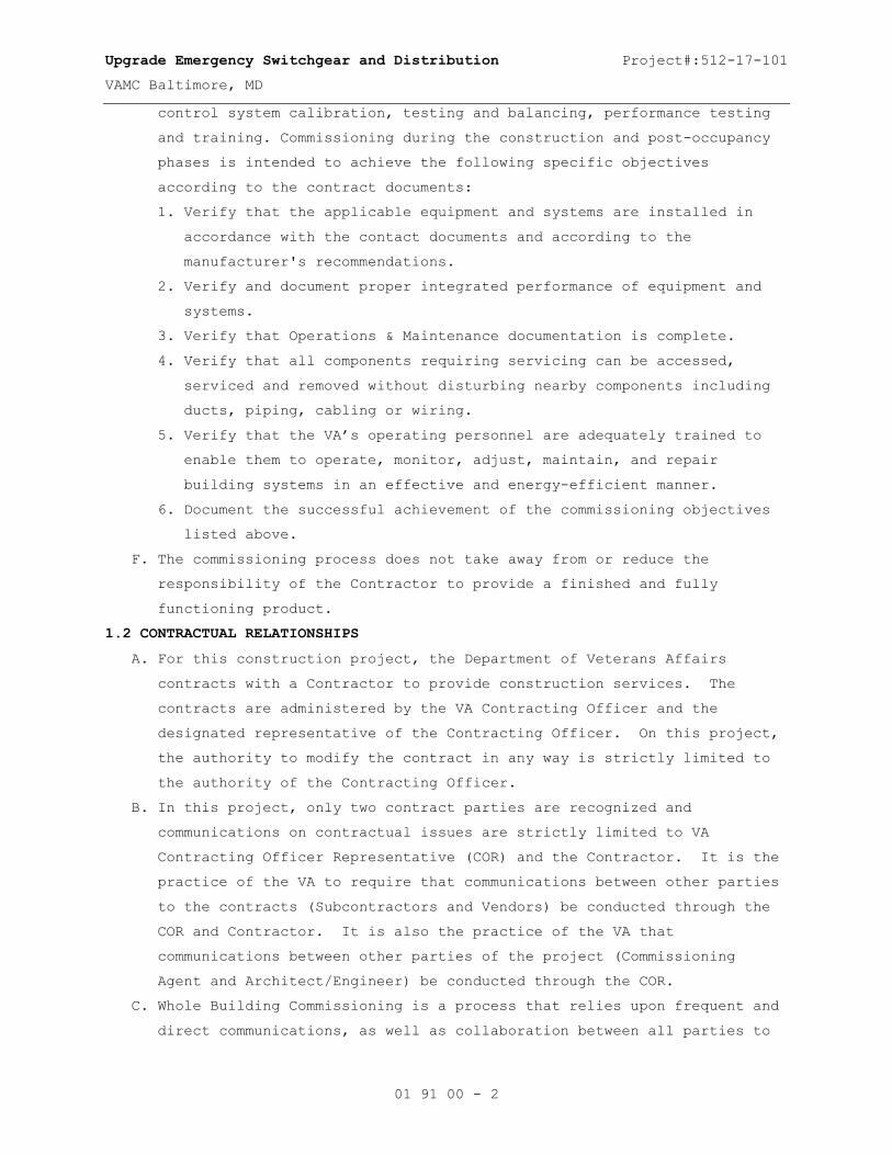
Upgrade Emergency Switchgear and Distribution Project#:512-17-101
VAMC Baltimore, MD
01 91 00 - 2
control system calibration, testing and balancing, performance testing
and training. Commissioning during the construction and post-occupancy
phases is intended to achieve the following specific objectives
according to the contract documents:
1. Verify that the applicable equipment and systems are installed in
accordance with the contact documents and according to the
manufacturer's recommendations.
2. Verify and document proper integrated performance of equipment and
systems.
3. Verify that Operations & Maintenance documentation is complete.
4. Verify that all components requiring servicing can be accessed,
serviced and removed without disturbing nearby components including
ducts, piping, cabling or wiring.
5. Verify that the VA’s operating personnel are adequately trained to
enable them to operate, monitor, adjust, maintain, and repair
building systems in an effective and energy-efficient manner.
6. Document the successful achievement of the commissioning objectives
listed above.
F. The commissioning process does not take away from or reduce the
responsibility of the Contractor to provide a finished and fully
functioning product.
1.2 CONTRACTUAL RELATIONSHIPS
A. For this construction project, the Department of Veterans Affairs
contracts with a Contractor to provide construction services. The
contracts are administered by the VA Contracting Officer and the
designated representative of the Contracting Officer. On this project,
the authority to modify the contract in any way is strictly limited to
the authority of the Contracting Officer.
B. In this project, only two contract parties are recognized and
communications on contractual issues are strictly limited to VA
Contracting Officer Representative (COR) and the Contractor. It is the
practice of the VA to require that communications between other parties
to the contracts (Subcontractors and Vendors) be conducted through the
COR and Contractor. It is also the practice of the VA that
communications between other parties of the project (Commissioning
Agent and Architect/Engineer) be conducted through the COR.
C. Whole Building Commissioning is a process that relies upon frequent and
direct communications, as well as collaboration between all parties to

Upgrade Emergency Switchgear and Distribution Project#:512-17-101
VAMC Baltimore, MD
01 91 00 - 3
the construction process. By its nature, a high level of communication
and cooperation between the Commissioning Agent and all other parties
(Architects, Engineers, Subcontractors, Vendors, third party testing
agencies, etc.) is essential to the success of the Commissioning
effort.
D. With these fundamental practices in mind, the commissioning process
described herein has been developed to recognize that, in the execution
of the Commissioning Process, the Commissioning Agent must develop
effective methods to communicate with every member of the construction
team involved in delivering commissioned systems while simultaneously
respecting the exclusive contract authority of the Contracting Officer
and COR. Thus, the procedures outlined in this specification must be
executed within the following limitations:
1. No communications (verbal or written) from the Commissioning Agent
shall be deemed to constitute direction that modifies the terms of
any contract between the Department of Veterans Affairs and the
Contractor.
2. Commissioning Issues identified by the Commissioning Agent will be
delivered to the COR and copied to the designated Commissioning
Representatives for the Contractor and subcontractors on the
Commissioning Team for information only in order to expedite the
communication process. These issues must be understood as the
professional opinion of the Commissioning Agent and as suggestions
for resolution.
3. In the event that any Commissioning Issues and suggested resolutions
are deemed by the COR to require either an official interpretation
of the construction documents or require a modification of the
contract documents, the Contracting Officer or COR will issue an
official directive to this effect.
4. All parties to the Commissioning Process shall be individually
responsible for alerting the COR of any issues that they deem to
constitute a potential contract change prior to acting on these
issues.
5. Authority for resolution or modification of design and construction
issues rests solely with the Contracting Officer or the COR, with
appropriate technical guidance from the Architect/Engineer and/or
Commissioning Agent.

Upgrade Emergency Switchgear and Distribution Project#:512-17-101
VAMC Baltimore, MD
01 91 00 - 4
1.3 RELATED WORK
A. Section 01 00 00 GENERAL REQUIREMENTS.
B. Section 01 32.16.15 PROJECT SCHEDULES (SMALL PROJECTS –
DESIGN/BID/BUILD)
C. Section 21 08 00 COMMISSIONING OF FIRE PROTECTION SYSTEMS.
D. Section 26 08 00 COMMISSIONING OF ELECTRICAL SYSTEMS. SYSTEMS. 1.4 SUMMARY
A. This Section includes general requirements that apply to implementation
of commissioning without regard to systems, subsystems, and equipment
being commissioned.
B. The commissioning activities have been developed to support the VA
requirements to meet guidelines for Federal Leadership in
Environmental, Energy, and Economic Performance.
1.5 ACRONYMS
List of Acronyms
Acronym Meaning
A/E Architect / Engineer Design Team
AHJ Authority Having Jurisdiction
ASHRAE Association Society for Heating Air Condition and
Refrigeration Engineers
BOD Basis of Design
BSC Building Systems Commissioning
CCTV Closed Circuit Television
CD Construction Documents
CMMS Computerized Maintenance Management System
CO Contracting Officer (VA)
COR Contracting Officer’s Representative (see also VA-RE)
COBie Construction Operations Building Information Exchange
CPC Construction Phase Commissioning
Cx Commissioning
CxA Commissioning Agent
CxM Commissioning Manager
CxR Commissioning Representative
DPC Design Phase Commissioning
FPT Functional Performance Test
GBI-GG Green Building Initiative - Green Globes
HVAC Heating, Ventilation, and Air Conditioning

Upgrade Emergency Switchgear and Distribution Project#:512-17-101
VAMC Baltimore, MD
01 91 00 - 5
List of Acronyms
Acronym Meaning
LEED Leadership in Energy and Environmental Design
NC Department of Veterans Affairs National Cemetery
NCA Department of Veterans Affairs National Cemetery
Administration
NEBB National Environmental Balancing Bureau
O&M Operations & Maintenance
OPR Owner’s Project Requirements
PFC Pre-Functional Checklist
PFT Pre-Functional Test
SD Schematic Design
SO Site Observation
TAB Test Adjust and Balance
VA Department of Veterans Affairs
VAMC VA Medical Center
VA CFM VA Office of Construction and Facilities Management
VACO VA Central Office
VA PM VA Project Manager
VA-RE VA Resident Engineer
USGBC United States Green Building Council
1.6 DEFINITIONS
Acceptance Phase Commissioning: Commissioning tasks executed after most
construction has been completed, most Site Observations and Static
Tests have been completed and Pre-Functional Testing has been completed
and accepted. The main commissioning activities performed during this
phase are verification that the installed systems are functional by
conducting Systems Functional Performance tests and Owner Training.
Accuracy: The capability of an instrument to indicate the true value of
a measured quantity.
Back Check: A back check is a verification that an agreed upon
solution to a design comment has been adequately addressed in a
subsequent design review
Basis of Design (BOD): The Engineer’s Basis of Design is comprised of
two components: the Design Criteria and the Design Narrative, these
documents record the concepts, calculations, decisions, and product

Upgrade Emergency Switchgear and Distribution Project#:512-17-101
VAMC Baltimore, MD
01 91 00 - 6
selections used to meet the Owner’s Project Requirements (OPR) and to
satisfy applicable regulatory requirements, standards, and guidelines.
Benchmarks: Benchmarks are the comparison of a building’s energy usage
to other similar buildings and to the building itself. For example,
ENERGY STAR Portfolio Manager is a frequently used and nationally
recognized building energy benchmarking tool.
Building Information Modeling (BIM): Building Information Modeling is
a parametric database which allows a building to be designed and
constructed virtually in 3D, and provides reports both in 2D views and
as schedules. This electronic information can be extracted and reused
for pre-populating facility management CMMS systems. Building Systems
Commissioning (BSC): NEBB acronym used to designate its commissioning
program.
Calibrate: The act of comparing an instrument of unknown accuracy with
a standard of known accuracy to detect, correlate, report, or eliminate
by adjustment any variation in the accuracy of the tested instrument.
CCTV: Closed circuit Television. Normally used for security
surveillance and alarm detections as part of a special electrical
security system.
COBie: Construction Operations Building Information Exchange (COBie)
is an electronic industry data format used to transfer information
developed during design, construction, and commissioning into the
Computer Maintenance Management Systems (CMMS) used to operate
facilities. See the Whole Building Design Guide website for further
information (http://www.wbdg.org/resources/cobie.php)
Commissionability: Defines a design component or construction process
that has the necessary elements that will allow a system or component
to be effectively measured, tested, operated and commissioned
Commissioning Agent (CxA): The qualified Commissioning Professional who
administers the Cx process by managing the Cx team and overseeing the
Commissioning Process. Where CxA is used in this specification it means
the Commissioning Agent, members of his staff or appointed members of
the commissioning team. Note that LEED uses the term Commissioning
Authority in lieu of Commissioning Agent.
Commissioning Checklists: Lists of data or inspections to be verified
to ensure proper system or component installation, operation, and
function. Verification checklists are developed and used during all

Upgrade Emergency Switchgear and Distribution Project#:512-17-101
VAMC Baltimore, MD
01 91 00 - 7
phases of the commissioning process to verify that the Owner’s Project
Requirements (OPR) is being achieved.
Commissioning Design Review: The commissioning design review is a
collaborative review of the design professionals design documents for
items pertaining to the following: owner’s project requirements; basis
of design; operability and maintainability (O&M) including
documentation; functionality; training; energy efficiency, control
systems’ sequence of operations including building automation system
features; commissioning specifications and the ability to functionally
test the systems.
Commissioning Issue: A condition identified by the Commissioning Agent
or other member of the Commissioning Team that adversely affects the
commissionability, operability, maintainability, or functionality of a
system, equipment, or component. A condition that is in conflict with
the Contract Documents and/or performance requirements of the installed
systems and components. (See also – Commissioning Observation).
Commissioning Manager (CxM): A qualified individual appointed by the
Contractor to manage the commissioning process on behalf of the
Contractor.
Commissioning Observation: An issue identified by the Commissioning
Agent or other member of the Commissioning Team that does not conform
to the project OPR, contract documents or standard industry best
practices. (See also Commissioning Issue)
Commissioning Plan: A document that outlines the commissioning process,
commissioning scope and defines responsibilities, processes, schedules,
and the documentation requirements of the Commissioning Process.
Commissioning Process: A quality focused process for enhancing the
delivery of a project. The process focuses upon verifying and
documenting that the facility and all of its systems, components, and
assemblies are planned, designed, installed, tested, can be operated,
and maintained to meet the Owner's Project Requirements.
Commissioning Report: The final commissioning document which presents
the commissioning process results for the project. Cx reports include
an executive summary, the commissioning plan, issue log,
correspondence, and all appropriate check sheets and test forms.
Commissioning Representative (CxR): An individual appointed by a sub-
contractor to manage the commissioning process on behalf of the sub-
contractor.

Upgrade Emergency Switchgear and Distribution Project#:512-17-101
VAMC Baltimore, MD
01 91 00 - 8
Commissioning Specifications: The contract documents that detail the
objective, scope and implementation of the commissioning process as
developed in the Commissioning Plan.
Commissioning Team: Individual team members whose coordinated actions
are responsible for implementing the Commissioning Process.
Construction Phase Commissioning: All commissioning efforts executed
during the construction process after the design phase and prior to the
Acceptance Phase Commissioning.
Contract Documents (CD): Contract documents include design and
construction contracts, price agreements and procedure agreements.
Contract Documents also include all final and complete drawings,
specifications and all applicable contract modifications or
supplements.
Construction Phase Commissioning (CPC): All commissioning efforts
executed during the construction process after the design phase and
prior to the Acceptance Phase Commissioning.
Coordination Drawings: Drawings showing the work of all trades that are
used to illustrate that equipment can be installed in the space
allocated without compromising equipment function or access for
maintenance and replacement. These drawings graphically illustrate and
dimension manufacturers’ recommended maintenance clearances. On
mechanical projects, coordination drawings include structural steel,
ductwork, major piping and electrical conduit and show the elevations
and locations of the above components.
Data Logging: The monitoring and recording of temperature, flow,
current, status, pressure, etc. of equipment using stand-alone data
recorders.
Deferred System Test: Tests that cannot be completed at the end of the
acceptance phase due to ambient conditions, schedule issues or other
conditions preventing testing during the normal acceptance testing
period.
Deficiency: See “Commissioning Issue”.
Design Criteria: A listing of the VA Design Criteria outlining the
project design requirements, including its source. These are used
during the design process to show the design elements meet the OPR.
Design Intent: The overall term that includes the OPR and the BOD. It
is a detailed explanation of the ideas, concepts, and criteria that are
defined by the owner to be important. The design intent documents are

Upgrade Emergency Switchgear and Distribution Project#:512-17-101
VAMC Baltimore, MD
01 91 00 - 9
utilized to provide a written record of these ideas, concepts and
criteria.
Design Narrative: A written description of the proposed design
solutions that satisfy the requirements of the OPR.
Design Phase Commissioning (DPC): All commissioning tasks executed
during the design phase of the project.
Environmental Systems: Systems that use a combination of mechanical
equipment, airflow, water flow and electrical energy to provide
heating, ventilating, air conditioning, humidification, and
dehumidification for the purpose of human comfort or process control of
temperature and humidity.
Executive Summary: A section of the Commissioning report that reviews
the general outcome of the project. It also includes any unresolved
issues, recommendations for the resolution of unresolved issues and all
deferred testing requirements.
Functionality: This defines a design component or construction process
which will allow a system or component to operate or be constructed in
a manner that will produce the required outcome of the OPR.
Functional Test Procedure (FTP): A written protocol that defines
methods, steps, personnel, and acceptance criteria for tests conducted
on components, equipment, assemblies, systems, and interfaces among
systems.
Industry Accepted Best Practice: A design component or construction
process that has achieved industry consensus for quality performance
and functionality. Refer to the current edition of the NEBB Design
Phase Commissioning Handbook for examples.
Installation Verification: Observations or inspections that confirm
the system or component has been installed in accordance with the
contract documents and to industry accepted best practices.
Integrated System Testing: Integrated Systems Testing procedures entail
testing of multiple integrated systems performance to verify proper
functional interface between systems. Typical Integrated Systems
Testing includes verifying that building systems respond properly to
loss of utility, transfer to emergency power sources, re-transfer from
emergency power source to normal utility source; interface between HVAC
controls and Fire Alarm systems for equipment shutdown, interface
between Fire Alarm system and elevator control systems for elevator
recall and shutdown; interface between Fire Alarm System and Security

Upgrade Emergency Switchgear and Distribution Project#:512-17-101
VAMC Baltimore, MD
01 91 00 - 10
Access Control Systems to control access to spaces during fire alarm
conditions; and other similar tests as determined for each specific
project.
Issues Log: A formal and ongoing record of problems or concerns – and
their resolution – that have been raised by members of the
Commissioning Team during the course of the Commissioning Process.
Lessons Learned Workshop: A workshop conducted to discuss and document
project successes and identify opportunities for improvements for
future projects.
Maintainability: A design component or construction process that will
allow a system or component to be effectively maintained. This includes
adequate room for access to adjust and repair the equipment.
Maintainability also includes components that have readily obtainable
repair parts or service.
Manual Test: Testing using hand-held instruments, immediate control
system readouts or direct observation to verify performance (contrasted
to analyzing monitored data taken over time to make the ‘observation’).
Owner’s Project Requirements (OPR): A written document that details the
project requirements and the expectations of how the building and its
systems will be used and operated. These include project goals,
measurable performance criteria, cost considerations, benchmarks,
success criteria, and supporting information.
Peer Review: A formal in-depth review separate from the commissioning
review processes. The level of effort and intensity is much greater
than a typical commissioning facilitation or extended commissioning
review. The VA usually hires an independent third-party (called the
IDIQ A/E) to conduct peer reviews.
Precision: The ability of an instrument to produce repeatable readings
of the same quantity under the same conditions. The precision of an
instrument refers to its ability to produce a tightly grouped set of
values around the mean value of the measured quantity.
Pre-Design Phase Commissioning: Commissioning tasks performed prior to
the commencement of design activities that includes project programming
and the development of the commissioning process for the project
Pre-Functional Checklist (PFC): A form used by the contractor to
verify that appropriate components are onsite, correctly installed, set
up, calibrated, functional and ready for functional testing.

Upgrade Emergency Switchgear and Distribution Project#:512-17-101
VAMC Baltimore, MD
01 91 00 - 11
Pre-Functional Test (PFT): An inspection or test that is done before
functional testing. PFT’s include installation verification and system
and component start up tests.
Procedure or Protocol: A defined approach that outlines the execution
of a sequence of work or operations. Procedures are used to produce
repeatable and defined results.
Range: The upper and lower limits of an instrument’s ability to measure
the value of a quantity for which the instrument is calibrated.
Resolution: This word has two meanings in the Cx Process. The first
refers to the smallest change in a measured variable that an instrument
can detect. The second refers to the implementation of actions that
correct a tested or observed deficiency.
Site Observation Visit: On-site inspections and observations made by
the Commissioning Agent for the purpose of verifying component,
equipment, and system installation, to observe contractor testing,
equipment start-up procedures, or other purposes.
Site Observation Reports (SO): Reports of site inspections and
observations made by the Commissioning Agent. Observation reports are
intended to provide early indication of an installation issue which
will need correction or analysis.
Special System Inspections: Inspections required by a local code
authority prior to occupancy and are not normally a part of the
commissioning process.
Static Tests: Tests or inspections that validate a specified static
condition such as pressure testing. Static tests may be specification
or code initiated.
Start Up Tests: Tests that validate the component or system is ready
for automatic operation in accordance with the manufactures
requirements.
Systems Manual: A system-focused composite document that includes all
information required for the owners operators to operate the systems.
Test Procedure: A written protocol that defines methods, personnel, and
expectations for tests conducted on components, equipment, assemblies,
systems, and interfaces among systems.
Testing: The use of specialized and calibrated instruments to measure
parameters such as: temperature, pressure, vapor flow, air flow, fluid
flow, rotational speed, electrical characteristics, velocity, and other
data in order to determine performance, operation, or function.

Upgrade Emergency Switchgear and Distribution Project#:512-17-101
VAMC Baltimore, MD
01 91 00 - 12
Testing, Adjusting, and Balancing (TAB): A systematic process or
service applied to heating, ventilating and air-conditioning (HVAC)
systems and other environmental systems to achieve and document air and
hydronic flow rates. The standards and procedures for providing these
services are referred to as “Testing, Adjusting, and Balancing” and are
described in the Procedural Standards for the Testing, Adjusting and
Balancing of Environmental Systems, published by NEBB or AABC.
Thermal Scans: Thermographic pictures taken with an Infrared
Thermographic Camera. Thermographic pictures show the relative
temperatures of objects and surfaces and are used to identify leaks,
thermal bridging, thermal intrusion, electrical overload conditions,
moisture containment, and insulation failure.
Training Plan: A written document that details, in outline form the
expectations of the operator training. Training agendas should include
instruction on how to obtain service, operate, startup, shutdown and
maintain all systems and components of the project.
Trending: Monitoring over a period of time with the building
automation system.
Unresolved Commissioning Issue: Any Commissioning Issue that, at the
time that the Final Report or the Amended Final Report is issued that
has not been either resolved by the construction team or accepted by
the VA. Validation: The process by which work is verified as complete
and operating correctly:
1. First party validation occurs when a firm or individual verifying
the task is the same firm or individual performing the task.
2. Second party validation occurs when the firm or individual verifying
the task is under the control of the firm performing the task or has
other possibilities of financial conflicts of interest in the
resolution (Architects, Designers, General Contractors and Third
Tier Subcontractors or Vendors).
3. Third party validation occurs when the firm verifying the task is
not associated with or under control of the firm performing or
designing the task.
Verification: The process by which specific documents, components,
equipment, assemblies, systems, and interfaces among systems are
confirmed to comply with the criteria described in the Owner’s Project
Requirements.
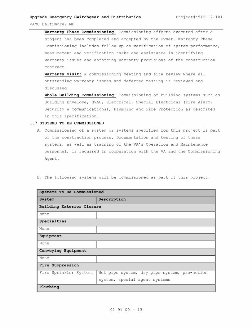
Upgrade Emergency Switchgear and Distribution Project#:512-17-101
VAMC Baltimore, MD
01 91 00 - 13
Warranty Phase Commissioning: Commissioning efforts executed after a
project has been completed and accepted by the Owner. Warranty Phase
Commissioning includes follow-up on verification of system performance,
measurement and verification tasks and assistance in identifying
warranty issues and enforcing warranty provisions of the construction
contract.
Warranty Visit: A commissioning meeting and site review where all
outstanding warranty issues and deferred testing is reviewed and
discussed.
Whole Building Commissioning: Commissioning of building systems such as
Building Envelope, HVAC, Electrical, Special Electrical (Fire Alarm,
Security & Communications), Plumbing and Fire Protection as described
in this specification.
1.7 SYSTEMS TO BE COMMISSIONED
A. Commissioning of a system or systems specified for this project is part
of the construction process. Documentation and testing of these
systems, as well as training of the VA’s Operation and Maintenance
personnel, is required in cooperation with the VA and the Commissioning
Agent.
B. The following systems will be commissioned as part of this project:
Systems To Be Commissioned
System Description
Building Exterior Closure
None
Specialties
None
Equipment
None
Conveying Equipment
None
Fire Suppression
Fire Sprinkler Systems Wet pipe system, dry pipe system, pre-action
system, special agent systems
Plumbing

Upgrade Emergency Switchgear and Distribution Project#:512-17-101
VAMC Baltimore, MD
01 91 00 - 14
Systems To Be Commissioned
System Description
None
HVAC
None
Electrical
Grounding & Bonding
Systems
Witness 3rd party testing, review reports
Electric Power
Monitoring Systems
Metering, sub-metering, power monitoring
systems, PLC control systems
Electrical System
Protective Device
Review reports, verify field settings
Low-Voltage
Distribution System
Normal power distribution system, Life-safety
power distribution system, critical power
distribution system, equipment power
distribution system, switchboards,
distribution panels, panelboards, verify
breaker testing results (injection current,
etc)
Emergency Power
Generation Systems
Generators, Generator paralleling switchgear,
automatic transfer switches, PLC and other
control systems
Lightning Protection
System
Witness 3rd party testing, review reports
Communications
None
Electronic Safety and Security
Grounding & Bonding Witness 3rd party testing, review reports
Fire Detection and
Alarm System
100% device acceptance testing, battery draw-
down test, verify system monitoring, verify
interface with other systems.
Renewable Energy Sources
None
Site Utilities
None
Transportation
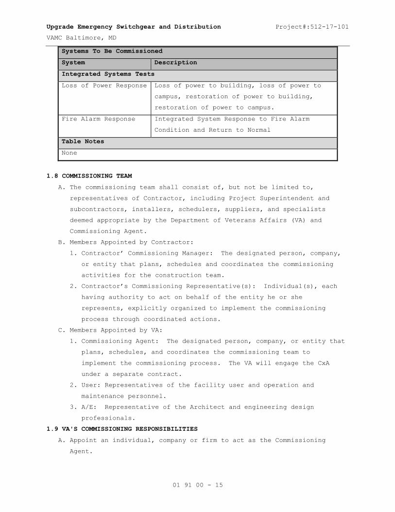
Upgrade Emergency Switchgear and Distribution Project#:512-17-101
VAMC Baltimore, MD
01 91 00 - 15
Systems To Be Commissioned
System Description
Integrated Systems Tests
Loss of Power Response Loss of power to building, loss of power to
campus, restoration of power to building,
restoration of power to campus.
Fire Alarm Response Integrated System Response to Fire Alarm
Condition and Return to Normal
Table Notes
None
1.8 COMMISSIONING TEAM
A. The commissioning team shall consist of, but not be limited to,
representatives of Contractor, including Project Superintendent and
subcontractors, installers, schedulers, suppliers, and specialists
deemed appropriate by the Department of Veterans Affairs (VA) and
Commissioning Agent.
B. Members Appointed by Contractor:
1. Contractor’ Commissioning Manager: The designated person, company,
or entity that plans, schedules and coordinates the commissioning
activities for the construction team.
2. Contractor’s Commissioning Representative(s): Individual(s), each
having authority to act on behalf of the entity he or she
represents, explicitly organized to implement the commissioning
process through coordinated actions.
C. Members Appointed by VA:
1. Commissioning Agent: The designated person, company, or entity that
plans, schedules, and coordinates the commissioning team to
implement the commissioning process. The VA will engage the CxA
under a separate contract.
2. User: Representatives of the facility user and operation and
maintenance personnel.
3. A/E: Representative of the Architect and engineering design
professionals.
1.9 VA'S COMMISSIONING RESPONSIBILITIES
A. Appoint an individual, company or firm to act as the Commissioning
Agent.

Upgrade Emergency Switchgear and Distribution Project#:512-17-101
VAMC Baltimore, MD
01 91 00 - 16
B. Assign operation and maintenance personnel and schedule them to
participate in commissioning team activities including, but not limited
to, the following:
1. Coordination meetings.
2. Training in operation and maintenance of systems, subsystems, and
equipment.
3. Testing meetings.
4. Witness and assist in Systems Functional Performance Testing.
5. Demonstration of operation of systems, subsystems, and equipment.
C. Provide the Construction Documents, prepared by Architect and approved
by VA, to the Commissioning Agent and for use in managing the
commissioning process, developing the commissioning plan, systems
manuals, and reviewing the operation and maintenance training plan.
1.10 CONTRACTOR'S COMMISSIONING RESPONSIBILITIES
A. The Contractor shall assign a Commissioning Manager to manage
commissioning activities of the Contractor, and subcontractors.
B. The Contractor shall ensure that the commissioning responsibilities
outlined in these specifications are included in all subcontracts and
that subcontractors comply with the requirements of these
specifications.
C. The Contractor shall ensure that each installing subcontractor shall
assign representatives with expertise and authority to act on behalf of
the subcontractor and schedule them to participate in and perform
commissioning team activities including, but not limited to, the
following:
1. Participate in commissioning coordination meetings.
2. Conduct operation and maintenance training sessions in accordance
with approved training plans.
3. Verify that Work is complete and systems are operational according
to the Contract Documents, including calibration of instrumentation
and controls.
4. Evaluate commissioning issues and commissioning observations
identified in the Commissioning Issues Log, field reports, test
reports or other commissioning documents. In collaboration with
entity responsible for system and equipment installation, recommend
corrective action.
5. Review and comment on commissioning documentation.

Upgrade Emergency Switchgear and Distribution Project#:512-17-101
VAMC Baltimore, MD
01 91 00 - 17
6. Participate in meetings to coordinate Systems Functional Performance
Testing.
7. Provide schedule for operation and maintenance data submittals,
equipment startup, and testing to Commissioning Agent for
incorporation into the commissioning plan.
8. Provide information to the Commissioning Agent for developing
commissioning plan.
9. Participate in training sessions for VA's operation and maintenance
personnel.
10. Provide technicians who are familiar with the construction and
operation of installed systems and who shall develop specific test
procedures to conduct Systems Functional Performance Testing of
installed systems.
1.11 COMMISSIONING AGENT’S RESPONSIBILITIES
A. Organize and lead the commissioning team.
B. Prepare the commissioning plan. See Paragraph 1.11-A of this
specification Section for further information.
C. Review and comment on selected submittals from the Contractor for
general conformance with the Construction Documents. Review and
comment on the ability to test and operate the system and/or equipment,
including providing gages, controls and other components required to
operate, maintain, and test the system. Review and comment on
performance expectations of systems and equipment and interfaces
between systems relating to the Construction Documents.
D. At the beginning of the construction phase, conduct an initial
construction phase coordination meeting for the purpose of reviewing
the commissioning activities and establishing tentative schedules for
operation and maintenance submittals; operation and maintenance
training sessions; TAB Work; Pre-Functional Checklists, Systems
Functional Performance Testing; and project completion.
E. Convene commissioning team meetings for the purpose of coordination,
communication, and conflict resolution; discuss status of the
commissioning processes. Responsibilities include arranging for
facilities, preparing agenda and attendance lists, and notifying
participants. The Commissioning Agent shall prepare and distribute
minutes to commissioning team members and attendees within five
workdays of the commissioning meeting.

Upgrade Emergency Switchgear and Distribution Project#:512-17-101
VAMC Baltimore, MD
01 91 00 - 18
F. Observe construction and report progress, observations and issues.
Observe systems and equipment installation for adequate accessibility
for maintenance and component replacement or repair, and for general
conformance with the Construction Documents.
G. Prepare Project specific Pre-Functional Checklists and Systems
Functional Performance Test procedures.
H. Coordinate Systems Functional Performance Testing schedule with the
Contractor.
I. Witness selected systems startups.
J. Verify selected Pre-Functional Checklists completed and submitted by
the Contractor.
K. Witness and document Systems Functional Performance Testing.
L. Compile test data, inspection reports, and certificates and include
them in the systems manual and commissioning report.
M. Review and comment on operation and maintenance (O&M) documentation and
systems manual outline for compliance with the Contract Documents.
Operation and maintenance documentation requirements are specified in
Paragraph 1.25, Section 01 00 00 GENERAL REQUIREMENTS.
N. Review operation and maintenance training program developed by the
Contractor. Verify training plans provide qualified instructors to
conduct operation and maintenance training.
O. Prepare commissioning Field Observation Reports.
P. Prepare the Final Commissioning Report.
Q. Return to the site at 10 months into the 12 month warranty period and
review with facility staff the current building operation and the
condition of outstanding issues related to the original and seasonal
Systems Functional Performance Testing. Also interview facility staff
and identify problems or concerns they have operating the building as
originally intended. Make suggestions for improvements and for
recording these changes in the O&M manuals. Identify areas that may
come under warranty or under the original construction contract. Assist
facility staff in developing reports, documents and requests for
services to remedy outstanding problems.
R. Assemble the final commissioning documentation, including the Final
Commissioning Report and Addendum to the Final Commissioning Report.

Upgrade Emergency Switchgear and Distribution Project#:512-17-101
VAMC Baltimore, MD
01 91 00 - 19
1.12 COMMISSIONING DOCUMENTATION
A. Commissioning Plan: A document, prepared by Commissioning Agent, that
outlines the schedule, allocation of resources, and documentation
requirements of the commissioning process, and shall include, but is
not limited, to the following:
1. Plan for delivery and review of submittals, systems manuals, and
other documents and reports. Identification of the relationship of
these documents to other functions and a detailed description of
submittals that are required to support the commissioning processes.
Submittal dates shall include the latest date approved submittals
must be received without adversely affecting commissioning plan.
2. Description of the organization, layout, and content of
commissioning documentation (including systems manual) and a
detailed description of documents to be provided along with
identification of responsible parties.
3. Identification of systems and equipment to be commissioned.
4. Schedule of Commissioning Coordination meetings.
5. Identification of items that must be completed before the next
operation can proceed.
6. Description of responsibilities of commissioning team members.
7. Description of observations to be made.
8. Description of requirements for operation and maintenance training.
9. Schedule for commissioning activities with dates coordinated with
overall construction schedule.
10. Process and schedule for documenting changes on a continuous basis
to appear in Project Record Documents.
11. Process and schedule for completing prestart and startup checklists
for systems, subsystems, and equipment to be verified and tested.
12. Preliminary Systems Functional Performance Test procedures.
B. Systems Functional Performance Test Procedures: The Commissioning
Agent will develop Systems Functional Performance Test Procedures for
each system to be commissioned, including subsystems, or equipment and
interfaces or interlocks with other systems. Systems Functional
Performance Test Procedures will include a separate entry, with space
for comments, for each item to be tested. Preliminary Systems
Functional Performance Test Procedures will be provided to the VA,
Architect/Engineer, and Contractor for review and comment. The Systems
Performance Test Procedure will include test procedures for each mode

Upgrade Emergency Switchgear and Distribution Project#:512-17-101
VAMC Baltimore, MD
01 91 00 - 20
of operation and provide space to indicate whether the mode under test
responded as required. Each System Functional Performance Test
procedure, regardless of system, subsystem, or equipment being tested,
shall include, but not be limited to, the following:
1. Name and identification code of tested system.
2. Test number.
3. Time and date of test.
4. Indication of whether the record is for a first test or retest
following correction of a problem or issue.
5. Dated signatures of the person performing test and of the witness,
if applicable.
6. Individuals present for test.
7. Observations and Issues.
8. Issue number, if any, generated as the result of test.
C. Pre-Functional Checklists: The Commissioning Agent will prepare Pre-
Functional Checklists. Pre-Functional Checklists shall be completed
and signed by the Contractor, verifying that systems, subsystems,
equipment, and associated controls are ready for testing. The
Commissioning Agent will spot check Pre-Functional Checklists to verify
accuracy and readiness for testing. Inaccurate or incomplete Pre-
Functional Checklists shall be returned to the Contractor for
correction and resubmission.
D. Test and Inspection Reports: The Commissioning Agent will record test
data, observations, and measurements on Systems Functional Performance
Test Procedure. The report will also include recommendation for system
acceptance or non-acceptance. Photographs, forms, and other means
appropriate for the application shall be included with data.
Commissioning Agent will compile test and inspection reports and test
and inspection certificates and include them in systems manual and
commissioning report.
E. Corrective Action Documents: The Commissioning Agent will document
corrective action taken for systems and equipment that fail tests. The
documentation will include any required modifications to systems and
equipment and/or revisions to test procedures, if any. The
Commissioning Agent will witness and document any retesting of systems
and/or equipment requiring corrective action and document retest
results. The contractor is liable for any cost incurred by the VA as a
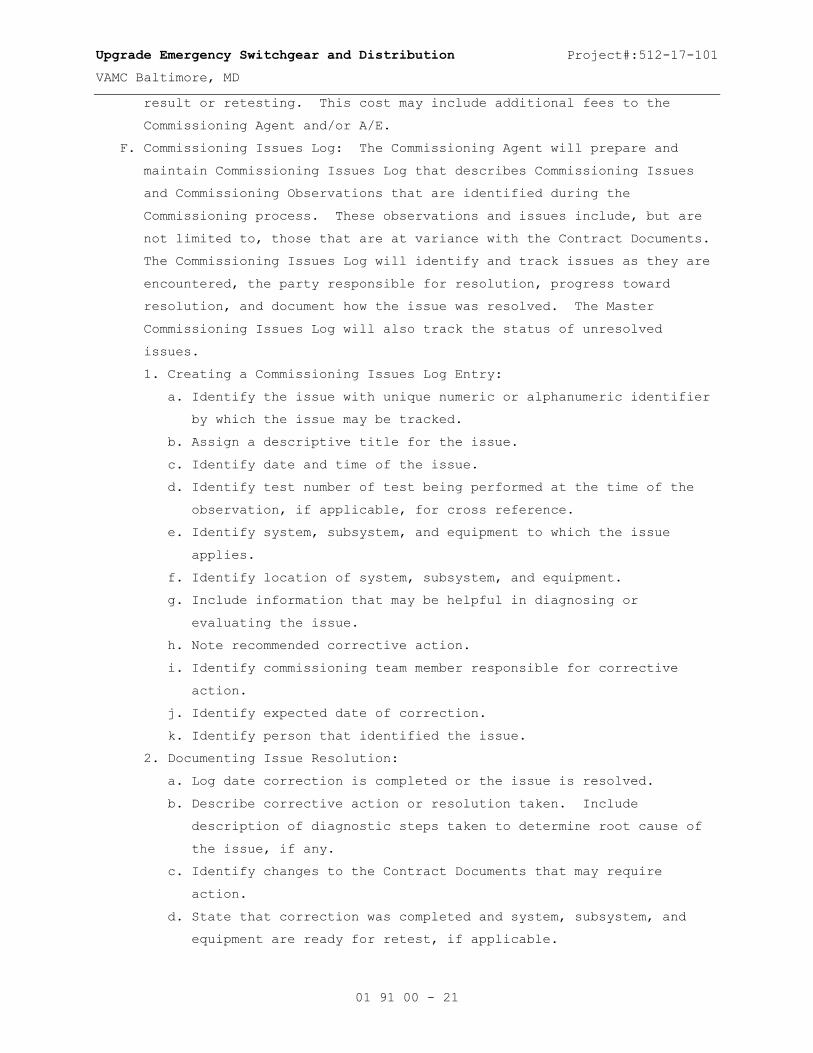
Upgrade Emergency Switchgear and Distribution Project#:512-17-101
VAMC Baltimore, MD
01 91 00 - 21
result or retesting. This cost may include additional fees to the
Commissioning Agent and/or A/E.
F. Commissioning Issues Log: The Commissioning Agent will prepare and
maintain Commissioning Issues Log that describes Commissioning Issues
and Commissioning Observations that are identified during the
Commissioning process. These observations and issues include, but are
not limited to, those that are at variance with the Contract Documents.
The Commissioning Issues Log will identify and track issues as they are
encountered, the party responsible for resolution, progress toward
resolution, and document how the issue was resolved. The Master
Commissioning Issues Log will also track the status of unresolved
issues.
1. Creating a Commissioning Issues Log Entry:
a. Identify the issue with unique numeric or alphanumeric identifier
by which the issue may be tracked.
b. Assign a descriptive title for the issue.
c. Identify date and time of the issue.
d. Identify test number of test being performed at the time of the
observation, if applicable, for cross reference.
e. Identify system, subsystem, and equipment to which the issue
applies.
f. Identify location of system, subsystem, and equipment.
g. Include information that may be helpful in diagnosing or
evaluating the issue.
h. Note recommended corrective action.
i. Identify commissioning team member responsible for corrective
action.
j. Identify expected date of correction.
k. Identify person that identified the issue.
2. Documenting Issue Resolution:
a. Log date correction is completed or the issue is resolved.
b. Describe corrective action or resolution taken. Include
description of diagnostic steps taken to determine root cause of
the issue, if any.
c. Identify changes to the Contract Documents that may require
action.
d. State that correction was completed and system, subsystem, and
equipment are ready for retest, if applicable.

Upgrade Emergency Switchgear and Distribution Project#:512-17-101
VAMC Baltimore, MD
01 91 00 - 22
e. Identify person(s) who corrected or resolved the issue.
f. Identify person(s) verifying the issue resolution.
G. Final Commissioning Report: The Commissioning Agent will document
results of the commissioning process, including unresolved issues, and
performance of systems, subsystems, and equipment. The Commissioning
Report will indicate whether systems, subsystems, and equipment have
been properly installed and are performing according to the Contract
Documents. This report will be used by the Department of Veterans
Affairs when determining that systems will be accepted. This report
will be used to evaluate systems, subsystems, and equipment and will
serve as a future reference document during VA occupancy and operation.
It shall describe components and performance that exceed requirements
of the Contract Documents and those that do not meet requirements of
the Contract Documents. The commissioning report will include, but is
not limited to, the following:
1. Lists and explanations of substitutions; compromises; variances with
the Contract Documents; record of conditions; and, if appropriate,
recommendations for resolution. Design Narrative documentation
maintained by the Commissioning Agent.
2. Commissioning plan.
3. Pre-Functional Checklists completed by the Contractor, with
annotation of the Commissioning Agent review and spot check.
4. Systems Functional Performance Test Procedures, with annotation of
test results and test completion.
5, Commissioning Issues Log.
6. Listing of deferred and off-season test(s) not performed, including
the schedule for their completion.
H. Addendum to Final Commissioning Report: The Commissioning Agent will
prepare an Addendum to the Final Commissioning Report near the end of
the Warranty Period. The Addendum will indicate whether systems,
subsystems, and equipment are complete and continue to perform
according to the Contract Documents. The Addendum to the Final
Commissioning Report shall include, but is not limited to, the
following:
1. Documentation of deferred and off season test(s) results.
2. Completed Systems Functional Performance Test Procedures for off
season test(s).

Upgrade Emergency Switchgear and Distribution Project#:512-17-101
VAMC Baltimore, MD
01 91 00 - 23
3. Documentation that unresolved system performance issues have been
resolved.
4. Updated Commissioning Issues Log, including status of unresolved
issues.
5. Identification of potential Warranty Claims to be corrected by the
Contractor.
I. Systems Manual: The Commissioning Agent will gather required
information and compile the Systems Manual. The Systems Manual will
include, but is not limited to, the following:
1. Design Narrative, including system narratives, schematics, single-
line diagrams, flow diagrams, equipment schedules, and changes made
throughout the Project.
2. Reference to Final Commissioning Plan.
3. Reference to Final Commissioning Report.
4. Approved Operation and Maintenance Data as submitted by the
Contractor.
1.13 SUBMITTALS
A. Preliminary Commissioning Plan Submittal: The Commissioning Agent has
prepared a Preliminary Commissioning Plan based on the final
Construction Documents. The Preliminary Commissioning Plan is included
as an Appendix to this specification section. The Preliminary
Commissioning Plan is provided for information only. It contains
preliminary information about the following commissioning activities:
1. The Commissioning Team: A list of commissioning team members by
organization.
2. Systems to be commissioned. A detailed list of systems to be
commissioned for the project. This list also provides preliminary
information on systems/equipment submittals to be reviewed by the
Commissioning Agent; preliminary information on Pre-Functional
Checklists that are to be completed; preliminary information on
Systems Performance Testing, including information on testing sample
size (where authorized by the VA).
3. Commissioning Team Roles and Responsibilities: Preliminary roles and
responsibilities for each Commissioning Team member.
4. Commissioning Documents: A preliminary list of commissioning-related
documents, include identification of the parties responsible for
preparation, review, approval, and action on each document.

Upgrade Emergency Switchgear and Distribution Project#:512-17-101
VAMC Baltimore, MD
01 91 00 - 24
5. Commissioning Activities Schedule: Identification of Commissioning
Activities, including Systems Functional Testing, the expected
duration and predecessors for the activity.
6. Pre-Functional Checklists: Preliminary Pre-Functional Checklists
for equipment, components, subsystems, and systems to be
commissioned. These Preliminary Pre-Functional Checklists provide
guidance on the level of detailed information the Contractor shall
include on the final submission.
7. Systems Functional Performance Test Procedures: Preliminary step-
by-step System Functional Performance Test Procedures to be used
during Systems Functional Performance Testing. These Preliminary
Systems Functional Performance procedures provide information on the
level of testing rigor, and the level of Contractor support required
during performance of system’s testing.
B. Final Commissioning Plan Submittal: Based on the Final Construction
Documents and the Contractor’s project team, the Commissioning Agent
will prepare the Final Commissioning Plan as described in this section.
The Commissioning Agent will submit three hard copies and three sets of
electronic files of Final Commissioning Plan. The Contractor shall
review the Commissioning Plan and provide any comments to the VA. The
Commissioning Agent will incorporate review comments into the Final
Commissioning Plan as directed by the VA.
C. Systems Functional Performance Test Procedure: The Commissioning Agent
will submit preliminary Systems Functional Performance Test Procedures
to the Contractor, and the VA for review and comment. The Contractor
shall return review comments to the VA and the Commissioning Agent.
The VA will also return review comments to the Commissioning Agent. The
Commissioning Agent will incorporate review comments into the Final
Systems Functional Test Procedures to be used in Systems Functional
Performance Testing.
D. Pre-Functional Checklists: The Commissioning Agent will submit Pre-
Functional Checklists to be completed by the Contractor.
E. Test and Inspection Reports: The Commissioning Agent will submit test
and inspection reports to the VA with copies to the Contractor and the
Architect/Engineer.
F. Corrective Action Documents: The Commissioning Agent will submit
corrective action documents to the VA Resident Engineer with copies to
the Contractor and Architect.

Upgrade Emergency Switchgear and Distribution Project#:512-17-101
VAMC Baltimore, MD
01 91 00 - 25
G. Preliminary Commissioning Report Submittal: The Commissioning Agent
will submit three electronic copies of the preliminary commissioning
report. One electronic copy, with review comments, will be returned to
the Commissioning Agent for preparation of the final submittal.
H. Final Commissioning Report Submittal: The Commissioning Agent will
submit four sets of electronically formatted information of the final
commissioning report to the VA. The final submittal will incorporate
comments as directed by the VA.
I. Data for Commissioning:
1. The Commissioning Agent will request in writing from the Contractor
specific information needed about each piece of commissioned
equipment or system to fulfill requirements of the Commissioning
Plan.
2. The Commissioning Agent may request further documentation as is
necessary for the commissioning process or to support other VA data
collection requirements, including Construction Operations Building
Information Exchange (COBIE), Building Information Modeling (BIM),
etc.
1.14 COMMISSIONING PROCESS
A. The Commissioning Agent will be responsible for the overall management
of the commissioning process as well as coordinating scheduling of
commissioning tasks with the VA and the Contractor. As directed by the
VA, the Contractor shall incorporate Commissioning tasks, including,
but not limited to, Systems Functional Performance Testing (including
predecessors) with the Master Construction Schedule.
B. Within 14 days of contract award, the Contractor shall designate a
specific individual as the Commissioning Manager (CxM) to manage and
lead the commissioning effort on behalf of the Contractor. The
Commissioning Manager shall be the single point of contact and
communications for all commissioning related services by the
Contractor.
C. Within 14 days of contract award, the Contractor shall ensure that each
subcontractor designates specific individuals as Commissioning
Representatives (CXR) to be responsible for commissioning related
tasks. The Contractor shall ensure the designated Commissioning
Representatives participate in the commissioning process as team
members providing commissioning testing services, equipment operation,

Upgrade Emergency Switchgear and Distribution Project#:512-17-101
VAMC Baltimore, MD
01 91 00 - 26
adjustments, and corrections if necessary. The Contractor shall ensure
that all Commissioning Representatives shall have sufficient authority
to direct their respective staff to provide the services required, and
to speak on behalf of their organizations in all commissioning related
contractual matters.
1.15 QUALITY ASSURANCE
A. Instructor Qualifications: Factory authorized service representatives
shall be experienced in training, operation, and maintenance procedures
for installed systems, subsystems, and equipment.
B. Test Equipment Calibration: The Contractor shall comply with test
equipment manufacturer's calibration procedures and intervals.
Recalibrate test instruments immediately whenever instruments have been
repaired following damage or dropping. Affix calibration tags to test
instruments. Instruments shall have been calibrated within six months
prior to use.
1.16 COORDINATION
A. Management: The Commissioning Agent will coordinate the commissioning
activities with the VA and Contractor. The Commissioning Agent will
submit commissioning documents and information to the VA. All
commissioning team members shall work together to fulfill their
contracted responsibilities and meet the objectives of the contract
documents.
B. Scheduling: The Contractor shall work with the Commissioning Agent and
the VA to incorporate the commissioning activities into the
construction schedule. The Commissioning Agent will provide sufficient
information (including, but not limited to, tasks, durations and
predecessors) on commissioning activities to allow the Contractor and
the VA to schedule commissioning activities. All parties shall address
scheduling issues and make necessary notifications in a timely manner
in order to expedite the project and the commissioning process. The
Contractor shall update the Master Construction as directed by the VA.
C. Initial Schedule of Commissioning Events: The Commissioning Agent will
provide the initial schedule of primary commissioning events in the
Commissioning Plan and at the commissioning coordination meetings. The
Commissioning Plan will provide a format for this schedule. As
construction progresses, more detailed schedules will be developed by
the Contractor with information from the Commissioning Agent.

Upgrade Emergency Switchgear and Distribution Project#:512-17-101
VAMC Baltimore, MD
01 91 00 - 27
D. Commissioning Coordinating Meetings: The Commissioning Agent will
conduct periodic Commissioning Coordination Meetings of the
commissioning team to review status of commissioning activities, to
discuss scheduling conflicts, and to discuss upcoming commissioning
process activities.
E. Pretesting Meetings: The Commissioning Agent will conduct pretest
meetings of the commissioning team to review startup reports, Pre-
Functional Checklist results, Systems Functional Performance Testing
procedures, testing personnel and instrumentation requirements.
F. Systems Functional Performance Testing Coordination: The Contractor
shall coordinate testing activities to accommodate required quality
assurance and control services with a minimum of delay and to avoid
necessity of removing and replacing construction to accommodate testing
and inspecting. The Contractor shall coordinate the schedule times for
tests, inspections, obtaining samples, and similar activities.
PART 2 - PRODUCTS
2.1 TEST EQUIPMENT
A. The Contractor shall provide all standard and specialized testing
equipment required to perform Systems Functional Performance Testing.
Test equipment required for Systems Functional Performance Testing will
be identified in the detailed System Functional Performance Test
Procedure prepared by the Commissioning Agent.
B. Data logging equipment and software required to test equipment shall be
provided by the Contractor.
C. All testing equipment shall be of sufficient quality and accuracy to
test and/or measure system performance with the tolerances specified in
the Specifications. If not otherwise noted, the following minimum
requirements apply: Temperature sensors and digital thermometers shall
have a certified calibration within the past year to an accuracy of 0.5
oC (1.0 oF) and a resolution of + or - 0.1 oC (0.2 oF). Pressure sensors
shall have an accuracy of + or - 2.0% of the value range being measured
(not full range of meter) and have been calibrated within the last
year. All equipment shall be calibrated according to the manufacturer's
recommended intervals and following any repairs to the equipment.
Calibration tags shall be affixed or certificates readily available.

Upgrade Emergency Switchgear and Distribution Project#:512-17-101
VAMC Baltimore, MD
01 91 00 - 35
PART 3 - EXECUTION
3.1 COMMISSIONING PROCESS ROLES AND RESPONSIBILITIES
A. The following table outlines the roles and responsibilities for the Commissioning Team members during
the Construction Phase:
Construction Phase CxA = Commissioning Agent
COR = Contracting Officer
Representative
A/E = Design Arch/Engineer
PC = Prime Contractor
O&M = Gov’t Facility O&M
L = Lead
P = Participate
A = Approve
R = Review
O = Optional
Commissioning Roles & Responsibilities
Category Task Description CxA RE A/E PC O&M Notes
Meetings Construction Commissioning Kick Off
meeting L A P P O
Commissioning Meetings L A P P O
Project Progress Meetings P A P L O
Controls Meeting L A P P O
Coordination Coordinate with [OGC's, AHJ, Vendors,
etc.] to ensure that Cx interacts
properly with other systems as needed
to support the OPR and BOD.
L A P P N/A
Cx Plan & Spec Final Commissioning Plan L A R R O
Schedules Duration Schedule for Commissioning
Activities L A R R N/A
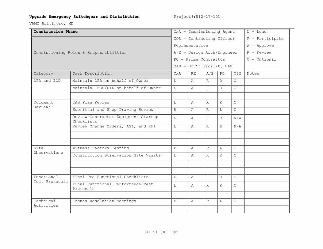
Upgrade Emergency Switchgear and Distribution Project#:512-17-101
VAMC Baltimore, MD
01 91 00 - 36
Construction Phase CxA = Commissioning Agent
COR = Contracting Officer
Representative
A/E = Design Arch/Engineer
PC = Prime Contractor
O&M = Gov’t Facility O&M
L = Lead
P = Participate
A = Approve
R = Review
O = Optional
Commissioning Roles & Responsibilities
Category Task Description CxA RE A/E PC O&M Notes
OPR and BOD Maintain OPR on behalf of Owner L A R R O
Maintain BOD/DID on behalf of Owner L A R R O
Document
Reviews
TAB Plan Review L A R R O
Submittal and Shop Drawing Review R A R L O
Review Contractor Equipment Startup
Checklists L A R R N/A
Review Change Orders, ASI, and RFI L A R R N/A
Site
Observations
Witness Factory Testing P A P L O
Construction Observation Site Visits L A R R O
Functional
Test Protocols
Final Pre-Functional Checklists L A R R O
Final Functional Performance Test
Protocols L A R R O
Technical
Activities
Issues Resolution Meetings P A P L O

Upgrade Emergency Switchgear and Distribution Project#:512-17-101
VAMC Baltimore, MD
01 91 00 - 37
Construction Phase CxA = Commissioning Agent
COR = Contracting Officer
Representative
A/E = Design Arch/Engineer
PC = Prime Contractor
O&M = Gov’t Facility O&M
L = Lead
P = Participate
A = Approve
R = Review
O = Optional
Commissioning Roles & Responsibilities
Category Task Description CxA RE A/E PC O&M Notes
Reports and
Logs
Status Reports L A R R O
Maintain Commissioning Issues Log L A R R O
B. The following table outlines the roles and responsibilities for the Commissioning Team members during
the Acceptance Phase:
Acceptance Phase CxA = Commissioning Agent
COR = Contracting Officer
Representative
A/E = Design Arch/Engineer
PC = Prime Contractor
O&M = Gov’t Facility O&M
L = Lead
P = Participate
A = Approve
R = Review
O = Optional
Commissioning Roles & Responsibilities
Category Task Description CxA RE A/E PC O&M Notes
Meetings Commissioning Meetings L A P P O
Project Progress Meetings P A P L O
Pre-Test Coordination Meeting L A P P O
Lessons Learned and Commissioning
Report Review Meeting L A P P O

Upgrade Emergency Switchgear and Distribution Project#:512-17-101
VAMC Baltimore, MD
01 91 00 - 38
Acceptance Phase CxA = Commissioning Agent
COR = Contracting Officer
Representative
A/E = Design Arch/Engineer
PC = Prime Contractor
O&M = Gov’t Facility O&M
L = Lead
P = Participate
A = Approve
R = Review
O = Optional
Commissioning Roles & Responsibilities
Category Task Description CxA RE A/E PC O&M Notes
Coordination Coordinate with [OGC's, AHJ, Vendors,
etc.] to ensure that Cx interacts
properly with other systems as needed
to support OPR and BOD
L P P P O
Cx Plan & Spec Maintain/Update Commissioning Plan L A R R O
Schedules Prepare Functional Test Schedule L A R R O
OPR and BOD Maintain OPR on behalf of Owner L A R R O
Maintain BOD/DID on behalf of Owner L A R R O
Document
Reviews
Review Completed Pre-Functional
Checklists L A R R O
Pre-Functional Checklist Verification L A R R O
Review Operations & Maintenance Manuals L A R R R
Training Plan Review L A R R R
Warranty Review L A R R O
Review TAB Report L A R R O
Site
Observations
Construction Observation Site Visits L A R R O
Witness Selected Equipment Startup L A R R O

Upgrade Emergency Switchgear and Distribution Project#:512-17-101
VAMC Baltimore, MD
01 91 00 - 39
Acceptance Phase CxA = Commissioning Agent
COR = Contracting Officer
Representative
A/E = Design Arch/Engineer
PC = Prime Contractor
O&M = Gov’t Facility O&M
L = Lead
P = Participate
A = Approve
R = Review
O = Optional
Commissioning Roles & Responsibilities
Category Task Description CxA RE A/E PC O&M Notes
Functional
Test Protocols
TAB Verification L A R R O
Systems Functional Performance Testing L A P P P
Retesting L A P P P
Technical
Activities
Issues Resolution Meetings P A P L O
Systems Training L S R P P
Reports and
Logs
Status Reports L A R R O
Maintain Commissioning Issues Log L A R R O
Final Commissioning Report L A R R R
Prepare Systems Manuals L A R R R
C. The following table outlines the roles and responsibilities for the Commissioning Team members during
the Warranty Phase:

Upgrade Emergency Switchgear and Distribution Project#:512-17-101
VAMC Baltimore, MD
01 91 00 - 40
Warranty Phase CxA = Commissioning Agent
COR = Contracting Officer
Representative
A/E = Design Arch/Engineer
PC = Prime Contractor
O&M = Gov’t Facility O&M
L = Lead
P = Participate
A = Approve
R = Review
O = Optional
Commissioning Roles & Responsibilities
Category Task Description CxA RE A/E PC O&M Notes
Meetings Post-Occupancy User Review Meeting L A O P P
Site
Observations
Periodic Site Visits L A O O P
Functional
Test Protocols
Deferred and/or seasonal Testing L A O P P
Technical
Activities
Issues Resolution Meetings L S O O P
Post-Occupancy Warranty Checkup and
review of Significant Outstanding
Issues
L A R P
Reports and
Logs
Final Commissioning Report Amendment L A R R
Status Reports L A R R

Upgrade Emergency Switchgear and Distribution Project#:512-17-101
VAMC Baltimore, MD
01 91 00 - 41
3.2 STARTUP, INITIAL CHECKOUT, AND PRE-FUNCTIONAL CHECKLISTS
A. The following procedures shall apply to all equipment and systems to be
commissioned, according to Part 1, Systems to Be Commissioned.
1. Pre-Functional Checklists are important to ensure that the equipment
and systems are hooked up and operational. These ensure that Systems
Functional Performance Testing may proceed without unnecessary
delays. Each system to be commissioned shall have a full Pre-
Functional Checklist completed by the Contractor prior to Systems
Functional Performance Testing. No sampling strategies are used.
a. The Pre-Functional Checklist will identify the trades responsible
for completing the checklist. The Contractor shall ensure the
appropriate trades complete the checklists.
b. The Commissioning Agent will review completed Pre-Functional
Checklists and field-verify the accuracy of the completed
checklist using sampling techniques.
2. Startup and Initial Checkout Plan: The Contractor shall develop
detailed startup plans for all equipment. The primary role of the
Contractor in this process is to ensure that there is written
documentation that each of the manufacturer recommended procedures
have been completed. Parties responsible for startup shall be
identified in the Startup Plan and in the checklist forms.
a. The Contractor shall develop the full startup plan by combining
(or adding to) the checklists with the manufacturer's detailed
startup and checkout procedures from the O&M manual data and the
field checkout sheets normally used by the Contractor. The plan
shall include checklists and procedures with specific boxes or
lines for recording and documenting the checking and inspections
of each procedure and a summary statement with a signature block
at the end of the plan.
b. The full startup plan shall at a minimum consist of the following
items:
1) The Pre-Functional Checklists.
2) The manufacturer's standard written startup procedures copied
from the installation manuals with check boxes by each
procedure and a signature block added by hand at the end.
3) The manufacturer's normally used field checkout sheets.
c. The Commissioning Agent will submit the full startup plan to the
VA and Contractor for review. Final approval will be by the VA.

Upgrade Emergency Switchgear and Distribution Project#:512-17-101
VAMC Baltimore, MD
01 91 00 - 42
d. The Contractor shall review and evaluate the procedures and the
format for documenting them, noting any procedures that need to
be revised or added.
3. Sensor and Actuator Calibration
a. All field installed temperature, relative humidity, CO2 and
pressure sensors and gages, and all actuators (dampers and
valves) on all equipment shall be calibrated using the methods
described in Division 21, Division 22, Division 23, Division 26,
Division 27, and Division 28 specifications.
b. All procedures used shall be fully documented on the Pre-
Functional Checklists or other suitable forms, clearly
referencing the procedures followed and written documentation of
initial, intermediate and final results.
4. Execution of Equipment Startup
a. Four weeks prior to equipment startup, the Contractor shall
schedule startup and checkout with the VA and Commissioning
Agent. The performance of the startup and checkout shall be
directed and executed by the Contractor.
b. The Commissioning Agent will observe the startup procedures for
selected pieces of primary equipment.
c. The Contractor shall execute startup and provide the VA and
Commissioning Agent with a signed and dated copy of the completed
startup checklists, and contractor tests.
d. Only individuals that have direct knowledge and witnessed that a
line item task on the Startup Checklist was actually performed
shall initial or check that item off. It is not acceptable for
witnessing supervisors to fill out these forms.
3.3 DEFICIENCIES, NONCONFORMANCE, AND APPROVAL IN CHECKLISTS AND STARTUP
A. The Contractor shall clearly list any outstanding items of the initial
startup and Pre-Functional Checklist procedures that were not completed
successfully, at the bottom of the procedures form or on an attached
sheet. The procedures form and any outstanding deficiencies shall be
provided to the VA and the Commissioning Agent within two days of
completion.
B. The Commissioning Agent will review the report and submit comments to
the VA. The Commissioning Agent will work with the Contractor to
correct and verify deficiencies or uncompleted items. The Commissioning

Upgrade Emergency Switchgear and Distribution Project#:512-17-101
VAMC Baltimore, MD
01 91 00 - 43
Agent will involve the VA and others as necessary. The Contractor shall
correct all areas that are noncompliant or incomplete in the checklists
in a timely manner, and shall notify the VA and Commissioning Agent as
soon as outstanding items have been corrected. The Contractor shall
submit an updated startup report and a Statement of Correction on the
original noncompliance report. When satisfactorily completed, the
Commissioning Agent will recommend approval of the checklists and
startup of each system to the VA.
C. The Contractor shall be responsible for resolution of deficiencies as
directed the VA.
3.4 PHASED COMMISSIONING
A. The project may require startup and initial checkout to be executed in
phases. This phasing shall be planned and scheduled in a coordination
meeting of the VA, Commissioning Agent, and the Contractor. Results
will be added to the master construction schedule and the commissioning
schedule.
3.5 DDC SYSTEM TRENDING FOR COMMISSIONING
A. Trending is a method of testing as a standalone method or to augment
manual testing. The Contractor shall trend any and all points of the
system or systems at intervals specified below.
B. Alarms are a means to notify the system operator that abnormal
conditions are present in the system. Alarms shall be structured into
three tiers – Critical, Priority, and Maintenance.
1. Critical alarms are intended to be alarms that require the immediate
attention of and action by the Operator. These alarms shall be
displayed on the Operator Workstation in a popup style window that
is graphically linked to the associated unit's graphical display.
The popup style window shall be displayed on top of any active
window within the screen, including non DDC system software.
2. Priority level alarms are to be printed to a printer which is
connected to the Operator’s Work Station located within the
engineer’s office. Additionally Priority level alarms shall be able
to be monitored and viewed through an active alarm application.
Priority level alarms are alarms which shall require reaction from
the operator or maintenance personnel within a normal work shift,
and not immediate action.
3. Maintenance alarms are intended to be minor issues which would
require examination by maintenance personnel within the following

Upgrade Emergency Switchgear and Distribution Project#:512-17-101
VAMC Baltimore, MD
01 91 00 - 44
shift. These alarms shall be generated in a scheduled report
automatically by the DDC system at the start of each shift. The
generated maintenance report will be printed to a printer located
within the engineer’s office.
C. The Contractor shall provide a wireless internet network in the
building for use during controls programming, checkout, and
commissioning. This network will allow project team members to more
effectively program, view, manipulate and test control devices while
being in the same room as the controlled device.
D. The Contractor shall provide graphical trending through the DDC control
system of systems being commissioned. Trending requirements are
indicated below and included with the Systems Functional Performance
Test Procedures. Trending shall occur before, during and after Systems
Functional Performance Testing. The Contractor shall be responsible for
producing graphical representations of the trended DDC points that show
each system operating properly during steady state conditions as well
as during the System Functional Testing. These graphical reports shall
be submitted to the Resident Engineer and Commissioning Agent for
review and analysis before, during dynamic operation, and after Systems
Functional Performance Testing. The Contractor shall provide, but not
limited to, the following trend requirements and trend submissions:
1. Pre-testing, Testing, and Post-testing – Trend reports of trend logs
and graphical trend plots are required as defined by the
Commissioning Agent. The trend log points, sampling rate, graphical
plot configuration, and duration will be dictated by the
Commissioning Agent. At any time during the Commissioning Process
the Commissioning Agent may recommend changes to aspects of trending
as deemed necessary for proper system analysis. The Contractor shall
implement any changes as directed by the Resident Engineer. Any pre-
test trend analysis comments generated by the Commissioning Team
should be addressed and resolved by the Contractor, as directed by
the Resident Engineer, prior to the execution of Systems Functional
Performance Testing.
2. Dynamic plotting – The Contractor shall also provide dynamic
plotting during Systems Functional Performance testing at frequent
intervals for points determined by the Systems Functional
Performance Test Procedure. The graphical plots will be formatted

Upgrade Emergency Switchgear and Distribution Project#:512-17-101
VAMC Baltimore, MD
01 91 00 - 45
and plotted at durations listed in the Systems Functional
Performance Test Procedure.
3. Graphical plotting - The graphical plots shall be provided with a
dual y-axis allowing 15 or more trend points (series) plotted
simultaneously on the graph with each series in distinct color. The
plots will further require title, axis naming, legend etc. all
described by the Systems Functional Performance Test Procedure. If
this cannot be sufficiently accomplished directly in the Direct
Digital Control System then it is the responsibility of the
Contractor to plot these trend logs in Microsoft Excel.
4. The following tables indicate the points to be trended and alarmed
by system. The Operational Trend Duration column indicates the
trend duration for normal operations. The Testing Trend Duration
column indicates the trend duration prior to Systems Functional
Performance Testing and again after Systems Functional Performance
Testing. The Type column indicates point type: AI = Analog Input,
AO = Analog Output, DI = Digital Input, DO = Digital Output, Calc =
Calculated Point. In the Trend Interval Column, COV = Change of
Value. The Alarm Type indicates the alarm priority; C = Critical, P
= Priority, and M = Maintenance. The Alarm Range column indicates
when the point is considered in the alarm state. The Alarm Delay
column indicates the length of time the point must remain in an
alarm state before the alarm is recorded in the DDC. The intent is
to allow minor, short-duration events to be corrected by the DDC
system prior to recording an alarm.
E. The Contractor shall provide the following information prior to Systems
Functional Performance Testing. Any documentation that is modified
after submission shall be recorded and resubmitted to the COR and
Commissioning Agent.
1. Point-to-Point checkout documentation;
2. Sensor field calibration documentation including system name,
sensor/point name, measured value, DDC value, and Correction Factor.
3. A sensor calibration table listing the referencing the location of
procedures to following in the O&M manuals, and the frequency at
which calibration should be performed for all sensors, separated by
system, subsystem, and type. The calibration requirements shall be
submitted both in the O&M manuals and separately in a standalone
document containing all sensors for inclusion in the commissioning
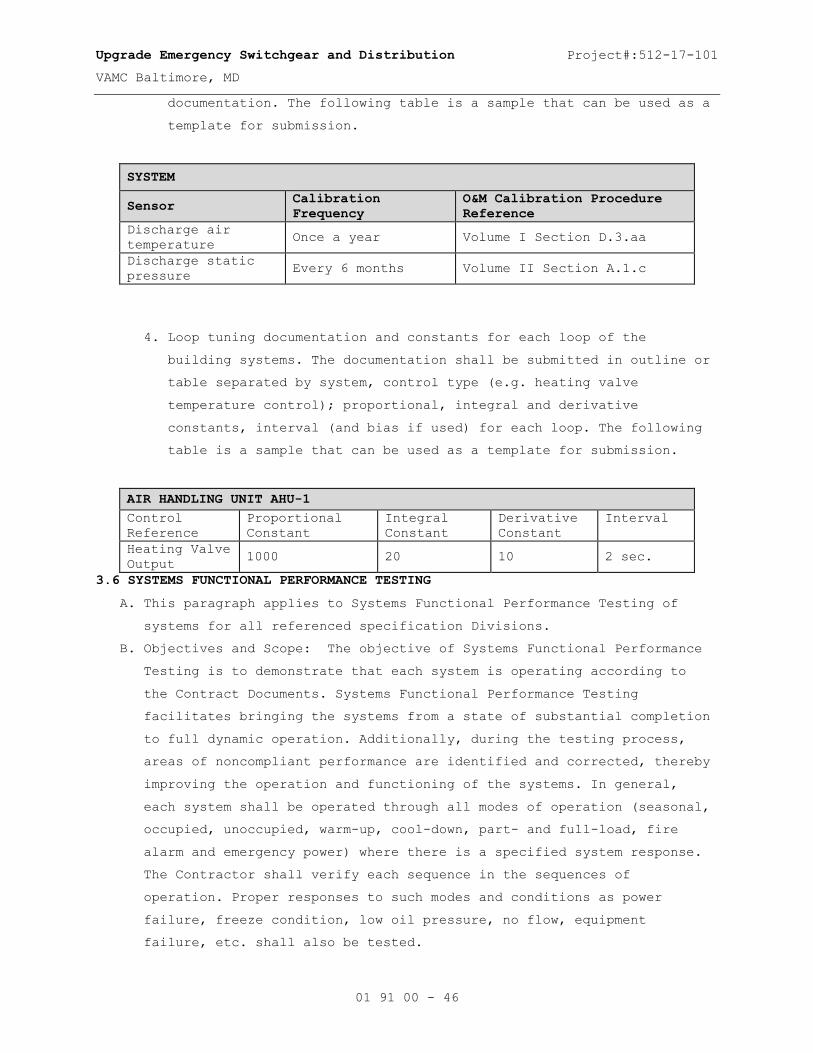
Upgrade Emergency Switchgear and Distribution Project#:512-17-101
VAMC Baltimore, MD
01 91 00 - 46
documentation. The following table is a sample that can be used as a
template for submission.
SYSTEM
Sensor Calibration
Frequency
O&M Calibration Procedure
Reference
Discharge air
temperature Once a year Volume I Section D.3.aa
Discharge static
pressure Every 6 months Volume II Section A.1.c
4. Loop tuning documentation and constants for each loop of the
building systems. The documentation shall be submitted in outline or
table separated by system, control type (e.g. heating valve
temperature control); proportional, integral and derivative
constants, interval (and bias if used) for each loop. The following
table is a sample that can be used as a template for submission.
AIR HANDLING UNIT AHU-1
Control
Reference
Proportional
Constant
Integral
Constant
Derivative
Constant
Interval
Heating Valve
Output 1000 20 10 2 sec.
3.6 SYSTEMS FUNCTIONAL PERFORMANCE TESTING
A. This paragraph applies to Systems Functional Performance Testing of
systems for all referenced specification Divisions.
B. Objectives and Scope: The objective of Systems Functional Performance
Testing is to demonstrate that each system is operating according to
the Contract Documents. Systems Functional Performance Testing
facilitates bringing the systems from a state of substantial completion
to full dynamic operation. Additionally, during the testing process,
areas of noncompliant performance are identified and corrected, thereby
improving the operation and functioning of the systems. In general,
each system shall be operated through all modes of operation (seasonal,
occupied, unoccupied, warm-up, cool-down, part- and full-load, fire
alarm and emergency power) where there is a specified system response.
The Contractor shall verify each sequence in the sequences of
operation. Proper responses to such modes and conditions as power
failure, freeze condition, low oil pressure, no flow, equipment
failure, etc. shall also be tested.

Upgrade Emergency Switchgear and Distribution Project#:512-17-101
VAMC Baltimore, MD
01 91 00 - 47
C. Development of Systems Functional Performance Test Procedures: Before
Systems Functional Performance Test procedures are written, the
Contractor shall submit all requested documentation and a current list
of change orders affecting equipment or systems, including an updated
points list, program code, control sequences and parameters. Using the
testing parameters and requirements found in the Contract Documents and
approved submittals and shop drawings, the Commissioning Agent will
develop specific Systems Functional Test Procedures to verify and
document proper operation of each piece of equipment and system to be
commissioned. The Contractor shall assist the Commissioning Agent in
developing the Systems Functional Performance Test procedures as
requested by the Commissioning Agent i.e. by answering questions about
equipment, operation, sequences, etc. Prior to execution, the
Commissioning Agent will provide a copy of the Systems Functional
Performance Test procedures to the VA, the Architect/Engineer, and the
Contractor, who shall review the tests for feasibility, safety,
equipment and warranty protection.
D. Purpose of Test Procedures: The purpose of each specific Systems
Functional Performance Test is to verify and document compliance with
the stated criteria of acceptance given on the test form.
Representative test formats and examples are found in the Commissioning
Plan for this project. (The Commissioning Plan is issued as a separate
document and is available for review.) The test procedure forms
developed by the Commissioning Agent will include, but not be limited
to, the following information:
1. System and equipment or component name(s)
2. Equipment location and ID number
3. Unique test ID number, and reference to unique Pre-Functional
Checklists and startup documentation, and ID numbers for the piece
of equipment
4. Date
5. Project name
6. Participating parties
7. A copy of the specification section describing the test requirements
8. A copy of the specific sequence of operations or other specified
parameters being verified
9. Formulas used in any calculations
10. Required pretest field measurements

Upgrade Emergency Switchgear and Distribution Project#:512-17-101
VAMC Baltimore, MD
01 91 00 - 48
11. Instructions for setting up the test.
12. Special cautions, alarm limits, etc.
13. Specific step-by-step procedures to execute the test, in a clear,
sequential and repeatable format
14. Acceptance criteria of proper performance with a Yes / No check box
to allow for clearly marking whether or not proper performance of
each part of the test was achieved.
15. A section for comments.
16. Signatures and date block for the Commissioning Agent. A place for
the Contractor to initial to signify attendance at the test.
E. Test Methods: Systems Functional Performance Testing shall be achieved
by manual testing (i.e. persons manipulate the equipment and observe
performance) and/or by monitoring the performance and analyzing the
results using the control system's trend log capabilities or by
standalone data loggers. The Contractor and Commissioning Agent shall
determine which method is most appropriate for tests that do not have a
method specified.
1. Simulated Conditions: Simulating conditions (not by an overwritten
value) shall be allowed, although timing the testing to experience
actual conditions is encouraged wherever practical.
2. Overwritten Values: Overwriting sensor values to simulate a
condition, such as overwriting the outside air temperature reading
in a control system to be something other than it really is, shall
be allowed, but shall be used with caution and avoided when
possible. Such testing methods often can only test a part of a
system, as the interactions and responses of other systems will be
erroneous or not applicable. Simulating a condition is preferable.
e.g., for the above case, by heating the outside air sensor with a
hair blower rather than overwriting the value or by altering the
appropriate setpoint to see the desired response. Before simulating
conditions or overwriting values, sensors, transducers and devices
shall have been calibrated.
3. Simulated Signals: Using a signal generator which creates a
simulated signal to test and calibrate transducers and DDC constants
is generally recommended over using the sensor to act as the signal
generator via simulated conditions or overwritten values.
4. Altering Setpoints: Rather than overwriting sensor values, and when
simulating conditions is difficult, altering setpoints to test a
Upgrade Emergency Switchgear and Distribution Project#:512-17-101
VAMC Baltimore, MD
01 91 00 - 49
sequence is acceptable. For example, to see the Air Conditioning
compressor lockout initiate at an outside air temperature below 12 C
(54 F), when the outside air temperature is above 12 C (54 F),
temporarily change the lockout setpoint to be 2 C (4 F) above the
current outside air temperature.
5. Indirect Indicators: Relying on indirect indicators for responses
or performance shall be allowed only after visually and directly
verifying and documenting, over the range of the tested parameters,
that the indirect readings through the control system represent
actual conditions and responses. Much of this verification shall be
completed during systems startup and initial checkout.
F. Setup: Each function and test shall be performed under conditions that
simulate actual conditions as closely as is practically possible. The
Contractor shall provide all necessary materials, system modifications,
etc. to produce the necessary flows, pressures, temperatures, etc.
necessary to execute the test according to the specified conditions. At
completion of the test, the Contractor shall return all affected
building equipment and systems, due to these temporary modifications,
to their pretest condition.
G. Sampling: No sampling is allowed in completing Pre-Functional
Checklists. Sampling is allowed for Systems Functional Performance
Test Procedures execution. The Commissioning Agent will determine the
sampling rate. If at any point, frequent failures are occurring and
testing is becoming more troubleshooting than verification, the
Commissioning Agent may stop the testing and require the Contractor to
perform and document a checkout of the remaining units, prior to
continuing with Systems Functional Performance Testing of the remaining
units.
H. Cost of Retesting: The cost associated with expanded sample System
Functional Performance Tests shall be solely the responsibility of the
Contractor. Any required retesting by the Contractor shall not be
considered a justified reason for a claim of delay or for a time
extension by the Contractor.
I. Coordination and Scheduling: The Contractor shall provide a minimum of
7 days’ notice to the Commissioning Agent and the VA regarding the
completion schedule for the Pre-Functional Checklists and startup of
all equipment and systems. The Commissioning Agent will schedule
Systems Functional Performance Tests with the Contractor and VA. The

Upgrade Emergency Switchgear and Distribution Project#:512-17-101
VAMC Baltimore, MD
01 91 00 - 50
Commissioning Agent will witness and document the Systems Functional
Performance Testing of systems. The Contractor shall execute the tests
in accordance with the Systems Functional Performance Test Procedure.
J. Testing Prerequisites: In general, Systems Functional Performance
Testing will be conducted only after Pre-Functional Checklists have
been satisfactorily completed. The control system shall be sufficiently
tested and approved by the Commissioning Agent and the VA before it is
used to verify performance of other components or systems. The air
balancing and water balancing shall be completed before Systems
Functional Performance Testing of air-related or water-related
equipment or systems are scheduled. Systems Functional Performance
Testing will proceed from components to subsystems to systems. When the
proper performance of all interacting individual systems has been
achieved, the interface or coordinated responses between systems will
be checked.
K. Problem Solving: The Commissioning Agent will recommend solutions to
problems found, however the burden of responsibility to solve, correct
and retest problems is with the Contractor.
3.7 DOCUMENTATION, NONCONFORMANCE AND APPROVAL OF TESTS
A. Documentation: The Commissioning Agent will witness, and document the
results of all Systems Functional Performance Tests using the specific
procedural forms developed by the Commissioning Agent for that purpose.
Prior to testing, the Commissioning Agent will provide these forms to
the VA and the Contractor for review and approval. The Contractor shall
include the filled out forms with the O&M manual data.
B. Nonconformance: The Commissioning Agent will record the results of the
Systems Functional Performance Tests on the procedure or test form. All
items of nonconformance issues will be noted and reported to the VA on
Commissioning Field Reports and/or the Commissioning Master Issues Log.
1. Corrections of minor items of noncompliance identified may be made
during the tests. In such cases, the item of noncompliance and
resolution shall be documented on the Systems Functional Test
Procedure.
2. Every effort shall be made to expedite the systems functional
Performance Testing process and minimize unnecessary delays, while
not compromising the integrity of the procedures. However, the
Commissioning Agent shall not be pressured into overlooking
noncompliant work or loosening acceptance criteria to satisfy
Upgrade Emergency Switchgear and Distribution Project#:512-17-101
VAMC Baltimore, MD
01 91 00 - 51
scheduling or cost issues, unless there is an overriding reason to
do so by direction from the VA.
3. As the Systems Functional Performance Tests progresses and an item
of noncompliance is identified, the Commissioning Agent shall
discuss the issue with the Contractor and the VA.
4. When there is no dispute on an item of noncompliance, and the
Contractor accepts responsibility to correct it:
a. The Commissioning Agent will document the item of noncompliance
and the Contractor's response and/or intentions. The Systems
Functional Performance Test then continues or proceeds to another
test or sequence. After the day's work is complete, the
Commissioning Agent will submit a Commissioning Field Report to
the VA. The Commissioning Agent will also note items of
noncompliance and the Contractor’s response in the Master
Commissioning Issues Log. The Contractor shall correct the item
of noncompliance and report completion to the VA and the
Commissioning Agent.
b. The need for retesting will be determined by the Commissioning
Agent. If retesting is required, the Commissioning Agent and the
Contractor shall reschedule the test and the test shall be
repeated.
5. If there is a dispute about item of noncompliance, regarding whether
it is an item of noncompliance, or who is responsible:
a. The item of noncompliance shall be documented on the test form
with the Contractor's response. The item of noncompliance with
the Contractor’s response shall also be reported on a
Commissioning Field Report and on the Master Commissioning Issues
Log.
b. Resolutions shall be made at the lowest management level
possible. Other parties are brought into the discussions as
needed. Final interpretive and acceptance authority is with the
Department of Veterans Affairs.
c. The Commissioning Agent will document the resolution process.
d. Once the interpretation and resolution have been decided, the
Contractor shall correct the item of noncompliance, report it to
the Commissioning Agent. The requirement for retesting will be
determined by the Commissioning Agent. If retesting is required,
the Commissioning Agent and the Contractor shall reschedule the
Upgrade Emergency Switchgear and Distribution Project#:512-17-101
VAMC Baltimore, MD
01 91 00 - 52
test. Retesting shall be repeated until satisfactory performance
is achieved.
C. Cost of Retesting: The cost to retest a System Functional Performance
Test shall be solely the responsibility of the Contractor. Any
required retesting by the Contractor shall not be considered a
justified reason for a claim of delay or for a time extension by the
Contractor.
D. Failure Due to Manufacturer Defect: If 10%, or three, whichever is
greater, of identical pieces (size alone does not constitute a
difference) of equipment fail to perform in compliance with the
Contract Documents (mechanically or substantively) due to manufacturing
defect, not allowing it to meet its submitted performance
specifications, all identical units may be considered unacceptable by
the VA. In such case, the Contractor shall provide the VA with the
following:
1. Within one week of notification from the VA, the Contractor shall
examine all other identical units making a record of the findings.
The findings shall be provided to the VA within two weeks of the
original notice.
2. Within two weeks of the original notification, the Contractor shall
provide a signed and dated, written explanation of the problem,
cause of failures, etc. and all proposed solutions which shall
include full equipment submittals. The proposed solutions shall not
significantly exceed the specification requirements of the original
installation.
3. The VA shall determine whether a replacement of all identical units
or a repair is acceptable.
4. Two examples of the proposed solution shall be installed by the
Contractor and the VA shall be allowed to test the installations for
up to one week, upon which the VA will decide whether to accept the
solution.
5. Upon acceptance, the Contractor shall replace or repair all
identical items, at their expense and extend the warranty
accordingly, if the original equipment warranty had begun. The
replacement/repair work shall proceed with reasonable speed
beginning within one week from when parts can be obtained.
E. Approval: The Commissioning Agent will note each satisfactorily
demonstrated function on the test form. Formal approval of the Systems

Upgrade Emergency Switchgear and Distribution Project#:512-17-101
VAMC Baltimore, MD
01 91 00 - 53
Functional Performance Test shall be made later after review by the
Commissioning Agent and by the VA. The Commissioning Agent will
evaluate each test and report to the VA using a standard form. The VA
will give final approval on each test using the same form, and provide
signed copies to the Commissioning Agent and the Contractor.
3.8 DEFERRED TESTING
A. Unforeseen Deferred Systems Functional Performance Tests: If any
Systems Functional Performance Test cannot be completed due to the
building structure, required occupancy condition or other conditions,
execution of the Systems Functional Performance Testing may be delayed
upon approval of the VA. These Systems Functional Performance Tests
shall be conducted in the same manner as the seasonal tests as soon as
possible. Services of the Contractor to conduct these unforeseen
Deferred Systems Functional Performance Tests shall be negotiated
between the VA and the Contractor.
B. Deferred Seasonal Testing: Deferred Seasonal Systems Functional
Performance Tests are those that must be deferred until weather
conditions are closer to the systems design parameters. The
Commissioning Agent will review systems parameters and recommend which
Systems Functional Performance Tests should be deferred until weather
conditions more closely match systems parameters. The Contractor shall
review and comment on the proposed schedule for Deferred Seasonal
Testing. The VA will review and approve the schedule for Deferred
Seasonal Testing. Deferred Seasonal Systems Functional Performances
Tests shall be witnessed and documented by the Commissioning Agent.
Deferred Seasonal Systems Functional Performance Tests shall be
executed by the Contractor in accordance with these specifications.
3.9 OPERATION AND MAINTENANCE TRAINING REQUIREMENTS
A. Training Preparation Conference: Before operation and maintenance
training, the Commissioning Agent will convene a training preparation
conference to include VA's Resident Engineer, VA’s Operations and
Maintenance personnel, and the Contractor. The purpose of this
conference will be to discuss and plan for Training and Demonstration
of VA Operations and Maintenance personnel.
B. The Contractor shall provide training and demonstration as required by
other Division 21, Division 22, Division 23, Division 26, Division 27,
Division 28, and Division 31 sections. The Training and Demonstration
shall include, but is not limited to, the following:

Upgrade Emergency Switchgear and Distribution Project#:512-17-101
VAMC Baltimore, MD
01 91 00 - 54
1. Review the Contract Documents.
2. Review installed systems, subsystems, and equipment.
3. Review instructor qualifications.
4. Review instructional methods and procedures.
5. Review training module outlines and contents.
6. Review course materials (including operation and maintenance
manuals).
7. Review and discuss locations and other facilities required for
instruction.
8. Review and finalize training schedule and verify availability of
educational materials, instructors, audiovisual equipment, and
facilities needed to avoid delays.
9. For instruction that must occur outside, review weather and
forecasted weather conditions and procedures to follow if conditions
are unfavorable.
C. Training Module Submittals: The Contractor shall submit the following
information to the VA and the Commissioning Agent:
1. Instruction Program: Submit two copies of outline of instructional
program for demonstration and training, including a schedule of
proposed dates, times, length of instruction time, and instructors'
names for each training module. Include learning objective and
outline for each training module. At completion of training, submit
two complete training manuals for VA's use.
2. Qualification Data: Submit qualifications for facilitator and/or
instructor.
3. Attendance Record: For each training module, submit list of
participants and length of instruction time.
4. Evaluations: For each participant and for each training module,
submit results and documentation of performance-based test.
5. Demonstration and Training Recording:
a. General: Engage a qualified commercial photographer to record
demonstration and training. Record each training module
separately. Include classroom instructions and demonstrations,
board diagrams, and other visual aids, but not student practice.
At beginning of each training module, record each chart
containing learning objective and lesson outline.
b. Video Format: Provide high quality color DVD color on standard
size DVD disks.

Upgrade Emergency Switchgear and Distribution Project#:512-17-101
VAMC Baltimore, MD
01 91 00 - 55
c. Recording: Mount camera on tripod before starting recording,
unless otherwise necessary to show area of demonstration and
training. Display continuous running time.
d. Narration: Describe scenes on video recording by audio narration
by microphone while demonstration and training is recorded.
Include description of items being viewed. Describe vantage
point, indicating location, direction (by compass point), and
elevation or story of construction.
e. Submit two copies within seven days of end of each training
module.
6. Transcript: Prepared on 8-1/2-by-11-inch paper, punched and bound
in heavy-duty, 3-ring, vinyl-covered binders. Mark appropriate
identification on front and spine of each binder. Include a cover
sheet with same label information as the corresponding videotape.
Include name of Project and date of videotape on each page.
D. Quality Assurance:
1. Facilitator Qualifications: A firm or individual experienced in
training or educating maintenance personnel in a training program
similar in content and extent to that indicated for this Project,
and whose work has resulted in training or education with a
record of successful learning performance.
2. Instructor Qualifications: A factory authorized service
representative, complying with requirements in Division 01
Section "Quality Requirements," experienced in operation and
maintenance procedures and training.
3. Photographer Qualifications: A professional photographer who is
experienced photographing construction projects.
E. Training Coordination:
1. Coordinate instruction schedule with VA's operations. Adjust
schedule as required to minimize disrupting VA's operations.
2. Coordinate instructors, including providing notification of dates,
times, length of instruction time, and course content.
3. Coordinate content of training modules with content of approved
emergency, operation, and maintenance manuals. Do not submit
instruction program until operation and maintenance data has been
reviewed and approved by the VA.
F. Instruction Program:
Upgrade Emergency Switchgear and Distribution Project#:512-17-101
VAMC Baltimore, MD
01 91 00 - 56
1. Program Structure: Develop an instruction program that includes
individual training modules for each system and equipment not part
of a system, as required by individual Specification Sections, and
as follows:
a. Fire protection systems, including fire alarm, fire pumps, and
fire suppression systems.
b. HVAC systems, including air handling equipment, air distribution
systems, and terminal equipment and devices.
c. HVAC instrumentation and controls.
d. Electrical service and distribution, including switchgear,
transformers, switchboards, panelboards, uninterruptible power
supplies, and motor controls.
e. Packaged engine generators, including synchronizing
switchgear/switchboards, and transfer switches.
f. Communication systems, including intercommunication,
surveillance, nurse call systems, public address, mass
evacuation, voice and data, and entertainment television
equipment.
G. Training Modules: Develop a learning objective and teaching outline
for each module. Include a description of specific skills and
knowledge that participants are expected to master. For each module,
include instruction for the following:
1. Basis of System Design, Operational Requirements, and Criteria:
Include the following:
a. System, subsystem, and equipment descriptions.
b. Performance and design criteria if Contractor is delegated design
responsibility.
c. Operating standards.
d. Regulatory requirements.
e. Equipment function.
f. Operating characteristics.
g. Limiting conditions.
H, Performance curves.
2. Documentation: Review the following items in detail:
a. Emergency manuals.
b. Operations manuals.
c. Maintenance manuals.

Upgrade Emergency Switchgear and Distribution Project#:512-17-101
VAMC Baltimore, MD
01 91 00 - 57
d. Project Record Documents.
e. Identification systems.
f. Warranties and bonds.
g. Maintenance service agreements and similar continuing
commitments.
3. Emergencies: Include the following, as applicable:
a. Instructions on meaning of warnings, trouble indications, and
error messages.
b. Instructions on stopping.
c. Shutdown instructions for each type of emergency.
d. Operating instructions for conditions outside of normal operating
limits.
e. Sequences for electric or electronic systems.
f. Special operating instructions and procedures.
4. Operations: Include the following, as applicable:
a. Startup procedures.
b. Equipment or system break-in procedures.
c. Routine and normal operating instructions.
d. Regulation and control procedures.
e. Control sequences.
f. Safety procedures.
g. Instructions on stopping.
h. Normal shutdown instructions.
i. Operating procedures for emergencies.
j. Operating procedures for system, subsystem, or equipment failure.
k. Seasonal and weekend operating instructions.
l. Required sequences for electric or electronic systems.
m. Special operating instructions and procedures.
5. Adjustments: Include the following:
a. Alignments.
b. Checking adjustments.
c. Noise and vibration adjustments.
d. Economy and efficiency adjustments.
6. Troubleshooting: Include the following:
a. Diagnostic instructions.
b. Test and inspection procedures.
7. Maintenance: Include the following:
a. Inspection procedures.

Upgrade Emergency Switchgear and Distribution Project#:512-17-101
VAMC Baltimore, MD
01 91 00 - 58
b. Types of cleaning agents to be used and methods of cleaning.
c. List of cleaning agents and methods of cleaning detrimental to
product.
d. Procedures for routine cleaning
e. Procedures for preventive maintenance.
f. Procedures for routine maintenance.
g. Instruction on use of special tools.
8. Repairs: Include the following:
a. Diagnosis instructions.
b. Repair instructions.
c. Disassembly; component removal, repair, and replacement; and
reassembly instructions.
d. Instructions for identifying parts and components.
e. Review of spare parts needed for operation and maintenance.
H. Training Execution:
1. Preparation: Assemble educational materials necessary for
instruction, including documentation and training module. Assemble
training modules into a combined training manual. Set up
instructional equipment at instruction location.
2. Instruction:
a. Facilitator: Engage a qualified facilitator to prepare
instruction program and training modules, to coordinate
instructors, and to coordinate between Contractor and Department
of Veterans Affairs for number of participants, instruction
times, and location.
b. Instructor: Engage qualified instructors to instruct VA's
personnel to adjust, operate, and maintain systems, subsystems,
and equipment not part of a system.
1) The Commissioning Agent will furnish an instructor to describe
basis of system design, operational requirements, criteria,
and regulatory requirements.
2) The VA will furnish an instructor to describe VA's operational
philosophy.
3) The VA will furnish the Contractor with names and positions of
participants.
3. Scheduling: Provide instruction at mutually agreed times. For
equipment that requires seasonal operation, provide similar
instruction at start of each season. Schedule training with the VA

Upgrade Emergency Switchgear and Distribution Project#:512-17-101
VAMC Baltimore, MD
01 91 00 - 59
and the Commissioning Agent with at least seven days' advance
notice.
4. Evaluation: At conclusion of each training module, assess and
document each participant's mastery of module by use of an oral, or
a written, performance-based test.
5. Cleanup: Collect used and leftover educational materials and remove
from Project site. Remove instructional equipment. Restore systems
and equipment to condition existing before initial training use.
I. Demonstration and Training Recording:
1. General: Engage a qualified commercial photographer to record
demonstration and training. Record each training module separately.
Include classroom instructions and demonstrations, board diagrams,
and other visual aids, but not student practice. At beginning of
each training module, record each chart containing learning
objective and lesson outline.
2. Video Format: Provide high quality color DVD color on standard size
DVD disks.
3. Recording: Mount camera on tripod before starting recording, unless
otherwise necessary to show area of demonstration and training.
Display continuous running time.
4. Narration: Describe scenes on videotape by audio narration by
microphone while demonstration and training is recorded. Include
description of items being viewed. Describe vantage point,
indicating location, direction (by compass point), and elevation or
story of construction.
----- END -----

Upgrade Emergency Switchgear and Distribution Project#:512-17-101
VAMC Baltimore, MD
02 41 00 - 1
SECTION 02 41 00
DEMOLITION
PART 1 - GENERAL
1.1 DESCRIPTION:
This section specifies demolition and removal of buildings, portions of
buildings, utilities, other structures and debris from trash dumps
shown.
1.2 RELATED WORK:
A. Safety Requirements: Section 01 35 26 Safety Requirements Article,
ACCIDENT PREVENTION PLAN (APP).
B. Disconnecting utility services prior to demolition: Section 01 00 00,
GENERAL REQUIREMENTS.
C. Reserved items that are to remain the property of the Government:
Section 01 00 00, GENERAL REQUIREMENTS.
D. Asbestos Removal: Section 02 82 11, TRADITIONAL ASBESTOS ABATEMENT.
E. Lead Paint: Section 02 83 33.13, LEAD-BASED PAINT REMOVAL AND DISPOSAL.
F. Environmental Protection: Section 01 57 19, TEMPORARY ENVIRONMENTAL
CONTROLS.
G. Construction Waste Management: Section 01 74 19 CONSTRUCTION WASTE
MANAGEMENT.
H. Infectious Control: Section 01 35 26, SAFETY REQUIREMENTS.
1.3 PROTECTION:
A. Perform demolition in such manner as to eliminate hazards to persons
and property; to minimize interference with use of adjacent areas,
utilities and structures or interruption of use of such utilities; and
to provide free passage to and from such adjacent areas of structures.
Comply with requirements of GENERAL CONDITIONS Article, ACCIDENT
PREVENTION.
B. Provide safeguards, including warning signs, barricades, temporary
fences, warning lights, and other similar items that are required for
protection of all personnel during demolition and removal operations.
Comply with requirements of Section 01 00 00, GENERAL REQUIREMENTS,
Article PROTECTION OF EXISTING VEGETATION, STRUCTURES, EQUIPMENT,
UTILITIES AND IMPROVEMENTS.
C. Maintain fences, barricades, lights, and other similar items around
exposed excavations until such excavations have been completely filled.

Upgrade Emergency Switchgear and Distribution Project#:512-17-101
VAMC Baltimore, MD
02 41 00 - 2
D. Provide enclosed dust chutes with control gates from each floor to
carry debris to truck beds and govern flow of material into truck.
Provide overhead bridges of tight board or prefabricated metal
construction at dust chutes to protect persons and property from
falling debris.
E. Prevent spread of flying particles and dust. Sprinkle rubbish and
debris with water to keep dust to a minimum. Do not use water if it
results in hazardous or objectionable condition such as, but not
limited to; ice, flooding, or pollution. Vacuum and dust the work area
daily.
F. In addition to previously listed fire and safety rules to be observed
in performance of work, include following:
1. No wall or part of wall shall be permitted to fall outwardly from
structures.
2. Wherever a cutting torch or other equipment that might cause a fire
is used, provide and maintain fire extinguishers nearby ready for
immediate use. Instruct all possible users in use of fire
extinguishers.
3. Keep hydrants clear and accessible at all times. Prohibit debris
from accumulating within a radius of 4500 mm (15 feet) of fire
hydrants.
G. Before beginning any demolition work, the Contractor shall survey the
site and examine the drawings and specifications to determine the
extent of the work. The contractor shall take necessary precautions to
avoid damages to existing items to remain in place, to be reused, or to
remain the property of the Medical Center; any damaged items shall be
repaired or replaced as approved by the Contracting Officer
Representative. The Contractor shall coordinate the work of this
section with all other work and shall construct and maintain shoring,
bracing, and supports as required. The Contractor shall ensure that
structural elements are not overloaded and shall be responsible for
increasing structural supports or adding new supports as may be
required as a result of any cutting, removal, or demolition work
performed under this contract. Do not overload structural elements.
Provide new supports and reinforcement for existing construction
weakened by demolition or removal works. Repairs, reinforcement, or

Upgrade Emergency Switchgear and Distribution Project#:512-17-101
VAMC Baltimore, MD
02 41 00 - 3
structural replacement must have Contracting Officer Representative’s
approval.
H. The work shall comply with the requirements of Section 01 57 19,
TEMPORARY ENVIRONMENTAL CONTROLS.
I. The work shall comply with the requirements of Section 01 00 00,
GENERAL REQUIREMENTS and Section 01 35 26, SAFETY REQUIREMENTS.
PART 2 - PRODUCTS (NOT USED)
PART 3 – EXECUTION
3.1 DEMOLITION:
B. Debris, including brick, concrete, stone, metals and similar materials
shall become property of Contractor and shall be disposed of by him
daily, off the // Medical Center // Cemetery Property // to avoid
accumulation at the demolition site. Materials that cannot be removed
daily shall be stored in areas specified by the Contracting Officer
Representative. Break up concrete slabs below grade that do not require
removal from present location into pieces not exceeding 600 mm (24
inches) square to permit drainage. Contractor shall dispose debris in
compliance with applicable federal, state or local permits, rules
and/or regulations.
D. Remove and legally dispose of all materials, other than earth to remain
as part of project work, from any trash dumps shown. Materials removed
shall become property of contractor and shall be disposed of in
compliance with applicable federal, state or local permits, rules
and/or regulations . All materials in the indicated trash dump areas,
including above surrounding grade and extending to a depth of 1500mm
(5feet) below surrounding grade, shall be included as part of the lump
sum compensation for the work of this section. Materials that are
located beneath the surface of the surrounding ground more than 1500 mm
(5 feet), or materials that are discovered to be hazardous, shall be
handled as unforeseen. The removal of hazardous material shall be
referred to Hazardous Materials specifications.
E. Remove existing utilities as indicated or uncovered by work and
terminate in a manner conforming to the nationally recognized code
covering the specific utility and approved by the Contracting Officer
Representative. When Utility lines are encountered that are not
indicated on the drawings, the Contracting Officer Representative shall
be notified prior to further work in that area.

Upgrade Emergency Switchgear and Distribution Project#:512-17-101
VAMC Baltimore, MD
02 41 00 - 4
3.2 CLEAN-UP:
On completion of work of this section and after removal of all debris,
leave site in clean condition satisfactory to the Contracting Officer
Representative. Clean-up off the // Medical Center shall include
disposal of all items and materials not required to remain property of
the Government as well as all debris and rubbish resulting from
demolition operations.
- - - E N D - - -

Upgrade Emergency Switchgear and Distribution Project#:512-17-101
VAMC Baltimore, MD
SECTION 03 30 53 CAST-IN-PLACE CONCRETE
PART 1 - GENERAL
1.1 SUMMARY
A. Section Includes:
1. Equipment pads.
2. Preparation of existing surfaces to receive concrete.
3. Preparation of existing surface to received concrete topping.
1.2 RELATED REQUIREMENTS
A. Materials Testing and Inspection During Construction: Section 01 45 29,
TESTING LABORATORY SERVICES.
1.3 APPLICABLE PUBLICATIONS
A. Comply with references to extent specified in this Section.
B. American Concrete Institute (ACI):
1. 117-15 - Tolerances for Concrete Construction, Materials and
Commentary.
2. 117M-10(R2015) - Tolerances for Concrete Construction, Materials and
Commentary.
3. 211.2-98(R2004) - Selecting Proportions for Structural Lightweight
Concrete.
4. 301/310M-10 - Structural Concrete.
5. 305.1-14 - Hot Weather Concreting.
6. 306.1-90(R2002) - Cold Weather Concreting.
7. 318/318M-14 - Building Code Requirements for Structural Concrete and
SP-66-04-ACI Detailing Manual.
8. 347-04 - Guide to Formwork for Concrete.
C. ASTM International(ASTM):
1. A615/A615M-15ae1 - Deformed and Plain Carbon-Steel Bars for Concrete
Reinforcement.
2. A996/A996M-15 - Rail-Steel and Axle-Steel Deformed Bars for Concrete
Reinforcement.
3. A1064/A1064M-15 - Carbon-Steel Wire and Welded Wire Reinforcement,
Plain and Deformed, for Concrete.
4. C33/C33M-13 - Concrete Aggregates.
5. C39/C39M-15a - Compressive Strength of Cylindrical Concrete
Specimens.
6. C94/C94M-15a - Ready-Mixed Concrete.
03 30 53 - 1

Upgrade Emergency Switchgear and Distribution Project#:512-17-101
VAMC Baltimore, MD
7. C143/C143M-15 - Slump of Hydraulic Cement Concrete.
8. C150/C150M-15 - Portland Cement.
9. C171-07 - Sheet Material for Curing Concrete.
10. C192/C192M-15 - Making and Curing Concrete Test Specimens in the Laboratory.
11. C219-14a - Terminology Relating to Hydraulic Cement.
12. C260/C260M-10a - Air-Entraining Admixtures for Concrete. 13. C330/C330M-14 - Lightweight Aggregates for Structural Concrete.
14. C494/C494M-15 - Chemical Admixtures for Concrete. 15. C618-15 - Coal Fly Ash and Raw or Calcined Natural Pozzolan for Use
in Concrete.
16. C881/C881M-14 - Epoxy-Resin-Base Bonding Systems for Concrete. 17. C989/C989M-14 - Slag Cement for Use in Concrete and Mortars.
18. C1240-15 - Silica Fume Used in Cementitious Mixtures. 19. D1751-04(2013el) - Preformed Expansion Joint Fillers for Concrete
Paving and Structural Construction (Non-extruding and Resilient
Bituminous Types).
20. E1155-14 - Determining FF Floor Flatness and FL Floor Levelness
Numbers.
21. E1745-11 - Water Vapor Retarders Used in Contact with Soil or
Granular Fill under Concrete Slabs.
D. International Concrete Repair Institute:
1. 310.2R-2013 - Selecting and Specifying Concrete Surface Preparation
for Sealers, Coatings, Polymer Overlays, and Concrete Repair.
1.4 SUBMITTALS
A. Submittal Procedures: Section 01 33 23, SHOP DRAWINGS, PRODUCT DATA,
AND SAMPLES.
B. Submittal Drawings:
1. Large scale drawings of reinforcing steel.
C. Manufacturer's Literature and Data:
1. Concrete Mix Design.
2. Air-entraining admixture, chemical admixtures, and curing compounds.
3. Indicate manufacturer's recommendation for each application.
D. Certificates: Certify products comply with specifications.
a. Each ready mix concrete batch delivered to site.
E. Contractor must provide the VA with a list of projects on similar
installations for at least 5 years. Provide contact names and addresses
of complete projects.
03 30 53 - 2

Upgrade Emergency Switchgear and Distribution Project#:512-17-101
VAMC Baltimore, MD
1.5 DELIVERY
A. Deliver each ready-mixed concrete batch with mix certification in
duplicate according to ASTM C94/C94M.
1.6 WARRANTY
A. Construction Warranty: FAR clause 52.246-21, "Warranty of
Construction."
PART 2 - PRODUCTS
2.1 MATERIALS
A. Portland Cement: ASTM C150/C150M, Type I or II.
B. Fine Aggregate: ASTM C33/C33M.
C. Lightweight Aggregate for Structural Concrete: ASTM C330/C330M, Table
1.
D. Mixing Water: Fresh, clean, and potable.
E. Air-Entraining Admixture: ASTM C260/C260M.
F. Chemical Admixtures: ASTM C494/C494M.
G. Vapor Barrier: ASTM E1745, Class A with a minimum puncture resistance
of 2200 g (3000 lbs.); minimum 0.38 mm (15 mil) thick.
H. Reinforcing Steel: ASTM A615/A615M, Grade 60.
I. Forms: Wood, plywood, metal, or other materials, approved by
Contracting Officer, of grade or type suitable to obtain type of finish
specified.
1. Plywood: Exterior grade, free of defects and patches on contact
surface.
2. Lumber: Sound, grade-marked, S4S stress graded softwood.
3. Form coating: As recommended by Contractor.
J. Expansion Joint Filler: ASTM D1751.
K. Sheet Materials for Curing Concrete: ASTM C171.
L. Abrasive Aggregates: Aluminum oxide grains or emery grits.
M. Liquid Densifier/Sealer: 100 percent active colorless aqueous
siliconate solution.
N. Grout, Non-Shrinking: Premixed ferrous or non-ferrous. Grout to show no
settlement or vertical drying shrinkage at 3 days. Compressive strength
for grout, at least 18 MPa (2500 psi) at 3 days and 35 MPa (5000 psi)
at 28 days.
2.2 ACCESSORIES
A. Bonding Agent: ASTM C 1059/C 1059M, Type II.
03 30 53 - 3

Upgrade Emergency Switchgear and Distribution Project#:512-17-101
VAMC Baltimore, MD
B. Structural Adhesive: ASTM C881, 2-component material suitable for use
on dry or damp surfaces. Provide material Type, Grade, and Class to
suit Project requirements.
C. Water Stops: Rubber base with self-healing properties. Expanding clay
based products not acceptable.
D. Weeps: Geotextile type as recommended by Contractor and approved by
Contracting Officer.
2.3 CONCRETE MIXES
A. Design concrete mixes according to ASTM C94/C94M, Option C.
B. Compressive strength at 28 days: minimum 27.6 MPa (4,000 psi) for
lightweight concrete for superstructure (roof slab supported on metal
deck).
C. Submit mix design and results of compression tests to the Contracting
Officer for his evaluation. Identify all materials, including
admixtures, making-up the concrete.
D. Maximum Slump for Vibrated Concrete: 76 mm (3 inches) to 152 mm (6
inches) tested according to ASTM C143.
E. Cement and Water Factor (See Table I):
TABLE I - CEMENT AND WATER FACTORS FOR CONCRETE
Concrete: Strength Non-Air-Entrained Air-Entrained
Min. 28 Day Comp.
Str.
MPa (psi)
Min. Cement
kg/cu. m
(lbs./cu.
yd.)
Max. Water
Cement Ratio
Min. Cement
kg/cu. m
(lbs./cu.
yd.)
Max. Water
Cement Ratio
35 (5000)1,3 375 (630) 0.45 385 (650) 0.40
30 (4000)1,3 325 (550) 0.55 340 (570) 0.50
25 (3000)1,3 280 (470) 0.65 290 (490) 0.55
25 (3000)1,2 300 (500) * 310 (520) *
03 30 53 - 4

Upgrade Emergency Switchgear and Distribution Project#:512-17-101
VAMC Baltimore, MD
TABLE I - CEMENT AND WATER FACTORS FOR CONCRETE
Concrete: Strength Non-Air-Entrained Air-Entrained
Min. 28 Day Comp.
Str.
MPa (psi)
Min. Cement
kg/cu. m
(lbs./cu.
yd.)
Max. Water
Cement Ratio
Min. Cement
kg/cu. m
(lbs./cu.
yd.)
Max. Water
Cement Ratio
Footnotes:
1. If trial mixes are used, achieve a compressive strength 8.3 MPa (1
200 psi) in excess of f'c. For concrete strengths greater than 35 MPa
(5,000 psi), achieve a compressive strength 9.7 MPa (1,400 psi) in excess of
f’c.
2. Lightweight Structural Concrete: Pump mixes may require higher cement
values as specified in ACI 318/318M.
3. For Concrete Exposed to High Sulfate Content Soils: Maximum water cement
ratio is 0.44.
* Laboratory Determined according to ACI 211.1 for normal weight concrete or
ACI 211.2 for lightweight structural concrete.
F. Air-entrainment as specified, and conform with the following for air
content table:
TABLE II - TOTAL AIR CONTENT
FOR VARIOUS SIZES OF COARSE AGGREGATES
Nominal Maximum Size of
Coarse Aggregate
Total Air Content, percent
10 mm (3/8 inches) 6 Moderate exposure; 7.5 severe
exposure
13 mm (1/2 inches) 5.5 Moderate exposure; 7 severe
exposure
19 mm (3/4 inches) 5 Moderate exposure; 6 severe exposure
25 mm (1 inches) 4.5 Moderate exposure; 6 severe
exposure
40 mm (1 1/2 inches) 4.5 Moderate exposure; 5.5 severe
exposure
2.4 BATCHING AND MIXING
A. Store, batch, and mix materials according to ASTM C94/C94M.
03 30 53 - 5

Upgrade Emergency Switchgear and Distribution Project#:512-17-101
VAMC Baltimore, MD
1. Job-Mixed: Batch mix concrete in stationary mixers as specified in
ASTM C94/C94M.
2. Ready-Mixed Concrete: Comply with ASTM C94/C94M, except use of
non-agitating equipment for transporting concrete to Site is not
acceptable.
3. Mixing Structural Lightweight Concrete: Charge mixer with 2/3 of
total mixing water and total aggregate for each batch. Mix
ingredients minimum 30 seconds in stationary mixer or minimum 10
revolutions at mixing speed in truck mixer. Add remaining mixing
water and other ingredients and continue mixing. Above procedure may
be modified as recommended by aggregate producer.
4. When aggregate producer's instructions deviate from specifications,
submit proposed resolution for Contracting Officer's Representative
consideration.
PART 3 - EXECUTION
3.1 FORMWORK
A. Installation: Conform to ACI 347. Construct forms to obtain concrete of
the shapes, dimensions and profiles indicated, with tight joints.
B. Design and construct forms to prevent bowing-out of forms between
supports and to be removable without prying against or otherwise
damaging fresh concrete.
C. When patching formed concrete, seal form edges against existing surface
to prevent leakage; set forms so that patch is flush with adjacent
surfaces.
D. Treating and Wetting: Treat or wet concrete contact surfaces:
1. Coat plywood and lumber forms with non-staining form sealer.
2. Wet wood forms thoroughly when they are not treated with form
release agent.
3. Prevent water from accumulating and remaining within forms.
4. Clean and coat removable metal forms with light form oil before
reinforcement is placed.
5. In hot weather, cool metal forms by thoroughly wetting with water
just before placing concrete.
6. Prevent water from accumulating and remaining within forms.
E. Inserts, Sleeves, and Similar Items: Install flashing reglets, masonry
ties, anchors, inserts, wires, hangers, sleeves, boxes for floor
03 30 53 - 6
Upgrade Emergency Switchgear and Distribution Project#:512-17-101
VAMC Baltimore, MD
hinges, and other cast-in items specified in other Sections. Place
where indicated, square, flush and secured to formwork.
F. Construction Tolerances - General: Install and maintain concrete
formwork to assure completion of work within specified tolerances.
G. Adjust or replace completed work exceeding specified tolerances before
placing concrete.
3.2 REINFORCEMENT
A. Install concrete reinforcement according to ACI 318 and ACI SP-66.
B. Support and securely tie reinforcing steel to prevent displacement
during placing of concrete.
C. Drilling for Dowels in Existing Concrete: Use sharp bits, drill hole
slightly oversize, fill with epoxy grout, inset the dowel, and remove
excess epoxy.
3.3 VAPOR BARRIER
A. Except where membrane waterproofing is required, place interior
concrete slabs on a continuous vapor barrier.
B. Lap joints 150 mm (6 inches) and seal with a compatible
pressure-sensitive tape.
C. Patch punctures and tears.
3.4 PLACING CONCRETE
A. Remove water before concrete is placed. Remove hardened concrete,
debris and other foreign materials from interior of forms, and from
inside of mixing and conveying equipment. Obtain approval from
Contracting Officer's Representative before placing concrete.
B. Install screeds at required elevations for concrete slabs.
C. Roughen and clean free from laitance, foreign matter, and loose
particles before placing new concrete on existing concrete.
1. Blow-out areas with compressed air and immediately coat contact
areas with adhesive in compliance with manufacturer's instructions.
D. Place structural concrete according to ACI 301 and ACI 318.
E. Convey concrete from mixer to final place of deposit by method that
will prevent segregation or loss of ingredients. Do not deposit, in
Work, concrete that has attained its initial set or has contained its
water or cement more than 1 1/2 hours. Do not allow concrete to drop
freely more than 1500 mm (5 feet) in unexposed work nor more than
900 mm (3 feet) in exposed work.
03 30 53 - 7

Upgrade Emergency Switchgear and Distribution Project#:512-17-101
VAMC Baltimore, MD
F. Place and consolidate concrete in horizontal layers not exceeding
300 mm (12 inches) in thickness. Consolidate concrete by spading,
rodding, and mechanical vibrator. Do not secure vibrator to forms or
reinforcement. Continuously vibrate during placement of concrete.
G. Hot Weather Concrete Placement: As recommended by ACI 305.1 to prevent
adversely affecting properties and serviceability of hardened concrete.
H. Cold Weather Concrete Placement: As recommended by ACI 306.1, to
prevent freezing of thin sections less than 300 mm (12 inches) and to
permit concrete to gain strength properly.
1. Do not use calcium chloride without written approval from
Contracting Officer's Representative.
3.5 TOLERANCES
A. Slab on Grade Finish Tolerance: Comply with ACI 117, FF-number and
FL-number method.
3.6 PROTECTION AND CURING
A. Protect exposed surfaces of concrete from premature drying, wash by
rain or running water, wind, mechanical damage, and excessive hot or
cold temperatures.
B. Curing Methods: Cure concrete with curing compound using wet method
with sheets.
C. Formed Concrete Curing: Wet the tops and exposed portions of formed
concrete and keep moist until forms are removed.
1. If forms are removed before 14 days after concrete is cast, install
sheet curing materials as specified above.
D. Concrete Flatwork Curing:
1. Install sheet materials according to the manufacturer's
instructions.
a. When manufacturer's instructions deviate from specifications,
submit proposed resolution for Contracting Officer's
Representative consideration.
3.7 FORM REMOVAL
A. Maintain forms in place until concrete is self-supporting, with
construction operation loads.
B. Remove fins, laitance and loose material from concrete surfaces when
forms are removed. Repair honeycombs, rock pockets, sand runs, spalls,
03 30 53 - 8

Upgrade Emergency Switchgear and Distribution Project#:512-17-101
VAMC Baltimore, MD
or otherwise damaged surfaces by patching with the same mix as concrete
minus the coarse aggregates.
C. Finish to match adjacent surfaces.
3.8 FINISHES
A. Vertical and Overhead Surface Finishes:
1. Surfaces Concealed in Completed Construction: As-cast; no additional
finishing required.
2. Surfaces Exposed in Unfinished Areas: As-cast; no additional
finishing required.
a. Interior Electrical Room inside IPD101 Electrical room.
3. Surfaces Exposed to View Scheduled for Paint Finish: Remove fins,
burrs and similar projections by mechanical means approved by
Contracting Officer's Representative flush with adjacent surface.
Lightly rub with fine abrasive stone or hone. Use ample amount of
water during rubbing without working up a lather of mortar or
changing texture of concrete.
4. Surfaces Exposed to View in Finished Areas: Grout finish, unless
otherwise shown, for uniform color and smooth finish treated.
a. Remove laitance, fins and burrs.
b. Scrub concrete with wire brushes. Clean stained concrete
surfaces with hone or stone.
c. Apply grout composed of 1 part Portland cement and 1 part clean,
fine sand (smaller than 600 micro-m (No. 30) sieve). Work grout
into surface of concrete with cork floats or fiber brushes until
pits and honeycomb are filled.
d. After grout has hardened, but is still plastic, remove surplus
grout with sponge rubber float and by rubbing with clean burlap.
e. In hot, dry weather fog spray surfaces with water to keep grout
wet during setting period. Complete finished areas in same day.
Confine limits of finished areas to natural breaks in wall
surface. Do not leave grout on concrete surface overnight.
B. Slab Finishes: 1. Allow bleed water to evaporate before surface is finished. Do not
sprinkle dry cement on surface to absorb water.
2. Broom Finish: Finish exterior slabs, ramps, and stair treads with
bristle brush moistened with clear water after surfaces have been
floated.
03 30 53 - 9

Upgrade Emergency Switchgear and Distribution Project#:512-17-101
VAMC Baltimore, MD
3.9 SURFACE TREATMENTS
A. Mix and apply the following surface treatments according to
manufacturer's instructions.
1. When manufacturer's instructions deviate from specifications, submit
proposed resolution for Contracting Officer's Representative
consideration.
B. Liquid Densifier/Sealer: Use for exposed concrete floors and concrete
floors to receive carpeting // except those specified to receive
non-slip finish //.
C. Slip Resistant Finish:
1. Except where safety nosing and tread coverings are shown, apply
abrasive aggregate to treads and platforms of concrete steps and
stairs, and to surfaces of exterior concrete ramps and platforms.
a. Broadcast aggregate uniformly over concrete surface. Trowel
concrete surface to smooth dense finish. After curing, rub
treated surface with abrasive brick and water sufficiently to
slightly expose abrasive aggregate.
3.10 APPLIED TOPPING
A. Install concrete topping with thickness and strength shown with only
enough water to ensure stiff, workable, plastic mix.
B. Continuously place applied topping until entire area is complete,
struck off with straightedge, compact by rolling or tamping, float and
steel trowel to hard smooth finish.
3.11 RESURFACING FLOORS
A. Remove existing flooring by abrasive blasting or grinding, in areas to
receive resurfacing, to expose existing structural slab. Achieve a
surface profile of 2 to 4 according to ICRI 310.2R for the condition
found at Site.
B. Prepare exposed structural slab surface by cleaning, wetting, and
applying adhesive according to manufacturer's instructions as specified
in the flooring section.
- - E N D - -
03 30 53 - 10
Upgrade Emergency Switchgear and Distribution Project#:512-17-101
VAMC Baltimore, MD
SECTION 05 12 00 STRUCTURAL STEEL FRAMING
PART 1 - GENERAL
1.1 SUMMARY
A. Section Includes:
1. Structural steel shapes, plates, and bars.
2. Bolts, nuts, and washers.
1.2 RELATED REQUIREMENTS
A. Materials Testing And Inspection During Construction: Section 01 45 29,
TESTING LABORATORY SERVICES.
B. Fireproofing: Section 07 81 00, APPLIED FIREPROOFING.
C. Steel Finishes: Section 09 06 00, SCHEDULE FOR FINISHES.
1.3 APPLICABLE PUBLICATIONS
A. Comply with references to extent specified in this section.
B. American Institute of Steel Construction (AISC):
1. AISC Manual - Steel Construction Manual, 14th Ed.
2. 303-10 - Code of Structural Steel Buildings and Bridges.
3. 360-10: Specification for Structural Steel Buildings.
C. The American Society of Mechanical Engineers (ASME):
1. B18.22.1-09 - Washers: Helical Spring-Lock, Tooth Lock, and Plain
Washers.
D. American Welding Society (AWS):
1. D1.1/D1.1M-15 - Structural Welding Code - Steel.
E. ASTM International (ASTM):
1. A6/A6M-14 - General Requirements for Rolled Structural Steel Bars,
Plates, Shapes, and Sheet Piling.
2. A36/A36M-14 - Carbon Structural Steel.
3. A53/A53M-12 - Pipe, Steel, Black and Hot-Dip, Zinc-Coated, Welded
and Seamless.
4. A123/A123M-15 - Zinc (Hot-Dip Galvanized) Coatings on Iron and Steel
Products.
5. A242/A242M-13 - High-Strength Low-Alloy Structural Steel.
6. A283/A283M-13 - Low and Intermediate Tensile Strength Carbon Steel
Plates.
7. A307-14 - Carbon Steel Bolts, Studs, and Threaded Rod 60,000 PSI
Tensile Strength.
05 12 00 - 1
Upgrade Emergency Switchgear and Distribution Project#:512-17-101
VAMC Baltimore, MD
8. A500/A500M-13 - Cold-Formed Welded and Seamless Carbon Steel
Structural Tubing and Rounds and Shapes.
9. A501/A501M-14 - Hot-Formed Welded and Seamless Carbon Steel
Structural Tubing and Rounds and Shapes.
10. A572/A572M-15 - High-Strength Low-Alloy Columbium-Vanadium
Structural Steel.
11. A992/A992M-15 - Structural Shapes. 12. F2329/F2329M-15 - Zinc Coating, Hot-Dip, Requirements for
Application to Carbon and Alloy steel Bolts, Screws, washers, Nuts,
and Special Threaded Fasteners.
13. F3125/F3125M-15 - Standard Specification for High Strength
Structural Bolts, Steel and Alloy Steel, Heat Treated, 120 ksi (830
MPa) and 150 ksi (1040 MPa) Minimum Tensile Strength, Inch and
Metric Dimensions
F. Master Painters Institute (MPI):
1. No. 18 - Primer, Zinc Rich, Organic.
G. Military Specifications (Mil. Spec.):
1. MIL-P-21035 - Paint, High Zinc Dust Content, Galvanizing, Repair.
H. Occupational Safety and Health Administration (OSHA):
1. 29 CFR 1926.752(e) - Guidelines For Establishing The Components Of A
Site-Specific Erection Plan.
2. 29 CFR 1926-2001 - Safety Standards for Steel Erection.
I. Research Council on Structural Connections (RCSC) of The Engineering
Foundation:
1. Specification for Structural Joints Using ASTM F3125 Bolts.
1.4 SUBMITTALS
A. Submittal Procedures: Section 01 33 23, SHOP DRAWINGS, PRODUCT DATA,
AND SAMPLES.
B. Submittal Drawings:
1. Show size, configuration, and fabrication and installation details.
C. Test Reports: Certify products comply with specifications.
1. Welders' qualifying tests.
D. Certificates: Certify each product complies with specifications.
1. Structural steel.
2. Steel connections.
3. Welding materials.
4. Shop coat primer paint.
E. Qualifications: Substantiate qualifications comply with specifications.
05 12 00 - 2
Upgrade Emergency Switchgear and Distribution Project#:512-17-101
VAMC Baltimore, MD
1. Fabricator with project experience list.
2. Installer with project experience list.
3. Welders and welding procedures.
F. Record Surveys: Signed and sealed by responsible surveyor or engineer.
1.5 QUALITY ASSURANCE
A. Fabricator Qualifications: AISC Quality Certification participant
designated as AISC Certified Plant, Category STD.
1. Regularly fabricates specified products.
2. Fabricated specified products with satisfactory service on five
similar installations for minimum five years.
a. Project Experience List: Provide contact names and addresses for
completed projects.
B. Installer Qualifications: AISC Quality Certification Program
participant designated as AISC-Certified Erector, Category ACSE.
1. Regularly installs specified products.
2. Installed specified products with satisfactory service on five
similar installations for minimum five years.
a. Project Experience List: Provide contact names and addresses for
completed projects.
C. Before commencement of Work, ensure steel erector provides written
notification required by OSHA 29 CFR 1926.752(e). Submit a copy of the
notification to Contracting Officer's Representative.
D. Welders and Welding Procedures Qualifications: AWS D1.1/D1.1M.
1.6 WARRANTY
A. Construction Warranty: FAR clause 52.246-21, "Warranty of
Construction."
PART 2 - PRODUCTS
2.1 MATERIALS
A. W-Shapes:
1. ASTM A992/A992M.
2. ASTM A572/A572M; Grade 60
B. Channel and Angles:
1. ASTM A36/A36M.
C. Plates and Bars:
1. ASTM A36/A36M.
05 12 00 - 3
Upgrade Emergency Switchgear and Distribution Project#:512-17-101
VAMC Baltimore, MD
D. Bolts, Nuts and Washers: Galvanized for galvanized framing and plain
finish for other framing.
1. High-strength bolts, including nuts and washers: ASTM F3125.
2. Plain washers, other than those in contact with high-strength bolt
heads and nuts: ASME B18.22.1.
E. Welding Materials: AWS D1.1, type to suit application.
2.2 PRODUCTS - GENERAL
A. Basis of Design: Section 09 06 00, SCHEDULE FOR FINISHES.
2.3 FABRICATION
A. Fabricate structural steel according to Chapter M, AISC 360.
B. Shop and Field Connections:
1. Weld connections according to AWS D1.1/D1.1M. Welds shall be made
only by welders and welding operators who have been previously
qualified by tests as prescribed in AWS D1.1 to perform type of work
required.
2.4 FINISHES
A. Shop Priming:
1. Prime paint structural steel according to AISC 303, Section 6.
a. Interstitial Space Structural Steel: Prime paint, unless
indicated to receive sprayed on fireproofing.
B. Shop Finish Painting: Apply primer and finish paint as specified in
Section 09 91 00, PAINTING.
C. Do not paint:
1. Surfaces within 50 mm (2 inches) of field welded joints.
2. Surfaces indicated to be encased in concrete.
3. Surfaces receiving sprayed on fireproofing.
4. Beam top flanges receiving shear connector studs applied.
2.5 ACCESSORIES
A. General: Shop paint steel according to AISC 303, Section 6.
B. Finish Paint System: Primer and finish as specified in Section
09 91 00, PAINTING.
C. Galvanizing Repair Paint: MPI No. 18.
PART 3 - EXECUTION
3.1 ERECTION
A. Erect structural steel according to AISC 303 and AISC 360.
05 12 00 - 4

Upgrade Emergency Switchgear and Distribution Project#:512-17-101
VAMC Baltimore, MD
B. Set structural steel accurately at locations and elevations indicated
on drawings.
C. Maintain erection tolerances of structural steel within AISC 303
requirements.
1. Pour Stop Elevation Tolerance: 6 mm (1/4 inch), maximum, before
concrete placement.
D. Weld and bolt connections as specified for shop connections.
3.2 FIELD PAINTING
A. After welding, clean and prime weld areas to match adjacent finish.
B. Touch-up primer damaged by construction operations.
C. Apply galvanizing repair paint to galvanized coatings damaged by
construction operations.
D. Finish Painting: As specified in Section 09 91 00, PAINTING.
3.3 FIELD QUALITY CONTROL
A. Record Survey:
1. Engage registered land surveyor or registered civil engineer as
specified in Section 01 00 00, GENERAL REQUIREMENTS to perform
survey.
2. Measure and record structural steel framing plumbness, level, and
alignment after completing bolting and welding and before
installation of work supported by structural steel.
3. Identify deviations from allowable tolerances specified in
AISC Manual.
- - E N D - -
05 12 00 - 5

Upgrade Emergency Switchgear and Distribution Project#:512-17-101
VAMC Baltimore, MD
SECTION 05 50 00 METAL FABRICATIONS
PART 1 - GENERAL
1.1 DESCRIPTION
A. This section specifies items and assemblies fabricated from structural
steel shapes and other materials as shown and specified.
B. Items specified.
2. Frames:
3. Guards
12. Railings:
13. Catwalks and Platforms
1.2 RELATED WORK
A. Railings attached to steel stairs: Section 05 51 00, METAL STAIRS.
B. Colors, finishes, and textures: Section 09 06 00, SCHEDULE FOR
FINISHES.
C. Prime and finish painting: Section 09 91 00, PAINTING.
1.3 SUBMITTALS
A. Submit in accordance with Section 01 33 23, SHOP DRAWINGS, PRODUCT
DATA, AND SAMPLES.
B. Manufacturer's Literature and Data:
CENTRIA SRS-2 & SRS-493A
C. Shop Drawings:
1. Each item specified, showing complete detail, location in the
project, material and size of components, method of joining various
components and assemblies, finish, and location, size and type of
anchors.
2. Mark items requiring field assembly for erection identification and
furnish erection drawings and instructions.
3. Provide templates and rough-in measurements as required.
D. Manufacturer's Certificates:
1. Anodized finish as specified.
2. Live load designs as specified.
E. Design Calculations for specified live loads including dead loads.
05 50 00- 1
Upgrade Emergency Switchgear and Distribution Project#:512-17-101
VAMC Baltimore, MD
F. Furnish setting drawings and instructions for installation of anchors
to be preset into concrete and masonry work, and for the positioning of
items having anchors to be built into concrete or masonry construction.
1.4 QUALITY ASSURANCE
A. Each manufactured product shall meet, as a minimum, the requirements
specified, and shall be a standard commercial product of a manufacturer
regularly presently manufacturing items of type specified.
B. Each product type shall be the same and be made by the same
manufacturer.
C. Assembled product to the greatest extent possible before delivery to
the site.
D. Include additional features, which are not specifically prohibited by
this specification, but which are a part of the manufacturer's standard
commercial product.
E. Installation: Contractor must provide a list of project on similar
installations for at least 5 years. Provide contact names and
addresses for completed projects. Comply with all OSHA applicable
requirements for safety railing installation on roofs.
1.5 APPLICABLE PUBLICATIONS
A. The publications listed below form a part of this specification to the
extent referenced. The publications are referenced in the text by the
basic designation only.
B. American Society of Mechanical Engineers (ASME):
B18.6.1-97..............Wood Screws
B18.2.2-87(R2010).......Square and Hex Nuts
C. American Society for Testing and Materials (ASTM):
A36/A36M-14.............Structural Steel
A47-99(R2014)...........Malleable Iron Castings
A48-03(R2012)...........Gray Iron Castings
A53-12..................Pipe, Steel, Black and Hot-Dipped, Zinc-Coated
Welded and Seamless
A123-15.................Zinc (Hot-Dip Galvanized) Coatings on Iron and
Steel Products
A240/A240M-15...........Standard Specification for Chromium and
Chromium-Nickel Stainless Steel Plate, Sheet
and Strip for Pressure Vessels and for General
Applications.
05 50 00- 2

Upgrade Emergency Switchgear and Distribution Project#:512-17-101
VAMC Baltimore, MD
A269-15.................Seamless and Welded Austenitic Stainless Steel
Tubing for General Service
A307-14.................Carbon Steel Bolts and Studs, 60,000 PSI
Tensile Strength
A391/A391M-07(R2015)....Grade 80 Alloy Steel Chain
A786/A786M-15...........Rolled Steel Floor Plate
B221-14.................Aluminum and Aluminum-Alloy Extruded Bars,
Rods, Wire, Shapes, and Tubes
B456-11.................Electrodeposited Coatings of Copper Plus Nickel
Plus Chromium and Nickel Plus Chromium
B632-08.................Aluminum-Alloy Rolled Tread Plate
C1107-13................Packaged Dry, Hydraulic-Cement Grout
(Nonshrink)
D3656-13................Insect Screening and Louver Cloth Woven from
Vinyl-Coated Glass Yarns
F436-16.................Hardened Steel Washers
F468-06(R2015)..........Nonferrous Bolts, Hex Cap Screws, Socket Head
Cap Screws and Studs for General Use
F593-13.................Stainless Steel Bolts, Hex Cap Screws, and
Studs
F1667-15................Driven Fasteners: Nails, Spikes and Staples
D. American Welding Society (AWS):
D1.1-15.................Structural Welding Code Steel
D1.2-14.................Structural Welding Code Aluminum
D1.3-18.................Structural Welding Code Sheet Steel
E. National Association of Architectural Metal Manufacturers (NAAMM)
AMP 521-01(R2012).......Pipe Railing Manual
AMP 500-06..............Metal Finishes Manual
MBG 531-09(R2017).......Metal Bar Grating Manual
MBG 532-09..............Heavy Duty Metal Bar Grating Manual
F. Structural Steel Painting Council (SSPC)/Society of Protective
Coatings:
SP 1-15.................No. 1, Solvent Cleaning
SP 2-04.................No. 2, Hand Tool Cleaning
SP 3-04.................No. 3, Power Tool Cleaning
G. Federal Specifications (Fed. Spec):
RR-T-650E...............Treads, Metallic and Nonmetallic, Nonskid
05 50 00- 3

Upgrade Emergency Switchgear and Distribution Project#:512-17-101
VAMC Baltimore, MD
PART 2 - PRODUCTS
2.1 DESIGN CRITERIA
A. In addition to the dead loads, design fabrications to support the
following live loads unless otherwise specified.
B. Ladders and Rungs: 120 kg (250 pounds) at any point.
C. Railings and Handrails: 900 N (200 pounds) in any direction at any
point.
E. Manhole Covers: 1200 kg/m2 (250 pounds per square foot).
2.2 MATERIALS
A. Structural Steel: ASTM A36.
B. Stainless Steel: ASTM A240, Type 302 or 304.
C. Aluminum, Extruded: ASTM B221, Alloy 6063-T5 unless otherwise
specified. For structural shapes use alloy 6061-T6 and alloy 6061-
T4511.
F. Cast-Iron: ASTM A48, Class 30, commercial pattern.
H. Primer Paint: As specified in Section 09 91 00, PAINTING.
J. Modular Channel Units:
1. Factory fabricated, channel shaped, cold formed sheet steel shapes,
complete with fittings bolts and nuts required for assembly.
2. Form channel within turned pyramid shaped clamping ridges on each
side.
3. Provide case hardened steel nuts with serrated grooves in the top
edges designed to be inserted in the channel at any point and be
given a quarter turn so as to engage the channel clamping ridges.
Provide each nut with a spring designed to hold the nut in place.
4. Factory finish channels and parts with oven baked primer when
exposed to view. Channels fabricated of ASTM A525, G90 galvanized
steel may have primer omitted in concealed locations. Finish screws
and nuts with zinc coating.
5. Fabricate snap-in closure plates to fit and close exposed channel
openings of not more than 0.3 mm (0.0125 inch) thick stainless
steel.
K. Grout: ASTM C1107, pourable type.
2.3 HARDWARE
A. Rough Hardware:
1. Furnish rough hardware with a standard plating, applied after
punching, forming and assembly of parts; galvanized, cadmium plated,
05 50 00- 4

Upgrade Emergency Switchgear and Distribution Project#:512-17-101
VAMC Baltimore, MD
or zinc-coated by electro-galvanizing process. Galvanized G-90 where
specified.
2. Use G90 galvanized coating on ferrous metal for exterior work unless
non-ferrous metal or stainless is used.
B. Fasteners:
1. Bolts with Nuts:
a. ASME B18.2.2.
b. ASTM A307 for 415 MPa (60,000 psi) tensile strength bolts.
c. ASTM F468 for nonferrous bolts.
d. ASTM F593 for stainless steel.
2. Screws: ASME B18.6.1.
3. Washers: ASTM F436, type to suit material and anchorage.
4. Nails: ASTM F1667, Type I, style 6 or 14 for finish work.
2.4 FABRICATION GENERAL
A. Material
1. Use material as specified. Use material of commercial quality and
suitable for intended purpose for material that is not named or its
standard of quality not specified.
2. Use material free of defects which could affect the appearance or
service ability of the finished product.
B. Size:
1. Size and thickness of members as shown.
2. When size and thickness is not specified or shown for an individual
part, use size and thickness not less than that used for the same
component on similar standard commercial items or in accordance with
established shop methods.
C. Connections
1. Except as otherwise specified, connections may be made by welding,
riveting or bolting.
2. Field riveting will not be approved.
3. Design size, number and placement of fasteners, to develop a joint
strength of not less than the design value.
4. Holes, for rivets and bolts: Accurately punched or drilled and burrs
removed.
5. Size and shape welds to develop the full design strength of the
parts connected by welds and to transmit imposed stresses without
permanent deformation or failure when subject to service loadings.
05 50 00- 5

Upgrade Emergency Switchgear and Distribution Project#:512-17-101
VAMC Baltimore, MD
6. Use Rivets and bolts of material selected to prevent corrosion
(electrolysis) at bimetallic contacts. Plated or coated material
will not be approved.
7. Use stainless steel connectors for removable members machine screws
or bolts.
D. Fasteners and Anchors
1. Use methods for fastening or anchoring metal fabrications to
building construction as shown or specified.
2. Where fasteners and anchors are not shown, design the type, size,
location and spacing to resist the loads imposed without deformation
of the members or causing failure of the anchor or fastener, and
suit the sequence of installation.
3. Use material and finish of the fasteners compatible with the kinds
of materials which are fastened together and their location in the
finished work.
4. Fasteners for securing metal fabrications to new construction only,
may be by use of threaded or wedge type inserts or by anchors for
welding to the metal fabrication for installation before the
concrete is placed or as masonry is laid.
5. Fasteners for securing metal fabrication to existing construction or
new construction may be expansion bolts, toggle bolts, power
actuated drive pins, welding, self drilling and tapping screws or
bolts.
E. Workmanship
1. General:
a. Fabricate items to design shown.
b. Furnish members in longest lengths commercially available within
the limits shown and specified.
c. Fabricate straight, true, free from warp and twist, and where
applicable square and in same plane.
d. Provide holes, sinkages and reinforcement shown and required for
fasteners and anchorage items.
e. Provide openings, cut-outs, and tapped holes for attachment and
clearances required for work of other trades.
f. Prepare members for the installation and fitting of hardware.
g. Cut openings in gratings and floor plates for the passage of
ducts, sumps, pipes, conduits and similar items. Provide
reinforcement to support cut edges.
05 50 00- 6

Upgrade Emergency Switchgear and Distribution Project#:512-17-101
VAMC Baltimore, MD
h. Fabricate surfaces and edges free from sharp edges, burrs and
projections which may cause injury.
2. Welding:
a. Weld in accordance with AWS.
b. Welds shall show good fusion, be free from cracks and porosity
and accomplish secure and rigid joints in proper alignment.
c. Where exposed in the finished work, continuous weld for the full
length of the members joined and have depressed areas filled and
protruding welds finished smooth and flush with adjacent
surfaces.
d. Finish welded joints to match finish of adjacent surface.
3. Joining:
a. Miter or butt members at corners.
b. Where frames members are butted at corners, cut leg of frame
member perpendicular to surface, as required for clearance.
4. Anchors:
a. Where metal fabrications are shown to be preset in concrete, weld
32 x 3 mm (1-1/4 by 1/8 inch) steel strap anchors, 150 mm (6
inches) long with 25 mm (one inch) hooked end, to back of member
at 600 mm (2 feet) on center, unless otherwise shown.
b. Where metal fabrications are shown to be built into masonry use
32 x 3 mm (1-1/4 by 1/8 inch) steel strap anchors, 250 mm (10
inches) long with 50 mm (2 inch) hooked end, welded to back of
member at 600 mm (2 feet) on center, unless otherwise shown.
5. Cutting and Fitting:
a. Accurately cut, machine and fit joints, corners, copes, and
miters.
b. Fit removable members to be easily removed.
c. Design and construct field connections in the most practical
place for appearance and ease of installation.
d. Fit pieces together as required.
e. Fabricate connections for ease of assembly and disassembly
without use of special tools.
f. Joints firm when assembled.
g. Conceal joining, fitting and welding on exposed work as far as
practical.
h. Do not show rivets and screws prominently on the exposed face.
05 50 00- 7

Upgrade Emergency Switchgear and Distribution Project#:512-17-101
VAMC Baltimore, MD
i. The fit of components and the alignment of holes shall eliminate
the need to modify component or to use exceptional force in the
assembly of item and eliminate the need to use other than common
tools.
F. Finish:
1. Finish exposed surfaces in accordance with NAAMM AMP 500 Metal
Finishes Manual.
2. Aluminum: NAAMM AMP 501.
a. Mill finish, AA-M10, as fabricated, use unless specified
otherwise.
b. Clear anodic coating, AA-C22A41, chemically etched medium matte,
with Architectural Class 1, 0.7 mils or thicker.
c. Colored anodic coating, AA-C22A42, chemically etched medium matte
with Architectural Class 1, 0.7 mils or thicker.
d. Painted: AA-C22R10.
3. Steel and Iron: NAAMM AMP 504.
a. Zinc coated (Galvanized): ASTM A123, G90 unless noted otherwise.
b. Surfaces exposed in the finished work:
1) Finish smooth rough surfaces and remove projections.
2) Fill holes, dents and similar voids and depressions with epoxy
type patching compound.
c. Shop Prime Painting:
1) Surfaces of Ferrous metal:
a) Items not specified to have other coatings.
b) Galvanized surfaces specified to have prime paint.
c) Remove all loose mill scale, rust, and paint, by hand or
power tool cleaning as defined in SSPC-SP2 and SP3.
d) Clean of oil, grease, soil and other detrimental matter by
use of solvents or cleaning compounds as defined in SSPC-
SP1.
e) After cleaning and finishing apply one coat of primer as
specified in Section 09 91 00, PAINTING.
2) Non ferrous metals: Comply with MAAMM-500 series.
G. Protection:
1. Insulate aluminum surfaces that will come in contact with concrete,
masonry, plaster, or metals other than stainless steel, zinc or
05 50 00- 8

Upgrade Emergency Switchgear and Distribution Project#:512-17-101
VAMC Baltimore, MD
white bronze by giving a coat of heavy-bodied alkali resisting
bituminous paint or other approved paint in shop.
2. Spot prime all abraded and damaged areas of zinc coating which
expose the bare metal, using zinc rich paint on hot-dip zinc coat
items and zinc dust primer on all other zinc coated items.
2.5 SUPPORTS
A. General:
1. Fabricate ASTM A36 structural steel shapes as shown.
2. Use clip angles or make provisions for welding hangers and braces to
overhead construction.
3. Field connections may be welded or bolted.
C. For Wall Mounted Items:
1. For items supported by metal stud partitions.
2. Steel strip or hat channel minimum of 1.5 mm (0.0598 inch) thick.
3. Steel strip minimum of 150 mm (6 inches) wide, length extending one
stud space beyond end of item supported.
4. Steel hat channels where shown. Flange cut and flatted for anchorage
to stud.
5. Structural steel tube or channel for grab bar at water closets floor
to structure above with clip angles or end plates formed for
anchors.
6. Use steel angles for thru wall counters. Drill angle for fasteners
at ends and not over 100 mm (4 inches) on center between ends.
D. For Trapeze Bars:
1. Construct assembly above ceilings as shown and design to support not
less than a 340 kg (750 pound) working load at any point.
2. Fabricate trapeze supports as shown, with all exposed members,
including screws, nuts, bolts and washers, fabricated of stainless
steel.
3. Fabricate concealed components of structural steel shapes unless
shown otherwise.
4. Stainless steel ceiling plate drilled for eye bolt.
5. Continuously weld connections where welds shown.
6. Use modular channel where shown with manufacturers bolts and
fittings.
a. Weld ends of steel angle braces to steel plates and secure to
modular channel units as shown. Drill plates for anchor bolts.
05 50 00- 9
Upgrade Emergency Switchgear and Distribution Project#:512-17-101
VAMC Baltimore, MD
b. Fabricate eye bolt, special clamp bolt, and plate closure full
length of modular channel at ceiling line and secure to modular
channel unit with manufacturers standard fittings.
2.6 COVERS AND FRAMES FOR PITS AND TRENCHES
A. Fabricate covers to support live loads specified.
B. Galvanized steel members after fabrication in accordance with ASTM
A123, G-90 coating.
2.7 RAILINGS
A. In addition to the dead load design railing assembly to support live
load specified.
B. Fabrication General:
1. Provide continuous welded joints, dressed smooth and flush.
2. Standard flush fittings, designed to be welded, may be used.
3. Exposed threads will not be approved.
4. Form handrail brackets to size and design shown.
5. Exterior Post Anchors.
a. Fabricate tube or pipe sleeves with closed ends or plates as
shown.
b. Where inserts interfere with reinforcing bars, provide flanged
fittings welded or threaded to posts for securing to concrete
with expansion bolts.
c. Provide heavy pattern sliding flange base plate with set screws
at base of pipe or tube posts.
C. Handrails:
1. Close free ends of rail with flush metal caps welded in place except
where flanges for securing to walls with bolts are shown.
2. Make provisions for attaching handrail brackets to wall, posts, and
handrail as shown.
D. Steel Pipe Railings:
1. Fabricate of steel pipe with welded joints.
2. Number and space of rails as shown.
3. Space posts for railings not over 1800 mm (6 feet) on centers
between end posts.
4. Form handrail brackets from malleable iron.
5. Fabricate removable sections with posts at end of section.
a. Provide suitable stops, so that gate will swing as shown.
b. Provide padlock eyes where shown.
05 50 00- 10

Upgrade Emergency Switchgear and Distribution Project#:512-17-101
VAMC Baltimore, MD
9. Chains:
a. Chains: ASTM A391, Grade 63, straight link style, normal size
chain bar 8 mm (5/16 inch) diameter, eight links per 25 mm (foot)
and with boat type snap hook on one end, and through type eye
bolt on other end.
b. Fabricate eye bolt for attaching chain to pipe posts, size not
less than 9 mm (3/8 inch) diameter.
c. Fabricate anchor at walls, for engagement of snap hook of either
a 9 mm (3/8 inch) diameter eye bolt or punched angle.
d. Galvanize chain and bolts after fabrication.
PART 3 - EXECUTION
3.1 INSTALLATION, GENERAL
A. Set work accurately, in alignment and where shown, plumb, level, free
of rack and twist, and set parallel or perpendicular as required to
line and plane of surface.
B. Items set into concrete or masonry.
1. Provide temporary bracing for such items until concrete or masonry
is set.
2. Place in accordance with setting drawings and instructions.
3. Build strap anchors, into masonry as work progresses.
C. Set frames of gratings, covers, corner guards, trap doors and similar
items flush with finish floor or wall surface and, where applicable,
flush with side of opening.
D. Field weld in accordance with AWS.
1. Design and finish as specified for shop welding.
2. Use continuous weld unless specified otherwise.
E. Install anchoring devices and fasteners as shown and as necessary for
securing metal fabrications to building construction as specified.
Power actuated drive pins may be used except for removable items and
where members would be deformed or substrate damaged by their use.
F. Spot prime all abraded and damaged areas of zinc coating as specified
and all abraded and damaged areas of shop prime coat with same kind of
paint used for shop priming.
G. Isolate aluminum from dissimilar metals and from contact with concrete
and masonry materials as required to prevent electrolysis and
corrosion.
05 50 00- 11

Upgrade Emergency Switchgear and Distribution Project#:512-17-101
VAMC Baltimore, MD
H. Secure escutcheon plate with set screw.
3.2 INSTALLATION OF SUPPORTS
A. Anchorage to structure.
1. Secure angles or channels and clips to overhead structural steel by
continuous welding unless bolting is shown.
2. Secure supports to concrete inserts by bolting or continuous welding
as shown.
3. Secure supports to mid height of concrete beams when inserts do not
exist with expansion bolts and to slabs, with expansion bolts.
unless shown otherwise.
4. Secure steel plate or hat channels to studs as detailed.
C. Supports for Wall Mounted items:
1. Locate center of support at anchorage point of supported item.
2. Locate support at top and bottom of wall hung cabinets.
E. Ceiling Support for Operating Light:
1. Anchor support to structure above as shown.
2. Set leveling plate as shown level with ceiling.
3. Secure operating light to leveling plate in accordance with light
manufacturer's requirements.
3.5 DOOR FRAMES
A. Secure clip angles at bottom of frames to concrete slab with expansion
bolts as shown.
B. Level and plumb frame; brace in position required.
C. At masonry, set frames in walls so anchors are built-in as the work
progresses unless shown otherwise.
D. Set frames in formwork for frames cast into concrete.
E. Where frames are set in prepared openings, bolt to wall with spacers
and expansion bolts.
3.6 OTHER FRAMES
A. Set frame flush with surface unless shown otherwise.
B. Anchor frames at ends and not over 450 mm (18 inches) on centers unless
shown otherwise.
C. Set in formwork before concrete is placed.
3.14 RAILINGS
A. Steel Posts:
1. Secure fixed posts to concrete with expansion bolts through flanged
fittings except where sleeves are shown with pourable grout.
2. Install sleeves in concrete formwork.
05 50 00- 12

Upgrade Emergency Switchgear and Distribution Project#:512-17-101
VAMC Baltimore, MD
3. Set post in sleeve and pour grout to surface. Apply beveled bead of
urethane sealant at perimeter of post or under flange fitting as
specified in Section 07 92 00, JOINT SEALANTS on exterior posts.
4. Secure removable posts to concrete with either machine screws
through flanged fittings which are secured to inverted flanges
embedded in and set flush with finished floor, or set posts in close
fitting pipe sleeves without grout.
5. Secure sliding flanged fittings to posts at base with set screws.
6. Secure fixed flanged fittings to concrete with expansion bolts.
7. Secure posts to steel with welds.
B. Chains:
1. Eye bolt chains to pipe posts.
2. Eye bolt anchoring at walls.
a. Expansion bolt to concrete or solid masonry.
b. Toggle bolt to hollow masonry of frame wall installed support.
C. Handrails:
1. Anchor brackets for metal handrails as detailed.
2. Install brackets within 300 mm (12 inches) of return of walls, and
at evenly spaced intermediate points not exceeding 1200 mm (4 feet)
on centers unless shown otherwise.
3. Expansion bolt to concrete or solid masonry.
4. Toggle bolt to installed supporting frame wall and to hollow masonry
unless shown otherwise.
3.20 CLEAN AND ADJUSTING
A. Adjust movable parts including hardware to operate as designed without
binding or deformation of the members centered in the opening or frame
and, where applicable, contact surfaces fit tight and even without
forcing or warping the components.
B. Clean after installation exposed prefinished and plated items and items
fabricated from stainless steel, aluminum and copper alloys, as
recommended by the metal manufacture and protected from damage until
completion of the project.
- - - E N D - - -
05 50 00- 13

Upgrade Emergency Switchgear and Distribution Project#:512-17-101
VAMC Baltimore, MD
07 84 00 - 1
SECTION 07 84 00
FIRESTOPPING
PART 1 - GENERAL
1.1 DESCRIPTION:
A. Provide UL or equivalent approved firestopping system for the closures
of openings in walls, floors, and roof decks against penetration of
flame, heat, and smoke or gases in fire resistant rated construction.
B. Provide UL or equivalent approved firestopping system for the closure
of openings in walls against penetration of gases or smoke in smoke
partitions.
1.2 RELATED WORK:
A. Expansion and seismic joint firestopping: Section 07 95 13, EXPANSION
JOINT COVER ASSEMBLIES.
B. Spray applied fireproofing: Section 07 81 00, APPLIED FIREPROOFING
C. Sealants and application: Section 07 92 00, JOINT SEALANTS.
D. Fire and smoke damper assemblies in ductwork: Section 23 31 00, HVAC
DUCTS AND CASINGS and Section 23 37 00, AIR OUTLETS AND INLETS.
1.3 SUBMITTALS:
A. Submit in accordance with Section 01 33 23, SHOP DRAWINGS, PRODUCT
DATA, AND SAMPLES.
B. Sustainable Design Submittals, as described below:
1. Volatile organic compounds per volume as specified in
PART 2 - PRODUCTS.
C. Installer qualifications.
D. Inspector qualifications.
E. Manufacturers literature, data, and installation instructions for types
of firestopping and smoke stopping used.
F. List of FM, UL, or WH classification number of systems installed.
G. Certified laboratory test reports for ASTM E814 tests for systems not
listed by FM, UL, or WH proposed for use.
H. Submit certificates from manufacturer attesting that firestopping
materials comply with the specified requirements.
1.4 DELIVERY AND STORAGE:
A. Deliver materials in their original unopened containers with
manufacturer’s name and product identification.
B. Store in a location providing protection from damage and exposure to
the elements.

Upgrade Emergency Switchgear and Distribution Project#:512-17-101
VAMC Baltimore, MD
07 84 00 - 2
1.5 QUALITY ASSURANCE:
A. FM, UL, or WH or other approved laboratory tested products will be
acceptable.
B. Installer Qualifications: A firm that has been approved by FM Global
according to FM Global 4991 or been evaluated by UL and found to comply
with UL’s “Qualified Firestop Contractor Program Requirements.” Submit
qualification data.
C. Inspector Qualifications: Contractor to engage a qualified inspector to
perform inspections and final reports. The inspector to meet the
criteria contained in ASTM E699 for agencies involved in quality
assurance and to have a minimum of two years’ experience in
construction field inspections of firestopping systems, products, and
assemblies. The inspector to be completely independent of, and divested
from, the Contractor, the installer, the manufacturer, and the supplier
of material or item being inspected. Submit inspector qualifications.
1.6 APPLICABLE PUBLICATIONS
A. Publications listed below form a part of this specification to the
extent referenced. Publications are referenced in the text by the basic
designation only.
B. ASTM International (ASTM):
E84-14..................Surface Burning Characteristics of Building
Materials
E699-09.................Standard Practice for Evaluation of Agencies
Involved in Testing, Quality Assurance, and
Evaluating of Building Components
E814-13a................Fire Tests of Through-Penetration Fire Stops
E2174-14................Standard Practice for On-Site Inspection of
Installed Firestops
E2393-10a...............Standard Practice for On-Site Inspection of
Installed Fire Resistive Joint Systems and
Perimeter Fire Barriers
C. FM Global (FM):
Annual Issue Approval Guide Building Materials
4991-13.................Approval of Firestop Contractors
D. Underwriters Laboratories, Inc. (UL):
Annual Issue Building Materials Directory
Annual Issue Fire Resistance Directory

Upgrade Emergency Switchgear and Distribution Project#:512-17-101
VAMC Baltimore, MD
07 84 00 - 3
723-10(2008)............Standard for Test for Surface Burning
Characteristics of Building Materials
1479-04(R2014)..........Fire Tests of Through-Penetration Firestops
E. Intertek Testing Services - Warnock Hersey (ITS-WH):
Annual Issue Certification Listings
F. Environmental Protection Agency (EPA):
40 CFR 59(2014).........National Volatile Organic Compound Emission
Standards for Consumer and Commercial Products
PART 2 - PRODUCTS
2.1 FIRESTOP SYSTEMS:
A. Provide either factory built (Firestop Devices) or field erected
(through-Penetration Firestop Systems) to form a specific building
system maintaining required integrity of the fire barrier and stop the
passage of gases or smoke. Firestop systems to accommodate building
movements without impairing their integrity.
B. Through-penetration firestop systems and firestop devices tested in
accordance with ASTM E814 or UL 1479 using the "F" or "T" rating to
maintain the same rating and integrity as the fire barrier being
sealed. "T" ratings are not required for penetrations smaller than or
equal to 101 mm (4 in.) nominal pipe or 0.01 sq. m (16 sq. in.) in
overall cross sectional area.
C. Firestop sealants used for firestopping or smoke sealing to have the
following properties:
1. Contain no flammable or toxic solvents.
2. Release no dangerous or flammable out gassing during the drying or
curing of products.
3. Water-resistant after drying or curing and unaffected by high
humidity, condensation or transient water exposure.
4. When installed in exposed areas, capable of being sanded and
finished with similar surface treatments as used on the surrounding
wall or floor surface.
5. VOC Content: Firestopping sealants and sealant primers to comply
with the following limits for VOC content when calculated according
to 40 CFR 59, (EPA Method 24):
a. Sealants: 250 g/L.
b. Sealant Primers for Nonporous Substrates: 250 g/L.
c. Sealant Primers for Porous Substrates: 775 g/L.
Upgrade Emergency Switchgear and Distribution Project#:512-17-101
VAMC Baltimore, MD
07 84 00 - 4
D. Firestopping system or devices used for penetrations by glass pipe,
plastic pipe or conduits, unenclosed cables, or other non-metallic
materials to have following properties:
1. Classified for use with the particular type of penetrating material
used.
2. Penetrations containing loose electrical cables, computer data
cables, and communications cables protected using firestopping
systems that allow unrestricted cable changes without damage to the
seal.
E. Maximum flame spread of 25 and smoke development of 50 when tested in
accordance with ASTM E84 or UL 723. Material to be an approved
firestopping material as listed in UL Fire Resistance Directory or by a
nationally recognized testing laboratory.
F. FM, UL, or WH rated or tested by an approved laboratory in accordance
with ASTM E814.
G. Materials to be nontoxic and noncarcinogen at all stages of
application or during fire conditions and to not contain hazardous
chemicals. Provide firestop material that is free from Ethylene Glycol,
PCB, MEK, and asbestos.
H. For firestopping exposed to view, traffic, moisture, and physical
damage, provide products that do not deteriorate when exposed to these
conditions.
1. For piping penetrations for plumbing and wet-pipe sprinkler systems,
provide moisture-resistant through-penetration firestop systems.
2. For floor penetrations with annular spaces exceeding 101 mm (4 in.)
or more in width and exposed to possible loading and traffic,
provide firestop systems capable of supporting the floor loads
involved either by installing floor plates or by other means
acceptable to the firestop manufacturer.
3. For penetrations involving insulated piping, provide through-
penetration firestop systems not requiring removal of insulation.
2.2 SMOKE STOPPING IN SMOKE PARTITIONS:
A. Provide silicone sealant in smoke partitions as specified in Section
07 92 00, JOINT SEALANTS.
B. Provide mineral fiber filler and bond breaker behind sealant.
C. Sealants to have a maximum flame spread of 25 and smoke developed of 50
when tested in accordance with ASTM E84.
Upgrade Emergency Switchgear and Distribution Project#:512-17-101
VAMC Baltimore, MD
07 84 00 - 5
D. When used in exposed areas capable of being sanded and finished with
similar surface treatments as used on the surrounding wall or floor
surface.
PART 3 - EXECUTION
3.1 EXAMINATION:
A. Submit product data and installation instructions, as required by
article, submittals, after an on-site examination of areas to receive
firestopping.
B. Examine substrates and conditions with installer present for compliance
with requirements for opening configuration, penetrating items,
substrates, and other conditions affecting performance of firestopping.
Do not proceed with installation until unsatisfactory conditions have
been corrected.
3.2 PREPARATION:
A. Remove dirt, grease, oil, laitance and form-release agents from
concrete, loose materials, or other substances that prevent adherence
and bonding or application of the firestopping or smoke stopping
materials.
B. Remove insulation on insulated pipe for a distance of 150 mm (6 inches)
on each side of the fire rated assembly prior to applying the
firestopping materials unless the firestopping materials are tested and
approved for use on insulated pipes.
C. Prime substrates where required by joint firestopping system
manufacturer using that manufacturer’s recommended products and
methods. Confine primers to areas of bond; do not allow spillage and
migration onto exposed surfaces.
D. Masking Tape: Apply masking tape to prevent firestopping from
contacting adjoining surfaces that will remain exposed upon completion
of work and that would otherwise be permanently stained or damaged by
such contact or by cleaning methods used to remove smears from
firestopping materials. Remove tape as soon as it is possible to do so
without disturbing seal of firestopping with substrates.
3.3 INSTALLATION:
A. Do not begin firestopping work until the specified material data and
installation instructions of the proposed firestopping systems have
been submitted and approved.
B. Install firestopping systems with smoke stopping in accordance with FM,
UL, WH, or other approved system details and installation instructions.

Upgrade Emergency Switchgear and Distribution Project#:512-17-101
VAMC Baltimore, MD
07 84 00 - 6
C. Install smoke stopping seals in smoke partitions.
3.4 CLEAN-UP:
A. As work on each floor is completed, remove materials, litter, and
debris.
B. Clean up spills of liquid type materials.
C. Clean off excess fill materials and sealants adjacent to openings and
joints as work progresses by methods and with cleaning materials
approved by manufacturers of firestopping products and of products in
which opening and joints occur.
D. Protect firestopping during and after curing period from contact with
contaminating substances or from damage resulting from construction
operations or other causes so that they are without deterioration or
damage at time of Substantial Completion. If, despite such protection,
damage or deterioration occurs, cut out and remove damaged or
deteriorated firestopping immediately and install new materials to
provide firestopping complying with specified requirements.
3.5 INSPECTIONS AND ACCEPTANCE OF WORK:
A. Do not conceal or enclose firestop assemblies until inspection is
complete and approved by the Contracting Officer Representative (COR).
B. Furnish service of approved inspector to inspect firestopping in
accordance with ASTM E2393 and ASTM E2174 for firestop inspection, and
document inspection results. Submit written reports indicating
locations of and types of penetrations and type of firestopping used at
each location; type is to be recorded by UL listed printed numbers.
- - - E N D - - -

Upgrade Emergency Switchgear and Distribution Project#:512-17-101 VAMC Baltimore, MD
SECTION 08 11 13 HOLLOW METAL DOORS AND FRAMES
PART 1 - GENERAL
1.1 SUMMARY
A. Section Includes:
1. Hollow metal doors hung in hollow metal frames at interior
locations.
1.2 RELATED REQUIREMENTS
A. Frames fabricated of structural steel: Section 05 50 00, METAL
FABRICATIONS.
B. Forced Entry and Ballistic Resistant doors: Section 08 34 53, SECURITY
DOORS AND FRAMES.
C. Door Hardware: Section 08 71 00, DOOR HARDWARE.
1.3 APPLICABLE PUBLICATIONS
A. Comply with references to extent specified in this section.
B. American National Standard Institute (ANSI):
1. A250.8-2014 - Standard Steel Doors and Frames.
C. ASTM International (ASTM):
1. A240/A240M-15b - Chromium and Chromium-Nickel Stainless Steel Plate,
Sheet, and Strip for Pressure Vessels and for General Applications.
2. A653/A653M-15 - Steel Sheet, Zinc-Coated (Galvanized) or Zinc-Iron
Alloy-Coated (Galvannealed) by the Hot-Dip.
3. A1008/A1008M-15 - Steel, Sheet, Cold-Rolled, Carbon, Structural,
High Strength Low Alloy and High Strength Low Alloy with Improved
Formability, Solution Hardened, and Bake Hardenable.
4. E90-09 - Laboratory Measurement of Airborne Sound Transmission Loss
of Building Partitions and Elements.
D. Federal Specifications (Fed. Spec.):
1. L-S-125B - Screening, Insect, Nonmetallic.
E. Master Painters Institute (MPI):
1. No. 18 - Primer, Zinc Rich, Organic.
F. National Association of Architectural Metal Manufacturers (NAAMM):
1. AMP 500-06 - Metal Finishes Manual.
G. National Fire Protection Association (NFPA):
1. 80-16 - Fire Doors and Other Opening Protectives.
H. UL LLC (UL):
1. 10C-09 - Positive Pressure Fire Tests of Door Assemblies.
08 11 13 - 1

Upgrade Emergency Switchgear and Distribution Project#:512-17-101 VAMC Baltimore, MD
2. 1784-15 - Air Leakage Tests of Door Assemblies and Other Opening
Protectives.
1.4 SUBMITTALS
A. Submittal Procedures: Section 01 33 23, SHOP DRAWINGS, PRODUCT DATA,
AND SAMPLES.
B. Submittal Drawings:
1. Show size, configuration, and fabrication and installation details.
C. Manufacturer's Literature and Data:
1. Description of each product.
2. Include schedule showing each door and frame requirements, fire
label, and smoke control label for openings.
3. Installation instructions.
D. Test reports: Certify each product complies with specifications.
1.5 QUALITY ASSURANCE
A. Manufacturer Qualifications:
1. Regularly manufactures specified products.
2. Manufactured specified products with satisfactory service on five
similar installations for minimum five years.
a. Project Experience List: Provide contact names and addresses
for completed projects.
1.6 DELIVERY
A. Fasten temporary steel spreaders across the bottom of each doorframe
before shipment.
B. Deliver products in manufacturer's original sealed packaging.
C. Mark packaging, legibly. Indicate manufacturer's name or brand, type,
production run number, and manufacture date.
D. Before installation, return or dispose of products within distorted,
damaged, or opened packaging.
1.7 STORAGE AND HANDLING
A. Store products indoors in dry, weather tight, conditioned, facility.
B. Protect products from damage during handling and construction
operations.
1.8 WARRANTY
A. Construction Warranty: FAR clause 52.246-21, "Warranty of
Construction."
08 11 13 - 2
Upgrade Emergency Switchgear and Distribution Project#:512-17-101 VAMC Baltimore, MD
PART 2 - PRODUCTS
2.1 SYSTEM PERFORMANCE
A. Design hollow metal doors and frames complying with specified
performance:
1. Fire Doors and Frames: UL 10C; NFPA 80 labeled.
a. Fire Ratings: See drawings.
2. Smoke Control Doors and Frames: UL 1784; NFPA 80 labeled, maximum
0.15424 cu. m/s/sq. m (3.0 cfm/sf) at 24.9 Pa (0.10 inches water
gage) pressure differential.
2.2 MATERIALS
A. Sheet Steel: ASTM A1008/A1008M, cold-rolled.
B. Galvanized Sheet Steel: ASTM A653.
2.3 PRODUCTS - GENERAL
A. Basis of Design: Section 09 06 00, SCHEDULE FOR FINISHES.
B. Provide hollow metal doors and frames from one manufacturer.
2.4 HOLLOW METAL DOORS
A. Hollow Metal Doors: ANSI A250.8; 44 mm (1-3/4 inches) thick. See
drawings for sizes and designs.
1. Interior Doors: Level 3 and Physical Performance Level A,
extra-heavy duty; Model 2, seamless at securitylocations.
B. Door Faces:
1. Interior Doors: Galvanized sheet steel minimum Z275 (G90) coating.
2. Fire Doors: Manufacturer's standard complying with specified fire
rating performance.
2.5 HOLLOW METAL FRAMES
A. Hollow Metal Frames: ANSI A250.8; face welded. See drawings for sizes
and designs.
1. Interior Frames:
a. Level 3 Hollow Metal Doors: 1.3 mm (0.053 inch) thick.
B. Frame Materials:
1. Interior Frames: Galvanized sheet steel minimum Z275 (G90) coating.
2.6 FABRICATION
A. Hardware Preparation: ANSI A250.8; for hardware specified in Section
08 71 00, DOOR HARDWARE.
B. Hollow Metal Door Fabrication:
08 11 13 - 3

Upgrade Emergency Switchgear and Distribution Project#:512-17-101 VAMC Baltimore, MD
1. Close top edge of exterior doors flush and seal to prevent water
intrusion.
2. Fill spaces between vertical steel stiffeners with insulation.
C. Fire Doors:
1. Close top and vertical edges flush.
2. Apply steel astragal to active leaf at pair and double egress doors.
a. Exception: Where vertical rod exit devices are specified for
both leaves swinging in same direction.
3. Fire Door Clearances: NFPA 80.
4. Two Piece Frames:
a. One piece unequal leg finished rough buck sub-frames as shown,
drilled for anchor bolts.
b. Unequal leg finished frames formed to fit subframes and secured
to subframe legs with countersunk, flat head screws, spaced
300 mm (12 inches) on center at head and jambs on both sides.
c. Preassemble at factory for alignment.
5. Frame Anchors:
a. Floor anchors:
1) Provide extension type floor anchors to compensate for depth
of floor fills.
2) Provide mullion 2.3 mm (0.093 inch) thick steel channel
anchors, drilled for two floor fasteners and frame anchor
screws.
3) Provide continuous 1 mm (0.042 inch) thick steel rough bucks
drilled for floor fasteners and frame anchor screws for sill
sections.
a) Space floor bolts50 mm (24 inches) on center.
b. Jamb anchors:
1) Place anchors on jambs:
a) Near top and bottom of each frame.
b) At intermediate points at maximum 600 mm (24 inches)
spacing.
2) Form jamb anchors from steel minimum 1 mm (0.042 inch) thick.
3) Anchors set in masonry: Provide adjustable anchors designed
for friction fit against frame and extended into masonry
minimum 250 mm (10 inches). Provide one of following types:
a) Wire Loop Type: 5 mm (3/16 inch) diameter wire.
b) T-Shape type.
08 11 13 - 4

Upgrade Emergency Switchgear and Distribution Project#:512-17-101 VAMC Baltimore, MD
c) Strap and stirrup type: Corrugated or perforated sheet
steel.
2.7 FINISHES
A. Galvanized Steel: ANSI A250.8; shop primed.
B. Finish exposed surfaces after fabrication.
2.8 ACCESSORIES
A. Primers: ANSI A250.8.
B. Barrier Coating: ASTM D1187/D1187M.
C. Welding Materials: AWS D1.1/D1.1M, type to suit application.
D. Clips Connecting Members and Sleeves: Match door faces.
E. Fasteners: // Galvanized steel.
1. Metal Framing: Steel drill screws.
2. Masonry and Concrete: Expansion bolts.
F. Anchors: // Galvanized steel.
G. Galvanizing Repair Paint: MPI No. 18.
H. Insulation: Unfaced mineral wool.
PART 3 - EXECUTION
3.1 PREPARATION
A. Examine and verify substrate suitability for product installation.
B. Protect existing construction and completed work from damage.
C. Apply barrier coating to metal surfaces in contact with cementitious
materials to minimum 0.7 mm (30 mils) dry film thickness.
3.2 INSTALLATION - GENERAL
A. Install products according to manufacturer's instructions and approved
submittal drawings
1. When manufacturer's instructions deviate from specifications, submit
proposed resolution for Contracting Officer's Representative
consideration.
2. Install fire doors and frames according to NFPA 80.
3. Install smoke control doors and frames according to NFPA 105.
3.3 FRAME INSTALLATION
A. Apply barrier coating to concealed surfaces of frames built into
masonry.
B. Plumb, align, and brace frames until permanent anchors are set.
08 11 13 - 5

Upgrade Emergency Switchgear and Distribution Project#:512-17-101 VAMC Baltimore, MD
1. Use triangular bracing near each corner on both sides of frames with
temporary wood spreaders at midpoint.
2. Use wood spreaders at bottom of frame when shipping spreader is
removed.
3. Where construction permits concealment, leave shipping spreaders in
place after installation, otherwise remove spreaders when frames are
set and anchored.
4. Remove wood spreaders and braces when walls are built and jamb
anchors are secured.
C. Jamb Anchors:
1. Masonry Walls:
a. Embed anchors in mortar.
b. Fill space between frame and masonry with grout or mortar as
walls are built.
2. Prepared Masonry and Concrete Openings:
a. Direct Securement: 6 mm (1/4 inch) diameter expansion bolts
through spacers.
b. Subframe or Rough Buck Securement:
1) 6 mm (1/4 inch) diameter expansion bolts on 600 mm (24 inch)
centers.
2) Power activated drive pins on 600 mm (24 inches) centers.
D. Frames for Sound Rated Doors: Fill frames with insulation.
E. Touch up damaged factory finishes.
1. Repair galvanized surfaces with galvanized repair paint.
2. Repair painted surfaces with touch up primer.
3.4 DOOR INSTALLATION
A. Install doors plumb and level.
B. Adjust doors for smooth operation.
C. Touch up damaged factory finishes.
1. Repair galvanized surfaces with galvanized repair paint.
2. Repair painted surfaces with touch up primer.
3.5 CLEANING
A. Clean exposed door and frame surfaces. Remove contaminants and stains.
3.6 PROTECTION
A. Protect doors and frames from construction operations.
B. Remove protective materials immediately before acceptance.
C. Repair damage.
08 11 13 - 6

Upgrade Emergency Switchgear and Distribution Project#:512-17-101 VAMC Baltimore, MD
- - - E N D - - -
08 11 13 - 7

Upgrade Emergency Switchgear and Distribution Project#:512-17-101
VAMC Baltimore, MD
SECTION 08 71 00 DOOR HARDWARE
PART 1 - GENERAL
1.1 DESCRIPTION
A. Door hardware and related items necessary for complete installation and
operation of doors.
1.2 RELATED WORK
A. Caulking: Section 07 92 00 JOINT SEALANTS.
B. Application of Hardware: Section 08 11 13, HOLLOW METAL DOORS AND
FRAMES
C. Painting: Section 09 91 00, PAINTING.
D. Electrical: Division 26, ELECTRICAL.
1.3 GENERAL
A. All hardware shall comply with UFAS, (Uniform Federal Accessible
Standards) unless specified otherwise.
B. Provide rated door hardware assemblies where required by most current
version of the International Building Code (IBC).
C. Hardware for Labeled Fire Doors and Exit Doors: Conform to requirements
of NFPA 80 for labeled fire doors and to NFPA 101 for exit doors, as
well as to other requirements specified. Provide hardware listed by UL,
except where heavier materials, large size, or better grades are
specified herein under paragraph HARDWARE SETS. In lieu of UL labeling
and listing, test reports from a nationally recognized testing agency
may be submitted showing that hardware has been tested in accordance
with UL test methods and that it conforms to NFPA requirements. The
word “Fire must be included as part of the certification on the UL
label on exit devices to be used on fire doors.
D. Hardware for application on metal and wood doors and frames shall be
made to standard templates. Furnish templates to the fabricator of
these items in sufficient time so as not to delay the construction.
E. The following items shall be of the same manufacturer, except as
otherwise specified:
1. Mortise locksets.
2. Hinges for hollow metal and wood doors.
3. Surface applied overhead door closers.
4. Exit devices.
5. Floor closers.
08 71 00-1

Upgrade Emergency Switchgear and Distribution Project#:512-17-101
VAMC Baltimore, MD
1.4 WARRANTY
A. Automatic door operators shall be subject to the terms of FAR Clause
52.246-21, except that the Warranty period shall be two years in lieu
of one year for all items except as noted below:
1. Locks, latchsets, and panic hardware: 5 years.
2. Door closers and continuous hinges: 10 years.
1.5 MAINTENANCE MANUALS
A. In accordance with Section 01 00 00, GENERAL REQUIREMENTS Article
titled "INSTRUCTIONS", furnish maintenance manuals and instructions on
all door hardware. Provide installation instructions with the submittal
documentation.
1.6 SUBMITTALS
A. Submit only hardware that is consistent with manufacturer, type and
style used throughout the VAMC for electrical rooms.
B. Submittals shall be in accordance with Section 01 33 23, SHOP DRAWINGS,
PRODUCT DATA AND SAMPLES. Submit 6 copies of the schedule per Section
01 33 23. Submit 2 final copies of the final approved schedules to VAMC
Locksmith as record copies (VISN Locksmith if the VAMC does not have a
locksmith).
C. Hardware Schedule: Prepare and submit hardware schedule in the
following form:
Hardware Item
Quantity Size Reference Publication Type No.
Finish Mfr. Name and Catalog No.
Key Control Symbols
UL Mark (if fire rated and listed)
ANSI/BHMA Finish Designation
1 1 Stn Stl
Schlage B-Label
2 1 Stn Stl
Schlage
D. Samples and Manufacturers' Literature:
1. Samples are not required for hardware listed in the specifications
by manufacturer's catalog number, if the contractor proposes to use
the manufacturer's product specified.
E. Certificate of Compliance and Test Reports: Submit certificates that
hardware conforms to the requirements specified herein. Certificates
shall be accompanied by copies of reports as referenced. The testing
08 71 00-2

Upgrade Emergency Switchgear and Distribution Project#:512-17-101
VAMC Baltimore, MD
shall have been conducted either in the manufacturer's plant and
certified by an independent testing laboratory or conducted in an
independent laboratory, within four years of submittal of reports for
approval.
1.7 DELIVERY AND MARKING
A. Deliver items of hardware to job site in their original containers,
complete with necessary appurtenances including screws, keys, and
instructions. Tag one of each different item of hardware and deliver to
COR for reference purposes. Tag shall identify items by Project
Specification number and manufacturer's catalog number. These items
shall remain on file in COR’s office until all other similar items have
been installed in project, at which time the COR will deliver items on
file to Contractor for installation in predetermined locations on the
project.
1.8 INSTRUCTIONS
A. Hardware Set Symbols on Drawings: Except for protective plates, door
stops, mutes, thresholds and the like specified herein, hardware
requirements for each door are indicated on drawings by symbols.
Symbols for hardware sets consist of letters (e.g., "HW") followed by a
number. Each number designates a set of hardware items applicable to a
door type.
B. Keying: All cylinders shall be keyed into existing Great Grand Master
Key System. Provide removable core cylinders that are removable only
with a special key or tool without disassembly of knob or lockset.
Cylinders shall be 6 or 7 pin type (as determined by the COR). Keying
information shall be furnished at a later date by the COR.
1.9 APPLICABLE PUBLICATIONS
A. The publications listed below form a part of this specification to the
extent referenced. The publications are referenced in the text by the
basic designation only. In text, hardware items are referred to by
series, types, etc., listed in such specifications and standards,
except as otherwise specified.
B. American Society for Testing and Materials (ASTM):
F883-04.................Padlocks
E2180-07................Standard Test Method for Determining the
Activity of Incorporated Antimicrobial Agent(s)
In Polymeric or Hydrophobic Materials
08 71 00-3

Upgrade Emergency Switchgear and Distribution Project#:512-17-101
VAMC Baltimore, MD
C. American National Standards Institute/Builders Hardware Manufacturers
Association (ANSI/BHMA):
A156.1-06...............Butts and Hinges
A156.2-03...............Bored and Pre-assembled Locks and Latches
A156.3-08...............Exit Devices, Coordinators, and Auto Flush
Bolts
A156.4-08...............Door Controls (Closers)
A156.5-14...............Cylinders and Input Devices for Locks.
A156.6-05...............Architectural Door Trim
A156.8-05...............Door Controls-Overhead Stops and Holders
A156.11-14..............Cabinet Locks
A156.12-05 .............Interconnected Locks and Latches
A156.13-05..............Mortise Locks and Latches Series 1000
A156.14-07 .............Sliding and Folding Door Hardware
A156.15-06..............Release Devices-Closer Holder, Electromagnetic
and Electromechanical
A156.16-08..............Auxiliary Hardware
A156.17-04 .............Self-Closing Hinges and Pivots
A156.18-06..............Materials and Finishes
A156.20-06 .............Strap and Tee Hinges, and Hasps
A156.21-09..............Thresholds
A156.22-05..............Door Gasketing and Edge Seal Systems
A156.23-04..............Electromagnetic Locks
A156.24-03..............Delayed Egress Locking Systems
A156.25-07 .............Electrified Locking Devices
A156.26-06..............Continuous Hinges
A156.28-07 .............Master Keying Systems
A156.29-07 .............Exit Locks and Alarms
A156.30-03 .............High Security Cylinders
A156.31-07 .............Electric Strikes and Frame Mounted Actuators
A156.36-10..............Auxiliary Locks
A250.8-03...............Standard Steel Doors and Frames
D. National Fire Protection Association (NFPA):
80-10...................Fire Doors and Other Opening Protectives
101-09..................Life Safety Code
E. Underwriters Laboratories, Inc. (UL):
Building Materials Directory (2008)
08 71 00-4

Upgrade Emergency Switchgear and Distribution Project#:512-17-101
VAMC Baltimore, MD
PART 2 - PRODUCTS
2.1 BUTT HINGES
A. ANSI A156.1. Provide only three-knuckle hinges, except five-knuckle
where the required hinge type is not available in a three-knuckle
version (e.g., some types of swing-clear hinges). The following types
of butt hinges shall be used for the types of doors listed, except
where otherwise specified:
2. Interior Doors: Type A8112/A5112 for doors 900 mm (3 feet) wide or
less and Type A8111/A5111 for doors over 900 mm (3 feet) wide.
Hinges for doors exposed to high humidity areas (shower rooms,
toilet rooms, kitchens, janitor rooms, etc. shall be of stainless
steel material.
B. Provide quantity and size of hinges per door leaf as follows:
1. Doors 1210 mm (4 feet) to 2260 mm (7 feet 5 inches) high: 3 hinges minimum.
C. See Articles "MISCELLANEOUS HARDWARE" and "HARDWARE SETS" for pivots
and hinges other than butts specified above and continuous hinges
specified below.
2.3 DOOR CLOSING DEVICES
A. Closing devices shall be products of one manufacturer for each type
specified.
2.4 OVERHEAD CLOSERS
A. Conform to ANSI A156.4, Grade 1.
B. Closers shall conform to the following:
1. The closer shall have minimum 50 percent adjustable closing force
over minimum value for that closer and have adjustable hydraulic
back check effective between 60 degrees and 85 degrees of door
opening.
2. Where specified, closer shall have hold-open feature.
3. Size Requirements: Provide multi-size closers, sizes 1 through 6,
except where multi-size closer is not available for the required
application.
4. Material of closer body shall be forged or cast.
5. Arm and brackets for closers shall be steel, malleable iron or high
strength ductile cast iron.
08 71 00-5

Upgrade Emergency Switchgear and Distribution Project#:512-17-101
VAMC Baltimore, MD
6. Where closers are exposed to the exterior or are mounted in rooms
that experience high humidity, provide closer body and arm assembly
of stainless steel material.
7. Closers shall have full size metal cover; plastic covers will not be
accepted.
8. Closers shall have adjustable hydraulic back-check, separate valves
for closing and latching speed, adjustable back-check positioning
valve, and adjustable delayed action valve.
9. Provide closers with any accessories required for the mounting
application, including (but not limited to) drop plates, special
soffit plates, spacers for heavy-duty parallel arm fifth screws,
bull-nose or other regular arm brackets, longer or shorter arm
assemblies, and special factory templating. Provide special arms,
drop plates, and templating as needed to allow mounting at doors
with overhead stops and/or holders.
10. Closer arms or backcheck valve shall not be used to stop the door
from overswing, except in applications where a separate wall, floor,
or overhead stop cannot be used.
11. Provide parallel arm closers with heavy duty rigid arm.
12. Where closers are to be installed on the push side of the door,
provide parallel arm type except where conditions require use of top
jamb arm.
13. Provide all surface closers with the same body attachment screw
pattern for ease of replacement and maintenance.
14. All closers shall have a 1 ½” (38mm) minimum piston diameter.
2.5 OVERHEAD DOOR STOPS AND HOLDERS
A. Conform to ANSI Standard A156.8. Overhead holders shall be of sizes
recommended by holder manufacturer for each width of door. Set overhead
holders for 110 degree opening, unless limited by building construction
or equipment. Provide Grade 1 overhead concealed slide type: stop-only
at rated doors and security doors, hold-open type with exposed hold-
open on/off control at all other doors requiring overhead door stops.
2.6 LOCKS AND LATCHES
A. Conform to ANSI A156.2. Locks and latches for doors 45 mm (1-3/4 inch)
thick or over shall have beveled fronts. Lock cylinders shall have not
less than seven pins. Cylinders for all locksets shall be removable
core type.
08 71 00-6

Upgrade Emergency Switchgear and Distribution Project#:512-17-101
VAMC Baltimore, MD
2.7 KEYS
A. Stamp all keys with change number and key set symbol. Furnish keys in
quantities as follows:
Locks/Keys Quantity
Cylinder locks 2 keys each
Cylinder lock change key blanks
100 each different key way
Master-keyed sets 6 keys each
Grand Master sets 6 keys each
Great Grand Master set 5 keys
Control key 2 keys
2.8 ARMOR PLATES, KICK PLATES, MOP PLATES AND DOOR EDGING
A. Conform to ANSI Standard A156.6.
B. Provide protective plates and door edging as specified below:
1. Kick plates, mop plates and armor plates of metal, Type J100 series.
2.9 FINISHES
A. Exposed surfaces of hardware shall have ANSI A156.18, finishes as
specified below. Finishes on all hinges, pivots, closers, thresholds,
etc., shall be as specified below under "Miscellaneous Finishes." For
field painting (final coat) of ferrous hardware, see Section 09 91 00,
PAINTING.
B. 626 or 630: All surfaces on exterior and interior of buildings, except
where other finishes are specified.
C. Miscellaneous Finishes:
2. Hinges --interior doors: 652 or 630.
3. Pivots: Match door trim.
4. Door Closers: Factory applied paint finish. Dull or Satin Aluminum
color.
5. Thresholds: Mill finish aluminum.
6. Cover plates for floor hinges and pivots: 630.
7. Other primed steel hardware: 600.
D. Hardware Finishes for Existing Buildings: U.S. Standard finishes shall
match finishes of hardware in (similar) existing spaces except where
otherwise specified.
08 71 00-7
Upgrade Emergency Switchgear and Distribution Project#:512-17-101
VAMC Baltimore, MD
2.10 BASE METALS
A. Apply specified U.S. Standard finishes on different base metals as
following:
Finish Base Metal
652 Steel
626 Brass or bronze
630 Stainless steel
PART 3 - EXECUTION
3.1 HARDWARE HEIGHTS
A. For existing buildings locate hardware on doors at heights to match
existing hardware. The Contractor shall visit the site, verify location
of existing hardware and submit locations to VA Resident Engineer for
approval.
B. Hardware Heights from Finished Floor:
1. Exit devices centerline of strike (where applicable) 1024 mm (40-
5/16 inches).
2. Locksets and latch sets centerline of strike 1024 mm (40-5/16
inches).
3. Deadlocks centerline of strike 1219 mm (48 inches).
3.2 INSTALLATION
A. Closer devices, including those with hold-open features, shall be
equipped and mounted to provide maximum door opening permitted by
building construction or equipment. Closers shall be mounted on side of
door inside rooms, inside stairs, and away from corridors At exterior
doors, closers shall be mounted on interior side. Where closers are
mounted on doors they shall be mounted with hex nuts and bolts; foot
shall be fastened to frame with machine screws.
B. Hinge Size Requirements:
Door Thickness Door Width Hinge Height
45 mm (1-3/4 inch) 900 mm (3 feet) and less 113 mm (4-1/2 inches)
C. Hinge leaves shall be sufficiently wide to allow doors to swing clear
of door frame trim and surrounding conditions.
08 71 00-8

Upgrade Emergency Switchgear and Distribution Project#:512-17-101
VAMC Baltimore, MD
D. Where new hinges are specified for new doors in existing frames or
existing doors in new frames, sizes of new hinges shall match sizes of
existing hinges; or, contractor may reuse existing hinges provided
hinges are restored to satisfactory operating condition as approved by
the COR. Existing hinges shall not be reused on door openings having
new doors and new frames. Coordinate preparation for hinge cut-outs and
screw-hole locations on doors and frames.
E. Hinges Required Per Door:
Doors over 1500 mm (5 ft) high and not over 2280 mm (7 ft 6 in) high
3 butts
F. Fastenings: Suitable size and type and shall harmonize with hardware as
to material and finish. Provide machine screws and lead expansion
shields to secure hardware to concrete, ceramic or quarry floor tile,
or solid masonry. Fiber or rawl plugs and adhesives are not permitted.
All fastenings exposed to weather shall be of nonferrous metal.
G. After locks have been installed; show in presence of Resident Engineer
that keys operate their respective locks in accordance with keying
requirements. (All keys, Master Key level and above shall be sent
Registered Mail to the Medical Center Director along with the bitting
list. Also a copy of the invoice shall be sent to the COR for his
records.) Installation of locks which do not meet specified keying
requirements shall be considered sufficient justification for rejection
and replacement of all locks installed on project.
3.3 FINAL INSPECTION
A. Installer to provide letter to VA Resident/Project Engineer that upon
completion, installer has visited the Project and has accomplished the
following:
1. Re-adjust hardware.
2. Evaluate maintenance procedures and recommend changes or additions,
and instruct VA personnel.
3. Identify items that have deteriorated or failed.
4. Submit written report identifying problems.
3.4 DEMONSTRATION
A. Demonstrate efficacy of mechanical hardware and electrical, and
electronic hardware systems, including adjustment and maintenance
procedures, to satisfaction of Resident/Project Engineer and VA
Locksmith.
08 71 00-9

Upgrade Emergency Switchgear and Distribution Project#:512-17-101
VAMC Baltimore, MD
3.5 HARDWARE SETS
A. Following sets of hardware correspond to hardware symbols shown on
drawings. Only those hardware sets that are shown on drawings will be
required. Disregard hardware sets listed in specifications but not
shown on drawings.
B. Hardware Consultant working on a project will be responsible for
providing additional information regarding these hardware sets. The
numbers shown in the following sets come from BHMA standards.
INTERIOR SINGLE DOORS
HW-Z
Electrical Room Door to Have:
1.5 Pair of Painted Steel Butts Hager
1 B-Label compliant Door and Frame
1 Mortised cyclinder lever Schlage
1 Panic Exit Device Von Duprin
1 Kick Plate (each side) J102 – 12” x 35”
1 Closer C02011/C02021
1 Floor Stop L02121 x 3 FASTENERS
3 Silencers L03011
The above is also noted on Sheet A101.
- - - E N D - - -
ELECTRIC HARDWARE ABBREVIATIONS LEGEND:
ADO = Automatic Door Operator
EMCH = Electro-Mechanical Closer-Holder
MHO = Magnetic Hold-Open (wall- or floor-mounted)
08 71 00-10

Upgrade Emergency Switchgear and Distribution Project#:512-17-101
VAMC Baltimore, MD
SECTION 09 91 00 PAINTING
PART 1 - GENERAL
1.1 DESCRIPTION:
A. Work of this Section includes all labor, materials, equipment, and
services necessary to complete the painting and finishing as shown on the
construction documents and/or specified herein, including, but not limited
to, the following:
1. Prime coats which may be applied in shop under other sections.
2. Prime painting unprimed surfaces to be painted under this Section.
3. Painting items furnished with a prime coat of paint, including touching
up of or repairing of abraded, damaged or rusted prime coats applied by
others.
4. Painting ferrous metal (except stainless steel) exposed to view.
5. Painting galvanized ferrous metals exposed to view.
6. Painting interior concrete block exposed to view.
7. Painting gypsum drywall exposed to view.
8. Painting of wood exposed to view, except items which are specified to
be painted or finished under other Sections of these specifications.
Back painting of all wood in contact with concrete, masonry or other
moisture areas.
9. Painting pipes, pipe coverings, conduit, ducts, insulation, hangers,
supports and other mechanical and electrical items and equipment
exposed to view.
10. Painting surfaces above, behind or below grilles, gratings, diffusers,
louvers lighting fixtures, and the like, which are exposed to view
through these items.
11. Painting includes shellacs, stains, varnishes, coatings specified, and
striping or markers and identity markings.
12. Incidental painting and touching up as required to produce proper
finish for painted surfaces, including touching up of factory finished
items.
13. Painting of any surface not specifically mentioned to be painted
herein or on construction documents, but for which painting is
obviously necessary to complete the job, or work which comes within the
intent of these specifications, is to be included as though specified.
1.2 RELATED WORK:
A. Activity Hazard Analysis: Section 01 35 26, SAFETY REQUIREMENTS.
09 91 00 - 1

Upgrade Emergency Switchgear and Distribution Project#:512-17-101
VAMC Baltimore, MD
B. Requirements: Section 01 81 13, SUSTAINABLE DESIGN REQUIREMENTS. //
C. Lead Paint Removal: Section 02 83 33.13, LEAD-BASED PAINT REMOVAL AND
DISPOSAL.
D. Masonry Repairs: Section 04 05 13, MASONRY MORTARING ; Section 04 05 16,
MASONRY GROUTING.
E. Shop prime painting of steel and ferrous metals: Division 05 - METALS,
Division 08 - OPENINGS; Division 10 - SPECIALTIES;
Division 11 - EQUIPMENT; Division 12 - FURNISHINGS; Division 13 – SPECIAL
CONSTRUCTION; Division 14 – CONVEYING EQUIPMENT; Division 21 – FIRE
SUPPRESSION; Division 22 - PLUMBING; Division 23 – HEATING; VENTILATION
AND AIR-CONDITIONING; Division 26 - ELECTRICAL; Division 27 -
COMMUNICATIONS; and Division 28 – ELECTRONIC SAFETY AND SECURITY sections.
F. Prefinished flush doors with transparent finishes: Section 08 14 00, WOOD
DOORS.
G. Type of Finish, Color, and Gloss Level of Finish Coat: Section 09 06 00,
SCHEDULE FOR FINISHES.
H. Glazed wall surfacing or tile like coatings: Section 09 96 59, HIGH-BUILD
GLAZED COATINGS.
I. Multi-color Textured Wall Finish: Section 09 94 19, MULTICOLOR INTERIOR
FINISHING.
1.3 SUBMITTALS:
A. Submit in accordance with Section 01 33 23, SHOP DRAWINGS, PRODUCT DATA,
AND SAMPLES.
C. Painter qualifications.
D. Manufacturer's Literature and Data:
1. Before work is started, or sample panels are prepared, submit
manufacturer's literature and technical data, the current Master
Painters Institute (MPI) "Approved Product List" indicating brand
label, product name and product code as of the date of contract award,
will be used to determine compliance with the submittal requirements of
this specification. The Contractor may choose to use subsequent MPI
"Approved Product List", however, only one (1) list may be used for the
entire contract and each coating system is to be from a single
manufacturer. All coats on a particular substrate must be from a single
manufacturer. No variation from the MPI "Approved Product List" where
applicable is acceptable.
09 91 00 - 2

Upgrade Emergency Switchgear and Distribution Project#:512-17-101
VAMC Baltimore, MD
E. Sample Panels:
1. After painters' materials have been approved and before work is started
submit sample panels showing each type of finish and color specified.
2. Panels to Show Color: Composition board, 100 x 250 mm (4 x 10 inch).
G. Manufacturers' Certificates indicating compliance with specified
requirements:
1. Manufacturer's paint substituted for Federal Specification paints meets
or exceeds performance of paint specified.
2. High temperature aluminum paint.
3. Epoxy coating.
4. Intumescent clear coating or fire retardant paint (Canopy Structure).
5. Plastic floor coating.
1.4 DELIVERY AND STORAGE:
A. Deliver materials to site in manufacturer's sealed container marked to
show following:
1. Name of manufacturer.
2. Product type.
3. Batch number.
4. Instructions for use.
5. Safety precautions.
B. In addition to manufacturer's label, provide a label legibly printed as
following:
1. Federal Specification Number, where applicable, and name of material.
2. Surface upon which material is to be applied.
3. Specify Coat Types: Prime; body; finish; etc.
C. Maintain space for storage, and handling of painting materials and
equipment in a ventilated, neat and orderly condition to prevent
spontaneous combustion from occurring or igniting adjacent items.
D. Store materials at site at least 24 hours before using, at a temperature
between 7 and 30 degrees C (45 and 85 degrees F).
1.5 QUALITY ASSURANCE:
A. Qualification of Painters: Use only qualified journeyman painters for the
mixing and application of paint on exposed surfaces. Submit evidence that
key personnel have successfully performed surface preparation and
application of coating on a minimum of three (3) similar projects within
the past three (3) years.
B. Paint Coordination: Provide finish coats which are compatible with the
prime paints used. Review other Sections of these specifications in which
09 91 00 - 3

Upgrade Emergency Switchgear and Distribution Project#:512-17-101
VAMC Baltimore, MD
prime paints are to be provided to ensure compatibility of the total
coatings system for the various substrates. Upon request from other
subcontractors, furnish information on the characteristics of the finish
materials proposed to be used, to ensure that compatible prime coats are
used. Provide barrier coats over incompatible primers or remove and re-
prime as required. Notify the Contracting Officer Representative (COR) in
writing of any anticipated problems using the coating systems as specified
with substrates primed by others.
1.6 SAFETY AND HEALTH
A. Apply paint materials using safety methods and equipment in accordance
with the following:
1. Comply with applicable Federal, State, and local laws and regulations,
and with the ACCIDENT PREVENTION PLAN, including the Activity Hazard
Analysis (AHA) as specified in Section 01 35 26, SAFETY REQUIREMENTS.
The AHA is to include analyses of the potential impact of painting
operations on painting personnel and on others involved in and adjacent
to the work zone.
B. Safety Methods Used During Paint Application: Comply with the requirements
of SSPC PA Guide 10.
C. Toxic Materials: To protect personnel from overexposure to toxic
materials, conform to the most stringent guidance of:
1. The applicable manufacturer’s Material Safety Data Sheets (MSDS) or
local regulation.
2. 29 CFR 1910.1000.
3. ACHIH-BKLT and ACGHI-DOC, threshold limit values.
1.7 APPLICABLE PUBLICATIONS:
A. Publications listed below form a part of this specification to the extent
referenced. Publications are referenced in the text by basic designation
only.
B. American Conference of Governmental Industrial Hygienists (ACGIH):
ACGIH TLV-BKLT-2012.....Threshold Limit Values (TLV) for Chemical
Substances and Physical Agents and Biological
Exposure Indices (BEIs)
ACGIH TLV-DOC-2012......Documentation of Threshold Limit Values and
Biological Exposure Indices, (Seventh Edition)
C. ASME International (ASME):
A13.1-07(R2013).........Scheme for the Identification of Piping Systems
09 91 00 - 4

Upgrade Emergency Switchgear and Distribution Project#:512-17-101
VAMC Baltimore, MD
D. Code of Federal Regulation (CFR):
40 CFR 59...............Determination of Volatile Matter Content, Water
Content, Density Volume Solids, and Weight Solids
of Surface Coating
E. Commercial Item Description (CID):
A-A-1272A...............Plaster Gypsum (Spackling Compound)
F. Federal Specifications (Fed Spec):
TT-P-1411A..............Paint, Copolymer-Resin, Cementitious (For
Waterproofing Concrete and Masonry Walls) (CEP)
G. Master Painters Institute (MPI):
1.......................Aluminum Paint
4.......................Interior/ Exterior Latex Block Filler
5.......................Exterior Alkyd Wood Primer
7.......................Exterior Oil Wood Primer
8.......................Exterior Alkyd, Flat MPI Gloss Level 1
9.......................Exterior Alkyd Enamel MPI Gloss Level 6
10......................Exterior Latex, Flat
11......................Exterior Latex, Semi-Gloss
18......................Organic Zinc Rich Primer
22......................Aluminum Paint, High Heat (up to 590% - 1100F)
27......................Exterior / Interior Alkyd Floor Enamel, Gloss
31......................Polyurethane, Moisture Cured, Clear Gloss
36......................Knot Sealer
43......................Interior Satin Latex, MPI Gloss Level 4
44......................Interior Low Sheen Latex, MPI Gloss Level 2
45......................Interior Primer Sealer
46......................Interior Enamel Undercoat
47......................Interior Alkyd, Semi-Gloss, MPI Gloss Level 5
48......................Interior Alkyd, Gloss, MPI Gloss Level 6
50......................Interior Latex Primer Sealer
51......................Interior Alkyd, Eggshell, MPI Gloss Level 3
52......................Interior Latex, MPI Gloss Level 3
53......................Interior Latex, Flat, MPI Gloss Level 1
54......................Interior Latex, Semi-Gloss, MPI Gloss Level 5
59......................Interior/Exterior Alkyd Porch & Floor Enamel, Low
Gloss
60......................Interior/Exterior Latex Porch & Floor Paint, Low
Gloss
09 91 00 - 5

Upgrade Emergency Switchgear and Distribution Project#:512-17-101
VAMC Baltimore, MD
66......................Interior Alkyd Fire Retardant, Clear Top-Coat (ULC
Approved)
67......................Interior Latex Fire Retardant, Top-Coat (ULC
Approved)
68......................Interior/ Exterior Latex Porch & Floor Paint,
Gloss
71......................Polyurethane, Moisture Cured, Clear, Flat
77......................Epoxy Cold Cured, Gloss
79......................Marine Alkyd Metal Primer
90......................Interior Wood Stain, Semi-Transparent
91......................Wood Filler Paste
94......................Exterior Alkyd, Semi-Gloss
95......................Fast Drying Metal Primer
98......................High Build Epoxy Coating
101.....................Epoxy Anti-Corrosive Metal Primer
108.....................High Build Epoxy Coating, Low Gloss
114.....................Interior Latex, Gloss
119.....................Exterior Latex, High Gloss (acrylic)
134.....................Galvanized Water Based Primer
135.....................Non-Cementitious Galvanized Primer
138.....................Interior High Performance Latex, MPI Gloss Level 2
139.....................Interior High Performance Latex, MPI Gloss Level 3
140.....................Interior High Performance Latex, MPI Gloss Level 4
141.....................Interior High Performance Latex (SG) MPI Gloss
Level 5
163.....................Exterior Water Based Semi-Gloss Light Industrial
Coating, MPI Gloss Level 5
G. Society for Protective Coatings (SSPC):
SSPC SP 1-82(R2004).....Solvent Cleaning
SSPC SP 2-82(R2004).....Hand Tool Cleaning
SSPC SP 3-28(R2004).....Power Tool Cleaning
SSPC SP 10/NACE No.2....Near-White Blast Cleaning
SSPC PA Guide 10........Guide to Safety and Health Requirements
H. Maple Flooring Manufacturer’s Association (MFMA):
I. U.S. National Archives and Records Administration (NARA):
29 CFR 1910.1000........Air Contaminants
J. Underwriter’s Laboratory (UL)
09 91 00 - 6

Upgrade Emergency Switchgear and Distribution Project#:512-17-101
VAMC Baltimore, MD
PART 2 - PRODUCTS
2.1 MATERIALS:
A. Conform to the coating specifications and standards referenced in PART 3.
Submit manufacturer’s technical data sheets for specified coatings and
solvents.
2.2 PAINT PROPERTIES:
A. Use ready-mixed (including colors), except two component epoxies,
polyurethanes, polyesters, paints having metallic powders packaged
separately and paints requiring specified additives.
B. Where no requirements are given in the referenced specifications for
primers, use primers with pigment and vehicle, compatible with substrate
and finish coats specified.
C. Provide undercoat paint produced by the same manufacturer as the finish
coats. Use only thinners approved by the paint manufacturer, and use only
to recommended limits.
D. VOC Content: For field applications that are inside the weatherproofing
system, paints and coating to comply with VOC content limits of
authorities having jurisdiction and the following VOC content limits:
1. Flat Paints and Coatings: 50 g/L.
2. Non-flat Paints and Coatings: 150 g/L.
3. Dry-Fog Coatings: 400 g/L.
4. Primers, Sealers, and Undercoaters: 200 g/L.
5. Anticorrosive and Antirust Paints applied to Ferrous Metals: 250 g/L.
6. Zinc-Rich Industrial Maintenance Primers: 340 g/L.
7. Pretreatment Wash Primers: 420 g/L.
8. Shellacs, Clear: 730 g/L.
9. Shellacs, Pigmented: 550 g/L.
E. VOC test method for paints and coatings is to be in accordance with
40 CFR 59 (EPA Method 24). Part 60, Appendix A with the exempt compounds’
content determined by Method 303 (Determination of Exempt Compounds) in
the South Coast Air Quality Management District’s (SCAQMD) “Laboratory
Methods of Analysis for Enforcement Samples” manual.
2.3 PLASTIC TAPE:
A. Pigmented vinyl plastic film in colors as specified in Section 09 06 00,
SCHEDULE FOR FINISHES or specified.
B. Pressure sensitive adhesive back.
09 91 00 - 7

Upgrade Emergency Switchgear and Distribution Project#:512-17-101
VAMC Baltimore, MD
1.1 Biobased Content
A. Paint products shall comply with following bio-based standards for
biobased materials:
Material Type Percent by Weight
Interior Paint 20 percent biobased material
Interior Paint- Oil Based and Solvent Alkyd
67 percent biobased material
B. The minimum-content standards are based on the weight (not the volume) of the material.
PART 3 - EXECUTION
3.1 JOB CONDITIONS:
A. Safety: Observe required safety regulations and manufacturer's warning and
instructions for storage, handling and application of painting materials.
1. Take necessary precautions to protect personnel and property from
hazards due to falls, injuries, toxic fumes, fire, explosion, or other
harm.
2. Deposit soiled cleaning rags and waste materials in metal containers
approved for that purpose. Dispose of such items off the site at end of
each day’s work.
B. Atmospheric and Surface Conditions:
1. Do not apply coating when air or substrate conditions are:
a. Less than 3 degrees C (5 degrees F) above dew point.
b. Below 10 degrees C (50 degrees F) or over 35 degrees C
(95 degrees F), unless specifically pre-approved by the COR and the
product manufacturer. Under no circumstances are application
conditions to exceed manufacturer recommendations.
c. When the relative humidity exceeds 85 percent; or to damp or wet
surfaces; unless otherwise permitted by the paint manufacturer’s
printed instructions.
2. Maintain interior temperatures until paint dries hard.
3. Do no exterior painting when it is windy and dusty.
4. Do not paint in direct sunlight or on surfaces that the sun will warm.
5. Apply only on clean, dry and frost free surfaces except as follows:
a. Apply water thinned acrylic and cementitious paints to damp (not
wet) surfaces only when allowed by manufacturer's printed
instructions.
09 91 00 - 8

Upgrade Emergency Switchgear and Distribution Project#:512-17-101
VAMC Baltimore, MD
b. Concrete and masonry when permitted by manufacturer’s
recommendations, dampen surfaces to which water thinned acrylic and
cementitious paints are applied with a fine mist of water on hot dry
days to prevent excessive suction and to cool surface.
3.2 INSPECTION:
A. Examine the areas and conditions where painting and finishing are to be
applied and correct any conditions detrimental to the proper and timely
completion of the work. Do not proceed with the work until unsatisfactory
conditions are corrected to permit proper installation of the work.
3.3 GENERAL WORKMANSHIP REQUIREMENTS:
A. Application may be by brush or roller. Spray application only upon
acceptance from the COR in writing.
B. Furnish to the COR a painting schedule indicating when the respective
coats of paint for the various areas and surfaces will be completed. This
schedule is to be kept current as the job progresses.
C. Protect work at all times. Protect all adjacent work and materials by
suitable covering or other method during progress of work. Upon completion
of the work, remove all paint and varnish spots from floors, glass and
other surfaces. Remove from the premises all rubbish and accumulated
materials of whatever nature not caused by others and leave work in a
clean condition.
D. Remove and protect hardware, accessories, device plates, lighting
fixtures, and factory finished work, and similar items, or provide in
place protection. Upon completion of each space, carefully replace all
removed items by workmen skilled in the trades involved.
E. When indicated to be painted, remove electrical panel box covers and doors
before painting walls. Paint separately and re-install after all paint is
dry.
F. Materials are to be applied under adequate illumination, evenly spread and
flowed on smoothly to avoid runs, sags, holidays, brush marks, air bubbles
and excessive roller stipple.
G. Apply materials with a coverage to hide substrate completely. When color,
stain, dirt or undercoats show through final coat of paint, the surface is
to be covered by additional coats until the paint film is of uniform
finish, color, appearance and coverage, at no additional cost to the
Government.
H. All coats are to be dry to manufacturer’s recommendations before applying
succeeding coats.
09 91 00 - 9

Upgrade Emergency Switchgear and Distribution Project#:512-17-101
VAMC Baltimore, MD
I. All suction spots or “hot spots” in plaster after the application of the
first coat are to be touched up before applying the second coat.
J. Do not apply paint behind frameless mirrors that use mastic for adhering
to wall surface.
3.4 SURFACE PREPARATION:
A. General:
1. The Contractor shall be held wholly responsible for the finished
appearance and satisfactory completion of painting work. Properly
prepare all surfaces to receive paint, which includes cleaning,
sanding, and touching-up of all prime coats applied under other
Sections of the work. Broom clean all spaces before painting is
started. All surfaces to be painted or finished are to be completely
dry, clean and smooth.
2. See other sections of specifications for specified surface conditions
and prime coat.
3. Perform preparation and cleaning procedures in strict accordance with
the paint manufacturer’s instructions and as herein specified, for each
particular substrate condition.
4. Clean surfaces before applying paint or surface treatments with
materials and methods compatible with substrate and specified finish.
Remove any residue remaining from cleaning agents used. Do not use
solvents, acid, or steam on concrete and masonry. Schedule the cleaning
and painting so that dust and other contaminants from the cleaning
process will not fall in wet, newly painted surfaces.
5. Maximum Moisture Content of Substrates: When measured with an
electronic moisture meter as follows:
a. Concrete: 12 percent.
b. Fiber-Cement Board: 12 percent.
c. Masonry (Clay and CMU’s): 12 percent.
d. Wood: 15 percent.
e. Gypsum Board: 12 percent.
f. Plaster: 12 percent.
C. Ferrous Metals:
1. Remove oil, grease, soil, drawing and cutting compounds, flux and other
detrimental foreign matter in accordance with SSPC-SP 1 (Solvent
Cleaning).
09 91 00 - 10

Upgrade Emergency Switchgear and Distribution Project#:512-17-101
VAMC Baltimore, MD
2. Remove loose mill scale, rust, and paint, by hand or power tool
cleaning, as defined in SSPC-SP 2 (Hand Tool Cleaning) and SSPC-SP 3
(Power Tool Cleaning). Where high temperature aluminum paint is used,
prepare surface in accordance with paint manufacturer's instructions.
3. Fill dents, holes and similar voids and depressions in flat exposed
surfaces of hollow steel doors and frames, access panels, roll-up steel
doors and similar items specified to have semi-gloss or gloss finish
with TT-F-322D (Filler, Two-Component Type, For Dents, Small Holes and
Blow-Holes). Finish flush with adjacent surfaces.
a. Fill flat head countersunk screws used for permanent anchors.
b. Do not fill screws of item intended for removal such as glazing
beads.
4. Spot prime abraded and damaged areas in shop prime coat which expose
bare metal with same type of paint used for prime coat. Feather edge of
spot prime to produce smooth finish coat.
5. Spot prime abraded and damaged areas which expose bare metal of factory
finished items with paint as recommended by manufacturer of item.
D. Zinc-Coated (Galvanized) Metal, Aluminum, Copper and Copper Alloys
Surfaces Specified Painted:
1. Clean surfaces to remove grease, oil and other deterrents to paint
adhesion in accordance with SSPC-SP 1 (Solvent Cleaning).
2. Spot coat abraded and damaged areas of zinc-coating which expose base
metal on hot-dip zinc-coated items with MPI 18 (Organic Zinc Rich
Coating). Prime or spot prime with MPI 134 (Waterborne Galvanized
Primer) or MPI 135 (Non-Cementitious Galvanized Primer) depending on
finish coat compatibility.
E. Masonry, Concrete, Cement Board, Cement Plaster and Stucco:
1. Clean and remove dust, dirt, oil, grease efflorescence, form release
agents, laitance, and other deterrents to paint adhesion.
2. Use emulsion type cleaning agents to remove oil, grease, paint and
similar products. Use of solvents, acid, or steam is not permitted.
3. Remove loose mortar in masonry work.
4. Replace mortar and fill open joints, holes, cracks and depressions with
new mortar specified in Section 04 05 13, MASONRY MORTARING Section 04
05 16, MASONRY GROUTING. Do not fill weep holes. Finish to match
adjacent surfaces.
5. Neutralize Concrete floors to be painted by washing with a solution of
1.4 Kg (3 pounds) of zinc sulfate crystals to 3.8 L (1 gallon) of
09 91 00 - 11

Upgrade Emergency Switchgear and Distribution Project#:512-17-101
VAMC Baltimore, MD
water, allow to dry three (3) days and brush thoroughly free of
crystals.
6. Repair broken and spalled concrete edges with concrete patching
compound to match adjacent surfaces as specified in
Division 03, CONCRETE Sections. Remove projections to level of adjacent
surface by grinding or similar methods.
3.5 PAINT PREPARATION:
A. Thoroughly mix painting materials to ensure uniformity of color, complete
dispersion of pigment and uniform composition.
B. Do not thin unless necessary for application and when finish paint is used
for body and prime coats. Use materials and quantities for thinning as
specified in manufacturer's printed instructions.
C. Remove paint skins, then strain paint through commercial paint strainer to
remove lumps and other particles.
D. Mix two (2) component and two (2) part paint and those requiring additives
in such a manner as to uniformly blend as specified in manufacturer's
printed instructions unless specified otherwise.
E. For tinting required to produce exact shades specified, use color pigment
recommended by the paint manufacturer.
3.6 APPLICATION:
A. Start of surface preparation or painting will be construed as acceptance
of the surface as satisfactory for the application of materials.
B. Unless otherwise specified, apply paint in three (3) coats; prime, body,
and finish. When two (2) coats applied to prime coat are the same, first
coat applied over primer is body coat and second coat is finish coat.
C. Apply each coat evenly and cover substrate completely.
D. Allow not less than 48 hours between application of succeeding coats,
except as allowed by manufacturer's printed instructions, and approved by
COR.
E. Apply by brush or roller. Spray application for new or existing occupied
spaces only upon approval by acceptance from COR in writing.
1. Apply painting materials specifically required by manufacturer to be
applied by spraying.
2. In new construction and in existing occupied spaces, where paint is
applied by spray, mask or enclose with polyethylene, or similar air
tight material with edges and seams continuously sealed including items
specified in “Building and Structural Work Field Painting”; “Work not
09 91 00 - 12

Upgrade Emergency Switchgear and Distribution Project#:512-17-101
VAMC Baltimore, MD
Painted”; motors, controls, telephone, and electrical equipment, fronts
of sterilizes and other recessed equipment and similar prefinished
items.
F. Do not paint in closed position operable items such as access doors and
panels, window sashes, overhead doors, and similar items except overhead
roll-up doors and shutters.
3.7 PRIME PAINTING:
A. After surface preparation, prime surfaces before application of body and
finish coats, except as otherwise specified.
B. Spot prime and apply body coat to damaged and abraded painted surfaces
before applying succeeding coats.
C. Additional field applied prime coats over shop or factory applied prime
coats are not required except for exterior exposed steel apply an
additional prime coat.
Wood Except Floors Article” and “Finish for Wood Floors Article” .
2. Apply two (2) coats of primer MPI 7 (Exterior Oil Wood Primer) or MPI 5
(Exterior Alkyd Wood Primer) or sealer MPI 45 (Interior Primer Sealer)
or MPI 46 (Interior Enamel Undercoat) to surfaces of wood doors,
including top and bottom edges, which are cut for fitting or for other
reason.
3. Apply one (1) coat of primer MPI 7 (Exterior Oil Wood Primer) or MPI 5
(Exterior Alkyd Wood Primer) or sealer MPI 45 (Interior Primer Sealer)
or MPI 46 (Interior Enamel Undercoat) as soon as delivered to site to
surfaces of unfinished woodwork, except concealed surfaces of shop
fabricated or assembled millwork and surfaces specified to have
varnish, stain or natural finish.
4. Back prime and seal ends of exterior woodwork, and edges of exterior
plywood specified to be finished.
5. Apply MPI 67 (Interior Latex Fire Retardant, Top-Coat (UL Approved) to
wood for fire retardant finish.
F. Metals except boilers, incinerator stacks, and engine exhaust pipes:
1. Steel and iron: MPI 79 (Marine Alkyd Metal Primer) or MPI 95 (Fast
Drying Metal Primer). Use MPI 101 (Cold Curing Epoxy Primer) where MPI
77 (Epoxy Cold Cured, Gloss, MPI 98 (High Build Epoxy Coating), or MPI
108 (High Build Epoxy Marine Coating finish is specified.
2. Zinc-coated steel and iron: MPI 134 (Waterborne Galvanized Primer) , or
MPI 135 (Non-Cementitious Galvanized Primer).
3. Aluminum scheduled to be painted: MPI 95 (Fast Drying Metal Primer).
09 91 00 - 13

Upgrade Emergency Switchgear and Distribution Project#:512-17-101
VAMC Baltimore, MD
7. Asphalt coated metal: MPI 1 (Aluminum Paint).
8. Metal over 94 degrees C (201 degrees F), Boilers, Incinerator Stacks,
and Engine Exhaust Pipes: MPI 22 (High Heat Resistant Coating).
I. Concrete Masonry Units except glazed or integrally colored and decorative
units:
1. MPI 4 (Block Filler) on interior surfaces.
2. Prime exterior surface as specified for exterior finishes.
J. Cement Plaster or stucco Concrete Masonry, Brick Masonry and Interior
Surfaces of Ceilings and Walls:
1. MPI 54 (Interior Latex, Flat, MPI Semi-gloss Level 1)
2. MPI 138 (Interior High Performance Latex, MPI Gloss Level 2
3.8 EXTERIOR FINISHES:
A. Apply following finish coats where specified in Section 09 06 00, SCHEDULE
FOR FINISHES.
C. Steel and Ferrous Metal, Including Tern:
1. Two (2) coats of MPI 94 (Exterior Alkyd, Semi-Gloss) on exposed
surfaces, except on surfaces over 94 degrees C (201 degrees F).
E. Concrete Masonry Units Concrete:
1. General:
a. Where specified in Section 09 06 00, SCHEDULE FOR FINISHES or shown.
b. Mix as specified in manufacturer's printed directions.
c. Do not mix more paint than can be used within four (4) hours after
mixing. Discard paint that has started to set.
d. Dampen warm surfaces above 24 degrees C (75 degrees F) with fine
mist of water before application of paint. Do not leave free water
on surface.
e. Cure paint with a fine mist of water as specified in manufacturer's
printed instructions.
2. Use two (2) coats of TT-P-1411 (Paint, Co-polymer-Resin, Cementitious),
unless specified otherwise.
3.9 INTERIOR FINISHES:
A. Apply following finish coats over prime coats in spaces or on surfaces
specified in Section 09 06 00, SCHEDULE FOR FINISHES.
B. Metal Work:
1. Apply to exposed surfaces.
09 91 00 - 14

Upgrade Emergency Switchgear and Distribution Project#:512-17-101
VAMC Baltimore, MD
2. Omit body and finish coats on surfaces concealed after installation
except electrical conduit containing conductors over 600 volts.
3. Ferrous Metal, Galvanized Metal, and Other Metals Scheduled:
a. Apply two (2) coats of MPI 47 (Interior Alkyd, Semi-Gloss) unless
specified otherwise.
b. Two (2) coats of MPI 51 (Interior Alkyd, Eggshell).
c. One (1) coat of MPI 46 (Interior Enamel Undercoat) plus one coat of
MPI 47 (Interior Alkyd, Semi-Gloss) on exposed interior surfaces of
alkyd-amine enamel prime finished windows.
e. Machinery: One (1) coat MPI 9 (Exterior Alkyd Enamel).
f. Asphalt Coated Metal: One (1) coat MPI 1 (Aluminum Paint).
g. Ferrous Metal over 94 degrees K (290 degrees F): Boilers,
Incinerator Stacks, and Engine Exhaust Pipes: One (1) coat MPI 22
(High Heat Resistant Coating.
E. Masonry and Concrete Walls:
1. Over MPI 4 (Interior/Exterior Latex Block Filler) on CMU surfaces.
2. Two (2) coats of MPI 53 (Interior Latex, Flat, MPI 54 (Interior Latex,
Semi-Gloss, MPI Gloss Level 5).
3. Two (2) coats of // MPI 138 (Interior High Performance Latex, MPI Gloss
Level 3).
G. Concrete Floors: One (1) coat of MPI 68 (Interior/ Exterior Latex Porch &
Floor Paint, Gloss).
I. Miscellaneous:
1. Apply where specified in Section 09 06 00, SCHEDULE FOR FINISHES.
2. MPI 1 (Aluminum Paint): Two (2) coats of aluminum paint.
3.10 REFINISHING EXISTING PAINTED SURFACES:
A. Clean, patch and repair existing surfaces as specified under “Surface
Preparation”. No “telegraphing” of lines, ridges, flakes, etc., through
new surfacing is permitted. Where this occurs, sand smooth and re-finish
until surface meets with COR’s approval.
B. Remove and reinstall items as specified under “General Workmanship
Requirements”.
C. Remove existing finishes or apply separation coats to prevent non
compatible coatings from having contact.
09 91 00 - 15

Upgrade Emergency Switchgear and Distribution Project#:512-17-101
VAMC Baltimore, MD
D. Patched or Replaced Areas in Surfaces and Components: Apply spot prime and
body coats as specified for new work to repaired areas or replaced
components.
E. Except where scheduled for complete painting apply finish coat over plane
surface to nearest break in plane, such as corner, reveal, or frame.
F. In existing rooms and areas where alterations occur, clean existing
stained and natural finished wood retouch abraded surfaces and then give
entire surface one (1) coat of MPI 31 (Polyurethane, Moisture Cured, Clear
Gloss).
G. Refinish areas as specified for new work to match adjoining work unless
specified or scheduled otherwise.
H. Coat knots and pitch streaks showing through old finish with MPI 36 (Knot
Sealer) before refinishing.
I. Sand or dull glossy surfaces prior to painting.
J. Sand existing coatings to a feather edge so that transition between new
and existing finish will not show in finished work.
3.11 PAINT COLOR:
A. Color and gloss of finish coats is specified Architectural Sheet A101.
C. Coat Colors:
1. Color of priming coat: Lighter than body coat.
2. Color of body coat: Lighter than finish coat.
3. Color prime and body coats to not show through the finish coat and to
mask surface imperfections or contrasts.
D. Painting, Caulking, Closures, and Fillers Adjacent to Casework:
1. Paint to match color of casework where casework has a paint finish.
2. Paint to match color of wall where casework is stainless steel, plastic
laminate, or varnished wood.
3.12 MECHANICAL AND ELECTRICAL WORK FIELD PAINTING SCHEDULE:
A. Field painting of mechanical and electrical consists of cleaning,
touching-up abraded shop prime coats, and applying prime, body and finish
coats to materials and equipment if not factory finished in space
scheduled to be finished.
B. In spaces not scheduled to be finish painted in Section 09 06 00, SCHEDULE
FOR FINISHES paint as specified below.
C. Paint various systems specified in Division 02 – EXISTING CONDITIONS,
Division 21 – FIRE SUPPRESSION, Division 22 - PLUMBING, Division 23 –
09 91 00 - 16

Upgrade Emergency Switchgear and Distribution Project#:512-17-101
VAMC Baltimore, MD
HEATING, VENTILATION AND AIR-CONDITIONING, Division 26 - ELECTRICAL,
Division 27 - COMMUNICATIONS, and Division 28 – ELECTRONIC SAFETY AND
SECURITY.
D. Paint after tests have been completed.
E. Omit prime coat from factory prime-coated items.
F. Finish painting of mechanical and electrical equipment is not required
when located in interstitial spaces, above suspended ceilings, in
concealed areas such as pipe and electric closets, pipe basements, pipe
tunnels, trenches, attics, roof spaces, shafts and furred spaces except on
electrical conduit containing feeders 600 volts or more.
G. Omit field painting of items specified in “BUILDING AND STRUCTURAL WORK
FIELD PAINTING”; “Building and Structural Work not Painted”.
H. Color:
1. Paint colors as specified in Section 09 06 00, SCHEDULE FOR FINISHES
except for following:
a. White: Exterior unfinished surfaces of enameled plumbing fixtures.
Insulation coverings on breeching and uptake inside boiler house,
drums and drum-heads, oil heaters, condensate tanks and condensate
piping.
b. Gray: Heating, ventilating, air conditioning and refrigeration
equipment (except as required to match surrounding surfaces), and
water and sewage treatment equipment and sewage ejection equipment.
c. Aluminum Color: Ferrous metal on outside of boilers and in
connection with boiler settings including supporting doors and door
frames and fuel oil burning equipment, and steam generation system
(bare piping, fittings, hangers, supports, valves, traps and
miscellaneous iron work in contact with pipe).
d. Federal Safety Red: Exposed fire protection piping hydrants, post
indicators, electrical conducts containing fire alarm control
wiring, and fire alarm equipment.
e. Federal Safety Orange: Entire lengths of electrical conduits
containing feeders 600 volts or more.
f. Color to match brickwork sheet metal covering on breeching outside
of exterior wall of boiler house.
I. Apply paint systems on properly prepared and primed surface as follows:
1. Exterior Locations:
09 91 00 - 17

Upgrade Emergency Switchgear and Distribution Project#:512-17-101
VAMC Baltimore, MD
a. Apply two (2) coats of MPI 8 (Exterior Alkyd, Flat), MPI 94
(Exterior Alkyd, Semi-gloss). MPI 9 (Exterior Alkyd Enamel)to the
following ferrous metal items:
Vent and exhaust pipes with temperatures under 94 degrees C(201
degrees F), roof drains, fire hydrants, post indicators, yard
hydrants, exposed piping and similar items.
2. Interior Locations:
a. Apply two (2) coats of MPI 47 (Interior Alkyd, Semi-Gloss) to
following items:
1) Metal under 94 degrees C (201 degrees F) of items such as bare
piping, fittings, hangers and supports.
2) Equipment and systems such as hinged covers and frames for
control cabinets and boxes, cast-iron radiators, electric
conduits and panel boards.
3) Heating, ventilating, air conditioning, plumbing equipment, and
machinery having shop prime coat and not factory finished.
e. Paint electrical conduits containing cables rated 600 volts or more
using two (2) coats of MPI 9.
3. Other exposed locations:
a. Metal surfaces, except aluminum, of cooling towers exposed to view,
including connected pipes, rails, and ladders: Two (2) coats of
MPI 1 (Aluminum Paint).
3.13 BUILDING AND STRUCTURAL WORK FIELD PAINTING:
A. Painting and finishing of interior and exterior work except as specified
here-in-after.
1. Painting and finishing of new work including colors and gloss of finish
selected is specified on Architectural Drawing A101.
2. Painting of disturbed, damaged and repaired or patched surfaces when
entire space is not scheduled for complete repainting or refinishing.
3. Painting of ferrous metal and galvanized metal.
4. Painting of wood with fire retardant paint exposed in attics, when used
as mechanical equipment space (except shingles).
5. Identity painting and safety painting.
B. Building and Structural Work not Painted:
1. Prefinished items:
a. Casework, doors, elevator entrances and cabs, metal panels, wall
covering, and similar items specified factory finished under other
sections.
09 91 00 - 18

Upgrade Emergency Switchgear and Distribution Project#:512-17-101
VAMC Baltimore, MD
b. Factory finished equipment and pre-engineered metal building
components such as metal roof and wall panels.
2. Finished surfaces:
a. Hardware except ferrous metal.
b. Anodized aluminum, stainless steel, chromium plating, copper, and
brass, except as otherwise specified.
c. Signs, fixtures, and other similar items integrally finished.
3. Concealed surfaces:
a. Inside dumbwaiter, elevator and duct shafts, interstitial spaces,
pipe basements, crawl spaces, pipe tunnels, above ceilings, attics,
except as otherwise specified.
b. Inside walls or other spaces behind access doors or panels.
c. Surfaces concealed behind permanently installed casework and
equipment.
4. Moving and operating parts:
a. Shafts, chains, gears, mechanical and electrical operators,
linkages, and sprinkler heads, and sensing devices.
b. Tracks for overhead or coiling doors, shutters, and grilles.
5. Labels:
a. Code required label, such as Underwriters Laboratories Inc.,
Intertek Testing Service or Factory Mutual Research Corporation.
b. Identification plates, instruction plates, performance rating, and
nomenclature.
6. Galvanized metal:
a. Exterior chain link fence and gates, corrugated metal areaways, and
gratings.
b. Gas Storage Racks.
c. Except where specifically specified to be painted.
7. Metal safety treads and nosings.
8. Gaskets.
9. Concrete curbs, gutters, pavements, retaining walls, exterior exposed
foundations walls and interior walls in pipe basements.
10. Face brick.
11. Structural steel encased in concrete, masonry, or other enclosure.
12. Structural steel to receive sprayed-on fire proofing.
13. Ceilings, walls, columns in interstitial spaces.
14. Ceilings, walls, and columns in pipe basements.
09 91 00 - 19

Upgrade Emergency Switchgear and Distribution Project#:512-17-101
VAMC Baltimore, MD
5. Identify pipe contents with sufficient additional details such as
temperature, pressure, and contents to identify possible hazard.
COLOR OF COLOR OF COLOR OF LEGEND
PIPING EXPOSED PIPING BACKGROUND LETTERS ABBREVIATIONS
Blow-off Green White Blow-off
Boiler Feedwater Green White Blr Feed
A/C Condenser Water
Supply Green White A/C Cond Wtr Sup
A/C Condenser Water
Return Green White A/C Cond Wtr Ret
Chilled Water Supply Green White Ch. Wtr Sup
Chilled Water Return Green White Ch. Wtr Ret
Shop Compressed Air Blue White Shop Air
Air-Instrument Controls Green White Air-Inst Cont
Drain Line Green White Drain
Emergency Shower Green White Emg Shower
High Pressure Steam Green White H.P. ______*
High Pressure Condensate
Return Green White H.P. Ret ____*
Medium Pressure Steam Green White M. P. Stm ____*
Medium Pressure Condensate
Return Green White M.P. Ret _____*
Low Pressure Steam Green White L.P. Stm _____*
Low Pressure Condensate
Return Green White L.P. Ret _____*
High Temperature Water
Supply Green White H. Temp Wtr Sup
High Temperature Water
Return Green White H. Temp Wtr Ret
Hot Water Heating Supply Green White H. W. Htg Sup
Hot Water Heating Return Green White H. W. Htg Ret
Gravity Condensate Return Green White Gravity Cond Ret Pumped Condensate Return Green White Pumped Cond Ret
Vacuum Condensate Return Green White Vac Cond Ret
Fuel Oil - Grade // // Brown White Fuel Oil-Grade // //
(Diesel Fuel included under Fuel Oil)
Boiler Water Sampling Green White Sample
Chemical Feed Green White Chem Feed
Continuous Blow-Down Green White Cont. B D
Pumped Condensate Green White Pump Cond
Pump Recirculating Green White Pump-Recirc.
Vent Line Green White Vent
09 91 00 - 20
Upgrade Emergency Switchgear and Distribution Project#:512-17-101
VAMC Baltimore, MD
Alkali Orange Black Alk
Bleach Orange Black Bleach
Detergent Yellow Black Det
Liquid Supply Yellow Black Liq Sup
Reuse Water Yellow Black Reuse Wtr
Cold Water (Domestic) White Green White C.W. Dom
Hot Water (Domestic)
Supply White Yellow Black H.W. Dom
Return White Yellow Black H.W. Dom Ret
Tempered Water White Yellow Black Temp. Wtr
Ice Water
Supply White Green White Ice Wtr
Return White Green White Ice Wtr Ret
Reagent Grade Water Green White RG
Reverse Osmosis Green White RO
Sanitary Waste Green White San Waste
Sanitary Vent Green White San Vent
Storm Drainage Green White St Drain
Pump Drainage Green White Pump Disch
Chemical Resistant Pipe
Waste Orange Black Acid Waste
Vent Orange Black Acid Vent
Atmospheric Vent Green White ATV
Silver Recovery Green White Silver Rec
Oral Evacuation Green White Oral Evac
Fuel Gas Yellow Black Gas
Fire Protection Water
Sprinkler Red Red White Auto Spr
Standpipe Red Red White Stand
Sprinkler Red Red White Drain
7. Electrical Conduits containing feeders over 600 volts, paint legends
using 50 mm (2 inch) high black numbers and letters, showing the
voltage class rating. Provide legends where conduits pass through walls
and floors and at maximum 6096 mm (20 foot) intervals in between. Use
labels with yellow background with black border and words Danger High
Voltage Class, 5000, 15000,25000.
8. See Sections for methods of identification, legends, and abbreviations
of the following:
a. Regular compressed air lines: Section 22 15 00, GENERAL SERVICE
COMPRESSED-AIR SYSTEMS.
09 91 00 - 21

Upgrade Emergency Switchgear and Distribution Project#:512-17-101
VAMC Baltimore, MD
b. Dental compressed air lines: Section 22 61 13.74, DENTAL COMPRESSED-
AIR PIPING / Section 22 61 19.74, DENTAL COMPRESSED-AIR EQUIPMENT.
c. Laboratory gas and vacuum lines: Section 22 62 00, VACUUM SYSTEMS
FOR LABORATORY AND HEALTHCARE FACILITIES / Section 22 63 00, GAS
SYSTEMS FOR LABORATORY AND HEALTHCARE FACILITIES.
d. Oral evacuation lines: Section 22 62 19.74, DENTAL VACUUM AND
EVACUATION EQUIPMENT.
e. Medical Gases and vacuum lines: Section 22 62 00, VACUUM SYSTEMS FOR
LABORATORY AND HEALTHCARE FACILITIES / Section 22 63 00, GAS SYSTEMS
FOR LABORATORY AND HEALTHCARE FACILITIES.
f. Conduits containing high voltage feeders over 600 volts:
Section 26 05 33, RACEWAY AND BOXES FOR ELECTRICAL SYSTEMS /
Section 27 05 33, RACEWAYS AND BOXES FOR COMMUNICATIONS SYSTEMS /
Section 28 05 33, RACEWAYS AND BOXES FOR ELECTRONIC SAFETY AND
SECURITY.
B. Fire and Smoke Partitions:
1. Identify partitions above ceilings on both sides of partitions except
within shafts in letters not less than 64 mm (2 1/2 inches) high.
2. Stenciled message: "SMOKE BARRIER" or, "FIRE BARRIER" as applicable.
3. Locate not more than 6096 mm (20 feet) on center on corridor sides of
partitions, and with a least one (1) message per room on room side of
partition.
4. Use semi-gloss paint of color that contrasts with color of substrate.
C. Identify columns in pipe basements and interstitial space:
1. Apply stenciled number and letters to correspond with grid numbering
and lettering indicated on construction documents.
2. Paint numbers and letters 101 mm (4 inches) high, locate 45 mm
(18 inches) below overhead structural slab.
3. Apply on four (4) sides of interior columns and on inside face only of
exterior wall columns.
4. Color:
a. Use black on concrete columns.
b. Use white or contrasting color on steel columns.
3.15 PROTECTION CLEAN UP, AND TOUCH-UP:
A. Protect work from paint droppings and spattering by use of masking, drop
cloths, removal of items or by other approved methods.
B. Upon completion, clean paint from hardware, glass and other surfaces and
items not required to be painted of paint drops or smears.
09 91 00 - 22

Upgrade Emergency Switchgear and Distribution Project#:512-17-101
VAMC Baltimore, MD
C. Before final inspection, touch-up or refinished in a manner to produce
solid even color and finish texture, free from defects in work which was
damaged or discolored.
- - - E N D - - -
09 91 00 - 23

Upgrade Emergency Switchgear and Distribution Project#:512-17-101
VAMC Baltimore, MD
21 08 00 - 1
SECTION 21 08 00
COMMISSIONING OF FIRE SUPPRESSION SYSTEMS
PART 1 - GENERAL
1.1 DESCRIPTION
A. The requirements of this Section apply to all sections of Division 21.
B. This project will have selected building systems commissioned. The
complete list of equipment and systems to be commissioned is specified
in Section 01 91 00 GENERAL COMMISSIONING REQUIREMENTS. The
commissioning process, which the Contractor is responsible to execute,
is defined in Section 01 91 00 GENERAL COMMISSIONING REQUIRMENTS. A
Commissioning Agent (CxA) appointed by the VA will manage the
commissioning process.
1.2 RELATED WORK
A. Section 01 00 00 GENERAL REQUIREMENTS.
B. Section 01 91 00 GENERAL COMMISSIONING REQUIREMENTS. C. Section 01 33 23 SHOP DRAWINGS, PRODUCT DATA, AND SAMPLES.
1.3 SUMMARY
A. This Section includes requirements for commissioning the Fire
Suppression systems, subsystems and equipment. This Section
supplements the general requirements specified in Section 01 91 00
General Commissioning Requirements.
B. Refer to Section 01 91 00 GENERAL COMMISSIONING REQUIREMENTS for more
details regarding processes and procedures as well as roles and
responsibilities for all Commissioning Team members.
1.4 DEFINITIONS
A. Refer to Section 01 91 00 GENERAL COMMISSIONING REQUIREMENTS for
definitions.
1.5 COMMISSIONED SYSTEMS
A. Commissioning of a system or systems specified in Division 21 is part
of the construction process. Documentation and testing of these
systems, as well as training of the VA’s Operation and Maintenance
personnel in accordance with the requirements of Section 01 91 00 and
of Division 21, is required in cooperation with the VA and the
Commissioning Agent.
B. The Fire Suppression systems commissioning will include the systems
listed in Section 01 91 00 General Commissioning Requirements:
Upgrade Emergency Switchgear and Distribution Project#:512-17-101
VAMC Baltimore, MD
21 08 00 - 2
1.6 SUBMITTALS
A. The commissioning process requires review of selected Submittals. The
Commissioning Agent will provide a list of submittals that will be
reviewed by the Commissioning Agent. This list will be reviewed and
approved by the VA prior to forwarding to the Contractor. Refer to
Section 01 33 23 SHOP DRAWINGS, PRODUCT DATA, and SAMPLES for further
details.
B. The commissioning process requires Submittal review simultaneously with
engineering review. Specific submittal requirements related to the
commissioning process are specified in Section 01 91 00 GENERAL
COMMISSIONING REQUIREMENTS.
PART 2 - PRODUCTS (NOT USED)
PART 3 - EXECUTION
3.1 CONSTRUCTION INSPECTIONS
A. Commissioning of the building fire suppression systems will require
inspection of individual elements of the fire suppression construction
throughout the construction period. The Contractor shall coordinate
with the Commissioning Agent in accordance with Section 01 91 00 and
the Commissioning plan to schedule inspections as required to support
the Commissioning Process.
3.2 PRE-FUNCTIONAL CHECKLISTS
A. The Contractor shall complete Pre-Functional Checklists to verify
systems, subsystems, and equipment installation is complete and systems
are ready for Systems Functional Performance Testing. The
Commissioning Agent will prepare Pre-Functional Checklists to be used
to document equipment installation. The Contractor shall complete the
checklists. Completed checklists shall be submitted to the VA and to
the Commissioning Agent for review. The Commissioning Agent may spot
check a sample of completed checklists. If the Commissioning Agent
determines that the information provided on the checklist is not
accurate, the Commissioning Agent will return the marked-up checklist
to the Contractor for correction and resubmission. If the
Commissioning Agent determines that a significant number of completed
checklists for similar equipment are not accurate, the Commissioning
Agent will select a broader sample of checklists for review. If the
Commissioning Agent determines that a significant number of the broader
sample of checklists is also inaccurate, all the checklists for the
type of equipment will be returned to the Contractor for correction and

Upgrade Emergency Switchgear and Distribution Project#:512-17-101
VAMC Baltimore, MD
21 08 00 - 3
resubmission. Refer to SECTION 01 91 00 GENERAL COMMISSIONING
REQUIREMENTS for submittal requirements for Pre-Functional Checklists,
Equipment Startup Reports, and other commissioning documents.
3.3 CONTRACTORS TESTS
A. Contractor tests as required by other sections of Division 21 shall be
scheduled and documented in accordance with Section 01 00 00 GENERAL
REQUIREMENTS. All testing shall be incorporated into the project
schedule. Contractor shall provide no less than 7 calendar days’
notice of testing. The Commissioning Agent will witness selected
Contractor tests at the sole discretion of the Commissioning Agent.
Contractor tests shall be completed prior to scheduling Systems
Functional Performance Testing.
3.4 SYSTEMS FUNCTIONAL PERFORMANCE TESTING
A. The Commissioning Process includes Systems Functional Performance
Testing that is intended to test systems functional performance under
steady state conditions, to test system reaction to changes in
operating conditions, and system performance under emergency
conditions. The Commissioning Agent will prepare detailed Systems
Functional Performance Test procedures for review and approval by the
COR. The Contractor shall review and comment on the tests prior to
approval. The Contractor shall provide the required labor, materials,
and test equipment identified in the test procedure to perform the
tests. The Commissioning Agent will witness and document the testing.
The Contractor shall sign the test reports to verify tests were
performed. See Section 01 91 00 GENERAL COMMISSIONING REQUIREMENTS,
for additional details.
3.5 TRAINING OF VA PERSONNEL
A. Training of the VA operation and maintenance personnel is required in
cooperation with the COR and Commissioning Agent. Provide competent,
factory authorized personnel to provide instruction to operation and
maintenance personnel concerning the location, operation, and
troubleshooting of the installed systems. Contractor shall submit
training agendas and trainer resumes in accordance with the
requirements of Section 01 91 00. The instruction shall be scheduled
in coordination with the COR after submission and approval of formal
training plans. Refer to Section 01 91 00 GENERAL COMMISSIONING
REQUIREMENTS and Division 21 Sections for additional Contractor
training requirements.

Upgrade Emergency Switchgear and Distribution Project#:512-17-101
VAMC Baltimore, MD
21 08 00 - 4
----- END -----
Upgrade Emergency Switchgear and Distribution Project#:512-17-101
VAMC Baltimore, MD
SECTION 21 13 16 DRY-PIPE SPRINKLER SYSTEMS
PART 1 - GENERAL
1.1 DESCRIPTION
A. Design, installation and testing shall be in accordance with NFPA 13.
B. The design and installation of a hydraulically calculated automatic
dry-pipe sprinkler system complete and ready for operation, for those
locations as shown on the contract drawings.
1.2 RELATED WORK
A. Section 01 33 23, SHOP DRAWINGS, PRODUCT DATA, AND SAMPLES.
B. Section 07 84 00, FIRESTOPPING.
C. Section 09 91 00, PAINTING.
D. Section 22 05 23, GENERAL-DUTY VALVES FOR PLUMBING PIPING.
E. Section 28 31 00, FIRE DETECTION AND ALARM.
1.3 DESIGN CRITERIA
A. Design Basis Information: Provide design, materials, equipment,
installation, inspection, and testing of the automatic sprinkler system
in accordance with the requirements of NFPA 13.
1. Perform hydraulic calculations in accordance with NFPA 13 utilizing
the Area/Density method, including all applicable design area
increases.
2. Sprinkler Protection: Sprinkler hazard classifications shall be in
accordance with NFPA 13. The hazard classification examples of uses
and conditions identified in the Annex of NFPA 13 shall be
mandatory. Request clarification from the Government for any hazard
classification not identified.
3. Dry-pipe Sprinkler System Volume:
a. Contractor shall indicate the calculated volume of each system on
the sprinkler system shop drawings.
b. For dry-pipe sprinkler systems with volumes greater than 1893 L
(500 gal) up to 2839 L (750 gal), provide a quick opening device
unless water delivery time calculations indicate the quick
opening devices is not required.
c. For dry-pipe sprinkler systems with volumes greater than 2839 L
(750 gal), provide calculations for water delivery time.
Calculations shall demonstrate compliance with NFPA 13.
21 13 16 - 1

Upgrade Emergency Switchgear and Distribution Project#:512-17-101
VAMC Baltimore, MD
4. Nitrogen Generator Plant: Coordinate sizing of nitrogen generator
and air compressor with the nitrogen generator manufacturer.
5. Hydraulic Calculations: Calculated demand including hose stream
requirements shall fall no less than 10 percent below the available
water supply curve.
6. Water Supply: Base water supply on annual fire pump test data.
1.4 SUBMITTALS
A. Submit as one package in accordance with Section 01 33 23, SHOP
DRAWINGS, PRODUCT DATA, AND SAMPLES. Prepare detailed working drawings
that are signed by a NICET Level III or Level IV Sprinkler Technician
or stamped by a Registered Professional Engineer licensed in the field
of Fire Protection Engineering. As the Government review is for
technical adequacy only, the installer remains responsible for
correcting any conflicts with other trades and building construction
that arise during installation. Partial submittals will not be
accepted. Material submittals shall be approved prior to the purchase
or delivery to the job site. Suitably bind submittals in notebooks or
binders and provide an index referencing the appropriate specification
section. In addition to the hard copies, provide submittal items in
Paragraphs 1.4(A)1 through 1.4(A)5 electronically in pdf format on a
compact disc or as directed by the COR. Submittals shall include, but
not be limited to, the following:
1. Qualifications:
a. Provide a copy of the installing contractors fire sprinkler and
state contractor’s license.
b. Provide a copy of the NICET certification for the NICET Level III
or Level IV Sprinkler Technician who prepared and signed the
detailed working drawings unless the drawings are stamped by a
Registered Professional Engineer licensed in the field of Fire
Protection Engineering.
c. Provide documentation showing that the installer has been
actively and successfully engaged in the installation of
commercial automatic sprinkler systems for the past ten years.
2. Drawings: Submit detailed 1:100 (1/8 inch) scale (minimum) working
drawings conforming to the Plans and Calculations chapter of NFPA
13. Drawings shall include graphical scales that allow the user to
21 13 16 - 2

Upgrade Emergency Switchgear and Distribution Project#:512-17-101
VAMC Baltimore, MD
determine lengths when the drawings are reduced in size. Include a
plan showing the piping to the water supply test location.
3. Manufacturer’s Data Sheets: Provide data sheets for all materials
and equipment proposed for use on the system. Include listing
information and installation instructions in data sheets. Where data
sheets describe items in addition to those proposed to be used for
the system, clearly identify the proposed items on the sheet.
4. Calculation Sheets:
a. Submit hydraulic calculation sheets in tabular form conforming to
the requirements and recommendations of the Plans and
Calculations chapter of NFPA 13.
b. For dry-pipe sprinkler systems with volumes more than 2838 L (750
gal), submit calculations for dry-pipe system water delivery time
in accordance with NFPA 13.
5. Valve Charts: Provide a valve chart that identifies the location of
each control valve. Coordinate nomenclature and identification of
control valves with COR. Where existing nomenclature does not
exist, the chart shall include no less than the following: Tag ID
No., Valve Size, Service (control valve, main drain, aux. drain,
inspectors test valve, etc.), and Location.
6. Final Document Submittals: Provide as-built drawings, testing and
maintenance instructions in accordance with the requirements in
Section 01 33 23, SHOP DRAWINGS, PRODUCT DATA, AND SAMPLES. In
addition, submittals shall include, but not be limited to, the
following:
a. A complete set of as-built drawings showing the installed system
with the specific interconnections between the system switches
and the fire alarm equipment. Provide a complete set in the
formats as follows. Submit items 2 and 3 below on a compact disc
or as directed by the COR.
1) One full size (or size as directed by the COR) printed copy.
2) One complete set in electronic pdf format.
3) One complete set in AutoCAD format or a format as directed by
the COR.
b. Material and Testing Certificate: Upon completion of the
sprinkler system installation or any partial section of the
system, including testing and flushing, provide a copy of a
completed Material and Testing Certificate as indicated in NFPA
21 13 16 - 3

Upgrade Emergency Switchgear and Distribution Project#:512-17-101
VAMC Baltimore, MD
13. Certificates shall be provided to document all parts of the
installation.
c. Operations and Maintenance Manuals that include step-by-step
procedures required for system startup, operation, shutdown, and
routine maintenance and testing. The manuals shall include the
manufacturer's name, model number, parts list, and tools that
should be kept in stock by the owner for routine maintenance,
including the name of a local supplier, simplified wiring and
controls diagrams, troubleshooting guide, and recommended service
organization, including address and telephone number, for each
item of equipment.
d. One paper copy of the Material and Testing Certificates and the
Operations and Maintenance Manuals above shall be provided in a
binder. In addition, these materials shall be provided in pdf
format on a compact disc or as directed by the COR.
e. Provide one additional copy of the Operations and Maintenance
Manual covering the system in a flexible protective cover and
mount in an accessible location adjacent to the riser or as
directed by the COR.
1.5 QUALITY ASSURANCE
A. Installer Reliability: The installer shall possess a valid State of
Maryland fire sprinkler contractor's license. The installer shall have
been actively and successfully engaged in the installation of
commercial automatic sprinkler systems for the past ten years.
Contractor must provide to the VA a list of project on similar
installations for at least 5 years. Provide contact names and addresses
of completed installations.
B. Materials and Equipment: All equipment and devices shall be of a make
and type listed by UL or approved by FM, or other nationally recognized
testing laboratory for the specific purpose for which it is used. All
materials, devices, and equipment shall be approved by the VA. All
materials and equipment shall be free from defect. All materials and
equipment shall be new unless specifically indicated otherwise on the
contract drawings.
1.6 APPLICABLE PUBLICATIONS
A. The publications listed below form a part of this specification to the
extent referenced. The publications are referenced in the text by the
basic designation only.
21 13 16 - 4

Upgrade Emergency Switchgear and Distribution Project#:512-17-101
VAMC Baltimore, MD
B. National Fire Protection Association (NFPA):
13-2016 .............Installation of Sprinkler Systems
25-2017 ............Inspection, Testing, and Maintenance of Water-
Based Fire Protection Systems
170-2105 ............Fire Safety Symbols
C. Underwriters Laboratories, Inc. (UL):
Fire Protection Equipment Directory 2018
D. Factory Mutual Engineering Corporation (FM):
Approval Guide 2018
PART 2 PRODUCTS
2.1 GENERAL
Dry-pipe sprinkler systems shall comply with the requirements of NFPA
13.
2.2 PIPING & FITTINGS
A. Piping and fittings for private underground water mains shall be in
accordance with NFPA 13.
B. Piping and fittings for sprinkler systems shall be in accordance with
NFPA 13.
1. Plain-end pipe fittings with locking lugs or shear bolts are not
permitted.
2. Piping sizes 50 mm (2 inches) and smaller shall be black steel
Schedule 40 with threaded end connections.
3. Piping sizes 65 mm (2 ½ inches) and larger shall be black steel
Schedule 10 with grooved connections. Grooves in Schedule 10 piping
shall be rolled grooved only.
2.3 VALVES
A. General:
1. Valves shall be in accordance with NFPA 13.
2. Do not use quarter turn ball valves for 50 mm (2 inch) or larger
drain valves.
B. Control Valve: 1. Shall be a manually operated outside stem and yoke (OS&Y) type.
C. Dry-pipe Valve: 1. Shall be a latching differential type.
2. Shall be complete with trim piping, valves, fittings, pressure
gauges, priming water fill cup, velocity drip check, drip cup, and
other ancillary components as required for proper operation.
21 13 16 - 5

Upgrade Emergency Switchgear and Distribution Project#:512-17-101
VAMC Baltimore, MD
3. For dry-pipe sprinkler systems with volumes more than 1893 L (500
gal), provide a quick opening device unless water delivery time
calculations have proven no quick opening device is required.
4. Shall be capable of external reset.
2.4 SPRINKLERS
A. All sprinklers shall be FM approved. All sprinklers shall be upright
type. Provide FM Approved quick response sprinklers in all areas.
B. Temperature Ratings: In accordance with NFPA 13.
C. Provide sprinkler guards in accordance with NFPA 13 and when the
elevation of the head is less than 7 feet 6 inches above finished
floor. The sprinkler guard shall be listed or approved for use with the
corresponding sprinkler.
2.5 SUPERVISORY NITROGEN SYSTEM
A. General:
1. Nitrogen generation and supply system shall be in accordance with
NFPA 13.
B. Nitrogen Generator Plant:
1. Provide a nitrogen supply system in accordance with the
manufacturers’ requirements. The system shall provide at least 98%
nitrogen within the system piping.
2. The nitrogen generator shall be complete with, but not limited to,
air compressor, air treatment filtration, nitrogen storage tank,
relief valves, check valves, isolation valves, pressure regulator,
air maintenance device, and all necessary pressure controls and
gauges.
3. The air compressor shall be sized to pressurize the sprinkler system
to 275 kPa (40 psi) within 30 minutes.
4. Nitrogen concentration shall be automatically monitored for each
dry-pipe sprinkler zone.
a. The nitrogen monitoring device shall provide a digital readout of
the nitrogen concentration for each connected dry-pipe sprinkler
zone.
b. The nitrogen monitoring device shall sample the nitrogen
concentration at least once a day.
c. Where the nitrogen concentration is below 98%, a trouble signal
shall be sent to the fire alarm system (normally open contact)
and/or the building management system.
21 13 16 - 6
Upgrade Emergency Switchgear and Distribution Project#:512-17-101
VAMC Baltimore, MD
5. A nitrogen system trouble alarm will sound when nitrogen system is
in the bypass mode. Where the nitrogen system is in bypass mode, a
trouble signal shall be sent to the fire alarm system (normally open
contact) and/or the building management system.
6. The nitrogen generator plant shall be wall or skid mounted.
C. Purging Device:
1. The purging device shall shut automatically once the nitrogen
concentration in the dry-pipe system piping reaches 98%.
2. The purging device shall be of the same manufacturer as the nitrogen
generator.
2.6 AIR PRESSURE MAINTENANCE DEVICE
Air Pressure Maintenance Device: Air pressure maintenance device shall
be UL listed or FM approved and shall automatically reduce supply air
pressure to provide the pressure required to be maintained in the
piping system. The device shall have a cast bronze body and valve
housing complete with diaphragm assembly, spring, filter, ball check to
prevent backflow, 1.6 mm (1/16 inch) restriction to prevent rapid
pressurization of the system, and adjustment screw. The device shall be
capable of reducing an inlet pressure of up to 680 kPa (100 psig) to a
fixed outlet pressure adjustable to 70 kPa (10 psig).
2.7 SPRINKLER CABINET
A. Provide sprinkler cabinet with the required number of sprinkler heads
of all ratings and types installed, and a sprinkler wrench for each
type of sprinkler in accordance with NFPA 13.
B. Provide a list of sprinklers installed in the property in the cabinet.
The list shall include the following:
1. Manufacturer, model, orifice, deflector type, thermal sensitivity,
and pressure for each type of sprinkler in the cabinet.
2. General description of where each sprinkler is used.
3. Quantity of each type present in the cabinet.
4. Issue or revision date of list.
2.8 SPRINKLER SYSTEM SIGNAGE
Rigid plastic, steel or aluminum signs with white lettering on a red
background with holes for easy attachment. Sprinkler system signage
shall be attached to the valve or piping with chain.
2.9 SWITCHES
A. OS&Y Valve Supervisory Switches shall be in a weatherproof die cast/red
baked enamel, oil resistant, aluminum housing with tamper resistant
21 13 16 - 7

Upgrade Emergency Switchgear and Distribution Project#:512-17-101
VAMC Baltimore, MD
screws, 13 mm (1/2 inch) conduit entrance and necessary facilities for
attachment to the valves. Provide two SPDT switches rated at 2.5 amps
at 24 VDC.
B. Alarm Pressure Switches: Activation by any flow of water equal to or in
excess of the discharge from one sprinkler. The alarm pressure switch
shall be UL Listed or Factory Mutual Approved for the application in
which it is used. Activation of the alarm pressure switch shall
cause an alarm on the fire alarm system control unit.
C. High/Low Pressure Supervisory Switches: The pressure switch shall be UL
Listed or FM Approved and contain two single pole double throw
contacts. Each switch shall be adjustable from 70 to 414 kPa (10 to 60
psi). The low pressure switch shall supervise pressure in the system
and shall be set to activate at 70 kPa (10 psi) above the dry-pipe
valve trip point pressure. The high pressure switch shall supervise
pressure in the system and shall be set to activate at 70 kPa (10 psi)
above the normal dry-pipe supervisory pressure. Activation of either
high or low pressure switch shall cause a supervisory alarm on the fire
alarm system control unit.
2.10 GAUGES
Provide gauges as required by NFPA 13. Provide gauges where the normal
pressure of the system is at the midrange of the gauge.
2.11 PIPE HANGERS, SUPPORTS AND RESTRAINT OF SYSTEM PIPING
Pipe hangers, supports, and restraint of system piping shall be in
accordance with NFPA 13.
2.12 WALL, FLOOR AND CEILING PLATES
Provide chrome plated steel escutcheon plates.
2.13 VALVE TAGS
Engraved black filled numbers and letters not less than 15 mm (1/2
inch) high for number designation, and not less than 8 mm (1/4 inch)
for service designation on 19 gage, 40 mm (1-1/2 inches) round brass
disc, attached with brass "S" hook, brass chain, or nylon twist tie.
PART 3 - EXECUTION
3.1 INSTALLATION
A. Installation shall be accomplished by the licensed contractor. Provide
a qualified technician, experienced in the installation and operation
of the type of system being installed, to supervise the installation
and testing of the system.
21 13 16 - 8

Upgrade Emergency Switchgear and Distribution Project#:512-17-101
VAMC Baltimore, MD
B. Installation of Piping: Accurately cut pipe to measurements established
by the installer and work into place without springing or forcing. In
any situation where bending of the pipe is required, use a standard
pipe-bending template. In stairways, locate piping as near to the
ceiling as possible to prevent tampering by unauthorized personnel and
to provide a minimum headroom clearance of 2250 mm (seven feet six
inches). Piping shall not obstruct the minimum means of egress
clearances required by NFPA 101. Pipe hangers, supports, and restraint
of system piping, shall be installed accordance with NFPA 13.
C. Pitching of Pipe: Conform to the requirements of NFPA 13.
D. Drains: Provide drips and drains, including low point drains, in
accordance with NFPA 13. Pipe drains to discharge at safe points
outside of the building. Do not provide a direct drain connection to
sewer system or discharge into sinks.
E. Supervisory Switches: Provide supervisory switches for sprinkler
control valves to monitor closure of the valve and for high and low
system supervisory air/nitrogen pressure to monitor abnormal system
pressures.
F. Pressure Alarm Switches: Install alarm pressure switches in easily
accessible locations.
G. Inspector's Test Connection: Install and supply in conformance with
NFPA 13, and discharge to the exterior of the building. Locate test
connection in an area not susceptible to mechanical damage. For dry-
pipe sprinkler systems more than 2800 L (750 gal), provide the number
of equivalent sprinkler outlets as calculated for water delivery time
in accordance with NFPA 13.
H. Affix cutout disks, which are created by cutting holes in the walls of
pipe for non-threaded pipe connections, to the respective pipe
connection near to the pipe from where they were cut.
I. Provide escutcheon plates for exposed piping passing through walls,
floors or ceilings.
J. Clearances: For systems requiring seismic protection, piping that
passes through floors or walls shall have penetrations sized 50 mm (2
inches) nominally larger than the penetrating pipe for pipe sizes 25 mm
(1 inch) to 90 mm (3 ½ inches) and 100 mm (4 inches) nominally larger
for penetrating pipe sizes 100 mm (4 inches) and larger.
K. Sleeves: Provide for pipes passing through masonry or concrete. Provide
space between the pipe and the sleeve in accordance with NFPA 13. Seal
21 13 16 - 9

Upgrade Emergency Switchgear and Distribution Project#:512-17-101
VAMC Baltimore, MD
this space with a UL Listed through penetration fire stop material in
accordance with Section 07 84 00, FIRESTOPPING. Where core drilling is
used in lieu of sleeves, also seal space around penetrations. Seal
penetrations of walls, floors and ceilings of other types of
construction, in accordance with Section 07 84 00, FIRESTOPPING.
L. Firestopping shall be provided for all penetrations of fire resistance
rated construction. Firestopping shall comply with Section 07 84 00,
FIRESTOPPING.
M. Painting of Pipe: Where pipe is located outside the building, paint
primed surfaces with two coats of paint to match adjacent surfaces,
except paint valves and operating accessories with two coats of gloss
red enamel. Painting shall comply with Section 09 90 00, PAINTING.
Any painted sprinkler shall be replaced with a new sprinkler.
N. Locate sprinkler cabinet adjacent to the dry-pipe sprinkler system
riser or as directed by COR.
O. Sprinkler System Signage: Provide rigid sprinkler system signage in
accordance with NFPA 13 and NFPA 25. Sprinkler system signage shall
include, but not limited to, the following:
1. Identification Signs:
a. Provide signage for each control valve, drain valve, sprinkler
cabinet, and inspector’s test.
b. Provide valve tags for each operable valve. Coordinate
nomenclature and identification of operable valves with COR.
Where existing nomenclature does not exist, the Tag
Identification shall include no less than the following: (FP-B-
F/SZ-#) Fire Protection, Building Number, Floor Number/Smoke Zone
(if applicable), and Valve Number. (E.g., FP-500-1E-001) Fire
Protection, Building 500, First Floor East, Number 001.)
2. Instruction/Information Signs:
a. Provide signage for each control valve to indicate valve function
and to indicate what system is being controlled.
b. Provide signage indicating the number and location of low point
drains.
3. Hydraulic Placards:
a. Provide signage indicating hydraulic design information. The
placard shall include location of the design area, discharge
densities, required flow and residual pressure at the base of
riser, occupancy classification, hose stream allowance, flow test
21 13 16 - 10

Upgrade Emergency Switchgear and Distribution Project#:512-17-101
VAMC Baltimore, MD
information, and installing contractor. Locate hydraulic placard
information signs at each dry-pipe valve.
P. Repairs: Repair damage to the building or equipment resulting from the
installation of the sprinkler system by the installer at no additional
expense to the Government.
Q. Interruption of Service: There shall be no interruption of the existing
sprinkler protection, water, electric, or fire alarm services without
prior permission of the Contracting Officer Representative. Contractor
shall develop an interim fire protection program where interruptions
involve in occupied spaces. Request in writing at least one week prior
to the planned interruption.
3.2 INSPECTION AND TEST
A. Preliminary Testing: Flush newly installed systems prior to performing
tests in order to remove any debris which may have been left as well as
ensuring piping is unobstructed. Manually demonstrate nitrogen
concentration in dry-pipe sprinkler system piping is at least 98%.
Hydrostatically test system, pneumatically test system, test air
compressor fill time to operating pressure within 30 minutes, and trip
test system as specified in NFPA 13, in the presence of the Contracting
Officers Representative (COR) or their designated representative. For
dry-pipe sprinkler systems with a quick-opening device, the system
shall be trip tested with the quick-opening device functioning and with
the quick-opening device disabled. Record the time to water delivery
for each test. Demonstrate pitch of pipe is in compliance with NFPA
13.
B. Final Inspection and Testing: Subject system to tests in accordance
with NFPA 13, and when all necessary corrections have been
accomplished, advise COR to schedule a final inspection and test.
Connection to the fire alarm system shall have been in service for at
least ten days prior to the final inspection, with adjustments made to
prevent false alarms. Furnish all instruments, labor and materials
required for the tests and provide the services of the installation
foreman or other competent representative of the installer to perform
the tests. Correct deficiencies and retest system as necessary, prior
to the final inspection and testing. Include the operation of all
features of the systems under normal operations in test. At the
21 13 16 - 11

Upgrade Emergency Switchgear and Distribution Project#:512-17-101
VAMC Baltimore, MD
conclusion of final inspection and testing, blow out dry-pipe system
piping using compressed air. Verify piping is fully drained, including
low point drains.
C. Post-Final Inspection: One month after final inspection and testing,
the contractor shall manually verify that the system piping has a
nitrogen concentration of at least 98%. Advise COR to schedule post-
final inspection.
D. Final Contractual Acceptance: Final contractual acceptance will be
given after successful completion of the final inspection and testing
and post-final inspection. The warranty period shall begin after final
contractual acceptance.
3.3 INSTRUCTIONS
Furnish the services of a competent instructor for not less than two
hours for instructing personnel in the operation and maintenance of the
system on the dates requested by the COR.
- - - E N D - - -
21 13 16 - 12

Upgrade Emergency Switchgear and Distribution Project#:512-17-101
VAMC Baltimore, MD
22 05 11 - 1
SECTION 22 05 11
COMMON WORK RESULTS FOR PLUMBING
PART 1 - GENERAL
1.1 DESCRIPTION
A. The requirements of this Section shall apply to all sections of
Division 22.
B. Definitions:
1. Exposed: Piping and equipment exposed to view in finished rooms.
C. Abbreviations/Acronyms:
1. ABS: Acrylonitrile Butadiene Styrene
2. AC: Alternating Current
3. ACR: Air Conditioning and Refrigeration
4. AI: Analog Input
5. AISI: American Iron and Steel Institute
6. AO: Analog Output
7. AWG: American Wire Gauge
8. BACnet: Building Automation and Control Network
9. BAg: Silver-Copper-Zinc Brazing Alloy
10. BAS: Building Automation System
11. BCuP: Silver-Copper-Phosphorus Brazing Alloy
12. BSG: Borosilicate Glass Pipe
13. CDA: Copper Development Association
14. C: Celsius
15. CLR: Color
16. CO: Carbon Monoxide
17. COR: Contracting Officer’s Representative
18. CPVC: Chlorinated Polyvinyl Chloride
19. CR: Chloroprene
20. CRS: Corrosion Resistant Steel
21. CWP: Cold Working Pressure
22. CxA: Commissioning Agent
23. db(A): Decibels (A weighted)
24. DDC: Direct Digital Control
25. DI: Digital Input
26. DISS: Diameter Index Safety System
27. DO: Digital Output
28. DVD: Digital Video Disc
29. DN: Diameter Nominal
Upgrade Emergency Switchgear and Distribution Project#:512-17-101
VAMC Baltimore, MD
22 05 11 - 2
30. DWV: Drainage, Waste and Vent
31. ECC: Engineering Control Center
32. EPDM: Ethylene Propylene Diene Monomer
33. EPT: Ethylene Propylene Terpolymer
34. ETO: Ethylene Oxide
35. F: Fahrenheit
36. FAR: Federal Acquisition Regulations
37. FD: Floor Drain
38. FED: Federal
39. FG: Fiberglass
40. FNPT: Female National Pipe Thread
41. FPM: Fluoroelastomer Polymer
42. GPM: Gallons Per Minute
43. HDPE: High Density Polyethylene
44. Hg: Mercury
45. HOA: Hands-Off-Automatic
46. HP: Horsepower
47. HVE: High Volume Evacuation
48. ID: Inside Diameter
49. IPS: Iron Pipe Size
50. Kg: Kilogram
51. kPa: Kilopascal
52. lb: Pound
53. L/s: Liters Per Second
54. L/min: Liters Per Minute
55. MAWP: Maximum Allowable Working Pressure
56. MAX: Maximum
57. MED: Medical
58. m: Meter
59. MFG: Manufacturer
60. mg: Milligram
61. mg/L: Milligrams per Liter
62. ml: Milliliter
63. mm: Millimeter
64. MIN: Minimum
65. NF: Oil Free Dry (Nitrogen)
66. NPTF: National Pipe Thread Female
67. NPS: Nominal Pipe Size

Upgrade Emergency Switchgear and Distribution Project#:512-17-101
VAMC Baltimore, MD
22 05 11 - 3
68. NPT: Nominal Pipe Thread
69. OD: Outside Diameter
70. OSD: Open Sight Drain
71. OS&Y: Outside Stem and Yoke
72. OXY: Oxygen
73. PBPU: Prefabricated Bedside Patient Units
74. PH: Power of Hydrogen
75. PLC: Programmable Logic Controllers
76. PP: Polypropylene
77. PPM: Parts per Million
78. PSIG: Pounds per Square Inch
79. PTFE: Polytetrafluoroethylene
80. PVC: Polyvinyl Chloride
81. PVDF: Polyvinylidene Fluoride
82. RAD: Radians
83. RO: Reverse Osmosis
84. RPM: Revolutions Per Minute
85. RTRP: Reinforced Thermosetting Resin Pipe
86. SCFM: Standard Cubic Feet Per Minute
87. SDI: Silt Density Index
88. SPEC: Specification
89. SPS: Sterile Processing Services
90. STD: Standard
91. SUS: Saybolt Universal Second
92. SWP: Steam Working Pressure
93. TEFC: Totally Enclosed Fan-Cooled
94. TFE: Tetrafluoroethylene
95. THHN: Thermoplastic High-Heat Resistant Nylon Coated Wire
96. THWN: Thermoplastic Heat & Water Resistant Nylon Coated Wire
97. T/P: Temperature and Pressure
98. USDA: U.S. Department of Agriculture
99. V: Volt
100. VAC: Vacuum
101. VA: Veterans Administration
102. VAMC: Veterans Administration Medical Center
103. VAC: Voltage in Alternating Current
104. WAGD: Waste Anesthesia Gas Disposal
105. WOG: Water, Oil, Gas

Upgrade Emergency Switchgear and Distribution Project#:512-17-101
VAMC Baltimore, MD
22 05 11 - 4
1.2 RELATED WORK
A. Section 01 00 00, GENERAL REQUIREMENTS.
B. Section 01 33 23, SHOP DRAWINGS, PRODUCT DATA, AND SAMPLES.
C. Section 01 74 19, CONSTRUCTION WASTE MANAGEMENT.
D. Section 07 84 00, FIRESTOPPING.
E. Section 09 91 00, PAINTING.
F. Section 22 07 11, PLUMBING INSULATION.
1.3 APPLICABLE PUBLICATIONS
A. The publications listed below shall form a part of this specification
to the extent referenced. The publications are referenced in the text
by the basic designation only.
B. American Society of Mechanical Engineers (ASME):
ASME Boiler and Pressure Vessel Code -
BPVC Section IX-2013....Welding, Brazing, and Fusing Qualifications
B31.1-2012..............Power Piping
C. American Society for Testing and Materials (ASTM):
A36/A36M-2012...........Standard Specification for Carbon Structural
Steel
A575-96(R2013)e1........Standard Specification for Steel Bars, Carbon,
Merchant Quality, M-Grades
E84-2013a...............Standard Test Method for Surface Burning
Characteristics of Building Materials
E119-2012a..............Standard Test Methods for Fire Tests of
Building Construction and Materials
F1760-01(R2011).........Standard Specification for Coextruded
Poly(Vinyl Chloride) (PVC) Non-Pressure Plastic
Pipe Having Reprocessed-Recycled Content
D. International Code Council, (ICC):
IBC-2012................International Building Code
IPC-2012................International Plumbing Code
E. Manufacturers Standardization Society (MSS) of the Valve and Fittings
Industry, Inc:
SP-58-2009..............Pipe Hangers and Supports - Materials, Design,
Manufacture, Selection, Application and
Installation
SP-69-2003..............Pipe Hangers and Supports - Selection and
Application

Upgrade Emergency Switchgear and Distribution Project#:512-17-101
VAMC Baltimore, MD
22 05 11 - 5
F. Military Specifications (MIL):
P-21035B................Paint High Zinc Dust Content, Galvanizing
Repair (Metric)
G. National Electrical Manufacturers Association (NEMA):
MG 1-2011...............Motors and Generators
H. National Fire Protection Association (NFPA):
51B-2014................Standard for Fire Prevention During Welding,
Cutting and Other Hot Work
54-2012.................National Fuel Gas Code
70-2014.................National Electrical Code (NEC)
I. NSF International (NSF):
5-2012..................Water Heaters, Hot Water Supply Boilers, and
Heat Recovery Equipment
14-2012.................Plastic Piping System Components and Related
Materials
61-2012.................Drinking Water System Components – Health
Effects
372-2011................Drinking Water System Components – Lead Content
J. Department of Veterans Affairs (VA):
PG-18-10................Plumbing Design Manual
PG-18-13-2011...........Barrier Free Design Guide
1.4 SUBMITTALS
A. Submittals, including number of required copies, shall be submitted in
accordance with Section 01 33 23, SHOP DRAWINGS, PRODUCT DATA, and
SAMPLES.
B. Information and material submitted under this section shall be marked
"SUBMITTED UNDER SECTION 22 05 11, COMMON WORK RESULTS FOR PLUMBING",
with applicable paragraph identification.
C. Contractor shall make all necessary field measurements and
investigations to assure that the equipment and assemblies will meet
contract requirements and will fit the space available.
D. If equipment is submitted which differs in arrangement from that shown,
provide drawings that show the rearrangement of all associated systems.
Approval will be given only if all features of the equipment and
associated systems, including accessibility, are equivalent to that
required by the contract.
E. Prior to submitting shop drawings for approval, contractor shall
certify in writing that manufacturers of all major items of equipment

Upgrade Emergency Switchgear and Distribution Project#:512-17-101
VAMC Baltimore, MD
22 05 11 - 6
have each reviewed drawings and specifications, and have jointly
coordinated and properly integrated their equipment and controls to
provide a complete and efficient installation.
F. Installing Contractor shall provide lists of previous installations for
selected items of equipment. Contact persons who will serve as
references, with telephone numbers and e-mail addresses shall be
submitted with the references.
G. Manufacturer's Literature and Data: Manufacturer’s literature shall be
submitted under the pertinent section rather than under this section.
1. Electric motor data and variable speed drive data shall be submitted
with the driven equipment.
2. Equipment and materials identification.
3. Firestopping materials.
4. Hangers, inserts, supports and bracing. Provide load calculations
for variable spring and constant support hangers.
5. Wall, floor, and ceiling plates.
H. Submittals and shop drawings for interdependent items, containing
applicable descriptive information, shall be furnished together and
complete in a group. Coordinate and properly integrate materials and
equipment in each group to provide a completely compatible and
efficient installation. Final review and approvals will be made only by
groups.
I. Coordination Drawings: Complete consolidated and coordinated layout
drawings shall be submitted for all new systems, and for existing
systems that are in the same areas. The drawings shall include plan
views, elevations and sections of all systems and shall be on a scale
of not less than 1:32 (3/8 inch equal to one foot). Clearly identify
and dimension the proposed locations of the principal items of
equipment. The drawings shall clearly show the proposed location and
adequate clearance for all equipment, controls, piping, pumps, valves
and other items. All valves, trap primer valves, water hammer
arrestors, strainers, and equipment requiring service shall be provided
with an access door sized for the complete removal of plumbing device,
component, or equipment. Equipment foundations shall not be installed
until equipment or piping layout drawings have been approved. Detailed
layout drawings shall be provided for all piping systems. In addition,
details of the following shall be provided.
1. Mechanical equipment rooms.

Upgrade Emergency Switchgear and Distribution Project#:512-17-101
VAMC Baltimore, MD
22 05 11 - 7
2. Interstitial space.
3. Hangers, inserts, supports, and bracing.
4. Pipe sleeves.
5. Equipment penetrations of floors, walls, ceilings, or roofs.
J. Maintenance Data and Operating Instructions:
1. Maintenance and operating manuals in accordance with Section 01 00
00, GENERAL REQUIREMENTS, Article, INSTRUCTIONS, for systems and
equipment. Include complete list indicating all components of the
systems with diagrams of the internal wiring for each item of
equipment.
2. Include listing of recommended replacement parts for keeping in
stock supply, including sources of supply, for equipment shall be
provided. The listing shall include belts for equipment: Belt
manufacturer, model number, size and style, and distinguished
whether of multiple belt sets.
1.5 QUALITY ASSURANCE
A. Products Criteria:
1. Standard Products: Material and equipment shall be the standard
products of a manufacturer regularly engaged in the manufacture,
supply and servicing of the specified products for at least 5 years.
However, digital electronics devices, software and systems such as
controls, instruments, computer work station, shall be the current
generation of technology and basic design that has a proven
satisfactory service record of at least 5 years.
2. Equipment Service: There shall be permanent service organizations,
authorized and trained by manufacturers of the equipment supplied,
located within 160 km (100 miles) of the project. These
organizations shall come to the site and provide acceptable service
to restore operations within four hours of receipt of notification
by phone, e-mail or fax in event of an emergency, such as the shut-
down of equipment; or within 24 hours in a non-emergency. Names,
mail and e-mail addresses and phone numbers of service organizations
providing service under these conditions for (as applicable to the
project): pumps, compressors, water heaters, critical
instrumentation, computer workstation and programming shall be
submitted for project record and inserted into the operations and
maintenance manual.

Upgrade Emergency Switchgear and Distribution Project#:512-17-101
VAMC Baltimore, MD
22 05 11 - 8
3. All items furnished shall be free from defects that would adversely
affect the performance, maintainability and appearance of individual
components and overall assembly.
4. The products and execution of work specified in Division 22 shall
conform to the referenced codes and standards as required by the
specifications. Local codes and amendments enforced by the local
code official shall be enforced, if required by local authorities
such as the natural gas supplier. If the local codes are more
stringent, then the local code shall apply. Any conflicts shall be
brought to the attention of the Contracting Officers Representative
(COR).
5. Multiple Units: When two or more units of materials or equipment of
the same type or class are required, these units shall be products
of one manufacturer.
6. Assembled Units: Manufacturers of equipment assemblies, which use
components made by others, assume complete responsibility for the
final assembled product.
7. Nameplates: Nameplate bearing manufacturer's name or identifiable
trademark shall be securely affixed in a conspicuous place on
equipment, or name or trademark cast integrally with equipment,
stamped or otherwise permanently marked on each item of equipment.
8. Asbestos products or equipment or materials containing asbestos
shall not be used.
9. Bio-Based Materials: For products designated by the USDA’s Bio-
Preferred Program, provide products that meet or exceed USDA
recommendations for bio-based content, so long as products meet all
performance requirements in this specifications section. For more
information regarding the product categories covered by the Bio-
Preferred Program, visit http://www.biopreferred.gov.
B. Welding: Before any welding is performed, contractor shall submit a
certificate certifying that welders comply with the following
requirements:
1. Qualify welding processes and operators for piping according to ASME
"Boiler and Pressure Vessel Code", Section IX, "Welding and Brazing
Qualifications".
2. Comply with provisions of ASME B31 series "Code for Pressure
Piping".

Upgrade Emergency Switchgear and Distribution Project#:512-17-101
VAMC Baltimore, MD
22 05 11 - 9
3. Certify that each welder and welding operator has passed American
Welding Society (AWS) qualification tests for the welding processes
involved, and that certification is current.
4. All welds shall be stamped according to the provisions of the
American Welding Society.
C. Manufacturer's Recommendations: Where installation procedures or any
part thereof are required to be in accordance with the recommendations
of the manufacturer of the material being installed, printed copies of
these recommendations shall be furnished to the COR prior to
installation. Installation of the item will not be allowed to proceed
until the recommendations are received. Failure to furnish these
recommendations can be cause for rejection of the material.
D. Execution (Installation, Construction) Quality:
1. All items shall be applied and installed in accordance with
manufacturer's written instructions. Conflicts between the
manufacturer's instructions and the contract documents shall be
referred to the COR for resolution. Printed copies or electronic
files of manufacturer’s installation instructions shall be provided
to the COR at least 10 working days prior to commencing installation
of any item.
2. All items that require access, such as for operating, cleaning,
servicing, maintenance, and calibration, shall be easily and safely
accessible by persons standing at floor level, or standing on
permanent platforms, without the use of portable ladders. Examples
of these items include, but are not limited to: all types of valves,
filters and strainers, transmitters, and control devices. Prior to
commencing installation work, refer conflicts between this
requirement and contract documents to COR for resolution.
3. Complete layout drawings shall be required by Paragraph, SUBMITTALS.
Construction work shall not start on any system until the layout
drawings have been approved by VA.
4. Installer Qualifications: Installer shall be licensed and shall
provide evidence of the successful completion of at least five
projects of equal or greater size and complexity. Provide tradesmen
skilled in the appropriate trade.
5. If an installation is unsatisfactory to the COR, the Contractor
shall correct the installation at no additional cost or additional
time to the Government.
Upgrade Emergency Switchgear and Distribution Project#:512-17-101
VAMC Baltimore, MD
22 05 11 - 10
E. Guaranty: Warranty of Construction, FAR clause 52.246-21.
F. Plumbing Systems: IPC, International Plumbing Code. Unless otherwise
required herein, perform plumbing work in accordance with the latest
version of the IPC. For IPC codes referenced in the contract documents,
advisory provisions shall be considered mandatory, the word “should”
shall be interpreted as “shall”. Reference to the “code official” or
“owner” shall be interpreted to mean the COR.
G. Cleanliness of Piping and Equipment Systems:
1. Care shall be exercised in the storage and handling of equipment and
piping material to be incorporated in the work. Debris arising from
cutting, threading and welding of piping shall be removed.
2. Piping systems shall be flushed, blown or pigged as necessary to
deliver clean systems.
3. The interior of all tanks shall be cleaned prior to delivery and
beneficial use by the Government. All piping shall be tested in
accordance with the specifications and the International Plumbing
Code (IPC). All filters, strainers, fixture faucets shall be flushed
of debris prior to final acceptance.
4. Contractor shall be fully responsible for all costs, damage, and
delay arising from failure to provide clean systems.
1.6 DELIVERY, STORAGE AND HANDLING
A. Protection of Equipment:
1. Equipment and material placed on the job site shall remain in the
custody of the Contractor until phased acceptance, whether or not
the Government has reimbursed the Contractor for the equipment and
material. The Contractor is solely responsible for the protection of
such equipment and material against any damage.
2. Damaged equipment shall be replaced with an identical unit as
determined and directed by the COR. Such replacement shall be at no
additional cost or additional time to the Government.
3. Interiors of new equipment and piping systems shall be protected
against entry of foreign matter. Both inside and outside shall be
cleaned before painting or placing equipment in operation.
4. Existing equipment and piping being worked on by the Contractor
shall be under the custody and responsibility of the Contractor and
shall be protected as required for new work.
Upgrade Emergency Switchgear and Distribution Project#:512-17-101
VAMC Baltimore, MD
22 05 11 - 11
1.7 AS-BUILT DOCUMENTATION
A. Submit manufacturer’s literature and data updated to include submittal
review comments and any equipment substitutions.
B. Submit operation and maintenance data updated to include submittal
review comments, substitutions and construction revisions shall be
inserted into a three ring binder. All aspects of system operation and
maintenance procedures, including piping isometrics, wiring diagrams of
all circuits, a written description of system design, control logic,
and sequence of operation shall be included in the operation and
maintenance manual. The operations and maintenance manual shall include
troubleshooting techniques and procedures for emergency situations.
Notes on all special systems or devices such as damper and door closure
interlocks shall be included. A List of recommended spare parts
(manufacturer, model number, and quantity) shall be furnished.
Information explaining any special knowledge or tools the owner will be
required to employ shall be inserted into the As-Built documentation.
C. The installing contractor shall maintain as-built drawings of each
completed phase for verification; and, shall provide the complete set
at the time of final systems certification testing. As-built drawings
are to be provided, and a copy of them on Auto-Cad provided on compact
disk or DVD. Should the installing contractor engage the testing
company to provide as-built or any portion thereof, it shall not be
deemed a conflict of interest or breach of the ‘third party testing
company’ requirement.
D. Certification documentation shall be provided prior to submitting the
request for final inspection. The documentation shall include all test
results, the names of individuals performing work for the testing
agency on this project, detailed procedures followed for all tests, and
a certification that all results of tests were within limits specified.
PART 2 - PRODUCTS
2.1 MATERIALS FOR VARIOUS SERVICES
A. Non-pressure PVC pipe shall contain a minimum of 25 percent recycled
content. Steel pipe shall contain a minimum of 25 percent recycled
content.
B. Plastic pipe, fittings and solvent cement shall meet NSF 14 and shall
bear the NSF seal “NSF-PW”. Polypropylene pipe and fittings shall

Upgrade Emergency Switchgear and Distribution Project#:512-17-101
VAMC Baltimore, MD
22 05 11 - 12
comply with NSF 14 and NSF 61. Solder or flux containing lead shall not
be used with copper pipe.
C. Material or equipment containing a weighted average of greater than
0.25 percent lead shall not be used in any potable water system
intended for human consumption, and shall be certified in accordance
with NSF 61 or NSF 372.
D. In-line devices such as water meters, building valves, check valves,
stops, valves, fittings, tanks and backflow preventers shall comply
with NSF 61 and NSF 372.
E. End point devices such as drinking fountains, lavatory faucets, kitchen
and bar faucets, ice makers supply stops, and end-point control valves
used to dispense drinking water must meet requirements of NSF 61 and
NSF 372.
2.2 FACTORY-ASSEMBLED PRODUCTS
A. Standardization of components shall be maximized to reduce spare part
requirements.
B. Manufacturers of equipment assemblies that include components made by
others shall assume complete responsibility for final assembled unit.
1. All components of an assembled unit need not be products of same
manufacturer.
2. Constituent parts that are alike shall be products of a single
manufacturer.
3. Components shall be compatible with each other and with the total
assembly for intended service.
4. Contractor shall guarantee performance of assemblies of components,
and shall repair or replace elements of the assemblies as required
to deliver specified performance of the complete assembly at no
additional cost or time to the Government.
C. Components of equipment shall bear manufacturer's name and trademark,
model number, serial number and performance data on a name plate
securely affixed in a conspicuous place, or cast integral with, stamped
or otherwise permanently marked upon the components of the equipment.
D. Major items of equipment, which serve the same function, shall be the
same make and model.
2.3 COMPATIBILITY OF RELATED EQUIPMENT
A. Equipment and materials installed shall be compatible in all respects
with other items being furnished and with existing items so that the

Upgrade Emergency Switchgear and Distribution Project#:512-17-101
VAMC Baltimore, MD
22 05 11 - 13
result will be a complete and fully operational system that conforms to
contract requirements.
2.4 EQUIPMENT AND MATERIALS IDENTIFICATION
A. Use symbols, nomenclature and equipment numbers specified, shown on the
drawings, or shown in the maintenance manuals. Coordinate equipment and
valve identification with local VAMC shops. In addition, provide bar
code identification nameplate for all equipment which will allow the
equipment identification code to be scanned into the system for
maintenance and inventory tracking. Identification for piping is
specified in Section 09 91 00, PAINTING.
B. Interior (Indoor) Equipment: Engraved nameplates, with letters not less
than 7 mm (3/16 inch) high of brass with black-filled letters, or rigid
black plastic with white letters specified in Section 09 91 00,
PAINTING shall be permanently fastened to the equipment. Unit
components such as water heaters, tanks, coils, filters, etc. shall be
identified.
C. Exterior (Outdoor) Equipment: Brass nameplates, with engraved black
filled letters, not less than 7 mm (3/16 inch) high riveted or bolted
to the equipment.
D. Control Items: All temperature, pressure, and controllers shall be
labeled and the component’s function identified. Identify and label
each item as they appear on the control diagrams.
E. Valve Tags and Lists:
1. Plumbing: All valves shall be provided with valve tags and listed on
a valve list (Fixture stops not included).
2. Valve tags: Engraved black filled numbers and letters not less than
15 mm (1/2 inch) high for number designation, and not less than 8 mm
(1/4 inch) for service designation on 19 gage, 40 mm (1-1/2 inches)
round brass disc, attached with brass "S" hook or brass chain.
3. Valve lists: Valve lists shall be created using a word processing
program and printed on plastic coated cards. The plastic coated
valve list card(s), sized 215 mm (8-1/2 inches) by 275 mm (11
inches) shall show valve tag number, valve function and area of
control for each service or system. The valve list shall be in a
punched 3-ring binder notebook. An additional copy of the valve list
shall be mounted in picture frames for mounting to a wall. COR shall
instruct contractor where frames shall be mounted.

Upgrade Emergency Switchgear and Distribution Project#:512-17-101
VAMC Baltimore, MD
22 05 11 - 14
4. A detailed plan for each floor of the building indicating the
location and valve number for each valve shall be provided in the
3-ring binder notebook. Each valve location shall be identified with
a color coded sticker or thumb tack in ceiling or access door.
2.5 FIRESTOPPING
A. Section 07 84 00, FIRESTOPPING specifies an effective barrier against
the spread of fire, smoke and gases where penetrations occur for
piping. Refer to Section 22 07 11, PLUMBING INSULATION, for pipe
insulation.
2.6 GALVANIZED REPAIR COMPOUND
A. Mil. Spec. DOD-P-21035B, paint.
2.7 PIPE AND EQUIPMENT SUPPORTS AND RESTRAINTS
A. In lieu of the paragraph which follows, suspended equipment support and
restraints may be designed and installed in accordance with the
International Building Code (IBC) requirements, or the following
paragraphs of this Section shall be stamped and signed by a
professional engineer registered in the state where the project is
located. The Support system of suspended equipment over 227 kg (500
pounds) shall be submitted for approval of the COR in all cases. See
the above specifications for lateral force design requirements.
B. Type Numbers Specified: For materials, design, manufacture, selection,
application, and installation refer to MSS SP-58. For selection and
application refer to MSS SP-69.
C. For Attachment to Concrete Construction:
1. Concrete insert: Type 18, MSS SP-58.
2. Self-drilling expansion shields and machine bolt expansion anchors:
Permitted in concrete not less than 100 mm (4 inches) thick when
approved by the COR for each job condition.
3. Power-driven fasteners: Permitted in existing concrete or masonry
not less than 100 mm (4 inches) thick when approved by the COR for
each job condition.
D. For Attachment to Steel Construction: MSS SP-58.
1. Welded attachment: Type 22.
2. Beam clamps: Types 20, 21, 28 or 29. Type 23 C-clamp may be used for
individual copper tubing up to 23 mm (7/8 inch) outside diameter.
E. Attachment to Metal Pan or Deck: As required.
F. For Attachment to Wood Construction: Wood screws or lag bolts.

Upgrade Emergency Switchgear and Distribution Project#:512-17-101
VAMC Baltimore, MD
22 05 11 - 15
G. Hanger Rods: Hot-rolled steel, ASTM A36/A36M or ASTM A575 for allowable
load listed in MSS SP-58. For piping, provide adjustment means for
controlling level or slope. Types 13 or 15 turn-buckles shall provide
40 mm (1-1/2 inches) minimum of adjustment and incorporate locknuts.
All-thread rods are acceptable.
H. Multiple (Trapeze) Hangers: Galvanized, cold formed, lipped steel
channel horizontal member, not less than 43 mm by 43 mm (1-5/8 inches
by 1-5/8 inches), 2.7 mm (No. 12 gage), designed to accept special
spring held, hardened steel nuts.
1. Allowable hanger load: Manufacturers rating less 91kg (200 pounds).
2. Guide individual pipes on the horizontal member of every other
trapeze hanger with 8 mm (1/4 inch) U-bolt fabricated from steel
rod. Provide Type 40 insulation shield, secured by two 15 mm (1/2
inch) galvanized steel bands, or insulated calcium silicate shield
for insulated piping at each hanger.
I. Pipe Hangers and Supports: (MSS SP-58), use hangers sized to encircle
insulation on insulated piping. Refer to Section 22 07 11, PLUMBING
INSULATION for insulation thickness. To protect insulation, provide
Type 39 saddles for roller type supports or insulated calcium silicate
shields. Provide Type 40 insulation shield or insulated calcium
silicate shield at all other types of supports and hangers including
those for insulated piping.
1. General Types (MSS SP-58):
a. Standard clevis hanger: Type 1; provide locknut.
b. Riser clamps: Type 8.
c. Wall brackets: Types 31, 32 or 33.
d. Roller supports: Type 41, 43, 44 and 46.
e. Saddle support: Type 36, 37 or 38.
f. Turnbuckle: Types 13 or 15.
g. U-bolt clamp: Type 24.
h. Copper Tube:
1) Hangers, clamps and other support material in contact with
tubing shall be painted with copper colored epoxy paint,
copper-coated, plastic coated or taped with isolation tape to
prevent electrolysis.
2) For vertical runs use epoxy painted, copper-coated or plastic
coated riser clamps.

Upgrade Emergency Switchgear and Distribution Project#:512-17-101
VAMC Baltimore, MD
22 05 11 - 16
3) For supporting tube to strut: Provide epoxy painted pipe
straps for copper tube or plastic inserted vibration isolation
clamps.
4) Insulated Lines: Provide pre-insulated calcium silicate
shields sized for copper tube.
i. Supports for plastic or glass piping: As recommended by the pipe
manufacturer with black rubber tape extending one inch beyond
steel support or clamp.
j. Spring hangers are required on all plumbing system pumps one
horsepower and greater.
2. Plumbing Piping (Other Than General Types):
a. Horizontal piping: Type 1, 5, 7, 9, and 10.
b. Chrome plated piping: Chrome plated supports.
c. Hangers and supports in pipe chase: Prefabricated system ABS
self-extinguishing material, not subject to electrolytic action,
to hold piping, prevent vibration and compensate for all static
and operational conditions.
d. Blocking, stays and bracing: Angle iron or preformed metal
channel shapes, 1.3 mm (18 gage) minimum.
J. Pre-insulated Calcium Silicate Shields:
1. Provide 360 degree water resistant high density 965 kPa (140 psig)
compressive strength calcium silicate shields encased in galvanized
metal.
2. Pre-insulated calcium silicate shields to be installed at the point
of support during erection.
3. Shield thickness shall match the pipe insulation.
4. The type of shield is selected by the temperature of the pipe, the
load it must carry, and the type of support it will be used with.
a. Shields for supporting cold water shall have insulation that
extends a minimum of 25 mm (1 inch) past the sheet metal.
b. The insulated calcium silicate shield shall support the maximum
allowable water filled span as indicated in MSS SP-69. To support
the load, the shields shall have one or more of the following
features: structural inserts 4138 kPa (600 psig) compressive
strength, an extra bottom metal shield, or formed structural
steel (ASTM A36/A36M) wear plates welded to the bottom sheet
metal jacket.

Upgrade Emergency Switchgear and Distribution Project#:512-17-101
VAMC Baltimore, MD
22 05 11 - 17
5. Shields may be used on steel clevis hanger type supports, trapeze
hangers, roller supports or flat surfaces.
2.8 PIPE PENETRATIONS
A. Pipe penetration sleeves shall be installed for all pipe other than
rectangular blocked out floor openings for risers in mechanical bays.
B. Pipe penetration sleeve materials shall comply with all firestopping
requirements for each penetration.
C. To prevent accidental liquid spills from passing to a lower level,
provide the following:
1. For sleeves: Extend sleeve 25 mm (1 inch) above finished floor and
provide sealant for watertight joint.
2. For blocked out floor openings: Provide 40 mm (1-1/2 inch) angle set
in silicone adhesive around opening.
3. For drilled penetrations: Provide 40 mm (1-1/2 inch) angle ring or
square set in silicone adhesive around penetration.
D. Penetrations are not allowed through beams or ribs, but may be
installed in concrete beam flanges, with structural engineer prior
approval. Any deviation from these requirements must receive prior
approval of COR.
E. Sheet metal, plastic, or moisture resistant fiber sleeves shall be
provided for pipe passing through floors, interior walls, and
partitions, unless brass or steel pipe sleeves are specifically called
for below.
F. Cast iron or zinc coated pipe sleeves shall be provided for pipe
passing through exterior walls below grade. The space between the
sleeve and pipe shall be made watertight with a modular or link rubber
seal. The link seal shall be applied at both ends of the sleeve.
G. Galvanized steel or an alternate black iron pipe with asphalt coating
sleeves shall be for pipe passing through concrete beam flanges, except
where brass pipe sleeves are called for. A galvanized steel sleeve
shall be provided for pipe passing through floor of mechanical rooms,
laundry work rooms, and animal rooms above basement. Except in
mechanical rooms, sleeves shall be connected with a floor plate.
H. Brass Pipe Sleeves shall be provided for pipe passing through quarry
tile, terrazzo or ceramic tile floors. The sleeve shall be connected
with a floor plate.
I. Sleeve clearance through floors, walls, partitions, and beam flanges
shall be 25 mm (1 inch) greater in diameter than external diameter of
Upgrade Emergency Switchgear and Distribution Project#:512-17-101
VAMC Baltimore, MD
22 05 11 - 18
pipe. Sleeve for pipe with insulation shall be large enough to
accommodate the insulation plus 25 mm (1 inch) in diameter. Interior
openings shall be caulked tight with firestopping material and sealant
to prevent the spread of fire, smoke, water and gases.
J. Sealant and Adhesives: Bio-based materials shall be utilized when
possible.
K. Pipe passing through roof shall be installed through a 4.9 kg per
square meter copper flashing with an integral skirt or flange. Skirt or
flange shall extend not less than 200 mm (8 inches) from the pipe and
set in a solid coating of bituminous cement. Extend flashing a minimum
of 250 mm (10 inches) up the pipe. Pipe passing through a waterproofing
membrane shall be provided with a clamping flange. The annular space
between the sleeve and pipe shall be sealed watertight.
2.9 TOOLS AND LUBRICANTS
A. Furnish, and turn over to the COR, special tools not readily available
commercially, that are required for disassembly or adjustment of
equipment and machinery furnished.
B. Grease Guns with Attachments for Applicable Fittings: One for each type
of grease required for each motor or other equipment.
C. Tool Containers: metal, permanently identified for intended service and
mounted, or located, where directed by the COR.
D. Lubricants: A minimum of 0.95 L (1 quart) of oil, and 0.45 kg (1 pound)
of grease, of equipment manufacturer's recommended grade and type, in
unopened containers and properly identified as to use for each
different application. Bio-based materials shall be utilized when
possible.
2.10 WALL, FLOOR AND CEILING PLATES
A. Material and Type: Chrome plated brass or chrome plated steel, one
piece or split type with concealed hinge, with set screw for fastening
to pipe, or sleeve. Use plates that fit tight around pipes, cover
openings around pipes and cover the entire pipe sleeve projection.
B. Thickness: Not less than 2.4 mm (3/32 inch) for floor plates. For wall
and ceiling plates, not less than 0.64 mm (0.025 inch) for up to 75 mm
(3 inch) pipe, 0.89 mm (0.035 inch) for larger pipe.
C. Locations: Use where pipe penetrates floors, walls and ceilings in
exposed locations, in finished areas only. Wall plates shall be used
where insulation ends on exposed water supply pipe drop from overhead.

Upgrade Emergency Switchgear and Distribution Project#:512-17-101
VAMC Baltimore, MD
22 05 11 - 19
A watertight joint shall be provided in spaces where brass or steel
pipe sleeves are specified.
2.11 ASBESTOS
A. Materials containing asbestos are not permitted.
PART 3 - EXECUTION
3.1 ARRANGEMENT AND INSTALLATION OF EQUIPMENT AND PIPING
A. Location of piping, sleeves, inserts, hangers, and equipment, access
provisions shall be coordinated with the work of all trades. Piping,
sleeves, inserts, hangers, and equipment shall be located clear of
windows, doors, openings, light outlets, and other services and
utilities. Equipment layout drawings shall be prepared to coordinate
proper location and personnel access of all facilities. The drawings
shall be submitted for review.
B. Manufacturer's published recommendations shall be followed for
installation methods not otherwise specified.
C. Operating Personnel Access and Observation Provisions: All equipment
and systems shall be arranged to provide clear view and easy access,
without use of portable ladders, for maintenance, testing and operation
of all devices including, but not limited to: all equipment items,
valves, backflow preventers, filters, strainers, transmitters, sensors,
meters and control devices. All gages and indicators shall be clearly
visible by personnel standing on the floor or on permanent platforms.
Maintenance and operating space and access provisions that are shown on
the drawings shall not be changed nor reduced.
D. Structural systems necessary for pipe and equipment support shall be
coordinated to permit proper installation.
E. Location of pipe sleeves, trenches and chases shall be accurately
coordinated with equipment and piping locations.
F. Cutting Holes:
1. Holes shall be located to avoid interference with structural members
such as beams or grade beams. Holes shall be laid out in advance and
drilling done only after approval by COR. If the Contractor
considers it necessary to drill through structural members, this
matter shall be referred to COR for approval.
2. Waterproof membrane shall not be penetrated. Pipe floor penetration
block outs shall be provided outside the extents of the waterproof
membrane.
Upgrade Emergency Switchgear and Distribution Project#:512-17-101
VAMC Baltimore, MD
22 05 11 - 20
3. Holes through concrete and masonry shall be cut by rotary core
drill. Pneumatic hammer, impact electric, and hand or manual hammer
type drill will not be allowed, except as permitted by COR where
working area space is limited.
G. Minor Piping: Generally, small diameter pipe runs from drips and
drains, water cooling, and other services are not shown but must be
provided.
H. Protection and Cleaning:
1. Equipment and materials shall be carefully handled, properly stored,
and adequately protected to prevent damage before and during
installation, in accordance with the manufacturer's recommendations
and as approved by the COR. Damaged or defective items in the
opinion of the COR, shall be replaced at no additional cost or time
to the Government.
2. Protect all finished parts of equipment, such as shafts and bearings
where accessible, from rust prior to operation by means of
protective grease coating and wrapping. Close pipe openings with
caps or plugs during installation. Pipe openings, equipment, and
plumbing fixtures shall be tightly covered against dirt or
mechanical injury. At completion of all work thoroughly clean
fixtures, exposed materials and equipment.
I. Concrete and Grout: Concrete and shrink compensating grout 25 MPa (3000
psig) minimum shall be used for all pad or floor mounted equipment.
J. Gages, thermometers, valves and other devices shall be installed with
due regard for ease in reading or operating and maintaining said
devices. Thermometers and gages shall be located and positioned to be
easily read by operator or staff standing on floor or walkway provided.
Servicing shall not require dismantling adjacent equipment or pipe
work.
K. Interconnection of Controls and Instruments: Electrical interconnection
is generally not shown but shall be provided. This includes
interconnections of sensors, transmitters, transducers, control
devices, control and instrumentation panels, alarms, instruments and
computer workstations. Comply with NFPA 70.
L. Work in Existing Building:
1. Perform as specified in Article, OPERATIONS AND STORAGE AREAS,
Article, ALTERATIONS, and Article, RESTORATION of the Section 01 00

Upgrade Emergency Switchgear and Distribution Project#:512-17-101
VAMC Baltimore, MD
22 05 11 - 21
00, GENERAL REQUIREMENTS for relocation of existing equipment,
alterations and restoration of existing building(s).
2. As specified in Section 01 00 00, GENERAL REQUIREMENTS, Article,
OPERATIONS AND STORAGE AREAS, make alterations to existing service
piping at times that will cause the least interfere with normal
operation of the facility.
M. Work in Animal Research Areas: Seal all pipe penetrations with silicone
sealant to prevent entrance of insects.
N. Work in bathrooms, restrooms, housekeeping closets: All pipe
penetrations behind escutcheons shall be sealed with plumbers putty.
O. Switchgear Drip Protection: Every effort shall be made to eliminate the
installation of pipe above data equipment, and electrical and telephone
switchgear. If this is not possible, encase pipe in a second pipe with
a minimum of joints. Drain valve shall be provided in low point of
casement pipe.
P. Inaccessible Equipment:
1. Where the Government determines that the Contractor has installed
equipment not conveniently accessible for operation and maintenance,
equipment shall be removed and reinstalled or remedial action
performed as directed at no additional cost or additional time to
the Government.
2. The term "conveniently accessible" is defined as capable of being
reached without the use of ladders, or without climbing or crawling
under or over obstacles such as electrical conduit, motors, fans,
pumps, belt guards, transformers, high voltage lines, piping, and
ductwork.
3.2 TEMPORARY PIPING AND EQUIPMENT
A. Continuity of operation of existing facilities may require temporary
installation or relocation of equipment and piping. Temporary equipment
or pipe installation or relocation shall be provided to maintain
continuity of operation of existing facilities.
B. The Contractor shall provide all required facilities in accordance with
the requirements of phased construction and maintenance of service. All
piping and equipment shall be properly supported, sloped to drain,
operate without excessive stress, and shall be insulated where injury
can occur to personnel by contact with operating facilities. The
requirements of paragraph 3.1 shall apply.

Upgrade Emergency Switchgear and Distribution Project#:512-17-101
VAMC Baltimore, MD
22 05 11 - 22
C. Temporary facilities and piping shall be completely removed back to the
nearest active distribution branch or main pipe line and any openings
in structures sealed. Dead legs are not allowed in potable water
systems. Necessary blind flanges and caps shall be provided to seal
open piping remaining in service.
3.3 RIGGING
A. Openings in building structures shall be planned to accommodate design
scheme.
B. Alternative methods of equipment delivery may be offered and will be
considered by Government under specified restrictions of phasing and
service requirements as well as structural integrity of the building.
C. All openings in the building shall be closed when not required for
rigging operations to maintain proper environment in the facility for
Government operation and maintenance of service.
D. Contractor shall provide all facilities required to deliver specified
equipment and place on foundations. Attachments to structures for
rigging purposes and support of equipment on structures shall be
Contractor's full responsibility.
E. Contractor shall check all clearances, weight limitations and shall
provide a rigging plan designed by a Registered Professional Engineer.
All modifications to structures, including reinforcement thereof, shall
be at Contractor's cost, time and responsibility.
F. Rigging plan and methods shall be referred to COR for evaluation prior
to actual work.
3.4 PIPE AND EQUIPMENT SUPPORTS
A. Where hanger spacing does not correspond with joist or rib spacing, use
structural steel channels secured directly to joist and rib structure
that will correspond to the required hanger spacing, and then suspend
the equipment and piping from the channels. Holes shall be drilled or
burned in structural steel ONLY with the prior written approval of the
COR.
B. The use of chain pipe supports, wire or strap hangers; wood for
blocking, stays and bracing, or hangers suspended from piping above
shall not be permitted. Rusty products shall be replaced.
C. Hanger rods shall be used that are straight and vertical. Turnbuckles
for vertical adjustments may be omitted where limited space prevents
use. A minimum of 15 mm (1/2 inch) clearance between pipe or piping
covering and adjacent work shall be provided.

Upgrade Emergency Switchgear and Distribution Project#:512-17-101
VAMC Baltimore, MD
22 05 11 - 23
D. For horizontal and vertical plumbing pipe supports, refer to the
International Plumbing Code (IPC) and these specifications.
E. Overhead Supports:
1. The basic structural system of the building is designed to sustain
the loads imposed by equipment and piping to be supported overhead.
2. Provide steel structural members, in addition to those shown, of
adequate capability to support the imposed loads, located in
accordance with the final approved layout of equipment and piping.
3. Tubing and capillary systems shall be supported in channel troughs.
F. Floor Supports:
1. Provide concrete bases, concrete anchor blocks and pedestals, and
structural steel systems for support of equipment and piping.
Concrete bases and structural systems shall be anchored and doweled
to resist forces under operating and seismic conditions (if
applicable) without excessive displacement or structural failure.
2. Bases and supports shall not be located and installed until
equipment mounted thereon has been approved. Bases shall be sized to
match equipment mounted thereon plus 50 mm (2 inch) excess on all
edges. Structural drawings shall be reviewed for additional
requirements. Bases shall be neatly finished and smoothed, shall
have chamfered edges at the top, and shall be suitable for painting.
3. All equipment shall be shimmed, leveled, firmly anchored, and
grouted with epoxy grout. Anchor bolts shall be placed in sleeves,
anchored to the bases. Fill the annular space between sleeves and
bolts with a grout material to permit alignment and realignment.
3.5 LUBRICATION
A. All equipment and devices requiring lubrication shall be lubricated
prior to initial operation. All devices and equipment shall be field
checked for proper lubrication.
B. All devices and equipment shall be equipped with required lubrication
fittings. A minimum of one liter (one quart) of oil and 0.45 kg (1
pound) of grease of manufacturer's recommended grade and type for each
different application shall be provided. All materials shall be
delivered to COR in unopened containers that are properly identified as
to application.
C. A separate grease gun with attachments for applicable fittings shall be
provided for each type of grease applied.

Upgrade Emergency Switchgear and Distribution Project#:512-17-101
VAMC Baltimore, MD
22 05 11 - 24
D. All lubrication points shall be accessible without disassembling
equipment, except to remove access plates.
E. All lubrication points shall be extended to one side of the equipment.
3.6 PLUMBING SYSTEMS DEMOLITION
A. Rigging access, other than indicated on the drawings, shall be provided
after approval for structural integrity by the COR. Such access shall
be provided without additional cost or time to the Government. Where
work is in an operating plant, approved protection from dust and debris
shall be provided at all times for the safety of plant personnel and
maintenance of plant operation and environment of the plant.
B. In an operating plant, cleanliness and safety shall be maintained. The
plant shall be kept in an operating condition. Government personnel
will be carrying on their normal duties of operating, cleaning and
maintaining equipment and plant operation. Work shall be confined to
the immediate area concerned; maintain cleanliness and wet down
demolished materials to eliminate dust. Dust and debris shall not be
permitted to accumulate in the area to the detriment of plant
operation. All flame cutting shall be performed to maintain the fire
safety integrity of this plant. Adequate fire extinguishing facilities
shall be available at all times. All work shall be performed in
accordance with recognized fire protection standards including NFPA
51B. Inspections will be made by personnel of the VA Medical Center,
and the Contractor shall follow all directives of the COR with regard
to rigging, safety, fire safety, and maintenance of operations.
C. Unless specified otherwise, all piping, wiring, conduit, and other
devices associated with the equipment not re-used in the new work shall
be completely removed from Government property per Section 01 74 19,
CONSTRUCTION WASTE MANAGEMENT. This includes all concrete equipment
pads, pipe, valves, fittings, insulation, and all hangers including the
top connection and any fastenings to building structural systems. All
openings shall be sealed after removal of equipment, pipes, ducts, and
other penetrations in roof, walls, floors, in an approved manner and in
accordance with plans and specifications where specifically covered.
Structural integrity of the building system shall be maintained.
Reference shall also be made to the drawings and specifications of the
other disciplines in the project for additional facilities to be
demolished or handled.

Upgrade Emergency Switchgear and Distribution Project#:512-17-101
VAMC Baltimore, MD
22 05 11 - 25
D. All valves including gate, globe, ball, butterfly and check, all
pressure gages and thermometers with wells shall remain Government
property and shall be removed and delivered to COR and stored as
directed. The Contractor shall remove all other material and equipment,
devices and demolition debris under these plans and specifications.
Such material shall be removed from Government property expeditiously
and shall not be allowed to accumulate. Coordinate with the COR and
Infection Control.
3.7 CLEANING AND PAINTING
A. Prior to final inspection and acceptance of the plant and facilities
for beneficial use by the Government, the plant facilities, equipment
and systems shall be thoroughly cleaned and painted.
B. In addition, the following special conditions apply:
1. Cleaning shall be thorough. Solvents, cleaning materials and methods
recommended by the manufacturers shall be used for the specific
tasks. All rust shall be removed prior to painting and from surfaces
to remain unpainted. Scratches, scuffs, and abrasions shall be
repaired prior to applying prime and finish coats.
2. The following Material and Equipment shall NOT be painted:
a. Motors, controllers, control switches, and safety switches.
b. Control and interlock devices.
c. Regulators.
d. Pressure reducing valves.
e. Control valves and thermostatic elements.
f. Lubrication devices and grease fittings.
g. Copper, brass, aluminum, stainless steel and bronze surfaces.
h. Valve stems and rotating shafts.
i. Pressure gages and thermometers.
j. Glass.
k. Name plates.
3. Control and instrument panels shall be cleaned and damaged surfaces
repaired. Touch-up painting shall be made with matching paint type
and color obtained from manufacturer or computer matched.
4. Pumps, motors, steel and cast iron bases, and coupling guards shall
be cleaned, and shall be touched-up with the same paint type and
color as utilized by the pump manufacturer.
5. 6. The final result shall be a smooth, even-colored, even-textured
factory finish on all items. The entire piece of equipment shall be

Upgrade Emergency Switchgear and Distribution Project#:512-17-101
VAMC Baltimore, MD
22 05 11 - 26
repainted, if necessary, to achieve this. Lead based paints shall
not be used.
3.8 IDENTIFICATION SIGNS
A. Laminated plastic signs, with engraved lettering not less than 7 mm
(3/16 inch) high, shall be provided that designates equipment function,
for all equipment, switches, motor controllers, relays, meters, control
devices, including automatic control valves. Nomenclature and
identification symbols shall correspond to that used in maintenance
manual, and in diagrams specified elsewhere. Attach by chain, adhesive,
or screws.
B. Factory Built Equipment: Metal plate, securely attached, with name and
address of manufacturer, serial number, model number, size, and
performance data shall be placed on factory built equipment.
C. Pipe Identification: Refer to Section 09 91 00, PAINTING.
3.9 STARTUP AND TEMPORARY OPERATION
A. Startup of equipment shall be performed as described in the equipment
specifications. Vibration within specified tolerance shall be verified
prior to extended operation.
3.10 OPERATING AND PERFORMANCE TESTS
A. Prior to the final inspection, all required tests shall be performed as
specified in Section 01 00 00, GENERAL REQUIREMENTS, Article, TESTS and
submit the test reports and records to the COR.
B. Should evidence of malfunction in any tested system, or piece of
equipment or component part thereof, occur during or as a result of
tests, make proper corrections, repairs or replacements, and repeat
tests at no additional cost to the Government.
C. When completion of certain work or systems occurs at a time when final
control settings and adjustments cannot be properly made to make
performance tests, then conduct such performance tests and finalize
control settings during the first actual seasonal use of the respective
systems following completion of work. Rescheduling of these tests shall
be requested in writing to COR for approval.
3.11 OPERATION AND MAINTENANCE MANUALS
A. All new and temporary equipment and all elements of each assembly shall
be included.
B. Data sheet on each device listing model, size, capacity, pressure,
speed, horsepower, impeller size, and other information shall be
included.

Upgrade Emergency Switchgear and Distribution Project#:512-17-101
VAMC Baltimore, MD
22 05 11 - 27
C. Manufacturer’s installation, maintenance, repair, and operation
instructions for each device shall be included. Assembly drawings and
parts lists shall also be included. A summary of operating precautions
and reasons for precautions shall be included in the Operations and
Maintenance Manual.
D. Lubrication instructions, type and quantity of lubricant shall be
included.
E. Schematic diagrams and wiring diagrams of all control systems corrected
to include all field modifications shall be included.
F. Set points of all interlock devices shall be listed.
G. Trouble-shooting guide for the control system troubleshooting shall be
inserted into the Operations and Maintenance Manual.
H. The control system sequence of operation corrected with submittal
review comments shall be inserted into the Operations and Maintenance
Manual.
I. Emergency procedures for shutdown and startup of equipment and systems.
- - - E N D - - -

Upgrade Emergency Switchgear and Distribution Project#:512-17-101
VAMC Baltimore, MD
22 07 11 - 1
SECTION 22 07 11
PLUMBING INSULATION
PART 1 - GENERAL
1.1 DESCRIPTION
A. Field applied insulation for thermal efficiency and condensation
control for the following:
1. Plumbing piping and equipment.
B. Definitions:
1. ASJ: All Service Jacket, Kraft paper, white finish facing or jacket.
2. Air conditioned space: Space having air temperature and/or humidity
controlled by mechanical equipment.
3. All insulation systems installed within supply, return, exhaust,
relief and ventilation air plenums shall be limited to uninhabited
crawl spaces, areas above a ceiling or below the floor, attic
spaces, interiors of air conditioned or heating ducts, and
mechanical equipment rooms shall be noncombustible or shall be
listed and labeled as having a flame spread indexes of not more than
25 and a smoke-developed index of not more than 50 when tested in
accordance with ASTM E84 or UL 723. Note: ICC IMC, Section 602.2.1.
4. Cold: Equipment or piping handling media at design temperature of 15
degrees C (60 degrees F) or below.
5. Concealed: Piping above ceilings and in chases, interstitial space,
and pipe spaces.
6. Exposed: Piping and equipment exposed to view in finished areas
including mechanical equipment rooms or exposed to outdoor weather.
Shafts, chases, interstitial spaces, unfinished attics, crawl spaces
and pipe basements are not considered finished areas.
7. FSK: Foil-scrim-Kraft facing.
8. Hot: Plumbing equipment or piping handling media above 40 degrees C
(104 degrees F).
9. Density: kg/m3 - kilograms per cubic meter (Pcf - pounds per cubic
foot).
10. Thermal conductance: Heat flow rate through materials.
a. Flat surface: Watts per square meter (BTU per hour per square
foot).
b. Pipe or Cylinder: Watts per linear meter (BTU per hour per linear
foot) for a given outside diameter.

Upgrade Emergency Switchgear and Distribution Project#:512-17-101
VAMC Baltimore, MD
22 07 11 - 2
11. Thermal Conductivity (k): Watts per meter, per degree K (BTU - inch
thickness, per hour, per square foot, per degree F temperature
difference).
12. Vapor Retarder (Vapor Barrier): A material which retards the
transmission (migration) of water vapor. Performance of the vapor
retarder is rated in terms of permeance (perms). For the purpose of
this specification, vapor retarders/vapor barriers shall have a
maximum published permeance of .02 perms.
13. HWR: Hot water recirculating.
14. CW: Cold water.
15. SW: Soft water.
16. HW: Hot water.
17. PVDC: Polyvinylidene chloride vapor retarder jacketing, white.
1.2 RELATED WORK
A. Section 01 00 00, GENERAL REQUIREMENTS.
B. Section 01 33 23, SHOP DRAWINGS, PRODUCT DATA, AND SAMPLES.
C. Section 07 84 00, FIRESTOPPING: Mineral fiber and bond breaker behind
sealant.
D. Section 22 05 11, COMMON WORK RESULTS FOR PLUMBING: General mechanical
requirements and items, which are common to more than one section of
Division 22.
1.3 APPLICABLE PUBLICATIONS
A. The publications listed below form a part of this specification to the
extent referenced. The publications are referenced in the text by basic
designation only.
B. American Society for Testing and Materials (ASTM):
B209-2014...............Standard Specification for Aluminum and
Aluminum-Alloy Sheet and Plate
C411-2011...............Standard Test Method for Hot-Surface
Performance of High-Temperature Thermal
Insulation
C449-2007 (R2013).......Standard Specification for Mineral Fiber
Hydraulic-Setting Thermal Insulating and
Finishing Cement
C450-2008 (R2014).......Standard Practice for Fabrication of Thermal
Insulating Fitting Covers for NPS Piping, and
Vessel Lagging

Upgrade Emergency Switchgear and Distribution Project#:512-17-101
VAMC Baltimore, MD
22 07 11 - 3
Adjunct to C450.........Compilation of Tables that Provide Recommended
Dimensions for Prefab and Field Thermal
Insulating Covers, etc.
C533-2013...............Standard Specification for Calcium Silicate
Block and Pipe Thermal Insulation
C534/C534M-2014.........Standard Specification for Preformed Flexible
Elastomeric Cellular Thermal Insulation in
Sheet and Tubular Form
C547-2015...............Standard Specification for Mineral Fiber Pipe
Insulation
C552-2014...............Standard Specification for Cellular Glass
Thermal Insulation
C553-2013...............Standard Specification for Mineral Fiber
Blanket Thermal Insulation for Commercial and
Industrial Applications
C591-2013...............Standard Specification for Unfaced Preformed
Rigid Cellular Polyisocyanurate Thermal
Insulation
C680-2014...............Standard Practice for Estimate of the Heat Gain
or Loss and the Surface Temperatures of
Insulated Flat, Cylindrical, and Spherical
Systems by Use of Computer Programs
C612-2014...............Standard Specification for Mineral Fiber Block
and Board Thermal Insulation
C1126-2014..............Standard Specification for Faced or Unfaced
Rigid Cellular Phenolic Thermal Insulation
C1136-2012..............Standard Specification for Flexible, Low
Permeance Vapor Retarders for Thermal
Insulation
C1710-2011..............Standard Guide for Installation of Flexible
Closed Cell Preformed Insulation in Tube and
Sheet Form
D1668/D1668M-1997a (2014)e1 Standard Specification for Glass Fabrics
(Woven and Treated) for Roofing and
Waterproofing
E84-2015a...............Standard Test Method for Surface Burning
Characteristics of Building Materials

Upgrade Emergency Switchgear and Distribution Project#:512-17-101
VAMC Baltimore, MD
22 07 11 - 4
E2231-2015..............Standard Practice for Specimen Preparation and
Mounting of Pipe and Duct Insulation to Assess
Surface Burning Characteristics
C. Federal Specifications (Fed. Spec.):
L-P-535E-1979...........Plastic Sheet (Sheeting): Plastic Strip; Poly
(Vinyl Chloride) and Poly (Vinyl Chloride -
Vinyl Acetate), Rigid.
D. International Code Council, (ICC):
IMC-2012................International Mechanical Code
E. Military Specifications (Mil. Spec.):
MIL-A-3316C (2)-1990....Adhesives, Fire-Resistant, Thermal Insulation
MIL-A-24179A (2)-1987...Adhesive, Flexible Unicellular-Plastic Thermal
Insulation
MIL-PRF-19565C (1)-1988.Coating Compounds, Thermal Insulation, Fire-and
Water-Resistant, Vapor-Barrier
MIL-C-20079H-1987.......Cloth, Glass; Tape, Textile Glass; and Thread,
Glass and Wire-Reinforced Glass
F. National Fire Protection Association (NFPA):
90A-2015................Standard for the Installation of Air-
Conditioning and Ventilating Systems
G. Underwriters Laboratories, Inc (UL):
723-2008 (R2013)........Standard for Test for Surface Burning
Characteristics of Building Materials
1887-2004 (R2013).......Standard for Fire Test of Plastic Sprinkler
Pipe for Visible Flame and Smoke
Characteristics
H. 3E Plus® version 4.1 Insulation Thickness Computer Program: Available
from NAIMA with free download; http://.www.pipeinsulation.net
1.4 SUBMITTALS
A. Submittals, including number of required copies, shall be submitted in
accordance with Section 01 33 23, SHOP DRAWINGS, PRODUCT DATA, AND
SAMPLES.
B. Information and material submitted under this section shall be marked
“SUBMITTED UNDER SECTION 22 07 11, PLUMBING INSULATION”, with
applicable paragraph identification.
C. Manufacturer's Literature and Data including: Full item description and
optional features and accessories. Include dimensions, weights,

Upgrade Emergency Switchgear and Distribution Project#:512-17-101
VAMC Baltimore, MD
22 07 11 - 5
materials, applications, standard compliance, model numbers, size, and
capacity.
D. Shop Drawings:
1. All information, clearly presented, shall be included to determine
compliance with drawings and specifications and ASTM Designation,
Federal and Military specifications.
a. Insulation materials: Specify each type used and state surface
burning characteristics.
b. Insulation facings and jackets: Each type used and state surface
burning characteristics.
c. Insulation accessory materials: Each type used.
d. Manufacturer's installation and fitting fabrication instructions
for flexible unicellular insulation shall follow the guidelines
in accordance with ASTM C1710.
e. Make reference to applicable specification paragraph numbers for
coordination.
f. All insulation fittings (exception flexible unicellular
insulation) shall be fabricated in accordance with ASTM C450 and
the referenced Adjunct to ASTM C450.
1.5 QUALITY ASSURANCE
A. Refer to article QUALITY ASSURANCE, in Section 22 05 11, COMMON WORK
RESULTS FOR PLUMBING.
B. Criteria:
1. Comply with NFPA 90A, particularly paragraphs 4.3.3.1 through
4.3.3.6, 4.3.11.2.6, parts of which are quoted as follows:
4.3.3.1 Pipe and duct insulation and coverings, duct linings,
vapor retarder facings, adhesives, fasteners, tapes, and
supplementary materials added to air ducts, plenums, panels and
duct silencers used in duct systems shall have, in the form in
which they are used, a maximum flame spread index of 25 without
evidence of continued progressive combustion and a maximum smoke
developed index of 50 when tested in accordance with ASTM E84 and
appropriate mounting practice, e.g. ASTM E2231.
4.3.3.3 Coverings and linings for air ducts, pipes, plenums and
panels including all pipe and duct insulation materials shall not
flame, glow, smolder, or smoke when tested in accordance with a
similar test for pipe covering, ASTM C411, Standard Test Method
for Hot-Surface Performance of High-Temperature Thermal
Insulation, at the temperature to which they are exposed in
service. In no case shall the test temperature be below 121
degrees C (250 degrees F).
4.3.11.2.6.3 Nonferrous fire sprinkler piping shall be listed as
having a maximum peak optical density of 0.5 or less, an average

Upgrade Emergency Switchgear and Distribution Project#:512-17-101
VAMC Baltimore, MD
22 07 11 - 6
optical density of 0.15 or less, and a maximum flame spread
distance of 1.5 m (5 ft) or less when tested in accordance with
UL 1887, Standard for Safety Fire Test of Plastic Sprinkler Pipe
for Visible Flame and Smoke Characteristics.
4.3.11.2.6.8 Smoke detectors shall not be required to meet the
provisions of Section 4.3.
2. Test methods: ASTM E84, UL 723, and ASTM E2231.
3. Specified k factors are at 24 degrees C (75 degrees F) mean
temperature unless stated otherwise. Where optional thermal
insulation material is used, select thickness to provide thermal
conductance no greater than that for the specified material. For
pipe, use insulation manufacturer's published heat flow tables. For
domestic hot water supply and return, run out insulation and
condensation control insulation, no thickness adjustment need be
made.
4. All materials shall be compatible and suitable for service
temperature, and shall not contribute to corrosion or otherwise
attack surface to which applied in either the wet or dry state.
D. Bio-Based Materials: For products designated by the USDA’s Bio-
Preferred Program, provide products that meet or exceed USDA
recommendations for bio-based content, so long as products meet all
performance requirements in this specifications section. For more
information regarding the product categories covered by the Bio-
Preferred Program, visit http://www.biopreferred.gov.
1.6 AS-BUILT DOCUMENTATION
A. Submit manufacturer’s literature and data updated to include submittal
review comments and any equipment substitutions.
B. Submit operation and maintenance data updated to include submittal
review comments, substitutions and construction revisions shall be
inserted into a three ring binder. All aspects of system operation and
maintenance procedures, including piping isometrics, wiring diagrams of
all circuits, a written description of system design, control logic,
and sequence of operation shall be included in the operation and
maintenance manual. The operations and maintenance manual shall include
troubleshooting techniques and procedures for emergency situations.
Notes on all special systems or devices such as damper and door closure
interlocks shall be included. A List of recommended spare parts
(manufacturer, model number, and quantity) shall be furnished.

Upgrade Emergency Switchgear and Distribution Project#:512-17-101
VAMC Baltimore, MD
22 07 11 - 7
Information explaining any special knowledge or tools the owner will be
required to employ shall be inserted into the As-Built documentation.
C. The installing contractor shall maintain as-built drawings of each
completed phase for verification; and, shall provide the complete set
at the time of final systems certification testing. As-built drawings
are to be provided, and a copy of them in Auto-CAD provided on compact
disk or DVD. Should the installing contractor engage the testing
company to provide as-built or any portion thereof, it shall not be
deemed a conflict of interest or breach of the ‘third party testing
company’ requirement.
D. Certification documentation shall be provided prior to submitting the
request for final inspection. The documentation shall include all test
results, the names of individuals performing work for the testing
agency on this project, detailed procedures followed for all tests, and
certification that all results of tests were within limits specified.
1.7 STORAGE AND HANDLING OF MATERIAL
A. Store materials in clean and dry environment, pipe insulation jackets
shall be clean and unmarred. Place adhesives in original containers.
Maintain ambient temperatures and conditions as required by printed
instructions of manufacturers of adhesives, mastics and finishing
cements.
PART 2 - PRODUCTS
2.1 MINERAL FIBER OR FIBER GLASS
A. ASTM C547 (Pipe Fitting Insulation and Preformed Pipe Insulation),
Class 1, k = 0.037 (0.26) at 24 degrees C (75 degrees F), for use at
temperatures up to 230 degrees C (446 degrees F) with an all service
vapor retarder jacket (ASJ) and with polyvinyl chloride (PVC) premolded
fitting covering.
2.8 INSULATION FACINGS AND JACKETS
A. Vapor Retarder, higher strength with low water permeance = 0.02 or less
perm rating, Beach puncture 50 units for insulation facing on pipe
insulation jackets. Facings and jackets shall be ASJ or PVDC Vapor
Retarder jacketing.
B. ASJ shall be white finish (kraft paper) bonded to 0.025 mm (1 mil)
thick aluminum foil, fiberglass reinforced, with pressure sensitive
adhesive closure. Comply with ASTM C1136. Beach puncture is 50 units,
suitable for painting without sizing. Jackets shall have minimum 40 mm
(1-1/2 inch) lap on longitudinal joints and minimum 75 mm (3 inch) butt

Upgrade Emergency Switchgear and Distribution Project#:512-17-101
VAMC Baltimore, MD
22 07 11 - 8
strip on end joints. Butt strip material shall be same as the jacket.
Lap and butt strips shall be self-sealing type with factory-applied
pressure sensitive adhesive.
C. Vapor Retarder medium strength with low water vapor permeance of 0.02
or less perm rating), Beach puncture 25 units: FSK or PVDC type for
concealed ductwork and equipment.
D. Except for flexible elastomeric cellular thermal insulation (not for
high humidity exposures), field applied vapor barrier jackets shall be
provided, in addition to the specified facings and jackets, on all
exterior piping as well as on interior piping exposed to outdoor air
(i.e.; in ventilated attics, piping in ventilated (not air conditioned)
spaces, etc.)in high humidity locations conveying fluids below ambient
temperature. The vapor barrier jacket shall consist of a multi-layer
laminated cladding with a maximum water vapor permeance of 0.001 perms.
The minimum puncture resistance shall be 35 cm-kg (30 inch-pounds) for
interior locations and 92 cm-kg (80 inch-pounds) for exterior or
exposed locations or where the insulation is subject to damage.
E. Except for cellular glass thermal insulation, when all longitudinal and
circumferential joints are vapor sealed with a vapor barrier mastic or
caulking, vapor barrier jackets may not be provided. For aesthetic and
physical abuse applications, exterior jacketing is recommended.
Otherwise field applied vapor barrier jackets shall be provided, in
addition to the applicable specified facings and jackets, on all
exterior piping as well as on interior piping exposed to outdoor air
(i.e.; in ventilated attics, piping in ventilated (not air conditioned)
spaces, etc.) in high humidity locations conveying fluids below ambient
temperature. The vapor barrier jacket shall consist of a multi-layer
laminated cladding with a maximum water vapor permeance of 0.001 perms.
The minimum puncture resistance shall be 35 cm-kg (30 inch-pounds) for
interior locations and 92 cm-kg (80 inch-pounds) for exterior or
exposed locations or where the insulation is subject to damage.
F. Pipe fitting insulation covering (jackets): Fitting covering shall be
premolded to match shape of fitting and shall be PVC conforming to Fed
Spec L-P-535E, composition A, Type II Grade GU, and Type III, minimum
thickness 0.7 mm (0.03 inches). Provide color matching vapor retarder
pressure sensitive tape. Staples, tacks, or any other attachment that
penetrates the PVC covering is not allowed on any form of a vapor
barrier system in below ambient process temperature applications.

Upgrade Emergency Switchgear and Distribution Project#:512-17-101
VAMC Baltimore, MD
22 07 11 - 9
2.9 PIPE COVERING PROTECTION SADDLES
A. Cold pipe support: Premolded pipe insulation 180 degrees (half-shells)
on bottom half of pipe at supports. Material shall be cellular glass or
high density Polyisocyanurate insulation of the same thickness as
adjacent insulation. Density of Polyisocyanurate insulation shall be a
minimum of 48 kg/m3 (3.0 pcf).
Nominal Pipe Size and Accessories Material (Insert Blocks)
Nominal Pipe Size mm (inches) Insert Blocks mm (inches)
Up through 125 (5) 150 (6) long
150 (6) 150 (6) long
200 (8), 250 (10), 300 (12) 225 (9) long
350 (14), 400 (16) 300 (12) long
450 through 600 (18 through 24) 350 (14) long
2.10 ADHESIVE, MASTIC, CEMENT
A. Mil. Spec. MIL-A-3316, Class 1: Jacket and lap adhesive and protective
finish coating for insulation.
B. Mil. Spec. MIL-A-3316, Class 2: Adhesive for laps and for adhering
insulation to metal surfaces.
C. Mil. Spec. MIL-A-24179A, Type II Class 1: Adhesive for installing
flexible unicellular insulation and for laps and general use.
D. Mil. Spec. MIL-PRF-19565C, Type I: Protective finish for outdoor use.
E. Mil. Spec. MIL-PRFC-19565C, Type I or Type II: Vapor barrier compound
for indoor use.
F. ASTM C449: Mineral fiber hydraulic-setting thermal insulating and
finishing cement.
G. Other: Insulation manufacturers' published recommendations.
2.11 MECHANICAL FASTENERS
A. Pins, anchors: Welded pins, or metal or nylon anchors with galvanized
steel or fiber washer, or clips. Pin diameter shall be as recommended
by the insulation manufacturer.
B. Staples: Outward clinching galvanized steel. Staples are not allowed
for below ambient vapor barrier applications.
C. Wire: 1.3 mm thick (18 gage) soft annealed galvanized or 1.9 mm (14
gage) copper clad steel or nickel copper alloy or stainless steel.

Upgrade Emergency Switchgear and Distribution Project#:512-17-101
VAMC Baltimore, MD
22 07 11 - 10
D. Bands: 13 mm (1/2 inch) nominal width, brass, galvanized steel,
aluminum or stainless steel.
E. Tacks, rivets, screws or any other attachment device capable of
penetrating the vapor retarder shall NOT be used to attach/close the
any type of vapor retarder jacketing. Thumb tacks sometimes used on PVC
jacketing and preformed fitting covers closures are not allowed for
below ambient vapor barrier applications.
2.12 REINFORCEMENT AND FINISHES
A. Glass fabric, open weave: ASTM D1668/D1668M, Type III (resin treated)
and Type I (asphalt or white resin treated).
B. Glass fiber fitting tape: Mil. Spec MIL-C-20079H, Type II, Class 1.
C. Tape for Flexible Elastomeric Cellular Insulation: As recommended by
the insulation manufacturer.
D. Hexagonal wire netting: 25 mm (one inch) mesh, 0.85 mm thick (22 gage)
galvanized steel.
E. Corner beads: 50 mm (2 inch) by 50 mm (2 inch), 0.55 mm thick (26 gage)
galvanized steel; or, 25 mm (1 inch) by 25 mm (1 inch), 0.47 mm thick
(28 gage) aluminum angle adhered to 50 mm (2 inch) by 50 mm (2 inch)
Kraft paper.
F. PVC fitting cover: Fed. Spec L-P-535E, Composition A, 11-86 Type II,
Grade GU, with Form B Mineral Fiber insert, for media temperature 10 to
121 degrees C (50 to 250 degrees F). Below 10 degrees C (50 degrees F)
and above 121 degrees C (250 degrees F) provide mitered pipe insulation
of the same type as insulating straight pipe. Provide double layer
insert. Provide vapor barrier pressure sensitive tape matching the
color of the PVC jacket.
2.13 FIRESTOPPING MATERIAL
A. Other than pipe insulation, refer to Section 07 84 00, FIRESTOPPING.
2.14 FLAME AND SMOKE
A. Unless shown otherwise all assembled systems shall meet flame spread 25
and smoke developed 50 rating as developed under ASTM and UL standards
and specifications. See paragraph "Quality Assurance".
PART 3 - EXECUTION
3.1 GENERAL REQUIREMENTS
A. Required pressure tests of piping joints and connections shall be
completed and the work approved by the Contracting Officer’s
Representative (COR) for application of insulation. Surface shall be

Upgrade Emergency Switchgear and Distribution Project#:512-17-101
VAMC Baltimore, MD
22 07 11 - 11
clean and dry with all foreign materials, such as dirt, oil, loose
scale and rust removed.
B. Except for specific exceptions or as noted, insulate all specified
equipment, and piping (pipe, fittings, valves, accessories). Insulate
each pipe individually. Do not use scrap pieces of insulation where a
full length section will fit.
C. Insulation materials shall be installed with smooth and even surfaces,
with jackets and facings drawn tight and smoothly cemented down and
sealed at all laps. Insulation shall be continuous through all sleeves
and openings, except at fire dampers and duct heaters (NFPA 90A).
D. Vapor retarders shall be continuous and uninterrupted throughout
systems with operating temperature 15 degrees C (60 degrees F) and
below. Lap and seal vapor barrier over ends and exposed edges of
insulation. Anchors, supports and other metal projections through
insulation on cold surfaces shall be insulated and vapor sealed for a
minimum length of 150 mm (6 inches).
E. Install vapor stops with operating temperature 15 degrees C (60 degrees
F) and below at all insulation terminations on either side of valves,
pumps, fittings, and equipment and particularly in straight lengths
every 4.6 to 6.1 meters (approx. 15 to 20 feet) of pipe insulation. The
annular space between the pipe and pipe insulation of approx. 25 mm (1
inch) in length at every vapor stop shall be sealed with appropriate
vapor barrier sealant. Bio-based materials shall be utilized when
possible.
F. Plumbing work not to be insulated unless otherwise noted:
1. Piping and valves of fire protection system.
2. Chromium plated brass piping.
3. Water piping in contact with earth.
4. Distilled water piping.
G. Apply insulation materials subject to the manufacturer's recommended
temperature limits. Apply adhesives, mastic and coatings at the
manufacturer's recommended minimum wet or dry film thickness. Bio-based
materials shall be utilized when possible.
H. Elbows, flanges and other fittings shall be insulated with the same
material as is used on the pipe straights. Use of polyurethane or
polyisocyanurate spray-foam to fill a PVC elbow jacket is prohibited on
cold applications.

Upgrade Emergency Switchgear and Distribution Project#:512-17-101
VAMC Baltimore, MD
22 07 11 - 12
I. Firestop Pipe insulation:
1. Provide firestopping insulation at fire and smoke barriers through
penetrations. Firestopping insulation shall be UL listed as defined
in Section 07 84 00, FIRESTOPPING.
2. Pipe penetrations requiring fire stop insulation including, but not
limited to the following:
a. Pipe risers through floors
b. Pipe chase walls and floors
c. Smoke partitions
d. Fire partitions
e. Hourly rated walls
J. Freeze protection of above grade outdoor piping (over heat tracing
tape): 20 mm (3/4 inch) thick insulation, for all pipe sizes 75 mm (3
inches) and smaller and 25 mm (1 inch) thick insulation for larger
pipes. Provide metal jackets for all pipe insulations.
K. Provide vapor barrier systems as follows:
1. All piping exposed to outdoor weather.
2. All interior piping conveying fluids exposed to outdoor air (i.e. in
attics, ventilated (not air conditioned) spaces, etc.) below ambient
air temperature.
3.2 INSULATION INSTALLATION
A. Molded Mineral Fiber Pipe and Tubing Covering:
1. Fit insulation to pipe, aligning all longitudinal joints. Seal
longitudinal joint laps and circumferential butt strips by rubbing
hard with a nylon sealing tool to assure a positive seal. Staples
may be used to assist in securing insulation except for cold piping.
Seal all vapor retarder penetrations on cold piping with a generous
application of vapor barrier mastic. Provide cellar glass inserts
and install with metal insulation shields at outside pipe supports.
Install freeze protection insulation over heating cable.
2. Contractor's options for fitting, flange and valve insulation:
a. Insulating and finishing cement for sizes less than 100 mm (4
inches) operating at surface temperature of 15 degrees C (60
degrees F) or more.
b. Factory premolded, one piece PVC covers with mineral fiber, (Form
B), inserts surface temperature of above 4 degrees C (40 degrees
F) to 121 degrees C (250 degrees F). Provide mitered preformed
insulation of the same type as the installed straight pipe

Upgrade Emergency Switchgear and Distribution Project#:512-17-101
VAMC Baltimore, MD
22 07 11 - 13
insulation for pipe temperatures below 4 degrees C (40 degrees
F). Secure first layer of mineral fiber insulation with twine.
Seal seam edges with vapor barrier mastic and secure with fitting
tape.
c. Factory preformed, ASTM C547 or fabricated mitered sections,
joined with adhesive or (hot only) wired in place. (Bio-based
materials shall be utilized when possible.) For hot piping finish
with a smoothing coat of finishing cement. For cold fittings, 15
degrees C (60 degrees F) or less, vapor seal with a layer of
glass fitting tape imbedded between two 2 mm (1/16 inch) coats of
vapor barrier mastic.
d. Fitting tape shall extend over the adjacent pipe insulation and
overlap on itself at least 50 mm (2 inches).
3. Nominal thickness in millimeters and inches specified in the
schedule at the end of this section.
3.3 PIPE INSULATION SCHEDULE
A. Provide insulation for piping systems as scheduled below:
Insulation Thickness Millimeters (Inches)
Nominal Pipe Size Millimeters (Inches)
Operating
Temperature
Range/Service
Insulation
Material
Less than
25 (1)
25 – 32
(1 – 1¼)
38 – 75
(1½ - 3)
100 (4)
and
Greater
38-60 degrees C
(100-140 degrees F)
Mineral Fiber
(Above ground
piping only)
38 (1.5) 38 (1.5) 50 (2.0) 50 (2.0)
- - - E N D - - -

Upgrade Emergency Switchgear and Distribution Project#:512-17-101
VAMC Baltimore, MD
22 14 00 - 1
SECTION 22 14 00
FACILITY STORM DRAINAGE
PART 1 - GENERAL
1.1 DESCRIPTION
A. This section describes the requirements for storm drainage systems,
including piping and all necessary accessories as designated in this
section.
B. A complete listing of all acronyms and abbreviations are included in
Section 22 05 11, COMMON WORK RESULTS FOR PLUMBING.
1.2 RELATED WORK
A. Section 01 00 00, GENERAL REQUIREMENTS.
B. Section 01 33 23, SHOP DRAWINGS, PRODUCT DATA, AND SAMPLES.
C. Section 07 84 00, FIRESTOPPING: Penetrations in rated enclosures.
D. Section 07 92 00, JOINT SEALANTS.
E. Section 09 91 00, PAINTING: Preparation and finish painting and
identification of piping systems.
F. Section 22 05 11, COMMON WORK RESULTS FOR PLUMBING: Pipe Hangers and
Supports, Materials Identification.
G. Section 22 07 11, PLUMBING INSULATION.
1.3 APPLICABLE PUBLICATIONS
A. The publications listed below form a part of this specification to the
extent referenced. The publications are referenced in the text by the
basic designation only.
B. American Society of Mechanical Engineers (ASME):
A112.6.4-2003 (R2012) ..Roof, Deck, and Balcony Drains
A13.1-2007 (R2013)......Scheme for Identification of Piping Systems
B1.20.1-2013............Pipe Threads, General Purpose, Inch
B16.3-2011..............Malleable Iron Threaded Fittings: Classes 150
and 300
B16.9-2012..............Factory-Made Wrought Buttwelding Fittings
B16.11-2011.............Forged Fittings, Socket-Welding and Threaded
B16.12-2009 (R2014).....Cast Iron Threaded Drainage Fittings
C. American Society of Sanitary Engineering (ASSE)
1079-2012...............Performance Requirements for Dielectric Pipe
Unions
D. American Society for Testing and Materials (ASTM):
A47/A47M-1999 (R2014)...Standard Specification for Ferritic Malleable
Iron Castings
Upgrade Emergency Switchgear and Distribution Project#:512-17-101
VAMC Baltimore, MD
22 14 00 - 2
A53/A53M-2012...........Standard Specification for Pipe, Steel, Black
And Hot-Dipped, Zinc-coated Welded and Seamless
A74-2013a...............Standard Specification for Cast Iron Soil Pipe
and Fittings
A183-2014...............Standard Specification for Carbon Steel Track
Bolts and Nuts
A312/A312M-2015.........Standard Specification for Seamless, Welded,
and Heavily Cold Worked Austenitic Stainless
Steel Pipes
A536-1984(R2014)........Standard Specification for Ductile Iron
Castings
A733-2013...............Standard Specification for Welded and Seamless
Carbon Steel and Austenitic Stainless Steel
Pipe Nipples
A888-2013a..............Standard Specification for Hubless Cast Iron
Soil Pipe and Fittings for Sanitary and Storm
Drain, Waste, and Vent Piping Applications
B32-2008 (R2014)........Standard Specification for Solder Metal
B61-2008 (R2013)........Standard Specification for Steam or Valve
Bronze Castings
B62-2009................Standard Specification for Composition Bronze
or Ounce Metal Castings
B75/B75M-2011...........Standard Specification for Seamless Copper Tube
B88-2014................Standard Specification for Seamless Copper
Water Tube
B306-2013...............Standard Specification for Copper Drainage Tube
(DWV)
B584-2014...............Standard Specification for Copper Alloy Sand
Castings for General Applications
B687-1999 (R2011).......Standard Specification for Brass, Copper, and
Chromium-Plated Pipe Nipples
B828-2002 (R2010).......Standard Practice for Making Capillary Joints
by Soldering of Copper and Copper Alloy Tube
and Fittings
B813-2010...............Standard Specification for Liquid and Paste
Fluxes for Soldering of Copper and Copper Alloy
Tube

Upgrade Emergency Switchgear and Distribution Project#:512-17-101
VAMC Baltimore, MD
22 14 00 - 3
C564-2014...............Standard Specification for Rubber Gaskets for
Cast Iron Soil Pipe and Fittings
C1173-2010 (R2014)......Standard Specification for Flexible Transition
Couplings for Underground Piping Systems
D1785-2012..............Standard Specification for Poly(Vinyl Chloride)
(PVC) Plastic Pipe, Schedules 40, 80 and 120
D2000-2012..............Standard Classification System for Rubber
Products in Automotive Applications
D2321-2014e1............Standard Practice for Underground Installation
of Thermoplastic Pipe for Sewers and Other
Gravity-Flow Applications
D2564-2012..............Standard Specification for Solvent Cements for
Poly (Vinyl Chloride) (PVC) Plastic Piping
Systems
D2665-2014..............Standard Specification for Poly (Vinyl
Chloride) (PVC) Plastic Drain, Waste, and Vent
Pipe and Fittings
D2855-1996 (R2010)......Standard Practice for Making Solvent-Cemented
Joints with Poly (Vinyl Chloride) (PVC) Pipe
and Fittings
D4101-2014..............Standard Specification for Polypropylene
Injection and Extrusion Materials
D5926-2011..............Standard for Poly (Vinyl Chloride) (PVC)
Gaskets for Drain, Waste, and Vent (DWV),
Sewer, Sanitary, and Storm Plumbing Systems
F477-2014...............Standard Specification for Elastomeric Seals
(Gaskets) for Joining Plastic Pipe
F656-2010...............Standard Specification for Primers for Use in
Solvent Cement Joints of Poly (Vinyl Chloride)
(PVC) Plastic Pipe and Fittings
F1545-2015..............Standard Specification for Plastic-Lined
Ferrous Metal Pipe, Fittings, and Flanges
E. American Welding Society (AWS):
A5.8M/A5.8 AMD1-2011....Specification for Filler Metals for Brazing and
Braze Welding
F. Copper Development Association (CDA):
A4015-2011..............Copper Tube Handbook

Upgrade Emergency Switchgear and Distribution Project#:512-17-101
VAMC Baltimore, MD
22 14 00 - 4
G. Cast Iron Soil Pipe Institute (CISPI):
301-2012................Standard Specification for Hubless Cast Iron
Soil Pipe and Fittings for Sanitary and Storm
Drain, Waste, and Vent Piping Applications
310-2012................Standard Specification for Coupling for Use in
Connection with Hubless Cast Iron Soil Pipe and
Fittings for Sanitary and Storm Drain, Waste,
and Vent Piping Applications
H. International Code Council (ICC):
IPC-2012................International Plumbing Code
1.4 SUBMITTALS
A. Submittals, including number of required copies, shall be submitted in
accordance with Section 01 33 23, SHOP DRAWINGS, PRODUCT DATA, AND
SAMPLES.
B. Information and material submitted under this section shall be marked
“SUBMITTED UNDER SECTION 22 14 00, FACILITY STORM DRAINAGE”, with
applicable paragraph identification.
C. Manufacturer's Literature and Data including: Full item description and
optional features and accessories. Include dimensions, weights,
materials, applications, standard compliance, model numbers, size, and
capacity.
1. Pipe and Fittings.
2. Specialty Pipe Fittings.
3. Cleanouts.
4. Roof Drains.
D. Detailed shop drawing of clamping device and extensions when required
in connection with the waterproofing membrane.
1.5 QUALITY ASSURANCE
A. Bio-Based Materials: For products designated by the USDA’s Bio-
Preferred Program, provide products that meet or exceed USDA
recommendations for bio-based content, so long as products meet all
performance requirements in this specifications section. For more
information regarding the product categories covered by the Bio-
Preferred Program, visit http://www.biopreferred.gov.
1.6 AS-BUILT DOCUMENTATION
A. Submit manufacturer’s literature and data updated to include submittal
review comments and any equipment substitutions.

Upgrade Emergency Switchgear and Distribution Project#:512-17-101
VAMC Baltimore, MD
22 14 00 - 5
B. Submit operation and maintenance data updated to include submittal
review comments, substitutions and construction revisions shall be
inserted into a three ring binder. All aspects of system operation and
maintenance procedures, including piping isometrics, wiring diagrams of
all circuits, a written description of system design, control logic,
and sequence of operation shall be included in the operation and
maintenance manual. The operations and maintenance manual shall include
troubleshooting techniques and procedures for emergency situations.
Notes on all special systems or devices such as damper and door closure
interlocks shall be included. A List of recommended spare parts
(manufacturer, model number, and quantity) shall be furnished.
Information explaining any special knowledge or tools the owner will be
required to employ shall be inserted into the As-Built documentation.
C. The installing contractor shall maintain as-built drawings of each
completed phase for verification; and, shall provide the complete set
at the time of final systems certification testing. As-built drawings
are to be provided, and a copy of them in Auto-CAD version provided on
compact disk or DVD. Should the installing contractor engage the
testing company to provide as-built or any portion thereof, it shall
not be deemed a conflict of interest or breach of the ‘third party
testing company’ requirement.
D. Certification documentation shall be provided to COR 10 working days
prior to submitting the request for final inspection. The documentation
shall include all test results, the names of individuals performing
work for the testing agency on this project, detailed procedures
followed for all tests, and certification that all results of tests
were within limits specified.
PART 2 - PRODUCTS
2.1 STORM WATER DRAIN PIPING
A. Cast Iron Storm Pipe and Fittings:
1. Cast iron storm pipe and fittings shall be used for the following
applications:
a. Pipe buried in or in contact with earth.
b. Extension of pipe to a distance of approximately 1500 mm (5 feet)
outside of building walls.
c. Interior storm piping above grade.
d. All mechanical equipment rooms or other areas containing
mechanical air handling equipment.
Upgrade Emergency Switchgear and Distribution Project#:512-17-101
VAMC Baltimore, MD
22 14 00 - 6
2. The cast iron storm pipe shall be bell and spigot, or hubless (plain
end or no-hub) as required by selected jointing method.
3. The material for all pipe and fittings shall be cast iron soil pipe
and fittings and shall conform to the requirements of CISPI 301,
ASTM A888, or ASTM A74.
4. Joints for hubless pipe and fittings shall conform to the
manufacturer’s installation instructions. Couplings for hubless
joints shall conform to CISPI 310. Joints for hub and spigot pipe
shall be installed with compression gaskets conforming to the
requirements of ASTM C564.
B. Polyvinyl Chloride (PVC):
1. PVC storm sewer pipe and fittings are permitted for single story
structures except for mechanical equipment rooms and other areas
containing air handling equipment or hot water generation equipment.
2. PVC storm sewer pipe and fittings shall be schedule 40 solid core
piping conforming to ASTM D1785 and ASTM D2665, Sewer and Drain
Series, with ends for solvent cemented joints.
3. PVC joints shall be solvent welded socket type using solvent cement
conforming to ASTM D2564 and adhesive primer conforming to ASTM
F656. Bio-based materials shall be utilized when possible.
C. Roof drain piping and body of drain in locations where the outdoor
conditions are subject to freezing shall be insulated.
2.3 SPECIALTY PIPE FITTINGS
A. Transition pipe couplings shall join piping with small differences in
outside diameters or be of different materials. End connections shall
be of the same size and compatible with the pipes being joined. The
transition coupling shall be unshielded, elastomeric, sleeve type
reducing or transition pattern conforming with ASTM C1173 and include
shear ring and corrosion resistant metal tension band and tightening
mechanism on each end. The transition coupling sleeve coupling shall be
of the following material:
1. For cast iron soil pipes, the sleeve material shall be rubber
conforming to ASTM C564.
2. For PVC soil pipes, the sleeve material shall be elastomeric seal
conforming to ASTM F477 or PVC conforming to ASTM D5926.
3. dissimilar pipes, the sleeve material shall be PVC conforming to
ASTM D5926, or other material compatible with the pipe materials
being joined.

Upgrade Emergency Switchgear and Distribution Project#:512-17-101
VAMC Baltimore, MD
22 14 00 - 7
B. Dielectric fittings shall conform to ASSE 1079 with a pressure rating
of 1035 kPa (150 psig) at a minimum temperature of 82 degrees C (180
degrees F). The end connection shall be solder joint copper alloy and
threaded ferrous.
C. Dielectric flanges shall conform to ASSE 1079 with a pressure rating of
1035 kPa (150 psig). The flange shall be a factory fabricated, bolted,
companion flange assembly. The end connection shall be threaded or
solder-joint copper alloy and threaded ferrous.
D. Dielectric flange insulating kits shall be of non-conducting materials
for field assembly of companion flanges with a pressure rating of 1035
kPa (150 psig). The gasket shall be neoprene or phenolic. The bolt
sleeves shall be phenolic or polyethylene. The washers shall be
phenolic with steel backing washers.
E. Dielectric nipples shall be electroplated steel and shall conform with
ASTM F1545 with a pressure ratings of 2070 kPa (300 psig) at 107
degrees C (225 degrees F). The end connection shall be male threaded.
The lining shall be inert and noncorrosive propylene. Bio-based
materials shall be utilized when possible.
2.4 CLEANOUTS
A. Cleanouts shall be the same size as the pipe, up to 100 mm (4 inches);
not less than 100 mm (4 inches) for larger pipe. Cleanouts shall be
easily accessible and shall be gastight and watertight. A minimum
clearance of 600 mm (24 inches) shall be provided for clearing a
clogged storm sewer line.
B. Cleanouts shall be provided at or near the base of the vertical stacks
with the cleanout plug located approximately 600 mm (24 inches) above
the floor. The cleanouts shall be extended to the wall access cover.
Cleanout shall consist of sanitary tees. Nickel bronze square frame and
stainless steel cover with minimum opening of 150 mm by 150 mm (6 inch
by 6 inch) shall be provided at each wall cleanout.
C. In horizontal runs above grade, cleanouts shall consist of cast brass
tapered screw plug in fitting or caulked/no hub cast iron ferrule.
Plain end (no-hub) piping in interstitial space or above ceiling may
use plain end (no-hub) blind plug and clamp.
2.5 ROOF DRAINS AND CONNECTIONS
A. Roof Drains: Roof Drains (RD) shall be cast iron with clamping device
for making watertight connection and shall conform with ASME A112.6.4.
Free openings through strainer shall be twice area of drain outlet. For

Upgrade Emergency Switchgear and Distribution Project#:512-17-101
VAMC Baltimore, MD
22 14 00 - 8
roof drains not installed in connection with a waterproof membrane, a
soft copper membrane shall be provided 300 mm (12 inches) in diameter
greater than outside diameter of drain collar. An integral gravel stop
shall be provided for drains installed on roofs having built up roofing
covered with gravel or slag. Integral no-hub, soil pipe gasket or
threaded outlet connection shall be provided.
1. Flat Roofs: The roof drain shall have a beehive or dome shaped
strainer with integral flange not less than 300 mm (12 inches) in
diameter. For an insulated roof, a roof drain with an adjustable
drainage collar shall be provided, which can be raised or lowered to
meet required insulation heights, sump receiver and deck clamp. The
bottom section shall serve as roof drain during construction before
insulation is installed.
2. Protective Roof Membrane Insulation Assembly: The roof drain shall
have a perforated stainless steel extension filter, non-puncturing
clamp ring, large sump with extra wide roof flange and deck clamp.
a. Non pedestrian Roofs: The roof drain shall have large
polypropylene or aluminum locking dome.
b. Pedestrian Roof: The roof drain shall have a bronze promenade top
356 mm (14 inches) square, set in square secured frame support
collar.
3. Roof Drains, Overflow or Secondary (Emergency): Roof Drains
identified as overflow or secondary (emergency) drains shall have a
50 mm (2 inch) water dam integral to the drain body.
4. Roof drains in areas subject to freezing shall have heat tape and
shall be insulated.
B. Expansion Joints: Expansions joints shall be heavy cast iron with cast
brass or PVC expansion sleeve having smooth bearing surface working
freely against a packing ring held in place and under pressure of a
bolted gland ring, forming a water and air tight flexible joint.
Asbestos packing is prohibited.
C. Interior Downspouts: An expansion joint shall be provided, specified
above, at top of run on straight, vertical runs of downspout piping 12
m (40 feet) long or greater.
2.6 WATERPROOFING
A. A sleeve flashing device shall be provided at points where pipes pass
through membrane waterproofed floors or walls. The sleeve flashing
device shall be manufactured, cast iron fitting with clamping device

Upgrade Emergency Switchgear and Distribution Project#:512-17-101
VAMC Baltimore, MD
22 14 00 - 9
that forms a sleeve for the pipe floor penetration of the floor
membrane. A galvanized steel pipe extension shall be included in the
top of the fitting that will extend 50 mm (2 inches) above finished
floor and galvanized steel pipe extension in the bottom of the fitting
that will extend through the floor slab. A waterproofed caulked joint
shall be provided at the top hub.
PART 3 - EXECUTION
3.1 PIPE INSTALLATION
A. The pipe installation shall comply with the requirements of the IPC and
these specifications.
B. Branch piping shall be installed from the piping system and connect to
all drains and outlets.
C. Pipe shall be round and straight. Cutting shall be done with proper
tools. Pipe, except for glass, shall be reamed to remove burrs and a
clean smooth finish restored to full pipe inside diameter.
D. All pipe runs shall be laid out to avoid interference with other
work/trades.
E. The piping shall be installed above accessible ceilings to allow for
ceiling panel removal.
F. Unless otherwise stated on the documents, minimum horizontal slope
shall be one inch for every 2.44 m (8 feet) (1 percent slope) of pipe
length.
G. The piping shall be installed free of sags and bends.
H. Seismic restraint shall be installed where required by code.
I. Changes in direction for storm drainage piping shall be made using
appropriate branches, bends and long sweep bends. Sanitary tees and
short sweep ¼ bends may be used on vertical stacks if change in
direction of flow is from horizontal to vertical. Long turn double wye
branch and 1/8 bend fittings shall be used if two drains are installed
back to back or side by side with common drain pipe. Do not change
direction of flow more than 90 degrees. Proper size of standard
increaser and reducers shall be used if pipes of different sizes are
connected. Reducing size of drainage piping in direction of flow is
prohibited.
J. Buried storm drainage piping shall be laid beginning at the low point
of each system. Piping shall be installed true to grades and alignment
indicated with unbroken continuity of invert. Hub ends shall be placed
upstream. Required gaskets shall be installed according to

Upgrade Emergency Switchgear and Distribution Project#:512-17-101
VAMC Baltimore, MD
22 14 00 - 10
manufacturer’s written instruction for use of lubricants, cements, and
other installation requirements. Bio-based materials shall be utilized
when possible.
K. Cast iron piping shall be installed according to CISPI’s “Cast Iron
Soil Pipe and Fittings Handbook,” Chapter IV, “Installation of Cast
Iron Soil Pipe and Fittings”
L. Aboveground PVC piping shall be installed according to ASTM D2665.
Underground PVC piping shall be installed according to ASTM D2321.
3.2 JOINT CONSTRUCTION
A. Hub and spigot, cast iron piping with gasket joints shall be joined in
accordance with CISPI’s “Cast Iron Soil Pipe and Fittings Handbook” for
compression joints.
B. Hub and spigot, cast iron piping with calked joints shall be joined in
accordance with CISPI’s “Cast Iron Soil Pipe and Fittings Handbook” for
lead and oakum calked joints.
C. Hubless, cast iron piping shall be joined in accordance with CISPI’s
“Cast Iron Soil Pipe and Fittings Handbook” for hubless piping coupling
joints.
D. For PVC piping, solvent cement joints shall be used for joints. All
surfaces shall be cleaned and dry prior to applying the primer and
solvent cement. Installation practices shall comply with ASTM F402. The
joint shall conform to ASTM D2855 and ASTM D2665 appendices.
3.3 SPECIALTY PIPE FITTINGS
A. Transition coupling shall be installed at pipe joints with small
differences in pipe outside diameters.
B. Dielectric fittings shall be installed at connections of dissimilar
metal piping and tubing.
3.4 PIPE HANGERS, SUPPORTS AND ACCESSORIES
A. All piping shall be supported according to the IPC, Section 22 05 11,
COMMON WORK RESULTS FOR PLUMBING, and these specifications.
B. Hangers, supports, rods, inserts and accessories used for Pipe supports
shall be shop coated with zinc Chromate primer paint. Electroplated
copper hanger rods, hangers and accessories may be used with copper
tubing.
C. Horizontal piping and tubing shall be supported within 300 mm (12
inches) of each fitting or coupling.
D. Horizontal cast iron piping shall be supported with the following
maximum horizontal spacing and minimum hanger rod diameters:

Upgrade Emergency Switchgear and Distribution Project#:512-17-101
VAMC Baltimore, MD
22 14 00 - 11
1. NPS 1-1/2 to NPS 2 (DN 40 to DN 50): 1500 mm (60 inches) with 10 mm
(3/8 inch) rod.
2. NPS 3 (DN 80): 1500 mm (60 inches) with 15 mm (1/2 inch) rod.
3. NPS 4 to NPS 5 (DN 100 to DN 125): 1500 mm (60 inches) with 18 mm
(5/8 inch) rod.
4. NPS 6 to NPS 8 (DN 150 to DN 200): 1500 mm (60 inches) with 20 mm
(3/4 inch) rod.
5. NPS 10 to NPS 12 (DN 250 to DN 300): 1500 mm (60 inches) with 23 mm
(7/8 inch) rod.
E. The maximum support spacing for horizontal plastic shall be 1.22 m (4
feet).
F. Vertical piping and tubing shall be supported at the base, at each
floor, and at intervals no greater than 4.6 m (15 feet).
G. In addition to the requirements in Section 22 05 11, COMMON WORK
RESULTS FOR PLUMBING, floor, wall and ceiling plates shall have the
following characteristics:
1. Solid or split unplated cast iron.
2. All plates shall be provided with set screws.
3. Height adjustable clevis type pipe hangers.
4. Adjustable Floor Rests and Base Flanges shall be steel.
5. Hanger Rods shall be low carbon steel, fully threaded or threaded at
each end with two removable nuts at each end for positioning rod and
hanger and locking each in place.
6. Riser Clamps shall be malleable iron or steel.
7. Roller shall be cast iron.
8. Hangers and supports utilized with insulated pipe and tubing shall
have 180 degree (minimum) metal protection shield centered on and
welded to the hanger and support. The shield shall be 100 mm (4
inches) in length and be 1.6 mm (16 gage) steel. The shield shall be
sized for the insulation.
H. Miscellaneous materials shall be provided as specified, required,
directed or as noted on the drawings for proper installation of
hangers, supports and accessories. If the vertical distance exceeds 6.1
m (20 feet) for cast iron pipe additional support shall be provided in
the center of that span. All necessary auxiliary steel shall be
provided to provide that support.
Upgrade Emergency Switchgear and Distribution Project#:512-17-101
VAMC Baltimore, MD
22 14 00 - 12
I. Cast escutcheon with set screw shall be installed at each wall, floor
and ceiling penetration in exposed finished locations and within
cabinets and millwork.
J. Penetrations:
1. Fire Stopping: Where pipes pass through fire partitions, fire walls,
smoke partitions, or floors, a fire stop shall be installed that
provides an effective barrier against the spread of fire, smoke and
gases as specified in Section 07 84 00, FIRESTOPPING. Clearances
between raceways and openings shall be completely filled and sealed
with the fire stopping materials.
2. Water proofing: At floor penetrations, Clearances around the pipe
shall be completely sealed and made watertight with sealant as
specified in Section 07 92 00, JOINT SEALANTS. Bio-based materials
shall be utilized when possible.
3.5 INSULATION
A. Insulate horizontal sections and 600 mm (2 feet) past changes of
direction to vertical sections for interior section of roof drains.
Install insulation in accordance with the requirements of Section 22 07
11, PLUMBING INSULATION.
- - - E N D - - -
Upgrade Emergency Switchgear and Distribution Project#:512-17-101
VAMC Baltimore, MD
23 05 11 - 1
SECTION 23 05 11
COMMON WORK RESULTS FOR HVAC
PART 1 - GENERAL
1.1 DESCRIPTION A. The requirements of this Section apply to all sections of Division 23. B. Definitions:
1. Exposed: Piping, ductwork, and equipment exposed to view in finished rooms.
2. Exterior: Piping, ductwork, and equipment exposed to weather be it
temperature, humidity, precipitation, wind, or solar radiation.
C. Abbreviations/Acronyms:
1. ac: Alternating Current
2. ACR: Air Conditioning and Refrigeration
3. AI: Analog Input
4. AISI: American Iron and Steel Institute
5. AO: Analog Output
6. ASJ: All Service Jacket
7. AWG: American Wire Gauge
8. BACnet: Building Automation and Control Networking Protocol
9. BAg: Silver-Copper-Zinc Brazing Alloy
10. BAS: Building Automation System
11. BCuP: Silver-Copper-Phosphorus Brazing Alloy
12. bhp: Brake Horsepower
13. Btu: British Thermal Unit
14. Btu/h: British Thermal Unit Per Hour
15. CDA: Copper Development Association
16. C: Celsius
17. CD: Compact Disk
18. CFM: Cubic Foot Per Minute
19. CH: Chilled Water Supply
20. CHR: Chilled Water Return
21. CLR: Color
22. CO: Carbon Monoxide
23. COR: Contracting Officer’s Representative
24. CPD: Condensate Pump Discharge
25. CPM: Cycles Per Minute
26. CPVC: Chlorinated Polyvinyl Chloride
27. CRS: Corrosion Resistant Steel

Upgrade Emergency Switchgear and Distribution Project#:512-17-101
VAMC Baltimore, MD
23 05 11 - 2
28. CTPD: Condensate Transfer Pump Discharge
29. CTPS: Condensate Transfer Pump Suction
30. CW: Cold Water
31. CWP: Cold Working Pressure
32. CxA: Commissioning Agent
33. dB: Decibels
34. dB(A): Decibels (A weighted)
35. DDC: Direct Digital Control
36. DI: Digital Input
37. DO: Digital Output
38. DVD: Digital Video Disc
39. DN: Diameter Nominal
40. DWV: Drainage, Waste and Vent
41. EPDM: Ethylene Propylene Diene Monomer
42. EPT: Ethylene Propylene Terpolymer
43. ETO: Ethylene Oxide
44. F: Fahrenheit
45. FAR: Federal Acquisition Regulations
46. FD: Floor Drain
47. FED: Federal
48. FG: Fiberglass
49. FGR: Flue Gas Recirculation
50. FOS: Fuel Oil Supply
51. FOR: Fuel Oil Return
52. FSK: Foil-Scrim-Kraft facing
53. FWPD: Feedwater Pump Discharge
54. FWPS: Feedwater Pump Suction
55. GC: Chilled Glycol Water Supply
56. GCR: Chilled Glycol Water Return
57. GH: Hot Glycol Water Heating Supply
58. GHR: Hot Glycol Water Heating Return
59. gpm: Gallons Per Minute
60. HDPE: High Density Polyethylene
61. Hg: Mercury
62. HOA: Hands-Off-Automatic
63. hp: Horsepower
64. HPS: High Pressure Steam (414 kPa (60 psig) and above)
65. HPR: High Pressure Steam Condensate Return
Upgrade Emergency Switchgear and Distribution Project#:512-17-101
VAMC Baltimore, MD
23 05 11 - 3
66. HW: Hot Water
67. HWH: Hot Water Heating Supply
68. HWHR: Hot Water Heating Return
69. Hz: Hertz
70. ID: Inside Diameter
71. IPS: Iron Pipe Size
72. kg: Kilogram
73. klb: 1000 lb
74. kPa: Kilopascal
75. lb: Pound
76. lb/hr: Pounds Per Hour
77. L/s: Liters Per Second
78. L/min: Liters Per Minute
79. LPS: Low Pressure Steam (103 kPa (15 psig) and below)
80. LPR: Low Pressure Steam Condensate Gravity Return
81. MAWP: Maximum Allowable Working Pressure
82. MAX: Maximum
83. MBtu/h: 1000 Btu/h
84. MBtu: 1000 Btu
85. MED: Medical
86. m: Meter
87. MFG: Manufacturer
88. mg: Milligram
89. mg/L: Milligrams Per Liter
90. MIN: Minimum
91. MJ: Megajoules
92. ml: Milliliter
93. mm: Millimeter
94. MPS: Medium Pressure Steam (110 kPa (16 psig) through 414 kPa (60
psig))
95. MPR: Medium Pressure Steam Condensate Return
96. MW: Megawatt
97. NC: Normally Closed
98. NF: Oil Free Dry (Nitrogen)
99. Nm: Newton Meter
100. NO: Normally Open
101. NOx: Nitrous Oxide 102. NPT: National Pipe Thread

Upgrade Emergency Switchgear and Distribution Project#:512-17-101
VAMC Baltimore, MD
23 05 11 - 4
103. NPS: Nominal Pipe Size
104. OD: Outside Diameter 105. OSD: Open Sight Drain
106. OS&Y: Outside Stem and Yoke 107. PC: Pumped Condensate
108. PID: Proportional-Integral-Differential
109. PLC: Programmable Logic Controllers 110. PP: Polypropylene
111. PPE: Personal Protection Equipment 112. ppb: Parts Per Billion
113. ppm: Parts Per Million
114. PRV: Pressure Reducing Valve \ 115. PSIA: Pounds Per Square Inch Absolute
116. psig: Pounds Per Square Inch Gauge 117. PTFE: Polytetrafluoroethylene
118. PVC: Polyvinyl Chloride
119. PVDC: Polyvinylidene Chloride Vapor Retarder Jacketing, White 120. PVDF: Polyvinylidene Fluoride
121. rad: Radians 122. RH: Relative Humidity
123. RO: Reverse Osmosis
124. rms: Root Mean Square 125. RPM: Revolutions Per Minute
126. RS: Refrigerant Suction 127. RTD: Resistance Temperature Detectors
128. RTRF: Reinforced Thermosetting Resin Fittings
129. RTRP: Reinforced Thermosetting Resin Pipe 130. SCFM: Standard Cubic Feet Per Minute
131. SPEC: Specification 132. SPS: Sterile Processing Services
133. STD: Standard
134. SDR: Standard Dimension Ratio 135. SUS: Saybolt Universal Second
136. SW: Soft water 137. SWP: Steam Working Pressure
138. TAB: Testing, Adjusting, and Balancing
139. TDH: Total Dynamic Head 140. TEFC: Totally Enclosed Fan-Cooled

Upgrade Emergency Switchgear and Distribution Project#:512-17-101
VAMC Baltimore, MD
23 05 11 - 5
141. TFE: Tetrafluoroethylene
142. THERM: 100,000 Btu 143. THHN: Thermoplastic High-Heat Resistant Nylon Coated Wire
144. THWN: Thermoplastic Heat & Water-Resistant Nylon Coated Wire 145. T/P: Temperature and Pressure
146. USDA: U.S. Department of Agriculture
147. V: Volt 148. VAC: Vacuum
149. VA: Veterans Administration 150. VAC: Voltage in Alternating Current
151. VA CFM: VA Construction & Facilities Management
152. VA CFM CSS: VA Construction & Facilities Management, Consulting Support Service
153. VAMC: Veterans Administration Medical Center 154. VHA OCAMES: Veterans Health Administration – Office of Capital
Asset Management Engineering and Support
155. VR: Vacuum condensate return 156. WCB: Wrought Carbon Steel, Grade B
157. WG: Water Gauge or Water Column 158. WOG: Water, Oil, Gas
1.2 RELATED WORK A. Section 01 00 00, GENERAL REQUIREMENTS. B. Section 01 33 23, SHOP DRAWINGS, PRODUCT DATA, AND SAMPLES.
C. Section 01 74 19, CONSTRUCTION WASTE MANAGEMENT. D. Section 05 50 00, METAL FABRICATIONS.
E. Section 07 84 00, FIRESTOPPING.
F. Section 07 92 00, JOINT SEALANTS. G. Section 09 91 00, PAINTING.
H. Section 23 05 12, GENERAL MOTOR REQUIREMENTS FOR HVAC and STEAM GENERATION.
I. Section 23 05 93, TESTING, ADJUSTING, AND BALANCING FOR HVAC.
J. Section 26 05 11, REQUIREMENTS FOR ELECTRICAL INSTALLATIONS. K. Section 26 05 19, LOW-VOLTAGE ELECTRICAL POWER CONDUCTORS AND CABLES.
L. Section 26 29 11, MOTOR CONTROLLERS. 1.3 APPLICABLE PUBLICATIONS
A. The publications listed below form a part of this specification to the
extent referenced. The publications are referenced in the text by the

Upgrade Emergency Switchgear and Distribution Project#:512-17-101
VAMC Baltimore, MD
23 05 11 - 6
basic designation only. Where conflicts occur these specifications and
the VHA standard will govern.
B. Air Movement and Control Association (AMCA):
410-1996................Recommended Safety Practices for Users and
Installers of Industrial and Commercial Fans
C. American Society of Mechanical Engineers (ASME):
B31.1-2014..............Power Piping
B31.9-2014..............Building Services Piping
ASME Boiler and Pressure Vessel Code:
BPVC Section IX-2015....Welding, Brazing, and Fusing Qualifications
D. American Society for Testing and Materials (ASTM):
A36/A36M-2014...........Standard Specification for Carbon Structural
Steel
A575-1996(R2013)e1......Standard Specification for Steel Bars, Carbon,
Merchant Quality, M-Grades
E. Association for Rubber Products Manufacturers (ARPM):
IP-20-2015..............Specifications for Drives Using Classical
V-Belts and Sheaves
IP-21-2009..............Specifications for Drives Using Double-V
(Hexagonal) Belts
IP-24-2010..............Specifications for Drives Using Synchronous
Belts
IP-27-2015..............Specifications for Drives Using Curvilinear
Toothed Synchronous Belts
F. Manufacturers Standardization Society (MSS) of the Valve and Fittings
Industry, Inc.:
SP-58-2009..............Pipe Hangers and Supports-Materials, Design,
Manufacture, Selection, Application, and
Installation
SP-127-2014a............Bracing for Piping Systems: Seismic–Wind–
Dynamic Design, Selection, and Application
G. Military Specifications (MIL): MIL-P-21035B-2003.......Paint High Zinc Dust Content, Galvanizing
Repair (Metric)
H. National Fire Protection Association (NFPA):
70-2014.................National Electrical Code (NEC)
101-2015................Life Safety Code

Upgrade Emergency Switchgear and Distribution Project#:512-17-101
VAMC Baltimore, MD
23 05 11 - 7
I. Department of Veterans Affairs (VA):
PG-18-10-2016...........Physical Security and Resiliency Design Manual
1.4 SUBMITTALS A. Submittals, including number of required copies, shall be submitted in
accordance with Section 01 33 23, SHOP DRAWINGS, PRODUCT DATA, AND
SAMPLES.
B. Information and material submitted under this section shall be marked “SUBMITTED UNDER SECTION 23 05 11, COMMON WORK RESULTS FOR HVAC”, with
applicable paragraph identification.
C. If the project is phased submit complete phasing plan/schedule with
manpower levels prior to commencing work. The phasing plan shall be
detailed enough to provide milestones in the process that can be
verified.
D. Contractor shall make all necessary field measurements and investigations to assure that the equipment and assemblies will meet
contract requirements, and all equipment that requires regular
maintenance, calibration, etc are accessable from the floor or
permanent work platform. It is the Contractor’s responsibility to
ensure all submittals meet the VA specifications and requirements and
it is assumed by the VA that all submittals do meet the VA
specifications unless the Contractor has requested a variance in
writing and approved by COR prior to the submittal. If at any time
during the project it is found that any item does not meet the VA
specifications and there was no variance approval the Contractor shall
correct at no additional cost or time to the Government even if a
submittal was approved.
E. If equipment is submitted which differs in arrangement from that shown, provide documentation proving equivalent performance, design standards
and drawings that show the rearrangement of all associated systems.
Additionally, any impacts on ancillary equipment or services such as
foundations, piping, and electrical shall be the Contractor’s
responsibility to design, supply, and install at no additional cost or
time to the Government. VA approval will be given only if all features
of the equipment and associated systems, including accessibility, are
equivalent to that required by the contract.
F. Prior to submitting shop drawings for approval, Contractor shall
certify in writing that manufacturers of all major items of equipment
have each reviewed contract documents, and have jointly coordinated and

Upgrade Emergency Switchgear and Distribution Project#:512-17-101
VAMC Baltimore, MD
23 05 11 - 8
properly integrated their equipment and controls to provide a complete
and efficient installation.
G. Submittals and shop drawings for interdependent items, containing
applicable descriptive information, shall be furnished together.
Coordinate and properly integrate materials and equipment to provide a
completely compatible and efficient installation.
H. Coordination/Shop Drawings: 1. Submit complete consolidated and coordinated shop drawings for all
new systems, and for existing systems that are in the same areas.
2. The coordination/shop drawings shall include plan views, elevations
and sections of all systems and shall be on a scale of not less than
1:32 (3/8-inch equal to one foot). Clearly identify and dimension
the proposed locations of the principal items of equipment. The
drawings shall clearly show locations and adequate clearance for all
equipment, piping, valves, control panels and other items. Show the
access means for all items requiring access for operations and
maintenance. Provide detailed coordination/shop drawings of all
piping and duct systems. The drawings should include all
lockout/tagout points for all energy/hazard sources for each piece
of equipment. Coordinate lockout/tagout procedures and practices
with local VA requirements.
3. Do not install equipment foundations, equipment or piping until coordination/shop drawings have been approved.
4. In addition, for HVAC systems, provide details of the following: a. Mechanical equipment rooms.
b. Hangers, inserts, supports, and bracing.
c. Pipe sleeves. d. Duct or equipment penetrations of floors, walls, ceilings, or
roofs.
I. Manufacturer's Literature and Data: Include full item description and
optional features and accessories. Include dimensions, weights,
materials, applications, standard compliance, model numbers, size, and
capacity. Submit under the pertinent section rather than under this
section.
1. Submit electric motor data and variable speed drive data with the
driven equipment.
2. Equipment and materials identification. 3. Fire-stopping materials.

Upgrade Emergency Switchgear and Distribution Project#:512-17-101
VAMC Baltimore, MD
23 05 11 - 9
4. Hangers, inserts, supports and bracing. Provide complete stress
analysis for variable spring and constant support hangers.
5. Wall, floor, and ceiling plates.
J. Rigging Plan: Provide documentation of the capacity and weight of the rigging and equipment intended to be used. The plan shall include the
path of travel of the load, the staging area and intended access, and
qualifications of the operator and signal person.
K. HVAC Maintenance Data and Operating Instructions:
1. Maintenance and operating manuals in accordance with Section 01 00 00, GENERAL REQUIREMENTS, Article, INSTRUCTIONS, for systems and
equipment.
2. Complete operating and maintenance manuals including wiring diagrams, technical data sheets, information for ordering
replacement parts, and troubleshooting guide:
a. Include complete list indicating all components of the systems.
b. Include complete diagrams of the internal wiring for each item of
equipment.
c. Diagrams shall have their terminals identified to facilitate
installation, operation and maintenance.
3. Provide a listing of recommended replacement parts for keeping in
stock supply, including sources of supply, for equipment. Include in
the listing belts for equipment: Belt manufacturer, model number,
size and style, and distinguished whether of multiple belt sets.
L. Provide copies of approved HVAC equipment submittals to the TAB Subcontractor.
1.5 QUALITY ASSURANCE A. Mechanical, electrical and associated systems shall be safe, reliable,
efficient, durable, easily and safely operable and maintainable, easily
and safely accessible, and in compliance with applicable codes as
specified. The systems shall be comprised of high quality
institutional-class and industrial-class products of manufacturers that
are experienced specialists in the required product lines. All
construction firms and personnel shall be experienced and qualified
specialists in industrial and institutional HVAC.
B. Flow Rate Tolerance for HVAC Equipment: Section 23 05 93, TESTING,
ADJUSTING, AND BALANCING FOR HVAC.

Upgrade Emergency Switchgear and Distribution Project#:512-17-101
VAMC Baltimore, MD
23 05 11 - 10
C. Products Criteria:
1. Standard Products: Material and equipment shall be the standard products of a manufacturer regularly engaged in the manufacture of
the products for at least 3 years (or longer as specified
elsewhere). The design, model and size of each item shall have been
in satisfactory and efficient operation on at least three
installations for approximately three years. However, digital
electronics devices, software and systems such as controls,
instruments, computer work station, shall be the current generation
of technology and basic design that has a proven satisfactory
service record of at least three years. See other specification
sections for any exceptions and/or additional requirements.
2. Refer to all other sections for quality assurance requirements for
systems and equipment specified therein.
3. All items furnished shall be free from defects that would adversely
affect the performance, maintainability and appearance of individual
components and overall assembly.
4. The products and execution of work specified in Division 33 shall
conform to the referenced codes and standards as required by the
specifications. Local codes and amendments shall be enforced, along
with requirements of local utility companies. The most stringent
requirements of these specifications, local codes, or utility
company requirements shall always apply. Any conflicts shall be
brought to the attention of the COR.
5. Multiple Units: When two or more units of materials or equipment of
the same type or class are required, these units shall be of the
same manufacturer and model number, or if different models are
required they shall be of the same manufacturer and identical to the
greatest extent possible (i.e., same model series).
6. Assembled Units: Performance and warranty of all components that
make up an assembled unit shall be the responsibility of the
manufacturer of the completed assembly.
7. Nameplates: Nameplate bearing manufacturer's name or identifiable
trademark shall be securely affixed in a conspicuous place on
equipment, or name or trademark cast integrally with equipment,
stamped or otherwise permanently marked on each item of equipment.
8. Use of asbestos products or equipment or materials containing asbestos is prohibited.

Upgrade Emergency Switchgear and Distribution Project#:512-17-101
VAMC Baltimore, MD
23 05 11 - 11
D. HVAC Equipment Service Providers: Service providers shall be authorized
and trained by the manufacturers of the equipment supplied. These
providers shall be capable of responding onsite and provide acceptable
service to restore equipment operations within 4 hours of receipt of
notification by phone, e-mail or fax in event of an emergency, such as
the shutdown of equipment; or within 24 hours in a non-emergency.
Submit names, mail and e-mail addresses and phone numbers of service
personnel and companies providing service under these conditions for
(as applicable to the project): fans, air handling units, chillers,
cooling towers, control systems, pumps, critical instrumentation,
computer workstation and programming.
E. HVAC Mechanical Systems Welding: Before any welding is performed, Contractor shall submit a certificate certifying that welders comply
with the following requirements:
1. Qualify welding processes and operators for piping according to ASME
BPVC Section IX. Provide proof of current certification.
2. Comply with provisions of ASME B31 series "Code for Pressure Piping".
3. Certify that each welder and welding operator has passed American Welding Society (AWS) qualification tests for the welding processes
involved, and that certification is current.
4. All welds shall be stamped according to the provisions of the AWS or ASME as required herein and by the associated code.
F. Manufacturer's Recommendations: Where installation procedures or any part thereof are required to be in accordance with the recommendations
of the manufacturer of the material being installed, printed copies of
these recommendations shall be furnished to the COR with submittals.
Installation of the item will not be allowed to proceed until the
recommendations are received. Failure to furnish these recommendations
can be cause for rejection of the material and removal by the
Contractor and no additional cost or time to the Government.
G. Execution (Installation, Construction) Quality: 1. Apply and install all items in accordance with manufacturer's
written instructions. Refer conflicts between the manufacturer's
instructions and the contract documents to the COR for resolution.
Provide written hard copies and computer files on CD or DVD of
manufacturer’s installation instructions to the COR with submittals
prior to commencing installation of any item. Installation of the

Upgrade Emergency Switchgear and Distribution Project#:512-17-101
VAMC Baltimore, MD
23 05 11 - 12
item will not be allowed to proceed until the recommendations are
received and approved by the VA. Failure to furnish these
recommendations is a cause for rejection of the material.
2. All items that require access, such as for operating, cleaning, servicing, maintenance, and calibration, shall be easily and safely
accessible by persons standing at floor level, or standing on
permanent platforms, without the use of portable ladders. Examples
of these items include, but are not limited to, all types of valves,
filters and strainers, transmitters, control devices. Prior to
commencing installation work, refer conflicts between this
requirement and contract documents to the COR for resolution.
Failure of the Contractor to resolve, or point out any issues will
result in the Contractor correcting at no additional cost or time to
the Government.
3. Complete coordination/shop drawings shall be required in accordance
with Paragraph, SUBMITTALS. Construction work shall not start on any
system until the coordination/shop drawings have been approved by
VA.
4. Workmanship/craftsmanship will be of the highest quality and standards. The VA reserves the right to reject any work based on
poor quality of workmanship this work shall be removed and done
again at no additional cost or time to the Government.
H. Upon request by Government, provide lists of previous installations for
selected items of equipment. Include contact persons who will serve as
references, with current telephone numbers and e-mail addresses.
I. Guaranty: Warranty of Construction, FAR Clause 52.246-21. 1.6 DELIVERY, STORAGE AND HANDLING
A. Protection of Equipment:
1. Equipment and material placed on the job site shall remain in the custody of the Contractor until phased acceptance, whether or not
the Government has reimbursed the Contractor for the equipment and
material. The Contractor is solely responsible for the protection of
such equipment and material against any damage or theft.
2. Large equipment such as boilers, chillers, cooling towers, fans, and air handling units if shipped on open trailer trucks shall be
covered with shrink on plastics or water proof tarpaulins that
provide protection from exposure to rain, road salts and other

Upgrade Emergency Switchgear and Distribution Project#:512-17-101
VAMC Baltimore, MD
23 05 11 - 13
transit hazards. Protection shall be kept in place until equipment
is moved into a building or installed as designed.
3. Repair damaged equipment in first class, new operating condition and
appearance; or, replace same as determined and directed by the COR.
Such repair or replacement shall be at no additional cost or time to
the Government.
4. Protect interiors of new equipment and piping systems against entry of foreign matter. Clean both inside and outside before painting or
placing equipment in operation.
5. Existing equipment and piping being worked on by the Contractor
shall be under the custody and responsibility of the Contractor and
shall be protected as required for new work.
6. Protect plastic piping and tanks from ultraviolet light (sunlight).
B. Cleanliness of Piping and Equipment Systems: 1. Exercise care in storage and handling of equipment and piping
material to be incorporated in the work. Remove debris arising from
cutting, threading and welding of piping.
2. Piping systems shall be flushed, blown or pigged as necessary to
deliver clean systems.
3. Clean interior of all tanks prior to delivery for beneficial use by
the Government.
4. Boilers shall be left clean following final internal inspection by Government insurance representative or inspector.
5. Contractor shall be fully responsible for all costs, damage, and delay arising from failure to provide clean systems.
1.7 AS-BUILT DOCUMENTATION A. Submit manufacturer’s literature and data updated to include submittal
review comments and any equipment substitutions.
B. Submit operation and maintenance data updated to include submittal review comments, VA approved substitutions and construction revisions
shall be inserted into a three-ring binder. All aspects of system
operation and maintenance procedures, including applicable piping
isometrics, wiring diagrams of all circuits, a written description of
system design, control logic, and sequence of operation shall be
included in the operation and maintenance manual. The operations and
maintenance manual shall include troubleshooting techniques and
procedures for emergency situations. Notes on all special systems or
devices shall be included. A List of recommended spare parts
Upgrade Emergency Switchgear and Distribution Project#:512-17-101
VAMC Baltimore, MD
23 05 11 - 14
(manufacturer, model number, and quantity) shall be furnished.
Information explaining any special knowledge or tools the owner will be
required to employ shall be inserted into the As-Built documentation.
C. The installing Contractor shall maintain as-built drawings of each completed phase for verification; and, shall provide the complete set
at the time of final systems certification testing. Should the
installing Contractor engage the testing company to provide as-built or
any portion thereof, it shall not be deemed a conflict of interest or
breach of the ‘third party testing company’ requirement. Provide record
drawings as follows:
1. Red-lined, hand-marked drawings are to be provided, with one paper
copy and a scanned PDF version of the hand-marked drawings provided
on CD or DVD.
D. The as-built drawings shall indicate the location and type of all lockout/tagout points for all energy sources for all equipment and
pumps to include breaker location and numbers, valve tag numbers, etc.
Coordinate lockout/tagout procedures and practices with local VA
requirements.
E. Certification documentation shall be provided to COR 21 working days prior to submitting the request for final inspection. The documentation
shall include all test results, the names of individuals performing
work for the testing agency on this project, detailed procedures
followed for all tests, and provide documentation/certification that
all results of tests were within limits specified. Test results shall
contain written sequence of test procedure with written test results
annotated at each step along with the expected outcome or setpoint. The
results shall include all readings, including but not limited to data
on device (make, model and performance characteristics_), normal
pressures, switch ranges, trip points, amp readings, and calibration
data to include equipment serial numbers or individual identifications,
etc.
1.8 JOB CONDITIONS – WORK IN EXISTING BUILDING A. Building Operation: Government employees will be continuously operating
and managing all facilities, including temporary facilities that serve
the VAMC.
B. Maintenance of Service: Schedule all work to permit continuous service
as required by the VAMC.

Upgrade Emergency Switchgear and Distribution Project#:512-17-101
VAMC Baltimore, MD
23 05 11 - 15
C. Steam and Condensate Service Interruptions: Limited steam and
condensate service interruptions, as required for interconnections of
new and existing systems, will be permitted by the COR during periods
when the demands are not critical to the operation of the VAMC. These
non-critical periods are limited to between 8 pm and 5 am in the
appropriate off-season (if applicable). Provide at least 10 working
days advance notice to the COR. The request shall include a detailed
plan on the proposed shutdown and the intended work to be done along
with manpower levels. All equipment and materials must be onsite and
verified with plan 5 days prior to the shutdown or it will need to be
rescheduled.
D. Phasing of Work: Comply with all requirements shown on contract documents. Contractor shall submit a complete detailed phasing
plan/schedule with manpower levels prior to commencing work. The
phasing plan shall be detailed enough to provide milestones in the
process that can be verified.
E. Building Working Environment: Maintain the architectural and structural integrity of the building and the working environment at all times.
Maintain the interior of building at 18 degrees C (65 degrees F)
minimum. Limit the opening of doors, windows or other access openings
to brief periods as necessary for rigging purposes. Storm water or
ground water leakage is prohibited. Provide daily clean-up of
construction and demolition debris on all floor surfaces and on all
equipment being operated by VA. Maintain all egress routes and safety
systems/devices.
F. Acceptance of Work for Government Operation: As new equipment, systems
and facilities are made available for operation and these items are
deemed of beneficial use to the Government, inspections will be made
and tests will be performed. Based on the inspections, a list of
contract deficiencies will be issued to the Contractor. After
correction of deficiencies as necessary for beneficial use, the
Contracting Officer will process necessary acceptance and the equipment
will then be under the control and operation of Government personnel.
PART 2 - PRODUCTS
2.1 FACTORY-ASSEMBLED PRODUCTS A. Provide maximum standardization of components to reduce spare part
requirements.

Upgrade Emergency Switchgear and Distribution Project#:512-17-101
VAMC Baltimore, MD
23 05 11 - 16
B. Performance and warranty of all components that make up an assembled
unit shall be the responsibility of the manufacturer of the completed
assembly.
1. All components of an assembled unit need not be products of same manufacturer.
2. Constituent parts that are alike shall be products of a single
manufacturer.
3. Components shall be compatible with each other and with the total
assembly for intended service.
4. Contractor shall guarantee performance of assemblies of components,
and shall repair or replace elements of the assemblies as required
to deliver specified performance of the complete assembly.
C. Equipment and components of equipment shall bear manufacturer's name
and trademark, model number, serial number and performance data on a
nameplate securely affixed in a conspicuous place, or cast integral
with, stamped or otherwise permanently marked upon the components of
the equipment.
D. Major items of equipment, which serve the same function, must be the
same make and model. Exceptions must be approved by the VA, but may be
permitted if performance requirements cannot be met.
2.2 COMPATIBILITY OF RELATED EQUIPMENT A. Equipment and materials installed shall be compatible in all respects
with other items being furnished and with existing items so that the
result will be a complete and fully operational plant that conforms to
contract requirements.
2.3 LIFTING ATTACHMENTS A. Provide equipment with suitable lifting attachments to enable equipment
to be lifted in its normal position. Lifting attachments shall
withstand any handling conditions that might be encountered, without
bending or distortion of shape, such as rapid lowering and braking of
load.
2.4 ELECTRIC MOTORS A. All material and equipment furnished and installation methods shall
conform to the requirements of Section 23 05 12, GENERAL MOTOR
REQUIREMENTS FOR HVAC AND STEAM GENERATION EQUIPMENT; Section 26 29 11,
MOTOR CONTROLLERS; and, Section 26 05 19, LOW-VOLTAGE ELECTRICAL POWER
CONDUCTORS AND CABLES. Provide all electrical wiring, conduit, and
devices necessary for the proper connection, protection and operation

Upgrade Emergency Switchgear and Distribution Project#:512-17-101
VAMC Baltimore, MD
23 05 11 - 17
of the systems. Provide special energy efficient premium efficiency
type motors as scheduled.
2.5 VARIABLE SPEED MOTOR CONTROLLERS A. Refer to Section 26 05 11, REQUIREMENTS FOR ELECTRICAL INSTALLATIONS
and Section 26 29 11, MOTOR CONTROLLERS for specifications.
B. The combination of controller and motor shall be provided by the
manufacturer of the driven equipment, such as pumps and fans, and shall
be rated for 100 percent output performance. Multiple units of the same
class of equipment, i.e. air handlers, fans, pumps, shall be product of
a single manufacturer.
C. Motors shall be premium efficiency type and be approved by the motor
controller manufacturer. The controller-motor combination shall be
guaranteed to provide full motor nameplate horsepower in variable
frequency operation. Both driving and driven motor/fan sheaves shall be
fixed pitch.
D. Controller shall not add any current or voltage transients to the input
ac power distribution system, DDC controls, sensitive medical
equipment, etc., nor shall be affected from other devices on the ac
power system.
2.6 EQUIPMENT AND MATERIALS IDENTIFICATION A. Use symbols, nomenclature and equipment numbers specified, shown on the
contract documents and shown in the maintenance manuals. Identification
for piping is specified in Section 09 91 00, PAINTING.
B. Interior (Indoor) Equipment: Engraved nameplates, with letters not less than 5 mm (3/16 inch) high of brass with black-filled letters, or rigid
black plastic with white letters specified in Section 09 91 00,
PAINTING permanently fastened to the equipment. Identify unit
components such as coils, filters, fans, etc.
C. Exterior (Outdoor) Equipment: Brass nameplates, with engraved black filled letters, not less than 5 mm (3/16 inch) high riveted or bolted
to the equipment.
D. Control Items: Label all instrumentation, temperature and humidity sensors, controllers and control dampers. Identify and label each item
as they appear on the control diagrams.
E. Valve Tags and Lists:
1. HVAC and Mechanical Rooms: Provide for all valves other than for
equipment in Section 23 82 00, CONVECTION HEATING AND COOLING UNITS
and Section 23 36 00, AIR TERMNAL UNITS.

Upgrade Emergency Switchgear and Distribution Project#:512-17-101
VAMC Baltimore, MD
23 05 11 - 18
2. Valve tags: Engraved black filled numbers and letters not less than
15 mm (1/2 inch) high for number designation, and not less than 6 mm
(1/4 inch) for service designation on 19-gauge 40 mm (1-1/2 inches)
round brass disc, attached with brass "S" hook or brass chain.
3. Valve lists: Typed or printed plastic coated card(s), sized 215 mm
(8-1/2 inches) by 275 mm (11 inches) showing tag number, valve
function and area of control, for each service or system. Punch
sheets for a 3-ring notebook.
4. Provide detailed plan for each floor of the building indicating the location and valve number for each valve. Identify location of each
valve with a color-coded thumb tack in ceiling.
F. Ceiling Grid Labels: 1. 50 mm (2 inch) long by 15 mm (1/2 inch) wide by 0.025 mm (1 mil)
thick UV resistant metalized polyester label with red border color
and black custom lettering on white background interior. Peel and
stick adhesive backing. Label and adhesive manufactured specifically
for use in equipment inventory tagging.
2. Custom print labels with above ceiling HVAC equipment numbers. 2.7 FIRESTOPPING
A. Section 07 84 00, FIRESTOPPING specifies an effective barrier against
the spread of fire, smoke and gases where penetrations occur for piping
and ductwork.
2.8 GALVANIZED REPAIR COMPOUND A. Mil-P-21035B, paint form.
2.9 HVAC PIPE AND EQUIPMENT SUPPORTS AND RESTRAINTS A. Vibration Isolators: Refer to Section 23 05 41, NOISE AND VIBRATION
CONTROL FOR HVAC PIPING AND EQUIPMENT.
B. Supports for Roof Mounted Items:
1. Equipment: Equipment rails shall be galvanized steel, minimum 1.3 mm (18 gauge), with integral baseplate, continuous welded corner seams,
factory installed 50 by 100 mm (2 by 4 inches) treated wood nailer,
1.3 mm (18 gauge) galvanized steel counter flashing cap with screws,
built-in cant strip, (except for gypsum or tectum deck), minimum
height 275 mm (11 inches). For surface insulated roof deck, provide
raised cant strip to start at the upper surface of the insulation.
2. Pipe/duct pedestals: Provide a galvanized Unistrut channel welded to
U-shaped mounting brackets which are secured to side of rail with
galvanized lag bolts.
Upgrade Emergency Switchgear and Distribution Project#:512-17-101
VAMC Baltimore, MD
23 05 11 - 19
C. Pipe Supports: Comply with MSS SP-58. Type Numbers specified refer to
this standard. For selection and application comply with MSS SP-58.
Refer to Section 05 50 00, METAL FABRICATIONS, for miscellaneous metal
support materials and prime coat painting requirements.
D. Attachment to Concrete Building Construction:
1. Concrete insert: MSS SP-58, Type 18.
2. Self-drilling expansion shields and machine bolt expansion anchors: Permitted in concrete not less than 100 mm (4 inches) thick when
approved by the COR for each job condition.
3. Power-driven fasteners: Permitted in existing concrete or masonry
not less than 100 mm (4 inches) thick when approved by the COR for
each job condition.
E. Attachment to Steel Building Construction:
1. Welded attachment: MSS SP-58, Type 22. 2. Beam clamps: MSS SP-58, Types 20, 21, 28 or 29. Type 23 C-clamp may
be used for individual copper tubing up to 23 mm (7/8 inch) outside
diameter.
F. Attachment to existing structure: Support from existing floor/roof
frame.
G. Attachment to Wood Construction: Wood screws or lag bolts.
H. Hanger Rods: Hot-rolled steel, ASTM A36/A36M or ASTM A575 for allowable
load listed in MSS SP-58. For piping, provide adjustment means for
controlling level or slope. Types 13 or 15 turn-buckles shall provide
40 mm (1-1/2 inches) minimum of adjustment and incorporate locknuts.
All-thread rods are acceptable.
I. Hangers Supporting Multiple Pipes (Trapeze Hangers): Galvanized, cold
formed, lipped steel channel horizontal member, not less than 41 mm by
41 mm (1-5/8 inches by 1-5/8 inches), 2.7 mm (12 gauge), designed to
accept special spring held, hardened steel nuts. Trapeze hangers are
prohibited for use for steam supply and condensate piping.
1. Allowable hanger load: Manufacturers rating less 91 kg (200 pounds).
2. Guide individual pipes on the horizontal member of every other trapeze hanger with 6 mm (1/4 inch) U-bolt fabricated from steel
rod. Provide Type 40 insulation shield, secured by two 15 mm (1/2
inch) galvanized steel bands, or preinsulated calcium silicate
shield for insulated piping at each hanger.

Upgrade Emergency Switchgear and Distribution Project#:512-17-101
VAMC Baltimore, MD
23 05 11 - 20
J. Supports for Piping Systems:
1. Select hangers sized to encircle insulation on insulated piping. Refer to Section 23 07 11, HVAC AND BOILER PLANT INSULATION for
insulation thickness. To protect insulation, provide Type 39 saddles
for roller type supports or preinsulated calcium silicate shields.
Provide Type 40 insulation shield or preinsulated calcium silicate
shield at all other types of supports and hangers including those
for preinsulated piping.
2. Piping Systems except High and Medium Pressure Steam (MSS SP-58): a. Standard clevis hanger: Type 1; provide locknut.
b. Riser clamps: Type 8.
c. Wall brackets: Types 31, 32 or 33. d. Roller supports: Type 41, 43, 44 and 46.
e. Saddle support: Type 36, 37 or 38. f. Turnbuckle: Types 13 or 15. Preinsulate.
g. U-bolt clamp: Type 24.
h. Copper Tube: 1) Hangers, clamps and other support material in contact with
tubing shall be painted with copper colored epoxy paint,
plastic coated or taped with non-adhesive isolation tape to
prevent electrolysis.
2) For vertical runs use epoxy painted or plastic-coated riser clamps.
3) For supporting tube to strut: Provide epoxy painted pipe straps for copper tube or plastic inserted vibration isolation
clamps.
4) Insulated Lines: Provide pre-insulated calcium silicate shields sized for copper tube.
i. Supports for plastic piping: As recommended by the pipe manufacturer with black rubber tape extending one inch beyond
steel support or clamp.
3. Convertor and Expansion Tank Hangers: May be Type 1 sized for the shell diameter. Insulation where required will cover the hangers.
K. Pre-insulated Calcium Silicate Shields: 1. Provide 360-degree water resistant high density 965 kPa (140 psig)
compressive strength calcium silicate shields encased in galvanized
metal.

Upgrade Emergency Switchgear and Distribution Project#:512-17-101
VAMC Baltimore, MD
23 05 11 - 21
2. Pre-insulated calcium silicate shields to be installed at the point
of support during erection.
3. Shield thickness shall match the pipe insulation.
4. The type of shield is selected by the temperature of the pipe, the load it must carry, and the type of support it will be used with.
a. Shields for supporting chilled or cold water shall have
insulation that extends a minimum of 25 mm (1 inch) past the
sheet metal. Provide for an adequate vapor barrier in chilled
lines.
b. The pre-insulated calcium silicate shield shall support the
maximum allowable water filled span as indicated in MSS SP-58. To
support the load, the shields may have one or more of the
following features: structural inserts 4138 kPa (600 psig)
compressive strength, an extra bottom metal shield, or formed
structural steel (ASTM A36/A36M) wear plates welded to the bottom
sheet metal jacket.
5. Shields may be used on steel clevis hanger type supports, roller supports or flat surfaces.
2.10 PIPE PENETRATIONS A. Install sleeves during construction for other than blocked out floor
openings for risers in mechanical bays.
B. To prevent accidental liquid spills from passing to a lower level, provide the following:
1. For sleeves: Extend sleeve 25 mm (1 inch) above finished floor and provide sealant for watertight joint.
2. For blocked out floor openings: Provide 40 mm (1-1/2 inch) angle set
in silicone adhesive around opening.
3. For drilled penetrations: Provide 40 mm (1-1/2 inch) angle ring or
square set in silicone adhesive around penetration.
C. Penetrations through beams or ribs are prohibited, but may be installed
in concrete beam flanges. Any deviation from these requirements must
receive prior approval of COR.
D. Sheet Metal, Plastic, or Moisture-resistant Fiber Sleeves: Provide for
pipe passing through floors, interior walls, and partitions, unless
brass or steel pipe sleeves are specifically called for below.
E. Cast Iron or Zinc Coated Pipe Sleeves: Provide for pipe passing through
exterior walls below grade. Make space between sleeve and pipe
Upgrade Emergency Switchgear and Distribution Project#:512-17-101
VAMC Baltimore, MD
23 05 11 - 22
watertight with a modular or link rubber seal. Seal shall be applied at
both ends of sleeve.
F. Galvanized Steel or an alternate Black Iron Pipe with asphalt coating
Sleeves: Provide for pipe passing through concrete beam flanges, except
where brass pipe sleeves are called for. Provide sleeve for pipe
passing through floor of mechanical rooms, laundry work rooms, and
animal rooms above basement. Except in mechanical rooms, connect sleeve
with floor plate.
G. Brass Pipe Sleeves: Provide for pipe passing through quarry tile, terrazzo or ceramic tile floors. Connect sleeve with floor plate.
H. Sleeves are not required for wall hydrants for fire department
connections or in drywall construction.
I. Sleeve Clearance: Sleeve through floors, walls, partitions, and beam
flanges shall be one inch greater in diameter than external diameter of
pipe. Sleeve for pipe with insulation shall be large enough to
accommodate the insulation. Interior openings shall be caulked tight
with fire stopping material and sealant to prevent the spread of fire,
smoke, and gases.
J. Sealant and Adhesives: Shall be as specified in Section 07 92 00, JOINT SEALANTS.
2.11 DUCT PENETRATIONS A. Provide curbs for roof mounted piping, ductwork and equipment. Curbs
shall be 450 mm (18 inches) high with continuously welded seams, built-
in cant strip, interior baffle with acoustic insulation, curb bottom,
hinged curb adapter.
B. Provide firestopping for openings through fire and smoke barriers,
maintaining minimum required rating of floor, ceiling or wall assembly.
See section 07 84 00, FIRESTOPPING.
2.12 SPECIAL TOOLS AND LUBRICANTS A. Furnish, and turn over to the COR, tools not readily available
commercially, that are required for disassembly or adjustment of
equipment and machinery furnished.
B. Grease Guns with Attachments for Applicable Fittings: One for each type
of grease required for each motor or other equipment.
C. Refrigerant Tools: Provide system charging/Evacuation equipment,
gauges, fittings, and tools required for maintenance of furnished
equipment.
Upgrade Emergency Switchgear and Distribution Project#:512-17-101
VAMC Baltimore, MD
23 05 11 - 23
D. Tool Containers: Hardwood or metal, permanently identified for intended
service and mounted, or located, where directed by the COR.
E. Lubricants: A minimum of 0.95 L (1 quart) of oil, and 0.45 kg (1 pound)
of grease, of equipment manufacturer's recommended grade and type, in
unopened containers and properly identified as to use for each
different application.
2.13 WALL, FLOOR AND CEILING PLATES A. Material and Type: Chrome plated brass or chrome plated steel, one
piece or split type with concealed hinge, with set screw for fastening
to pipe, or sleeve. Use plates that fit tight around pipes, cover
openings around pipes and cover the entire pipe sleeve projection.
B. Thickness: Not less than 2.4 mm (3/32 inch) for floor plates. For wall and ceiling plates, not less than 0.64 mm (0.025 inch) for up to 80 mm
(3-inch pipe), 0.89 mm (0.035 inch) for larger pipe.
C. Locations: Use where pipe penetrates floors, walls and ceilings in
exposed locations, in finished areas only. Provide a watertight joint
in spaces where brass or steel pipe sleeves are specified.
2.14 ASBESTOS A. Materials containing asbestos are prohibited.
PART 3 - EXECUTION
3.1 GENERAL A. If an installation is unsatisfactory to the COR, the Contractor shall
correct the installation at no additional cost or time to the
Government.
3.2 ARRANGEMENT AND INSTALLATION OF EQUIPMENT AND PIPING A. Location of piping, sleeves, inserts, hangers, and equipment, access
provisions shall be coordinated with the work of all trades. The
coordination/shop drawings shall be submitted for review. Locate
piping, sleeves, inserts, hangers, ductwork and equipment clear of
windows, doors, openings, light outlets, and other services and
utilities. Equipment coordination/shop drawings shall be prepared to
coordinate proper location and personnel access of all facilities. The
drawings shall be submitted for review. Follow manufacturer's published
recommendations for installation methods not otherwise specified.
B. Operating Personnel Access and Observation Provisions: Select and
arrange all equipment and systems to provide clear view and easy
access, without use of portable ladders, for maintenance and operation
of all devices including, but not limited to: all equipment items,

Upgrade Emergency Switchgear and Distribution Project#:512-17-101
VAMC Baltimore, MD
23 05 11 - 24
valves, filters, strainers, transmitters, sensors, control devices. All
gauges and indicators shall be clearly visible by personnel standing on
the floor or on permanent platforms. Do not reduce or change
maintenance and operating space and access provisions that are shown on
the contract documents.
C. Equipment and Piping Support: Coordinate structural systems necessary
for pipe and equipment support with pipe and equipment locations to
permit proper installation.
D. Location of pipe sleeves, trenches and chases shall be accurately coordinated with equipment and piping locations.
E. Cutting Holes:
1. Cut holes through concrete and masonry by rotary core drill. Pneumatic hammer, impact electric, and hand or manual hammer type
drill is prohibited, except as permitted by COR where working area
space is limited.
2. Locate holes to avoid interference with structural members such as
slabs, columns, ribs, beams or reinforcing. Holes shall be laid out
in advance and drilling done only after approval by COR. If the
Contractor considers it necessary to drill through structural
members, this matter shall be referred to COR for approval.
3. Do not penetrate membrane waterproofing.
F. Minor Piping: Generally, small diameter pipe runs from drips and drains, water cooling, and other service are not shown but must be
provided.
G. Electrical Interconnection of Instrumentation or Controls: This
generally not shown but must be provided. This includes
interconnections of sensors, transmitters, transducers, control
devices, control and instrumentation panels, instruments and computer
workstations. Devices shall be located so they are easily accessible
for testing, maintenance, calibration, etc. The COR has the final
determination on what is accessible and what is not. Comply with NFPA
70.
H. Protection and Cleaning:
1. Equipment and materials shall be carefully handled, properly stored, and adequately protected to prevent damage before and during
installation, in accordance with the manufacturer's recommendations
and as approved by the COR. Damaged or defective items in the
opinion of the COR, shall be replaced.

Upgrade Emergency Switchgear and Distribution Project#:512-17-101
VAMC Baltimore, MD
23 05 11 - 25
2. Protect all finished parts of equipment, such as shafts and bearings
where accessible, from rust prior to operation by means of
protective grease coating and wrapping. Close pipe openings with
caps or plugs during installation. Tightly cover and protect
fixtures and equipment against dirt, water chemical, or mechanical
injury. At completion of all work thoroughly clean fixtures, exposed
materials and equipment.
I. Concrete and Grout: Use concrete and non-shrink grout 20 MPa (3000
psig) minimum, specified in Section 03 30 00, CAST-IN-PLACE CONCRETE.
J. Install gauges, thermometers, valves and other devices with due regard
for ease in reading or operating and maintaining said devices. Locate
and position thermometers and gauges to be easily read by operator or
staff standing on floor or walkway provided. Servicing shall not
require dismantling adjacent equipment or pipe work.
K. Install steam piping expansion joints as per manufacturer’s
recommendations.
L. Work in Existing Building: 1. Perform as specified in Article, OPERATIONS AND STORAGE AREAS,
Article, ALTERATIONS, and Article, RESTORATION of the Section 01 00
00, GENERAL REQUIREMENTS for relocation of existing equipment,
alterations and restoration of existing building(s).
2. As specified in Section 01 00 00, GENERAL REQUIREMENTS, Article, OPERATIONS AND STORAGE AREAS, make alterations to existing service
piping at times that will least interfere with normal operation of
the facility.
M. Work in Animal Research Areas: Seal all pipe and duct penetrations with
silicone sealant to prevent entrance of insects.
N. Switchgear/Electrical Equipment Drip Protection: Every effort shall be
made to eliminate the installation of pipe above electrical and
data/telephone switchgear. If this is not possible, encase pipe in a
second pipe with a minimum of joints. Installation of piping, ductwork,
leak protection apparatus or other installations foreign to the
electrical installation shall not be located in the space equal to the
width and depth of the equipment and extending from to a height of 1.8
m (6 feet) above the equipment or to ceiling structure, whichever is
lower (NFPA 70).

Upgrade Emergency Switchgear and Distribution Project#:512-17-101
VAMC Baltimore, MD
23 05 11 - 26
O. Inaccessible Equipment:
1. Where the Government determines that the Contractor has installed equipment not conveniently accessible for operation and maintenance
or inspections, equipment shall be removed and reinstalled or
remedial action performed as directed at no additional cost or time
to the Government.
2. The term "conveniently accessible" is defined as capable of being reached without the use of ladders, or without climbing or crawling
under or over obstacles such as, but not limited to motors, fans,
pumps, belt guards, transformers, high voltage lines, conduit and
raceways, piping, hot surfaces, and ductwork. The COR has final
determination on whether an installation meets this requirement or
not.
3.3 TEMPORARY PIPING AND EQUIPMENT A. Continuity of operation of existing facilities will generally require
temporary installation or relocation of equipment and piping.
B. The Contractor shall provide all required facilities in accordance with the requirements of phased construction and maintenance of service. All
piping and equipment shall be properly supported, sloped to drain,
operate without excessive stress, and shall be insulated where injury
can occur to personnel by contact with operating facilities. The
requirements of Paragraph, ARRANGEMENT AND INSTALLATION OF EQUIPMENT
AND PIPING apply.
C. Temporary facilities and piping shall be completely removed and any openings in structures sealed. Provide necessary blind flanges and caps
to seal open piping remaining in service.
3.4 RIGGING A. Design is based on application of available equipment. Openings in
building structures are planned to accommodate design scheme.
B. Alternative methods of equipment delivery may be offered by Contractor
and will be considered by Government under specified restrictions of
phasing and maintenance of service requirements as well as structural
integrity of the building.
C. Close all openings in the building when not required for rigging operations to maintain proper environment in the facility for
Government operation and maintenance of service.
D. Contractor shall provide all facilities required to deliver specified equipment and place on foundations. Attachments to structures for

Upgrade Emergency Switchgear and Distribution Project#:512-17-101
VAMC Baltimore, MD
23 05 11 - 27
rigging purposes and support of equipment on structures shall be
Contractor's full responsibility. Upon request, the Government will
check structure adequacy and advise Contractor of recommended
restrictions.
E. Contractor shall check all clearances, weight limitations and shall
offer a rigging plan designed by a Registered Professional Engineer.
All modifications to structures, including reinforcement thereof, shall
be at Contractor's cost, time and responsibility.
F. Follow approved rigging plan. G. Restore building to original condition upon completion of rigging work.
3.5 PIPE AND EQUIPMENT SUPPORTS A. Where hanger spacing does not correspond with joist or rib spacing, use
structural steel channels designed by a structural engineer, secured
directly to joist and rib structure that will correspond to the
required hanger spacing, and then suspend the equipment and piping from
the channels. Drill or burn holes in structural steel only with the
prior approval of the COR.
B. Use of chain pipe supports; wire or strap hangers; wood for blocking,
stays and bracing; or, hangers suspended from piping above are
prohibited. Replace or thoroughly clean rusty products and paint with
zinc primer.
C. Hanger rods shall be used that are straight and vertical. Turnbuckles for vertical adjustments may be omitted where limited space prevents
use. Provide a minimum of 15 mm (1/2 inch) clearance between pipe or
piping covering and adjacent work.
D. HVAC Horizontal Pipe Support Spacing: Refer to MSS SP-58. Provide
additional supports at valves, strainers, in-line pumps and other heavy
components. Provide a support within one foot of each elbow.
E. HVAC Vertical Pipe Supports: 1. Up to 150 mm (6-inch pipe), 9 m (30 feet) long, bolt riser clamps to
the pipe below couplings, or welded to the pipe and rests supports
securely on the building structure.
2. Vertical pipe larger than the foregoing, support on base elbows or
tees, or substantial pipe legs extending to the building structure.
F. Overhead Supports:
1. Provide steel structural members, in addition to those shown, of
adequate capability to support the imposed loads, located in
accordance with the final approved layout of equipment and piping.

Upgrade Emergency Switchgear and Distribution Project#:512-17-101
VAMC Baltimore, MD
23 05 11 - 28
2. Tubing and capillary systems shall be supported in channel troughs.
G. Floor Supports: 1. Provide concrete bases, concrete anchor blocks and pedestals, and
structural steel systems for support of equipment and piping.
Concrete bases and structural systems shall be anchored and doweled
to resist forces under operating and seismic conditions (if
applicable) without excessive displacement or structural failure.
2. Bases and supports shall not be located and installed until
equipment mounted thereon has been approved. Bases shall be sized to
match equipment mounted thereon plus 50 mm (2 inch) excess on all
edges. Chiller foundations shall have horizontal dimensions that
exceed chiller base frame dimensions by at least 150 mm (6 inches)
on all sides. Structural contract documents shall be reviewed for
additional requirements. Bases shall be neatly finished and
smoothed, shall have chamfered edges at the top, and shall be
suitable for painting.
3. All equipment shall be shimmed, leveled, firmly anchored, and grouted with epoxy grout. Anchor bolts shall be placed in sleeves,
anchored to the bases. Fill the annular space between sleeves and
bolts with a granular material to permit alignment and realignment.
3.6 MECHANICAL DEMOLITION A. Rigging access, other than indicated on the contract documents, shall
be provided by the Contractor after approval for structural integrity
by the COR. Such access shall be provided without additional cost or
time to the Government. Where work is in an operating plant, provide
approved protection from dust and debris at all times for the safety of
plant personnel and maintenance of plant operation and environment of
the plant.
B. In an operating facility, maintain the operation, cleanliness and safety. Government personnel will be carrying on their normal duties of
operating, cleaning and maintaining equipment and plant operation.
Confine the work to the immediate area concerned; maintain cleanliness
and wet down demolished materials to eliminate dust. Debris accumulated
in the area to the detriment of plant operation is prohibited. Perform
all flame cutting to maintain the fire safety integrity of this plant.
Adequate fire extinguishing facilities shall be available at all times.
Perform all work in accordance with recognized fire protection
standards. Inspection will be made by personnel of the VAMC, and

Upgrade Emergency Switchgear and Distribution Project#:512-17-101
VAMC Baltimore, MD
23 05 11 - 29
Contractor shall follow all directives of the COR with regard to
rigging, safety, fire safety, and maintenance of operations.
C. Unless specified otherwise, all piping, wiring, conduit, and other
devices associated with the equipment not re-used in the new work shall
be completely removed from Government property per Section 01 74 19,
CONSTRUCTION WASTE MANAGEMENT. This includes all concrete pads, pipe,
valves, fittings, insulation, and all hangers including the top
connection and any fastenings to building structural systems. All
openings shall be sealed after removal of equipment, pipes, ducts, and
other penetrations in roof, walls, floors, in an approved manner and in
accordance with contract documents where specifically covered.
Structural integrity of the building system shall be maintained.
Reference shall also be made to the contract documents of the other
disciplines in the project for additional facilities to be demolished
or handled.
D. All indicated valves including gate, globe, ball, butterfly and check,
all pressure gauges and thermometers with wells shall remain Government
property and shall be removed and delivered to COR and stored as
directed. The Contractor shall remove all other material and equipment,
devices and demolition debris under these contract documents. Such
material shall be removed from Government property expeditiously and
shall not be allowed to accumulate.
3.7 CLEANING AND PAINTING A. Prior to final inspection and acceptance of the plant and facilities
for beneficial use by the Government, the plant facilities, equipment
and systems shall be thoroughly cleaned and painted. Refer to Section
09 91 00, PAINTING.
B. In addition, the following special conditions apply:
1. Cleaning shall be thorough. Solvents, cleaning materials and methods recommended by the manufacturers shall be used for the specific
tasks. All rust shall be removed prior to painting and from surfaces
to remain unpainted. Repair scratches, scuffs, and abrasions prior
to applying prime and finish coats.
2. The following material and equipment shall not be painted: a. Motors, controllers, control switches, and safety switches.
b. Control and interlock devices.
c. Regulators. d. Pressure reducing valves.

Upgrade Emergency Switchgear and Distribution Project#:512-17-101
VAMC Baltimore, MD
23 05 11 - 30
e. Control valves and thermostatic elements.
f. Lubrication devices and grease fittings. g. Copper, brass, aluminum, stainless steel and bronze surfaces.
h. Valve stems and rotating shafts. i. Pressure gauges and thermometers.
j. Glass.
k. Nameplates. 3. Control and instrument panels shall be cleaned, damaged surfaces
repaired, and shall be touched-up with matching paint obtained from
panel manufacturer.
4. Pumps, motors, steel and cast-iron bases, and coupling guards shall
be cleaned, and shall be touched-up with the same paint type and
color as utilized by the pump manufacturer.
5. Temporary Facilities: Apply paint to surfaces that do not have existing finish coats. This may include painting exposed metals
where hangers were removed or where equipment was moved or removed.
6. Paint shall withstand the following temperatures without peeling or discoloration:
a. Condensate and Feedwater: 38 degrees C (100 degrees F) on insulation jacket surface and 121 degrees C (250 degrees F) on
metal pipe surface.
b. Steam: 52 degrees C (125 degrees F) on insulation jacket surface and 190 degrees C (374 degrees F) on metal pipe surface.
7. Final result shall be smooth, even-colored, even-textured factory finish on all items. Completely repaint the entire piece of
equipment if necessary to achieve this.
8. Lead based paints are prohibited. 3.8 IDENTIFICATION SIGNS
A. Provide laminated plastic signs, with engraved lettering not less than 5 mm (3/16 inch) high, designating functions, for all equipment,
switches, motor controllers, relays, meters, control devices, including
automatic control valves. Nomenclature and identification symbols shall
correspond to that used in maintenance manual, and in diagrams
specified elsewhere. Attach by chain, adhesive, or screws.
B. Factory Built Equipment: Metal plate, securely attached, with name and
address of manufacturer, serial number, model number, size,
performance.
C. Pipe Identification: Refer to Section 09 91 00, PAINTING.

Upgrade Emergency Switchgear and Distribution Project#:512-17-101
VAMC Baltimore, MD
23 05 11 - 31
D. Attach ceiling grid label on ceiling grid location directly underneath
above-ceiling air terminal, control system component, valve, filter
unit, fan etc.
3.9 MOTOR AND DRIVES A. Use synchronous belt drives only on equipment controlled by soft
starters or variable frequency drive motor controllers without a bypass
contactor. Use V-belt drives on all other applications.
B. Alignment of V-Belt Drives: Set driving and driven shafts parallel and
align so that the corresponding grooves are in the same plane.
C. Alignment of Synchronous Belt Drives: Set driving and driven shafts
parallel and align so that the corresponding pulley flanges are in the
same plane.
D. Alignment of Direct-Connect Drives: Securely mount motor in accurate
alignment so that shafts are per coupling manufacturer’s tolerances
when both motor and driven machine are operating at normal
temperatures.
3.10 LUBRICATION A. All equipment and devices requiring lubrication shall be lubricated
prior to initial operation. Field-check all devices for proper
lubrication.
B. All devices and equipment shall be equipped with required lubrication
fittings or devices. A minimum of 0.95 liter (1 quart) of oil and 0.45
kg (1 pound) of grease of manufacturer's recommended grade and type for
each different application shall be provided; also provide 12 grease
sticks for lubricated plug valves. Deliver all materials to COR in
unopened containers that are properly identified as to application.
C. All lubrication points shall be accessible without disassembling equipment, except to remove access plates.
D. All lubrication points shall be extended to one side of the equipment. 3.11 STARTUP, TEMPORARY OPERATION AND TESTING
A. Perform tests as recommended by product manufacturer and listed
standards and under actual or simulated operating conditions and prove
full compliance with design and specified requirements. Tests of the
various items of equipment shall be performed simultaneously with the
system of which each item is an integral part.
B. When any defects are detected, correct defects and repeat test at no
additional cost or time to the Government.
Upgrade Emergency Switchgear and Distribution Project#:512-17-101
VAMC Baltimore, MD
23 05 11 - 32
C. Startup of equipment shall be performed as described in equipment
specifications. Vibration within specified tolerance shall be verified
prior to extended operation. Temporary use of equipment is specified in
Section 01 00 00, GENERAL REQUIREMENTS, Article, TEMPORARY USE OF
MECHANICAL AND ELECTRICAL EQUIPMENT.
3.12 OPERATING AND PERFORMANCE TESTS A. Prior to the final inspection, perform required tests as specified in
Section 01 00 00, GENERAL REQUIREMENTS Article, TESTS, and in
individual Division 23 specification sections and submit the test
reports and records to the COR.
B. Should evidence of malfunction in any tested system, or piece of
equipment or component part thereof, occur during or as a result of
tests, make proper corrections, repairs or replacements, and repeat
tests at no additional cost or time to the Government.
C. When completion of certain work or system occurs at a time when final
control settings and adjustments cannot be properly made to make
performance tests, then conduct such performance tests and finalize
control settings for heating systems and for cooling systems
respectively during first actual seasonal use of respective systems
following completion of work. Rescheduling of these tests shall be
requested in writing to COR for approval.
D. No adjustments may be made during the acceptance inspection. All adjustments shall have been made by this point.
- - - E N D - - -

Upgrade Emergency Switchgear and Distribution Project#:512-17-101
VAMC Baltimore, MD
23 05 93 - 1
SECTION 23 05 93
TESTING, ADJUSTING, AND BALANCING FOR HVAC
PART 1 - GENERAL
1.1 DESCRIPTION
A. Testing, adjusting, and balancing (TAB) of heating, ventilating and air
conditioning (HVAC) systems. TAB includes the following:
1. Planning systematic TAB procedures.
2. Design Review Report.
3. Systems Inspection report.
4. Systems Readiness Report.
5. Balancing air and water distribution systems; adjustment of total
system to provide design performance; and testing performance of
equipment and automatic controls.
6. Recording and reporting results.
B. Definitions:
1. Basic TAB used in this Section: Chapter 38, "Testing, Adjusting and
Balancing" of 2011 ASHRAE Handbook, "HVAC Applications".
2. TAB: Testing, Adjusting and Balancing; the process of checking and
adjusting HVAC systems to meet design objectives.
3. AABC: Associated Air Balance Council.
4. NEBB: National Environmental Balancing Bureau.
5. Air Systems: Includes all outside air, supply air, return air,
exhaust air and relief air systems.
1.2 RELATED WORK
A. Section 01 33 23, SHOP DRAWINGS, PRODUCT DATA, and SAMPLES.
C. Section 23 05 11, COMMON WORK RESULTS FOR HVAC.
1.3 QUALITY ASSURANCE
A. Refer to Articles, Quality Assurance and Submittals, in Section
23 05 11, COMMON WORK RESULTS FOR HVAC.
B. Qualifications:
1. TAB Agency: The TAB agency shall be a subcontractor of the General
Contractor and shall report to and be paid by the General
Contractor.
2. The TAB agency shall be either a certified member of AABC or
certified by the NEBB to perform TAB service for HVAC, water
balancing and vibrations and sound testing of equipment. The
certification shall be maintained for the entire duration of duties
specified herein. If, for any reason, the agency loses subject

Upgrade Emergency Switchgear and Distribution Project#:512-17-101
VAMC Baltimore, MD
23 05 93 - 2
certification during this period, the General Contractor shall
immediately notify the Resident Engineer and submit another TAB firm
for approval. Any agency that has been the subject of disciplinary
action by either the AABC or the NEBB within the five years
preceding Contract Award shall not be eligible to perform any work
related to the TAB. All work performed in this Section and in other
related Sections by the TAB agency shall be considered invalid if
the TAB agency loses its certification prior to Contract completion,
and the successor agency’s review shows unsatisfactory work
performed by the predecessor agency.
3. TAB Specialist: The TAB specialist shall be either a member of AABC
or an experienced technician of the Agency certified by NEBB. The
certification shall be maintained for the entire duration of duties
specified herein. If, for any reason, the Specialist loses subject
certification during this period, the General Contractor shall
immediately notify the Resident Engineer and submit another TAB
Specialist for approval. Any individual that has been the subject of
disciplinary action by either the AABC or the NEBB within the five
years preceding Contract Award shall not be eligible to perform any
duties related to the HVAC systems, including TAB. All work
specified in this Section and in other related Sections performed by
the TAB specialist shall be considered invalid if the TAB Specialist
loses its certification prior to Contract completion and must be
performed by an approved successor.
4. TAB Specialist shall be identified by the General Contractor within
60 days after the notice to proceed. The TAB specialist will be
coordinating, scheduling and reporting all TAB work and related
activities and will provide necessary information as required by the
Resident Engineer. The responsibilities would specifically include:
a. Shall directly supervise all TAB work.
b. Shall sign the TAB reports that bear the seal of the TAB
standard. The reports shall be accompanied by report forms and
schematic drawings required by the TAB standard, AABC or NEBB.
c. Would follow all TAB work through its satisfactory completion.
d. Shall provide final markings of settings of all HVAC adjustment
devices.
e. Permanently mark location of duct test ports.

Upgrade Emergency Switchgear and Distribution Project#:512-17-101
VAMC Baltimore, MD
23 05 93 - 3
5. All TAB technicians performing actual TAB work shall be experienced
and must have done satisfactory work on a minimum of 3 projects
comparable in size and complexity to this project. Qualifications
must be certified by the TAB agency in writing. The lead technician
shall be certified by AABC or NEBB
C. Test Equipment Criteria: The instrumentation shall meet the
accuracy/calibration requirements established by AABC National
Standards or by NEBB Procedural Standards for Testing, Adjusting and
Balancing of Environmental Systems and instrument manufacturer. Provide
calibration history of the instruments to be used for test and balance
purpose.
D. Tab Criteria:
1. One or more of the applicable AABC, NEBB or SMACNA publications,
supplemented by ASHRAE Handbook "HVAC Applications" Chapter 38, and
requirements stated herein shall be the basis for planning,
procedures, and reports.
2. Flow rate tolerance: Following tolerances are allowed. For
tolerances not mentioned herein follow 2011 ASHRAE Handbook "HVAC
Applications", Chapter 38, as a guideline. Air Filter resistance
during tests, artificially imposed if necessary, shall be at least
100 percent of manufacturer recommended change over pressure drop
values for pre-filters and after-filters.
a. Air handling unit and all other fans, cubic meters/min (cubic
feet per minute): Minus 0 percent to plus l0 percent.
3. Systems shall be adjusted for energy efficient operation as
described in PART 3.
4. Typical TAB procedures and results shall be demonstrated to the
Resident Engineer for one air distribution system (including all
fans, three terminal units, three rooms randomly selected by the
Resident Engineer) and one hydronic system (pumps and three coils)
as follows:
a. When field TAB work begins.
b. During each partial final inspection and the final inspection for
the project if requested by VA.
1.4 SUBMITTALS
A. Submit in accordance with Section 01 33 23, SHOP DRAWINGS, PRODUCT
DATA, and SAMPLES.

Upgrade Emergency Switchgear and Distribution Project#:512-17-101
VAMC Baltimore, MD
23 05 93 - 4
B. Submit names and qualifications of TAB agency and TAB specialists
within 60 days after the notice to proceed. Submit information on three
recently completed projects and a list of proposed test equipment.
C. For use by the Resident Engineer staff, submit one complete set of
applicable AABC or NEBB publications that will be the basis of TAB
work.
D. Submit Following for Review and Approval:
1. Design Review Report within 90 days for conventional design projects
and within 60 days for design-build projects after the system layout
on air and water side is completed by the Contractor.
2. Systems inspection report on equipment and installation for
conformance with design.
3. Duct Air Leakage Test Report.
4. Systems Readiness Report.
5. Intermediate and Final TAB reports covering flow balance and
adjustments, performance tests, vibration tests and sound tests.
6. Include in final reports uncorrected installation deficiencies noted
during TAB and applicable explanatory comments on test results that
differ from design requirements.
E. Prior to request for Final or Partial Final inspection, submit
completed Test and Balance report for the area.
1.5 APPLICABLE PUBLICATIONS
A. The following publications form a part of this specification to the
extent indicated by the reference thereto. In text the publications are
referenced to by the acronym of the organization.
B. American Society of Heating, Refrigerating and Air Conditioning
Engineers, Inc. (ASHRAE):
2011 ...................HVAC Applications ASHRAE Handbook, Chapter 38,
Testing, Adjusting, and Balancing and Chapter
48, Sound and Vibration Control
C. Associated Air Balance Council (AABC):
2002....................AABC National Standards for Total System
Balance
D. National Environmental Balancing Bureau (NEBB):
7th Edition 2005 ........Procedural Standards for Testing, Adjusting,
Balancing of Environmental Systems
2nd Edition 2006 .......Procedural Standards for the Measurement of
Sound and Vibration

Upgrade Emergency Switchgear and Distribution Project#:512-17-101
VAMC Baltimore, MD
23 05 93 - 5
3rd Edition 2009 ........Procedural Standards for Whole Building Systems
Commissioning of New Construction
E. Sheet Metal and Air Conditioning Contractors National Association
(SMACNA):
3rd Edition 2002 ........HVAC SYSTEMS Testing, Adjusting and Balancing
PART 2 - PRODUCTS
2.1 PLUGS
Provide plastic plugs to seal holes drilled in ductwork for test
purposes.
2.2 INSULATION REPAIR MATERIAL
See Section 23 07 11, HVAC and BOILER PLANT INSULATION Provide for
repair of insulation removed or damaged for TAB work.
PART 3 - EXECUTION
3.1 GENERAL
A. Refer to TAB Criteria in Article, Quality Assurance.
B. Obtain applicable contract documents and copies of approved submittals
for HVAC equipment and automatic control systems.
3.2 DESIGN REVIEW REPORT
The TAB Specialist shall review the Contract Plans and specifications
and advise the Resident Engineer of any design deficiencies that would
prevent the HVAC systems from effectively operating in accordance with
the sequence of operation specified or prevent the effective and
accurate TAB of the system. The TAB Specialist shall provide a report
individually listing each deficiency and the corresponding proposed
corrective action necessary for proper system operation.
3.3 SYSTEMS INSPECTION REPORT
A. Inspect equipment and installation for conformance with design.
B. The inspection and report is to be done after air distribution
equipment is on site and duct installation has begun, but well in
advance of performance testing and balancing work. The purpose of the
inspection is to identify and report deviations from design and ensure
that systems will be ready for TAB at the appropriate time.
C. Reports: Follow check list format developed by AABC, NEBB or SMACNA,
supplemented by narrative comments, with emphasis on air handling units
and fans. Check for conformance with submittals. Verify that diffuser
and register sizes are correct. Check air terminal unit installation
including their duct sizes and routing.

Upgrade Emergency Switchgear and Distribution Project#:512-17-101
VAMC Baltimore, MD
23 05 93 - 6
3.4 SYSTEM READINESS REPORT
A. Inspect each System to ensure that it is complete including
installation and operation of controls. Submit report to RE in
standard format and forms prepared and or approved by the Commissioning
Agent.
B. Verify that all items such as ductwork piping, ports, terminals,
connectors, etc., that is required for TAB are installed. Provide a
report to the Resident Engineer.
3.5 TAB REPORTS
A. Submit an intermediate report for 100 percent of systems and equipment
tested and balanced to establish satisfactory test results.
B. The TAB contractor shall provide raw data immediately in writing to the
Resident Engineer if there is a problem in achieving intended results
before submitting a formal report.
C. If over 20 percent of readings in the intermediate report fall outside
the acceptable range, the TAB report shall be considered invalid and
all contract TAB work shall be repeated and re-submitted for approval
at no additional cost to the owner.
D. Do not proceed with the remaining systems until intermediate report is
approved by the Resident Engineer.
3.6 TAB PROCEDURES
A. Tab shall be performed in accordance with the requirement of the
Standard under which TAB agency is certified by either AABC or NEBB.
B. General: During TAB all related system components shall be in full
operation. Fan and pump rotation, motor loads and equipment vibration
shall be checked and corrected as necessary before proceeding with TAB.
Set controls and/or block off parts of distribution systems to simulate
design operation of variable volume air or water systems for test and
balance work.
C. Coordinate TAB procedures with existing systems and any phased construction completion requirements for the project. Return existing
areas outside the work area to pre constructed conditions.
D. Allow 5 days time in construction schedule for TAB and submission of all reports for an organized and timely correction of deficiencies.
E. Air Balance and Equipment Test: Include fan.
1. Adjust fan speeds to provide design air flow.

Upgrade Emergency Switchgear and Distribution Project#:512-17-101
VAMC Baltimore, MD
23 05 93 - 7
2. Test and balance systems in all specified modes of operation,
including variable volume, economizer, and fire emergency modes.
Verify that dampers and other controls function properly.
5. Record final measurements for air handling equipment performance
data sheets.
3.7 MARKING OF SETTINGS
Following approval of Tab final Report, the setting of all HVAC
adjustment devices including valves, splitters and dampers shall be
permanently marked by the TAB Specialist so that adjustment can be
restored if disturbed at any time. Style and colors used for markings
shall be coordinated with the Resident Engineer.
3.8 IDENTIFICATION OF TEST PORTS
The TAB Specialist shall permanently and legibly identify the location
points of duct test ports. If the ductwork has exterior insulation, the
identification shall be made on the exterior side of the insulation.
All penetrations through ductwork and ductwork insulation shall be
sealed to prevent air leaks and maintain integrity of vapor barrier.
3.9 PHASING
A. Phased Projects: Testing and Balancing Work to follow project with
areas shall be completed per the project phasing. Upon completion of
the project all areas shall have been tested and balanced per the
contract documents.
B. Existing Areas: Systems that serve areas outside of the project scope
shall not be adversely affected. Measure existing parameters where
shown to document system capacity.
- - E N D - - -

Upgrade Emergency Switchgear and Distribution Project#:512-17-101
VAMC Baltimore, MD
23 34 00 - 1
SECTION 23 34 00
HVAC FANS
PART 1 - GENERAL
1.1 DESCRIPTION
A. Fans for heating, ventilating and air conditioning.
B. Product Definitions: AMCA Publication 99, Standard l-66.
1.2 RELATED WORK
A. Section 01 00 00, GENERAL REQUIREMENTS.
B. Section 01 33 23, SHOP DRAWINGS, PRODUCT DATA, and SAMPLES.
C. Section 23 05 11, COMMON WORK RESULTS FOR HVAC and STEAM GENERATION.
D. Section 23 05 93, TESTING, ADJUSTING, and BALANCING FOR HVAC.
1.3 QUALITY ASSURANCE
A. Refer to paragraph, QUALITY ASSURANCE, in Section 23 05 11, COMMON WORK
RESULTS FOR HVAC and STEAM GENERATION.
B. Fans and power ventilators shall be listed in the current edition of
AMCA 26l, and shall bear the AMCA performance seal.
C. Fans and power ventilators shall comply with the following standards:
l. Testing and Rating: AMCA 2l0.
2. Sound Rating: AMCA 300.
D. Performance Criteria:
l. The fan schedule shall show the design air volume and static
pressure. Select the fan motor HP by increasing the fan BHP by 10
percent to account for the drive losses and field conditions.
2. Select the fan operating point as follows:
a. Forward Curve and Axial Flow Fans: Right hand side of peak
pressure point
b. Air Foil, Backward Inclined, or Tubular: At or near the peak
static efficiency
E. Safety Criteria: Provide manufacturer's standard screen on fan inlet
and discharge where exposed to operating and maintenance personnel.
1.4 SUBMITTALS
A. Submit in accordance with Section 01 33 23, SHOP DRAWINGS, PRODUCT
DATA, and SAMPLES.
B. Manufacturers Literature and Data:
1. Propeller fans.
C. Certified Sound power levels for each fan.
D. Motor ratings types, electrical characteristics and accessories.
Upgrade Emergency Switchgear and Distribution Project#:512-17-101
VAMC Baltimore, MD
23 34 00 - 2
E. Maintenance and Operating manuals in accordance with Section 01 00 00,
GENERAL REQUIREMENTS.
F. Certified fan performance curves for each fan showing cubic feet per
minute (CFM) versus static pressure, efficiency, and horsepower for
design point of operation.
1.5 APPLICABLE PUBLICATIONS
A. The publications listed below form a part of this specification to the
extent referenced. The publications are referenced in the text by the
basic designation only.
B. Air Movement and Control Association International, Inc. (AMCA):
99-86...................Standards Handbook
2l0-06..................Laboratory Methods of Testing Fans for
Aerodynamic Performance Rating
26l-09..................Directory of Products Licensed to bear the AMCA
Certified Ratings Seal - Published Annually
300-08..................Reverberant Room Method for Sound Testing of
Fans
C. American Society for Testing and Materials (ASTM):
B117-07a................Standard Practice for Operating Salt Spray
(Fog) Apparatus
D1735-08................Standard Practice for Testing Water Resistance
of Coatings Using Water Fog Apparatus
D3359-08................Standard Test Methods for Measuring Adhesion by
Tape Test
G152-06.................Standard Practice for Operating Open Flame
Carbon Arc Light Apparatus for Exposure of Non-
Metallic Materials
G153-04.................Standard Practice for Operating Enclosed Carbon
Arc Light Apparatus for Exposure of Non-
Metallic Materials
D. National Fire Protection Association (NFPA):
NFPA 96-08..............Standard for Ventilation Control and Fire
Protection of Commercial Cooking Operations
E. National Sanitation Foundation (NSF):
37-07...................Air Curtains for Entrance Ways in Food and Food
Service Establishments
F. Underwriters Laboratories, Inc. (UL):
181-2005................Factory Made Air Ducts and Air Connectors

Upgrade Emergency Switchgear and Distribution Project#:512-17-101
VAMC Baltimore, MD
23 34 00 - 3
PART 2 - PRODUCTS
2.1 PROPELLER FANS
A. Standards and Performance Criteria: Refer to Paragraph, QUALITY
ASSURANCE.
B. Belt-driven or direct-driven fans as indicated on drawings.
C. Square steel panel, deep drawn venturi, arc welded to support arms and
fan/motor support brackets, baked enamel finish. Provide wall collar
for thru-wall installations.
D. Motor, Motor Base and Drive: Refer to Section 23 05 11, COMMON WORK
RESULTS FOR HVAC and STEAM GENERATION. Motor shall be totally enclosed
type.
E. Wall Shutter: Fan manufacturer's standard, steel frame, aluminum
blades, spring closed.
F. Wire Safety Guards: Provide on exposed inlet and outlet.
PART 3 - EXECUTION
3.1 INSTALLATION
A. Install fan, motor and drive in accordance with manufacturer's
instructions.
B. Align fan and motor sheaves to allow belts to run true and straight.
C. Bolt equipment to curbs with galvanized lag bolts.
3.2 PRE-OPERATION MAINTENANCE
A. Lubricate bearings, pulleys, belts and other moving parts with
manufacturer recommended lubricants.
B. Rotate impeller by hand and check for shifting during shipment and
check all bolts, collars, and other parts for tightness.
C. Clean fan interiors to remove foreign material and construction dirt
and dust.
3.3 START-UP AND INSTRUCTIONS
A. Verify operation of motor, drive system and fan wheel according to the
drawings and specifications.
B. Check vibration and correct as necessary for air balance work.
- - - E N D - - -

Upgrade Emergency Switchgear and Distribution Project#:512-17-101
VAMC Baltimore, MD
SECTION 26 05 11 REQUIREMENTS FOR ELECTRICAL INSTALLATIONS
PART 1 - GENERAL
1.1 DESCRIPTION
A. This section applies to all sections of Division 26.
B. Furnish and install electrical systems, materials, equipment, and
accessories in accordance with the specifications and drawings.
Capacities and ratings of motors, transformers, conductors and cable,
switchboards, switchgear, panelboards, generators, automatic transfer
switches, and other items and arrangements for the specified items are
shown on the drawings.
C. Conductor ampacities specified or shown on the drawings are based on
copper conductors, with the conduit and raceways sized per NEC.
Aluminum conductors are prohibited.
1.2 MINIMUM REQUIREMENTS
A. The latest International Building Code (IBC), Underwriters
Laboratories, Inc. (UL), Institute of Electrical and Electronics
Engineers (IEEE), and National Fire Protection Association (NFPA) codes
and standards are the minimum requirements for materials and
installation.
B. The drawings and specifications shall govern in those instances where
requirements are greater than those stated in the above codes and
standards.
1.3 TEST STANDARDS
A. All materials and equipment shall be listed, labeled, or certified by a
Nationally Recognized Testing Laboratory (NRTL) to meet Underwriters
Laboratories, Inc. (UL), standards where test standards have been
established. Materials and equipment which are not covered by UL
standards will be accepted, providing that materials and equipment are
listed, labeled, certified or otherwise determined to meet the safety
requirements of a NRTL. Materials and equipment which no NRTL accepts,
certifies, lists, labels, or determines to be safe, will be considered
if inspected or tested in accordance with national industrial
standards, such as ANSI, NEMA, and NETA. Evidence of compliance shall
include certified test reports and definitive shop drawings.
B. Definitions:
1. Listed: Materials and equipment included in a list published by an
organization that is acceptable to the Authority Having Jurisdiction
26 05 11 - 1

Upgrade Emergency Switchgear and Distribution Project#:512-17-101
VAMC Baltimore, MD
and concerned with evaluation of products or services, that
maintains periodic inspection of production or listed materials and
equipment or periodic evaluation of services, and whose listing
states that the materials and equipment either meets appropriate
designated standards or has been tested and found suitable for a
specified purpose.
2. Labeled: Materials and equipment to which has been attached a label,
symbol, or other identifying mark of an organization that is
acceptable to the Authority Having Jurisdiction and concerned with
product evaluation, that maintains periodic inspection of production
of labeled materials and equipment, and by whose labeling the
manufacturer indicates compliance with appropriate standards or
performance in a specified manner.
3. Certified: Materials and equipment which:
a. Have been tested and found by a NRTL to meet nationally
recognized standards or to be safe for use in a specified manner.
b. Are periodically inspected by a NRTL.
c. Bear a label, tag, or other record of certification.
4. Nationally Recognized Testing Laboratory: Testing laboratory which
is recognized and approved by the Secretary of Labor in accordance
with OSHA regulations.
1.4 QUALIFICATIONS (PRODUCTS AND SERVICES)
A. Manufacturer’s Qualifications: The manufacturer shall regularly and
currently produce, as one of the manufacturer's principal products, the
materials and equipment specified for this project, and shall have
manufactured the materials and equipment for at least three years.
B. Product Qualification:
1. Manufacturer's materials and equipment shall have been in
satisfactory operation, on three installations of similar size and
type as this project, for at least three years.
2. The Government reserves the right to require the Contractor to
submit a list of installations where the materials and equipment
have been in operation before approval.
C. Service Qualifications: There shall be a permanent service organization
maintained or trained by the manufacturer which will render
satisfactory service to this installation within four hours of receipt
26 05 11 - 2

Upgrade Emergency Switchgear and Distribution Project#:512-17-101
VAMC Baltimore, MD
of notification that service is needed. Submit name and address of
service organizations.
1.5 APPLICABLE PUBLICATIONS
A. Applicable publications listed in all Sections of Division 26 shall be
the latest issue, unless otherwise noted.
B. Products specified in all sections of Division 26 shall comply with the
applicable publications listed in each section.
1.6 MANUFACTURED PRODUCTS
A. Materials and equipment furnished shall be of current production by
manufacturers regularly engaged in the manufacture of such items, and
for which replacement parts shall be available. Materials and
equipment furnished shall be new, and shall have superior quality and
freshness.
B. When more than one unit of the same class or type of materials and
equipment is required, such units shall be the product of a single
manufacturer.
C. Equipment Assemblies and Components:
1. Components of an assembled unit need not be products of the same
manufacturer.
2. Manufacturers of equipment assemblies, which include components made
by others, shall assume complete responsibility for the final
assembled unit.
3. Components shall be compatible with each other and with the total
assembly for the intended service.
4. Constituent parts which are similar shall be the product of a single
manufacturer.
D. Factory wiring and terminals shall be identified on the equipment being
furnished and on all wiring diagrams.
E. When Factory Tests are specified, Factory Tests shall be performed in
the factory by the equipment manufacturer, and witnessed by the
contractor. In addition, the following requirements shall be complied
with:
1. The Government shall have the option of witnessing factory tests.
The Contractor shall notify the Government through the COR a minimum
of thirty (30) days prior to the manufacturer’s performing of the
factory tests.
2. When factory tests are successful, contractor shall furnish four (4)
copies of the equipment manufacturer’s certified test reports to the
26 05 11 - 3

Upgrade Emergency Switchgear and Distribution Project#:512-17-101
VAMC Baltimore, MD
COR fourteen (14) days prior to shipment of the equipment, and not
more than ninety (90) days after completion of the factory tests.
3. When factory tests are not successful, factory tests shall be
repeated in the factory by the equipment manufacturer, and witnessed
by the Contractor. The Contractor shall be liable for all
additional expenses for the Government to witness factory re-
testing.
1.7 VARIATIONS FROM CONTRACT REQUIREMENTS
A. Where the Government or the Contractor requests variations from the
contract requirements, the connecting work and related components shall
include, but not be limited to additions or changes to branch circuits,
circuit protective devices, conduits, wire, feeders, controls, panels
and installation methods.
1.8 MATERIALS AND EQUIPMENT PROTECTION
A. Materials and equipment shall be protected during shipment and storage
against physical damage, vermin, dirt, corrosive substances, fumes,
moisture, cold and rain.
1. Store materials and equipment indoors in clean dry space with
uniform temperature to prevent condensation.
2. During installation, equipment shall be protected against entry of
foreign matter, and be vacuum-cleaned both inside and outside before
testing and operating. Compressed air shall not be used to clean
equipment. Remove loose packing and flammable materials from inside
equipment.
3. Damaged equipment shall be repaired or replaced, as determined by
the COR.
4. Painted surfaces shall be protected with factory installed removable
heavy kraft paper, sheet vinyl or equal.
5. Damaged paint on equipment shall be refinished with the same quality
of paint and workmanship as used by the manufacturer so repaired
areas are not obvious.
1.9 WORK PERFORMANCE
A. All electrical work shall comply with requirements of the latest NFPA
70 (NEC), NFPA 70B, NFPA 70E, NFPA 99, NFPA 110, OSHA Part 1910 subpart
J – General Environmental Controls, OSHA Part 1910 subpart K – Medical
and First Aid, and OSHA Part 1910 subpart S – Electrical, in addition
to other references required by contract.
26 05 11 - 4
Upgrade Emergency Switchgear and Distribution Project#:512-17-101
VAMC Baltimore, MD
B. Job site safety and worker safety is the responsibility of the
Contractor.
C. Electrical work shall be accomplished with all affected circuits or
equipment de-energized. However, energized electrical work may be
performed only for the non-destructive and non-invasive diagnostic
testing(s), or when scheduled outage poses an imminent hazard to
patient care, safety, or physical security. In such case, all aspects
of energized electrical work, such as the availability of
appropriate/correct personal protective equipment (PPE) and the use of
PPE, shall comply with the latest NFPA 70E, as well as the following
requirements:
1. Only Qualified Person(s) shall perform energized electrical work.
Supervisor of Qualified Person(s) shall witness the work of its
entirety to ensure compliance with safety requirements and approved
work plan.
2. At least two weeks before initiating any energized electrical work,
the Contractor and the Qualified Person(s) who is designated to
perform the work shall visually inspect, verify and confirm that the
work area and electrical equipment can safely accommodate the work
involved.
3. At least two weeks before initiating any energized electrical work,
the Contractor shall develop and submit a job specific work plan,
and energized electrical work request to the COR, and Medical
Center’s Chief Engineer or his/her designee. At the minimum, the
work plan must include relevant information such as proposed work
schedule, area of work, description of work, name(s) of Supervisor
and Qualified Person(s) performing the work, equipment to be used,
procedures to be used on and near the live electrical equipment,
barriers to be installed, safety equipment to be used, and exit
pathways.
4. Energized electrical work shall begin only after the Contractor has
obtained written approval of the work plan, and the energized
electrical work request from the COR, and Medical Center’s Chief
Engineer or his/her designee. The Contractor shall make these
approved documents present and available at the time and place of
energized electrical work.
26 05 11 - 5

Upgrade Emergency Switchgear and Distribution Project#:512-17-101
VAMC Baltimore, MD
5. Energized electrical work shall begin only after the Contractor has
invited and received acknowledgment from the COR, and Medical
Center’s Chief Engineer or his/her designee to witness the work.
D. For work that affects existing electrical systems, arrange, phase and
perform work to assure minimal interference with normal functioning of
the facility. Refer to Article OPERATIONS AND STORAGE AREAS under
Section 01 00 00, GENERAL REQUIREMENTS.
E. New work shall be installed and connected to existing work neatly,
safely and professionally. Disturbed or damaged work shall be replaced
or repaired to its prior conditions, as required by Section 01 00 00,
GENERAL REQUIREMENTS.
F. Coordinate location of equipment and conduit with other trades to
minimize interference.
1.10 EQUIPMENT INSTALLATION AND REQUIREMENTS
A. Equipment location shall be as close as practical to locations shown on
the drawings.
B. Working clearances shall not be less than specified in the NEC.
C. Inaccessible Equipment:
1. Where the Government determines that the Contractor has installed
equipment not readily accessible for operation and maintenance, the
equipment shall be removed and reinstalled as directed at no
additional cost to the Government.
2. "Readily accessible” is defined as being capable of being reached
quickly for operation, maintenance, or inspections without the use
of ladders, or without climbing or crawling under or over obstacles
such as, but not limited to, motors, pumps, belt guards,
transformers, piping, ductwork, conduit and raceways.
D. Electrical service entrance equipment and arrangements for temporary
and permanent connections to the electric utility company’s system
shall conform to the electric utility company's requirements.
Coordinate fuses, circuit breakers and relays with the electric utility
company’s system, and obtain electric utility company approval for
sizes and settings of these devices.
1.11 EQUIPMENT IDENTIFICATION
A. In addition to the requirements of the NEC, install an identification
sign which clearly indicates information required for use and
maintenance of items such as switchboards and switchgear, panelboards,
cabinets, motor controllers, fused and non-fused safety switches,
26 05 11 - 6

Upgrade Emergency Switchgear and Distribution Project#:512-17-101
VAMC Baltimore, MD
generators, automatic transfer switches, separately enclosed circuit
breakers, individual breakers and controllers in switchboards,
switchgear and motor control assemblies, control devices and other
significant equipment.
B. Identification signs for Normal Power System equipment shall be
laminated black phenolic resin with a white core with engraved
lettering. Identification signs for Essential Electrical System (EES)
equipment, as defined in the NEC, shall be laminated red phenolic resin
with a white core with engraved lettering. Lettering shall be a minimum
of 12 mm (1/2 inch) high. Identification signs shall indicate equipment
designation, rated bus amperage, voltage, number of phases, number of
wires, and type of EES power branch as applicable. Secure nameplates
with screws.
C. Install adhesive arc flash warning labels on all equipment as required
by the latest NFPA 70E. Label shall show specific and correct
information for specific equipment based on its arc flash calculations.
Label shall show the followings:
1. Nominal system voltage.
2. Equipment/bus name, date prepared, and manufacturer name and
address.
3. Arc flash boundary.
4. Available arc flash incident energy and the corresponding working
distance.
5. Minimum arc rating of clothing.
6. Site-specific level of PPE.
1.12 SUBMITTALS
A. Submit to the CORin accordance with Section 01 33 23, SHOP DRAWINGS,
PRODUCT DATA, AND SAMPLES.
B. The Government's approval shall be obtained for all materials and
equipment before delivery to the job site. Delivery, storage or
installation of materials and equipment which has not had prior
approval will not be permitted.
C. All submittals shall include six copies of adequate descriptive
literature, catalog cuts, shop drawings, test reports, certifications,
samples, and other data necessary for the Government to ascertain that
the proposed materials and equipment comply with drawing and
specification requirements. Catalog cuts submitted for approval shall
26 05 11 - 7

Upgrade Emergency Switchgear and Distribution Project#:512-17-101
VAMC Baltimore, MD
be legible and clearly identify specific materials and equipment being
submitted.
D. Submittals for individual systems and equipment assemblies which
consist of more than one item or component shall be made for the system
or assembly as a whole. Partial submittals will not be considered for
approval.
1. Mark the submittals, "SUBMITTED UNDER SECTION__________________".
2. Submittals shall be marked to show specification reference including
the section and paragraph numbers.
3. Submit each section separately.
E. The submittals shall include the following:
1. Information that confirms compliance with contract requirements.
Include the manufacturer's name, model or catalog numbers, catalog
information, technical data sheets, shop drawings, manuals,
pictures, nameplate data, and test reports as required.
2. Elementary and interconnection wiring diagrams for communication and
signal systems, control systems, and equipment assemblies. All
terminal points and wiring shall be identified on wiring diagrams.
3. Parts list which shall include information for replacement parts and
ordering instructions, as recommended by the equipment manufacturer.
F. Coordination Drawings:
1. Coordination Drawings: Conduit and busway routing plans, drawn to
scale, on which the following items are shown and coordinated with each
other, using input from installers of items involved:
a. Existing and New Structural members in paths of busways and
conduit groups with common supports.
b. Existing and new HVAC and plumbing items and architectural
features in paths of busways and conduit groups with common
supports.
c. Core drill locations for conduit sleeves and busway openings
between floors.
d. Existing and new electrical equipment.
G. Maintenance and Operation Manuals:
1. Submit as required for systems and equipment specified in the
technical sections. Furnish in hardcover binders or an approved
equivalent.
2. Inscribe the following identification on the cover: the words
"MAINTENANCE AND OPERATION MANUAL," the name and location of the
26 05 11 - 8

Upgrade Emergency Switchgear and Distribution Project#:512-17-101
VAMC Baltimore, MD
system, material, equipment, building, name of Contractor, and
contract name and number. Include in the manual the names,
addresses, and telephone numbers of each subcontractor installing
the system or equipment and the local representatives for the
material or equipment.
3. Provide a table of contents and assemble the manual to conform to
the table of contents, with tab sheets placed before instructions
covering the subject. The instructions shall be legible and easily
read, with large sheets of drawings folded in.
4. The manuals shall include:
a. Internal and interconnecting wiring and control diagrams with
data to explain detailed operation and control of the equipment.
b. A control sequence describing start-up, operation, and shutdown.
c. Description of the function of each principal item of equipment.
d. Installation instructions.
e. Safety precautions for operation and maintenance.
f. Diagrams and illustrations.
g. Periodic maintenance and testing procedures and frequencies,
including replacement parts numbers.
h. Performance data.
i. Pictorial "exploded" parts list with part numbers. Emphasis shall
be placed on the use of special tools and instruments. The list
shall indicate sources of supply, recommended spare and
replacement parts, and name of servicing organization.
j. List of factory approved or qualified permanent servicing
organizations for equipment repair and periodic testing and
maintenance, including addresses and factory certification
qualifications.
H. Approvals will be based on complete submission of shop drawings,
manuals, test reports, certifications, and samples as applicable.
.
1.13 SINGULAR NUMBER
A. Where any device or part of equipment is referred to in these
specifications in the singular number (e.g., "the switch"), this
reference shall be deemed to apply to as many such devices as are
required to complete the installation as shown on the drawings.
26 05 11 - 9

Upgrade Emergency Switchgear and Distribution Project#:512-17-101
VAMC Baltimore, MD
1.15 ACCEPTANCE CHECKS AND TESTS
A. The Contractor shall furnish the instruments, materials, and labor for
tests.
B. Where systems are comprised of components specified in more than one
section of Division 26, the Contractor shall coordinate the
installation, testing, and adjustment of all components between various
manufacturer’s representatives and technicians so that a complete,
functional, and operational system is delivered to the Government.
C. When test results indicate any defects, the Contractor shall repair or
replace the defective materials or equipment, and repeat the tests for
the equipment. Repair, replacement, and re-testing shall be
accomplished at no additional cost to the Government.
1.16 WARRANTY
A. All work performed and all equipment and material furnished under this
Division shall be free from defects and shall remain so for a period of
one year from the date of acceptance of the entire installation by the
Contracting Officer for the Government.
1.17 INSTRUCTION
A. Instruction to designated Government personnel shall be provided for
the particular equipment or system as required in each associated
technical specification section.
B. Furnish the services of competent and factory-trained instructors to
give full instruction in the adjustment, operation, and maintenance of
the specified equipment and system, including pertinent safety
requirements. Instructors shall be thoroughly familiar with all
aspects of the installation, and shall be factory-trained in operating
theory as well as practical operation and maintenance procedures.
C. A training schedule shall be developed and submitted by the Contractor
and approved by the COR at least 30 days prior to the planned training.
PART 2 - PRODUCTS (NOT USED)
PART 3 - EXECUTION (NOT USED)
---END---
26 05 11 - 10

Upgrade Emergency Switchgear and Distribution Project#:512-17-101
VAMC Baltimore, MD
26 05 19 - 1
SECTION 26 05 19
LOW-VOLTAGE ELECTRICAL POWER CONDUCTORS AND CABLES
PART 1 - GENERAL
1.1 DESCRIPTION
A. This section specifies the furnishing, installation, connection, and
testing of the electrical conductors and cables for use in electrical
systems rated 600 V and below, indicated as cable(s), conductor(s),
wire, or wiring in this section.
1.2 RELATED WORK
A. Section 07 84 00, FIRESTOPPING: Sealing around penetrations to maintain
the integrity of fire-resistant rated construction.
B. Section 26 05 11, REQUIREMENTS FOR ELECTRICAL INSTALLATIONS:
Requirements that apply to all sections of Division 26.
C. Section 26 05 26, GROUNDING AND BONDING FOR ELECTRICAL SYSTEMS:
Requirements for personnel safety and to provide a low impedance path
for possible ground fault currents.
D. Section 26 05 33, RACEWAY AND BOXES FOR ELECTRICAL SYSTEMS: Conduits
for conductors and cables.
1.3 QUALITY ASSURANCE
A. Quality Assurance shall be in accordance with Paragraph, QUALIFICATIONS
(PRODUCTS AND SERVICES) in Section 26 05 11, REQUIREMENTS FOR
ELECTRICAL INSTALLATIONS.
1.4 SUBMITTALS
A. Submit in accordance with Paragraph, SUBMITTALS in Section 26 05 11,
REQUIREMENTS FOR ELECTRICAL INSTALLATIONS, and the following
requirements:
1. Shop Drawings:
a. Submit sufficient information to demonstrate compliance with
drawings and specifications.
b. Submit the following data for approval:
1) Electrical ratings and insulation type for each conductor and
cable.
2) Splicing materials and pulling lubricant.
2. Certifications: Two weeks prior to final inspection, submit the
following.
a. Certification by the manufacturer that the conductors and cables
conform to the requirements of the drawings and specifications.

Upgrade Emergency Switchgear and Distribution Project#:512-17-101
VAMC Baltimore, MD
26 05 19 - 2
b. Certification by the Contractor that the conductors and cables
have been properly installed, adjusted, and tested.
1.5 APPLICABLE PUBLICATIONS
A. Publications listed below (including amendments, addenda, revisions,
supplements and errata) form a part of this specification to the extent
referenced. Publications are reference in the text by designation only.
B. American Society of Testing Material (ASTM):
D2301-10................Standard Specification for Vinyl Chloride
Plastic Pressure-Sensitive Electrical
Insulating Tape
D2304-10................Test Method for Thermal Endurance of Rigid
Electrical Insulating Materials
D3005-10................Low-Temperature Resistant Vinyl Chloride
Plastic Pressure-Sensitive Electrical
Insulating Tape
C. National Electrical Manufacturers Association (NEMA):
WC 70-09................Power Cables Rated 2000 Volts or Less for the
Distribution of Electrical Energy
D. National Fire Protection Association (NFPA):
70-17...................National Electrical Code (NEC)
E. Underwriters Laboratories, Inc. (UL):
44-14...................Thermoset-Insulated Wires and Cables
83-14...................Thermoplastic-Insulated Wires and Cables
467-13..................Grounding and Bonding Equipment
486A-486B-13............Wire Connectors
486C-13.................Splicing Wire Connectors
486D-15.................Sealed Wire Connector Systems
486E-15.................Equipment Wiring Terminals for Use with
Aluminum and/or Copper Conductors
493-07..................Thermoplastic-Insulated Underground Feeder and
Branch Circuit Cables
514B-12.................Conduit, Tubing, and Cable Fittings
PART 2 - PRODUCTS
2.1 CONDUCTORS AND CABLES
A. Conductors and cables shall be in accordance with ASTM, NEMA, NFPA, UL,
as specified herein, and as shown on the drawings.
B. All conductors shall be copper.
C. Single Conductor and Cable:

Upgrade Emergency Switchgear and Distribution Project#:512-17-101
VAMC Baltimore, MD
26 05 19 - 3
1. No. 12 AWG: Minimum size, except where smaller sizes are specified
herein or shown on the drawings.
2. No. 8 AWG and larger: Stranded.
3. No. 10 AWG and smaller: Solid; except shall be stranded for final
connection to motors, transformers, and vibrating equipment.
4. Insulation: THHN-THWN
D. Color Code:
1. No. 10 AWG and smaller: Solid color insulation or solid color
coating.
2. No. 8 AWG and larger: Color-coded using one of the following
methods:
a. Solid color insulation or solid color coating.
b. Stripes, bands, or hash marks of color specified.
c. Color using 19 mm (0.75 inches) wide tape.
4. For modifications and additions to existing wiring systems, color
coding shall conform to the existing wiring system.
5. Conductors shall be color-coded as follows:
208/120 V Phase 480/277 V
Black A Brown
Red B Orange
Blue C Yellow
White Neutral Gray *
* or white with colored (other than green) tracer.
6. Lighting circuit “switch legs”, and 3-way and 4-way switch
“traveling wires,” shall have color coding that is unique and
distinct (e.g., pink and purple) from the color coding indicated
above. The unique color codes shall be solid and in accordance with
the NEC. Coordinate color coding in the field with the COR.
2.2 SPLICES
A. Splices shall be in accordance with NEC and UL.
B. Above Ground Splices for No. 10 AWG and Smaller:
1. Solderless, screw-on, reusable pressure cable type, with integral
insulation, approved for copper and aluminum conductors.
2. The integral insulator shall have a skirt to completely cover the
stripped conductors.

Upgrade Emergency Switchgear and Distribution Project#:512-17-101
VAMC Baltimore, MD
26 05 19 - 4
3. The number, size, and combination of conductors used with the
connector, as listed on the manufacturer's packaging, shall be
strictly followed.
C. Above Ground Splices for No. 8 AWG to No. 4/0 AWG:
1. Compression, hex screw, or bolt clamp-type of high conductivity and
corrosion-resistant material, listed for use with copper and
aluminum conductors.
2. Insulate with materials approved for the particular use, location,
voltage, and temperature. Insulation level shall be not less than
the insulation level of the conductors being joined.
3. Splice and insulation shall be product of the same manufacturer.
4. All bolts, nuts, and washers used with splices shall be zinc-
platedsteel.
D. Above Ground Splices for 250 kcmil and Larger:
1. Long barrel “butt-splice” or “sleeve” type compression connectors,
with minimum of two compression indents per wire, listed for use
with copper and aluminum conductors.
2. Insulate with materials approved for the particular use, location,
voltage, and temperature. Insulation level shall be not less than
the insulation level of the conductors being joined.
3. Splice and insulation shall be product of the same manufacturer.
E.Plastic electrical insulating tape: Per ASTM D2304, flame-retardant,
cold and weather resistant.
2.3 CONNECTORS AND TERMINATIONS
A. Mechanical type of high conductivity and corrosion-resistant material,
listed for use with copper and aluminum conductors.
B. Long barrel compression type of high conductivity and
corrosion-resistant material, with minimum of two compression indents
per wire, listed for use with copper and aluminum conductors.
C. All bolts, nuts, and washers used to connect connections and
terminations to bus bars or other termination points shall be zinc-
plated steel.
2.4 CONTROL WIRING
A. Unless otherwise specified elsewhere in these specifications, control
wiring shall be as specified herein, except that the minimum size shall
be not less than No. 14 AWG.
Upgrade Emergency Switchgear and Distribution Project#:512-17-101
VAMC Baltimore, MD
26 05 19 - 5
B. Control wiring shall be sized such that the voltage drop under in-rush
conditions does not adversely affect operation of the controls.
2.5 WIRE LUBRICATING COMPOUND
A. Lubricating compound shall be suitable for the wire insulation and
conduit, and shall not harden or become adhesive.
PART 3 - EXECUTION
3.1 GENERAL
A. Installation shall be in accordance with the NEC, as shown on the
drawings, and manufacturer’s instructions.
B. Install all conductors in raceway systems.
C. Splice conductors only in outlet boxes, junction boxes, and pullboxes
D. Conductors of different systems (e.g., 120 V and 277 V) shall not be
installed in the same raceway.
E. Install cable supports for all vertical feeders in accordance with the
NEC. Provide split wedge type which firmly clamps each individual cable
and tightens due to cable weight.
F. In panelboards, cabinets, wireways, switches, enclosures, and equipment
assemblies, neatly form, train, and tie the conductors with non-
metallic ties.
G. For connections to motors, transformers, and vibrating equipment,
stranded conductors shall be used only from the last fixed point of
connection to the motors, transformers, or vibrating equipment.
H. Use expanding foam or non-hardening duct-seal to seal conduits entering
a building, after installation of conductors.
I. Conductor and Cable Pulling:
1. Provide installation equipment that will prevent the cutting or
abrasion of insulation during pulling. Use lubricants approved for
the cable.
2. Use nonmetallic pull ropes.
3. Attach pull ropes by means of either woven basket grips or pulling
eyes attached directly to the conductors.
4. All conductors in a single conduit shall be pulled simultaneously.
5. Do not exceed manufacturer’s recommended maximum pulling tensions
and sidewall pressure values.
J. No more than three branch circuits shall be installed in any one
conduit.

Upgrade Emergency Switchgear and Distribution Project#:512-17-101
VAMC Baltimore, MD
26 05 19 - 6
K. When stripping stranded conductors, use a tool that does not damage the
conductor or remove conductor strands.
3.2 SPLICE AND TERMINATION INSTALLATION
A. Splices and terminations shall be mechanically and electrically secure,
and tightened to manufacturer’s published torque values using a torque
screwdriver or wrench.
B. Where the Government determines that unsatisfactory splices or
terminations have been installed, replace the splices or terminations
at no additional cost to the Government.
3.3 CONDUCTOR IDENTIFICATION
A. When using colored tape to identify phase, neutral, and ground
conductors larger than No. 8 AWG, apply tape in half-overlapping turns
for a minimum of 75 mm (3 inches) from terminal points, and in junction
boxes, pullboxes, and manholes. Apply the last two laps of tape with no
tension to prevent possible unwinding. Where cable markings are covered
by tape, apply tags to cable, stating size and insulation type.
3.4 FEEDER CONDUCTOR IDENTIFICATION
A. In each interior pullbox and each underground manhole and handhole,
install brass tags on all feeder conductors to clearly designate their
circuit identification and voltage. The tags shall be the embossed
type, 40 mm (1-1/2 inches) in diameter and 40 mils thick. Attach tags
with plastic ties.
3.5 CONTROL WIRING INSTALLATION
A. Unless otherwise specified in other sections, install control wiring
and connect to equipment to perform the required functions as specified
or as shown on the drawings.
B. Install a separate power supply circuit for each system, except where
otherwise shown on the drawings.
3.6 CONTROL WIRING IDENTIFICATION
A. Install a permanent wire marker on each wire at each termination.
B. Identifying numbers and letters on the wire markers shall correspond to
those on the wiring diagrams used for installing the systems.
C. Wire markers shall retain their markings after cleaning.
3.7 ACCEPTANCE CHECKS AND TESTS
A. Perform in accordance with the manufacturer's recommendations. In
addition, include the following:

Upgrade Emergency Switchgear and Distribution Project#:512-17-101
VAMC Baltimore, MD
26 05 19 - 7
1. Visual Inspection and Tests: Inspect physical condition.
2. Electrical tests:
a. After installation but before connection to utilization devices,
such as fixtures, motors, or appliances, test conductors phase-
to-phase and phase-to-ground resistance with an insulation
resistance tester. Existing conductors to be reused shall also
be tested.
b. Applied voltage shall be 500 V DC for 300 V rated cable, and 1000
V DC for 600 V rated cable. Apply test for one minute or until
reading is constant for 15 seconds, whichever is longer. Minimum
insulation resistance values shall not be less than 25 megohms
for 300 V rated cable and 100 megohms for 600 V rated cable.
c. Perform phase rotation test on all three-phase circuits.
---END---

Upgrade Emergency Switchgear and Distribution Project#:512-17-101
VAMC Baltimore, MD
26 05 26 - 1
SECTION 26 05 26
GROUNDING AND BONDING FOR ELECTRICAL SYSTEMS
PART 1 - GENERAL
1.1 DESCRIPTION
A. This section specifies the furnishing, installation, connection, and
testing of grounding and bonding equipment, indicated as grounding
equipment in this section.
B. “Grounding electrode system” refers to grounding electrode conductors
and all electrodes required or allowed by NEC, as well as made,
supplementary, and lightning protection system grounding electrodes.
C. The terms “connect” and “bond” are used interchangeably in this section
and have the same meaning.
1.2 RELATED WORK
A. Section 26 05 11, REQUIREMENTS FOR ELECTRICAL INSTALLATIONS:
Requirements that apply to all sections of Division 26.
B. Section 26 05 19, LOW-VOLTAGE ELECTRICAL POWER CONDUCTORS AND CABLES:
Low-voltage conductors.
C. Section 26 05 33, RACEWAY AND BOXES FOR ELECTRICAL SYSTEMS: Conduit and
boxes.
D. E. Section 26 23 13, GENERATOR PARALLELING CONTROLS: Generator
paralleling controls.
F. Section 26 22 00, LOW-VOLTAGE TRANSFORMERS: Low-voltage
transformers.
G. Section 26 23 00, LOW-VOLTAGE SWITCHGEAR: Low-voltage switchgear.
H. Section 26 24 16, PANELBOARDS: Low-voltage panelboards.
I. Section 26 32 13, ENGINE GENERATORS: Engine generators.
J. Section 26 36 23, AUTOMATIC TRANSFER SWITCHES: Automatic transfer
switches.
K. Section 26 41 00, FACILITY LIGHTNING PROTECTION: Lightning protection.
1.3 QUALITY ASSURANCE
A. Quality Assurance shall be in accordance with Paragraph, QUALIFICATIONS
(PRODUCTS AND SERVICES) in Section 26 05 11, REQUIREMENTS FOR
ELECTRICAL INSTALLATIONS.
1.4 SUBMITTALS
A. Submit in accordance with Paragraph, SUBMITTALS in Section 26 05 11,
REQUIREMENTS FOR ELECTRICAL INSTALLATIONS, and the following
requirements:
Upgrade Emergency Switchgear and Distribution Project#:512-17-101
VAMC Baltimore, MD
26 05 26 - 2
1. Shop Drawings:
a. Submit sufficient information to demonstrate compliance with
drawings and specifications.
b. Submit plans showing the location of system grounding electrodes
and connections, and the routing of aboveground grounding
electrode conductors.
2. Test Reports:
a. Two weeks prior to the final inspection, submit ground resistance
field test reports to the COR.
3. Certifications:
a. Certification by the Contractor that the grounding equipment has
been properly installed and tested.
1.5 APPLICABLE PUBLICATIONS
A. Publications listed below (including amendments, addenda, revisions,
supplements, and errata) form a part of this specification to the
extent referenced. Publications are referenced in the text by
designation only.
B. American Society for Testing and Materials (ASTM):
B1-13...................Standard Specification for Hard-Drawn Copper
Wire
B3-13...................Standard Specification for Soft or Annealed
Copper Wire
B8-11...................Standard Specification for Concentric-Lay-
Stranded Copper Conductors, Hard, Medium-Hard,
or Soft
C. Institute of Electrical and Electronics Engineers, Inc. (IEEE):
81-12...................IEEE Guide for Measuring Earth Resistivity,
Ground Impedance, and Earth Surface Potentials
of a Ground System Part 1: Normal Measurements
D. National Fire Protection Association (NFPA):
70-17...................National Electrical Code (NEC)
70E-15..................National Electrical Safety Code
99-15...................Health Care Facilities
E. Underwriters Laboratories, Inc. (UL):
44-14 ..................Thermoset-Insulated Wires and Cables
83-14 ..................Thermoplastic-Insulated Wires and Cables
467-13 .................Grounding and Bonding Equipment

Upgrade Emergency Switchgear and Distribution Project#:512-17-101
VAMC Baltimore, MD
26 05 26 - 3
PART 2 - PRODUCTS
2.1 GROUNDING AND BONDING CONDUCTORS
A. Equipment grounding conductors shall be insulated stranded copper,
except that sizes No. 10 AWG and smaller shall be solid copper.
Insulation color shall be continuous green for all equipment grounding
conductors, except that wire sizes No. 4 AWG and larger shall be
identified per NEC.
B. Bonding conductors shall be bare stranded copper, except that sizes No.
10 AWG and smaller shall be bare solid copper. Bonding conductors
shall be stranded for final connection to motors, transformers, and
vibrating equipment.
C. Conductor sizes shall not be less than shown on the drawings, or not
less than required by the NEC, whichever is greater.
D. Insulation: THHN-THWN
2.2 GROUND CONNECTIONS
A. Above Grade:
1. Bonding Jumpers: Listed for use with aluminum and copper conductors.
For wire sizes No. 8 AWG and larger, use compression-type
connectors. For wire sizes smaller than No. 8 AWG, use mechanical
type lugs. Connectors or lugs shall use zinc-plated steel bolts,
nuts, and washers. Bolts shall be torqued to the values recommended
by the manufacturer.
2. Connection to Building Steel: Exothermic-welded type connectors.
3. Connection to Grounding Bus Bars: Listed for use with aluminum and
copper conductors. Use mechanical type lugs, with zinc-platedsteel
bolts, nuts, and washers. Bolts shall be torqued to the values
recommended by the manufacturer.
PART 3 - EXECUTION
3.1 GENERAL
A. Installation shall be in accordance with the NEC, as shown on the
drawings, and manufacturer’s instructions.
B. System Grounding:
1. Secondary service neutrals: Ground at the supply side of the
secondary disconnecting means and at the related transformer.
2. Separately derived systems (transformers downstream from the service
entrance): Ground the secondary neutral.
C. Equipment Grounding: Metallic piping, building structural steel,
electrical enclosures, raceways, junction boxes, outlet boxes,

Upgrade Emergency Switchgear and Distribution Project#:512-17-101
VAMC Baltimore, MD
26 05 26 - 4
cabinets, machine frames, and other conductive items in close proximity
with electrical circuits, shall be bonded and grounded.
3.2 INACCESSIBLE GROUNDING CONNECTIONS
A. Make grounding connections, which are inaccessible, by exothermic weld.
3.3 SECONDARY VOLTAGE EQUIPMENT AND CIRCUITS
A. Main Bonding Jumper: Bond the secondary service neutral to the ground
bus in the service equipment.
B. Metallic Piping, Building Structural Steel, and Supplemental
Electrode(s):
1. Provide a grounding electrode conductor sized per NEC between the
service equipment ground bus and all metallic water pipe systems,
building structural steel, and supplemental or made electrodes.
Provide jumpers across insulating joints in the metallic piping.
2. Provide a supplemental ground electrode as shown on the drawings and
bond to the grounding electrode system.
C. Switchgear, Panelboards, Engine-Generators, Automatic Transfer
Switches, and other electrical equipment:
1. Connect the equipment grounding conductors to the ground bus.
2. Connect metallic conduits by grounding bushings and equipment
grounding conductor to the equipment ground bus.
D. Transformers:
1. Separately derived systems (transformers downstream from service
equipment): Ground the secondary neutral at the transformer. Provide
a grounding electrode conductor from the transformer to the nearest
component of the grounding electrode system .
3.4 RACEWAY
A. Conduit Systems:
1. Ground all metallic conduit systems. All metallic conduit systems
shall contain an equipment grounding conductor.
2. Metallic conduit that only contains a grounding conductor, and is
provided for its mechanical protection, shall be bonded to that
conductor at the entrance and exit from the conduit.
3. Metallic conduits which terminate without mechanical connection to
an electrical equipment housing by means of locknut and bushings or
adapters, shall be provided with grounding bushings. Connect

Upgrade Emergency Switchgear and Distribution Project#:512-17-101
VAMC Baltimore, MD
26 05 26 - 5
bushings with a equipment grounding conductor to the equipment
ground bus.
B. Feeders and Branch Circuits: Install equipment grounding conductors
with all feeders, and power and lighting branch circuits.
C. Boxes, Cabinets, Enclosures, and Panelboards:
1. Bond the equipment grounding conductor to each pullbox, junction
box, outlet box, device box, cabinets, and other enclosures through
which the conductor passes.
2. Provide lugs in each box and enclosure for equipment grounding
conductor termination.
D. Wireway Systems:
1. Bond the metallic structures of wireway to provide electrical
continuity throughout the wireway system, by connecting a No. 6 AWG
bonding jumper at all intermediate metallic enclosures and across
all section junctions.
2. Install insulated No. 6 AWG bonding jumpers between the wireway
system, bonded as required above, and the closest building ground at
each end and approximately every 16 M (50 feet).
3. Use insulated No. 6 AWG bonding jumpers to ground or bond metallic
wireway at each end for all intermediate metallic enclosures and
across all section junctions.
4. Use insulated No. 6 AWG bonding jumpers to ground cable tray to
column-mounted building ground plates (pads) at each end and
approximately every 15 M (49 feet).
E. Receptacles shall not be grounded through their mounting screws. Ground
receptacles with a jumper from the receptacle green ground terminal to
the device box ground screw and a jumper to the branch circuit
equipment grounding conductor.
F. Ground lighting fixtures to the equipment grounding conductor of the
wiring system. Fixtures connected with flexible conduit shall have a
green ground wire included with the power wires from the fixture
through the flexible conduit to the first outlet box.
G. Fixed electrical appliances and equipment shall be provided with a
ground lug for termination of the equipment grounding conductor.
Upgrade Emergency Switchgear and Distribution Project#:512-17-101
VAMC Baltimore, MD
26 05 26 - 6
3.5 CORROSION INHIBITORS
A. When making grounding and bonding connections, apply a corrosion
inhibitor to all contact surfaces. Use corrosion inhibitor appropriate
for protecting a connection between the metals used.
3.6 CONDUCTIVE PIPING
A. Bond all conductive piping systems, interior and exterior, to the
grounding electrode system. Bonding connections shall be made as close
as practical to the equipment ground bus.
3.7 MAIN ELECTRICAL ROOM GROUNDING
A. Provide ground bus bar modifications and mounting hardware at main
electrical room where incoming feeders are terminated, as shown on the
drawings. Connect to pigtail extensions of the building grounding ring,
as shown on the drawings.
3.8 GROUND RESISTANCE
A. Grounding system resistance to ground shall not exceed 5 ohms. Make
additional connections to the grounding electrode system necessary for
compliance without additional cost to the Government. Final tests shall
ensure that this requirement is met.
3.9 ACCEPTANCE CHECKS AND TESTS
A. Resistance of the grounding electrode system shall be measured using
grounding clamp on meter.
B. Provide equipment grounding testing for equipment in accordance with
the 2017 ANSI/NETA ATS.
---END---

Upgrade Emergency Switchgear and Distribution Project#:512-17-101
VAMC Baltimore, MD
26 05 33 - 1
SECTION 26 05 33
RACEWAY AND BOXES FOR ELECTRICAL SYSTEMS
PART 1 - GENERAL
1.1 DESCRIPTION
A. This section specifies the furnishing, installation, and connection of
conduit, fittings, and boxes, to form complete, coordinated, grounded
raceway systems. Raceways are required for all wiring unless shown or
specified otherwise.
B. Definitions: The term conduit, as used in this specification, shall
mean any or all of the raceway types specified.
1.2 RELATED WORK
B. Section 07 84 00, FIRESTOPPING: Sealing around penetrations to maintain
the integrity of fire rated construction.
C. Section 07 92 00, JOINT SEALANTS: Sealing around conduit penetrations
through the building envelope to prevent moisture migration into the
building.
D. Section 09 91 00, PAINTING: Identification and painting of conduit and
other devices.
E. Section 26 05 11, REQUIREMENTS FOR ELECTRICAL INSTALLATIONS: General
electrical requirements and items that are common to more than one
section of Division 26.
F. Section 26 05 26, GROUNDING AND BONDING FOR ELECTRICAL SYSTEMS:
Requirements for personnel safety and to provide a low impedance path
for possible ground fault currents.
1.3 QUALITY ASSURANCE
A. Quality Assurance shall be in accordance with Paragraph, QUALIFICATIONS
(PRODUCTS AND SERVICES) in Section 26 05 11, REQUIREMENTS FOR
ELECTRICAL INSTALLATIONS.
1.4 SUBMITTALS
A. Submit in accordance with Paragraph, SUBMITTALS in Section 26 05 11,
REQUIREMENTS FOR ELECTRICAL INSTALLATIONS, and the following
requirements:
1. Shop Drawings:
a. Size and location of main feeders.
b. Size and location of panels and pull-boxes.

Upgrade Emergency Switchgear and Distribution Project#:512-17-101
VAMC Baltimore, MD
26 05 33 - 2
c. Layout of required conduit penetrations through structural
elements.
d. Coordination Drawings – As indicated in Section 26 05 11,
REQUIREMENTS FOR ELECTRICAL INSTALLATIONS
e. Submit the following data for approval:
1) Raceway types and sizes.
2) Conduit bodies, connectors and fittings.
3) Junction and pull boxes, types and sizes.
2. Certifications: Two weeks prior to final inspection, submit the
following:
a. Certification by the manufacturer that raceways, conduits,
conduit bodies, connectors, fittings, junction and pull boxes,
and all related equipment conform to the requirements of the
drawings and specifications.
b. Certification by the Contractor that raceways, conduits, conduit
bodies, connectors, fittings, junction and pull boxes, and all
related equipment have been properly installed.
1.5 APPLICABLE PUBLICATIONS
A. Publications listed below (including amendments, addenda, revisions,
supplements, and errata) form a part of this specification to the
extent referenced. Publications are referenced in the text by
designation only.
B. American Iron and Steel Institute (AISI):
S100-12.................North American Specification for the Design of
Cold-Formed Steel Structural Members
C. National Electrical Manufacturers Association (NEMA):
C80.1-15................Electrical Rigid Steel Conduit
C80.3-15................Steel Electrical Metal Tubing
C80.6-05................Electrical Intermediate Metal Conduit
FB1-14..................Fittings, Cast Metal Boxes and Conduit Bodies
for Conduit, Electrical Metallic Tubing and
Cable
FB2.10-13...............Selection and Installation Guidelines for
Fittings for use with Non-Flexible Conduit or
Tubing (Rigid Metal Conduit, Intermediate
Metallic Conduit, and Electrical Metallic
Tubing)

Upgrade Emergency Switchgear and Distribution Project#:512-17-101
VAMC Baltimore, MD
26 05 33 - 3
FB2.20-14...............Selection and Installation Guidelines for
Fittings for use with Flexible Electrical
Conduit and Cable
D. National Fire Protection Association (NFPA):
70-17...................National Electrical Code (NEC)
E. Underwriters Laboratories, Inc. (UL):
1-05....................Flexible Metal Conduit
5-16....................Surface Metal Raceway and Fittings
6-07....................Electrical Rigid Metal Conduit - Steel
50-15...................Enclosures for Electrical Equipment
360-13..................Liquid-Tight Flexible Steel Conduit
467-13..................Grounding and Bonding Equipment
514A-13.................Metallic Outlet Boxes
514B-12.................Conduit, Tubing, and Cable Fittings
797-07..................Electrical Metallic Tubing
1242-14.................Electrical Intermediate Metal Conduit - Steel
PART 2 - PRODUCTS
2.1 MATERIAL
A. Conduit Size: In accordance with the NEC, but not less than 13 mm
(0.5-inch) unless otherwise shown. Where permitted by the NEC, 13 mm
(0.5-inch) flexible conduit may be used for tap connections to recessed
lighting fixtures.
B. Conduit:
1. Size: In accordance with the NEC, but not less than 13 mm (0.5-
inch).
2. Rigid Steel Conduit (RMC): Shall conform to UL 6 and NEMA C80.1.
3. Rigid Intermediate Steel Conduit (IMC): Shall conform to UL 1242
and NEMA C80.6.
4. Electrical Metallic Tubing (EMT): Shall conform to UL 797 and NEMA
C80.3. Maximum size not to exceed 105 mm (4 inches) and shall be
permitted only with cable rated 600 V or less.
5. Flexible Metal Conduit: Shall conform to UL 1.
6. Liquid-tight Flexible Metal Conduit: Shall conform to UL 360.
C. Conduit Fittings:
1. Rigid Steel and Intermediate Metallic Conduit Fittings:
a. Fittings shall meet the requirements of UL 514B and NEMA FB1.

Upgrade Emergency Switchgear and Distribution Project#:512-17-101
VAMC Baltimore, MD
26 05 33 - 4
b. Standard threaded couplings, locknuts, bushings, conduit bodies,
and elbows: Only steel or malleable iron materials are
acceptable. Integral retractable type IMC couplings are also
acceptable.
c. Locknuts: Bonding type with sharp edges for digging into the
metal wall of an enclosure.
d. Bushings: Metallic insulating type, consisting of an insulating
insert, molded or locked into the metallic body of the fitting.
Bushings made entirely of metal or nonmetallic material are not
permitted.
e. Sealing Fittings: Threaded cast iron type. Use continuous
drain-type sealing fittings to prevent passage of water vapor.
In concealed work, install fittings in flush steel boxes with
blank cover plates having the same finishes as that of other
electrical plates in the room.
2. Electrical Metallic Tubing Fittings:
a. Fittings and conduit bodies shall meet the requirements of UL
514B, NEMA C80.3, and NEMA FB1.
b. Only steel or malleable iron materials are acceptable.
c. Compression Couplings and Connectors: Concrete-tight and rain-
tight, with connectors having insulated throats.
d. Indent-type connectors or couplings are prohibited.
e. Die-cast or pressure-cast zinc-alloy fittings or fittings made of
"pot metal" are prohibited.
3. Flexible Metal Conduit Fittings:
a. Conform to UL 514B. Only steel or malleable iron materials are
acceptable.
b. Clamp-type, with insulated throat.
4. Liquid-tight Flexible Metal Conduit Fittings:
a. Fittings shall meet the requirements of UL 514B and NEMA FB1.
b. Only steel or malleable iron materials are acceptable.
c. Fittings must incorporate a threaded grounding cone, a steel or
plastic compression ring, and a gland for tightening. Connectors
shall have insulated throats.
5. Expansion and Deflection Couplings:
a. Conform to UL 467 and UL 514B.

Upgrade Emergency Switchgear and Distribution Project#:512-17-101
VAMC Baltimore, MD
26 05 33 - 5
b. Accommodate a 19 mm (0.75-inch) deflection, expansion, or
contraction in any direction, and allow 30 degree angular
deflections.
c. Include internal flexible metal braid, sized to guarantee conduit
ground continuity and a low-impedance path for fault currents, in
accordance with UL 467 and the NEC tables for equipment grounding
conductors.
d. Jacket: Flexible, corrosion-resistant, watertight, moisture and
heat-resistant molded rubber material with stainless steel jacket
clamps.
D. Conduit Supports:
1. Parts and Hardware: Zinc-coat or provide equivalent corrosion
protection.
2. Individual Conduit Hangers: Designed for the purpose, having a
pre-assembled closure bolt and nut, and provisions for receiving a
hanger rod.
3. Multiple Conduit (Trapeze) Hangers: Not less than 38 mm x 38 mm
(1.5 x 1.5 inches), 12-gauge steel, cold-formed, lipped channels;
with not less than 9 mm (0.375-inch) diameter steel hanger rods.
4. Solid Masonry and Concrete Anchors: Self-drilling expansion
shields, or machine bolt expansion.
E. Outlet, Junction, and Pull Boxes:
1. Comply with UL-50 and UL-514A.
2. Rustproof cast metal where required by the NEC or shown on drawings.
3. Sheet Metal Boxes: Galvanized steel, except where shown on
drawings.
F. Metal Wireways: Equip with hinged covers, except as shown on drawings.
Include couplings, offsets, elbows, expansion joints, adapters, hold-
down straps, end caps, and other fittings to match and mate with
wireways as required for a complete system.
PART 3 - EXECUTION
3.1 PENETRATIONS
A. Cutting or Holes:
1. Cut holes in advance where they should be placed in the structural
elements, such as ribs or beams. Obtain the approval of the COR
prior to drilling through structural elements.

Upgrade Emergency Switchgear and Distribution Project#:512-17-101
VAMC Baltimore, MD
26 05 33 - 6
2. Cut holes through concrete and masonry in new and existing
structures with a diamond core drill or concrete saw. Pneumatic
hammers, impact electric, hand, or manual hammer-type drills are not
allowed, except when permitted by the COR where working space is
limited.
3. Floor slabs shall be X-rayed to determine location of rebar or
embedded elements prior to core drilling. X-raying slabs shall be
performed after business hours or on weekends and only once written
approval is provided. Provide at least 14 days advance notice of
proposed X-raying.
B. Firestop: Where conduits, wireways, and other electrical raceways pass
through fire partitions, fire walls, smoke partitions, or floors,
install a fire stop that provides an effective barrier against the
spread of fire, smoke and gases as specified in Section 07 84 00,
FIRESTOPPING.
C. Waterproofing: At exterior wall and roof conduit penetrations,
completely seal the gap around conduit to render it watertight, as
specified in Section 07 92 00, JOINT SEALANTS.
3.2 INSTALLATION, GENERAL
A. In accordance with NEC, NEMA, UL, as shown on drawings, and as
specified herein.
B. Raceway systems used for Essential Electrical Systems (EES) shall be
entirely independent of other raceway systems.
C. Install conduit as follows:
1. In complete mechanically and electrically continuous runs before
pulling in cables or wires.
2. Unless otherwise indicated on the drawings or specified herein,
installation of all conduits shall be concealed within finished
walls, floors, and ceilings.
3. Flattened, dented, or deformed conduit is not permitted. Remove and
replace the damaged conduits with new conduits.
4. Assure conduit installation does not encroach into the ceiling
height head room, walkways, or doorways.
5. Cut conduits square, ream, remove burrs, and draw up tight.
6. Independently support conduit at 2.4 M (8 feet) on centers with
specified materials and as shown on drawings.

Upgrade Emergency Switchgear and Distribution Project#:512-17-101
VAMC Baltimore, MD
26 05 33 - 7
7. Do not use suspended ceilings, suspended ceiling supporting members,
lighting fixtures, other conduits, cable tray, boxes, piping, or
ducts to support conduits and conduit runs.
8. Support within 300 mm (12 inches) of changes of direction, and
within 300 mm (12 inches) of each enclosure to which connected.
9. Close ends of empty conduits with plugs or caps at the rough-in
stage until wires are pulled in, to prevent entry of debris.
10. Secure conduits to cabinets, junction boxes, pull-boxes, and outlet
boxes with bonding type locknuts. For rigid steel and IMC conduit
installations, provide a locknut on the inside of the enclosure,
made up wrench tight. Do not make conduit connections to junction
box covers.
11. Flashing of penetrations of the roof membrane is specified in
Section 07 60 00, FLASHING AND SHEET METAL.
12. Conduit bodies shall only be used for changes in direction, and
shall not contain splices.
D. Conduit Bends:
1. Make bends with standard conduit bending machines.
2. Conduit hickey may be used for slight offsets and for straightening
stubbed out conduits.
3. Bending of conduits with a pipe tee or vise is prohibited.
E. Layout and Homeruns:
1. Install conduit with wiring, including homeruns, as shown on
drawings.
2. Deviations: Make only where necessary to avoid interferences and
only after drawings showing the proposed deviations have been
submitted and approved by the COR.
3.3 CONCEALED WORK INSTALLATION
A. Above Furred or Suspended Ceilings and in Walls:
1. 2. Conduit for Conductors 600 V and Below: Rigid steel, IMC, or
EMT. Mixing different types of conduits in the same system is
prohibited.
3. Align and run conduit parallel or perpendicular to the building
lines.

Upgrade Emergency Switchgear and Distribution Project#:512-17-101
VAMC Baltimore, MD
26 05 33 - 8
4. Connect recessed lighting fixtures to conduit runs with maximum 1.8
M (6 feet) of flexible metal conduit extending from a junction box
to the fixture.
5. Tightening set screws with pliers is prohibited.
6. For conduits running through metal studs, limit field cut holes to
no more than 70% of web depth. Spacing between holes shall be at
least 457 mm (18 inches). Cuts or notches in flanges or return lips
shall not be permitted.
3.4 EXPOSED WORK INSTALLATION
A. Unless otherwise indicated on drawings, exposed conduit is only
permitted in mechanical and electrical rooms.
B. Conduit for Conductors 600 V and Below: Rigid steel, IMC, or EMT.
Mixing different types of conduits in the system is prohibited.
C. Align and run conduit parallel or perpendicular to the building lines.
D. Install horizontal runs close to the ceiling or beams and secure with
conduit straps.
E. Support horizontal or vertical runs at not over 2.4 M (8 feet)
intervals.
F. Painting:
1. Paint exposed conduit as specified in Section 09 91 00, PAINTING.
3.5 WET OR DAMP LOCATIONS
A. Use rigid steel or IMC conduits unless as shown on drawings.
B. Provide sealing fittings to prevent passage of water vapor where
conduits pass from warm to cold locations, i.e., refrigerated spaces,
constant-temperature rooms, air-conditioned spaces, building exterior
walls, roofs, or similar spaces.
D. Conduits run on roof shall be supported with integral galvanized lipped
steel channel, attached to UV-inhibited polycarbonate or polypropylene
blocks every 2.4 M (8 feet) with 9 mm (3/8-inch) galvanized threaded
rods, square washer and locknut. Conduits shall be attached to steel
channel with conduit clamps.
3.6 MOTORS AND VIBRATING EQUIPMENT
A. Use flexible metal conduit for connections to motors and other
electrical equipment subject to movement, vibration, misalignment,
cramped quarters, or noise transmission.
B. Use liquid-tight flexible metal conduit for installation in exterior
locations, moisture or humidity laden atmosphere, corrosive atmosphere,

Upgrade Emergency Switchgear and Distribution Project#:512-17-101
VAMC Baltimore, MD
26 05 33 - 9
water or spray wash-down operations, inside airstream of HVAC units,
and locations subject to seepage or dripping of oil, grease, or water.
C. Provide a green equipment grounding conductor with flexible and liquid-
tight flexible metal conduit.
3.7 EXPANSION JOINTS
A. Conduits 75 mm (3 inch) and larger that are secured to the building
structure on opposite sides of a building expansion joint require
expansion and deflection couplings. Install the couplings in
accordance with the manufacturer's recommendations.
B. Provide conduits smaller than 75 mm (3 inch) with junction boxes on
both sides of the expansion joint. Connect flexible metal conduits to
junction boxes with sufficient slack to produce a 125 mm (5 inch)
vertical drop midway between the ends of the flexible metal conduit.
Flexible metal conduit shall have a green insulated copper bonding
jumper installed. In lieu of this flexible metal conduit, expansion and
deflection couplings as specified above are acceptable.
C. Install expansion and deflection couplings where shown.
3.8 CONDUIT SUPPORTS
A. Safe working load shall not exceed one-quarter of proof test load of
fastening devices.
B. Use pipe straps or individual conduit hangers for supporting individual
conduits.
C. Support multiple conduit runs with trapeze hangers. Use trapeze
hangers that are designed to support a load equal to or greater than
the sum of the weights of the conduits, wires, hanger itself, and an
additional 90 kg (200 lbs). Attach each conduit with U-bolts or other
approved fasteners.
D. Support conduit independently of junction boxes, pull-boxes, fixtures,
suspended ceiling T-bars, angle supports, and similar items.
E. Fasteners and Supports in Solid Masonry and Concrete:
2. Existing Construction:
a. Steel expansion anchors not less than 6 mm (0.25-inch) bolt size
and not less than 28 mm (1.125 inch) in embedment.
b. Power set fasteners not less than 6 mm (0.25-inch) diameter with
depth of penetration not less than 75 mm (3 inch).
c. Use vibration and shock-resistant anchors and fasteners for
attaching to concrete ceilings.

Upgrade Emergency Switchgear and Distribution Project#:512-17-101
VAMC Baltimore, MD
26 05 33 - 10
F. Hollow Masonry: Toggle bolts.
G. Bolts supported only by plaster or gypsum wallboard are not acceptable.
H. Metal Structures: Use machine screw fasteners or other devices
specifically designed and approved for the application.
I. Attachment by wood plugs, rawl plug, plastic, lead or soft metal
anchors, or wood blocking and bolts supported only by plaster is
prohibited.
J. Chain, wire, or perforated strap shall not be used to support or fasten
conduit.
K. Spring steel type supports or fasteners are prohibited for all uses
except horizontal and vertical supports/fasteners within walls.
L. Vertical Supports: Vertical conduit runs shall have riser clamps and
supports in accordance with the NEC and as shown. Provide supports for
cable and wire with fittings that include internal wedges and retaining
collars.
3.9 BOX INSTALLATION
A. Boxes for Concealed Conduits:
1. Flush-mounted.
2. Provide raised covers for boxes to suit the wall or ceiling,
construction, and finish.
B. In addition to boxes shown, install additional boxes where needed to
prevent damage to cables and wires during pulling-in operations or
where more than the equivalent of 4-90 degree bends are necessary.
C. Locate pullboxes so that covers are accessible and easily removed.
Coordinate locations with piping and ductwork where installed above
ceilings.
D. Remove only knockouts as required. Plug unused openings. Use threaded
plugs for cast metal boxes and snap-in metal covers for sheet metal
boxes.
E. Outlet boxes mounted back-to-back in the same wall are prohibited. A
minimum 600 mm (24 inch) center-to-center lateral spacing shall be
maintained between boxes.
F. Flush-mounted wall or ceiling boxes shall be installed with raised
covers so that the front face of raised cover is flush with the wall.
Surface-mounted wall or ceiling boxes shall be installed with surface-
style flat or raised covers.

Upgrade Emergency Switchgear and Distribution Project#:512-17-101
VAMC Baltimore, MD
26 05 33 - 11
G. Minimum size of outlet boxes for ground fault circuit interrupter
(GFCI) receptacles is 100 mm (4 inches) square x 55 mm (2.125 inches)
deep, with device covers for the wall material and thickness involved.
H. Stencil or install phenolic nameplates on covers of the boxes
identified on riser diagrams; for example "SIG-FA JB No. 1."
I. On all branch circuit junction box covers, identify the circuits with
black marker.
- - - E N D - - -

Upgrade Emergency Switchgear and Distribution Project#:512-17-101
VAMC Baltimore, MD
26 05 73 - 1
SECTION 26 05 73
OVERCURRENT PROTECTIVE DEVICE COORDINATION STUDY
PART 1 - GENERAL
1.1 DESCRIPTION
A. This section specifies the overcurrent protective device coordination
study, related calculations and analysis, indicated as the study in
this section.
B. A short-circuit and selective coordination study, and arc flash
calculations and analysis shall be prepared for the electrical
overcurrent devices to be installed under this project.
C. The study shall present a well-coordinated time-current analysis of
each overcurrent protective device from the existing D Substation
transformers to the new Normal D Switchgear, and to the downstream
devices, up to and including the first existing overcurrent device.
Also, the new generator paralleling switchgear with existing generators
connected, to all downstream devices up to and including the first
existing overcurrent device from each feeder. In addition, any new
panels added shall be coordinated with the distribution in which they
connect.
1.2 RELATED WORK
A. Section 26 05 11, REQUIREMENTS FOR ELECTRICAL INSTALLATIONS: General
electrical requirements that are common to more than one section of
Division 26.
B. Section 26 23 00, LOW-VOLTAGE SWITCHGEAR: Low-voltage switchgear.
E. Section 26 24 16, PANELBOARDS: Low-voltage panelboards.
G. Section 26 32 13, ENGINE GENERATORS: Engine generators.
I. Section 26 36 23, AUTOMATIC TRANSFER SWITCHES: Automatic transfer
switches.
1.3 QUALITY ASSURANCE
A. Quality Assurance shall be in accordance with Paragraph, QUALIFICATIONS
(PRODUCTS AND SERVICES) in Section 26 05 11, REQUIREMENTS FOR
ELECTRICAL INSTALLATIONS.
B. The study shall be prepared by the equipment manufacturer, and
performed by the equipment manufacturer’s licensed electrical engineer.

Upgrade Emergency Switchgear and Distribution Project#:512-17-101
VAMC Baltimore, MD
26 05 73 - 2
1.4 SUBMITTALS
A. Submit in accordance with Paragraph, SUBMITTALS in Section 26 05 11,
REQUIREMENTS FOR ELECTRICAL INSTALLATIONS, and the following
requirements:
1. Product data on the software program to be used for the study.
Software shall be in mainstream use in the industry, shall provide
device settings and ratings, and shall show selective coordination
by time-current drawings.
2. Complete study as described in paragraph 1.6. Submittal of the study
shall be well-coordinated with submittals of the shop drawings for
equipment in related specification sections.
3. Certifications: Two weeks prior to final inspection, submit the
following.
a. Certification by the Contractor that the overcurrent protective
devices have been set in accordance with the approved study.
1.5 APPLICABLE PUBLICATIONS
A. Publications listed below (including amendments, addenda, revisions,
supplements, and errata) form a part of this specification to the
extent referenced. Publications are referenced in the text by
designation only.
B. Institute of Electrical and Electronics Engineers (IEEE):
241-90..................Recommended Practice Electrical Systems in
Commercial Buildings
242-03..................Recommended Practice for Protection and
Coordination of Industrial and Commercial Power
Systems
399-97..................Recommended Practice for Industrial and
Commercial Power Systems Analysis
1584-02.................Performing Arc-Flash Hazards Calculations
1584A-04................Performing Arc-Flash Hazards Calculations –
Amendment 1
1584B-11................Performing Arc-Flash Hazards Calculations –
Amendment 2
C. National Fire Protection Association (NFPA):
70-17...................National Electrical Code (NEC)
70E-18..................Standard for Electrical Safety in the Workplace
99-18...................Health Care Facilities Code

Upgrade Emergency Switchgear and Distribution Project#:512-17-101
VAMC Baltimore, MD
26 05 73 - 3
1.6 STUDY REQUIREMENTS
A. The study shall be in accordance with IEEE and NFPA standards.
B. The study shall include one line diagram, short-circuit and ground
fault analysis, protective coordination plots for all overcurrent
protective devices, and arc flash calculations and analysis.
C. One Line Diagram:
1. Show all electrical equipment and wiring to be protected by the
overcurrent devices.
2. Show the following specific information:
a. Calculated fault impedance, X/R ratios, and short-circuit values
at each feeder and branch circuit bus.
b. Relay, circuit breaker, and fuse ratings.
c. Generator kW/kVA and transformer kVA and voltage ratings, percent
impedance, X/R ratios, and wiring connections.
d. Voltage at each bus.
e. Identification of each bus, matching the identification on the
drawings.
f. Conduit, conductor, and busway material, size, length, and X/R
ratios.
D. Short-Circuit Study:
1. The study shall be performed using computer software designed for
this purpose. Pertinent data and the rationale employed in
developing the calculations shall be described in the introductory
remarks of the study.
2. Calculate the fault impedance to determine the available short-
circuit and ground fault currents at each bus. Incorporate
applicable motor and/or generator contribution in determining the
momentary and interrupting ratings of the overcurrent protective
devices.
3. Present the results of the short-circuit study in a table. Include
the following:
a. Device identification.
b. Operating voltage.
c. Overcurrent protective device type and rating.
d. Calculated short-circuit current.
E. Coordination Study:
1. Prepare the coordination curves to determine the required settings
of overcurrent protective devices to demonstrate selective

Upgrade Emergency Switchgear and Distribution Project#:512-17-101
VAMC Baltimore, MD
26 05 73 - 4
coordination. Graphically illustrate on log-log paper that adequate
time separation exists between devices, including the utility
company upstream device if applicable. Plot the specific
time-current characteristics of each overcurrent protective device
in such a manner that all devices are clearly depicted.
2. The following specific information shall also be shown on the
coordination curves:
a. Device identification.
b. Potential transformer and current transformer ratios.
c. Three-phase and single-phase ANSI damage points or curves for
each cable, transformer, or generator.
d. Applicable circuit breaker or protective relay characteristic
curves.
e. No-damage, melting, and clearing curves for fuses.
f. Transformer in-rush points.
3. Develop a table to summarize the settings selected for the
overcurrent protective devices. Include the following in the table:
a. Device identification.
b. Protective relay or circuit breaker potential and current
transformer ratios, sensor rating, and available and suggested
pickup and delay settings for each available trip characteristic.
c. Fuse rating and type.
F. Arc Flash Calculations and Analysis:
1. Arc flash warning labels shall comply with Section 26 05 11,
REQUIREMENTS FOR ELECTRICAL INSTALLATIONS.
2. Arc flash calculations shall be based on actual over-current
protective device clearing time. Maximum clearing time shall be in
accordance with IEEE 1584.
3. Arc flash analysis shall be based on the lowest clearing time
setting of the over-current protective device to minimize the
incident energy level without compromising selective coordination.
4. Arc flash boundary and available arc flash incident energy at the
corresponding working distance shall be calculated for all
electrical power distribution equipment specified in the project,
and as shown on the drawings.
5. Required arc-rated clothing and other PPE shall be selected and
specified in accordance with NFPA 70E.

Upgrade Emergency Switchgear and Distribution Project#:512-17-101
VAMC Baltimore, MD
26 05 73 - 5
1.7 ANALYSIS
A. Analyze the short-circuit calculations, and highlight any equipment
determined to be underrated as specified. Propose solutions to
effectively protect the underrated equipment.
1.8 ADJUSTMENTS, SETTINGS, AND MODIFICATIONS
A. Final field settings and minor modifications of the overcurrent
protective devices shall be made to conform with the study, without
additional cost to the Government.
PART 2 - PRODUCTS (NOT USED)
PART 3 - EXECUTION (NOT USED)
---END---

Upgrade Emergency Switchgear and Distribution Project#:512-17-101
VAMC Baltimore, MD
SECTION 26 08 00
COMMISSIONING OF ELECTRICAL SYSTEMS
PART 1 - GENERAL
1.1 DESCRIPTION
A. The requirements of this Section apply to all sections of Division 26.
B. This project will have selected building systems commissioned. The
complete list of equipment and systems to be commissioned is specified
in Section 01 91 00 GENERAL COMMISSIONING REQUIREMENTS. The
commissioning process, which the Contractor is responsible to execute,
is defined in Section 01 91 00 GENERAL COMMISSIONING REQUIRMENTS. A
Commissioning Agent (CxA) appointed by the VA will manage the
commissioning process.
1.2 RELATED WORK
A. Section 01 00 00 GENERAL REQUIREMENTS. B. Section 01 91 00 GENERAL COMMISSIONING REQUIREMENTS.
C. Section 01 33 23 SHOP DRAWINGS, PRODUCT DATA, AND SAMPLES. 1.3 SUMMARY
A. This Section includes requirements for commissioning the Facility
electrical systems, related subsystems and related equipment. This
Section supplements the general requirements specified in Section 01 91
00 General Commissioning Requirements.
B. Refer to Section 01 91 00 GENERAL COMMISSIONING REQUIREMENTS for more
details regarding processes and procedures as well as roles and
responsibilities for all Commissioning Team members.
1.4 DEFINITIONS
A. Refer to Section 01 91 00 GENERAL COMMISSIONING REQUIREMENTS for
definitions.
1.5 COMMISSIONED SYSTEMS
A. Commissioning of a system or systems specified in Division 26 is part
of the construction process. Documentation and testing of these
systems, as well as training of the VA’s Operation and Maintenance
personnel in accordance with the requirements of Section 01 91 00 and
of Division 26, is required in cooperation with the VA and the
Commissioning Agent.
B. The Facility electrical systems commissioning will include the systems
listed in Section 01 91 00 General Commissioning Requirements:
26 08 00 - 1
Upgrade Emergency Switchgear and Distribution Project#:512-17-101
VAMC Baltimore, MD
1.6 SUBMITTALS
A. The commissioning process requires review of selected Submittals that
pertain to the systems to be commissioned. The Commissioning Agent
will provide a list of submittals that will be reviewed by the
Commissioning Agent. This list will be reviewed and approved by the VA
prior to forwarding to the Contractor. Refer to Section 01 33 23 SHOP
DRAWINGS, PRODUCT DATA, and SAMPLES for further details.
B. The commissioning process requires Submittal review simultaneously with
engineering review. Specific submittal requirements related to the
commissioning process are specified in Section 01 91 00 GENERAL
COMMISSIONING REQUIREMENTS.
PART 2 - PRODUCTS (NOT USED)
PART 3 - EXECUTION
3.1 CONSTRUCTION INSPECTIONS
A. Commissioning of Electrical systems will require inspection of
individual elements of the electrical systems construction throughout
the construction period. The Contractor shall coordinate with the
Commissioning Agent in accordance with Section 01 91 00 and the
Commissioning plan to schedule electrical systems inspections as
required to support the Commissioning Process.
3.2 PRE-FUNCTIONAL CHECKLISTS
A. The Contractor shall complete Pre-Functional Checklists to verify
systems, subsystems, and equipment installation is complete and systems
are ready for Systems Functional Performance Testing. The
Commissioning Agent will prepare Pre-Functional Checklists to be used
to document equipment installation. The Contractor shall complete the
checklists. Completed checklists shall be submitted to the VA and to
the Commissioning Agent for review. The Commissioning Agent may spot
check a sample of completed checklists. If the Commissioning Agent
determines that the information provided on the checklist is not
accurate, the Commissioning Agent will return the marked-up checklist
to the Contractor for correction and resubmission. If the
Commissioning Agent determines that a significant number of completed
checklists for similar equipment are not accurate, the Commissioning
Agent will select a broader sample of checklists for review. If the
Commissioning Agent determines that a significant number of the broader
sample of checklists is also inaccurate, all the checklists for the
type of equipment will be returned to the Contractor for correction and
26 08 00 - 2
Upgrade Emergency Switchgear and Distribution Project#:512-17-101
VAMC Baltimore, MD
resubmission. Refer to SECTION 01 91 00 GENERAL COMMISSIONING
REQUIREMENTS for submittal requirements for Pre-Functional Checklists,
Equipment Startup Reports, and other commissioning documents.
3.3 CONTRACTORS TESTS
A. Contractor tests as required by other sections of Division 26 shall be
scheduled and documented in accordance with Section 01 00 00 GENERAL
REQUIREMENTS. All testing shall be incorporated into the project
schedule. Contractor shall provide no less than 7 calendar days’
notice of testing. The Commissioning Agent will witness selected
Contractor tests at the sole discretion of the Commissioning Agent.
Contractor tests shall be completed prior to scheduling Systems
Functional Performance Testing.
3.4 SYSTEMS FUNCTIONAL PERFORMANCE TESTING
A. The Commissioning Process includes Systems Functional Performance
Testing that is intended to test systems functional performance under
steady state conditions, to test system reaction to changes in
operating conditions, and system performance under emergency
conditions. The Commissioning Agent will prepare detailed Systems
Functional Performance Test procedures for review and approval by the
Resident Engineer. The Contractor shall review and comment on the
tests prior to approval. The Contractor shall provide the required
labor, materials, and test equipment identified in the test procedure
to perform the tests. The Commissioning Agent will witness and
document the testing. The Contractor shall sign the test reports to
verify tests were performed. See Section 01 91 00 GENERAL
COMMISSIONING REQUIREMENTS, for additional details.
3.5 TRAINING OF VA PERSONNEL
A. Training of the VA operation and maintenance personnel is required in
cooperation with the Resident Engineer and Commissioning Agent.
Provide competent, factory authorized personnel to provide instruction
to operation and maintenance personnel concerning the location,
operation, and troubleshooting of the installed systems. Contractor
shall submit training agendas and trainer resumes in accordance with
the requirements of Section 01 91 00. The instruction shall be
scheduled in coordination with the VA Resident Engineer after
submission and approval of formal training plans. Refer to Section 01
91 00 GENERAL COMMISSIONING REQUIREMENTS and Division 26 Sections for
additional Contractor training requirements.
26 08 00 - 3

Upgrade Emergency Switchgear and Distribution Project#:512-17-101
VAMC Baltimore, MD
----- END -----
26 08 00 - 4

Upgrade Emergency Switchgear and Distribution Project#:512-17-101
VAMC Baltimore, MD
SECTION 26 23 00 LOW-VOLTAGE SWITCHGEAR
PART 1 - GENERAL
1.1 DESCRIPTION
A. This section specifies the furnishing, installation, connection, and
testing of UL 1558 front access only low-voltage switchgear, indicated
as switchgear in this section.
B. The switchgear specified in this section is to be installed within a
room with limited working space in order to phase the construction and
provide an expedited transfer of power distribution to the new
equipment. Contractor shall fully coordinate the dimensions of the
required equipment with the existing field conditions and review the
pathways needed to bring the equipment into the required area.
Additional switchgear shipping splits, ability to rotate sections
horizontally, and removal of building components (doors, door frames,
conduit, partitions, etc) may be required. Contractor shall visit the
site prior to bid and include any required elements needed for
installing the switchgear where indicated.
C. Coordinate layout and installation of switchgear and components with
other construction that penetrates ceilings or is supported by them,
including conduit, piping, equipment, and adjacent surfaces. Maintain
required clearances for workspace and equipment access doors and
panels.
D. Coordinate size and location of concrete bases. Concrete,
reinforcement, and formwork requirements are specified with concrete.
1.2 RELATED WORK
A. Section 03 30 00, CAST-IN-PLACE CONCRETE: Requirements for concrete
equipment pads.
B. Section 26 05 11, REQUIREMENTS FOR ELECTRICAL INSTALLATIONS:
Requirements that apply to all sections of Division 26.
C. Section 26 05 19, LOW-VOLTAGE ELECTRICAL POWER CONDUCTORS AND CABLES:
Low-voltage conductors.
D. Section 26 05 26, GROUNDING AND BONDING FOR ELECTRICAL SYSTEMS:
Requirements for personnel safety and to provide a low impedance path
for possible fault currents.
E. Section 26 05 33, RACEWAY AND BOXES FOR ELECTRICAL SYSTEMS: Conduits.
26 23 00 - 1

Upgrade Emergency Switchgear and Distribution Project#:512-17-101
VAMC Baltimore, MD
F. Section 26 05 73, OVERCURRENT PROTECTIVE DEVICE COORDINATION STUDY:
Short circuit and coordination study, and requirements for a
coordinated electrical system.
G. Section 26 23 13, GENERATOR PARALLELING CONTROLS: For switchgear used
as part of a generator paralleling system.
H. Section 26 25 11, BUSWAYS: Feeder busways and fittings.
I. Section 26 43 13, SURGE PROTECTIVE DEVICES: For surge protective
devices integral to the switchgear.
1.3 QUALITY ASSURANCE
A. Quality Assurance shall be in accordance with Paragraph, QUALIFICATIONS
(PRODUCTS AND SERVICES) in Section 26 05 11, REQUIREMENTS FOR
ELECTRICAL INSTALLATIONS.
1.4 FACTORY TESTS
A. Factory Tests shall be required.
B. Factory Tests shall be in accordance with Paragraph, MANUFACTURED
PRODUCTS in Section 26 05 11, REQUIREMENTS FOR ELECTRICAL
INSTALLATIONS, and the following requirements:
C. Switchgear shall be tested, with the circuit breakers in the connected
position in their compartments. Tests shall be in accordance with IEEE
C37.20.1 and NEMA C37.51. Factory tests shall be certified, and shall
include the following tests:
1. Design tests.
2. Production tests.
3. Conformance tests.
D. The following additional tests shall be performed:
1. Verify that circuit breaker sizes and types correspond to drawings,
and the Overcurrent Protective Device Coordination Study.
2. Verify tightness of bolted electrical connections by calibrated
torque-wrench method in accordance with manufacturer’s published
data.
3. Confirm correct operation and sequencing of key-type mechanical
interlock systems for multiple circuit breakers by attempting
closure on locked-open devices, and attempting to open locked-
closed devices, and making key exchange with devices operated in
off-normal positions.
4. Verify correct barrier and shutter installation and operation.
5. Exercise all active components.
6. Inspect indicating devices for correct operation.
26 23 00 - 2

Upgrade Emergency Switchgear and Distribution Project#:512-17-101
VAMC Baltimore, MD
7. Perform an insulation-resistance test, phase to ground, on each bus
section, with phases not under test grounded, in accordance with
manufacturer’s published data.
8. Perform insulation-resistance tests on control wiring with respect
to ground. Applied potential shall be 500 V DC for 300-volt rated
cable and 1000 V DC for 600-volt rated cable, or as required if
solid-state components or control devices cannot tolerate the
applied voltage.
9. If applicable, verify correct function of control transfer relays
located in the switchgear with multiple control power sources.
10. Perform phasing checks on double-ended or dual-source switchgear to
insure correct bus phasing from each source.
1.5 SUBMITTALS
A. Submit in accordance with Paragraph, SUBMITTALS in Section 26 05 11,
REQUIREMENTS FOR ELECTRICAL INSTALLATIONS, and the following
requirements:
1. Shop Drawings:
a. Switchgear shop drawings shall be submitted simultaneously with
or after the Overcurrent Protective Device Coordination Study.
b. Submit sufficient information to demonstrate compliance with
drawings and specifications.
c. Prior to fabrication of switchgear, submit the following data for
approval:
1) Complete electrical ratings.
2) Circuit breaker sizes.
3) Interrupting ratings.
4) Safety features.
5) Accessories and nameplate data.
6) Switchgear one line diagram, showing ampere rating, number of
bars per phase and neutral in each bus run (horizontal and
vertical), bus spacing, equipment ground bus, and bus
material.
7) Elementary and interconnection wiring diagrams.
8) Technical data for each component.
9) Dimensioned exterior views of the switchgear.
10) Dimensioned section views of the switchgear.
11) Floor plan of the switchgear.
12) Foundation plan for the switchgear.
26 23 00 - 3

Upgrade Emergency Switchgear and Distribution Project#:512-17-101
VAMC Baltimore, MD
13) Provisions and required locations for external conduit and
wiring entrances.
14) Equipment weight.
15) Nameplate legends
16) Conduit entrance locations.
2. Manuals:
a. Submit, simultaneously with the shop drawings, companion copies
of complete maintenance and operating manuals, including
technical data sheets, wiring diagrams, and information for
ordering replacement parts.
1) Schematic signal and control diagrams, with all terminals
identified, matching terminal identification in the
switchgear.
2) Include information for testing, repair, trouble shooting,
assembly, disassembly, and factory recommended/required
periodic maintenance procedures and frequency.
3) Provide a replacement and spare parts list. Include a list
of tools and instruments for testing and maintenance
purposes.
b. If changes have been made to the maintenance and operating
manuals originally submitted, submit updated maintenance and
operating manuals two weeks prior to the final inspection.
3. Certifications: Two weeks prior to final inspection, submit the
following.
a. Certification by the manufacturer that switchgear conforms to the
requirements of the drawings and specifications.
b. Certification by the Contractor that switchgear has been properly
installed, adjusted, and tested.
4. Submit written logic control scheme and sequence of operation.
5. Submit a complete specification review indicating compliance with
each subparagraph. By noting the term "comply," it is understood the
manufacturer is in full compliance with the item specified and will
provide exactly the same. Any requested deviation must be documented
in sufficient detail to allow a complete understanding of the
bidder’s intent. Detailed information to support the proposed
substitute product, material or method shall accompany any
deviations.
26 23 00 - 4
Upgrade Emergency Switchgear and Distribution Project#:512-17-101
VAMC Baltimore, MD
6. Coordination Drawings: Floor plans showing dimensioned layout,
required working clearances, and required area above and around
switchgear where pipe and ducts are prohibited. Show switchgear
layout and relationships between components and adjacent structural
and mechanical elements. Show support locations, type of support,
and weight on each support. Indicate field measurements.
1.6 APPLICABLE PUBLICATIONS
A. Publications listed below (including amendments, addenda, revisions,
supplements, and errata), form a part of this specification to the
extent referenced. Publications are referenced in the text by basic
designation only.
B. Institute of Engineering and Electronic Engineers (IEEE):
C37.13-15...............Low-voltage AC Power Circuit Breakers Used in
Enclosures
C37.20.1-15.............Metal-Enclosed Low-Voltage Power Circuit
Breaker Switchgear
C57.13-16...............Instrument Transformers
C62.41.1-08.............Surge Environment in Low-voltage (1000V or
less) AC Power Circuits
C62.45-92...............Surge Testing for Equipment connected to Low-
Voltage AC Power Circuits
C. International Code Council (ICC):
IBC-15..................International Building Code
D. National Electrical Manufacturers Association (NEMA):
C37.51-03...............Metal-Enclosed Low Voltage AC Power Circuit
Breaker Switchgear Assemblies — Conformance
Test Procedures
C37.51A-10..............Metal-Enclosed Low Voltage AC Power Circuit
Breaker Switchgear Assemblies — Conformance
Test Procedures Amendment 1 Short-Time
Withstand Current Tests
E. National Fire Protection Association (NFPA):
70-17...................National Electrical Code (NEC).
F. Underwriters Laboratories, Inc. (UL):
977-12..................Safety Fused Power-Circuit Devices
1053-15.................Ground Fault Sensing and Relaying Equipment
1558-99.................Metal-Enclosed Low-Voltage Power Circuit
Breaker Switchgear
26 23 00 - 5

Upgrade Emergency Switchgear and Distribution Project#:512-17-101
VAMC Baltimore, MD
PART 2 - PRODUCTS
2.1 GENERAL
A. Manufacturers: Subject to compliance with requirements, provide
products by one of the following or Government approved equal:
1. Eaton Corporation
2. The listing of specific manufacturers above does not imply
acceptance of their products that do not meet the specified ratings,
features and functions. Manufacturers listed above are not relieved
from meeting these specifications in their entirety. Products in
compliance with the specification and manufactured by others not
named will be considered only if pre-approved by the Engineer ten
(10) days prior to bid date.
B. Dimensions:
1. Overall nominal dimensions of low voltage switchgear shall not
exceed:
a. 266-inches wide (Across entire front; includes 90 degree corner)
b. 42-inched deep
c. 96-inches high
C. Shall be in accordance with IEEE, NEMA, NFPA, UL, as shown on the
drawings, and have the following features:
1. Switchgear shall be Front Access Only UL 1558 Construction.
Switchgear shall be a complete, grounded, continuous-duty, integral
assembly, metal clad, dead-front, self-supporting, indoor type
switchgear assembly, . Incorporate devices shown on the drawings and
all related components required to fulfill operational and
functional requirements.
2. Switchgear shall be Type 1 front accessible with cable sections
accessed in front adjacent to circuit breaker sections.
3. Ratings shall not be less than shown on the drawings. Short circuit
ratings shall not be less than 65 kA.
4. Switchgear shall conform to the arrangements and details shown on
the drawings.
5. Provide service entrance UL label and necessary applicable service
entrance features per NEC.
6. Switchgear shall be assembled, connected, and wired at the factory
so that only external circuit connections are required at the
construction site. Split the structure only as required for shipping
26 23 00 - 6

Upgrade Emergency Switchgear and Distribution Project#:512-17-101
VAMC Baltimore, MD
and installation. Packaging shall provide adequate protection
against rough handling during shipment.
7. All non-current-carrying parts shall be grounded per Section 26 05
26, GROUNDING AND BONDING FOR ELECTRICAL SYSTEMS for additional
requirements.
D. The switchgear shall consist of the required number of vertical
sections bolted together to form a rigid assembly. The Front Access
Only switchgear structures shall be of two types: vertically stacked
breaker cells and installed breakers, and adjacent cable connection
structures with the breaker load-side bus wrapped around and extended
into the cable termination compartment. The sides shall be covered
with removable bolt-on covers. All edges of front covers or hinged
front panels shall be formed.
1. The assembly shall be provided with adequate lifting means and shall
be capable of being moved into installation position and bolted
directly to the floor without the use of floor sills providing the
floor is level to 1/8 inch per 3-foot distance in any direction.
Provisions shall be made for jacking of shipping groups, for removal
of skids or insertion of equipment rollers. Base of assembly shall
be suitable for rolling directly on pipes without skids. The base
shall be equipped with slots in the base frame members to
accommodate the use of pry bars for moving the equipment to its
final position.
2. Each vertical steel unit forming part of the switchgear line-up
shall be a self-contained housing having one or more individual
breaker or instrument compartments, a centralized bus compartment
and front accessible cable compartments. Each individual circuit
breaker compartment, or cell, shall be segregated from adjacent
compartments and sections by means of steel barriers to the maximum
extent possible. It shall be equipped with drawout rails and primary
and secondary disconnecting contacts. Removable hinge pins shall be
provided on the breaker compartment door hinges. Current
transformers for feeder instrumentation, where shown on the plans,
shall be located within the appropriate breaker cells and be front
accessible and removable.
3. The stationary part of the primary disconnecting devices for each
power circuit breaker shall be breaker mounted and consist of a set
of contacts extending to the rear through a glass polyester
26 23 00 - 7

Upgrade Emergency Switchgear and Distribution Project#:512-17-101
VAMC Baltimore, MD
insulating support barrier; corresponding moving finger contacts,
suitably spaced, shall be furnished on the power circuit breaker
studs which engage in only the connected position. The assembly
shall provide multiple silver-to-silver full floating high pressure
point contacts with uniform pressure on each finger maintained by
springs. Each circuit shall include the necessary three-phase bus
connections between the section bus and the breaker line side studs.
Load studs shall be equipped with insulated copper load extension
buses terminating in solder-less type terminals in the rear cable
compartment of each structure. Bus extensions shall be silver-plated
where outgoing terminals are attached. All terminals shall be
accessible through the front only.
4. The circuit breaker door design shall be such that the following
functions may be performed without the need to open the circuit
breaker door: lever circuit breaker between positions, operate
manual charging system, close and open circuit breaker, examine and
adjust trip unit, and read circuit breaker rating nameplate.
5. The secondary disconnecting devices shall consist of floating
terminals mounted on the stationary unit and engaging mating
contacts at the front of the breaker. The secondary disconnecting
devices shall be gold-plated and engagement shall be maintained in
the “connected” and “test” positions.
6. The removable power circuit breaker element shall be equipped with
disconnecting contacts and interlocks for drawout application. It
shall have four positions, “connected,” “test,” “disconnected” and
“removed.” The breaker drawout element shall contain a worm gear
levering “in” and “out” mechanism with removable lever crank.
Levering shall be accomplished via the use of conventional tools.
Mechanical interlocking shall be provided so that the breaker is in
the tripped position before levering “in” or “out” of the cell.
Interlocking that trips the breaker will not be accepted. The
breaker shall include an optional provision for key locking open to
prevent manual or electric closing. Padlocking shall provide for
securing the breaker in the connected, test, or disconnected
position by preventing levering.
7. An insulating flash shield shall be mounted above each circuit
breaker to prevent flashover from the arc chutes to ground.
26 23 00 - 8

Upgrade Emergency Switchgear and Distribution Project#:512-17-101
VAMC Baltimore, MD
8. Provide in the cell when the circuit breaker is withdrawn, a safety
shutter which automatically covers the line and load stabs and
protects against incidental contact.
9. Section barriers between main and tie circuit-breaker compartments
shall be extended to rear of section.
10. Bus isolation barriers shall be arranged to isolate line bus from
load bus at each main and tie circuit breaker.
11. Auxiliary Compartments: Match and align with basic switchgear
assembly. Include the following:
a. Metering compartment that complies with requirements.
b. Bus transition sections.
c. Incoming-line pull sections.
d. Hinged front panels for access to metering, accessory, and blank
compartments.
12. Bus bars connect between vertical sections and between
compartments. Cable connections are not permitted.
a. Main horizontal bus bars shall be mounted with all three phases
arranged in the same vertical plane. Bus sizing shall be based on
ANSI standard temperature rise criteria of 65 degrees C over a 40
degrees C ambient (outside the enclosure).
b. Main Phase Bus: Uniform capacity the entire length of assembly.
c. Neutral Bus: 100 percent of phase-bus ampacity, except as
indicated. Equip bus with pressure-connector terminations for
outgoing circuit neutral conductors. Include braces for neutral-
bus extensions for busway feeders.
d. Vertical Section Bus Size: Comply with IEEE C37.20.1, including
allowance for spare circuit breakers and spaces for future
circuit breakers.
e. Phase- and Neutral-Bus Material: Silver-plated, hard-drawn
copper of 98 percent minimum conductivity, with copper feeder
circuit-breaker line connections.
f. Use copper for connecting circuit-breaker line to copper bus.
g. Contact Surfaces of Buses: Silver plated.
h. Feeder Circuit-Breaker Load Terminals: Silver-plated copper bus
extensions equipped with pressure connectors for outgoing circuit
conductors.
i. Ground Bus: Hard-drawn copper of 98 percent minimum
conductivity, with pressure connector for feeder and branch-
26 23 00 - 9

Upgrade Emergency Switchgear and Distribution Project#:512-17-101
VAMC Baltimore, MD
circuit ground conductors, minimum size 1/4 by 2 inches (6 by 50
mm). Copper ground bus shall be furnished firmly secured to each
vertical section structure and shall extend the entire length of
the switchgear. The ground bus short-time withstand rating shall
meet that of the largest circuit breaker within the assembly.
j. Supports and Bracing for Buses: Adequate strength for indicated
short-circuit currents.
k. Neutral bus equipped with pressure-connector terminations for
outgoing circuit neutral conductors. Neutral-bus extensions for
busway feeders are braced.
l. Neutral Disconnect Link: Bolted, uninsulated, 1/4-by-2-inch (6-
by-50-mm) copper bus, arranged to connect neutral bus to ground
bus.
m. Provide for future extensions from either end of main phase,
neutral, and ground bus by means of predrilled bolt-holes and
connecting links.
n. All hardware used on conductors shall be high-tensile strength
and zinc-plated. All bus joints shall be provided with
Belleville-type washers.
o. Where bus sectionalizing breaker is present, the buses on the two
sides of that breaker will be isolated from each other. Where an
incoming line or main breaker is present, the incoming line
conductors shall be isolated from the main bus.
2.2 HOUSING
A. Finish:
1. All metal surfaces shall be thoroughly cleaned, phosphatized and
factory primed prior to applying baked enamel or lacquer finish.
2. Provide a light gray finish for indoor switchgear.
2.3 LOW-VOLTAGE POWER CIRCUIT BREAKERS
A. General: Circuit breakers shall be dead front, drawout, stored energy
type with solid state trip devices. Arcing contacts shall be renewable.
B. All power circuit breakers shall be constructed and tested in
accordance with ANSI C37.13, C37.16, C37.17, C37.50, UL 1066 and NEMA
SG-3 standard. The breaker shall carry a UL label.
1. Narrow frame circuit breakers shall be provided where required to
meet the maximum switchgear widths identified. Circuit breakers
shall be capable of mounting within 18” and 22” wide sections as
identified on the drawings.
26 23 00 - 10

Upgrade Emergency Switchgear and Distribution Project#:512-17-101
VAMC Baltimore, MD
2. The power circuit breaker shall have three windows in the front
cover to clearly indicate any electrical accessories that are
mounted in the breaker. The accessory shall have a label that will
indicate its function and voltage. The accessories shall be plug and
lock type and UL listed for easy field installation. They shall be
modular in design and shall be common to all frame sizes and
ratings.
3. Each power circuit breaker shall offer sixty (60) front-mounted
dedicated secondary wiring points. Each wiring point shall have
finger safe contacts, which will accommodate #10 AWG maximum field
connections with ring tongue or spade terminals or bare wire.
4. The breaker control interface shall have color-coded visual
indicators to indicate contact open or closed positions, as well as
mechanism charged and discharged positions. Manual control
pushbuttons on the breaker face shall be provided for opening and
closing the breaker. The power circuit breaker shall have a
“Positive On” feature. The breaker flag will read “Closed” if the
contacts are welded and the breaker is tripped or opened.
5. Main and tie circuit breakers shall be electrically operated with
features and accessories described in this specification. All the
breakers shall be rated to carry 100% of the current rating of the
breaker continuously. Breakers shall have minimum interrupting
ratings as shown on the drawings.
6. The current sensors shall have a back cover window that will permit
viewing the sensor rating on the back of the breaker. A rating plug
will offer indication of the rating on the front of the trip unit.
7. Breakers shall be provided in drawout configuration. The 800, 1200,
1600, 2000 and 3200 ampere frame outgoing feeder power circuit
breakers shall be provided in the same physical frame size. All
physical frame sizes shall have a common height and depth.
8. A position indicator shall be located on the faceplate of the
breaker. This indicator shall provide color indication of the
breaker position in the cell. These positions shall be Connect
(Red), Test (Yellow), and Disconnect (Green). The levering door
shall be interlocked so that when the breaker is in the closed
position, the breaker levering-in door shall not open.
9. Circuit breakers shall have true 30 cycle withstand capability equal
to its short time rating to help assure selectivity with downstream
26 23 00 - 11

Upgrade Emergency Switchgear and Distribution Project#:512-17-101
VAMC Baltimore, MD
devices and minimize nuisance tripping when closing onto high inrush
loads. The breaker shall not use a hidden instantaneous or making
current release to achieve its short time withstand ratings. The
breaker close and latch rating shall be equal to its short time
rating.
10. Ratings: As indicated for continuous, interrupting, and short-
time current ratings for each circuit breaker; voltage and frequency
ratings same as switchgear.
11. The mains and tie shall be electrically operated.
12. Operating Mechanism: Mechanically and electrically trip-free,
stored-energy operating mechanism with the following features:
a. Normal Closing Speed: Independent of both control and
operator.
b. Slow Closing Speed: Optional with operator for inspection and
adjustment.
c. Stored-Energy Mechanism: Two-step stored-energy mechanism to
charge the closing springs. The closing of the breaker
contacts shall automatically charge the opening springs to
ensure quick-break operation. Electrically operated breakers
shall be complete with 120 VAC motor operators. The charging
time of the motor shall not exceed 6 seconds.
d. Operation counter.
13. Trip Devices: Solid-state, overcurrent trip-device system
consisting of one or two current transformers or sensors per phase,
a release mechanism, and the following features:
a. Functions: Long-time-delay, short-time-delay, and
instantaneous-trip functions, independent of each other in
both action and adjustment.
b. Temperature Compensation: Ensures accuracy and calibration
stability from minus 5 to plus 40 deg C.
c. Field-adjustable, time-current characteristics.
d. Current Adjustability: Dial settings and rating plugs on trip
units or sensors on circuit breakers, or a combination of
these methods.
e. Three bands, minimum, for long-time- and short-time-delay
functions; marked "minimum," "intermediate," and "maximum."
26 23 00 - 12
Upgrade Emergency Switchgear and Distribution Project#:512-17-101
VAMC Baltimore, MD
f. Pickup Points: Five minimum, for long-time- and short-time-
trip functions. Equip short-time-trip function for switchable
I2t operation.
g. Pickup Points: Five minimum, for instantaneous-trip
functions.
h. Ground-fault protection with at least three short-time-delay
settings and three trip-time-delay bands; adjustable current
pickup. Arrange to provide protection for the following:
1) Three-wire circuit or system.
2) Four-wire circuit or system.
3) Four-wire, double-ended switchgear.
i. Trip Indication: Labeled, battery-powered lights or
mechanical targets on trip device to indicate type of fault.
j. Each low voltage power circuit breaker shall be equipped with
a solid-state tripping system consisting of three current
sensors, microprocessor-based trip device and flux-transfer
shunt trip. Current sensors shall provide operation and signal
function. The trip unit shall use microprocessor-based
technology to provide the basic adjustable time-current
protection functions. True rms sensing circuit protection
shall be achieved by analyzing the secondary current signals
received from the circuit breaker current sensors and
initiating trip signals to the circuit breaker trip actuators
when predetermined trip levels and time delay settings are
reached. Interchangeable current sensors with their associated
rating plug shall establish the continuous trip rating of each
circuit breaker. The trip unit shall be Eaton type Digitrip
520MC or Government approved equal.
k. The trip unit shall have an information system that utilizes
battery backup LEDs to indicate mode of trip following an
automatic trip operation. The indication of the mode of trip
shall be retained after an automatic trip. A reset button
shall be provided to turn off the LED indication after an
automatic trip. A test pushbutton shall energize a LED to
indicate the battery status.
l. The trip unit shall be provided with a display panel,
including a representation of the time/current curve that will
indicate the protection functions. The unit shall be
26 23 00 - 13

Upgrade Emergency Switchgear and Distribution Project#:512-17-101
VAMC Baltimore, MD
continuously self-checking and provide a visual indication
that the internal circuitry is being monitored and is fully
operational.
m. The trip unit shall be provided with a making-current release
circuit. The circuit shall be armed for approximately two
cycles after breaker closing and shall operate for all peak
fault levels above 25 times the ampere value of the rating
plug.
n. Trip unit shall have selectable powered and unpowered thermal
memory for enhanced circuit protection.
o. Complete system selective coordination shall be provided by
the addition of the following individually adjustable
time/current curve shaping solid-state elements:
1) All circuit breakers shall have adjustments for long delay
pickup and time.
2) All circuit breakers shall have individual adjustments for
short delay pickup and time, and include I2t settings.
3) All circuit breakers shall have an adjustable instantaneous
pickup.
4) All circuit breakers shall have individually adjustable
ground fault current pickup and time, and include I2t
settings.
p. The trip unit shall have provisions for a single test kit to
test each of the trip functions.
q. The trip unit shall have a 24-character LCD display showing
phase, neutral, and ground current. The accuracy of these
readings shall be +/- 2% of full scale.
r. The trip unit shall be equipped to permit communication via a
network twisted pair for remote monitoring and control.
s. The trip unit shall include a power/relay module which shall
supply control to the readout display. Following an automatic
trip operation of the circuit breaker, the trip unit shall
maintain the cause of trip history and the mode of trip LED
indication as long as its internal power supply is available.
t. Metering display accuracy of the complete system, including
current sensors, auxiliary CTs, and the trip unit, shall be
+/- 1% of full scale for current values.
u. The unit shall be capable of monitoring the following data:
26 23 00 - 14

Upgrade Emergency Switchgear and Distribution Project#:512-17-101
VAMC Baltimore, MD
1) Instantaneous value of phase, neutral and ground current
v. The trip unit shall offer information on the circuit breaker’s
health. The data available shall include total number of all
Instantaneous and Short Delay trips seen by the circuit
breaker, an additional count of all the overloads and ground
fault trips seen by the circuit breaker, an operation counter,
a time stamp of the last breaker operation, and the maximum
temperature seen by the trip unit. All these data points will
be stored in non volatile memory and available for remote
communications.
w. Trip units shall include zone interlocking capability for the
short-time delay and ground fault delay trip functions for
improved system coordination. The zone interlocking system
shall restrain the tripping of an upstream circuit breaker and
allow the circuit breaker closest to the fault to trip with no
intentional time delay. In the event that the downstream
breaker does not trip, the upstream breaker shall trip after
the pre-set time delay. Factory wire zone interlocking system
for breakers within the switchgear.
14. Auxiliary Contacts: For interlocking or remote indication of
circuit-breaker position, with spare auxiliary switches and other
auxiliary switches required for normal circuit-breaker operation,
quantity as required. Each consists of two Type "a" and two Type
"b" stages (contacts) wired through secondary disconnect devices to
a terminal block in stationary housing.
15. Drawout Features: Circuit-breaker mounting assembly equipped
with a racking mechanism to position circuit breaker and hold it
rigidly in connected, test, and disconnected positions. Include the
following features:
a. Interlocks: Prevent movement of circuit breaker to or from
connected position when it is closed, and prevent closure of
circuit breaker unless it is in connected, test, or
disconnected position.
b. Circuit-Breaker Positioning: An open circuit breaker may be
racked to or from connected, test, and disconnected positions
only with the associated compartment door closed unless live
parts are covered by a full dead-front shield. An open
circuit breaker may be manually withdrawn to a position for
26 23 00 - 15

Upgrade Emergency Switchgear and Distribution Project#:512-17-101
VAMC Baltimore, MD
removal from the structure with the door open. Status for
connection devices for different positions includes the
following:
1) Test Position: Primary disconnect devices disengaged,
and secondary disconnect devices and ground contact
engaged.
2) Disconnected Position: Primary and secondary devices
and ground contact disengaged.
16. Arc Chutes: Readily removable from associated circuit breaker
when it is in disconnected position, and arranged to permit
inspection of contacts without removing circuit breaker from
switchgear.
17. Padlocking Provisions: For installing at least three padlocks on
each circuit breaker to secure its enclosure and prevent movement of
drawout mechanism.
18. Operating Handle: One for each circuit breaker capable of manual
operation.
19. Electric Close Button: One for each electrically operated
circuit breaker.
20. Shunt-Trip Devices: On all mains and ties, 120VAC.
21. Indicating Lights: To indicate circuit breaker is open or
closed, for main and bus tie circuit breakers interlocked either
with each other or with external devices.
22. To facilitate lifting, the power circuit breaker shall have
integral handles on the side of the breaker.
C. Rating: Circuit breakers shall be 3 pole, 600 volts AC and below, 60
cycle with frame size, trip rating and functions, and system voltage as
shown on drawings.
2.4 SURGE PROTECTIVE DEVICE
A. Refer to Section 26 43 13, SURGE PROTECTIVE DEVICES.
2.5 METERING
A. Refer to Section 25 10 10, ADVANCED UTILITY METERING. Refer to
drawings for meter locations.
B. As necessary, provide compartment with a front hinged door to provide
safe isolated access to meters and all associated terminal and fuse
blocks for maintenance, calibration, or testing.
26 23 00 - 16

Upgrade Emergency Switchgear and Distribution Project#:512-17-101
VAMC Baltimore, MD
C. Provide current transformers for each meter. Current transformers shall
be wired to shorting-type terminal blocks.
D. Provide voltage transformers including primary fuses and secondary
protective devices for metering as shown on the drawings.
2.6 OTHER EQUIPMENT
A. Furnish tools and accessories required for circuit breaker and
switchgear test, inspection, maintenance, and proper operation.
B. Circuit breaker removal equipment: Furnish a permanent circuit breaker
removal device mounted on top of enclosure for installation and removal
of circuit breakers.
2.7 CONTROL WIRING AND TERMINATIONS
1. Small wiring, necessary fuse blocks and terminal blocks within the
switchgear shall be furnished as required. Control components mounted
within the assembly shall be suitably marked for identification
corresponding to the appropriate designations on manufacturer’s wiring
diagrams.
2. Provide a front accessible, isolated vertical wireway for routing of
factory and field wiring. Factory provisions shall be made for securing
field wiring without the need for adhesive wire anchors.
3. Front access to all circuit breaker secondary connection points shall
be provided for ease of troubleshooting and connection to external
field connections without the need of removing the circuit breaker for
access.
4. All control wire shall be type SIS. Control wiring shall be 14 gauge
for control circuits and 12 gauge for current transformer circuits.
Wire bundles shall be secured with nylon ties and anchored to the
assembly with the use of pre-punched wire lances or nylon non-adhesive
anchors. All current transformer secondary leads shall first be
connected to conveniently accessible shorting terminal blocks before
connecting to any other device. Shorting screws with provisions for
storage shall be provided. All groups of control wires leaving the
switchgear shall be provided with terminal blocks with suitable
numbering strips and provisions for #10 AWG field connections. Each
control wire shall be marked to the origin zone/wire name/destination
zone over the entire length of the wire using a cured ink process.
Provide wire markers at each end of all control wiring. Plug-in
terminal blocks shall be provided for all shipping split wires.
26 23 00 - 17

Upgrade Emergency Switchgear and Distribution Project#:512-17-101
VAMC Baltimore, MD
Terminal connections to remote devices or sources shall be front
accessible via doors above each circuit breaker.
5. Mechanical-type lugs shall be provided for all line and load
terminations suitable for copper or aluminum cable rated for 75 degrees
C of the size indicated on the drawings.
6. Lugs shall be provided in the incoming line section for connection of
the main grounding conductor. Additional lugs for connection of other
grounding conductors shall be provided as indicated on the drawings.
7. Reusable insulating boots shall be provided to cover all power cable
terminations.
2.8 COMPONENTS
A. Provision for Future Devices: Equip compartments with rails, mounting
brackets, supports, necessary appurtenances, and bus connections.
B. Control Power Supply: Control power transformer supplying 120-V
control circuits through secondary disconnect devices. Include the
following features:
1. Dry-type transformers, in separate compartments for units larger
than 3 kVA, including primary and secondary fuses.
2. Two control power transformers in separate compartments with
necessary interlocking relays; each transformer connected to line
side of associated main circuit breaker.
a. Secondary windings connected through a relay or relays to control
bus to effect an automatic transfer scheme.
3. Control Power Fuses: Primary and secondary fuses with current-
limiting and overload protection.
2.9 NAMEPLATES AND MIMIC BUS
A. Nameplates: For Normal Power system, provide laminated black phenolic
resin with white core with 12 mm (1/2 inch) engraved lettered
nameplates next to each circuit breaker. For Essential Electrical
System, provide laminated red phenolic resin with white core with 12 mm
(1/2 inch) engraved lettered nameplates next to each circuit breaker.
Nameplates shall indicate equipment served, spaces, or spares in
accordance with one line diagram shown on drawings. Nameplates shall be
mounted with plated screws on front of breakers or on equipment
enclosure next to breakers. Mounting nameplates only with adhesive is
not acceptable.
B. Mimic Bus: Provide an approved mimic bus on front of each switchgear
assembly. Color shall be black for the Normal Power system and red for
26 23 00 - 18

Upgrade Emergency Switchgear and Distribution Project#:512-17-101
VAMC Baltimore, MD
the Essential Electrical System, either factory-painted plastic or
metal strips. Plastic tape shall not be used. Use symbols similar to
one line diagram shown on drawings. Plastic or metal strips shall be
mounted with plated screws.
2.10 MAIN-TIE-MAIN CONTROLS
A. Provide all controls necessary for proper main-tie-main transfer
operation in an OPEN TRANSITION format.
B. Where indicated on the drawings, provide an automatic transfer control
system for control of both main breakers and the tie breaker (3 circuit
breakers per switchgear). The logic of the transfer control system
functions shall be provided via a microprocessor. The set points shall
be field adjustable without the use of special tools.
C. A digital readout shall display each option as it is functioning. The
readout shall display actual line-to-line voltage, line frequency and
timers. When timers are functioning, the microprocessor shall display
the timer counting down. All set points shall be capable of being re-
programmed from the front of the logic panel when the transfer control
system is in the program mode. A test pushbutton shall be included as
part of the microprocessor. The microprocessor shall be compatible with
a twisted pair communication over a network to a computer for control
or printer.
D. Functions and controls shall include the following and match or exceed
the functionality:
1. Automatic transfer to alternate source, automatic re-transfer to
normal source for main-tie-main.
2. Phase loss (47 Device), open transition with control program
interlocking to prevent paralleling.
3. Bypass of retransfer delay if alternate source fails.
4. Electrically interlocked.
5. Manual circuit breaker close buttons inhibited unless manual
operation is selected
6. Undervoltage sensing on both sources (27 Device)
7. Phase sequence (reverse phase) sensing on both sources (47 device),
2 cycles with local LED indication.
8. Auto/Manual switch with removable key and light indication.
9. White light for AUTO.
10. Blue light for MANUAL.
11. Control power transfer between sources.
26 23 00 - 19

Upgrade Emergency Switchgear and Distribution Project#:512-17-101
VAMC Baltimore, MD
12. Open (Green) / Close (Red) lighted push buttons for manual
operation of the circuit breakers.
13. Test switch for simulating loss of either source.
14. Circuit breaker electrical trip lockout with amber light
indication.
15. 120Vac control power from control power transformer, best
available source.
16. White lights for sources available.
17. HMI panel with Mimic One Line Graphics.
18. Manual retransfer to normal switch for Main-Tie-Main.
19. Remote alarm contact (System Inoperative), 5A @120Vac.
20. Pilot lights test switch.
21. The HMI panel shall show the following: Main- Tie- Main one line
diagram; main and tie breaker status (open, closed, tripped, out of
cell); readout marked "Source 1" and "Source 2" to indicate that
respective source voltages are available; automatic/manual mode
select pushbutton; pushbuttons for manual breaker control; and alarm
information (loss of source, breaker trip).
E. Sequence of Operation - Automatic Mode
1. Under normal conditions, the main breakers are closed and the tie
breaker is open.
2. Undervoltage set points for each source shall be adjustable between
80% and 100% of nominal voltage.
3. An undervoltage time delay to transfer shall be adjustable between
0.5 to 60 seconds, to override momentary voltage dips and outages.
4. After an undervoltage condition is experienced on a source and the
set time delay expires, the transfer control system shall open the
affected main breaker and close the tie breaker.
5. When normal voltage has been restored after a time delay, adjustable
from 1 to 600 seconds (to ensure the integrity of the source), the
transfer control system shall open the tie breaker. The transfer
control system shall have an adjustable neutral position timer (0-10
seconds) to allow voltage to decay sufficiently before the affected
main breaker is then closed (open transition retransfer).
6. If Source 2 should fail while carrying the load, transfer to Source
1 shall be made instantaneously upon restoration of Source 1 to
satisfactory conditions.
26 23 00 - 20

Upgrade Emergency Switchgear and Distribution Project#:512-17-101
VAMC Baltimore, MD
7. If both sources should fail simultaneously, no action shall be
taken. Upon the return of either single source and after an
adjustable time delay to ensure source integrity, the main to the
de-energized source shall be opened and the tie breaker closed.
8. If the main or tie breakers trip due to a fault, the transfer
control system shall be reset to manual mode and manual operation of
that breaker shall be prevented until its overcurrent trip switch is
reset.
F. Sequence of Operation - Manual Mode
1. While in manual mode, breakers shall be capable of being opened and
closed using control switches or push buttons on the transfer
control system display. Electrical interlocking shall be provided to
prevent placing the mains and ties in the closed position at the
same time (i.e. closed transition operation). Provide switch on
front of switchgears to select manual or automatic operation.
G. Provide a programmable logic controller with 24 volts dc ride-through
power supply (battery backup or UPS). Primary control power shall be
provided by a control power transformer on each source.
H. Transfer control system display: The main tie main controls for the
transfer scheme shall be mounted on the switchgear.
1. The touch screen HMI (Human Machine Interface) shall include a color
touch screen with one line graphical representation of the
switchgear. (Eaton PanelMate or Government approved equal).
2. The PanelMate shall allow control of the Main and Tie Breakers via
pushbuttons ONLY when “Manual” is selected on the MODE SELECTOR
switch located on the front of each switchgear lineup.
3. Each switchgear one line screen shall show both Main Breakers and
the Tie Breaker in their current status and shall update upon any
status change. Four (4) Breaker status positions shall be displayed:
CLOSED, OPENED, TRIPPED and DISCONNECTED.
4. A bus status legend shall indicate whether Load Bus is energized.
RED indicates there is Voltage present on the Load Bus and Green
indicates Voltage is not present. The status will update
accordingly.
5. Automatic Mode / Manual Mode. The HMI will display the current mode
of operation of the PLC. This is selected by the MODE SELECTOR on
the switchgear and is not selectable from the HMI. NOTE: If a
26 23 00 - 21

Upgrade Emergency Switchgear and Distribution Project#:512-17-101
VAMC Baltimore, MD
breaker is Tripped, the PLC shall defaults to Manual Mode until the
Tripped condition is reset.
6. The HMI shall display status of the (2) two incoming sources.
7. The HMI shall display the current availability of each incoming
source as either Normal or Abnormal. The status of the incoming
sources will update accordingly.
8. The HMI shall display pushbuttons for the user to select different
screens. The following shall push button functions be provided:
a. Current Transfer Timers.
b. Display Alarm Page
c. Display Sequence of Operation.
9. Breaker Control Pushbuttons. These buttons are only visible when the
PLC is in Manual Mode. They allow the operator to Open and Close the
Main and Tie Breakers. The Open and Close buttons will appear when
the operator selects a Breaker to control.
10. Transfer Timers. The operator can select the Transfer Time that
occurs when either source is lost. When the desired button is pushed
a numerical display will appear and the operator can input data from
.5 to 60 seconds. The display will also show the timer counting
down.
11. Stabilization Timer. The operator can select the amount of time
needed for the returning source to stabilize before Re-Transferring.
When the desired button is pushed a numerical display will appear
and the operator can input data from 1 to 600 seconds. The display
will also show the timer counting down.
12. HMI Buttons shall allow the user to go back to the previous
screen.
13. Alarm Event Logger screen shall show when an Alarm occurred, when
it was Acknowledged and when it was Cleared. The current alarm status
shall be displayed. It shall updates automatically when alarms occur or
are cleared. Provide a graphical display of Alarms.
14. Touchscreen shall be mounted at a level for easy viewing and
control on the front of the switchgear
PART 3 - EXECUTION
3.1 INSTALLATION
A. Installation shall be in accordance with the NEC, as shown on the
drawings, and manufacturer’s instructions.
26 23 00 - 22
Upgrade Emergency Switchgear and Distribution Project#:512-17-101
VAMC Baltimore, MD
B. Anchor switchgear with rustproof bolts, nuts, and washers not less than
13 mm (1/2 inch) diameter, in accordance with manufacturer’s
instructions, and as shown on drawings.
C. Interior Location. Mount switchgear on concrete slab. Unless otherwise
indicated, the slab shall be at least 125 mm (6 inches) thick. The top
of the concrete slab shall be approximately 150 mm (6 inches) above
finished floor. Edges above floor shall have 15 mm (1/2 inch) chamfer.
The slab shall be of adequate size to project at least 100 mm (8
inches) beyond the equipment. Concrete work shall be as specified in
Section 03 30 00, CAST-IN-PLACE CONCRETE.
3.2 ACCEPTANCE CHECKS AND TESTS
A. Perform in accordance with the manufacturer's recommendations. In
addition, include the following:
1. Visual Inspection and Tests:
a. Compare equipment nameplate data with specifications and approved
shop drawings.
b. Inspect physical, electrical, and mechanical condition.
c. Confirm correct application of manufacturer's recommended
lubricants.
d. Verify appropriate anchorage, required area clearances, and
correct alignment.
e. Verify that circuit breaker sizes and types correspond to
approved shop drawings.
f. Verifying tightness of accessible bolted electrical connections
by calibrated torque-wrench method, or performing thermographic
survey after energization.
g. Confirm correct operation and sequencing of HMI touch screen,
transfer scheme operation, and mechanical interlock systems.
h. Vacuum-clean switchgear enclosure interior. Clean switchgear
enclosure exterior.
i. Inspect insulators for evidence of physical damage or
contaminated surfaces.
j. Verify correct shutter installation and operation.
k. Exercise all active components.
l. Verify the correct operation of all sensing devices, alarms, and
indicating devices.
m. Verify that vents are clear.
2. Electrical tests:
26 23 00 - 23

Upgrade Emergency Switchgear and Distribution Project#:512-17-101
VAMC Baltimore, MD
a. Perform insulation-resistance tests on each bus section.
b. Perform insulation-resistance test on control wiring; do not
perform this test on wiring connected to solid-state components.
c. Perform phasing check on double-ended switchgear to ensure
correct bus phasing from each source.
3.3 FOLLOW-UP VERIFICATION
A. Upon completion of acceptance checks, settings, and tests, the
Contractor shall show by demonstration in service that the switchgear
is in good operating condition and properly performing the intended
function.
3.4 TEMPORARY HEATING
A. Apply temporary heat to switchgear, according to manufacturer's written
instructions, throughout periods when switchgear environment is not
controlled for temperature and humidity within manufacturer's
stipulated service conditions.
3.5 WARNING SIGN
A. Mount on each entrance door of thenew ATS room, approximately 1500 mm
(5 feet) above grade or floor, a clearly lettered warning sign for
warning personnel. The sign shall be attached with rustproof metal
screws.
3.6 ONE LINE DIAGRAM AND SEQUENCE OF OPERATION
A. At final inspection, an as-built one line diagram shall be laminated or
mounted under acrylic glass, and installed in a frame mounted in the
switchgear room or in the outdoor switchgear enclosure.
B. Furnish a written sequence of operation for the switchgear and
connected line side/load side electrical distribution equipment. The
sequence of operation shall be laminated or mounted under acrylic
glass, and installed in a frame mounted in the switchgear room or in
the outdoor switchgear enclosure.
C. Deliver an additional four copies of the as-built one line diagram and
sequence of operation to the COR.
3.7 AS-LEFT TRIP UNIT SETTINGS
A. The trip unit settings shall be set in the field by an authorized
representative of the switchgear manufacturer per the approved
Overcurrent Protective Device Coordination Study in accordance with
Section 26 05 73, OVERCURRENT PROTECTIVE DEVICE COORDINATION STUDY.
26 23 00 - 24

Upgrade Emergency Switchgear and Distribution Project#:512-17-101
VAMC Baltimore, MD
B. Post a durable copy of the "as-left" trip unit settings in a convenient
location in the switchgear room . Deliver four additional copies of the
settings to the CORprior to the activation of the switchgear.
3.8 INSTRUCTION
A. Furnish the services of a factory-trained technician for two, 4-hour
training periods for instructing personnel in the maintenance and
operation of the switchgear, on the dates requested by the COR.
---END---
26 23 00 - 25

Upgrade Emergency Switchgear and Distribution Project#:512-17-101
VAMC Baltimore, MD
SECTION 26 23 13 GENERATOR PARALLELING CONTROLS
PART 1 - GENERAL
1.1 DESCRIPTION
A. This section specifies the furnishing, installation, connection, and
testing of outdoor control components for low-voltage paralleling
StandbyandEssential Electrical System existing generators. Caterpillar
is the basis of design, but government approved equal meeting the
designed dimensions and weights can be provided.
B. The location of the generator paralleling switchgear is space and
weight constrained. Contractor shall fully coordinate the dimensions of
the required equipment with the existing field conditions and review
the pathways needed to bring the equipment into the required area.
Additional switchgear shipping splits, ability to rotate sections
horizontally, and removal of building components (doors, door frames,
conduit, partitions, etc) may be required. Contractor shall visit the
site prior to bid and include any required elements needed for
installing the switchgear where indicated.
C.The generator paralleling controls shall be compatible and functional
with the switchgear, engine generators, automatic transfer switches,
remote annunciators, and all related components.
1.2 RELATED WORK
A. Section 26 05 11, REQUIREMENTS FOR ELECTRICAL INSTALLATIONS:
Requirements that apply to all sections of Division 26.
B. Section 26 05 26, GROUNDING AND BONDING FOR ELECTRICAL SYSTEMS:
Requirements for personnel safety and to provide a low impedance path
for possible fault currents.
C. Section 26 05 73, OVERCURRENT PROTECTIVE DEVICE COORDINATION STUDY:
Short circuit and coordination study, and requirements for a
coordinated electrical system.
D. Section 26 23 00, LOW-VOLTAGE SWITCHGEAR: For draw out circuit breakers
and trip units.
E. Section 26 32 13, ENGINE GENERATORS: Existing Engine generator
modifications.
F. Section 26 36 23, AUTOMATIC TRANSFER SWITCHES: Automatic transfer
switches.
26 23 13 - 1

Upgrade Emergency Switchgear and Distribution Project#:512-17-101
VAMC Baltimore, MD
G. Section 26 43 13, SURGE PROTECTIVE DEVICES: For surge protective
devices integral to the switchgear.
1.3 QUALITY ASSURANCE
A. Quality Assurance shall be in accordance with Paragraph, QUALIFICATIONS
(PRODUCTS AND SERVICES) in Section 26 05 11, REQUIREMENTS FOR
ELECTRICAL INSTALLATIONS.
1.4 FACTORY TESTS
A. Factory Tests shall be required.
B. Factory Tests shall be in accordance with Paragraph, MANUFACTURED
PRODUCTS in Section 26 05 11, REQUIREMENTS FOR ELECTRICAL
INSTALLATIONS, and the following requirement:
1. Generator paralleling controls shall be tested to assure that there
are no electrical or mechanical defects. Tests shall be conducted in
accordance with UL and ANSI standards.
1.5 SUBMITTALS
A. Submit in accordance with Paragraph, SUBMITTALS in Section 26 05 11,
REQUIREMENTS FOR ELECTRICAL INSTALLATIONS, and the following
requirements:
1. Shop Drawings:
a. Per the requirements of Section 26 23 00, LOW-VOLTAGE SWITCHGEAR.
b. Include sequences of operation and interconnecting controls
diagrams, showing connections to switchgear, generators,
automatic transfer switches, and remote annunciators.
2. Manuals:
a. When submitting the shop drawings, submit companion copies of
complete maintenance and operating manuals, including technical
data sheets, wiring diagrams, and information for ordering
replacement parts.
1) The terminals of wiring diagrams shall be identified to
facilitate installation, maintenance, and operation.
2) Wiring diagrams shall indicate internal wiring for each piece
of equipment and the interconnection between the pieces of
equipment, including related equipment specified in other
sections.
3) Provide a clear and concise description of operation,
including detailed information required to properly operate
the equipment.
26 23 13 - 2

Upgrade Emergency Switchgear and Distribution Project#:512-17-101
VAMC Baltimore, MD
4) Approvals shall be based on complete submissions of manuals
together with shop drawings.
b. If changes have been made to the maintenance and operating
manuals originally submitted, submit updated maintenance and
operating manuals two weeks prior to the final inspection.
3. Test Reports:
a. Two weeks prior to the final inspection, submit certified field
test reports and data sheets.
4. Certifications: Two weeks prior to the final inspection, submit the
following.
a. Certification by the manufacturer that the generator paralleling
controls conform to the requirements of the drawings and
specifications.
b. Certification by the Contractor that the generator paralleling
controls have been properly installed, connected, and tested.
5. Compliance Checklist – A line by line checklist shall be submitted
identifying each specification paragraph and whether and how the
contractor or manufacturer will comply with the specified
requirement. If the equipment submitted does not meet the
requirement, provide an explanation and description of an alternate
solution proposed. Alternates will be considered but may not
necessarily be approved.
1.6 APPLICABLE PUBLICATIONS
A. Publications listed below (including amendments, addenda, revisions,
supplements, and errata) form a part of this specification to the
extent referenced. Publications are referenced in the text by the basic
designation only.
B. International Code Council (ICC):
IBC-15..................International Building Code
C. National Fire Protection Association (NFPA):
70-17...................National Electrical Code (NEC)
99-15...................Health Care Facilities
110-16..................Emergency and Standby Power Systems
D. National Electrical Manufacturers Association (NEMA):
250-14..................Enclosures for Electrical Equipment (1000 Volts
Maximum)
ICS 6-11................Enclosures
E. Underwriters Laboratories Inc. (UL):
26 23 13 - 3

Upgrade Emergency Switchgear and Distribution Project#:512-17-101
VAMC Baltimore, MD
50-15...................Enclosures for Electrical Equipment
508A-13.................Industrial Control Panels
UL 1558.................Standard for Metal-Enclosed Low-Voltage Power
Circuit Breaker Switchgear
PART 2 – PRODUCTS
2.1 GENERATOR PARALLELING SWITCHGEAR OUTDOOR ENCLOSURE
A. The generator paralleling switchgear shall be mounted within a
prefabricated, walk-in, sheltered aisle, weatherproof housing to be
located on the roof of the medical center.
B. The maximum dimensions of the switchgear housing are 251” long by 143”
wide. A housing with a larger dimension than indicated will not be
acceptable.
C. The switchgear enclosure shall be prefabricated with all interior
equipment as a package, ready for field utility and control
connections.
D. The housing shall have the following features:
1. Structural steel base assembly including the following items:
a. Two NEMA Standard copper grounding provisions installed at
diagonally opposite corners of the steel base for use by others.
b. Four point lift provisions
c. Concrete pad anchor holes
d. NEC-250 sized and rated ground strap installed between the
switchgear line-up and the structural steel base floor.
e. Conduit openings with removable mill finished 14 gauge galvanized
steel cover plates and hold down provisions installed on the sub
base floor for cable access to the switchgear.
f. Conduit opening with removable cover plate installed through the
sub base floor for cable access to the panelboard.
g. Approximate structural steel base assembly dimensions: 143"W x
15"H x 229"L
2. Enclosure group including the following items:
a. 14 Gauge galvannealed steel enclosure (142"W x 128"H x 228"L).
The roof is crowned to prevent the ponding of water and the seams
have continuous welds preventing the entrance of water.
b. 2"-Thick mineral fiber insulation and a perforated galvanized
mill-finish liner are applied to the interior walls and ceiling
of the enclosure.
26 23 13 - 4

Upgrade Emergency Switchgear and Distribution Project#:512-17-101
VAMC Baltimore, MD
3. The Two (2) 36"W x 84"H pre-hung commercial access doors are
equipped with the following items:
a. The doors are UL fire-rated
b. Doors are steel constructed
c. Doors are painted the same color as the enclosure
d. Drip gutters installed above the doors. The gutters shall extend
6" beyond each side door opening as required and as permitted.
e. Key locking door handles
f. UL listed interior panic hardware
g. Perimeter gaskets
h. Detachable restraint chains
i. Aluminum with rubber gasketed threshold
4. Two (2) sets of enclosure access stairs, each includes the following
items:
a. Step assemblies in compliance with OSHA standard 1910.24
b. Steps shall be custom fabricated based on the field conditions
with the unit selected and the final concrete pad and roofing
condition.
c. Fabricated aluminum stair treads with anti-skid dimples
d. Fabricated aluminum support structure and stringers
e. Modular aluminum guard rail assembly
f. All items remain mill finished and unpainted
h. The stairs are designed to mount to the concrete pad
5. Enclosure electrical accessory group including the following items:
a. Breaker type panelboard rated 150A, 208/120 volt three phase,
four wire and complete with a thermal magnetic trip only bolt-in
style main circuit breaker and bolt-in style branch circuit
breakers for the enclosure accessories. Provide circuits as
required, designed per NEC requirements for convenience
receptacle, lighting, HVAC, and other accessories. It shall have
a service entrance label listing and a Ground bus lug for #6 AWG
electrode grounding conductor to building steel and Bottom
conduit entry with single point power connection
b. All wiring is installed in surface mounted EMT (Electrical
Metallic Tubing), liquid tight flexible conduit and galvanized
steel boxes. All wire will be THHN unless otherwise noted and all
liquid tight flexible conduit runs will be less than six feet
long.
26 23 13 - 5

Upgrade Emergency Switchgear and Distribution Project#:512-17-101
VAMC Baltimore, MD
c. Three 120VAC, forty-eight inch, LED light fixtures complete with
vapor proof type/ wet location diffusers, two wall switches and
two GFI protected duplex receptacles.
d. Two exterior mounted LED wall pack fixtures complete with
photoelectric cell. The lighting will be directed downward and
come installed above the personnel access doors.
e. Two LED EXIT signs complete with dual 120VAC emergency light
lamps, integral calcium battery and battery charger.
f. One (1) CMCO supplied 5 ton, 60Hz wall mounted air conditioner
complete with low ambient controls and heating elements.
g. Install 480 volt switchgear line up which measures 95"H x 72"D
inside housing. The low voltage switchgear line up will sit on a
three inch pedestal. Please Note: The switchgear line up needs to
include bolt-on type rear access panels.
6. Switchgear heaters shall be wired to the panelboard.
7. The four (4) 42"W x 84"H rear switchgear access doors is equipped
with the following items:
a. Doors constructed of the same material type as the enclosure.
b. Drip gutters installed above the doors. The gutters shall extend
6" beyond each side door opening as required and as permitted.
c. Stainless steel, surface mount, padlocking handles
d. Zinc plated, three-point latches
e. Stainless steel, surface mount, strap-type hinges
f. Full perimeter gaskets
g. Detachable restraint chains
h. Anti-skid tape applied to the thresholds
i. All enclosure seams are caulked prior to painting
j. Prime coat: two component Urethane
k. Intermediate coat: Epoxy Ester
l. Top coat: Acrylic Enamel
m. The color will be ANSI gray
n. Housing shall be prepped to support fire alarm devices on plan
and overhead connection from dry system sprinkler piping
indicated.
E. Secure the housing to the new concrete slab in accordance with the
manufacturer’s requirements.
26 23 13 - 6

Upgrade Emergency Switchgear and Distribution Project#:512-17-101
VAMC Baltimore, MD
2.2 METAL-ENCLOSED LOW VOLTAGE SWITCHGEAR
A. Source Limitations: Obtain paralleling low-voltage switchgear from same manufacturer as required for generator controls.
B. Description: Factory assembled and tested, and complying with IEEE C37.20.1 and UL 1558.
C. Ratings: Suitable for application in three-phase, 60-Hz, solidly
grounded neutral system.
D. Nominal System Voltage: 480/277 V, four wire, 60 Hz.
E. Isolated Paralleling Bus: 6000 A. F. Phase-, Neutral-, and Ground-Bus Materials:
Phase and Neutral Bus: Copper, silver plated at connection points.
Ground Bus: Copper, silver plated; minimum size 1/4 by 2 inches (6 by
50 mm).
Bus bars connect between vertical sections and between compartments.
Cable connections are not permitted.
Uniform capacity for horizontal and vertical bus.
Neutral Bus: 100 percent of phase-bus ampacity.
G. Supports and Bracing for Buses: Adequate strength for indicated short-
circuit currents.
H. Short-Circuit Current: Match rating of highest-rated circuit breaker in
switchgear assembly.
I. Switchgear Fabrication: Bus isolation barriers shall be arranged to isolate line bus from load
bus at each main and tie circuit breaker.
Circuit-breaker compartments shall be equipped to house drawout-type
circuit breakers and shall be fitted with hinged outer doors.
J. Auxiliary Compartments: Match and align with basic switchgear assembly. Hinged front panels for access to accessory and blank compartments.
K. Bottom: Insulating, fire-resistive material with separate holes for cable drops into switchgear. Coordiante with walk-in enclosure
manufacturer.
L. Cable Supports: Arranged to ease cabling and adequate to support cables indicated, including those for future installation.
M. Neutral Disconnect Link: Bolted, uninsulated, 1/4-by-2-inch (6-by-50-mm) copper bus, arranged to connect neutral bus to ground bus.
N. Bolted Bus Joints: Insulate with secure joint covers that can easily be
removed and reinstalled.
26 23 13 - 7

Upgrade Emergency Switchgear and Distribution Project#:512-17-101
VAMC Baltimore, MD
O. Circuit-Breaker Terminals for Cable Connections: Silver-plated copper
bus extensions equipped with pressure connectors for conductors.
P. Circuit Breakers: Comply with IEEE C37.13, IEEE C37.16, and IEEE
C37.17.
Q. Ratings: As indicated for continuous, interrupting, and short-time
current ratings for each circuit breaker; voltage and frequency ratings
same as switchgear.
R. Operating Mechanism: Mechanically and electrically trip-free, stored-
energy operating mechanism with the following features:
S. Normal Closing Speed: Independent of both control and operator.
T. Stored-Energy Mechanism: Electrically charged, with optional manual
charging and operation counter.
U. Trip Devices: Match the requirements indicated in Section 262300 Low
Voltage Switchgear.
V. Auxiliary Contacts: For interlocking or remote indication of circuit-
breaker position, with spare auxiliary switches and other auxiliary
switches required for normal circuit-breaker operation, quantity as
indicated. Each consists of two Type "a" and two Type "b" stages
(contacts) wired through secondary disconnect devices to a terminal
block in stationary housing.
W. Drawout Features: Circuit-breaker mounting assembly equipped with a
racking mechanism to position circuit breaker and hold it rigidly in
connected, test, and disconnected positions.
X. Interlocks: Prevent movement of circuit breaker to or from connected position when it is closed.
Y. Circuit-Breaker Positioning:
-An open circuit breaker may be racked to or from connected, test, and
disconnected positions only with the associated compartment door
closed, unless live parts are covered by a full dead-front shield.
-An open circuit breaker may be manually withdrawn to a position for
removal from the structure with the door open.
Z. Status for connection devices for different positions includes the following:
-Test Position: Primary disconnect devices disengaged, and
secondary disconnect devices and ground contact engaged.
-Disconnected Position: Primary and secondary devices and ground
contact disengaged.
26 23 13 - 8

Upgrade Emergency Switchgear and Distribution Project#:512-17-101
VAMC Baltimore, MD
AA. Arc Chutes: Readily removable from associated circuit breaker
when it is in disconnected position; arranged to permit inspection of
contacts without removing circuit breaker from switchgear.
BB. Padlocking Provisions: For installing at least three padlocks on
each circuit breaker to secure its enclosure and prevent movement of
drawout mechanism.
CC. Operating Handle: One for each circuit breaker capable of manual
operation.
DD. Generator Paralleling Circuit Breakers: Interlocked with system
control so that circuit breaker does not close unless mode selector
switch is in "Auto" position and engine generator is synchronized with
the isolated paralleling bus.
EE. Electric Close Button: One for each electrically operated circuit
breaker.
FF. Generator Paralleling Circuit Breakers: Interlocked with system
control so that circuit breaker does not close unless mode selector
switch is in "Auto" position and engine generator is synchronized with
the isolated paralleling bus.
GG. Undervoltage Trip Devices: Adjustable time-delay and pickup
voltage.
HH. Shunt-Trip Devices:
24-V dc for generator paralleling circuit breakers and for distribution
paralleling switchgear circuit breakers.
II. Indicating Lights: To indicate circuit breaker is open or closed,
for main and bus tie circuit breakers interlocked either with each
other or with external devices.
JJ. Metering:
Type and Locations:
-Isolated Paralleling Bus: Multifunction digital-metering monitor
on door of separate metering compartment.
-Generator Circuit Breakers: Multifunction digital-metering
monitor on circuit-breaker door.
-Distribution Circuit Breakers: Multifunction digital-metering
monitor on circuit-breaker door.
KK. Instrument Transformers:
Comply with IEEE C57.13.
LL. Potential Transformers: Secondary-voltage rating of 120 V and
NEMA accuracy class of 0.3 with burdens of W, X, and Y.
26 23 13 - 9

Upgrade Emergency Switchgear and Distribution Project#:512-17-101
VAMC Baltimore, MD
MM. Current Transformers:
-Burden and accuracy class suitable for connected relays, meters, and
instruments.
-Size for the maximum momentary current amperage based on calculation
or the momentary rating of the circuit breaker protecting the
conductor.
-Include shorting-type terminal blocks.
NN. Multifunction Digital-Metering Monitor:
-Microprocessor-based unit suitable for three- or four-wire systems.
-Inputs from sensors or 5-A current-transformer secondaries, and
potential terminals rated to 600 V.
OO. Switch-selectable digital display with the following features:
-Phase Currents, Each Phase: Plus or minus 1 percent.
-Phase-to-Phase Voltages, Three Phase: Plus or minus 1 percent.
-Phase-to-Neutral Voltages, Three Phase: Plus or minus 1 percent.
-Three-Phase Real Power: Plus or minus 2 percent.
-Three-Phase Reactive Power: Plus or minus 2 percent.
-Power Factor: Plus or minus 2 percent.
-Frequency: Plus or minus 0.5 percent.
Integrated Demand, with Demand Interval Selectable from 5 to 60
Minutes: Plus or minus 2 percent.
-Accumulated energy, in megawatt hours (joules), plus or minus 2
percent; stored values unaffected by power outages for up to 72 hours.
-Communications module suitable for remote monitoring of meter
quantities and functions.
-Mounting: Display and control unit that is flush or semirecessed
mounted in instrument compartment door.
-Door-Mounted Control Components: Industrial-type oiltight devices and
digital-display indicator lamps.
PP. Control Power Supply:
-Control power transformer shall supply 24-V dc control circuits from
the generator source through secondary disconnect devices.
-Dry-type transformers shall be in separate compartments for units
larger than 3 kVA, including primary and secondary fuses.
Control power shall be derived from a best battery system, between all
generator 24V-dc batteries and the paralleling gear station battery,
located in the existing 8th floor switchgear room. Size station battery
and charger for required load to operate paralleling switchgear
26 23 13 - 10

Upgrade Emergency Switchgear and Distribution Project#:512-17-101
VAMC Baltimore, MD
controls and close all circuit breakers in switchgear once, plus 25%
spare capacity.
QQ. Control Power Fuses: Primary and secondary fuses shall provide
current-limiting and overload protection.
RR. Control Wiring:
-Factory installed, complete with bundling, lacing, and protection.
-Provide flexible conductors for No. 8 AWG and smaller, for conductors
across hinges and for conductors for interconnections between shipping
units.
-Conductors shall be sized according to NFPA 70 for duty required.
SS. Provision for Future Devices: Equip compartments with rails,
mounting brackets, supports, necessary appurtenances, and bus
connections.
TT. Identify units, devices, controls, and wiring.
UU. Mimic Bus: Continuous mimic bus, applied to front of paralleling
low-voltage switchgear, arranged in one-line diagram format, using
symbols and lettered designations consistent with approved mimic-bus
diagram.
VV. Mimic-bus segments coordinated with devices in paralleling low-
voltage switchgear sections to which applied, to produce a concise
visual presentation of principal paralleling switchgear components and
connections.
WW. Color: Contrasting with factory-finish background; as selected by
Architect from manufacturer's full range.
XX. Accessories:
-Tools for circuit-breaker and switchgear tests, inspections,
maintenance, and operation.
-Racking handle to manually move circuit breaker between connected and
disconnected positions.
-Portable test set for testing all functions of circuit-breaker, solid-
state trip devices without removal from switchgear.
-Relay and meter test plugs suitable for testing switchgear meters and
switchgear class relays.
YY. Circuit-Breaker Removal Apparatus: Portable, floor-supported,
roller-base, elevating carriage arranged for moving circuit breakers in
and out of compartments.
ZZ. Circuit-Breaker Removal Apparatus: Overhead-circuit-breaker
lifting device, track mounted at top front of switchgear and complete
26 23 13 - 11

Upgrade Emergency Switchgear and Distribution Project#:512-17-101
VAMC Baltimore, MD
with hoist and lifting yokes matching each size of draw-out circuit
breaker installed.
AAA. Storage for Manual: Rack or holder, near the operating
instructions, for a copy of maintenance manual.
BBB. SOURCE QUALITY CONTROL
-Testing: Test and inspect paralleling low-voltage switchgear, at
paralleling low-voltage switchgear manufacturer's factory.
CCC. Paralleling Low-Voltage Switchgear:
-NETA ATS, 7.6.1.2, "Circuit Breaker, Air, Low-Voltage Power
Switchgear."
-Factory test with simulated inputs. Test control and relay functions
for proper operation.
DDD. Engine Generator:
-NETA ATS, 7.22.1, "Emergency Systems, Engine Generator."
-NETA ATS, 7.15.1, "Rotating Machinery, AC Motors & Generator."
EEE. Automatic Transfer Switches:
-NETA ATS, 7.22.3, "Emergency System, Automatic Transfer Switches."
FFF. Verification of Performance:
-Rate paralleling low-voltage switchgear, with generators and transfer
switches, according to operation of functions and features specified.
-Paralleling low-voltage switchgear, with generators and transfer
switches, will be considered defective if it does not pass tests and
inspections.
GGG. Coordinate scheduling of the factory witness test with COR.
Perform successfully tests prior to witness test.
HHH. Prepare test and inspection reports.
2.3 GENERATOR PARALLELING CONTROLS
A. Generator paralleling controls shall be integral to the switchgear,and
be integrated into the controls on each paralleled engine generator.
The functional requirements are identical for all system topologies.
B. The generator paralleling controls shall perform automatic and manual
operation, synchronization, load management, monitoring, and alarm
annunciation functions of the paralleled engine generator system.
C. The control logic shall be distributed between the generator
paralleling controls and each engine generator such that each engine
generator is capable of starting and paralleling to the bus, in the
26 23 13 - 12

Upgrade Emergency Switchgear and Distribution Project#:512-17-101
VAMC Baltimore, MD
event of failure of the generator paralleling controls and receipt of a
start signal from any automatic transfer switch.
D. The master control and display panel shall be a touchscreen panel, or a
combination of digital and analog control, monitoring, and alarm
devices. The generator paralleling control logic and master control
and display panel shall be such that the master controls will continue
to function in the event of a master control and display panel failure.
1. The master control and display panel shall indicate the following
status information:
a. Status of utility-source at transfer switches and generator-
source buses.
b. Status of each utility to transfer switches and generator-source
circuit breaker, including protective relays if applicable.
c. Status of each engine generator, including start, run, stop, off,
automatic operation, manual operation, speed in rotations per
minute (RPM), oil pressure, coolant temperature, hours of
operation.
d. Status of each automatic transfer switch.
2. The master control and display panel shall indicate and trend the
following metering information on a per-phase, line-to-line, line-
to-neutral, and summary basis as applicable.
a. Instantaneous and average volts, amperes, kilowatts, kilovars,
kilovolt-amperes, frequency, and power factor for each generator
bus, and for each generator source. Provide similar info if
available from existing or new transfer switches. At a minimum,
utility source available must be indicated.
b. Demand amperes, kilowatts, and kilovolt-amperes for each
generator bus, and for each generator source.
3. The master control and display panel shall provide the following
control functions for each generator.
a. Automatic, manual, start, stop.
4. The master control and display panel shall provide the following
system control functions.
a. Automatic, manual, exercise, test with load, and test without
load operation.
b. Load management functions that monitor bus loads and
automatically or manually control generators to meet system
requirements, including prioritization of Essential and Normal
26 23 13 - 13
Upgrade Emergency Switchgear and Distribution Project#:512-17-101
VAMC Baltimore, MD
Electrical System loads and groups of loads as shown on the
drawings, and operation under failure conditions of one or more
engine generators.
c. Password-protected means to alter the system programming.
5. The master control and display panel shall provide the following
alarm functions.
a. All alarms annunciated by each engine generator.
b. All system alarms.
E. The master control and display panel shall be powered by at least two
sources, which will be from a best battery system with existing engine
generator start batteries and/or switchgear station batteries.
F. Interconnecting Communications Protocol and Media: The generator
paralleling controls shall be interconnected to the switchgear, engine
generators, automatic transfer switches and the remote
annunciator(s)dedicated CAT5E network or as required per manufacturers
controls and the existing transfer switches. Provide all necessary
copper media, raceways, hardware, software, and programming necessary
to establish interconnection between all components. All equipment
shall share a non-proprietary and open topology and communications
protocol.
G. Existing transfer switches to be integrated shall reused existing hard
wire connections and extend to new paralleling switchgear.
2.4 REMOTE ANNUNCIATOR PANEL
A. A remote annunciator panel shall be installed at the 7th floor
Engineering Control Center and the first floor Fire Command Center.
B. The annunciator shall indicate alarm conditions as required by NFPA 99
and 110.
C. Include control wiring between the remote annunciator panel and the
engine generator. 120VAC circuit shall be provided to the panel. Wiring
shall be as required by the manufacturer.
D. The display shall be a touch screen panel to mimic the generator
switchgear HMI. Control or programming of the generator plant shall not
be provided from the annunciator.
2.5 PARALLELING OPERATION
A. Refer to Sequence of Operations on Drawings
26 23 13 - 14
Upgrade Emergency Switchgear and Distribution Project#:512-17-101
VAMC Baltimore, MD
PART 3 - EXECUTION
3.1 INSTALLATION
A. Installation shall be as shown on the drawings, manufacturer’s
instructions, and per Section 26 23 00, LOW-VOLTAGE SWITCHGEAR for
front and rear access switchgear.
B. Mount generator paralleling controls on concrete slab at roof.
Coordinate with architectural and structural details. Provide conduit
turnups and cable entrance space required by the equipment to be
mounted. Seal voids around conduit openings in slab with water- and
oil-resistant caulking or sealant. Cut off and bush conduits 75 mm (3
inches) above slab surface. Concrete work shall be as specified in
Section 03 30 00, CAST-IN-PLACE CONCRETE.
3.2 ACCEPTANCE CHECKS AND TESTS
A. An authorized representative of the generator paralleling controls
manufacturer shall technically supervise and participate during all of
the field adjustments and tests. Major adjustments and field tests
shall be witnessed by the COR. The manufacturer’s representative shall
certify in writing that the equipment has been installed, adjusted, and
tested in accordance with the manufacturer’s recommendations.
B. Perform in accordance with the manufacturer's recommendations. In
addition, include the following:
1. Visual Inspection and Tests:
a. Compare equipment nameplate data with specifications and approved
shop drawings.
b. Inspect physical, electrical, and mechanical condition.
c. Vacuum-clean enclosure interior. Clean enclosure exterior.
d. Verify appropriate equipment grounding.
e. Verify appropriate anchorage and required area clearances.
2. Systems Tests:
a. Verify proper operation of all control, monitoring, trending, and
alarm functions.
b. Verify undisrupted operation of the system under conditions of
loss of the generator paralleling controls.
c. Test and verify continuity of all interconnecting copper and
fiber optic control media.
C. Perform all acceptance checks and tests specified in Section 26 23 00,
LOW-VOLTAGE SWITCHGEAR, Section 26 32 13, ENGINE GENERATORS, and
Section 26 36 23, AUTOMATIC TRANSFER SWITCHES.
26 23 13 - 15

Upgrade Emergency Switchgear and Distribution Project#:512-17-101
VAMC Baltimore, MD
3.3 FOLLOW-UP VERIFICATION
A. Upon completion of acceptance checks, settings, and tests, the
Contractor shall demonstrate that the generator paralleling controls
are in good operating condition and properly performing the intended
function.
3.4 INSTRUCTION
A. Furnish the services of a factory-trained technician for two 4-hour
periods to instruct personnel in the operation and maintenance of the
generator paralleling controls and related equipment on the date
requested by the COR.
---END---
26 23 13 - 16

Upgrade Emergency Switchgear and Distribution Project#:512-17-101
VAMC Baltimore, MD
26 24 16 - 1
SECTION 26 24 16
PANELBOARDS
PART 1 - GENERAL
1.1 DESCRIPTION
A. This section specifies the furnishing, installation, and connection of
panelboards.
1.2 RELATED WORK
A. Section 09 91 00, PAINTING: Painting of panelboards.
B. Section 26 05 11, REQUIREMENTS FOR ELECTRICAL INSTALLATIONS:
Requirements that apply to all sections of Division 26.
C. Section 26 05 19, LOW-VOLTAGE ELECTRICAL POWER CONDUCTORS AND CABLES:
Low-voltage conductors.
D. Section 26 05 26, GROUNDING AND BONDING FOR ELECTRICAL SYSTEMS:
Requirements for personnel safety and to provide a low impedance path
for possible ground fault currents.
E. Section 26 05 33, RACEWAY AND BOXES FOR ELECTRICAL SYSTEMS: Conduits.
F. Section 26 05 73, OVERCURRENT PROTECTIVE DEVICE COORDINATION STUDY:
Short circuit and coordination study, and requirements for a
coordinated electrical system.
G. Section 26 43 13, SURGE PROTECTIVE DEVICES: Surge protective devices
integral to panelboards.
1.3 QUALITY ASSURANCE
A. Quality Assurance shall be in accordance with Paragraph, QUALIFICATIONS
(PRODUCTS AND SERVICES) in Section 26 05 11, REQUIREMENTS FOR
ELECTRICAL INSTALLATIONS.
1.4 SUBMITTALS
A. Submit in accordance with Paragraph, SUBMITTALS in Section 26 05 11,
REQUIREMENTS FOR ELECTRICAL INSTALLATIONS, and the following
requirements:
1. Shop Drawings:
a. Submit sufficient information to demonstrate compliance with
drawings and specifications.
b. Include electrical ratings, dimensions, mounting details,
materials, required clearances, terminations, weight, circuit
breakers, wiring and connection diagrams, accessories, and
nameplate data.

Upgrade Emergency Switchgear and Distribution Project#:512-17-101
VAMC Baltimore, MD
26 24 16 - 2
2. Manuals:
a. Submit, simultaneously with the shop drawings, complete
maintenance and operating manuals including technical data
sheets, wiring diagrams, and information for ordering circuit
breakers and replacement parts.
1) Include schematic diagrams, with all terminals identified,
matching terminal identification in the panelboards.
2) Include information for testing, repair, troubleshooting,
assembly, and disassembly.
b. If changes have been made to the maintenance and operating
manuals originally submitted, submit updated maintenance and
operating manuals two weeks prior to the final inspection.
3. Certifications: Two weeks prior to final inspection, submit the
following.
a. Certification by the manufacturer that the panelboards conform to
the requirements of the drawings and specifications.
b. Certification by the Contractor that the panelboards have been
properly installed, adjusted, and tested.
1.5 APPLICABLE PUBLICATIONS
A. Publications listed below (including amendments, addenda, revisions,
supplements, and errata) form a part of this specification to the
extent referenced. Publications are referenced in the text by
designation only.
B. International Code Council (ICC):
IBC-15..................International Building Code
C. National Electrical Manufacturers Association (NEMA):
PB 1-11.................Panelboards
250-14..................Enclosures for Electrical Equipment (1,000V
Maximum)
D. National Fire Protection Association (NFPA):
70-17...................National Electrical Code (NEC)
70E-18..................Standard for Electrical Safety in the Workplace
E. Underwriters Laboratories, Inc. (UL):
50-15...................Enclosures for Electrical Equipment
67-09...................Panelboards
489-16..................Molded Case Circuit Breakers and Circuit
Breaker Enclosures

Upgrade Emergency Switchgear and Distribution Project#:512-17-101
VAMC Baltimore, MD
26 24 16 - 3
PART 2 - PRODUCTS
2.1 GENERAL REQUIREMENTS
A. Panelboards shall be in accordance with NEC, NEMA, UL, as specified,
and as shown on the drawings.
B. Panelboards shall have main breaker or main lugs, bus size, voltage,
phases, number of circuit breaker mounting spaces, top or bottom feed,
flush or surface mounting, branch circuit breakers, and accessories as
shown on the drawings.
C. Panelboards shall be completely factory-assembled with molded case
circuit breakers and integral accessories as shown on the drawings or
specified herein.
D. Non-reduced size copper bus bars, rigidly supported on molded
insulators, and fabricated for bolt-on type circuit breakers.
E. Bus bar connections to the branch circuit breakers shall be the
“distributed phase” or “phase sequence” type.
F. Mechanical lugs furnished with panelboards shall be cast, stamped, or
machined metal alloys listed for use with the conductors to which they
will be connected.
G. Neutral bus shall be 100rated, mounted on insulated supports.
H. Grounding bus bar shall be equipped with screws or lugs for the
connection of equipment grounding conductors.
I. Bus bars shall be braced for the available short-circuit current as
shown on the drawings, but not be less than 10,000 A symmetrical for
120/208 V and 120/240 V panelboards, and 14,000 A symmetrical for
277/480 V panelboards.
2.2 ENCLOSURES AND TRIMS
A. Enclosures:
1. Provide galvanized steel enclosures, with NEMA rating as shown on
the drawings or as required for the environmental conditions in
which installed.
2. Enclosures shall not have ventilating openings.
3. Enclosures may be of one-piece formed steel or of formed sheet steel
with end and side panels welded, riveted, or bolted as required.
4. Provide manufacturer’s standard option for prepunched knockouts on
top and bottom endwalls.
5. Include removable inner dead front cover, independent of the
panelboard cover.

Upgrade Emergency Switchgear and Distribution Project#:512-17-101
VAMC Baltimore, MD
26 24 16 - 4
B. Trims:
1. Hinged “door-in-door” type.
2. Interior hinged door with hand-operated latch or latches, as
required to provide access only to circuit breaker operating
handles, not to energized parts.
3. Outer hinged door shall be securely mounted to the panelboard
enclosure with factory bolts, screws, clips, or other fasteners,
requiring a key or tool for entry. Hand-operated latches are not
acceptable.
4. Inner and outer doors shall open left to right.
5. Trims shall be flush or surface type as shown on the drawings.
2.3 MOLDED CASE CIRCUIT BREAKERS
A. Circuit breakers shall be per UL, NEC, as shown on the drawings, and as
specified.
B. Circuit breakers shall be bolt-on type.
C. Circuit breakers shall have minimum interrupting rating as required to
withstand the available fault current, but not less than:
1. 120/208 V Panelboard: 10,000 A symmetrical.
2. 120/240 V Panelboard: 10,000 A symmetrical.
3. 277/480 V Panelboard: 14,000 A symmetrical.
D. Circuit breakers shall have automatic, trip free, non-adjustable,
inverse time, and instantaneous magnetic trips for less than 400 A
frame. Circuit breakers with 400 A frames and above shall have magnetic
trip, adjustable from 5x to 10x. Breaker trip setting shall be set in
the field, based on the approved protective device study as specified
in Section 26 05 71, ELECTRICAL SYSTEM PROTECTIVE DEVICE STUDY.
E. Circuit breaker features shall be as follows:
1. A rugged, integral housing of molded insulating material.
2. Silver alloy contacts.
3. Arc quenchers and phase barriers for each pole.
4. Quick-make, quick-break, operating mechanisms.
5. A trip element for each pole, thermal magnetic type with long time
delay and instantaneous characteristics, a common trip bar for all
poles and a single operator.
6. Electrically and mechanically trip free.
7. An operating handle which indicates closed, tripped, and open
positions.

Upgrade Emergency Switchgear and Distribution Project#:512-17-101
VAMC Baltimore, MD
26 24 16 - 5
8. An overload on one pole of a multi-pole breaker shall automatically
cause all the poles of the breaker to open.
9. Ground fault current interrupting breakers, shunt trip breakers, ,
or other accessory devices or functions shall be provided where
shown on the drawings.
10. For circuit breakers being added to existing panelboards, coordinate
the breaker type with existing panelboards. Modify the panel
directory accordingly.
2.4 SURGE PROTECTIVE DEVICES
A. Where shown on the drawings, furnish panelboards with surge protective
devices. Refer to Section 26 43 13, SURGE PROTECTIVE DEVICES.
PART 3 - EXECUTION
3.1 INSTALLATION
A. Installation shall be in accordance with the manufacturer’s
instructions, the NEC, as shown on the drawings, and as specified.
B. Locate panelboards so that the present and future conduits can be
conveniently connected.
C. Install a printed schedule of circuits in each panelboard after
approval by the COR. Schedules shall reflect final load descriptions,
room numbers, and room names connected to each circuit breaker.
Schedules shall be printed on the panelboard directory cards and be
installed in the appropriate panelboards
D. Mount panelboards such that the maximum height of the top circuit
breaker above the finished floor shall not exceed 1980 mm (78 inches).
E. Provide blank cover for each unused circuit breaker mounting space.
F. Panelboard enclosures shall not be used for conductors feeding through,
spliced, or tapping off to other enclosures or devices.
3.2 ACCEPTANCE CHECKS AND TESTS
A. Perform in accordance with the manufacturer's recommendations. In
addition, include the following:
1. Visual Inspection and Tests:
a. Compare equipment nameplate data with specifications and approved
shop drawings.
b. Inspect physical, electrical, and mechanical condition.
c. Verify appropriate anchorage and required area clearances.

Upgrade Emergency Switchgear and Distribution Project#:512-17-101
VAMC Baltimore, MD
26 24 16 - 6
d. Verify that circuit breaker sizes and types correspond to
approved shop drawings.
e. To verify tightness of accessible bolted electrical connections,
use the calibrated torque-wrench method or perform thermographic
survey after energization.
f. Vacuum-clean enclosure interior. Clean enclosure exterior.
3.3 FOLLOW-UP VERIFICATION
A. Upon completion of acceptance checks, settings, and tests, the
Contractor shall demonstrate that the panelboards are in good operating
condition and properly performing the intended function.
---END---

Upgrade Emergency Switchgear and Distribution Project#:512-17-101
VAMC Baltimore, MD
26 25 11 - 1
SECTION 26 25 11
BUSWAYS
PART 1 - GENERAL
1.1 DESCRIPTION
A. This section specifies the furnishing, installation, connection, and
testing of busways for use in electrical systems rated 600 V and below.
1.2 RELATED WORK
A. Section 07 84 00, FIRESTOPPING: Sealing around busway penetrations to
maintain the integrity of fire-resistant rated construction.
B. Section 07 92 00, JOINT SEALANTS: Sealing around busway penetrations
through the building envelope to prevent moisture migration into the
building.
C. Section 26 05 11, REQUIREMENTS FOR ELECTRICAL INSTALLATIONS:
Requirements that apply to all sections of Division 26.
D. Section 26 05 26, GROUNDING AND BONDING FOR ELECTRICAL SYSTEMS:
Requirements for personnel safety and to provide a low impedance path
to ground for possible ground fault currents.
E. Section 26 24 16, PANELBOARDS: Circuit breakers for use in plug-in
busway.
F. Section 26 29 21, ENCLOSED SWITCHES AND CIRCUIT BREAKERS: Switches and
fuses for use in plug-in busway.
1.3 QUALITY ASSURANCE
A. Quality Assurance shall be in accordance with Paragraph, QUALIFICATIONS
(PRODUCTS AND SERVICES) in Section 26 05 11, REQUIREMENTS FOR
ELECTRICAL INSTALLATIONS.
1.4 SUBMITTALS
A. Submit in accordance with Paragraph, SUBMITTALS in Section 26 05 11,
REQUIREMENTS FOR ELECTRICAL INSTALLATIONS, and the following
requirements:
1. Shop Drawings:
a. Submit sufficient information to demonstrate compliance with
drawings and specifications.
b. Submit the following data for approval:
1) Electrical ratings, dimensions, mounting details and position,
mounting method, vertical supports, materials, fire stops, and
weatherproofing.

Upgrade Emergency Switchgear and Distribution Project#:512-17-101
VAMC Baltimore, MD
26 25 11 - 2
2) Detailed coordinated connections to equipment terminations
such as switchgear, switchboards, and transformers.
3) Coordination Drawings: Submit floor plans and sections, drawn
to scale. Include bus assembly layouts and relationships
between components and adjacent structural, mechanical, and
electrical elements. Indicate vertical and horizontal
enclosed busway runs, offsets, transitions, and clearances for
access above and to the side of enclosed busways. Indicate
vertical elevation of busway above the floor or bottom of
structure. Indicate support locations, type of support, and
weight on each support. Coordinate layouts with existing
conditions and opening locations through floors.
2. Manuals:
a. Submit complete maintenance and operating manuals including
technical data sheets, and information for ordering replacement
parts.
1) Include information for testing, repair, troubleshooting,
assembly, and disassembly.
b. If changes have been made to the maintenance and operating
manuals originally submitted, submit updated maintenance and
operating manuals two weeks prior to the final inspection.
3. Certifications: Two weeks prior to final inspection, submit the
following.
a. Certification by the manufacturer that the busway conforms to the
requirements of the drawings and specifications.
b. Certification by the Contractor that the busway has been properly
installed, adjusted, and tested.
1.5 APPLICABLE PUBLICATIONS
A. Publications listed below (including amendments, addenda, revisions,
supplement and errata) form a part of this specification to the extent
referenced. Publications are referenced in the text by the basic
designation only.
B. International Code Council (ICC):
IBC-15..................International Building Code
C. National Electrical Manufacturers Association (NEMA):
BU 1.1-10...............General Instructions for Handling,
Installation, Operation and Maintenance of
Busway Rated 600 Volts or Less

Upgrade Emergency Switchgear and Distribution Project#:512-17-101
VAMC Baltimore, MD
26 25 11 - 3
BU 1.2-13...............Application Information for Busway Rated 600
Volts or Less
D. National Fire Protection Association (NFPA):
70-17...................National Electrical Code (NEC)
E. Underwriters Laboratories Inc. (UL):
857-09..................Busways
PART 2 - PRODUCTS
2.1 MATERIAL
A. Busway shall be in accordance with NEMA and UL.
B. Busway shall be rated as shown on the drawings.
C. Busway shall have the following features:
1. For indoor locations; plug-in type, totally enclosed and moisture
resistant.
2. Short circuit current rating shall not be less than 65,000 A, or as
required to withstand the available fault current shown on the
drawings, whichever is higher.
3. 3-phase, 4-wire, with fullneutral, except where 3-phase, 3-wire is
shown on the drawings.
4. Internal 50%-rated ground bus bar. Busway housing is not allowed to
serve as the equipment grounding conductor.
5. All bus bars, phase, neutral, and ground, for each busway shall be
within a single housing.
6. Bus Bars:
a. Shall be full round edge rectangular copper of sufficient cross-
section to provide full current rating without exceeding a
temperature rise of 55° C above a 40° C ambient.
b. Interconnection joints shall be tin or silver plated, with steel
bolts, nuts, and Belleville washers.
c. Shall be completely insulated with flame-retardant, track-
resistant, self-extinguishing insulation.
7. Housings:
a. Shall be steel or aluminum, with continuous mounting rails.
b. Shall be thoroughly cleaned and painted at the factory with
primer and the manufacturer's standard finish.
c. Shall have rustproof metal hardware.
d. Provide external flanges and weatherproofing at busway entrances
to buildings.

Upgrade Emergency Switchgear and Distribution Project#:512-17-101
VAMC Baltimore, MD
26 25 11 - 4
e. For busways that pass through fire-resistant rated construction,
incorporate listed fire stops within the busway housings and
external flanges.
f. Install expansion fittings in the busway runs in compliance with
the manufacturer's standard recommendations.
g. The temperature rise at any point on the housing shall not exceed
30° C above an ambient temperature of 40° C.
8. Busway shall not be reduced in size at any point.
9. Provide manufacturer’s fittings and accessories, including but not
limited to elbows, tees, tap boxes, transformer taps, end boxes,
expansion fittings, offsets, adapters, hangers, and mounting
hardware.
10. Transition cable tap boxes will be required on existing GE Armor-
Clad busway as detailed on the drawings. These items must be
manufactured by ABB/GE for use with the legacy Armor-Clad type
busway installed in the field to match the busway being connected.
Nameplate info must be sent to ABB/GE to custom manufacture the
required tap boxes and transitions.
D. Dimensions and Configuration:
1. Configure within the space designated for busway installation.
2. Coordinate busway routing with equipment installation by other
trades to avoid conflicts.
3. Make final field measurements and check them with the busway
coordination drawings prior to authorization of fabrication of the
busways.
2.2 PLUG-IN TYPE BUSWAY
A. Plug-in busway shall be available in standard trade lengths, with plug-
in openings provided on both sides of the busway sections. Plug-in
covers shall prohibit dirt and debris from entering contact plug-in
openings in the busway. The contact surfaces for bus plug stabs shall
be tin- or silver-plated and of the same material, thickness, and
rating as the phase bars. A standard housing ground connection shall be
supplied in each plug-in opening.
B. Plug-in units of the types and ratings indicated on the drawings and
specifications shall be supplied. Plug-in units shall be mechanically
interlocked with the busway housing to prevent their installation or
removal while the switch is in the “ON” position. The enclosure of any
plug-in unit shall make positive ground connection to the duct housing
Upgrade Emergency Switchgear and Distribution Project#:512-17-101
VAMC Baltimore, MD
26 25 11 - 5
before the stabs make contact with the bus bars. All plug-in units
shall be equipped with an interlock that can be defeated to prevent the
cover from being opened while the plug-in unit is in the “ON” position,
and to prevent accidental closing while the cover is open. The plug-in
units shall be provided with a means for padlocking. The operating
handle and mechanism shall remain in control of the plug-in unit at all
times, permitting easy operation by means of a hook stick or chain. All
plug-in units shall be interchangeable without alteration or
modification of plug-in busway.
C. Fusible-type plug-in units shall have a quick-make/quick-break
disconnect switch and positive pressure fuse clips. Provide fuses as
specified in Section 26 29 21, ENCLOSED SWITCHES AND CIRCUIT BREAKERS,
and as shown on the drawings.
D. Circuit breaker-type plug-in units shall have an interrupting rating of
not less than 65kA symmetrical RMS amperes, as shown on the drawings.
All circuit breaker plug-in devices shall be of the same manufacturer
as the busway. Circuit breakers shall be as specified in Section 26 24
16, PANELBOARDS.
PART 3 - EXECUTION
3.1 INSTALLATION
A. Installation shall be in accordance with the NEC, as shown on the
drawings, and manufacturer’s instructions.
B. Support busways as required by the NEC and as required by
manufacturer’s shop drawings.
C. In seismic areas, busway shall be adequately anchored and braced per
details on structural contract drawings to withstand the seismic forces
at the location where installed.
D. Coordinate all of the busway terminations to equipment to ensure proper
phasing.
E. Tighten bolted connections with a torque wrench to values as required
by the manufacturer.
F. Install expansion fittings at locations where busways cross building
expansion joints. Install at other locations so distance between
expansion fittings does not exceed manufacturer's recommended distance
between fittings.
G. Install fire-stop assemblies per Section 07 84 00, FIRESTOPPING where
busways penetrate fire-resistant construction.
Upgrade Emergency Switchgear and Distribution Project#:512-17-101
VAMC Baltimore, MD
26 25 11 - 6
H. Install weatherproofing fittings and flanges where busways penetrate
exterior elements such as walls or roofs. Seal around openings to make
weathertight according to Section 07 92 00, JOINT SEALANTS.
3.2 ACCEPTANCE CHECKS AND TESTS
A. Perform manufacturer’s required field tests in accordance with the
manufacturer's recommendations. In addition, include the following:
1. Visual Inspection and Tests:
a. Compare equipment nameplate data with specifications and approved
shop drawings.
b. Inspect physical, electrical, and mechanical condition.
c. Verify appropriate anchorage, required area clearances, and
correct alignment.
d. Verify tightness of accessible bolted electrical connections by
calibrated torque-wrench method, or performing thermographic
survey after energization.
e. Verify appropriate equipment grounding.
f. Examine outdoor busways for removal of weep-hole plugs, if
applicable, and the correct installation of joint shield.
2. Electrical Tests:
a. After installation, test busway phase-to-phase and phase-to-
ground resistance with an insulation resistance tester.
Resulting values shall not be less than one megohm.
3.3 FOLLOW-UP VERIFICATION
A. Upon completion of acceptance checks and tests, the Contractor shall
show by demonstration in service that the busway is in good operating
condition and properly performing the intended function.
B. After the busways have been energized for a minimum of 30 days, repeat
the torque wrench tightening of all bolt connections.
---END---
Upgrade Emergency Switchgear and Distribution Project#:512-17-101
VAMC Baltimore, MD
26 27 26 - 1
SECTION 26 27 26
WIRING DEVICES
PART 1 - GENERAL
1.1 DESCRIPTION
A. This section specifies the furnishing, installation, connection, and
testing of wiring devices.
1.2 RELATED WORK
A. Section 26 05 11, REQUIREMENTS FOR ELECTRICAL INSTALLATIONS: General
electrical requirements that are common to more than one section of
Division 26.
B. Section 26 05 19, LOW-VOLTAGE ELECTRICAL POWER CONDUCTORS AND CABLES:
Cables and wiring.
C. Section 26 05 26, GROUNDING AND BONDING FOR ELECTRICAL SYSTEMS:
Requirements for personnel safety and to provide a low impedance path
to ground for possible ground fault currents.
D. Section 26 05 33, RACEWAY AND BOXES FOR ELECTRICAL SYSTEMS: Conduit and
boxes.
E. Section 26 51 00, INTERIOR LIGHTING: Fluorescent ballasts and LED
drivers.
1.3 QUALITY ASSURANCE
A. Quality Assurance shall be in accordance with Paragraph, QUALIFICATIONS
(PRODUCTS AND SERVICES) in Section 26 05 11, REQUIREMENTS FOR
ELECTRICAL INSTALLATIONS.
1.4 SUBMITTALS
A. Submit in accordance with Paragraph, SUBMITTALS in Section 26 05 11,
REQUIREMENTS FOR ELECTRICAL INSTALLATIONS, and the following
requirements:
1. Shop Drawings:
a. Submit sufficient information to demonstrate compliance with
drawings and specifications.
b. Include electrical ratings, dimensions, mounting details,
construction materials, grade, and termination information.
2. Manuals:
a. Submit, simultaneously with the shop drawings, companion copies
of complete maintenance and operating manuals, including
technical data sheets and information for ordering replacement
parts.

Upgrade Emergency Switchgear and Distribution Project#:512-17-101
VAMC Baltimore, MD
26 27 26 - 2
b. If changes have been made to the maintenance and operating
manuals originally submitted, submit updated maintenance and
operating manuals two weeks prior to the final inspection.
3. Certifications: Two weeks prior to final inspection, submit the
following.
a. Certification by the manufacturer that the wiring devices conform
to the requirements of the drawings and specifications.
b. Certification by the Contractor that the wiring devices have been
properly installed and adjusted.
1.5 APPLICABLE PUBLICATIONS
A. Publications listed below (including amendments, addenda, revisions,
supplements and errata) form a part of this specification to the extent
referenced. Publications are referenced in the text by basic
designation only.
B. National Electrical Manufacturers Association (NEMA):
WD 1-99(R2015)..........General Color Requirements for Wiring Devices
WD 6-16 ................Wiring Devices – Dimensional Specifications
C. National Fire Protection Association (NFPA):
70-17...................National Electrical Code (NEC)
99-18...................Health Care Facilities
D. Underwriter’s Laboratories, Inc. (UL):
5-16....................Surface Metal Raceways and Fittings
20-10...................General-Use Snap Switches
231-16..................Power Outlets
467-13..................Grounding and Bonding Equipment
498-17..................Attachment Plugs and Receptacles
943-16..................Ground-Fault Circuit-Interrupters
1449-14.................Surge Protective Devices
1472-15.................Solid State Dimming Controls
PART 2 - PRODUCTS
2.1 RECEPTACLES
A. General: All receptacles shall comply with NEMA, NFPA, UL, and as shown
on the drawings.
1. Mounting straps shall be nickel plated brass, brass, nickel plated
steel or galvanize steel with break-off plaster ears, and shall
include a self-grounding feature. Terminal screws shall be brass,
brass plated or a copper alloy metal.

Upgrade Emergency Switchgear and Distribution Project#:512-17-101
VAMC Baltimore, MD
26 27 26 - 3
2. Receptacles shall have provisions for back wiring with separate
metal clamp type terminals (four minimum) and side wiring from four
captively held binding screws.
B. Duplex Receptacles - Hospital-grade: shall be listed for hospital
grade, single phase, 20 ampere, 120 volts, 2-pole, 3-wire, NEMA 5-20R,
with break-off feature for two-circuit operation.
1. Bodies shall be white in color.
2.
3.
4. Ground Fault Current Interrupter (GFCI) Duplex Receptacles: Shall be
an integral unit, hospital-grade, suitable for mounting in a
standard outlet box, with end-of-life indication and provisions to
isolate the face due to improper wiring. GFCI receptacles shall be
self-test receptacles in accordance with UL 943.
a. Ground fault interrupter shall consist of a differential current
transformer, self-test, solid state sensing circuitry and a
circuit interrupter switch. Device shall have nominal sensitivity
to ground leakage current of 4-6 milliamperes and shall function
to interrupt the current supply for any value of ground leakage
current above five milliamperes (+ or – 1 milliampere) on the
load side of the device. Device shall have a minimum nominal
tripping time of 0.025 second.
b. Self-test function shall be automatically initiated within 5
seconds after power is activated to the receptacles. Self-test
function shall be periodically and automatically performed every
3 hours or less.
c. End-of-life indicator light shall be a persistent flashing or
blinking light to indicate that the GFCI receptacle is no longer
in service.
C. Weatherproof Receptacles: Shall consist of a duplex receptacle, mounted
in box with a gasketed, weatherproof, cast metal cover plate and cap
over each receptacle opening. The cap shall be permanently attached to
the cover plate by a spring-hinged flap. The weatherproof integrity
shall not be affected when heavy duty specification or hospital grade
attachment plug caps are inserted. Cover plates on outlet boxes mounted
flush in the wall shall be gasketed to the wall in a watertight manner.

Upgrade Emergency Switchgear and Distribution Project#:512-17-101
VAMC Baltimore, MD
26 27 26 - 4
Provide “while in use” cover, which protects outlet while cord is
connected to receptacle
D.
2.2 TOGGLE SWITCHES
A. Toggle switches shall be totally enclosed tumbler type with nylon
bodies. Handles shall be white in color unless otherwise specified or
shown on the drawings.
1. Shall be single unit toggle, butt contact, quiet AC type, heavy-duty
general-purpose use with an integral self grounding mounting strap
with break-off plasters ears and provisions for back wiring with
separate metal wiring clamps and side wiring with captively held
binding screws.
2. Switches shall be rated 20 amperes at 120-277 Volts AC.
3. Timer switches shall have an integral programmable timer and LCD
display with push button. Include flash function to warn occupants
prior to switching lighting off. 20A, 120/277V, backlit for
visibility when off.
2.3 WALL PLATES
A. Wall plates for switches and receptacles shall be type 302 stainless
steel. Oversize plates are not acceptable.
B. Color shall be stainless steel unless otherwise specified.
C. For receptacles or switches mounted adjacent to each other, wall plates
shall be common for each group of receptacles or switches.
PART 3 - EXECUTION
3.1 INSTALLATION
A. Installation shall be in accordance with the NEC and as shown as on the
drawings.
B. Install wiring devices after wall construction and painting is
complete.
C. The ground terminal of each wiring device shall be bonded to the outlet
box with an approved green bonding jumper, and also connected to the
branch circuit equipment grounding conductor.
D. Outlet boxes for toggle switches shall be mounted on the strike side of
doors.
E. Provide barriers in multi-gang outlet boxes to comply with the NEC.

Upgrade Emergency Switchgear and Distribution Project#:512-17-101
VAMC Baltimore, MD
26 27 26 - 5
F. Coordinate the electrical work with the work of other trades to ensure
that wiring device flush outlets are positioned with box openings
aligned with the face of the surrounding finish material.
G. Exact field locations of floors, walls, partitions, doors, windows, and
equipment may vary from locations shown on the drawings. Prior to
locating sleeves, boxes and chases for roughing-in of conduit and
equipment, the Contractor shall coordinate exact field location of the
above items with other trades.
H. Install wall switches 1.2 M (48 inches) above floor, with the toggle
OFF position down.
I. Install receptacles 450 mm (18 inches) above floor. Install specific-
use receptacles at heights shown on the drawings.
J. Install horizontally mounted receptacles with the ground pin to the
right.
K. When required or recommended by the manufacturer, use a torque
screwdriver. Tighten unused terminal screws.
L. Label device plates with a permanent adhesive label listing panel and
circuit feeding the wiring device.
3.2 ACCEPTANCE CHECKS AND TESTS
A. Perform manufacturer’s required field checks in accordance with the
manufacturer's recommendations, and the latest NFPA 99. In addition,
include the following:
1. Visual Inspection and Tests:
a. Inspect physical and electrical conditions.
b. Vacuum-clean surface metal raceway interior. Clean metal raceway
exterior.
c. Test wiring devices for damaged conductors, high circuit
resistance, poor connections, inadequate fault current path,
defective devices, or similar problems using a portable
receptacle tester. Correct circuit conditions, remove
malfunctioning units and replace with new, and retest as
specified above.
d. Test GFCI receptacles.
---END---

Upgrade Emergency Switchgear and Distribution Project#:512-17-101
VAMC Baltimore, MD
26 29 11 - 1
SECTION 26 29 11
MOTOR CONTROLLERS
PART 1 - GENERAL
1.1 DESCRIPTION
A. This section specifies the furnishing, installation, connection, and
testing of motor controllers, including all low- -voltage motor
controllers and manual motor controllers, indicated as motor
controllers in this section.
B. Motor controllers, whether furnished with the equipment specified in
other sections or otherwise shall meet this specification and all
related specifications.
1.2 RELATED WORK
A. Section 25 10 10, ADVANCED UTILITY METERING: For electricity metering
installed in motor controllers.
B. Section 26 05 11, REQUIREMENTS FOR ELECTRICAL INSTALLATIONS:
Requirements that apply to all sections of Division 26.
C. Section 26 05 19, LOW-VOLTAGE ELECTRICAL POWER CONDUCTORS AND CABLES:
Low-voltage conductors.
D. Section 26 05 26, GROUNDING AND BONDING FOR ELECTRICAL SYSTEMS:
Requirements for personnel safety and to provide a low impedance path
for possible ground fault currents.
E. Section 26 05 33, RACEWAY AND BOXES FOR ELECTRICAL SYSTEMS: Conduits.
1.3 QUALITY ASSURANCE
A. Quality Assurance shall be in accordance with Paragraph, QUALIFICATIONS
(PRODUCTS AND SERVICES) in Section 26 05 11, REQUIREMENTS FOR
ELECTRICAL INSTALLATIONS.
1.4 SUBMITTALS
A. Submit in accordance with Paragraph, SUBMITTALS in Section 26 05 11,
REQUIREMENTS FOR ELECTRICAL INSTALLATIONS, and the following
requirements:
1. Shop Drawings:
a. Submit sufficient information to demonstrate compliance with
drawings and specifications.
b. Include electrical ratings, dimensions, weights, mounting
details, materials, overcurrent protection devices, overload
relays, sizes of enclosures, wiring diagrams, starting
characteristics, interlocking, and accessories.

Upgrade Emergency Switchgear and Distribution Project#:512-17-101
VAMC Baltimore, MD
26 29 11 - 2
2. Manuals:
a. Submit, simultaneously with the shop drawings, companion copies
of complete maintenance and operating manuals, including
technical data sheets, wiring diagrams, and information for
ordering replacement parts.
1) Wiring diagrams shall have their terminals identified to
facilitate installation, maintenance, and operation.
2) Wiring diagrams shall indicate internal wiring for each item
of equipment and interconnections between the items of
equipment.
3) Elementary schematic diagrams shall be provided for clarity of
operation.
4) Include the catalog numbers for the correct sizes of overload
relays for the motor controllers.
b. If changes have been made to the maintenance and operating
manuals originally submitted, submit updated maintenance and
operating manuals two weeks prior to the final inspection.
3. Certifications: Two weeks prior to final inspection, submit the
following.
a. Certification by the manufacturer that the motor controllers
conform to the requirements of the drawings and specifications.
b. Certification by the Contractor that the motor controllers have
been properly installed, adjusted, and tested.
1.5 APPLICABLE PUBLICATIONS
A. Publications listed below (including amendments, addenda, revisions,
supplements, and errata) form a part of this specification to the
extent referenced. Publications are referenced in the text by basic
designation only.
B. Institute of Electrical and Electronic Engineers (IEEE):
519-14..................Recommended Practices and Requirements for
Harmonic Control in Electrical Power Systems
C37.90.1-12.............Standard Surge Withstand Capability (SWC) Tests
for Relays and Relay Systems Associated with
Electric Power Apparatus
C. International Code Council (ICC):
IBC-15..................International Building Code
D. National Electrical Manufacturers Association (NEMA):

Upgrade Emergency Switchgear and Distribution Project#:512-17-101
VAMC Baltimore, MD
26 29 11 - 3
ICS 1-00(R2015).........Industrial Control and Systems: General
Requirements
ICS 1.1-84(R2015).......Safety Guidelines for the Application,
Installation and Maintenance of Solid State
Control
ICS 2-00(R2005).........Industrial Control and Systems Controllers,
Contactors, and Overload Relays Rated 600 Volts
ICS 4-15................Industrial Control and Systems: Terminal Blocks
ICS 6-93(R2016).........Industrial Control and Systems: Enclosures
ICS 7-14................Industrial Control and Systems: Adjustable-
Speed Drives
ICS 7.1-14..............Safety Standards for Construction and Guide for
Selection, Installation, and Operation of
Adjustable-Speed Drive Systems
E. National Fire Protection Association (NFPA):
70-17...................National Electrical Code (NEC)
F. Underwriters Laboratories Inc. (UL):
508A-13.................Industrial Control Panels
508C-16.................Power Conversion Equipment
1449-14.................Surge Protective Devices
PART 2 - PRODUCTS
2.1 MOTOR CONTROLLERS
A. Motor controllers shall comply with IEEE, NEMA, NFPA, UL, and as shown
on the drawings.
B. Motor controllers shall be separately enclosed, unless part of another
assembly.
C. Enclosures:
1. Enclosures shall be NEMA-type rated 1, 3R, or 12 as indicated on the
drawings or as required per the installed environment.
3. All metal surfaces shall be thoroughly cleaned, phosphatized, and
factory primed prior to applying light gray baked enamel finish.
D. Overload relays:
1. ThermalTemperature Probe Thermal Relay type. Devices shall be NEMA
type.
2. One for each pole.
3. Overload relays shall be matched to nameplate full-load current of
actual protected motor and with appropriate adjustment for duty
cycle.

Upgrade Emergency Switchgear and Distribution Project#:512-17-101
VAMC Baltimore, MD
26 29 11 - 4
2.2 MANUAL MOTOR CONTROLLERS
A. Shall be in accordance with applicable requirements of 2.1 above.
B. Manual motor controllers shall have the following features:
1. Controllers shall be general-purpose Class A, manually operated type
with full voltage controller for induction motors, rated in
horsepower.
2. Units shall include thermal overload relays, on-off operator, red
pilot light, normally open auxiliary contacts.
C. Fractional horsepower manual motor controllers shall have the following
features:
1. Controllers shall be general-purpose Class A, manually operated type
with full voltage controller for fractional horsepower induction
motors.
2. Units shall include thermal overload relays, red pilot light, and
toggle operator.
PART 3 - EXECUTION
3.1 INSTALLATION
A. Install motor controllers in accordance with the NEC, as shown on the
drawings, and as recommended by the manufacturer.
B. Set field-adjustable switches, auxiliary relays, time-delay relays,
timers, and electronic overload relay pickup and trip ranges.
3.2 ACCEPTANCE CHECKS AND TESTS
A. Perform manufacturer’s required field tests in accordance with the
manufacturer's recommendations. In addition, include the following:
1. Visual Inspection and Tests:
a. Compare equipment nameplate data with specifications and approved
shop drawings.
b. Inspect physical, electrical, and mechanical condition.
c. Verify appropriate anchorage, required area clearances, and
correct alignment.
d. Verify that circuit breaker, motor circuit protector, and fuse
sizes and types correspond to approved shop drawings.
e. Verify overload relay ratings are correct.
f. Vacuum-clean enclosure interior. Clean enclosure exterior.

Upgrade Emergency Switchgear and Distribution Project#:512-17-101
VAMC Baltimore, MD
26 29 11 - 5
g. Verify tightness of accessible bolted electrical connections by
calibrated torque-wrench method in accordance with manufacturer’s
published data.
h. Test all control and safety features of the motor controllers.
---END---

Upgrade Emergency Switchgear and Distribution Project#:512-17-101
VAMC Baltimore, MD
26 29 21 - 1
SECTION 26 29 21
ENCLOSED SWITCHES AND CIRCUIT BREAKERS
PART 1 - GENERAL
1.1 DESCRIPTION
A. This section specifies the furnishing, installation, and connection of
fused and unfused disconnect switches (indicated as switches in this
section), and separately-enclosed circuit breakers for use in
electrical systems rated 600 V and below.
1.2 RELATED WORK
A. Section 26 05 11, REQUIREMENTS FOR ELECTRICAL INSTALLATIONS:
Requirements that apply to all sections of Division 26.
B. Section 26 05 19, LOW-VOLTAGE ELECTRICAL POWER CONDUCTORS AND CABLES:
Low-voltage conductors.
C. Section 26 05 26, GROUNDING AND BONDING FOR ELECTRICAL SYSTEMS:
Requirements for personnel safety and to provide a low impedance path
for possible ground faults.
D. Section 26 05 33, RACEWAY AND BOXES FOR ELECTRICAL SYSTEMS: Conduits.
E. Section 26 24 16, PANELBOARDS: Molded-case circuit breakers.
1.3 QUALITY ASSURANCE
A. Quality Assurance shall be in accordance with Paragraph, QUALIFICATIONS
(PRODUCTS AND SERVICES) in Section 26 05 11, REQUIREMENTS FOR
ELECTRICAL INSTALLATIONS.
1.4 SUBMITTALS
A. Submit in accordance with Paragraph, SUBMITTALS in Section 26 05 11,
REQUIREMENTS FOR ELECTRICAL INSTALLATIONS, and the following
requirements:
1. Shop Drawings:
a. Submit sufficient information to demonstrate compliance with
drawings and specifications.
b. Submit the following data for approval:
1) Electrical ratings, dimensions, mounting details, materials,
required clearances, terminations, weight, fuses, circuit
breakers, wiring and connection diagrams, accessories, and
device nameplate data.
2. Manuals:

Upgrade Emergency Switchgear and Distribution Project#:512-17-101
VAMC Baltimore, MD
26 29 21 - 2
a. Submit complete maintenance and operating manuals including
technical data sheets, wiring diagrams, and information for
ordering fuses, circuit breakers, and replacement parts.
1) Include schematic diagrams, with all terminals identified,
matching terminal identification in the enclosed switches and
circuit breakers.
2) Include information for testing, repair, troubleshooting,
assembly, and disassembly.
b. If changes have been made to the maintenance and operating
manuals originally submitted, submit updated maintenance and
operating manuals two weeks prior to the final inspection.
3. Certifications: Two weeks prior to final inspection, submit the
following.
a. Certification by the manufacturer that the enclosed switches and
circuit breakers conform to the requirements of the drawings and
specifications.
b. Certification by the Contractor that the enclosed switches and
circuit breakers have been properly installed, adjusted, and
tested.
1.5 APPLICABLE PUBLICATIONS
A. Publications listed below (including amendments, addenda, revisions,
supplements, and errata) form a part of this specification to the
extent referenced. Publications are referenced in the text by
designation only.
B. International Code Council (ICC):
IBC-15..................International Building Code
C. National Electrical Manufacturers Association (NEMA):
FU l-12.................Low Voltage Cartridge Fuses
KS l-13.................Heavy Duty Enclosed and Dead-Front Switches
(600 Volts Maximum)
D. National Fire Protection Association (NFPA):
70-17...................National Electrical Code (NEC)
E. Underwriters Laboratories, Inc. (UL):
98-16...................Enclosed and Dead-Front Switches
248 1-11................Low Voltage Fuses
489-13..................Molded Case Circuit Breakers and Circuit
Breaker Enclosures

Upgrade Emergency Switchgear and Distribution Project#:512-17-101
VAMC Baltimore, MD
26 29 21 - 3
PART 2 - PRODUCTS
2.1 SEPARATELY-ENCLOSED CIRCUIT BREAKERS
A. Provide circuit breakers in accordance with the applicable requirements
in Section 26 24 16, PANELBOARDS.
B. Enclosures shall be the NEMA types shown on the drawings. Where the
types are not shown, they shall be the NEMA type most suitable for the
ambient environmental conditions.
PART 3 - EXECUTION
3.1 INSTALLATION
A. Installation shall be in accordance with the NEC, as shown on the
drawings, and manufacturer’s instructions.
3.2 ACCEPTANCE CHECKS AND TESTS
A. Perform in accordance with the manufacturer's recommendations. In
addition, include the following:
1. Visual Inspection and Tests:
a. Compare equipment nameplate data with specifications and approved
shop drawings.
b. Inspect physical, electrical, and mechanical condition.
c. Verify tightness of accessible bolted electrical connections by
calibrated torque-wrench method.
d. Vacuum-clean enclosure interior. Clean enclosure exterior.
3.3 SPARE PARTS
A. Two weeks prior to the final inspection, furnish one complete set of
spare fuses for each fused disconnect switch installed on the project.
Deliver the spare fuses to the COR.
---END---

Upgrade Emergency Switchgear and Distribution Project#:512-17-101
VAMC Baltimore, MD
26 32 13 - 1
SECTION 26 32 13
ENGINE GENERATORS
PART 1 - GENERAL
1.1 DESCRIPTION
A. This section specifies the controls retrofit of existing 480/277V, 3
phase diesel engine generators, with associated installation,
connection, and testing.
1.2 RELATED WORK
A. Section 26 05 11, REQUIREMENTS FOR ELECTRICAL INSTALLATIONS:
Requirements that apply to all sections of Division 26.
B. Section 26 05 19, LOW-VOLTAGE ELECTRICAL POWER CONDUCTORS AND CABLES:
Low-voltage conductors.
C. Section 26 05 26, GROUNDING AND BONDING FOR ELECTRICAL SYSTEMS:
Requirements for personnel safety and to provide a low impedance path
for possible ground fault currents.
D. Section 26 05 73, OVERCURRENT PROTECTIVE DEVICE COORDINATION STUDY:
Short circuit and coordination study, and requirements for a
coordinated electrical system.
E. Section 26 23 00, LOW-VOLTAGE SWITCHGEAR: Requirements for secondary
distribution switchgear.
F. Section 26 23 13, GENERATOR PARALLELING CONTROLS: Requirements for
generator paralleling.
G. Section 26 36 23, AUTOMATIC TRANSFER SWITCHES: Requirements for
automatic transfer switches for use with engine generators.
1.3 QUALITY ASSURANCE
A. Quality Assurance shall be in accordance with Paragraph, QUALIFICATIONS
(PRODUCTS AND SERVICES) in Section 26 05 11, REQUIREMENTS FOR
ELECTRICAL INSTALLATIONS.
B. A factory-authorized representative shall be capable of providing
emergency maintenance and repairs at the project site within 4hours
maximum of notification.
1.5 SUBMITTALS
A. Submit in accordance with Paragraph, SUBMITTALS in Section 26 05 11,
REQUIREMENTS FOR ELECTRICAL INSTALLATIONS, and the following
requirements:

Upgrade Emergency Switchgear and Distribution Project#:512-17-101
VAMC Baltimore, MD
26 32 13 - 2
1. Shop Drawings:
a. Submit sufficient information to demonstrate compliance with
drawings and specifications.
b. Scaled drawings, showing plan views, side views, elevations, and
cross-sections.
2. Diagrams:
a. Control system diagrams, control sequence diagrams or tables,
wiring diagrams, interconnections diagrams (between engine
generators, automatic transfer switches, paralleling switchgear,
local control cubicles, remote annunciator panels, as
applicable), and other like items.
3. Technical Data:
a. Published ratings, catalog cuts, pictures, and manufacturer’s
specifications for governor, voltage regulator, , and control and
supervisory equipment.
b. Description of operation.
4. Manuals:
a. When submitting the shop drawings, submit complete maintenance
and operating manuals, to include the following:
1) Technical data sheets.
2) Wiring diagrams.
3) Include information for testing, repair, troubleshooting, and
factory recommended periodic maintenance procedures and
frequency.
4) Provide a replacement and spare parts list. Include a list of
tools and instruments for testing and maintenance purposes.
b. If changes have been made to the maintenance and operating
manuals originally submitted, submit updated maintenance and
operating manuals two weeks prior to the final inspection.
5. Test Reports:
a. Submit field test reports two weeks prior to the final
inspection.
6. Certifications:
a. Two weeks prior to the final inspection, submit the following.
1) Certification by the manufacturer that the engine generators
conform to the requirements of the drawings and
specifications.

Upgrade Emergency Switchgear and Distribution Project#:512-17-101
VAMC Baltimore, MD
26 32 13 - 3
2) Certification by the Contractor that the engine generators
have been properly installed, adjusted, and tested.
1.6 STORAGE AND HANDLING
A. Controls shall withstand shipping and handling stresses in addition to
the electrical and mechanical stresses which occur during operation of
the system. B. Store the engine generators in a location approved by
the COR.
1.7 JOB CONDITIONS
A. Job conditions shall conform to the arrangements and details shown on
the drawings. The dimensions, enclosures, and arrangements of the
engine generator control system shall permit the operating personnel to
safely and conveniently operate and maintain the system in the space
designated for installation.
1.8 APPLICABLE PUBLICATIONS
A. Publications listed below (including amendments, addenda, revisions,
supplements, and errata) form a part of this specification to the
extent referenced. Publications are referenced in the text by
designation only.
B. International Code Council (ICC):
IBC-15..................International Building Code
C. International Organization for Standardization (ISO):
8528-1-05...............Reciprocating Internal Combustion Engine-Driven
Alternate Current Generating Sets – Part 1:
Application, Ratings and Performance
D. National Electrical Manufacturers Association (NEMA):
C38.50-12...............Low-Voltage AC Power Circuit Breakers Used In
Enclosures - Test Procedure
ICS 6-93(R2016).........Enclosures
ICS 4-15................Application Guideline for Terminal Blocks
MG 1-16.................Motor and Generators
MG 2-14.................Safety Standard and Guide for Selection,
Installation and Use of Electric Motors and
Generators
PB 2-11.................Dead-Front Distribution Switchboards
250-14..................Enclosures for Electrical Equipment (1000 Volts
Maximum)
E. National Fire Protection Association (NFPA):
30-18...................Flammable and Combustible Liquids Code
Upgrade Emergency Switchgear and Distribution Project#:512-17-101
VAMC Baltimore, MD
26 32 13 - 4
37-18...................Installations and Use of Stationary Combustion
Engine and Gas Turbines
70-17...................National Electrical Code (NEC)
99-18...................Health Care Facilities
110-16..................Standard for Emergency and Standby Power
Systems
F. Underwriters Laboratories, Inc. (UL):
50-15...................Enclosures for Electrical Equipment
467-13..................Grounding and Bonding Equipment
508-99..................Industrial Control Equipment
891-05..................Switchboards
1236-15.................Battery Chargers for Charging Engine-Starter
Batteries
2085-97.................Insulated Aboveground Tanks for Flammable and
Combustible Liquids
2200-12.................Stationary Engine Generator Assemblies
PART 2 - PRODUCTS
2.1 GENERAL REQUIREMENTS
A. The project includes the replacement of an existing paralleling
switchboard and associated controls to the existing engine generators.
The engine generators include six Onan KTA 38 (DFJA) Series diesel
generators, 750kW, 937.5kVA, 480/277V with remote radiators.
B. The generators include a Cummins governor, Detector engine control, and
a Torque Match-2 (VRAS-2) voltage regulator. Existing paralleling and
load sharing controls are within the existing paralleling switchboard.
C. New controls shall be provided at each generator to replace the
existing controls, sensor switches, governor, and regulator. The
controls shall be integrated with the new paralleling switchgear
controls. The existing battery systems shall be retrofit to a best
battery system between all engines and the new station battery.
D. The engine generator system shall be in accordance with ASTM, ISO,
NEMA, NFPA, UL, as shown on the drawings, and as specified herein.
E. 2.2 GOVERNOR
A. Isochronous, electronic type.
B. Steady-state speed band at 60 Hz shall not exceed plus or minus 0.33%.

Upgrade Emergency Switchgear and Distribution Project#:512-17-101
VAMC Baltimore, MD
26 32 13 - 5
2.3 CONTROLS
A. Shall include Engine Generator Control Cubicle(s).
B. General:
1. Control equipment shall be in accordance with UL 508, NEMA ICS-4,
ICS-6, and ANSI C37.90.1.
2. Panels shall be in accordance with UL 50.
3. Cubicles shall be in accordance with UL 891.
4. Coordinate controls with the automatic transfer switches shown on
the drawings so that the systems will operate as specified.
5. Cubicles:
a. Code gauge steel: manufacturer's recommended heavy gauge steel
with factory primer and light gray finish.
b. Doors shall be gasketed, attached with concealed or semi-
concealed hinges, and shall have a permanent means of latching in
closed position.
c. Panels shall be wall-mounted or incorporated in other equipment
as indicated on the drawings or as specified.
d. Door locks for panels and cubicles shall be keyed identically to
operate from a single key.
6. Wiring: Insulated, rated at 600 V.
a. Install the wiring in vertical and horizontal runs, neatly
harnessed.
b. Terminate all external wiring at heavy duty, pressure-type,
terminal blocks.
7. The equipment, wiring terminals, and wires shall be clearly and
permanently labeled.
8. The appropriate wiring diagrams shall be laminated or mounted under
plexiglass within the frame on the inside of the cubicles and
panels.
9. All indicating lamps and switches shall be accessible and mounted on
the cubicle doors.
10. Meters shall be per the requirements of Section 25 10 10, ADVANCED
UTILITY METERING.
11. The manufacturer shall coordinate the interconnection and
programming of the generator controls with all related equipment,

Upgrade Emergency Switchgear and Distribution Project#:512-17-101
VAMC Baltimore, MD
26 32 13 - 6
including automatic transfer switches and generator paralleling
controls as applicable, specified in other sections.
C. Engine Generator Control Cubicle:
1. Starting and Stopping Controls:
a. A three-position, maintained-contact type selector switch with
positions marked "AUTOMATIC," "OFF," and "RUN." Provide flashing
amber light for OFF and RUN positions.
b. c. Selector switch in AUTOMATIC position shall cause the
engine to start automatically when a single pole contact in a
remote device closes. When the generator's output voltage
increases to not less than 90% of its rated voltage, and its
frequency increases to not less than 58 Hz, the remote devices
shall transfer the load to the generator. An adjustable time
delay relay, in the 0 to 15 minute range, shall cause the engine
generator to continue operating without any load after completion
of the period of operation with load. Upon completion of the
additional 0 to 15 minute (adjustable) period, the engine
generator shall stop.
d. Selector switch in OFF position shall prevent the engine from
starting either automatically or manually. Selector switch in
MANUAL position shall also cause the engine to start when the
manual start push-button is depressed momentarily.
e. With selector switch is in RUN position, the engine will start
and achieve rated speed and voltage.
f. A maintained-contact, red mushroom-head push-button switch marked
"EMERGENCY STOP" will cause the engine to stop without a cool-
down period, independent of the position of the selector switch.
2. Engine Cranking Controls:
a. The cranking cycles shall be controlled by a timer that will be
independent of the battery voltage fluctuations.
b. The controls shall crank the engine through one complete cranking
cycle, consisting of four starting attempts of 10 seconds each
with 10 seconds between each attempt.
c. Total actual cranking time for the complete cranking cycle shall
be 40 seconds during a 70-second interval.
d. Cranking shall terminate when the engine starts so that the
starting system will not be damaged. Termination of the cranking
shall be controlled by self-contained, speed-sensitive switch.
Upgrade Emergency Switchgear and Distribution Project#:512-17-101
VAMC Baltimore, MD
26 32 13 - 7
The switch shall prevent re-cranking of the engine until after
the engine stops.
e. After the engine has stopped, the cranking control shall reset.
3. Supervisory Controls:
a. Overcrank:
1) When the cranking control system completes one cranking cycle
(four starting attempts), without starting the engine, the
OVERCRANK signal light and the audible alarm shall be
energized.
2) The cranking control system shall lock-out, and shall require
a manual reset.
b. Coolant Temperature:
1) When the temperature rises to the predetermined first stage
level, the HIGH COOLANT TEMPERATURE - FIRST STAGE signal light
and the audible alarm shall be energized.
2) When the temperature rises to the predetermined second stage
level, which shall be low enough to prevent any damage to the
engine and high enough to avoid unnecessary engine shutdowns,
the HIGH COOLANT TEMPERATURE - SECOND STAGE signal light and
the audible alarm shall be energized and the engine shall
stop.
3) The difference between the first and second stage temperature
settings shall be approximately -12 ˚C (10 ˚F).
4) Permanently indicate the temperature settings near the
associated signal light.
5) When the coolant temperature drops to below 21 ˚C (70 ˚F), the
"LOW COOLANT TEMPERATURE" signal light and the audible alarm
shall be energized.
c. Low Coolant Level: When the coolant level falls below the minimum
level recommended by the manufacturer, the LOW COOLANT LEVEL
signal light and audible alarm shall be energized.
d. Lubricating Oil Pressure:
1) When the pressure falls to the predetermined first stage
level, the OIL PRESSURE - FIRST STAGE signal light and the
audible alarm shall be energized.
2) When the pressure falls to the predetermined second stage
level, which shall be high enough to prevent damage to the
engine and low enough to avoid unnecessary engine shutdowns,

Upgrade Emergency Switchgear and Distribution Project#:512-17-101
VAMC Baltimore, MD
26 32 13 - 8
the OIL PRESSURE - SECOND STAGE signal light and the audible
alarm shall be energized and the engine shall stop.
3) The difference between the first and second stage pressure
settings shall be approximately 15% of the oil pressure.
4) The pressure settings near the associated signal light shall
be permanently displayed so that the running oil pressure can
be compared to the target (setpoint) value.
e. Overspeed:
1) When the engine RPM exceeds the maximum RPM recommended by the
manufacturer of the engine, the engine shall stop.
2) Simultaneously, the OVERSPEED signal light and the audible
alarm shall be energized.
f. Low Fuel - Day Tank:
When the fuel oil level in the day tank decreases to less than
the level at which the fuel oil transfer pump should start to
refill the tank, the LOW FUEL DAY TANK light and the audible
alarm shall be energized.
g. Low Fuel - Main Storage Tank:
When the fuel oil level in the storage tank decreases to less
than one-third of total tank capacity, the LOW FUEL-MAIN STORAGE
TANK signal light and audible alarm shall be energized.
h. Reset Alarms and Signals:
Overcrank, Coolant Temperature, Coolant Level, Oil Pressure,
Overspeed, and Low Fuel signal lights and the associated audible
alarms shall require manual reset. A momentary-contact silencing
switch and push-button shall silence the audible alarm by using
relays or solid state devices to seal in the audible alarm in the
de-energized condition. Elimination of the alarm condition shall
automatically release the sealed-in circuit for the audible alarm
so that it will be automatically energized again when the next
alarm condition occurs. The signal lights shall require manual
reset after elimination of the condition which caused them to be
energized.. The audible alarm shall be rated for 80 dB at 3 M (10
feet).
i.
4. Monitoring Devices:
a. Gauges for the cooling water temperatures and lubricating oil
pressures shall be available via display screen. .

Upgrade Emergency Switchgear and Distribution Project#:512-17-101
VAMC Baltimore, MD
26 32 13 - 9
b. A running time indicator, totalizing not fewer than 9,999 hours,
and atachometer shall be available on the display screen.
c. A voltmeter, ammeter, frequency meter, kilowatt meter, voltage
adjustment for the output voltage, and the other items shown on
the drawings shall beavailable via a menu driven backlit screen
and a keypad.
d. Install potential and current transformers as required.
e. Visual Indications on Screen:
1) OVERCRANK
2) HIGH COOLANT TEMPERATURE - FIRST STAGE
3) HIGH COOLANT TEMPERATURE - SECOND STAGE
4) LOW COOLANT TEMPERATURE
5) OIL PRESSURE - FIRST STAGE
6) OIL PRESSURE - SECOND STAGE
7) LOW COOLANT LEVEL
8) GENERATOR BREAKER
9) OVERSPEED
10) LOW FUEL - DAY TANK
11) LOW FUEL – MAIN STORAGE TANK
f. Lamp Test: The LAMP TEST momentary contact switch shall
momentarily actuate the alarm buzzer and all the indicating
lamps.
5. Automatic Voltage Regulator:
a. Shall correct voltage fluctuations rapidly and restore the output
voltage to the predetermined level with a minimum amount of
hunting.
b. Shall include voltage level rheostat located inside the control
cubicle.
c. Provide a 3-phase automatic voltage regulator immune to waveform
distortion.
2.4 REMOTE MANUAL STOP STATION
A. Shall be provided per NFPA 101, and shall be a red mushroom-head push-
button switch for each generator and the paralleling gear.
B. Shall be connected to the main generator control panel to provide
emergency shutdown of the generator.
C. Shall be located outside the room housing the generator.
D. Shall have permanent label reading “EMERGENCY STOP”.

Upgrade Emergency Switchgear and Distribution Project#:512-17-101
VAMC Baltimore, MD
26 32 13 - 10
2.5 REMOTE ANNUNCIATOR PANEL
A. A remote touch screen annunciator panel shall be installed at the
Engineering Control Centerlocation as shown on the drawings.
B. The annunciator shall indicate alarm conditions as required by NFPA 99
and 110.
C. Include control wiring between the remote annunciator panel and the
paralleling gear. Wiring shall be as required by the manufacturer.
2.6 SPARE PARTS
A. For each control panel:
1. Three complete sets of fuses, if applicable. 2.7 PERMANENT LOAD BANK
A. Provide optional pricing for installation of roof mounted resistive
load bank, sized as indicated on the drawings. 480V, 60Hz with 5 or
50kW load step resolution.
B. Provide remote load bank control panel for mounting inside the new
generator outdoor enclosure.
C. Weatherproof housing with vertical venting installed on roof and
secured to concrete pad.
D. All exterior fasteners shall be stainless steel. The load bank
shall include forklift channels in the base for lifting.
E. The load bank shall be constructed of heavy gauge of aluminized steel
per ASTM A463. Aluminized steel provides superior corrosion protection
and extended service life, with a better tolerance to high heat
exposure compared to the more common galvanized steel.
F. The main input load bus, load step relays, fuses and blower/control
relays shall be located within the load bank enclosure. A
thermostatically controlled heater shall be located within the control
section to provide protection to the control devices from the effects
of moisture and condensation.
G. Airflow throughout the load bank shall be vertical. Ambient intake
cooling air shall be drawn in at the base of the unit and heated air
exhausted out the top. Intake openings shall be designed to prevent
objects greater than 0.50″ diameter from entering the unit.
H. The load bank exhaust hood(s) shall be angled and include interior
baffle plates to direct falling rain from the interior of the load
bank. The exhaust hood(s) shall be constructed of non-corrosive
aluminized steel or aluminum.
Upgrade Emergency Switchgear and Distribution Project#:512-17-101
VAMC Baltimore, MD
26 32 13 - 11
I. The load bank enclosure shall have a baked polyester powder coated
finish with a film thickness of 2.8 +/- 0.4 mils per coat.
J. Load elements shall be contained in an integral resistor case.
Resistors can be individually removed for inspection or service.
K. The load bank shall be of riveted construction. Riveted provides a
stronger framework.
L. Remote-controlled contactors switch groups of load elements. Contactor
coils are rated 120
M. Contactors shall be located in a separate NEMA 250, Type 3R enclosure
within load-bank enclosure, accessible from exterior through bolt on
panels with stainless steel hardware.
N. Provide internal control power transformer for blower and control
circuit voltage.
O. The load bank shall be cooled by integral TEFC or TEAO motor(s) which
is direct coupled to the cooling fan blade. The fan motor must be
electrically protected against overload using a motor overload device
and short circuit protected using three (3) current limiting fuses with
an interrupting rating of 200K A.I.C.
P. The fan blade is to be an airfoil design constructed from aluminum or
non-corroding material.
G PROTECTIVE DEVICES
1. A differential pressure switch shall be provided to detect air loss.
The switch shall be electrically interlocked with the load
application controls to prevent load from being applied if cooling
air is not present.
2. An over-temperature switch shall be provided to sense the load bank
exhaust in the resistor case assembly. The switch shall be
electrically interlocked with the load application controls to
remove load from being applied in the event of an over temperature
condition.
3. To provide for major fault protection, branch fuses shall be
provided on all three phases of switched load steps above 50 kW.
Branch fuses shall be current limiting type with an interrupting
rating of 200K A.I.C.
4. The exterior of the load bank shall have appropriate warning/caution
statements on access panels.
H. The fan motor shall separately protected by motor overload and short-
circuit devices.

Upgrade Emergency Switchgear and Distribution Project#:512-17-101
VAMC Baltimore, MD
26 32 13 - 12
I. The control panel shall be a (remote) or (local) 19″ rack mounted panel
housed in a NEMA 4 type enclosure. The control panel shall contain the
following manual controls:
1. Power ON/OFF switch
2. Blower START/STOP pushbuttons.
3. Master load ON/OFF switch.
4. Load step switches for ON/OFF application of individual load steps.
Control panel visual indicators shall be as follows:
1. Power ON indication light.
2. Blower ON light.
3. Blower/Air FAILURE light.
4. OVERTEMPERATURE light.
J. A digital meter shall be installed in the control panel to show 3 line
digital display of voltage, current, frequency, and power measurement.
The software interface to the meter shall allow for real-time data
acquisition and data logging from a laptop PC.
K. A standard remote load dump circuit shall be provided as part of the
load bank control circuit. Provisions shall be provided to remove the
load bank off-line from the operation of a remote normally closed set
of auxiliary contacts from a transfer switch or other device. In the
event of the remote contact opening, all load is removed.
L. An integral control power transformer shall be provided to supply 120V,
1 phase, 60 Hz to the load banks control and motor starter circuitry.
Transformer primary and secondary control circuits shall be fuse
protected.
M. An Automatic Load Controller shall be provided for maintaining a
minimum load steps on the generator set. The controller shall monitor
the connected downstream loads and shall automatically add or subtract
load steps in response to building load changes as to maintain a
minimum load level on the generator set. The controller includes an
initial time delay circuit, and automatic time delayed load step
application circuit.
PART 3 - EXECUTION
3.1 INSTALLATION
A. Installation of the engine generator shall comply with manufacturer's
written instructions and with NFPA 110.
B. Mounting:
1. Support controllers on strut, isolated from generator frame.

Upgrade Emergency Switchgear and Distribution Project#:512-17-101
VAMC Baltimore, MD
26 32 13 - 13
2. All connections between the engine generator and exterior systems,
such as fuel lines, electrical connections, and engine exhaust
system and air exhaust shroud, shall be flexible.
C. Connect all components of the generator system so that they will
continue to be energized during failure of the normal electrical power
supply system.
3.2 ACCEPTANCE CHECKS AND TESTS
A. Provide the services of a factory-authorized, factory-trained representative of the engine generator controller manufacturer to
inspect field-assembled components and equipment installation, and to
supervise the field tests.
B. When the complete engine generator system has been installed and prior
to the final inspection, test all components of the system in the
presence of the COR for proper operation of the individual components
and the complete system and to eliminate electrical and mechanical
defects.
C. Furnish fuel oil, lubricating oil, anti-freeze liquid, water treatment,
rust-inhibitor, and load bank for testing of the engine generator.
D. Visual Inspection: Visually verify proper installation of engine
generator and all components per manufacturer’s pre-functional
installation checklist.
E. Set engine generator circuit breaker protective functions per Section
26 05 73, OVERCURRENT PROTECTIVE DEVICE COORDINATION STUDY.
F. Field Tests:
1. Perform manufacturer’s after-starting checks and inspections.
2. Test the engine generator for six hours of continuous operation as
follows:
a. Two hours while delivering 100% of the specified kW.
b. Four hours while the engine generator is delivering 80% of its
specified kW rating.
c. If during the 6-hour continuous test, an engine generator failure
occurs or the engine generator cannot maintain specified power
output, the test(s) are null and void. After repair and/or
adjustments, the test(s) shall be repeated at no additional cost
to the Government until satisfactory results are attained.
3. Record the following test data at 30-minute intervals:
a. Time of day, as well as reading of running time indicator.

Upgrade Emergency Switchgear and Distribution Project#:512-17-101
VAMC Baltimore, MD
26 32 13 - 14
b. kW.
c. Voltage on each phase.
d. Amperes on each phase.
e. Engine RPM.
f. Frequency.
g. Coolant water temperature.
h. Fuel pressure.
i. Oil pressure.
j. Outdoor temperature.
k. Average ambient temperature in the vicinity of the engine
generator.
4. Demonstrate that the engine generator will attain proper voltage and
frequency within the specified time limit from a cold start after
the closing of a single contact.
5. Furnish a resistance-type load for the testing of the engine
generator. Test loads shall always include adequate resistance to
assure stability of the loads and equipment during all of the
testing operations. The test load kW rating shall not be less than
100% of the specified kW rating of the engine generator.
G. Starting System Test:
1. Demonstrate that the batteries and cranking motor are capable of
five starting attempts of 10 seconds cranking each at 10-second
intervals with the battery charger turned off.
H. Remote Annunciator Panel and Remote Manual Stop Tests:
Simulate conditions to verify proper operation of each visual or
audible indication, interconnecting hardware and software, and reset
button. Simulate emergency stop of the generator by initiating the
remote manual stop station, while the generator is in operation.
I. Parallel Operation Test:
1. Test the capability of each engine generator to parallel and share
load with other engine generators, individually and in all
combinations. During operations, record load-sharing characteristics
of each engine generator in parallel operation. Provide multiple
load banks as required. Record the following data:
a. Ambient temperature (at 15-minute intervals).
b. Generator output current (before and after load changes).

Upgrade Emergency Switchgear and Distribution Project#:512-17-101
VAMC Baltimore, MD
26 32 13 - 15
c. Generator output voltage (before and after load changes).
d. Power division and exchange between engine generators.
e. Real power (watts) and reactive power (vars) on each engine
generator.
2. Connect each engine generator, while operating at no load, in
parallel with one other engine generator in the system, operating at
rated kW, until all possible two-unit-in-parallel combinations have
been tested. Verify stabilization of voltage and frequency within
specified bandwidths and proportional sharing of real and reactive
loads. Document stabilization of voltage, frequency within specified
bandwidth, the active power division, active power exchange,
reactive power division, voltage and frequency stability, and
transient response in the following steps for each combination.
a. Divide the load proportionally between the engine generators and
operate in parallel for 15 minutes.
b. Increase the load in steps until each engine generator is loaded
to its service load.
c. Decrease the load in steps until each engine generator is loaded
to approximately 25% of its rated kW.
d. Increase the load in steps until each engine generator is loaded
to approximately 50% of its rated kW. Verify stabilization of
voltage and frequency within specified bandwidths and
proportional sharing of real and reactive load.
e. Reduce the sum of the loads on all engine generators to the rated
kW of one engine generator.
f. Transfer a load equal to the rated kW of one engine generator to
and from each engine generator. Verify stabilization of voltage
and frequency within specified bandwidths and proportional
sharing of real and reactive load.
3. Connect each engine generator, while operating at no load, in
parallel with all multiple combinations of all other engine
generators in the system, while operating at rated kW, until all
multiple combinations of parallel operations have been achieved.
J. At the completion of the field tests, fill the main storage tank and
day tank with fuel of grade and quality as recommended by the
manufacturer of the engine. Fill all engine fluids to levels as
recommended by manufacturer.

Upgrade Emergency Switchgear and Distribution Project#:512-17-101
VAMC Baltimore, MD
26 32 13 - 16
K. When any defects are detected during the tests, correct all the
deficiencies and repeat all or part of the 6-hour continuous test as
requested by the COR, at no additional cost to the Government.
L. Provide test and inspection results in writing to the COR.
3.3 FOLLOW-UP VERIFICATION
A. After completion of acceptance checks, settings, and tests, the
Contractor shall demonstrate that the engine generator(s) and control
and annunciation components are in good operating condition and
properly performing the intended function.
3.4 INSTRUCTIONS AND FINAL INSPECTIONS
A. Laminate or mount under acrylic resin a set of operating instructions
for the system and install instructions within a frame mounted on the
wall near the engine generator at a location per the COR.
B. Furnish the services of a competent and factory-trained technician for
one 4-hour period for instructions to VA personnel in operation and
maintenance of the equipment, on the date requested by the COR.
---END---

Upgrade Emergency Switchgear and Distribution Project#:512-17-101
VAMC Baltimore, MD
26 36 23 - 1
SECTION 26 36 23
AUTOMATIC TRANSFER SWITCHES
PART 1 - GENERAL
1.1 DESCRIPTION
A. This section specifies the furnishing, installation, connection, and
testing of open-transition automatic transfer switches with bypass
isolation, indicated as automatic transfer switches or ATS in this
section.
1.2 RELATED WORK
A. Section 03 30 00, CAST-IN-PLACE CONCRETE: Requirements for concrete
equipment pads.
B. Section 26 05 11, REQUIREMENTS FOR ELECTRICAL INSTALLATIONS:
Requirements that apply to all sections of Division 26.
C. Section 26 05 19, LOW-VOLTAGE ELECTRICAL POWER CONDUCTORS AND CABLES:
Low-voltage conductors.
D. Section 26 05 26, GROUNDING AND BONDING FOR ELECTRICAL SYSTEMS:
Requirements for personal safety and to provide a low impedance path
for possible ground fault currents.
E. Section 26 05 33, RACEWAYS AND BOXES FOR ELECTRICAL SYSTEMS: Conduits.
F. Section 26 05 73, OVERCURRENT PROTECTIVE DEVICE COORDINATION STUDY:
Short circuit and coordination study, and requirements for a
coordinated electrical system.
G. Section 26 23 13, GENERATOR PARALLELING CONTROLS: Paralleling controls
for multiple engine-generators.
H. Section 26 32 13, ENGINE-GENERATORS: Requirements for normal and
emergency power generation.
1.3 QUALITY ASSURANCE
A. Quality Assurance shall be in accordance with Paragraph, QUALIFICATIONS
(PRODUCTS AND SERVICES) in Section 26 05 11, REQUIREMENTS FOR
ELECTRICAL INSTALLATIONS.
B. A factory-authorized representative shall be capable of providing
emergency maintenance and repairs at the project site within 4 hours
maximum of notification.
C. Automatic transfer switch, bypass/isolation switch, and annunciation
control panels shall be products of the same manufacturer.

Upgrade Emergency Switchgear and Distribution Project#:512-17-101
VAMC Baltimore, MD
26 36 23 - 2
1.4 FACTORY TESTS
A. ATS shall be thoroughly tested at the factory to assure that there are
no electrical or mechanical defects.
B. Factory Tests shall be in accordance with Paragraph, MANUFACTURED
PRODUCTS in Section 26 05 11, REQUIREMENTS FOR ELECTRICAL
INSTALLATIONS, and the following requirements:
1. Perform visual inspection to verify that each ATS is as specified.
2. Perform mechanical test to verify that ATS sections are free of
mechanical defects.
3. Perform insulation resistance test to ensure electrical integrity
and continuity of entire system.
4. Perform main switch contact resistance test.
5. Perform electrical tests to verify complete system electrical
operation.
1.5 SUBMITTALS
A. Submit in accordance with Paragraph, SUBMITTALS in Section 26 05 11,
REQUIREMENTS FOR ELECTRICAL INSTALLATIONS, and the following
requirements:
1. Shop Drawings:
a. Submit sufficient information to demonstrate compliance with
drawings and specifications.
b. Include voltage rating, continuous current rating, number of
phases, withstand and closing rating, dimensions, weights,
mounting details, conduit entry provisions, front view, side
view, equipment and device arrangement, elementary and
interconnection wiring diagrams, factory relay settings, and
accessories.
c. For automatic transfer switches that are networked together to a
common means of annunciation and/or control, submit
interconnection diagrams as well as site and building plans,
showing connections for normal and emergency sources of power,
load, control and annunciation components, and interconnecting
communications paths. Equipment locations on the diagrams and
plans shall match the site, building, and room designations on
the drawings.
d. Complete nameplate data, including manufacturer's name and
catalog number.

Upgrade Emergency Switchgear and Distribution Project#:512-17-101
VAMC Baltimore, MD
26 36 23 - 3
e. A copy of the markings that are to appear on the automatic
transfer switches when installed.
2. Manuals:
a. Submit, simultaneously with the shop drawings, companion copies
of complete maintenance and operating manuals, including
technical data sheets, wiring diagrams, and information for
ordering replacement parts.
1) Schematic signal and control diagrams, with all terminals
identified, matching terminal identification in the automatic
transfer switches.
2) Include information for testing, repair, troubleshooting,
assembly, disassembly, and factory recommended/required
periodic maintenance procedures and frequency.
3) Provide a replacement and spare parts list. Include a list of
tools and instruments for testing and maintenance purposes.
b. If changes have been made to the maintenance and operating
manuals originally submitted, submit updated maintenance and
operating manuals two weeks prior to the final inspection.
1) Include complete "As Installed" diagrams that indicate all
pieces of equipment and their interconnecting wiring.
2) Include complete diagrams of the internal wiring for each
piece of equipment, including "As Installed" revisions of the
diagrams.
3) The wiring diagrams shall identify the terminals to facilitate
installation, maintenance, operation, and testing.
3. Certifications:
a. When submitting the shop drawings, submit a certified test report
from a recognized independent testing laboratory that a
representative sample has passed UL 1008 prototype testing.
b. Two weeks prior to final inspection, submit the following.
1) Certification by the manufacturer that the ATS conform to the
requirements of the drawings and specifications.
2) Certification by the Contractor that transfer switches have
been properly installed, adjusted, and tested.
1.6 APPLICABLE PUBLICATIONS
A. Publications listed below (including amendments, addenda, revisions,
supplements, and errata) form a part of this specification to the

Upgrade Emergency Switchgear and Distribution Project#:512-17-101
VAMC Baltimore, MD
26 36 23 - 4
extent referenced. Publications are referenced in the text by
designation only.
B. Institute of Electrical and Electronic Engineers (IEEE):
446-95..................Emergency and Standby Power Systems for
Industrial and Commercial Applications
C37.90.1-12.............Surge Withstand Capability (SWC) Tests for
Relays and Relay Systems Associated with
Electric Power Apparatus
C62.41.1-02.............Guide on the Surges Environment in Low-Voltage
(1000 V and Less) AC Power Circuits
C62.41.2-02.............Recommended Practice on Characterization of
Surges in Low-Voltage (1000 V and Less) AC
Power Circuits
C. International Code Council (ICC):
IBC-15..................International Building Code
D. National Electrical Manufacturers Association (NEMA):
250-14..................Enclosures for Electrical Equipment (1000 Volts
Maximum)
ICS 6-06................Enclosures
ICS 4-15................Application Guideline for Terminal Blocks
MG 1-16.................Motors and Generators
E. National Fire Protection Association (NFPA):
70–17...................National Electrical Code (NEC)
99-15...................Health Care Facilities
110-16..................Emergency and Standby Power Systems
F. Underwriters Laboratories, Inc. (UL):
50-15...................Enclosures for Electrical Equipment
508-99..................Industrial Control Equipment
891-05..................Switchboards
1008-14.................Transfer Switch Equipment
PART 2 - PRODUCTS
2.1 GENERAL REQUIREMENTS
A. Automatic transfer switches shall comply with IEEE, NEMA, NFPA, UL, and
have the following features:
1. Automatic transfer switches shall be open transition switches, 4-
pole, draw-out construction, electrically operated, mechanically
held open contact type, without integral overcurrent protection.

Upgrade Emergency Switchgear and Distribution Project#:512-17-101
VAMC Baltimore, MD
26 36 23 - 5
Automatic transfer switches utilizing automatic or non-automatic
molded case circuit breakers, insulated case circuit breakers, or
power circuit breakers as switching mechanisms are not acceptable.
2. Automatic transfer switches shall be completely factory-assembled
and wired such that only external circuit connections are required
in the field.
3. Each automatic transfer switch shall be equipped with an integral
bypass/isolation switch.
4. Ratings:
a. Phases, voltage, continuous current, poles, and withstand and
closing ratings shall be as shown on the drawings.
b. Transfer switches are to be rated for continuous duty at
specified continuous current rating on 60Hz systems.
c. Maximum automatic transfer switch rating: 1200 A.
5. Markings:
a. Markings shall be in accordance with UL 1008.
6. Tests:
a. Automatic transfer switches shall be tested in accordance with UL
1008. The contacts of the transfer switch shall not weld during
the performance of withstand and closing tests when used with the
upstream overcurrent device and available fault current
specified.
7. Surge Withstand Test:
a. Automatic transfer switches utilizing solid-state devices in
sensing, relaying, operating, or communication equipment or
circuits shall comply with IEEE C37.90.1.
8. Housing:
a. Enclose automatic transfer switches in wall- or floor-mounted
steel cabinets, with metal gauge not less than No. 14, in
accordance with UL 508
b. Enclosure shall be constructed so that personnel are protected
from energized bypass-isolation components during automatic
transfer switch maintenance.
c. Automatic transfer switch components shall be removable without
disconnecting external source or load power conductors.

Upgrade Emergency Switchgear and Distribution Project#:512-17-101
VAMC Baltimore, MD
26 36 23 - 6
d. Finish: Cabinets shall be given a phosphate treatment, painted
with rust-inhibiting primer, and finish-painted with the
manufacturer's standard enamel or lacquer finish.
9. Operating Mechanism:
a. Actuated by an electrical operator.
b. Electrically and mechanically interlocked so that the main
contact cannot be closed simultaneously in either normal and
emergency position.
c. Normal and emergency main contacts shall be mechanically locked
in position by the operating linkage upon completion of transfer.
Release of the locking mechanism shall be possible only by normal
operating action.
d. Contact transfer time shall not exceed six cycles.
e. Operating mechanism components and mechanical interlocks shall be
insulated or grounded.
10. Contacts:
a. Main contacts: Silver alloy.
b. Neutral contacts: Silver alloy, with same current rating as phase
contacts.
c. Current carrying capacity of arcing contacts shall not be used in
the determination of the automatic transfer switch rating, and
shall be separate from the main contacts.
d. Main and arcing contacts shall be visible for inspection with
cabinet door open and barrier covers removed.
11. Manual Operator:
a. Capable of operation by one person in either direction under no
load.
12. Replaceable Parts:
a. Include the main and arcing contacts individually or as units, as
well as relays, and control devices.
b. Automatic transfer switch contacts and accessories shall be
replaceable from the front without removing the switch from the
cabinet and without removing main conductors.
13. Sensing Features:
a. Undervoltage Sensing for Each Phase of Normal Source: Sense low
phase-to-ground voltage on each phase. Pickup voltage shall be
adjustable from 85 to 100% of nominal, and dropout voltage is

Upgrade Emergency Switchgear and Distribution Project#:512-17-101
VAMC Baltimore, MD
26 36 23 - 7
adjustable from 75 to 98% of pickup value. Factory set for pickup
at 90% and dropout at 85%.
b. Adjustable Time Delay: For override of normal-source voltage
sensing to delay transfer and engine start signals. Adjustable
from zero to six seconds, and factory set for one second.
c. Voltage/Frequency Lockout Relay: Prevent premature transfer to
the engine-generator. Pickup voltage shall be adjustable from 85
to 100% of nominal. Factory set for pickup at 90%. Pickup
frequency shall be adjustable from 90 to 100% of nominal. Factory
set for pickup at 95%.
d. Time Delay for Retransfer to Normal Source: Adjustable from 0 to
30 minutes, and factory set for 10 minutes to automatically
defeat delay on loss of voltage or sustained undervoltage of
emergency source, provided normal supply has been restored.
e. Test Switch: Simulate normal-source failure.
f. Switch-Position Indication: Indicate source to which load is
connected.
g. Source-Available Indication: Supervise sources via transfer
switch normal- and emergency-source sensing circuits.
h. Normal Power Indication: Indicate "Normal Source Available."
i. Emergency Power Indication: Indicate "Emergency Source
Available."
j. Transfer Override Control: Overrides automatic retransfer
control so that automatic transfer switch shall remain connected
to emergency power source regardless of condition of normal
source. Control panel shall indicate override status.
k. Engine Starting Contacts: One isolated and normally closed and
one isolated and normally open; rated 5 A at 30 V DC minimum.
l. Engine Shutdown Contacts: Time delay adjustable from zero to 15
minutes, and factory set for 5 minutes. Contacts shall initiate
shutdown at remote engine-generator controls after retransfer of
load to normal source.
m. Engine control contacts shall be coordinated with paralleling
switchgear controls for starting and shutdown of generators.
Sensing of source status from ATS shall be communicated to
paralleling switchgear.

Upgrade Emergency Switchgear and Distribution Project#:512-17-101
VAMC Baltimore, MD
26 36 23 - 8
m. Engine-Generator Exerciser: Coordinate with paralleling
switchgear. Engine exercising controls shall be part of
paralleling switchgear.
n. Transfer to emergency time delay - adjustable 0 to 60 minutes.
p. Emergency source stabilization time delay to ignore momentary
transients during initial generator set loading – adjustable 0 to
6 seconds.
q. Unloaded running time delay for engine cool down - adjustable 0
to 60 minutes.
r. Pre-transfer and post-transfer signal time delay for selective
load disconnect with a programmable bypass on source failures -
adjustable 0 to 5 minutes.
s. Delayed transition load disconnect time delay - adjustable 0 to 5
minutes.
14. Controls:
a. Controls shall provide indication of switch status and be
equipped with alarm diagnostics.
b. Controls shall control operation of the automatic transfer
switches.
c. Switches shall be fully integrated with paralleling switchgear to
coordinate with automatic load shed/load add step features and
manual transfer controls at switchgear.
15. Factory Wiring: Train and bundle factory wiring and label either by
color-code or by numbered/lettered wire markers. Labels shall match
those on the shop drawings.
16. Annunciation, Control, and Programming Interface Components:
Devices for communicating with remote programming devices,
annunciators, or control panels and paralleling switchgear shall
have open-protocol communication capability matched with remote
device.
17. All ATS indications shall be available for the paralleling
switchgear.
18. Provide contacts for connection to elevator controllers, one closed
when automatic transfer switch is connected to the normal source,
and one closed when automatic transfer switch is connected to the
emergency source.Only required on spare standby ATS switches.

Upgrade Emergency Switchgear and Distribution Project#:512-17-101
VAMC Baltimore, MD
26 36 23 - 9
19. Elevator Pre-Transfer Signal Relay: Provide a pre-signal relay on
all automatic transfer switches that will indicate to an elevator
controller or controllers that a transfer or re-transfer is about to
occur. Only required on spare standby ATS switches.
20. Motor Disconnect and Timing Relay: Controls designate starters so
they disconnect motors before transfer and reconnect them
selectively at an adjustable time interval after transfer. Control
connection to motor starters is through wiring external to the
automatic transfer switch. Time delay for reconnecting individual
motor loads is adjustable between 1 and 60 seconds, and settings are
as indicated. Relay contacts handling motor-control circuit in-rush
and seal currents are rated for actual currents to be encountered.
2.2 SEQUENCE OF OPERATION
A. A SEQUENCE OF OPERATIONS is indicated on the drawings for ATS switches
in conjunction with generator paralleling controls.
2.3 BYPASS-ISOLATION SWITCH
A. Provide each automatic transfer switch with two-way bypass-isolation
manual type switch. The bypass-isolation switch shall permit load by-
pass to either normal or emergency power source and complete isolation
of the automatic transfer switch, independent of transfer switch
position. Bypass and isolation shall be possible under all conditions
including when the automatic transfer switch is removed from service.
B. Operation: The bypass-isolation switch shall have provisions for
operation by one person through the movement of a maximum of two
handles at a common dead front panel in no more than 15 seconds.
Provide a lock, which must energize to unlock the bypass switch, to
prevent bypassing to a dead source. Provide means to prevent
simultaneous connection between normal and emergency sources.
1. Bypass to normal (or emergency): Operation of bypass handle shall
allow direct connection of the load to the normal (or emergency)
source, without load interruption or by using a break-before-make
design, or provide separate load interrupter contacts to momentarily
interrupt the load.
a. Ensure continuity of auxiliary circuits necessary for proper
operation of the system.
b. A red indicating lamp shall light when the automatic transfer
switch is bypassed.

Upgrade Emergency Switchgear and Distribution Project#:512-17-101
VAMC Baltimore, MD
26 36 23 - 10
c. Bypassing source to source: If the power source is lost while in
the bypass position, bypass to the alternate source shall be
achievable without re-energization of the automatic transfer
switch service and load connections.
2. Isolation: Operation of the isolating handle shall isolate all live
power conductors to the automatic transfer switch without
interruption of the load.
a. Interlocking: Provide interlocking as part of the bypass-
isolation switch to eliminate personnel-controlled sequence of
operation, and to prevent operation to the isolation position
until the bypass function has been completed.
b. Padlocking: Include provisions to padlock the isolating handle in
the isolated position.
c. Visual verification: The isolation blades shall be visible in the
isolated position.
3. Testing: It shall be possible to test (normal electrical operation)
the automatic transfer switch and engine–generator(s) with the
isolation contacts closed and the load bypassed without interruption
of power to the load.
C. Ratings: The electrical capabilities and ratings of the bypass-
isolation switch shall be compatible with those of the associated
automatic transfer switch, including any required additional withstand
tests.
2.4 REMOTE ANNUNCIATOR AND CONTROL SYSTEM
A. Include the following functions for indicated automatic transfer
switches:
1. Indication of sources available, as defined by actual pickup and
dropout settings of automatic transfer switch controls.
2. Indication of automatic transfer switch position.
3. Indication of automatic transfer switch in test mode.
4. Indication of failure of communication link.
5. User-code access to control functions of panel.
6. Control of automatic transfer switch test initiation.
7. Control of automatic transfer switch operation in either direction.
8. Control of time-delay bypass for transfer to normal source.
B. Malfunction of remote annunciator and control system or communication
link shall not affect functions of automatic transfer switches.

Upgrade Emergency Switchgear and Distribution Project#:512-17-101
VAMC Baltimore, MD
26 36 23 - 11
Automatic transfer switch sensing, controlling, or operating functions
shall not depend on remote annunciator and control system for proper
operation.
C. Remote annunciation and control system shall include the following
features:
1. Touchscreen type operator interface.
2. Control and indication means grouped together for each automatic
transfer switch.
3. Label each indication and control group. Indicate the automatic
transfer switch it controls, the location of the automatic transfer
switch, and the identity of the load that it serves.
4. Digital Communication Capability: Matched to that of automatic
transfer switches supervised.
5. Mounting: Steel cabinet, flush or surface mounted, as shown on the
drawings. Annunciator will be coordinated with Paralleling Controls
as a combined annunciator.
PART 3 - EXECUTION
3.1 INSTALLATION
A. Install automatic transfer switches and associated remote components in
accordance with the NEC, as shown on the drawings, and manufacturer’s
instructions.
B. Anchor automatic transfer switches with rustproof bolts, nuts, and
washers not less than 12 mm (1/2 inch) diameter, in accordance with
manufacturer’s instructions, and as shown on drawings.
C. Mount automatic transfer switches on concrete slab. Unless otherwise
indicated, the slab shall be at least 100 mm (4 inches) thick. The top
of the concrete slab shall be approximately 100 mm (4 inches) above
finished floor. Edges above floor shall have 12.5 mm (1/2 inch)
chamfer. The slab shall be of adequate size to project at least 100 mm
(8 inches) beyond the equipment. Concrete work shall be as specified in
Section 03 30 00, CAST-IN-PLACE CONCRETE.
D. Anchor remote control and/or annunciator panel to wall.
3.2 ACCEPTANCE CHECKS AND TESTS
A. An authorized representative of the automatic transfer switch
manufacturer shall technically supervise and participate during all of
the field adjustments and tests. Major adjustments and field tests
shall be witnessed by the COR. The manufacturer’s representative shall

Upgrade Emergency Switchgear and Distribution Project#:512-17-101
VAMC Baltimore, MD
26 36 23 - 12
certify in writing that the equipment has been installed, adjusted and
tested in accordance with the manufacturer’s recommendations.
B. All tests shall be coordinated and performed in conjunction with
paralleling switchgear controls. All electrical functional testing must
be performed on all transfer switches, whether new or existing.
C. Perform manufacturer’s required field tests in accordance with the
manufacturer's recommendations. In addition, include the following:
1. Visual Inspection and Tests:
a. Compare equipment nameplate data with specifications and approved
shop drawings.
b. Inspect physical, electrical, and mechanical condition.
c. Confirm correct application of manufacturer's recommended
lubricants.
d. Verify appropriate anchorage, required area clearances, and
correct alignment.
e. Verify tightness of accessible bolted electrical connections by
calibrated torque-wrench method, or performing thermographic
survey after energization.
f. Verify grounding connections.
g. Verify ratings of sensors.
h. Vacuum-clean enclosure interior. Clean enclosure exterior.
i. Exercise all active components.
j. Verify that manual transfer warning signs are properly placed.
k. Verify the correct operation of all sensing devices, alarms, and
indicating devices.
2. Electrical tests:
a. Perform insulation-resistance tests.
b. After energizing circuits, demonstrate the interlocking sequence
and operational function for each automatic transfer switch at
least three times.
1) Test bypass-isolation unit functional modes and related
automatic transfer switch operations.
2) Power failure of normal source shall be simulated by opening
upstream protective device. This test shall be performed a
minimum of five times.
3) Power failure of emergency source with normal source available
shall be simulated by opening upstream protective device for

Upgrade Emergency Switchgear and Distribution Project#:512-17-101
VAMC Baltimore, MD
26 36 23 - 13
emergency source. This test shall be performed a minimum of
five times.
4) Low phase-to-ground voltage shall be simulated for each phase
of normal source.
5) Operation and settings shall be verified for specified
automatic transfer switch operational feature, such as
override time delay, transfer time delay, return time delay,
engine shutdown time delay, exerciser, auxiliary contacts, and
supplemental features.
6) Verify pickup and dropout voltages by data readout or
inspection of control settings.
7) Verify that bypass and isolation functions perform correctly,
including the physical removal of the automatic transfer
switch while in bypass mode.
c. Ground-fault tests: Verify that operation of automatic transfer
switches shall not cause nuisance tripping or alarms of ground
fault protection on either source.
d. When any defects are detected, correct the defects and repeat the
tests as requested by the COR at no additional cost to the
Government.
3.3 FIELD SETTINGS VERIFICATION
A. The automatic transfer switch settings shall be verified in the field
by an authorized representative of the manufacturer.
3.4 FOLLOW-UP VERIFICATION
A. Upon completion of acceptance checks and tests, the Contractor shall
show by demonstration in service that the automatic transfer switches
are in good operating condition and properly performing the intended
function.
3.5 INSTRUCTION
A. Furnish the services of a factory-trained technician for one 4-hour
training period for instructing personnel in the maintenance and
operation of the automatic transfer switches, on the dates requested by
the COR.
---END---

Upgrade Emergency Switchgear and Distribution Project#:512-17-101
VAMC Baltimore, MD
26 41 00 - 1
SECTION 26 41 00
FACILITY LIGHTNING PROTECTION
PART 1 - GENERAL
1.1 DESCRIPTION
A. This section specifies the modification of an existing lightning
protection system to accommodate new equipment on the roof. It is
unknown if an existing UL master labelexists for the lightning
protection system. Components modified shall be completed in accordance
with UL requirements so as not to void an existing UL master label for
the system.
1.2 RELATED WORK
A. Section 07 60 00, FLASHING AND SHEET METAL: Penetrations through the
roof.
B. Section 26 05 11, REQUIREMENTS FOR ELECTRICAL INSTALLATIONS:
Requirements that apply to all sections of Division 26.
C. Section 26 05 26, GROUNDING AND BONDING FOR ELECTRICAL SYSTEMS:
Requirements for personnel safety and to provide a low impedance path
to ground for possible ground faults.
D. Section 26 43 13, SURGE PROTECTIVE DEVICES: Surge protective device
installed at the electrical service entrance.
1.3 QUALITY ASSURANCE
A. Quality Assurance shall be in accordance with Paragraph, QUALIFICATIONS
(PRODUCTS AND SERVICES) in Section 26 05 11, REQUIREMENTS FOR
ELECTRICAL INSTALLATIONS.
1.4 SUBMITTALS
A. Submit in accordance with Paragraph, SUBMITTALS in Section 26 05 11,
REQUIREMENTS FOR ELECTRICAL INSTALLATIONS, and the following
requirements:
1. Shop Drawings:
a. Submit sufficient information to demonstrate compliance with
drawings and specifications.
b. Show locations of air terminals, connections to required metal
surfaces, down conductors, and grounding means.
c. Show the mounting hardware and materials used to attach air
terminals and conductors to the structure.
2. Certifications: Two weeks prior to final inspection, submit the
following.

Upgrade Emergency Switchgear and Distribution Project#:512-17-101
VAMC Baltimore, MD
26 41 00 - 2
a. Certification by the manufacturer that the lightning protection
system conforms to the requirements of the drawings and
specifications.
b. Certification by the Contractor that the lightning protection
system has been properly installed and inspected.
c. Certification that the lightning protection system has been
inspected by a UL representative and has been approved by UL
without variation for the portions of the system modified
1.5 APPLICABLE PUBLICATIONS
A. Publications listed below (including amendments, addenda, revisions,
supplements, and errata) form a part of this specification to the
extent referenced. Publications are referenced in the text by
designation only.
B. National Fire Protection Association (NFPA):
70-17...................National Electrical Code (NEC)
780-17..................Standard for the Installation of Lightning
Protection Systems
C. Underwriters Laboratories, Inc. (UL):
96-16...................Lightning Protection Components
96A-16..................Installation Requirements for Lightning
Protection Systems
467-13..................Standard for Grounding and Bonding Equipment
PART 2 - PRODUCTS
2.1 GENERAL REQUIREMENTS
A. Lightning protection components shall conform to NFPA 780 and UL 96,
for use on Class IIstructures. Aluminum materials are not allowed.
1. Class IIconductors: Copper.
2. Class II air terminals: Solid copper, 460 mm (18 inches) long, not
less than 12.7 mm (1/2 inch) diameter, with rounded bare
copperpoints.
3. Bonding plates: Bronze, 50 square cm (8 square inches).
4. Down conductor guards: Stiff copper or brass.
5. Anchors and fasteners: Bronze bolt and clamp type shall be used for
all applications except for membrane roof. Adhesive type are
allowed only for attachment to membrane roof materials, using
adhesive that is compatible with the membrane material.

Upgrade Emergency Switchgear and Distribution Project#:512-17-101
VAMC Baltimore, MD
26 41 00 - 3
6. Connectors: Bronze clamp-type connectors shall be used for roof
conductor splices, and the connection of the roof conductor to air
terminals and bonding plates. Crimp-type connectors are not
allowed.
7. Pipe clamp – Tin plated copper pipe clamp where installing air
terminals on railing. Swivel adapter to adjust to any mounting
angle.
PART 3 - EXECUTION
3.1 INSTALLATION
A. Installation shall be in accordance with the NEC, as shown on the
drawings, and manufacturer’s instructions.
B. Coordinate installation with the roofing manufacturer and roofing
installer.
C. Install the conductors as inconspicuously as practical.
D. Connect to existing down conductors on the existing roof protection.
E. Make connections of dissimilar metal with bimetallic type fittings to
prevent electrolytic action.
F. Bond down conductors to building structural steel.
G. Connect roof conductors to all metallic projections and equipment above
the roof as indicated on the drawings.
H. Connect exterior metal surfaces, located within 900 mm (3 feet) of the
conductors, to the conductors to prevent flashovers.
I. Maintain horizontal or downward coursing of main conductor and
insure that all bends have at least an 200 mm (8 inches) radius and do
not exceed 90 degrees.
J. Conductors shall be rigidly fastened every 900 mm (3 feet) along
the roof and down to the building to ground.
K. Air terminals shall be secured against overturning either by
attachment to the object to be protected or other braces permanently
and rigidly attached to the building or structure.
L. Install air terminal bases, cable holders and other roof-system
supporting means without piercing membrane or metal roofs.
M. Where the drawings show the new lightning protection system connected
to an existing lightning protection system with or without a UL master

Upgrade Emergency Switchgear and Distribution Project#:512-17-101
VAMC Baltimore, MD
26 41 00 - 4
label, the new portion of the lightning protection system requires UL
inspection and a Letter of Findings.
3.2 ACCEPTANCE CHECKS AND TESTS
A. Test the ground resistance to earth by standard methods, and conform to
the ground resistance requirements specified in Section 26 05 26,
GROUNDING AND BONDING FOR ELECTRICAL SYSTEMS.
B. A UL representative shall inspect the lightning protection system. .
---END---

Upgrade Emergency Switchgear and Distribution Project#:512-17-101
VAMC Baltimore, MD
26 43 13 - 1
SECTION 26 43 13
SURGE PROTECTIVE DEVICES
PART 1 - GENERAL
1.1 DESCRIPTION
A. This section specifies the furnishing, installation, and connection of
Type 2 Surge Protective Devices, as defined in NFPA 70, and indicated
as SPD in this section.
1.2 RELATED WORK
A. Section 26 05 11, REQUIREMENTS FOR ELECTRICAL INSTALLATIONS:
Requirements that apply to all sections of Division 26.
B. Section 26 23 00, LOW-VOLTAGE SWITCHGEAR: For factory-installed or
external SPD.
D. Section 26 24 16, PANELBOARDS: For factory-installed or external SPD.
E. Section 26 26 00, POWER DISTRIBUTION UNITS FOR STATIC UNINTERRUPTIBLE
POWER SYSTEMS: For factory-installed or external SPD.
1.3 QUALITY ASSURANCE
A. Quality Assurance shall be in accordance with Paragraph, QUALIFICATIONS
(PRODUCTS AND SERVICES) in Section 26 05 11, REQUIREMENTS FOR
ELECTRICAL INSTALLATIONS.
1.4 SUBMITTALS
A. Submit in accordance with Paragraph, SUBMITTALS in Section 26 05 11,
REQUIREMENTS FOR ELECTRICAL INSTALLATIONS, and the following
requirements:
1. Shop Drawings:
a. Submit sufficient information to demonstrate compliance with
drawings and specifications.
b. Include electrical ratings and device nameplate data.
2. Manuals:
a. Submit, simultaneously with the shop drawings, companion copies
of complete maintenance and operating manuals including technical
data sheets, wiring diagrams, and information for ordering
replacement parts.
b. If changes have been made to the maintenance and operating
manuals originally submitted, submit updated maintenance and
operating manuals two weeks prior to the final inspection.
3. Certifications: Two weeks prior to final inspection, submit the
following.

Upgrade Emergency Switchgear and Distribution Project#:512-17-101
VAMC Baltimore, MD
26 43 13 - 2
a. Certification by the manufacturer that the SPD conforms to the
requirements of the drawings and specifications.
b. Certification by the Contractor that the SPD has been properly
installed.
1.5 APPLICABLE PUBLICATIONS
A. Publications listed below (including amendments, addenda, revisions,
supplement and errata) form a part of this specification to the extent
referenced. Publications are referenced in the text by the basic
designation only.
B. Institute of Engineering and Electronic Engineers (IEEE):
IEEE C62.41.2-02........Characterization of Surges in Low-Voltage (1000
V and Less) AC Power Circuits
IEEE C62.45-08..........Surge Testing for Equipment Connected to Low-
Voltage (1000 V and Less) AC Power Circuits
C. National Fire Protection Association (NFPA):
70-17...................National Electrical Code (NEC)
D. Underwriters Laboratories, Inc. (UL):
UL 1283-15..............Electromagnetic Interference Filters
UL 1449-14..............Surge Protective Devices
PART 2 - PRODUCTS
2.1 SWITCHGEAR/SWITCHBOARD SPD
A. General Requirements:
1. Comply with IEEE and UL.
2. Modular design with field-replaceable modules, or non-modular
design.
3. Fuses, rated at 200 kA interrupting capacity.
4. Bolted compression lugs for internal wiring.
5. Integral disconnect switch.
6. Redundant suppression circuits.
7. LED indicator lights for power and protection status.
8. Audible alarm, with silencing switch, to indicate when protection
has failed.
9. Form-C contacts rated at 5 A and 250-V ac, one normally open and one
normally closed, for remote monitoring of protection status.
Contacts shall reverse on failure of any surge diversion module or
on opening of any current-limiting device.
10. Four-digit transient-event counter.
11. EMI/RFI Filtering

Upgrade Emergency Switchgear and Distribution Project#:512-17-101
VAMC Baltimore, MD
26 43 13 - 3
B. Surge Current per Phase: Minimum 240kA per phase.
2.2 PANELBOARD SPD
A. General Requirements:
1. Comply with UL 1449 and IEEE C62.41.2.
2. Modular design with field-replaceable modules, or non-modular
design.
3. Fuses, rated at 200 kA interrupting capacity.
4. Bolted compression lugs for internal wiring.
5. Integral disconnect switch.
6. Redundant suppression circuits.
7. LED indicator lights for power and protection status.
8. Audible alarm, with silencing switch, to indicate when protection
has failed.
9. Form-C contacts rated at 5 A and 250-V ac, one normally open and one
normally closed, for remote monitoring of protection status.
Contacts shall reverse on failure of any surge diversion module or
on opening of any current-limiting device.
10. Four-digit transient-event counter.
11. Mount external to panelboards.
12. EMI/RFI Filtering
B. Surge Current per Phase: Minimum 120kA per phase.
2.3 ENCLOSURES
A. Enclosures: NEMA 1.
PART 3 - EXECUTION
3.1 INSTALLATION
A. Installation shall be in accordance with the NEC, as shown on the
drawings, and manufacturer’s instructions.
B. Factory-installed SPD: Switchgear manufacturer shall install SPD at the
factory.
C. Field-installed SPD: Contractor shall install SPD with conductors or
buses between SPD and points of attachment as short and straight as
possible. Do not exceed manufacturer's recommended lead length. Do
not bond neutral and ground.
1. Provide a circuit breaker as a dedicated disconnecting means for
TVSS as shown on drawings.
D. Do not perform insulation resistance tests on switchgear, switchboards,
panelboards, or feeders with the SPD connected. Disconnect SPD before

Upgrade Emergency Switchgear and Distribution Project#:512-17-101
VAMC Baltimore, MD
26 43 13 - 4
conducting insulation resistance tests, and reconnect SPD immediately
after insulation resistance tests are complete.
3.2 ACCEPTANCE CHECKS AND TESTS
A. Perform in accordance with the manufacturer's recommendations. In
addition, include the following:
1. Visual Inspection and Tests:
a. Compare equipment nameplate data with specifications and approved
shop drawings.
b. Inspect physical, electrical, and mechanical condition.
c. Verify that disconnecting means and feeder size and maximum
length to SPD corresponds to approved shop drawings.
d. Verifying tightness of accessible bolted electrical connections
by calibrated torque-wrench method.
e. Vacuum-clean enclosure interior. Clean enclosure exterior.
f. Verify the correct operation of all sensing devices, alarms, and
indicating devices.
3.3 FOLLOW-UP VERIFICATION
A. After completion of acceptance checks and tests, the Contractor shall
show by demonstration in service that SPD are in good operating
condition and properly performing the intended function.
3.4 INSTRUCTION
A. Provide the services of a factory-trained technician for one 2-hour
training period for instructing personnel in the maintenance and
operation of the SPD, on the date requested by the COR.
`---END---

Upgrade Emergency Switchgear and Distribution Project#:512-17-101
VAMC Baltimore, MD
26 51 00 - 1
SECTION 26 51 00
INTERIOR LIGHTING
PART 1 - GENERAL
1.1 DESCRIPTION:
A. This section specifies the furnishing, installation, and connection of
the interior lighting systems. The terms “lighting fixture,”
“fixture,” and “luminaire” are used interchangeably.
1.2 RELATED WORK
A. Section 01 74 19, CONSTRUCTION WASTE MANAGEMENT: Disposal of lamps.
B. Section 02 41 00, DEMOLITION: Removal and disposal of lamps and
ballasts.
C. Section 26 05 11, REQUIREMENTS FOR ELECTRICAL INSTALLATIONS:
Requirements that apply to all sections of Division 26.
D. Section 26 05 19, LOW-VOLTAGE ELECTRICAL POWER CONDUCTORS AND CABLES:
Low-voltage conductors.
E. Section 26 05 26, GROUNDING AND BONDING FOR ELECTRICAL SYSTEMS:
Requirements for personnel safety and to provide a low impedance path
to ground for possible ground fault currents.
F. Section 26 27 26, WIRING DEVICES: Wiring devices used for control of
the lighting systems.
1.3 QUALITY ASSURANCE
A. Quality Assurance shall be in accordance with Paragraph, QUALIFICATIONS
(PRODUCTS AND SERVICES) in Section 26 05 11, REQUIREMENTS FOR
ELECTRICAL INSTALLATIONS.
1.4 SUBMITTALS
A. Submit in accordance with Paragraph, SUBMITTALS in Section 26 05 11,
REQUIREMENTS FOR ELECTRICAL INSTALLATIONS, and the following
requirements:
1. Shop Drawings:
a. Submit the following information for each type of lighting
fixture designated on the LIGHTING FIXTURE SCHEDULE, arranged in
order of lighting fixture designation.
b. Material and construction details, include information on housing
and optics system.
c. Physical dimensions and description.
d. Wiring schematic and connection diagram.

Upgrade Emergency Switchgear and Distribution Project#:512-17-101
VAMC Baltimore, MD
26 51 00 - 2
e. Installation details.
f. Energy efficiency data.
g. Photometric data based on laboratory tests complying with IES
Lighting Measurements testing and calculation guides.
h. Lamp data including lumen output (initial and mean), color
rendition index (CRI), rated life (hours), and color temperature
(degrees Kelvin).
i. Ballast data including ballast type, starting method, ambient
temperature, ballast factor, sound rating, system watts, and
total harmonic distortion (THD).
j. For LED lighting fixtures, submit US DOE LED Lighting Facts
label, and IES L70 rated life.
2. Manuals:
a. Submit, simultaneously with the shop drawings, complete
maintenance and operating manuals, including technical data
sheets, wiring diagrams, and information for ordering replacement
parts.
b. If changes have been made to the maintenance and operating
manuals originally submitted, submit updated maintenance and
operating manuals two weeks prior to the final inspection.
3. Certifications: Two weeks prior to final inspection, submit the
following.
a. Certification by the Contractor that the interior lighting
systems have been properly installed and tested.
1.5 APPLICABLE PUBLICATIONS
A. Publications listed below (including amendments, addenda, revisions,
supplements, and errata) form a part of this specification to the
extent referenced. Publications are referenced in the text by
designation only.
B. Environmental Protection Agency (EPA):
40 CFR 261..............Identification and Listing of Hazardous Waste
C. Federal Communications Commission (FCC):
CFR Title 47, Part 15...Radio Frequency Devices
CFR Title 47, Part 18...Industrial, Scientific, and Medical Equipment
D. Illuminating Engineering Society of North America (IESNA):
LM-79-08................Electrical and Photometric Measurements of
Solid-State Lighting Products

Upgrade Emergency Switchgear and Distribution Project#:512-17-101
VAMC Baltimore, MD
26 51 00 - 3
LM-80-15................Measuring Lumen Maintenance of LED Light
Sources
LM-82-12................Characterization of LED Light Engines and LED
Lamps for Electrical and Photometric Properties
as a Function of Temperature
E. Institute of Electrical and Electronic Engineers (IEEE):
C62.41-91(R1995)........Surge Voltages in Low Voltage AC Power Circuits
F. International Code Council (ICC):
IBC-15..................International Building Code
G. National Electrical Manufacturer's Association (NEMA):
C78.376-14..............Chromaticity of Fluorescent Lamps
C82.1-04(R2015).........Lamp Ballasts – Line Frequency Fluorescent Lamp
Ballasts
C82.2-02(R2016).........Method of Measurement of Fluorescent Lamp
Ballasts
C82.11-17...............Lamp Ballasts - High Frequency Fluorescent Lamp
Ballasts
SSL 1-16................Electronic Drivers for LED Devices, Arrays, or
Systems
H. National Fire Protection Association (NFPA):
70-17...................National Electrical Code (NEC)
101-18..................Life Safety Code
I. Underwriters Laboratories, Inc. (UL):
496-17..................Lampholders
542-05..................Fluorescent Lamp Starters
924-16..................Emergency Lighting and Power Equipment
935-01..................Fluorescent-Lamp Ballasts
1598-08.................Luminaires
8750-15.................Light Emitting Diode (LED) Light Sources for
Use in Lighting Products
PART 2 - PRODUCTS
2.1 LIGHTING FIXTURES
A. Shall be in accordance with NFPA, UL, as shown on drawings, and as
specified. Refer to LIGHT FIXTURE SCHEDULE on drawings for specifics on
light fixtures.
B. Sheet Metal:

Upgrade Emergency Switchgear and Distribution Project#:512-17-101
VAMC Baltimore, MD
26 51 00 - 4
1. Shall be formed to prevent warping and sagging. Housing, trim and
lens frame shall be true, straight (unless intentionally curved),
and parallel to each other as designed.
2. Wireways and fittings shall be free of burrs and sharp edges, and
shall accommodate internal and branch circuit wiring without damage
to the wiring.
3. When installed, any exposed fixture housing surface, trim frame,
door frame, and lens frame shall be free of light leaks.
4. Hinged door frames shall operate smoothly without binding. Latches
shall function easily by finger action without the use of tools.
C. Ballasts and lamps shall be serviceable while the fixture is in its
normally installed position. Ballasts shall not be mounted to
removable reflectors or wireway covers unless so specified.
D. Lamp Sockets:
1. Fluorescent: Single slot entry type, requiring a one-quarter turn of
the lamp after insertion. Lampholder contacts shall be the biting
edge type.
E. Mechanical Safety: Lighting fixture closures (lens doors, trim frame,
hinged housings, etc.) shall be retained in a secure manner by captive
screws, chains, aircraft cable, captive hinges, or fasteners such that
they cannot be accidentally dislodged during normal operation or
routine maintenance.
F. Metal Finishes:
1. The manufacturer shall apply standard finish (unless otherwise
specified) over a corrosion-resistant primer, after cleaning to free
the metal surfaces of rust, grease, dirt and other deposits. Edges
of pre-finished sheet metal exposed during forming, stamping or
shearing processes shall be finished in a similar corrosion
resistant manner to match the adjacent surface(s). Fixture finish
shall be free of stains or evidence of rusting, blistering, or
flaking, and shall be applied after fabrication.
2. Interior light reflecting finishes shall be white with not less than
85 percent reflectances, except where otherwise shown on the
drawing.
3. Exterior finishes shall be as shown on the drawings.
G. Lighting fixtures shall have a specific means for grounding metallic
wireways and housings to an equipment grounding conductor.
H. Light Transmitting Components for Fluorescent Fixtures:

Upgrade Emergency Switchgear and Distribution Project#:512-17-101
VAMC Baltimore, MD
26 51 00 - 5
1. Shall be 100 percent virgin acrylic.
2. Flat lens panels shall have not less than 3 mm (1/8 inch) of average
thickness.
3. Unless otherwise specified, lenses, reflectors, diffusers, and
louvers shall be retained firmly in a metal frame by clips or
clamping ring in such a manner as to allow expansion and contraction
without distortion or cracking.
I. 2.2 BALLASTS
A. Linear Fluorescent Lamp Ballasts: Multi-voltage (120 – 277V),
electronic programmed-starttype, designed for type and quantity of
lamps indicated. Ballasts shall be designed for full light output
unless dimmer or bi-level control is indicated. Ballasts shall include
the following features:
1. Automatic lamp starting after lamp replacement.
2. Sound Rating: Class A.
3. Total Harmonic Distortion (THD): 10 percent or less.
4. Transient Voltage Protection: IEEE C62.41.1 and IEEE C62.41.2,
Category A or better.
5. Operating Frequency: 20 kHz or higher.
6. Lamp Current Crest Factor: 1.7 or less.
7. Ballast Factor: 0.87 or higher unless otherwise indicated.
8. Power Factor: 0.98 or higher.
9. EMR/RFI Interference: Comply with CFR Title 47 Part 18 for
limitations on electromagnetic and radio-frequency interference for
non-consumer equipment.
.
2.3 FLUORESCENT EMERGENCY BALLAST
A. Self-contained, modular, battery-inverter unit, factory mounted within
lighting fixture housing and compatible with ballast.
1. Emergency Connection: Operate onefluorescent lamp(s) continuously
at an output of 1450lumens each. Connect unswitched circuit to
battery-inverter unit and switched circuit to fixture ballast.
2. Test Push Button and Indicator Light: Visible and accessible
without opening fixture or entering ceiling space.
a. Push Button: Push-to-test type, in unit housing, simulates loss
of normal power and demonstrates unit operability.
Upgrade Emergency Switchgear and Distribution Project#:512-17-101
VAMC Baltimore, MD
26 51 00 - 6
b. Indicator Light: LED indicates normal power on. Normal glow
indicates trickle charge; bright glow indicates charging at end
of discharge cycle.
3. Battery: Sealed, maintenance-free, nickel-cadmium type.
4. Charger: Fully automatic, solid-state, constant-current type with
sealed power transfer relay.
5. Integral Self-Test: Automatically initiates test of unit emergency
operation at required intervals. Test failure is annunciated by an
integral audible alarm and a flashing LED.
2.4 LAMPS
A. Linear T8 Fluorescent Lamps:
1. Except as indicated below, lamps shall be low-mercury energy saving
type, have a color temperature of 3000 K , a Color Rendering Index
(CRI) equal or greater than 80, 30,000 hours when used with a
programmed or rapid start ballast (based on 3 hour starts), and be
suitable for use with dimming ballasts, unless otherwise indicated.
2. Lamps shall comply with EPA Toxicity Characteristic Leachate
Procedure (TCLP) requirements.
2.5 LED EXIT LIGHT FIXTURES
A. Exit light fixtures shall meet applicable requirements of NFPA and UL.
B. Housing and door shall be die-cast aluminum.
C. For general purpose exit light fixtures, door frame shall be hinged,
with latch.
D. Finish shall be satin or fine-grain brushed aluminum.
E. There shall be no radioactive material used in the fixtures.
F. Fixtures:
1. Inscription panels shall be cast or stamped aluminum a minimum of
2.25 mm (0.090 inch) thick, stenciled with 150 mm (6 inch) high
letters, baked with red color stable plastic or fiberglass. Lamps
shall be luminous Light Emitting Diodes (LED) mounted in center of
letters on red color stable plastic or fiberglass.
2. Double-Faced Fixtures: Provide double-faced fixtures where required
or as shown on drawings.
3. Directional Arrows: Provide directional arrows as part of the
inscription panel where required or as shown on drawings.
Directional arrows shall be the "chevron-type" of similar size and
width as the letters and meet the requirements of NFPA 101.

Upgrade Emergency Switchgear and Distribution Project#:512-17-101
VAMC Baltimore, MD
26 51 00 - 7
G. Voltage: Multi-voltage (120 – 277V).
2.6 LED LIGHT FIXTURES
A. General:
1. LED light fixtures shall be in accordance with IES, NFPA, UL, as
shown on the drawings, and as specified.
2. LED light fixtures shall be Reduction of Hazardous Substances
(RoHS)-compliant.
3. LED drivers shall include the following features unless otherwise
indicated:
a. Minimum efficiency: 85% at full load.
b. Minimum Operating Ambient Temperature: -20˚ C. (-4˚ F.)
c. Input Voltage: 120 - 277V (±10%) at 60 Hz.
d. Integral short circuit, open circuit, and overload protection.
e. Power Factor: ≥ 0.95.
f. Total Harmonic Distortion: ≤ 20%.
g. Comply with FCC 47 CFR Part 15.
4. LED modules shall include the following features unless otherwise
indicated:
a. Comply with IES LM-79 and LM-80 requirements.
b. Minimum CRI 80 and color temperature 3000˚ K unless otherwise
specified in LIGHTING FIXTURE SCHEDULE.
c. Minimum Rated Life: 50,000 hours per IES L70.
d. Light output lumens as indicated in the LIGHTING FIXTURE
SCHEDULE.
PART 3 - EXECUTION
3.1 INSTALLATION
A. Installation shall be in accordance with the NEC, manufacturer's
instructions, and as shown on the drawings or specified.
B. Align, mount, and level the lighting fixtures uniformly.
C. Lighting Fixture Supports:
1. Shall provide support for all of the fixtures. Supports may be
anchored to channels of the ceiling construction, to the structural
slab or to structural members within a partition, or above a
suspended ceiling.
2. Shall maintain the fixture positions after cleaning and relamping.

Upgrade Emergency Switchgear and Distribution Project#:512-17-101
VAMC Baltimore, MD
26 51 00 - 8
3. Shall support the lighting fixtures without causing the ceiling or
partition to deflect.
4. Surface mounted lighting fixtures:
a. Fixtures shall be bolted against the ceiling independent of the
outlet box at four points spaced near the corners of each unit.
The bolts (or stud-clips) shall be minimum 6 mm (1/4 inch) bolt,
secured to main ceiling runners and/or secured to cross runners.
Non-turning studs may be attached to the main ceiling runners and
cross runners with special non-friction clip devices designed for
the purpose, provided they bolt through the runner, or are also
secured to the building structure by 12 gauge safety hangers.
Studs or bolts securing fixtures weighing in excess of 25 kg (56
pounds) shall be supported directly from the building structure.
b. Where ceiling cross runners are installed for support of lighting
fixtures, they must have a carrying capacity equal to that of the
main ceiling runners and be rigidly secured to the main runners.
c. Fixtures less than 6.8 kg (15 pounds) in weight and occupying
less than 3715 sq cm (two square feet) of ceiling area may, when
designed for the purpose, be supported directly from the outlet
box when all the following conditions are met.
1) Screws attaching the fixture to the outlet box pass through
round holes (not key-hole slots) in the fixture body.
2) The outlet box is attached to a main ceiling runner (or cross
runner) with approved hardware.
3) The outlet box is supported vertically from the building
structure.
d. Fixtures mounted in open construction shall be secured directly
to the building structure with approved bolting and clamping
devices.
5. Single or double pendant-mounted lighting fixtures:
a. Each stem shall be supported by an approved outlet box mounted
swivel joint and canopy which holds the stem captive and provides
spring load (or approved equivalent) dampening of fixture
oscillations. Outlet box shall be supported vertically from the
building structure.
D. Furnish and install the new lamps as specified for all lighting
fixtures installed under this project, and for all existing lighting
fixtures reused under this project.
Upgrade Emergency Switchgear and Distribution Project#:512-17-101
VAMC Baltimore, MD
26 51 00 - 9
E. The electrical trades shall coordinate to ascertain that approved
lighting fixtures are furnished in the proper sizes and installed with
the proper devices (hangers, clips, trim frames, flanges, etc.), to
match the ceiling system being installed.
F. Bond lighting fixtures to the grounding system as specified in Section
26 05 26, GROUNDING AND BONDING FOR ELECTRICAL SYSTEMS.
G. At completion of project, replace all defective components of the
lighting fixtures at no cost to the Government.
H. Dispose of lamps per requirements of Section 01 74 19, CONSTRUCTION
WASTE MANAGEMENT, and Section 02 41 00, DEMOLITION.
3.2 ACCEPTANCE CHECKS AND TESTS
A. Perform the following:
1. Visual Inspection:
a. Verify proper operation by operating the lighting controls.
b. Visually inspect for damage to fixtures, lenses, reflectors,
diffusers, and louvers. Clean fixtures, lenses, reflectors,
diffusers, and louvers that have accumulated dust, dirt, or
fingerprints during construction.
2. Electrical tests:
a. Burn-in all lamps that require specific aging period to operate
properly, prior to occupancy by Government. Burn-in period to be
40 hours minimum, unless specifically recommended otherwise by
the lamp manufacturer. Replace any lamps and ballasts which
fail during burn-in.
3.3 FOLLOW-UP VERIFICATION
A. Upon completion of acceptance checks and tests, the Contractor shall
show by demonstration in service that the lighting systems are in good
operating condition and properly performing the intended function.
---END---

Upgrade Emergency Switchgear and Distribution Project#:512-17-101
VAMC Baltimore, MD
28 31 00 - 1
SECTION 28 31 00
FIRE DETECTION AND ALARM
PART 1 - GENERAL
1.1 DESCRIPTION
A. This section of the specifications includes the furnishing,
installation, and connection of the fire alarm equipment as needed for
the installation of a new dry-pipe sprinkler system and the
construction of a new switchgear room at the existing penthouse to form
a complete coordinated system ready for operation. It shall include,
but not be limited to, alarm initiating devices, alarm notification
appliances, and wiring as shown on the drawings and specified.
B. Fire alarm systems shall comply with requirements of the most recent VA
FIRE PROTECTION DESIGN MANUAL and NFPA 72 unless variations to NFPA 72
are specifically identified within these contract documents by the
following notation: "variation". The design, system layout, document
submittal preparation, and supervision of installation and testing
shall be provided by a technician that is certified NICET level III or
a registered fire protection engineer. The NICET certified technician
shall be on site for the supervision and testing of the system. Factory
engineers from the equipment manufacturer, thoroughly familiar and
knowledgeable with all equipment utilized, shall provide additional
technical support at the site as required by the CORor his authorized
representative. Installers shall have a minimum of 2 years experience
installing fire alarm systems.
C. Fire alarm signals:
1. The building is provided with an existing automatic digitized voice
fire alarm signal with emergency manual voice override to notify
occupants to evacuate. The digitized voice message shall identify
the area of the building (smoke zone) from which the alarm was
initiated.
D. Alarm signals (by device), supervisory signals (by device) and system
trouble signals (by device not reporting) shall be distinctly
transmitted to the main fire alarm system control unit located in the
security office.
Upgrade Emergency Switchgear and Distribution Project#:512-17-101
VAMC Baltimore, MD
28 31 00 - 2
E. The existing main fire alarm control unit shall automatically transmit
alarm signals to a listed central station using a digital alarm
communicator transmitter in accordance with NFPA 72.
1.2 SCOPE
A. New devices as required shall be connected to the existing fully
addressable fire alarm system and shall be designed and installed in
accordance with the specifications and drawings. Device location and
wiring runs shown on the drawings are for reference only unless
specifically dimensioned. Actual locations shall be in accordance with
NFPA 72 and this specification.
B. Basic Performance:
1. Alarm and trouble signals from each building fire alarm control
panel shall be digitally encoded by UL listed electronic devices
onto a multiplexed communication system.
2. Response time between alarm initiation (contact closure) and
recording at the main fire alarm control unit (appearance on
alphanumeric read out) shall not exceed 5 seconds.
3. The signaling line circuits (SLC) between building fire alarm
control units shall be wired Style 7 in accordance with NFPA 72.
Isolation shall be provided so that no more than one building can be
lost due to a short circuit fault.
4. Initiating device circuits (IDC) shall be wired Style C in
accordance with NFPA 72.
5. Signaling line circuits (SLC) within buildings shall be wired Style
4 in accordance with NFPA 72. Individual signaling line circuits
shall be limited to covering 22,500 square feet (2,090 square
meters) of floor space or 3 floors whichever is less.
6. Notification appliance circuits (NAC) shall be wired Style Y in
accordance with NFPA 72.
1.3 RELATED WORK
A. Section 01 33 23, SHOP DRAWINGS, PRODUCT DATA, AND SAMPLES.
Requirements for procedures for submittals.
B. Section 07 84 00 - FIRESTOPPING. Requirements for fire proofing wall
penetrations.
Upgrade Emergency Switchgear and Distribution Project#:512-17-101
VAMC Baltimore, MD
28 31 00 - 3
//C. Section 21 13 16 - DRY-PIPE SPRINKLER SYSTEMS. Requirements for
sprinkler systems.//
1.4 SUBMITTALS
A. General: Submit 5 copies in accordance with Section 01 33 23, SHOP
DRAWINGS, PRODUCT DATA, AND SAMPLES, and Section 26 05 11, REQUIREMENTS
FOR ELECTRICAL INSTALLATIONS.
B. Drawings:
1. Prepare drawings using AutoCAD Release 14 software and include all
contractors information. Layering shall be by VA criteria as
provided by the Contracting Officer’s Technical Representative
(COTR). Bid drawing files on AutoCAD will be provided to the
Contractor at the pre-construction meeting. The contractor shall be
responsible for verifying all critical dimensions shown on the
drawings provided by VA.
2. Floor plans: Provide locations of all devices (with device number at
each addressable device corresponding to control unit programming),
appliances, equipment, junction/terminal cabinets/boxes, risers,
electrical power connections, individual circuits and raceway
routing, system zoning; number, size, and type of raceways and
conductors in each raceway; conduit fill calculations with cross
section area percent fill for each type and size of conductor and
raceway. Only those devices connected and incorporated into the
final system shall be on these floor plans. Do not show any removed
devices on the floor plans. Show all interfaces for all fire safety
functions.
3. Detailed wiring diagrams: Provide for modules, showing termination
identifications, size and type conductors. Diagrams shall be drawn
to a scale sufficient to show spatial relationships between
components, enclosures and equipment configuration.
4. Two weeks prior to final inspection, the Contractor shall deliver to
the COTR 3 sets of as-built drawings and one set of the as-built
drawing computer files(using AutoCAD 2007 or later). As-built
drawings (floor plans) shall show all new and/or existing conduit
used for the fire alarm system.

Upgrade Emergency Switchgear and Distribution Project#:512-17-101
VAMC Baltimore, MD
28 31 00 - 4
C. Manuals:
1. Submit simultaneously with the shop drawings, companion copies of
complete maintenance and operating manuals including technical data
sheets for all items used in the system, power requirements, device
wiring diagrams, dimensions, and information for ordering
replacement parts.
a. Wiring diagrams shall have their terminals identified to
facilitate installation, operation, expansion and maintenance.
b. Wiring diagrams shall indicate internal wiring for each item of
equipment and the interconnections between the items of
equipment.
c. Include complete listing of all software used and installation
and operation instructions including the input/output matrix
chart.
d. Provide a clear and concise description of operation that gives,
in detail, the information required to properly operate, inspect,
test and maintain the equipment and system. Provide all
manufacturer's installation limitations including but not limited
to circuit length limitations.
e. Include information indicating who will provide emergency service
and perform post contract maintenance.
f. Provide a replacement parts list with current prices. Include a
list of recommended spare parts, tools, and instruments for
testing and maintenance purposes.
g. A computerized preventive maintenance schedule for all equipment.
The schedule shall be provided on disk in a computer format
acceptable to the VAMC and shall describe the protocol for
preventive maintenance of all equipment. The schedule shall
include the required times for systematic examination, adjustment
and cleaning of all equipment. A print out of the schedule shall
also be provided in the manual. Provide the disk in a pocket
within the manual.
h. Furnish manuals in 3 ring loose-leaf binder or i. A print out
for all devices proposed on each signaling line circuit with
spare capacity indicated.
2. Two weeks prior to final inspection, deliver 4 copies of the final
updated maintenance and operating manual to the COTR.

Upgrade Emergency Switchgear and Distribution Project#:512-17-101
VAMC Baltimore, MD
28 31 00 - 5
a. The manual shall be updated to include any information
necessitated by the maintenance and operating manual approval.
b. Complete "As installed" wiring and schematic diagrams shall be
included that shows all items of equipment and their
interconnecting wiring. Show all final terminal identifications.
c. Complete listing of all programming information, including all
control events per device including an updated input/output
matrix.
d. Certificate of Installation as required by NFPA 72 for each
building. The certificate shall identify any variations from the
National Fire Alarm Code.
e. Certificate from equipment manufacturer assuring compliance with
all manufacturers installation requirements and satisfactory
system operation.
D. Certifications:
1. Together with the shop drawing submittal, submit the technician's
NICET level III fire alarm certification as well as certification
from the control unit manufacturer that the proposed performer of
contract maintenance is an authorized representative of the major
equipment manufacturer. Include in the certification the names and
addresses of the proposed supervisor of installation and the
proposed performer of contract maintenance. Also include the name
and title of the manufacturer’s representative who makes the
certification.
2. Together with the shop drawing submittal, submit a certification
from either the control unit manufacturer or the manufacturer of
each component (e.g., smoke detector) that the components being
furnished are compatible with the control unit.
3. Together with the shop drawing submittal, submit a certification
from the major equipment manufacturer that the wiring and connection
diagrams meet this specification, UL and NFPA 72 requirements.
1.5 WARRANTY
All work performed and all material and equipment furnished under this
contract shall be free from defects and shall remain so for a period of
one year from the date of acceptance of the entire installation by the
Contracting Officer.
1.6 NOT USED

Upgrade Emergency Switchgear and Distribution Project#:512-17-101
VAMC Baltimore, MD
28 31 00 - 6
1.7 APPLICABLE PUBLICATIONS
A. The publications listed below (including amendments, addenda,
revisions, supplements and errata) form a part of this specification to
the extent referenced. The publications are referenced in text by the
basic designation only and the latest editions of these publications
shall be applicable.
B. National Fire Protection Association (NFPA):
NFPA 13 ................Standard for the Installation of Sprinkler
Systems, 2016 edition
NFPA 70.................National Electrical Code (NEC), 2017 edition
NFPA 72.................National Fire Alarm Code, 2016 edition
C. Underwriters Laboratories, Inc. (UL): Fire Protection Equipment
Directory
D. Factory Mutual Research Corp (FM): Approval Guide
E. International Code Council, International Building Code (IBC), 2012
edition
PART 2 - PRODUCTS
2.1 EQUIPMENT AND MATERIALS, GENERAL
A. All equipment and components shall be new and the manufacturer's
current model. All equipment shall be tested and listed by Underwriters
Laboratories, Inc. or Factory Mutual Research Corporation for use as
part of a fire alarm system. The authorized representative of the
manufacturer of the major equipment shall certify that the installation
complies with all manufacturers’ requirements and that satisfactory
total system operation has been achieved.
2.2 CONDUIT, BOXES, AND WIRE
A. Conduit shall be as follows:
1. All new conduits shall be installed in accordance with NFPA 70.
2. Conduit fill shall not exceed 40 percent of interior cross sectional
area.
3. All new conduits shall be 3/4 inch (19 mm) minimum and red finished.
B. Wire:
1. Wiring shall be in accordance with NEC article 760, Section 28 05
13, CONDUCTORS AND CABLES FOR ELECTRONIC SAFETY AND SECURITY, and as
recommended by the manufacturer of the fire alarm system. All wires
shall be color coded. Number and size of conductors shall be as
recommended by the fire alarm system manufacturer, but not less than

Upgrade Emergency Switchgear and Distribution Project#:512-17-101
VAMC Baltimore, MD
28 31 00 - 7
18 AWG for initiating device circuits and 14 AWG for notification
device circuits.
2. Addressable circuits and wiring used for the multiplex communication
loop shall be twisted and shielded unless specifically excepted by
the fire alarm equipment manufacturer in writing.
3. Any fire alarm system wiring that extends outside of a building
shall have additional power surge protection to protect equipment
from physical damage and false signals due to lightning, voltage and
current induced transients. Protection devices shall be shown on the
submittal drawings and shall be UL listed or in accordance with
written manufacturer's requirements.
4. All wire or cable used in underground conduits including those in
concrete shall be listed for wet locations.
C. Terminal Boxes, Junction Boxes, and Cabinets:
1. Shall be galvanized steel in accordance with UL requirements.
2. All boxes shall be sized and installed in accordance with NFPA 70.
3. covers shall be repainted red in accordance with Section 09 91 00,
PAINTING and shall be identified with white markings as "FA" for
junction boxes and as "FIRE ALARM SYSTEM" for cabinets and terminal
boxes. Lettering shall be a minimum of 3/4 inch (19 mm) high.
4. Terminal boxes and cabinets shall have a volume 50 percent greater
than required by the NFPA 70. Minimum sized wire shall be considered
as 14 AWG for calculation purposes.
5. Terminal boxes and cabinets shall have identified pressure type
terminal strips and shall be located at the base of each riser.
Terminal strips shall be labeled as specified or as approved by the
COTR.
2.3 ALARM NOTIFICATION APPLIANCES
A. Speakers:
1. Shall operate on either 25 VRMS or 70.7 VRMS with field selectable
output taps from 0.5 to 2.0W and originally installed at the 1/2
watt tap. Speakers shall provide a minimum sound output of 80 dBA at
10 feet (3,000 mm) with the 1/2 watt tap.
2. Frequency response shall be a minimum of 400 HZ to 4,000 HZ.

Upgrade Emergency Switchgear and Distribution Project#:512-17-101
VAMC Baltimore, MD
28 31 00 - 8
3. Four inches (100 mm) or 8 inches (200 mm) cone type speakers ceiling
mounted with white colored baffles in areas with suspended ceilings
and wall mounted in areas without ceilings.
B. Strobes:
1. Xenon flash tube type minimum 15 candela in toilet rooms and 75
candela in all other areas with a flash rate of 1 HZ. Strobes shall
be synchronized where required by the National Fire Alarm Code (NFPA
72).
2. Backplate shall be red with 1/2 inch (13 mm) permanent red letters.
Lettering to read "Fire", be oriented on the wall or ceiling
properly, and be visible from all viewing directions.
3. Each strobe circuit shall have a minimum of 20 percent spare
capacity.
4. Strobes may be combined with the audible notification appliances
2.4 ALARM INITIATING DEVICES
A. Smoke Detectors:
1. Smoke detectors shall be photoelectric type and UL listed for use
with the fire alarm control unit being furnished.
2. Smoke detectors shall be addressable type complying with applicable
UL Standards for system type detectors. Smoke detectors shall be
installed in accordance with the manufacturer's recommendations and
NFPA 72.
3. Detectors shall have an indication lamp to denote an alarm
condition. Provide remote indicator lamps and identification plates
where detectors are concealed from view. Locate the remote indicator
lamps and identification plates flush mounted on walls so they can
be observed from a normal standing position.
4. All spot type and duct type detectors installed shall be of the
photoelectric type.
5. Photoelectric detectors shall be factory calibrated and readily
field adjustable. The sensitivity of any photoelectric detector
shall be factory set at 3.0 plus or minus 0.25 percent obscuration
per foot.
6. Detectors shall provide a visual trouble indication if they drift
out of sensitivity range or fail internal diagnostics. Detectors
shall also provide visual indication of sensitivity level upon
testing. Detectors, along with the fire alarm control units shall be
UL listed for testing the sensitivity of the detectors.
Upgrade Emergency Switchgear and Distribution Project#:512-17-101
VAMC Baltimore, MD
28 31 00 - 9
B. Water Flow and Pressure Switches:
1. Dry pipe alarm pressure switches for sprinkler systems shall be
connected to the fire alarm system by way of an address reporting
interface device.
2. All new water flow switches shall be of a single manufacturer and
series and non-accumulative retard type. See Section 21 13 16, DRY-
PIPE SPRINKLER SYSTEMS for new switches added. Connect all switches
shown on the approved shop drawings.
3. All new switches shall have an alarm transmission delay time that is
conveniently adjustable from 0 to 60 seconds. Initial settings shall
be 30-45 seconds. Timing shall be recorded and documented during
testing.
C. Flame Detection:
1. Provide IR flame detection with 100 foot range and suitable for
diesel fuel flame spectrum detection. Provide with 90 degree field
of view. Provide a fire alarm power supply, controller, and
addressable monitor modules as required to supervise the detector
status and monitor alarm conditions.
2.5 SUPERVISORY DEVICES
A. Sprinkler System Supervisory Switches:
1. Each sprinkler system water supply or zone control valve, shall be
equipped with a supervisory switch.
2. Valve supervisory switches shall be connected to the fire alarm
system by way of address reporting interface device. 3. The
mechanism shall be contained in a weatherproof die-cast aluminum
housing that shall provide a 3/4 inch (19 mm) tapped conduit
entrance and incorporate the necessary facilities for attachment to
the valves.
4. The entire installed assembly shall be tamper-proof and arranged to
cause a switch operation if the housing cover is removed or if the
unit is removed from its mounting.
5. Where dry-pipe sprinkler systems are installed, high and low air
pressure switches shall be provided and monitored by way of an
address reporting interface devices.
2.6 ADDRESS REPORTING INTERFACE DEVICE
A. Shall have unique addresses that reports directly to the building fire
alarm panel.
Upgrade Emergency Switchgear and Distribution Project#:512-17-101
VAMC Baltimore, MD
28 31 00 - 10
B. Shall be configurable to monitor normally open or normally closed
devices for both alarm and trouble conditions.
C. Shall have terminal designations clearly differentiating between the
circuit to which they are reporting from and the device that they are
monitoring.
D. Shall be UL listed for fire alarm use and compatibility with the panel
to which they are connected.
E. Shall be mounted in weatherproof housings if mounted exterior to a
building.
2.7 SPARE AND REPLACEMENT PARTS
A. Provide spare and replacement parts as follows:
1. Sprinkler system water pressure switch - 1 of each type
2. Sprinkler valve tamper switch - 1 of each type
B. Spare and replacement parts shall be in original packaging and
submitted to the COR.
C. Furnish and install a storage cabinet of sufficient size and suitable
for storing spare equipment. Doors shall include a pad locking device.
Padlock to be provided by the VA. Location of cabinet to be determined
by the COR.
D. Provide to the VA, all hardware, software, programming tools, license
and documentation necessary to permanently modify the fire alarm system
on site. The minimum level of modification includes addition and
deletion of devices, circuits, zones and changes to system description,
system operation, and digitized evacuation and instructional messages.
2.8 INSTRUCTION CHART:
Provide typewritten instruction card mounted behind a Lexan plastic or
glass cover in a stainless steel or aluminum frame with a backplate.
Install the frame in a conspicuous location observable from each
control unit where operations are performed. The card shall show those
steps to be taken by an operator when a signal is received under all
conditions, normal, alarm, supervisory, and trouble. Provide an
additional copy with the binder for the input output matrix for the
sequence of operation. The instructions shall be approved by the COTR
before being posted.
2.9 FIRE ALARM WIRE AND CABLE
A. General Wire and Cable Requirements: NRTL listed and labeled as
complying with NFPA 70, Article 760.
Upgrade Emergency Switchgear and Distribution Project#:512-17-101
VAMC Baltimore, MD
28 31 00 - 11
B. Signaling Line Circuits: Twisted, shielded pair, not less than No. 18
AWG as recommended by system manufacturer.
1. Circuit Integrity Cable: Twisted shielded pair, NFPA 70, Article
760, Classification CI, for power-limited fire alarm signal service
Type FPL. NRTL listed and labeled as complying with UL 1424 and UL
2196 for a 2-hour rating.
C. Non-Power-Limited Circuits: Solid-copper conductors with 600-V rated,
75 deg C, color-coded insulation.
1. Low-Voltage Circuits: No. 16 AWG, minimum.
2. Line-Voltage Circuits: No. 12 AWG, minimum.

Upgrade Emergency Switchgear and Distribution Project#:512-17-101
VAMC Baltimore, MD
28 31 00 - 12
PART 3 - EXECUTION
3.1 INSTALLATION:
A. Installation shall be in accordance with NFPA 70, 72, and as shown on
the drawings, and as recommended by the major equipment manufacturer.
Fire alarm wiring shall be installed in conduit. All conduit and wire
shall be installed in accordance with, Section 28 05 13 CONDUCTORS AND
CABLES FOR ELECTRONIC SAFETY AND SECURITY, Section 28 05 26 GROUNDING
AND BONDING FOR ELECTRONIC SAFETY AND SECURITY, Section 28 05 28.33
CONDUIT AND BACKBOXES FOR ELECTRONIC SAFETY AND SECURITY, and all
penetrations of smoke and fire barriers shall be protected as required
by Section 07 84 00, FIRESTOPPING.
B. All conduits, junction boxes, conduit supports and hangers shall be
concealed in finished areas and may be exposed in unfinished areas.
C. All new and reused exposed conduits shall be painted in accordance with
Section 09 91 00, PAINTING to match surrounding finished areas and red
in unfinished areas.
D. Speakers shall be ceiling mounted and fully recessed in areas with
suspended ceilings. Speakers shall be wall mounted and recessed in
finished areas without suspended ceilings. Speakers may be surface
mounted in unfinished areas.
E. Strobes shall be flush wall mounted with the bottom of the unit located
80 inches (2,000 mm) above the floor or 6 inches (150 mm) below
ceiling, whichever is lower. Locate and mount to maintain a minimum 36
inches (900 mm) clearance from side obstructions.
F. Where possible, locate water flow and pressure switches a minimum of 12
inches (300 mm) from a fitting that changes the direction of the flow
and a minimum of 36 inches (900 mm) from a valve.
G. Mount valve tamper switches so as not to interfere with the normal
operation of the valve and adjust to operate within 2 revolutions
toward the closed position of the valve control, or when the stem has
moved no more than 1/5 of the distance from its normal position.
H. Connect flow and tamper switches installed under Section 21 13 16, DRY-
PIPE SPRINKLER SYSTEMS.
3.2 TYPICAL OPERATION

Upgrade Emergency Switchgear and Distribution Project#:512-17-101
VAMC Baltimore, MD
28 31 00 - 13
A. Activation of any water flow or pressure switch or smoke detector
shall cause the following operations to occur:
1. Operate the emergency voice communication system in Buildings
indicate buildings. For sprinkler protected buildings, flash strobes
continuously only in the zone of alarm.
2. Continuously sound a temporal pattern general alarm and flash all
strobes in the building in alarm until reset at the local fire alarm
control unit.
3. Release only the magnetic door holders in the smoke zone on the
floor from which alarm was initiated after the alert signal.
4. Transmit a separate alarm signal, via the main fire alarm control
unit to the fire department.
5. Unlock the electrically locked exit doors within the zone of alarm.
B. Operation of any sprinkler system valve supervisory switch, high/low
air pressure switch, shall cause a system supervisory condition.
3.3 TESTS
A. Provide the service of a NICET level III, competent, factory-trained
engineer or technician authorized by the manufacturer of the fire alarm
equipment to technically supervise and participate during all of the
adjustments and tests for the system. Make all adjustments and tests in
the presence of the COTR.
B. When the systems have been completed and prior to the scheduling of the
final inspection, furnish testing equipment and perform the following
tests in the presence of the COTR. When any defects are detected, make
repairs or install replacement components, and repeat the tests until
such time that the complete fire alarm systems meets all contract
requirements. After the system has passed the initial test and been
approved by the COTR, the contractor may request a final inspection.
1. Before energizing the cables and wires, check for correct
connections and test for short circuits, ground faults, continuity,
and insulation.
2. Test the insulation on all installed cable and wiring by standard
methods as recommended by the equipment manufacturer.
3. Run water through all flow switches. Check time delay on water flow
switches. Submit a report listing all water flow switch operations
and their retard time in seconds.
4. Open each alarm initiating and notification circuit to see if
trouble signal actuates.

Upgrade Emergency Switchgear and Distribution Project#:512-17-101
VAMC Baltimore, MD
28 31 00 - 14
5. Ground each alarm initiation and notification circuit and verify
response of trouble signals.
3.4 FINAL INSPECTION AND ACCEPTANCE
A. Prior to final acceptance a minimum 30 day "burn-in" period shall be
provided. The purpose shall be to allow equipment to stabilize and
potential installation and software problems and equipment malfunctions
to be identified and corrected. During this diagnostic period, all
system operations and malfunctions shall be recorded. Final acceptance
will be made upon successful completion of the "burn-in" period and
where the last 14 days is without a system or equipment malfunction.
B. At the final inspection a factory trained representative of the
manufacturer of the major equipment shall repeat the tests in Article
3.3 TESTS and those required by NFPA 72. In addition the representative
shall demonstrate that the systems function properly in every respect.
The demonstration shall be made in the presence of a VA representative.
3.5 FIRE ALARM WIRING INSTALLATION
A. Comply with NECA 1 and NFPA 72.
B. Wiring Method: Install wiring in metal raceway according to Division
26 Section CONDUITS AND BACKBOXES FOR ELECTRICAL SYSTEMS."
1. Install plenum cable in environmental air spaces, including plenum
ceilings.
2. Fire alarm circuits and equipment control wiring associated with the
fire alarm system shall be installed in a dedicated raceway system.
This system shall not be used for any other wire or cable.
C. Wiring Method:
1. Cables and raceways used for fire alarm circuits, and equipment
control wiring associated with the fire alarm system, may not
contain any other wire or cable.
2. Fire-Rated Cables: Use of 2-hour, fire-rated fire alarm cables,
NFPA 70, Types MI and CI, is permitted.
3. Signaling Line Circuits: Power-limited fire alarm cables may be
installed in the same cable or raceway as signaling line circuits.
D. Wiring within Enclosures: Separate power-limited and non-power-limited
conductors as recommended by manufacturer. Install conductors parallel
with or at right angles to sides and back of the enclosure. Bundle,
lace, and train conductors to terminal points with no excess. Connect
conductors that are terminated, spliced, or interrupted in any
enclosure associated with the fire alarm system to terminal blocks.
Upgrade Emergency Switchgear and Distribution Project#:512-17-101
VAMC Baltimore, MD
28 31 00 - 15
Mark each terminal according to the system's wiring diagrams. Make all
connections with approved crimp-on terminal spade lugs, pressure-type
terminal blocks, or plug connectors.
E. Cable Taps: Use numbered terminal strips in junction, pull, and outlet
boxes, cabinets, or equipment enclosures where circuit connections are
made.
F. Color-Coding: Color-code fire alarm conductors differently from the
normal building power wiring. Use one color-code for alarm circuit
wiring and another for supervisory circuits. Color-code audible alarm-
indicating circuits differently from alarm-initiating circuits. Use
different colors for visible alarm-indicating devices. Paint fire
alarm system junction boxes and covers red.
G. Risers: Install at least two vertical cable risers to serve the fire
alarm system. Separate risers in close proximity to each other with a
minimum one-hour-rated wall, so the loss of one riser does not prevent
the receipt or transmission of signals from other floors or zones.
H. Wiring to Remote Alarm Transmitting Device: 1-inch (25-mm) conduit
between the fire alarm control panel and the transmitter. Install
number of conductors and electrical supervision for connecting wiring
as needed to suit monitoring function.
- - END - -