Switchgear & Duct Bank Infrastructure - Houston Community ...
297
Houston Community College Project Manual for Switchgear & Duct Bank Infrastructure at Central Campus January, 2013 HCC Project No. 13–24 LDS Project No. 724 5120 Woodway Suite 8010 Houston, TX 77056
-
Upload
khangminh22 -
Category
Documents
-
view
4 -
download
0
Transcript of Switchgear & Duct Bank Infrastructure - Houston Community ...

Houston Community College
Project Manualfor
Switchgear & Duct Bank Infrastructure
at
Central Campus
January, 2013HCC Project No. 13–24
LDS Project No. 724
5120 WoodwaySuite 8010
Houston, TX 77056

TABLE OF CONTENTS 2 llewelyn-davies sahni
HOUSTON COMMUNITY COLLEGE SYSTEMCentral College - Central CampusProject Manual | Switchgear & Duct Bank Infrastructure
January 2013724
Issued for Bid
Table of ConTenTs
Uniform General and sUpplemenTary General CondiTions
ArTICLE 1 – DEFINITIONS 5
ArTICLE 2 – LAWS GOvErNING CONSTrUCTION 7
ArTICLE 3 – GENErAL rESPONSIBILITIES OF OWNEr & CONTrACTOr 10
ArTICLE 4 – ArTICLE 4. SMALL BUSINESS (SB) SUBCONTrACTING PLAN 15
ArTICLE 5 – BONDS & INSUrANCE 16
ArTICLE 6 – CONTrACT DOCUMENTS 23
ArTICLE 7 – CONSTrUCTION SAFETY 25
ArTICLE 8 – QUALITY CONTrOL 27
ArTICLE 9 – PrOJECT SCHEDULING rEQUIrEMENTS 32
ArTICLE 10 – PAYMENTS 37
ArTICLE 11 – CHANGES 41
ArTICLE 12 – PrOJECT COMPLETION AND ACCEPTANCE 46
ArTICLE 13 – WArrANTY & GUArANTEE 50
ArTICLE 14 – SUSPENSION AND TErMINATION 52
ArTICLE 15 – DISPUTE rESOLUTION 55
ArTICLE 16 – MISCELLANEOUS 56
sample ConTraCT 57
diVision 1 – General reQUiremenTs
01 00 00 – MISCELLANEOUS rEQUIrEMENTS 63
01 20 00 – PrOJECT MEETINGS 71
01 27 00 – UNIT PrICES 73
01 31 00 – PrOJECT ADMINISTrATION 75
01 32 00 – PrOJECT PLANNING AND SCHEDULING 88
01 32 20 – PHOTOGrAPHIC DOCUMENTATION 92
01 33 00 – SUBMITTAL PrOCEDUrES 93
01 35 20 – LEED rEQUIrEMENTS (IF LEED PrOJECT) 103
01 35 23 – PrOJECT SAFETY rEQUIrEMENTS 104
01 36 00 – PrOJECT MANAGEMENT SOFTWArE 112
01 40 00 – QUALITY rEQUIrEMENTS 117
01 42 00 – rEFErENCE STANDArDS 124

TABLE OF CONTENTS 3 llewelyn-davies sahni
HOUSTON COMMUNITY COLLEGE SYSTEMCentral College - Central CampusProject Manual | Switchgear & Duct Bank Infrastructure
January 2013724
Issued for Bid
01 43 39 – SITE MOCK–UPS 142
01 45 00 – QUALITY CONTrOL 143
01 45 18 – FIELD ENGINEErING 144
01 50 00 – CONSTrUCTION FACILITIES AND TEMPOrArY CONTrOLS 145
01 50 10 – PrOJECT SIGNAGE 151
01 52 40 – CONSTrUCTION WASTE MANAGEMENT 152
01 60 00 – PrODUCT rEQUIrEMENTS 154
01 70 00 – CONTrACT CLOSE–OUT 161
01 73 00 – EXECUTION 164
01 73 29 – CUTTING AND PATCHING 170
01 73 30 – TrENCH SAFETY SYSTEM 174
diVision 26 – eleCTriCal
26 00 01 - ELECTrICAL GENErAL PrOvISIONS 176
26 01 60 - ELECTrICAL SHOrT CIrCUIT, COOrDINATION AND ArC FAULT STUDY 194
26 05 13 - CABLE AND TErMINATIONS (MEDIUM vOLTAGE) 201
26 05 26 - GrOUNDING 214
26 05 33 - rACEWAYS, CONDUITS AND BOXES 217
26 05 53 - ELECTrICAL IDENTIFICATION 226
26 13 02 - METAL ENCLOSED SWITCHGEAr, MEDIUM vOLTAGE 15 Kv 229
26 27 01 - ELECTrICAL SErvICE ENTrANCE 242
diVision 31 – earThwork
31 23 00 – GrADING EXCAvATION AND FILL 245
diVision 32 – exTerior improVemenTs
32 12 16 – ASPHALTIC CONCrETE PAvEMENT 251
32 13 13 – POrTLAND CEMENT CONCrETE 258
32 13 13.26 – CONCrETE WALKS AND rAMPS 264
32 13 73.19 – CAST–IN–PLACE CONCrETE 268
32 16 13 – CONCrETE CUrBS AND CUrB AND GUTTEr 286
diVision 33 – UTiliTies
33 71 19 - UNDErGrOUND DUCTBANKS AND MANHOLES 290

TABLE OF CONTENTS 4 llewelyn-davies sahni
HOUSTON COMMUNITY COLLEGE SYSTEMCentral College - Central CampusProject Manual | Switchgear & Duct Bank Infrastructure
January 2013724
Issued for Bid
project Team:
Architect: llewelyn–davies sahni
Civil Engineers: espa Corp
Electrical Engineers: e&C engineers & Consultants

UNIFOrM GENErAL AND SUPPLEMENTArY GENErAL CONDITIONS 5 llewelyn-davies sahni
HOUSTON COMMUNITY COLLEGE SYSTEMCentral College - Central CampusProject Manual | Switchgear & Duct Bank Infrastructure
January 2013724
Issued for Bid
Uniform General and sUpplemenTary General CondiTions for houston Community College building Construction Contracts
Definitions article 1 – Unless the context clearly requires another meaning, the following terms have the meaning assigned herein.
Architect/Engineer (A/E) means a person registered as an architect pursuant to Tex. 1.1 Occ. Code Ann., Chapter 1051, as a landscape architect pursuant to Tex. Occ. Code Ann., Chapter 1052, a person licensed as a professional engineer pursuant Tex. Occ. Code Ann., Chapter 1001 and/or a firm employed by Owner or Design–Build Contractor to provide professional architectural or engineering services and to exercise overall responsibility for the design of a Project or a significant portion thereof, and to perform the contract administration responsibilities set forth in the Contract.
Change Order means a written modification of the Contract between the Owner and 1.2 Contractor, signed by the Owner, the Contractor and the Architect/Engineer.
Change Order Proposal means a Contractor –generated document in response to a 1.3 Change Order request (COr).
Change Order request (COr) means a document which informs the Contractor of a 1.4 proposed change in the Work, and appropriately describes or otherwise documents such change.
Close–out documents means the product brochures, product/equipment maintenance 1.5 and operations instructions, manuals, and other documents/warranties, as–built record documents, affidavit of payment, release of lien and claim, and as may be further defined, identified, and required by the Contract Documents.
Contract means the entire agreement between the Owner and the Contractor, including 1.6 all of the Contract Documents.
Contract Date is the date when the agreement between the owner and the Contractor 1.7 becomes effective.
Contract Documents means those documents identified as a component of the agreement 1.8 (contract) between the owner and the Contractor. These may include, but are not limited to, Drawings, Specifications, General, Supplementary and Special Conditions, and all pre–bid and/or pre–proposal addenda.
Contractor means the individual, corporation, company, partnership, firm or other entity 1.9 contracted to perform the Work, regardless of the type of construction contract used, so that the term as used herein includes a Contractor or a Design–Build firm as well as a General or Prime Contractor. The contract documents refer to Contractor as if singular in number.
UNIFOrM GENErAL AND SUPPLEMENTArY GENErAL CONDITIONS 6 llewelyn-davies sahni
HOUSTON COMMUNITY COLLEGE SYSTEMCentral College - Central CampusProject Manual | Switchgear & Duct Bank Infrastructure
January 2013724
Issued for Bid
Contract Sum means the total compensation payable to the Contractor for completion of 1.10 the Work in accordance with the terms of the contract.
Contract Time means the period between the Start Date identified in the Notice to Proceed 1.11 with Construction and the Substantial Completion date identified in the Notice to Proceed or as subsequently amended by Change Order.
Date of Commencement means the date designated in the Notice to Proceed for the 1.12 Contractor to commence the Work.
Day means a calendar day, unless otherwise specifically stipulated. 1.13
Drawings mean that product of the Architect/Engineer which graphically depicts the 1.14 Work.
Final Completion means the date determined and certified by the Architect/Engineer and 1.15 Owner on which the Work is fully and satisfactorily complete in accordance with the Contract.
Owner means Houston Community College, the State of Texas and any Agency of the 1.16 State of Texas, acting through the responsible entity of Houston Community College identified in the Contract as the Owner.
Owner’s Designated Representative (ODR) means the individual assigned by the Owner 1.17 to act on its behalf, and to undertake certain activities as specifically outlined in the Contract. The ODr is the only party authorized to direct changes to the scope, cost, or time of the contract.
Project means all activities necessary for realization of the Work. This includes design, 1.18 contract award(s), execution of the Work itself, and fulfillment of all contract and warranty obligations.
Samples means representative physical examples of materials, equipment or workmanship, 1.19 used to confirm compliance with requirements and/or to establish standards for use in execution of the Work.
Schedule of Values means the detailed breakdown of the cost of the materials, labor and 1.20 equipment necessary to accomplish the Work as described in the Contract Documents, submitted by Contractor for approval by Owner and Architect/Engineer.
Shop Drawings means the drawings, diagrams, illustrations, schedules, performance 1.21 charts, brochures and other data prepared by the Contractor or its agents, which detail a portion of the Work.
Site means the geographical area of the location of the Work. 1.22
Special Conditions means the documents containing terms and conditions, which may 1.23 be unique to the project. Special Conditions are a part of the Contract Documents and

UNIFOrM GENErAL AND SUPPLEMENTArY GENErAL CONDITIONS 7 llewelyn-davies sahni
HOUSTON COMMUNITY COLLEGE SYSTEMCentral College - Central CampusProject Manual | Switchgear & Duct Bank Infrastructure
January 2013724
Issued for Bid
have precedence over the Uniform General Conditions.
Specifications means the written product of the Architect/Engineer that establishes the 1.24 quality and/or performance of products utilized in the Work and processes to be used, including testing and verification for producing the Work.
Subcontractor means a business entity that enters into an agreement with the Contractor 1.25 to perform part of the Work or to provide services, materials or equipment for use in the Work.
Substantial Completion means the date determined and certified by the Contractor, 1.26 Architect/Engineer and Owner when the Work or a designated portion thereof is sufficiently complete, in accordance with the Contract, so as to be operational and fit for the use intended.
Supplementary General Conditions means procedures and requirements that modify 1.27 the Uniform General Conditions. Supplementary General Conditions, when used, have precedence over the Uniform General Conditions.
Unit Price Work means Work or a portion of the Work paid for based on incremental units 1.28 of measurement.
Unilateral Change Order (ULCO) means a Change Order issued by the Owner without 1.29 the agreement of the Contractor.
Work means the administration, procurement, materials, equipment, construction and 1.30 all services necessary for the Contractor, and/or its agents, to fulfill the Contractors obligations under the Contract.
laws Governing Construction article 2 –
Environmental regulations. The Contractor conducts activities in compliance with 2.1 applicable laws and regulations and other requirements of the Contract relating to the environment, and its protection at all times. Unless otherwise specifically determined, the Owner is responsible for obtaining and maintaining permits related to stormwater run–off. The Contractor shall conduct operations consistent with stormwater run–off permit conditions. Contractor is responsible for all items it brings to site, including hazardous materials, and all such items brought to the site by its subcontractor and suppliers, or by other entities subject to direction of the Contractor. The Contractor shall not incorporate hazardous materials into the Work without prior approval of Owner, and shall provide an affidavit attesting to such in association with request for Substantial Completion inspection.
Wage rates. The Contractor shall not pay less than the wage scale of the various classes 2.2 of labor as shown on the “Prevailing Wage Schedule” provided by the Owner. The specified wage rates are minimum rates only. The Owner is not bound to pay any claims for additional compensation made by any Contractor because the Contractor pays wages in

UNIFOrM GENErAL AND SUPPLEMENTArY GENErAL CONDITIONS 8 llewelyn-davies sahni
HOUSTON COMMUNITY COLLEGE SYSTEMCentral College - Central CampusProject Manual | Switchgear & Duct Bank Infrastructure
January 2013724
Issued for Bid
excess of the applicable minimum rate contained in the Contract. The “Prevailing Wage Schedule” is not a representation that qualified labor adequate to perform the Work is available locally at the prevailing wage rates.
Notification to Workers. The Contractor shall notify each worker, in writing, of the 2.2.1 following as they commence work on the contract: the worker’s job classification, the established minimum wage rate requirement for that classification, as well as the worker’s actual wage. The notice must be delivered to and signed in acknowledgement of receipt by the employee and must list both the wages and fringe benefits to be paid or furnished for each classification in which the worker is assigned duties. When requested by the Owner, the Contractor shall furnish evidence of compliance with the Texas Prevailing Wage Law.
Submit a copy of each worker wage–rate notification to the ODR with the 2.2.1.1 application for progress payment for the period during which the worker was engaged in activities on behalf of the project.
The “Prevailing Wage Schedule” is determined by the Owner in compliance 2.2.1.2 with Tex. Gov’t Code, Chapter 2258. Should the Contractor at any time become aware that a particular skill or trade not reflected on the Owner’s Prevailing Wage Schedule will be or is being employed in the Work, whether by the Contractor or by a Subcontractor, the Contractor shall promptly inform the ODR of the proposed wage to be paid for the skill along with a justification for same. The Contractor is responsible for determining the most appropriate wage for a particular skill in relation to similar skills or trades identified on the Prevailing Wage Schedule. In no case shall any worker be paid less than the wage indicated for Laborers.
Penalty for Violation. The Contractor and any Subcontractor will pay to the 2.2.1.3 Owner a penalty of sixty dollars ($60) for each worker employed for each calendar day, or portion thereof, that the worker is paid less than the wage rates stipulated in the Prevailing Wage Schedule.
Complaints of violations 2.2.1.4
Owner’s Determination of Good Cause. Upon receipt of information 2.2.1.4.1 concerning a violation of Tex. Gov’t Code, Chapter 2258, the Owner will, within 31 days, make an initial determination as to whether good cause exists that a violation occurred. The Owner will send documentation of the initial determination to the Contractor against whom the violation was alleged, and to the worker involved. Upon making a good–cause finding, the Owner will retain the full amounts claimed by the claimant or claimants as the difference between wages paid and wages due under the Prevailing Wage Schedule and any supplements thereto, together with the applicable penalties, such amounts being subtracted from successive progress payments pending a final decision on the violation.
If the Contractor and claimant worker reach an agreement concerning the 2.2.1.4.2

UNIFOrM GENErAL AND SUPPLEMENTArY GENErAL CONDITIONS 9 llewelyn-davies sahni
HOUSTON COMMUNITY COLLEGE SYSTEMCentral College - Central CampusProject Manual | Switchgear & Duct Bank Infrastructure
January 2013724
Issued for Bid
claim, the Contractor shall promptly notify the Owner in a written document countersigned by the worker.
Arbitration Required. If the violation is not resolved within 14 days following 2.2.1.4.3 initial determination by the Owner, the Contractor and the claimant worker must participate in binding arbitration in accordance with the Texas General Arbitration Act, Tex. Civ. Prac. & Rev. Code, Chapter 171. For a period not to exceed 10 days, after which, if no agreement reached, a district court may be petitioned by any of the parties to the arbitration to appoint an arbitrator whose decision will be binding on all parties.
Arbitration Award. If an arbitrator assesses an award against the Contractor, 2.2.1.4.4 the Contractor shall promptly furnish a copy of said award to the Owner. The Owner may use any amounts retained under Article 2.2.1.4.1 to pay the worker the amount as designated in the arbitration award. If the retained funds are insufficient to pay the worker in accordance with the arbitration award, the worker has a right of action against the Contractor, and/or the surety to receive the amount owed, plus attorneys’ fees and court costs. The Owner has no duty to release any funds to either the claimant or the Contractor until it has received the notices of agreement or the arbitration award.
No Extension of Time. If the Owner’s determination proves valid that 2.2.1.4.5 good cause existed to believe a violation had occurred, the Contractor is not entitled to an extension of time for any delay arising directly or indirectly from of the arbitration procedures set forth herein.
Venue for Suits. The venue for any suit arising from this contract will be in a court of 2.3 competent jurisdiction in Houston, Harris County, Texas, or as may otherwise designated in the Supplementary General Conditions.
Licensing of Trades. The Contractor shall comply with all applicable provisions of state 2.4 law related to license requirements for skilled tradesmen, Contractors, suppliers and or laborers, as necessary to accomplish the Work. In the event the Contractor, or one of its Subcontractors, loses its license during the term of performance of the Contract, the Contractor shall promptly hire or contract with a licensed provider of the service at no additional cost to the Owner.
royalties, Patents & Copyrights. The Contractor shall pay all royalties and license fees, 2.5 defend all suits or claims for infringement of any patent rights and shall save the Owner harmless from loss on account thereof.
State Sales and Use Taxes. The Owner qualifies for exemption from certain State and 2.6 Local Sales and Use Taxes pursuant to the provisions of Tex. Tax Code, Chapter 151. The Contractor may claim exemption from payment of applicable State taxes by complying with such procedures as prescribed by the State Comptroller of Public Accounts. Owner is not required to reimburse Contractor for taxes paid on items that qualify for tax exemption.

UNIFOrM GENErAL AND SUPPLEMENTArY GENErAL CONDITIONS 10 llewelyn-davies sahni
HOUSTON COMMUNITY COLLEGE SYSTEMCentral College - Central CampusProject Manual | Switchgear & Duct Bank Infrastructure
January 2013724
Issued for Bid
General responsibilities of owner & Contractor article 3 –
Owner’s General Responsibilities. The Owner is the entity identified as such in the 3.1 Contract and referred to throughout the Contract Documents as if singular in number.
Preconstruction Conference. Prior to, or concurrent with, the issuance of Notice 3.1.1 to Proceed with Construction, a conference will be convened for attendance by the Owner, Contractor, Architect/Engineer (AE) and appropriate Subcontractors. The purpose of the conference is to establish a working understanding among the parties as to the Work, the operational conditions at the project site, and general administration of the Project. Topics include communications, schedules, procedures for handling Shop Drawings and other submittals, processing Applications for Payment, maintaining required records and all other matters of importance to the administration of the Project and effective communications between the project team members.
Owner’s Designated representative. Prior to the start of construction, Owner will 3.1.2 identify the Owner’s Designated representative (ODr), who has the express authority to act and bind the Owner to the extent and for the purposes described in the various Articles of the Contract, including responsibilities for general administration of the Contract.
Unless otherwise specifically defined elsewhere in the contract documents, 3.1.2.1 the ODR is the single point of contact between the Owner and Contractor. Notice to the ODr, unless otherwise noted, constitutes notice to the Owner under the Contract.
All directives on behalf of the Owner will be conveyed to the Contractor by the 3.1.2.2 ODr in writing.
Owner Supplied Materials and Information. 3.1.3
The Owner will furnish to the Contractor those surveys describing the physical 3.1.3.1 characteristics, legal description, limitations of the site, site utility locations, and other information used in the preparation of the Contract Documents.
The Owner will provide information, equipment, or services under the Owner’s 3.1.3.2 control to the Contractor with reasonable promptness.
Availability of Lands. The Owner will furnish, as indicated in the Contract, all required 3.1.4 rights to use the lands upon which the Work occurs. This includes rights–of–way and easements for access and such other lands that are designated for use by the Contractor. The Contractor shall comply with all Owner identified encumbrances or restrictions specifically related to use of lands so furnished. The Owner will obtain and pay for easements for permanent structures or permanent changes in existing facilities, unless otherwise required in the Contract Documents.
Limitation on Owner’s Duties 3.1.5
UNIFOrM GENErAL AND SUPPLEMENTArY GENErAL CONDITIONS 11 llewelyn-davies sahni
HOUSTON COMMUNITY COLLEGE SYSTEMCentral College - Central CampusProject Manual | Switchgear & Duct Bank Infrastructure
January 2013724
Issued for Bid
The Owner will not supervise, direct, control or have authority over or be 3.1.5.1 responsible for Contractor’s means, methods, technologies, sequences or procedures of construction or the safety precautions and programs incident thereto. The Owner is not responsible for any failure of Contractor to comply with laws and regulations applicable to the Work. The Owner is not responsible for the failure of Contractor to perform or furnish the Work in accordance with the Contract Documents. Owner is not responsible for the acts or omissions of Contractor, or any of its Subcontractor, suppliers or of any other person or organization performing or furnishing any of the Work on behalf of the Contractor.
The Owner will not take any action in contravention of a design decision made 3.1.5.2 by the AE in preparation of the Contract Documents, when such actions are in conflict with statutes under which the AE is licensed for the protection of the public health and safety.
Role of Architect/Engineer. Unless specified otherwise in the Contract between the 3.2 Owner and the Contractor, the AE shall provide general administration services for the Owner during the construction phase of the project. Written correspondence, requests for information, and shop drawings/submittals shall be directed to the AE for action. The AE has the authority to act on behalf of the Owner to the extent provided in the Contract Documents, unless otherwise modified by written instrument, which will be furnished to the Contractor by the ODR, upon request.
Site visits 3.2.1
The AE will make visits to the site at intervals as provided in the AE’s contract 3.2.1.1 agreement with the Owner, to observe the progress and the quality of the various aspects of Contractor’s executed Work and report findings to the Owner.
The AE has the authority to interpret Contract Documents and inspect the Work 3.2.1.2 for compliance and conformance with the Contract. Except as referenced in Article 3.1.5.2, the Owner retains the sole authority to accept or reject Work and issue direction for correction, removal, or replacement of Work.
Clarifications and Interpretations. It may be determined that clarifications or 3.2.2 interpretations of the Contract Documents are necessary. Upon direction by the ODR such clarifications or interpretations will be provided by the AE consistent with the intent of the Contract Documents. The AE will issue these clarifications with reasonable promptness to the Contractor as Architect’s Supplemental Instruction (ASI) or similar instrument. If the Contractor believes that such clarification or interpretation justifies an adjustment in the Contract Sum or the Contract Time, the Contractor shall so notify the Owner in accordance with the provisions of Article 11.
Limitations on Architect/Engineer Authority. The AE is not responsible for: 3.2.3

UNIFOrM GENErAL AND SUPPLEMENTArY GENErAL CONDITIONS 12 llewelyn-davies sahni
HOUSTON COMMUNITY COLLEGE SYSTEMCentral College - Central CampusProject Manual | Switchgear & Duct Bank Infrastructure
January 2013724
Issued for Bid
The Contractor’s means, methods, techniques, sequences, procedures, 3.2.3.1 safety, or programs incident to the Project nor will the AE supervise, direct, control or have authority over the same.
The Failure of Contractor to comply with laws and regulations applicable to 3.2.3.2 the furnishing or performing the Work.
The Contractor’s failure to perform or furnish the Work in accordance with the 3.2.3.3 Contract Documents.
Acts or omissions of the Contractor, or of any other person or organization 3.2.3.4 performing or furnishing any of the Work.
Contractor’s General Responsibilities. The Contractor is solely responsible for 3.3 implementing the Work in full compliance with all applicable laws and the contract documents and shall supervise and direct the Work using the best skill and attention to assure that each element of the Work conforms to the Contract requirements. The Contractor is solely responsible for all construction means, methods, techniques, safety, sequences, coordination and procedures. The Contractor is responsible for visiting the site and being familiar with local conditions such as the location, accessibility, and general character of the site and/or building.
Project Administration. The Contractor shall provide project administration for 3.3.1 all Subcontractors, vendors, suppliers, and others involved in implementing the Work and shall coordinate administration efforts with those of the AE and ODr in accordance with these General Conditions and provisions of Division 1 Specifications, and as outlined in the Pre–construction Conference.
The Contractor shall furnish to the ODr one copy of the current edition of 3.3.1.1 Means Facility Cost Data at no additional cost. This document shall be in either hard copy format or electronic CD, at option of the ODr.
The Contractor shall furnish to the ODr one copy of the current edition of the 3.3.1.2 “Rental Rate Blue Book for Construction Mobilization Costs” at no additional cost. This document shall be in either hard copy format or electronic CD, at option of the ODr.
Contractor’s Superintendent. Employ a competent resident superintendent 3.3.2 who will be present at the Project Site during the progress of the Work. The superintendent is subject to the approval of the ODR. Do not change approved superintendents during the course of the project without the written approval of the ODr unless the superintendent leaves the employ of the Contractor.
Labor. Provide competent, suitably qualified personnel to survey, lay–out, and 3.3.3 construct the Work as required by the Contract Documents. Maintain good discipline and order at the Site at all times.
Services, Materials, and Equipment. Unless otherwise specified, provide 3.3.4

UNIFOrM GENErAL AND SUPPLEMENTArY GENErAL CONDITIONS 13 llewelyn-davies sahni
HOUSTON COMMUNITY COLLEGE SYSTEMCentral College - Central CampusProject Manual | Switchgear & Duct Bank Infrastructure
January 2013724
Issued for Bid
and assume full responsibility for all services, materials, equipment, labor, transportation, construction equipment and machinery, tools, appliances, fuel, power, light, heat, telephone, water, sanitary facilities, temporary facilities, and all other facilities, incidentals, and services necessary for the construction, performance, testing, start–up, inspection and completion of the Work.
Non–Compliant Work. Should the AE and/or the ODr identify Work as non–3.3.5 compliant with the Contract Documents, the ODR will communicate the finding to the Contractor and the Contractor will correct such Work at its expense. The approval of Work by either the AE or ODR does not relieve the Contractor from the obligation to comply with all requirements of the Contract Documents.
Subcontractors. Do not employ any Subcontractor, supplier or other person or 3.3.6 organization, whether initially or as a substitute, against whom the Owner may have reasonable objection. The Owner will communicate such objections in writing. The Contractor is not required to employ any Subcontractor, supplier or other person or organization to furnish any of the work to whom the Contractor has reasonable objection. The Contractor will not substitute Subcontractors without the acceptance of the Owner.
All Subcontracts and supply contracts shall be consistent with and bound to 3.3.6.1 the terms and conditions of the Contract Documents including provisions of the Agreement between the Contractor and the Owner.
The Contractor shall be solely responsible for scheduling and coordinating 3.3.6.2 the Work of Subcontractors, suppliers and other persons and organizations performing or furnishing any of the Work under a direct or indirect contract with the Contractor. Require all Subcontractors, suppliers and such other persons and organizations performing or furnishing any of the Work to communicate with Owner only through the Contractor. Furnish to the Owner a copy of each first–tier subcontract promptly after its execution. The Contractor agrees that the Owner has no obligation to review or approve the content of such contracts and that providing the Owner such copies in no way relieves the Contractor of any of the terms and conditions of the Contract, including, without limitation, any provisions of the Contract which require the Subcontractor to be bound to the Contractor in the same manner in which the Contractor is bound to the Owner.
Continuing the Work. Carry on the Work and adhere to the progress schedule 3.3.7 during all disputes, disagreements or alternative resolution processes with the Owner. Do not delay or postpone any Work because of the pending resolution of any disputes, disagreements or processes, except as the Owner and the Contractor may agree in writing.
Cleaning. At all times, keep the Site and the Work clean and free from accumulation 3.3.8 of waste materials or rubbish caused by the construction activities under the Contract. The Contractor shall ensure that the entire Project is thoroughly cleaned prior to requesting Substantial Completion Inspection and, again, upon

UNIFOrM GENErAL AND SUPPLEMENTArY GENErAL CONDITIONS 14 llewelyn-davies sahni
HOUSTON COMMUNITY COLLEGE SYSTEMCentral College - Central CampusProject Manual | Switchgear & Duct Bank Infrastructure
January 2013724
Issued for Bid
completion of the Project prior to the final inspection.
Acts and Omissions of Contractor, its Subcontractors and Employees. The 3.3.9 Contractor is responsible for acts and omissions of his employees and all its Subcontractors, their agents and employees. The Owner may, in writing, require the Contractor to remove from the Project any of Contractor’s or its Subcontractors employees that the ODR finds to be careless, incompetent, or otherwise objectionable.
Indemnification of Owner. The Contractor covenants and agrees to FULLY 3.3.10 INDEMNIFY and HOLD HARMLESS, the Owner and the elected officials, employees, officers, directors, volunteers, and representatives of the Owner, individually or collectively, from and against any and all costs, claims, liens, damages, losses, expenses, fees, fines, penalties, proceedings, actions, demands, causes of action, liability and suits of any kind and nature, including but not limited to, personal or bodily injury, death and property damage, made upon the Owner directly or indirectly arising out of, resulting from or related to Contractor’s activities under this Contract, including any acts or omissions of Contractor, any agent, officer, director, representative, employee, consultant or the Subcontractor of Contractor , and their respective officers, agents, employees, directors and representatives while in the exercise of performance of the rights or duties under this Contract. The indemnity provided for in this paragraph does not apply to any liability resulting from the negligence of the Owner, officers or employees, separate Contractor s or assigned Contractors, in instances where such negligence causes personal injury, death or property damage. IN THE EvENT CONTrACTOr AND OWNEr ArE FOUND JOINTLY LIABLE BY A COUrT OF COMPETENT JUrISDICTION, LIABILITY WILL BE APPOrTIONED COMPArATIvELY IN ACCOrDANCE WITH THE LAWS OF THE STATE OF TEXAS, WITHOUT WAIvING ANY GOvErNMENTAL IMMUNITY AvAILABLE TO THE STATE UNDEr TEXAS LAW AND WITHOUT WAIvING ANY DEFENSES OF THE PArTIES UNDEr TEXAS LAW.
The provisions of this Indemnification are solely for the benefit of the parties 3.3.10.1 hereto and not intended to create or grant any rights, contractual or otherwise, to any other person or entity.
Promptly advise the Owner in writing of any claim or demand against the 3.3.10.2 Owner or the Contractor known to the Contractor related to or arising out of the Contractor’s activities under this Contract.
Ancillary Areas. Operate and maintain operations and associated storage areas 3.3.11 at the site of the Work in accordance with the following:
Confine all Contractor operations, including storage of materials and employee 3.3.11.1 parking upon the Site of Work, to areas designated by the Owner.
The Contractor may erect, at its own expense, temporary buildings that will 3.3.11.2 remain its property. Remove such buildings and associated utility service

UNIFOrM GENErAL AND SUPPLEMENTArY GENErAL CONDITIONS 15 llewelyn-davies sahni
HOUSTON COMMUNITY COLLEGE SYSTEMCentral College - Central CampusProject Manual | Switchgear & Duct Bank Infrastructure
January 2013724
Issued for Bid
lines upon completion of the Work, unless the Contractor requests and the Owner provides written consent that it may abandon such buildings and utilities in place.
Use only established roadways or construct and use such temporary roadways 3.3.11.3 as may be authorized by the Owner. Do not allow load limits of vehicles to exceed the limits prescribed by appropriate regulations or law. Provide protection to road surfaces, curbs, sidewalks, trees, shrubbery, sprinkler s, drainage structures and other like existing improvements to prevent damage and repair any damage thereto at the expense of the Contractor.
The Owner may restrict the Contractor’s entry to the site to specifically 3.3.11.4 assigned entrances and routes.
Separate Contracts. Additional Contractor responsibilities when the Owner 3.3.12 awards separate Contracts
The Owner reserves the right to award other contracts in connection with 3.3.12.1 other portions of the Project under these or similar contract conditions.
The Owner reserves the right to perform operations related to the Project with 3.3.12.2 the Owner’s own forces.
Under a separate contract, the conditions described herein continue to apply 3.3.12.3 except as may be amended by change order.
The Contractor shall cooperate with other Contractors employed on the project 3.3.12.4 by the Owner, including providing access to site and project information as requested.
article 4. small business (sb) subcontracting plan article 4 –
General Description. The purpose of the Small Business (SB) Program is to promote 4.1 equal business opportunities for economically disadvantaged businesses to contract with the HCC in accordance with the goals specified in HCC Small Business Requirements.
State agencies are required by statute to make a good faith effort to assist SBs 4.1.1 in participating in contract awards issued by the State. 1 TAC §111.11–111.28, outline the state’s policy to encourage outreach to and potential utilization of SBs in state contracting opportunities through race, ethnic and gender neutral means.
A Contractor who contracts with the HCC in an amount of $100,000 is required to 4.1.2 make a good faith effort to award subcontracts to SBs in accordance with HCC Board policy by submitting a SB Subcontracting Plan at the time of bidding and complying with the SB Subcontracting Plan after it is accepted by the Owner and during the term of the contract.

UNIFOrM GENErAL AND SUPPLEMENTArY GENErAL CONDITIONS 16 llewelyn-davies sahni
HOUSTON COMMUNITY COLLEGE SYSTEMCentral College - Central CampusProject Manual | Switchgear & Duct Bank Infrastructure
January 2013724
Issued for Bid
Compliance with Approved SB Subcontracting Plan. Contractor, having been awarded 4.2 this Contract in part by complying with the SB Program policies, hereby covenants to continue to comply with the SB Program as follows:
Prior to substituting a SB Subcontracting Plan the Contractor will promptly notify 4.2.1 the Owner in the event a change is required for any reason; the Owner must approve and accept the substituted SB Subcontracting Plan.
Conduct the good faith effort activities required and provide the Owner with 4.2.2 necessary documentation to justify approval of a change to the approved SB Subcontracting Plan.
Cooperate in the execution of a Change Order or such other approval of the 4.2.3 change in the SB Subcontracting Plans as the Contractor and Owner may agree to.
Maintain and make available to Owner upon request business records documenting 4.2.4 compliance with the accepted SB Subcontracting Plan.
Upon receipt of payment for performance of Work, submit to Owner a compliance 4.2.5 report, in the format required by the Owner that demonstrates Contractor’s performance of the SB Subcontracting Plan.
Promptly and accurately explain and provide supplemental information to Owner 4.2.6 to assist in the Owner’s investigation of the Contractor’s good faith effort to fulfill the SB Subcontracting Plan and the requirements under 1 TAC §111.14.
Failure to Demonstrate Good Faith Effort. Upon a determination by Owner that Contractor 4.3 has failed to demonstrate a good faith effort to fulfill the SB Subcontracting Plan or any contract covenant detailed above, the Owner may, in addition to all other remedies available to it, may bar the Contractor from future contracting opportunities with the Owner.
bonds & insurance article 5 –
Construction Bonds. The Contractor is required to tender to Owner, prior to commencing 5.1 the Work, performance and payment bonds, as required by Tex. Gov’t Code, Chapter 2253.
A Performance Bond is required if the Contract Price is in excess of $100,000. 5.1.1 The Performance Bond is solely for the protection of the Owner. The Performance Bond is to be for the Contract Sum to guarantee the faithful performance of the Work in accordance with the Contract Documents. The form of the bond shall be approved by the bond approved by Attorney General of Texas. The Performance Bond shall be effective through the Contractor’s warranty period.
A Payment Bond is required if the Contract Price is in excess of $25,000. The 5.1.2

UNIFOrM GENErAL AND SUPPLEMENTArY GENErAL CONDITIONS 17 llewelyn-davies sahni
HOUSTON COMMUNITY COLLEGE SYSTEMCentral College - Central CampusProject Manual | Switchgear & Duct Bank Infrastructure
January 2013724
Issued for Bid
payment bond is to be for the Contract Sum and is payable to the Owner solely for the protection and use of payment bond beneficiaries who have a direct contractual relationship with the Contractor or a Subcontractor. The form of the bond shall be the bond approved by the Attorney General of Texas.
Bond Requirements. Each bond shall be executed by a corporate surety or sureties 5.1.3 authorized to do business in the State of Texas and acceptable to the Owner, on the Owner’s form, and in compliance with the relevant provisions of the Texas Insurance Code. If any bond is for more than 10 percent of the surety’s capital and surplus, the Owner may require certification that the company has reinsured the excess portion with one or more reinsurers authorized to do business in the State. A reinsurer may not reinsure for more than 10 percent of its capital and surplus. If a surety upon a bond loses its authority to do business in the State, the Contractor shall, within thirty (30) days after such loss, furnish a replacement bond at no added cost to the Owner.
Power of Attorney. Each bond shall be accompanied by a valid Power–of–5.1.4 Attorney (issued by the surety company and attached, signed and sealed with the corporate embosses seal, to the bond) authorizing the attorney in fact who signs the bond to commit the company to the terms of the bond, and stating any limit in the amount for which the attorney can issue a single bond.
Bond Indemnification. The process of requiring and accepting bonds and making 5.1.5 claims thereunder shall be conducted in compliance with Tex. Gov’t Code, Chapter 2253. IF FOr ANY rEASON A STATUTOrY PAYMENT Or PErFOrMANCE BOND IS NOT HONOrED BY THE SUrETY, THE CONTrACTOr SHALL FULLY INDEMNIFY AND HOLD THE OWNEr HArMLESS OF AND FrOM ANY COSTS, LOSSES, OBLIGATIONS Or LIABILITIES IT INCUrS AS A rESULT.
Furnishing Bond Information. Owner shall furnish certified copies of the payment 5.1.6 bond and the related Contract to any qualified person seeking copies who complies with Tex. Gov’t Code, §2253.026.
Claims on Payment Bonds. Claims on payment bonds must be sent directly to 5.1.7 the Contractor and his surety in accordance with Tex. Gov’t Code § 2253.041. All Payment Bond claimants are cautioned that no lien exists on the funds unpaid to the Contractor on such Contract, and that reliance on notices sent to the Owner may result in loss of their rights against the Contractor and/or his surety. The Owner is not responsible in any manner to a claimant for collection of unpaid bills, and accepts no such responsibility because of any representation by any agent or employee.
Payment Claims when Payment Bond not Required. The rights of Subcontractors 5.1.8 regarding payment are governed by Tex. Prop. Code, §§ 53.231 – 53.239 when the value of the Contract between the Owner and the Contractor is less than $25,000.00. These provisions set out the requirements for filing a valid lien on funds unpaid to the Contractor as of the time of filing the claim, actions necessary to release the lien and satisfaction of such claim.

UNIFOrM GENErAL AND SUPPLEMENTArY GENErAL CONDITIONS 18 llewelyn-davies sahni
HOUSTON COMMUNITY COLLEGE SYSTEMCentral College - Central CampusProject Manual | Switchgear & Duct Bank Infrastructure
January 2013724
Issued for Bid
Sureties shall be listed on the US Department of the Treasury’s Listing Approved 5.1.9 Sureties stating companies holding Certificates of Authority as A– acceptable sureties on Federal Bonds and acceptable reinsuring companies (Department Circular 570).
Insurance requirements. 5.2 The Contractor shall carry insurance in the types and amounts indicated in this Article for the duration of the Contract. The required insurance shall include coverage for Owner’s property in the care, custody and control of Contractor prior to construction, during construction and during the warranty period. The insurance shall be evidenced by delivery to the Owner of certificates of insurance executed by the insurer or its authorized agent stating coverages, limits, expiration dates and compliance with all applicable required provisions. Upon request, the Owner, and/or its agents, shall be entitled to receive without expense, copies of the policies and all endorsements. The Contractor shall update all expired policies prior to submission for monthly payment. Failure to update policies shall be reason for withholding of payment until renewal is provided to the Owner.
The Contractor shall provide and maintain the insurance coverage with the 5.2.1 minimum amounts described below until the end of the warranty period unless otherwise stated in Supplementary General Conditions. Failure to maintain insurance coverage, as required, is grounds for Suspension of Work for Cause pursuant to Article 14. The Contractor will be notified of the date on which the Builder’s Risk insurance policy may be terminated through Substantial Completion Notices, Acceptance Notices and/or other means as deemed appropriate by the Owner.
Coverage shall be written on an occurrence basis by companies authorized and 5.2.2 admitted to do business in the State of Texas and rated A– or better by A.M. Best Company or otherwise acceptable to Owner.
Insurance coverage required includes: 5.2.2.1
Workers’ Compensation. Insurance with limits as required by the Texas 5.2.2.1.1 Workers’ Compensation Act, with the policy endorsed to provide a waiver of subrogation as to the Owner, Employer’s Liability insurance of not less then: $1,000,000 each accident $1,000,000 disease each employee $1,000,000 disease policy limit
Commercial General Liability Insurance. Including Independent Contractor’s 5.2.2.1.2 liability, Products and Completed Operations and Contractual Liability, covering, but not limited to, the liability assumed under the indemnification provisions of this contract, fully insuring Contractor’s (or Subcontractors) liability for bodily injury and property damage with a combined bodily injury

UNIFOrM GENErAL AND SUPPLEMENTArY GENErAL CONDITIONS 19 llewelyn-davies sahni
HOUSTON COMMUNITY COLLEGE SYSTEMCentral College - Central CampusProject Manual | Switchgear & Duct Bank Infrastructure
January 2013724
Issued for Bid
(including death) and property damage minimum limit of : $1,000,000 per occurrence $1,000,000 general aggregate $1,000,000 products and completed operations aggregate
Coverage shall be on an “occurrence” basis.
The policy shall include coverage extended to apply to completed operations and explosion, collapse, underground hazards. The policy shall include endorsement CG2503 Amendment–Aggregate Limits of Insurance (Per Project) or its equivalent.
Asbestos Abatement Liability Insurance, including coverage for liability 5.2.2.1.3 arising from the encapsulation, removal, handling, storage, transportation, and disposal of asbestos containing materials. *This requirement applies if the Work or the Project includes asbestos containing materials.
The Combined single limit for bodily injury and property damage will be a minimum of $1,000,000 per occurrence.
*Specific Requirement for Claims–Made Form: Required period of coverage will be determined by the following formula: Continuous coverage for life of the contract, plus one (1) year (to provide coverage for the warranty period), and an extended discovery period for a minimum of five (5) years which shall begin at the end of the warranty period.
If this contract is for asbestos abatement only, the All–Risk Builder’s Risk or All–risk Installation Floater (e) is not required.
Comprehensive Automobile Liability Insurance, covering owned, hired, 5.2.2.1.4 and non–owned vehicles, with a combined bodily injury (including death) and property damage minimum limit of $1,000,000 per occurrence. No aggregate shall be permitted for this type of coverage. Such insurance is to include coverage for loading and unloading hazards.
All risk Builder’s risk Insurance (or All risk Installation Floater for instances 5.2.2.1.5 in which the project involves solely the installation of equipment). Coverage shall be All–Risk, including, but not limited to, Fire, Extended Coverage, vandalism and Malicious Mischief, Flood, Earthquake, Theft and damage resulting from faulty workmanship, design or materials. If Builder’s risk, limit shall be equal to 100 percent of the contract. If Installation Floater, limit shall be equal to 100 percent of the contract cost. The policy shall be written jointly in the names of the Owner, the Contractor, Subcontractors and, Subsubcontractors shall be named as additional insured. The policy shall have endorsements as follows:
This insurance shall be specific as to coverage and not contributing 5.2.2.1.5.1 insurance with any permanent insurance maintained on the

UNIFOrM GENErAL AND SUPPLEMENTArY GENErAL CONDITIONS 20 llewelyn-davies sahni
HOUSTON COMMUNITY COLLEGE SYSTEMCentral College - Central CampusProject Manual | Switchgear & Duct Bank Infrastructure
January 2013724
Issued for Bid
property.
This insurance shall not contain an occupancy clause suspending 5.2.2.1.5.2 or reducing coverage should the Owner occupy, or begin beneficial occupancy before the Owner has accepted final completion.
Loss, if any, shall be adjusted with and made payable to the Owner 5.2.2.1.5.3 as Trustee for the insureds as their interests may appear; the right of subrogation under the Builder’s Risk policy shall be waived as to the Owner. The Owner shall be named as Loss Payee. For renovation projects or projects that involve portions of work contained within an existing structure, refer to Special Conditions for possible additional Builder’s risk insurance requirements.
“Umbrella” Liability Insurance. The Contractor shall obtain, pay for and 5.2.2.1.6 maintain umbrella liability insurance during the contract term, insuring the Contractor (or Subcontractor) for an amount of not less than amount specified in the Supplementary General Conditions or Special Conditions that provides coverage at least as broad as and applies in excess and follows form of the primary liability coverages required hereinabove. The policy shall provide “drop down” coverage where underlying primary insurance coverage limits are insufficient or exhausted.
If this contract is for asbestos abatement only, the “Umbrella” Excess Liability is not required
Policies must include the following clauses, as applicable: 5.2.3
This insurance shall not be canceled, materially changed, or non–renewed 5.2.3.1 until after thirty (30) days prior written notice has been given to the Owner.
It is agreed that the Contractor’s insurance shall be deemed primary with 5.2.3.2 respect to any insurance or self insurance carried by the Owner for liability arising out of operations under the Contract with the Owner.
The Owner, its officials, directors, employees, representatives, and volunteers 5.2.3.3 are added as additional insureds as respects operations and activities of, or on behalf of the named insured performed under contract with the Owner. The additional insured status must cover completed operations as well. This is not applicable to the workers’ compensation policy.
The workers’ compensation and employers’ liability policy will provide a waiver 5.2.3.4 of subrogation in favor of the Owner.
Without limiting any of the other obligations or liabilities of the Contractor, the 5.2.4 Contractor shall require each Subcontractor performing work under the Contract, at the Subcontractor’s own expense, to maintain during the term of the Contract, the same stipulated minimum insurance including the required provisions and additional policy conditions as shown above. As an alternative, the Contractor may

UNIFOrM GENErAL AND SUPPLEMENTArY GENErAL CONDITIONS 21 llewelyn-davies sahni
HOUSTON COMMUNITY COLLEGE SYSTEMCentral College - Central CampusProject Manual | Switchgear & Duct Bank Infrastructure
January 2013724
Issued for Bid
include its Subcontractors as additional insured on its own coverage as prescribed under these requirements. The Contractor’s certificate of insurance shall note in such event that the Subcontractors are included as additional insured’s and that Contractor agrees to provide Workers’ Compensation for the Subcontractors and their employees. The Contractor shall obtain and monitor the certificates of insurance from each Subcontractor in order to assure compliance with the insurance requirements. The Contractor must retain the certificates of insurance for the duration of the Contract plus 5 years and shall have the responsibility of enforcing these insurance requirements among its Subcontractors. The Owner shall be entitled, upon request and without expense, to receive copies of these certificates.
Workers’ Compensation Insurance Coverage must meet the statutory requirements 5.2.5 of the Tex. Lab. Code, §401.011(44) and specific to construction projects for public entities as required by Tex. Lab. Code, §406.096.
Definitions: A.
Certificate of coverage (“certificate”)– A copy of a certificate of insurance, a certificate of authority to self–insure issued by the commission, or a coverage agreement (TWCC–81, TWCC–82, TWCC–83, or TWCC–84), showing statutory workers’ compensation insurance coverage for the person’s or entity’s employees providing services on a project, for the duration of the project.
Duration of the project – includes the time from the beginning of the work on the project until the Contractor’s/person’s work on the project has been completed and accepted by the governmental entity.
Persons providing services on the project (“Subcontractor” in §406.096) – includes all persons or entities performing all or part of the services the Contractor has undertaken to perform on the project, regardless of whether that person contracted directly with the Contractor and regardless of whether that person has employees. This includes, without limitation, independent Contractors, Subcontractors, leasing companies, motor carriers, owner–operators, employees of any such entity, or employees of any entity which furnishes persons to provide services on the project. “Services” include, without limitation, providing, hauling, or delivering equipment or materials, or providing labor, transportation, or other service related to a project. “Services” does not include activities unrelated to the project, such as food/beverage vendors, office supply deliveries, and delivery of portable toilets.
The Contractor shall provide coverage, based on proper reporting of classification B. codes and payroll amounts and filing of any coverage agreements, which meets the statutory requirements of Texas Labor Code, Section 401.011(44) for all employees of the Contractor providing services on the project, for the duration of the project.
The Contractor must provide a certificate of coverage to the governmental entity prior to C. being awarded the contract.

UNIFOrM GENErAL AND SUPPLEMENTArY GENErAL CONDITIONS 22 llewelyn-davies sahni
HOUSTON COMMUNITY COLLEGE SYSTEMCentral College - Central CampusProject Manual | Switchgear & Duct Bank Infrastructure
January 2013724
Issued for Bid
If the coverage period shown on the Contractor’s current certificate of coverage ends D. during the duration of the project, the Contractor must, prior to the end of the coverage period, file a new certificate of coverage with the governmental entity showing that coverage has been extended.
The Contractor shall obtain from each person providing services on a project, and provide E. to the governmental entity:
a certificate of coverage, prior to that person beginning work on the project, so the (1) governmental entity will have on file certificates of coverage showing coverage for all persons providing services on the project; and
no later than seven days after receipt by the Contractor, a new certificate of (2) coverage showing extension of coverage, if the coverage period shown on the current certificate of coverage ends during the duration of the project.
The Contractor shall retain all required certificates of coverage for the duration of the F. project and for one year thereafter.
The Contractor shall notify the governmental entity in writing by certified mail or personal G. delivery, within 10 days after the Contractor knew or should have known, of any change that materially affects the provision of coverage of any person providing services on the project.
The Contractor shall post on each project site a notice, in the text, form and manner H. prescribed by the Texas Workers’ Compensation Commission, informing all persons providing services on the project that they are required to be covered, and stating how a person may verify coverage and report lack of coverage.
The Contractor shall contractually require each person with whom it contracts to provide I. services on a project, to:
provide coverage, based on proper reporting of classification codes and payroll (1) amounts and filing of any coverage agreements, which meets the statutory requirements of Texas Labor Code, Section 401.011(44) for all of its employees providing services on the project, for the duration of the project;
provide to the Contractor, prior to that person beginning work on the project, a (2) certificate of coverage showing that coverage is being provided for all employees of the person providing services on the project, for the duration of the project;
provide the Contractor, prior to the end of the coverage period, a new certificate (3) of coverage showing extension of coverage, if the coverage period shown on the current certificate of coverage ends during the duration of the project;
obtain from each other person with whom it contracts, and provide to the (4) Contractor:

UNIFOrM GENErAL AND SUPPLEMENTArY GENErAL CONDITIONS 23 llewelyn-davies sahni
HOUSTON COMMUNITY COLLEGE SYSTEMCentral College - Central CampusProject Manual | Switchgear & Duct Bank Infrastructure
January 2013724
Issued for Bid
a certificate of coverage, prior to the other person beginning work on the (a) project; and
a new certificate of coverage showing extension of coverage, prior to the (b) end of the coverage period, if the coverage period shown on the current certificate of coverage ends during the duration of the project;
retain all required certificates of coverage on file for the duration of the project and (5) for one year thereafter;
notify the governmental entity in writing by certified mail or personal delivery, within (6) 10 days after the person knew or should have known, of any change that materially affects the provision of coverage of any person providing services on the project; and
contractually require each person with whom it contracts, to perform as required by (7) paragraphs (1) – (7), with the certificates of coverage to be provided to the person for whom they are providing services.
By signing this contract or providing or causing to be provided a certificate of coverage, the J. Contractor is representing to the governmental entity that all employees of the Contractor who will provide services on the project will be covered by workers’ compensation coverage for the duration of the project, that the coverage will be based on proper reporting of classification codes and payroll amounts, and that all coverage agreements will be filed with the appropriate insurance carrier or, in the case of a self–insured, with the commission’s Division of Self–Insurance regulation. Providing false or misleading information may subject the Contractor to administrative penalties, criminal penalties, civil penalties, or other civil actions.
The Contractor’s failure to comply with any of these provisions is a breach of contract by K. the Contractor which entitles the governmental entity to declare the contract void if the Contractor does not remedy the breach within ten days after receipt of notice of breach from the governmental entity.
Contract documents article 6 –
Drawings and Specifications 6.1
Copies Furnished. The Contractor will be furnished, free of charge, the number of 6.1.1 complete sets of the Drawings and Specifications as provided in the Supplementary General Conditions or Special Conditions. Additional complete sets of Drawings and Specifications, if requested, will be furnished at reproduction cost to the one requesting such additional sets.
Ownership of Drawings and Specifications. All Drawings, Specifications and copies 6.1.2 thereof furnished by the AE are to remain A/E’s property. These documents are not to be used on any other project, and with the exception of one Contract set
UNIFOrM GENErAL AND SUPPLEMENTArY GENErAL CONDITIONS 24 llewelyn-davies sahni
HOUSTON COMMUNITY COLLEGE SYSTEMCentral College - Central CampusProject Manual | Switchgear & Duct Bank Infrastructure
January 2013724
Issued for Bid
for each party to the Contract, are to be returned to the Architect/Engineer, upon request, following completion of the Work.
Interrelation of Documents. The Contract Documents as referenced in the 6.1.3 Agreement between the Owner and the Contractor are complimentary, and what is required by one shall be as binding as if required by all.
Resolution of Conflicts in Documents. Where conflicts may exist between and/6.1.4 or within the Contract Documents, the higher quality, greater quantity, more restrictive, and/or more expensive requirement shall be required. The Contractor shall notify the AE and the ODR of any conflict before executing the work in question.
Contractor’s Duty to review Contract Documents. In order to facilitate its 6.1.5 responsibilities for completion of the Work in accordance with and as reasonably inferable from the Contract Documents, prior to pricing or commencing the Work, the Contractor shall examine and compare the Contract Documents, information furnished by the Owner, relevant field measurements made by the Contractor and any visible or reasonably anticipated conditions at the site affecting the Work. This duty extends throughout the construction phase prior to commencing each particular work activity and/or installation.
Discrepancies and Omissions in Drawings and Specifications 6.1.6
The Owner does not warrant or make any representations as to the accuracy 6.1.6.1 or completeness of the information furnished to the Contractor by the Owner. The Contractor shall promptly report to the ODr and to the AE the discovery of any apparent error, omission or inconsistency in the Contract Documents prior to execution of the Work.
It is recognized that the Contractor is not acting in the capacity of a licensed 6.1.6.2 design professional, unless it is performing as a Design–Build firm.
It is further recognized that the Contractor’s examination of contract documents 6.1.6.3 is to facilitate construction and does not create an affirmative responsibility to detect errors, omissions or inconsistencies or to ascertain compliance with applicable laws, building codes or regulations, unless it is performing as a Design–Build firm or a Contractor.
When performing as a Design–Build firm, the Contractor has sole responsibility 6.1.6.4 for discrepancies, errors, and omissions in the drawings and specifications.
When performing as a Contractor, the Contractor has a shared responsibility 6.1.6.5 for discovery and resolution of discrepancies, errors, and omissions in the Contract Documents. In such case, the Contractor’s responsibility pertains to review, coordination, and recommendation of resolution strategies within budget constraints, but does not establish a liability for design.
UNIFOrM GENErAL AND SUPPLEMENTArY GENErAL CONDITIONS 25 llewelyn-davies sahni
HOUSTON COMMUNITY COLLEGE SYSTEMCentral College - Central CampusProject Manual | Switchgear & Duct Bank Infrastructure
January 2013724
Issued for Bid
The Contractor has no liability for errors, omissions, or inconsistencies unless 6.1.6.6 the Contractor knowingly failed to report a recognized problem to the Owner or the Work is executed under a Design–Build or Contractor contract as outlined above. Should the Contractor fail to perform the examination and reporting obligations of these provisions, the Contractor is responsible for avoidable costs, direct, and/or consequential damages.
requirements for record Documents 6.2 Maintain at the Site one copy of all Drawings, Specifications, addenda, approved Submittals, Contract modifications, and all Project correspondence. Keep current and maintain Drawings and Specifications in good order with postings and markings to record actual conditions of Work and show and reference all changes made during construction. Provide Owner and AE access to these documents.
Maintain this record set of Drawings and Specifications which reflect the “As 6.2.1 Constructed” conditions and representations of the Work performed, whether it be directed by addendum, Change Order or otherwise. Make available all records prescribed herein for reference and examination by the Owner and its representatives and agents.
Update the “As–Constructed” Drawings and Specifications monthly prior to 6.2.2 submission of periodic partial pay estimates. Failure to maintain such records constitutes cause for denial of a progress payment otherwise due.
Prior to requesting Substantial Completion Inspection by the ODR and AE, furnish 6.2.3 a complete set of the marked up “As–Constructed” set maintained at the site and one photocopy of same. Concurrently with furnishing these record drawings, furnish a preliminary copy of each operating and maintenance manual (O&M) required by the Contract Documents, for review by the AE and the ODR.
Once determined acceptable, provide mylar prints of professionally drafted 6.2.4 “As–Constructed” drawings, along with electronic copy on CD, “As–Constructed” specifications in bound volume(s) along with electronic copy on CD, two sets of photocopies or prints of the mylar “As–Constructed” drawings, two sets of operating and maintenance manuals, two sets of approved submittals, and other record documents as required elsewhere in the Contract Documents. All electronic copies shall be provided in a format acceptable to the ODR.
Construction safety article 7 –
General. It is the duty and responsibility of the Contractor and all of its Subcontractors 7.1 to be familiar with, enforce and comply with all requirements of Public Law 91–596, 29 U.S.C. §§651 et. seq., the Occupational Safety and Health Act of 1970, (OSHA) and all amendments thereto. The Contractor shall prepare a Safety Plan specific to the Project and submit it to the ODR and AE prior to commencing Work. In addition, the Contractor and all of its Subcontractors shall comply with all applicable laws and regulations of any
UNIFOrM GENErAL AND SUPPLEMENTArY GENErAL CONDITIONS 26 llewelyn-davies sahni
HOUSTON COMMUNITY COLLEGE SYSTEMCentral College - Central CampusProject Manual | Switchgear & Duct Bank Infrastructure
January 2013724
Issued for Bid
public body having jurisdiction for safety of persons or property to protect them from damage, injury or loss and erect and maintain all necessary safeguards for such safety and protection.
Notices. The Contractor shall provide notices as follows: 7.2
Notify owners of adjacent property including those that own or operate utility 7.2.1 services and/or underground facilities, and utility owners, when prosecution of the Work may affect them or their facilities, and cooperate with them in the protection, removal, relocation and replacement, and access to their facilities and/or utilities.
Coordinate the exchange of material safety data sheets or other hazard 7.2.2 communication information required to be made available to or exchanged between or among employers at the site in connection with laws and regulations. Maintain a complete file of MSDS for all materials in use on site throughout the construction phase and make such file available to the Owner and its agents as requested.
Emergencies. In any emergency affecting the safety of persons or property, the Contractor 7.3 shall act to minimize, mitigate, and prevent threatened damage, injury or loss.
Have authorized agents of Contractor respond immediately upon call at any time 7.3.1 of day or night when circumstances warrant the presence of Contractor to protect the Work or adjacent property from damage or to take such action pertaining to the Work as may be necessary to provide for the safety of the public.
Give the ODr and AE prompt notice of all such events. 7.3.2
If Contractor believes that any changes in the Work or variations from Contract 7.3.3 Documents have been caused by its emergency response, promptly notify the Owner within 72 hours of the emergency response event.
Should Contractor fail to respond, Owner is authorized to direct other forces to 7.3.4 take action as necessary and Owner may deduct any cost of remedial action from funds otherwise due the Contractor.
Injuries. In the event of an incident or accident involving outside medical care for an 7.4 individual on or near the Work, Contractor shall notify the ODr and other parties as may be directed within twenty–four (24) hours of the event.
Record the location of the event and the circumstances surrounding it, by 7.4.1 using photography or other means, and gather witness statements and other documentation which describes the event.
Supply the ODr and AE with an incident report no later than 36 hours after the 7.4.2 occurrence of the event. In the event of a catastrophic incident (one fatality or three workers hospitalized), barricade and leave intact the scene of the incident

UNIFOrM GENErAL AND SUPPLEMENTArY GENErAL CONDITIONS 27 llewelyn-davies sahni
HOUSTON COMMUNITY COLLEGE SYSTEMCentral College - Central CampusProject Manual | Switchgear & Duct Bank Infrastructure
January 2013724
Issued for Bid
until all investigations are complete. A full set of incident investigation documents, including facts, finding of cause, and remedial plans shall be provided within one week after occurrence, unless otherwise directed by legal counsel. Contractor shall provide the ODR with written notification within one week of such catastrophic event if legal counsel delays submission of full report.
Environmental Safety. Upon encountering any previously unknown potentially hazardous 7.5 material, or other materials potentially contaminated by hazardous material, Contractor shall immediately stop work activities impacted by the discovery, secure the affected area, and notify the ODr immediately.
Bind all Subcontractors to the same duty. 7.5.1
Upon receiving such notice, the ODR will promptly engage qualified experts 7.5.2 to make such investigations and conduct such tests as may be reasonably necessary to determine the existence or extent of any environmental hazard. Upon completion of this investigation, the ODr will issue a written report to the Contractor identifying the material(s) found and indicate any necessary steps to be taken to treat, handle, transport or dispose of the material.
The Owner may hire third–party Contractors to perform any or all such steps. 7.5.3
Should compliance with the ODr’s instructions result in an increase in the 7.5.4 Contractor’s cost of performance, or delay the Work, the Owner will make an equitable adjustment to the Contract price and/or the time of completion, and modify the Contract in writing accordingly.
Trenching Plan. When the project requires excavation which either exceeds a depth 7.6 of four feet, or results in any worker’s upper body being positioned below grade level, the Contractor is required to submit a trenching plan to the ODR prior to commencing trenching operations. The plan is required to be prepared and sealed by a professional engineer registered in the State of Texas, and employed by the Contractor. Said engineer cannot be anyone who is otherwise either directly or indirectly engaged on this project.
Quality Control article 8 –
Materials & Workmanship. The Contractor shall execute Work in a good and workmanlike 8.1 matter in accordance with the Contract Documents. The Contractor shall develop and provide a Quality Control Plan specific to this project and acceptable to the Owner. Where Contract Documents do not specify quality standards, complete and construct all Work in compliance with generally accepted construction industry standards. Unless otherwise specified, incorporate all new materials and equipment into the Work under the Contract.
Testing 8.2
Contractor Testing. The Contractor is responsible for coordinating and paying 8.2.1

UNIFOrM GENErAL AND SUPPLEMENTArY GENErAL CONDITIONS 28 llewelyn-davies sahni
HOUSTON COMMUNITY COLLEGE SYSTEMCentral College - Central CampusProject Manual | Switchgear & Duct Bank Infrastructure
January 2013724
Issued for Bid
for all routine and special tests required to confirm compliance with quality and performance requirements of the Contract Documents. This “quality control” testing shall include any particular testing required by the Specifications and the following general tests.
Any test of basic material or fabricated equipment included as part of a 8.2.1.1 submittal for a required item in order to establish compliance with the Contract Documents.
Any test of basic material or fabricated equipment offered as a substitute 8.2.1.2 for a specified item on which a test may be required in order to establish compliance with the Contract Documents.
routine, preliminary, start–up, pre–functional and operational testing of 8.2.1.3 building equipment and s as necessary to confirm operational compliance with requirements of the Contract Documents.
All subsequent tests on original or replaced materials conducted as a result 8.2.1.4 of prior testing failure.
Owner Testing. The Owner reserves the right to subject materials and s incorporated 8.2.2 into the Project to routine tests as may be specified or as deemed necessary by the ODr or the AE to ensure compliance with the quality and/or performance requirements of the Contract Documents and/or with laws, ordinances, rules, regulations and/or orders of any public authority having jurisdiction. The results of such “quality assurance” testing will be provided to the Contractor and, to the extent provided, the Contractor may rely on findings.
All testing shall be performed in accordance with standard test procedures by 8.2.3 an accredited laboratory, or special consultant as appropriate, acceptable to the Owner. Results of all tests shall be provided promptly to the ODR, Architect/Engineer and the Contractor.
Non–Compliance (Test results). Should any of the tests indicate that a material 8.2.4 and/or does not comply with the contract requirements, the burden of proof remains with the Contractor, subject to:
Contractor selection and submission of the laboratory for Owner 8.2.4.1 acceptance.
Acceptance by the Owner of the quality and nature of tests. 8.2.4.2
All tests taken in the presence of the Architect/Engineer and/or ODr, or their 8.2.4.3 representatives.
If tests confirm that the material/s comply with Contract Documents, the 8.2.4.4 Owner will pay the cost of the test.
UNIFOrM GENErAL AND SUPPLEMENTArY GENErAL CONDITIONS 29 llewelyn-davies sahni
HOUSTON COMMUNITY COLLEGE SYSTEMCentral College - Central CampusProject Manual | Switchgear & Duct Bank Infrastructure
January 2013724
Issued for Bid
If tests reveal noncompliance, the Contractor will pay those laboratory fees and 8.2.4.5 costs of that particular test and all future tests, of that failing Work, necessary to eventually confirm compliance with Contract Documents.
Proof of noncompliance with the Contract Documents will make the Contractor 8.2.4.6 liable for any corrective action which the ODR determines appropriate, including complete removal and replacement of non¬compliant work or material.
Notice of Testing. The Contractor shall give the ODr and the AE timely notice 8.2.5 of its readiness and the date arranged so the ODR and AE may observe such inspection, testing or approval.
Test Samples. The Contractor is responsible for providing samples of sufficient 8.2.6 size for test purposes and for coordinating such tests with their Work Progress Schedule to avoid delay.
Covering Up Work – If the Contractor covers up any Work without providing 8.2.7 the Owner an opportunity to inspect, the Contractor shall, if requested by ODR, uncover and recover the work at Contractor’s expense.
Submittals 8.3
Contractor’s Submittals. Submit with reasonable promptness consistent with the 8.3.1 Project Schedule and in orderly sequence all Shop Drawings, Samples, or other information required by the Contract Documents, or subsequently required by Change Order. Prior to submitting, the Contractor shall review each submittal for compliance with Contract Documents and certify by approval stamp affixed to each copy. Submittal data presented without the Contractor’s certification will be returned without review or comment, and any delay resulting from such certification is the Contractor’s responsibility.
Within twenty–one (21) calendar days of the effective date of the Notice 8.3.1.1 To Proceed with construction, submit to the ODR, and the AE, a submittal schedule/register, organized by specification section, listing all items to be furnished for review and approval by the Architect/Engineer and Owner. The list shall include shop drawings, manufacturer’s literature, certificates of compliance, materials samples, materials colors, guarantees, and all other items identified throughout the specifications.
Indicate the type of item, contract requirements reference, and Contractor’s 8.3.1.2 scheduled dates for submitting the item along with the requested dates for approval answers from the Architect/Engineer and Owner. The submittal register shall indicate the projected dates for procurement of all included items and shall be updated at least monthly with actual approval and procurement dates. Show and allow a minimum of thirty (30) calendar days duration after receipt by the Architect/Engineer and ODR for review and approval. If re–submittal is required, allow a minimum of an additional fifteen (15) calendar days for review. Submit the updated submittal register with each request for

UNIFOrM GENErAL AND SUPPLEMENTArY GENErAL CONDITIONS 30 llewelyn-davies sahni
HOUSTON COMMUNITY COLLEGE SYSTEMCentral College - Central CampusProject Manual | Switchgear & Duct Bank Infrastructure
January 2013724
Issued for Bid
progress payment. The Owner may establish routine review procedures and schedules for submittals at the preconstruction conference and/or elsewhere in the Contract Documents. Failure to update and provide the submittal schedule/register as required shall constitute cause for Owner to withhold payment otherwise due.
Coordinate the submittal register with the Work Progress Schedule. Do 8.3.1.3 not schedule Work requiring a submittal to begin prior to scheduling review and approval of the related submittal. Revise and/or update both schedules monthly to ensure consistency and current project data. Provide to the ODr the updated submittal register and schedule with each application for progress payment. refer to requirements for the Work Progress Schedule for inclusion of procurement activities therein. Regardless, the submittal register shall identify dates submitted and returned and shall be used to confirm status and disposition of particular items submitted, including approval or other action taken and other information not conveniently tracked through the Work Progress Schedule.
By submitting Shop Drawings, Samples or other required information, the 8.3.1.4 Contractor represents and certifies that they have determined and verified all applicable field measurements, field construction criteria, materials, catalog numbers and similar data; and has checked and coordinated each Shop Drawing and Sample with the requirements of the Work and the Contract Documents.
Review of Submittals. AE and ODR review is only for conformance with the design 8.3.2 concept and the information provided in the Contract Documents. responses to submittals will be in writing. The approval of a separate item does not indicate approval of an assembly in which the item functions. The approval of a submittal does not relieve the Contractor of responsibility for any deviation from the requirements of the Contract unless the Contractor informs the AE and ODr of such deviation in a clear, conspicuous, and written manner on the submittal transmittal and at the time of submission, and obtains the Owner’s written specific approval of the particular deviation.
Correction and Resubmission. Make any corrections required to a submittal and 8.3.3 resubmit the required number of corrected copies promptly so as to avoid delay, until submittal approval. Direct attention in writing to the AE and the ODR, when applicable, to any new revisions other than the corrections requested on previous submissions.
Limits on Shop Drawing Approvals. The Contractor shall not commence any 8.3.4 Work requiring a submittal until approval of the submittal. Construct all such work in accordance with approved submittals. Approval of Shop Drawings and Samples is not authorization to Contractor to perform extra work or changed work unless authorized through a Change Order. The AE’s and ODr’s approval, if any, does not relieve Contractor from responsibility for defects in the Work resulting from errors or omissions of any kind on the submittal, regardless of any approval
UNIFOrM GENErAL AND SUPPLEMENTArY GENErAL CONDITIONS 31 llewelyn-davies sahni
HOUSTON COMMUNITY COLLEGE SYSTEMCentral College - Central CampusProject Manual | Switchgear & Duct Bank Infrastructure
January 2013724
Issued for Bid
action.
No Substitutions Without Approval. The ODR and the AE may receive and 8.3.5 consider the Contractor’s request for substitution when the Contractor agrees to reimburse the Owner for review costs and satisfies 8.3.5.1, 8.3.5.2, and 8.3.5.3 in combination with one or more of the items in 8.3.5.4 through 8.3.5.11 of the following conditions, as determined by the Owner. If the Contractor does not satisfy these conditions, the ODr and AE will return the request without action except to record noncompliance with these requirements. The Owner will not consider the request if the Contractor cannot provide the product or method because of failure to pursue the Work promptly or coordinate activities properly.
The Contract Documents do not require extensive revisions. 8.3.5.1
Proposed changes are in keeping with the general intent of the Contract 8.3.5.2 Documents and the design intent of the AE and do not result in an increase in cost to the Owner.
The request is timely, fully documented, and properly submitted. 8.3.5.3
The Contractor cannot provide the specified product, assembly or method of 8.3.5.4 construction within the Contract Time.
The request directly relates to an “or–equal” clause or similar language in the 8.3.5.5 Contract Documents.
The request directly relates to a “product design standard” or “performance 8.3.5.6 standard” clause in the Contract Documents.
The requested substitution offers the Owner a substantial advantage in cost, 8.3.5.7 time, energy conservation or other considerations, after deducting additional responsibilities the Owner must assume.
The specified product or method of construction cannot receive necessary 8.3.5.8 approval by an authority having jurisdiction, and the ODR can approve the requested substitution.
The Contractor cannot provide the specified product, assembly or method of 8.3.5.9 construction in a manner that is compatible with other materials and where the Contractor certifies that the substitution will overcome the incompatibility.
Unauthorized Substitutions at Contractor’s Risk. The Contractor is financially 8.3.6 responsible for any additional costs or delays resulting from using materials, equipment or fixtures other than those specified. The Contractor shall reimburse the Owner for any increased design or contract administration costs resulting from such unauthorized substitutions.
UNIFOrM GENErAL AND SUPPLEMENTArY GENErAL CONDITIONS 32 llewelyn-davies sahni
HOUSTON COMMUNITY COLLEGE SYSTEMCentral College - Central CampusProject Manual | Switchgear & Duct Bank Infrastructure
January 2013724
Issued for Bid
Field Mock–up 8.4
Mockups shall be constructed prior to commencement of a specified scope of 8.4.1 work to confirm acceptable workmanship.
As a minimum, field mock–ups shall be constructed for roofing s, exterior 8.4.1.1 veneer / finishes, glazing, and any other Work requiring a mock–up as identified throughout the Contract Documents. Mockups for s not part of the project scope shall not be required.
Mock–ups may be incorporated into the Work if allowed by the Contract 8.4.1.2 Documents and if acceptable to the ODR. If mock–ups are freestanding, they shall remain in place until otherwise directed by the Owner.
The Contractor shall include field mock–ups in their Work Progress Schedule 8.4.1.3 and shall notify the ODr and Architect/Engineer of readiness for review sufficiently in advance to coordinate review without delay.
Inspection During Construction 8.5
The Contractor shall provide sufficient, safe, and proper facilities, including 8.5.1 equipment as necessary for safe access, at all reasonable times for observation and/or inspection of the Work by the Owner and its agents.
The Contractor shall not cover up any work with finishing materials or other 8.5.2 building components prior to providing the Owner and its agents an opportunity to perform an inspection of the Work.
Should corrections of the Work be required for approval, do not cover up 8.5.2.1 corrected Work until the Owner indicates approval.
Provide notification of at least five (5) working days or otherwise as mutually 8.5.2.2 agreed, to the ODr of the anticipated need for a cover up inspection. Should the ODr fail to make the necessary inspection within the agreed period, the Contractor may proceed with cover up Work, but is not relieved of responsibility for Work to comply with requirements of the Contract Documents.
project scheduling requirements article 9 –
Contract Time. TIME IS AN ESSENTIAL ELEMENT OF THE CONTrACT. The Contract 9.1 Time is the time between the dates indicated in the Notice to Proceed for commencement of the Work and for achieving Substantial Completion and Final Completion. The Contract Time can be modified only by Change Order. Failure to achieve Substantial Completion within the Contract Time, Final Completion within thirty (30) days following Substantial Completion or as otherwise agreed to in writing will cause damage to the Owner and may subject the Contractor to Liquidated

UNIFOrM GENErAL AND SUPPLEMENTArY GENErAL CONDITIONS 33 llewelyn-davies sahni
HOUSTON COMMUNITY COLLEGE SYSTEMCentral College - Central CampusProject Manual | Switchgear & Duct Bank Infrastructure
January 2013724
Issued for Bid
Damages as provided in the Contract Documents.
Notice to Proceed. The Owner will issue a Notice to Proceed which shall state the dates 9.2 for beginning Work and for achieving Substantial Completion and Final Completion of the Work.
Work Progress Schedule. refer to Special Conditions and Division 1 General Administration 9.3 Specifications for additional schedule requirements. This Article pertains to construction phase schedules. Additional requirements for design phase scheduling for Contractor and Design Build contracts are outlined in Division 1 Project Planning and Scheduling Specification. Unless indicated otherwise in those documents, Contractor shall submit their initial Work Progress Schedule for the Work in relation to the entire Project not later than twenty–one (21) days after the effective date of the Notice to Proceed to the ODr and the AE. Unless otherwise indicated in the Contract Documents, the Work Progress Schedule shall be computerized Critical Path Method (CPM) with full reporting capability. This initial schedule shall indicate the dates for starting and completing the various aspects required to complete the Work, including mobilization, procurement, installation, testing, inspection, and acceptance of all the Work of the Contract. When acceptable to the Owner, the initially accepted schedule shall be the Baseline Schedule for comparison to actual conditions throughout the contract duration.
Schedule Requirements. Submit electronic and paper copy of the initial Work 9.3.1 Progress Schedule reflecting accurate and reliable representations of the planned progress of the Work, the Work to date if any, and of the Contractor’s actual plans for its completion. Organize and provide adequate detail so the Schedule is capable of measuring and forecasting the effect of delaying events on completed and uncompleted activities.
Re–submit initial Schedule as required to address review comments from AE 9.3.1.1 and ODr until such Schedule is accepted as the Baseline Schedule.
Submittal of a schedule, schedule revision or schedule update constitutes 9.3.1.2 the Contractor’s representation to the Owner of the accurate depiction of all progress to date and that the Contractor will follow the schedule as submitted in performing the Work.
Schedule Updates. Update the Work Progress Schedule and the Submittal 9.3.2 Schedule monthly, as a minimum, to reflect progress to date and current plans for completing the Work, and submit paper and electronic copy of the update to the AE and ODr as directed. The Owner has no duty to make progress payments unless accompanied by the updated Work Progress Schedule. Show the anticipated date of completion reflecting all extensions of time granted through Change Order as of the date of the update. The Contractor may revise the Progress Schedule logic only with the Owner’s concurrence when in the Contractor’s judgment it becomes necessary for the management of the Work. Identify all proposed changes to schedule logic to Owner and to the AE via an Executive Summary accompanying the updated schedule for review prior to implementation of revisions.

UNIFOrM GENErAL AND SUPPLEMENTArY GENErAL CONDITIONS 34 llewelyn-davies sahni
HOUSTON COMMUNITY COLLEGE SYSTEMCentral College - Central CampusProject Manual | Switchgear & Duct Bank Infrastructure
January 2013724
Issued for Bid
The Work Progress Schedule is for the Contractor’s use in managing the Work 9.3.3 and submittal of the Schedule, and successive updates or revisions, is for the information of the Owner and to demonstrate that the Contractor has complied with requirements for planning the Work. The Owner’s acceptance of a schedule, schedule update or revision constitutes the Owner’s agreement to coordinate its own activities with the Contractor’s activities as shown on the schedule.
Acceptance of the Work Progress Schedule, or update and/or revision thereto 9.3.3.1 does not indicate any approval of the Contractor’s proposed sequences and duration.
Acceptance of a Work Progress Schedule update or revision indicating early or 9.3.3.2 late completion does not constitute the Owner’s consent, alter the terms of the Contract, or waive either the Contractor’s responsibility for timely completion or the Owner’s right to damages for the Contractor’s failure to do so.
The Contractor’s scheduled dates for completion of any activity or the entire 9.3.3.3 Work do not constitute a change in terms of the contract. Change Orders are the only method of modifying the completion Date(s) and Contract time.
Ownership of Float. Unless indicated otherwise in the Contract Documents, the Contractor 9.4 shall develop the schedule and their execution plan to provide a minimum of 10 percent total float at the project level at acceptance of the Baseline Schedule. Float time contained in the Work Progress Schedule is not for the exclusive benefit of the Contractor or the Owner, but belongs to the Project and may be consumed by either party as needed on a first–used basis.
Completion of Work. The Contractor is accountable for completing the Work in the time 9.5 stated in the Contract, or as otherwise amended by Change Order.
If, in the judgment of the Owner, the work is behind schedule and the rate of 9.5.1 placement of work is inadequate to regain scheduled progress to insure timely completion of the entire work or a separable portion thereof, the Contractor, when so informed by the Owner, shall immediately take action to increase the rate of work placement by:
An increase in working forces. 9.5.1.1
An increase in equipment or tools. 9.5.1.2
An increase in hours of work or number of shifts. 9.5.1.3
Expedite delivery of materials. 9.5.1.4
Other action proposed if acceptable to Owner. 9.5.1.5
Within ten (10) calendar days after such notice from the ODr, the Contractor 9.5.2 shall notify the ODR in writing of the specific measures taken and/or planned to

UNIFOrM GENErAL AND SUPPLEMENTArY GENErAL CONDITIONS 35 llewelyn-davies sahni
HOUSTON COMMUNITY COLLEGE SYSTEMCentral College - Central CampusProject Manual | Switchgear & Duct Bank Infrastructure
January 2013724
Issued for Bid
increase the rate of progress. Include an estimate as to the date of scheduled progress recovery and an updated Work Progress Schedule illustrating the Contractor’s plan for achieving timely completion of the project. Should the ODr deem the plan of action inadequate, take additional steps or make adjustments as necessary to its plan of action until it meets with the ODr’s approval.
Modification of the Contract Time 9.6
Delays and extension of time as hereinafter described are valid only if executed 9.6.1 in accordance with provisions set forth in Article 11.
When a delay defined herein as excusable prevents the Contractor from 9.6.2 completing the Work within the Contract Time, the Contractor is entitled to an extension of time. The Owner will make an equitable adjustment and extend the number of calendar days lost because of excusable delay, as measured by the Contractor’s progress schedule. All extensions of time will be granted in calendar days. In no event, however, will an extension of time be granted for delays that merely extend the duration of non–critical activities, or which only consume float without delaying the project completion date.
“A Weather Day” is a day on which the Contractor’s current schedule indicates 9.6.2.1 Work is to be done, and on which inclement weather and related site conditions prevent the Contractor from performing seven continuous hours of Work between the hours of 7:00 a.m. and 6:00 p.m. Weather days are excusable delays. When weather conditions at the site prevent work from proceeding, immediately notify the ODR for confirmation of the conditions. At the end of each calendar month, submit to the ODR and AE a list of Weather Days occurring in that month along with documentation of the impact on critical activities. Based on confirmation by the ODR, any time extension granted will be issued by Change Order. If the Contractor and Owner cannot agree on the time extension, the Owner may issue a ULCO for fair and reasonable time extension.
Excusable Delay. The Contractor is entitled to an equitable adjustment of 9.6.2.2 time, issued via change order, for delays caused by the following:
Errors, omissions and imperfections in design which the AE corrects by 9.6.2.2.1 means of changes in the drawings and specifications.
Unanticipated physical conditions at the Site which the AE corrects by 9.6.2.2.2 means of changes to the drawings and specifications or for which the ODR directs changes in the Work identified in the Contract Documents.
Changes in the Work that effect activities identified in the Contractor’s 9.6.2.2.3 schedule as “critical” to completion of the entire Work, if such changes are ordered by the ODR or the AE.
Suspension of Work for unexpected natural events (sometimes called 9.6.2.2.4
UNIFOrM GENErAL AND SUPPLEMENTArY GENErAL CONDITIONS 36 llewelyn-davies sahni
HOUSTON COMMUNITY COLLEGE SYSTEMCentral College - Central CampusProject Manual | Switchgear & Duct Bank Infrastructure
January 2013724
Issued for Bid
“acts of God”), civil unrest, strikes or other events which are not within the reasonable control of the Contractor.
Suspension of Work for convenience of the ODr, which prevents 9.6.2.2.5 Contractor from completing the Work within the Contract Time.
The Contractor’s relief in the event of such delays is the time impact to the critical 9.6.3 path as determined by analysis of the Contractor’s schedule. In the event that the Contractor incurs additional direct costs because of the delay, they are to be determined pursuant to the provisions of Article 11.
No Damages for Delay. The Contractor has no claim for monetary damages for delay or 9.7 hindrances to the work from any cause except when the delay is solely caused by the Owner.
Concurrent Delay. When the completion of the Work is simultaneously delayed by an 9.8 excusable delay and a delay arising from a cause not designated as excusable, the Contractor may not be entitled to a time extension for the period of concurrent delay
Other Time Extension requests. Time extensions requested in association with changes 9.9 to the Work directed or requested by the Owner shall be included with the Contractor’s proposed costs for such change. Time extensions requested for inclement weather are covered by paragraph 9.6.2.1 above. If the Contractor believes that the completion of the Work is delayed by a circumstance other than for changes directed to the Work or weather, they shall give the ODr written notice, stating the nature of the delay and the activities potentially affected, within five (5) calendar days after the onset of the event or circumstance giving rise to the excusable delay. Provide sufficient written evidence to document the delay. In the case of a continuing cause of delay, only one notice of delay is necessary. State claims for extensions of time in numbers of whole or half calendar days.
Within ten (10) calendar days after the cessation of the delay, the Contractor shall 9.9.1 formalize its request for extension of time in writing to include a full analysis of the schedule impact of the delay and substantiation of the excusable nature of the delay. All Changes to the Contract Time or made as a result of such claims is by Change Order, as set forth in Article 11.
No extension of time releases the Contractor or the Surety furnishing a performance 9.9.2 or payment bond from any obligations under the contract or such a bond. Those obligations remain in full force until the discharge of the Contract.
Contents of Time Extension requests. Provide with each Time Extension request 9.9.3 a quantitative demonstration of the impact of the delay on project completion time, based on the Work Progress Schedule. Include with Time Extension Requests a reasonably detailed narrative setting forth:
The nature of the delay and its cause; the basis of the Contractor’s claim of 9.9.3.1 entitlement to a time extension.
UNIFOrM GENErAL AND SUPPLEMENTArY GENErAL CONDITIONS 37 llewelyn-davies sahni
HOUSTON COMMUNITY COLLEGE SYSTEMCentral College - Central CampusProject Manual | Switchgear & Duct Bank Infrastructure
January 2013724
Issued for Bid
Documentation of the actual impacts of the claimed delay on the critical path 9.9.3.2 indicated in the Contractor’s Work Progress Schedule, and any concurrent delays.
Description and documentation of steps taken by the Contractor to mitigate 9.9.3.3 the effect of the claimed delay, including, when appropriate, the modification of the Work Progress Schedule.
Owner’s Response. The Owner will respond to the Time Extension Request by 9.9.4 providing to the Contractor written notice of the number of days granted, if any, and giving its reason if this number differs from the number of days requested by the Contractor.
The Owner will not grant time extensions for delays that do not affect the 9.9.4.1 Contract Completion Date.
The Owner will respond to each properly submitted Time Extension Request 9.9.4.2 within fifteen (15) calendar days following receipt. If the Owner cannot reasonably make a determination about the Contractor’s entitlement to a time extension within that time, the Owner will notify the Contractor in writing. Unless otherwise agreed by the Contractor, the Owner has no more than fifteen (15) additional calendar days to prepare a final response. If the Owner fails to respond within forty–five (45) calendar days from the date the Time Extension request is received, the Contractor is entitled to a time extension in the amount requested.
Failure to Complete Work Within the Contract Time. TIME IS OF THE ESSENSE OF 9.10 THIS CONTRACT. The Contractor’s failure to substantially complete the Work within the Contract Time or to achieve final completion as required will cause damage to the Owner. These damages may be liquidated by agreement of the Contractor and the Owner, as set forth in the Contract Documents.
Liquidated Damages. The Owner may collect Liquidated Damages due from the 9.11 Contractor directly or indirectly by reducing the contract sum in the amount of Liquidated Damages stated in the Contract Documents.
payments article 10 –
Schedule of Values. The Contractor shall submit to the ODR and the AE for acceptance 10.1 a Schedule of Values, or Work Breakdown, accurately itemizing material and labor for the various classifications of the Work based on the organization of the specification sections and using the same activity names and terms as the Work Progress Schedule. The accepted Schedule of Values will be the basis for the progress payments under the Contract.
No progress payments will be made prior to receipt and acceptance of the Schedule 10.1.1 of Values, provided in such detail as required by the ODR, and submitted not less

UNIFOrM GENErAL AND SUPPLEMENTArY GENErAL CONDITIONS 38 llewelyn-davies sahni
HOUSTON COMMUNITY COLLEGE SYSTEMCentral College - Central CampusProject Manual | Switchgear & Duct Bank Infrastructure
January 2013724
Issued for Bid
than twenty–one calendar (21) days prior to the first request for payment. The Schedule of Values shall follow the order of trade divisions of the specifications and include costs for general conditions, fees, contingencies, and Owner cash allowances, if applicable, so that the sum of the items will equal the contract price. As appropriate, assign each item labor and/or material values, the subtotal thereof equaling the value of the work in place when complete.
The Contractor shall retain a copy of all worksheets used in preparation of its bid 10.1.2 or proposal, supported by a notarized statement that the worksheets are true and complete copies of the documents used to prepare the bid or proposal. Make the worksheets available to the ODR at the time of Contract execution. Thereafter grant the Owner during normal business hours access to said notarized copy of worksheets at any time during the period commencing upon execution of the Contract and ending one year after final payment.
Progress Payments. The Contractor will receive periodic progress payments for Work 10.2 performed, materials in place, suitably stored on site, or as otherwise agreed to by the Owner and the Contractor. Payment is not due until receipt by the ODR or his designee of a correct and complete Pay Application in electronic and/or hard copy format as set forth in Supplementary General Conditions, Special Conditions or Division 1 Specifications, and certified by the AE. Progress payments are made provisionally and do not constitute acceptance of work not in accordance with the Contract Documents. The Owner will not process progress payment applications for Change Order work until all parties execute the Change Order.
Preliminary Pay Worksheet once each month that a progress payment is to be 10.2.1 requested, the Contractor shall submit to the Architect/Engineer and the ODR a complete, clean copy of a preliminary pay worksheet or Preliminary Pay Application, to include the following:
The Contractor estimate of the amount of Work performed, labor furnished 10.2.1.1 and materials incorporated into the Work, using the established Schedule of values.
An updated Work Progress Schedule including the Executive Summary and 10.2.1.2 all required schedule reports.
SB Subcontracting Plan reports. 10.2.1.3
Such additional documentation as Owner may require as set forth in 10.2.1.4 the Supplementary General Conditions or elsewhere in the Contract Documents.
Contractor’s Application for Progress Payment. As soon as practicable, but in 10.2.2 no event later than seven days after receipt of the Preliminary Pay Worksheet, the AE and ODr will meet with the Contractor to review the Preliminary Pay Worksheet and to observe the condition of the Work. Based on this review, the ODR and the AE may require modifications to the Preliminary Pay Worksheet

UNIFOrM GENErAL AND SUPPLEMENTArY GENErAL CONDITIONS 39 llewelyn-davies sahni
HOUSTON COMMUNITY COLLEGE SYSTEMCentral College - Central CampusProject Manual | Switchgear & Duct Bank Infrastructure
January 2013724
Issued for Bid
prior to the submittal of an application for progress payment, and will promptly notify the Contractor of revisions necessary for approval. As soon as practicable, theContractor shall submit its Invoice on the appropriate and completed form, reflecting the required modifications to the Schedule of Values required by the AE and/or ODR. Attach all additional documentation required by the ODR and/or AE, as well as an affidavit affirming that all payrolls, bills for labor, materials, equipment, subcontracted work and other indebtedness connected with the Contractor’s invoice are paid or will be paid within the time specified in Tex. Gov’t Code, Chapter 2251. No invoice is complete unless it fully reflects all required modifications, and attaches all required documentation including the Contractor’s affidavit.
Certification by Architect/Engineer. Within five days or earlier following the AE’s 10.2.3 receipt of the Contractor’s formal invoice, the AE will review the application for progress payment for completeness, and forward to the ODr. The AE will certify that the application is complete and payable, or that it is incomplete, stating in particular what is missing. If the Invoice is incomplete, the Contractor shall make the required corrections and resubmit the Invoice for processing.
Owner’s Duty to Pay. The Owner has no duty to pay the Contractor except on receipt by 10.3 the ODR of; 1) a complete Invoice certified by the AE and 2) the Contractor’s updated Work Progress Schedule, and 3) confirmation that the Contractor’s as–built documentation at the site is kept current.
Payment for stored materials and/or equipment confirmed by the Owner and AE 10.3.1 to be on–site or otherwise properly stored may be limited to 85 percent of the invoice price or 85 percent of the scheduled value for the materials or equipment, whichever is less.
retainage. The Owner will withhold from each progress payment, as retainage, 5 10.3.2 percent of the total earned amount, the amount authorized by law, or as otherwise set forth in the Supplementary General Conditions. retainage is managed in conformance with Tex. Gov’t Code, Chapter 2252, Government Code, subchapter B.
The Contractor shall provide written consent of its Surety for any request for 10.3.2.1 reduction or release of retainage.
At least sixty–five (65) percent of the total Contract must be completed before 10.3.2.2 the Owner can consider a retainage reduction or release.
Price reduction to Cover Loss. The Owner may reduce any Periodic Invoice, or 10.3.3 application for Progress Payment, prior to payment to the extent necessary to protect the Owner from loss on account of actions of the Contractor including, but not limited to:
Defective or incomplete Work not remedied. 10.3.3.1
UNIFOrM GENErAL AND SUPPLEMENTArY GENErAL CONDITIONS 40 llewelyn-davies sahni
HOUSTON COMMUNITY COLLEGE SYSTEMCentral College - Central CampusProject Manual | Switchgear & Duct Bank Infrastructure
January 2013724
Issued for Bid
Damage to Work of a separate Contractor. 10.3.3.2
Failure to maintain scheduled progress or reasonable evidence that the Work 10.3.3.3 will not be completed within the Contract Time.
Persistent failure to carry out the Work in accordance with the Contract 10.3.3.4 Documents.
Reasonable evidence that the Work cannot be completed for the unpaid 10.3.3.5 portion of the contract sum.
Assessment of fines for violations of Prevailing Wage Rate law; or 10.3.3.6
Failure to include the appropriate amount of retainage for that periodic 10.3.3.7 progress payment.
Title to all material and Work covered by progress payments transfers to the 10.3.4 Owner upon payment.
Transfer of title to Owner does not relieve the Contractor of the sole 10.3.4.1 responsibility for the care and protection of materials and Work upon which payments have been made until final acceptance of the entire Work, or the restoration of any damaged Work, or waive the right of the Owner to require the fulfillment of all the terms of the Contract.
Progress payments to the Contractor do not release the Contractor or its surety from any 10.4 obligations under this Contract.
Upon the Owner’s request, the Contractor shall furnish proof of the status of 10.4.1 Subcontractor’s accounts in a form acceptable to the Owner.
Pay estimate certificates must be signed by a corporate officer or a representative 10.4.2 duly authorized by the Contractor.
Provide copies of bills of lading, invoices, delivery receipts or other evidence of 10.4.3 the location and value of such materials in requesting payment for materials.
For purposes of Tex. Gov’t Code § 2251.021 (a) (2), the date the performance 10.4.4 of service is complete is the date when the Owner’s representative approves the application for payment.
Off–Site Storage. With prior approval by the Owner and in the event Contractor elects to 10.5 store materials at an off–site location, abide by the following conditions, unless otherwise agreed to in writing by the Owner.
Store materials in a Bonded Commercial Warehouse. 10.5.1
Provide separate Insurance Coverage adequate not only to cover materials while 10.5.2 in storage, but also in transit from the off–site storage areas to the project site.

UNIFOrM GENErAL AND SUPPLEMENTArY GENErAL CONDITIONS 41 llewelyn-davies sahni
HOUSTON COMMUNITY COLLEGE SYSTEMCentral College - Central CampusProject Manual | Switchgear & Duct Bank Infrastructure
January 2013724
Issued for Bid
Copies of duly authenticated Certificates of Insurance, made out to insure the State Agency which is signatory to the contract, must be filed with the Owner’s representative.
Inspection by Owner’s representative is allowed at any time. The Owner’s 10.5.3 Inspectors must be satisfied with the security, control, maintenance, and preservation measures.
Materials for this project are physically separated and marked for the project in 10.5.4 a sectioned–off area. Only materials which have been approved through the submittal process are to be considered for payment.
Owner reserves the right to reject materials at any time prior to final acceptance 10.5.5 of the complete Contract if they do not meet Contract requirements regardless of any previous progress payment made.
With each monthly payment estimate, submit a report to the ODR, AE, and 10.5.6 Inspector listing the quantities of materials already paid for and still stored in the off–site location.
Make warehouse records, receipts and invoices available to Owner’s 10.5.7 representatives, upon request, to verify the quantities and their disposition.
In the event of Contract termination or default by Contractor, the items in storage 10.5.8 off–site, upon which payment has been made, will be promptly turned over to Owner or Owner’s agents at a location near the jobsite as directed by the ODR. The full provisions of Performance and Payment Bonds on this project cover the materials off–site in every respect as though they were stored on the Project Site.
Changes article 11 –
Change Orders. A Change Order issued after execution of the Contract is a written 11.1 order to the Contractor, signed by the ODR, the Contractor, and the Architect/Engineer, authorizing a change in the Work or an adjustment in the Contract Sum or the Contract Time. The Contract Sum and the Contract Time can only be changed by Change Order. A Change Order signed by the Contractor indicates his agreement with it, including the adjustment in the Contract Sum and/or the Contract Time. The ODr may issue written authorization for the Contractor to proceed with work of a change order in advance of final execution by all parties. In the absence of an agreement with the Contractor on a Change Order, the Owner may issue a Unilateral Change Order that will have the full force and effect of a contract modification. The issuance of a Unilateral Change Order does not prejudice the Contractor’s rights to make claims or to appeal disputed matters under terms of the Contract.
The Owner, without invalidating the Contract, and without approval of the 11.1.1 Contractor’s Surety, may order changes in the Work within the general scope of
UNIFOrM GENErAL AND SUPPLEMENTArY GENErAL CONDITIONS 42 llewelyn-davies sahni
HOUSTON COMMUNITY COLLEGE SYSTEMCentral College - Central CampusProject Manual | Switchgear & Duct Bank Infrastructure
January 2013724
Issued for Bid
the Contract consisting of additions, deletions or other revisions, and the Contract Sum and the Contract Time will be adjusted accordingly. All such changes in the Work shall be authorized by Change Order, and shall be performed under the applicable conditions of the Contract Documents. If such changes cause an increase or decrease in the Contractor’s cost of, or time required for, performance of the Contract, an equitable adjustment shall be made and confirmed in writing in a Change Order.
The parties acknowledge that the specifications and drawings may not be 11.1.2 complete or free from errors, omissions or imperfections and that they may require changes or additions in order for the work to be completed to the satisfaction of Owner. Therefore, and notwithstanding any other provisions in this Contract, the parties agree that any errors, omissions or imperfections in the specifications and drawings, or any changes in or additions to them or to the work ordered by Owner and any resulting delays in the work or increases in Contractor’s costs and expenses, shall not constitute or give rise to any claim, demand or cause of action of any nature whatsoever in favor of Contractor, whether for breach of contract, quantum meruit, or otherwise; provided, however, that Owner shall be liable to Contractor for the sum stated to be due Contractor in any Change Order approved and signed by both parties. The parties agree that the Change Order sum, together with any extension of time contained in the Change Order, shall constitute full compensation to Contractor for all costs, expenses and damages to Contractor, whether direct, consequential or otherwise that are incident to, arise out of, or result directly or indirectly from or indirectly from the work performed by Contractor under such Change Order.
Procedures for administration of Change Orders shall be established by the 11.1.3 Owner and stated in Supplementary General Conditions, Special Conditions, or elsewhere in the Contract Documents.
Except as provided above, no order, oral statement, or direction of the Owner or 11.1.4 his duly appointed representative shall be treated as a change under this article or entitle the Contractor to an adjustment.
The Contractor agrees that the Owner or any of its duly authorized representatives 11.1.5 shall have access and the right to examine any directly pertinent books, documents, papers, and records of the Contractor. Further, the Contractor agrees to include in all its subcontracts a provision giving the Owner or any of its duly authorized representative’s access to and the right to examine any directly pertinent books, documents, papers and records of any Subcontractor relating to any claim arising from this Contract, whether or not the Subcontractor is a party to the claim. The right of access and examination described herein shall continue for the duration of any claims brought under the Disputes article of the Contract, litigation, or the settlement of claims arising out of the performance of this Contract until final disposition of such claims, appeals or litigation.
Unit Prices: The Contract Documents may require the Contractor to provide certain 11.2 work or materials on the basis of unit prices. If the quantity originally contemplated in

UNIFOrM GENErAL AND SUPPLEMENTArY GENErAL CONDITIONS 43 llewelyn-davies sahni
HOUSTON COMMUNITY COLLEGE SYSTEMCentral College - Central CampusProject Manual | Switchgear & Duct Bank Infrastructure
January 2013724
Issued for Bid
determining any unit price is materially changed such that application of the agreed unit price to the actual quantity of work required will cause substantial inequity to the Owner or the Contractor, the applicable unit price shall be equitably adjusted as provided in the Special Conditions or as agreed to by the parties and incorporated into Change Order.
Claims for Additional Costs 11.3
The Contractor shall provide written notice to the Owner and the Architect/Engineer 11.3.1 within twenty–one (21) days of the occurrence of any event or the discovery of any condition that the Contractor claims will cause an increase in the Contract Sum or Contract Time that is not related to a requested change. The Contractor shall not proceed with any work for which it will assert a claim for additional cost or time before providing the written notices, except for emergency situations governed by Article 7.3. Failure to provide the required notices is sufficient grounds for rejecting any claim for an increase in the Contract Sum or the Contract Time arising from the event or the condition. Any adjustment in the Contract Sum or Contract Time for any additional Work shall be authorized by Change Order.
The notice provisions of Article 11.3.1 apply to, but are not limited to, any claims 11.3.2 for additional cost or time brought by the Contractor as a result of: 1) any written interpretation of the Contract Documents, 2) any order by the Owner to stop the Work pursuant to Article 14 where the Contractor was not at fault, or 3) any written order for a minor change in the Work issued pursuant to Article 11.4.
Should the Contractor or his Subcontractors fail to call attention of the AE to 11.3.3 obvious discrepancies or omissions in the Bid/Proposal Documents during the pre–bid/pre–proposal period, but claim additional costs for corrective work after contract award, the Owner may assume intent to circumvent competitive bidding for necessary corrective work. In such case, the Owner may choose to let a separate contract for the corrective work, or issue a Unilateral Change Order to require performance by the Contractor. Claims for time extensions or for extra cost resulting from delayed notice of contract document discrepancies or omissions will not be considered by the Owner.
Minor Changes. The AE, with concurrence of the ODr, will have authority to order minor 11.4 changes in the Work not involving an adjustment in the Contract Sum or an extension of the Contract Time. Such changes shall be effected by written order which the Contractor shall carry out promptly and record on as–built record documents.
Concealed Site Conditions. If, in the performance of the Contract, subsurface, latent or 11.5 concealed conditions at the site are found to be materially different from the information included in the bid/proposal documents, or if unknown conditions of an unusual nature are disclosed differing materially from the conditions usually inherent in work of the character shown and specified, the ODR and the Architect/Engineer shall be notified in writing of such conditions before they are disturbed. Upon such notice, or upon its own observation of such conditions, the Architect/Engineer, with the approval of the ODr, will promptly make such changes in the Drawings and Specifications as they deem necessary to conform to the different conditions, and any increase or decrease in the cost of the Work,

UNIFOrM GENErAL AND SUPPLEMENTArY GENErAL CONDITIONS 44 llewelyn-davies sahni
HOUSTON COMMUNITY COLLEGE SYSTEMCentral College - Central CampusProject Manual | Switchgear & Duct Bank Infrastructure
January 2013724
Issued for Bid
or in the time within which the Work is to be completed, resulting from such changes will be adjusted by Change Order, subject to the prior approval of the ODR.
Extension of Time. All Changes to the Contract Time shall be made as a consequence of 11.6 requests as required under Article 9.6, and as documented by Change Order as provided under Article 11.1.
Administration of Change Order requests 11.7 All changes in the Contract shall be administered in accordance with procedures approved by the Owner, and when required make use of such electronic information management (s) as the owner may employ.
Routine changes in the Construction Contract shall be formally initiated by the 11.7.1 Architect/Engineer by means of a Change Request form detailing requirements of the proposed change for pricing by the Contractor. This action may be preceded by communications between the Contractor, AE and ODR concerning the need and nature of the change, but such communications shall not constitute a basis for beginning the proposed Work by the Contractor. Except for emergency conditions described below, approval of the Contractor’s cost proposal by the Architect/Engineer and ODR will be required for authorization to proceed with the Work being changed. The Owner will not be responsible for the cost of work changed without prior approval and the Contractor may be required to remove work so installed.
Any unexpected circumstance which necessitates an immediate change in order to 11.7.2 avoid a delay in progress of the Work may be expedited by verbal communication and authorization between the Contractor and Owner, with written confirmation following within twenty–four (24) hours. A limited scope not–to–exceed estimate of cost and time will be requested prior to authorizing Work to proceed. Should the estimate be impractical for any reason, the ODR may authorize the use of detailed cost records of such work to establish and confirm the actual costs and time for documentation in a formal Change Order.
Emergency changes to save life or property may be initiated by the Contractor 11.7.3 alone (see Article 7.3) with the claimed cost and/or time of such work to be fully documented as to necessity and detail of the reported costs and/or time.
The method of incorporating approved changes into the parameters of the 11.7.4 accepted Schedule of Values must be coordinated and administered in a manner acceptable to the ODR.
Pricing Change Order Work 11.8
All proposed costs for change order work must be supported by itemized 11.8.1 accounting of material, equipment and associated itemized installation costs in sufficient detail, following the outline and organization of the established Schedule of Values, to permit analysis by the AE and ODR using current estimating guides and/or practices.

UNIFOrM GENErAL AND SUPPLEMENTArY GENErAL CONDITIONS 45 llewelyn-davies sahni
HOUSTON COMMUNITY COLLEGE SYSTEMCentral College - Central CampusProject Manual | Switchgear & Duct Bank Infrastructure
January 2013724
Issued for Bid
Photocopies of Subcontractor and vendor proposals shall be furnished unless 11.8.1.1 specifically waived by the ODR.
Contractor shall provide written response to change request within twenty–11.8.1.2 one (21) calendar days of receipt.
If the parties cannot agree on an equitable adjustment for labor hours 11.8.1.3 attributable to a change, they shall use the Means Facility Cost Data as a guide for labor hours as a basis of negotiation.
If the parties cannot agree on an equitable adjustment for equipment rental 11.8.1.4 charges attributable to a change, they shall use the Rental Rate Blue Book for Construction Mobilization as a basis of negotiation.
The amounts that the Contractor and/or its Subcontractors add to a Change Order 11.8.2 for profit and overhead will also be considered by the Owner before approval is given. The amounts established hereinafter are the maximums that are acceptable to the Owner.
For work performed by its forces, the Contractor will be allowed their actual 11.8.2.1 costs for materials, the total amount of wages paid for labor, the total cost of Federal Old Age Benefit (Social Security Tax) and of Worker’s Compensation and Comprehensive General Liability Insurance, plus Bond cost if the change results in an increase in the Bond premium paid by the Contractor. To the total of the above costs, the Contractor will be allowed to add a percentage as noted below to cover overhead and profit combined. Overhead shall be considered to include insurance other than mentioned above, field and office supervisors and assistants, including safety and scheduling personnel, use of small tools, incidental job burdens and general Home Office expenses, and no separate allowance will be made therefore. Allowable percentages for overhead and profit on changes will not exceed 15 percent if the total of self–performed work is less than or equal to $10,000, 10 percent if the total of self–performed work is between $10,000 and $20,000 and 7.5 percent if the total of self–performed work is over $20,000, for any specific change priced.
On contracts based on a Guaranteed Maximum Price (GMP), the 11.8.2.1.1 Contractor or Design Build Firm shall NOT be entitled to a percentage mark–up on any change order work unless the Change Order increases the Guaranteed Maximum Price.
For subcontracted Work each affected Subcontractor shall figure its costs, 11.8.2.2 overhead and profit as described above for Contractor’s work, all Subcontractor costs shall be combined, and to that total Subcontractor cost the Contractor will be allowed to add a maximum mark–up of 10 percent if the total of all subcontracted work is less than or equal to $10,000, 7.5 percent if the total of all subcontracted work is between $10,000 and $20,000 and 5 percent if the total of all Subcontractor work is over $20,000.

UNIFOrM GENErAL AND SUPPLEMENTArY GENErAL CONDITIONS 46 llewelyn-davies sahni
HOUSTON COMMUNITY COLLEGE SYSTEMCentral College - Central CampusProject Manual | Switchgear & Duct Bank Infrastructure
January 2013724
Issued for Bid
On changes involving both additions and deletions, percentages for overhead 11.8.2.3 and profit will be allowed only on the net addition. The Owner does not accept and will not pay for additional contract cost identified as indirect, consequential, or as damages caused by delay.
project Completion and acceptance article 12 –
Closing Inspections 12.1
Substantial Completion Inspection. When the Contractor considers the entire 12.1.1 Work or part thereof Substantially Complete, it shall notify the ODR in writing that the Work will be ready for Substantial Completion Inspection on a specific date. The Contractor shall include with this notice the Contractors Punchlist to indicate that it has previously inspected all the Work associated with the request for inspection, has corrected items where possible, and includes all items scheduled for completion or correction prior to final inspection. The failure to include any items on this list does not alter the responsibility of the Contractor to complete all Work in accordance with the Contract Documents. If any of the items on this list prevents the building from the use to which it is intended, the Contractor shall not request a Substantial Completion Inspection. The Owner and its representatives will review the list of items and schedule the requested inspection, or inform the Contractor in writing that such an inspection is premature because the Work is not sufficiently advanced or conditions are not as represented on the Contractor’s list.
Prior to the Substantial Completion Inspection, the Contractor shall furnish 12.1.1.1 a copy of its marked–up As–Built Drawings and a preliminary copy of each instructional manual, maintenance and operating manual, parts catalog, wiring diagrams, spare parts, specified written warranties and like publications or parts for all installed equipment, s and like items. Delivery of these items is a prerequisite for requesting the Substantial Completion Inspection.
On the date requested by Contractor, or as mutually agreed upon, the AE, 12.1.1.2 ODR, the Contractor and other Owner representatives as determined by the Owner, will jointly attend the Substantial Completion Inspection, which shall be conducted by the ODR or their delegate. If the ODR concurs with the AE and Contractor in a determination that the Work is Substantially Complete, the ODR will issue a Certificate of Substantial Completion to be signed by the AE, Owner and Contractor, establishing the date of Substantial Completion and identifying responsibilities for security, maintenance, and insurance. AE will provide with this certificate a list of punchlist items (the Pre–Final Punchlist) for completion prior to final inspection. This list may include items in addition to those on the Contractor’s punchlist, which the inspection team deems necessary to correct or complete prior to Final Inspection. If the Owner occupies the facility upon determination of Substantial Completion, the Contractor shall complete all corrective Work at the convenience of the Owner,
UNIFOrM GENErAL AND SUPPLEMENTArY GENErAL CONDITIONS 47 llewelyn-davies sahni
HOUSTON COMMUNITY COLLEGE SYSTEMCentral College - Central CampusProject Manual | Switchgear & Duct Bank Infrastructure
January 2013724
Issued for Bid
without disruption to Owner’s use of the facility for its intended purposes.
Final Inspection. The Contractor shall complete the list of items identified on 12.1.2 the Pre–Final Punchlist prior to requesting a Final Inspection. Unless otherwise specified, or otherwise agreed in writing by the parties as documented on the Certificate of Substantial Completion, the Contractor shall complete and/or correct all Work within thirty (30) days of the Substantial Completion date. Upon completion of the Pre–Final Punchlist work, the Contractor shall give written notice to the ODR and AE that the Work will be ready for Final Inspection on a specific date. The Contractor shall accompany this notice with a copy of the updated Pre–Final Punchlist indicating resolution of all items. On the date specified or as soon thereafter as is practicable, the ODR, AE and the Contractor will inspect the Work. The AE will submit to the Contractor a Final Punchlist of open items that the inspection team requires corrected or completed before final acceptance of the Work.
Correct or complete all items on the Final Punchlist before requesting Final 12.1.2.1 Payment. Unless otherwise agreed to in writing by the parties, complete this work within seven (7) days of receiving the Final Punchlist. Upon completion of the Final Punchlist, notify the AE and ODr in writing stating the disposition of each Final Punchlist item. The AE, Owner and Contractor shall promptly inspect the completed items. When the Final Punchlist is complete, and the Contract is fully satisfied according to the Contract Documents the ODR will issue a certificate establishing the date of Final Completion. Completion of all Work is a condition precedent to the Contractor’s right to receive Final Payment.
Annotation. Any Certificate issued under this Article may be annotated to indicate 12.1.3 that it is not applicable to specified portions of the Work, or that it is subject to any limitation as determined by the Owner.
Purpose of Inspection. Inspection is for determining the completion of the Work, 12.1.4 and does not relieve the Contractor of its overall responsibility for completing the Work in a good and competent fashion, in compliance with the Contract. Work accepted with incomplete punchlist items or failure of the Owner or other parties to identify Work that does not comply with the Contract Documents or is defective in operation or workmanship does not constitute a waiver of the Owner’s rights under the Contract or relieve the Contractor of its responsibility for performance or warranties.
Additional Inspections 12.1.5
If the Owner’s inspection team determines that the Work is not Substantially 12.1.5.1 Complete at the Substantial Completion Inspection, the ODR or AE will give the Contractor written notice listing cause(s) of the rejection. The Contractor will set a time for completion of incomplete or defective work as acceptable to the ODr. Complete or correct all work so designated prior to requesting a second Substantial Completion Inspection.

UNIFOrM GENErAL AND SUPPLEMENTArY GENErAL CONDITIONS 48 llewelyn-davies sahni
HOUSTON COMMUNITY COLLEGE SYSTEMCentral College - Central CampusProject Manual | Switchgear & Duct Bank Infrastructure
January 2013724
Issued for Bid
If the Owner’s inspection team determines that the Work is not complete 12.1.5.2 at the Final Inspection, the ODr or the AE will give the Contractor written notice listing the cause(s) of the rejection. The Contractor will set a time for completion of incomplete or defective work as acceptable to the ODR. The Contractor shall complete or correct all Work so designated prior to again requesting a Final Inspection.
The Contract Agreement contemplates three (3) comprehensive inspections: 12.1.5.3 the Substantial Completion Inspection, the Final Completion Inspection, and the Inspection of Completed Final Punchlist Items. The cost to the Owner of additional inspections resulting from the Work not being ready for one or more of these inspections is the responsibility of the Contractor. The Owner may issue a Unilateral Change Order deducting these costs from Final Payment. Upon the Contractor’s written request, the Owner will furnish documentation of any costs so deducted. Work added to the Contract by Change Order after Substantial Completion Inspection is not corrective work for purposes of determining timely completion, or assessing the cost of additional inspections.
Phased Completion. The contract may provide, or project conditions may warrant, 12.1.6 as determined by the ODR, that designated elements or parts of the Work be completed in phases. Where phased completion is required or specifically agreed to by the parties, the provisions of the contract related to Closing Inspections, Occupancy and Acceptance apply independently to each designated element or part of the Work. For all other purposes, unless otherwise agreed by the parties in writing, Substantial Completion of the Work as a whole is the date on which the last element or part of the Work completed receives a Substantially Completion certificate. Final Completion of the Work as a whole is the date on which the last element or part of the Work completed receives a Final Completion certificate or notice.
Owner’s right of Occupancy. The Owner may occupy or use all or any portion of the 12.2 Work following Substantial Completion, or at any earlier stage of completion. Should the Owner wish to use or occupy the Work, or part thereof, prior to Substantial Completion, the ODR will notify the Contractor in writing and identify responsibilities for security, maintenance, and insurance. Work performed on the premises by third parties on the Owner’s behalf does not constitute occupation or use of the Work by the Owner for purposes of this Article. All Work performed by the Contractor after occupancy, whether in part or in whole, shall be at the convenience of the Owner so as to not disrupt Owner’s use of, or access to occupied areas of the project.
Acceptance & Payment 12.3
Request for Final Payment. Following the certified completion of all work, including 12.3.1 all punch list items, cleanup, and the delivery of record documents, the Contractor shall submit a certified Application for Final Payment that includes all sums held as retainage and forward to the AE and the ODr for review and approval.

UNIFOrM GENErAL AND SUPPLEMENTArY GENErAL CONDITIONS 49 llewelyn-davies sahni
HOUSTON COMMUNITY COLLEGE SYSTEMCentral College - Central CampusProject Manual | Switchgear & Duct Bank Infrastructure
January 2013724
Issued for Bid
Final Payment Documentation. Prior to or with the Application for Final Payment, 12.3.2 Contractor shall submit final copies of all close out documents, maintenance and operating instructions, guarantees and warranties, certificates, record documents and all other items required by the Contract. Submit Consent of Surety to Final Payment and an affidavit that all payrolls, bills for materials and equipment, subcontracted work and other indebtedness connected with the Work, except as specifically noted, are paid, will be paid, or otherwise satisfied within the period of time required by Tex. Gov’t Code, Chapter 2251. Furnish documentation establishing payment or satisfaction of all such obligations, such as receipts, releases and waivers of claims and liens arising out of the Contract. The Contractor may not subsequently submit a claim on behalf of a Subcontractor or vendor unless the Contractor’s affidavit notes that claim as an exception.
Architect/Engineer Approval. The AE will review a submitted Application for Final 12.3.3 Payment promptly but in no event later than ten (10) days after its receipt. Prior to the expiration of this deadline, the AE will either 1) return the Application for Final Payment to Contractor with corrections for action and resubmission or 2) accept it, note their approval and send to Owner.
Offsets and Deductions. The Owner may deduct from the Final Payment all sums 12.3.4 due from the Contractor. If the Certificate of Final Completion notes any Work remaining, incomplete, or defects not remedied, the Owner may deduct the cost of remedying such deficiencies from the Final Payment. On such deductions, the Owner will identify each deduction, the amount, and the explanation of the deduction on or by the 21st day after Owner’s receipt of an approved Application for Final Payment. Such offsets and deductions shall be incorporated via a final Change Order, including Unilateral Change Order as may be applicable.
Final Payment Due. Final Payment is due and payable by the Owner, subject 12.3.5 to all allowable offsets and deductions, on the 31st day following the Owner’s approval of the Application for Payment. If the Contractor disputes any amount deducted by the Owner, the Contractor shall give notice of the dispute on or before the thirtieth (30th) day following receipt of Final Payment. Failure to do so will bar any subsequent claim for payment of amounts deducted.
Effect of Final Payment. Final Payment constitutes a waiver of all claims by the 12.3.6 Owner, relating to the condition of the Work except those arising from:
Faulty or defective Work appearing after Substantial Completion (latent 12.3.6.1 defects); and/or
Failure of the Work to comply with the requirements of the Contract Documents; 12.3.6.2 and/or
Terms of any warranties required by the Contract, or implied by law; and/or 12.3.6.3
Claims arising from personal injury or property damage to third parties. 12.3.6.4

UNIFOrM GENErAL AND SUPPLEMENTArY GENErAL CONDITIONS 50 llewelyn-davies sahni
HOUSTON COMMUNITY COLLEGE SYSTEMCentral College - Central CampusProject Manual | Switchgear & Duct Bank Infrastructure
January 2013724
Issued for Bid
Waiver of Claims. Submission of an Application for Final Payment by the 12.3.7 Contractor constitutes a waiver of all claims and liens by the Contractor except those specifically identified in writing and submitted to the ODR prior to the application for Final Payment.
Effect on Warranty. regardless of approval and issuance of Final Payment, the 12.3.8 Contract is not deemed fully performed by the Contractor and closed until the expiration of all warranty periods.
warranty & Guarantee article 13 –
Contractor’s General Warranty and Guarantee. Contractor warrants to the Owner that all 13.1 Work is executed in accordance with the Contract, complete in all parts and in accordance with approved practices and customs, and of the best finish and workmanship. The Contractor further warrants that unless otherwise specified, all materials and equipment incorporated in the Work under the Contract are new. The Owner may, at its option, agree in writing to waive any failure of the Work to conform to the Contract, and to accept a reduction in the Contract Price for the cost of repair or diminution in value of the Work by reason of such defect. Absent such a written agreement, the Contractor’s obligation to perform and complete the Work in accordance with the Contract Documents is absolute and is not waived by any inspection or observation by the Owner, Architect/Engineer or others, by making any progress payment or final payment, by the use or occupancy of the Work or any portion thereof by the Owner, at any time, or by any repair or correction of such defect made by the Owner.
Warranty Period. Except as may be otherwise specified or agreed, the Contractor shall 13.2 repair all defects in materials, equipment, or workmanship appearing within one year from the date of Substantial Completion of the Work. If less than all of the Work is accepted as substantially complete (Partial Substantial Completion), the warranty period for the Work accepted begins on the date of Partial Substantial Completion, or as otherwise stipulated on the Certificate of Partial Substantial Completion for the Work.
Limits on Warranty. Contractor’s warranty and guarantee hereunder excludes defects or 13.3 damage caused by:
Modification or improper maintenance or operation by persons other than 13.3.1 Contractor, Subcontractors, or any other individual or entity for whom Contractor is not responsible, unless Owner is compelled to undertake maintenance or operation due to the neglect of the Contractor.
Normal wear and tear under normal usage after acceptance of the Work by the 13.3.2 Owner.
Events Not Affecting Warranty. Contractor’s obligation to perform and complete the 13.4 Work in a good and workmanlike manner in accordance with the Contract Documents is absolute. None of the following will constitute an acceptance of Work that is not

UNIFOrM GENErAL AND SUPPLEMENTArY GENErAL CONDITIONS 51 llewelyn-davies sahni
HOUSTON COMMUNITY COLLEGE SYSTEMCentral College - Central CampusProject Manual | Switchgear & Duct Bank Infrastructure
January 2013724
Issued for Bid
in accordance with the Contract Documents or a release of Contractor’s obligation to perform the Work in accordance with the Contract Documents:
Observations by Owner and/or AE. 13.4.1
Recommendation to pay any progress or final payment by AE. 13.4.2
The issuance of a certificate of Substantial Completion or any payment by Owner 13.4.3 to Contractor under the Contract Documents.
Use or occupancy of the Work or any part thereof by Owner. 13.4.4
Any acceptance by Owner or any failure to do so. 13.4.5
Any review of a Shop Drawing or sample submittal; or 13.4.6
Any inspection, test or approval by others. 13.4.7
Separate Warranties. If a particular piece of equipment or component of the Work for 13.5 which the contract requires a separate warranty is placed in continuous service before Substantial Completion, the Warranty Period for that equipment or component will not begin until Substantial Completion, regardless of any warranty agreements in place between suppliers and/or Subcontractors and the Contractor. The ODR will certify the date of service commencement in the Substantial Completion Certificate.
In addition to the Contractor’s warranty and duty to repair, the Contractor expressly 13.5.1 assumes all warranty obligations required under the Contract for specific building components, s and equipment.
The Contractor may satisfy any such obligation by obtaining and assigning to the 13.5.2 Owner a complying warranty from a manufacturer, supplier, or Subcontractor. Where an assigned warranty is tendered and accepted by the Owner which does not fully comply with the requirements of the Contract, the Contractor remains liable to the Owner on all elements of the required warranty not provided by the assigned warranty.
Correction of Defects. Upon receipt of written notice from the Owner, or any agent of 13.6 the Owner designated as responsible for management of the Warranty Period, of the discovery of a defect, the Contractor shall promptly remedy the defect(s), and provide written notice to the Owner and designated agent indicating action taken. In case of emergency where delay would cause serious risk of loss or damage to the Owner, or if the Contractor fails to remedy within 30 days, or within another period agreed to in writing, the Owner may correct the defect and be reimbursed the cost of remedying the defect from the Contractor or its Surety.
Certification of No Asbestos Containing Materials or Work. The Contractor shall ensure 13.7 compliance with the Asbestos Hazard Emergency Response Act (AHERA– 40 CFR 763–99 (7)) from all Subcontractors and materials suppliers, and shall provide a notarized

UNIFOrM GENErAL AND SUPPLEMENTArY GENErAL CONDITIONS 52 llewelyn-davies sahni
HOUSTON COMMUNITY COLLEGE SYSTEMCentral College - Central CampusProject Manual | Switchgear & Duct Bank Infrastructure
January 2013724
Issued for Bid
certification to the Owner that all equipment and materials used in fulfillment of their contract responsibilities are non Asbestos Containing building Materials (ACBM). This certification must be provided no later than the Contractor’s application for Final Payment.
suspension and Termination article 14 –
Suspension of Work for Cause. The Owner may, at any time without prior notice, suspend 14.1 all or any part of the Work if the Owner determines it is necessary to do so to prevent or correct any condition of the Work which constitutes an immediate safety hazard or which may reasonably be expected to impair the integrity, usefulness or longevity of the Work when completed.
The Owner will give the Contractor a written notice of suspension for cause, 14.1.1 setting forth the reason for the suspension and identifying the Work suspended. Upon receipt of the notice, the Contractor shall immediately cease all activities related to the identified Work. As soon as practicable following the issuance of a suspension notice, the Owner will conduct an investigation into the circumstances giving rise to the suspension, and issue a written determination of the findings.
If the cause of the suspension is due to actions or omissions within the control 14.1.2 of the Contractor, the Contractor will not be entitled to an extension of time for delay resulting from the suspension. If the cause of the suspension is something not within the control of the Contractor and the suspension will prevent the Contractor from completing the Work within the Contract Time, the suspension is an Excusable Delay and a Time Extension will be granted through a Change Order.
Suspension of work under this provision will be no longer than is reasonably 14.1.3 necessary to remedy the conditions giving rise to the suspension.
Suspension of Work for Owner’s Convenience. Upon seven (7) calendar days written 14.2 notice to the Contractor, the Owner may at any time without breach of the Contract suspend all or any portion of the Work for its own convenience. Upon resumption of the Work, if the suspension prevents the Contractor from completing the Work within the Contract Time, it is an Excusable Delay. A notice of suspension for convenience may be modified by the Owner at any time on seven (7) calendar days written notice to the Contractor. If the Owner suspends the Work for its convenience for more than 60 consecutive calendar days, the Contractor may elect to terminate the contract pursuant to the provisions of the contract.
Termination by Owner for Cause 14.3
Upon thirty (30) days written notice to the Contractor and its Surety, the Owner 14.3.1 may, without prejudice to any right or remedy, terminate the employment of the Contractor and take possession of the site and of all materials, equipment, tools,
UNIFOrM GENErAL AND SUPPLEMENTArY GENErAL CONDITIONS 53 llewelyn-davies sahni
HOUSTON COMMUNITY COLLEGE SYSTEMCentral College - Central CampusProject Manual | Switchgear & Duct Bank Infrastructure
January 2013724
Issued for Bid
construction equipment and machinery thereon owned by the Contractor, under any of the following circumstances:
Persistent or repeated failure or refusal, except during complete or partial 14.3.1.1 suspensions of work authorized under the Contract, to supply enough properly skilled workmen or proper materials; and/or
Persistent disregard of laws, ordinances, rules, regulations or orders of any 14.3.1.2 public authority having jurisdiction, including the ODR; and/or
Persistent failure to prosecute the work in accordance with the Contract, and 14.3.1.3 to insure its completion within the time, or any approved extension thereof, specified in this Contract; and/or
Failure to remedy defective work condemned by the ODR; and/or 14.3.1.4
Failure to pay Subcontractors, laborers, and material suppliers pursuant to 14.3.1.5 Tex. Gov’t Code Chapter 2251; and/or
Persistent endangerment to the safety of labor or of the Work; and/or 14.3.1.6
Failure to supply or maintain statutory bonds or to maintain required insurance, 14.3.1.7 pursuant to the contract; and/or
Any material breach of the Contract; and/or 14.3.1.8
The Contractor’s insolvency, bankruptcy, or demonstrated financial inability to 14.3.1.9 perform the work.
Failure by the Owner to exercise the right to terminate in any instance is not a 14.3.2 waiver of the right to do so in any other instance.
Upon receipt of a termination notice, the Contractor or its Surety has thirty days 14.3.3 to cure the reasons for the termination or demonstrate to the satisfaction of the Owner that it is prepared to remedy to the condition(s) upon which the notice of termination was based. If the Owner is satisfied that the Contractor or its Surety can remedy the reasons for the termination and complete the Work as required, the notice of termination shall be rescinded in writing by the Owner and the Work shall continue without an extension of time.
If at the conclusion of the thirty day cure period the Contractor or its Surety is 14.3.4 unable to demonstrate to the satisfaction of the Owner its ability to remedy the reasons for termination, the Owner may immediately terminate the employment of the Contractor, make alternative arrangements for completion of the Work and deduct the cost of completion from the unpaid Contract Sum.
Recoverable costs include additional Owner expenses for items such as AE 14.3.4.1 services, other consultants, and contract administration.

UNIFOrM GENErAL AND SUPPLEMENTArY GENErAL CONDITIONS 54 llewelyn-davies sahni
HOUSTON COMMUNITY COLLEGE SYSTEMCentral College - Central CampusProject Manual | Switchgear & Duct Bank Infrastructure
January 2013724
Issued for Bid
The Owner will make no further payment to the Contractor or its Surety until all 14.3.5 costs of completing the Work are paid. If the unpaid balance of the Contract Sum exceeds the costs of administering and finishing the Work, the Contractor will receive the excess funds. If costs of completing the Work exceed the unpaid balance, the Contractor or its Surety will pay the difference to the Owner.
This obligation for payment survives the termination of the Contract. 14.3.5.1
The owner reserves the right in termination for cause to take assignment of all 14.3.6 contracts between the Contractor and its Subcontractors, vendors and suppliers. The ODr will promptly notify the Contractor of the contracts the Owner elects to assume. Upon receipt of such notice, the Contractor shall promptly take all steps necessary to effect such assignment.
Termination for Convenience of Owner. Upon written notice to the Contractor and the AE, 14.4 the Owner may, without breach, terminate the Contract for any reason.
The notice will specify the reason for and the effective date of contract termination. 14.4.1 The notice may also contain instructions necessary for the protection, storage or decommissioning of incomplete work or s, and for safety.
Upon receipt of the notice of termination, the Contractor shall immediately proceed 14.4.2 with the following obligations:
Stop all work. 14.4.2.1
Place no further subcontracts or orders for materials or services. 14.4.2.2
Terminate all subcontracts. 14.4.2.3
Cancel all materials and equipment orders as applicable. 14.4.2.4
Take appropriate action to protect and preserve all property related to this 14.4.2.5 Contract which is in the possession of the Contractor.
When the Contract is terminated for the Owner’s convenience, the Contractor 14.4.3 may recover from the Owner payment for all Work executed before the notice of termination along with the actual and reasonable cost of any additional work required to secure the project and property related to the Contract following the notice of termination. The Contractor will not be entitled to recover any other costs or damages arising from the termination for convenience of the Owner including, but not limited to, claims for lost profits or lost business opportunities.
Termination By Contractor. If the Work is stopped for a period of ninety (90) days under 14.5 an order of any court or other public authority having jurisdiction, or as a result of an act of government, such as a declaration of a national emergency making materials unavailable, through no act or fault of the Contractor or a Subcontractor or their agents or employees or any other persons performing any of the Work under a contract with the
UNIFOrM GENErAL AND SUPPLEMENTArY GENErAL CONDITIONS 55 llewelyn-davies sahni
HOUSTON COMMUNITY COLLEGE SYSTEMCentral College - Central CampusProject Manual | Switchgear & Duct Bank Infrastructure
January 2013724
Issued for Bid
Contractor, then the Contractor may, upon thirty (30) additional days’ written notice to the ODr, terminate the Contract and recover from the Owner payment for all Work executed before the work stoppage and the actual and reasonable cost of securing the project and property related to the Contract during the work stoppage. The Contractor will not be entitled to recover any other costs or damages arising from the work stoppage including, but not limited to, claims for lost profits or lost business opportunities. If the cause of the work stoppage is removed prior to the end of the thirty (30) day notice period, the Contractor may not terminate the Contract.
Settlement on Termination. Within 180 days of the effective date of Contract termination 14.6 for any reason, the Contractor shall submit a final termination settlement proposal to the Owner based upon recoverable costs as provided under the contract. If the Contractor fails to submit a settlement proposal within the time allowed, the Owner may unilaterally determine the amount due to the Contractor because of the termination.
dispute resolution article 15 –
Unresolved Contractor Disputes. The dispute resolution process provided for in Tex. 15.1 Gov’t Code, Chapter 2260, shall be used by the Owner and the Contractor to attempt to resolve any claim for breach of contract made by the Contractor, that is not resolved under procedures described throughout the Uniform General Conditions, Supplemental Conditions, or Special Conditions of the Contract.
Alternative Dispute Resolution Process. The Owner may establish a dispute resolution 15.2 process to be utilized in advance of that outlined in Tex. Gov’t Code, Chapter 2260.
Before submitting any matter not resolved in the ordinary course of business to the 15.3 dispute resolution process provided for in Tex. Gov’t Code, Chapter 2260, the Contractor shall make a written request to the Owner’s designated official in charge of construction contract administration for a determination of the matter in dispute. The written request shall clearly state the disputed issue and include or incorporate by specific reference all information or documents that the Contractor wants the official to consider in reaching his/her determination. The official shall issue a written notice of decision on the request. Within 30 days of the notice of decision, the Contractor may submit a request for reconsideration to the official that particularly states the factual and legal basis for the Contractor’s objections to the official’s decision. The official will review his/her decision and consider the basis for reconsideration asserted in the request. The official will issue a written notice of decision following reconsideration which shall be final and conclusive on all matters except for claims of breach of contract which are then subject to the dispute resolution process provide by Chapter 2260.
Nothing herein shall hinder, prevent or be construed as a waiver of Owner’s right to seek 15.4 redress on any disputed matter in a court of competent jurisdiction.
Nothing herein shall waive or be construed as a waiver of the state’s sovereign 15.5 immunity.
UNIFOrM GENErAL AND SUPPLEMENTArY GENErAL CONDITIONS 56 llewelyn-davies sahni
HOUSTON COMMUNITY COLLEGE SYSTEMCentral College - Central CampusProject Manual | Switchgear & Duct Bank Infrastructure
January 2013724
Issued for Bid
miscellaneous article 16 –
Supplemental and Special Conditions. When the Work contemplated by the Owner is of 16.1 such a character that the foregoing Uniform General Conditions of the Contract cannot adequately cover necessary and additional contractual relationships, the Contract may include Supplemental and Special Conditions as described below:
Supplemental Conditions may describe the standard procedures and 16.1.1 requirements of contract administration followed by a contracting agency of the State. Supplemental Conditions may expand upon matters covered by the Uniform General Conditions, where necessary, provided the expansion does not weaken the character or intent of the Uniform General Conditions. Supplemental Conditions are of such a character that it is to be anticipated that a contracting agency of the State will normally use the same, or similar, conditions to supplement each of its several projects.
Special Conditions shall relate to a particular project and be peculiar to that project 16.1.2 but shall not weaken the character or intent of the Uniform General Conditions.
Federally Funded Projects. On Federally funded projects, the Owner may waive, suspend 16.2 or modify any Article in these Uniform General Conditions which conflicts with any Federal statue, rule, regulation or procedure, where such waiver, suspension or modification is essential to receipt by the Owner of such Federal funds for the project. In the case of any project wholly financed by Federal funds, any standards required by the enabling Federal statute, or any Federal rules, regulations or procedures adopted pursuant thereto, shall be controlling.
Internet–based Project Management s. At its option, the Owner may administer its design 16.3 and construction management through an Internet–based management. In such cases, the Contractor shall conduct communication through this media and perform all project related functions utilizing this database. This includes correspondence, submittals, requests for information, vouchers or payment requests and processing, amendment, change orders and other administrative activities.
Accessibility And Administration. 16.3.1
When used, the Owner will make the software accessible via the Internet to 16.3.1.1 all project team members.
The Owner shall administer the software. 16.3.1.2
Training. When used, the Owner shall provide training to the project team 16.3.2 members.
end of Uniform General CondiTions

SAMPLE CONTrACT 57 llewelyn-davies sahni
HOUSTON COMMUNITY COLLEGE SYSTEMCentral College - Central CampusProject Manual | Switchgear & Duct Bank Infrastructure
January 2013724
Issued for Bid
sample ConTraCT
ConTraCT beTween hoUsTon CommUniTy ColleGe
and
___________________________________________
hCC projeCT no. ________
This Contract ("Contract") is made by and between Houston Community College ("HCC," “Owner”), a public community college district organized under Chapter 130 of the Texas Education Code, and ___________________________________________, hereinafter known as (the “Consultant"), whose address is ________________________________ (individually, "Party" and collectively, "Parties"), effective as of _______________________ ("Effective Date").
WITNESSETH, that the Contractor and the Owner for the consideration hereinafter named agree as follows:
arTiCle 1. sCope of work: The Contractor shall furnish all of the materials and perform all of the work shown on the drawings and described in the specifications for the project entitled ________________________________________(Project No.__________). These drawings and specifications prepared for Houston Community College by _______________________________, acting as and in these Contract Documents entitled the Project Architect. The Contractor shall do everything required by this Agreement, the General and Supplemental Conditions of the Contract, the Special Conditions, the Addenda, the Specifications, the Drawings, the Historically Underutilized Business (HUB) Subcontracting Plan, and the Proposal attached as Exhibit 1 (including any unit prices stated therein).
The Specifications and Drawings are enumerated as follows: Uniform General And Supplementary General Conditions Exhibit 1Section 01 00 00 Miscellaneous Requirements Exhibit 2Contract Forms And General Requirements Exhibit 3Drawing List Exhibit 4Addendum No.1 Exhibit 5Addendum No. 2 Exhibit 6Allowances Exhibit 7General Conditions,Requirements, Insurances, Taxes & Bond Line Items Exhibit 8Insurance Requirements Exhibit 9Payment And Performance Bonds, Documents Bf & Bg Exhibit 10Owner’s Specifications Exhibit 11Assurance Of SBDP Goal Exhibit 12Policy On UTilization Of Small Business (SB) Program Exhibit 13Contractor/Subcontractor Participation Form Attachment ASubcontractor Payment Certification Form Attachment BSubcontractor Progress Assessment Form: Attachment CSmall Business Development Program Attachment DPayroll For Contractor’s Optional Use (U.S.) Dept Of Labor) Exhibit 14

SAMPLE CONTrACT 58 llewelyn-davies sahni
HOUSTON COMMUNITY COLLEGE SYSTEMCentral College - Central CampusProject Manual | Switchgear & Duct Bank Infrastructure
January 2013724
Issued for Bid
arTiCle 2. Time of CompleTion: The Owner shall provide a Notice to Proceed in which a date for commencement of the work shall be stated; such commencement date shall be 10 or more days after the date of the notice. The Contractor shall achieve substantial completion of the work within __________________________(_____) calendar days after such commencement date, as such completion date may be extended by approved Change Orders. The time set forth for completion of the work is an essential element of the Contract.
arTiCle 3. The ConTraCT sUm: The Owner shall pay the Contractor for performance of the Contract, subject to additions and deductions provided therein, the sum of _______________________________________________________________________ ($ ______________), and make payment on account as hereinafter provided.
arTiCle 4. hUb sUbConTraCTinG plan: The Owner has adopted Document DG, Assurance of SBDP Goal (“Policy”), which is incorporated herein by reference. Contractor, as a provision of the Agreement must comply with the requirements of the Policy and adhere to the Small Business (“SB”) Subcontracting Plan submitted with Contractor's Proposal and attached as Exhibit 10, Exhibit 11, and Exhibit 12. No changes to the SB Subcontracting Plan can be made by the Contractor without the prior written approval of the Owner in accordance with the Policy.
arTiCle 5. liQUidaTed damaGes: For each consecutive calendar day after the substantial completion period set forth in Article 2 above that any work, including the correction of deficiencies found during the final testing and inspection, is not completed, the amount of five hundren dollars ($500.00) will be deducted from the money due or becomes due the Contractor, not as a penalty but as liquidated damages representing the parties' estimate at the time of contract execution of the damages which the Owner will sustain for late completion.
arTiCle 6. CerTifiCaTion of no asbesTos ConTaininG maTerials or work: The Contractor shall provide a certification statement, included with each materials submittal, stating that no asbestos containing materials or work is included within the scope of the proposed submittal.
The Contractor shall insure that Texas Department of Health licensed individuals, consultants or companies are used for any required asbestos work including asbestos inspection, asbestos abatement plans/specifications, asbestos abatement, asbestos project management and third–party asbestos monitoring.
The Contractor shall provide at Substantial Completion, a notarized affidavit to the Owner and the Architect stating that no asbestos containing materials or work was provided, installed, furnished or added to the Project.
The Contractor shall take whatever measures he deems necessary to insure that all employees, suppliers, fabricators, materialmen, subcontractors, or their assigns, comply with this requirement.
All materials used on this Project shall be certified as non Asbestos Containing Building Materials (ACBM). The Contractor shall insure compliance with the following acts from all of his

SAMPLE CONTrACT 59 llewelyn-davies sahni
HOUSTON COMMUNITY COLLEGE SYSTEMCentral College - Central CampusProject Manual | Switchgear & Duct Bank Infrastructure
January 2013724
Issued for Bid
subcontractors and assigns:
Asbestos Hazard Emergency Response Act (AHERA—40 CFR 763–99 (7));
National Emission Standards for Hazardous Air Pollutants (NESHAP—EPA 40 CFR 61, National Emission Standard for Asbestos);
Texas Asbestos Health Protection Rules (TAHRP—Tex. Admin. Code Title 25, Part 1, Ch. 295C, Asbestos Health Protection);
Every subcontractor shall provide a notarized statement that no ACBM has been used, provided, or left on this Project.
The Contractor shall provide, in hard copy and electronic form, all necessary material safety data sheets (MSDS) of all products used in the construction of the Project to the Texas Department of Health licensed inspector or Project Architect or Engineer who will compile the information from the MSDS and, finding no asbestos in any of the product, make a certification statement.
At Final Completion the Contractor shall provide a notarized certification statement per TAC Title 25 Part 1, Ch. 295.34, par. c.1 that no ACBM was used during construction of the Project. arTiCle 7. aCCepTanCe of bid or award of ConTraCT: By signing this Agreement, the undersigned certifies as follows:
Assignment. This Agreement is a personal service contract for the services of Construction, and Contractor’s interest in this Agreement, duties hereunder and/or fees due hereunder may not be assigned or delegated to a third party.
Records of expenses pertaining to Additional Services and services performed on the basis of a Worker Wage Rate or Monthly Salary Rate shall be kept on the basis of generally accepted accounting principles and in accordance with cost accounting standards promulgated by the Federal Office of Management and Budget Cost Accounting Standards Board and shall be available for audit by the Owner or the Owner's authorized representative on reasonable notice.
Family Code Child Support Certification. Pursuant to Section 231.006, Texas Family Code, Service Provider certifies that it is not ineligible to receive the award of or payments under this Agreement and acknowledges that this Agreement may be terminated and payment may be withheld if this certification is inaccurate.
Eligibility Certification. Pursuant to Section 2155.004, Texas Government Code, Service Provider certifies that the individual or business entity named in this Agreement is not ineligible to receive the award of or payments under this Agreement and acknowledges that this Agreement may be terminated and payment withheld if this certification is inaccurate.
Franchise Tax Certification. A corporate or limited liability company Contractor certifies that it is not currently delinquent in the payment of any Franchise Taxes due under Chapter 171 of the Texas Tax Code, or that the corporation or limited liability company is exempt from the payment

SAMPLE CONTrACT 60 llewelyn-davies sahni
HOUSTON COMMUNITY COLLEGE SYSTEMCentral College - Central CampusProject Manual | Switchgear & Duct Bank Infrastructure
January 2013724
Issued for Bid
of such taxes, or that the corporation or limited liability company is an out–of–state corporation or limited liability company that is not subject to the Texas Franchise Tax, whichever is applicable.
Payment of Debt or Delinquency to the State. Pursuant to Sections 2107.008 and 2252.903, Texas Government Code, Contractor agrees that any payments owing to Contractor under this Agreement may be applied directly toward any debt or delinquency that Contractor owes the State of Texas or any agency of the State of Texas regardless of when it arises, until such debt or delinquency is paid in full.
Entire Agreement; Modifications. This Agreement supersedes all prior agreements, written or oral, between Contractor and Owner and shall constitute the entire Agreement and understanding between the parties with respect to the Project. This Agreement and each of its provisions shall be binding upon the parties and may not be waived, modified, amended or altered except by a writing signed by Contractor and Owner.
Captions. The captions of paragraphs in this Agreement are for convenience only and shall not be considered or referred to in resolving questions of interpretation or construction.
Governing Law and Venue. This Agreement and all of the rights and obligations of the parties and all of the terms and conditions shall be construed, interpreted and applied in accordance with and governed by and enforced under the laws of the State of Texas without reference to its conflicts of law provisions. The county where the Project is located, Houston, Texas, Harris County, shall be the sole place of venue for any legal action arising from or related to this Agreement or the Project in which the Owner is a party.
Waivers. No delay or omission by either party in exercising any right or power arising from non compliance or failure of performance by the other party with any of the provisions of this Agreement shall impair or constitute a waiver of any such right or power. A waiver by either party of any covenant or condition of this Agreement shall not be construed as a waiver of any subsequent breach of that or of any other covenant or condition of the Agreement.
Binding Effect. This Agreement shall be binding upon and inure to the benefit of the parties and their respective permitted assigns and successors.
Appointment. Owner hereby expressly reserves the right from time to time to designate by notice to Contractor a representative(s) to act partially or wholly for Owner in connection with the performance of Owner's obligations. Contractor shall act only upon instructions from the designated representative(s) unless otherwise specifically notified to the contrary.
Records. Records of Contractor’s costs, reimbursable expenses pertaining to the Project and payments shall be available to Owner or its authorized representative during business hours and shall be retained for four (4) years after final Payment or abandonment of the Project, unless Owner otherwise instructs Contractor in writing.
Notices. All notices, consents, approvals, demands, requests or other communications relied on by the parties shall be in writing. Written notice shall be deemed to have been given when delivered in person to the designated representative of the Contractor or Owner for whom it is intended; or sent

SAMPLE CONTrACT 61 llewelyn-davies sahni
HOUSTON COMMUNITY COLLEGE SYSTEMCentral College - Central CampusProject Manual | Switchgear & Duct Bank Infrastructure
January 2013724
Issued for Bid
by U. S. Mail to the last known business address of the designated representative; or transmitted by fax machine to the last know business fax number of the designated representative. Mail notices are deemed effective upon receipt or on the third business day after the date of mailing, whichever is sooner. Fax notices are deemed effective the next business day after faxing.
Severability. Should any term or provision of this Agreement be held invalid or unenforceable in any respect, the remaining terms and provisions shall not be affected and this Agreement shall be construed as if the invalid or unenforceable term or provision had never been included.
Illegal Dumping. The Contractor shall ensure that it and all of its Subcontractors and assigns prevent illegal dumping of litter in accordance with Title 5, Texas Health and Safety Code, Chapter 365.
Ethics Matters/No Financial Interest. Contractor and its employees, agents, representatives and subcontractors have read and understand HCC’s Ethics Policy, http://www.hccs.edu/hcc/System%20Home/Departments/Procurement_Operations/About_Procurement/Ethics%20Policy.pdf available at and the HCC Vendor Conflict Interest Questionnaire, http://www.hccs.edu/hcc/System%20Home/Departments/Procurement_Operations/About_Procurement/Conflict%20of%20Interest%20Questionnaire.pdf and is in compliance with said policies and applicable state ethics laws and rules. Neither Contractor nor its employees, agents, representatives or subcontractors will assist or cause HCC employees to violate HCC’s Ethic’s Policy, provisions described by HCC Standards of Conduct Guilde, , or applicable state ethics laws or rules. Contractor represents and warrants that no member of the Board has a direct or indirect financial interest in the transaction that is the subject of this Agreement.
By signature hereon, Contractor certifies that no member of the Board of Trustees of Houston Community College, or Executive Officers, has a financial interest, directly or indirectly, in the transaction that is the subject of this contract.

SAMPLE CONTrACT 62 llewelyn-davies sahni
HOUSTON COMMUNITY COLLEGE SYSTEMCentral College - Central CampusProject Manual | Switchgear & Duct Bank Infrastructure
January 2013724
Issued for Bid
BY SIGNING BELOW, the Parties have executed and bound themselves to this Agreement as of the day and year first above written.
aTTesT: ConTraCTor:
By: _________________________ By: _____________________________ Insert Contractor’s Name _________________________ _____________________________ Date: _____________________________
ConTenT approVed: HOUSTON COMMUNITY COLLEGE Office of Facilities Planning and Construction (Owner)Houston Community College
By: ____________________________ By: _____________________________ (Original Signature) (Original Signature)
Name: Winston Dahse Name: Dr. Mary SpanglerTitle: Chief Administration Officer Title: ChancellorFacilities Planning and Construction Date: ____________________________
ConTenT approVed:Office of General Counsel Houston Community College
By: ____________________________ (Original Signature)
Name: renee Byas Title: General Counsel

01 00 00 – MISCELLANEOUS rEQUIrEMENTS 63 llewelyn-davies sahni
HOUSTON COMMUNITY COLLEGE SYSTEMCentral College - Central CampusProject Manual | Switchgear & Duct Bank Infrastructure
January 2013724
Issued for Bid
diVision 1 – General reQUiremenTs
01 00 00 – misCellaneoUs reQUiremenTs
sUmmary1.1
These Miscellaneous requirements are issued as supplements to the Uniform General A. Conditions for Construction Contracts (UGCs) and any Special Conditions that form a part of the Contract for Construction between the Owner and the General Contractor (or Construction Manager, or Design–Build Contractor). The term “Contractor”, as used herein, is meant to refer to a General Contractor, or a Design–Build Contractor, or a Construction Manager. Should any provision of these Division 1 Specifications conflict with the Contract, the UGCs or the Special Conditions, the latter shall govern.
remoVal of debris (see seCTion 01 52 40)1.2
The Contractor shall remove and legally dispose of all demolition debris and all unused A. construction materials off–site. Unless specifically noted otherwise, all excess earth and rock excavation materials shall be removed and disposed of offsite. Such demolition debris, unused construction materials and excess excavated earth and rock shall be handled, transported and legally disposed of at the Contractor’s expense.
drawinGs and speCifiCaTions (also see UGC arTiCle 6)1.3
The Drawings and Specifications are intended to describe and provide for a finished and A. complete piece of Work that meets the requirements of all the applicable governing laws, ordinances, rules, and regulations of the locality. It is mandatory that all work must meet these requirements.
No extra compensation will be allowed for the Contractor’s rework due to its failure 1. to conform to any such requirements unless the original installation was directed by written order issued by the A/E or the Owner.
Anything mentioned in the Specifications and not shown on the Drawings, or shown 2. on the Drawings and not mentioned in the Specifications, shall be like effect as if shown or mentioned in both. If the Contractor believes that some information is missing then that information should be requested of the Owner or A/E in writing. Should the Drawings disagree among themselves, or with the Specifications, the better quality and/or greater quantity of work and/or materials shall be included with the Contractor’s project proposed pricing. In the case where the Specifications do not fully agree with the material schedules, the material schedules shall govern.
The general character of the detail work is shown on Drawings, but minor 3. modifications may be made by A/E in full size Drawings, shop drawings, or models. Contractor shall not attempt to execute any part of the Work requiring such drawings until he has received approved copies of same.
01 00 00 – MISCELLANEOUS rEQUIrEMENTS 64 llewelyn-davies sahni
HOUSTON COMMUNITY COLLEGE SYSTEMCentral College - Central CampusProject Manual | Switchgear & Duct Bank Infrastructure
January 2013724
Issued for Bid
Where the word “similar or typical” occurs on Drawings, they shall be understood 4. in their general sense and not as meaning identical. All details shall be worked out in relation to their location and their connection to other parts of the Work. If the Contractor finds this to be beyond its capability, interpretations and directions should be requested of the A/E.
Small scale and large scale drawings are intended to be mutually compatible and 5. explanatory. In case of variances, the following order of preferences is established to define the intent of the work.
Explanatory notes on Drawings;a)
recorded dimensions;b)
Large scale details;c)
Small scale details;d)
Scaled measurements.e)
The “Scope of Work” description placed in the front portion of each section of the 6. Specifications is intended to designate the scope and locations of all items of Work included in that section, either generally or specifically. It is not, however, intended to limit the scope of the work where plans, schedules, or notes indicate a larger scope.
inTerpreTaTions of doCUmenTs (see UGC 3.2.2)1.4
Whether bidding or building the Project, if there is any doubt as to the meaning of any A. part of the Construction Documents, the Contractor shall submit a written request to the Owner seeking an interpretation. If the question has to do with technical requirements, the Contractor should provide the A/E with a copy of the request as the Owner will typically ask the A/E for the technical interpretation. If such a request is made during bidding, it should be made at least ten days before bid opening. Interpretations shall then be issued by written response only and during bidding only by issuing an “Addendum” to the bid documents. When in doubt during construction, the Contractor should proceed only with a written interpretation by the Owner, or in its absence, proceed only after notifying the Owner in writing about the interpretation that is being used. Failure of the Contractor to request an interpretation shall not relieve the Contractor from responsibility to complete the Work to the Owner’s satisfaction. If the Contractor does not agree that an interpretation received is satisfactory and without cost or time implications, the Owner should be notified immediately in writing of that fact.
maTerials and work (see UGC 8.1)1.5
Unless otherwise specified, all materials shall be new and free of asbestos, noxious A. or toxic fumes, urea–formaldehyde and lead (lead in potable water system) and both workmanship and materials shall be of the best quality. If requested by the Owner, the Contractor shall furnish satisfactory evidence as to the kind and quality of his materials and workmanship. Any work installed that does not meet the requirements of the Construction

01 00 00 – MISCELLANEOUS rEQUIrEMENTS 65 llewelyn-davies sahni
HOUSTON COMMUNITY COLLEGE SYSTEMCentral College - Central CampusProject Manual | Switchgear & Duct Bank Infrastructure
January 2013724
Issued for Bid
Documents shall be removed and replaced with conforming Work. (UGC 3.3.5)
The Contractor and subcontractors shall be responsible for the proper care and protection B. of all materials and equipment furnished both during and after installation. Such materials and equipment may be staged inside the construction fence, or areas designated by the Owner, but only consistent with a Staging Plan acceptable to the Owner. All materials affected by the weather shall be covered and protected to keep them free from damage while being transported to the site. When stored on site, they shall be placed in watertight storage shed/compartments or otherwise protected from the weather. Any material damaged by water or other causes shall be removed from the site and replaced with new material.
When necessary to avoid delay or to protect work or equipment, provide suitable C. watertight coverings over windows, doors, skylights, hatchways, and such other openings admitting rain, including the Owner’s materials within the building area when working on a combined effort.
The Contractor and subcontractors shall protect and be responsible for their Work D. and any damage to their Work from the date of delivery or installation until Substantial Completion when the Owner will take possession and assume responsibility. They shall make good, without cost to the Owner, any damage or loss that may occur to their Work during this period.
When any room in one of Owner’s buildings has been provided for use as a shop, E. storeroom, etc., the Contractor shall restore the room to equal, or better, condition by providing repairs, patching, cleaning, and painting at its sole expense.
During the execution of the Work the open ends of all piping, conduit and mechanical F. ducts and openings in equipment shall be sealed in such a way as to prevent the entrance of foreign matter. All heating, ventilating, plumbing and electrical equipment shall be covered and protected. All plumbing fixtures shall be protected and boarded over to prevent their usage by any person. All drains shall be covered until they are placed into service.
The Contractor shall provide all scaffolding and ladders necessary for performing the G. Work. All scaffolding shall be so constructed, anchored and braced to comply in all respects with OSHA guidelines to afford safety and protection to both workers and their Work, the inspectors and the Work of other contractors.
Except as otherwise specified, the Contractor shall furnish at its own cost and risk all H. tools, apparatus, hoists or cranes, derricks, etc. needed for the Work.
Temporary equipment shall be installed in such a manner that finished Work will not I. be damaged by smoke, falling mortar, concrete or other causes. The location and arrangement of temporary equipment shall be subject to the approval of the Owner.
All temporary shoring required for the installation of Work shall be provided by the J. Contractor who will take all responsibility.

01 00 00 – MISCELLANEOUS rEQUIrEMENTS 66 llewelyn-davies sahni
HOUSTON COMMUNITY COLLEGE SYSTEMCentral College - Central CampusProject Manual | Switchgear & Duct Bank Infrastructure
January 2013724
Issued for Bid
The Contractor and its subcontractors shall provide on the premises, at locations approved K. by the Owner, suitable watertight storage sheds for the storage of tools and equipment. Such sheds shall be at least 6 inches off the ground on heavy joists. The Contractor shall maintain such sheds in good condition and remove them when directed by the Owner.
Also see Sections 01 31 00, 01 35 23 and 01 50 00 for related requirements.L.
inTenT of The doCUmenTs (see UGC 11.1.2)1.6
It is the intention of the Construction Documents to describe and require the complete A. installation of the various systems and the Contractor is to furnish all items necessary to make the various systems complete, although each and every item required may not be specifically mentioned in the Construction Documents.
It is not the intent of the Construction Documents to limit materials, equipment or fixtures B. to the product of any particular manufacturer. Where definite materials, equipment or fixtures have been specified by name, manufacturer or catalog number, it has been done to set a quality standard, applicability, physical conformity and other characteristics. It is not the Owner’s intent to discriminate against or prevent any dealer, jobber or manufacturer from furnishing materials, equipment or fixtures that meet or exceed the characteristics of the specified items. However, substitutions of materials shall not be made without a specific written request by the Contractor having been approved by the Owner in writing. (see paragraph 18 of this section.)
Any discrepancies in the Specifications must be reported to the Owner for clarification, C. correction and interpretation from the A/E before the work is executed.
exisTinG UnderGroUnd UTiliTies1.7
If existing underground lines occur in the site where the work is to be accomplished, such A. lines will be located and staked by the Contractor for the benefit of the Owner and the Contractor prior to start of the work. Contractor shall maintain these markings throughout the duration of the construction project. Prior to any excavation, the Contractor shall review with the Owner the locations of all underground utilities and receive the Owner’s written permission to proceed.
pUmpinG, shorinG, eTC.1.8
Pumping: When necessary to avoid delay or to protect the Work or the premises, provide A. suitable pumping equipment and keep excavations, pits and other areas involved free of water that may leak, seep, or rain in. Do not allow water to flow into excavations. Do not allow water to flow off site in quantities or at rates that exceed the quantities or rates that existed prior to the start of construction
Shoring: The Contractor shall provide and be responsible for all temporary shoring B. required for execution and protection of the work. After all construction is secure and stable, and when authorized by the Structural Engineer or Civil Engineer, the Contractor

01 00 00 – MISCELLANEOUS rEQUIrEMENTS 67 llewelyn-davies sahni
HOUSTON COMMUNITY COLLEGE SYSTEMCentral College - Central CampusProject Manual | Switchgear & Duct Bank Infrastructure
January 2013724
Issued for Bid
shall remove all shoring.
hazardoUs maTerials1.9
If during the course of his work, the Contractor observes the existence of asbestos, or A. asbestos bearing materials, the Contractor shall immediately terminate further operations and notify Owner of the condition. The Owner will, after consultations, determine a further course of action. (UGC 7.5)
Contractor shall furnish Manufacturer’s Safety Data Sheets (MSDS) on all materials and B. products installed by the Contractor and subcontractors on this project to indicate no asbestos–containing materials have been installed.
sUbsTanTial CompleTion (see UGC 1.26 and 12.1.1)1.10
“Substantial Completion” constitutes a stage of project completion that will allow Owner A. beneficial occupancy for the purpose of safely installing furnishings, maintaining normal security over them, and use of the facility for its intended purpose. Substantial Completion shall not be considered as Final Completion as there may be minor correction items outstanding and there are additional completion items required to achieve Final Completion. Upon acceptance that an entire Project, or a portion of a Project, as Substantially Complete the Owner will take possession from the Contractor and assume operations, maintenance and insurance liability responsibilities for that portion of the Project.
CoordinaTion (see UGC 3.3.6.2 and The Csp ConTraCT)1.11
The Contractor and subcontractors on the project shall coordinate their work with each A. other, advising on work schedules, equipment locations, etc. It shall be the responsibility of Contractor to assure this coordination and to schedule and supervise the work of all subcontractors performing work under this contract. Contactor shall be responsible for the proper fit of the various parts of the Work and for the coordination of operations of all trades, the subcontractors and the material suppliers engaged upon or in connection with the Work as well as those of his own employees. Contractor shall accommodate and coordinate with other independent contractors and Owner personnel on site during construction to allow them necessary access to perform their work.
obserVaTion of work (see UGC 8.5.1)1.12
The Owner’s representatives, as well as the A/E, shall have access to the work at all A. times wherever it is in preparation or progress. The Contractor shall provide proper and safe facilities for such access and for observation.
CooperaTion wiTh bUildinG offiCials1.13
Contractor, Subcontractor and all related suppliers, vendors and employees will cooperate A. with applicable utility and government officials and inspectors at all times. If such official

01 00 00 – MISCELLANEOUS rEQUIrEMENTS 68 llewelyn-davies sahni
HOUSTON COMMUNITY COLLEGE SYSTEMCentral College - Central CampusProject Manual | Switchgear & Duct Bank Infrastructure
January 2013724
Issued for Bid
or inspector deems special inspections necessary, provide assistance and facilities that will expedite such inspection or observation.
noTifiCaTion1.14
The Contractor shall notify the Owner at least 48 hours in advance (Monday thru Friday) A. of concrete pours, roofing installation, start of each new section of classification of work, concealment of plumbing, heating, air conditioning, or electrical work.
onGoinG operaTions/ConsTrUCTion personnel1.15
The facilities of the campus will only be available during the scheduled construction A. time–period as specified by the Owner, and if not specified, then from 8:00 a.m. until 6:00 p.m., Monday through Friday. Work during other times, including weekends, shall only be allowed with prior request and written authorization from the Owner. In addition, the Contractor shall accommodate and coordinate its construction work force and activities to allow the Owner’s forces and Owner’s separate contractors (i.e. telephone, data, IT, computer, and furniture installation) to enter the jobsite to perform their work.
This project is surrounded by continuously functioning campus facilities, including student B. housing, academic and research efforts. The Contractor shall make every effort to avoid disruptions to ongoing campus activities and to maintain a safe environment for students, faculty, and staff in the areas adjacent to the Project.
Adjacent facilities will continue to be used for their intended purpose while this Project is C. underway and the following requirements shall apply:
Contractor, Subcontractors, Owner and A/E shall meet regularly to coordinate and 1. schedule any construction activities affecting ongoing operations including, but not limited to: testing days, student/staff holidays, special events, etc.
The Owner may have other contractors, or its own employees, performing work on 2. the campus and in the vicinity of the Contractor’s Work. The Contractor shall not commit any act, or allow any act, that will interfere with the performance of work by these other work forces. The Contractor shall cooperate with all performing parties so that the Owner can realize the best possible outcome of all projects involved and requiring coordination.
Student, faculty and general public safety is of utmost importance. Fire and life 3. safety exiting from buildings must be maintained at all times and closely monitored. Review and receive approval for changes in existing conditions with the local fire marshal for each phase of construction. Provide temporary signage as required by the fire marshal and/or the Owner.
Fire arms, drugs, intoxicating beverages, X–rated materials, etc. are banned from 4. the Owner’s property.
Smoking is not allowed inside any campus building or anywhere on the campus 5. except in designated areas. Smoking will not be allowed in any enclosed area of

01 00 00 – MISCELLANEOUS rEQUIrEMENTS 69 llewelyn-davies sahni
HOUSTON COMMUNITY COLLEGE SYSTEMCentral College - Central CampusProject Manual | Switchgear & Duct Bank Infrastructure
January 2013724
Issued for Bid
the building(s) of this project. Enclosed, as used here, refers to erection of exterior walls and overhead structure for any portion of the project; it does not mean to limit the term to only “dried in” situations. Use of or possession of illegal drugs or alcohol on the project site or anywhere on campus is prohibited.
Construction personnel are not to communicate or interact with students and faculty 6. on site. Only the Project Superintendent, Project Manager and/or their appointed representatives may communicate with the faculty and administrative staff on an as needed basis.
Campus utilities must not be interrupted except when scheduled and approved in D. advance through Owner–designated campus channels. The Contractor or his personnel shall NOT open or close any valves of the central campus utility systems. valve operation is to be done by University utilities personnel only. The Contractor shall not activate or de–activate any campus utility system or component of any system, without express written direction from the Owner.
Chemical cleaning of new utility additions shall be done by circulating a good non–E. phosphate cleaner through as much of the new system as possible. Prior to dumping the cleaning agent, the Contractor shall notify the local City/County industrial water treatment department to sample the effluent. If the City/County officials approve of dumping to drain, then the Contractor will dump into the sanitary sewer. The Contractor shall refill the new system with water and again have the City/County water treatment officials sample the effluent prior to dumping. If at any stage the City/County water treatment officials refuse to accept the effluent, then the Contractor must make special arrangements for legal disposal at its expense and provide the Owner with copies of the resulting shipping and disposal manifests.
field measUremenTs (see 01 45 18 – field enGineerinG)1.16
The Contractor will employ an experienced, competent staff to establish or survey the A. building lines, elevations, and field dimensions. Each subcontractor shall verify all existing grades, lines, levels and dimensions affected by their work.
Before ordering any materials or doing any work, each subcontractor shall verify all B. measurements and shall be responsible for their correctness. Any difference between the actual dimensions and conditions on the site and those indicated on the drawings shall be submitted to the Owner for instructions and consideration before proceeding with the work.
sUbsTiTUTions (see UGC 8.3.5 and 8.3.6)1.17
The Contractor may submit and Owner and A/E will consider substitutions that have A. not been submitted and approved prior to receipt of proposals. Contractor shall submit a written substitution request on an Owner approved form and the substitution shall be fully identified for product or method being replaced by substitution, including related specification section and drawing number(s) and fully documented to show compliance with the requirements of the Construction Documents. Include product data/drawings,

01 00 00 – MISCELLANEOUS rEQUIrEMENTS 70 llewelyn-davies sahni
HOUSTON COMMUNITY COLLEGE SYSTEMCentral College - Central CampusProject Manual | Switchgear & Duct Bank Infrastructure
January 2013724
Issued for Bid
description of methods, samples where applicable and Contractor’s detailed comparison of significant qualities between the specified item and the proposed substitution. The Contractor shall include a statement of effect on construction time, coordination and other affected work, cost information or proposal and a written guarantee indicating the proposed substitution will result in overall work equal to or better than work originally indicated. Contractor shall allow sufficient time for review and approval of such proposed substitutions.
end of seCTion 01 00 00

01 20 00 – PrOJECT MEETINGS 71 llewelyn-davies sahni
HOUSTON COMMUNITY COLLEGE SYSTEMCentral College - Central CampusProject Manual | Switchgear & Duct Bank Infrastructure
January 2013724
Issued for Bid
01 20 00 – projeCT meeTinGs
pre–ConsTrUCTion ConferenCes (see UGC 3.1.1 and Csp ConTraCT)1.1
Prior to commencing construction, the Contractor shall schedule a meeting to review A. all aspects of the Construction Project. The time of the Pre–Construction Conference and the attendees shall be determined through discussions between the Owner and Contractor prior to scheduling.
The following is a tentative agenda for the Pre–Construction Conference:B.
Critical work sequencing;1.
Designation of responsible personnel;2.
Procedures for processing submittals, substitutions, applications for payment, 3. proposal requests, change letters and Contract Close–out procedures;
Parking and access to the site;4.
Office, storage areas and temporary facilities;5.
Utility information;6.
Testing procedures;7.
Procedures for maintaining record documents.8.
Minutes of the Pre–Construction Conference will be kept and distributed to all attendees C. and to all team members not present at the meeting. All final decisions recorded in the minutes shall become binding on the parties.
pre–insTallaTion ConferenCes1.2
Conduct a Pre–installation Conference at the site before each construction activity that A. requires extensive coordination and for those activities where a pre–installation meeting is specifically required by the specification section.
proGress meeTinGs (see UGC 8.5 and 8.6)1.3
The Contractor shall schedule progress meetings at regular intervals to discuss and A. monitor the construction project. The Contractor shall determine the meeting times and required attendees.
Minutes of the Progress Meeting shall be kept and distributed to all attendees and to all B. team members not present at the meeting.
Close–oUT meeTinGs1.4
When the Contractor determines that a Project, including all punch list items, has been A.
01 20 00 – PrOJECT MEETINGS 72 llewelyn-davies sahni
HOUSTON COMMUNITY COLLEGE SYSTEMCentral College - Central CampusProject Manual | Switchgear & Duct Bank Infrastructure
January 2013724
Issued for Bid
substantially completed and an acceptance date established, a formal project close–out meeting will be scheduled and attended by the parties designated by the Owner and A/E.
At the close–out meeting, upon documentation of exceptions and assignment of completion B. responsibilities, the close–out documents required by the Construction Documents will be released to the Owner.
Minutes of the Project Close–out meeting will be kept by the A/E and any exceptions C. identified will be recorded. Specific completion dates for the exceptions will be established and tracked by the Owner to ensure expeditious completion. Copies of the minutes will be distributed to all attendees.
end of seCTion 01 20 00

01 27 00 – UNIT PrICES 73 llewelyn-davies sahni
HOUSTON COMMUNITY COLLEGE SYSTEMCentral College - Central CampusProject Manual | Switchgear & Duct Bank Infrastructure
January 2013724
Issued for Bid
01 27 00 – UniT priCes
GeneralparT 1 -
sUmmary1.1
Section includes administrative and procedural requirements for unit prices.A.
related Sections include:B.
Division 1 Section “Allowances” for procedures for using unit prices to adjust 1. quantity allowances.
Division 1 Section “Contract Modification Procedures” for procedures for submitting 2. and handling Change Orders.
Division 1 Section “Quality Requirements” for general testing and inspecting 3. requirements.
definiTions1.2
Unit price is an amount proposed by bidders, stated on the Bid Form, as a price per unit A. of measurement for materials or services added to or deducted from the Contract Sum by appropriate modification, if estimated quantities of Work required by the Contract Documents are increased or decreased.
proCedUres1.3
Unit prices include all necessary material, plus cost for delivery, installation, insurance, A. applicable taxes, overhead, and profit.
Owner reserves the right to reject Contractor's measurement of work–in–place that B. involves use of established unit prices and to have this work measured, at Owner's expense, by an independent surveyor acceptable to Contractor.
List of Unit Prices: A list of unit prices is included in Part 3. Specification Sections C. referenced in the schedule contain requirements for materials described under each unit price.
prodUCTs (not Used)parT 2 -
exeCUTionparT 3 -
lisT of UniT priCes3.1
01 27 00 – UNIT PrICES 74 llewelyn-davies sahni
HOUSTON COMMUNITY COLLEGE SYSTEMCentral College - Central CampusProject Manual | Switchgear & Duct Bank Infrastructure
January 2013724
Issued for Bid
Unit Price No. 1A – Concrete Sidewalks:A.
Description: Cost to add one square foot of concrete sidewalk at the thickness 1. shown on the plans, sand bedding according to sidewalk details and Division 32 Section “Concrete Walks and Ramps.”
Unit of Measurement: Per Square Foot.2.
Unit Price No. 2B– Concrete Sidewalks:B.
Description: Credit to deduct one square foot of concrete sidewalk at the thickness 1. shown on the plans, sand bedding according to sidewalk details and Division 32 Section “Concrete Walks and Ramps”.
Unit of Measurement: Per Square Foot.2.
Unit Price No. 3A – Duct Banks:C.
Description: Cost to provide material, excavate, install and backfill one (1) linear 1. foot of underground duct bank as specified in the Construction Documents.
Unit of Measurement: Per Linear Foot.2.
Unit Price No. 3A – Duct Banks:D.
Description: Credit to deduct material, excavate, install and backfill one (1) linear 1. foot of underground duct bank as specified in the Construction Documents.
Unit of Measurement: Per Linear Foot.2.
Unit Price No. 4A – Manhole:E.
Description: Cost to provide material, excavate, install and backfill one manhole.1.
Unit of Measurement: Per Unit.2.
nit Price No. 4B – Manhole:F.
Description: Credit to deduct material, excavate, install and backfill one manhole.1.
Unit of Measurement: Per Unit.2.
end of seCTion 01 27 00

01 31 00 – PrOJECT ADMINISTrATION 75 llewelyn-davies sahni
HOUSTON COMMUNITY COLLEGE SYSTEMCentral College - Central CampusProject Manual | Switchgear & Duct Bank Infrastructure
January 2013724
Issued for Bid
01 31 00 – projeCT adminisTraTion
sUbConTraCTs (see UGC 3.3.6)1.1
Contractor agrees to bind every subcontractor, and every subcontractor agrees to be A. bound by the terms and conditions of the Owner’s contract.
The Contractor is required to submit a list of all first tier subcontractors to the Owner as B. subcontracts are executed.
flow of CommUniCaTions (see UGC 3.2, 3.3.1 and 3.3.6)1.2
The Owner’s Designated representative (ODr) is the Owner’s primary representative A. for the Project who will be designated to the Contractor in writing. The ODR is the only party authorized to issue written/or oral instructions directly to the Contractor that involve changes to the contract scope, cost or time of the Work. If any other party directs the Contractor to make changes to the Work that will involve scope, cost or time the Contractor should notify the ODr immediately in writing. (see UGC 1.17)
Normally, the Owner will also designate in writing an Owner’s Designated Site B. Representative (ODSR). The ODSR will have the authority, delegated by the ODR, to make decisions on behalf of the Owner concerning coordination with the University of Work on the site including: traffic controls, site safety, scheduling of utility outages, and all matters within the contract that do not involve changes to the scope, cost and/or time for completion. The ODSr, or a designee, will coordinate and conduct quality inspections of the construction work as it is installed or performed, authorize payments (except first and final) and conduct final acceptance inspections. The ODSR will be the Contractor’s primary point of contact on the site.
The Architect/Engineer (A/E) is responsible to the Owner for the technical aspects of C. the Design, including the review of Contractor Submittals and for interpretation of the technical requirements of the Construction Documents. The Owner’s written instructions to the Contractor on these matters will generally be issued through the A/E.
The A/E may issue clarifications and other information not affecting the contract 1. scope, cost or time by means of an A/E’s Supplemental Instructions (ASI), or similar clarification form, that will be sequentially numbered. Both the A/E and Contractor will maintain separate ASI registers. (see UGC 3.2.2).
If Contractor believes such a clarification will create a change in the contract scope, 2. cost or time for performance, a written notification of such must be provided to the ODR before performing the Work involved. The Contractor should proceed with such Work only after being directed to do so in writing by the ODR.
Any oral direction to the Contractor by the ODR, ODSR or the A/E should be confirmed D. in writing prior to the Contractor proceeding with the direction.
All Project correspondence shall include the Project Number and Name in the title or E.

01 31 00 – PrOJECT ADMINISTrATION 76 llewelyn-davies sahni
HOUSTON COMMUNITY COLLEGE SYSTEMCentral College - Central CampusProject Manual | Switchgear & Duct Bank Infrastructure
January 2013724
Issued for Bid
reference.
All correspondence originated by the Contractor should include simultaneous copies F. to the ODSr and the A/E. Such correspondence that involves changes, or proposed changes, to the scope, cost or time for the Work, or any dispute or potential dispute, should also include copies to the ODr.
All subcontractor correspondence to either the Owner or the A/E shall be routed through G. the Contactor.
All subcontractor Requests for Information (RFIs) shall be submitted by and under H. cover of the Contractor, who is to carefully review and ensure the completeness and appropriateness of the question prior to submission. The Contractor should sequentially number each RFI and submit them directly to the A/E, with copies to the ODSR. The Contractor and A/E will maintain separate rFI logs.
The preparation and handling of Pay Applications, request for Information, Change I. Proposals, Submittals, etc. are to be processed as discussed in the Pre–Construction Conference meeting.
projeCT ChanGes (see UGC 9.1, 9.3.3.3, 9.6.2.2 and arTiCle 11)1.3
All changes to the Contract involving scope, cost, or time will be issued on the standard A. Houston Community College (HCC) Change Order form. Such Change Orders are valid only if signed by either the Chancellor of HCC or by the Executive Director for Construction Administration. A single Change Order may include several different change issues and they will not be required to be related to each other.
Prior to issuing a Change Order, the Owner must have received from the Contractor a B. Change Order Proposal that is complete in its description of the changes in scope and its detailed presentation of cost and time implications of the proposed change. If the Owner and Contractor do not agree on the implications of a proposed change, they will meet and discuss and resolve their differences prior to proceeding with the changes to the Work.
The Contactor shall summarize all costs for each change at each level of 1. subcontractor and supplier by preparing a “Cost Analysis”, and shall provide each subcontractor’s cost summary as backup. Additional support documentation from both the Contractor and its subcontractors is encouraged.
Where the Contractor believes it is entitled to a time extension, it shall so state 2. as part of its response to the Change Proposal, including a justification for such request. Time extensions will be granted only if a Change Order Proposal affects the activities on the Critical Path of the Owner approved Project Schedule (i.e., when the work impacts the “Contract Substantial Completion Date”).
If the Owner and Contractor cannot mutually agreed upon a fair and reasonable 3. cost and time settlement, the Owner may: 1) reject the quotation and void the Change Order Proposal, 2) Issue instruction to the Contractor to proceed on a

01 31 00 – PrOJECT ADMINISTrATION 77 llewelyn-davies sahni
HOUSTON COMMUNITY COLLEGE SYSTEMCentral College - Central CampusProject Manual | Switchgear & Duct Bank Infrastructure
January 2013724
Issued for Bid
time and material basis for a price to be determined later not to exceed a fixed maximum dollar and time, or 3) Issue a Unilateral Change Order.
The Owner may issue Field Orders directly to the Contractor for minor changes 4. to the contract, which can be negotiated in the field. Pricing backup shall be the same as a Change Order Proposal and is to be outlined as noted above. Once the Owner and the Contractor have signed the Field Order, the work is authorized and the Field Order will be included in the next Change Order.
liQUidaTed damaGes (see UGC 9.11, 12.1.4 and 25.2)1.4
If assessed, liquidated damages will be withheld from progress payments beginning with A. the first payment after the Contract completion date and until all work of the contract is complete. The amount assessed shall be deducted from the contract price through a written Change Order.
siTe Use issUes1.5
The Contractor is responsible for the actions of its entire work force, including Subcontractor A. and Supplier employees, whenever they are on the campus. Harassment of any kind toward any person will not be tolerated. Offending workers will be removed from the project immediately and permanently. Harassment includes any action such as jeering, whistling, calling–out, staring, snickering, making rude or questionable comments, or similar behavior. Any offending worker or employee will be removed.
The Contractor shall provide and submit a program plan for worker orientation, identification B. and control of access to the site and for managing personnel records, including payroll records. All workers on the project shall participate in this program before beginning work of the project. This plan shall include, as a minimum:
Employee identification badges with a photo of the employee, the employer and 1. employees’ name. Badges shall be provided for all employees and produced by a system on site. This identification shall be worn at all times while on the project site. Lack of an ID badge shall be grounds for removal from the project until the badge is produced.
Identification badges for workers, busing of workers from remote parking lots, 2. frequent written and verbal reminders to the work force of appropriate behavior and avoidance of campus facilities and publication of acceptable access and egress routes from the work site are all minimum requirements of the plan.
shop drawinGs and sUbmiTTals (see UGC 8.3 and Csp ConTraCT)1.6
Refer to the UGC for requirements not identified in this section.A.
The Contractor shall assign an identifying number to each submittal following a format to B. be established at the Pre–Construction Conference. The same number with a numerical or alphabetical suffix will be used to identify re–submittals.
01 31 00 – PrOJECT ADMINISTrATION 78 llewelyn-davies sahni
HOUSTON COMMUNITY COLLEGE SYSTEMCentral College - Central CampusProject Manual | Switchgear & Duct Bank Infrastructure
January 2013724
Issued for Bid
The burden of timeliness to complete the submittal process is on the Contractor. The C. Contractor shall allow sufficient time within the construction schedule for the A/E and Owner to review and approve all submittals, including time for all re–submittals on any unaccepted/rejected submittal.
Any deviation from the Construction Documents shall be conspicuously noted on the D. submittal and the transmittal cover sheet. Failure to so note deviations will void any action taken on the submittal.
All manufacturers’ data contained within the submittal shall have all inapplicable features E. crossed out or deleted in a manner that will clearly indicate exactly what is to be furnished.
Equipment of larger sizes than shown, even though of a specified manufacturer, will F. not be acceptable unless it can be demonstrated that ample space exists for proper installation, operations and maintenance.
The Owner will not be responsible for payment of any item that has not been submitted G. and approved through the established submittal process. (UGC 10.5.1.4)
The exact number of submittal copies required for distribution will be determined at the H. Pre–Construction Conference. The Contractor shall anticipate providing a minimum of four (4) copies of each submittal in addition to those needed by the Contractor and its subcontractors. Two (2) of the approved copies will be returned to the Contractor and one (1) shall be set aside for subsequent turn over to Owner at Project Closeout.
sUbsTiTUTion of maTerials, labor and eQUipmenT (see UGC 8.3.5 and 1.7 01 00 00 paraGraph 17)
Refer to the UGC for requirements not identified in this section.A.
The specified products referenced in the Construction Documents establish minimum B. qualities for which substitutions shall at least equal to be considered acceptable. The burden of proof of equality rests with the Contractor. The Owner retains sole authority for acceptance of substitutions.
All substitutions shall be submitted with ninety (90) days of the Notice to Proceed for C. Construction and be clearly marked as such on the transmittal cover sheet for the submittal.
The Contractor shall allow a minimum of four (4) weeks for review of each substitution by D. the A/E and/or Owner in addition to the requirements identified in Section 7.3 above.
When requested by the A/E, the Contractor shall provide a sample of the proposed E. substitution item. In some cases, samples of both the specified item and the proposed item shall be required for comparison purposes.
Acceptance of materials and equipment will be based on the supplier/manufacturer’s F.
01 31 00 – PrOJECT ADMINISTrATION 79 llewelyn-davies sahni
HOUSTON COMMUNITY COLLEGE SYSTEMCentral College - Central CampusProject Manual | Switchgear & Duct Bank Infrastructure
January 2013724
Issued for Bid
published data and will be tentative subject to submission of complete shop drawings and/or specifications indicating compliance with the Construction Documents. Acceptance of materials and/or equipment under this provision shall not be construed as authorizing any deviation from the Construction Documents, unless specifically directed in writing from the A/E.
Any and all additional costs or time resulting from the acceptance or rejection of any G. substitution shall be the sole responsibility of the Contractor. These include costs that are not presented at the time of the substitution request and those costs that become known after the approval of the substitution. This includes direct as well as indirect costs.
If a substitution is accepted, and the substitute proves defective, or otherwise unsatisfactory H. as determined by the Owner for the service intended within the warranty period, the substitute shall be replaced with the material or equipment specified in the Construction Documents, or as approved by the Owner, at no additional cost to the Owner.
allowanCes (see Csp ConTraCT)1.8
Allowances shall include:A.
Cost of materials to Contractor.1.
Delivery to project site; handling, storage and installation at project site.2.
Protection, security, including insurance.3.
Contractor’s overhead and profit and other costs.4.
At contract closeout, monies remaining in any allowance line item will be credited to the B. Owner by Change Order.
alTernaTes1.9
Alternates will be exercised and added to the proposed contract sum at the option of the A. Owner.
For any or all additive alternates selected or otherwise approved for addition to the B. contract sum by the Owner, the Contractor shall coordinate all related work and modify the surrounding work as required to complete the work, including changes under each alternate, only if acceptance is designated in the contract.
UniT priCes (see UGC 11.2 and Csp ConTraCT)1.10
The Contractor shall provide unit prices for specific portions of the work identified by A. the Owner during the pre–bid process. Unit pricing shall include all costs of materials, including, but not limited to shipping, and their related labor cost, including, but not limited to all appropriate burdens and markups.
appliCaTions for paymenT (see UGC arTiCle 10 and 12.3 as well as 1.11

01 31 00 – PrOJECT ADMINISTrATION 80 llewelyn-davies sahni
HOUSTON COMMUNITY COLLEGE SYSTEMCentral College - Central CampusProject Manual | Switchgear & Duct Bank Infrastructure
January 2013724
Issued for Bid
Csp ConTraCT)
Such requests shall be presented on (AIA) style G702 & G703 Pay Application forms. A. The G702 & G703 forms which may be supplemented with columnar continuation sheets shall separately identify each update to the original contract or GMP amounts.
The Contractor’s project accounting records shall be kept on the basis of generally B. accepted accounting principles in accordance with cost accounting standards issued by the Federal Office of Management and Budget Cost Accounting Standards Board and organized by each pay request period.
Prior to the submission of the initial Application for Payment the Contractor shall submit C. the following documents to the A/E and Owner for review:
Contract Price of GMP Schedule of values: A single document itemizing the 1. breakdown of the Contract Price/GMP, including general conditions, contingencies and allowances shall be submitted using HCC standard Schedule of Values format. The Contractor shall submit a draft breakdown and such submittal shall be a condition precedent to the processing of the first pay application. The Contractor shall submit subsequent draft copies of the Schedule of Values no later than five (5) working days prior to formal submission of each monthly pay request.
The breakdown shall follow the trade divisions of the specifications.2.
No adjustment to the original detailed breakdown of the contract line item shall be 3. made once accepted by the Owner and A/E, unless such adjustment is directed by the Owner in writing.
Construction Manager or Design–Builders will be allowed to reallocate among 4. General Conditions line items after consultation with, and agreement from, the Owner. In the event the contractual limits on General Condition’s costs are exceeded, the overruns shall be subtracted from the Fee.
The Contractor shall not use subcontractor invoices/pay applications in lieu of a 5. single Schedule of values from the Contractor.
The breakdown shall anticipate future Change Orders and make provisions for 6. incorporating all changes into the breakdown listing. If issued, Change Orders shall be identified separately and shall itemize the GMP Change Orders, Change Proposals and/or Field Orders, which are incorporated into each Change Order for payment on a line–item basis. Contracts with Guaranteed Maximum Price proposals shall repeat the process outlined in this section every time a subcontract is added to the monthly Schedule of values for payment.
Submission and approval of Construction Staging Plans, Parking Plans, Quality 7. Control Plans and Trenching Plans are a prerequisite for starting Work at the site and for receiving the first monthly partial payment.
At a minimum, the Contractor shall provide attachments to each month’s payment request D. as follows:

01 31 00 – PrOJECT ADMINISTrATION 81 llewelyn-davies sahni
HOUSTON COMMUNITY COLLEGE SYSTEMCentral College - Central CampusProject Manual | Switchgear & Duct Bank Infrastructure
January 2013724
Issued for Bid
Four copies of the monthly Small Business Progress Assessment reports.1.
Four copies of the updated Submittal Schedule.2.
Four copies of all invoices required by the contract.3.
Four copies of the certified wage rate notification form for each member of the 4. workforce not previously submitted.
Four copies of the updated rFI and ASI logs.5.
Four copies of the updated Work Progress Schedule as specified herein.6.
All regular monthly applications for payment shall be submitted to the Owner and A/E E. for review and approval in draft form no less than five working days prior to the formal submission. The Contractor shall be prepared to review the draft copy at the project site, or at such other location as may be agreed to by the parties. Failure to comply with the requirements outlined in this section shall relieve the Owner from its obligation to make payments on any/all line items until the Contractor meets all requirements.
Payments cannot exceed the contract, work in–place, or subcontract amounts as 1. noted on the Schedule of values line items.
All as–built drawings shall be up to date and available for review by the A/E and 2. Owner.
When requesting payment for materials stored off site, all such materials shall be 3. specifically identified, including supporting documentation, photos and insurance. The Contractor should be available to escort the Owner to visit and personally verify the stored materials in a physically separated and secure area.
request for payments in association with release of, or reduction in retainage, or F. completion of work have additional requirements outlined in the UGC.
proCUremenT of sUbConTraCTs (applies To ConsTrUCTion manaGer 1.12 aT risk and desiGn–bUild ConTraCTs only) – (see 5.6 & 5.7 of The Cm@r ConTraCT if appliCable)
The Construction Manager at risk (CM) or Design/Build Contract (DB) shall provide A. a written Bid/Proposal Package Strategy (B/PPS) for procuring subcontracts including self–performance work (other than General Conditions), prior to the approval of the Guaranteed Maximum Price, but no later than twenty calendar days prior to the first advertisement for subcontractor proposals. The B/PPS shall be a written plan submitted to, and reviewed by the Owner.
The plan shall identify bid packages that are most advantageous to the Project 1. and align with the CM/DB’s HCC SB Good Faith Effort by providing at least three qualified respondents (including CM/DB). Each bid package shall include the UGC, Owner’s Division 1 Specifications, Drawings and Specifications and any other HCC requirements included in the CM/DB Contract pertaining to the scope

01 31 00 – PrOJECT ADMINISTrATION 82 llewelyn-davies sahni
HOUSTON COMMUNITY COLLEGE SYSTEMCentral College - Central CampusProject Manual | Switchgear & Duct Bank Infrastructure
January 2013724
Issued for Bid
of work covered in the packages.
The B/PPS shall include the following for each bid package contemplated:2.
Anticipated scope of work to be procured;a)
A current Work Progress Schedule;b)
Anticipated selection criteria and questions;c)
Self–perform work proposals to be submitted by the CM/DB;d)
Proposed advertising dates;e)
Proposed pre–proposal meeting(s) dates;f)
Proposed receipt, review and award dates;g)
Anticipated notice to proceed dates.h)
The CM/DB shall update the B/PPS monthly at a minimum, as conditions change, or as B. proposed dates are revised.
Per the Texas Higher Education Code 51.782: “A Construction Manager at–Risk shall C. publicly advertise, in the manner prescribed by HCC, and receive bids or proposals from trade contractors or subcontractors for the performance of all major elements of the work other than the minor work that may be included in the general conditions”.
The goal of the Project Team shall be to have all work procured through advertised D. competitive proposals, however, if a “minor procurement” condition arises during the process, the following procurement guidelines may be used by the CM/DB, with Owner approval, for procurement of work: Less than $5,000.00 No requirements Between $5,000.01 to $25,000.00 Obtain three solicitations Greater than $25,000.00 Advertised competitive proposals If the CM does not receive at least three competitive proposals on procurements over $5,000.00, the CM shall re–package the scope and reissue the proposal without additional cost to the Owner, or delay to the project “Substantial Completion” date. This solicitation requirement does not pertain to Change Orders to existing subcontracts.
Work shall be divided into reasonable lots; however, material and labor acquired through E. purchase order/vendor type contracts are subject to the entire project (i.e. Concrete material shall be procured as a unit price time an estimated total project quantity provided by the CM/DB to equal a total construction cost). Work shall not be incrementally divided for the purpose of circumventing the procurement guidelines of 12.4 above.
The CM/DB may establish selection criteria for each phase of work for review and F. approval by the Project Team. Criteria shall be qualifications based and consistent with the information needed by the CM/DB to make a proper evaluation and selection. The CM/DB shall establish a selection matrix including cost, criteria, weighting and ranking procedures for evaluation and work with the Project Team to tailor the selection criteria to be project and scope specific to ensure the questions are proper and relevant to the goals of the project. SB participation/status cannot be used as criteria for determining

01 31 00 – PrOJECT ADMINISTrATION 83 llewelyn-davies sahni
HOUSTON COMMUNITY COLLEGE SYSTEMCentral College - Central CampusProject Manual | Switchgear & Duct Bank Infrastructure
January 2013724
Issued for Bid
“best value,” only for determining if the respondent is responsive.
The CM/DB shall establish clear criteria and questions so that those reading the 1. Request for Proposals will understand how they will be evaluated.
If criteria are not included in the advertisement for proposals, the proposal shall 2. be considered a lump sum bid, and the CM/DB shall award the work to the lowest qualified, responsive bidder.
After selection criteria have been established, the CM/DB shall publicly advertise 3. the work in general circulations and trade associations in accordance with TEC 51.782 for CM, Article 7 of the current Contract for DB and the Texas Administrative Code 111.14 –“HUB” for both CM and DB. This advertisement shall include, at a minimum, the following:
HCC Project Number and Project Name;a)
Institution/Campus name;b)
CM/DB name and address;c)
CM/DB contract name and phone number;d)
Location for viewing of plans and specifications;e)
Date, time and location of Pre–proposal meeting(s);f)
Date, time deadlines(s), and location for receiving proposals;g)
Instruction to respondents for submitting proposals;h)
Selection criteria, questions and submittal requirements.i)
At the time and location identified in the advertisement, the CM/DB shall hold a Pre–G. proposal meeting(s) for all potential subcontractors with the Project Team and Owner present. The CM/DB shall review the following at a minimum:
The general scope of the project and specific scope of work included in this 1. package;
Instructions to respondents for submitting proposals;2.
Selection criteria and questions;3.
HUB Good Faith Effort requirements;4.
Project safety requirements;5.
Project schedule requirements;6.
Payment procedures and requirements, including retainage;7.
Commissioning and Close–out requirements.8.
If the CM/DB identifies any self–performance in the B/PPS (work to be performed by its H. own employees), the CM/DB shall submit a proposal to the Owner at least 24 hours before

01 31 00 – PrOJECT ADMINISTrATION 84 llewelyn-davies sahni
HOUSTON COMMUNITY COLLEGE SYSTEMCentral College - Central CampusProject Manual | Switchgear & Duct Bank Infrastructure
January 2013724
Issued for Bid
the advertised time and location in a manner so as not to compromise the competitive process.
The CM/DB shall accept all proposals at the advertised location until the advertised I. deadline. Upon receipt, the Owner shall be allowed to review the proposal and confirm the time and date received. Any proposals received after the deadline shall not be considered by the CM/DB, and shall be returned to the respondent unopened. Fax proposals shall not be accepted unless the ODR, prior to the initial advertisement for proposals, approves a detailed plan by the CM/DB for proper care and custody.
After compiling, reviewing and verifying the costs and scope associated with all proposals, J. the CM/DB shall provide a “bid tabulation” matrix and a proposed Schedule of Values for review by the project team.
The bid tabulation matrix shall compare all equivalent scope proposals to the CM/1. DB’s estimate.
Each matrix shall indicate the CM/DB estimate(s) for each scope of work and 2. identify the respective cost savings/over–runs.
The CM/DB may use values/quantities from its own estimate to provide full scope 3. comparisons between each respondent, however, these “plug” numbers shall be clearly identified in the matrix to the Project Team and be used only to compare various proposals.
The proposed updated Schedule of values shall summarize all executed and 4. recommended “best value” subcontracts to provide a current status of the Guaranteed Maximum Price Proposal.
Once the proposals are compiled into a bid tabulation matrix and the proposed 5. Schedule of Values has been updated, the CM/DB shall request a meeting with the Project Team to review the proposals.
The CM/DB shall lead the proposal review meeting and identify any exclusions or K. conditions, identify any non–qualifying respondents and any other problems that may have occurred during the process.
The CM/DB shall confirm that the respondents are qualified, meet the established 1. selection criteria, and identify the amount of the proposals.
The CM/DB shall identify the “best values” and the current status of the buyout 2. savings to the project team. If the “best value” causes the CM/DB to exceed the Cost of Work line item, including contingencies in the GMP the CM/DB shall acknowledge that the overage will be deducted from the CM/DB’s Construction Phase Fee.
Once the “best value” respondent has been identified by the CM/DB, without exception L. by the Owner, the CM/DB shall finalize negotiations with the selected “best value” respondent. If the CM/DB is unsuccessful in its negotiations with the selected respondent, the CM/DB shall notify the ODR that it intends to begin negotiations with the second “best

01 31 00 – PrOJECT ADMINISTrATION 85 llewelyn-davies sahni
HOUSTON COMMUNITY COLLEGE SYSTEMCentral College - Central CampusProject Manual | Switchgear & Duct Bank Infrastructure
January 2013724
Issued for Bid
value” and report the cost implications to the Schedule of Values. Once negotiations are successfully completed the CM/DB shall notify the Owner in writing that it intends to write a subcontract to the selected “best value” respondent and identify the bid package number, value of the contract, along with any changes from the bid day value, changes in scope, report the current status of the GMP identifying the current savings/overages and provided a copy of the executed subcontract or purchase order prior to any request for payment by the CM/DB for applicable work.
The Owner reserves the right to object to the “best value” identified by the CM/DB and may M. conduct an evaluation of the selection process. If after evaluation the Owner disagrees with the CM/DB “best value” recommendation, the Owner may instruct the CM/DB to re–bid the scope of work or use the Owner’s “best value” selection. If the value of the Owner’s selection causes an increase in the Total Contract Price, the increase will be the responsibility of the Owner.
The process identified in this section shall be repeated for each bid package until the N. project is entirely bought–out.
ConTraCTor daily reporTs1.13
The Contractor shall provide the Owner with a report detailing its daily activities on the A. Project in a format acceptable to the Owner. All tests performed by the Contractor are to be attached to these daily reports. All work reports required of subcontractors shall be attached to the Contractor’s daily report. As a minimum, the report shall include the following information as it relates to the day’s activities on site: subcontractors on site, equipment on site, areas of work, type of work performed, materials received, tests performed, any injuries or accidents, any oral instructions received from the Owner or A/E, any material damage, any change in supervisory personnel and anything that might impact the projects quality or schedule. These reports shall be submitted to the Owner on a daily basis. Not receiving these reports in a timely manner may be grounds for the Owner withholding payments until they are submitted.
as–bUilT drawinGs and reCord drawinGs (see UGC 10.3 and 11.4 as 1.14 well as The Csp ConTraCT)
One copy of all record documents shall be kept up to date and available at the Project Site. A. “As–Built” drawings, specifications, detail manuals, and submittals shall be continuously annotated by the Contractor to reflect actual record field conditions, addenda, issuance of all Change Orders and clarifications, and actual dimensional records for underground and all other services. One copy of all approved submittals and material selections shall also be kept available.
Maintenance of current documentation by the Contractor is required in order to process B. pay applications. The Owner and A/E will review the status of such documentation monthly, at a minimum. Also refer to the Commissioning Procedures and Project Close–out Procedures for detailed instructions on As–Built drawings and specifications.

01 31 00 – PrOJECT ADMINISTrATION 86 llewelyn-davies sahni
HOUSTON COMMUNITY COLLEGE SYSTEMCentral College - Central CampusProject Manual | Switchgear & Duct Bank Infrastructure
January 2013724
Issued for Bid
UTiliTy oUTaGes1.15
The Contractor shall notify the Owner, in writing, of any planned utility outages ten A. business days in advance of the anticipated outage date. The notice shall identify the utility(s) to be shutdown, the anticipated duration of the outage and the subcontractor responsible for initiating and terminating the outage. The Owner has final authority to approve or disapprove of the requested outage date and time.
A standard form for processing a request for utility shutdown or any other disruption shall B. be provided by the Owner at the Pre–Construction Conference. The Contractor shall utilize this form, with attachments as necessary, in requesting an outage.
CoordinaTion of spaCe (see UGC seCTion 3.3 and 3.3.6.2 in parTiCUlar. 1.16 also see The Csp ConTraCT)
The Contractor and subcontractors should coordinate the use of Project space and A. sequence of installation of mechanical, electrical, plumbing, HVAC and Communications work which is indicated diagrammatically on the drawings. The Contractor and subcontractors should follow routing shown for pipes, ducts, and conduits as closely as practicable, with due allowance for available physical space. The Contractor and subcontractors should utilize space efficiently to maximize accessibility for other and future installations, maintenance and repairs. Making adjustments due to field conditions is considered a part of the work.
Within finished areas all pipes, ducts and wiring should be concealed, unless otherwise B. directed in the plans and specifications. The Contractor and subcontractors should coordinate locations of fixtures and outlets with finish elements.
The Contractor and subcontractors should verify that mechanical and electrical controls, C. valves, cut–offs, cleanouts, switches and other items are located in such as manner as to make them readily accessible to the user.
In no case shall locations of equipment be established by scaling the drawings. In D. the event exact dimensions are not provided with the drawings either supplemental instructions should be obtained from the A/E, or approval of placement from the Owner, should be obtained prior to final placement.
All work should be arranged in a neat and orderly manner while maximizing clearances.E.
All operating system components which will be approved through the submittal process F. should be reviewed prior to submittal to confirm there is physically adequate space to accommodate the device.
repair of damaGe (see UGC 3.3.11.3)1.17
The Contractor shall be responsible for any loss or damage caused by Contractor, A. his workers or his subcontractors, to the Work, materials stored on site, to tools and equipment, to adjacent property and to persons. The Contractor shall make good any

01 31 00 – PrOJECT ADMINISTrATION 87 llewelyn-davies sahni
HOUSTON COMMUNITY COLLEGE SYSTEMCentral College - Central CampusProject Manual | Switchgear & Duct Bank Infrastructure
January 2013724
Issued for Bid
loss, damage or injury at Contractor’s own expense and take particular care to protect adjacent buildings, utilities, landscape and lawn sprinkler systems.
deliVeries1.18
The Owner will not accept delivery of products and materials bound for the Contractor. A. The Owner will not be responsible for material losses, or make arrangements to have someone present for acceptance of deliveries.
The name and address of Owner shall not be used for delivery of materials and B. equipment.
The Contractor should make arrangements for deliveries in accordance with construction C. schedules and in ample time to facilitate inspection prior to installation without causing delay to the project.
proTeCTion of UTiliTies, eTC. (see UGC 3.3.11.3)1.19
The Contractor and all subcontractors and vendors should take precaution to protect and A. leave intact the streets, site and work previously accomplished, including buildings, streets, utility poles, fire hydrants, utility lines, catch basins and storm drainage systems.
end of seCTion 01 31 00
01 32 00 – PrOJECT PLANNING AND SCHEDULING 88 llewelyn-davies sahni
HOUSTON COMMUNITY COLLEGE SYSTEMCentral College - Central CampusProject Manual | Switchgear & Duct Bank Infrastructure
January 2013724
Issued for Bid
01 32 00 – projeCT planninG and sChedUlinG(see UGC Article 9 and the CSP Contract)
definiTions:1.1
Project Schedule (a.k.a. Work Progress Schedule) – the schedule developed, monitored A. Construction phases of the project.
Project Team – refers to the Owner, Architect/Engineer (A/E), Design Consultants, Users, B. Contractor and Subcontractors that are contracted and/or specifically assigned to the Project.
Work Day – refers to a day in which work is planned, excluding weekends and legally C. recognized state holidays.
Critical Path – is the sequence of activities that determines the longest duration for the D. project when the Total Float is equal to, or less than zero.
Total Float – the number of days an activity on the longest path can be delayed without E. delaying the Substantial Completion Date. Total float should not be shown as a single activity, but rather the relationship between the early and late finish dates or early and late start dates of each activity.
pUrpose1.2
Time is an essential part of this contract. Therefore, the timely and successful completion A. of the Work requires careful planning and scheduling of all activities inherent in the completion of the project.
The Contractor shall participate with the Owner and A/E in a project planning workshop B. promptly upon execution of the contract unless specified differently in the Construction Documents. The Schedule shall be coordinated with the Contract Price Breakdown, or Schedule of Values, and shall include all significant procurement actions (including long lead time delivery items and related approval activities), all work placement activities (including start and completion dates), identification of the timing of overhead inspections, system startup and commissioning activities, pre–final and final inspections, and punch list corrections as a minimum.
Acceptance of the Project Schedule; or any subsequent update thereof, by the Owner is C. for format and extent of detail of the Project Schedule only. Such “acceptance” does not indicate approval of the Contractor’s means or methods, or of any change to the contract terms including without limitation any required contract milestones.
The Project Schedule shall be developed with a certain amount of float time. This float, D. which shall be no less than ten percent of the total duration of the project, shall be presented in a format which facilitates reporting of progress and trends and can be used to identify risk and opportunities, project upcoming activities and forecast project

01 32 00 – PrOJECT PLANNING AND SCHEDULING 89 llewelyn-davies sahni
HOUSTON COMMUNITY COLLEGE SYSTEMCentral College - Central CampusProject Manual | Switchgear & Duct Bank Infrastructure
January 2013724
Issued for Bid
milestones.
The Owner must be able to reasonably rely on the Contractor’s Project Schedule in order E. to make accurate commitments to the Project Team, campus administration and other parties as necessary.
ConTraCTor responsibiliTies1.3
The Contractor is responsible for planning, managing, coordinating and scheduling all A. activities from a Notice to Proceed to Final Completion of the project within the time allotted by the contract.
The Contractor is responsible for keeping the Owner and Project Team fully informed of B. schedule status and upcoming activities throughout the project.
The Contractor’s Pre–Construction and Construction project management personnel C. shall actively participate in the planning and development of the Project Schedule and shall be prepared to review such development and progress with the Owner, A/E and any other members of the Project Team so the planned sequences and procedures are clearly understood by all parties.
The Contractor is to plan for appropriate activity durations to allow for thorough review, D. procurement, submittal, installation, inspection, testing and commissioning of all work in order to confirm compliance with the project plans and specifications.
sChedUle deVelopmenT reQUiremenTs1.4
Appropriate logic relationships must be in place and complete, while the Project Schedule A. shall be free of any mandatory and/or late finish constraints, except for the Substantial Completion Date.
The estimated activity duration of an activity shall be expressed in work days only.B.
During Pre–Construction Services, the Project Team will establish the maximum duration C. for every activity included in the schedule.
The Project Schedule should be coordinated with the Contractor’s Submittal Schedule D. and Schedule of values.
planninG and sChedUlinG workshop1.5
Within fifteen calendar days after the Notice of Proceed is issued the Contractor will A. conduct a Planning and Scheduling Workshop with the Contractor’s Project Manager, Superintendent, the Owner, A/E, User Representative and any available subcontractors prior to submitting the initial Project Schedule to the Owner.
Two separate Planning and Scheduling Workshops should be held with the B. aforementioned parties prior to the Contractor submitting the baseline Preconstruction

01 32 00 – PrOJECT PLANNING AND SCHEDULING 90 llewelyn-davies sahni
HOUSTON COMMUNITY COLLEGE SYSTEMCentral College - Central CampusProject Manual | Switchgear & Duct Bank Infrastructure
January 2013724
Issued for Bid
Project Schedule.
The baseline schedule shall be submitted within 10 work days after the Planning and C. Scheduling Workshops are complete.
ConsTrUCTion phase baseline sChedUle sUbmiTTal1.6
The Baseline Project Schedule shall be submitted to the Owner with the required Total A. Float and a current data date (within five days of the date of submission). The Baseline Schedule will be updated within ten days of the date when each subcontractor is procured and brought on to the project.
Once the full scope of the Project has been approved (i.e. the last stage GMP Change B. Order has been executed), the Project Manager shall coordinate with the Owner to reset the Baseline Project Schedule.
The Owner reserves the right to withhold any and all payments related to the Project C. Schedule and/or General Conditions if a Baseline Project Schedule is not submitted, or is not acceptable to the Owner.
The Project Schedule shall be presented in a graphic time–scaled view including all D. activities, early start and finish dates, estimated durations and total float, sorted by early start.
UpdaTinG The projeCT sChedUle1.7
Once the Baseline Project Schedule has been accepted, the Project Manager shall A. update the Project Schedule on at least a monthly basis and submit the updated Project Schedule with the draft application for payment.
Project Schedule updates shall be based on actual work progress, current logic and B. remaining durations.
Total Float is intended to be used proportionally with the duration of the project; therefore, C. there should be no remaining Total Float at the actual Substantial Completion Date.
exCUsable delays and Time exTensions1.8
Excusable delays shall be administered per the UGC.A.
If an excusable delay extends the Contract Substantial Completion Date, the ODR may B. extend the contract time by the number of excusable calendar days lost on the Project Schedule, or take other actions as appropriate under the terms of the contract.
Any Change Order Proposal that the Contractor claims, or will claim, justifies an 1. extension of contract time must contain the information necessary to justify the time extension.

01 32 00 – PrOJECT PLANNING AND SCHEDULING 91 llewelyn-davies sahni
HOUSTON COMMUNITY COLLEGE SYSTEMCentral College - Central CampusProject Manual | Switchgear & Duct Bank Infrastructure
January 2013724
Issued for Bid
Change Order Proposals that do not affect the Critical Path for the Project and 2. delay the Substantial Completion Date, or does not include a request for additional time prior to approval by the ODR, shall not be due a time extension.
Once the ODr accepts a time extension, and authorizes the Contractor to proceed with the C. contract change, the proposed revision shall be incorporated in the Project Schedule.
end of seCTion 01 32 00

01 32 20 – PHOTOGrAPHIC DOCUMENTATION 92 llewelyn-davies sahni
HOUSTON COMMUNITY COLLEGE SYSTEMCentral College - Central CampusProject Manual | Switchgear & Duct Bank Infrastructure
January 2013724
Issued for Bid
01 32 20 – phoToGraphiC doCUmenTaTion
phoToGraphiC media1.1
Digital Images: Provide images in uncompressed TIFF format produced with a minimum A. 4.0 mega pixels and image resolution of not less than 1024 by 768 pixels.
video Format: Provide DvD+/–r video discs.B.
ConsTrUCTion phoToGraphs1.2
Take photographs using the maximum range of depth of field, and that are in focus, to A. clearly show the work. Photos with blurry or out–of–focus areas will not be accepted.
Maintain key plan with each set of construction photos that identifies each photo B. location.
Digital Images: Submit digital images exactly as originally recorded in the digital camera, C. without alteration, manipulation, editing, or modifications using image–editing software.
Date and Time: Include date and time filename for each image.D.
Preconstruction Photos: Before commencement of work on the project take digital photos E. of the project site and surrounding properties, including existing items to remain during construction, for different vantage points.
Take photos to show existing conditions adjacent to the project site.F.
ConsTrUCTion Videos 1.3
Preconstruction DvD’s: Before starting construction on the project site prepare a video A. recording of the site and surrounding properties from different vantage points. Show existing conditions of the site and adjacent buildings. Show protection efforts by Contractor including, but not limited to, tree protection and storm water controls.
end of seCTion 01 32 20
01 33 00 – SUBMITTAL PrOCEDUrES 93 llewelyn-davies sahni
HOUSTON COMMUNITY COLLEGE SYSTEMCentral College - Central CampusProject Manual | Switchgear & Duct Bank Infrastructure
January 2013724
Issued for Bid
01 33 00 – sUbmiTTal proCedUres
GeneralparT 1 -
sUmmary1.1
This Section includes administrative and procedural requirements for submitting Shop A. Drawings, Product Data, Samples, and other submittals.
See Division 01 Section "Construction Progress Documentation" for submitting schedules B. and reports, including Contractor's Construction Schedule.
See Division 01 Section "Quality Requirements" for submitting test and inspection C. reports.
See Division 01 Section "Closeout Procedures" for submitting warranties.D.
See Division 01 Section "Project Record Documents" for submitting Record Drawings, E. Record Specifications, and Record Product Data.
See Division 01 Section "Operation and Maintenance Data" for submitting operation and F. maintenance manuals.
See Division 01 Section "Demonstration and Training" for submitting videotapes of G. demonstration of equipment and training of Owner's personnel.
definiTions1.2
Action Submittals: Written and graphic information that requires Architect's responsive A. action.
Informational Submittals: Written information that does not require Architect's responsive B. action. Submittals may be rejected for not complying with requirements.
sUbmiTTal proCedUres1.3
Coordination: Coordinate preparation and processing of submittals with performance of A. construction activities.
Coordinate each submittal with fabrication, purchasing, testing, delivery, other 1. submittals, and related activities that require sequential activity.
Coordinate transmittal of different types of submittals for related parts of the Work 2. so processing will not be delayed because of need to review submittals concurrently for coordination.
Architect reserves the right to withhold action on a submittal requiring a)
01 33 00 – SUBMITTAL PrOCEDUrES 94 llewelyn-davies sahni
HOUSTON COMMUNITY COLLEGE SYSTEMCentral College - Central CampusProject Manual | Switchgear & Duct Bank Infrastructure
January 2013724
Issued for Bid
coordination with other submittals until related submittals are received.
Submittals Schedule: Comply with requirements in Division 01 Section "Construction B. Progress Documentation" for list of submittals and time requirements for scheduled performance of related construction activities.
Processing Time: Allow enough time for submittal review, including time for re–submittals, C. as follows. Time for review shall commence on Architect's receipt of submittal. No extension of the Contract Time will be authorized because of failure to transmit submittals enough in advance of the Work to permit processing, including re–submittals.
Initial Review: Allow 10 days for initial review of each submittal. Allow additional 1. time if coordination with subsequent submittals is required. Architect will advise Contractor when a submittal being processed must be delayed for coordination.
Intermediate Review: If intermediate submittal is necessary, process it in same 2. manner as initial submittal.
Re–submittal Review: Allow 10 days for review of each re–submittal.3.
Identification: Place a permanent label or title block on each submittal for identification.D.
Indicate name of firm or entity that prepared each submittal on label or title block.1.
Provide a space approximately 2. 6 by 8 inches (150 by 200 mm) on label or beside title block to record Contractor's review and approval markings and action taken by Architect.
Include the following information on label for processing and recording action 3. taken:
Project name.a)
Date.b)
Name and address of Architect.c)
Name and address of Contractor.d)
Name and address of subcontractor.e)
Name and address of supplier.f)
Name of manufacturer.g)
Submittal number or other unique identifier, including revision identifier.h)
Submittal number shall use Specification Section number followed by 1) a decimal point and then a sequential number (e.g., 061000.01). Re–submittals shall include an alphabetic suffix after another decimal point (e.g., 061000.01.A).
Number and title of appropriate Specification Section.i)
Drawing number and detail references, as appropriate.j)
01 33 00 – SUBMITTAL PrOCEDUrES 95 llewelyn-davies sahni
HOUSTON COMMUNITY COLLEGE SYSTEMCentral College - Central CampusProject Manual | Switchgear & Duct Bank Infrastructure
January 2013724
Issued for Bid
Location(s) where product is to be installed, as appropriate.k)
Other necessary identification.l)
Deviations: Highlight, encircle, or otherwise specifically identify deviations from the E. Contract Documents on submittals.
Additional Copies: F.
Unless additional copies are required for final submittal, and unless Architect 1. observes noncompliance with provisions in the Contract Documents, initial submittal may serve as final submittal.
Additional copies submitted for maintenance manuals will be marked with action 2. taken and will be returned.
Transmittal: Use AIA Document G810. Package each submittal individually and G. appropriately for transmittal and handling. Transmit each submittal using a transmittal form. Architect will return submittals, without review, if received from sources other than Contractor.
Re–submittals: Make re–submittals in same form and number of copies as initial H. submittal.
Note date and content of previous submittal.1.
Note date and content of revision in label or title block and clearly indicate extent 2. of revision.
Resubmit submittals until they are marked “Reviewed” or “Reviewed as Noted.” 3.
Distribution: Furnish copies of final submittals to manufacturers, subcontractors, I. suppliers, fabricators, installers, authorities having jurisdiction, and others as necessary for performance of construction activities. Show distribution on transmittal forms.
Use for Construction: Use only final submittals indicating "Reviewed” or “Reviewed 1. as Noted" marked by Architect.
ConTraCTor's Use of arChiTeCT's Cad files1.4
General: At Contractor's written request, copies of Architect's CAD files will be provided A. to Contractor for Contractor's use in connection with Project, subject to the Contractor executing Architect’s release form.
prodUCTsparT 2 -
aCTion sUbmiTTals2.1
General: Prepare and submit Action Submittals required by individual Specification A.
01 33 00 – SUBMITTAL PrOCEDUrES 96 llewelyn-davies sahni
HOUSTON COMMUNITY COLLEGE SYSTEMCentral College - Central CampusProject Manual | Switchgear & Duct Bank Infrastructure
January 2013724
Issued for Bid
Sections.
Product Data: Collect information into a single submittal for each element of construction B. and type of product or equipment.
If information must be specially prepared for submittal because standard printed 1. data are not suitable for use, submit as Shop Drawings, not as Product Data.
Mark each copy of each submittal to show which products and options are 2. applicable.
Include the following information, as applicable:3.
Manufacturer's written recommendations.a)
Manufacturer's product specifications.b)
Manufacturer's installation instructions.c)
Manufacturer's catalog cuts.d)
Wiring diagrams showing factory–installed wiring.e)
Printed performance curves.f)
Operational range diagrams.g)
Compliance with specified referenced standards.h)
Testing by recognized testing agency.i)
Number of Copies: Submit four copies of Product Data, unless otherwise indicated. 4. Architect will return three copies. Mark up and retain one returned copy as a Project Record Document. Any additional submittals issued to the architect above the amount required will be returned unmarked.
Shop Drawings: Prepare Project–specific information, drawn accurately to scale. Do not C. base Shop Drawings on reproductions of the Contract Documents or standard printed data, unless submittal of Architect's CAD Drawings is otherwise permitted.
Preparation: Fully illustrate requirements in the Contract Documents. Include the 1. following information, as applicable:
Dimensions.a)
Identification of products.b)
Fabrication and installation drawings.c)
roughing–in and setting diagrams.d)
Wiring diagrams showing field–installed wiring, including power, signal, and e) control wiring.
Shop work manufacturing instructions.f)
Templates and patterns.g)

01 33 00 – SUBMITTAL PrOCEDUrES 97 llewelyn-davies sahni
HOUSTON COMMUNITY COLLEGE SYSTEMCentral College - Central CampusProject Manual | Switchgear & Duct Bank Infrastructure
January 2013724
Issued for Bid
Schedules.h)
Notation of coordination requirements.i)
Notation of dimensions established by field measurement.j)
relationship to adjoining construction clearly indicated.k)
Seal and signature of professional engineer if specified.l)
Wiring Diagrams: Differentiate between manufacturer–installed and field–m) installed wiring.
Sheet Size: Except for templates, patterns, and similar full–size drawings, submit 2. Shop Drawings on sheets at least 8–1/2 by 11 inches but no larger than 30 by 42 inches.
Number of Copies: Submit four opaque (bond) copies of each submittal. Architect 3. will return 3 copies. Any additional shop drawings issued to the architect above the amount required will be returned unmarked.
Samples: Submit Samples for review of kind, color, pattern, and texture for a check of D. these characteristics with other elements and for a comparison of these characteristics between submittal and actual component as delivered and installed.
Transmit Samples that contain multiple, related components such as accessories 1. together in one submittal package.
Identification: Attach label on unexposed side of Samples that includes the 2. following:
Generic description of Sample.a)
Product name and name of manufacturer.b)
Sample source.c)
Number and title of appropriate Specification Section.d)
Disposition: Maintain sets of approved Samples at Project site, available for 3. quality–control comparisons throughout the course of construction activity. Sample sets may be used to determine final acceptance of construction associated with each set.
Samples for Initial Selection: Submit manufacturer's color charts consisting of 4. units or sections of units showing the full range of colors, textures, and patterns available.
Number of Samples: Submit one full set(s) of available choices where a) color, pattern, texture, or similar characteristics are required to be selected from manufacturer's product line. Architect will return submittal with options selected.
Samples for Verification: Submit full–size units or Samples of size indicated, 5. prepared from same material to be used for the Work, cured and finished in manner

01 33 00 – SUBMITTAL PrOCEDUrES 98 llewelyn-davies sahni
HOUSTON COMMUNITY COLLEGE SYSTEMCentral College - Central CampusProject Manual | Switchgear & Duct Bank Infrastructure
January 2013724
Issued for Bid
specified, and physically identical with material or product proposed for use, and that show full range of color and texture variations expected. Samples include, but are not limited to, the following: partial sections of manufactured or fabricated components; small cuts or containers of materials; complete units of repetitively used materials; swatches showing color, texture, and pattern; color range sets; and components used for independent testing and inspection.
Number of Samples: Submit four sets of Samples. Architect will retain 3 a) Sample sets; remainder will be returned. Mark up and retain one returned Sample set as a Project record Sample.
Submittals Schedule: Comply with requirements specified in Division 01 Section E. "Construction Progress Documentation."
Application for Payment: Comply with requirements specified in Division 01 Section F. "Payment Procedures."
Schedule of Values: Comply with requirements specified in Division 01 Section "Payment G. Procedures."
Subcontract List: Prepare a written summary identifying individuals or firms proposed H. for each portion of the Work, including those who are to furnish products or equipment fabricated to a special design. Use CSI Form 1.5A.
Number of Copies: Submit 4 copies of subcontractor list, unless otherwise 1. indicated. Architect will return 3 copies.
informaTional sUbmiTTals2.2
General: Prepare and submit Informational Submittals required by other Specification A. Sections.
Number of Copies: Submit two copies of each submittal, unless otherwise indicated. 1. Architect will not return copies.
Certificates and Certifications: Provide a notarized statement that includes signature 2. of entity responsible for preparing certification. Certificates and certifications shall be signed by an officer or other individual authorized to sign documents on behalf of that entity.
Test and Inspection Reports: Comply with requirements specified in Division 01 3. Section "Quality requirements."
Coordination Drawings: Comply with requirements specified in Division 01 Section B. "Project Management and Coordination."
Contractor's Construction Schedule: Comply with requirements specified in Division 01 C. Section "Construction Progress Documentation."
Qualification Data: Prepare written information that demonstrates capabilities and D.
01 33 00 – SUBMITTAL PrOCEDUrES 99 llewelyn-davies sahni
HOUSTON COMMUNITY COLLEGE SYSTEMCentral College - Central CampusProject Manual | Switchgear & Duct Bank Infrastructure
January 2013724
Issued for Bid
experience of firm or person. Include lists of completed projects with project names and addresses, names and addresses of architects and owners, and other information specified.
Welding Certificates: Prepare written certification that welding procedures and personnel E. comply with requirements in the Contract Documents. Submit record of Welding Procedure Specification (WPS) and Procedure Qualification Record (PQR) on AWS forms. Include names of firms and personnel certified.
Installer Certificates: Prepare written statements on manufacturer's letterhead certifying F. that Installer complies with requirements in the Contract Documents and, where required, is authorized by manufacturer for this specific Project.
Manufacturer Certificates: Prepare written statements on manufacturer's letterhead G. certifying that manufacturer complies with requirements in the Contract Documents. Include evidence of manufacturing experience where required.
Product Certificates: Prepare written statements on manufacturer's letterhead certifying H. that product complies with requirements in the Contract Documents.
Material Certificates: Prepare written statements on manufacturer's letterhead certifying I. that material complies with requirements in the Contract Documents.
Material Test Reports: Prepare reports written by a qualified testing agency, on testing J. agency's standard form, indicating and interpreting test results of material for compliance with requirements in the Contract Documents.
Product Test Reports: Prepare written reports indicating current product produced by K. manufacturer complies with requirements in the Contract Documents. Base reports on evaluation of tests performed by manufacturer and witnessed by a qualified testing agency, or on comprehensive tests performed by a qualified testing agency.
research/Evaluation reports: Prepare written evidence, from a model code organization L. acceptable to authorities having jurisdiction, that product complies with building code in effect for Project.
Preconstruction Test Reports: Prepare reports written by a qualified testing agency, on M. testing agency's standard form, indicating and interpreting results of tests performed before installation of product, for compliance with performance requirements in the Contract Documents.
Compatibility Test Reports: Prepare reports written by a qualified testing agency, on N. testing agency's standard form, indicating and interpreting results of compatibility tests performed before installation of product. Include written recommendations for primers and substrate preparation needed for adhesion.
Field Test Reports: Prepare reports written by a qualified testing agency, on testing O. agency's standard form, indicating and interpreting results of field tests performed either

01 33 00 – SUBMITTAL PrOCEDUrES 100 llewelyn-davies sahni
HOUSTON COMMUNITY COLLEGE SYSTEMCentral College - Central CampusProject Manual | Switchgear & Duct Bank Infrastructure
January 2013724
Issued for Bid
during installation of product or after product is installed in its final location, for compliance with requirements in the Contract Documents.
Maintenance Data: Prepare written and graphic instructions and procedures for operation P. and normal maintenance of products and equipment. Comply with requirements specified in Division 01 Section "Operation and Maintenance Data."
Design Data: Prepare written and graphic information, including, but not limited to, Q. performance and design criteria, list of applicable codes and regulations, and calculations. Include list of assumptions and other performance and design criteria and a summary of loads. Include load diagrams if applicable. Provide name and version of software, if any, used for calculations. Include page numbers.
Manufacturer's Instructions: Prepare written or published information that documents r. manufacturer's recommendations, guidelines, and procedures for installing or operating a product or equipment. Include name of product and name, address, and telephone number of manufacturer.
Manufacturer's Field Reports: Prepare written information documenting factory–S. authorized service representative's tests and inspections. Include the following, as applicable:
Statement on condition of substrates and their acceptability for installation of 1. product.
Summary of installation procedures being followed, whether they comply with 2. requirements and, if not, what corrective action was taken.
Results of operational and other tests and a statement of whether observed 3. performance complies with requirements.
Insurance Certificates and Bonds: Prepare written information indicating current status T. of insurance or bonding coverage. Include name of entity covered by insurance or bond, limits of coverage, amounts of deductibles, if any, and term of the coverage.
Material Safety Data Sheets (MSDSs): Submit information directly to Owner; do not U. submit to Architect. Architect will not review submittals that include MSDSs and will return them for re–submittal.
deleGaTed desiGn2.3
Performance and Design Criteria: Where professional design services or certifications by A. a design professional are specifically required of Contractor by the Contract Documents, provide products and systems complying with specific performance and design criteria indicated. If criteria indicated are not sufficient to perform services or certification required, submit a written request for additional information to Architect.
Delegated–Design Submittal: In addition to Shop Drawings, Product Data, and other B. required submittals, submit four copies of a statement, signed and sealed by the
01 33 00 – SUBMITTAL PrOCEDUrES 101 llewelyn-davies sahni
HOUSTON COMMUNITY COLLEGE SYSTEMCentral College - Central CampusProject Manual | Switchgear & Duct Bank Infrastructure
January 2013724
Issued for Bid
responsible design professional, for each product and system specifically assigned to Contractor to be designed or certified by a design professional.
Indicate that products and systems comply with performance and design criteria 1. in the Contract Documents. Include list of codes, loads, and other factors used in performing these services.
exeCUTionparT 3 -
ConTraCTor's reView3.1
Review each submittal and check for coordination with other Work of the Contract and for A. compliance with the Contract Documents. Note corrections and field dimensions. Mark with approval stamp before submitting to Architect.
Approval Stamp: Stamp each submittal with a uniform, approval stamp. Include Project B. name and location, submittal number, Specification Section title and number, name of reviewer, date of Contractor's approval, and statement certifying that submittal has been reviewed, checked, and approved for compliance with the Contract Documents.
arChiTeCT's aCTion3.2
General: Architect will not review submittals that do not bear Contractor's approval stamp A. and will return them without action.
Action Submittals: Architect will review each submittal, make marks to indicate corrections B. or modifications required, and return it. Architect will stamp each submittal with an action stamp and will mark stamp appropriately to indicate action taken, as follows:
Final Unrestricted Release: Where the submittal is marked “REVIEWED” the Work 1. covered by the submittal may proceed provided it complies with the Contract Documents. Final Acceptance will depend on that compliance.
Final–but–Restricted Release: Where the submittal is marked “REVIEWED AS 2. NOTED” the Work covered by submittal may proceed provided it complies both Architect’s notations and corrections on the submittal and the Contract Documents. Final acceptance will depend on that compliance.
Returned for Re–submittal: Where the submittal is marked “REVISE AND 3. RESUBMIT” do not proceed with the Worked covered by the submittal, including purchasing, fabrication, delivery, or other activity for the product submitted. Revise or prepare a new submittal according to Architect’s notations and corrections.
Rejected: Where the submittal is marked “REJECTED” do not proceed with the 4. work covered by submittal. Prepare a new submittal for a product that complies with the Contract Documents.
Incomplete: Incomplete submittals will not be reviewed and will be returned to the 5.

01 33 00 – SUBMITTAL PrOCEDUrES 102 llewelyn-davies sahni
HOUSTON COMMUNITY COLLEGE SYSTEMCentral College - Central CampusProject Manual | Switchgear & Duct Bank Infrastructure
January 2013724
Issued for Bid
contractor unmarked.
Informational Submittals: Architect will review each submittal and will not return it, or will C. return it if it does not comply with requirements. Architect will forward each submittal to appropriate party.
Partial submittals are not acceptable, will be considered nonresponsive, and will be D. returned without review.
Submittals not required by the Contract Documents may not be reviewed and may be E. discarded.
end of seCTion 01 33 00

01 35 20 – LEED rEQUIrEMENTS (IF LEED PrOJECT) 103 llewelyn-davies sahni
HOUSTON COMMUNITY COLLEGE SYSTEMCentral College - Central CampusProject Manual | Switchgear & Duct Bank Infrastructure
January 2013724
Issued for Bid
01 35 20 – leed reQUiremenTs (if leed projeCT)
definiTions1.1
LEED – Leadership in Energy and Environmental Design.A.
sUbmiTTals1.2
The Contractor shall provide preliminary submittals of its LEED Action Plan, indicating how A. the Owner’s requirements will be met, within thirty days after the Start date established by the Notice to Proceed. Submit additional LEED submittals required by other specification sections.
QUaliTy assUranCe1.3
LEED Coordinator: Engage an experienced LEED–Accredited Professional to coordinate A. LEED requirements. LEED coordinator may also serve as waste management coordinator.
end of seCTion 01 35 20
01 35 23 – PrOJECT SAFETY rEQUIrEMENTS 104 llewelyn-davies sahni
HOUSTON COMMUNITY COLLEGE SYSTEMCentral College - Central CampusProject Manual | Switchgear & Duct Bank Infrastructure
January 2013724
Issued for Bid
01 35 23 – projeCT safeTy reQUiremenTs(see UGC Article 7 and the CSP Contract)
pUrpose1.1
The Contractor shall bear overall responsibility for all aspects of safety at the project.A.
The Contractor shall, at all times, provide adequate resources, equipment, training and B. documentation to:
Assure compliance with all applicable regulatory and contract requirements.1.
Assure a safe work environment at the Project.2.
Instill a culture for safe behavior in all supervisors and workers.3.
Ensure a universal understanding that safety and health issues take precedence 4. over all other considerations at the Project.
The Contractor and every subcontractor shall comply with the requirements of this section C. and all Federal, State, and local statures, standards, and regulations. In any circumstance where this Section differs from, or is in conflict with any statutory requirement, the more stringent shall apply.
The Owner reserves the right to have any manager, supervisor or worker removed from D. the project for disregarding the Project’s safety requirements.
The Owner reserves the right to deduct from the contract any safety related expenses E. that the Owner incurs as a result of the Contractor’s, or any subcontractor’s, failure to comply with the requirements of this Section.
The Owner will deny requests for time extensions and/or monetary considerations F. whenever the Owner intercedes on behalf of safety compliance as a result of Contractor failure to act as required by the contract.
ConTraCTor’s projeCT safeTy CoordinaTor (psC)1.2
The Contractor shall provide a Project Safety Coordinator, who shall be responsible for A. safety training, inspections, investigations, record keeping, reporting, incident response, and claims management, and shall serve as the technical advisor to the Contractor’s Project staff for all safety issues.
If the contract value is less than $3,000,000 the Contractor’s project superintendent B. may perform these duties. If the contract value exceeds $3,000,000 the Contractor shall furnish a construction safety specialist.
sUbConTraCTors’ projeCT safeTy represenTaTiVe (psr)1.3
Every subcontractor shall identify one employee to be its Project Safety Representative A.

01 35 23 – PrOJECT SAFETY rEQUIrEMENTS 105 llewelyn-davies sahni
HOUSTON COMMUNITY COLLEGE SYSTEMCentral College - Central CampusProject Manual | Switchgear & Duct Bank Infrastructure
January 2013724
Issued for Bid
who will be on–site during all the subcontractor’s activities and will participate in all training activities, audits, etc. related to the safety program.
The PSr shall attend all safety meetings while the company is actively performing work B. at the project and shall be responsible for reporting all incidents to the PSC.
The PSr shall transport or accompany any injured co–worker that requires medical C. attention at facilities outside the project.
The PSR shall be responsible for either conducting or making arrangements for all D. training, equipment and materials that workers need to perform their duties in the safest possible manner.
projeCT safeTy proGram1.4
The Contractor shall develop a written, site specific, safety program. It shall be printed in A. English and an initial draft shall be submitted to the Owner for review and comment as a prerequisite to issuance of the Notice to Proceed with construction services.
The Contractor shall incorporate Owner comments into a final draft which shall be B. resubmitted to the Owner for concurrence.
personal proTeCTiVe eQUipmenT (ppe)1.5
PPE shall be required for all workers in construction areas. The followings items shall be A. furnished, inspected, and maintained by the employer. The Contractor shall maintain an adequate inventory to furnish these items for five Owner representatives who may visit the project from time to time:
Hard Hats (safety helmets): shall be ANSI stamped (Z89.1–1997, Type I, Class E, 1. G and C and be worn at all times while in the construction areas.
Eye protection (safety glasses): shall be ANSI stamped Z87. If a worker wears 2. prescription glasses (plastic lenses only) that are marked Z87, the employer shall furnish goggles or safety glasses that are designed to fit over another pair of glasses and be worn at all times while in the construction areas.
Vests shall be at a minimum a Class II reflective traffic vests and be worn at all 3. times while in the construction areas.
Hand protection, Hearing Protection, respiratory Protection, Fall Arrest 4. Equipment, Other PPE: shall all be furnished as required to comply with OSHA Standards.
mediCal eQUipmenT1.6
The Contractor shall maintain at least one first aid kit on the project site at all times per A. ANSI Z308.1.

01 35 23 – PrOJECT SAFETY rEQUIrEMENTS 106 llewelyn-davies sahni
HOUSTON COMMUNITY COLLEGE SYSTEMCentral College - Central CampusProject Manual | Switchgear & Duct Bank Infrastructure
January 2013724
Issued for Bid
CerTifiCaTions1.7
Supervisors, Competent Persons, Equipment and Crane Operators, and Emergency A. Responders shall all be identified in lists submitted by employers to the PSC prior to commencement of work. In addition to lists, the employers shall include copies of all available training certificates or formal documentation to support the declared positions. For all operations that require a “competent person” (per OSHA definition), the PSC shall maintain a project file containing the transmittals from each employer naming each person declared to be competent for each operation. For operations requiring independent certification, a copy of the certificates shall be attached.
projeCT safeTy siGns and posTers1.8
The Contractor shall post safety regulation signs at every point of entry to the project in A. English and Spanish. The content of the sign should at a minimum indicate that visitors are required to check in at the project office, persons entering the construction area must be appropriately attired, no weapons, tobacco, alcohol, controlled substances and related paraphernalia may be brought onto the premises, a posted speed limit will be identified and copies of the MSDS sheets are available at the project office.
The Contractor shall post emergency contacts and notification, including phone numbers, B. notification of insurance carrier for Worker’s Compensation Coverage and any and all other required State and Federal postings.
projeCT safeTy TraininG and meeTinGs1.9
Within fifteen days of the issuance of the Notice to Proceed the Contractor shall hold A. the initial safety meeting and all Project Team members are strongly encouraged to participate.
The PSC shall present orientation training to every person who is to be allowed into the B. construction area without an escort. A translator shall be present when there are workers in attendance who do not speak English.
The PSC shall maintain a site safety orientation log signed by all persons receiving C. safety training.
Project safety meetings will be held on a weekly basis and will be chaired by the PSC D. and attended by all companies’ PSRs who are currently on site. The topics of discussion should focus on safety and loss control issues.
“Tool Box Talks” shall be conducted on a weekly basis by each PSR and will cover E. safety issues related to upcoming work, current site conditions and review of any recent incidents.
Special task training should occur when new equipment or non–routine activities are F. scheduled.

01 35 23 – PrOJECT SAFETY rEQUIrEMENTS 107 llewelyn-davies sahni
HOUSTON COMMUNITY COLLEGE SYSTEMCentral College - Central CampusProject Manual | Switchgear & Duct Bank Infrastructure
January 2013724
Issued for Bid
safeTy inspeCTions1.10
Daily – The PSC shall observe work operations in all areas of the project and note any A. violations in the daily progress reports.
Weekly – A comprehensive safety inspection shall be conducted by the PSC and each PSR B. for their respective work areas. A written record of the observations and recommended corrections should be made and placed in the project files.
Quarterly – The PSC shall facilitate an inspection which shall include, but not be limited to C. the following: fall arrest equipment, fire extinguishers, rigging, ladders, hand tools, power tools, cords, welding leads, hoses, alarms, respirators, ground fault circuit interrupters, first aid stations, eye wash stations, and emergency rescue equipment.
Semi–Annually – The PSC shall facilitate an inspection of all hoists, cranes, mobile D. equipment, motorized lift platforms, stages, generators and compressors to assure proper operational condition.
The PSC shall notify the Owner within one hour of the arrival at the project site by E. any representative of a regulatory agency and provide the Owner with a copy of any published findings or citations issued to any employer and shall ensure that statutory posting requirements are met.
reCords and reporTs1.11
The PSC shall prepare a written report for each incident that involves any injury that A. may not be resolved by first aid response and/or each incident that involves damage to property or equipment. The report should contain a list of factual details that created the incident, the responsive actions that occurred during and immediately following the incident and recommendations for modifications to prevent repetition of the incident. A copy of the report should be submitted to the Owner within 24 hours of the incident.
ConsTrUCTion operaTions1.12
Cranes:A.
Tower cranes and related power supply equipment shall be surrounded by at least 1. an eight foot high, 5/8” plywood enclosure with lock controlled entrance.
Operators of cranes, derricks and/or hoisting equipment shall possess certification 2. from a nationally accredited training organization.
Demolition:B.
Safe egress paths and barrier isolation of impacted areas shall be monitored 1. and maintained to prevent entry by other trades and members of the public. This includes removal of materials and trash from elevated locations.
Electrical Power:C.

01 35 23 – PrOJECT SAFETY rEQUIrEMENTS 108 llewelyn-davies sahni
HOUSTON COMMUNITY COLLEGE SYSTEMCentral College - Central CampusProject Manual | Switchgear & Duct Bank Infrastructure
January 2013724
Issued for Bid
Ground fault circuit interruption (GFCI) shall be the primary protection from 1. exposure to electrical current for all workers on the project. Only exit lighting and medium–high (greater than 240) voltage service will not be GFCI protected.
All strings of temporary lights shall be fully lamped and guarded regardless of 2. height, and shall be continuously maintained. Adequate levels of illumination for the work operations must be maintained at all times.
All receptacles and switches shall have trim plates installed before they are 3. energized.
All power distribution panels shall have full covers installed before primary power 4. is brought into the panel.
Excavations:D.
Prior to starting, each excavation shall be reviewed with the Owner to obtain any 1. historical knowledge about existing utilities in the area. Where applicable, “utility locates” will be called for seventy two hours in advance of commencement of the excavation. Potholing and/or hand excavation shall be required within two horizontal feet of located centerlines and in areas where knowledge is lacking.
When a trench excavation cannot be backfilled in the same day as it is created, a 2. highly visible barricade shall be erected no less than six feet from all approachable edges. All portable means of access shall be removed at the end of each workday.
Earth ramps that are to be used for walking access shall not exceed twenty percent 3. in grade slope. Steeper slopes shall be gated and used for equipment only.
Fall Protection and Prevention:E.
Any walking/working surface shall be defined to have a fall exposure that has 1. one or more sides, ends or edges without a guardrail system attached or a solid continuous wall of at least forty–two inches in height above the walking/working surface, and within twelve horizontal inches from the edge. The Contractor shall require engineered or conventional fall protection measures for each and every fall exposure that involves vertical distances equal to or greater than six feet. The recognized exemptions/exceptions are as follows:
Portable step ladders.a)
Extension and straight ladders.b)
Erection and dismantling of scaffolding.c)
Limited exposure for engaging and disengaging a hook.d)
Vertical fall exposure protected by a warning line and six foot setback.e)
Provide covers over holes which are secured and clearly marked as covers.2.
Job built ramps and bridges must be covered with non–skid materials.3.

01 35 23 – PrOJECT SAFETY rEQUIrEMENTS 109 llewelyn-davies sahni
HOUSTON COMMUNITY COLLEGE SYSTEMCentral College - Central CampusProject Manual | Switchgear & Duct Bank Infrastructure
January 2013724
Issued for Bid
Materials, scraps, waste and tools shall never be allowed to free–fall from a height 4. greater than twenty feet, unless it is contained within a chute or controlled by a hoist.
Fire ProtectionF.
The Contractor shall review fire prevention needs and procedures with the Owner 1. and shall post appropriate information and warnings.
The Contractor shall maintain unobstructed access to fire extinguishers, temporary 2. fire protection facilities, stairways and other access routes.
The Contractor shall provide supervision of welding operations, combustion type 3. temporary heating units and similar sources of ignition.
All floors that have combustible materials present shall be accessible from ground 4. level by a usable stair system. For structures greater than three stories in height shall have a fire sprinkler stand pipe installed and it shall be charged to within two stories (or thirty vertical feet) of all floors containing combustible materials. A Siamese connection shall be installed at every second level to provide access for fire hoses.
All fire extinguishers that are not task–specific shall be adequate in number and 5. description to comply with OSHA declared limits for egress points, floor area and travel distances. They shall be situated in highly visible locations.
All fire extinguisher that are task specific shall be inspected and furnished in 6. advance by the employer that will be conducting the work that requires such firefighting provisions. Such extinguishers shall be located with twenty–five feet from the perimeter of the task operation.
Housekeeping – The Contractor shall ensure that all subcontractors effectively clean the G. project site continuously throughout each workday. Effective cleanup shall address all of the following housekeeping issues:
All construction waste, trash, and debris shall be placed in designated receptacles. 1. No glass bottles will be permitted on the project site.
Stack all whole and scrap materials in locations that do not obstruct a clear pathway 2. nor create a risk of toppling causing injury or damage to the work.
Place all hoses, cords, cables and wires in locations that prevent them from being 3. damaged by tires, sharp edges, or pinch points and from creating trip or hook hazards.
Secure and effectively cover all materials on roofs and elevated levels to prevent 4. displacement by wind.
All materials and equipment shall be protected from the elements while staged on 5. the project site.

01 35 23 – PrOJECT SAFETY rEQUIrEMENTS 110 llewelyn-davies sahni
HOUSTON COMMUNITY COLLEGE SYSTEMCentral College - Central CampusProject Manual | Switchgear & Duct Bank Infrastructure
January 2013724
Issued for Bid
All signs, barricades, fire extinguishers, guardrails, gates, etc. are to be restored 6. to their proper locations in sound condition after they have been moved for work purposes.
Properly store and secure all flammable and combustible liquids and gases.7.
Collect and place all cut–off or waste pieces of rolling stock into waste and scrape 8. containers as they are created.
Live rounds ejected from powder–actuated tools shall be immediately placed in 9. designated containers and periodically returned to the tool dealer or law enforcement agency for proper disposal.
All puncture and impalement exposures shall be covered or eliminated as soon as 10. they are created.
Ladders:H.
Portable aluminum ladders are prohibited.1.
Extension, straight and job built ladders shall be secured from movement at the 2. top and bottom.
Manufactured portable ladders shall display ANSI heavy duty rating (Class 1–A) 3. and be inspected daily.
Medical Assistance and Screening:I.
The PSC shall maintain a First Aid Log for all treatment administered on the 1. project.
Drug and alcohol screening shall be mandatory for every supervisor and/or worker 2. who sustains or contributes to the cause of any injury (beyond first aid) or property damage incident.
Minimum requirements for chemical screening shall at least match the threshold 3. limits for a NIDA 5–panel protocol and for alcohol screening shall at least match the Texas DOT vehicle operator’s limit for blood alcohol content.
Any supervisor or worker who tests positive shall be ejected and excluded from 4. return to work at the project. Successful completion of an acceptable rehabilitation program may be considered by the Owner for restoring a person’s ability to return to the project. The final decision rest solely with the Owner.
Petroleum Fuel Operated Equipment:J.
Where possible, equipment operator cabs shall be locked during non–working 1. hours. Only equipment operators and direct supervisors shall have access to keys.
Any combustion engine equipment with less than ninety–eight percent clean air 2. exhaust shall not be operated in enclosed spaces unless the exhaust is piped to

01 35 23 – PrOJECT SAFETY rEQUIrEMENTS 111 llewelyn-davies sahni
HOUSTON COMMUNITY COLLEGE SYSTEMCentral College - Central CampusProject Manual | Switchgear & Duct Bank Infrastructure
January 2013724
Issued for Bid
outside air, and fresh air is brought into the space to replace the amount being consumed. This includes generators/welders and compressors as well as mobile equipment.
For hose and termination fittings on air compressors, whip checks shall be used 3. at all connection points. Emergency shut off valves shall be installed on every discharge fitting of all air compressors.
Public Protection – The public boundary perimeter shall be secured from public intrusion. K. Attractive nuisance items such as tower cranes, tall ladders, fire escapes, large excavations, etc. shall require additional and separate security measures.
Project Service Water:L.
Potable water: Comply with city health requirements.1.
Non–potable water: Water storage containers, hose bibs and faucet shall be posted 2. in English and Spanish “Danger – Do Not Drink”
Welding and Burning:M.
Oxygen and fuel gas cylinders shall not be stored together, including on bottle 1. carts. At the end of any workday bottles must be moved to OSHA prescribed storage arrangements.
Anti–flashback arrestors shall be installed at the pressure regulator gauges of all 2. Oxy–Acetylene cutting rigs.
Welding operations shall not be allowed to present an opportunity for flash burn 3. exposures to the eyes of any workers in the vicinity. All welding operations shall provide appropriate screening measures, erected in advance to contain the high energy light.
end of seCTion 01 35 23

01 36 00 – PrOJECT MANAGEMENT SOFTWArE 112 llewelyn-davies sahni
HOUSTON COMMUNITY COLLEGE SYSTEMCentral College - Central CampusProject Manual | Switchgear & Duct Bank Infrastructure
January 2013724
Issued for Bid
01 36 00 – projeCT manaGemenT sofTware
GeneralparT 1 -
relaTed doCUmenTs1.1
Attention is directed to the Contract and General Conditions and all Sections within A. Division 1 – General Requirements, which are hereby made a part of this Section.
Refer to specification Section 01 33 00 – Submittals for additional information.B.
sUmmary1.2
Project Management Communications: The Contractor shall use the Internet web based A. project management communications tool, e–Builder® ASP software and protocols included in that software during this project. The use of project management communications as herein described does not replace or change any contractual responsibilities of the participants.
Project management communications is available through e–Builder1. ® as provided by "e–Builder®" in the form and manner required by HCC.
The project communications database is on–line and fully functional. User 2. registration, electronic and computer equipment, and Internet connections are the responsibility of each project participant. The sharing of user accounts is prohibited
Training: e–BuilderB. ® will provide a group training sessions scheduled by HCC, the cost of which is included in the initial users’ fee. Users are required to attend the scheduled training sessions they are assigned to. Requests for specific scheduled classes will be on a first come first served basis for available spaces. Companies may also obtain group training from E–Builder at their own expense, please contact e–Builder® for availability and cost.
Support: e–BuilderC. ® will provide on–going support through on–line help files.
Project Archive: The archive shall be available to each team member at a nominal cost. D. The archive set will contain only documents that the firm has security access to during construction. All legal rights in any discovery process are retained. Archive material shall be ordered from e–Builder®.
Copyrights and Ownership: Nothing in this specification or the subsequent communications E. supersedes the parties’ obligations and rights for copyright or document ownership as established by the Contract Documents. The use of CAD files, processes or design information distributed in this system is intended only for the project specified herein.
Purpose: The intent of using e–BuilderF. ® is to improve project work efforts by promoting

01 36 00 – PrOJECT MANAGEMENT SOFTWArE 113 llewelyn-davies sahni
HOUSTON COMMUNITY COLLEGE SYSTEMCentral College - Central CampusProject Manual | Switchgear & Duct Bank Infrastructure
January 2013724
Issued for Bid
timely initial communications and responses. Secondly, to reduce the number of paper documents while providing improved record keeping by creation of electronic document files.
Authorized Users: Access to the web site will be by individuals who are licensed users.G.
Individuals may use the User Application included in these specifications or may 1. request the User Application.
Submit completed user application forms with check made payable to "e–Builder, 2. Inc."
Authorized users will be contacted directly by the web site provider, e–Builder3. ®, who will assign the temporary user password.
Individuals shall be responsible for the proper use of their passwords and access 4. to data as agents of the company in which they are employed.
Administrative Users: Administrative users have access and control of user licenses H. and all posted items. do noT posT priVaTe or yoUr Company ConfidenTial iTems in The daTabase! Improper or abusive language toward any party or repeated posting of items intended to deceive or disrupt the work of the project will not be tolerated and will result in deletion of the offensive items and revocation of user license at the sole discretion of the Administrative User(s).
Communications: The use of fax, email and courier communication for this project is I. discouraged in favor of using e–Builder® to send messages. Communication functions are as follows:
Document Integrity and revisions:1.
Documents, comments, drawings and other records posted to the system a) shall remain for the project record. The authorship time and date shall be recorded for each document submitted to the system. Submitting a new document or record with a unique ID, authorship, and time stamp shall be the method used to make modifications or corrections.
The system shall make it easy to identify revised or superseded documents b) and their predecessors.
Server or Client side software enhancements during the life of the project c) shall not alter or restrict the content of data published by the system. System upgrades shall not affect access to older documents or software.
Document Security:2.
The system shall provide a method for communication of documents. a) Documents shall allow security group assignment to respect the contractual parties’ communication except for Administrative Users. do noT posT priVaTe or yoUr Company ConfidenTial iTems in The daTabase!

01 36 00 – PrOJECT MANAGEMENT SOFTWArE 114 llewelyn-davies sahni
HOUSTON COMMUNITY COLLEGE SYSTEMCentral College - Central CampusProject Manual | Switchgear & Duct Bank Infrastructure
January 2013724
Issued for Bid
Document Integration:3.
Documents of various types shall be logically related to one another and a) discoverable. For example, requests for information, daily field reports, supplemental sketches and photographs shall be capable of reference as related records.
reporting:4.
The system shall be capable of generating reports for work in progress, a) and logs for each document type. Summary reports generated by the system shall be available for team members.
Notifications and Distribution:5.
Document distribution to project members shall be accomplished both a) within the extranet system and via email as appropriate. Project document distribution to parties outside of the project communication system shall be accomplished by secure email of outgoing documents and attachments, readable by a standard email client.
required Document Types:6.
rFI, request for Information.a)
Submittals, including record numbering by drawing and specification b) section.
Transmittals, including record of documents and materials delivered in hard c) copy.
Meeting Minutes.d)
Application for Payments (Draft or Pencil).e)
review Comments.f)
Daily Field reports.g)
Construction Photographs.h)
Drawings.i)
Supplemental Sketches.j)
Schedules.k)
Specifications.l)
record Keeping: Except for paper documents, which require original signatures and large J. format documents (greater than 8½ x 11 inches), all other 8½ x 11 inches documents shall be submitted by transmission in electronic form to the e–Builder® web site by licensed users.
The Owner and his representatives, the Construction Manager and his 1. representatives, the Architect and his consultants, and the Contractor and his sub–contractors and suppliers at every tier shall respond to documents received

01 36 00 – PrOJECT MANAGEMENT SOFTWArE 115 llewelyn-davies sahni
HOUSTON COMMUNITY COLLEGE SYSTEMCentral College - Central CampusProject Manual | Switchgear & Duct Bank Infrastructure
January 2013724
Issued for Bid
in electronic form on the web site, and consider them as if received in paper document form.
The Owner and his representatives, the Construction Manager and his 2. representatives, the Architect and his consultants, and the Contractor and his sub–contractors and suppliers at every tier reserves the right to and shall reply or respond by transmissions in electronic form on the web site to documents actually received in paper document form.
The Owner and his representatives, the Construction Manager and his 3. representatives, the Architect and his consultants, and the Contractor and his sub–contractors and suppliers at every tier reserves the right to and shall copy any paper document into electronic form and make same available on the web site.
The following are some but not all of the paper documents which require original 4. signature:
Contracta)
Change Ordersb)
Application & Certificates for Paymentc)
Construction Change Directives (CCD)d)
Forms and reports in Division 0 e)
Minimum Equipment and Internet Connection: In addition to other requirements K. specified in this Section, the Owner and his representatives, the Construction Manager and his representatives, the Architect and his consultants, and the Contractor and his sub–contractors and suppliers at every tier required to have a user license(s) shall be responsible for the following:
Providing suitable computer systems for each licensed user at the users normal 1. work location with high–speed Internet access, i.e. DSL, local cable company's Internet connection, or T1 connection.
Each of the above referenced computer systems shall have the following minimum 2. system and software requirements:
Desktop configuration (Laptop configurations are similar and should be equal to or L. exceed desktop system.)
PC system 500 MHz Intel Pentium III or equivalent AMD processor1.
128 MB ram2.
Display capable of SVGA (1024 x 768 pixels) 256 colors display3.
101 key Keyboard4.
Mouse or other pointing device5.

01 36 00 – PrOJECT MANAGEMENT SOFTWArE 116 llewelyn-davies sahni
HOUSTON COMMUNITY COLLEGE SYSTEMCentral College - Central CampusProject Manual | Switchgear & Duct Bank Infrastructure
January 2013724
Issued for Bid
Operating system and software shall be properly licensed.M.
Internet Explorer or other browser (current version is a free distribution for 1. download). This specification is not intended to restrict the host server or client computers provided that industry standard HTTP clients may access the published content.
Adobe Acrobat Reader (current version is a free distribution for download).2.
Or, users intending to scan and upload to the documents area of e–Builder® should 3. have Adobe Acrobat (current version must be purchased).
Users should have the standard Microsoft Office Suite (current version must be 4. purchased) or the equivalent.
prodUCTsparT 2 -
liCense2.1
A.
Contact e–Builder® at (800) 580–9322 to purchase licenses Project Archive.B.
exeCUTion (not applicable.)parT 3 -
end of seCTion 01 36 00

01 40 00 – QUALITY rEQUIrEMENTS 117 llewelyn-davies sahni
HOUSTON COMMUNITY COLLEGE SYSTEMCentral College - Central CampusProject Manual | Switchgear & Duct Bank Infrastructure
January 2013724
Issued for Bid
01 40 00 – QUaliTy reQUiremenTs
GeneralparT 1 -
sUmmary1.1
This Section includes administrative and procedural requirements for quality assurance A. and quality control.
Testing and inspecting services are required to verify compliance with requirements B. specified or indicated. These services do not relieve Contractor of responsibility for compliance with the Contract Document requirements.
Specified tests, inspections, and related actions do not limit Contractor's other 1. quality–assurance and –control procedures that facilitate compliance with the Contract Document requirements.
requirements for Contractor to provide quality–assurance and –control services 2. required by Architect, Owner, or authorities having jurisdiction are not limited by provisions of this Section.
See Divisions 02 through 49 Sections for specific test and inspection requirements.C.
definiTions1.2
Quality–Assurance Services: Activities, actions, and procedures performed before and A. during execution of the Work to guard against defects and deficiencies and substantiate that proposed construction will comply with requirements.
Quality–Control Services: Tests, inspections, procedures, and related actions during B. and after execution of the Work to evaluate that actual products incorporated into the Work and completed construction comply with requirements. Services do not include contract enforcement activities performed by Architect.
Mockups: Full–size, physical assemblies that are constructed on–site. Mockups are C. used to verify selections made under sample submittals, to demonstrate aesthetic effects and, where indicated, qualities of materials and execution, and to review construction, coordination, testing, or operation; they are not Samples. Approved mockups establish the standard by which the Work will be judged.
Preconstruction Testing: Tests and inspections that are performed specifically for the D. Project before products and materials are incorporated into the Work to verify performance or compliance with specified criteria.
Product Testing: Tests and inspections that are performed by an NRTL, an NVLAP, or a E. testing agency qualified to conduct product testing and acceptable to authorities having jurisdiction, to establish product performance and compliance with industry standards.

01 40 00 – QUALITY rEQUIrEMENTS 118 llewelyn-davies sahni
HOUSTON COMMUNITY COLLEGE SYSTEMCentral College - Central CampusProject Manual | Switchgear & Duct Bank Infrastructure
January 2013724
Issued for Bid
Source Quality–Control Testing: Tests and inspections that are performed at the source, F. i.e., plant, mill, factory, or shop.
Field Quality–Control Testing: Tests and inspections that are performed on–site for G. installation of the Work and for completed Work.
Testing Agency: An entity engaged to perform specific tests, inspections, or both. Testing H. laboratory shall mean the same as testing agency.
Installer/Applicator/Erector: Contractor or another entity engaged by Contractor as an I. employee, Subcontractor, or Sub–subcontractor, to perform a particular construction operation, including installation, erection, application, and similar operations.
Using a term such as "carpentry" does not imply that certain construction activities 1. must be performed by accredited or unionized individuals of a corresponding generic name, such as "carpenter." It also does not imply that requirements specified apply exclusively to trades people of the corresponding generic name.
Experienced: When used with an entity, "experienced" means having successfully J. completed a minimum of five previous projects similar in size and scope to this Project; being familiar with special requirements indicated; and having complied with requirements of authorities having jurisdiction.
ConfliCTinG reQUiremenTs1.3
General: If compliance with two or more standards is specified and the standards A. establish different or conflicting requirements for minimum quantities or quality levels, comply with the most stringent requirement. refer uncertainties and requirements that are different, but apparently equal, to Architect for a decision before proceeding.
Minimum Quantity or Quality Levels: The quantity or quality level shown or specified B. shall be the minimum provided or performed. The actual installation may comply exactly with the minimum quantity or quality specified, or it may exceed the minimum within reasonable limits. To comply with these requirements, indicated numeric values are minimum or maximum, as appropriate, for the context of requirements. refer uncertainties to Architect for a decision before proceeding.
sUbmiTTals1.4
Qualification Data: For testing agencies specified in "Quality Assurance" Article to A. demonstrate their capabilities and experience. Include proof of qualifications in the form of a recent report on the inspection of the testing agency by a recognized authority.
Reports: Prepare and submit certified written reports that include the following:B.
Date of issue.1.
Project title and number.2.

01 40 00 – QUALITY rEQUIrEMENTS 119 llewelyn-davies sahni
HOUSTON COMMUNITY COLLEGE SYSTEMCentral College - Central CampusProject Manual | Switchgear & Duct Bank Infrastructure
January 2013724
Issued for Bid
Name, address, and telephone number of testing agency.3.
Dates and locations of samples and tests or inspections.4.
Names of individuals making tests and inspections.5.
Description of the Work and test and inspection method.6.
Identification of product and Specification Section.7.
Complete test or inspection data.8.
Test and inspection results and an interpretation of test results.9.
record of temperature and weather conditions at time of sample taking and testing 10. and inspecting.
Comments or professional opinion on whether tested or inspected Work complies 11. with the Contract Document requirements.
Name and signature of laboratory inspector.12.
recommendations on retesting and re–inspecting.13.
Permits, Licenses, and Certificates: For Owner's records, submit copies of permits, C. licenses, certifications, inspection reports, releases, jurisdictional settlements, notices, receipts for fee payments, judgments, correspondence, records, and similar documents, established for compliance with standards and regulations bearing on performance of the Work.
QUaliTy assUranCe1.5
General: Qualifications paragraphs in this Article establish the minimum qualification A. levels required; individual Specification Sections specify additional requirements.
Installer Qualifications: A firm or individual experienced in installing, erecting, or assembling B. work similar in material, design, and extent to that indicated for this Project, whose work has resulted in construction with a record of successful in–service performance.
Manufacturer Qualifications: A firm experienced in manufacturing products or systems C. similar to those indicated for this Project and with a record of successful in–service performance, as well as sufficient production capacity to produce required units.
Fabricator Qualifications: A firm experienced in producing products similar to those D. indicated for this Project and with a record of successful in–service performance, as well as sufficient production capacity to produce required units.
Professional Engineer Qualifications: A professional engineer who is legally qualified to E. practice in the state of Texas and who is experienced in providing engineering services of the kind indicated. Engineering services are defined as those performed for installations of the system, assembly, or product that are similar to those indicated for this Project in
01 40 00 – QUALITY rEQUIrEMENTS 120 llewelyn-davies sahni
HOUSTON COMMUNITY COLLEGE SYSTEMCentral College - Central CampusProject Manual | Switchgear & Duct Bank Infrastructure
January 2013724
Issued for Bid
material, design, and extent.
Specialists: Certain sections of the Specifications require that specific construction F. activities shall be performed by entities who are recognized experts in those operations. Specialists shall satisfy qualification requirements indicated and shall be engaged for the activities indicated.
Requirement for specialists shall not supersede building codes and regulations 1. governing the Work.
Testing Agency Qualifications: An NRTL, an NVLAP, or an independent agency with the G. experience and capability to conduct testing and inspecting indicated, as documented according to ASTM E 548; and with additional qualifications specified in individual Sections; and where required by authorities having jurisdiction, that is acceptable to authorities.
NRTL: A nationally recognized testing laboratory according to 29 CFR 1910.7.1.
NVLAP: A testing agency accredited according to NIST's National Voluntary 2. Laboratory Accreditation Program.
Factory–Authorized Service Representative Qualifications: An authorized representative H. of manufacturer who is trained and approved by manufacturer to inspect installation of manufacturer's products that are similar in material, design, and extent to those indicated for this Project.
Mockups: Before installing portions of the Work requiring mockups, build mockups for I. each form of construction and finish required to comply with the following requirements, using materials indicated for the completed Work:
Build mockups in location and of size indicated or, if not indicated, as directed by 1. Architect.
Notify Architect seven days in advance of dates and times when mockups will be 2. constructed.
Demonstrate the proposed range of aesthetic effects and workmanship.3.
Obtain Architect's approval of mockups before starting work, fabrication, or 4. construction.
Maintain mockups during construction in an undisturbed condition as a standard 5. for judging the completed Work.
Demolish and remove mockups when directed, unless otherwise indicated.6.
QUaliTy ConTrol1.6
Owner Responsibilities: Where quality–control services are indicated as Owner's A. responsibility, Owner will engage a qualified testing agency to perform these services.
01 40 00 – QUALITY rEQUIrEMENTS 121 llewelyn-davies sahni
HOUSTON COMMUNITY COLLEGE SYSTEMCentral College - Central CampusProject Manual | Switchgear & Duct Bank Infrastructure
January 2013724
Issued for Bid
Owner will furnish Contractor with names, addresses, and telephone numbers of 1. testing agencies engaged and a description of types of testing and inspecting they are engaged to perform.
Costs for retesting and re–inspecting construction that replaces or is a) necessitated by work that failed to comply with the Contract Documents will be charged to Contractor, and the Contract Sum will be adjusted by Change Order.
Tests and inspections not explicitly assigned to Owner are Contractor's responsibility. B. Unless otherwise indicated, provide quality–control services specified and those required by authorities having jurisdiction. Perform quality–control services required of Contractor by authorities having jurisdiction, whether specified or not.
Where services are indicated as Contractor's responsibility, engage a qualified 1. testing agency to perform these quality–control services.
Contractor shall not employ same entity engaged by Owner, unless agreed to in writing C. by Owner.
Notify testing agencies at least 24 hours in advance of time when Work that requires 1. testing or inspecting will be performed.
Where quality–control services are indicated as Contractor's responsibility, submit 2. a certified written report, in duplicate, of each quality–control service.
Testing and inspecting requested by Contractor and not required by the Contract 3. Documents are Contractor's responsibility.
Submit additional copies of each written report directly to authorities having 4. jurisdiction, when they so direct.
Manufacturer's Field Services: Where indicated, engage a factory–authorized service D. representative to inspect field–assembled components and equipment installation, including service connections. Report results in writing as specified in Division 01 Section "Submittal Procedures."
retesting/re–inspecting: regardless of whether original tests or inspections were E. Contractor's responsibility, provide quality–control services, including retesting and re–inspecting, for construction that replaced Work that failed to comply with the Contract Documents.
Testing Agency Responsibilities: Cooperate with Architect and Contractor in performance F. of duties. Provide qualified personnel to perform required tests and inspections.
Notify Architect and Contractor promptly of irregularities or deficiencies observed 1. in the Work during performance of its services.
Determine the location from which test samples will be taken and in which in–situ 2. tests are conducted.
01 40 00 – QUALITY rEQUIrEMENTS 122 llewelyn-davies sahni
HOUSTON COMMUNITY COLLEGE SYSTEMCentral College - Central CampusProject Manual | Switchgear & Duct Bank Infrastructure
January 2013724
Issued for Bid
Conduct and interpret tests and inspections and state in each report whether tested 3. and inspected work complies with or deviates from requirements.
Submit a certified written report, in duplicate, of each test, inspection, and similar 4. quality–control service through Contractor.
Do not release, revoke, alter, or increase the Contract Document requirements or 5. approve or accept any portion of the Work.
Do not perform any duties of Contractor.6.
Associated Services: Cooperate with agencies performing required tests, inspections, G. and similar quality–control services, and provide reasonable auxiliary services as requested. Notify agency sufficiently in advance of operations to permit assignment of personnel. Provide the following:
Access to the Work.1.
Incidental labor and facilities necessary to facilitate tests and inspections.2.
Adequate quantities of representative samples of materials that require testing and 3. inspecting. Assist agency in obtaining samples.
Facilities for storage and field curing of test samples.4.
Delivery of samples to testing agencies.5.
Preliminary design mix proposed for use for material mixes that require control by 6. testing agency.
Security and protection for samples and for testing and inspecting equipment at 7. Project site.
Coordination: Coordinate sequence of activities to accommodate required quality–H. assurance and –control services with a minimum of delay and to avoid necessity of removing and replacing construction to accommodate testing and inspecting. Schedule times for tests, inspections, obtaining samples, and similar activities.
speCial TesTs and inspeCTions1.7
Special Tests and Inspections: Conducted by a qualified testing agency or special A. inspector as required by authorities having jurisdiction, as indicated in individual Specification Sections, and as follows:
Verifying that manufacturer maintains detailed fabrication and quality–control 1. procedures and reviewing the completeness and adequacy of those procedures to perform the Work.
Notifying Architect and Contractor promptly of irregularities and deficiencies 2. observed in the Work during performance of its services.
01 40 00 – QUALITY rEQUIrEMENTS 123 llewelyn-davies sahni
HOUSTON COMMUNITY COLLEGE SYSTEMCentral College - Central CampusProject Manual | Switchgear & Duct Bank Infrastructure
January 2013724
Issued for Bid
Submitting a certified written report of each test, inspection, and similar quality–3. control service to Architect with copy to Contractor and to authorities having jurisdiction.
Submitting a final report of special tests and inspections at Substantial Completion, 4. this includes a list of unresolved deficiencies.
Interpreting tests and inspections and stating in each report whether tested and 5. inspected work complies with or deviates from the Contract Documents.
retesting and re–inspecting corrected work.6.
prodUCTs (not Used)parT 2 -
exeCUTionparT 3 -
repair and proTeCTion3.1
General: On completion of testing, inspecting, sample taking, and similar services, repair A. damaged construction and restore substrates and finishes.
Provide materials and comply with installation requirements specified in other 1. Specification Sections. Restore patched areas and extend restoration into adjoining areas with durable seams that are as invisible as possible.
Comply with the Contract Document requirements for Division 01 Section "Cutting 2. and Patching."
Protect construction exposed by or for quality–control service activities.B.
Repair and protection are Contractor's responsibility, regardless of the assignment of C. responsibility for quality–control services.
end of seCTion 01 40 00

01 42 00 – rEFErENCE STANDArDS 124 llewelyn-davies sahni
HOUSTON COMMUNITY COLLEGE SYSTEMCentral College - Central CampusProject Manual | Switchgear & Duct Bank Infrastructure
January 2013724
Issued for Bid
01 42 00 – referenCe sTandards
GoVerninG reGUlaTions/aUThoriTies1.1
The Architect/Engineer (A/E) has contacted the appropriate authorities having jurisdiction A. for the listed regulations and codes to obtain information for preparation of the Construction Documents. The Contractor may contact the authorities having jurisdiction directly for information and decisions having bearing on the work. refer to the coversheet of the plans issued for construction to identify the appropriate authorities having jurisdiction.
sTandards1.2
Reference to standards, codes, Specifications, recommendations and regulations refer A. to the latest edition or printing prior to the date of issue of the Construction Documents.
Applicable portions of standards listed that are not in conflict with the Construction B. Documents are hereby made a part of the Specifications
Modifications or exceptions to Standards shall be considered as amendments and C. unmodified portions shall remain in full effect. In cases of discrepancies between standards, the more stringent requirements shall govern.
Copies of Standards: Each entity engaged in construction of the Project is required to be D. familiar with industry standards applicable to its respective construction activity. Copies of applicable standards are not bound with the Construction Documents. Where copies of standards are needed to perform a required construction activity, the Contractor shall obtain copies directly from the publication source.
sChedUle of sTandards1.3
aa Aluminum Association1525 Wilson Blvd. Suite 600Arlington, vA 22209703.358.2960Fax 703.358.2961www.aluminum.org
aabC Associated Air Balance Council1518 K St. NWWashington, DC 20005202.737.0202www.aabchq.com

01 42 00 – rEFErENCE STANDArDS 125 llewelyn-davies sahni
HOUSTON COMMUNITY COLLEGE SYSTEMCentral College - Central CampusProject Manual | Switchgear & Duct Bank Infrastructure
January 2013724
Issued for Bid
aama American Architectural Manufacturers Assoc.1827 Walden Office Square, Suite 550Schaumburg, IL 60173–4268847.303.5664Fax 847.303.5774www.aamanet.org
aan American Association of Nurserymen1250 Eye St., NW, Suite 500Washington, DC 20005202.789.2900
anla American Nursery and Landscape Association1000 vermont Ave., NW, Suite 300Washington, DC 20005–4914202.789.2900www.anla.org
aashTo American Association of State Highway and TransportationOfficials444 North Capitol St., Suite 225Washington, DC 20001202.624.5800www.transporation.orgaCi American Concrete Institute38800 Country Club Dr.Farmington Hills, MI 48331248.848.3700Fax 248.848.3701www.aci–int.org
aCil American Council on Independent Laboratories1629 K St. NWWashington, DC 20006202.887.5872www.acil.org
aCpa American Concrete Pipe Association1303 West Walnut Hill Lane, Suite 305Irving, TX 75038–3008972.506.7216Fax 972.506.7682www.concrete–pipe.org

01 42 00 – rEFErENCE STANDArDS 126 llewelyn-davies sahni
HOUSTON COMMUNITY COLLEGE SYSTEMCentral College - Central CampusProject Manual | Switchgear & Duct Bank Infrastructure
January 2013724
Issued for Bid
adC Air Diffusion Council1901 N. roselle rd., Suite 800Schaumburg, IL 60195847.706.6750Fax 847.706.6751www.flexibleduct.org
af&pa American Forest & Paper Products(Formerly National Forest Products Assoc. (NFPA)1111 Nineteenth St., NW, Suite 800Washington, DC 20036800.878.8878Fax 202.463.2700www.afandpa.org
ai Asphalt Institute2696 research Park Dr.Lexington, KY 40512–4052606.288.4960http://wwwashpaltinstitute.org
aia American Institute of Architects1735 New York Ave. NWWashington, DC 20006202.626.7300www.aia.org
aiha American Industrial Hygiene Assoc.P 2700 Prosperity Ave., Suite 250Fairfax, vA 22031703.849–888www.aiha.org
aisC American Institute of Steel ConstructionOne East Wacker Dr., Suite 3100Chicago, IL 60601–2001312.670.2400www.aisc.org
aisi American Iron and Steel Institute1140 Connecticut Ave., NW, Suite 705Washington, DC 20036202.452.7100www.steel.org

01 42 00 – rEFErENCE STANDArDS 127 llewelyn-davies sahni
HOUSTON COMMUNITY COLLEGE SYSTEMCentral College - Central CampusProject Manual | Switchgear & Duct Bank Infrastructure
January 2013724
Issued for Bid
aiTC American Institute of Timber Construction7012 S. revere Parkway, Suite 140Centennial, CO 80112303.792.9559303.792.0669www.aitc–glulam.org
ali Associated Laboratories, Inc.500 S. vermont St.Palatine, IL 60067800.685.0026www.associatedlabs.org
alsC American Lumber Standards CommitteeP.O. Box 210Germantown, MD 20875301.972.1700www.alsc.org
amCa Air Movement and Control Assoc.30 W. University Dr.Arlington Heights, IL 60004–1893847.394.0150www.amca.org
ansi American National Standards Institute1819 L St., NW, 6th Fl.Washington, DC 20036202.293.8020Fax 202.293.9287www.ansi.org
apa American Plywood Assoc.7011 S. 19thTacoma, WA 98466253.565.6600Fax 253.565.7265www.apawood.orgari Air Conditioning and refrigeration Institute4100 North Fairfax Dr., Suite 200Arlington, vA 22203703.524.8800Fax 703.528.3816www.ari.org

01 42 00 – rEFErENCE STANDArDS 128 llewelyn-davies sahni
HOUSTON COMMUNITY COLLEGE SYSTEMCentral College - Central CampusProject Manual | Switchgear & Duct Bank Infrastructure
January 2013724
Issued for Bid
arma Asphalt Roofing Manufacturers Assoc.Public Information Dept.1156 15th St., NW, Suite 900Washington, DC 20005202.207.0917Fax 202.223.9741www.asphaltroofing.org
asa Acoustical Society of America2 Huntington Quadrangle, Suite 1N01Melville, NY 11747–44502516.576.2360Fax 516.576.2377Page 37 of 69Date 3/02/09www.asaa.aip.org
asC Adhesive and Sealant Council7979 Old Georgetown rd. Suite 500Bethesda, MA 20814301.986.9700Fax 301.986.9795www.ascouncil.org
ashrae American Society of Heating, refrigerating and Air–ConditioningEngineers1791 Tullie Circle, NEAtlanta, GA 30329404.636.8400Fax 404.321.5478www.ashrae.org
asme American Society of Mechanical EngineersThree Park Ave.New York, NY 10016–5990800.843.2763www.asme.org
aspe American Society of Plumbing Engineers8614 Catalpa Ave., Suite 1007Chicago, IL 60656–1116773.693.2773Fax 773.695.9007www.aspe.org

01 42 00 – rEFErENCE STANDArDS 129 llewelyn-davies sahni
HOUSTON COMMUNITY COLLEGE SYSTEMCentral College - Central CampusProject Manual | Switchgear & Duct Bank Infrastructure
January 2013724
Issued for Bid
asse American Society of Sanitary Engineers901 Canterbury, Suite AWestlake, OH 44145440.835.3040Fax 440.835.3488www.asse–plumbing.org
asTm American Society for Testing and Materials100 Barr Harbor Dr.West Conshohocken, PA 19428–2959610.832.9500Fax 610.832.9555awCma American Window Covering Manufacturers Assoc.355 Lexington, AvE, 17th Fl.New York, NY 10017212.297.2122Fax 212.370.9047www.wcmanet.org
awi Architectural Woodwork Institute46179 Westlake Dr., Suite 120Potomac Falls, vA 20165571.323.3636Fax 571.323.3630www.awinet.org
awpa American Wood–Preservers’ Assoc.P.O. Box 361784Birmingham, AL 35236–1784205.733.4077www.awpa.com
awpb American Wood Preservers Bureau4 D. Washington, StNewnan, GA 30263404.254.9877
aws American Welding Society50 N.W. LeJeune rd.Miami, FL 33126800.443.9353Fax 305.443.9353www.aws.org

01 42 00 – rEFErENCE STANDArDS 130 llewelyn-davies sahni
HOUSTON COMMUNITY COLLEGE SYSTEMCentral College - Central CampusProject Manual | Switchgear & Duct Bank Infrastructure
January 2013724
Issued for Bid
bhma Builder’s Hardware Manufacturers Assoc.355 Lexington Ave., 15th Fl.New York, NY 10017212.297.2122Fax 212.370.9047www.buildershardware.com
bia The Brick Industry Association1850 Centennial Park Dr., Suite 301reston, vA 20191703.620.0010Fax 703.620.3928www.bia.org
bifma Business and Institutional Furniture Manufacturers Assoc.2680 Horizon, Dr., SE, Suite A–1Grand rapids, MI 49546–7500616.285.3963Fax 616.285.3765www.bifma.org
Cffa Chemical Fabrics & Film Assoc., Inc.c/o Thomas Assoc., Inc1300 Sumner Ave.Cleveland, OH 44115–2851216.241.7333www.chmicalfabricsandfilm.com
CisCa Ceiling and Interior Systems Construction Assoc.5700 Old Orchard rd., 1st Fl.Skokie, IL 60077708.965.2776www.cisca.org
Cispi Cast Iron Soil Pipe Institute5959 Shallowford rd., Suite 419Chattanooga, TN 37421615.892.0137Fax 615.892.0817www.cispi.org
Cri Carpet and rug InstituteP.O. Box 2048Dalton, GA 30722706.278.8835Fax 706.278.8835 www.carpet–rug.org

01 42 00 – rEFErENCE STANDArDS 131 llewelyn-davies sahni
HOUSTON COMMUNITY COLLEGE SYSTEMCentral College - Central CampusProject Manual | Switchgear & Duct Bank Infrastructure
January 2013724
Issued for Bid
Crsi Concrete reinforcing Steel Institute933 North Plum Grove rd.Schaumburg, IL 60173–4758847.517.1200Fax 847.517.1206www.crsi.org
CTioa Ceramic Tile Institute of America12064 Jefferson, Blvd.Culver City, CA 90230–6219310.574.7800Fax 310.821.4655www.ctioa.org
dhi Door and Hardware Institute14150 Newbrook Dr., Suite 200Page 40 of 69Date 3/02/09Chantilly, vA 20151703.222.2010Fax 703.222.2410www.dhi.org
eTl ETL Testing Laboratories, Inc.P.O. Box 2040route 11, Industrial ParkCortland, NY 13045607.753.6711www.etl.com
eCds Energy Conservation Design Standards for New State BuildingsState Energy Conservation OfficeTexas Facilities CommissionP.O. Box 13047Austin, TX 78711–3047
fGma Flat Glass Marketing Assoc.(The Flat Glass Marketing Assoc. included Glass TemperingAssociation, and members of the Laminators Safety GlassAssociation consolidated to form the Glass Assoc. of NorthAmerica)2495 SW Wanamaker Dr., Suite ATopeka, KS 66614785.271.0208Fax 785.271.0166www.glasswebsite.com

01 42 00 – rEFErENCE STANDArDS 132 llewelyn-davies sahni
HOUSTON COMMUNITY COLLEGE SYSTEMCentral College - Central CampusProject Manual | Switchgear & Duct Bank Infrastructure
January 2013724
Issued for Bid
fm Factory Mutual research Organization500 river ridgeP.O. Box 9102Norwood, MA 02062617.762.4300
Ga Gypsum Association810 First St., NE #510Washington, DC 20002202.289.5440Fax 202.289.3707www.gypsum.org
hma Hardwood Manufacturers Assoc.400 Penn Center Blvd., Suite 350Pittsburg, PA 15235412.829.0770Fax 412.829.0844www.hmamembers.org
hpma Hardwood Plywood Manufacturers Assoc.1825 Michael Farraday Dr.reston, vA 20190703.435.2900Fax 703.435.2537www.hpva.org
ibC International Building CodeInternational Code Council500 New Jersey Ave., NW 6th Fl.Washington, DC 20001–2070
ibd Institute of Business Designers341 Merchandise MartChicago, IL 60654312.647.1950
iCC International Code Council500 New Jersey Ave., NW, 6th FloorWashington, DC 20001888.422.7233Fax 202.783.2348www.iccsafe.org
ieCC International Energy Conservation Coderwww.iccsafe.com

01 42 00 – rEFErENCE STANDArDS 133 llewelyn-davies sahni
HOUSTON COMMUNITY COLLEGE SYSTEMCentral College - Central CampusProject Manual | Switchgear & Duct Bank Infrastructure
January 2013724
Issued for Bid
ieee Institute of Electrical and Electronic Engineers3 Park Ave., 17th Fl.New York, NY 10016–5997212.419.7900Fax 212.752.4929www.ieee.org
iesna Illuminating Engineering Society of North American120 Wall Street, Fl. 17New York, NY 10005212.248.5000Fax 212.248.5017www.iesna.org
ifC International File Codewww.iccsafe.org
iGCC Insulating Glass Certification Councilc/o ETL Testing Laboratories, Inc.P.O. Box 9Henderson Harbor, NY 13651315.646.2234Fax 315.646.2297www.igcc.org
ili Indiana Limestone Institute of American400 Stone City Bank Bldg.Bedford, IN 47421812.275.4426Fax 812.279.8682www.iliai.com
ipC International Plumbing Codewww.iccsafe.org
isa Instrument Society of America67 Alexander Dr.research Triangle Park, NC 27709919.549.8411Fax 919.549.8288www.isa.org
lia Lead Industries Assoc., Inc.Sparta, New Jerseywww.leadinfo.com

01 42 00 – rEFErENCE STANDArDS 134 llewelyn-davies sahni
HOUSTON COMMUNITY COLLEGE SYSTEMCentral College - Central CampusProject Manual | Switchgear & Duct Bank Infrastructure
January 2013724
Issued for Bid
lpi Lightning Protection Institute25475 Magnolia Dr.P.O. Box 99Maryville MO 64468800.488.6864www.lightning.org
mbma Metal Building Manufacturers Assoc.1300 Sumner Ave.Cleveland OH 44115–2851216.241.7333Fax 216.241.0105www.mbma.com
mCaa Mechanical Contractors Assoc. of America1385 Piccard Dr.rockville, MD 20850301.869.5800Fax 301.990.9690www.mcaa.orgmfma Maple Flooring Manufacturers Assoc.60 revere Dr., Suite 500Northbrook, IL 60062888.480.9138Fax 847.480.9282www.maplefloor.org
mia Marble Institute of America28901 Clemens rd., Suite 100Cleveland, OH 44145440.250.9222Fax 440.250.9223www.marble–institute.com
ml/sfa Metal Lath/Steel Framing Assoc.(A Division of the National Association of Architectural MetalManufacturers)800 roosevelt rd., Bldg. C, Suite 312Glen Ellyn, IL 60137630.942.6591Fax 630.7903095www.naamm.org
naamm National Association of Architectural Metal Manufacturers800 roosevelt rd., Bldg. C, Suite 312Glen Ellyn, IL 60137630.942.6591

01 42 00 – rEFErENCE STANDArDS 135 llewelyn-davies sahni
HOUSTON COMMUNITY COLLEGE SYSTEMCentral College - Central CampusProject Manual | Switchgear & Duct Bank Infrastructure
January 2013724
Issued for Bid
Fax 630.7903095www.naamm.org
naima North American Insulation Manufacturers Assoc,44 Canal Center Plaza, Suite 310Alexandria, vA 22314703.684.0084Fax 703.684.0427www.naima.org
napa National Asphalt Pavement AssociationNAPA Building5100 Forbes Blvd.Lanham, MD 20706888.468.6499www.hotmix.org
nCma National Concrete Masonry Assoc.13750 Sunrise valley Dr.Herndon, vA 20171–4662703.713.1900Fax 703.713.1910www.ncma.org
neC National Electrical Code (NFPA)
neCa National Electrical Contractors Assoc.3 Bethesda Metro Center, Suite 1100Bethesda, MD 20814301.657.3110Fax 301.215.4500www.necanet.org
neii National Elevator Industry, Inc.1677 County route 64P.O. Box 838Salem, NY 127865–0838518.854.3100Fax 518.854.3257www.neii.org
nema National Electrical Manufacturers Assoc.1300 North 17th St., Suite 1752rosslyn, vA 22209703.841.3200Fax 703.841.5900www.nema.org

01 42 00 – rEFErENCE STANDArDS 136 llewelyn-davies sahni
HOUSTON COMMUNITY COLLEGE SYSTEMCentral College - Central CampusProject Manual | Switchgear & Duct Bank Infrastructure
January 2013724
Issued for Bid
nfpa National Fire Protection Assoc.1 Batterymarch ParkQuincy, MA 02169–7471617.770.3000Fax 617.770.0700www.nfpa.org
nhla National Hardwood Lumber Assoc.6830 raleigh–LaGrange rd.Memphis, TN 38184–0518901.377.1818www.natlhardwood.org
nlGa National Lumber Grades Authority#302 960 Quayside Dr.New Westminister, BC v3M 6G2 Canada604.524.2393Fax 604.524.2893www.nlga.org
npa National Particleboard Assoc.18928 Premiere CourtGaithersburg, MD 20879–1569301.670.0604Fax 301.840.1252www.pbmdf.org
npCa National Paint and Coatings Assoc.1500 rhode Island Ave., NWWashington, DC 20005202.462.6272Fax 202.462.8549www.paint.org
nrCa National Roofing Contractors Assoc.10255 W. Higgins rd., Suite 600rosemont, IL 60018–5607708.299.9070Fax 847.299.1183
nTma National Terrazzo and Mosaic Assoc.201 North Maple, Suite 208Purcellville, vA 20132540.751.0930Fax 540.751.0935www.ntma.com
01 42 00 – rEFErENCE STANDArDS 137 llewelyn-davies sahni
HOUSTON COMMUNITY COLLEGE SYSTEMCentral College - Central CampusProject Manual | Switchgear & Duct Bank Infrastructure
January 2013724
Issued for Bid
nwwda National Wood Window and Door Assoc.1400 E. Touhy Ave.Des Plains, IL 60018800.223.2301Fax 708.299.1286
pCa Portland Cement Assoc.5420 Old Orchard rd.Skokie, IL 60077847.966.6200Fax 847.966.8389www.cement.org
pCi Precast/Prestressed Concrete Institute209 W. Jackson Blvd. #500Chicago, IL 60606312.786.0300Fax 312.786.0353www.pci.org
rfCi resilient Floor Covering Institute401 E. Jefferson St., Suite 102rockville, MC 20850301.340.8580Fax 301.340.7283www.rfci.com
rma Rubber Manufacturers Assoc.1400 K St., NW, Suite 900Washington DC 20005202.682.4800www.rma.org
sdi Steel Deck InstituteP.O. Box 25Fox river Grove, IL 60021847.458.4647Fax 847.458.4648
seCo State Energy Conservation OfficeLBJ State Office Bldg.111 E. 17th St., rm 1114Austin, TX 78701512.463.1931Fax 512.475.2569www.seco.cpa.stat.tx.us

01 42 00 – rEFErENCE STANDArDS 138 llewelyn-davies sahni
HOUSTON COMMUNITY COLLEGE SYSTEMCentral College - Central CampusProject Manual | Switchgear & Duct Bank Infrastructure
January 2013724
Issued for Bid
sGCC Safety Glazing Certification CouncilP.O. Box 730Sackets Harbor, NY 13685315.646.2234Fax 315.646.2297www.sgcc.org
siGma Sealed Insulating Glass Manufacturers Assoc.401 N. MichiganChicago, IL 60611312.644.8610www.sigmaonline.org
sji Steel Joist Institute3127 Mr. Joe White Ave.Myrtle Beach, SC 29577–6760843.626.1995Fax 843.626.5565www.steeljoist.org
smaCna Sheet Metal and Air Conditioning Contractors National Assoc.4201 Lafayette Center Dr.Chantilly, vA 20151–1209703.803.2980703.803.3732www.smacna.org
spib Southern Pine Inspection BureauP.O. Box 10915Pensacola, FL 32524–0915850.434.2611Fax 850.433.5594www.spib.org
spri Single Ply Roofing Institute77 rumford Ave., Suite 3BWaltham, MA 02453781.647.7026Fax 781.647.7222www.spri.org
TCa Tile Council of America100 Clemson research Blvd.Anderson, SC 29625864.646.8453Fax 864.646.2821www.tileusa.com
01 42 00 – rEFErENCE STANDArDS 139 llewelyn-davies sahni
HOUSTON COMMUNITY COLLEGE SYSTEMCentral College - Central CampusProject Manual | Switchgear & Duct Bank Infrastructure
January 2013724
Issued for Bid
Tima Thermal Insulation Manufacturers Assoc.29 Bank St.Stanford, CT 06901203.324.7533(Standards now issued by NAIMA, www.naima.org)
UfaC Upholstered Furniture Action CouncilBox 2436High Point, NC 27261919.885.5065www.ufac.org
Ul Underwriters Laboratories, Inc.333 Pfingsten Rd.Northbrook, IL 60062–2096847.272.8800Fax 847.272.8129www.ul.comwsfi Wood and Synthetic Flooring Institute4415 W. Harrison St., Suite 242–CHillside, IL 60162708.449.2933
wwpa Western Wood Products Assoc.522 SW Fifth Ave., Suite 500Portland, Or 97204–2122503.224.3930Fax 503.224.3934www.wwpa.org
w.w.p.a. Woven Wire Products Assoc.2515 N. Nordica Ave.Chicago, IL 60635312.637.1359www.wovenwire.org
Government agencies:
CpsC Consumer Products Safety Commission4330 E. West HighwayBethesda, MD 20814301.504.7923Fax 301.504.0124www.cpsc.gov
01 42 00 – rEFErENCE STANDArDS 140 llewelyn-davies sahni
HOUSTON COMMUNITY COLLEGE SYSTEMCentral College - Central CampusProject Manual | Switchgear & Duct Bank Infrastructure
January 2013724
Issued for Bid
Cs Commercial Standard(U.S. Department of Commerce)1401 Constitution Ave., NWWashington, DC 20230Page 49 of 69Date 3/02/09202.482.2000www.commerce.gov
doC U.S. Department of Commerce1401 Constitution Ave., NWWashington, DC 20230202.482.2000www.commerce.gov
epa Environmental Protection Agency1445 ross Ave., Suite 1200Dallas, TX 75202214.665.6444www.epa.gov
fs Federal Specifications (from GSA Specifications Unit WFSIS)7th and D St., SWWashington DC 20407202.708.9205www.apps.fss.gsa.gov/pub/fedspecs
Gsa General Services Administration1800 F. St., SWWashington DC, 20405202.708.9205www.gsa.gov
GsC Texas Building and Procurement Commission1711 San JacintoAustin, TX 78701512.463.6363www.tbpc.state.tx.us
nisT National Institute of Standards and Technology100 Bureau Dr., Stop 1070Gaithersbury, MD 20899–1077301.975.6478Fax 301.975.8295www.nist.gov
01 42 00 – rEFErENCE STANDArDS 141 llewelyn-davies sahni
HOUSTON COMMUNITY COLLEGE SYSTEMCentral College - Central CampusProject Manual | Switchgear & Duct Bank Infrastructure
January 2013724
Issued for Bid
osha Occupational Safety and Health AdministrationFederal Office Building1205 Texas Ave., rm 806Lubbock, TX 79401806.472.7681Fax 806.472.7686www.osha.gov
ps Product Standard of NBS(U.S. Department of Commerce)Washington, DC 20230202.482.2000www.thenbs.com
Usda U.S. Department of Agriculture1400 Independence Ave., SWWashington, DC 20250202.447.2791www.usda.gov
end of seCTion 01 42 00

01 43 39 – SITE MOCK–UPS 142 llewelyn-davies sahni
HOUSTON COMMUNITY COLLEGE SYSTEMCentral College - Central CampusProject Manual | Switchgear & Duct Bank Infrastructure
January 2013724
Issued for Bid
01 43 39 – siTe moCk–Ups(see UGC 8.4)
GeneralparT 1 -
The Contractor shall direct all the appropriate subcontractors in the construction of all A. site mock–ups for review by the Owner and Architect/Engineer (A/E) as required by the Construction Documents.
The mock–up(s) when approved by the A/E and Owner shall become the site reference B. for quality of the incorporated features of materials and workmanship.
The mock–up shall not be part of the work and shall remain in place until Substantial C. Completion, or otherwise directed by the Owner.
end of seCTion 01 43 39

01 45 00 – QUALITY CONTrOL 143 llewelyn-davies sahni
HOUSTON COMMUNITY COLLEGE SYSTEMCentral College - Central CampusProject Manual | Switchgear & Duct Bank Infrastructure
January 2013724
Issued for Bid
01 45 00 – QUaliTy ConTrol(see 01 40 00)
GeneralparT 1 -
Quality control shall be the sole responsibility of the Contractor, unless specifically noted A. otherwise. The Contractor shall be responsible for all testing, coordination, start–up, operational checkout and commissioning of all items of work included in the project. All costs for these services shall be included in the Contractor’s cost of work and general conditions.
Specific quality control requirements for individual construction activities are specified in B. sections that govern those activities.
The Contractor employed testing agency shall comply with the requirements of ASTM C. C – 1021, 1077, 1093, E – 329, 543 and 548.
The Contractor shall develop design mixes for products to be used and have the appropriate D. test performed by the Contractor’s employed testing agency at its own expense.
end of seCTion 01 45 00

01 45 18 – FIELD ENGINEErING 144 llewelyn-davies sahni
HOUSTON COMMUNITY COLLEGE SYSTEMCentral College - Central CampusProject Manual | Switchgear & Duct Bank Infrastructure
January 2013724
Issued for Bid
01 45 18 – field enGineerinG
QUaliTy assUranCe1.1
Surveyor Qualifications: Engage a land surveyor, registered in the State of Texas, to A. perform required land surveying services.
examinaTion1.2
verify layout information shown on the construction documents, in relation to the property A. survey and existing benchmarks and building locations and finish floor elevations before proceeding to lay out the work. Protect existing benchmarks and control points. Preserve permanent reference points during construction.
Do not change or relocate benchmarks or control points without prior written 1. approval from the Owner.
Establish and maintain a minimum of two permanent benchmarks on the site.2.
performanCe1.3
Work from lines and levels established by the Construction Documents. Calculate and A. measure required dimensions with indicated and recognized tolerances. Do not scale drawings to determine dimensions.
record deviations from required lines and levels and advise A/E immediately when B. deviations exceed indicated or recognized tolerances.
Furnish information necessary to adjust, move, or relocate existing structures, utility C. poles, lines services, or other appurtenances located in or affect by construction.
The as–built documents shall include a final Title I property survey.D.
end of seCTion 01 45 18

01 50 00 – CONSTrUCTION FACILITIES AND TEMPOrArY CONTrOLS 145 llewelyn-davies sahni
HOUSTON COMMUNITY COLLEGE SYSTEMCentral College - Central CampusProject Manual | Switchgear & Duct Bank Infrastructure
January 2013724
Issued for Bid
01 50 00 – ConsTrUCTion faCiliTies and Temporary ConTrols(see UGC 3.3.4, 8.1 & 13.1; also see the Csp Contract)
General reQUiremenTs1.1
Contractor shall provide all construction facilities and temporary controls specified in A. this section and as necessary for the proper and expeditious prosecution of the work. The Contractor will be provided with a description of the Project Site and the Limits of Construction either by the Construction Documents, or by the Owner. At any time such a description has not been provided, the Contractor should request it of the Owner in writing.
The Contractor shall erect a wire mesh fence around the Project Site. The Contractor B. and all its personnel, assigns, material suppliers and subcontractors shall confine and limit their work to the Project Site and shall confine their construction activities to within the Limits of Construction. All areas beyond these defined areas are patrolled either by the Campus Police or by the Police Department of the City. All public and University laws, ordinances, rules and regulations shall be obeyed. No tools, construction vehicles or construction materials shall be permitted to be outside the Project Site. Loitering of construction–related personnel in areas outside the Project Site is strongly discouraged and it will be discontinued if it becomes persistent, or otherwise a nuisance to the ordinary and normal functioning of the campus. (UGC 3.3.11)
All campus roads, drives, fire lanes and sidewalks/pedestrian routes (other than those C. specifically given over to the Contractor for its use) must be kept open and clean at all times. The Contractor shall make advanced preparations for, and obtain security clearance for, all significant materials and equipment movements that will disrupt traffic and pedestrian flows. The Contractor shall provide all traffic controls, warning signs, barricades and flag persons needed to minimize disruptions during such approved movements. When such movements cause damage or leave debris, the Contractor shall immediately repair and clean up afterwards. (UGC 3.3.11.3)
Contractor shall pay all charges for all connections to and distribution from existing D. services and sources of supply.
Requirements of service and utility companies relating to the work shall be ascertained E. by Contractor, and the Contractor shall comply with all requirements, including those relating to continued protection and maintenance until completion of the work.
Materials and construction for construction facilities and temporary controls may be new F. or used, must be in adequate capacity, must not create unsafe conditions and shall not be unsightly.
Contractor shall relocate temporary services and facilities at it own expense, as required G. by progress of construction. (See UGC 7.2.1)
Contractor shall remove all temporary services and facilities when their use is no longer H.

01 50 00 – CONSTrUCTION FACILITIES AND TEMPOrArY CONTrOLS 146 llewelyn-davies sahni
HOUSTON COMMUNITY COLLEGE SYSTEMCentral College - Central CampusProject Manual | Switchgear & Duct Bank Infrastructure
January 2013724
Issued for Bid
required or at completion of the project. (See UGC 3.3.11)
Contractor shall clean and repair damage caused by temporary services and facilities to I. new condition for new work and to a condition as good as or better than existing prior to start of work for existing construction projects. (See UGC 3.3.11.3)
yard repairs1.2
Where compaction of the soil has occurred in turf or other plant material areas within the A. limits of construction, the areas shall be rejuvenated by deep cultivation of the compacted soil. After completion of construction, the Contractor shall scarify the construction site within the limits of construction to a minimum depth of eight inches, except within thirty feet of trees where it shall be a six inch depth. The Contractor will either place sod or hydro mulch on the rejuvenated areas, as may be mutually agreed to between the Owner and the Contractor, depending on the season and availability of irrigation.
Temporary UTiliTies and serViCes1.3
The Contractor shall provide for all necessary and appropriate temporary utilities and A. services for execution and protection of the work.
Schedule of Costs and Fees for Utility Services are different on different campuses. The B. Contractor must review the Construction Documents carefully and communicate with the Owner to determine the status on each Project.
Temporary Water – The Contractor shall provide and install temporary lines for all water C. required for the Work and will arrange with the Owner’s Utility Department for connection to the campus system and for services.
Temporary Electrical – The Contractor shall arrange with the local Utility Company for D. temporary power and for metering. When using this temporary power, the Contractor shall be responsible for all related costs, including energy costs and fuel costs. If such power if available from the campus power systems, then the Contractor will make the same arrangements, but the Owner will pay for the power used unless the Contractor wastes energy and is not consuming it in a reasonable and prudent manner. The Contractor shall not energize the permanent power on the Project it is constructing until the Owner specifically approves.
Temporary Heating, Cooling and ventilation – If temporary heating/cooling/ventilation is E. required for the protection of the Work or the work forces, the Contractor shall provide, at its cost, Owner–approved apparatus.
Temporary Lighting – The Contractor shall provide adequate temporary lighting to facilitate F. quality workmanship and appropriate inspection of the Work. Temporary lighting provided by the Contractor also must be adequate for site security, inspections of excavations, night work if pursued and for personal and general safety of operations. Provide the following minimum standards:

01 50 00 – CONSTrUCTION FACILITIES AND TEMPOrArY CONTrOLS 147 llewelyn-davies sahni
HOUSTON COMMUNITY COLLEGE SYSTEMCentral College - Central CampusProject Manual | Switchgear & Duct Bank Infrastructure
January 2013724
Issued for Bid
Provide and maintain lighting for construction operations to achieve a minimum lighting G. level of two watts per square foot.
Provide and maintain one watt per square foot lighting for exterior staging and storage H. areas after dark for security purposes.
Provide and maintain one–quarter watt per square foot lighting to interior work areas I. after dark for security purposes.
Permanent building lighting may be utilized during construction.J.
Temporary Services Provided by Owner – When approved by the Owner, the Contractor K. may request that Project mechanical and electrical systems be put into service prior to Substantial Completion, even if only to facilitate Contractor operations. However, the Contractor shall NOT open or close any valve connecting to the campus systems without specific Owner approval. During operation of the equipment prior to Substantial Completion the Contractor shall keep the equipment in good operating condition, properly and legally flushed with chemical treatment systems, properly started and stopped, properly maintained, including regular replacement and/or cleaning of filters. Without exception the filters will be newly replaced just prior to turning the equipment over to the Owner for operation. The actual warranty periods will not start until the equipment is officially turned over to the Owner at Substantial Completion.
Temporary Facilities/Equipment removal – Prior to turning the Project over to the Owner L. for operation and maintenance, the Contractor shall completely remove all temporary facilities and equipment from the Project Site and shall repair or replace any material, equipment, finished surfaces or landscaping that has been damaged by its activities on the site.
ConsTrUCTion aids1.4
Material and Personnel Hoists: The Contractor shall provide material and personnel hoist A. as required for normal use by all trades without charge. All necessary guards, signals and safety devices required for safe operation of these hoists shall be provided and properly maintained at all times.
Stairs: Provide temporary protective treads, handrails and wall coverings at stairways.B.
barriers and enClosUres1.5
Contractor shall construct temporary barricades, warning signs, hazard and warning A. lights, walks, passage–ways and similar temporary barriers and enclosures that are necessary to protect persons and property from hazards or damage due to construction operations, and required by the Owner, city, state or federal laws, ordinances or codes.
Contractor shall furnish and install construction fences and gates within the limits of B. construction, prior to beginning any other work on the project.

01 50 00 – CONSTrUCTION FACILITIES AND TEMPOrArY CONTrOLS 148 llewelyn-davies sahni
HOUSTON COMMUNITY COLLEGE SYSTEMCentral College - Central CampusProject Manual | Switchgear & Duct Bank Infrastructure
January 2013724
Issued for Bid
Contractor shall furnish and install movable fences as may be necessary and appropriate C. to facilitate execution of the work.
The Contractor shall be responsible for the protection of existing building surfaces (both D. interior and exterior), utilities, exterior structures, pavements, sidewalks, landscape, vegetation and irrigation systems. Any damage to existing areas will be repaired by the Contractor at its expense and to the satisfaction of the Owner. Such needed repairs that are not timely undertaken or completed by the Contractor may, at the Owner’s sole discretion, be repaired by the Owner and the related expenses deducted from the Contract Amount by change order.
All existing trees, shrubs or endangered plants within the Project Site or near access ways E. to the Project Site, shall be protected by the Contractor as indicated on the Drawings and maintained in sound condition unless ordered by the Owner to remove them. Contractor shall furnish and install barricades, fences and guards as necessary to prevent damage to existing trees, shrubs or endangered plants indicated to remain after construction is completed. Contractor shall not remove, cut or trim any tree, shrub or endangered plant before first notifying the Owner and receiving prior approval for the action. The Contractor will be responsible for repair or replacement in kind of damaged vegetation including watering and maintenance until fully restored.
All fencing, gates, barricades and guards shall be maintained to be straight, level and F. having a neat and uniform appearance while in place. Upon removal all holes and damage caused by the placement and use of the fences shall be repaired to its original condition.
Contractor shall provide temporary roofing and weather tight insulated closures for G. openings in exterior surfaces as required to maintain specified working conditions and moisture content of all project materials.
seCUriTy1.6
The Contractor shall provide security and facilities to protect the Work, materials and A. equipment from unauthorized entry, vandalism, or theft until Substantial Completion has been achieved. If deemed necessary the Contractor may, at its own expense, employ unarmed security personnel. The Contractor must first must notify the Owner and provide particulars about the security firm and its personnel prior to its employment.
The Campus Police will not provide security for the Project Site or the areas that are B. given over to the Contractor’s control.
Temporary ConTrols1.7
Cleaning during construction: Contractor at all–time shall keep the premises free from A. accumulation of waste materials and rubbish caused by operations for the work. Provide a collection can at each area used for eating. Pick up garbage daily. Keep project site free of garbage, trash, vermin and rodent infestation. Require each subcontractor to collect and deposit waste and rubbish caused by subcontractor operations at designated

01 50 00 – CONSTrUCTION FACILITIES AND TEMPOrArY CONTrOLS 149 llewelyn-davies sahni
HOUSTON COMMUNITY COLLEGE SYSTEMCentral College - Central CampusProject Manual | Switchgear & Duct Bank Infrastructure
January 2013724
Issued for Bid
locations. Clean interior areas prior to start of finish work and maintain areas free of dust and other contaminates during finishing operations. Protect installed equipment and seal installed ductwork and piping to prevent intrusion of dust. When the Work is within or adjacent to existing spaces that continue to be occupied, protect finishes, seal off occupied spaces and open ductwork and piping. The Contractor shall provide personnel for janitorial work to clean up (both on the Project Site and in adjacent spaces) any dust or debris that results from its operations. (see UGC 3.3.8)
Noise control: In and around occupied areas, minimize use of noise producing equipment B. and sequence the Work to minimize its affect of occupants. Work with noise producing equipment adjacent to occupied spaces will be coordinated with the Owner. Curtail such use to accommodate specific meetings or activities when requested by the Owner.
Water control: Provide methods to control surface water to prevent damage to the project C. and adjoining properties. Control fill, grade and ditch to direct surface drainage away from excavations, pits, tunnels and other construction areas. Direct runoff to proper runoff paths.
Storm Water Pollution Prevention Plan (SWPPP): Contractor shall be responsible for D. securing the appropriate SWPPP permit and paying all related fees, penalties, fines, etc., related thereto, from Texas Commission on Environmental Quality (TCEQ). The Contractor shall implement the SWPPP plan and insure that all devices and structures are properly maintained through the course of the project. Upon completion of the project the Contractor shall provide TCEQ with a Notice of Termination within thirty days of final stabilization achievement. Refer to SWPPP for additional requirements and to ensure compliance with its requirements.
Pollution controls: Provide methods, means and facilities required to prevent contamination E. of soil, water, or atmosphere by discharge of noxious or hazardous substances from construction operations. The Contractor shall notify the Owner immediately of all pollutant spills. The Contractor shall be solely responsible for cleaning up and properly disposing of, in accordance with applicable laws and regulations, all spilled pollutants brought to the Site as a part of the Work including oil, paint, fuels, antifreeze, solvents, etc. The Contractor must keep accurate records of these clean up and disposal actions.
Protection of installed work: (see UGC 10.3.4.1)F.
Protect installed work and provide special protection where specified in individual 1. specification sections.
Provide temporary and removable protection of installed products and control 2. activity in the immediate area to prevent damage.
Provide protective coverings at walls, projections, jambs, sills, and soffits of 3. openings.
Protect finished floors, stairs and other surfaces from dirt traffic, wear, damage, or 4. movement of heavy objects.
01 50 00 – CONSTrUCTION FACILITIES AND TEMPOrArY CONTrOLS 150 llewelyn-davies sahni
HOUSTON COMMUNITY COLLEGE SYSTEMCentral College - Central CampusProject Manual | Switchgear & Duct Bank Infrastructure
January 2013724
Issued for Bid
Prohibit traffic or storage upon waterproofed or roofed surfaces, or in the alternative 5. obtain the manufacturer’s recommendations for protection.
Prohibit traffic from landscaped areas.6.
parkinG: (see UGC 3.3.11.1)1.8
Parking for workmen employed on the site shall be provided within the Limits of A. Construction or on such remote site as may be designated by the Owner from time to time. Any costs involved in Contractor parking shall be borne by the Contractor. The Contractor’s forces shall not park on campus in areas outside the Project Site.
In some, but not all circumstances, Owner may provide remote parking spaces near the B. campus. In these cases the parking may be available for Contractor use at no cost, but permits issued by the campus police will be necessary to use this parking. In providing remote parking the Owner will not take on any responsibility for the vehicles, or contents of the vehicles, when they are parked in the remote locations provided.
The contractor shall provide adequate reserved parking for the Owner’s and the A/E’s C. Project Team members who regularly visit the Project Site.
The Contractor shall be responsible for restoration of all pavement, curbs, signage, D. sidewalks, etc., damaged by the construction operations and/or the workmen.
field offiCes and sheds1.9
The office shall be weather tight, with lighting, electrical outlets, highspeed internet A. connection, telephone, heating, cooling and ventilation and equipped with sturdy furniture, a drawing table and plan racks.
Provide adequate space for projects meetings.B.
Temporary ToileTs (see UGC 3.3.4)1.10
Provide, maintain and pay for required temporary sanitary facilities and enclosures. A. Provide at time of project mobilization and do not remove until Substantial Completion. Locate these facilities away from public view as much as practical.
Clean and empty these facilities at least weekly unless it is needed more often to keep B. them sanitary. Post notices, remove deposited debris and take all steps necessary to keep the facilities clean and sanitary.
Do not use the Owner’s toilet facilities, unless specifically approved by the Owner.C.
end of seCTion 01 50 00

01 50 10 – PrOJECT SIGNAGE 151 llewelyn-davies sahni
HOUSTON COMMUNITY COLLEGE SYSTEMCentral College - Central CampusProject Manual | Switchgear & Duct Bank Infrastructure
January 2013724
Issued for Bid
01 50 10 – projeCT siGnaGe
insTallaTion of Temporary projeCT siGnaGe1.1
When permitted by the Owner, an exterior construction project sign shall be installed A. immediately after contract award. The sign will make specific reference to the Houston Community College Campus Location.
Prior to any construction or installation of the sign, submit to the Owner for approval a B. quarter scale drawing, complete with all graphics and lettering.
The Contractor shall ensure the exterior construction project signage is properly set–back C. from all street intersections and pedestrian walkways such that it does not conflict with or impede fields of view necessary to vehicular and pedestrian traffic circulation.
The Contractor may install one sign bearing the company name, logo, project address D. and point of contact.
The sign shall remain the property of the Contractor and shall be removed from the E. Project Site and legally disposed of at the completion of the Work.
siGnaGe dimensions and maTerials1.2
The exterior construction project sign shall be constructed of a single four foot by eight A. foot sheet of three–quarter inch thick marine plywood placed on two four inch by four inch treated posts. The Architect/Engineer (A/E) shall provide the Contractor with the lettering, font background and rendering of the project, which will be installed by a professional sign company. All related costs shall be included in the General Conditions costs of Construction Manager and Design–Build contracts.
end of seCTion 01 50 10

01 52 40 – CONSTrUCTION WASTE MANAGEMENT 152 llewelyn-davies sahni
HOUSTON COMMUNITY COLLEGE SYSTEMCentral College - Central CampusProject Manual | Switchgear & Duct Bank Infrastructure
January 2013724
Issued for Bid
01 52 40 – ConsTrUCTion wasTe manaGemenT
definiTions1.1
Demolition Waste: Building and site improvement materials resulting from demolition or A. selective demolition operations.
Disposal: Removal off–site of demolition and construction waste and deposited in landfill B. or incinerator acceptable to authorities having jurisdiction.
Recycle: Recovery of demolition or construction waste for subsequent processing in C. preparation for reuse.
Salvage: Recovery of demolition or construction waste and subsequent sale or reuse in D. another facility.
Salvage and Reuse: Recovery of demolition or construction waste and subsequent E. incorporation into the work.
performanCe Goals1.2
The Contractor shall develop a waste management plan that will result in end of project A. rates for salvage/recycling as directed by the Owner during the Pre–construction conference.
QUaliTy assUranCe1.3
The Contractor shall continuously monitor the disposal, recycling, salvage and reuse of A. materials generated by the Project to confirm compliance with the waste management plan and provide a report to the project team at each progress meeting.
wasTe manaGemenT plan1.4
The Contractor shall develop a plan consisting of waste identification, waste reduction A. work plan and cost/revenue analysis. The plan should include separate sections for demolition and construction waste.
salVaGinG demoliTion wasTe1.5
Salvage of items for sale or donation by the Contractor or subcontractors is not A. permitted.
Salvaged items for Owner’s use:B.
Clean salvaged items;1.
Pack or crate items and properly identify contents on the container;2.

01 52 40 – CONSTrUCTION WASTE MANAGEMENT 153 llewelyn-davies sahni
HOUSTON COMMUNITY COLLEGE SYSTEMCentral College - Central CampusProject Manual | Switchgear & Duct Bank Infrastructure
January 2013724
Issued for Bid
Store items in a secure area until delivery to Owner;3.
Transport items to Owner’s designated storage area.4.
reCyClinG demoliTion and ConsTrUCTion wasTe, General1.6
Separate recyclable waste by type at project site to maximum extent practical.A.
Provide appropriately marked containers or bins for controlling recyclable waste until B. they are removed from the project site.
Remove recyclable waste off Owner’s property and transport to recycling receiver or C. processor within a reasonable time after an appropriate amount has been accumulated.
end of seCTion 01 52 40

01 60 00 – PrODUCT rEQUIrEMENTS 154 llewelyn-davies sahni
HOUSTON COMMUNITY COLLEGE SYSTEMCentral College - Central CampusProject Manual | Switchgear & Duct Bank Infrastructure
January 2013724
Issued for Bid
01 60 00 – prodUCT reQUiremenTs
GeneralparT 1 -
sUmmary1.1
This Section includes administrative and procedural requirements for selection of A. products for use in Project; product delivery, storage, and handling; manufacturers' standard warranties on products; special warranties and product substitutions.
See Division 01 Section "Closeout Procedures" for submitting warranties for Contract B. closeout.
See Divisions 02 through 49 Sections for specific requirements for warranties on products C. and installations specified to be warranted.
definiTions1.2
Products: Items purchased for incorporating into the Work, whether purchased for A. Project or taken from previously purchased stock. The term "product" includes the terms "material," "equipment," "system," and terms of similar intent.
Named Products: Items identified by manufacturer's product name, including make 1. or model number or other designation shown or listed in manufacturer's published product literature, which is current as of date of the Contract Documents.
New Products: Items that have not previously been incorporated into another 2. project or facility, except that products consisting of recycled–content materials are allowed, unless explicitly stated otherwise. Products salvaged or recycled from other projects are not considered new products.
Substitutions: Changes proposed by Contractor in products, materials, equipment, and B. methods of construction from those required by the Contract Documents.
Basis–of–Design Product Specification: Where a specific manufacturer's product is named C. and accompanied by the words "basis of design," including make or model number or other designation, to establish the significant qualities related to type, function, dimension, in–service performance, physical properties, appearance, and other characteristics for purposes of evaluating comparable products of other named manufacturers.
sUbmiTTals1.3
Substitution Requests: Submit three copies of each request for consideration. Identify A. product or fabrication or installation method to be replaced. Include Specification Section number and title and Drawing numbers and titles.
Substitution Request Form: Use facsimile of HCC form provided at end of 1.

01 60 00 – PrODUCT rEQUIrEMENTS 155 llewelyn-davies sahni
HOUSTON COMMUNITY COLLEGE SYSTEMCentral College - Central CampusProject Manual | Switchgear & Duct Bank Infrastructure
January 2013724
Issued for Bid
Section.
Documentation: Show compliance with requirements for substitutions and the 2. following, as applicable:
Statement indicating why specified material or product cannot be provided.B.
Coordination information, including a list of changes or modifications needed to other C. parts of the Work and to construction performed by Owner and separate contractors, that will be necessary to accommodate proposed substitution.
Detailed comparison of significant qualities of proposed substitution with those of the D. Work specified. Significant qualities may include attributes such as performance, weight, size, durability, visual effect, and specific features and requirements indicated.
Product Data, including drawings and descriptions of products and fabrication and E. installation procedures.
Samples, where applicable or requested.F.
List of similar installations for completed projects with project names and addresses and G. names and addresses of architects and owners.
Material test reports from a qualified testing agency indicating and interpreting test results H. for compliance with requirements indicated.
Research/evaluation reports evidencing compliance with building code in effect for I. Project, from a model code organization acceptable to authorities having jurisdiction.
Detailed comparison of Contractor's Construction Schedule using proposed substitution J. with products specified for the Work, including effect on the overall Contract Time. If specified product or method of construction cannot be provided within the Contract Time, include letter from manufacturer, on manufacturer's letterhead, stating lack of availability or delays in delivery.
Cost information, including a proposal of change, if any, in the Contract Sum.K.
Contractor's certification that proposed substitution complies with requirements in the L. Contract Documents and is appropriate for applications indicated.
Contractor's waiver of rights to additional payment or time that may subsequently become M. necessary because of failure of proposed substitution to produce indicated results.
Architect's Action: If necessary, Architect will request additional information or 1. documentation for evaluation within 7 days of receipt of a request for substitution. Architect will notify Contractor of acceptance or rejection of proposed substitution within 15 days of receipt of request, or 7 days of receipt of additional information or documentation, whichever is later.

01 60 00 – PrODUCT rEQUIrEMENTS 156 llewelyn-davies sahni
HOUSTON COMMUNITY COLLEGE SYSTEMCentral College - Central CampusProject Manual | Switchgear & Duct Bank Infrastructure
January 2013724
Issued for Bid
Form of Acceptance: Change Order.a)
Use product specified if Architect cannot make a decision on use of a b) proposed substitution within time allocated.
Basis–of–Design Product Specification Submittal: Comply with c) requirements in Division 01 Section "Submittal Procedures." Show compliance with requirements.
QUaliTy assUranCe1.4
Compatibility of Options: If Contractor is given option of selecting between two or more A. products for use on Project, product selected shall be compatible with products previously selected, even if previously selected products were also options.
prodUCT deliVery, sToraGe, and handlinG1.5
Deliver, store, and handle products using means and methods that will prevent damage, A. deterioration, and loss, including theft. Comply with manufacturer's written instructions.
Delivery and Handling:B.
Schedule delivery to minimize long–term storage at Project site and to prevent 1. overcrowding of construction spaces.
Coordinate delivery with installation time to ensure minimum holding time for items 2. that are flammable, hazardous, easily damaged, or sensitive to deterioration, theft, and other losses.
Deliver products to Project site in an undamaged condition in manufacturer's 3. original sealed container or other packaging system, complete with labels and instructions for handling, storing, unpacking, protecting, and installing.
Inspect products on delivery to ensure compliance with the Contract Documents 4. and to ensure that products are undamaged and properly protected.
Storage:C.
Store products to allow for inspection and measurement of quantity or counting of 1. units.
Store materials in a manner that will not endanger Project structure.2.
Store products that are subject to damage by the elements, under cover in a weather 3. tight enclosure above ground, with ventilation adequate to prevent condensation.
Store cementitious products and materials on elevated platforms.4.
Store foam plastic from exposure to sunlight, except to extent necessary for period 5. of installation and concealment.
Comply with product manufacturer's written instructions for temperature, humidity, 6.

01 60 00 – PrODUCT rEQUIrEMENTS 157 llewelyn-davies sahni
HOUSTON COMMUNITY COLLEGE SYSTEMCentral College - Central CampusProject Manual | Switchgear & Duct Bank Infrastructure
January 2013724
Issued for Bid
ventilation, and weather–protection requirements for storage.
Protect stored products from damage and liquids from freezing.7.
prodUCT warranTies1.6
Warranties specified in other Sections shall be in addition to, and run concurrent with, A. other warranties required by the Contract Documents. Manufacturer's disclaimers and limitations on product warranties do not relieve Contractor of obligations under requirements of the Contract Documents.
Manufacturer's Warranty: Preprinted written warranty published by individual 1. manufacturer for a particular product and specifically endorsed by manufacturer to Owner.
Special Warranty: Written warranty required by or incorporated into the Contract 2. Documents, either to extend time limit provided by manufacturer's warranty or to provide more rights for Owner.
Special Warranties: Prepare a written document that contains appropriate terms and B. identification, ready for execution. Submit a draft for approval before final execution.
Manufacturer's Standard Form: Modified to include Project–specific information 1. and properly executed.
Specified Form: When specified forms are included with the Specifications, prepare 2. a written document using appropriate form properly executed.
Refer to Divisions 2 through 49 Sections for specific content requirements and 3. particular requirements for submitting special warranties.
Submittal Time: Comply with requirements in Division 01 Section "Closeout C. Procedures."
prodUCTsparT 2 -
prodUCT seleCTion proCedUres2.1
General Product requirements: Provide products that comply with the Contract A. Documents, that are undamaged and, unless otherwise indicated, that are new at time of installation.
Provide products complete with accessories, trim, finish, fasteners, and other items 1. needed for a complete installation and indicated use and effect.
Standard Products: If available, and unless custom products or nonstandard 2. options are specified, provide standard products of types that have been produced and used successfully in similar situations on other projects.

01 60 00 – PrODUCT rEQUIrEMENTS 158 llewelyn-davies sahni
HOUSTON COMMUNITY COLLEGE SYSTEMCentral College - Central CampusProject Manual | Switchgear & Duct Bank Infrastructure
January 2013724
Issued for Bid
Owner reserves the right to limit selection to products with warranties not in conflict 3. with requirements of the Contract Documents.
Where products are accompanied by the term "as selected," Architect will make 4. selection.
Where products are accompanied by the term "match sample," sample to be 5. matched is Architect's.
Descriptive, performance, and reference standard requirements in the Specifications 6. establish "salient characteristics" of products.
Product Selection Procedures:B.
Product: Where Specifications name a single product and manufacturer, provide 1. the named product that complies with requirements.
Manufacturer/Source: Where Specifications name a single manufacturer or 2. source, provide a product by the named manufacturer or source that complies with requirements.
Products: Where Specifications include a list of names of both products 3. and manufacturers, provide one of the products listed that complies with requirements.
Manufacturers: Where Specifications include a list of manufacturers' names, provide 4. a product by one of the manufacturers listed that complies with requirements.
Available Products: Where Specifications include a list of names of both products 5. and manufacturers, provide one of the products listed, or an unnamed product, that complies with requirements. Comply with provisions in Part 2 "Comparable Products" Article for consideration of an unnamed product.
Available Manufacturers: Where Specifications include a list of manufacturers, 6. provide a product by one of the manufacturers listed, or an unnamed manufacturer, that complies with requirements. Comply with provisions in Part 2 "Comparable Products" Article for consideration of an unnamed product.
First two subparagraphs below correspond to nonrestrictive specifications described 7. in CSI's "Manual of Practice" and require specifying salient characteristics of desired products.
Product Options: Where Specifications indicate that sizes, profiles, and 8. dimensional requirements on Drawings are based on a specific product or system, provide the specified product or system. Comply with provisions in Part 2 "Product Substitutions" Article for consideration of an unnamed product or system.
Basis–of–Design Product: Where Specifications name a product and include a list 9. of manufacturers, provide the specified product or a comparable product by one of the other named manufacturers. Drawings and Specifications indicate sizes, profiles, dimensions, and other characteristics that are based on the product named.

01 60 00 – PrODUCT rEQUIrEMENTS 159 llewelyn-davies sahni
HOUSTON COMMUNITY COLLEGE SYSTEMCentral College - Central CampusProject Manual | Switchgear & Duct Bank Infrastructure
January 2013724
Issued for Bid
Comply with provisions in Part 2 "Comparable Products" Article for consideration of an unnamed product by the other named manufacturers.
VisUal maTChinG speCifiCaTion: 2.2
Where Specifications require matching an established Sample, select a product that A. complies with requirements and matches Architect's sample. Architect's decision will be final on whether a proposed product matches.
If no product available within specified category matches and complies with other B. specified requirements, comply with provisions in Part 2 "Product Substitutions" Article for proposal of product.
Visual Selection Specification: Where Specifications include the phrase "as 1. selected from manufacturer's colors, patterns, textures" or a similar phrase, select a product that complies with other specified requirements.
Standard Range: Where Specifications include the phrase "standard range of colors, C. patterns, textures" or similar phrase, Architect will select color, pattern, density, or texture from manufacturer's product line that does not include premium items.
Full Range: Where Specifications include the phrase "full range of colors, patterns, D. textures" or similar phrase, Architect will select color, pattern, density, or texture from manufacturer's product line that includes both standard and premium items.
prodUCT sUbsTiTUTions2.3
Timing: Architect will consider requests for substitution if received within 30 days after A. the Notice to Proceed. Requests received after that time may be considered or rejected at discretion of Architect.
Conditions: Architect will consider Contractor's request for substitution when the following B. conditions are satisfied. If the following conditions are not satisfied, Architect will return requests without action, except to record noncompliance with these requirements:
Requested substitution offers Owner a substantial advantage in cost, time, energy 1. conservation, or other considerations, after deducting additional responsibilities Owner must assume. Owner's additional responsibilities may include compensation to Architect for redesign and evaluation services, increased cost of other construction by Owner, and similar considerations.
Requested substitution does not require extensive revisions to the Contract 2. Documents.
Requested substitution is consistent with the Contract Documents and will produce 3. indicated results.
Substitution request is fully documented and properly submitted.4.

01 60 00 – PrODUCT rEQUIrEMENTS 160 llewelyn-davies sahni
HOUSTON COMMUNITY COLLEGE SYSTEMCentral College - Central CampusProject Manual | Switchgear & Duct Bank Infrastructure
January 2013724
Issued for Bid
Requested substitution will not adversely affect Contractor's Construction 5. Schedule.
Requested substitution has received necessary approvals of authorities having 6. jurisdiction.
Requested substitution is compatible with other portions of the Work.7.
Requested substitution has been coordinated with other portions of the Work.8.
Requested substitution provides specified warranty.9.
exeCUTion (not Used)parT 3 -
end of seCTion 01 60 00

01 70 00 – CONTrACT CLOSE–OUT 161 llewelyn-davies sahni
HOUSTON COMMUNITY COLLEGE SYSTEMCentral College - Central CampusProject Manual | Switchgear & Duct Bank Infrastructure
January 2013724
Issued for Bid
01 70 00 – ConTraCT Close–oUT
General (see UGC arTiCle 12)1.1
Project closeout is hereby defined to include requirements near the end of the contract A. time, in preparation for Substantial Completion acceptance, occupancy by Owner, release of retainage, final acceptance, final payment and similar actions evidencing completion of the work.
Time of closeout is directly related to completion and acceptance and may either be B. a single time period for the entire project, or a series of times for individual portions or phases of the project that have been certified as substantially complete at different times.
If the project is to be accepted in phases, whether by originally specified project scope or C. by subsequent agreement between the parties, then the project closeout requirements shall pertain to each separately accepted portion or phase of the project. All required documentation for the portion of the project to be occupied early shall be furnished by the Contractor to the Owner on, or before, the date of early occupancy by the Owner. Such early occupancy of any portion of the Work will not waive the Contractor’s obligations to complete the remaining Work within the Contract Time specified in the contract.
reCord doCUmenTs (see UGC 6.2)1.2
Record documents for project closeout shall include, but not necessarily limited to the A. following, which are required for substantial completion:
As–built record drawings;1.
As–built record specifications;2.
Operating & maintenance manuals;3.
Record approved submittals and samples;4.
Certificate of no asbestos products incorporated in project;5.
Completed punch lists.6.
reQUired doCUmenTs1.3
Required documents for final payment to be released included final versions of all of the A. above and the following:
Final release of claims and liens; (see the CSP contract)1.
Affidavit of payment of debts and claims;2.
Consent(s) of surety;3.
01 70 00 – CONTrACT CLOSE–OUT 162 llewelyn-davies sahni
HOUSTON COMMUNITY COLLEGE SYSTEMCentral College - Central CampusProject Manual | Switchgear & Duct Bank Infrastructure
January 2013724
Issued for Bid
Completed SWPPP documents and Notice of Termination;4.
Completed commissioning and closeout manuals.5.
reQUiremenTs for sUbsTanTial CompleTion (see UGC 12.1.1)1.4
Prior to requesting Architect/Engineer (A/E) and Owner to schedule a Substantial A. Completion, or Pre–Final inspection, the Contractor shall complete the following and list known exceptions in the request:
Contractor’s payment request should reflect a minimum of 95% completion for all 1. applicable work.
Provide A/E and Owner with a complete copy of the Contractor’s most current 2. punch list.
Submit to the A/E for review a full set of as–built record drawings and 3. specifications.
Submit to the A/E for review preliminary copies of the operating and maintenance 4. manuals.
Submit release enabling Owner’s full and unrestricted use of the work and access 5. to service and utilities, including operating certificates and similar releases.
Contractor shall make provisions for final changeover of locks with the Owner’s 6. personnel.
Complete initial clean up requirements as described in the specifications.7.
The Contractor shall ensure that the work is ready for inspection and/or reinspection. If B. the work is found not to be as stated in the Contractor’s punch list or the items have not been substantially corrected/completed; the inspection will be terminated.
reQUiremenTs for final aCCepTanCe (see UGC 12.1.2)1.5
Prior to requesting A/E and Owner to schedule final inspection for the project, the A. Contractor shall complete the following:
Prepare draft payment request showing 100% completion for each line item 1. on the schedule of values, including all appropriate releases and supporting documentation.
Submit a copy of the pre–final punch list which includes evidence that each item 2. has been completed or otherwise resolved.
Submit final meter readings for utilities as of the time when the Owner took 3. possession.
Transmit completed commissioning and close–out manuals to the Owner.4.

01 70 00 – CONTrACT CLOSE–OUT 163 llewelyn-davies sahni
HOUSTON COMMUNITY COLLEGE SYSTEMCentral College - Central CampusProject Manual | Switchgear & Duct Bank Infrastructure
January 2013724
Issued for Bid
Complete final cleaning and touch–up.5.
Submit final payment request.6.
Submit evidence of final and continuing insurance coverage complying with 7. applicable insurance requirements.
operaTinG and mainTenanCe manUals (see UGC 6.2.3 & 6.2.4)1.6
Contractor shall organize operating and maintenance manual information into suitable A. sets of manageable size, and bind into individual binders properly tabbed and indexed. Two complete copies of each bound operating and maintenance manual shall be provided to the Owner and one complete copy for the A/E.
The requirements of this section are separate, distinct and in addition to product submittal B. requirements that may be established by this and other sections of the specifications.
Material and equipment data required by this section is intended to include all data C. necessary for the proper installation, removal, normal operation, emergency operation, startup, shutdown, maintenance, cleaning, adjustment, calibration, lubrication, assembly, disassembly, repair, inspection, trouble shooting and service of the equipment or materials.
reCord prodUCT sUbmiTTals1.7
During progress of the work, maintain approved copies of each product data submittal A. and shop drawings, and mark–up significant variations in the actual work in comparison with submitted information. A separate binder with one copy of all MSDS sheets for any and all products incorporated into the project shall be maintained during the course of the project, this binder shall be included in the record submittal documents.
reCord sample sUbmiTTals1.8
Immediately prior to the date(s) of Substantial Completion, arrange for A/E and Owner A. to meet with Contractor at the project site to determine which (if any) of the submitted samples or mock–ups maintained by Contractor during progress of the work are to be transmitted to Owner for record purposes.
CommissioninG and Close–oUT manUal1.9
The Contractor shall incorporate all commissioning and closeout documentation and/or A. verification not included in the operating and maintenance manuals, into a manual for transmittal to the Owner.
end of seCTion 01 70 00

01 73 00 – EXECUTION 164 llewelyn-davies sahni
HOUSTON COMMUNITY COLLEGE SYSTEMCentral College - Central CampusProject Manual | Switchgear & Duct Bank Infrastructure
January 2013724
Issued for Bid
01 73 00 – exeCUTion
GeneralparT 1 -
sUmmary1.1
This Section includes general procedural requirements governing execution of the Work A. including, but not limited to, the following:
Construction layout.1.
Field engineering and surveying.2.
General installation of products.3.
Progress cleaning.4.
Starting and adjusting.5.
Protection of installed construction.6.
Correction of the Work.7.
See Division 01 Section "Closeout Procedures" for submitting final property survey with B. Project record Documents, recording of Owner–accepted deviations from indicated lines and levels, and final cleaning.
sUbmiTTals1.2
Certificates: Submit certificate signed by land surveyor or professional engineer certifying A. that location and elevation of improvements comply with requirements.
Landfill Receipts: Submit copy of receipts issued by a landfill facility, licensed to accept B. hazardous materials, for hazardous waste disposal.
QUaliTy assUranCe1.3
Land Surveyor Qualifications: A professional land surveyor who is legally qualified to A. practice in jurisdiction where Project is located and who is experienced in providing land–surveying services of the kind indicated.
prodUCTs (not Used)parT 2 -
exeCUTionparT 3 -

01 73 00 – EXECUTION 165 llewelyn-davies sahni
HOUSTON COMMUNITY COLLEGE SYSTEMCentral College - Central CampusProject Manual | Switchgear & Duct Bank Infrastructure
January 2013724
Issued for Bid
examinaTion3.1
Existing Conditions: The existence and location of site improvements, utilities, and other A. construction indicated as existing are not guaranteed. Before beginning work, investigate and verify the existence and location of mechanical and electrical systems and other construction affecting the Work.
Existing Utilities: The existence and location of underground and other utilities and B. construction indicated as existing are not guaranteed. Before beginning site work, investigate and verify the existence and location of underground utilities and other construction affecting the Work.
Before construction, verify the location and invert elevation at points of connection 1. of sanitary sewer, storm sewer, and water–service piping; and underground electrical services.
Furnish location data for work related to Project that must be performed by public 2. utilities serving Project site.
Acceptance of Conditions: Examine substrates, areas, and conditions, with Installer C. or Applicator present where indicated, for compliance with requirements for installation tolerances and other conditions affecting performance. Record observations.
Verify compatibility with and suitability of substrates, including compatibility with 1. existing finishes or primers.
Examine roughing–in for mechanical and electrical systems to verify actual 2. locations of connections before equipment and fixture installation.
Examine walls, floors, and roofs for suitable conditions where products and systems 3. are to be installed.
Proceed with installation only after unsatisfactory conditions have been corrected. 4. Proceeding with the Work indicates acceptance of surfaces and conditions.
preparaTion3.2
Existing Utility Information: Furnish information to local utility that is necessary to adjust, A. move, or relocate existing utility structures, utility poles, lines, services, or other utility appurtenances located in or affected by construction. Coordinate with authorities having jurisdiction.
Field Measurements: Take field measurements as required to fit the Work properly. B. Recheck measurements before installing each product. Where portions of the Work are indicated to fit to other construction, verify dimensions of other construction by field measurements before fabrication. Coordinate fabrication schedule with construction progress to avoid delaying the Work.
Space requirements: verify space requirements and dimensions of items shown C.

01 73 00 – EXECUTION 166 llewelyn-davies sahni
HOUSTON COMMUNITY COLLEGE SYSTEMCentral College - Central CampusProject Manual | Switchgear & Duct Bank Infrastructure
January 2013724
Issued for Bid
diagrammatically on Drawings.
review of Contract Documents and Field Conditions: Immediately on discovery of the need D. for clarification of the Contract Documents, submit a request for information to Architect. Include a detailed description of problem encountered, together with recommendations for changing the Contract Documents. Submit requests on CSI Form 13.2A, "Request for Interpretation."
ConsTrUCTion layoUT3.3
Verification: Before proceeding to lay out the Work, verify layout information shown on A. Drawings, in relation to the property survey and existing benchmarks. If discrepancies are discovered, notify Architect promptly.
General: Engage a professional engineer to lay out the Work using accepted surveying B. practices.
Establish benchmarks and control points to set lines and levels at each story of 1. construction and elsewhere as needed to locate each element of Project.
Establish dimensions within tolerances indicated. Do not scale Drawings to obtain 2. required dimensions.
Inform installers of lines and levels to which they must comply.3.
Check the location, level and plumb, of every major element as the Work 4. progresses.
Notify Architect when deviations from required lines and levels exceed allowable 5. tolerances.
Close site surveys with an error of closure equal to or less than the standard 6. established by authorities having jurisdiction.
Site Improvements: Locate and lay out site improvements, including pavements, grading, C. fill and topsoil placement, utility slopes, and invert elevations.
record Log: Maintain a log of layout control work. record deviations from required D. lines and levels. Include beginning and ending dates and times of surveys, weather conditions, name and duty of each survey party member, and types of instruments and tapes used. Make the log available for reference by Architect.
field enGineerinG: 3.4
Locate existing permanent benchmarks, control points, and similar reference points A. before beginning the Work. Preserve and protect permanent benchmarks and control points during construction operations
insTallaTion3.5

01 73 00 – EXECUTION 167 llewelyn-davies sahni
HOUSTON COMMUNITY COLLEGE SYSTEMCentral College - Central CampusProject Manual | Switchgear & Duct Bank Infrastructure
January 2013724
Issued for Bid
General: Locate the Work and components of the Work accurately, in correct alignment A. and elevation, as indicated.
Make vertical work plumb and make horizontal work level.1.
Where space is limited, install components to maximize space available for 2. maintenance and ease of removal for replacement.
Conceal pipes, ducts, and wiring in finished areas, unless otherwise indicated.3.
Comply with manufacturer's written instructions and recommendations for installing B. products in applications indicated.
Install products at the time and under conditions that will ensure the best possible results. C. Maintain conditions required for product performance until Substantial Completion.
Conduct construction operations so no part of the Work is subjected to damaging D. operations or loading in excess of that expected during normal conditions of occupancy.
Tools and Equipment: Do not use tools or equipment that produces harmful noise E. levels.
Templates: Obtain and distribute to the parties involved templates for work specified to F. be factory prepared and field installed. Check Shop Drawings of other work to confirm that adequate provisions are made for locating and installing products to comply with indicated requirements.
Anchors and Fasteners: Provide anchors and fasteners as required to anchor each G. component securely in place, accurately located and aligned with other portions of the Work.
Mounting Heights: Where mounting heights are not indicated, mount components 1. at heights directed by Architect.
Allow for building movement, including thermal expansion and contraction.2.
Coordinate installation of anchorages. Furnish setting drawings, templates, and 3. directions for installing anchorages, including sleeves, concrete inserts, anchor bolts, and items with integral anchors, that are to be embedded in concrete or masonry. Deliver such items to Project site in time for installation.
Joints: Make joints of uniform width. Where joint locations in exposed work are not H. indicated, arrange joints for the best visual effect. Fit exposed connections together to form hairline joints.
Hazardous Materials: Use products, cleaners, and installation materials that are not I. considered hazardous.
proGress CleaninG3.6

01 73 00 – EXECUTION 168 llewelyn-davies sahni
HOUSTON COMMUNITY COLLEGE SYSTEMCentral College - Central CampusProject Manual | Switchgear & Duct Bank Infrastructure
January 2013724
Issued for Bid
General: Clean Project site and work areas daily, including common areas. Coordinate A. progress cleaning for joint–use areas where more than one installer has worked. Enforce requirements strictly. Dispose of materials lawfully.
Comply with requirements in NFPA 241 for removal of combustible waste materials 1. and debris.
Do not hold materials more than 7 days during normal weather or 3 days if the 2. temperature is expected to rise above 80 deg F (27 deg C).
Containerize hazardous and unsanitary waste materials separately from other 3. waste. Mark containers appropriately and dispose of legally, according to regulations.
Site: Maintain Project site free of waste materials and debris.B.
Work Areas: Clean areas where work is in progress to the level of cleanliness necessary C. for proper execution of the Work.
remove liquid spills promptly.1.
Where dust would impair proper execution of the Work, broom–clean or vacuum 2. the entire work area, as appropriate.
Installed Work: Keep installed work clean. Clean installed surfaces according to written D. instructions of manufacturer or fabricator of product installed, using only cleaning materials specifically recommended. If specific cleaning materials are not recommended, use cleaning materials that are not hazardous to health or property and that will not damage exposed surfaces.
Concealed Spaces: Remove debris from concealed spaces before enclosing the E. space.
Exposed Surfaces in Finished Areas: Clean exposed surfaces and protect as necessary F. to ensure freedom from damage and deterioration at time of Substantial Completion.
Waste Disposal: Burying or burning waste materials on–site will not be permitted. G. Washing waste materials down sewers or into waterways will not be permitted.
During handling and installation, clean and protect construction in progress and adjoining H. materials already in place. Apply protective covering where required to ensure protection from damage or deterioration at Substantial Completion.
Clean and provide maintenance on completed construction as frequently as necessary I. through the remainder of the construction period. Adjust and lubricate operable components to ensure operability without damaging effects.
Limiting Exposures: Supervise construction operations to assure that no part of the J. construction, completed or in progress, is subject to harmful, dangerous, damaging, or otherwise deleterious exposure during the construction period.

01 73 00 – EXECUTION 169 llewelyn-davies sahni
HOUSTON COMMUNITY COLLEGE SYSTEMCentral College - Central CampusProject Manual | Switchgear & Duct Bank Infrastructure
January 2013724
Issued for Bid
sTarTinG and adjUsTinG3.7
Start equipment and operating components to confirm proper operation. Remove A. malfunctioning units, replace with new units, and retest.
Adjust operating components for proper operation without binding. Adjust equipment for B. proper operation.
Test each piece of equipment to verify proper operation. Test and adjust controls and C. safeties. replace damaged and malfunctioning controls and equipment.
Manufacturer's Field Service: If a factory–authorized service representative is required to D. inspect field–assembled components and equipment installation, comply with qualification requirements in Division 01 Section "Quality requirements."
proTeCTion of insTalled ConsTrUCTion3.8
Provide final protection and maintain conditions that ensure installed Work is without A. damage or deterioration at time of Substantial Completion.
Comply with manufacturer's written instructions for temperature and relative humidity.B.
CorreCTion of The work3.9
Repair or remove and replace defective construction. Restore damaged substrates A. and finishes. Comply with requirements in Division 01 Section "Cutting and Patching." Repairing includes replacing defective parts, refinishing damaged surfaces, touching up with matching materials, and properly adjusting operating equipment.
Restore permanent facilities used during construction to their specified condition.B.
Remove and replace damaged surfaces that are exposed to view if surfaces cannot be C. repaired without visible evidence of repair.
repair components that do not operate properly. remove and replace operating D. components that cannot be repaired.
Remove and replace chipped, scratched, and broken glass or reflective surfaces.E.
end of seCTion 01 73 00

01 73 29 – CUTTING AND PATCHING 170 llewelyn-davies sahni
HOUSTON COMMUNITY COLLEGE SYSTEMCentral College - Central CampusProject Manual | Switchgear & Duct Bank Infrastructure
January 2013724
Issued for Bid
01 73 29 – CUTTinG and paTChinG
GeneralparT 1 -
sUmmary1.1
This Section includes procedural requirements for cutting and patching.A.
See Divisions 2 through 49 Sections for specific requirements and limitations applicable B. to cutting and patching individual parts of the Work.
sUbmiTTals1.2
Cutting and Patching Proposal: Submit a proposal describing procedures at least 10 A. days before the time cutting and patching will be performed, requesting approval to proceed. Include the following information:
Extent: Describe cutting and patching, show how they will be performed, and 1. indicate why they cannot be avoided.
Changes to In–Place Construction: Describe anticipated results. Include changes 2. to structural elements and operating components as well as changes in building's appearance and other significant visual elements.
Products: List products to be used and firms or entities that will perform the 3. Work.
Dates: Indicate when cutting and patching will be performed.4.
Utility Services and Mechanical/Electrical Systems: List services/systems that 5. cutting and patching procedures will disturb or affect. List services/systems that will be relocated and those that will be temporarily out of service. Indicate how long services/systems will be disrupted.
Structural Elements: Where cutting and patching involve adding reinforcement 6. to structural elements, submit details and engineering calculations showing integration of reinforcement with original structure.
Architect's Approval: Obtain approval of cutting and patching proposal before 7. cutting and patching. Approval does not waive right to later require removal and replacement of unsatisfactory work.
QUaliTy assUranCe1.3
Structural Elements: Do not cut and patch structural elements in a manner that could A. change their load–carrying capacity or load–deflection ratio.
Operational Elements: Do not cut and patch operating elements and related components B.

01 73 29 – CUTTING AND PATCHING 171 llewelyn-davies sahni
HOUSTON COMMUNITY COLLEGE SYSTEMCentral College - Central CampusProject Manual | Switchgear & Duct Bank Infrastructure
January 2013724
Issued for Bid
in a manner that results in reducing their capacity to perform as intended or that results in increased maintenance or decreased operational life or safety.
Miscellaneous Elements: Do not cut and patch miscellaneous elements or related C. components in a manner that could change their load–carrying capacity, that results in reducing their capacity to perform as intended, or that results in increased maintenance or decreased operational life or safety.
visual requirements: Do not cut and patch construction in a manner that results in visual D. evidence of cutting and patching. Do not cut and patch construction exposed on the exterior or in occupied spaces in a manner that would, in Architect's opinion, reduce the building's aesthetic qualities. Remove and replace construction that has been cut and patched in a visually unsatisfactory manner.
warranTy1.4
Existing Warranties: remove, replace, patch, and repair materials and surfaces cut or A. damaged during cutting and patching operations, by methods and with materials so as not to void existing warranties.
prodUCTsparT 2 -
maTerials2.1
General: Comply with requirements specified in other Sections.A.
In–Place Materials: Use materials identical to in–place materials. For exposed surfaces, B. use materials that visually match in–place adjacent surfaces to the fullest extent possible. If identical materials are unavailable or cannot be used, use materials that, when installed, will match the visual and functional performance of in–place materials.
exeCUTionparT 3 -
examinaTion3.1
Examine surfaces to be cut and patched and conditions under which cutting and patching A. are to be performed.
Compatibility: Before patching, verify compatibility with and suitability of substrates, 1. including compatibility with in–place finishes or primers.
Proceed with installation only after unsafe or unsatisfactory conditions have been 2. corrected.
preparaTion3.2

01 73 29 – CUTTING AND PATCHING 172 llewelyn-davies sahni
HOUSTON COMMUNITY COLLEGE SYSTEMCentral College - Central CampusProject Manual | Switchgear & Duct Bank Infrastructure
January 2013724
Issued for Bid
Temporary Support: Provide temporary support of Work to be cut.A.
Protection: Protect in–place construction during cutting and patching to prevent damage. B. Provide protection from adverse weather conditions for portions of Project that might be exposed during cutting and patching operations.
Adjoining Areas: Avoid interference with use of adjoining areas or interruption of free C. passage to adjoining areas.
Existing Utility Services and Mechanical/Electrical Systems: Where existing services/D. systems are required to be removed, relocated, or abandoned, bypass such services/systems before cutting to minimize interruption to occupied areas.
performanCe3.3
General: Employ skilled workers to perform cutting and patching. Proceed with cutting A. and patching at the earliest feasible time, and complete without delay. Cut in–place construction to provide for installation of other components or performance of other construction, and subsequently patch as required to restore surfaces to their original condition.
Cutting: Cut in–place construction by sawing, drilling, breaking, chipping, grinding, and B. similar operations, including excavation, using methods least likely to damage elements retained or adjoining construction. If possible, review proposed procedures with original Installer; comply with original Installer's written recommendations.
In general, use hand or small power tools designed for sawing and grinding, not 1. hammering and chopping. Cut holes and slots as small as possible, neatly to size required, and with minimum disturbance of adjacent surfaces. Temporarily cover openings when not in use.
Finished Surfaces: Cut or drill from the exposed or finished side into concealed 2. surfaces.
Concrete: Cut using a cutting machine, such as an abrasive saw or a diamond–3. core drill.
Excavating and Backfilling: Comply with requirements in applicable Division 31 4. Sections where required by cutting and patching operations.
Mechanical and Electrical Services: Cap, valve, or plug and seal remaining portion 5. of pipe or conduit to prevent entrance of moisture or other foreign matter after cutting.
Proceed with patching after construction operations requiring cutting are 6. complete.
Patching: Patch construction by filling, repairing, refinishing, closing up, and similar C. operations following performance of other Work. Patch with durable seams that are

01 73 29 – CUTTING AND PATCHING 173 llewelyn-davies sahni
HOUSTON COMMUNITY COLLEGE SYSTEMCentral College - Central CampusProject Manual | Switchgear & Duct Bank Infrastructure
January 2013724
Issued for Bid
as invisible as possible. Provide materials and comply with installation requirements specified in other Sections.
Inspection: Where feasible, test and inspect patched areas after completion to 1. demonstrate integrity of installation.
Exposed Finishes: Restore exposed finishes of patched areas and extend finish 2. restoration into retained adjoining construction in a manner that will eliminate evidence of patching and refinishing.
Exterior Building Enclosure: Patch components in a manner that restores enclosure 3. to a weather tight condition.
Cleaning: Clean areas and spaces where cutting and patching are performed. Completely D. remove paint, mortar, oils, putty, and similar materials.
end of seCTion 01 73 29

01 73 30 – TrENCH SAFETY SYSTEM 174 llewelyn-davies sahni
HOUSTON COMMUNITY COLLEGE SYSTEMCentral College - Central CampusProject Manual | Switchgear & Duct Bank Infrastructure
January 2013724
Issued for Bid
01 73 30 – TrenCh safeTy sysTem
GeneralparT 1 -
desCripTion1.1
The work specified in this section consists of furnishing, installation, maintenance and A. removal of all necessary shoring, bracing, sheeting, shields, piling, deterring equipment and incidentals for all trench excavation, five feet or more in depth. The systems shall be in accordance with Occupational Safety and Health Administration (OSHA) Standards, 29CFR Part 1926 (Amended) October 31, 1989, Subpart P, Excavations.
This section applies to all required trenching, including but not limited to, excavation for B. storm sewers, water lines, sanitary sewer lines, and other underground improvements.
sUbmiTTals1.2
The Contractor shall be responsible for selecting the excavation safety system as A. approved by OSHA 29CFR Part 1926 (amended October 31, 1989) and shall provide written notification of the protective system selected for project reference. The written notification shall include any tables, charts, diagrams, drawings or tabulated data applicable to the manufacturer’s equipment.
paymenT1.3
A line item shall be added for this section in the schedule of values. The Contract Total A. Bid Price shall include this item.
prodUCTsparT 2 -
shorinG maTerials2.1
Materials used for sheeting and sheet piling, bracing, shoring, and underpinning, shall A. be in good serviceable condition, and timbers used shall be sound and free from large or loose knots, and shall be designed and installed so as to be effective to the bottom of the excavation.
exeCUTionparT 3 -
insTallaTion3.1
Trench Safety System shall be installed in accordance with the OSHA requirements.A.
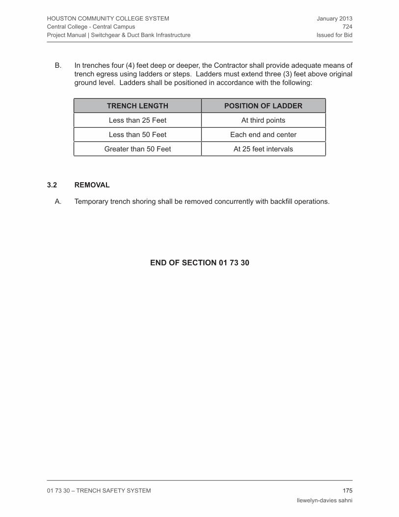
01 73 30 – TrENCH SAFETY SYSTEM 175 llewelyn-davies sahni
HOUSTON COMMUNITY COLLEGE SYSTEMCentral College - Central CampusProject Manual | Switchgear & Duct Bank Infrastructure
January 2013724
Issued for Bid
In trenches four (4) feet deep or deeper, the Contractor shall provide adequate means of B. trench egress using ladders or steps. Ladders must extend three (3) feet above original ground level. Ladders shall be positioned in accordance with the following:
TrenCh lenGTh posiTion of ladder
Less than 25 Feet At third points
Less than 50 Feet Each end and center
Greater than 50 Feet At 25 feet intervals
remoVal3.2
Temporary trench shoring shall be removed concurrently with backfill operations.A.
end of seCTion 01 73 30

26 00 01 - ELECTrICAL GENErAL PrOvISIONS 176 llewelyn-davies sahni
HOUSTON COMMUNITY COLLEGE SYSTEMCentral College - Central CampusProject Manual | Switchgear & Duct Bank Infrastructure
January 2013724
Issued for Bid
diVision 26 – eleCTriCal
26 00 01 - eleCTriCal General proVisions
GeneralparT 1 -
relaTed doCUmenTs1.1
The Conditions of the Contract and applicable requirements of Divisions 0 and 1 and this A. Section govern the work of this Division.
desCripTion of work:1.2
Work Included: This Work of this Division includes the furnishing of all supervision, labor, A. materials, supplies, equipment, apparatus, appurtenances , transportation, storage, utilities, permits and licenses required for complete installation of complete, tested and operating electrical systems as shown on the drawings and specified or as reasonably inferred there from, in place and ready for service. All work performed under this Section shall be performed in a workmanlike manner in accordance with the Drawings and Specifications and industry standards and subject to the terms and conditions of the Contract. For purposes of these Specifications, “provide” and “furnish and install” shall be synonymous.
Drawings: refer to the Electrical Drawings for graphic representations, schedules, and B. notations of required electrical work.
Specifications: Refer to this Division and related Divisions for the primary technical C. specifications of electrical work.
Work of Other Sections: requirements given within this Section apply to the Work of all D. Sections of this Division. The actual performance of the Work stays within the Section in which it occurs; but subject to the requirements of this Section to the extent applicable.
All prime, finished, and protective painting for all areas shall be provided under this 1. Division.
Installation of electrical control power which is not specified as an integral part of 2. equipment specified under Divisions 21, 22, 23 and 25 shall be provided under this Division.
Concrete housekeeping pads , ductbank encasement and supporting structures 3. are specified under this Divisions. Dimensions and locations of pads and supports shall be the responsibility of this Division.
Owner and General Contractor-furnished equipment is furnished and installed 4. under other Divisions. Proper electrical provisions, including rough-in and final

26 00 01 - ELECTrICAL GENErAL PrOvISIONS 177 llewelyn-davies sahni
HOUSTON COMMUNITY COLLEGE SYSTEMCentral College - Central CampusProject Manual | Switchgear & Duct Bank Infrastructure
January 2013724
Issued for Bid
equipment connections, are included in the Work of this Division.
Codes, permiTs and fees:1.3
General: Comply with the most recently revised versions of applicable laws, rules, A. regulations, and ordinances of federal, state, and local utilities and authorities. Where alterations to and deviations from the Contract Documents are required by said authority, report the requirements and secure approval before starting work. Obtain all applicable permits, licenses and inspections and pay all fees charged by above authorities.
Code Design Basis: The following codes and ordinances were used in the design of the B. project and shall be complied with during construction of the project.
Building Code - International Building code with city of Houston amendments 1. 2006 Edition.
Electrical Code – National Electrical Code 2011 Edition.2.
Accessibility Code- Texas Accessibility Standards(TAS), 1994 and Americans with 3. Disabilities Act of 1990.
Precedence: Where Contract Document requirements are in excess of Code requirements C. and are permitted under the Code, the Contract Documents shall govern. None of the terms or provisions of the Drawings or specification shall be construed as waiving any of the rules, regulations or requirements of these authorities. In the event of conflict between the Contract Documents and the local enforcing authority, the latter shall rule. Any modifications resulting there from shall be made without additional cost to the Owner or Engineer. This Contractor shall report any such modifications to the Engineer and secure his approval before proceeding.
QUaliTy assUranCe and sTandards:1.4
Materials/Methods: Manufacturers, materials, and methods described in the various A. sections of the Specifications, and indicated on the Drawings are intended to establish a standard of quality only. It is not the intention of the Engineer to discriminate against any product, material or method that is equal to the standards as indicated and/or specified, nor is it intended to preclude open, competitive bidding. The fact that a specific manufacturer is listed as an acceptable manufacturer should not be interpreted to mean that the manufacturers’ standard product will meet the requirements of the project design, Specifications and space constraints. The Engineer shall be the sole judge of quality and equivalence of equipment, materials and methods.
Alternative Products/Materials/Methods: Products by other reliable manufacturers, other B. materials, and other methods may be accepted provided they have equivalent capacity, construction, and performance. Under no circumstances shall any substitution be made without the prior written approval of the Engineer. Wherever a definite product, material or method is specified and there is not a statement that another product, material or method will be acceptable, it is the intention of the Engineer that the specified product,

26 00 01 - ELECTrICAL GENErAL PrOvISIONS 178 llewelyn-davies sahni
HOUSTON COMMUNITY COLLEGE SYSTEMCentral College - Central CampusProject Manual | Switchgear & Duct Bank Infrastructure
January 2013724
Issued for Bid
material or method is the only one that shall be used without prior approval. Wherever a definite material or manufacturer’s product is specified and the Specification states that products of similar design and equal construction from the specified list of manufacturers may be provided, it is the intention of the Engineer that products of manufacturers that are specified are the only products that will be acceptable and that products of other manufacturers will not be considered for substitution without prior written approval.
Alternative Equipment: Where substituted or alternative equipment is used on the project, C. it shall be the responsibility of the Contractor or Subcontractor involved to verify that the equipment will fit in the space available, including all required Code and maintenance clearances, and to coordinate all equipment requirements and provisions with the Electrical Design and all other Contractors and Subcontractors.
Compatibility: Provide products which are compatible with other products of the electrical D. work, and with other work requiring interface with the electrical work, including electrical connections and control devices. For exposed electrical work, coordinate colors and finishes with other work. Determine in advance of purchase that equipment and materials proposed for installation will fit into the confines indicated, leaving adequate clearance as required by applicable codes and for adjustment, repair, and replacement.
Standards: refer to Divisions 0 and 1 for general administrative/procedural requirements E. related to compliance with applicable standards. This Work and all materials shall meet the standards set forth in the applicable portions of the following recognized standards:
AEIC Association of Edison Illuminating Companies.1.
ANSI American National Standards Institute.2.
ASHrAE American Society of Heating, refrigerating & Air-Conditioning 3. Engineers.
ASME American Society of Mechanical Engineers.4.
ASPE American Society of Plumbing Engineers.5.
ASSE American Society of Sanitary Engineering.6.
ASTM American Society for Testing and Materials.7.
AWS American Welding Society.8.
CBM Certified Ballast Manufacturers.9.
CDA Copper Development Association.10.
CE Corps of Engineers (U. S. Department of the Army).11.
EIA Electronic Industry Association.12.
ETL Electrical Testing Laboratory.13.
FAA Federal Aviation Administration (US Department of Transportation).14.

26 00 01 - ELECTrICAL GENErAL PrOvISIONS 179 llewelyn-davies sahni
HOUSTON COMMUNITY COLLEGE SYSTEMCentral College - Central CampusProject Manual | Switchgear & Duct Bank Infrastructure
January 2013724
Issued for Bid
FCC Federal Communications Commission.15.
FM Factory Mutual Engineering Corporation.16.
FS Federal Specification (General Services Administration).17.
ICEA Insulated Cable Engineering Association.18.
IEEE Institute of Electrical and Electronics Engineers.19.
IES Illuminating Engineering Society of North America.20.
IrI Industrial risk Insurers.21.
LPI Lighting Protection Institute.22.
MIL Military Standardization Documents (US Dept. of Defense).23.
MSS Manufacturers Standardization Society of the valve and Fittings Industry.24.
NEC National Electrical Code (by NFPA).25.
NECA National Electrical Contractor Association.26.
NEMA National Electrical Manufacturers Association.27.
NFPA National Fire Protection Association.28.
OSHA Occupational Safety Health Administration (US Department of Labor).29.
UL Underwriters’ Laboratories, Inc.30.
siTe VisiT and familiarizaTion:1.5
General: Become familiar with the Drawings and Specifications, examine the premises, A. and understand the conditions under which the Contract shall be performed, prior to submitting a bid.
Site: Be informed of the site conditions, verify locations of new and existing equipment, B. and determine exact requirements for connections.
Coordination: Submission of a bid for this project infers that the Contractor has visited C. the site and has become familiar with the Drawings and site conditions and has included in his proposal, all work necessary to properly install the systems on the project.
Pre-Bid Conference: refer to Divisions 0 and 1.D.
drawinGs and speCifiCaTions:1.6
General: The Drawings are schematic in nature and indicate approximate locations of A. the electrical systems, equipment, fixtures and devices, except where specific locations are noted and dimensioned on the Drawings. All items are shown approximately to

26 00 01 - ELECTrICAL GENErAL PrOvISIONS 180 llewelyn-davies sahni
HOUSTON COMMUNITY COLLEGE SYSTEMCentral College - Central CampusProject Manual | Switchgear & Duct Bank Infrastructure
January 2013724
Issued for Bid
scale. The intent is to show how these items shall be integrated into the building. Locate all items by on the job measurements and in accordance with the Contract Documents. Cooperate with other trades to ensure project completion as indicated.
Location: Prior to locating electrical devices, and other items, obtain the Architect/ B. Engineer’s approval as to exact location. Locations shall not be determined by scaling Drawings. Where there is a question concerning the required location for items of electrical work, the Contractor shall submit a request for information to the Architect/Engineer requesting specific directions for locating the item. Contractor shall be responsible for costs of redoing work of trades necessitated by failure to comply with this requirement.
The Drawings show diagrammatically the location of the apparatus. Exact 1. locations of these apparatus shall be determined by reference to the Architectural Drawings and to all detail Drawings, equipment Drawings, rough-in Drawings, etc., by measurements at the building, and in cooperation with the other trades. The Owner and Architect/Engineer reserve the right to make any reasonable change in location of any outlet or apparatus before installation, without additional cost to the Owner.
Specifications: The specifications are intended to supplement the Drawings and it is not C. in the scope of the specifications to mention any part of the work which the Drawings are competent to fully explain. Conversely, any part of the work which the specification are competent to fully explain, may not be mentioned on the Drawings.
Disagreement: Disagreement between the Drawings or specifications or within the D. Drawings or specifications shall be estimated using the better quality or greater quantity of material or installation, and a request for information shall be made to the Engineer.
disCrepanCies:1.7
Clarification: Clarification shall be obtained before submitting a proposal for the Work A. under this Division as to discrepancies or omissions from the Contract Documents or questions as to the intent thereof.
Detailed Instructions: Should it appear that the work hereby intended to be done or any B. of the materials relative thereto, is not sufficiently detailed or explained in the Drawings or Specifications, then the Contractor shall submit a request for information to the Engineer for such further Drawings or explanations as may be necessary before proceeding, allowing a reasonable time for the Engineer to respond. The Contractor shall conform to this additional information as a part of the Contract without additional cost to the Owner or Engineer.
Interpretations: Should any doubt or question arise respecting the true meaning of C. Drawings or Specifications, reference shall be made to the Engineer, whose written decision shall be final and conclusive. No alleged statement by the Engineer will be accepted as an excuse for inferior work.
Contractor Agreement: Consideration will not be granted for misunderstanding of the D.

26 00 01 - ELECTrICAL GENErAL PrOvISIONS 181 llewelyn-davies sahni
HOUSTON COMMUNITY COLLEGE SYSTEMCentral College - Central CampusProject Manual | Switchgear & Duct Bank Infrastructure
January 2013724
Issued for Bid
amount of work to be performed. Submission of a bid conveys full Contractor agreement of the items and conditions specified, shown, scheduled, or required by the nature of the project.
UTiliTies:1.8
General: Utility information shown on the Drawings have been shown based upon data A. obtained from the site survey and the agencies having jurisdiction and are accurate to the best of the knowledge of the Engineer.
Coordination: The Contractor shall be responsible for field verification of the actual location B. of site and/or building utilities and shall make modifications necessary for connection to or construction around those utilities at no additional cost to the Owner or Engineer.
Temporary faCiliTies:1.9
General: refer to Uniform General Conditions and Divisions 0 and 1 for requirements A. concerning temporary electrical facilities.
ChanGe orders:1.10
General: refer to Uniform General Conditions and Divisions 0 and 1 for requirement A. concerning Change Orders.
alTernaTes:1.11
General: refer to Divisions 0 and 1 for information concerning Alternates.A.
UniT priCes:1.12
General: refer to Divisions 0 and 1 for information on required Unit Prices which are part A. of the project bid.
preConsTrUCTion ConferenCe:1.13
Conference: Upon the award of this Contract and prior to commencing any work, the A. Contractor and his designated major subcontractors, shall confer with the Architect, Engineer and Owner concerning the Work under this Contract. The conference shall be at a mutually agreeable place and time.
siTe obserVaTion:1.14
General: Observation at the site to verify general compliance with Contract Documents A. shall be made periodically by the Engineer or his representative. Written observation comments shall be submitted to the General Contractor for review and a written response.

26 00 01 - ELECTrICAL GENErAL PrOvISIONS 182 llewelyn-davies sahni
HOUSTON COMMUNITY COLLEGE SYSTEMCentral College - Central CampusProject Manual | Switchgear & Duct Bank Infrastructure
January 2013724
Issued for Bid
reQUesTs for informaTion (rfi):1.15
General: All Contractor Requests for Information (RFI’s) shall be submitted to the A. Engineer in writing, for response.
Format: All RFI’s shall be submitted on a form which includes the date, a sequential RFI B. number, the requested information and space for the Engineer’s response, signature and date. RFI’s shall be submitted to the Engineer in a electronic format (unprotected pdf, doc/docx or xls/xlsx format) for response.
responses: The Engineer will endeavor to provide rFI response time in the Engineer’s C. office of five working days after receipt of the RFI by the Engineer.
sUbmiTTals:1.16
General: Submittals required for this project shall include, but not be limited to:A.
Shop Drawings and Product Brochure Submittals.1.
Certifications and Test Reports.2.
Operating and Maintenance Manuals.3.
Warranties (Guarantees).4.
Refer to Division 1 for additional submittal requirements.B.
Shop Drawings and Product Brochure Submittals: The Contractor shall submit one C. electronic (unprotected pdf format) copy or a sufficient number of complete bound hardcopy sets of Shop Drawings and complete data covering each item of equipment or material. The terms “Submittal” and “Shop Drawing” in this Specification are defined as either product literature, samples of equipment, or actual Shop Drawings. The first submittal of each item requiring a submittal must be received by the Engineer within 90 days of contract award. The Engineer shall not be responsible for any delays or costs incurred due to excessive Shop Drawing review time where the first submittal is received more than 90 days after contract award. The Architect and Engineer will each retain one copy of all hardcopy Shop Drawing submittals for their files. The Contractor is required to include a copy of all final electrical Shop Drawing submittals in Electrical O&M manuals.
Contractor shall prepare complete submittals that include all pertinent information 1. about the product. A single Shop Drawing shall not contain information from more than one Specification section, but a single Specification section may be subdivided into separate submittals for items or equipment that are specified in that section. Shop Drawings shall be separately bound by complete or partial Specification section. Where a single Shop Drawing contains information from more than one Specification section, it will be marked “REVISE AND RESUBMIT” and returned. Each Shop Drawing shall include the following items enclosed in a suitable binder, Shop Drawings that do not comply with the above requirements will be marked “REVISE AND RESUBMIT” and returned to the Contractor:

26 00 01 - ELECTrICAL GENErAL PrOvISIONS 183 llewelyn-davies sahni
HOUSTON COMMUNITY COLLEGE SYSTEMCentral College - Central CampusProject Manual | Switchgear & Duct Bank Infrastructure
January 2013724
Issued for Bid
A cover sheet with the names and addresses of the Project, Architect, a) M/E/P Engineer, General Contractor, and the Subcontractor making the submittal. The cover sheet shall also contain the Specification section number applicable to the item or items submitted, the item nomenclature and description and a submittal number. Electrical submittals shall be numbered sequentially by Specification section with a sequence suffix (e.g. 26 22 00 1, 26 23 12 2, 26 25 01 1, etc.). Resubmittals shall be numbered with the original submittal number plus an “R” in the sequence suffix (e.g. the resubmittals of submittal 26 22 00 1 would be 26 22 00 1R1, 26 22 00 1r2, ...).
An index page with a listing of all data included in the submittal.b)
A list of variations. This page shall list all variations, including unfurnished c) or additional items or features between the submitted equipment and the specified equipment. If there are no variations, then this page shall state “No Variations”. Where variations affect the work of other contractors, then the contractor shall certify on this page that these variations have been fully coordinated with the affected contractors and that all additional costs to the affected contractors associated with the variations shall be paid by the submitting contractor.
Equipment information including manufacturer’s name and designation, d) size, performance and capacity data. All applicable listings, labels, approvals and standards shall be clearly indicated.
Dimensional data and actual sketches as applicable to show that the e) submitted equipment will fit the space available with all required Code and maintenance clearances.
Identification of each item of material or equipment matching that indicated f) on the Drawings.
Sufficient pictorial, descriptive and diagrammatic data on each item to g) show its conformance with the Drawings and Specifications. Any options or special requirements shall be so indicated. All applicable information shall be clearly indicated with arrows or another approved method. Any non-applicable information shall be crossed out.
Additional information as required in other sections of this Division.h)
Certification by the General Contractor and Subcontractor that the material i) submitted is in accordance with the Contract Documents, signed and dated.
Reports or information requiring certification shall be certified by an j) authorized officer of the manufacturer or testing agency.
Certified Shop Drawings showing dimensions, loading details, anchor bolt k) locations, and inserts required for each piece of equipment set on concrete in sufficient time to cause no delay in the Work.
Equipment and material submittals shall show sufficient data including all l)

26 00 01 - ELECTrICAL GENErAL PrOvISIONS 184 llewelyn-davies sahni
HOUSTON COMMUNITY COLLEGE SYSTEMCentral College - Central CampusProject Manual | Switchgear & Duct Bank Infrastructure
January 2013724
Issued for Bid
performance data, recommended installation details, and sufficient data to indicate complete compliance with the Contract Documents, including proper sizes, clearances, capacities, materials, and finishes.
Required Shop Drawing Submittals: Submit Shop Drawings, including, but not limited D. to the following items. Refer to individual specification sections for specific submittal requirements.
Medium Voltage Conductors and Cable Refer to Section 26 05 13.1.
Electrical Grounding refer to Section 26 05 26.2.
Electrical raceways refer to Section 26 05 33.3.
Short Circuit Analysis/Coordination Study refer to Section 26 01 60.4.
Medium voltage Load Interrupter Switchgear refer to Section 26 10 025.
Electrical Service Entrance refer to Section 26 27 01.6.
Underground Duct banks and Manholes Refer to Section 33 71 19. 7.
Samples: Submit two samples, upon request, of electrical devices and materials for E. review by the Architect/Engineer. Samples will be returned upon written request of the Contractor.
Shop Drawing Submittal Review: Shop Drawings will be reviewed for general conformance F. with the design concept of the project and general compliance with the information given in the Contract Documents. Any action shown in review comments is subject to the requirements of the Contract Documents. The submitting Contractor is responsible for: dimensions which shall be confirmed at the job site; fabrication processes and techniques of construction; coordination of his work with that of all other trades; and the satisfactory performance of his work.
The Engineer will endeavor to provide a Shop Drawing review time in the Engineer’s 1. office of two weeks per review, exclusive of transmittal time, and this review time shall be considered by the Contractor when scheduling his work on the project.
The Architect’s review or approval and the Engineer’s review of Shop Drawings shall 2. not relieve the Contractor of the responsibility for errors, omissions or deviations that may be contained in the submittals. If the Contractor proceeds on the basis of undetected errors, omissions or deviations in reviewed Shop Drawings, it shall be at his sole responsibility and the review does not allow deviations from the requirements of the Contract Documents. Noting some errors, omissions, and deviations but overlooking other errors, omissions, and deviations does not grant the Contractor permission to proceed in error. regardless of any information contained in the Shop Drawing or the Engineer’s review thereof, the Contract Documents shall govern the Work and are neither waived or superseded by the Shop Drawing review.

26 00 01 - ELECTrICAL GENErAL PrOvISIONS 185 llewelyn-davies sahni
HOUSTON COMMUNITY COLLEGE SYSTEMCentral College - Central CampusProject Manual | Switchgear & Duct Bank Infrastructure
January 2013724
Issued for Bid
It shall be the responsibility of the submitting Contractor to check all equipment 3. and materials for conformance with the Contract Documents and “REVIEWED WITH NO EXCEPTIONS TAKEN” or “MAKE CORRECTIONS NOTED” submittal at the time such equipment and materials are delivered to the job site, and to notify the Engineer of any deviations.
Inadequate or incomplete Shop Drawings will not be reviewed by the Architect 4. or the Engineer and will be returned to the Contractor marked “REVISE AND RESUBMIT” for completion and resubmittal.
Shop Drawings will be marked “REVIEWED WITH NO EXCEPTIONS TAKEN”, 5. “MAKE CORRECTIONS NOTED”, “ MAKE CORRECTIONS NOTED AND SUBMIT WRITTEN RESPONSE”, “REVISE AND RESUBMIT” or “REJECTED” when reviewed by the Engineer. The definitions of these terms for review purposes is as follows:
rEvIEWED WITH NO EXCEPTIONS TAKEN - The Shop Drawing was a) reviewed and no exceptions from the general conformance with the design concept and general compliance with the information given in the Contract Documents were noted.
MAKE COrrECTIONS NOTED - The Shop Drawing was reviewed and b) found to have minor deviations from the requirements of the Contract Documents, as noted. A Shop Drawing resubmittal is not required, however, the furnished material/systems shall comply with the corrections noted in the submittal review.
MAKE COrrECTIONS NOTED AND SUBMIT WrITTEN rESPONSE - c) The Shop Drawing was reviewed and found to have either minor deviations from the requirements of the Contract Documents or information missing from the submittal, as noted. A complete Shop Drawing resubmittal is not required, however, a written response to all review comments shall be submitted in the format used for a resubmittal.
rEvISE AND rESUBMIT - The Shop Drawing was reviewed and major d) deviations from general conformance with the design concept and general compliance with the information given in the Contract Documents were observed, as noted. The Shop Drawing shall be revised to eliminate the deviations noted and resubmitted.
rEJECTED - The Shop Drawing was reviewed and is not in general e) conformance with the design concept or in compliance with the information given in the Contract Documents, as noted. A revised Shop Drawing submittal for the specified equipment or materials shall be resubmitted.
Division 1 and General Conditions requirements concerning Shop Drawing 6. submittal review are not applicable to this Division.
Materials and equipment which are purchased or installed without a “REVIEWED 7. WITH NO EXCEPTIONS TAKEN” or “MAKE CORRECTIONS NOTED” Shop Drawing review shall be at the risk of the Contractor and the cost for removal and

26 00 01 - ELECTrICAL GENErAL PrOvISIONS 186 llewelyn-davies sahni
HOUSTON COMMUNITY COLLEGE SYSTEMCentral College - Central CampusProject Manual | Switchgear & Duct Bank Infrastructure
January 2013724
Issued for Bid
replacement of such materials and equipment and related work which is judged unsatisfactory by the Architect/Engineer for any reason, shall be at the expense of the Contractor.
Shop Drawings shall be complete and checked prior to submission to the Engineer 8. for review. Where more than three reviews are required for a given Shop Drawing to reach “REVIEWED WITH NO EXCEPTIONS TAKEN” or “MAKE CORRECTIONS NOTED” status, the Subcontractor will be invoiced for extra services at a cost of $100.00 per hour for review of the fourth and subsequent reviews. If the Subcontractor fails to pay any legitimate extra services invoice in full within 30 days, then that invoice will be forwarded to the Architect/Owner requesting him to withhold payment of the amount invoiced from the next General Contractors request for payment as allowed for under the General Conditions of the Contract for Construction (AIA Document A 201). Incomplete submittals will be returned to the Contractor unchecked.
Certifications and Test Reports: The Engineer may, at their option, witness any or all on G. and off-site acceptance and operational testing. Submit a detailed listing of certification and testing for each system indicating estimated dates for completion of system installation. This listing of certification and testing shall be submitted at least 30 days before any testing is conducted.
Test procedures and test result reporting forms shall be submitted for review no 1. later than the date of the certification and testing listing submittal.
Notify the Engineer in writing two weeks prior to all scheduled testing to allow time 2. for Engineer to schedule witnessing of testing, where elected by the Engineer.
Submit four copies of all certifications and test reports to the Engineer for review 3. adequately in advance of completion of the Work to allow for remedial action as required to correct deficiencies discovered in equipment and systems.
Certifications and test reports to be submitted shall include, but not be limited to 4. those items outlined in Section 26 01 25 “Electrical Testing”.
Operating and Maintenance Manuals: Submit two copies of Operating and Maintenance H. Manuals to the Engineer for approval prior to the beginning of operator training. Provide four approved Operating and Maintenance Manuals for use in operator training. Manuals shall be bound in rigid cover, 3 ring binders with spine and cover labels and shall provide operating and maintenance information for every piece of equipment furnished under this Specification. All sections shall be typed and indexed into sections and labeled for easy reference. Bulletins containing information about equipment which is not installed on the project shall be properly marked up or stripped and reassembled. All pertinent information required by the Owner for proper operation and maintenance of applicable equipment supplied by Division 26, 27 and 28 shall be clearly and legibly set forth in memoranda which shall, likewise, be bound with bulletins. As a minimum, the following information shall be provided as applicable:
Complete description of each system, item of equipment, and apparatus provided 1.

26 00 01 - ELECTrICAL GENErAL PrOvISIONS 187 llewelyn-davies sahni
HOUSTON COMMUNITY COLLEGE SYSTEMCentral College - Central CampusProject Manual | Switchgear & Duct Bank Infrastructure
January 2013724
Issued for Bid
under this Division, including ratings, capacities, performances, data and curves, characteristics identifying name and number, locations, and wiring diagrams, including sources for all parts.
Fully detailed parts lists, including all numbered parts and recommended spare 2. parts, of each item of equipment and apparatus provided under this Division.
Manufacturer’s printed instructions describing operation, service, maintenance, 3. and repair of each item of equipment and apparatus.
Typed record of tests made of materials, equipment, and systems included under 4. this Division. Such records shall state the dates the tests were conducted, name(s) of person(s) making and witnessing the tests, and citing any unusual conditions relevant to the tests.
Identifying names, name tags designations and locations for all equipment.5.
Fuse and motor heater information including location and use.6.
Equipment and motor nameplate data.7.
Copies of all approved Shop Drawing submittals.8.
Fabrication drawings.9.
Equipment and device bulletins and cutsheets clearly highlighted to show equipment 10. installed on the project and including performance curves and data as applicable.
Maintenance instructions clearly highlighted to show all required periodic 11. maintenance and lubrication.
Wiring diagrams.12.
Operating instructions clearly highlighted to show proper operating procedures for 13. all equipment.
Exploded parts views and parts lists for all equipment and devices.14.
Color coding charts for all painted equipment and conduit.15.
Location and listing of all spare parts and special keys and tools furnished to the 16. Owner.
Tools: Provide and deliver to the Owner’s authorized representative any special tools I. required for maintenance of systems, equipment, and apparatus installed under this Division prior to requesting final acceptance of the installation.
projeCT reCord doCUmenTs:1.17
Site Prints: Maintain a set of clearly marked prints of the Contract Drawings at the job A. site which shall be used for recording the work details, final size, location, interrelation, and similar items of all work under this Division. This set of Drawings shall be corrected

26 00 01 - ELECTrICAL GENErAL PrOvISIONS 188 llewelyn-davies sahni
HOUSTON COMMUNITY COLLEGE SYSTEMCentral College - Central CampusProject Manual | Switchgear & Duct Bank Infrastructure
January 2013724
Issued for Bid
daily as the Work progresses and shall clearly indicate all changes to suit field conditions, changes made by “Field Order” or “Change Order”, accurate dimensions of all buried or concealed work, precise locations of all concealed work, locations of all concealed boxes, controls and devices and any deviations from the work shown on the Construction Documents which are required for coordination. All dimensions shall be to at least two permanent structure points.
Upon completion of the work, the Contractor shall clearly and legibly transfer all marks B. from the site prints to a set of reproducible Record “As-Built” Drawings using red pen or pencil. The reproducible Record “As-Built” Drawings shall have the Engineers Name and Seal removed or blacked out and shall be clearly marked and signed on each sheet as follows:
CErTIFIED rECOrD DrAWINGS
DATE:
(NAME OF GENErAL CONTrACTOr)
BY:
(SIGNATUrE)
(NAME OF SUBCONTrACTOr)
BY:
(SIGNATUrE)
Approval: Prior to final acceptance of the Work of this Division, the Contractor shall C. submit three prints of properly certified Record Drawings to the Engineer for review and shall make changes, corrections or additions as the Engineer may require to the record Drawings.
CoordinaTion of eleCTriCal work:1.18
General: Refer to Division 1 for general coordination requirements applicable to the A. entire work. It is recognized that the Contract Documents are diagrammatic in showing certain physical relationships which must be established within the electrical work, and in its interface with other work including utilities and mechanical work and that such establishment is the exclusive responsibility of the Contractor. The Drawings show diagrammatically the sizes and locations of the various conduit and raceway systems and equipment items and the sizes of the major interconnecting distribution, without

26 00 01 - ELECTrICAL GENErAL PrOvISIONS 189 llewelyn-davies sahni
HOUSTON COMMUNITY COLLEGE SYSTEMCentral College - Central CampusProject Manual | Switchgear & Duct Bank Infrastructure
January 2013724
Issued for Bid
showing exact details as to elevations, offsets, control lines, and installation details.
Arrange electrical work in a neat, well organized and workmanlike manner with 1. services running parallel with primary lines of the construction.
The Contractor shall carefully lay out his work at the site to conform to the 2. architectural and structural conditions, to avoid obstructions and to provide proper grading of lines. Exact locations of outlets, apparatus and connections thereto shall be determined by reference to detail Drawings, equipment Drawings, roughing-in Drawings, etc., by measurements at the building and in cooperation with other Contractors and in all cases shall be subject to the approval of the Engineer. Relocations necessitated by the conditions at the site or directed by the Engineer shall be made without any additional cost to the Owner or Engineer.
Equipment has been chosen to fit within the available space with all required Code 3. and maintenance clearances and shall be installed as shown. Every effort has been made to also accommodate equipment of other approved manufacturers, however since equipment and access space requirements vary, the final responsibility for installation access and proper fit of substituted equipment rests with the Contractor.
System interferences shall be handled by giving precedence to pipe lines which 4. require a stated grade for proper operation. Where space requirements conflict, the following order of precedence shall, in general, be observed:
Existing Utilities.a)
Locate electrical equipment properly to provide easy access. Arrange entire 5. electrical work with adequate code access for operation and maintenance.
Advise other trades of openings required in their work for the subsequent move in 6. of large units of electrical work (equipment).
Coordinate all items which will affect the installation of the work of this Division. 7. This coordination shall include, but not be limited to: voltage, ampacity, capacity, electrical connections, space requirements, sequence of construction, building requirements and special conditions.
When submitting Shop Drawings on the project, this Contractor is indicating that all 8. necessary coordination has been completed and that the systems, products and equipment submitted can be installed in the building and will operate as specified and intended, in full coordination with all other Contractors and Subcontractors.
Changes to the Construction Documents or the project design concepts.9.
maTerials and workmanship:1.19
General: Materials and equipment shall be new, of best grade and quality, and standard A. products of reputable manufacturers regularly engaged in the production of such materials and equipment.

26 00 01 - ELECTrICAL GENErAL PrOvISIONS 190 llewelyn-davies sahni
HOUSTON COMMUNITY COLLEGE SYSTEMCentral College - Central CampusProject Manual | Switchgear & Duct Bank Infrastructure
January 2013724
Issued for Bid
Workmanship: Work shall be executed and materials installed in accordance with the B. best practice of the trades in a thorough, substantial, workmanlike manner by competent workmen, presenting a neat appearance when completed.
Manufacturer’s Recommendations: With exceptions as specified or indicated on the C. Drawings or in the Specifications, apply, install, connect, erect, use, clean, and condition manufactured articles, materials, and equipment per manufacturer’s current printed recommendations. Copies of such printed recommendations shall be kept at the job site and made available as required.
spaCe reQUiremenTs:1.20
General: Determine in advance of purchase that the equipment and materials proposed A. for installation will fit into the confines indicated, leaving adequate code clearances for adjustments, repair, or replacement.
Clearance: Allow adequate space for clearance in accordance with requirements of the B. Code and local inspection department.
Scheduled Equipment: The design shown on the Drawings is based on the equipment C. scheduled.
Responsibility: Since space requirements and equipment arrangement vary for each D. manufacturer, the responsibility for initial access and proper fit rests with the Contractor.
Review: Final arrangements of equipment to be installed shall be subject to the Architect’s E. review.
safeTy reGUlaTions:1.21
All electrical work shall be performed in compliance with all applicable and governing A. safety regulations. All safety lights, guards, signs, and other safety materials and provisions required for the performance of the electrical work shall be provided by and operated by the Electrical contractor.
deliVery, sToraGe and handlinG of maTerials:1.22
General: Protect all materials and equipment to be installed under this Division from A. physical and weather damage.
Scope: Work under this Division shall include, but not limited to:B.
Shipping from point of manufacture to job site.1.
Unloading, moving, and storage on site with proper protection as required to 2. properly protect equipment from rust, drip, humidity, dust, or physical damage.
Hoisting and scaffolding of materials and equipment included in this Division.3.

26 00 01 - ELECTrICAL GENErAL PrOvISIONS 191 llewelyn-davies sahni
HOUSTON COMMUNITY COLLEGE SYSTEMCentral College - Central CampusProject Manual | Switchgear & Duct Bank Infrastructure
January 2013724
Issued for Bid
Ensuring safety of employees, materials, and equipment using such hoisting 4. equipment and scaffolding.
Coordination: All large pieces of apparatus which are to be installed in the building and C. which are too large to permit access through doorways, stairways or shafts shall be brought to the job by the Contractor and shall be placed in the spaces before enclosing partitions and structure are completed. All apparatus shall be cribbed up from the floor by Contractor and shall be covered with tarpaulins or other protective covering where required for protection.
noise and VibraTion:1.23
General: Warrant the electrical systems, and their component parts to operate without A. objectionable noise or vibration. Noise from systems or equipment which results in noise within occupied spaces above the recommended NC curves (refer to ASHRAE Standard) shall be considered objectionable. Vibration shall not be apparent to the senses in occupied areas of the building. Objectionable noise, vibration, or transmission thereof to the building shall be corrected.
CleaninG, adjUsTinG and sTarT Up:1.24
Start up Services: Where specified for any individual item of electrical equipment, provide A. a factory-authorized representative for testing, start-up of equipment, and instruction of Owner’s operating personnel. Certify that these services have been performed by including a properly executed invoice for these services or a letter from the manufacturer.
Testing: Refer to Section 26 01 25, “Electrical Testing” for requirements.B.
Clean up: Each Contractor shall clean away from the job site all debris, surplus material, C. and similar items, resulting from his work or operations, leaving the job and equipment in a clean condition. Each Contractor shall thoroughly clean all pieces of equipment, conduit, boxes, fixtures, and similar items, leaving the installation in a first class condition.
Operation Prior to Completion: When any piece of electrical equipment is operable D. and it is to the advantage of the Contractor to operate the equipment, he may do so, providing that he properly supervises the operation, and has the Engineer’s written permission to do so. The warranty period shall, however, not commence until such time as the equipment is operated for the beneficial use of the Owner, or date of substantial completion, whichever occurs first. Regardless of whether or not the equipment has or has not been operated, the Contractor shall properly clean the equipment, properly adjust, and complete all deficiency list items before final acceptance by the Owner. The date of final acceptance and the start of the warranty may not be the same date.
final reView:1.25
General: Upon completion of the Work, perform a final test of the entire system.A.
The system shall be operating properly.1.

26 00 01 - ELECTrICAL GENErAL PrOvISIONS 192 llewelyn-davies sahni
HOUSTON COMMUNITY COLLEGE SYSTEMCentral College - Central CampusProject Manual | Switchgear & Duct Bank Infrastructure
January 2013724
Issued for Bid
After the final test, any changes or corrections noted as necessary for the Work to 2. comply with these Specifications or the Drawings, shall be accomplished without delay in order to secure final acceptance of the Work.
The date for the final test shall be sufficiently in advance of the Contract completion 3. date to permit execution, before expiration of the Contract, of any adjustments or alterations which the final acceptance tests indicate as necessary for the proper functioning of all equipment. Any such modifications shall be completed within the time allotted for completion of the Contract. Retests shall be conducted as directed and shall be of such time duration as necessary to ensure proper functioning of adjusted and altered items. retests shall not relieve the Contractor of completion date responsibility.
Certificates, including certificates of occupancy from local authorities and documents 4. required herein, shall be completely in order and presented to the Engineer at least one week prior to the review.
Qualified Person: Individuals knowledgeable of the systems and persons approved by B. the Engineer, shall be present at this final inspection to demonstrate the system and prove the performance of the equipment.
owner insTrUCTion:1.26
General: This Contractor and appropriate factory-trained representatives shall instruct A. the Owner’s representative in the proper operation and maintenance of all systems and equipment and shall explain all warranties.
Outline: Prior to instruction of Owner Personnel, prepare a typed outline, listing the B. subjects that will be included in this instruction, and submit the outline for review by the Engineer.
Certification: At the conclusion of the instruction period obtain the signature of each C. person being instructed on each copy of the approved outline to signify that he has a proper understanding of the operation and maintenance of the systems and resubmit the signed outlines.
Other requirements: refer to other Division 26, 27 and 28 Sections for additional D. Operator Training requirements.
ConTraCTor warranTies and GUaranTees:1.27
General: Contractor shall guarantee all material and equipment installed by him against A. defects in workmanship and material for a period of 12 months after final acceptance of the work by the Owner and he shall repair or replace any materials or equipment developing such defects within that time, promptly on due notice given him by the Owner and at Contractor’s sole cost and expense.
Equipment: All equipment bearing a manufacturer’s guarantee, such as electrical B.

26 00 01 - ELECTrICAL GENErAL PrOvISIONS 193 llewelyn-davies sahni
HOUSTON COMMUNITY COLLEGE SYSTEMCentral College - Central CampusProject Manual | Switchgear & Duct Bank Infrastructure
January 2013724
Issued for Bid
equipment, devices, components, and similar items, shall be construed to have an extended guarantee to the Owner by the manufacturer. Any such equipment that proves defective in materials or workmanship within the guarantee period is to be replaced by the Contractor in accordance with the manufacturer’s guarantee.
Start up: The Electrical Contractor shall provide instructions and equipment starting C. service on new equipment for one complete year after date of final acceptance of the work by the Owner, at Contractor’s sole cost and expense.
prodUCTsparT 2 - Not applicable.
exeCUTionparT 3 - Not applicable.
end of seCTion 26 00 01

26 01 60 - ELECTrICAL SHOrT CIrCUIT, COOrDINATION AND ArC FAULT STUDY 194 llewelyn-davies sahni
HOUSTON COMMUNITY COLLEGE SYSTEMCentral College - Central CampusProject Manual | Switchgear & Duct Bank Infrastructure
January 2013724
Issued for Bid
26 01 60 - eleCTriCal shorT CirCUiT, CoordinaTion and arC faUlT sTUdy
GeneralparT 1 -
work inClUded1.1
The Electrical Contractor shall provide the Engineer with a Power System Short Circuit A. Analysis, Protective Device Coordination Study and Arc Flash and Electrical Hazard Study. The analysis and study shall include all power distribution systems, beginning at the electric service point from the Electric Utility Company to the secondary buses of each panelboard as described hereafter.
The Short Circuit Analysis, Protective Device Coordination Study and Arc Flash 1. and Electrical Hazard Studies specified in this section shall be completed and submitted prior to submitting submittals for the switchgear.
The Electrical Contractor shall provide the Engineer with a Power System Short 2. Circuit Analysis, Protective Device Coordination Study and Arc Flash and Electrical Hazard Study. These analysis’s and studies shall include all power distribution systems, beginning at the electric service point from the Electric Utility Company for the switchgear.
The Short Circuit Analysis, Protective Device Coordination Study and Arc Flash 3. and Electrical Hazard Studies shall be prepared by and certified with a registration seal and signature of a Registered Professional Engineer. The Engineer shall be qualified by experience in preparation of studies having similar requirements and of similar magnitude to that specified in this section of the Specifications.
The Short Circuit Analysis shall terminate at the transformer the branch breakers 4. are serving. Appropriate recommendations shall be made for corrective action in the conclusions of the report where the interrupting rating of electrical equipment is exceeded by the available fault current.
The Protective Device Coordination Study shall start at the electric service and 5. include all electrical distribution equipment protective devices with adjustable trip units, relay settings. The curves and settings for the Power Company protective devices shall be included in the scope of this study. The coordination plots shall terminate with the first non-adjustable overcurrent device or devices downstream of all protective devices with an adjustable trip unit, relay settings. The protective device study shall include a separate analysis for phase and ground protection.
The Arc Flash and Electrical Hazard Study comply with applicable NEC and 6. OSHA requirements and shall include calculating the Arc Flash and establishing the Electrical Hazard rating for each switchboard, distribution panel, panelboard, automatic transfer switch, enclosed circuit breaker and disconnect switch to be installed on the project.

26 01 60 - ELECTrICAL SHOrT CIrCUIT, COOrDINATION AND ArC FAULT STUDY 195 llewelyn-davies sahni
HOUSTON COMMUNITY COLLEGE SYSTEMCentral College - Central CampusProject Manual | Switchgear & Duct Bank Infrastructure
January 2013724
Issued for Bid
The Contractor shall obtain all lengths of cable from the electrical drawings and, 7. where not shown the entire length of the run, from Contractor estimated lengths. All other equipment ratings shall be obtained by the Contractor from the equipment manufacturer's and/or suppliers.
Short Circuit Analysis: The Short Circuit Analysis shall include the following:B.
A schematic one-line drawing of the entire electrical system included in the study, 1. from the power company system including the point of delivery, to each primary transformer, and including all main secondary buses of each transformer included in the study. Secondary buses shall include multiple secondary transformations within the scope of the study. Each device shall be identified using project assigned identification labels. Each bus shall be assigned an identification number.
Source voltage and impedance data shall be given in the analysis, including 2. reactance and resistance in OHMS to the source, and available symmetrical and asymmetrical short circuit amperes at the point of delivery of electrical power. Short circuit amperes shall be based on an assumed bolted 3 phase short circuit.
At each bus, including buses of all primary protective and switching devices, primary 3. and secondary of all transformers, all secondary main and feeder breakers, within the scope of the study, the following shall be calculated for assumed bolted 3 phase short circuits.
Symmetrical rMS short circuit amperes, calculated using total source and a) motor contribution reactance and resistance values.
Asymmetrical average 3 phase rMS amperes at 1/2 cycle, calculated b) using actual total source and motor contribution X/R ratio.
reactance ("X") and resistance ("r") in OHMS at the voltage of the device c) being examined, including both The Power Company source and all motor contributions.
Calculation sheets for cable sections shall indicate voltage, wire size, cable length, 4. reactance and resistance of the section in OHMS and total "X" and "r" to the source.
Calculation sheets for transformer sections shall indicate transformer kvA, 5. secondary voltage, percent impedance, percent reactance, percent resistance, and total "X" and "r" value in OHMS at the secondary voltage to source, including The Power Company source impedance plus any primary motor contribution.
Calculation sheets for busway and miscellaneous devices shall provide all pertinent 6. parameters including operating voltage, section "X" and "r" values in OHMS, and total "X" and "R" values in OHMS to the source, based on source impedance plus any motor contribution.
Bus summary sheets shall be provided giving consecutive bus numbers, description, 7. voltage, "X" and "r" values in OHMS including The Power Company plus all motor contributions, symmetrical and asymmetrical short circuit amperes, X/R ration, and
26 01 60 - ELECTrICAL SHOrT CIrCUIT, COOrDINATION AND ArC FAULT STUDY 196 llewelyn-davies sahni
HOUSTON COMMUNITY COLLEGE SYSTEMCentral College - Central CampusProject Manual | Switchgear & Duct Bank Infrastructure
January 2013724
Issued for Bid
asymmetrical factor.
An evaluation of the adequacy of the short-circuit ratings of the electrical equipment 8. supplied by that manufacturer. For this evaluation, circuit breakers shall all be fully rated.
All information shall be presented in a report form, signed and sealed by the 9. engineer providing the analysis.
Protective Device Coordination Study: The Coordination Study shall include the C. following:
Time-current coordination plots shall be made on 11" x 15-1/2" log-log sheets and 1. shall graphically indicate the coordination proposed for all of the key systems. The plots shall include complete titles, one-line diagram, and legend.
The Power Company's relay, fuse, or protective device shall be plotted with all load 2. protective devices at the same voltage.
Transformer primary protective device, transformer magnetic inrush, transformer 3. ANSI withstand points, secondary voltage fuse or circuit breaker and largest feeder fuse or circuit breaker shall be plotted at the secondary voltage. Circuit breaker curves shall include complete operating bands, terminating with the appropriate available short circuit current. Fuse curves shall be identified as either total clearing time or damage time as applicable.
15 kv circuit breakers shall have instantaneous, short delay, long-time pick-up and 4. ground fault trip ampere values indicated and ground fault and short delay-time values indicated as applicable to the specific circuit breaker. Sensor or monitor rating shall be stated for each circuit breaker. All regions of the circuit breaker curve shall be identified.
The coordination plots shall include significant motor starting characteristics and 5. large motor protective devices.
Feeder circuit breakers shall have the time-damage curve of the feeder conductors 6. plotted to indicate protection of the conductor insulation at the total clearing time of the circuit breaker or fuse. This time-damage point shall be calculated for the specific parameters of conductor insulation used, with average 3Äphase rMS asymmetrical amperes as 1/2 cycle calculated using actual resistance and reactance values of the source plus all motor contributions which exist at the load end of the feeder conductors. Conductor initial temperature and conductor maximum transient temperature for short circuits as recommended by ICEA shall be indicated.
A summary tabulation shall be included in the study listing all adjustable protective 7. devices with all recommended settings of each adjustable band included in each device.
High voltage relays shall have coil taps, time-dial settings and pick-up settings 8.

26 01 60 - ELECTrICAL SHOrT CIrCUIT, COOrDINATION AND ArC FAULT STUDY 197 llewelyn-davies sahni
HOUSTON COMMUNITY COLLEGE SYSTEMCentral College - Central CampusProject Manual | Switchgear & Duct Bank Infrastructure
January 2013724
Issued for Bid
as plotted; identified. Current transformer ratios shall be stated. Relays shall be separated by a 0.45 second time margin to assure proper selectivity where feasible. The relay operating curves shall be suitably terminated to reflect the actual maximum fault current sensed by the device.
A determination of settings or ratings for the overcurrent and ground fault protective 9. devices supplied. Where necessary, an appropriate compromise shall be made between system protection and service continuity with service continuity/system protection considered more important than system protection/service continuity. The time-current coordination analysis shall be performed with the aid of a digital computer.
An evaluation of the degree of system protection and service continuity possible 10. with the overcurrent devices supplied.
All information shall be presented in a report form, signed and sealed by the 11. engineer providing the analysis.
Main breaker and branch breakers are provided with setback to reduce the arc 12. fault level both settings shall be included in the study.
Arc Flash & Electrical Hazard Analysis:D.
The Arc-Flash & Electrical Hazard Analysis (AFEHA) shall be performed in 1. accordance with the requirements of NFPA 70 Section 110.16, NESC ANSI C2-2007 Section 410.A.3, IEEE Std. 1584 and OSHA 29 CFr 1910.132(d) and 1910.335.
The AFEHA shall:2.
Calculate incident energy levels and flash protection boundaries at all a) relevant equipment busses based on available short-circuit current, protective device clearing time and other applicable one-line diagram information.
Calculate the Minimum Arc Fault Current, Arc Flash Boundary and Arc b) Fault rating (cal/cm2) for switchgear and transformers.
Identify the Arc Flash Hazard Category and risk of personnel injury as a c) result of exposure to incident energy released during an arc flash event for the switchgear and transformers on the project.
Identify the current appropriate ratings of personal protective equipment d) (PPE) for the switchgear and transformers to be installed on the project.
Establish the Flash Protection Boundary (approach limit distance) as e) required by NFPA 70E for the switchgear and transformers to be installed on the project.
Provide equipment specific environment and chemical arc-flash hazard f) warning label requirements per NEC Section 110.16 for the switchgear and transformers to be installed on the project, including all information

26 01 60 - ELECTrICAL SHOrT CIrCUIT, COOrDINATION AND ArC FAULT STUDY 198 llewelyn-davies sahni
HOUSTON COMMUNITY COLLEGE SYSTEMCentral College - Central CampusProject Manual | Switchgear & Duct Bank Infrastructure
January 2013724
Issued for Bid
specified to be provided on individual equipment warning labels.
Provide recommendations and methods to mitigate the hazard risk, where g) applicable, in order to reduce PPE requirements.
All information shall be presented in a report form, signed and sealed by h) the engineer providing the analysis.
QUaliTy assUranCe1.2
The short circuit analysis/coordination study shall be performed by the Engineering A. Department of the electrical equipment supplied for the project or by a qualified engineering consultant approved in writing in advance by the Engineer.
sUbmiTTals1.3
Shop Drawing submittals shall include, but not be limited to, the following:A.
Four copies of the short-circuit analysis including, but not limited to:1.
A computer printout of input data, a computer printout of calculated results a) and an explanation of how to interpret the printouts.
A one-line diagram identifying all bus locations and the maximum available b) short-circuit current at each bus.
A bus-to-bus listing of the maximum available short-circuit current c) expressed in rMS symmetrical amperes and the X over r ratio of that fault current.
A table of equipment short-circuit ratings versus calculated short-circuit d) current values.
An analysis of the results in which any inadequacies shall be called to the e) attention of the Engineer and recommendations made for improvements.
Four copies of the protective device coordination study including, but not limited 2. to:
Time-current characteristic curve drawings on 11" x 17" log-log paper a) which illustrate:
The recommended settings of the adjustable overcurrent and ground 1) fault protective devices supplied.
The key or limiting overcurrent device characteristics, load 2) characteristics, and protection requirements affecting the settings or ratings of the overcurrent protective devices supplied.
The degree of service continuity and system protection achieved with 3) the overcurrent protective devices supplied.
A tabulation of the suggested settings for the adjustable overcurrent b) protective devices supplied.
26 01 60 - ELECTrICAL SHOrT CIrCUIT, COOrDINATION AND ArC FAULT STUDY 199 llewelyn-davies sahni
HOUSTON COMMUNITY COLLEGE SYSTEMCentral College - Central CampusProject Manual | Switchgear & Duct Bank Infrastructure
January 2013724
Issued for Bid
An analysis of the results in which any inadequacies shall be called to the c) attention of the Engineer and recommendations made for improvements.
Four copies of the arc-flash & electrical hazard analysis including, but not limited 3. to:
Minimum Arc Fault Current, Arc Flash Boundary and Arc Fault rating (cal/a) cm2) for the switchgear and transformers to be installed on the project.
Arc Flash Hazard Category and risk of personnel injury as a result of b) exposure to incident energy released during an arc flash event for the switchgear and transformers to be installed on the project.
Current appropriate ratings of personal protective equipment (PPE) for c) each switchboard, distribution panel, panelboard, automatic transfer switch, enclosed circuit breaker and disconnect switch to be installed on the project.
The Flash Protection Boundary (approach limit distance) as required by d) NFPA 70 for the switchgear and transformers to be installed on the project.
Equipment specific environment and chemical arc-flash hazard warning e) label requirements per NEC Section 110.16 for the switchgear and transformers to be installed on the project, including all information specified to be provided on individual equipment warning labels.
recommendations and methods to mitigate the hazard risk, where f) applicable, in order to reduce PPE requirements.
Cut sheets and submittal information on the Arc Flash warning labels being 4. provided.
prodUCTsparT 2 -
arC flash warninG labels2.1
Labels: Seton Write-On Arc Flash Warning Labels or an approved equal labels with NEC A. and OSHA required warning information and with Arc Flash Hazard Category, minimum Personal Protection Equipment (PPE) required and Minimum Arc rating (cal/cm2) clearly indicated.
exeCUTion parT 3 -
proTeCTiVe deViCe seleCTion and seTTinG 3.1
Settings and SelectionA. : Prior to project Substantial Completion, the Contractor shall set all relays, overcurrent devices and ground fault protection devices and confirm selection of fuse overcurrent devices as follows.

26 01 60 - ELECTrICAL SHOrT CIrCUIT, COOrDINATION AND ArC FAULT STUDY 200 llewelyn-davies sahni
HOUSTON COMMUNITY COLLEGE SYSTEMCentral College - Central CampusProject Manual | Switchgear & Duct Bank Infrastructure
January 2013724
Issued for Bid
Relays: Reset all adjustable relay settings from the factory default settings to the 1. settings recommended in the studies specified in this section.
Circuit Breakers: Reset all adjustable trip settings from the factory default settings 2. to the settings recommended in the studies specified in this section.
Ground Fault Protection Devices: Reset all adjustable device settings from the 3. factory default settings to the settings recommended in the studies specified in this section and as required by the power company.
Certification: Prior to project Substantial Completion, the Contractor shall submit 4 signed copies B. of a document certifying that the Contractor has completed the settings and selection scope specified in Paragraph 3.1 A. to the Engineer.
end of seCTion - 26 01 60

26 05 13 - CABLE AND TErMINATIONS (MEDIUM vOLTAGE) 201 llewelyn-davies sahni
HOUSTON COMMUNITY COLLEGE SYSTEMCentral College - Central CampusProject Manual | Switchgear & Duct Bank Infrastructure
January 2013724
Issued for Bid
26 05 13 - Cable and TerminaTions (mediUm VolTaGe)
GeneralparT 1 -
relaTed doCUmenTs:1.1
The Conditions of the Contract and applicable requirements of Division 1, "General A. requirements", and Section 26 01 00, "Basic Electrical requirements", govern this Section.
desCripTion of work:1.2
Work Included: Provide electrical cable, wire, and fitting work as shown, scheduled, A. indicated, and as specified.
Types: The types of 15 kV cable and fittings required for the project include, but are not B. limited to, the following:
Medium voltage power cable.C.
Medium voltage power cable splices and terminations.D.
Application: The application for 5/15 kV cable and fittings required on the project is E. power distribution circuitry.
QUaliTy assUranCe:1.3
Manufacturers: Provide products complying with these specifications and produced by A. one of the following:
Power Cable:1.
American Insulated Wire Corp.2.
Cablec.3.
Okonite Company.4.
Southwire.5.
General Cable.6.
Splices and Terminations:B.
Elastimold.1.
General Electric.2.
Joslyn.3.

26 05 13 - CABLE AND TErMINATIONS (MEDIUM vOLTAGE) 202 llewelyn-davies sahni
HOUSTON COMMUNITY COLLEGE SYSTEMCentral College - Central CampusProject Manual | Switchgear & Duct Bank Infrastructure
January 2013724
Issued for Bid
Minnesota Mining and Manufacturing Company (3M).4.
raychem.5.
rTE Corporation6.
UL Label: All cable, wire, and connectors shall be UL-labeled.C.
Standards: Products shall be designed, manufactured, tested, and installed in compliance D. with the following standards:
ICEA Pub. No. S-68-516 (NEMA Standard WC-8), latest issue.1.
AEIC Standard No. 6, latest issue.2.
ICEA Pub. No. S-19-81.3.
IEEE 383, latest edition.4.
NEMA Standard WC-3.5.
In addition to standards and codes mentioned elsewhere in Project Manual, the following E. latest edition (at date of Project Manual) of applicable standards and codes shall apply:
American Society for Testing and Materials (ASTM).1.
Association of Edison Illuminating Companies (AEIC).2.
Insulated Cable Engineers Association (ICEA).3.
Institute of Electrical and Electronic Engineers (IEEE).4.
International Electrical Testing Association (NETA).5.
sUbmiTTals:1.4
Shop Drawing submittals shall include, but not be limited to, the following:A.
Cut sheets on all 15 kV cable with manufacturers name, ratings and capacities, 1. insulation characteristics, and construction, clearly listed.
Cut sheets indicating all cable splices, termination fittings and cable accessories.2.
Cut sheets indicating types of conductor identification bands.3.
Manufacturer's recommendations for material shipping, handling, storage, 4. installation, splicing, termination, and field-acceptance testing procedures.
Manufacturer's recommended pulling lubricant.5.
Manufacturer's certified factory test reports on cables for this Project.6.
Cable warranties, including replacement of defective cable.7.

26 05 13 - CABLE AND TErMINATIONS (MEDIUM vOLTAGE) 203 llewelyn-davies sahni
HOUSTON COMMUNITY COLLEGE SYSTEMCentral College - Central CampusProject Manual | Switchgear & Duct Bank Infrastructure
January 2013724
Issued for Bid
Cable manufacturer's statement of review procedures of Contractor's installation, 8. splices, termination, and field-testing.
Additional information as required in Section 26 01 00.9.
Submit the following for field acceptance test:B.
Submit education/experience record of firm and individuals proposed to conduct 1. field-testing. Firm/individuals shall have a minimum of 5 years active field experience in this specialty service, and shall be independent of Contractor, Owner, Architect, and material manufacturers or suppliers.
Submit list of equipment, including calibration reports, proposed for cable testing.2.
Submit procedures, test voltages, time duration, etc., acceptable to cable 3. manufacturer.
Submit samples of similar cable test reports.4.
State basis of test results to determine acceptability of testing. Final acceptance 5. by Engineer.
DELIvErY, STOrAGE AND HANDLING:C.
Provide factory-wrapped waterproof flexible barrier material for covering wire and 1. cable wood reels, where applicable; and weather resistant fiberboard containers for factory-packaging of cable, wire and connectors, to protect against physical damage in transit. Damaged cable, wire, or connectors shall be removed from project site.
Store cable and fittings in their factory-furnished coverings, and in a clean, dry 2. indoor space which provides protection against the weather.
prodUCTsparT 2 -
mediUm VolTaGe power Cable:2.1
General: Provide 15 kV power distribution cable, single conductor, shielded copper, with A. a 105˚C normal operating temperature rating, a 140˚C emergency overload temperature rating, a 250˚C short circuit rating, and a 133% insulation level rating. Ensure materials and method of manufacture comply with AEIC Standard No. 6-87 and as follows:
Conductor: Uncoated, annealed copper, Class "B", stranded, per ASTM B8.1.
Strand Screen: Extruded semiconducting thermosetting compound strand screen 2. in accordance with ICEA 5-19-81 and NEMA WC-3.
Insulation: Ethylene-propylene rubber (EPR) insulation meeting or exceeding 3. the requirements of ICEA S-68-516 and AEIC 6. Insulation thickness 220 mils
26 05 13 - CABLE AND TErMINATIONS (MEDIUM vOLTAGE) 204 llewelyn-davies sahni
HOUSTON COMMUNITY COLLEGE SYSTEMCentral College - Central CampusProject Manual | Switchgear & Duct Bank Infrastructure
January 2013724
Issued for Bid
minimum average.
Insulation Screen: Extruded semiconducting thermosetting compound insulation 4. screen in accordance with ICEA S-68-516 and NEMA WC-3.
Insulation Shield: A helically applied copper tape or a longitudinally applied copper 5. sheet which fully encircles the insulation screen. All shield joints (laps) shall have a minimum 12% overlap. Shield thickness shall be minimum 5 mils.
Outer Jacket: Chlorosulfinated polyethylene (hypalon) outer jacket in accordance 6. with ICEA S-68-516 and NEMA WC-8. Outer jacket shall also meet the sunlight resistance requirements of UL Standard 1072.
Identification: Cable shall be identified by surface printing on the cable outer 7. insulation and jacket indicating: manufacturer, year, insulation type, conductor size, conductor material, rated voltage, insulation thickness, and sequential footage.
faCTory TesTinG:2.2
Factory test each length of cable in accordance with the latest standards of ICEA, NEMA, A. AEIC, and other recognized industry standards. Include as a minimum: DC Conductor resistance Test, High voltage AC and DC Test, Insulation resistance Testing, AEIC Corona Test and Immersion Test, with all tests performed on shipping cable lengths.
Notify Engineer 21 days prior to scheduled testing. Engineer and Owner reserve the B. right to witness such tests.
Certified reports, signed by those conducting and witnessing factory tests, plus a C. statement that cables meet or exceed requirements of the Contract, shall be submitted to Engineer within 10 days of factory tests.
spliCes and TerminaTions:2.3
Splices and Terminations for Medium Voltage Cable: Provide factory-packaged splice A. and termination kits of the size, rating, material, type, and class as required for each service.
15 kv Splices and Terminations: Make all 15 kv splices and terminations using 15 kv, B. 115 kV BIL slip-on splice and stress cone termination kits approved for use by the cable manufacturer.
Electrical Tapes: Tapes used in splicing and termination shall be equal to those C. manufactured by Electro products Division/3M as follows:
Fireproofing: Scotch No. 77.D.
Glass Cloth: Scotch No. 27.E.
Self-fusing Silicone Rubber: Scotch No. 70.F.

26 05 13 - CABLE AND TErMINATIONS (MEDIUM vOLTAGE) 205 llewelyn-davies sahni
HOUSTON COMMUNITY COLLEGE SYSTEMCentral College - Central CampusProject Manual | Switchgear & Duct Bank Infrastructure
January 2013724
Issued for Bid
vinyl Plastic: Scotch No. 88.G.
Load Break Elbows: Provide 15kV load break elbows for connection to transformer and H. switch wells for electric service. Elbows shall be Elastimold, RTE or an approved equal load break elbow with test point and insert. Elbows shall be constructed of thermoset material and shall be rated for 200 amperes at 14.4 kV, 95 kV BIL. Elbows shall be compatible with the connector wells on transformers and switches. Each elbow shall be provided with a compatible standoff insulator for use with parking stands in transformers and switches.
Dead Break Elbows: Provide 15kV dead break elbows for connections to transformer and I. switch wells for electric service. Elbows shall be Elastimold, RTE or an approved equal dead break elbow with test port and insert. Elbows shall be constructed of thermoset material and shall be rated for 600 amperes at 14.4kV, 95kV BIL. Elbows shall be compatible with the connector wells on transformers and switches. Each elbow shall be provided with a compatible standoff insulator for use with parking stands in transformers and switches.
Provide compression lugs where indicated for connection to transformers or load break J. switches as shown on the drawings.
manUfaCTUrers:2.4
Qualification: The manufacturer shall have a minimum of 10 years experience A. manufacturing MV cable. Provide a list of users and other data upon request.
exeCUTionparT 3 -
insTallaTion:3.1
General: Install electrical cable, wire and connectors as shown, in accordance with A. the manufacturer's written instructions, the applicable requirements of NEC, the NECA's "Standard of Installation", and recognized industry practices to ensure that products serve the intended functions.
Installation shall be made by experienced and knowledgeable personnel familiar with B. proper procedures for installing this type of cable. Manufacturer's recommended maximum pulling tensions shall not be exceeded. Provide and use proper tension meter for cable pulls. Use hand or motor-operated winch suitable for cable. Do not use motor vehicle to pull cable.
Coordination: Coordinate cable and wire installation work with electrical raceway and C. equipment installation work, as necessary for proper interface.
Inspection: Examine areas and conditions under which medium voltage cable terminations D. are to be installed and notify the Architect/Engineer in writing of conditions detrimental
26 05 13 - CABLE AND TErMINATIONS (MEDIUM vOLTAGE) 206 llewelyn-davies sahni
HOUSTON COMMUNITY COLLEGE SYSTEMCentral College - Central CampusProject Manual | Switchgear & Duct Bank Infrastructure
January 2013724
Issued for Bid
to the proper and timely completion of the work. Do not proceed with the work until unsatisfactory conditions have been corrected.
Medium Voltage Power Cable, Splices and Terminations:E.
Install medium voltage cable and terminations as indicated in accordance with 1. the manufacturer's written instructions, the applicable requirements of NEC and the NECA's "Standard of Installation", and in accordance with recognized industry practices to ensure that products serve the intended functions.
Installation equipment shall be complete with instruments for reading pulling 2. tension.
Pulling tension shall in no case exceed maximum values recommended by cable 3. manufacturer.
Pulling lubricants shall be used only as recommended by cable manufacturer.4.
Pulling shall be at even rate not to exceed 50' per minute.5.
Basket grips may be used only for pulling lengths less than 50' between switchgear 6. and transformers. Pulling tension shall not exceed 1,000 pounds per grip.
Cable reel shall be supported on sturdy reel supports located near manhole to 7. permit feeding cable through manhole opening without rubbing on sides or on ground. Cables on ground shall be protected by vinyl plastic underlay so cable does not touch ground.
Pulling cable shall be attached to power cable with an approved swivel clevis to 8. prevent twisting of cables.
Engineer may witness cable pulling.9.
Sheaves and similar equipment around which cable is pulled shall have a radius 10. of not less than fifteen times outside diameter of the cable. Pull angle shall not exceed 90 degrees.
Provide galvanized steel channels and brackets and porcelain blocks and locate to 11. provide proper support of cable and splices.
Before any cable is pulled into a conduit or duct, thoroughly swab the conduit 12. to remove all foreign material and to permit wire to be pulled into a clean, dry conduit.
Do not permit conductors entering or leaving a junction or pull box to deflect so as 13. to cause pressure on the conductor insulation.
Where cable terminates in a stress cone, wrap exposed insulation with half-lapped 14. layer of self-fusing silicone tape applied without stretch. Secure ends of silicone tape with vinyl plastic tape to prevent ravel.
Damaged cable jacket and/or insulation will be cause for rejection of cable. Do 15.
26 05 13 - CABLE AND TErMINATIONS (MEDIUM vOLTAGE) 207 llewelyn-davies sahni
HOUSTON COMMUNITY COLLEGE SYSTEMCentral College - Central CampusProject Manual | Switchgear & Duct Bank Infrastructure
January 2013724
Issued for Bid
not install cable if jacket is damaged in any way. No kinks are permitted and the bends are to be kept in accordance with the minimums recommended by the manufacturer. Pull cables directly into the duct from the coil or reel on which they are received. Cable shall not be pulled off and laid on the ground prior to installation. Make pulls in one direction.
Splices shall be permitted only where indicated on the drawings.16.
Provide cable lengths with liberal allowances for slack for terminating. If pulling 17. grips are used, sufficient excess cable shall be allowed so that damage due to the pulling grips can be removed prior to terminating. Use rubber tape to seal cable ends. Cable shall not be pulled with the ends open. Cable ends shall not be allowed to rest on the floor. Cable ends shall be moisture-proofed at all times until terminations are installed.
Provide pull-in guides, cable feeders or draw-in protectors to prevent damage to 18. the cable at the duct mouths. Pull cable by grips on the conductors with proper taping of the insulation to prevent pushback. Short lengths may be pulled with cable grips around the entire group; however, care should be taken to ensure equal distribution of tension and any damaged ends must be cut off and discarded before terminating the cable.
Stop pulling instantly if undue tension occurs. Lubricate shall be used to facilitate 19. pulling and shall be compatible with the type of cable used.
Make all splices, when required, in pullboxes. Ensure all cable lengths are splice-20. free to the maximum extent possible.
Install splices and stress cone terminations in accordance with manufacturer's 21. instructions.
Cable Supports:F.
Provide cable racks in manholes.1.
Provide approved cable supports in equipment.2.
Ground Wire:G.
Provide a bare uncoated copper equipment grounding conductor with all 5/15kV 1. cable installed in conduit. Ground conductor shall be bonded to metallic raceways at raceway terminations and to cable shields at splice and terminations. Cable shield shall be grounded at splices and terminations with #6 AWG stranded copper wire; ground noncurrent-carrying metal parts.
Provide copper-clad ground rods at manholes; connect grounding conductors to 2. ground rod.
Cable Protection:H.
Cable splices and terminations shall be completed without delay once conductors 1.
26 05 13 - CABLE AND TErMINATIONS (MEDIUM vOLTAGE) 208 llewelyn-davies sahni
HOUSTON COMMUNITY COLLEGE SYSTEMCentral College - Central CampusProject Manual | Switchgear & Duct Bank Infrastructure
January 2013724
Issued for Bid
and insulation are exposed.
Protect terminations of cable from accidental contact, deterioration of covering, 2. and moisture by use of terminating devices and materials. Terminations shall be made using materials and methods in accordance with published instructions of both cable manufacturer and termination kit manufacturer.
Cable Splices:I.
Cable splices shall be made by qualified cable splicers in accordance with published 1. recommendations of cable manufacturer.
Splice kits shall be furnished in kit form complete with instructions for fabrication 2. assembly and installation. Splice shall include stress cones and shield grounding.
Splices shall occur only in junction boxes of adequate and proper size to contain 3. splices. Size of junction box shall be as recommended by cable manufacturer.
Cable Terminations: Cable terminations shall be made according to cable manufacturer's J. and terminator kit manufacturer's published instructions. Termination kits shall be properly sized and suitable for application.
Cable Fireproofing:K.
Cables in the vicinity of medium-voltage cables not in conduit or ducts shall be 1. fireproofed.
Strips of fireproofing tape approximately 1/16" thick by 3" wide shall be wrapped 2. tightly around each cable spirally in half-lapped wrapping, or in two butt-joined wrappings with the second wrapping covering the joints in the first. The tape shall be applied with the coated side toward the cable and shall extend one inch (1") into the ducts. To prevent unraveling, the fireproofing tape shall be random wrapped the entire length of the fireproofing with pressure sensitive glass cloth tape. The fireproofing tape shall consist of a flexible, conformable fabric having one side coated with flame retardant, flexible, polymeric coating and/or a chlorinated elastomer not less than 0.050" thick and shall weigh not less than 2.5 pounds per square yard. The tape shall be noncorrosive to cable sheath, shall be self-extinguishing, and shall not support combustion. The tape shall not deteriorate when subjected to oil, water, gases, salt water, sewage, or fungus.
Medium Voltage Cable Identification: Identify cables as to phase, circuit, and building L. numbers at each accessible location. Identification to be accomplished by means of brass tags permanently affixed to cable embossed in letters no less than 1/2" high. Arrange tags such that they can be read without moving cables.
Identify individual phases of each power circuit at points near each end of the 1. cables. Before connections are made at cable terminals, check by ringing out or talking over each conductor by means of a portable hand telephone set. Identify circuits before terminal connections are made by one of the methods specified

26 05 13 - CABLE AND TErMINATIONS (MEDIUM vOLTAGE) 209 llewelyn-davies sahni
HOUSTON COMMUNITY COLLEGE SYSTEMCentral College - Central CampusProject Manual | Switchgear & Duct Bank Infrastructure
January 2013724
Issued for Bid
above.
Conduit containing MV cables shall be labeled with appropriate warning labels.2.
TesTinG3.2 :
Medium Voltage Power Cable Pre-TestA. :
Each circuit shall be rung-out or talked-out with proper signaling devices and with 1. all equipment disconnected at each end to indicate that it is a continuous circuit where the operating requirements are that it shall be continuous.
Insulation resistance of each cable shall be measured with a 500 volt megohm 2. meter. Cable will be rejected if resistance is less than 25 megohms.
Preparation for TestingB. :
Testing equipment and devices used in performing required tests shall have 1. calibration label affixed to each device stating date when calibrated, date due for recalibration, and signature of individual who did calibration. In addition to calibration label, certificate shall accompany testing equipment stating standards to which device was calibrated, name of calibrating agency, name and signature of calibrating individual, and brand name and serial number of device calibrated.
Safety2. :
Barricade areas around ends of cable under test with warning signs and a) qualified personnel stationed to guard area against inadvertent intrusion.
Test set operator, an assistant to record readings, person guarding other b) end of cable, and representatives of Owner and Engineer shall be only persons within defined test area.
Verify circuit under test to be de-energized with reliable voltage tester, c) using hot-dead-hot method. Voltage tester shall be used with hotstick with operator properly attired with protective gear.
Ground other conductors, shields, cable armor, etc.d)
Provide necessary safety equipment and manpower for safe test.e)
Cable ends (or lugs) shall be properly terminated, but not connected.f)
Protective covers shall be placed over prepared cable ends to protect them g) from contamination.
Prior to testing, cables shall be isolated from equipment.h)
Medium Voltage Power Cable High Potential TestC. : Perform a high potential test on each 5/15 kV cable after installation and before being placed in service.
All power cables shall be given dc high potential tests after potheads or other 1. terminations have been made, but before connections have been made to busses or apparatus according to the manufacturer's recommendation and ICEA

26 05 13 - CABLE AND TErMINATIONS (MEDIUM vOLTAGE) 210 llewelyn-davies sahni
HOUSTON COMMUNITY COLLEGE SYSTEMCentral College - Central CampusProject Manual | Switchgear & Duct Bank Infrastructure
January 2013724
Issued for Bid
standards. A nondestructive dc testing device, such as von, Westinghouse "High Pot Tester", or approved equal shall be employed. Testing of existing cables and of new connections to existing cables shall be approved by the Owner and Engineer prior to proceeding with tests.
Precautions and limits as specified in "Acceptance Testing Specifications", 2. STD-ATS-1987 of the International Electrical Testing Association, Washington, D.C. shall be adhered to. Current sensing circuits in test equipment shall measure only the leakage current associated with cable under test, and shall not include internal leakage current of the test equipment. Test procedures shall be acceptable to the cable manufacturer (provide letter of acceptance from manufacturer).
record temperature and relative humidity. Perform tests when weather is clear 3. and dry.
Conductor shall be individually-tested with other conductors and shields 4. grounded.
Terminations shall be properly corona-suppressed by guard ring, field reduction 5. sphere, or other suitable methods.
A dc microammeter in series with the ground connection of the high voltage 6. transformer shall be used to read the leakage current in the cable at intervals specified hereinafter. A variable ratio voltage regulator of adequate rating shall be used to permit the raising of test voltage at a slow but uniform rate from zero to test value. Testing time shall be started when the voltage on the cable has attained test value.
Each cable shall be tested for a minimum of 15 minutes or until the current reading 7. levels off and remains steady for at least 3 minutes. The potential shall be raised at a slow uniform rate with current readings taken every 15 seconds until full voltage is reached; thereafter, current readings shall be recorded separately. The removal of the voltage shall be done in an approved manner to prevent damaging the cable.
The test voltage shall be in accordance with ICEA recommended values as 8. follows:rATED CIrCUIT vOLTAGE DC TEST vOLTAGE(PHASE TO PHASE vOLTS)(133% INSULATION LEvEL)2001 - 500025 kv8001 - 1500065 kv
Adequate means shall be taken to insure safety during the tests and all safety 9. instructions of the test operator shall be carried out.
Ensure the method, voltage, length of time and other requirements of the test are 10. in accordance with the specifications for the type of cable involved.
Record test data for each cable test in accordance with the "DC High Voltage 11. Cable Test Report" included in this Section.

26 05 13 - CABLE AND TErMINATIONS (MEDIUM vOLTAGE) 211 llewelyn-davies sahni
HOUSTON COMMUNITY COLLEGE SYSTEMCentral College - Central CampusProject Manual | Switchgear & Duct Bank Infrastructure
January 2013724
Issued for Bid
remove, replace, and retest conductors which splices and terminations do not 12. meet or exceed the cable manufacturer's recommended standards.
Furnish all instruments and personnel required for tests. Submit four copies of 13. certified test results to Architect for review prior to placing cables in service. Include conductor tested, date and time of test, relative humidity and weather conditions, in test reports.
SubmittalsD. : Contractor shall furnish all instruments and personnel required for tests. Submit four copies of certified test results to Architect for review. Test reports shall include conductor tested, date and time of test, relative humidity, temperature, and weather conditions.
iniTial enerGizaTion:3.3
Immediately after successful field-testing of installed cables, remove test equipment and A. accessories, and temporary grounds. Complete terminations and, unless objection is voiced by Owner, Engineer, Contractor, manufacturer, or testing agency, and in their presence, energize the systems.
Successful energization shall constitute acceptance of cable installation and B. commencement of manufacturer's warranties.
warranTy:3.4
During the period of warranty any failure in primary cable, terminations or splices shall A. require immediate correction. In the event of failure creating interruption in electrical service, furnish and install all labor and materials for temporary services to get the electrical system back in service. Work shall begin immediately upon notification of a failure, regardless of time.

26 05 13 - CABLE AND TErMINATIONS (MEDIUM vOLTAGE) 212 llewelyn-davies sahni
HOUSTON COMMUNITY COLLEGE SYSTEMCentral College - Central CampusProject Manual | Switchgear & Duct Bank Infrastructure
January 2013724
Issued for Bid
DC HIGH vOLTAGE CABLE TEST rEPOrT (Specification Paragraph 3.02,B)
Date___________________
Contract and Work LocationContract (Project) No. Circuit Identification
(Drawing, Title, Number and Ckt. Number)
Test Equipment (Make, Model, Serial No., Etc.)
Applied Test voltage Conductor Polarity Normal Operation voltage ________________
Cable Installation: New _______________ Used __________________ (Date) (No. Years)
Temperature _________ (³C) Humidity _________ Wind _________ (MPH)
D. C. TEST DATA CABLE
Copper or Aluminum Time CUrrENT (Microamperes) AWG size _______ Allotted
Minutes % Test volt kv Phase A Phase B Phase C Length______________(Feet)
20 _______ _______ _______ _______ rated _________________kv
40 _______ _______ _______ _______ Manufacturer ______________ 60 _______ _______ _______ _______ Grounded _____Ungr._______ 80 _______ _______ _______ _______ Insulation Type_____________
1 100 _______ _______ _______ _______ Avg. Thickness_____________
2 _______ _______ _______ _______ _______ Jacket/Sheath Type_________
3 _______ _______ _______ _______ _______ Average Thickness__________
4 _______ _______ _______ _______ _______ Shield Type________________
5 _______ _______ _______ _______ _________________________________

26 05 13 - CABLE AND TErMINATIONS (MEDIUM vOLTAGE) 213 llewelyn-davies sahni
HOUSTON COMMUNITY COLLEGE SYSTEMCentral College - Central CampusProject Manual | Switchgear & Duct Bank Infrastructure
January 2013724
Issued for Bid
D. C. TEST DATA CABLE
Copper or Aluminum Time CUrrENT (Microamperes) AWG size _______ Allotted
Minutes % Test volt kv Phase A Phase B Phase C Length______________(Feet)
20 _______ _______ _______ _______ rated _________________kv
40 _______ _______ _______ _______ Manufacturer ______________ 60 _______ _______ _______ _______ Grounded _____Ungr._______ 80 _______ _______ _______ _______ Insulation Type_____________
1 100 _______ _______ _______ _______ Avg. Thickness_____________
2 _______ _______ _______ _______ _______ Jacket/Sheath Type_________
3 _______ _______ _______ _______ _______ Average Thickness__________
4 _______ _______ _______ _______ _______ Shield Type________________
5 _______ _______ _______ _______ _________________________________
end of seCTion 26 05 13
26 05 26 - GrOUNDING 214 llewelyn-davies sahni
HOUSTON COMMUNITY COLLEGE SYSTEMCentral College - Central CampusProject Manual | Switchgear & Duct Bank Infrastructure
January 2013724
Issued for Bid
26 05 26 - GroUndinG
GeneralparT 1 -
work inClUded1.1
Power system grounding.A.
Electrical equipment and raceway grounding and bonding.B.
relaTed work1.2
referenCes1.3
NFPA 70 – National Electrical Code, latest editionA.
ANSI/UL 467 – Electrical Grounding and Bonding EquipmentB.
ANSI/IEEE STD 142 – recommended Practice for Grounding of Industrial and Commercial C. Power Systems
IEEE 81 – Guide for Measuring Earth receptivity, Ground Impedance and earth Surface D. Potential of a ground System
IEEE 1100 – recommended Practice for Powering and Grounding Sensitive Electronic E. Equipment
ANSI/TIA/EIA 607 – Commercial Building Grounding and Bonding requirements for F. Telecommunications
sysTem desCripTion1.4
Ground the electrical service system at service entrance equipment to grounding A. electrodes. Electrical systems that are grounded shall be connected to earth in a manner that will limit the voltage imposed by lightning, line surges, or unintentional contact with higher-voltage lines and that will stabilize the voltage to earth during normal operations. Concrete encased electrodes shall be connected as the most effective grounding electrodes. Provide a completely grounded system in accordance with Article 250 of the NEC.
Bonding jumpers shall be installed around non-metal fittings or insulating joints to ensure B. electrical continuity. Bonding shall be provided where necessary to ensure electrical continuity and the capacity to conduct safely any fault current likely to be imposed.
Supplementary Grounding Electrodes: Use driven ground rods and connection to the C. lightning protection counterpoise as shown on the Drawings. Install ground rods in

26 05 26 - GrOUNDING 215 llewelyn-davies sahni
HOUSTON COMMUNITY COLLEGE SYSTEMCentral College - Central CampusProject Manual | Switchgear & Duct Bank Infrastructure
January 2013724
Issued for Bid
suitable recessed wells, filled with gravel after connections are made.
sUbmiTTals1.5
Provide submittals in accordance with and in additional to Section 26 00 00 Basic A. Electrical Requirements, and Division 01 for submittal requirement.
prodUCTsparT 2 -
maTerials and eQUipmenT2.1
Grounding system components shall be as required to comply with the design and A. construction of the system indicated. Components shall be as indicated in manufacturer's submittal data.
Ground conductors shall be stranded tinned, annealed copper cable of the sizes indicated B. on drawings. Bond grounding conductors at both ends of metallic conduit.
Grounding clips shall be Steel City Type G, or equal.C.
Ground Rods shall be copper-encased steel, 3/4" diameter, minimum length 10 feet.D.
exeCUTionparT 3 -
insTallaTion3.1
Install ground system as indicated, in accordance with the applica ble requirements of the A. National Electrical Code and the National Electrical Contractors Association's "Standard of Installation".
Install grounding conductors continuous, without splice or connec tion, between equipment B. and grounding electrodes. Install test wells as required per drawings.
In feeder and branch circuits, provide a separate, insulated equipment grounding C. conductor. Terminate each end on a grounding lug, bus, or bushing.
Connect grounding electrode conductors to metal water pipe where metal pipe is available D. and accessible using suitable ground clamp. Make connections to flanged piping at street side of flange. Provide bonding jumper around water meter.
Install fusion welded ground connectors where they are concealed or inaccessible. E.
Ground each outlet by the use of an approved grounding clip at tached to the junction box F. in such a position to be readily in spected on removal of the cover plate; or by the use of an approved grounding yoke type receptacle.

26 05 26 - GrOUNDING 216 llewelyn-davies sahni
HOUSTON COMMUNITY COLLEGE SYSTEMCentral College - Central CampusProject Manual | Switchgear & Duct Bank Infrastructure
January 2013724
Issued for Bid
No strap grounding clamps shall be used; connections requiring bolting shall be made G. up with monel metal bolts, washers and nuts. Connections shall be made only after surfaces have been cleaned, or ground to expose virgin metal.
Install external ground wire on liquid tight flexible metal conduit with grounding H. bushings.
Conductor connections shall be made by means of solderless connec tors such as I. serrated bolted clamps or split bolt and nut type connectors. .
The neutral of each transformer shall be bonded to system ground at one point only. This J. point shall be ahead of the first secondary protective device.
Connect grounding conductors to ground rods at the upper end of the rod with the end K. of the rod and the connection points below finished grade. Below grade connection shall be exothermic-welded type connectors as manufactured by Cadweld, Thermoweld. In manhole, install ground rods with 4 to 6 inches above the floor with connections of grounding conductors fully visible and accessible.
Isolated Grounding Systems: Use insulated equipment grounding conductor and connect L. only to separate grounding bus.
field QUaliTy ConTrol3.2
Inspect grounding and bonding system conductors and connections for tightness and A. proper installation.
Measure ground resistance from system neutral connection at service entrance to B. convenient ground reference point using suitable ground testing equipment. Resistance shall not exceed 10 ohms. Provide additional ground rod as required until resistance reading is 10 ohms or less.
end of seCTion 26 05 26

26 05 33 - rACEWAYS, CONDUITS AND BOXES 217 llewelyn-davies sahni
HOUSTON COMMUNITY COLLEGE SYSTEMCentral College - Central CampusProject Manual | Switchgear & Duct Bank Infrastructure
January 2013724
Issued for Bid
26 05 33 - raCeways, CondUiTs and boxes
GeneralparT 1 -
work inClUded1.1
raceways:A.
Surface metal raceways.1.
Conduit:B.
Rigid metal conduit and fittings. (RGS)1.
Intermediate metal conduit and fittings. (IMC)2.
Electrical metallic tubing and fittings. (EMT)3.
Flexible metal conduit and fittings.4.
Liquid-tight flexible metal conduit and fittings.5.
Non-metallic conduit and fittings. (underground use only)6.
Boxes:C.
Pull and junction boxes.1.
referenCes1.2
NFPA 70 – National Electrical Code, latest editionA.
ANSI C80.1 - Rigid Steel Conduit, Zinc-CoatedB.
ANSI C80.3 - Electrical Metallic Tubing, Zinc-CoatedC.
ANSI/NEMA FB 1 - Fittings and Supports for Conduit and Cable AssembliesD.
EMA TC 3 - PVC Fittings for Use with Rigid PVC Conduit and TubingE.
ANSI/NEMA OS 1 - Sheet-Steel Outlet Boxes, Device Boxes, Covers and Box SupportsF.
NEMA 250 - Enclosures for Electrical Equipment (1000 volts Maximum)G.
ANSI/NEMA TC 2 – Electrical Plastic Tubing (EPT) and Conduit (EPC-40 and EPC-80)H.
ANSI/UL 1 – Flexible Metal ConduitI.
ANSI/UL 5 – Surface Metal raceways and FittingsJ.

26 05 33 - rACEWAYS, CONDUITS AND BOXES 218 llewelyn-davies sahni
HOUSTON COMMUNITY COLLEGE SYSTEMCentral College - Central CampusProject Manual | Switchgear & Duct Bank Infrastructure
January 2013724
Issued for Bid
ANSI/UL 360 – Liquid-tight Flexible Steel ConduitK.
ANSI/UL 467 – Electrical Grounding and Bonding EquipmentL.
ANSI/UL 651 – Schedule 40 and 80 rigid PvC Conduit (underground use only)M.
ANSI/UL 797 – Electrical Metal TubingN.
ANSI/UL 870 – Wireways, Auxiliary Gutters and FittingsO.
NEMA rN 1 – Polyvinyl Chloride (PvC) Externally Coated galvanized rigid Steel Conduit P. and Intermediate Metal Conduit
NEMA VE 1 – Metallic Cable Tray SystemsQ.
UL 6 – rigid Metal Conduit r.
ANSI/UL 5C – Surface raceways and Fittings for Use with Data, Signal, and Control S. Circuits
ANSI/UL 498 – Attachment Plugs and receptaclesT.
ANSI/UL 943 – Ground Fault Circuit InterruptersU.
sUbmiTTals1.3
Provide submittals in accordance with and in additional to Section 26 00 00 Basic A. Electrical Requirements, and Division 01 for submittal requirement.
Shop drawings consisting of a complete list of equipment and materials, which will be B. used for the project, including manufacturer's descriptive and technical literature, catalog cuts and installation instructions.
Sealing/fire stopping materials and details.C.
sToraGe and handlinG1.4
Handle materials carefully to avoid damage, breaking, denting and scoring. Damaged A. equipment or materials shall not be installed.
Store materials in a clean dry space and protected from the weather.B.
prodUCTsparT 2 -
wireways2.1
Wireways shall be of steel construction general purpose for indoor spaces and rain tight A.

26 05 33 - rACEWAYS, CONDUITS AND BOXES 219 llewelyn-davies sahni
HOUSTON COMMUNITY COLLEGE SYSTEMCentral College - Central CampusProject Manual | Switchgear & Duct Bank Infrastructure
January 2013724
Issued for Bid
for outdoor applications with knockouts.
Size shall be as indicated on Drawings.B.
Cover shall be hinged or screw applied as indicated on Drawings. Rain tight wireways C. shall be provided with full gasketing.
Fittings shall be so constructed to continue the "lay-in" feature through the entire D. installation.
Provide all sheet metal parts with a rust inhibiting phophatizing primer coating and finished E. in gray enamel. All hardware shall be cadmium plated to prevent corrosion.
CondUiT and fiTTinGs2.2
Conduit and fittings for all electrical systems on this project shall include the following:A.
Service entrance1.
Electrical power and lighting feeders2.
For each electrical wireway system indicated, provide a complete assembly of conduit, B. tubing or duct with fittings including, but not necessarily limited to, connectors, nipples, couplings, locknuts, bushings, expansion fittings, other components and accessories as needed to form a complete system of the same type indicated.
Conduit fittings shall be designed and approved for the specific use intended. Conduit C. fittings, including flexible, shall have insulated throats or bushings. Rigid conduits shall have insulated bushings, unless grounding bushings are required by N.E.C. Article 250. Grounding bushings shall have insulated throats.
Rigid and intermediate metal conduit shall be hot-dipped galvanized. Fittings shall be D. threaded type. Expansion fittings shall be OZ Type DX.
Electrical metallic tubing shall be galvanized. Fittings shall be all steel compression type. E. Expansion fittings shall be OZ Type TX.
Flexible metal conduit and fittings shall be zinc-coated steel.F.
Liquid-tight flexible conduit and fittings shall consist of single strip, continuous, flexible G. interlocked, double-wrapped steel, galvanized inside and outside, forming smooth internal wiring channel with liquid-tight covering of flexible polyvinyl chloride (PVC). It shall be furnished with a sealing O-ring where entering an enclosure subject to moisture. Where O-Rings are used, ground type bushings shall be used in the box or enclosure.
Nonmetallic conduit and fittings shall be suitable for temperature rating of conductor but H. not less than 90°C. Nonmetallic conduit and fittings shall be molded of high impact PVC compound having noncombustible, nonmagnetic, non-corrosive and chemical resistant properties and shall be of the same manufacturer. Where located outdoors and above

26 05 33 - rACEWAYS, CONDUITS AND BOXES 220 llewelyn-davies sahni
HOUSTON COMMUNITY COLLEGE SYSTEMCentral College - Central CampusProject Manual | Switchgear & Duct Bank Infrastructure
January 2013724
Issued for Bid
ground, the conduit and fittings shall be UV resistant. Solvent cement shall be of the same manufacturer as the conduit and shall be of the brush-on type. Spray solvents are prohibited. PVC coated metallic fittings shall not be permitted for PVC conduit connections.
Crimp or set-screw type fittings are not acceptable.I.
Minimum conduit size shall be 3/4 inch, except 1/2 inch flexible metallic conduit may be J. used as fixture whips.
PVC coated rigid steel conduit shall be externally coated with a 40 mil PVC coating and K. internal phenolic coating over a galvanized surface.
pUll and jUnCTion boxes2.3
Boxes shall be galvanized sheet metal conforming to ANSI/NEMA OS 1 with screw-on A. cover and welded seams, stainless steel nuts, bolts, screws and washers.
Boxes larger than 12 inches in any dimension shall be panelboard code gauze galvanized B. steel with hinged cover.
Boxes shall be sized in accordance with NEC.C.
Provide cast-in-place, pre-cast concrete or die-molded fiberglass handholes/pull boxes D. as per design for underground installations. Cast-in-place and pre-cast boxes shall be provided with reinforcing bars with material compressive strength no less than 11,000 psi, and shall be approved by Owner/Structural Engineer.
exeCUTionparT 3 -
insTallaTion - CondUiT3.1
Install products as indicated, in accordance with the applicable requirements of NEC, A. NEMA and the National Electrical Contractors Association's "Standard of Installation".
Cut conduit square using a saw or pipe cutter. De-burr cut ends. Joints in steel conduit B. must be painted with T&B Kopr shield and drawn up tight. Threads for rigid metal conduit and IMC shall be deep and clean. Running threads shall not be used. Wipe plastic conduit clean and dry before joining. Apply full, even coat of cement with brush to entire area that will be inserted into fitting. Let joint cure for 20 minutes minimum. Spray type of cement is not acceptable. Install raceway and conduit system from point of origin in outlets shown, complete with support assemblies including all necessary hangers, beam clamps, hanger rods, turnbuckles, bracing, rolls, clips angles, through bolts, brackets, saddles, nuts, bolts, washers, offsets, pull boxes, junction boxes and fittings to ensure a complete functional raceway system. Where vertical drops of conduit are made to equipment in open space, the vertical conduit shall be rigidly supported from racks

26 05 33 - rACEWAYS, CONDUITS AND BOXES 221 llewelyn-davies sahni
HOUSTON COMMUNITY COLLEGE SYSTEMCentral College - Central CampusProject Manual | Switchgear & Duct Bank Infrastructure
January 2013724
Issued for Bid
supported on the floor.
Install rigid wall hot-dipped galvanized steel conduit or hot-dipped galvanized intermediate C. metal conduit for service entrance; feeders; wall or floor penetrations; mechanical rooms electrical rooms and exposed locations where there is a high potential subject to physical damage; exposed outdoor locations; damp locations or any location as per design drawing. The following exceptions permitted:
EMT1.
In sizes up to and including 1-1/2 inch, may be used inside dry locations a) where not subject to mechanical damage. EMT may be used in air-conditioned spaces, such as accessible ceilings, dry wall partitions and exposed where 6 feet above the floor. EMT may not be used outside, in concrete, underground, in under floor spaces, in masonry walls, in locations likely to be damp, in electrical rooms subject to mechanical damage due to future installation, or exposed within 6 feet of the floor. EMT shall not be used for medium voltage circuits.
Where used for feeder circuits receptacle branch circuits and motor branch b) circuits EMT shall also contain a NEC grounding conductor.
All conduits shall be concealed in walls or ceilings unless otherwise noted.c)
PvC (underground use only)2.
Install PVC schedule 40 conduit where direct buried in earth. a)
Type EB, Utility Duct, encased in concrete.b)
Liquid-Tight3.
Install liquid-tight flexible metal conduit for connections to rotating, a) vibrating, moving or movable equipment, including dry-type transformers. Install external ground wire on flexible conduit with grounding bushings. Maximum length shall be 6 feet minimum of 2 feet.
Flexible Metal Conduit4.
Install standard flexible metal conduit (not liquid-tight), which shall be only a) used for lighting fixture whips or motor vibrations, with internal ground wire. Install flexible conduit connection such that vibrations are not transmitted to adjoining conduit or building structure. Maximum length shall be 6 feet minimum of 3 feet; minimum size shall be 3/4; and minimum size shall be ½ inch for lay-in light fixture whips.
Install conduits parallel and supported on Unistrut, or equal, trapezes and anchored with D. split ring hangers, conduit straps or other devices specifically designed for the purpose. No raceways or boxes shall be supported using wire. Arrange conduit to maintain headroom and present a neat appearance. Conduit routes shall follow the contour of the surface it is routed on. Route exposed conduit and tray above accessible ceilings parallel and perpendicular to walls and adjacent piping. Maintain 12-inch clearance
26 05 33 - rACEWAYS, CONDUITS AND BOXES 222 llewelyn-davies sahni
HOUSTON COMMUNITY COLLEGE SYSTEMCentral College - Central CampusProject Manual | Switchgear & Duct Bank Infrastructure
January 2013724
Issued for Bid
between conduit and heat sources, such as flues, steam pipes, and heating appliances. Wire ties or “wrap lock” are not permitted to support or secure conduit system. Fasten conduit with the following material:
Wood screws on wood1.
Toggle bolts on hollow masonry2.
Bolts and expansion anchors in concrete or brick3.
Machine screws, threaded rods and clamps on steel4.
Conduit clips on steel joists.5.
4 inch x 4 inch penta-treated pine installed in pitch pans on roof, spaced at intervals 6. not to exceed 5 feet.
Install conduits outside of building lines at a minimum depth of 30 inches below finished E. grade. Maintain twelve inches earth or two inches concrete separation between electrical conduits and other services or utilities underground. Encase all plastic service entrance conduits with concrete unless otherwise specifically detailed or noted on the drawings.
Ducts in concrete encased ductbanks shall be independently supported by interlocking F. module spacers by Formex or equal. Spacers shall provide 3 inches separation between adjacent ducts. Spacers shall be installed at 6 feet maximum intervals.
Ducts in concrete encased ductbanks shall be terminated in manholes, pull boxes, and G. vaults with interlocking terminators. A watertight tapered plug shall be furnished and installed in unused duct openings. Where terminators are installed in new work, they shall be poured-in-place.
Install underground conduits with sealing glands equal to OZ Type FSK exterior to the H. conduit and OZ type CSB, or equal internally at the point where conduits enter the building to prevent water seepage into the building.
Fittings shall be approved for grounding purposes or shall be jumpered with a copper I. grounding conductor of appropriate ampacity. Leave termination of such jumpers exposed.
Install expansion fittings in metal and PVC conduit as follows:J.
Conduit Crossing Building Expansion Joints:1.
EMT all sizesa)
IMC all sizesb)
rMC all sizesc)
PvC all sizesd)
Conduits entering environmental rooms and other locations subject to thermal 2.

26 05 33 - rACEWAYS, CONDUITS AND BOXES 223 llewelyn-davies sahni
HOUSTON COMMUNITY COLLEGE SYSTEMCentral College - Central CampusProject Manual | Switchgear & Duct Bank Infrastructure
January 2013724
Issued for Bid
expansion and as required by NEC.
Unless expansion fitting has an integral bonding braid, as in Crouse-Hinds Type 3. XC, a green insulated grounding conductor shall be pulled in the conduit. Both ends of this green grounding conductors shall be accessible for inspection.
Install conduit concealed in walls, partitions and above ceilings. Install conduit exposed K. in ceiling area (at structure) of boiler rooms, mechanical rooms and in other similar rooms where ceilings are not called for. Install conduit concealed in slab when finished areas below do not have ceiling. A written approval shall be obtained from Owner/Structural Engineer prior to construction.
Avoid moisture traps where possible; where unavoidable, provide junction box with drain L. fitting at conduit low point.
Use suitable conduit caps to protect installed conduit against entrance of dirt and moisture M. if cable or wire are not installed immediate after conduit run. Tape covering conduit ends is not acceptable.
Provide 200 lb. nylon cord full length in empty conduit.N.
Where conduit penetrates fire-rated walls and floors, provide pipe sleeve two sizes larger O. than conduit; pack void around conduit with oakum and fill ends of sleeve with fire-resistive compound or provide mechanical fire-stop fittings with UL listed fire-rating or seal opening around conduit with UL listed foamed silicone elastomer compound equal to fire-rating of floor or wall.
Install no more than the equivalent of three 90-degree bends between boxes. Where P. four 90 degree bends are required, prior approval by the Engineer is required. Use conduit bodies to make sharp changes in direction, as around beams. Conduit bodies shall be readily accessible and sized for the cables installed. Running or rolling offsets are not approved. Use factory long radius elbows for bends in conduit larger than 2-inch size. All parallel bends shall be concentric.
Conduit entering/exiting cable tray shall be attached to the tray rail by means of strut Q. bolted to the rail and standard manufacturer's accessories or by use of a UL listed conduit to tray connector. Conduit shall only enter/exit tray horizontally supported within 3 feet of the tray and extend into the tray 2 inches. Conduit shall be terminated with a grounding bushing and bonded to the ground conductor routed in the tray. The attachment to the tray shall not be considered a ground.
Pull string shall be provided full length in conduit designated for future use.r.
insTallaTion - sUrfaCe meTal raCeway and mUlTi-oUTleT3.2
Use flathead screws to fasten channel to surfaces. Mount plumb and level.A.
Use suitable insulating bushings and inserts at connections to outlets and corner fittings B.

26 05 33 - rACEWAYS, CONDUITS AND BOXES 224 llewelyn-davies sahni
HOUSTON COMMUNITY COLLEGE SYSTEMCentral College - Central CampusProject Manual | Switchgear & Duct Bank Infrastructure
January 2013724
Issued for Bid
on multi-outlet assembly.
Maintain grounding continuity between raceway components to provide a continuous C. grounding path in accordance with the requirement of NEC.
insTallaTion - wireways3.3
Bolt wireways to steel channels fastened to the wall or in self-supporting structure. Install A. level.
Gasket each joint and conduit hub in oil-tight wireway.B.
Mount rain tight wireway for exterior installation in horizontal position only.C.
insTallaTion - boxes3.4
Provide electrical boxes as shown on Drawings, and as required for splices, taps, wire A. pulling, equipment connections, and code compliance.
Provide outlet box accessories as required for each installation, including mounting B. brackets, wallboard hangers, extension rings, fixture studs, cable clamps and metal straps for supporting outlet boxes, compatible with outlet boxes being used and meeting requirements of individual situations.
Electrical box locations shown on Contract Drawings are approximate unless dimensioned. C. verify location of outlets prior to rough-in.
Locate and install boxes to allow access, minimum 12 inches above ceiling except where D. space dimensions do not allow.
Do not install boxes back-to-back in walls. Provide minimum 6 inch separation. Provide E. minimum 24 inch separation in acoustic-rated walls. If boxes are connected together, install flexible connection between the two and pack openings with fiberglass.
Secure boxes rigidly to the substrate upon which they are being mounted, or solidly imbed F. boxes in concrete or masonry. Do not support junction boxes from the raceway systems. Boxes shall not be permitted to move laterally. Boxes shall be secured between two studs. Boxes connected to one stud are not permitted.
Provide knockout plugs for unused openings.G.
Use multiple-gang boxes where more than one device is mounted together. Do not use H. sectional boxes. Provide barriers to separate wiring of different voltage systems.
Install boxes in walls without damaging wall insulation.I.
Outlet boxes in plaster partitions shall be "shallow-type" set flush in wall so there is at J. least 5/8 inch plaster covering back of box.

26 05 33 - rACEWAYS, CONDUITS AND BOXES 225 llewelyn-davies sahni
HOUSTON COMMUNITY COLLEGE SYSTEMCentral College - Central CampusProject Manual | Switchgear & Duct Bank Infrastructure
January 2013724
Issued for Bid
Outlet boxes for switch shall not be used as junction boxes.K.
Coordinate mounting heights and locations of outlets mounted above counters, benches L. and backsplashes.
In inaccessible ceiling areas, position outlets and junction boxes within 6 inches of M. recessed luminaire, to be accessible through luminaire ceiling opening.
Outlet boxes supporting fixtures shall be securely anchored in place in an approved N. manner. Support outlet boxes and fixtures in acoustic ceiling areas from building structures, not from acoustic ceilings. Lighting fixture outlets shall be coordinated with mechanical and architectural equipment and elements to eliminate conflicts and provide a workable neat installation.
Set floor boxes level and flush with finish flooring material.O.
Prove tamper resistance receptacles in child care areas, psychiatric, medical facilities P. and in other locations required by the NEC.
wall and floor peneTraTions3.5
Core drilling shall be approved in writing by the Structural Engineer prior to execution. A. Avoid anchor bolt on structural column by installing “column hugging” type of unistrut support for electrical installation. PVC shall not be used for wall and floor penetration.
Wall penetrations for cable tray or under floor raceway shall be sealed in accordance with B. Specification Section 07840, Fire-stopping and Section 07900, Joint Sealers.
Provide a 3-1/2 inch curb around block outs through concrete floors. Fire-stop per C. Architectural specification.
Route conduit through roof openings for piping and ductwork where possible; otherwise, D. route through roof jack with pitch pocket. Coordinate roof penetrations with the roofing contractor.
end of seCTion 26 05 33

26 05 53 - ELECTrICAL IDENTIFICATION 226 llewelyn-davies sahni
HOUSTON COMMUNITY COLLEGE SYSTEMCentral College - Central CampusProject Manual | Switchgear & Duct Bank Infrastructure
January 2013724
Issued for Bid
26 05 53 - eleCTriCal idenTifiCaTion
General parT 1 -
work inClUded 1.1
Nameplates and tape labelsA.
Wire and cable markersB.
referenCes1.2
NFPA 70 – National Electrical Code (latest edition)A.
sUbmiTTals1.3
Provide submittals in accordance with and in additional to Section 26 00 00. Basic A. Electrical Requirements, and Division 01for submittal requirement.
Furnish nameplate identification schedules listing equipment type and nameplate 1. data with letter sizes and nameplate material.
prodUCTsparT 2 -
maTerials2.1
Equipment Nameplates:A.
For normal power electrical equipment, provide engraved three-layer laminated 1. plastic nameplates, engraved white letters on a black background.
Underground Warning Tape B.
Manufactured polyethylene material and unaffected by acids and alkalines.1.
3.5 mils thick and 6 inches wide.2.
Tensile strength of 1,750 psi lengthwise.3.
Printing on tape shall include an identification note BURIED ELECTRIC LINE, and 4. a caution note CAUTION. Repeat identification and caution notes over full length of tape. Provide with black letters on a red background.
Conductor Color Tape and Heat Shrink:C.
Colored vinyl electrical tape shall be applied perpendicular to the long dimension 1.

26 05 53 - ELECTrICAL IDENTIFICATION 227 llewelyn-davies sahni
HOUSTON COMMUNITY COLLEGE SYSTEMCentral College - Central CampusProject Manual | Switchgear & Duct Bank Infrastructure
January 2013724
Issued for Bid
of the cable or conductor.
J-Box and Cover plate Voltage Labels: Black stenciled letters 1/4" high. Adhesive back D. tapes may be used if a clear tape is applied over the label for protection.
exeCUTion parT 3 -
insTallaTion 3.1
Degrease and clean surfaces to receive nameplates or tape labels. A.
Install nameplates parallel to equipment lines.B.
Secure plastic nameplates to equipment fronts using screws or rivets. Use of adhesives C. shall be per Owner’s approval. Secure nameplate to outside face of flush mounted panelboard doors in finished locations.
wire idenTifiCaTion 3.2
Provide wire markers on each conductor in panelboard gutters, pull boxes, outlet and A. junction boxes, and at load connection. Identify with branch circuit or feeder number for power and lighting circuits. Label control wire with number as indicated on schematic and interconnection diagrams or equipment manufacturer's shop drawings for control wiring.
Conductors for power circuits to be identified per the following schedule.B.
System voltage
Conductor Medium voltage 15 Kv
208/120v
Phase A Black Black
Phase B red red
Phase C Blue Blue
Neutral N/A White
Grounding Green Green
IG N/A Green w/Yellow

26 05 53 - ELECTrICAL IDENTIFICATION 228 llewelyn-davies sahni
HOUSTON COMMUNITY COLLEGE SYSTEMCentral College - Central CampusProject Manual | Switchgear & Duct Bank Infrastructure
January 2013724
Issued for Bid
nameplaTe enGraVinG sChedUle 3.3
Provide nameplates of minimum letter height as scheduled below. Nameplates shall be A. same as equipment names indicated on the Drawings.
Switchgear: 3/8-inch; identify equipment designation. 1/4 -inch; identify source, voltage, B. bus rating and source location.
Individual Overcurrent Devices in Switchgear: 1/4-inch; identify source to device and the C. load it serves, including location.
end of seCTion 26 05 53

26 13 02 - METAL ENCLOSED SWITCHGEAr, MEDIUM vOLTAGE 15 Kv 229 llewelyn-davies sahni
HOUSTON COMMUNITY COLLEGE SYSTEMCentral College - Central CampusProject Manual | Switchgear & Duct Bank Infrastructure
January 2013724
Issued for Bid
26 13 02 - meTal enClosed swiTChGear, mediUm VolTaGe 15 kV
GeneralparT 1 -
work inClUded1.1
Metal enclosed medium voltage 15 KV switchgear with ratings and configuration as A. indicated on Drawings.
Submit relay curves and bill of material to center Point for approval and setting of B. relays.
Relay settings shall be coordinated with Center Point and the Short circuit study.C.
Contractor shall be responsible for setting all realys.D.
referenCes1.2
The metal-clad switchgear and all components shall be designed, manufactured and A. tested in accordance with the latest applicable standards of NEMA SG-4 and SG-5, IEEE, and but not limited to, ANSI 37.20.2.
ANSI C37.04 and 06 - Standard for Indoor AC Medium-voltage Circuit Breakers used in B. Metal-Clad Switchgear
ANSI C37.55 - American National Standard for Metal-Clad Switchgear Assemblies C. Conformance Test Procedures.
ANSI C57.13 - requirements for Instrument TransformersD.
ANSI C37.90a - Surge Withstand Capability Test.E.
ANSI 37.20.2 Standard for Metal-Clad Switchgear F.
NFP-70 - Medium voltage Switchgear.G.
sUbmiTTals1.3
Provide submittals in accordance with and in additional to Section 26 00 00 Basic A. Electrical Requirements, and Division 01 for submittal requirement.
Provide certified shop drawings, literature, and samples upon request showing proposed B. for use. Use NEMA device designations and symbols for all electric circuit diagrams submitted.
Submit dimensioned drawings of metal enclosed switchgear showing accurately scaled C.

26 13 02 - METAL ENCLOSED SWITCHGEAr, MEDIUM vOLTAGE 15 Kv 230 llewelyn-davies sahni
HOUSTON COMMUNITY COLLEGE SYSTEMCentral College - Central CampusProject Manual | Switchgear & Duct Bank Infrastructure
January 2013724
Issued for Bid
basic units including, but not necessarily limited to, front and side view elevations showing arrangement of all devices, auxiliary compartments, unit components and combination units, floor plan, top and bottom views showing entry and exit space for conduits. Submit schematic equipment schedules, and bill of materials.
Schematic diagram/one line including cable terminal sizes.D.
Component list.E.
Submit assembly ratings including, but not limited to, short-circuit rating, voltage, F. continuous current, and basic impulse level for equipment over 600 volts.
Submit major component rating including, but not limited to, voltage, continuous current, G. interrupting current, and coordination curves for each type and rating of circuit breaker.
Submit schematics and wiring diagrams for metering and controls.H.
Furnish, upon request, manufacturer's certification of rating of the basic switch and fusing I. components and the integrated metal-enclosed interrupter switchgear assembly.
Descriptive bulletins.J.
Product sheets.K.
Nameplate schedule.L.
All device or equipment nameplate numbers that appear on shop drawings shall be M. consistent with design drawings.
QUalifiCaTions1.4
The manufacturer of the assembly shall be the manufacturer of the major components A. within the assembly.
For the equipment specified herein, the manufacturer shall be ISO 9000, 9001 or 9002 B. certified.
The manufacturer of this equipment shall have produced similar electrical equipment for C. a minimum period of five (5) years. When requested by the Engineer, an acceptable list of installations with similar equipment shall be provided demonstrating compliance with this requirement.
prodUCT deliVery, sToraGe and handlinG1.5
Equipment shall be handled and stored in accordance with manufacturer's instructions. A. One (1) copy of these instructions shall be included with the equipment at time of shipment.

26 13 02 - METAL ENCLOSED SWITCHGEAr, MEDIUM vOLTAGE 15 Kv 231 llewelyn-davies sahni
HOUSTON COMMUNITY COLLEGE SYSTEMCentral College - Central CampusProject Manual | Switchgear & Duct Bank Infrastructure
January 2013724
Issued for Bid
Deliver switchgear in factory fabricated water resistant wrapping.B.
Maintain factory wrapping or provide an additional heavy canvas or plastic cover.C.
Store switchgear in a clean and dry space and protected from weather in accordance D. with manufacturer’s instructions.
Switchgear being stored prior to installation shall be stored so as to maintain the equipment E. in a clean and dry condition. If stored outdoors indoor gear shall be covered and heated, and outdoor gear shall be heated.
Shipping groups shall be designed to be shipped by truck, rail, or ship. Circuit breakers F. and accessories shall be packaged and shipped separately. Switchgear shall be equipped to be handled by crane. Where cranes are not available, switchgear shall be suitable for skidding in place on rollers using jacks to raise and lower the groups. Handle switchgear carefully to avoid damage to material components, enclosure and finish.
prodUCTsparT 2 -
aCCepTable manUfaCTUrers2.1
Cutler-HammerA.
General ElectricB.
Square DC.
SiemensD.
swiTChGear ConsTrUCTion2.2
The switchgear assembly shall consist of individual vertical sections housing various A. combinations of circuit breakers and auxiliaries, bolted to form a rigid metal-clad switchgear assembly. Metal side sheets shall provide grounded barriers between adjacent structures and solid removable metal barriers shall isolate the major primary sections of each circuit. Each rear compartment shall have hinged lockable doors. Also provide infrared transparent crystal inspection ports for all cable and transformer termination connections.
The switchgear shall be designed for NEMA 3R outdoor Aisleless construction. The B. exterior doors shall be equipped to allow installation of both center point and customer-owned locks with access through either of the two.
The stationary primary contacts shall be silver-plated and recessed within insulating C. tubes. A steel shutter shall automatically cover the stationary primary disconnecting contacts when the breaker is in the disconnected position or out of the cell.
26 13 02 - METAL ENCLOSED SWITCHGEAr, MEDIUM vOLTAGE 15 Kv 232 llewelyn-davies sahni
HOUSTON COMMUNITY COLLEGE SYSTEMCentral College - Central CampusProject Manual | Switchgear & Duct Bank Infrastructure
January 2013724
Issued for Bid
The main bus shall be 98 percent IACS conductivity copper bars with rounded edges, D. silver-plated and of bolted design and have fluidized bed epoxy flame-retardant and track-resistant insulation. Rate the main bus not less than as shown on the drawings, based on continuous duty, including skin and proximity effect, insulation, steel enclosure, and a 65 degree C maximum temperature rise with an ambient temperature of 40 degree C. The temperature rise of the bus and connections shall be in accordance with ANSI standards and documented by design tests. The bus supports between units shall be flame retardant, track-resistant, glass polyester supports for 5-kV class. The switchgear shall be constructed so that all buses, bus supports and connections shall withstand stresses that would be produced by currents equal to the' momentary ratings of the circuit breakers. All bus joints shall be plated, bolted and insulated with easily installed boots. The bus shall be braced to withstand fault currents equal to the close and latch rating of the breakers. Lugs shall be tin-plated copper. Provide for future extension of bus at each end of switchgear where applicable.
Provide ground bus consisting of silver-plated copper bar in each section bolted to copper E. clad steel that is welded to the steel enclo sure. Each individual ground connection, one per section, to have short circuit current capability consistent with the short circuit rating of integrated assembly. Extend ground bus through the entire length of the switchgear. Provide for future extension of ground bus at each end of switchgear where applicable.
The switchgear manufacturer shall provide suitable terminal blocks for secondary wire F. terminations and a minimum of 10% spare terminal connections shall be provided. Two control circuit cutout devices shall be provided in each circuit breaker housing – one for the trip circuit and one for the close circuit. Switchgear secondary wire shall be #14 AWG, type SIS rated 600 volt, 90 degrees C, furnished with wire markers at each termination. Wires shall terminate on terminal blocks with marker strips numbered in agreement with detailed connection diagrams.
Incoming line and feeder cable lugs to fit the type and size cable indicated on the drawings G. shall be furnished. Lugs shall be two hole, long barrel compression copper.
Provide station class surge arresters, for type and rating as indicated on drawings. H. Surge arresters shall be solid-state type using metal oxide ceramic elements. Surge arresters shall be installed at the incoming terminations and securely grounded to the metal structure.
Provide Kirk key interlocks as shown on the drawings.I.
Make provisions for entrance of medium voltage conductors from the bottom of the J. switchgear. Make provisions for entrance of medium voltage conductors from the bottom of the switchgear for each feeder breaker section designated for future. Incoming cable termination shall be compression type. Provide adequate room for outdoor stress cones terminators, conductor size and quantity as shown on Drawings.
Barriers made of glass polyester meeting or exceeding the BIL of the bus insulation K. system shall be provided between fuse and switch compartments, between individual, and between outer phases and the enclosure. Finish in inaccessible areas shall

26 13 02 - METAL ENCLOSED SWITCHGEAr, MEDIUM vOLTAGE 15 Kv 233 llewelyn-davies sahni
HOUSTON COMMUNITY COLLEGE SYSTEMCentral College - Central CampusProject Manual | Switchgear & Duct Bank Infrastructure
January 2013724
Issued for Bid
have phosphatizing bath and iron oxide zinc-chromate anti-corrosion primer to ensure that all surfaces are protected.
A conductive zinc coating shall be applied to interior and exterior surfaces to furnish L. cathodic protection for the steel, promote neutralization of atmospheric contaminants, improve finished covering at sharp edges and retard under film propagation of rust. The intermediate coat to be epoxy ester primer. Final coat of epoxy modified alkyd resin, color ANSI 61, gray.
Ratings: The ratings for the integrated switchgear assembly shall be as follows:M.
Nominal voltage Class 15 Kv1.
Maximum Design voltage 15 Kv2.
Basic Impulse Level As shown on Drawings, 95 Kv minimum.3.
Main Bus 1200A4.
Short Circuit 25 KA5.
Three Second rating 25 KA6.
rated Interrupting Time 3 Cycles7.
The switchgear manufacturer shall provide suitable terminal blocks for secondary wire N. terminations and a minimum of 10% spare terminal connections shall be provided. Two control circuit cutout device shall be provided in each circuit breaker housing; one for the close circuit and one for the trip circuit. Switchgear secondary wire shall be #14 AWG, type SIS rated 600 volt, 90 degrees C, furnished with wire markers at each termination. Wires shall terminate on terminal blocks with marker strips numbered in agreement with detailed connection diagrams.
Incoming line and feeder cable lugs to fit the type and size cable indicated on the drawings O. shall be furnished. Lugs shall be two hole, long barrel compression copper.
The finish shall consist of a coat of gray (ANSI-61), thermosetting, polyester powder paint P. applied electrostatically to pre-cleaned and phosphatized steel and aluminum for internal and external parts. The coating shall have corrosion resistance of 600 hours to 5% salt spray. Prior to shipment, the complete assemblies, indoor as well as outdoor, shall be given 1.5 to 2.0 mil thick exterior finish spray coat of air drying high-gloss gray enamel.
Provide a freestanding separate crane hoist cart, which shall be used for moving the Q. breaker elements. Provide all accessories. Sufficient room space shall be provided to accommodate such operation.
Each vertical section of the switchgear shall be provided with a thermostatically space r. heaters. Tubular type heaters operated at half voltage for long life shall be supplied. SOD-volt or 250-volt rated heaters shall be used at 240 or 120 volts, respectively. Power for space heaters shall be furnished from a control power transformer mounted in the

26 13 02 - METAL ENCLOSED SWITCHGEAr, MEDIUM vOLTAGE 15 Kv 234 llewelyn-davies sahni
HOUSTON COMMUNITY COLLEGE SYSTEMCentral College - Central CampusProject Manual | Switchgear & Duct Bank Infrastructure
January 2013724
Issued for Bid
switchgear. Provide a heater circuit disconnect device in each vertical section.
The switchgear bussing shall be designed for future extension. S.
The assembly shall be designed to allow for a future Main tie Main arrangementT. .
CirCUiT breakers2.3
Provide horizontal drawout type vacuum circuit breakers designed for use in metal-A. clad switchgear. Make breakers of same current rating completely interchangeable. Provide circuit breakers capable of being withdrawn on rails. The circuit breakers shall be operated by a means of a stored energy mechanism, which is normally charged by a universal motor but can also be charged by the manual handle on each breaker for manual emergency closing or testing. The closing speed of the moving contacts shall be independent of both the control voltage and the operator. Provide a full front shield on the breaker.
The racking mechanism to move the breaker between positions shall be operable with the B. front door closed and position indication shall be visible with door closed. A Mechanical interlocking system shall be provided to prevent racking a closed circuit breaker to or from any position. An additional interlock shall automatically discharge the stored energy operating mechanism springs upon removal of the breaker out of the compartment.
The secondary contacts shall be silver-plated and shall automatically engage in the C. breaker operating position, which can be manually engaged in the breaker test position.
Interlocks shall be provided to prevent closing of a breaker between operating and test D. positions, to trip breakers upon insertion or removal from housing and to discharge stored energy mechanisms upon insertion or removal from the housing. The breaker shall be secured positively in the housing between and including the operating and test positions.
Provide breakers with current ratings as shown on drawings. Provide breakers with E. maximum symmetrical interrupting rating as shown on drawings.
Provide metering for each branch breaker as indicated on the drawings.F.
Each circuit breaker shall contain three vacuum interrupters separately mounted in a self-G. contained, self-aligning pole unit, which can be removed easily. The vacuum interrupt pole unit shall be mounted on glass polyester for rated voltage. An integral contact wear indicator indicating available contact life for each vacuum interrupter shall be easily visible when the breaker is removed from its compartment. The current transfer from the vacuum interrupter-moving stem to the breaker main conductor shall be a non-sliding design. The breaker front panel shall be removable when the breaker is withdrawn for ease of inspection and maintenance. Primary, main and secondary contacts shall be silver-plated copper.
Provide breakers operated by motor-charged-spring, stored-energy mechanisms. H.
26 13 02 - METAL ENCLOSED SWITCHGEAr, MEDIUM vOLTAGE 15 Kv 235 llewelyn-davies sahni
HOUSTON COMMUNITY COLLEGE SYSTEMCentral College - Central CampusProject Manual | Switchgear & Duct Bank Infrastructure
January 2013724
Issued for Bid
Additionally, provide a manual means of charging the mechanism and of slowly opening the contacts for inspection or adjustment. The circuit breaker control voltage shall be 120 volts or as indicated on drawings. Each breaker shall be complete with control switch and red and green indicating lights to indicate breaker contact position. Secondary control circuit shall be connected automatically with a self-aligning, self-engaging plug and receptacle arrangement when the circuit breaker is racked into the connected position. Provide capacitor trip stored energy mechanism for all breakers.
Provide a mechanism for moving the breaker from the connected to the test/disconnected I. position and for removal from the compartment. Provide padlocking capability for both positions.
Provide each breaker with six auxiliary MOC (Mechanism Operated Cell) contacts (3 J. normally open, and 3 normally closed) operated by the MOC auxiliary switch to indicate status of breaker in open or closed position. Provide each breaker with six auxiliary TOC (Truck Operated Cell) contacts (3 normally open, and 3 normally closed) operated by the TOC auxiliary switch to indicate status of breaker in connected or test/disconnected position.
Breakers shall have arm maintenance mode Arc flash reduction setting via panel mounted K. selector switch or switch on each breaker. Maintenance mode shall be accomplished via the protective relays by use of alternate trip settings for the “normal” and “maintenance” modes. A light shall be turn on to indicate breaker is in the arm maintenance mode.
Breakers shall be capable of being removed with electrical levering-in device with remote L. operator.
proTeCTiVe relays2.4
Provided factory installed microprocessor-based relays for overcurrent protection, in the A. metal clad switchgear. Relays shall be factory calibrated and blocked before shipment. All relays shall have integral test switches. If relay does not have integral test switches, separate mounted test switches shall be provided for the instrument transformer inputs.
The quantity, ANSI device function type and rating of protection relays shall be as B. indicated on the Drawings. Functions shall be adjustable.
Protective relay shall be drawout type, with test switches and devices incorporated in C. the relay unit. Include hand reset tripping indicators. Provide rS-485 port for external communications via ModBus rTU.
Relay shall have low burden characteristics, high thermal capacity and negligible D. temperature error. All settings shall be readily visible and accessible from the front of the relay.
Specific characteristics and relay settings shall be in accordance with the Short Circuit E. and Device Coordination Study.

26 13 02 - METAL ENCLOSED SWITCHGEAr, MEDIUM vOLTAGE 15 Kv 236 llewelyn-davies sahni
HOUSTON COMMUNITY COLLEGE SYSTEMCentral College - Central CampusProject Manual | Switchgear & Duct Bank Infrastructure
January 2013724
Issued for Bid
Brushing current transformers located inside the Customers circuit breaker shall have F. relay accuracy of C 100 or better.
insTrUmenT Transformers2.5
Install and connect at the factory instrument transformers with primary/secondary ratio A. specified on drawings, 60 hertz, burden and accuracy consistent with connected metering and relay devices.
Ring type current transformers shall be furnished as indicated on the contract drawings. B. The thermal and mechanical ratings of the current transformers shall be coordinated with the circuit breakers. Their accuracy rating shall be equal to or higher than ANSI standard requirements. The standard location for the current transformers on the bus side and line side of the breaker units shall be front accessible to permit adding or changing current transformers without removing high-voltage insulation connections. Shorting terminal blocks shall be furnished on the secondary of all the current transformers.
voltage and control power transformers of the quantity and ratings indicated in the detail C. specification shall be supplied. Voltage transformers and control power transformers rated 15kVA, single phase shall be mounted in drawout drawers contained in an enclosed auxiliary compartment. Primary control power fuses for voltage transformers for switchgear shall be mounted on the drawout potential transformers. Secondary fuses shall be fixed mounted.. Rails shall be provided for each drawer to permit easy inspection testing and fuse replacement. Shutters shall isolate primary bus stabs when drawers are withdrawn.
A mechanical interlock shall be provided to require the secondary breaker to be open D. before the CPT drawer or CPT primary fuse drawer can be withdrawn.
Design instrument voltage transformers (PT) to fit into and coordinate with the complete E. switchgear units, including the instruments, relays, meters, and devices specified. Voltage transformers shall be per phase (3 per source) connected in a grounded wye-grounded wye configuration, drawout mounted, disconnecting type with integral primary and secondary fuses. Provide rails for each drawer to allow easy inspection, testing, and fuse replacement. Interlock with compartment access door to disconnect, ground and isolate from primary voltage when door is open.
Design instrument current transformers (CT) for installation on bushings of primary F. disconnecting contacts in circuit breakers. The standard location for the current transformers on the bus side and line side of the medium voltage switchgear shall be front accessible to allow adding or changing current transformers without removing medium voltage insulation connections.
Control transformers shall be 120V, 60 Hertz, 15 KVA minimum, single-phase, drawout G. mounted, disconnecting type with integral primary and secondary fuses. Provide 100amp 120V circuit breakers for control transformer secondary protection. Interlock with compartment access door to disconnect, ground and isolate from primary voltage when door is open.

26 13 02 - METAL ENCLOSED SWITCHGEAr, MEDIUM vOLTAGE 15 Kv 237 llewelyn-davies sahni
HOUSTON COMMUNITY COLLEGE SYSTEMCentral College - Central CampusProject Manual | Switchgear & Duct Bank Infrastructure
January 2013724
Issued for Bid
low-VolTaGe ComponenTs2.6
All low-voltage components, including meters, instruments, and relays, shall be located in A. grounded, steel-enclosed compartments separate from high voltage to provide isolation and shall be arranged to allow complete accessibility for test and maintenance without exposure to high voltage.
meTerinG2.7
Provide microprocessor-based power monitoring device for each circuit breaker as A. indicated on drawings. Include associated instrument transformers.
Provide Digital meter with selector switch for each breaker as shown on the drawings.B.
Provide current transformers for each meter. Current transformers shall be wired to C. shorting type terminal blocks.
Potential transformers including primary and secondary fuses with disconnecting means D. for metering as shown on the drawings.
Microprocessor Metering Unit (MMU): Each switchgear main and branch shall be E. provided with: Microprocessor Metering Unit capable of monitoring the main breaker and downstream distribution breakers. The MMU shall be a digital line Meter Monitor and Protection (MM&P) device equal to Cutler Hammer IQ 250 having the features and functions specified below. The MMU shall be UL recognized. CSA certified and also meet ANSI Standard C37.90. The MMU shall provide direct reading metered or calculated values of the items listed below and shall auto range between Units, Kilo-units, and Mega-units for all metered values. Accuracy indicated below to be of displayed or calculated values.
AC amperes in each phase, 0.1% accuracy.1.
AC voltage. phase-to-phase, phase-to-neutral, 0.1% accuracy.2.
Watts, 0.2% accuracy.3.
vars. 0.2% accuracy.4.
Power factor, 0.4 4% accuracy.5.
Frequency, 0.2% accuracy.6.
Watt Demand (5-, 10-, 15-. 30-minute interval programmable) 0.2% accuracy7.
Watt-hours, 0.2% accuracy.8.
Kva Demand (5-, 10-, 15-. 30-minute interval programmable) 0.2% accuracy.9.
The MMU shall allow the user to disable undesired values/functions and to later reactivate F. them if required. A neutral terminal shall be provided and wired for 4-wire, grounded systems. The 600-volt and below voltage power module shall be detachable from the
26 13 02 - METAL ENCLOSED SWITCHGEAr, MEDIUM vOLTAGE 15 Kv 238 llewelyn-davies sahni
HOUSTON COMMUNITY COLLEGE SYSTEMCentral College - Central CampusProject Manual | Switchgear & Duct Bank Infrastructure
January 2013724
Issued for Bid
chassis. Three (3) in line fuses shall protect the MM&P from current overloads.
The MMU shall have non-volatile memory and not require battery backup; in the event G. of a power failure, the MMU shall retain all pre-set parameters, accumulated watt-hours, watt demand.
Input ranges of the MMU shall accommodate external current transformers. Provide H. three (3) external current transformers with rating sized for incoming service.
The MMU shall have an operating temperature range of 0 degrees C to 70 degrees C, I. and 0 to 95% relative humidity non-condensing.
The MMU shall have integral ModBus RTU communication capabilities via a RS485 J. network to the campus Andover BCAS system. The switchgear manufacturer shall provide the Modbus register maps for each meter used to the school’s building management as part of the submittal package.
Electrical contractor shall contact the HCC site controls contractor (Kratos Control 713 937-8506) K. to provide necessary interface and programming to add the points to the site control panel. Allow for 5 point to be mapped per meter, coordinate point with HCC facility engineer.
Provide a ABB type FT-11 test switch for the current and potential inputs complete with L. matching test plug.
aCCessories2.8
The following accessories will be provided for the circuit breaker switchgearA.
Tool for manually charging the breaker closing spring and manually opening.1.
Levering crank/remote electrical levering-in device for moving the breaker between 2. test and connected position.
Test jumper for electrically operating the breaker while out of its compartment.3.
One breaker lifting yoke used for attachment to breaker for· lifting breaker on or off 4. compartment rails
One set of rail extensions and rail clamps5.
Circuit breaker lifting device: Carriage and track on top of switchgear lineup with 6. lifting device to serve draw out circuit breakers in switchgear, or manufacturer's standard device.
One portable lifting device for lifting the breaker on or off the rails7.
One electrical levering device8.
Circuit breaker control switch per breaker with red and green indicating lights, LED 9. type.

26 13 02 - METAL ENCLOSED SWITCHGEAr, MEDIUM vOLTAGE 15 Kv 239 llewelyn-davies sahni
HOUSTON COMMUNITY COLLEGE SYSTEMCentral College - Central CampusProject Manual | Switchgear & Duct Bank Infrastructure
January 2013724
Issued for Bid
High voltage Cable termination.B.
Each termination shall have removable cover/insulation caps provided by the switchgear 1. supplier.
Wiring and Termination BlocksC.
All control, metering, and instrumentation wiring shall be terminated on 600V 1. heavy-duty terminal blocks. CT terminal blocks shall be separately mounted with all CT secondary terminated on 4-point shorting type terminal blocks.
Test blocks shall be provided per the Drawings and mounted on hinged instrument 2. panels and fully wired. Provide test plugs (four potential and six current).
All control wiring shall be 14 AWG minimum, 600V 90-degree C, type SIS. All 3. control conductors shall be terminated in crimp-on lugs. All conductor leads shall be spade type except current leads, which shall be ring type.
Conductor and terminal block identification: All conductors shall have machine-4. lettered, PVC sleeve type wire markers. All terminal blocks shall be identified with phenolic nameplates as described herein. Individual terminals shall be clearly and neatly labeled with indelible, black marking pen.
Both sides of all trip and close coils shall be wired to terminal blocks.5.
Nameplates: Identification as per Section 26 05 53. Inscription shall be as per the D. Drawings. All exterior nameplates shall be attached with stainless steel screws. Interior nameplates may be attached with adhesives. Provide master nameplate on breaker cubicle indicating equipment name, voltage and service, and source of power. In addi-tion, a "Danger High Voltage" sign shall be mounted on all doors providing access to high voltage. Arch flash rating name plates per study shall be submitted for review by the owner per the arc flash study.
Mimic Bus: Provide a plastic mimic bus over the face of the switchgear. Mimic bus shall E. depict incoming lines, outgoing lines, breakers, voltage transformer and control power transformer. Mimic shall be medium blue in color and fastened with countersunk screws. Mimic bus layout shall be submitted for review by the owner.
faCTory TesTinG2.9
The following standard factory tests shall be performed on the circuit breaker element A. provided under this section. All tests shall be in accordance with the latest version of ANSI standards.
Alignment test with master cell to verify all interfaces and interchangeability1.
Circuit breakers operated over the range of minimum to maximum control voltage2.
Factory setting of contact gap3.
One-minute dielectric test per ANSI standards4.
26 13 02 - METAL ENCLOSED SWITCHGEAr, MEDIUM vOLTAGE 15 Kv 240 llewelyn-davies sahni
HOUSTON COMMUNITY COLLEGE SYSTEMCentral College - Central CampusProject Manual | Switchgear & Duct Bank Infrastructure
January 2013724
Issued for Bid
Final inspections and quality checks5.
The following production test shall be performed on each breaker housing:B.
Alignment test with master breaker to verify interfaces1.
One-minute dielectric test per ANSI standards on primary and secondary circuits2.
Operation of wiring, relays and other devices verified by an operational sequence test3.
Final inspection and quality check.4.
The manufacturer shall provide three (3)-certified copies of factory test reports.C.
exeCUTionparT 3 -
inspeCTion3.1
Installer shall examine the areas and conditions under which switchgear is to be installed A. and notify the Contractor in writing of conditions detrimental to the proper and timely completion of the work. Do not proceed with the work until unsatisfactory conditions have been corrected.
insTallaTion3.2
Install switchgear as indicated in accordance with manufacturer's written instructions A. and applicable requirements of the NEC, ANSI, and NEMA. Secure the switchgear units rigidly on the concrete housekeeping pad with anchor bolts or other approved means recommended by the manufacturer.
Field Quality Control: Provide the services of a qualified factory-trained manufacturer's B. representative to assist the Contractor in installation and start-up of the equipment specified under this section for a period of 10 working days. The manufacturer's representative shall provide technical direction and assistance to the contractor in general assembly of the equipment, connections and adjustments, and testing of the assembly and components contained therein. The qualified factory trained manufacturer’s representative shall perform startup testing and commissioning. The Contractor shall provide three (3) copies of the manufacturer's field start-up report.
Relay Adjustments: The qualified factory trained manufacturer’s representative shall C. properly set adjustable current, voltage, and time settings in accordance with settings designated in a coordination study of the system as required elsewhere in the contract documents.
Relay Testing: A complete test of all relays shall be performed by manufacturer’s certified D. technician after installation and before acceptance by the Owner’s representative. This test shall involve passing a primary current through the current sensor with a suitable,
26 13 02 - METAL ENCLOSED SWITCHGEAr, MEDIUM vOLTAGE 15 Kv 241 llewelyn-davies sahni
HOUSTON COMMUNITY COLLEGE SYSTEMCentral College - Central CampusProject Manual | Switchgear & Duct Bank Infrastructure
January 2013724
Issued for Bid
low-voltage test set and timer, which shall allow verification that the protective relays track their published curves and that they actually trip the devices on which they applied. This test shall also include the polarity of the current sensors and give an indication of satisfactory operations. The field test of protective relays shall include testing of relays at their final settings. Provide manufacturer’s testing services using qualified personnel. Submit personnel qualifications, test equipment calibration reports, as well as final test reports to Owner and Architect/Engineer. Prior to energization of switchgear, Megger Test phase-to-phase and phase-to-ground insulation resistance.
Prior to energization, check metering and control wiring for correct polarity and proper E. interconnection.
Subsequent to wire and cable hook-ups, energize switchgear and verify functioning of all F. features, metering, controls and protec tive relaying.
Tighten all current-carrying bolted connections and all support framing and panels with a G. torque wrench to NEMA standards or manufac turer's recommendations. Mark bolts with paint after torqueing.
Adjust operating mechanism for free mechanical movement. Touch-up scratched or H. marred surfaces to match original finish.
CerTifiCaTion3.3
A qualified factory-trained manufacturer's representative shall certify in writing that the A. equipment has been installed, adjusted and tested in accordance with the manufacturer's recommendations. The Contractor shall provide three (3) copies of the manufacturer's· representative's certification and test reports.
Provide the services of Professional Engineer, licensed in Texas, to certify in writing that B. the switchgear has been designed, manufactured, installed, and tested in full compliance with utility standards and requirements, with national standards, and with Owner’s requirements. Provide three copies of certification.
TraininG3.4
The Contractor shall provide a training session for up to (10) Owner’s representatives for A. (1) normal workday at a jobsite location determined by the Owner.
The training session shall be conducted by a qualified manufacturer’s representative. B. Training program shall include instruction on the assembly, circuit breaker, protective devices, and other major components. Training program shall also include instructions on maintenance procedures and troubleshooting procedure for all switchgear components.
end of seCTion 26 13 02

26 27 01 - ELECTrICAL SErvICE ENTrANCE 242 llewelyn-davies sahni
HOUSTON COMMUNITY COLLEGE SYSTEMCentral College - Central CampusProject Manual | Switchgear & Duct Bank Infrastructure
January 2013724
Issued for Bid
26 27 01 - eleCTriCal serViCe enTranCe
GeneralparT 1 -
relaTed doCUmenTs:1.1
The Conditions of the Contract and applicable requirements of Divisions 0 and 1 and A. Section 26 00 01, “Electrical General Provisions”, govern this Section.
desCripTion of work:1.2
General: The electrical service shall be at 12,470/21,598 volts, 3-phase, 3-wire, 60 A. Hz, and shall be obtained from Centerpoint Energy (CPN) hereafter called "The Power Company".
Power Company Data: Obtain from The Power Company all required information and B. installation standards to furnish a complete electrical service installation and make all arrangements required to obtain electrical service.
Responsibilities: Division 26 shall be responsible for determining which equipment and C. labor is by The Power Company, which is by Division 26, and shall be responsible for any charges by The Power Company for service installation. Make all arrangements necessary to obtain electrical service from The Power Company. Obtain all necessary standards and detail drawings from The Power Company before construction of service equipment is commenced. The Power Company service data as shown is accurate as determined on the date of Specification issue and shall be verified as specified hereinabove. All materials, construction, and methods of installation of service equipment shall comply with The Power Company requirements, including, but not limited to: Primary conduits and ductbanks, concrete equipment pads, grounding system. Service equipment shall be grounded per the National Electrical Code (NEC) and as indicated on the Drawings and in the Specifications.
Submit all breaker relay curve and bill of material to the power company.D.
Utility Service Equipment: Service for the site will be available from a primary terminal pole E. by The Power Company. Service metering cabinet shall be by the power company.
sUbmiTTals:1.3
Shop Drawings submittals shall include, but not be limited to, the following:A.
Dimensioned drawing showing exact provisions for service.1.
Additional information as required in Section 26 00 01, “Electrical General 2. Provisions”.
26 27 01 - ELECTrICAL SErvICE ENTrANCE 243 llewelyn-davies sahni
HOUSTON COMMUNITY COLLEGE SYSTEMCentral College - Central CampusProject Manual | Switchgear & Duct Bank Infrastructure
January 2013724
Issued for Bid
prodUCTsparT 2 -
General:2.1
Service Data: The Power Company service data is accurate as determined on the date of A. Specification issue and shall be verified as described in Paragraph 1.02, hereinabove.
primary serViCe:2.2
General: Division 26 shall provide primary switchgear, service ductbank and manholes A. as shown and as specified in Section 26 05 33, "Electrical Raceways", and Section 26 05 34, "Electrical Boxes".
Power Company: The Power Company shall provide primary cables, splices, terminations, B. and primary overhead service lines.
Approval: The Power Company shall approve the underground primary conduit installation C. prior to concrete encasement.
swiTChGear:2.3
General: Division 26 shall provide switchgear and all necessary provisions for service as A. required by The Power Company, including, but not limited to, grounding rods, grounding conductors, concrete pads and sleeves.
Power Company: The Power Company shall provide pad mounted meter cubicle, primary B. cable to the meter cubicle.
primary serViCe Cable:2.4
General: Division 26 shall provide primary cables as shown for connection to the service A. Meter cubicle from the switchgear. Power Company shall provide primary cables to the meter cubicle.
meTerinG eQUipmenT and proVisions:2.5
General: Division 26 shall provide metering provisions as shown and as directed by The A. Power Company including concrete pads.
Power Company: The Power Company shall provide metering equipment.B.
exeCUTionparT 3 -
insTallaTion:3.1
Standards: The complete installation of the service entrance provisions shall comply A.

26 27 01 - ELECTrICAL SErvICE ENTrANCE 244 llewelyn-davies sahni
HOUSTON COMMUNITY COLLEGE SYSTEMCentral College - Central CampusProject Manual | Switchgear & Duct Bank Infrastructure
January 2013724
Issued for Bid
with the standards and requirements of The Power Company and with requirements of other Sections of this Division.
Correction: Any failure to meet these standards and requirements shall be corrected to B. the satisfaction of The Power Company without any additional cost to the Owner.
end of seCTion 26 27 01
31 23 00 – GrADING EXCAvATION AND FILL 245 llewelyn-davies sahni
HOUSTON COMMUNITY COLLEGE SYSTEMCentral College - Central CampusProject Manual | Switchgear & Duct Bank Infrastructure
January 2013724
Issued for Bid
diVision 31 – earThwork
31 23 00 – GradinG exCaVaTion and fill
GeneralparT 1 -
relaTed work speCified elsewhere1.1
Protection of trees.A.
Field engineering for site layout.B.
Testing laboratory services.C.
Fill material for pavement sub base.D.
Concrete reinforcing.E.
Cast–In–Place concrete.F.
Informational reference to site survey and to subsurface conditions.G.
QUaliTy assUranCe1.2
reference Standards:A.
ASTM D 698, Test for Moisture–Density relations of Soils (Standard Proctor).1.
ASTM D 2922, Test for Density of Soil in Place by Nuclear Method.2.
ASTM D 2487, Classification of Soils for Engineering Purposes.3.
sUbmiTTals1.3
Samples:A.
Submit 10 pound sample quantity of fill materials.1.
Submit 20 pound sample quantity of topsoil material.2.
Pack tightly in containers to prevent contamination.3.
Grades1.4
Carefully compare new grade requirements with existing conditions.A.
Provide necessary earth, grading and shaping work.B.

31 23 00 – GrADING EXCAvATION AND FILL 246 llewelyn-davies sahni
HOUSTON COMMUNITY COLLEGE SYSTEMCentral College - Central CampusProject Manual | Switchgear & Duct Bank Infrastructure
January 2013724
Issued for Bid
Extra payment will not be authorized for overage or shortage of material.C.
prodUCTsparT 2 -
maTerials2.1
Sub base Material: Unwashed pit run or crushed gravel, crushed stone, or crushed A. slag, naturally or artificially graded with maximum aggregate size of 1–1/2 inches, as acceptable to testing laboratory.
Backfill and Fill Material: Soil materials free of debris, waste, frozen matter, vegetable B. and other deleterious matter, as acceptable to testing laboratory.
Select Fill: Imported lean clay with a narrow Plasticity Index (PI) range of 10 to 15.C.
Lime Treated D. Structural Fill: On–site clay mixture, free of silt, loam, friable or soluble materials and organic matter; treated in 6 inch lifts with 36 pounds per square yard of hydrated lime.
Backfill:E.
Free from rocks larger than 3 inches in size, alkali, salt, petroleum products, debris, 1. waste, roots, vegetable and other deleterious matter.
Excess non–vegetated excavated soils available from site may be used if con-2. forming to specified requirements.
Lime: Material conforming to SDHPT Item 264, “Hydrated Lime and Lime Slurry”.F.
Soil Filter Fabric: Mirafi “1405” is specified; DuPont “Typar” is acceptable, or approved G. equal.
exeCUTionparT 3 -
obsTrUCTions3.1
Remove obstructions within lines of improvements.A.
Refer obstructions of questionable nature to Engineer.B.
Remove abandoned foundations down to 12 inches below finished grade, or the finished C. elevation of pavements and walks unless indicated otherwise on the drawings.
remove foundations of light standards completely.D.

31 23 00 – GrADING EXCAvATION AND FILL 247 llewelyn-davies sahni
HOUSTON COMMUNITY COLLEGE SYSTEMCentral College - Central CampusProject Manual | Switchgear & Duct Bank Infrastructure
January 2013724
Issued for Bid
sTrippinG3.2
Strip entire area to receive pavement and slabs on grade to a minimum depth of six A. inches to remove soil containing vegetated material.
remove vegetated material from site as waste.B.
remove topsoil; spread on areas already graded and prepared for topsoil, or deposit in C. storage piles convenient to areas subsequently to receive topsoil.
Scarify existing asphalt surfacing and flexible base course material and remove from D. site.
Remove existing site improvements in areas scheduled to receive lawns, buildings, and E. pavements.
Stripped material becomes property of Contractor; remove from Project site imme diately F. and dispose of properly.
Maintain site surface drainage during construction.G.
exCaVaTion and CompaCTion below Grade beams and slabs–on–3.3 Grade
Excavate sub grade for the building footprint to allow a minimum of 4 feet of thickness A. below the bottom of the slabs–on–grade .in accordance with lines and grades required for construction of the work, including space for placing and removal of forms, bracing and shoring, for inspection and a minimum of 5 feet beyond the building line.
Maintain excavations free of loose earth, debris, and keep dry until placement of B. concrete.
Proof roll the soil at the base of the excavation using a rubber–tired vehicle weighing C. about 20 tons, such as a loaded dump or water truck.
Remove and replace any soft or weak soils identified. Disking, drying and recompaction D. during dry weather or treatment with a chemical additive may be used as needed as remedial options.
Place a minimum 4 feet thickness of E. lime treated structural fill and select, fill as indicated, in consecutive 8 inch maximum loose lifts. Compact lime treated clay and select fill to at least 95 percent of the standard Proctor maximum density according to ASTM D 698.
If high moisture content is determined by ASTM D698, compare the in–place density F. of lime–treated clays with 90 percent of the maximum density determined by modified effort according to ASTM D 1557, if required. The actual range of moisture within which specified compaction can be achieved may be adjusted once the moisture–density relationship for the structural fill has been developed.

31 23 00 – GrADING EXCAvATION AND FILL 248 llewelyn-davies sahni
HOUSTON COMMUNITY COLLEGE SYSTEMCentral College - Central CampusProject Manual | Switchgear & Duct Bank Infrastructure
January 2013724
Issued for Bid
Protect open excavations with coverings as necessary to maintain existing soil moisture G. content.
exCaVaTion for UTiliTy TrenChes3.4
Excavate using ladder–type trenching machine or backhoe unless indicated otherwise.A.
Cut trench sides vertical from trench bottom to one foot above top of pipe; slope back on B. stable slope above that point.
Extend trench width minimum 6 inches and maximum 18 inches each side of pipe.C.
Excavate trench to a minimum depth of 4 inches below bottom elevation of proposed D. pipelines.
Leave no more than 500 feet of trench open at one time.E.
Where augured hole is indicated, provide opening no larger than one inch greater than F. outside diameter of pipe bell.
dewaTerinG3.5
Keep excavations dry; maintain dewatered condition for depth of one foot below A. excavation bottom.
Operate suitable pumps necessary to keep excavations continuously free of water.B.
Discharge drainage waterlines into approved sewers only with appropriate approvals; C. use of sanitary sewer is prohibited.
Direct surface drainage away from excavated areas.D.
Control grading adjacent to excavations to prevent water running into excavated areas.E.
perimeTer baCkfill3.6
Backfill exterior side of perimeter of structure with lime–treated on–site clay materials, A. carrying such fill up to indicated sub grades.
Backfill systematically and as early as possible to allow maximum time for natural B. settlement and compaction.
Commence backfilling after underground work has been inspected, tested, forms C. removed, and excavation cleaned of trash and debris.
Place and compact backfill to minimize settlement and avoid damage to work in place.D.
Place backfill simultaneously on both sides of freestanding structures; prevent wedging E.

31 23 00 – GrADING EXCAvATION AND FILL 249 llewelyn-davies sahni
HOUSTON COMMUNITY COLLEGE SYSTEMCentral College - Central CampusProject Manual | Switchgear & Duct Bank Infrastructure
January 2013724
Issued for Bid
action against structure.
Place materials in successive horizontal layers of not more than 8 inches (4 inches for F. hand held tamping equipment) and uniformly compacted to 92% of maximum density as confirmed by testing laboratory.
UTiliTy TrenCh baCkfill3.7
Pipe bedding and backfill for water distribution system piping shall be in accor dance A. with City of Houston “Specifications for Water Main Construction and Mate rials” and “Specifications for Water Taps and Service Lines”, 3/4–inch through 2–inch, with latest addenda and amendments thereto.
Backfill trench as soon as possible after pipe has been laid, jointed, and inspected; B. complete backfilling at end of each day.
Within Pipe Zone: Place backfill material and hand tamp in 6 inch layers to one foot C. above top of pipe.
Use of bulldozer or similar tracked equipment is unacceptable for compaction.D.
preparaTion of sUbGrade for paVinG, walks and exTerior slabs3.8
Cut and fill areas as required.A.
Proof roll sub grade with heavy roller. Cut out any soft area that cannot be com pacted B. by surface rolling and replace with compacted select fill.
Provide select fill at areas where required to elevate sub grade. Lime Stabilization: C. Stabilize to depth of 8 inches with lime slurry in accordance with TxDOT Item 260. Subgrade beneath sidewalks shall not be lime stabilized.
Compact to not less than 85 to 92% of maximum density in accordance with ASTM D698 D. as confirmed by testing laboratory; with moisture content for compacted material within +/– 2% of optimum moisture.
Maintain site surface drainage during construction.E.
roUGh GradinG3.9
Shape sub grade to allow for maximum amount of natural settlement and compaction.A.
Remove debris, roots, branches, stones, in excess of 2 inches in size.B.
Remove subsoil which has been contaminated with petroleum products.C.
Excavate areas, to sub grade elevation, which are to receive paving and sidewalks.D.

31 23 00 – GrADING EXCAvATION AND FILL 250 llewelyn-davies sahni
HOUSTON COMMUNITY COLLEGE SYSTEMCentral College - Central CampusProject Manual | Switchgear & Duct Bank Infrastructure
January 2013724
Issued for Bid
Bring sub grade to required levels, profiles and contours, making gradual changes in E. grade; blend slopes into level areas.
Slope grade away from building minimum 2 inches in 10 feet unless indicated F. otherwise.
Cultivate sub grade to a depth of 3 inches where topsoil is to be placed; repeat cultivation G. in areas where equipment used for hauling and spreading topsoil has compacted sub grade.
Maintain site surface drainage during construction.H.
sUrplUs maTerials3.10
Remove surplus subsoil from site.A.
Leave stockpile areas and entire job site clean and raked, ready to receive landscaping.B.
Clean–Up3.11
Remove temporary structures, rubbish, and waste materials from work site daily.A.
end of seCTion 31 23 00

32 12 16 – ASPHALTIC CONCrETE PAvEMENT 251 llewelyn-davies sahni
HOUSTON COMMUNITY COLLEGE SYSTEMCentral College - Central CampusProject Manual | Switchgear & Duct Bank Infrastructure
January 2013724
Issued for Bid
diVision 32 – exTerior improVemenTs
32 12 16 – asphalTiC ConCreTe paVemenT
GeneralparT 1 -
seCTion inClUdes1.1
Surface courses of compacted mixture of coarse and fine aggregates and asphaltic A. material.
measUremenT and paymenT1.2
Stipulated Price (Lump Sum). If the Contract is a Stipulated Price Contract, payment for A. work in this Section is included in the total Stipulated Price.
referenCes1.3
ASTM C 33 – Standard Specification for Concrete Aggregates.A.
ASTM C 131 – Standard Test Method for resistance to Degradation of Small–Size B. Coarse Aggregate by Abrasion and Impact in the Los Angeles Machine.
ASTM C 136 – Standard Method for Sieve Analysis of Fine and Coarse Aggregates.C.
TxDOT Tex-126–E – Molding, Testing, and Evaluation of Bituminous Black Base D. Material.
TxDOT Tex-106–E – Method of Calculating the Plasticity Index of Soils.E.
TxDOT Tex–203–F – Sand Equivalent Test.F.
TxDOT Tex–204–F – Design of Bituminous Mixtures.G.
TxDOT Tex–207–F – Determination of Density of Compacted Bituminous Mixtures.H.
TxDOT Tex–208–F – Test for Stabilometer Value of Bituminous Mixtures.I.
TxDOT Tex-217–F – Determination of Deleterious Material and Decantation Test for J. Coarse Aggregates.
TxDOT Tex–227–F – Theoretical Maximum Specific Gravity of Bituminous Mixtures.K.
sUbmiTTals1.4
Submittals shall conform to requirements of Section 01 33 00- Submittal Procedures.A.

32 12 16 – ASPHALTIC CONCrETE PAvEMENT 252 llewelyn-davies sahni
HOUSTON COMMUNITY COLLEGE SYSTEMCentral College - Central CampusProject Manual | Switchgear & Duct Bank Infrastructure
January 2013724
Issued for Bid
Submit certificates that asphaltic materials and aggregates meet requirements of Article B. 2.1, Materials, of this Section.
Submit proposed design mix and test data for each type and strength of surface course C. in Work.
Submit manufacturer’s description and characteristics of mixing plant for approval.D.
Submit manufacturer’s description and characteristics of spreading and finishing machine E. for approval.
prodUCTsparT 2 -
maTerials2.1
Coarse Aggregate: Gravel or crushed stone, or combination thereof, that is retained on A. No. 10 sieve, uniform in quality throughout and free from dirt, organic or other injurious matter occurring either free or as coating on aggregate. Aggregate shall conform to ASTM C 33 except for gradation. Furnish rock or gravel with Los Angeles abrasion loss not to exceed 40 percent by weight when tested in accordance with ASTM C 131.
Fine Aggregate: Sand or stone screenings or combination of both passing No. 10 sieve. B. Aggregate shall conform to ASTM C 33 except for gradation. Use sand composed of sound, durable stone particles free from loams or other injurious foreign matter. Furnish screenings of same or similar material as specified for coarse aggregate. Plasticity index of that part of fine aggregate passing No. 40 sieve shall be not more than 6 when tested by Tex–106–E. Sand equivalent shall have a minimum value of 45 when tested by Tex–203–F.
Composite Aggregate: Conform to following limits when graded in accordance with C. ASTM C 136.
GrADATION OF COMPOSITE AGGrEGATE
Sieve Size Percent Passing
1/2" 100
3/8" 85 to 100
#4 50 to 70
#10 32 to 42
#40 11 to 26
#80 4 to 14
#200 1 to 6*
* 2 to 8 when Test Method Tex–200–F, Part II (Washed Sieve Analysis) is used.

32 12 16 – ASPHALTIC CONCrETE PAvEMENT 253 llewelyn-davies sahni
HOUSTON COMMUNITY COLLEGE SYSTEMCentral College - Central CampusProject Manual | Switchgear & Duct Bank Infrastructure
January 2013724
Issued for Bid
Asphaltic Material: Moisture–free homogeneous material which will not foam when D. heated to 347 degrees F, meeting following requirements:
vISCOSITY GrADE
TESTAC–10 AC–20
Min. Max. Min. Max.
viscosity, 140E F stokes 1000 + 200 2000 + 400
viscosity, 275E F stokes 1.9 – 2.5 –
Penetration, 77E F, 100 g, 5 sec. 85 – 55 –
Flash Point, C.O.C., F. 450 – 450 –
Solubility in trichloroethylene, percent 99.0 – 99.0 –
Tests on residues from thin film oven tests:
viscosity, 140E F stokes – 3000 – 6000
Ductility, 77E F, 5 cms per min., cms 70 – 50 –
Spot tests Negative for all grades
Material shall not be cracked.1.
Engineer will designate grade of asphalt to use after design tests have been 2. made. Use only one grade of asphalt after grade is determined by test design for project.
eQUipmenT2.2
Mixing Plant: Weight–batching or drum mix plant with capacity for producing continuously A. mixtures meeting specifications. Plant shall have satisfactory conveyors, power units, aggregate handling equipment, hot aggregate screens and bins, and dust collectors. Provide equipment to supply materials adequately in accordance with rated capacity of plant and produce finished material within specified tolerances. Following equipment is essential:
Cold aggregate bins and proportioning device.1.
Dryer.2.
Screens.3.
Aggregate weight box and batching scales.4.

32 12 16 – ASPHALTIC CONCrETE PAvEMENT 254 llewelyn-davies sahni
HOUSTON COMMUNITY COLLEGE SYSTEMCentral College - Central CampusProject Manual | Switchgear & Duct Bank Infrastructure
January 2013724
Issued for Bid
Mixer.5.
Asphalt storage and heating devices.6.
Asphalt measuring devices.7.
Truck scales.8.
Bins: Separate aggregate into minimum of four bins to produce consistently uniform B. grading and asphalt content in completed mix.
mixes2.3
Employ a certified testing laboratory to prepare design mixes. Test in accordance with A. Tex–126–E or Tex–204–F and Tex–208–F.
Density and Stability Requirements:B.
Percent Density Percent HVEEM Stability PercentMin. Max. Optimum Not Less Than
94.5 97.5 96 35
Proportions for Asphaltic Material: Provide 4 to 8 percent of mixture by weight. Aggregate C. by weight shall not contain more than 1.0 percent by weight of fine dust, clay–like particles, or silt when tested in accordance with Tex-217-F, Part II.
exeCUTionparT 3 -
examinaTion3.1
Verify compacted base course is ready to support imposed loads.A.
verify lines and grades are correct.B.
preparaTion3.2
Prime Coat: If indicated on the Drawings, apply a prime coat conforming to requirements A. of Section 32 12 13.19 – Prime Coat. Do not apply a tack coat until primed base has cured to satisfaction of Engineer.
Tack Coat: Conform to requirements of Section 32 12 13.13 – Tack Coat. Where the B. mixture will adhere to the surface on which it is to be placed without use of a tack coat, tack coat may be eliminated if approved by Engineer.
32 12 16 – ASPHALTIC CONCrETE PAvEMENT 255 llewelyn-davies sahni
HOUSTON COMMUNITY COLLEGE SYSTEMCentral College - Central CampusProject Manual | Switchgear & Duct Bank Infrastructure
January 2013724
Issued for Bid
Prepare subgrade in advance of asphaltic concrete paving operation.C.
plaCemenT3.3
Do not place asphaltic mixture when air temperature is below 50 degrees F and falling. A. Mixture may be placed when air temperature taken in shade and away from artificial heat is above 40 degrees F and rising.
Haul prepared and heated asphaltic concrete mixture to the project in tight vehicles B. previously cleaned of foreign material. Mixture shall be at temperature between 250 degrees F and 325 degrees F when laid.
Spread material into place with approved mechanical spreading and finishing machine C. of screening or tamping type. Use track–mounted finish machine to place base course directly on earth subgrade.
Surface Course Material: Surface course 2 inches or less in thickness may be spread in D. one lift. Spread lifts in such manner that, when compacted, finished course will be smooth, of uniform density, and will be to section, line and grade as shown. Place construction joints on surface courses to coincide with lane lines or as directed by Engineer.
Place courses as nearly continuously as possible. Pass roller over unprotected ends E. of freshly laid mixture only when mixture has cooled. When work is resumed, cut back laid material to produce slightly beveled edge for full thickness of course. Remove old material which has been cut away and lay new mix against fresh cut.
When new asphalt is laid against existing or old asphalt, existing or old asphalt shall be F. saw cut full depth to provide straight smooth joint.
In restricted areas where use of paver is impractical, spread and finish asphalt by G. mechanical compactor. Use wood or steel forms, rigidly supported to assure correct grade and cross section. Carefully place materials to avoid segregation of mix. Do not broadcast material. Remove any lumps that do not break down readily. Place asphalt courses in same sequence as if placed by machine.
CompaCTion3.4
Begin rolling while pavement is still hot and as soon as it will bear roller without undue A. displacement or hair cracking. Keep wheels properly moistened with water to prevent adhesion of surface mixture. Do not use excessive water.
Compress surface thoroughly and uniformly, first with power–driven, 3–wheel, or tandem B. rollers weighing from 8 to 10 tons. Obtain subsequent compression by starting at side and rolling longitudinally toward center of pavement, overlapping on successive trips by at least one–half width of rear wheels. Make alternate trips slightly different in length. Continue rolling until no further compression can be obtained and rolling marks are eliminated. Complete rolling before mixture temperature drops below 175 degrees F.

32 12 16 – ASPHALTIC CONCrETE PAvEMENT 256 llewelyn-davies sahni
HOUSTON COMMUNITY COLLEGE SYSTEMCentral College - Central CampusProject Manual | Switchgear & Duct Bank Infrastructure
January 2013724
Issued for Bid
Use tandem roller for final rolling. Double coverage with approved pneumatic roller on C. asphaltic concrete surface is acceptable after flat wheel and tandem rolling has been completed.
Along walls, curbs, headers and similar structures, and in locations not accessible to D. rollers, compact mixture thoroughly with lightly oiled tamps.
Compact binder course and surface course to density not less than 93 percent of the E. maximum possible density of voidless mixture composed of same materials in like proportions.
ToleranCes3.5
Furnish templates for checking surface in finished sections. Maximum deflection of A. templates, when supported at center, shall not exceed 1/8 inch.
Completed surface, when tested with 10–foot straightedge laid parallel to center line of B. pavement, shall show no deviation in excess of 1/8 inch in 10 feet. Correct any surface not meeting this requirement.
field QUaliTy ConTrol3.6
Testing will be performed under provisions of applicable Division 01 Sections.A.
Minimum of one core will be taken at random locations per 1000 feet per lane of roadway B. or 500 square yards of base to determine in–place depth and density.
In–place density will be determined in accordance with Tex–207–F and Tex–227–F C. from cores or sections. Other methods of determining in-place density, which correlate satisfactorily with results obtained from roadway specimens, may be used when approved by Engineer.
Contractor may, at his own expense, request three additional cores in vicinity of cores D. indicating nonconforming in–place depths. In–place depth at these locations shall be average depth of four cores.
Fill cores and density test sections with new compacted asphaltic concrete.E.
nonConforminG paVemenT3.7
Recompact pavement sections not meeting specified densities or replace them with A. new asphaltic concrete material. replace with new material sections of surface course pavement not meeting surface test requirements or having unacceptable surface texture. Patch asphalt pavement sections in accordance with procedures established by Asphalt Institute.
Remove and replace areas of asphalt found deficient in thickness by more than 10 B. percent. Use new asphaltic base of thickness shown on Drawings.

32 12 16 – ASPHALTIC CONCrETE PAvEMENT 257 llewelyn-davies sahni
HOUSTON COMMUNITY COLLEGE SYSTEMCentral College - Central CampusProject Manual | Switchgear & Duct Bank Infrastructure
January 2013724
Issued for Bid
replace nonconforming pavement sections.C.
UniT priCe adjUsTmenT3.8
Unit price adjustments shall be made for in–place depth determined by cores as A. follows:
Adjusted Unit Price shall be ratio of average thickness as determined by cores to 1. thickness bid upon, times unit price bid.
Adjustment shall apply to lower limit of 90 percent and upper limit of 105 percent 2. of unit price.
Average depth below 90 percent may be rejected by Engineer.3.
proTeCTion3.9
Do not open pavement to traffic until 12 hours after completion of rolling, or as shown on A. Drawings.
Maintain asphaltic concrete pavement in good condition until completion of Work.B.
Repair defects immediately by replacing asphaltic concrete pavement to full depth.C.
end of seCTion 32 12 16

32 13 13 – POrTLAND CEMENT CONCrETE 258 llewelyn-davies sahni
HOUSTON COMMUNITY COLLEGE SYSTEMCentral College - Central CampusProject Manual | Switchgear & Duct Bank Infrastructure
January 2013724
Issued for Bid
32 13 13 – porTland CemenT ConCreTe
GeneralparT 1 -
desCripTion1.1
This Section specifies the requirements for providing, placing, curing and protecting A. Portland cement concrete paving, with or without reinforcement as indicated, constructed on a prepared subgrade.
QUaliTy assUranCe1.2
Reference Standards Applicable to this SectionA.
1. ACI: American Concrete Institute
a. 301: Specifications for Structural Concrete for Buildings.
b. 316R: Recommendations for Construction of Concrete Pavements and Concrete Bases.
2. ASTM: American Society for Testing and Materials
a. A 615: Specification for Deformed and Plain Billet–Steel Bars for Concrete reinforcement (with Supplement + S1).
b. C 150: Specification for Portland Cement Type I or Type II.
c. C 309: Specification for Liquid Membrane–Forming Com pounds for Curing Concrete.
d. C 881: Specification for Epoxy–Resin–Base Bonding Systems for Concrete.
e. D 1565: Specifications for Flexible Cellular Materials Vinyl Chloride Polymers and Copolymers (Open–Cell Foam).
f. D 1751: Specification for Preformed Expansion Joint Fillers for Concrete Paving and Structural Construction (Nonextruding and Resilient bituminous Types).
g. D 1752: Specifications for Preformed Sponge Rubber and Cork Expansion Joint Fillers for Concrete Paving and Structural Construction.
h. D 3405: Specification for Joint Sealants, Hot–Poured, for Portland Cement

32 13 13 – POrTLAND CEMENT CONCrETE 259 llewelyn-davies sahni
HOUSTON COMMUNITY COLLEGE SYSTEMCentral College - Central CampusProject Manual | Switchgear & Duct Bank Infrastructure
January 2013724
Issued for Bid
Concrete Pavement.
3. TxDOT: Texas Department of Transportation.
a. Standard Specifications for Construction of Highways, Streets, and Bridges –– Latest Edition.
1) Item 360, CONCrETE PAvEMENT.
B. Formwork Tolerances
Formwork tolerances shall be as specified in ACI 316 R, Chapter 5.
C. Finishing Tolerance
The top surface of pavement shall have a Class B tolerance as specified in ACI 316 R, Chapter 12.5 and ACI 301, Chapter 11.9.
D. The Portland Cement Paving Contractor/Subcontractor shall provide HCCS with evidence of his/her ability to perform the specified work. This evidence shall be in the form of at least five (5) successfully completed Portland Cement paving projects for either the HCCS, Harris County, City of Houston or any combination of the three.
This list of projects shall be submitted to HCCS prior to any paving operations beginning so that HCCS will be able to inspect the quality of workmanship at the site and approve the Contractor/Subcontractor.
sUbmiTTals1.3
A. In accordance with Section 01 330 0 – Submittal Procedures of these Specifications, the following shall be submitted:
1. reinforcement Materials
a. As required in Section 03 21 00 – Concrete reinforcement of these Specifications.
2. Concrete Materials
a. As required in Sections 32 13 73.19 – Cast–in–Place Concrete of these Specifications.
3. Joint Materials
a. As required in Section 32 13 19 – Concrete Pavement Joints.

32 13 13 – POrTLAND CEMENT CONCrETE 260 llewelyn-davies sahni
HOUSTON COMMUNITY COLLEGE SYSTEMCentral College - Central CampusProject Manual | Switchgear & Duct Bank Infrastructure
January 2013724
Issued for Bid
exTended warranTy1.4
A. Manufacturer of joint sealant shall provide at least a 1 year written warranty against material degradation or failure and water and foreign matter infiltration through the joint from the time of written acceptance of the Work. This warranty shall not limit HCCS’s rights or remedies as may otherwise be afforded under law or statute.
prodUCTsparT 2 -
maTerials2.1
A. Forms
Metal forms, as indicated in ACI 316 r, Chapter 5.
B. Welded Steel Wire Fabric
Plain wire fabric, as specified in Section 032100 – Concrete Reinforcement of these Specifications.
C. reinforcing Steel Bars
As specified in Section 032100 – Concrete Reinforcement of these Specifications.
D. Dowel Bars
Smooth, ASTM A 615 + S1, Grade 60, new billet steel, coated with a water–resistant lubricant immediately prior to placement of concrete in which unbonded ends of bars are to be embedded.
E. Dowel Bar Sleeves
Sleeves, PVC or plastic, slightly larger than dowel bars, closed end, a minimum of 6 in. long, with 1–1/2 in. long compressible insert.
F. Concrete
Class 3000, as specified in Section 321373.19 – Cast–in–Place Concrete of these Specifications.
G. Membrane Forming Curing Compound
ASTM C 309, Type 2, unless otherwise directed.

32 13 13 – POrTLAND CEMENT CONCrETE 261 llewelyn-davies sahni
HOUSTON COMMUNITY COLLEGE SYSTEMCentral College - Central CampusProject Manual | Switchgear & Duct Bank Infrastructure
January 2013724
Issued for Bid
H. Joint Materials
1. Preformed Expansion Joint Filler: ASTM D 1751, ASTM D 1752, and D 1565.
2. Joint Sealing Material: See Section 321319, Concrete Pavement Joints of these Specifications.
I. Form Coating
Commercial formulation form–coating compounds that will neither bond with, stain, nor adversely affect concrete surfaces and will not impair subsequent treatment of concrete surfaces. Contractor shall submit sample for approval prior to use.
J. Precast Concrete Wheel Stops
Accurately formed and finished, of size and shape as indicated, reinforced and anchored as required. Fabricate wheel stops on Site or substitute approved precast units of like design and dimensions.
K. Epoxy Bonding Grout
ASTM C 881, Type I.
exeCUTionparT 3 -
inspeCTion and preparaTion3.1
A. Prepared subgrade shall be proof–rolled to check for unstable areas and need for additional compaction. Do not begin paving work until such deficiencies have been corrected and subgrade is ready to receive paving.
B. Loose material shall be removed from the compacted subgrade immediately prior to placing concrete and subgrade shall be uniformly dampened.
seTTinG forms3.2
A. Forms shall be set in accordance with the recommendations of ACI 316 R, Chapter 5, and as specified herein.
B. Forms shall be set in sufficient quantity to allow continuous progress of concrete placement, and to ensure that forms shall remain in place not less than 24 hours.
C. Forms shall be cleaned after each use and coated with an approved form release agent prior to each use.

32 13 13 – POrTLAND CEMENT CONCrETE 262 llewelyn-davies sahni
HOUSTON COMMUNITY COLLEGE SYSTEMCentral College - Central CampusProject Manual | Switchgear & Duct Bank Infrastructure
January 2013724
Issued for Bid
insTallaTion of joinTs, reinforCemenT, and sealanT3.3
A. Joints and reinforcement shall be installed in accordance with the recommendations of ACI 316 R, Chapter 6, as specified in Section 032100 – Concrete Reinforcement of these Specifications, and in Section 321319 – Concrete Pavement Joints.
B. Sealant manufacturer’s instructions and procedures shall be followed so as not to invalidate the warranty.
plaCinG and finishinG ConCreTe3.4
A. Concrete shall be placed and finished in accordance with the recommen dations of ACI 316 R, Chapters 10 and 12.5, and as specified in Section 321373.19 – Cast–in–Place Concrete of these Specifications.
CUrinG and proTeCTinG ConCreTe3.5
A. Concrete shall be cured in accordance with the recommendations of ACI 316 R, Chapter 11, using the membrane curing method and materials.
B. Protection as recommended in ACI 316 R, Chapter 11 shall be provided until written acceptance by HCCS.
insTallaTion of ConCreTe wheel sTops3.6
A. Install concrete wheel stops where indicated and in accordance with manufacturer’s installation instructions as required. Where dowels are to be embedded into concrete, embed with epoxy bonding grout.
field QUaliTy ConTrol3.7
A. Coring
After the pavement is placed and before final acceptance the Engineer may elect to determine pavement thickness by cores cut from the pavement or direct measurement of the edge thickness. Acceptable pavement thickness shall be deficient by no more than two tenths of an inch. Core holes shall be promptly repaired with concrete conforming to the requirements specified herein by the Contractor at no cost to HCCS.

32 13 13 – POrTLAND CEMENT CONCrETE 263 llewelyn-davies sahni
HOUSTON COMMUNITY COLLEGE SYSTEMCentral College - Central CampusProject Manual | Switchgear & Duct Bank Infrastructure
January 2013724
Issued for Bid
B. Deficient Pavement Price Adjustments
Where the average thickness of pavement is deficient in thickness by more than 0.2 inch, but not more than 0.75 inch, payment will be made at an adjusted price as specified in the following table.
Concrete Pavement Deficiency
Deficiency in ThicknessDetermined by Cores
Inches
Proportional Partof Contract Price
Allowed
0.00 to 0.20Over 0.20 to 0.30Over 0.30 to 0.40Over 0.40 to 0.50Over 0.50 to 0.75
100 percent80 percent72 percent68 percent57 percent
Any area of pavement found deficient in thickness by more than 0.75 of an inch but not more than one inch or 1/8 of the plan thickness, whichever is greater, shall be evaluated by the Engineer. If, in the judgment of the Engineer, the area of such deficiency should not be removed and replaced, there will be no payment for the area retained. If, in the judgment of the Engineer, the area of such deficiency warrants removal, the area shall be removed and replaced, at the Contractor’s entire expense, with concrete of the thickness shown on the plans. Deficient pavement shall be removed for the full area of the slab between joints, or between pre–established limits.
end of seCTion 32 13 13

32 13 13.26 – CONCrETE WALKS AND rAMPS 264 llewelyn-davies sahni
HOUSTON COMMUNITY COLLEGE SYSTEMCentral College - Central CampusProject Manual | Switchgear & Duct Bank Infrastructure
January 2013724
Issued for Bid
32 13 13.26 – ConCreTe walks and ramps
parT 1 – General
1.1 desCripTion
A. This Section specifies the requirements for providing, placing, curing and protecting Portland cement concrete walks, wheelchair and driveway ramps, constructed on a prepared subgrade.
1.2 QUaliTy assUranCe
A. Reference Standards Applicable to this Section
1. ACI: American Concrete Institute
a. 301: Specifications for Structural Concrete for Buildings.
b. 316R: Recommendations for Construction of Concrete Pavements and Concrete Bases.
2. ASTM: American Society for Testing and Materials
a. C 150: Specification for Portland Cement Type I or Type II.
b. C 309: Specification for Liquid Membrane – Forming Compounds for Curing Concrete.
c. D 1565: Specifications for Flexible Cellular Materials Vinyl Chloride Polymers and Copolymers (Open–Cell Foam).
d. D 1751: Specification for Preformed Expansion Joint Fillers for Concrete Paving and Structural Construction (Nonextruding and resilient Bituminous Types).
e. D 1752: Specifications for Preformed Sponge Rubber and Cork Expansion Joint Fillers for Concrete Paving and Structural Construction.
f. D 3405: Specification for Joint Sealants, Hot–Poured, for Portland Cement Concrete Pavement.
g. C 920: Standard Specification for Elastomeric Joint Sealants.
1.3 sUbmiTTals
A. The following shall be submitted:
32 13 13.26 – CONCrETE WALKS AND rAMPS 265 llewelyn-davies sahni
HOUSTON COMMUNITY COLLEGE SYSTEMCentral College - Central CampusProject Manual | Switchgear & Duct Bank Infrastructure
January 2013724
Issued for Bid
1. reinforcement Materials
a. As required in Section 032100 – Concrete reinforcement of these Specifications.
2. Concrete Materials
a. As required in Sections 321373.19 – Cast–in–Place Concrete, and 321313 – Portland Cement Concrete of these Specifications.
1.4 exTended warranTy
A. Manufacturer of joint sealant shall provide at least a 1 year written warranty against material degradation or failure and water and foreign matter infiltration through the joint from the time of written acceptance of the Work. This warranty shall not limit HCCS rights or remedies as may otherwise be afforded under law or statute.
parT 2 – prodUCTs
2.1 maTerials
A. Forms
Either wood or metal, straight and free of warp.
B. reinforcing Steel Bars
As specified in Section 032100 – Concrete Reinforcement of these Specifications.
C. Welded Steel Wire Fabric
Plain wire fabric, as specified in Section 032100 – Concrete Reinforcement of these Specifications.
D. Concrete
Class 3000, as specified in Section 321313 – Portland Cement Concrete of these Specifications.
E. Membrane Forming Curing Compound
ASTM C 309, Type 2, unless otherwise directed.F. Joint Materials
1. Preformed Expansion Joint Filler: ASTM 1565, ASTM D 1751, and ASTM 1752.

32 13 13.26 – CONCrETE WALKS AND rAMPS 266 llewelyn-davies sahni
HOUSTON COMMUNITY COLLEGE SYSTEMCentral College - Central CampusProject Manual | Switchgear & Duct Bank Infrastructure
January 2013724
Issued for Bid
2. Joint Sealing Material: See Section 321319 – Joint Sealants of these Specifications.
G. Form Coating
Commercial formulation form–coating compound that will neither bond with, stain, nor adversely affect concrete surfaces and will not impair subsequent treatment of concrete surfaces.
parT 3 – exeCUTion
3.1 inspeCTion and preparaTion
A. Prepared subgrade shall be inspected for unstable or unsuitable areas and need for additional compaction. Do not begin walk or ramp construction until all such deficiencies have been corrected.
B. Loose and foreign material shall be removed from the compacted subgrade immediately prior to placing concrete, and subgrade shall be uniformly dampened.
3.2 seTTinG forms
A. Forms shall be set to the line and grade indicated and shall be securely staked to maintain set position during depositing and curing of concrete.
B. Forms shall be set in sufficient quantity to allow continuous progress of concrete placement, and to ensure that forms shall remain in place not less than 24 hours.
C. Forms shall be cleaned after each use and coated with an approved form release agent prior to each use.
3.3 insTallaTion of joinTs, reinforCemenT, and sealanT
A. Reinforcement shall be installed as indicated on the Drawings and as specified in Section 032100 – Concrete Reinforcement of these Specifications.
B. Walks shall be constructed in sections, of the length indicated on the Drawings, with sections a minimum of 8 ft. long and a maximum of 20 ft. long. Sections shall be separated by joint fillers placed vertically and at right angles to the longitudinal axis of the walk. Transverse scored control joints shall be spaced at a dimension no greater than the width of the sidewalk.
C. Expansion joint fillers shall be installed for the full length and depth of joints, where walks or ramps abut rigid construction, and where obstructions protrude through walks or ramps.
D. Sealant manufacturer’s instructions and procedures shall be followed so as not to

32 13 13.26 – CONCrETE WALKS AND rAMPS 267 llewelyn-davies sahni
HOUSTON COMMUNITY COLLEGE SYSTEMCentral College - Central CampusProject Manual | Switchgear & Duct Bank Infrastructure
January 2013724
Issued for Bid
invalidate the warranty.
3.4 plaCinG and finishinG ConCreTe
A. Concrete shall be placed and finished as specified in Section 321373.19 – Cast–in–Place Concrete of these Specifications, and ACI 301, Chapter 11.9 and ACI 316R, Chapters 10 and 12.5.
B. Concrete shall be consolidated in accordance with Section 321373.19 – Cast–In–Place Concrete of these Specifications.
C. The top surface shall be wood floated to a uniform gritty texture. The edges and joints shall be rounded using an edging tool having a radius of 1/8 in. Scored joints shall be placed in a regular pattern, as indicated on the Drawings.
3.5 walks and ramps
A. Thickness
1. Walk and ramp thickness shall be as indicated on Drawings.
B. Deficient Thickness
1. Thickness shall be determined in accordance with Item 360, Paragraph 360.13 of the TxDOT Standard Specifications.
2. Price adjustments for thickness deficiencies will be determined in accordance with Item 360, ARTICLE 360.13, SUBARTICLE of the TxDOT Standard Specifications.
C. Color
1. All Ramps to be colored as per 321316 Dry–Shake Colored Hardener of these Specifications.
3.6 CUrinG and proTeCTinG
A. Concrete shall be cured in accordance with the recommendations of ACI 316 R, Chapter 11, using the membrane curing method and materials.
B. Protection as recommended in ACI 316 R, Chapter 11, shall be provided until written acceptance by HCCS.
end of seCTion 321313.26
32 13 73.19 – CAST–IN–PLACE CONCrETE 268 llewelyn-davies sahni
HOUSTON COMMUNITY COLLEGE SYSTEMCentral College - Central CampusProject Manual | Switchgear & Duct Bank Infrastructure
January 2013724
Issued for Bid
32 13 73.19 – CasT–in–plaCe ConCreTe
GeneralparT 1 -
desCripTion 1.1
This Section specifies the requirements for designing, furnishing, erecting and removing A. formwork; constructing and sealing expansion and contraction joints and waterstops; and furnishing, placing, curing, protecting and finishing cast–in–place concrete.
QUaliTy assUranCe1.2
Reference Standards Applicable to this SectionA.
AASHTO: American Association of State Highway and Transportation Officials1.
M 182: Specification for Burlap Cloth made from Jute or Kenaf. a)
ACI: American Concrete Institute2.
301: Specifications for Structural Concrete for Buildings. a)
303 r: Guide to Cast–in–Place Architectural Concrete Practice.b)
304: recommended Practice for Measuring, Mixing, Transporting and c) Placing Concrete.
305 r: Hot Weather Concreting. d)
306 r: Cold Weather Concreting. e)
309: Standard Practice for Consolidation of Concrete. f)
347: recommended Practice for Concrete Formwork. g)
224r: Control of Cracking in Concrete Structuresh)
ASTM: American Society for Testing and Materials 3.
C 150: Specification for Portland Cement.a)
C 171: Specification for Sheet Materials for Curing Concrete. b)
C 157: Length Change of Hardened Hydraulic Cement Mortar and c) Concrete.
C 309: Specification for Liquid Membrane – Forming Compounds for d) Curing Concrete.
C 494: Specification for Chemical Admixtures for Concrete. With the e) following exceptions:
Paragraph 17.1.4, last sentence, the value 0.010 shall be replaced by 1) 0.000.

32 13 73.19 – CAST–IN–PLACE CONCrETE 269 llewelyn-davies sahni
HOUSTON COMMUNITY COLLEGE SYSTEMCentral College - Central CampusProject Manual | Switchgear & Duct Bank Infrastructure
January 2013724
Issued for Bid
In Table 1, Physical Requirements, Length Change, Percent of Control; 2) 135 shall be replaced by 100 Increase over Control; 0.010 shall be replaced by 0.000.
C 881: Specification for Epoxy–Resin Base Bonding Systems for f) Concrete.
D 1565: Specifications for Flexible Cellular Materials Vinyl Chloride g) Polymers and Copolymers (Open–Cell Foam).
D 1751: Specification for Preformed Expansion Joint Fillers for Concrete h) Paving and Structural Construction (Non–extruding and resilient Bituminous Types).
D 1752: Specifications for Preformed Sponge Rubber and Cork Expansion i) Joint Fillers for Concrete Paving and Structural Construction.
j. D 3405: Specification for Joint Sealants, Hot–Poured, for Concrete and j) Asphalt Pavements.
D 3407: Standard Methods of Testing Joint Sealants, Hot–Poured, for k) Concrete and Asphalt Pavements.
CRD: U.S. Army Corps of Engineers Handbook for Concrete and Cement4.
C 513: Rubber Waterstops. a)
C 572: Polyvinyl chloride Waterstops. b)
FS: Federal Specifications and Standards 5.
K–P–146: Tarpaulins, Cotton Duck, Fwwmr. a)
L–P–512: Plastic Sheet (Sheeting), Polyethylene. b)
HH–I–521: Insulation Blankets, Thermal (Mineral Fiber, for Ambient c) Temperatures).
LLL–B–810: Building Board, (Hardboard) Hard Pressed, Vegetable Fiber.d)
PS–1: Plywood Product Standard.e)
TxDOT: Texas Department of Transportation, Standard Specifications for 6. Construction of Highways, Streets, and Bridges – Latest Edition, Item 420, Specification for Concrete Structures, Article 420.11 Placing Concrete – General, paragraph (2) Transporting Time only.
Formwork TolerancesB.
Formwork tolerances shall be as specified in ACI 301, Chapter 4 and as required 1. herein for specified finishing tolerances.
Finishing TolerancesC.
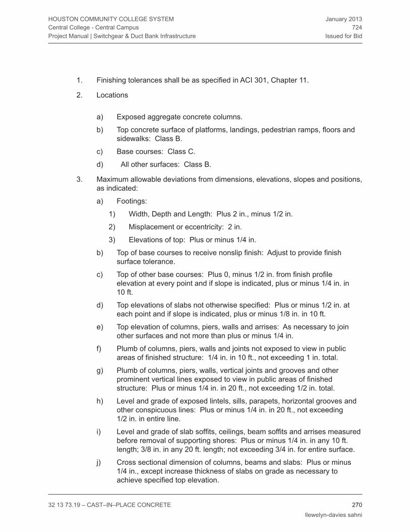
32 13 73.19 – CAST–IN–PLACE CONCrETE 270 llewelyn-davies sahni
HOUSTON COMMUNITY COLLEGE SYSTEMCentral College - Central CampusProject Manual | Switchgear & Duct Bank Infrastructure
January 2013724
Issued for Bid
Finishing tolerances shall be as specified in ACI 301, Chapter 11.1.
Locations2.
Exposed aggregate concrete columns.a)
Top concrete surface of platforms, landings, pedestrian ramps, floors and b) sidewalks: Class B.
Base courses: Class C.c)
All other surfaces: Class B. d)
Maximum allowable deviations from dimensions, elevations, slopes and positions, 3. as indicated:
Footings:a)
Width, Depth and Length: Plus 2 in., minus 1/2 in.1)
Misplacement or eccentricity: 2 in.2)
Elevations of top: Plus or minus 1/4 in. 3)
Top of base courses to receive nonslip finish: Adjust to provide finish b) surface tolerance.
Top of other base courses: Plus 0, minus 1/2 in. from finish profile c) elevation at every point and if slope is indicated, plus or minus 1/4 in. in 10 ft.
Top elevations of slabs not otherwise specified: Plus or minus 1/2 in. at d) each point and if slope is indicated, plus or minus 1/8 in. in 10 ft.
Top elevation of columns, piers, walls and arrises: As necessary to join e) other surfaces and not more than plus or minus 1/4 in.
Plumb of columns, piers, walls and joints not exposed to view in public f) areas of finished structure: 1/4 in. in 10 ft., not exceeding 1 in. total.
Plumb of columns, piers, walls, vertical joints and grooves and other g) prominent vertical lines exposed to view in public areas of finished structure: Plus or minus 1/4 in. in 20 ft., not exceeding 1/2 in. total.
Level and grade of exposed lintels, sills, parapets, horizontal grooves and h) other conspicuous lines: Plus or minus 1/4 in. in 20 ft., not exceeding 1/2 in. in entire line.
Level and grade of slab soffits, ceilings, beam soffits and arrises measured i) before removal of supporting shores: Plus or minus 1/4 in. in any 10 ft. length; 3/8 in. in any 20 ft. length; not exceeding 3/4 in. for entire surface.
Cross sectional dimension of columns, beams and slabs: Plus or minus j) 1/4 in., except increase thickness of slabs on grade as necessary to achieve specified top elevation.
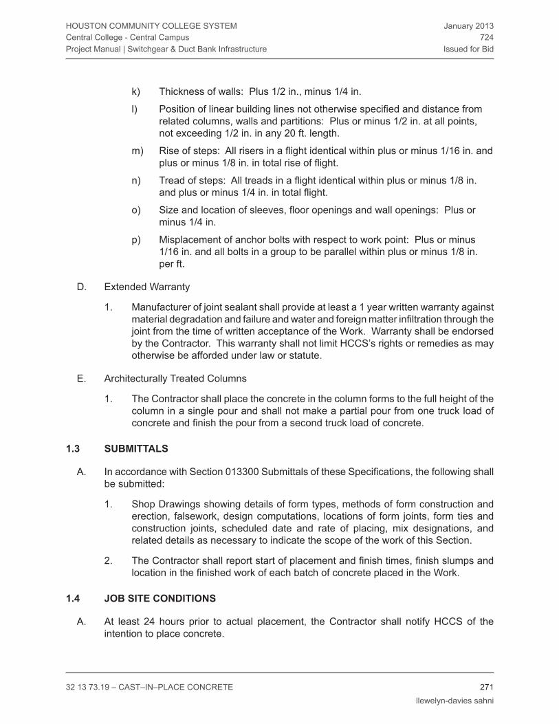
32 13 73.19 – CAST–IN–PLACE CONCrETE 271 llewelyn-davies sahni
HOUSTON COMMUNITY COLLEGE SYSTEMCentral College - Central CampusProject Manual | Switchgear & Duct Bank Infrastructure
January 2013724
Issued for Bid
Thickness of walls: Plus 1/2 in., minus 1/4 in. k)
Position of linear building lines not otherwise specified and distance from l) related columns, walls and partitions: Plus or minus 1/2 in. at all points, not exceeding 1/2 in. in any 20 ft. length.
Rise of steps: All risers in a flight identical within plus or minus 1/16 in. and m) plus or minus 1/8 in. in total rise of flight.
Tread of steps: All treads in a flight identical within plus or minus 1/8 in. n) and plus or minus 1/4 in. in total flight.
Size and location of sleeves, floor openings and wall openings: Plus or o) minus 1/4 in.
Misplacement of anchor bolts with respect to work point: Plus or minus p) 1/16 in. and all bolts in a group to be parallel within plus or minus 1/8 in. per ft.
Extended WarrantyD.
Manufacturer of joint sealant shall provide at least a 1 year written warranty against 1. material degradation and failure and water and foreign matter infiltration through the joint from the time of written acceptance of the Work. Warranty shall be endorsed by the Contractor. This war ranty shall not limit HCCS’s rights or remedies as may otherwise be afforded under law or statute.
Architecturally Treated ColumnsE.
The Contractor shall place the concrete in the column forms to the full height of the 1. column in a single pour and shall not make a partial pour from one truck load of concrete and finish the pour from a second truck load of concrete.
sUbmiTTals1.3
In accordance with Section 013300 Submittals of these Specifications, the following shall A. be submitted:
Shop Drawings showing details of form types, methods of form construction and 1. erection, falsework, design computations, locations of form joints, form ties and construction joints, scheduled date and rate of placing, mix designations, and related details as necessary to indicate the scope of the work of this Section.
The Contractor shall report start of placement and finish times, finish slumps and 2. location in the finished work of each batch of concrete placed in the Work.
job siTe CondiTions1.4
At least 24 hours prior to actual placement, the Contractor shall notify HCCS of the A. intention to place concrete.
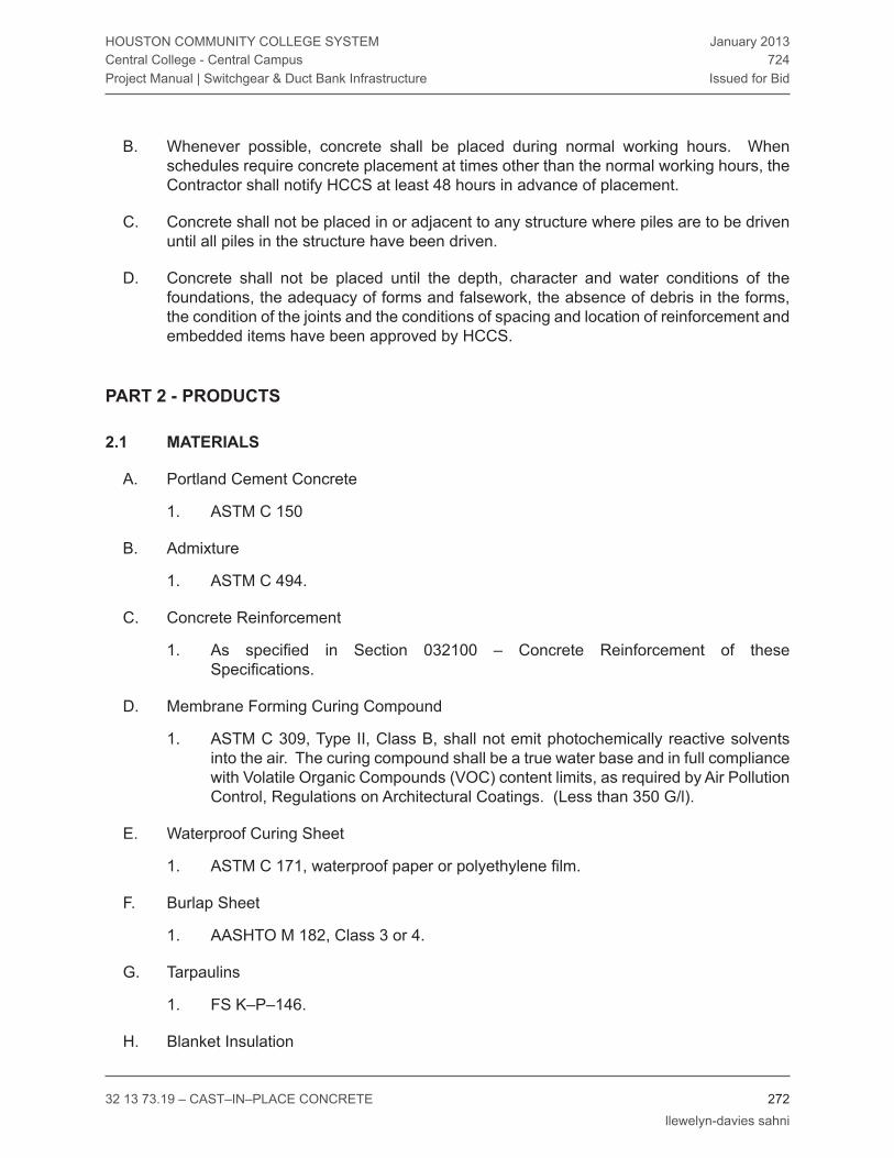
32 13 73.19 – CAST–IN–PLACE CONCrETE 272 llewelyn-davies sahni
HOUSTON COMMUNITY COLLEGE SYSTEMCentral College - Central CampusProject Manual | Switchgear & Duct Bank Infrastructure
January 2013724
Issued for Bid
Whenever possible, concrete shall be placed during normal working hours. When B. schedules require concrete placement at times other than the normal working hours, the Contractor shall notify HCCS at least 48 hours in advance of placement.
Concrete shall not be placed in or adjacent to any structure where piles are to be driven C. until all piles in the structure have been driven.
Concrete shall not be placed until the depth, character and water conditions of the D. foundations, the adequacy of forms and falsework, the absence of debris in the forms, the condition of the joints and the conditions of spacing and location of reinforcement and embedded items have been approved by HCCS.
prodUCTsparT 2 -
maTerials2.1
Portland Cement ConcreteA.
ASTM C 1501.
Admixture B.
ASTM C 494.1.
Concrete reinforcementC.
As specified in Section 032100 – Concrete Reinforcement of these 1. Specifications.
Membrane Forming Curing CompoundD.
ASTM C 309, Type II, Class B, shall not emit photochemically reactive solvents 1. into the air. The curing compound shall be a true water base and in full compliance with Volatile Organic Compounds (VOC) content limits, as required by Air Pollution Control, regulations on Architectural Coatings. (Less than 350 G/l).
Waterproof Curing SheetE.
ASTM C 171, waterproof paper or polyethylene film. 1.
Burlap SheetF.
AASHTO M 182, Class 3 or 4.1.
TarpaulinsG.
FS K–P–146.1.
Blanket InsulationH.

32 13 73.19 – CAST–IN–PLACE CONCrETE 273 llewelyn-davies sahni
HOUSTON COMMUNITY COLLEGE SYSTEMCentral College - Central CampusProject Manual | Switchgear & Duct Bank Infrastructure
January 2013724
Issued for Bid
FS HH–I–521.1.
Joint MaterialsI.
Preformed Expansion Joint Filler: Non–extruding and resilient Bituminous type: 1. ASTM D 1751, Flexible Cellular Materials: ASTM D1565 and Sponge Rubber and Cork Type: ASTM D 1752.
WaterstopsJ.
Rubber type, Corps of Engineers Specification CRD C 513, either natural or synthetic 1. or extruded Polyvinyl chloride, Corps of Engineers Specification CRD C 572.
vapor BarrierK.
Polyethylene sheet, 0.01 in. thick, FS L–P–512, Type I, Class H, Grade 5. 1.
Abrasive AggregateL.
Aluminum oxide or silicon carbide; well graded in size from particles retained on 1. the No. 30 sieve to those passing the No. 8 sieve.
Epoxy Mortar/GroutM.
Approved product mixed and applied in accordance with the manufacturer’s 1. instructions, meeting ASTM C 881.
FormworkN.
Plywood: B–B Plyform, Class I or Class II Exterior, conforming to the requirements 1. of U.S. National Bureau of Standards Product Standard PS–1.
Hardboard: Tempered, smooth–one–side, conforming to FS LLL–B 810. 2.
Steel Forms and Fiberglass – Reinforced Plastic Forms: As required to form 3. concrete surfaces to the specified tolerances and finishes, free of irregularity, concrete stain and seam markings.
Fiber Tubular Forms: Spirally constructed of laminated plies of fiber, with wall 4. thickness as recommended by the manufacturer to meet load requirements of the various uses and sizes.
Column Forms: Column forms shall be such that when stripped from hardened 5. concrete shall leave no evidence of seams or any other markings.
Form Ties: Approved form clamps and factory–fabricated snap–off metal type 6. ties designed to minimize form deflection and preclude concrete spalling upon tie removal; fabricated so that the set –back in the concrete is such that the portion of the tie remaining after snap–off and removal of the exterior portions is at least 2 in. back from the concrete surface. Spreader cones on tie wires shall not exceed 7/8 in. in diameter.

32 13 73.19 – CAST–IN–PLACE CONCrETE 274 llewelyn-davies sahni
HOUSTON COMMUNITY COLLEGE SYSTEMCentral College - Central CampusProject Manual | Switchgear & Duct Bank Infrastructure
January 2013724
Issued for Bid
Bond Breaker: Nonstaining, free of mineral oils and other non drying ingredients 7. and leaving no bond–inhibiting residues on the face of the concrete, compatible with specified water–repellant coatings, paint systems or other indicated surface treatments.
Chamfer Strips: Triangular fillets milled from clear, straight –grain wood, surfaced 8. each side or extruded vinyl type.
Coarse AggregatesO.
All coarse aggregates shall conform to Section 321313 – Portland Cement Concrete 1. of these Specifications.
Fine AggregatesP.
All fine aggregates shall conform to Section 321313 – Portland Cement Concrete 1. of these Specifications.
Coloring AdmixtureQ.
Coloring of all Accessible Ramps per Section 32 13 16 of these Specifications1.
exeCUTionparT 3 -
formwork3.1
GeneralA.
Formwork shall be designed and constructed in accordance with the applicable 1. requirements of ACI 301 and ACI 347 and as specified herein.
Earth cuts shall not be used as forms for vertical surfaces except where specifically 2. indicated.
Forms shall conform to the lines and dimensions shown on the Contract Drawings 3. and shall be sufficiently tight to prevent mortar leakage.
Formwork shall have sufficient strength to withstand the pressure resulting from 4. placement and vibration of the concrete and shall conform to the tolerances of Article 1.02 of this Section.
Temporary openings shall be provided at the base of column forms and wall 5. forms and at other points where necessary, to facilitate cleaning and observation immediately before concrete is deposited.
Forms for outside surfaces shall be constructed with stiff wales at right angles to 6. the studs and form clamps extending through and fastened to the wales. Forms shall be anchored and braced to produce proper alignment and structural safety.

32 13 73.19 – CAST–IN–PLACE CONCrETE 275 llewelyn-davies sahni
HOUSTON COMMUNITY COLLEGE SYSTEMCentral College - Central CampusProject Manual | Switchgear & Duct Bank Infrastructure
January 2013724
Issued for Bid
Exposed edges and corners of concrete shall be chamfered a minimum 3/4 in., 7. unless otherwise indicated.
Form CoatingsB.
Forms shall be cleaned before each use and coated with an approved bond breaker 1. in accordance with the manufacturer’s instructions before concrete or reinforcing steel is placed.
Embedded ItemsC.
Inserts, anchors, sleeves, and other items shall be securely installed in the 1. formwork as shown on the Drawings, using a template to locate the embedded item accurately. Embedded items shall be securely fastened, but not fastened to reinforcing steel, unless otherwise indicated.
Exposed curb angle surfaces, tread strips and similar surfaces shall be protected 2. during placing of concrete.
Ends of conduits, piping and sleeves embedded in concrete shall be closed with 3. approved easily removable caps or plugs.
Edge Forms and ScreedsD.
Edge forms and screeds shall be set to produce the indicated elevations and 1. contours, and shall be secured to prevent displacement during placing and consolidation of the concrete.
Form removalE.
When repair of surface defects or finishing is required, side forms shall be removed 1. as soon as the concrete has hardened sufficiently to resist damage from removal operations.
Formwork used to support the weight of the concrete shall remain in place until the 2. following specified minimum flexural strengths have been reached:
Class 3000: Minimum 7 day beam strength 500 psi.a)
Class 4000: Minimum 7 day beam strength 650 psi.b)
Class 5000: Minimum 7 day beam strength 850 psi.c)
preparaTion3.2
Hardened concrete and foreign materials shall be removed from the inner surfaces of the A. forms and conveying equipment.
Underground pipes, conduits and ducts in the pour area shall be completely installed and B.

32 13 73.19 – CAST–IN–PLACE CONCrETE 276 llewelyn-davies sahni
HOUSTON COMMUNITY COLLEGE SYSTEMCentral College - Central CampusProject Manual | Switchgear & Duct Bank Infrastructure
January 2013724
Issued for Bid
approved before placing concrete.
Each subgrade surface shall be sprinkled sufficiently to prevent absorption of water from C. freshly placed concrete.
ConVeyinG3.3
Concrete shall be handled from the mixer to the place of final deposit as rapidly as A. practical by methods that will prevent segregation, undue drying, temperature rise or loss of ingredients and so as to retain required quality of concrete.
Conveying equipment shall be of approved size and design to maintain a continuous flow B. of concrete at the discharge end. Conveying equipment with aluminum parts that could come in contact with concrete during conveying shall not be used.
Belt conveyors shall be horizontal or at a slope which will cause neither segregation nor C. loss of ingredients. An approved arrangement shall be used at the discharge end to prevent segregation. Long runs shall be discharged into a hopper. Concrete shall not be allowed to adhere to the return belt.
Chutes shall be metal or metal–lined and shall have a slope not exceeding one vertical to D. two horizontal and not less than one vertical to three horizontal. Chutes more than 20 ft. long and chutes not meeting slope requirements may be used if the chutes discharge into an approved hopper before distribution.
Pumping and pneumatic conveying equipment shall be of a suitable kind with adequate E. pumping capacity. Equipment shall be cleaned at the end of each operation. Pneumatic placement shall be controlled so that segregation does not occur in the discharged concrete. Concrete shall not be conveyed through pipe made of aluminum or aluminum alloy.
plaCemenT3.4
GeneralA.
Concrete shall be placed in accordance with the applicable requirements of ACI 304 1. and as specified herein.
Concrete shall be deposited into forms so as not to cause segregation. Vibrators 2. shall not be used for shifting the mass of fresh concrete. The free drop of any concrete shall not exceed 5 ft. Column concrete shall be placed by adjustable length pipes not less than 6 in. in diameter.
Layers of concrete shall not be tapered off in wedge shaped slopes but shall be 3. built with squared ends and level tops. Concrete shall be deposited continuously or in layers of such thickness that concrete will not be deposited on concrete which

32 13 73.19 – CAST–IN–PLACE CONCrETE 277 llewelyn-davies sahni
HOUSTON COMMUNITY COLLEGE SYSTEMCentral College - Central CampusProject Manual | Switchgear & Duct Bank Infrastructure
January 2013724
Issued for Bid
has hardened sufficiently to cause the formation of seams or planes of weakness within the section.
Concrete shall be placed at such a rate that the concrete being integrated with 4. fresh concrete is still plastic. Concrete which has partially hardened or has been contaminated by foreign materials shall not be deposited.
Temporary spreaders in forms shall be removed when placed concrete has reached 5. an elevation which renders spreaders unnecessary.
Slab top surfaces shall be aligned to screed contours by strike –off, or if the nature 6. of the finished surface so requires, by approved vibrating screeds or roller pipe screeds.
ConsolidationB.
Concrete shall be consolidated in accordance with the applicable requirements of 1. ACI 309 and as specified herein.
Consolidation of concrete shall be done until voids are filled and free mortar 2. appears on the surface.
Vibrators shall have a minimum frequency of 8,000 vibrations per minute and 3. sufficient amplitude to effectively consolidate concrete.
Vibrators shall be used to consolidate the incoming concrete within 15 minutes 4. after depositing in forms. In all cases, at least one spare vibrator shall be available at the site of any structure during concrete placement. Vibrators shall not be used to transport concrete within forms.
Location, manner and duration of vibration shall secure maximum consolidation 5. of concrete without causing segregation of mortar and coarse aggregate without causing water or cement paste to flush to the surface. The thickness of the layers shall not be greater than can be satisfactorily consolidated by vibrators. Vibrators shall vertically penetrate a few inches into the previous layer at regular intervals.
Vibrators shall not remain in an area long enough to create a cavity. Vibrators shall 6. be plunged into concrete rapidly, so as not to spatter forms or create depressions in the lift and shall be withdrawn slowly.
hoT weaTher plaCemenT3.5
Placement of concrete in hot weather shall comply with the applicable requirements of A. ACI 305R and as specified herein.
When the temperature at the Site rises above 70 F, a water–reducing, set–retarding B. admixture shall be added to all concrete mixes. Such admixture shall be required in all cased drilled shafts regardless of temperature. The rate of dosage and method of introduction shall be in accordance with the manufacturer’s recommendations.

32 13 73.19 – CAST–IN–PLACE CONCrETE 278 llewelyn-davies sahni
HOUSTON COMMUNITY COLLEGE SYSTEMCentral College - Central CampusProject Manual | Switchgear & Duct Bank Infrastructure
January 2013724
Issued for Bid
The maximum temperature of the cement when introduced to the batch shall be 170 F. C.
Concrete temperature prior to placement shall not exceed 85 F. D.
When the temperature at the Site rises above 85 F, 50 percent of the mix water 1. shall be replaced pound for pound with crushed, shaved or chipped ice made from potable water placed directly into the mixer in order to reduce the concrete temperature to an acceptable level.
When the temperature at the Site rises above 90 F, 75 or more percent of the 2. mix water shall be replaced pound for pound with crushed, shaved or chipped ice made from potable water placed directly into the mixer in order to reduce the concrete temperature to an acceptable level.
Concrete shall be placed in accordance with requirements of Item 420, ARTICLE 420.11 E. of the TxDOT Standard Specifications as follows:
The maximum time interval between the addition of cement to the batch, and the 1. placing of concrete in the forms shall not exceed the following:
AIr Or CONCrETETEMPErATUrE
(Whichever is Higher)
MAXIMUM TIME(Addition of Water or
Cement to Placing in Forms)
Non–Agitated Concrete
Over 80 F 15 Minutes
35 F to 79 F 30 Minutes
Agitated Concrete
90 F or Above 45 Minutes
75 F to 89 F 60 Minutes
35 F to 74 F 90 Minutes
The use of an approved retarding agent in the concrete will permit the extension 2. of each of the above temperature–time maximums by 30 minutes for bridge decks, top slabs of direct traffic culverts and cased drilled shafts, and one hour for all other concrete except that the maximum time shall not exceed 30 minutes for non–agitated concrete.
If required, concrete placement may be restricted to early morning or late afternoon or F. evening.
Cold weaTher plaCemenT3.6
Placement of concrete in cold weather shall be performed in accordance with the A.

32 13 73.19 – CAST–IN–PLACE CONCrETE 279 llewelyn-davies sahni
HOUSTON COMMUNITY COLLEGE SYSTEMCentral College - Central CampusProject Manual | Switchgear & Duct Bank Infrastructure
January 2013724
Issued for Bid
requirements of ACI 306r. The temperature of the concrete itself at the time of placement shall be not less than 50 F nor more than 85 F.
finishinG3.7
Formed SurfacesA.
rough Form Finish, F11.
Formed concrete surfaces that will be concealed by finish work shall have a) an as–cast rough form finish.
Rough form finish shall be in accordance with ACI 301, Chapter 10.b)
Smooth Form Finish, F22.
As–cast smooth form finish shall be provided to formed concrete surfaces a) that will be exposed to view or that are to be covered with a coating material applied directly to the concrete or a covering material bonded to the concrete such as waterproofing, damp–proofing, painting or other similar system.
Smooth form finish shall be in accordance with ACI 301, Chapter 10.b)
Grout Cleaned Finish, F33.
Grout cleaned finish shall be provided to scheduled concrete surfaces a) which have been cast with a smooth form finish.
Grout cleaned finish shall be in accordance with ACI 301, Chapter 10. b)
Brush Blast Finish, F44.
Brush blast finish shall be provided to scheduled concrete surfaces which a) have been cast with a smooth form finish.
Brush blast finish shall be in accordance with ACI 303R, Chapter 9.b)
Bushhammer Finish, F55.
Apply bushhammer finish to concrete surface of round columns where a) shown on drawings. Minimum depth shall be 1/2 inch and maximum depth shall be 3/4 inch.
Surface continuity: Perform bushhammer finishing in as continuous an b) operation as possible, utilizing same work crew to maintain continuity of finish on each surface or area of work.
Surface cut: Maintain depth of cut and general aggregate exposure c) to match Architect’s approved field constructed mock–up. Use power hammerheads for large, flat surfaces and hard hammers for small area, at corners and edges, and for restricted locations where power tools cannot reach. Use multi–point hammers.
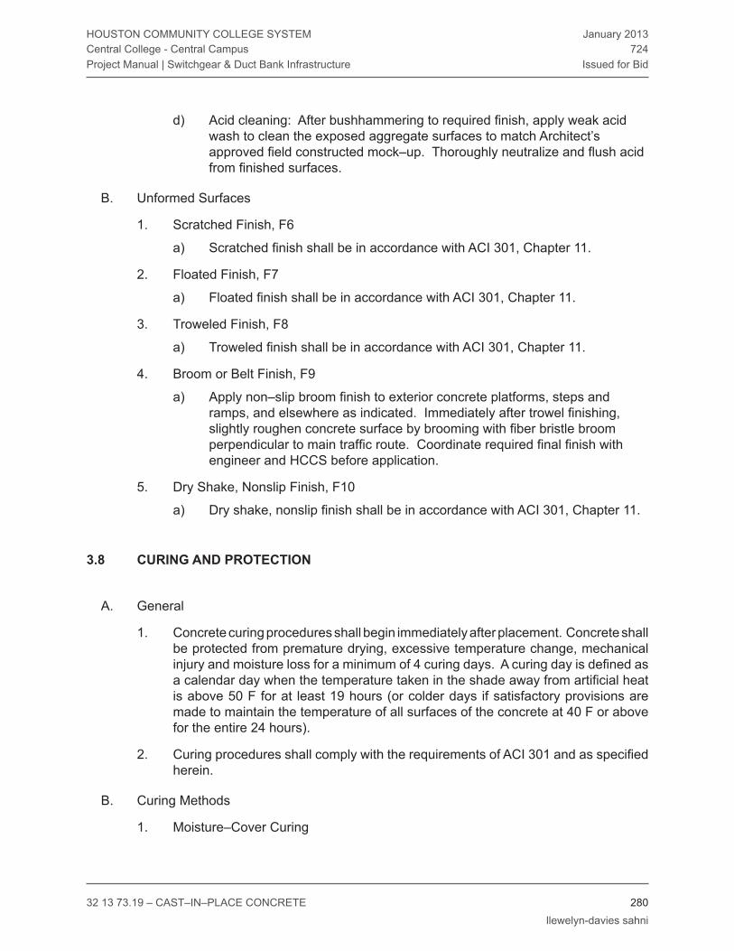
32 13 73.19 – CAST–IN–PLACE CONCrETE 280 llewelyn-davies sahni
HOUSTON COMMUNITY COLLEGE SYSTEMCentral College - Central CampusProject Manual | Switchgear & Duct Bank Infrastructure
January 2013724
Issued for Bid
Acid cleaning: After bushhammering to required finish, apply weak acid d) wash to clean the exposed aggregate surfaces to match Architect’s approved field constructed mock–up. Thoroughly neutralize and flush acid from finished surfaces.
Unformed SurfacesB.
Scratched Finish, F61.
Scratched finish shall be in accordance with ACI 301, Chapter 11.a)
Floated Finish, F72.
Floated finish shall be in accordance with ACI 301, Chapter 11.a)
Troweled Finish, F83.
Troweled finish shall be in accordance with ACI 301, Chapter 11.a)
Broom or Belt Finish, F94.
Apply non–slip broom finish to exterior concrete platforms, steps and a) ramps, and elsewhere as indicated. Immediately after trowel finishing, slightly roughen concrete surface by brooming with fiber bristle broom perpendicular to main traffic route. Coordinate required final finish with engineer and HCCS before application.
Dry Shake, Nonslip Finish, F105.
Dry shake, nonslip finish shall be in accordance with ACI 301, Chapter 11.a)
CUrinG and proTeCTion3.8
GeneralA.
Concrete curing procedures shall begin immediately after placement. Concrete shall 1. be protected from premature drying, excessive temperature change, mechanical injury and moisture loss for a minimum of 4 curing days. A curing day is defined as a calendar day when the temperature taken in the shade away from artificial heat is above 50 F for at least 19 hours (or colder days if satisfactory provisions are made to maintain the temperature of all surfaces of the concrete at 40 F or above for the entire 24 hours).
Curing procedures shall comply with the requirements of ACI 301 and as specified 2. herein.
Curing MethodsB.
Moisture–Cover Curing1.

32 13 73.19 – CAST–IN–PLACE CONCrETE 281 llewelyn-davies sahni
HOUSTON COMMUNITY COLLEGE SYSTEMCentral College - Central CampusProject Manual | Switchgear & Duct Bank Infrastructure
January 2013724
Issued for Bid
The concrete surfaces to be cured shall be covered with specified a) moisture–retaining cover material placed in the widest practical width with sides and ends lapped at least 3 inches and sealed by waterproofing tape or adhesive. All holes and tears that develop during the curing period shall be repaired immediately.
Liquid Membrane Curing2.
The specified membrane curing compound shall be applied to damp a) concrete surfaces as soon as possible after final finishing operations are complete, but no later than 2 hours after finishing. Curing compound shall be applied uniformly over the concrete surfaces by means of approved spray equipment in accordance with the manufacturer’s instructions. Should the coat be damaged from any cause during the curing period, damaged portions shall be repaired and recoated immediately with additional compound.
Membrane curing compound shall not be used on surfaces that are to b) receive paint, tile or other application requiring a positive bond, unless it can be satisfactorily demonstrated that the membrane compound is compatible with the material requiring the positive bonding.
Curing Formed SurfacesC.
Formed concrete surfaces shall be cured by moist curing, with the forms in place, 1. wherever possible.
If the forms are removed before the end of the curing period, curing shall continue 2. as on unformed surfaces.
Curing Unformed SurfacesD.
Unformed concrete surfaces such as slabs or other flat surfaces shall be initially 1. cured by moist curing wherever possible.
Unless otherwise indicated, unformed surfaces shall be finally cured by any of the 2. methods specified above.
Protection from Mechanical InjuryE.
During the curing period, concrete surfaces shall be protected from damage and 1. mechanical disturbances, such as load stresses, heavy shock and excessive vibration.
Finished concrete surfaces shall be protected from potential damage due to 2. construction equipment, materials, methods, application of curing procedures, rain, flowing water and other hazards.
ConsTrUCTion joinTs3.9

32 13 73.19 – CAST–IN–PLACE CONCrETE 282 llewelyn-davies sahni
HOUSTON COMMUNITY COLLEGE SYSTEMCentral College - Central CampusProject Manual | Switchgear & Duct Bank Infrastructure
January 2013724
Issued for Bid
Construction joints and keys shall be provided as indicated on the Drawings. Joints not A. otherwise indicated shall be located so as not to impair strength and appearance of the structure. Such construction joints shall be located as follows:
At the top of a footing or at the top of a slab on ground. 1.
In slabs on ground, so as to divide the slab into areas not in excess of 1200 sq. ft., 2. unless otherwise approved.
Longitudinal keys at least 1–1/2 inches deep shall be provided at joints in walls and B. between walls and slabs or footings, unless otherwise indicated. Other construction joints shall be made without keys, except where keys are indicated. Keyways shall be formed to dimensions indicated on the Drawings.
When indicated or permitted, bond surface shall be obtained by use of an approved C. chemical retarder which delays but does not prevent setting of the surface mortar. Retarded mortar shall be removed within 24 hours after placing to produce a clean exposed coarse aggregate bonding surface.
After the pour has been completed to the construction joint, and before placement of fresh D. concrete, reinforcing steel and the surfaces of horizontal and vertical construction joints shall be cleaned of surface latence, curing compound and other materials foreign to the concrete to expose clean coarse aggregate of at least 3/8 inch size. Hardened concrete surfaces shall be cleaned by abrasive blast methods, to expose coarse aggregate, after the curing period or immediately before placing concrete at the joint. Surfaces of concrete which has been in place not more than 8 hours may be cleaned with air and water jets, if surface latence is removed and clean coarse aggregate is exposed. Surfaces of horizontal construction joints, where expansion joint filler or bond breaking compound is to be placed as indicated, shall be cleaned of dirt, sawdust and other loose materials. Surfaces on which concrete is to be placed shall be moistened with water immediately before placing concrete. Sealant manufacturer’s instructions and procedures shall be followed so as not to invalidate the warranty.
When it is necessary to make a construction joint because of an emergency, additional E. reinforcing steel shall be placed across the joint as directed by the Engineer. Notify HCCS in writing of such action.
When new concrete is to be joined to existing concrete by means of reinforcing steel F. dowels, grouted in holes drilled in the existing concrete, the holes shall be drilled to the required depth, blown out, wetted and filled with ASTM C 881 non–metallic, non–shrink grout, then the clean dowels shall be inserted and left undisturbed until the grout cures hard in accordance with manufacturer’s instructions.
expansion, ConTraCTion, ConsTrUCTion and ConTrol joinTs3.10
Reinforcement or other fixed metal items shall not be run continuous through joints, A.

32 13 73.19 – CAST–IN–PLACE CONCrETE 283 llewelyn-davies sahni
HOUSTON COMMUNITY COLLEGE SYSTEMCentral College - Central CampusProject Manual | Switchgear & Duct Bank Infrastructure
January 2013724
Issued for Bid
unless otherwise indicated.
Open joints shall be constructed at the locations indicated, using a wood strip, metal plate B. or other approved material to be subsequently removed or the joints may be sawcut.
Expansion joints in the pavement areas shall be spaced as shown on the drawings or as C. required for alternate methods of construction.
All joints shall conform to HCCS Standard Drawing CES–1003–1A, CIvIL STANDArD D. JOINTED rEINFOrCED CONCrETE PAvEMENT.
waTersTops3.11
The configuration and location of waterstops in construction joints and expansion joints A. shall be as indicated on the Drawings.
Each piece of waterstop shall be of maximum practical length to minimize the number of B. end joints.
insTallinG joinT maTerials3.12
Joint materials and sealants shall be installed so as not to invalidate the manufacturer’s A. warranty, and in strict accordance with his procedures and instructions.
proTeCTion from and remoVal of sTains3.13
Concrete shall be protected from staining from steel members and other substances A. during the course of the Work. Dirt shall not be allowed to accumulate on horizontal surfaces. All surfaces shall be kept clean and free of standing water.
If staining occurs, stain shall be removed and the concrete shall be restored to its original B. color and finish.
repair of sUrfaCe defeCTs3.14
GeneralA.
Surface defects shall be repaired immediately after form removal as recommended 1. by ACI standard practices.
Concrete repair work shall result in a monolithic concrete surface of uniform color 2. and texture and shall be free of irregularities and discontinuities.
HCCS shall be informed upon completion of patching and repairs so as to witness 3. the resultant surfaces and work quality.
All repairs of surface defects shall be at no additional cost to HCCS.4.

32 13 73.19 – CAST–IN–PLACE CONCrETE 284 llewelyn-davies sahni
HOUSTON COMMUNITY COLLEGE SYSTEMCentral College - Central CampusProject Manual | Switchgear & Duct Bank Infrastructure
January 2013724
Issued for Bid
Patching Defective AreasB.
Defective areas shall be repaired with an approved epoxy–based mortar, where 1. directed.
Honeycomb, rock pockets, voids over 1/4 inch in any dimension shall be cut down 2. to solid concrete but, in no case, to a depth of less than 1 inch. Edges of cuts shall be made perpendicular to the concrete surface. Before placing the cement mortar, the area to be patched shall be thoroughly cleaned, dampened with water and brush–coated with neat cement grout.
For exposed–to–view surfaces, white Portland cement shall be blended with 3. standard Portland cement so that, when dry, the patching mortar will match the color of the surrounding concrete. Areas shall be tested at inconspicuous locations to verify mixture and color match before proceeding with the patching.
Holes extending through concrete shall be filled using a plunger–type gun or other 4. suitable device from the least exposed face, using a flush stop held at the exposed face to ensure complete filling.
repair of Formed SurfacesC.
Exposed–to–view formed concrete surfaces that contain defects which affect 1. the finish appearance shall be repaired, where possible. If defects cannot be repaired, defective concrete shall be removed and replaced. Surface defects shall include color and texture irregularities, cracks, spalls, air bubbles, honeycomb, rock pockets, fins, other projections on the surface, stains and discolorations that cannot be removed by cleaning.
Concealed formed concrete surfaces that contain defects which adversely 2. affect concrete durability shall be repaired, where possible. If defects cannot be repaired, defective concrete shall be removed and replaced. Surface defects shall include cracks in excess of 0.01 inch wide, cracks of any width and other surface deficiencies which penetrate to the reinforcement or completely through non–reinforced sections, honeycomb, rock pockets and spalls, except minor breakage at the corner.
repair of Unformed SurfacesD.
Unformed surfaces shall be tested for smoothness and surface plane tolerances 1. as specified for each surface and finish. Low and high areas shall be corrected as specified.
Unformed surfaces sloped to drain shall be tested for trueness of slope, in addition 2. to smoothness, using a template having the required slope. High and low areas shall be corrected as specified.
Finished unformed surfaces which contain defects which adversely affect concrete 3. durability shall be repaired. Surface defects, as such, shall include crazing, cracks in excess of 0.01 inch wide or which penetrate to the reinforcement or completely

32 13 73.19 – CAST–IN–PLACE CONCrETE 285 llewelyn-davies sahni
HOUSTON COMMUNITY COLLEGE SYSTEMCentral College - Central CampusProject Manual | Switchgear & Duct Bank Infrastructure
January 2013724
Issued for Bid
through non–reinforced sections regardless of width, spalling, popouts, honeycomb, rock pockets and other objectionable conditions.
High areas in unformed surfaces shall be corrected by grinding, after the concrete 4. has cured sufficiently so that repairs can be made without damage to adjacent areas.
Low areas in unformed surfaces shall be corrected, during or immediately after 5. completion of surface finishing operations, by cutting out the low area and placing fresh concrete.
Defective areas, except random cracks and single holes not exceeding 1 inch in 6. diameter, shall be repaired by cutting out the defect and placing fresh concrete. Concrete surface in contact with patching concrete shall be dampened and brushed with a neat cement grout coating or a concrete bonding agent. Patching concrete shall be placed before grout takes its initial set. The patching mixture shall be made of the same materials as the original adjacent concrete and shall be cured in the same manner.
Isolated random cracks and single holes not exceeding 1 inch in diameter shall 7. be repaired by the dry pack method. The top of the cracks shall be grooved and the holes shall be cut out to sound concrete and cleaned of dust, dirt and loose particles. Cleaned concrete surfaces shall be dampened and brushed with a neat cement grout coating. Dry pack shall be placed before grout takes its initial set. The dry pack mixture shall consist of one part Portland cement to 2–1/2 parts fine aggregate passing a No. 16 sieve, using only enough water as required for handling and placing. The dry pack mixture shall be compacted in place and finished as required to match the adjacent concrete.
end of seCTion 32 13 73.19

32 16 13 – CONCrETE CUrBS AND CUrB AND GUTTEr 286 llewelyn-davies sahni
HOUSTON COMMUNITY COLLEGE SYSTEMCentral College - Central CampusProject Manual | Switchgear & Duct Bank Infrastructure
January 2013724
Issued for Bid
32 16 13 – ConCreTe CUrbs and CUrb and GUTTer
GeneralparT 1 -
1.1 desCripTion
A. This Section specifies the requirements for providing, placing, curing, and protecting Portland cement concrete curbs, and combination curbs and gutters, constructed on a prepared subgrade.
1.2 QUaliTy assUranCe
A. Reference Standards Applicable to this Section
1. ACI: American Concrete Institute
a. 316r: recommendations for Construction of Concrete Pavements and Concrete Bases.
2. ASTM: American Society for Testing and Materials
a. A 615: Specification for Deformed and Plain Billet–Steel Bars for Concrete reinforcement (with Supplement + S1).
b. C 150: Specification for Portland Cement Type I or Type II.
c. C 309: Specification for Liquid Membrane – Forming Compounds for Curing Concrete.
d. D 1565: Specifications for Flexible Cellular Materials Vinyl Chloride Polymers and Copolymers (Closed Cell).
e. D 1751: Specification for Preformed Expansion Joint Fillers for Concrete Paving and Structural Construction (Nonextruding and Resilient bituminous Types).
f. D 1752: Specifications for Preformed Sponge Rubber and Cork Expansion Joint Fillers for Concrete Paving and Structural Construction.
g. D 3405: Specification for Joint Sealants, Hot–Poured, for Portland Cement Concrete Pavement.
3. FS: Federal Specifications and Standards

32 16 13 – CONCrETE CUrBS AND CUrB AND GUTTEr 287 llewelyn-davies sahni
HOUSTON COMMUNITY COLLEGE SYSTEMCentral College - Central CampusProject Manual | Switchgear & Duct Bank Infrastructure
January 2013724
Issued for Bid
a. TT–P–86: Paint, red–Lead–Base, ready–Mixed.
B. Finishing Tolerance
The top surface of curbs and combination curbs and gutters shall have a Class A tolerance as specified in ACI 316 R, Chapter 12.5.
1.3 sUbmiTTals
A. In accordance with Section 013300 – Submittal Procedures of these Specifications, the following shall be submitted:
1. reinforcement Materials
a. As required in Section 032100 – Concrete reinforcement of these Specifications.
2. Concrete Materials
a. As required in Sections 321373.19 – Cast–in–Place Concrete of these Specifications.
1.4 exTended warranTy
A. Manufacturer of joint sealant shall provide at least a 1–year written warranty against material degradation and failure and water and foreign matter infiltration through the joint from the time of written acceptance of the Work. This warranty shall not limit HCCS rights or remedies as may otherwise be afforded under law or statute.
parT 2 – prodUCTs
2.1 maTerials
A. Forms
Either wood or metal, of the size and shape necessary for forming the item, straight and free of warp.
B. reinforcing Steel Bars
As specified in Section 032100 – Concrete Reinforcement of these Specifications.
C. Dowel Bars
Smooth, ASTM A 615 + S1, Grade 60, new billet steel, unbonded ends painted with

32 16 13 – CONCrETE CUrBS AND CUrB AND GUTTEr 288 llewelyn-davies sahni
HOUSTON COMMUNITY COLLEGE SYSTEMCentral College - Central CampusProject Manual | Switchgear & Duct Bank Infrastructure
January 2013724
Issued for Bid
red–lead–base paint, FS TT–P–86, Type I and coated with a water–resistant lubricant immediately prior to placement of concrete in which unbonded ends of bars are to be embedded.
D. Dowel Bar Expansion Caps
PVC or plastic cap, slightly larger than dowel bar, closed end, a minimum of 6 in. long, with 1–1/2 in. long compressible insert.
E. Concrete
Class 3000, as specified in Section 321373.19 – Cast–in–Place Concrete of these Specifications.
F. Membrane Forming Curing Compound
ASTM C 309, Type 2, unless otherwise directed.
G. Joint Materials
1. Preformed Expansion Joint Filler: Nonextruding and resilient bituminous type, ASTM D 1751.
2. Joint Sealing Material: See Section 321373 of these Specifications.
H. Form Coating
Commercial formulation form–coating compound that will not bond with, stain nor adversely affect concrete surfaces and will not impair subsequent treatment of concrete surfaces.
parT 3 – exeCUTion
3.1 inspeCTion and preparaTion
A. Prepared subgrade shall be inspected for unstable or unsuitable areas and need for additional compaction. Notify the Engineer in writing of such deficiencies. Do not begin curb construction until all such deficiencies have been corrected.
B. Loose and foreign material shall be removed from the compacted subgrade immediately prior to placing concrete, and subgrade shall be uniformly dampened.
3.2 seTTinG forms
A. Forms shall be set to the line and grade indicated, and shall be securely staked to

32 16 13 – CONCrETE CUrBS AND CUrB AND GUTTEr 289 llewelyn-davies sahni
HOUSTON COMMUNITY COLLEGE SYSTEMCentral College - Central CampusProject Manual | Switchgear & Duct Bank Infrastructure
January 2013724
Issued for Bid
maintain set position during depositing and curing of concrete. The inside form shall be rigidly attached to the outside form.
B. Forms shall be set in sufficient quantity to allow continuous progress of concrete placement and to ensure that forms shall remain in place not less than 24 hours.
Forms shall be cleaned after each use and coated with an approved form release agent C. prior to each use.
3.3 insTallaTion of joinTs, reinforCemenT, and sealanT
A. Reinforcement shall be installed as indicated on the Drawings and as specified in Section 032100 – Concrete Reinforcement of these Specifications. Joints shall be installed where indicated on the Drawings and in accordance with Section 321319 – Concrete Pavement Joints of these Specifications.
B. Sealant manufacturer’s instructions and procedures shall be followed so as not to invalidate the warranty.
3.4 plaCinG and finishinG ConCreTe
A. Concrete shall be placed and finished as specified in Section 321373.19 – Cast–in–Place Concrete of these Specifications, and ACI 316 R, Chapters 10 and 12.5.
B. After concrete has been struck off and has sufficiently set, the exposed surfaces shall be worked with a wood float. The exposed edges shall be rounded using an edging tool.
C. After form removal, the surfaces of the curb or combination curb and gutter shall be plastered with a mortar consisting of one part Portland Cement and two parts fine aggregate. Mortar shall be applied with a template constructed to the shape and dimensions of the item to be plastered. All exposed surfaces shall be brushed to a uniform smooth texture.
3.5 CUrinG and proTeCTinG ConCreTe
A. Concrete shall be cured in accordance with the recommendations of ACI 316 R, Chapter 11, using the membrane curing method and materials.
B. Protection as recommended in ACI 316 R, Chapter 11 shall be provided until written acceptance by the Engineer.
end of seCTion 32 16 13

33 71 19 - UNDErGrOUND DUCTBANKS AND MANHOLES 290 llewelyn-davies sahni
HOUSTON COMMUNITY COLLEGE SYSTEMCentral College - Central CampusProject Manual | Switchgear & Duct Bank Infrastructure
January 2013724
Issued for Bid
diVision 33 – UTiliTies
33 71 19 - UnderGroUnd dUCTbanks and manholes
GeneralparT 1 -
work inClUded1.1
This Section specifies the requirements necessary to provide underground ductbanks in A. reinforced concrete.
relaTed work1.2
This Section shall be used in conjunction with the following other specifications and A. related Contract Documents to establish the total requirements for underground electrical ductbanks. All earth and concrete work under this Section shall be under the supervision of the Professional Engineer.
Division 01 Sections included in the project specificationsB.
Section 01 73 30 – Trenching Safety Systems.1.
Section 31 32 00 – Grading Excavation and Fill.2.
Section 32 13 73.19 – Cast in Place Concrete.3.
Concrete Reinforcement and Embedded Materials4.
Section 26 00 01 - Electrical General Provisions5.
Section 26 05 33 – raceway, Conduit, and Boxes6.
In the event of conflict involving underground electrical ductbank requirements between C. this Section and any other Sections, the provisions of this Section shall govern.
appliCable Codes and sTandards1.3
NEMA TC 6 & 8 – Polyvinyl Chloride (PvC) Plastic Utilities Duct for Underground A. Installations
NEMA TC 9 – Fittings for Polyvinyl Chloride (PvC) Plastic Utilities Duct for Underground B. Installations
ASTM C 31 – Standards Practice for Making and Curing Concrete Test Specimens in C. the Field
ASTM C 39 – Standard Test Method for Compressive Strength of Cylindrical Concrete D.

33 71 19 - UNDErGrOUND DUCTBANKS AND MANHOLES 291 llewelyn-davies sahni
HOUSTON COMMUNITY COLLEGE SYSTEMCentral College - Central CampusProject Manual | Switchgear & Duct Bank Infrastructure
January 2013724
Issued for Bid
Specimens
ASTM C 172 – Standards Practice for Sampling Freshly Mixed Concrete E.
ACI 301 – Structural ConcreteF.
ASTM A 615 – Deformed and Plain Carbon Steel Bars for Concrete ReinforcementG.
ASTM D 698 – Standard Test Methods for laboratory Compaction Characteristics of Soil H. Using Standard Effort
sUbmiTTals1.4
Submit the following in addition to, and in accordance with, Section 26 00 01 Electrical A. General Provisions, and Division 01 for submittal requirement.
Complete list of equipment and materials including manufacturer's descriptive 1. and technical literature, catalog cuts, and installation instructions for conduit and fittings, concrete (including admixture), and rebar.
Submit trench safety plans, as outlined by Section 01 73 30 specification 2. section.
Provide the following one week before pulling medium-voltage cable:B.
Diagram of ductbank indicating lengths of straight conduit sections, bend locations 1. with radius of bands, conduit sizes.
Pulling calculation per cable manufacturer's recommended method with acceptable 2. values for pulling tension and sidewall pressure indicated for each cable size/type.
warranTy1.5
Provide a warranty for material and installation per Section 26 00 00. Basic Electrical A. Requirements, unless a longer warranty period is required in specific product specifications.
prodUCTsparT 2 -
CondUiT and fiTTinGs2.1
All products shall be new, first-quality materials.A.
Nonmetallic Conduit: rigid PVC per NEMA TC-6 & 8. Conduit sizes and type shall be in B. accordance with Drawings. Conduit shall be of standard length, with tapered end and matching solvent weld couplings. Provide fitting of the same type material as ducts.

33 71 19 - UNDErGrOUND DUCTBANKS AND MANHOLES 292 llewelyn-davies sahni
HOUSTON COMMUNITY COLLEGE SYSTEMCentral College - Central CampusProject Manual | Switchgear & Duct Bank Infrastructure
January 2013724
Issued for Bid
Provide spacers with minimum separation between conduits as indicated on Drawings. C.
Provide polypropylene pull full length.D.
ConCreTe2.2
Cast-in-place concrete and components: Conform to the following general A. requirements:
Provide concrete work per ACI 301.1.
Concrete shall be normal weight, air-entrained with 28 day strength of 2,500 psi or 2. in the direction per Professional Engineer.
Slump: Performed at the point of placement shall not exceed 6 inches. Make 3. slump tests for each nine cubic yards of concrete placed.
Color: All electrical ductbank concrete shall be color dyed by mixing red inorganic 4. pigment (iron oxide) in cement; rate shall be 1 ½ pounds of iron oxide per cubic yard of cement.
Temperature limits for concrete work shall be in accordance with civil engineering B. standard.
reinforCinG sTeel2.3
All ductbanks shall be constructed with reinforcing bars in the ductbank. The quantities A. and sizes of the reinforcing bars shall be provided as directed by the project structural engineer.
manholes2.4
The manholes shall be precast as per drawings. The manhole shall have grade 60 A. reinforcement of H20 loading and 4,500 psi concrete. Precast end bell type terminators shall be provided for each ductbank entry as noted on the Drawings. Pulling eyes shall be located opposite each set of duct openings. The manhole shall include a 30 inch type B frame and cover suitable for vehicular traffic appropriately marked “electric” or “telephone”. The frame shall be doweled into the manhole to prevent any movement away from the opening. A #4/0 bare copper ground wire shall penetrate the side wall in the bottom Section of the manhole and shall extend 48 inches inside and outside the manhole. The exterior end of this grounding lead shall be connected to a 3/4 inch diameter 10-foot long grounding rod. The interior end of this grounding lead shall be connected to a copper grounding plate. The exposed metal surfaces such as cable rack, metal conduit shall be connected to the grounding plate. Use of a ground rod to penetrate the manhole wall is unacceptable. A sump shall be included in the bottom of each manhole.
Mastic joint compound shall be provided and shall be placed in the grooves of the B. attached Sections.

33 71 19 - UNDErGrOUND DUCTBANKS AND MANHOLES 293 llewelyn-davies sahni
HOUSTON COMMUNITY COLLEGE SYSTEMCentral College - Central CampusProject Manual | Switchgear & Duct Bank Infrastructure
January 2013724
Issued for Bid
Provide cable support hardware and all supports for all cable, cable splices and cable C. terminations as required to support cable inside manhole.
exeCUTion parT 3 -
TrenCh exCaVaTion3.1
Comply with the following OSHA Part 1926 – Safety and Health regulations for A. Construction, Subpart P - Excavation
1926.650 - requirements for Open Excavations 1.
1926.651 - Requirements for Specific Excavations 2.
1926.652 – requirements for Protective Systems3.
1926.653 - Definitions4.
Before beginning trenching operations, stake out the proposed ductbank routing including B. trench width and obtain approval from the Owner’s representative. After trenching has begun and before any ducts or conduits are placed, notify the Owner’s representative so that the trenching and installation may be inspected. Also notify the Owner’s representative prior to any placement of concrete for ductbanks, so that he may observe the placement.
Excavate to permit installation of the duct bank along the grades shown on the Drawings. C. Deviations to ductbank depth must have prior approval from the Owner and Engineer.
Excavate a trench of sufficient width to allow thorough compacting of the backfill under D. and around the duct bank. A level sand bed a minimum of 6 inches deep shall be placed in the trench before conduit is installed.
Where excavation is in rock, remove all rock to a depth below the grade shown on the E. Drawings. Rock is defined as material that cannot be ripped or excavated by a backhoe with a one cubic yard bucket with rock teeth. Water shall be continuously pumped out from the trench.
The Owner's approval is required for the extent of the trench excavation prior to the duct F. bank installation. Contractor shall schedule excavation in accordance with the Owner's requirements prior to beginning construction.
Provide all necessary bracing and bridging to maintain traffic flow during construction G. through all areas interrupted by trenching. Provide construction signage, traffic barriers, and warning notices throughout the construction period.
Provide all necessary repairs to erosion control measures and reseeding of grass in H. areas disturbed by trenching.

33 71 19 - UNDErGrOUND DUCTBANKS AND MANHOLES 294 llewelyn-davies sahni
HOUSTON COMMUNITY COLLEGE SYSTEMCentral College - Central CampusProject Manual | Switchgear & Duct Bank Infrastructure
January 2013724
Issued for Bid
Sheet and brace the excavation as required to prevent caving. The trench width may I. be increased accordingly. Maintain sheeting until the ductbank has been inspected and backfilled to either a depth of 30-inch minimum over the top of the ductbank or as indicated on Drawings. Leave sheeting and shoring in place where directed by the Owner's representative.
dUCTbank insTallaTion3.2
Carefully handle and place all conduits to prevent breakage or other damage. Brace and A. support all conduits as shown on the Drawings to prevent shifting when concrete is poured. All underground ductbanks under roads and parking lots shall be steel reinforced.
Lay conduit in true straight line of a gradual or uniform sweep. Maintain uniform grade B. between buildings and/or manholes per profile Drawings. Conduits shall be sloped to drain into manholes or buildings where possible at a minimum grade 4 inches per 100 feet. Provide factory made long sweep bends for all bends 15 degrees or more, either horizontal or vertical, unless prior approval is given by Owner to bend conduit in field. Bend radius shall be 48” minimum unless noted otherwise on Drawings.
Space ducts or conduits a minimum of 3 inches, or in accordance with Drawings, from C. adjacent ducts. Place spacers or separators on not greater than 5 foot centers.
Stagger joints 6 inches vertically and horizontally in horizontal duct runs and make joints D. watertight in accordance with manufacturer’s recommendations. Where necessary to cut a tapered end on a duct, make the cut with a tool or lathe designed to cut such a taper to match the taper of the particular duct used.
Cleanout conduits as work progresses and securely plug all open ends to prevent water, E. mud or debris from entering the duct.
Prior to acceptance of ductbank by the Owner, the Contractor shall pull an approved F. mandrel through each conduit. Mandrel must not be less than 12 inches long with a diameter approximately 1/4 inch less than the inside diameter of the duct or conduit. Swab all conduits clean immediately before pulling cable.
Form conduits into ductbanks as shown on the Drawings. Quantity of spacers shall be G. as required to insure conduit is supported to maintain a true straight line without sagging. Spacers shall be made of plastic, concrete or a suitable nonmetallic, non-decaying material. Conduits shall be secured to the spacers using plastic ties; use of wire is not acceptable.
Provide PVC end bells where the ducts enter and terminate in the manhole, building, H. concrete walls, or other rigid structures.
Concrete forming and placement. Concrete shall be placed in forms within the excavated I. trench. Top of concrete shall be level. Trowel in additional red dye on top of concrete. Conduits shall be not less than 3 inches from the edge of concrete.

33 71 19 - UNDErGrOUND DUCTBANKS AND MANHOLES 295 llewelyn-davies sahni
HOUSTON COMMUNITY COLLEGE SYSTEMCentral College - Central CampusProject Manual | Switchgear & Duct Bank Infrastructure
January 2013724
Issued for Bid
Identify the ductbank location with metallic safety tape or vinyl tape with magnetic J. tracer marked "CAUTION! BUrIED HIGH vOLTAGE ELECTrICAL LINE". Tape shall be located 12 inches above the ductbank. Identify each individual conduit as per the schedule in the Drawings. Conduits shall be identified in accordance with 26 05 53 Electrical Identification.
manhole insTallaTion3.3
The excavation for the manhole shall be to a suitable depth to allow for the manhole cover A. to be slightly elevated above the finished grade to prevent run-off from the entering. The finished grade material shall be sloped around the manhole collar of frame to prevent adequate cover and support.
The site preparation for the manhole shall conform to the manufacturer’s recommendations. B. Generally 3 to 6 inches of stabilize sand and base material shall be spread in the bottom of the excavation. The base material or sand shall be compacted and graded to the proper elevation.
TrenCh baCkfillinG3.4
Backfill using fine material up to 24 inches above the top of the ductbank placed in 6-inch A. lifts and thoroughly tamped.
Consolidate the ductbank fill material under roads or similar traffic areas in such a manner B. as to provide an unyielding foundation of the paving. remove all excess materials.
Succeeding layers of backfill 18 inches and greater above the ductbank may contain C. courser materials. Backfill shall be free of all organic material or any other material that would cause subsequent settlement. Maximum size of backfill stone or aggregate shall not exceed 6 inches in its greatest dimension.
Surface of backfill shall be safe for vehicular traffic as soon as possible. At the upper D. 12 inches of the backfill provide an approved moist material, thoroughly compacted by tamping thin lifts, approximately 4 inches per lift. Lay the top layer at the required grade surface.
Compact backfill by tamping or other method as approved by the Owner's representative. E. Maintain compaction at a minimum of 95 percent of the maximum density at optimum moisture content as determined by ASTM D 698. The Owner's representative shall direct which method of consolidation is to be followed on each part of the work.
Contractor shall assume full responsibility for any deficiency in quantity of material or F. filling of depressions caused by settlement of backfill material. Damage to other trade's work caused by settling shall be corrected at the Contractor's expense. Contractor shall assume full responsibility for damages to any underground utility lines or other structure.
Dispose of all excess material from the construction site as directed by the OwnerG. .

33 71 19 - UNDErGrOUND DUCTBANKS AND MANHOLES 296 llewelyn-davies sahni
HOUSTON COMMUNITY COLLEGE SYSTEMCentral College - Central CampusProject Manual | Switchgear & Duct Bank Infrastructure
January 2013724
Issued for Bid
Contractor should remove excess spoils and other material from the site.
The Contractor shall match the existing material where ever disturbed.H.
reCord drawinGs3.5
Provide all concrete test reports required per Division 03 specifications.A.
All duct bank locations shall be located with respect to site horizontal controls. All B. ductbanks shall be located at ends and change of directions. Record accurately all ductbank bends (radius and center point) ±1-foot by 0-inch accuracy on the construction As-Build drawings.
Record the installed length of each conduit in the ductbank to the nearest foot and C. transmit to the Owner's representative.
end of seCTion 33 71 19

BACKCOVER