Medium Voltage Switchgear - Tri-State Electrical Supply
26
Distribution Products Catalog CA08101001E—July 2010 www.eaton.com 1 22 22 22 22 22 22 22 22 22 22 22 22 22 22 22 22 22 22 22 22 22 22 22 22 22 22 22 22 22 22 Medium Voltage Switchgear Indoor Type VCP-W Metal-Clad Switchgear Assembly (5/15 kV shown) 22.1 Introduction Product Selection Guide . . . . . . . . . . . . . . . . . . . . . . . . . . . . . . . . . . . . . . . . . 2 22.2 Metal-Clad Vacuum Switchgear Product Overview Product Description . . . . . . . . . . . . . . . . . . . . . . . . . . . . . . . . . . . . . . . . . . 4 Application Description . . . . . . . . . . . . . . . . . . . . . . . . . . . . . . . . . . . . . . . . 4 Features, Benefits and Functions . . . . . . . . . . . . . . . . . . . . . . . . . . . . . . . . 5 Options and Accessories . . . . . . . . . . . . . . . . . . . . . . . . . . . . . . . . . . . . . . 6 Technical Data and Specifications . . . . . . . . . . . . . . . . . . . . . . . . . . . . . . . . 6 26-Inch Wide, 5 kV, 250 MVA, 1200A Switchgear Product Description . . . . . . . . . . . . . . . . . . . . . . . . . . . . . . . . . . . . . . . . . . 7 Application Description . . . . . . . . . . . . . . . . . . . . . . . . . . . . . . . . . . . . . . . . 7 Features, Benefits and Functions . . . . . . . . . . . . . . . . . . . . . . . . . . . . . . . . 7 Standards and Certifications . . . . . . . . . . . . . . . . . . . . . . . . . . . . . . . . . . . . 7 38 kV Metal-Clad Switchgear Product Description . . . . . . . . . . . . . . . . . . . . . . . . . . . . . . . . . . . . . . . . . . 8 Application Description . . . . . . . . . . . . . . . . . . . . . . . . . . . . . . . . . . . . . . . . 8 Features, Benefits and Functions . . . . . . . . . . . . . . . . . . . . . . . . . . . . . . . . 8 Standards and Certifications . . . . . . . . . . . . . . . . . . . . . . . . . . . . . . . . . . . . 8 Technical Data and Specifications . . . . . . . . . . . . . . . . . . . . . . . . . . . . . . . . 9 22.3 High Resistance Grounding System Product Description . . . . . . . . . . . . . . . . . . . . . . . . . . . . . . . . . . . . . . . . . . . . . 18 Application Description . . . . . . . . . . . . . . . . . . . . . . . . . . . . . . . . . . . . . . . . . . 18 Features, Benefits and Functions . . . . . . . . . . . . . . . . . . . . . . . . . . . . . . . . . . . 21 Standards and Certifications . . . . . . . . . . . . . . . . . . . . . . . . . . . . . . . . . . . . . . 21 Catalog Number Selection . . . . . . . . . . . . . . . . . . . . . . . . . . . . . . . . . . . . . . . . 22 Technical Data and Specifications . . . . . . . . . . . . . . . . . . . . . . . . . . . . . . . . . . 23 Dimensions . . . . . . . . . . . . . . . . . . . . . . . . . . . . . . . . . . . . . . . . . . . . . . . . . . . 26 Learn Online
-
Upload
khangminh22 -
Category
Documents
-
view
5 -
download
0
Transcript of Medium Voltage Switchgear - Tri-State Electrical Supply

Distribution Products Catalog
CA08101001E—July 2010 www.eaton.com
1
222222222222222222222222222222222222222222222222222222222222
Medium Voltage Switchgear
Indoor Type VCP-W Metal-Clad Switchgear Assembly (5/15 kV shown)
22.1 Introduction
Product Selection Guide . . . . . . . . . . . . . . . . . . . . . . . . . . . . . . . . . . . . . . . . .
2
22.2 Metal-Clad Vacuum Switchgear
Product OverviewProduct Description . . . . . . . . . . . . . . . . . . . . . . . . . . . . . . . . . . . . . . . . . .
4
Application Description . . . . . . . . . . . . . . . . . . . . . . . . . . . . . . . . . . . . . . . .
4
Features, Benefits and Functions . . . . . . . . . . . . . . . . . . . . . . . . . . . . . . . .
5
Options and Accessories . . . . . . . . . . . . . . . . . . . . . . . . . . . . . . . . . . . . . .
6
Technical Data and Specifications . . . . . . . . . . . . . . . . . . . . . . . . . . . . . . . .
6
26-Inch Wide, 5 kV, 250 MVA, 1200A SwitchgearProduct Description . . . . . . . . . . . . . . . . . . . . . . . . . . . . . . . . . . . . . . . . . .
7
Application Description . . . . . . . . . . . . . . . . . . . . . . . . . . . . . . . . . . . . . . . .
7
Features, Benefits and Functions . . . . . . . . . . . . . . . . . . . . . . . . . . . . . . . .
7
Standards and Certifications . . . . . . . . . . . . . . . . . . . . . . . . . . . . . . . . . . . .
7
38 kV Metal-Clad SwitchgearProduct Description . . . . . . . . . . . . . . . . . . . . . . . . . . . . . . . . . . . . . . . . . .
8
Application Description . . . . . . . . . . . . . . . . . . . . . . . . . . . . . . . . . . . . . . . .
8
Features, Benefits and Functions . . . . . . . . . . . . . . . . . . . . . . . . . . . . . . . .
8
Standards and Certifications . . . . . . . . . . . . . . . . . . . . . . . . . . . . . . . . . . . .
8
Technical Data and Specifications . . . . . . . . . . . . . . . . . . . . . . . . . . . . . . . .
9
22.3 High Resistance Grounding System
Product Description . . . . . . . . . . . . . . . . . . . . . . . . . . . . . . . . . . . . . . . . . . . . .
18
Application Description . . . . . . . . . . . . . . . . . . . . . . . . . . . . . . . . . . . . . . . . . .
18
Features, Benefits and Functions. . . . . . . . . . . . . . . . . . . . . . . . . . . . . . . . . . .
21
Standards and Certifications . . . . . . . . . . . . . . . . . . . . . . . . . . . . . . . . . . . . . .
21
Catalog Number Selection . . . . . . . . . . . . . . . . . . . . . . . . . . . . . . . . . . . . . . . .
22
Technical Data and Specifications . . . . . . . . . . . . . . . . . . . . . . . . . . . . . . . . . .
23
Dimensions . . . . . . . . . . . . . . . . . . . . . . . . . . . . . . . . . . . . . . . . . . . . . . . . . . .
26
LearnOnline

2 Distribution Products Catalog
CA08101001E—July 2010 www.eaton.com
222222222222222222222222222222222222222222222222222222222222
22.1
Medium Voltage Switchgear
Introduction
Indoor Type VCP-W Metal-Clad Switchgear Assembly (5/15 kV shown)
Contents
Description
Product Selection Guide
Product Selection Guide
Product Offering Chart—Metal-Enclosed
�
Notes
�
Additional products not shown include medium voltage transfer, high resistance ground and low profile switchgear.
�
Listings are voltage dependant. See individual product sheets for detail.
Description MVS MEB MSB UPC Mini-MVS
Voltage 5, 15, 27, 38 kV 5, 15 kV 5, 15 kV 5, 15 kV 5 kV only
Operation duty cycle Low High High Low Low
Enclosure Indoor, outdoor aisleless Indoor, outdoor aisleless Indoor, outdoor aisleless Indoor only Indoor, outdoor aisleless
Listed UL
®
, CSA
®
— — — UL, CSA
Assembly standards ANSI/IEEE
®
, C37.30.3, C37.20.4, C37.22, C37.57, C37.58, CSA 22.2 #31
�
ANSI/IEEE, C37.30.3, C37.20.4, C37.22, C37.57, C37.58, CSA 22.2 #31
ANSI/IEEE, C37.30.3, C37.20.4, C37.22, C37.57, C37.58, CSA 22.2 #31
— ANSI/IEEE, C37.30.3, C37.20.4, C37.22, C37.57, C37.58, CSA 22.2 #31
�
Circuit breaker type N/A VCP-W VCP-TR (5, 15 kV), VCP-W 27 kV N/A N/A
Circuit breaker mounted N/A Drawout Fixed N/A N/A
Seismically rated Zone 4 to California Building Code Title 24
Yes Yes Yes Yes Yes
BIL ratings 60 kV (5 kV) 60 kV (5 kV) 60 kV (5 kV) 60 kV (5 kV) 60 kV (5 kV)
95 kV (15 kV) 95 kV (15 kV) 95 kV (15 kV) 95 kV (15 kV)
125 kV (27 kV) 125 kV (27 kV)
150 kV (38 kV)
Main bus ratings 800, 1200A (5/15/27/38 kV) 800, 1200A (5/15 kV) 800, 1200A (5/15/27 kV) N/A N/A, cable in, cable out application
Breaker ratings N/A 1200A (5/15 kV) 600, 800, 1200A (5/15/27 kV) N/A N/A
Overcurrent protective device Yes (fused) Yes Yes Yes (fused) Yes (fused)
Short-circuit interrupting capacity
Per fuse IC 29, 41, 63 kA (5 kV) 16, 20, 25, 40 kA (5/15 kV) Per fuse IC Per fuse IC
18, 28, 37, 63 kA (15 kV) 25 kA (27 kV)
Conduit entry Top or bottom Top or bottom Top or bottom Top or bottom Top or bottom

Distribution Products Catalog
CA08101001E—July 2010 www.eaton.com
3
222222222222222222222222222222222222222222222222222222222222
22.1
Medium Voltage Switchgear
Introduction
Product Offering Chart—Metal-Clad
�
Notes
�
Additional products not shown include medium voltage transfer, high resistance ground and low profile switchgear.
�
Listings are voltage dependant. See individual product sheets for detail.
�
Ratings are arc ratings, not interrupting capacity.
Description MVA Standard Narrow Design MVA Arc Resistant
Voltage 5, 15, 27, 38 kV 5 kV 5, 15, 27, 38 kV
Operation duty cycle High High High
Enclosure Indoor (5–38 kV) Indoor only Indoor only
Outdoor aisleless (5–27 kV) Outdoor aisle
Outdoor aisle (5–15 kV)
Outdoor common aisle (5–15 kV)
Listed UL, CSA UL, CSA CSA only
Assembly standards ANSI/IEEE, C37.04, C37.06, C37.54, C37.20.2, C37.55, CSA 22.2 #31
�
ANSI/IEEE, C37.04, C37.06, C37.54, C37.20.2, C37.55, CSA 22.2 #31
�
ANSI/IEEE, C37.04, C37.06, C37.54, C37.20.2, C37.20.7, C37.55, CSA 22.2 #31
�
Circuit breaker type VCP-W VCP-W ND VCP-W
Circuit breaker mounted 5 kV drawout, direct roll-in breaker option Drawout 5 kV only 5 kV drawout, direct roll-in breaker option
15 kV drawout, direct roll-in breaker option 15 kV drawout, direct roll-in breaker option
27 kV drawout, direct roll-in breaker option 27 kV drawout, direct roll-in breaker option
38 kV direct roll-in breakers 38 kV direct roll-in breakers
Seismically rated Zone 4 to California Building Code Title 24
Yes Yes Yes
BIL ratings 60 kV (5 kV) 60 kV (5 kV only) 60 kV (5 kV)
95 kV (15 kV) 95 kV (15 kV)
125 kV (27 kV) 125 kV (27 kV)
170 kV (38 kV) 170 kV (38 kV)
Main bus ratings 1200, 2000, 3000, 4000A (5 kV) 1200A (5 kV only) 1200, 2000, 3000A (5 kV)
1200, 2000, 3000, 4000A (15 kV) 2000A, 3000A 1200, 2000, 3000A (15 kV)
1200, 2000A (27 kV) 1200, 2000A (27 kV)
1200, 2000, 3000A depending on kA rating (38 kV) 1200, 2000, 3000A (38 kV)
Breaker ratings 1200, 2000, 3000A (5 kV) 1200A (5 kV only) 1200, 2000, 3000A (5 kV)
1200, 2000, 3000A (15 kV) 1200, 2000, 3000A (15 kV)
1200, 2000A (27 kV) 1200, 2000A (27 kV)
1200, 1600, 2500A depending on kA rating (38 kV) 1200A (38 kV)
Overcurrent protective device Yes Yes Yes
Short-circuit interrupting capacity 29, 41, 63 kA (5 kV) 29 kA (5 kV) 37 kA (5 kV)
�
33 kA (8.25 kV) —
18, 28, 37, 63 kA 37 kA (15 kV)
�
16, 22, 25, 40 kA 25 kA (27 kV)
�
16, 21, 25, 32, 40 kA (38 kV) 25 kA (38 kV)
�
40, 50, 63 kA (5 kV)
�
40, 50, 63 kA (15 kV)
�
25, 40 kA (27 kV)
�
25, 40 kA (38 kV)
�
Conduit Entry Top or bottom Top or bottom Top or bottom

4 Distribution Products Catalog
CA08101001E—July 2010 www.eaton.com
222222222222222222222222222222222222222222222222222222222222
22.2
Medium Voltage Switchgear
Metal-Clad Vacuum Switchgear
VCP-W Breaker
Contents
Description Page
Product OverviewFeatures, Benefits and Functions . . . . . . . . . . . . . . . . .
5
Options and Accessories . . . . . . . . . . . . . . . . . . . . . . . .
6
Technical Data and Specifications . . . . . . . . . . . . . . . . .
6
26-Inch Wide, 5 kV, 250 MVA, 1200A Switchgear . . . . . . .
7
38 kV Metal-Clad Switchgear . . . . . . . . . . . . . . . . . . . . . . .
8
An EatonGreen Solution
Product Overview
Product Description
Eaton has been manufacturing metal-clad switchgear for over 50 years, and vacuum circuit breakers for over 30 years. Tens of thousands of Eaton vacuum circuit breakers, used in a wide variety of applications, have been setting industry performance standards for years.
With reliability as a fundamental goal, Eaton’s engineers have simplified the VCP-W switchgear design to minimize problems and gain trouble-free performance. Special attention was given to material quality and maximum possible use was made of components proven over the years in Eaton switchgear.
Maintenance requirements are minimized by the use of enclosed long-life vacuum interrupters. When maintenance or inspection is required, the component arrangements and drawers allow easy access. The VCP-W’s light weight simplifies handling and relocation of the breakers.
The VCP-W meets or exceeds all applicable ANSI, NEMA
®
and IEEE design standards, and additionally offers many outstanding safety features.To ensure reliability and quality, the testing of VCP-W switchgears has been extensive. UL and CSA listed switchgear is available for 5 and 15 kV. CSA is available for 27 and 38 kV.
Application Description
Eaton’s VCP-W metal-clad switchgear with type VCP-W vacuum breakers provides centralized control and protection of medium voltage power equipment and circuits in industrial, commercial and utility installations involving generators, motors, feeder circuits, and transmission and distribution lines.
VCP-W switchgear is available in maximum voltage ratings from 4.76 kV through 38 kV, and interrupting ratings as shown on
Page
11
. VCP-W offers a total design concept of cell, breaker and auxiliary equipment, which can be assembled in various combinations to satisfy user application requirements. Two-high breaker arrangements are standard up to 15 kV. One-high arrangements can be furnished when required.

Distribution Products Catalog
CA08101001E—July 2010 www.eaton.com
5
222222222222222222222222222222222222222222222222222222222222
22.2
Medium Voltage Switchgear
Metal-Clad Vacuum Switchgear
Features, Benefits and Functions
Endurance
High power laboratory tests prove VCP-W breakers are capable of 50 to 200 full fault current interruptions.
Space Savings
Up to 50% floor space reduction over previous designs.
Vacuum Interrupter, Current Transfer Conductor
Eaton’s stiff-flexible design eliminates sliding/rolling contacts in the main conductor, which provides excellent electrical and thermal transfer, and long vacuum interrupter life.
Grounded Steel Safety Shutters
Prevents accidental contact with live primary voltage connections when breaker is withdrawn.
Breaker Rails
On 5–27 kV units, the breaker can be withdrawn on rails for inspection and maintenance without the need for a separate lifting device.
Direct Roll-In Beakers
5–27 kV switchgear is available with direct roll-in breakers. Direct roll-in breakers can be supplied in two-high configurations with fully interchangeable breakers. Rails or a special direct roll-in lift pan can be used if desired to withdraw upper breakers for inspection.
Reduced Breaker Weight
525 Ibs (238 kg) maximum through 27 kV vs. 2450 Ibs (1112 kg) in a comparable air-magnetic design for ease of handling.
Reduced Breaker Maintenance
Vacuum interrupter requires only periodic check for contact erosion. Integral wear indicator provided. No contact adjustments are required.
Front Accessible Mechanism
Front accessible mechanism is standard on all VCP-W breakers.
Front Accessible CTs (5–38 kV)
Up to 12 CTs per breaker can be mounted for easy access.
Drawout Auxiliary Compartments
Up to four drawers per vertical section can be equipped with CPTs or VTs up to 15 kV. Primary isolation shutters are standard.
Fluidized Bed Epoxy Bus Insulation
Excellent track resistant and flame retardant properties.
Standardized Functional Designs
Shortens order cycle time.
Protective Relays
A full scope of protective relays designed to meet all application requirements is available to provide the utmost in system and component protection. One such multipurpose relay system is Eaton’s Digitrip™ FP-5000. FP-5000 enhanced capabilities include auto-throwover schemes, voltage and current protection, and communication. This microprocessor-based circuit protective, control and monitoring relay system includes devices 50, 51, 50N, 51N, 50G, 51G and 86, plus cause and magnitude of trip, integral test and programming, ampere demand, high load alarm, non-volatile set points, self-testing and communications capabilities. The Digitrip is capable of being monitored and controlled through PowerNet™, DeviceNet™, Ethernet and Web PONIs. Refer to
Section
26
for further information.
PowerNet—Integrated Monitoring Protection and Control Communications System
Medium voltage VCP-W switchgear is ideally suited for Eaton’s unique PowerNet system.
PowerNet is the unique system that, for the first time, ties together multiple devices in electrical distribution systems in a wide variety of buildings and plants.
PowerNet uses the proven, INCOM™ chip for highly reliable, two-way communications (even in noisy industrial environments) between the master control unit and system devices via a twisted pair of conductors. Communications wires can be extended up to 10,000 feet (3.04m) from the master control unit without repeaters...and as many as 1000 compatible devices, installed in various assemblies, can be on the PowerNet system.
Easy Installation
Installation is uncomplicated and devices are connected, daisy chain style, via the twisted pair conductors. All assemblies and devices are standard Eaton equipment when PowerNet compatible devices are ordered as part of an assembly. The assemblies (with compatible devices built in) are prewired, pretested and delivered complete.
Flexibility
PowerNet is flexible in that it can include those assemblies, such as VCP-W switchgear, that are desired in a distribution system...but PowerNet can be easily upgraded as new assemblies are added. In essence, a customer determines the requirements for a building’s electrical distribution system, and Eaton provides the PowerNet system to fit those specific requirements.
Environmentally-Friendly
Eaton’s medium voltage switchgear uses vacuum switches combined with solid insulation material. This environmentally-friendly technology avoids the use of SF
6
as an insulation gas, and can offer a lower total cost of ownership over the complete life cycle of your medium voltage equipment.

6 Distribution Products Catalog
CA08101001E—July 2010 www.eaton.com
222222222222222222222222222222222222222222222222222222222222
22.2
Medium Voltage Switchgear
Metal-Clad Vacuum Switchgear
Options and Accessories
Supplemental Devices
World-Class VCP-W Vacuum Circuit Breakers are Designed
with a Patented V-Flex Nonsliding Current Transfer System
Ground and Test Device
The ground and test device is a drawout element that may be inserted into a metal-clad switchgear housing in place of a circuit breaker to provide access to the primary circuits to permit the temporary connection of grounds or testing equipment to the high voltage circuits. High potential testing of cable or phase checking of circuits are typical tests that may be performed. The devices are insulated to suit the voltage rating of the switchgear and will carry required levels of short-circuit current.
Before using ground and test devices, it is recommended that each user develop detailed operating procedures consistent with safe operating practices. Only qualified personnel should be authorized to use ground and test devices.
Manual and electrical ground and test devices are available. These devices include six studs for connection to primary circuits. On the manual device, selection and grounding is accomplished by cable connection. On the electrical-type device, grounding is accomplished by an electrically operated grounding switch.
Standard Accessories
●
One test jumper
●
One levering crank
●
One maintenance tool
●
One lifting yoke (5–38 kV)
●
Two sets of rails (5–27 kV)
●
One turning handle (5th wheel, 38 kV)
Optional Accessories
●
One transport dolly (5–27 kV)
●
One portable lifter (5–27 kV)
●
One test cabinet
●
One electrical levering device (5–27 kV)
●
One ramp for lower breaker (5–27 kV)
●
One manual or electrical ground and test device. Electrical ground up to 15 kV only
●
One hi-pot tester
●
One offset manual racking device
Technical Data and Specifications
●
Maximum voltages:
●
4.76 kV, 8.25 kV, 15 kV, 27 kV, 38 kV
●
Interrupting ratings:
●
4.76 kV:250 MVA (29 kA) 350 MVA (41 kA)500 MVA (63 kA)
●
8.25 kV:500 MVA (33 kA)
●
15 kV:500 MVA (18 kA)750 MVA (28 kA)1000 MVA (37 kA)1500 MVA (63 kA)
●
27 kV:16 kA, 22 kA, 25 kA, 40 kA
●
38 kV:16 kA, 25 kA, 31.5 kA, 40 kA2300 MVA (35 kA)
●
Continuous current: circuit breakers
●
1200A, 2000A, 3000A (5 and 15 kV)
●
4000A forced cooled (5 and 15 kV)
●
1200A, 2000A, (27 kV)
●
600A, 1200A, 1600A, 200A, 2500A (38 kV)
● 3000A forced cooled (38 kV)
● Continuous current: main bus● 1200A, 2000A, 3000A,
4000A (5 and 15 kV)● 1200A, 2000A, (27 kV)● 1200A, 2000A, 2500A,
3000A (38 kV)

Distribution Products Catalog CA08101001E—July 2010 www.eaton.com 7
222222222222222222222222222222222222222222222222222222222222
22.2Medium Voltage Switchgear
Metal-Clad Vacuum Switchgear
Typical Indoor Assembly with a Breaker Withdrawn on Rails ContentsDescription Page
Product Overview. . . . . . . . . . . . . . . . . . . . . . . . . . . . . . . . . 4
26-Inch Wide, 5 kV, 250 MVA, 1200A Switchgear 38 kV Metal-Clad Switchgear . . . . . . . . . . . . . . . . . . . . . . . 8
26-Inch Wide, 5 kV, 250 MVA, 1200A SwitchgearProduct Description26-inch wide VCP-W switchgear was designed for use in instances where floor space requirements would not allow the industry standard 36-inch (914.4 mm) wide switchgear.
Application DescriptionTypical applications include not only new construction, but also replacement switchgear for installations previously equipped with 26-inch (660.4 mm) wide airbreak devices. This new line of switchgear has also proven very popular among Generator Control manufacturers where 5 kV, 250 MVA, 1200A applications are commonplace.
Features, Benefits and FunctionsFunctionality is the name of the game. Available configurations include breaker over breaker, one or two auxiliaries over breaker, breaker over one or two auxiliaries, or up to four auxiliaries in one vertical section.
In addition to the tremendous floor space saving offered by the 26-inch (660.4 mm) wide design, a savings in the height of the switchgear is also available. Where height is an issue, such as an outdoor powerhouse or in a mobile power container, the standard 95-inch (2413 mm) height can be reduced to an 80-inch (2032 mm) tall model with a single-high breaker with one auxiliary and/or control cubical. In addition, the low-profile structure is designed to accommodate Voltage Transformers that are front mounted. Shallow-depth versions are also available for applications where depth is an issue. Contact your local Eaton representative for more information on special dimensional requirements.
For installations requiring 2000A main breakers with 1200A feeders, lineups can be built with standard 36-inch (914.4 mm) wide main breaker cubicles and 26-inch (660.4 mm) wide feeders. The main bus connections are 100% compatible with standard 36-inch (914.4 mm) wide vertical sections. As a result, add-ons to existing installations can be simply and rapidly performed without costly system modifications and transition sections.
Standards and CertificationsAt the heart of the new switchgear line is Eaton’s world-class VCPW-ND “Narrow Design” vacuum circuit breaker. The 26-inch (660.4 mm) wide offering includes breakers and gear that are rated for use on 5 kV, 250 MVA, 1200A, 60 kV BIL maximum systems. Main bus ratings of up to 2000A are available.
The 26-inch (660.4 mm) wide VCP-W switchgear meets or exceeds ANSI, NEMA and IEEE design standards. UL and CSA listed switchgear is also available.

8 Distribution Products Catalog CA08101001E—July 2010 www.eaton.com
222222222222222222222222222222222222222222222222222222222222
22.2 Medium Voltage Switchgear
Metal-Clad Vacuum Switchgear
Typical Indoor Switchgear Unit ContentsDescription Page
Product Overview . . . . . . . . . . . . . . . . . . . . . . . . . . . . . . . . 4
26-Inch Wide, 5 kV, 250 MVA, 1200A Switchgear . . . . . . . 7
38 kV Metal-Clad Switchgear Technical Data and Specifications . . . . . . . . . . . . . . . . . . 9
38 kV Metal-Clad SwitchgearProduct DescriptionThis member of the Eaton’s VCP-W switchgear family was designed for use in applications with distribution voltages at 38 kV maximum.
Application DescriptionTypical applications include not only new construction, but also replacement for older airbreak, minimum oil or SF6 switchgear. This line is available in two basic versions: one designed specifically for domestic and export ANSI applications (VCP-W), with a continuous current range of 600–2500A; and one built for export only IEC applications (W-VAC) for continuous current ranges of 630–2500A.
Features, Benefits and FunctionsBoth ANSI and IEC versions offer 40 kA rms symmetrical momentary short-circuit, 80 kV 1 minute withstand, 170 kV BIL ratings as standard, and both feature a revolutionary interface design that permits crossover and transition bus connections to adjacent sections without the need for a transition section. Standard dimensions of this 170 kV BIL gear is 42 inches wide x 100 inches tall x 128.8 inches deep (1066.8 mm wide x 2540 mm tall x 3270.3 mm deep), making the VCP-W offering the smallest in its class.
Safety has been thoroughly addressed in the design of the 38 kV VCP-W. On all standard units, shutters can be independently padlocked to prevent inadvertent energizing during maintenance. Where needed, fully rated feeder earthing switches are also available.
Ease of service is another benefit. All 38 kV switchgear units are equipped with roll-on-the-floor vacuum circuit breakers that provide both unprecedented mobility and ready accessibility to the breaker cell. Levering-in mechanisms for breaker installation employ an innovative ball-screw bearing drive that can be operated by a single technician.
The 38 kV line can be equipped with a variety of optional features to enhance system protection and monitoring. Eaton’s Digitrip FP-5000 microprocessor-based trip system, IQ Analyzer and the PowerNet communications system are all available with the 38 kV metal-clad switchgear.
Standards and CertificationsBoth ANSI and IEC designs are designed and tested at the factory to be corona-free. In addition, optional arc-resistant designs can be specified to comply with EEMAC G-14-1 for Accessibility Types A and B.
CSA listed switchgear is also available.

Distribution Products Catalog CA08101001E—July 2010 www.eaton.com 9
222222222222222222222222222222222222222222222222222222222222
22.2Medium Voltage Switchgear
Metal-Clad Vacuum Switchgear
Technical Data and Specifications
Available Type VCP-W Vacuum Circuit Breakers Rated on Symmetrical Current Basis, Per ANSI Standards (Rated K=1)
Notes� All circuit breakers are tested at 60 Hz, however, they can also be applied at 50 Hz with no
de-rating.� 4000A fan cooled rating is available for 3000A circuit breakers.� Because the voltage range factor K=1, the short-time withstand current and the maximum
symmetrical interrupting current are equal to the rated symmetrical interrupting current.� Based on the standard DC TIME constant of 45 ms (corresponding to X/R of 17 for 60 Hz) and
the minimum contact parting time as determined from the minimum opening time plus the assumed minimum relay time of 1/2 cycle (8.33 ms for 60 Hz).
� The asymmetrical interrupting current, I total, is given by (It) = I x Sqrt (1 + 2 x %DC x %DC) kA rms asym total.
� Duration of short-time current and maximum permissible tripping delay are both two seconds for all circuit breakers listed in this table, as required in C37.04-1999, C37.06-2000 and C37.06-2009.
� RRRV can also be calculated as = 1.137 x E2/T2.� Each operation consists of one closing plus one opening. All 40 and 50 kA circuit breakers exceed required 5000 no-load operations; all 63 kA circuit
breakers exceed the required 2000 no-load ANSI operations.� These circuit breakers were tested to the preferred TRV ratings specified in C37.06-2000.
Rated Values
Drawout Circuit Breaker Type50 VCP-W 25
50 VCP-W 40
50 VCP-W50
50 VCP-W63
75 VCP-W40
Maximum voltage (V) (kV rms) 4.76 4.76 4.76 4.76 8.25
Power frequency (Hz) � 60 60 60 60 60
Insulation level Power frequency withstand voltage (1 min.) (kV rms) 19 19 19 19 36
Lightning impulse withstand voltage (1.2 x 50 �s) (kV peak) 60 60 60 60 95
Continuous current (A rms) � 120020003000
120020003000
120020003000
120020003000
120020003000
Short-circuit ratings (reference C37.04-1999 and C37.06-2009 except as noted �) Symmetrical interrupting circuit (l) (kA rms sym) � 25 40 50 63 40
DC component (%DC) (%) � 50 50 44 55 50
Asymmetrical interrupting current (lt) (kA rms asym total) � 31 49 59 80 49
Closing and latching current (2.6 x l) (kA peak) 65 104 130 164 104
Short-time withstand current (rms) � 25 40 50 63 40
Transient recovery voltage parameters are based on TD-4Peak voltage (E2) = (uc) (kV peak) 8.2 8.2 8.2 8.2 14
Time to peak (T2 = t3 x 1.137) (�sec) 50 50 50 50 59
TRV rise time (t3) (�sec) 44 44 44 44 52
RRRV = uc/t3 (kV/�sec) � 0.19 0.19 0.19 0.19 0.27
Interrupting time (ms, cycles (60 Hz)) 50, 3 50, 3 50, 3 50, 3 50, 3
Operating duty (duty cycle) O-0.3s-CO-3m-CO O-0.3s-CO-3m-CO O-0.3s-CO-3m-CO O-0.3s-CO-3m-CO O-0.3s-CO-3m-CO
Mechanical endurance (no-load operations) � 10,000 10,000 10,000 10,000 10,000
Capacitance current switching capability (reference C47.04a-2003, C37.06-2009 and C37.09a-2005) Cable-charging current (class, A rms) C2, 3–10 C2, 3–10 C2, 3–10 C2, 7.5–25 C2, 7.5–25
Isolated shunt capacitor bank current (class, A rms) C2, 75–63075–100075–1600
C2, 75–63075–100075–1600
C2, 75–63075–100075–1600
C2, 75–63075–100075–1600
C2, 75–63075–100075–1600
Back-to-back capacitor switching
Capacitor bank current (class, A rms) C2, 75–63075–100075–1600
C2, 75–63075–100075–1600
C2, 75–63075–100075–1600
C2, 75–63075–100075–1600
C2, 75–63075–100075–1600
Inrush current (kA peak) 6 6 6 6 6
Inrush frequency (kHz) 0.80.50.3
0.80.50.3
0.80.50.3
0.80.50.3
0.80.50.3
Out-of-phase switching Voltage = 1.44 x V (kV rms) 7 7 7 7 12
Current = 0.25 x l (kA rms) 6.3 10 12.5 15.8 10

10 Distribution Products Catalog CA08101001E—July 2010 www.eaton.com
222222222222222222222222222222222222222222222222222222222222
22.2 Medium Voltage Switchgear
Metal-Clad Vacuum Switchgear
Available Type VCP-W Vacuum Circuit Breakers Rated on Symmetrical Current Basis, Per ANSI Standards (Rated K=1), continued
Notes� All circuit breakers are tested at 60 Hz, however, they can also be applied at 50 Hz with no
de-rating.� 4000A fan cooled rating is available for 3000A circuit breakers.� Because the voltage range factor K=1, the short-time withstand current and the maximum
symmetrical interrupting current are equal to the rated symmetrical interrupting current.� Based on the standard DC time constant of 45 ms (corresponding to X/R of 17 for 60 Hz) and
the minimum contact parting time as determined from the minimum opening time plus the assumed minimum relay time of 1/2 cycle (8.33 ms for 60 Hz).
� The asymmetrical interrupting current, I total, is given by (It) = I x Sqrt (1 + 2 x %DC x %DC) kA rms asym total.
� Duration of short-time current and maximum permissible tripping delay are both two seconds for all circuit breakers listed in this table, as required in C37.04-1999, C37.06-2000 and C37.06-2009.
� RRRV can also be calculated as = 1.137 x E2/T2.� Each operation consists of one closing plus one opening. All 40 and 50 kA circuit breakers exceed required 5000 no-load operations; all 63 kA circuit
breakers exceed the required 2000 no-load ANSI operations.� These circuit breakers were tested to the preferred TRV ratings specified in C37.06-2000.
Rated Values
Drawout Circuit Breaker Type75 VCP-W50
150 VCP-W25
150 VCP-W40
150 VCP-W50
150 VCP-W63
Maximum voltage (V) (kV rms) 8.25 15 15 15 15
Power frequency (Hz) � 60 60 60 60 60
Insulation level Power frequency withstand voltage (1 min.) (kV rms) 36 36 36 36 36
Lightning impulse withstand voltage (1.2 x 50 �s) (kV peak) 95 95 95 95 95
Continuous current (A rms) � 120020003000
1200 �20003000
120020003000
120020003000
1200 �2000 �3000 �
Short-circuit ratings (reference C37.04-1999 and C37.06-2009 except as noted �) Symmetrical interrupting circuit (l) (kA rms sym) � 50 25 40 50 63
DC component (%DC) (%) � 44 50 50 44 55
Asymmetrical interrupting current (lt) (kA rms asym total) � 59 31 49 59 80
Closing and latching current (2.6 x l) (kA peak) 130 65 104 130 164
Short-time withstand current (rms) � 50 25 40 50 63
Transient recovery voltage parameters are based on TD-4Peak voltage (E2) = (uc) (kV peak) 14 28 �
25.725.7 25.7 28 �
Time to peak (T2 = t3 x 1.137) (�sec) 59 75 75 75 75
TRV rise time (t3) (�sec) 52 66 66 66 66
RRRV = uc/t3 (kV/�sec) � 0.27 0.420.39
0.39 0.39 0.42
Interrupting time (ms, cycles (60 Hz)) 50, 3 50, 3 50, 3 50, 3 50, 3
Operating duty (duty cycle) O-0.3s-CO-3m-CO O-0.3s-CO-3m-CO O-0.3s-CO-3m-CO O-0.3s-CO-3m-CO O-0.3s-CO-3m-CO
Mechanical endurance (no-load operations) � 10,000 10,000 10,000 10,000 10,000
Capacitance current switching capability(reference C47.04a-2003, C37.06-2009 and C37.09a-2005) Cable-charging current (class, A rms) C2, 7.5–25 C2, 7.5–25 C2, 7.5–25 C2, 7.5–25 C2, 7.5–25
Isolated shunt capacitor bank current (class, A rms) C2, 75–63075–100075–1600
C2, 75–630C2, 75–1000C1, 75–1000
C2, 75–630C2, 75–1000C1, 75–1600
C2, 75–630C2, 75–1000C1, 75–1600
C2, 75–63075–100075–1600
Back-to-back capacitor switching
Capacitor bank current (class, A rms) C2, 75–63075–100075–1600
C2, 75–630C2, 75–1000C1, 75–1000
C2, 75–630C2, 75–1000C1, 75–1600
C2, 75–630C2, 75–1000C1, 75–1600
C2, 75–63075–100075–1600
Inrush current (kA peak) 6 6 6 6 6
Inrush frequency (kHz) 0.80.50.3
0.80.50.3
0.80.50.3
0.80.50.3
0.80.50.3
Out-of-phase switching Voltage = 1.44 x V (kV rms) 12 22 22 22 22
Current = 0.25 x l (kA rms) 12.5 6.3 10 12.5 15.8
Distribution Products Catalog CA08101001E—July 2010 www.eaton.com 11
222222222222222222222222222222222222222222222222222222222222
22.2Medium Voltage Switchgear
Metal-Clad Vacuum Switchgear
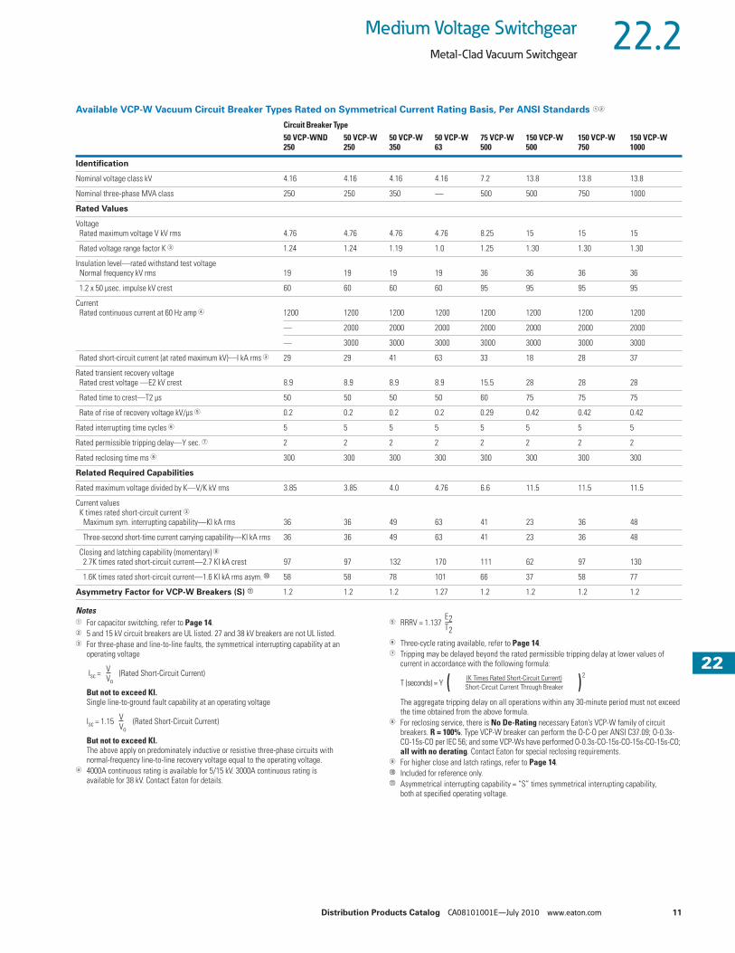
Available VCP-W Vacuum Circuit Breaker Types Rated on Symmetrical Current Rating Basis, Per ANSI Standards ��
Notes� For capacitor switching, refer to Page 14.� 5 and 15 kV circuit breakers are UL listed. 27 and 38 kV breakers are not UL listed.� For three-phase and line-to-line faults, the symmetrical interrupting capability at an
operating voltage
Isc = (Rated Short-Circuit Current)
But not to exceed KI.Single line-to-ground fault capability at an operating voltage
Isc = 1.15 (Rated Short-Circuit Current)
But not to exceed KI.The above apply on predominately inductive or resistive three-phase circuits with normal-frequency line-to-line recovery voltage equal to the operating voltage.
� 4000A continuous rating is available for 5/15 kV. 3000A continuous rating is available for 38 kV. Contact Eaton for details.
� RRRV = 1.137
� Three-cycle rating available, refer to Page 14.� Tripping may be delayed beyond the rated permissible tripping delay at lower values of
current in accordance with the following formula:
T (seconds) = Y
The aggregate tripping delay on all operations within any 30-minute period must not exceed the time obtained from the above formula.
� For reclosing service, there is No De-Rating necessary Eaton’s VCP-W family of circuit breakers. R = 100%. Type VCP-W breaker can perform the O-C-O per ANSI C37.09; O-0.3s-CO-15s-CO per IEC 56; and some VCP-Ws have performed O-0.3s-CO-15s-CO-15s-CO-15s-CO; all with no derating. Contact Eaton for special reclosing requirements.
For higher close and latch ratings, refer to Page 14.� Included for reference only.� Asymmetrical interrupting capability = “S” times symmetrical interrupting capability,
both at specified operating voltage.
Circuit Breaker Type50 VCP-WND250
50 VCP-W250
50 VCP-W350
50 VCP-W63
75 VCP-W500
150 VCP-W500
150 VCP-W750
150 VCP-W1000
Identification
Nominal voltage class kV 4.16 4.16 4.16 4.16 7.2 13.8 13.8 13.8
Nominal three-phase MVA class 250 250 350 — 500 500 750 1000
Rated Values
Voltage Rated maximum voltage V kV rms 4.76 4.76 4.76 4.76 8.25 15 15 15
Rated voltage range factor K � 1.24 1.24 1.19 1.0 1.25 1.30 1.30 1.30
Insulation level—rated withstand test voltage Normal frequency kV rms 19 19 19 19 36 36 36 36
1.2 x 50 µsec. impulse kV crest 60 60 60 60 95 95 95 95
Current Rated continuous current at 60 Hz amp � 1200 1200 1200 1200 1200 1200 1200 1200
— 2000 2000 2000 2000 2000 2000 2000
— 3000 3000 3000 3000 3000 3000 3000
Rated short-circuit current (at rated maximum kV)—I kA rms � 29 29 41 63 33 18 28 37
Rated transient recovery voltage Rated crest voltage —E2 kV crest 8.9 8.9 8.9 8.9 15.5 28 28 28
Rated time to crest—T2 µs 50 50 50 50 60 75 75 75
Rate of rise of recovery voltage kV/µs � 0.2 0.2 0.2 0.2 0.29 0.42 0.42 0.42
Rated interrupting time cycles � 5 5 5 5 5 5 5 5
Rated permissible tripping delay—Y sec. � 2 2 2 2 2 2 2 2
Rated reclosing time ms � 300 300 300 300 300 300 300 300
Related Required Capabilities
Rated maximum voltage divided by K—V/K kV rms 3.85 3.85 4.0 4.76 6.6 11.5 11.5 11.5
Current values K times rated short-circuit current � Maximum sym. interrupting capability—KI kA rms 36 36 49 63 41 23 36 48
Three-second short-time current carrying capability—KI kA rms 36 36 49 63 41 23 36 48
Closing and latching capability (momentary) 2.7K times rated short-circuit current—2.7 KI kA crest 97 97 132 170 111 62 97 130
1.6K times rated short-circuit current—1.6 KI kA rms asym. � 58 58 78 101 66 37 58 77
Asymmetry Factor for VCP-W Breakers (S) � 1.2 1.2 1.2 1.27 1.2 1.2 1.2 1.2
VVo
VVo
E2T2------
(K Times Rated Short-Circuit Current)Short-Circuit Current Through Breaker( )
2

12 Distribution Products Catalog CA08101001E—July 2010 www.eaton.com
222222222222222222222222222222222222222222222222222222222222
22.2 Medium Voltage Switchgear
Metal-Clad Vacuum Switchgear
Available VCP-W Vacuum Circuit Breaker Types Rated on Symmetrical Current Rating Basis, Per ANSI Standards, continued ��
Notes� For capacitor switching, refer to Page 14.� 5 and 15 kV circuit breakers are UL listed. 27 and 38 kV breakers are not UL listed.� For three-phase and line-to-line faults, the symmetrical interrupting capability at an
operating voltage
Isc = (Rated Short-Circuit Current)
But not to exceed KI.Single line-to-ground fault capability at an operating voltage
Isc = 1.15 (Rated Short-Circuit Current)
But not to exceed KI.The above apply on predominately inductive or resistive three-phase circuits with normal-frequency line-to-line recovery voltage equal to the operating voltage.
� 4000A continuous rating is available for 5/15 kV. 3000A continuous rating is available for 38 kV. Contact Eaton for details.
� RRRV = 1.137
� Three-cycle rating available, refer to Page 14.� Tripping may be delayed beyond the rated permissible tripping delay at lower values of
current in accordance with the following formula:
T (seconds) = Y
The aggregate tripping delay on all operations within any 30-minute period must not exceed the time obtained from the above formula.
� For reclosing service, there is No De-Rating necessary for Eaton’s VCP-W family of circuit breakers. R = 100%. Type VCP-W breaker can perform the O-C-O per ANSI C37.09; O-0.3s-CO-15s-CO per IEC 56; and some VCP-Ws have performed O-0.3s-CO-15s-CO-15s-CO-15s-CO; all with no derating. Contact Eaton for special reclosing requirements.
For higher close and latch ratings, refer to Page 14.� Included for reference only.� Asymmetrical interrupting capability = “S” times symmetrical interrupting capability,
both at specified operating voltage.
Circuit Breaker Type150 VCP-W63
270 VCP-W750
270 VCP-W1000
270 VCP-W1250
270 VCP-W40
Identification
Nominal voltage class kV 13.8 27 27 27 27
Nominal three-phase MVA class — — — — —
Rated Values
Voltage Rated maximum voltage kV rms 15 27 27 27 27
Rated voltage range factor K � 1.0 1.0 1.0 1.0 1.0
Insulation level—rated withstand test voltage Normal frequency kV rms 36 60 60 60 60
1.2 x 50 µsec. impulse kV crest 95 125 125 125 125
Current Rated continuous current at 60 Hz amp � 1200 600 600 600 1200
2000 1200 1200 1200 2000
3000 2000 2000 2000 —
Rated short-circuit current (at rated maximum kV)—I kA rms � 63 16 22 25 40
Rated transient recovery voltage Rated crest voltage —E2 kV crest 28 51 51 51 51
Rated time to crest—T2 µs 75 105 105 105 105
Rate of rise of recovery voltage kV/µs � 0.42 0.55 0.55 0.55 0.55
Rated interrupting time cycles � 5 5 5 5 5
Rated permissible tripping delay—Y sec. � 2 2 2 2 2
Rated reclosing time ms � 300 300 300 300 300
Related Required Capabilities
Rated maximum voltage divided by K—V/K kV rms 15 27 27 27 27
Current values K times rated short-circuit current � Maximum sym. interrupting capability—KI kA rms 63 16 22 25 40
Three-second short-time current carrying capability—KI kA rms 63 16 22 25 40
Closing and latching capability (momentary) 2.7K times rated short-circuit current—2.7 KI kA crest 170 43 60 68 108
1.6K times rated short-circuit current—1.6 KI kA rms asym. � 100 26 35 40 64
Asymmetry Factor for VCP-W Breakers (S) � 1.27 1.2 1.2 1.2 1.2
VVo
VVo
E2T2------
(K Times Rated Short-Circuit Current)Short-Circuit Current Through Breaker( )
2

Distribution Products Catalog CA08101001E—July 2010 www.eaton.com 13
222222222222222222222222222222222222222222222222222222222222
22.2Medium Voltage Switchgear
Metal-Clad Vacuum Switchgear
Available VCP-W Vacuum Circuit Breaker Types Rated on Symmetrical Current Rating Basis, Per ANSI Standards, continued ��
Notes� For capacitor switching, refer to Page 14.� 5 and 15 kV circuit breakers are UL listed. 27 and 38 kV breakers are not UL listed.� For three-phase and line-to-line faults, the symmetrical interrupting capability at an
operating voltage
Isc = (Rated Short-Circuit Current)
But not to exceed KI.Single line-to-ground fault capability at an operating voltage
Isc = 1.15 (Rated Short-Circuit Current)
But not to exceed KI.The above apply on predominately inductive or resistive three-phase circuits with normal-frequency line-to-line recovery voltage equal to the operating voltage.
� 4000A continuous rating is available for 5/15 kV. 3000A continuous rating is available for 38 kV. Contact Eaton for details.
� RRRV = 1.137
� Three-cycle rating available, refer to Page 14.� Tripping may be delayed beyond the rated permissible tripping delay at lower values of
current in accordance with the following formula:
T (seconds) = Y
The aggregate tripping delay on all operations within any 30-minute period must not exceed the time obtained from the above formula.
� For reclosing service, there is No De-Rating necessary for Eaton’s VCP-W family of circuit breakers. R = 100%. Type VCP-W breaker can perform the O-C-O per ANSI C37.09; O-0.3s-CO-15s-CO per IEC 56; and some VCP-Ws have performed O-0.3s-CO-15s-CO-15s-CO-15s-CO; all with no derating. Contact Eaton for special reclosing requirements.
For higher close and latch ratings, refer to Page 14.� Included for reference only.� Asymmetrical interrupting capability = “S” times symmetrical interrupting capability,
both at specified operating voltage.� ANSI standard requires 150 kV BIL. All 38 kV ratings are tested to 170 kV BIL.� Type 380 VCP-2 40 circuit breaker is not rated for rapid reclosing.
Circuit Breaker Type380 VCP-W16
380 VCP-W21
380 VCP-W25
380 VCP-W32
380 VCP-W40
Identification
Nominal voltage class kV 34.5 34.5 34.5 34.5 34.5
Nominal three-phase MVA class — — — — —
Rated Values
Voltage Rated maximum voltage kV rms 38 38 38 38 38
Rated voltage range factor K � 1.0 1.65 1.0 1.0 1.0
Insulation level—rated withstand test voltage Normal frequency kV rms 80 80 80 80 80
1.2 x 50 µsec. impulse kV crest � 170 � 170 � 170 � 170 � 170 �
Current Rated continuous current at 60 Hz amp � 600 1200 600 600 600
1200 2000 1200 1200 1200
1600 — 1600 1600 1600
2000 — 2000 2000 2000
— — — 2500 2500
Rated short-circuit current (at rated maximum kV)—I kA rms � 16 21 25 31.5 40
Rated transient recovery voltage
Rated crest voltage —E2 kV crest 71 71 71 71 71
Rated time to crest—T2 µs 125 125 125 125 125
Rate of rise of recovery voltage kV/µs � 0.64 0.64 0.64 0.64 0.64
Rated interrupting time cycles � 5 5 5 5 5
Rated permissible tripping delay—Y sec. � 2 2 2 2 2
Rated reclosing time ms � 300 300 300 300 �
Related Required Capabilities
Rated maximum voltage divided by K—V/K kV rms 38 23 38 38 38
Current values K times rated short-circuit current � Maximum sym. interrupting capability—KI kA rms 16 35 25 31.5 40
Three-second short-time current carrying capability—KI kA rms 16 35 25 31.5 40
Closing and latching capability (momentary) 2.7K times rated short-circuit current—2.7 KI kA crest 43 95 68 85 108
1.6K times rated short-circuit current—1.6 KI kA rms asym. � 26 56 40 51 64
Asymmetry Factor for VCP-W Breakers (S) � 1.2 1.2 1.2 1.2 1.2
VVo
VVo
E2T2------
(K Times Rated Short-Circuit Current)Short-Circuit Current Through Breaker( )
2
14 Distribution Products Catalog CA08101001E—July 2010 www.eaton.com
222222222222222222222222222222222222222222222222222222222222
22.2 Medium Voltage Switchgear
Metal-Clad Vacuum Switchgear
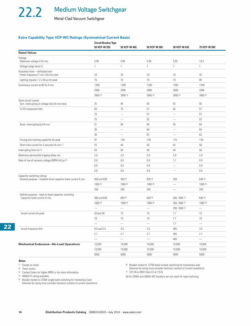
Extra Capability Type VCP-WC Ratings (Symmetrical Current Basis)
Notes� Except as noted.� Three cycles.� Contact Eaton for higher RRRV or for more information.� 4000A FC rating available.� Breaker tested to 2700A single bank switching for momentary load
(thermal de-rating must consider harmonic content of current waveform).
� Breaker tested to 1270A back-to-back switching for momentary load (thermal de-rating must consider harmonic content of current waveform).
� C37.04.a-2003 Class C2 at 15 kV.
38 kV, 2500A and 3000A WC breakers are not rated for rapid reclosing.
Circuit Breaker Type50 VCP-W 25C 50 VCP-W 40C 50 VCP-W 50C 50 VCP-W 63C 75 VCP-W 50C
Rated Values
Voltage Maximum voltage V kV rms 5.95 5.95 5.95 5.95 10.3
Voltage range factor K 1 1 1 1 1
Insulation level—withstand test Power frequency (1 min.) kA rms total 24 24 24 24 42
Lighting impulse 1.2 x 50 µs kV peak 75 75 75 75 95
Continuous current at 60 Hz A rms 1200 1200 1200 1200 1200
2000 2000 2000 2000 2000
3000 � 3000 � 3000 � 3000 � 3000 �
Short-circuit current Sym. interrupting at voltage (Isc) kA rms total 25 40 50 63 50
% DC component (Idc) 50 75 57 62 57
75 — 57 — 57
75 — 52 — 52
Asym. interrupting (It) kA rms 31 58 64 83 64
36 — 64 — 64
36 — 62 — 62
Closing and latching capability kA peak 97 139 139 175 139
Short-time current for 3 seconds kA rms � 25 40 50 63 50
Interrupting time ms � 50 50 50 50 50
Maximum permissible tripping delay sec. 2.0 2.0 2.0 2.0 2.0
Rate of rise of recovery voltage (RRRV) kV/µs � 0.9 0.9 0.9 1.1 0.9
0.9 0.9 0.9 — 0.9
0.8 0.8 0.8 — 0.8
Capacitor switching ratings General purpose—isolated shunt capacitor bank current A rms 400 and 630 630 � 630 � 250 630 �
1000 � 1000 � 1000 � — 1000 �
250 250 250 — 250
Definite purpose—back-to-back capacitor switching Capacitor bank current A rms 400 and 630 630 � 630 � 200, 1600 � 630 �
1000 � 1000 � 1000 � 200, 1600 � 1000 �
— — — 200, 1600 � —
Inrush current kA peak 20 and 20 15 15 7.7 15
18 18 18 7.7 18
— — — 7.7 —
Inrush frequency kHz 6.5 and 5.5 3.5 3.5 465 3.5
2.7 2.7 2.7 465 2.7
— — — 465 —
Mechanical Endurance—No-Load Operations 10,000 10,000 10,000 10,000 10,000
10,000 10,000 10,000 10,000 10,000
5000 5000 5000 5000 5000

Distribution Products Catalog CA08101001E—July 2010 www.eaton.com 15
222222222222222222222222222222222222222222222222222222222222
22.2Medium Voltage Switchgear
Metal-Clad Vacuum Switchgear
Extra Capability Type VCP-WC Ratings (Symmetrical Current Basis), continued
Notes� Except as noted.� Three cycles.� Contact Eaton for higher RRRV or for more information.� 4000A FC rating available.� Breaker tested to 2700A single bank switching for momentary load
(thermal de-rating must consider harmonic content of current waveform).� Breaker tested to 1270A back-to-back switching for momentary load
(thermal de-rating must consider harmonic content of current waveform).� C37.04.a-2003 Class C2 at 15 kV.
� Close and latch current for 1200A Type 150 VCP-W 25C is proven at 15 kV. For sealed interrupters at high altitudes, switching voltage is not de-rated.
Capacitor switching ratings are proven at 15 kV. For sealed interrupters at high altitudes, switching voltage is not de-rated.
� 2.5 seconds.� 1.6 second.� 1 second.� 2000A FC to 3000A.� 2500A FC to 3000A.
38 kV, 2500A and 3000A WC breakers are not rated for rapid reclosing.
Circuit Breaker Type150 VCP-W 25C 150 VCP-W 40C 150 VCP-W 50C 150 VCP-W 63C 270 VCP-W 25C
Rated Values
Voltage Maximum voltage V kV rms 17.5 17.5 17.5 15 27
Voltage range factor K 1 1 1 1 1
Insulation level—withstand test Power frequency (1 min.) kA rms total 42 42 42 42 60
Lighting impulse 1.2 x 50 µs kV peak 95 96 95 95 125
Continuous current at 60 Hz A rms 1200 1200 1200 1200 1200
2000 2000 2000 2000 1600
3000 � 3000 � 3000 � 3000 � —
Short-circuit current Sym. interrupting at voltage (Isc) kA rms total 25 40 50 63 25
% DC component (Idc) 50 75 57 62 75
75 — 57 — —
75 — 52 — —
Asym. interrupting (It) kA rms 31 58 64 83 36
36 — 64 — —
36 — 62 — —
Closing and latching capability kA peak 97 � 139 139 175 85
Short-time current for 3 seconds kA rms � 25 40 50 63 25 �
Interrupting time ms � 50 50 50 50 50
Maximum permissible tripping delay sec. 2.0 2.0 2.0 2.0 2.0
Rate of rise of recovery voltage (RRRV) kV/µs � 0.9 0.9 0.9 1.1 1.1
0.9 0.9 0.9 — —
0.8 0.8 0.8 — —
Capacitor switching ratings General purpose—isolated shunt capacitor bank current A rms 400A and 630 630 � 630 � 250 400
1000 � 1000 � 1000 � — —
250 250 250 — —
Definite purpose—back-to-back capacitor switching Capacitor bank current A rms 400 and 600 630 � 630 � 200, 1600 � 400
1000 � 1000 � 1000 � 200, 1600 � —
— — — 200, 1600 � —
Inrush current kA peak 20 and 20 15 15 7.7 20
18 18 18 7.7 —
— — — 7.7 —
Inrush frequency kHz 6.5 and 5.5 3.5 3.5 465 4.2
2.7 2.7 2.7 465 —
— — — 465 —
Mechanical Endurance—No-Load Operations 10,000 10,000 10,000 10,000 5,000
10,000 10,000 10,000 10,000 —
5000 5000 5000 5000 —

16 Distribution Products Catalog CA08101001E—July 2010 www.eaton.com
222222222222222222222222222222222222222222222222222222222222
22.2 Medium Voltage Switchgear
Metal-Clad Vacuum Switchgear
Extra Capability Type VCP-WC Ratings (Symmetrical Current Basis), continued
Notes� Except as noted.� Three cycles.� Contact Eaton for higher RRRV or for more information.� 1.6 seconds.� 1 second.� 2000A FC to 3000A. 2500A FC to 3000A.� 2.5 seconds.
38 kV, 2500A and 3000A WC breakers are not rated for rapid reclosing.
Circuit Breaker Type270 VCP-W 32C 270 VCP-W 40C 380 VCP-W 16C 380 VCP-W 25C 380 VCP-W 32C 380 VCP-W 40C
Rated Values
Voltage Maximum voltage V kV rms 27 27 38 38 38 38
Voltage range factor K 1 1 1 1 1 1
Insulation level—withstand test Power frequency (1 min.) kA rms total 60 60 80 80 80 80
Lighting impulse 1.2 x 50 µs kV peak 125 125 170 170 170 170
Continuous current at 60 Hz A rms 1200 1200 600 600 600 1200
1600 1600 1200 1200 1200 2000
— — 1600 1600 1600 2500
— — 2000 2000 2000 3000FC
— — — — 2500 —
— — — — 3000FC � —
Short-circuit current Sym. interrupting at voltage (Isc) kA rms total 31.5 40 16 25 33.1 40
% DC component (Idc) 55 50 75 65 57 63
Asym. interrupting (It) kA rms 40 49 23.3 34.0 42.5 53.5
Closing and latching capability kA peak 100 112 50 75 91 107
Short-time current for 3 seconds kA rms � 31.5 � 40 � 16 25 31.5 � 40
Interrupting time rms � 50 50 50 50 50 50
Maximum permissible tripping delay sec. 2.0 2.0 2.0 2.0 2.0 2.0
Rate of rise of recovery voltage (RRRV) kV/µs � 1.1 1.1 0.7 0.7 0.7 0.7
— — 0.7 0.7 0.7 —
— — 1.3 1.3 0.7 —
— — — — 1.3 —
— — — — 0.7 —
— — — — 1.3 —

Distribution Products Catalog CA08101001E—July 2010 www.eaton.com 17
222222222222222222222222222222222222222222222222222222222222
22.2Medium Voltage Switchgear
Metal-Clad Vacuum Switchgear
Extra Capability Type VCP-WC Ratings (Symmetrical Current Basis), continued
Note38 kV, 2500A and 3000A WC breakers are not rated for rapid reclosing.
Circuit Breaker Type270 VCP-W 32C 270 VCP-W 40C 380 VCP-W 16C 380 VCP-W 25C 380 VCP-W 32C 380 VCP-W 40C
Rated Values, continued
Capacitor switching ratings General purpose—isolated shunt capacitor bank current A rms 400 400 250 250 250 —
— — 250 250 250 —
— — 250 250 250 —
— — 250 and 1000 250 and 1000 250 and 1000 —
— — — — — —
— — — — 250 and 1000 —
Definite purpose—back-to-back capacitor switching Capacitor bank current A rms 400 400 250 250 250 —
— — 250 250 250 —
— — 250 250 250 —
— — 250 and 1000 250 and 1000 250 and 1000 —
— — — — — —
— — — — 250 and 1000 —
Inrush current kA peak 20 20 20 20 20 —
— — 20 20 20 —
— — 20 and 20 20 and 20 20 and 20 —
— — — — — —
— — — — 20 and 20 —
Inrush frequency kHz 4.2 4.2 4.4 4.4 4.4 —
— — 4.4 4.4 4.4 —
— — 4.4 4.4 4.4 —
— — 5 and 5 5 and 5 5 and 5 —
— — — — — —
— — — — 5 and 5 —
Mechanical Endurance—No-Load Operations 5,000 5,000 10,000 10,000 10,000 10,000

18 Distribution Products Catalog CA08101001E—July 2010 www.eaton.com
222222222222222222222222222222222222222222222222222222222222
22.3 Medium Voltage Switchgear
High Resistance Grounding System
C-HRG Free-Standing NEMA 1 Unit ContentsDescription Page
High Resistance Grounding System Features, Benefits and Functions . . . . . . . . . . . . . . . . . . 21
Standards and Certifications . . . . . . . . . . . . . . . . . . . . . . 21
Catalog Number Selection . . . . . . . . . . . . . . . . . . . . . . . 22
Technical Data and Specifications . . . . . . . . . . . . . . . . . . 23
Dimensions . . . . . . . . . . . . . . . . . . . . . . . . . . . . . . . . . . . 26
Product DescriptionWhere continuity of service is a high priority, high resistance grounding can add the safety of a grounded system while minimizing the risk of service interruptions due to grounds. The concept is a simple one: provide a path for ground current via a grounding transformer (with adjustable resistance across its secondary) that limits the current magnitude and a monitor to determine when an abnormal condition exists.
The ground current path is provided at the point where the service begins, by placing a predominantly resistive impedance in the connection from system neutral to ground. Control equipment continuously measures ground current; a relay detects when the current exceeds a predetermined level. An alarm alerts building personnel that a ground exists. The system has built-in fault tracing means to assist in finding the source of the ground. A 120 Vac supply (remote) is required for control power for the system.
Application DescriptionThis member of Eaton’s MV metal-clad switchgear family has actually been around for many years. The free-standing C-HRG provides a standalone unit that can be added to existing installations. The C-HRG is used to protect an electrical distribution system from damaging transient overvoltages caused by ground faults. It also provides a means to locate the ground fault, therefore extending the life of the distribution system.
Ratings and ConfigurationsThe C-HRG MV is offered at the 5 kV class rating. It can be applied to delta or wye ungrouped three-wire distribution systems.
4200V (Maximum) Delta SystemsTo add high resistance grounding to an ungrounded delta-connected system, a neutral point must be created. Three single-phase transformers can be interconnected in a wye-broken delta configuration to provide such a neutral point. The transformers and grounding resistors are chosen to limit the ground current to a maximum value of 6A.
Note: The neutral point may not be used to serve phase-to-neutral loads. Also, this technique may be applied on wye-connected sources when the neutral point is not conveniently accessible from the service entrance location. This method is shown in the illustration shown on Page 24. One delta high resistance grounding would ground the 5 kV system.
4200V (Maximum) Wye SystemsTo add high resistance grounding to a wye-connected system, resistors are placed across the secondary of a grounding transformer whose primary is placed in series with the neutral-to-ground connection of the power source. The resistors are chosen to limit the current to a maximum value of 6A.
Note: Per 1993 NEC® 250-5b, exception No. 5, line-to-neutral loads may not be connected to a system in which the neutral is resistance grounded. Also, if the system has two switchable sources not permanently connected to the bus, two wye-type grounding systems are required as shown on Page 24.

Distribution Products Catalog CA08101001E—July 2010 www.eaton.com 19
222222222222222222222222222222222222222222222222222222222222
22.3Medium Voltage Switchgear
High Resistance Grounding System
Ground Current DetectionAny time a system is energized, a small ground current called the “capacitive charging current” will be observed. For medium voltage (4200V and below) systems, this naturally occurring current is typically 3A or less.
When one phase becomes grounded, additional current above the charging level will flow. As all ground current must flow through the grounding resistor/grounding transformer assembly, an ammeter in this circuit will read the total amount of ground current. By placing a current-sensing relay in series with the ammeter, the current relay can be adjusted to pick up at a level in excess of the capacitive charging current, thus indicating the abnormal condition.
Alternatively, an optional voltmeter-relay can be connected across the grounding resistors. The voltage across the resistorsis proportional to the amount of ground current. The voltmeter-relay’s pickup adjustment is set above the capacitive charging current, to the desired detection level.
In both current and voltage detection methods, the ground current ammeter provides a direct reading of the total actual ground current present in the system at that time. It will be helpful to periodically note the ammeter’s reading: a trend toward higher values may indicate the need for equipment maintenance, and hence reduce the occurrence of unplanned shutdowns.
Indication and Alarm CircuitsWhen a fault is detected, an adjustable time delay is provided to override transients. When the time delay has been exceeded, the green “normal” light will turn off, the red “ground fault” light will turn on, and the ground alarm contacts will transfer. If equipped with the optional alarm horn, it will sound.
The grounding transformer secondary breaker must be closed for the system to be operational. Should this breaker be opened at any time, the system will signal a ground fault condition as a fail-safe feature. The breaker must be closed to clear the alarm signal.
When the fault is cleared, the current/voltage relay will reset. If the reset control is set on “auto,” the lights will return to “normal” on, “ground fault” off, and the ground alarm contacts will re-transfer. If the reset control is set on “manual,” the lights and relay contacts will remain latched until the operator turns the reset control to “reset.” The lights and ground alarm contacts will then return to normal. The system can be reset only if the fault has been cleared.
During a fault, the optional alarm horn can be silenced at any time by using the “alarm silence” pushbutton. It will not re-sound until either the system is reset, or the re-alarm timer expires. The re-alarm timer is activated by the “alarm silence” control. If the horn has been silenced but the fault has not been cleared, the timer will run. It has a range of 2–48 hours. When the timer times out, the horn will re-sound, alerting maintenance personnel that the fault has not been cleared.
Test CircuitA test circuit is provided to allow the user to quickly determine that the system is working properly. The test circuit will operate only under normal conditions—it will not allow testing if the system is sensing a fault. The test operation does not simulate an actual system ground fault. It does, however, test the complete controls of the fault indication and pulsing circuitry. The system then reacts as it would under actual system ground conditions —lights transfer, alarm contacts transfer and the (optional) horn sounds.
Pulser CircuitThe pulser circuit offers a convenient means to locate the faulted feeder and trace the fault to its origin. The pulser is available any time a fault has been detected. The pulse intervals are controlled by an adjustable recycle timer. The “pulse” light flashes on and off, corresponding to the on-off cycles of the pulser contactor. The pulser contactor switches a bank of resistors on and off, thus allowing a momentary increase in the ground current (approximately a 4A current pulse above the ground current).
Locating a Ground FaultThe current pulses can be noted with a clamp-on ammeter when the ammeter is placed around the cables or conduit feeding the fault. The operator tests each conduit or set of cables until the pulsing current is noted. By moving the ammeter along the conduit, or checking the conduit periodically along its length, the fault can be traced to its origin. The fault may be located at the point where the pulsing current drops off or stops.
If little or no change in the pulsing current is noted along the entire length of a conduit, then the fault may be in the connected load. If the load is a panelboard, distribution switchboard or motor control center, repeat the process of checking all outgoing cable groups and conduits to find the faulted feeder. If the fault is not found in an outgoing feeder, the fault may be internal to that equipment.
Note: It may not be possible to precisely locate faults within a conduit. The ground current may divide into many components, depending on the number of cables per phase, number of conduits per feeder, and the number and resistance of each ground point along the conduits. The resulting currents may be too small to allow detection or may take a path that the ammeter cannot trace. An important note to keep in mind is that while the pulser can greatly aid in locating a fault, there may be certain conditions under which the pulses cannot be readily traced, and other test procedures (megohm, high-potential, etc.) may be needed.

20 Distribution Products Catalog CA08101001E—July 2010 www.eaton.com
222222222222222222222222222222222222222222222222222222222222
22.3 Medium Voltage Switchgear
High Resistance Grounding System
Sequence of Operations
Normal● Green “normal” light on● Red “ground fault” light off● White “pulse” light off● System control switch in
“normal” position● Reset control switch in
either “auto” or “manual”
TestTurn and hold the system control switch in the “test” position. This mode will test the control circuitry only. It will bypass the sensing circuit and cause the green “normal” light to turn off and the red “ground fault” light to turn on. The pulser will be activated as well. The white “pulse” light will turn on and off as the pulser contactor closes and opens. However, the ground current ammeter will not display the total ground current, including the incremental pulse current. When ready, return the system control switch to “normal.” The pulser will stop. If the reset control is in the “manual” position, turn it to “reset” to reset the fault sensing circuit. The red “ground fault” light will turn off, and the green “normal” light will turn on. Test mode is not available if the system is detecting a ground. The sensing circuit will disable the test circuit.
Ground FaultWhen the sensing circuit detects a fault, the green “normal” light will turn off and the red “ground fault” light will turn on. The ground current ammeter will indicate the total ground current. To use the pulser, turn the system control switch to “pulse.” The pulser contactor will cycle on and off as controlled by the recycle timer relay. Use the clamp-on ammeter to locate the faulted feeder. Open the feeder and clear the fault. If the reset control switch is in the “manual” position, turn it to “reset” to reset the sensing circuit. (If reset control is in “auto,” it will reset itself.) When ready to restore service to the load, close the feeder. Return the system control to “normal.”

Distribution Products Catalog CA08101001E—July 2010 www.eaton.com 21
222222222222222222222222222222222222222222222222222222222222
22.3Medium Voltage Switchgear
High Resistance Grounding System
Features, Benefits and FunctionsWhen a ground fault occurs on an ungrounded system, high transient voltages can occur, which may cause more frequent equipment failures than if the equipment were grounded. These transient overvoltages, as high as four times the normal voltage, reduce the life of the system’s insulation resulting in:
● Motor failure● Transformer failure● Coil failure● Electronic equipment
failure● Cable insulation failure
By using a high resistance ground system, many facilities can gain the benefit of a grounded system without impairing the continuity of service to their equipment. The concept behind high resistance grounding is to provide a path for the ground current to flow while limiting its magnitude by using a resistor. The ground current path is provided at the point where service begins. Control equipment continuously monitors the magnitude of the ground current.
When the ground current exceeds a predetermined level, the built-in alarm relay alerts building personnel that a ground fault exists. In addition, the C-HRG MV “safe ground” system has a built-in fault pulsing as a means to assist in finding the source of the ground fault without interrupting service.
● Current sensingground fault detection (2–10A pickup/0.5–20 second delay)
● Ground current transformer (10/10 ratio)
● Control circuit pull fuseblock
● Ground current ammeter (0–10A, 1% accuracy)
● Indicating lights: ● Red (ground fault) ● Green (normal) ● White (pulse)
● Adjustable pulsing timer (0–10 seconds)
● Tapped resistors (limits primary current to 3–6A)
● Three-position selector switch (normal, pulse, test)
● Control switch for manual or automatic reset
● Ground fault contacts (1NO/1NC)
● Shorting terminal block for ground current CT
● UL label● Wiremarkers
Standards and CertificationsThe system shall be completely assembled, wired and tested at the factory in accordance with NEMA and UL requirements. A certified production test report shall be shipped with the unit.

22 Distribution Products Catalog CA08101001E—July 2010 www.eaton.com
222222222222222222222222222222222222222222222222222222222222
22.3 Medium Voltage Switchgear
High Resistance Grounding System
Catalog Number SelectionA C-HRG High Resistance Grounding Assembly can be completely described by an 8-digit catalog number: MVRG-_ _ _ _ _ _ _ _
High Resistance Grounding Systems
Example: MVRG-FWWCLLTS defines a free-standing NEMA 1 enclosure, 4200V/60 Hz, wye-connected system, current-sensing control scheme, alarm horn with re-alarm timer, alarm relay with 1NO and 1NC, transformer type incandescent lights, wrap-on wiremarkers.
Service VoltageW = 4200V 60 HzX = 2400V 60 HzY = 3300V 60 Hz
System Neutral PointChoose wye when the neutral point of the power source is accessible for direct connection to grounding transformer. Choose delta when there is no neutral or when neutral is not accessible.W = WyeD = D (wye broken delta
grounding transformer)
Fault SensingCurrent sensingVoltage sensingVoltage sensingC = Overcurrent relayV = Single set point voltmeter relayD = Indicating voltmeter only
Enclosure TypeFree-standing enclosure for mounting grounding transformer and resistors internally.F = Free-standing NEMA 1R= Free-standing NEMA 3R outdoor
WiremarkersMarks all internal wiring for ease of maintenance.S = Standard wrap-onT = Tube/heat shrink type
Indicating LampsStandard lights are industrial, oil-tight, transformer type. Optional are the same type lights except with a push-to-test feature.T = Transformer type incandescent lampsX = Push-to-test transformer type
Loss of Control Power Alarm
A relay is connected across the customer’s 120 Vac supply.N = No relayL = Alarm relay with
1NO and 1NC
Audible AlarmAlarm contacts are standard on all assemblies.N = No audible alarmL = Alarm horn with
re-alarm timer
MVRG F X D D N L T S

Distribution Products Catalog CA08101001E—July 2010 www.eaton.com 23
222222222222222222222222222222222222222222222222222222222222
22.3Medium Voltage Switchgear
High Resistance Grounding System
Technical Data and SpecificationsGeneralProvide a high resistance grounding system as a means to provide a path for ground current via a resistance that limits the current magnitude. While monitoring the ground current, the system must be able to determine when an abnormal condition exists. Once the abnormality is detected, the system shall alert building personnel that a ground exists. The system shall be suitable for 5000V maximum service, and designed and tested for that voltage class in accordance with the latest standards of NEMA and UL.
● Tapped resistors supply primary ground current between 3 and 6A in 1A increments
● Pulse current is an additional 4A. (pulse currents of a lower magnitude may be difficultto detect)
● Pulse timer is adjustable from 3 to 60 pulses per minute
● Time delay for current sensing relay is 0.5 to 20 seconds with a 2 to 10A pickup. Time delay for voltage sensing relay is 1 to 60 seconds
● “Pull-type” fuse disconnects are supplied for control equipment protection
● All exterior nameplates are fastened with stainless steel screws
● Nameplates are 2-ply with 3/16-inch (4.8 mm) lettering. The nameplate size is 1-inch (25.4 mm) x 2-1/2-inch (63.5 mm). White background with black lettering is standard
● Top and bottom cable entry areas
● Phase and neutral terminals accept #4 AWG to 500 kcmil
● Ground terminal accepts wire sizes from #4 AWG to 500 kcmil. Ground bus is 1/4-inch (6.35 mm) x 2-inch (50.8 mm) copper
● The powder paint is applied to the parts electrostatically. Metal surfaces are prepared by spray cleaning and phosphatizing. The powder paint is a polyester urethane. The standard color is ANSI 61, light gray. The paint is applied to a thickness of 1.5 mil
● Appropriate current limit drawout type fuses are provided. The chassis is mechanically interlocked with a secondary circuit breaker to prevent its withdrawal under load conditions
● Resistors are grid type to provide the maximum area for heat dissipation
● No. 4 AWG wire is used for internal connections from the neutral point to ground. Control connections are a minimum of #14 gauge. All control wires insulation is type SIS
● Recommended spare parts list
● Steel pocket on the inside of the door is provided to hold drawings and manuals
Note: The C-HRG units can be applied on any three-wire distribution system, regardless of the manufacturer of the distribution equipment or source power transformer.
System Ratings and FeaturesProvide a UL-labeled high-resistance grounding system equal to Eaton catalog number _________ for use on a system with a short-circuit capacity of __kA at ____ volts. The structure shall be a [free-standing NEMA 1] [free-standing NEMA 3R]. The system neutral point shall be provided by [the power transformer’s wye neutral point] [wye-broken delta grounding transformers]. The ground current shall be detected with [an overcurrent relay] [a single set point voltmeter relay]. [An alarm horn with re-alarm timer is required.] [An alarm to indicate the loss of control power is required.] The indicating lights shall be [transformer-type incandescent lamps] [push-to-test transformer type lamps]. Control wiring shall be marked using [wrap-on type] [heat-shrink sleeve type] wiremarkers. [A portable clamp on detector with 1/2/5/10/20A scales, a shorting switch and a storage case is required].
In addition to the components specified, the following shall be supplied with each system:
● Ground current transformer (10/10 ratio)
● Control circuit disconnect switch (fused)
● Ground current ammeter (0–10A, 1% accuracy)
● Control switch for manual or automatic reset
● Ground fault contacts (1NO/1NC) for customer use
● Shorting terminal block for ground current CT
● Adjustable pulsing timer (0–10 seconds)
● Tapped resistors (across neutral forming transformer secondary, limiting primary current to 3–6A)
● Three-position selector switch (normal, pulse, test)
● Indicating lights:Red (ground fault)Green (normal)White (pulse)
Components and ConnectionsPhase and neutral terminals shall accept #4 AWG to 500 kcmil wire. Ground terminals shall accept wire sizes from #8 AWG to 500 kcmil. Ground bus shall be 1/4-inch (6.35 mm) x 2-inch (50.8 mm) copper. #4 AWG wire shall be used for all internal connections from the neutral point to ground. Control connections shall be a minimum of #14 gauge. All control wire insulation shall be type SIS. All control wiring shall be labeled at each end. Wiring within the resistor assembly shall be rated for 200°C service.
StructureThe unit shall be free-standing and house the resistor bank within an isolated section of the structure. Access to the resistor shall be via a bolted-on cover. The rear cover shall be removable. The structure shall provide top and bottom cable entry points. Lifting angles shall be provided to facilitate the installation of the unit. The structure shall be suitable for moving on rollers and shall be skidded for shipment in a manner suitable for handling by a forklift.
All steel parts (except for plated parts) shall be thoroughly cleaned and phosphatized prior to the application of the light gray ANSI No. 61 finish. A pocket is required on the inside of the control compartment door to store drawings and manuals.

24 Distribution Products Catalog CA08101001E—July 2010 www.eaton.com
222222222222222222222222222222222222222222222222222222222222
22.3 Medium Voltage Switchgear
High Resistance Grounding System
Wiring Diagram
HRG—High Resistance Grounding System
Wye HRG
51N
59
Delta HRG
59
51
Generator
BusDuct
BusDuct
To PowerCircuit
Conduit
5 kV Switchgear
To MCC
Cable
BusDuct
Wye HRG
51N
59
Utility

Distribution Products Catalog CA08101001E—July 2010 www.eaton.com 25
222222222222222222222222222222222222222222222222222222222222
22.3Medium Voltage Switchgear
High Resistance Grounding System
Circuit Diagrams
Ungrounded Wye System (with standard current and optional voltage relay fault detectors)
Ungrounded Delta System (with standard current and optional voltage relay fault detectors)
DetectorCurrent
Det
ecto
r
Volt
age
Mec
han
ical
H33
H2 H1
X3
X2X1
X0
UngroundedWye
ToDistributionCircuits
X0
5 kV - CLEFuses
Inte
rlo
ck
[1]ControlPowerTransformer
SecondaryCircuitBreakerB B
59
ShortCircuitT.B.
AM
5IN
CT
10/
10A
Pu
lsin
g R
esis
tor
Pu
lsin
g C
on
tact
or
Gro
un
din
g R
esis
tor
GroundCurrent
tT.B.
ToRemoteAlarm
G R W
ControlCircuit
Normal Alarm Pulsing Audible Alarm
Optional
20A
20A
Fuses120V60 HzSupply
Op
tio
nal
C
3A
4A
5A
6A
4
Option
Curren t DetectorD
etec
tor
Volt
age
H3
Mec
han
ical
H2H1
Ungrounded
DeltaToDistributionCircuits
5 kV - CLEFuses
Inte
rlo
ck
3-AuxiliaryControlPowerTransformers
SecondaryCircuitBreaker
B B
59
Short CircuitT.B.
AM
5IN
CT
10/
10A
Pu
lsin
g R
esis
tor
Pu
lsin
g C
on
tact
or
Gro
un
din
g R
esis
tor
GroundCurrent
tT.B.
ToRemoteAlarm
G R W
ControlCircuit
Normal Alarm Pulsing Audible Alarm
Optional
20A
20A
Fuses120V60 HzSupply
Op
tio
nal
C
3A
4A
5A6A
4
X3
X2 X1

26 Distribution Products Catalog CA08101001E—July 2010 www.eaton.com
222222222222222222222222222222222222222222222222222222222222
22.3 Medium Voltage Switchgear
High Resistance Grounding System
DimensionsApproximate Dimensions in Inches (mm)
NEMA 1 Free-Standing
Primary ConduitEntrance
Vent
92.00(2336.8)
36.00(914.4)
36.00(914.4)
40.00(1016)
3.50(88.9)
8.50(215.9)
1.50(38.1)
3.76(95.6)
3.62(91.9)
3.25(82.6)
7.12(180.9)
9.38(238.3)
3.50(88.9)
3.75(95.3)
3.00(76.2)2.75
(69.9)
1.75(44.5)
0.81(20.6)0.562 (14.3) Diameter (4)
Primary ConduitConduit Entrance
Secondary ConduitEntrance
2.00 (50.8) DiameterKnockoutfor SecondaryConduit Entrance
Plan View
Front View
Floor Plan
3.75(95.3)
3.75(95.3)
2.75(69.9)
2.75(69.9)
0.81(20.6)
2.75(69.9)