Switchgear Type SIMOSEC, up to 24 kV, Air-Insulated ...
28
MEDIUM-VOLTAGE SWITCHGEAR Switchgear Type SIMOSEC, up to 24 kV, Air-Insulated, Extendable siemens.com/SIMOSEC Catalog HA 41.43 ⋅ 2022
-
Upload
khangminh22 -
Category
Documents
-
view
0 -
download
0
Transcript of Switchgear Type SIMOSEC, up to 24 kV, Air-Insulated ...

MEDIUM-VOLTAGE SWITCHGEAR
Switchgear Type SIMOSEC, up to 24 kV, Air-Insulated, Extendable
siemens.com/SIMOSEC
Catalog HA 41.43 ⋅ 2022

Transfer switchgear with integrated low-voltage niche
Utilities transfer substation for industrial plants
R-HA
4143
_014
8 jpg
R-HA
41-1
15.ti
f
R-HA
4143
_014
9 jpg
R-HA
4143
_015
1 jpg
R-HA
4143
_015
0 jpg
ApplicationTypical uses
2 Switchgear Type SIMOSEC, up to 24 kV, Air-Insulated, Extendable · Siemens HA 41.43 · 2022

The products and systems described in this catalog are manufactured and sold according to a certified management system (acc. to ISO 9001, ISO 14001 and BS OHSAS 18001).
MEDIUM-VOLTAGE SWITCHGEAR
Switchgear Type SIMOSEC, up to 24 kV, Air-Insulated, Extendable
Catalog HA 41.43 · 2022
Invalid: Catalog HA 41.43 · 2018
siemens.com/medium-voltage-switchgear siemens.com/SIMOSEC
Application, requirementsFeatures 4Features, classification, standards 6
Technical dataElectrical data of the switchgear 7Technical data, switching capacity and classification of switching devices 9
Product rangeProduct range overview 11Ring-main panels, cable panels, busbar earthing panels 12Transformer panels, disconnector panels 13Metering panels as billing metering panels 14Busbar voltage metering panels, bus riser panels 15Circuit-breaker panels 16
DesignPanel design (examples) 17
ComponentsBusbars 19Selection data for various cable sealing ends 20Cable cross-sections and instrument transformer combination 21Cable fixing 22Current transformers, voltage transformers 23Low-voltage niche 24Low-voltage compartment 25
DimensionsRoom planning 26
Contents Page
Switchgear Type SIMOSEC, up to 24 kV, Air-Insulated, Extendable · Siemens HA 41.43 · 2022 3

* For standards, see page 6
SIMOSEC switchgear is a factory-assembled, type-tested, three-phase, metal-enclosed, indoor switchgear according to IEC 62271-200 * for single busbars.
Typical usesSIMOSEC switchgear is used for power distribution in distribution systems with busbar currents up to 1250 A. The modular, space saving design enables application in• Substations, customer transfer substations, distribution
substations and switching substations of power supply and public utilities
• Public buildings, such as high-rise buildings, railway stations, hospitals
• Industrial plants.Typical applications• Wind power plants• High-rise buildings• Airports• Underground railway stations• Sewage treatment plants• Port facilities• Traction power supply systems• Automobile industry• Petroleum industry• Chemical industry• Combined heat and power plants• Textile, paper and food industries• Emergency power supply installations• Shopping centers and data centers.
Modular design • Individual panels, for free combination and extension• Option: Low-voltage compartments can be supplied in two
overall heights• Circuit-breaker panels for various applications.
Reliability• Type- and routine-tested *• Reduced dielectric stress thanks to stainless steel switch-
ing-device vessel• Standardized and manufactured using numerically
controlled machines• Quality management system according to
DIN EN ISO 9001• More than 100,000 switchgear components in operation
worldwide for many years.
Personal safety• All switching operations can be performed with closed
panel front• Metal-enclosed LSC 1 / LSC 2 panels• HV HRC fuses and cable sealing ends are only accessible
when the outgoing feeders are earthed• Logical interlocks• Capacitive voltage detecting system to verify safe isolation
from supply• Earthing of outgoing feeders by means of make-proof
earthing switches.
Compact design Thanks to the use of gas-insulated switching-device vessels, compact dimensions are possible. Thus:• Existing switchgear rooms can be used effectively• New constructions cost little• Costly city-area space is saved.
Security of operation• Components, e.g. operating mechanisms, three-position
switches and vacuum circuit-breakers proven for years• LSC 1 / LSC 2 panels:
– Panels with metal partition (metal-clad) between busbar and switching device as well as between switching device and cable compartment (R, T, L)
– Panels with metal partition between switching device and busbar compartment
• Metal-enclosed switching-device vessel with three-position switch, gas-insulated
– Welded switching-device vessel, sealed-for-life – With welded-in rotary bushings for operation – Three-position switch-disconnector with gas-insulated switching functions
– Three-position disconnector, gas-insulated – Switching functions CLOSE-OPEN-EARTH
• Operating mechanisms of switching devices accessible outside the switching-device vessel
• Maintenance-free operating mechanism parts (IEC 62271-1*)
• Mechanical position indication integrated in mimic diagram• Switchgear interlocking system with logical interlocks.
Re-availability• Three-position switch-disconnector with gas-insulated,
maintenance-free quenching principle• Metal partition between busbar compartment, switching
devices and cable compartment.
Application, requirementsFeatures
4 Switchgear Type SIMOSEC, up to 24 kV, Air-Insulated, Extendable · Siemens HA 41.43 · 2022

Compartments InsulationBusbar AirSwitching-device vessel SF6
Cable connection Air
���
����
����
����
Cost-efficiencyLow lifecycle costs and high availability throughout the entire product lifecycle as a result of:• Minimum space requirements • Easy switchgear extension, without gas work• Maintenance-free gas-insulated switching functions of the
three-position switch (gas-insulated quenching principle)• Modular product range and design, e.g. circuit-breaker
panels• Low maintenance.
Quality and environment• Quality and environmental management system according
to DIN EN ISO 9001 and DIN EN ISO 14001• Easy switchgear extension, without gas work on site• Minimum space requirements.
Service lifeUnder normal service conditions, the expected service life of air-insulated switchgear SIMOSEC is at least 35 years, prob-ably 40 to 50 years, taking the tightness of the hermetically welded switching-device vessel into account. The service life is limited by the maximum number of operating cycles of the switching devices installed:• For circuit-breakers, according to the endurance class
defined in IEC 62271-100• For three-position disconnectors and earthing
switches, according to the endurance class defined in IEC 62271-102
• For three-position switch-disconnectors, according to the endurance class defined in IEC 62271-103.
Insulating system• Switching-device vessel filled with SF6 gas• Features of SF6 gas:
– Non-toxic – Odorless and colorless – Non-inflammable – Chemically neutral – Heavier than air – Electronegative (high-quality insulator) – Global Warming Potential GWP = 22,800
• Pressure of SF6 gas in the switching-device vessel (absolute values at 20 °C):
– Rated filling level: 140 kPa – Design pressure: 180 kPa – Design temperature of the SF6 gas: 80 °C – Operating pressure of bursting disc: ≥ 270 kPa – Bursting pressure: ≥ 550 kPa – Gas leakage rate: < 0.1 % per year.
General design• Air-insulated indoor switchgear• Gas-insulated, maintenance-free switching functions for
the three-position switch as switch-disconnector• Three-pole primary enclosure• Phases arranged one behind the other• Three-position switch, metal-enclosed, with air-insulated
primary terminals and gas-insulated switching functions• Vacuum circuit-breaker up to 1250 A, metal-enclosed,
fixed-mounted in gas-insulated switching-device vessel or as removable design: easy to remove after loosening the fixing bolts
• Hermetically welded, stainless-steel switching-device vessels
– for switching devices – with insulating gas SF6 (fluorinated greenhouse gas)
• Factory-assembled, type-tested• Metal-enclosed, with metal partitions• Pressure relief
– to the rear and upwards – separately for each compartment.
Application, requirementsFeatures
Switchgear Type SIMOSEC, up to 24 kV, Air-Insulated, Extendable · Siemens HA 41.43 · 2022 5

Electrical features• Rated voltages up to 24 kV• Rated short-time withstand current up to 25 kA• Rated continuous current of feeders
– Up to 800 A, e.g. for ring-main panels, metering panels – Up to 1250 A, for circuit-breaker panels – Up to 1250 A, for bus sectionalizer panels
• Rated continuous current of busbar up to 1250 A.
SIMOSEC switchgear is a factory-assembled, type-tested, metal-enclosed switchgear for indoor installation. SIMOSEC switchgear is classified according to IEC 62271-200.
Design and construction
Partition class PM (metal partition)Loss of service continuity category for panels: – With HV HRC fuses (T, ...) – Without HV HRC fuses (R, L, D, ...) – Metering panels type M... or
cable panels type K
LSC 2 LSC 2 LSC 1
Accessibility to compartments (enclosure) – Busbar compartment – Switching-device compartment – Switching-device compartment
with removable circuit-breaker – Low-voltage compartment (option) – Cable compartment for panels:
– Without HV HRC fuses (R, L, ...) – With HV HRC fuses (T, ...) – Cable panel (K) – Metering panels (air-insulated)
(M, ...H)
– Tool-based – Non-accessible – Interlock-controlled – Tool-based – Interlock-controlled – Interlock-controlled – Tool-based – Tool-based
Internal arc classification (option)
The following internal arc classifications are fulfilled: IAC A FL(R), Isc, tIAC Internal Arc ClassificationIAC class for: – Wall-standing arrangement – Free-standing arrangement
Rated voltage 7.2 kV to 24 kV:IAC A FL, Isc, t IAC A FLR, Isc, t
Type of accessibility: A
– F – L – R
Switchgear in closed electrical service location, access for authorized personnel only (according to IEC 62271-200)Front Lateral Rear (for free-standing arrangement)
Arc test current Isc Up to 21 kATest duration t 1 s
StandardsSIMOSEC switchgear complies with the relevant standards and specifications applicable at the time of type tests.
In accordance with the harmonization agreement reached by the countries of the European Union, their national specifications conform to the IEC standards.
Overview of standards
IEC standard EN standardSwitchgear SIMOSEC IEC 62271-1 EN 62271-1
IEC 62271-200 EN 62271-200Devices Circuit-breakers IEC 62271-100 EN 62271-100
Disconnectors and earthing switches IEC 62271-102 EN 62271-102Switch-disconnectors IEC 62271-103 EN 62271-103Switch-disconnector / fuse combination IEC 62271-105 EN 62271-105HV HRC fuses IEC 60282-1 EN 60282-1Voltage detecting systems IEC 61243-5 EN 61243-5Voltage presence indicating systems IEC 62271-206 EN 62271-206
Degree of protection
IP code IEC 60529 EN 60529IK code IEC 62262 EN 50102
Insulation – IEC 60071 EN 60071Instrument transformers General requirements IEC 61869-1 EN 61869-1
Current transformers IEC 61869-2 EN 61869-2Voltage transformers IEC 61869-3 EN 61869-3
Power installations Common rules IEC 61936-1 EN 61936-1Earthing of power installations – EN 50522
Insulating gas SF6 Specification for sulfur hexafluoride (SF6) IEC 60376 EN 60376
The rated continuous currents apply to ambient air temperatures of max. 40 °C. The 24-hour mean value is max. 35 °C (according to IEC 62271-1).
Application, requirementsFeatures, classification, standards
6 Switchgear Type SIMOSEC, up to 24 kV, Air-Insulated, Extendable · Siemens HA 41.43 · 2022

Common electrical data
Rated insulation level Rated voltage Ur kV 7.2 12 17.5 24Rated short-dur. power- frequency withstand voltage Ud – phase-to-phase, phase-to-earth, open contact gap– across the isolating distance
kV kV
2023
28, 42 32, 48
3845
50 60
Rated lightning impulse withstand voltage Up – phase-to-phase, phase-to-earth, open contact gap– across the isolating distance
kVkV
6070
7585
95
110
125145
Rated frequency fr Hz 50 /60Rated continuous current Ir for busbar
Standard A 630Option A 800, 1250
50 Hz Rated short-time withstand current Ik
for rated duration of short-circuit tk = 1 s, 2 s up to kA 21 25 21 25 21 25 16 20 25for rated duration of short-circuit tk = 3 s (20 kA / 4 s) up to kA 21 – 21 – 21 – 16 20 –
Rated peak withstand current Ip up to kA 52.5 63 52.5 63 52.5 63 40 50 6360 Hz Rated short-time
withstand current Ik
for rated duration of short-circuit tk = 1 s, 2 s up to kA 21 25 21 25 21 25 16 20 25for rated duration of short-circuit tk = 3 s up to kA 21 – 21 – 21 – 16 20 –
Rated peak withstand current Ip up to kA 55 65 55 65 55 65 42 52 65
Pressure values, temperature
Pressure in gas-insulated switching-device vessel for SF6 gas-insulated switching devices (pressure values at 20 °C)
Rated filling level for insulation pre (absolute) kPa 140Minimum functional level for insulation pme (absolute) kPa 120Signal of filling level for insulation pae (absolute) kPa 120Minimum functional level for switching psw (absolute) kPa 120
Ambient air temperature T (minimum/maximum ambient air temperature depends on the secondary equipment used)
Operation Standard °C –5 to +55Option (if panel heating available) °C –25
Storage/transport Standard °C –5 to +55Option °C –25, +70Option °C –40
Degree of protection for gas-filled switching-device vessel IP65for switchgear enclosure IP2X/IP3Xfor low-voltage compartment IP3X / IP4X
Technical dataElectrical data of the switchgear
Switchgear Type SIMOSEC, up to 24 kV, Air-Insulated, Extendable · Siemens HA 41.43 · 2022 7

Common electrical data of the switchgear panels
Rated insulation level Rated voltage Ur kV 7.2 12 17.5 24Ring-main panel types R, R1, R(T), R1(T), cable panel types K and K1,disconnector panel types D1, D1(T)Rated continuous current Ir Standard A 630
D1, D1(T), K1 A 125050 Hz Rated short-time
withstand current Ik
for rated duration of short-circuit tk = 1 s, 2 s up to kA 21 25 21 25 21 25 16 20 25for rated duration of short-circuit tk = 3 s (4 s) up to kA 21 – 21 – 21 – 16 20 –
Rated peak withstand current Ip up to kA 52.5 63 52.5 63 52.5 63 40 50 63Rated short-circuit making current Ima for ring-main feeders up to kA 52.5 63 52.5 63 52.5 63 40 50 63
60 Hz Rated short-time withstand current Ik
for rated duration of short-circuit tk = 1 s, 2 s up to kA 21 25 21 25 21 25 16 20 25for rated duration of short-circuit tk = 3 s up to kA 21 – 21 – 21 – 16 20 –
Rated peak withstand current Ip up to kA 55 65 55 65 55 65 42 52 65Rated short-circuit making current Ima for ring-main feeders up to kA 55 65 55 65 55 65 42 52 65
Circuit-breaker panel types L, L1, L(T), L1(T), L1(r), L1(r, T), metering panel types M, bus riser panel types H, H1Rated continuous current Ir L, L(T), L1, L1(T), L1(r), L1(r, T),
M, M(-K), M(-B), M(-BK), M(KK), H, H1 A 630
L1, L1(T), L2(r), L2(r, T),M, M(-K), M(-B), M(-BK), H, H1
A 1250
50 Hz Rated short-time withstand current Ik
for rated duration of short-circuit tk = 1 s, 2 s up to kA 21 25 21 25 21 25 16 20 25for rated duration of short-circuit tk = 3 s, 4 s up to kA 21 – 21 – 21 – 16 20 –
Rated peak withstand current Ip up to kA 52.5 63 52.5 63 52.5 63 40 50 63Rated short-circuit making current Ima
for circuit-breaker panel L, L1….. up to kA 52.5 63 52.5 63 52.5 63 40 50 63
Rated short-circuit breaking current Isc
for circuit-breaker panel L, L1….. up to kA 21 25 21 25 21 25 16 20 25
60 Hz Rated short-time withstand current Ik
for rated duration of short-circuit tk = 1 s, 2 s up to kA 21 25 21 25 21 25 16 20 25for rated duration of short-circuit tk = 3 s up to kA 21 – 21 – 21 – 16 20 –
Rated peak withstand current Ip up to kA 55 65 55 65 55 65 42 52 65Rated short-circuit making current Ima
for circuit-breaker panel L, L1….. up to kA 55 65 55 65 55 65 42 52 65
Rated short-circuit breaking current Isc
for circuit-breaker panel L, L1….. up to kA 21 25 21 25 21 25 16 20 25
Busbar voltage metering panel types M(VT), M1(VT), M(VT-F), M1(VT-F),transformer panel types T, T1, busbar earthing panel type ERated continuous current Ir Standard (except busbar earthing panel type E) A 20050 Hz Rated short-time
withstand current Ik
for rated duration of short-circuit tk = 1 s, 2 s up to kA 21 25 21 25 21 25 16 20 25for rated duration of short-circuit tk = 3 s, 4 s up to kA 21 – 21 – 21 – 16 20 –
Rated peak withstand current Ip up to kA 52.5 63 52.5 63 52.5 63 40 50 6360 Hz Rated short-time
withstand current Ik
for rated duration of short-circuit tk = 1 s, 2 s up to kA 21 25 21 25 21 25 16 20 25for rated duration of short-circuit tk = 3 s, 4 s up to kA 21 – 21 – 21 – 16 20 –
Rated peak withstand current Ip up to kA 55 65 55 65 55 65 42 52 65
Technical dataElectrical data of the switchgear
8 Switchgear Type SIMOSEC, up to 24 kV, Air-Insulated, Extendable · Siemens HA 41.43 · 2022

Switch-disconnector / fuse combination
Switch-disconnector/fuse combination according to IEC/EN 62271-105
Rated voltage Ur kV 7.2 12 17.5 24Rated continuous current Ir A 200 1)
Rated transfer current Itransfer A 1750 1750 1500 1400Maximum transformer rating kVA 800 1600 1600 2500Switching capacity for make-proof earthing switch, arranged on feeder side, downstream from HV HRC fuses
Rated short-time withstand current tk = 1 s kARated short-circuit making current Ima 50 Hz kA
60 Hz kA
255.2
Make-proof earthing switch (air-insulated, arrangement on the cable feeder) [e.g. for circuit-breaker panel types L1(r), L2(r)]
Technical data
Rated voltage Ur kV 7.2 12 17.5 2450 Hz Rated short-time
withstand current Ik
for rated duration of short-circuit tk = 1 s up to kA 20 25 20 25 20 25 16 20 25for rated duration of short-circuit tk = 3 s up to kA 20 – 20 – 20 – 16 20 –
Rated short-circuit making current Ima up to kA 50 63 50 63 50 63 40 50 63Rated peak withstand current Ip up to kA 50 63 50 63 50 63 40 50 63
60 Hz Rated short-time withstand current Ik
for rated duration of short-circuit tk = 1 s up to kA 20 25 20 25 20 25 16 20 25for rated duration of short-circuit tk = 3 s up to kA 20 – 20 – 20 – – 20 –
Rated short-circuit making current Ima up to kA 52 65 52 65 52 65 42 52 65Rated peak withstand current Ip up to kA 52 65 52 65 52 65 42 52 65
Number of operating cycles, classification
Three-position switch-disconnector, with functions: load breaking (CLOSE-OPEN) and earthing (EARTH)
Rated voltage Ur kV 7.2 12 17.5 24General- purpose switches according to IEC/EN 62271-103
Number of mechanical operating cycles n n
Classification Mechanical enduranceNumber of electrical operating cycles with Iload nClassification Electrical enduranceNumber of short-circuit making operations with Ima nClassification Electrical endurance
Capacitive switching operation
Disconnectors according to IEC/EN 62271-102
Number of mechanical operating cycles nClassification Mechanical enduranceNumber of mechanical operating cycles nClassification Mechanical endurance
Earthing switches according to IEC/EN 62271-102
Number of mechanical operating cycles nClassification Mechanical enduranceNumber of short-circuit making operations with Ima nClassification Electrical endurance
Earthing switches, arranged on feeder side, downstream from HV HRC fuses, for typicals: T, T1, M(VT-F)
Number of short-circuit making operations with Ima nClassificationNumber of mechanical operating cycles nClassification Mechanical endurance
10002000 (on request)M1100E35E3C2
1000M02000 (on request)M11000M05E25E11000M0
1) Depending on HV HRC fuse-link (depending on the let-through current of the HV HRC fuse-link)
Technical dataTechnical data, switching capacity and classification of switching devices
Switchgear Type SIMOSEC, up to 24 kV, Air-Insulated, Extendable · Siemens HA 41.43 · 2022 9

Vacuum circuit-breaker
Number of operating cycles, classification (continued)
Three-position disconnector, with functions: disconnecting (CLOSE-OPEN) and earthing (OPEN-EARTH)
Rated voltage Ur kV 7.2 12 17.5 24Disconnectors according to IEC/EN 62271-102
Number of mechanical operating cycles nClassification Mechanical enduranceNumber of mechanical operating cycles nClassification Mechanical endurance
Earthing switches according to IEC/EN 62271-102
Number of mechanical operating cycles nClassification Mechanical enduranceNumber of short-circuit making operations with Ima nClassification Electrical endurance
1000M02000 (on request)M1 (on request)1000M05E2
Classification and number of operating cycles for circuit-breaker 1) according to IEC/EN 62271-100
Rated voltage Ur kV 7.2 12 17.5 24Circuit-breakerCB-f NAR
Number of mechanical operating cycles nClassification Mechanical enduranceNumber of electrical operating cycles nClassification Electrical endurance
Capacitive switching operation
Number of short-circuit breaking operations with Isc for CB-f NAR nRated operating sequence
Circuit-breakerCB-f AR, CB-r (SION L)
Number of mechanical operating cycles nClassification Mechanical enduranceNumber of electrical operating cycles nClassification Electrical endurance
Capacitive switching operation
Number of short-circuit breaking operations with Isc for CB-f AR nNumber of short-circuit breaking operations with Isc for CB-r (SION L) nRated operating sequence CB-f
CB-fCB-r (SION L)
2000M12000E2C1
20O – 3 min – CO – 3 min – CO10,000M210,000E2C2
30 or 5030O – 0.3 s – CO – 3 min – COO – 0.3 s – CO – 30 s – COO – 0.3 s – CO – 15 s – CO
Earthing switch according to IEC/EN 62271-102 (air-insulated, arrangement on the cable feeder in panel types L1(r), L2(r))
Earthing switch according to IEC/EN 62271-102
Number of mechanical operating cycles nClassification Mechanical enduranceNumber of short-circuit making operations with Ima nClassification Electrical endurance
1000M05E1
Technical dataTechnical data, switching capacity and classification of switching devices
1) Definition of the different types of vacuum circuit-breakers (= VCB): Panel type VCB type Vacuum circuit-breaker design: CB-...NAR CB-...ARL, L1 CB-f fixed-mounted in gas-insulated switching-device vessel, combined with three-position disconnector CB-f NAR CB-f ARL1(r), L2(r) CB-r (SION L) air-insulated, removable, separate three-position disconnector CB-r AR
Definition of the different types of vacuum circuit-breakers (= VCB): VCB version: without auto-reclosing with auto-reclosing
10 Switchgear Type SIMOSEC, up to 24 kV, Air-Insulated, Extendable · Siemens HA 41.43 · 2022

Transformer panel, type T
Circuit-breaker panel
Circuit-breaker panel L1(r)
Standard panels (examples)
Circuit-breaker panel, type L with CB type “CB-f NAR” 2) (500 mm)
Panel designation Panel type
Panel width mm
Rated current LSC category (Loss of service continuity category)
Application as: Cable feeder panelsRing-main panel 1) R 375 630 A, 800 A
LSC 2R1 500 630 A, 800 A
Transformer panel 1) T 375 200 ALSC 2
T1 500 200 ACable panel K 375 630 A
LSC 1K1 500 630 A, 1250 A
Circuit-breaker panel (fixed-mounted CB-f AR/NAR) 1) L 500 630 ALSC 2
L1 750 630 A, 1250 ACircuit-breaker panel (removable CB-r (SION L)) L1(r) 750 630 A
LSC 2L2(r) 875 1250 A
Disconnector panel 1) D1 500 1250 A LSC 2
Application as: Transfer panelsRing-main transfer panel 1) R(T) 375 630 A, 800 A –Ring-main transfer panel 1) R1(T) 500 630 A –Circuit-breaker transfer panel 1) L(T) 500 630 A –Circuit-breaker transfer panel 1) L1(T) 750 630 A, 1250 A –Circuit-breaker transfer panel L1(r, T) 750 630 A
–L2(r, T) 875 1250 A
Disconnector transfer panel 1) D1(T) 500 1250 A –
Application as: Metering panels and other panel types Metering panel as billing metering panel M 750 630 A, 800 A, 1250 A –Metering panel with cable connection M(-K) 750 630 A, 800 A, 1250 A LSC 1Metering panel with busbar connection M(-B) 750 630 A, 800 A, 1250 A –Metering panel with busbar and cable connection M(-BK) 750 630 A, 800 A, 1250 A
LSC 1Metering panel with cable connection: individual panel M(KK) 750 630 A, 800 ABusbar voltage metering panel M(VT) 375 200 A –Busbar voltage metering panel M1(VT) 500 200 A –Busbar voltage metering panel with fuses M(VT-F) 375 200 A –Busbar voltage metering panel with fuses M1(VT-F) 500 200 A –Bus riser panel H 375 630 A, 800 A, 1250 A –Metering panel / bus riser panel H1 500 630 A, 1250 A –
Application as: Busbar earthing panelBusbar earthing panel E 375 – –
Ring-main panel, type R
1) Panel design with metal partitions (metal-clad)2) Type designation of vacuum circuit-breaker
Product rangeProduct range overview
Switchgear Type SIMOSEC, up to 24 kV, Air-Insulated, Extendable · Siemens HA 41.43 · 2022 11

��
��
���
����
����
����
�
��
��
��
��
���
����
����
����
� Option
Option
Option
Option Option
or
or
or
Option
Option
or
Option
or
���
����
����
����
�
��
Option
Option
Option
Option *
or *���
����
����
����
�
��
���
����
����
����
�
��
Option
���
����
����
����
�
Option
���
����
����
����
�
��
��
Option
Option *
Option *
Type R 375 mm wide
Three-position switch-disconnector
Make-proof earthing switch
Fixed earthing point
Capacitive voltage detecting system
��
Cable-type current transformer, e.g. 4MC703 . . .
��
Block-type current transformer 4MA, cast-resin insulated
��
Three-phase current transformer 4MC63 . . .
��
Voltage transformer, e.g. 4MR, 1-pole, cast-resin insulated
Cable connection for 1, 2 or 3 cables per phase
2nd cable
2nd cable, 3rd cable
Surge arrester
Type K1 500 mm wide
Ring-main panels as feeder panels
Type R1 500 mm wide
Cable panels as feeder panels, 1250 A
Type K 375 mm wide
Product rangeRing-main panels, cable panels, busbar earthing panel
Ring-main panel as transfer panel for attachment to panel types M, M(-K), H types L1(r, T)
Busbar earthing panel
Type R(T) 375 mm wide
Type R1(T) 500 mm wide
Type E 375 mm wide
* Option: Up to Ur=17.5 kV Installation options for block-type CTs, VTs are dependent on rated voltages and rated currents
12 Switchgear Type SIMOSEC, up to 24 kV, Air-Insulated, Extendable · Siemens HA 41.43 · 2022

��
���
����
����
����
�
Type D1 500 mm wide
Type T 375 mm wide
���
����
����
����
�
��
Type D1(T) 500 mm wide
���
����
����
����
�
Type T1 500 mm wide
���
����
����
����
�
��
Option
Option
Option
Three-position switch-disconnector
Three-position disconnector
Discharge switch
HV HRC fuse
Capacitive voltage detecting system
��
Cable-type current transformer, e.g. 4MC703 . . .
Cable
2nd cable
Surge arrester
Transformer panels as feeder panels
Disconnector panels as feeder panels
Option
Option
Option
Option
Option
Option
as transfer panel for attachment to panel types D1(T)-D1(T), D1(T)-H, D1(T)-M, D1(T)-M(-K), L1(T)-D1(T), L2(r,T)-D1(T)
Product rangeTransformer panels, disconnector panels
Installation options for block-type CTs, VTs are dependent on rated voltages and rated currents
Switchgear Type SIMOSEC, up to 24 kV, Air-Insulated, Extendable · Siemens HA 41.43 · 2022 13

Billing metering panels 630 A, 800 A, 1250 A for busbar connection
���
����
����
����
�
Option
Option
or
Option
Option
Type M(-B) 750 mm wide
Billing metering panels 630 A, 800 A, 1250 A for busbar connection
Type M(-BK) 750 mm wide
���
����
����
����
�
Option
Option
or
OptionOption
Option
Billing metering panels 630 A, 800 A, 1250 A for cable connection
Type M(-K) 750 mm wide
���
����
����
����
� Option
Option
or
OptionOption
Option
Billing metering panels 630 A, 800 A, 1250 A Standard
Type M 750 mm wide
���
����
����
����
� Option
Option
or
Option
Option
Capacitive voltage detecting system
Fixed earthing point
Block-type current transformer 4MA, cast-resin insulated
Voltage transformer, e.g. 4MR, 1-pole, cast-resin insulated
Cable
2nd cable
Surge arrester
Option:
Individual metering panel type M(KK)
Panel design M(-B)
Panel design M(-BK)
Panel design M(K)
Standard M
Transfer panel
Standard: For transfer to the right
Standard: For transfer to the right
Panel design M
Standard M
Transfer panel
Installation options for block-type CTs, VTs are dependent on rated voltages and rated currents
Product rangeMetering panels as billing metering panels
14 Switchgear Type SIMOSEC, up to 24 kV, Air-Insulated, Extendable · Siemens HA 41.43 · 2022

���
����
����
����
�
���
����
����
����
�
���
����
����
����
�
���
����
����
����
�
Type H1, 630 A, 1250 A 500 mm wide
��
���
����
����
����
�
��
Option
Option
Option
Option
or
Type H, 630 A, 800 A, 1250 A 375 mm wide
��
���
����
����
����
�
��
Option
Option
Option
Option
or
Three-position switch-disconnector
Capacitive voltage detecting system
Fixed earthing point
HV HRC fuse
Voltage transformer, e.g. 4MR, 1-pole, cast-resin insulated
Discharge switch
��
Block-type current transformer 4MA, cast-resin insulated
Voltage transformer, e.g. 4MR, 1-pole, cast-resin insulated
Busbar voltage metering panels
Type M(VT) 375 mm wide
up to 17.5 kV up to 24 kV
Type M1(VT) 500 mm wide
Option
Type M(VT-F) 375 mm wide
Option
Option
Type M1(VT-F) 500 mm wide
Option
Option
Option
Metering panel and/or bus riser panels
Installation options for block-type CTs, VTs are dependent on rated voltages and rated currents
as transfer panel for attachment to panel types R(T)-H, L(T)-H, L1(T)-H, D1(T)-H
as transfer panel for attachment to panel types L1(r,T)-H1, L2(r,T)-H1
Product rangeBusbar voltage metering panels, bus riser panels
Switchgear Type SIMOSEC, up to 24 kV, Air-Insulated, Extendable · Siemens HA 41.43 · 2022 15

��
���
����
����
����
�
��
��
�� ��
��
���
����
����
����
�
��
��
�� ��
��
��
���
����
����
����
�
��
��
��
���
����
����
����
�
��
��
��
Option
Option
Option
Option
Option
Option
Option Option
orOption
Option
or **
or
Option
Option
Option
Option
Option
Option
Option
Option
Option
or
or
Option
Option
Option
Option
**
Three-position disconnector
Vacuum circuit-breaker (type 3AH5 (CB-f) fixed-mounted)
��
Vacuum circuit-breaker (type 3AE6 (CB-r) removable)
Make-proof earthing switch
Capacitive voltage detecting system
Fixed earthing point
��
Cable-type current transformer, e.g. 4MC703 . . .
��
Block-type current transformer 4MA, cast-resin insulated
��
Three-phase current transformer 4MC63 . . .
��
Voltage transformer, e.g. 4MR, 1-pole, cast-resin insulated
Cable 2nd cable
Surge arrester
���
����
����
�����
��
��
Option
Option
Type L2(r, T), 1250 A875 mm wide
Type L1(r, T), 630 A750 mm wide
With vacuum circuit-breaker, type 3AE6
Installation options for block-type CTs, VTs are dependent on rated voltages and rated currents
Product rangeCircuit-breaker panels
Circuit-breaker panels 630 A as feeder panels
Circuit-breaker panels 630 A, 1250 A as feeder panels
as transfer panel for attachment to panel types M, M(-K) or H or R(T), D1(T)
Panel combinations Design Rated current
L1(r, T) + H1 Standard 630 AL1(r, T) + R1(T) Standard 630 AL2(r, T) + D1(T) Standard 1250 AL2(r, T) + H1 Standard 1250 A
** Standard: Feeder earthing via the vacuum circuit-breaker type 3AE6 (with interlocks, without earthing switch)
Type L1(r), 630 A 750 mm wide, 1–2 cables per phase
Type L2(r), 1250 A 875 mm wide, 2–3 cables per phase
Type L500 mm wide
Type L1750 mm wide
Type L1(T) 750 mm wide
Type L(T): 500 mm wide
With vacuum circuit-breaker,fixed-mounted
With vacuum circuit-breaker,fixed-mounted
With vacuum circuit-breaker,fixed-mounted
With vacuum circuit-breaker, type 3AE6, removable
as transfer panel for attachment to panels (see types in the table below)
16 Switchgear Type SIMOSEC, up to 24 kV, Air-Insulated, Extendable · Siemens HA 41.43 · 2022

���
����
����
�����
����
�����
����
��������������
�
��
��
��
��
��
��
��
��
��
��
��
��
��
��
��
���� ��
��
��
��
��
��
��
��
��
Type R Section
���
����
����
����
�
��
��
��
��
��
������
��
��
��
��
��
��
������������
��
������
����
�
��
��
��
��
��
��
��
��
�
��
��
��
Type T Section
���
����
����
�����
�
��
�
�
��
��
��
��
��
��
��
��
��
��
��
��
��
��
��
��
��
��
��
Type M Section
Ring-main panel as feeder Transformer panel as feeder
Billing metering panelLegend for pages 17 and 18 (continued on page 18) 1 Option: Low-voltage compartment 2 Niche for optional low-voltage equipment, cover can be unscrewed 3 Option: CAPDIS-Sx voltage detecting system 4 Option: Short-circuit /earth-fault indicator 5 Option: Ready-for-service indicator for switching device 6 Position indication for load-break function “CLOSE – OPEN” 7 Position indication for earthing function “OPEN – EARTHED” 8 Feeder designation label 9 Mimic diagram10 Option: Sockets for capacitive voltage
detecting system (depending on arrangement)10.1 for feeder10.2 for busbar11 Option: Momentary-contact rotary control
switch “CLOSE – OPEN” for motor operating mechanism with local-remote switch for three-position switch-disconnector
12 Option: Locking device for three-position switch-disconnector
13 Pressure relief device for switching device14 Manual operation for the mechanism of
the earthing function15 Manual operation for the mechanism of the
load-break or disconnecting function in L panels16 Nameplate17 Gas-insulated vessel for switching device
(contains fluorinated greenhouse gas SF6)18 Manual operation for mechanism, “spring charging”19 Bushing-type insulator for busbar
DesignPanel design (examples)
Switchgear Type SIMOSEC, up to 24 kV, Air-Insulated, Extendable · Siemens HA 41.43 · 2022 17

Type L (500 mm) Section
���
����
����
����
�
�
�
�
�����
��
��
����
��
��
��
��
��
��
��
��
�� ��
����
��
�
��
��
�
��
��
��
��
��
��
��
��
��
��
��
����
����
��
��
��
��
��
��
Type L1 (750 mm) Section
���
����
����
����
�
�
�
�
����
��
��
��
��
��
��
��
��
�� ��
����
��
��
�
��
��
��
��
��
��
��
��
��
��
��
�����
��
��
��
�
��
����
����
��
��
��
��
��
Circuit-breaker panel (with vacuum circuit-breaker type CB-f NAR)
Legend for pages 17 and 1820 Bushing-type insulator for feeder21 Terminal for HV HRC fuse assembly (with tripping)22 Cable bracket with cable clamps (option)
for cable fixing23 Busbar24 “Spring charged” indicator for stored-energy “OPEN”25 Spring-operated mechanism for three-position
switch-disconnector26 Spring-operated / stored-energy mechanism for
three-position switch-disconnector27 Three-position switch-disconnector28 Cable connection29 Cable compartment cover30 Earthing connection (for location, see dimensional
drawings)31 Earthing switch for cable connection32 Inspection window33 Post insulator34 Operation for stored-energy mechanism
– stored-energy “OPEN” (red) – stored-energy “CLOSED” (black)
35 Option: HV HRC fuse-link (e = 292 mm or 442 mm)
36 Option: Heater in the panel37 Option: Secondary protection
for voltage transformer38 Cover, screwed on39 Voltage transformer 4MR40 Block-type current transformer 4MA7
Vacuum circuit-breaker:
49 Option: Three-phase current transformer 4MC6350 Option: Time-overcurrent protection relay
(type 7SR45 or similar)51 Option: Multifunction protection relay
SIPROTEC 5 7SJ82 52 Cable-type current transformer53 Niche provided for control cables and /or bus wires54 Option: Additional earthing busbar
for switching-device vessel55 Metal partition of busbar compartment57 Busbar compartment cover for panel extension58 Cable sealing end (not included in scope of supply)59 Earthing busbar 60 Cover for instrument transformer connection compartment61 Insulating cap on the busbar (for Ur > 17.5 kV)62 Insulating cap for cable connection (for Ur > 17.5 kV)
Vacuum circuit-breaker (VCB), fixed-mounted42 Operating mechanism box43 Manual operation for “spring charging”
– for closing with manual operating mechanism – for emergency operation with motor operating
mechanism44 Mechanical “OFF” pushbutton45 Mechanical “ON” pushbutton
(not supplied in case of spring-operated mechanism)46 “Spring charged” indicator47 Operation counter (option for VCB type: CB-f NAR)48 Position indicator
41
DesignPanel design (examples)
Circuit-breaker panel (with vacuum circuit-breaker type CB-f NAR)
18 Switchgear Type SIMOSEC, up to 24 kV, Air-Insulated, Extendable · Siemens HA 41.43 · 2022

�
�
���
����
����
����
�
�
�
���
����
����
����
�
Busbars
• Safe-to-touch due to metal enclosure• Busbar compartment with metal partitions• Three-pole design, can be bolted together from panel to panel• Easy switchgear extension• Made of copper: round E-Cu.
1 Busbar2 Bushing-type insulator for busbar
Busbar compartment extending over 3 panels (example ≤ 17.5 kV)
Side view
Side view
1 Busbar2 Bushing-type insulator for busbar
Busbar compartment extending over 3 panels (example 24 kV)
ComponentsBusbars
Switchgear Type SIMOSEC, up to 24 kV, Air-Insulated, Extendable · Siemens HA 41.43 · 2022 19

Examples for cable connection in R, L and T:
���
����
����
����
�
Panel type R ...
���
����
����
����
�
Panel type L ...
���
����
����
����
�Panel type T ...
Note: For cable connections, the manufacturer information about the sealing end and the design of the cable must be taken into account (e.g. operating voltage, rated power-frequency withstand voltage, cable type, core material). Depending on make and type, the termination of the cable sealing end (= shield earth) for the cables and the fitted cable clamps may be located underneath the panel in the cable basement. This must be taken into account in panels with floor cover (option).
Cable sealing ends for all feeder types with cable connection
Make Type Cross-section in mm2
Single-core thermoplastic-insulated cables for ≤ 12 kV (6 / 10 kV); acc. to IEC standardEuromold AIN 10, AFN 10 25–300 (500)
AIS, AIP 150–300; 50–30012 MONOi 25–300 (500)
Prysmian Kabel und Systeme ELTI-1C-12 25–300TE Connectivity IXSU-F 16–300 (500)
MVTI-31xx- 25–240 (300)EPKT 16–300
3M 92-EB 6x-1 35–300 (400)Südkabel SEHDI 10.2 35–300 (500)nkt cables TI 12 25–240
TO 12 25–300 (500)Three-core thermoplastic-insulated cables for ≤ 12 kV (6 / 10 kV); acc. to IEC standardEuromold AIN 10, AFN 10 25–300 (500)
12 MONOi 35–300 (500)Prysmian Kabel und Systeme ELTI-3C-12 25–300TE Connectivity IXSU-F33xx 16–300 (500)Single-core thermoplastic-insulated cables for > 12 kV to ≤ 24 kV (12 / 20 kV) Euromold AIN 20, AFN 20 25–300 (630)
AIS, AIP 70–300; 25–300ITK-224 25–240
Prysmian Kabel und Systeme ELTI mb-1C-24 35–240ELTI-1C-24 25–300
TE Connectivity IXSU-F 25–300 (500)MVTI-51xx- 25–300EPKT 16–300 (500)
Lovink-Enertech IAEM 20 25–300IAES 20 25–300 (500)
3M 93-EB 6x-1 50–300 (400)Südkabel SEHDI 20.2 35–300 (500)
SEI 24 25–240nkt cables TI 24 25–240
TO 24 25–300 (500)Three-core thermoplastic-insulated cables for > 12 kV to ≤ 24 kV (12 / 20 kV) Lovink-Enertech GHKI 25–300 (500)TE Connectivity on request IXSU-F53xx on request
ComponentsSelection data for various cable sealing ends
20 Switchgear Type SIMOSEC, up to 24 kV, Air-Insulated, Extendable · Siemens HA 41.43 · 2022

Cable cross-sections and instrument transformer combinationPanel type
Panel width in mm
Feeder current
Max. cables per phase
Cable connec-tion height (+/-10 mm)
Instrument transformer combination in the connection compartment
12 kV 17.5 kV 24 kV 4MC63 4MC70 4MA 4MRK 375 630 A 1–2 1 931 mm – x – –
K1 500630 A
1–3 931 mm – x – –
1450 mm – x x –313 mm – * – x
1250 A 2–3 931 mm – x – –
R 375 630 A 1–2 1931 mm – x – –854 mm x x – –
R1 500
630 A1–2
931 mm – x – –630 A 854 mm x x630 A
1450 mm – x x –
630 A 313 mm – * – xD1 500 1250 A 2 931 mm – x – –
T 375 200 A1 – 384 mm – ** – –– 1 534 mm – ** – –
T1 500 200 A1 – 384 mm – ** – –– 1 534 mm – ** – –
L 500 630 A
1–3 646 mm – x – –1 215 mm – * x –
1 – 646 mm – x – x1–3 569 mm x x – –
1 130 mm x * x –1 – 569 mm x x – x
L1 750
630 A 1–2
646 mm – x – –460 mm – x x –646 mm – x – x460 mm – x x x
1250 A
2–4 646 mm – x – –
2–3460 mm – x x –646 mm – x – x
2–3 2 460 mm – x x x
630 A 1–2
569 mm x x – –460 mm x x x –569 mm x x – x460 mm x x x x
1250 A
2–4 569 mm x x – –
2–3460 mm x x x –569 mm x x – x
2–3 2 460 mm x x x x
L1(r) 750 630 A 1–2 494 mmx x – –x x x –x x – x
L2(r) 875 1250 A 2–3 494 mmx x – –x x x –x x – x
M(-K) 750 630 A / 1250 A
2 495 mm– – x x– – x x
3 368 mm – – x x
M(-BK) 750630 A 2–3
590 mm– – x x
1250 A2 – – x x3 460 mm – – x x
M(KK) 750 630 A / 800 A
1–2 – 590 mm – – x x– 1–2 460 mm – – x x
* Mounting possible underneath the panel ** Mounting possible underneath the panel. For 17.5 kV also possible in the panel*** Depending on the transfer combination
***
ComponentsCable cross-sections and instrument transformer combination
Switchgear Type SIMOSEC, up to 24 kV, Air-Insulated, Extendable · Siemens HA 41.43 · 2022 21
���
�� �� �����
����
����
����
�
��
���
��
��
��
�� �� ��
���
���
����
����
����
�
���
��
��
��
���
��
���
�� �� ��
��
���
����
����
����
�
��
���
���
��
��
�� �� �����
����
����
����
�
���
���
��
��
���
��
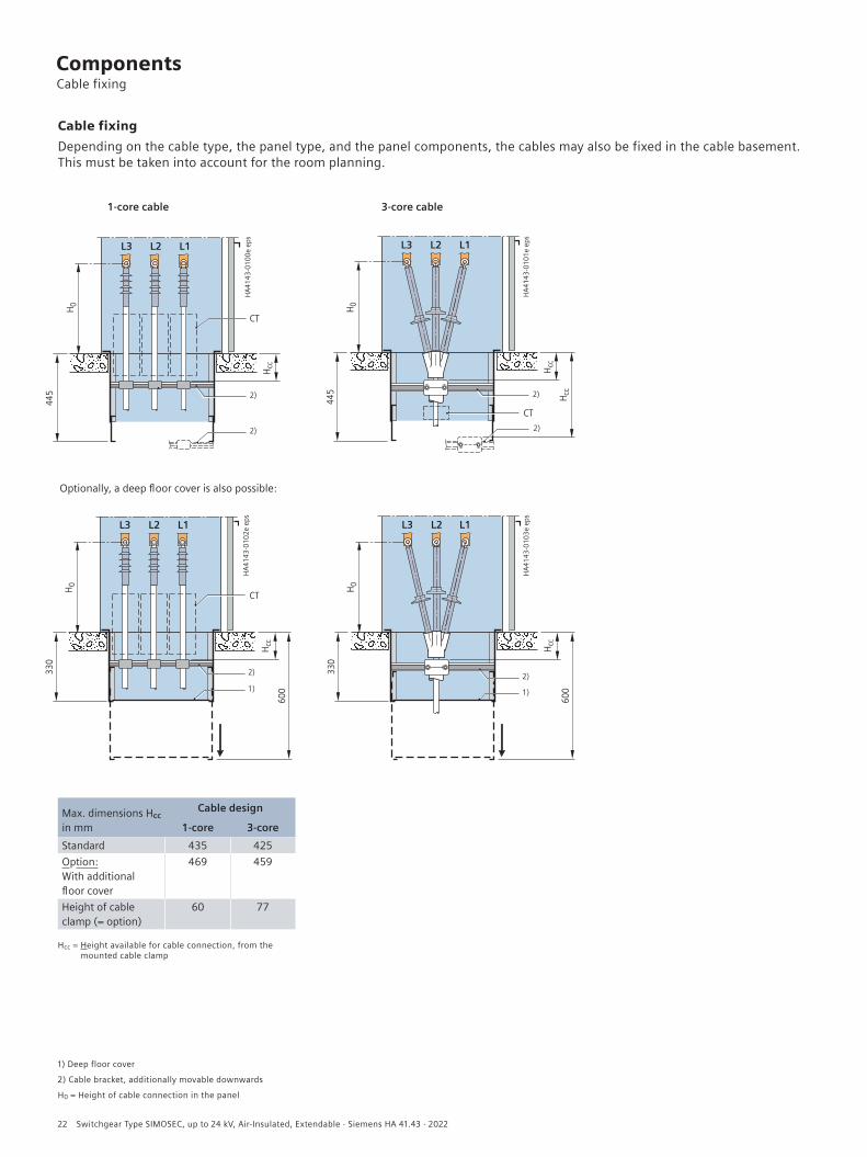
Cable fixing Depending on the cable type, the panel type, and the panel components, the cables may also be fixed in the cable basement. This must be taken into account for the room planning.
1-core cable
Optionally, a deep floor cover is also possible:
1) Deep floor cover
2) Cable bracket, additionally movable downwards
H0 = Height of cable connection in the panel
3-core cable
Max. dimensions Hcc in mm
Cable design
1-core 3-coreStandard 435 425Option: With additional floor cover
469 459
Height of cable clamp (= option)
60 77
Hcc = Height available for cable connection, from the mounted cable clamp
ComponentsCable fixing
22 Switchgear Type SIMOSEC, up to 24 kV, Air-Insulated, Extendable · Siemens HA 41.43 · 2022

Current transformers according to IEC/EN 61869-1 and -2
TypeCable-type current trans-
formers 4MC7033 and 4MC7031 (single-pole)
Three-phase current transformer 4MC63
(three-pole)
Bus/cable-type current transformer
4MC7032 (single-pole)
Current transformer 4MA7 (single-pole)
Features • Designed as ring-core current transformers• Insulation class E• Inductive type• Free of dielectrically stressed cast-resin parts (due to design)
• Dimensions according to DIN 42600-5
• Insulation class E• Cast-resin insulated• Designed as an indoor block-
type current transformer• Secondary connection
by means of screw-type terminals
Installation • Arranged on the cable at the panel connection
• For shielded cables• Current transformers
factory-assembled on a mounting plate
• Final assembly on the cables on site
• Arranged outside the switching-device vessel at the bushings
• Mounted at the factory
• Arranged on the cable at the panel connection
• For shielded cables • Current transformers
factory-assembled on a mounting plate
• Final assembly on the cables on site
• For installation at various positions depending on the panel type
Voltage transformer according to IEC/EN 61869-1 and -3
Type 4MR (single-pole or, as an option, two-pole)
Features • Dimensions according to DIN 42600-9 (small model)• Designed as an indoor voltage transformer• Cast-resin insulated• Insulation class E• Secondary connection by means of screw-type terminals
Installation • For installation at various positions depending on the panel type
R_HA
41_0
24b e
ps
R-HA
41-0
25.ep
s
R-HA
41-0
22.ep
s
R-HA
41-0
27.ep
s
R-HA
41-0
30 ep
s
R-HA
41-0
29 ep
s
ComponentsCurrent transformers, voltage transformers
Switchgear Type SIMOSEC, up to 24 kV, Air-Insulated, Extendable · Siemens HA 41.43 · 2022 23

���
����
����
�����
In circuit-breaker panel type L (500 mm)
R-HA
4143
_015
4 tif
���
����
����
����
�
In metering panel type M (750 mm) (low-voltage niche open)
Low-voltage niche (standard)• Inside the panel• Cover for low-voltage niche:
– Standard: Screwed-on cover – With door (option)
• For accommodation of terminals and standard protection devices, e.g. in circuit-breaker panels
– Protection relays, e.g. – Type 7SR45, 7SR10
On request: – Type 7SJ82, 7SX800
• For bus wires and / or control cables; niche open at the side to the adjacent panel
• Partitioned safe-to-touch from the high-voltage part of the panel
• Degree of protection IP3X (standard).
Low-voltage niche (examples)
In circuit-breaker panel type L1(T) (750 mm)
ComponentsLow-voltage niche
24 Switchgear Type SIMOSEC, up to 24 kV, Air-Insulated, Extendable · Siemens HA 41.43 · 2022

R-HA
4143
_015
3 tif
R-HA
41-0
40a t
if
����
����
���
����
����
����
�
���
����
���
���
���
���
���
Low-voltage compartment (option)• Available heights
– 350 mm – 550 mm
• Partitioned safe-to-touch from the high-voltage part of the panel
• Installation on the panel possible per feeder• Customer-specific equipment
For accommodation of protection, control, measuring and metering equipment
• Overall height depends on the panel-specific configuration of primary and secondary devices
• Door with hinge on the left (standard) Option: Door with hinge on the right.
Low-voltage compartment (example 750 x 350 mm)
Low-voltage compartment door (example 750 x 350 mm)
Overall panel dimensions
Low-voltage cables• Control cables of the panel to the low-voltage compart-
ment via multi-pole, coded module plugs• Option: Plug-in bus wires from panel to panel inside the
low-voltage niche, or optionally in the separate wiring duct on the panel.
ComponentsLow-voltage compartment
Switchgear Type SIMOSEC, up to 24 kV, Air-Insulated, Extendable · Siemens HA 41.43 · 2022 25

���
����
����
����
�
�����
������
������
�����
����
����
���
Switchgear installationWall-standing arrangement, free-standing arrangement
– 1 row – 2 rows (for face-to-face arrangement).
Room dimensionsSee dimensional drawing.
Room door dimensionsThe door dimensions depend on:
– Number of panels in a transport unit – Design with or without low-voltage compartment.
Switchgear fastening• Foundations:
– Steel girder construction – Steel-reinforced concrete.
26 Switchgear Type SIMOSEC, up to 24 kV, Air-Insulated, Extendable · Siemens HA 41.43 · 2022
DimensionsRoom planning


Status 04/2022
Subject to changes and errors. The information given in this document only contains general descriptions and/or performance features which may not always specifically reflect those described, or which may undergo modification in the course of further development of the products. The requested performance features are binding only when they are expressly agreed upon in the concluded contract.
© Siemens 2022
Published by Siemens AG
Smart Infrastructure Electrification & Automation Mozartstraße 31 C 91052 Erlangen, Germany
For further information please contact our Customer Support Center Phone: +49 180 524 70 00 Fax: +49 180 524 24 71 [email protected] siemens.com/medium-voltage-switchgear siemens.com/SIMOSEC
Article no. SIDS-C10091-00-7600 VO 211596 en KG 04.22 0.0
Medium-Voltage Switchgear
Smart Infrastructure combines the real and digital worlds across energy systems, buildings and industries, enhancing the way people live and work and significantly improving efficiency and sustainability.
We work together with customers and partners to create an ecosystem that both intuitively responds to the needs of people and helps customers achieve their business goals.
It helps our customers to thrive, communities to progress and supports sustainable development to protect our planet for the next generation.
siemens.com/smart-infrastructure