— UniSec Air-insulated medium voltage secondary ... - ABB
124
— DISTRIBUTION SOLUTIONS UniSec Air-insulated medium voltage secondary distribution switchgear up to 24 kV, 1250 A, 25 kA
-
Upload
khangminh22 -
Category
Documents
-
view
0 -
download
0
Transcript of — UniSec Air-insulated medium voltage secondary ... - ABB

— DISTRIBUTION SOLUTIONS
UniSecAir-insulated medium voltage secondary distribution switchgear up to 24 kV, 1250 A, 25 kA

— Power drives modern life, keeping people safe and managing the flow of electricity from substation to end user. Our electrical distribution solutions upgrade power in homes and businesses to create safer, more energy efficient and productive environments, enabling you and your customers to do more with less. UniSec is the result of ABB’s quest for continuous innovation, focused on meeting ever-changing market needs. It's the ABB solution for a fully automated power network in medium voltage secondary distribution systems.

3D IS TR I B U TI O N SO LU TI O NS
004-019 UniSec: its strengths, your benefits
020-024 1. General characteristics
025-056 2. Typical units
057-082 3. Main components
083-093 4. Protection and automation devices
094-098 5. Marine applications
099-103 6. Smart Grid and Digital Application
104 7. IEC classification
105-107 8. Internal arc withstand capacity
108-118 9. Installation information
119-121 10. Dimensional drawings
122 11. Configuration software
123 12. Insights
— Table of contents

4 U N I S EC A I R - I NSU L ATED M ED I U M VO LTAG E SECO N DA R Y D IS TR IB U TI O N S W ITCH G E A R
Productivity and flexibility
Reliability and safety
Sustainability and efficiency
—UniSec: its strengths, your benefits

U N ISEC : ITS S TR EN G THS , YO U R B EN EFITS 5
Easy to install- Modular and flexible design available- Extensions and upgrades are always possible- Simple and easy installation- We provide the complete switchgear ready for installation- Reduction in the amount of civil engineering work required when
switchgear is installed- Different ways for exhausting the gas produced by internal arcs
Speeds up your projects- Smart design and versatile solutions- Can be customized and easily modified- Rapid developments thanks to the wide range of functional units- The broad portfolio ensures Service Continuity tailored to every
need- Quotation tool for generating drawings and layouts
Continuous operation- Excellent quality product thanks to high process automation- Specialized ABB Service personnel for support, installation and
maintenance world-wide
Services and training- Dedicated service training and in-house trained personnel - Field application support and analysis for special applications - Technical support for choosing the best solution for your specific
application
Productivity and flexibilityMaximizing your output

6 U N I S EC A I R - I NSU L ATED M ED I U M VO LTAG E SECO N DA R Y D IS TR IB U TI O N S W ITCH G E A R
Safety and protection- UniSec switchgear is supported by sensor technology and the latest
protection relays with IEC 61850 communication and GOOSE messaging
- Integrated voltage Indicator and interlocking devices- Arc-proof switchgear with integrated specific protection solutions
to limit the negative effects of internal arcs- Monitoring available to support preventive maintenance
Reliability in different conditions- Each unit is stringently tested- Sturdy construction- Extremely durable and reliable operating mechanism- Local ABB support with global focus on reliability and quality- Fully designed and type-tested according to IEC 62271-200 Standards with high mechanical and electrical performance
Optimum interface- Standardized product family - Common, simple interface and accessories for all unit
configurations- Engineered for the latest circuit breaker, isolator, sensor and relay
technology
Reliability and safetyProtecting your assets
—UniSec: its strengths, your benefits

U N ISEC : ITS S TR EN G THS , YO U R B EN EFITS 7
Optimized logistics and Global availability- Any place, anywhere, with ABB global experience and knowledge- You can count on a worldwide presence for any support you may need - Presence in more than 100 countries, thus enhanced knowledge of
local markets and regulatory frameworks- Regional factories to optimize deliveries and guarantee supplies
Efficient- Long life cycle and high mechanical endurance- Low maintenance costs- Virtually maintenance-free
Sustainable- You can rely on a sustainable approach to long-term development - Low environmental impact- Environment-friendly air-insulated system
Reduced footprint- Compact switchgear available- Components can be fitted inside the busbar compartment, thus
saving panel costs while reducing the total switchgear length- Panels that combine several functional units
Sustainability and efficiency Optimizing your investments

8 U N I S EC A I R - I NSU L ATED M ED I U M VO LTAG E SECO N DA R Y D IS TR IB U TI O N S W ITCH G E A R
Industry
—Applications Use of UniSec switchgear and typical configuration
Substations and Smart grids
SBC-W - WBC - WBS - DRS - WBC - SFC - SBC-W
SDC - SDC - SFC

U N ISEC : ITS S TR EN G THS , YO U R B EN EFITS 9
SBC-W - HBC - HBC - SFC
Buildings and infrastructures - Light Industry
SDC - SDC - SBM - HBC - HBC
Data centers - Small generation systems

10 U N I S EC A I R - I NSU L ATED M ED I U M VO LTAG E SECO N DA R Y D IS TR IB U TI O N S W ITCH G E A R
—ApplicationsUse of UniSec switchgear
Buildings and infrastructure
DistributionData centers
Industry
Smart Grids
Green powerTransportation
Marine applications and ports Solar powerWind Hydro power
UniSec switchgear is used in medium voltage secondary power distribution systems. It is ideal for use in transformer substations, for controlling and protecting feeders and power transformers, for infrastructure, airports, hospitals, shopping centers, industries, etc.UniSec is the ABB solution for a fully automated power distribution network. Supported by sensor technology and the latest in protection relays, it meets even the demanding requirements in different applications.UniSec offers a wide range of functional units and is thus able to provide the cost-efficient solution for all applications by combining different panel types.

U N ISEC : ITS S TR EN G THS , YO U R B EN EFITS 11
Customer needs Industrial customers require a stable and non-fluctuating power supply without outages: • Reliable solutions• A wide range of functional units that are easy to upgrade• Safe and easy use for operators
Solutions UniSec offers industrial customers:• A proven design• A broad portfolio enabling the best solution to be created for the required
application• Easy operation and service
Industry

12 U N I S EC A I R - I NSU L ATED M ED I U M VO LTAG E SECO N DA R Y D IS TR IB U TI O N S W ITCH G E A R
Customer needsThe distribution network includes switching substations that supply, protect, monitor and control residential areas, industrial sites and large buildings. Priorities here are:• Continuity of service and reliability• Safety• Life cycle cost• Easy integration into existing networks and systems
Light substation solutionsUniSec solutions for distribution include:• Service continuity Removable and withdrawable circuit-breakers that meet the highest demands
for personnel safety and reliability. LSC2A and LSC2B category units and the latest generation of protection, monitoring and control solutions are available.
• Safety Switchgear designed and tested according to IEC and internal arc proofing
standards.• Life cycle cost Standard and modular solutions, less training and maintenance required, fewer
spare parts, ease of operation, fast replacement of components with fewer resources dedicated to the plant.
• Easy integration Compliance with local requirements.
—Applications A superior switchgear range
Distribution

U N ISEC : ITS S TR EN G THS , YO U R B EN EFITS 13
Customer needsResidential areas get their power from a local transformer substation.• The transformer substation must be safe, compact in size and with low
environmental impact• Continuity of service and stable supply are important design requirements for
the equipment to be installed
Transformer substation solutionsA transformer substation is the most common UniSec solution for ring networks, residential areas, buildings and small industries.Modular and flexible design ensures simple and easy installation. Key factors in this case are:• Easy expansion• Very compact units• Wide range of protection, control and monitoring solutions
Other applications
MeteringFollowing the demand for deregulation and liberalization of the electricity market, UniSec has developed standard solutions for metering applications.
GenerationTypical generator applications include emergency power supplies for consumers such as hospitals, airports, shopping centres and to provide back-up power for greenhouses where reliability is absolutely crucial.
Smart GridsNetworks are changing and UniSec is able to maintain the high standards required thanks to its compact dimensions, versatility, automation and communication functions.
Marine applicationsUniSec is type-tested and approved by major Shipping Registers. Reliabile and versatile, it is the perfect solution.
Buildings and infrastructure
14 U N I S EC A I R - I NSU L ATED M ED I U M VO LTAG E SECO N DA R Y D IS TR IB U TI O N S W ITCH G E A R
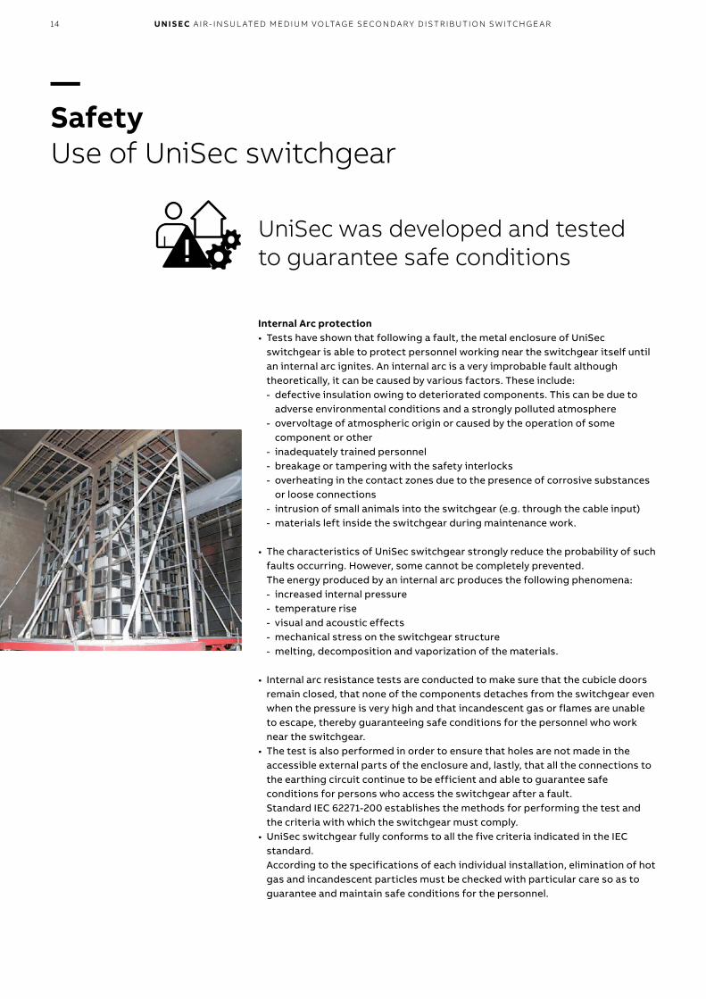
Internal Arc protection • Tests have shown that following a fault, the metal enclosure of UniSec
switchgear is able to protect personnel working near the switchgear itself until an internal arc ignites. An internal arc is a very improbable fault although theoretically, it can be caused by various factors. These include: - defective insulation owing to deteriorated components. This can be due to
adverse environmental conditions and a strongly polluted atmosphere - overvoltage of atmospheric origin or caused by the operation of some
component or other - inadequately trained personnel - breakage or tampering with the safety interlocks - overheating in the contact zones due to the presence of corrosive substances
or loose connections - intrusion of small animals into the switchgear (e.g. through the cable input) - materials left inside the switchgear during maintenance work.
• The characteristics of UniSec switchgear strongly reduce the probability of such faults occurring. However, some cannot be completely prevented. The energy produced by an internal arc produces the following phenomena: - increased internal pressure - temperature rise - visual and acoustic effects - mechanical stress on the switchgear structure - melting, decomposition and vaporization of the materials.
• Internal arc resistance tests are conducted to make sure that the cubicle doors remain closed, that none of the components detaches from the switchgear even when the pressure is very high and that incandescent gas or flames are unable to escape, thereby guaranteeing safe conditions for the personnel who work near the switchgear.
• The test is also performed in order to ensure that holes are not made in the accessible external parts of the enclosure and, lastly, that all the connections to the earthing circuit continue to be efficient and able to guarantee safe conditions for persons who access the switchgear after a fault. Standard IEC 62271-200 establishes the methods for performing the test and the criteria with which the switchgear must comply.
• UniSec switchgear fully conforms to all the five criteria indicated in the IEC standard. According to the specifications of each individual installation, elimination of hot gas and incandescent particles must be checked with particular care so as to guarantee and maintain safe conditions for the personnel.
—Safety Use of UniSec switchgear
UniSec was developed and tested to guarantee safe conditions

U N ISEC : ITS S TR EN G THS , YO U R B EN EFITS 15
Fault limiting systems• ABB has also developed active protection systems that provide the following
important benefits: - faults are generally detected and eliminated within less than 100 ms, thus
improving the stability of the network - less damage to the equipment - the switchgear remains out of service for a shorter time.
• Active internal arc protection can be achieved by installing various types of sensors in the different compartments and IED protection systems in the low voltage compartment equipped with rapid and selective electric arc protection. These devices are able to detect the immediate effects of the fault and release the circuit-breakers in the selective mode.
• The fault limiting systems are based on sensors that make use of the pressure or light generated by the internal arc fault to as to allow the faulty line to disconnect.
Interlocks• Another important issue to bear in mind is how the medium voltage
compartments can be accessed during normal operation, for maintenance work or any other reason. IEC 62271-200 defines three methods for controlling the way an accessible compartment is opened: - The first involves the use of interlocks to ensure that all live parts inside the
switchgear are dead and earthed before the compartment is opened - The second is based on the user’s procedure and on a locking device to ensure
safety. In this case, the compartment is equipped with padlocks, keys, locking magnets or some other equivalent device
- The third method does not provide for any integrated devices to ensure electrical safety prior to opening, but tools are required to open the compartments; even commonly used objects, like screwdrivers or pliers, are considered tools

16 U N I S EC A I R - I NSU L ATED M ED I U M VO LTAG E SECO N DA R Y D IS TR IB U TI O N S W ITCH G E A R
• The first two types of compartment are available to operators. If a compartment requires tools for opening (the third type), this is normally a clear indication that the user must adopt other controls to guarantee safety. The procedures to be complied with in the installation and the roles and responsibilities of the various different individuals involved, as described in 50110-1, must be defined prior to any other activity, made available and known.
• All interlocks between the different positions of the apparatus and doors required to guarantee safety are mandatory in UniSec switchgear. Optionally, there is also a a wide variety of keys, padlocks and locking magnets for the purpose of creating specific procedures for each installation.
• As mentioned above, choosing the correct solution from those available is the responsibility of the installation manager, since he is familiar with the entire installation of which the switchgear is only a part.
• An example is access to compartments declared accessible only with tools, such as a direct incoming feeder in duct, cable, or busbar. In this case, the standard does not envisage a disconnector and, as required by standard IEC 50110-1, the installation designer and user should provide for an adequate procedure when maintenance or other work is required.
• This procedure could also involve earthing at the other end of the cable. When the offer is being made, it is always advisable to coordinate with the installation designer to ensure that all needs to access the installation are addressed, not just access to the switchgear. Keys allowing a procedure to be created for earthing earthing-switches (for busbars, the line, incoming or outgoing feeders) are another example.
• The ability to earth a disconnector or to access a compartment in safe conditions does not only depend on the state of the panel and/or switchgear but also on the state of the installation. The safe state of any apparatus connected, e.g. the power transformers or the circuit-breaker on the load side of an incoming feeder, must also be ensured. Keys are the best things to use for this.
—Safety Use of UniSec switchgear
U N ISEC : ITS S TR EN G THS , YO U R B EN EFITS 17
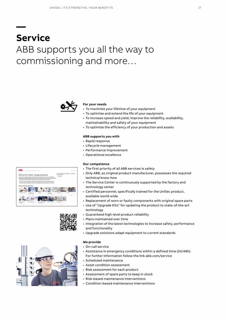
For your needs • To maximize your lifetime of your equipment• To optimize and extend the life of your equipment• To increase speed and yield, improve the reliability, availability,
maintainability and safety of your equipment• To optimize the efficiency of your production and assets
ABB supports you with • Rapid response• Lifecycle management• Performance improvement• Operational excellence
Our competence• The first priority of all ABB services is safety• Only ABB, as original product manufacturer, possesses the required
technical know-how• The Service Center is continuously supported by the factory and
technology center• Certified personnel, specifically trained for the UniSec product,
available world-wide• Replacement of worn or faulty components with original spare parts• Use of “Upgrade Kits” for updating the product to state-of-the-art
technology• Guaranteed high-level product reliability• Plans maintained over time• Integration of the latest technologies to increase safety, performance
and functionality• Upgrade solutions adapt equipment to current standards
We provide• On-call service• Assistance in emergency conditions within a defined time (24/48h).
For further information follow the link abb.com/service• Scheduled maintenance• Asset condition assessment• Risk assessment for each product• Assessment of spare parts to keep in stock• Risk-based maintenance interventions• Condition-based maintenance interventions
—Service ABB supports you all the way to commissioning and more…
18 U N I S EC A I R - I NSU L ATED M ED I U M VO LTAG E SECO N DA R Y D IS TR IB U TI O N S W ITCH G E A R
UniSec switchgear not only enhances your business, but also reduces environmental impact thanks to improved energy efficiency and increased industrial productivity.
ABB's commitment to reduce environmental impact
—Environment
Test LaboratoryComplies with UNI CEI EN ISO/IEC 17025 standards, accredited by an independent organization.
Environmental Management SystemComplies with ISO 14001 standards, certified by an independent organization.
Quality SystemComplies with ISO 9001 standards, certified by an independent organization.
Health and Safety Management SystemComplies with OHSAS 18001 standards, certified by an independent organization.

U N ISEC : ITS S TR EN G THS , YO U R B EN EFITS 19
ABB’s present and future operations and processes will always comply with environmental standards and legislation.
ABB strives to develop and provide products and services with reduced harmful environmental impact that are safe to use and can be recycled, reused or disposed of safely.This includes the products and services obtained from ABB’s suppliers and subcontractors. Our research and development activities focus on innovative and environmentally sound technologies, systems and products.To support customers and protect the environment during maintenance and at the end of the service life of their switchgear, ABB offers a complete service program aimed at preventing SF6 gas from being released into the atmosphere.UniSec units are produced in compliance with the requirements established by the international standards for quality management systems and environmental management systems.
ABB is committed to protecting the environment and complies with ISO 14001 standards. The product is developed in accordance with the requirements established by IEC 62271-200.The following table lists the materials used in the SDC 375 mm unit.
Recycling capability
Material Recyclable kg %
Steel Yes 106.5 69
Stainless steel Yes 5.5 3.5
Copper Yes 14 9
Brass Yes <0.5 <0.5
Aluminium Yes 4 3
Zinc Yes 1.5 1
Plastics Yes 4.6 3
SF6 Yes <0.5 <0.5
Total recyclables 132 87
Rubber No <1 <0.5
Epoxy No 18.5 12
Total non-recyclables 19 13
Recycling of SF6 gasIt is ABB’s obligation to facilitate end-of-life recycling for its products. Compliance with the F-Gas Regulation is mandatory in the EU and EEA.SF6 is a fluorinated greenhouse gas and care must be taken to prevent its emission. SF6 gas must be recovered before equipment can be disposed of at end-of-life. Please consult ABB for further information.
Recycling

20 U N I S EC A I R - I NSU L ATED M ED I U M VO LTAG E SECO N DA R Y D IS TR IB U TI O N S W ITCH G E A R
In the case of GOST versions, the following voltage classes are available:• voltage class 6 with insulation level A
(20kV test voltage) and B (32kV test voltage)• voltage class 10 with insulation level A
(28kV test voltage) and B (42kV test voltage)• voltage class 15 with insulation level A
(38kV test voltage)• voltage class 20 with insulation level A
(50kV test voltage)
Switchgear electrical characteristics
Rated voltage kV 12 17.5 24
Test voltage (50-60 Hz x 1 min) kV 28 38 50
Impulse withstand voltage kV 75 95 125
Rated frequency Hz 50-60 50-60 50-60
Rated main busbar current A 630/800/1250 630/800/1250 630/1250
Rated current of apparatus:
VD4/R-Sec - VD4/L-Sec - HD4/R-Sec - HD4/RE-Sec removable circuit-breaker A 630/800 630/800 630
VD4/R-Sec - HD4/R-Sec withdrawable circuit-breaker A 630 630 630
HySec multi-function apparatus A 630 630 630
GSec gas switch-disconnector A 630/800 630/800 630
VD4/P withdrawable circuit-breaker A 630/1250 630/1250 –
VD4/Sec withdrawable circuit-breaker A – – 630/1250
HD4/Sec withdrawable circuit-breaker A 630/1250 630/1250 630/1250
VSC/P withdrawable vacuum contactor A 400 – –
Rated short time withstand current kA (3s) 16/20 (3)/25 (1) (2) 16/20 (3)/25 (1) (2) 16/20 (3)/25 (1)
Peak current kA 40/50 (3)/62.5 40/50 (3)/62.5 40/50 (3)/62.5
Internal arc withstand current (up to IAC AFLR) kA (1s) 12.5/16/20 (3)/25 (2) (4) 12.5/16/20 (3)/25 (2) (4) 12.5/16/20 (3)/25 (4)
(1) 25 kA 2s for LSC2A service continuity classification up to 630A(2) For LSC2B service continuity classification(3) Contact ABB for 21 kA/52.5 kAp(4) If LSC2A unit, only with gas duct at 12kV, height 2000 mm and width 750 mm (further details on page 96)
UniSec offers the following features:• Air insulation of all live parts• SF6 switch-disconnectors• LSC2A and LSC2B service continuity
classifications• Removable and withdrawable vacuum and SF6
circuit-breakers for LSC2A service continuity switchgear
• Withdrawable vacuum and SF6 circuit-breaker for LSC2B service continuity switchgear
• Withdrawable vacuum contactor for LSC2B service continuity switchgear
Available apparatus:01 VD4/R-Sec02 HD4/R-Sec03 HySec04 VD4/Sec and VD4/P05 VSC/P06 HD4/Sec
01 02 03
—1. General characteristics

211 . G EN ER A L CH A R AC TER IS TI C S
• Multi-function apparatus with integrated vacuum circuit-breaker and gas-insulated disconnector
• Complete range of functional units and accessories
• Large selection of state-of-the-art protection relays, integrated into removable circuit-breakers or installed in LV compartments for protection, control and measurement functions.
Reference StandardsThe switchgear and the main equipment it contains comply with the following standards:• IEC 62271-1 for general application• IEC/EN 62271-200 for switchgear. With
reference to the classifications established by the standards, UniSec switchgear is defined as described below: - continuity of service classifications:
LSC2A and LSC2B - classification of the segregations:
PM (metallic partition) and PI (insulation partition) for withdrawable circuit-breakers at 24 kV only
• IEC 62271-102 for the earthing switch• IEC 62271-100 for the circuit-breakers• IEC 60071-2 for insulation co-ordination• IEC 62271-106 for the contactors• IEC 62271-103 for the switch disconnectors• IEC 60529 for the protection classes• IEEE 693 Seismic qualification testing of the
switchgear (***)
• IEC 62271-304 for severe climatic conditions (***)
• IEC 62271-1 for IK07 for structure strength.
Available versions• Arc fault tested in accordance with standard
IEC 62271-200: - IAC AF arc proof version on front side
up to 16 kA - IAC AFL arc proof version on front and
lateral sides at 12.5 kA
- IAC AFLR arc proof version on front, lateral and rear sides at 16 kA and 21 kA; 25 kA for panels with LSC2B service continuity up to 17.5 kV and at 12 kV for LSC2A units, height 2000 mm and width 750 mm (further details on page 101)
• Seismic withstand version in accordance with standard IEEE 693 (1)
• Marine version• Type tested according to IEC 62271-202 type AB
for installation inside high voltage / low voltage concrete Compact SubStations.
Available apparatus• GSec SF6 gas switch-disconnector• VD4/R-Sec removable and withdrawable
vacuum circuit-breakers
• VD4/L-Sec removable vacuum circuit-breakers• HD4/R-Sec removable and withdrawable SF6
gas circuit-breakers• Integrated HySec vacuum circuit-breaker and
SF6 disconnector• VD4/P frontal withdrawable circuit-breaker
up to 17.5 kV • VD4/Sec frontal withdrawable vacuum
circuit-breaker at 24 kV• HD4/Sec frontal withdrawable SF6 gas
circuit-breaker• VSC/P frontal withdrawable vacuum contactor.
Normal service conditions
Storage temperature: –5 °C ... +70 °C (*)
Ambient temperature range: –5 °C ... +40 °C (*)
Maximum relative humidity without condensation: 95 %
Minimum relative humidity without condensation: 5 %
Altitude: <1000 m above sea level (**)
(*) Contact ABB for -25 °C operating temperatures and -40 °C storage temperatures
(**) For higher altitudes, contact ABB
(***) Contact ABB for detailed information
(1) Contact ABB to optimize switchgear configuration
04 05 06

22 U N I S EC A I R - I NSU L ATED M ED I U M VO LTAG E SECO N DA R Y D IS TR IB U TI O N S W ITCH G E A R
Protection classes(1)
The protection classes of the switchgear comply with IEC 60529 standards.UniSec switchgear is generally supplied with the following standard protection classes:• IP 3X for enclosure (excluding operating seat)• IP 2X for partition between compartments. Optional:• IP 31 for enclosure and mechanical operating
equipment• IP 32 for enclosure and mechanical operating
equipment• IP 4X for enclosure and mechanical operating
equipment• IP 41 for enclosure and mechanical operating
equipment• IP 42 for enclosure and mechanical operating
equipment.
Surface treatmentUniSec units are made of pre-galvanized sheet metal. The doors of the front panels and the switch-disconnector cover are painted grey RAL 7035 with gloss finish.
Design concept Each unit is made entirely of pre-galvanized metal sheets. Each unit consists of several compartments, which are described in the following sections. The busbar compartment is situated along the entire length of the switchgear. Each unit has holes for fixing to the floor and is provided with a bottom closure fitted with openings for routing medium voltage cables.
All units fitted with a door have a mechanical interlock which only allows the door to be opened under safe conditions. There is a metal wiring duct in each unit to segregate the low voltage circuits from the medium voltage circuits.
Compartments Each unit consists of several power compartments: cable compartment [8], busbar compartment [4] and apparatus compartment [9].The compartments are metal segregated from each other by means of the switch-disconnector, multi functional apparatus or by means of shutters [10] in the case of withdrawable circuit-breakers. The units can be fitted with an auxiliary circuit compartment [7], where all the instruments and wiring are fitted.Arc-proof switchgear is normally provided with a duct for exhausting the gases produced by an arc. All the units are accessible from the front, so maintenance and servicing operations can also be carried out when the switchgear is positioned against a wall.
Main busbarsThe busbar compartment contains the main busbar system connected to the fixed upper contacts of the switch-disconnector. The main busbars are made of electrolytic copper up to 1250 A. The system consists of flat busbars.
(1) In the case of IP X1 or IP X2 consider 120 mm extra height due to the additional roof on the unit
LSC2ALSC2A
55
68
3
11
2
8
4 47 7

231 . G EN ER A L CH A R AC TER IS TI C S
LV compartment for auxiliary circuitsAll the units include an LV compartment in which the low voltage components, protection equipment, measuring, remote control and data transmission devices can be installed.3 types of LV compartments are available.
• Standard LV compartment The standard LV compartment is always present. Low voltage components, terminals, push-buttons, lamps and sensors can be installed inside.
• Wide LV compartment This compartment is used when, besides the low voltage components, a protection relay such as REF 601, REJ 603, REF 610, REF 611, REF 615, REF 620 or REF 542 plus with sensors is required.
• Large LV compartment This compartment is used when protection relays and measuring instruments, or particularly bulky relays such as REF 630, REF 542 plus or REF 541 are required.
The protection relays, secondary wiring and terminal boxes are installed in this compartment.The compartment dimensions are given in chapter 10.
Earthing busbarThe earthing busbar is made of electrolytic copper. It runs lengthwise right round the switchgear, thereby ensuring maximum safety for the personnel and plant. The section of the earthing busbars is 75 mm2.
Switch-disconnector multifunctional apparatus The two compartments of an LSC2A unit are formed by GSec 3-position SF6-insulated switch-disconnectors or HySec multifunctional apparatus which includes both a 3-position SF6-insulated switch-disconnector and circuit-breaker.The equipment is housed in an enclosure made of two materials: the top part is a molded resin case that guarantees the insulation level; the bottom part is made of stainless steel to provide metallic partitions and earthing between the busbar compartment and the cable compartment.This metallic partition (classification PM - Metallic Partitions according to Standard IEC 62271-200) guarantees maximum safety for personnel even when work is performed in the cable compartment with the busbar energized, e.g.to replace the fuses or check the cables.
Earthing switchEach incoming/outgoing unit can be equipped with an earthing switch for earthing the cables. This is not necessary for HBC units since direct earthing of the cable is provided by HySec.This same device can be used for earthing the busbar system. It can also be installed directly on the main busbar system in a dedicated cubicle (busbar application).The earthing switch has short-circuit making capacity (with the exception of units with fuses).The earthing switch is operated from the front of the switchgear or can be remotely motor-operated in the case of LSC2B panels.The position of the earthing switch can be checked from the front of the switchgear by means of a mechanical indicator.
Apparatus compartment The LSC2B unit has an apparatus compartment where the following apparatus can be fitted: • VD4/P circuit breaker (Vacuum, up to 17.5 kV)• VD4/Sec circuit breaker (Vacuum, 24 kV)• HD4/Sec circuit breaker (SF6, up to 24 kV)• VSC/P contactor (Vacuum, up to 12 kV).The insulating bushings of the apparatus compartment contain the upper and lower contacts for connecting the equipment to the busbar compartment and cable compartment, respectively.
1 Switch-disconnector2 Fuses3 Circuit-breaker4 Busbar compartment5 Mechanism compartment 6 Circuit-breaker operating
mechanism7 LV compartment for
auxiliary circuits8 Cable compartment9 Apparatus compartment10 Metallic shutters for
panels up to 17.5 kV and insulating shutters up to 24 kV
LSC2B
9
10
8
4 7

24 U N I S EC A I R - I NSU L ATED M ED I U M VO LTAG E SECO N DA R Y D IS TR IB U TI O N S W ITCH G E A R
PadlocksThe apparatus and cable compartment doors can be locked in the closed position by padlocks. A padlock can be installed on the GSec switch-disconnector so as to lock the position on the line side and/or earth side.The switchgear is pre-engineered for use of 4 to 8 mm diameter padlocks.
The key lock can also be applied to the earthing switch of busbar applications. The following keys can be used for the interlock: standard ABB, Ronis and Profalux.
Cable compartment The LSC2A unit has a switch-disconnector or the multifunctional apparatus which creates a metal partition between the cable and busbar compartment.
Terminals The cable compartment contains the terminals for connecting the power cables to the lower fixed isolating contacts of the apparatus. The terminals are made of electrolytic copper and have flat busbars for the whole range of currents.
Mechanism compartmentThis compartment contains the operating mechanism for the switch-disconnector and earthing switch or for the multifunctional apparatus, the mechanical interlocks and the position indicators. The auxiliary contacts, trip coils and voltage indicators are also installed in this compartment.
InterlocksUniSec switchgear is fitted with all the interlocks and accessories needed to guarantee a high level of safety and reliability both for the installation and operators.Safety interlocks can either be those provided as standard or special versions available on request.The former are required by the standards and are therefore necessary to guarantee the correct operation sequence. The latter can be supplied on request and their integration must be considered during the installation and maintenance stage.Their presence guarantees the highest level of reliability even in the case of accidental errors and achieves what ABB defines as an “error-free” system of interlocks.
Key interlocksThe use of key interlocks is very important in creating interlocking logics between units of the same switchgear, or of other medium, low and high voltage switchgear. The logic is created by means of key exchange boxes or by ringed keys.The earthing switch closing and opening operations can be locked by means of key interlocks, which can only be disabled when the earthing switch is in the opposite position to that of the lock to be made.
CablesUp to a maximum of 2 single-pole cables can be used per phase, depending on the rated voltage, the dimensions of the unit and the cross section of the cables themselves.Three-pole cables must be split under the floor so that they can be mounted on each phase (please, contact ABB if a different solution is required).The switchgear can be positioned against the wall of the station since the cables can be easily accessed from the front.Consult chapter 9 for further details.

252 . T Y PI C A L U N ITS
List of available units
Application Acronym Width
190 mm 375 mm 500 mm 600 mm 750 mm
Feeder with switch-disconnector SDC, Switch Disconnector Cables • • •Coupler with switch-disconnector SDS, Switch Disconnector Sectionalizing • • •Feeder with double switch-disconnector SDD, Switch Disconnector Double •Coupler with switch-disconnector for measurement SDM, Switch Disconnector Measurement •Universal metering unit UMP, Universal Metering Panel •Direct feeder with measurement and busbar earthing DRC, Direct Riser Cables • •Riser with measurement DRS, Direct Riser Sectionalizing • •Measurement with fused switch-disconnector SFV, Switch Fused Voltage •Feeder with fused switch-disconnector SFC, Switch Fused Cables • • •Coupler with fused switch-disconnector SFS, Switch-disconnector with fuses • •Feeder with circuit-breaker and switch-disconnector SBC, Switch Breaker Cables •Feeder with withdrawable circuit-breaker and switch-disconnector
SBC-W, Switch Breaker Cables withdrawable •
Coupler with circuit-breaker and switch-disconnector SBS, Switch Breaker Sectionalizing •Coupler with withdrawable circuit-breaker and switch-disconnector
SBS-W, Switch Breaker Sectionalizing withdrawable •
Coupler with circuit-breaker and double switch-disconnector for measurement
SBM, Switch Breaker Measurement•
Reversed feeder with circuit-breaker and switch-disconnector
SBR, Switch Breaker reversed•
Feeder with integrated circuit-breaker and disconnector
HBC, Hybrid Breaker Cables•
Coupler with integrated circuit-breaker and disconnector
HBS, Hybrid Breaker Sectionali ing•
Left or right lateral cable riser RLC/RRC, Riser Left/Right Cables •Feeder with withdrawable frontal circuit-breaker WBC, Withdrawable Breaker Cables • (*) • (**)
Coupler with withdrawable frontal circuit-breaker WBS, Withdrawable Breaker Sectionalizing • (*) • (**)
Direct feeder with measurement and busbar earthing BME, Busbars Measurement Earthing • (*)
(*) 12-17.5 kV(**) 24 kV
—2. Typical units

26 U N I S EC A I R - I NSU L ATED M ED I U M VO LTAG E SECO N DA R Y D IS TR IB U TI O N S W ITCH G E A R
The feeder with switch-disconnector is mainly used as an incoming, ring or branch unit. The unit is equippedwith a 3-position switch-disconnector that can be in one of three positions: “closed”, “open” or “earthed”, therefore preventing incorrect operations.The cable compartment can be accessed in the “earthed” position. When used, the cable connections and fault indicators are easily inspected through the front-door window.
Un Ir Ik
kV A kA
12 630/800 16 (1)/20 (2)/25 (3) (3s)
17.5 630/800 16 (1)/20 (2)/25 (4) (3s)
24 630 16 (1)/20 (2)/25 (4) (3s)
(1) 630 A, 16 kA 3s for double spring operating mechanism(2) Contact ABB for 21 kA(3) 25 kA (2s)(4) 25 kA (2s) as disconnector class E0 (interlocked with upstream CB)
—SDC – Feeder with switch-disconnector
Reference Standard equipment Main accessories
GSec Switch-disconnector
3-position switch-disconnector 4 contacts for signalling closed - earthed
Mechanical operating mechanism with position indicators
Digital or analog pressure gauge with optional alarm contacts
Integrated voltage indicator Motor operator mechanism
Shunt opening release
Shunt closing release
Undervoltage coil
Line (1)/earth locking magnet
Panel Integrated standard auxiliary circuit compartment DIN current transformers, combined sensors (except 375 mm panels) or ring core current transformer
Mechanical interlocks DIN voltage transformers (phase-earth or phase-phase except 375 mm panels)
Busbars Current and voltage sensors in 500 mm panels
Cable compartment bottom cover Accessories for internal arc classification
Earthing bar Wiring duct for routing auxiliary cables
Anti-condensation heater
Internal lighting
Key interlocks
Short-circuit indicator
Padlocks
Surge arresters
Wide and big (*) low voltage compartment
Terminals for parallel cables
Base frame H = 300 mm
Cable clamps
(1) Not available for double spring operating mechanism (*) Not available for panels H = 2000 mm
Panel width Weight (kg)
mm (*) H = 1700 mm H = 2000 mm
375 150 (1) 160 (1)
500 170 (1) 180 (1)
750 195 (2) 210 (2)
(*) Consult chap. 9 for the overall dimensions(1) Without CT(2) Without CT or VT

272 . T Y PI C A L U N ITS
Un Ir Ik
kV A kA
12 630/800 16 (1)/20 (2)/25 (3) (3s)
17.5 630/800 16 (1)/20 (2)/25 (4) (3s)
24 630 16 (1)/20 (2)/25 (4) (3s)
(1) 630 A, 16 kA 3s for double spring operating mechanism(2) Contact ABB for 21 kA(3) 25 kA (2s)(4) 25 kA (2s) as disconnector class E0 (interlocked with upstream CB)
—SDS – Coupler with switch-disconnector
The switch-disconnector unit for isolation is used together with the riser unit. The standard version is equipped with a3-position switch-disconnector for isolating the busbars. The earthing system is always provided as standard equipment.Units 500 mm in width can be equipped with CTs and VTs.
Reference Standard equipment Main accessories
GSec Switch-disconnector
3-position switch-disconnector 4 contacts for signalling closed - earthed
Mechanical operating mechanism with position indicators
Digital or analog pressure gauge with optional alarm contacts
Integrated voltage indicator Motor operator mechanism
Shunt opening release
Shunt closing release
Undervoltage coil
Line (1)/earth locking magnet
Panel Integrated standard auxiliary circuit compartment DIN current transformer or combined sensors (except 375 mm panels)
Mechanical interlocks DIN voltage transformer (except 375 mm panels)
Busbars Accessories for internal arc classification
Bottom cover Wiring duct for routing auxiliary cables
Earthing bar Anti-condensation heater
Internal lighting
Key interlocks
Padlocks
Wide and big (*) low voltage compartment
Base frame H = 300 mm
(1) Not available for double spring operating mechanism (*) Not available for panels H = 2000 mm
Panel width Weight (kg)
mm (*) H = 1700 mm H = 2000 mm
375 155 (1) 165 (1)
500 175 (1) 185 (1)
750 200 (1) 215 (1)
(*) Consult chap. 9 for the overall dimensions (1) Without CT or VT

28 U N I S EC A I R - I NSU L ATED M ED I U M VO LTAG E SECO N DA R Y D IS TR IB U TI O N S W ITCH G E A R
—SDD – Feeder with double switch-disconnector
The unit includes 2 disconnectors mechanically interlocked with each other.This unit is suitable for switching two main medium voltage lines or for switching between a main line and an auxiliary line (e.g. electric generating set).Mechanical interlocking of the two disconnectors guarantees the utmost reliability and prevents the operator from committing errors since the disconnectors cannot be closed at the same time.The disconnector switching operations can be performed in the manual mode (by means of a lever and/or push-buttons) or by means of a motor and opening/closing coils (locally and/or via remote control).Switching between the two lines can occur automatically or in the semi-automatic mode by means of a monitoring system that controls the operation of the disconnectors (as described on the next page).The original situation can be reset either automatically or in the manual mode.The logic of the SDD unit interlock is given in the table below.
Lh disconnector position (main line)
Rh disconnector position(secondary line)
Closed Open Earth Closed Open Earth
• •• •• •• •
• •• •

292 . T Y PI C A L U N ITS
Un Ir Ik
kV A kA
12 630 16 (3s)
17.5 630 16 (3s)
24 630 16 (3s)
Reference Standard equipment Main accessories
GSec Switch-disconnector
2 switch-disconnectors interlocked with each other with 3 positions
4 closed-earthed signalling contacts
Mechanical operating mechanism with position indicators
Digital or analog pressure gauge with optional alarm contacts
Integrated voltage indicator Motor operator mechanism
Shunt opening release
Shunt closing release
Panel Integrated standard auxiliary circuit compartment Ring core current transformer
Mechanical interlocks Accessories for internal arc classification
Busbars Wiring duct for routing auxiliary cables
Cable compartment bottom cover Anti-condensation heating element
Earthing bars Internal lighting
Key interlocks (only on the earth)
Padlock
Wide and big (*) low voltage compartment
Surge arresters
Base frame H = 300 mm
Cable clamps
(*) Not available for panels H = 2000 mm
The standard ABB solution: automatic switching of two supply lines.
Once the primary line (Q1) has been defined, switching to the auxiliary line (Q2) occurs in the absence of voltage in the primary line (Q1) either instantaneously (300 ms) or on request within a time T1 selected by the customer (from 0.1 s to 16 h), so as to prevent voltage dips in the network. After voltage returns in the primary line (Q1), the initial situation returns either instantaneously (300 ms) or after a time T2 selected by the customer (from 1 s to 60 s).The automatic operating transfer threshold is 10 kV.
Consult ABB if other installation solutions are required.
Panel width Weight (kg)
mm (*) H = 1700 mm H = 2000 mm
750 270 (1) 290 (1)
(*) Consult chap. 9 for the overall dimensions
—Diagram of ATS SDD switching times
KFT11 = Delay time in the absence of a generator to avoid voltage dips [0.1 s ÷ 16.5 h]KFT12 = Delay time at beginning of switching procedure [0.1 s ÷ 16.5 h]KFT1 = Opening delay time of circuit-breaker on emergency line [0.1 s ÷ 16.5 h]KFT2 = Closing delay time of circuit-breaker on emergency line [0.1 s ÷ 16.5 h]
Always comply with the following rule: KFT11 ≤ KFT12
KFT12 KFT1 KFT20.3s
KFT11
Normal Line OK
QBS1 Closed
Gen Start
Emergency Line OK
QBS2 Closed

30 U N I S EC A I R - I NSU L ATED M ED I U M VO LTAG E SECO N DA R Y D IS TR IB U TI O N S W ITCH G E A R
—SDM – Coupler with switch-disconnector for measurement
The isolating unit with measurement with switch-disconnector performs measurement and isolation functions in a single unit and can be used instead of the SDS + DRS units when there is not much space available.The standard version uses a three-position switch-disconnector and allows isolation of the main busbars and relative earthing (always available).The unit can be equipped with DIN current and voltage transformers. The voltage transformers, which are optional, can be connected on either the supply or load sides of the current transformers.
Un Ir Ik
kV A kA
12 630/800 16/20 (1)/25 (2) (3s)
17.5 630/800 16/20 (1)/25 (3) (3s)
24 630 16/20 (1)/25 (3) (3s)
(1) Contact ABB for 21 kA(2) 25 kA (2s)(3) 25 kA (2s) as disconnector class E0 (interlocked with upstream CB)
Reference Standard equipment Main accessories
GSec Switch-disconnector
3-position switch-disconnector 4 contacts for signalling closed - earthed
Mechanical operating mechanism with position indicators
Digital or analog pressure gauge with optional alarm contacts
Integrated voltage indicator Motor operator mechanism
Line/earth locking magnet
Panel Integrated standard auxiliary circuit compartment DIN current transformers or combined sensors
Mechanical interlocks DIN voltage transformer (phase-earth or phase-phase with or without fuses)
Busbars and insulators Accessories for internal arc classification
Bottom cover Wiring duct for routing auxiliary cables
Earthing bar Anti-condensation heater
Internal lighting
Key interlocks
Wide and big(*) low voltage compartment
Surge arresters
Base frame H = 300 mm
(*) Not available for panels H = 2000 mm
The switch-disconnector can be installed on the left, right or on
both sides
Panel width Weight (kg)
mm (*) H = 1700 mm H = 2000 mm
750 230 (1) 250 (1)
(*) Consult chap. 9 for the overall dimensions (1) Without CT or VT

312 . T Y PI C A L U N ITS
Un Ir Ik
kV A kA
12 630/800 16/20 (1)/25 (2) (3s)
17.5 630/800 16/20 (1)/25 (3) (3s)
24 630 16/20 (1)/25 (3) (3s)
(1) Contact ABB for 21 kA(2) 25 kA (2s)(3) 25 kA (2s) available only for New UMP
—UMP – Universal Metering Unit
This unit is used in medium voltage applications where a dedicated panel is required for the instrument transformers.The unit is very flexible and six configurations are available: busbar input and cable output, cable input and output, busbar input and output.These configurations fully meet the requirements of the most demanding customers.The instrument transformers are easy and safe to install and access. Safety seals and/or padlocks can be provided on the door.The instrument transformers are fitted individually on sliding plates, which are fixed onto guides positioned on the walls.The unit is pre-engineered for the installation of DIN type instrument transformers.
Reference Standard equipment Main accessories
Panel Busbars and insulators Accessories for internal arc classification
Current transformers, combined sensors DIN or Arteche type Wiring duct for auxiliary cables
Voltage transformers (phase-earth or phase-phase) DIN or Arteche type
Internal lighting
Integrated standard auxiliary circuit compartment Anti-condensation heater
Earthing busbars Wide and big(*) low voltage compartment
Mechanical interlocks (padlock and sealing) Base frame H = 300 mm
Integrated voltage indicator Cable clamps
(*) Not available for panels H = 2000 mm
Panel width Weight (kg)
mm (*) H = 1700 mm H = 2000 mm (2)
750 200 (1) 220 (1)
(*) Consult chap. 10 for the overall dimensions (1) Without CT or VT (2) for new version only
(On request, please contact ABB)

32 U N I S EC A I R - I NSU L ATED M ED I U M VO LTAG E SECO N DA R Y D IS TR IB U TI O N S W ITCH G E A R
—DRC – Direct feeder with measurement and busbar earthing
A direct riser unit is available for connecting cables directly to the busbars. The lower front door is fixed and can only beopened with a tool.The door has a window for inspection.The earthing switch with full making capacity can be installed in the 500 mm unit. It can be used for earthing the switchgear busbars or the incoming line cable.The panel can be fitted with current transformers, combined sensors or voltage transformers.The unit is also available in the version without cable output for measurements (voltage) and busbar earthing.
Reference Standard equipment Main accessories
Panel Integrated basic auxiliary circuit compartment DIN current transformers, combined sensors (except 375 mm panels) or ring core current transformer
Busbars and insulators DIN voltage transformers (phase-earth or phase-phase (except 375 mm panels)
Cable compartment cover Accessories for internal arc classification
Integrated voltage indicator Wiring duct for routing auxiliary cables
Earthing busbar Anti-condensation heater
Internal lighting
Short-circuit indicator
Surge arresters
Wide and big(*) low voltage compartment
Terminals for parallel cables (except 375 mm)
Earthing switch with full making capacity (except 375 mm)(1)
Base frame H = 300 mm
Cable clamps
(*) Not available for panels H = 2000 mm(1) Only for 630 A
Un Ir Ik IkAp (*)
kV A kA kAp
12 630/800/1250 16/20 (1)/25 (2) (3s) 40/50 (1)/63
17.5 630/800/1250 16/20 (1)/25 (2) (3s) 40/50 (1)/63
24 630/1250 (3) 16/20 (1)/25 (2) (3s) 40/50 (1)/63
(*) Making capacity ES-230 N class E1, M0(1) Contact ABB for 21 kA(2) 25 kA (2s)(3) Only for H = 2000 mm
Panel width Weight (kg)
mm (*) H = 1700 mm H = 2000 mm
375 120 (1) 130 (1)
500 135 (1) 145 (1)
(*) Consult chap. 9 for the overall dimensions (1) Without CT or VT

332 . T Y PI C A L U N ITS
Un Ir Ik
kV A kA
12 630/800/1250 16/20 (2)/25 (3) (4) (3s)
17.5 630/800/1250 16/20 (2)/25 (3) (4) (3s)
24 630/1250 (1) 16/20 (2)/25 (3) (3s)
(1) Only for H = 2000 mm (2) Contact ABB for 21 kA(3) 25 kA (2s)(4) 25 kA, 3s DRS coupled to WBC/WBS
—DRS – Riser with measurement
The direct riser unit with measurement connects the busbar to the bottom of an isolating unit with circuit-breaker or switch-disconnector. The 500 mm width version can be used as a measurement unit and can house 3 CTs and 3 VTs (VTs can only be housed when the lower busbar exit is on the left). The bottom front door is fixed to the unit and has to be opened with a tool. The door has a window for inspection.The riser unit with measurement can also be coupled to panels WBC and WBS with withdrawable circuit-breakers (the dimensions are different: height 2000 mm and the 500 mm width only). DIN-type CTs and VTs can always be installed in this case.
Reference Standard equipment Main accessories
Panel Integrated standard auxiliary circuit compartment Accessories for internal arc classification
Compartment for busbars for riser Wiring duct for routing auxiliary cables
Integrated voltage indicator DIN current transformer, combined sensors (except 375 mm)
Bottom cover DIN Voltage transformer phase-earth or phase-phase (except 375 mm) (1)
Earthing busbar Anti-condensation heater
Internal lighting
Wide and big (*) low voltage compartment
Base frame H = 300 mm
(*) Not available for panels H = 2000 mm(1) Only VT with left side exit for panel H = 1700 mm
Panel width Weight (kg)
mm (*) H = 1700 mm H = 2000 mm
375 120 (1) 130 (1)
500 135 (1) 145 (1)
(*) Consult chap. 9 for the overall dimensions (1) Without CT and VT

34 U N I S EC A I R - I NSU L ATED M ED I U M VO LTAG E SECO N DA R Y D IS TR IB U TI O N S W ITCH G E A R
The SFV unit with fused switch-disconnector is primarily used for voltage measurement. The unit is equipped with a 3-position switch-disconnector. For fuse earthing, the integrated earthing switch acts on the supply side, while a separate earthing switch available on request acts on the load side of the fuses. A double-spring operating mechanism with automatic fuse blowing is available as an alternative to the single-spring operating mechanism. The voltage transformers are located in the bottom part of the unit to provide the measurement function.
Un Ik Fuses
kV kA A
12 16/20 (1)/25 (2) (3s) 2 to 6
17.5 16/20 (1)/25 (3) (3s) 2 to 6
24 16/20 (1)/25 (3) (3s) 2 to 6
(1) Contact ABB for 21 kA(2) 25 kA (2s)(3) 25 kA (2s) as disconnector class E0 with 1s Op. Mechanism and without fuse
tripping (interlocked with upstream CB)
—SFV – Measurement with fused switch-disconnector
Reference Standard equipment Main accessories
GSec Switch-disconnector
3-position switch-disconnector 4 contacts for signalling closed - earthed
Mechanical operating mechanism with position indicators
Fuse tripping
Integrated voltage indicator Digital or analog pressure gauge with optional alarm contacts
1 contact for indicating fuse blown Shunt opening release
Shunt closing release
Undervoltage coil
Motor-operator mechanism
Earth locking magnet
Lower earthing switch on load side
Panel Integrated standard auxiliary circuit compartment Accessories for internal arc classification
Mechanical interlocks Wiring duct for routing auxiliary cables
Busbars Anti-condensation heater
Fuse supports Release indicator for blown fuse
Voltage transformer to DIN Standards (phase-earth or phase-phase)
Internal lighting
Bottom cover Power transformers
Earthing busbar Key interlock
Padlocks
DIN fuses (1)
Wide and big (*) low voltage compartment
Base frame H = 300 mm
(1) DIN Fuses: 292 and 442 mm at 12-17.5 kV 442 mm at 24 kV(*) Not available for panels H = 2000 mm
Panel width Weight (kg)
mm (*) H = 1700 mm H = 2000 mm
500 175 (1) 185 (1)
(*) Consult chap. 9 for the overall dimensions (1) Without VT and fuses

352 . T Y PI C A L U N ITS
The SFC type of unit with fused switch-disconnector is mainly used for transformer protection. The unit is equipped with a 3-position switch-disconnector and an earthing switch. To earth the fuses, the integrated earthing switch acts on the on the supply side, whereas a separate earthing switch acts on the load side of the fuses. A double-spring operating mechanism is used with automatic fuse tripping. The cable compartment can only be accessed in the “earthed” position. Cable connections and fault indicators can be easily inspected through the front door window.
Un Ik IkAp (*) Fuses
kV kA kAp A
12 16/20 (1)/25 (2) (3s) 5 160 (3)
17.5 16/20 (1)/25 (4) (3s) 5 125 (3)
24 16/20 (1)/25 (4) (3s) 5 100 (3)
(*) Making capacity of the load side earthing switch EF 230 (Ik = 2 kA)(1) Contact ABB for 21 kA(2) 25 kA (2s)(3) Consult chap. 3, Fuses section, for details about the type of fuses(4) 25 kA (2s) as disconnector class E0 with 1s Op. Mechanism and without fuse
tripping (interlocked with upstream CB)
—SFC – Feeder with fused switch-disconnector
Reference Standard equipment Main accessories
GSec Switch-disconnector
3-position switch-disconnector 4 contacts for signalling closed - earthed
Mechanical operating mechanism with position indicators
Digital or analog pressure gauge with optional alarm contacts
Integrated voltage indicator Motor operator mechanism
1 contact for indicating fuse blown Shunt opening release
Shunt closing release
Undervoltage coil
Earth locking magnet
Panel Integrated standard auxiliary circuit compartment DIN current transformers, combined sensors (only 750 mm panels) or ring core current transformer
Mechanical interlocks Accessories for internal arc classification
Release indicator for fuse blown Wiring duct for routing auxiliary cables
Busbars Anti-condensation heater
Lower earthing switch on load side of fuses (EF 230) Internal lighting
Fuse supports DIN Standard fuses (1)
Cable compartment bottom cover Key interlocks
Earthing bar Padlocks
Wide and big(*) low voltage compartment
Base frame H = 300 mm
Cable clamps
(1) DIN Fuses: 292 and 442 mm at 12-17.5 kV 442 mm at 24 kV(*) Not available for panels H = 2000 mm
Panel width Weight (kg)
mm (*) H = 1700 mm H = 2000 mm
375 155 (1) 165 (1)
500 175 (1) 185 (1)
750 200 (1) 215 (1)
(*) Consult chap. 9 for the overall dimensions (1) Without fuses

36 U N I S EC A I R - I NSU L ATED M ED I U M VO LTAG E SECO N DA R Y D IS TR IB U TI O N S W ITCH G E A R
SFS units are used when a disconnector unit with fuse protection is required. To earth the fuses, the integrated earthing switch acts on the supply side, whereas a separate earthing switch acts on the load side of the fuses.A double-spring operating mechanism is used with automatic fuse blowing. The cable compartment can only be accessed in the “earthed” position. Connection can be made on the left of the lower busbars.
—SFS – Coupler with fused switch-disconnector
Reference Standard equipment Main accessories
GSec Switch-disconnector
3-position switch-disconnector 4 contacts for signalling closed - earthed
Mechanical operating mechanism with position indicators
Digital or analog pressure gauge with optional alarm contacts
Integrated voltage indicator Motor-operator mechanism
1 contact for indicating fuse blown Shunt opening release
Shunt closing release
Undervoltage coil
Earth locking magnet
Panel Integrated standard auxiliary circuit compartment Accessories for internal arc classification
Release indicator for fuse blown Wiring duct for routing auxiliary cables
Busbars Anti-condensation heater
Lower earthing switch on load side of fuses (EF 230) Internal lighting
Bottom cover DIN Standard fuses (1)
Base for fuses Wide and big (*) low voltage compartment
Earthing bar Base frame H = 300 mm
(1) DIN Fuses: 292 and 442 mm at 12-17.5 kV 442 mm at 24 kV(*) Not available for panels H = 2000 mm
Panel width Weight (kg)
mm (*) H = 1700 mm H = 2000 mm
375 165 (1) 175 (1)
500 180 (1) 190 (1)
(*) Consult chap. 9 for the overall dimensions (1) Without fuses
Un Ik IkAp (*) Fuses
kV kA kAp A
12 16/20 (1)/25 (2) (3s) 5 160 (3)
17.5 16/20 (1)/25 (4) (3s) 5 125 (3)
24 16/20 (1)/25 (4) (3s) 5 100 (3)
(*) Making capacity of the load side earthing switch EF 230 (Ik = 2 kA)(1) Contact ABB for 21 kA(2) 25 kA (2s)(3) Consult chap. 3, Fuses section, for details about the type of fuses(4) 25 kA (2s) as disconnector class E0 with 1s Op. Mechanism and without fuse
tripping (interlocked with upstream CB)

372 . T Y PI C A L U N ITS
SBC units are designed to control and protect distribution lines, networks, motors, transformers, capacitor banks, etc. They can be equipped with a vacuum or SF6 gas circuit-breaker. The circuit-breaker is installed on a rail and fixed to the busbars. A 3-position switch-disconnector fitted with an earthing switch is provided for the isolating operations and is positioned between the circuit-breaker and busbars.The door is mechanically interlocked with the earthing position of the switch-disconnector to ensure personnel safety. The units can be equipped with CTs, VTs or combined sensors (the shape is toroidal or according DIN standards, see main components). A circuit-breaker with integrated current sensors and relay is available as an alternative.
Un Ir Ik IkAp(*)
kV A kA kAp
12 630/800 16/20 (1)/25 (2) (3s) 40/50 (1)/63
17.5 630/800 16/20 (1)/25 (3) (3s) 40/50 (1)/63
24 630 16/20 (1)/25 (3) (3s) 40/50 (1)/63
(*) Making capacity of the load side earthing switch ES230-N class E1, M0(1) Contact ABB for 21 kA(2) 25 kA (2s)(3) 25 kA (2s) as disconnector class E0 interlocked with 630A Vacuum CB
(SF6 CB not available)
—SBC – Feeder with circuit-breaker and switch-disconnector
Reference Standard equipment Main accessories
GSec Switch-disconnector
3-position switch-disconnector 4 contacts for signalling closed – earthed
Mechanical operating mechanism with position indicator Digital or analog pressure gauge with optional alarm contacts
Integrated voltage indicator Motor operator mechanism
Line/earth locking magnet
VD4 - HD4 Circuit-breaker
Opening device with mechanical signalling and opening and closing pushbuttons
Motor-operator mechanism
Removable vacuum or gas circuit-breaker REF601 relay and current sensors on-board
Panel Integrated standard auxiliary circuit compartment DIN current transformers and combined sensors or ring core current transformer and sensor
Mechanical interlocks DIN Voltage transformer (phase-earth or phase-phase without fuses) upstream or downstream DIN CTs
Busbars Current and voltage sensors
Cable compartment bottom cover Accessories for internal arc classification
Earthing switch on the cables (ES 230) Wiring duct for routing auxiliary cables
Earthing busbar Anti-condensation heater
Internal lighting
Wide range of protection relays
Key interlocks
Padlocks
Surge arresters
Terminals for parallel cables
Wide and big (*) low voltage compartment
Base frame H = 300 mm
Cable clamps
(*) Not available for panels H = 2000 mm
Panel width Weight (kg)
mm (*) H = 1700 mm H = 2000 mm
750 335 (1) 355 (1)
(*) Consult chap. 9 for the overall dimensions (1) Without CT or VT
38 U N I S EC A I R - I NSU L ATED M ED I U M VO LTAG E SECO N DA R Y D IS TR IB U TI O N S W ITCH G E A R
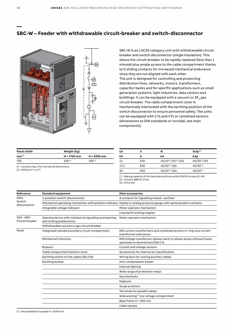
SBC-W is an LSC2A category unit with withdrawable circuit-breaker and switch disconnector (single insulation). This allows the circuit-breaker to be rapidly replaced (less than 1 minute) plus ample access to the cable compartment thanks to 6 sliding contacts for increased mechanical endurance since they are not aligned with each other. The unit is designed for controlling and protecting distribution lines, networks, motors, transformers, capacitor banks and for specific applications such as small generation systems, light industries, data centers and buildings. It can be equipped with a vacuum or SF6 gas circuit-breaker. The cable compartment cover is mechanically interlocked with the earthing position of the switch disconnector to ensure personnel safety. The units can be equipped with CTs and VTs or combined sensors (dimensions to DIN standards or toroidal, see main components).
Un Ir Ik IkAp(*)
kV A kA kAp
12 630 16/20 (1)/25 (2) (3s) 40/50 (1)/63
17.5 630 16/20 (1) (3s) 40/50 (1)
24 630 16/20 (1) (3s) 40/50 (1)
(*) Making capacity of the load side earthing switch ES230-N class E1, M0(1) Contact ABB for 21 kA(2) 25 kA (2s)
—SBC-W – Feeder with withdrawable circuit-breaker and switch-disconnector
Reference Standard equipment Main accessories
GSec Switch-disconnector
3-position switch-disconnector 4 contacts for signalling closed – earthed
Mechanical operating mechanism with position indicator Digital or analog pressure gauge with optional alarm contacts
Integrated voltage indicator Motor operator mechanism
Line/earth locking magnet
VD4 - HD4 Circuit-breaker
Opening device with mechanical signalling and opening and closing pushbuttons
Motor operator mechanism
Withdrawable vacuum or gas circuit-breaker
Panel Integrated standard auxiliary circuit compartment DIN current transformers and combined sensors or ring core current transformer and sensor
Mechanical interlocks DIN Voltage transformer (phase-earth or phase-phase without fuses)upstream or downstream DIN CTs
Busbars Current and voltage sensors
Cable compartment bottom cover Accessories for internal arc classification
Earthing switch on the cables (ES 230) Wiring duct for routing auxiliary cables
Earthing busbar Anti-condensation heater
Internal lighting
Wide range of protection relays
Key interlocks
Padlocks
Surge arresters
Terminals for parallel cables
Wide and big (*) low voltage compartment
Base frame H = 300 mm
Cable clamps
(*) Not available for panels H = 2000 mm
Panel width Weight (kg)
mm (*) H = 1700 mm H = 2000 mm
750 335 (1) 355 (1)
(*) Consult chap. 9 for the overall dimensions (1) Without CT or VT

392 . T Y PI C A L U N ITS
The SBS unit with switch-disconnector and circuit-breaker for isolation is used together with the riser unit. The standard units are equipped with a 3-position switch-disconnector in series with a circuit-breaker for isolating the busbar. The unit is equipped with a vacuum or SF6 gas circuit-breaker.The circuit-breaker is installed on a rail and fixed to thebusbars. The load side earthing switch, which is mechanically interlocked with the switch-disconnector, is available for the right lower busbar connection panel variant while earthing balls are available for the left one to provide the earth connection.The door is mechanically interlocked with the load side earthing switch to ensure personnel safety, or can be equipped with an indipendent mechanical interlock.The units can also be equipped with CTs or combined sensors (DIN Standard dimensions). A circuit-breaker with integrated current sensors and relay is available as an alternative.
Un Ir Ik IkAp(*)
kV A kA kAp
12 630/800 16/20 (1)/25 (2) (3s) 40/50 (1)/63
17.5 630/800 16/20 (1)/25 (3) (3s) 40/50 (1)/63
24 630 16/20 (1)/25 (3) (3s) 40/50 (1)/63
(*) Making capacity of the load side earthing switch ES230-N class E1, M0 for lower right busbar connection panel variant only
(1) Contact ABB for 21 kA(2) 25 kA (2s)(3) 25 kA (2s) as disconnector class E0 interlocked with 630A Vacuum CB
(SF6 CB not available)
—SBS – Coupler with circuit-breaker and switch-disconnector
Reference Standard equipment Main accessories
GSec Switch-disconnector
3-position switch-disconnector 4 contacts for signalling closed – earthed
Mechanical operating mechanism with position indicator Digital or analog pressure gauge with optional alarm contacts
Integrated voltage indicator Motor operator mechanism
Line/earth locking magnet
VD4 - HD4 (Circuit-breaker)
Opening device with mechanical signalling and opening and closing pushbuttons
Motor operator mechanism
Removable vacuum or gas circuit-breaker REF601 relay and current sensors on-board
Panel Integrated standard auxiliary circuit compartment DIN current transformers or combined sensors
Mechanical interlocks Accessories for internal arc classification
Busbars Wiring duct for routing auxiliary cables
Earthing switch on the cables (ES 230) in lower right busbar connection panel variant
Anti-condensation heater
Bottom cover Internal lighting
Earthing busbar Wide range of protection relays
Key interlocks
Padlocks
Wide and big (*) low voltage compartment
Base frame H = 300 mm
(*) Not available for panels H = 2000 mm
Panel width Weight (kg)
mm (*) H = 1700 mm H = 2000 mm
750 355 (1) 375 (1)
(*) Consult chap. 9 for the overall dimensions (1) Without CT

40 U N I S EC A I R - I NSU L ATED M ED I U M VO LTAG E SECO N DA R Y D IS TR IB U TI O N S W ITCH G E A R
SBS-W is an LSC2A category unit with withdrawable circuit-breaker and switch disconnector (single isolation). This allows the circuit-breaker to be rapidly replaced (less than 1 minute) plus ample access to the cable compartment thanks to 6 sliding contacts for increased mechanical endurance, since they are not aligned with each other. The unit is equipped with a 3-position switch-disconnector in series with a circuit-breaker for isolating the busbar. It can be equipped with a vacuum or SF6 gas circuit-breaker. The cable compartment cover is mechanically interlocked with the earthing position of the switch disconnector to ensure personnel safety. The units can be equipped with CTs or combined sensors (dimensions to DIN standards, see main components).
Un Ir Ik IkAp(*)
kV A kA kAp
12 630 16/20 (1)/25 (2) (3s) 40/50 (1)/63
17.5 630 16/20 (1) (3s) 40/50 (1)
24 630 16/20 (1) (3s) 40/50 (1)
(*) Making capacity of the load side earthing switch ES230-N class E1, M0(1) Contact ABB for 21 kA(2) 25 kA (2s)
—SBS-W – Coupler with withdrawable circuit-breaker and switch-disconnector
Reference Standard equipment Main accessories
GSec Switch-disconnector
3-position switch-disconnector 4 contacts for signalling closed – earthed
Mechanical operating mechanism with position indicator Digital or analog pressure gauge with optional alarm contacts
Integrated voltage indicator Motor operator mechanism
Line/earth locking magnet
VD4 - HD4 Circuit-breaker
Opening device with mechanical signalling and opening and closing pushbuttons
Motor operator mechanism
Withdrawable vacuum or gas circuit-breaker
Panel Integrated standard auxiliary circuit compartment DIN current transformers or combined sensors
Mechanical interlocks Accessories for internal arc classification
Busbars Wiring duct for routing auxiliary cables
Earthing switch on the cables (ES 230) Anti-condensation heater
Bottom cover Internal lighting
Earthing busbar Wide range of protection relays
Key interlocks
Padlocks
Wide and big (*) low voltage compartment
Base frame H = 300 mm
(*) Not available for panels H = 2000 mm
Panel width Weight (kg)
mm (*) H = 1700 mm H = 2000 mm
750 355 (1) 375 (1)
(*) Consult chap. 9 for the overall dimensions (1) Without CT

412 . T Y PI C A L U N ITS
The unit consists of a removable circuit-breaker and two three-position disconnectors interlocked with each other and operating in parallel.The SBM unit can be used instead of the SBS+SDS units, thereby saving 500 mm of space. Current transformers (alternatively combined sensors) and voltage transformers of the DIN type can be installed inside the unit.Use of the SBM unit is of fundamental importance in medium voltage applications where measuring transformers or switchgear isolation are required.
—SBM – Coupler with circuit-breaker & double switch-disconnector for measurement
Un Ir Ik
kV A kA
12 630/800 16/20 (1)/25 (2) (3s)
17.5 630/800 16/20 (1)/25 (3) (3s)
24 630 16/20 (1)/25 (3) (3s)
(1) Contact ABB for 21 kA(2) 25 kA (2s)(3) 25 kA (2s) as disconnector class E0 interlocked with 630A Vacuum CB
(SF6 CB not available)
Reference Standard equipment Main accessories
GSec Switch-disconnector
2 switch-disconnectors interlocked with each other with 3 positions
4 closed-earthed signalling contacts
Mechanical operating mechanism with position indicators
Digital or analog pressure gauge with optional alarm contacts
Integrated voltage indicator Line/earth locking magnet
VD4 - HD4 Circuit-breaker
Opening device with mechanical signalling and opening and closing push-buttons
Motor operator mechanism
Removable vacuum or gas circuit-breaker REF601 and current sensors on board
Panel Integrated basic auxiliary circuit compartment DIN current transformers or combined sensors
Mechanical interlocks DIN voltage transformers
Busbars Accessories for internal arc classification
Bottom cover Wiring duct for routing auxiliary cables
Earthing bars Anti-condensation heater
Internal lighting
Key interlocks
Padlocks
Wide and big (*) low voltage compartment
Wide range of protection relays
Base frame H = 300 mm
(*) Not available for panels H = 2000 mm
Panel width Weight (kg)
mm (*) H = 1700 mm H = 2000 mm
750 390 (1) 410 (1)
(*) Consult chap. 9 for the overall dimensions (1) Without CT or VT

42 U N I S EC A I R - I NSU L ATED M ED I U M VO LTAG E SECO N DA R Y D IS TR IB U TI O N S W ITCH G E A R
Un Ir Ik IkAp(*) IkAp(**)
kV A kA kAp kAp
12 630 12.5/16 (1s) 31.5/40 5
17.5 630 12.5/16 (1s) 31.5/40 5
24 630 12.5/16 (1s) 31.5/40 5
(*) Making capacity of the supply side earthing switch ESBR230-U(**) Making capacity of the load side earthing switch ESBR230-L
—SBR – Reversed feeder with circuit-breaker and switch-disconnector
The SBR unit allows the switch-disconnector to be opened and earthed while leaving the cable compartment in service.The standard unit is equipped with a 3-position switch-disconnector in series with a circuit-breaker.The unit has a vacuum or SF6 gas circuit-breaker. The cable compartment is mechanically key interlocked; the circuit-breaker compartment is key interlocked with the switch-disconnector. The circuit-breaker door is mechanically interlocked with the earthed position of the switch-disconnectors to ensure personnel safety. The unit can be equipped with CT, combined sensors and toroidal sensors. A circuit-breaker with integrated current sensors and relay is available as an alternative. The panel is suitable for CEI 0-16 network connection.
Reference Standard equipment Main accessories
GSec Switch-disconnector
3-position switch-disconnector 4 contacts for signalling closed and earthed positions
Mechanical operating mechanism with position indicators
Digital or analog pressure gauge with optional alarm contacts
Integrated voltage indicator
VD4 - HD4 Circuit-breaker
Opening device with mechanical signalling and opening and closing pushbuttons
Motor-operator mechanism
Removable vacuum or gas circuit-breaker REF601 relay and circuit-breaker sensors on-board
Panel Integrated basic auxiliary circuit compartment DIN current transformers or combined sensors installed in the busbar compartment
Mechanical interlocks Ring core current transformers installed in the base of the compartment
Busbars and insulators Earthing switch in the ESBR230-U busbar compartment
Earthing busbar Accessories for internal arc classification
Cable compartment bottom cover Wiring duct for routing auxiliary cables
Anti-condensation heater
Internal lighting
Voltage indicator on busbar side
Mechanical interlocks
Key interlocks
Wide range of protection relays
Wide and big low voltage compartment
Base frame H = 300 mm
Earth balls for earthing stick (CEI 0-16)
Earthing switch on ESBR230-L cables
Key interlock cable side for CEI 0-16
Panel width Weight (kg)
mm (*) H = 1700 mm
750 335 (1)
(*) Consult chap. 9 for the overall dimensions (1) Without CT or VT

432 . T Y PI C A L U N ITS
HBC is equipped with HySec multifunction apparatus with integrated vacuum circuit-breaker and 3-position gas-insulated disconnector (closed - isolated - earth). To allow the apparatus to function safely and properly, the circuit-breaker and disconnector are mechanically interlocked together. The cable compartment door is mechanically interlocked with the earth position of the disconnector to allow specialized personnel to access the apparatus in safe conditions.Thanks to the HySec apparatus, the HBC unit can be used both as an incoming and outgoing line for the protection of transformers and motors.HBC can therefore be used as a connection to the grid since it conforms to standard IEC 0-16.The unit can be be equipped with DIN and ring-type CT, combined sensors, DIN type VT and surge arresters.
—HBC – Feeder with integrated circuit-breaker and disconnector
Un Ir Ik
kV A kA
12 630 16/20(1) (3 s)
17.5 630 16/20(1) (3 s)
24 630 16/20(1) (3 s)
(1) Contact ABB for 21 kA
Panel width Weight (kg)
mm H = 1700 mm H = 2000 mm
500 250 (1) 275 (1)
(1) Without CT or VT
Reference Standard equipment Main accessories
HySec: multi-function circuit-breaker and switch-disconnector apparatus
3-position switch-disconnector 4 contacts for signalling closed - earthed
Mechanical operating mechanism with position indicatorsDigital or analog pressure gauge with optional alarm contacts
Integrated voltage indicator Motor-operator mechanism for circuit-breaker
Opening device with mechanical signalling and opening and closing push-buttons
Vacuum circuit-breaker with opening coil
Mechanical interlock between circuit-breaker and switch-disconnector
Panel Integrated standard auxiliary circuit compartment DIN current transformers, combined sensors or ring core current transformers
Mechanical interlocks DIN voltage transformer (12-17.5 kV) alternative to DIN current transformers
Busbars Current and voltage sensors alternative to DIN current transformers
Cable compartment cover Accessories for internal arc classification
Earthing busbar Wiring duct for routing auxiliary cables
Anti-condensation heater
Internal lighting
Wide range of protection relays
Key interlocks
Padlocks
Surge arresters
Terminals for cables in parallel
Wide and big (*) low voltage compartment
Base frame H = 300 mm
Cable clamps
Voltage indicator on busbar side
(*) Not available for panels with H = 2000 mm

44 U N I S EC A I R - I NSU L ATED M ED I U M VO LTAG E SECO N DA R Y D IS TR IB U TI O N S W ITCH G E A R
HBC is equipped with HySec multifunction apparatus with integrated vacuum circuit-breaker and 3-position gas-insulated disconnector (closed - isolated - earth). To allow the apparatus to function safely and properly, the circuit-breaker and disconnector are mechanically interlocked together. The lower busbar compartment door is mechanically interlocked with the earth position of the disconnector to allow specialized personnel to access the apparatus in safe conditions.The HBC compact unit is now available also as Coupler version in both left and right configuration. The unit can be equippend with DIN CT and combined sensor.
—HBS – Coupler with integrated circuit-breaker and disconnector
Un Ir Ik
kV A kA
12 630 16/20(1) (3 s)
17.5 630 16/20(1) (3 s)
24 630 16/20(1) (3 s)
(1) Contact ABB for 21 kA
Panel width Weight (kg)
mm H = 1700 mm H = 2000 mm
500 250 (1) 275 (1)
(1) Without CT or VT
Reference Standard equipment Main accessories
HySec: multi-function circuit-breaker and switch-disconnector apparatus
3-position switch-disconnector 4 contacts for signalling closed - earthed
Mechanical operating mechanism with position indicators Digital or analog pressure gauge with optional alarm contacts
Integrated voltage indicator Motor-operator mechanism for circuit-breaker
Opening device with mechanical signalling and opening and closing push-buttons
Vacuum circuit-breaker with opening coil
Mechanical interlock between circuit-breaker and switch-disconnector
Panel Integrated standard auxiliary circuit compartment DIN current transformers, combined sensors
Mechanical interlocks DIN voltage transformer alternative to DIN current transformers
Busbars Combined current and voltage sensors alternative to DIN current transformers
Bottom compartment cover Accessories for internal arc classification
Earthing busbar Wiring duct for routing auxiliary cables
Anti-condensation heater
Internal lighting
Wide range of protection relays
Key interlocks
Padlocks
Wide and big (*) low voltage compartment
Base frame H = 300 mm
Voltage indicator on busbar side
(*) Not available for panels with H = 2000 mm

B
AC
RLC
B
A
C
RRC
452 . T Y PI C A L U N ITS
—RLC/RRC – Left or right lateral cable riser
Right (RRC) and left (RLC) lateral risers are available for H = 1700 mm and H = 2000 mm panels.Voltage indicators can be installed in the H = 2000 mm cable riser.The lateral cable riser is coupled to the following panels.
Un Ir Ik
kV A kA
12 630 16/20/25(*) (3s)
17.5 630 16/20/25(*) (3s)
24 630 16/20/25(*) (3s)
IAC up to 21 kA(*) 25 kA 2s
Panel width Weight
mm A x B x C kg
190 x 1700 x 1070 80
190 x 2000 x 1070 90
Table of matches with RRC/RLC cable riser units
Unit
Cable riser H = 1700 mm
Cable riser H = 2000 mm
RLC RRC RLC RRC
SDC 375 • • • •SDC 500 • • • •SDC 750 • •SDS 375 output bars left •SDS 375 output bars right •SDS 500 output bars left •SDS 500 output bars right •SDS 750 output bars left •SDS 750 output bars right •SDD 750 cable outlet • • • •SDD 750 output bars left • •SDD 750 output bars left • •SDM 750 Gsec left •SDM 750 Gsec right •SFV 500 • • • •SFC 375 • • • •SFC 500 • • • •SFC 750 • • • •SFS 375 output bars left •SFS 500 output bars left •SBC and SBC-W 750 • •SBS and SBS-W 750 output bars left •SBM 750 • •SBR 750 • •HBC • • • •HBS output bars left • •HBS output bars right • •
(*) Not available for 1250A version

46 U N I S EC A I R - I NSU L ATED M ED I U M VO LTAG E SECO N DA R Y D IS TR IB U TI O N S W ITCH G E A R
—Withdrawable frontal breaker unit
The position of the earthing switch is visible from the front of the unit through an inspection window in the feeder compartment door.
Monoblocs and shutters Three-pole monoblocs are located in the apparatus compartment. The fixed contacts that connect the circuit-breaker to the busbar and cable compartment are housed inside the monoblocs.Metallic shutters for panels up to 17.5 kV and insulated shutters for 24 kV panels are automatically operated when the circuit-breaker switches from the withdrawn position to the connected position, and vice versa.
CablesSingle-pole cables with up to a maximum cross section of 630 mm2 can be used.Three-pole cables must be branched under the floor so that they can be mounted on each phase (please, contact ABB if a different solution is required).The cables are also accessed from the front of the compartments. This allows the switchgear to be positioned right against a wall.
Gas exhaust ductSimilarly to all the other units, those with withdrawable circuit-breakers can be equipped with:• gas exhaust duct positioned above the switchgear. The
gas exhaust duct runs the whole length of the switchgear. Thanks to this solution, the hot gas and incandescent particles produced by internal arcs are exhausted out of the room;
• absorbent gas filters positioned on the rear of each unit. In this case, the hot gas and incandescent particles produced by internal arcs are exhausted into the room.
High electrical characteristics Thanks to the way it is designed,the unit with withdrawable circuit-breaker ensures high electrical performance. Increasingly innovative components together with a tried-and-tested solution allow high-performance switchgear to be obtained.
• Short-circuit current up to 25 kA for 3s• Internal arc withstand capability on the 4 sides (front,
sides and rear) 25 kA for 1s for panels up to 17.5 kV and 21 kA for 1s for 24kV panels in the two configurations for exhausting gas after an internal arc:
- with absorbent gas filters (gas inside the room) 25 kA at 12-17.5 kV and 16 kA at 24 kV
- with gas duct (gas outside the room) 25 kA at 12-17.5 kV and 21 kA at 24 kV.
Units with withdrawable circuit-breakers are suitable for secondary distribution applications where high performance is required. They guarantee:• service continuity • safety• high electrical characteristics.
Service continuityUnits with withdrawable circuit-breakers are classified according to IEC 62271-200 Standards.
LSC2B Classification Busbar [A], cable [B] and apparatus [C] compartments are physically and electrically segregated.The circuit-breaker compartment of units in this category can be accessed when the busbars and cables are live.Units in this category provide maximum service continuity since the apparatus compartment can be accessed while the other compartments and/or functional units remain energized.
Partitions between compartmentsThe busbar, line and apparatus compartments are segregated from each other by continuous metal partitions and metal shutters ((PM) for panels up to 17.5 kV), or by insulated shutters ((PI) for 24 kV panels).
Earthing switchThe earthing switch features short-circuit making capacity.The incoming/outgoing units are equipped with a device for earthing the cables. In the bus-tie unit, the earthing switch earths a section of the main busbars.The earthing switch is controlled from the front of the switchgear in the manual mode.
A
B
C

472 . T Y PI C A L U N ITS
Interlocking units for LSC2B-PM units
Standard safety interlocks (compulsory)
Type Description Condition1 A Apparatus racking-in/out Apparatus in "open" position and truck locking magnet energized
B Closing of apparatus Truck in a determined position
2 A Racking-in of apparatus Multi-contact apparatus plug connected
B Removal of apparatus multi-contact plug Truck in test position
3 A Closing of earthing switch Truck in test position
B Racking-in of apparatus Earthing switch in "open" position
4 A Opening of apparatus compartment door Truck in test position
B Apparatus racking-in Apparatus compartment door closed
5 A Opening of feeder compartment door Earthing switch in "closed" position
B Opening of earthing switch Feeder compartment door closed
Keys Use of key interlocks is important for creating interlocking logic between units of the same switchgear or with other medium and/or low voltage switchgear.The logic is created by means of distributors or by ringing the keys themselves.
Keys (on request)1 Lock on apparatus racking-in Can only be removed if truck is
in withdrawn position
2 Lock on earthing switch closing Can only be removed if earthing switch is open
3 Lock on earthing switch opening Can only be removed if earthing switch is closed
Locking magnet (on request)1 Operating mechanism locking magnet
2 Earthing switch opening and closing
3 Apparatus compartment door opening
Accessory devices
Fail-safe on shutters The device locks the shutters when the apparatus is removed from the compartment.The operator cannot open the shutters manually. The shutters can only be activated by the apparatus truck or by the service trucks.
Apparatus compatibility matrix - switchgear unit
The multi-contact apparatus plug and relative switchgear unit socket are fitted with a mechanical matrix, which makes apparatus racking-in impossible in a switchgear unit with inappropriate rated current.
Circuit-breaker mechanical operating mechanism
The apparatus compartment is fitted with mechanical devices which allow the circuit-breakers to be closed and/or opened directly by means of the front control pushbuttons, keeping the door closed.The commands can be transmitted with the circuit-breakers in the service and withdrawn position.
SafetyLike all UniSec units, those with withdrawable circuit-breakers are fitted with the interlocks and accessories required to ensure the highest level of safety and reliability for both plant and operators, such as: interlocks, padlocks, keys and magnet interlocks between the door, the earthing switch and the truck.
InterlocksThere are two types of safety interlocks in the unit:• standard, envisaged by the standards and therefore
required to guarantee the sequence of operations;• locks provided on request. Their presence must comply
with the established plant service and maintenance procedures.
Padlocks
1 Insertion of apparatus racking-in/out lever
2 Shutter opening and closing
3 Insertion of earthing switch operating lever (on request)

48 U N I S EC A I R - I NSU L ATED M ED I U M VO LTAG E SECO N DA R Y D IS TR IB U TI O N S W ITCH G E A R
—WBC – Feeder with withdrawable frontal circuit-breaker
Un Ir Ik IkAp(*)
kV A kA kAp
12 400 (1)/630/1250 16/20 (2)/25 (3s) 40/50 (2)/63
17.5 630/1250 16/20 (2)/25 (3s) 40/50 (2)/63
24 630/1250 16/20 (2) 40/50 (2)
(*) Making capacity ESWB-150(1) Solution with VSC/P contactor (2) Contact ABB for 21 kA
Panel width Weight
mm (*) kg
600 (12-17.5 kV PM) 600 (1)
750 (24 kV PI) 750 (1)
(*) Consult chap. 9 for the overall dimensions (1) Without CT or VT
Reference Standard equipment Main accessories
Apparatus Opening device with mechanical signalling and opening and closing pushbuttons
Motor-operator mechanism
Withdrawable vacuum circuit-breaker (VD4/P up to 17.5 kV and VD4/Sec at 24 kV), SF6 circuit-breaker (HD4/Sec up to 24 kV) or vacuum contactor (VSC/P up to 12 kV)
Truck locking magnet
Panel Integrated standard auxiliary circuit compartment DIN current transformers and combined sensors or ring core current transformer and sensor
Mechanical safety interlocks Voltage transformer to DIN standards with or without fuses (*)
Busbars and insulators Accessories for internal arc classification
Earthing busbar Wiring duct for routing auxiliary cables
Metal or insulated shutters Cable compartment anti-condensation heater
Cable compartment bottom cover Apparatus and/or cable compartment internal lighting
Wide range of protection relays
Manual or motor-operated earthing switch on cable side
Mechanical interlocks
Voltage indicator lamp on cable and/or busbar side
Key interlocks
Locking magnets on circuit-breaker door and/or on earting switch
Surge arresters
Cable connection up to 630 mm2 for 12-17.5 kV and 400 mm2 for 24 kV
Mechanical "on-off" pushbuttons on the circuit-breaker door
5NO + 5NC auxiliary contacts on the earthing switch
Wide low voltage compartment
Cable clamps
Base frame H = 300 mm
(*) IEC 60282-1 type fuses
Unit available in the 600 mm (12-17.5 kV) and 750 mm (24 kV) widths.The WBC feeder with withdrawable circuit-breaker or contactor, is used for controlling and protecting installations such as airports, railways, underground railways and industries, where service continuity, high safety levels and high electrical characteristics are major requirements.VSC/P contactors are suitable for operating in AC and are normally used to control users requiring a high number of hourly operations. VSC/P contactors are used for controlling electrical apparatus in industry, in the service sector, etc.They are designed to control and protect motors, transformers, power factor correction banks, switching systems, etc. Fitted with suitable fuses, they can be used in circuits with fault levels up to 1000 MVA.

492 . T Y PI C A L U N ITS
Un Ir Ik IkAp(*)
kV A kA kAp
12 630/1250 16/20 (1)/25 (3s) 40/50 (1)/63
17.5 630/1250 16/20 (1)/25 (3s) 40/50 (1)/63
24 630/1250 16/20 (1) 40/50 (1)
(*) Making capacity ESWB-150 (1) Contact ABB for 21 kA
Panel width Weight
mm (*) kg
600 (12-17.5 kV PM) 600 (1)
750 (24 kV PI) 750 (1)
(*) Consult chap. 9 for the overall dimensions (1) Without CT or VT
Reference Standard equipment Main accessories
Apparatus Opening device with mechanical signalling and opening and closing pushbuttons
Motor operator mechanism
Withdrawable vacuum circuit-breaker (VD4/P up to 17.5 kV and VD4/Sec at 24 kV) or SF6 circuit-breaker (HD4/Sec up to 24 kV)
Truck locking magnet
Panel Integrated basic auxiliary circuit compartment DIN current transformers and combined sensors
Mechanical interlocks Accessories for internal arc classification
Busbars and insulators Wiring duct for routing auxiliary cables
Earthing busbar Cable compartment anti-condensation heater
Metallic or insulated shutters Apparatus and/or cable compartment internal lighting
Bottom cover Wide range of protection relays
Manual or motor-operated earthing switch on cable side
Mechanical interlocks
Voltage indicator lamp on lower and/or upper busbar side
Key interlocks
Locking magnets on circuit-breaker door and/or on earthing switch
Mechanical "on-off" pushbuttons on the circuit-breaker door
5NO+5NC earthing switch auxiliary contacts
Wide low voltage compartment
Base frame H = 300 mm
—WBS – Coupler with withdrawable frontal circuit-breaker
Unit available in the 600 mm (12-17.5 kV) and 750 mm (24 kV) widths.The WBS coupler with withdrawable circuit-breaker, is used together with the DRS 2000 mm riser unit.The unit is classified LSC2B-PM for units up to 17.5 kV and LSC2B-PI at 24 kV and comprises three compartments. Busbars, isolating busbars and apparatus are segregated from each other by means of metal shutters up to 17.5 kV, or by means of insulated shutters (at 24 kV).This category ensures maximum service continuity since the apparatus compartment can be accessed while the other compartments and/or functional units remain energized.The unit can be fitted with a withdrawable VD4/P or VD4/Sec series vacuum or HD4/Sec series SF6 gas circuit-breaker installed on a wheeled truck that allows the it to be handled inside the compartment. The operations for racking-out, racking-in the apparatus, putting it into service, maintenance and servicing are performed directly from the front. The unit can be equipped with an earthing switch with full making capacity for earthing the busbars on the load side of the circuit-breaker.A large compartment for the auxiliary circuits and for installing the protection relays is integrated into the unit itself.The unit is fitted with safety interlocks, padlocks, key and magnet interlocks between the door, the earthing switch and the truck to guarantee maximum personnel safety.Current transformers can also be installed in the unit (dimensions according to DIN standards – see Main Components section). Current and current/voltage sensors can be installed as an alternative.

50 U N I S EC A I R - I NSU L ATED M ED I U M VO LTAG E SECO N DA R Y D IS TR IB U TI O N S W ITCH G E A R
—BME – Direct feeder with measurement and busbar earthing
Unit available in the 600 mm width (12-17.5 kV).It can be coupled directly to WBC and WBS units with withdrawable circuit-breakers.BME units have been created for earthing the switchgear busbar by means of the earthing switch with full making capacity and/or busbar measurement using voltage transformers (dimensions according to DIN standards - see Main Components section), with or without fuses at the bottom.The transformers are installed on a metal plate that can be easily removed for maintenance work or replacements.This unit is available with optional cable connection to be used as direct incomer. CT, VT or combined sensors are available in this configuration.Besides the safety interlocks prescribed by the standard, the earthing switch can be equipped with key interlocks and locking magnet.
Panel width Weight
mm (*) kg
600 (12-17.5 KV PM) 450 (1)
(*) Consult chap. 9 for the overall dimensions (1) Without CT or VT
Reference Standard equipment Main accessories
Panel Integrated basic auxiliary circuit compartment DIN current transformers and combined sensors
Busbars and insulators Voltage transformer to DIN standards with or without fuses (*)
Earthing busbar Accessories for internal arc classification
Bottom cover Wiring duct for routing auxiliary cables
Anti-condensation heater
Internal lighting
Key interlocks on the earthing switch
Locking magnet on the earthing switch
Wide low voltage compartment
Voltage indicator lamp on busbar side
Manual or motor-operated earthing switch
Surge arresters
Apparatus and/or cable compartment internal lighting
5NO+5NC auxiliary contacts on the earthing switch
Cable connection up to 630 mm2
Cable clamps
Base frame H = 300 mm
(*) IEC 60282-1 type fuses
Un Ir (2) Ik IkAp (*)
kV A kA kAp
12 630/1250 16/20 (1)/25 (3s) 40/50 (1)/63
17.5 630/1250 16/20 (1)/25 (3s) 40/50 (1)/63
(*) Making capacity ESWB-150(1) Contact ABB for 21 kA(2) Only if used as direct incomer

200
0
200
0
170
0/20
00
600750
500750
LSC2A LSC2ALSC2B
512 . T Y PI C A L U N ITS
Since WBC/WBS/BME panels are designed differently and the omnibus busbars are different in height, direct coupling to H = 1700 mm and H = 2000 mm panels with switch-disconnectors and/or removable circuit-breakers is not possible.So much so, busbars have been specially designed to ensure coupling in same switchgear line-up using panels 2000 mm in height.With the exception of busbar design, the panel maintains all the characteristics of a standard panel and can therefore be used as an incoming/outgoing unit.
—Coupling to panels with withdrawable frontal breaker unit and switch-disconnector (GSec)
The following panels are available for coupling to WBC/WBS/BME:
Unit Width(mm)
Weight (*)
(kg)
SDC 500 220
SFC 500 225
SFV 500 225
SBC 750 380
DRC 500 145
DRS 500 150
HBC 500 275
SDS 500 185
HBS 500 295
(*) Estimated weight, considering the base unit with 630 A busbars, without TA, TV and fuses
An adapter panel allowing UniSec switchgear to be coupled to the other ABB switchgear (UniMix, UniSwitch and UniAir) is available on request.
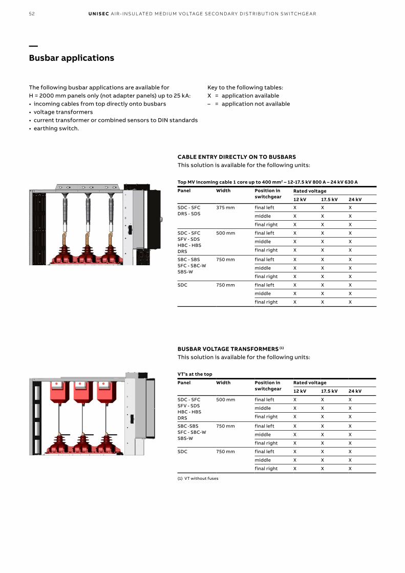
52 U N I S EC A I R - I NSU L ATED M ED I U M VO LTAG E SECO N DA R Y D IS TR IB U TI O N S W ITCH G E A R
CABLE ENTRY DIRECTLY ON TO BUSBARSThis solution is available for the following units:
Top MV incoming cable 1 core up to 400 mm2 – 12-17.5 kV 800 A – 24 kV 630 A
Panel Width Position inswitchgear
Rated voltage
12 kV 17.5 kV 24 kV
SDC - SFCDRS - SDS
375 mm final left X X X
middle X X X
final right X X X
SDC - SFCSFV - SDSHBC - HBS DRS
500 mm final left X X X
middle X X X
final right X X X
SBC - SBS SFC - SBC-WSBS-W
750 mm final left X X X
middle X X X
final right X X X
SDC 750 mm final left X X X
middle X X X
final right X X X
BUSBAR VOLTAGE TRANSFORMERS (1) This solution is available for the following units:
VT’s at the top
Panel Width Position inswitchgear
Rated voltage
12 kV 17.5 kV 24 kV
SDC - SFCSFV - SDSHBC - HBSDRS
500 mm final left X X X
middle X X X
final right X X X
SBC -SBSSFC - SBC-W SBS-W
750 mm final left X X X
middle X X X
final right X X X
SDC 750 mm final left X X X
middle X X X
final right X X X
(1) VT without fuses
—Busbar applications
The following busbar applications are available for H = 2000 mm panels only (not adapter panels) up to 25 kA:• incoming cables from top directly onto busbars• voltage transformers• current transformer or combined sensors to DIN standards• earthing switch.
Key to the following tables:X = application available– = application not available

532 . T Y PI C A L U N ITS
BUSBAR CURRENT TRANSFORMERS (1) (2) This solution is available for the following units:
CT’s at the top
Panel WidthPosition inswitchgear
Rated voltage
12 kV 17.5 kV 24 kV
SDC-SFCSFV-HBC
500 mm final left X X –
middle X X X
final right X X –
SBC SBC-W
750 mm final left X X –
middle X X X
final right X X X
SDC-SFC 750 mm final left X X X
middle X X X
final right X X –
(1) Roof removal is no longer allowed with this top application. For this reason, please pay attention to the sequence of the units in the switchgear line-up
(2) The panel adjacent to a panel with CTs at the top cannot have CTs at its top. Please see the following example:
Panel layout
BUSBAR EARTHING SWITCH WITH FULL MAKING CAPACITY (1) This solution is available for the following units:
ES at the top
Panel WidthPosition inswitchgear
Rated voltage
12 kV 17.5 kV 24 kV
SDC-SFC-SFV 500 mm final left – – –
middle X X X
final right X X X
SBC SBC-W
750 mm final left – – –
middle X X X
final right X X X
SDC-SFC 750 mm final left X X X
middle X X X
final right X X X
(1) The safety and earthing procedure is ensured with additional padlocks, keys or locking magnet on the earthing switch position.
—Busbar applications
Standard busbars CT’s busbars
FIRST PANEL MIDDLE PANEL LAST PANEL
H=2
00
0
H=1
700
H=2
00
0
Standard busbars CT’s busbars
FIRST PANEL MIDDLE PANEL LAST PANEL
H=2
00
0
H=1
700
H=2
00
0
Standard busbars

54 U N I S EC A I R - I NSU L ATED M ED I U M VO LTAG E SECO N DA R Y D IS TR IB U TI O N S W ITCH G E A R
—Weights (*)
Estimated weights of basic units1700 mm height and 2000 mm height for basic units with 630 A main busbars and without CTs VTs or fuses.
Width(mm)
Type of unit (kg)
SDC SDS SDM SDD UMP SFC SFSSBC/SBC-W
SBS/SBS-W SBM SBR HBC HBS SFV DRC DRS RLC RRC
190 – – – – – – – – – – – – – – – – 80 80
375 150/160
155/165
– – – 155/165
165/175
– – – – – – – 120/130
125/135
– –
500 170/180
175/185
– – – 175/185
180/190
– – – – 250/275
270/295
175/185
135/145
140/150
– –
600 – – – – – – – – – – – – – – – – – –
750 195/210
200/215
230/250
270/290
200 200/215
– 335/355
355/375 (2)
390/410
335 – – – – – – –
(2) SBS 1250A version 370/390
Width(mm)
Adapter panels (kg)
WBC WBS BME DRS SDC SFC SFV SBC DRC SDS HBC HBS500 – – – 160 220 225 225 – 270 300 275 295
600 600 600 450 – – – – – – – – –
750 750 750 – – – – – 380 – – – –
(*) The weights are only indicative. Please contact ABB for more details
Current transformers
12/17.5 kV 22 kg
24 kV 33 kg
Voltage transformers
12/17.5 kV 20 kg
24 kV 35 kg
Apparatus
VD4/R-Sec, VD4/L-Sec 90 kg
HD4/R-Sec, HD4/RE-Sec 105 kg
HySec 80 kg
VD4/Sec, VD4/P 125 kg
HD4/Sec 123 kg
VSC/P 52 kg (*)
GSec 38 kg
(*) Excluding fuses
Fuses
3 fuses 19 kg
Gas exhaust type Gas ducts height 1700 mm height 2000 mm
Width 375 mm 14 kg 25 kg
Width 500 mm 17 kg 30 kg
Width 600 mm - 38 kg
Width 750 mm 30 kg 45 kg
Gas exhaust type Filter height 1700 mm height 2000 mm
Width 375 mm 27 kg 18 kg
Width 500 mm 34 kg 21 kg
Width 600 mm - 25 kg
Width 750 mm 47 kg 28 kg
Gas exhaust type Downwards height 1700 mm height 2000 mm
Width 375 mm 15 kg 18 kg
Width 500 mm 18 kg 21 kg
Width 600 mm - 25 kg
Width 750 mm 25 kg 28 kg
Estimated weight of components

553 . M A I N CO M P O N ENTS
—3. Main components
The special geometry of the contacts and the material used, as well as the limited duration and low voltage of the arc,guarantee minimum contact wear and long life. Furthermore, the vacuum prevents their oxidation and contamination.
Standard equipment1 Closing pushbutton2 Opening pushbutton3 Operation counter4 Mechanical indicators for circuit-breaker opening/closing5 Manual spring loading crank lever6 Mechanical indicator of the loaded/discharged state of the
closing springs 7 Kit 1: set of five open/closed auxiliary contacts.
Un = 24…250 V AC-DC8 Kit 2: shunt opening release (M01). Allows the apparatus to
be opened remotely.
Characteristics
Un 24 - 30 - 48 - 60 - 110 - 125 - 132 - 220 - 250 V–
Un 48 - 60 - 110 - 120 - 127 - 220...240 V~ 50 Hz
Un 110 - 120 - 127 - 220 - 240 V~ 60 Hz
Operating limits 65…120 % Un
Inrush power (Ps) DC 200 W; AC = 200 VA
Inrush time about 100 ms
Inrush upkeep time (Pc) DC = 5 W; AC = 5 VA
Opening time 40...60 ms
Insulation voltage 2000 V 50 Hz (for 1 min)
9 Kit 3: key lock in open position with different or identical keys.
VD4/R-Sec and VD4/L-Sec technical data
Rated voltage 12 kV 17.5 kV 24 kV
Rated frequency [Hz] 50/60 50/60 50/60
Rated impulse withstand voltage [kV] 75 95 125
Rated test voltage at power frequency [kV] 28 38 50
Rated current [A] 630/800 630/800 630
Breaking capacity [kA] 12/16/20(1)/25(2) 12/16/20(1)/25 (2) 12/16/20/25 (2)
Making capacity [kA] 30/40/50/62.5 30/40/50/62.5 30/40/50/62.5
Short-circuit duration [s] 3 3 3
Pole center distance [mm] 230 230 230
(1) Contact ABB for 21 kA (2) 25 kA - 2s
The VD4/R-Sec and VD4/L-Sec vacuum circuit-breaker has been specially designed for UniSec switchgear. The circuit-breaker capacity is sufficient for any conditions arising from operation of the apparatus as well as from system components under normal service and fault conditions.Use of vacuum circuit-breakers is particularly advantageous in power systems where frequent operations with normal operating currents are required. VD4/R and VD4/L-Sec vacuum circuit-breakers are equipped with a stored-energy spring operating mechanism suitable for the normal operating sequence, and also for the auto-reclosing sequence (O-0.3s-CO-15s-CO). They feature high operating reliability and long life.The circuit-breaker poles include vacuum interrupters installed in tubular epoxy resin insulators.
Breaking techniqueThe current-breaking process in a vacuum circuit-breaker differs from all other circuit-breakers, which use an oil or gas arc quenching medium. After separation of the current-carrying contacts, the contact material has to generate the charge carriers required to pass the current through the natural zero vacuum by itself. For normal currents up to about 10 kA this effect is described as a “diffuse vacuum arc”. Without special measures, contraction of the diffuse vacuum arc occurs at higher levels, resulting in overheating and general erosion of the contacts.These effects are avoided by magnetically forced movement of the plasma arc due to the spiral geometry of the contacts. Since high dielectric strength can be reached in the vacuum, even with minimum distances, interruption of the circuit is also guaranteed when separation of the contacts takes place a few milliseconds before the current passesthrough natural zero.
—VD4/R-Sec and VD4/L-Sec removable vacuum circuit-breaker Standard IEC 62271-100

56 U N I S EC A I R - I NSU L ATED M ED I U M VO LTAG E SECO N DA R Y D IS TR IB U TI O N S W ITCH G E A R
—Vacuum circuit-breaker accessories
SPRING LOADING MOTOR OPERATOR (MAS)
This device automatically loads the operating mechanism springs after the closing operation.
Characteristics
Un 24...30 - 48...60 - 110...130 - 220...250 V–
Un 100 ...130 - 220...250 V~ 50/60 Hz
Operating limits 85-110 % Un
Inrush power (Ps) DC = 600 W; AC = 600 VA
Rated power (Pn) DC = 200 W; AC = 200 VA
Inrush time 0.2 s
Loading time 6-7 s
Insulation voltage 2000 V 50 Hz (for 1 min)
SHUNT CLOSING RELEASE (MBC)
This is an electromechanical device which, after an electromagnet has been energized, activates the operating mechanism lever making the circuit-breaker close.
Characteristics
Un 24 - 30 - 48 - 60 - 110 - 125 - 132 - 220 - 250 V–
Un 48 - 60 - 110 - 120...127 - 220...240 V~ 50 Hz
Un 110 - 120 - 127 - 220 - 240 V~ 60 Hz
Operating limits 65…120 % Un
Inrush power (Ps) DC 200 W; AC = 200 VA
Inrush time about 100 ms
Inrush upkeep time (Pc) DC = 5 W; AC = 5 VA
Closing time 40...80 ms
Insulation voltage 2000 V 50 Hz (for 1 min)
ADDITIONAL SHUNT OPENING RELEASE (MBO2)
This is an electromechanical device which, after an electromagnet has been energized, activates the operating mechanism lever making the circuit-breaker open.
Characteristics
Un 24 - 30 - 48 - 60 - 110 - 125 - 132 - 220 - 250 V–
Un 48 - 60 - 110 - 120 - 127 - 220...240 V~ 50 Hz
Un 110 - 120 - 127 - 220 - 240 V~ 60 Hz
Operating limits 65…120 % Un
Inrush power (Ps) DC 200 W; AC = 200 VA
Inrush time about 100 ms
Inrush upkeep time (Pc) DC = 5 W; AC = 5 VA
Opening time 40...60 ms
Insulation voltage 2000 V 50 Hz (for 1 min)
UNDERVOLTAGE RELEASE (MBU)
This release opens the circuit-breaker when there is a sharp reduction or cut in the power supply voltage.
Characteristics
Un 24 - 30 - 48 - 60 - 110 - 125 - 220 - 250 V–
Un 48 - 60 - 110 - 120 - 127 - 220...240 V~ 50 Hz
Un 110 - 120...127 - 220...240 V~ 60 Hz
Operating limits – circuit-breaker opening: 35-70 % Un
– circuit-breaker closing: 85-110 % Un
Inrush power (Ps) DC 200 W; AC = 200 VA
Inrush time about 100 ms
Inrush upkeep time (Pc) DC = 5 W; AC = 5 VA
Opening time 60...80 ms
Insulation voltage 2000 V 50 Hz (for 1 min)

573 . M A I N CO M P O N ENTS
—HD4/R-Sec and HD4/RE-Sec removable gas circuit-breakerStandard IEC 62271-100
HD4/R-Sec SF6 medium voltage circuit-breakers have been specifically designed for installation in UniSec units, and are equipped with right-hand lateral operating mechanism. They use SF6 gas to extinguish electric arcs and as insulating medium. They are built using the separate pole technique. The operating mechanism is the ESH type with stored energy and free release. Closing and opening are independent of the operator's action. With the addition of electrical accessories they can be remote controlled. Construction is compact, sturdy and of limited weight. HD4/R-Sec circuit-breakers are systems with sealed-for-life pressure (IEC 60271-1 Standards).The UniSec unit can also be equipped with the stored energy, trip-free SF6 gas-insulated HD4/RE-Sec medium voltage circuit-breaker with right-hand lateral control type EL and opening/closing operations independent of the operator. The HD4/RE-Sec circuit-breaker is built using the separate pole technique (230 mm center-distance).With the addition of electrical accessories, it can be remote controlled.The gas in the poles providesthe insulation and allows arcs to be extinguished as the circuit-breaker opens.HD4/RE-Sec circuit-breakers are available for performance up to 24 kV, 630 A and 16 kA.HD4/R-Sec and HD4/RE-Sec circuit-breakers feature a sturdy, compact design and are low in weight.Both HD4/R-Sec and HD4/RE-Sec circuit-breakers are permanently sealed pressurized systems (standard IEC 60271-1).
Breaking techniqueSF6 is an inert gas with excellent insulating properties. Thanks to its special thermal and chemical stability, SF6 maintains its characteristics for a long time, ensuring a high level of reliability for the circuit-breakers.The blasting and cooling effect of SF6 and the special shape of the contacts,gradually quenches the electric arc and rapidly restores the dielectric properties, without re-ignition. This process results in very low overvoltage values and short arc duration. These characteristics make HD4/R-Sec and HD4/RE-Sec circuit-breakers ideal for MV distribution substations.
Standard equipment 1 Closing pushbutton2 Opening pushbutton3 Operation counter4 Mechanical indicators for circuit-breaker opening/closing5 Manual spring loading crank lever6 Mechanical indicator for closing springs loaded/discharged7 Kit 1: set of five open/closed auxiliary contacts.
Un = 24…250 V AC-DC8 Kit 2: shunt opening release (MBO1). Allows the apparatus
to be opened remotely.
Electrical characteristic
Inrush power 125 VA/W
Voltages available 24-30-48-60-110-125-132-220-250 V–
48-110-120-127-220-230-240 V 50 Hz
110-120-127-220-230-240 V 60 Hz
9 Kit 3: key lock in open position with different or identical keys.
HD4/R-Sec technical data
Rated voltage 12 kV 17.5 kV 24 kV
Rated frequency [Hz] 50/60 50/60 50/60
Rated impulse withstand voltage [kV] 75 95 125
Rated test voltage at power frequency [kV] 28 38 50
Rated current [A] 630/800 630/800 630
Breaking capacity [kA] 12/16/20(1)/25(2) 12/16/20(1) 12/16/20(1)
Making capacity [kA] 30/40/50/62.5 30/40/50 30/40/50
Short-circuit duration [s] 3 3 3
Pole centre distances [mm] 230 230 230
(1) Contact ABB for 21 kA(2) 25 kA - 2s

58 U N I S EC A I R - I NSU L ATED M ED I U M VO LTAG E SECO N DA R Y D IS TR IB U TI O N S W ITCH G E A R
Two-level pressure switch• First level - tripping due to low pressure:
the indication is given when the gas pressure drops from 380 kPa absolute to 310 kPa absolute value.
• Second level - tripping due to insufficient pressure: the indication is given when the gas pressure drops to below the 280 kPa absolute value.
The pressure switch must be requested at the time of ordering because it must be installed and tested in the factory.
Circuit-breaker locking device with signaling lamps for insufficient SF6 gas pressureThis device can only be supplied for circuit-breakers provided with a pressure switch.The locking circuit is an optional application and can only be installed by ABB.The following configurations are available:A - Circuit for automatic circuit-breaker opening with three
signaling lamps.B - Circuit for locking the circuit-breaker in the position it is
in, with three signalling lamps.
—Gas circuit-breaker accessories
SPRING LOADINGMOTOR OPERATOR (MAS)
This device automatically loads the operating mechanism springs after the closing operation.
Electrical characteristics
Inrush power 1500 VA / W
Continuous power 400 VA / W
Loading time from 7 to 10 s.
Voltages available 24-30-48-60-110-125-220 V–24-30-48-60-110-120-127-220-230-240 V 50 Hz
110-120-127-220-230-240 V 60 Hz
SHUNT CLOSING RELEASE (MBC)
This is an electromechanical device which, after an electromagnet has been energized, activates the operating mechanism release lever making the circuit-breaker close.
Electrical characteristics
Inrush power 250 VA / W
Continuous power 5 VA / W
Voltages available 24-30-48-60-110-125-132-220-250 V–24-30-48-60-110-120-127-220-230-240 V 50 Hz
110-120-127-220-230-240 V 60 Hz
ADDITIONAL SHUNT OPENING RELEASE (MBO2)
This is an electromechanical device which, after an electromagnet has been energized, activates the operating mechanism lever making the circuit-breaker open.
Electrical characteristics
Inrush power 125 VA / W
Voltages available 24-30-48-60-110-125-132-220-250 V–48-110-120-127-220-230-240 V 50 Hz
110-120-127-220-230-240 V 60 Hz
UNDERVOLTAGE RELEASE (MBU)
This release opens the circuit-breaker when there is a sharp reduction or cut in the power supply voltage.
Electrical characteristics
Inrush power 250 VA / W
Continuous power 5 VA / W
Voltages available 24-30-48-60-110-125-132-220-250 V–24-48-60-110-120-127-220-230-240 V 50 Hz
110-120-127-220-230-240 V 60 Hz

593 . M A I N CO M P O N ENTS
—HySec: multi-function apparatus with integrated vacuum circuit-breaker and gas-insulated disconnectorStandard IEC 62271-100 IEC 62271-102
operations are being performed but also when the panel is installed and serviced: the lower part of the apparatus is made of stainless steel to provide metallic segregation (PM) between the cable and busbar compartments as well as LSC2A continuity of service. Use of resin parts and SF6 as insulating medium in the disconnector part reduces the size of the apparatus while guaranteeing a higher level of protection over time against strongly aggressive outdoor conditions.The lower insulators of HySec also integrate capacitive sockets for the voltage indicators and pre-engineering for cable connection, thereby reducing the number of components in the panel and using the space in the cable compartment to the best advantage.HySec has been specifically designed for the HBC panel of the UniSec series. This apparatus is so versatile that the HBC panel can be used as both incoming panel with circuit-breaker (SBR series) and outgoing panel (SBC series).Compact design with the integrated functions of two devices in a single enclosure allow the size of HBC panels to be cut down to just 500 mm in width. Moreover, the apparatus contains less than 300 grams of SF6, thereby reducing the product’s environmental impact to the minimum.
HySec multi-function apparatus integrates both vacuum circuit-breaker and gas-insulated disconnector functions. The upper part of the apparatus provides the circuit-breaker function. It consists of an epoxy resin enclosure that houses the vacuum interrupters. The lower part performs the functions of an SF6-insulated 3-position (line – isolated – earth) disconnector. HySec apparatus has been designed to guarantee maximum safety for the personnel: interlocks ensure that the operations take place in the correct sequence. The operating mechanisms of the circuit-breaker and disconnector parts are mechanically interlocked together so that the switch-disconnector can only be operated when the circuit-breaker contacts are in the open position. There is also an interlock with the panel door that prevents access to the cable compartment when the earthing switch is not closed. It also prevents the panel from being put into service unless the door is closed. The disconnector has been designed so that line and earth operations must be performed separately: this creates a natural interlock and guarantees that the operations take place in the correct sequence, e.g. by preventing the earthing switch from closing when the line contact is closed.HySec provides maximum safety, not only when the
HBC technical data
Rated voltage 12 kV 17.5 kV 24 kV
Power-frequency rated test voltage (50 Hz, 1 min) [kV] 28 38 50
Rated impulse withstand voltage [kV] 75 95 125
Rated frequency [Hz] 50/60
Rated current [A] 630
Breaking capacity [kA] 12.5 - 16 - 21
Making capacity of breaking part [kAp] 12.5 - 16 - 21
Earthing contact making capacity [kAp] 31.5 - 40 - 52,5
Short-time withstand current [kA (s)] 12.5 (3s) - 16 (3s) - 20 (3s)
Operating sequence O - 0.3s - CO - 15s - CO
Center-distance between phases [mm] 230

60 U N I S EC A I R - I NSU L ATED M ED I U M VO LTAG E SECO N DA R Y D IS TR IB U TI O N S W ITCH G E A R
— Standard equipment
Circuit-breaker functions1. Mechanical lever operating mechanism to load springs
in the manual mode2. Opening time3. Closing push-button4. Mechanical circuit-breaker state indicators
(open/closed and springs loaded/discharged)5. Operation counter6. Aux contacts (6 + 6 ) 7. Opening coil –MO1
Disconnector functions8. Mechanical interlock between circuit-breaker and
switch-disconnector9. Mechanical interlock with door for access to cable
compartment of panel10. Pre-engineering for padlocks to lock position of
switch-disconnector operating mechanism
— Operating sequence from closed to earthed position
Closed Open Isolated Earth

613 . M A I N CO M P O N ENTS
UNDERVOLTAGE RELEASE –MU
This release opens the circuit-breaker when there is a sharp reduction or cut in the power supply voltage.
Characteristics
Un 24 - 30 - 48 - 60 - 110 - 125 - 220 - 250 V–
Un 48 - 60 - 110 - 120 - 127 - 220...240 V~ 50 Hz
Un 110 - 120...127 - 220...240 V~ 60 Hz
Operating limits – circuit-breaker opening: 35-70 % Un
– circuit-breaker closing: 85-110 % Un
Inrush power (Ps) DC 200 W; AC = 200 VA
Inrush time about 100 ms
Inrush upkeep time (Pc) DC = 5 W; AC = 5 VA
Opening time 60...80 ms
Insulation voltage 2000 V 50 Hz (for 1 min)
A mechanical override is also available for this release.
SHUNT OPENING RELEASE –MO1
This is an electromechanical device which, after an electromagnetic has been energized, activates the operating mechanism lever, thus opening the circuit-breaker.
Characteristics
Un 24 - 30 - 48 - 60 - 110 - 125 - 132 - 220 - 250 V–
Un 48 - 60 - 110 - 120 - 127 - 220...240 V~ 50 Hz
Un 110 - 120 - 127 - 220 - 240 V~ 60 Hz
Operating limits 70…110 % Un
Inrush power (Ps) DC 200 W; AC = 200 VA
Inrush time about 100 ms
Inrush upkeep time (Pc) DC = 5 W; AC = 5 VA
Opening time 40...60 ms
Insulation voltage 2000 V 50 Hz (for 1 min)
Release –MO1 is part of the standard equipment supplied with the apparatus.
— Accessories
SHUNT CLOSING RELEASE –MC
This is an electromechanical device which, after an electromagnetic has been energized, activates the operating mechanism lever, thus closing the circuit-breaker.
Characteristics
Un 24 - 30 - 48 - 60 - 110 - 125 - 132 - 220 - 250 V–
Un 48 - 60 - 110 - 120...127 - 220...240 V~ 50 Hz
Un 110 - 120 - 127 - 220 - 240 V~ 60 Hz
Operating limits 70…110 % Un
Inrush power (Ps) DC 200 W; AC = 200 VA
Inrush time about 100 ms
Inrush upkeep time (Pc) DC = 5 W; AC = 5 VA
Closing time 40...80 ms
Insulation voltage 2000 V 50 Hz (for 1 min)
OPENING SOLENOID -MBO3The opening solenoid (-MBO3) is a special demagneting release for use in conjunction with self-supplied overcurrent protection relays. The demagneting release is an accessory and is not an alternative to release -MBO1.

62 U N I S EC A I R - I NSU L ATED M ED I U M VO LTAG E SECO N DA R Y D IS TR IB U TI O N S W ITCH G E A R
AUXILIARY CONTACTS
Allow the position of the apparatus to be signaled from a remote location. 4 auxiliary contacts are available for the line and 4 for the earth. Each contact can be used as a normally closed (NC) or normally open (NO) circuit. See circuit diagram.
Maximum capacity AC DC
Voltage [V] 250 250
Current [A] 16 0.3
KEY LOCKS FOR THE DISCONNECTOR PART
Allow each of the operation locks of the switch-disconnector part of the apparatus to be locked in the open or closed positions. Up to a maximum of two keys for the line and two keys for the earth can be used together. Three types of keys are available: standard, Ronis and Profalux.
Key locks 1S - Single spring operating mechanism
Line 2 free keys - 1 open and 1 closed
•
1 key free - open •1 free key - closed •
Earth 2 free keys - 1 open and 1 closed
•
1 key free - open •1 free key - closed •
CIRCUIT-BREAKER OPERATING MECHANISM SPRING LOADING MOTOR
Automatically loads the springs of the operating mechanism after the closing operation.
Characteristics
Un 24...30 - 48...60 - 110...130 - 220...250 V–
Un 100...130 - 220...250 V~ 50/60 Hz
Operating limits 85-110 % Un
Inrush power (Ps) DC = 600 W; AC = 600 VA
Rated power (Pn) DC = 200 W; AC = 200 VA
Inrush time 0.2 s
Loading time 6-7 s
Insulation voltage 2000 V 50 Hz (for 1 min)
VIS VOLTAGE INDICATORSUniSec panels can be fitted with two different types of VDS and VPIS voltage indicators.
VDS: device based on the HR system that complies with Standard IEC 61243-5. VDS consists of a fixed device with capacitive sockets installed on the switchgear and a movable one fitted with luminous indicators to visually indicate the presence or absence of voltage and the in-phase condition.
VPIS: device that complies with Standard IEC 62271-206. VPIS consists of a fixed device installed on the switchgear with capacitive sockets and luminous indicators showing the state of voltage in the main switchgear circuit.The devices can be combined with an insulator with capacitive dividers or DIN type CT.
— Accessories

633 . M A I N CO M P O N ENTS
ANALOG PRESSURE GAUGE
Displays the gas pressure and provides an analog indication of the value.The information can be seen on the front of the panel and canalso be transmitted to another location by means of wiring and a terminal box. See circuit diagram.
—
TEMPERATURE COMPENSATED GAS DENSITY GAUGE
Monitors the gas pressure and provides an alarm if the pressure drops too low.
Signal Description
OK Correct operating pressure
LOW Indicates the minimum gas level for which operation of the switch-disconnector is guaranteed
VERY LOW The switch-disconnector cannot be operated
The state of the signals can also be transmitted to another location by means of wiring and a terminal box. See circuit diagram.

64 U N I S EC A I R - I NSU L ATED M ED I U M VO LTAG E SECO N DA R Y D IS TR IB U TI O N S W ITCH G E A R
VD4 medium voltage circuit-breaker interrupters use vacuum to extinguish the electric arc and as insulating medium.Thanks to the unrivalledproperties of vacuum and the breaking technique used, current interruption takes place without arc chopping and without overvoltages. Restoration of the dielectric properties following interruption is extremely rapid.VD4 circuit-breakers are used for protecting cables, overhead lines, motors, transformers, generators and capacitor banks.
Operating mechanismThe VD4 circuit-breaker is fitted with a mechanical storedenergy type operating mechanism.The trip free mechanism allows opening and closing operations independent of the operator.The spring system of the operating mechanism can be reloaded either manually or by means of a geared motor. The apparatus can be opened and closed by means of the pushbuttons on the front of the operating mechanism or by means of electric releases (shunt closing, shunt opening and undervoltage).The circuit-breakers are always fitted with an anti-pumping device to eliminate the risk of simultaneous opening and closing commands, closing commands with springs discharged or with the main contacts not yet in their run-end position.
—VD4/Sec and VD4/P withdrawable vacuum circuit-breakerStandard IEC 62271-100
TruckThe poles and operating mechanism are fixed onto a metalsupport and truck.The truck is provided with a wheel system which allows the operations for racking the apparatus into and out of the switchgear to be performed with the door closed. The truck allows the circuit-breaker to be efficiently earthed by means of the metallic structure of the switchgear unit.The vacuum circuit-breaker truck can be motor-operated.The racking-out and racking-in operations can be carried out by means of electrical controls, either locally by the operator or by a remote system.
Apparatus-operator interfaceThe front part of the circuit-breaker provides the user interface.It features the following equipment:• ON pushbutton• OFF pushbutton• Operation counter• Circuit-breaker open and closed state indicator• Indicator of loaded or discharged state of the operating
mechanism springs• Manual loading device for the operating mechanism
springs• Override selector of the undervoltage release (optional).
VD4/P (12-17.5 kV) and VD4/Sec (24 kV) electrical characteristics
Rated voltage 12 kV 17.5 kV 24 kV
Rated frequency [Hz] 50/60 50/60 50/60
Rated impulse withstand voltage [kV] 75 95 125
Rated test voltage at power frequency [kV] 28 38 50
Rated current [A] 630/1250 630/1250 630/1250
Breaking capacity [kA] 16/20/25 16/20/25 16/20 (1)
Making capacity [kA] 40/50/62.5 40/50/62.5 40/50
Short-circuit duration [s] 3 3 3
Pole center distance [mm] 150 150 210
(1) Contact ABB for 21 kA
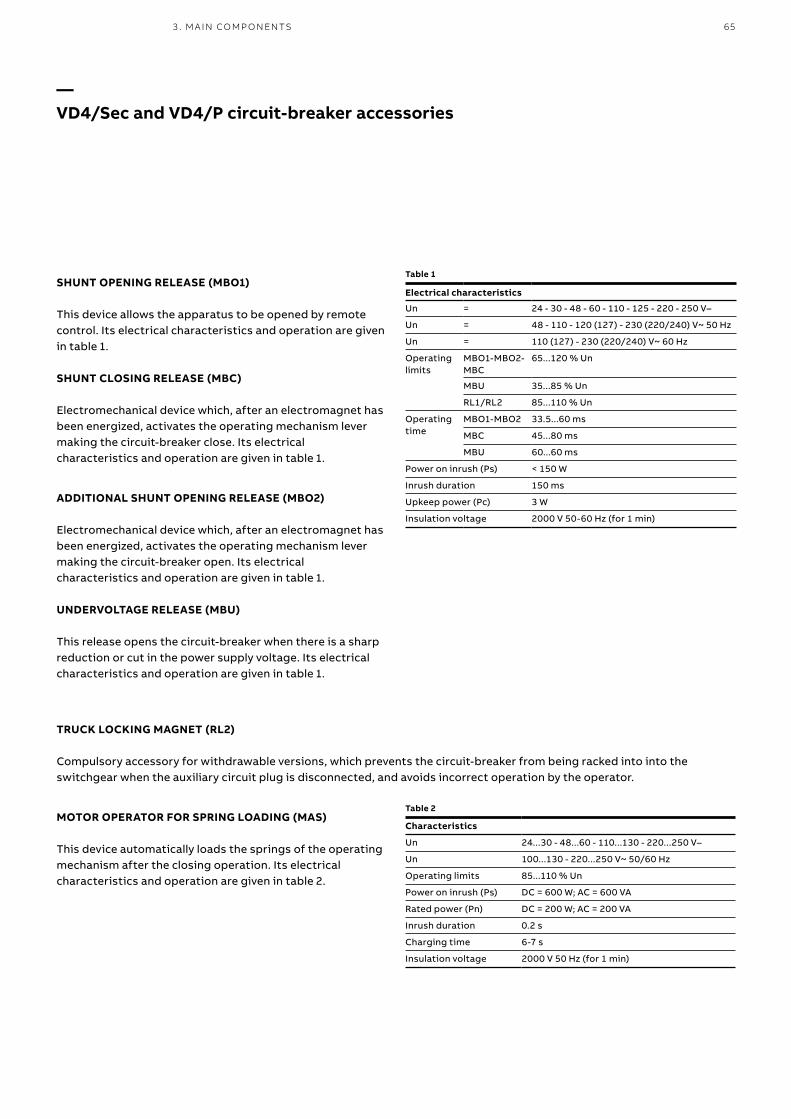
653 . M A I N CO M P O N ENTS
—VD4/Sec and VD4/P circuit-breaker accessories
SHUNT OPENING RELEASE (MBO1)
This device allows the apparatus to be opened by remote control. Its electrical characteristics and operation are given in table 1.
SHUNT CLOSING RELEASE (MBC)
Electromechanical device which, after an electromagnet has been energized, activates the operating mechanism lever making the circuit-breaker close. Its electrical characteristics and operation are given in table 1.
ADDITIONAL SHUNT OPENING RELEASE (MBO2)
Electromechanical device which, after an electromagnet has been energized, activates the operating mechanism lever making the circuit-breaker open. Its electrical characteristics and operation are given in table 1.
UNDERVOLTAGE RELEASE (MBU)
This release opens the circuit-breaker when there is a sharp reduction or cut in the power supply voltage. Its electrical characteristics and operation are given in table 1.
Table 1
Electrical characteristics
Un = 24 - 30 - 48 - 60 - 110 - 125 - 220 - 250 V–
Un = 48 - 110 - 120 (127) - 230 (220/240) V∼ 50 Hz
Un = 110 (127) - 230 (220/240) V∼ 60 Hz
Operating limits
MBO1-MBO2- MBC
65...120 % Un
MBU 35...85 % Un
RL1/RL2 85...110 % Un
Operatingtime
MBO1-MBO2 33.5...60 ms
MBC 45...80 ms
MBU 60...60 ms
Power on inrush (Ps) < 150 W
Inrush duration 150 ms
Upkeep power (Pc) 3 W
Insulation voltage 2000 V 50-60 Hz (for 1 min)
TRUCK LOCKING MAGNET (RL2)
Compulsory accessory for withdrawable versions, which prevents the circuit-breaker from being racked into into the switchgear when the auxiliary circuit plug is disconnected, and avoids incorrect operation by the operator.
MOTOR OPERATOR FOR SPRING LOADING (MAS)
This device automatically loads the springs of the operating mechanism after the closing operation. Its electrical characteristics and operation are given in table 2.
Table 2
Characteristics
Un 24...30 - 48...60 - 110...130 - 220...250 V–
Un 100...130 - 220...250 V~ 50/60 Hz
Operating limits 85...110 % Un
Power on inrush (Ps) DC = 600 W; AC = 600 VA
Rated power (Pn) DC = 200 W; AC = 200 VA
Inrush duration 0.2 s
Charging time 6-7 s
Insulation voltage 2000 V 50 Hz (for 1 min)

66 U N I S EC A I R - I NSU L ATED M ED I U M VO LTAG E SECO N DA R Y D IS TR IB U TI O N S W ITCH G E A R
—HD4/Sec withdrawable gas circuit-breakerStandard IEC 62271-100
The HD4 medium voltage circuit-breakers use sulphur hexafluoride gas (SF6) to extinguish electric arcs and as insulating medium.Thanks to the excellent properties of SF6 gas, currents are interrupted without arc chopping and overvoltages. There is no restriking after interruption and the dielectric properties are recovered extremely rapidly.These circuit-breakers are particularly recommended for use in capacitor banks, motors, oil-insulated transformers and in installations where components that are particularly sensitive to dielectric and dynamic stress are installed (for example, old cables or transformers).
Operating mechanismThe HD4 circuit-breaker is fitted with a mechanicalstored energy operating mechanism. This is trip free and therefore allows opening and closing operations independent of the operator.The spring operating mechanism can be reloaded either manually or by means of a geared motor. The same type of operating mechanism is used for the whole series and has a standardized range of accessories and spare parts.All the accessory components can easily be replaced bymeans of plug-socket connectors.The apparatus can be opened and closed using the pushbuttons on the front of the operating mechanism or by electrical releases (shunt closing, shunt opening and undervoltage).
The circuit-breakers are always fitted with an anti-pumpingdevice to prevent simultaneous opening and closing commands, closing commands with springs discharged or with the main contacts not yet in their run-end position.
TruckThe poles and operating mechanism are fixed to a metal support and truck.The truck has a wheel system which allows the apparatus to be racked into and out of the switchgear with the door closed.The truck enables the circuit-breaker to be effectively earthed by means of the metallic structure of the switchgear unit.
Apparatus-operator interfaceThe front panel of the circuit-breaker provides the user interface. It comprises the following equipment:• ON pushbutton• OFF pushbutton• operation counter• circuit-breaker open and closed indicator• indicator for signaling operating mechanism springs
loaded/discharged• manual loading device for the operating mechanism
springs• override selector of the undervoltage release (optional)• LED gas pressure indicator (optional).
HD4/Sec electrical characteristics
Rated voltage 12 kV 17.5 kV 24 kV
Rated frequency [Hz] 50/60 50/60 50/60
Rated impulse withstand voltage [kV] 75 95 125
Rated test voltage at power frequency [kV] 28 38 50
Rated current [A] 630/1250 630/1250 630/1250
Breaking capacity [kA] 16/20/25 16/20/25 16/20
Making capacity [kA] 40/50/62.5 40/50/62.5 40/50
Short-circuit duration [s] 3 3 3
Pole center distance [mm] 150 150 210

673 . M A I N CO M P O N ENTS
—HD4/Sec circuit-breaker accessories
SHUNT OPENING RELEASE (MBO1, MBO2)
This device allows the apparatus to be opened by remote control. Its electrical characteristics and operation are given in table 1. An Additional -MBO2 shunt opening release is available as an optional.
Ps = 125 W/VA (Instantaneous service ≤ 45 ms)
Un = 24 - 30 - 48 - 60 - 110 - 125 - 220 - 250 V–
Un = 48 - 110 - 120 (127), 230 (220/240) V∼ 50 Hz
Un = 110 (127), 230 (220/240) V∼ 60 Hz
MOTOR OPERATOR FOR SPRING LOADING (MAS)
This device automatically loads the operating mechanism springs after the closing operation. Its electrical characteristics and operation are given in table 1.
Ps = 1500 W/VA (100 ms)
Pc = 400 W/VA (spring loading time: 6 s)
Un = 24 - 30 - 48 - 60 - 110 - 125 - 220 - 250 V–
Un = 48 - 110 - 120 (127) - 230 (220/240) V∼ 50 Hz
Un = 110 (127) - 230 (220/240) V∼ 60 Hz
SHUNT CLOSING RELEASE (MBC)
Electromechanical device which, after an electromagnet has been energized, activates the operating mechanism lever and makes the circuit-breaker close. Its electrical characteristics and operation are given in table 1.
Ps = 250 W/VA (150 ms)
Pc = 5 W/VA (continuous service)
Un = 24 - 30 - 48 - 60 - 110 - 125 - 220 - 250 V–
Un = 48 - 110 - 120 (127) - 230 (220/240) V∼ 50 Hz
Un = 110 (127) - 230 (220/240) V∼ 60 Hz
UNDERVOLTAGE RELEASE (MBU)
This release opens the circuit-breaker when there is a sharp reduction or cut in the power supply voltage. Its electrical characteristics and operation are given in table 1.
Ps = 250 W/VA (150 ms)
Pc = 5 W/VA (continuous service)
Un = 24 - 30 - 48 - 60 - 110 - 125 - 220 - 250 V–
Un = 48 - 110 - 120 (127) - 230 (220/240) V∼ 50 Hz
Un = 110 (127) - 230 (220/240) V∼ 60 Hz
TRUCK LOCKING MAGNET (RL2)
Compulsory accessory for withdrawable versions which prevents the circuit-breaker from being racked into the switchgear when the auxiliary circuit plug is disconnected, and avoids incorrect operation by the operator.
Ps = 250 W/VA (150 ms)
Pc = 5 W/VA (continuous service)
Un = 24 - 30 - 48 - 60 - 110 - 125 - 220 - 250 V–
Un = 48 - 110 - 120 (127) - 230 (220/240) V∼ 50 Hz
Un = 110 (127) - 230 (220/240) V∼ 60 Hz
GAS CONTROL DEVICE
• 22A Two-level pressure switch. Standard version for -5...+40 °C operating temp.; a compensated pressure-switch for ambient temperatures below -5 °C is available on request.
• 22B Two-level SF6 pressure switch control device with three LEDs and -MO2 additional shunt opening release: circuit-breaker opening and locking on closing.
• 22C Two-level SF6 pressure switch control device with 3 LEDs: circuit-breaker locking in the position in which it is found.
Un = 24 - 30 - 48 - 60 - 110 - 125 - 220 - 250 V–
Un = 48 - 110 - 120 (127) - 230 (220/240) V∼ 50 Hz
Un = 110 (127) - 230 (220/240) V∼ 60 Hz

68 U N I S EC A I R - I NSU L ATED M ED I U M VO LTAG E SECO N DA R Y D IS TR IB U TI O N S W ITCH G E A R
Medium voltage VSC/P contactors are designed for operation in alternating current and are normally used to control users requiring a high number of hourly operations. They are suitable for controlling and protecting motors, transformers and power factor correction banks.When fitted with suitable fuses, they can be used in circuits with fault levels up to 1000 MVA.The electrical life of the VSC/P contactor is defined as category AC3 with 100,000 operations (closing/opening)and 400 A interrupted current.
VSC/P contactorThese contactors consist of a resin monobloc containing the following components:• vacuum interrupters• moving parts• magnetic actuator• multivoltage feeder• accessories and auxiliary contacts.The contactors are available in the following versions:• VSC 7/P for voltages up to 7.2 kV• VSC 12/P for voltages up to 12 kV.
Operating mechanismGiven the presence of the magnetic actuator, VSC/P contactors require a negligible amount of auxiliary power in all configurations (30 W on inrush - 36 W for 6 seconds the first time if the main capacitor is completely discharged - 5 W continuous).
VSC/P contactors are available in three different configurations:• SCO (Single Command Operated). The contactor closes
when auxiliary voltage is supplied to the multivoltage feeder input, whereas it opens when auxiliary voltage is cut off
• DCO (Double Command Operated). The contactor closes when auxiliary voltage is supplied to the closing input of the multivoltage feeder, whereas it opens when voltage is supplied to the opening input. The anti-pumping function is built-in.
• On request, the DCO configuration is also available with a delayed undervoltage function. This function allows the contactor to open automatically when the level of auxiliary voltage drops below the levels defined by the IEC Stan-dards. Opening can be delayed from 0 to 5 seconds (setting de-fined by the customer by means of dip-switches).
FusesThe contactor is fitted with medium voltage fuses to protect the users.Coordination between the contactor, fuses and protection unit in class C is guaranteed in compliance with IEC 62271-106 Standards.The fuseholder frame is normally able to house three fuses with average dimensions and striker, according to the following Standards:• DIN 43625• BS 2692 (*).The following fuses can be used:• DIN type with 192, 292 and 442 mm length• BS type with 235, 305, 410, 453 and 553 mm length.
(*) ABB’s CMF-BS fuses cannot be used in VSC/P
VSC/P electrical characteristics
VSC7/P VSC12/P
Rated voltage [kV] 7.2 12
Rated insulation voltage [kV] 7.2 12
Rated test voltage at power frequency [kV] 1 min 20 28
Rated impulse withstand voltage [kV] 60 75
Rated frequency [Hz] 50/60 50/60
Rated short-time withstand current [kA] (1) …25 …25
Peak current [kA] …62.5 …62.5
Internal arc withstand current (2) [kA] 1 s …25 …25
Maximum contactor rated current [A] 400 400
(1) Limited by the fuses(2) The internal arc withstand values are guaranteed in the compartments on the supply side of the fuses
(busbars and apparatus) by the structure of the switchgear and in the compartment on the load side (feeder) by the limiting properties of the fuses
—VSC/P withdrawable vacuum contactorStandard IEC 62271-106

693 . M A I N CO M P O N ENTS
The fuseholder frames are fitted with an automatic opening device that functions even if only a single fuse blows.This device prevents the contactor from closing even when only a single fuse is missing.The ABB range of fuses for transformer protection is called CEF, while the one for motor and capacitor banks is CMF.
StandardsIEC 62271-106 for the contactorIEC 60282-1 for the fuses
Maximum performance of contactor with fuses
3.6 kV 7.2 kV 12 kV
Motors kW 1000 1800 3000
Transformers kVA 2000 2500 2500
Capacitor banks kVAR 1000 1800 3000
Maximum fuse load current
Feeder Transformers Motors Single bank capacitor
Rated voltage Fuse Maximum load Fuse Maximum load Fuse Maximum load
3.6 kV 200 A 160 A 315 A 250 A 450 A 250 A
7.2 kV 200 A 160 A 315 A 250 A 355 A 250 A
12 kV 200 A 160 A 200 A 160 A 200 A 160 A
Note: fuse size is indicative. Please consult the technical catalog of the contactor when choosing fuses

70 U N I S EC A I R - I NSU L ATED M ED I U M VO LTAG E SECO N DA R Y D IS TR IB U TI O N S W ITCH G E A R
GSec is an SF6-insulated 3-position switch-disconnector.The contacts of the switch-disconnector are housed in an enclosure made of two materials: the top part is a moldedresin housing to guarantee the insulation level; the bottom part is made of stainless steel to guarantee metallic segregation and earthing between the busbar compartment and cable compartment.This guarantees maximum personnel safety in the case of trips in the line compartment even when the main busbars are energized, e.g. when one or more fuses are being replaced or when the cables are checked.The switch-disconnector can be used in combination with fuses, e.g. for protecting transformers.
—GSec gas switch-disconnectorsStandard IEC 62271-102 IEC 62271-103 IEC 62271-105
Electrical characteristics
Rated voltage kV 12 17.5 24
Power-frequency withstand voltage (50-60 Hz, 1 min)
– Line to line and line to earth kV 28 38 50
– Between open contacts kV 32 45 60
Lightning impulse withstand voltage (BIL 1.2/50 µs) IEC 62271-105
– Line to line and line to earth kVp 75 95 125
– Between open contacts kVp 85 110 145
Rated frequency Hz 50-60 50-60 50-60
Rated current (40 °C) A 800 (1) 800 (1) 630
Rated short-time withstand current kA 25 (2s) (2) 20 (3s) (2)(3)/25 (2s) 20 (3s) (2)(3)/25 (2s)
Making capacity (peak current) kAp 62.5 (2) 52.5 (2) 52.5 (2)
Breaking capacity:
– Active load A 800 (1) 800 (1) 630
– No-load transformers A 16 16 16
– No-load lines A 25 25 25
– No-load cables A 50 50 50
– Ring circuits A 800 (1) 800 (1) 630
Mechanical and electrical performance
Electrical life of the line contact Class E3 - up to 5 closing operations and 100 rated current interruptions (4)
Electrical life of the earth contact Class E2 - up to 5 closing operations (4)
Mechanical life of the line contact with 1S - Single spring operating mechanism
Class M2 - 5000 mechanical operations (4)
Mechanical life of the line contact with 2S - Double spring operating mechanism
Class M1 - 1000 mechanical operations (4)
Mechanical life of the earth contact 1S - Single spring operating mechanism
Class M1 - 2000 mechanical operations (4)
Mechanical life of the earth contact with 2S - Double spring operating mechanism
Class M0 - 1000 mechanical operations (4)
(1) 630 A for SDC with 2S - Double spring operating mechanism (2) 16 kA (3s) and 41,5 kAp for 2S - Double spring operating mechanism in a panel without fuses(3) Contact ABB for 21 kA (3s)(4) At 25 kA 17,5 and 24 kV with 1S operating mechanism Class is E0,M0 and 25 not available
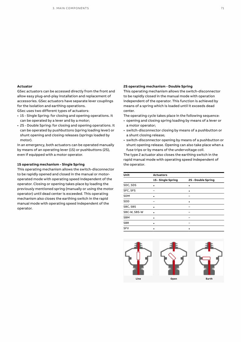
713 . M A I N CO M P O N ENTS
ActuatorGSec actuators can be accessed directly from the front and allow easy plug-and-play installation and replacement of accessories. GSec actuators have separate lever couplings for the isolation and earthing operations.GSec uses two different types of actuators:• 1S - Single Spring: for closing and opening operations. It
can be operated by a lever and by a motor;• 2S - Double Spring: for closing and opening operations. It
can be operated by pushbuttons (spring loading lever) or shunt opening and closing releases (springs loaded by motor).
In an emergency, both actuators can be operated manually by means of an operating lever (1S) or pushbuttons (2S), even if equipped with a motor operator.
1S operating mechanism - Single SpringThis operating mechanism allows the switch-disconnector to be rapidly opened and closed in the manual or motor-operated mode with operating speed independent of the operator. Closing or opening takes place by loading the previously mentioned spring (manually or using the motor operator) until dead center is exceeded. This operating mechanism also closes the earthing switch in the rapid manual mode with operating speed independent of the operator.
2S operating mechanism - Double SpringThis operating mechanism allows the switch-disconnector to be rapidly closed in the manual mode with operation independent of the operator. This function is achieved by means of a spring which is loaded until it exceeds dead center.The operating cycle takes place in the following sequence:• opening and closing spring loading by means of a lever or
a motor operator;• switch-disconnector closing by means of a pushbutton or
a shunt closing release;• switch-disconnector opening by means of a pushbutton or
shunt opening release. Opening can also take place when a fuse trips or by means of the undervoltage coil.
The type 2 actuator also closes the earthing switch in the rapid manual mode with operating speed independent of the operator.
Unit Actuators
1S - Single Spring 2S - Double Spring
SDC, SDS • •SFC, SFS – •SDM • –
SDD – •SBC, SBS • –
SBC-W, SBS-W • –
SBM • –
SBR • –
SFV • •
EarthOpenLine
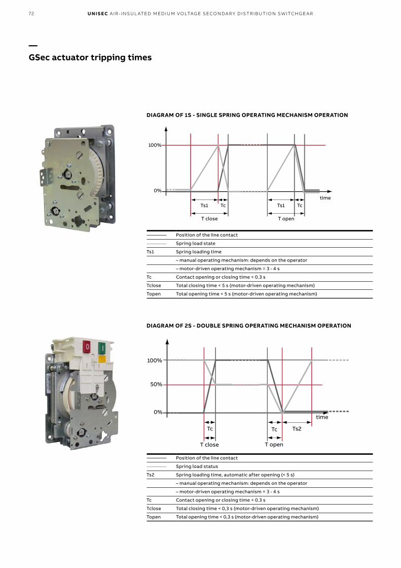
T open
Ts1 Tctime
T close
Ts1 Tc
100%
0%
T open
Tc
time
T close
Tc
100%
0%
50%
Ts2
72 U N I S EC A I R - I NSU L ATED M ED I U M VO LTAG E SECO N DA R Y D IS TR IB U TI O N S W ITCH G E A R
— GSec actuator tripping times
DIAGRAM OF 2S - DOUBLE SPRING OPERATING MECHANISM OPERATION
Position of the line contact
Spring load state
Ts1 Spring loading time
– manual operating mechanism: depends on the operator
– motor-driven operating mechanism = 3 - 4 s
Tc Contact opening or closing time < 0.3 s
Tclose Total closing time < 5 s (motor-driven operating mechanism)
Topen Total opening time < 5 s (motor-driven operating mechanism)
Position of the line contact
Spring load status
Ts2 Spring loading time, automatic after opening (< 5 s)
– manual operating mechanism: depends on the operator
– motor-driven operating mechanism = 3 - 4 s
Tc Contact opening or closing time < 0.3 s
Tclose Total closing time < 0,3 s (motor-driven operating mechanism)
Topen Total opening time < 0,3 s (motor-driven operating mechanism)
DIAGRAM OF 1S - SINGLE SPRING OPERATING MECHANISM OPERATION

733 . M A I N CO M P O N ENTS
— GSec gas switch-disconnector accessories
KEY LOCKS
Allow each of the operation locks of the apparatus (line and earth) to be locked in the open or closed positions. Up to a maximum of two keys for the line and two keys for the earth can be used together.Three types of keys are available: standard, Ronis and Profilux.The line operation lock of disconnectors with 2S - Double spring operating mechanism cannot be locked in the closed position.
Key locks 1S - Single springoperating mechanism
2S - Double springoperating mechanism
Line 2 free keys - 1 open and 1 closed •1 free key - open • •1 free key - closed •
Earth 2 free keys - 1 open and 1 closed • •1 free key - open • •1 free key - closed • •
PADLOCK HOUSING
Allows padlocks to be housed so as to lock the apparatus in the open, in line or earthed positions. Up to three padlocks can be used together per apparatus. The maximum diameter of the padlock latch is 6 mm.It is part of the standard equipment for all GSec apparatus. The padlocks are not supplied.
REMOTE CONTROL OF GSEC
The opening and closing operations of all types of GSec operating mechanism can be remote controlled. Remote control for the 1S - Single spring operating mechanism - is performed by means of the spring loading motor.Remote control for the 2S - Double spring operating mechanism - is performed by means of the spring loading motor and closing and opening coils.
AUXILIARY CONTACTS
Allow the position of the apparatus to be signalled from a remote location. 4 auxiliary contacts are available for the line and 4 for the earth. Each contact can be used as a normally closed (NC) or normally open (NO) circuit. See circuit diagram.
Maximum capacity AC DC
Voltage [V] 250 250
Current [A] 16 0,3
MOTOR FOR THE 1S - SINGLE SPRING OPERATING MECHANISM
The motor automatically loads the spring of the 1S – Single spring operating mechanism for line and earth operations.This allows the disconnector to be operated by remote control. The disconnector’s closing (Tclose) and opening (Topen) times are less than 5 seconds. Consult the circuit diagram to check supply methods.
DC DC/AC (50Hz)
Power supply voltage [V] 24 48 110 220
Power required [W/VA] 90 90 90 90
If the motor operates in a faulty way, the disconnector can always be operated in the manual mode with the operating lever.

74 U N I S EC A I R - I NSU L ATED M ED I U M VO LTAG E SECO N DA R Y D IS TR IB U TI O N S W ITCH G E A R
MOTOR FOR THE 2S - DOUBLE SPRING OPERATING MECHANISM
The motor automatically loads the springs of the 2S – Double spring operating mechanism for line operations.Thanks to this motor and the closing and opening releases, the disconnector can be operated by remote control.Spring loading with the motor takes less than 4 seconds and starts automatically after opening.Consult the circuit diagram to check supply methods.
DC DC/AC (50Hz)
Power supply voltage [V] 24 48 110 220
Power required [W/VA] 260 260 260 260
SHUNT OPENING RELEASE -MBO4 (FOR THE 2S - DOUBLE SPRING OPERATING MECHANISM)
Electromechanical device that opens the line contact of the apparatus after an electromagnet has been energized. See circuit diagram. The total opening time of the disconnector contacts is 300 ms.
AC (50-60 Hz) DC
LV power supply voltage [V] 48, 60 24, 48, 60
HV power supply voltage [V] 110-127, 220-250 110-132, 220-250
Inrush power 200 VA 200 W
SHUNT CLOSING RELEASE -MBC4 (FOR THE 2S - DOUBLE SPRING OPERATING MECHANISM)
Electromechanical device that closes the line contact of the apparatus after an electromagnet has been energized. See circuit diagram. The total closing time of the disconnector contacts is 300 ms.
AC (50-60 Hz) DC
LV power supply voltage [V] 48, 60 24, 48, 60
HV power supply voltage [V] 110-127, 220-250 110-132, 220-250
Inrush power 200 VA 200 W
UNDERVOLTAGE RELEASE -MBU (FOR THE 2S - DOUBLE SPRING OPERATING MECHANISM)
This release opens the line contact of the switch-disconnector when the auxiliary power supply voltage drops or is interrupted. See circuit diagram.
AC (50 Hz) DC
LV power supply voltage [V] 48, 60 24, 48, 60
HV power supply voltage [V] 110-132 (*)
220-250 (*)
110-132 220-250
Inrush power 250 VA 250 W
Inrush time [ms] 150 150
Continuous power 5 VA 5 W
Tripping limits 35-70% of the rated voltage of the auxiliary power supply
(*) Also available for 60 Hz
COIL TO PREVENT THE OPERATING LEVER FROM ENTERING THE LINE SEAT -RLE5 (FOR 1S - SINGLE SPRING OPERATING MECHANISM)
When the coil is not energized, a mechanical lock prevents the lever from being fitted into the line switching seat.See circuit diagram. This accessory is only available for the 1S - Single spring operating mechanism.
Characteristics
Power supply voltage [V] 24, 30, 48, 60, 110, 220, 240
Rated power [W] 250
Continuous power [W] 5
Inrush time [ms] 150
— GSec gas switch-disconnector accessories

753 . M A I N CO M P O N ENTS
VIS VOLTAGE INDICATIONUniSec switchgear can be fitted with two different types of VDS and VPIS voltage indicators.
VDS: device based on the HR system compliant with Standard IEC 61243-5. VDS consists of a fixed device with capacitive sockets installed on the switchgear and a movable one with luminous indicators, which visually indicates the presence or absence of voltage and the in-phase condition.VPIS: device compliant with Standard IEC 62271-206. VPIS consists of a fixed device installed on the switchgear with capacitive sockets and luminous indicators showing the state of voltage in the main switchgear circuit.The devices can be combined with insulator with capacitive dividers or DIN type CT.
ANALOG PRESSURE GAUGE
This pressure gauge displays the pressure of the gas and provides an analog indication of its value.The information can be seen on the front of the panel and can also be transmitted by remote control via dedicated wiring and a terminal box. See circuit diagram.
COIL TO PREVENT THE OPERATING LEVER FROM ENTERING THE EARTHING SEAT -RLE3
When the coil is not energized, a mechanical lock prevents the lever from being fitted into the switching seat of the earthing switch. See circuit diagram.This accessory is supplied as an alternative to the key lock for the earth switching seat.
Characteristics
Power supply voltage [V] 24, 30, 48, 60, 110, 220, 240
Rated power [W] 250
Continuous power [W] 5
Inrush time [ms] 150
FUSES BLOWN SIGNALING CONTACT
When a fuse blows, a kinematic chain activates an indicator that can be seen on the front of the panel (part of the standard equipment for all GSec/T2F devices).A signaling contact that transmits information about blown fuses by remote control is also available.The contact can be normally closed (NC) or normally open (NO). See circuit diagram.
TEMPERATURE COMPENSATED GAS DENSITY GAUGE
The density gauge monitors the gas pressure and provides an alarm that signals when the pressure is low.
Signal Description
OK Correct operating pressure
LOW Indicates the minimum gas level for which operation of the disconnector is guaranteed
VERY LOW The disconnector cannot be operated
The state of the signals can also be transmitted by remote control via dedicated wiring and a terminal box. See circuit diagram.

76 U N I S EC A I R - I NSU L ATED M ED I U M VO LTAG E SECO N DA R Y D IS TR IB U TI O N S W ITCH G E A R
Fuses with maximum rated current can be applied for SFC units: IN = 160 A up to UN = 12 kV IN = 125 A up to UN = 15 kV IN = 100 A up to UN = 24 kV
Selection of fuses for transformer protection (SFC panel)
Transformer rated voltage[kV]
Transformer power [kVA] Fuse ratedvoltage[kV]
25 50 75 100 125 160 200 250 315 400 500 630 800 1000 1250 1600 2000 2500
CEF Fuse In [A]
3 16 25 25 40 40 50 63 80 100 125 160(1) – – – – – 3.6/7.2
5 10 16 25 25 25 40 40 50 63 80 100 125 160(1) – – –
6 6 16 16 25 25 25 40 40 50 63 80 100 125 160(1) – –
10 6 10 16 16 16 20 20 25 31.5 40 50 63 80 100 125 160(1) 12
12 6 6 10 16 16 16 20 20 25 40 40 50 63 80 100 125 160(1)
15 6 6 10 10 16 16 16 20 20 25 40 40 50 63 80 100 125(1) 17.5
20 6 6 6 10 10 16 16 16 20 20 25 31.5 40 50 63 80 100(1) 24
24 6 6 6 6 10 10 16 16 16 20 20 25 40 40 50 63 80 100(1)
Three fuses (one fuse for each phase) for transformer protection can be connected in series with the switch-disconnector. The fuse must be chosen in compliance with the data in the table, depending on the voltage and power of the transformer. To ensure that current is transferred in accordance with IEC 60282-1, use ABB fuses type CEF or SIBA SSK if higher ratings are required, as shown in the table below.
Transformer protection and fuse selection When disconnectors are used to control transformer protection, a special type of current-limiting fuse is used to guarantee selectivity with other protection devices and to withstand the high transformer connection currents without deterioration. In this case, protection against overcurrents on the medium voltage side of the transformer is not indispensable since this task is performed by the protection provided on the low voltage side. Protection on the medium voltage side is the task of the fuse. This must be selected by taking into account the no-load connection current, which can be more than 10 times the rated current, depending on the power of the transformer and the type of punched sheets used (hot rolled sheet or sheet with orientated crystals).
Maximum connection current occurs when circuit-breaker closing takes place when the voltage crosses zero.Another situation to be guaranteed is protection against faults in the low voltage winding and in the part of this that connects to the circuit-breaker on the secondary winding. To ensure rapid tripping even under these fault conditions, use of fuses with excessively high rated current must be avoided. Rapid inspection of the short-circuit currents at the transformer secondary terminals and on the supply side of the circuit-breaker on the secondary when installed at a significant distance, allows the trip time to be checked on the fuse melting curve. The data in the table below takes the required conditions into account, i.e. sufficiently high rated current to avoid untimely fuse blowing during the no-load connection stage and, in any case, of a value which guarantees protection of against faults on the low voltage side.
— ABB CEF/CEF-VT fuses for transformer protection Standard IEC 60282-1/DIN 43625
Selection of fuses for measurement and protection VT (SFV panel)
Type Striker Rated voltageUn [kV]
Rated currentIn [A]
Length e [mm]
Diameter D [mm]
Short circuit current I1 [kA]
Minimum breaking current I3 [A]
Rated power losses Pn [W]
Resistance RO [mΩ]
CEF-VT no 7.2/12 2 292 53 63 27 7.4 1.50
CEF-VT yes 7.2/12 2 292 53 63 27 7.4 1.34
CEF-VT yes 7.2/12 6.3 292 53 63 41 18 0.33
CEF-VT no 17.5/24 2 292 53 31.5 32 17 3.10
CEF-VT no 17.5/24 2 442 53 31.5 32 17 3.10
CEF-VT yes 17.5/24 6.3 292 53 31.5 46 35 0.60
CEF-VT yes 17.5/24 6.3 442 53 31.5 46 35 0.60
(1) Fuse SIBA SSK

773 . M A I N CO M P O N ENTS
—Current transformer – type TPU
—Phase-to-earth VT – type TJC
—Phase-to-phase VT – type TDC
—Phase-to-earth VT with fuse - type TJP
Current transformers to DIN standardsDIN current transformers are insulated in resin and are used for powering measuring devices and protections.These transformers can have one or more wound cores and come with performance and precision classes that suit the requirements of the installation. They conform to standard IEC 61869-2.Their dimensions normally comply with standard DIN 42600 Narrow Type.The current transformers can also be supplied with a capacitive socket for connection to voltage signaling devices.The ABB range of current transformers is called TPU.
— Measuring transformers
Voltage transformers to DIN standardsVoltage transformers are insulated in epoxy resin and are used for powering measuring devices and protections.They are available for fixed assembly or on a plug-in plate for switchgear with withdrawable circuit-breakers. In this case, the transformers can be equippped with a medium voltage protection fuse.They conform to standard IEC 61869-3.Their dimensions comply with standard DIN 42600 Narrow Type.These transformers can have one or two poles and possess performance and precision classes that suit the functional requirements of the instruments to which they are connected.The ABB range of voltage transformers comprises types TJC, TDC, TJP.

78 U N I S EC A I R - I NSU L ATED M ED I U M VO LTAG E SECO N DA R Y D IS TR IB U TI O N S W ITCH G E A R
—Toroidal current transformer with low voltage insulation BD 00 type A, B or C
Toroidal current transformersToroidal transformers are insulated in resin and are used for powering measuring devices and protections.They can be the closed or openable core type and can house two cables per phase. They can be used both for measuring phase current and for detecting earth fault current.They conform to standard IEC 61869-2. Toroidal current transformers are much lighter than the DIN type. This means that they reduce panel weight to a considerable extent. Since these toroidal current transformers are a low voltage product, they can be installed around an insulated cable, thus saving space in the panel.Being low voltage products, toroidal current transformers can be installed near to each other and save additional space. This is impossible with DIN transformers, where distance is required so as to avoid discharge.
— Measuring transformers

793 . M A I N CO M P O N ENTS
Electronic measuring transformersThe technology of the future for measuring current and voltage in UniSec smart switchgear is a measuring transformer (belonging to the electronic measuring transformer group according to current IEC standards) called “sensor” for short. These sensors replace the conventional measuring transformers with ferromagnetic core.The distinguishing feature of ABB sensors is the level of the output signal, which perfectly suits the requirements of microprocessor equipment since these devices do not require power for powering purposes, but just a signal.The level of the analog output signal depends on the principle used and can be:• in mV for current sensors (the characteristic value is
150 mV at the rated primary current)• in Volts for voltage sensors, in which the partition ratio is
1:10000 (e.g. 1/√3 V output for 10000/√3 kV rated voltage of the system in the primary/input side).
Sensor characteristicsThe current and voltage sensors are without a ferromagnetic core. This leads to a number of important advantages:• sensor behavior is not influenced by the non-linearity and
amplitude of the hysteresis curve. This leads to a precise and linear response for a wide dynamic range of quantities measured
• the same device/sensor can be used for both measuring and protection (separate devices are not required)
• there is no loss of hysteresis, thus the sensors provide an excellent reponse even at frequencies that differ from the rated value. This ensures an extremely selective signal for the protection functions, thereby achieving very precise fault analysis and efficient fault localization
• the sensors are without dangerous operating states (absence of problems concerning short-circuited or open outputs) and thus ensure a high degree of safety for both the surrounding devices and the personnel. The output signal remains very low even in network fault situations
• use of sensors does away with the problem of ferroresonance, increasing safety and the reliability of the distribution grid to a further degree. Moreover, there is no need for further protection devices, wiring or particular investments.
— Measuring sensors
ABB sensors are connected to the measuring and protection apparatus by means of shielded cables and connectors, thereby guaranteeing a high degree of immunity from electromagnetic interference. These sensors and their wiring are controlled and tested for accuracy, thus the availability of precise information is guaranteed through to the measuring instrument. Moreover, use of ABB sensors and relays guarantees total precision in the system. This means that over 1% accuracy is assured for the entire measuring chain (sensors plus IED).
Advantages of the sensorsGiven the linear response and the wide dynamic field, the sensors are standardized to a much higher degree (in relation to numerous other models of CT and VT). This means that it is much easier to select the right model (simplified engineering activities), while the number of spare parts can be reduced. A significant reduction in energy consumption during sensor operation, owing to the negligible losses induced by the sensors themselves (absence of iron = no loss of hysteresis; lower current value on the winding and negligible on the output = reduced losses on the sensor windings) leads to enormous savings in lost energy and a minimum temperature rise (which consequently improves the temperature conditions and aging process inside the application). The resulting devices are much lighter than the conventional CT or VT. This means that special systems/devices are not required to transport them, thus reducing the transport costs.Rapid connection of the sensors to the electronic devices without the need for special tools also simplifies and reduces the assembly costs.
—Linearity of the ABB sensors and comparison with the wave shape of the output signals of a conventional saturation current
isUs
ABB sensor Standard CT
Sec
on
dar
y O
utp
ut
Saturation level
10 A 100 A 1000 A 10000 A Primary current

80 U N I S EC A I R - I NSU L ATED M ED I U M VO LTAG E SECO N DA R Y D IS TR IB U TI O N S W ITCH G E A R
Current sensorCurrent measurement is based on the Rogowski coil principle. The Rogowski coil is a toroidal coil without iron core, wound around the primary conductor in the same way as as the secondary winding of a current transformer. However, the difference from this latter is that an output signal from a Rogowski coil is not a current, but a voltage:
In all cases, a signal reproducing the actual primary current waveform is obtained by integrating the transmitted voltage signal.
Voltage sensorVoltage measurement is based on the principle of a resistive voltage divider. The output voltage is directly proportional to the input voltage:
UniSec can be equipped with various ABB sensors and combined sensors with both the DIN or toroidal shape, depending on which is most suitable for the switchgear in question.
In all cases, the transmitted signal reproduces the actual waveform of the primary voltage.
— Measuring sensors
US
Ip
Uout
Up
R1
R2
uout = M –––––––dip
dt
uout = M ––––––– up
R2
R1 + R2
—01 KECA current sensor02 KEVCD current and voltage sensor03 KEVA voltage sensor04 KEVCR 24 current
sensor OC2 (630 A) AC2 (1250 A)
—01
—02
—03
—04

814 . PR OTEC TI O N A N D AU TO M ATI O N D E V I CE S
its normal operating state or isolate the fault to limit damage to the power system and prevent injuries to personnel. This provides a safe environment for all. Power protection systems do not prevent power network faults from arising. They will only activate when a fault has occurred in the power system. However, careful matching of the available protection functions provided by ABB IEDs to the specific power protection requirements of the power system and its components not only creates the best power protection for the power system, but also improves the performance and the reliability of the power protection system within it. This minimizes the effects of faults in the power grid and prevents the abnormal conditions or disturbances from spreading to the healthy parts of the power grid.
—4. Protection and automation devices
—ABB’s Power Protection Philosophy
Having supplied protection IEDs (Intelligent Electronic Devices) to more than 70 countries, ABB is now familiar with the diverse protection requirements established by vastly different local legislation, safety specifications and engineering practices. ABB has thus developed a power protection philosophy that not only contemplates the specific needs and requirements of diverse power systems, but also nurtures a feeling of confidence and peace of mind for both power system owners and users alike.The main purpose of an ABB IED power protection system is to detect any abnormal power system conditions, or faulty components in the power system. Based on the information acquired by the IED, the power protection system will then implement corrective actions to restore the power system to

82 U N I S EC A I R - I NSU L ATED M ED I U M VO LTAG E SECO N DA R Y D IS TR IB U TI O N S W ITCH G E A R
High-level requirements
Typ
e o
f lin
e
Standard requirements
Power supply from both ends
Ring circuits
Parallel lines
Lines with distributed generation
Radial lines with auto-reclosing
devices/disconnectors
Radial lines
Distance protection
HMI* single-line diagram
Fault finder
Energy quality supervision
Communication
Auto-reclosing
Single function
* Human-Machine Interface
—Comparison between lines with standard and high-level requirements
Advantages of a complete protection systemThe speed of operation, sensitivity, selectivity and reliability of the protection system are important factors that are worthy of attention. There is a close correlation between the operating speed of the protection system and the risks and damage caused by a fault in the network. Automation in substations provides remote supervision and monitoring functions that speed up the fault localization process and the time it takes to restore the power supply. Moreover, rapid operation of the protection releases minimizes post-fault load peaks which, along with voltage dips, increase the risk of faults spreading to the unaffected components of the network. The protection must be sensitive enough to allow high resistance earth faults and short-circuits to be detected in the furthest components of the network. Reliable selectivity is of fundamental importance if power losses are to be kept under control as much as possible and to reliably localize faulty components in a network. Only in this way can dedicated corrective actions be taken and the power supply restored as quickly as possible. The protection system must be extremely reliable. For instance, this means that if a circuit-breaker is subjected to a fault, that fault will be identified and eliminated by the back-up protection.Automation in substations allows the operator to keep the substation itself under perfect control.
Moreover, the substation automation system (SA) improves the quality of the power supplied by the transmission and distribution network in normal service conditions ,but especially if faults occur and during maintenance work. A substation automation system (SA) or SCADA (Supervisory Control and Data Acquisition) offers all the advantages of digital technology for protecting and monitoring networks. The terminals can be easily set and parameterized to suit the specific requirements of the system through safe and easy access from the operator’s station.
Single-function and multiple-function protection terminalsAdequate protection methods and complete functionality increase the efficiency of the protection system. The meaning of “complete functionality” varies, depending on the requirements of the network or the electrical system protected. While single-function protection IED are sufficient for certain network applications, networks and systems of a more complex type require advanced multiple-function protection IED. Single-function protection IED include a set of protection functions, e.g. for a specific type of application. The main advantages of these IED are redundancy and their price. One or more single-function protection IED provide sufficient protection for the majority of applications.
—ABB’s Power Protection Philosophy

834 . PR OTEC TI O N A N D AU TO M ATI O N D E V I CE S
The safety of the personnel is of prime importance when modern medium voltage switchgear is developed. This is why UniSec switchgear has been designed and tested to withstand the internal arc produced by a short-circuit current of the same level as the maximum permissible short-time withstand current.Tests have shown that the metal enclosure of UniSec switchgear is able to protect personnel working near the switchgear itself if a fault evolves until an internal arc ignites. An internal arc is a very improbable fault although theoretically, it can be caused by various factors, such as:• defective insulation owing to deteriorated
components. This can be due to adverse environmental conditions and a strongly polluted atmosphere
• over-voltage of atmospheric origin or caused by the operation of some component or other
• inadequately trained personnel • breakage or tampering with the safety
interlocks • overheating in the contact zones due to the
presence of corrosive substances or loose connections
• intrusion of small animals into the switchgear (e.g. through the cable input)
• materials left inside the switchgear during maintenance work.
The characteristics of UniSec switchgear strongly reduce the probability of these faults occurring. However, some cannot be completely prevented.
The energy produced by the internal arc produces the following phenomena:• increase in the internal pressure• temperature rise• visual and acoustic effects• mechanical stress on the switchgear structure• melting, decomposition and vaporization of the
materials.Unless they are adequately kept under control, these phenomena can affect the personnel in a very serious way, causing injuries (due to shock waves, parts that are thrown up and doors that open) and burns (due to the emission of hot gas).
—Products to limit Internal Arc duration for increased safety and less damage
The purpose of the internal arc resistance test is to make sure that the cubicle doors remain closed, that none of the components detach from the switchgear even when the pressure is very high, and that incandescent gas or flames are unable to escape, thereby guaranteeing safe conditions for the personnel who work in the vicinity of the switchgear.The test is also performed in order to ensure that holes are not made in the accessible external parts of the enclosure and, lastly, that all the connections to the earthing circuit continue to be efficient and able to guarantee safe conditions for persons who access the switchgear after a fault.Standard IEC 62271-200 establishes the methods for performing the test and the criteria with which the switchgear must comply.UniSec switchgear fully conforms to all the five criteria indicated in the IEC standard.The parameters of each specific installation establish that the elimination of hot gas and incandescent particles must be checked with particular care so as to guarantee and maintain safe conditions for the personnel.
Fault limiting systemsThe structure of UniSec switchgear provides complete passive protection against the effects of internal arc faults for 1 second up to 25 kA. ABB has also developed active protection systems able to provide the following important benefits:• fault detection and extinguishing, generally
within less than 100 ms, which improves the stability of the network
• less damage to the equipment• the switchgear remains out of sevice for a
shorter time.Active internal arc protection can be achieved by installing various types of sensors in the different compartments. These devices are able to detect the immediate effects of the fault and release the circuit-breakers in the selective mode.The fault limiting systems are based on sensors that take advantage of the pressure or light generated by the internal arc fault so as to allow the faulty line to disconnect.

light
REA 103
REA 101
REA 103
trip
trip
84 U N I S EC A I R - I NSU L ATED M ED I U M VO LTAG E SECO N DA R Y D IS TR IB U TI O N S W ITCH G E A R
TVOCThis system consists of an electronic monitoring device housed in the low voltage cubicle, to which optic sensors are connected. These latter are distributed amongst the power cubicles and are connected to the device by means of optic fibers.The device causes the circuit-breakers to open when a preset level of light is exceeded.Current transformers can also be connected to the monitoring device to prevent the system from being tripped by occasional light created by external factors (a camera flash, reflected external light, etc.).The protection module only transmits the opening command to the circuit-breaker if it receives the light signal and that of short-circuit current at the same time. The total release time is 62 ms (2 ms TVOC + 60 ms the circuit-breaker).
REA This system provides the same functions as the TVOC system. It consists of a central unit (REA 101) and an optional extension unit (REA 103, 105, 107), allowing customized selective release solutions to be created. The total release time is 62.5 ms (2.5 ms REA + 60 ms the circuit-breaker).
Electric arc protection with IEDOn request, the IED (Intelligent Electronic Devices) Relion® 610 – 615 series can be equipped with rapid and selective electric arc protection. This arc fault protection system has two or three channels for supervising electric arcs in the circuit-breaker cubicles, line and busbars of the switchgear. The total release time is 72 ms (12 ms IED + 60 ms the circuit-breaker).
—Typical configuration with REA 101 and subunit 103
—01 REA 101 electric
arc protection unit with REA 103, REA 105 and REA 107 extensions
02 TVOC electric arc protection unit
—01
—02

854 . PR OTEC TI O N A N D AU TO M ATI O N D E V I CE S
—Recommended distribution protection and control products
WARNING!
If relay REF601 is supplied by means of a UPS (Uninterruptible Power Supply) with modified sine wave, a transformer must be used to limit the power supply voltage (peak voltage) to within the values specified for the relay itself. The recommended characteristics of the transformer are:• Rated power: 20 VA• Output voltage of the secondary: 30...150 V a.c.For further information contact ABB.
REJ603 is a digital feeder protection relay. It is used for the selective short-circuit and earth-fault protection of distribution networks and for protecting small transformers in utilities and industries. The relay is self-powered (or dual-powered by 24-250 V AC/DC). It does not require external supply voltage as it receives power from the primary current transformers. The relay has a capacitor discharge impulse output (24 V DC, 100 mJ) for tripping the circuit breaker with sensitive trip coil. An additional binary output is provided for external trip indication. Phase as well earth fault trip indication is provided by means of a manually reset electromagnetic flag which en sures that the relay functions even in the absence of primary CT current.
REF601 is a digital feeder protection relay, designed to protect and control utility and industrial power systems.The relay provides basic short-circuit, overcurrent and earth fault protection in networks where the neutral is directly earthed by means of a resistance and in those with isolated neutral. The phase currents are measured by Rogowski coil type current sensors and earth-fault current can be internally calculated or measured by conventional current transformers.ABB offers two sensors:• KECA (Rogowski coil type) mounted around the MV cables • KEVCR installed on board the circuit-breaker.The REF601 relay can be installed on VD4/R-Sec, VD4/L-Sec and HD4/R-Sec circuit-breakers or in the auxiliary contact compartment.Two types of relay are available:REF601 compliant with IEC StandardsREF601 compliant with the CEI 0-16 Standard for the Italian market.
Auxiliary supply voltage: 24…240 V AC/DC
RELION® 605 series

86 U N I S EC A I R - I NSU L ATED M ED I U M VO LTAG E SECO N DA R Y D IS TR IB U TI O N S W ITCH G E A R
RELION® 611 Series
The 611 series is part of ABB’s Relion® protection and control relay family and is designed to provide simplified but powerful functions for the majority of applications.Once the application-specific parameter set has been entered, the installed IED (intelligent electronic device) is ready to be put into service. The further addition of communication functionality and interoperability between substation automation devices offered by the IEC 61850 standard adds flexibility and value for end users as well as electrical system manufacturers.• REF611 is a dedicated feeder IED designed for the protection, control,
measurement and supervision of utility substations and industrial power systems including radial, looped and meshed distribution networks with or without distributed power generation. REF611 is available in two alternative standard configurations.
• REM611 is a dedicated motor protection and control IED designed for the protection, control, measurement and supervision of asynchronous motors in manufacturing and process industry. Typically, the motor IED is used with circuit breaker or contactor-controlled medium-sized or small motors in a variety of drives, such as pumps and conveyors, crushers and choppers, mixers and agitators, fans and aerators. REM611 is available in one standard configuration.
• REB611 is a dedicated busbar protection IED designed for phase-segregated short circuit protection, control and supervision of single busbars. REB611 is intended for use in high-impedance-based applications within utility substations and industrial power systems. In addition, the IED can be used in restricted earth-fault and residual earth-fault applications for the protection of generators, motors, transformers and reactors. REB611 is available in one standard configuration.
Auxiliary power supply voltage:High: 48 - 250 V DC 100 - 240 V ACLow: 24…60 V DC
• REF615 provides general protection for overhead lines, cable feeders and distribution substation busbar systems. It can be adapted for both isolated neutral networks and networks with the neutral earthed by means of resistance or impedance.
• REM615 is a dedicated motor protection and control IED, designed for the protection, control, measurement and monitoring of asynchronous motors in the manufacturing and process industry.
• RET615 is a dedicated IED for protecting and controlling power transformers, unit and step-up transformers including power generator-transformer blocks in utility and industrial power distribution systems.
• REG615 is a dedicated generator and interconnection protection relay for protection, control, measurement and supervision of power generators and interconnection points of distributed generation units in utility and industrial power distribution system.
RELION® 615 Series
—Recommended distribution protection and control products

874 . PR OTEC TI O N A N D AU TO M ATI O N D E V I CE S
• RED615 is a line residual current IED which is especially useful in applications requiring highly selective feeder protection (unit protection). RED615 maintains selectivity even in cases where the fault current has a variable magnitude and can be supplied by several sources.
• REU615 is an IED available in two predefined configurations called A and B, designed for two of the most common applications. Configuration A is preset for protections based on voltage and frequency. Configuration B is preset for automatic voltage adjustment functions for transformers fitted with an on load tap changer.
Auxiliary power supply voltage:High: 100 - 110 - 120 - 220 - 240 V 50/60 Hz 46 - 60 - 115 - 220 - 250 V DCLow: 24 - 30 - 48 - 60 V DC
RELION® 620 Series
• REF620 is a dedicated feeder IED designed for the protection, control, measurement and supervision of utility and industrial power distribution systems, including radial, looped and meshed distribution networks. REF620 belongs to ABB's Relion® protection and control product family. 620 series IEDs feature functional scalability and withdrawable unit design. The 620 series makes use of the full potential of Standard IEC 61850 for communication and the interoperability of substation automation devices.
• REM620 is a dedicated motor IED designed for the protection, control, measurement and supervision of medium-sized and large asynchronous motors, also requiring differential protection, in the manufacturing and process industry. REM620 belongs to ABB’s Relion® protection and control product family. 620 series IEDs feature functional scalability and withdrawable-unit design.
• RET620 is a dedicated transformer IED designed for the protection, control, measurement and supervision of both power and step-up transformers, including power generator-transformer blocks, in utility and industrial power distribution systems. RET620 belongs to ABB’s Relion® protection and control product family. 620 series IEDs are characterized by their functional scalability and withdrawable-unit design.
Auxiliary power supply voltage:High: 48 - 250 V DC 100 - 240 V ACLow: 24…60 V DC

88 U N I S EC A I R - I NSU L ATED M ED I U M VO LTAG E SECO N DA R Y D IS TR IB U TI O N S W ITCH G E A R
RELION® 630 series
• REF630 line protection and monitoring unit: this unit provides important protection functions for overhead lines and cable lines in power distribution networks. REF630 adapts to both networks with isolated neutral and networks with neutral earthed by means of a resistor or impedance. The four pre-engineered configurations available are designed to comply with line monitoring and protection requirements.
• RET630 transformer protection and monitoring terminal: this is a complete IED for controlling transformers. It has been designed to protect, monitor, measure and supervise power transformers, unit and stet-up transformers including transformer-generator units in utility and industrial distribution networks. This terminal provides the main protection for power transformers with two windings and generator-power transformer units.
• REM630 motor protection and monitoring unit: complete with motor management functions, this IED has been designed to protect, monitor, measure and supervise medium-large asynchronous motors in medium-voltage industrial electrical systems.
With functional scalability and flexible configuration, REM630 belongs to ABB’s Relion® family of products and to the 630 product series. It also possesses the monitoring functions required for managing industrial motor control switchgear. REM630 provides the main protection for asynchronous motors and the relative transmissions.
Auxiliary power supply voltage:High: 100 - 110 - 120 - 220 - 240 V 50/60 Hz 46 - 60 - 115 - 220 - 250 V DCLow: 48 - 60 V DC
—Recommended distribution protection and control products

894 . PR OTEC TI O N A N D AU TO M ATI O N D E V I CE S
COM600 Substation Management Unit
COM600, ABB’s station automation device, is an all-in-one communication gateway, automation platform and user interface solution for utility and industrial distribution substations.The gateway functionality provides seamless IEC 61850 connectivity between substation IEDs and network-level control and management systems.The automation platform with its logic processor makes COM600 a flexible implementation platform for substation level automation tasks. As a user interface solution COM600 accommodates web technology based functionalities providing access to substation devices and processes via a web browser based human machine interface (HMI).
ProductThe COM600 Station Automation System offers web server functionality, providing a human machine interface (HMI) for local substation monitoring and control. Secure communication enables access to the substation HMI over the internet or LAN/WAN for any authorized user with a standard PC and web browser. By connecting a laptop computer to the unit locally, an HMI for full monitoring and control functionality is obtained at substation level.The COM600 Station Automation System also provides gateway functions for mapping data and signals between substation and higher-level systems such as SCADA, DSC.COM600 is designed for smooth system integration and interoperability based on pre-configured solutions using connectivity packages for ABB IEDs.With its compact, sturdy design, COM600 well adapts to harsh environments. It meets the IP4x degree of protection by enclosure and contains no moving parts subject to wear and tear. COM600 is based on embedded technology for durability and maximum availability.

90 U N I S EC A I R - I NSU L ATED M ED I U M VO LTAG E SECO N DA R Y D IS TR IB U TI O N S W ITCH G E A R
60
5
60
5
60
5
60
5
611
611
611
611
615
615
615
615
615
615
615
615
615
615
615
62
0
62
0
62
0
62
0
62
0
62
0
630
630
630
630
RE
F601
RE
J601
RE
J603
RE
M6
01
RE
B61
1 IE
C
RE
F611
IEC
RE
M61
1 IE
C
RE
U61
1 IE
C
RE
F615
IEC
RE
D61
5 IE
C
REG
615
IEC
RE
M61
5 IE
C
RE
T615
IEC
RE
U61
5 IE
C
RE
V61
5 IE
C
RE
F615
AN
SI
RE
F615
R A
NS
I
RE
M61
5 A
NS
I
RE
T615
AN
SI
RE
F62
0 IE
C
RE
M6
20
IEC
RE
T62
0 IE
C
RE
F62
0 A
NS
I
RE
M6
20
AN
SI
RE
T62
0 A
NS
I
RE
F63
0 IE
C
RE
M63
0 IE
C
RE
T63
0 IE
C
REG
630
IEC
Standard
ANSI X X X X X X X X X X
IEC X X X X X X X X X X X X X X X X X X X X X X
Application
Arc fault protection application O O O O O O O O O O O O O O O O
Busbar application X
Back-up application X X O X X X X
Capacitor bank application X
Feeder application X X X X X X X X X X X X X
Generator application X X
Motor application X O X X X X X X
Power management/load-shedding application X
Transformer application O X X X X X X X
Functionality
Autorecloser X X X X X X X X X X
Circuit breaker controllability X X X X X X X X X X X X X X X X X X X X X X X X X X X
Condition monitoring X X X X X X X X X X X X X X X X X X X X X X X X X X
Current-based protection X X X X X X X X X X X X X X X X X X X X X X X X X X X
Distance protection X
Fault locator X X X X
Generator differential protection X X X
LCD display with Single Line Diagram (SLD) X X X X X X X X X X X X X X X X X X X X X
Line differential protection (in-zone transformer support)
X
Load-shedding X X X
Motor differential protection X X X X X
On-load tap changer control X X X
Power quality X X X X X X X X
Self-powered protection relay X
Synchro-check X X X X X X X X X X X X
Transformer differential protection X X X X X X X
Voltage based protection X X X X X X X O X X X X X X X X X X X X X X
Withdrawable release mechanism X X X X X X X X X X X X X X X X X X X X
Hardware
Analog inputs (CTs/VTs) 4/0 4/0 4/0 4/0 4/0 4/1 4/0 0/5 4/5 4/5 7/5 4/5 7/5 4/5 7/5 7/6 4/5 7/4 7/6 4/5 7/5 8/9 7/8 7/4 10/4 4/5 8/4 8/3 8/4
Analog inputs (sensor channels/CTs) 3/1 3/1 3/1 6/1 6/1 6/1 6/1
Binary inputs/outputs 4/6 4/6 0/2 4/6 4/6 10/9 4/6 4/6 18/13 18/13 16/10 16/12 14/12 14/12 14/12 18/13 11/7 18/13 14/13 32/18 20/14 16/17 32/18 14/13 16/17 50/45 50/45 50/45 50/45
RTD/mA inputs 2/1 2/1 2/1 6/2 6/2 6/2 6/2 6/2 2/1 6/2 12/4 8/3 14/5 2/1 8 8 8 8
mA outputs 4 4 4 4
Communication protocols
DNP 3.0 X X X X X X X X X X X X X X X X X X X X X
IEC 60870-5-103 X X X X X X X X X X X X X X X X X X X X X X X X
IEC 61850 X X X X X X X X X X X X X X X X X X X X X X X X X
Modbus X X X X X X X X X X X X X X X X X X X X X X X X
Profibus X X X X X X X X X X X X X X X X X
Communication media
Ethernet (RJ-45) X X X X X X X X X X X X X X X X X X X X X X X X X
Ethernet (LC) X X X X X X X X X X X X X X X X X X X X X X X X X
Ethernet redundant solutions (HSR/PRP/RSTP) X X X X X X X X X X X X X X X X X X X X X
Serial (RS 232/485, ST conn.) X X X X X X X X X X X X X X X X X X X X X X X X X X X X
—Selection table The Relion® Interactive Selection Guide (ISG), which covers the entire Relion® family, is available online.Go to: http://abb.relionisg.com
In the table: X = function supported O = function available as option

914 . PR OTEC TI O N A N D AU TO M ATI O N D E V I CE S
60
5
60
5
60
5
60
5
611
611
611
611
615
615
615
615
615
615
615
615
615
615
615
62
0
62
0
62
0
62
0
62
0
62
0
630
630
630
630
RE
F601
RE
J601
RE
J603
RE
M6
01
RE
B61
1 IE
C
RE
F611
IEC
RE
M61
1 IE
C
RE
U61
1 IE
C
RE
F615
IEC
RE
D61
5 IE
C
REG
615
IEC
RE
M61
5 IE
C
RE
T615
IEC
RE
U61
5 IE
C
RE
V61
5 IE
C
RE
F615
AN
SI
RE
F615
R A
NS
I
RE
M61
5 A
NS
I
RE
T615
AN
SI
RE
F62
0 IE
C
RE
M6
20
IEC
RE
T62
0 IE
C
RE
F62
0 A
NS
I
RE
M6
20
AN
SI
RE
T62
0 A
NS
I
RE
F63
0 IE
C
RE
M63
0 IE
C
RE
T63
0 IE
C
REG
630
IEC
Standard
ANSI X X X X X X X X X X
IEC X X X X X X X X X X X X X X X X X X X X X X
Application
Arc fault protection application O O O O O O O O O O O O O O O O
Busbar application X
Back-up application X X O X X X X
Capacitor bank application X
Feeder application X X X X X X X X X X X X X
Generator application X X
Motor application X O X X X X X X
Power management/load-shedding application X
Transformer application O X X X X X X X
Functionality
Autorecloser X X X X X X X X X X
Circuit breaker controllability X X X X X X X X X X X X X X X X X X X X X X X X X X X
Condition monitoring X X X X X X X X X X X X X X X X X X X X X X X X X X
Current-based protection X X X X X X X X X X X X X X X X X X X X X X X X X X X
Distance protection X
Fault locator X X X X
Generator differential protection X X X
LCD display with Single Line Diagram (SLD) X X X X X X X X X X X X X X X X X X X X X
Line differential protection (in-zone transformer support)
X
Load-shedding X X X
Motor differential protection X X X X X
On-load tap changer control X X X
Power quality X X X X X X X X
Self-powered protection relay X
Synchro-check X X X X X X X X X X X X
Transformer differential protection X X X X X X X
Voltage based protection X X X X X X X O X X X X X X X X X X X X X X
Withdrawable release mechanism X X X X X X X X X X X X X X X X X X X X
Hardware
Analog inputs (CTs/VTs) 4/0 4/0 4/0 4/0 4/0 4/1 4/0 0/5 4/5 4/5 7/5 4/5 7/5 4/5 7/5 7/6 4/5 7/4 7/6 4/5 7/5 8/9 7/8 7/4 10/4 4/5 8/4 8/3 8/4
Analog inputs (sensor channels/CTs) 3/1 3/1 3/1 6/1 6/1 6/1 6/1
Binary inputs/outputs 4/6 4/6 0/2 4/6 4/6 10/9 4/6 4/6 18/13 18/13 16/10 16/12 14/12 14/12 14/12 18/13 11/7 18/13 14/13 32/18 20/14 16/17 32/18 14/13 16/17 50/45 50/45 50/45 50/45
RTD/mA inputs 2/1 2/1 2/1 6/2 6/2 6/2 6/2 6/2 2/1 6/2 12/4 8/3 14/5 2/1 8 8 8 8
mA outputs 4 4 4 4
Communication protocols
DNP 3.0 X X X X X X X X X X X X X X X X X X X X X
IEC 60870-5-103 X X X X X X X X X X X X X X X X X X X X X X X X
IEC 61850 X X X X X X X X X X X X X X X X X X X X X X X X X
Modbus X X X X X X X X X X X X X X X X X X X X X X X X
Profibus X X X X X X X X X X X X X X X X X
Communication media
Ethernet (RJ-45) X X X X X X X X X X X X X X X X X X X X X X X X X
Ethernet (LC) X X X X X X X X X X X X X X X X X X X X X X X X X
Ethernet redundant solutions (HSR/PRP/RSTP) X X X X X X X X X X X X X X X X X X X X X
Serial (RS 232/485, ST conn.) X X X X X X X X X X X X X X X X X X X X X X X X X X X X

92 U N I S EC A I R - I NSU L ATED M ED I U M VO LTAG E SECO N DA R Y D IS TR IB U TI O N S W ITCH G E A R
—Description
The shipping market can be divided into four different segments:• passenger ships (cruise liners and ferries)• industrial vessels (tankers, drillships, oil
tankers, freighters, etc.)• platforms (oil platforms and rigs)• the navy.In these sort of applications, temperature range, vibrations and buoyancy are particularly aggravating conditions that affect the functionality of the instruments on board, including switchgear.ABB is the leading manufacturer of air-insulated switchgear for applications installed by all the major shipyards (in Brazil, China, Denmark, Finland, France, Germany, Japan, Korea, Italy, Norway, Singapore, Spain, United Kingdom and the United States).UniSec is designed for 7.2-12 kV marine applications (a version for 17.5 kV can also be supplied). Over 10,000 ABB panels installed in vessels of all types are in service throughout the world. Shipping Registers and end customers (shipyards or shipowners) need switchgear manufactured in compliance with the Shipping Register test requirements for the equipment on board.
This is why tests are performed to ensure compliance with the main provisions established by the Shipping Registers: DNV, LR, RINA, BV, GL and ABS. To create the necessary structures and ensure livable conditions, large electric generating systems and monitoring equipment must be concentrated into very small spaces.UniSec switchgear is available in the single level version and provides a wide range of apparatus and monitoring units suitable for marine applications.
UniSec switchgear is the ideal technical solution for marine applications:• the arc-proof structure, mechanical safety
interlocks, automatic segregation shutters and closed-door apparatus control guarantee safe conditions for the personnel during installation, maintenance and service
• the outer enclosure possess a high protection class (up to IP42)
• metallic segregation between each cubicle is guaranteed plus earthing of all components that can be accessed by the personnel: apparatus, shutters, doors and the entire switchgear frame
• the switchgear provides a high degree of fire resistance since plastic materials and resins are only used to a limited extent: the auxiliary equipment and wiring are highly self-extinguishing.
—5. Marine applications
—Main Switchgear with withdrawable circuit-breaker panels type LSC2B

935 . M A R I N E A PPL I C ATI O NS
Environmental conditions for the classification of equipment on board• Ambient temperature from -5 °C to +45 °C• Up to 25° permanent inclination
Complete range of tests
Besides having been subjected to all the tests required by the international standards (IEC), UniSec switchgear has also undergone the tests established by the principal Shipping Registers (LR, DNV, RINA, BV and GL) for use on board. These tests are:• High ambient temperature
The operating conditions of the electrical equipment in marine installations are generally more severe than those normally found on land. Temperature is one of these factors. This is why the regulations established by the Shipping Registers specify that switchgear must be able to operate at a higher ambient temperature (45 °C or more) than that required by IEC standards (40 °C).
• InclinationThe test must be performed by tilting the switchgear up to 25° on all four sides for a given time and by operating the control apparatus.The test proves that the switchgear is able to withstand these extreme service conditions and that all the apparatus it contains can be operated without difficulty and without being damaged.
• VibrationThat UniSec switchgear is sturdy and reliable is a proven fact demonstrated by the result of the test that assesses its ability to withstand mechanical stress due to vibration. Operating conditions in marine applications and rigs need switchgear able to function in the presence of strong vibrations, as occurs for the engines of large cruise liners or the drilling systems of oil rigs: - 1 mm amplitude in the 2…13.2 Hz frequency range - 0.7 g acceleration amplitude in the 13.2…100 Hz
frequency range.
IEC electrical specifications
Rated voltage (*) kV 7.2 12
Rated insulation voltage kV 7.2 12
Power-frequency test voltage kV 1 min 20 28
Impulse withstand voltage kV 60 75
Rated frequency Hz 50/60 50/60
Rated short-time withstand current kA 3s 16/21/25 16/21/25
Peak current kA 40/50/62.5 40/50/62.5
Internal arc withstand current kA 1s 16/21/25 16/21/25
Rated current of main busbars A 630-800-1250 630-800-1250
Rated current of circuit-breaker A 630-800-1250 630-800-1250(*) Contact ABB for 17.5 kV Note: – The values indicated are also valid for vacuum circuit-breakers – The rated current value is 400 A for panels with contactor
—Thermographic inspectionThermographic inspection is generally required for the terminals of power cables and sometimes for the main busbar systems.The former type of inspection is normally required since the majority of the faults in switchgear concern the cable terminals, while faults in busbars systems are rather rare.Checking and thermographic supervision of the power cables can be performed by temporary inspection with an IR camera through the window provided.This method (temporary inspection) requires an IR (infrared) camera and an inspection window for each cubicle controlled.

94 U N I S EC A I R - I NSU L ATED M ED I U M VO LTAG E SECO N DA R Y D IS TR IB U TI O N S W ITCH G E A R
—“Shore connection” panel
Nowadays, sustainability is a prime issue in the marine industry and strong measures are being adopted on many different fronts so as to drastically reduce these emissions.One of these measures is the “shore-to-ship” supply system, which does away with the problem of pollution and the emission of polluting particles as well as the noise and vibrations produced by moored vessels.The UniSec Shore Connection panel is supplied in the form of a ready-to-use substation equipped with both a power module and monitoring module.Depending on how the system is configured and the requirements on board, the substation can be fitted with cable connectors housed on its front or with openings for incoming cables through the substation floor.All the equipment is manufactured and tested in the factory according to international standards and the Shipping Register classifications.
When moored at the quayside, ships keep their power generating systems running so as to supply their normal processes and users and this creates a strongly localized and considerable source of pollution. In harbours with heavy shipping traffic, this practice leads to a negative impact on both the environment and on the health of the surrounding local communities.Since global trade is continually expanding, emissions from ships are becoming an environmental problem of growing proportions.
—The picture illustrates the version with bottom cable connection.An alternative version with frontal plug connection is also available.
Complete onboard system Including HV Shore Connection panel and cable drum
Sub-station (incl. 50/60 Hz converter)
Shoreside transformer kiosk
HV underground cable (distance 1 - 5 Km)
Power outlet 6.6 kV / 11 kV

955 . M A R I N E A PPL I C ATI O NS
—Characteristics
Specifications for marine applications that are not part of the standard configuration are described below.
Protection classOn request, the external enclosure of UniSec switchgear is available with different protection classes. The standard protection class required for marine applications is IP32 or IP42: protection against solid foreign objects with a diameter of 1 mm and protection against water sprayed at an angle of up to 15°.
Duct for interconnectionsOn request, the top of the switchgear can be equipped with duct for interconnections, installed on the low voltage side. This duct houses the terminal boxes to which the wiring between panels is connected.
Gas filters-absorbersIn ships, exhaust gas cannot normally be exhausted from the room. UniSec switchgear is arc-proof and equipped with filters-absorbers to exhaust the gas produced by electric arcs. This filter is fixed to the rear part of the cubicle.
—Distribution ring with circuit-breaker and switch-disconnector panels type LSC2A
DoorsAll the doors (low voltage compartment, apparatus and line) are equipped with a lock that holds them in the open position.
CablesThe cable connection height of UniSec WBC units can be at 600 mm for standard cable connections, with up to 3 cables per phase.The cable connection height of units SBC and SDC can be at 500 mm and 915 mm for cable connections, with up to 2 cables per phase.

96 U N I S EC A I R - I NSU L ATED M ED I U M VO LTAG E SECO N DA R Y D IS TR IB U TI O N S W ITCH G E A R
—Typical units in ships
The typical units used in ships are:• WBC feeder with withdrawable frontal circuit-breaker • WBS coupler with withdrawable frontal circuit-breaker• DRS riser with measurement• BME direct feeder with measurement and busbar earthing• SDC feeder with switch-disconnector• SBC feeder with circuit-breaker and switch-disconnector• SBS coupler with circuit-breaker and switch-disconnector• DRC direct feeder with measurement and busbar earthing.
For Marine version, the withdrawable vacuum circuit-breaker to be used for LSC2B cubicles is VMax/Sec (catalog 1VCP000408).
—WBC: feeder unit
—SBC: feeder with circuit-breaker and switch-disconnector
—WBS: coupler unit
—SDC: feeder with switch-disconnector
—BME: direct feeder with measurement and busbar earthing
—DRS: riser with measurement
—SBS: couplerwith circuit-breaker and switch-disconnector
—DRC: feeder with measurement and busbar earthing

976 . SM A RT G R ID A N D D I G ITA L A PPL I C ATI O NS
— 6. Smart Grid and Digital applications
The integrated Smart Grid functions which increase automation allow:• Monitoring: the fault in the grid can be remotely
located.• Control: the faulty part can be quickly isolated
by reconfiguring the network. Energy loss is minimized, leading to savings for future investments.
• Diagnostics: improved protection, maintenance, condition monitoring.
UniSec for Smart Grid is equipped with advanced Feeder Automation device which, in conjunction with additional devices (from Fault Passage Indicators up to ABB Relion multifunctional relays) provides data for remote control centers. Grid automation devices are located in the LV compartment, a flexible solution that facilitates additional customizing requirements.
Benefits for utilities and energy consumers are:• Improved quality of the power supply.• Less and shorter outages plus improved voltage
quality.• Improved grid efficiency, reliability and
availability.• Ensured safety for personnel.• Enhanced operational efficiency and network
stability.• Fault analysis: density of fault, failure rate,
criteria for the classification of faults.• Improved maintenance, also proactive,
activities.• Improved tools for the network operators and
field crews.• Less need to travel to locations with difficult
access.
—Application
Depending on the complexity of the network and its degree of automation, ABB proposes three different technical solutions based on UniSec which are available as preconfigured switchgears.
Protectionselectivity
Power flowmanagement
Faultisolation
Situationalawareness
MeasurementAccurate MV
measurements
ControlMV SwitchesLV Switches
MonitoringMV/LV MonitoringLV Measurement
Measurements
Monitoring &control
ControlMV SwitchesLV Switches
MonitoringMV/LV MonitoringLV Measurement
ProtectionCBs with remote
control for in-/outgoing lines
MeasurementAccurate MV
measurements
ControlMV SwitchesLV Switches
MonitoringMV/LV MonitoringLV Measurement
Protection &logic selectivity
Retrofit of automation (brownfield) Packaged solution automation and primary (greenfield)

FPI
Ring Ring LV
Ring Ring LV
Measurement
98 U N I S EC A I R - I NSU L ATED M ED I U M VO LTAG E SECO N DA R Y D IS TR IB U TI O N S W ITCH G E A R
—1. Monitoring & Control Level
Function: Monitoring • Fault location and state of monitoring devices• Switch state indication• Fault passage indication• LV Measurements• Monitoring of conditions in substation
Function: Control• Fault isolation and recovery• Remote control of switches (motorized switch)• Remote network configuration (motorized
switch)
Devices• UniSec switchgear with 2 motorized
switch- disconnector units and 1 fused switch- disconnector unit
• 1 REC603 (RTU & Communication)• Battery and battery charger• 1 Fault Passage Indicator (FPI)
Monitoring & Control
ControlMV SwitchesLV Switches
MonitoringMV/LV MonitoringLV Measurement
—2. Measurement Level
Function: Measurement• Fault location and state of monitoring devices• Switch state indication• Fault passage indication• LV Measurements• Condition monitoring in substation• Fault isolation and recovery• Remote control of switches (motorized switch)• Remote network configuration (motorized
switch)• Active users• Improved management of distributed
generation• Highly accurate MV measurements• Blue words are additional elements based on
the first solution
Devices• UniSec switchgear with 2 motorized switch-
disconnector units and 1 fused switch- disconnector unit
• 1 RER601 (Communication)• 1 REC615 (Control, Advantage FPI)• 1 set of KEVCR combined sensors• Battery and battery charger• RIO600
MeasurementAccurate MV Measurements
ControlMV SwitchesLV Switches
MonitoringMV/LV MonitoringLV Measurement
Measurements
SDC SDC SFC
SDC SDC SFC

Ring Ring LV
Protections Protections
996 . SM A RT G R ID A N D D I G ITA L A PPL I C ATI O NS
—3. Protection & Logic Selectivity Level
Function: Protection & Logic selectivity• Fault location and state of monitoring
devices• Switch staten indication• Fault passage indication• LV Measurements• Condition monitoring in substation• Fault isolation and recovery• Remote control of switches (motorized
switch)• Remote network configuration
(motorized switch)• Active users• Improved management of distributed
generation• Highly accuracte MV measurements • Protections, chronometric and logic
selectivity• Blue words are additional elements
based on the first and second solutions
Devices• UniSec switchgear with 2 circuit-breaker
units and 1 fused switch-disconnector
• 1 RER601 (Communication)• 2 REC615 (Control, Protections)• Battery and battery charger
ProtectionCBs with remote control
for in-/outgoing lines
MeasurementAccurate MV measurements
ControlMV SwitchesLV Switches
MonitoringMV/LV MonitoringLV Measurement
Protection &Logic Selectivity
HBC HBCSFC

100 U N I S EC A I R - I NSU L ATED M ED I U M VO LTAG E SECO N DA R Y D IS TR IB U TI O N S W ITCH G E A R
—System Network Architecture
The network architecture proposed by ABB uses GPRS mobile data service where the data are collected via the IEC 61870-5-104 protocol using encrypted connections to VPNs to ensure data security.The solution achieves a sensible improvement in terms of operational efficiency, a streamlined network infrastructure and reduced maintenance costs. The permanently-on connection enables the grid to employ fast fault management logic.
—Smart Grid Lab in Dalmine, Italy
A specifically designed lab where the behavior of medium and low voltage components in smart grids is simulated and studied using real equipment, including MV and LV substations and Solar inverters.
HBC-HBC-SFC HBC-HBC-SFC HBC-HBC-SFC HBC-HBC-SFC
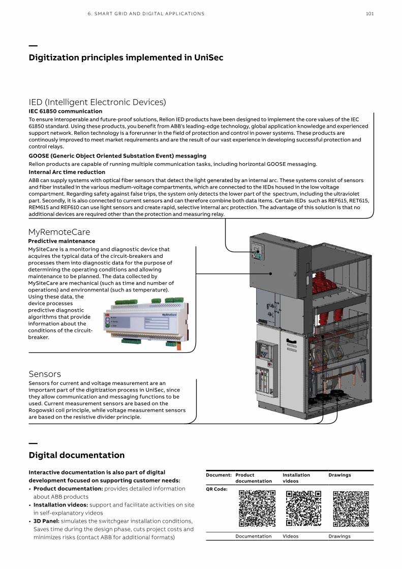
1016 . SM A RT G R ID A N D D I G ITA L A PPL I C ATI O NS
IED (Intelligent Electronic Devices)IEC 61850 communicationTo ensure interoperable and future-proof solutions, Relion IED products have been designed to implement the core values of the IEC 61850 standard. Using these products, you benefit from ABB’s leading-edge technology, global application knowledge and experienced support network. Relion technology is a forerunner in the field of protection and control in power systems. These products are continously improved to meet market requirements and are the result of our vast experience in developing successful protection and control relays.
GOOSE (Generic Object Oriented Substation Event) messagingRelion products are capable of running multiple communication tasks, including horizontal GOOSE messaging.Internal Arc time reductionABB can supply systems with optical fiber sensors that detect the light generated by an internal arc. These systems consist of sensors and fiber installed in the various medium-voltage compartments, which are connected to the IEDs housed in the low voltage compartment. Regarding safety against false trips, the system only detects the lower part of the spectrum, including the ultraviolet part. Secondly, it is also connected to current sensors and can therefore combine both data items. Certain IEDs such as REF615, RET615, REM615 and REF610 can use light sensors and create rapid, selective internal arc protection. The advantage of this solution is that no additional devices are required other than the protection and measuring relay.
—Digitization principles implemented in UniSec
MyRemoteCarePredictive maintenanceMySiteCare is a monitoring and diagnostic device that acquires the typical data of the circuit-breakers and processes them into diagnostic data for the purpose of determining the operating conditions and allowing maintenance to be planned. The data collected by MySiteCare are mechanical (such as time and number of operations) and environmental (such as temperature). Using these data, the device processes predictive diagnostic algorithms that provide information about the conditions of the circuit-breaker.
SensorsSensors for current and voltage measurement are an important part of the digitization process in UniSec, since they allow communication and messaging functions to be used. Current measurement sensors are based on the Rogowski coil principle, while voltage measurement sensors are based on the resistive divider principle.
—Digital documentation
Interactive documentation is also part of digital development focused on supporting customer needs:• Product documentation: provides detailed information
about ABB products• Installation videos: support and facilitate activities on site
in self-explanatory videos• 3D Panel: simulates the switchgear installation conditions,
Saves time during the design phase, cuts project costs and minimizes risks (contact ABB for additional formats)
Document: Product documentation
Installation videos
Drawings
QR Code:
Documentation Videos Drawings

102 U N I S EC A I R - I NSU L ATED M ED I U M VO LTAG E SECO N DA R Y D IS TR IB U TI O N S W ITCH G E A R
—ABB UniPack
—Maximum safety for switchgear installations according to IEC 62271-200
Standard IEC 62271-200 1-200 has introduced new issues regarding the definitions and classifications of MV switchgear.One of the most significant changes introduced by this Standard is that classification of switchgear into metal-enclosed, divided into compartments and with units has been eliminated. Switchgear classification has been revised by taking the user’s point of view into account, particularly for some aspects such as switchgear operation and maintenance, compliant with good substation management, from installation to disposal. In this context, “loss of service continuity” is considered a fundamental criterion for the user.
According to the updated standards, UniSec switchgear can be defined as follows:1. Compartment with access controlled by an interlock,
containing high-voltage parts, designed to be opened for normal operation and/or normal maintenance, where access is controlled by the integral configuration of switchgear and controlgear.
2. Compartment with procedure-based access, containing high-voltage parts, designed to be opened for normal operation and/or normal maintenance, where access is controlled by a suitable procedure associated with a lock.
3. Service continuity class The busbar and cable compartments are physically and
electrically partitioned. This category defines the possibility of opening a main circuit compartment while keeping other compartments and/or functional units energized.
4. Partition class Controlgear with continuous metal partitions, intended
to be earthed, between the compartment with free access and the main circuit live parts.
The metal partitions or metal parts of these must be connected to the earthing point of the functional unit.
— 7. IEC classification
—UniSec tested according to IEC 62271-202 standards
Maximum Safety for installations in Compact SubStationsIn addition to the classic type tests for medium voltage switchgear according to IEC 62271-200, the UniSec portfolio has also been tested for internal arc resistance for use in compact substations (type ABB UniPack) according to IEC 62271-202 ed. 2. The standard specifies the type test requirements for CSS products up to 52 kV. A “prefabricated substation”, also known as “factory-assembled substation”, is a housing that contains the transformer, low voltage and high voltage switchgear, connections and auxiliary installations. These structures are often situated in locations accessible to the general public and therefore need to provide protection for people, depending on the specified service conditions. IAC-AB internal arc classification up to 20 kA 1 sec of CSS equipped with UniSec switchgear ensures the level of safety required for both operators and the general public. The internal arc gas produced is exhausted downwards in the type-tested UniSec solution in compact substations. A dedicated gas duct, separated from the cable and busbar compartments, is installed on the back of each cubicle and exhausts the hot gas through the bottom of the switchgear into the volume below the floor of the CSS. A complete UniSec LSC2A (two MV compartments) range compliant with IEC 62271-202 standards and with ratings up 24 kV, 1250 A and 20 kA 1 sec is available for installation in compact substations.

1038 . INTER N A L A R C W ITHS TA N D C A PACIT Y
— 8. Internal arc withstand capacity
Internal arc faults are extremely rare occurrences, but can still occur due to human errors, faulty apparatus, insulation worn through age or other exceptional reasons. When UniSec switchgear was designed, special attention was paid to ensure personnel safety during internal arc situations. The switchgear features extremely high mechanical strength since it is able to withstand pressure and thermal effects caused by even the highest internal arc currents. Switchgear design also notably reduces the probability of an internal arc occurring in the first place. UniSec switchgear has been subjected to internal arc tests according to Standard IEC 62271-200, Annex A.Internal arc withstand tests are classified in a better way in this new standard as compared to the previous one.The test to check that the switchgear protection is able to effectively protect people against internal arcs, is performed by assessing the dynamic pressure and thermal effects.
UniSec complies with all the 5 acceptance criteria established by the standard. Internal arc withstand tests have been conducted in the busbar and cable compartments, as well as in the switch-disconnector enclosure.UniSec offers various Internal Arc Classified (IAC) solutions.All solutions are class A (authorized personnel only). UniSec switchgear can be accessed from different sides (F for front, L for lateral and R for rear) and complies with all 5 of the IEC standard criteria.UniSec switchgear ensures high-level of safety for personnel in the arc-proof version only.UniSec classifications: • IAC AF (*) up to 16 kA 1s• IAC AFL(**) up to 12.5 kA 1s• IAC AFLR up to 16 kA 1s• IAC AFLR up to 21 kA 1s• IAC AFLR up to 25 kA 1s.
(*) WARNING: No access to rear and lateral sides of switchgear while in service
(**) WARNING: No access to rear side of switchgear while in service
—Setup for an internal arc withstand test

104 U N I S EC A I R - I NSU L ATED M ED I U M VO LTAG E SECO N DA R Y D IS TR IB U TI O N S W ITCH G E A R
IAC AFL up to 12.5 kA 1s(**)
Internal arc protection is guaranteed on 3 sides of the switchgear, front and lateral.
Switchgear right up against the wallThis solution allows a compartment for exausting gas to be created using the rear of the switchgear and the wall. Closing plates installed on the top and sides of the switchgear convey the incandescent gas to the rear of the switchgear and into this specially created compartment (see figure).
IAC AF up to 16 kA 1s(*)
Basic solution This switchgear version can be positioned against a wall or in the middle of the room. Internal arc fault protection is guaranteed on the front side. The gas produced by the arc is exhausted into the switchgear room. The switchgear structure provides protection against internal arcs on the front of the panel and additional accessories such as filters and gas ducts are required.
(*) WARNING: No access to rear and lateral sides of switchgear while in service(**) WARNING: No access to rear side of switchgear while in service. Minimum switchgear lenght 1000 mm
— 8. Internal arc withstand capacity

1058 . INTER N A L A R C W ITHS TA N D C A PACIT Y
IAC AFLR up to 21 kA 1s and AFLR up to 25 kA 1s(1)
Solution with gas absorbers In this case, the switchgear can be positioned against a wall or in the middle of the room. Internal arc fault protection is guaranteed on 4 sides. The gas produced by the arc is exhausted into the switchgear room. An effificient absorption structure for the gases produced by the arc ensures that they are cooled to a considerable degree and that their pressure is reduced before they enter the switchgear room. This guarantees internal arc protection up to a fault current of 21 kA and 25 kA (*). These absorbers are installed behind each switchgear unit. Additional work is not required at site.
IAC AFLR up to 21 kA 1s Solution with gas exhausted downwards The switchgear can be positioned against the wall or in the middle of the room. Internal arc fault protection is guaranteed on 4 sides up to a fault current of 21 kA. The gas produced by the arc is exhausted into the cable duct. Gas exhausts are installed behind each switchgear unit. The cable duct must be built according to the dimensions specified on page 107.
IAC AFLR up to 21 kA 1s and AFLR up to 25 kA 1s(1) (2)
Solution with gas exaust ductThe switchgear can be positioned against a wall or in the middle of the room. Internal arc fault protection is guaranteed on 4 sides up to a fault current of 21 kA and 25 kA (1) (2). The switchgear is supplied with at least 1-meter of extension duct between it and the wall, so as to exhaust the gas out of the installation room. Contact ABB if longer ducts are required. The solution is available with extension duct on the right, left, rear and in a raised position.
(1) Only for LSC2B unit up to 17.5 kV(2) Only for LSC2A units up to 24kV, height 2000 mm and width 750 mm (except SBC-W, SBS-W, SDD, UMP and SBR units)

1070
1700
/200
0
1000 min (*)
400
min
2100
/240
0m
in150
30m
in
1000
min
2100
/240
0m
in
1700
/200
0
1070 1000 min (*)
400
min
30m
in
200 min
106 U N I S EC A I R - I NSU L ATED M ED I U M VO LTAG E SECO N DA R Y D IS TR IB U TI O N S W ITCH G E A R
— 9. Installation information
—Switchgear room
The installation room must be prepared to suit the switchgear dimensions and version. Compliance with the distances indicated ensures that the equipment will operate correctly and safely. Please consult ABB if the installation conditions differ from those indicated.
Against the wall IAC A-FL up to 12.5 kA Distances from the walls of the installation room with compartment for the exhaust gas duct at the rear. Solution IAC A-FL 12.5 kA, 1s against the wall.
(*) 1300 mm at least for panels with circuit-breaker or 1030 mm using the special truck (only with VD4/R-Sec) on request. Please, contact ABB
Room layout
IAC A-F up to 16 kA Minimum distances from the walls of the installation room. IAC A-F 16 kA 1s basic solution.

2100
/240
0m
in
1700
/200
0
1070 1000 min (*)
400
min
30m
in
200 min26
00m
in
2000
1070 1000 min (*)
600
min
35m
in
200 min (1)
1079. I NS TA L L ATI O N I N FO R M ATI O N
Room layout
Filters IAC A-FLR up to 16 kAMinimum distances from the walls of the installation room.Solution IAC A-FLR 16 kA 1s with filters installed on each unit.
(*) 1300 mm at least for panels with circuit-breaker or 1030 mm using the special truck (only with VD4/R-Sec) on request. Please, contact ABB(1) The minimum distance can be decreased to 150 min for special conditions defined with ABB
Filters IAC A-FLR up to 21 kAMinimum distances from the walls of the installation room. Solution IAC A-FLR 21 kA 1s with filters installed on each unit.

2100
/240
0m
in
1070 1000 min (*)
400
min
1700
/200
0
200 min (3)
30m
in
108 U N I S EC A I R - I NSU L ATED M ED I U M VO LTAG E SECO N DA R Y D IS TR IB U TI O N S W ITCH G E A R
Room layout
Gas exhaust ducts IAC A-FLR up to 21 and up to 25 kA(2) Minimum distances from the walls of the installation room. Solution IAC A-FLR 21/25(2) kA 1s with gas exhaust ducts.
(*) 1300 mm at least for panels with circuit-breaker or 1030 mm using the special truck (only with VD4/R-Sec) on request. Please, contact ABB(2) Only for LSC2A units up to 24kV, height 2000 mm and width 750 mm (except SBC-W, SBS-W, SDD, UMP and SBR units)(3) Please contact ABB to define minimum distance in the case of special conditions
— 9. Installation information

2100
/240
0m
in
1070 1000 min (*)
400
min
1700
/200
0
30m
in
200 min (1)
min
. 400
956
1050
155
1099. I NS TA L L ATI O N I N FO R M ATI O N
Room layout
Gas exhausted downwards IAC A-FLR up to 21 kAMinimum distances from the walls of the installation room. Solution IAC A-FLR 21 kA 1s with gas exhausted downwards.
(*) 1300 mm at least for panels with circuit-breaker or 1030 mm using the special truck (only with VD4/R-Sec) on request. Please, contact ABB.(1) The minimum distance can be up to 130 min in the case of special conditions defined with ABB
Minimum dimensions of cable duct.

2000
200 min (2) 1200/1300 1200 min
400
min
2400
min
30m
in
30m
in
1200 min1200/1300
2600
min
600
min
2000
200 min (1)
110 U N I S EC A I R - I NSU L ATED M ED I U M VO LTAG E SECO N DA R Y D IS TR IB U TI O N S W ITCH G E A R
Room layout for unit with withdrawable frontal breaker unit
Gas exhaust ducts IAC A-FLR up to 25 kAMinimum distances from walls of installation room. Solution IAC A-FLR 25 kA, 1s at 12-17.5 kV and 21 kA, 1s at 24 kV with gas exhaust ducts.
(1) Minimum distance can be up to 130 min for special conditions defined with ABB(2) Please contact ABB to define the minimum distance in the case of special conditions(3) 1200 mm for 12-17,5 kV or 1300 mm for 24 kV
Filters IAC A-FLR up to 25 kA Minimum distances from the walls of the installation room. Solution IAC A-FLR 25 kA, 1s at 12-17.5 kV and 16 kA, 1s at 24 kV with filters installed on each unit.
— 9. Installation information

12,5
33
103
7
43,5 43,5
158
,5 8
00
375
107
0
229
650
77,5 220
12,5
33
103
7
43,5 43,5 1
58,5
800
500
107
0
229
650
140 220
12,5
33
103
7
43,5 43,5
158
,5 8
00
500
107
0
229
650
97,5 230
12,5
33
103
7
43,5 43,5
158
,5 8
00
750
107
0
229
650
327 220
12,5
33
103
7
43,5 43,5
158
,5 8
00
750
107
0
229
650
265 220
1037
150
100
229
650
25
107
0
158
,5 8
00
12,5
1119. I NS TA L L ATI O N I N FO R M ATI O N
—Cable entry and fixing points of the units
The following drawings show the positions and sizes of the cable entry underneath the different units.These holes must be made before the switchgear is installed. The switchgear fixing points are also shown in the drawings. There is one fixing point in each corner of the unit (4 per unit). The dimensions and fixing points of units without cable entry depend on the width of the unit. 10 mm anchor bolts can be used for fixing.
Units 375 mm wide 500 mm width for DRC unitUnits 500 mm wide
Units 750 mm wide 750 mm width for SBR unit 190 mm width for RLC/RRC units(only SBR)

12,5
33
116
7
43,5 43,5
185
268
,5 8
00
600
120
0
700
82 436
154
30 10 4
3
30 10
101
92
25
12,5
33
126
7
43,5 43,5
92
81
185
268
,5 8
00
100
750
10
130
0
762
,5
550
12,5
33
116
7 / 1
267
43,5 43,5
268
,5 8
00
500
120
0 / 1
300
12,5
33
43,5 43,5
268
,5 8
00
500
116
7
120
0
220
650
140
333
112 U N I S EC A I R - I NSU L ATED M ED I U M VO LTAG E SECO N DA R Y D IS TR IB U TI O N S W ITCH G E A R
600 mm width for units with withdrawable circuit-breakers up to 17.5 kV WBS and BME without cable outlet
750 mm width for units with withdrawable circuit-breakers up to 24 kV WBS without cable outlet
—Cable entry and fixing points of the unitsThe following drawings show the positions and sizes of the cable entry underneath the different units.
DRS for WBC/WBS/BME DRC for WBC/WBS/BME

1200
110
2010
70
LSC2A LSC2B12-17.5 kV
1300
110
120
1070
LSC2A LSC2B24 kV
1070
(LS
C2A
)12
00 (L
SC
2B) 1
2-17
.5 k
V13
00 (L
SC
2B) 2
4 kV
LSC2A orLSC2B
LSC2A orLSC2B
1139. I NS TA L L ATI O N I N FO R M ATI O N
The switchgear can be fixed to the concrete floor by jack bolts, on a metal frame and on a raised floor.The switchgear must be fixed in place as shown in the drawing (see additional drawings).
Depths of LSC2A and/or LSC2B panelsDepending on the type of unit (LSC2A/LSC2B) and different rated voltage (12-17.5 kV/24 kV) the depth and misalignment between units connected in the same line-up can change, as outlined below:
—Foundations
The switchgear must be positioned on a foundation that complies with the 2x1000 levelling requirement in relation to the length of the switchgear. Since it is difficult to make a concrete foundation that fulfils this levelness requirement, suitable adjustments are made using a metal frame or by installing steel plates under the corners of the units. The load capacity of the floor and foundation must also be sufficient to bear the weight of the switchgear. The switchgear must be fixed on a level with the holes in the base of the unit (2 welding seams/unit) or by inserting two bolts/unit straight into the floor.
Switchgear LSC2A and LSC2B 12-17.5 kVSwitchgear with SAME depths
Switchgear LSC2A and LSC2B 24 kV
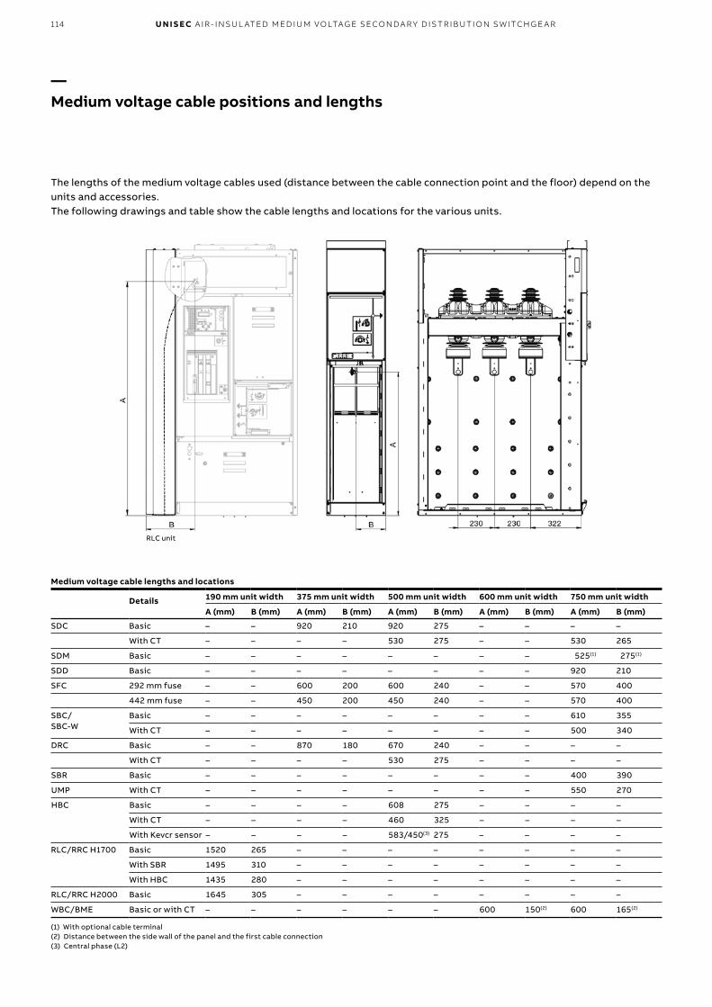
114 U N I S EC A I R - I NSU L ATED M ED I U M VO LTAG E SECO N DA R Y D IS TR IB U TI O N S W ITCH G E A R
Medium voltage cable lengths and locations
Details
190 mm unit width 375 mm unit width 500 mm unit width 600 mm unit width 750 mm unit width
A (mm) B (mm) A (mm) B (mm) A (mm) B (mm) A (mm) B (mm) A (mm) B (mm)
SDC Basic – – 920 210 920 275 – – – –
With CT – – – – 530 275 – – 530 265
SDM Basic – – – – – – – – 525(1) 275(1)
SDD Basic – – – – – – – – 920 210
SFC 292 mm fuse – – 600 200 600 240 – – 570 400
442 mm fuse – – 450 200 450 240 – – 570 400
SBC/ SBC-W
Basic – – – – – – – – 610 355
With CT – – – – – – – – 500 340
DRC Basic – – 870 180 670 240 – – – –
With CT – – – – 530 275 – – – –
SBR Basic – – – – – – – – 400 390
UMP With CT – – – – – – – – 550 270
HBC Basic – – – – 608 275 – – – –
With CT – – – – 460 325 – – – –
With Kevcr sensor – – – – 583/450(3) 275 – – – –
RLC/RRC H1700 Basic 1520 265 – – – – – – – –
With SBR 1495 310 – – – – – – – –
With HBC 1435 280 – – – – – – – –
RLC/RRC H2000 Basic 1645 305 – – – – – – – –
WBC/BME Basic or with CT – – – – – – 600 150(2) 600 165(2)
(1) With optional cable terminal(2) Distance between the side wall of the panel and the first cable connection (3) Central phase (L2)
RLC unit
—Medium voltage cable positions and lengths
The lengths of the medium voltage cables used (distance between the cable connection point and the floor) depend on the units and accessories. The following drawings and table show the cable lengths and locations for the various units.

1159. I NS TA L L ATI O N I N FO R M ATI O N
—Cable terminations
• Cold application• Can be used in restricted spaces• No special tools needed• Prefabricated for easy and safe installation• Minimal cable stripping• Active pressure• Few components• Long life
General aspectsThe power cables used for the switchgear need suitable terminations. The power cable has an aluminium or copper conductor, insulation made of polymeric material, an extruded insulating sheath, metal braiding, armor (optional) and an outer polymeric sheath.To ensure a safe and reliable current carrying capacity, a good mechanical connection must be made between the cable conductor and busbar. To do this, ABB offers mechanical cable terminals specially designed to be screwed onto the cable conductor. It is also essential to guide the electric field produced by the cable correctly. ABB supplies terminations made of cold-applied rubber, which ensure an active pressure around the cable. Furthermore, if the cable is designed with a metal sheath without copper, special earthing kits must be used to deal properly with fault currents. Cable armor must guarantee the same earth potential as the sheath, so it might be necessary to use additional connection material, which can also be supplied by ABB.
—SOT cable terminations
Detailed information is given in the separate technical documentation regarding ABB cable accessories.
Standards The equipment meets the requirements of CENELEC HD 629.1 S1.
Applications and characteristics The right type of cable accessories must be used, depending on the cable structure.When a single-core cable screened only by a copper sheath is used, it is sufficient to use a cable terminal and a termination that suits the actual cable dimensions. Three-pole cables must be split under the floor so that they can be mounted on each phase, as shown below (please contact ABB if a different solution is required).Correct preparation of the cable is just as important as using the right type of material. ABB offers a wide range of tools for preparing cables. Recommended products SOT pre-molded cable terminations can be used on any polymeric cable, regardless of the structure or conductor dimensions. Just a few termination variants fit a wide range of cable sizes. For 12/17.5/24 kV values, only four types of terminations are required to cover cable dimensions up to 800 mm2.
—Three-pole cable connections

116 U N I S EC A I R - I NSU L ATED M ED I U M VO LTAG E SECO N DA R Y D IS TR IB U TI O N S W ITCH G E A R
Kits complete with screw cable terminal Cable termination, including bimetal screw cable terminal for Al and Cu conductors.The cable terminal is equipped with shear bolts.
Designation Weight Designation Weight XLPE-Ø Conduction (12 kV) Conduction (24 kV)
Indoor termination 3-core / 3 x single-core kg/kit
Indoor termination single-phase kit kg/kit mm mm2 mm2
SOT 241 A-3 0.60 SOT 241 A 0.20 11-15 10-35 10
SOT 241-3 0.60 SOT 241 0.19 15-28 50-185 25-120
SOT 242-3 0.70 SOT 242 0.23 24-39 240-500 150-300
SOT 242 B-3 0.90 SOT 242 B 0.30 38-54 630 500-630
Designation Weight Designation Weight Conduction (12 kV) Conduction (24 kV)
Indoor termination 1-core / 1 x single-core kg/kit
3-core / 3 x single-corefor indoors kg/kit mm2 mm2
SOT 241A S1 0.35 SOT 241A-3 S1 1.05 16-35 16
SOT 241 S1 0.34 SOT 241-3 S1 1.02 50-70 25-70
SOT 241 S2 0.44 SOT 241-3 S2 1.32 95-150 95-120
SOT 241 S3 0.59 SOT 241-3 S3 1.50 185 –
SOT 242 S2 0.48 SOT 242-3 S2 1.44 – 150
SOT 242 S3 0.63 SOT 242-3 S3 1.89 240 185-240
SOT 242 S4 0.98 SOT 242-3 S4 2.94 300-400 300-400
SOT 242B S5 1.78 SOT 242B-3 S5 5.25 500-630 500-630
Designation
I L
mm
SOT 241/242/242 B 235 min 300
Cable connections based on SOT standard
Panels WidthMax number of cables
Max cross section of cables (mm2)
SDC 375 1 (*) 400
500 2 300
1 630
750 2 300
1 400
SDD 750 1 400
SFC 375 1 95
500 1 95
750 1 95
SBC/SBC-W 750 2 300
1 630
SBR 750 1 300
HBC 500 2 300
1 630
DRC 375 1 (1) 400
500 2 300
1 630
WBC/BME 600 (12-17.5 kV) 4 300
2 400
1 (2) 630
750 (24 kV) 4 240
2 400
UMP 750 2 300
1 400
RLC/RRC 190 1 400
(1) 2 (two) 300 mm2 cables @ 12 kV(2) Only for 630 A version
—Cable terminations

1070 110(*)
1700/2000
(**)
110(*)1070140
1700
/200
0(**)
1070 110(*)
1700/2000
(**)
110(*)1070140
2000
(**)
11710. D I M ENSI O N A L D R AW I N G S
— 10. Dimensional drawings
Side view IAC A-FL 12.5 kA 1s (solution right against the wall)
The drawings merely give the indicative dimensions of typical units but do not refer to specific configurations.
(*) For panels with removable and withdrawable circuit-breakers(**) Not available for SBR switchgear
Side view IAC A-FLR 16 kA, with filters
(*) For panels with removable and withdrawable circuit-breakers(**) Not available for SBR switchgear
Side view IAC A-F 16 kA 1s, basic solution
(*) For panels with removable and withdrawable circuit-breakers(**) Not available for SBR switchgear
(*) For panels with removable and withdrawable circuit-breakers(**) Not available for SBR switchgear
Side view IAC A-FLR 21 kA, with filters

110(*)1070140
1700
/200
0(**)
1070 110(*)140
20
20/
2320
17
00/
2000
(**)
120 1200/1300
20
00
100 1200/1300
20
002
34
0
118 U N I S EC A I R - I NSU L ATED M ED I U M VO LTAG E SECO N DA R Y D IS TR IB U TI O N S W ITCH G E A R
Side view IAC A-FLR 21 and 25(1) kA, with duct
(*) For panels with removable and withdrawable circuit-breakers(**) Not available for SBR switchgear(1) Only for LSC2A units up to 24kV, height 2000 mm and width 750 mm
(except SBC-W and SBS-W unit)
Side view IAC A-FLR 21 kA, with downward gas duct
(*) For panels with removable and withdrawable circuit-breakers(**) Not available for SBR switchgear
WBCWBSDRS forWBSBME (*)
WBCWBSDRS for WBSBME (*)
Side view of switchgear with withdrawable circuit-breakers, IAC A-FLR 25 kA, 1 sec up to 17.5 kV and IAC A-FLR 16 kA, 1s at 24 kV with filters
Side view of switchgear with withdrawable circuit-breakers, IAC A-FLR 25 kA, 1 sec up to 17.5 kV and IAC A-FLR 21 kA, 1s at 24 kV with duct
(*) Only 12-17.5 kV(1) 12-17.5 kV / 24 kV(2) 1200 mm for 12-17,5 kV or 1300 mm for 24 kV
— 10. Dimensional drawings
(2)
(2)

125
280
17
00
1070
A
235
58
0
20
00
1070 110
B
20
00
500
1070 110
58
0
C
2300
750
350
1101200/1300
B
235
2000
450
1200/1300
A
11910. D I M ENSI O N A L D R AW I N G S
Low voltage compartments available
A = Standard (*) B = Wide C = Big (*)
A = Standard B = Wide
(*) Not available for panels H = 2000 mm
(1) 1200 mm for 12-17,5 kV or 1300 mm for 24 kV
Solutions for LSC2A classified switchgear
Solutions for switchgear with frontal withdrawable circuit-breakers and contactors
(1)
(1)

120 U N I S EC A I R - I NSU L ATED M ED I U M VO LTAG E SECO N DA R Y D IS TR IB U TI O N S W ITCH G E A R
UniSec Pro
UniSec Pro has been developed as a tender and switchgear design tool. The three main features of the new release of the UniSec Pro are:• Simple preconfigured solutions (applications):
guide the user to Standard products, thereby drastically reducing quotation time and the possibility of making mistakes while introducing standard configurations for the market, channel or customer/consultant;
• Simple interface: since there are only a few selections to be made, the user can focus on the most important items and options; user-friendly operation for even inexpert operators;
• Complete documentation: technical /commercial output, technical specifications for tenders and special offers, editable project drawings (.pdf and .dwg).
Please contact your local ABB representative.
• Projects are stored online, allowing follow-up and enabling statistics to be created.
• Online site for projects, feedback, news, installation files, etc.
— 11. Configuration software

1211 2 . I NSI G HTS
Document QR Code
VD4/R MV vacuum circuit-breakers for secondary distribution
HD4/R - HD4/RE MV gas circuit-breakers for secondary distribution
VD4 Medium voltage vacuum circuit-breakers 12...36 kV - 630...4000 A - 16...50 kA
HD4 Medium Voltage circuit breaker 40.5 kV, 3600 A, 50 kA
VSC Medium Voltagecontactors 12 kV, 400 A
GSec - Gas-insulated switching and isolating apparatus
HySec - Compact multifunction apparatus 12…24 kV - 630 A - 12.5…21 kA
Document QR Code
Instrument transformers & Sensors
Fuses
Relays - Distribution Automation & Protection
Global Service
More documentation about UniSec
Do you need to know more about technical issues?Please consult our Technical Application Papers containing details about our low and medium voltage solutions
— 12. Insights
For more information
Do you need to know more about the use of UniSec switchgear and related products? Please consult the following documents using the link below:

122 U N I S EC A I R - I NSU L ATED M ED I U M VO LTAG E SECO N DA R Y D IS TR IB U TI O N S W ITCH G E A R
— Notes


—For more information please contact:
—More product information: abb.com/mediumvoltageYour contact center: abb.com/contactcenters More service information:abb.com/service
1VF
M20
00
03
– R
ev. N
, en
– P
rod
uct
Cat
alo
gu
e –
2019
.01
(mt)
© Copyright 2019 ABB. All rights reserved. The data and illustrations are not binding. We reserve the right to make changes in the course of technical development of the product.