Product specification - Controller software IRC5 - ABB Group
Upload
khangminh22Category
view
4download
0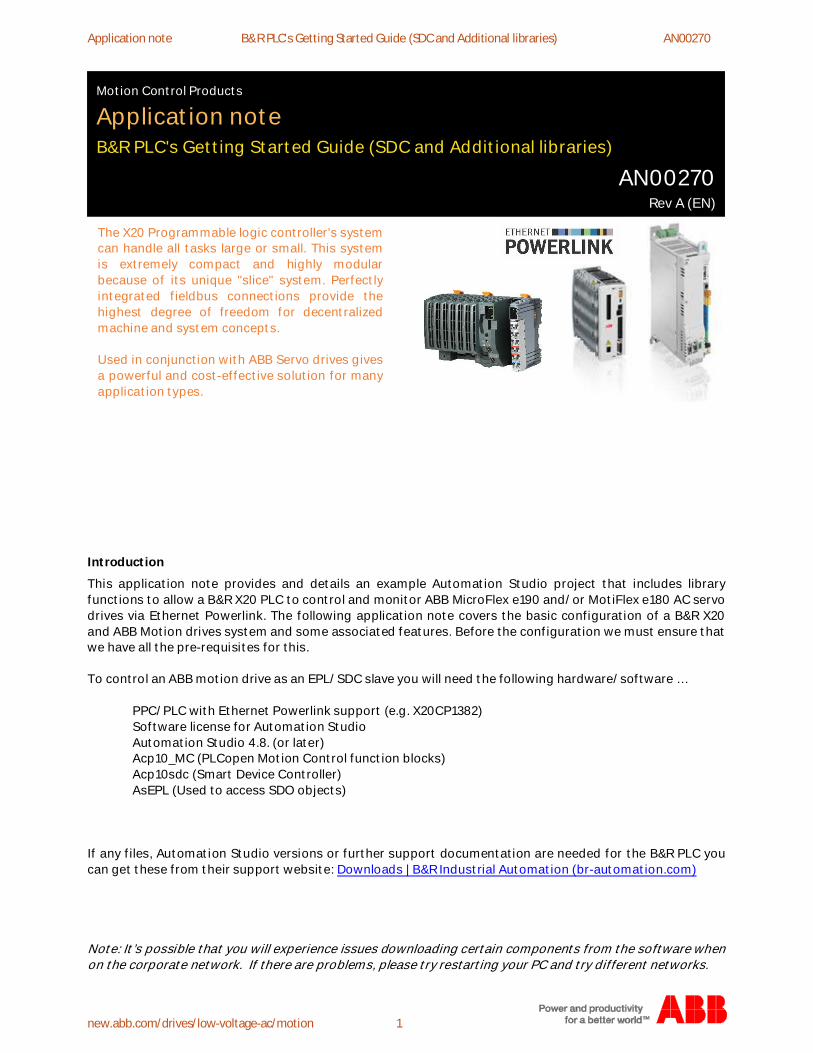
Application note B&R PLC's Getting Started Guide (SDC and Additional libraries) AN00270
new.abb.com/drives/low-voltage-ac/motion 1
Introduction
This application note provides and details an example Automation Studio project that includes libraryfunctions to allow a B&R X20 PLC to control and monitor ABB MicroFlex e190 and/or MotiFlex e180 AC servodrives via Ethernet Powerlink. The following application note covers the basic configuration of a B&R X20and ABB Motion drives system and some associated features. Before the configuration we must ensure thatwe have all the pre-requisites for this.
To control an ABB motion drive as an EPL/SDC slave you will need the following hardware/software …
PPC/PLC with Ethernet Powerlink support (e.g. X20CP1382)Software license for Automation StudioAutomation Studio 4.8. (or later)Acp10_MC (PLCopen Motion Control function blocks)Acp10sdc (Smart Device Controller)AsEPL (Used to access SDO objects)
If any files, Automation Studio versions or further support documentation are needed for the B&R PLC youcan get these from their support website: Downloads | B&R Industrial Automation (br-automation.com)
Note: It’s possible that you will experience issues downloading certain components from the software whenon the corporate network. If there are problems, please try restarting your PC and try different networks.
Motion Control Products
Application noteB&R PLC's Getting Started Guide (SDC and Additional libraries)
AN00270Rev A (EN)
The X20 Programmable logic controller’s systemcan handle all tasks large or small. This systemis extremely compact and highly modularbecause of its unique "slice" system. Perfectlyintegrated fieldbus connections provide thehighest degree of freedom for decentralizedmachine and system concepts.
Used in conjunction with ABB Servo drives givesa powerful and cost-effective solution for manyapplication types.
Application note Generic drive interface AN00270
https://new.abb.com/drives/low-voltage-ac/motion 2
Getting Started
Activating your licenceBefore you can use your Automation Studio you must activate your licence (which can be purchased fromyour local B&R salespoint). To do so follow the below steps:
Open Automation Studio and navigate to Help > About
Select Relicense
Select Type: Automation StudioEnter the code you have been given and then Press Activate
Activation should take a few minutes to complete.After its finish now be complete. Restart AS.
Application note B&R PLC's Getting Started Guide (SDC and Additional libraries) AN00270
new.abb.com/drives/low-voltage-ac/motion 3
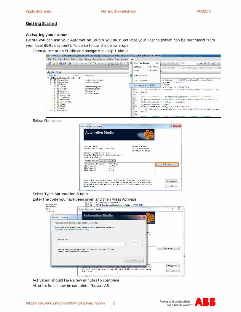
NavigationTo aide easy navigation and descriptions used within this app note the key view tabs are pointed out below.When you open AS you will see a standard UI layout with several key areas as pointed out below
Within each area there are tabs to change view or get different detail. The tabs in the Hardware area arepointed out below. Logical View: Manage all the PLC program, library
Configuration View: Interface between PLC program and physical devices
Physical View: List all the physical devices
Hardware
Toolbar
Errors
Project navigation
Properties
Toolbox
Online status
Application note Generic drive interface AN00270
https://new.abb.com/drives/low-voltage-ac/motion 4
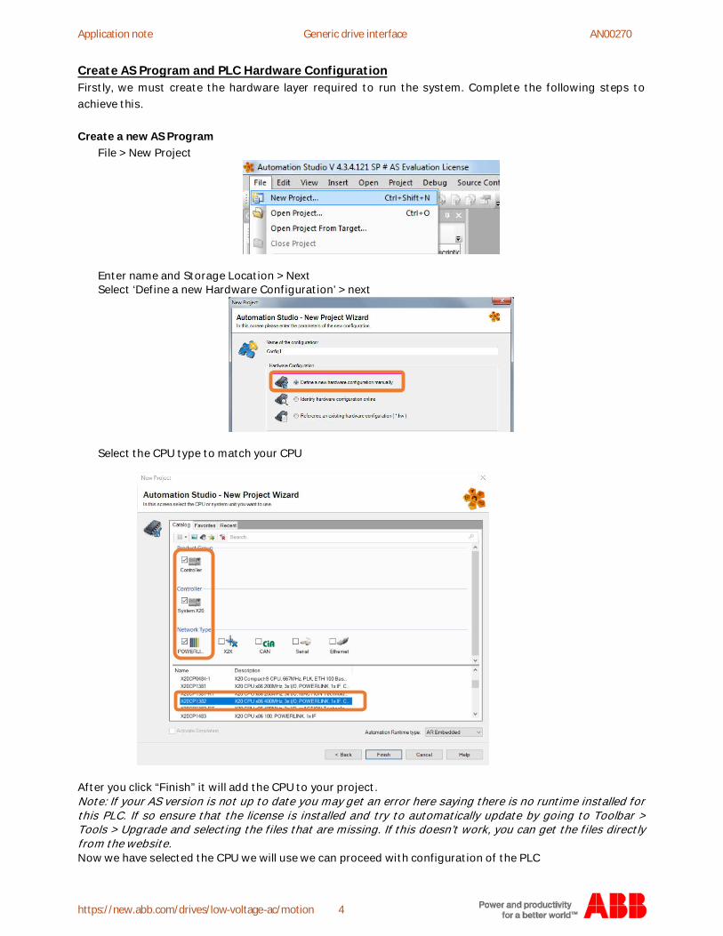
Create AS Program and PLC Hardware ConfigurationFirstly, we must create the hardware layer required to run the system. Complete the following steps toachieve this.
Create a new AS ProgramFile > New Project
Enter name and Storage Location > NextSelect ‘Define a new Hardware Configuration’ > next
Select the CPU type to match your CPU
After you click “Finish” it will add the CPU to your project.Note: If your AS version is not up to date you may get an error here saying there is no runtime installed forthis PLC. If so ensure that the license is installed and try to automatically update by going to Toolbar >Tools > Upgrade and selecting the files that are missing. If this doesn’t work, you can get the files directlyfrom the website.Now we have selected the CPU we will use we can proceed with configuration of the PLC
Application note B&R PLC's Getting Started Guide (SDC and Additional libraries) AN00270
new.abb.com/drives/low-voltage-ac/motion 5
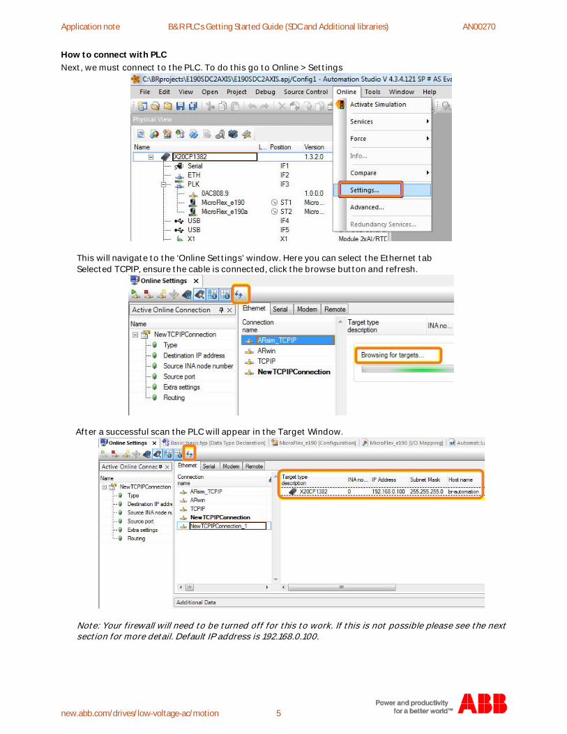
How to connect with PLCNext, we must connect to the PLC. To do this go to Online > Settings
This will navigate to the ‘Online Settings’ window. Here you can select the Ethernet tabSelected TCPIP, ensure the cable is connected, click the browse button and refresh.
After a successful scan the PLC will appear in the Target Window.
Note: Your firewall will need to be turned off for this to work. If this is not possible please see the nextsection for more detail. Default IP address is 192.168.0.100.
Application note Generic drive interface AN00270
https://new.abb.com/drives/low-voltage-ac/motion 6
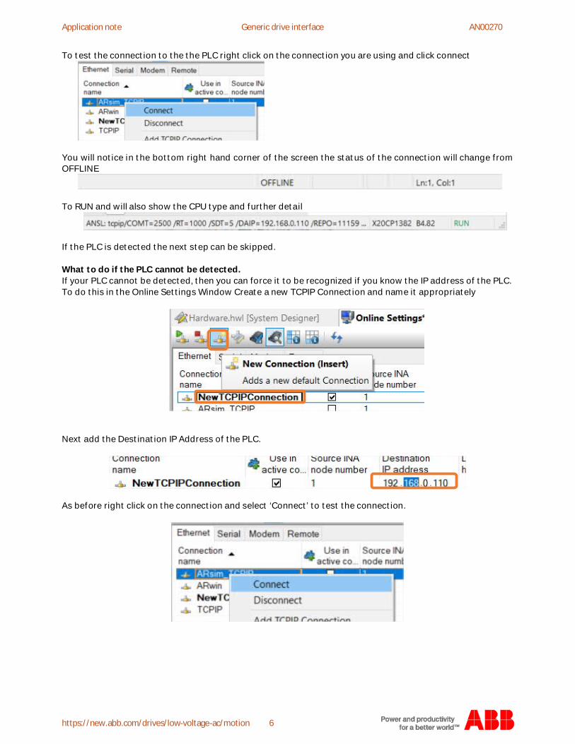
To test the connection to the the PLC right click on the connection you are using and click connect
You will notice in the bottom right hand corner of the screen the status of the connection will change fromOFFLINE
To RUN and will also show the CPU type and further detail
If the PLC is detected the next step can be skipped.
What to do if the PLC cannot be detected.If your PLC cannot be detected, then you can force it to be recognized if you know the IP address of the PLC.To do this in the Online Settings Window Create a new TCPIP Connection and name it appropriately
Next add the Destination IP Address of the PLC.
As before right click on the connection and select ‘Connect’ to test the connection.
Application note B&R PLC's Getting Started Guide (SDC and Additional libraries) AN00270
new.abb.com/drives/low-voltage-ac/motion 7
What to do if you cannot force a connection?The next steps vary dependent on the CPU type you use. You can select the relevant chapter based to thepart code.
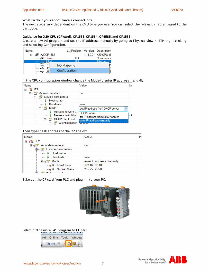
Guidance for X20 CPU (CF card), CP1583, CP1584, CP1585, and CP1586Create a new AS program and set the IP address manually by going to Physical view > ‘ETH’ right clickingand selecting Configuration.
In the CPU configuration window change the Mode to enter IP address manually
Then type the IP address of the CPU below
Take out the CF card from PLC and plug it into your PC.
Select offline install AS program to CF card.

Application note Generic drive interface AN00270
https://new.abb.com/drives/low-voltage-ac/motion 8
Browse to the destination where the card is on your PC
Create the file system and Reinstall Card in PLC then Re-boot itThen as mentioned earlier in ‘What to do if the PLC cannot be detected’ you can force an IP address into thedestination IP and connect to the PLC with the IP you set.
Guidance for X20 Compact CPU, integrated hard disk, CP1381, CP1382You can try to use the Serial port to scan the PLC hardware, and then change the IP address using thisconnection and download it to PLC.If this fails, it’s possible some IT issues could be causing the problem so to try a different PC to eliminatethis as a possible issue
Application note B&R PLC's Getting Started Guide (SDC and Additional libraries) AN00270
new.abb.com/drives/low-voltage-ac/motion 9
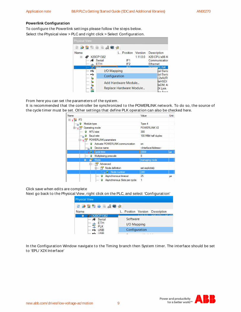
Powerlink ConfigurationTo configure the Powerlink settings please follow the steps below.Select the Physical view > PLC and right click > Select Configuration.
From here you can set the parameters of the system.It is recommended that the controller be synchronized to the POWERLINK network. To do so, the source ofthe cycle timer must be set. Other settings that define PLK operation can also be checked here.
Click save when edits are completeNext go back to the Physical View, right click on the PLC, and select ‘Configuration’
In the Configuration Window navigate to the Timing branch then System timer. The interface should be setto ‘EPL/X2X Interface’
Application note Generic drive interface AN00270
https://new.abb.com/drives/low-voltage-ac/motion 10
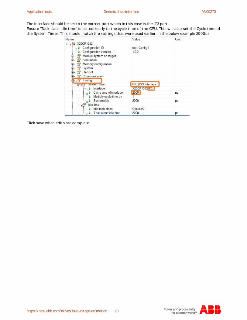
The Interface should be set to the correct port which in this case is the IF3 port.Ensure ‘Task class idle time’ is set correctly to the cycle time of the CPU. This will also set the Cycle time ofthe System Timer. This should match the settings that were used earlier. In the below example 2000us
Click save when edits are complete
Application note B&R PLC's Getting Started Guide (SDC and Additional libraries) AN00270
new.abb.com/drives/low-voltage-ac/motion 11
How to import the ABB servo drive files into ASNow the PLC hardware, Ethernet and Powerlink communications are configured it’s possible to proceedinto the configuration of the drives. Before we can add these to our project, we must ensure the latest filesare installed into AS. The below steps How to import ABB servo drive into AS are below
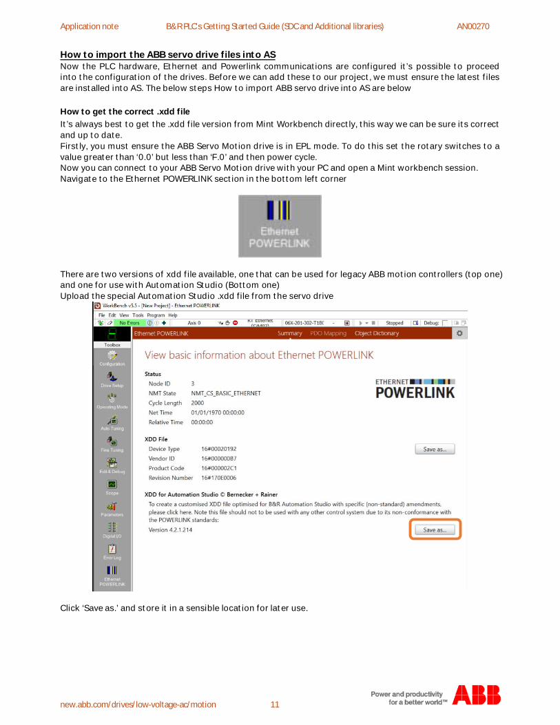
How to get the correct .xdd fileIt’s always best to get the .xdd file version from Mint Workbench directly, this way we can be sure its correctand up to date.Firstly, you must ensure the ABB Servo Motion drive is in EPL mode. To do this set the rotary switches to avalue greater than ‘0.0’ but less than ‘F.0’ and then power cycle.Now you can connect to your ABB Servo Motion drive with your PC and open a Mint workbench session.Navigate to the Ethernet POWERLINK section in the bottom left corner
There are two versions of xdd file available, one that can be used for legacy ABB motion controllers (top one)and one for use with Automation Studio (Bottom one)Upload the special Automation Studio .xdd file from the servo drive
Click ‘Save as.’ and store it in a sensible location for later use.
Application note Generic drive interface AN00270
https://new.abb.com/drives/low-voltage-ac/motion 12
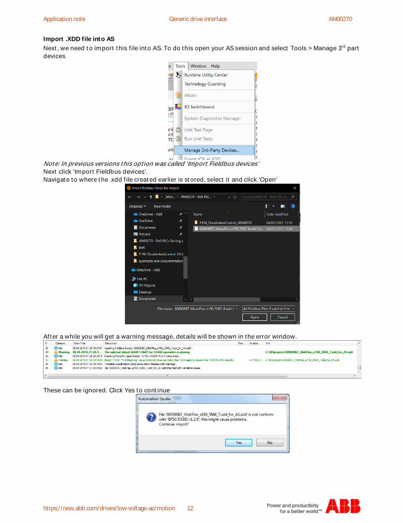
Import .XDD file into ASNext, we need to import this file into AS. To do this open your AS session and select Tools > Manage 3rd partdevices
Note: In previous versions this option was called ‘Import Fieldbus devices’Next click ‘Import Fieldbus devices’.Navigate to where the .xdd file created earlier is stored, select it and click ‘Open’
After a while you will get a warning message, details will be shown in the error window.
These can be ignored. Click Yes to continue
Application note B&R PLC's Getting Started Guide (SDC and Additional libraries) AN00270
new.abb.com/drives/low-voltage-ac/motion 13
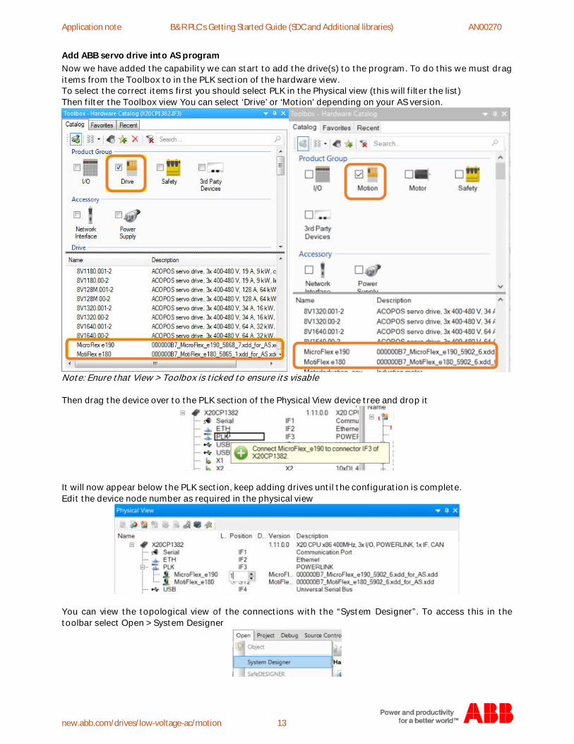
Add ABB servo drive into AS programNow we have added the capability we can start to add the drive(s) to the program. To do this we must dragitems from the Toolbox to in the PLK section of the hardware view.To select the correct items first you should select PLK in the Physical view (this will filter the list)Then filter the Toolbox view You can select ‘Drive’ or ‘Motion’ depending on your AS version.
Note: Enure that View > Toolbox is ticked to ensure its visable
Then drag the device over to the PLK section of the Physical View device tree and drop it
It will now appear below the PLK section, keep adding drives until the configuration is complete.Edit the device node number as required in the physical view
You can view the topological view of the connections with the “System Designer”. To access this in thetoolbar select Open > System Designer
Application note Generic drive interface AN00270
https://new.abb.com/drives/low-voltage-ac/motion 14
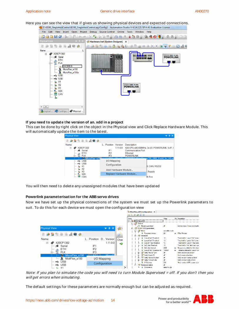
Here you can see the view that if gives us showing physical devices and expected connections.
If you need to update the version of an. xdd in a projectThis can be done by right click on the object in the Physical view and Click Replace Hardware Module. Thiswill automatically update the item to the latest.
You will then need to delete any unassigned modules that have been updated
Powerlink parameterisation for the ABB servo drivesNow we have set up the physical connections of the system we must set up the Powerlink parameters tosuit. To do this for each device we must open the configuration view
>Note: If you plan to simulate the code you will need to turn Module Supervised = off. If you don’t then youwill get errors when simulating.
The default settings for these parameters are normally enough but can be adjusted as required.
Application note B&R PLC's Getting Started Guide (SDC and Additional libraries) AN00270
new.abb.com/drives/low-voltage-ac/motion 15
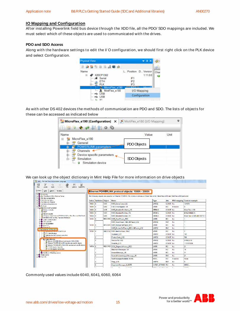
IO Mapping and ConfigurationAfter installing Powerlink field bus device through the XDD file, all the PDO/SDO mappings are included. Wemust select which of these objects are used to communicated with the drives.
PDO and SDO AccessAlong with the hardware settings to edit the I/O configuration, we should first right click on the PLK deviceand select Configuration.
As with other DS 402 devices the methods of communication are PDO and SDO. The lists of objects forthese can be accessed as indicated below
We can look up the object dictionary in Mint Help File for more information on drive objects
Commonly used values include 6040, 6041, 6060, 6064
SDO Objects
PDO Objects

Application note Generic drive interface AN00270
https://new.abb.com/drives/low-voltage-ac/motion 16
PDO MappingAll standard and drive specific PDO objects which need to be accessed during cyclic transmission areaccessed via the ‘Channels’ section of the tree. As default no PDO’s are mapped (‘cyclic transmission’ =None), so you must find and map them as needed and also define the data from direction by setting theproperty for ‘cyclic transmission’ designation to be READ or WRITE.
Once relevant mappings are complete (Objects 6040, 6041, 6060, 6064 and 607A) Save the changes.After setting up in the “Channels”, we must then go to PDO mapping list by right clicking on the Drive inPhysical view and selecting in the “I/O mapping” page as below:
As you can see the added IO is there in addition to ‘ModuleOK’ which is mapped by default.
We must then map across the DS 402 objects to the Sdc control structure process variable, to do this clickon the items in the Process Variable column one by one and click the ‘…’ next pick the correct item from thegSdcAxisCtrl structure as shown below. Each item has a number after it eg [0] this refers to the item in thesdc, 0 is e190 (1st item), 1 is e180 (2nd item)
Output
Exclamationpoint means
that itsmapped
Input
Application note B&R PLC's Getting Started Guide (SDC and Additional libraries) AN00270
new.abb.com/drives/low-voltage-ac/motion 17
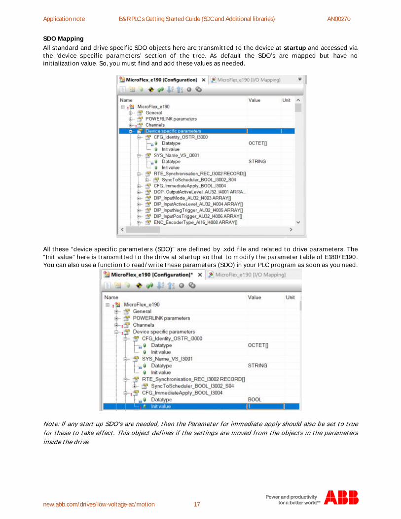
SDO MappingAll standard and drive specific SDO objects here are transmitted to the device at startup and accessed viathe ‘device specific parameters’ section of the tree. As default the SDO’s are mapped but have noinitialization value. So, you must find and add these values as needed.
All these “device specific parameters (SDO)” are defined by .xdd file and related to drive parameters. The“Init value” here is transmitted to the drive at startup so that to modify the parameter table of E180/E190.You can also use a function to read/write these parameters (SDO) in your PLC program as soon as you need.
Note: If any start up SDO’s are needed, then the Parameter for immediate apply should also be set to truefor these to take effect. This object defines if the settings are moved from the objects in the parametersinside the drive.
Application note Generic drive interface AN00270
https://new.abb.com/drives/low-voltage-ac/motion 18
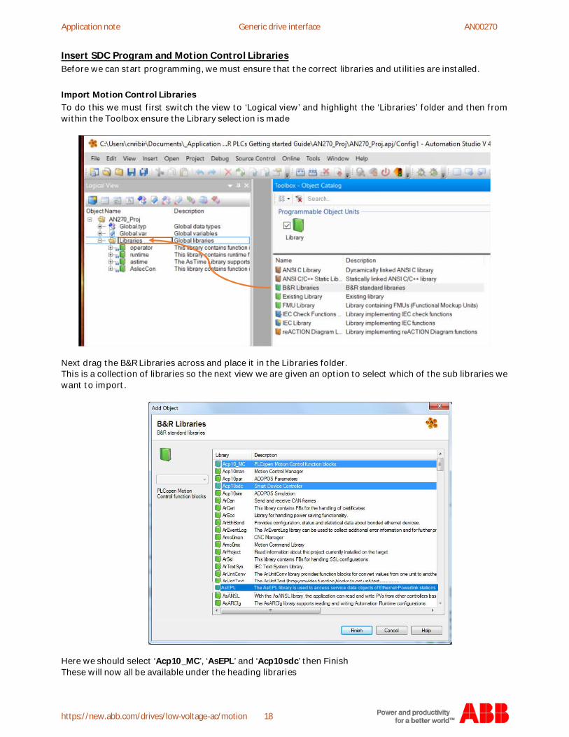
Insert SDC Program and Motion Control LibrariesBefore we can start programming, we must ensure that the correct libraries and utilities are installed.
Import Motion Control LibrariesTo do this we must first switch the view to ‘Logical view’ and highlight the ‘Libraries’ folder and then fromwithin the Toolbox ensure the Library selection is made
Next drag the B&R Libraries across and place it in the Libraries folder.This is a collection of libraries so the next view we are given an option to select which of the sub libraries wewant to import.
Here we should select ‘Acp10_MC’, ‘AsEPL’ and ‘Acp10sdc’ then FinishThese will now all be available under the heading libraries
Application note B&R PLC's Getting Started Guide (SDC and Additional libraries) AN00270
new.abb.com/drives/low-voltage-ac/motion 19
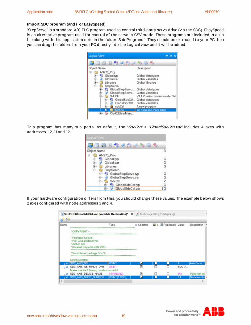
Import SDC program (and / or EasySpeed)‘StepServo’ is a standard X20 PLC program used to control third-party servo drive (via the SDC). EasySpeedis an alternative program used for control of the servo in CSV mode. These programs are included in a zipfile along with this application note in the folder ‘Sub Programs’. They should be extracted to your PC thenyou can drag the folders from your PC directly into the Logical view and it will be added.
This program has many sub parts. As default, the ‘SdcCtrl’ > ‘GlobalSdcCrtl.var’ includes 4 axes withaddresses 1,2, 11 and 12.
If your hardware configuration differs from this, you should change these values. The example below shows2 axes configured with node addresses 3 and 4.
Application note Generic drive interface AN00270
https://new.abb.com/drives/low-voltage-ac/motion 20
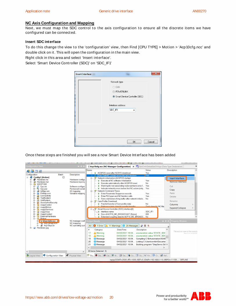
NC Axis Configuration and MappingNext, we must map the SDC control to the axis configuration to ensure all the discrete items we haveconfigured can be connected.
Insert SDC interfaceTo do this change the view to the ‘configuration’ view, then Find [CPU TYPE] > Motion > ‘Acp10cfg.ncc’ anddouble click on it. This will open the configuration in the main view.Right click in this area and select ‘Insert interface’.Select ‘Smart Device Controller (SDC)’ on ‘SDC_IF1’
Once these steps are finished you will see a now Smart Device Interface has been added
Application note B&R PLC's Getting Started Guide (SDC and Additional libraries) AN00270
new.abb.com/drives/low-voltage-ac/motion 21
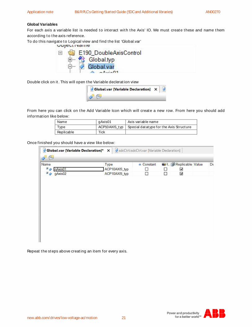
Global VariablesFor each axis a variable list is needed to interact with the Axis’ IO. We must create these and name themaccording to the axis reference.To do this navigate to Logical view and find the list ‘Global.var’
Double click on it. This will open the Variable decleration view
From here you can click on the Add Variable Icon which will create a new row. From here you should addinformation like below:
Name gAxis01 Axis variable nameType ACP10AXIS_typ Special datatype for the Axis StructureReplicable Tick
Once finished you should have a view like below:
Repeat the steps above creating an item for every axis.

Application note Generic drive interface AN00270
https://new.abb.com/drives/low-voltage-ac/motion 22
NC mappingNext, we must add an NC mapping object to connect the Axis Control Program, the SDC Program and theActual hardware Axis together. You cannot edit the preexisting NC mapping object “Acp10map.ncm” so youmust add a new one from the toolbox into the same area to create a new editable version “Acp10map1.ncm”.To do this first select the Configuration view and look for the object called ‘ACP10 Mapping Table’ then dragit into the Motion folder.
Now we can double click on the new mapping table to open the Editor and start to add NC Objects to it. Todo so right click in the mapping editor and selected ‘Add NC Object’
Add mappings for all the axes in your project using the table below for Guidance…
NC Object Name gAxis01 Axis name defined in Axis_Control_ProgramPLC Address SDC_IF1.ST1 Axis name defined in SDC interfaceNc Object Type ncAXIS Defines data format structureNC INIT Parameter intAxis Initial parameter table of NC Axis. The NC Initialization Parameter
Table contains the basic parameters for the NC Managerinitialization axis, which is made when the controller is started.
ACOPOS Parameter ParaTable Parameters (Special parameters, non-basic parameters) thatshould be transferred when the drive is initialized can be enteredin an ACOPOS parameter table.
Additional Data Connect SDC axis with actual axis
When your finished you should end up with all the axes added with the correct references
Application note B&R PLC's Getting Started Guide (SDC and Additional libraries) AN00270
new.abb.com/drives/low-voltage-ac/motion 23
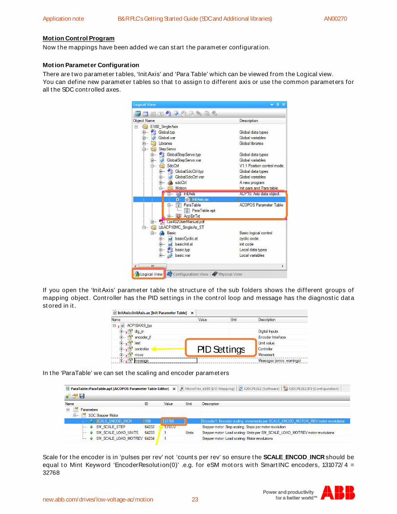
Motion Control ProgramNow the mappings have been added we can start the parameter configuration.
Motion Parameter ConfigurationThere are two parameter tables, ‘InitAxis’ and ‘Para Table’ which can be viewed from the Logical view.You can define new parameter tables so that to assign to different axis or use the common parameters forall the SDC controlled axes.
If you open the ‘InitAxis’ parameter table the structure of the sub folders shows the different groups ofmapping object. Controller has the PID settings in the control loop and message has the diagnostic datastored in it.
In the ‘ParaTable’ we can set the scaling and encoder parameters
Scale for the encoder is in ‘pulses per rev’ not ‘counts per rev’ so ensure the SCALE_ENCOD_INCR should beequal to Mint Keyword ‘EncoderResolution(0)’ .e.g. for eSM motors with SmartINC encoders, 131072/4 =32768
PID Settings
Application note Generic drive interface AN00270
https://new.abb.com/drives/low-voltage-ac/motion 24
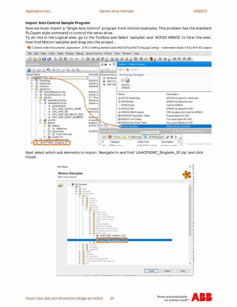
Import Axis Control Sample ProgramNow we must import a “Single Axis Control” program from motion examples. This problem has the standardPLCopen style command to control the servo drive.To do this in the Logical view, go to the Toolbox and Select ‘samples’ and ‘ACP10/ARNC0’ to filter the view,then find Motion samples and drag into the project…
Next select which sub elements to import. Navigate to and find ‘LibACP10MC_SingleAx_ST.zip’ and clickFinish.
Application note B&R PLC's Getting Started Guide (SDC and Additional libraries) AN00270
new.abb.com/drives/low-voltage-ac/motion 25
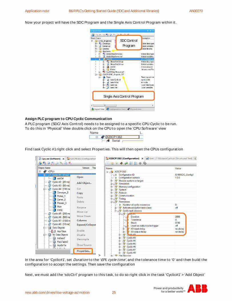
Now your project will have the SDC Program and the Single Axis Control Program within it.
Assign PLC program to CPU Cyclic CommunicationA PLC program (SDC/Axis Control) needs to be assigned to a specific CPU Cyclic to be run.To do this in ‘Physical’ View double click on the CPU to open the ‘CPU Software’ view
Find task Cyclic #1 right click and select Properties. This will then open the CPUs configuration
>In the area for ‘Cyclic#1’, set Duration to the ‘EPL cycle time’, and the tolerance time to ‘0’ and then build theconfiguration to accept the settings. Then save the configuration
Next, we must add the ‘sdcCtrl’ program to this task, to do so right click in the task ‘Cyclic#1’ > ‘Add Object’
SDC ControlProgram
Single Axis Control Program
Application note Generic drive interface AN00270
https://new.abb.com/drives/low-voltage-ac/motion 26
Then navigate to ‘[Project] > StepServo > SdcCtrl > SdcCtrl program’ click okay.
>The SDC program is now assigned to this task.Repeat the above step for additional axes.
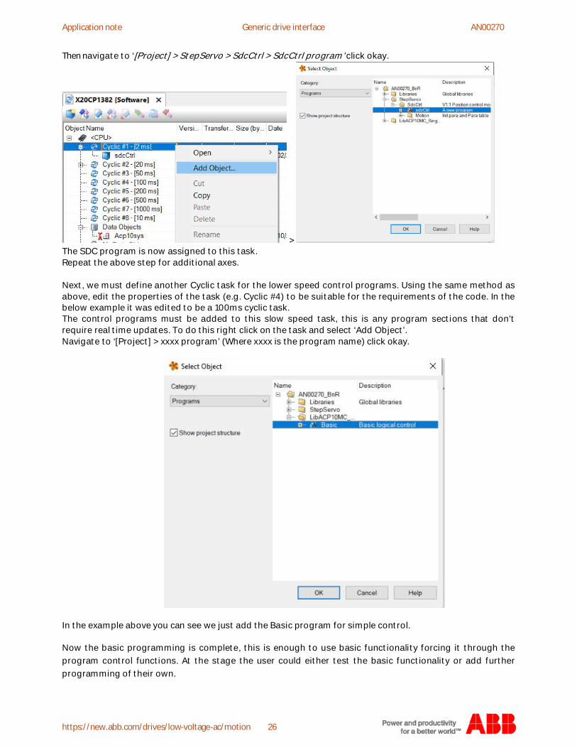
Next, we must define another Cyclic task for the lower speed control programs. Using the same method asabove, edit the properties of the task (e.g. Cyclic #4) to be suitable for the requirements of the code. In thebelow example it was edited to be a 100ms cyclic task.The control programs must be added to this slow speed task, this is any program sections that don’trequire real time updates. To do this right click on the task and select ‘Add Object’.Navigate to ‘[Project] > xxxx program’ (Where xxxx is the program name) click okay.
In the example above you can see we just add the Basic program for simple control.
Now the basic programming is complete, this is enough to use basic functionality forcing it through theprogram control functions. At the stage the user could either test the basic functionality or add furtherprogramming of their own.
Application note B&R PLC's Getting Started Guide (SDC and Additional libraries) AN00270
new.abb.com/drives/low-voltage-ac/motion 27
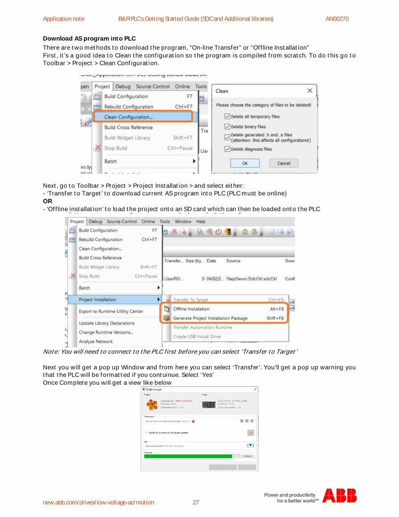
Download AS program into PLCThere are two methods to download the program, “On-line Transfer” or “Offline Installation”First, it’s a good idea to Clean the configuration so the program is compiled from scratch. To do this go toToolbar > Project > Clean Configuration.
Next, go to Toolbar > Project > Project Installation > and select either:- ‘Transfer to Target’ to download current AS program into PLC (PLC must be online)OR- ‘Offline installation’ to load the project onto an SD card which can then be loaded onto the PLC
Note: You will need to connect to the PLC first before you can select ‘Transfer to Target’
Next you will get a pop up Window and from here you can select ‘Transfer’. You’ll get a pop up warning youthat the PLC will be formatted if you contuinue. Select ‘Yes’Once Complete you will get a view like below
Application note Generic drive interface AN00270
https://new.abb.com/drives/low-voltage-ac/motion 28
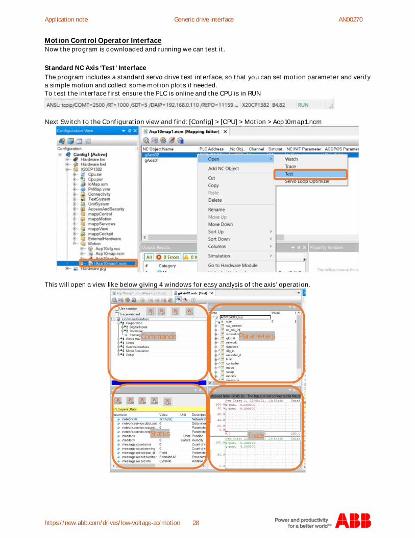
Motion Control Operator InterfaceNow the program is downloaded and running we can test it.
Standard NC Axis ‘Test’ InterfaceThe program includes a standard servo drive test interface, so that you can set motion parameter and verifya simple motion and collect some motion plots if needed.To test the interface first ensure the PLC is online and the CPU is in RUN
Next Switch to the Configuration view and find: [Config] > [CPU] > Motion > Acp10map1.ncm
This will open a view like below giving 4 windows for easy analysis of the axis’ operation.
Commands Parameters
TraceStatus
Application note B&R PLC's Getting Started Guide (SDC and Additional libraries) AN00270
new.abb.com/drives/low-voltage-ac/motion 29
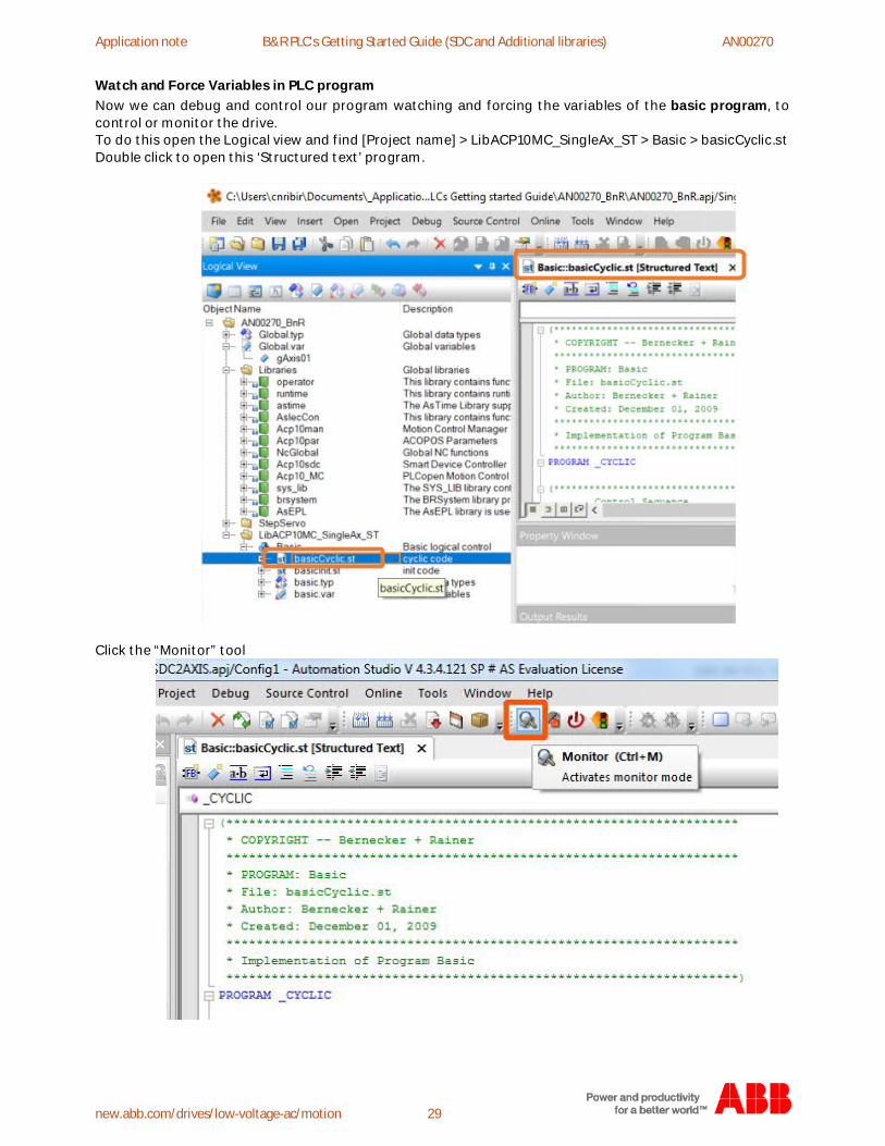
Watch and Force Variables in PLC programNow we can debug and control our program watching and forcing the variables of the basic program, tocontrol or monitor the drive.To do this open the Logical view and find [Project name] > LibACP10MC_SingleAx_ST > Basic > basicCyclic.stDouble click to open this ‘Structured text’ program.
Click the “Monitor” tool
Application note Generic drive interface AN00270
https://new.abb.com/drives/low-voltage-ac/motion 30
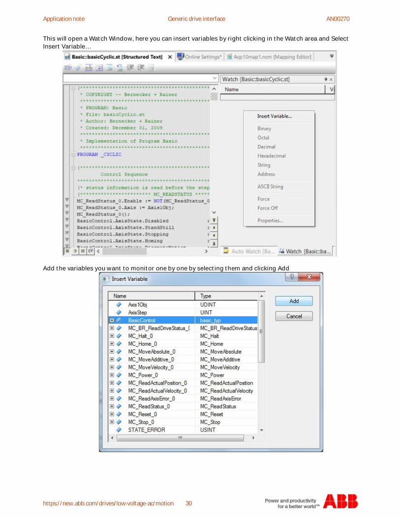
This will open a Watch Window, here you can insert variables by right clicking in the Watch area and SelectInsert Variable…
Add the variables you want to monitor one by one by selecting them and clicking Add
Application note B&R PLC's Getting Started Guide (SDC and Additional libraries) AN00270
new.abb.com/drives/low-voltage-ac/motion 31
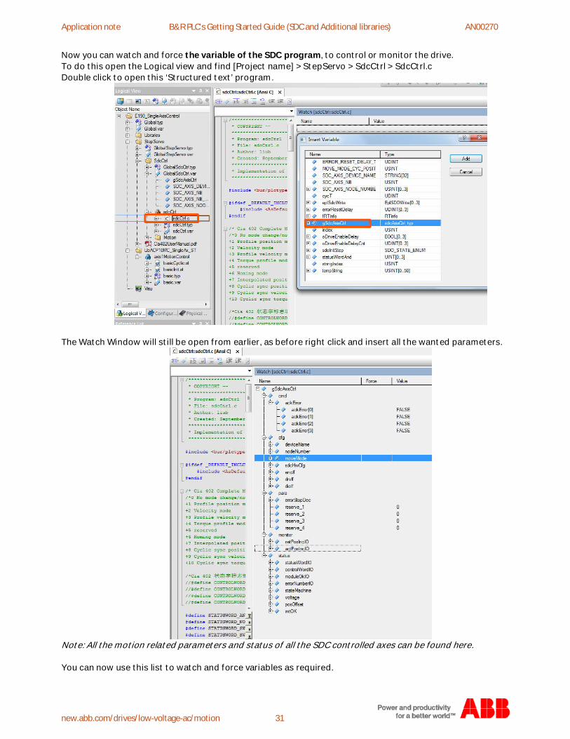
Now you can watch and force the variable of the SDC program, to control or monitor the drive.To do this open the Logical view and find [Project name] > StepServo > SdcCtrl > SdcCtrl.cDouble click to open this ‘Structured text’ program.
The Watch Window will still be open from earlier, as before right click and insert all the wanted parameters.
Note: All the motion related parameters and status of all the SDC controlled axes can be found here.
You can now use this list to watch and force variables as required.
Application note Generic drive interface AN00270
https://new.abb.com/drives/low-voltage-ac/motion 32
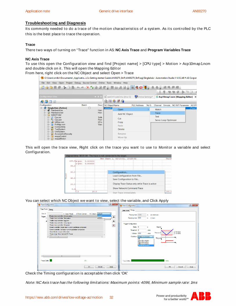
Troubleshooting and DiagnosisIts commonly needed to do a trace of the motion characteristics of a system. As its controlled by the PLCthis is the best place to trace the operation.
TraceThere two ways of turning on “Trace” function in AS: NC Axis Trace and Program Variables Trace
NC Axis TraceTo use this open the Configuration view and find [Project name] > [CPU type] > Motion > Acp10map1.ncmand double click on it. This will open the Mapping EditorFrom here, right click on the NC Object and select Open > Trace
This will open the trace view, Right click on the trace you want to use to Monitor a variable and selectConfiguration.
You can select which NC Object we want to view, select the variable, and Click Apply
Check the Timing configuration is acceptable then click ‘OK’
Note: NC Axis trace has the following limitations: Maximum points: 4096, Minimum sample rate: 1ms

Application note B&R PLC's Getting Started Guide (SDC and Additional libraries) AN00270
new.abb.com/drives/low-voltage-ac/motion 33
Program Variables TraceTo use this open the Logical view and find [Project name] > LibACP10MC_SingleAx_ST > Basic and right clickThen select Open > TraceFrom here, right click on the NC Object and select Open > Trace
This will open the trace for the program you right clicked on.Next press the icon to Insert Trace then right click on it and select Properties
>
Application note Generic drive interface AN00270
https://new.abb.com/drives/low-voltage-ac/motion 34
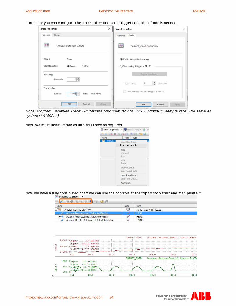
From here you can configure the trace buffer and set a trigger condition if one is needed.
Note: Program Variables Trace: Limitations Maximum points: 32767, Minimum sample rate: The same assystem tick(400us)
Next, we must insert variables into this trace as required.
Now we have a fully configured chart we can use the controls at the top to stop start and manipulate it.
>
Application note B&R PLC's Getting Started Guide (SDC and Additional libraries) AN00270
new.abb.com/drives/low-voltage-ac/motion 35
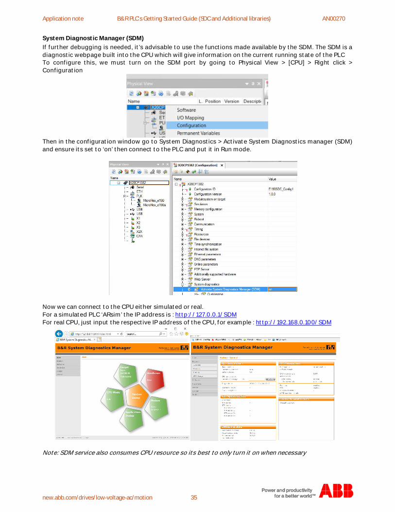
System Diagnostic Manager (SDM)If further debugging is needed, it’s advisable to use the functions made available by the SDM. The SDM is adiagnostic webpage built into the CPU which will give information on the current running state of the PLCTo configure this, we must turn on the SDM port by going to Physical View > [CPU] > Right click >Configuration
Then in the configuration window go to System Diagnostics > Activate System Diagnostics manager (SDM)and ensure its set to ‘on’ then connect to the PLC and put it in Run mode.
Now we can connect to the CPU either simulated or real.For a simulated PLC ‘ARsim’ the IP address is : http://127.0.0.1/SDMFor real CPU, just input the respective IP address of the CPU, for example : http://192.168.0.100/SDM
Note: SDM service also consumes CPU resource so its best to only turn it on when necessary
Application note Generic drive interface AN00270
https://new.abb.com/drives/low-voltage-ac/motion 36
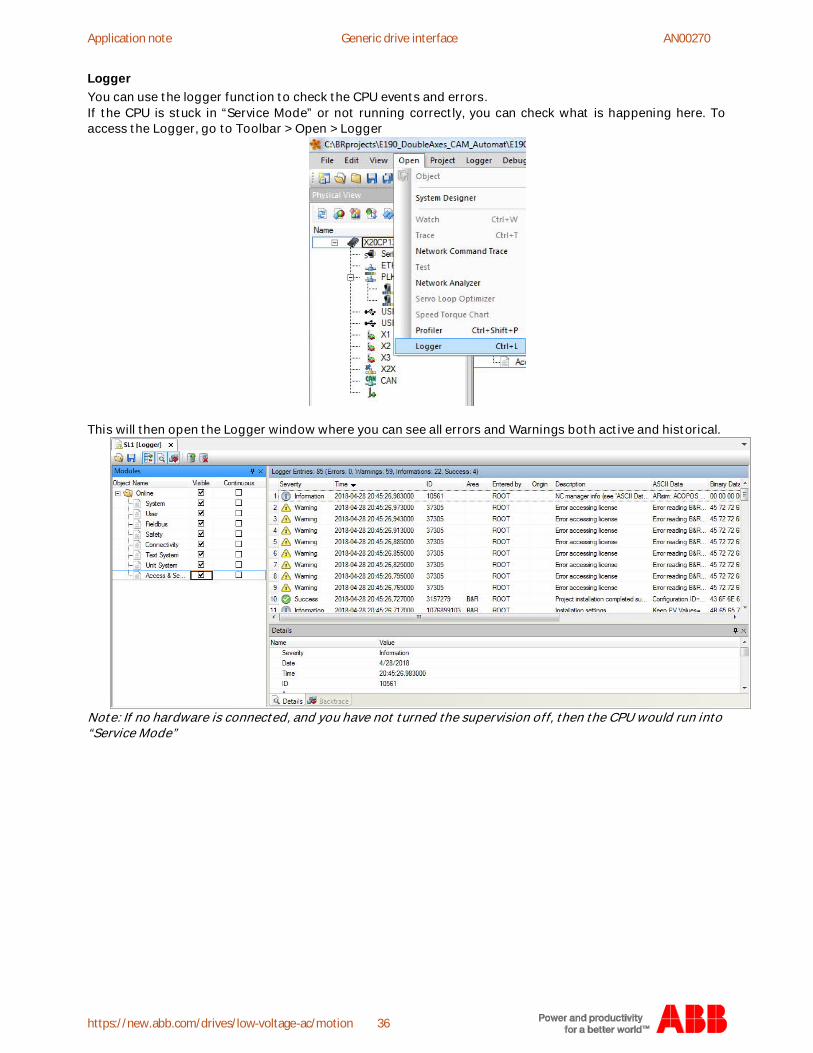
LoggerYou can use the logger function to check the CPU events and errors.If the CPU is stuck in “Service Mode” or not running correctly, you can check what is happening here. Toaccess the Logger, go to Toolbar > Open > Logger
This will then open the Logger window where you can see all errors and Warnings both active and historical.
Note: If no hardware is connected, and you have not turned the supervision off, then the CPU would run into“Service Mode”

Application note B&R PLC's Getting Started Guide (SDC and Additional libraries) AN00270
new.abb.com/drives/low-voltage-ac/motion 37
ProfilerIf your program is running but you want to check how its running you can use the profiler. Here you cancheck the CPU load and cyclic running.To access it go to the Toolbar > Open > Profiler.
This will then Open the Profiler view which will give and active view of all the CPU cycle times, CPUloading and so on.

Application note Generic drive interface AN00270
https://new.abb.com/drives/low-voltage-ac/motion 38
Additional Programs and Files
Included with this application note there are several programs which include the examples are outlinedbelow.
Example 1 File name: AN270_BnR_1Ax CSPFunctions: (SDC Control, 1 Axis, e190, Address = 3, Axis = 1)Description: Simple Single axis configuration
Example 2 File name: AN270_BnR_2Ax CSPFunctions: (SDC Control, 2 Axis, e190, [Address = 3, Axis = 1] and e180 [Address = 4, Axis = 2])Description: Dual Axis configuration with additional Function Block examples for CAM and Gear
Example 3 File name: AN270_BnR_2Ax CSVFunctions: (SDC Control, 2 Axis, e190, [Address = 3, Axis = 1] and e180 [Address = 4, Axis = 2])Description: Dual Axis configuration showing structures needed for CSV control
These programs can be loaded to test and learn more about the programs and structures used to realizemotion with B&R X20 PLC’s
Please see also the below app notes for more information on B&R and SDC.
AN00275 - B&R SDC using the Touchprobe function, for further information on SDC functions
AN00265 - Generic Drive Interface - B&R PLC with Modbus (GDI)
AN00264 - Generic Drive Interface - B&R PLC with EPL (GDI)
Contact us
For more information please contact yourlocal ABB representative or one of the following:
new.abb.com/drives/low-voltage-ac/motionnew.abb.com/drivesnew.abb.com/channel-partnersnew.abb.com/plc
© Copyright 2020 ABB. All rights reserved.
Specifications subject to change withoutnotice.
Copyright © 2022 FDOKUMEN