
Bay control REC670 Version 2.2 Product guide - ABB Group
143
RELION® 670 SERIES — Bay control REC670 Version 2.2 Product guide
-
Upload
khangminh22 -
Category
Documents
-
view
1 -
download
0
Transcript of Bay control REC670 Version 2.2 Product guide - ABB Group

RELION® 670 SERIES— Bay control REC670 Version 2.2 Product guide

Contents
1. Application..................................................................... 3
2. Available functions..........................................................9
3. Control......................................................................... 25
4. Differential protection....................................................28
5. Wide area measurement system...................................28
6. Current protection........................................................ 28
7. Voltage protection........................................................ 30
8. Frequency protection....................................................31
9. Multipurpose protection................................................32
10. General calculation......................................................32
11. Secondary system supervision.................................... 32
12. Control........................................................................ 33
13. Scheme communication..............................................35
14. Logic...........................................................................36
15. Monitoring...................................................................38
16. Metering......................................................................41
17. Human machine interface............................................42
18. Basic IED functions..................................................... 42
19. Ethernet...................................................................... 42
20. Station communication ...............................................43
21. Remote communication.............................................. 44
22. Hardware description.................................................. 45
23. Connection diagrams.................................................. 48
24. Technical data............................................................. 49
25. Ordering for customized IED......................................121
26. Ordering for pre-configured IED.................................132
27. Ordering for Accessories........................................... 138
Disclaimer
The information in this document is subject to change without notice and should not be construed as a commitment by ABB. ABB assumes no responsibility for any
errors that may appear in this document. Drawings and diagrams are not binding.
© Copyright 2017 ABB.
All rights reserved.
Trademarks
ABB and Relion are registered trademarks of the ABB Group. All other brand or product names mentioned in this document may be trademarks or registered
trademarks of their respective holders.
1MRK 511 404-BEN BBay control REC670 2.2 Product version: 2.2
2 ABB

1. ApplicationM13637-3 v13
The Intelligent Electronic Device (IED) is used for the control,protection and monitoring of different types of bays in powernetworks. The IED is especially suitable for applications incontrol systems where the IEC 61850–8–1 Ed 1 or Ed 2station bus features of the IED can be fully utilized. It is usedfor station-wide interlocking via GOOSE messages andvertical client-server MMS communication to a local station orremote SCADA operator workplace. This supports thearchitecture with distributed control IEDs in all bays with highdemands on reliability. Redundant communication is obtainedthrough the built-in PRP and HSR features which can be usedin star or ringbus architectures. The IED can be used on allvoltage levels. It is suitable for the control of all apparatusesin any type of switchgear arrangement.
The control is performed from remote (SCADA/Station)through the IEC 61850–8–1 Ed1 or Ed2 stationcommunication or from the built-in multi-display local HMI.Cyber security measures are implemented to secure safeautonomous operation of the protection and control functionseven if simultaneous cyber attacks occur. For all commontypes of switchgear arrangements, there are different pre-configurations for control and interlocking. One control IEDcan be used for single bay or multi-bay applications. Thecontrol operation is based on the select-before-executeprinciple to give highest possible security. There aresynchrocheck functions available to assist optimal breakerclosing at the right instance in synchronous as well asasynchronous networks.
A number of protection functions are available for flexibility inuse for different station types and busbar arrangements. Tofulfil the user's application requirements, the IED features, forexample, up to six instantaneous phase and earth overcurrentfunctions, 4–step directional or non-directional delayed-phaseand earth overcurrent functions, thermal overload andfrequency functions, two instances of 2–step under- andovervoltage functions, autorecloser functions and severaldifferent measuring functions. This, together with the multi-display local HMI that can show one or more pages perfeeder allows using the IED for protection and control for upto six bays in a substation.
The auto-reclose for single-, two-, and/or three-phase recloseincludes priority circuits for multi-breaker arrangements. It co-operates with the synchrocheck function with high-speed ordelayed reclosing. Several breaker failure functions areavailable to provide a breaker failure function independentfrom the protection IEDs, also for a complete one- and a halfbreaker diameter.
Disturbance recording and fault locator are available to allowindependent post-fault analysis after primary disturbances incase of a failure in the protection system.
Duplex communication channels for transfer of up to 192intertrip and binary signals are available on each remote-enddata communication card (LDCM). Typical applications arethe communication between IEDs inside the station or withIEDs in a remote station as remote I/O.
The IED can be used in applications with the IEC/UCA61850-9-2LE process bus with up to eight Merging Units(MU). Each MU has eight analogue channels, four current andfour voltages. Conventional input transformer module andMerging Unit channels can be mixed freely in your application.
Logic is prepared with a graphical tool. The advanced logiccapability allows special applications such as automaticopening of disconnectors in multi-breaker arrangements,closing of breaker rings, load transfer logics and so on. Thegraphical configuration tool ensures simple and fast testingand commissioning.
Forcing of binary inputs and outputs is a convenient way totest wiring in substations as well as testing configuration logicin the IEDs. Basically it means that all binary inputs andoutputs on the IED I/O modules (BOM, BIM, IOM & SOM) canbe forced to arbitrary values.
Central Account Management is an authenticationinfrastructure that offers a secure solution for enforcingaccess control to IEDs and other systems within a substation.This incorporates management of user accounts, roles andcertificates and the distribution of such, a procedurecompletely transparent to the user.
Flexible Product Naming allows the customer to use an IED-vendor independent IEC 61850 model of the IED. Thiscustomer model will be used as the IEC 61850 data model,but all other aspects of the IED will remain unchanged (e.g.,names on the local HMI and names in the tools). This offerssignificant flexibility to adapt the IED to the customers'system and standard solution.
SEMOD51278-4 v11
Four packages have been defined for following applications:
• Single breaker (double or single bus) arrangement (A30)• Double breaker arrangement (B30)• 1 ½ breaker arrangement for a complete diameter (C30)• Single breaker (double bus) arrangement with PMU
functionality (D30)
Optional functions are available in PCM600 ApplicationConfiguration Tool and can be configured by the user.Interface to analog and binary IO:s are configurable withoutneed of configuration changes. Analog and control circuitshave been pre-defined. Other signals need to be applied asrequired for each application. The main differences betweenthe packages above are the interlocking modules and thenumber of apparatuses to control.
1MRK 511 404-BEN BBay control REC670 2.2 Product version: 2.2 Issued: March 2018
Revision: B
ABB 3

Description of configuration A30M15200-3 v7
REC670 A30 – Double busbar in single breaker arrangement 12AI (6I + 6U)
QB1
QA1
QB2
QB9
S CILO
3 Control
S CSWI
3 Control
S XSWI
3 Control
S CILO
3 Control
S CSWI
3 Control
S XSWI
3 Control
S CILO
3 Control
S CSWI
3 Control
S XSWI
3 Control
S CILO
3 Control
S CSWI
3 Control
S XSWI
3 Control
DRP RDRE
DFR/SER DR
CV MMXN
MET P/Q
VN MMXU
MET UN
ETP MMTR
MET W/Varh
QC9
SES RSYN
25 SC/VC
Q CBAY
3 Control
Q CRSV
3 Control
BRC PTOC
46 Iub>
CC PDSC
52PD PD
Other Functions available from the function library
TCM YLTC
84
LOV PTUV
27 3U<
VDC PTOV
60 Ud>
CCS SPVC
87 INd/I
TCL YLTC
84
NS4 PTOC
46I2 4(I2>)
LC PTTR
26 θ>
Optional Functions
HZ PDIF
87 Id>
PH PIOC
50 3I>>
OC4 PTOC
51_67 4(3I>)
EF PIOC
50N IN>>
EF4 PTOC
51N_67N 4(IN>)
LF PTTR
26 θ>
SDE PSDE
67N IN>
UV2 PTUV
27 2(3U<)
SA PTOF
81 f>
OV2 PTOV
59 2(3U>)
GOP PDOP
32 P>
SA PFRC
81 df/dt<>
GUP PDUP
37 P<
TR PTTR
49 θ>
CV GAPC
2(I>/U<)
LMB RFLO
21FL FL
EC PSCH
85
TR8 ATCC
90 U↑↓
ECRW PSCH
85
TR1 ATCC
90 U↑↓
ROV2 PTOV
59N 2(U0>)
SA PTUF
81 f<
VD SPVC
60 Ud>
SMP PTRC
94 1 0
CC RBRF
50BF 3I>BF
VN MMXU
MET UN
V MMXU
MET U
V MSQI
MET Usqi
C MMXU
MET I
C MSQI
MET Isqi
S CILO
3 Control
S CSWI
3 Control
S XCBR
3 Control
VN MMXU
MET UN
SMB RREC
79 5(0 1)
WA1
WA2
WA2_VT
WA1_VT
LINE_CT
LINE_VT
FUF SPVC
U>/I<
S CILO
3 Control
S CSWI
3 Control
S XSWI
3 Control
QC1
QC2
S CILO
3 Control
S CSWI
3 Control
S XSWI
3 Control
IEC05000837-5-en.vsd
R ESIN
3 Control
S SIMG
63
S SIML
71
S SCBR
Control
S SCBR
Control
S SCBR
Control
PMU REP
STB PTOC
50STB 3I>STB
VR PVOC
51V 2(I>/U<)
ZC PSCH
85
ZCRW PSCH
85
ZCLC PSCH
IEC05000837 V5 EN-US
Figure 1. Configuration diagram for configuration A30
1MRK 511 404-BEN BBay control REC670 2.2 Product version: 2.2
4 ABB

Description of configuration B30M15200-12 v5
REC670 B30 - Double breaker arrangement 12AI (6I + 6U)
QB1
QA1
QB61
QB2
QA2
QB62
QB9
S CILO
3 Control
S CSWI
3 Control
S XCBR
3 Control
ETP MMTR
MET W/Varh
BRC PTOC
46 Iub>
CC PSDC
52PD PD
Other Functions available from the function library
LOV PTUV
27 3U<
VDC PTOV
60 Ud>
CCS SPVC
87 INd/I
TCL YLTC
84
NS4 PTOC
46I2 4(I2>)
Optional Functions
HZ PDIF
87 Id>
PH PIOC
50 3I>>
OC4 PTOC
51_67 4(3I>)
EF PIOC
50N IN>>
EF4 PTOC
51N_67N 4(IN>)
SDE PSDE
67N IN>
UV2 PTUV
27 2(3U<)
SA PTOF
81 f>
OV2 PTOV
59 2(3U>)
GOP PDOP
32 P>
SA PFRC
81 df/dt<>
GUP PDUP
37 P<
CV GAPC
2(I>/U<)
LMB RFLO
21FL FL
EC PSCH
TR8 ATCC
90 U↑↓
ECRW PSCH
TR1 ATCC
90 U↑↓
ROV2 PTOV
59N 2(U0>)
SA PTUF
81 f<
QC9
3 Control
VD SPVC
60 Ud>
S SIMG
63
S SIML
71
CC RBRF
50BF 3I>BF
TR PTTR
49 θ
SMB RREC
79 5(0 1)
SMP PTRC
94 1 0
LF PTTR
26 θ
LC PTTR
26 θ
C MMXU
MET I
C MSQI
MET Isqi
FUF SPVC
U>/I<
WA1
WA2_VT
WA1_VT
WA2
LINE_VT
LINE_CT1
LINE_CT2
S CILO
3 Control
S CSWI
3 Control
S XSWI
3 Control
S CILO
3 Control
S CSWI
3 Control
S XSWI
3 Control
VN MMXU
MET UN
S CILO
3 Control
S CSWI
3 Control
S XCBR
3 Control
VN MMXU
MET UN
VN MMXU
MET UN
V MMXU
MET U
V MSQI
MET Usqi
DRP RDRE
DFR/SER DR
Q CBAY Q CRSV
3 Control
R ESIN
3 Control
S CILO
3 Control
S CSWI
3 Control
S XSWI
3 Control
S CILO
3 Control
S CSWI
3 Control
S XSWI
3 Control
S CILO
3 Control
S CSWI
3 Control
S XSWI
3 Control
S CILO
3 Control
S CSWI
3 Control
S XSWI
3 Control
SES RSYN
25 SC/VC
SES RSYN
25 SC/VC
CV MMXN
MET P/Q
↓
=IEC05000838=5=en=Original.vsd
S SCBR
Control
S SCBR
Control
S SCBR
Control
S SCBR
Control
S SCBR
Control
S SCBR
Control
PMU REP
STB PTOC
50STB 3I>STB
VR PVOC
51V 2(I>/U<)
TCM YLTC
84
ZC PSCH
85
ZCLC PSCH ZCRW PSCH
85
85 85
IEC05000838 V5 EN-US
Figure 2. Configuration diagram for configuration B30
1MRK 511 404-BEN BBay control REC670 2.2 Product version: 2.2
ABB 5

Description of configuration C30M15200-24 v5
S CILO
3 Control
S CSWI
3 Control
S XSWI
3 Control
S CILO
3 Control
S CSWI
3 Control
S XSWI
3 Control
S CILO
3 Control
S CSWI
3 Control
S XSWI
3 Control
S CILO
3 Control
S CSWI
3 Control
S XSWI
3 Control
S CILO
3 Control
S CSWI
3 Control
S XSWI
3 Control
S CILO
3 Control
S CSWI
3 Control
S XSWI
3 Control
S CILO
3 Control
S CSWI
3 Control
S XSWI
3 Control
S CILO
3 Control
S CSWI
3 Control
S XSWI
3 Control
S CILO
3 Control
S CSWI
3 Control
S XSWI
3 Control
S CILO
3 Control
S CSWI
3 Control
S XSWI
3 Control
DRP RDRE
DFR/SER DR
Q CBAY
3 Control
S CILO
3 Control
S CSWI
3 Control
S XCBR
3 Control
S CILO
3 Control
S CSWI
3 Control
S XCBR
3 Control
S CILO
3 Control
S CSWI
3 Control
S XCBR
3 Control
ETP MMTR
MET W/Varh
V MMXU
MET U
REC670C30 – Complete one-and a half breaker diameter arrangement 24AI (6I + 6U, 6I+6U)
V MMXU
MET U
BRC PTOC
46 Iub>
CC PDSC
52PD PD
Other Functions available from the function library
LOV PTUV
27 3U<
VDC PTOV
60 Ud>
CCS SPVC
87 INd/I
TCL YLTC
84
Optional Functions
OC4 PTOC
51_67 4(3I>)
EF PIOC
50N IN>>
EF4 PTOC
51N_67N 4(IN>)
GOP PDOP
32 P>
GUP PDUP
37 P<
LMB RFLO
21FL FL
EC PSCH
85
ECRW PSCH
85
SMP PTRC
94 1 0
Q CRSV
3 Control
C MMXU
MET I
C MSQI
MET Isqi
C MMXU
MET I
C MSQI
MET Isqi
WA1
WA2_VT
FUF SPVC
U>/I<
V MSQI
MET Usqi
V MSQI
MET Usqi
S SIMG
63
TR PTTR
49 θ>
CV GAPC
U</I>
S SIML
71
VD SPVC
60 Ud>
QB1
WA1_QA1
WA1_QB6
LINE1_QC9QB61
TIE_QA1
QB62
LINE1_QB9
LINE2_QC9WA2_QB6
LINE2_QB9
WA2_QA1
QB2
WA1_VT
WA1_CT
WA2_CT
LINE2_VT
TIE_CT
LINE1_VT
WA2
Σ
SES RSYN
25 SC
SES RSYN
25 SC
SES RSYN
25 SC/VC
Σ
VN MMXU
MET UN
ETP MMTR
MET W/Varh
CV MMXN
MET P/Q
FUF SPVC
U>/I<
CV MMXN
MET P/Q
VN MMXU
MET UN
VN MMXU
MET UN
VN MMXU
MET UN
CC RBRF
50BF 3I>BF
R ESIN
3 Control
S SCBR
Control
S SCBR
Control
S SCBR
Control
S SCBR
Control
S SCBR
Control
S SCBR
Control
S SCBR
Control
S SCBR
Control
S SCBR
Control
PMU REP
STB PTOC
50STB 3I>STB
VR PVOC
51V 2(I>/U<)
HZ PDIF
87 Id>
LC PTTR
26 θ>
LF PTTR
26 θ>
PH PIOC
50 3I>>
NS4 PTOC
46I2 4(I2>)
OV2 PTOV
59 2(3U>)
SDE PSDE
67N IN>
ROV2 PTOV
59N 2(U0>)
SA PFRC
81 df/dt<>
SA PTOF
81 f>
SA PTUF
81 f<
SMB RREC
79 5(0 1)↓
UV2 PTUV
27 2(3U<)
TR1 ATCC
90 U↑↓
TR8 ATCC
90 U↑↓
ZC PSCH
85
ZCLC PSCH
ZCRW PSCH
85
TCM YLTC
84
IEC05000839-5-en.vsd
IEC05000839 V5 EN-US
Figure 3. Configuration diagram for configuration C30
1MRK 511 404-BEN BBay control REC670 2.2 Product version: 2.2
6 ABB

Description of configuration D30GUID-15D86A4C-4D37-432E-8DC2-518814830097 v1
REC670 D30 – Double busbar in single breaker arrangement with PMU functionality 12AI (6I + 6U)
QB1
QA1
QB2
QB9
S CILO
3 Control
S CSWI
3 Control
S XSWI
3 Control
S CILO
3 Control
S CSWI
3 Control
S XSWI
3 Control
S CILO
3 Control
S CSWI
3 Control
S XSWI
3 Control
S CILO
3 Control
S CSWI
3 Control
S XSWI
3 Control
DRP RDRE
DFR/SER DR
CV MMXN
MET P/Q
ETP MMTR
MET W/Varh
QC9
SES RSYN
25 SC/VC
Q CBAY
3 Control
Q CRSV
3 Control
BRC PTOC
46 Iub>
CC PDSC
52PD PD
Other Functions available from the function library
TCM YLTC
84
LOV PTUV
27 3U<
VDC PTOV
60 Ud>
CCS SPVC
87 INd/I
TCL YLTC
84
NS4 PTOC
46I2 4(I2>)
LC PTTR
26 θ>
Optional Functions
HZ PDIF
87 Id>
PH PIOC
50 3I>>
OC4 PTOC
51_67 4(3I>)
EF PIOC
50N IN>>
EF4 PTOC
51N_67N 4(IN>)
LF PTTR
26 θ>
OV2 PTOV
59 2(3U>)
GOP PDOP
32 P>
GUP PDUP
37 P<
CV GAPC
2(I>/U<)
LMB RFLO
21FL FL
EC PSCH
85
ECRW PSCH
85
VD SPVC
60 Ud>
SMP PTRC
94 1 0
CC RBRF
50BF 3I>BF
VN MMXU
MET UN
V MMXU
MET U
V MSQI
MET Usqi
C MMXU
MET I
C MSQI
MET Isqi
S CILO
3 Control
S CSWI
3 Control
S XCBR
3 Control
VN MMXU
MET UN
SMB RREC
79 5(0 1)
WA1
WA2
WA2_VT
WA1_VT
LINE_CT
LINE_VT
S CILO
3 Control
S CSWI
3 Control
S XSWI
3 Control
QC1
QC2
S CILO
3 Control
S CSWI
3 Control
S XSWI
3 Control
IEC16000194=IEC16000194=1=en=Original
.vsdx
R ESIN
3 Control
S SCBR
Control
S SCBR
Control
S SCBR
Control
STB PTOC
50STB 3I>STB
VR PVOC
51V 2(I>/U<)
IEEE Std 1344
IEEE Std C37.118
VN MMXU
MET UN
FUF SPVC
U>/I<
PMU REP
Phasor data
ZC PSCH
85
ZCRW PSCH
85
ZCLC PSCH
SA PFRC
81 df/dt<>
ROV2 PTOV
59N 2(U0>)
SA PTOF
81 f>
SA PTUF
81 f<
SDE PSDE
67N IN>
TR PTTR
49 θ>
TR1 ATCC
90 U↑↓
TR8 ATCC
90 U↑↓
UV2 PTUV
27 2(3U<)
IEC16000194 V1 EN-US
Figure 4. Configuration diagram for configuration D30
GUID-79B8BC84-4AAB-44E7-86CD-FF63098B009D v2
1MRK 511 404-BEN BBay control REC670 2.2 Product version: 2.2
ABB 7

The basic delivery includes one binary input module and onebinary output module, which is sufficient for the defaultconfigured IO to trip and close circuit breaker. All IEDs can bereconfigured with the help of the application configuration toolin PCM600. The IED can be adapted to special applicationsand special logic can be developed, such as logic forautomatic opening of disconnectors and closing of ring bays,automatic load transfer from one busbar to the other, and soon.
The basic IED configuration is provided with the signal matrix,single line diagram and the application configuration preparedfor the functions included in the product by default. Allparameters should be verified by the customer, since these
are specific to the system, object or application. Optionalfunctions and optional IO ordered will not be configured atdelivery. It should be noted that the standard only includesone binary input and one binary output module and only thekey functions such as tripping are connected to the outputsin the signal matrix tool. The required total IO must becalculated and specified at ordering.
The configurations are as far as found necessary providedwith application comments to explain why the signals havebeen connected in the special way. On request, ABB isavailable to support the re-configuration work, either directlyor to do the design checking.
1MRK 511 404-BEN BBay control REC670 2.2 Product version: 2.2
8 ABB

2. Available functionsGUID-F5776DD1-BD04-4872-BB89-A0412B4B5CC3 v1
The following tables list all the functionsavailable in the IED. Those functions that
are not exposed to the user or do not needto be configured are not described in thismanual.
Main protection functionsGUID-66BAAD98-851D-4AAC-B386-B38B57718BD2 v13
Table 1. Example of quantities
2 = number of basic instances0-3 = option quantities3-A03 = optional function included in packages A03 (refer to ordering details)
IEC 61850 orfunction name
ANSI Function description Bay control
REC670(Customized)
RE
C67
0 (A
30)
RE
C67
0 (B
30)
RE
C67
0 (C
30)
RE
C67
0 (D
30)
Differential protection
HZPDIF 87 High impedance differential protection,single phase
0-6 3-A02 3-A02 6-A07 3-A02
1MRK 511 404-BEN BBay control REC670 2.2 Product version: 2.2
ABB 9

Back-up protection functionsGUID-A8D0852F-807F-4442-8730-E44808E194F0 v13
IEC 61850 orfunction name
ANSI Function description Bay control
REC670(Customized)
RE
C67
0 (A
30)
RE
C67
0 (B
30)
RE
C67
0 (C
30)
RE
C67
0 (D
30)
Current protection
PHPIOC 50 Instantaneous phase overcurrentprotection
0-6 1-C51 2-C52 2-C53 1-C51
OC4PTOC 51_671) Directional phase overcurrent protection,four steps
0-6 1-C51 2-C52 2-C53 1-C51
EFPIOC 50N Instantaneous residual overcurrentprotection
0-6 1-C51 2-C52 2-C53 1-C51
EF4PTOC 51N67N2)
Directional residual overcurrentprotection, four steps
0-6 1-C51 2-C52 2-C53 1-C51
NS4PTOC 46I2 Four step directional negative phasesequence overcurrent protection
0-6 1-C51 2-C52 2-C53 1-C51
SDEPSDE 67N Sensitive directional residual overcurrentand power protection
0-6 1-C16 1–C16 1-C16 1-C16
LCPTTR 26 Thermal overload protection, one timeconstant, Celsius
0-6 1-C51 1-C52 2-C53 1-C51
LFPTTR 26 Thermal overload protection, one timeconstant, Fahrenheit
0-6 1-C51 1-C52 2-C53 1-C51
TRPTTR 49 Thermal overload protection, two timeconstants
0-6 1-C51 1-C52 2-C53 1-C51
CCRBRF 50BF Breaker failure protection 0-6 1-C51 2-C52 3-C53 1-C51
STBPTOC 50STB Stub protection 0-6 1-B27 2-B25 2-B25 1-B27
CCPDSC 52PD Pole discordance protection 0-6 1 2 3 1
GUPPDUP 37 Directional underpower protection 0-2 1-C35 1-C35 1-C35 1-C35
GOPPDOP 32 Directional overpower protection 0-2 1-C35 1-C35 1-C35 1-C35
BRCPTOC 46 Broken conductor check 0-1 1 1 1 1
CBPGAPC Capacitor bank protection 0-3
VRPVOC 51V Voltage restrained overcurrent protection 0-3 1-C35 1-C35 1-C35 1-C35
Voltage protection
UV2PTUV 27 Two step undervoltage protection 0-2 2-D02 2-D02 2-D02 2-D02
OV2PTOV 59 Two step overvoltage protection 0-2 2-D02 2-D02 2-D02 2-D02
ROV2PTOV 59N Two step residual overvoltage protection 0-2 2-D02 2-D02 2-D02 2-D02
VDCPTOV 60 Voltage differential protection 0-6 2 2 2 2
LOVPTUV 27 Loss of voltage check 0-2 1 1 2 1
Frequency protection
1MRK 511 404-BEN BBay control REC670 2.2 Product version: 2.2
10 ABB

IEC 61850 orfunction name
ANSI Function description Bay control
REC670(Customized)
RE
C67
0 (A
30)
RE
C67
0 (B
30)
RE
C67
0 (C
30)
RE
C67
0 (D
30)
SAPTUF 81 Underfrequency protection 0-6 6-E01 6-E01 6-E01 6-E01
SAPTOF 81 Overfrequency protection 0-6 6-E01 6-E01 6-E01 6-E01
SAPFRC 81 Rate-of-change of frequency protection 0-6 6-E01 6-E01 6-E01 6-E01
FTAQFVR 81A Frequency time accumulation protection 0-12
Multipurpose protection
CVGAPC General current and voltage protection 0-9 4-F01 4-F01 4-F01 4-F01
General calculation
SMAIHPAC Multipurpose filter 0-6
1) 67 requires voltage2) 67N requires voltage
1MRK 511 404-BEN BBay control REC670 2.2 Product version: 2.2
ABB 11

Control and monitoring functionsGUID-E3777F16-0B76-4157-A3BF-0B6B978863DE v16
IEC 61850 orfunction name
ANSI Function description Bay control
REC670(Customized)
RE
C67
0 (A
30)
RE
C67
0 (B
30)
RE
C67
0 (C
30)
RE
C67
0 (D
30)
Control
SESRSYN 25 Synchrocheck, energizingcheck and synchronizing
0-6 1 2 3 1
SMBRREC 79 Autorecloser 0-6 1-H04 2-H05 3-H06 1-H04
APC10 3 Control functionality for asingle bay, max 10 objects(1CB), includinginterlocking (see Table 3)
0-1 1 1
APC15 3 Control functionality for asingle bay, max 15 objects(2CB), includinginterlocking (see Table 4)
0-1 1
APC30 3 Control functionality for upto 6 bays, max 30 objects(6CBs), includinginterlocking (see Table 5)
0-1 1
QCBAY Bay control 1+5/APC30 1 1 1+5/APC30
1
LOCREM Handling of LR-switchpositions
1+5/APC30 1 1 1+5/APC30
1
LOCREMCTRL LHMI control of PSTO 1 1 1 1 1
SXCBR Circuit breaker 18 3 6 18 3
TR1ATCC 90 Automatic voltage controlfor tap changer, singlecontrol
0-4 1-H11 1-H11 2-H16 1-H11
TR8ATCC 90 Automatic voltage controlfor tap changer, parallelcontrol
0-4 1-H15 1-H15 2-H18 1-H15
TCMYLTC 84 Tap changer control andsupervision, 6 binaryinputs
0-4 4 4 4 4
TCLYLTC 84 Tap changer control andsupervision, 32 binaryinputs
0-4 4 4 4 4
SLGAPC Logic rotating switch forfunction selection andLHMI presentation
15 15 15 15 15
VSGAPC Selector mini switch 30 30 30 30 30
DPGAPC Generic communicationfunction for Double Pointindication
16 16 16 16 16
SPC8GAPC Single point genericcontrol function 8 signals
5 5 5 5 5
1MRK 511 404-BEN BBay control REC670 2.2 Product version: 2.2
12 ABB

IEC 61850 orfunction name
ANSI Function description Bay control
REC670(Customized)
RE
C67
0 (A
30)
RE
C67
0 (B
30)
RE
C67
0 (C
30)
RE
C67
0 (D
30)
AUTOBITS Automation bits, commandfunction for DNP3.0
3 3 3 3 3
SINGLECMD Single command, 16signals
4 4 4 4 4
I103CMD Function commands forIEC 60870-5-103
1 1 1 1 1
I103GENCMD Function commandsgeneric for IEC60870-5-103
50 50 50 50 50
I103POSCMD IED commands withposition and select for IEC60870-5-103
50 50 50 50 50
I103POSCMDV IED direct commands withposition for IEC60870-5-103
50 50 50 50 50
I103IEDCMD IED commands for IEC60870-5-103
1 1 1 1 1
I103USRCMD Function commands userdefined for IEC60870-5-103
4 4 4 4 4
Secondary systemsupervision
CCSSPVC 87 Current circuit supervision 0-6 1 2 3 1
FUFSPVC Fuse failure supervision 0-4 3 3 3 3
VDSPVC 60 Fuse failure supervisionbased on voltagedifference
0-2 1-G03 1-G03 1-G03 1-G03
Logic
SMPPTRC 94 Tripping logic 12 12 12 12 12
SMAGAPC General start matrix block 12 12 12 12 12
STARTCOMB Start combinator 32 32 32 32 32
TMAGAPC Trip matrix logic 12 12 12 12 12
ALMCALH Logic for group alarm 5 5 5 5 5
WRNCALH Logic for group warning 5 5 5 5 5
INDCALH Logic for group indication 5 5 5 5 5
AND, GATE, INV,LLD, OR,PULSETIMER,RSMEMORY,SRMEMORY,TIMERSET, XOR
Basic configurable logicblocks (see Table 2)
40-420 40-420 40-420 40-420 40-420
1MRK 511 404-BEN BBay control REC670 2.2 Product version: 2.2
ABB 13

IEC 61850 orfunction name
ANSI Function description Bay control
REC670(Customized)
RE
C67
0 (A
30)
RE
C67
0 (B
30)
RE
C67
0 (C
30)
RE
C67
0 (D
30)
ANDQT,INDCOMBSPQT,INDEXTSPQT,INVALIDQT,INVERTERQT,ORQT,PULSETIMERQT,RSMEMORYQT,SRMEMORYQT,TIMERSETQT,XORQT
Configurable logic blocksQ/T (see Table 6)
0-1 1 1 1 1
AND, GATE, INV,LLD, OR,PULSETIMER,RSMEMORY,SLGAPC,SRMEMORY,TIMERSET,VSGAPC, XOR
Extension logic package(see Table 7)
0-1
FXDSIGN Fixed signal function block 1 1 1 1 1
B16I Boolean to integerconversion, 16 bit
18 18 18 18 18
BTIGAPC Boolean to integerconversion with logicalnode representation, 16 bit
16 16 16 16 16
IB16 Integer to Boolean 16conversion
18 18 18 18 18
ITBGAPC Integer to Boolean 16conversion with LogicNode representation
16 16 16 16 16
TEIGAPC Elapsed time integratorwith limit transgressionand overflow supervision
12 12 12 12 12
INTCOMP Comparator for integerinputs
30 30 30 30 30
REALCOMP Comparator for real inputs 30 30 30 30 30
1MRK 511 404-BEN BBay control REC670 2.2 Product version: 2.2
14 ABB

Table 2. Total number of instances for basic configurable logic blocks
Basic configurable logic block Total number of instances
AND 280
GATE 40
INV 420
LLD 40
OR 298
PULSETIMER 40
RSMEMORY 40
SRMEMORY 40
TIMERSET 60
XOR 40
Table 3. Number of function instances in APC10
Function name Function description Total number of instances
SCILO Interlocking 10
BB_ES 3
A1A2_BS 2
A1A2_DC 3
ABC_BC 1
BH_CONN 1
BH_LINE_A 1
BH_LINE_B 1
DB_BUS_A 1
DB_BUS_B 1
DB_LINE 1
ABC_LINE 1
AB_TRAFO 1
SCSWI Switch controller 10
SXSWI Circuit switch 9
QCRSV Apparatus control 2
RESIN1 1
RESIN2 59
POS_EVAL Evaluation of position indication 10
XLNPROXY Proxy for signals from switching device viaGOOSE
12
GOOSEXLNRCV GOOSE function block to receive a switchingdevice
12
1MRK 511 404-BEN BBay control REC670 2.2 Product version: 2.2
ABB 15

Table 4. Number of function instances in APC15
Function name Function description Total number of instances
SCILO Interlocking 15
BB_ES 3
A1A2_BS 2
A1A2_DC 3
ABC_BC 1
BH_CONN 1
BH_LINE_A 1
BH_LINE_B 1
DB_BUS_A 1
DB_BUS_B 1
DB_LINE 1
ABC_LINE 1
AB_TRAFO 1
SCSWI Switch controller 15
SXSWI Circuit switch 14
QCRSV Apparatus control 2
RESIN1 1
RESIN2 59
POS_EVAL Evaluation of position indication 15
XLNPROXY Proxy for signals from switching device viaGOOSE
20
GOOSEXLNRCV GOOSE function block to receive a switchingdevice
20
1MRK 511 404-BEN BBay control REC670 2.2 Product version: 2.2
16 ABB

Table 5. Number of function instances in APC30
Function name Function description Total number of instances
SCILO Interlocking 30
BB_ES 6
A1A2_BS 4
A1A2_DC 6
ABC_BC 2
BH_CONN 2
BH_LINE_A 2
BH_LINE_B 2
DB_BUS_A 3
DB_BUS_B 3
DB_LINE 3
ABC_LINE 6
AB_TRAFO 4
SCSWI Switch controller 30
SXSWI Circuit switch 24
QCRSV Apparatus control 6
RESIN1 1
RESIN2 59
POS_EVAL Evaluation of position indication 30
QCBAY Bay control 5
LOCREM Handling of LR-switch positions 5
XLNPROXY Proxy for signals from switching device viaGOOSE
42
GOOSEXLNRCV GOOSE function block to receive a switchingdevice
42
Table 6. Total number of instances for configurable logic blocks Q/T
Configurable logic blocks Q/T Total number of instances
ANDQT 120
INDCOMBSPQT 20
INDEXTSPQT 20
INVALIDQT 22
INVERTERQT 120
ORQT 120
PULSETIMERQT 40
RSMEMORYQT 40
SRMEMORYQT 40
TIMERSETQT 40
XORQT 40
1MRK 511 404-BEN BBay control REC670 2.2 Product version: 2.2
ABB 17
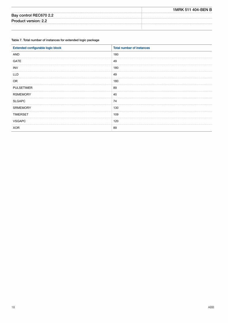
Table 7. Total number of instances for extended logic package
Extended configurable logic block Total number of instances
AND 180
GATE 49
INV 180
LLD 49
OR 180
PULSETIMER 89
RSMEMORY 40
SLGAPC 74
SRMEMORY 130
TIMERSET 109
VSGAPC 120
XOR 89
1MRK 511 404-BEN BBay control REC670 2.2 Product version: 2.2
18 ABB

IEC 61850 orfunction name
ANSI Function description Bay control
REC670(Customized)
RE
C67
0 (A
30)
RE
C67
0 (B
30)
RE
C67
0 (C
30)
RE
C67
0 (D
30)
Monitoring
CVMMXN Power systemmeasurement
6 6 6 6 6
CMMXU Current measurement 10 10 10 10 10
VMMXU Voltage measurementphase-phase
6 6 6 6 6
CMSQI Current sequencemeasurement
6 6 6 6 6
VMSQI Voltage sequencemeasurement
6 6 6 6 6
VNMMXU Voltage measurementphase-earth
6 6 6 6 6
EVENT Event function 20 20 20 20 20
DRPRDRE,A4RADR,
Disturbance report 1 1 1 1 1
SPGAPC Generic communicationfunction for Single Pointindication
64 64 64 64 64
SP16GAPC Generic communicationfunction for Single Pointindication 16 inputs
24 24 24 24 24
MVGAPC Generic communicationfunction for measuredvalues
24 24 24 24 24
BINSTATREP Logical signal status report 3 3 3 3 3
RANGE_XP Measured value expanderblock
66 66 66 66 66
SSIMG 63 Insulation supervision forgas medium
21 21 21 21 21
SSIML 71 Insulation supervision forliquid medium
3 3 3 3 3
SSCBR Circuit breaker conditionmonitoring
0-18 3 6 9 3
LMBRFLO Fault locator 0-1 1 1 1 1
LOLSPTR 26/49HS
Transformer insulationloss of life monitoring
0-4 4-M21 4-M21 4-M21 4-M21
I103MEAS Measurands for IEC60870-5-103
1 1 1 1 1
I103MEASUSR Measurands user definedsignals for IEC60870-5-103
3 3 3 3 3
1MRK 511 404-BEN BBay control REC670 2.2 Product version: 2.2
ABB 19

IEC 61850 orfunction name
ANSI Function description Bay control
REC670(Customized)
RE
C67
0 (A
30)
RE
C67
0 (B
30)
RE
C67
0 (C
30)
RE
C67
0 (D
30)
I103AR Function status auto-recloser for IEC60870-5-103
1 1 1 1 1
I103EF Function status earth-faultfor IEC 60870-5-103
1 1 1 1 1
I103FLTPROT Function status faultprotection for IEC60870-5-103
1 1 1 1 1
I103IED IED status for IEC60870-5-103
1 1 1 1 1
I103SUPERV Supervison status for IEC60870-5-103
1 1 1 1 1
I103USRDEF Status for user definedsignals for IEC60870-5-103
20 20 20 20 20
L4UFCNT Event counter with limitsupervision
30 30 30 30 30
TEILGAPC Running hour meter 6 6 6 6 6
Metering
PCFCNT Pulse-counter logic 16 16 16 16 16
ETPMMTR Function for energycalculation and demandhandling
6 6 6 6 6
1MRK 511 404-BEN BBay control REC670 2.2 Product version: 2.2
20 ABB

CommunicationGUID-5F144B53-B9A7-4173-80CF-CD4C84579CB5 v16
IEC 61850 orfunction name
ANSI Function description Bay control
REC670(Customized)
RE
C67
0 (A
30)
RE
C67
0 (B
30)
RE
C67
0 (C
30)
RE
C67
0 (D
30)
Station communication
LONSPA, SPA SPA communication protocol 1 1 1 1 1
ADE LON communication protocol 1 1 1 1 1
HORZCOMM Network variables via LON 1 1 1 1 1
DNPGEN DNP3.0 communication general protocol 1 1 1 1 1
MST1TCP,MST2TCP,MST3TCP, MST4TCP
DNP3.0 for TCP/IP communication protocol 1 1 1 1 1
IEC 61850-8-1 IEC 61850 1 1 1 1 1
GOOSEINTLKRCV Horizontal communication via GOOSE forinterlocking
59 59 59 59 59
GOOSEBINRCV GOOSE binary receive 16 16 16 16 16
GOOSEDPRCV GOOSE function block to receive a doublepoint value
64 64 64 64 64
GOOSEINTRCV GOOSE function block to receive an integervalue
32 32 32 32 32
GOOSEMVRCV GOOSE function block to receive ameasurand value
60 60 60 60 60
GOOSESPRCV GOOSE function block to receive a singlepoint value
64 64 64 64 64
VCTRSEND Horizontal communication via GOOSE forVCTR
1 1 1 1 1
GOOSEVCTRRCV Horizontal communication via GOOSE forVCTR
7 7 7 7 7
GOOSEVCTRCONF GOOSE VCTR configuration for send andreceive
1 1 1 1 1
MULTICMDRCV,MULTICMDSND
Multiple command and transmit 60/10 60/10 60/10 60/10 60/10
OPTICAL103 IEC 60870-5-103 Optical serialcommunication
1 1 1 1 1
RS485103 IEC 60870-5-103 serial communication forRS485
1 1 1 1 1
AGSAL Generic security application component 1 1 1 1 1
LD0LLN0 IEC 61850 LD0 LLN0 1 1 1 1 1
SYSLLN0 IEC 61850 SYS LLN0 1 1 1 1 1
LPHD Physical device information 1 1 1 1 1
PCMACCS IED configuration protocol 1 1 1 1 1
1MRK 511 404-BEN BBay control REC670 2.2 Product version: 2.2
ABB 21

IEC 61850 orfunction name
ANSI Function description Bay control
REC670(Customized)
RE
C67
0 (A
30)
RE
C67
0 (B
30)
RE
C67
0 (C
30)
RE
C67
0 (D
30)
FSTACCS Field service tool access 1 1 1 1 1
IEC 61850-9-2 Process buscommunication, 8 merging units
0-1 1-P30 1-P30 1-P30 1-P30
ACTIVLOG Activity logging 1 1 1 1 1
ALTRK Service tracking 1 1 1 1 1
PRP IEC 62439-3 Parallel redundancy protocol 0-1 1-P23 1-P23 1-P23 1-P23
HSR IEC 62439-3 High-availability seamlessredundancy
0-1 1-P24 1-P24 1-P24 1-P24
PMUCONF,PMUREPORT,PHASORREPORT1,ANALOGREPORT1BINARYREPORT1,SMAI1 - SMAI123PHSUMPMUSTATUS
Synchrophasor report, 8 phasors (seeTable 8)
0-1 1-P32 1-P32 1-P32 1
PTP Precision time protocol 1 1 1 1 1
SCHLCCH Access point diagnostic for non-redundantEthernet port
6 6 6 6 6
RCHLCCH Access point diagnostic for redundantEthernet ports
3 3 3 3 3
QUALEXP IEC 61850 quality expander 96 96 96 96 96
Remote communication
BinSignRec1_1BinSignRec1_2BinSignReceive2
Binary signal transfer receive 3/3/6 3/3/6 3/3/6 3/3/6 3/3/6
Scheme communication
ZCPSCH 85 Scheme communication logic with deltabased blocking scheme signal transmit
0-1 1-K01 1-K01 1-K01 1-K01
ZCRWPSCH 85 Current reversal and weak-end infeed logicfor distance protection
0-1 1-K01 1-K01 1-K01 1-K01
ZCLCPSCH Local acceleration logic 0-1 1-K01 1-K01 1-K01 1-K01
ECPSCH 85 Scheme communication logic for residualovercurrent protection
0-1 1-C51 1-C52 1-C53 1-C51
ECRWPSCH 85 Current reversal and weak-end infeed logicfor residual overcurrent protection
0-1 1-C51 1-C52 1-C53 1-C51
1MRK 511 404-BEN BBay control REC670 2.2 Product version: 2.2
22 ABB

Table 8. Number of function instances in Synchrophasor report, 8 phasors
Function name Function description Number of instances
PMUCONF Configuration parameters for C37.118 2011 and IEEE1344 protocol 1
PMUREPORT Protocol reporting via IEEE 1344 and C37.118 1
PHASORREPORT1 Protocol reporting of phasor data via IEEE 1344 and C37.118, phasors 1-8 1
ANALOGREPORT1 Protocol reporting of analog data via IEEE 1344 and C37.118, analogs 1-8 1
BINARYREPORT1 Protocol reporting of binary data via IEEE 1344 and C37.118, binary 1-8 1
SMAI1–SMAI12 Signal matrix for analog inputs 1
3PHSUM Summation block 3 phase 6
PMUSTATUS Diagnostics for C37.118 2011 and IEEE1344 protocol 1
1MRK 511 404-BEN BBay control REC670 2.2 Product version: 2.2
ABB 23

Basic IED functionsGUID-C8F0E5D2-E305-4184-9627-F6B5864216CA v13
Table 9. Basic IED functions
IEC 61850 or functionname
Description
INTERRSIG Self supervision with internal event list
TIMESYNCHGEN Time synchronization module
BININPUT, SYNCHCAN,SYNCHGPS,SYNCHCMPPS,SYNCHLON,SYNCHPPH,SYNCHPPS, SNTP,SYNCHSPA
Time synchronization
TIMEZONE Time synchronization
IRIG-B Time synchronization
SETGRPS Number of setting groups
ACTVGRP Parameter setting groups
TESTMODE Test mode functionality
CHNGLCK Change lock function
SMBI Signal matrix for binary inputs
SMBO Signal matrix for binary outputs
SMMI Signal matrix for mA inputs
SMAI1 - SMAI12 Signal matrix for analog inputs
3PHSUM Summation block 3 phase
ATHSTAT Authority status
ATHCHCK Authority check
AUTHMAN Authority management
FTPACCS FTP access with password
ALTMS Time master supervision
ALTIM Time management
COMSTATUS Protocol diagnostic
1MRK 511 404-BEN BBay control REC670 2.2 Product version: 2.2
24 ABB

Table 10. Local HMI functions
IEC 61850 or functionname
ANSI Description
LHMICTRL Local HMI signals
LANGUAGE Local human machine language
SCREEN Local HMI Local human machine screen behavior
FNKEYTY1–FNKEYTY5FNKEYMD1–FNKEYMD5
Parameter setting function for HMI in PCM600
LEDGEN General LED indication part for LHMI
OPENCLOSE_LED LHMI LEDs for open and close keys
GRP1_LED1–GRP1_LED15GRP2_LED1–GRP2_LED15GRP3_LED1–GRP3_LED15
Basic part for CP HW LED indication module
3. Control
Synchrocheck, energizing check, and synchronizingSESRSYN
M12480-3 v16
The Synchronizing function allows closing of asynchronousnetworks at the correct moment including the breaker closingtime, which improves the network stability.
Synchrocheck, energizing check, and synchronizing(SESRSYN) function checks that the voltages on both sides ofthe circuit breaker are in synchronism, or with at least oneside dead to ensure that closing can be done safely.
SESRSYN function includes a built-in voltage selectionscheme for double bus and 1½ breaker or ring busbararrangements.
Manual closing as well as automatic reclosing can bechecked by the function and can have different settings.
For systems, which can run asynchronously, a synchronizingfeature is also provided. The main purpose of thesynchronizing feature is to provide controlled closing of circuitbreakers when two asynchronous systems are in phase andcan be connected. The synchronizing feature evaluatesvoltage difference, phase angle difference, slip frequency andfrequency rate of change before issuing a controlled closingof the circuit breaker. Breaker closing time is a setting.
Autorecloser SMBRRECM12390-3 v17
The auto recloser (SMBRREC) function provides:
• high-speed and/or delayed auto reclosing• single and/or three phase auto reclosing• support for single or multi-breaker applications.
The auto recloser can be used for delayed busbar restoration.
Up to five reclosing shots can be performed. The first shotcan be single-, two-, and /or three-phase depending on thetype of the fault and the selected auto reclosing mode.
Several auto reclosing functions can be provided for multi-breaker arrangements. A priority circuit allows one circuitbreaker to reclose first and the second will only close if thefault proved to be transient.
Each auto reclosing function can be configured to co-operatewith the synchrocheck function.
Apparatus control APCM13444-3 v15
The apparatus control functions are used for control andsupervision of circuit breakers, disconnectors and earthingswitches within a bay. Permission to operate is given afterevaluation of conditions from other functions such asinterlocking, synchrocheck, operator place selection andexternal or internal blockings.
Apparatus control features:• Select-Execute principle to give high reliability• Selection function to prevent simultaneous operation• Selection and supervision of operator place• Command supervision• Block/deblock of operation• Block/deblock of updating of position indications
1MRK 511 404-BEN BBay control REC670 2.2 Product version: 2.2
ABB 25

• Substitution of position and quality indications• Overriding of interlocking functions• Overriding of synchrocheck• Operation counter• Suppression of mid position
Two types of command models can be used:• Direct with normal security• SBO (Select-Before-Operate) with enhanced security
Normal security means that only the command is evaluatedand the resulting position is not supervised. Enhancedsecurity means that the command is evaluated with anadditional supervision of the status value of the controlobject. The command sequence with enhanced security isalways terminated by a CommandTermination serviceprimitive and an AddCause telling if the command wassuccessful or if something went wrong.
Control operation can be performed from the local HMI withauthority control if so defined.
M16909-3 v3
Features of the apparatus control function are:
• Operation of primary apparatuses• Select-Execute principle to give high reliability• Selection and reservation function to prevent
simultaneous operation• Selection and supervision of operator place• Command supervision• Block/deblock of operation• Block/deblock of updating of position indications• Substitution of position indications• Overriding of interlocking functions• Overriding of synchrocheck• Pole discordance supervision• Operation counter
The apparatus control function is realized by means of anumber of function blocks designated:
• Bay control QCBAY• Switch controller SCSWI• Circuit breaker SXCBR• Circuit switch SXSWI
The three latter functions are logical nodes according to IEC61850-8-1. To realize the reservation function also thefunction blocks Reservation input (RESIN) and Bay reserve(QCRSV) are included in the apparatus control function.
InterlockingM13531-3 v4
The interlocking function blocks the possibility to operateprimary switching devices, for instance when a disconnectoris under load, in order to prevent material damage and/oraccidental human injury.
Each apparatus control function has interlocking modulesincluded for different switchyard arrangements, where eachfunction handles interlocking of one bay. The interlockingfunction is distributed to each IED and is not dependent onany central function. For the station-wide interlocking, theIEDs communicate via the system-wide interbay bus (IEC61850-8-1) or by using hard wired binary inputs/outputs. Theinterlocking conditions depend on the circuit configurationand apparatus position status at any given time.
For easy and safe implementation of the interlocking function,the IED is delivered with standardized and tested softwareinterlocking modules containing logic for the interlockingconditions. The interlocking conditions can be altered, tomeet the customer’s specific requirements, by addingconfigurable logic by means of the graphical configurationtool.
The following interlocking modules are available:
• Line for double and transfer busbars, ABC_LINE• Bus coupler for double and transfer busbars, ABC_BC• Transformer bay for double busbars, AB_TRAFO• Bus-section breaker for double busbars, A1A2_BS• Bus-section disconnector for double busbars, A1A2_DC• Busbar earthing switch, BB_ES• Double CB Bay, DB_BUS_A, DB_LINE, DB_BUS_B• 1 1/2-CB diameter, BH_LINE_A, BH_CONN, BH_LINE_B
Switch controller SCSWIM13486-3 v10
The Switch controller (SCSWI) initializes and supervises allfunctions to properly select and operate switching primaryapparatuses. The Switch controller may handle and operateon one multi-phase device or up to three one-phase devices.
Circuit breaker SXCBRM13489-3 v6
The purpose of Circuit breaker (SXCBR) is to provide theactual status of positions and to perform the controloperations, that is, pass all the commands to primaryapparatuses in the form of circuit breakers via binary outputboards and to supervise the switching operation and position.
Circuit switch SXSWIM16492-3 v6
The purpose of Circuit switch (SXSWI) function is to providethe actual status of positions and to perform the controloperations, that is, pass all the commands to primaryapparatuses in the form of disconnectors or earthing switchesvia binary output boards and to supervise the switchingoperation and position.
Reservation function QCRSVM13506-3 v5
The purpose of the reservation (QCRSV) function is primarilyto transfer interlocking information between IEDs in a safeway and to prevent double operation in a bay, switchyardpart, or complete substation.
1MRK 511 404-BEN BBay control REC670 2.2 Product version: 2.2
26 ABB

Reservation input RESINM16501-3 v5
The Reservation input (RESIN) function receives thereservation information from other bays. The number ofinstances is the same as the number of involved bays (up to60 instances are available).
Bay control QCBAYM13447-3 v8
The Bay control (QCBAY) function is used together with Localremote and local remote control functions to handle theselection of the operator place per bay. QCBAY also providesblocking functions that can be distributed to differentapparatuses within the bay.
Proxy for signals from switching device via GOOSEXLNPROXY
GUID-11F9CA1C-8E20-489B-822B-34DACC59553A v1
The proxy for signals from switching device via GOOSE(XLNPROXY) gives an internal representation of the positionstatus and control response for a switch modelled in abreaker IED. This representation is identical to that of anSXCBR or SXSWI function.
GOOSE function block to receive a switching deviceGOOSEXLNRCV
GUID-5AC7DE11-CB95-4565-A8AE-FB23D59FD717 v1
The GOOSE XLN Receive component is used to collectinformation from another device’s XCBR/XSWI logical nodesent over process bus via GOOSE. The GOOSE XLN Receivecomponent includes 12 different outputs (and their respectivechannel valid bits) with defined names to ease the 61850mapping of the GOOSE signals in the configuration process.
Local remote LOCREM/Local remote control LOCREMCTRLM17086-3 v10
The signals from the local HMI or from an external local/remote switch are connected via the function blocks localremote (LOCREM) and local remote control (LOCREMCTRL)to the Bay control (QCBAY) function block. The parameterControlMode in function block LOCREM is set to choose ifthe switch signals are coming from the local HMI or from anexternal hardware switch connected via binary inputs.
Voltage control TR1ATCC/TR8ATCC , TCMYLTC/TCLYLTCM5864-3 v12
Automatic voltage control for tap changer, single control(TR1ATCC), Automatic voltage control for tap changer,parallel control (TR8ATCC), Tap changer control andsupervision, 6 binary inputs (TCMYLTC) and Tap changercontrol and supervision, 32 binary inputs (TCLYLTC) are usedfor control of power transformers with an on-load tapchanger. The functions provide automatic regulation of thevoltage on the secondary side of transformers or alternativelyon a load point further out in the network.
Control of a single transformer, as well as control of up toeight transformers in parallel is possible. For parallel control ofpower transformers, three alternative methods are available:the master-follower method, the circulating current methodand the reverse reactance method. The first two methodsrequire exchange of information between the paralleltransformers and this is provided for within IEC 61850-8-1.
Voltage control includes many extra features such as thepossibility to avoid simultaneous tapping of paralleltransformers, hot stand by regulation of a transformer in agroup which regulates it to a correct tap position even thoughthe LV CB is open, compensation for a possible capacitorbank on the LV side bay of a transformer, extensive tapchanger monitoring including contact wear and huntingdetection, monitoring of the power flow in the transformer sothat, for example, the voltage control can be blocked if thepower reverses, etc.
Logic rotating switch for function selection and LHMIpresentation SLGAPC
SEMOD114908-4 v11
The logic rotating switch for function selection and LHMIpresentation (SLGAPC) (or the selector switch function block)is used to get an enhanced selector switch functionalitycompared to the one provided by a hardware selector switch.Hardware selector switches are used extensively by utilities,in order to have different functions operating on pre-setvalues. Hardware switches are however sources formaintenance issues, lower system reliability and an extendedpurchase portfolio. The selector switch function eliminates allthese problems.
Selector mini switch VSGAPCSEMOD158756-5 v10
The Selector mini switch (VSGAPC) function block is amultipurpose function used for a variety of applications, as ageneral purpose switch.
VSGAPC can be controlled from the menu, from a symbol onthe single line diagram (SLD) on the local HMI or from Binaryinputs.
Generic communication function for Double Point indicationDPGAPC
SEMOD55850-5 v7
Generic communication function for Double Point indication(DPGAPC) function block is used to send double pointposition indications to other systems, equipment or functionsin the substation through IEC 61850-8-1 or othercommunication protocols. It is especially intended to be usedin the interlocking station-wide logics.
Single point generic control 8 signals SPC8GAPCSEMOD176462-4 v11
The Single point generic control 8 signals (SPC8GAPC)function block is a collection of 8 single point commands thatcan be used for direct commands for example reset of LEDsor putting IED in "ChangeLock" state from remote. In thisway, simple commands can be sent directly to the IEDoutputs, without confirmation. Confirmation (status) of theresult of the commands is supposed to be achieved by othermeans, such as binary inputs and SPGAPC function blocks.The commands can be pulsed or steady with a settable pulsetime.
Automation bits, command function for DNP3.0 AUTOBITSSEMOD158591-5 v8
Automation bits function for DNP3 (AUTOBITS) is used withinPCM600 to get into the configuration of the commandscoming through the DNP3 protocol. The AUTOBITS function
1MRK 511 404-BEN BBay control REC670 2.2 Product version: 2.2
ABB 27

plays the same role as functions GOOSEBINRCV (for IEC61850) and MULTICMDRCV (for LON).
Single command, 16 signalsM12446-6 v5
The IEDs can receive commands either from a substationautomation system or from the local HMI. The commandfunction block has outputs that can be used, for example, tocontrol high voltage apparatuses or for other user definedfunctionality.
4. Differential protection
High impedance differential protection, single phase HZPDIFM13071-3 v13
High impedance differential protection, single phase (HZPDIF)functions can be used when the involved CT cores have thesame turns ratio and similar magnetizing characteristics. Itutilizes an external CT secondary current summation bywiring. Actually all CT secondary circuits which are involved inthe differential scheme are connected in parallel. Externalseries resistor, and a voltage dependent resistor which areboth mounted externally to the IED, are also required.
The external resistor unit shall be ordered under IEDaccessories in the Product Guide.
HZPDIF can be used to protect tee-feeders or busbars,reactors, motors, auto-transformers, capacitor banks and soon. One such function block is used for a high-impedancerestricted earth fault protection. Three such function blocksare used to form three-phase, phase-segregated differentialprotection.
5. Wide area measurement system
Synchrophasor report, 8 phasorsGUID-7539462D-A3D6-492D-9926-E67C5B7C72D9 v1
Configuration parameters for IEEE1344 and C37.118 protocolPMUCONF
GUID-33694C62-A109-4D8F-9063-CEFA5D0E78BC v4
The IED supports the following IEEE synchrophasorstandards:• IEEE 1344-1995 (Both measurements and data
communication)• IEEE Std C37.118-2005 (Both measurements and data
communication)• IEEE Std C37.118.1–2011 and C37.118.1a-2014
(Measurements)• IEEE Std C37.118.2-2011 (Data communication)
PMUCONF contains the PMU configuration parameters forboth IEEE C37.118 and IEEE 1344 protocols. This means allthe required settings and parameters in order to establish anddefine a number of TCP and/or UDP connections with one ormore PDC clients (synchrophasor client). This includes portnumbers, TCP/UDP IP addresses, and specific settings forIEEE C37.118 as well as IEEE 1344 protocols.
Protocol reporting via IEEE 1344 and C37.118 PMUREPORT
GUID-8DF29209-252A-4E51-9F4A-B14B669E71AB v4
The phasor measurement reporting block moves the phasorcalculations into an IEEE C37.118 and/or IEEE 1344synchrophasor frame format. The PMUREPORT blockcontains parameters for PMU performance class andreporting rate, the IDCODE and Global PMU ID, format of thedata streamed through the protocol, the type of reportedsynchrophasors, as well as settings for reporting analog anddigital signals.
The message generated by the PMUREPORT function blockis set in accordance with the IEEE C37.118 and/or IEEE 1344standards.
There are settings for Phasor type (positive sequence,negative sequence or zero sequence in case of 3-phasephasor and L1, L2 or L3 in case of single phase phasor),PMU's Service class (Protection or Measurement), Phasorrepresentation (polar or rectangular) and the data types forphasor data, analog data and frequency data.
Synchrophasor data can be reported to up to 8 clients overTCP and/or 6 UDP group clients for multicast or unicasttransmission of phasor data from the IED. More informationregarding synchrophasor communication structure andTCP/UDP configuration is available in Application Manualunder section C37.118 Phasor Measurement Data StreamingProtocol Configuration.
Multiple PMU functionality can be configured in the IED,which can stream out same or different data at differentreporting rates or different performance (service) classes.
6. Current protection
Instantaneous phase overcurrent protection PHPIOCM12910-3 v14
The instantaneous three phase overcurrent (PHPIOC) functionhas a low transient overreach and short tripping time to allowuse as a high set short-circuit protection function.
Directional phase overcurrent protection, four stepsOC4PTOC
M12846-3 v17
Directional phase overcurrent protection, four steps(OC4PTOC) has an inverse or definite time delay for eachstep.
All IEC and ANSI inverse time characteristics are availabletogether with an optional user defined time characteristic.
The directional function needs voltage as it is voltagepolarized with memory. The function can be set to bedirectional or non-directional independently for each of thesteps.
A second harmonic blocking level can be set for the functionand can be used to block each step individually.
1MRK 511 404-BEN BBay control REC670 2.2 Product version: 2.2
28 ABB

Instantaneous residual overcurrent protection EFPIOCM12701-3 v16
The Instantaneous residual overcurrent protection (EFPIOC)has a low transient overreach and short tripping times toallow the use for instantaneous earth-fault protection, with thereach limited to less than the typical eighty percent of the lineat minimum source impedance. EFPIOC is configured tomeasure the residual current from the three-phase currentinputs and can be configured to measure the current from aseparate current input.
Directional residual overcurrent protection, four stepsEF4PTOC
M13667-3 v19
Directional residual overcurrent protection, four steps(EF4PTOC) can be used as main protection for phase-to-earth faults. It can also be used to provide a system back-up,for example, in the case of the primary protection being out ofservice due to communication or voltage transformer circuitfailure.
EF4PTOC has an inverse or definite time delay independentfor each step.
All IEC and ANSI time-delayed characteristics are availabletogether with an optional user-defined characteristic.
EF4PTOC can be set to be directional or non-directionalindependently for each step.
IDir, UPol and IPol can be independently selected to be eitherzero sequence or negative sequence.
A second harmonic blocking can be set individually for eachstep.
Directional operation can be combined together with thecorresponding communication logic in permissive or blockingteleprotection scheme. The current reversal and weak-endinfeed functionality are available as well.
The residual current can be calculated by summing the three-phase currents or taking the input from the neutral CT.
Four step directional negative phase sequence overcurrentprotection NS4PTOC
GUID-485E9D36-0032-4559-9204-101539A32F47 v6
Four step directional negative phase sequence overcurrentprotection (NS4PTOC) has an inverse or definite time delayindependent for each step separately.
All IEC and ANSI time delayed characteristics are availabletogether with an optional user defined characteristic.
The directional function is voltage polarized.
NS4PTOC can be set directional or non-directionalindependently for each of the steps.
NS4PTOC can be used as main protection for unsymmetricalfault; phase-phase short circuits, phase-phase-earth shortcircuits and single phase earth faults.
NS4PTOC can also be used to provide a system backup forexample, in the case of the primary protection being out ofservice due to communication or voltage transformer circuitfailure.
Directional operation can be combined together withcorresponding communication logic in permissive or blockingteleprotection scheme. The same logic as for directional zerosequence current can be used. Current reversal and weak-end infeed functionality are available.
Sensitive directional residual overcurrent and powerprotection SDEPSDE
SEMOD171438-5 v6
In isolated networks or in networks with high impedanceearthing, the earth fault current is significantly smaller thanthe short circuit currents. In addition to this, the magnitude ofthe fault current is almost independent on the fault location inthe network. The protection can be selected to use either theresidual current or residual power component 3U0·3I0·cos j,for operating quantity with maintained short circuit capacity.There is also available one nondirectional 3I0 step and one3U0 overvoltage tripping step.
No specific sensitive current input is needed. Sensitivedirectional residual overcurrent and power protection(SDEPSDE) can be set as low 0.25% of IBase.
Thermal overload protection, one time constant LCPTTR/LFPTTR
M12020-4 v14
The increasing utilization of the power system closer to thethermal limits has generated a need of a thermal overloadprotection for power lines.
A thermal overload will often not be detected by otherprotection functions and the introduction of the thermaloverload protection can allow the protected circuit to operatecloser to the thermal limits.
The three-phase current measuring protection has an I2tcharacteristic with settable time constant and a thermalmemory. The temperature is displayed in either Celsius orFahrenheit, depending on whether the function used isThermal overload protection (LCPTTR) (Celsius) or (LFPTTR)(Fahrenheit).
An alarm level gives early warning to allow operators to takeaction well before the line is tripped.
Estimated time to trip before operation, and estimated time toreclose after operation are presented.
Thermal overload protection, two time constants TRPTTRM13243-3 v12
If a power transformer reaches very high temperatures theequipment might be damaged. The insulation within thetransformer will experience forced ageing. As a consequenceof this the risk of internal phase-to-phase or phase-to-earthfaults will increase.
1MRK 511 404-BEN BBay control REC670 2.2 Product version: 2.2
ABB 29

The thermal overload protection (TRPTTR) estimates theinternal heat content of the transformer (temperature)continuously. This estimation is made by using a thermalmodel of the transformer with two time constants, which isbased on current measurement.
Two warning levels are available. This enables actions in thepower system to be done before dangerous temperatures arereached. If the temperature continues to increase to the tripvalue, the protection initiates a trip of the protectedtransformer.
The estimated time to trip before operation is presented.
Breaker failure protection CCRBRFM11550-6 v17
Breaker failure protection (CCRBRF) ensures a fast backuptripping of the surrounding breakers in case the own breakerfails to open. CCRBRF can be current-based, contact-basedor an adaptive combination of these two conditions.
A current check with extremely short reset time is used ascheck criterion to achieve high security against unwantedoperation.
Contact check criteria can be used where the fault currentthrough the breaker is small.
CCRBRF can be single- or three-phase initiated to allow usewith single phase tripping applications. For the three-phaseversion of CCRBRF the current criteria can be set to operateonly if two out of four for example, two phases or one phaseplus the residual current start. This gives a higher security tothe back-up trip command.
CCRBRF function can be programmed to give a single- orthree-phase re-trip of its own breaker to avoid unnecessarytripping of surrounding breakers at an incorrect initiation dueto mistakes during testing.
Stub protection STBPTOCM12902-3 v10
When a power line is taken out of service for maintenanceand the line disconnector is opened in multi-breakerarrangements the voltage transformers will mostly be outsideon the disconnected part. The primary line distanceprotection will thus not be able to operate and must beblocked.
The stub protection (STBPTOC) covers the zone between thecurrent transformers and the open disconnector. The three-phase instantaneous overcurrent function is released from anormally open, NO (b) auxiliary contact on the linedisconnector.
Pole discordance protection CCPDSCM13269-3 v15
An open phase can cause negative and zero sequencecurrents which cause thermal stress on rotating machinesand can cause unwanted operation of zero sequence ornegative sequence current functions.
Normally the own breaker is tripped to correct such asituation. If the situation persists the surrounding breakersshould be tripped to clear the unsymmetrical load situation.
The Pole discordance protection function (CCPDSC) operatesbased on information from auxiliary contacts of the circuitbreaker for the three phases with additional criteria fromunsymmetrical phase currents when required.
Directional over/underpower protection GOPPDOP/GUPPDUP
SEMOD175421-4 v7
The directional over-/under-power protection (GOPPDOP/GUPPDUP) can be used wherever a high/low active, reactiveor apparent power protection or alarming is required. Thefunctions can alternatively be used to check the direction ofactive or reactive power flow in the power system. There area number of applications where such functionality is needed.Some of them are:
• detection of reversed active power flow• detection of high reactive power flow
Each function has two steps with definite time delay.
Broken conductor check BRCPTOCSEMOD171446-5 v2
The main purpose of the function Broken conductor check(BRCPTOC) is the detection of broken conductors onprotected power lines and cables (series faults). Detectioncan be used to give alarm only or trip the line breaker.
Voltage-restrained time overcurrent protection VRPVOCGUID-935E1CE8-601F-40E2-8D22-2FF68420FADF v6
Voltage-restrained time overcurrent protection (VRPVOC)function can be used as generator backup protection againstshort-circuits.
The overcurrent protection feature has a settable current levelthat can be used either with definite time or inverse timecharacteristic. Additionally, it can be voltage controlled/restrained.
One undervoltage step with definite time characteristic is alsoavailable within the function in order to provide functionalityfor overcurrent protection with undervoltage seal-in.
Capacitor bank protection CBPGAPCGUID-D55CEBF7-9377-4E36-BD8B-533609048A1E v3
Shunt Capacitor Banks (SCB) are used in a power system toprovide reactive power compensation and power factorcorrection. They are as well used as integral parts of StaticVar Compensators (SVC) or Harmonic Filters installations.Capacitor bank protection (CBPGAPC) function is speciallydesigned to provide protection and supervision features forSCBs.
7. Voltage protection
Two-step undervoltage protection UV2PTUVM13789-3 v12
Undervoltages can occur in the power system during faults orabnormal conditions. The two-step undervoltage protectionfunction (UV2PTUV) can be used to open circuit breakers to
1MRK 511 404-BEN BBay control REC670 2.2 Product version: 2.2
30 ABB

prepare for system restoration at power outages or as a long-time delayed back-up to the primary protection.
UV2PTUV has two voltage steps, each with inverse or definitetime delay.
It has a high reset ratio to allow settings close to the systemservice voltage.
Two step overvoltage protection OV2PTOVM13798-3 v16
Overvoltages may occur in the power system during abnormalconditions such as sudden power loss, tap changerregulating failures, and open line ends on long lines.
Two step overvoltage protection (OV2PTOV) function can beused to detect open line ends, normally then combined with adirectional reactive over-power function to supervise thesystem voltage. When triggered, the function will cause analarm, switch in reactors, or switch out capacitor banks.
OV2PTOV has two voltage steps, each of them with inverseor definite time delayed.
OV2PTOV has a high reset ratio to allow settings close tosystem service voltage.
Two step residual overvoltage protection ROV2PTOVM13808-3 v11
Residual voltages may occur in the power system duringearth faults.
Two step residual overvoltage protection (ROV2PTOV)function calculates the residual voltage from the three-phasevoltage input transformers or measures it from a singlevoltage input transformer fed from an open delta or neutralpoint voltage transformer.
ROV2PTOV has two voltage steps, each with inverse ordefinite time delay.
A reset delay ensures operation for intermittent earth faults.
Voltage differential protection VDCPTOVSEMOD153862-5 v7
A voltage differential monitoring function is available. Itcompares the voltages from two three phase sets of voltagetransformers and has one sensitive alarm step and one tripstep. Alternatively, it can be used as voltage differentialprotection (VDCPTOV) for shunt capacitor banks.
Loss of voltage check LOVPTUVSEMOD171457-5 v8
Loss of voltage check (LOVPTUV ) is suitable for use innetworks with an automatic system restoration function.LOVPTUV issues a three-pole trip command to the circuitbreaker, if all three phase voltages fall below the set value fora time longer than the set time and the circuit breakerremains closed.
The operation of LOVPTUV is supervised by the fuse failuresupervision FUFSPVC.
8. Frequency protection
Underfrequency protection SAPTUFM13349-3 v13
Underfrequency occurs as a result of a lack of generation inthe network.
Underfrequency protection (SAPTUF) measures frequencywith high accuracy, and is used for load shedding systems,remedial action schemes, gas turbine startup and so on.Separate definite time delays are provided for operate andrestore.
SAPTUF is provided with undervoltage blocking.
The operation is based on positive sequence voltagemeasurement and requires two phase-phase or three phase-neutral voltages to be connected.
Overfrequency protection SAPTOFM14953-3 v12
Overfrequency protection function (SAPTOF) is applicable inall situations, where reliable detection of high fundamentalpower system frequency is needed.
Overfrequency occurs because of sudden load drops orshunt faults in the power network. Close to the generatingplant, generator governor problems can also cause overfrequency.
SAPTOF measures frequency with high accuracy, and is usedmainly for generation shedding and remedial action schemes.It is also used as a frequency stage initiating load restoring. Adefinite time delay is provided for operate.
SAPTOF is provided with an undervoltage blocking.
The operation is based on positive sequence voltagemeasurement and requires two phase-phase or three phase-neutral voltages to be connected.
Rate-of-change of frequency protection SAPFRCM14965-3 v13
The rate-of-change of frequency protection function(SAPFRC ) gives an early indication of a main disturbance inthe system. SAPFRC measures frequency with high accuracy,and can be used for generation shedding, load shedding andremedial action schemes. SAPFRC can discriminate betweena positive or negative change of frequency. A definite timedelay is provided for operate.
SAPFRC is provided with an undervoltage blocking. Theoperation is based on positive sequence voltagemeasurement and requires two phase-phase or three phase-neutral voltages to be connected.
Frequency time accumulation protection FTAQFVRGUID-020CE8CF-9BEA-455D-ACBD-13023B93B4D1 v5
Frequency time accumulation protection (FTAQFVR) is basedon measured system frequency and time counters. FTAQFVRfor generator protection provides the START output for aparticular settable frequency limit, when the system frequencyfalls in that settable frequency band limit and positivesequence voltage within settable voltage band limit. The
1MRK 511 404-BEN BBay control REC670 2.2 Product version: 2.2
ABB 31

START signal triggers the individual event timer, which is thecontinuous time spent within the given frequency band, andthe accumulation timer, which is the cumulative time spentwithin the given frequency band. Once the timers reach theirlimit, an alarm or trip signal is activated to protect the turbineagainst the abnormal frequency operation. This function isblocked during generator start-up or shut down conditions bymonitoring the circuit breaker position and current thresholdvalue. The function is also blocked when the system positivesequence voltage magnitude deviates from the given voltageband limit which can be enabled by EnaVoltCheck setting.
It is possible to create functionality with more than onefrequency band limit by using multiple instances of thefunction. This can be achieved by a proper configurationbased on the turbine manufacturer specification.
9. Multipurpose protection
General current and voltage protection CVGAPCM13083-11 v9
The General current and voltage protection (CVGAPC) can beutilized as a negative sequence current protection detectingunsymmetrical conditions such as open phase orunsymmetrical faults.
CVGAPC can also be used to improve phase selection forhigh resistive earth faults, outside the distance protectionreach, for the transmission line. Three functions are used,which measures the neutral current and each of the threephase voltages. This will give an independence from loadcurrents and this phase selection will be used in conjunctionwith the detection of the earth fault from the directional earthfault protection function.
10. General calculation
Multipurpose filter SMAIHPACGUID-EB0B11C3-FF79-4B8D-A335-649623E832F9 v3
The multi-purpose filter function block (SMAIHPAC) isarranged as a three-phase filter. It has very much the sameuser interface (e.g. inputs and outputs) as the standard pre-processing function block SMAI. However the main differenceis that it can be used to extract any frequency componentfrom the input signal. Thus it can, for example, be used tobuild sub-synchronous resonance protection for synchronousgenerator.
11. Secondary system supervision
Current circuit supervision CCSSPVCM12444-3 v10
Open or short circuited current transformer cores can causeunwanted operation of many protection functions such asdifferential, earth-fault current and negative-sequence currentfunctions.
Current circuit supervision (CCSSPVC) compares the residualcurrent from a three phase set of current transformer cores
with the neutral point current on a separate input taken fromanother set of cores on the current transformer.
A detection of a difference indicates a fault in the circuit andis used as alarm or to block protection functions expected togive inadvertent tripping.
Fuse failure supervision FUFSPVCSEMOD113820-4 v12
The aim of the fuse failure supervision function (FUFSPVC) isto block voltage measuring functions at failures in thesecondary circuits between the voltage transformer and theIED in order to avoid inadvertent operations that otherwisemight occur.
The fuse failure supervision function basically has threedifferent detection methods, negative sequence and zerosequence based detection and an additional delta voltageand delta current detection.
The negative sequence detection algorithm is recommendedfor IEDs used in isolated or high-impedance earthednetworks. It is based on the negative-sequence quantities.
The zero sequence detection is recommended for IEDs usedin directly or low impedance earthed networks. It is based onthe zero sequence measuring quantities.
The selection of different operation modes is possible by asetting parameter in order to take into account the particularearthing of the network.
A criterion based on delta current and delta voltagemeasurements can be added to the fuse failure supervisionfunction in order to detect a three phase fuse failure, which inpractice is more associated with voltage transformerswitching during station operations.
Fuse failure supervision VDSPVCGUID-6AF2219A-264F-4971-8D03-3B8A9D0CB284 v5
Different protection functions within the protection IEDoperates on the basis of measured voltage at the relay point.Some example of protection functions are:
• Distance protection function.• Undervoltage function.• Energisation function and voltage check for the weak
infeed logic.
These functions can operate unintentionally, if a fault occursin the secondary circuits between voltage instrumenttransformers and the IED. These unintentional operations canbe prevented by fuse failure supervision (VDSPVC).
VDSPVC is designed to detect fuse failures or faults in voltagemeasurement circuit, based on phase wise comparison ofvoltages of main and pilot fused circuits. VDSPVC blockingoutput can be configured to block functions that need to beblocked in case of faults in the voltage circuit.
1MRK 511 404-BEN BBay control REC670 2.2 Product version: 2.2
32 ABB

12. Control
Synchrocheck, energizing check, and synchronizingSESRSYN
M12480-3 v16
The Synchronizing function allows closing of asynchronousnetworks at the correct moment including the breaker closingtime, which improves the network stability.
Synchrocheck, energizing check, and synchronizing(SESRSYN) function checks that the voltages on both sides ofthe circuit breaker are in synchronism, or with at least oneside dead to ensure that closing can be done safely.
SESRSYN function includes a built-in voltage selectionscheme for double bus and 1½ breaker or ring busbararrangements.
Manual closing as well as automatic reclosing can bechecked by the function and can have different settings.
For systems, which can run asynchronously, a synchronizingfeature is also provided. The main purpose of thesynchronizing feature is to provide controlled closing of circuitbreakers when two asynchronous systems are in phase andcan be connected. The synchronizing feature evaluatesvoltage difference, phase angle difference, slip frequency andfrequency rate of change before issuing a controlled closingof the circuit breaker. Breaker closing time is a setting.
Autorecloser SMBRRECM12390-3 v17
The auto recloser (SMBRREC) function provides:• high-speed and/or delayed auto reclosing• single and/or three phase auto reclosing• support for single or multi-breaker applications.
The auto recloser can be used for delayed busbar restoration.
Up to five reclosing shots can be performed. The first shotcan be single-, two-, and /or three-phase depending on thetype of the fault and the selected auto reclosing mode.
Several auto reclosing functions can be provided for multi-breaker arrangements. A priority circuit allows one circuitbreaker to reclose first and the second will only close if thefault proved to be transient.
Each auto reclosing function can be configured to co-operatewith the synchrocheck function.
Apparatus control APCM13444-3 v15
The apparatus control functions are used for control andsupervision of circuit breakers, disconnectors and earthingswitches within a bay. Permission to operate is given afterevaluation of conditions from other functions such asinterlocking, synchrocheck, operator place selection andexternal or internal blockings.
Apparatus control features:
• Select-Execute principle to give high reliability• Selection function to prevent simultaneous operation• Selection and supervision of operator place• Command supervision• Block/deblock of operation• Block/deblock of updating of position indications• Substitution of position and quality indications• Overriding of interlocking functions• Overriding of synchrocheck• Operation counter• Suppression of mid position
Two types of command models can be used:• Direct with normal security• SBO (Select-Before-Operate) with enhanced security
Normal security means that only the command is evaluatedand the resulting position is not supervised. Enhancedsecurity means that the command is evaluated with anadditional supervision of the status value of the controlobject. The command sequence with enhanced security isalways terminated by a CommandTermination serviceprimitive and an AddCause telling if the command wassuccessful or if something went wrong.
Control operation can be performed from the local HMI withauthority control if so defined.
M16909-3 v3
Features of the apparatus control function are:
• Operation of primary apparatuses• Select-Execute principle to give high reliability• Selection and reservation function to prevent
simultaneous operation• Selection and supervision of operator place• Command supervision• Block/deblock of operation• Block/deblock of updating of position indications• Substitution of position indications• Overriding of interlocking functions• Overriding of synchrocheck• Pole discordance supervision• Operation counter
The apparatus control function is realized by means of anumber of function blocks designated:
• Bay control QCBAY• Switch controller SCSWI• Circuit breaker SXCBR• Circuit switch SXSWI
The three latter functions are logical nodes according to IEC61850-8-1. To realize the reservation function also thefunction blocks Reservation input (RESIN) and Bay reserve(QCRSV) are included in the apparatus control function.
1MRK 511 404-BEN BBay control REC670 2.2 Product version: 2.2
ABB 33

InterlockingM13531-3 v4
The interlocking function blocks the possibility to operateprimary switching devices, for instance when a disconnectoris under load, in order to prevent material damage and/oraccidental human injury.
Each apparatus control function has interlocking modulesincluded for different switchyard arrangements, where eachfunction handles interlocking of one bay. The interlockingfunction is distributed to each IED and is not dependent onany central function. For the station-wide interlocking, theIEDs communicate via the system-wide interbay bus (IEC61850-8-1) or by using hard wired binary inputs/outputs. Theinterlocking conditions depend on the circuit configurationand apparatus position status at any given time.
For easy and safe implementation of the interlocking function,the IED is delivered with standardized and tested softwareinterlocking modules containing logic for the interlockingconditions. The interlocking conditions can be altered, tomeet the customer’s specific requirements, by addingconfigurable logic by means of the graphical configurationtool.
The following interlocking modules are available:
• Line for double and transfer busbars, ABC_LINE• Bus coupler for double and transfer busbars, ABC_BC• Transformer bay for double busbars, AB_TRAFO• Bus-section breaker for double busbars, A1A2_BS• Bus-section disconnector for double busbars, A1A2_DC• Busbar earthing switch, BB_ES• Double CB Bay, DB_BUS_A, DB_LINE, DB_BUS_B• 1 1/2-CB diameter, BH_LINE_A, BH_CONN, BH_LINE_B
Switch controller SCSWIM13486-3 v10
The Switch controller (SCSWI) initializes and supervises allfunctions to properly select and operate switching primaryapparatuses. The Switch controller may handle and operateon one multi-phase device or up to three one-phase devices.
Circuit breaker SXCBRM13489-3 v6
The purpose of Circuit breaker (SXCBR) is to provide theactual status of positions and to perform the controloperations, that is, pass all the commands to primaryapparatuses in the form of circuit breakers via binary outputboards and to supervise the switching operation and position.
Circuit switch SXSWIM16492-3 v6
The purpose of Circuit switch (SXSWI) function is to providethe actual status of positions and to perform the controloperations, that is, pass all the commands to primaryapparatuses in the form of disconnectors or earthing switchesvia binary output boards and to supervise the switchingoperation and position.
Reservation function QCRSV
M13506-3 v5
The purpose of the reservation (QCRSV) function is primarilyto transfer interlocking information between IEDs in a safeway and to prevent double operation in a bay, switchyardpart, or complete substation.
Reservation input RESINM16501-3 v5
The Reservation input (RESIN) function receives thereservation information from other bays. The number ofinstances is the same as the number of involved bays (up to60 instances are available).
Bay control QCBAYM13447-3 v8
The Bay control (QCBAY) function is used together with Localremote and local remote control functions to handle theselection of the operator place per bay. QCBAY also providesblocking functions that can be distributed to differentapparatuses within the bay.
Proxy for signals from switching device via GOOSEXLNPROXY
GUID-11F9CA1C-8E20-489B-822B-34DACC59553A v1
The proxy for signals from switching device via GOOSE(XLNPROXY) gives an internal representation of the positionstatus and control response for a switch modelled in abreaker IED. This representation is identical to that of anSXCBR or SXSWI function.
GOOSE function block to receive a switching deviceGOOSEXLNRCV
GUID-5AC7DE11-CB95-4565-A8AE-FB23D59FD717 v1
The GOOSE XLN Receive component is used to collectinformation from another device’s XCBR/XSWI logical nodesent over process bus via GOOSE. The GOOSE XLN Receivecomponent includes 12 different outputs (and their respectivechannel valid bits) with defined names to ease the 61850mapping of the GOOSE signals in the configuration process.
Local remote LOCREM/Local remote control LOCREMCTRLM17086-3 v10
The signals from the local HMI or from an external local/remote switch are connected via the function blocks localremote (LOCREM) and local remote control (LOCREMCTRL)to the Bay control (QCBAY) function block. The parameterControlMode in function block LOCREM is set to choose ifthe switch signals are coming from the local HMI or from anexternal hardware switch connected via binary inputs.
Voltage control TR1ATCC/TR8ATCC , TCMYLTC/TCLYLTCM5864-3 v12
Automatic voltage control for tap changer, single control(TR1ATCC), Automatic voltage control for tap changer,parallel control (TR8ATCC), Tap changer control andsupervision, 6 binary inputs (TCMYLTC) and Tap changercontrol and supervision, 32 binary inputs (TCLYLTC) are usedfor control of power transformers with an on-load tapchanger. The functions provide automatic regulation of thevoltage on the secondary side of transformers or alternativelyon a load point further out in the network.
Control of a single transformer, as well as control of up toeight transformers in parallel is possible. For parallel control ofpower transformers, three alternative methods are available:
1MRK 511 404-BEN BBay control REC670 2.2 Product version: 2.2
34 ABB

the master-follower method, the circulating current methodand the reverse reactance method. The first two methodsrequire exchange of information between the paralleltransformers and this is provided for within IEC 61850-8-1.
Voltage control includes many extra features such as thepossibility to avoid simultaneous tapping of paralleltransformers, hot stand by regulation of a transformer in agroup which regulates it to a correct tap position even thoughthe LV CB is open, compensation for a possible capacitorbank on the LV side bay of a transformer, extensive tapchanger monitoring including contact wear and huntingdetection, monitoring of the power flow in the transformer sothat, for example, the voltage control can be blocked if thepower reverses, etc.
Logic rotating switch for function selection and LHMIpresentation SLGAPC
SEMOD114908-4 v11
The logic rotating switch for function selection and LHMIpresentation (SLGAPC) (or the selector switch function block)is used to get an enhanced selector switch functionalitycompared to the one provided by a hardware selector switch.Hardware selector switches are used extensively by utilities,in order to have different functions operating on pre-setvalues. Hardware switches are however sources formaintenance issues, lower system reliability and an extendedpurchase portfolio. The selector switch function eliminates allthese problems.
Selector mini switch VSGAPCSEMOD158756-5 v10
The Selector mini switch (VSGAPC) function block is amultipurpose function used for a variety of applications, as ageneral purpose switch.
VSGAPC can be controlled from the menu, from a symbol onthe single line diagram (SLD) on the local HMI or from Binaryinputs.
Generic communication function for Double Point indicationDPGAPC
SEMOD55850-5 v7
Generic communication function for Double Point indication(DPGAPC) function block is used to send double pointposition indications to other systems, equipment or functionsin the substation through IEC 61850-8-1 or othercommunication protocols. It is especially intended to be usedin the interlocking station-wide logics.
Single point generic control 8 signals SPC8GAPCSEMOD176462-4 v11
The Single point generic control 8 signals (SPC8GAPC)function block is a collection of 8 single point commands thatcan be used for direct commands for example reset of LEDsor putting IED in "ChangeLock" state from remote. In thisway, simple commands can be sent directly to the IEDoutputs, without confirmation. Confirmation (status) of theresult of the commands is supposed to be achieved by othermeans, such as binary inputs and SPGAPC function blocks.The commands can be pulsed or steady with a settable pulsetime.
Automation bits, command function for DNP3.0 AUTOBITSSEMOD158591-5 v8
Automation bits function for DNP3 (AUTOBITS) is used withinPCM600 to get into the configuration of the commandscoming through the DNP3 protocol. The AUTOBITS functionplays the same role as functions GOOSEBINRCV (for IEC61850) and MULTICMDRCV (for LON).
Single command, 16 signalsM12446-6 v5
The IEDs can receive commands either from a substationautomation system or from the local HMI. The commandfunction block has outputs that can be used, for example, tocontrol high voltage apparatuses or for other user definedfunctionality.
13. Scheme communication
Scheme communication logic with delta based blockingscheme signal transmit ZCPSCH
M13860-3 v11
To achieve instantaneous fault clearance for all line faults,scheme communication logic is provided. All types ofcommunication schemes for permissive underreaching,permissive overreaching, blocking, delta based blocking,unblocking and intertrip are available.
The built-in communication module (LDCM) can be used forscheme communication signaling when included.
Current reversal and weak-end infeed logic for distanceprotection ZCRWPSCH
M13896-3 v15
The ZCRWPSCH function provides the current reversal andweak end infeed logic functions that supplement the standardscheme communication logic. It is not suitable for standaloneuse as it requires inputs from the distance protectionfunctions and the scheme communications function includedwithin the terminal.
On detection of a current reversal, the current reversal logicprovides an output to block the sending of the teleprotectionsignal to the remote end, and to block the permissive trippingat the local end. This blocking condition is maintained longenough to ensure that no unwanted operation will occur as aresult of the current reversal.
On verification of a weak end infeed condition, the weak endinfeed logic provides an output for sending the receivedteleprotection signal back to the remote sending end andother output(s) for local tripping. For terminals equipped forsingle- and two-pole tripping, outputs for the faulted phase(s)are provided. Undervoltage detectors are used to detect thefaulted phase(s).
Local acceleration logic ZCLCPSCHM13823-3 v7
To achieve fast clearing of faults on the whole line, when nocommunication channel is available, local acceleration logic(ZCLCPSCH) can be used. This logic enables fast faultclearing and re-closing during certain conditions, butnaturally, it can not fully replace a communication channel.
1MRK 511 404-BEN BBay control REC670 2.2 Product version: 2.2
ABB 35

The logic can be controlled either by the autorecloser (zoneextension) or by the loss-of-load current (loss-of-loadacceleration).
Scheme communication logic for residual overcurrentprotection ECPSCH
M13918-4 v11
To achieve fast fault clearance of earth faults on the part ofthe line not covered by the instantaneous step of the residualovercurrent protection, the directional residual overcurrentprotection can be supported with a logic that usescommunication channels.
In the directional scheme, information of the fault currentdirection must be transmitted to the other line end. Withdirectional comparison, a short operate time of the protectionincluding a channel transmission time, can be achieved. Thisshort operate time enables rapid autoreclosing function afterthe fault clearance.
The communication logic module for directional residualcurrent protection enables blocking as well as permissiveunder/overreaching, and unblocking schemes. The logic canalso be supported by additional logic for weak-end infeed andcurrent reversal, included in Current reversal and weak-endinfeed logic for residual overcurrent protection (ECRWPSCH)function.
Current reversal and weak-end infeed logic for residualovercurrent protection ECRWPSCH
M13928-3 v8
The Current reversal and weak-end infeed logic for residualovercurrent protection (ECRWPSCH) is a supplement toScheme communication logic for residual overcurrentprotection ECPSCH.
To achieve fast fault clearing for all earth faults on the line, thedirectional earth fault protection function can be supportedwith logic that uses tele-protection channels.
This is why the IEDs have available additions to the schemecommunication logic.
M13928-6 v2
If parallel lines are connected to common busbars at bothterminals, overreaching permissive communication schemescan trip unselectively due to fault current reversal. Thisunwanted tripping affects the healthy line when a fault iscleared on the other line. This lack of security can result in atotal loss of interconnection between the two buses. To avoidthis type of disturbance, a fault current reversal logic(transient blocking logic) can be used.
M13928-8 v5
Permissive communication schemes for residual overcurrentprotection can basically operate only when the protection inthe remote IED can detect the fault. The detection requires asufficient minimum residual fault current, out from this IED.The fault current can be too low due to an opened breaker orhigh-positive and/or zero-sequence source impedancebehind this IED. To overcome these conditions, weak-endinfeed (WEI) echo logic is used. The weak-end infeed echo islimited to 200 ms to avoid channel lockup.
14. Logic
Tripping logic SMPPTRCM12275-3 v14
A function block for protection tripping and general startindication is always provided as a basic function for eachcircuit breaker. It provides a settable pulse prolongation timeto ensure a trip pulse of sufficient length, as well as allfunctionality necessary for correct co-operation withautoreclosing functions.
The trip function block includes a settable latch function forthe trip signal and circuit breaker lockout.
The trip function can collect start and directional signals fromdifferent application functions. The aggregated start anddirectional signals are mapped to the IEC 61850 logical nodedata model.
General start matrix block SMAGAPCGUID-BA516165-96DE-4CD9-979B-29457C7653C0 v3
The Start Matrix (SMAGAPC) merges start and directionaloutput signals from different application functions and createsa common start and directional output signal (STDIR) to beconnected to the Trip function.
The purpose of this functionality is to provide general startand directional information for the IEC 61850 trip logic datamodel SMPPTRC.
Trip matrix logic TMAGAPCM15321-3 v13
The trip matrix logic (TMAGAPC) function is used to route tripsignals and other logical output signals to different outputcontacts on the IED.
The trip matrix logic function has 3 output signals and theseoutputs can be connected to physical tripping outputsaccording to the specific application needs for settable pulseor steady output.
Group alarm logic function ALMCALHGUID-16E60E27-F7A8-416D-8648-8174AAC49BB5 v4
The group alarm logic function (ALMCALH) is used to routeseveral alarm signals to a common indication, LED and/orcontact, in the IED.
Group warning logic function WRNCALHGUID-F7D9A012-3AD4-4D86-BE97-DF2A99BE5383 v4
The group warning logic function (WRNCALH) is used to routeseveral warning signals to a common indication, LED and/orcontact, in the IED.
Group indication logic function INDCALHGUID-D8D1A4EE-A87F-46C6-8529-277FC1ADA9B0 v4
The group indication logic function (INDCALH) is used toroute several indication signals to a common indication, LEDand/or contact, in the IED.
Basic configurable logic blocksM11396-4 v17
The basic configurable logic blocks do not propagate the timestamp and quality of signals (have no suffix QT at the end oftheir function name). A number of logic blocks and timers arealways available as basic for the user to adapt theconfiguration to the specific application needs. The list belowshows a summary of the function blocks and their features.
1MRK 511 404-BEN BBay control REC670 2.2 Product version: 2.2
36 ABB
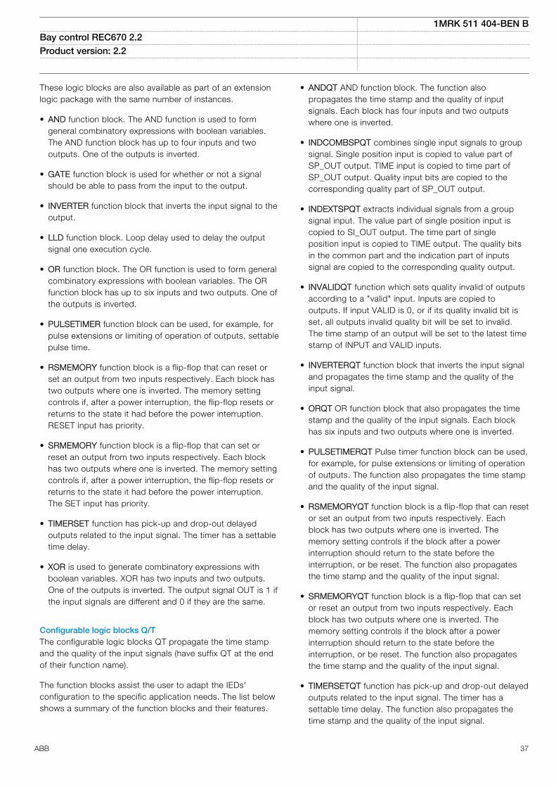
These logic blocks are also available as part of an extensionlogic package with the same number of instances.
• AND function block. The AND function is used to formgeneral combinatory expressions with boolean variables.The AND function block has up to four inputs and twooutputs. One of the outputs is inverted.
• GATE function block is used for whether or not a signalshould be able to pass from the input to the output.
• INVERTER function block that inverts the input signal to theoutput.
• LLD function block. Loop delay used to delay the outputsignal one execution cycle.
• OR function block. The OR function is used to form generalcombinatory expressions with boolean variables. The ORfunction block has up to six inputs and two outputs. One ofthe outputs is inverted.
• PULSETIMER function block can be used, for example, forpulse extensions or limiting of operation of outputs, settablepulse time.
• RSMEMORY function block is a flip-flop that can reset orset an output from two inputs respectively. Each block hastwo outputs where one is inverted. The memory settingcontrols if, after a power interruption, the flip-flop resets orreturns to the state it had before the power interruption.RESET input has priority.
• SRMEMORY function block is a flip-flop that can set orreset an output from two inputs respectively. Each blockhas two outputs where one is inverted. The memory settingcontrols if, after a power interruption, the flip-flop resets orreturns to the state it had before the power interruption.The SET input has priority.
• TIMERSET function has pick-up and drop-out delayedoutputs related to the input signal. The timer has a settabletime delay.
• XOR is used to generate combinatory expressions withboolean variables. XOR has two inputs and two outputs.One of the outputs is inverted. The output signal OUT is 1 ifthe input signals are different and 0 if they are the same.
Configurable logic blocks Q/TGUID-0CA6511A-E8BD-416E-9B59-5C6BD98C60B7 v5
The configurable logic blocks QT propagate the time stampand the quality of the input signals (have suffix QT at the endof their function name).
The function blocks assist the user to adapt the IEDs'configuration to the specific application needs. The list belowshows a summary of the function blocks and their features.
• ANDQT AND function block. The function alsopropagates the time stamp and the quality of inputsignals. Each block has four inputs and two outputswhere one is inverted.
• INDCOMBSPQT combines single input signals to groupsignal. Single position input is copied to value part ofSP_OUT output. TIME input is copied to time part ofSP_OUT output. Quality input bits are copied to thecorresponding quality part of SP_OUT output.
• INDEXTSPQT extracts individual signals from a groupsignal input. The value part of single position input iscopied to SI_OUT output. The time part of singleposition input is copied to TIME output. The quality bitsin the common part and the indication part of inputssignal are copied to the corresponding quality output.
• INVALIDQT function which sets quality invalid of outputsaccording to a "valid" input. Inputs are copied tooutputs. If input VALID is 0, or if its quality invalid bit isset, all outputs invalid quality bit will be set to invalid.The time stamp of an output will be set to the latest timestamp of INPUT and VALID inputs.
• INVERTERQT function block that inverts the input signaland propagates the time stamp and the quality of theinput signal.
• ORQT OR function block that also propagates the timestamp and the quality of the input signals. Each blockhas six inputs and two outputs where one is inverted.
• PULSETIMERQT Pulse timer function block can be used,for example, for pulse extensions or limiting of operationof outputs. The function also propagates the time stampand the quality of the input signal.
• RSMEMORYQT function block is a flip-flop that can resetor set an output from two inputs respectively. Eachblock has two outputs where one is inverted. Thememory setting controls if the block after a powerinterruption should return to the state before theinterruption, or be reset. The function also propagatesthe time stamp and the quality of the input signal.
• SRMEMORYQT function block is a flip-flop that can setor reset an output from two inputs respectively. Eachblock has two outputs where one is inverted. Thememory setting controls if the block after a powerinterruption should return to the state before theinterruption, or be reset. The function also propagatesthe time stamp and the quality of the input signal.
• TIMERSETQT function has pick-up and drop-out delayedoutputs related to the input signal. The timer has asettable time delay. The function also propagates thetime stamp and the quality of the input signal.
1MRK 511 404-BEN BBay control REC670 2.2 Product version: 2.2
ABB 37

• XORQT XOR function block. The function alsopropagates the time stamp and the quality of the inputsignals. Each block has two outputs where one isinverted.
Extension logic packageGUID-144BAAA3-A5EF-49AF-8876-93CC5F3D0234 v1
The logic extension block package includes additional tripmatrix logic and configurable logic blocks.
Fixed signal function block FXDSIGNM15322-3 v15
The Fixed signals function (FXDSIGN) has nine pre-set (fixed)signals that can be used in the configuration of an IED, eitherfor forcing the unused inputs in other function blocks to acertain level/value, or for creating certain logic. Boolean,integer, floating point, string types of signals are available.
One FXDSIGN function block is included in all IEDs.
Elapsed time integrator with limit transgression and overflowsupervision TEIGAPC
GUID-2D64874A-F266-4251-8EED-E813F40513D7 v3
The Elapsed time integrator function (TEIGAPC) is a functionthat accumulates the elapsed time when a given binary signalhas been high.
The main features of TEIGAPC
• Applicable to long time integration (≤999 999.9seconds).
• Supervision of limit transgression conditions andoverflow.
• Possibility to define a warning or alarm with theresolution of 10 milliseconds.
• Retaining of the integration value.• Possibilities for blocking and reset.• Reporting of the integrated time.
Boolean to integer conversion, 16 bit B16ISEMOD175725-4 v5
Boolean to integer conversion, 16 bit (B16I) is used totransform a set of 16 boolean (logical) signals into an integer.
Boolean to integer conversion with logical noderepresentation, 16 bit BTIGAPC
SEMOD175781-4 v8
Boolean to integer conversion with logical noderepresentation, 16 bit (BTIGAPC) is used to transform a set of16 boolean (logical) signals into an integer. The block inputwill freeze the output at the last value.
Integer to Boolean 16 conversion IB16SEMOD158373-5 v6
Integer to boolean 16 conversion function (IB16) is used totransform an integer into a set of 16 boolean (logical) signals.
Integer to Boolean 16 conversion with logic noderepresentation ITBGAPC
SEMOD158421-5 v9
Integer to boolean conversion with logic node representationfunction (ITBGAPC) is used to transform an integer which istransmitted over IEC 61850 and received by the function to16 boolean (logic) output signals.
Comparator for integer inputs INTCOMPGUID-A93564FA-0017-4939-A9C1-095DA0FD9832 v1
The function gives the possibility to monitor the level ofinteger values in the system relative to each other or to afixed value. It is a basic arithmetic function that can be usedfor monitoring, supervision, interlocking and other logics.
Comparator for real inputs REALCOMPGUID-E17A88D7-D095-4F36-9CD5-64EBFD2A1DEA v1
The function gives the possibility to monitor the level of realvalue signals in the system relative to each other or to a fixedvalue. It is a basic arithmetic function that can be used formonitoring, supervision, interlocking and other logics.
15. Monitoring
Measurements CVMMXN, CMMXU, VNMMXU, VMMXU,CMSQI, VMSQI
M12024-3 v9
The measurement functions are used to get on-lineinformation from the IED. These service values make itpossible to display on-line information on the local HMI andon the substation automation system about:
• measured voltages, currents, frequency, active, reactiveand apparent power and power factor
• measured analog values from merging units• primary phasors• positive, negative and zero sequence currents and
voltages• mA, input currents• pulse counters
Supervision of mA input signalsM16054-3 v2
The main purpose of the function is to measure and processsignals from different measuring transducers. Many devicesused in process control represent various parameters such asfrequency, temperature and DC battery voltage as low currentvalues, usually in the range 4-20 mA or 0-20 mA.
Alarm limits can be set and used as triggers, e.g. to generatetrip or alarm signals.
The function requires that the IED is equipped with the mAinput module.
Disturbance report DRPRDREM12153-3 v14
Complete and reliable information about disturbances in theprimary and/or in the secondary system together withcontinuous event-logging is accomplished by the disturbancereport functionality.
Disturbance report (DRPRDRE), always included in the IED,acquires sampled data of all selected analog input and binarysignals connected to the function block with a maximum of40 analog and 352 binary signals.
The Disturbance report functionality is a common name forseveral functions:
1MRK 511 404-BEN BBay control REC670 2.2 Product version: 2.2
38 ABB

• Event list• Indications• Event recorder• Trip value recorder• Disturbance recorder• Fault locator• Settings information
The Disturbance report function is characterized by greatflexibility regarding configuration, starting conditions,recording times, and large storage capacity.
A disturbance is defined as an activation of an input to theAnRADR or BnRBDR function blocks, which are set to triggerthe disturbance recorder. All connected signals from start ofpre-fault time to the end of post-fault time will be included inthe recording. Disturbance record will have visible settingsfrom all function instances that are configured in theapplication configuration tool.
Every disturbance report recording is saved in the IED in thestandard Comtrade format as a reader file HDR, aconfiguration file CFG, and a data file DAT. The same appliesto all events, which are continuously saved in a ring-buffer.The local HMI is used to get information about the recordings.The disturbance report files can be uploaded to PCM600 forfurther analysis using the disturbance handling tool.
Event list DRPRDREM12412-6 v8
Continuous event-logging is useful for monitoring the systemfrom an overview perspective and is a complement to specificdisturbance recorder functions.
The event list logs all binary input signals connected to theDisturbance recorder function. The list may contain up to1000 time-tagged events stored in a ring-buffer.
Indications DRPRDREM12030-3 v7
To get fast, condensed and reliable information aboutdisturbances in the primary and/or in the secondary system itis important to know, for example binary signals that havechanged status during a disturbance. This information is usedin the short perspective to get information via the local HMI ina straightforward way.
There are three LEDs on the local HMI (green, yellow andred), which will display status information about the IED andthe Disturbance recorder function (triggered).
The Indication list function shows all selected binary inputsignals connected to the Disturbance recorder function thathave changed status during a disturbance.
Event recorder DRPRDREM12033-3 v8
Quick, complete and reliable information about disturbancesin the primary and/or in the secondary system is vital, forexample, time-tagged events logged during disturbances.This information is used for different purposes in the short
term (for example corrective actions) and in the long term (forexample functional analysis).
The event recorder logs all selected binary input signalsconnected to the Disturbance recorder function. Eachrecording can contain up to 150 time-tagged events.
The event recorder information is available for thedisturbances locally in the IED.
The event recording information is an integrated part of thedisturbance record (Comtrade file).
Trip value recorder DRPRDREM12128-3 v7
Information about the pre-fault and fault values for currentsand voltages are vital for the disturbance evaluation.
The Trip value recorder calculates the values of all selectedanalog input signals connected to the Disturbance recorderfunction. The result is magnitude and phase angle before andduring the fault for each analog input signal.
The trip value recorder information is available for thedisturbances locally in the IED.
The trip value recorder information is an integrated part of thedisturbance record (Comtrade file).
Disturbance recorder DRPRDREM12156-3 v12
The Disturbance recorder function supplies fast, completeand reliable information about disturbances in the powersystem. It facilitates understanding system behavior andrelated primary and secondary equipment during and after adisturbance. Recorded information is used for differentpurposes in the short perspective (for example correctiveactions) and long perspective (for example functionalanalysis).
The Disturbance recorder acquires sampled data fromselected analog and binary signals connected to theDisturbance recorder function (maximum 40 analog and 352binary signals). The binary signals available are the same asfor the event recorder function.
The function is characterized by great flexibility and is notdependent on the operation of protection functions. It canrecord disturbances not detected by protection functions. Upto ten seconds of data before the trigger instant can be savedin the disturbance file.
The disturbance recorder information for up to 100disturbances are saved in the IED and the local HMI is usedto view the list of recordings .
Event functionM12805-6 v11
When using a Substation Automation system with LON orSPA communication, time-tagged events can be sent atchange or cyclically from the IED to the station level. Theseevents are created from any available signal in the IED that is
1MRK 511 404-BEN BBay control REC670 2.2 Product version: 2.2
ABB 39

connected to the Event function (EVENT). The EVENTfunction block is used for LON and SPA communication.
Analog, integer and double indication values are alsotransferred through the EVENT function.
Generic communication function for Single Point indicationSPGAPC
SEMOD55713-5 v8
Generic communication function for Single Point indication(SPGAPC) is used to send one single logical signal to othersystems or equipment in the substation.
Generic communication function for measured valuesMVGAPC
SEMOD55872-5 v10
Generic communication function for measured values(MVGAPC) function is used to send the instantaneous valueof an analog signal to other systems or equipment in thesubstation. It can also be used inside the same IED, to attacha RANGE aspect to an analog value and to permitmeasurement supervision on that value.
Measured value expander block RANGE_XPSEMOD52450-4 v8
The current and voltage measurements functions (CVMMXN,CMMXU, VMMXU and VNMMXU), current and voltagesequence measurement functions (CMSQI and VMSQI) andIEC 61850 generic communication I/O functions (MVGAPC)are provided with measurement supervision functionality. Allmeasured values can be supervised with four settable limits:low-low limit, low limit, high limit and high-high limit. Themeasure value expander block (RANGE_XP) has beenintroduced to enable translating the integer output signal fromthe measuring functions to 5 binary signals: below low-lowlimit, below low limit, normal, above high limit or above high-high limit. The output signals can be used as conditions in theconfigurable logic or for alarming purpose.
Insulation supervision for gas medium function SSIMGGUID-0692CD0D-F33E-4370-AC91-B216CAAAFC28 v6
Insulation supervision for gas medium (SSIMG) is used formonitoring the circuit breaker condition. Binary informationbased on the gas pressure in the circuit breaker is used asinput signals to the function. In addition, the functiongenerates alarms based on received information.
Insulation supervision for liquid medium SSIMLGUID-3B1A665F-60A5-4343-85F4-AD9C066CBE8D v7
Insulation supervision for liquid medium (SSIML) is used formonitoring the oil insulated device condition. For example,transformers, shunt reactors, and so on. Binary informationbased on the oil level in the oil insulated devices are used asinput signals to the function. In addition, the functiongenerates alarms based on the received information.
Circuit breaker condition monitoring SSCBRGUID-E1FD74C3-B9B6-4E11-AA1B-7E7F822FB4DD v13
The circuit breaker condition monitoring function (SSCBR) isused to monitor different parameters of the breaker condition.The breaker requires maintenance when the number ofoperations reaches a predefined value. For a properfunctioning of the circuit breaker, it is essential to monitor thecircuit breaker operation, spring charge indication or breaker
wear, travel time, number of operation cycles and estimatethe accumulated energy during arcing periods.
Fault locator LMBRFLOM13970-3 v13
The accurate fault locator is an essential component tominimize the outages after a persistent fault and/or to pin-point a weak spot on the line.
The fault locator is an impedance measuring function givingthe distance to the fault in km, miles or % of line length. Themain advantage is the high accuracy achieved bycompensating for load current and for the mutual zero-sequence effect on double circuit lines.
The compensation includes setting of the remote and localsources and calculation of the distribution of fault currentsfrom each side. This distribution of fault current, together withrecorded load (pre-fault) currents, is used to exactly calculatethe fault position. The fault can be recalculated with newsource data at the actual fault to further increase theaccuracy.
Especially on heavily loaded long lines, where the sourcevoltage angles can be up to 35-40 degrees apart, theaccuracy can be still maintained with the advancedcompensation included in fault locator.
Event counter with limit supervison L4UFCNTGUID-13157EAB-1686-4D2E-85DF-EC89768F3572 v6
The Limit counter (L4UFCNT) provides a settable counter withfour independent limits where the number of positive and/ornegative flanks on the input signal are counted against thesetting values for limits. The output for each limit is activatedwhen the counted value reaches that limit.
Overflow indication is included for each up-counter.
Running hour-meter TEILGAPCGUID-464FB24F-B367-446C-963A-A14841943B87 v2
The Running hour-meter (TEILGAPC) function is a functionthat accumulates the elapsed time when a given binary signalhas been high.
The main features of TEILGAPC are:
• Applicable to very long time accumulation (≤ 99999.9hours)
• Supervision of limit transgression conditions and rollover/overflow
• Possibility to define a warning and alarm with theresolution of 0.1 hours
• Retain any saved accumulation value at a restart• Possibilities for blocking and reset• Possibility for manual addition of accumulated time• Reporting of the accumulated time
Estimation of transformer winding insulation life LOLSPTRGUID-CDE89397-8E99-4873-9701-FF642101A308 v2
Estimation of transformer winding insulation life (LOLSPTR) isused to calculate transformer winding hot spot temperatureusing the empirical formulae. It is also used to estimate
1MRK 511 404-BEN BBay control REC670 2.2 Product version: 2.2
40 ABB

transformer loss of life from the winding hot spot temperaturevalue. The transformer winding insulation is degraded whenthe winding hot spot temperature exceeds certain limit.LOLSPTR gives warning and alarm signals when the windinghot spot temperature reaches a set value.
Hot spot temperature calculation requires top oil temperatureat a given time. This value can either be a measured valuetaken through sensors or the one calculated by the function.This decision is made based on the top oil temperaturesensor quality. Top oil temperature calculation is done usingthe method explained in IEC 60076-7 standard.
Inputs required for hot spot temperature calculation are:• Transformer oil time constant• Winding time constant• Loss ratio at different tap positions• Ambient temperature around the transformer
The oil and winding time constants can be calculated by thefunction based on transformer parameters if the inputs arenot available from the transformer manufacturer.
Ambient temperature to the function can either be providedthrough the sensor or monthly average ambient temperaturesettings. This decision is made based on the ambienttemperature sensor quality. Additionally, LOLSPTR functionprovides difference between measured value and calculatedvalue of the top oil temperature.
Additionally, the function calculates loss of life in form of daysand years. This information is updated at settable intervals,for example, hourly or daily. Transformer winding percentageloss of life is calculated every day and the information isprovided as total percentage loss of life from the installationdate and yearly percentage loss of life.
16. Metering
Pulse-counter logic PCFCNTM13394-3 v7
Pulse-counter logic (PCFCNT) function counts externallygenerated binary pulses, for instance pulses coming from anexternal energy meter, for calculation of energy consumptionvalues. The pulses are captured by the binary input moduleand then read by the PCFCNT function. A scaled servicevalue is available over the station bus. The special Binaryinput module with enhanced pulse counting capabilities mustbe ordered to achieve this functionality.
Function for energy calculation and demand handlingETPMMTR
GUID-6898E29B-DA70-421C-837C-1BBED8C63A7A v3
Power system measurement (CVMMXN) can be used tomeasure active as well as reactive power values. Function forenergy calculation and demand handling (ETPMMTR) usesmeasured active and reactive power as input and calculatesthe accumulated active and reactive energy pulses, in forwardand reverse direction. Energy values can be read or
generated as pulses. Maximum demand power values arealso calculated by the function. This function includes zeropoint clamping to remove noise from the input signal. Asoutput of this function: periodic energy calculations,integration of energy values, calculation of energy pulses,alarm signals for limit violation of energy values and maximumpower demand, can be found.
The values of active and reactive energies are calculated fromthe input power values by integrating them over a selectedtime tEnergy. The integration of active and reactive energyvalues will happen in both forward and reverse directions.These energy values are available as output signals and alsoas pulse outputs. Integration of energy values can becontrolled by inputs (STARTACC and STOPACC) and EnaAccsetting and it can be reset to initial values with RSTACCinput.
The maximum demand for active and reactive powers arecalculated for the set time interval tEnergy and these valuesare updated every minute through output channels. Theactive and reactive maximum power demand values arecalculated for both forward and reverse direction and thesevalues can be reset with RSTDMD input.
1MRK 511 404-BEN BBay control REC670 2.2 Product version: 2.2
ABB 41

17. Human machine interface
Local HMIAMU0600442 v15
IEC13000239-3-en.vsd
IEC13000239 V3 EN-US
Figure 5. Local human-machine interface
The LHMI of the IED contains the following elements• Graphical display capable of showing a user defined single
line diagram and provide an interface for controllingswitchgear.
• Navigation buttons and five user defined command buttonsto shortcuts in the HMI tree or simple commands.
• 15 user defined three-color LEDs.• Communication port for PCM600.
The LHMI is used for setting, monitoring and controlling.
18. Basic IED functions
Time synchronizationM11344-3 v11
The time synchronization function is used to select a commonsource of absolute time for the synchronization of the IEDwhen it is a part of a control and a protection system. Thismakes it possible to compare events and disturbance databetween all IEDs within a station automation system and inbetween sub-stations. A common source shall be used forIED and merging unit when IEC/UCA 61850-9-2LE processbus communication is used.
M11345-3 v11
Precision time protocol PTPPTP according to IEEE 1588-2008 and specifically its profileIEC/IEEE 61850-9-3 for power utility automation is asynchronization method that can be used to maintain acommon time within a station. This time can be synchronizedto the global time using, for instance, a GPS receiver. If PTPis enabled on the IEDs and the switches that connect thestation are compatible with IEEE 1588, the station willbecome synchronized to one common time with an accuracyof under 1us. Using an IED as a boundary clock betweenseveral networks will keep 1us accuracy on three levels orwhen using an HSR, 15 IEDs can be connected in a ringwithout losing a single microsecond in accuracy.
19. Ethernet
Access pointsGUID-6E5D2696-A8EE-43E7-A94B-69C3D0612127 v2
An access point is an Ethernet communication interface forsingle or redundant station communication. Each accesspoint is allocated with one physical Ethernet port, twophysical Ethernet ports are allocated if redundantcommunication is activated for the access point.
AP1
SFP_302SFP_301
Device 1
AP1
SFP_302SFP_301
Device 1
AP2
IEC16000092-1-en.vsdx
SFP_303
AP3 AP2
SFP_303
AP3
IEC16000092 V1 EN-US
Figure 6. Access points, non redundant (left) and redundantcommunication (right)
Access points diagnosticsGUID-20F64A6D-AA8C-47D7-AA7D-4810996B2FF2 v2
The access point diagnostics function blocks (RCHLCCH,SCHLCCH and FRONTSTATUS) supervise communication.SCHLCCH is used for communication over the rear Ethernetports, RCHLCCH is used for redundant communications overthe rear Ethernet ports and FRONTSTATUS is used forcommunication over the front port. All access point functionblocks include output signal for denial of service.
Redundant communicationGUID-A90FDBA7-D4D7-4CBD-9F05-13DCC9971779 v7
IEC 62439-3 redundant communication PRPRedundant communication according to IEC 62439-3 PRP-0,IEC 62439-3 PRP-1 parallel redundancy protocol (PRP) isavailable as an option when ordering IEDs. PRP according toIEC 62439-3 uses two optical Ethernet ports.
IEC 62439-3 High-availability seamless redundancy HSRRedundant station bus communication according to IEC62439-3 Edition 2 High-availability seamless redundancy(HSR) is available as an option when ordering IEDs.Redundant station bus communication according to IEC62439-3 uses two optical Ethernet ports.
1MRK 511 404-BEN BBay control REC670 2.2 Product version: 2.2
42 ABB

The HSR ring supports the connection of up to 30 relays. Ifmore than 30 relays are to be connected, it is recommendedto split the network into several rings to guarantee theperformance for real-time applications.
RoutesGUID-95F9C7BA-92F8-489F-AD0A-047410B5E66F v1
A route is a specified path for data to travel between thesource device in a subnetwork to the destination device in adifferent subnetwork. A route consists of a destinationaddress and the address of the gateway to be used whensending data to the destination device, see Figure 7.
Gateway
Source Destination
Default gateway
IEC16000095-1-en.vsdx
IEC16000095 V1 EN-US
Figure 7. Route from source to destination through gateway
20. Station communication
Communication protocolsM14815-3 v14
Each IED is provided with several communication interfacesenabling it to connect to one or many substation levelsystems or equipment, either on the Substation Automation(SA) bus or Substation Monitoring (SM) bus.
Available communication protocols are:
• IEC 61850-8-1 communication protocol• IEC/UCA 61850-9-2LE communication protocol• LON communication protocol• SPA communication protocol• IEC 60870-5-103 communication protocol
Several protocols can be combined in the same IED.
IEC 61850-8-1 communication protocolM14787-3 v16
IEC 61850 Ed.1 or Ed.2 can be chosen by a setting inPCM600. The IED is equipped with up to six (orderdependent) optical Ethernet rear ports for IEC 61850-8-1station bus communication.The IEC 61850-8-1communication is also possible from the electrical Ethernetfront port. IEC 61850-8-1 protocol allows intelligent electricaldevices (IEDs) from different vendors to exchange informationand simplifies system engineering. IED-to-IED communicationusing GOOSE and client-server communication over MMS aresupported. Disturbance recording file (COMTRADE) uploadingcan be done over MMS or FTP.
The front port is only intended for PCM600communication, maintenance, training andtest purposes due to risk of interferenceduring normal operation.
IEC 61850 quality expander QUALEXPGUID-9C5DC78E-041B-422B-9668-320E62B847A2 v1
The quality expander component is used to display thedetailed quality of an IEC/UCA 61850-9-2LE analog channel.The component expands the channel quality output of aMerging Unit analog channel received in the IED as per theIEC 61850-7-3 standard. This component can be used duringthe ACT monitoring to get the particular channel quality of theMerging Unit.
IEC/UCA 61850-9-2LE communication protocolGUID-C3AA21B4-730F-4327-943A-3C77102A80A0 v4
Optical Ethernet port communication standard IEC/UCA61850-9-2LE for process bus is supported. IEC/UCA61850-9-2LE allows Non Conventional InstrumentTransformers (NCIT) with Merging Units (MUs) or stand-aloneMUs to exchange information with the IED, and simplifies SAengineering. IEC/UCA 61850-9-2LE uses the same port asIEC 61850-8-1.
LON communication protocolSEMOD120140-5 v3
Existing stations with ABB station bus LON can be extendedwith use of the optical LON interface (glass or plastic). Thisallows full SA functionality including peer-to-peer messagingand cooperation between the IEDs.
SPA communication protocolSEMOD120134-5 v1
A single glass or plastic port is provided for the ABB SPAprotocol. This allows extensions of simple substationautomation systems but the main use is for SubstationMonitoring Systems SMS.
IEC 60870-5-103 communication protocolSEMOD120137-5 v4
A single glass or plastic port is provided for the IEC60870-5-103 standard. This allows design of simplesubstation automation systems including equipment fromdifferent vendors. Disturbance files uploading is provided.
Measurands for IEC 60870-5-103 I103MEAS103MEAS is a function block that reports all valid measuringtypes depending on the connected signals. The set ofconnected inputs will control which ASDUs (ApplicationService Data Units) are generated.
Measurands user-defined signals for IEC 60870-5-103I103MEASUSRI103MEASUSR is a function block with user-defined inputmeasurands in monitor direction. These function blocksinclude the FunctionType parameter for each block in theprivate range, and the Information number parameter for eachblock.
1MRK 511 404-BEN BBay control REC670 2.2 Product version: 2.2
ABB 43

Function status auto-recloser for IEC 60870-5-103 I103ARI103AR is a function block with defined functions forautorecloser indications in monitor direction. This blockincludes the FunctionType parameter, and the informationnumber parameter is defined for each output signal.
Function status earth-fault for IEC 60870-5-103 I103EFI103EF is a function block with defined functions for earthfault indications in monitor direction. This block includes theFunctionType parameter; the information number parameteris defined for each output signal.
Function status fault protection for IEC 60870-5-103I103FLTPROTI103FLTPROT is used for fault indications in monitordirection. Each input on the function block is specific for acertain fault type and therefore must be connected to acorrespondent signal present in the configuration. Forexample: 68_TRGEN represents the General Trip of thedevice and must be connected to the general trip signalSMPPTRC_TRIP or equivalent.
IED status for IEC 60870-5-103 I103IEDI103IED is a function block with defined IED functions inmonitor direction. This block uses the parameterFunctionType; the information number parameter is definedfor each input signal.
Supervison status for IEC 60870-5-103 I103SUPERVI103SUPERV is a function block with defined functions forsupervision indications in monitor direction. This blockincludes the FunctionType parameter; the information numberparameter is defined for each output signal.
Status for user-defined signals for IEC 60870-5-103I103USRDEFI103USRDEF comprises function blocks with user-definedinput signals in monitor direction. These function blocksinclude the FunctionType parameter for each block in theprivate range, and the information number parameter for eachinput signal.
Function commands for IEC 60870-5-103 I103CMDI103CMD is a command function block in control directionwith pre-defined output signals. The signals are in steadystate, not pulsed, and stored in the IED in case of restart.
IED commands for IEC 60870-5-103 I103IEDCMDI103IEDCMD is a command block in control direction withdefined IED functions. All outputs are pulsed and they areNOT stored. Pulse-time is a hidden parameter.
Function commands user-defined for IEC 60870-5-103I103USRCMDI103USRCMD is a command block in control direction withuser-defined output signals. These function blocks includethe FunctionType parameter for each block in the private
range, and the Information number parameter for each outputsignal.
Function commands generic for IEC 60870-5-103I103GENCMDI103GENCMD is used for transmitting generic commandsover IEC 60870-5-103. The function has two output signals,CMD_OFF and CMD_ON, that can be used to implementdouble-point command schemes.
The I103GENCMD component can be configured as either 2pulsed ON/OFF or 2 steady ON/OFF outputs. The ON outputis pulsed with a command with value 2, while the OFF outputis pulsed with a command with value 1. If in steady mode isON asserted and OFF deasserted with command 2 and viceversa with command 1.
IED commands with position and select for IEC 60870-5-103I103POSCMDI103POSCMD has double-point position indicators that aregetting the position value as an integer (for example, from thePOSITION output of the SCSWI function block) and sending itover IEC 60870-5-103 (1=OPEN; 2=CLOSE). The standarddoes not define the use of values 0 and 3. However, whenconnected to a switching device, these values aretransmitted.
The BLOCK input will block only the signals in monitoringdirection (the position information), not the commands via IEC60870-5-103. The SELECT input is used to indicate that themonitored apparatus has been selected (in a select-before-operate type of control).
DNP3.0 communication protocolSEMOD153688-5 v3
An electrical RS485 serial port, optical serial ports on theserial communication module (SLM), optical Ethernet portsare available for DNP3.0 communication. DNP3.0 Level 2communication with unsolicited events, time synchronizationand disturbance reporting is provided for communication toRTUs, Gateways or HMI systems.
Multiple command and transmitM14791-3 v3
When IEDs are used in Substation Automation systems withLON, SPA or IEC 60870-5-103 communication protocols, theEvent and Multiple Command function blocks are used as thecommunication interface for vertical communication to stationHMI and gateway, and as interface for horizontal peer-to-peercommunication (over LON only).
21. Remote communication
Analog and binary signal transfer to remote endM12449-6 v3
Three analog and eight binary signals can be exchangedbetween two IEDs. This functionality is mainly used for theline differential protection. However it can be used in otherproducts as well. An IED can communicate with up to 4remote IEDs.
1MRK 511 404-BEN BBay control REC670 2.2 Product version: 2.2
44 ABB

Binary signal transferSEMOD52522-4 v8
The remote end data communication is used for thetransmission of analog values for line differential protection orfor the transmission of only binary signals between IEDs. Thebinary signals are freely configurable and can thus be usedfor any purpose, such as communication scheme relatedsignals, transfer trip and/or other binary signals betweenIEDs.
Communication between two IEDs requires that each IED isequipped with a Line Data Communication Module (LDCM).The LDCM then acts as an interface to 64 kbit/s and 2Mbit/scommunication channels for duplex communication betweenthe IEDs. In 2Mbit/s mode, each LDCM can send and receiveup to 9 analog and up to 192 binary signals simultaneously.In 64kbit/s mode, the LDCM can be configured to work ineither analog mode or binary mode. In analog mode, the IEDcan send and receive up to 3 analog signals and up to 8binary signals. In binary mode, the LDCM can send andreceive only binary data (up to 192 binary signals).
The IED can be equipped with up to two short range, mediumrange or long range LDCMs.
Line data communication module, short, medium and longrange LDCM
SEMOD168481-4 v10
The line data communication module (LDCM) is used forcommunication between the IEDs situated at a distance <110km/68 miles or from the IED to the optical-to-electricalconverter with G.703 or G.703E1 interface located at adistance < 3 km/1.9 miles away. The LDCM module sendsand receives data to and from another LDCM module. TheIEEE/ANSI C37.94 standard format is used.
Galvanic interface G.703 resp G.703E1M16035-3 v5
The external galvanic data communication converter G.703/G.703E1 makes an optical-to-galvanic conversion forconnection to a multiplexer. These units are designed for 64kbit/s resp 2Mbit/s operation. The converter is delivered with19” rack mounting accessories.
22. Hardware description
Hardware modulesIP14529-1 v1
Numeric processing module NUMM12643-3 v4
The numeric processing module (NUM) is a CPU module thathandles all protection functions and logic.
NUM provides up to 4 optical (type LC) or galvanic (typeRJ45) Ethernet ports(one basic and three optional).
Power supply module PSMM11595-3 v6
The power supply module is used to provide the correctinternal voltages and full isolation between the IED and thebattery system. An internal fail alarm output is available.
Alternative connectors of Ring lug or Compression type canbe ordered.
Binary input module BIMM1769-3 v4
The binary input module has 16 optically isolated inputs andis available in two versions, one standard and one withenhanced pulse counting capabilities on the inputs to beused with the pulse counter function. The binary inputs arefreely programmable and can be used for the input of logicalsignals to any of the functions. They can also be included inthe disturbance recording and event-recording functions. Thisenables extensive monitoring and evaluation of operation ofthe IED and for all associated electrical circuits.
Binary output module BOMM6938-3 v4
The binary output module has 24 independent output relaysand is used for trip output or any signaling purpose.
Static binary output module SOMSEMOD174196-4 v4
The static binary output module has six fast static outputsand six change over output relays for use in applications withhigh speed requirements.
Binary input/output module IOMM6939-3 v6
The binary input/output module is used when only a few inputand output channels are needed. The ten standard outputchannels are used for trip output or any signaling purpose.The two high speed signal output channels are used forapplications where short operating time is essential. Eightoptically isolated binary inputs cater for required binary inputinformation.
mA input module MIMM15020-3 v4
The milli-ampere input module is used to interface transducersignals in the –20 to +20 mA range from for example OLTCposition, temperature or pressure transducers. The modulehas six independent, galvanically separated channels.
Optical Ethernet moduleM16073-3 v8
The optical Ethernet module (OEM) provides two additionaloptical ethernet ports. The port connectors are of LC type.
Serial and LON communication module (SLM) for SPA/IEC60870-5-103, LON and DNP 3.0
M14933-3 v6
The Serial and LON communication module (SLM) is used forSPA, IEC 60870-5-103, DNP3 and LON communication. SLMhas two optical communication ports for plastic/plastic,plastic/glass or glass/glass fiber cables. One port is used forserial communication (SPA, IEC 60870-5-103 or DNP3 port)and the other port is used for LON communication.
Line data communication module LDCMM16075-3 v5
Each module has one optical port, one for each remote endto which the IED communicates.
Alternative modules for Long range (1550 nm single mode),Medium range (1310 nm single mode) and Short range (850nm multi mode) are available.
Galvanic RS485 serial communication moduleSEMOD158664-5 v3
The Galvanic RS485 communication module (RS485) is usedfor DNP3.0 and IEC 60870-5-103 communication. The
1MRK 511 404-BEN BBay control REC670 2.2 Product version: 2.2
ABB 45

module has one RS485 communication port. The RS485 is abalanced serial communication that can be used either in 2-wire or 4-wire connections. A 2-wire connection uses thesame signal for RX and TX and is a multidrop communicationwith no dedicated Master or slave. This variant requireshowever a control of the output. The 4-wire connection hasseparated signals for RX and TX multidrop communicationwith a dedicated Master and the rest are slaves. No specialcontrol signal is needed in this case.
GPS time synchronization module GTMM14851-3 v5
This module includes a GPS receiver used for timesynchronization. The GTM has one SMA contact forconnection to an antenna. It also includes an optical PPS ST-connector output.
IRIG-B Time synchronizing moduleSEMOD141113-4 v8
The IRIG-B time synchronizing module is used for accuratetime synchronizing of the IED from a station clock.
Electrical (BNC) and optical connection (ST) for 0XX and 12XIRIG-B support.
Transformer input module TRMM14875-3 v9
The transformer input module is used to galvanically separateand adapt the secondary currents and voltages generated bythe measuring transformers. The module has twelve inputs indifferent combinations of currents and voltage inputs.
Alternative connectors of Ring lug or Compression type canbe ordered.
High impedance resistor unitM16727-3 v2
The high impedance resistor unit, with resistors for pick-upvalue setting and a voltage dependent resistor, is available ina single phase unit and a three phase unit. Both are mountedon a 1/1 19 inch apparatus plate with compression typeterminals.
Layout and dimensionsIP14539-1 v1
DimensionsIP14826-1 v1
M15243-4 v7
CB
D
E
A
IEC08000163-2-en.vsdIEC08000163 V2 EN-US
Figure 8. Case with rear cover
IEC08000165-2-en.vsdx
JG
F
K
H
IEC08000165 V2 EN-US
Figure 9. Case with rear cover and 19” rack mounting kit
1MRK 511 404-BEN BBay control REC670 2.2 Product version: 2.2
46 ABB

IEC06000182-2-en.vsdIEC06000182 V2 EN-US
Figure 10. A 1/2 x 19” size IED side-by-side with RHGS6.
M15243-12 v9
Case size(mm)/(inches)
A B C D E F G H J K
6U, 1/2 x 19” 265.9/10.47
223.7/8.81
242.1/9.53
255.8/10.07
205.7/8.10
190.5/7.50
203.7/8.02
- 228.6/9.00
-
6U, 3/4 x 19” 265.9/10.47
336.0/13.23
242.1/9.53
255.8/10.07
318.0/12.52
190.5/7.50
316.0/12.4
- 228.6/9.00
-
6U, 1/1 x 19” 265.9/10.47
448.3/17.65
242.1/9.53
255.8/10.07
430.3/16.86
190.5/7.50
428.3/16.86
465.1/18.31
228.6/9.00
482.6/19.00
The H and K dimensions are defined by the 19” rack mounting kit.
Mounting alternativesM16079-3 v14
• 19” rack mounting kit• Flush mounting kit with cut-out dimensions:
– 1/2 case size (h) 254.3 mm/10.01” (w) 210.1 mm/8.27”
– 3/4 case size (h) 254.3 mm/10.01” (w) 322.4 mm/12.69”
– 1/1 case size (h) 254.3 mm/10.01” (w) 434.7 mm/17.11”
• Wall mounting kit
See ordering for details about available mounting alternatives.
1MRK 511 404-BEN BBay control REC670 2.2 Product version: 2.2
ABB 47

23. Connection diagramsGUID-CF4EFFA5-3081-4FC7-9A14-ED127C3C0FDE v7
The connection diagrams are delivered in the IED Connectivitypackage as part of the product delivery.
The latest versions of the connection diagrams can bedownloaded from http://www.abb.com/protection-control.
Connection diagrams for IEC Customized products
Connection diagram, 670 series 2.2 1MRK002801-AG
Connection diagrams for Configured products
Connection diagram, REC670 2.2, A30X00 1MRK002807-CA
Connection diagram, REC670 2.2, B30X00 1MRK002807-CB
Connection diagram, REC670 2.2, C30X00 1MRK002807-CC
Connection diagram, REC670 2.2, D30X00 1MRK002807-CE
Connection diagrams for ANSI Customized products
Connection diagram, 670 series 2.2 1MRK002802-AG
1MRK 511 404-BEN BBay control REC670 2.2 Product version: 2.2
48 ABB

24. Technical data
GeneralIP11376-1 v2M10993-1 v3
Definitions
Reference value The specified value of an influencing factor to which are referred the characteristics of the equipment
Nominal range The range of values of an influencing quantity (factor) within which, under specified conditions, the equipment meets thespecified requirements
Operative range The range of values of a given energizing quantity for which the equipment, under specified conditions, is able to perform itsintended functions according to the specified requirements
Presumptions for Technical DataGUID-1E949E38-E04D-4374-A086-912C25E9F93C v2
The technical data stated in this document are only validunder the following circumstances:
1. Main current transformers with 1 A or 2 A secondaryrating are wired to the IED 1 A rated CT inputs.
2. Main current transformer with 5 A secondary rating arewired to the IED 5 A rated CT inputs.
3. CT and VT ratios in the IED are set in accordance withthe associated main instrument transformers. Note thatfor functions which measure an analogue signal whichdo not have corresponding primary quantity the 1:1 ratioshall be set for the used analogue inputs on the IED.Example of such functions are: HZPDIF, ROTIPHIZ andSTTIPHIZ.
4. Parameter IBase used by the tested function is setequal to the rated CT primary current.
5. Parameter UBase used by the tested function is setequal to the rated primary phase-to-phase voltage.
6. Parameter SBase used by the tested function is setequal to:– √3 × IBase × UBase
7. The rated secondary quantities have the followingvalues:– Rated secondary phase current Ir is either 1 A or 5 A
depending on selected TRM.– Rated secondary phase-to-phase voltage Ur is within
the range from 100 V to 120 V.– Rated secondary power for three-phase system Sr =
√3 × Ur × Ir8. For operate and reset time testing, the default setting
values of the function are used if not explicitly statedotherwise.
9. During testing, signals with rated frequency have beeninjected if not explicitly stated otherwise.
1MRK 511 404-BEN BBay control REC670 2.2 Product version: 2.2
ABB 49

Energizing quantities, rated values and limitsAnalog inputs
IP15842-1 v1M16988-1 v11
Table 11. TRM - Energizing quantities, rated values and limits for protection transformer
Description Value
Frequency
Rated frequency fr 50/60 Hz
Operating range fr ± 10%
Current inputs
Rated current Ir 1 or 5 A
Operating range (0-100) x Ir
Thermal withstand 100 × Ir for 1 s *)30 × Ir for 10 s10 × Ir for 1 min4 × Ir continuously
Dynamic withstand 250 × Ir one half wave
Burden < 20 mVA at Ir = 1 A< 150 mVA at Ir = 5 A
*) max. 350 A for 1 s when COMBITEST test switch is included.
Voltage inputs **)
Rated voltage Ur 110 or 220 V
Operating range 0 - 340 V
Thermal withstand 450 V for 10 s420 V continuously
Burden < 20 mVA at 110 V< 80 mVA at 220 V
**) all values for individual voltage inputs
Note! All current and voltage data are specified as RMS values at rated frequency
1MRK 511 404-BEN BBay control REC670 2.2 Product version: 2.2
50 ABB

Table 12. TRM - Energizing quantities, rated values and limits for measuring transformer
Description Value
Frequency
Rated frequency fr 50/60 Hz
Operating range fr ± 10%
Current inputs
Rated current Ir 1A 5 A
Operating range (0-1.8) × Ir (0-1.6) × Ir
Thermal withstand 80 × Ir for 1 s25 × Ir for 10 s10 × Ir for 1 min1.8 × Ir for 30 min1.1 × Ir continuously
65 × Ir for 1 s20 × Ir for 10 s8 × Ir for 1 min1.6 × Ir for 30 min1.1 × Ir continuously
Burden < 200 mVA at Ir < 350 mVA at Ir
Voltage inputs *)
Rated voltage Ur 110 or 220 V
Operating range 0 - 340 V
Thermal withstand 450 V for 10 s420 V continuously
Burden < 20 mVA at 110 V< 80 mVA at 220 V
*) all values for individual voltage inputs
Note! All current and voltage data are specified as RMS values at rated frequencyM6389-1 v5
Table 13. MIM - mA input module
Quantity: Rated value: Nominal range:
Input resistance Rin = 194 Ohm -
Input range ±5, ±10, ±20 mA0-5, 0-10, 0-20, 4-20 mA
-
Power consumptioneach mA boardeach mA input
£ 2 W£ 0.1 W
-
Auxiliary DC voltageIP15843-1 v3M12286-1 v8
Table 14. PSM - Power supply module
Quantity Rated value Nominal range
Auxiliary DC voltage, EL (input) EL = (24-60) VEL = (100-250) V
EL ±20%EL ±20%
Power consumption 50 W typically -
Auxiliary DC power in-rush < 10 A during 0.1 s -
Supply interruption bridging time < 50 ms -
1MRK 511 404-BEN BBay control REC670 2.2 Product version: 2.2
ABB 51

Binary inputs and outputsIP15844-1 v1M12576-1 v11
Table 15. BIM - Binary input module
Quantity Rated value Nominal range
Binary inputs 16 -
DC voltage, RL 24/30 V48/60 V110/125 V220/250 V
RL ±20%RL ±20%RL ±20%RL ±20%
Power consumption24/30 V, 50 mA48/60 V, 50 mA110/125 V, 50 mA220/250 V, 50 mA220/250 V, 110 mA
max. 0.05 W/inputmax. 0.1 W/inputmax. 0.2 W/inputmax. 0.4 W/inputmax. 0.5 W/input
-
Counter input frequency 10 pulses/s max -
Oscillating signal discriminator Blocking settable 1–40 HzRelease settable 1–30 Hz
Debounce filter Settable 1–20 ms
Binary input operate time(Debounce filter set to 0 ms)
3 ms -
Maximum 176 binary input channels maybe activated simultaneously with influencingfactors within nominal range.
The stated operate time for functionsinclude the operating time for the binaryinputs and outputs.
M50609-2 v8
Table 16. BIM - Binary input module with enhanced pulse counting capabilities
Quantity Rated value Nominal range
Binary inputs 16 -
DC voltage, RL 24/30 V48/60 V110/125 V220/250 V
RL ±20%RL ±20%RL ±20%RL ±20%
Power consumption24/30 V48/60 V110/125 V220/250 V
max. 0.05 W/inputmax. 0.1 W/inputmax. 0.2 W/inputmax. 0.4 W/input
-
Counter input frequency 10 pulses/s max -
Balanced counter input frequency 40 pulses/s max -
Oscillating signal discriminator Blocking settable 1–40 HzRelease settable 1–30 Hz
Debounce filter Settable 1-20 ms
Binary input operate time(Debounce filter set to 0 ms)
3 ms -
1MRK 511 404-BEN BBay control REC670 2.2 Product version: 2.2
52 ABB

Maximum 176 binary input channels maybe activated simultaneously with influencingfactors within nominal range.
The stated operate time for functionsinclude the operating time for the binaryinputs and outputs.
M12573-1 v10
Table 17. IOM - Binary input/output module
Quantity Rated value Nominal range
Binary inputs 8 -
DC voltage, RL 24/30 V48/60 V110/125 V220/250 V
RL ±20%RL ±20%RL ±20%RL ±20%
Power consumption24/30 V, 50 mA48/60 V, 50 mA110/125 V, 50 mA220/250 V, 50 mA220/250 V, 110 mA
max. 0.05 W/inputmax. 0.1 W/inputmax. 0.2 W/inputmax. 0.4 W/inputmax. 0.5 W/input
-
Counter input frequency 10 pulses/s max
Oscillating signal discriminator Blocking settable 1-40 HzRelease settable 1-30 Hz
Debounce filter Settable 1-20 ms
Binary input operate time(Debounce filter set to 0 ms)
3 ms -
1MRK 511 404-BEN BBay control REC670 2.2 Product version: 2.2
ABB 53

Maximum 176 binary input channels maybe activated simultaneously with influencingfactors within nominal range.
The stated operate time for functionsinclude the operating time for the binaryinputs and outputs.
M12318-1 v9
Table 18. IOM - Binary input/output module contact data (reference standard: IEC 61810-2)
Function or quantity Trip and signal relays Fast signal relays (parallelreed relay)
Binary outputs 10 2
Max system voltage 250 V AC, DC 250 V DC
Test voltage across open contact, 1 min 1000 V rms 800 V DC
Current carrying capacityPer relay, continuousPer relay, 1 sPer process connector pin, continuous
8 A10 A12 A
8 A10 A12 A
Making capacity at inductive load with L/R > 10 ms 0.2 s1.0 s
30 A10 A
0.4 A0.4 A
Making capacity at resistive load 0.2 s1.0 s
30 A10 A
220–250 V/0.4 A110–125 V/0.4 A48–60 V/0.2 A24–30 V/0.1 A
Breaking capacity for AC, cos φ > 0.4 250 V/8.0 A 250 V/8.0 A
Breaking capacity for DC with L/R < 40 ms 48 V/1 A110 V/0.4 A125 V/0.35 A220 V/0.2 A250 V/0.15 A
48 V/1 A110 V/0.4 A125 V/0.35 A220 V/0.2 A250 V/0.15 A
Maximum capacitive load - 10 nF
Operating time < 6 ms <= 1 ms
Maximum 72 outputs may be activatedsimultaneously with influencing factorswithin nominal range. After 6 ms anadditional 24 outputs may be activated.The activation time for the 96 outputs mustnot exceed 200 ms. 48 outputs can beactivated during 1 s. Continued activationis possible with respect to currentconsumption but after 5 minutes the
temperature rise will adversely affect thehardware life. Maximum two relays perBOM/IOM/SOM should be activatedcontinuously due to power dissipation.
1MRK 511 404-BEN BBay control REC670 2.2 Product version: 2.2
54 ABB

The stated operate time for functionsinclude the operating time for the binaryinputs and outputs.
M12584-1 v9
Table 19. IOM with MOV and IOM 220/250 V, 110mA - contact data (reference standard: IEC 61810-2)
Function or quantity Trip and Signal relays Fast signal relays (parallel reed relay)
Binary outputs IOM: 10 IOM: 2
Max system voltage 250 V AC, DC 250 V DC
Test voltage across opencontact, 1 min
250 V rms 250 V rms
Current carrying capacityPer relay, continuousPer relay, 1 sPer process connector pin,continuous
8 A10 A12 A
8 A10 A12 A
Making capacity at inductiveloadwith L/R > 10 ms0.2 s1.0 s
30 A10 A
0.4 A0.4 A
Making capacity at resistive load 0.2 s1.0 s
30 A10 A
220–250 V/0.4 A110–125 V/0.4 A48–60 V/0.2 A24–30 V/0.1 A
Breaking capacity for AC, cos j> 0.4
250 V/8.0 A 250 V/8.0 A
Breaking capacity for DC withL/R < 40 ms
48 V/1 A110 V/0.4 A220 V/0.2 A250 V/0.15 A
48 V/1 A110 V/0.4 A220 V/0.2 A250 V/0.15 A
Maximum capacitive load - 10 nF
Operating time < 6 ms <= 1 ms
Maximum 72 outputs may be activatedsimultaneously with influencing factorswithin nominal range. After 6 ms anadditional 24 outputs may be activated.The activation time for the 96 outputs mustnot exceed 200 ms. 48 outputs can beactivated during 1 s. Continued activationis possible with respect to currentconsumption but after 5 minutes the
temperature rise will adversely affect thehardware life. Maximum two relays perBOM/IOM/SOM should be activatedcontinuously due to power dissipation.
1MRK 511 404-BEN BBay control REC670 2.2 Product version: 2.2
ABB 55

The stated operate time for functionsinclude the operating time for the binaryinputs and outputs.
SEMOD175395-2 v8
Table 20. SOM - Static Output Module (reference standard: IEC 61810-2): Static binary outputs
Function of quantity Static binary output trip
Rated voltage 48-60 VDC 110-250 VDC
Number of outputs 6 6
Impedance open state ~300 kΩ ~810 kΩ
Test voltage across open contact, 1 min No galvanic separation No galvanic separation
Current carrying capacity:
Continuous 5 A 5 A
1.0 s 10 A 10 A
Making capacity at capacitive load with themaximum capacitance of 0.2 μF :
0.2 s 30 A 30 A
1.0 s 10 A 10 A
Breaking capacity for DC with L/R ≤ 40 ms 48 V/1 A 110 V/0.4 A
60 V/0.75 A 125 V/0.35 A
220 V/0.2 A
250 V/0.15 A
Operating time < 1 ms < 1 ms
Table 21. SOM - Static Output module data (reference standard: IEC 61810-2): Electromechanical relay outputs
Function of quantity Trip and signal relays
Max system voltage 250 V AC/DC
Number of outputs 6
Test voltage across open contact, 1 min 1000 V rms
Current carrying capacity:
Continuous 8 A
1.0 s 10 A
Making capacity at capacitive load with the maximum capacitance of0.2 μF:
0.2 s 30 A
1.0 s 10 A
Breaking capacity for DC with L/R ≤ 40 ms 48 V/1 A
110 V/0.4 A
125 V/0.35 A
220 V/0.2 A
250 V/0.15 A
Operating time < 6 ms
1MRK 511 404-BEN BBay control REC670 2.2 Product version: 2.2
56 ABB

The stated operate time for functionsinclude the operating time for the binaryinputs and outputs.
M12441-1 v9
Table 22. BOM - Binary output module contact data (reference standard: IEC 61810-2)
Function or quantity Trip and Signal relays
Binary outputs 24
Max system voltage 250 V AC, DC
Test voltage across open contact, 1 min 1000 V rms
Current carrying capacityPer relay, continuousPer relay, 1 sPer process connector pin, continuous
8 A10 A12 A
Making capacity at inductive load with L/R > 10 ms0.2 s1.0 s
30 A10 A
Breaking capacity for AC, cos j > 0.4 250 V/8.0 A
Breaking capacity for DC with L/R < 40 ms 48 V/1 A110 V/0.4 A125 V/0.35 A220 V/0.2 A250 V/0.15 A
Operating time < 6 ms
The stated operate time for functionsinclude the operating time for the binaryinputs and outputs.
Influencing factorsIP15846-1 v1M16705-1 v15
Table 23. Temperature and humidity influence
Parameter Reference value Nominal range Influence
Ambient temperature, operatevalue
+20°C -25°C to +55°C 0.02%/°C
Relative humidityOperative range
10-90%0-95%
10-90% -
Storage temperature - -40°C to +70°C -
1MRK 511 404-BEN BBay control REC670 2.2 Product version: 2.2
ABB 57

Table 24. Auxiliary DC supply voltage influence on functionality during operation
Dependence on Reference value Within nominalrange
Influence
Ripple, in DC auxiliary voltageOperative range
max. 2%Full wave rectified
15% of EL 0.01%/%
Auxiliary voltage dependence, operatevalue
±20% of EL 0.01%/%
Interrupted auxiliary DC voltage
24-60 V DC ± 20% 100-250 V DC ±20%
Interruptioninterval0–50 ms
No restart
0–∞ s Correct behaviour at power down
Restart time < 300 s
Table 25. Frequency influence (reference standard: IEC 60255–1)
Dependence on Within nominal range Influence
Frequency dependence, operate value fr ±2.5 Hz for 50 Hzfr ±3.0 Hz for 60 Hz
±1.0%/Hz
Harmonic frequency dependence (20% content) 2nd, 3rd and 5th harmonic of fr ±2.0%
Harmonic frequency dependence for high impedance differentialprotection (10% content)
2nd, 3rd and 5th harmonic of fr ±10.0%
Harmonic frequency dependence for overcurrent protection 2nd, 3rd and 5th harmonic of fr ±3.0%
Type tests according to standardsIP15778-1 v1M16706-1 v13
1MRK 511 404-BEN BBay control REC670 2.2 Product version: 2.2
58 ABB

Table 26. Electromagnetic compatibility
Test Type test values Reference standards
1 MHz burst disturbance 2.5 kV IEC 60255-26
100 kHz slow damped oscillatory wave immunity test 2.5 kV IEC 61000-4-18, Class III
Ring wave immunity test, 100 kHz 2-4 kV IEC 61000-4-12, Class IV
Surge withstand capability test 2.5 kV, oscillatory4.0 kV, fast transient
IEEE/ANSI C37.90.1
Electrostatic dischargeDirect applicationIndirect application
15 kV air discharge8 kV contact discharge8 kV contact discharge
IEC 60255-26 IEC 61000-4-2, Class IV
Electrostatic dischargeDirect applicationIndirect application
15 kV air discharge8 kV contact discharge8 kV contact discharge
IEEE/ANSI C37.90.1
Fast transient disturbance 4 kV2 kV, SFP galvanic RJ452 kV, MIM mA-inputs
IEC 60255-26, Zone A IEC 60255-26, Zone B
Surge immunity test 2-4 kV, 1.2/50ms high energy1-2 kV, BOM and IRF outputs
IEC 60255-26, Zone AIEC 60255-26, Zone B
Power frequency immunity test 150-300 V, 50 Hz IEC 60255-26, Zone A
Conducted common mode immunity test 15 Hz-150 kHz IEC 61000-4-16, Class IV
Power frequency magnetic field test 1000 A/m, 3 s100 A/m, cont.
IEC 61000-4-8, Class V
Pulse magnetic field immunity test 1000 A/m IEC 61000–4–9, Class V
Damped oscillatory magnetic field test 100 A/m IEC 61000-4-10, Class V
Radiated electromagnetic field disturbance 20 V/m, 80-1000 MHz 1.4-2.7 GHz
IEC 60255-26
Radiated electromagnetic field disturbance 20 V/m80-1000 MHz10 V/m, 5.1-6.0 GHz
IEEE/ANSI C37.90.2 EN 50121-5
Conducted electromagnetic field disturbance 10 V, 0.15-80 MHz IEC 60255-26
Radiated emission 30-5000 MHz IEC 60255-26
Radiated emission 30-5000 MHz IEEE/ANSI C63.4, FCC
Conducted emission 0.15-30 MHz IEC 60255-26
Table 27. Insulation
Test Type test values Reference standard
Dielectric test 2.0 kV AC, 1 min.(SFP galvanic RJ45: 1.0kVrms, 1 min.)
IEC 60255-27ANSI C37.90IEEE 802.3-2015,Environment A
Impulse voltage test 5 kV, 1.2/50ms, 0.5 J1 kV, 1.2/50 ms 0.5 J, SFPgalvanic RJ45
Insulation resistance > 100 MW at 500 VDC
1MRK 511 404-BEN BBay control REC670 2.2 Product version: 2.2
ABB 59

Table 28. Environmental tests
Test Type test value Reference standard
Cold operation test Test Ad for 16 h at -25°C IEC 60068-2-1
Cold storage test Test Ab for 16 h at -40°C IEC 60068-2-1
Dry heat operation test Test Bd for 16 h at +70°C IEC 60068-2-2
Dry heat storage test Test Bb for 16 h at +85°C IEC 60068-2-2
Change of temperature test Test Nb for 5 cycles at -25°C to +70°C IEC 60068-2-14
Damp heat test, steady state Test Ca for 10 days at +40°C and humidity 93% IEC 60068-2-78
Damp heat test, cyclic Test Db for 6 cycles at +25 to +55°C and humidity 93 to 95% (1 cycle =24 hours)
IEC 60068-2-30
Table 29. CE compliance
Test According to
Immunity EN 60255–26
Emissivity EN 60255–26
Low voltage directive EN 60255–27
Table 30. Mechanical tests
Test Type test values Reference standards
Vibration response test Class II IEC 60255-21-1
Vibration endurance test Class I IEC 60255-21-1
Shock response test Class I IEC 60255-21-2
Shock withstand test Class I IEC 60255-21-2
Bump test Class I IEC 60255-21-2
Seismic test Class II IEC 60255-21-3
1MRK 511 404-BEN BBay control REC670 2.2 Product version: 2.2
60 ABB

Differential protectionM13081-1 v12
Table 31. High impedance differential protection, single phase HZPDIF
Function Range or value Accuracy
Operate voltage (10-900) VI=U/R
±1.0% of Ir at I ≤ Ir±1.0% of I at I > Ir
Reset ratio >95% at (30-900) V -
Maximum continuous power U>Trip2/SeriesResistor ≤200 W -
Operate time at 0 to 10 x Ud Min. = 5 msMax. = 15 ms
Reset time at 10 x Ud to 0 Min. = 75 msMax. = 95 ms
Critical impulse time 2 ms typically at 0 to 10 x Ud -
Operate time at 0 to 2 x Ud Min. = 25 msMax. = 35 ms
Reset time at 2 x Ud to 0 Min. = 50 msMax. = 70 ms
Critical impulse time 15 ms typically at 0 to 2 x Ud -
1MRK 511 404-BEN BBay control REC670 2.2 Product version: 2.2
ABB 61

Wide area measurement systemGUID-F0BAEBD8-E361-4D50-9737-7DF8B043D66A v4
Table 32. Protocol reporting via IEEE 1344 and C37.118 PMUREPORT
Influencing quantity Range Accuracy
Signal frequency ± 0.1 x fr ≤ 1.0% TVE
Signal magnitude:Voltage phasorCurrent phasor
(0.1–1.2) x Ur(0.5–2.0) x Ir
Phase angle ± 180°
Harmonic distortion 10% from 2nd – 50th
Interfering signal:MagnitudeMinimum frequencyMaximum frequency
10% of fundamental signal0.1 x fr1000 Hz
1MRK 511 404-BEN BBay control REC670 2.2 Product version: 2.2
62 ABB

Current protectionM12336-1 v13
Table 33. Instantaneous phase overcurrent protection PHPIOC
Function Range or value Accuracy
Operate current (5-2500)% of lBase ±1.0% of Ir at I ≤ Ir±1.0% of I at I > Ir
Reset ratio > 95% at (50–2500)% of IBase -
Operate time at 0 to 2 x Iset Min. = 15 msMax. = 25 ms
-
Reset time at 2 x Iset to 0 Min. = 15 msMax. = 25 ms
-
Critical impulse time 10 ms typically at 0 to 2 x Iset -
Operate time at 0 to 10 x Iset Min. = 5 msMax. = 15 ms
-
Reset time at 10 x Iset to 0 Min. = 25 msMax. = 40 ms
-
Critical impulse time 2 ms typically at 0 to 10 x Iset -
Dynamic overreach < 5% at t = 100 ms -
1MRK 511 404-BEN BBay control REC670 2.2 Product version: 2.2
ABB 63

M12342-1 v21
Table 34. Directional phase overcurrent protection, four steps OC4PTOC
Function Range or value Accuracy
Operate current, step 1-4 (5-2500)% of lBase ±1.0% of Ir at I ≤ Ir±1.0% of I at I > Ir
Reset ratio > 95% at (50–2500)% of lBase -
Minimum operate current, step 1-4 (1-10000)% of lBase ±1.0% of Ir at I ≤ Ir±1.0% of I at I > Ir
Relay characteristic angle (RCA) (40.0–65.0) degrees ±2.0 degrees
Relay operating angle (ROA) (40.0–89.0) degrees ±2.0 degrees
Second harmonic blocking (5–100)% of fundamental ±2.0% of Ir
Independent time delay at 0 to 2 x Iset, step1-4
(0.000-60.000) s ±0.2% or ±35 ms whichever is greater
Minimum operate time for inverse curves ,step 1-4
(0.000-60.000) s ±0.2% or ±35 ms whichever is greater
Inverse time characteristics, see table 155,table 156 and table 157
16 curve types See table 155, table 156 and table 157
Operate time, start non-directional at 0 to 2 xIset
Min. = 15 ms -
Max. = 30 ms
Reset time, start non-directional at 2 x Iset to 0 Min. = 15 ms -
Max. = 30 ms
Operate time, start non-directional at 0 to 10 xIset
Min. = 5 msMax. = 20 ms
-
Reset time, start non-directional at 10 x Iset to0
Min. = 20 msMax. = 35 ms
-
Critical impulse time 10 ms typically at 0 to 2 x Iset -
Impulse margin time 15 ms typically -
Operate frequency, directional overcurrent 38-83 Hz -
Operate frequency, non-directionalovercurrent
10-90 Hz -
1MRK 511 404-BEN BBay control REC670 2.2 Product version: 2.2
64 ABB

M12340-2 v9
Table 35. Instantaneous residual overcurrent protection EFPIOC
Function Range or value Accuracy
Operate current (5-2500)% of lBase ±1.0% of Ir at I ≤ Ir±1.0% of I at I > Ir
Reset ratio > 95% at (50–2500)% of lBase -
Operate time at 0 to 2 x Iset Min. = 15 msMax. = 25 ms
-
Reset time at 2 x Iset to 0 Min. = 15 msMax. = 25 ms
-
Critical impulse time 10 ms typically at 0 to 2 x Iset -
Operate time at 0 to 10 x Iset Min. = 5 msMax. = 15 ms
-
Reset time at 10 x Iset to 0 Min. = 25 msMax. = 35 ms
-
Critical impulse time 2 ms typically at 0 to 10 x Iset -
Dynamic overreach < 5% at t = 100 ms -
1MRK 511 404-BEN BBay control REC670 2.2 Product version: 2.2
ABB 65

M15223-1 v17
Table 36. Directional residual overcurrent protection, four steps EF4PTOC
Function Range or value Accuracy
Operate current, step 1-4 (1-2500)% of IBase ±1.0% of Ir at I ≤ Ir±1.0% of I at I > Ir
Reset ratio > 95% at (10-2500)% of IBase -
Relay characteristic angle(RCA)
(-180 to 180) degrees ±2.0 degrees
Operate current for directional release (1–100)% of IBase For RCA ±60 degrees:±2.5% of Ir at I ≤ Ir±2.5% of I at I > Ir
Independent time delay at 0 to 2 x Iset, step1-4
(0.000-60.000) s ±0.2% or ±35 ms whichever is greater
Minimum operate time for inverse curves,step 1-4
(0.000 - 60.000) s ±0.2% or ±35 ms whichever is greater
Inverse time characteristics, see Table 155,Table 156 and Table 157
16 curve types See Table 155, Table 156 and Table 157
Second harmonic blocking (5–100)% of fundamental ±2.0% of Ir
Minimum polarizing voltage (1–100)% of UBase ±0.5% of Ur
Minimum polarizing current (2-100)% of IBase ±1.0% of Ir
Real part of source Z used for currentpolarization
(0.50-1000.00) W/phase -
Imaginary part of source Z used for currentpolarization
(0.50–3000.00) W/phase -
Operate time, start non-directional at 0 to 2 xIset
Min. = 15 msMax. = 30 ms
-
Reset time, start non-directional at 2 x Iset to0
Min. = 15 msMax. = 30 ms
-
Operate time, start non-directional at 0 to 10x Iset
Min. = 5 msMax. = 20 ms
-
Reset time, start non-directional at 10 x Iset to0
Min. = 20 msMax. = 35 ms
-
Critical impulse time 10 ms typically at 0 to 2 x Iset -
Impulse margin time 15 ms typically -
1MRK 511 404-BEN BBay control REC670 2.2 Product version: 2.2
66 ABB

GUID-E83AD807-8FE0-4244-A50E-86B9AF92469E v6
Table 37. Four step directional negative phase sequence overcurrent protection NS4PTOC
Function Range or value Accuracy
Operate current, step 1 - 4 (1-2500)% of lBase ±1.0% of Ir at I £ Ir±1.0% of I at I > Ir
Reset ratio > 95% at (10-2500)% of IBase -
Independent time delay at 0 to 2 x Iset,step 1 - 4
(0.000-60.000) s ±0.2% or ±35 ms whichever is greater
Minimum operate time for inverse curves,step 1 - 4
(0.000 - 60.000) s ±0.2% or ±35 ms whichever is greater
Inverse time characteristics, see table155, table 156 and table 157
16 curve types See table 155, table 156 and table 157
Minimum operate current, step 1 - 4 (1.00 - 10000.00)% of IBase ±1.0% of Ir at I ≤ Ir±1.0% of I at I > Ir
Relay characteristic angle (RCA) (-180 to 180) degrees ±2.0 degrees
Operate current for directional release (1–100)% of IBase For RCA ±60 degrees:±2.5% of Ir at I ≤ Ir±2.5% of I at I > Ir
Minimum polarizing voltage (1–100)% of UBase ±0.5% of Ur
Real part of negative sequence sourceimpedance used for current polarization
(0.50-1000.00) W/phase -
Imaginary part of negative sequencesource impedance used for currentpolarization
(0.50–3000.00) W/phase -
Operate time, start non-directional at 0 to2 x Iset
Min. = 15 msMax. = 30 ms
-
Reset time, start non-directional at 2 x Isetto 0
Min. = 15 msMax. = 30 ms
-
Operate time, start non-directional at 0 to10 x Iset
Min. = 5 msMax. = 20 ms
-
Reset time, start non-directional at 10 xIset to 0
Min. = 20 msMax. = 35 ms
-
Critical impulse time 10 ms typically at 0 to 2 x Iset -
Impulse margin time 15 ms typically -
Transient overreach <10% at τ = 100 ms -
1MRK 511 404-BEN BBay control REC670 2.2 Product version: 2.2
ABB 67

SEMOD173350-2 v16
Table 38. Sensitive directional residual overcurrent and power protection SDEPSDE
Function Range or value Accuracy
Operate level for 3I0·cosj directional residualovercurrent
(0.25-200.00)% of IBase ±1.0% of Ir at I £ Ir±1.0% of I at I > Ir
Operate level for ·3I0·3U0 cosj directionalresidual power
(0.25-200.00)% of SBase ±1.0% of Sr at S £ Sr±1.0% of S at S > Sr
Operate level for 3I0 and j residualovercurrent
(0.25-200.00)% of IBase ±1.0% of Ir at £ Ir±1.0% of I at I > Ir
Operate level for non-directional overcurrent (1.00-400.00)% of IBase ±1.0% of Ir at I £ Ir±1.0% of I at I > Ir
Operate level for non-directional residualovervoltage
(1.00-200.00)% of UBase ±0.5% of Ur at U £ Ur±0.5% of U at U > Ur
Residual release current for all directionalmodes
(0.25-200.00)% of IBase ±1.0% of Ir at I £ Ir±1.0% of I at I > Ir
Residual release voltage for all directionalmodes
(1.00-300.00)% of UBase ±0.5% of Ur at U £ Ur±0.5% of U at U > Ur
Operate time for non-directional residualovercurrent at 0 to 2 x Iset
Min. = 40 ms
Max. = 65 ms
Reset time for non-directional residualovercurrent at 2 x Iset to 0
Min. = 40 ms
Max. = 65 ms
Operate time for directional residualovercurrent at 0 to 2 x Iset
Min. = 110 ms
Max. = 160 ms
Reset time for directional residual overcurrentat 2 x Iset to 0
Min. = 20 ms
Max. = 60 ms
Independent time delay for non-directionalresidual overvoltage at 0.8 x Uset to 1.2 x Uset
(0.000 – 60.000) s ±0.2% or ± 75 ms whichever is greater
Independent time delay for non-directionalresidual overcurrent at 0 to 2 x Iset
(0.000 – 60.000) s ±0.2% or ± 75 ms whichever is greater
Independent time delay for directionalresidual overcurrent at 0 to 2 x Iset
(0.000 – 60.000) s ±0.2% or ± 170 ms whichever is greater
Inverse characteristics, see table 158,Table 159 and Table 160
16 curve types See Table 158, Table 159 and Table 160
Relay characteristic angle (RCADir) (-179 to 180) degrees ±2.0 degrees
Relay operate angle (ROADir) (0 to 90) degrees ±2.0 degrees
1MRK 511 404-BEN BBay control REC670 2.2 Product version: 2.2
68 ABB
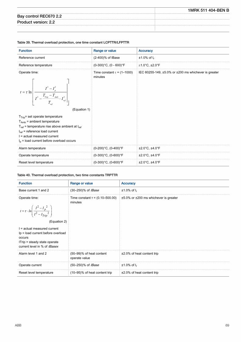
M12352-1 v15
Table 39. Thermal overload protection, one time constant LCPTTR/LFPTTR
Function Range or value Accuracy
Reference current (2-400)% of IBase ±1.0% of Ir
Reference temperature (0-300)°C, (0 - 600)°F ±1.0°C, ±2.0°F
Operate time:
2 2
2 2
ln p
Trip Amb
ref
ref
I It
T TI I
T
σ,
<,
, √
EQUATION13000039 V3 EN-US (Equation 1)
TTrip= set operate temperatureTAmb = ambient temperatureTref = temperature rise above ambient at IrefIref = reference load currentI = actual measured currentIp = load current before overload occurs
Time constant t = (1–1000)minutes
IEC 60255-149, ±5.0% or ±200 ms whichever is greater
Alarm temperature (0-200)°C, (0-400)°F ±2.0°C, ±4.0°F
Operate temperature (0-300)°C, (0-600)°F ±2.0°C, ±4.0°F
Reset level temperature (0-300)°C, (0-600)°F ±2.0°C, ±4.0°FM13266-2 v9
Table 40. Thermal overload protection, two time constants TRPTTR
Function Range or value Accuracy
Base current 1 and 2 (30–250)% of IBase ±1.0% of Ir
Operate time:
2 2
2 2p
Trip
I It ln
I Iσ
∑ ⌡, < √ ,
EQUATION1356 V3 EN-US (Equation 2)
I = actual measured currentIp = load current before overloadoccursITrip = steady state operatecurrent level in % of IBasex
Time constant τ = (0.10–500.00)minutes
±5.0% or ±200 ms whichever is greater
Alarm level 1 and 2 (50–99)% of heat contentoperate value
±2.0% of heat content trip
Operate current (50–250)% of IBase ±1.0% of Ir
Reset level temperature (10–95)% of heat content trip ±2.0% of heat content trip
1MRK 511 404-BEN BBay control REC670 2.2 Product version: 2.2
ABB 69

M12353-1 v14
Table 41. Breaker failure protection CCRBRF
Function Range or value Accuracy
Operate phase current (5-200)% of lBase ±1.0% of Ir at I £ Ir±1.0% of I at I > Ir
Reset ratio, phase current > 95% -
Operate residual current (2-200)% of lBase ±1.0% of Ir at I £ Ir±1.0% of I at I > Ir
Reset ratio, residual current > 95% -
Phase current level for blocking of contact function (5-200)% of lBase ±1.0% of Ir at I £ Ir±1.0% of I at I > Ir
Reset ratio > 95% -
Operate time for current detection 10 ms typically -
Reset time for current detection 15 ms maximum -
Time delay for re-trip at 0 to 2 x Iset (0.000-60.000) s ±0.2% or ±15 ms whichever is greater
Time delay for back-up trip at 0 to 2 x Iset (0.000-60.000) s ±0.2% or ±15 ms whichever is greater
Time delay for back-up trip at multi-phase start at0 to 2 x Iset
(0.000-60.000) s ±0.2% or ±20 ms whichever is greater
Additional time delay for a second back-up trip at0 to 2 x Iset
(0.000-60.000) s ±0.2% or ±20 ms whichever is greater
Time delay for alarm for faulty circuit breaker (0.000-60.000) s ±0.2% or ±15 ms whichever is greaterM12350-1 v12
Table 42. Stub protection STBPTOC
Function Range or value Accuracy
Operating current (5-2500)% of IBase ±1.0% of Ir at I ≤ Ir±1.0% of I at I > Ir
Reset ratio > 95% at (50-2500)% of IBase -
Independent time delay at 0 to 2 x Iset (0.000-60.000) s ±0.2% or ±30 ms whichever is greater
Operate time, start at 0 to 2 x Iset Min. = 10 msMax. = 20 ms
-
Reset time, start at 2 x Iset to 0 Min. = 10 msMax. = 20 ms
-
Critical impulse time 10 ms typically at 0 to 2 x Iset -
Impulse margin time 15 ms typically -M13279-1 v10
Table 43. Pole discordance protection CCPDSC
Function Range or value Accuracy
Operate current (0–100)% of IBase ±1.0% of Ir
Independent time delaybetween trip condition and tripsignal
(0.000-60.000) s ±0.2% or ± 30 ms whichever is greater
1MRK 511 404-BEN BBay control REC670 2.2 Product version: 2.2
70 ABB

SEMOD175152-2 v11
Table 44. Directional underpower protection GUPPDUP
Function Range or value Accuracy
Power levelfor Step 1 and Step 2
(0.0–500.0)% of SBase ±1.0% of Sr at S ≤ Sr±1.0% of S at S > Srwhere
1.732r r rS U I= × ×
Characteristic anglefor Step 1 and Step 2
(-180.0–180.0) degrees ±2.0 degrees
Independent time delay to operate for Step 1and Step 2 at 2 x Sr to 0.5 x Sr and k=0.000
(0.01-6000.00) s ±0.2% or ±40 ms whichever is greater
SEMOD175159-2 v9
Table 45. Directional overpower protection GOPPDOP
Function Range or value Accuracy
Power levelfor Step 1 and Step 2
(0.0–500.0)% of SBase
±1.0% of Sr at S ≤ Sr±1.0% of S at S > Sr
Characteristic anglefor Step 1 and Step 2
(-180.0–180.0) degrees ±2.0 degrees
Operate time, start at 0.5 x Sr to 2 x Sr andk=0.000
Min. =10 ms
Max. = 25 ms
Reset time, start at 2 x Sr to 0.5 x Sr andk=0.000
Min. = 35 ms
Max. = 55 ms
Independent time delay to operate for Step 1and Step 2 at 0.5 x Sr to 2 x Sr and k=0.000
(0.01-6000.00) s ±0.2% or ±40 ms whichever is greater
SEMOD175200-2 v7
Table 46. Broken conductor check BRCPTOC
Function Range or value Accuracy
Minimum phase current for operation (5–100)% of IBase ±1.0% of Ir
Unbalance current operation (50–90)% of maximum current ±1.0% of Ir
Independent operate time delay (0.000-60.000) s ±0.2% or ±45 ms whichever is greater
Independent reset time delay (0.010-60.000) s ±0.2% or ±30 ms whichever is greater
Start time at current change from Ir to 0 Min. = 25 msMax. = 35 ms
-
Reset time at current change from 0 to Ir Min. = 5 msMax. = 20 ms
-
1MRK 511 404-BEN BBay control REC670 2.2 Product version: 2.2
ABB 71

GUID-6A7DA510-E145-4C5B-A7DC-97BC4258E621 v9
Table 47. Capacitor bank protection CBPGAPC
Function Range or value Accuracy
Operate value, overcurrent (10-900)% of lBase ±2.0% of Ir at I ≤ Ir±2.0% of I at I > Ir
Reset ratio, overcurrent >95% at (100-900)% of IBase -
Start time, overcurrent, at 0.5 x Isetto 2 x Iset
Min. = 5 msMax. = 20 ms
-
Reset time, overcurrent, at 2 x Iset to0.5 x Iset
Min. = 25 msMax. = 40 ms
-
Critical impulse time, overcurrentprotection start
2 ms typically at 0.5 x Iset to 2 x Iset1 ms typically at 0.5 x Iset to 10 x Iset
-
Impulse margin time, overcurrentprotection start
10 ms typically
Operate value, undercurrent (5-100)% of IBase ±2.0% of Ir
Reset ratio, undercurrent <105% at (30-100)% of IBase -
Operate value, reconnection inhibitfunction
(4-1000)% of IBase ±1.0% of Ir at I ≤ Ir±1.0% of I at I > Ir
Operate value, reactive poweroverload function
(10-900)% ±1.0% of Sr at S ≤ Sr±1.0% of S at S > Sr
Operate value, voltage protectionfunction for harmonic overload(Definite time)
(10-500)% ±0.5% of Ur at U ≤ Ur±0.5% of U at U > Ur
Operate value, voltage protectionfunction for harmonic overload(Inverse time)
(80-200)% ±0.5% of Ur at U ≤ Ur±0.5% of U at U > Ur
Inverse time characteristic According to IEC 60871-1 (2005) andIEEE/ANSI C37.99 (2000)
±20% or ±200 ms whichever is greater
Maximum trip delay, harmonicoverload IDMT
(0.05-6000.00) s ±20% or ±200 ms whichever is greater
Minimum trip delay, harmonicoverload IDMT
(0.05-60.00) s ±20% or ±200 ms whichever is greater
Independent time delay, overcurrentat 0 to 2 x Iset
(0.00-6000.00) s ±0.2% or ±30 ms whichever is greater
Independent time delay, undercurrentat 2 x Iset to 0
(0.00-6000.00) s ±0.2% or ±60 ms whichever is greater
Independent time delay, reactivepower overload function at 0 to 2 xQOL>
(1.00-6000.00) s ±0.2% or ±100 ms whichever is greater
Independent time delay, harmonicoverload at 0 to 2 x HOL>
(0.00-6000.00) s ±0.2% or ±35 ms whichever is greater
1MRK 511 404-BEN BBay control REC670 2.2 Product version: 2.2
72 ABB

GUID-7EA9731A-8D56-4689-9072-D72D9CDFD795 v8
Table 48. Voltage-restrained time overcurrent protection VRPVOC
Function Range or value Accuracy
Start overcurrent (2.0 - 5000.0)% of IBase ±1.0% of Ir at I ≤ Ir±1.0% of I at I > Ir
Reset ratio, overcurrent > 95% -
Operate time, start overcurrent at 0 to 2 x Iset Min. = 15 ms -
Max. = 30 ms
Reset time, start overcurrent at 2 x Iset to 0 Min. = 15 ms -
Max. = 30 ms
Operate time, start overcurrent at 0 to 10 xIset
Min. = 5 msMax. = 20 ms
-
Reset time, start overcurrent at 10 x Iset to 0 Min. = 20 msMax. = 35 ms
-
Independent time delay to operate at 0 to 2 xIset
(0.00 - 6000.00) s ±0.2% or ±35 ms whichever is greater
Inverse time characteristics,see tables 155 and 156
13 curve types See tables 155 and 156
Minimum operate time for inverse timecharacteristics
(0.00 - 60.00) s ±0.2% or ±35 ms whichever is greater
High voltage limit, voltage dependentoperation
(30.0 - 100.0)% of UBase ±1.0% of Ur
Start undervoltage (2.0 - 100.0)% of UBase ±0.5% of Ur
Reset ratio, undervoltage < 105% -
Operate time start undervoltage at 2 x Uset to0
Min. = 15 ms -
Max. = 30 ms
Reset time start undervoltage at 0 to 2 x Uset Min. = 15 ms -
Max. = 30 ms
Independent time delay to operate,undervoltage at 2 x Uset to 0
(0.00 - 6000.00) s ±0.2% or ±35 ms whichever is greater
Internal low voltage blocking (0.0 - 5.0)% of UBase ±0.25% of Ur
Overcurrent:Critical impulse timeImpulse margin time
10 ms typically at 0 to 2 x Iset15 ms typically
-
Undervoltage:Critical impulse timeImpulse margin time
10ms typically at 2 x Uset to 015 ms typically
-
1MRK 511 404-BEN BBay control REC670 2.2 Product version: 2.2
ABB 73

Voltage protectionM13290-1 v15
Table 49. Two step undervoltage protection UV2PTUV
Function Range or value Accuracy
Operate voltage, low and high step (1.0–100.0)% of UBase ±0.5% of Ur
Absolute hysteresis (0.0–50.0)% of UBase ±0.5% of Ur
Internal blocking level, step 1 and step 2 (1–50)% of UBase ±0.5% of Ur
Inverse time characteristics for step 1and step 2, see table 164
- See table 164
Definite time delay, step 1 at 1.2 x Uset to0
(0.00-6000.00) s ±0.2% or ±40ms whichever is greater
Definite time delay, step 2 at 1.2 x Uset to0
(0.000-60.000) s ±0.2% or ±40ms whichever is greater
Minimum operate time, inversecharacteristics
(0.000–60.000) s ±0.5% or ±40ms whichever is greater
Operate time, start at 2 x Uset to 0 Min. = 15 msMax. = 30 ms
-
Reset time, start at 0 to 2 x Uset Min. = 15 msMax. = 30 ms
-
Operate time, start at 1.2 x Uset to 0 Min. = 5 msMax. = 25 ms
-
Reset time, start at 0 to 1.2 x Uset Min. = 15 msMax. = 35 ms
-
Critical impulse time 5 ms typically at 1.2 x Uset to 0 -
Impulse margin time 15 ms typically -
1MRK 511 404-BEN BBay control REC670 2.2 Product version: 2.2
74 ABB

M13304-1 v14
Table 50. Two step overvoltage protection OV2PTOV
Function Range or value Accuracy
Operate voltage, step 1 and 2 (1.0-200.0)% of UBase ±0.5% of Ur at U ≤ Ur±0.5% of U at U > Ur
Absolute hysteresis (0.0–50.0)% of UBase ±0.5% of Ur at U ≤ Ur±0.5% of U at U > Ur
Inverse time characteristics for steps 1 and2, see table 163
- See table 163
Definite time delay, low step (step 1) at 0to 1.2 x Uset
(0.00 - 6000.00) s ±0.2% or ±45 ms whichever is greater
Definite time delay, high step (step 2) at 0to 1.2 x Uset
(0.000-60.000) s ±0.2% or ±45 ms whichever is greater
Minimum operate time, Inversecharacteristics
(0.000-60.000) s ±0.2% or ±45 ms whichever is greater
Operate time, start at 0 to 2 x Uset Min. = 15 msMax. = 30 ms
-
Reset time, start at 2 x Uset to 0 Min. = 15 msMax. = 30 ms
-
Operate time, start at 0 to 1.2 x Uset Min. = 20 msMax. = 35 ms
-
Reset time, start at 1.2 x Uset to 0 Min. = 5 msMax. = 25 ms
-
Critical impulse time 10 ms typically at 0 to 2 x Uset -
Impulse margin time 15 ms typically -
1MRK 511 404-BEN BBay control REC670 2.2 Product version: 2.2
ABB 75

M13317-2 v14
Table 51. Two step residual overvoltage protection ROV2PTOV
Function Range or value Accuracy
Operate voltage, step 1 - step 2 (1.0-200.0)% of UBase ± 0.5% of Ur at U ≤ Ur± 0.5% of U at U > Ur
Absolute hysteresis (0.0–50.0)% of UBase ± 0.5% of Ur at U ≤ Ur± 0.5% of U at U > Ur
Inverse time characteristics for low andhigh step, see table 165
- See table 165
Definite time delay low step (step 1) at 0to 1.2 x Uset
(0.00–6000.00) s ± 0.2% or ± 45 ms whichever is greater
Definite time delay high step (step 2) at 0to 1.2 x Uset
(0.000–60.000) s ± 0.2% or ± 45 ms whichever is greater
Minimum operate time (0.000-60.000) s ± 0.2% or ± 45 ms whichever is greater
Operate time, start at 0 to 2 x Uset Min. = 15 msMax. = 30 ms
-
Reset time, start at 2 x Uset to 0 Min. = 15 msMax. = 30 ms
-
Operate time, start at 0 to 1.2 x Uset Min. = 20 msMax. = 35 ms
-
Reset time, start at 1.2 x Uset to 0 Min. = 5 msMax. = 25 ms
-
Critical impulse time 10 ms typically at 0 to 2 x Uset -
Impulse margin time 15 ms typically -SEMOD166919-2 v7
Table 52. Voltage differential protection VDCPTOV
Function Range or value Accuracy
Voltage difference for alarm and trip (2.0–100.0) % of UBase ±0.5% of Ur
Under voltage level (1.0–100.0) % of UBase ±0.5% of Ur
Independent time delay for voltagedifferential alarm at 0.8 x UDAlarm to 1.2 xUDAlarm
(0.000–60.000)s ±0.2% or ±40 ms whichever is greater
Independent time delay for voltagedifferential trip at 0.8 x UDTrip to 1.2 xUDTrip
(0.000–60.000)s ±0.2% or ±40 ms whichever is greater
Independent time delay for voltagedifferential reset at 1.2 x UDTrip to 0.8 xUDTrip
(0.000–60.000)s ±0.2% or ±40 ms whichever is greater
1MRK 511 404-BEN BBay control REC670 2.2 Product version: 2.2
76 ABB

SEMOD175210-2 v6
Table 53. Loss of voltage check LOVPTUV
Function Range or value Accuracy
Operate voltage (1–100)% of UBase ±0.5% of Ur
Pulse timer when disconnectingall three phases
(0.050–60.000) s ±0.2% or ±15 ms whichever is greater
Time delay for enabling thefunctions after restoration
(0.000–60.000) s ±0.2% or ±35 ms whichever is greater
Operate time delay whendisconnecting all three phases
(0.000–60.000) s ±0.2% or ±35 ms whichever is greater
Time delay to block when allthree phase voltages are not low
(0.000–60.000) s ±0.2% or ±35 ms whichever is greater
1MRK 511 404-BEN BBay control REC670 2.2 Product version: 2.2
ABB 77

Frequency protectionM13360-1 v15
Table 54. Underfrequency protection SAPTUF
Function Range or value Accuracy
Operate value, start function, at symmetrical threephase voltage
(35.00-75.00) Hz ±2.0 mHz
Operate time, start at fset + 0.02 Hz to fset - 0.02 Hzfn = 50 Hz
Min. = 80 ms
-Max. = 95 ms
fn = 60 HzMin. = 65 ms
Max. = 80 ms
Reset time, start at fset - 0.02 Hz to fset + 0.02 Hz Min. = 15 msMax. = 30 ms -
Operate time, definite time function at fset + 0.02 Hzto fset - 0.02 Hz
(0.000-60.000)s ±0.2% or ±100 ms whichever is greater
Reset time, definite time function at fset - 0.02 Hz tofset + 0.02 Hz
(0.000-60.000)s ±0.2% or ±120 ms whichever is greater
Voltage dependent time delay Settings:UNom=(50-150)% of UbaseUMin=(50-150)% of UbaseExponent=0.0-5.0tMax=(0.010–60.000)stMin=(0.010–60.000)s
±1.0% or ±100 ms whichever is greater
( )ExponentU UMin
t tMax tMin tMinUNom UMin
-= × - +
-é ùê úë û
EQUATION1182 V1 EN-US (Equation 3)
U=Umeasured
M14964-1 v12
Table 55. Overfrequency protection SAPTOF
Function Range or value Accuracy
Operate value, start function at symmetrical three-phase voltage (35.00-90.00) Hz ±2.0 mHz
Operate time, start at fset -0.02 Hz to fset +0.02 Hz fn = 50Hz Min. = 80 msMax. = 95 ms
-
fn = 60 Hz Min. = 65 msMax. = 80 ms
Reset time, start at fset +0.02 Hz to fset -0.02 Hz Min. = 15 msMax. = 30 ms
-
Operate time, definite time function at fset -0.02 Hz to fset +0.02 Hz (0.000-60.000)s ±0.2% ±100 mswhichever is greater
Reset time, definite time function at fset +0.02 Hz to fset -0.02 Hz (0.000-60.000)s ±0.2% ±120 ms,whichever is greater
1MRK 511 404-BEN BBay control REC670 2.2 Product version: 2.2
78 ABB

M14976-1 v10
Table 56. Rate-of-change of frequency protection SAPFRC
Function Range or value Accuracy
Operate value, start function (-10.00-10.00) Hz/s ±10.0 mHz/s
Operate value, restore enable frequency (45.00-65.00) Hz ±2.0 mHz
Definite restore time delay (0.000-60.000) s ±0.2% or ±100 ms whichever isgreater
Definite time delay for frequency gradient trip (0.000-60.000) s ±0.2% or ±120 ms whichever isgreater
Definite reset time delay (0.000-60.000) s ±0.2% or ±250 ms whichever isgreater
GUID-E8D0EE7C-D7B8-46C3-9C0D-363FFC75DE93 v5
Table 57. Frequency accumulation protection FTAQFVR
Function Range or value Accuracy
Operate value, frequency high limit level atsymmetrical three phase voltage
(35.00 – 90.00) Hz ±2.0 mHz
Operatevalue, frequency low limit level atsymmetrical three phase voltage
(30.00 – 85.00) Hz ±2.0 mHz
Operate value, voltage high and low limitfor voltage band limit check
(0.0 – 200.0)% of UBase ±0.5% of Ur at U ≤ Ur±0.5% of U at U > Ur
Operate value, current start level (5.0 – 100.0)% of IBase ±1.0% of Ir or 0.01 A at I≤Ir
Independent time delay for the continuoustime limit at fset+0.02 Hz to fset-0.02 Hz
(0.0 – 6000.0) s ±0.2% or ±250 ms whichever isgreater
Independent time delay for theaccumulation time limit at fset+0.02 Hz tofset-0.02 Hz
(10.0 – 90000.0) s ±0.2% or ±250 ms whichever isgreater
1MRK 511 404-BEN BBay control REC670 2.2 Product version: 2.2
ABB 79

Multipurpose protectionM13095-2 v10
1MRK 511 404-BEN BBay control REC670 2.2 Product version: 2.2
80 ABB
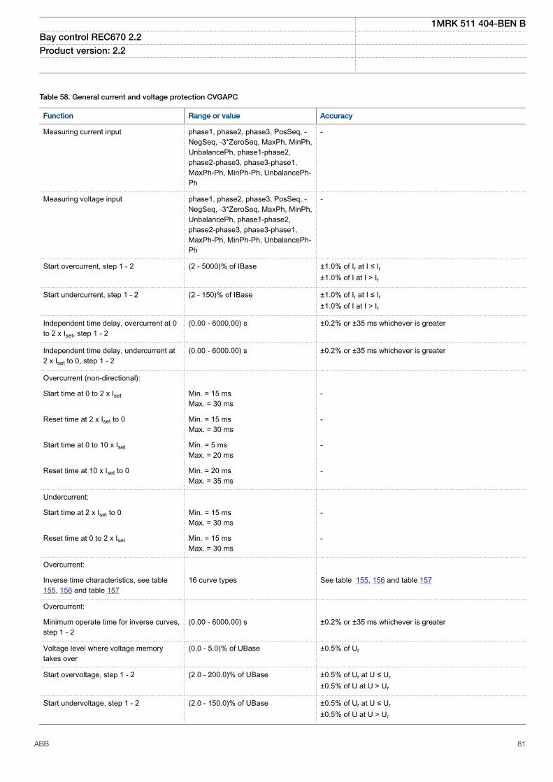
Table 58. General current and voltage protection CVGAPC
Function Range or value Accuracy
Measuring current input phase1, phase2, phase3, PosSeq, -NegSeq, -3*ZeroSeq, MaxPh, MinPh,UnbalancePh, phase1-phase2,phase2-phase3, phase3-phase1,MaxPh-Ph, MinPh-Ph, UnbalancePh-Ph
-
Measuring voltage input phase1, phase2, phase3, PosSeq, -NegSeq, -3*ZeroSeq, MaxPh, MinPh,UnbalancePh, phase1-phase2,phase2-phase3, phase3-phase1,MaxPh-Ph, MinPh-Ph, UnbalancePh-Ph
-
Start overcurrent, step 1 - 2 (2 - 5000)% of IBase ±1.0% of Ir at I ≤ Ir±1.0% of I at I > Ir
Start undercurrent, step 1 - 2 (2 - 150)% of IBase ±1.0% of Ir at I ≤ Ir±1.0% of I at I > Ir
Independent time delay, overcurrent at 0to 2 x Iset, step 1 - 2
(0.00 - 6000.00) s ±0.2% or ±35 ms whichever is greater
Independent time delay, undercurrent at2 x Iset to 0, step 1 - 2
(0.00 - 6000.00) s ±0.2% or ±35 ms whichever is greater
Overcurrent (non-directional):
Start time at 0 to 2 x Iset Min. = 15 msMax. = 30 ms
-
Reset time at 2 x Iset to 0 Min. = 15 msMax. = 30 ms
-
Start time at 0 to 10 x Iset Min. = 5 msMax. = 20 ms
-
Reset time at 10 x Iset to 0 Min. = 20 msMax. = 35 ms
-
Undercurrent:
Start time at 2 x Iset to 0 Min. = 15 msMax. = 30 ms
-
Reset time at 0 to 2 x Iset Min. = 15 msMax. = 30 ms
-
Overcurrent:
Inverse time characteristics, see table155, 156 and table 157
16 curve types See table 155, 156 and table 157
Overcurrent:
Minimum operate time for inverse curves,step 1 - 2
(0.00 - 6000.00) s ±0.2% or ±35 ms whichever is greater
Voltage level where voltage memorytakes over
(0.0 - 5.0)% of UBase ±0.5% of Ur
Start overvoltage, step 1 - 2 (2.0 - 200.0)% of UBase ±0.5% of Ur at U ≤ Ur±0.5% of U at U > Ur
Start undervoltage, step 1 - 2 (2.0 - 150.0)% of UBase ±0.5% of Ur at U ≤ Ur±0.5% of U at U > Ur
1MRK 511 404-BEN BBay control REC670 2.2 Product version: 2.2
ABB 81

Table 58. General current and voltage protection CVGAPC , continued
Function Range or value Accuracy
Independent time delay, overvoltage at0.8 x Uset to 1.2 x Uset, step 1 - 2
(0.00 - 6000.00) s ±0.2% or ±35 ms whichever is greater
Independent time delay, undervoltage at1.2 x Uset to 0.8 x Uset, step 1 - 2
(0.00 - 6000.00) s ±0.2% or ±35 ms whichever is greater
Overvoltage:
Start time at 0.8 x Uset to 1.2 x Uset Min. = 15 msMax. = 30 ms
-
Reset time at 1.2 x Uset to 0.8 x Uset Min. = 15 msMax. = 30 ms
-
Undervoltage:
Start time at 1.2 x Uset to 0.8 x Uset Min. = 15 msMax. = 30 ms
-
Reset time at 1.2 x Uset to 0.8 x Uset Min. = 15 msMax. = 30 ms
-
Overvoltage:
Inverse time characteristics, see table163
4 curve types See table 163
Undervoltage:
Inverse time characteristics, see table164
3 curve types See table 164
High and low voltage limit, voltagedependent operation, step 1 - 2
(1.0 - 200.0)% of UBase ±1.0% of Ur at U ≤ Ur±1.0% of U at U > Ur
Directional function Settable: NonDir, forward andreverse
-
Relay characteristic angle (-180 to +180) degrees ±2.0 degrees
Relay operate angle (1 to 90) degrees ±2.0 degrees
Reset ratio, overcurrent > 95% -
Reset ratio, undercurrent < 105% -
Reset ratio, overvoltage > 95% -
Reset ratio, undervoltage < 105% -
Operate frequency 10-90 Hz -
Overcurrent:
Critical impulse time 10 ms typically at 0 to 2 x Iset -
Impulse margin time 15 ms typically -
Undercurrent:
Critical impulse time 10 ms typically at 2 x Iset to 0 -
Impulse margin time 15 ms typically -
Overvoltage:
Critical impulse time 10 ms typically at 0.8 x Uset to 1.2 xUset
-
Impulse margin time 15 ms typically -
1MRK 511 404-BEN BBay control REC670 2.2 Product version: 2.2
82 ABB

Table 58. General current and voltage protection CVGAPC , continued
Function Range or value Accuracy
Undervoltage:
Critical impulse time 10 ms typically at 1.2 x Uset to 0.8 xUset
-
Impulse margin time 15 ms typically -
1MRK 511 404-BEN BBay control REC670 2.2 Product version: 2.2
ABB 83

Secondary system supervisionM12358-1 v10
Table 59. Current circuit supervision CCSSPVC
Function Range or value Accuracy
Operate current (10-200)% of IBase ±10.0% of Ir at I ≤ Ir±10.0% of I at I > Ir
Reset ratio, Operate current >90%
Block current (20-500)% of IBase ±5.0% of Ir at I ≤ Ir±5.0% of I at I > Ir
Reset ratio, Block current >90% at (50-500)% of IBase M16069-1 v12
Table 60. Fuse failure supervision FUFSPVC
Function Range or value Accuracy
Operate voltage, zero sequence (1-100)% of UBase ±0.5% of Ur
Operate current, zero sequence (1–100)% of IBase ±0.5% of Ir
Operate voltage, negative sequence (1-100)% of UBase ±0.5% of Ur
Operate current, negative sequence (1–100)% of IBase ±0.5% of Ir
Operate voltage change level (1-100)% of UBase ±10.0% of Ur
Operate current change level (1–100)% of IBase ±10.0% of Ir
Operate phase voltage (1-100)% of UBase ±0.5% of Ur
Operate phase current (1–100)% of IBase ±0.5% of Ir
Operate phase dead line voltage (1-100)% of UBase ±0.5% of Ur
Operate phase dead line current (1–100)% of IBase ±0.5% of Ir
Operate time, start, 1 ph, at 1 x Ur to 0 Min. = 10 msMax. = 25 ms
-
Reset time, start, 1 ph, at 0 to 1 x Ur Min. = 15 msMax. = 30 ms
-
1MRK 511 404-BEN BBay control REC670 2.2 Product version: 2.2
84 ABB

GUID-E2EA8017-BB4B-48B0-BEDA-E71FEE353774 v5
Table 61. Fuse failure supervision VDSPVC
Function Range or value Accuracy
Operate value, block of main fuse failure (10.0-80.0)% of UBase ±0.5% of Ur
Reset ratio <110%
Operate time, block of main fuse failure at 1 x Ur to 0 Min. = 5 ms –
Max. = 15 ms
Reset time, block of main fuse failure at 0 to 1 x Ur Min. = 15 ms –
Max. = 30 ms
Operate value, alarm for pilot fuse failure (10.0-80.0)% of UBase ±0.5% of Ur
Reset ratio <110% –
Operate time, alarm for pilot fuse failure at 1 x Ur to 0 Min. = 5 ms –
Max. = 15 ms
Reset time, alarm for pilot fuse failure at 0 to 1 x Ur Min. = 15 ms –
Max. = 30 ms
1MRK 511 404-BEN BBay control REC670 2.2 Product version: 2.2
ABB 85

ControlM12359-1 v15
Table 62. Synchronizing, synchrocheck and energizing check SESRSYN
Function Range or value Accuracy
Phase shift, jline - jbus (-180 to 180) degrees -
Voltage high limit for synchronizing and synchrocheck (50.0-120.0)% of UBase ±0.5% of Ur at U ≤ Ur±0.5% of U at U > Ur
Reset ratio, synchrocheck > 95% -
Frequency difference limit between bus and line for synchrocheck (0.003-1.000) Hz ±2.5 mHz
Phase angle difference limit between bus and line for synchrocheck (5.0-90.0) degrees ±2.0 degrees
Voltage difference limit between bus and line for synchronizing andsynchrocheck
(0.02-0.5) p.u ±0.5% of Ur
Time delay output for synchrocheck when angle difference between busand line jumps from “PhaseDiff” + 2 degrees to “PhaseDiff” - 2 degrees
(0.000-60.000) s ±0.2% or ±35 ms whichever isgreater
Frequency difference minimum limit for synchronizing (0.003-0.250) Hz ±2.5 mHz
Frequency difference maximum limit for synchronizing (0.050-1.000) Hz ±2.5 mHz
Maximum closing angle between bus and line for synchronizing (15-30) degrees ±2.0 degrees
Breaker closing pulse duration (0.050-1.000) s ±0.2% or ±15 ms whichever isgreater
tMaxSynch, which resets synchronizing function if no close has beenmade before set time
(0.000-6000.00) s ±0.2% or ±35 ms whichever isgreater
Minimum time to accept synchronizing conditions (0.000-60.000) s ±0.2% or ±35 ms whichever isgreater
Voltage high limit for energizing check (50.0-120.0)% of UBase ±0.5% of Ur at U ≤ Ur±0.5% of U at U > Ur
Reset ratio, voltage high limit > 95% -
Voltage low limit for energizing check (10.0-80.0)% of UBase ±0.5% of Ur
Reset ratio, voltage low limit < 105% -
Maximum voltage for energizing (50.0-180.0)% of UBase ±0.5% of Ur at U ≤ Ur±0.5% of U at U > Ur
Time delay for energizing check when voltage jumps from 0 to 90% ofUrated
(0.000-60.000) s ±0.2% or ±100 ms whichever isgreater
Operate time for synchrocheck function when angle difference betweenbus and line jumps from “PhaseDiff” + 2 degrees to “PhaseDiff” - 2degrees
Min. = 15 msMax. = 30 ms
–
Operate time for energizing function when voltage jumps from 0 to 90%of Urated
Min. = 70 msMax. = 90 ms
–
1MRK 511 404-BEN BBay control REC670 2.2 Product version: 2.2
86 ABB

M12379-1 v13
Table 63. Autorecloser SMBRREC
Function Range or value Accuracy
Dead time:shot 1 “t1 1Ph”shot 1 “t1 2Ph”shot 1 “t1 3Ph “shot 1 “t1 3PhHS”
(0.000-120.000) s
±0.2% or ±35 mswhichever is greater
Dead time:shot 2 “t2 3Ph”shot 3 “t3 3Ph”shot 4 “t4 3Ph”shot 5 “t5 3Ph”
(0.00-6000.00) s ±0.2% or ±35 mswhichever is greater
Extend three-phase dead time duration “tExtended t1” (0.000-60.000) s ±0.2% or ±35 mswhichever is greater
Minimum time that circuit breaker must be closed before new sequence is allowed“tCBClosedMin”
(0.00-6000.00) s ±0.2% or ±35 mswhichever is greater
Wait time for the slave to close when WAIT input has reset “tSlaveDeadTime” (0.100-60.000) s ±0.2% or ±35 mswhichever is greater
Maximum allowed start pulse duration “tLongStartInh” (0.000-60.000) s ±0.2% or ±15 mswhichever is greater
Circuit breaker closing pulse duration “tPulse” (0.000-60.000) s ±0.2% or ±15 mswhichever is greater
Reclaim time ”tReclaim” (0.00-6000.00) s ±0.2% or ±15 mswhichever is greater
Maximum wait time for release from master “tWaitForMaster” (0.00-6000.00) s ±0.2% or ±15 mswhichever is greater
Reset time for reclosing inhibit “tInhibit” (0.000-60.000) s ±0.2% or ±45 mswhichever is greater
Wait time after close command before proceeding to next shot “tAutoContWait” (0.000-60.000) s ±0.2% or ±45 mswhichever is greater
Maximum wait time for fulfilled synchrocheck conditions “tSync” (0.00-6000.00) s ±0.2% or ±45 mswhichever is greater
Delay time before indicating successful reclosing “tSuccessful” (0.000-60.000) s ±0.2% or ±50 mswhichever is greater
Maximum wait time for circuit breaker closing before indicating unsuccessful “tUnsucCl” (0.00-6000.00) s ±0.2% or ±45 mswhichever is greater
1MRK 511 404-BEN BBay control REC670 2.2 Product version: 2.2
ABB 87
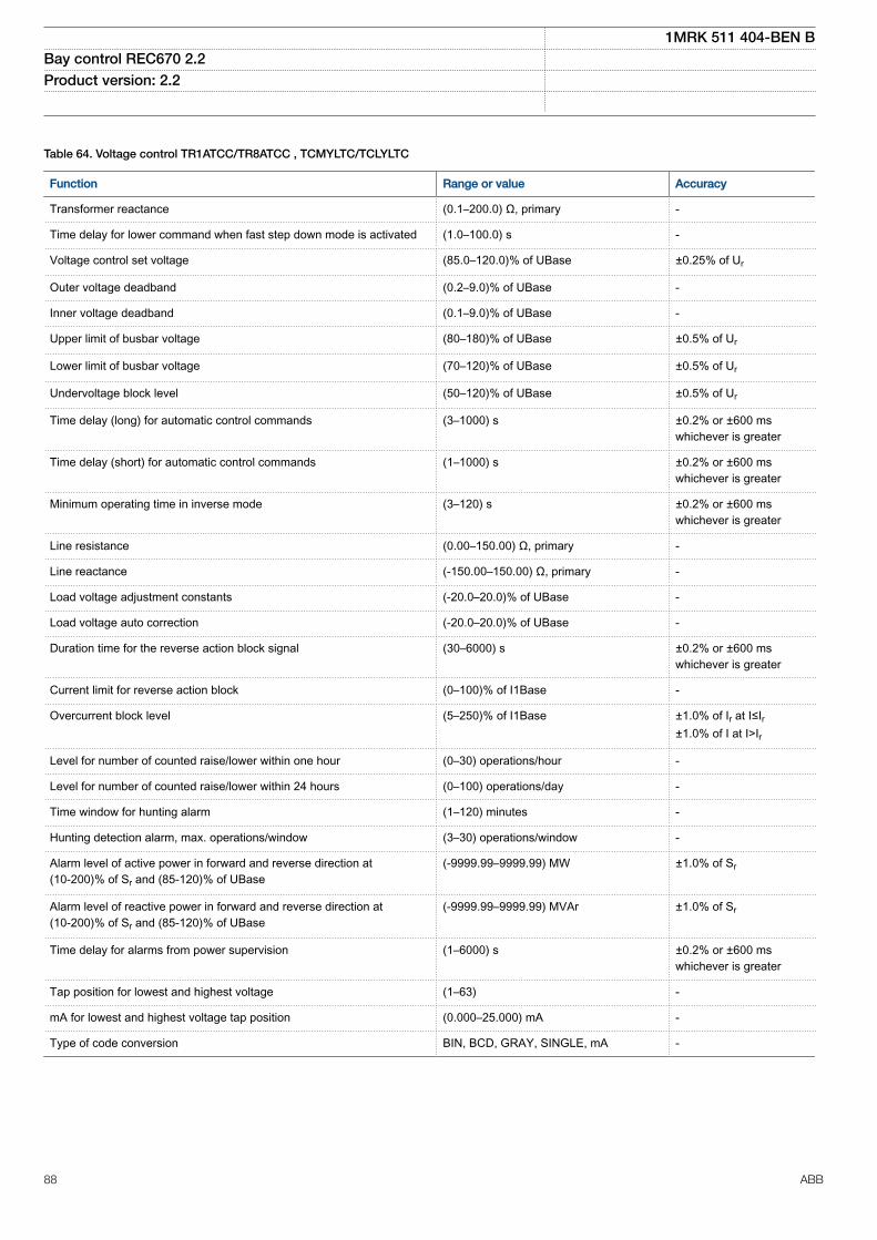
SEMOD175215-2 v14
Table 64. Voltage control TR1ATCC/TR8ATCC , TCMYLTC/TCLYLTC
Function Range or value Accuracy
Transformer reactance (0.1–200.0) Ω, primary -
Time delay for lower command when fast step down mode is activated (1.0–100.0) s -
Voltage control set voltage (85.0–120.0)% of UBase ±0.25% of Ur
Outer voltage deadband (0.2–9.0)% of UBase -
Inner voltage deadband (0.1–9.0)% of UBase -
Upper limit of busbar voltage (80–180)% of UBase ±0.5% of Ur
Lower limit of busbar voltage (70–120)% of UBase ±0.5% of Ur
Undervoltage block level (50–120)% of UBase ±0.5% of Ur
Time delay (long) for automatic control commands (3–1000) s ±0.2% or ±600 mswhichever is greater
Time delay (short) for automatic control commands (1–1000) s ±0.2% or ±600 mswhichever is greater
Minimum operating time in inverse mode (3–120) s ±0.2% or ±600 mswhichever is greater
Line resistance (0.00–150.00) Ω, primary -
Line reactance (-150.00–150.00) Ω, primary -
Load voltage adjustment constants (-20.0–20.0)% of UBase -
Load voltage auto correction (-20.0–20.0)% of UBase -
Duration time for the reverse action block signal (30–6000) s ±0.2% or ±600 mswhichever is greater
Current limit for reverse action block (0–100)% of I1Base -
Overcurrent block level (5–250)% of I1Base ±1.0% of Ir at I≤Ir±1.0% of I at I>Ir
Level for number of counted raise/lower within one hour (0–30) operations/hour -
Level for number of counted raise/lower within 24 hours (0–100) operations/day -
Time window for hunting alarm (1–120) minutes -
Hunting detection alarm, max. operations/window (3–30) operations/window -
Alarm level of active power in forward and reverse direction at(10-200)% of Sr and (85-120)% of UBase
(-9999.99–9999.99) MW ±1.0% of Sr
Alarm level of reactive power in forward and reverse direction at(10-200)% of Sr and (85-120)% of UBase
(-9999.99–9999.99) MVAr ±1.0% of Sr
Time delay for alarms from power supervision (1–6000) s ±0.2% or ±600 mswhichever is greater
Tap position for lowest and highest voltage (1–63) -
mA for lowest and highest voltage tap position (0.000–25.000) mA -
Type of code conversion BIN, BCD, GRAY, SINGLE, mA -
1MRK 511 404-BEN BBay control REC670 2.2 Product version: 2.2
88 ABB

Table 64. Voltage control TR1ATCC/TR8ATCC , TCMYLTC/TCLYLTC , continued
Function Range or value Accuracy
Time after position change before the value is accepted (1–60) s ±0.2% or ±200 mswhichever is greater
Tap changer constant time-out (1–120) s ±0.2% or ±200 mswhichever is greater
Raise/lower command output pulse duration (0.5–10.0) s ±0.2% or ±200 mswhichever is greater
1MRK 511 404-BEN BBay control REC670 2.2 Product version: 2.2
ABB 89

Scheme communicationM16038-1 v14
Table 65. Scheme communication logic with delta based blocking scheme signal transmit ZCPSCH
Function Range or value Accuracy
Scheme type OffIntertripPermissive URPermissive ORBlockingDeltaBlocking
-
Operate voltage, Delta U (0–100)% of UBase ±5.0% of ΔU
Operate current, Delta I (0–200)% of IBase ±5.0% of ΔI
Operate zero sequence voltage,Delta 3U0
(0–100)% of UBase ±10.0% of Δ3U0
Operate zero sequence current,Delta 3I0
(0–200)% of IBase ±10.0% of Δ3I0
Co-ordination time for blockingcommunication scheme
(0.000-60.000) s ±0.2% or ±15 ms whichever is greater
Minimum duration of a carrier sendsignal
(0.000-60.000) s ±0.2% or ±45 ms whichever is greater
Security timer for loss of guardsignal detection
(0.000-60.000) s ±0.2% or ±15 ms whichever is greater
Operation mode of unblocking logic OffNoRestartRestart
-
M16039-1 v16
Table 66. Current reversal and weak-end infeed logic for distance protection ZCRWPSCH
Function Range or value Accuracy
Detection level phase-to-neutralvoltage
(10-90)% of UBase ±0.5% of Ur
Detection level phase-to-phasevoltage
(10-90)% of UBase ±0.5% of Ur
Operate time for current reversallogic
(0.000-60.000) s ±0.2% or ±15 ms whichever is greater
Delay time for current reversal (0.000-60.000) s ±0.2% or ±15 ms whichever is greater
Coordination time for weak-endinfeed logic
(0.000-60.000) s ±0.2% or ±15 ms whichever is greater
M16049-1 v10
Table 67. Scheme communication logic for residual overcurrent protection ECPSCH
Function Range or value Accuracy
Scheme type Permissive UnderreachingPermissive OverreachingBlocking
-
Communication schemecoordination time
(0.000-60.000) s ±0.2% or ±20 ms whichever is greater
1MRK 511 404-BEN BBay control REC670 2.2 Product version: 2.2
90 ABB

GUID-CC9A02C2-AAE8-4B8C-A091-D4ED584A2EA7 v1
Table 68. Local acceleration logic ZCLCPSCH
Function Range or value Accuracy
Operate current, LoadCurr (1–100)% of IBase ±1.0% of Ir
Operate current, MinCurr (1–100)% of IBase ±1.0% of Ir
Delay time on pick-up for current release (0.000–60.000) s ±0.2% or ±35 ms whichever is greater
Delay time on drop-off for current release (0.000–60.000) s ±0.2% or ±35 ms whichever is greater
Delay time on pick-up for MinCurr value (0.000–60.000) s ±0.2% or ±35 ms whichever is greaterM16051-2 v11
Table 69. Current reversal and weak-end infeed logic for residual overcurrent protection ECRWPSCH
Function Range or value Accuracy
Operate mode of WEI logic OffEchoEcho & Trip
-
Operate voltage 3U0 for WEI trip (5-70)% of UBase ±0.5% of Ur
Operate time for current reversallogic
(0.000-60.000) s ±0.2% or ±30 ms whichever is greater
Delay time for current reversal (0.000-60.000) s ±0.2% or ±30 ms whichever is greater
Coordination time for weak-endinfeed logic
(0.000–60.000) s ±0.2% or ±30 ms whichever is greater
1MRK 511 404-BEN BBay control REC670 2.2 Product version: 2.2
ABB 91

LogicM12380-1 v13
Table 70. Tripping logic common 3-phase output SMPPTRC
Function Range or value Accuracy
Trip action 3-ph, 1/3-ph, 1/2/3-ph -
Minimum trip pulse length (0.000-60.000) s ±0.2% or ±15 ms whichever is greater
3-pole trip delay (0.020-0.500) s ±0.2% or ±15 ms whichever is greater
Evolving fault delay (0.000-60.000) s ±0.2% or ±15 ms whichever is greaterGUID-1E1A829D-1F26-433A-8813-1F5A6F225418 v1
Table 71. Number of SMAGAPC instances
Function Quantity with cycle time
3 ms 8 ms 100 ms
SMAGAPC 12 - -
Table 72. Number of STARTCOMB instances
Function Quantity with cycle time
3 ms 8 ms 100 ms
STARTCOMB 32 - -GUID-3AB1EE95-51BF-4CC4-99BD-F4ECDAACB75A v2
Table 73. Number of TMAGAPC instances
Function Quantity with cycle time
3 ms 8 ms 100 ms
TMAGAPC 6 6 -GUID-A05AF26F-DC98-4E62-B96B-E75D19F20767 v2
Table 74. Number of ALMCALH instances
Function Quantity with cycle time
3 ms 8 ms 100 ms
ALMCALH - - 5GUID-70B7357D-F467-4CF5-9F73-641A82D334F5 v2
Table 75. Number of WRNCALH instances
Function Quantity with cycle time
3 ms 8 ms 100 ms
WRNCALH - - 5GUID-EAA43288-01A5-49CF-BF5B-9ABF6DC27D85 v2
Table 76. Number of INDCALH instances
Function Quantity with cycle time
3 ms 8 ms 100 ms
INDCALH - 5 -
1MRK 511 404-BEN BBay control REC670 2.2 Product version: 2.2
92 ABB

GUID-D1179280-1D99-4A66-91AC-B7343DBA9F23 v3
Table 77. Number of AND instances
Logic block Quantity with cycle time
3 ms 8 ms 100 ms
AND 60 60 160GUID-45DF373F-DC39-4E1B-B45B-6B454E8E0E50 v3
Table 78. Number of GATE instances
Logic block Quantity with cycle time
3 ms 8 ms 100 ms
GATE 10 10 20GUID-0EC4192A-EF03-47C0-AEC1-09B68B411A98 v3
Table 79. Number of INV instances
Logic block Quantity with cycle time
3 ms 8 ms 100 ms
INV 90 90 240GUID-B2E6F510-8766-4381-9618-CE02ED71FFB6 v2
Table 80. Number of LLD instances
Logic block Quantity with cycle time
3 ms 8 ms 100 ms
LLD 10 10 20GUID-35A795D7-A6BD-4669-A023-43C497DBFB01 v4
Table 81. Number of OR instances
Logic block Quantity with cycle time
3 ms 8 ms 100 ms
OR 78 60 160GUID-E05E5FB1-23E7-4816-84F2-1FBFFDFF2B43 v2
Table 82. Number of PULSETIMER instances
Logic block Quantity with cycle time Range or Value Accuracy
3 ms 8 ms 100 ms
PULSETIMER 10 10 20 (0.000–90000.000) s ±0.5% ±10 msGUID-BE6FD540-E96E-4F15-B2A2-12FFAE6C51DB v2
Table 83. Number of RSMEMORY instances
Logic block Quantity with cycle time
3 ms 8 ms 100 ms
RSMEMORY 10 10 20GUID-7A0F4327-CA83-4FB0-AB28-7C5F17AE6354 v2
Table 84. Number of SRMEMORY instances
Logic block Quantity with cycle time
3 ms 8 ms 100 ms
SRMEMORY 10 10 20
1MRK 511 404-BEN BBay control REC670 2.2 Product version: 2.2
ABB 93

GUID-C6C98FE0-F559-45EE-B853-464516775417 v3
Table 85. Number of TIMERSET instances
Logic block Quantity with cycle time Range or Value Accuracy
3 ms 8 ms 100 ms
TIMERSET 15 15 30 (0.000–90000.000) s ±0.5% ±10 msGUID-0B07F78C-10BD-4070-AFF0-6EE36454AA03 v2
Table 86. Number of XOR instances
Logic block Quantity with cycle time
3 ms 8 ms 100 ms
XOR 10 10 20GUID-23D4121A-4C9A-4072-BBE3-6DB076EDAB79 v1
Table 87. Number of ANDQT instances
Logic block Quantity with cycle time
3 ms 8 ms 100 ms
ANDQT - 20 100GUID-27DF23C0-A0B2-4BB0-80B5-FC7B7F7FE448 v1
Table 88. Number of INDCOMBSPQT instances
Logic block Quantity with cycle time
3 ms 8 ms 100 ms
INDCOMBSPQT - 10 10GUID-C1E61AE5-22CF-4198-97CF-8C8043EE96D2 v1
Table 89. Number of INDEXTSPQT instances
Logic block Quantity with cycle time
3 ms 8 ms 100 ms
INDEXTSPQT - 10 10GUID-77FEBE9B-0882-4E85-8B1A-7671807BFC02 v2
Table 90. Number of INVALIDQT instances
Logic block Quantity with cycle time
3 ms 8 ms 100 ms
INVALIDQT 10 6 6GUID-F25B94C6-9CC9-48A0-A7A3-47627D2B56E2 v1
Table 91. Number of INVERTERQT instances
Logic block Quantity with cycle time
3 ms 8 ms 100 ms
INVERTERQT - 20 100GUID-88B27B3C-26D2-47AF-9878-CC19018171B1 v1
Table 92. Number of ORQT instances
Logic block Quantity with cycle time
3 ms 8 ms 100 ms
ORQT - 20 100
1MRK 511 404-BEN BBay control REC670 2.2 Product version: 2.2
94 ABB

GUID-61263951-53A8-4113-82B5-3DB3BF0D9449 v1
Table 93. Number of PULSETIMERQT instances
Logic block Quantity with cycle time Range or Value Accuracy
3 ms 8 ms 100 ms
PULSETIMERQT - 10 30 (0.000–90000.000) s ±0.5% ±10 msGUID-94C803B4-6C5A-4072-AB5C-20DDE98C9A70 v1
Table 94. Number of RSMEMORYQT instances
Logic block Quantity with cycle time
3 ms 8 ms 100 ms
RSMEMORYQT - 10 30GUID-341562FB-6149-495B-8A63-200DF16A5590 v1
Table 95. Number of SRMEMORYQT instances
Logic block Quantity with cycle time
3 ms 8 ms 100 ms
SRMEMORYQT - 10 30GUID-B6231B97-05ED-40E8-B735-1E1A50FDB85F v1
Table 96. Number of TIMERSETQT instances
Logic block Quantity with cycle time Range or Value Accuracy
3 ms 8 ms 100 ms
TIMERSETQT - 10 30 (0.000–90000.000) s ±0.5% ±10 msGUID-1C381E02-6B9E-44DC-828F-8B3EA7EDAA54 v1
Table 97. Number of XORQT instances
Logic block Quantity with cycle time
3 ms 8 ms 100 ms
XORQT - 10 30
1MRK 511 404-BEN BBay control REC670 2.2 Product version: 2.2
ABB 95

GUID-19810098-1820-4765-8F0B-7D585FFC0C78 v7
Table 98. Number of instances in the extension logic package
Logic block Quantity with cycle time
3 ms 8 ms 100 ms
SLGAPC 10 10 54
VSGAPC 10 10 100
AND 40 40 100
OR 40 40 100
PULSETIMER 20 20 49
GATE — — 49
TIMERSET 30 30 49
XOR 10 10 69
LLD — — 49
SRMEMORY 10 10 110
INV 40 40 100
RSMEMORY 10 10 20GUID-65A2876A-F779-41C4-ACD7-7662D1E7F1F2 v3
Table 99. Number of B16I instances
Function Quantity with cycle time
3 ms 8 ms 100 ms
B16I 6 4 8GUID-3820F464-D296-4CAD-8491-F3F997359D79 v2
Table 100. Number of BTIGAPC instances
Function Quantity with cycle time
3 ms 8 ms 100 ms
BTIGAPC 4 4 8GUID-B45901F4-B163-4696-8220-7F8CAC84D793 v2
Table 101. Number of IB16 instances
Function Quantity with cycle time
3 ms 8 ms 100 ms
IB16 6 4 8GUID-A339BBA3-8FD0-429D-BB49-809EAC4D53B0 v2
Table 102. Number of ITBGAPC instances
Function Quantity with cycle time
3 ms 8 ms 100 ms
ITBGAPC 4 4 8
1MRK 511 404-BEN BBay control REC670 2.2 Product version: 2.2
96 ABB

GUID-B258726E-1129-47C9-94F9-BE634A2085FA v4
Table 103. Elapsed time integrator with limit transgression and overflow supervision TEIGAPC
Function Cycle time (ms) Range or value Accuracy
Elapsed time integration 3 0 ~ 999999.9 s ±0.2% or ±20 ms whichever isgreater
8 0 ~ 999999.9 s ±0.2% or ±100 ms whichever isgreater
100 0 ~ 999999.9 s ±0.2% or ±250 ms whichever isgreater
Table 104. Number of TEIGAPC instances
Function Quantity with cycle time
3 ms 8 ms 100 ms
TEIGAPC 4 4 4GUID-CEA332FF-838D-42B7-AEFC-C1E87809825E v3
Table 105. Number of INTCOMP instances
Function Quantity with cycle time
3 ms 8 ms 100 ms
INTCOMP 10 10 10GUID-3FDD7677-1D86-42AD-A545-B66081C49B47 v4
Table 106. Number of REALCOMP instances
Function Quantity with cycle time
3 ms 8 ms 100 ms
REALCOMP 10 10 10
1MRK 511 404-BEN BBay control REC670 2.2 Product version: 2.2
ABB 97

MonitoringM12386-1 v16
Table 107. Power system measurement CVMMXN
Function Range or value Accuracy
Frequency (0.95-1.05) x fr ±2.0 mHz
Voltage (10 to 300) V ±0.3% of U at U≤ 50 V±0.2% of U at U> 50 V
Current (0.1-4.0) x Ir ±0.8% of I at 0.1 x Ir< I < 0.2 x Ir± 0.5% of I at 0.2 x Ir< I < 0.5 x Ir±0.2% of I at 0.5 x Ir< I < 4.0 x Ir
Active power, P (10 to 300) V(0.1-4.0) x Ir
±0.5% of Sr at S ≤0.5 x Sr
±0.5% of S at S > 0.5 x Sr
(100 to 220) V(0.5-2.0) x Ircos φ> 0.7
±0.2% of P
Reactive power, Q (10 to 300) V(0.1-4.0) x Ir
±0.5% of Sr at S ≤0.5 x Sr
±0.5% of S at S > 0.5 x Sr
(100 to 220) V(0.5-2.0) x Ircos φ< 0.7
±0.2% of Q
Apparent power, S (10 to 300) V(0.1-4.0) x Ir
±0.5% of Sr at S ≤0.5 x Sr
±0.5% of S at S >0.5 x Sr
(100 to 220) V(0.5-2.0) x Ir
±0.2% of S
Power factor, cos (φ) (10 to 300) V(0.1-4.0) x Ir
<0.02
(100 to 220) V(0.5-2.0) x Ir
<0.01
GUID-5E04B3F9-E1B7-4974-9C0B-DE9CD4A2408F v6
Table 108. Current measurement CMMXU
Function Range or value Accuracy
Current at symmetrical load (0.1-4.0) × Ir ±0.3% of Ir at I ≤ 0.5 × Ir±0.3% of I at I > 0.5 × Ir
Phase angle at symmetrical load (0.1-4.0) × Ir ±1.0 degrees at 0.1 × Ir < I ≤ 0.5 × Ir±0.5 degrees at 0.5 × Ir < I ≤ 4.0 × Ir
GUID-374C2AF0-D647-4159-8D3A-71190FE3CFE0 v5
Table 109. Voltage measurement phase-phase VMMXU
Function Range or value Accuracy
Voltage (10 to 300) V ±0.5% of U at U ≤ 50 V±0.2% of U at U > 50 V
Phase angle (10 to 300) V ±0.5 degrees at U ≤ 50 V±0.2 degrees at U > 50 V
1MRK 511 404-BEN BBay control REC670 2.2 Product version: 2.2
98 ABB

GUID-ED634B6D-9918-464F-B6A4-51B78129B819 v6
Table 110. Voltage measurement phase-earth VNMMXU
Function Range or value Accuracy
Voltage (5 to 175) V ±0.5% of U at U ≤ 50 V±0.2% of U at U > 50 V
Phase angle (5 to 175) V ±0.5 degrees at U ≤ 50 V±0.2 degrees at U > 50 V
GUID-9B8A7FA5-9C98-4CBD-A162-7112869CF030 v5
Table 111. Current sequence measurement CMSQI
Function Range or value Accuracy
Current positive sequence, I1Three phase settings
(0.1–4.0) × Ir ±0.3% of Ir at I ≤ 0.5 × Ir±0.3% of I at I > 0.5 × Ir
Current zero sequence, 3I0Three phase settings
(0.1–1.0) × Ir ±0.3% of Ir at I ≤ 0.5 × Ir±0.3% of I at I > 0.5 × Ir
Current negative sequence, I2Three phase settings
(0.1–1.0) × Ir ±0.3% of Ir at I ≤ 0.5 × Ir±0.3% of I at I > 0.5 × Ir
Phase angle (0.1–4.0) × Ir ±1.0 degrees at 0.1 × Ir < I ≤ 0.5 × Ir±0.5 degrees at 0.5 × Ir < I ≤ 4.0 × Ir
GUID-47094054-A828-459B-BE6A-D7FA1B317DA7 v6
Table 112. Voltage sequence measurement VMSQI
Function Range or value Accuracy
Voltage positive sequence, U1 (10 to 300) V ±0.5% of U at U ≤ 50 V±0.2% of U at U > 50 V
Voltage zero sequence, 3U0 (10 to 300) V ±0.5% of U at U ≤ 50 V±0.2% of U at U > 50 V
Voltage negative sequence, U2 (10 to 300) V ±0.5% of U at U ≤ 50 V±0.2% of U at U > 50 V
Phase angle (10 to 300) V ±0.5 degrees at U ≤ 50 V±0.2 degrees at U > 50 V
M16080-1 v5
Table 113. Supervision of mA input signals
Function Range or value Accuracy
mA measuring function ±5, ±10, ±20 mA0-5, 0-10, 0-20, 4-20 mA
±0.1 % of set value ±0.005 mA
Max current of transducer toinput
(-20.00 to +20.00) mA
Min current of transducer toinput
(-20.00 to +20.00) mA
Alarm level for input (-20.00 to +20.00) mA
Warning level for input (-20.00 to +20.00) mA
Alarm hysteresis for input (0.0-20.0) mA
1MRK 511 404-BEN BBay control REC670 2.2 Product version: 2.2
ABB 99

M12760-1 v11
Table 114. Disturbance report DRPRDRE
Function Range or value Accuracy
Pre-fault time (0.05–9.90) s -
Post-fault time (0.1–10.0) s -
Limit time (0.5–10.0) s -
Maximum number of recordings 100, first in - first out -
Time tagging resolution 1 ms See table 150
Maximum number of analog inputs 30 + 10 (external + internallyderived)
-
Maximum number of binary inputs 352 -
Maximum number of phasors in the Trip Value recorder per recording 30 -
Maximum number of indications in a disturbance report 352 -
Maximum number of events in the Event recording per recording 150 -
Maximum number of events in the Event list 1000, first in - first out -
Maximum total recording time (3.4 s recording time and maximum number ofchannels, typical value)
340 seconds (100 recordings) at50 Hz, 280 seconds (80recordings) at 60 Hz
-
Sampling rate 1 kHz at 50 Hz1.2 kHz at 60 Hz
-
Recording bandwidth (5-300) Hz -GUID-F034B396-6600-49EF-B0A5-8ED96766A6A0 v8
Table 115. Insulation supervision for gas medium function SSIMG
Function Range or value Accuracy
Pressure alarm level 1.00-100.00 ±10.0% of set value
Pressure lockout level 1.00-100.00 ±10.0% of set value
Temperature alarm level -40.00-200.00 ±2.5% of set value
Temperature lockout level -40.00-200.00 ±2.5% of set value
Time delay for pressure alarm (0.000-60.000) s ±0.2% or ±250ms whichever is greater
Reset time delay for pressure alarm (0.000-60.000) s ±0.2% or ±250ms whichever is greater
Time delay for pressure lockout (0.000-60.000) s ±0.2% or ±250ms whichever is greater
Time delay for temperature alarm (0.000-60.000) s ±0.2% or ±250ms whichever is greater
Reset time delay for temperature alarm (0.000-60.000) s ±0.2% or ±250ms whichever is greater
Time delay for temperature lockout (0.000-60.000) s ±0.2% or ±250ms whichever is greater
1MRK 511 404-BEN BBay control REC670 2.2 Product version: 2.2
100 ABB

GUID-83B0F607-D898-403A-94FD-7FE8D45C73FF v8
Table 116. Insulation supervision for liquid medium function SSIML
Function Range or value Accuracy
Oil alarm level 1.00-100.00 ±10.0% of set value
Oil lockout level 1.00-100.00 ±10.0% of set value
Temperature alarm level -40.00-200.00 ±2.5% of set value
Temperature lockout level -40.00-200.00 ±2.5% of set value
Time delay for oil alarm (0.000-60.000) s ±0.2% or ±250ms whichever is greater
Reset time delay for oil alarm (0.000-60.000) s ±0.2% or ±250ms whichever is greater
Time delay for oil lockout (0.000-60.000) s ±0.2% or ±250ms whichever is greater
Time delay for temperature alarm (0.000-60.000) s ±0.2% or ±250ms whichever is greater
Reset time delay for temperature alarm (0.000-60.000) s ±0.2% or ±250ms whichever is greater
Time delay for temperature lockout (0.000-60.000) s ±0.2% or ±250ms whichever is greaterGUID-B6799420-D726-460E-B02F-C7D4F1937432 v9
Table 117. Circuit breaker condition monitoring SSCBR
Function Range or value Accuracy
Alarm level for open and close travel time (0 – 200) ms ±3 ms
Alarm level for number of operations (0 – 9999) -
Independent time delay for spring chargingtime alarm
(0.00 – 60.00) s ±0.2% or ±30 ms whichever is greater
Independent time delay for gas pressure alarm (0.00 – 60.00) s ±0.2% or ±30 ms whichever is greater
Independent time delay for gas pressurelockout
(0.00 – 60.00) s ±0.2% or ±30 ms whichever is greater
CB Contact Travel Time, opening and closing ±3 ms
Remaining Life of CB ±2 operations
Accumulated Energy ±1.0% or ±0.5 whichever is greaterM14987-1 v6
Table 118. Fault locator LMBRFLO
Function Value or range Accuracy
Reactive and resistive reach (0.001-1500.000) Ω/phase ±2.0% static accuracyConditions:Voltage range: (0.1-1.1) x UrCurrent range: (0.5-30) x Ir
Phase selection According to input signals -
Maximum number of faultlocations
100 -
1MRK 511 404-BEN BBay control REC670 2.2 Product version: 2.2
ABB 101

GUID-F6B6ED6B-2488-483C-B068-3F4631F34DC8 v1
Table 119. Transformer loss of life LOLSPTR
Function Range or value Accuracy
Service value, hot spottemperature
– ±2.0% of expected value
Service value, top oiltemperature
– ±2.0% of expected value
Service value, loss of life – ±2.0% of expected value
Operate level , Warning level 1and 2
(50 - 700)°C/°F of hot spot temperature ±2.0% of hot spot temperature
Operate time, Warning level 1and 2
(50 - 700)°C/°F of hot spot temperature ±200 ms typically
Operate time, definite timefunction (ALARMx)
(0.0 - 6000.0) s ±250 ms typically
M12700-1 v4
Table 120. Event list
Function Value
Buffer capacity Maximum number of events in the list 1000
Resolution 1 ms
Accuracy Depending on time synchronizingM13765-1 v5
Table 121. Indications
Function Value
Buffer capacity Maximum number of indications presented for single disturbance 352
Maximum number of recorded disturbances 100M12702-1 v4
Table 122. Event recorder
Function Value
Buffer capacity Maximum number of events in disturbance report 150
Maximum number of disturbance reports 100
Resolution 1 ms
Accuracy Depending on timesynchronizing
M13747-1 v5
Table 123. Trip value recorder
Function Value
Buffer capacity
Maximum number of analog inputs 30
Maximum number of disturbance reports 100
1MRK 511 404-BEN BBay control REC670 2.2 Product version: 2.2
102 ABB

M12384-1 v7
Table 124. Disturbance recorder
Function Value
Buffer capacity Maximum number of analog inputs 40
Maximum number of binary inputs 352
Maximum number of disturbance reports 100
Maximum total recording time (3.4 s recording time and maximum numberof channels, typical value)
340 seconds (100 recordings) at 50 Hz280 seconds (80 recordings) at 60 Hz
GUID-C43B8654-60FE-4E20-8328-754C238F4AD0 v3
Table 125. Event counter with limit supervision L4UFCNT
Function Range or value Accuracy
Counter value 0-65535 -
Max. count up speed 30 pulses/s (50% duty cycle) -GUID-F5E124E3-0B85-41AC-9830-A2362FD289F2 v1
Table 126. Running hour-meter TEILGAPC
Function Range or value Accuracy
Time limit for alarm supervision, tAlarm (0 - 99999.9) hours ±0.1% of set value
Time limit for warning supervision, tWarning (0 - 99999.9) hours ±0.1% of set value
Time limit for overflow supervision Fixed to 99999.9 hours ±0.1%
1MRK 511 404-BEN BBay control REC670 2.2 Product version: 2.2
ABB 103

MeteringM13404-2 v5
Table 127. Pulse-counter logic PCFCNT
Function Setting range Accuracy
Input frequency See Binary Input Module (BIM) -
Cycle time for report of countervalue
(1–3600) s -
SEMOD153707-2 v5
Table 128. Function for energy calculation and demand handling ETPMMTR
Function Range or value Accuracy
Energy metering kWh Export/Import, kvarh Export/Import
Input from MMXU. No extra error at steady load
1MRK 511 404-BEN BBay control REC670 2.2 Product version: 2.2
104 ABB

Station communicationM15031-1 v9
Table 129. Communication protocols
Function Value
Protocol IEC 61850-8-1
Communication speed for the IEDs 100BASE-FX
Protocol IEC 60870–5–103
Communication speed for the IEDs 9600 or 19200 Bd
Protocol DNP3.0
Communication speed for the IEDs 300–115200 Bd
Protocol TCP/IP, Ethernet
Communication speed for the IEDs 100 Mbit/s
Protocol LON
Communication speed for the IEDs 1.25 Mbit/s
Protocol SPA
Communication speed for the IEDs 300–38400 BdGUID-E8B5405C-241C-4DC2-8AB1-3FA77343A4DE v2
Table 130. IEC 61850-9-2 communication protocol
Function Value
Protocol IEC 61850-9-2
Communication speed for the IEDs 100BASE-FXM11927-1 v2
Table 131. LON communication protocol
Function Value
Protocol LON
Communication speed 1.25 Mbit/sM11901-1 v2
Table 132. SPA communication protocol
Function Value
Protocol SPA
Communication speed 300, 1200, 2400, 4800, 9600, 19200 or 38400 Bd
Slave number 1 to 899M11921-1 v4
Table 133. IEC 60870-5-103 communication protocol
Function Value
Protocol IEC 60870-5-103
Communication speed 9600, 19200 Bd
1MRK 511 404-BEN BBay control REC670 2.2 Product version: 2.2
ABB 105

M12589-1 v4
Table 134. SLM – LON port
Quantity Range or value
Optical connector Glass fiber: type STPlastic fiber: type HFBR snap-in
Fiber, optical budget Glass fiber: 11 dB (1000m/3000 ft typically *)Plastic fiber: 7 dB (10m/35ft typically *)
Fiber diameter Glass fiber: 62.5/125 mmPlastic fiber: 1 mm
*) depending on optical budget calculationSEMOD117441-2 v5
Table 135. SLM – SPA/IEC 60870-5-103/DNP3 port
Quantity Range or value
Optical connector Glass fiber: type STPlastic fiber: type HFBR snap-in
Fiber, optical budget Glass fiber: 11 dB (1000m/3000ft m typically *)Plastic fiber: 7 dB (25m/80ft m typically *)
Fiber diameter Glass fiber: 62.5/125 mmPlastic fiber: 1 mm
*) depending on optical budget calculationSEMOD158710-2 v2
Table 136. Galvanic RS485 communication module
Quantity Range or value
Communication speed 2400–19200 bauds
External connectors RS-485 6-pole connectorSoft ground 2-pole connector
SEMOD55310-2 v13
Table 137. SFP - Optical ethernet port
Quantity Rated value
Number of channels Up to 6 single or 3 redundant or a combination of single and redundant links forcommunication using any protocol
Standard IEEE 802.3u 100BASE-FX
Type of fiber 62.5/125 mm multimode fiber
Wave length 1310 nm, Class 1 laser safety
Optical connector Type LC
Communication speed Fast Ethernet 100 Mbit/s
1MRK 511 404-BEN BBay control REC670 2.2 Product version: 2.2
106 ABB

Table 138. SFP - Galvanic RJ45
Quantity Rated value
Number of channels Up to 6 single or 3 redundant or a combination of single and redundant links forcommunication using any protocol
Standard IEEE 802.3u 100BASE-TX
Type of cable Cat5e FTP
Connector Type RJ45
Communication Speed Fast Ethernet 100 Mbit/sGUID-8651FF22-C007-4D53-B7E3-686A30F37CB6 v6
Table 139. Ethernet redundancy protocols, IEC 62439-3
Function Value
Protocol IEC 62439-3 Ed.1 Parallel Redundancy Protocol (PRP-0)
Communication speed 100Base-FX
Protocol IEC 62439-3 Ed.2 Parallel Redundancy Protocol (PRP-1)
Communication speed 100Base-FX
Protocol IEC 62439-3 Ed.2 High-availability Seamless Redundancy (HSR)
Communication speed 100Base-FX
Connectors Optical, type LC
1MRK 511 404-BEN BBay control REC670 2.2 Product version: 2.2
ABB 107

Remote communication
M12756-1 v11
Table 140. Line data communication module
Characteristic Range or value
Type of LDCM Short range (SR) Medium range (MR) Long range (LR)
Type of fiber Multi-mode fiberglass 62.5/125 µm Multi-mode fiberglass 50/125 µm
Single-mode fiberglass 9/125 µm
Single-mode fiberglass 9/125 µm
Peak Emission Wave lengthNominalMaximumMinimum
820 nm865 nm792 nm
1310 nm1330 nm1290 nm
1550 nm1580 nm1520 nm
Optical budgetMulti-mode fiber glass 62.5/125 mm
18.8 dB (typicaldistance about 3km/2 mile *)
26.8 dB (typicaldistance 80 km/50mile *)
28.7 dB (typicaldistance 120 km/68mile *)
Multi-mode fiber glass 50/125 mm 11.5 dB (typicaldistance about 2km/1 mile *)
Optical connector Type ST Type FC/PC Type FC/PC
Protocol C37.94 C37.94implementation **)
C37.94implementation **)
Data transmission Synchronous Synchronous Synchronous
Transmission rate / Data rate 2 Mbit/s / 64 kbit/s 2 Mbit/s / 64 kbit/s 2 Mbit/s / 64 kbit/s
Clock source Internal or derivedfrom received signal
Internal or derivedfrom received signal
Internal or derivedfrom received signal
*) depending on optical budget calculation**) C37.94 originally defined just for multi-mode; using same header, configuration and data format as C37.94
1MRK 511 404-BEN BBay control REC670 2.2 Product version: 2.2
108 ABB

HardwareIED
SEMOD53385-1 v1M11778-1 v7
Table 141. Case
Material Steel sheet
Front plate Stainless steel with cut-out for HMI
Surface treatment Aluzink preplated steel
Finish Light grey (RAL 7035)M12327-1 v5
Table 142. Water and dust protection level according to IEC 60529
Front IP40 (IP54 with sealing strip)
Sides, top and bottom IP40
Rear side IP20 with screw compression typeIP10 with ring lug terminals
M11777-1 v7
Table 143. Weight
Case size Weight
6U, 1/2 x 19” £ 7.5 kg/16 lb
6U, 3/4 x 19” £ 15 kg/33 lb
6U, 1/1 x 19” £ 15 kg/33 lb
Electrical safetyGUID-2825B541-DD31-4DAF-B5B3-97555F81A1C2 v1GUID-1CF5B10A-CF8B-407D-8D87-F4B48B43C2B2 v2
Table 144. Electrical safety according to IEC 60255-27
Equipment class I (protective earthed)
Overvoltage category III
Pollution degree 2 (normally only non-conductive pollution occurs except that occasionally a temporary conductivity caused bycondensation is to be expected)
Connection systemSEMOD53371-1 v1SEMOD53376-2 v6
Table 145. CT and VT circuit connectors
Connector type Rated voltage and current Maximum conductor area
Screw compression type 250 V AC, 20 A 4 mm2 (AWG12)2 x 2.5 mm2 (2 x AWG14)
Terminal blocks suitable for ring lug terminals 250 V AC, 20 A 4 mm2 (AWG12)M12583-1 v7
Table 146. Auxiliary power supply and binary I/O connectors
Connector type Rated voltage Maximum conductor area
Screw compression type 250 V AC 2.5 mm2 (AWG14)2 × 1 mm2 (2 x AWG18)
Terminal blocks suitable for ring lug terminals 300 V AC 3 mm2 (AWG14)
Because of limitations of space, when ringlug terminal is ordered for Binary I/O
1MRK 511 404-BEN BBay control REC670 2.2 Product version: 2.2
ABB 109

connections, one blank slot is necessarybetween two adjacent IO modules. Pleaserefer to the ordering particulars for details.
GUID-96676D5D-0835-44DA-BC22-058FD18BDF34 v3
Table 147. NUM: Communication ports
NUM 4 Ethernet ports1 Basic, 3 Optional
Ethernet connection type SFP Optical LC or Galvanic RJ45
Carrier modules supported OEM, LDCMGUID-4876834C-CABB-400B-B84B-215F65D8AF92 v3
Table 148. OEM: Number of Ethernet ports
OEM 2 Ethernet Ports
Ethernet connection type SFP Optical LC or Galvanic RJ45
1MRK 511 404-BEN BBay control REC670 2.2 Product version: 2.2
110 ABB

Basic IED functionsM11963-1 v5
Table 149. Self supervision with internal event list
Data Value
Recording manner Continuous, event controlled
List size 40 events, first in-first outM12331-1 v9
Table 150. Time synchronization, time tagging
Function Value
Time tagging accuracy of the synchrophasor data ± 1 µs
Time tagging resolution, events and sampled measurement values 1 ms
Time tagging error with synchronization once/min (minute pulse synchronization), events and sampledmeasurement values
± 1.0 ms typically
Time tagging error with SNTP synchronization, sampled measurement values ± 1.0 ms typicallyGUID-8AEB81D0-1731-46DF-A206-D2E758823575 v2
Table 151. Time synchronization PTP: IEC/IEEE 61850-9-3
Supported types of clock Boundary Clock (BC), Ordinary Clock (OC), Transparent Clock (TC)
Accuracy According to standard IEC/IEEE 61850-9-3
Number of nodes According to standard IEC/IEEE 61850-9-3
Ports supported All rear Ethernet portsSEMOD55660-2 v3
Table 152. GPS time synchronization module (GTM)
Function Range or value Accuracy
Receiver – ±1µs relative UTC
Time to reliable time reference with antenna in newposition or after power loss longer than 1 month
<30 minutes –
Time to reliable time reference after a power losslonger than 48 hours
<15 minutes –
Time to reliable time reference after a power lossshorter than 48 hours
<5 minutes –
SEMOD55693-2 v5
Table 153. GPS – Antenna and cable
Function Value
Max antenna cable attenuation 26 db @ 1.6 GHz
Antenna cable impedance 50 ohm
Lightning protection Must be provided externally
Antenna cable connector SMA in receiver endTNC in antenna end
Accuracy +/-1μs
1MRK 511 404-BEN BBay control REC670 2.2 Product version: 2.2
ABB 111

SEMOD141136-2 v9
Table 154. IRIG-B
Quantity Rated value
Number of channels IRIG-B 1
Number of optical channels 1
Electrical connector:
Electrical connector IRIG-B BNC
Pulse-width modulated 5 Vpp
Amplitude modulated– low level– high level
1-3 Vpp3 x low level, max 9 Vpp
Supported formats IRIG-B 00x, IRIG-B 12x
Accuracy +/-10μs for IRIG-B 00x and +/-100μs for IRIG-B 12x
Input impedance 100 k ohm
Optical connector:
Optical connector IRIG-B Type ST
Type of fiber 62.5/125 μm multimode fiber
Supported formats IRIG-B 00x
Accuracy +/- 1μs
1MRK 511 404-BEN BBay control REC670 2.2 Product version: 2.2
112 ABB

Inverse characteristicM12388-1 v23
Table 155. ANSI Inverse time characteristics
Function Range or value Accuracy
Operating characteristic:
( )1P
At B kI
æ öç ÷= + ×ç ÷-è ø
EQUATION1249-SMALL V3 EN-US
Reset characteristic:
( )2 1= ×
-
trt kI
EQUATION1250-SMALL V1 EN-US
I = Imeasured/Iset
0.05 ≤ k ≤ 999.001.5 x Iset ≤ I ≤ 20 x Iset
ANSI/IEEE C37.112 ,±2.0% or ±40 mswhichever is greater
ANSI Extremely Inverse A=28.2, B=0.1217, P=2.0 , tr=29.1
ANSI Very inverse A=19.61, B=0.491, P=2.0 , tr=21.6
ANSI Normal Inverse A=0.0086, B=0.0185, P=0.02, tr=0.46
ANSI Moderately Inverse A=0.0515, B=0.1140, P=0.02, tr=4.85
ANSI Long Time Extremely Inverse A=64.07, B=0.250, P=2.0, tr=30
ANSI Long Time Very Inverse A=28.55, B=0.712, P=2.0, tr=13.46
ANSI Long Time Inverse A=0.086, B=0.185, P=0.02, tr=4.6
1MRK 511 404-BEN BBay control REC670 2.2 Product version: 2.2
ABB 113

Table 156. IEC Inverse time characteristics
Function Range or value Accuracy
Operating characteristic:
( )1= ×
-
æ öç ÷ç ÷è ø
P
At k
I
EQUATION1251-SMALL V1 EN-US
I = Imeasured/Iset
0.05 ≤ k ≤ 999.001.5 x Iset ≤ I ≤ 20 x Iset
IEC 60255-151, ±2.0%or ±40 ms whichever isgreater
IEC Normal Inverse A=0.14, P=0.02
IEC Very inverse A=13.5, P=1.0
IEC Inverse A=0.14, P=0.02
IEC Extremely inverse A=80.0, P=2.0
IEC Short time inverse A=0.05, P=0.04
IEC Long time inverse A=120, P=1.0
Programmable characteristicOperate characteristic:
( )= + ×
-
æ öç ÷ç ÷è ø
P
At B k
I C
EQUATION1370-SMALL V1 EN-US
Reset characteristic:
( )= ×
-PR
TRt k
I CR
EQUATION1253-SMALL V1 EN-US
I = Imeasured/Iset
k = (0.05-999) in steps of 0.01A=(0.005-200.000) in steps of 0.001B=(0.00-20.00) in steps of 0.01C=(0.1-10.0) in steps of 0.1P=(0.005-3.000) in steps of 0.001TR=(0.005-100.000) in steps of 0.001CR=(0.1-10.0) in steps of 0.1PR=(0.005-3.000) in steps of 0.001
The parameter setting Characteristn =Reserved (where, n = 1 - 4) shall not be
used, since this parameter setting is forfuture use and not implemented yet.
1MRK 511 404-BEN BBay control REC670 2.2 Product version: 2.2
114 ABB

Table 157. RI and RD type inverse time characteristics
Function Range or value Accuracy
RI type inverse characteristic
1
0.2360.339
= ×
-
t k
IEQUATION1137-SMALL V1 EN-US
I = Imeasured/Iset
0.05 ≤ k ≤ 999.001.5 x Iset ≤ I ≤ 20 x Iset
IEC 60255-151, ±2.0%or ±40 ms whichever isgreater
RD type logarithmic inverse characteristic
5.8 1.35= - ×æ öç ÷è ø
tI
Ink
EQUATION1138-SMALL V1 EN-US
I = Imeasured/Iset
GUID-19F8E187-4ED0-48C3-92F6-0D9EAA2B39BB v4
Table 158. ANSI Inverse time characteristics for Sensitive directional residual overcurrent and power protection
Function Range or value Accuracy
Operating characteristic:
( )1P
At B kI
æ öç ÷= + ×ç ÷-è ø
EQUATION1249-SMALL V3 EN-US
Reset characteristic:
( )2 1= ×
-
trt kI
EQUATION1250-SMALL V1 EN-US
I = Imeasured/Iset
0.05 ≤ k ≤ 2.001.5 x Iset ≤ I ≤ 20 x Iset
ANSI/IEEE C37.112 ,±5.0% or ±160 mswhichever is greater
ANSI Extremely Inverse A=28.2, B=0.1217, P=2.0 , tr=29.1
ANSI Very inverse A=19.61, B=0.491, P=2.0 , tr=21.6
ANSI Normal Inverse A=0.0086, B=0.0185, P=0.02, tr=0.46
ANSI Moderately Inverse A=0.0515, B=0.1140, P=0.02, tr=4.85
ANSI Long Time Extremely Inverse A=64.07, B=0.250, P=2.0, tr=30
ANSI Long Time Very Inverse A=28.55, B=0.712, P=2.0, tr=13.46
ANSI Long Time Inverse A=0.086, B=0.185, P=0.02, tr=4.6
1MRK 511 404-BEN BBay control REC670 2.2 Product version: 2.2
ABB 115

Table 159. IEC Inverse time characteristics for Sensitive directional residual overcurrent and power protection
Function Range or value Accuracy
Operating characteristic:
( )1= ×
-
æ öç ÷ç ÷è ø
P
At k
I
EQUATION1251-SMALL V1 EN-US
I = Imeasured/Iset
0.05 ≤ k ≤ 2.001.5 x Iset ≤ I ≤ 20 x Iset
IEC 60255-151, ±5.0%or ±160 ms whichever isgreater
IEC Normal Inverse A=0.14, P=0.02
IEC Very inverse A=13.5, P=1.0
IEC Inverse A=0.14, P=0.02
IEC Extremely inverse A=80.0, P=2.0
IEC Short time inverse A=0.05, P=0.04
IEC Long time inverse A=120, P=1.0
Programmable characteristicOperate characteristic:
( )= + ×
-
æ öç ÷ç ÷è ø
P
At B k
I C
EQUATION1370-SMALL V1 EN-US
Reset characteristic:
( )= ×
-PR
TRt k
I CR
EQUATION1253-SMALL V1 EN-US
I = Imeasured/Iset
k = (0.05-2.00) in steps of 0.01A=(0.005-200.000) in steps of 0.001B=(0.00-20.00) in steps of 0.01C=(0.1-10.0) in steps of 0.1P=(0.005-3.000) in steps of 0.001TR=(0.005-100.000) in steps of 0.001CR=(0.1-10.0) in steps of 0.1PR=(0.005-3.000) in steps of 0.001
Table 160. RI and RD type inverse time characteristics for Sensitive directional residual overcurrent and power protection
Function Range or value Accuracy
RI type inverse characteristic
1
0.2360.339
= ×
-
t k
IEQUATION1137-SMALL V1 EN-US
I = Imeasured/Iset
0.05 ≤ k ≤ 2.001.5 x Iset ≤ I ≤ 20 x Iset
IEC 60255-151, ±5.0%or ±160 ms whichever isgreater
RD type logarithmic inverse characteristic
5.8 1.35= - ×æ öç ÷è ø
tI
Ink
EQUATION1138-SMALL V1 EN-US
I = Imeasured/Iset
1MRK 511 404-BEN BBay control REC670 2.2 Product version: 2.2
116 ABB

GUID-2AE8C92E-5DA8-487F-927D-8E553EE29240 v2
Table 161. ANSI Inverse time characteristics for Voltage restrained time overcurrent protection
Function Range or value Accuracy
Operating characteristic:
( )1P
At B kI
æ öç ÷= + ×ç ÷-è ø
EQUATION1249-SMALL V3 EN-US
Reset characteristic:
( )2 1= ×
-
trt kI
EQUATION1250-SMALL V1 EN-US
I = Imeasured/Iset
0.05 ≤ k ≤ 999.00 ANSI/IEEE C37.112 ,± 5.0% or ±40 mswhichever is greater
ANSI Extremely Inverse A=28.2, B=0.1217, P=2.0 , tr=29.1
ANSI Very inverse A=19.61, B=0.491, P=2.0 , tr=21.6
ANSI Normal Inverse A=0.0086, B=0.0185, P=0.02, tr=0.46
ANSI Moderately Inverse A=0.0515, B=0.1140, P=0.02, tr=4.85
ANSI Long Time Extremely Inverse A=64.07, B=0.250, P=2.0, tr=30
ANSI Long Time Very Inverse A=28.55, B=0.712, P=2.0, tr=13.46
ANSI Long Time Inverse A=0.086, B=0.185, P=0.02, tr=4.6
Table 162. IEC Inverse time characteristics for Voltage restrained time overcurrent protection
Function Range or value Accuracy
Operating characteristic:
( )1= ×
-
æ öç ÷ç ÷è ø
P
At k
I
EQUATION1251-SMALL V1 EN-US
I = Imeasured/Iset
0.05 ≤ k ≤ 999.00 IEC 60255-151, ±5.0%or ±40 ms whichever isgreater
IEC Normal Inverse A=0.14, P=0.02
IEC Very inverse A=13.5, P=1.0
IEC Inverse A=0.14, P=0.02
IEC Extremely inverse A=80.0, P=2.0
IEC Short time inverse A=0.05, P=0.04
IEC Long time inverse A=120, P=1.0
1MRK 511 404-BEN BBay control REC670 2.2 Product version: 2.2
ABB 117

SEMOD116978-2 v10
Table 163. Inverse time characteristics for overvoltage protection
Function Range or value Accuracy
Type A curve:
=- >
>
æ öç ÷è ø
tk
U U
UEQUATION1436-SMALL V1 EN-US
U> = UsetU = Umeasured
k = (0.05-1.10) in steps of 0.01 ±5.0% or ±45 mswhichever is greater
Type B curve:
2.0
4800.035
32 0.5n
n
kt
U U
U
IECEQUATION2423 V2 EN-US
k = (0.05-1.10) in steps of 0.01
Type C curve:
3.0480 0.035
32 0.5n
ktU UU
×= +
- >æ ö× -ç ÷>è øIECEQUATION2421 V1 EN-US
k = (0.05-1.10) in steps of 0.01
Programmable curve:
×= +
- >× -
>
æ öç ÷è ø
P
k At D
U UB C
UEQUATION1439-SMALL V1 EN-US
k = (0.05-1.10) in steps of 0.01A = (0.005-200.000) in steps of 0.001B = (0.50-100.00) in steps of 0.01C = (0.0-1.0) in steps of 0.1D = (0.000-60.000) in steps of 0.001P = (0.000-3.000) in steps of 0.001
1MRK 511 404-BEN BBay control REC670 2.2 Product version: 2.2
118 ABB

Table 164. Inverse time characteristics for undervoltage protection
Function Range or value Accuracy
Type A curve:
=< -
<
æ öç ÷è ø
kt
U U
UEQUATION1431-SMALL V1 EN-US
U< = UsetU = Umeasured
k = (0.05-1.10) in steps of 0.01 ±5.0% or ±45 mswhichever is greater
Type B curve:
2.0
4800.055
32 0.5
×= +
< -× -
<
æ öç ÷è ø
kt
U U
UEQUATION1432-SMALL V1 EN-US
U< = UsetU = Umeasured
k = (0.05-1.10) in steps of 0.01
Programmable curve:
×= +
< -× -
<
é ùê úê úê úæ öê úç ÷ë è ø û
P
k At D
U UB C
UEQUATION1433-SMALL V1 EN-US
U< = UsetU = Umeasured
k = (0.05-1.10) in steps of 0.01A = (0.005-200.000) in steps of 0.001B = (0.50-100.00) in steps of 0.01C = (0.0-1.0) in steps of 0.1D = (0.000-60.000) in steps of 0.001P = (0.000-3.000) in steps of 0.001
1MRK 511 404-BEN BBay control REC670 2.2 Product version: 2.2
ABB 119

Table 165. Inverse time characteristics for residual overvoltage protection
Function Range or value Accuracy
Type A curve:
=- >
>
æ öç ÷è ø
tk
U U
UEQUATION1436-SMALL V1 EN-US
U> = UsetU = Umeasured
k = (0.05-1.10) in steps of0.01
±5.0% or ±45 ms whichever is greater
Type B curve:
2.0
480
32 0.5
=⋅
− >⋅ −
0.035+
>
tk
U U
UEQUATION1437-SMALL V2 EN-US
k = (0.05-1.10) in steps of0.01
Type C curve:
3.0
480
32 0.5
=⋅
⋅ −− >
0.035+
>
tk
U U
UEQUATION1438-SMALL V2 EN-US
k = (0.05-1.10) in steps of0.01
Programmable curve:
×= +
- >× -
>
æ öç ÷è ø
P
k At D
U UB C
UEQUATION1439-SMALL V1 EN-US
k = (0.05-1.10) in steps of0.01A = (0.005-200.000) insteps of 0.001B = (0.50-100.00) in stepsof 0.01C = (0.0-1.0) in steps of0.1D = (0.000-60.000) insteps of 0.001P = (0.000-3.000) in stepsof 0.001
1MRK 511 404-BEN BBay control REC670 2.2 Product version: 2.2
120 ABB

25. Ordering for customized IEDGUID-43BAC6E7-5454-464E-A4B0-97D2A602785D v8
Table 166. General guidelines
GuidelinesCarefully read and follow the set of rules to ensure problem-free order management.Please refer to the available functions table for included application functions.PCM600 can be used to make changes and/or additions to the delivered factory configuration of the pre-configured.
Table 167. Example ordering code
To obtain the complete ordering code, please combine code from the selection tables, as given in the example below.The selected qty of each table must be filled in, if no selection is possible the code is 0.Example of a complete code: REC670*2.2-F00X00 - A000006000000000 - B00000000000000000000000000 - C6600666666660036221300300 - D22206020 -E6662 - F9 - S6 - G642 - H26461114444 - K10101110 - L1100 - M614 - P11100000000000100 - B1X0 - AC - CA - B - A3X0 - CD1D1ARGN1N1XXXXXXX -KKKXXHKKLAGXSY
Product definition - Differential protection -REC670* 2.2 - F00 X00 - A 0 0 0 0 0 0 0 0 0 0 0 0 0 0 -
Impedance protection -B 0 0 0 0 0 0 0 0 0 0 0 0 0 0 0 0 0 0 0 0 0 0 0 0 0 0 -
Current protection -C 00 00 0 0 0 0 -
Voltage protection - Frequency protection - Multipurpose protection - Generalcalculation
-
D 0 0 0 - E - F - S -
Secondary system supervision - Control -G - H -
Scheme communication - Logic - Monitoring - Station communication -K 0 0 0 - L 00 - M - P 0 0 0 0 0 0 0 0 0 0 0 0 0 -
Language - Casingandmounting
- Powersupply
- HMI - Analog input - Binary input/output -
B1 - - - - - -
Station communication, remote end serial communication and time synchronizationK
Table 168. Product definition
REC670* 2.2 F00
Table 169. Product definition ordering codes
Product REC670*Software version 2.2Configuration alternativeBay control REC670 F00ACT configurationNo ACT configuration downloaded X00
Table 170. Differential protection
Position 1 2 3 4 5 6 7 8 9 10 11 12 13 14 15
A 0 0 0 0 0 0 0 0 0 0 0 0 0 0
1MRK 511 404-BEN BBay control REC670 2.2 Product version: 2.2
ABB 121

Table 171. Differential functions
Function Functionidentification
Ordering no Position Availableqty
Selectedqty
Notes and rules
High impedance differential protection, single phase HZPDIF 1MRK005904-HB 6 0-6
Table 172. Impedance protection
Position 1 2 3 4 5 6 7 8 9 10 11 12 13 14 15 16 17 18 19 20 21 22 23 24 25 26
B 0 0 0 0 0 0 0 0 0 0 0 0 0 0 0 0 0 0 0 0 0 0 0 0 0 0
Table 173. Current protection
Position 1 2 3 4 5 6 7 8 9 10 11 12 13 14 15 16 17 18 19 20 21 22 23
C 00 00 0 0 0 0
Table 174. Current functions
Function Functionidentification
Ordering no Position Availableqty
Selectedqty
Notes and rules
Instantaneous phase overcurrent protection PHPIOC 1MRK005910-AD 1 0-6 Directional phase overcurrent protection, four steps OC4PTOC 1MRK005910-BC 2 0-6 Instantaneous residual overcurrent protection EFPIOC 1MRK005910-DD 4 0-6 Directional residual overcurrent protection, four steps EF4PTOC 1MRK005910-EE 5 0-6 Four step directional negative phase sequence overcurrentprotection
NS4PTOC 1MRK005910-FB 6 0-6
Sensitive directional residual overcurrent and power protection SDEPSDE 1MRK005910-GA 7 0-6 Thermal overload protection, one time constant, Celsius LCPTTR 1MRK005911-BA 8 0-6 Thermal overload protection, one time constant, Fahrenheit LFPTTR 1MRK005911-AA 9 0-6 Thermal overload protection, two time constants TRPTTR 1MRK005910-HC 10 0-6 Breaker failure protection CCRBRF 1MRK005910-LA 11 0-6 Stub protection STBPTOC 1MRK005910-NC 13 0-6 Pole discordance protection CCPDSC 1MRK005910-PA 14 0-6 Directional underpower protection GUPPDUP 1MRK005910-RA 15 0-2 Directional overpower protection GOPPDOP 1MRK005910-TA 16 0-2 Broken conductor check BRCPTOC 1MRK005910-SA 17 0-1 Capacitor bank protection CBPGAPC 1MRK005910-UB 18 0-3 Voltage restrained overcurrent protection VRPVOC 1MRK005910-XA 21 0-3
Table 175. Voltage protection
Position 1 2 3 4 5 6 7 8
D 0 0 0
Table 176. Voltage functions
Function Functionidentification
Ordering no Position Availableqty
Selectedqty
Notes and rules
Two step undervoltage protection UV2PTUV 1MRK005912-AA 1 0-2 Two step overvoltage protection OV2PTOV 1MRK005912-BA 2 0-2 Two step residual overvoltage protection ROV2PTOV 1MRK005912-CC 3 0-2 Voltage differential protection VDCPTOV 1MRK005912-EA 5 0-6 Loss of voltage check LOVPTUV 1MRK005912-GA 7 0-2
Table 177. Frequency protection
Position 1 2 3 4
E
1MRK 511 404-BEN BBay control REC670 2.2 Product version: 2.2
122 ABB

Table 178. Frequency functions
Function Functionidentification
Ordering no Position Availableqty
Selectedqty
Notes and rules
Underfrequency protection SAPTUF 1MRK005914-AC 1 0-6 Overfrequency protection SAPTOF 1MRK005914-BB 2 0-6 Rate-of-change of frequency protection SAPFRC 1MRK005914-CB 3 0-6 Frequency time accumulation protection FTAQFVR 1MRK005914-DB 4 00-12
Table 179. Multipurpose protection
Position 1
F
Table 180. Multipurpose functions
Function Functionidentification
Ordering no Position Availableqty
Selectedqty
Notes and rules
General current and voltage protection CVGAPC 1MRK005915-AA 1 0-9
Table 181. General calculation
Position 1
S
Table 182. General calculation functions
Function Functionidentification
Ordering no Position Availableqty
Selectedqty
Notes and rules
Multipurpose filter SMAIHPAC 1MRK005915-KB 1 0-6
Table 183. Secondary system supervision
Position 1 2 3
G
Table 184. Secondary system supervision functions
Function Functionidentification
Ordering no Position Availableqty
Selectedqty
Notes and rules
Current circuit supervision CCSSPVC 1MRK005916-AC 1 0-6 Fuse failure supervision FUFSPVC 1MRK005916-BA 2 0-4 Fuse failure supervision based on voltage difference VDSPVC 1MRK005916-CA 3 0-2
Table 185. Control
Position 1 2 3 4 5 6 7 8 9 10 11
H
1MRK 511 404-BEN BBay control REC670 2.2 Product version: 2.2
ABB 123

Table 186. Control functions
Function Functionidentification
Ordering no Position Availableqty
SelectedQty
Notes and rules
Synchrocheck, energizing check and synchronizing SESRSYN 1MRK005917-AC 1 0-2 Can only be orderedwith Apparatuscontrol APC10/APC15
Synchrocheck, energizing check and synchronizing SESRSYN 1MRK005917-XD 2 0-6 Can only be orderedwith Apparatuscontrol APC30
Autorecloser SMBRREC 1MRK005917-BC 3 0-4 Can only be orderedwith Apparatuscontrol APC10/APC15
Autorecloser SMBRREC 1MRK005917-XE 4 0-6 Can only be orderedwith Apparatuscontrol APC30
Control functionality for a single bay, max 10 objects (1CB),including interlocking
APC10 1MRK005917-AZ 5 1 Only one of APC10,APC15 or APC30must be ordered.Control functionality for a single bay, max 15 objects (2CB),
including interlockingAPC15 1MRK005917-BZ 6 1
Control functionality for up to 6 bays, max 30 objects (6CBs),including interlocking
APC30 1MRK005917-CZ 7 1
Automatic voltage control for tapchanger, single control TR1ATCC 1MRK005917-NC 8 0-4 Only one ATCCmay be selected.If TR1ATCC orTR8ATCC isordered then one ofTCMYLTC orTCLYLTC must beordered.
Automatic voltage control for tapchanger, parallel control TR8ATCC 1MRK005917-PC 9 0-4
Tap changer control and supervision, 6 binary inputs TCMYLTC 1MRK005917-DB 10 0-4 Tap changer control and supervision, 32 binary inputs TCLYLTC 1MRK005917-EA 11 0-4
Table 187. Scheme communication
Position 1 2 3 4 5 6 7 8
K 0 0 0
Table 188. Scheme communication functions
Function Functionidentification
Ordering no Position Availableqty
Selectedqty
Notes and rules
Scheme communication logic with delta based blocking schemesignal transmit
ZCPSCH 1MRK005920-AA 1 0-1
Current reversal and weak-end infeed logic for distance protection ZCRWPSCH 1MRK005920-CA 3 0-1 Local acceleration logic ZCLCPSCH 1MRK005920-EA 5 0-1 Scheme communication logic for residual overcurrent protection ECPSCH 1MRK005920-FA 6 0-1 Current reversal and weak-end infeed logic for residualovercurrent protection
ECRWPSCH 1MRK005920-GA 7 0-1
Table 189. Logic
Position 1 2 3
L 00
Table 190. Logic functions
Function Functionidentification
Ordering no Position Availableqty
Selectedqty
Notes and rules
Configurable logic blocks Q/T 1MRK005922-MX 1 0-1 Extension logic package 1MRK005922-AZ 2 0-1
Table 191. Monitoring
Position 1 2 3
M
1MRK 511 404-BEN BBay control REC670 2.2 Product version: 2.2
124 ABB

Table 192. Monitoring functions
Function Functionidentification
Ordering no Position Availableqty
Selectedqty
Notes and rules
Circuit breaker condition monitoring SSCBR 1MRK005924-HA 1 00-18 Fault locator LMBRFLO 1MRK005925-XB 2 0-1 Transformer insulation loss of life monitoring LOLSPTR 1MRK005924-NB 3 0-4
Table 193. Station communication
Position 1 2 3 4 5 6 7 8 9 10 11 12 13 14 15 16 17
P 0 0 0 0 0 0 0 0 0 0 0 0 0
Table 194. Station communication functions
Function Functionidentification
Ordering no Position Availableqty
Selectedqty
Notes and rules
IEC 61850-9-2 Process bus communication, 8 merging units 1MRK005933-HA 1 0-1 IEC 62439-3 Parallel redundancy protocol PRP 1MRK005932-FA 2 0-1 PRP and HSR
require two SFPsplaced in pairs.IEC 62439-3 High-availability seamless redundancy HSR 1MRK005932-NA 3 0-1
Synchrophasor report, 8 phasors 1MRK005933-DA 15 0-1
Table 195. Language selection
Language Ordering no Selection Notes and rules
First local HMI user dialogue language HMI language, English IEC 1MRK002930-AA B1 Additional local HMI user dialogue language No additional HMI language X0 HMI language, English US 1MRK002920-UB A12 Selected B1
Table 196. Casing selection
Casing Ordering no Selection Notes and rules
1/2 x 19" rack casing, 1 TRM 1MRK000151-VA A 3/4 x 19" rack casing, 1 TRM 1MRK000151-VB B 3/4 x 19" rack casing, 2 TRM 1MRK000151-VE C 1/1 x 19" rack casing, 1 TRM 1MRK000151-VC D 1/1 x 19" rack casing, 2 TRM 1MRK000151-VD E Selected
Table 197. Mounting selection
Mounting details with IP40 of protection from the front Ordering no Selection Notes and rules
No mounting kit included X 19" rack mounting kit for 1/2 x 19" case or 2xRHGS6 or RHGS12 1MRK002420-BB A 19" rack mounting kit for 3/4 x 19" case or 3xRHGS6 1MRK002420-BA B 19" rack mounting kit for 1/1 x 19" case 1MRK002420-CA C Wall mounting kit 1MRK002420-DA D Wall mounting not recommended
with communication modules withfiber connection
Flush mounting kit 1MRK002420-PA E Flush mounting kit + IP54 mounting seal 1MRK002420-NA F Selected
1MRK 511 404-BEN BBay control REC670 2.2 Product version: 2.2
ABB 125

Table 198. Power supply module selection
Power supply module Ordering no Selection Notes and rules
Compression terminals 1MRK002960-GA C Ringlug terminals 1MRK002960-HA R Power supply module 24-60 VDC 1MRK002239-AB A Power supply module 90-250 VDC 1MRK002239-BB B Selected
Table 199. Human machine interface selection
Human machine hardware interface Case size Ordering no Selection Notes and rules
Medium size - graphic display, IEC keypad symbols 1/2 x 19", IEC3/4 x 19”, IEC1/1 x 19”, IEC
1MRK000028-AA1MRK000028-CA1MRK000028-BA
B
Medium size - graphic display, ANSI keypad symbols 1/2 x 19", ANSI3/4 x 19”, ANSI1/1 x 19”, ANSI
1MRK000028-AB1MRK000028-CB1MRK000028-BB
C
Selected
1MRK 511 404-BEN BBay control REC670 2.2 Product version: 2.2
126 ABB

Table 200. Analog system selection
Analog system Ordering no Selection Notes and rules
When more than one TRM is selected, the connector type on both TRMs must be the same (A compression or B ring lug). Slot position (front view/rear view)
P40/
X401
P41/
X411
No Transformer input module included X0 X0 TRM 12I 1A, 50/60Hz, compression terminals 1MRK002247-CG A1 A1 TRM 12I 5A, 50/60Hz, compression terminals 1MRK002247-CH A2 A2 TRM 9I 1A + 3U 110/220V, 50/60Hz, compression terminals 1MRK002247-BG A3 A3 TRM 9I 5A + 3U 110/220V, 50/60Hz, compression terminals 1MRK002247-BH A4 A4 TRM 5I 1A + 4I 5A + 3U 110/220V, 50/60Hz, compression terminals 1MRK002247-BK A5 A5 TRM 6I 1A + 6U 110/220V, 50/60Hz, compression terminals 1MRK002247-AG A6 A6 TRM 6I 5A + 6U 110/220V, 50/60Hz, compression terminals 1MRK002247-AH A7 A7 TRM 6I 1A, 50/60Hz, compression terminals 1MRK002247-DG A8 A8 TRM 6I 5A, 50/60Hz, compression terminals 1MRK002247-DH A9 A9 TRM 7I 1A + 5U 110/220V, 50/60Hz, compression terminals 1MRK002247-AP A12 A12 TRM 7I 5A + 5U 110/220V, 50/60Hz, compression terminals 1MRK002247-AR A13 A13 TRM 6I 5A + 1I 1A + 5U 110/220V, 50/60Hz, compression terminals 1MRK002247-AU A14 A14 TRM 3I 5A + 4I 1A + 5U 110/220V, 50/60Hz, compression terminals 1MRK002247-AV A15 A15 TRM 3I 5A + 3I 1A + 6U 110/220V, 50/60Hz, compression terminals 1MRK002247-AE A16 A16 TRM 3IM 1A + 4IP 1A + 5U 110/220V, 50/60Hz, compression terminals 1MRK002247-EA A17 A17 TRM 3IM 5A + 4IP 5A + 5U 110/220V, 50/60Hz, compression terminals 1MRK002247-EB A18 A18 TRM 10I 1A + 2U 110/220V, 50/60Hz, compression terminals 1MRK002247-FA A19 A19 TRM 10I 5A + 2U 110/220V, 50/60Hz, compression terminals 1MRK002247-FB A20 A20 TRM 12I 1A, 50/60Hz, ring lug terminals 1MRK002247-CC B1 B1 TRM 12I 5A, 50/60Hz, ring lug terminals 1MRK002247-CD B2 B2 TRM 9I 1A + 3U 110/220V, 50/60Hz, ring lug terminals 1MRK002247-BC B3 B3 TRM 9I 5A + 3U 110/220V, 50/60Hz, ring lug terminals 1MRK002247-BD B4 B4 TRM 5I 1A + 4I 5A + 3U 110/220V, 50/60Hz, ring lug terminals 1MRK002247-BF B5 B5 TRM 6I 1A + 6U 110/220V, 50/60Hz, ring lug terminals 1MRK002247-AC B6 B6 TRM 6I 5A + 6U 110/220V, 50/60Hz, ring lug terminals 1MRK002247-AD B7 B7 TRM 6I 1A, 50/60Hz, ring lug terminals 1MRK002247-DC B8 B8 TRM 6I 5A, 50/60Hz, ring lug terminals 1MRK002247-DD B9 B9 TRM 7I 1A + 5U 110/220V, 50/60Hz, ring lug terminals 1MRK002247-AS B12 B12 TRM 7I 5A + 5U 110/220V, 50/60Hz, ring lug terminals 1MRK002247-AT B13 B13 TRM 6I 5A + 1I 1A + 5U 110/220V, 50/60Hz, ring lug terminals 1MRK002247-AX B14 B14 TRM 3I 5A + 4I 1A + 5U 110/220V, 50/60Hz, ring lug terminals 1MRK002247-AY B15 B15 TRM 3I 5A + 3I 1A + 6U 110/220V, 50/60Hz, ring lug terminals 1MRK002247-AF B16 B16 TRM 3IM 1A + 4IP 1A + 5U 110/220V, 50/60Hz, ring lug terminals 1MRK002247-EC B17 B17 TRM 3IM 5A + 4IP 5A + 5U 110/220V, 50/60Hz, ring lug terminals 1MRK002247-ED B18 B18 TRM 10I 1A + 2U 110/220V, 50/60Hz, ring lug terminals 1MRK002247-FC B19 B19 TRM 10I 5A + 2U 110/220V, 50/60Hz, ring lug terminals 1MRK002247-FD B20 B20 Selected
1MRK 511 404-BEN BBay control REC670 2.2 Product version: 2.2
ABB 127

Table 201. Maximum quantity of I/O modules, with compression terminals
When ordering I/O modules, observe the maximum quantities according to the tables below. Note: Standard order of location for I/O modules is BIM-BOM-SOM-IOM-MIM from left to right as seen from the rear side of the IED, butcan also be freely placed.Note: The maximum quantity of I/O modules depends on the type of connection terminals.
Case sizes BIM IOM BOM/SOM
MIM Maximum in case
1/1 x 19” rack casing,one (1) TRM
14 6 4 4 14 *)
1/1 x 19” rack casing,two (2) TRM
11 6 4 4 11 *)
3/4 x 19” rack casing,one (1) TRM
8 6 4 4 8 *)
3/4 x 19” rack casing,two (2) TRM
5 5 4 4 5 *)
1/2 x 19” rack casing,one (1) TRM
3 3 3 1 3
*) including a combination of maximum four modules of type BOM, SOM and MIM
Table 202. Maximum quantity of I/O modules, with ringlug terminals
Note: Only every second slot can be used.
Case sizes BIM IOM BOM/SOM
MIM Maximum in case
1/1 x 19” rack casing,one (1) TRM
7 6 4 4 7 **) possible locations: P3, P5, P7, P9, P11, P13, P15
1/1 x 19” rack casing,two (2) TRM
5 5 4 4 5 **) possible locations: P3, P5, P7, P9, P11
3/4 x 19” rack casing,one (1) TRM
4 4 4 4 4 **) possible locations: P3, P5, P7, P9
3/4 x 19” rack casing,two (2) TRM
2 2 2 2 2, possible locations: P3, P5
1/2 x 19” rack casing,one (1) TRM
1 1 1 1 1, possible location: P3
**) including a combination of maximum four modules of type BOM, SOM and MIM
1MRK 511 404-BEN BBay control REC670 2.2 Product version: 2.2
128 ABB

Table 203. Binary input/output module selection
Binary input/output modules
Ordering no Selection Notes and rules
Slot position(front view/rearview)
P3/X
31
P4/X
41
P5/X
51
P6/X
61
P7/X
71
P8/X
81
P9/X
91
P10/
X101
P11/
X111
P12/
X121
P13/
X131
P14/
X141
P15/
X151
P16/
X161
1/2 case with 1TRM
These black marksindicate the maximumnumber of modules percasing type and theslots that can beoccupied.
3/4 case with 1TRM
3/4 case with 2TRM
1/1 case with 1TRM
1/1 case with 2TRM
Compressionterminals
1MRK002960-KA C
Ringlug terminals 1MRK002960-LA R Only every second slotcan be used; see Table202
No board in slot X X X X X X X X X X X X X X Binary output
module 24 outputrelays (BOM)
1MRK000614-AB A A A A A A A A A A A A A A
BIM 16 inputs,RL24, 24-30VDC,50mA
1MRK000508-DD B1 B1 B1 B1 B1 B1 B1 B1 B1 B1 B1 B1 B1 B1
BIM 16 inputs,RL48, 48-60VDC,50mA
1MRK000508-AD C1 C1 C1 C1 C1 C1 C1 C1 C1 C1 C1 C1 C1 C1
BIM 16 inputs,RL110,110-125VDC,50mA
1MRK000508-BD D1 D1 D1 D1 D1 D1 D1 D1 D1 D1 D1 D1 D1 D1
BIM 16 inputs,RL220,220-250VDC,50mA
1MRK000508-CD E1 E1 E1 E1 E1 E1 E1 E1 E1 E1 E1 E1 E1 E1
BIM 16 inputs,RL220,220-250VDC,120mA
1MRK000508-CE E2 E2 E2 E2 E2 E2 E2 E2 E2 E2 E2 E2 E2 E2
BIM 16 inputs,RL24, 24-30VDC,50mA, enhancedpulse counting
1MRK000508-HA F F F F F F F F F F F F F F
BIM 16 inputs,RL48, 48-60VDC,50mA, enhancedpulse counting
1MRK000508-EA G G G G G G G G G G G G G G
BIM 16 inputs,RL110,110-125VDC,50mA, enhancedpulse counting
1MRK000508-FA H H H H H H H H H H H H H H
BIM 16 inputs,RL220,220-250VDC,50mA, enhancedpulse counting
1MRK000508-GA K K K K K K K K K K K K K K
IOM 8 inputs,10+2 outputs,RL24, 24-30VDC,50mA
1MRK000173-GD L1 L1 L1 L1 L1 L1 L1 L1 L1 L1 L1 L1 L1 L1
IOM 8 inputs,10+2 outputs,RL48, 48-60VDC,50mA
1MRK000173-AE M1 M1 M1 M1 M1 M1 M1 M1 M1 M1 M1 M1 M1 M1
1MRK 511 404-BEN BBay control REC670 2.2 Product version: 2.2
ABB 129

Table 203. Binary input/output module selection, continuedBinary input/output modules
Ordering no Selection Notes and rules
IOM 8 inputs,10+2 outputs,RL110,110-125VDC,50mA
1MRK000173-BE N1 N1 N1 N1 N1 N1 N1 N1 N1 N1 N1 N1 N1 N1
IOM 8 inputs,10+2 outputs,RL220,220-250VDC,50mA
1MRK000173-CE P1 P1 P1 P1 P1 P1 P1 P1 P1 P1 P1 P1 P1 P1
IOM 8 inputs10+2 outputs,RL220,220-250VDC,110mA
1MRK000173-CF P2 P2 P2 P2 P2 P2 P2 P2 P2 P2 P2 P2 P2 P2
IOM with MOV 8inputs, 10+2outputs, RL24,24-30VDC, 50mA
1MRK000173-GC U U U U U U U U U U U U U U
IOM with MOV 8inputs, 10+2outputs, RL48,48-60VDC, 50mA
1MRK000173-AD V V V V V V V V V V V V V V
IOM with MOV 8inputs, 10+2outputs, RL110,110-125VDC,50mA
1MRK000173-BD W W W W W W W W W W W W W W
IOM with MOV 8inputs, 10+2outputs, RL220,220-250VDC,50mA
1MRK000173-CD Y Y Y Y Y Y Y Y Y Y Y Y Y Y
mA input moduleMIM 6 channels
1MRK000284-AB R R R R R R R R R R R R R R
SOM Staticoutput module,12 outputs; 6standard relays+ 6 static outputs,48-60VDC
1MRK002614-BA T1 T1 T1 T1 T1 T1 T1 T1 T1 T1 T1 T1 T1 SOM must not beplaced in the followingpositions: 1/2 case slotP5, 3/4 case 1 TRM slotP10, 3/4 case 2 TRMslot P7, 1/1 case 2 TRMslot P13. SOM Static
output module,12 outputs; 6standard relays+ 6 static outputs,110-250VDC
1MRK002614-CA T2 T2 T2 T2 T2 T2 T2 T2 T2 T2 T2 T2 T2
Selected
1MRK 511 404-BEN BBay control REC670 2.2 Product version: 2.2
130 ABB

Table 204. Station communication, remote end serial communication and time synchronization selection
Station communication, remote endserial communication and timesynchronization
Ordering no Selection Notes and rules
Slot position (front view/rear view)
P30:
1/X3
01
P30:
2/X3
02
P30:
3/X3
03
P30:
4/X3
04
P30:
5/X3
05
P30:
6/X3
06
P30:
6:1/
X306
1
P30:
6:2/
X306
2
P31:
1/X3
11
P31:
2/X3
12
P31:
3/X3
13
P32:
2/X3
22
P32:
3/X3
23
LDC
M m
ode The maximum number
and type of LDCMmodules supporteddepend on the totalamount of I/O andcommunication modulesin the IED.
Available slots in 1/2, 3/4 and 1/1case with 1 TRM
Available slots in 3/4 and 1/1 casewith 2 TRM
No communication board included X X X X X X X X X X X XEthernet SFP, optical LC connector 1MRK005500-AA K K K K K K Ethernet SFP is basic in
P30:1. P30:6:1 andP30:6:2 require theOptical Ethernet modulein P30:6.
Ethernet SFP, RJ45 connector 1MRK005500-BA P P P P P P
Optical Ethernet module 1MRK002266-EA HSerial SPA/LON/DNP/IEC60870-5-103 plastic interface
1MRK001608-AB L
Serial SPA/LON/DNP/IEC60870-5-103 plastic/glass interface
1MRK001608-BB M
Serial SPA/LON/DNP/IEC60870-5-103 glass interface
1MRK001608-CB N
Galvanic RS485 communicationmodule
1MRK002309-AA G G G
Optical short range LDCM 1MRK002122-AB A A A A A A Max 2 LDCMs can beordered. Always placeLDCM modules on thesame board to supportredundantcommunication: in P30:5and P30:6, P31:2 andP31:3 or P32:2 andP32:3.
Optical medium range LDCM, 1310nm
1MRK002311-AA B B B B B B
Optical long range LDCM, 1550 nm 1MRK002311-BA C C C C C C
Line data communication, default64kbps mode
— X Default if no LDCM isselected
Allow line data communication in2Mbps mode
1MRK007002-AA Y
GPS time module 1MRK002282-AB S S S SIRIG-B time synchronization module 1MRK002305-AA F F F F
Selected
1MRK 511 404-BEN BBay control REC670 2.2Product version: 2.2
ABB 131

26. Ordering for pre-configured IEDGUID-25AF8847-411F-4F1D-91ED-0ED71C5AA8A1 v13
GuidelinesCarefully read and follow the set of rules to ensure problem-free order management.Please refer to the available functions table for included application functions.PCM600 can be used to make changes and/or additions to the delivered factory configuration of the pre-configured.
To obtain the complete ordering code, please combine code from the tables, as given in the example below.Example code: REC670 *2.2-A30X00- A02H02-B1A3-AC-CA-B-A3X0-CDAB1RGN1N1XXXXXXX-KKKXXHKKLAGXSY. Using the code of each position #1-11specified as REC670*1-2 2-3 3-4 4-5 6-7 7-8-9 9 9-10 10 10 10 10 10 10 10-11 11 11 11 11 11 11 11 11 11 11
# 1 - 2 - 3 - 4 - 5 6 - 7 - 8 - 9 -REC670* 2.2 - - - - - - - -
10 - 11 -
Position
SOFTWARE #1 Notes and rules
Version number Version no. 2.2
Selection for position #1
Configuration alternatives Ordering no #2 Notes and rules
Single breaker 1MRK004004-AG A30 Double breaker 1MRK004004-BG B30 1 1/2 breaker diameter 1MRK004004-CG C30 Single breaker, with PMU 1MRK004004-EG D30 ACT configuration ABB standard configuration X00 Selection for
position #2
1MRK 511 404-BEN BBay control REC670 2.2 Product version: 2.2
132 ABB

Software options Ordering no #3 Notes and rules
No option X00 All fields in the ordering form donot need to be filled in.
High impedance differential protection - 3 blocks 1MRK004001-AB A02 A02 only in A30/B30/D30, A07only in C30 High impedance differential protection - 6 blocks 1MRK004001-AG A07
Stub protection 1MRK004001-VG B25 B25 only in B30/C30 1MRK004001-VK B27 B27 only in A30/D30 Sensitive directional residual overcurrent and power protection 1MRK004001-CT C16 Directional power and voltage restrained overcurrent protection 1MRK004001-VL C35 Current and breaker failure protection - 1 circuit breaker 1MRK004001-US C51 Only one type of Current and
breaker failure protection can beordered.C51 only in A30/D30; C52 only inB30; C53 only in C30
Current and breaker failure protection - 2 circuit breakers 1MRK004001-UT C52 Current and breaker failure protection - 1 1/2 circuit breaker 1MRK004001-UU C53
Voltage protection - 2 buses 1MRK004001-DB D02 Frequency protection - station 1MRK004001-EA E01 General current and voltage protection 1MRK004001-FA F01 Fuse failure supervision based on voltage difference 1MRK004001-HC G03 Autorecloser, 1 circuit breaker 1MRK004001-GD H04 Only one type of Autorecloser
can be ordered.H04 only in A30/D30, H05 only inB30, H06 only in C30
Autorecloser, 2 circuit breakers 1MRK004001-GE H05 Autorecloser, 3 circuit breakers 1MRK004001-GF H06
Voltage control, single transformer 1MRK004001-GL H11 H11 and H15 only inA30/B30/D30H16 and H18 only in C30Only one type of voltage controlcan be ordered.
Voltage control, parallel transformers 1MRK004001-GM H15 Voltage control, single transformer, 2 control blocks 1MRK004001-GN H16 Voltage control, parallel transformers, 2 control blocks 1MRK004001-GP H18 Scheme communication 1MRK004001-KC K01 Transformer insulation loss of life monitoring 1MRK004001-KM M21 IEC 62439-3 Parallel redundancy protocol 1MRK004001-PP P23 Options P23 and P24 require two
SFPs placed in pairs. IEC 62439-3 High-availability seamless redundancy 1MRK004001-PR P24 IEC 61850-9-2 Process Bus communication, 8 merging units 1MRK004001-PT P30 Synchrophasor report, 8 phasors 1MRK004001-PV P32 P32 only in A30/B30/C30 Selection for
position #3
Language Ordering no #4 Notes and rules
First local HMI user dialogue language HMI language, English IEC 1MRK002930-AA B1 Additional local HMI user dialogue language No additional HMI language X0 HMI language, English US 1MRK002920-UB A12 Selection for
position #4B1
Casing Ordering no #5 Notes and rules
1/2 x 19" rack casing, 1 TRM 1MRK000151-VA A Only for A30/B30/D30 3/4 x 19" rack casing, 1 TRM 1MRK000151-VB B 3/4 x 19" rack casing, 2 TRM 1MRK000151-VE C 1/1 x 19" rack casing, 1 TRM 1MRK000151-VC D Only for A30/B30/D30 1/1 x 19" rack casing, 2 TRM 1MRK000151-VD E Selection for
position #5
1MRK 511 404-BEN BBay control REC670 2.2 Product version: 2.2
ABB 133

Mounting details with IP40 of protection from the front Ordering no #6 Notes and rules
No mounting kit included X 19" rack mounting kit for 1/2 x 19" case or 2xRHGS6 or RHGS12 1MRK002420-BB A Only for A30/B30/D30 19" rack mounting kit for 3/4 x 19" case or 3xRGHS6 1MRK002420-BA B 19" rack mounting kit for 1/1 x 19" case 1MRK002420-CA C Wall mounting kit 1MRK002420-DA D Wall mounting not recommended
with communication modules withfiber connection
Flush mounting kit 1MRK002420-PA E Flush mounting kit + IP54 mounting seal 1MRK002420-NA F Selection for
position #6
Power supply modules Ordering no #7 Notes and rules
Compression terminals 1MRK002960-GA C Ringlug terminals 1MRK002960-HA R Power supply module, 24-60 VDC 1MRK002239-AB A Power supply module, 90-250 VDC 1MRK002239-BB B Selection for
position #7
Human machine hardware interface Case size Ordering no #8 Notes and rules
Medium size - graphic display, IEC keypad symbols 1/2 x 19", IEC 1MRK000028-AA B Only valid for A30/B30/D303/4 x 19”, IEC 1MRK000028-CA 1/1 x 19”, IEC 1MRK000028-BA
Medium size - graphic display, ANSI keypad symbols 1/2 x 19", ANSI 1MRK000028-AB C Only valid for A30/B30/D303/4 x 19”, ANSI 1MRK000028-CB 1/1 x 19”, ANSI 1MRK000028-BB
Selection forposition #8
Analog system Ordering no #9 Notes and rules
When more than one TRM is selected, the connector type on both TRMs must be the same (A compression or B ring lug). Slot position (front view/rear view)
P40/
X401
P41/
X411
No Transformer input module included X0 X0 Only valid if IEC 61850-9-2Process bus communication isselected.
TRM 9I 1A + 3U 110/220V, 50/60Hz, compression terminals 1MRK002247-BG A3 Only for A30/B30/D30 TRM 9I 5A + 3U 110/220V, 50/60Hz, compression terminals 1MRK002247-BH A4 TRM 5I 1A + 4I 5A + 3U 110/220V, 50/60Hz, compression terminals 1MRK002247-BK A5 TRM 6I 1A + 6U 110/220V, 50/60Hz, compression terminals 1MRK002247-AG A6 A6 A second TRM is optional for
A30/B30/D30 and required forC30. TRM 6I 5A + 6U 110/220V, 50/60Hz, compression terminals 1MRK002247-AH A7 A7
TRM 6I 1A, 50/60Hz, compression terminals 1MRK002247-DG A8 Only for A30/B30/D30 TRM 6I 5A, 50/60Hz, compression terminals 1MRK002247-DH A9 TRM 7I 1A + 5U 110/220V, 50/60Hz, compression terminals 1MRK002247-AP A12 TRM 7I 5A + 5U 110/220V, 50/60Hz, compression terminals 1MRK002247-AR A13 TRM 9I 1A + 3U 110/220V, 50/60Hz, ring lug terminals 1MRK002247-BC B3 TRM 9I 5A + 3U 110/220V, 50/60Hz, ring lug terminals 1MRK002247-BD B4 TRM 5I 1A + 4I 5A + 3U 110/220V, 50/60Hz, ring lug terminals 1MRK002247-BF B5 TRM 6I 1A + 6U 110/220V, 50/60Hz, ring lug terminals 1MRK002247-AC B6 B6 A second TRM is optional for
A30/B30/D30 and required forC30. TRM 6I 5A + 6U 110/220V, 50/60Hz, ring lug terminals 1MRK002247-AD B7 B7
TRM 6I 1A, 50/60Hz, ring lug terminals 1MRK002247-DC B8 Only for A30/B30/D30 TRM 6I 5A, 50/60Hz, ring lug terminals 1MRK002247-DD B9 TRM 7I 1A + 5U 110/220V, 50/60Hz, ring lug terminals 1MRK002247-AS B12 TRM 7I 5A + 5U 110/220V, 50/60Hz, ring lug terminals 1MRK002247-AT B13 Selection for
position #9
1MRK 511 404-BEN BBay control REC670 2.2 Product version: 2.2
134 ABB

Binary input/outputmodule and mAinput module
Ordering no #10 Notes and rules
For pulse counting, for example kWh metering, the BIM with enhanced pulse counting capabilities must be used.Note: 1 BIM required in position P3 and 1 BOM required in position P4. Products B30 and C30 require an extra BIM in position P5.
Slot position (frontview/rear view)
P3/X
31
P4/X
41
P5/X
51
P6/X
61
P7/X
71
P8/X
81
P9/X
91
P10/
X101
P11/
X111
P12/
X121
P13/
X131
P14/
X141
P15/
X151
P16/
X161
1/2 case with 1 TRM These black marksindicate the maximumnumber of modules percasing type and theslots that can beoccupied.
3/4 case with 1 TRM 3/4 case with 2 TRM 1/1 case with 1 TRM 1/1 case with 2 TRM Compression
terminals1MRK002960-KA C
No board in slot X X X X X X X X X X X X Binary output
module 24 outputrelays (BOM)
1MRK000614-AB A A A A A A A A A A A A A Maximum 4 (BOM+SOM+MIM) boards. P5 not inB30/C30.
BIM 16 inputs,RL24, 24-30VDC,50mA
1MRK000508-DD B1 B1 B1 B1 B1 B1 B1 B1 B1 B1 B1 B1 B1
BIM 16 inputs,RL48, 48-60VDC,50mA
1MRK000508-AD C1 C1 C1 C1 C1 C1 C1 C1 C1 C1 C1 C1 C1
BIM 16 inputs,RL110,110-125VDC,50mA
1MRK000508-BD D1 D1 D1 D1 D1 D1 D1 D1 D1 D1 D1 D1 D1
BIM 16 inputs,RL220,220-250VDC,50mA
1MRK000508-CD E1 E1 E1 E1 E1 E1 E1 E1 E1 E1 E1 E1 E1
BIM 16 inputs,RL220,220-250VDC,120mA
1MRK000508-CE E2 E2 E2 E2 E2 E2 E2 E2 E2 E2 E2 E2 E2
BIM 16 inputs,RL24, 24-30VDC,50mA, enhancedpulse counting
1MRK000508-HA F F F F F F F F F F F F P5 not in B30/C30
BIM 16 inputs,RL48, 48-60VDC,50mA, enhancedpulse counting
1MRK000508-EA G G G G G G G G G G G G
BIM 16 inputs,RL110,110-125VDC,50mA, enhancedpulse counting
1MRK000508-FA H H H H H H H H H H H H
BIM 16 inputs,RL220,220-250VDC,50mA, enhancedpulse counting
1MRK000508-GA K K K K K K K K K K K K
IOM 8 inputs, 10+2outputs, RL24,24-30VDC, 50mA
1MRK000173-GD L1 L1 L1 L1 L1 L1 L1 L1 L1 L1 L1 L1
IOM 8 inputs, 10+2outputs, RL48,48-60VDC, 50mA
1MRK000173-AE M1 M1 M1 M1 M1 M1 M1 M1 M1 M1 M1 M1
IOM 8 inputs, 10+2outputs, RL110,110-125VDC,50mA
1MRK000173-BE N1 N1 N1 N1 N1 N1 N1 N1 N1 N1 N1 N1
IOM 8 inputs, 10+2outputs, RL220,220-250VDC,50mA
1MRK000173-CE P1 P1 P1 P1 P1 P1 P1 P1 P1 P1 P1 P1
1MRK 511 404-BEN BBay control REC670 2.2 Product version: 2.2
ABB 135

Binary input/outputmodule and mAinput module
Ordering no #10 Notes and rules
For pulse counting, for example kWh metering, the BIM with enhanced pulse counting capabilities must be used.Note: 1 BIM required in position P3 and 1 BOM required in position P4. Products B30 and C30 require an extra BIM in position P5.
IOM 8 inputs 10+2outputs, RL220,220-250VDC,110mA
1MRK000173-CF P2 P2 P2 P2 P2 P2 P2 P2 P2 P2 P2 P2
IOM with MOV 8inputs, 10+2outputs, RL24,24-30VDC, 50mA
1MRK000173-GC U U U U U U U U U U U U
IOM with MOV 8inputs, 10+2outputs, RL48,48-60VDC, 50mA
1MRK000173-AD V V V V V V V V V V V V
IOM with MOV 8inputs, 10+2outputs, RL110,110-125VDC,50mA
1MRK000173-BD W W W W W W W W W W W W
IOM with MOV 8inputs, 10+2outputs, RL220,220-250VDC,50mA
1MRK000173-CD Y Y Y Y Y Y Y Y Y Y Y Y
mA input moduleMIM 6 channels
1MRK000284-AB R R R R R R R R R R R R Maximum 1 MIM in 1/2caseP5 not in B30/C30
SOM Static outputmodule, 12outputs; 6 standardrelays + 6 staticoutputs, 48-60VDC
1MRK002614-BA T1 T1 T1 T1 T1 T1 T1 T1 T1 T1 T1 SOM must not to beplaced in the positionnearest to NUM: 1/2case slot P5, 3/4 case 1TRM slot P10, 3/4 case2 TRM slot P7, 1/1 case2 TRM slot P13.P5 not in B30/C30
SOM Static outputmodule, 12outputs; 6 standardrelays + 6 staticoutputs,110-250VDC
1MRK002614-CA T2 T2 T2 T2 T2 T2 T2 T2 T2 T2 T2
Selection forposition #10
C
1MRK 511 404-BEN BBay control REC670 2.2 Product version: 2.2
136 ABB

Station communication, remote endserial communication and timesynchronization
Ordering no #11 Notes and rules
Slot position (front view/rear view)
P30:
1/X3
01
P30:
2/X3
02
P30:
3/X3
03
P30:
4/X3
04
P30:
5/X3
05
P30:
6/X3
06
P30:
6:1/
X306
1
P30:
6:2/
X306
2
P31:
1/X3
11
P31:
2/X3
12
P31:
3/X3
13
P32:
2/X3
22
P32:
3/X3
23
LDC
M m
ode The maximum number
and type of LDCMmodules supporteddepend on the totalamount of I/O andcommunication modulesin the IED.
Available slots in 1/2 and 3/4 casewith 1 TRM
Available slots in 3/4 and 1/1 casewith 2 TRM
No communication board included X X X X X X X X X X X X Ethernet SFP, optical LC connector 1MRK005500-AA K K K K K K Ethernet SFP is basic in
P30:1. P30:6:1 andP30:6:2 require OpticalEthernet module inP30:6.
Ethernet SFP, RJ45 connector 1MRK005500-BA p p p p p p
Optical Ethernet module 1MRK002266-EA H Serial SPA/LON/DNP/IEC
60870-5-103 plastic interface1MRK001608-AB L
Serial SPA/LON/DNP/IEC60870-5-103 plastic/glass interface
1MRK001608-BB M
Serial SPA/LON/DNP/IEC60870-5-103 glass interface
1MRK001608-CB N
Galvanic RS485 communicationmodule
1MRK002309-AA G G G
Optical short range LDCM 1MRK002122-AB A A A A A A Max 2 LDCMs can beordered. Always placeLDCM modules on thesame board to supportredundantcommunication: in P30:5and P30:6, P31:2 andP31:3 or P32:2 andP32:3.
Optical medium range, LDCM 1310nm
1MRK002311-AA B B B B B B
Line data communication, default64kbps mode
— X Default if no LDCM isselected
Allow line data communication in2Mbps mode
1MRK007002-AA Y
GPS time module 1MRK002282-AB S S S S IRIG-B time synchronization module 1MRK002305-AA F F F F Selection for
position #11
1MRK 511 404-BEN BBay control REC670 2.2 Product version: 2.2
ABB 137

27. Ordering for Accessories
AccessoriesIP15151-1 v1
GPS antenna and mounting detailsM12374-3 v5
GPS antenna, including mounting kits Quantity: 1MRK 001 640-AA
Cable for antenna, 20 m (Appx. 65 ft) Quantity: 1MRK 001 665-AA
Cable for antenna, 40 m (Appx. 131 ft) Quantity: 1MRK 001 665-BA
Interface converter (for remote end data communication)M16668-3 v9
External interface converter from C37.94 (64kbps) to G703 Quantity: 1 2 1MRK 002 245-AA
External interface converter from C37.94 (64kbps/2Mbps) to G703.E1 Quantity: 1 2 1MRK 002 245-BA
Test switchSEMOD111888-5 v12
The test system COMBITEST intended for use with the IEDsis described in 1MRK 512 001-BEN and 1MRK 001024-CA.Please refer to the website: www.abb.com/protection-controlfor detailed information.
Due to the high flexibility of our product and the wide varietyof applications possible the test switches needs to beselected for each specific application.
Select your suitable test switch base on the availablecontacts arrangements shown in the referencedocumentation.
However our proposals for suitable variants are;
Single breaker/Single or Three Phase trip with internal neutralon current circuits (ordering number RK926 315-AK).
Single breaker/Single or Three Phase trip with external neutralon current circuits (ordering number RK926 315-AC).
Multi-breaker/Single or Three Phase trip with internal neutralon current circuits (ordering number RK926 315-BE).
Multi-breaker/Single or Three Phase trip with external neutralon current circuit (ordering number RK926 315-BV).
The normally open "In test mode" contact 29-30 on the RTXPtest switches should be connected to the input of the testfunction block to allow activation of functions individuallyduring testing.
Test switches type RTXP 24 is ordered separately. Pleaserefer to Section Related documents for references tocorresponding documents.
RHGS 6 Case or RHGS 12 Case with mounted RTXP 24 andthe on/off switch for dc-supply are ordered separately. Pleaserefer to Section Related documents for references tocorresponding documents.
Protection coverM15040-3 v6
Protective cover for rear side of RHGS6, 6U, 1/4 x 19” Quantity: 1MRK 002 420-AE
Protective cover for rear side of terminal, 6U, 1/2 x 19” Quantity: 1MRK 002 420-TA
Protective cover for rear side of terminal, 6U, 3/4 x 19” Quantity: 1MRK 002 420-SA
Protective cover for rear side of terminal, 6U, 1/1 x 19” Quantity: 1MRK 002 420-RA
1MRK 511 404-BEN BBay control REC670 2.2 Product version: 2.2
138 ABB

External resistor unitSEMOD120228-4 v8
High impedance resistor unit with resistor and voltage dependent resistor 20-100V, 1ph Quantity: 1 2 3 RK 795 101-MA
High impedance resistor unit with resistor and voltage dependent resistor 20-100V, 3ph Quantity: RK 795 101-MB
High impedance resistor unit with resistor and voltage dependent resistor 100-400V, 1ph Quantity: 1 2 3 RK 795 101-CB
High impedance resistor unit with resistor and voltage dependent resistor 100-400V, 3ph Quantity: RK 795 101-DC
CombiflexIP15161-1 v1
Key switch for settingsSEMOD130356-4 v6
Key switch for lock-out of settings via LHMI Quantity: 1MRK 000 611-A
Note: To connect the key switch, leads with 10 A Combiflex socket on one end must be used.SEMOD130267-5 v7
Mounting kit Ordering number
Side-by-side mounting kit Quantity 1MRK 002 420-Z
Configuration and monitoring toolsIP15162-1 v2M15042-3 v4
Front connection cable between LHMI and PC Quantity: 1MRK 001 665-CA
SEMOD131414-4 v3
LED Label special paper A4, 1 pc Quantity: 1MRK 002 038-CA
LED Label special paper Letter, 1 pc Quantity: 1MRK 002 038-DA
ManualsM15161-3 v14
Note: One (1) IED Connect USB flash drive containing user documentation (Operation manual, Technicalmanual, Installation manual, Commissioning manual, Application manual and Getting started guide),Connectivity packages and LED label template is always included for each IED.
Rule: Specify additional quantity of IED Connect USB flash drive requested. Quantity: 1MRK 002 290-AE
1MRK 511 404-BEN BBay control REC670 2.2 Product version: 2.2
ABB 139

User documentation
Rule: Specify the number of printed manuals requested
Application manual IEC Quantity: 1MRK 511 401-UEN
ANSI Quantity: 1MRK 511 401-UUS
Technical manual IEC Quantity: 1MRK 511 402-UEN
ANSI Quantity: 1MRK 511 402-UUS
Commissioning manual IEC Quantity: 1MRK 511 403-UEN
ANSI Quantity: 1MRK 511 403-UUS
Communication protocol manual, IEC 61850 Edition 1
IEC Quantity: 1MRK 511 392-UEN
Communication protocol manual, IEC 61850 Edition 2 IEC Quantity: 1MRK 511 393-UEN
Communication protocol manual, IEC 60870-5-103 IEC Quantity: 1MRK 511 394-UEN
Communication protocol manual, LON IEC Quantity: 1MRK 511 395-UEN
Communication protocol manual, SPA IEC Quantity: 1MRK 511 396-UEN
Communication protocol manual, DNP ANSI Quantity: 1MRK 511 391-UUS
Point list manual, DNP ANSI Quantity 1MRK 511 397-UUS
Operation manual IEC Quantity: 1MRK 500 127-UEN
ANSI Quantity: 1MRK 500 127-UUS
Installation manual IEC Quantity: 1MRK 514 026-UEN
ANSI Quantity: 1MRK 514 026-UUS
Engineering manual IEC Quantity: 1MRK 511 398-UEN
1MRK 511 404-BEN BBay control REC670 2.2 Product version: 2.2
140 ABB

ANSI Quantity: 1MRK 511 398-UUS
Cyber security deployment guideline IEC Quantity: 1MRK 511 399-UEN
Application guide, Communication set-up IEC Quantity: 1MRK 505 382-UEN
Reference informationM2175-3 v4
For our reference and statistics we would be pleased to be provided with the following application data:
Country: End user:
Station name: Voltage level: kV
Related documentsGUID-94E8A5CA-BE1B-45AF-81E7-5A41D34EE112 v6
Documents related to REC670 Document numbers
Application manual IEC:1MRK 511 401-UENANSI:1MRK 511 401-UUS
Commissioning manual IEC:1MRK 511 403-UENANSI:1MRK 511 403-UUS
Product guide 1MRK 511 404-BEN
Technical manual IEC:1MRK 511 402-UENANSI:1MRK 511 402-UUS
Type test certificate IEC:1MRK 511 404-TENANSI:1MRK 511 404-TUS
670 series manuals Document numbers
Operation manual IEC:1MRK 500 127-UENANSI:1MRK 500 127-UUS
Engineering manual IEC:1MRK 511 398-UENANSI:1MRK 511 398-UUS
Installation manual IEC:1MRK 514 026-UENANSI:1MRK 514 026-UUS
Communication protocol manual,DNP3
1MRK 511 391-UUS
Communication protocol manual,IEC 60870-5-103
1MRK 511 394-UEN
Communication protocol manual,IEC 61850 Edition 1
1MRK 511 392-UEN
Communication protocol manual,IEC 61850 Edition 2
1MRK 511 393-UEN
Communication protocol manual,LON
1MRK 511 395-UEN
Communication protocol manual,SPA
1MRK 511 396-UEN
Point list manual, DNP3 1MRK 511 397-UUS
Accessories guide IEC:1MRK 514 012-BENANSI:1MRK 514 012-BUS
Cyber security deploymentguideline
1MRK 511 399-UEN
Connection and Installationcomponents
1MRK 513 003-BEN
Test system, COMBITEST 1MRK 512 001-BEN
Application guide,Communication set-up
1MRK 505 382-UEN
1MRK 511 404-BEN BBay control REC670 2.2 Product version: 2.2
ABB 141

142

—ABB AB Grid Automation Products721 59 Västerås, SwedenPhone: +46 (0) 21 32 50 00
abb.com/protection-control
© Copyright 2017 ABB. All rights reserved. Specifications subject to change without notice. 1M
RK
511
40
4-B
EN