Table of content - ABB
104
Introduction Switching devices Cabinets Pre-assembled distribution boards Technical data Designations in alphabetical order Notes Table of content 1 5 3 2 6 4 7 | We reserve the right to alter design and range of our products without prior notice | ABB Catalog 2015 | Fusegear and Cable Distribution Cabinets | 1
-
Upload
khangminh22 -
Category
Documents
-
view
2 -
download
0
Transcript of Table of content - ABB

Introduction
Switching devices
Cabinets
Pre-assembled distribution boards
Technical data
Designations in alphabetical order
Notes
Table of content
11
5
3
2
6
4
7
| We reserve the right to alter design and range of our products without prior notice | ABB Catalog 2015 | Fusegear and Cable Distribution Cabinets | 1

1
1/1 | 2015 | Kabeldon fusegear and cable distribution cabinets | Introduction |

Table of contentIntroduction
Introduction
Kabeldon IP-system 1/4
Rugged, corrosion-resistant enclosures 1/5
Surface treatment 1/6
Distribution boards for various applications 1/7
Planning and design program, Connect IT 1/8
Our products 1/9
Reference pictures
Application areas 1/10
Manufacturing, surface treatment and assembling 1/12
1
| Introduction | Kabeldon fusegear and cable distribution cabinets | 2015 | 1/2

Introduction
We work to create safe electrical distribution via cable
networks. To achieve this we develop, manufacture and
market a broad range of cable accessories, switching devices
and enclosures. Our main groups of customers are power
supply companies, network companies, industrial companies
and OEMs.
Our primary areas of expertise are electrical connections in
cable systems and control of electrical field. Our own testing
plant is an important aid to product development.
Our business idea
”We provide companies that work with electric power with
solutions which enable them to joint and connect cables
easily and safely, and distribute electricity”.
The catalog
The introductory pages show the most important products
in production and in various applications. The entire range
is then presented in two sections: “Switching devices” and
“Enclosures”, including product data.
An alphabetical list of content can be found at the end of this
catalogue. The product catalogue is also available at
our website.
Our factory is situated in Alingsås, Sweden. The production is automated and meets stringent quality and environmental requirements.
Quality and environment
“We provide companies that work with electric power with
solutions which enable them to joint and connect cables
easily and safely, and distribute electricity“.
Satisfying customer needs, Quality and Environment are our
priorities.
We work continuously to improve our processes. Important
foundations for this work are our quality and environment
management systems.
− ISO 9001
− ISO 14001
− OHSAS 18001
We reserve the right to alter the design and range of
our products without prior notice.
1
1/3 | 2015 | Kabeldon fusegear and cable distribution cabinets | Introduction |

Introduction Kabeldon IP-system
Kabeldon IP-system consists of a unique, screen-protected
busbar system which is combined with a broad range of
switching devices and connectors.
Features of the Kabeldon IP-system are its simplicity and
reliability. These are the most important factors when you
want to achieve low operating costs and high delivery
reliability in a distribution system.
Features – busbar system
− Busbars of continuously extruded aluminium sections,
insulated with a layer of polyamid.
− The busbar has a screen-protected contact slot. This
ensures safety regardless of where on the busbar the
switching device is placed.
− Busbars are available with rated currents from 400 to
2500 A.
Features – switching devices
− Can be arranged in any order, regardless of rated current.
− Switching devices 100 – 1600 A.
− All parts have a high degree of protection and are safe.
− Switching devices are mounted on and connected to the
busbar system in the same operation.
− Switching devices can be connected when the system is
live.
− Always voltage-free (“dead”) when changing fuses.
− Switching devices, connectors and busbars combine to
form a modular system. Each module is 12.5 mm. The
modular system makes planning easier.
− The compact design of the switching devices makes them
suitable for use in many different types of distribution
boards.
− All switching devices have a utilization category so
that they can be used in cable distribution cabinets,
substations and other low voltage distribution boards.
A test finger on a busbar‘s screen-protected contact slot;
which demonstrates personal safety, regardless of where on
the busbar the switching device is placed.
Switching devices, connectors and the busbars are based on a
modular system. Each module is 12.5 mm. The modular system
makes planning easier.
Finger max 12 mmIP2X is defi ned as:
1
| Introduction | Kabeldon fusegear and cable distribution cabinets | 2015 | 1/4
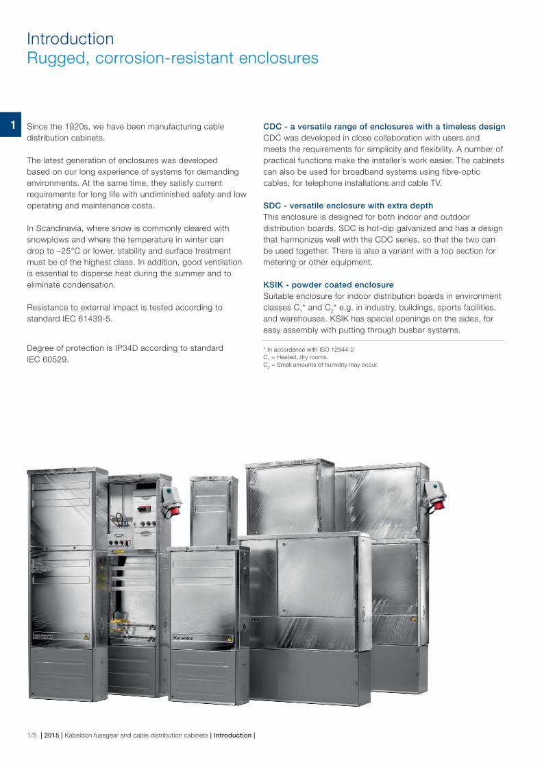
Introduction Rugged, corrosion-resistant enclosures
Since the 1920s, we have been manufacturing cable
distribution cabinets.
The latest generation of enclosures was developed
based on our long experience of systems for demanding
environments. At the same time, they satisfy current
requirements for long life with undiminished safety and low
operating and maintenance costs.
In Scandinavia, where snow is commonly cleared with
snowplows and where the temperature in winter can
drop to –25°C or lower, stability and surface treatment
must be of the highest class. In addition, good ventilation
is essential to disperse heat during the summer and to
eliminate condensation.
Resistance to external impact is tested according to
standard IEC 61439-5.
Degree of protection is IP34D according to standard
IEC 60529.
CDC - a versatile range of enclosures with a timeless design
CDC was developed in close collaboration with users and
meets the requirements for simplicity and flexibility. A number of
practical functions make the installer’s work easier. The cabinets
can also be used for broadband systems using fibre-optic
cables, for telephone installations and cable TV.
SDC - versatile enclosure with extra depth
This enclosure is designed for both indoor and outdoor
distribution boards. SDC is hot-dip galvanized and has a design
that harmonizes well with the CDC series, so that the two can
be used together. There is also a variant with a top section for
metering or other equipment.
KSIK - powder coated enclosure
Suitable enclosure for indoor distribution boards in environment
classes C1* and C
2* e.g. in industry, buildings, sports facilities,
and warehouses. KSIK has special openings on the sides, for
easy assembly with putting through busbar systems.
* In accordance with ISO 12944-2
C1 = Heated, dry rooms.
C2 = Small amounts of humidity may occur.
1
1/5 | 2015 | Kabeldon fusegear and cable distribution cabinets | Introduction |

Introduction Surface treatment
Enclosure series CDC and SDC are made of sheet steel
and are protected against corrosion by hot-dip galvanizing
according to ISO 1461. For parts that are buried in the
ground, the corrosion protection has been reinforced
with a polymer coating. To make sure that the polymer
coat adheres to the hot-dip galvanized surface, it has
undergone zinc/manganese phosphating.
The above treatment gives excellent protection against
corrosion, so that the life of the enclosures is very long
in the most commonly occurring environments for outdoor
enclosures.
Six protective coats for outstanding corrosion
protection of steel in the ground
Zn/Mn-phosphating
Steel
Hot-dip galvanizing/Zn (active protection)
Hot-dip galvanizing/Zn (active protection)
Polymer coat (passive protection)
Zn/Mn-phosphating
Polymer coat (passive protection)
1
| Introduction | Kabeldon fusegear and cable distribution cabinets | 2015 | 1/6

Introduction Distribution boards for various applications
Kabeldon low voltage distribution systems feature small
dimensions, flexibility, safety, reliability and a clear layout.
To ensure high quality, the enclosure is assembled at the
factory. The enclosure is then fitted with the required devices.
It is a simple matter to wire up the distribution board and put
it into service.
In indoor electrical rooms, the busbar system can also be
mounted on the wall. However, we recommend an enclosed
distribution board located outdoor, both for safety reasons
and for saving valuable indoor space.
The distribution board is planned with the Connect IT
program, which is available for free download.
There are also pre-assembled metered public lighting pillars,
service distribution boards for direct kWh metering or trans-
former metering and pre-assembled standby power, see
section 4‚
“Pre-assembled distribution boards”.
The distribution boards satisfy the requirements of:
IEC 60529: Degrees of protection provided by enclosures
(IP code).
IEC 60947: Low voltage switchgear and controlgear:
− Part 1: General rules.
− Part 3: Switches, disconnectors, switch-disconnectors
and fuse-combination units.
IEC 61439: Low voltage switchgear and controlgear
assemblies:
− Part 1: General rules.
− Part 5: Assemblies for power distribution in public
networks.
The following list shows some applications:
Utilities
− Electricity distribution in low voltage networks.
− Street and road lighting; traffic lights.
− Electricity supply for street markets, travelling exhibitions,
circuses and fairgrounds.
Buildings
− Distribution boards for hospitals, hotels, shopping malls
and office buildings.
Ports and airports
− Electricity supply for boats and ships.
− Electricity supply for aircrafts on the ground.
Sports installations
− Floodlighting for football and sports stadiums.
− Lighting for jogging tracks and control panels for ski lifts.
− Electricity supply.
Construction sites
− Temporary electricity supply.
− Central electric heating.
− Distribution boards for cranes and other equipment.
Industry
− Distribution boards to supply power to various types of
industrial firms.
Communication systems (enclosures)
− Enclosures for fibre-optic networks.
− Enclosures for antenna systems and cable TV.
− Terminal blocks for telephone.
Incoming
Switch-fuses with
independent manual
operation
Outgoing
Fuse-switch-disconnector
Spare space
Outgoing
Measuring unit
Voltage fuses and current
transformers, sealable
Spare space
Incoming
A distribution board with kWh metering.
1
1/7 | 2015 | Kabeldon fusegear and cable distribution cabinets | Introduction |

Introduction Planning and design program, Connect IT
Connect IT planning software
Connect IT is a Windows®-based planning program for
cable distribution cabinets, service distribution boards and
other applications based on the range of switching devices,
busbar system and enclosures.
Connect IT makes it easy to design an electrical distribution
board and to obtain details of its components as follows:
− Enclosures with accessories
− Busbar system
− Switching devices and connection
− Own hardware added, e.g. fuses
Connect IT also generates information for ordering, planning
and documentation.
− A single-line diagram, to which addresses, cable data and
other details can be added.
− A front panel sketch, which can be used as a basis for
component mounting.
Connect IT offers great scope to freely create any desired
combination of switching devices and enclosures. The work
is done quickly and simply, with the aid of pictures and text.
Connect IT is also suitable for use when planning a busbar
system without enclosure, e.g. for installation in electrical
operating areas.
Connect IT is available for free download at:
www.abb.se/kabeldon or contact us.
Contact us for further information and to place your order!
Front panel sketch of complete cabinet created in Connect IT.
1
| Introduction | Kabeldon fusegear and cable distribution cabinets | 2015 | 1/8

Introduction Our products
Enclosures for various fields of application.
Cable distribution cabinets with switching devices and busbar systems.
1
1/9 | 2015 | Kabeldon fusegear and cable distribution cabinets | Introduction |

Distribution board at a port situated in Sweden.
Cable distribution cabinet at railway station, Sweden.Cable distribution cabinet at the construction of the “Friends” Arena in Solna,
Sweden.
Distribution board, Kalmar, Sweden.
Cable distribution board for illuminated advertising signs.
Reference picturesApplication areas
Enclosure with upper section CDCM used as metering cabinet, Latvia.
1
| Introduction | Kabeldon fusegear and cable distribution cabinets | 2015 | 1/10

Examples of using Kabeldon products on the wall in low voltage switchgear, Sweden.
Reference picturesApplication areas
Cable distribution boards at Hedens bandy rink, Gothenburg, Sweden. Distribution board in powder coated enclosure mounted onthe wall in a switchgear room at a bakery, in Gothenburg, Sweden.
Cable distribution board, Sweden. Kabeldon switching devices SLDL, Sweden, especially designed for CSS.
Kabeldon switching devices in a CSS, Latvia.
1
1/11 | 2015 | Kabeldon fusegear and cable distribution cabinets | Introduction |

Reference picturesManufacturing, surface treatment and assembling
Automatic hot-dip galvanizing plant.
Powder coating of foundation parts.Treatment for outgoing waste water from surface
treatment.
Fully-automatic plant for pressing, punching and bending of metal plates.
Assembly of enclosures.
Production of switching devices and connectors with modern technology.
Automatic pre-treatment of enclosures before powder coating.
Assembly of distribution boards according to customer specific requirements.
1
| Introduction | Kabeldon fusegear and cable distribution cabinets | 2015 | 1/12

2
2/1 | 2015 | Kabeldon fusegear and cable distribution cabinets | Switching devices |

Table of contentSwitching Devices
Standard
Switching devices 2/4
Switching devices with dependent manual operation
SLD 63 2/6
SLD 000 2/7
SLD 00 2/8
SLD-FHD 2/9
SLD 1 2/10
SLD 2 2/11
Disconnector with dependent manual operation
FD 3300 2/12
Switching devices for substations 400 A – 630 A
SLDL, SLDL 2-1P, SLDL 3, SLDL 3-1P 2/13
Switching devices with independent handmanover
SEKOD 2/15
SLOB, LBOC 2/16
Adapter plates for module case circuit breakers (MCCB)
T3, T5 2/17
Connectors
Connectors 2/18
Busbar system
Busbars with protection (IP2X) – KSFS 2/19
Busbars without protection (IP00) – KSNS 2/20
5-wire system 2/21
Busbar supports – KSST, KLKB 2/22
Middle support for 400–1600 A busbars – MSB 2/23
Busbar system 1600 A forsubstations and switchgears 2/24
Busbar system 2500 A forsubstations and switchgears 2/25
General accessories
Accessories for OEM manufacturers 2/26
Temporary single-phase outlet, TFU 25 and other accessories 2/28
Street lighting box – GBL 63 2/29
Surge current arrester and surge voltage arrester – SCA, SVA 2/30
Dimension drawings
Fuse-switch-disconnectors 2/31
Switch fuses 2/32
Connectors 2/33
Busbar supports and middle supports 400–1600 A 2/34
Busbar supports and middle supports 1600 A and 2500 A 2/34
2
| Switching devices | Kabeldon fusegear and cable distribution cabinets | 2015 | 2/2

2
2/3 | 2015 | Kabeldon fusegear and cable distribution cabinets | Switching devices |

Standard switching devices
Utilization category
The utilization category for the switching devices is stated in
the “Technical data” for each product.
Rated diversity factor
For switching devices mounted in a cable distribution
cabinet, distribution board or directly on the wall; the rated
current must be reduced where there are parallel current
paths.
Rated current for phase- and neutral busbars.
The stated rated current refers to the highest permitted
current in any section of the busbar.
Voltage testing
All of the devices have apertures designed for voltage testers
conforming to IEC 61243-3.
Connectors
All switching devices SLD come complete with terminal
connectors for both copper and aluminium conductors.
Connectors for aluminium conductors have been tested
according to IEC 61238-1.
The torque range depends on the conductor cross-section,
please see “Technical data” or installation instructions.
Normally it’s no need to any retightening but it may be
required in special situations, i.e. when a short-circuit has
happened.
Area range
The stated area range refers to connection with a stranded
or solid conductor. When connecting a flexible conductor,
reduce the max. area by one area step.
Parallel conductors
The connectable area for parallel conductors is determined
by dividing the maximum area by the number of parallel
conductors and reducing by one more area step.
Ex: max cable connection 300 mm²,
300/2 150 go down by a step 120.
Modular system
The dimensions of all items that can be connected to the
busbar system are based on a module (one module
M = 12.5 mm). This makes it easy to calculate the space
required by a particular distribution board and then to
choose a suitable enclosure.
Number of main circuits Rated diversity factor
2 and 3 0.9
4 and 5 0.8
6-9 0.7
10 and above 0.6
10 M 4 M 12 M
2
| Switching devices | Kabeldon fusegear and cable distribution cabinets | 2015 | 2/4

2
2/5 | 2015 | Kabeldon fusegear and cable distribution cabinets | Switching devices |

Switching devices with dependent manual operationSLD 63
SLD 63
Fuse-switch-disconnector.
− AC-21B according to
IEC 60947-3 at 400 V.
− 3 modules or 38 mm width.
− Diazed fuses, DII or DIII.
− Sealing possibility.
Designation ID number Degree of protection
Number of modules Rated data Cable connection Al/Cu Numbers per kit
Weight
M * mm² kg/pcs
SLD 63 2CGX0 63050110 IP2X 3 400 V 63 A 1,5–25** 1 1,45
* 1 modul M = 12.5 mm.
** Max conductor cross section refers to connection with a stranded or solid conductor.
To be ordered separately:Designation ID number Color Number
per kitRated current Weight
A kg/pcs
PDA 10 2CGX0 53050131 Red 3 10 0,01
PDA 16 2CGX0 53050130 Grey 3 16 0,01
PDA 20 2CGX0 53050129 Blue 3 20 0,01
PDA 25 2CGX0 53050128 Yellow 3 25 0,01
PDA 35 2CGX0 53050127 Black 3 35 0,01
PDA 50 2CGX0 53050126 White 3 50 0,01
PBA 63 2CGX0 53050301 Transparent yellow
1 – 0,01
PBA 63
Seal cover.
PDA 10-50
Gauge pieces.
Note:
− Switching devices to be tightened with a torque.
For “Tightening torque” see page 5/6.
− For 10 – 25 A we recommend using reduction
sleeve.
2
| Switching devices | Kabeldon fusegear and cable distribution cabinets | 2015 | 2/6

Switching devices with dependent manual operationSLD 000, 80 A–100 A
JDDA 000
Earthing device.
SLD 000
Fuse-switch-disconnector.
− AC-23B according to
IEC 60947-3 at 400 V.
− 3 modules or 38 mm width.
− Fuse NH 000 or C00 or linking
knife KN 00.
− Sealing possibility.
KSBD 00
Blocking device.
KN 00
Linking knife.
FHHD-A 000
Kit with detachable handle and
adapter for fuse-switch-disconnector
SLD 000. With this solution the
depth is reduced with 35 mm.
FHH
Detachable handle to FHHD-A,
SLD-FHD and FHD.
Designation ID No. Degree of protection
Number of modules
Rated data Cable connection Al/Cu
Numbers per kit
Weight
M * 400 V 690 V mm² kg/pcs
SLD 000 2CGX0 63050106 IP2X ** 3 100 A 80 A 2.5-95 *** 1 1.7
* One module M = 12.5 mm.
** IP1X with open device, depending on design of fuse.
*** Max conductor cross section refers to connection with a stranded or solid conductor.
To be ordered separately:
Designation ID No. Number of modules Rated data
Numbers per kit
Weight
M * kg/pcs
JDDA 000 2CGX0 63190375 3 6.1 kA/1 s 1 2.2
KSBD 00 2CGX0 63190109 – – 3 0.1
KN 00 2CGX0 53190319 – 160 A 3 0.1
FHHD-A 000 2CGX0 53050205 – – 1 0.02
FHH 2CGX0 43050404 – – 1 0.02
* One module M = 12.5 mm.
Note:
Switching devices to be tightened with a torque.
For “Tightening torque” see page 5/6.
2
2/7 | 2015 | Kabeldon fusegear and cable distribution cabinets | Switching devices |

Switching devices with dependent manual operationSLD 00, 160 A
JDDA 00
Earthing device.
SLD 00
Fuse-switch-disconnector.
− AC-23B according to
IEC 60947-3 at 400 V.
− 4 modules or 50 mm width.
− Fuse NH 00 or linking knife
KN 00.
− Sealing possibility.
KSBD 00
Blocking device.
KN 00
Linking knife
FHHD-A 00
Kit with detachable handle and
adapter for fuse-switch-discon-
nector SLD 00. With this solution
the depth is reduced with 35 mm.
FHH
Detachable handle to FHHD-A,
SLD-FHD and FHD.
Designation ID No. Degree of protection
Number of modules
Rated data Cable connection Al/Cu
Numbers per kit
Weight
M * 400 V 690 V mm² kg/pcs
SLD 00 2CGX0 63050107 IP2X ** 4 160 A 160 A 2.5-95 *** 1 1.8
* One module M = 12.5 mm.
** IP1X with open device, depending on design of fuse.
*** Max conductor cross section refers to connection with a stranded or solid conductor.
To be ordered separately:
Designation ID No. Number of modules Rated data Number per kit
Weight
M * kg/pcs
JDDA 00 2CGX0 63190376 4 6.1 kA/1 s 1 2.3
KSBD 00 2CGX0 63190109 – – 3 0.1
KN 00 2CGX0 53190319 – 160 A 3 0.1
FHHD-A 00 2CGX0 53050204 – – 1 0.03
FHH 2CGX0 43050404 – – 1 0.02
* One module M = 12.5 mm.
Note:
Switching devices to be tightened with the torque.
For “Tightening torque” see page 5/6.
2
| Switching devices | Kabeldon fusegear and cable distribution cabinets | 2015 | 2/8

Switching devices with dependent manual operationSLD-FHD, 100 A–160 A
SLD-FHD 000
Fuse-switch-disconnector
− AC-21B according to
IEC 60947-3 at 400 V.
− Three single-pole fuse-holders.
− Blade fuses type C00, NH 000 or
linking knife KN 00.
SLD-FHD 00
Fuse-switch-disconnector
− AC-21B according to
IEC 60947-3 at 400 V.
− Three single-pole fuse-holders.
− Blade fuses type typ NH 00 or
linking knife KN 00.
FHD 000
The kit contains three single-pole fuse-
holders and one handle.
Replaces the cover to SLD 000 when
single-pole breaking.
FHD 00
The kit contains three single-pole
fuseholders and one handle. Replaces
the cover to SLD 00 when single-pole
breaking.
Designation ID No. Degree of protection
Number of modules Rated data Cable connection Al/Cu Numbers per kit
Weight
M * 230 V mm² kg/pcs
SLD-FHD 000 2CGX0 63050116 IP2X ** 3 100 A 2.5-95 *** 1 1.76
SLD-FHD 00 2CGX0 63050117 IP2X ** 4 160 A 2.5-95 *** 1 1.89
* One module M = 12.5 mm.
** IP1X with open device, depending on design of fuse.
*** Max conductor cross section refers to connection with a stranded or solid conductor.
Note:
Switching devices to be tightened with the torque.
For “Tightening torque” see page 5/6.
KN 00
Linking knife
To be ordered separately:
Designation ID No. Degree of protection
Number of modules Rated data Number per kit
Weight
M * kg/pcs
FHD 000 2CGX0 53050225 IP2X ** 3 100 A 3 0.10
FHD 00 2CGX0 53050226 IP2X ** 4 160 A 3 0.12
KN 00 2CGX0 53190319 – 160 A 3 0.1
* One module M = 12.5 mm.
2
2/9 | 2015 | Kabeldon fusegear and cable distribution cabinets | Switching devices |

Designation ID No. Degree of protection Number of modules
Rated data Cable connection Al/Cu
Weight
M * 400 V 690 V mm² kg/pcs
SLD 1 2CGX0 63050108 IP2X 10 250 A ** 250 A 50-300 *** 4.3
* One module M = 12.5 mm.
** 250 A with fuse, 400 A with linking knife.
*** Max. conductor cross section refers to connection with a stranded or solid conductor.
To be ordered separately:
Designation ID No. Degree of protection Rated data Dimensions Cable connectionAl/Cu
Numbers per kit
Weight
H B D
mm mm² kg/pcs
JDDA 1 2CGX0 63190402 – 16.2 kA/1 s – – – – 1 0.4
KSBD 2 2CGX0 63190110 – – – – – – 3 0.1
KN 1 2CGX0 53190345 – 400 A – – – – 3 0.2
STM 400 2CGX0 63090026 IP2X 400 V, 400 A 220 35 85 50-300 1 0.4
ADP 300 2CGX0 63090035 IP2X 690 V, 630 A 253 38 127 2//50-300 1 0,8
Switching devices with dependent manual operationSLD 1, 250 A
SLD 1
Fuse-switch-disconnector.
− AC-23B according to
IEC 60947-3 at 400 V.
− 10 modules or 120 mm width.
− Fuse NH 1 (max width 42 mm) or
linking knife KN 1.
JDDA 1
Earthing device for SLD 1.
KN 1
Linking knife.
KSBD 2
Blocking device.
STM 400
Conductor rail with connector for
current transformer metering.
Dimensions of conductor rail are
25x13 mm.
ADP 300
Insulated connector for parallel
conductors with fuse-switch-disconnectors
SLD 1, SLD 2 and also circuit-breakers
ABB Tmax T5.
Note:
Switching devices to be tightened with the torque.
For “Tightening torque” see page 5/6.
2
| Switching devices | Kabeldon fusegear and cable distribution cabinets | 2015 | 2/10

Switching devices with dependent manual operationSLD 2, 100–400 A
Designation ID No. Degree of protection
Number of modules
Rated data when voltage level Cable connection Al/Cu
Weight
400 V 690 V 1000 V
M * A mm² kg/pcs
SLD 2 2CGX0 63050109 IP2X 12 400 ** 355 100 50-300 *** 4.6
* One module M = 12.5 mm.
** 400 A with fuse, 630 A with linking knife.
*** Max. conductor cross section refers to connection with a stranded or solid conductor.
To be ordered separately:
Designation ID No. Degree of protection
Rated data Dimensions Cable connection Al/Cu
Numbers per kit
Weight
H B D
mm mm² kg/pcs
JDDA 2 2CGX0 63190401 – 16.2 kA/1 s – – – – 1 2.5
PHD 2 2CGX0 63090024 – – – – – – 1 1.5
PHD 2 SDC 2CGX0 63090023 – – – – – – 1 1.5
KSBD 2 2CGX0 63190110 – – – – – – 3 0.1
KNB 2 2CGX0 53190321 – 630 A – – – – 3 0.2
STM 400 2CGX0 63090026 IP2X 400 V, 400 A 220 35 85 50-300 1 0.4
ADP 300 2CGX0 63090035 IP2X 690 V, 630 A 253 38 127 2//50-300 1 0,8
SLD 2
Fuse-switch-disconnector
− AC-23B according to IEC 60947-3 at 400 V.
− 12 modules or 150 mm width
− Fuse NH 2 or linking knife KNB 2.
− Possibility for parallel operation
− Tested up to 1000 V for installation in dry
indoor environments.
− When using SLD 2 in 1000V systems, fuses
that are designed for 1000 V must be used.
JDDA 2
Earthing device.
STM 400
Conductor rail with connector
for current transformer
metering. Dimensions of
conductor rail are 25x13 mm.
KSBD 2
Blocking device.
ADP 300
Insulated connector for parallel
conductors with fuse-switch-
disconnectors SLD 1, SLD 2 and
also circuit-breakers
ABB Tmax T5.
Note:
Switching devices to be tightened with the torque.
For “Tightening torque” see page 5/6.
KNB 2
Linking knife.
PHD 2 SDC
Parallel handle for parallel operation
of two SLD 2 in enclosures SDC
and CSS switchgears.
PHD 2
Parallel handle for parallel
operation of two SLD 2 in
enclosures CDC.
2
2/11 | 2015 | Kabeldon fusegear and cable distribution cabinets | Switching devices |

Designation ID No. Degree of protection
Number of modules
Rated data
Cable connection Al/Cu
Weight
M * mm² kg/pcs
FD 3300 2CGX0 63030032 IP2X 7 500 V, 400 A 50-300 ** 2.6
* One module M = 12.5 mm.
** Max. conductor cross section refers to connection with a stranded or solid conductor.
To be ordered separately:
Designation ID No. Weight
kg/pcs
KFBD 2CGX0 63190112 0.1
Disconnector with dependent manual operationFD 3300, 400 A
Disconnectors are intended for single-pole breaking. By using the linking knives
between adjacent disconnectors, the busbar system can be disconnected without
stopping the current from the incoming cable passing through.
FD 3300
Disconnector.
KFBD
Blocking device.
Note:
Switching devices to be tightened with the
torque. For “Tightening torque” see page 5/6.
2
| Switching devices | Kabeldon fusegear and cable distribution cabinets | 2015 | 2/12

Switching devices with dependent manual operation, 100 A–630 ASLDL 2, SLDL 2-1P, SLDL 3, SLDL 3-1P
SLDL 2, SLDL 3
Three-pole fuse-switch-
disconnector for 400 A
and 630 A.
SLDL 3-1P
Single-pole fuse-switch-
disconnector for 630 A.
SLDL 3
Three-pole fuse-switch-
disconnector 630 A,
mounted to connect the
cable from above.
Designation ID No. Degree of protection
Number of modules Rated data Cable connection Al/Cu
Weight
M * V A mm² kg/pcs
SLDL 2 2CGX0 63050242 IP 2X 8 400 400 35-240 2//95-240
5,5
690 400
1000 160
SLDL 2-1P 2CGX0 63050243 IP 2X 8 230 400 35-240 2//95-240
5,3
400 400
690 160
SLDL 3 2CGX0 63050240 IP 2X 8 400 630 35-240 2//95-240
6,4
690 500
1000 160
SLDL 3-1P 2CGX0 63050241 IP 2X 8 230 630 35-240 2//95-240
6,2
400 500
690 160
* One module M = 12.5 mm.
The fuse-switch-disconnector available in four variants:
− SLDL 2, 400 A for three-pole breaking.
− SLDL 2-1P, 400 A for single-pole breaking.
− SLDL 3, 630 A for three-pole breaking.
− SLDL 3-1P, 630 A for single-pole breaking.
Application area
SLDL is used in the low voltage part of substations and
similar applications.
Standard
− Meets the requirements of IEC 60947-3.
− Degree of protection, IP2X.
Design
Fuse-switch-disconnectors’ outer layer is made of fiber
glass reinforced plastic with strength according to the
requirements for use in substations.
− SLDL is 100 mm wide.
− Fits to the Kabeldon busbar system.
− To enable cable connection from above, the rear section
of the apparatus can be reversed 180°. The handles’
opening angle and direction are unchanged.
− The design allows visual inspection of the screw
connections’ mode after installation.
− The cable may be connected in the apparatus with clamps
or cable lugs.
− Possibility for parallel operation of two SLDL.
Suitable fuse sizes
− For SLDL 2 and SLDL 2-1P use NH2.
− For SLDL 3 and SLDL 3-1P use NH2, NH3.
NOTE:
− SLDL does not fit in the cable distribution cabinets
type CDC, SDC and KSIP.
− Terminal clamps must be ordered separately.
− Switching devices to be tightened with torque.
For “Tightening torque” see page 5/6.
2
2/13 | 2015 | Kabeldon fusegear and cable distribution cabinets | Switching devices |

Accessories SLDL 2, SLDL 2-1P, SLDL 3, SLDL 3-1P
Accessories Designation ID No. Weight
kg/pcs
Protective hood CS SLDL 2CGX0 63050244 0,05
Parallel handle PHDL 2CGX0 63050249 0,2
Linking knife KNB 2 2CGX0 53190321 0,1
Terminal clamp, single TCS 35-240 2CGX0 53050279 0,5
Terminal clamp, parallel TCD 50-240 2CGX0 53050280 0,8
Blocking device KSBD 2 2CGX0 63190110 0,1
Terminal clamp Fits to cable with Conductor cross section
mm²
TCS 35-240 sector-shaped stranded conductor 35-240
sector-shaped solid conductor 35-300
round stranded conductor 16-185
round solid conductor 16-240
TCD 50-240 sektor stranded conductor 2//95-240
sektor solid conductor 2//120-300
round stranded conductor 2//50-185
round solid conductor 2//70-240
CS SLDL
Protective hood, used when
connecting cable from above.
KNB 2
Linking knife for fuseless disconnection.
PHDL
Handle for parallel operation of two
SLDL at once.
KSBD 2
Blocking device protects against con-
nection while working.
TCS 35-240
Terminal clamp for connection of a
cable, 35–240 mm². TCS is delivered
in set of 3.
TCD 50-240
Terminal clamp for parallel connection
of two cables, 50–240 mm². TCD is
delivered in set of 3.
2
| Switching devices | Kabeldon fusegear and cable distribution cabinets | 2015 | 2/14

Switching devices with independent manual operationSEKOD, 125 A–355 A
Designation ID No. Number of modules
Rated current
Cable connectionAl/Cu
Fits in enclosures Suitable fuse size
Weight
M * A mm² kg/pcs
SEKOD 125 2CGX0 63050233 12 125 ** 50-300 *** KSIK, CDC, SDC NH 00 3.5
SEKOD 224 2CGX0 63050234 17 224 ** 50–300 *** KSIK, SDC NH 0, NH 1 5.2
SEKOD 355 2CGX0 63050235 17 355 ** 50–300 *** KSIK, SDC NH 1, NH 2 8.2
* One module M = 12.5 mm.
** Rated current with fuses in enclosure.
*** Max. conductor cross section refers to connection with a stranded or solid conductor.
To be ordered separately
Designation ID No. Rated current Qty. per kit
Weight
A kg/pcs
ILM 125 2CGX0 63090036 – 1 0.3
ILM 224 2CGX0 63090032 – 1 0.8
ILM 355 2CGX0 63090034 – 1 0.6
PSM 224 2CGX0 63090031 – 1 0.7
KN 00 2CGX0 53190319 125 3 0.1
KN 1 2CGX0 53190345 355 3 0.2
SEKOD 224
Switch-fuse with breaking on both sides of the
fuse. 3-pole breaking with sealing possibility.
System always dead when replacing fuses.
Degree of protection is IP2X.
SEKOD 355
Switch-fuse with breaking on both sides of the
fuse. 3-pole breaking with sealing possibility.
System always dead when replacing fuses.
Degree of protection is IP2X.
SEKOD 125
Switch-fuse with breaking on both sides of the
fuse. 3-pole breaking with sealing possibility.
System always dead when replacing fuses.
Degree of protection is IP2X.
ILM 224
Mechanical interlocking mechanism for two
switch-fuses SEKOD 224. Preventing activa-
tion of a SEKOD 224 if the other one is not in
OFF-position.
ILM 355
Mechanical interlocking mechanism for two
switch-fuses SEKOD 355. Preventing activa-
tion of a SEKOD 355 if the other one is not in
OFF-position.
PSM 224
Parallel handle for the connection and disconnection
of two parallel mounted SEKOD 224.
KN 1
Linking knife.
KN 00
Linking knife.
ILM 125
Mechanical interlocking mechanism for two
switch-fuses SEKOD 125. Preventing activa-
tion of a SEKOD 125 if the other one is not in
OFF-position.
Note:
Switching devices to be tightened with
torque. For “Tightening torque” see
page 5/6.
Rated current with linking knivesApplication area SEKOD 125 SEKOD 224 SEKOD 355
Rated current with linking knives
160 A 250 A 400 A
Suitable linking knives KN 00 KN 1 KN 1
2
2/15 | 2015 | Kabeldon fusegear and cable distribution cabinets | Switching devices |

Switching devices with independent manual operationSLOB, LBOC, 355 A–1600 A
SLOB 400, 630, 800
Section switch-fuse with breaking on both
sides of the fuse. 3-pole breaking with
sealing possibility. System always dead
when replacing fuses. Degree of protection
is IP2X.
Note:
− For installation of section circuit breaker SLOB 400
it is necessary to split the busbars and complete
with 2 extra busbar support KSST 316/23*.
− For SLOB 800 with rated current from 800 A and
LBOC 800 A and 1600 A the busbars must be
machined, please contact us for further information.
− Switching devices to be tightened with torque. For
“Tightening torque” see page 5/6.
* Busbar support as accessory is to be ordered separately.
Designation ID No. Number of modules Rated current Fits in enclosure Suitable fuse size
Weight
M * A kg/each
SLOB 400 ** 2CGX0 63050097 17 355 KSIK, SDC 0-2 8.6
SLOB 630 2CGX0 63050101 30 630 KSIK, SDC 3 15
SLOB 800 2CGX0 63050102 27 800 KSIK, SDC 3 15
LBOC 630 2CGX0 63050103 27 630 KSIK, SDC – 8
LBOC 800 2CGX0 63050104 23 800 KSIK, SDC – 8
LBOC 1600 2CGX0 63050105 34 1600 KSIK, SDC – 18
* One module M = 12.5 mm.
** With linking knife to be applied 400 A for SLOB 400.
LBOC 630, 800, 1600
Section switch without fuse.
LBOC 630 with devided busbar and busbar
supports in both sides.
2
| Switching devices | Kabeldon fusegear and cable distribution cabinets | 2015 | 2/16

Adapter plates for moulded case circuit breakers (MCCB) T3 and T5, 250 A and 525 A
Designation ID No. Number of modules
Rated data Cable connection Al/Cu
Dimensions with mounted circuit-breaker Weight
Height Width Depth
M * V A mm² mm kg/pcs
AS-T3 2CGX0 63050093 9 690 250 300 325 113 190 2.1
KLAP T5 630 2CGX0 53050209 12 400 525 – 395 150 296 3.0
ADP 300 2CGX0 63090035 3 690 630 2//50-300 – – – 0,8
* One module M = 12.5 mm.
AS-T3
Adapter for circuit-breaker type
ABB Tmax T3 for 250 A from ABB SACE.
− Degree of protection IP2X.
− Allows circuit-breakers to be mounted
on a live busbar system.
− Fits all Kabeldon busbars.
− Fits Kabeldon enclosures.
− Meets the requirements of
IEC 60947-1.
Note:
Circuit-breaker is not included! For complete solution the
additional should be ordered:
− Adapter plate AS-T3.
− Circuit-breaker T3 250 – Fixed – 3-pole.
− Conversion kit from fixed to Plug-in, 1 SD AO 51413 R1.
Moulded-case circuit-breaker ABB Tmax T3, is mounted on
adapter plate AS-T3.
Moulded-case circuit-breaker ABB
Tmax T5 and plug-in socket, mounted
on adapter plate KLAP T5 630.
Note:
Circuit-breaker and plug-in socket is not included.
For complete solution the additional should be ordered:
− Adapter plate KLAP T5 630.
− Circuit-breaker T5 630 – Fixed – 3-pole.
− Conversion kit from fixed to Plug-in, 1SDA 054847 R1.
− Plinth, 1SDA 054762 R1.
− Connector.
KLAP T5 630
Adapter plate for plug-in socket to
circuit-breaker ABB Tmax T5 630 for 525 A
from ABB Sace.
− Fits all Kabeldon busbars.
− Meets the requirements of IEC 60947-1.
− Doesn‘t fit in Kabeldon enclosures.
− To be mounted when disconnected.
Note:
− Only the adapter plates are included in Kabeldon supply.
− For more information, please contact your local
ABB supplier.
ADP 300
Insulated connector for parallel
conductors with fuse-switch-
disconnectors SLD 1, SLD 2
and also circuit-breakers
ABB Tmax T5.
2
2/17 | 2015 | Kabeldon fusegear and cable distribution cabinets | Switching devices |

Connectors
AD 70
Non-insulated connector.
May only be used with
non-protected busbars.
ADC 25
Non-insulated connector.
May only be used with
non-protected busbars.
KSBH 300
Cover for disconnected cable, for
protection against accidental contact,
with AD 300 or AD 2150.
AD 2150
Insulated connector
for parallel conductors.
AD 95
Insulated connector.
ADB 3M
Insulated connector
for compact fitting of
AD 300 for 3 phases.
AD 350
Non-insulated connector for connect-
ing three separate conductors.
May only be used with non-protected
busbars.
AD 400
Insulated connector.
Note:
Switching devices and connectors must be tightened to the
recommended torque. For “Tightening torque” see page 5/6.
ADO 240
Non-insulated connector.
May only be used with non-
protected busbars.
ADN
Spacer for PEN bar, used with AD 300.
AD 300
Insulated connector.
Designation ID No. Number of modules Width Rated data Degree of protection
Cable connection Al/Cu ** Weight
M * mm V A mm² kg/pcs
ADC 25 2CGX0 63030233 – 14 – 63 – 1,5-25 0,1
AD 70 2CGX0 63030038 – 23 – 200 – 6-95 0,1
ADO 240 2CGX0 63030263 3 30 – 400 – 120-240 0,25
AD 350 2CGX0 63030262 – 38 – 400 – 3 x 6-50 0,2
AD 95 2CGX0 63030249 2 25 690 200 IP2X 6-95 0,1
AD 2150 2CGX0 63030037 3 38 690 400 IP2X 35-2//150 0,2
AD 300 *** 2CGX0 63030195 3 38 690 630 IP2X 50-300 0,2
AD 400 2CGX0 63030267 3 42 690 630 IP2x 50-400 0,47
ADB 3M **** 2CGX0 63030258 3 38 500 500 IP2X – 0,7
STM 400 2CGX0 63090026 3 35 400 400 IP2X 50-300 0,4
ADP 300 2CGX0 63090035 3 38 690 630 IP2X 2//50-300 0,8
KSBH 300 2CGX0 63190111 – 46 – – – – 0,1
ADN 2CGX0 63030231 – 37 – 500 – – 0,3
* One module M = 12.5 mm.
** Max conductor cross section refers to connection with a stranded or solid conductor.
*** Three-phase connection, 6-9 modules.
**** ADB 3M to be supplemented with three AD 300
STM 400
Conductor rail with connector
for current transformer
metering. Dimensions of
conductor rail are 25x13 mm.
ADP 300
Insulated connector for parallel
conductors with fuse-switch-
disconnectors SLD 1, SLD 2
and also circuit-breakers
ABB Tmax T5.
2
| Switching devices | Kabeldon fusegear and cable distribution cabinets | 2015 | 2/18

Busbar system with accessories With protection (IP2X) against accidental contact, 400 A–1600 A
Designation ID No. Number of modules
Rated data Suitable busbar support Length Weight
KSST 36 KSST 316
KSST 316/23
M * A KSST 316/100 mm kg/m
KSFS 420 2CGX0 43320260 20 400 x x 284 0.6
KSFS 440 2CGX0 43320261 40 400 x x 534 0.6
KSFS 443 2CGX0 43320037 43 400 x x 569 0.6
KSFS 448 2CGX0 43320258 48 400 x x 636 0.6
KSFS 460 2CGX0 43320262 60 400 x x 784 0.6
KSFS 463 2CGX0 43320038 63 400 x x 809 0.6
KSFS 473 2CGX0 43320264 73 400 x x 950 0.6
KSFS 640 A 2CGX0 43320363 40 630 x x 534 0.9
KSFS 643 A 2CGX0 43320367 43 630 x x 569 0.9
KSFS 648 A 2CGX0 43320365 48 630 x x 636 0.9
KSFS 660 A 2CGX0 43320364 60 630 x x 784 0.9
KSFS 663 A 2CGX0 43320368 63 630 x x 809 0.9
KSFS 673 A 2CGX0 43320369 73 630 x x 950 0.9
KSFS 698 A 2CGX0 43320366 98 630 x x 1264 0.9
KSFS 1083 2CGX0 43320145 83 1000 – x 1079 1.6
KSFS 1098 2CGX0 43320156 98 1000 – x 1264 1.6
KSFS 10126 2CGX0 43320146 126 1000 – x 1600 1.6
KSFS 1683 2CGX0 43320152 83 1600 – x 1079 3.0
KSFS 1698 2CGX0 43320158 98 1600 – x 1264 3.0
KSFS 16126 2CGX0 43320153 126 1600 – x 1600 3.0
KSFS 16149 2CGX0 43320154 149 1600 – x 1890 3.0
KSFS 16181 2CGX0 43320155 181 1600 – x 2300 3.0
* One module M = 12.5 mm.
Note:
The stated rated current is the maximum
current in any part of the busbar.
AB 800-53, AB 1200-53,AB 1200-70
For connection to the back of the busbar; fits
KSFS 1000 A and KSFS 1600 A bar. The kit
includes:
− Plastic cover.
− Thread insert, M12/M16 length 53 respec-
tively 70mm.
− Connecting washer.
− Flat washer, Ø 36 mm.
− Compression washer, Ø 29 mm.
− Nut, M12.
Note: Cable lug is not included in the kit.
Designation ID No. Number of modules
Rated data Diameter Ø
Length of Thread insert
Qty per pack
Weight
M * mm mm kg/pcs
AB 800-53 2CGX0 53030500 – 500 V, 800 A 26 53 1 0.1
AB 1200-53 2CGX0 53030501 – 500 V, 1200 A 37 53 1 0.1
AB 1200-70 2CGX0 53030502 – 500 V, 1200 A 37 70 1 0.1
* One module M = 12.5 mm.
KSFS 420-473
400 A.
KSFS 640 A-698 A
630 A.
KSFS 1083-10126
1000 A.
KSFS 1683-16181
1600 A.
2
2/19 | 2015 | Kabeldon fusegear and cable distribution cabinets | Switching devices |

Busbar system with accessories Without protection against accidental contact type PEN, PE and N, 400 A–1000 A
Designation ID No. Number of modules Rated current Length Weight
M * A mm kg/m
KSNS 417 2CGX0 43320059 17 400 209 0.6
KSNS 420 2CGX0 43320192 20 400 333 0.6
KSNS 440 ** 2CGX0 43320193 40 400 585 0.6
KSNS 443 2CGX0 43320052 43 400 569 0.6
KSNS 460 2CGX0 43320194 60 400 835 0.6
KSNS 463 2CGX0 43320053 63 400 809 0.6
KSNS 473 2CGX0 43320196 73 400 900 0.6
KSNS 498 2CGX0 43320190 98 400 1214 0.6
KSNS 498 KSIK 2CGX0 43320195 98 400 1266 0.6
KSNS 1083 2CGX0 43320162 83 1000 1079 1.6
KSNS 1098 2CGX0 43320169 98 1000 1212 1.6
KSNS 1098 KSIK 2CGX0 43320343 98 1000 1264 1.6
KSNS 10126 2CGX0 43320163 126 1000 1600 1.6
KSNS 10149 2CGX0 43320164 149 1000 1890 1.6
KSNS 10181 2CGX0 43320165 181 1000 2300 1.6
* One module M = 12.5 mm.
** KSNS 440 is used with SDC X48 and CDC X40.
KSNS 1083-10181
1000 A.
Designation ID No. Dimensions Weight
Length Width Depth kg/pcs
KSNSV 410 2CGX0 63120002 160 36 62 0,26
KSNSV 410
Vertical PEN-bar, used in replacement of
equipment in older enclosures where
PEN- bar has not enough space.
KSNS 417-498
400 A.
2
| Switching devices | Kabeldon fusegear and cable distribution cabinets | 2015 | 2/20

Busbar system5-wire system
Designation ID No. Fits enclosure Number of modules Rated current Length Weight
M * A mm kg/pcs
C20-TNS 2CGX0 53310613 CDC 20 20 400 333 0.6
C40-TNS 2CGX0 53310614 CDC 40 40 400 583 0.7
C60-TNS 2CGX0 53310615 CDC 60 60 400 833 0.9
SD 48-TNS 2CGX0 53320208 SDC 48 48 400 584 0.9
SD 73-TNS 2CGX0 53320219 SDC 73 73 400 898 1.0
SD 98-TNS 2CGX0 53320209 SDC 98 98 400 1212 1.2
KD 43-TNS 2CGX0 53320210 KSIK 043 43 400 570 0,6
KD 63-TNS 2CGX0 53320211 KSIK 063 63 400 810 0,7
KD 98-TNS 2CGX0 53320212 KSIK 098 98 400 1270 1,0
* One module M = 12.5 mm.
Kit for conversion to 5-wire system, TN-S or TN-C-S.
The kit includes a 400 A non-protected busbar.
− CXX-TNS fits in enclosures type CDC.
− SD XX-TNS fits in enclosures type SDC.
Note:
For additional information regarding upgrading kit for
1000 A or for use in enclosure type KSIK please contact
your supplier.
2
2/21 | 2015 | Kabeldon fusegear and cable distribution cabinets | Switching devices |

Busbar system with accessoriesBusbar supports
Designation ID No. Rated current Free space behind the bars Number of modules Suitable enclosures
Weight
A mm M * kg/pcs
KSST 36 2CGX0 53320186 – 11 2 all 0.1
KSST 316 2CGX0 53320104 – 9 2 all 0.5
KSST 316/23 2CGX0 53320106 – 23 2 all 0.8
KSST 316/100 2CGX0 53320105 – 100 2 SDC 1.1
KSST-CDC 2CGX0 53320231 – 15 – CDC 0.4
KSST 36-CDC 2CGX0 53320187 – 15 2 CDC 0.3
KLKB-S 630 2CGX0 51190106 630 – – all 3.4
KLKB-S 1200 2CGX0 51190107 1200 – – SDC 6.6
* One module M = 12.5 mm.
KSST 36
Support for 400 A and 630 A
busbars. Fixing hole pitch 85 mm.
To split busbar systems for
metering with current transform-
ers, etc.
KSST 316, 316/23, 316/100
Support for 400 A, 630 A, 1000 A
and 1600 A busbars. Primarily in
enclosures type SDC.
KSST 36-CDC
Support for 400 A and 630 A
phase bars. Fixing hole pitch
is 85 mm. Used in split and
shortened busbar systems in
CDC enclosures.
KSST-CDC
Support for 400 and 630 A busbars
when mounting in enclosure type
CDC. The kit consists of a complete
support and two fixing bolts.
KLKB-S 630, 1200
Bar bridge to interconnect busbar
systems in two enclosures. May
only be installed on dead busbar.
2
| Switching devices | Kabeldon fusegear and cable distribution cabinets | 2015 | 2/22

Busbar system with accessories Middle support for 400–1600 A busbars
Designation ID No. Free space behind the busbars Number of modules Weight
mm M * kg/pcs
MSB 316 2CGX0 53320201 9 1 0.5
MSB 316/23 2CGX0 53320202 23 1 0.8
MSB 316/100 2CGX0 53320203 100 1 1.2
* One module M = 12.5 mm.
MSB 316/100
Middle support fits to KSST 316/100.
Made from non-magnetic stainless steel.
Note:
− In order to fulfill the requirements for short-circuit strength
normally a middle support is mounted when the distance
between two busbar supports exceeds 1.25 meters.
− Not required in Kabeldon standard enclosures unless they
are built together with through busbar system.
MSB 316/23
Middle support fits to KSST 316/23.
Made from non-magnetic stainless steel.
MSB 316
Middle support fits to KSST 316.
Made from non-magnetic stainless steel.
2
2/23 | 2015 | Kabeldon fusegear and cable distribution cabinets | Switching devices |

Busbar system for substations and low voltage switchgears 1600 A
Designation ID No. Degree of protection
Number of modules
Dimensions Weight
Height Length Width Depth
M * mm kg/pcs
KSSTD 312/16 2CGX0 53320240 – 3 330 – 30 82 0.4
MSBD 312/16 2CGX0 53320241 – 1 318 – 9.5 82 0.9
AB 2500 CSS 2CGX0 53320248 IP0X 7 60 80 56 0.31
KSFS 16151 CSS 2CGX0 53320361 IP2X 151 70 1910 – 49 7.6
KSFS 16183 CSS 2CGX0 53320360 IP2X 183 70 2310 – 49 9.2
* One module M = 12.5 mm.
The system has been tested for up to 30 kA short-circuit
current.
At short circuit < 30 kA used busbar support KSSTD
312/16 and if necessary the middle support MSBD
312/16.
Simple to connect power supply at rear with connection
washer, AB 2500 CSS without modification to the busbar.
Each busbar is lifted into place separately from the front
prior to attachment.
Busbars and accessories
Connection washer, AB 2500 CSS
− For connection at the rear of the busbar.
− Fits busbars, KSFS 16183 CSS and KSFS 16151 CSS.
Busbar support, KSSTD 312/16
For wall mounting or in a frame. Can be mounted on a flat
surface or between two opposite walls.
Middle support, MSBD 312/16
In order to fulfill the requirements for short-circuit strength
normally a middle support is mounted when the distance
between two busbar supports exceeds 1.25 meters.
MSBD 312/16KSSTD 312/16
AB 2500 CSS
A complete installation as shown in this figure consists of two busbar supports,
a middle support, three busbars and three connection washers.
KSFS 16151 CSS
KSFS 16183 CSS
Quick installation, each busbar is lifted into place separately
from the front prior to attachment.
Example of connection at the rear.
2
| Switching devices | Kabeldon fusegear and cable distribution cabinets | 2015 | 2/24

Designation ID No. Degree of protection
Number of modules
Dimensions Weight
Hight Length Width Depth
M * mm kg/pcs
KSFS 25150 CSS 2CGX0 53320354 IP2X 150 70 1910 – 49 8.8
KSFS 25182 CSS 2CGX0 53320353 IP2X 182 70 2310 – 49 10.6
KSNS 25150 CSS 2CGX0 43320501 IP0X 150 70 1910 49 8.8
KSNS 25182 CSS 2CGX0 43320500 IP0X 182 70 2310 49 10.6
KSST 325 CSS 2CGX0 53320251 – 4 365 – 43 114 2.4
MSB 325 CSS 2CGX0 53320250 – 2 365 – 19.5 114 1.2
KSST 325 CSS-F 2CGX0 53320249 – 3 365 – 27 114 1.2
AB 2500 CSS 2CGX0 53320248 IP0X 7 60 – 80 56 0.3
* One module M = 12.5 mm.
Busbar system for substations and low voltage switchgears2500 A
The system has been tested for up to 65 kA short-circuit
current.
Simple to connect power supply at rear with connection
washer, AB 2500 CSS without any treatment of busbar.
Each busbar is lifted into place separately from the front
prior to attachment.
Busbars and accessories
Phase busbars, KSFS 25150, 25182 CSS
Busbars with protection against contact.
Non-protected busbars, KSNS 25150, 25182 CSS
Busbars without protection against contact for use as PEN,
PE or N busbars.
Connection washer, AB 2500 CSS
− For connection at the rear of the busbar.
− Fits busbars, KSFS 16183 CSS and KSFS 16151 CSS.
Busbar support, KSST 325 CSS
Reinforced busbar support for wall mounting, includes
an additional support for lateral movements.
Middle support, MSB 325 CSS
In order to fulfill the requirements for short-circuit strength
normally a middle support is mounted when
the distance between two busbar supports exceeds
1.25 meters.
Busbar support, KSST 325 CSS-F
Support for frame mounting. To be placed between two
opposing walls, providing support for the busbars.
KSFS 25150 CSS
KSFS 25182 CSS
AB 2500 CSS
KSST 325 CSS MSB 325 CSS KSST 325 CSS F
Example of connection at the rear.
Quick installation, each busbar is lifted into place separately from the
front prior to attachment.
A complete installation as shown in this figure consists of two bus-
bar supports, a middle support, three busbars and three connection
washers.
KSNS 25150 CSS
KSNS 25182 CSS
2
2/25 | 2015 | Kabeldon fusegear and cable distribution cabinets | Switching devices |

General accessories For OEM manufacturers
Designation ID No. Number of modules Rated data Diameter Ø Length of Thread insert
Qty per pack
Weight
M * mm mm kg/pcs
AB 800-53 2CGX0 53030500 – 500 V, 800 A 26 53 1 0.1
AB 1200-53 2CGX0 53030501 – 500 V, 1200 A 37 53 1 0.1
AB 1200-70 2CGX0 53030502 – 500 V, 1200 A 37 70 1 0.1
ADR M8 ** 2CGX0 63030239 2 500 V, 630 A – – 50 0.1
ADR M10 ** 2CGX0 63030240 2 500 V, 630 A – – 50 0.1
ADR H12 2CGX0 63030259 2 500 V, 630 A – – 50 0.1
* One module M = 12.5 mm.
** M8 and M10 screw thread respectively.
AB 800-53, AB 1200-53, AB 1200-70
Connection kit for connection to the rear of the busbar.
Fits KSFS 1000 A and KSFS 1600 A busbars.
The kit includes:
− Plastic cover.
− Thread insert, M12/M16 length 53 respectively
70mm.
− Connecting washer.
− Flat washer, Ø 36 mm.
− Compression washer, Ø 29 mm.
− Nut, M12.
Note: Cable lug is not included in the kit.
ADR M8/M10
Connector kit for connection to the front of the busbar, with
M8 or M10 thread.
ADR H12
For connection to the front of the busbar, with Ø12 hole.
For busbars without protection against accidental contact.
2
| Switching devices | Kabeldon fusegear and cable distribution cabinets | 2015 | 2/26

Designation ID No. Busbar Conductor cross section Al/Cu
Connecting clamp Weight
Width Thickness W H1 H2 D
mm mm² mm kg/pcs
TC 50-12 2CGX0 63030202 12 1.5-3 6-50 21 27 5 16 0.02
TC 70-15 2CGX0 63030203 15 2-4 10-70 26 47 12 16 0.04
TC 120-20 2CGX0 63030204 20 3-5 35-120 32 60 12 22 0.08
TC 300-25 2CGX0 63030205 25 4-6 70-300 40 85 13 30 0.2
TC 300-40 2CGX0 63030209 40 4-6 95-300 47 84 – 30 0.2
TCD 185-25 2CGX0 63030206 25 4-6 2//50-185 48 75 – 30 0.2
TCD 300-40 2CGX0 63030207 40 4-6 2//95-300 65 84 – 30 0.3
General accessories For OEM manufacturers
TC
Connecting clamp.
H1
H2
W D
TC 300-40
Connecting clamp TC 300-40.
H1
WD
TCD
Connecting clamp TCD.
H1
WD
TC 50-12
TC 70-15
TC 120-20
TC 300-25
TC 300-40
TCD 185-25
TCD 300-40
2
2/27 | 2015 | Kabeldon fusegear and cable distribution cabinets | Switching devices |

General accessories
TFU 25
Single-phase power outlet for temporary connections,
e.g. for a hand lamp or power drill.
– Mounts directly on the busbar.
– Conductor cross section, max. 35 mm² Al/Cu.
– Diazed säkring max 25 A.
Connectors for the PE and N conductors are also
needed (see the page about connectors).
UKRA 90
Universal clamp for fixing cables with Ø 20-90 mm,
on mounting rails in a cabinet, for example.
AK-ADAS
Prefabricated connector for the extension of Al
cable, while connecting in a cable distri-bution
cabinet, a service distribution board or in switch-
gears. Dimensioned in accordance with the cable
loading and short-circuit data.
− Meets the requirements of: IEC 61238-1
Flexible insulated Cu conductor compressed
onto a prefabricated Al/Cu cable connection. The
aluminium part is designed for crimping with the
Elpress system. The length of all the connectors are
700 mm.
PBKP 25/50
Seal cover for KSKP 25/50.
KSKP 25/50
Terminal block.
PSFS 5/17
Plate for sealing phase bar.
Designation ID No. Number of modules
Rated data Cable connection Dimensions Weight
Al/Cu Height Width Depth
M * mm² mm kg/pcs
TFU 25 2CGX0 63140001 – 230 V, 25 A 1.5 -35 84 30 185 0.3
KSKP 25 2CGX0 63130005 – 500 V, 63 A 1.5-25 – 56 – 0.2
KSKP 50 2CGX0 63130007 – 400 V, 160 A 6-50 – 73 – 0.3
PSFS 5 2CGX0 53050143 5 – – – – – 0.1
PSFS 17 2CGX0 53050144 17 – – – – – 0.1
PBKP 25 2CGX0 53050141 – – – – 80 – 0.1
PBKP 50 2CGX0 53050142 – – – – 96 – 0.1
* 1 module M = 12.5 mm.
Designation ID No. Diameter Qty per pack
Weight
mm kg/pcs
UKRA 90 2GLX0 65300013 20-90 1 0.2
Designation ID No. Fits aluminium conductor cross section
Conductor cross section of connector
Weight
mm² mm² kg/pcs
AK-ADAS 5025-7 2CGX0 63030075 50 25 0.2
AK-ADAS 7035-7 2CGX0 63030082 70 35 0.2
AK-ADAS 9550-7 2CGX0 63030090 95 50 0.5
AK-ADAS 12070-7 2CGX0 63030097 120 70 0.5
AK-ADAS 15070-7 2CGX0 63030104 150 70 0.6
AK-ADAS 185120-7 2CGX0 63030115 185 120 0.9
AK-ADAS 240120-7 2CGX0 63030118 240 120 1.0
2
| Switching devices | Kabeldon fusegear and cable distribution cabinets | 2015 | 2/28

Street lighting boxesGBL 63
Designation ID No. Rated data Cable connection
Dimensions Weight
Height Width Depth
mm² mm kg/pcs
GBL 63 2CGX0 63190374 400 V, 63 A 4Cu/16 Al/Cu 382 250 132 4.8
Maximum lighting loads switched by contactor
(Data coming from the contactor manufacturer)Lamp type Lamp
WattageLamp rated current
230 VMax Quantity
lamps/phase
W A GBL 63
High-pressure sodium Metall-halogen lampsUncompensated
150 1,8 23
250 3,0 14
400 4,4 9
600 6,2 7
1000 10,3 4
High-pressure sodium Metall-halogen lampsCompensated
150 1,0 50
250 1,5 33
400 2,5 20
600 3,3 15
1000 6,2 8
Mercury, high pressureUncompensated
125 1,2 37
250 2,2 20
400 3,3 13
Mercury, high pressureCompensated
125 0,7 64
250 1,3 33
400 2,1 21
GBL 63
Street lighting box for five-wire system (TN-S).
− Can be mounted on mounting plate in the upper section of
enclosures CDCM and SDCM.
− Contactor for 63 A.
− Degree of protection IP3X.
− 7 M (125) free space for kWh metering, control etc.
Connectable cable cross-section:
− Incoming/outgoing cable to terminal block, max. 16 mm².
− Incoming/outgoing wiring for control circuits, max. 4 mm².
Single line diagram for GBL 63.
2
2/29 | 2015 | Kabeldon fusegear and cable distribution cabinets | Switching devices |

Surge arrestersSCA, SVA
Designation ID No. Rated data Cable connection
Dimensions Weight
Height Width Depth
mm² mm kg/pcs
SCA 2CGX0 53190270 230 V (L-N) 25 150 130 90 2.9
SVA 2CGX0 53310671 230 V (L-N) 25 90 90 90 1.9
SCA
Surge current arrester kit. Heavy-duty protection needed
when an overhead line or lightning-conductor is used.
The kit comprises:
− Three heavy duty arresters for TN-C (four-wire) system
with bracket for mounting on the PEN bar.
− The necessary flexible wires.
− Connectors (AD 95 for phase connection, AD 70 for PEN
connection).
− Installation instructions.
Choice of surge protection:
Choose SCA (heavy-duty protection)
− When the building has a lightning conductor.
− Electricity supply via overhead line.
− In rural areas with a high frequency of lightning strikes.
− Class: I/B.
Choice of surge protection:
Choose SVA (medium-duty protection)
− With electricity supply via buried cable (at least 200 metres
of cable to the overhead line network).
− Class: II/C.
SVA
Surge voltage arrester kit.
A medium-duty arrester for use with underground networks
and where no lightning-conductors are used.
The kit comprises:
− Four medium-duty arresters for TN-S systems with at-
tachment for mounting on the N bar.
− The necessary flexible wires.
− Connectors (AD 95 for phase connection, AD 70 for PE
and N connection).
− Installation instructions.
Can also be used in a TN-C system.
SVABuried cable > 200 m.
SCALightning conductor.
SCAOverhead line.
2
| Switching devices | Kabeldon fusegear and cable distribution cabinets | 2015 | 2/30

Dimension drawingsAll dimensions in mm
SLDL 2
SLDL 3
SLDL 2-1P
SLDL 3-1P
SLDL 2 and SLDL 3
when cable is connected
from above.
517
242
79
160150SLD 1
SLD 00SLD 000 SLD 2
806
85
85
440
178
100
209
200
806
100
85
85
440
200
178
200
355
113
42
87,5
139
965
100
517
242
120160
79
77
495
222
160
38
495
222
160
77
50
387
143
43
38
139
SLD 1SLD 63
FD 3300
2
2/31 | 2015 | Kabeldon fusegear and cable distribution cabinets | Switching devices |

Dimension drawingsAll dimensions in mm
Designation H B D
SLOB 400 365 211 215
SLOB 630 384 357 260
SLOB 800 410 308 235
SEKOD 125 SEKOD 355SEKOD 224
425
225
405
175
148 212
425
225
212
D
B
H
Designation H B D
LBOC 630 292 313 200
LBOC 800 292 280 180
LBOC 1600 363 420 220
H
2
| Switching devices | Kabeldon fusegear and cable distribution cabinets | 2015 | 2/32

Dimension drawingsAll dimensions in mm
ADO 240
68
30
3050
AD 350
61
4538
31
AD 2150
3878
69100
AD 300
100
69
3879
AD 95
2546
80
44
ADP 300
253
127
38
ADB 3M + 3 AD 300
AD 300
AD 300
AD 300
38161
15
85
85
22
9,5
Ø 10,2
AD 70
45 16
2333
ADC 25
1026
36
220
85
35
STM 400
100
Distance to
busbar is
69 mm
42
101
AD 400
2
2/33 | 2015 | Kabeldon fusegear and cable distribution cabinets | Switching devices |
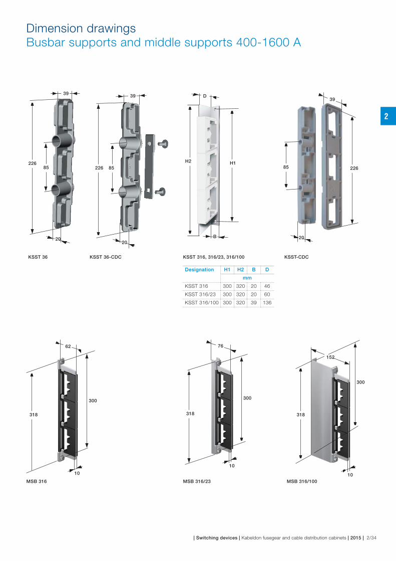
Dimension drawingsBusbar supports and middle supports 400-1600 A
Designation H1 H2 B D
mm
KSST 316 300 320 20 46
KSST 316/23 300 320 20 60
KSST 316/100 300 320 39 136
KSST 36-CDC
MSB 316
KSST 36 KSST-CDCKSST 316, 316/23, 316/100
MSB 316/23 MSB 316/100
300
10
318
62
300
10
318
76
A
300
10
318
152
22685
39
20
H2 H1
D
B
22685
39
20
226 85
39
20
2
| Switching devices | Kabeldon fusegear and cable distribution cabinets | 2015 | 2/34

Dimension drawingsBusbar supports and middle supports 1600 A and 2500 A
KSST 325 CSSKSSTD 312/16
MSBD 312/16
MSB 325 CSS
KSST 325 CSS F
19,5
340
365
114
43
340
365
114
30
300
330
86
27
340
365
114
9,5
300
319
88
2
2/35 | 2015 | Kabeldon fusegear and cable distribution cabinets | Switching devices |

2
| Switching devices | Kabeldon fusegear and cable distribution cabinets | 2015 | 2/36

3
3/1 | 2015 | Kabeldon fusegear and cable distribution cabinets | Enclosures |

Table of contentEnclosures
Standards
Enclosures 3/4
Enclosures
Hot-dip galvanized enclosures – CDC 3/7
Hot-dip galvanized enclosures – SDC 3/9
Powder coated enclosures for indoor use – KSIK 3/11
Hot-dip galvanized enclosures with upper section – CDCM 3/13
Hot-dip galvanized enclosures with upper section – SDCM 3/15
Hot-dip galvanized pole-mounted cable distribution cabinets – CDCP 3/17
Hot-dip galvanized accessory cabinet – CDCA, CDCA-BV 3/19
Hot-dip galvanized enclosures for telecommunications, fibre-optic cables 3/23
Options and accessories
5-wire system 3/25
Accessories – Enclosures 3/26
Accessories – Enclosures SDC and SDCM 3/27
Accessories – kWh metering 3/28
Accessories – Locks and tools 3/31
Accessories – Keys and tools 3/32
Examples of enclosure combinations 3/33
Dimension drawings
Dimension drawing – CDC, SDC 3/34
Dimension drawings – KSIK, CDCM 3/35
Dimension drawings – SDCM, CDCA, CDCP 3/36
3
| Enclosures | Kabeldon fusegear and cable distribution cabinets | 2015 | 3/2

3
3/3 | 2015 | Kabeldon fusegear and cable distribution cabinets | Enclosures |

StandardsEnclosures
Enclosure
Enclosure series CDC and SDC are made of galvanized
steel sheet and with the performance standards
ISO 1461, IEC 61439-1, IEC 61439-5.
− IEC ISO 1461: Inorganic coatings - Hot dip
galvanized coatings on fabricated iron and steel
articles - Specifications and test methods (ISO
1461:1999).
− IEC 61439: Part 1: Low-voltage switchgear and
controlgear assemblies – Part 5: Assemblies for
power distribution in public networks.
The enclosures KSIK are powder coated steel
enclosures indoors. Environmental Class C1 and C2
according to:
− IEC ISO 12944-2: Paints and varnishes – Corrosion
protection of steel structures by painting.
− Part 2: Classification of environmental conditions
(ISO 12944-2:1998).
Degree of protection
The degree of protection is IP34D, in accordance with
the requirements of IEC 60529, unless otherwise stated
under “Technical data”.
Excavation depth
To ensure an attractive and functional installation in the
ground, we recommend excavating to a depth at which
about 10 cm of the foundation is visible above the
restored surface. A marking label indicates the ground
level.
Special operating conditions
With this type of installation, consideration must be
given to the risk of condensation, dust, vibration and
impacts.
All enclosures CDC and SDC have ventilation apertures
between the cover plate and the door and between the
door and the roof, both on the front and back of the
enclosure.
The ability of the enclosure to withstand external blows
and impacts has been checked by testing at –50° C in
accordance with the requirements for use in an Arctic
climate in IEC 61439-5.
To reduce the risk of condensation we recommend filling the founda-
tion with sand, leca and/or using a damp barrier type Cxx-DB above the
foundation.
Sand or
Leca
Filling mass0
,1 m
Base plate
3
| Enclosures | Kabeldon fusegear and cable distribution cabinets | 2015 | 3/4
StandardsEnclosures
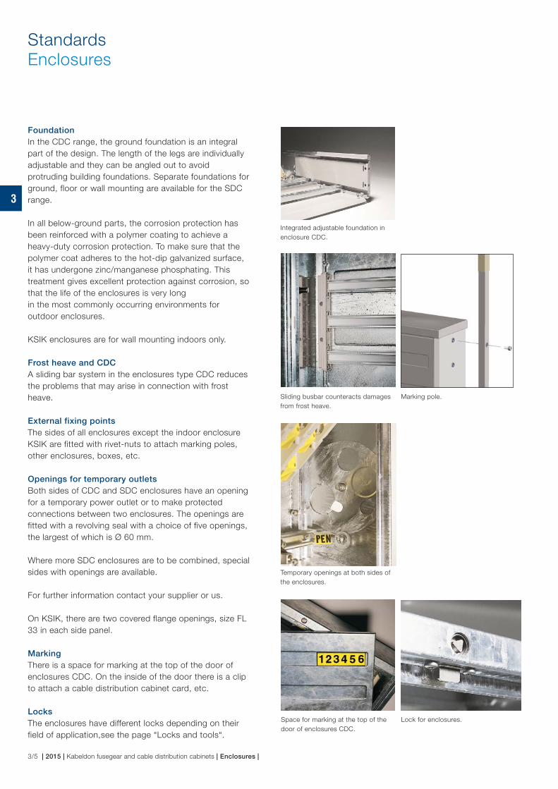
Foundation
In the CDC range, the ground foundation is an integral
part of the design. The length of the legs are individually
adjustable and they can be angled out to avoid
protruding building foundations. Separate foundations for
ground, floor or wall mounting are available for the SDC
range.
In all below-ground parts, the corrosion protection has
been reinforced with a polymer coating to achieve a
heavy-duty corrosion protection. To make sure that the
polymer coat adheres to the hot-dip galvanized surface,
it has undergone zinc/manganese phosphating. This
treatment gives excellent protection against corrosion, so
that the life of the enclosures is very long
in the most commonly occurring environments for
outdoor enclosures.
KSIK enclosures are for wall mounting indoors only.
Frost heave and CDC
A sliding bar system in the enclosures type CDC reduces
the problems that may arise in connection with frost
heave.
External fixing points
The sides of all enclosures except the indoor enclosure
KSIK are fitted with rivet-nuts to attach marking poles,
other enclosures, boxes, etc.
Openings for temporary outlets
Both sides of CDC and SDC enclosures have an opening
for a temporary power outlet or to make protected
connections between two enclosures. The openings are
fitted with a revolving seal with a choice of five openings,
the largest of which is Ø 60 mm.
Where more SDC enclosures are to be combined, special
sides with openings are available.
For further information contact your supplier or us.
On KSIK, there are two covered flange openings, size FL
33 in each side panel.
Marking
There is a space for marking at the top of the door of
enclosures CDC. On the inside of the door there is a clip
to attach a cable distribution cabinet card, etc.
Locks
The enclosures have different locks depending on their
field of application,see the page “Locks and tools“.
Marking pole.
Lock for enclosures.
Temporary openings at both sides of
the enclosures.
Sliding busbar counteracts damages
from frost heave.
Space for marking at the top of the
door of enclosures CDC.
Integrated adjustable foundation in
enclosure CDC.
3
3/5 | 2015 | Kabeldon fusegear and cable distribution cabinets | Enclosures |

StandardsEnclosures
Modular system
All parts that can be connected to the busbar system have
modular dimensions (one module M = 12.5 mm). This
makes it easy to calculate the space required by a particular
distribution board and then to choose a suitable enclosure.
Type designation
The following list mentions some typical applications for
Kabeldon IP-system:
CDC xyz (CDC = enclosure type. This may be replaced by
SDC or KSIK.)
x = rated current:
0 = cabinet without busbar system
4 = busbar system with rated current 400 A
6 = busbar system with rated current 630 A
yz = number of modules available on the busbar
(20, 40, 48 etc.)
Enclosures with upper section
As standard, the enclosure comes with a busbar system
in the lower section, but with no equipment in the upper
section (the meter space).
For the upper section there are meter panels, MPF 25 B
or MPF 63 B, to mount the meters on.
The meter panel fixes on to a mounted fixing bar, making
fitting simple and flexible. Meter panels have a width of
220 mm. The meter panels come with a suitable intermediate
terminal block.
Entries to the upper section
Between the upper and lower sections there are openings
which are partly covered by a plastic plug with “breakouts”.
The largest opening, Ø 50 mm, can take seven 50 mm2
cables.
Locks
The upper section of the enclosure is fitted with a lock which
takes a standard triangular-section key, so that the customer
and the electricity supplier can open that section. For the
lower section, see the product pages.
60 M = 850 mm
Enclosures with upper section, CDCM
and SDCM.
Meter panel
MPF 25 B/63 B.
Module dimensioned busbar system
in the cable distribution cabinet.
Lock for the upper section
of enclosures with upper
section CDCM.
Lock for the upper section
of enclosures with upper
section SDCM.
3
| Enclosures | Kabeldon fusegear and cable distribution cabinets | 2015 | 3/6

Hot-dip galvanized enclosures CDC
CDC is supplied with a busbar system or with a mounting
plate.
− Tested to the requirements of IEC 61439-5. Passes arctic
climate tests.
− Integral foundation.
− Adjustable foundation prepared for fitting of a base plate.
− The foundation is prepared for fixing conduits when
installing heating cables.
− The sides have rivet-nuts to attach a snow marking pole
or an accessory cabinet.
− On the inside of the door there is a cable distribution
cabinet card.
− The embossed areas on the door are compatible with
most common marking systems.
− Degree of protection IP34D.
Designation ID No. Equipment included
Number of modules
Rated current
Dimensions Weight
Height Width Depth
M * A mm kg/pcs
CDC 020 2CGX0 63300396 mounting plate – – 1200 350 220 36
CDC 040 2CGX0 63300397 mounting plate – – 1200 600 220 50
CDC 060 2CGX0 63300398 mounting plate – – 1200 850 220 64
CDC 420 2CGX0 63300390 busbar system 20 400 1200 350 220 34
CDC 440 2CGX0 63300391 busbar system 40 400 1200 600 220 47
CDC 460 2CGX0 63300392 busbar system 60 400 1200 850 220 59
CDC 640 2CGX0 63300394 busbar system 40 630 1200 600 220 48
CDC 660 2CGX0 63300395 busbar system 60 630 1200 850 220 60
* One module M = 12.5 mm.
The enclosure includes
Content Enclosure with busbar system Enclosure without busbar system
CDC 420-660 CDC 020-060
Mounting plate No Yes
Busbar system 400 A, 630 A No
PEN bar movable to three positions 400 A No
Anchor bar adjustable to two positions Yes Yes
Foundation leg length individually adjustable Yes Yes
Outlet opening with revolving seal Ø 15-60 mm Yes Yes
Key shape for lock SE Triangular
Heavy-current warning symbol on outside of door Yes No
CDC 040
3
3/7 | 2015 | Kabeldon fusegear and cable distribution cabinets | Enclosures |
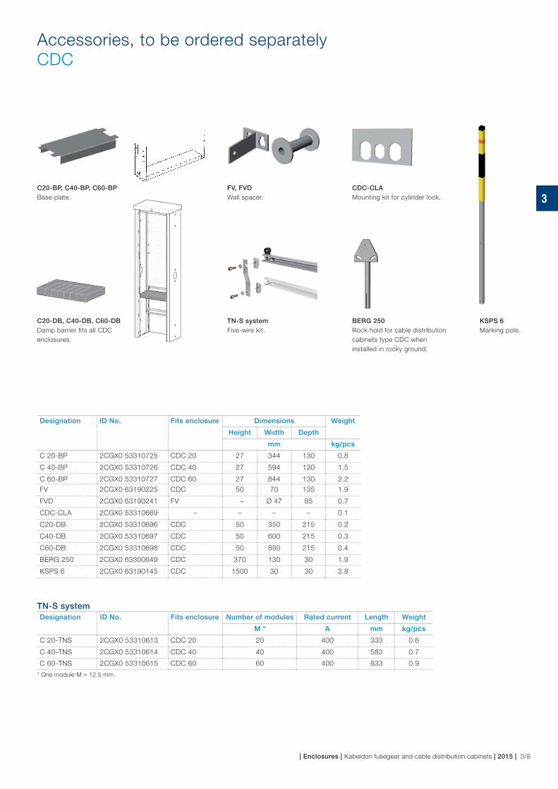
CDC-CLA
Mounting kit for cylinder lock.
TN-S system
Five-wire kit.
C20-BP, C40-BP, C60-BP
Base plate.
FV, FVD
Wall spacer.
C20-DB, C40-DB, C60-DB
Damp barrier fits all CDC
enclosures.
BERG 250
Rock hold for cable distribution
cabinets type CDC when
installed in rocky ground.
KSPS 6
Marking pole.
Accessories, to be ordered separatelyCDC
Designation ID No. Fits enclosure Dimensions Weight
Height Width Depth
mm kg/pcs
C 20-BP 2CGX0 53310725 CDC 20 27 344 130 0.8
C 40-BP 2CGX0 53310726 CDC 40 27 594 130 1.5
C 60-BP 2CGX0 53310727 CDC 60 27 844 130 2.2
FV 2CGX0 63190225 CDC 50 70 135 1.9
FVD 2CGX0 63190241 FV – Ø 47 85 0.7
CDC-CLA 2CGX0 53310669 – – – – 0.1
C20-DB 2CGX0 53310696 CDC 50 350 215 0.2
C40-DB 2CGX0 53310697 CDC 50 600 215 0.3
C60-DB 2CGX0 53310698 CDC 50 850 215 0.4
BERG 250 2CGX0 63300649 CDC 370 130 30 1.9
KSPS 6 2CGX0 63190145 CDC 1500 30 30 3.8
TN-S system
Designation ID No. Fits enclosure Number of modules Rated current Length Weight
M * A mm kg/pcs
C 20-TNS 2CGX0 53310613 CDC 20 20 400 333 0.6
C 40-TNS 2CGX0 53310614 CDC 40 40 400 583 0.7
C 60-TNS 2CGX0 53310615 CDC 60 60 400 833 0.9
* One module M = 12.5 mm.
3
| Enclosures | Kabeldon fusegear and cable distribution cabinets | 2015 | 3/8

Hot-dip galvanized enclosuresSDC
SDC is supplied with or without a busbar system. The SDC
range is suitable for electrical distribution boards such as general
distributions boards, power distribution boards in industry,
construction site distributions boards or for temporary power
distribution.
The distribution boards are built to customer requirements, with
direct metering or current transformer metering.
− Tested to the requirements of IEC 61439-5. Passes arctic
climate tests.
− Side-hung doors, opening angle >180°.
− The sides have rivet-nuts to attach a snow marking pole
or an accessory cabinet.
− The depth, 312 mm, allows installation of all switching devices
with independent manual operation.
− The LD version is available with a depth of 242 mm.
− Degree of protection IP34D.
Note:
− For quick, simple planning, download your copy of the free
Connect IT program.
− Many different configurations of the SDC range can be
ordered. Please contact your supplier for further information.
− Busbar system for 1600 A on request.
Designation ID No. Equipment included
Number of modules
Rated current Dimensions Weight
Height Width Depth
M * A mm kg/pcs
SDC 048 2CGX0 63300433 – – – 895 682 312 46
SDC 073 2CGX0 63300551 – – – 895 996 312 58
SDC 098 2CGX0 63300437 – – – 895 1310 312 70
SDC 448 2CGX0 63300431 busbar system 48 400 895 682 312 48
SDC 473 2CGX0 63300552 busbar system 73 400 895 996 312 60
SDC 648 2CGX0 63300432 busbar system 48 630 895 682 312 49
SDC 673 2CGX0 63300553 busbar system 73 630 895 996 312 62
SDC 698 2CGX0 63300434 busbar system 98 630 895 1310 312 75
SDC 1048 2CGX0 63300458 busbar system 48 1000 895 682 312 50
SDC 1073 2CGX0 63300554 busbar system 73 1000 895 996 312 63
SDC 1098 2CGX0 63300459 busbar system 48 1000 895 1310 312 76
SDC 673 LD 2CGX0 63300635 busbar system 73 630 895 996 242 59
SDC 698 LD 2CGX0 63300571 busbar system 98 630 895 1310 242 73
* One module M = 12.5 mm.
The enclosure includes
Content Enclosure with busbar system Enclosure without busbar system
SDC 448-698 SDC 673-698 LD SDC 048-098
Mounting plate No No
Busbar system 400 A, 630 A No
PEN bar 400 A No
Foundation No (order separately) No (order separately)
Outlet opening with revolving seal Ø 15-60 mm Yes Yes
Key shape for lock, SDC 448-698 Triangular Triangular
Key shape for lock, SDC 673-698 LD SE (EBR) –
Heavy-current warning symbol on outside of door Yes No
SDC 073
Busbar systems for 1000 A–1600 A on request.
3
3/9 | 2015 | Kabeldon fusegear and cable distribution cabinets | Enclosures |

GOLV-S 48-98
Floor foundation.
BPF-S 48-98
Base plate.
SLUS 48-98
Lower door with outlet
opening.
KSMP-S 48-98
Mounting plate.
MARK-S 48-98
MARK-S 73-98 LD
Ground foundation.
FVD, VF 100
Wall spacer.
TN-S system
Five-wire kit.
VF-S 30
Wall bracket.
KSPS 6
Marking pole.
Accessories, to be ordered separately SDC
Designation ID No. Fits enclosure Dimensions Weight
Height Width Depth
mm kg/pcs
GOLV-S 48 2CGX0 63300441 SDC 48 400 672 303 23
GOLV-S 73 2CGX0 63300550 SDC 73 400 986 303 30
GOLV-S 98 2CGX0 63300442 SDC 98 400 1300 303 36
BPF-S 48 2CGX0 53310629 SDC 48 30 672 282 4
BPF-S 73 2CGX0 53310682 SDC 73 30 986 282 5
BPF-S 98 2CGX0 53310630 SDC 98 30 1300 282 6
SLUS 48 2CGX0 53310666 SDC 48 288 626 22 5
SLUS 73 2CGX0 53310684 SDC 73 288 940 22 7.5
SLUS 98 2CGX0 53310668 SDC 98 288 1254 22 10
KSMP-S 48 2CGX0 53190332 SDC 780 660 21 5.0
KSMP-S 73 2CGX0 53190335 SDC 780 974 21 8.0
KSMP-S 98 2CGX0 53190333 SDC 780 1268 21 11.0
MARK-S 48 2CGX0 63300439 SDC 940 672 303 30
MARK-S 73 2CGX0 63300549 SDC 940 986 303 36
MARK-S 73 LD 2CGX0 63300636 SDC 73 LD 940 986 233 34
MARK-S 98 2CGX0 63300440 SDC 98 940 1300 303 42
MARK-S 98 LD 2CGX0 63300572 SDC 98 LD 940 1300 233 40
FVD 2CGX0 63190241 SDC – Ø 47 85 0.7
VF 100 2CGX0 53310678 SDC 40 228 35 0.2
VF-S 30 2CGX0 53310643 SDC 500 40 40 0.5
KSPS 6 2CGX0 63190145 SDC 1500 30 30 3.8
TN-S system
Designation ID No. Fits enclosure Number of modules Rated current Length Weight
M * A mm kg/pcs
SD 48-TNS 2CGX0 53320208 SDC 48 48 400 584 0.9
SD 73-TNS 2CGX0 53320219 SDC 73 73 400 898 1.0
SD 98-TNS 2CGX0 53320209 SDC 98 98 400 1212 1.2
* One module M = 12.5 mm.
3
| Enclosures | Kabeldon fusegear and cable distribution cabinets | 2015 | 3/10

Powder coated enclosures for indoor use KSIK
KSIK enclosures are designed for indoor use, environment
classes C1 and C
2*. An enclosure with a high degree of
protection, well suited for installations in industry and in
buildings.
The enclosure is developed for distribution boards and
therefore has special openings in its sides to allow
busbar systems to pass through where more than one
enclosure is combined.
− Supplied complete with wall brackets and mounting plate.
− Powder coated.
− Side-hung doors.
− Removable mounting plate.
− Split base plate.
− Degree of protection IP34D.
Note:
Busbar systems for 400 A-1600 A on request.
* To ISO 12944-2
C1: Heated, dry room
C2: Small amounts of humidity may occur.
Designation ID No. Qty flange openings FL 21 in the base plate
Number of modules
Dimensions Weight
Height Width Depth
M * mm kg/pcs
KSIK 043 2CGX0 63300411 4 43 900 655 325 42
KSIK 063 2CGX0 63300412 6 63 900 895 325 57
KSIK 098 2CGX0 63300413 10 98 900 1350 325 75
* One module M = 12.5 mm.
The enclosure includes
Content Enclosure KSIK
Mounting plate Yes
Key shape for lock DIN 3
Two covered flange openings, size FL 33 in each side panel. Yes
Base plate with FL 21 flange openings Yes
Split base plate Yes
Busbar system On request
KSIK 048
3
3/11 | 2015 | Kabeldon fusegear and cable distribution cabinets | Enclosures |

KD xx-TNS
Five-wire kit.
KSFS 400 A-1600 A
Busbar system.
Phase busbar
Designation ID No. Number of modules
Rated current Suitable busbar support Length Weight
KSST 36 KSST 316
KSST 316/23
M * A KSST 316/100 mm kg/m
KSFS 443 2CGX0 43320037 43 400 x x 569 0.6
KSFS 448 2CGX0 43320258 48 400 x x 636 0.6
KSFS 463 2CGX0 43320038 63 400 x x 809 0.6
KSFS 643 A 2CGX0 43320367 43 630 x x 569 0.9
KSFS 663 A 2CGX0 43320368 63 630 x x 809 0.9
KSFS 698 A 2CGX0 43320366 98 630 x x 1264 0.9
KSFS 1098 2CGX0 43320156 98 1000 – x 1264 1.6
KSFS 1698 2CGX0 43320158 98 1600 – x 1264 3.0
* One module M = 12.5 mm.
TN-S system
Designation ID No. Number of modules
Rated current Length Weight
M * A mm kg/pcs
KD 43-TNS 2CGX0 53320210 43 400 570 0.6
KD 63-TNS 2CGX0 53320211 63 400 810 0.7
KD 98-TNS 2CGX0 53320212 98 400 1270 1.0
* One module M = 12.5 mm.
AccessoriesTo be ordered separately for KSIK
3
| Enclosures | Kabeldon fusegear and cable distribution cabinets | 2015 | 3/12

Hot-dip galvanized enclosures with upper section CDCM
The CDCM cabinets are the same as CDC but are fitted with
an upper section which can be locked separately. CDCM 020
and CDCM 040 comes with a mounting plate instead of a
busbar system in the lower section.
The CDCM range is suitable for construction of electrical
distribution boards such as general distribution boards,
power distribution boards in industry, construction site
distribution boards etc where there is a need to integrate
the equipment with kWh metering. The distribution boards
are built to customer requirements, with direct metering or
current transformer metering.
− Tested to the requirements of IEC 61439-5. Passes arctic
climate tests.
− Integrated foundation.
− The sides have river-nuts to attach a snow marking pole
or an accessory cabinet.
− On the inside of the door there is a holder for a cable
distribution cabinet card.
− The embossed areas on the door are compatible with
most common marking systems.
− The upper section is fitted with a fixing bar for meter panel
MPF 25 B/MPF 63 B or with mounting plate MPP 20.
− Removable mounting plate.
− Split base plate.
− Degree of protection IP34D.
Designation ID No. Equipment included
Space for Meter panels
MPF 25/MPF 63
Number of modules
Rated current
Dimensions Weight
Height Width Depth
M * A mm kg/pcs
CDCM 020 2CGX0 63300530 Mounting plate 1 – – 1800 350 220 49
CDCM 040 2CGX0 63300608 Mounting plate 2 – – 1800 600 220 68
CDCM 420 2CGX0 63300430 Busbar system 1 20 400 1800 350 220 47
CDCM 440 2CGX0 63300609 Busbar system 2 40 400 1800 600 220 65
CDCM 640 2CGX0 63300610 Busbar system 2 40 630 1800 600 220 66
* One module M = 12.5 mm.
The enclosure includes
Content Enclosure with busbar system Enclosure without busbar system
CDC 420-640 CDC 020-040
Mounting plate, lower section No Yes
Busbar system 400 A, 630 A No
PEN bar movable to three positions 400 A No
Anchor bar adjustable to two positions Yes Yes
Foundation leg length individually adjustable Yes Yes
Outlet opening with revolving seal Ø 15-60 mm Yes Yes
50 mm diameter openings between the sections fitted with plastic covers Yes Yes
Key shape for lock, lower/upper section SE/customer SE/customer
Heavy-current warning symbol on outside of door Yes No
Note:
− For quick, simple planning, download your copy of the
free Connect IT program.
CDCM 040CDCM 020
3
3/13 | 2015 | Kabeldon fusegear and cable distribution cabinets | Enclosures |

MPP 20, MPT 40
Mounting plate.
MPF 25 B/MPF 63 B
Meter panel.
KSPS 6
Marking pole.
BERG 250
Rock hold for cable distribution
cabinets type CDC when installed
in rocky ground.
CDC-CLA
Mounting kit for cylinder lock.
FV, FVD
Wall spacer.
TN-S system
Five-wire kit.
AccessoriesTo be ordered separately for CDCM
Designation ID No. Fits enclosure Number of modules
Dimensions Weight
Height Width Depth
M * mm kg/pcs
C 20-BP 2CGX0 53310725 CDCM 20 – 27 344 130 0.8
C 40-BP 2CGX0 53310726 CDCM 40 – 27 594 130 1.5
C 60-BP 2CGX0 53310727 CDCM 60 – 27 844 130 2.2
MPP 20 2CGX0 53310665 CDCM 20 – 540 268 25 2.0
MPT 40 2CGX0 53310724 CDCM 40 – 550 550 12 1.9
MPF 25 B 2CGX0 53310737 CDCM 25 570 220 115 5.0
MPF 63 B 2CGX0 53310738 CDCM 63 570 220 115 5.0
KSPS 6 2CGX0 63190145 CDCM – 1500 30 30 3.8
CDC-CLA 2CGX0 53310669 – – – – – 0.1
FV 2CGX0 63190225 CDCM – 50 70 135 1.9
FVD 2CGX0 63190241 FV – – Ø 47 85 0.7
BERG 250 2CGX0 63300649 CDCM – 370 130 30 1.9
* One module M = 12.5 mm.
TN-S system
Designation ID No. Fits enclosure Number of modules Length Weight
M * mm kg/pcs
C 20-TNS 2CGX0 53310613 CDCM 20 20 333 0.6
C 40-TNS 2CGX0 53310614 CDCM 40 40 583 0.7
C 60-TNS 2CGX0 53310615 CDCM 60 60 833 0.9
* One module M = 12.5 mm.
C20-BP, C40-BP, C60-BP
Floor foundation.
3
| Enclosures | Kabeldon fusegear and cable distribution cabinets | 2015 | 3/14

Hot-dip galvanized enclosures with upper section SDCM
The SDCM cabinets are the same as SDC but are fitted with
an upper section which can be locked separately. The upper
section can be used to house kWh meters or fitted with a
mounting plate for various purposes.
The SDCM range is suitable for the construction of electrical
distribution boards such as general distribution boards, power
distribution boards in industry, construction site distribution
boards etc., where there is a need to integrate the equipment
with kWh metering.
− Tested to the requirements of IEC 61439-5. Passes arctic
climate tests.
− Side-hung doors, opening angle >180°.
− The sides have rivet-nuts to attach a snow marking pole or
an accessory cabinet.
− The depth allows installation of all switching devices with
independent manual operation.
− Degree of protection IP34D.
Note:
− For quick, simple planning, download your copy of the free
Connect IT program.
− Many different configurations of the SDC range can be
ordered. Please contact your supplier for further information.
Designation ID No. Equipment included
Space for Qty Meter panels
MPF 25/MPF 63
Number of modules
Rated current
Dimensions Weight
Height Width Depth
M * A mm kg/pcs
SDCM 048 2CGX0 63300443 – 3 – – 1523 682 312 72
SDCM 073 2CGX0 63300561 – 4 – – 1523 996 312 92
SDCM 098 2CGX0 63300444 – 5 – – 1523 1310 312 111
SDCM 448 2CGX0 63300435 Busbar system 3 48 400 1523 682 312 74
SDCM 473 2CGX0 63300562 Busbar system 4 73 400 1523 996 312 94
SDCM 648 2CGX0 63300436 Busbar system 3 48 630 1523 682 312 75
SDCM 673 2CGX0 63300563 Busbar system 4 73 630 1523 996 312 96
SDCM 698 2CGX0 63300438 Busbar system 5 98 630 1523 1310 312 116
* One module M = 12.5 mm.
The enclosure includes
Content Enclosure with busbar system Enclosure without busbar system
SDCM 448-698 SDCM 048-098
Mounting plate, lower section No No (order separately)
Busbar system 400 A, 630 A No
PEN bar 400 A No
Foundation No (order separately) No (order separately)
Outlet opening with revolving seal Ø 15-60 mm Yes Yes
50 mm diameter openings between the sections fitted with plastic covers Yes Yes
Key shape for lock, lower/upper section Triangular/customer Triangular/customer
Heavy-current warning symbol on outside of the door Yes No
SDCM 048
Busbar systems for 1000 A–1600 A on request.
3
3/15 | 2015 | Kabeldon fusegear and cable distribution cabinets | Enclosures |

GOLV-S 48-98
Floor foundation.
BPF-S 48-98
Base plate.
SLUS 48-98
Lower door with outlet
opening.
MARK-S 48-98
Ground foundation.
FVD
Wall spacer.
MPP-S 48-73, KSMP-S 48-98, MPT-S 48
Mounting plate.
TN-S system
Five-wire kit.
VF-S 30
Wall bracket.
MPF 25 B /63 B
Meter panel.
KSPS 6
Marking pole.
Designation ID No. Fits enclosure Number of modules Dimensions Weight
Height Width Depth
M * mm kg/pcs
GOLV-S 48 2CGX0 63300441 SDCM 48 48 400 672 303 23
GOLV-S 73 2CGX0 63300550 SDCM 73 73 400 986 303 30
GOLV-S 98 2CGX0 63300442 SDCM 98 98 400 1300 303 36
BPF-S 48 2CGX0 53310629 SDCM 48 48 30 672 282 4
BPF-S 73 2CGX0 53310682 SDCM 73 73 30 986 282 5
BPF-S 98 2CGX0 53310630 SDCM 98 98 30 1300 282 6
SLUS 48 2CGX0 53310666 SDCM 48 48 288 626 22 5
SLUS 73 2CGX0 53310684 SDCM 73 73 288 940 22 7.5
SLUS 98 2CGX0 53310668 SDCM 98 98 288 1254 22 10
MARK-S 48 2CGX0 63300439 SDCM 48 48 940 672 303 30
MARK-S 73 2CGX0 63300549 SDCM 73 73 940 986 303 36
MARK-S 98 2CGX0 63300440 SDCM 98 98 940 1300 303 42
MPP-S 48 2CGX0 53190334 SDCM 48 48 580 585 25 3,0
MPP-S 73 2CGX0 53310735 SDCM 73 73 580 856 25 7.0
KSMP-S 48 2CGX0 53190332 SDCM 48 48 780 660 21 5.0
KSMP-S 73 2CGX0 53190335 SDCM 73 73 780 974 21 8.0
KSMP-S 98 2CGX0 53190333 SDCM 98 98 780 1268 21 11.0
MPT-S 48 2CGX0 53310647 SDCM 48 48 580 600 12 2.2
MPT-S 73 2CGX0 53310688 SDCM 73 73 580 890 12 3.3
FVD 2CGX0 63190241 SDCM – – Ø 47 85 0.7
VF 100 2CGX0 53310678 SDCM – 40 228 35 0.2
VF-S 30 2CGX0 53310643 SDCM – 500 40 40 0.5
MPF 25 B 2CGX0 53310737 SDCM 25 570 220 115 5.0
MPF 63 B 2CGX0 53310738 SDCM 63 570 220 115 5.0
KSPS 6 2CGX0 63190145 SDCM – 1500 30 30 3.8
* One module M = 12.5 mm.
TN-S system
Designation ID No. Fits enclosure Number of modules rated current Length Weight
M * A mm kg/pcs
SD 48-TNS 2CGX0 53320208 SDC 48 48 400 584 0.9
SD 73-TNS 2CGX0 53320219 SDC 73 73 400 898 1.0
SD 98-TNS 2CGX0 53320209 SDC 98 98 400 1212 1.2
* One module M = 12.5 mm.
AccessoriesTo be ordered separately for SDCM
VF 100
Wall spacer.
3
| Enclosures | Kabeldon fusegear and cable distribution cabinets | 2015 | 3/16

Pole-mounted cable distribution cabinetsCDCP
Hot-dip galvanized pole-mounted cable distribution
cabinets are supplied with integral pole bracket, busbar
system or mounting plate and as well as a cable duct to
the ground.
− On the back there is an opening for an earthing line
and an opening for temporary connections.
− Breakouts for up to seven cable channels.
− Degree of protection IP34D.
Designation ID No. Equipment included
Number of modules
Rated current
Number of cable ducts
Dimensions Weight
Height Width Depth
M * A mm kg/pcs
CDCP 020 2CGX0 63300621 Mounting plate 20 – 0 - 3 1200 350 382 45
CDCP 040 2CGX0 63300622 Mounting plate 40 – 0 - 7 1200 600 382 61
CDCP 420 2CGX0 63300428 Busbar system 20 400 0 - 3 1200 350 382 43
CDCP 440 2CGX0 63300429 Busbar system 40 400 0 - 7 1200 600 382 58
* One module M = 12.5 mm.
Breakouts for cable channels on
the back of the pole-mounted
cabinet.
The enclosure includes
Content Enclosure with busbar system Enclosure without busbar system
CDCP 420, 440 CDCP 020, 040
Cable duct to the ground Yes Yes
Busbar system 400 A No
PEN bar 400 A No
Anchor bar Yes Yes
Key shape for lock SE Triangular
Heavy-current warning symbol on outside of door Yes No
A cable duct to the ground is supplied with the cabinet.
Opening for
temporary
connections
Ø 48 mm
Opening for
earthing
3
3/17 | 2015 | Kabeldon fusegear and cable distribution cabinets | Enclosures |

Designation ID No. Number per kit
Dimensions Weight
Height Width Depth
mm kg/pcs
KKCS 2CGX0 53190244 1 100 57 61 0.2
KHB 3 2CGX0 63190245 1 105 184 250 0.3
KHB 5 2CGX0 63190246 1 105 294 250 0.4
KHB 7 2CGX0 63190279 1 105 404 250 0.6
KKS 2CGX0 63190286 1 30 250 190 0.4
CDCP-TP 2CGX0 53310728 1 16 260 191 0.6
KKC 5 2CGX0 53190243 1 kit 2400 55 55 3.2
KKS
Extra support for cable channel.
CDCP-TP
Base plate for sealing the opening
at the bottom.
KKCS
Joining piece for cable channel made
of non-corrosive and non-magnetic
material.
KHB 3
Holder for 1 to 3 cable channels.
KHB 5
Holder for 3 to 5 cable channels.
KHB 7
Holder for 5 to 7 cable channels.
KKC 5
Cable channel 2 x 2.4 m with
joining piece KKCS.
AccessoriesTo be ordered separately for CDCP
3
| Enclosures | Kabeldon fusegear and cable distribution cabinets | 2015 | 3/18

Hot-dip galvanized accessory cabinet CDCA
CDCA
Accessory cabinet for mounting on another enclosure.
The cabinet comes with a mounting plate.
− There are outlet openings in the sides. The opening on the
right-hand side has a revolving seal with a choice of five
openings. The seal can be moved to the left-hand side.
− The bottom of the cabinet has an opening with integral
strain relief for temporarily connected cables. When not
in use, the opening is blanked off with the cover supplied.
− Inserts for temporary power outlets KSMU 16/32/63
can be installed in the cabinet, as well as meter panel
MPF 25 B/MPF 63 B. Where meter panel MPF 25 B/
MPF 63 B is installed, upgrade kit CKM is required.
Designation ID No. Dimensions Weight
Height Width Depth
mm kg/pcs
CDCA 2CGX0 63300451 730 280 218 14.5
The openings on the sides of
the cabinet is used for temporary
power outlets, etc.
CDCA mounted on the
right side of CDC 420.
Accessory cabinet includesContent Accessory cabinet
CDCA
Mounting plate Yes
Outlet opening with revolving seal Ø 15-60 mm Yes
Opening at the bottom with integral strain relief for temporarily connected cables Yes
Lock Triangular, CDC-LT
KSMUB used in CDCA.Accessory cabinet CDCA.
3
3/19 | 2015 | Kabeldon fusegear and cable distribution cabinets | Enclosures |

Designation ID No. Cable connection
Outlet Dimensions Weight
Height Width Depth
mm² mm kg/pcs
KSMUB 16 2CGX0 63300611 6 1x16 A + 2x10 A 711 222 191 5.5
KSMUB 32 2CGX0 63300612 6 1x32 A + 2x10 A 711 222 191 5.5
MPF 25 B 2CGX0 53310737 – – 570 220 115 5.0
MPF 63 B 2CGX0 53310738 – – 570 220 115 5.0
CKM 2CGX0 53390034 – – – – – 0.02
KSM 017 2CGX0 53310397 – – 670 218 50 1.2
KSM 417 2CGX0 53310383 – – 670 218 50 2.3
KSFL 17 2CGX0 53320115 – – 21 x 5 x 3 0.4
CDCA-CD 2CGX0 53310705 – – 380 240 66 2.3
KSMUB 16/32
1x16 + 2x10 A or 1x32 + 2x10A with
residual current device, miniature
circuit-breaker and space for a kWh
meter. Strength of short circuit 6 kA in
combination with equipment max 63 A.
CKM
Upgrade kit for installing meter panel
MPF 25/63 B in accessory cabinet
CDCA or in low-profile meter cable
enclosures.
MPF 25 B/MPF 63 B
Meter panel for 25 A or 63 A.
CDCA-CD
Cable protection duct for fibre
optic cables, for example (in CDCA).
− Max cable diameter 25 mm
inside cabinet.
− Max. diameter for optical fibre pipes is
45 mm.
− Degree of protection IP34D.
Accessories, to be ordered separatelyCDCA and CDCA-BV
KSM 017
Mounting plate.
KSM 417
Mounting plate with busbar
system 400 A.
KSFL 17
5-wire system for KSM 417.
3
| Enclosures | Kabeldon fusegear and cable distribution cabinets | 2015 | 3/20

CDCA-BV with openings in
the bottom and both sides.
Accessory cabinet for example mounting to contact line
post.
− Empty enclosure with bracket for mounting plate
KSM 417 or KSM 017
− The gables are provided with flange opening FL13
− Flange opening FL 21 at the bottom.
− Triangular lock.
− The cabinet can be equipped with a busbar system
type KSM 417.
− Inserts for temporary power outlets KSMUB 16/32
can be installed in the cabinet, as well as meter panel
MPF 25 B/MPF 63 B. Where meter panel MPF 25 B/
MPF 63 B is installed, upgrade kit CKM is required.
− Four angular fixing brackets for mounting to the place
are included.
Hot-dip galvanized accessory cabinet CDCA-BV
Designation ID No. Dimensions Weight
Height Width Depth
mm kg/pcs
CDCA-BV 2CGX0 63300576 730 280 218 13
Accessory cabinet includesContent Accessory cabinet
CDCA-BV
Mounting plate No
Angle clamp 4
Opening in bottem FL 21
Opening in gable FL 13
Lock Triangular, CDC-LT
3
3/21 | 2015 | Kabeldon fusegear and cable distribution cabinets | Enclosures |

Designation ID No. Cable connection
Outlet Dimensions Weight
Height Width Depth
mm² mm kg/pcs
KSMUB 16 2CGX0 63300611 6 1x16 A + 2x10 A 711 222 191 5.5
KSMUB 32 2CGX0 63300612 6 1x32 A + 2x10 A 711 222 191 5.5
MPF 25 B 2CGX0 53310737 – – 570 220 115 5.0
MPF 63 B 2CGX0 53310738 – – 570 220 115 5.0
CKM 2CGX0 53390034 – – – – – 0.02
KSM 017 2CGX0 53310397 – – 670 218 50 1.2
KSM 417 2CGX0 53310383 – – 670 218 50 2.3
KSFL 17 2CGX0 53320115 – – 21 x 5 x 3 0.4
KSMUB 16/32
1x16 + 2x10 A or 1x32 + 2x10A with residual
current device, miniature circuit-breaker and
space for a kWh meter. Strength of short
circuit 6 kA in combination with equipment
max 63 A.
CKM
Upgrade kit for installing meter panel
MPF 25/63 B in accessory cabinet
CDCA or in low-profile meter cable
enclosures.
MPF 25 B/MPF 63 B
Meter panel for 25 A or 63 A.
Accessories, to be ordered separatelyCDCA and CDCA-BV
KSM 017
Mounting plate.
KSM 417
Mounting plate with busbar system 400 A.
KSFL 17
5-wire system for KSM 417.
3
| Enclosures | Kabeldon fusegear and cable distribution cabinets | 2015 | 3/22

Hot-dip galvanized enclosuresTelecommunications and fibre-optic cables
Hot-dip galvanized enclosures for outdoor applications or
in environments where long life and durability are essential.
− Tested to the requirements of IEC 61439-5. Passes
arctic climate tests.
− Integral foundation (CDC).
− The sides have rivet-nuts to mark it as an obstacle or for
an accessory cabinet.
− On the inside of the door there is a holder for a cable
distribution cabinet card. The outside is compatible with
the most common marking systems.
− Degree of protection IP34D.
Note:
Under an agreement with the telecoms sector, enclosures
for telecommunications must not be fitted with a triangular
lock. Order these enclosures with CDC-LTC or SDC-LTC.
Designation ID No. Mounting plate Dimensions Installations depth
Locks Weight
Height Width
mm mm kg/pcs
CDC 020 2CGX0 63300396 700 300 198 Triangular 36
CDC 040 2CGX0 63300397 700 550 198 Triangular 50
CDC 060 2CGX0 63300398 700 800 198 Triangular 64
SDC 048 2CGX0 63300433 770 584 275 Triangular 46
SDC 073 2CGX0 63300551 770 898 275 Triangular 58
Enclosure with cable coiler for fibre-optic cable.
A cable distribution cabinet for electric power
combined with an enclosure including a
fiberduct module.
3
3/23 | 2015 | Kabeldon fusegear and cable distribution cabinets | Enclosures |

AccessoriesTo be ordered separately for telecom enclosures
CC 20
Cable coiler for about 25
metres of 13 mm OD cable.
CC 30
Cable coiler for about 30
metres of 16 mm OD cable.
EB 435
Earth block for 4 mm² or
35 mm².
KSMP-S 48/73
Steel mounting plate for SDC.
Perforated with 38 mm hole
pitch (Ø 3.5 mm).
BK-N
Bracket for fibre-optic cable
junction box from Nexans.
BK-T
Bracket for fibre-optic cable
junction box from Tykoflex.
FDM-K
Mounting kit developed for
mounting fibre duct module
FDM (Ericsson Ribbonet)
on Kabeldon IP-system.
BK-E
Bracket for fibre-optic cable
junction box from Ericsson.
FDM
The fibre duct module
is used when jointing
ducts for optical fibre.
BERG 250
Rock hold for cable
distribution cabinets
type CDC when
installed in rocky
ground.
C20-DB C40-DB, C60-DB
Damp barrier fits all enclosures
type CDC.
CDC-LTC
Lock for CDC enclosures with
telecom equipment.
SDC-LTC
Lock for SDC enclosures
with telecom equipment.
NK-TC
Key to lock CDC-LTC and
SDC-LTC.
Designation ID No. Fits enclosure Dimensions Weight
Height Width Depth
mm kg/pcs
CC 20 2CGX0 53310695 CDC/SDC 415 215 153 0.6
CC 30 2CGX0 53310689 CDC/SDC 740 550 155 2.5
EB 435 2CGX0 43311031 CDC/SDC 135 35 35 0.1
KSMP-S 48 2CGX0 53190332 SDC 770 584 19 5.0
KSMP-S 73 2CGX0 53190335 SDC 770 898 19 8.0
BK-E 2CGX0 53310691 CDC/SDC 167 167 10 0.4
BK-N 2CGX0 53310694 CDC/SDC 295 198 10 0.6
BK-T 2CGX0 53310690 CDC/SDC 225 160 10 0.3
FDM-K 2CGX0 53310704 CDC/SDC – – – 0.1
FDM 2CMA1 31600R1000 CDC/SDC 506 135 93 1.0
C20-DB 2CGX0 53310696 CDC 50 350 215 0.2
C40-DB 2CGX0 53310697 CDC 50 600 215 0.3
C60-DB 2CGX0 53310698 CDC 50 850 215 0.4
CDC-LTC 2CGX0 43311040 CDC – – – 0.1
SDC-LTC 2CGX0 43310599 SDC – – – 0.1
NK-TC 2CGX0 63190373 CDC/SDC 113 30 26 0.1
BERG 250 2CGX0 63300649 CDC 370 130 30 1.9
3
| Enclosures | Kabeldon fusegear and cable distribution cabinets | 2015 | 3/24

Busbar system5-wire system
Designation ID No. Fits enclosure Number of modules Rated current Length Weight
M * A mm kg/pcs
C20-TNS 2CGX0 53310613 CDC 20 20 400 333 0.6
C40-TNS 2CGX0 53310614 CDC 40 40 400 583 0.7
C60-TNS 2CGX0 53310615 CDC 60 60 400 833 0.9
SD 48-TNS 2CGX0 53320208 SDC 48 48 400 584 0.9
SD 73-TNS 2CGX0 53320219 SDC 73 73 400 898 1.0
SD 98-TNS 2CGX0 53320209 SDC 98 98 400 1212 1.2
KD 43-TNS 2CGX0 53320210 KSIK 043 43 400 570 0.6
KD 63-TNS 2CGX0 53320211 KSIK 063 63 400 810 0.7
KD 98-TNS 2CGX0 53320212 KSIK 098 98 400 1270 1.0
* One module M = 12.5 mm.
Kit for conversion to 5-wire system, TN-S or TN-C-S.
The kit includes a 400 A non-protected busbar.
− CXX-TNS fits in enclosures type CDC.
− SD XX-TNS fits in enclosures type SDC.
Note:
For additional information regarding upgrading kit for
1000 A or for use in enclosure type KSIK please contact
your supplier.
2
3/25 | 2015 | Kabeldon fusegear and cable distribution cabinets | Switching devices |

FV
Wall bracket for enclosures CDC/CDCM.
BERG 250
Rock hold for cable distribution
cabinets type CDC when installed
in rocky ground.
VF 100
Wall bracket for enclosures CDC and SDC.
Keeps the CDC cabinet 100 mm away
from the wall of the building. For SDC, the
distance from the wall is 8 mm.
FDM
Fibre duct module is used for jointing
fibre optic ducts. The duct in the
service cable is jointed to a multi-duct
cable.
C60-XA
Extra anchor bar which can be installed
under the cover plate in CDC 60.
It is used when replacing enclosure where
the cable must be jointed.
C20-DB, C40-DB, C60-DB
Damp barrier, fits all CDC enclosures.
FDM-K
Mounting kit developed for mounting fibre
duct module FDM (Ericsson Ribbonet) on
Kabeldon IP-system.
C20-BP, C40-BP, C60-BP
Sheet steel foundation base plate for CDC/CDCM.
FVD
Wall spacer, used together with FV.
KSPS 6
Marking pole.
Accessories forEnclosures
Designation ID No. Suitable for Dimensions Weight
Height Width Depth
mm kg/pcs
C 20-BP 2CGX0 53310725 CDC/CDCM 20 27 344 130 0.8
C 40-BP 2CGX0 53310726 CDC/CDCM 40 27 594 130 1.5
C 60-BP 2CGX0 53310727 CDC 60 27 844 130 2.2
BERG 250 2CGX0 63300649 CDC/CDCM 370 130 30 1.9
FDM-K 2CGX0 53310704 CDC/SDC – – – 0.1
FV 2CGX0 63190225 CDC/CDCM 50 70 135 1.9
FDM 2CMA1 31600R1000 CDC/SDC 506 135 93 1.0
C20-DB 2CGX0 53310696 CDC 50 350 215 0.2
C40-DB 2CGX0 53310697 CDC 50 600 215 0.3
C60-DB 2CGX0 53310698 CDC 50 850 215 0.4
VF 100 2CGX0 53310678 CDC/CDCM/SDC/SDCM 40 228 35 0.2
FVD 2CGX0 63190241 FV – Ø 47 85 0.7
KSPS 6 2CGX0 63190145 CDC/CDCM/SDC/SDCM 1500 30 30 3.8
C60-XA 2CGX0 53310667 CDC 60 42 935 50 1.7
3
| Enclosures | Kabeldon fusegear and cable distribution cabinets | 2015 | 3/26

Designation ID No. Fits enclosure Dimensions Weight
Height Width Depth
mm kg/pcs
SLUS 48 2CGX0 53310666 SDC/SDCM 48 288 626 22 5
SLUS 73 2CGX0 53310684 SDC/SDCM 73 288 940 22 7.5
SLUS 98 2CGX0 53310668 SDC/SDCM 98 288 1254 22 10.0
MARK-S 48 2CGX0 63300439 SDC/SDCM 48 940 672 303 30
GOLV-S 48 2CGX0 63300441 SDC/SDCM 48 400 672 303 23
GOLV-S 73 2CGX0 63300550 SDC/SDCM 73 400 986 303 30
GOLV-S 98 2CGX0 63300442 SDC/SDCM 98 400 1300 303 36
BPF-S 48 2CGX0 53310629 SDC/SDCM 48 30 672 282 4
BPF-S 73 2CGX0 53310682 SDC/SDCM 73 30 986 282 5
BPF-S 98 2CGX0 53310630 SDC/SDCM 98 30 1300 282 6
MARK-S 73 2CGX0 63300549 SDC/SDCM 73 940 986 303 36
MARK-S 73 LD 2CGX0 63300636 SDC 73 LD 940 986 233 34
MARK-S 98 2CGX0 63300440 SDC/SDCM 98 940 1300 303 42
MARK-S 98 LD 2CGX0 63300572 SDC 98 LD 940 1300 233 40
VF-S 30 2CGX0 53310643 SDC/SDCM 500 40 40 0.5
MARK-S 48-98
MARK-S 73-98 LD
Complete foundation when the
enclosure is installed in the ground.
Accessories for enclosures SDC and SDCM
GOLV-S 48-98
Complete foundation when the enclosure is
installed on a floor.
BPF-S 48-98
Base plate with 4, 6 or 10 FL 21 flange
openings.
SLUS 48-98
Door with outlet opening at the bottom
for temporary connections. The outlet
opening measures 60 mm x 240 mm.
VF-S 30
Wall bracket. Two required per cabinet.
Gives 30 mm free space behind the cabinet.
3
3/27 | 2015 | Kabeldon fusegear and cable distribution cabinets | Enclosures |

Designation ID No. Description Rated current
Number of modules
Dimensions Weight
Height Width Depth
A M * mm kg/pcs
MPF 25 B 2CGX0 53310737 Meter panel including terminal block KSKP 25
25 17 570 220 115 5.0
MPF 63 B 2CGX0 53310738 Meter panel including terminal block KSKP 50
63 17 570 220 115 5.0
CKM 2CGX0 53390034 Upgrade kit – – – – – 0.02
PBKP 25 2CGX0 53050141 Seal cover – 6 – 80 – 0.1
PBKP 50 2CGX0 53050142 Seal cover – 7 – 96 – 0.1
* One module M = 12.5 mm.
Accessories for kWh metering
CKM
Upgrade kit for installing meter panel
MPF 25/63 B in accessory cabinet CDCA
or in low-profile meter cable enclosures.
PBKP 25/50
Seal cover for KSKP 25/50.
MPF 25/63 B
Meter panel with terminal block.
3
| Enclosures | Kabeldon fusegear and cable distribution cabinets | 2015 | 3/28

TRAFO-CD and TRAFO-SD contains:
1 kit Busbar bridges incl. busbar supports
1 Fuse-switch-disconnector, SLD 000
2 Neutral terminals, ADC 25
1 Seal cover
Designation ID No. Fits enclosure Number of modules Rated Data Weight
M * kg/pcs
TRAFO-CD 630 2CGX0 63190392 CDC, CDCM, CDCP 13 500 V, 630 A 5.5
TRAFO-SD 630 2CGX0 63190391 SDC, SDCM, KSIK 13 500 V, 630 A 5.5
TRAFO-SD 1200 2CGX0 63190390 SDC, SDCM, KSIK 19 500 V, 1200 A 8.9
KSSM-S 630 2CGX0 63090017 SDC, SDCM, KSIK 9 500 V, 630 A 2.7
KSSM-S 1200 2CGX0 63090018 SDC, SDCM, KSIK 15 500 V, 1200 A 6.1
* One module M = 12.5 mm.
Rated current A B(max) C(min) D(min) E(max)
A mm mm mm mm mm
630 85 50 30 10 40
1200 100 50 60 20 40
Accessories for kWh metering
KSSM-S 630/1200
Busbar bridges incl. busbar supports for
current transformer. For 630 A or 1200 A.
May only be installed on dead busbar.
TRAFO-CD 630, TRAFO-SD 630/1200
Complete kits for current transformer
metering. To be used for 630 A or 1200 A.
Dimension C in current transformers
Dimension C in current transformers, 60 mm if
dimension A is larger than 85 mm for being able
to adjust the distance between them in relation to
the busbars’ distance of 85 mm.
Dimension C in current transformers
Dimension C, 30 mm if dimension A in
current transformer is 85 mm or lesser.
B A
D
CE
85 mm85 mm
AF
FA
A
Current transformer
3
3/29 | 2015 | Kabeldon fusegear and cable distribution cabinets | Enclosures |

Designation ID No. Fits enclosure Dimensions Weight
Height Width Depth
mm kg/pcs
MPP 20 2CGX0 53310665 CDCM 540 268 25 2.0
MPT 40 2CGX0 53310724 CDCM 550 550 12 1.75
MPP-S 48 2CGX0 53190334 SDCM 580 585 25 3.0
MPP-S 73 2CGX0 53310735 SDCM 580 856 25 7.0
MPT-S 48 2CGX0 53310647 SDCM 580 600 12 2.2
MPT-S 73 2CGX0 53310688 SDCM 580 890 12 3.3
KSMP-S 48 2CGX0 53190332 SDC, SDCM 780 660 21 5.0
KSMP-S 73 2CGX0 53190335 SDC, SDCM 780 974 21 8.0
KSMP-S 98 2CGX0 53190333 SDC, SDCM 780 1268 21 11.0
Accessories for kWh metering
MPP 20
Mounting plate, steel, for upper sec-
tion of CDCM. Two plates are used for
CDCM X40.
MPT-S 48
MPT-S 73
Mounting plate, wood, for the upper
section of SDCM X48 and SDCM X73.
Two plates MPT-S 48 are used for
SDCM X98.
MPT 40
Mounting plate, wood, for upper section
of CDCM X40.
MPP-S 48, MPP-S 73
Mounting plate, steel, for the upper
section of enclosures type SDCM X48
and SDCM X73. Two plates are used for
SDCM X98.
KSMP-S 48, KSMP-S 73,
KSMP-S 98
Mounting plate, steel, for SDC and the
lower section of enclosures type SDCM.
KSMP-S 48/73 is perforated with hole
pitch 38 mm (Ø 3.5). These mounting
plates are not fitted for use in enclosures
SDC 673 LD and SDC 698 LD.
3
| Enclosures | Kabeldon fusegear and cable distribution cabinets | 2015 | 3/30

Designation ID No. Suitable key Weight
KSNR 4 NK 3 NK 5 NK 30 NKD 3 NK-TC kg/pcs
CDC-LT 2CGX0 43310739 – x x x – – 0.1
CDC-LA 2CGX0 43310740 x x x x – – 0.1
CDC-LD 2CGX0 43310742 – – – – x – 0.1
CDC-LSE 2CGX0 43310743 – – – x – – 0.1
CDC-LTC 2CGX0 43311040 – – – – – x 0.1
SDC-LT 2CGX0 43310597 – x x x – – 0.1
SDC-LA 2CGX0 43310596 x x x x – – 0.1
SDC-LD 2CGX0 43310595 – – – – x – 0.1
SDC-LSE 2CGX0 43310598 – – – x – x 0.1
SDC-LTC 2CGX0 43310599 – – – – – x 0.1
CDC-CLA 2CGX0 53310669 – – – – – – 0.1
KSCA 2CGX0 53190278 – – – – – – 0.1
AccessoriesLocks and tools
CDC-LT
Triangular lock for CDC/
CDCM.
CDC-LA
Subscriber lock for CDC/
CDCM.
CDC-LD
DIN 3 lock CDC/CDCM.
CDC-LSE
SE lock for CDC/CDCM.
CDC-LTC
Lock for CDC/CDCM with
equipment for telecommu-
nication.
SDC-LT
Triangular lock for SDC/
SDCM.
SDC-LA
Subscriber lock for SDC/
SDCM.
SDC-LD
DIN lock for SDC/SDCM.
SDC-LSE
SE lock for SDC/SDCM.
SDC-LTC
Lock for SDC/SDCM with
equipment for telecommu-
nication.
CDC-CLA
Kit for fitting cylinder lock
type ASSA Abloy/Trioving
to CDC.
KSCA
Adaptor ring for ASSA
Abloy lock for SDC.
3
3/31 | 2015 | Kabeldon fusegear and cable distribution cabinets | Enclosures |

Designation ID No. Weight
kg/pcs
KSNR 4 2CGX0 43190104 0.1
NKD 3 2CGX0 43190661 0.1
VHB 68 2CGX0 63090014 0.4
NK 3 2CGX0 63190370 0.1
NK 30 2CGX0 63190369 0.1
NK-TC 2CGX0 63190373 0.1
AccessoriesKeys and tools
KSNR 4
Key for subscriber lock.
NK 3
Key for triangular lock with door
opener. The door opener is used to
facilitate opening the enclosure if the
door has jammed.
NK 30
Key for triangular lock and SE lock with
door opener. The door opener is used
to facilitate opening the enclosure if the
door has jammed.
NK-TC
Key for lock for CDC-LTC and SDC-LTC
with door opener. The door opener is used
to facilitate opening the enclosure if the
door has jammed.
NKD 3
Key for DIN lock.
VHB 68
Insulating hand tool.6 and 8 mm hexa-
gon spanner. Fits torque wrench with
1/2“ square peg.
3
| Enclosures | Kabeldon fusegear and cable distribution cabinets | 2015 | 3/32

Examples of combinations Enclosures
SDC 48 + SDC 98CDC 40 + SDC 98
SDCM 48 + SDCM 98SDC 98 + SDCM 48
CDC 40 + CDCASDC 98 + BPF-S 98
3
3/33 | 2015 | Kabeldon fusegear and cable distribution cabinets | Enclosures |

Dimension drawingsAll dimensions in mm
350
12
00
30
0-8
40
90
0
50
06
82
80
83
0
max Ø 60
240
300
198
Enclosures CDC
220
Mounting
plate
300x700
Mounting plate
550x700
Mounting plate
800x700
M10
Enclosures SDC
600 850
1310 (SDC 98)
88
94
00
94
0
10
02
76
50
0
max Ø 60
M10
996 (SDC 73)
682 (SDC 48)312 (SDC)
242 (SDC LD)
296 (SDC)
226 (SDC LD)
3
| Enclosures | Kabeldon fusegear and cable distribution cabinets | 2015 | 3/34

Dimension drawingsAll dimensions in mm
Enclosures CDCM with upper section
600 (CDCM 40)
518
350 (CDCM 20)
268 220
175
240
360
max Ø 60
18
00
57
0
11
00
14
40
15
00
30
0-8
40
83
0
Enclosures KSIK
305
FL 33
FL 33
655 (KSIK 43) 895 (KSIK 63) 1350 (KSIK 98) 325
90
0
3
3/35 | 2015 | Kabeldon fusegear and cable distribution cabinets | Enclosures |

Dimension drawingsAll dimensions in mm
Accessory cabinet CDCA
280
222 218
195
16
5 28
0
73
0
Mounting
plate
220x709
682 (SDCM 48) 1310 (SDCM 98) 312
88
94
00
94
0
10
02
76
50
0
max Ø 60
63
4
15
23
Enclosures SDCM with upper section
263
M10
996 (SDCM 73)
350/600 170 220
253 78
18
70
67
03
30
11
00
12
00
Pole mounted cable distribution cabinets CDCP
3
| Enclosures | Kabeldon fusegear and cable distribution cabinets | 2015 | 3/36

4/1 | 2015 | Kabeldon fusegear and cable distribution cabinets | Pre-assembled distribution boards |
4

| Pre-assembled distribution boards | Kabeldon fusegear and cable distribution cabinets | 2015 | 4/2
Content Pre-assembled distribution boards
Pre-assembled distribution boards
Metered public lighting pillars – GBC 4/3
Service distribution board – Direct kWh metering, CDCS 4/4
Service distribution board – Transformer metering, CDCS, SDCS 4/5
Standby power – CDCR, SDCR 4/6
Service distribution board – direct kWh metering, CDCS L, CDCS LP 4/7
Options and accessories 4/8
4

4/3 | 2015 | Kabeldon fusegear and cable distribution cabinets | Pre-assembled distribution boards |
Pre-assembled metered public lighting pillarsGBC 6338, GBC 6338 UR
Pre-assembled lighting pillars are available in two variants;
with or without astronomical clock. The service line feeder is to
be connected to a terminal block for maximum 50 mm² Al/Cu
conductors. Control of outgoing groups is made by a
HAND-O-AUTO switch. Light relay or other control to be
connected via built-in auxiliary relay.
− A meter panel and a contactor with rated current 63 A.
− Fundament for installation in the ground is included.
− To be completed with several outgoing groups when needed.
− Easy to make up with service outlet including residual
current device.
Note:
Please contact us when ordering service outlet or uncontrolled
outgoing groups.
Designation ID number Number of modules
Rated data Suitable fuse Dimensions Weight
Height Width Depth
M* mm kg/pcs
GBC 6338 2CGX0 63301206 40 400 V, 63 A DIII 1800 600 220 81
GBC 6338 UR 2CGX0 63301207 40 400 V, 63 A DIII 1800 600 220 81
* One module M = 12.5 mm.
Designation ID number Number of modules
Rated data Suitable fuse Dimensions Weight See page
Height Width Depth
M* mm kg/pcs
SLD 000 2CGX0 63050106 3 400 V, 100 A C00 / NH000 495 38 160 1.7 2/7
AD 350 2CGX0 63030262 – 400 A – 61 38 45 0.2 2/18
ADC 25 2CGX0 63030233 – 63 A – 36 10 26 0.1 2/18
* One module M = 12.5 mm.
Options and accessories, to be ordered separately:
Material for additional outgoing groups
SLD 000
Fuse-switch-disconnector.
AD 350
Non-insulated connector.
ADC 25
Non-insulated connector.
4

| Pre-assembled distribution boards | Kabeldon fusegear and cable distribution cabinets | 2015 | 4/4
CDCS 2520
CDCS 6320
Pre-assembled distribution board for direct kWh meteringCDCS 2520, CDCS 6320
Options and accessories Rated current
Designation ID No. Cable connection Al/Cu
Width Weight See page
A mm² M * kg/pcs
Outgoing groups 100 SLD 000 (C00) 2CGX0 63050106 2.5-95 3 1.7 2/7
Connection to phase busbar 200 AD 95 2CGX0 63030249 6-95 2 0.1 2/18
PE/N clamp – AD 70 2CGX0 63030038 6-95 – 0.1 2/18
* One module M = 12.5 mm.
Designation ID No. Fuse-switchRated current
Max outgoing groups
Free space on the busbar
Weight
A M * kg/pcs
CDCS 2520 2CGX0 63301145 25 6 20 55
CDCS 6320 2CGX0 63301146 63 6 20 55
* One module M = 12.5 mm.
Options and accessories, to be ordered separately:
Material for additional outgoing groups
SLD 000
Fuse-switch-disconnectors.
AD 70
Non-insulated connector.
AD 95
insulated connector.
Pre-assembled service distribution boards for direct kWh
metering type CDCS 2520 for 25 A and CDCS 6320 for
63 A complete with all essential components for connecting
the service line feeder and also an outgoing cable.
In these distribution boards, space for maximum six outgoing
groups type SLD 000 is available. The service line feeder
is to be connected to a terminal block for maximum
50 mm² Al/Cu conductors.
− The enclosures are tested according to IEC 61439-5 and
fulfill the requirements for use in arctic climate.
− Degree of protection, enclosures, IP34D.
− Degree of protection, switching devices, IP 2X according
to IEC 60529.
− The foundation is integrated in the enclosure both for
putting up on the floor indoors, and in the ground for
installation outdoors.
− Subscriber lock (triangular) to upper section, DIN 3 lock
for lower section and key to respective lock are included.
− Adapted to TN-C-S.
4

4/5 | 2015 | Kabeldon fusegear and cable distribution cabinets | Pre-assembled distribution boards |
Options and accessories, to be ordered separately:
Material for additional outgoing groups
AD 70, ADO 240
Non-insulated connector.
Pre-assembled distribution boards for transformer meteringCDCS 16015 and SDCS 16023, 25018, 25043
Pre-assembled service distribution boards is available in four
variants for 160 A or 250 A, complete with all essential components
for connecting the service cable, mounting current transformer,
terminal blocks and meter. Outgoing groups are not included.
Space for outgoing groups varies from 5 to maximally 14 depending
on the size of the chosen service distribution board.
− Enclosures are tested according to IEC 61439-5 and fulfill the
requirements for use in arctic climate.
− Degree of protection, enclosures, IP34D.
− Degree of protection, switching devices, IP2X according
to IEC 60529.
− The foundation of CDCS 16015 is integrated in the enclosure
both for putting up on the floor indoors, and in the ground for
installation outdoors.
− For SDCS the choice of foundation is dependent to putting
up indoors on the floor or fixed on the wall; or also installation
outdoors in the ground, see page 4/8 for suitable foundation.
− Subscriber lock (triangular) for upper section and DIN 3
lock for lower section.
− Keys included; KSNR 4 to subscriber lock, NKD 3 to DIN 3.
− Adapted to TN-C-S.
Options and accessories
Rated current Designation ID No. Cable connection Al/Cu
Number ofmodules
Weight See page
A mm² M * kg/pcs
Outgoing groups 100 SLD 000 (C00) 2CGX0 63050106 2.5-95 3 1.7 2/7
Outgoing groups 160 SLD 00 (00) 2CGX0 63050107 2.5-95 4 1.8 2/8
Outgoing groups 250 SLD 1 (1) 2CGX0 63050108 50-300 10 4.3 2/10
PE-/N clamp – AD 70 2CGX0 63030038 6-95 – 0.1 2/18
PE-/N clamp – ADO 240 2CGX0 63030263 120-300 – 0.25 2/18
* One module M = 12.5 mm.
Designation ID No. Switch-fuseRated current
Max outgoing groups
Free space on the busbar
Dimensions Weight
Height Width Depth
A M * mm kg/pcs
CDCS 16015 2CGX0 63301122 160 / 125 ** 5 15 1800 600 220 79
SDCS 16023 2CGX0 63301123 160 / 125 ** 7 23 1523 682 312 88
SDCS 25018 2CGX0 63301124 250 / 224 ** 6 18 1523 682 312 94
SDCS 25043 2CGX0 63301125 250 / 224 ** 14 43 1523 996 312 115
* One module M = 12.5 mm.
** Rated current with enclosure.
SLD 000
Fuse-switch-disconnector.
SLD 00
Fuse-switch-disconnector.
SLD 1
Fuse-switch-disconnector.
CDCS 16015 SDCS 25043
4

| Pre-assembled distribution boards | Kabeldon fusegear and cable distribution cabinets | 2015 | 4/6
Pre-assembled distribution board for standby powerCDCR 63, SDCR 125
Pre-assembled distribution board with standby power switch,
inlet and metering is available in two variants:
− CDCR 63 with direct kWh metering.
− SDCR 125 with transformer metering
Complete with all essential components for connecting the
service cable. Outgoing groups are not included.
Space for outgoing groups is varies between 12 for CDCR 63
and 13 for SDCR 125. The service line feeder is to be connected
to a terminal block for maximum 50 mm² Al/Cu conductors.
− Enclosures are tested according to IEC 61439-5 and fulfill the
requirements for use in arctic climate.
− Degree of protection, enclosures, IP34D.
− Degree of protection, switching devices, IP2X according
to IEC 60529.
− The foundation of CDCR 63 is integrated in the enclosure
both for putting up on the floor indoors, and in the ground
for installation outdoors.
− For SDCR 125 the choice of foundation is dependent to
putting up indoors on the floor or fixed on the wall; or also
installation outdoors in the ground, see page 4/8 for
suitable foundation.
− Subscriber lock (triangular) for upper section and DIN 3
lock for lower section.
− Keys included; KSNR 4 to subscriber lock, NKD 3 to DIN 3.
− Adapted to TN-C-S.
Designa-tion
ID No. Switch-fuseRated current
Fitting fuse type
Max outgoing groups
Free space on the busbar
Dimensions Weight
Height Width Depth
A M * mm kg/pcs
CDCR 63 2CGX0 63301204 63 DIII 12 38 1800 740 220 95
SDCR 125 2CGX0 63301205 125 NH 00 13 40 1530 1166 312 125
* 1 module M = 12,5 mm.
Options and accessories, to be ordered separately:
Material for additional outgoing groups
AD 70, ADO 240
Non-insulated connector.
Options and accessories
Rated current Designation ID No. Cable connection Al/Cu
Number ofmodules
Weight See page
A mm² M * kg/pcs
Outgoing groups 100 SLD 000 (C00) 2CGX0 63050106 2.5-95 3 1.7 2/7
Outgoing groups 160 SLD 00 (00) 2CGX0 63050107 2.5-95 4 1.8 2/8
Outgoing groups 250 SLD 1 (1) 2CGX0 63050108 50-300 10 4.3 2/10
PE-/N clamp – AD 70 2CGX0 63030038 6-95 – 0.1 2/18
PE-/N clamp – ADO 240 2CGX0 63030263 120-300 – 0.25 2/18
* One module M = 12.5 mm.
SLD 000
Fuse-switch-disconnector.
SLD 00
Fuse-switch-disconnector.
SLD 1
Fuse-switch-disconnector.
CDCR 63 SDCR 125
4

4/7 | 2015 | Kabeldon fusegear and cable distribution cabinets | Pre-assembled distribution boards |
Pre-assembled distribution board for direct kWh metering CDCS 25 L and CDCS 63 LCDCS 25 LP, CDCS 63 LP
Pre-assembled sevice distribution board, low profile with
direct kWh metering, available in four versions:
− CDCS 25 L for 25 A
− CDCS 63 L for 63 A
− CDCS 25 LP for 25 A
− CDCS 63 LP for 63 A
The enclosures CDCS LP are powder coated in green color
(RAL 6012) to fit the green spaces such as parks.
Included details
− The foundation is integrated in the enclosure for both
indoor and outdoor installations.
− Meter panel for 25 or 63 A.
Connecting clamps for connecting the service line feeder
and also for outgoing cable.
− Subscriber lock.
Standard
− The enclosures are tested according to IEC 60439-5 and
fulfill the requirements for use in arctic climate.
− Degree of protection IP34D.
Designation ID number Fuse-switch Cable connection Dimensions Weight
Rated current Al/Cu Height Width Depth
A mm² mm kg/pcs
CDCS 25 L 2CGX0 63301208 25 6–50 1200 350 220 40
CDCS 63 L 2CGX0 63301209 63 6–50 1200 350 220 40
CDCS 25 LP 2CGX0 63301210 25 6–50 1200 350 220 40
CDCS 63 LP 2CGX0 63301211 63 6–50 1200 350 220 40
UKRA 90
Universal clamp for fixing cables
with Ø 20-90 mm, on mounting
rails in a cabinet, for example.
Designation ID No. Diameter Ø Qtyper pack
Weight
mm kg/pcs
UKRA 90 2GLX0 65300013 20-90 1 0.2
Accessories, to be ordered separately
CDCS L CDCS LP
Note:
– Key for subscriber lock, KSNR 4, to be ordered
separately. See page 3/32.
4

| Pre-assembled distribution boards | Kabeldon fusegear and cable distribution cabinets | 2015 | 4/8
Designationservice distribution board
DesignationSuitable foundation
Description ID No.
GBC 6338, CDCS 2520, CDCS 6320, CDCS 16015, CDCR 63, CDCS 25 L, CDCS 63 L, CDCS 25 LP, CDCS 63 LP
Integrated – –
SDCR 125
MARK-S 73 Foundation to be installed outdoors in the ground 2CGX0 63300549
BPF-S 73 1) Base plate with 4 st FL21-flange openings 2) 2CGX0 53310682
GOLV-S 73 Foundation to be installed indoors on a floor 2CGX0 63300550
SDCS 16023
MARK-S 48 Foundation to be installed outdoors in the ground 2CGX0 63300439
BPF-S 48 1) Base plate with 6 st FL21-flange openings2) 2CGX0 53310629
GOLV-S 48 Foundation to be installed indoors on a floor 2CGX0 63300441
SDCS 25018
MARK-S 48 Foundation to be installed outdoors in the ground 2CGX0 63300439
BPF-S 48 1) Base plate with 4 st FL21-flange openings 2) 2CGX0 53310629
GOLV-S 48 Foundation to be installed indoors on a floor 2CGX0 63300441
SDCS 25043
MARK-S 73 Foundation to be installed outdoors in the ground 2CGX0 63300549
BPF-S 73 1) Base plate with 6 st FL21-flange openings2) 2CGX0 53310682
GOLV-S 73 Foundation to be installed indoors on a floor 2CGX0 63300550
1) Choose also FV or VF-S 30.
2) Flanges are not included.
Quantity Designation Description ID No.
1 VHB 68 Insulated hand tool 1000 V, 6 and 8 mm 2CGX0 63090014
2 VF-S 30 Wall bracket for SDCS, provide 30 mm free space behind the cabinet 2CGX0 53310643
4 FV Wall bracket for CDCS/SDCS 2CGX0 63190225
1 UKRA 90 Universal clamp 2GLX0 65300013
BPF-S 48/BPF-S 73
Base plate with 4 or 6 flange
openings when distribution board
is installed indoors on a wall.
MARK-S 48/MARK-S 73
Complete foundation when
distribution board is installed
outdoors in the ground.
GOLV-S 48/GOLV-S 73
Complete foundation when
distribution board is installed
indoors on a floor.
VF-S 30
Wall bracket, two required per
cabinet. Fits cabinets SDCS.
UKRA 90
Universal clamp for fixing
cables with max 90 mm
outer diameter.
VHB 68
Insulated hand tool, 6 and
8 mm hexagon spanner.
Fits torque wrench with 1/2“
square peg.
FV
Wall bracket for installing on
the wall, fits all Kabeldon cabi-
nets CDC and CDCM.
Other accessories
Suitable foundations
Options and accessoriesTo be ordered separately for pre-assembled distribution boards
4

5/1 | 2015 | Kabeldon fusegear and cable distribution cabinets | Technical data |
5

| Technical data | Kabeldon fusegear and cable distribution cabinets | 2015 | 5/2
Technical data
Technical data
Busbar system 5/3
Switching devices with dependent manual operation 5/3
Switching devices with independent manual operation 5/4
Connectors 5/4
Switching devices with independent manual operation, etc 5/5
Accessories 5/5
Cable distribution cabinets 5/5
Torque wrench for switching devices and enclosures 5/6
5

5/3 | 2015 | Kabeldon fusegear and cable distribution cabinets | Technical data |
Technical data
Busbar system Quantity 400 A 630 A 1000 A 1600 A 1600 A 2500 A
CSS 2) CSS 2)
Rated operational voltage, Ue
V 690 690 690 690 690 690
Rated insulation voltage, Ui
V 1000 1000 1000 1000 1000 1000
Rated conventional thermal current, Ith and rated
operational current, Ie
A 400 630 1000 1600 1600 2500
Rated short-time withstand current, Icw
kArms/s
30/0.21) 23/11) 40/11) 70/11) 30/1 65/1
Rated fused short-circuit current, Icf
kArms
50 85 50 85 – – – –
max A 3//315 3//250 3//315 3//250 – – – –
Rated peak withstand current, Ipk
kApeak
55 55 – – 67 148
Rated peak withstand current; 1 m long busbar without fitted device, I
pk
kApeak
– – 50 85 – –
Degree of protection according to IEC 60 529 IP2X IP2X IP2X IP2X IP2X IP2X
1) Test prerequisite: T=100 K. Final temperature of the busbar max. 150° C.2) Adjusted for use in substations and low voltage switchgears.
Switching device with dependent manual operation, uninterrupted duty
Quan-tity
SLD 000 SLD-FHD 000
SLD 00 SLD-FHD 00
SLD 1 SLD 2 SLD 63
FD 3300
Rated operational voltage, Ue
V 400 690 1) 230 400 690 1) 230 400 690 1) 400 690 1) 1000 1) 400 400
Rated insulation voltage, Ui
V 690 690 690 690 690 1000 690 690
Rated impulse withstand voltage, U
imp
kV 8 8 8 8 8 8 8 8
Rated operational current, Ie
and rated conventional thermal current, I
th 2)
A
100 80 100 160 160 160 250 250 400 355 100 63 400
400 3) 630 3)
Utilization category accordingto IEC 60947-3
AC-23B AC-22B AC-21B AC-23B AC-21B AC-21B AC-23B AC-22B AC-23B AC-22B AC-21B AC-21B
Rated short-time withstand current, I
cw
kArm/s
6.1/1 5) – 6.1/1 5) – 16.2/1 5) 16.2/1 5) – 15/1
Rated peak withstand current, Ipk
kApeak
10.9 5) – 10.9 5) – 34.4 5) 34.4 5) – 42
Rated conditional fused short-circuit current, I
cf
kArms
50 30 30 50 30 30 50 50 50 50 30 40 50
max A 100 80 100 160 160 160 250 250 400 355 100 63 2//400
Degree of protection according to IEC 60529
fuse IP2X 4) IP2X 4) IP2X 4) IP2X 4) IP2X IP2X IP2X IP2X
Connectable conductor cross-section, Al/Cu
mm2 2.5-95 2.5-95 2.5-95 2.5-95 50-300 50-300 1,5–25 50-300
Remarks1) To be used only in dry environments. 2) Fuse with power dissipation according to IEC 60269-2-1.3) With linking knives.4) IP1X at operation, depending on design dimensions of the fuse.5) Tested with the earthing device JDD.
Switching device with dependent manual operation, uninterrupted duty
Quantity SLDL 2 SLDL 2-1P SLDL 3 SLDL 3-1P
Rated operational voltage, Ue
V 400 690 1) 1000 1) 230 400 1) 690 1) 400 690 1) 1000 1) 230 400 1) 690 1)
Rated insulation voltage, Ui
V 1000 1000 1000 1000
Rated impulse withstand voltage, Uimp
kV 8 8 8 8
Rated operational current, Ie and rated
conventional thermal current, Ith 2)
A 400 400 100 400 400 100 630 500 100 630 500 100
Utilization category according to IEC 60947-3
AC-23B AC-22B AC-21B AC-23B AC-22B AC-21B AC-23B AC-22B AC-21B AC-23B AC-22B AC-21B
Rated short-time withstand current, Icw
kAeff
/s 10,3/1 10,3/1 10,3/1 10,3/1
Rated peak withstand current, Ipk
kAtopp
21,0 21,0 21,0 21,0
Rated conditional fused short-circuit current, I
cf
kAeff
50 50 28 50 50 28 50 50 28 50 50 28
max A 400 400 100 400 400 100 630 500 100 630 500 100
Degree of protection according to IEC 60529
IP2X IP2X IP2X IP2X
Connectable conductor cross-section, Al/Cu
mm2 35-240 35-240 35-240 35-240
2 x 95-240 2 x 95-240 2 x 95-240 2 x 95-240
Remarks1) To be used only in dry environments. 2) Fuse with power dissipation according to IEC 60269-2-1.
5

| Technical data | Kabeldon fusegear and cable distribution cabinets | 2015 | 5/4
Technical data
Switching device with independent manual operation
Quantity SEKOD SEKOD SLOB LBOD
125 224 355 400 630 800 675 1250
Rated operational voltage, Ue
V 690 690 690 690 690 690 690 690
Rated insulation voltage, Ui V 1000 1000 1000 1000 1000 1000 1000 1000
Rated impulse withstand voltage, Uimp
kV 8 12 12 12 12 12 12 12
Rated conventional thermal current, Ith and rated
operational current, Ie
A 1251)
1602)
2241) 2502)
3551) 4002)
3551)
4002)
630 800 675 1250
Utilization category according to IEC 60947-3 AC-23A AC-23A AC-23A AC-23A AC-23A AC-22A AC-23A AC-23A
Rated short-time withstand current, Icw
kArms/s
5 8 14 14 16 20 20 50
Rated peak withstand current, Ipk
kApeak
– – – – – – 80 110
Rated conditional fused short-circuit current, Icf
kArms
20 32 46 50 50 50 – –
Fuse max A 160 250 400 400 630 800 – –
Degree of protection according to IEC 60529 IP2X IP2X IP2X IP2X IP2X IP2X IP2X IP2X
Connectable conductor cross-section, Al/Cu mm2 50–300 50–300 50–300 – – – – –
1) Mounting with horizontal fuses limits the current by 8 % which gives the fuse sizes according to the table.2) With linking knives 160 A, 250 A and 400 A respectively.
Connectors1) Quantity ADC 25 AD 70 ADO 240 AD 350 AD 95 AD 2150 AD 300 ADB 3M AD 400
Rated operational voltage, Ue
V 690 690 690 690 690 690 690 500 690
Rated insulation voltage, Ui
V – – – – 1000 690 1000 690 1000
Rated conventional thermal current, Ith and
rated operational current, Ie
A 63 200 400 400 200 400 630 500 630
Max. fuse A – – – – – 2//200 – – –
Rated short-time withstand current, Icw
kArms/s
– 19/1 – 25/1 30/0.2 30/0.2 30/1 – 35/1
Rated conditional short-circuit current with fuse I
cf
kArms
– 50 50 50 50 50 50 – –
max. A – 200 400 400 200 2//200 400 – –
Degree of protection according to IEC 60529 – – – – IP2X IP2X IP2X IP2X IP2X
Connectable conductor cross-section Al/Cu mm2 1.5 - 25 6 - 95 70-240 3 x 6-50 6 - 95 35-2//150 50 - 300 50-300 50-400
1) According to IEC 61238-1.
Connectors Quantity STM 400 ADP 300 KSSM-S 630 KSSM-S 1200 AB 800 AB 1200 ADR M8/M12 ADR H12
Rated operational voltage, Ue
V 690 690 500 500 500 500 – –
Rated insulation voltage, Ui
V 690 1000 690 690 690 690 – –
Rated conventional thermal current, Ith
and rated operational current, Ie
A 400 630 630 1200 800 1200 630 630
Degree of protection according to IEC 60529 IP2X IP2X IP2X IP2X – – – –
Connectable conductor cross-section Al/Cu mm2 50-300 2//50-300 – – – – – –
5

5/5 | 2015 | Kabeldon fusegear and cable distribution cabinets | Technical data |
Technical data
Switching devices with independent manual operation
Quantity AS-T3 KLAP T5 630
with SACE Tmax T3 with SACE Tmax T5
Rated operational voltage, Ue
V 400 690 400 690
Rated insulation voltage, Ui V 800 1000
Rated impulse withstand voltage, Uimp
kV 8 8
Rated conventional thermal current, Ith and rated
operational current, Ie
A 250 525
Utilization category according to IEC 60947-2 A A
Rated ultimate short-circuit breaking capacity, Icu
kA 36 5 36 20
Rated service short-circuit breaking capacity, Ics
kA 27 4 36 20
Degree of protection according to IEC 60529, mounted
IP2X – – IP2X1)
Connectable conductor cross-section, Al/Cu mm2 50-300 –
1) May only be installed disconnected.
Cable distribution cabinets Quantity 400 A 630 A
Rated operational voltage, Ue
V 400 400
Rated insulation voltage, Ui V 1000 1000
Rated conventional thermal current, Ith and
rated operational current, Ie
kV 400 630
Max. fuse A 3//315 3//315
Rated short-time withstand current, Icw
A 30/0.21) 23/11)
Rated fuse short-circuit current, lcf
kArms/s
50 85 50 85
max A 3//315 3//250 3//315 3//250
Rated peak withstand current, lpk
kApeak
55 55
Degree of protection acc. to IEC 60529 Busbar system IP2X IP2X
Enclosure IP34D IP34D
1) Test prerequisite: ∆T=100 K. Final busbar temperature max. 150° C.
Accessories Quantity PHD 2 PHD 2 SDC JDDA 000 JDDA 00 JDDA 1 JDDA 2 KBS 20
Rated operational voltage, Ue
V 400 400 – – – – –
Rated insulation voltage, Ui
V 690 690 690 690 690 690 690
Rated conventional thermal current, Ith and
rated operational current, Ie
A 4001) 4001) – – – – –
Utilization category acc to IEC 60947-3 AC-23B AC-23B – – – – –
Rated short-time withstand current, Icw
kArms/s
– – 6.1/1 6.1/1 16.2/1 16.2/1 21.1/12)
Rated peak withstand current, Ipk
kApeak
– – 10.9 10.9 34.4 34.4 43.32)
Rated fused short-circuit current, I kArms
50 50 – – – – –
400 400 – – – – –
Remarks
1) Fuses with power dissipation according to IEC 60269-2-1.
2) With 95 mm² earthing cable.
5

| Technical data | Kabeldon fusegear and cable distribution cabinets | 2015 | 5/6
Torque wrench for switching devices and enclosures
Designation To phase busbar
Cable connection
2.5-35 mm² 50-95 mm² 120-300 mm² Others
SLD 63 15 Nm 15 Nm – – –
SLD 000, SLD 00 15 Nm 15 Nm 20 Nm – –
SLD-FHD 000, SLD-FHD 00 15 Nm 15 Nm 20 Nm – –
SLD 1, SLD 2 15 Nm – 20 Nm 35 Nm –
FD 3300 20 Nm – 20 Nm 45 Nm –
SLDL 2, SLDL 3 15 Nm – 25 Nm 25 Nm 35 Nm 1)
SLDL 2-1P, SLDL 3-1P 15 Nm – 25 Nm 25 Nm 35 Nm 1)
AD 70 20 Nm 20 Nm (from 6 mm²) 20 Nm – –
ADO 240 20 Nm – - 35 Nm (max 240 mm²) –
AD 350 20 Nm 20 Nm (from 6 mm²) 20 Nm (max 50 mm²) – –
AD 95 20 Nm 20 Nm (from 6 mm²) 20 Nm – –
AD 300 20 Nm – 20 Nm 45 Nm –
AD 2150 20 Nm – 20 Nm 45 Nm –
ADB 3M 20 Nm – – – 20 Nm 2)
AD 400 20 Nm – 20 Nm 45 Nm –
SEKOD 125 15 Nm – 20 Nm 45 Nm 20 Nm 3)
SEKOD 224 15 Nm – 20 Nm 45 Nm 20 Nm 3)
SEKOD 355 15 Nm – 20 Nm 45 Nm 20 Nm 3)
SLOB 400 20 Nm – – – -
SLOB 630 20 Nm – – – 35 Nm 5)
SLOB 800 20 Nm – – – 60 Nm 6)
AS-T3 20 Nm – 20 Nm 45 Nm 20 Nm 3)
KLAP T5 20 Nm – – – 20 Nm 4)
TRAFO-C/S 630 20 Nm – – – –
KSSM-S 630/1200 20 Nm – – – –
KLKB-S 630/1200 20 Nm – – – –
1) The torque refers to the connection between the SLDL and the cable (cable lug or cable connector).
2) The torque refers to the connection between the ADB 3M contact and the AD 300 connector.
3) The torque refers to the connection to the switch connection lug.
4) The torque refers to the connection between the adapter plate and the plug-in socket.
5) The torque refers to the connection between the connector part and the switch connection lug.
6) The torque refers to the connection between the switch connection lug and the machined busbar.
Designation Cable connection Screw
6 mm² 50 mm² 95 mm² 120 mm² 150 mm² 185 mm² 300 mm² M10
TC 50-12 12 Nm
TC 70-15TC 120-20TC 300-25
20 Nm 25 Nm 45 Nm
TCD 185-25 20 Nm 35 Nm
TC 300-40TCD 300-40
35 Nm 45 Nm 35 Nm
5

6/1 | 2015 | Kabeldon fusegear and cable distribution cabinets | Table of contents – Alphabetical order |
6

| Table of content – Alphabetical order | Kabeldon fusegear and cable distribution cabinets | 2015 | 6/2
Innehållsförteckning
Innehållsförteckning – Alfabetisk ordning 6/3
Table of contentsAlphabetical order
6

6/3 | 2015 | Kabeldon fusegear and cable distribution cabinets | Table of contents – Alphabetical order |
Designations in alphabetical order
Designation Page No.
A
AB 1200-53/ 1200-70/ 800-53 2/19, 2/26
AB 2500 CSS 2/24, 2/25
AD 2150 2/18
AD 300 2/18
AD 350 2/18
AD 400 2/18
AD 70 2/18
AD 95 2/18
ADB 3M 2/18
ADC 25 2/18
ADN 2/18
ADO 240 2/18
ADP 300 2/10, 2/11, 2/17, 2/18
ADR H12/ ADR M10/ ADR M8 2/26
AK-ADAS 2/28
AS-T3 2/17
B
BERG 250 3/26
BK-E/ BK-N/ BK-T 3/24
BPF-S 48/73/98 3/27, 4/8
C
C20-BP/C40-BP/ C60-BP 3/26
C20-DB/C40-DB/ C60-DB 3/26
C20-TNS, C40-TNS, C60-TNS 2/21, 3/25
C 60-XA 3/26
CC 20/CC 30 3/24
CDC 020/040/060 3/7, 3/14, 3/23
CDC 420/440/460/640/660 3/7
CDC-CLA 3/31
CDC-LA 3/31
CDC-LD 3/31
CDC-LSE 3/31
CDC-LT 3/31
CDC-LTC 3/31
CDCA 3/19
CDCA-BV 3/21
CDCA-CD 3/20
CDCM 020/040/420/440/640 3/13
CDCP 020/040/420/440 3/17
CDCP-TP 3/18
CDCR 63 4/6
CDCS 16015 4/5
CDCS 2520/CDCS 6320 4/4
CDCS 25 L 4/7
CDCS 63 L 4/7
CDCS 25 LP 4/8
CDCS 63 LP 4/8
CKM 3/20, 3/22, 3/24, 3/28
Connect IT 1/9
CS SLDL 2/14
E
EB 435 3/24
F
FD 3300 2/10
FDM 3/24, 3/26
FDM-K 3/24, 3/26
FHD 00/FHD 000 2/9
FHH 2/7, 2/8
FHHD-A 000 2/7
FHHD-A 00 2/8
FV 3/26
FVD 3/26
G
GBC 6338 4/3
GBC 6338 UR 4/3
GBL 63 2/29
GOLV-S 48/73/98 3/27, 4/7
I
ILM 125 2/15
ILM 224 2/15
ILM 355 2/15
J
JDDA 000 2/7
JDDA 00 2/8
JDDA 1 2/10
JDDA 2 2/11
K
KD 43-TNS, KD 63-TNS, KD 98-TNS 2/19, 3/12, 3/25
KFBD 2/12
KHB 3/KHB 5/ KHB 7 3/18
KKC 5 3/18
KKCS 3/18
KKS 3/18
KLAP T5 630 2/17
KLKB-S 1200/ KLKB-S 630 2/22
KN 00 2/7, 2/8, 2/15
KN 1 2/10, 2/15
KNB 2 2/11, 2/14
KSBD 00 2/6, 2/7
KSBD 2 2/10, 2/11, 2/14
KSBH 300 2/18
KSCA 3/31
KSFL 17 3/20, 3/22
KSFS 2/19
KSFS 16151 CSS, KSFS 16183 CSS 2/24
KSFS 25150 CSS, KSFS 25182 CSS 2/25
KSIK 043/063/098 3/11
Designation Page No.
6

| Table of content – Alphabetical order | Kabeldon fusegear and cable distribution cabinets | 2015 | 6/4
Designations in alphabetical order
KSKP 25/ KSKP 50 2/28
KSM 017 3/20, 3/22
KSM 417 3/20, 3/22
KSMP-S 48/73/98 3/30
KSMUB 16/32 3/20, 3/22
KSNR 4 3/32
KSNS 2/20, 2/25
KSPS 6 3/26
KSNSV 410 2/20
KSSM-S 630/1200 3/29
KSST 36 2/22
KSST 36 - CDC 2/22
KSST 316 2/22
KSST 316/100 2/22
KSST 316/23 2/22
KSST 325 CSS 2/25
KSST 325 CSS F 2/25
KSST 25182 CSS 2/25
KSST-CDC 2/20
KSSTD 312/16 2/24
L
LBOC 630, 800,1600 2/16
M
MARK-S 48/73/98 3/27, 4/7
MARK-S 73/98 LD 3/27
MPF 25/63 B 3/20, 3/22, 3/28
MPP 20 3/30
MPP-S 48/73 3/30
MPT 40 3/30
MPT-S 48/73 3/30
MSB 316 2/23
MSB 316/100 2/23
MSB 316/23 2/23
MSB 325 CSS 2/25
MSBD 312/16 2/24
N
NK 3 3/32
NK 30 3/32
NKD 3 3/32
NK-TC 3/32
P
PBA 63 2/6
PBKP 25/50 2/28, 3/28
PDA 10–50 2/6
PHD 2 2/11
PHD 2 SDC 2/11
PHDL 2/14
PSFS 5/17 2/28
PSM 224 2/15
S
SD 48-TNS, SD 73-TNS, SD 98-TNS 2/21, 3/20
SCA 2/30
SDC 048/073/098 3/9, 3/23
SDC 448/473/648/673/698 3/9
SDC 673 LD/SDC 698 LD 3/9
SDC-LA 3/31
SDC-LD 3/31
SDC-LSE 3/31
SDC-LT 3/31
SDC-LTC 3/31
SDCM 048/073/098 3/15
SDCR 125 4/6
SDCS 16023/25018/25043 4/5
SEKOD 125/ 224/355 2/15
SLD 00 2/8
SLD 000 2/7
SLD 1 2/10
SLD 2 2/11
SLDL 2 2/13
SLDL 2-1P 2/13
SLDL 3 2/13
SLDL 3-1P 2/13
SLD 63 2/6
SLD-FHD 00/000 2/9
SLOB 400/630/800 2/16
SLUS 48/73/98 3/27
STM 400 2/10, 2/11, 2/18
SVA 2/30
T
TC 2/27
TCD 2/27
TCD 50-240 2/14
TCS 35-240 2/14
TFU 25 2/28
TRAFO-CD 630 3/29
TRAFO-SD 630/1200 3/29
U
UKRA 90 2/28
V
VF-S 30 3/27
VF100 3/26
VHB 68 3/32
Designation Page No.
P
Designation Page No.
K
6

7/1 | 2015 | Kabeldon fusegear and cable distribution cabinets | Notes |
Notes
7