ABB Process Analytics
44
ABB Process Analytics Installation Guide EXFG Probe EXFG Oxygen Analyzer System
-
Upload
khangminh22 -
Category
Documents
-
view
2 -
download
0
Transcript of ABB Process Analytics

ABB Process Analytics
Installation Guide
EXFG Probe
EXFGOxygen Analyzer System
ABB PROCESS ANALYTICS
Health and SafetyTo ensure that our products are safe and without risk to health, the following points must be noted:
1. The relevant sections of these instructions must be read carefully before proceeding.
2. Warning labels on containers and packages must be observed.
3. Installation, operation, maintenance and servicing must only be carried out by suitably trained personnel and in accordance with theinformation given.
4. Normal safety precautions must be taken to avoid the possibility of an accident occurring when operating in conditions of high pressureand/or temperature.
5. Chemicals must be stored away from heat, protected from temperature extremes and powders kept dry. Normal safe handling proceduresmust be used.
6. When disposing of chemicals ensure that no two chemicals are mixed.
Safety advice concerning the use of the equipment described in this manual or any relevant hazard data sheets (where applicable) may beobtained from the Company address on the back cover, together with servicing and spares information.
The Company
ABB Process Analytics specializes in the engineering, manufacture, sale and support of high quality, highly functional, analyticalinstrumentation for on-line analysis of process streams.
ABB Process Analytics is committed to quality leadership in the on-line analyser industry. The Company-wide, world-widecommitment is well expressed in the quality statement for ABB Process Analytics:
Use of Instructions
Warning.An instruction that draws attention to the risk of injury ordeath.
Caution.An instruction that draws attention to the risk of damage tothe product, process or surroundings.
Note.Clarification of an instruction or additional information.
Information.Further reference for more detailed information ortechnical details.
Although Warning hazards are related to personal injury, and Caution hazards are associated with equipment or property damage,it must be understood that operation of damaged equipment could, under certain operational conditions, result in degradedprocess system performance leading to personal injury or death. Therefore, comply fully with all Warning and Caution notices.
Information in this manual is intended only to assist our customers in the efficient operation of our equipment. Use of this manualfor any other purpose is specifically prohibited and its contents are not to be reproduced in full or part without prior approval ofTechnical Communications Department, ABB Process Analytics.
'We will conform to requirements and deliver defect-free products on time,to satisfy the needs of our internal and external customers.'
1
CONTENTS
Section Page
1 INTRODUCTION ......................................................... 21.1 Documentation ................................................. 21.2 Certification ...................................................... 21.3 System Overview ............................................. 31.4 Principle of Operation ...................................... 4
2 PREPARATION ........................................................... 52.1 Checking the Code Number ............................. 52.2 Accessories Check ........................................... 6
2.2.1 Test Gas Connector Kit ...................... 62.2.2 Probe Flange ...................................... 62.2.3 Mounting Plates .................................. 6
3 INSTALLATION ........................................................... 73.1 Siting ............................................................ 73.2 Mounting ........................................................... 8
4 ELECTRICAL CONNECTIONS .................................. 94.1 Conduit, Cable and Gland Specifications ........ 94.2 Conduit and Cable Options ............................ 10
4.2.1 Access to Probe Terminals ............... 104.2.2 Single Conduit Probe Connections .. 104.2.3 Dual Conduit Probe Connections ..... 114.2.4 Dual Cable Probe Connections ........ 12
4.3 Pipe Connections ........................................... 134.3.1 External Reference Air Connection .. 134.3.2 Vent Connection ............................... 134.3.3 Test Gas Connection ........................ 13
4.4 Resealing the Probe Head ............................. 13
5 OPERATION .............................................................. 14
6 CALIBRATION ........................................................ 14
7 FAULT FINDING........................................................ 157.1 Checking the Zirconia Cell ............................. 15
7.1.1 Checking the Control Thermocouple 157.1.2 Checking the Heater Resistance ...... 16
7.2 Checking the Trip Thermocouple ................... 17
Section Page
8 DISMANTLING AND RE-ASSEMBLY ...................... 188.1 Replacing the Ceramic Filter .......................... 19
8.1.1 Removing the Ceramic Filter ............ 198.1.2 Fitting the Ceramic Filter .................. 19
8.2 Replacing the Zirconia Cell ............................ 208.2.1 Removing the Zirconia Cell .............. 208.2.2 Fitting the Zirconia Cell ..................... 21
8.3 Replacing the Thermocouple/ElectrodeLead Assembly ............................................... 228.3.1 Removing the Thermocouple/
Electrode Lead Assembly ................. 228.3.2 Fitting Ceramic Insulators ................. 238.3.3 Fitting the Thermocouple/Electrode
Lead Assembly ................................. 248.4 Removing the Probe Body ............................. 258.5 Replacing the Heater Assembly ..................... 26
8.5.1 Removing the Heater Assembly ....... 268.5.2 Fitting the Heater Assembly ............. 278.5.3 Aligning the Heater Assembly .......... 28
8.6 Replacing the Trip Thermocouple Assembly . 318.6.1 Removing the Trip
Thermocouple Assembly .................. 318.6.2 Fitting the Trip Thermocouple
Assembly .......................................... 328.7 Removing Seized Screws .............................. 33
9 REPLACEMENT PARTS… ...................................... 349.1 Illustrated Parts List .......................................... 349.2 Mounting Plate .................................................. 389.3 Conduit Assemblies and Special Dual Cable ... 38
9.3.1 Single Conduit Assembly(combined power/signal) .................. 38
9.3.2 Dual Conduit Assembly(separate power/signal) .................... 38
9.3.3 Special Dual Cable(separate power and signal cable) ... 38
9.4 Spares Kits and Replacement Items ............. 389.4.1 Electrode/Thermocouple
Lead Assembly ................................. 389.4.2 Zirconia Cell ...................................... 389.4.3 Ceramic Filter ................................... 389.4.4 Heater ............................................... 389.4.5 Fasteners .......................................... 38
9.5 Sealants ......................................................... 389.6 Accessory Kits ................................................ 38
APPENDIX ................................................................ 39A1 Displayed Value (mV) v. Percentage Oxygen ... 39
2
1 INTRODUCTION
Fig. 1.1 EXFG Documentation
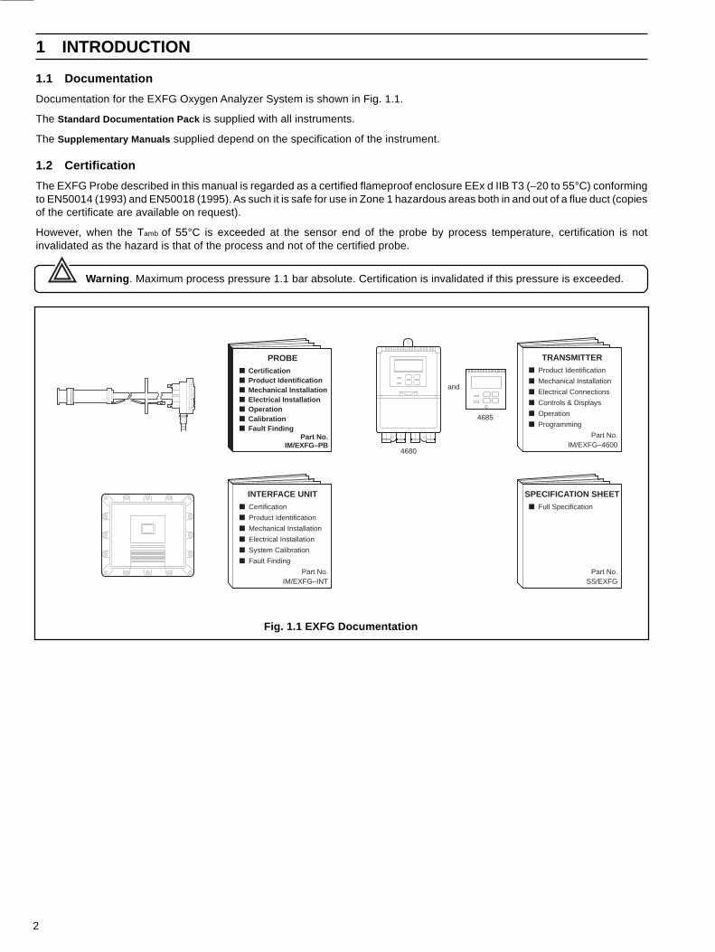
1.1 Documentation
Documentation for the EXFG Oxygen Analyzer System is shown in Fig. 1.1.
The Standard Documentation Pack is supplied with all instruments.
The Supplementary Manuals supplied depend on the specification of the instrument.
1.2 Certification
The EXFG Probe described in this manual is regarded as a certified flameproof enclosure EEx d IIB T3 (–20 to 55°C) conformingto EN50014 (1993) and EN50018 (1995). As such it is safe for use in Zone 1 hazardous areas both in and out of a flue duct (copiesof the certificate are available on request).
However, when the Tamb of 55°C is exceeded at the sensor end of the probe by process temperature, certification is notinvalidated as the hazard is that of the process and not of the certified probe.
Warning . Maximum process pressure 1.1 bar absolute. Certification is invalidated if this pressure is exceeded.
SPECIFICATION SHEETFull Specification
Part No.SS/EXFG
TRANSMITTERProduct Identification
Mechanical Installation
Electrical Connections
Controls & Displays
Operation
Programming
Part No.IM/EXFG–4600
and
4680
4685
INTERFACE UNITCertification
Product Identification
Mechanical Installation
Electrical Installation
System Calibration
Fault Finding
Part No.IM/EXFG–INT
PROBE
Part No.
IM/EXFG–PB
CertificationProduct IdentificationMechanical InstallationElectrical InstallationOperationCalibrationFault Finding

3
1.3 System Overview – Fig. 1.2
The EXFG Oxygen Probe measures oxygen concentration in flue gas using an in situ (‘wet analysis’) method. The 'wet analysis'method avoids measurement error (typically 20% of reading higher than the actual value) which would be introduced by asampling system using the ‘dry analysis’ method.
System equipment comprises the EXFG Oxygen Probe (flue-mounted), an EXFG Interface Electronics Unit and an EXFGOxygen Transmitter. During operation, a zirconia cell within the EXFG Probe is controlled by the EXFG Interface Electronics Unitat a temperature of 700°C. This temperature is maintained by a probe heater and control thermocouple assembly. A tripthermocouple is fitted to ensure the surface temperature of the probe never exceeds T3 (200°C). If the heater control circuitry fails'unsafe' a mechanically interlocked power supply trip relay operates cutting the power supply to the probe. Therefore the systemfails 'safe'.
Warning . The probe must be only be connected to the EXFG Interface Electronics Unit, otherwise probe certificationmay be invalidated.
An output generated at the zirconia cell is processed in the EXFG interface electronics unit into a 4 to 20mA retransmission signalrepresenting 25% to 0.25% O2.
1 INTRODUCTION…
Fig. 1.2 System Schematic
NON HAZARDOUS AREAHAZARDOUS AREA(Zone 1, Class IIB)
Process20°C to600°C1.1 Bar
AbsoluteMaximum(40in WG)
EXFG ProbeEEx d IIB T3 (Tamb –20°C to 55°C)to EN50014 1993 and EN50018 1995
Mains Supply
Control ThermocoupleSignal
4 to 20mA Output Signal(25% to 0.25% O2)
or
4680 Transmitter
Mains Supply
Flameproof Interface Electronics UnitEEx d IIB T6 Conforming to BS5501 Part 5: 1977
Flue
4685 Transmitter
RetransmissionOutput
Reference Air Line Entry
Regulated Reference AirUnit (003000241)
O2 mV Signal(–20 to +180mV)
or
LogicAlarmSignal
1.1 BarAbsolute Maximum
Dry, Oil-freeInstrument Air(10 bar max.)
ControlledHeaterSupply
Over-temperatureTrip Thermocouple
Test GasInlet
4
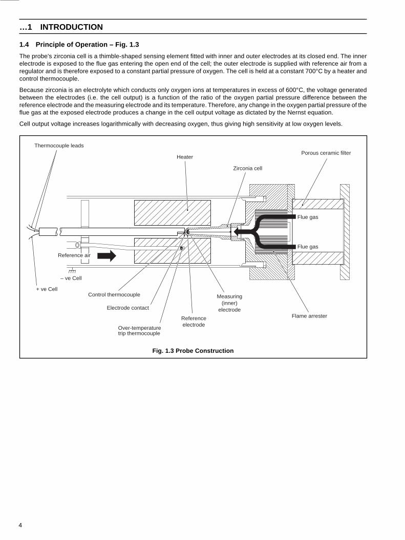
1.4 Principle of Operation – Fig. 1.3
The probe's zirconia cell is a thimble-shaped sensing element fitted with inner and outer electrodes at its closed end. The innerelectrode is exposed to the flue gas entering the open end of the cell; the outer electrode is supplied with reference air from aregulator and is therefore exposed to a constant partial pressure of oxygen. The cell is held at a constant 700°C by a heater andcontrol thermocouple.
Because zirconia is an electrolyte which conducts only oxygen ions at temperatures in excess of 600°C, the voltage generatedbetween the electrodes (i.e. the cell output) is a function of the ratio of the oxygen partial pressure difference between thereference electrode and the measuring electrode and its temperature. Therefore, any change in the oxygen partial pressure of theflue gas at the exposed electrode produces a change in the cell output voltage as dictated by the Nernst equation.
Cell output voltage increases logarithmically with decreasing oxygen, thus giving high sensitivity at low oxygen levels.
…1 INTRODUCTION
Thermocouple leads
Heater
Zirconia cell
Porous ceramic filter
Flame arrester
Flue gas
Measuring(inner)
electrode
Referenceelectrode
Control thermocouple
Electrode contact
Flue gas
Over-temperaturetrip thermocouple
+ ve Cell
Reference air
– ve Cell
Fig. 1.3 Probe Construction

5
2.1 Checking the Code Number – Fig. 2.1
2 PREPARATION 2 PREPARATION…
Check code number – see Table 2.1
Fig. 2.1 Checking the Code Number
2
EXFG Oxygen Analyzer System EXFG/ X X X 000
EXFG Probe Not supplied 01.64ft (0.5m) insertion length – with standard flange 13.281ft (1.0m) insertion length – with standard flange 26.562 (2.0m) insertion length – with standard flange 31.64ft (0.5m) insertion length – with ANSI flange 43.281ft (1.0m) (insertion length) – with ANSI flange 56.562 (2.0m) insertion length – with ANSI flange 6
Flexible Conduits No conduits 0
19.68ft (6.0m) Single conduit assembly – combined signal/power 132.81ft (10.0m) Single conduit assembly – combined signal/power 2
19.68ft (6.0m) Dual conduit assembly – separate signal/power 3(comprising one signal conduit and one power conduit)
32.81ft (10.0m) Dual conduit assembly – separate signal/power 4(comprising one signal conduit and one power conduit)
or
Dual Special Cables (ordered separately)SWA signal cable – EXFG/0194 (per metre, 100 metre max.)
25/20mm reducer – B11274 (qty. 2 rqd.)20mm barrier gland – (qty. 2 rqd.)
andSWA power cable – EXFG/0195 (per metre, 100 metre max.)
20mm barrier gland – B11275 (qty. 2 rqd.)
Mounting Plate Not supplied 0Mounting plate assembly – standard flange only 1
Table 2.1 Code Number Interpretation
6
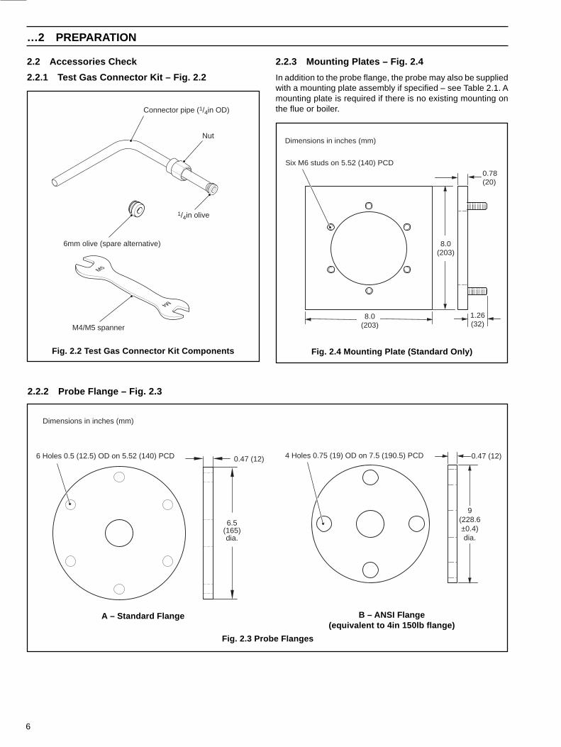
2.2 Accessories Check
2.2.1 Test Gas Connector Kit – Fig. 2.2
2.2.3 Mounting Plates – Fig. 2.4
In addition to the probe flange, the probe may also be suppliedwith a mounting plate assembly if specified – see Table 2.1. Amounting plate is required if there is no existing mounting onthe flue or boiler.
Fig. 2.4 Mounting Plate (Standard Only)
…2 PREPARATION
2.2.2 Probe Flange – Fig. 2.3
Fig. 2.2 Test Gas Connector Kit Components
A – Standard Flange
Fig. 2.3 Probe Flanges
B – ANSI Flange(equivalent to 4in 150lb flange)
Six M6 studs on 5.52 (140) PCD
Dimensions in inches (mm)
0.78(20)
8.0(203)
1.26(32)
8.0(203)
0.47 (12)
9(228.6±0.4)dia.
4 Holes 0.75 (19) OD on 7.5 (190.5) PCD6 Holes 0.5 (12.5) OD on 5.52 (140) PCD 0.47 (12)
6.5(165)dia.
Dimensions in inches (mm)
Connector pipe (1/4in OD)
6mm olive (spare alternative)
Nut
1/4in olive
M4/M5 spanner
7
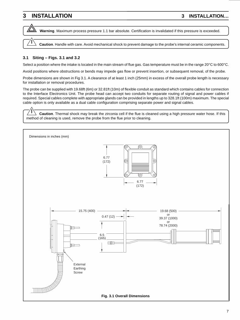
3 INSTALLATION
Fig. 3.1 Overall Dimensions
3 INSTALLATION…
Dimensions in inches (mm)
15.75 (400) 19.68 (500)or
39.37 (1000)or
78.74 (2000)
0.47 (12)
6.5(165)
ExternalEarthingScrew
6.77(172)
6.77(172)
Warning . Maximum process pressure 1.1 bar absolute. Certification is invalidated if this pressure is exceeded.
Caution . Handle with care. Avoid mechanical shock to prevent damage to the probe's internal ceramic components.
3.1 Siting – Figs. 3.1 and 3.2
Select a position where the intake is located in the main stream of flue gas. Gas temperature must be in the range 20°C to 600°C.
Avoid positions where obstructions or bends may impede gas flow or prevent insertion, or subsequent removal, of the probe.
Probe dimensions are shown in Fig 3.1. A clearance of at least 1 inch (25mm) in excess of the overall probe length is necessaryfor installation or removal procedures.
The probe can be supplied with 19.68ft (6m) or 32.81ft (10m) of flexible conduit as standard which contains cables for connectionto the Interface Electronics Unit. The probe head can accept two conduits for separate routing of signal and power cables ifrequired. Special cables complete with appropriate glands can be provided in lengths up to 328.1ft (100m) maximum. The specialcable option is only available as a dual cable configuration comprising separate power and signal cables.
Caution . Thermal shock may break the zirconia cell if the flue is cleaned using a high pressure water hose. If thismethod of cleaning is used, remove the probe from the flue prior to cleaning.
8
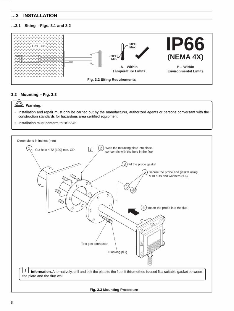
…3 INSTALLATION
Information. Alternatively, drill and bolt the plate to the flue. If this method is used fit a suitable gasket betweenthe plate and the flue wall.
…3.1 Siting – Figs. 3.1 and 3.2
IP66B – Within
Environmental Limits
(NEMA 4X)A – Within
Temperature Limits
Gas Flue50°CMax.
–20°CMin.
Fig. 3.3 Mounting Procedure
Fig. 3.2 Siting Requirements
3.2 Mounting – Fig. 3.3
Warning.
• Installation and repair must only be carried out by the manufacturer, authorized agents or persons conversant with theconstruction standards for hazardous area certified equipment.
• Installation must conform to BS5345.
Cut hole 4.72 (120) min. ODWeld the mounting plate into place,concentric with the hole in the flue
Fit the probe gasket
Secure the probe and gasket usingM10 nuts and washers (x 6)
Insert the probe into the flue
Test gas connector
Blanking plug
1 2
3
4
5
Dimensions in inches (mm)
9
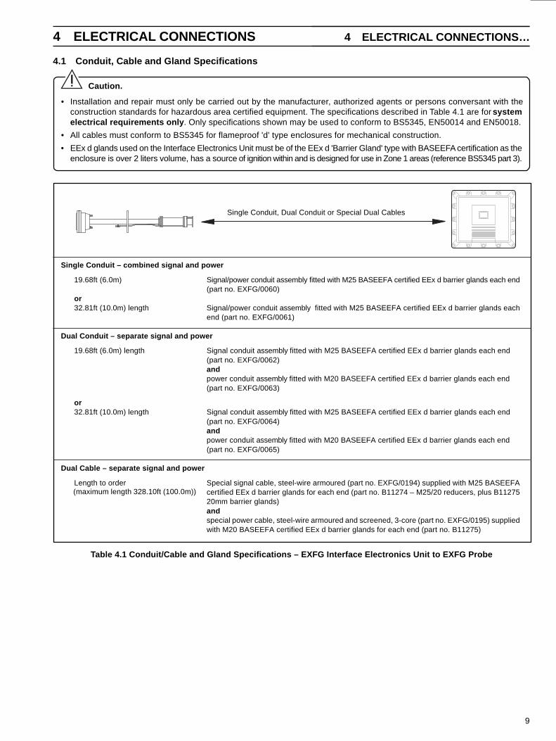
4.1 Conduit, Cable and Gland Specifications
4 ELECTRICAL CONNECTIONS 4 ELECTRICAL CONNECTIONS…
Caution.
• Installation and repair must only be carried out by the manufacturer, authorized agents or persons conversant with theconstruction standards for hazardous area certified equipment. The specifications described in Table 4.1 are for systemelectrical requirements only . Only specifications shown may be used to conform to BS5345, EN50014 and EN50018.
• All cables must conform to BS5345 for flameproof 'd' type enclosures for mechanical construction.
• EEx d glands used on the Interface Electronics Unit must be of the EEx d 'Barrier Gland' type with BASEEFA certification as theenclosure is over 2 liters volume, has a source of ignition within and is designed for use in Zone 1 areas (reference BS5345 part 3).
Single Conduit, Dual Conduit or Special Dual Cables
Single Conduit – combined signal and power
19.68ft (6.0m) Signal/power conduit assembly fitted with M25 BASEEFA certified EEx d barrier glands each end(part no. EXFG/0060)
or32.81ft (10.0m) length Signal/power conduit assembly fitted with M25 BASEEFA certified EEx d barrier glands each
end (part no. EXFG/0061)
Dual Conduit – separate signal and power
19.68ft (6.0m) length Signal conduit assembly fitted with M25 BASEEFA certified EEx d barrier glands each end(part no. EXFG/0062)andpower conduit assembly fitted with M20 BASEEFA certified EEx d barrier glands each end(part no. EXFG/0063)
or32.81ft (10.0m) length Signal conduit assembly fitted with M25 BASEEFA certified EEx d barrier glands each end
(part no. EXFG/0064)andpower conduit assembly fitted with M20 BASEEFA certified EEx d barrier glands each end(part no. EXFG/0065)
Dual Cable – separate signal and power
Length to order Special signal cable, steel-wire armoured (part no. EXFG/0194) supplied with M25 BASEEFAcertified EEx d barrier glands for each end (part no. B11274 – M25/20 reducers, plus B1127520mm barrier glands)andspecial power cable, steel-wire armoured and screened, 3-core (part no. EXFG/0195) suppliedwith M20 BASEEFA certified EEx d barrier glands for each end (part no. B11275)
(maximum length 328.10ft (100.0m))
Table 4.1 Conduit/Cable and Gland Specifications – EXFG Interface Electronics Unit to EXFG Probe
10
…4 ELECTRICAL CONNECTIONS
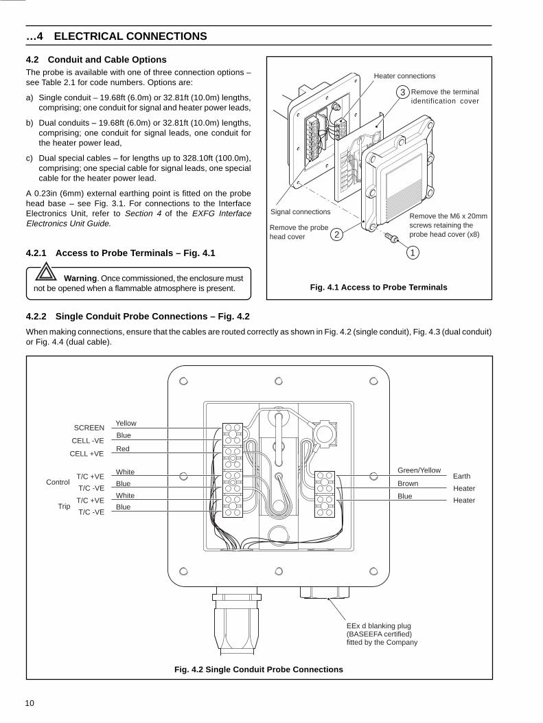
4.2.2 Single Conduit Probe Connections – Fig. 4.2
When making connections, ensure that the cables are routed correctly as shown in Fig. 4.2 (single conduit), Fig. 4.3 (dual conduit)or Fig. 4.4 (dual cable).
Fig. 4.2 Single Conduit Probe Connections
4.2 Conduit and Cable OptionsThe probe is available with one of three connection options –see Table 2.1 for code numbers. Options are:
a) Single conduit – 19.68ft (6.0m) or 32.81ft (10.0m) lengths,comprising; one conduit for signal and heater power leads,
b) Dual conduits – 19.68ft (6.0m) or 32.81ft (10.0m) lengths,comprising; one conduit for signal leads, one conduit forthe heater power lead,
c) Dual special cables – for lengths up to 328.10ft (100.0m),comprising; one special cable for signal leads, one specialcable for the heater power lead.
A 0.23in (6mm) external earthing point is fitted on the probehead base – see Fig. 3.1. For connections to the InterfaceElectronics Unit, refer to Section 4 of the EXFG InterfaceElectronics Unit Guide.
4.2.1 Access to Probe Terminals – Fig. 4.1
Warning . Once commissioned, the enclosure mustnot be opened when a flammable atmosphere is present. Fig. 4.1 Access to Probe Terminals
YELLOWGREEN/
GREY
GREY
YELLOWGREEN/
BLUE
BROWN
BLUE
WHITE
RED
HEATER
HEATER
EARTH
-VE
TRIP T/C +VETRIP T/CT/C -V
ECONTROLT/C +VECONTROL
CELL+VE
CELL-VE
SCREEN
Heater connections
Signal connections
Remove the terminalidentification cover
Remove the probehead cover
Remove the M6 x 20mmscrews retaining theprobe head cover (x8)
1
2
3
Blue
White
Blue
White
Red
Yellow
T/C -VE
T/C +VE
CELL +VE
CELL -VE
SCREENBlue
T/C -VE
T/C +VE
Control
Trip
Green/Yellow
Brown
Blue
Earth
Heater
Heater
EEx d blanking plug(BASEEFA certified)fitted by the Company
11
4 ELECTRICAL CONNECTIONS…
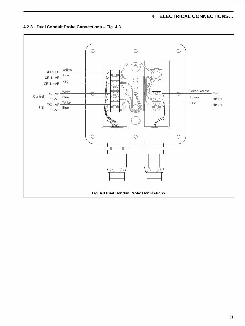
4.2.3 Dual Conduit Probe Connections – Fig. 4.3
Fig. 4.3 Dual Conduit Probe Connections
Blue
White
Blue
White
Red
Yellow
T/C -VE
T/C +VE
CELL +VE
CELL -VE
SCREENBlue
T/C -VE
T/C +VE
Control
Trip
Green/Yellow
Brown
Blue
Earth
Heater
Heater
12
…4 ELECTRICAL CONNECTIONS
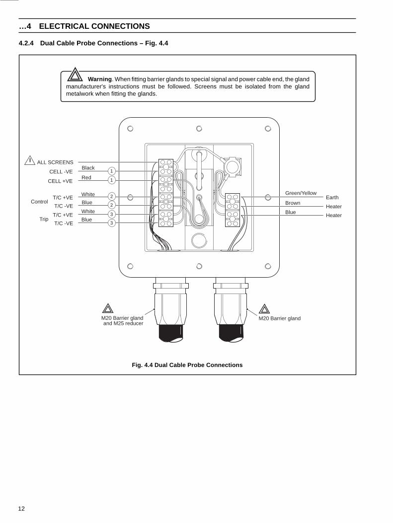
4.2.4 Dual Cable Probe Connections – Fig. 4.4
Warning . When fitting barrier glands to special signal and power cable end, the glandmanufacturer's instructions must be followed. Screens must be isolated from the glandmetalwork when fitting the glands.
Fig. 4.4 Dual Cable Probe Connections
Blue
White
Blue
White
Red
T/C -VE
T/C +VE
CELL +VE
CELL -VE
ALL SCREENSBlack
T/C -VE
T/C +VE
Control
Trip
Green/Yellow
Brown
Blue
Earth
Heater
Heater
M20 Barrier glandand M25 reducer
M20 Barrier gland
1
1
2
2
3
3
13
Apply grease tothe flange(CG5317)
Ensure grease can be seenaround the entire flange thenremove any excess grease andcheck with a (0.2 mm) feelergauge that the gap between the lidand base is less than 0.2 mm
Fit the probe headcover
Insert M6 x 20mmsocket-head screwsand torque toapproximately3 ft-lbs (4Nm) usingan M5 Allen key
1
2
3
4
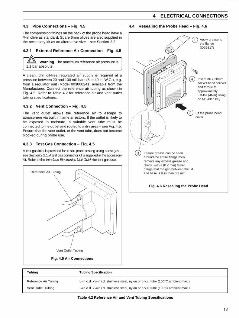
4.4 Resealing the Probe Head – Fig. 4.6
4 ELECTRICAL CONNECTIONS
4.3 Pipe Connections – Fig. 4.5
The compression fittings on the back of the probe head have a1/4in olive as standard. Spare 6mm olives are also supplied inthe accessory kit as an alternative size – see Section 2.2.
4.3.1 External Reference Air Connection – Fig. 4.5
Warning . The maximum reference air pressure is1.1 bar absolute.
A clean, dry, oil-free regulated air supply is required at apressure between 20 and 100 millibars (8 to 40 in. W.G.), e.g.from a regulator unit (Model 003000241) available from theManufacturer. Connect the reference air tubing as shown inFig. 4.5. Refer to Table 4.2 for reference air and vent outlettubing specifications.
4.3.2 Vent Connection – Fig. 4.5
The vent outlet allows the reference air to escape toatmosphere via built in flame arrestors. If the outlet is likely tobe exposed to moisture, a suitable vent tube must beconnected to the outlet and routed to a dry area – see Fig. 4.5.Ensure that the vent outlet, or the vent tube, does not becomeblocked during probe use.
4.3.3 Test Gas Connection – Fig. 4.5
A test gas inlet is provided for in situ probe testing using a test gas –see Section 2.2.1. A test gas connector kit is supplied in the accessorykit. Refer to the Interface Electronics Unit Guide for test gas use.
Table 4.2 Reference Air and Vent Tubing Specifications
Tubing Tubing Specification
Reference Air Tubing 1/4in o.d. x1/8in i.d. stainless steel, nylon or p.v.c. tube (100°C ambient max.)
Vent Outlet Tubing 1/4in o.d. x1/8in i.d. stainless steel, nylon or p.v.c. tube (100°C ambient max.)
Fig. 4.6 Resealing the Probe Head
Fig. 4.5 Air Connections
Reference Air Tubing
Vent Outlet Tubing

14
5 OPERATION 6 CALIBRATION
POWER HEATERO/TU/T
DO NOT OPEN WHEN FLAMMABLEATMOSPHERE IS PRESENT
The heater LEDflashes when theprobe heater is atthe correctoperatingtemperature(approximately 15minutes afterpower up)
The power LEDremains lit continuouslywhen power is appliedto the unit
Fig. 5.1 LED Indication Showing Probe Heater atNormal Operating Temperature
a) Check that a blanking plug is securely fitted to the test gasconnector on the probe – see Fig. 3.3.
Note. If the blanking plug is not fitted, air leakinginto the probe via the connector may causemeasurement errors. In a pressurized flue, gases ventingto atmosphere through the connector could causecorrosion of the test gas tube. In a negative pressure flue,air leakage may cause high O2 reading errors.
b) Check connections on both the Probe and the InterfaceElectronics Unit (refer also to the EXFG InterfaceElectronics Unit Guide).
c) Switch on the mains power supply and reference air flow.
d) Check and, if necessary, adjust the reference air flow to astable flow rate between 50 and 1,000cc/min.
e) Check the l.e.d.s on the EXFG Interface Electronics Unit– see Fig. 5.1.
Refer to the EXFG Interface Electronics Unit Guide, Fig.6.1 for other l.e.d. indications.
Full gas calibration procedures for the system are described inSection 5 of the EXFG Interface Electronics Unit Guide.
Note . Test gas flows for all probes must be set to3,000cc/min. (±10%) or measurement errors may occur.
System fault finding procedures are given in Section 7. Wherea fault is traced to the probe, it may be possible to identify andrectify the fault.
After any rectification, the system must be re-calibrated asdescribed in Section 5 of the EXFG Interface Electronics UnitGuide to maintain the stated accuracies.
15
7 FAULT FINDING 7 FAULT FINDING…
Check for the correct voltage reading with respectto the ambient temperature – see Table 7.1
Disconnectthe controlthermocoupleleads
Measure the voltage across thecontrol thermocouple terminals
Measure the temperature at thecontrol thermocouple terminals
50°C
0°C
V – VE
+VE
1
2
3
4
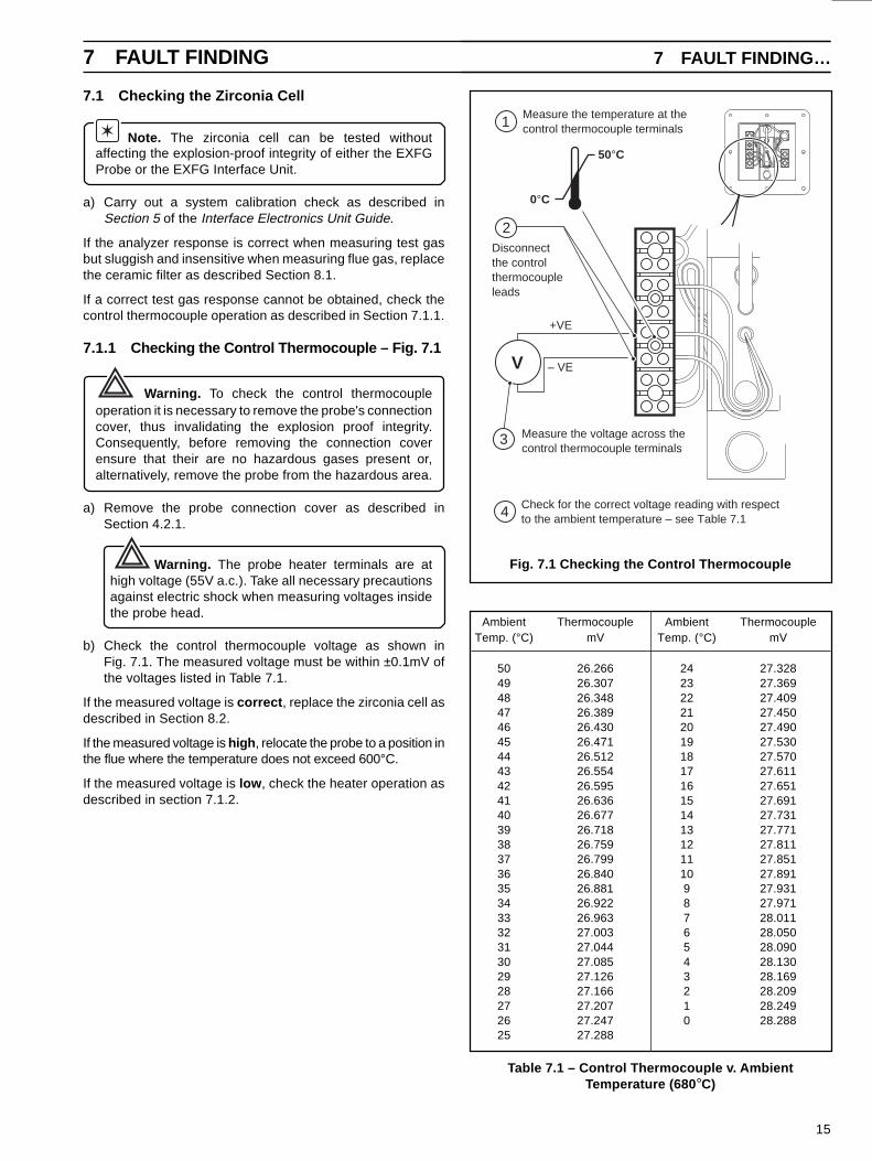
Fig. 7.1 Checking the Control Thermocouple
7.1 Checking the Zirconia Cell
Note. The zirconia cell can be tested withoutaffecting the explosion-proof integrity of either the EXFGProbe or the EXFG Interface Unit.
a) Carry out a system calibration check as described inSection 5 of the Interface Electronics Unit Guide.
If the analyzer response is correct when measuring test gasbut sluggish and insensitive when measuring flue gas, replacethe ceramic filter as described Section 8.1.
If a correct test gas response cannot be obtained, check thecontrol thermocouple operation as described in Section 7.1.1.
7.1.1 Checking the Control Thermocouple – Fig. 7.1
Warning. To check the control thermocoupleoperation it is necessary to remove the probe's connectioncover, thus invalidating the explosion proof integrity.Consequently, before removing the connection coverensure that their are no hazardous gases present or,alternatively, remove the probe from the hazardous area.
a) Remove the probe connection cover as described inSection 4.2.1.
Warning. The probe heater terminals are athigh voltage (55V a.c.). Take all necessary precautionsagainst electric shock when measuring voltages insidethe probe head.
b) Check the control thermocouple voltage as shown inFig. 7.1. The measured voltage must be within ±0.1mV ofthe voltages listed in Table 7.1.
If the measured voltage is correct , replace the zirconia cell asdescribed in Section 8.2.
If the measured voltage is high , relocate the probe to a position inthe flue where the temperature does not exceed 600°C.
If the measured voltage is low , check the heater operation asdescribed in section 7.1.2.
Ambient Thermocouple Ambient ThermocoupleTemp. (°C) mV Temp. (°C) mV
50 26.266 24 27.32849 26.307 23 27.36948 26.348 22 27.40947 26.389 21 27.45046 26.430 20 27.49045 26.471 19 27.53044 26.512 18 27.57043 26.554 17 27.61142 26.595 16 27.65141 26.636 15 27.69140 26.677 14 27.73139 26.718 13 27.77138 26.759 12 27.81137 26.799 11 27.85136 26.840 10 27.89135 26.881 9 27.93134 26.922 8 27.97133 26.963 7 28.01132 27.003 6 28.05031 27.044 5 28.09030 27.085 4 28.13029 27.126 3 28.16928 27.166 2 28.20927 27.207 1 28.24926 27.247 0 28.28825 27.288
Table 7.1 – Control Thermocouple v. AmbientTemperature (680 °C)
16
…7 FAULT FINDING
Measure the resistanceacross the heater leads
Disconnect the heaterleads from the terminalblock
The measuredresistance must be22Ω to 28Ω
Ω
1
2
3
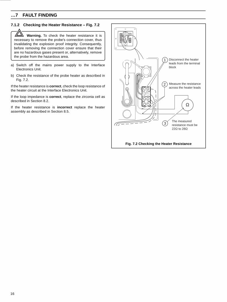
Fig. 7.2 Checking the Heater Resistance
7.1.2 Checking the Heater Resistance – Fig. 7.2
Warning. To check the heater resistance it isnecessary to remove the probe's connection cover, thusinvalidating the explosion proof integrity. Consequently,before removing the connection cover ensure that theirare no hazardous gases present or, alternatively, removethe probe from the hazardous area.
a) Switch off the mains power supply to the InterfaceElectronics Unit.
b) Check the resistance of the probe heater as described inFig. 7.2.
If the heater resistance is correct , check the loop resistance ofthe heater circuit at the Interface Electronics Unit.
If the loop impedance is correct , replace the zirconia cell asdescribed in Section 8.2.
If the heater resistance is incorrect replace the heaterassembly as described in Section 8.5.
17
7 FAULT FINDING
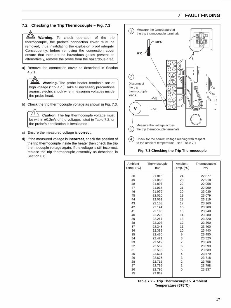
Ambient Thermocouple Ambient ThermocoupleTemp. (°C) mV Temp. (°C) mV
50 21.815 24 22.87749 21.856 23 22.91848 21.897 22 22.95847 21.938 21 22.99946 21.979 20 23.03945 22.020 19 23.07944 22.061 18 23.11943 22.103 17 23.16042 22.144 16 23.20041 22.185 15 23.24040 22.226 14 23.28039 22.267 13 23.32038 22.308 12 23.36037 22.348 11 23.40036 22.389 10 23.44035 22.430 9 23.48034 22.471 8 23.52033 22.512 7 23.56032 22.552 6 23.59931 22.593 5 23.63930 22.634 4 23.67929 22.675 3 23.71828 22.715 2 23.75827 22.756 1 23.79826 22.796 0 23.83725 22.837
Table 7.2 – Trip Thermocouple v. AmbientTemperature (575 °C)
Fig. 7.3 Checking the Trip Thermocouple
Check for the correct voltage reading with respectto the ambient temperature – see Table 7.1
– VE
+VE
Disconnectthe tripthermocoupleleads
V
Measure the voltage acrossthe trip thermocouple terminals
Measure the temperature atthe trip thermocouple terminals
50°C
0°C
1
2
3
4
7.2 Checking the Trip Thermocouple – Fig. 7.3
Warning. To check operation of the tripthermocouple, the probe's connection cover must beremoved, thus invalidating the explosion proof integrity.Consequently, before removing the connection coverensure that their are no hazardous gases present or,alternatively, remove the probe from the hazardous area.
a) Remove the connection cover as described in Section4.2.1.
Warning. The probe heater terminals are athigh voltage (55V a.c.). Take all necessary precautionsagainst electric shock when measuring voltages insidethe probe head.
b) Check the trip thermocouple voltage as shown in Fig. 7.3.
Caution. The trip thermocouple voltage mustbe within ±0.2mV of the voltages listed in Table 7.2, orthe probe's certification is invalidated.
c) Ensure the measured voltage is correct .
d) If the measured voltage is incorrect , check the position ofthe trip thermocouple inside the heater then check the tripthermocouple voltage again. If the voltage is still incorrect,replace the trip thermocouple assembly as described inSection 8.6.
18
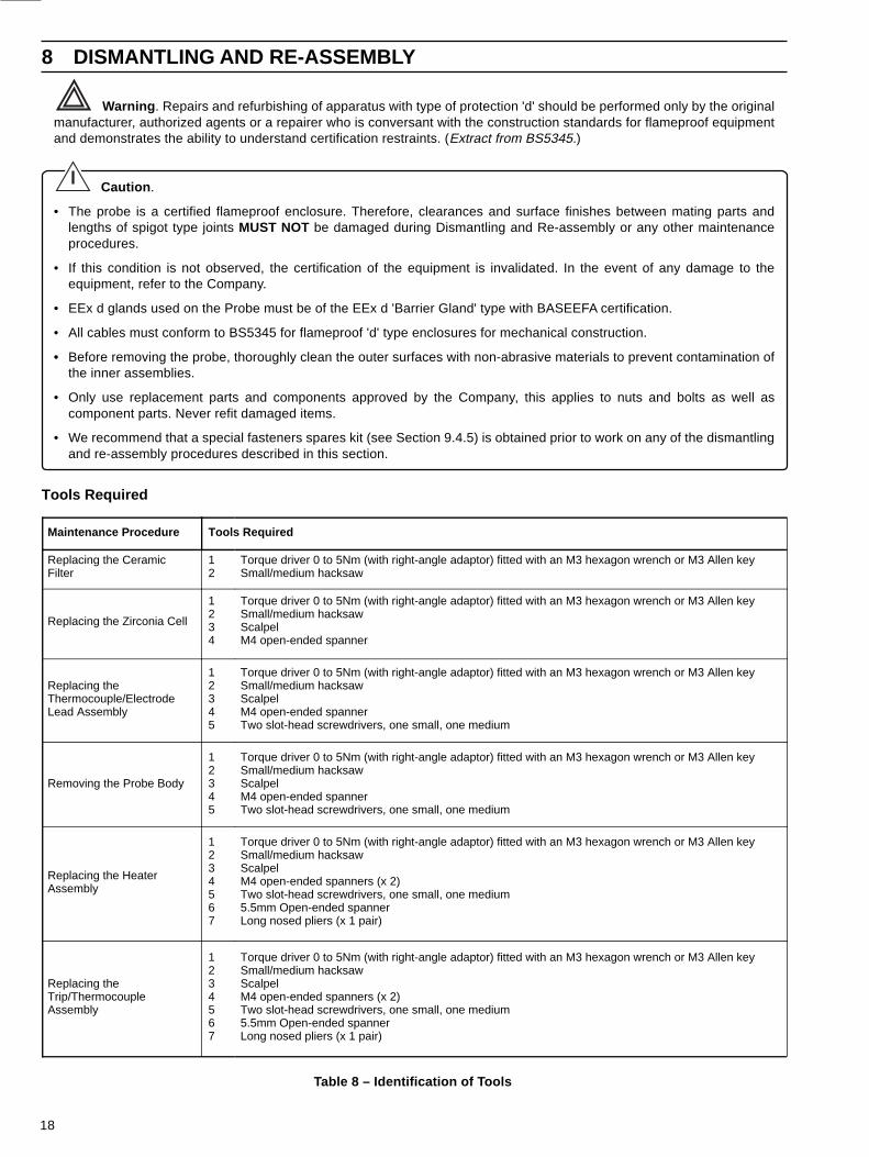
8 DISMANTLING AND RE-ASSEMBLY
Maintenance Procedure Tools Required
Replacing the Ceramic Filter
1 2
Torque driver 0 to 5Nm (with right-angle adaptor) fitted with an M3 hexagon wrench or M3 Allen keySmall/medium hacksaw
Replacing the Zirconia Cell
1234
Torque driver 0 to 5Nm (with right-angle adaptor) fitted with an M3 hexagon wrench or M3 Allen keySmall/medium hacksawScalpelM4 open-ended spanner
Replacing the Thermocouple/Electrode Lead Assembly
12345
Torque driver 0 to 5Nm (with right-angle adaptor) fitted with an M3 hexagon wrench or M3 Allen keySmall/medium hacksawScalpelM4 open-ended spannerTwo slot-head screwdrivers, one small, one medium
Removing the Probe Body
12345
Torque driver 0 to 5Nm (with right-angle adaptor) fitted with an M3 hexagon wrench or M3 Allen keySmall/medium hacksawScalpelM4 open-ended spannerTwo slot-head screwdrivers, one small, one medium
Replacing the Heater Assembly
1234567
Torque driver 0 to 5Nm (with right-angle adaptor) fitted with an M3 hexagon wrench or M3 Allen keySmall/medium hacksawScalpelM4 open-ended spanners (x 2)Two slot-head screwdrivers, one small, one medium5.5mm Open-ended spannerLong nosed pliers (x 1 pair)
Replacing the Trip/Thermocouple Assembly
1234567
Torque driver 0 to 5Nm (with right-angle adaptor) fitted with an M3 hexagon wrench or M3 Allen key Small/medium hacksawScalpelM4 open-ended spanners (x 2)Two slot-head screwdrivers, one small, one medium5.5mm Open-ended spannerLong nosed pliers (x 1 pair)
Table 8 – Identification of Tools
Warning . Repairs and refurbishing of apparatus with type of protection 'd' should be performed only by the originalmanufacturer, authorized agents or a repairer who is conversant with the construction standards for flameproof equipmentand demonstrates the ability to understand certification restraints. (Extract from BS5345.)
Caution .
• The probe is a certified flameproof enclosure. Therefore, clearances and surface finishes between mating parts andlengths of spigot type joints MUST NOT be damaged during Dismantling and Re-assembly or any other maintenanceprocedures.
• If this condition is not observed, the certification of the equipment is invalidated. In the event of any damage to theequipment, refer to the Company.
• EEx d glands used on the Probe must be of the EEx d 'Barrier Gland' type with BASEEFA certification.
• All cables must conform to BS5345 for flameproof 'd' type enclosures for mechanical construction.
• Before removing the probe, thoroughly clean the outer surfaces with non-abrasive materials to prevent contamination ofthe inner assemblies.
• Only use replacement parts and components approved by the Company, this applies to nuts and bolts as well ascomponent parts. Never refit damaged items.
• We recommend that a special fasteners spares kit (see Section 9.4.5) is obtained prior to work on any of the dismantlingand re-assembly procedures described in this section.
Tools Required
19
Fig. 8.1 Replacing the Ceramic Filter
8 DISMANTLING AND RE-ASSEMBLY…
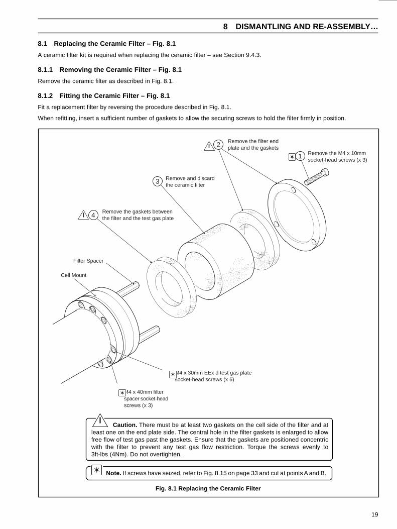
8.1 Replacing the Ceramic Filter – Fig. 8.1
A ceramic filter kit is required when replacing the ceramic filter – see Section 9.4.3.
8.1.1 Removing the Ceramic Filter – Fig. 8.1
Remove the ceramic filter as described in Fig. 8.1.
8.1.2 Fitting the Ceramic Filter – Fig. 8.1
Fit a replacement filter by reversing the procedure described in Fig. 8.1.
When refitting, insert a sufficient number of gaskets to allow the securing screws to hold the filter firmly in position.
Note. If screws have seized, refer to Fig. 8.15 on page 33 and cut at points A and B.
Caution. There must be at least two gaskets on the cell side of the filter and atleast one on the end plate side. The central hole in the filter gaskets is enlarged to allowfree flow of test gas past the gaskets. Ensure that the gaskets are positioned concentricwith the filter to prevent any test gas flow restriction. Torque the screws evenly to3ft-lbs (4Nm). Do not overtighten.
Cell Mount
Remove the M4 x 10mmsocket-head screws (x 3)
Remove the filter endplate and the gaskets
Remove and discardthe ceramic filter
Remove the gaskets betweenthe filter and the test gas plate
Filter Spacer
M4 x 40mm filterspacer socket-headscrews (x 3)
M4 x 30mm EEx d test gas platesocket-head screws (x 6)
1
2
3
4

20
…8 DISMANTLING AND RE-ASSEMBLY
8.2 Replacing the Zirconia Cell
A zirconia cell assembly is required when replacing thezirconia cell – see Section 9.4.2.
Fig. 8.2 Removing the Zirconia Cell
8.2.1 Removing the Zirconia Cell – Fig. 8.2
a) Remove the ceramic filter as described in Section 8.1.1.
b) Remove the zirconia cell as described in Fig. 8.2.
Caution . During prolonged service the celltip may become welded to the helical contact on theend of the thermocouple/electrode lead assemblyand thus prevent removal of the cell. If resistance isfelt when removing the cell mount, once all of thespring movement is taken up, do not try to forceremoval or the inner electrode may be damaged.
Note. If screws have seized, refer to Fig.8.15 on page 33 and cut at points B and C.
Gently ease the cell assembly out of theprobe body until approximately 0.39in(10mm) of the ceramic assembly is visible
0.08 to 0.12in(2 to 3mm) max.
Carefully separate the cell tipfrom the helical contact usinga scapel
Thermocouple/Electrodelead assembly
Disconnect the thermocouple/electrodesignal leads and straighten them out toallow easy withdrawal of the leadassembly – see Fig. 8.6
Test gas plate
Probe body
'O' Ring
Remove the M4 x 40mm filterspacer screws (x 3), the M4 x 30mmtest gas plate retaining screws (x 3),the filter spacers (x 3) and the test gas plate
Cell assembly
Red
White
Blue
1
2
3
4
21
8 DISMANTLING AND RE-ASSEMBLY…
Fig. 8.3 Fitting the Zirconia Cell
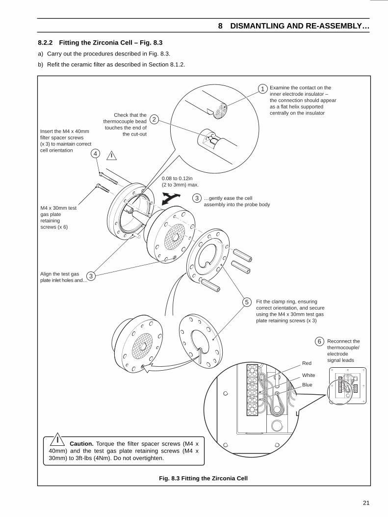
8.2.2 Fitting the Zirconia Cell – Fig. 8.3
a) Carry out the procedures described in Fig. 8.3.
b) Refit the ceramic filter as described in Section 8.1.2.
Caution. Torque the filter spacer screws (M4 x40mm) and the test gas plate retaining screws (M4 x30mm) to 3ft-lbs (4Nm). Do not overtighten.
Examine the contact on theinner electrode insulator –the connection should appearas a flat helix supportedcentrally on the insulatorCheck that the
thermocouple beadtouches the end of
the cut-out
Align the test gasplate inlet holes and…
…gently ease the cellassembly into the probe body
Insert the M4 x 40mmfilter spacer screws(x 3) to maintain correctcell orientation
Fit the clamp ring, ensuringcorrect orientation, and secureusing the M4 x 30mm test gasplate retaining screws (x 3)
M4 x 30mm testgas plateretainingscrews (x 6)
0.08 to 0.12in(2 to 3mm) max.
Reconnect thethermocouple/electrodesignal leads
Red
White
Blue
1
2
3
4
5
6
3
22
…8 DISMANTLING AND RE-ASSEMBLY
8.3 Replacing theThermocouple/Electrode Lead Assembly
An electrode/thermocouple assembly is required whenreplacing the electrode/thermocouple lead assembly – seeSection 9.4.1
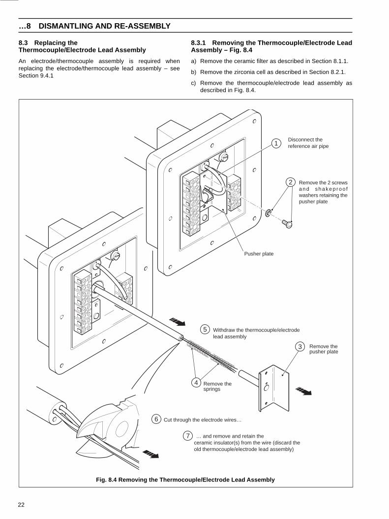
8.3.1 Removing the Thermocouple/Electrode LeadAssembly – Fig. 8.4
a) Remove the ceramic filter as described in Section 8.1.1.
b) Remove the zirconia cell as described in Section 8.2.1.
c) Remove the thermocouple/electrode lead assembly asdescribed in Fig. 8.4.
Fig. 8.4 Removing the Thermocouple/Electrode Lead Assembly
Withdraw the thermocouple/electrodelead assembly
Remove thesprings
Remove thepusher plate
Cut through the electrode wires…
… and remove and retain theceramic insulator(s) from the wire (discard theold thermocouple/electrode lead assembly)
Remove the 2 screwsa n d s h a k e p r o o fwashers retaining thepusher plate
Pusher plate
Disconnect thereference air pipe1
2
3
4
5
6
7

23
8 DISMANTLING AND RE-ASSEMBLY…
Fig. 8.5 Fitting Ceramic Insulators
Note . Ensure that wires between the ceramic insulators donot cross and that the ceramic insulators butt together correctly atthe joints.
Caution. Do not attempt to thread more than half theceramic insulator length onto a wire at any one time.
Information . Use a magnet to check that the insulators andPTFE sleeves have been threaded onto the correct wires; thethermocouple –ve lead should be attracted by the magnet andsleeved blue.
8.3.2 Fitting Ceramic Insulators – Fig. 8.5
a) Lay the new thermocouple/electrode lead assembly at the end of a long work surface and carefully uncoil the extension wires,one at a time.
Note . To retain the uncoiled lead ends during fitting, use a clamping block constructed from a wooden board and threebulldog clips – see Fig. 8.5.
Caution. Do not to kink the wires during fitting to avoid damage to the finished assembly.
b) Refit the ceramic insulators as described in Fig. 8.5.
c) Refit the zirconia cell as described in Section 8.2.2.
d) Refit the ceramic filter as described in Section 8.1.2.
11in (280mm)
Thread the ceramic insulator(s) onto the extensionwires one at a time. Ensure that each wire is locatedin the correct bore.
Slide 11in (280mm) of PTFE sleevingonto the wire ends then pass sleevinginto the ceramic insulator until 7.87in(200mm) protrudes. Ensure that thecorrect color sleeving is used.
Blue(Thermocouple –ve,
magnetic)Red
(Electrode)
White(Thermocouple +ve)
Cut the wires to length leavingapproximately 0.40in (10mm)bare. Bend approximately 0.20in(5mm) of lead end over to retainthe PTFE sleeves on the wires.
Clamping Block
0.40in(10mm)
0.20in(5mm)
1
2
3

24
…8 DISMANTLING AND RE-ASSEMBLY
8.3.3 Fitting the Thermocouple/Electrode Lead Assembly – Fig. 8.6
a) Refit the thermocouple/electrode lead assembly as described in Fig. 8.6.
b) Refit the zirconia cell as described in Section 8.2.2.
c) Refit the ceramic filter as described in Section 8.1.2.
Fig. 8.6 Fitting the Thermocouple/Electrode Assembly
2in(50mm)
Insert the PVC feed tube (supplied with leadassembly kit) through the probe body untilapproximately 2in (50mm) protrudes fromend of body
Slide the three extension leadsinto one end of the feed tube
Slide the thermocouple/electrode lead assemblythrough the probe until thePVC feed tube appearsat the head cover end ofthe probe
Remove the PVC feed tubefrom the extension wires
Refit the springsover the PVCfeed tube
…… refit the pusher plate assemblyby reversing the procedure detailedin Section 8.3.1
Re-connect the extensionwires to the terminal block
White (+ve)
Blue (–ve)
Feed the extension wires throughthe tube on the pusher plate and……
Red (+ve)
1
2
3
4
5
6
7

25
8 DISMANTLING AND RE-ASSEMBLY…
8.4 Removing the Probe Body – Fig. 8.7
A special fasteners kit is required when refitting the probe body– see Section 9.4.5.
Fig. 8.7 Removing the Probe Body
a) Remove the ceramic filter as described in Section 8.1.1.
b) Remove the zirconia cell as described in Section 8.2.1.
c) Remove the probe body described in Fig. 8.7.
Note. If screws have seized refer to Fig. 8.15, page 33 and cut at point C.
Remove the M4 x 16mmsocket-head screws (x 6)
Slide the probe body off(keep the test gas tubein position)
Retain the O-rings(x 2) for re-assembly– replace if damaged
Test gas tube
1
2
3
26
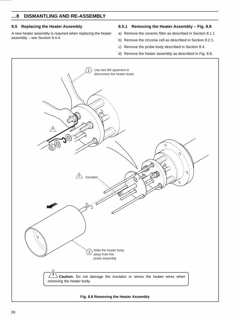
8.5 Replacing the Heater Assembly
A new heater assembly is required when replacing the heaterassembly – see Section 9.4.4.
…8 DISMANTLING AND RE-ASSEMBLY
8.5.1 Removing the Heater Assembly – Fig. 8.8
a) Remove the ceramic filter as described in Section 8.1.1
b) Remove the zirconia cell as described in Section 8.2.1.
c) Remove the probe body described in Section 8.4.
d) Remove the heater assembly as described in Fig. 8.8.
Fig. 8.8 Removing the Heater Assembly
Caution. Do not damage the insulator or stress the heater wires whenremoving the heater body.
Slide the heater bodyaway from theprobe assembly
Insulator
Use two M4 spanners todisconnect the heater leads
1
2
27
8 DISMANTLING AND RE-ASSEMBLY…
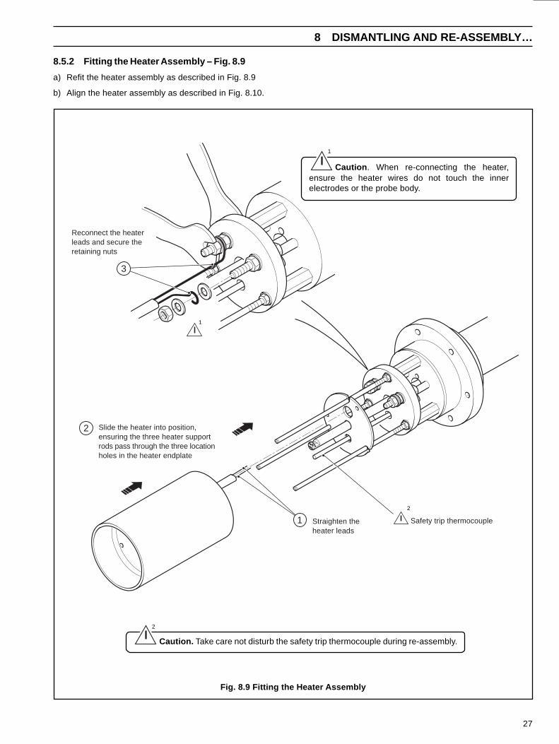
8.5.2 Fitting the Heater Assembly – Fig. 8.9
a) Refit the heater assembly as described in Fig. 8.9
b) Align the heater assembly as described in Fig. 8.10.
Fig. 8.9 Fitting the Heater Assembly
1
Caution . When re-connecting the heater,ensure the heater wires do not touch the innerelectrodes or the probe body.
1
Reconnect the heaterleads and secure theretaining nuts
Slide the heater into position,ensuring the three heater supportrods pass through the three locationholes in the heater endplate
Straighten theheater leads
Safety trip thermocouple1
2
3
Caution. Take care not disturb the safety trip thermocouple during re-assembly.
2
2
28
…8 DISMANTLING AND RE-ASSEMBLY
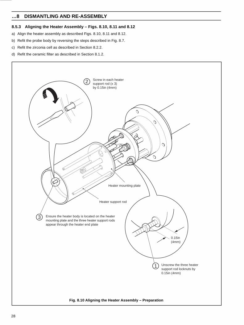
Fig. 8.10 Aligning the Heater Assembly – Preparation
8.5.3 Aligning the Heater Assembly – Figs. 8.10, 8.11 and 8.12
a) Align the heater assembly as described Figs. 8.10, 8.11 and 8.12.
b) Refit the probe body by reversing the steps described in Fig. 8.7.
c) Refit the zirconia cell as described in Section 8.2.2.
d) Refit the ceramic filter as described in Section 8.1.2.
0.15in(4mm)
1
3
2
Unscrew the three heatersupport rod locknuts by0.15in (4mm)
Heater mounting plate
Heater support rod
Screw in each heatersupport rod (x 3)by 0.15in (4mm)
Ensure the heater body is located on the heatermounting plate and the three heater support rodsappear through the heater end plate

29
8 DISMANTLING AND RE-ASSEMBLY…
Fig. 8.11 Aligning the Heater Assembly – Checking Heater Alignment
…8.5.3 Aligning the Heater Assembly
Caution. Do not force the heater into the probe shoulder byovertightening the heater support rods.
Screw the heater support rods (x 3)anti-clockwise until the top of the heatermeets the internal shoulder of the probe body
Refit the probe body (including the O-ring)and temporarily secure the body in position fittingthe M4 x 16mm screws (x 2) in opposing holes
Check for an even fit, ensure no gapis visible between the heater and theinternal shoulder in probe
3
2
1
Internal shoulder
30
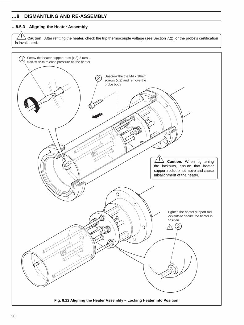
…8 DISMANTLING AND RE-ASSEMBLY
Fig. 8.12 Aligning the Heater Assembly – Locking Heater into Position
…8.5.3 Aligning the Heater Assembly
Caution . After refitting the heater, check the trip thermocouple voltage (see Section 7.2), or the probe's certificationis invalidated.
Caution. When tighteningthe locknuts, ensure that heatersupport rods do not move and causemisalignment of the heater.
Tighten the heater support rodlocknuts to secure the heater inposition
1 Screw the heater support rods (x 3) 2 turnsclockwise to release pressure on the heater
Unscrew the the M4 x 16mmscrews (x 2) and remove theprobe body
2
3

31
8 DISMANTLING AND RE-ASSEMBLY…
8.6 Replacing the Trip Thermocouple Assembly
A replacement trip thermocouple assembly is required for this procedure – see Section 9, Fig. 9.1b, item 35.
8.6.1 Removing the Trip Thermocouple Assembly – Fig. 8.13
a) Remove the ceramic filter as described in Section 8.1.1.
b) Remove the zirconia cell as described in Section 8.2.1.
c) Remove the probe body described in Section. 8.4.
d) Disconnect the thermocouple/electrode lead assembly as described in Section 8.3.1.
e) Disconnect the trip thermocouple leads in the terminal head – see Section 4.
f) Remove the trip thermocouple assembly as described in Fig. 8.13.
Fig. 8.13 Removing the Trip Thermocouple Assembly
Remove the existing trip thermocouplefrom the probe internal assembly bygently bending and easing it out of theslot in the flange
Loosen the three filter spacersby unscrewing each spacer
evenly, 2 turns at a time
Carefully withdraw the columninsulators from the column probe taking
care not to damage the ceramic tubes
Slot
Disconnect the tripthermocouple leads1
White
Blue
2
3
4
Caution. When withdrawing the trip thermocouple, do not apply stress on supporting components.
32
…8 DISMANTLING AND RE-ASSEMBLY
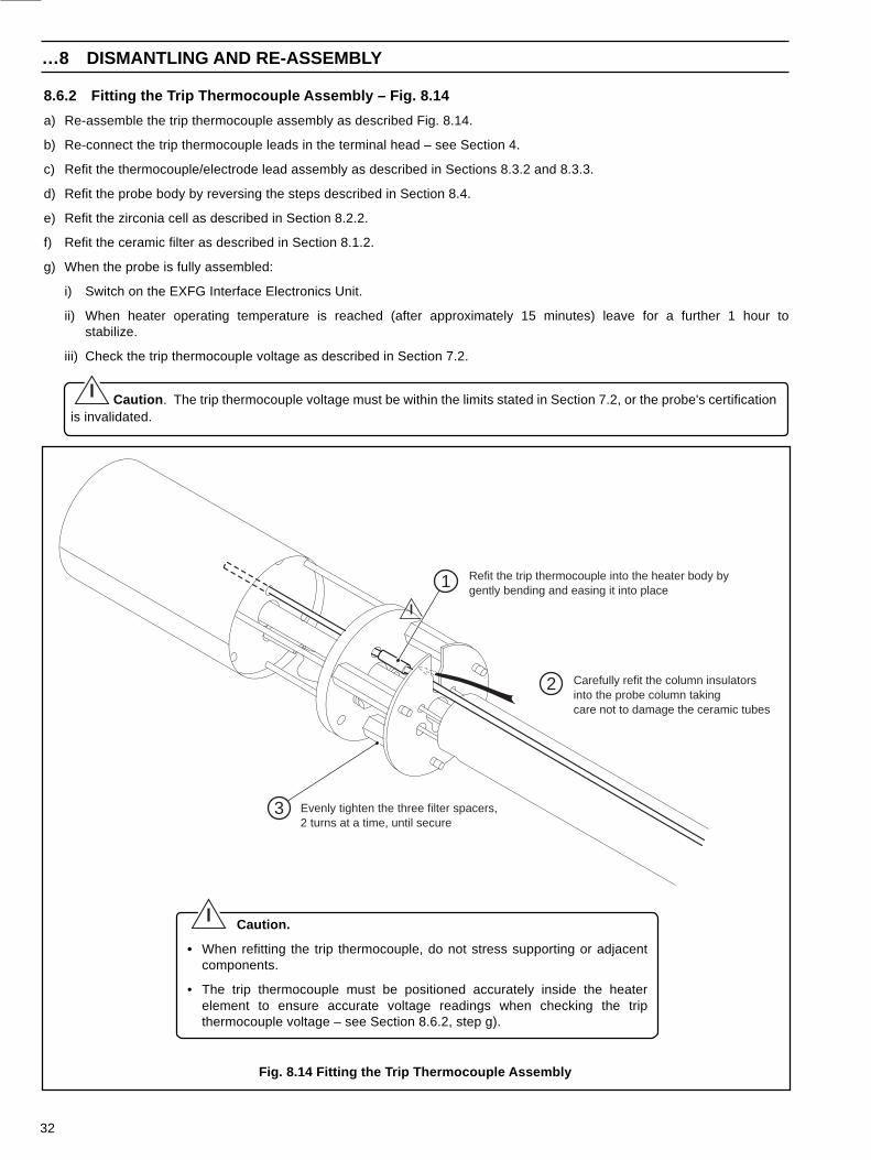
8.6.2 Fitting the Trip Thermocouple Assembly – Fig. 8.14
a) Re-assemble the trip thermocouple assembly as described Fig. 8.14.
b) Re-connect the trip thermocouple leads in the terminal head – see Section 4.
c) Refit the thermocouple/electrode lead assembly as described in Sections 8.3.2 and 8.3.3.
d) Refit the probe body by reversing the steps described in Section 8.4.
e) Refit the zirconia cell as described in Section 8.2.2.
f) Refit the ceramic filter as described in Section 8.1.2.
g) When the probe is fully assembled:
i) Switch on the EXFG Interface Electronics Unit.
ii) When heater operating temperature is reached (after approximately 15 minutes) leave for a further 1 hour tostabilize.
iii) Check the trip thermocouple voltage as described in Section 7.2.
Caution . The trip thermocouple voltage must be within the limits stated in Section 7.2, or the probe's certificationis invalidated.
Fig. 8.14 Fitting the Trip Thermocouple Assembly
1
3
2
Evenly tighten the three filter spacers,2 turns at a time, until secure
Refit the trip thermocouple into the heater body bygently bending and easing it into place
Carefully refit the column insulatorsinto the probe column takingcare not to damage the ceramic tubes
Caution.
• When refitting the trip thermocouple, do not stress supporting or adjacentcomponents.
• The trip thermocouple must be positioned accurately inside the heaterelement to ensure accurate voltage readings when checking the tripthermocouple voltage – see Section 8.6.2, step g).
33
8 DISMANTLING AND RE-ASSEMBLY…
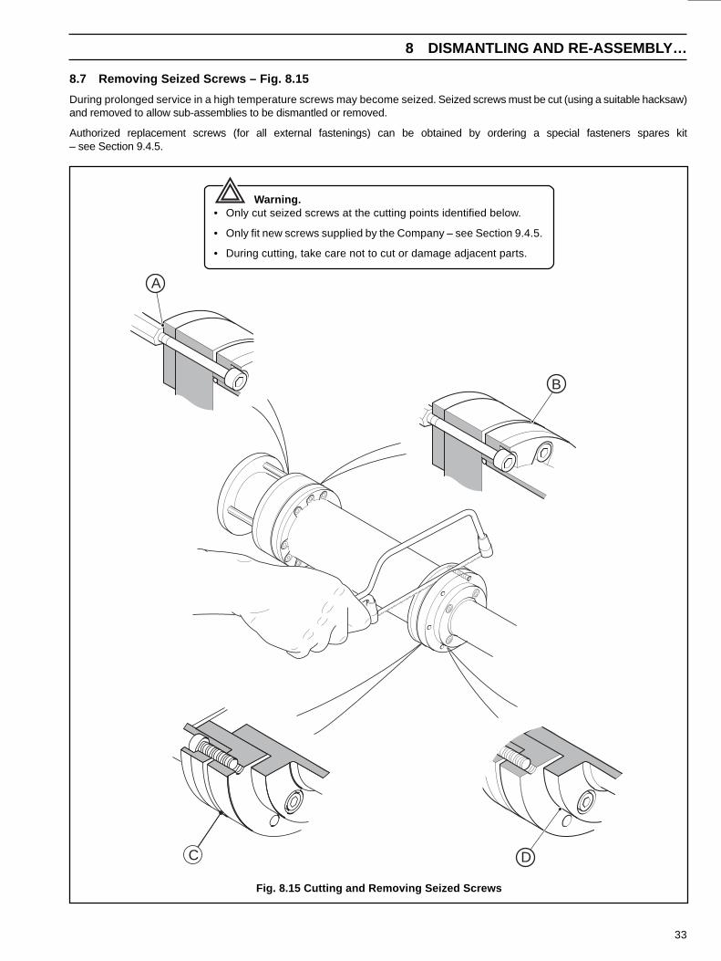
8.7 Removing Seized Screws – Fig. 8.15
During prolonged service in a high temperature screws may become seized. Seized screws must be cut (using a suitable hacksaw)and removed to allow sub-assemblies to be dismantled or removed.
Authorized replacement screws (for all external fastenings) can be obtained by ordering a special fasteners spares kit– see Section 9.4.5.
Fig. 8.15 Cutting and Removing Seized Screws
Warning.• Only cut seized screws at the cutting points identified below.
• Only fit new screws supplied by the Company – see Section 9.4.5.
• During cutting, take care not to cut or damage adjacent parts.
D
A
C
B
34
9 REPLACEMENT PARTS…
Fig
. 9.1
a Id
entif
icat
ion
of P
arts
19
18
16
15
20
22
23
89
10
109
8
1213
65
25
4
3
1
24
6
21
7
11
14
17
2
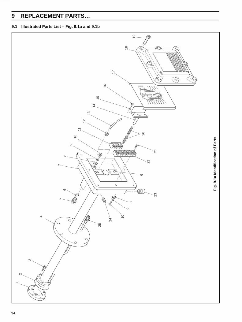
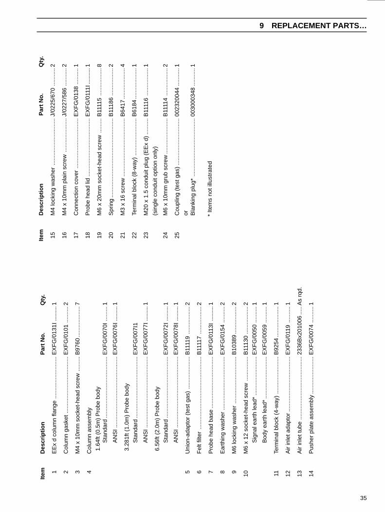
9.1 Illustrated Parts List – Fig. 9.1a and 9.1b
35
9 REPLACEMENT PARTS…
* Ite
ms
not i
llust
rate
d
Item
Des
crip
tion
Par
t No.
Qty
.
1E
Ex
d co
lum
n fla
nge
......
......
......
......
..E
XF
G/0
131I
......
....1
2C
olum
n ga
sket
......
......
......
......
......
.....
EX
FG
/010
1...
......
.2
3M
4 x
10m
m s
ocke
t-he
ad s
crew
......
...B
9760
......
......
......
.7
4C
olum
n as
sem
bly
1.64
ft (0
.5m
) P
robe
bod
yS
tand
ard
......
......
......
......
......
......
..E
XF
G/0
070I
......
...1
AN
SI.
......
......
......
......
......
......
......
.EX
FG
/007
6I...
......
.1
3.28
1ft (
1.0m
) P
robe
bod
y
Sta
ndar
d...
......
......
......
......
......
.....
EX
FG
/007
I1
AN
SI.
......
......
......
......
......
......
......
.EX
FG
/007
7I...
......
.1
6.56
ft (2
.0m
) P
robe
bod
y
Sta
ndar
d...
......
......
......
......
......
.....
EX
FG
/007
2I...
......
.1
AN
SI.
......
......
......
......
......
......
......
.EX
FG
/007
8I...
......
.1
5U
nion
-ada
ptor
(te
st g
as)
......
......
......
..B
1111
9...
......
......
..2
6F
elt f
ilter
......
......
......
......
......
......
......
...B
1111
7...
......
......
..2
7P
robe
hea
d ba
se...
......
......
......
......
.....
EX
FG
/011
3I...
......
.1
8E
arth
ing
was
her
......
......
......
......
......
...E
XF
G/0
154
......
....2
9M
6 lo
ckin
g w
ashe
r...
......
......
......
......
..B
1038
9...
......
......
..2
10M
6 x
12 s
ocke
t-he
ad s
crew
......
......
...B
1113
0...
......
......
..2
Sig
nal e
arth
lead
*...
......
......
......
...E
XF
G/0
050
......
....1
Bod
y ea
rth
lead
*...
......
......
......
.....
EX
FG
/005
9...
......
.1
11Te
rmin
al b
lock
(4-
way
)...
......
......
......
..B
9254
......
......
......
.1
12A
ir in
let a
dapt
or...
......
......
......
......
......
.EX
FG
/011
9...
......
.1
13A
ir in
let t
ube
......
......
......
......
......
......
...23
36B
x201
006
.....
As
rqd.
14P
ushe
r pl
ate
asse
mbl
y...
......
......
......
..E
XF
G/0
074
......
....1
Item
Des
crip
tion
Par
t No.
Qty
.
15M
4 lo
ckin
g w
ashe
r...
......
......
......
......
..J/
0225
/670
......
.....
2
16M
4 x
10m
m p
lain
scr
ew...
......
......
......
J/02
27/5
86...
......
..2
17C
onne
ctio
n co
ver
......
......
......
......
......
.EX
FG
/013
8...
......
.1
18P
robe
hea
d lid
......
......
......
......
......
......
EX
FG
/011
1I...
......
..1
19M
6 x
20m
m s
ocke
t-he
ad s
crew
......
...B
1111
5...
......
......
..8
20S
prin
g...
......
......
......
......
......
......
......
....B
1118
6...
......
......
..2
21M
3 x
16 s
crew
......
......
......
......
......
......
B64
17...
......
......
....4
22Te
rmin
al b
lock
(8-
way
)...
......
......
......
..B
6184
......
......
......
.1
23M
20 x
1.5
con
duit
plug
(E
Ex
d)...
......
.B11
116
......
......
.....
1
(sin
gle
cond
uit o
ptio
n on
ly)
24M
6 x
10m
m g
rub
scre
w...
......
......
......
.B11
114
......
......
.....
2
25C
oupl
ing
(tes
t gas
)...
......
......
......
......
..00
2320
044
......
.....
1
or Bla
nkin
g pl
ug*
......
......
......
......
......
......
0030
0034
8...
......
..1
36
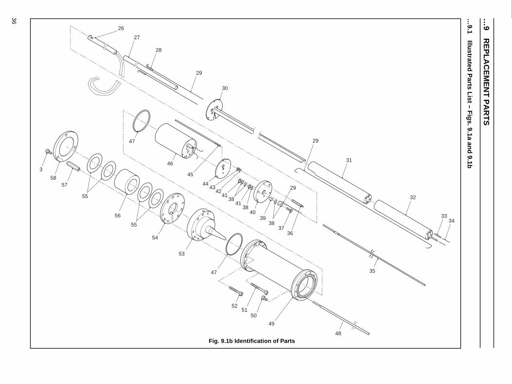
Fig. 9.1b Identification of Parts
…9
RE
PLA
CE
ME
NT
PA
RT
S
48
3334
32
31
27
28
29
30
26
29
3
5857
56
55
54
53
47
5150
49
37
4039
36
38
4243
44
38
29
4138
41
45
46
47
55
6035
52
…9.1
Illustrated Parts List – F
igs. 9.1a and 9.1b

37
9 REPLACEMENT PARTS…
Item
Des
crip
tion
......
......
......
......
......
......
...P
art N
o....
......
......
Qty
.
38M
4 pl
ain
was
her
......
......
......
......
......
...B
7298
......
......
......
.10
39C
onne
ctio
n pl
ate
spac
er...
......
......
.....
ZF
G2/
0129
......
.....
2
40C
eram
ic te
rmin
al p
late
......
......
......
.....
EX
FG
/010
8...
......
.1
41M
4 fu
ll nu
t....
......
......
......
......
......
......
...B
8690
......
......
......
.4
42M
3 pl
ain
was
her
......
......
......
......
......
...B
1113
8...
......
......
..3
43M
3 fu
ll nu
t....
......
......
......
......
......
......
...B
7067
......
......
......
.3
44H
eate
r m
ount
ing
plat
e...
......
......
......
...Z
FG
2/01
58...
......
..1
45H
eate
r su
ppor
t rod
s...
......
......
......
......
EX
FG
/011
8...
......
.3
46S
pare
s he
ater
ass
embl
y...
......
......
.....
EX
FG
/009
6...
......
.1
47O
-rin
g...
......
......
......
......
......
......
......
....0
0231
0038
......
.....
2
48Te
st g
as tu
be...
......
......
......
......
......
.....
EX
FG
/012
6...
......
.1
49E
Ex
d pr
obe
body
ass
embl
y...
......
.....
EX
FG
/009
0I...
......
.1
50M
4 x
16m
m s
ocke
t-he
ad s
crew
......
...B
7295
......
......
......
.6
51M
4 x
40m
m s
ocke
t-he
ad s
crew
......
...B
1070
9...
......
......
..3
52M
4 x
30m
m s
ocke
t-he
ad s
crew
......
...B
1071
4...
......
......
..6
53S
pare
s ce
ll as
sem
bly
......
......
......
......
.E
XF
G/0
088
......
....1
54E
Ex
d te
st g
as p
late
......
......
......
......
...E
XF
G/0
133I
......
....2
55F
ilter
gas
ket.
......
......
......
......
......
......
...00
3000
094
......
.....
4 (m
in.)
56S
pare
s ce
ram
ic fi
lter
kit.
......
......
......
...E
XF
G/0
087
......
....1
57F
ilter
spa
cer
......
......
......
......
......
......
...E
XF
G/0
135
......
....3
58F
ilter
end
pla
te...
......
......
......
......
......
..E
XF
G/0
134
......
....1
Item
Des
crip
tion
Par
t No.
Qty
.
26E
lect
rode
/ther
moc
oupl
e as
sem
bly.
....
see
Sec
tion
9.5
(ful
l rep
lace
men
t kit,
exc
ludi
ng. i
tem
27)
27C
eram
ic tu
be
1.64
ft (0
.5m
) P
robe
bod
y...
......
....R
MV
313
......
......
...1
3.28
ft (1
.0m
) P
robe
bod
y...
......
....R
MV
313
......
......
...3
6.56
ft (2
.0m
) P
robe
bod
y...
......
....R
MV
313
......
......
...7
28H
eate
r le
ad in
sula
tor
slee
ve...
......
......
EX
FG
/016
2...
......
.2
29H
eate
r/ce
ram
ic in
sula
tor
wire
......
......
.001
3510
06...
......
..A
s rq
d.
30C
entr
e tu
be a
ssem
bly
1.64
ft (0
.5m
) P
robe
bod
y...
......
....E
XF
G/0
080I
......
....1
3.28
ft (1
.0m
) P
robe
bod
y...
......
....E
XF
G/0
081I
......
....1
6.56
ft (2
.0m
) P
robe
bod
y...
......
....E
XF
G/0
082I
......
....1
31C
olum
n in
sula
tor
mac
hine
d...
......
......
.EX
FG
/010
7...
......
.1
32C
olum
n in
sula
tor
1.64
ft (0
.5m
) P
robe
bod
y...
......
....E
XF
G/0
106
......
....1
3.28
ft (1
.0m
) P
robe
bod
y...
......
....E
XF
G/0
106
......
....4
6.56
ft (2
.0m
) P
robe
bod
y...
......
....E
XF
G/0
106
......
....9
1.64
ft (0
.5m
) P
robe
bod
y on
lyS
hort
col
umn
insu
lato
r*...
......
......
EX
FG
/011
4...
......
.1
33H
eate
r co
nnec
tion
wire
sle
eve
......
.....
B42
04...
......
......
....A
s rq
d.
34H
eate
r co
nnec
tion
wire
......
......
......
....B
2404
......
......
......
.As
rqd.
35Tr
ip th
erm
ocou
ple
1.64
ft (0
.5m
) P
robe
bod
y...
......
....E
XF
G/0
170
......
....1
3.28
ft (1
.0m
) P
robe
bod
y...
......
....E
XF
G/0
171
......
....1
6.56
ft (2
.0m
) P
robe
bod
y...
......
....E
XF
G/0
172
......
....1
36H
eate
r m
ount
ing
spac
ers
EX
FG
/012
23
37M
4 x
25m
m h
exag
on-h
ead
scre
w...
...B
1072
7...
......
......
..2
* Ite
ms
not i
llust
rate
d
38
9 REPLACEMENT PARTS
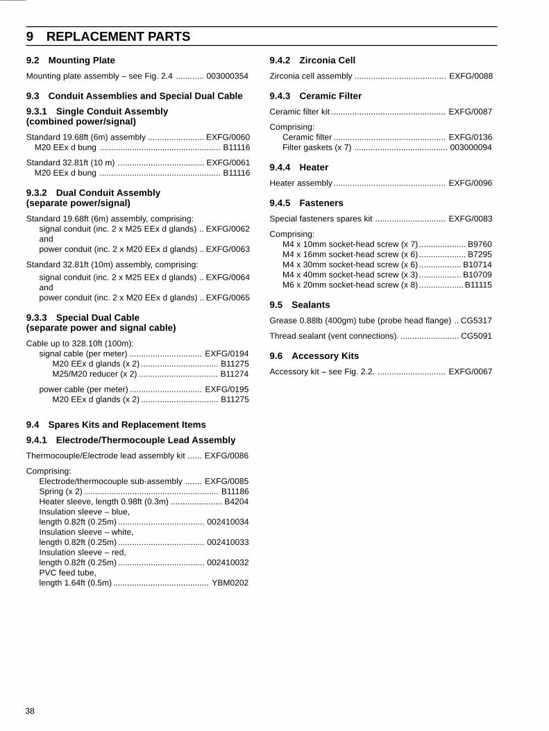
9.2 Mounting Plate
Mounting plate assembly – see Fig. 2.4 ............ 003000354
9.3 Conduit Assemblies and Special Dual Cable
9.3.1 Single Conduit Assembly(combined power/signal)
Standard 19.68ft (6m) assembly ........................ EXFG/0060M20 EEx d bung .................................................... B11116
Standard 32.81ft (10 m) ..................................... EXFG/0061M20 EEx d bung .................................................... B11116
9.3.2 Dual Conduit Assembly(separate power/signal)
Standard 19.68ft (6m) assembly, comprising:signal conduit (inc. 2 x M25 EEx d glands) .. EXFG/0062andpower conduit (inc. 2 x M20 EEx d glands) .. EXFG/0063
Standard 32.81ft (10m) assembly, comprising:
signal conduit (inc. 2 x M25 EEx d glands) .. EXFG/0064andpower conduit (inc. 2 x M20 EEx d glands) .. EXFG/0065
9.3.3 Special Dual Cable(separate power and signal cable)
Cable up to 328.10ft (100m):signal cable (per meter) ............................... EXFG/0194
M20 EEx d glands (x 2) ................................. B11275M25/M20 reducer (x 2) .................................. B11274
power cable (per meter) ............................... EXFG/0195M20 EEx d glands (x 2) ................................. B11275
9.4 Spares Kits and Replacement Items
9.4.1 Electrode/Thermocouple Lead Assembly
Thermocouple/Electrode lead assembly kit ...... EXFG/0086
Comprising:Electrode/thermocouple sub-assembly ....... EXFG/0085Spring (x 2) .......................................................... B11186Heater sleeve, length 0.98ft (0.3m) ...................... B4204Insulation sleeve – blue,length 0.82ft (0.25m) ..................................... 002410034Insulation sleeve – white,length 0.82ft (0.25m) ..................................... 002410033Insulation sleeve – red,length 0.82ft (0.25m) ..................................... 002410032PVC feed tube,length 1.64ft (0.5m) ......................................... YBM0202
9.4.2 Zirconia Cell
Zirconia cell assembly ....................................... EXFG/0088
9.4.3 Ceramic Filter
Ceramic filter kit ................................................. EXFG/0087
Comprising:Ceramic filter ................................................ EXFG/0136Filter gaskets (x 7) ........................................ 003000094
9.4.4 Heater
Heater assembly ................................................ EXFG/0096
9.4.5 Fasteners
Special fasteners spares kit .............................. EXFG/0083
Comprising:M4 x 10mm socket-head screw (x 7) .................... B9760M4 x 16mm socket-head screw (x 6) .................... B7295M4 x 30mm socket-head screw (x 6) .................. B10714M4 x 40mm socket-head screw (x 3) .................. B10709M6 x 20mm socket-head screw (x 8) ................... B11115
9.5 Sealants
Grease 0.88lb (400gm) tube (probe head flange) .. CG5317
Thread sealant (vent connections). ......................... CG5091
9.6 Accessory Kits
Accessory kit – see Fig. 2.2. ............................. EXFG/0067
39
APPENDIX
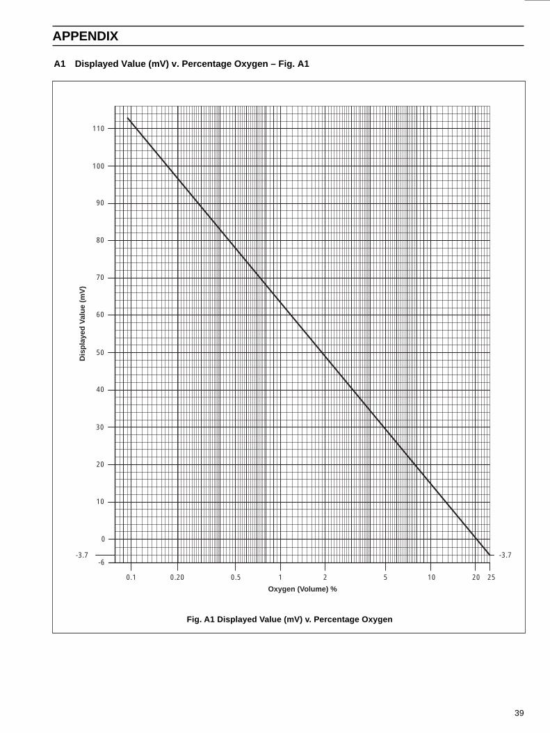
Fig. A1 Displayed Value (mV) v. Percentage Oxygen
A1 Displayed Value (mV) v. Percentage Oxygen – Fig. A1
Dis
play
ed V
alue
(m
V)
Oxygen (Volume) %
0.1 0.5 1 2 5 10 20 25
-3.7-6
-3.7
0
10
20
30
40
50
60
70
80
90
0.20
100
110

40
NOTES
CUSTOMER SUPPORT
Service, Support and Maintenance
ABB Process Analytics' commitment to quality doesn't end when we deliver our equipment.
We also provide, at the client's request: start-up services, maintenance services, training services, reconditioning, repair andreplacement parts services.
Training services are available for virtually every aspect of operating and maintaining ABB Process Analytics analyzers andsystems. Training may be arranged on-site or at any of our training centres.
Maintenance services are available on an unscheduled, as needed basis, or by way of long-term, scheduled maintenanceagreements.
Facilities
ABB Process Analytics' primary manufacturing and administrative facility is located in Lewisburg, West Virginia. We also operatesales and service centres in Houston, Texas; Baton Rouge, Louisiana; Sarnia, Ontario; UK; France; Italy; The Netherlands andSingapore. Training centres are located in Lewisburg, Houston and Europe.
For complete information and assistance with ABB Process Analytics analyzers, systems and services, contact any of ourfacilities for details of your nearest Service and Repair Centre.
United StatesABB Process Analytics843 N. Jefferson StreetLewisburg, WV 24901USAOffice: (304)647-4358FAX: (304)645-4236
CanadaABB Process Analytics1362 Lambton Mall RoadUnit#18Sarnia, Ontario N7S 5R6CANADAOffice: (519)541-0011FAX: (519)541-0012
United KingdomABB Process Analytics LtdHoward RoadEaton Socon, St. NeotsCambs. UK PE19 3EUOffice: 44-1480-404440FAX: 44-1480-405775
Middle EastABB ARESCONPO Box 2774Manama, BahrainOffice: 973-725377FAX: 973-725332
BeneluxABB Process Analytics BVPampuslaan 891382 JM WeespNetherlandsOffice: 31-2944-17291FAX: 31-2944-13656
FranceABB InstrumentationProcess Analytics Div6/8 Rue PeupliersBP 430-92004 NanterreCedex, FranceOffice: 33-1-4769-7280FAX: 33-1-4242-3995
Pacific RimABB Industry Pte. Ltd.No. 2 Ayer Rajah CrescentSingapore 0513Office: 65-776-5711FAX: 65-778-0222
ItalyABB Kent-Taylor SpAProcess Analytics DivisionValle Edison, 5020099 Sesto S. Giovanni - MIItalyOffice: 39-2-262321FAX: 39-2-26232902

The Company's policy is one of continuous product improvementand the right is reserved to modify the information containedherein without notice.
© January 1996 ABB Process Analytics Printed in U.K. IM/E
XF
GP
B–P
AIs
sue
2
ABB Process Analytics843 N. Jefferson StreetLewisburg, WV 24901USAOffice: (304)647-4358FAX: (304)645-4236