— REX640 Operation Manual - ABB
164
— RELION® PROTECTION AND CONTROL REX640 Operation Manual
-
Upload
khangminh22 -
Category
Documents
-
view
2 -
download
0
Transcript of — REX640 Operation Manual - ABB

—RELION® PROTECTION AND CONTROL
REX640Operation Manual


Document ID: 1MRS759118Issued: 2020-12-10
Revision: C
© Copyright 2020 ABB. All rights reserved

Copyright
This document and parts thereof must not be reproduced or copied without writtenpermission from ABB, and the contents thereof must not be imparted to a thirdparty, nor used for any unauthorized purpose.
The software or hardware described in this document is furnished under a licenseand may be used, copied, or disclosed only in accordance with the terms of suchlicense.
TrademarksABB and Relion are registered trademarks of the ABB Group. All other brand orproduct names mentioned in this document may be trademarks or registeredtrademarks of their respective holders.
Open Source SoftwareThis product contains open source software. For license information refer toproduct documentation at www.abb.com.
WarrantyPlease inquire about the terms of warranty from your nearest ABB representative.
www.abb.com/mediumvoltage

Disclaimer
The data, examples and diagrams in this manual are included solely for the conceptor product description and are not to be deemed as a statement of guaranteedproperties. All persons responsible for applying the equipment addressed in thismanual must satisfy themselves that each intended application is suitable andacceptable, including that any applicable safety or other operational requirementsare complied with. In particular, any risks in applications where a system failureand/or product failure would create a risk for harm to property or persons(including but not limited to personal injuries or death) shall be the soleresponsibility of the person or entity applying the equipment, and those soresponsible are hereby requested to ensure that all measures are taken to exclude ormitigate such risks.
This product has been designed to be connected and communicate data andinformation via a network interface which should be connected to a securenetwork. It is the sole responsibility of the person or entity responsible for networkadministration to ensure a secure connection to the network and to take thenecessary measures (such as, but not limited to, installation of firewalls, applicationof authentication measures, encryption of data, installation of anti virus programs,etc.) to protect the product and the network, its system and interface included,against any kind of security breaches, unauthorized access, interference, intrusion,leakage and/or theft of data or information. ABB is not liable for any such damagesand/or losses.
This document has been carefully checked by ABB but deviations cannot becompletely ruled out. In case any errors are detected, the reader is kindly requestedto notify the manufacturer. Other than under explicit contractual commitments, inno event shall ABB be responsible or liable for any loss or damage resulting fromthe use of this manual or the application of the equipment. In case of discrepanciesbetween the English and any other language version, the wording of the Englishversion shall prevail.

Conformity
This product complies with the directive of the Council of the EuropeanCommunities on the approximation of the laws of the Member States relating toelectromagnetic compatibility (EMC Directive 2014/30/EU) and concerningelectrical equipment for use within specified voltage limits (Low-voltage directive2014/35/EU). This conformity is the result of tests conducted by the third partytesting laboratory Intertek in accordance with the product standard EN 60255-26for the EMC directive, and with the product standards EN 60255-1 and EN60255-27 for the low voltage directive. The product is designed in accordance withthe international standards of the IEC 60255 series.

Table of contents
Section 1 Introduction.......................................................................5This manual........................................................................................ 5Intended audience.............................................................................. 5Product documentation.......................................................................6
Product documentation set............................................................6Document revision history............................................................. 6Related documentation..................................................................6
Symbols and conventions...................................................................7Symbols.........................................................................................7Document conventions..................................................................7Functions, codes and symbols...................................................... 8
Section 2 Environmental aspects...................................................19Sustainable development................................................................. 19Disposal of a device......................................................................... 19
Section 3 REX640 overview...........................................................21Overview...........................................................................................21Relay hardware................................................................................ 21Local HMI......................................................................................... 22Switchgear HMI................................................................................ 26HMI communication ports.................................................................30Web HMI...........................................................................................31
Command buttons....................................................................... 32User authorization............................................................................ 34Station communication..................................................................... 35PCM600............................................................................................36
Connectivity packages.................................................................36PCM600 and relay connectivity package version........................37
Modification Sales............................................................................ 37
Section 4 Using HMI.......................................................................39Logging in......................................................................................... 39
Managing forgotten password..................................................... 40Logging out ......................................................................................41Selecting local or remote use........................................................... 42Identifying device..............................................................................43Changing backlight brightness and timeout......................................43Changing setting visibility................................................................. 44Monitoring relay status..................................................................... 45
Table of contents
REX640 1Operation Manual

Switchgear HMI status indications...............................................45Changing language.......................................................................... 46Alarms.............................................................................................. 46
Viewing alarm list.........................................................................46Acknowledging alarms.................................................................47
Measurements and phasor diagrams............................................... 48Viewing measurements............................................................... 48Viewing phasor diagrams............................................................ 49
Showing parameters.........................................................................50Editing values................................................................................... 50Committing settings.......................................................................... 51Clearing and acknowledging............................................................ 53Accessing disturbance records.........................................................53Viewing fault records........................................................................ 54Selecting USB actions...................................................................... 55Using local HMI help.........................................................................56Changing setting group.................................................................... 57Controlling........................................................................................ 58Bookmarking pages..........................................................................59
Section 5 Using Web HMI.............................................................. 61Connecting to Web HMI................................................................... 61
Logging in....................................................................................62Logging out..................................................................................64
Navigating in menus......................................................................... 64Identifying device..............................................................................64Viewing dashboard........................................................................... 65Viewing self-supervision................................................................... 65Changing language.......................................................................... 65Alarms.............................................................................................. 66
Viewing alarm list.........................................................................66Acknowledging alarms.................................................................68
Measurements and phasor diagrams............................................... 68Viewing measurements............................................................... 68Viewing phasor diagrams............................................................ 69
Viewing monitoring........................................................................... 72Viewing single-line diagram..............................................................72Showing parameters.........................................................................73Editing values................................................................................... 75Committing settings.......................................................................... 76Clearing and acknowledging............................................................ 78Accessing event view....................................................................... 79Accessing disturbance record view.................................................. 81
Saving disturbance records.........................................................81
Table of contents
2 REX640Operation Manual

Triggering disturbance recorder manually...................................82Deleting disturbance records.......................................................82
Viewing fault records........................................................................ 83Exporting load profile records...........................................................84Importing and exporting of settings.................................................. 84
Exporting settings........................................................................85Importing settings........................................................................ 85
Exporting report summary................................................................ 87Using Web HMI help.........................................................................88
Section 6 Troubleshooting..............................................................89Fault tracing......................................................................................89
Identifying hardware errors..........................................................89Identifying runtime errors.............................................................89Identifying communication errors.................................................89
Checking communication link operation.................................89Checking time synchronization...............................................90
Reading of internal log files......................................................... 90Reading internal log files via HMI’s USB port.........................90Reading internal log files from Web HMI................................90
Checking local HMI connectivity..................................................91Self-supervision................................................................................ 91
Internal faults...............................................................................92Warnings..................................................................................... 97Power supply module Ready LED and HMI Home button LED...99
Correction procedures.................................................................... 100Creating relay backup in HMI.................................................... 100Rebooting the software..............................................................101Restoring factory settings..........................................................102Restoring relay backup from local HMI .....................................102Restoring relay backup from switchgear HMI ...........................106Setting passwords..................................................................... 106Identifying relay application problems ...................................... 106
Inspecting wiring...................................................................107Sample data interruptions.................................................... 107
Section 7 Commissioning.............................................................109Commissioning checklist................................................................ 109Checking installation.......................................................................109
Checking power supply............................................................. 109Checking CT circuits..................................................................110Checking VT circuits..................................................................111Checking binary input and output circuits..................................111
Checking binary input circuits...............................................111
Table of contents
REX640 3Operation Manual
Checking binary output circuits............................................ 111Authorizations.................................................................................112
User authorization..................................................................... 112Setting protection relay and communication...................................113
Setting the communication between protection relays andPCM600.....................................................................................113
Communication between PCM600 and protection relay...... 114Communication settings............................................................ 115
Ethernet ports.......................................................................115Protocol control.................................................................... 117Protocol write access rights..................................................118Physical locations of the serial channels..............................119Assigning of a serial communication protocol to a COMserial port..............................................................................121Serial link diagnostics and monitoring.................................. 121Defining Ethernet port settings............................................. 122Defining serial port settings.................................................. 123Setting communication protocol parameters........................ 123RS-485 bias and termination settings.................................. 123
Connecting and setting HMI...................................................... 124Connecting local HMI directly to relay.................................. 125Connecting local HMI to a relay through station network..... 126Connecting switchgear HMI to a relay through stationnetwork.................................................................................130Pairing HMI with relay.......................................................... 134Setting system time and time synchronization..................... 137
Testing of protection relay operation.............................................. 138Selecting IED test mode ...........................................................138Testing and commissioning support on local HMI ....................139
Testing I/O interface............................................................. 140Testing functions.................................................................. 143Checking GOOSE data........................................................ 144Checking SMV data..............................................................146
Selecting internal fault test ....................................................... 147Selecting IED blocked or IED test and blocked mode...............147
ABB Product Data Registration...................................................... 148
Section 8 Glossary....................................................................... 151
Table of contents
4 REX640Operation Manual

Section 1 Introduction
1.1 This manual
The operation manual contains instructions on how to operate the protection relayonce it has been commissioned. The manual provides instructions for monitoring,controlling and setting the relay. The manual also describes how to identifydisturbances and how to view calculated and measured power grid data todetermine the cause of a fault.
1.2 Intended audience
This manual addresses the operator who operates the protection relay frequently.
The operator must be trained in and have a basic knowledge of how to operateprotection equipment. The manual contains terms and expressions commonly usedto describe this kind of equipment.
1MRS759118 C Section 1Introduction
REX640 5Operation Manual
1.3 Product documentation
1.3.1 Product documentation set
Plan
ning
&
purc
hase
Engi
neer
ing
Inst
alla
tion
Com
mis
sion
ing
Ope
ratio
n
Mai
nten
ance
Dec
omm
issi
onin
g,
dein
stal
latio
n &
disp
osal
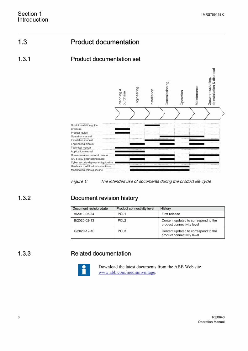
Quick installation guideBrochureProduct guideOperation manualInstallation manualEngineering manualTechnical manualApplication manualCommunication protocol manualIEC 61850 engineering guideCyber security deployment guidelineHardware modification instructionsModification sales guidelineGUID-65F8531E-8455-4F6C-BEFE-86B0B518D4E6 V2 EN-US
Figure 1: The intended use of documents during the product life cycle
1.3.2 Document revision historyDocument revision/date Product connectivity level HistoryA/2019-05-24 PCL1 First release
B/2020-02-13 PCL2 Content updated to correspond to theproduct connectivity level
C/2020-12-10 PCL3 Content updated to correspond to theproduct connectivity level
1.3.3 Related documentation
Download the latest documents from the ABB Web sitewww.abb.com/mediumvoltage.
Section 1 1MRS759118 CIntroduction
6 REX640Operation Manual

1.4 Symbols and conventions
1.4.1 Symbols
The electrical warning icon indicates the presence of a hazardwhich could result in electrical shock.
The warning icon indicates the presence of a hazard which couldresult in personal injury.
The caution icon indicates important information or warning relatedto the concept discussed in the text. It might indicate the presenceof a hazard which could result in corruption of software or damageto equipment or property.
The information icon alerts the reader of important facts andconditions.
The tip icon indicates advice on, for example, how to design yourproject or how to use a certain function.
Although warning hazards are related to personal injury, it is necessary tounderstand that under certain operational conditions, operation of damagedequipment may result in degraded process performance leading to personal injuryor death. Therefore, comply fully with all warning and caution notices.
1.4.2 Document conventions
A particular convention may not be used in this manual.
• Abbreviations and acronyms are spelled out in the glossary. The glossary alsocontains definitions of important terms.
• Menu paths are presented in bold.Select Main menu/Settings.
• WHMI menu names are presented in bold.Click Information in the WHMI menu structure.
• Parameter names are shown in italics.The function can be enabled and disabled with the Operation setting.
• Parameter values are indicated with quotation marks.The corresponding parameter values are "On" and "Off".
1MRS759118 C Section 1Introduction
REX640 7Operation Manual

• Input/output messages and monitored data names are shown in Courier font.When the function starts, the START output is set to TRUE.
• Values of quantities are expressed with a number and an SI unit. Thecorresponding imperial units may be given in parentheses.
• This document assumes that the parameter setting visibility is "Advanced".
1.4.3 Functions, codes and symbolsTable 1: Functions included in the relay
Function IEC 61850 IEC 60617 ANSIProtection
Distance protection DSTPDIS Z< 21P,21N
Local accelerationlogic
DSTPLAL LAL 21LAL
Schemecommunication logic
DSOCPSCH CL 85 21SCHLGC
Current reversal andweak-end infeed logic
CRWPSCH CLCRW 85 21CREV,WEI
Communication logicfor residualovercurrent
RESCPSCH CLN 85 67G/N SCHLGC
Current reversal andweak-end infeed logicfor residualovercurrent
RCRWPSCH CLCRWN 85 67G/N CREV,WEI
Line differentialprotection with inzonepower transformer
LNPLDF 3Id/I> 87L
Binary signal transfer BSTGAPC BST BST
Switch-onto-faultprotection
CVPSOF CVPSOF SOTF
Three-phase non-directional overcurrentprotection, low stage
PHLPTOC 3I> 51P-1
Three-phase non-directional overcurrentprotection, high stage
PHHPTOC 3I>> 51P-2
Three-phase non-directional overcurrentprotection,instantaneous stage
PHIPTOC 3I>>> 50P
Three-phasedirectional overcurrentprotection, low stage
DPHLPDOC 3I> -> 67P/51P-1
Three-phasedirectional overcurrentprotection, high stage
DPHHPDOC 3I>> -> 67P/51P-2
Non-directional earth-fault protection, lowstage
EFLPTOC Io> 51G/51N-1
Table continues on next page
Section 1 1MRS759118 CIntroduction
8 REX640Operation Manual

Function IEC 61850 IEC 60617 ANSINon-directional earth-fault protection, highstage
EFHPTOC Io>> 51G/51N-2
Non-directional earth-fault protection,instantaneous stage
EFIPTOC Io>>> 50G/50N
Directional earth-faultprotection, low stage
DEFLPDEF Io> -> 67G/N-1 51G/N-1
Directional earth-faultprotection, high stage
DEFHPDEF Io>> -> 67G/N-1 51G/N-2
Three-phase powerdirectional element
DPSRDIR I1 -> 67P-TC
Neutral powerdirectional element
DNZSRDIR I2 ->, Io -> 67N-TC
Admittance-basedearth-fault protection
EFPADM Yo> -> 21NY
Multifrequencyadmittance-basedearth-fault protection
MFADPSDE Io> -> Y 67NYH
Wattmetric-basedearth-fault protection
WPWDE Po> -> 32N
Transient/intermittentearth-fault protection
INTRPTEF Io> -> IEF 67NTEF/NIEF
Harmonics-basedearth-fault protection
HAEFPTOC Io>HA 51NH
Negative-sequenceovercurrent protection
NSPTOC I2>M 46M
Phase discontinuityprotection
PDNSPTOC I2/I1> 46PD
Residual overvoltageprotection
ROVPTOV Uo> 59G/59N
Three-phaseundervoltageprotection
PHPTUV 3U< 27
Three-phaseovervoltage variationprotection
PHVPTOV 3Urms> 59.S1
Three-phaseovervoltage protection
PHPTOV 3U> 59
Positive-sequenceovervoltage protection
PSPTOV U1> 59PS
Positive-sequenceundervoltageprotection
PSPTUV U1< 27PS
Negative-sequenceovervoltage protection
NSPTOV U2> 59NS
Frequency protection FRPFRQ f>/f<,df/dt 81
Three-phase voltage-dependent overcurrentprotection
PHPVOC 3I(U)> 51V
Table continues on next page
1MRS759118 C Section 1Introduction
REX640 9Operation Manual

Function IEC 61850 IEC 60617 ANSIOverexcitationprotection
OEPVPH U/f> 24
Three-phase thermalprotection for feeders,cables and distributiontransformers
T1PTTR 3Ith>F 49F
Three-phase thermaloverload protection,two time constants
T2PTTR 3Ith>T/G/C 49T/G/C
Three-phase overloadprotection for shuntcapacitor banks
COLPTOC 3I> 3I< 51,37,86C
Current unbalanceprotection for shuntcapacitor banks
CUBPTOC dI>C 60N
Three-phase currentunbalance protectionfor shunt capacitorbanks
HCUBPTOC 3dI>C 60P
Shunt capacitor bankswitching resonanceprotection, currentbased
SRCPTOC TD> 55ITHD
Compensated neutralunbalance voltageprotection
CNUPTOV CNU> 59NU
Directional negative-sequence overcurrentprotection
DNSPDOC I2> -> 67Q
Low-voltage ride-through protection
LVRTPTUV UU 27RT
Voltage vector shiftprotection
VVSPPAM VS 78VS
Directional reactivepower undervoltageprotection
DQPTUV Q> -> ,3U< 32Q,27
Reverse power/directional overpowerprotection
DOPPDPR P>/Q> 32R/32O
Underpower protection DUPPDPR P< 32U
Three-phaseunderimpedanceprotection
UZPDIS ZZ 21G
Three-phaseunderexcitationprotection
UEXPDIS X< 40
Third harmonic-basedstator earth-faultprotection
H3EFPSEF dUo>/Uo3H 64TN
Rotor earth-faultprotection (injectionmethod)
MREFPTOC Io>R 64R
Table continues on next page
Section 1 1MRS759118 CIntroduction
10 REX640Operation Manual

Function IEC 61850 IEC 60617 ANSIHigh-impedance orflux-balance baseddifferential protection
MHZPDIF 3dIHi>M 87HIM
Out-of-step protectionwith double blinders
OOSRPSB OOS 78PS
Negative-sequenceovercurrent protectionfor machines
MNSPTOC I2>M 46M
Loss of phase,undercurrent
PHPTUC 3I< 37
Loss of loadsupervision
LOFLPTUC 3I< 37
Motor load jamprotection
JAMPTOC Ist> 50TDJAM
Motor start-upsupervision
STTPMSU Is2t n< 49,66,48,50TDLR
Motor start counter MSCPMRI n< 66
Phase reversalprotection
PREVPTOC I2>> 46R
Thermal overloadprotection for motors
MPTTR 3Ith>M 49M
Stabilized andinstantaneousdifferential protectionfor machines
MPDIF 3dl>M/G 87M/87G
Underpower factorprotection
MPUPF PF< 55U
Stabilized andinstantaneousdifferential protectionfor two- or three-winding transformers
TR3PTDF 3dI>3W 87T3
Stabilized andinstantaneousdifferential protectionfor two-windingtransformers
TR2PTDF 3dI>T 87T
Numerical stabilizedlow-impedancerestricted earth-faultprotection
LREFPNDF dIoLo> 87NLI
High-impedancebased restricted earth-fault protection
HREFPDIF dIoHi> 87NHI
High-impedancedifferential protectionfor phase A
HIAPDIF dHi_A> 87_A
High-impedancedifferential protectionfor phase B
HIBPDIF dHi_B> 87_B
High-impedancedifferential protectionfor phase C
HICPDIF dHi_C> 87_C
Table continues on next page
1MRS759118 C Section 1Introduction
REX640 11Operation Manual

Function IEC 61850 IEC 60617 ANSICircuit breaker failureprotection
CCBRBRF 3I>/Io>BF 50BF
Three-phase inrushdetector
INRPHAR 3I2f> 68HB
Master trip TRPPTRC Master Trip 94/86
Arc protection ARCSARC ARC AFD
High-impedance faultdetection
PHIZ HIF HIZ
Fault locator SCEFRFLO FLOC FLOC
Load-shedding andrestoration
LSHDPFRQ UFLS/R 81LSH
Multipurposeprotection
MAPGAPC MAP MAP
Accidentalenergization protection
GAEPVOC U<,I> 27/50
Control
Circuit-breaker control CBXCBR I <-> O CB 52
Three-statedisconnector control
P3SXSWI I<->O P3S 29DS/GS
Disconnector control DCXSWI I <-> O DCC 29DS
Earthing switch control ESXSWI I <-> O ESC 29GS
Three-statedisconnector positionindication
P3SSXSWI I<->O P3SS 29DS/GS
Disconnector positionindication
DCSXSWI I <-> O DC 29DS
Earthing switchposition indication
ESSXSWI I <-> O ES 29GS
Emergency start-up ESMGAPC ESTART EST,62
Autoreclosing DARREC O -> I 79
Autosynchronizer forgenerator breaker
ASGCSYN AUTOSYNCG 25AUTOSYNCG
Autosynchronizer fornetwork breaker
ASNSCSYN AUTOSYNCBT/T 25AUTOSYNCBT/T
Autosynchronizer co-ordinator
ASCGAPC AUTOSYNC 25AUTOSYNC
Synchronism andenergizing check
SECRSYN SYNC 25
Tap changer controlwith voltage regulator
OL5ATCC COLTC 90V
Transformer datacombiner
OLGAPC OLGAPC OLGAPC
Petersen coil controller PASANCR ANCR 90
Condition monitoring and supervision
Circuit-breakercondition monitoring
SSCBR CBCM 52CM
Table continues on next page
Section 1 1MRS759118 CIntroduction
12 REX640Operation Manual

Function IEC 61850 IEC 60617 ANSIHot-spot and insulationageing rate monitoringfor transformers
HSARSPTR 3Ihp>T 26/49HS
Trip circuit supervision TCSSCBR TCS TCM
Current circuitsupervision
CCSPVC MCS 3I CCM
Current circuitsupervision fortransformers
CTSRCTF MCS 3I,I2 CCM 3I,I2
Current transformersupervision for high-impedance protectionscheme for phase A
HZCCASPVC MCS I_A CCM_A
Current transformersupervision for high-impedance protectionscheme for phase B
HZCCBSPVC MCS I_B CCM_B
Current transformersupervision for high-impedance protectionscheme for phase C
HZCCCSPVC MCS I_C CCM_C
Fuse failuresupervision
SEQSPVC FUSEF VCM, 60
Protectioncommunicationsupervision
PCSITPC PCS PCS
Runtime counter formachines and devices
MDSOPT OPTS OPTM
Three-phase remanentundervoltagesupervision
MSVPR 3U<R 27R
Measurement
Three-phase currentmeasurement
CMMXU 3I IA, IB, IC
Sequence currentmeasurement
CSMSQI I1, I2, I0 I1, I2, I0
Residual currentmeasurement
RESCMMXU Io IG
Three-phase voltagemeasurement
VMMXU 3U VA, VB, VC
Single-phase voltagemeasurement
VAMMXU U_A V_A
Residual voltagemeasurement
RESVMMXU Uo VG/VN
Sequence voltagemeasurement
VSMSQI U1, U2, U0 V1, V2, V0
Three-phase powerand energymeasurement
PEMMXU P, E P, E
Load profile recorder LDPRLRC LOADPROF LOADPROF
Table continues on next page
1MRS759118 C Section 1Introduction
REX640 13Operation Manual

Function IEC 61850 IEC 60617 ANSIFrequencymeasurement
FMMXU f f
Tap changer positionindication
TPOSYLTC TPOSM 84T
Power quality
Current total demand,harmonic distortion,DC component (TDD,THD, DC) andindividual harmonics
CHMHAI PQM3IH PQM ITHD,IDC
Voltage total harmonicdistortion, DCcomponent (THD, DC)and individualharmonics
VHMHAI PQM3VH PQM VTHD,VDC
Voltage variation PHQVVR PQMU PQMV SWE,SAG,INT
Voltage unbalance VSQVUB PQUUB PQMV UB
Traditional LED indication
LED indication control LEDPTRC LEDPTRC LEDPTRC
Individual virtual LEDcontrol
LED LED LED
Logging functions
Disturbance recorder(common functionality)
RDRE DR DFR
Disturbance recorder,analog channels 1...12
A1RADR A1RADR A1RADR
Disturbance recorder,analog channels13...24
A2RADR A2RADR A2RADR
Disturbance recorder,binary channels 1...32
B1RBDR B1RBDR B1RBDR
Disturbance recorder,binary channels33...64
B2RBDR B2RBDR B2RBDR
Fault recorder FLTRFRC FAULTREC FR
Other functionality
Parameter settinggroups
PROTECTION PROTECTION PROTECTION
Time mastersupervision
GNRLLTMS GNRLLTMS GNRLLTMS
Serial port supervision SERLCCH SERLCCH SERLCCH
IEC 61850-1 MMS MMSLPRT MMSLPRT MMSLPRT
IEC 61850-1 GOOSE GSELPRT GSELPRT GSELPRT
IEC 60870-5-103protocol
I3CLPRT I3CLPRT I3CLPRT
IEC 60870-5-104protocol
I5CLPRT I5CLPRT I5CLPRT
DNP3 protocol DNPLPRT DNPLPRT DNPLPRT
Table continues on next page
Section 1 1MRS759118 CIntroduction
14 REX640Operation Manual

Function IEC 61850 IEC 60617 ANSIModbus protocol MBSLPRT MBSLPRT MBSLPRT
OR gate with twoinputs
OR OR OR
OR gate with six inputs OR6 OR6 OR6
OR gate with twentyinputs
OR20 OR20 OR20
AND gate with twoinputs
AND AND AND
AND gate with sixinputs
AND6 AND6 AND6
AND gate with twentyinputs
AND20 AND20 AND20
XOR gate with twoinputs
XOR XOR XOR
NOT gate NOT NOT NOT
Real maximum valueselector
MAX3R MAX3R MAX3R
Real minimum valueselector
MIN3R MIN3R MIN3R
Rising edge detector R_TRIG R_TRIG R_TRIG
Falling edge detector F_TRIG F_TRIG F_TRIG
Real switch selector SWITCHR SWITCHR SWITCHR
Integer 32-bit switchselector
SWITCHI32 SWITCHI32 SWITCHI32
SR flip-flop, volatile SR SR SR
RS flip-flop, volatile RS RS RS
Minimum pulse timer,two channels
TPGAPC TP 62TP
Minimum pulse timersecond resolution, twochannels
TPSGAPC TPS 62TPS
Minimum pulse timerminutes resolution, twochannels
TPMGAPC TPM 62TPM
Pulse counter forenergy measurement
PCGAPC PCGAPC PCGAPC
Pulse timer, eightchannels
PTGAPC PT 62PT
Time delay off, eightchannels
TOFGAPC TOF 62TOF
Time delay on, eightchannels
TONGAPC TON 62TON
Daily timer DTMGAPC DTM DTM
Calendar function CALGAPC CAL CAL
SR flip-flop, eightchannels, nonvolatile
SRGAPC SR SR
Table continues on next page
1MRS759118 C Section 1Introduction
REX640 15Operation Manual
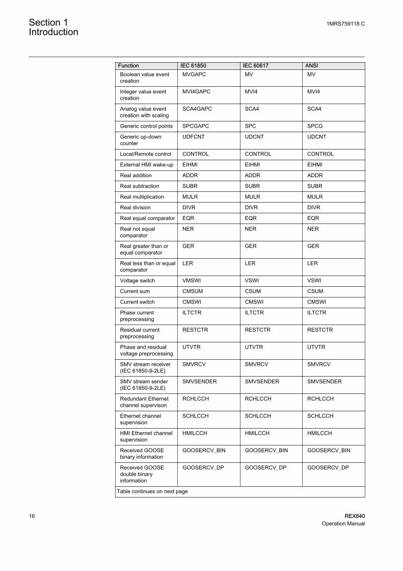
Function IEC 61850 IEC 60617 ANSIBoolean value eventcreation
MVGAPC MV MV
Integer value eventcreation
MVI4GAPC MVI4 MVI4
Analog value eventcreation with scaling
SCA4GAPC SCA4 SCA4
Generic control points SPCGAPC SPC SPCG
Generic up-downcounter
UDFCNT UDCNT UDCNT
Local/Remote control CONTROL CONTROL CONTROL
External HMI wake-up EIHMI EIHMI EIHMI
Real addition ADDR ADDR ADDR
Real subtraction SUBR SUBR SUBR
Real multiplication MULR MULR MULR
Real division DIVR DIVR DIVR
Real equal comparator EQR EQR EQR
Real not equalcomparator
NER NER NER
Real greater than orequal comparator
GER GER GER
Real less than or equalcomparator
LER LER LER
Voltage switch VMSWI VSWI VSWI
Current sum CMSUM CSUM CSUM
Current switch CMSWI CMSWI CMSWI
Phase currentpreprocessing
ILTCTR ILTCTR ILTCTR
Residual currentpreprocessing
RESTCTR RESTCTR RESTCTR
Phase and residualvoltage preprocessing
UTVTR UTVTR UTVTR
SMV stream receiver(IEC 61850-9-2LE)
SMVRCV SMVRCV SMVRCV
SMV stream sender(IEC 61850-9-2LE)
SMVSENDER SMVSENDER SMVSENDER
Redundant Ethernetchannel supervison
RCHLCCH RCHLCCH RCHLCCH
Ethernet channelsupervision
SCHLCCH SCHLCCH SCHLCCH
HMI Ethernet channelsupervision
HMILCCH HMILCCH HMILCCH
Received GOOSEbinary information
GOOSERCV_BIN GOOSERCV_BIN GOOSERCV_BIN
Received GOOSEdouble binaryinformation
GOOSERCV_DP GOOSERCV_DP GOOSERCV_DP
Table continues on next page
Section 1 1MRS759118 CIntroduction
16 REX640Operation Manual
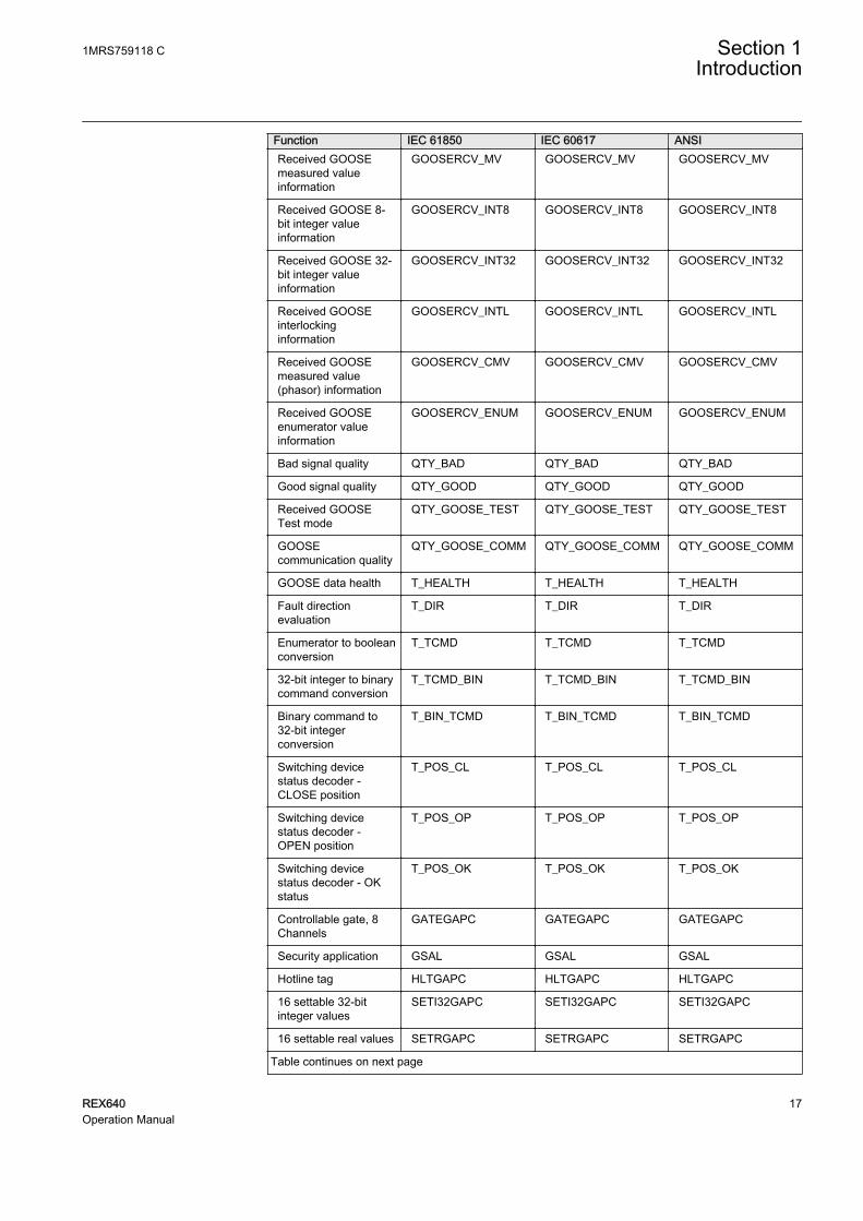
Function IEC 61850 IEC 60617 ANSIReceived GOOSEmeasured valueinformation
GOOSERCV_MV GOOSERCV_MV GOOSERCV_MV
Received GOOSE 8-bit integer valueinformation
GOOSERCV_INT8 GOOSERCV_INT8 GOOSERCV_INT8
Received GOOSE 32-bit integer valueinformation
GOOSERCV_INT32 GOOSERCV_INT32 GOOSERCV_INT32
Received GOOSEinterlockinginformation
GOOSERCV_INTL GOOSERCV_INTL GOOSERCV_INTL
Received GOOSEmeasured value(phasor) information
GOOSERCV_CMV GOOSERCV_CMV GOOSERCV_CMV
Received GOOSEenumerator valueinformation
GOOSERCV_ENUM GOOSERCV_ENUM GOOSERCV_ENUM
Bad signal quality QTY_BAD QTY_BAD QTY_BAD
Good signal quality QTY_GOOD QTY_GOOD QTY_GOOD
Received GOOSETest mode
QTY_GOOSE_TEST QTY_GOOSE_TEST QTY_GOOSE_TEST
GOOSEcommunication quality
QTY_GOOSE_COMM QTY_GOOSE_COMM QTY_GOOSE_COMM
GOOSE data health T_HEALTH T_HEALTH T_HEALTH
Fault directionevaluation
T_DIR T_DIR T_DIR
Enumerator to booleanconversion
T_TCMD T_TCMD T_TCMD
32-bit integer to binarycommand conversion
T_TCMD_BIN T_TCMD_BIN T_TCMD_BIN
Binary command to32-bit integerconversion
T_BIN_TCMD T_BIN_TCMD T_BIN_TCMD
Switching devicestatus decoder -CLOSE position
T_POS_CL T_POS_CL T_POS_CL
Switching devicestatus decoder -OPEN position
T_POS_OP T_POS_OP T_POS_OP
Switching devicestatus decoder - OKstatus
T_POS_OK T_POS_OK T_POS_OK
Controllable gate, 8Channels
GATEGAPC GATEGAPC GATEGAPC
Security application GSAL GSAL GSAL
Hotline tag HLTGAPC HLTGAPC HLTGAPC
16 settable 32-bitinteger values
SETI32GAPC SETI32GAPC SETI32GAPC
16 settable real values SETRGAPC SETRGAPC SETRGAPC
Table continues on next page
1MRS759118 C Section 1Introduction
REX640 17Operation Manual

Function IEC 61850 IEC 60617 ANSIBoolean to integer 32-bit conversion
T_B16_TO_I32 T_B16_TO_I32 T_B16_TO_I32
Integer 32-bit toboolean conversion
T_I32_TO_B16 T_I32_TO_B16 T_I32_TO_B16
Integer 32-bit to realconversion
T_I32_TO_R T_I32_TO_R T_I32_TO_R
Real to integer 8-bitconversion
T_R_TO_I8 T_R_TO_I8 T_R_TO_I8
Real to integer 32-bitconversion
T_R_TO_I32 T_R_TO_I32 T_R_TO_I32
Constant FALSE FALSE FALSE FALSE
Constant TRUE TRUE TRUE TRUE
Section 1 1MRS759118 CIntroduction
18 REX640Operation Manual

Section 2 Environmental aspects
2.1 Sustainable development
Sustainability has been taken into account from the beginning of the product designincluding the pro-environmental manufacturing process, long life time, operationreliability and disposing of the device.
The choice of materials and suppliers has been made according to the EU RoHSdirective (2011/65/EU). This directive limits the use of hazardous substances.
Operational reliability and long life time have been ensured with extensive testingduring the design and manufacturing processes. Moreover, long life time issupported by maintenance and repair services as well as by the availability of spareparts.
Design and manufacturing have been done under a certified environmental system.The effectiveness of the environmental system is constantly evaluated by anexternal auditing body. We follow environmental rules and regulationssystematically to evaluate their effect on our products and processes.
2.2 Disposal of a device
Definitions and regulations of hazardous materials are country-specific and changewhen the knowledge of materials increases. The materials used in this product aretypical for electric and electronic devices.
All parts used in this product are recyclable. When disposing of a device or itsparts, contact a local waste handler who is authorized and specialized in disposingof electronic waste. These handlers can sort the material by using dedicated sortingprocesses and dispose of the product according to the local requirements.
1MRS759118 C Section 2Environmental aspects
REX640 19Operation Manual

Table 2: Materials of the protection relay parts
Protection relay Parts MaterialCase Casted enclosure Aluminium
Metallic plates Aluminium
Screws, bushes Steel
Plastic parts PC1), LCP2)
LHMI Various
Package Box Cardboard
Attached material Manuals Paper
1) Polycarbonate2) Liquid crystal polymer
Section 2 1MRS759118 CEnvironmental aspects
20 REX640Operation Manual

Section 3 REX640 overview
3.1 Overview
REX640 is a powerful all-in-one protection and control relay for use in advancedpower distribution and generation applications with unmatched flexibility availableduring the complete life cycle of the device – from ordering of the device, throughtesting and commissioning to upgrading the functionality of the modular softwareand hardware as application requirements change.
The modular design of both hardware and software elements facilitates thecoverage of any comprehensive protection application requirement that may ariseduring the complete life cycle of the relay and substation.
REX640 makes modification and upgrading easy and pushes the limits of what canbe achieved with a single device.
3.2 Relay hardware
The relay includes a Ready LED on the power supply module that indicates therelay's status. In normal situations, the Ready LED has a steady green light. Anyother situation that requires the operator’s attention is indicated with a flashinglight.
1MRS759118 C Section 3REX640 overview
REX640 21Operation Manual

1
2
GUID-5D4C7B10-17CA-4F59-B9E0-8024CB82CDE8 V1 EN-US
Figure 2: Hardware module slot overview of the REX640 relay
1 Slot markings in enclosure (top and bottom)
2 Ready LED
The relay has a nonvolatile memory which does not need any periodicalmaintenance. The nonvolatile memory stores all events, recordings and logs to amemory which retains data if the relay loses its auxiliary supply.
3.3 Local HMI
The LHMI is used for setting, monitoring and controlling the protection relay andthe related process. It comprises a 7-inch color screen with capacitive touchsensing and a Home button at the bottom of the LHMI.
Section 3 1MRS759118 CREX640 overview
22 REX640Operation Manual

The LHMI is an accessory for the relay which is fully operationaleven without the LHMI.
GUID-093E5A0B-C7B9-4BEC-8EA6-42EF75793B4F V1 EN-US
Figure 3: Example of a local HMI page
The LHMI presents pages in two categories.
• Operator pages are typically required as a part of an operator’s normalactivities, such as a single-line diagram, controls, measurements, events oralarms
• Engineer pages are specifically designed pages supporting relayparametrization, troubleshooting, testing and commissioning activities
The Operator pages can be scrolled either by pressing the Home button or byswiping the actual pages. The Engineer pages are accessible by tapping the menubutton in the menu bar on the top of the LHMI display.
The Home button indicates the relay’s status at a glance. In normal situations, theHome button shows a steady green light. Any other situation that requires theoperator’s attention is indicated with a flashing light, a red light or a combinationof these.
1MRS759118 C Section 3REX640 overview
REX640 23Operation Manual

Table 3: Power supply module Ready LED and local HMI Home button LED
State Power supply moduleReady LED
LHMI Home button Alarm acknowledged
Relay under normaloperation and LHMIconnected
Steady green Steady green N/A
Relay’s IRF activated,but communicates withLHMI
High frequencyblinking green1)
High frequencyblinking red1)
N/A
Communication lostbetween Relay andLHMI, but no IRF
Steady green High frequencyblinking green1)
N/A
LHMI not runningnormally or in start-upinitialization phase
Steady green High frequencyblinking green1)
N/A
Process related alarmactive
Steady green Low frequency blinkingred2)
No
Process related alarmactive
Steady green Steady red Yes
Process related alarmhas been activeearlier, but is not anymore active.
Steady green Low frequency blinkingred2)
No
Process related alarmhas been activeearlier, but is not anymore active.
Steady green Steady green Yes
Relay set to TestMode
Low frequency blinkinggreen2)
Low frequency blinkinggreen2)
No
1) High frequency = 3 Hz2) Low frequency = 1 Hz
The Operator pages can be used as such or customized according to the project’srequirements using Graphical Display Editor in PCM600. The Engineer pages arefixed and cannot be customized.
Section 3 1MRS759118 CREX640 overview
24 REX640Operation Manual

2
1 2 3 4 5 6 7 8 9 10
11 8GUID-01F7FC3E-980D-4670-B195-F8D6D712EF58 V2 EN-US
Figure 4: Menu bar elements
1 Bay name for the relay
2 Page name
3 Edit mode active (parameter editing)
4 Date, time and time synchronization status
5 Page help (visible if help is available for the page)
6 Login button/logged in user indication
7 Local/remote indication
8 USB memory not connected/connected (visible only if USB port is enabled)
9 Number of active alarms
10 Menu button for Engineer pages
11 Store or reject changed parameters indication
Table 4: Local HMI default pages
Page category Pages SubpagesOperator pages Overview Alarms
Events
Fault Records
Timeline
Measurements PhasorsLoad Profile Records
Table continues on next page
1MRS759118 C Section 3REX640 overview
REX640 25Operation Manual

Page category Pages SubpagesEngineer pages Parameters
Testing andCommissioning
Force FunctionsForce OutputsSimulate InputsView I/OSend EventsSecondary Injection MonitoringProtection Measurement DirectionCoil Controller Commissioning1)
View GOOSE sendingView GOOSE receivingView SMV sendingView SMV receiving
Relay Status Monitoring
Clear
Disturbance Records
Alarms
Device Information
USB Actions
1) Available with the Petersen coil control application package
GUID-8F826DCA-FC52-4255-8B31-3AEE58AD46C2 V2 EN-US
Figure 5: Engineer pages menu
3.4 Switchgear HMI
The SHMI is used for setting, monitoring and controlling up to 20 REX640protection relays and the related processes. It comprises a 7-inch color screen withcapacitive touch sensing and a Home button at the bottom of the SHMI. Allfeatures of standard HMI are also available in the SHMI.
Section 3 1MRS759118 CREX640 overview
26 REX640Operation Manual

The SHMI is an accessory for the relay which is fully operationaleven without the SHMI.
GUID-046CF58D-7A0C-4E02-8B0D-CA45819316E5 V1 EN-US
Figure 6: Example of a switchgear HMI navigation page
The SHMI has a navigation page which presents the physical switchgear lineupinstallation and indicates the status of each REX640 within the system. The areapresenting a single switchgear bay has a small user-configurable bay overviewsection and a virtual Home button showing the status of the connected relay. Bytapping the selected bay overview area, the SHMI connects with the relatedREX640 and works as normal LHMI for that relay.
1MRS759118 C Section 3REX640 overview
REX640 27Operation Manual

1 2 3 4 5
6
7
9
11 12 13
10
8
GUID-909B3396-063C-4E6A-917C-5F83F1521A9A V1 EN-US
Figure 7: Navigation page elements
1 User-defined substation name
2 User-defined name for the switchgear or sub-part of switchgear lineup controlled by the SHMI
3 Date, time and time synchronization status
4 Logout button and authentication status
5 Menu button
6 User-defined voltage level name
7 User defined bay name and voltage level extension
8 Bay overview area showing static or dynamic information for a bay and functioning as anavigation point to launch the HMI view for the respective relay, user-defined content
9 SHMI navigation page
10 Virtual Home button representing the status of the respective relay’s physical Home button
11 Number of active alarms
12 Panel lineup overview showing the current status of all connected relays and the current positionof navigation page
13 SHMI’s physical Home button
Section 3 1MRS759118 CREX640 overview
28 REX640Operation Manual
Bay overview areaBay overview area consists either of a static picture or a dynamic SLD. They areconfigured with Graphical Display Editor in PCM600. One relay can have twooverview pages.
Static picture may be, for example, a drawing or a photo of switchgear lineup.Maximum size of the picture is 186 × 320 px.
SLD does not support control operations. The following features are available.
• Static symbols such as connections, measurement devices, transformers andreactors
• Dynamic status for switching devices, but no control operations• Dynamic and static text objects
• Boolean state text• Integer state text• Label (translation not supported)• Numeric value• String value
• Custom symbols• Busbar coloring
Physical and virtual Home buttonsOn the SHMI navigation page, the virtual Home button shows the status of eachrelay as it would be shown with the physical Home button on a normal LHMIpanel. In normal situations, the virtual Home button shows a steady green light. Allother situations in which the relay requires operator’s attention are indicated with aflashing light, a red light or a combination of these.
SHMI’s physical Home button has two operation modes.
• On the SHMI navigation page, the Home button indicates the combined statusof all connected relays. If multiple relays have different statuses, the Homebutton shows the indication with the highest priority.
• On the HMI view, the Home button indicates the status of the respective relayas described in Table 3.
NavigationNavigation page is the default view for the SHMI. The navigation page shows bayoverviews areas which are lined up to represent the actual panel installations. Thenavigation page can be scrolled by swiping the screen horizontally or by pressingthe physical Home button to move the page from left to right one bay overview at atime.
Bay overview area is the configured view for one relay. It may show static ordynamic information but all control operations are disabled. The whole bay
1MRS759118 C Section 3REX640 overview
REX640 29Operation Manual

overview area works as a navigation point to the relay’s HMI view. Tapping thisarea opens the HMI view of the respective relay.
Panel lineup overview shows the position of the navigation page by highlightingthe visible bay overviews. It also shows the status of all connected relays and helpsin identifying which relay requires operator’s attention when the bay overview isnot visible on the navigation page.
When the HMI view is opened for a relay, the SHMI works exactly like a normalHMI. All the same features are available, and the Home button switches betweenthe configured home pages and indicates the alarm status for the respective relay.
Navigation area on the top left corner of the HMI view is used to navigate back tothe SHMI’s navigation page. The navigation area shows the bay name on thebutton to identify which relay’s HMI is open.
3.5 HMI communication ports
The relay communication module has a dedicated port where the LHMI isconnected using an RJ-45 connector and a CAT 6 S/FTP galvanic cable. The HMIcan be connected to the relay also via station communication network if a longerdistance is required between the relay and the HMI.
Additionally, the HMI contains one Ethernet service port with an RJ-45 connectorand one USB port. The service port can be used for the PCM600 connection or forWHMI connection. Data transfer to a USB stick is enabled via the USB port. Bydefault the USB port is disabled and has to be taken into use with a specificparameter.
Section 3 1MRS759118 CREX640 overview
30 REX640Operation Manual

D
1 2
GUID-D53AE6BA-8746-4796-B1C9-13352190FAEA V1 EN-US
Figure 8: Local HMI connectors
1 USB port
2 RJ-45 ports
3.6 Web HMI
The WHMI allows secure access to the protection relay via a Web browser. TheWHMI is verified with Google Chrome, Mozilla Firefox, Internet Explorer 11.0and Microsoft Edge.
GUID-85504DBF-C4B1-43B2-A569-A543E61072E7 V3 EN-US
Figure 9: Example view of the Web HMI
1MRS759118 C Section 3REX640 overview
REX640 31Operation Manual

WHMI offers several functions. The menu tree structure on the WHMI is almostidentical to the one on the LHMI.
Table 5: Web HMI main groups and submenus
Main groups Submenus DescriptionDashboard Used to see an overview of the
protection relay includingstatus, measurements, single-line diagram and latest events
Device MonitoringInformationSelf-supervisionSingle Line DiagramClearChange PasswordAbout
Used to navigate to monitoring,information, self-supervision,single-line diagram or clearpages
Measurements MeasurementsPhasor Diagrams
Used to navigate to themeasurements or phasordiagrams
Recordings EventsDisturbance recordsFault recordsLoad Profile RecordAlarm List
Used to view the events,disturbance records, faultrecords, load profile recordsand alarms
Import/Export Report SummaryImport/Export SettingsParameter List
Used to export a parameter listor a report summary, and toimport and export settings
Parameters Used to view the menu treestructure for the protectionrelay's setting parameters
Language selection Used to change the language
Logout Used to end the session
The WHMI can be accessed locally and remotely.
• Locally by connecting the laptop to the protection relay• Remotely over LAN/WAN
3.6.1 Command buttons
Command buttons can be used to edit parameters and control information via theWHMI.
Section 3 1MRS759118 CREX640 overview
32 REX640Operation Manual

Table 6: Command buttons
Name Description
Enabling parameter editing
Disabling parameter editing
Filtering the parameter list view
Writing parameters to the protection relay
Refreshing parameter values
Printing out parameters
Storing changes to protection relay's nonvolatile flash memory
Rejecting changes
Showing context sensitive help messages
Going to the previous event page
Going to the next event page
Going to the last event page
Going to the first event page
Clearing events
Triggering the disturbance recorder manually
Saving values to TXT or CSV file format
Freezing the values so that updates are not displayed
Receiving continuous updates to the monitoring view
Deleting the disturbance record(s)
Saving the disturbance record files
Viewing all fault records
Clearing all fault records
Importing settings
Table continues on next page
1MRS759118 C Section 3REX640 overview
REX640 33Operation Manual

Name Description
Exporting settings
Selecting all
Refreshing the parameter list view
Changing the visible setting group
Viewing persisting alarms
Viewing fleeting alarms
Viewing all available alarms
Acknowledging the selected alarm
Selecting reference phasor
Selecting events per page
Changing the password
Canceling the password change
Logging out
3.7 User authorization
The user management for the protection relay can be handled in two possible ways.Only one user management way can be enabled in the protection relay at a time.
For more information, see the cyber security deployment guideline.
Local user account managementFour factory default user accounts (VIEWER, OPERATOR, ENGINEER andADMINISTRATOR) have been predefined for the LHMI and the WHMI, eachwith different rights and default passwords. The roles for these user accounts arethe same as the username. Additional user accounts can be added for the protectionrelay.
IED Users in PCM600 is used to manage the user accounts. Each protection relaysupports eight fixed roles and 50 user accounts belonging to any one of these roles.Each user account can be mapped to a maximum of eight roles.
Section 3 1MRS759118 CREX640 overview
34 REX640Operation Manual

The factory default passwords can be changed with Administrator user rights or bythe users themselves. Relay user passwords can be changed using the LHMI, IEDUsers in PCM600 or the WHMI. Only Administrator can create user accounts andupdate the roles-to-rights mapping. Administrator can also reset the passwords ofthe users.
User authorization is disabled by default for the LHMI and can be enabled with theLocal override parameter via the menu path Configuration/Authorization/Passwords. WHMI always requires authentication. Changes in user managementsettings do not cause the protection relay to reboot. The changes are taken into useimmediately after committing the changed settings.
Central account managementThe user accounts and roles can be created and authenticated centrally in a CAMserver. CAM needs to be activated in the protection relay from AccountManagement in PCM600.
A CAM server can be a tool such as SDM600 or it can be an Active Directoryserver such as Windows AD. There can also be a secondary or redundant CAMserver configured which can act as a backup CAM server if the primary CAMserver is not accessible.
The protection relay is the CAM client and can maintain its own replica database ofthe user accounts and roles configured in the CAM server. This CAM replicadatabase acts as a backup authentication mechanism if primary and secondaryCAM servers are not accessible from the protection relay.
Each protection relay supports eight roles and 50 user accounts in the CAM replicadatabase. Each user account can be mapped to a maximum of eight roles.
For more information on user management and security logging,see the cyber security deployment guideline.
For user authorization for PCM600, see the PCM600documentation.
3.8 Station communication
Operational information and controls are available through a wide range ofcommunication protocols including IEC 61850 Edition 2, IEC 61850-9-2 LE, IEC60870-5-103, IEC 60870-5-104, Modbus® and DNP3. Full communicationcapabilities, for example, horizontal communication between the relays, are onlyenabled by IEC 61850.
1MRS759118 C Section 3REX640 overview
REX640 35Operation Manual

The relay provides the possibility for a second IP address and a second subnetworkwhen the communication modules with three Ethernet ports (COM1001...1003) areused. However, only one IP network can be used as the default route. Using two IPaddresses, communication networks can be separated based on the dominant user’sneeds. For example, one IP address can serve the dispatchers and the other one canserve the service engineers’ needs.
The IEC 61850 protocol is a core part of the relay as the protection and controlapplication is fully based on standard modelling. The relay supports Edition 2 andEdition 1 versions of the standard. With Edition 2 support, the relay has the latestfunctionality modelling for substation applications and the best interoperability formodern substations. The relay supports flexible product naming (FPN) facilitatingthe mapping of relay’s IEC 61850 data model to a customer defined IEC 61850data model.
3.9 PCM600
Protection and Control IED Manager PCM600 offers all the necessary functionalityto work throughout all stages of the protection relay's life cycle.
• Planning• Engineering• Commissioning• Operation and disturbance handling• Functional analysis
The whole substation configuration can be controlled and different tasks andfunctions can be performed with the individual tool components. PCM600 canoperate with many different topologies, depending on the project needs.
For more information, see the PCM600 documentation.
3.9.1 Connectivity packages
A connectivity package is a software component that consists of executable codeand data which enable system tools to communicate with a protection relay.Connectivity packages are used to create configuration structures in PCM600. Thelatest PCM600 and connectivity packages are backward compatible with olderprotection relay versions.
A connectivity package includes all the data which is used to describe theprotection relay. For example, it contains a list of the existing parameters, dataformat used, units, setting range, access rights and visibility of the parameters. In
Section 3 1MRS759118 CREX640 overview
36 REX640Operation Manual

addition, it contains code which allows the software packages that use theconnectivity package to properly communicate with the protection relay.
3.9.2 PCM600 and relay connectivity package version
• Protection and Control IED Manager PCM600 Ver.2.10 Hotfix 3 or later• REX640 Connectivity Package Ver.1.2.0 or later• SHMI Connectivity Package Ver.1.0.0 or later
Download connectivity packages from the ABB Web sitewww.abb.com/mediumvoltage or directly with Update Manager inPCM600.
3.10 Modification Sales
Modification Sales is a concept that provides modification support for alreadydelivered relays. Under Modification Sales it is possible to modify both thehardware and software capabilities of the existing relay. The same options areavailable as when a new relay variant is configured and ordered from the factory: itis possible to add new hardware modules into empty slots, change the type of theexisting modules within the slots or add software functions by adding applicationand, if necessary, add-on packages. If it is needed to use the possibilities providedby the Modification Sales concept, please contact your local ABB unit.
1MRS759118 C Section 3REX640 overview
REX640 37Operation Manual

38

Section 4 Using HMI
4.1 Logging in
1. Once the HMI is connected to the relay, tap the LOGIN icon on the menubar.
GUID-BD6B06BD-220C-4A17-B0B5-414044DDEEA8 V2 EN-US
Figure 10: Logging in to local HMI
2. Provide the username and password in the dialog box.
Keep the SHIFT key pressed for two seconds to switch fromtyping in lowercase to typing in uppercase, and vice versa.
GUID-347ED860-82CC-4D39-ADAD-9A91ECAE006B V2 EN-US
Figure 11: Providing the user credentials
The user is logged in to the protection relay and the username is displayed onthe menu bar of the HMI.
1MRS759118 C Section 4Using HMI
REX640 39Operation Manual

GUID-CFBB72FE-164D-4C88-B802-587159AC3E6A V2 EN-US
Figure 12: Logged in user
After a successful authentication to one relay, the SHMI triesto automatically log in to the other relays using the sameusername, password and role. If the login fails, username andpassword are asked again.
If the login fails because all sessions are in use, an error message is shown onthe login page.
GUID-639159B7-5342-4F50-8E93-50AA87187F3D V1 EN-US
Figure 13: Local HMI error message
4.1.1 Managing forgotten password
If the ADMINISTRATOR password is lost and there is no user account availableto be used for logging in to the protection relay, a one-time password can begenerated.
1. Connect a computer to the HMI port of the protection relay.2. Open a Web browser and go to https://192.168.0.254/OTP.html.3. Forward the displayed OTP related information to ABB's technical customer
support to receive a one-time password.4. Reset the ADMINISTRATOR password.
Section 4 1MRS759118 CUsing HMI
40 REX640Operation Manual

4.1. Open https://192.168.0.254/OTP.html.4.2. Type the ADMINISTRATOR username with capital letters.4.3. Type the one-time password.4.4. Click Reset.
Once the OTP is used to reset the protections relays' user accounts(that is, the user accounts are reverted to factory defaults), theprevious Local User Account Management/CAM configuration islost and needs to be reconfigured from the Account ManagementTool in PCM600.
4.2 Logging out
1. Tap the username on the menu bar.2. Tap Log out.
GUID-451F8864-473A-4032-B374-EA56D822C709 V2 EN-US
Figure 14: Logging out
Logging out from the SHMI automatically results in a logoutfrom all of the connected relays.
Changing the password causes an immediate logout.Changing password is not available in the logout menu when
1MRS759118 C Section 4Using HMI
REX640 41Operation Manual

the navigation page is open. Navigate to a relay and use thelogout menu in the relay’s HMI to change the password.
If the HMI and the protection relay have not been paired andthere is no user activity for the duration set inConfiguration/Web HMI timeout, the HMI session islogged out. By default, the timeout duration is three minutes.
4.3 Selecting local or remote use
In local position, the primary equipment, such as circuit breakers or disconnectors,can be controlled via the LHMI or SHMI when connected to a selected relay. Inremote position, control operations are possible only from a higher level, that isfrom a control center.
The control position of the protection relay can be changed via the Local/Remotedialog box.
1. Tap the menu button.2. Tap the selection button alongside the L/R State text.3. Select Off, Local or Remote.
GUID-02DF72B5-D279-4AD2-BFDC-3A41E7DB113F V1 EN-US
Figure 15: Selecting local or remote use
Section 4 1MRS759118 CUsing HMI
42 REX640Operation Manual

To control the protection relay, log in with the appropriateuser rights.
4.4 Identifying device
1. Tap the menu button.2. Tap Device Information.
Product Identifiers are shown by default on the page.3. Tap HW modules and select Detached LHMI to check the information of
the LHMI.
GUID-2FB4C17C-AC3C-48F0-9611-837671105D7F V1 EN-US
Figure 16: Identifying device
4.5 Changing backlight brightness and timeout
1. Tap the menu button.2. Tap Parameters.3. Tap Configuration and then HMI.4. Tap Edit.5. Tap Backlight brightness value field.6. Give the new value and tap OK.7. Tap Backlight timeout value field to change the backlight timeout.8. Give the new value and tap OK.
1MRS759118 C Section 4Using HMI
REX640 43Operation Manual

GUID-EF9F12A1-FF0B-4C9D-AF7A-C661E37F443E V1 EN-US
Figure 17: Changing backlight brightness
4.6 Changing setting visibility
1. Tap the menu button.2. Tap Parameters.3. Tap Settings from the left and select a function.4. Tap Advanced or Basic on the upper right corner of the page.
GUID-A224B139-5638-4CC3-82B5-57EE201B0BC8 V1 EN-US
Figure 18: Changing setting visibility
Section 4 1MRS759118 CUsing HMI
44 REX640Operation Manual

4.7 Monitoring relay status
1. Tap the menu button.2. Tap Relay Status.3. In case of active internal fault or warning, tap More Information.4. Tap Monitoring to open the monitoring menu.
GUID-2249D1E3-5636-45CB-A0DA-B4F95664CD10 V1 EN-US
Figure 19: Selecting self-supervision
4.7.1 Switchgear HMI status indications
In the panel lineup overview, a green square indicates a healthy state and a redtriangle the states that require operator’s attention.
Table 7: Status icons
Status icon DescriptionNormal relay status
The relay has alarms or some other state that requires operator’sattention.
Connection to relay is lost or the relay is not trusted.
Physical Home and virtual Home button indications behave identically althoughthe physical Home button shows a combination of home buttons for eachconnected relay. When relays have different statuses, the physical Home buttonshows the status with the highest priority.
1MRS759118 C Section 4Using HMI
REX640 45Operation Manual

Table 8:
Status Priority Home button Overview AcknowledgedRelay’s IRFactivated
5 High frequencyflashing red1)
N/A
Relay set to testmode
4 Low frequencyflashing green2)
N/A
Process relatedalarm active
3 Low frequencyflashing red
No
Process relatedalarm active
2 Steady red2) Yes
Process relatedalarm that hasbeen activeearlier but iscurrently inactive.
3 Low frequencyflashing red2)
No
Communicationlost between arelay and theSHMI
1 High frequencyflashing green1)
N/A
Process relatedalarm that hasbeen activeearlier but iscurrently inactive.
0 Steady green Yes
Relay undernormal operationand connected tothe SHMI
0 Steady green N/A
1) High frequency = 3 Hz2) Low frequency = 1 Hz
4.8 Changing language
1. Tap the menu button.2. Tap Language on the lower right corner of the page.3. Select a language from the list.
4.9 Alarms
4.9.1 Viewing alarm list
The Home button flashing a red light indicates at least one alarm is active orunacknowledged.
• Open the alarm list in one of the alternative ways.
Section 4 1MRS759118 CUsing HMI
46 REX640Operation Manual

• If the LHMI is in sleep mode, tap the Home button to open the alarm listpage.
• If the LHMI is active, tap the Alarms section on the Overview page ortap the menu button and select View Alarms.
The SHMI always opens to a navigation page. An alarm pageis opened if the user navigates to a relay with an alarmingstatus.
4.9.2 Acknowledging alarms
On the Alarms page there are three list groups.
• Persisting alarms: Alarms that are still active• Fleeting alarms: Alarms that are not active anymore, but have not been
acknowledged• Available alarms: Overview of all events predefined as alarms with status and
latest time stamp
More information about an alarm can be seen by tapping the alarm row.
1. Select the alarms in one of the alternative ways.• Select one or multiple alarms by tapping the check boxes.• Select all alarms by tapping Select All.
2. Tap Acknowledge.
Lockout or latched trip can also be reset on this page bytapping Reset Trip.
When a persisting alarm is acknowledged, it does notdisappear from the list until the cause of the alarm is resolved.
1MRS759118 C Section 4Using HMI
REX640 47Operation Manual

GUID-5148145D-5DFC-4BE1-9464-259506F268FD V1 EN-US
Figure 20: Acknowledging alarms
4.10 Measurements and phasor diagrams
4.10.1 Viewing measurements
The Measurements page is usually one of the Operator pages.
1. Swipe the LHMI screen until the Measurement page is shown.The number of measurements on the Measurement page depends on theLHMI configuration made with GDE.If there are more measurements configured than fitting on the screen at atime, a vertical scroll bar is shown on the right of the measurement listwindow.
2. Swipe the list vertically to see the remaining measurements.If configured with GDE, warning or alarm limits are indicated in theindividual measurement bars with dash or solid lines.Measurement with bad quality is shown by grey value in parentheses.
Section 4 1MRS759118 CUsing HMI
48 REX640Operation Manual

GUID-1CF47AF4-F9DC-444A-846F-1FF5F0901DFE V1 EN-US
Figure 21: Measurements page
4.10.2 Viewing phasor diagrams
Phasor diagrams can be found through the Measurements page.
1. Tap Phasors at the bottom of the page.2. If more than one phasor diagram page are available, select one from the list
opened.
GUID-39C70BB9-6D1C-4EE6-B1A6-BF77C3207328 V1 EN-US
Figure 22: Phasors page
1MRS759118 C Section 4Using HMI
REX640 49Operation Manual

4.11 Showing parameters
1. Tap the menu button.2. Tap Parameters.3. Tap Settings from the left and select a function.
GUID-646AF240-14CC-423E-BC50-F34D77F4DDFA V1 EN-US
Figure 23: Showing parameters
4.12 Editing values
1. Tap Edit on the lower left corner of the page to activate the edit mode.A blinking icon on the menu bar indicates that the edit mode is active.
2. Enter a value and tap OK.
Section 4 1MRS759118 CUsing HMI
50 REX640Operation Manual

GUID-EC70AF08-40AD-4194-BCC7-5786AB4BA976 V1 EN-US
Figure 24: Entering a numeric value
GUID-C0DF867D-7E1B-4974-90C2-538A2BF6A1CB V1 EN-US
Figure 25: Entering an alphanumeric value
4.13 Committing settings
The blinking icon on the menu bar indicates that at least one parameter valuehas been changed and storing to the nonvolatile memory is required.
1. Tap the icon or Edit button.2. Tap Store, Reject or Cancel in the dialog box that opens.
1MRS759118 C Section 4Using HMI
REX640 51Operation Manual

Tapping Reject exits the edit mode without storing the values to thenonvolatile memory.Tapping Cancel closes the dialog box and returns to parameter editing.
GUID-23546D2C-4E60-49C4-85B2-EC2D83A602E9 V1 EN-US
Figure 26: Storing required indication on the menu bar
GUID-4D497B0B-2204-4394-8441-3F796E43265A V1 EN-US
Figure 27: Storing or rejecting parameter changes
Section 4 1MRS759118 CUsing HMI
52 REX640Operation Manual
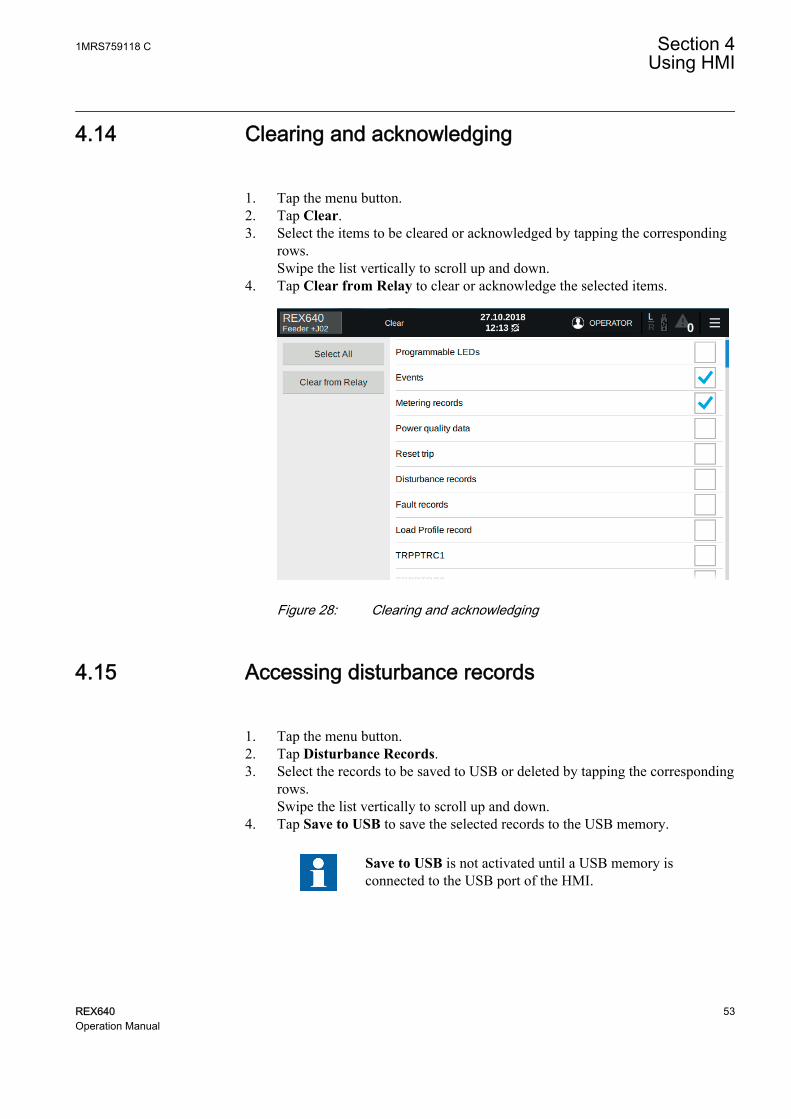
4.14 Clearing and acknowledging
1. Tap the menu button.2. Tap Clear.3. Select the items to be cleared or acknowledged by tapping the corresponding
rows.Swipe the list vertically to scroll up and down.
4. Tap Clear from Relay to clear or acknowledge the selected items.
GUID-108E4DDD-7C82-494E-82BA-A4CFA3E330A2 V1 EN-US
Figure 28: Clearing and acknowledging
4.15 Accessing disturbance records
1. Tap the menu button.2. Tap Disturbance Records.3. Select the records to be saved to USB or deleted by tapping the corresponding
rows.Swipe the list vertically to scroll up and down.
4. Tap Save to USB to save the selected records to the USB memory.
Save to USB is not activated until a USB memory isconnected to the USB port of the HMI.
1MRS759118 C Section 4Using HMI
REX640 53Operation Manual

GUID-897674CC-75C8-497A-8CDC-256318BB5049 V1 EN-US
Figure 29: Selecting disturbance records
Tap Trigger Recording to manually trigger a recording.
4.16 Viewing fault records
The Fault Records page is usually one of the Operator pages.
1. Swipe the LHMI screen until the Fault Records page is shown.The fault records stored in the relay are listed by time stamps on the left ofthe page.
2. Tap the time stamp in the list to see the data of the record.Both the fault records list and the data window can be scrolled up and downby swiping vertically the corresponding section of the page.
Section 4 1MRS759118 CUsing HMI
54 REX640Operation Manual

GUID-93D3FAAC-22DD-4D72-8529-33598E0C308C V1 EN-US
Figure 30: Fault records page
4.17 Selecting USB actions
The USB Actions page enables exporting various data from the relay.
Device information, events, fault records, parameters and the alarm list are saved inTXT format.
Disturbance records and load profile record files are saved in CFG and DATformats.
1. Tap the menu button.2. Tap USB Actions.3. Select the data to be saved to USB by tapping the corresponding rows.4. Tap Save to USB.
The USB port of the LHMI is disabled by default. To be ableto access the USB actions page, the USB port needs to beenabled by the parameter Enable USB access via Parameters/Configuration/HMI.
Save to USB is not activated until a USB memory isconnected to the USB port of the HMI.
1MRS759118 C Section 4Using HMI
REX640 55Operation Manual

The supported file systems for the USB memory are FAT,FAT32, NTFS, EXT2, EXT3 and EXT4.
GUID-3E138C18-BD33-4542-9278-CC3FBDE8030B V1 EN-US
Figure 31: USB Actions page
4.18 Using local HMI help
There are two levels of help on the LHMI.
• Help for a specific page• Help for a specific parameter on the Parameters page and for some specific
monitored data on the Monitoring page
• Access the LHMI help in one of the alternative ways.• Tap the button on the menu bar to access the page-specific help. This
help button is visible only when there is help available for a page.• Tap the button at the end of a parameter or monitored data row to
access parameter or monitored data specific help.
The edit mode needs to be activated to see the buttonson the Parameters and Monitoring pages.
Section 4 1MRS759118 CUsing HMI
56 REX640Operation Manual

GUID-7DC918C1-0C33-45F1-B1B0-26D3CA53036F V1 EN-US
Figure 32: Page help and parameter help buttons
4.19 Changing setting group
1. Tap the menu button.2. Tap Parameters.
Setting group list is opened by default.3. Tap Edit.4. Select the group by tapping the corresponding row and tap Set Active.5. Tap the icon or Edit.6. Tap Store.
1MRS759118 C Section 4Using HMI
REX640 57Operation Manual

GUID-B08B11DE-81D9-4F25-A1B7-68536F51FCBE V1 EN-US
Figure 33: Selecting active setting group
4.20 Controlling
Controllable objects, such as circuit breakers, disconnectors and earthing switches,can be opened and closed via the single-line diagram.
1. Tap the object in the single-line diagram to select it.2. Tap to open or to close the selected object.
GUID-4D70C1AC-3B68-489D-AD47-F5C4C93662AE V1 EN-US
Figure 34: Selecting object (circuit breaker) and control buttons
Section 4 1MRS759118 CUsing HMI
58 REX640Operation Manual

An interlocked object is indicated by the padlock symbol in the single-line diagram.
If the parameter Breaker operation in Configuration/Control/HMI is set to"After confirmation", a confirmation dialog box opens after tapping thecontrol button. The confirmation dialog box has a progress bar indicating theSelect timeout set for the controllable object. If the Control mode setting of acontrol function is set to "sbo-with-enhanced-security", the confirmationdialog box always opens regardless of the Breaker operation setting value.
GUID-EA50AF56-267A-443F-8A13-638B5EF25EC1 V1 EN-US
Figure 35: Confirming object closing
Control operations cannot be executed from the SHMI navigationpage. Navigate to the HMI view to perform control operations.
4.21 Bookmarking pages
A bookmark can be created to any page on the LHMI. Maximum six bookmarkscan be created.
1. Navigate to the page to be bookmarked.2. Touch the Home button for one second to open the Bookmarks page.3. Tap any Bookmark the active page icon to store the bookmark for the
selected page.4. On any page, touch the Home button for one second to open the Bookmarks
page.5. Use the bookmarks in one of the alternative ways.
1MRS759118 C Section 4Using HMI
REX640 59Operation Manual

• Tap the bookmark icon for the page to be opened.• Drag the bookmark icon onto the trash can symbol to remove the
bookmark.
To go to the Home page from any page, touch the Homebutton for one second and tap the Go to Home symbol of theBookmarks page.
GUID-05B2DB09-C8A9-4902-9CF7-2DC886AB13B8 V1 EN-US
Figure 36: Bookmarking pages
Section 4 1MRS759118 CUsing HMI
60 REX640Operation Manual

Section 5 Using Web HMI
5.1 Connecting to Web HMI
Connection to WHMI can be established using different communication card portsor the LHMI service port. WHMI is disabled by default and can be enabled with asetting parameter. As only secure communication is supported for the WHMI, itmust be accessed from a Web browser using the HTTPS protocol. Threesimultaneous LHMI and WHMI sessions are supported.
1. To enable the WHMI, select Configuration/HMI/Web HMI mode and setthe parameter to "On".
2. Reboot the relay for the change to take effect.3. Log in with the proper user rights to use the WHMI.
If the WHMI is accessed through the LHMI service port, use thecorresponding IP address of the relay communication port. The IP addresscan be obtained via the Engineer pages. Tap the relay's name on the LHMImenu bar to open the Relay address dialog box.
To establish a remote WHMI connection to the protectionrelay, contact the network administrator to check the companyrules for IP and remote connections.
HTTPS is enabled for all ports by default. To disable theHTTPS for station ports, select Communication/Protocols/Network1/HTTPS or Communication/Protocols/Network2/HTTPS and set the parameter to "Off". HTTPS is alwaysenabled for the X0/HMI port.
The WHMI write access can be limited with the parameterHTTPS write access in Configuration/Authorization/Network1 or Configuration/Authorization/Network2.
Disable the Web browser proxy settings or make an exceptionto the proxy rules to allow the protection relay's WHMIconnection, for example, by including the relay's IP address in
1MRS759118 C Section 5Using Web HMI
REX640 61Operation Manual

Internet Options/Connections/LAN Settings/Advanced/Exceptions.
5.1.1 Logging in
1. Open a Web browser.2. Type the protection relay's IP address in the address bar and press ENTER.3. Type the username.4. Type the password.
GUID-3073C31F-B502-46D0-B4C5-CC1F6BA36992 V1 EN-US
Figure 37: Entering username and password to use the Web HMI
If logging in fails because all sessions are used, an error message is shown onthe login page.
Section 5 1MRS759118 CUsing Web HMI
62 REX640Operation Manual

GUID-0753822C-8EB6-464F-92C6-CD9044B4F4C3 V1 EN-US
Figure 38: Web HMI error message
5. Select the role if an additional view opens.This view opens if there are several user roles configured.
GUID-FA4BF888-E17C-474F-904B-FC270EC3F77D V1 EN-US
Figure 39: Selecting user role
The progress indicator is displayed until the WHMI opens and the dashboardview is shown.
It is recommended to disable the auto-complete feature, which isusually enabled by default, in the Web browser to prevent theusernames and passwords from being stored in the browser's cache.
1MRS759118 C Section 5Using Web HMI
REX640 63Operation Manual

5.1.2 Logging out
The user is logged out after a session timeout. The timeout can be set inConfiguration/HMI/HMI timeout.
• To log out manually, click on the menu bar.
If password authorization is enabled (Local override is set to"False") and there is no user activity for the duration set inConfiguration/HMI/HMI timeout, the LHMI session is loggedout. By default, the timeout duration is three minutes.
5.2 Navigating in menus
The menu bar contains main groups which are divided further into more detailedsubmenus.
• Use the menu bar to access different views.
5.3 Identifying device
The Information menu includes detailed information about the device, for example,revision and serial number.
1. Select Device on the menu bar.2. Select Information.3. Click a submenu to see the data.
GUID-FD3BB229-146B-4331-AC35-BBBB74E2FCDB V2 EN-US
Figure 40: Viewing device information
Section 5 1MRS759118 CUsing Web HMI
64 REX640Operation Manual

5.4 Viewing dashboard
The Dashboard view is active automatically after logging in to WHMI andprovides an overview of the protection relay including, for example, the devicestatus, measurements, single-line diagram and latest events.
• Select Dashboard on the menu bar to view the dashboard.
GUID-100D488E-0128-4BA2-97E7-DB46A1B62FD9 V2 EN-US
Figure 41: Viewing dashboard
5.5 Viewing self-supervision
1. Select Device on the menu bar.2. Select Self-Supervision.
The Self-Supervision view shows currently active internal faults andwarnings.
GUID-D41600D4-9EE8-489D-AF97-702E5C7D1D4C V1 EN-US
Figure 42: Self-supervision: one internal fault is currently active
5.6 Changing language
The active language of the Web server session is indicated in the caption of themenu bar button.
1MRS759118 C Section 5Using Web HMI
REX640 65Operation Manual

1. Click the active language button to view all available languages.2. Select the language from the drop-down list.
GUID-6CA5A017-0737-4F84-8790-6648E4EC970F V2 EN-US
Figure 43: Changing language
5.7 Alarms
5.7.1 Viewing alarm list
1. Select Recordings on the menu bar.2. Select Alarm List to access the alarm list.3. Click one of the three buttons to select an alarm view.
• The Persisting Alarms view lists the active alarms.• The Fleeting Alarms view shows the alarms that are not active
anymore but are not acknowledged.• The Available Alarms view contains all configured alarms.
Acknowledged alarms are indicated using icon . Priority alarms areindicated with icon .
Section 5 1MRS759118 CUsing Web HMI
66 REX640Operation Manual

GUID-38702DC8-9BEB-4C69-B81E-0B24E7C9A5EB V1 EN-US
Figure 44: Viewing persisting alarms
GUID-06D99B6F-D12D-4804-AA22-CD9ED08580C5 V1 EN-US
Figure 45: Viewing fleeting alarms
GUID-D5D4CDDF-282D-4D5C-ADCA-FE81D2E07E46 V1 EN-US
Figure 46: Viewing all available alarms
1MRS759118 C Section 5Using Web HMI
REX640 67Operation Manual

5.7.2 Acknowledging alarms
1. Select Recordings on the menu bar.2. Select Alarm List.3. Select the alarm view.4. Select the alarms using check boxes.5. Click Acknowledge.
GUID-06D0F22E-32D2-4E1C-A345-3D6450C53137 V1 EN-US
Figure 47: Acknowledging alarms
Alarm list items can be configured in HMI Event Filtering inPCM600.
5.8 Measurements and phasor diagrams
5.8.1 Viewing measurements
1. Select Measurements on the menu bar.2. Select Measurements from the drop-down list.
GUID-27A910D5-2452-4D15-8A3F-B55B33617DAA V1 EN-US
Figure 48: Viewing measurements
Section 5 1MRS759118 CUsing Web HMI
68 REX640Operation Manual

Measurements are also displayed in the Dashboard view.
5.8.2 Viewing phasor diagrams
1. Select Measurements on the menu bar.2. Select Phasor Diagrams from the drop-down list.
GUID-DDD4933C-E175-44DE-8E25-6CE20E9BE0EE V2 EN-US
Figure 49: Monitoring phasors
3. Select the phasor from the drop-down list on the Phasor Diagrams page toview it.
1MRS759118 C Section 5Using Web HMI
REX640 69Operation Manual

GUID-71B6B2BE-931C-4B8C-B7A2-877FF145E503 V2 EN-US
Figure 50: Selecting the phasor
4. Select Custom from the drop-down list on the Phasor Diagrams page toopen the dialog with the phasor list.
GUID-FECB1994-259C-4794-9734-9E2EA9CEB590 V2 EN-US
Figure 51: Selecting the custom phasors
5. In the Custom dialog, select the phasors to be monitored and click Close.
Section 5 1MRS759118 CUsing Web HMI
70 REX640Operation Manual

GUID-BE7052C7-4B31-42ED-B434-21AFBCA6A252 V2 EN-US
Figure 52: Editing custom phasor list
6. Click the Select reference button to select a reference phasor and then clickClose.
GUID-9E92B283-0E03-41FD-842D-ECEB1BD64EBF V2 EN-US
Figure 53: Selecting the reference phasor
WHMI measurements and phasor diagrams follow LHMIdefinitions and can be edited with Graphical Display Editor inPCM600.
1MRS759118 C Section 5Using Web HMI
REX640 71Operation Manual

5.9 Viewing monitoring
1. Select Device on the menu bar.2. Select Monitoring from the drop-down list.3. Select the monitored view from the left navigation bar.
GUID-02091769-FD61-4FA8-BE30-9234633F7313 V1 EN-US
Figure 54: Monitoring data
5.10 Viewing single-line diagram
The single-line diagram is displayed on the dashboard and the Single Line Diagrampage. If there are more than one page, the first page is displayed and the others areincluded in the drop-down list.
1. Select Device on the menu bar.2. Select Single Line Diagram to view the single-line diagram page.
Section 5 1MRS759118 CUsing Web HMI
72 REX640Operation Manual

GUID-73D865B4-7BE7-47B5-A4F9-70F86FC5ECA7 V1 EN-US
Figure 55: Viewing the single-line diagram with IEC symbols
5.11 Showing parameters
Some function blocks have a function-specific ON/OFF setting. When the functionsetting is "off", all settings are hidden and when the function setting is "on", allsettings are visible based on the other visibility and hiding rules.
Switch a function block on or off via the Operation parameterunder the function block.
The values "Basic" or "Advanced" of the Setting visibilityparameter in Configuration/HMI have no effect on the ParameterList page. This page has its own Basic settings option which can beused to hide or show the advanced settings on the Parameter Listpage.
1. Select Import/Export on the menu bar.2. Select Parameter List from the drop-down list.
1MRS759118 C Section 5Using Web HMI
REX640 73Operation Manual

GUID-FA2C4E64-B088-483A-819B-0502911D1592 V1 EN-US
Figure 56: Displaying parameters
3. Click the filter icon .4. In the Apply filter dialog, select the settings that should be shown and click
Apply.If nothing is selected, all settings are shown.
GUID-CC9922C3-0D8F-4AC2-B062-E35118D7E9E6 V1 EN-US
Figure 57: Enabling settings
The Parameter List page offers filtering functionality where only chosenparameters are displayed, saved or printed. There are various options forfiltering.• Enabled Settings hides settings of disabled function blocks. This
option is checked by default.• Writable settings displays only writable settings.• Basic settings displays only basic settings.• Setting group displays only the settings of the selected setting group.
Section 5 1MRS759118 CUsing Web HMI
74 REX640Operation Manual

Options can be combined. For example, with the Enabled Settings andWritable settings selected, only enabled and writable settings are displayed.
5. Click Export and select text (.txt) or comma separated values (.csv) fileformat to save the settings.
6. Click Print to print all the selected parameters.
5.12 Editing values
1. Select Parameters on the menu bar.2. Click a submenu in the left navigation bar to see the function blocks.3. Click a function block to see the setting values.4. Click Enable Edit.
If the edit mode is enabled accidentally, click Disable Edit.Editing cannot be disabled when a value has already beenwritten to the protection relay. After clicking Write to Relay,click either Reject Changes or Store Changes.
GUID-124044A0-DD9A-4049-B358-73A3AD2FB86B V1 EN-US
Figure 58: Enable writing to edit a value
The selected setting group is shown in the Setting Group drop-down list andthe setting group parameters are listed on page. The active setting group isindicated with an asterisk *.
5. Edit the value.The minimum, maximum and step values for a parameter are shown in theMIN., MAX. and STEP columns.
1MRS759118 C Section 5Using Web HMI
REX640 75Operation Manual

GUID-41E97C14-E440-46AF-9C5C-BD19C77D1F7D V1 EN-US
Figure 59: Editing a value
If the entered value is within the accepted value range, the selection ishighlighted in blue. If the value is out of range, the row is highlighted in redand error text is displayed. Write to Relay is unavailable.
GUID-474F95AB-AED1-412D-9661-7162768F316B V1 EN-US
Figure 60: Error indicating that the entered value is incorrect
If writing values fails, an error message is displayed.
GUID-1FD447D8-367B-4CD6-9D7A-051D55A925A6 V1 EN-US
Figure 61: Error indicating that the values were not written to theprotection relay
6. Commit the settings.
5.13 Committing settings
Editable values are stored either in RAM or a nonvolatile flash memory. Thevalues stored in the flash memory are in effect also after a reboot.
Some parameters have an edit-copy. If writing is cancelled, the values with an edit-copy are immediately restored to the original value. The values without an edit-
Section 5 1MRS759118 CUsing Web HMI
76 REX640Operation Manual

copy, such as string values, are restored to the original value only after a rebooteven though the edited value is not stored in the flash memory.
1. After editing parameter values, click Write to Relay to put the values into theprotection relay's database for use.The values are not stored to the flash memory.
GUID-0694CCC5-3911-4036-A6D0-33CC9BFB1C3B V1 EN-US
Figure 62: Writing values to the protection relay
2. Click Store Changes to store the values to the flash memory.
Click Reject Changes to cancel saving settings. If theparameter has an edit-copy, the original parameter value isrestored. If the parameter does not have an edit-copy, theedited parameter value remains visible until the protectionrelay is rebooted. However, the edited value is not stored inthe nonvolatile memory and thus the reboot restores theoriginal value.
GUID-9DBC01BA-1C14-407A-87DC-38AEF0F11DF7 V1 EN-US
Figure 63: Storing changes
Storing values takes a few seconds.
1MRS759118 C Section 5Using Web HMI
REX640 77Operation Manual

If the values are not stored, they are not taken into use andthey are lost after a reboot.
5.14 Clearing and acknowledging
Reset, acknowledge or clear all messages and indications, including LEDs andlatched outputs as well as registers and recordings, in the Clear page.
1. Select Device on the menu bar.2. Select Clear from the drop-down list.
GUID-593D49DB-F268-4E3F-817D-DFF1F304544F V1 EN-US
Figure 64: Opening the Clear page
3. Select the item to be cleared.4. Click Clear from Relay.
Section 5 1MRS759118 CUsing Web HMI
78 REX640Operation Manual

GUID-12F1B054-4D00-4314-963D-E68618CB688A V1 EN-US
Figure 65: Clearing indications and LEDs
5.15 Accessing event view
The event view contains a list of events produced by the application configuration.When the event page is opened, it displays up to 20 latest events at one time. Theevent list is updated automatically.
1. Select Recordings on the menu bar.2. Select Events from the drop-down list.
1MRS759118 C Section 5Using Web HMI
REX640 79Operation Manual

GUID-E42C7F07-1C8A-4F5F-860D-A13D2C013523 V1 EN-US
Figure 66: Monitoring events
3. Click Freeze to stop updating the event list.4. Select a page to view older events.
GUID-E07826B1-9CB6-4D3E-AFB8-B4A93045F600 V1 EN-US
Figure 67: Viewing events
5. To save the events as .txt or .csv files, click Export and select the file formatfrom the drop-down list.
The CSV file can be opened with a spreadsheet program suchas OpenOffice.org Calc or Microsoft Excel.
6. Click Clear Events to clear all events from the protection relay.7. Click Print to print all the selected events.
Section 5 1MRS759118 CUsing Web HMI
80 REX640Operation Manual

5.16 Accessing disturbance record view
Disturbance records are listed in the disturbance records view.
1. Select Recordings on the menu bar.2. Select Disturbance Records from the drop-down list.
GUID-E2FF1DF6-5763-40C8-8827-0459A4540106 V1 EN-US
Figure 68: Viewing disturbance records
5.16.1 Saving disturbance records
1. Select Recordings on the menu bar.2. Select Disturbance Records from the drop-down list.3. To save the disturbance record files, click the Export button in the Export
Files column of the record. Both disturbance record files CFG and DAT aresaved at once.
GUID-E88B69D2-6B7B-4068-B5C0-95FA3A20E119 V1 EN-US
Figure 69: Saving a disturbance record
If prompted, give permission for file downloading dependingon the used Web browser.
4. Open the disturbance record files with a suitable program.
1MRS759118 C Section 5Using Web HMI
REX640 81Operation Manual

5.16.2 Triggering disturbance recorder manually
1. Select Recordings on the menu bar.2. Select Disturbance Records from the drop-down list.
GUID-1A4E13FA-FB4E-4C26-95B0-4FD85534845C V1 EN-US
Figure 70: Selecting Disturbance Records
3. Click Trigger Recording.
GUID-EF7AA6E5-6342-4FB6-BFB9-69AB418666DC V1 EN-US
Figure 71: Triggering recording
GUID-B4E57853-D0C6-43B8-8779-3DF8F19FCE39 V1 EN-US
Figure 72: Triggering recording - progress bar
5.16.3 Deleting disturbance records
1. Select Recordings on the menu bar.2. Select Disturbance Records from the drop-down list.3. Delete records in one of the alternative ways.
• Select all and click Delete to delete all records.• Select one or more recordings and click Delete to delete the selected
records.
Section 5 1MRS759118 CUsing Web HMI
82 REX640Operation Manual

GUID-6F24C664-331C-4BF7-A1EF-E08B2782969E V1 EN-US
Figure 73: Deleting disturbance records
5.17 Viewing fault records
1. Select Recordings on the menu bar.2. Select Fault Records from the drop-down list to view a list of all available
fault records.3. Click a record from the Fault records list to open the fault record details
view.4. To go back to the list view, click View All.5. To save the records as .txt or .csv files, select the format from the Export
drop-down list.• When the fault record details view is shown, only the shown fault
record is saved.• When fault record list view is shown, all fault records are saved.
6. To clear all fault records from the relay, click Clear All.This can be done only when the fault record list view is shown.
7. To print all fault records, click Print when the fault record list view is shown.8. To print only one record, open it in the details view and click Print.
GUID-3C4E5C18-0E18-417D-99B7-DB437F6CB20D V1 EN-US
Figure 74: Fault record list view
1MRS759118 C Section 5Using Web HMI
REX640 83Operation Manual

GUID-411C7B96-0CDB-4061-AAD0-5EE83847ADE5 V1 EN-US
Figure 75: Fault record details view
5.18 Exporting load profile records
1. Select Recordings on the menu bar.2. Select Load Profile Record from the drop-down list.3. To export the load profile record files, click the Export button in the Export
Files column.Both load profile record files CFG and DAT are saved at once.
4. Save the CFG and DAT files in the same folder on the computer.5. Open the load profile record COMTRADE files with a suitable program.
Open the load profile files, for example, with the Wavewintool included in PCM600.
5.19 Importing and exporting of settings
The relay's setting parameters can be imported and exported in the XRIO fileformat.
When importing parameters to PCM600 via an XRIO file generatedby the WHMI, some Ethernet communication and HMI-relatedparameters are not included in the import. Check the Outputwindow of PCM600 for such parameters and manually update thoseif needed.
Section 5 1MRS759118 CUsing Web HMI
84 REX640Operation Manual

5.19.1 Exporting settings
The relay's setting parameters can be exported in XRIO file format.
1. Select Import/Export on the menu bar.2. Select Import/Export Settings from the drop-down list.3. Click Export Settings.
The export file includes all parameters except status parameters andparameters writable only in LHMI.
GUID-E45F4AA1-A30F-48F9-8AD6-1E4B349A5318 V1 EN-US
Figure 76: Exporting settings
4. Click Save to export the settings to the computer.
5.19.2 Importing settings
The parameter export and import function can be used, for example, when theprotection relay's parameters are set using the WHMI instead of PCM600. Theprotection relay's settings engineered with PCM600 can be exported to XRIO filesand imported to the WHMI. The WHMI can be used to write the settings to theprotection relays. The WHMI can also be used to read the protection relay's settingparameters and to export those to files, which can be used by PCM600. WHMIimports all parameters from the import file except lockable and read-onlyparameters.
The XRIO file name supports only characters A-Z, a-z and 0-9.
The exporting and importing of settings is sensitive to theprotection relay content. Settings are exported and imported for oneprotection relay at a time. The export files of a specific protectionrelay can be exchanged between PCM600, WHMI and the actualphysical protection relay. To avoid errors and to efficiently manage
1MRS759118 C Section 5Using Web HMI
REX640 85Operation Manual

the exporting and importing of settings, for example, in a substationwith several relays, ensure that the names of the export filesidentify the relay to which the file should be imported.
Ensure that the correct settings are imported to the correct relay.Wrong settings may cause the relay to malfunction.
1. Select Import/Export on the menu bar.2. Select Import/Export Settings from the drop-down list.3. Click Choose File and choose the file to be imported.
GUID-AED858DE-78DD-4698-8BB0-EAEC888C2642 V1 EN-US
Figure 77: Selecting the settings to be imported
4. Click Import Settings.Wait until the file transfer is complete.
GUID-677E7932-D77F-4347-8B84-73D554E80215 V1 EN-US
Figure 78: Importing settings
5. Click Store to commit the imported settings to the relay.Wait until the import is complete.
Click Cancel to cancel the import. Both the WHMI and therelay revert to the settings in use prior to the import.
Section 5 1MRS759118 CUsing Web HMI
86 REX640Operation Manual

GUID-D786C9E5-4FD0-4925-A0C7-8EC0E4CC4FC3 V1 EN-US
Figure 79: Writing parameter settings
GUID-46164DE3-E805-4592-AA9B-6272DFD0C115 V1 EN-US
Figure 80: Parameter settings written to relay
Only editable parameters are written to the relay during theimport. If part of the import fails, the faulty parameters arelisted separately.
5.20 Exporting report summary
The Report Summary page allows exporting protection relay recordings, logs andparameters. Events, fault records and the parameter list are saved in TXT format.The saved files contain all events, fault records and settings.
Disturbance records and load profile record files are saved in CFG and DATformats.
1. Select Import/Export on the menu bar.2. Select Report Summary from the drop-down list.3. Select the items to be exported.
• Click Select all to select all items.• Click Clear all to clear all selections.
4. Click Export to export the .zip file with the selected files.
1MRS759118 C Section 5Using Web HMI
REX640 87Operation Manual

GUID-96C179E2-139F-44B7-99FF-E397D475FABC V1 EN-US
Figure 81: Report Summary page
5.21 Using Web HMI help
The context-sensitive WHMI help provides information on a single parameter, forexample.
• Move the mouse over to display the help dialog box.
GUID-C07C904F-EF9A-4A1C-BC49-032B50759482 V1 EN-US
Figure 82: Opening the Web HMI help
Section 5 1MRS759118 CUsing Web HMI
88 REX640Operation Manual

Section 6 Troubleshooting
6.1 Fault tracing
6.1.1 Identifying hardware errors
1. Check the module with an error.Check the relay supervision events in Relay Status for a faulty hardwaremodule.
2. Inspect the protection relay visually.• Inspect the protection relay visually to find any physical error causes.• If you can find some obvious physical damage, contact ABB for repair
or replacement actions.3. Check whether the error is external or internal.
• Check that the error is not caused by external origins.• Remove the wiring from the protection relay and test the input and
output operation with an external test device.• If the problem remains, contact ABB for repair or replacement actions.
6.1.2 Identifying runtime errors
1. Check the error origin from the protection relay's supervision events in RelayStatus.
2. Reboot the protection relay and recheck the supervision events to see if thefault has cleared.
3. In case of persistent faults, contact ABB for corrective actions.
6.1.3 Identifying communication errors
Communication errors are normally communication interruptions orsynchronization message errors due to communication link breakdown.
• In case of persistent faults originating from protection relay's internal faultssuch as component breakdown, contact ABB for repair or replacement actions.
6.1.3.1 Checking communication link operation
• Check the LEDs indicating communication link or communication activity onthe communication card. They should be lit or flashing.
1MRS759118 C Section 6Troubleshooting
REX640 89Operation Manual

Table 9: Front communication LEDs
LED Communication okUplink Steady green light
Communication Flashing yellow light
6.1.3.2 Checking time synchronization
• Check the time synchronization via LHMI in Relay Status/Monitoring/IEDstatus/Time synchronization.
6.1.4 Reading of internal log files
When contacting ABB customer service, be prepared to send the relay’s internallog files for investigation. The files can be read either via the HMI’s USB port orfrom the WHMI.
6.1.4.1 Reading internal log files via HMI’s USB port
1. Insert a USB stick to the HMI’s USB port, and navigate to the relay’s HMIview if using an SHMI.
2. On the USB Actions page, tap Select All to select all items.3. Tap Save to USB to save the .zip file with the selected files.4. Wait for the confirmation that the file is saved to the USB folder, tap OK, and
tap Safely Remove USB.5. Locate the .zip file saved to the HMI folder of your USB stick and send it to
ABB customer service for further analysis.
HMI’s USB access is disabled by default. To enable USB,instantiate the EIHMI function block in the applicationconfiguration. After this it can be taken into use by setting the USBaccess parameter via Configuration/HMI.
6.1.4.2 Reading internal log files from Web HMI
1. Connect to the WHMI.2. Select Import/Export on the menu bar.3. Select Report Summary from the drop-down list.4. Make sure that all items are selected. If not, click Select All to select all
items.5. Click Export to export a .zip file with the selected files.6. Save the .zip file to your PC and send it to ABB customer service for further
analysis.
Section 6 1MRS759118 CTroubleshooting
90 REX640Operation Manual

WHMI is disabled by default. It can be enabled by the Web HMImode parameter via Configuration/HMI. Reboot the relay for thechange to take effect.
6.1.5 Checking local HMI connectivity
If the connection between the LHMI and the relay is lost, check the following.
1. Check that the RJ-45 cable is properly connected between the LHMI's mainunit port X1.1. and the X0 port (HMI) of the relay's communication card.If the station communication connection (a LAN port of the communicationcard) is used between the LHMI and the relay, see chapter Connecting localHMI to a relay through station network to check the proper connection.
2. Check that the LHMI is paired with the relay. See chapter Pairing local HMIwith relay.
6.2 Self-supervision
The protection relay's extensive self-supervision system continuously supervisesthe relay’s software, hardware and certain external circuits. It handles the run-timefault situation and informs the user about a fault via the LHMI, the relay's mainunit power module Ready LED and through the communication channels. Thetarget of the self-supervision is to safeguard the relay’s reliability by increasingboth dependability and security. The dependability can be described as the relay’sability to operate when required. The security can be described as the relayscheme’s ability to refrain from operating when not required. The dependability isincreased by letting the system operators know about the problem, giving them achance to take the necessary actions as soon as possible. The security is increasedby preventing the relay from making false decisions, such as issuing false controlcommands.
There are two types of fault indications.
• Internal faults• Warnings
Warnings are indications of less severe situations which can also be caused byexternal reasons, for example, in case the RTD sensor measurement circuit is notcomplete.
On the LHMI, the self-supervision status is available as an advanced page underRelay Status page. The self-supervision status is indicated with Internal Fault,Warning and All OK LEDs. In normal operation, All OK LED is lit. The self-supervision also controls the status of IRF output relay. The IRF output relay is
1MRS759118 C Section 6Troubleshooting
REX640 91Operation Manual

energized under normal conditions and de-energized under internal faultconditions.
GUID-C2262ADD-640C-4F59-B584-BE03A1C43F95 V1 EN-US
Figure 83: Relay self-supervision status on local HMI
On the WHMI, the self-supervision status is available under Device menu. The topright LED indicates the relay status.
GUID-C1CB83B9-C8C1-4FBC-AD6A-664E7684ACE4 V1 EN-US
Figure 84: Relay self-supervision status on Web HMI
In addition, the last boot reason and time are shown on both LHMI and WHMI.
6.2.1 Internal faults
When an internal relay fault is detected, the relay protection operation is disabled,the self-supervision output relay is de-energized, and the change-over contact isreleased. In the main unit, the main indication of an internal fault is a flashinggreen Ready LED behind the power module, and on the HMI, a rapidly flashingred Home button.
Section 6 1MRS759118 CTroubleshooting
92 REX640Operation Manual

Different actions are taken depending on the severity of the internal fault. In caseof a temporary fault, the protection relay tries to recover from the situation byrestarting. The restart procedure includes two stages; when the relay detects a fault,it restarts itself in a few seconds after the fault occurrence. If the relay did notrecover after the first restart, or the fault reoccurs during the next 60 minutes, thesecond restart is delayed for 10 minutes. In case of a permanent fault, theprotection relay stays in the internal fault mode. All output relays are de-energizedand contacts are released for the internal fault. The protection relay continues toperform internal tests during the fault situation. If the internal fault disappears, thefault indication LEDs stop flashing and the protection relay returns to the normalservice state.
One possible cause for an internal fault situation is a so-called soft error. The softerror is a probabilistic phenomenon which is rare in a single device, statistically nothappening more often than once in a relay’s lifetime. No hardware failures areexpected and a full recovery from the soft error is possible by a self-supervisioncontrolled restart of the relay.
The self-supervision signal output operates on the closed-circuit principle. Undernormal conditions, the IRF output relay is energized and the contact gap 3-5 isclosed. If the auxiliary power supply fails or an internal fault is detected, the IRFoutput relay is de-energized and the contact gap 3-5 opens.
GUID-C9AF791D-D8F6-4768-A6D9-12FD192129CD V1 EN-US
Figure 85: Output contact
The internal fault code indicates the type of internal relay fault. When a faultappears, the code must be recorded so that it can be reported to ABB customerservice.
More details about the active internal fault are found on the Relay Status page. Onthe LHMI, the internal fault state is indicated with a red LED. More informationabout the fault and recovery options can be accessed by tapping More Information.
1MRS759118 C Section 6Troubleshooting
REX640 93Operation Manual

GUID-2BBCEC19-B8F1-4F8D-8EB3-1A5B376EBE34 V1 EN-US
Figure 86: Internal fault state indicated with red LED
More Information shows all active faults and the corresponding fault codes. Inaddition, a recovery procedure is described.
GUID-6FAA2FE1-AA4A-4DF4-B1CE-55F8B00BDE33 V1 EN-US
Figure 87: More information about the fault
Section 6 1MRS759118 CTroubleshooting
94 REX640Operation Manual

On the WHMI, internal fault information is shown under Self-Supervision Status.
GUID-D4B0F232-B2CC-49A7-9C54-5F880CDE4D34 V1 EN-US
Figure 88: Internal fault information on Web HMI
Table 10: Internal fault indications and codes
Fault indication Fault code Additional informationSystem error 2 An internal system error has
occurred.
File system error 7 A file system error hasoccurred.
Test 8 Internal fault test activatedmanually by the user
SW watchdog error 10 Watchdog reset has occurredtoo many times within an hour.
SO-relay(s),slot C -10 Faulty Signal Output relay(s) inmodule located in slot C
SO-relay(s),slot E -11 Faulty Signal Output relay(s) inmodule located in slot E
SO-relay(s),slot B -13 Faulty Signal Output relay(s) inmodule located in slot B
SO-relay(s),slot D -14 Faulty Signal Output relay(s) inmodule located in slot D
SO-relay(s),slot G -16 Faulty Signal Output relay(s) inmodule located in slot G
PO-relay(s),slot C -20 Faulty Power Output relay(s) inmodule located in slot C
PO-relay(s),slot E -21 Faulty Power Output relay(s) inmodule located in slot E
PO-relay(s),slot B -23 Faulty Power Output relay(s) inmodule located in slot B
PO-relay(s),slot D -24 Faulty Power Output relay(s) inmodule located in slot D
PO-relay(s),slot G -26 Faulty Power Output relay(s) inmodule located in slot G
Conf.error,slot C -30 Module in slot C is wrong type,is missing, does not belong tooriginal configuration or modulefirmware is faulty.
Table continues on next page
1MRS759118 C Section 6Troubleshooting
REX640 95Operation Manual

Fault indication Fault code Additional informationConf.error,slot E -31 Module in slot E is wrong type,
is missing, does not belong tooriginal configuration or modulefirmware is faulty.
Conf.error,slot A2 -32 Module in slot A2 is wrongtype, is missing, does notbelong to original configurationor module firmware is faulty.
Conf.error,slot B -33 Module in slot B is wrong type,is missing, does not belong tooriginal configuration or modulefirmware is faulty.
Conf.error,slot D -34 Module in slot D is wrong type,is missing, does not belong tooriginal configuration or modulefirmware is faulty.
Conf.error,slot F -35 Module in slot F is wrong type,is missing, does not belong tooriginal configuration or modulefirmware is faulty.
Conf.error,slot G -36 Module in slot G is wrong type,is missing, does not belong tooriginal configuration or modulefirmware is faulty.
Conf.error,slot A1 -37 Module in slot A1 is wrongtype, is missing, does notbelong to original configurationor module firmware is faulty.
Card error,slot C -40 Module in slot C is faulty.
Card error,slot E -41 Module in slot E is faulty.
Card error,slot A2 -42 Module in slot A2 is faulty.
Card error,slot B -43 Module in slot B is faulty.
Card error,slot D -44 Module in slot D is faulty.
Card error,slot F -45 Module in slot F is faulty.
Card error,slot G -46 Module in slot G is faulty.
Card error,slot A1 -47 Module in slot A1 is faulty.
Prod license error -62 Error in product license
RAM error 80 Error in the RAM memory onthe CPU module
ROM error 81 Error in the ROM memory onthe CPU module
EEPROM error 82 Error in the EEPROM memoryon the CPU module
FPGA error 83 Error in the FPGA on the CPUmodule
RTC error 84 Error in the RTC on the CPUmodule
COM card error 116 Error in the COM module
Section 6 1MRS759118 CTroubleshooting
96 REX640Operation Manual

6.2.2 Warnings
In case of a warning, the protection relay continues to operate except for thoseprotection functions affected by the fault. The main unit status LED remains lit asduring normal operation. If the device warning event is configured as alarms, theLHMI Home button flashes red.
If a warning appears, record the name and code so that it can beprovided to ABB customer service.
On the LHMI, an active warning is indicated with a yellow LED. More informationabout the warning and recovery options can be accessed by tapping MoreInformation.
GUID-07E927E8-22D8-4DB3-93A7-DDDC4C3E5787 V1 EN-US
Figure 89: Active warning on local HMI
More information shows all active warnings and corresponding fault codes. Inaddition, a recovery procedure is described.
1MRS759118 C Section 6Troubleshooting
REX640 97Operation Manual

GUID-D35FF83D-0266-4E9E-A056-E1276C32AEA1 V1 EN-US
Figure 90: More information about the warning
Table 11: Warning indications and codes
Warning indication Warning code Additional informationWatchdog reset 10 A watchdog reset has occurred.
Power down det. 11 The auxiliary supply voltagehas dropped too low.
DNP3 warning 22 Error in the DNP3communication
Dataset warning 24 Error in the Data set(s)
Report cont. warning 25 Error in the Report controlblock(s)
GOOSE contr. warning 26 Error in the GOOSE controlblock(s)
SCL config warning 27 Error in the SCL configurationfile or the file is missing
Logic warning 28
SMT logic warning 29
GOOSE input warning 30
ACT warning 31 Analog channel configurationwarning
GOOSE rec. warning 32
AFL warning 33
SMV warning 34 Error in the SMV configuration
Table continues on next page
Section 6 1MRS759118 CTroubleshooting
98 REX640Operation Manual

Warning indication Warning code Additional informationComm. channel down 35 Redundant Ethernet (HSR/
PRP) communicationinterrupted
Settings mismatch 36 Mismatch between parametersettings and applicationconfiguration
Protection comm. 50 Error in protectioncommunication
ARC1 cont. light 85 A continuous light has beendetected on the ARC light input1.
ARC2 cont. light 86 A continuous light has beendetected on the ARC light input2.
ARC3 cont. light 87 A continuous light has beendetected on the ARC light input3.
ARC4 cont. light 88 A continuous light has beendetected on the ARC light input4.
RTD meas. warn.,slot D -54 Abnormal signal from sensor(s)received in slot D
RTD meas. warn.,slot C -50 Abnormal signal from sensor(s)received in slot C
mA output warn.,slot D -24 Temporary error occurred inRTD module located in slot D
mA output warn.,slot C -20 Temporary error occurred inRTD module located in slot C
6.2.3 Power supply module Ready LED and HMI Home buttonLED
Both power supply module Ready LED and LHMI Home button LED visualize theself-supervision state of the relay. Table 12 shows how these states are indicated.
Table 12: Power supply module Ready LED and local HMI Home button LED
State Power supply moduleReady LED
LHMI Home button Alarm acknowledged
Relay under normaloperation and LHMIconnected
Steady green Steady green N/A
Relay’s IRF activated,but communicates withLHMI
HF blinking green HF blinking red N/A
Communication lostbetween Relay andLHMI, but no IRF
Steady green HF blinking green N/A
LHMI not runningnormally or in start-upinitialization phase
Steady green HF blinking green N/A
Table continues on next page
1MRS759118 C Section 6Troubleshooting
REX640 99Operation Manual

State Power supply moduleReady LED
LHMI Home button Alarm acknowledged
Process related alarmactive
Steady green LF blinking red No
Process related alarmactive
Steady green Steady red Yes
Process related alarmhas been activeearlier, but is not anymore active.
Steady green LF blinking red No
Process related alarmhas been activeearlier, but is not anymore active.
Steady green Steady green Yes
Relay set to TestMode
LF blinking green LF blinking green No
The physical SHMI Home button has two operation modes.
• On the SHMI’s navigation page, the Home button indicates the combinedstatus of all connected relays. If multiple relays have different statuses, theHome button shows the indication with the highest priority.
• On the HMI view, the Home button indicates the status of the respective relayas described in Table 12.
6.3 Correction procedures
6.3.1 Creating relay backup in HMI
• Pair the HMI and the relay to activate the automatic backup.The relay backup is read and stored by the LHMI when any change in relayconfiguration files (see Table 13 for details) or settings has occurred and 24hours has elapsed from the last change. The SHMI reads a backup for all of theconnected and paired relays.
Table 13: Configuration changes included in the relay backup
File or folder Description Part of backup and restore.\language\ Folder containing HMI-
specific language filesYes
.\license\ 640 license files NoNew license files aredelivered with thereplacement relay.
.\pages\ 640 HMI page configuration Yes
.\SLD\ Single-line diagram relatedfiles
Yes
Table continues on next page
Section 6 1MRS759118 CTroubleshooting
100 REX640Operation Manual

File or folder Description Part of backup and restore.\UAM\ User access management
related filesYes
ACT_graph.cact Yes
conf.xml.gz Relay's applicationconfiguration
Yes
conf.xml.gz.MD5 Checksum for applicationconfiguration
Yes
configsum.xml Contains checksums ofdifferent items and changeinformation. It is also used inthe relay to verify filechecksums (for example,UAM files).
Yes
done.txt When this file is updated(date modified changes),relay knows that itsconfiguration has changed.When the relay backup isrestored, this file contains:Updated over C:/backup.zip
Yes
hmi.xml HMI event configuration Yes
measurements.xml HMI-specific measurementconfiguration (used by phasorand measurement pages).
Yes
default_measurements.xml No
characteristics.xml No
udn.xml Use-defined naming Yes
When the relay is in IRF error (the Home button flashes redfast), the backup is not made.
The relay's device certificate and the CA root certificate are notpart of the backup. If SDM600 or PKI has been configured,these must be reconfigured using the corresponding tools. Inaddition, when SDM600 or PKI are in use, CAM settings arenot restored to avoid the condition where the relay is not ableto contact the configured CAM server.
6.3.2 Rebooting the software
1. Select Configuration/General/Software reset.2. Tap Edit, select Activate and tap .
1MRS759118 C Section 6Troubleshooting
REX640 101Operation Manual
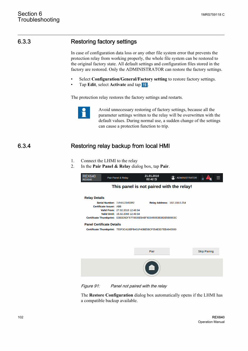
6.3.3 Restoring factory settings
In case of configuration data loss or any other file system error that prevents theprotection relay from working properly, the whole file system can be restored tothe original factory state. All default settings and configuration files stored in thefactory are restored. Only the ADMINISTRATOR can restore the factory settings.
• Select Configuration/General/Factory setting to restore factory settings.• Tap Edit, select Activate and tap .
The protection relay restores the factory settings and restarts.
Avoid unnecessary restoring of factory settings, because all theparameter settings written to the relay will be overwritten with thedefault values. During normal use, a sudden change of the settingscan cause a protection function to trip.
6.3.4 Restoring relay backup from local HMI
1. Connect the LHMI to the relay2. In the Pair Panel & Relay dialog box, tap Pair.
GUID-D0399976-8DBE-4BCE-9272-8C50E7C1C892 V1 EN-US
Figure 91: Panel not paired with the relay
The Restore Configuration dialog box automatically opens if the LHMI hasa compatible backup available.
Section 6 1MRS759118 CTroubleshooting
102 REX640Operation Manual

GUID-16152C56-3602-46F5-A3FF-3113219C436D V1 EN-US
Figure 92: Restoring saved configuration
3. Tap Details to see the differences in product and system identifiers betweenthe backup and the new relay.
GUID-4224433D-C02F-4614-8484-B5150C1F25EB V1 EN-US
Figure 93: Viewing the details of the backup and the new relay
LHMI restores the relay backup if the relay's serial number is different fromthat in the backup and the composition code of the relay contains all the
1MRS759118 C Section 6Troubleshooting
REX640 103Operation Manual

options in the backup. The relay's composition code may contain moreoptions.
4. Tap Write Configuration to Relay.The relay boots so that the new configuration can be taken into use.
GUID-9746DC2C-647E-4F72-BF82-F559D298B215 V1 EN-US
Figure 94: Relay rebooting
The following dialog box appears when the relay backup is restored.
Section 6 1MRS759118 CTroubleshooting
104 REX640Operation Manual

GUID-0F973ED3-832D-4BC5-8876-EDFFF1B7103D V1 EN-US
Figure 95: Backup restoring succeeds
If errors occur, the error details are shown.
GUID-38D84598-2755-4FE5-90B6-2809E626B45E V1 EN-US
Figure 96: Backup restoring fails
1MRS759118 C Section 6Troubleshooting
REX640 105Operation Manual

6.3.5 Restoring relay backup from switchgear HMI
As a precondition for restoring a backup from the SHMI, the replacement relay’slicense must include the same or wider capabilities than the faulty relay’s license.The replacement relay must have the same HW modules in the same slots as thefaulty relay although the other HW modules may differ.
1. Configure the faulty relay’s network address to the replacement relay, andconnect it to the station network so that it can be reached by the SHMI.The network address can be set by using the WHMI.
2. Go to the SHMI’s navigation page and tap the menu button.3. Tap Connect External.4. Type the replacement relay’s IP address and pair with the relay.
The replacement relay’s HMI opens on the SHMI.5. On the HMI view, tap the menu button and select Testing and
Commissioning and Restore.6. Select a backup to be restored from the list of available backups and tap
Restore.If the Restore selection is not enabled, the relay is incompatible with theselected backup.
6.3.6 Setting passwords
IED Users in PCM600 is used to manage user accounts.
User accounts can be created under any default roles (VIEWER, OPERATOR,ENGINEER and ADMINISTRATOR) or additional roles (INSTALLER,SECADM, SECAUD and RBACMNT). Only Administrator can create useraccounts and update the roles-to-rights mapping. Administrator needs to share thedefault password generated for the user account by the tool with the users andrecommend the user to change the password.
1. In IED Users or on the LHMI, change the password of the user account.2. Log in as administrator to reset the users' passwords.
For more information on user management, see the cyber security deploymentguideline.
If the administrator password is lost, contact ABB's technicalcustomer support to retrieve the administrator level access.
6.3.7 Identifying relay application problems
• Check that the function is on.• Check the blocking.• Check the mode.
Section 6 1MRS759118 CTroubleshooting
106 REX640Operation Manual

• Check the measurement value.• Check the connection to trip and disturbance recorder functions.• Check the channel settings.
6.3.7.1 Inspecting wiring
The physical inspection of wiring connections often reveals the wrong connectionfor phase currents or voltages. However, even though the phase current or voltageconnections to protection relay terminals might be correct, wrong polarity of one ormore measurement transformers can cause problems.
• Check the current or voltage measurements and their phase information fromMeasurements page/Phasors.
• Check that the phase information and phase shift between phases is correct.• Correct the wiring if needed.• Check the actual state of the connected binary inputs from Testing and
Commissioning/View I/O.• Test and change the output states manually in Testing and Commissioning/
Force Outputs.
6.3.7.2 Sample data interruptions
Occasionally protection relays can receive corrupted or faulty measurement dataduring runtime. In these cases the operation system halts the correspondingapplication execution until correct data is received. In case of permanent faults, themeasurement chain should be checked to remove the origin of the faultymeasurement data.
In case of persistent faults originating from protection relay'sinternal faults, contact ABB for repair or replacement actions.
1MRS759118 C Section 6Troubleshooting
REX640 107Operation Manual

108

Section 7 Commissioning
7.1 Commissioning checklist
Familiarize yourself with the protection relay and its functionality before you startthe commissioning work.
• Ensure that you have all the needed station drawings such as single line andwiring diagrams.
• Ensure that your version of the technical manual applies to the protection relayversion you test.
• Ensure that your setting software and connectivity packages work with theprotection relay version you test.
• Find out if you need any additional software.• Ensure that you have the relay settings either on paper or in electronic format.
The settings and logic should be well documented.• Inspect the settings to ensure that they are correct.• Ensure that you have the correct cable to connect your PC to the protection
relay's communication port. The RJ-45 port supports any CAT 5 Ethernetcable but the recommendation is STP.
• Test your PC's communication port before you go to the site.• Find out who to contact if you have trouble and make sure you have a means
to contact them.• Find out who is responsible for the settings.• Ensure that you have with you the proper test equipment and all needed
connection cables.• Ensure that the owner of the switchgear familiarizes you with the work site
and any special aspects of it.• Ensure that you know how to operate in emergency situations. Find out where
the first aid and safety materials and exit routes are.
7.2 Checking installation
7.2.1 Checking power supply
• Check the following for both the relay and LHMI, if used.• The auxiliary supply voltage must remain within the permissible input
voltage range under all operating conditions.• The polarity must be correct before connecting auxiliary power supply.
1MRS759118 C Section 7Commissioning
REX640 109Operation Manual

7.2.2 Checking CT circuits
Check that the wiring is in strict accordance with the suppliedconnection diagram.
The CTs must be connected in accordance with the connection diagram of theproject, both with regards to phases and polarity. The following tests arerecommended for every primary CT or CT core connected to the protection relay.
• Primary injection test to verify the current ratio of the CT, the correct wiringup to the protection relay and correct phase sequence connection (that is L1,L2, L3.)
• Polarity check to prove that the predicted direction of the secondary currentflow is correct for a given direction of the primary current flow. This is anessential test for the proper operation of the directional function, protection ormeasurement in the protection relay.
• CT secondary loop resistance measurement to confirm that the currenttransformer secondary loop DC resistance is within specification and that thereare no high resistance joints in the CT winding or wiring.
• CT excitation test to ensure that the correct core in the CT is connected to theprotection relay. Normally only a few points along the excitation curve arechecked to ensure that there are no wiring errors in the system, for example,due to a mistake in connecting the CT's measurement core to the protectionrelay.
• CT excitation test to ensure that the CT is of the correct accuracy rating andthat there are no short circuited turns in the CT windings. Manufacturer'sdesign curves should be available for the CT to compare the actual results.
• Earthing check of the individual CT secondary circuits to verify that eachthree-phase set of main CTs is properly connected to the station earth and onlyat one electrical point.
• Insulation resistance check.
Both the primary and the secondary sides must be disconnectedfrom the line and the protection relay when plotting the excitationcharacteristics.
If the CT secondary circuit is opened or its earth connection ismissing or removed without the CT primary being de-energizedfirst, dangerous voltages may be produced. This can be lethal andcause damage to the insulation. The re-energizing of the CTprimary should be prohibited as long as the CT secondary is openor unearthed.
Section 7 1MRS759118 CCommissioning
110 REX640Operation Manual

7.2.3 Checking VT circuits
Check that the wiring is in strict accordance with the supplied connection diagram.
Correct possible errors before continuing to test the circuitry.
Test the circuitry.
• Polarity check• VT circuit voltage measurement (primary injection test)• Earthing check• Phase relationship• Insulation resistance check
The polarity check verifies the integrity of circuits and the phase relationships. Thepolarity must be measured as close to the protection relay as possible.
The primary injection test verifies the VT ratio and the wiring all the way from theprimary system to the protection relay. Injection must be performed for each phase-to-neutral circuit and each phase-to-phase pair. In each case, voltages in all phasesand neutral are measured.
7.2.4 Checking binary input and output circuits
7.2.4.1 Checking binary input circuits
• Preferably, disconnect the binary input connector from the binary input cards.• Check all the connected signals so that both the input level and the polarity are
in accordance with the protection relay specifications.
Do not use AC voltage. Binary inputs are rated for DC voltageonly.
7.2.4.2 Checking binary output circuits
• Preferably, disconnect the binary output connector from the binary outputcards.
• Check all connected signals so that both load and voltage are in accordancewith the protection relay specifications.
1MRS759118 C Section 7Commissioning
REX640 111Operation Manual

7.3 Authorizations
7.3.1 User authorization
The user categories have been predefined for the LHMI and WHMI, each withdifferent rights and default passwords.
Passwords are settable for user accounts in all roles. Only the following charactersare accepted.
• Numbers 0-9• Letters a-z, A-Z• Space• Special characters !"#%&'()*+´-./:;<=>?@[\]^_`{|}~
By default, the password policies in the protection relay are as follows:
• Minimum password length: 6• Maximum password length: 20• Minimum uppercase characters: 0• Minimum numeric: 0• Minimum special characters: 0
The protection relays are delivered from the factory with default passwords. It isrequired to change the default passwords.
Table 14: Predefined users, their passwords and roles
Username Password Predefined roleVIEWER remote0001 VIEWER
OPERATOR remote0002 OPERATOR
ENGINEER remote0003 ENGINEER
ADMINISTRATOR remote0004 ADMINISTRATOR
The following enforcing rules of the password policies can be customized in IEDUsers in PCM600.
• Option of enabling or disabling password policies (disabling sets defaultpolicies as described above)
• Minimum password length• Use of uppercase characters• Use of lowercase characters• Use of numbers• Use of special characters
Section 7 1MRS759118 CCommissioning
112 REX640Operation Manual

It is required to login as an Administrator in PCM600 in order to change thepassword policies.
Each user can change their own password, but only Administrator can reset thepasswords of other users.
On Factory restore, factory default usernames, passwords and password policiesare restored.
User authorization is disabled by default and can be enabled via theLHMI Configuration/Authorization/Passwords.
For user authorization for PCM600, see the PCM600documentation.
Policy change and configuration is not allowed when the protectionrelay is in offline mode in PCM600.
If the last ADMINISTRATOR password is lost, contact ABB'stechnical customer support to retrieve the administrator levelaccess.
7.4 Setting protection relay and communication
7.4.1 Setting the communication between protection relays andPCM600
The communication between the protection relay and PCM600 is independent ofthe used communication protocol within the substation or to the NCC. It can beseen as a second channel for communication.
The media is always Ethernet and communication is based on TCP/IP.
Each protection relay has an Ethernet front connector for PCM600 access.Depending on the station concept and the used station protocol, additional Ethernetinterfaces may be available on the rear side of the protection relay. All Ethernetinterfaces can be used to connect PCM600.
1MRS759118 C Section 7Commissioning
REX640 113Operation Manual

When an Ethernet based station protocol is used, the PCM600 communication canuse the same Ethernet port and IP address. The protection relay is able to separatethe information belonging to the PCM600 dialog.
To configure the physical connection and the IP addresses:
1. Set up or get the IP addresses of the protection relays.2. Set up the PC for a direct link or connect the PC or workstation to the
network.3. Configure the IP addresses in the PCM600 project for each protection relay.
The addresses are used for communication between protection relays andPCM600.
7.4.1.1 Communication between PCM600 and protection relay
The communication between the protection relay and PCM600 is independent ofthe used communication protocol within the substation or to the NCC.
All communication is done over Ethernet using either IEC 61850 or the FTP/FTPSprotocol.
When an Ethernet-based station protocol is used, the same Ethernet port and IPaddress can be used for PCM600 communication.
Two basic variants have to be considered for the connection between PCM600 andthe protection relay.
• Direct point-to-point link between PCM600 and service port X1.2 on theprotection relay's LHMI or, if an LHMI is not used, the HMI port X0 of thecommunication module
• Indirect link via station LAN or remotely via network
1. If needed, the IP address for the protection relay is set.2. A PC or workstation is set up for a direct link (point-to-point), or the PC or
workstation is connected to the LAN/WAN network.3. The protection relays' IP addresses in the PCM600 project are configured to
match the IP addresses of the physical IEDs.4. Technical keys of the IEDs in the PCM600 project are configured to match the
technical keys of the physical IEDs.
For successful protection relay engineering and usage, the workstation firewallTCP and UDP port configurations should be checked, especially for IEC 61850and FTP. Other protocols are not used for engineering or they are optional.
Section 7 1MRS759118 CCommissioning
114 REX640Operation Manual

Table 15: IP ports used by the relay
Port number Type Default state Description21 TCP Open Explicit FTP over TLS
22 TCP Closed SSH (HMI only,normally closed)
102 TCP Open IEC 61850
443 TCP Open Web server HTTPS
123 UDP Client service notactive by default inrelay
SNTP
502 TCP Closed Modbus TCP
2404 TCP Closed IEC 60870-5-104 TCP
20000 TCP Closed DNP3 TCP
20000 UDP Closed DNP3 UDP
1468 TCP Closed CAL
514 UDP Closed CAL
49220...49235 TCP Closed Ports open on demandfor data transfer whenFTP PASV commandis given
7.4.2 Communication settings
7.4.2.1 Ethernet ports
The protection relay allows the use of a secondary IP address for the station portson the communication modules COM1001...COM1003. This secondary IP networkis assigned to a single Ethernet port and can be used to make separate networks fordifferent communication protocols or, for example, a separate service network forconfiguration purposes. Multicast station/bus communication, such as IEC61850-9-2 LE sampled values and GOOSE, is only supported on the Network 1interface. The parameters for setting the secondary IP network are located underConfiguration/Communication/Ethernet/Network 2 address.
Table 16: Secondary IP address parameters
Parameter Options DescriptionConfiguration/Communication/Ethernet/Network 2 address/Enable
False (default) Network 2 disabled
TRUE Network 2 enabled
Configuration/Communication/Ethernet/Network 2 address/IPaddress
0.0.0.0 IP address for Network 2
Configuration/Communication/Ethernet/Network 2 address/IPaddress
0.0.0.0 Subnet address for Network 2
Configuration/Communication/Ethernet/Network 2address/MAC address
xx-xx-xx-xx-xx-xx MAC address for Network 2
1MRS759118 C Section 7Commissioning
REX640 115Operation Manual
The IP address for Network 2 is disabled by default settings, and all Ethernet portsare assigned to the same IP address used in the Network 1 address menuConfiguration/Communication/Ethernet/Network 1. If Network 2 is taken intouse by the setting Enable="True" (requires reboot), the interlink port X3 of theCOM module is assigned to this second network, using the IP address and subnetparameters in the Network 2 address menu Configuration/Communication/Ethernet/Network 2 address.
If the Network 2 interface is enabled, PTP time synchronization andSMV/GOOSE multicast are disabled for that port.
Section 7 1MRS759118 CCommissioning
116 REX640Operation Manual

COM1002 COM1003ARC1001COM1001
1
2
1
2
1
2
GUID-A553A618-23A2-4128-9B0C-76A3C5CF123E V1 EN-US
Figure 97: Ethernet modes with Network 1 and Network 2
1 Network 1
2 Network 1/Network 2
7.4.2.2 Protocol control
It is possible to allow or block different protocols for different network interfacesin the protection relay using the parameters in Configuration/Communication/Protocols/Network1, Configuration/Communication/Protocols/Network2 andConfiguration/Communication/Protocols/HMI Port.
1MRS759118 C Section 7Commissioning
REX640 117Operation Manual

All protocols are allowed for each network by default, and can be separatelydisabled.
Table 17: Protocol control in the protection relay
Parameter Options DescriptionConfiguration/Communication/Protocols/Network1/FTP
Off Denies FTP and FTPS
On Allows FTP and FTPS
Secure (Default) Allows FTPS only
Configuration/Communication/Protocols/Network2/FTP
Off Denies FTP and FTPS
On Allows FTP and FTPS
Secure (Default) Allows FTPS only
Configuration/Communication/Protocols/HMI Port/FTP
Off Denies FTP and FTPS
On Allows FTP and FTPS
Secure (Default) Allows FTPS only
Configuration/Communication/Protocols/Network1/HTTPS
Off Denies HTTPS
On (Default) Allows HTTPS
Configuration/Communication/Protocols/Network2/HTTPS
Off Denies HTTPS
On (Default) Allows HTTPS
Configuration/Communication/Protocols/Network1/MMS
Off Denies IEC 61850 MMS
On (Default) Allows IEC 61850 MMS
Configuration/Communication/Protocols/Network2/MMS
Off Denies IEC 61850 MMS
On (Default) Allows IEC 61850 MMS
Configuration/Communication/Protocols/HMI Port/MMS
Off Denies IEC 61850 MMS
On (Default) Allows IEC 61850 MMS
Configuration/Communication/Protocols/Network1/DNP
Off Denies DNP3
On (Default) Allows DNP3
Configuration/Communication/Protocols/Network2/DNP
Off Denies DNP3
On (Default) Allows DNP3
Configuration/Communication/Protocols/Network1/Modbus
Off Denies Modbus
On (Default) Allows Modbus
Configuration/Communication/Protocols/Network2/Modbus
Off Denies Modbus
On (Default) Allows Modbus
Configuration/Communication/Protocols/Network1/IEC-60870-5-104
Off Denies IEC 60870-5-104
On (Default) Allows IEC 60870-5-104
Configuration/Communication/Protocols/Network2/IEC-60870-5-104
Off Denies IEC 60870-5-104
On (Default) Allows IEC 60870-5-104
7.4.2.3 Protocol write access rights
Write access rights are configurable for FTP, MMS, and HTTPS protocols inConfiguration/Authorization. The write access parameters are used to narrow
Section 7 1MRS759118 CCommissioning
118 REX640Operation Manual
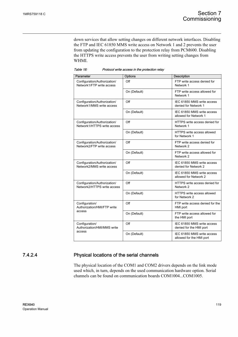
down services that allow setting changes on different network interfaces. Disablingthe FTP and IEC 61850 MMS write access on Network 1 and 2 prevents the userfrom updating the configuration to the protection relay from PCM600. Disablingthe HTTPS write access prevents the user from writing setting changes fromWHMI.
Table 18: Protocol write access in the protection relay
Parameter Options DescriptionConfiguration/Authorization/Network1/FTP write access
Off FTP write access denied forNetwork 1
On (Default) FTP write access allowed forNetwork 1
Configuration/Authorization/Network1/MMS write access
Off IEC 61850 MMS write accessdenied for Network 1
On (Default) IEC 61850 MMS write accessallowed for Network 1
Configuration/Authorization/Network1/HTTPS write access
Off HTTPS write access denied forNetwork 1
On (Default) HTTPS write access allowedfor Network 1
Configuration/Authorization/Network2/FTP write access
Off FTP write access denied forNetwork 2
On (Default) FTP write access allowed forNetwork 2
Configuration/Authorization/Network2/MMS write access
Off IEC 61850 MMS write accessdenied for Network 2
On (Default) IEC 61850 MMS write accessallowed for Network 2
Configuration/Authorization/Network2/HTTPS write access
Off HTTPS write access denied forNetwork 2
On (Default) HTTPS write access allowedfor Network 2
Configuration/Authorization/HMI/FTP writeaccess
Off FTP write access denied for theHMI port
On (Default) FTP write access allowed forthe HMI port
Configuration/Authorization/HMI/MMS writeaccess
Off IEC 61850 MMS write accessdenied for the HMI port
On (Default) IEC 61850 MMS write accessallowed for the HMI port
7.4.2.4 Physical locations of the serial channels
The physical location of the COM1 and COM2 drivers depends on the link modeused which, in turn, depends on the used communication hardware option. Serialchannels can be found on communication boards COM1004...COM1005.
1MRS759118 C Section 7Commissioning
REX640 119Operation Manual

• X7 is the fiber-optic interface. Only driver COM2 can be configured into fiber-optic mode.
• X8 is the RS-485/IRIG-B interface. Both drivers COM1 and COM2 can beconfigured to this interface: COM1 and COM2 can act as two RS-485 2-wirelinks or, alternatively, COM1 can act as one single RS-485 4-wire link. Bothports are galvanically isolated serial communication ports.
Table 19: Connector X8 signals
Pin No Pin name Description Alternative1 GND EARTH
2 GNDC GND connected toearth via 1nF capacitor
3 NC
4 IRIG-B - ISOL2_GND
5 IRIG-B +
6 ISOL_GND RS485 GND
7 RS485 B1/- 2-wire - , COM1 4-wire TX pair, COM1
8 RS485 A1/+ 2-wire + , COM1 4-wire TX pair, COM1
9 RS485 B2/- 2-wire - , COM2 4-wire RX pair, COM1
10 RS485 A2/+ 2-wire + , COM2 4-wire RX pair, COM1
12
34
56
78
910
GUID-3638E235-AB2E-4571-B1EE-DF76AEA0FC36 V1 EN-US
Figure 98: X8 connector pinout for socket on communication board
Table 20: LED configuration (COM1004...COM1005)
LED DescriptionX1 X1 LANA
X2 X2 LANB
X6 X6 LD
X7 TX FO-UART
Table continues on next page
Section 7 1MRS759118 CCommissioning
120 REX640Operation Manual

LED DescriptionX8 TX RS-485/COM2
X8 TX RS-485/COM1
IRIG-B IRIG-B
7.4.2.5 Assigning of a serial communication protocol to a COM serial port
The settings of the serial communication protocol instance include a settingparameter, called either Port or Serial port, which is used to select the COM1 orCOM2 setting.
Since not all serial protocol standards allow changes in linkparameters, all link setting parameters are not found in the COMnsettings. Additional link setting parameters are found in the settingparameter list of the used serial protocol.
7.4.2.6 Serial link diagnostics and monitoring
Serial communication diagnostics and monitoring is divided between the serial linkdriver and the serial communication protocol. The lower-level physical andprotocol-independent aspects of the UART-based serial communication aremonitored in the serial link driver. Diagnostic counters and monitoring values arelocated on the HMI under Monitoring/Communication/COMn (n= 1,2,…).
Depending on the communication protocol, the serial driver software receivessingle characters or complete protocol frames, based on the frame start/stopcharacters or on link frame timing.
Table 21: Setting parameters
Parameter DescriptionFiber mode Defines the fiber-optic mode used. Setting "No
fiber" is the same as galvanic mode.
Serial mode Used for galvanic RS-485 modes 2- or 4-wire.This setting is relevant only if Fiber mode is setto "No fiber".
Baudrate Communication speed used
1MRS759118 C Section 7Commissioning
REX640 121Operation Manual

Table 22: Diagnostic counters and indications
Counters DescriptionCharacters received Counts all incoming non-erroneous characters.
This counter operates regardless of whether theserial driver is set to detect a whole protocol linkframe or just separate characters.
Frames received Counts all protocol-specific non-erroneousframes received. Protocol-specific frames can bebased on timing (for example, Modbus RTU) oron special start and stop characters (forexample, Modbus ASCII).
Frames discarded Counts all protocol-specific erroneous framesreceived. If the driver detects an error whilereceiving a frame, the whole frame isautomatically discarded. This also means thatthe protocol in question never receives a faultylink frame from the driver. When this counter isincremented, one of the detailed error counters(Parity, Overrun, Framing) can also beincremented.
Frames transmitted Counts all protocol-specific frames transmittedfrom the COM channel
Collisions Counts the number of transmission collisionsthat have occurred. Used in RS-485 mode bysome protocols where transmissions couldcollide with reception. For example, DNP3unsolicited reporting mode
Parity errors Counts the number of parity errors detected incharacters received
Overrun errors Counts the number of overrun errors detected incharacters received
Framing errors Counts the number of framing errors detected incharacters received
Link status In write direction: By writing value 1 to thisparameter, all the diagnostic counters are resetto 0.
Link status In monitoring direction: If the driver instance is inuse by any communication protocol, themonitoring value shows value 1. Otherwise, thevalue is 0.
7.4.2.7 Defining Ethernet port settings
Change the Ethernet port settings primarily via PCM600 to ensurethat PCM600 is able to export a consistent configuration toSYS600. Ethernet port settings are recommended to be changedonly when the device is stand-alone and properly configured.
1. Select Configuration/Communication/Ethernet/Network1 address orConfiguration/Communication/Ethernet/Network2 address.
2. Define the settings for Network1 or Network2.
Section 7 1MRS759118 CCommissioning
122 REX640Operation Manual

• IP address• Subnet mask• Default gateway of the optional rear port Ethernet connector
7.4.2.8 Defining serial port settings
1. Select Configuration/Communication/COM1 or COM2.2. Define the settings for the serial port.
It is possible to change the general serial communication parameters per port.Select fiber or galvanic mode with the proper baud rate.
7.4.2.9 Setting communication protocol parameters
1. Select Configuration/Communication/<protocol>.2. Change the protocol specific settings.
Possible settings to be changed are, for example, the selected communicationport, address and link mode.
7.4.2.10 RS-485 bias and termination settings
A 6 x DIP switch is located on the COM1004...COM1005 cards. The COM cardneeds to be pulled out from the relay case to access the switch. See Figure 99 forthe location of the switch. RS-485 biasing and termination settings are possiblethrough this switch. If the switch is in “OFF” position, bias and termination aredisabled and in “ON” position, they are enabled.
1MRS759118 C Section 7Commissioning
REX640 123Operation Manual

ON
OFF
GUID-D3D92231-816C-465F-8357-AF60B4A64048 V2 EN-US
Figure 99: DIP switches on the COM1004...COM1005 cards
Table 23: Bias and termination DIP switch
Switch Signal X8 pin Type1 RS485_A1/+ 8 Bias
2 RS485_A1/+RS485_B1/-
Bus termination
3 RS485_B1/- 7 Bias
4 RS485_A2/+ 10 Bias
5 RS485_A2/+RS485_B2/-
Bus termination
6 RS485_B2/- 9 Bias
7.4.3 Connecting and setting HMI
• Connect the LHMI to the relay either directly from the main unit port X1.1 tothe relay’s X0/HMI port or through station network from the main unit portX1.1 to the relay’s Network 1 port. The HMI’s service port X1.2 is intendedfor local service access to the relay using PCM600 or the WHMI.
• Always connect the SHMI through the station network.• Depending on the planned network topology communication, adapt the HMI
settings to establish communication between the relay and the HMI. Theservice port settings must be set correctly to allow access to the relay eitherdirectly or through the station network.
Section 7 1MRS759118 CCommissioning
124 REX640Operation Manual

Table 24: HMI settings
Communication parameter DescriptionMain Unit Port/Automatic Address Automatically obtains the address for main unit
port from the relay’s HMI port
Main Unit Port/Address Static address used when the relay is connectedto the station network
Main Unit Port/Netmask Static network mask used when the relay isconnected to the station network
Main Unit Port/Gateway Gateway enabled when router is used betweenthe relay and the HMI
Main Unit Port/Gateway Address Router address
Service Port/Address Static address for the service port
Service Port/Netmask Static network mask for the service port
Service Port/Enable DHCP server Normally enabled to route service portautomatically to the main unit port and the relay
Configure the HMI service port and the main unit port to separatesubnetworks.
Service port DHCP server routes the main unit networkautomatically to the service port.
7.4.3.1 Connecting local HMI directly to relay
• Use a CAT 6 S/FTP cable to connect the LHMI to the protection relay.• Connect the cable to the X1.1/Main unit connector on the LHMI and to the
X0/HMI connector on the protection relay's communication module.
1MRS759118 C Section 7Commissioning
REX640 125Operation Manual

Table 25: Example of communication settings for direct local HMI connection
Parameter ValueHMI communication parameter Main Unit Port/Automatic
AddressChecked
Main Unit Port/Address -
Main Unit Port/Netmask -
Main Unit Port/Gateway Not checked
Main Unit Port/GatewayAddress
-
Service Port/Address 192.168.1.1
Service Port/Netmask 255.255.255.0
Service Port/Enable DHCPserver
Checked
REX640 communicationparameters
Configuration/Communication/Ethernet/HMI/IP address
192.168.0.254
Computer network adapter forHMI service port
IP address Obtain automatically
REX640 1
X0/H
MI
X1/L
AN
A
X2/L
AN
B X3
REX640 1
X0/H
MI
X1/L
AN
A
X2/L
AN
B X3
REX640 1
X0/H
MI
X1/L
AN
A
X2/L
AN
B X3
LHMI
X1.1
Mai
nUni
t
X1.2
Ser
vice
LHMI
X1.1
Mai
nUni
t
X1.2
Ser
vice
REX640 1
X0/H
MI
X1/L
AN
A
X2/L
AN
B X3
LHMI
X1.1
Mai
nUni
t
X1.2
Ser
vice
REX640 2
X0/H
MI
X1/L
AN
A
X2/L
AN
B X3
REX640 2
X0/H
MI
X1/L
AN
A
X2/L
AN
B X3
REX640 2
X0/H
MI
X1/L
AN
A
X2/L
AN
B X3
LHMI
X1.1
Mai
nUni
t
X1.2
Ser
vice
LHMI
X1.1
Mai
nUni
t
X1.2
Ser
vice
REX640 2
X0/H
MI
X1/L
AN
A
X2/L
AN
B X3
LHMI
X1.1
Mai
nUni
t
X1.2
Ser
vice
REX640 3
X0/H
MI
X1/L
AN
A
X2/L
AN
B X3
REX640 3
X0/H
MI
X1/L
AN
A
X2/L
AN
B X3
REX640 3
X0/H
MI
X1/L
AN
A
X2/L
AN
B X3LHMI
X1.1
Mai
nUni
t
X1.2
Ser
vice
LHMI
X1.1
Mai
nUni
t
X1.2
Ser
vice
REX640 3
X0/H
MI
X1/L
AN
A
X2/L
AN
B X3
LHMI
X1.1
Mai
nUni
t
X1.2
Ser
vice
GUID-0A18CC9E-1CBA-4813-9842-3EE2BB0593DD V1 EN-US
Figure 100: Example of direct local HMI connection
7.4.3.2 Connecting local HMI to a relay through station network
PCM600 or WHMI can be used to read the network settings of the relay's stationport via Configuration/Communication/Ethernet/Network1 address.
1. On the LHMI, tap Network Settings to configure the network settings of themain unit port X1.1.Network settings are also available as an Advanced page.
Section 7 1MRS759118 CCommissioning
126 REX640Operation Manual
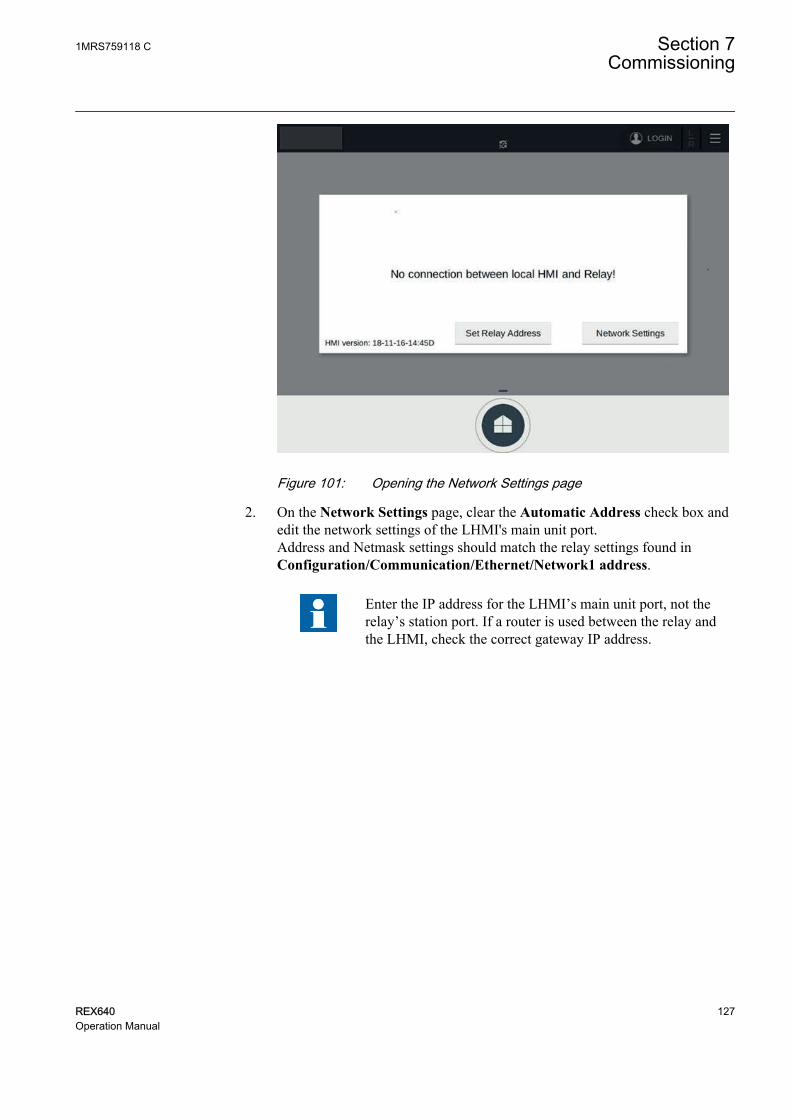
GUID-EFDCCB00-4FDF-4F2A-A28D-F03F2EC37450 V1 EN-US
Figure 101: Opening the Network Settings page
2. On the Network Settings page, clear the Automatic Address check box andedit the network settings of the LHMI's main unit port.Address and Netmask settings should match the relay settings found inConfiguration/Communication/Ethernet/Network1 address.
Enter the IP address for the LHMI’s main unit port, not therelay’s station port. If a router is used between the relay andthe LHMI, check the correct gateway IP address.
1MRS759118 C Section 7Commissioning
REX640 127Operation Manual

GUID-425A7E2C-C0C3-48FE-A6CA-5EE34C856D21 V1 EN-US
Figure 102: Configuring the network settings of the main unit port
3. Tap Apply and close the Network Settings page.4. Connect a network cable between the LHMI and the relay station port or
network switch.5. In the No connection between local LHMI and Relay! dialog box, tap Set
Relay Address.6. In the Relay address dialog box, type the relay's address found in
Configuration/Communication/Ethernet/Network1 address and tap OK.The LHMI connects to the relay through the station port.
Section 7 1MRS759118 CCommissioning
128 REX640Operation Manual
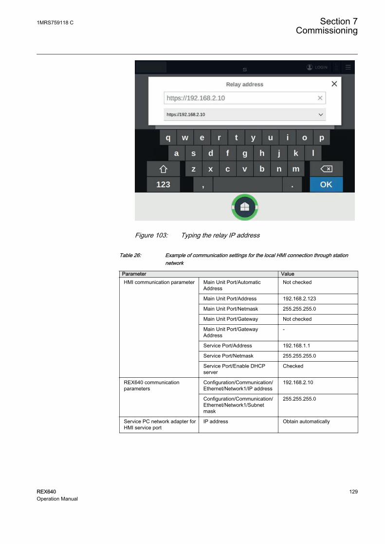
GUID-680D069A-B381-4415-BDE5-CA7A022D297B V1 EN-US
Figure 103: Typing the relay IP address
Table 26: Example of communication settings for the local HMI connection through stationnetwork
Parameter ValueHMI communication parameter Main Unit Port/Automatic
AddressNot checked
Main Unit Port/Address 192.168.2.123
Main Unit Port/Netmask 255.255.255.0
Main Unit Port/Gateway Not checked
Main Unit Port/GatewayAddress
-
Service Port/Address 192.168.1.1
Service Port/Netmask 255.255.255.0
Service Port/Enable DHCPserver
Checked
REX640 communicationparameters
Configuration/Communication/Ethernet/Network1/IP address
192.168.2.10
Configuration/Communication/Ethernet/Network1/Subnetmask
255.255.255.0
Service PC network adapter forHMI service port
IP address Obtain automatically
1MRS759118 C Section 7Commissioning
REX640 129Operation Manual

REX640 1
X0/H
MI
X1/L
AN
A
X2/L
AN
B X3
REX640 1
X0/H
MI
X1/L
AN
A
X2/L
AN
B X3
REX640 1
X0/H
MI
X1/L
AN
A
X2/L
AN
B X3
REX640 2X0
/HM
I
X1/L
AN
A
X2/L
AN
B X3
REX640 2X0
/HM
I
X1/L
AN
A
X2/L
AN
B X3
REX640 2X0
/HM
I
X1/L
AN
A
X2/L
AN
B X3
REX640 3
X0/H
MI
X1/L
AN
A
X2/L
AN
B X3
REX640 3
X0/H
MI
X1/L
AN
A
X2/L
AN
B X3
REX640 3
X0/H
MI
X1/L
AN
A
X2/L
AN
B X3
LHMI
X1.1
Mai
nUni
t
X1.2
Ser
vice
LHMI
X1.1
Mai
nUni
t
X1.2
Ser
vice
Switch
LHMI
X1.1
Mai
nUni
t
X1.2
Ser
vice
LHMI
X1.1
Mai
nUni
t
X1.2
Ser
vice
LHMI
X1.1
Mai
nUni
t
X1.2
Ser
vice
LHMI
X1.1
Mai
nUni
t
X1.2
Ser
vice
GUID-E6C372F3-BDC2-47FB-83BE-5FF063930E26 V1 EN-US
Figure 104: Example of local HMI connection through station network
7.4.3.3 Connecting switchgear HMI to a relay through station network
PCM600 or WHMI can be used to read the network settings of the relay's stationport via Configuration/Communication/Ethernet/Network1 address.
1. On the SHMI, tap Network Settings to configure the network settings of themain unit port X1.1.Network settings are also available as an Advanced page.
Section 7 1MRS759118 CCommissioning
130 REX640Operation Manual
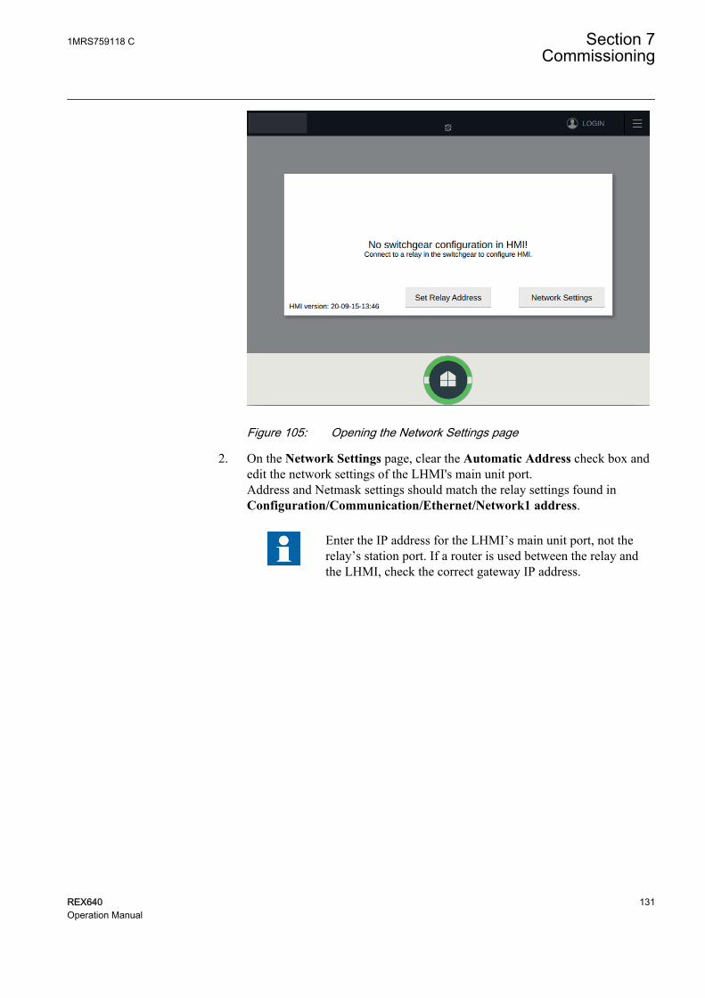
GUID-88372DAD-0168-4E3A-B7DB-512FC32FA3A0 V1 EN-US
Figure 105: Opening the Network Settings page
2. On the Network Settings page, clear the Automatic Address check box andedit the network settings of the LHMI's main unit port.Address and Netmask settings should match the relay settings found inConfiguration/Communication/Ethernet/Network1 address.
Enter the IP address for the LHMI’s main unit port, not therelay’s station port. If a router is used between the relay andthe LHMI, check the correct gateway IP address.
1MRS759118 C Section 7Commissioning
REX640 131Operation Manual
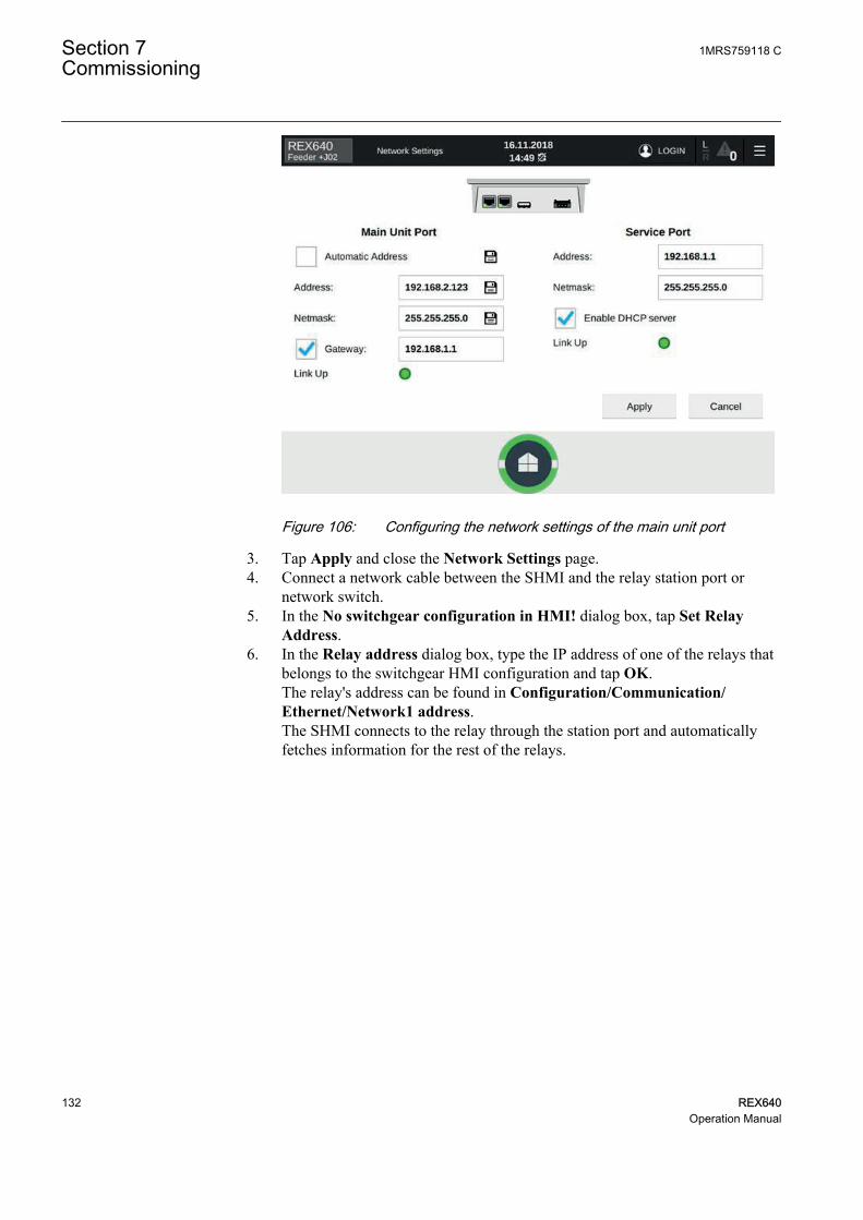
GUID-425A7E2C-C0C3-48FE-A6CA-5EE34C856D21 V1 EN-US
Figure 106: Configuring the network settings of the main unit port
3. Tap Apply and close the Network Settings page.4. Connect a network cable between the SHMI and the relay station port or
network switch.5. In the No switchgear configuration in HMI! dialog box, tap Set Relay
Address.6. In the Relay address dialog box, type the IP address of one of the relays that
belongs to the switchgear HMI configuration and tap OK.The relay's address can be found in Configuration/Communication/Ethernet/Network1 address.The SHMI connects to the relay through the station port and automaticallyfetches information for the rest of the relays.
Section 7 1MRS759118 CCommissioning
132 REX640Operation Manual
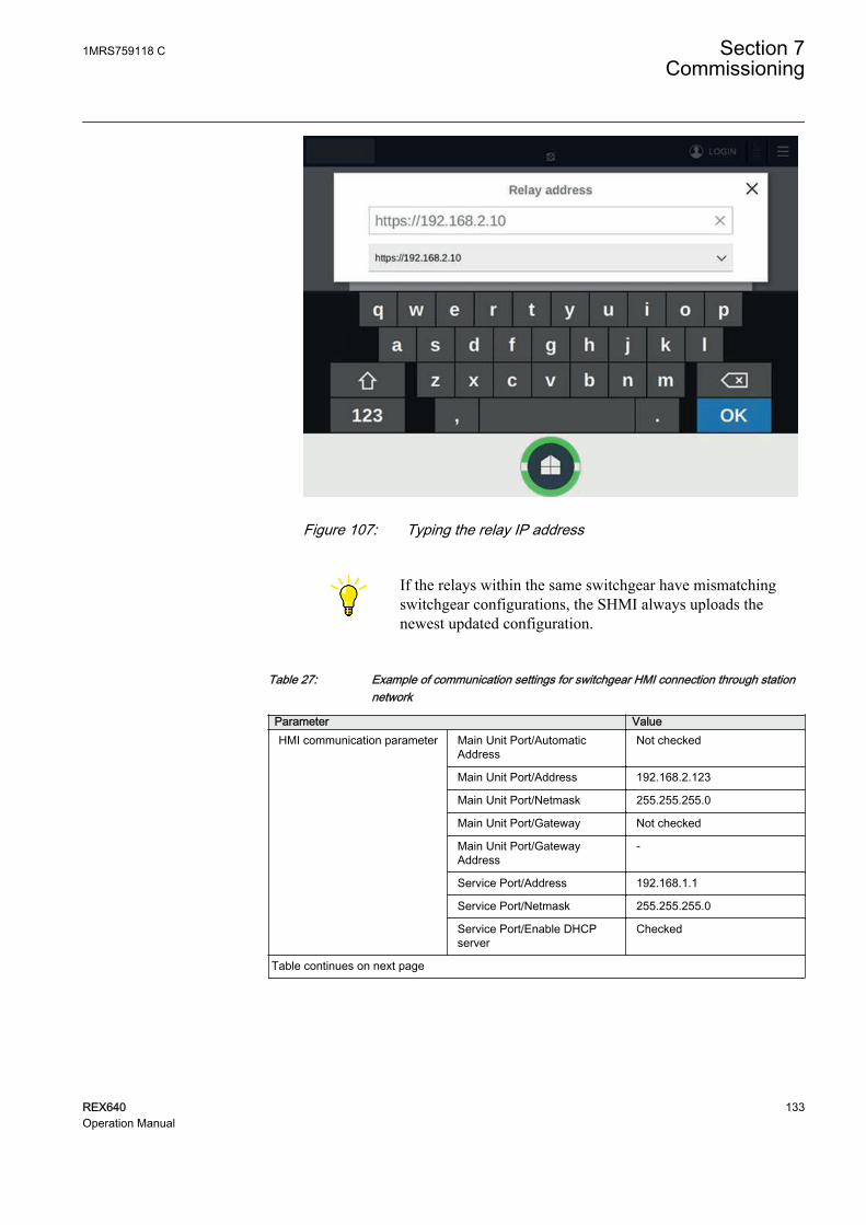
GUID-680D069A-B381-4415-BDE5-CA7A022D297B V1 EN-US
Figure 107: Typing the relay IP address
If the relays within the same switchgear have mismatchingswitchgear configurations, the SHMI always uploads thenewest updated configuration.
Table 27: Example of communication settings for switchgear HMI connection through stationnetwork
Parameter ValueHMI communication parameter Main Unit Port/Automatic
AddressNot checked
Main Unit Port/Address 192.168.2.123
Main Unit Port/Netmask 255.255.255.0
Main Unit Port/Gateway Not checked
Main Unit Port/GatewayAddress
-
Service Port/Address 192.168.1.1
Service Port/Netmask 255.255.255.0
Service Port/Enable DHCPserver
Checked
Table continues on next page
1MRS759118 C Section 7Commissioning
REX640 133Operation Manual

Parameter ValueREX640 communicationparameters
Configuration/Communication/Ethernet/Network1/IP address
192.168.2.10
Configuration/Communication/Ethernet/Network1/Subnetmask
255.255.255.0
Service PC network adapter forHMI service port
IP address Obtain automatically
REX640 1
X0/H
MI
X1/L
AN
A
X2/L
AN
B X3
REX640 1
X0/H
MI
X1/L
AN
A
X2/L
AN
B X3
REX640 1
X0/H
MI
X1/L
AN
A
X2/L
AN
B X3
REX640 2
X0/H
MI
X1/L
AN
A
X2/L
AN
B X3
REX640 2
X0/H
MI
X1/L
AN
A
X2/L
AN
B X3
REX640 2
X0/H
MI
X1/L
AN
A
X2/L
AN
B X3
REX640 3
X0/H
MI
X1/L
AN
A
X2/L
AN
B X3REX640 3
X0/H
MI
X1/L
AN
A
X2/L
AN
B X3REX640 3
X0/H
MI
X1/L
AN
A
X2/L
AN
B X3
Switch
SHMI
X1.1
Mai
nUni
t
X1.2
Ser
vice
SHMI
X1.1
Mai
nUni
t
X1.2
Ser
vice
GUID-DC684264-F1E2-4C74-B633-1F633D1FF01B V1 EN-US
Figure 108: Example of switchgear HMI connection through station network
7.4.3.4 Pairing HMI with relay
To enable proper connection and functionality between the HMI and a relay, theyneed to be paired.
1. Set up communication to establish a connection between the HMI and therelay.
2. In the confirmation window, tap Trust this Relay.
Section 7 1MRS759118 CCommissioning
134 REX640Operation Manual

GUID-70F11828-798E-4894-BDC1-9C9B5F8595E3 V1 EN-US
Figure 109: Confirming the relay connection
A page for initiating the pairing opens.3. To initiate pairing, login as administrator.
GUID-43DF8EC5-3C10-4F7B-8E87-83F6C6E7A4F1 V1 EN-US
Figure 110: Administrator login required
4. Finalize the pairing process depending on the HMI used.• To pair the LHMI with one relay only, tap Pair.• To pair the SHMI with multiple relays, tap Pair. The connected relays
are shown on the list of available relays. Select the trusted relays andtap Trust selected.
1MRS759118 C Section 7Commissioning
REX640 135Operation Manual

GUID-A25A7168-2661-4583-84C3-8DE812AE30E4 V1 EN-US
Figure 111: Pairing the local HMI with the relay
GUID-F1203FFC-DE33-4A44-A0DC-EE8ECA54408F V1 EN-US
Figure 112: Pairing the switchgear HMI with the relays
After a successful pairing, the LHMI Home page opens.
If Pair is selected while connecting to the first relay in aswitchgear, the SHMI attempts to pair with all the relays itfinds and is able to connect and login to within the switchgear.If pairing is at first skipped but needed later, initiate theconnection process again by typing in the IP address of one ofthe relays and choose to pair. Optionally, it is possible to loginand pair each relay individually.
Section 7 1MRS759118 CCommissioning
136 REX640Operation Manual

If the pairing is skipped, the LHMI can be used for monitoringpurposes only. Pairing can be initiated later via the drop-downmenu.
7.4.3.5 Setting system time and time synchronization
• Select Configuration/Time/System time to set the system time and timezone.
• Select Configuration/Time/Synchronization/Synch source to set thesynchronization source.
Setting daylight saving timeThe protection relay can be set to determine the correct date for the DST shiftevery year. The local time is used to set the DST.
1. Set the DST on day (weekday) and DST off day (weekday) parameters todefine on which week day the time shift occurs.
2. Set the DST on date (day), DST on date (month) and DST off date (month)parameters to define on which month and week the time shift occurs.The DST on/off date must precede the selected DST on/off day and be withinthe same week as the DST shift.
Table 28: Possible date values for DST change on Sunday
Day of the DST shift DST on/off date (day)First Sunday of the month 1
Second Sunday of the month 8
Third Sunday of the month 15
Fourth Sunday of the month 22
Last Sunday, if the month has 30 days 24
Last Sunday, if the month has 31 days 25
For example, if DST on time shift occurs on the last Sunday in March, at03:00 local time and DST off time shift occurs on the last Sunday in October,at 04:00 local time, the settings are the following.
DST on time (hours): 3 h
DST on time (minutes): 0 min
DST on date (day): 25
DST on date (month): March
DST on day (weekday): Sunday
DST off time (hours): 4 h
DST off time (minutes): 0 min
Table continues on next page
1MRS759118 C Section 7Commissioning
REX640 137Operation Manual

DST off date (day): 25
DST off date (month): October
DST off day (weekday): Sunday
Set the DST on day (weekday) and DST off day (weekday) to"reserved" to determine the exact date and time for the DST shift.Repeat the setting yearly, as the time for the DST shift is not on thesame date every year.
To disable the DST, set the DST in use parameter to "False".
7.5 Testing of protection relay operation
The protection relay has to be in the test mode before the digital outputs and certainoutput signals of protection and other functions can be activated.
7.5.1 Selecting IED test mode
The test mode can be activated using the LHMI. The Home button is flashing greenat low frequency to indicate that the test mode is activated. By default, the testmode can only be changed from the LHMI. Activation by remote client is possible,see the technical manual.
The test mode is useful for simulated testing of functions and outputs withoutproviding current inputs.
• Select Testing and Commissioning/Test mode/IED test to activate theinternal fault test.
Section 7 1MRS759118 CCommissioning
138 REX640Operation Manual

GUID-05CFE41C-A635-4032-9484-3854B3403D70 V1 EN-US
Figure 113: Selecting IED test mode
If the test mode is not cancelled, it remains on and the Home buttonremains flashing.
7.5.2 Testing and commissioning support on local HMI
The LHMI supports the engineer during the relay’s testing, commissioning andtroubleshooting activities. The information, traditionally accessible throughdifferent paths within the menu structure, is provided in a collectively grouped andvisualized format on the Testing and Commissioning pages found on the top barmenu.
Some of the Testing and Commissioning pages require the relay tobe set in test mode.
1MRS759118 C Section 7Commissioning
REX640 139Operation Manual

GUID-1ADCE271-EB04-4FFB-B703-268B42286FD0 V1 EN-US
Figure 114: Home page for Testing and Commissioning pages
7.5.2.1 Testing I/O interface
1. On the View I/O page, monitor the status of digital inputs and outputs andanalog inputs.1.1. Tap the module on the page to open the module-specific page.1.2. Tap or to scroll over the different modules.
GUID-D6A397FC-EF84-4C5D-BA21-AA7B909FCBED V1 EN-US
Figure 115: View I/O page
2. On the Force Outputs page, force the state of digital outputs.
Section 7 1MRS759118 CCommissioning
140 REX640Operation Manual

GUID-153062F6-F84E-4D46-8F11-55AE26783C68 V1 EN-US
Figure 116: Force Outputs page
2.1. Tap the module on the page to open the module-specific page.2.2. Tap or to scroll over the different modules.2.3. On the module-specific page, select state On or Off for the selected
output channel and tap Force.
GUID-1CB51F27-D05C-48C0-864E-87C5CD2BEDE8 V2 EN-US
Figure 117: Forcing outputs of selected module
3. On the Simulate Inputs page, simulate the digital and analog inputs.
1MRS759118 C Section 7Commissioning
REX640 141Operation Manual

3.1. Tap the module on the page to open the module-specific page.3.2. Tap or to scroll over the different modules.3.3. On the BIO module specific page, select On or Off for the selected
channel and tap Simulate.3.4. On the AIM/SIM module specific page, select Primary or Secondary
for Simulation Unit, set the simulation signal value for a channel andtap Simulate.
GUID-8870A02D-9C18-44B2-8410-85DEB62E0525 V1 EN-US
Figure 118: Simulating digital inputs of selected module
GUID-FF9D44A8-3801-4C35-B5F4-27280D1D5A01 V1 EN-US
Figure 119: Simulating analog inputs of selected module
Section 7 1MRS759118 CCommissioning
142 REX640Operation Manual

All current and voltage input signals (channels) share thesame phase angle value, that is, they are in phase.
7.5.2.2 Testing functions
1. On the Force Functions page, activate or deactivate an output signal forprotection or other function in one of the alternative ways.• Tap Edit, select the protection category from the left of the page and
activate or deactivate an output signal of a function from the list.• Tap Reset to deactivate all output signals for the function.
GUID-A8C0E4CE-70B6-4484-A9E1-3EFD13F552FB V1 EN-US
Figure 120: Force Functions page
2. On the Send Events page, send a selected event over the station bus to asubstation client.The sent events are defined in the IEC 61850 data sets. To send all availableevents in the relay, tap Send All Events.
When the events are sent, the related functions are notactivated.
1MRS759118 C Section 7Commissioning
REX640 143Operation Manual

GUID-94687084-2B9A-45D4-AD4A-D022CA593124 V1 EN-US
Figure 121: Send Events page
7.5.2.3 Checking GOOSE data
1. On the GOOSE Receiving page, check the GOOSE data that the relaysubscribes from the Ethernet network.The left side of this page shows a list of devices that send GOOSE messagesto the relay. These devices that publish data for the relay are defined in therelay configuration. The right side of the page shows the GOOSE data therelay receives from the network. The data set consists of value and qualityattributes. The received data has status indicators where green means all OK,yellow warning and red error.
Section 7 1MRS759118 CCommissioning
144 REX640Operation Manual

GUID-F1982C6F-DDCB-4963-A03F-97407D891C4F V1 EN-US
Figure 122: GOOSE Receiving page
2. On the GOOSE Sending page, check the status of the relay's configuredGOOSE control blocks and the values of the sent data.The left side of this page shows a list of the devices where the relay sendsGOOSE messages. In the system there may be more devices, but thesedevices are according to relay configuration the ones subscribing the datafrom the relay. The right side of the page shows the GOOSE data that therelay sends to the network. The data set consists of value and qualityattributes. The sent data has status indicators where green means all OK,yellow warning and red error.
GUID-460E8BEE-95EB-4561-B5CC-423A2686E50D V1 EN-US
Figure 123: GOOSE Sending page
1MRS759118 C Section 7Commissioning
REX640 145Operation Manual
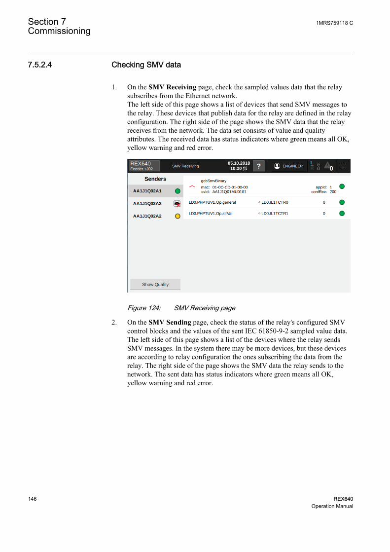
7.5.2.4 Checking SMV data
1. On the SMV Receiving page, check the sampled values data that the relaysubscribes from the Ethernet network.The left side of this page shows a list of devices that send SMV messages tothe relay. These devices that publish data for the relay are defined in the relayconfiguration. The right side of the page shows the SMV data that the relayreceives from the network. The data set consists of value and qualityattributes. The received data has status indicators where green means all OK,yellow warning and red error.
GUID-3F5F8BB4-025E-4710-A6BD-2E07E40B0CDB V1 EN-US
Figure 124: SMV Receiving page
2. On the SMV Sending page, check the status of the relay's configured SMVcontrol blocks and the values of the sent IEC 61850-9-2 sampled value data.The left side of this page shows a list of the devices where the relay sendsSMV messages. In the system there may be more devices, but these devicesare according to relay configuration the ones subscribing the data from therelay. The right side of the page shows the SMV data the relay sends to thenetwork. The sent data has status indicators where green means all OK,yellow warning and red error.
Section 7 1MRS759118 CCommissioning
146 REX640Operation Manual

GUID-17BB9307-FD1C-439C-83C7-FCF43D481692 V1 EN-US
Figure 125: SMV Sending page
7.5.3 Selecting internal fault test
The internal fault may be tested by using the LHMI. When enabling the test, theinternal relay fault output contact is activated. See the technical manual for theinternal relay fault output contact location. The internal fault can only be activatedby using the LHMI.
Differing from real internal fault situation, the other output contactsare not released and locked during the test. In other words,protection functions can operate and trip the outputs when theinternal fault is tested.
1. Ensure that the Test mode is activated.2. Select Testing and Commissioning/Internal fault test/Test on to activate
the internal fault test.
7.5.4 Selecting IED blocked or IED test and blocked mode
The IED blocked mode and the IED test and blocked mode can be activated usingthe LHMI. The Home button flashes green when the device is in the IED blockedor IED test and blocked mode. By default, the test mode can only be changed fromthe LHMI. Activation by remote client is possible, see the technical manual.
The test mode can be used for simulated testing of functions and outputs withoutproviding current inputs. The IED blocked mode can be used to block the physicaloutputs to the process.
1MRS759118 C Section 7Commissioning
REX640 147Operation Manual

• Select Testing and Commissioning/Test mode/IED blocked or IED testand blocked to activate the IED blocked mode and the IED test and blockedmode.
Table 29: Test mode
Test mode Description ProtectionBEH_BLK
ProtectionBEH_TST
Normal mode Normal operation FALSE FALSE
IED blocked Protection works as in “Normal mode”but the ACT configuration can be usedto block physical outputs to process.Control function commands areblocked.
TRUE FALSE
IED test Protection works as in “Normal mode”but protection functions work inparallel with test parameters
FALSE TRUE
IED test andblocked
Protection works as in “Normal mode”but protection functions work inparallel with the test parameter. TheACT configuration can be used toblock physical outputs to process. Thecontrol function command is blocked.
TRUE TRUE
If the IED blocked or IED test and blocked mode is not cancelled, itremains on and the Home button remain flashing.
7.6 ABB Product Data Registration
The ABB Product Data Registration feature traces composition changes in theprotection relay's SW or HW. Traceability allows better support and maintenancepossibilities.
After a composition change, an LCT indication is seen on the LHMI at theprotection relay start-up. PCM600 reads the changed data from the protectionrelay.
Therefore a connection to the protection relay must be established first.Composition data can be read with PCM600 by enabling LCT during PCM600installation and activating collection in PCM600 from the Lifecycle Handlingmenu. For detailed information, see PCM600 online help.
The LCT indication is cleared in the same way as other indications. If compositiondata is not collected with PCM600, the indication reappears after protection relay'sreboot.
Section 7 1MRS759118 CCommissioning
148 REX640Operation Manual

If the LCT indication appears, update the protection relaycomposition to avoid information mismatch. The LCT indicationdoes not affect the functionality of the protection relay.
The number of composition and setting changes can be seen from the Compositionchanges parameter in Monitoring/IED status.
LCT-generated events are reported as a bit-masked value (change flags); forexample, value 9 means that hardware and site identifier changes have been doneto the relay.
Table 30: LCT-generated events
Bit Description0 Hardware change
1 Software change
2 Configuration change
3 Site identifier change
4 Retrofit change
Other Not in used
1MRS759118 C Section 7Commissioning
REX640 149Operation Manual

150

Section 8 Glossary
AC Alternating currentAD Active directoryCAL Central activity loggingCAM Centralized account managementCAT 5 A twisted pair cable type designed for high signal
integrityCAT 6 Cable standard for gigabit Ethernet and other network
protocols that is backward compatible with CAT 5/5eand CAT 3 cable standards
CFG Configuration fileCOMTRADE Common format for transient data exchange for power
systems. Defined by the IEEE Standard.CT Current transformerDAT 1. Data attribute type
2. Data fileData set The content basis for reporting and logging containing
references to the data and data attribute valuesDC 1. Direct current
2. Disconnector3. Double command
DHCP Dynamic Host Configuration ProtocolDIP switch A set of on-off switches arranged in a standard dual
in-line packageDNP3 A distributed network protocol originally developed by
Westronic. The DNP3 Users Group has the ownershipof the protocol and assumes responsibility for itsevolution.
DST Daylight-saving timeEEPROM Electrically erasable programmable read-only memoryEMC Electromagnetic compatibilityEthernet A standard for connecting a family of frame-based
computer networking technologies into a LANFPGA Field-programmable gate array
1MRS759118 C Section 8Glossary
REX640 151Operation Manual

FPN Flexible product namingFTP File transfer protocolFTPS FTP SecureGDE Graphical Display Editor in PCM600GND Ground/earthGOOSE Generic Object-Oriented Substation EventHF High frequencyHMI Human-machine interfaceHSR High-availability seamless redundancyHTTPS Hypertext Transfer Protocol SecureHW HardwareIEC International Electrotechnical CommissionIEC 60870-5-104 Network access for IEC 60870-5-101IEC 61850 International standard for substation communication
and modelingIEC 61850-9-2 A communication protocol based on the IEC 61850
standard seriesIEC 61850-9-2 LE Lite Edition of IEC 61850-9-2 offering process bus
interfaceIED Intelligent electronic deviceIP Internet protocolIP address A set of four numbers between 0 and 255, separated
by periods. Each server connected to the Internet isassigned a unique IP address that specifies thelocation for the TCP/IP protocol.
IRF 1. Internal fault2. Internal relay fault
IRIG-B Inter-Range Instrumentation Group's time code formatB
LAN Local area networkLCP Liquid crystal polymerLCT Life cycle traceabilityLED Light-emitting diodeLF Low frequencyLHMI Local human-machine interfaceMMS 1. Manufacturing message specification
2. Metering management system
Section 8 1MRS759118 CGlossary
152 REX640Operation Manual

Modbus A serial communication protocol developed by theModicon company in 1979. Originally used forcommunication in PLCs and RTU devices.
Modbus ASCII Link mode using 7-bit ASCII charactersModbus RTU Link mode using 8-bit binary charactersNCC Network control centerOTP One-time passwordPC 1. Personal computer
2. PolycarbonatePCM600 Protection and Control IED ManagerPKI Public key infrastructurePTP Precision Time ProtocolRAM Random access memoryRJ-45 Galvanic connector typeRoHS Restriction of hazardous substancesROM Read-only memoryRS-485 Serial link according to EIA standard RS485RTC Real-time clockRTD Resistance temperature detectorSCL XML-based system configuration description language
defined by IEC 61850SDM600 A software solution for automatic management of
service and cyber security relevant data acrosssubstations
SHMI Switchgear HMISI Sensor inputSingle-line diagram Simplified notation for representing a three-phase
power system. Instead of representing each of threephases with a separate line or terminal, only oneconductor is represented.
SLD Single-line diagramSMV Sampled measured valuesSNTP Simple Network Time ProtocolSSH Secure shellSTP Shielded twisted-pairSW SoftwareTCP Transmission Control Protocol
1MRS759118 C Section 8Glossary
REX640 153Operation Manual

TCP/IP Transmission Control Protocol/Internet ProtocolTLS Transport layer securityUDP User datagram protocolUSB Universal serial busVT Voltage transformerWAN Wide area networkWHMI Web human-machine interfaceXRIO eXtended Relay Interface by OMICRON
Section 8 1MRS759118 CGlossary
154 REX640Operation Manual

155


ABB Distribution SolutionsP.O. Box 699FI-65101 VAASA, FinlandPhone +358 10 22 11
www.abb.com/mediumvoltage
—
© Copyright 2020 ABB. All rights reserved. 1MR
S75
9118
C