Commissioning manual - ABB Group
300
Relion ® 670 SERIES Generator protection REG670 Version 2.2 ANSI Commissioning manual
-
Upload
khangminh22 -
Category
Documents
-
view
2 -
download
0
Transcript of Commissioning manual - ABB Group

Relion® 670 SERIES
Generator protection REG670Version 2.2 ANSICommissioning manual


Document ID: 1MRK 502 073-UUSIssued: June 2021
Revision: JProduct version: 2.2
© 2017 - 2021 Hitachi Power Grids. All rights reserved

CopyrightThis document and parts thereof must not be reproduced or copied without written permission fromHitachi Power Grids, and the contents thereof must not be imparted to a third party, nor used for anyunauthorized purpose.
The software and hardware described in this document is furnished under a license and may be used ordisclosed only in accordance with the terms of such license.
This product includes software developed by the OpenSSL Project for use in the OpenSSL Toolkit.(https://www.openssl.org/) This product includes cryptographic software written/developed by: Eric Young([email protected]) and Tim Hudson ([email protected]).
TrademarksABB is a registered trademark of ABB Asea Brown Boveri Ltd. Manufactured by/for a Hitachi PowerGrids company. All other brand or product names mentioned in this document may be trademarks orregistered trademarks of their respective holders.
WarrantyPlease inquire about the terms of warranty from your nearest Hitachi Power Grids representative.

DisclaimerThe data, examples and diagrams in this manual are included solely for the concept or productdescription and are not to be deemed as a statement of guaranteed properties. All persons responsiblefor applying the equipment addressed in this manual must satisfy themselves that each intendedapplication is suitable and acceptable, including that any applicable safety or other operationalrequirements are complied with. In particular, any risks in applications where a system failure and/orproduct failure would create a risk for harm to property or persons (including but not limited to personalinjuries or death) shall be the sole responsibility of the person or entity applying the equipment, and thoseso responsible are hereby requested to ensure that all measures are taken to exclude or mitigate suchrisks.
This document has been carefully checked by Hitachi Power Grids but deviations cannot be completelyruled out. In case any errors are detected, the reader is kindly requested to notify the manufacturer.Other than under explicit contractual commitments, in no event shall Hitachi Power Grids be responsibleor liable for any loss or damage resulting from the use of this manual or the application of the equipment.

ConformityThis product complies with the directive of the Council of the European Communities on theapproximation of the laws of the Member States relating to electromagnetic compatibility (EMC Directive2004/108/EC) and concerning electrical equipment for use within specified voltage limits (Low-voltagedirective 2006/95/EC). This conformity is the result of tests conducted by Hitachi Power Grids inaccordance with the product standard EN 60255-26 for the EMC directive, and with the productstandards EN 60255-1 and EN 60255-27 for the low voltage directive. The product is designed inaccordance with the international standards of the IEC 60255 series and ANSI C37.90. The DNPprotocol implementation in the IED conforms to "DNP3 Intelligent Electronic Device (IED) CertificationProcedure Subset Level 2", available at www.dnp.org.

Table of contents
Section 1 Introduction.......................................................................................................131.1 This manual...............................................................................................................................131.2 Intended audience.....................................................................................................................131.3 Product documentation............................................................................................................. 141.3.1 Product documentation set......................................................................................................141.3.2 Document revision history....................................................................................................... 151.3.3 Related documents................................................................................................................. 161.4 Document symbols and conventions.........................................................................................161.4.1 Symbols...................................................................................................................................161.4.2 Document conventions............................................................................................................171.5 IEC 61850 edition 1 / edition 2 mapping................................................................................... 17
Section 2 Safety information............................................................................................ 232.1 Symbols on the product.............................................................................................................232.2 Warnings................................................................................................................................... 232.3 Caution signs.............................................................................................................................242.4 Note signs................................................................................................................................. 25
Section 3 Available functions........................................................................................... 273.1 Main protection functions.......................................................................................................... 273.2 Back-up protection functions..................................................................................................... 283.3 Control and monitoring functions...............................................................................................293.4 Communication......................................................................................................................... 343.5 Basic IED functions................................................................................................................... 37
Section 4 Starting up.........................................................................................................394.1 Factory and site acceptance testing..........................................................................................394.2 Commissioning checklist........................................................................................................... 394.3 Checking the power supply....................................................................................................... 404.4 Energizing the IED.................................................................................................................... 404.4.1 Checking the IED operation.................................................................................................... 404.4.2 IED start-up sequence ............................................................................................................404.5 Energizing REX060................................................................................................................... 414.5.1 REX060 start up sequence..................................................................................................... 414.6 Setting up communication between PCM600 and the IED....................................................... 414.7 Writing an application configuration to the IED..........................................................................464.8 Checking CT circuits................................................................................................................. 464.9 Checking VT circuits..................................................................................................................474.10 Using the RTXP test switch ......................................................................................................47
1MRK 502 073-UUS Rev. J Table of contents
Generator protection REG670 1Commissioning manual
© 2017 - 2021 Hitachi Power Grids. All rights reserved

4.11 Checking the binary input/output circuits...................................................................................484.11.1 Binary input circuits................................................................................................................. 484.11.2 Binary output circuits............................................................................................................... 484.12 Checking optical connections....................................................................................................48
Section 5 Configuring the IED and changing settings...................................................495.1 Overview................................................................................................................................... 495.2 Configuring analog CT inputs....................................................................................................495.3 Supervision of input/output modules......................................................................................... 50
Section 6 Calibrating injection based sensitive rotor earth fault protection............... 516.1 Function revision history............................................................................................................516.2 Commissioning process............................................................................................................ 516.3 Commissioning tool ICT............................................................................................................ 526.4 Launching injection commissioning tool (ICT) and performing the installation..........................546.5 Performing calibration............................................................................................................... 556.6 Acquiring references................................................................................................................. 606.7 Verifying calibration................................................................................................................... 616.8 Auditing..................................................................................................................................... 626.9 Editing features in graph........................................................................................................... 636.10 Logging measurements to file................................................................................................... 64
Section 7 Calibrating injection based 100% stator earth fault protection....................677.1 Commissioning process............................................................................................................ 677.2 Commissioning tool ICT............................................................................................................ 677.2.1 Initial set-up............................................................................................................................. 677.2.2 Installation............................................................................................................................... 737.2.3 Calibration............................................................................................................................... 757.2.3.1 Selection of the value of the calibration resistance Rcal and related tests......................... 797.2.3.2 Checks and tests after the second calibration....................................................................817.2.3.3 Checking the measurements by test resistances (generator at standstill).........................837.2.4 Commissioning and acquiring references............................................................................... 867.2.4.1 B.1 Recording of data during different operating conditions of the generator.................... 917.2.4.2 B.2 Analysis of collected data.........................................................................................917.2.4.3 B.3 Setting of REG670.......................................................................................................957.2.5 Auditing................................................................................................................................... 967.2.6 Editing features in graph......................................................................................................... 977.2.7 Logging measurements to file................................................................................................. 987.2.8 Signals requirement in the disturbance recorder ....................................................................997.2.9 Completing the test............................................................................................................... 1007.2.10 Check of the MCB or the fuse at the LV side of SIT..............................................................100
Section 8 Establishing connection and verifying the SPA/IEC communication........1038.1 Entering settings......................................................................................................................103
Table of contents 1MRK 502 073-UUS Rev. J
2 Generator protection REG670Commissioning manual
© 2017 - 2021 Hitachi Power Grids. All rights reserved

8.1.1 Entering SPA settings............................................................................................................1038.1.2 Entering IEC settings.............................................................................................................1038.2 Verifying the communication................................................................................................... 1048.2.1 Verifying SPA communication................................................................................................1048.2.2 Verifying IEC communication................................................................................................ 1048.3 Fiber optic loop........................................................................................................................1048.4 Optical budget calculation for serial communication with SPA/IEC ........................................105
Section 9 Establishing connection and verifying the LON communication.............. 1079.1 Communication via the rear ports .......................................................................................... 1079.1.1 LON communication..............................................................................................................1079.1.2 The LON Protocol..................................................................................................................1089.1.3 Hardware and software modules...........................................................................................1089.2 Optical budget calculation for serial communication with LON ...............................................110
Section 10 Establishing connection and verifying the IEC 61850 communication..... 11110.1 Overview.................................................................................................................................. 11110.2 Setting the station communication........................................................................................... 11110.3 Verifying the communication ................................................................................................... 111
Section 11 Establishing connection and verifying the IEEE C37.118/1344communication............................................................................................... 113
11.1 Overview..................................................................................................................................11311.2 Setting the PMU station communication (PMU Report)...........................................................11311.3 Setting the PMU station communication (PMU configuration).................................................11311.4 Setting the TCP/UDP client communication............................................................................ 11411.5 Verifying the communication....................................................................................................11811.5.1 Verifying the IEEE C37.118/1344 TCP communication.........................................................11811.5.2 Verifying the IEEE C37.118/1344 UDP communication........................................................ 12411.6 Optical budget calculation for PMU - PDC communication..................................................... 125
Section 12 Testing IED operation.....................................................................................12712.1 Preparing for test.....................................................................................................................12712.1.1 Requirements........................................................................................................................ 12712.1.2 Preparing the IED to verify settings.......................................................................................12812.2 Activating the test mode.......................................................................................................... 12912.3 Preparing the connection to the test equipment......................................................................12912.4 Connecting the test equipment to the IED...............................................................................13012.5 Releasing the function to be tested......................................................................................... 13112.6 Verifying analog primary and secondary measurement.......................................................... 13212.7 Testing the protection functionality.......................................................................................... 13212.8 Forcing of binary input/output signals for testing.....................................................................13212.8.1 Forcing concept.....................................................................................................................13212.8.2 How to enable forcing............................................................................................................133
1MRK 502 073-UUS Rev. J Table of contents
Generator protection REG670 3Commissioning manual
© 2017 - 2021 Hitachi Power Grids. All rights reserved

12.8.2.1 Enable forcing by using LHMI.......................................................................................... 13312.8.2.2 Enable forcing using TESTMODE function block.............................................................13312.8.3 How to change binary input/output signals using forcing...................................................... 13412.8.3.1 Forcing by using LHMI..................................................................................................... 13412.8.3.2 Forcing by using PCM600................................................................................................13512.8.4 How to undo forcing changes and return the IED to normal operation................................. 13712.8.4.1 Undo forcing by using TESTMODE component...............................................................13712.8.4.2 Undo forcing by using LHMI.............................................................................................13712.8.4.3 Undo forcing by using PCM600........................................................................................137
Section 13 Testing functionality by secondary injection...............................................13913.1 Testing disturbance report....................................................................................................... 13913.1.1 Introduction............................................................................................................................13913.1.2 Disturbance report settings................................................................................................... 13913.1.3 Disturbance recorder (DR).................................................................................................... 13913.1.4 Event recorder (ER) and Event list (EL)................................................................................ 14013.2 Identifying the function to test in the technical reference manual ...........................................14013.3 Differential protection...............................................................................................................14013.3.1 Transformer differential protection T2WPDIF and T3WPDIF(87T)....................................... 14013.3.1.1 Verifying the settings........................................................................................................ 14113.3.1.2 Completing the test.......................................................................................................... 14113.3.2 High impedance differential protection HZPDIF (87).............................................................14113.3.2.1 Verifying the settings........................................................................................................ 14213.3.2.2 Completing the test.......................................................................................................... 14213.3.3 Generator differential protection GENPDIF (87G).................................................................14213.3.3.1 Function revision history...................................................................................................14213.3.3.2 Verifying the settings........................................................................................................ 14313.3.3.3 Completing the test.......................................................................................................... 14313.3.4 Restricted earth fault protection, low impedance REFPDIF (87N)........................................ 14313.3.4.1 Function revision history...................................................................................................14413.3.4.2 Verifying the settings........................................................................................................ 14413.3.4.3 Completing the test.......................................................................................................... 14413.4 Impedance protection..............................................................................................................14413.4.1 Full scheme distance protection, mho characteristic ZMHPDIS (21) ................................... 14413.4.2 High speed distance protection zones, quadrilateral and mho characteristic ZMFPDIS
(21) ....................................................................................................................................... 14513.4.2.1 Function revision history...................................................................................................14513.4.2.2 Verifying the settings........................................................................................................ 14513.4.2.3 Measuring the operating limit of set values .....................................................................14813.4.2.4 Measuring the operating time of distance protection zones.............................................14913.4.2.5 Completing the test.......................................................................................................... 14913.4.3 High Speed distance for series compensated line zones, quadrilateral and mho
characteristic ZMFCPDIS (21) ............................................................................................. 149
Table of contents 1MRK 502 073-UUS Rev. J
4 Generator protection REG670Commissioning manual
© 2017 - 2021 Hitachi Power Grids. All rights reserved

13.4.3.1 Function revision history...................................................................................................14913.4.3.2 Verifying the settings........................................................................................................ 15013.4.3.3 Measuring the operating limit of set values .....................................................................15313.4.3.4 Measuring the operating time of distance protection zones.............................................15413.4.3.5 Transient directional element........................................................................................... 15413.4.3.6 Completing the test.......................................................................................................... 15413.4.4 Pole slip protection PSPPPAM (78).......................................................................................15413.4.4.1 Verifying the settings........................................................................................................ 15413.4.4.2 Completing the test.......................................................................................................... 15713.4.5 Out-of-step protection OOSPPAM ........................................................................................15713.4.5.1 Verifying the settings........................................................................................................ 15813.4.5.2 Test of point RE (RFwdR, XFwdX)........................................................................................16213.4.5.3 Test of the boundary between zone 1 and zone 2, which is defined by the
parameter ReachZ1......................................................................................................... 16513.4.5.4 Test of the point SE (RRvsR, XRvsX)...................................................................................16913.4.6 Loss of excitation LEXPDIS (40)........................................................................................... 17313.4.6.1 Verifying the settings........................................................................................................ 17313.4.6.2 Completing the test.......................................................................................................... 17413.4.7 Under impedance protection for Generator ZGVPDIS.......................................................... 17413.4.7.1 Verifying the settings........................................................................................................ 17513.4.7.2 Completing the test.......................................................................................................... 17713.4.8 Rotor earth fault protection with RXTTE4 and general current and voltage protection
CVGAPC............................................................................................................................... 17813.4.8.1 Testing..............................................................................................................................17813.4.8.2 Completing the test.......................................................................................................... 17913.5 Current protection....................................................................................................................17913.5.1 Instantaneous phase overcurrent protection 3-phase output PHPIOC (50)..........................17913.5.1.1 Measuring the trip limit of set values................................................................................17913.5.1.2 Completing the test.......................................................................................................... 18013.5.2 Directional phase overcurrent protection, four steps OC4PTOC (51_67) ............................ 18013.5.2.1 Function revision history...................................................................................................18013.5.2.2 Verifying the settings........................................................................................................ 18013.5.2.3 Completing the test.......................................................................................................... 18113.5.3 Instantaneous residual overcurrent protection EFPIOC (50N)..............................................18113.5.3.1 Measuring the trip limit of set values................................................................................18213.5.3.2 Completing the test.......................................................................................................... 18213.5.4 Four step residual overcurrent protection, (Zero sequence or negative sequence
directionality) EF4PTOC (51N/67N)...................................................................................... 18213.5.4.1 Function revision history...................................................................................................18213.5.4.2 Four step directional ground fault protection ...................................................................18313.5.4.3 Four step non-directional ground fault protection ............................................................18313.5.4.4 Completing the test.......................................................................................................... 18313.5.5 Four step negative sequence overcurrent protection NS4PTOC (46I2)................................183
1MRK 502 073-UUS Rev. J Table of contents
Generator protection REG670 5Commissioning manual
© 2017 - 2021 Hitachi Power Grids. All rights reserved

13.5.5.1 Function revision history...................................................................................................18413.5.5.2 Completing the test.......................................................................................................... 18413.5.6 Sensitive directional residual overcurrent and power protection SDEPSDE (67N)...............18513.5.6.1 Measuring the trip and time limit for set values................................................................18513.5.6.2 Completing the test.......................................................................................................... 18913.5.7 Thermal overload protection, two time constants TRPTTR (49)........................................... 18913.5.7.1 Checking trip and reset values.........................................................................................18913.5.7.2 Completing the test.......................................................................................................... 19013.5.8 Breaker failure protection, phase segregated activation and output CCRBRF (50BF) ........ 19013.5.8.1 Function revision history...................................................................................................19013.5.8.2 Checking the phase current trip value, Pickup_PH .........................................................19113.5.8.3 Checking the residual (ground fault) current trip value Pickup_N set below Pickup_PH 19113.5.8.4 Checking the re-trip and back-up times............................................................................19113.5.8.5 Verifying the re-trip mode................................................................................................. 19213.5.8.6 Verifying the back-up trip mode .......................................................................................19213.5.8.7 Verifying instantaneous back-up trip at CB faulty condition............................................. 19313.5.8.8 Verifying the case FunctionMode = CB Pos.....................................................................19313.5.8.9 Verifying the case RetripMode = Contact.........................................................................19413.5.8.10 Verifying the caseFunctionMode = Current or CB Pos.....................................................19413.5.8.11 Verifying the external start signal has timed out...............................................................19513.5.8.12 Verifying that backup signal is released when STALARM is reset................................... 19513.5.8.13 Test of FollowStart&Mode behaviour................................................................................19513.5.8.14 Test of FollowStart behaviour...........................................................................................19513.5.8.15 Completing the test.......................................................................................................... 19613.5.9 Overcurrent protection with binary release BRPTOC............................................................19613.5.9.1 Function revision history...................................................................................................19613.5.9.2 Measuring the operate limit of set values.........................................................................19613.5.9.3 Completing the test.......................................................................................................... 19713.5.10 Pole discrepancy protection CCPDSC (52PD)......................................................................19713.5.10.1 Verifying the settings........................................................................................................ 19713.5.10.2 Completing the test.......................................................................................................... 19813.5.11 Directional underpower protection GUPPDUP (37).............................................................. 19813.5.11.1 Verifying the settings........................................................................................................ 19813.5.11.2 Completing the test.......................................................................................................... 19913.5.12 Directional overpower protection GOPPDOP (32)................................................................ 19913.5.12.1 Verifying the settings........................................................................................................ 20013.5.12.2 Completing the test.......................................................................................................... 20013.5.13 Negative-sequence time overcurrent protection for machines NS2PTOC (46I2)..................20013.5.13.1 Verifying settings by secondary injection..........................................................................20013.5.13.2 Completing the test.......................................................................................................... 20213.5.14 Accidental energizing protection for synchronous generator AEGPVOC (50AE)................. 20213.5.14.1 Verifying the settings........................................................................................................ 20213.5.15 Voltage-restrained time overcurrent protection VRPVOC(51V)............................................ 202
Table of contents 1MRK 502 073-UUS Rev. J
6 Generator protection REG670Commissioning manual
© 2017 - 2021 Hitachi Power Grids. All rights reserved

13.5.15.1 Function revision history...................................................................................................20213.5.15.2 Verifying the settings........................................................................................................ 20313.5.15.3 Completing the test.......................................................................................................... 20613.5.16 Generator stator overload protection GSPTTR (49S)........................................................... 20613.5.16.1 Verifying the settings........................................................................................................ 20613.5.16.2 Completing the test.......................................................................................................... 20613.5.17 Generator rotor overload protection (49R)............................................................................ 20613.5.17.1 Verifying the settings........................................................................................................ 20613.5.17.2 Completing the test.......................................................................................................... 20713.5.18 Average Power Transient Earth Fault Protection, APPTEF.................................................. 20713.5.18.1 Verifying the signals and settings.....................................................................................20713.5.18.2 Completing the test...........................................................................................................21113.6 Voltage protection....................................................................................................................21113.6.1 Two step undervoltage protection UV2PTUV (27).................................................................21113.6.1.1 Verifying the settings........................................................................................................ 21113.6.1.2 Completing the test.......................................................................................................... 21213.6.2 Two step overvoltage protection OV2PTOV (59).................................................................. 21213.6.2.1 Verifying the settings........................................................................................................ 21213.6.2.2 Extended testing...............................................................................................................21313.6.2.3 Completing the test.......................................................................................................... 21313.6.3 Two step residual overvoltage protection ROV2PTOV (59N)............................................... 21313.6.3.1 Function revision history...................................................................................................21313.6.3.2 Verifying the settings........................................................................................................ 21413.6.3.3 Completing the test.......................................................................................................... 21413.6.4 Overexcitation protection OEXPVPH (24).............................................................................21513.6.4.1 Verifying the settings........................................................................................................ 21513.6.4.2 Completing the test.......................................................................................................... 21513.6.5 Voltage differential protection VDCPTOV (60)...................................................................... 21513.6.5.1 Function revision history...................................................................................................21613.6.5.2 Check of undervoltage levels........................................................................................... 21613.6.5.3 Check of voltage differential trip and alarm levels............................................................21813.6.5.4 Check of trip and trip reset timers.................................................................................... 21913.6.5.5 Final adjustment of compensation for VT ratio differences ............................................. 22013.6.5.6 Completing the test.......................................................................................................... 22013.6.6 100% Stator ground fault protection, 3rd harmonic based STEFPHIZ (59THD)...................22013.6.6.1 Testing..............................................................................................................................22013.6.6.2 Verifying settings.............................................................................................................. 22113.6.6.3 Completing the test.......................................................................................................... 22213.7 Frequency protection...............................................................................................................22213.7.1 Underfrequency protection SAPTUF (81)............................................................................. 22213.7.1.1 Verifying the settings........................................................................................................ 22213.7.1.2 Completing the test.......................................................................................................... 22313.7.2 Overfrequency protection SAPTOF (81)............................................................................... 223
1MRK 502 073-UUS Rev. J Table of contents
Generator protection REG670 7Commissioning manual
© 2017 - 2021 Hitachi Power Grids. All rights reserved

13.7.2.1 Verifying the settings........................................................................................................ 22313.7.2.2 Completing the test.......................................................................................................... 22413.7.3 Rate-of-change frequency protection SAPFRC (81)............................................................. 22413.7.3.1 Verifying the settings........................................................................................................ 22413.7.3.2 Completing the test.......................................................................................................... 22513.7.4 Frequency time accumulation protection function FTAQFVR (81A) .....................................22513.7.4.1 Verifying the settings........................................................................................................ 22513.7.4.2 Completing the test.......................................................................................................... 22613.8 Multipurpose protection........................................................................................................... 22713.8.1 Function revision history........................................................................................................22713.8.2 General current and voltage protection CVGAPC.................................................................22713.8.2.1 Built-in overcurrent feature (non-directional)....................................................................22713.8.2.2 Overcurrent feature with current restraint.........................................................................22813.8.2.3 Overcurrent feature with voltage restraint........................................................................ 22813.8.2.4 Overcurrent feature with directionality..............................................................................22913.8.2.5 Over/Undervoltage feature...............................................................................................22913.8.2.6 Completing the test.......................................................................................................... 22913.9 Secondary system supervision................................................................................................23013.9.1 Current circuit supervision CCSSPVC (87) .......................................................................... 23013.9.1.1 Verifying the settings........................................................................................................ 23013.9.1.2 Completing the test.......................................................................................................... 23013.9.2 Fuse failure supervision FUFSPVC.......................................................................................23013.9.2.1 Checking that the binary inputs and outputs trip as expected .........................................23013.9.2.2 Measuring the trip value for the negative sequence function ..........................................23113.9.2.3 Measuring the trip value for the zero-sequence function ................................................ 23213.9.2.4 Measuring the trip value for the dead line detection function...........................................23213.9.2.5 Checking the operation of the dv/dt and di/dt based function ......................................... 23313.9.2.6 Completing the test.......................................................................................................... 23313.9.3 Fuse failure supervision ....................................................................................................... 23313.9.3.1 Completing the test.......................................................................................................... 23413.9.4 Voltage based delta supervision DELVSPVC........................................................................23413.9.4.1 Verifying the signals and settings.....................................................................................23413.9.4.2 Completing the test.......................................................................................................... 23513.9.5 Current based delta supervision DELISPVC(7I)................................................................... 23513.9.5.1 Verifying the signals and settings.....................................................................................23513.9.5.2 Completing the test.......................................................................................................... 23613.9.6 Delta supervision of real input DELSPVC............................................................................. 23613.9.6.1 Verifying the signals and settings.....................................................................................23613.9.6.2 Completing the test.......................................................................................................... 23713.10 Control.....................................................................................................................................23713.10.1 Synchrocheck, energizing check, and synchronizing SESRSYN (25).................................. 23713.10.1.1 Testing the synchronizing function................................................................................... 23913.10.1.2 Testing the synchrocheck functionality.............................................................................239
Table of contents 1MRK 502 073-UUS Rev. J
8 Generator protection REG670Commissioning manual
© 2017 - 2021 Hitachi Power Grids. All rights reserved

13.10.1.3 Testing the energizing check............................................................................................24113.10.1.4 Testing the voltage selection............................................................................................ 24213.10.1.5 Completing the test.......................................................................................................... 24413.10.2 Apparatus control APC..........................................................................................................24413.10.3 Function revision history........................................................................................................24513.10.4 Tap changer control and supervision TCMYLTC, TCLYLTC ................................................ 24513.10.4.1 Secondary test................................................................................................................. 24613.10.4.2 Check the activation of the voltage control operation.......................................................24613.10.4.3 Check the normal voltage regulation function.................................................................. 24613.10.4.4 Check the undervoltage block function............................................................................ 24713.10.4.5 Check the upper and lower busbar voltage limit.............................................................. 24713.10.4.6 Check the overcurrent block function...............................................................................24713.10.4.7 Single transformer............................................................................................................24813.10.4.8 Completing the test.......................................................................................................... 24913.10.5 Single command, 16 signals SINGLECMD........................................................................... 24913.10.6 Interlocking............................................................................................................................ 24913.11 Logic........................................................................................................................................24913.11.1 Tripping logic, common 3-phase output SMPPTRC (94)...................................................... 24913.11.1.1 Function revision history...................................................................................................25013.11.1.2 3 phase operating mode...................................................................................................25013.11.1.3 1p/3p operating mode ..................................................................................................... 25013.11.1.4 1p/2p/3p operating mode ................................................................................................ 25113.11.1.5 Circuit breaker lockout......................................................................................................25113.11.1.6 Completing the test.......................................................................................................... 25213.11.2 Integrator TIGAPC.................................................................................................................25213.11.2.1 Completing the test.......................................................................................................... 25213.12 Monitoring................................................................................................................................25213.12.1 Gas medium supervision SSIMG.......................................................................................... 25213.12.1.1 Function revision history...................................................................................................25313.12.1.2 Testing the gas medium supervision for pressure alarm and pressure
lockout conditions.............................................................................................................25313.12.1.3 Testing the gas medium supervision for temperature alarm and temperature lockout
conditions......................................................................................................................... 25313.12.1.4 Completing the test.......................................................................................................... 25413.12.2 Liquid medium supervision SSIML........................................................................................ 25413.12.2.1 Function revision history...................................................................................................25413.12.2.2 Testing the liquid medium supervision for level alarm and level lockout conditions.........25413.12.2.3 Testing the gas medium supervision for temperature alarm and temperature lockout
conditions......................................................................................................................... 25513.12.2.4 Completing the test.......................................................................................................... 25513.12.3 Breaker monitoring SSCBR...................................................................................................25513.12.3.1 Verifying the settings........................................................................................................ 25513.12.3.2 Completing the test.......................................................................................................... 257
1MRK 502 073-UUS Rev. J Table of contents
Generator protection REG670 9Commissioning manual
© 2017 - 2021 Hitachi Power Grids. All rights reserved

13.12.4 Event function EVENT...........................................................................................................25713.12.5 Limit counter L4UFCNT.........................................................................................................25713.12.5.1 Completing the test.......................................................................................................... 25713.12.6 Estimation of transformer insulation life LOLSPTR (26/49HS)..............................................25713.12.6.1 Verifying the signals and settings.....................................................................................25713.12.6.2 Completing the test.......................................................................................................... 25913.12.7 Through fault monitoring PTRSTHR (51TF)..........................................................................25913.12.7.1 Verifying the signals and settings.....................................................................................25913.12.7.2 Completing the test.......................................................................................................... 26013.12.8 Function revision history........................................................................................................26013.12.9 Current harmonic monitoring CHMMHAI(ITHD)....................................................................26013.12.9.1 Verifying the signals and settings.....................................................................................26013.12.9.2 Completing the test.......................................................................................................... 26113.12.10 Function revision history........................................................................................................26113.12.11 Voltage harmonic monitoring VHMMHAI(VTHD)...................................................................26113.12.11.1 Verifying the signals and settings.....................................................................................26113.12.11.2 Completing the test.......................................................................................................... 26213.12.12 Function revision history........................................................................................................26213.12.13 Fault current and voltage monitoring function FLTMMXU .................................................... 26213.12.13.1 Verifying the settings........................................................................................................ 26213.12.13.2 Completing the test.......................................................................................................... 26313.13 Metering.................................................................................................................................. 26313.13.1 Pulse-counter logic PCFCNT................................................................................................ 26313.13.2 Function for energy calculation and demand handling ETPMMTR....................................... 26313.13.2.1 Verifying the settings........................................................................................................ 26313.13.2.2 Completing the test.......................................................................................................... 26413.14 Station communication............................................................................................................ 26513.14.1 Multiple command and transmit MULTICMDRCV / MULTICMDSND....................................26513.15 Remote communication...........................................................................................................26513.15.1 Binary signal transfer.............................................................................................................26513.16 Basic IED functions................................................................................................................. 26613.16.1 Parameter setting group handling SETGRPS....................................................................... 26613.16.1.1 Verifying the settings........................................................................................................ 26613.16.1.2 Completing the test.......................................................................................................... 26713.17 Exit test mode..........................................................................................................................267
Section 14 Checking the directionality............................................................................26914.1 Overview................................................................................................................................. 26914.2 Testing the directionality of the distance protection.................................................................269
Section 15 Commissioning and maintenance of the fault clearing system.................27115.1 Commissioning tests............................................................................................................... 27115.2 Periodic maintenance tests..................................................................................................... 271
Table of contents 1MRK 502 073-UUS Rev. J
10 Generator protection REG670Commissioning manual
© 2017 - 2021 Hitachi Power Grids. All rights reserved

15.2.1 Visual inspection....................................................................................................................27215.2.2 Maintenance tests................................................................................................................. 27215.2.2.1 Preparation.......................................................................................................................27215.2.2.2 Recording.........................................................................................................................27215.2.2.3 Secondary injection..........................................................................................................27315.2.2.4 Alarm test......................................................................................................................... 27315.2.2.5 Self supervision check......................................................................................................27315.2.2.6 Trip circuit check.............................................................................................................. 27315.2.2.7 Measurement of service currents.....................................................................................27415.2.2.8 Restoring..........................................................................................................................274
Section 16 Troubleshooting..............................................................................................27516.1 Checking the self supervision signals..................................................................................... 27516.1.1 Checking the self supervision function.................................................................................. 27516.1.1.1 Determine the cause of an internal failure........................................................................27516.1.2 Self supervision HMI data..................................................................................................... 27516.1.2.1 General IED status...........................................................................................................27516.2 Fault tracing.............................................................................................................................27616.2.1 Internal fault indications.........................................................................................................27616.2.2 Using front-connected PC..................................................................................................... 27716.2.3 Diagnosing the IED status via the LHMI hint menu...............................................................27816.2.4 Hardware re-configuration.....................................................................................................28116.3 Repair instruction.................................................................................................................... 28216.4 Repair support.........................................................................................................................28316.5 Maintenance............................................................................................................................283
Section 17 Glossary.......................................................................................................... 285
1MRK 502 073-UUS Rev. J Table of contents
Generator protection REG670 11Commissioning manual
© 2017 - 2021 Hitachi Power Grids. All rights reserved

12

Section 1 Introduction
1.1 This manualGUID-AB423A30-13C2-46AF-B7FE-A73BB425EB5F v20
The commissioning manual contains instructions on how to commission the IED. The manual can also beused by system engineers and maintenance personnel for assistance during the testing phase. Themanual provides procedures for the checking of external circuitry and energizing the IED, parametersetting and configuration as well as verifying settings by secondary injection. The manual describes theprocess of testing an IED in a substation which is not in service. The chapters are organized in thechronological order in which the IED should be commissioned. The relevant procedures may be followedalso during the service and maintenance activities.
1.2 Intended audienceGUID-C9B8127F-5748-4BEA-9E4F-CC762FE28A3A v11
This manual addresses the personnel responsible for commissioning, maintenance and taking the IED inand out of normal service.
The commissioning personnel must have a basic knowledge of handling electronic equipment. Thecommissioning and maintenance personnel must be well experienced in using protection equipment, testequipment, protection functions and the configured functional logics in the IED.
1MRK 502 073-UUS Rev. J Section 1Introduction
Generator protection REG670 13Commissioning manual
© 2017 - 2021 Hitachi Power Grids. All rights reserved

1.3 Product documentation
1.3.1 Product documentation setGUID-3AA69EA6-F1D8-47C6-A8E6-562F29C67172 v16
IEC07000220-4-en.vsd
Plan
ning
& p
urch
ase
Engi
neer
ing
Inst
allin
g
Com
mis
sion
ing
Ope
ratio
n
Mai
nten
ance
Dec
omm
issi
onin
gD
eins
tallin
g &
disp
osal
Application manual
Operation manual
Installation manual
Engineering manual
Communication protocol manual
Cyber security deployment guideline
Technical manual
Commissioning manual
IEC07000220 V4 EN-US
Figure 1: The intended use of manuals throughout the product lifecycle
The engineering manual contains instructions on how to engineer the IEDs using the various toolsavailable within the PCM600 software. The manual provides instructions on how to set up a PCM600project and insert IEDs to the project structure. The manual also recommends a sequence for theengineering of protection and control functions, as well as communication engineering for IEC 61850.
The installation manual contains instructions on how to install the IED. The manual provides proceduresfor mechanical and electrical installation. The chapters are organized in the chronological order in whichthe IED should be installed.
The commissioning manual contains instructions on how to commission the IED. The manual can also beused by system engineers and maintenance personnel for assistance during the testing phase. Themanual provides procedures for the checking of external circuitry and energizing the IED, parametersetting and configuration as well as verifying settings by secondary injection. The manual describes theprocess of testing an IED in a substation which is not in service. The chapters are organized in thechronological order in which the IED should be commissioned. The relevant procedures may be followedalso during the service and maintenance activities.
The operation manual contains instructions on how to operate the IED once it has been commissioned.The manual provides instructions for the monitoring, controlling and setting of the IED. The manual also
Section 1 1MRK 502 073-UUS Rev. JIntroduction
14 Generator protection REG670Commissioning manual
© 2017 - 2021 Hitachi Power Grids. All rights reserved

describes how to identify disturbances and how to view calculated and measured power grid data todetermine the cause of a fault.
The application manual contains application descriptions and setting guidelines sorted per function. Themanual can be used to find out when and for what purpose a typical protection function can be used. Themanual can also provide assistance for calculating settings.
The technical manual contains operation principle descriptions, and lists function blocks, logic diagrams,input and output signals, setting parameters and technical data, sorted per function. The manual can beused as a technical reference during the engineering phase, installation and commissioning phase, andduring normal service.
The communication protocol manual describes the communication protocols supported by the IED. Themanual concentrates on the vendor-specific implementations.
The point list manual describes the outlook and properties of the data points specific to the IED. Themanual should be used in conjunction with the corresponding communication protocol manual.
The cyber security deployment guideline describes the process for handling cyber security whencommunicating with the IED. Certification, Authorization with role based access control, and productengineering for cyber security related events are described and sorted by function. The guideline can beused as a technical reference during the engineering phase, installation and commissioning phase, andduring normal service.
1.3.2 Document revision historyGUID-34B323E4-1319-4D42-80CE-29B0F2D36E2C v5
Documentrevision
Date Product version History
- 2017-05 2.2.0 First release for product version 2.2
A 2017-10 2.2.1 Ethernet ports with RJ45 connector added. enhancements/updates made to GENPDIF, ZMFPDIS and ZMFCPDIS.
B 2017-03 2.2.1 Document enhancements and corrections
C 2018-06 2.2.2 LDCM galvanic X.21 added. Function PTRSTHR added.Ordering section updated.
D 2018-11 2.2.3 Functions CHMMHAI, VHMMHAI, DELVSPVC, DELISPVC andDELSPVC added. Updates/enhancements made toREALCOMP, and FNKEYMDx.
E 2019-05 2.2.3 PTP enhancements and corrections
F Document not released
G Document not released
H 2020-09 2.2.4 Functions APPTEF, IEC 61850SIM and ALGOS added.Updates/enhancements made to functions REFPDIF, ZMFPDIS,ZMFCPDIS, ROTIPHIZ, STTIPHIZ, EF4PTOC, ROV2PTOV,SAPTUF, SAPTOF, CCSSPVC, FUFSPVC, SESRSYN,SMPPTRC, SSIMG, and SSIML.
J 2021-06 2.2.5 Functions FLTMMXU, BRPTOC, HOLDMINMAX, INT_REAL,CONST_INT, INTSEL, LIMITER, ABS, POL_REC, RAD_DEG,CONST_REAL, REALSEL, STOREINT, STOREREAL,DEG_RAD and RSTP added. Updates/enhancements made tofunctions ZMFPDIS, ZMFCPDIS, EF4PTOC, CHMMHAI,VHMMHAI, OC4PTOC, NS4PTOC, CVGAPC, DRPRDRE,SXSWI and SXCBR.
1MRK 502 073-UUS Rev. J Section 1Introduction
Generator protection REG670 15Commissioning manual
© 2017 - 2021 Hitachi Power Grids. All rights reserved

1.3.3 Related documentsGUID-94E8A5CA-BE1B-45AF-81E7-5A41D34EE112 v8
Documents related to REG670 Document numbersApplication manual ANSI: 1MRK 502 071-UUS
Commissioning manual ANSI: 1MRK 502 073-UUS
Product guide 1MRK 502 074-BEN
Technical manual ANSI: 1MRK 502 072-UUS
Type test certificate ANSI: 1MRK 502 074-TUS
670 series manuals Document numbersOperation manual ANSI: 1MRK 500 127-UUS
Engineering manual ANSI: 1MRK 511 398-UUS
Installation manual ANSI: 1MRK 514 026-UUS
Communication protocol manual, DNP3 1MRK 511 391-UUS
Communication protocol manual, IEC 61850 Edition 2 1MRK 511 393-UEN
Point list manual, DNP3 1MRK 511 397-UUS
Accessories guide ANSI: 1MRK 514 012-BUS
Connection and Installation components 1MRK 513 003-BEN
Test system, COMBITEST 1MRK 512 001-BEN
1.4 Document symbols and conventions
1.4.1 SymbolsGUID-2945B229-DAB0-4F15-8A0E-B9CF0C2C7B15 v13
The electrical warning icon indicates the presence of a hazard which could result inelectrical shock.
The warning icon indicates the presence of a hazard which could result in personalinjury.
The caution hot surface icon indicates important information or warning about thetemperature of product surfaces.
Class 1 Laser product. Take adequate measures to protect the eyes and do not viewdirectly with optical instruments.
The caution icon indicates important information or warning related to the conceptdiscussed in the text. It might indicate the presence of a hazard which could result incorruption of software or damage to equipment or property.
Section 1 1MRK 502 073-UUS Rev. JIntroduction
16 Generator protection REG670Commissioning manual
© 2017 - 2021 Hitachi Power Grids. All rights reserved

The information icon alerts the reader of important facts and conditions.
The tip icon indicates advice on, for example, how to design your project or how to use acertain function.
Although warning hazards are related to personal injury, it is necessary to understand that under certainoperational conditions, operation of damaged equipment may result in degraded process performanceleading to personal injury or death. It is important that the user fully complies with all warning andcautionary notices.
1.4.2 Document conventionsGUID-96DFAB1A-98FE-4B26-8E90-F7CEB14B1AB6 v9
• Abbreviations and acronyms in this manual are spelled out in the glossary. The glossary alsocontains definitions of important terms.
• Push button navigation in the LHMI menu structure is presented by using the push button icons.For example, to navigate between the options, use and .
• HMI menu paths are presented in bold.For example, select Main menu/Settings.
• LHMI messages are shown in Courier font.For example, to save the changes in non-volatile memory, select Yes and press .
• Parameter names are shown in italics.For example, the function can be enabled and disabled with the Operation setting.
• Each function block symbol shows the available input/output signal.• the character ^ in front of an input/output signal name indicates that the signal name may be
customized using the PCM600 software.• the character * after an input signal name indicates that the signal must be connected to
another function block in the application configuration to achieve a valid applicationconfiguration.
• Dimensions are provided both in inches and millimeters. If it is not specifically mentioned then thedimension is in millimeters.
1.5 IEC 61850 edition 1 / edition 2 mappingGUID-C5133366-7260-4C47-A975-7DBAB3A33A96 v9
Function block names are used in ACT and PST to identify functions. Respective function block namesof Edition 1 logical nodes and Edition 2 logical nodes are shown in the table below.
Table 1: IEC 61850 edition 1 / edition 2 mapping
Function block name Edition 1 logical nodes Edition 2 logical nodes- - ALSVS
AEGPVOC AEGGAPC AEGPVOC
AGSAL AGSALSECLLN0
AGSAL
ALMCALH ALMCALH ALMCALH
ALTIM - ALTIM
ALTMS - ALTMS
Table continues on next page
1MRK 502 073-UUS Rev. J Section 1Introduction
Generator protection REG670 17Commissioning manual
© 2017 - 2021 Hitachi Power Grids. All rights reserved

Function block name Edition 1 logical nodes Edition 2 logical nodesALTRK - ALTRK
APPTEF
BRPTOC BRPTOC BRPTOC
BTIGAPC B16IFCVI BTIGAPC
CCPDSC CCRPLD CCPDSC
CCRBRF CCRBRF CCRBRF
CCSSPVC CCSRDIF CCSSPVC
CHMMHAI
CMMXU CMMXU CMMXU
CMSQI CMSQI CMSQI
CVGAPC GF2LLN0GF2MMXNGF2PHARGF2PTOVGF2PTUCGF2PTUVGF2PVOCPH1PTRC
GF2MMXNGF2PHARGF2PTOVGF2PTUCGF2PTUVGF2PVOCPH1PTRC
CVMMXN CVMMXN CVMMXN
DPGAPC DPGGIO DPGAPC
DRPRDRE DRPRDRE DRPRDRE
EF4PTOC EF4LLN0EF4PTRCEF4RDIRGEN4PHARPH1PTOC
EF4PTRCEF4RDIRGEN4PHARPH1PTOC
EFPIOC EFPIOC EFPIOC
ETPMMTR ETPMMTR ETPMMTR
FLTMMXU
FTAQFVR FTAQFVR FTAQFVR
FUFSPVC SDDRFUF FUFSPVCSDDSPVC
GENPDIF GENPDIF GENGAPCGENPDIFGENPHARGENPTRC
GOPPDOP GOPPDOP GOPPDOPPH1PTRC
GRPTTR GRPTTR GRPTTR
GSPTTR GSPTTR GSPTTR
GUPPDUP GUPPDUP GUPPDUPPH1PTRC
HZPDIF HZPDIF HZPDIF
INDCALH INDCALH INDCALH
ITBGAPC IB16FCVB ITBGAPC
Table continues on next page
Section 1 1MRK 502 073-UUS Rev. JIntroduction
18 Generator protection REG670Commissioning manual
© 2017 - 2021 Hitachi Power Grids. All rights reserved

Function block name Edition 1 logical nodes Edition 2 logical nodesL4UFCNT L4UFCNT L4UFCNT
LD0LLN0 LLN0 -
LEXPDIS LEXPDIS LEXPDISLEXPTRC
LOLSPTR LOLSPTR LOLSPTR
LPHD LPHD
MVGAPC MVGGIO MVGAPC
NS2PTOC NS2LLN0NS2PTOCNS2PTRC
NS2PTOCNS2PTRC
NS4PTOC EF4LLN0EF4PTRCEF4RDIRGEN4PHARPH1PTOC
EF4PTRCEF4RDIRPH1PTOC
OC4PTOC OC4LLN0GEN4PHARPH3PTOCPH3PTRC
GEN4PHARPH3PTOCPH3PTRC
OEXPVPH OEXPVPH OEXPVPH
OOSPPAM OOSPPAM OOSPPAMOOSPTRC
OV2PTOV GEN2LLN0OV2PTOVPH1PTRC
OV2PTOVPH1PTRC
PCFCNT PCGGIO PCFCNT
PHPIOC PHPIOC PHPIOC
PSPPPAM PSPPPAM PSPPPAMPSPPTRC
PTRSTHR PTRSTHR PTRSTHR
QCBAY QCBAY BAY/LLN0
QCRSV QCRSV QCRSV
RCHLCCH RCHLCCH RCHLCCH
REFPDIF REFPDIF REFPDIF
ROTIPHIZ ROTIPHIZ ROTIPHIZROTIPTRC
ROV2PTOV GEN2LLN0PH1PTRCROV2PTOV
PH1PTRCROV2PTOV
SAPFRC SAPFRC SAPFRC
SAPTOF SAPTOF SAPTOF
SAPTUF SAPTUF SAPTUF
SCHLCCH SCHLCCH SCHLCCH
SCILO SCILO SCILO
SCSWI SCSWI SCSWI
Table continues on next page
1MRK 502 073-UUS Rev. J Section 1Introduction
Generator protection REG670 19Commissioning manual
© 2017 - 2021 Hitachi Power Grids. All rights reserved

Function block name Edition 1 logical nodes Edition 2 logical nodesSDEPSDE SDEPSDE SDEPSDE
SDEPTOCSDEPTOVSDEPTRC
SESRSYN RSY1LLN0AUT1RSYNMAN1RSYNSYNRSYN
AUT1RSYNMAN1RSYNSYNRSYN
SLGAPC SLGGIO SLGAPC
SMPPTRC SMPPTRC SMPPTRC
SP16GAPC SP16GGIO SP16GAPC
SPC8GAPC SPC8GGIO SPC8GAPC
SPGAPC SPGGIO SPGAPC
SSCBR SSCBR SSCBR
SSIMG SSIMG SSIMG
SSIML SSIML SSIML
STEFPHIZ STEFPHIZ STEFPHIZ
STTIPHIZ STTIPHIZ STTIPHIZ
SXCBR SXCBR SXCBR
SXSWI SXSWI SXSWI
T2WPDIF T2WPDIF T2WGAPCT2WPDIFT2WPHART2WPTRC
T3WPDIF T3WPDIF T3WGAPCT3WPDIFT3WPHART3WPTRC
TCLYLTC TCLYLTC TCLYLTCTCSLTC
TCMYLTC TCMYLTC TCMYLTC
TEIGAPC TEIGGIO TEIGAPCTEIGGIO
TEILGAPC TEILGGIO TEILGAPC
TMAGAPC TMAGGIO TMAGAPC
TRPTTR TRPTTR TRPTTR
UV2PTUV GEN2LLN0PH1PTRCUV2PTUV
PH1PTRCUV2PTUV
VDCPTOV VDCPTOV VDCPTOV
VDSPVC VDRFUF VDSPVC
VHMMHAI
VMMXU VMMXU VMMXU
VMSQI VMSQI VMSQI
Table continues on next page
Section 1 1MRK 502 073-UUS Rev. JIntroduction
20 Generator protection REG670Commissioning manual
© 2017 - 2021 Hitachi Power Grids. All rights reserved

Function block name Edition 1 logical nodes Edition 2 logical nodesVNMMXU VNMMXU VNMMXU
VRPVOC VRLLN0PH1PTRCPH1PTUVVRPVOC
PH1PTRCPH1PTUVVRPVOC
VSGAPC VSGGIO VSGAPC
WRNCALH WRNCALH WRNCALH
ZGVPDIS ZGVLLN0PH1PTRCZGVPDISZGVPTUV
PH1PTRCZGVPDISZGVPTUV
ZMFCPDIS ZMFCLLN0PSFPDISZMFPDISZMFPTRCZMMMXU
PSFPDISZMFPDISZMFPTRCZMMMXU
ZMFPDIS ZMFLLN0PSFPDISZMFPDISZMFPTRCZMMMXU
PSFPDISPSFPDISZMFPDISZMFPTRCZMMMXU
ZMHPDIS ZMHPDIS ZMHPDIS
1MRK 502 073-UUS Rev. J Section 1Introduction
Generator protection REG670 21Commissioning manual
© 2017 - 2021 Hitachi Power Grids. All rights reserved

22

Section 2 Safety information
2.1 Symbols on the productGUID-E48F2EC3-6AB8-4ECF-A77E-F16CE45CA5FD v4
All warnings must be observed.
Read the entire manual before doing installation or any maintenance work on theproduct.
Class 1 Laser product. Take adequate measures to protect your eyes and do not viewdirectly with optical instruments.
Do not touch the unit in operation. The installation shall take into account the worst casetemperature.
2.2 WarningsIP1504-1 v2
Observe the warnings during all types of work related to the product.GUID-C9B6638A-57E7-4E05-9A33-A60E359C54AF v1
Only electrically skilled persons with the proper authorization and knowledge of anysafety hazards are allowed to carry out the electrical installation.
M2366-2 v2
National and local electrical safety regulations must always be followed. Working in ahigh voltage environment requires serious approach to avoid human injuries anddamage to equipment.
M2362-2 v1
Do not touch circuitry during operation. Potentially lethal voltages and currents arepresent.
M2364-2 v1
Always use suitable isolated test pins when measuring signals in open circuitry.Potentially lethal voltages and currents are present.
M2370-2 v1
Never connect or disconnect a wire and/or a connector to or from a IED during normaloperation. Hazardous voltages and currents are present that may be lethal. Operationmay be disrupted and IED and measuring circuitry may be damaged.
1MRK 502 073-UUS Rev. J Section 2Safety information
Generator protection REG670 23Commissioning manual
© 2017 - 2021 Hitachi Power Grids. All rights reserved

GUID-BEDD698E-356C-4CF9-9DAE-64DB3CEADEAD v1
Dangerous voltages can occur on the connectors, even though the auxiliary voltage hasbeen disconnected.
M2369-2 v3
Always connect the IED to protective ground, regardless of the operating conditions.This also applies to special occasions such as bench testing, demonstrations and off-siteconfiguration. This is class 1 equipment that shall be grounded.
M2367-2 v1
Never disconnect the secondary connection of current transformer circuit without short-circuiting the transformer’s secondary winding. Operating a current transformer with thesecondary winding open will cause a massive potential build-up that may damage thetransformer and may cause injuries to humans.
M2372-2 v1
Never remove any screw from a powered IED or from a IED connected to poweredcircuitry. Potentially lethal voltages and currents are present.
SEMOD168311-3 v1
Take adequate measures to protect the eyes. Never look into the laser beam.
GUID-11CCF92B-E9E7-409C-84D0-DFDEA1DCBE85 v2
The IED with accessories should be mounted in a cubicle in a restricted access areawithin a power station, substation or industrial or retail environment.
2.3 Caution signsIP1503-1 v1
GUID-5D1412B8-8F9D-4D39-B6D1-60FB35797FD0 v3
Whenever changes are made in the IED, measures should be taken to avoid inadvertenttripping.
GUID-F2A7BD77-80FB-48F0-AAE5-BE73DE520CC2 v1
The IED contains components which are sensitive to electrostatic discharge. ESDprecautions shall always be observed prior to touching components.
M2695-2 v2
Always transport PCBs (modules) using certified conductive bags.
M2696-2 v1
Do not connect live wires to the IED. Internal circuitry may be damaged
Section 2 1MRK 502 073-UUS Rev. JSafety information
24 Generator protection REG670Commissioning manual
© 2017 - 2021 Hitachi Power Grids. All rights reserved

M2697-2 v2
Always use a conductive wrist strap connected to protective ground when replacingmodules. Electrostatic discharge (ESD) may damage the module and IED circuitry.
M2698-2 v2
Take care to avoid electrical shock during installation and commissioning.
M2693-2 v2
Changing the active setting group will inevitably change the IED's operation. Be carefuland check regulations before making the change.
GUID-3BEE51C6-8793-4C89-B8A8-07D0FA6EE4CA v3
Avoid touching the enclosure of the coupling capacitor REX061 unit and the shuntresistor REX062 unit. The surface may be hot during normal operation. The temperaturecan rise 50°C in REX061 and 65°C in REX062 above the ambient temperature.
2.4 Note signsIP1497-1 v1
M19-2 v3
Observe the maximum allowed continuous current for the different current transformerinputs of the IED. See technical data.
1MRK 502 073-UUS Rev. J Section 2Safety information
Generator protection REG670 25Commissioning manual
© 2017 - 2021 Hitachi Power Grids. All rights reserved

26

Section 3 Available functionsGUID-F5776DD1-BD04-4872-BB89-A0412B4B5CC3 v1
The following tables list all the functions available in the IED. Those functions that arenot exposed to the user or do not need to be configured are not described in thismanual.
3.1 Main protection functionsGUID-66BAAD98-851D-4AAC-B386-B38B57718BD2 v17
Table 2: Example of quantities
2 = number of basic instances0-3 = option quantities3-A03 = optional function included in packages A03 (refer to ordering details)C30 =1/2 CB application. For the pre-configured variants
IEC 61850 orfunction name
ANSI Function description Generator
REG670(Customized)
Differential protection
T2WPDIF 87T Transformer differential protection, two winding 0-2
T3WPDIF 87T Transformer differential protection, three winding 0-2
HZPDIF 87 High impedance differential protection, single phase 0-6
GENPDIF 87G Generator differential protection 0-2
REFPDIF 87N Restricted earth fault protection, low impedance 0-3
Impedance protection
ZMHPDIS 21 Full-scheme distance protection, mho characteristic 0-4
ZDMRDIR 21D Directional impedance element for mho characteristic 0-2
ZMFPDIS 21 High speed distance protection, quad and mho characteristic 0-1
ZMFCPDIS 21 High speed distance protection for series comp. lines, quad and mho characteristic 0-1
PSPPPAM 78 Poleslip/out-of-step protection 0-1
OOSPPAM 78 Out-of-step protection 0-1
LEXPDIS 40 Loss of excitation 0-2
ROTIPHIZ 64R Sensitive rotor ground fault protection, injection based 0-1
STTIPHIZ 64S 100% stator ground fault protection, injection based 0-1
ZGVPDIS 21 Underimpedance protection for generators and transformers 0–2
1MRK 502 073-UUS Rev. J Section 3Available functions
Generator protection REG670 27Commissioning manual
© 2017 - 2021 Hitachi Power Grids. All rights reserved

3.2 Back-up protection functionsGUID-A8D0852F-807F-4442-8730-E44808E194F0 v17
IEC 61850 orfunction name
ANSI Function description
REG670(Customized)
Current protection
PHPIOC 50 Instantaneous phase overcurrent protection 0-4
OC4PTOC 51_671) Directional phase overcurrent protection, four steps 0-6
EFPIOC 50N Instantaneous residual overcurrent protection 0-2
EF4PTOC 51N_67N Directional residual overcurrent protection, four steps 0-6
NS4PTOC 46I2 Directional negative phase sequence overcurrent protection, four steps 0-2
SDEPSDE 67N Sensitive directional residual overcurrent and power protection 0-2
TRPTTR 49 Thermal overload protection, two time constants 0-3
CCRBRF 50BF Breaker failure protection 0-4
CCPDSC 52PD Pole discordance protection 0-4
GUPPDUP 37 Directional underpower protection 0-4
GOPPDOP 32 Directional overpower protection 0-4
NS2PTOC 46I2 Negative sequence time overcurrent protection for machines, two steps 0-2
AEGPVOC 50AE Accidental energizing protection for synchronous generator 0-2
VRPVOC 51V Voltage restrained overcurrent protection 0-3
GSPTTR 49S Stator overload protection 0-1
GRPTTR 49R Rotor overload protection 0-1
APPTEF 67NT Average power transient earth fault protection 0-1
BRPTOC 50 Overcurrent protection with binary release 0-4
Voltage protection
UV2PTUV 27 Two step undervoltage protection 0-2
OV2PTOV 59 Two step overvoltage protection 0-2
ROV2PTOV 59N Residual overvoltage protection, two steps 0-3
OEXPVPH 24 Overexcitation protection 0-2
VDCPTOV 60 Voltage differential protection 0-2
STEFPHIZ 59THD 100% stator earth fault protection, 3rd harmonic based 0-1
Frequency protection
SAPTUF 81 Underfrequency protection 0-10
SAPTOF 81 Overfrequency protection 0-6
Table continues on next page
Section 3 1MRK 502 073-UUS Rev. JAvailable functions
28 Generator protection REG670Commissioning manual
© 2017 - 2021 Hitachi Power Grids. All rights reserved
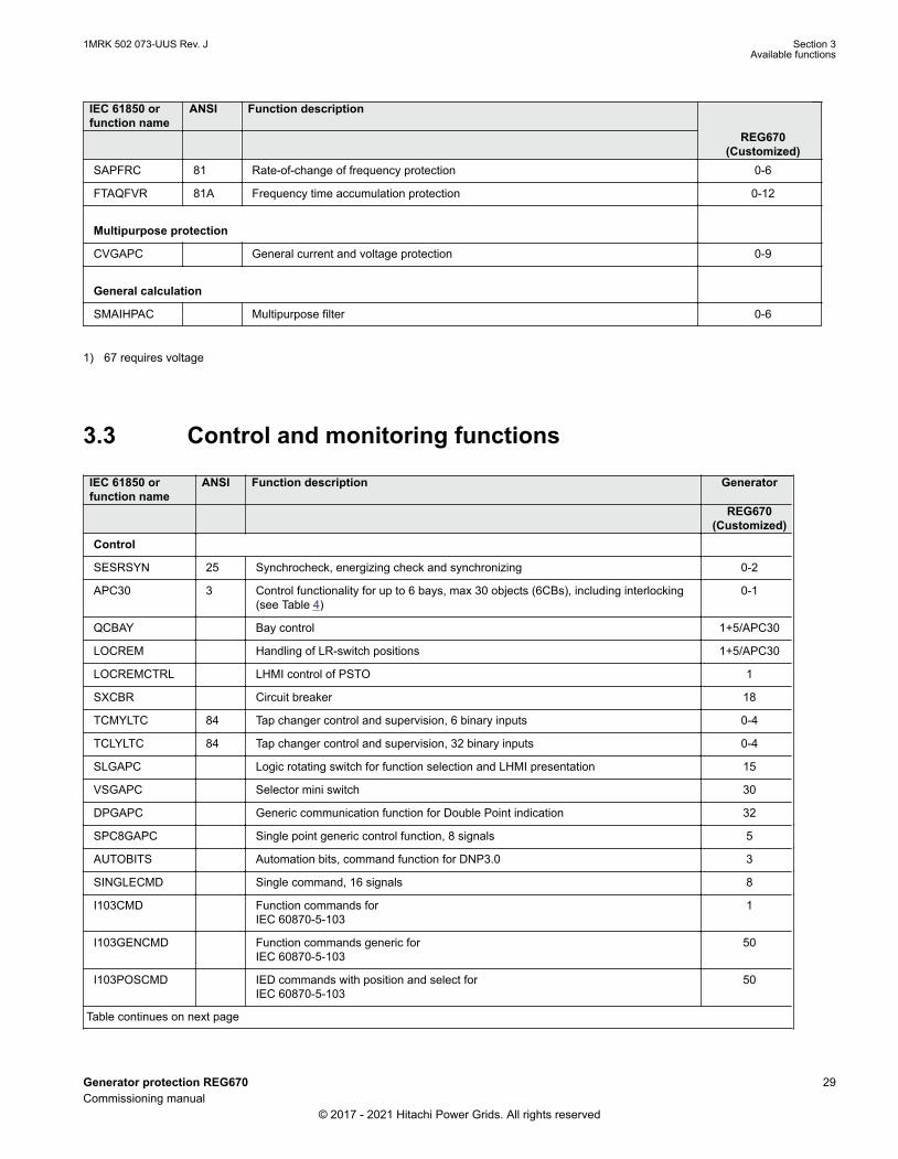
IEC 61850 orfunction name
ANSI Function description
REG670(Customized)
SAPFRC 81 Rate-of-change of frequency protection 0-6
FTAQFVR 81A Frequency time accumulation protection 0-12
Multipurpose protection
CVGAPC General current and voltage protection 0-9
General calculation
SMAIHPAC Multipurpose filter 0-6
1) 67 requires voltage
3.3 Control and monitoring functionsGUID-E3777F16-0B76-4157-A3BF-0B6B978863DE v21
IEC 61850 orfunction name
ANSI Function description Generator
REG670(Customized)
Control
SESRSYN 25 Synchrocheck, energizing check and synchronizing 0-2
APC30 3 Control functionality for up to 6 bays, max 30 objects (6CBs), including interlocking(see Table 4)
0-1
QCBAY Bay control 1+5/APC30
LOCREM Handling of LR-switch positions 1+5/APC30
LOCREMCTRL LHMI control of PSTO 1
SXCBR Circuit breaker 18
TCMYLTC 84 Tap changer control and supervision, 6 binary inputs 0-4
TCLYLTC 84 Tap changer control and supervision, 32 binary inputs 0-4
SLGAPC Logic rotating switch for function selection and LHMI presentation 15
VSGAPC Selector mini switch 30
DPGAPC Generic communication function for Double Point indication 32
SPC8GAPC Single point generic control function, 8 signals 5
AUTOBITS Automation bits, command function for DNP3.0 3
SINGLECMD Single command, 16 signals 8
I103CMD Function commands forIEC 60870-5-103
1
I103GENCMD Function commands generic forIEC 60870-5-103
50
I103POSCMD IED commands with position and select forIEC 60870-5-103
50
Table continues on next page
1MRK 502 073-UUS Rev. J Section 3Available functions
Generator protection REG670 29Commissioning manual
© 2017 - 2021 Hitachi Power Grids. All rights reserved
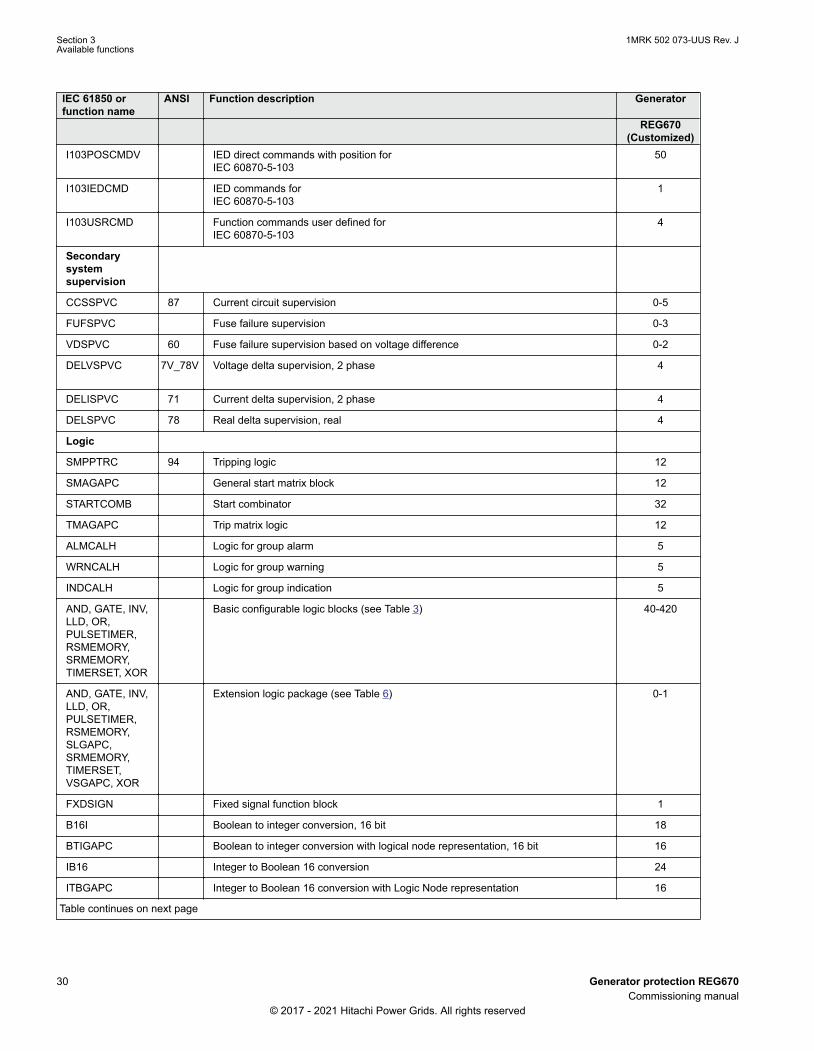
IEC 61850 orfunction name
ANSI Function description Generator
REG670(Customized)
I103POSCMDV IED direct commands with position forIEC 60870-5-103
50
I103IEDCMD IED commands forIEC 60870-5-103
1
I103USRCMD Function commands user defined forIEC 60870-5-103
4
Secondarysystemsupervision
CCSSPVC 87 Current circuit supervision 0-5
FUFSPVC Fuse failure supervision 0-3
VDSPVC 60 Fuse failure supervision based on voltage difference 0-2
DELVSPVC 7V_78V Voltage delta supervision, 2 phase 4
DELISPVC 71 Current delta supervision, 2 phase 4
DELSPVC 78 Real delta supervision, real 4
Logic
SMPPTRC 94 Tripping logic 12
SMAGAPC General start matrix block 12
STARTCOMB Start combinator 32
TMAGAPC Trip matrix logic 12
ALMCALH Logic for group alarm 5
WRNCALH Logic for group warning 5
INDCALH Logic for group indication 5
AND, GATE, INV,LLD, OR,PULSETIMER,RSMEMORY,SRMEMORY,TIMERSET, XOR
Basic configurable logic blocks (see Table 3) 40-420
AND, GATE, INV,LLD, OR,PULSETIMER,RSMEMORY,SLGAPC,SRMEMORY,TIMERSET,VSGAPC, XOR
Extension logic package (see Table 6) 0-1
FXDSIGN Fixed signal function block 1
B16I Boolean to integer conversion, 16 bit 18
BTIGAPC Boolean to integer conversion with logical node representation, 16 bit 16
IB16 Integer to Boolean 16 conversion 24
ITBGAPC Integer to Boolean 16 conversion with Logic Node representation 16
Table continues on next page
Section 3 1MRK 502 073-UUS Rev. JAvailable functions
30 Generator protection REG670Commissioning manual
© 2017 - 2021 Hitachi Power Grids. All rights reserved

IEC 61850 orfunction name
ANSI Function description Generator
REG670(Customized)
TIGAPC Delay on timer with input signal integration 30
TEIGAPC Elapsed time integrator with limit transgression and overflow supervision 12
INTCOMP Comparator for integer inputs 30
REALCOMP Comparator for real inputs 30
HOLDMINMAX Hold minimum and maximum of input 20
INT_REAL Converter integer to real 20
CONST_INT Definable constant for logic functions 10
INTSEL Analog input selector for integer values 5
LIMITER Definable limiter 20
ABS Absolute value 20
POL_REC Polar to rectangular converter 20
RAD_DEG Radians to degree angle converter 20
CONST_REAL Definable constant for logic functions 10
REALSEL Analog input selctor for real values 5
STOREINT Store value for integer inputs 10
STOREREAL Store value for real inputs 10
DEG_RAD Degree to radians angle converter 20
IEC 61850 orfunction name
ANSI Function description Generator
REG670(Customized)
Monitoring
AISVBAS General service value presentation of analog inputs 1
EVENT Event function 20
DRPRDRE,A1RADR-A4RADR,B1RBDR-B22RBDR
Disturbance report 1
SPGAPC Generic communication function for single point indication 96
SP16GAPC Generic communication function for single point indication, 16 inputs 16
MVGAPC Generic communication function for measured values 60
BINSTATREP Logical signal status report 3
RANGE_XP Measured values expander block 66
SSIMG 63 Insulation supervision for gas medium 21
SSIML 71 Insulation supervision for liquid medium 3
SSCBR Circuit breaker condition monitoring 0-12
LOLSPTR 26/49HS
Transformer insulation loss of life monitoring 0-4
Table continues on next page
1MRK 502 073-UUS Rev. J Section 3Available functions
Generator protection REG670 31Commissioning manual
© 2017 - 2021 Hitachi Power Grids. All rights reserved

IEC 61850 orfunction name
ANSI Function description Generator
REG670(Customized)
I103MEAS Measurands forIEC 60870-5-103
1
I103MEASUSR Measurands user defined signals forIEC 60870-5-103
3
I103AR Function status auto-recloser forIEC 60870-5-103
1
I103EF Function status earth-fault forIEC 60870-5-103
1
I103FLTPROT Function status fault protection forIEC 60870-5-103
1
I103IED IED status forIEC 60870-5-103
1
I103SUPERV Supervison status forIEC 60870-5-103
1
I103USRDEF Status for user defined signals forIEC 60870-5-103
20
L4UFCNT Event counter with limit supervision 30
PTRSTHR 51TF Through fault monitoring 0-2
CHMMHAI ITHD Current harmonic monitoring, 3 phase 0-3
VHMMHAI VTHD Voltage harmonic monitoring, 3 phase 0-3
FLTMMXU Fault current and voltage monitoring 3
Metering
PCFCNT Pulse-counter logic 16
ETPMMTR Function for energy calculation and demand handling 6
Table 3: Total number of instances for basic configurable logic blocks
Basic configurable logic block Total number of instancesAND 280
GATE 40
INV 420
LLD 40
OR 298
PULSETIMER 40
RSMEMORY 40
SRMEMORY 40
TIMERSET 60
XOR 40
Section 3 1MRK 502 073-UUS Rev. JAvailable functions
32 Generator protection REG670Commissioning manual
© 2017 - 2021 Hitachi Power Grids. All rights reserved

Table 4: Number of function instances in APC30
Function name Function description Total number of instancesSCILO Interlocking 30
BB_ES 6
A1A2_BS 4
A1A2_DC 6
ABC_BC 2
BH_CONN 2
BH_LINE_A 2
BH_LINE_B 2
DB_BUS_A 3
DB_BUS_B 3
DB_LINE 3
ABC_LINE 6
AB_TRAFO 4
SCSWI Switch controller 30
SXSWI Circuit switch 24
QCRSV Reservation function block forapparatus control
6
RESIN1 1
RESIN2 59
POS_EVAL Evaluation of position indication 30
QCBAY Bay control 5
LOCREM Handling of LR-switch positions 5
XLNPROXY Proxy for signals from switchingdevice via GOOSE
42
GOOSEXLNRCV GOOSE function block to receive aswitching device
42
Table 5: Total number of instances for configurable logic blocks Q/T
Configurable logic blocks Q/T Total number of instancesANDQT 120
INDCOMBSPQT 20
INDEXTSPQT 20
INVALIDQT 22
INVERTERQT 120
ORQT 120
PULSETIMERQT 40
RSMEMORYQT 40
Table continues on next page
1MRK 502 073-UUS Rev. J Section 3Available functions
Generator protection REG670 33Commissioning manual
© 2017 - 2021 Hitachi Power Grids. All rights reserved

Configurable logic blocks Q/T Total number of instancesSRMEMORYQT 40
TIMERSETQT 40
XORQT 40
Table 6: Total number of instances for extended logic package
Extended configurable logic block Total number of instancesAND 220
GATE 49
INV 220
LLD 49
OR 220
PULSETIMER 89
RSMEMORY 40
SLGAPC 74
SRMEMORY 130
TIMERSET 113
VSGAPC 120
XOR 89
3.4 CommunicationGUID-5F144B53-B9A7-4173-80CF-CD4C84579CB5 v19
IEC 61850 or functionname
ANSI Function description Generator
REG670(Customized)
Station communication
LONSPA, SPA SPA communication protocol 1
HORZCOMM Network variables via LON 1
PROTOCOL Operation selection between SPA and IEC60870-5-103 for SLM 1
RS485PROT Operation selection for RS485 1
RS485GEN RS485 1
CHSERRS485 DNP3.0 for EIA-485 communication protocol 1
CH1TCP, CH2TCP,CH3TCP, CH4TCP
DNP3.0 for TCP/IP communication protocol 1
CHSEROPT DNP3.0 for TCP/IP and EIA-485 communication protocol 1
MSTSER DNP3.0 serial master 1
DNPFREC DNP3.0 fault records for TCP/IP and EIA-485 communication protocol 1
IEC 61850-8-1 IEC 61850 1
GOOSEINTLKRCV Horizontal communication via GOOSE for interlocking 59
Table continues on next page
Section 3 1MRK 502 073-UUS Rev. JAvailable functions
34 Generator protection REG670Commissioning manual
© 2017 - 2021 Hitachi Power Grids. All rights reserved

IEC 61850 or functionname
ANSI Function description Generator
REG670(Customized)
IEC 61850SIM IEC 61850 simulation mode 1
GOOSEBINRCV GOOSE binary receive 16
GOOSEDPRCV GOOSE function block to receive a double point value 64
GOOSEINTRCV GOOSE function block to receive an integer value 32
GOOSEMVRCV GOOSE function block to receive a measurand value 60
GOOSESPRCV GOOSE function block to receive a single point value 64
ALGOS Supervision of GOOSE subscription 100
MULTICMDRCV,MULTICMDSND
Multiple command and transmit 60/10
AGSAL Generic security application component 1
LD0LLN0 IEC 61850 LD0 LLN0 1
SYSLLN0 IEC 61850 SYS LLN0 1
LPHD Physical device information 1
PCMACCS IED configuration protocol 1
SECALARM Component for mapping security events on protocols such as DNP3 and IEC103 1
FSTACCSNA Field service tool access via SPA protocol over Ethernet communication 1
FSTACCS Field service tool access 1
IEC 61850-9-2 Process bus communication, 8 merging units 0-1
ACTIVLOG Activity logging 1
ALTRK Service tracking 1
PRP IEC 62439-3 Parallel redundancy protocol 0-1
HSR IEC 62439-3 High-availability seamless redundancy 0-1
RSTP Rapid spanning tree protocol 0-1
PMUCONF,PMUREPORT,PHASORREPORT1,ANALOGREPORT1BINARYREPORT1,SMAI1 - SMAI123PHSUMPMUSTATUS
Synchrophasor report, 16 phasors (see Table 7) 0-1
AP_1-AP_6 AccessPoint_ABS 1
AP_FRONT Access point front 1
PTP Precision time protocol 1
ROUTE_1-ROUTE_6 Route_ABS 1
FRONTSTATUS Access point diagnostic for front Ethernet port 1
SCHLCCH Access point diagnostic for non-redundant Ethernet port 6
RCHLCCH Access point diagnostic for redundant Ethernet ports 3
DHCP DHCP configuration for front access point 1
Table continues on next page
1MRK 502 073-UUS Rev. J Section 3Available functions
Generator protection REG670 35Commissioning manual
© 2017 - 2021 Hitachi Power Grids. All rights reserved

IEC 61850 or functionname
ANSI Function description Generator
REG670(Customized)
Remote communication
BinSignRec1_1BinSignRec1_2BinSignReceive2
Binary signal transfer, receive 3/3/6
BinSignTrans1_1BinSignTrans1_2BinSignTransm2
Binary signal transfer, transmit 3/3/6
BSR2M_305BSR2M_312BSR2M_322BSR2M_306BSR2M_313BSR2M_323
Binary signal transfer, 2Mbit receive 1
BST2M_305BST2M_312BST2M_322BST2M_306BST2M_313BST2M_323
Binary signal transfer, 2Mbit transmit 1
LDCMTRN Transmission of analog data from LDCM 1
LDCMTRN_2M_305LDCMTRN_2M_306LDCMTRN_2M_312LDCMTRN_2M_313LDCMTRN_2M_322LDCMTRN_2M_323
Transmission of analog data from LDCM, 2Mbit 1
LDCMRecBinStat1LDCMRecBinStat3
Receive binary status from remote LDCM 6/3
LDCMRecBinStat2 Receive binary status from LDCM 3
LDCM2M_305LDCM2M_312LDCM2M_322
Receive binary status from LDCM, 2Mbit 1
LDCM2M_306LDCM2M_313LDCM2M_323
Receive binary status from remote LDCM, 2Mbit 1
Table 7: Number of function instances in Synchrophasor report, 16 phasors
Function name Function description Total number ofinstances
PMUCONF Configuration parameters for IEC/IEEE 60255-118 (C37.118) 2011 andIEEE1344 protocol
1
PMUREPORT Protocol reporting via IEEE 1344 and IEC/IEEE 60255-118 (C37.118) 2
PHASORREPORT1 Protocol reporting of phasor data via IEEE 1344 and IEC/IEEE 60255-118(C37.118), phasors 1-8
2
ANALOGREPORT1 Protocol reporting of analog data via IEEE 1344 and IEC/IEEE 60255-118(C37.118), analogs 1-8
2
BINARYREPORT1 Protocol reporting of binary data via IEEE 1344 and IEC/IEEE 60255-118(C37.118), binary 1-8
2
Table continues on next page
Section 3 1MRK 502 073-UUS Rev. JAvailable functions
36 Generator protection REG670Commissioning manual
© 2017 - 2021 Hitachi Power Grids. All rights reserved

Function name Function description Total number ofinstances
SMAI1–SMAI12 Signal matrix for analog inputs 1
3PHSUM Summation block 3 phase 6
PMUSTATUS Diagnostics for IEC/IEEE 60255-118 (C37.118) 2011 and IEEE1344 protocol 1
3.5 Basic IED functionsGUID-C8F0E5D2-E305-4184-9627-F6B5864216CA v14
Table 8: Basic IED functions
IEC 61850 or functionname
Description
INTERRSIGSELFSUPEVLST Self supervision with internal event list
TIMESYNCHGEN Time synchronization module
BININPUT,SYNCHCAN,SYNCHGPS,SYNCHCMPPS,SYNCHLON,SYNCHPPH,SYNCHPPS, SNTP,TIMEZONE
Time synchronization
DSTBEGIN GPS time synchronization module
DSTENABLE Enables or disables the use of daylight saving time
DSTEND GPS time synchronization module
IRIG-B Time synchronization
SETGRPS Number of setting groups
ACTVGRP Active parameter setting group
TESTMODE Test mode functionality
CHNGLCK Change lock function
TERMINALID IED identifiers
PRODINF Product information
SYSTEMTIME System time
LONGEN LON communication
RUNTIME IED Runtime component
SMBI Signal matrix for binary inputs
SMBO Signal matrix for binary outputs
SMMI Signal matrix for mA inputs
SMAI1 - SMAI12 Signal matrix for analog inputs
3PHSUM Summation block 3 phase
ATHSTAT Authority status
Table continues on next page
1MRK 502 073-UUS Rev. J Section 3Available functions
Generator protection REG670 37Commissioning manual
© 2017 - 2021 Hitachi Power Grids. All rights reserved

IEC 61850 or functionname
Description
ATHCHCK Authority check
AUTHMAN Authority management
FTPACCS FTP access with password
SPACOMMMAP SPA communication mapping
SPATD Date and time via SPA protocol
BCSCONF Basic communication system
GBASVAL Global base values for settings
PRIMVAL Primary system values
SAFEFILECOPY Safe file copy function
ALTMS Time master supervision
ALTIM Time management
CAMCONFIG Central account management configuration
CAMSTATUS Central account management status
TOOLINF Tools information
COMSTATUS Protocol diagnostic
Table 9: Local HMI functions
IEC 61850 or functionname
Description
LHMICTRL Local HMI signals
LANGUAGE Local human machine language
SCREEN Local HMI Local human machine screen behavior
FNKEYTY1–FNKEYTY5FNKEYMD1–FNKEYMD5
Parameter setting function for HMI in PCM600
LEDGEN General LED indication part for LHMI
OPENCLOSE_LED LHMI LEDs for open and close keys
GRP1_LED1–GRP1_LED15GRP2_LED1–GRP2_LED15GRP3_LED1–GRP3_LED15
Basic part for CP HW LED indication module
Section 3 1MRK 502 073-UUS Rev. JAvailable functions
38 Generator protection REG670Commissioning manual
© 2017 - 2021 Hitachi Power Grids. All rights reserved

Section 4 Starting up
4.1 Factory and site acceptance testingGUID-38C2B5FA-9210-4D85-BA21-39CE98A1A84A v2
Testing the proper IED operation is carried out at different occasions, for example:
• Acceptance testing• Commissioning testing• Maintenance testing
This manual describes the workflow and the steps to carry out the commissioning testing.
Factory acceptance testing (FAT) is typically done to verify that the IED and its correspondingconfiguration meet the requirements of the utility or industry. This test is the most complex and in depth,as it is done to familiarize the user with a new product or to verify a new configuration. The complexity ofthis testing depends on several factors, such as:
• New IED type• New configuration• Modified configuration
Site acceptance testing (SAT or commissioning testing) is typically done to verify that the installed IED iscorrectly set and connected to the power system. SAT requires that the acceptance testing has beenperformed and that the application configuration is verified.
Maintenance testing is a periodic verification that the IED is healthy and has correct settings, dependingon changes in the power system. There are also other types of maintenance testing.
4.2 Commissioning checklistGUID-93D14E4E-5DDE-4D37-84A6-2DF0656AB73D v4
Before starting up commissioning at site, check that the following items are available.
• Single line diagram• Protection block diagram• Circuit diagram• Setting list and configuration• RJ-45 Ethernet cable (CAT 5)• Three-phase test kit or other test equipment depending on the complexity of the configuration and
functions to be tested.• PC with PCM600 installed along with the connectivity packages corresponding to the IEDs to be
tested.• Administration rights on the PC, to set up IP addresses• Product documentation (engineering manual, installation manual, commissioning manual, operation
manual, technical manual and communication protocol manual)
1MRK 502 073-UUS Rev. J Section 4Starting up
Generator protection REG670 39Commissioning manual
© 2017 - 2021 Hitachi Power Grids. All rights reserved

4.3 Checking the power supplyM11725-2 v6
Do not insert anything else to the female connector but the corresponding maleconnector. Inserting anything else (such as a measurement probe) may damage thefemale connector and prevent a proper electrical contact between the printed circuitboard and the external wiring connected to the screw terminal block.
Check that the auxiliary supply voltage remains within the permissible input voltage range under alloperating conditions. Check that the polarity is correct before energizing the IED.
4.4 Energizing the IED
4.4.1 Checking the IED operationM11726-2 v8
Check all connections to external circuitry to ensure correct installation, before energizing the IED andcarrying out the commissioning procedures.
Energize the power supply of the IED to pickup. Keep the DC power supply on until the Root menu or theselected default screen is shown on the HMI before interrupting the DC power supply again. Theenergization could be done in a number of ways, from energizing a whole cubicle with many IEDs toenergizing each single IED one by one.
If HW (i.e. I/O and/or communication boards etc.) have been changed (i.e. removed, replaced, or added),the user should re-configure the IED by navigating in the local HMI menu to: Main menu/Configuration /Reconfigure HW modules to activate the changed hardware modules in order to enable the self-supervision function to detect possible hardware errors.
Check also the self-supervision function in Main menu/Diagnostics/IED status/General menu in localHMI to verify that the IED operates properly.
Set the IED time if no time synchronization source is configured.
To ensure that the IED is according to the delivery and ordering specifications documents deliveredtogether with each IED, the user should also after start-up use the built in HMI to check the IED's:
• Software version, Main menu /Diagnostics/IED status /Product identifiers.• Serial number, Main menu /Diagnostics/IED status /Product identifiers.• Installed modules and their ordering number, Main menu/Diagnostics /IED status/Installed HW .
4.4.2 IED start-up sequenceM11727-3 v13
When the IED is energized, the green LED starts flashing instantly. After approximately 55 seconds thewindow lights up and the window displays ‘IED Startup’. The main menu is displayed and the upper rowshould indicate ‘Available’ after about 90 seconds. A steady green light indicates a successful startup.
Section 4 1MRK 502 073-UUS Rev. JStarting up
40 Generator protection REG670Commissioning manual
© 2017 - 2021 Hitachi Power Grids. All rights reserved

xx04000310-1-en.vsd
t (s)0 t1 t2
1 32
IEC04000310 V2 EN-US
Figure 2: Typical IED start-up sequence
1 IED energized. Green LED instantly starts flashing
2 LCD lights up and "IED startup" is displayed
3 The main menu is displayed. A steady green light indicates a successful startup.
If the upper row in the window indicates ‘Fail’ instead of ‘Available’ and the green LED flashes, aninternal failure in the IED has been detected.
4.5 Energizing REX060
4.5.1 REX060 start up sequenceGUID-63A15CD3-17B0-41DD-9611-8272DDA53137 v2
When the injection unit REX060 is energized, the Hitachi Power grids logotype is shown followed bycurrent REX060 revision status. When the start up sequence is completed, the main menu (normaldisplay content) is shown. The duration of the start up sequence is a few seconds.
4.6 Setting up communication between PCM600 and the IEDSEMOD58570-5 v15
The communication between the IED and PCM600 is independent of the communication protocol usedwithin the substation or to the NCC.
The communication media is always Ethernet and the used transport layer is TCP/IP.
Each IED has an RJ-45 Ethernet interface connector on the front. The front Ethernet connector isrecommended to be used for communication with PCM600.
When an Ethernet-based station protocol is used, PCM600 communication can use the same Ethernetport and IP address.
To connect PCM600 to the IED, two basic variants must be considered.
• Direct point-to-point link between PCM600 and the IED front port. The front port can be seen as aservice port.
• A link via a station LAN or from remote via a network.
The physical connection and the IP address must be configured in both cases to enable communication.
The communication procedures are the same in both cases.
1. If needed, set the IP address for the IEDs.2. Set up the PC or workstation for a direct link (point-to-point), or3. Connect the PC or workstation to the LAN/WAN network.4. Configure the IED IP addresses in the PCM600 project for each IED to match the IP addresses of
the physical IEDs.
1MRK 502 073-UUS Rev. J Section 4Starting up
Generator protection REG670 41Commissioning manual
© 2017 - 2021 Hitachi Power Grids. All rights reserved

Setting up IP addressesCommunication between the IED and PCM600 is enabled from the LHMI. The IP address and thecorresponding communication subnetwork mask must be set via the Ethernet configuration tool (ECT) foreach available Ethernet interface in the IED. Each Ethernet interface has a default factory IP addresswhen the IED is delivered. The IP adress and the subnetwork mask might have to be reset when anadditional Ethernet interface is installed or an interface is replaced.
DHCP is available for the front port, and a device connected to it can thereby obtain an automaticallyassigned IP address via the local HMI path Main menu/ Configuration/ Communication/ Ethernetconfiguration/ Front port/ DHCP.
Alternatively the default IP address for the IED front port is 10.1.150.3 and the corresponding subnetworkmask is 255.255.255.0, which can be set via the local HMI path Main menu/ Configuration/Communication/ TCP-IP configuration/ ETHFRNT:1Main menu/ Configuration/ Communication/Ethernet configuration/ AP_FRONT.
Setting up the PC or workstation for point-to-point access to IEDs front portAn ethernet cable (max 2 m length) with RJ-45 connectors is needed to connect two physical Ethernetinterfaces together without a hub, router, bridge or switch in between.
If an IED is equipped with optical LC interface, a converter between RJ-45 and LC isneeded.
1. Select Search programs and files in the Start menu in Windows.
Section 4 1MRK 502 073-UUS Rev. JStarting up
42 Generator protection REG670Commissioning manual
© 2017 - 2021 Hitachi Power Grids. All rights reserved

IEC13000057-1-en.vsdIEC13000057 V1 EN-US
Figure 3: Select: Search programs and files
2. Type View network connections and click on the View network connections icon.
1MRK 502 073-UUS Rev. J Section 4Starting up
Generator protection REG670 43Commissioning manual
© 2017 - 2021 Hitachi Power Grids. All rights reserved

IEC13000058-1-en.vsdIEC13000058 V1 EN-US
Figure 4: Click View network connections
3. Right-click and select Properties.
IEC13000059-1-en.vsd
IEC13000059 V1 EN-US
Figure 5: Right-click Local Area Connection and select Properties
4. Select the TCP/IPv4 protocol from the list of configured components using this connection and clickProperties.
Section 4 1MRK 502 073-UUS Rev. JStarting up
44 Generator protection REG670Commissioning manual
© 2017 - 2021 Hitachi Power Grids. All rights reserved

IEC13000060-1-en.vsdIEC13000060 V1 EN-US
Figure 6: Select the TCP/IPv4 protocol and open Properties
5. Select Use the following IP address and define IP address and Subnet mask if the front port isused and if the IP address is not set to be obtained automatically by the IED,see Figure 7. The IPaddress must be different from the IP address chosen for the IED.
IEC13000062-1-en.vsdIEC13000062 V1 EN-US
Figure 7: Select: Use the following IP address
6. Use the ping command to verify connectivity with the IED.7. Close all open windows and start PCM600.
1MRK 502 073-UUS Rev. J Section 4Starting up
Generator protection REG670 45Commissioning manual
© 2017 - 2021 Hitachi Power Grids. All rights reserved

The PC and IED must belong to the same subnetwork for this set-up to work.
Setting up the PC to access the IED via a networkThe same method is used as for connecting to the front port.
The PC and IED must belong to the same subnetwork for this set-up to work.
4.7 Writing an application configuration to the IEDM11734-2 v7
When writing a configuration to the IED with PCM600, the IED is automatically set in configuration mode.When the IED is set in configuration mode, all functions are blocked. The red LED on the IED flashes,and the green LED is lit while the IED is in the configuration mode.
When the configuration is written and completed, the IED is automatically set into normal mode. Forfurther instructions please refer to the users manuals for PCM600.
4.8 Checking CT circuitsM12182-2 v15
Check that the wiring is in strict accordance with the supplied connection diagram.
The CTs must be connected in accordance with the circuit diagram provided with the IED, both withregards to phases and polarity. The following tests shall be performed on every primary CT connected tothe IED:
• Primary injection test to verify the current ratio of the CT, the correct wiring up to the protection IEDand correct phase sequence connection (that is A, B, C.)
• Polarity check to prove that the predicted direction of secondary current flow is correct for a givendirection of primary current flow. This is an essential test for the proper operation of the differentialfunction and directional protection functions.
• CT secondary loop resistance measurement to confirm that the current transformer secondary loopDC resistance is within the specification for the connected protection functions. When the measuredloop resistance is near the calculated value for maximum DC resistance, perform a complete burdentest.
• CT excitation test in order to confirm that the current transformer is of the correct accuracy ratingand that there are no shorted turns in the current transformer windings. Manufacturer's designcurves must be available for the current transformer to compare the actual results.
• Grounding check of the individual CT secondary circuits to verify that each three-phase set of mainCTs is properly connected to the station ground and only at one electrical point.
• Insulation resistance check.
While the CT primary is energized, the secondary circuit shall never be open circuitedbecause extremely dangerous high voltages may arise.
Section 4 1MRK 502 073-UUS Rev. JStarting up
46 Generator protection REG670Commissioning manual
© 2017 - 2021 Hitachi Power Grids. All rights reserved

Both the primary and the secondary sides must be disconnected from the line and theIED when plotting the excitation characteristics.
If the CT secondary circuit ground connection is removed without the current transformerprimary being de-energized, dangerous voltages may result in the secondary CT circuits.
4.9 Checking VT circuitsM11724-2 v10
Check that the wiring is in strict accordance with the supplied connection diagram.
Correct possible errors before continuing to test the circuitry.
Test the circuitry.
• Polarity check when applicable; this test is often omitted for CVTs• VT circuit voltage measurement (primary injection test)• Grounding check• Phase relationship• Insulation resistance check
The primary injection test verifies the VT ratio and the wiring all the way from the primary system to theIED. Injection must be performed for each phase-to-neutral circuit.
While testing VT secondary circuit and associated secondary equipment, care shall beexercised to isolate the VT from the circuit being tested to avoid backcharging the VTfrom the secondary side.
4.10 Using the RTXP test switchGUID-F1E29C06-7FE8-44D8-AD5A-EE8990A2AA41 v6
The RTXP test switch is designed to provide the means of safe testing of the IED. This is achieved by theelectromechanical design of the test switch and test plug handle. When the test plug handle is inserted, itfirst blocks the trip and alarm circuits then it short circuits the CT secondary circuit and opens the VTsecondary circuits making the IED available for secondary injection.
When pulled out, the test handle is mechanically stopped in half withdrawn position. In this position, thecurrent and voltage enter the protection, but the alarm and trip circuits are still isolated and the IED is intest mode. Before removing the test handle, check the measured values in the IED.
Not until the test handle is completely removed, the trip and alarm circuits are restored for operation.
Verify that the contact sockets have been crimped correctly and that they are fullyinserted by tugging on the wires. Never do this with current circuits in service.
Current circuit
1MRK 502 073-UUS Rev. J Section 4Starting up
Generator protection REG670 47Commissioning manual
© 2017 - 2021 Hitachi Power Grids. All rights reserved

1. Verify that the contacts are of current circuit type.2. Verify that the short circuit jumpers are located in the correct slots.
Voltage circuit
1. Verify that the contacts are of voltage circuit type.2. Check that no short circuit jumpers are located in the slots dedicated for voltage.
Trip and alarm circuits
1. Check that the correct types of contacts are used.
4.11 Checking the binary input/output circuitsM11722-2 v4
Do not insert anything else to the female connector but the corresponding maleconnector. Inserting anything else (such as a measurement probe) may damage thefemale connector and prevent a proper electrical contact between the printed circuitboard and the external wiring connected to the screw terminal block.
4.11.1 Binary input circuitsM11722-4 v3
Preferably, disconnect the binary input connector from the binary input cards. Check all connectedsignals so that both input level and polarity are in accordance with the IED specifications.
4.11.2 Binary output circuitsM11722-8 v3
Preferably, disconnect the binary output connector from the binary output cards. Check all connectedsignals so that both load and polarity are in accordance with IED specifications.
4.12 Checking optical connectionsM16022-2 v8
Check that the Tx and Rx optical connections are correct.
An IED equipped with optical connections has an minimum space requirement of 180mm (7.2 inches) for plastic fiber cables and 275 mm (10.9 inches) for glass fiber cables.Check the allowed minimum bending radius from the optical cable manufacturer.
Section 4 1MRK 502 073-UUS Rev. JStarting up
48 Generator protection REG670Commissioning manual
© 2017 - 2021 Hitachi Power Grids. All rights reserved

Section 5 Configuring the IED and changingsettings
5.1 OverviewM11730-2 v7
The customer specific values for each setting parameter and a configuration file have to be availablebefore the IED can be set and configured, if the IED is not delivered with a configuration.
Use the configuration tools in PCM600 to verify that the IED has the expected configuration.
Each function included in the IED has several setting parameters, which have to be set in order to makethe IED behave as intended. A factory default value is provided for each parameter.The ParameterSetting Tool in PCM600 is used when changing setting parameters.
All settings can be
• Entered manually through the local HMI.• Written from a PC, either locally or remotely using PCM600. Front or rear port communication has to
be established before the settings can be written to the IED.
Make sure that the DC supply is not turned off when the IED saves the writtenconfiguration.
The IED uses a FLASH disk for storing configuration data and process data like counters, object states,Local/Remote switch position etc. Since FLASH memory is used, measures have been taken in softwareto make sure that the FLASH disk is not worn out by too intensive storing of data.
This means, that to be absolutely sure that all data have been saved to FLASH, it is necessary to leavethe IED with auxiliary power connected after all the commissioning is done(including setting the Local/Remote switch to the desired position) for at least one hour after the last commissioning actionperformed on the IED.
After that time has elapsed, it will be safe to turn the IED off, no data will be lost.
5.2 Configuring analog CT inputsM12312-6 v8
The analog input channels must be configured to get correct measurement results as well as correctprotection functionality. Because all protection algorithms in the IED utilize the primary system quantities,it is extremely important to make sure that connected current transformer settings are done properly.These data are calculated by the system engineer and normally set by the commissioning personnelfrom the local HMI or from PCM600.
The analog inputs on the transformer input module are dimensioned for either 1A or 5A. Eachtransformer input module has a unique combination of current and voltage inputs. Make sure the inputcurrent rating is correct and that it matches the order documentation.
The primary CT data are entered via the HMI menu under Main menu /Configurations /Analogmodules
1MRK 502 073-UUS Rev. J Section 5Configuring the IED and changing settings
Generator protection REG670 49Commissioning manual
© 2017 - 2021 Hitachi Power Grids. All rights reserved

The following parameter shall be set for every current transformer connected to the IED:
Table 10: CT configuration
Parameter description Parameter name Range DefaultRated CT primary current in A CTPRIMn
n = channel numberfrom 0 to 99999 3000
This parameter defines the primary rated current of the CT. For two set of CTs with ratio 1000/1 and1000/5 this parameter is set to the same value of 1000 for both CT inputs. The parameter CTStarPointcan be used in order to reverse the direction of the CT. This might be necessary if two sets of CTs havedifferent neutral (WYE) point locations in relation to the protected busbar.
For main CTs with 2A rated secondary current, it is recommended to connect the secondary wiring to the1A input.
Take the rated permissive overload values for the current inputs into consideration.
5.3 Supervision of input/output modulesM11728-2 v3
I/O modules configured with PCM600 (BIM, BOM or IOM) are supervised.
I/O modules that are not configured are not supervised.
Each logical I/O module has an error flag that indicates signal or module failure. The error flag is also setwhen the physical I/O module of the correct type is not detected in the connected slot.
Section 5 1MRK 502 073-UUS Rev. JConfiguring the IED and changing settings
50 Generator protection REG670Commissioning manual
© 2017 - 2021 Hitachi Power Grids. All rights reserved

Section 6 Calibrating injection based sensitiverotor earth fault protection
6.1 Function revision historyGUID-B7FE34AB-E6BC-43DC-BA30-1E54ACDA925A v2
Documentrevision
Productrevision
History
A 2.2.1 -
B 2.2.1 -
C 2.2.2 -
D 2.2.3 -
E 2.2.3 -
F 2.2.4 -
G 2.2.4 Updated below settings and technical data values.
Non group settings Old value New value
k1Real, k1Imag, k2Real, k2Imag,RefR1, RefX1, RefR2 and RefX2– Values (Range)
-10 000 000 000.000 to10 000 000 000.000
-100 000.000 to 100 000.000
k1Real – Default Value 10000.000 4000.000
k1Imag – Default Value 0.000 600.000
k2Real – Default Value 0.000 -5000.000
k2Imag – Default Value 0.000 500.000
RefR1 – Default Value 1000000.000 200.000
RefX1 – Default Value 2000.000 -4000.000
RefR2 – Default Value 1000000.000 200.000
RefX2 – Default Value 2000.000 -4000.000
Group settings and technicaldata
Old value New value
RAlarm - Alarm limit of faultresistance – Range
(100 - 1000000)Ω (100 - 500000)Ω
H 2.2.5 -
6.2 Commissioning processGUID-837911AC-D87E-4E10-9D7D-B74A9F45A815 v1
The commissioning process utilizes the commissioning tool ICT. The instructions for the process coverinstallation, calibration, commissioning, monitoring and auditing for the sensitive rotor earth faultROTIPHIZ (64R) function.
1MRK 502 073-UUS Rev. J Section 6Calibrating injection based sensitive rotor earth fault protection
Generator protection REG670 51Commissioning manual
© 2017 - 2021 Hitachi Power Grids. All rights reserved

6.3 Commissioning tool ICTGUID-0C099215-B194-4212-AE81-15F840E24C50 v5
The sensitive rotor earth fault protection function in IED requires a number of settings. The settings k1,k2 and the reference impedance require measurements on the generator performed by the ICT (injectioncommissioning tool). The factors are derived in connection to the calibration measurements duringcommissioning. ICT is an integrated part of the PCM600 tool.
Furthermore, ICT also assists the commissioning engineer to perform a successful installation becauseof its structure and validating capabilities. During installation, commissioning and calibration, ICTperforms various tests to verify that the installation is acceptable and the calibration successful. Besidescarrying out the actual tests, ICT also provides the commissioning engineer with tips if needed during thecommissioning.
When ICT is started, rotor earth fault protection is chosen.
There are five different parts of the ICT tool to be performed at commissioning and operation:
1. Installing2. Calibrating3. Commissioning4. Monitoring5. Auditing
Before proceeding make sure that all necessary connections are in place.
InstallingDuring the installation, several checks are performed about both status of the function and levels of theinjected current and voltage. The check of signal levels need the setting of the gain according to thevalue that is selected in REX060.
A fine measurement of the frequency of the injected signals is also performed.
CalibratingThe calibration is the second activity that is performed by ICT. It is performed when the generator is atstandstill; the starting condition of calibration is the same as the one of installation.
The calibration shall be performed twice: after the first calibration the calculated parameters aretransferred to ICT and written into the REG670. This way the second calibration is performed startingfrom parameters that are related to the protected generator. At the end of the second calibration acomparison between the values of the parameters calculated by the first and second calibration shall beperformed.
The calibration is based on three measurements steps. During the steps, a check is made that there areenough changes in the measured impedance in order to guarantee that there is no primary fault from thebeginning or other problems due to the installation or calibration procedure.
The sequence of the calibration session follows a scheme shown in the Injection Commissioning Tool(ICT). Depending on the excitation of the field (static excitation or rotating diodes), steps 2 and 3 shall beperformed differently, as described below and shown in Figure 8 and Figure 9.
1. Calibration sequence 1: The injection must be activated and the rotor must be left with noimpedance connected.
2. Calibration sequence 2:
Section 6 1MRK 502 073-UUS Rev. JCalibrating injection based sensitive rotor earth fault protection
52 Generator protection REG670Commissioning manual
© 2017 - 2021 Hitachi Power Grids. All rights reserved

• Static excitation: In this configuration both poles are connected to earth through identicalresistances, as shown in Step 2 in Figure 8. Half of the value of the resistance (Rstep2/2 = Rcal)is then input into the ICT as the effective calibration resistance.
• Rotating Diodes excitation: In this configuration the injection point is connected to earththrough a resistance, as shown in Step 2 in Figure 9. The value of the resistance (Rstep2 =Rcal) is then input into the ICT as the effective calibration resistance.
3. Calibration sequence 3:• Static excitation: In this configuration both poles are directly connected to earth, as shown in
Step 3 in Figure 8.• Rotating Diodes excitation: For this configuration, the injection point is directly connected to
earth, as shown in Step 3 in Figure 9.
The sequence of the calibration steps is driven by ICT and it is shown in the figure below.
DC
AC
Crot
REX061I inj
DC
AC
Crot
Step 1 Step 2 Step 3
REX061I inj
DC
AC
C rot
REX061I inj
Rstep2 Rstep2
IEC11000205-2-en.vsdx
IEC11000205 V2 EN-US
Figure 8: Different steps at calibration measurements for Static Excitation
DC
AC
Step 1 Step 2 Step 3
DC
AC
Rstep2
DC
AC
c rot c rot c rot
Iinj Iinj Iinj
REX061 REX061 REX061
IEC20000530-2-en.vsd
IEC20000530 V2 EN-US
Figure 9: Different steps at calibration measurements for excitation with Rotating Diodes
After the three steps ICT calculates the complex factors k1 and k2. The reference impedance RefR1 +jRefX1 is also calculated. After this the values are downloaded to the parameter setting in PCM600.From PCM600 the settings are downloaded to IED.
Now the reference impedance is derived for one operational state. It might be necessary to makemeasurements to derive reference impedance for other operational cases. For information on this, seeCommissioning below.
CommissioningDifferent operating conditions of the machine may require different reference impedances.
If a particular operating condition of the generator requires a second reference impedance, theCommissioning tab of ICT is used to define and save the second reference.
1MRK 502 073-UUS Rev. J Section 6Calibrating injection based sensitive rotor earth fault protection
Generator protection REG670 53Commissioning manual
© 2017 - 2021 Hitachi Power Grids. All rights reserved

If more than one reference impedance are to be used, there must be a logic configured to detect whenthe generator is in such condition and change the reference.
MonitoringThe Monitoring tab of ICT offers the possibility to monitor several quantities during tests as well as innormal operating condition in order to evaluate the behavior of the protection function. It can help in theidentification of the operating conditions, where a change of reference impedance is required.
AuditingIn the auditing part installation, calibration and commissioning reports are stored.
6.4 Launching injection commissioning tool (ICT) andperforming the installation
GUID-15CAE2A3-FA17-4119-9188-824C7F309D4B v3
1. Make sure you have not attached any additional impedance in parallel with the rotor circuit. Allwirings shall be finalized and they shall be the definitive ones. All primary and secondary devicesshall be connected and switched on. All grounding of generator shall be removed. The generatorshall be in a condition that is as close as possible to the normal operating condition.
2. Activate the injection by turning the injection switch to on position on the injection unit REX060.3. To launch the Injection commissioning tool (ICT), right-click REG670 in the PCM plant structure and
select the Injection commissioning.4. In the ICT toolbar, select the Rotor Earth Fault function.
IEC11000222-1-en.vsdIEC11000222 V1 EN-US
Figure 10: ICT toolbar
5. Select the Installing tab if it was not already selected by default after the ICT was launched.The first thing that needs to be ensured before the calibration is that the measured voltage andcurrent signal on the injected frequency is present/found, and that their amplitude is within thepermitted limits.
6. Write the value of the “Gain” according to the setting in REX060. Select the Start reading valuesfrom IED button from the ICT toolbar to start performing continuous measurements.
7. Verify that the bars/voltage levels for both the voltage and current on the injected frequency haveacceptable level.The bars must be green and the function status field must also indicate OK.
8. Check that the actual injected frequency is close enough to the injection frequency set on theinjection unit (REX060).If the voltage and/or current level(s)/frequencies are not reasonable, or the ICT indicates otherwarnings/abnormalities in the function status field, verify that the HW connections are correct(cables etc.), and selected gains and injection frequency on the REX060 are properly set. Thenrepeat steps 3 to 6. Note that the FreqInjected setting in Parameter setting for the specific functionmust correspond with the chosen injection frequency on the REX060 HMI for that function.
Section 6 1MRK 502 073-UUS Rev. JCalibrating injection based sensitive rotor earth fault protection
54 Generator protection REG670Commissioning manual
© 2017 - 2021 Hitachi Power Grids. All rights reserved
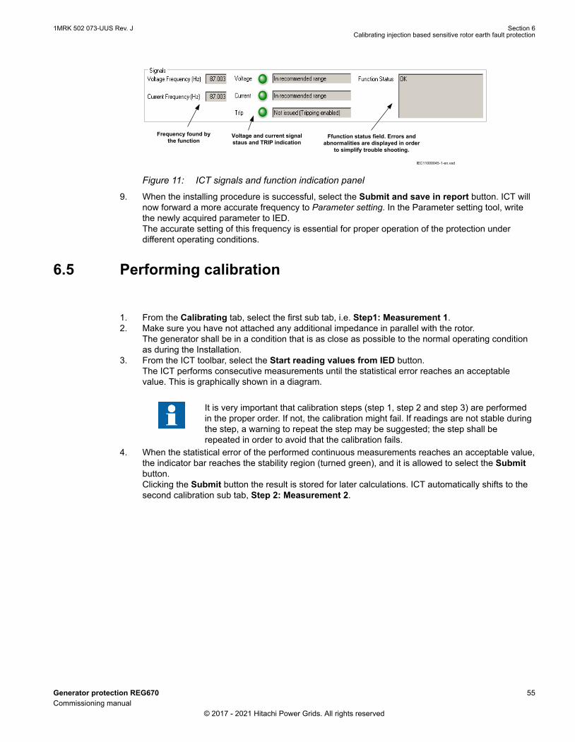
IEC11000045-1-en.vsd
Frequency found by the function
Voltage and current signal staus and TRIP indication
Ffunction status field. Errors and abnormalities are displayed in order
to simplify trouble shooting.
GUID-84947C77-215F-4007-AAC0-9433B8444396 V1 EN-US
Figure 11: ICT signals and function indication panel
9. When the installing procedure is successful, select the Submit and save in report button. ICT willnow forward a more accurate frequency to Parameter setting. In the Parameter setting tool, writethe newly acquired parameter to IED.The accurate setting of this frequency is essential for proper operation of the protection underdifferent operating conditions.
6.5 Performing calibrationGUID-DE96CE75-A268-4FE1-AD9D-093EA1F2ECBA v5
1. From the Calibrating tab, select the first sub tab, i.e. Step1: Measurement 1.2. Make sure you have not attached any additional impedance in parallel with the rotor.
The generator shall be in a condition that is as close as possible to the normal operating conditionas during the Installation.
3. From the ICT toolbar, select the Start reading values from IED button.The ICT performs consecutive measurements until the statistical error reaches an acceptablevalue. This is graphically shown in a diagram.
It is very important that calibration steps (step 1, step 2 and step 3) are performedin the proper order. If not, the calibration might fail. If readings are not stable duringthe step, a warning to repeat the step may be suggested; the step shall berepeated in order to avoid that the calibration fails.
4. When the statistical error of the performed continuous measurements reaches an acceptable value,the indicator bar reaches the stability region (turned green), and it is allowed to select the Submitbutton.Clicking the Submit button the result is stored for later calculations. ICT automatically shifts to thesecond calibration sub tab, Step 2: Measurement 2.
1MRK 502 073-UUS Rev. J Section 6Calibrating injection based sensitive rotor earth fault protection
Generator protection REG670 55Commissioning manual
© 2017 - 2021 Hitachi Power Grids. All rights reserved
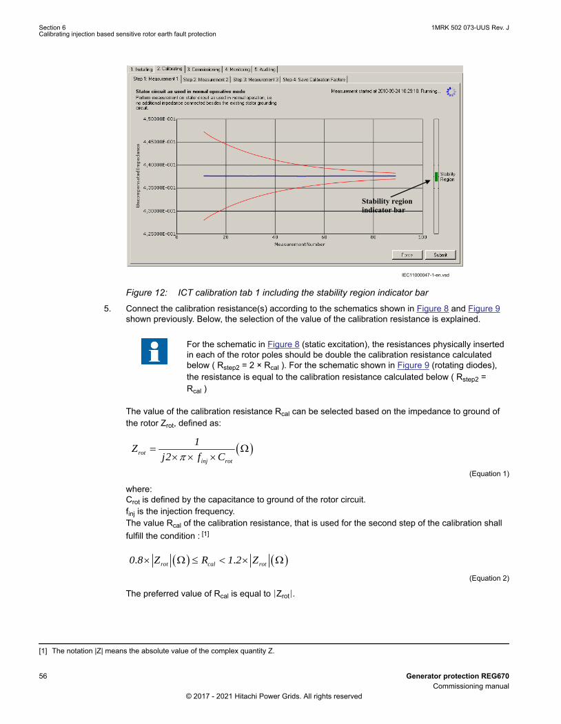
Stability region indicator bar
IEC11000047-1-en.vsdGUID-3C7F0567-2367-46E4-9606-FCFC7408DAA0 V1 EN-US
Figure 12: ICT calibration tab 1 including the stability region indicator bar
5. Connect the calibration resistance(s) according to the schematics shown in Figure 8 and Figure 9shown previously. Below, the selection of the value of the calibration resistance is explained.
For the schematic in Figure 8 (static excitation), the resistances physically insertedin each of the rotor poles should be double the calibration resistance calculatedbelow ( Rstep2 = 2 × Rcal ). For the schematic shown in Figure 9 (rotating diodes),the resistance is equal to the calibration resistance calculated below ( Rstep2 =Rcal )
The value of the calibration resistance Rcal can be selected based on the impedance to ground ofthe rotor Zrot, defined as:
rotinj rot
1Z
j2 f C
IECEQUATION20066 V1 EN-US (Equation 1)
where:Crot is defined by the capacitance to ground of the rotor circuit.finj is the injection frequency.The value Rcal of the calibration resistance, that is used for the second step of the calibration shallfulfill the condition : [1]
. .rot cal rot0 8 Z R 1 2 Z
IECEQUATION20067 V1 EN-US (Equation 2)
The preferred value of Rcal is equal to ∣Zrot∣.
[1] The notation |Z| means the absolute value of the complex quantity Z.
Section 6 1MRK 502 073-UUS Rev. JCalibrating injection based sensitive rotor earth fault protection
56 Generator protection REG670Commissioning manual
© 2017 - 2021 Hitachi Power Grids. All rights reserved

If the value of the calibration resistance is defined according to Equation 1 and Equation 2, it isexpected that the first reference impedance, that is calculated during the first calibration, fulfills thecondition:
. 2 2rot old old rot0 5 Z RefR1 RefX1 2 Z
IECEQUATION20068 V2 EN-US (Equation 3)
Where:RefR1old and RefX1old were defined by the first calibration.If the capacitance to ground of the rotor is unknown, a calibration resistance with tentative valueequal to 5000 Ω can be performed. If that is the case, it is expected that the first referenceimpedance, that is calculated during the first calibration, fulfills the condition:
2 2old old2500 RefR1 RefX1 10000
IECEQUATION20069 V2 EN-US (Equation 4)
The parameters, that are calculated during the first calibration, should be transferred to PST andwritten into REG670 to perform a second calibration. Even if the above checks are not fulfilled,these parameters are related to the generator and better starting values than the function defaultvalues.During the second calibration the value of the calibration resistance is selected according to theformula:
2 2cal rot old old oldR Z RefR1 RefX 1 RefZ1
IECEQUATION20070 V1 EN-US (Equation 5)
After the second calibration, the following condition should be fulfilled:
. 2 2cal cal0 5 R RefR1 RefX 1 2 R
IECEQUATION20071 V1 EN-US (Equation 6)
Where:Rcal is defined by Equation 5,If the condition in Equation 6 is not fulfilled, a third calibration can be attempted; before starting thethird calibration, the values of the parameters of the second calibration shall be transferred to PSTand written into REG670 to start the third calibration from better values of the parameters. In thiscase, the calibration resistance Rcal is selected according to the Equation 5, using the values ofRefR1 and RefX1 of the second calibration. First calibrationIf the capacitance to ground of the field winding is Crot = 0.27 µF, and the default injection frequency113 Hz is selected, then:
1MRK 502 073-UUS Rev. J Section 6Calibrating injection based sensitive rotor earth fault protection
Generator protection REG670 57Commissioning manual
© 2017 - 2021 Hitachi Power Grids. All rights reserved

15216.48
2rotinj rot
Z jj f C
IECEQUATION21100 V1 EN-US (Equation 7)
The following calibration resistances are defined:Rcal=5200 ΩRstep2=10400 ΩAt the second step of the calibration:• two calibration resistors with value Rstep2 = 10400 Ω are used: the first one is connected to
the pole “+” of the field winding; the second one is connected to the pole “-” of the fieldwinding;
• the value Rcal = 5200 Ω is entered into the field Connected impedance / Real (ohm) of thesecond step of the calibration.
Second calibrationWhen the first calibration is finalized, the parameters k1, k2 and RefZ1 are transferred to PST andwritten into REG670. In the following description the reference impedance, that was defined by thefirst calibration, is RefZ1old. Assuming that:RefZ1old=278.384 - j5194.771The calibration resistance Rcal of the second calibration is defined considering the absolute value ofRefZ1old:
2 2Re 1 Re 1 Re 1 5202 5200cal old old oldR fZ fR fX
IECEQUATION21101 V1 EN-US (Equation 8)
For the second calibration the following resistances are defined:Rcal=5200 ΩRstep2=10400 ΩThe two calibration resistors with value Rstep2 = 10400 Ω are connected to the poles of the fieldwinding.The value Rcal = 5200 Ω is entered into the field Connected impedance / Real (ohm) of the secondstep of the calibration.
6. Type the value in ohm of the calibration resistance Rcal in the real part of the Connectedimpedance field and type 0 in the imaginary part field.This informs the ICT that we have connected a pure resistive impedance that has a value equal tothe typed one.
7. In the ICT toolbar, select the Start reading values from IED button.The ICT performs consecutive measurements until the statistical error reaches an acceptablevalue. This is graphically shown in a diagram.
8. Once again, wait until the stability criteria is fulfilled, then select the Submit button.The result is stored for later calculations. ICT automatically shifts to the third calibration tab, Step 3:Measurement 3.
Section 6 1MRK 502 073-UUS Rev. JCalibrating injection based sensitive rotor earth fault protection
58 Generator protection REG670Commissioning manual
© 2017 - 2021 Hitachi Power Grids. All rights reserved

If readings are not stable during the step, a warning to repeat the step may besuggested; the step shall be repeated in order to avoid that the calibration fails.
9. Remove the known fault resistance(s) attached earlier and apply the short circuit(s) instead.10. In the ICT toolbar, select the Start reading values from IED button.
The ICT performs consecutive measurements until the statistical error reaches an acceptablevalue. This is graphically shown in a diagram.
11. When the stability criteria are fulfilled, select the Submit button once again.The result is stored for calculations. ICT automatically shifts to the fourth calibration tab, Step 4:Save Calibration Factors. Here the newly calculated complex factors k1 and k2 as well as thereference impedance 1 are presented. The values of these parameters are calculated by ICT onthe basis of the three measurement steps described above.
If readings are not stable during the step, a warning to repeat the step may besuggested; the step shall be repeated in order to avoid that the calibration fails.
12. ICT performs several checks on the measurement results of each steps in order to verify that thechange among measured impedances of the three steps is high enough (too low changes may berelated to a grounded system at the beginning of the calibration) and that no problem affected theinstallation and calibration procedure.Check the Calibration result field to make sure that all tests have been passed.• If a failure is indicated during one or more check(s), follow the instructions/tips provided by
the ICT in the Calibration result field.• If these tips do not solve the issue, then contact Hitachi Power grids Support.
IEC11000221-1-en.vsdIEC11000221 V1 EN-US
Figure 13: ICT calibration tab 4
1MRK 502 073-UUS Rev. J Section 6Calibrating injection based sensitive rotor earth fault protection
Generator protection REG670 59Commissioning manual
© 2017 - 2021 Hitachi Power Grids. All rights reserved

13. Before proceeding any further make sure that you have removed the short-circuit that was appliedduring the Step 3 of the calibration.
14. To finish the calibration process, select the Submit to Parameter setting button.15. In Parameter setting, write the newly acquired parameters to IED.
6.6 Acquiring referencesGUID-AC1645F9-9B48-4F6A-9D81-BDCB7382533E v3
A logic outside the protection function is needed in order to detect different operation conditions of thegenerator and select the proper impedance reference. Therefore changing/switching impedancereference is not described here but in a separate application note 1MRG005030 Application example forinjection based 100% Stator EF and Sensitive Rotor EF protection.
The injection commissioning tool (ICT) helps the commissioning engineer to acquire an additionalreference for different conditions of the generator. The below description assumes that reference 1 wasset during calibration and that the second reference must be set now.
If the second reference impedance shall be defined and the logic to switch from the first impedance tothe second one is already active in the configuration, then set the second reference impedance equal tothe first reference impedance before starting the procedure in the Commissioning tab. The trip of thefunction should be blocked, as advised by the pop-up window of ICT.
1. Ensure that the generator is in a state where the reference must be set (for example normaloperation).
2. To start, select the Commissioning tab.3. In the Reference impedance selection drop-down menu. select Reference 2.4. To start reading the measurements, click the Start reading values from IED button in the ICT
toolbar.ICT starts to read the selected viewed quantity from IED and plots values on the X/Y graph.
Measured absolute impedance ± standard deviation
Measured absolute impedance Floating average of the
measured absolute impedance
Reference Impedance Selection dropdown menu
IEC11000046-1-en.vsdGUID-FAE32C52-80F0-4AEF-AA0D-6BA39F896712 V1 EN-US
Figure 14: Commissioning tab
Section 6 1MRK 502 073-UUS Rev. JCalibrating injection based sensitive rotor earth fault protection
60 Generator protection REG670Commissioning manual
© 2017 - 2021 Hitachi Power Grids. All rights reserved

Normally continuous readings are performed and the read absolute impedance is viewed in theplot.By observing the standard deviation of the measured impedance, the commissioning engineer candecide if the impedance of the generator is stable/settled, and also if the average impedance isbased on enough values so that statistically the signal noise is “filtered out”. This results in a fairlyaccurate impedance measurement which can be used as a second reference.
5. Click the Select button when the standard deviation has converged so that its magnitude is withinthe noise level of the measured absolute impedance.In the second commissioning sub tab, Step2 : Save Reference Impedance, the measured real andimaginary reference 2 impedance is presented.
6. Select the Submit to Parameter setting button.This forwards the newly acquired reference to Parameter setting.
7. Write the newly acquired real and imaginary parts of Reference 2 to IED.
6.7 Verifying calibrationGUID-3805BA77-6369-4798-8E1B-1201A0B9C68A v4
After the calibration is performed, it is appropriate to verify that known faults are measured as expectedand that the function is indicating trips and alarms when it should, in other words that the calibration wassuccessful. For this purpose the monitoring feature can be used.
1. In the ICT toolbar, select the fourth tab, Monitoring.
Logger feature Currently measured impedance and its average
Selectable quantity for plotting Selectable graph
update period Currently used reference
IEC11000050-1-en.vsdGUID-DCE099B6-4DBA-4A52-9566-0E20B8AF7712 V1 EN-US
Figure 15: Monitoring tab
2. Set the graph update period to one second by typing 1 into the Graph update period field.3. To start continuously plotting values on the graph with one second interval, select Start reading
values from IED.By default the measured absolute impedance is plotted, however there are several items that canbe viewed when monitoring. To see these ones, select the available quantities under the Viewedquantity drop-down menu under the Monitoring tab.
4. Observe the fault conductance while applying known faults.
1MRK 502 073-UUS Rev. J Section 6Calibrating injection based sensitive rotor earth fault protection
Generator protection REG670 61Commissioning manual
© 2017 - 2021 Hitachi Power Grids. All rights reserved

Both the calibration factors and the reference that is used can be verified this way. In some casesthough, it is desired to be able to measure/view other quantities.
5. Select Fault conductance in the Viewed quantity drop-down menu.The fault conductance is equal to 1/fault resistance, and is more suitable to view when no faults orvery high values of fault resistance are applied/measured.Due to the fact that no fault theoretically equals infinite fault resistance and viewing this only plotsunreliable values, it is better to view the fault conductance, which is zero in this case.As no fault is applied, the measured fault conductance must be close to zero. Confirm this byviewing the graph.It may be necessary to zoom in or out to properly view the measurements. For instructions on this,see Editing features in graph.
6. Apply for example 9kΩ fault resistance.• Make sure that it is correctly measured.• Try to change the Viewed quantity to Fault resistance in order to verify the value of the
applied test resistance.You should be able to measure approximately 9kΩ here. If you choose to view faultconductance, the measurement corresponds to approximately 1.11×10⁻⁴ Mho.
7. Apply another known fault, say 1kΏ and verify that it is measured correctly.8. Apply a short circuit and monitor the measurement: the measured resistance shall be close to 0Ω;
the value of this measurement is an offset that will affect all performed measurements. If this valuedeviates from zero more than 10% of the Trip setting, a new calibration shall be performed with abetter calibration resistance at the second step: that may increase the accuracy of measurements.
9. When you are completely sure that the function measures correctly, stop the measurements andremove any applied faults.Previously it was verified that the function measures correctly by applying known faults andobserving the graph during monitoring. Besides measuring the fault size a trip indication is requiredwhen a large fault is measured to prevent that a damage to the generator occurs. To allow thespecific function to issue a trip indication, it must first be enabled:• Select the Enable Function Tripping button in the ICT toolbar.• Choose Yes in the pop-up message.
ICT now writes this to IED.• By default the trip level is set to 1kΩ. In other words, if the fault resistance is lower, then the
function issue trips.10. Verify the measurements by applying various faults.
Trip indication shall be visible in the ICT toolbar.11. Verify that TRIP and ALARM signals are connected to tripping/alarming/signaling/communication in
accordance with the scheme design.
It is very important that the Function Tripping is Enabled under the following situations:
• After completion of the calibration step• Before leaving the ICT Tool
6.8 AuditingGUID-70137BAD-6BD5-4835-964E-B6ADAE522A15 v2
During installations, calibrations and commissions the ICT generates reports for each of the steps andcollects them under the Auditing tab. See the procedures below on how to view and delete reports aswell as generate logs from reports.
1. To view the reports, go to the Auditing tab.
Section 6 1MRK 502 073-UUS Rev. JCalibrating injection based sensitive rotor earth fault protection
62 Generator protection REG670Commissioning manual
© 2017 - 2021 Hitachi Power Grids. All rights reserved

IEC11000049-1-en.vsdGUID-8348F60B-9BF5-4018-9740-0FA3371B0F9F V1 EN-US
Figure 16: Auditing tab
2. Open and view each report.3. View reports in one of the following ways:
• In the short cut menu, right click and select View report.• Click the View report button in the upper right corner of the auditing screen.• Double click a report record.
4. Delete reports in one of the following ways:• In the short cut menu, right click and select Delete.• Click the Delete button in the upper right corner of the auditing screen.• Select a record with the mouse cursor then press the Delete key on the keyboard.
5. Generate logs in one of the following ways:• In the short cut menu, right click and select Generate.• Click the Generate button.
Besides generating a report, you can also generate a log file with the same information as for thereport. Open and see the details of the file in Notepad or MS Excel.After a successful generation of the log, the system confirms with a message along with the path ofthe log file.
6.9 Editing features in graphGUID-B2784230-2355-4D4A-AAF0-34864C8D3190 v3
You can do the following operations on the graph during calibration, commissioning and monitoring:
• Zoom in• Zoom out• Cancel zoom• Enable X-zooming• Enable Y-zooming
1. Zoom in one of the following ways:
1MRK 502 073-UUS Rev. J Section 6Calibrating injection based sensitive rotor earth fault protection
Generator protection REG670 63Commissioning manual
© 2017 - 2021 Hitachi Power Grids. All rights reserved

• Right click a graph and select Zoom in or Zoom out in the shortcut menu.
IEC20000212 V1 EN-US
Figure 17: Zooming via the shortcut menu
• Use the mouse to zoom in and select a part of the graph area.
IEC20000213 V1 EN-US
Figure 18: Zooming via area selection of a part of the graph
• Press PgUp key on the keyboard to zoom in and PgDn to zoom out.
2. Cancel a zoom in the following ways:• Right click a graph and select Cancel Zoom in the shortcut menu.
The graph area is squeezed to the original size.• Press Esc.
3. Enable X and Y zooming• To enable and disable X zooming, right click the graph and select or deselect Enable X
zooming in the shortcut menu.• To enable and disable Y zooming, right click the graph and select or deselect Enable Y
zooming in the shortcut menu.
6.10 Logging measurements to fileGUID-C86EC2DF-88F0-4272-8988-583778B5F2AE v3
In addition to viewing online plotted data under the Monitoring tab, it is also possible to log quantities to afile (tabbed text file) that can be viewed in the graph. Besides this voltage levels measured by thefunction and also error codes are logged. This file can then be imported to other tools for deeper analysiswhen needed. The logger feature is available on the lower right corner of the Monitoring tab. Note thatthe logger is independent of graph plotting.
1. Select the Browse button.2. Navigate to a desired folder.3. Type a suitable file name for the .txt file and select Save.4. To start logging to this file, select the Start button.
Section 6 1MRK 502 073-UUS Rev. JCalibrating injection based sensitive rotor earth fault protection
64 Generator protection REG670Commissioning manual
© 2017 - 2021 Hitachi Power Grids. All rights reserved

ICT continuously logs data to this file with logging interval set under graph update period. Noticethat there is a field named Log period and its default value is 1 hour. The period can be adjustedbefore the logging is started, usually 3h is selected, and several logs needs to be captured to coverthe full generator cycle start-load-stop.
5. The logging can be stopped by selecting the Stop button.6. You can open the file in notepad or MS Excel.
1MRK 502 073-UUS Rev. J Section 6Calibrating injection based sensitive rotor earth fault protection
Generator protection REG670 65Commissioning manual
© 2017 - 2021 Hitachi Power Grids. All rights reserved

66

Section 7 Calibrating injection based 100% statorearth fault protection
7.1 Commissioning processGUID-F7897190-70E1-4421-984B-8E0F06BB93CD v2
The commissioning process utilizes the ICT (Injection Commissioning Tool). The instructions for theprocess cover installation, calibration, commissioning, monitoring and auditing for the 100% stator earthfault STTIPHIZ (64S) function.
7.2 Commissioning tool ICTGUID-06D3DD66-7D49-4D92-A175-AD1AE5ED19C3 v4
The 100% stator and rotor earth fault protection STTIPHIZ (64S) functions in IED require a number ofsettings. The settings k1, k2 and the reference impedance require measurements on the generatorperformed by the ICT (injection commissioning tool). The factors are derived in connection to thecalibration measurements during commissioning. The ICT tool is an integrated part of the PCM600 tool.
Furthermore, ICT also assists the commissioning engineer to perform a successful installation becauseof its structure and validating capabilities. During installation, commissioning and calibration, ICTperforms various tests to verify that the installation is acceptable and the calibration successful. Besidescarrying out the actual tests, ICT also provides the commissioning engineer with tips if such are neededduring the commissioning.
There are five different parts of the ICT tool to be performed during commissioning and operation:
1. Installing2. Calibrating3. Commissioning4. Monitoring5. Auditing
Before proceeding make sure that all necessary connections are in place.
7.2.1 Initial set-upGUID-D78C53B2-7BEA-4296-B2C5-D1CDBD881E85 v2
1. The HV side of the Signal Injection Transformer (SIT) shall be connected between the generatorneutral and ground (i.e. star point), see Figure 19 and Figure 20. The SIT shall be installed in a roomor area where the temperature is stable. The following type of SIT is selected for this application:• CPTA-95-10-14400-D147: 10 kVA CPT, primary rating 14.4 kV, secondary voltage 120/240V.
The SIT is a primary device and it shall be considered and checked by the insulation coordinationstudy.
2. The voltage measurement shall be performed through a shielded twisted pair cable with appropriatecross section. This cable is wired between the LV terminals of SIT and REX060 (see Figure 19).Either a miniature circuit breaker (MCB) or an appropriate fuse is also installed. Figure 19 shows anexample with MCB.
1MRK 502 073-UUS Rev. J Section 7Calibrating injection based 100% stator earth fault protection
Generator protection REG670 67Commissioning manual
© 2017 - 2021 Hitachi Power Grids. All rights reserved

The cable between the terminals X61:12-13 of REX060 and the low voltageterminals of SIT shall be a shielded twisted pair cable; this cable is used for themeasurement of the voltage signal; it is recommended to use the cable UL2586-SBTEW 2X14AWG(41/0.26)LF by Hitachi, that has lay length 71 mm, or an equivalentcable with either equal or shorter lay length.
3. Before starting the commissioning activities, it is necessary to check that the following conditions arefulfilled:• No additional impedance is connected in parallel to the stator circuit.• All wirings are finalized, and they are the definitive ones.• All primary and secondary devices are connected and switched on.• All the manual groundings of the generator are removed and all earthing switches are opened.• The generator is in the normal standstill condition.
If a generator circuit breaker is present, a capacitive contribution to the generator terminals isadded when it is in the closed position; the connected capacitance shall be evaluated andcompared to the one of the generator stator windings and equipment permanently connectedto generator terminals (and generator neutral, if any). If the generator circuit breaker connectsa capacitance that has a value higher than 50% of the one of the generator, installation (seeSection 7.2.2) and calibration (see Section 7.2.3) shall be performed with the generator circuitbreaker in closed position [1].
4. Check the time of DCS, the time in the PC where PCM is running and the internal time of REG670.Synchronize the time in best possible way (if a time difference cannot be avoided, it shall be shorterthan 5s and measured with an accuracy of 1s).
• In ICT logfiles, time stamps are based on the internal time of the PC wherePCM600 runs.
• In REG670, event lists time stamps are based on the internal time ofREG670.
• The time of disturbance recordings is based on the internal time of REG670.• In the DCS event lists, time stamps are based on the internal time of DCS PC.
Data provided by the above sources are correlated and analyzed during the commissioning and forthis reason a good synchronization of their internal time is needed.
5. Switch on the injection by the injection switch of REX060. The injection shall be active for at leasthalf an hour before starting the calibration to achieve a thermal stability of the devices in theinjection chain.
6. The measurement of the injected voltage at some key points shall be performed by using the samemultimeter (refer to the connection diagram in Figure 19).• REX060: X61:8-9• REX060: X61:10-11• REX060: X61:12-13• REX062: X1:2-4• REX062: X1:6-8• REX062: X1:9-10• SIT: X1-X4 (SIT LV terminals)• SIT: H1-H2 (SIT HV terminals)
7. Connect the Laptop to the REG670.8. Run PCM600 and the ICT (Injection commissioning tool) in PCM.9. Manually trigger a disturbance recording from REG670 HMI, retrieve it by the “Disturbance Handling
Tool” of PCM600 and save it in the PC.
[1] That will allow a better evaluation of the parameter k1 and k2, but the reference impedance RefZ1, that is valid at standstill, shall berecalculated based on data captured in a logfile when the generator is at standstill with open generator circuit breaker.
Section 7 1MRK 502 073-UUS Rev. JCalibrating injection based 100% stator earth fault protection
68 Generator protection REG670Commissioning manual
© 2017 - 2021 Hitachi Power Grids. All rights reserved

The analysis of the spectra of the injected signals (available in the disturbance recording) may berequired during commissioning.
1MRK 502 073-UUS Rev. J Section 7Calibrating injection based 100% stator earth fault protection
Generator protection REG670 69Commissioning manual
© 2017 - 2021 Hitachi Power Grids. All rights reserved

REX0
62Sh
unt R
esist
or U
nit
G
VT
NGR
SIT
Sign
al In
ject
ion
Tran
sfor
mer
95%
Stat
or E
FPr
otec
tion
H1 H2
X1 X4
X1:2
; Inj
ectio
n A
X1:4
; Inj
ectio
n B
Exte
rnal
A; X
1:9
Exte
rnal
B; X
1:10
I sen
se A
; X1:
6
I sen
se B
; X1:
8
X62:
1; In
jExt
A
X62:
2; In
jExt
B
X61:
14; I
A se
nse
X61:
15; I
B se
nse
X61:
12; U
A se
nse
X61:
13; U
B se
nseRE
X060
Inje
ctio
n U
nit
NO
TE: S
IM o
f REX
060
iseq
uipp
ed w
ith tw
ote
rmin
al b
lock
s X
61 a
nd X
62 IA o
ut; X
61:1
0
IB o
ut; X
61:1
1
UA
out;
X61:
8
UB
out;
X61:
9
REG
670
IED
AI (U
) cur
rent
mea
sure
men
t
AI (U
) cur
rent
mea
sure
men
t
AI (U
) vol
tage
mea
sure
men
t
AI (U
) vol
tage
mea
sure
men
t
PEPE
PE
PESh
ield
ed tw
isted
pair
cabl
e; c
ross
sect
ion
not l
ower
than
1.5
mm
2
2.5m
m2
2.5m
m2
2.5m
m2
2.5m
m2
This
cabl
e sh
all h
ave
insu
latio
n le
vel
acco
rdin
g to
gen
erat
orra
ted
volta
ge
95%
stat
or E
Fpr
otec
tion
is w
ired
to th
e ge
nera
tor
neut
ral V
T.Pr
imar
y te
rmin
als o
fVT
are
con
nect
ed to
gene
rato
r neu
tral
and
grou
nd.
Prot
ectio
n Re
lay
Cubi
cle
MCB
MCB
:2
pole
s min
iatu
r circ
uit b
reak
erRa
ted
curr
ent I
n =
6 A
Trip
ping
cha
ract
erist
ic: Z
Rate
d vo
ltage
: 400
V A
CM
in. o
pera
ting
volta
ge: 1
2 V
ACRa
ted
shor
t-ci
rcui
t cap
acity
Icu=
10 k
A
The
mcb
may
be
equi
pped
with
an
auxi
liary
con
tact
to m
onito
r its
pos
ition
and
bloc
k bo
th S
TTIP
HIZ
and
REX0
60in
ject
ion
whe
n it
is op
en.
*The
cab
le c
ross
sect
ion
depe
nds o
n th
e ca
ble
leng
th.
aux
Brea
kerStep
-up
tran
sfor
mer
Y
IEC20000204 V2 EN-US
Section 7 1MRK 502 073-UUS Rev. JCalibrating injection based 100% stator earth fault protection
70 Generator protection REG670Commissioning manual
© 2017 - 2021 Hitachi Power Grids. All rights reserved

Figure 19: Connection scheme using SIT at IEC grounded generator
1MRK 502 073-UUS Rev. J Section 7Calibrating injection based 100% stator earth fault protection
Generator protection REG670 71Commissioning manual
© 2017 - 2021 Hitachi Power Grids. All rights reserved

REX0
62Sh
unt R
esist
or U
nit
SIT
Sign
al In
ject
ion
Tran
sfor
mer
H1 H2
X1 X4
X1:2
; Inj
ectio
n A
X1:4
; Inj
ectio
n B
Exte
rnal
A; X
1:9
Exte
rnal
B; X
1:10
I sen
se A
; X1:
6
I sen
se B
; X1:
8
X62:
1; In
jExt
A
X62:
2; In
jExt
B
X61:
14; I
A se
nse
X61:
15; I
B se
nse
X61:
12; U
A se
nse
X61:
13; U
B se
nseRE
X060
Inje
ctio
n U
nit
NO
TE: S
IM o
f REX
060
iseq
uipp
ed w
ith tw
ote
rmin
al b
lock
s X
61 a
nd X
62 IA o
ut; X
61:1
0
IB o
ut; X
61:1
1
UA
out;
X61:
8
UB
out;
X61:
9
REG
670
IED
AI (U
) cur
rent
mea
sure
men
t
AI (U
) cur
rent
mea
sure
men
t
AI (U
) vol
tage
mea
sure
men
t
AI (U
) vol
tage
mea
sure
men
t
PEPE
PE
PESh
ield
ed tw
isted
pair
cabl
e; c
ross
sect
ion
not l
ower
than
1.5
mm
2
2.5m
m2
2.5m
m2
2.5m
m2
2.5m
m2
This
cabl
e sh
all h
ave
insu
latio
n le
vel
acco
rdin
g to
gen
erat
orra
ted
volta
ge
95%
stat
or E
F pr
otec
tion
isw
ired
to th
e LV
term
inal
sof
the
gene
rato
r neu
tral
DT (N
GT).
HV te
rmin
als o
f DT
are
conn
ecte
d to
gen
erat
orne
utra
l and
gro
und.
Ope
rate
rang
e of
vol
tage
chan
nels
of R
EG67
0 is
0-34
0 V
AC.
Prot
ectio
n Re
lay
Cubi
cle
MCB
MCB
:2
pole
s min
iatu
r circ
uit b
reak
erRa
ted
curr
ent I
n =
6 A
Trip
ping
cha
ract
erist
ic: Z
Rate
d vo
ltage
: 400
V A
CM
in. o
pera
ting
volta
ge: 1
2 V
ACRa
ted
shor
t-ci
rcui
t cap
acity
Icu=
10 k
A
The
mcb
may
be
equi
pped
with
an
auxi
liary
con
tact
to m
onito
r its
pos
ition
and
bloc
k bo
th S
TTIP
HIZ
and
REX0
60in
ject
ion
whe
n it
is op
en.
* Th
e ca
ble
cros
s sec
tion
depe
nds o
n th
e ca
ble
leng
th.
aux
DT
R N95
%St
ator
EF
Prot
ectio
n
100
ohm
Min
900
W
Ferr
o re
sona
nce
redu
ctio
n.Ex
ampl
e: 4
pie
ces o
f alu
min
ium
hous
ed re
sisto
rs 2
5 oh
m 2
50W
conn
ecte
d in
serie
s and
mou
nted
on
appr
opria
te h
eat s
ink.
G
Brea
kerStep
-up
tran
sfor
mer
Y
Section 7 1MRK 502 073-UUS Rev. JCalibrating injection based 100% stator earth fault protection
72 Generator protection REG670Commissioning manual
© 2017 - 2021 Hitachi Power Grids. All rights reserved

IEC20000205 V2 EN-US
Figure 20: Connection scheme using SIT at ANSI grounded generator
The redundant scheme foresees two REG670s (Main 1 and Main 2) that are wired to one REX060. Thewiring between REX060 and the two REG670s is performed according to the relevant alternative in1MRK002504-BA. One instance of the protection function STTIPHIZ is configured in each one of the twoREG670s.
The calibration is the fine tuning of one device and of its measuring channels. It is therefore necessary toperform the installation and calibration for each one of the two functions STTIPHIZ: the installation andcalibration are performed for the function STTIPHIZ of REG670-M1, while REG670-M2 is also connectedto REX060 and switched on; after this activity, the installation and calibration are performed for thefunction STTIPHIZ of REG670-M2, while REG670-M1 is also connected to REX060 and switched on.During the calibration of one function STTIPHIZ, it is possible to set to Off the Operation of the otherfunction STTIPHIZ that is not calibrated, if it is preferred that it does not issue alarms and trips.
The monitoring activity during the complete sequence of generator operating conditions (standstill – start-up – synchronization – synchronized to the network and loaded –shutdown – standstill) shall be carriedout collecting data (logfiles, disturbance recordings, event lists) for each one of the two functionsSTTIPHIZ that are configured in the two REG670s.
7.2.2 InstallationGUID-91745788-DE38-4B36-A010-6BFA6934EBE1 v2
The installation is the first activity that is performed by ICT.
1. Check that the condition in section 7.2.1 number 3 is fulfilled.2. Activate the injection of REX060:
• Reset any block of the injection• Turn the injection switch to position “1” on REX060.• Keep the injection active for a certain time before starting the procedure (see section 7.2.1,
number 5).3. To launch the Injection commissioning tool (ICT), right-click REG670 in the PCM plant structure and
select the Injection commissioning.4. In the ICT toolbar field Select Function, select the 100% Stator Earth Fault STTIPHIZ function.
Function selection dropdown menu
Button for enable/disable tripping
Buttons for start/stop reading from IED
IEC11000043-1-en.vsdGUID-3C378090-E33E-4AAA-8BBE-09FA872D9A87 V1 EN-US
Figure 21: ICT toolbar
Check that:• Voltage and Current frequency are close to the one set in REX060;• Voltage and Current are in the expected range (green LEDs);• The Function Status is OK.
5. Check the setting UmaxEF in REX060: It is possible to select of the four available values, where theselection is done considering the maximum possible voltage at the low voltage side of the SIT duringan earth fault at one of the generator terminals. Its steady-state value is given by Equation 9:
1MRK 502 073-UUS Rev. J Section 7Calibrating injection based 100% stator earth fault protection
Generator protection REG670 73Commissioning manual
© 2017 - 2021 Hitachi Power Grids. All rights reserved

,max ( )
3 *g ph ph
SIT
UU V
k-=
IECEQUATION20151 V1 EN-US (Equation 9)
where:Ug,ph-ph is the rated phase-to-phase voltage of the generator (V)kSIT is the used ratio of the SIT (i.e. kSIT = 14.4 / 0.24 kV = 60). For example: if Umax is equal to 230 V, then the appropriate setting of UmaxEF is 240 V.In ICT select the value UmaxEF from the top-down menu: selected the same value set in REX060.Select the Installing tab if it was not already selected by default after the ICT was launched.
6.Click the Start reading values from IED button (i.e. the green play button ) in the ICT toolbar tostart performing continuous measurements; verify that the bar’s levels of both injected voltage andcurrent have acceptable level (i.e. they are green).The value of the input channel Voltage (RMS) shown by ICT is typically close to the voltagemeasured at the terminals X61:8-9 of REX060 (see section 7.2.1, number 6).The value of the input channel Current (RMS) shown by ICT is typically close to the voltagemeasured at the terminals X61:10-11 of REX060 (see section 7.2.1, number 6).If any of the bars is red, check messages in the Function Status and check that the value ofUmaxEF that is selected in ICT is the same as in REX060. If these values are the same and any ofthe bars is red, a different value of UmaxEF might be needed.Another possible issue can be a wrong wiring. There is a possibility to disable the tripping function during the installation and calibration bypressing Disable Function Tripping in ICT tool.
IEC11000045-1-en.vsd
Frequency found by the function
Voltage and current signal staus and TRIP indication
Ffunction status field. Errors and abnormalities are displayed in order
to simplify trouble shooting.
GUID-84947C77-215F-4007-AAC0-9433B8444396 V1 EN-US
Figure 22: ICT signals and function indication panel
7. When all checks of the installing procedure are successful, select the Submit and save in reportbutton (before selecting it, check that the field UmaxEF shows the set value). ICT will now forward amore accurate frequency to PST (Parameter and Setting Tool). In PST, save the newly acquiredparameter and write them to IED because the accurate setting of the injection frequency is essentialfor proper operation of the protection under different operating conditions.Go to Auditing tab in ICT, select latest report for installation, click View Report to get the installationreport and save it as a reference document of the commissioning.
Section 7 1MRK 502 073-UUS Rev. JCalibrating injection based 100% stator earth fault protection
74 Generator protection REG670Commissioning manual
© 2017 - 2021 Hitachi Power Grids. All rights reserved

7.2.3 CalibrationGUID-8155410B-360D-4E63-A8D2-FEC70B5C9DB8 v2
The calibration is the second activity that is performed by ICT. It is performed when the generator is atstandstill; the starting condition of calibration is the same as the one of installation.
The calibration shall be performed twice: after the first calibration the calculated parameters aretransferred to ICT and written into the REG670. This way the second calibration is performed startingfrom parameters that are related to the protected generator. At the end of the second calibration acomparison between the values of the parameters calculated by the first and second calibration shall beperformed.
The calibration is based on three measurement steps as shown in Figure 23.
1. The injection is made to the healthy generator and the measured complex impedance is stored.2. A known resistance is connected between the generator neutral point and earth. The injection is
made to the generator and the measured complex impedance is stored.3. The generator neutral point is directly short-circuited to the earth. The injection is made to the
generator and the measured complex impedance is stored.
It is important that the calibration steps (step1, step2 and step3) are performed in theproper order. If not, the calibration might fail. If readings are not stable during the step, awarning to repeat the step may be suggested; the step shall be repeated to avoid thatthe calibration fails.
The sequence of the calibration steps is driven by ICT and it is shown in the figure below. The connectionof the calibration resistance and short circuit is shown here for the case with injection in the generatorneutral point through the Signal Injection Transformer (SIT) and generator grounding through primaryresistor.
SITSignal Injection Transformer
Cstator
inj
+
-
UinjRN
a
b
Step 1
SITSignal Injection Transformer
Cstator
inj
+
-
UinjRN
a
b
Step 2
Rcal
SITSignal Injection Transformer
Cstator
inj
+
-
UinjRN
a
b
Step 3
IEC20000207-1-en.vsdx
IEC20000207 V1 EN-US
Figure 23: Different steps at calibration measurements
Other methods for generator grounding than the IEC method displayed above. Independent of groundingmethod the SIT is always connected to the neutral star point and the injection is done through it, seeFigure 19 and Figure 20. The neutral point of the generator must be accessible to connect the calibrationresistance (step 2) and short circuit (step 3) during the calibration.
The following procedure should be followed for correct calibration:
1. From the Calibrating tab, select the first sub tab, that is, Step1: Measurement 1.2. Step1: Measurement 1.
1MRK 502 073-UUS Rev. J Section 7Calibrating injection based 100% stator earth fault protection
Generator protection REG670 75Commissioning manual
© 2017 - 2021 Hitachi Power Grids. All rights reserved
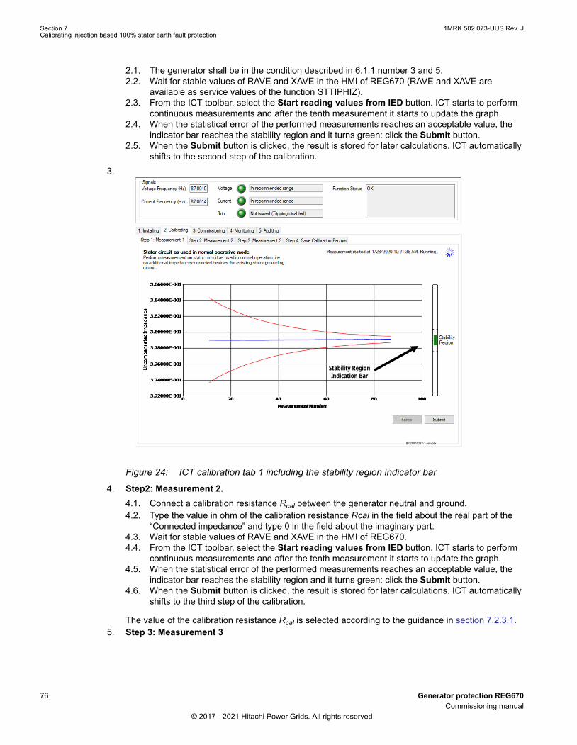
2.1. The generator shall be in the condition described in 6.1.1 number 3 and 5.2.2. Wait for stable values of RAVE and XAVE in the HMI of REG670 (RAVE and XAVE are
available as service values of the function STTIPHIZ).2.3. From the ICT toolbar, select the Start reading values from IED button. ICT starts to perform
continuous measurements and after the tenth measurement it starts to update the graph.2.4. When the statistical error of the performed measurements reaches an acceptable value, the
indicator bar reaches the stability region and it turns green: click the Submit button.2.5. When the Submit button is clicked, the result is stored for later calculations. ICT automatically
shifts to the second step of the calibration.3.
Stability RegionIndication Bar
IEC20000208-1-en.vsdx
IEC20000208 V1 EN-US
Figure 24: ICT calibration tab 1 including the stability region indicator bar
4. Step2: Measurement 2.4.1. Connect a calibration resistance Rcal between the generator neutral and ground.4.2. Type the value in ohm of the calibration resistance Rcal in the field about the real part of the
“Connected impedance” and type 0 in the field about the imaginary part.4.3. Wait for stable values of RAVE and XAVE in the HMI of REG670.4.4. From the ICT toolbar, select the Start reading values from IED button. ICT starts to perform
continuous measurements and after the tenth measurement it starts to update the graph.4.5. When the statistical error of the performed measurements reaches an acceptable value, the
indicator bar reaches the stability region and it turns green: click the Submit button.4.6. When the Submit button is clicked, the result is stored for later calculations. ICT automatically
shifts to the third step of the calibration.
The value of the calibration resistance Rcal is selected according to the guidance in section 7.2.3.1.5. Step 3: Measurement 3
Section 7 1MRK 502 073-UUS Rev. JCalibrating injection based 100% stator earth fault protection
76 Generator protection REG670Commissioning manual
© 2017 - 2021 Hitachi Power Grids. All rights reserved

5.1. Connect a short circuit between the neutral point of the generator and ground.5.2. Wait for stable values of RAVE and XAVE in the HMI of REG670.5.3. From the ICT toolbar, select the Start reading values from IED button. ICT starts to perform
continuous measurements and after the tenth measurement it starts to update the graph.5.4. When the statistical error of the performed measurements reaches an acceptable value, the
indicator bar reaches the stability region and it turns green: click the Submit button.5.5. When the Submit button is clicked, ICT automatically shifts to the fourth calibration tab, where
the result of the calibration are shown.6. Step 4: Save Calibration Factors:
The newly calculated complex factors k1 and k2 and the reference impedance 1 (RefR1, RefX1) arepresented. The values of these parameters are calculated by ICT, based on the three measurementsteps described above.ICT performs several checks on the measurement results of each steps. For example, it is verifiedthat there are enough changes in the measured impedances and that the useful signal, evaluated atthe HV side of the SIT, is high enough.6.1. Check the Calibration result field to verify that all tests have been passed.6.2. Click the Submit to Parameter setting button. ICT forwards the new calculated parameters
to PST.6.3. In PST, save the newly acquired parameters and write them to IED.6.4. View also the report of the Calibration in the Auditing tab and save it as a reference
document of the commissioning; generate also the logfile of the calibration by the buttonGenerate (right click) and save it as a reference document of the commissioning.
IEC20000209 V1 EN-US
Figure 25: ICT calibration tab 1 including the stability region indicator bar
Explanation of checks made by ICT at the end of the calibration
1MRK 502 073-UUS Rev. J Section 7Calibrating injection based 100% stator earth fault protection
Generator protection REG670 77Commissioning manual
© 2017 - 2021 Hitachi Power Grids. All rights reserved

The step 4 of the calibration shows the results of the following checks that are performed onthe calculated parameters.• Check 1: the difference between the bare impedances at the end of the three steps
shall be big enough. The difference is compared to the standard deviation of the last50 measurements of each one of the three steps. There can be different reasons whyCheck 1 can fail, such as:a It is possible that the stator winding was earthed during the calibration.b The injected signal is to weak and therefore the signal-to-noise ratio is too
low.c The user has not succeeded in changing the conditions (3 previous steps).
• Check 2a: the highest measured impedance shall be calculated for the step 1 (normalcondition) and the lowest measured impedance shall be calculated for the step 3(direct fault to earth).
• Check 2b: the useful signal, evaluated at the HV side of the SIT and expressed aspercentage of the injected signal, shall be higher than a minimum value.
• Check 3: The injected current signal and the injected voltage signal are not too lowduring each one of the steps. If the check 3 fails, there is the risk that the function isnot able to detect direct faults to earth because the corresponding signals are lowerthan the minimum levels that can be detected by the function.
7. Step 5: Save Calibration Factors:When the last calibration is finalized, disconnect calibration resistance and short circuit from thegenerator neutral. The results of the last calibration shall be analyzed and verified: Section 7.2.3.2describes checks and tests that shall be performed after the second (or third) calibration.
The equations below present in section 7.2.3.1 and Section 7.2.3.2 require data and variables to becollected from previous
Table 11: Data collected for calculations
Data DescriptionRn Equivalent primary grounding resistor (Ω)
finj Injection frequency (Hz)
fnetwork Rated generator and network frequency (i.e. 50 or 60 Hz)
Cstat Total capacitance to ground of all three stator windings andof equipment connected to the terminals of the generatorand to the generator neutral (F)
ω = 2·π·finj Angular Frequency (Hz)
SSIT Rated SIT (Signal Injection Transformer) Power (VA)
USIT,HV Rated primary Voltage of the SIT (V)
Section 7 1MRK 502 073-UUS Rev. JCalibrating injection based 100% stator earth fault protection
78 Generator protection REG670Commissioning manual
© 2017 - 2021 Hitachi Power Grids. All rights reserved

Table 12: Variables obtained from Calibrations
Variables DescriptionRefR1, RefX1 and RefZ1 Reference resistance, reactance and impedance defined
by second calibration (Ω)RefZ1 = RefR1 + j RefX1
RefR1old, RefX1old and RefZ1old Reference resistance, reactance and impedance definedby first calibration (Ω).RefZ1old = RefR1old + j RefX1old
k1 and k2 Obtained from the second calibration.k1 is defined by k1 = k1Real + j k1Imag.K2 is defined by k2 = k2Real + j k2Imag.
k1old and k2old Obtained from the first calibration and calculated the sameway as previous calibration factors.
7.2.3.1 Selection of the value of the calibration resistance Rcal and related testsGUID-88A4D759-CE03-4A50-A0BB-B9BACCCDDD19 v2
All following equations refer to the generator grounding through a primary groundingresistor Rn (IEC Grounding).
Value of the calibration resistance Rcal of the first calibration
The value of the calibration resistance Rcal can be selected based on the impedance to ground Zstat.
Zstat is defined as:
1( )
1stat
statn
Zj C
R
IECEQUATION20152 V1 EN-US (Equation 10)
The value Rcal of the resistor that is connected to the generator neutral during the second step of thecalibration shall fulfill the condition [2]:
0.8* ( ) 1.2* ( )stat cal statZ R Z
IECEQUATION20153 V1 EN-US (Equation 11)
The preferred value of Rcal is equal to |Zstat|.
If the capacitance to ground of the stator and/or equipment connected to the generator is unknown, acalibration resistance with tentative value equal to either 1000 Ω or the value that is defined by Equation12 can be used during the first calibration.
[2] The notion | Z | means the absolute value of the complex quantity Z.
1MRK 502 073-UUS Rev. J Section 7Calibrating injection based 100% stator earth fault protection
Generator protection REG670 79Commissioning manual
© 2017 - 2021 Hitachi Power Grids. All rights reserved
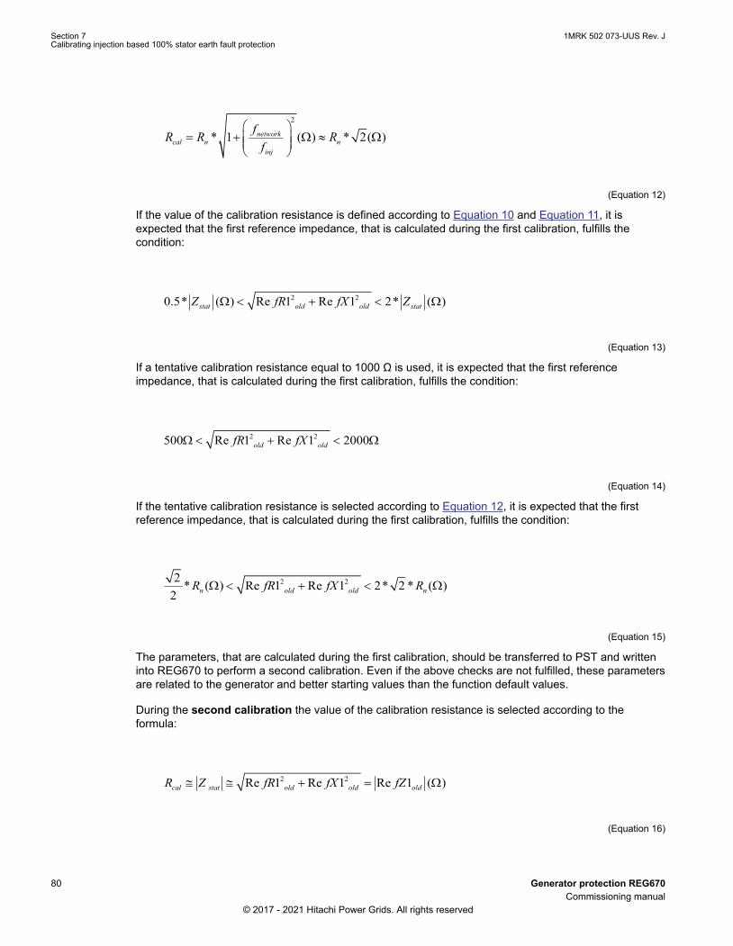
2
* 1 ( ) * 2( )networkcal n n
inj
fR R R
f
IECEQUATION20154 V1 EN-US (Equation 12)
If the value of the calibration resistance is defined according to Equation 10 and Equation 11, it isexpected that the first reference impedance, that is calculated during the first calibration, fulfills thecondition:
2 20.5* ( ) Re 1 Re 1 2* ( )stat old old statZ fR fX Z
IECEQUATION20155 V1 EN-US (Equation 13)
If a tentative calibration resistance equal to 1000 Ω is used, it is expected that the first referenceimpedance, that is calculated during the first calibration, fulfills the condition:
2 2500 Re 1 Re 1 2000old oldfR fX
IECEQUATION20156 V1 EN-US (Equation 14)
If the tentative calibration resistance is selected according to Equation 12, it is expected that the firstreference impedance, that is calculated during the first calibration, fulfills the condition:
2 22* ( ) Re 1 Re 1 2* 2 * ( )
2 n old old nR fR fX R
IECEQUATION20157 V1 EN-US (Equation 15)
The parameters, that are calculated during the first calibration, should be transferred to PST and writteninto REG670 to perform a second calibration. Even if the above checks are not fulfilled, these parametersare related to the generator and better starting values than the function default values.
During the second calibration the value of the calibration resistance is selected according to theformula:
2 2Re 1 Re 1 Re 1 ( )cal stat old old oldR Z fR fX fZ
IECEQUATION20158 V1 EN-US (Equation 16)
Section 7 1MRK 502 073-UUS Rev. JCalibrating injection based 100% stator earth fault protection
80 Generator protection REG670Commissioning manual
© 2017 - 2021 Hitachi Power Grids. All rights reserved

where:
RefR12old and RefX12
old were defined by the first calibration.
After the second calibration, the following condition should be fulfilled:
2 20.5* ( ) Re 1 Re 1 2* ( )cal old old calR fR fX R
IECEQUATION20159 V1 EN-US (Equation 17)
where:
Rcal is defined by Equation 16,
If the condition in Equation 17 is not fulfilled, a third calibration can be tried; before starting the thirdcalibration, the values of the parameters of the second calibration shall be transferred to PST and writteninto REG670 to start the third calibration from better values of the parameters. In this case, thecalibration resistance Rcal is selected according to theEquation 16, using the values of RefR1 and RefX1of the second calibration.
The notation |Z| means the absolute value of the complex quantity Z.
7.2.3.2 Checks and tests after the second calibrationGUID-BE429AB6-C258-44B1-9612-51E05139392F v2
After the second and last calibration the following checks shall be performed:
1. The relative difference between the parameters that are calculated during the first calibration (k1old,k2old and RefZ1old) and second calibration (k1, k2 and RefZ1) shall be lower than 10%:
%oldk1 k1
100 10k1
−
IECEQUATION20253 V1 EN-US (Equation 18)
%oldk2 k2
100 10k2
IECEQUATION20254 V1 EN-US (Equation 19)
%oldRefZ1 RefZ1100 10
RefZ1
-* <
IECEQUATION20255 V1 EN-US (Equation 20)2. The absolute value of the imaginary part of k2 shall be close to the series reactance of SIT at the
injection frequency.If a SIT with rated power SSIT = 10 kVA, HV side voltage USIT,HV = 14.4 kV and LV side voltage 240V is used, the following condition shall be fulfilled:
1MRK 502 073-UUS Rev. J Section 7Calibrating injection based 100% stator earth fault protection
Generator protection REG670 81Commissioning manual
© 2017 - 2021 Hitachi Power Grids. All rights reserved

,Im . %2
injSIT HV
SIT
fUk2 0 034 1022 15
S 60
IECEQUATION20257 V1 EN-US (Equation 21)
Values in Equation 21 is calculated for the default injection frequencyfinj = 87 Hz.3. The absolute value of k2 shall fulfill also the condition:
( )nk2 5 R
IECEQUATION20258 V1 EN-US (Equation 22)
where Rn is the (equivalent) primary grounding resistor.4. The first reference impedance RefZ1 shall fulfill the condition:
. cal cal0 5 R RefZ1 2 R
IECEQUATION20259 V1 EN-US (Equation 23)
where: Rcal is define by Equation 16
Equation 23 is the same as Equation 17 and it is repeated here for completeness.
5. The primary grounding resistor Rn can be used to validate the first reference impedance:
%
Ren
1R 20
1
RefR1 jRefX1
IECEQUATION20260 V1 EN-US (Equation 24)
6. Also the total capacitance to ground Cstat can be used to validate the first reference impedance:
Im
%( )statinj
1
RefR1 jRefX1C 20 F
2 f
IECEQUATION20261 V1 EN-US (Equation 25)7. Another important parameter that shall be evaluated is the “useful signal” expressed as percentage
of the injected signal (i.e. the percentage of the injected signal that propagates through the injectiontransformer SIT); the useful signal should be at least 10%. This condition is related to the so called“Check 2b” that is performed by ICT and is listed in the ICT calibration report. An approximate valueof the useful signal can be calculated as in the Equation 26.
%RefZ1
Usefulsignal 100 10RefZ1 k2
IECEQUATION20262 V1 EN-US (Equation 26)
Section 7 1MRK 502 073-UUS Rev. JCalibrating injection based 100% stator earth fault protection
82 Generator protection REG670Commissioning manual
© 2017 - 2021 Hitachi Power Grids. All rights reserved

7.2.3.3 Checking the measurements by test resistances (generator at standstill)GUID-80AF354F-87BD-4AD4-A565-DB9B5A6FE209 v2
A check of the measured resistance to ground is advised after the calibration. The generator circuitbreaker (if it exists) shall be in the same position as during the calibration.
Known test resistances are connected between the generator neutral and ground and the evaluatedresistance to ground RFAULT is checked in the service values of the function STTIPHIZ.
During this activity it is advised to run the logger of ICT; furthermore at least one disturbance recordingshould be triggered manually for each test resistance.
1. The generator shall be in the same condition described in Section 7.2.1 number 3 and 5.2. Verify that the trip is enabled in ICT (if needed, the hard-wired trip circuit to the CB can be open at
the cubicle terminal blocks, for example).3. In ICT go to the tab 4. Monitoring, see Figure 26.
• set the Graph update period to 1 s;• In the area Logger change the Log Period from 1 to 3 hours;• select the path and name of the logfile by clicking the button Browse;•
Click the Start reading values from IED button (i.e. the green play button ) in the ICTtoolbar to start performing continuous measurements.
• Start the logger by the button Start.
Logger Feature
Currently measured impedance and its average
Currently used reference
Selectable quantity for plotting
Selectable graph update period in (s)
IEC20000534-1-en.vsd
IEC20000534 V1 EN-US
Figure 26: ICT monitoring tab
1MRK 502 073-UUS Rev. J Section 7Calibrating injection based 100% stator earth fault protection
Generator protection REG670 83Commissioning manual
© 2017 - 2021 Hitachi Power Grids. All rights reserved

4. Trigger manually the disturbance recorder from the HMI of REG670 to have a recording related tothe condition without any test resistance connected to the generator neutral.
5. Read and record the value of RFAULT in the service values of the function STTIPHIZ.In HMI select; Test/Function status/Impedance protection/StatorInjection(64S,R<)/STTIPHIZ(64S,R<):1/Outputs .
6. Observe the fault conductance while applying known faults. Both the calibration factors and thereference that is used can be verified this way. In some cases, though, it is desired to be able tomeasure/view other quantities.
7. Select Fault conductance in the Viewed quantity drop-down menu.The fault conductance is equal to 1/R_f (1/fault resistance) and is more suitable to view when nofaults or very high values of fault resistance are applied/ measured.Since a not faulted condition theoretically equals to infinite fault resistance, it is better to view thefault conductance, which is zero in this case.As no fault is applied, the measured fault conductance must be close to zero. Confirm this byviewing the graph. It may be necessary to zoom in or out to properly view the measurements. Forinstructions on this, see Section 6.9.
8. Select Fault resistance in the Viewed quantity drop-down menu.Connect several test resistances to the generator neutral (see, for example, Table 13); themaximum value of the test resistance is equal to the double of the default setting of RAlarm (i.e.10000 Ω); for each test resistance:• Record the value of RFAULT;• Trigger manually the disturbance recorder from the HMI of REG670.• Check that alarm and trip are properly issued.
The measured resistance RFAULT shall be close to 0 Ω when the short circuit isapplied; the value of this measurement is an offset that will affect all performedmeasurements.If this value deviates from zero more than 10% of the trip setting RTrip, a newcalibration shall be performed with a better calibration resistance at the secondstep: that may increase the accuracy of measurements. When the short circuit isapplied it is possible that RFAULT shows occasionally the code “-1000”.
9. At the end of the test:9.1. Stop the logger in ICT.9.2. Click the Stop reading values from IED button (i.e. the blue stop button) in the ICT
toolbar.9.3. Retrieve disturbance recordings from REG670 by the Disturbance Handling Tool of PCM600
and save them in the PC;9.4. Disconnect all test resistances.9.5. Check that the value of RFAULT is either “-1000” or a very high value.9.6. Perform a check on the collected data:
• Alarm and trip are issued as expected;• Error of the evaluated resistances to ground RFAULT:
%testtest
RFAULT Rerr 100 10 if R 1000
1000
IECEQUATION20263 V1 EN-US (Equation 27)
Section 7 1MRK 502 073-UUS Rev. JCalibrating injection based 100% stator earth fault protection
84 Generator protection REG670Commissioning manual
© 2017 - 2021 Hitachi Power Grids. All rights reserved

%testtest
RFAULT Rerr 100 10 if 1000 R 10000
10000
IECEQUATION20264 V2 EN-US (Equation 28)• Signals in the disturbance recordings;• Measured values, error codes and function status in ICT logfile.
Table 13: Example of table where data are recorded during the test
Test FaultResistance(kΩ)
RFAULT (HMI)(kΩ)
DR # Alarm Trip Error (%) Note
No fault
10
9
7
5.5
5
4.5
4
3.5
3
2.5
2
1.5
1.1
1
0.9
0.7
0.5
0.3
0.1
0
After the test with test resistors connected to the generator neutral, it is possible to perform also a fewtests with known test resistors connected to one of the generator terminals (for example the phase L1),following a procedure that is similar to the one described here.
The tests shall be performed in the same condition described in Section 7.2.1 number 3 and 5.
The tests are performed to verify at least:
- the alarm level (for example two tests can be performed, the first one with a test resistor 10% higherthan RAlarm, and the second one with a test resistor 10% lower than RAlarm);
- the trip level (for example two tests can be performed, the first one with a test resistor 10% higher thanRTrip, and the second one with a test resistor 10% lower than RTrip);
1MRK 502 073-UUS Rev. J Section 7Calibrating injection based 100% stator earth fault protection
Generator protection REG670 85Commissioning manual
© 2017 - 2021 Hitachi Power Grids. All rights reserved
- the trip if a direct short between the generator terminal and ground.
7.2.4 Commissioning and acquiring referencesGUID-663303E6-1261-4E70-8BED-2F68E6C09892 v2
The generator operates in different conditions, such as: standstill, start-up, synchronization, synchronizedto the network and loaded, shutdown, synchronized and unloaded. Since the equivalent zero sequencenetwork includes nonlinear parameters that depend on the machine operating conditions, differentreferences can be needed for each condition to achieve stable and more accurate measurements.
Some operating conditions require the block of the function if, for example, the measured impedancechanges in a wide range (for example during start-up by static starter) or the machine is intentionallyconnected to ground (like during electrical braking).
The logic that performs the block of the function can be already implemented before starting the activityto define the reference impedances RefZ2, RefZ3 (and eventually RefZ4 and RefZ5).
A logic can be implemented in the application configuration to select the different reference impedances.A typical approach is:
• The first reference impedance (RefZ1) is active when:• the generator is at standstill (and/or when it is on turning gear).• during start-up and shutdown, when the generator is not excited, and the generator CB is
open.• The second reference impedance (RefZ2) is active during start-up and shutdown, when the
generator is excited, and the generator CB is open.• The third reference impedance (RefZ3) is active when the generator is synchronized, and it is
loaded, i.e. when it is excited, and the generator CB is closed.
The above logic will change the active reference impedance taking into account the generator operatingconditions; before starting the procedure to define the reference impedances RefZ2 and RefZ3 (andeventually also RefZ4 and RefZ5, if the logic selects also them), their values should be set equal to theone of RefZ1 because this value is related to the generator and it is therefore a better value than thedefault one. After the values of reference impedances are set in PST, they shall be saved and written intoREG670.
Section 7 1MRK 502 073-UUS Rev. JCalibrating injection based 100% stator earth fault protection
86 Generator protection REG670Commissioning manual
© 2017 - 2021 Hitachi Power Grids. All rights reserved

IEC20000535 V1 EN-US
Figure 27: Example of logic to select ZRef according to different generator operating conditions
The definition of references can be done in two ways.
1MRK 502 073-UUS Rev. J Section 7Calibrating injection based 100% stator earth fault protection
Generator protection REG670 87Commissioning manual
© 2017 - 2021 Hitachi Power Grids. All rights reserved

1. Finding references by using the Injection Commissioning Tool (ICT).2. Calculating references using a complete generator sequence.
A. Definition of references by using the Injection Commissioning Tool (ICT)The injection commissioning tool (ICT) helps the commissioning engineer to acquire additionalreferences for different conditions of the generator (RefZ2 to RefZ5). This procedure allows the definitionof preliminary values of the additional reference impedances and can be further used in the procedureexplained in item B which is the preferable one.
The description below assumes that reference 1 was set during calibration and that the second referencemust be set now. The trip of the function should be blocked (disabled), as advised by the pop-up windowof ICT.
1. Ensure that the generator is in a state where the reference must be set (for example normaloperation).
2. To start, select the Commissioning tab.3. Disable function tripping.4. Select tab; Step 1: Find Reference Impedance5. In the Reference impedance selection drop-down menu. select Reference 2.6. To start reading the measurements, click the Start reading values from IED button in the ICT
toolbar.• ICT starts to read the selected viewed quantity from IED and plots values on the X/Y graph.
Measured absoluteimpedance ± standard
deviationFloating average of themeasured absolute
impedance
Measured absoluteimpedance
Reference ImpedanceSelection dropdown menu
IEC20000211-1-en.vsdx
IEC20000211 V1 EN-US
Figure 28: Commissioning tab
Section 7 1MRK 502 073-UUS Rev. JCalibrating injection based 100% stator earth fault protection
88 Generator protection REG670Commissioning manual
© 2017 - 2021 Hitachi Power Grids. All rights reserved

Normally continuous readings are performed and the read absolute impedance is viewed in the plot.By observing the standard deviation of the measured impedance, the commissioning engineer candecide if the impedance of the generator is stable/settled and if the average impedance is based onenough values so that statistically the signal noise is filtered out. This results an accurate impedancemeasurement which can be used as a second reference.
7. Click the Select button when the standard deviation has converged so that its magnitude is withinthe noise level of the measured absolute impedance. In the second commissioning sub tab, Step2 :Save Reference Impedance, the measured real and imaginary reference 2 impedance is presented.
8. Select the Submit to Parameter setting button. This forward the newly acquired reference toParameter setting.
9. Write the newly acquired real and imaginary parts of Reference 2 to IED.10. After all references have been acquired, enable function tripping again by pressing the button in the
ICT toolbar Enable Function Tripping.
B. Calculating references using a complete generator sequenceThe definition of the reference impedances from RefZ2 to RefZ5 and the identification of the operatingconditions when they must be active can be based on the analysis of a logfile of ICT that is capturedduring a complete sequence of generator operating conditions: standstill – start-up – synchronization –synchronized to the network and loaded –shutdown – standstill. Manually triggered disturbancerecordings may be needed to complement the analysis. Event lists of DCS or, at least, of REG670 arealso needed to correlate the analysis of logfiles to the generator conditions and site events.
The procedure based on the analysis of logfiles, disturbance recordings and events list define not onlythe needed reference impedances, but allows also the identification of the operating conditions when thefunction STTIPHIZ shall be blocked and supplies the key parameters to define properly the settings ofthe function.
The monitoring of the generator by ICT logfiles and manually triggered disturbance recordings shall beperformed during the complete sequence (including the operation at the rated temperature), trying tominimize any interruption between logfiles.
During the monitoring of the generator also events of REG670 and events of DCS shall be collected.
Table 14 lists an example of a sequence of generator operating conditions. Logfiles shall be capturedalso during the transition from one operating condition to the following one and during the transition fromone reference impedance to another one. It is important that event lists of both REG670 and DCS areavailable also during these transitions. Even if it can be difficult to trigger disturbance recordings thatinclude transitions, the availability of these recordings can be very useful during the analysis. For thispurpose, it is possible to enable the trigger of the channels of the disturbance recorder that record theoutput signals of the logic that select the active reference impedance.
One logfile can include two or more operating conditions and the transitions between them.
For example, it is possible to save a logfile lasting at least one hour when the generator is at standstill.About 30 or 40 minutes before the start-up of the generator the logger of ICT is started again in order torecord a logfile that covers standstill, transition to start-up with static starter, static starter operation,transition to start-up, start-up (without static starter), transition to excitation on (and change of referenceimpedance of STTIPHIZ), excitation on, synchronization to the network, closing of generator circuitbreaker (and change of reference impedance of STTIPHIZ), generator synchronized to the network andtaking load, generator loaded (at least 30 or 40 minutes). Then a new logging can be started to monitorthe generator in loaded conditions. During the monitoring the time between two consecutive logfiles shallbe as short as possible.
1MRK 502 073-UUS Rev. J Section 7Calibrating injection based 100% stator earth fault protection
Generator protection REG670 89Commissioning manual
© 2017 - 2021 Hitachi Power Grids. All rights reserved

Several loggings can be needed to register data when the generator is loaded and when it is at its ratedtemperature with several different loads. The monitoring of the generator at its normal operatingtemperature has a fundamental importance and shall last for at least 2 hours.
A further logfile can be started about 30-40 minutes before the shutdown in order to register data duringthe preparation to the shutdown and all phases of the shutdown, covering carefully all transitions until thestandstill condition is reached. A final logfile is started when the generator is at standstill (or on turninggear) after the shutdown: the logfile shall last at least two hours. Consider that the max time of an ICTlogfile is 3 hours.
Table 14: Example of mandatory data to be collected during the complete sequence of generator operating conditions:standstill – start-up – synchronization – synchronized to the network and loaded –shutdown – standstill
Mandatory and Required, data and filesOperating condition Logfile DRs Event list (REG670 and
DCS)Standstill / Turning Gear Yes Yes Yes
Transition from Standstill toStatic Starter Start-up (if applicable)
Yes Yes Yes
Static Starter Start-up (if applicable) Yes Yes Yes
Transition from Static Starter Operation toStart-up without Static Starter (if applicable)
Yes Yes Yes
Start-up (without Static Starter) Yes Yes Yes
Transition from Start-up toExcitation on
Yes Yes Yes
Excitation on Yes Yes Yes
Synchronization to the network Yes Yes Yes
Closing of Generator Circuit Breaker Yes Yes Yes
Generator Loaded fromMin Power to Max Power
Yes Yes Yes
Generator atStable Operating Temperature with SeveralLoads
Yes Yes Yes
Preparation to Shutdown Yes Yes Yes
Transition from Synchronized Generator toShutdown with Excitation ON
Yes Yes Yes
Shutdown with Excitation ON Yes Yes Yes
Transition from Shutdown with Excitation ONtoShutdown with Excitation OFF
Yes Yes Yes
Shutdown without Excitation Yes Yes Yes
Transition to Electrical Braking(if any is performed)
Yes Yes Yes
Shutdown with Electrical Braking(if any is performed)
Yes Yes Yes
Transition toShutdown without Excitation
Yes Yes Yes
Shutdown without Excitation Yes Yes Yes
Transition to Mechanical Braking Yes Yes Yes
Table continues on next page
Section 7 1MRK 502 073-UUS Rev. JCalibrating injection based 100% stator earth fault protection
90 Generator protection REG670Commissioning manual
© 2017 - 2021 Hitachi Power Grids. All rights reserved

Mandatory and Required, data and filesOperating condition Logfile DRs Event list (REG670 and
DCS)Shutdown with Mechanical Braking Yes Yes Yes
Transition toShutdown without Excitation
Yes Yes Yes
Shutdown without Excitation Yes Yes Yes
Standstill / Turning Gear Yes Yes Yes
7.2.4.1 B.1 Recording of data during different operating conditions of the generatorGUID-204CBB15-7CD0-47C1-B816-EEB99E36F370 v1
1. Check that all test resistances are disconnected from the generator neutral.2. Check the time of DCS, the time in the PC where PCM is running and the internal time of REG670.
The time shall be synchronized in the best possible way, for example, manually setting time equallyin both units.
3. Set the reference impedances RefZ2… RefZ5 (i.e. RefR2, RefX2, RefR3, RefX3, …) to the samevalue of the reference impedance 1 (i.e. RefR1, RefX1) that was defined during the calibration.
4. In ICT go to the tab 4. Monitoring:4.1. set the Graph update period to 1 s;4.2. in the area Logger set the Log Period to 3 hours;4.3. select the path and name of the logfile by clicking the button Browse;4.4. start the logger by the button Start.4.5. Click the Start reading values from IED button (i.e. the green play button) in the ICT toolbar to
start performing continuous measurements.5. The logger shall record data during the complete sequence of generator operating modes. Several
logfiles can be saved, if the sequence takes a time longer than 3 hours.6. Manually trigger some disturbance recordings for each operating condition of the generator.7. Try to take a note about the time when it is performed the change from one operating condition to
another one. Try to take a note about the service values of the function STTIPHIZ.8. When the generator has a stable load higher than 75% of full load, manually trigger:
• one disturbance recording with REX060 injection on;• one disturbance recording with REX060 injection off.
Switch on again REX060 injection after the second recording.9. At the end of the sequence:
9.1. Stop the logger in ICT.9.2. Click the Stop reading values from IED button (i.e. the blue stop button) in the ICT toolbar.9.3. Retrieve disturbance recordings from REG670 by the Disturbance Handling Tool of
PCM600 and save them in the PC. (Depending on the number of triggered recordings, it canbe necessary to retrieve them and save in the PC during the sequence of generatoroperating conditions).
9.4. Save the event list of REG670 by the Event Viewer tool of PCM600.9.5. Get and save the DCS event list.
7.2.4.2 B.2 Analysis of collected dataGUID-D13AA4CA-5977-4A15-BC7D-B60461BA0D03 v2
1. Spectra of the injected signals and of the voltage at the generator neutral in some identifiedoperating conditions shall be analyzed and compared to verify that other frequencies do notinterfere with the frequency injected by REX060.For example the following conditions can be analyzed:
1MRK 502 073-UUS Rev. J Section 7Calibrating injection based 100% stator earth fault protection
Generator protection REG670 91Commissioning manual
© 2017 - 2021 Hitachi Power Grids. All rights reserved

• during start-up, when the generator is close to its rated speed and excitation is off;• during start-up, when excitation is on and generator CB (or unit CB) is still open;• when the generator is synchronized and loaded at two or three typical loads.
It is normal that the third harmonic voltage crosses the injection frequency duringthe generator start-up and shutdown; STTIPHIZ reacts to this circumstance with atemporary block of the function (block due to interference signal).
2. Spectra of the injected signals at the generator neutral in the disturbance recordings of B. 1 number8 shall be compared to evaluate background noise and frequencies that can interfere with theinjected one.
3. The logfile of ICT shall be analyzed in order to identify the needed reference impedances and theconditions when they must be active; typically, a search for sudden changes of the followingquantities is carried out:• Real value of the measured impedance.• Imaginary value of the measured impedance.• Absolute value of the measured impedance.
If the identified change is related to a change of the generator operating condition, this changeidentifies the need to change the reference impedance.The times at which changes occur can be identified in the logfile.
4. Compare the change times in Step 3 with the event list of DCS to identify the generator conditionand signals that can be used in the logic that activates the proper reference impedance. Theanalysis of disturbance recordings can complement this analysis.
5. The value of each reference impedance (i.e. RefZ2, RefZ3…RefZ5) can be calculated from thelogfile as average of the real values of the measured impedance (RefRx) and as average of theimaginary values of the measured impedance (RefXx) during the defined active time period of thereference impedance.
6. Each defined reference impedance shall be compared with RefZ1 and with the other referenceimpedances to evaluate the risk of false alarm if a wrong reference is active instead of the desiredone. For example, if RefZ1, RefZ2 and RefZ3 are identified as needed reference impedances, thefollowing quantities shall be calculated:
Re
12
1R
1 1
RefZ2 RefZ1
IECEQUATION20265 V1 EN-US (Equation 29)
Re
13
1R
1 1
RefZ3 RefZ1
IECEQUATION20266 V1 EN-US (Equation 30)
23
1R
1 1Re
RefZ3 RefZ2
IECEQUATION20267 V1 EN-US (Equation 31)
6.1. If the absolute value of any of the above quantities R12, R13, R23 is lower than 3 * RAlarm,than there is the risk of a false alarm if a wrong reference impedance is selected.The setting of RAlarm is therefore selected considering the minimum value of the abovequantities R12, R13, R23 and an appropriate safety factor:
Section 7 1MRK 502 073-UUS Rev. JCalibrating injection based 100% stator earth fault protection
92 Generator protection REG670Commissioning manual
© 2017 - 2021 Hitachi Power Grids. All rights reserved

. min( , , )Alarm 12 13 23R 0 33 R R R
IECEQUATION20268 V1 EN-US (Equation 32)6.2. If there is the wish to select a setting of RAlarm that is higher than the limit in Equation 32, a
deeper analysis is required to identify the proper strategy to avoid unwanted alarms. Forexample:• A proper value of the delay tAlarm can be defined. If several logfiles are available, it is
possible to compare times at the reference switching when there is a mismatchbetween the active reference impedance and the needed one; if a trustable maximumvalue of the mismatch time can be identified (t_reference_mismatch), the delaytAlarm can be set according to the following condition:
mismatchreferencetAlarm t 10 FilterLength s
IECEQUATION20269 V1 EN-US (Equation 33)• The function STTIPHIZ can be temporarily blocked and a logic can be designed to
perform this block.• More appropriate signals can be identified to drive the selection of the active
reference impedance.• The logic that selects the active reference impedance is improved.
Moreover, if RefZ4 and/or RefZ5 are also used, the analysis shall include them.7. In the logfile of ICT the real and imaginary values of the measured impedance are used to calculate
the measured impedance Zmeasured. Using the active reference impedance RefZx, the value ofthe fault resistance can be estimated by the formula:
fault
measured
1R
1 1Re
Z RefZx
IECEQUATION20270 V1 EN-US (Equation 34)
The quantity FaultNoise Limit can be calculated for each one of the defined reference impedancesas:
min ,faultFaultNoiseLimit RefZx R
When RefZx is active
IECEQUATION20271 V1 EN-US (Equation 35)
The maximum acceptable value of the setting of RAlarm is:
max . minRAlarm 0 2 FaultNoiseLimit
IECEQUATION20272 V1 EN-US (Equation 36)8. A typical setting of RTrip is between 500 Ω and 1000 Ω.
In any case the following conditions about RTrip shall be fulfilled:8.1. RTrip shall be lower than any of the above quantities R12, R13, R23 , with a safety margin:
. min( , , ,...)12 13 23RTrip 0 2 R R R
IECEQUATION20273 V1 EN-US (Equation 37)
1MRK 502 073-UUS Rev. J Section 7Calibrating injection based 100% stator earth fault protection
Generator protection REG670 93Commissioning manual
© 2017 - 2021 Hitachi Power Grids. All rights reserved

If this condition is not fulfilled, the function shall be blocked at reference switching.8.2. RTrip shall be lower than RAlarm, with a safety margin:
.RTrip 0 5 RAlarm
IECEQUATION20274 V1 EN-US (Equation 38)8.3. RTrip shall be lower than the FaultNoise Limit, with a safety margin:
. minRTrip 0 2 FaultNoiseLimit
IECEQUATION20275 V1 EN-US (Equation 39)8.4. The value of RTrip should preferably be close to the equivalent primary value of the
grounding resistor Rn; the following condition shall be fulfilled:
. n n0 4 R RTrip 2 R
IECEQUATION20276 V1 EN-US (Equation 40)
9. The ratio between each reference impedance and RefZ1 shall be also calculated:
RefZ2RatioRefZ21 100
RefZ1
IECEQUATION20277 V1 EN-US (Equation 41)
RefZ3RatioRefZ31 100
RefZ1
IECEQUATION20278 V1 EN-US (Equation 42)
RefZ4RatioRefZ41 100
RefZ1
IECEQUATION20279 V1 EN-US (Equation 43)
RefZ5RatioRefZ51 100
RefZ1
IECEQUATION20280 V1 EN-US (Equation 44)
It is expected that the ratios in the above equations from Equation 37 to Equation 40 are in therange 75% to 150%.
10. The analysis of ICT logfiles allow also the plot of several quantities, such as:
a. the real part of the measured impedance to ground,
b. the imaginary part of the measured impedance to ground,
c. the absolute value of the measured impedance to ground,
d. the deduced resistance to ground,
e. the deduced conductance to ground,
f. the deduced capacitance to ground,
Section 7 1MRK 502 073-UUS Rev. JCalibrating injection based 100% stator earth fault protection
94 Generator protection REG670Commissioning manual
© 2017 - 2021 Hitachi Power Grids. All rights reserved

g. the evaluated fault resistance,
h. the evaluated fault conductance,
i. the injected rms voltage after REX060 amplification,
j. the injected rms current after REX060 amplification.
The above plots are useful in the analysis of the behavior of the protection function.For example:• the plots of the first three quantities can be useful for the identification of the needed
reference impedances;• the study and the correlation of the above plots can support the understanding of issues.• the plot of the injected rms voltage after REX060 amplification shows if REX060 performs
any change of gain of its amplification.11. In addition to the above criteria, the analysis of the logfiles, of the values of the evaluated
resistance to ground RFAULT and of the above plots can suggest a minimum delay for the alarm or,in some cases, the block of the function.For example, the function STTIPHIZ, and eventually also REX060, shall be blocked in conditionslike the ones listed here below:• STTIPHIZ shall be blocked during short transients with low value of RFAULT.• It can be detected the need to block the function STTIPHIZ at the beginning of the shutdown
procedure, when the generator circuit breaker is opened; the block can be maintained duringa timer interval defined by the analysis performed.
• Typically, during start-up by static-starter the function STTIPHIZ and the injection of REX060shall be blocked and the current and voltage cable shall be disconnected from REX062 andREX060 respectively by normally closed contact of an auxiliary relay; this relay shall beenergized only during the block condition. The three steps (i.e. block of STTIPHIZ, block ofREX060 and opening of the wiring) shall be sequentially performed. After the synchronizationof the generator to the network the 100% stator EF protection is again enabled by performingthe above three steps in reverse sequence.
• The function STTIPHIZ shall be blocked during the electrical braking.• The function STTIPHIZ, and eventually also REX060, shall be blocked if specific site needs
are identified.
7.2.4.3 B.3 Setting of REG670GUID-DB2B1C7B-DB9A-426D-8311-1BB1A320CB6D v1
The settings of the function STTIPHIZ shall be updated with the defined values of the referenceimpedances RefZ2…RefZ5, and with the selected values of RAlarm, tAlarm and RTrip. The new settingsshall be written into REG670 by PST.
The updated logic that selects the active reference impedances and the logic that perform any neededblock of the function shall be defined in ACT (Application and Configuration Tool) and then the updatedlogic shall be written into REG670.
Finalization of the commissioningAfter the activities in the previous paragraphs are completed, the generator shall be monitored (i.e.running the logger of ICT Monitoring tab as explained in the previous paragraphs) during its normaloperation (standstill, start-up, synchronization to the network, operation up to the nominal load), seeSection 7.2.4.1, item 4 and 5.
During this sequence, the generator shall be monitored for a time that is long enough to reach its normaloperating temperature.
1MRK 502 073-UUS Rev. J Section 7Calibrating injection based 100% stator earth fault protection
Generator protection REG670 95Commissioning manual
© 2017 - 2021 Hitachi Power Grids. All rights reserved

If it is possible to perform a normal shutdown of the generator, also this shutdown and the followingstandstill should be monitored.
During this monitoring activity it is enough to capture only logfiles by ICT, following the strategy explainedin the paragraph Section 7.2.4.These logfiles are captured when REG670 has the definitive applicationconfiguration logic for STTIPHIZ and when STTIPHIZ itself has its definitive settings and shall betherefore analyzed carefully for a final assessment.
The analysis of logfiles has the following targets:
• Behavior of STTIPHIZ at the switching between reference impedances (evaluated resistance toground, error codes, function status).
• For each operating condition of the generator and the related reference impedance: identification ofthe minimum value of the evaluated resistance to ground (FaultNoiseLimit).
• Check and confirm the value of the reference impedances; if better values of the referenceimpedances are identified during this analysis, the settings of STTIPHIZ can be updated accordingly.
• Check that the function STTIPHIZ (and eventually also REX060 injection) is properly blocked by thelogic, if any block is needed.
• Confirmation of the settings of RAlarm, tAlarm and RTrip.• Comparison of data at standstill before and after the monitoring activity.
The commissioning of the protection function is not completed until this last monitoring activity and theanalysis of collected data is finalized.
7.2.5 AuditingGUID-70137BAD-6BD5-4835-964E-B6ADAE522A15 v2
During installations, calibrations and commissions the ICT generates reports for each of the steps andcollects them under the Auditing tab. See the procedures below on how to view and delete reports aswell as generate logs from reports.
1. To view the reports, go to the Auditing tab.
Section 7 1MRK 502 073-UUS Rev. JCalibrating injection based 100% stator earth fault protection
96 Generator protection REG670Commissioning manual
© 2017 - 2021 Hitachi Power Grids. All rights reserved

IEC11000049-1-en.vsdGUID-8348F60B-9BF5-4018-9740-0FA3371B0F9F V1 EN-US
Figure 29: Auditing tab
2. Open and view each report.3. View reports in one of the following ways:
• In the short cut menu, right click and select View report.• Click the View report button in the upper right corner of the auditing screen.• Double click a report record.
4. Delete reports in one of the following ways:• In the short cut menu, right click and select Delete.• Click the Delete button in the upper right corner of the auditing screen.• Select a record with the mouse cursor then press the Delete key on the keyboard.
5. Generate logs in one of the following ways:• In the short cut menu, right click and select Generate.• Click the Generate button.
Besides generating a report, you can also generate a log file with the same information as for thereport. Open and see the details of the file in Notepad or MS Excel.After a successful generation of the log, the system confirms with a message along with the path ofthe log file.
7.2.6 Editing features in graphGUID-B2784230-2355-4D4A-AAF0-34864C8D3190 v3
You can do the following operations on the graph during calibration, commissioning and monitoring:
• Zoom in• Zoom out• Cancel zoom• Enable X-zooming• Enable Y-zooming
1. Zoom in one of the following ways:• Right click a graph and select Zoom in or Zoom out in the shortcut menu.
1MRK 502 073-UUS Rev. J Section 7Calibrating injection based 100% stator earth fault protection
Generator protection REG670 97Commissioning manual
© 2017 - 2021 Hitachi Power Grids. All rights reserved

IEC20000212 V1 EN-US
Figure 30: Zooming via the shortcut menu
• Use the mouse to zoom in and select a part of the graph area.
IEC20000213 V1 EN-US
Figure 31: Zooming via area selection of a part of the graph
• Press PgUp key on the keyboard to zoom in and PgDn to zoom out.
2. Cancel a zoom in the following ways:• Right click a graph and select Cancel Zoom in the shortcut menu.
The graph area is squeezed to the original size.• Press Esc.
3. Enable X and Y zooming• To enable and disable X zooming, right click the graph and select or deselect Enable X
zooming in the shortcut menu.• To enable and disable Y zooming, right click the graph and select or deselect Enable Y
zooming in the shortcut menu.
7.2.7 Logging measurements to fileGUID-C86EC2DF-88F0-4272-8988-583778B5F2AE v3
In addition to viewing online plotted data under the Monitoring tab, it is also possible to log quantities to afile (tabbed text file) that can be viewed in the graph. Besides this voltage levels measured by thefunction and also error codes are logged. This file can then be imported to other tools for deeper analysiswhen needed. The logger feature is available on the lower right corner of the Monitoring tab. Note thatthe logger is independent of graph plotting.
1. Select the Browse button.2. Navigate to a desired folder.3. Type a suitable file name for the .txt file and select Save.4. To start logging to this file, select the Start button.
ICT continuously logs data to this file with logging interval set under graph update period. Noticethat there is a field named Log period and its default value is 1 hour. The period can be adjusted
Section 7 1MRK 502 073-UUS Rev. JCalibrating injection based 100% stator earth fault protection
98 Generator protection REG670Commissioning manual
© 2017 - 2021 Hitachi Power Grids. All rights reserved
before the logging is started, usually 3h is selected, and several logs needs to be captured to coverthe full generator cycle start-load-stop.
5. The logging can be stopped by selecting the Stop button.6. You can open the file in notepad or MS Excel.
7.2.8 Signals requirement in the disturbance recorderGUID-F704435B-ABC9-4C11-807A-4B2BB269529A v1
The study of disturbance recordings and of the event list complements the analysis of logfiles.
Comparison of data in logfiles, disturbance recordings and events lists require that time tags refer to thesame time.
Time tags of disturbance recordings and event list refer to the internal time of REG670. However, thetime tags of events in the logfiles refer to the internal time of the PC where PCM600 and ICT are run.
It is therefore extremely important that the time of the PC, where PCM600 and ICT run, is synchronizedto the time of REG670 in the best possible way. The best option is that they are synchronized with a timedifference shorter than 1 s because the resolution of events in the logfiles can be set to 1 s in ICT.
The following analog signals shall be available in the disturbance recordings that are captured during themonitoring activity:
1. Phase currents of the generator;2. Phase voltages of the generator;3. Neutral voltage of the generator;4. REX060 measured voltage (TRM channel of REG670 that is connected to REX060 X61:8-9);5. REX060 injected current (this signal is a voltage quantity because it is measured on the shunt of
REX060; it is the TRM channel of REG670 that is connected to REX060 X61:10-11);6. RAVE (average resistance evaluated by STTIPHIZ);7. XAVE (average reactance evaluated by STTIPHIZ);8. RFAULT (resistance to ground evaluated by STTIPHIZ);
The following binary signals shall be available in the disturbance recordings that are captured during themonitoring activity:
1. STTIPHIZ_START;2. STTIPHIZ_TRIP;3. STTIPHIZ_ALARM;4. STTIPHIZ_ERROR;5. STTIPHIZ_URMSSTAT;6. STTIPHIZ_ZREF shall be wired to a function block IB16 and the outputs OUT1, OUT2 and OUT3
shall be wired to the disturbance recorder; the name of disturbance recorder signals can be definedrespectively as: ZREF_bit1, ZREF_bit2 and ZREF_bit3;
7. STTIPHIZ_ERRSTAT shall be wired to a function block IB16 and the outputs OUT1, OUT2, … OUT8shall be wired to the disturbance recorder; the name of disturbance recorder signals can be definedrespectively as:• STT_no_Vinj;• STT_no_Iinj;• STT_fV_fI_dif;• STT_Vrms_high;• STT_Irms_high;• STT_Vinj_low;• STT_Iinj_low;• STT_V_interf;
1MRK 502 073-UUS Rev. J Section 7Calibrating injection based 100% stator earth fault protection
Generator protection REG670 99Commissioning manual
© 2017 - 2021 Hitachi Power Grids. All rights reserved

8. Signals that are used to select the active reference impedance: all both input signals to the selectionlogic (like excitation on or generator CB closed) and output signals of the selection logic (i.e. thesignals that are wired to the inputs of the function block B16I that selects the active referenceimpedance of STTIPHIZ);
9. Signals that are used to block the function STTIPHIZ (input signals to the blocking logic and blocksignal to STTIPHIZ);
10. Signals that are used to block REX060 injection (input signals to the blocking logic and block signalto REX060).
11. Any other signal in the application configuration that can affect STTIPHIZ.
7.2.9 Completing the testGUID-73A479C2-15B9-4D35-8D44-6AA906C2F235 v1
Continue to test another function or end the test by changing the Test mode setting to Off. Restoreconnections and settings to their original values, if they were changed for testing purposes.
7.2.10 Check of the MCB or the fuse at the LV side of SITGUID-52E550F8-0F19-42B2-859F-A8D583DDD811 v2
GeneralThe purpose of adding a miniature circuit breaker (MCB) or a fuse, is the disconnection of a faultedcircuit from the generator neutral. If an MCB is installed with an auxiliary contact, it is possible to blockSTTIPHIZ before the trip is issued and rise a corresponding alarm about the fault on the SIT secondaryside (that is not granted; for example, when the generator is at standstill).
A.1 MCB rated dataSingle 2 poles MCB shall be installed in the circuit that is connected to the LV terminals X1 and X4 of SIT.
The rated data of the MCB are listed below:
1. Rated current In = 6 A2. Tripping characteristic: Z3. Rated voltage: 400 V AC4. Rated short-circuit capacity Icu=10 kA
A verification of the installed MCB should be carried out, considering its let-through energy and itstripping characteristic. Check that it protects properly the cables that are wired to the LV terminals X1 andX4 of SIT.
During the commissioning verify that the voltage drop across the terminals of the MCB is reasonably low(a few tens of millivolt) when the injection is performed.
A.2 Fuse rated dataAn appropriate fuse can be installed at the X1 terminal of SIT, instead of the MCB. There is no need toinstall a fuse at the terminal X4 of SIT because it is grounded.
The rated data of the fuse are listed below:
1. Fast acting (F) fuse2. Voltage rating: 600 V AC3. Interrupting rating: 50 kA4. Current rating 5 A
Section 7 1MRK 502 073-UUS Rev. JCalibrating injection based 100% stator earth fault protection
100 Generator protection REG670Commissioning manual
© 2017 - 2021 Hitachi Power Grids. All rights reserved

An UL class K5 fuse can be used; check that the fuse protects properly the cables that are wired to theLV terminals X1 and X4 of SIT.
During the commissioning verify that the voltage drop across the terminals of the fuse is reasonably low(a few tens of millivolt) when the injection is performed.
1MRK 502 073-UUS Rev. J Section 7Calibrating injection based 100% stator earth fault protection
Generator protection REG670 101Commissioning manual
© 2017 - 2021 Hitachi Power Grids. All rights reserved

102

Section 8 Establishing connection and verifyingthe SPA/IEC communication
8.1 Entering settingsM11735-2 v2
If the IED is connected to a monitoring or control system via the rear SPA/IEC103 port, the SPA/IEC103port has to be set either for SPA or IEC103 use.
8.1.1 Entering SPA settingsM11735-7 v6
The SPA/IEC port is located on the rear side of the IED. Two types of interfaces can be used:
• plastic fibers with connector type HFBR• glass fibers with connector type ST
When using the SPA protocol, the rear SPA/IEC port must be set for SPA use.
Procedure:
1. Set the port for SPA use on the local HMI under Main menu /Configuration /Communication /Station communication/Port configuration /SLM optical serial port/PROTOCOL:1 . When thecommunication protocol is selected, the IED is automatically restarted, and the port then operatesas a SPA port.
2. Set the SlaveAddress and BaudRate for the rear SPA port on the local HMI under Main menu/Configuration/Communication/Station communication /SPA/SPA:1. Use the same settings forthese as is set in the SMS system for the IED.
8.1.2 Entering IEC settingsM11735-32 v6
The SPA/IEC port is located on the rear side of the IED. Two types of interfaces can be used:
• plastic fibers with connector type HFBR• glass fibers with connector type ST
When using the IEC protocol, the rear SPA/IEC port must be set for IEC use.
Procedure:
1. Set the port for IEC use on the local HMI under Main menu /Configuration /Communication /Station communication/Port configuration /SLM optical serial port/PROTOCOL:1 . When thecommunication protocol is selected, the IED is automatically restarted, and the port then operatesas an IEC port.
2. Set the SlaveAddress and BaudRate for the rear IEC port on the local HMI under Main menu /Configuration/Communication /Station communication/IEC60870-5-103 /OPTICAL103:1. Usethe same settings for these as is set in the SMS system for the IED.
1MRK 502 073-UUS Rev. J Section 8Establishing connection and verifying the SPA/IEC communication
Generator protection REG670 103Commissioning manual
© 2017 - 2021 Hitachi Power Grids. All rights reserved

8.2 Verifying the communicationM11735-77 v1
To verify that the rear communication with the SMS/SCS system is working, there are some differentmethods. Choose one of the following.
8.2.1 Verifying SPA communicationM11735-81 v5
Procedure
1. Use a SPA-emulator and send “RF” to the IED. The answer from the IED should be the type andversion of it, for example, “REL670 2.1...”.
2. Generate one binary event by activating a function, which is configured to an EVENT block wherethe used input is set to generate events on SPA. The configuration must be made with the PCM600software. Verify that the event is presented in the SMS/SCS system.
During the following tests of the different functions in the IED, verify that the events and indications in theSMS/SCS system are as expected.
8.2.2 Verifying IEC communicationM11735-91 v2
To verify that the IEC communication with the IEC master system is working, there are some differentmethods. Choose one of the following.
Procedure
1. Check that the master system time-out for response from the IED, for example after a settingchange, is > 40 seconds.
2. Use a protocol analyzer and record the communication between the IED and the IEC master.Check in the protocol analyzer’s log that the IED answers the master messages.
3. Generate one binary event by activating a function that is configured to an event block where theused input is set to generate events on IEC. The configuration must be made with the PCM600software. Verify that the event is presented in the IEC master system.
During the following tests of the different functions in the IED, verify that the events and indications in theIEC master system are as expected.
8.3 Fiber optic loopM11905-3 v7
The SPA communication is mainly used for SMS. It can include different numerical IEDs with remotecommunication possibilities. The fiber optic loop can contain < 20-30 IEDs depending on requirementson response time. Connection to a personal computer (PC) can be made directly (if the PC is located inthe substation) or by telephone modem through a telephone network with ITU (CCITT) characteristics.
Table 15: Max distances between IEDs/nodes
glass < 1000 m according to optical budget
plastic < 25 m (inside cubicle) according to optical budget
Section 8 1MRK 502 073-UUS Rev. JEstablishing connection and verifying the SPA/IEC communication
104 Generator protection REG670Commissioning manual
© 2017 - 2021 Hitachi Power Grids. All rights reserved

8.4 Optical budget calculation for serial communication withSPA/IEC
M11736-4 v2
Table 16: Example
Distance 1 kmGlass
Distance 25 mPlastic
Maximum attenuation - 11 dB - 7 dB
4 dB/km multi mode: 820 nm - 62.5/125 um 4 dB -
0.16 dB/m plastic: 620 nm - 1mm - 4 dB
Margins for installation, aging, and so on 5 dB 1 dB
Losses in connection box, two contacts (0.5 dB/contact) 1 dB -
Losses in connection box, two contacts (1 dB/contact) - 2 dB
Margin for 2 repair splices (0.5 dB/splice) 1 dB -
Maximum total attenuation 11 dB 7 dB
1MRK 502 073-UUS Rev. J Section 8Establishing connection and verifying the SPA/IEC communication
Generator protection REG670 105Commissioning manual
© 2017 - 2021 Hitachi Power Grids. All rights reserved

106

Section 9 Establishing connection and verifyingthe LON communication
9.1 Communication via the rear portsM12196-2 v1
9.1.1 LON communicationM12196-4 v6
LON communication is normally used in substation automation systems. Optical fiber is used within thesubstation as the physical communication link.
The test can only be carried out when the whole communication system is installed. Thus, the test is asystem test and is not dealt with here.
M14804-3 v6
Control Center
IED IEDIED
Gateway
Star couplerRER 111
Station HSIMicroSCADA
IEC05000663-1-en.vsdIEC05000663 V2 EN-US
Figure 32: Example of LON communication structure for a substation automation system
An optical network can be used within the substation automation system. This enables communicationwith the IEDs through the LON bus from the operator’s workplace, from the control center and also fromother IEDs via bay-to-bay horizontal communication. For LON communication an SLM card should beordered for the IEDs.
The fiber optic LON bus is implemented using either glass core or plastic core fiber optic cables.
1MRK 502 073-UUS Rev. J Section 9Establishing connection and verifying the LON communication
Generator protection REG670 107Commissioning manual
© 2017 - 2021 Hitachi Power Grids. All rights reserved

Table 17: Specification of the fiber optic connectors
Glass fiber Plastic fiberCable connector ST-connector snap-in connector
Cable diameter 62.5/125 m 1 mm
Max. cable length 1000 m 10 m
Wavelength 820-900 nm 660 nm
Transmitted power -13 dBm (HFBR-1414) -13 dBm (HFBR-1521)
Receiver sensitivity -24 dBm (HFBR-2412) -20 dBm (HFBR-2521)
9.1.2 The LON ProtocolM14804-32 v2
The LON protocol is specified in the LonTalkProtocol Specification Version 3 from Echelon Corporation.This protocol is designed for communication in control networks and is a peer-to-peer protocol where allthe devices connected to the network can communicate with each other directly. For more information ofthe bay-to-bay communication, refer to the section Multiple command function.
9.1.3 Hardware and software modulesM14804-35 v5
The hardware needed for applying LON communication depends on the application, but one very centralunit needed is the LON Star Coupler and optical fibers connecting the star coupler to the IEDs. Tointerface the IEDs from the MicroSCADA with Classic Monitor, application library LIB520 is required.
The HV Control 670 software module is included in the LIB520 high-voltage process package, which is apart of the Application Software Library in MicroSCADA applications.
The HV Control 670 software module is used for control functions in the IEDs. The module contains aprocess picture, dialogues and a tool to generate a process database for the control application inMicroSCADA.
When using MicroSCADA Monitor Pro instead of the Classic Monitor, SA LIB is used together with 670series Object Type files.
The HV Control 670 software module and 670 series Object Type files are used withboth 650 and 670 series IEDs.
Use the LON Network Tool (LNT) to set the LON communication. This is a software tool applied as onenode on the LON bus. To communicate via LON, the IEDs need to know
• The node addresses of the other connected IEDs.• The network variable selectors to be used.
This is organized by LNT.
The node address is transferred to LNT via the local HMI by setting the parameter ServicePinMsg = Yes.The node address is sent to LNT via the LON bus, or LNT can scan the network for new nodes.
The communication speed of the LON bus is set to the default of 1.25 Mbit/s. This can be changed byLNT.
Section 9 1MRK 502 073-UUS Rev. JEstablishing connection and verifying the LON communication
108 Generator protection REG670Commissioning manual
© 2017 - 2021 Hitachi Power Grids. All rights reserved

M11888-3 v5
The LON communication setting parameters are set via the local HMI. Refer to the Technical manual formore detailed specifications.
If LON communication from the IED stops because of illegal communication parameter settings (outsidethe setting range) or due to other kind of disturbance, it is possible to reset the IED's LON port.
M11643-1 v4
LON communication setting parameters (Table 18) and LON node information parameters (Table 19) canonly be set via the LON Network Tool (LNT).
Some of these parameters can be viewed on the local HMI under Main menu /Configuration /Communication /Station communication /Port configuration /SLM optical LON port /LONGEN:1 .
Table 18: LON communication setting parameters
Parameter Range Default Unit Parameter descriptionDomainID 0 0 - Domain identification number
SubnNetAddr* 0 - 255Step: 1
0 - Subnet address
NodeAddr* 0 - 127Step: 1
0 - Node address
*Can be viewed on the local HMI
Table 19: LON node information parameters
Parameter Range Default Unit Parameter descriptionNeuronID* 0 - 12 Not loaded - Neuron hardware identification number in hexadecimal
code
Location 0 - 6 No value - Location of the node
*Can be viewed on the local HMI
ADE settings are available on the local HMI under Main menu /Configuration /Communication /Station communicaton /LON /ADE:1
Table 20: ADE Non group settings (basic)
Name Values (Range) Unit Step Default DescriptionOperation Disabled
Enabled- - Disabled Operation
TimerClass SlowNormalFast
- - Slow Timer class
LON commands are available on the local HMI under Main menu /Configuration /Communication /Station communication /Port configuration /SLM optical LON pot /Service Pin Messae /Generateservice pin message
Table 21: LON commands
Command Command descriptionServPinMess Command with confirmation. Transfers the node address to the LON Network Tool.
1MRK 502 073-UUS Rev. J Section 9Establishing connection and verifying the LON communication
Generator protection REG670 109Commissioning manual
© 2017 - 2021 Hitachi Power Grids. All rights reserved

9.2 Optical budget calculation for serial communication withLON
M11737-4 v2
Table 22: Example
Distance 1 kmGlass
Distance10 mPlastic
Maximum attenuation -11 dB - 7 dB
4 dB/km multi mode: 820 nm - 62.5/125 um 4 dB -
0.3 dB/m plastic: 620 nm - 1mm - 3 dB
Margins for installation, aging, and so on 5 dB 2 dB
Losses in connection box, two contacts (0.75 dB/contact) 1.5 dB -
Losses in connection box, two contacts (1dB/contact) - 2 dB
Margin for repair splices (0.5 dB/splice) 0.5 dB -
Maximum total attenuation 11 dB 7 dB
Section 9 1MRK 502 073-UUS Rev. JEstablishing connection and verifying the LON communication
110 Generator protection REG670Commissioning manual
© 2017 - 2021 Hitachi Power Grids. All rights reserved

Section 10 Establishing connection and verifyingthe IEC 61850 communication
10.1 OverviewSEMOD172103-4 v9
The rear optical Ethernet ports are used for:
• process bus (IEC/UCA 61850-9-2LE) communication• IEEE C37.118/1344 communication• substation bus (IEC 61850-8-1) communication
10.2 Setting the station communicationSEMOD172108-3 v14
To enable IEC 61850 communication, the corresponding ports must be activated. The rear access pointscan be used for IEC 61850-8-1 and IEC/UCA 61850-9-2LE communication. IEC 61850-8-1 redundantcommunication requires the use of two Ethernet ports, when it is activated for Ethernet port the nextimmediate port is selected as the second Ethernet port and will become hidden.
To enable IEC 61850 station communication:
In this example access points 1, 2 and 3 are used.
1. Activate IEC 61850-8-1 (substation bus) communication.Navigate to: Main menu /Configuration/Communication /Station communication/IEC61850–8–1 /IEC61850–8–1:1
2. Enable operation for Access Point 1 and 3 in the Ethernet configuration tool (ECT) in PCM600.3. Enable redundant communication for Acess point 1 using ECT.4. Enable IEC/UCA 61850-9-2LE (process bus) communication for Access point 3 by connecting it to
a Merging unit in the Merging units tab in ECT.
There are no settings needed for the IEC/UCA 61850-9-2LE communication in the local HMI branchStation communication . Make sure that the optical fibers are connected correctly. Communication isenabled whenever the merging unit starts sending data.
10.3 Verifying the communicationSEMOD172108-24 v12
To verify that the communication is working a test/analyzing tool, for example ITT600, can be used.
Verifying redundant IEC 61850-8-1 communicationEnsure that the IED receives IEC 61850-8-1 data on the selected Ethernet ports. Browse in the local HMIto Main menu /Diagnostics /Communication /Ethernet status /Access point /APStatusRedundant /RCHLCCH:1 and check that ChARedStatus and ChBRedStatus are shown as Ok. This is only applicableif redundant communication is used. Remove the optical connection to one of the Ethernet ports. Verifythat either signal status (depending on which connection that was removed) is shown as Error and the
1MRK 502 073-UUS Rev. J Section 10Establishing connection and verifying the IEC 61850 communication
Generator protection REG670 111Commissioning manual
© 2017 - 2021 Hitachi Power Grids. All rights reserved

that other signal is shown as Ok. Be sure to re-connect the removed connection after completedverification.
Section 10 1MRK 502 073-UUS Rev. JEstablishing connection and verifying the IEC 61850 communication
112 Generator protection REG670Commissioning manual
© 2017 - 2021 Hitachi Power Grids. All rights reserved
Section 11 Establishing connection and verifyingthe IEEE C37.118/1344 communication
11.1 OverviewGUID-EFD77C28-6F7C-4277-8C7E-30E78CC8EFAD v3
The IED can support synchrophasor data communication via IEEE C37.118 and/or IEEE1344 withmaximum 8 TCP clients and 6 UDP client groups, simultaneously.
The rear OEM ports are used for IEEE C37.118/1344 communication. The same ports can also be usedfor substation bus (IEC 61850-8-1) communication and process bus (IEC/UCA 61850-9-2LE)communication where applicable.
In order to establish a connection between PMU and a TCP/UDP client (PDC client), an Ethernetcommunication link (e.g. optical fiber) shall be available and the required parameters on both PMU andthe TCP/UDP client shall be set. For the purpose of this section, an Open PDC tool (PMU ConnectionTester) installed on a PC is used as the TCP/UDP client.
11.2 Setting the PMU station communication (PMU Report)GUID-B8DCD7BA-AEBA-4977-89D4-2F18ECE34A2F v1
1. Check the settings for the PMU Report parameters by navigating to: Main menu /Configuration /Communication /Station communication /phasor measurement /PMU Report /PMUREPORT:11.1. Make sure that the operation of at least one PMU instance (e.g. PMU1) is Enabled.1.2. Enable sending the frequency data by setting the parameter SendFreqInfo to Enabled.
2. Check the operation of the required phasor channels (PHASORREPORT) by navigating to: Mainmenu /Configuration /Communication /Station communication /phasor measurement /PMUReport /PHASORREPORT:x .
11.3 Setting the PMU station communication (PMUconfiguration)
GUID-B4BA9F74-5E28-42FC-8F33-0BC98D5AE6B0 v2
To enable IEEE C37.118/1344 communication, the corresponding OEM ports must be activated. Thegalvanic Ethernet front port and the rear optical ports can be used for IEEE C37.118/1344communication.
To enable IEEE C37.118/1344 synchrophasor communication:
1. Enable communication for by navigating to: Main menu /Configuration /Communication /Ethernet configuration .
1MRK 502 073-UUS Rev. J Section 11Establishing connection and verifying the IEEE C37.118/1344 communication
Generator protection REG670 113Commissioning manual
© 2017 - 2021 Hitachi Power Grids. All rights reserved

1.1. Select the port.1.2. Set values for Mode, IPAddress and IPMask. Mode must be set to Normal.1.3. Check that the correct IP address is assigned to the port.
2. Set the TCP communication parameters by navigating to: Main menu /Configuration /Communication /Station communication /phasor measurement /PMU Configuration /PMUCONF . The first three parameters are related to TCP communication. The default TCPparameters setting can be used. More information regarding TCP communication is available in theApplication manual under section Short guidance for use of TCP.
3. Set the UDP communication parameters by navigating to: Main menu /Configuration /Communication /Station communication /phasor measurement /PMU Configuration /PMUCONF . The first three parameters are related to TCP communication and the rest ofparameters are related to setting of six independent UDP client groups. Each UDP group has eightparameters. More information regarding UDP communication is available in the Application manualunder section Short guidance for use of UDP. The following steps describes setting parameters forthe first UDP group:3.1. Enable the first UDP group by setting the parameter SendDataUDP1 to Enabled.3.2. Set the UDP client IP address by setting the parameter UDPDestAddres1 to 192.168.1.99.
For the purpose of the communication set-up in this section the LAN IP address of the PC isused, where the PDC client tool is installed.
3.3. The default parameter settings can be used for the rest of parameters for the first UDP group.
11.4 Setting the TCP/UDP client communicationGUID-6CEE3261-D211-4051-8CA8-5840C27C560E v2
As an example of a TCP/UDP client, the openPDC tool (PMU Connection Tester Ver. 4.2.12) from GridProtection Alliance is used in this section. Install PMU Connection Tester tool on a PC with Ethernetnetwork adaptor available. The same PC used for PCM600 can be used to install the PMU ConnectionTester tool.
Section 11 1MRK 502 073-UUS Rev. JEstablishing connection and verifying the IEEE C37.118/1344 communication
114 Generator protection REG670Commissioning manual
© 2017 - 2021 Hitachi Power Grids. All rights reserved

IEC140000133-1-en.vsd
IEC140000133 V1 EN-US
Figure 33: PMU Connection Tester tool
The following steps explain how to set the PMU Connection Tester parameters in order to establish anIEEE C37.118 connection with the PMU:
1. Set the IP stack on PMU Connection Tester to IPv4. Note that the default IP stack on PMUConnection Tester tool is IPv6.
1MRK 502 073-UUS Rev. J Section 11Establishing connection and verifying the IEEE C37.118/1344 communication
Generator protection REG670 115Commissioning manual
© 2017 - 2021 Hitachi Power Grids. All rights reserved

IEC140000134-1-en.vsd
IEC140000134 V1 EN-US
1.1. Navigate to the Settings tab.1.2. Force the IP stack to IPv4 by setting the parameter ForceIPv4 to True.
2. Set the Connection Parameters on PMU Connection Tester for TCP communication according tothe PMU configuration.
IEC140000135-1-en.vsd
IEC140000135 V1 EN-US
2.1. Set Host IP to the PMU IP address configured for the port in use. Here the LANAB:1IPAddress (192.168.1.10) is set.
2.2. Set Port to the IED's TCP port set in the PMU under parameter C37.118TCPport (4712 isdefault). Alternatively, in order to make an IEEE1344 communication, the 1344TCPportparameter setting can be used (4713 is default).
2.3. Set the Protocol as IEEE C37.118.2-2011.
Section 11 1MRK 502 073-UUS Rev. JEstablishing connection and verifying the IEEE C37.118/1344 communication
116 Generator protection REG670Commissioning manual
© 2017 - 2021 Hitachi Power Grids. All rights reserved

2.4. Set the Device ID Code in PMU Connection Tester per PMU Data Stream ID Number(IDCODE). The PMU Data Stream ID Number is a user assigned ID number (1-65534) foreach data stream sent out from the PMU and it is defined under parameterPMUdataStreamIDCODE. ( Main menu /Configuration /Communication /Stationcommunication /phasor measurement /PMU Report /PMUREPORT:1 )
2.5. Make sure that the Configure Alternate Command Channel is set as Not Defined. TheConfigure Alternate Command Channel is used to configure a TCP channel to control theUDP data communication and transfer the header, configuration and command frames.
2.6. Continue to the section Verifying the IEEE C37.118/1344 TCP communication.3. Set the Connection Parameters on PMU Connection Tester for UDP communication according to
the PMU configuration.
IEC140000136-1-en.vsd
IEC140000136 V1 EN-US
3.1. Set the Local Port to UDP destination port defined in the PMU under the parameterUDPDestPort1 (Default value: 8910).
3.2. Click the Configure Alternate Command Channel to configure the TCP channel. A newwindow will pop up. A TCP channel needs to be configured in order to control the UDP datacommunicatiuon and transfer the header, configuration and command frames.
IEC140000137-1-en.vsd
IEC140000137 V1 EN-US
3.3. Set the Host IP as the PMU IP address configured for the port in use. Here the LANAB:1IPAddress (192.168.1.10) is set.
1MRK 502 073-UUS Rev. J Section 11Establishing connection and verifying the IEEE C37.118/1344 communication
Generator protection REG670 117Commissioning manual
© 2017 - 2021 Hitachi Power Grids. All rights reserved

3.4. Set the Port as the TCP port defined in the PMU for control of data sent over UDP clientgroup 1 (Default value: 4713). This can be found under the parameter TCPportUDPdataCtrl1as one of the UDP communication parameters.
3.5. Save the Alternate Command Channel Configuration settings.3.6. Continue to the section Verifying the IEEE C37.118/1344 UDP communication
11.5 Verifying the communicationGUID-D10769FC-6C70-48A3-A1D8-FAFCCA82A3BE v2
Connect your PC to the substation network and ping the connected IED and the Substation Master PC,to verify that the communication is working (up to the transport layer). Make sure that the optical fibersare connected correctly.
After checking the communication, it is time to verify the IEEE C37.118/1344 communication over bothTCP and UDP protocols.
One way to verify the communication up to the application layer is to use a protocol analyzer connectedto the substation bus, and monitor the communication. Alternatively, the PMU Connection Tester tool canbe used to verify the IEEE C37.118/1344 communication. The section Setting the TCP/UDP clientcommunication explains how to set the PMU Connection Tester parameters in order to establish an IEEEC37.118 connection with the PMU.
11.5.1 Verifying the IEEE C37.118/1344 TCP communicationGUID-289E2E92-431E-45FE-B586-A723588B98A1 v1
After setting both PMU configuration and the TCP client configuration (As explained in sections Settingthe PMU station communication (PMU Report), Setting the PMU station communication (PMUconfiguration) and Setting the TCP/UDP client communication) and making sure that the Ethernetcommunication is set up, click Connect on the PMU Connection Tester tool.
IEC140000138-1-en.vsdIEC140000138 V1 EN-US
Figure 34: Verifying the TCP communication using PMU Connection Tester
• Now it should be possible to see the streaming synchrophasor data. In the Graph tab, observe theFrequency, data Reporting Rate, Phasor names, and Phase angles of the reported synchrophasors.Observe the real-time frame details of the Data Frame in the bottom of the window.
Section 11 1MRK 502 073-UUS Rev. JEstablishing connection and verifying the IEEE C37.118/1344 communication
118 Generator protection REG670Commissioning manual
© 2017 - 2021 Hitachi Power Grids. All rights reserved
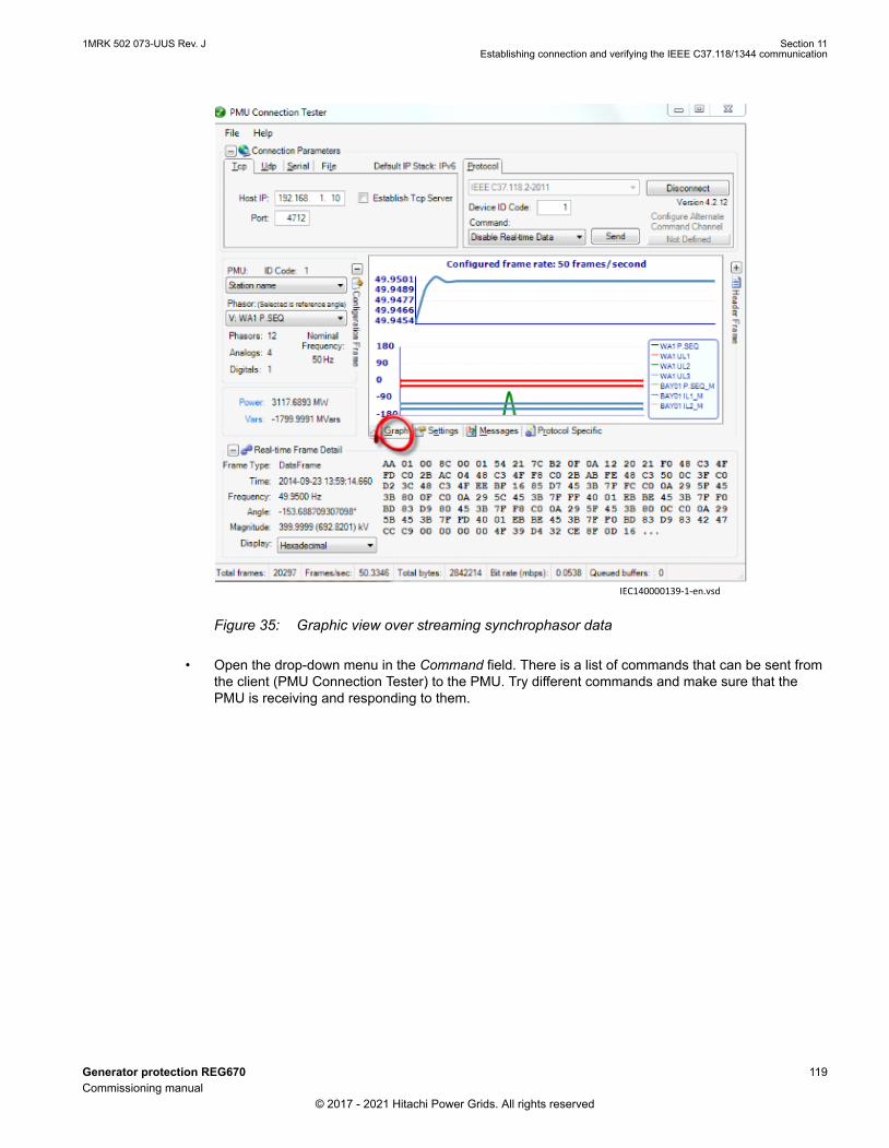
IEC140000139-1-en.vsdIEC140000139 V1 EN-US
Figure 35: Graphic view over streaming synchrophasor data
• Open the drop-down menu in the Command field. There is a list of commands that can be sent fromthe client (PMU Connection Tester) to the PMU. Try different commands and make sure that thePMU is receiving and responding to them.
1MRK 502 073-UUS Rev. J Section 11Establishing connection and verifying the IEEE C37.118/1344 communication
Generator protection REG670 119Commissioning manual
© 2017 - 2021 Hitachi Power Grids. All rights reserved

IEC140000140-1-en.vsdIEC140000140 V1 EN-US
Figure 36: Drop-down menu with commands for testing the PMU
• Switch to the Protocol Specific tab. Here, all the IEEE C37.118 message types can be seen. If theHeaderFrame is not included, ask the PMU to send the header frame via the Send Header Framecommand (Previous stage). Open each message type and observe the content of each message.
Section 11 1MRK 502 073-UUS Rev. JEstablishing connection and verifying the IEEE C37.118/1344 communication
120 Generator protection REG670Commissioning manual
© 2017 - 2021 Hitachi Power Grids. All rights reserved

IEC140000141-1-en.vsdIEC140000141 V1 EN-US
Figure 37: All the IEEE C37.118 message types
• It is also possible to capture the IEEE C37.118 synchrophasor data in an Excel file. This is done bynavigating to File /Capture /Start Stream Debug Capture... The tool will ask to Set Stream DebugCapture File Name and path to save the capture file.
1MRK 502 073-UUS Rev. J Section 11Establishing connection and verifying the IEEE C37.118/1344 communication
Generator protection REG670 121Commissioning manual
© 2017 - 2021 Hitachi Power Grids. All rights reserved

IEC140000142-1-en.vsdIEC140000142 V1 EN-US
Figure 38: Start capturing the IEEE C37.118 synchrophasor data
• The synchrophasor data capturing process can be stopped at any point of time by navigating toFile /Capture /Stop Stream Debug Capture...
Section 11 1MRK 502 073-UUS Rev. JEstablishing connection and verifying the IEEE C37.118/1344 communication
122 Generator protection REG670Commissioning manual
© 2017 - 2021 Hitachi Power Grids. All rights reserved

IEC140000143-1-en.vsdIEC140000143 V1 EN-US
Figure 39: Stop capturing the IEEE C37.118 synchrophasor data
• Open the capture file and observe the captured synchrophasor data. In order to get the Phasornames on top of each column (See figure 40), the capture process should start before connectingthe PMU Connection Tester to the PMU, i.e. first start the capturing and then click Connect.
1MRK 502 073-UUS Rev. J Section 11Establishing connection and verifying the IEEE C37.118/1344 communication
Generator protection REG670 123Commissioning manual
© 2017 - 2021 Hitachi Power Grids. All rights reserved

IEC140000144 V1 EN-US
Figure 40: Captured synchrophasor data
11.5.2 Verifying the IEEE C37.118/1344 UDP communicationGUID-F0D1117D-3D0F-498F-A00C-242763F8A4E6 v1
After setting both PMU configuration and the UDP client configuration (As explained in sections Settingthe PMU station communication (PMU Report), Setting the PMU station communication (PMUconfiguration) and Setting the TCP/UDP client communication) and making sure that the Ethernetcommunication is set up, click Connect on the PMU Connection Tester tool.
IEC140000145-1-en.vsdIEC140000145 V1 EN-US
Figure 41: Verifying the UDP communication using PMU Connection Tester
• Now it should be possible to see the streaming synchrophasor data.• Verify the communication by following the same steps as in section Verifying the IEEE C37.118/1344
TCP communication.
Section 11 1MRK 502 073-UUS Rev. JEstablishing connection and verifying the IEEE C37.118/1344 communication
124 Generator protection REG670Commissioning manual
© 2017 - 2021 Hitachi Power Grids. All rights reserved

11.6 Optical budget calculation for PMU - PDC communicationGUID-F5DEACB1-4B83-4C68-B59A-694CAC78AF3D v3
Most of the times, the PMU IEDs are located in the substations. A local PDC might be located in thesubstation. For communications within the substation or between the IED and the WAN/LAN accesspoint, it is important to know what is the optical budget available. The graph in Figure 42 shows thedynamic range available for a PMU – PDC configuration using typical OEMs.
14
12
10
8
6
4
2
00 0.5 1.0 1.5 2.0 2.5 3.0 3.5 4.0
62.5/125 µm
50/125 µm
OPB
– O
PTIC
AL
POW
ER B
UD
GET
- dB
FIBER OPTIC CABLE LENGTH - km
IEC11000409_1_en.vsdIEC11000409 V1 EN-US
Figure 42: Optical power budget for fiber optic cable lengths
As shown in the graph, if one uses a 62.5/125 µm fiber, the value under the 62.5/125 µm curverepresents the remaining optical budget at any link length, which is available for overcoming non-fibercable related losses.
Losses in the connectors and splices are typically 0.3dB/connection. The user must reserve 3dB sparefor the uncertainty of the measurements.
1MRK 502 073-UUS Rev. J Section 11Establishing connection and verifying the IEEE C37.118/1344 communication
Generator protection REG670 125Commissioning manual
© 2017 - 2021 Hitachi Power Grids. All rights reserved

126

Section 12 Testing IED operation
12.1 Preparing for testIP336-1 v1
12.1.1 RequirementsM11740-2 v11
IED test requirements:
• Calculated settings• Application configuration diagram• Signal matrix (SMT) configuration• Terminal connection diagram• Technical manual• Three-phase test equipment• Process bus, IEC/UCA 61850-9-2LE, MU test simulator, if IEC/UCA 61850-9-2LE process bus
communication is used.• PCM600
The setting and configuration of the IED must be completed before the testing can start.
The terminal diagram, available in the technical reference manual, is a general diagram of the IED.
Note that the same diagram is not always applicable to each specific delivery (especiallyfor the configuration of all the binary inputs and outputs).
Therefore, before testing, check that the available terminal diagram corresponds to the IED.
The technical manual contains application and functionality summaries, function blocks, logic diagrams,input and output signals, setting parameters and technical data sorted per function.
The test equipment should be able to provide a three-phase supply of voltages and currents. Themagnitude of voltage and current as well as the phase angle between voltage and current must bevariable. The voltages and currents from the test equipment must be obtained from the same source andthey must have minimal harmonic content. If the test equipment cannot indicate the phase angle, aseparate phase-angle measuring instrument is necessary.
Prepare the IED for test before testing a particular function. Consider the logic diagram of the testedprotection function when performing the test. All included functions in the IED are tested according to thecorresponding test instructions in this chapter. The functions can be tested in any order according to userpreferences. Only the functions that are used (Operation is set to Enabled) should be tested.
The response from a test can be viewed in different ways:
• Binary outputs signals• Service values on the local HMI (logical signals or phasors)• A PC with PCM600 application configuration software in work online mode
All setting groups that are used should be tested.
1MRK 502 073-UUS Rev. J Section 12Testing IED operation
Generator protection REG670 127Commissioning manual
© 2017 - 2021 Hitachi Power Grids. All rights reserved

This IED is designed for a maximum continuous current of four times the rated current.
All references to CT and VT must be interpreted as analog values received from mergingunits (MU) via IEC/UCA 61850-9-2LE communication protocol, analog values receivedfrom the transformer input module, or analog values received from the LDCM.
When using a MU test simulator, make sure it is set to the correct SVID and that thesystem frequency is set to the same as in the IED.
Please observe the measuring accuracy of the IED, the test equipment and the angularaccuracy for both of them.
Consider the configured logic from the function block to the output contacts whenmeasuring the trip time.
After intense testing, it is important that the IED is not immediately restarted, which mightcause a faulty trip due to flash memory restrictions. Some time must pass before the IEDis restarted. For more information about the flash memory, refer to section “Configuringthe IED and changing settings”.
If the IED is used together with a merging unit and no time synchronization is available,for example, in the laboratory test, the IED will synchronize to the SV datastream. During the re-synchronization, the protection functions will be blocked once asecond for about 45 ms, and this will continue for up to 10 minutes. To avoid this,configure PTP (IEEE 1588) to On for the access point where the merging unit isconfigured.
12.1.2 Preparing the IED to verify settingsM11741-2 v12
If a test switch is included, start preparation by making the necessary connections to the test switch. Thismeans connecting the test equipment according to a specific and designated IED terminal diagram.
Put the IED into the test mode to facilitate the test of individual functions and prevent unwanted operationcaused by other functions. The busbar differential protection is not included in the test mode and is notprevented to trip during the test operations. The test switch should then be connected to the IED.
Verify that analog input signals from the analog input module are measured and recorded correctly byinjecting currents and voltages required by the specific IED.
To make testing even more effective, use PCM600. PCM600 includes the Signal monitoring tool, which isuseful in reading the individual currents and voltages, their amplitudes and phase angles. In addition,PCM600 contains the Disturbance handling tool. The content of reports generated by the Disturbancehandling tool can be configured which makes the work more efficient. For example, the tool may beconfigured to only show time tagged events and to exclude analog information and so on.
Check the disturbance report settings to ensure that the indications are correct.
Section 12 1MRK 502 073-UUS Rev. JTesting IED operation
128 Generator protection REG670Commissioning manual
© 2017 - 2021 Hitachi Power Grids. All rights reserved

For information about the functions to test, for example signal or parameter names, see the technicalmanual. The correct initiation of the disturbance recorder is made on pickup and/or release or trip from afunction. Also check that the wanted recordings of analog (real and calculated) and binary signals areachieved.
Parameters can be entered into different setting groups. Make sure to test functions forthe same parameter setting group. If needed, repeat the tests for all different settinggroups used. The difference between testing the first parameter setting group and theremaining is that there is no need for testing the connections.
During testing, observe that the right testing method, that corresponds to the actual parameters set in theactivated parameter setting group, is used.
Set and configure the function(s) before testing. Most functions are highly flexible and permit a choice offunctional and tripping modes. The various modes are checked at the factory as part of the designverification. In certain cases, only modes with a high probability of coming into operation need to bechecked when commissioned to verify the configuration and settings.
12.2 Activating the test modeM11412-2 v15
Put the IED into the test mode before testing. The test mode blocks all protection functions and some ofthe control functions in the IED, and the individual functions to be tested can be unblocked to preventunwanted operation caused by other functions. In this way, it is possible to test slower back-upmeasuring functions without the interference from faster measuring functions. The test switch shouldthen be connected to the IED.Test mode is indicated when the yellow PickupLED flashes.
It is important that the IED function to be tested is put into test mode, even if the MU is sending datamarked as "test". The IED will interpret these data as valid if it is not in test mode.
1. Browse to the TESTMODE menu and press E.The TESTMODE menu is found on the local HMI under Main menu /Test/IED test mode /TESTMODE
2. Use the up and down arrows to choose Enabled and press E.3. Press the left arrow to exit the menu.
The dialog box Save changes appears.4. Choose Yes, press E and exit the menu.
The yellow pickupLED above the LCD will start flashing when the IED is in test mode.
12.3 Preparing the connection to the test equipmentM11743-2 v9
The IED can be equipped with a test switch of type RTXP8, RTXP18 or RTXP24 or FT. The test switchand its associated test plug handles are a part of the COMBITEST or FT system of Hitachi Power grids,which provides secure and convenient testing of the IED.
When using the COMBITEST, preparations for testing are automatically carried out in the propersequence, that is, for example, blocking of tripping circuits, short circuiting of CTs, opening of voltagecircuits, making IED terminals available for secondary injection. Terminals 1 and 8, 1 and 18 as well as 1and 12 of the test switches RTXP8, RTXP18 and RTXP24 respectively are not disconnected as theysupply DC power to the protection IED. When FT switch is used for testing, care shall be exercised toopen the tripping circuit, ahead of manipulating the CT fingers.
1MRK 502 073-UUS Rev. J Section 12Testing IED operation
Generator protection REG670 129Commissioning manual
© 2017 - 2021 Hitachi Power Grids. All rights reserved

The RTXH test-plug handle leads may be connected to any type of test equipment or instrument. When anumber of protection IEDs of the same type are tested, the test-plug handle only needs to be moved fromthe test switch of one protection IED to the test switch of the other, without altering the previousconnections.
Use COMBITEST test system to prevent unwanted tripping when the handle is withdrawn, since latcheson the handle secure it in the half withdrawn position. In this position, all voltages and currents arerestored and any re-energizing transients are given a chance to decay before the trip circuits arerestored. When the latches are released, the handle can be completely withdrawn from the test switch,restoring the trip circuits to the protection IED.
If a test switch is not used, perform measurement according to the provided circuit diagrams.
Never disconnect the secondary connection of a current transformer circuit without firstshort-circuiting the transformer's secondary winding. Operating a current transformerwith the secondary winding open will cause a massive potential build up that maydamage the transformer and cause personal injury.
12.4 Connecting the test equipment to the IEDM11744-2 v9
Connect the test equipment according to the IED specific connection diagram and the needed input andoutput signals for the function under test. An example of a connection is shown in figure 43.
Connect the current and voltage terminals. Pay attention to the current polarity. Make sure that theconnection of input and output current terminals and the connection of the residual current conductor iscorrect. Check that the input and output logical signals in the logic diagram for the function under test areconnected to the corresponding binary inputs and outputs of the IED under test.
To ensure correct results, make sure that the IED as well as the test equipment areproperly grounded before testing.
Section 12 1MRK 502 073-UUS Rev. JTesting IED operation
130 Generator protection REG670Commissioning manual
© 2017 - 2021 Hitachi Power Grids. All rights reserved

IAIBICIN
VAVBVCVN
IAIBIC
VA
IN (I4,I5)
TRIP ATRIP BTRIP C
Test
equ
ipm
ent
IED
ANSI09000652-1-en.vsd
VBVCVN
VN (U4,U5)
IEC 61850
ANSI09000652 V1 EN-US
Figure 43: Connection example of the test equipment to the IED when test equipment isconnected to the transformer input module
12.5 Releasing the function to be testedM11413-2 v8
Release or unblock the function to be tested. This is done to ensure that only the function or the chain offunctions to be tested are in operation and that other functions are prevented from operating. Release thetested function(s) by setting the corresponding Blocked parameter under Function test modes to No inthe local HMI .
When testing a function in this blocking feature, remember that not only the actual function must beactivated, but the whole sequence of interconnected functions (from measuring inputs to binary outputcontacts), including logic must be activated. Before starting a new test mode session, scroll throughevery function to ensure that only the function to be tested (and the interconnected ones) have theparameters Blocked and eventually EvDisable set to No and Yes respectively. Remember that a functionis also blocked if the BLOCK input signal on the corresponding function block is active, which dependson the configuration. Ensure that the logical status of the BLOCK input signal is equal to 0 for the functionto be tested. Event function blocks can also be individually blocked to ensure that no events are reportedto a remote station during the test. This is done by setting the parameter EvDisable to Yes.
Any function is blocked if the corresponding setting in the local HMI under Main menu /Test /Function test modes menu remains Enabled, that is, the parameter Blocked is setto Yes and the parameter TESTMODE under Main menu/Test /IED test mode remainsactive. All functions that were blocked or released in a previous test mode session, thatis, the parameter Test mode is set to Enabled, are reset when a new test mode sessionis started.
Procedure
1. Click the Function test modes menu.
1MRK 502 073-UUS Rev. J Section 12Testing IED operation
Generator protection REG670 131Commissioning manual
© 2017 - 2021 Hitachi Power Grids. All rights reserved

The Function test modes menu is located in the local HMI under Main menu/Test /Function testmodes.
2. Browse to the function instance that needs to be released.3. Set parameter Blocked for the selected function to No.
12.6 Verifying analog primary and secondary measurementM11745-2 v14
Verify that the connections are correct and that measuring and scaling is done correctly. This is done byinjecting current and voltage to the IED.
Besides verifying analog input values from the merging unit via the IEC/UCA 61850-9-2LE process bus,analog values from the transformer input module can be verified as follows.
Apply input signals as needed according to the actual hardware and the applicationconfiguration.
1. Inject a symmetrical three-phase voltage and current at rated value.2. Compare the injected value with the measured values.
The voltage and current phasor menu in the local HMI is located under Main menu /Measurements /Analog primary values and Main menu /Measurements /Analog secondaryvalues .
3. Compare the frequency reading with the set frequency and the direction of the power.The frequency and active power are located under Main menu /Measurements /Monitoring /ServiceValues(MMXN) /CVMMXN:x . Then navigate to the bottom of the list to find the frequency.
4. Inject an unsymmetrical three-phase voltage and current, to verify that phases are correctlyconnected.
If some setting deviates, check the analog input settings under
Main menu /Configuration /Analog modules
12.7 Testing the protection functionalityGUID-125B6F28-D3E5-4535-9CD6-6C056B79F496 v2
Each protection function must be tested individually by secondary injection.
• Verify operating levels (trip) and timers.• Verify alarm and blocking signals.• Use the disturbance handling tool in PCM600 to evaluate that the protection function has received
the correct data and responded correctly (signaling and timing).• Use the event viewer tool in PCM600 to check that only expected events have occurred.
12.8 Forcing of binary input/output signals for testing
12.8.1 Forcing conceptGUID-3FD8C676-10E5-432A-8CD5-4643299AD794 v2
Forcing of binary inputs and outputs is a convenient way to test wiring in substations as well as testingconfiguration logic in the IEDs. Basically it means that all binary inputs and outputs on the IED I/Omodules (BOM, BIM, IOM & SOM) can be set to a value (i.e active or not-active), selected by the user,while the IED is in test mode. For inputs, this is true regardless of the actual signal voltage present on the
Section 12 1MRK 502 073-UUS Rev. JTesting IED operation
132 Generator protection REG670Commissioning manual
© 2017 - 2021 Hitachi Power Grids. All rights reserved

input. For outputs, any output relay can be forced to be active or not, regardless of the current requestedstate of the output in the IED logic configuration.
Be observant that forcing of binary inputs and outputs on an IED, with inappropriatesetup, can result in potential danger.
12.8.2 How to enable forcingGUID-50280F59-A98C-4E48-AB6D-2B4C138943DD v2
To enable forcing, the IED must first be put into IED test mode. While the IED is not in test mode, theLHMI/PCM600 menus that relate to forcing will not have any effect on the input/output status due tosafety reasons.
12.8.2.1 Enable forcing by using LHMIGUID-41F7C636-75BC-42EF-A955-4BD9E347619E v2
1. Enable IED TESTMODE by setting IEDTestMode to On under Main menu /Test /IED test mode /TESTMODE:1 .
IEC15000029 V1 EN-US
2. Exit back to the root menu.3. Select Yes in the save dialogue box.
Once the IED is in test mode the yellow Start LED starts to blink.
12.8.2.2 Enable forcing using TESTMODE function blockGUID-DD17B7D6-516F-4561-9D30-906B968EAFE0 v2
• Use the TESTMODE function block, appropriately configured in PCM600/ACT.
It may be convenient to control the input on mentioned component from, for example, an LHMI functionkey or similar during commissioning to quickly and easily enter IED test mode.
1MRK 502 073-UUS Rev. J Section 12Testing IED operation
Generator protection REG670 133Commissioning manual
© 2017 - 2021 Hitachi Power Grids. All rights reserved

12.8.3 How to change binary input/output signals using forcingGUID-7DF9FAF1-68B1-49AF-9DE4-2A8D6F6FAEFE v2
Once the IED is in IED test mode, the LHMI/PCM600 menus can be used to control input/output signalsfreely.
12.8.3.1 Forcing by using LHMIGUID-D885671F-79E5-4B75-8777-B59E44F6FCFC v1
Editing a signal value directlyGUID-E0C115BE-3AD1-48C7-BA2D-29857CD3D3ED v1
• Edit the input/output value directly to select the desired logical level, by doing following:1. Select the value line of the desired signal, see figure 44.2. Press the Enter key to edit the value.
IEC15000021 V1 EN-US
Figure 44: Value line of the desired signal
3. Use the up/down arrows on the LHMI to change the signal value or the appropriate menu inPCM600.The status of the signal changes automatically to Forced (i.e. there is no need to set the statusto Forced manually).
On the LHMI, these edit changes have immediate effect. This means that the valuechanges directly when the up/down arrow is pressed (i.e. there is no need to press theEnter key to effectuate the change).
When navigating away from a LHMI forcing menu for an I/O board, the user is prompted to either leavethe signals forced, or to revert all of them back to the unforced state.
Section 12 1MRK 502 073-UUS Rev. JTesting IED operation
134 Generator protection REG670Commissioning manual
© 2017 - 2021 Hitachi Power Grids. All rights reserved

IEC15000022 V1 EN-US
It is possible to power-cycle the IED in this state without losing the forcing states andvalues. This means that once a signal is forced, and the IED remains in IED test mode,the input or output will appear “frozen” at the value selected by the user, even if the IEDis switched off and back on again.
Freezing a signal value without changing itGUID-FD76AAC1-7098-47D3-A3A1-6ACDF509ED91 v1
• Set the status of a signal to Forced, in the forcing menu that corresponds to the I/O card in question.See example of LHMI menu in figure 45
IEC15000020 V1 EN-US
Figure 45: Example of LHMI menu using BIM3
The signal “freezes” and will not change value even if, for example, a binary input signal voltage changeslevel, or if a binary output is activated as the result of a protection function block activating.
12.8.3.2 Forcing by using PCM600GUID-E9D0DAE6-7A86-4FF9-943E-42039015D05B v2
In PCM600 the concept is a bit different compared to LHMI.The forcing is accomplished by entering aforcing session. Within such a session, multiple signals on multiple I/O boards may be edited andchanged at the same time and has no effect on the IED. Once the user is satisfied with the forcing setup,then all the changes can be effectuated simultaneously towards the IED, potentially changing inputs andoutputs on multiple I/O boards at the same time. It is also possible to abort this operation (described instep 6 below) and to undo all forcing.
1MRK 502 073-UUS Rev. J Section 12Testing IED operation
Generator protection REG670 135Commissioning manual
© 2017 - 2021 Hitachi Power Grids. All rights reserved

1. Right click on the IED in the plant structure and select Signal Monitoring.2. Click on the List View tab.3. Click Forcing Session in the menu IED/Start Forcing.
IEC15000023 V1 EN-US
4. Click Start editing signal value for forcing on the tool bar.
IEC15000024 V1 EN-US
The Signal Monitoring menu changes and indicates the forcing values that can be edited.
IEC15000025 V1 EN-US
5. Select and edit the values.6. Click Acknowledge and send.
IEC15000026 V1 EN-US
This commits the values to the IED and exits the editing session.7. Click Cancel to abort the changes and revert back to actual IED values.
Section 12 1MRK 502 073-UUS Rev. JTesting IED operation
136 Generator protection REG670Commissioning manual
© 2017 - 2021 Hitachi Power Grids. All rights reserved

IEC15000032 V1 EN-US
Regardless if the forcing changes are commited or canceled, the forcing is still active.
To force more signals, click the button Start editing signal value for forcing again.
12.8.4 How to undo forcing changes and return the IED to normaloperation
GUID-00E2BAD8-A29E-4B9D-80E6-E12F59E019BD v1
Regardless of which input/output signals have been forced, all forced signals will return to their normalstates immediately when the IED is taken out of test mode.
When the forcing is removed by exiting from IED test mode, both input and outputsignals may change values. This means that logic input signals may activate functions inthe IED and that output relays may change state, which can be potentially dangerous.
12.8.4.1 Undo forcing by using TESTMODE componentGUID-CA5CCA57-DFFF-4362-AC1D-08738D2BA45F v2
• If the IED test mode was entered through the test mode function block:1. Deactivate the control input on that block.
This immediately undoes all forcing, regardless of how it was accomplished and disabled all the wayto force signals.
12.8.4.2 Undo forcing by using LHMIGUID-55199606-E70D-49B1-885D-251700FB562B v1
• If the IED test mode was enabled to using the LHMI:1. Set IEDTestMode to Off in the LHMI menu.2. Exit from the menu and click Yes in the Save dialogue box.
This immediately undoes all forcing, regardless of how it was accomplished and disabled.
12.8.4.3 Undo forcing by using PCM600GUID-CE7FD186-99FC-41C8-910F-894A57037777 v2
1. Uncheck Forcing Session under the menu IED.
1MRK 502 073-UUS Rev. J Section 12Testing IED operation
Generator protection REG670 137Commissioning manual
© 2017 - 2021 Hitachi Power Grids. All rights reserved

IEC15000031 V1 EN-US
2. Click Yes in the confirmation dialogue box.PCM600 will revert all forced signals back to unforced and the real signal values will immediatelytake effect again.
This may change both binary input values and output relay states and will undo anyforcing done by using the LHMI.If the IED is left in test mode, then it is still possible to perform new forcing operations,both from LHMI and from PCM600
Section 12 1MRK 502 073-UUS Rev. JTesting IED operation
138 Generator protection REG670Commissioning manual
© 2017 - 2021 Hitachi Power Grids. All rights reserved

Section 13 Testing functionality by secondaryinjection
13.1 Testing disturbance report
13.1.1 IntroductionM17101-2 v7
The following sub-functions are included in the disturbance report function:
• Disturbance recorder• Event list• Event recorder• Trip value recorder• Indications
If the disturbance report is enabled, then its sub-functions are also set up and so it is not possible to onlydisable these sub-functions. The disturbance report function is disabled (parameter Operation =Disabled) in PCM600 or the local HMI under Main menu/Settings/IED Settings/Monitoring /Disturbance report/DRPRDRE:1 .
13.1.2 Disturbance report settingsM11746-2 v7
When the IED is in test mode, the disturbance report can be made active or inactive. If the disturbancerecorder is turned on during test mode, recordings will be made. When test mode is switched off allrecordings made during the test session are cleared.
Setting OpModeTest for the control of the disturbance recorder during test mode are located on the localHMI under Main menu/Settings /IED Settings/Monitoring/Disturbance report /DRPRDRE:1.
13.1.3 Disturbance recorder (DR)M11750-2 v7
A Manual Trig can be started at any time. This results in a recording of the actual values from allrecorded channels.
The Manual Trig can be started in two ways:
1. From the local HMI under Main menu/Disturbance records .1.1. Enter on the row at the bottom of the HMI called Manual trig.
A new recording begins. The view is updated if you leave the menu and return.1.2. Navigate to General information or to Trip values to obtain more detailed information.
2. Open the Disturbance handling tool for the IED in the plant structure in PCM600.2.1. Right-click and select Execute manual Trig in the window Available recordings in IED.2.2. Read the required recordings from the IED.2.3. Refresh the window Recordings and select a recording.2.4. Right-click and select Create Report or Open With to export the recordings to any disturbance
analyzing tool that can handle Comtrade formatted files.
1MRK 502 073-UUS Rev. J Section 13Testing functionality by secondary injection
Generator protection REG670 139Commissioning manual
© 2017 - 2021 Hitachi Power Grids. All rights reserved

Evaluation of the results from the disturbance recording function requires access to a PC eitherpermanently connected to the IED or temporarily connected to the Ethernet port (RJ-45) on the front. ThePCM600 software package must be installed in the PC.
Disturbance upload can be performed by the use of PCM600 or by any third party tool with IEC 61850protocol. Reports can automatically be generated from PCM600. Disturbance files can be analyzed byany tool reading Comtrade formatted disturbance files.
It could be useful to have a printer for hard copies. The correct start criteria and behavior of thedisturbance recording function can be checked when IED protective functions are tested.
When the IED is brought into normal service it is recommended to delete all recordings, made duringcommissioning to avoid confusion in future fault analysis.
All recordings in the IED can be deleted in two ways:
1. in the local HMI under Main menu/Clear /Reset disturbances, or2. in the Disturbance handling tool in PCM600 by selecting Delete all recordings in the IED... in the
window Available Recordings in IED.
13.1.4 Event recorder (ER) and Event list (EL)M12645-2 v7
The result from the event recorder and event list can be viewed on the local HMI or, after upload, inPCM600 as follows:
1. on the local HMI under Main menu/Events , or in more details via2. the Event Viewer in PCM600.
The internal FIFO register of all events will appear when the event viewer is launched.
When the IED is brought into normal service it is recommended to delete all events resulting fromcommissioning tests to avoid confusion in future fault analysis. All events in the IED can be cleared in thelocal HMI under Main Menu//Clear/Clear internal event list or Main menu /Clear/Clear process eventlist . It is not possible to clear the event lists from PCM600.
When testing binary inputs, the event list (EL) might be used instead. No uploading or analyzing ofregistrations is then needed since the event list keeps running, independent of start of disturbanceregistration.
13.2 Identifying the function to test in the technical referencemanual
M11748-2 v4
Use the technical manual to identify function blocks, logic diagrams, input and output signals, settingparameters and technical data.
13.3 Differential protectionIP10805-1 v1
13.3.1 Transformer differential protection T2WPDIF and T3WPDIF(87T)SEMOD54284-49 v7
Prepare the IED for verification of settings outlined in Section "Preparing the IED to verify settings".
Section 13 1MRK 502 073-UUS Rev. JTesting functionality by secondary injection
140 Generator protection REG670Commissioning manual
© 2017 - 2021 Hitachi Power Grids. All rights reserved

13.3.1.1 Verifying the settingsSEMOD54284-51 v11
1. Go to Main menu /Test /Function test modes /Differential protection and make sure that therestricted earth fault protection, low impedance function REFPDIF (87N) is set to Disabled and thatthe four step residual overcurrent function EF4PTOC (51N/67N) under Main menu /Test /Functiontest modes /Current protection is set to Disabled, since they are configured to the same currenttransformer inputs as the transformer differential protection. Make sure that the transformerdifferential functions T2WPDIF (87T) or T3WPDIF (87T) are unblocked.
2. Connect the test set for injection of three-phase currents to the current terminals of the IED, whichare connected to the CTs on the HV side of the power transformer.
3. Increase the current in phase A until the protection function operates and note the operatingcurrent.
4. Check that the trip and alarm contacts operate according to the configuration logic.5. Decrease the current slowly from operate value and note the reset value.
Depending on the power transformer phase shift/vector group (Yd (Wye/Delta) and so on), thesingle-phase injection current may appear as differential current in one or two phases and theoperating value of the injected single-phase current will be different.
6. Check in the same way the function by injecting current in phases B and C respectively.7. Inject a symmetrical three-phase current and note the operate value.8. Connect the timer and set the current to twice the operate value.9. Switch on the current and note the operate time.10. Check in the same way the measuring circuits connected to the CTs on the LV side and other
current inputs to the transformer differential protection.11. Finally check that trip information is stored in the event menu.
Information on how to use the event menu is found in the operator’s manual.
12. If available on the test set, a second harmonic current of about 20% (assumes 15% setting on I1/I2ratio parameter) can be added to the fundamental frequency in phase A. Increase the current inphase A above the pickup value measured in step 6. Repeat test with current injection in phases Band C respectively.The balancing of currents flowing into and out of the differential zone is checked by primaryinjection testing.Fifth harmonic blocking can be tested in a similar way.
For more detailed formulas, please refer to the Application manual.
13.3.1.2 Completing the testSEMOD54284-86 v5
Continue to test another function or end the test by changing the TESTMODE setting to Disabled.Restore connections and settings to the original values, if changed for testing purposes.
13.3.2 High impedance differential protection HZPDIF (87)SEMOD55257-42 v3
Prepare the IED for verification of settings as outlined in section "Requirements" and section "Preparingfor test" in this chapter.
1MRK 502 073-UUS Rev. J Section 13Testing functionality by secondary injection
Generator protection REG670 141Commissioning manual
© 2017 - 2021 Hitachi Power Grids. All rights reserved

13.3.2.1 Verifying the settingsSEMOD55257-46 v5
1. Connect a single-phase or three-phase test set to inject the operating voltage. The injection is doneacross the measuring branch.
The required trip and alarm voltage, as well as the used stabilizing resistance valuemust be set in the function. Note as well that the used CT input in the IED musthave the ratio set as 1:1. This is essential for the measurement of the expectedvalue. Normally a slightly higher operating value is no problem as the sensitivity isnot influenced much.
2. Increase the voltage and make note of the trip value Pickup. This is done by manual testing andwithout trip of the test set.
3. Connect the trip contact to the test set to stop the test set for measurement of trip times below.4. Reduce the voltage slowly and make note of the reset value. The reset value must be high for this
function.5. Check the operating time by injecting a voltage corresponding to 1.2 ˣ Pickup level. Make note of
the measured trip time.6. If required, verify the trip time at another voltage. Normally 2 ˣ Pickup is selected.7. If used, measure the alarm level operating value. Increase the voltage and make note of the trip
value AlarmPickup. This is done with manual test and without trip of the test set.8. Measure the operating time on the alarm output by connecting the stop of the test set to an output
from tAlarm. Inject a voltage 1.2 ˣ AlarmPickup and measure the alarm time.9. Check that trip and alarm outputs trip according to the configuration logic.10. Finally check that pickup and alarm information is stored in the event menu and if a serial
connection to the SA is available verify that the correct and only the required signals are presentedon the local HMI and on the SCADA system.
Information on how to use the event menu is found in the operator's manual.
13.3.2.2 Completing the testSEMOD55257-73 v4
Continue to test another function or end the test by changing the TESTMODE setting to Disabled.Restore connections and settings to the original values, if changed for testing purposes.
13.3.3 Generator differential protection GENPDIF (87G)SEMOD155702-45 v4
Prepare the IED for verification of settings outlined in Section "Preparing the IED to verify settings".
13.3.3.1 Function revision historyGUID-7CFE84A1-D6AE-4082-9022-B6C70BE6A7D3 v2
Documentrevision
Productrevision
History
A 2.2.1 Added new outputs IDDCL1, IDDCL2, and IDDCL3 for measurement of DCcomponent in differential currents
B 2.2.1 -
C 2.2.2 -
Table continues on next page
Section 13 1MRK 502 073-UUS Rev. JTesting functionality by secondary injection
142 Generator protection REG670Commissioning manual
© 2017 - 2021 Hitachi Power Grids. All rights reserved

Documentrevision
Productrevision
History
D 2.2.3 -
E 2.2.3 -
F 2.2.4 -
G 2.2.4 -
H 2.2.5 -
13.3.3.2 Verifying the settingsSEMOD155702-49 v4
1. Go to Main menu /Test /Function test modes /Differential protection and make sure all otherfunctions, configured to the same current transformer inputs as the generator differential protection,are set off. Make sure that the generator differential function is unblocked.
2. Connect the test set for injection of three-phase current to the current IEDs, which are connected tothe CTs on the HV side of the generator.
3. Increase the current in phase A until the protection function operates and note the operatingcurrent.
4. Check that trip and alarm contacts operate according to the configuration logic.5. Decrease the current slowly from operate value and note the reset value.6. Check in the same way the function by injecting current in phases B and C.7. Inject a symmetrical three-phase current and note the operate value.8. Connect the timer and set the current to twice the operate value.9. Switch on the current and note the operate time.10. Check in the same way the functioning of the measuring circuits connected to the CTs on the
neutral point side of the generator.11. Finally check that trip information is stored in the event menu.
Information on how to use the event menu is found in the operator’s manual.
12. If available on the test set a second-harmonic current of about 20% (assumes 15% setting on I1/I2ratio parameter) can be added to the fundamental tone in phase A. Increase the current in phase Aabove the pickup value measured in step 3. Repeat test with current injection in phases B and Crespectively.Fifth-harmonic blocking can be tested in a similar way.The balancing of currents flowing into and out of the differential zone is typically checked byprimary testing.
13.3.3.3 Completing the testSEMOD155702-82 v3
Continue to test another function or end the test by changing the TESTMODE setting to Disabled.Restore connections and settings to the original values, if changed for testing purposes.
13.3.4 Restricted earth fault protection, low impedance REFPDIF (87N)SEMOD55252-82 v8
Prepare the IED for verification of settings outlined in Section "Preparing the IED to verify settings".
1MRK 502 073-UUS Rev. J Section 13Testing functionality by secondary injection
Generator protection REG670 143Commissioning manual
© 2017 - 2021 Hitachi Power Grids. All rights reserved

13.3.4.1 Function revision historyGUID-BFAA47D8-C2B6-4EC2-9129-B031333BAD19 v2
Documentrevision
Productrevision
History
A 2.2.1 -
B 2.2.1 -
C 2.2.2 -
D 2.2.3 -
E 2.2.3 -
F 2.2.4 -
G 2.2.4 The upper limit of ROA setting range is changed from 90 degrees to 119 degrees.
H 2.2.5 -
13.3.4.2 Verifying the settingsSEMOD55252-86 v12
1. Connect the test set for single-phase current injection to the protection terminals connected to theCT in the power transformer neutral-to-ground circuit.
2. Increase the injection current and note the operating value of the protection function.3. Check that all trip and pickup signals appear according to the configuration logic.4. Decrease the current slowly from operate value and note the reset value.5. Connect the timer and set the current to ten times the value of the IdMin setting.6. Switch on the current and note the operate time.7. Connect the test set to terminal A and neutral of the three-phase current input configured to
REFPDIF (87N). Also inject a current higher than half the IdMin setting in the neutral-to-groundcircuit with the same phase angle and with polarity corresponding to an internal fault.
8. Inject current into terminals B and C in the same way as in step 7 above and note the operate andreset values.
9. Inject a current equal to 10% of rated current into terminal A.10. Inject a current in the neutral-to-ground circuit with the same phase angle and with polarity
corresponding to an external fault.11. Finally check that trip information is stored in the event and disturbance recorder.
13.3.4.3 Completing the testSEMOD55252-118 v5
Continue to test another function or end the test by changing the TESTMODE setting to Disabled.Restore connections and settings to the original values, if changed for testing purposes.
13.4 Impedance protectionSEMOD53525-1 v2
13.4.1 Full scheme distance protection, mho characteristic ZMHPDIS (21)M14944-3 v10
Prepare the IED for verification of settings outlined in Section "Preparing the IED to verify settings".
Keep the current constant when measuring operating characteristics. Keep the current as close aspossible to its rated value or lower. But make sure it is higher than the set minimum operating current.
Section 13 1MRK 502 073-UUS Rev. JTesting functionality by secondary injection
144 Generator protection REG670Commissioning manual
© 2017 - 2021 Hitachi Power Grids. All rights reserved

Ensure that the maximum continuous current in an IED does not exceed four times its rated value, if themeasurement of the operating characteristics runs under constant voltage conditions.
To verify the mho characteristic, at least two points should be tested.
In the following, three test points are proposed. The mho characteristic always goes through the origin,which automatically gives a fourth point for the characteristic.
13.4.2 High speed distance protection zones, quadrilateral and mhocharacteristic ZMFPDIS (21)
GUID-DF1650F4-EC3E-402B-BE26-EF2EF1034237 v8
Prepare the IED for verification of settings outlined in section "Requirements" and section "Preparing fortest" in this chapter.
This under-impedance-based criterion is defined by the two setting parameters XStartand RStart. These two settings are common for both Ph-Ph and Ph-Gnd measurementloops. In order to ensure proper operation of the distance zones the under-impedancebased starting element shall be set in such a way to always cover (i.e. be larger than) allused distance zones for both Ph-Ph and Ph-Gnd loops.
13.4.2.1 Function revision historyGUID-DD5F2758-15E5-496C-8F8E-93AA34B2ACAC v3
Documentrevision
Productrevision
History
A 2.2.1 Impedance measurement and supervision added (ZMMXU).
B 2.2.1 -
C 2.2.2 -
D 2.2.3 -
E 2.2.3 -
F 2.2.4 -
G 2.2.4 -
H 2.2.4 Zone BU (Backup) is added. Now there are seven zones in total. Zone 2 direction anddirectional blinders (ArgDir, ArgNegRes) are now settable. Setting tTauDC is added; aparameter for optional fine tuning of performance.Added new setting RStart, which limits the resistive reach of the phase selection outside ofthe ArgLd sector. Changed setting name XLd to XStart.
J 2.2.5 Parallel line mutual coupling compensation feature based on the parallel line residual currentis added with new settings: EnaPar, INPRatio, R0MZ1, X0MZ1, R0MZ2, and X0MZ2.Load compensation and direction element are improved for earth faults without zerosequence current condition.This update is valid for all the previously released 2.2 products.
13.4.2.2 Verifying the settingsGUID-F01D9FAB-E554-402F-BA8A-F411F692292F v2
Measure operating characteristics during constant current conditions. Keep the measured current asclose as possible to its rated value or lower. But make sure it is higher than the set minimum operatingcurrent.
Ensure that the maximum continuous current to the IED does not exceed four times its rated value, if themeasurement of the operating characteristics runs under constant voltage conditions.
1MRK 502 073-UUS Rev. J Section 13Testing functionality by secondary injection
Generator protection REG670 145Commissioning manual
© 2017 - 2021 Hitachi Power Grids. All rights reserved

To verify the settings for the operating points according to the following fault types should be tested:
• One phase-to-phase fault• One phase-to-ground fault
The shape of the operating characteristic depends on the values of the setting parameters.
The figures illustrating the characteristic for the distance protection function can be usedwhen the load encroachment affects the zone characteristic and when it is not. The solidlines designate the diagram applicable when the load encroachment is overlapping withthe zone. All the test points except 13 are valid for this case. When the loadencroachment does not overlap with the zone, the dotted lines and test point 13 arevalid. Test points 5, 6, and 7 are not valid for this measurement however.
X1set
R
X
(Ω/phase)
50%
80%
1 2
3
4
56
7
89
10
11
50% of RFPPZx/2
25% of RFPPZx/2
RFPP/2
12
ANSI05000368-2-en.vsdx
13
ArgDir
ArgLd
ANSI05000368 V2 EN-US
Figure 46: Distance protection characteristic with test points for phase-to-phase measurements
Table 23: Test points for phase-to-phase loops A-B (Ohm/phase)
Test point Reach Set value Comments1 X X1set
R 0
2 X X1set
R R1set
3 X 0.8 x X1set
R 0.8 x R1set+ RFPP/2
4 X 0.5 x X1set
R 0.5 x R1set+ RFPP/2
Table continues on next page
Section 13 1MRK 502 073-UUS Rev. JTesting functionality by secondary injection
146 Generator protection REG670Commissioning manual
© 2017 - 2021 Hitachi Power Grids. All rights reserved

Test point Reach Set value Comments5 X 0.85 x RFPP/2 x tan (LdAngle) If RLdFwd < 0.85 x RFPP/2
R 0.85 x RFPP/2
6 X RLdFwd x tan (LdAngle) If RLdFwd < RFPP/2
R RLdFwd
7 X 0 If RLdFwd < RFPP/2
R RLdFw
8 X -0.8 x Rmin x tan( ArgDir) Rmin = minimum of RFPP/2 and RLdFwdArgDir = 20⁰ fixed
R 0.8 x Rmin
9 X -0.4 x Rmin x tan( ArgDir) Rmin = minimum of RFPP/2 and RLdFwdArgDir = 20⁰ fixed
R 0.4 x Rmin
10 X 0.5 x X1set ArgNegRes = 120⁰ fixedFormula applies if R set value < RFPP/2
R -0.5 x X1set xtan( ArgNegRes-90⁰)
11 X 0.8 x X1set ArgNegRes = 120⁰ fixedFormula applies if R set value < RFPP/2
R -0.8 x X1set xtan( ArgNegRes-90⁰)
12 X 0.5 x X1set
R 0.5 x R1set
13 X 0
R 0.5 x RFPP
(2 x X1set+X0set)/3
R
X
(Ω /loop)
50%
80%
1 2
3
4
5
6
7
89
10
11
50% of RFPEZx
25% of RFPEZx
RFPG
12
ANSI05000369-3-en.vsdx
13
ArgLd
alt. 80% ofRFPG (Loadencroachment)
ArgDir
ANSI05000369 V3 EN-US
Figure 47: Distance protection characteristic with test points for phase-to-ground measurements
1MRK 502 073-UUS Rev. J Section 13Testing functionality by secondary injection
Generator protection REG670 147Commissioning manual
© 2017 - 2021 Hitachi Power Grids. All rights reserved

Table 24: Test points for phase-to-ground C-G (Ohm/Loop)
Test point Reach Value Comments1 X (2 x X1set+X0set)/3
R 0
2 X (2 x X1set+ X0set)/3
R (2 x R1set+ R0set)/3
3 X 0.8 x (2 x X1set+ X0set)/3
R 0.8 x (2 x R1set+ R0set)/3 +RFPG
4 X 0.5 x (2 x X1set+ X0set)/3
R 0.5 x (2 x R1set+R0set)/3 + RFPG
5
X 0.85 x RFPG x tan(LdAngle) If RLdFwd < 0.85 x RFPG
R 0.85 x RFPG
6 X RLdFwd x tan(LdAngle) If RLdFwd < RFPG
R RLdFwd
7 X 0 If RLdFwd < RFPG
R RLdFwd
8 X -0.8 x Rmin x tan( ArgDir) Rmin = minimum of RFPG & RLdFwdArgDir = 15⁰ fixed
R 0.8 x Rmin
9 X -0.4 x Rmin x tan( ArgDir)
R 0.4 x Rmin
10 X 0.5 x (2 x X1set+ X0set)/3 ArgNegRes = 120⁰ fixedFormula applies if R Set value < RFPG
R -0.5 x (2 x X1set+ X0set)/3 xtan( ArgNegRes-90⁰)
11 X 0.8 x (2 x X1set+ X0set)/3 ArgNegRes = 120⁰ fixedFormula applies if R Set value < RFPG
R -0.8 x (2 x X1set+ X0set)/3 xtan( ArgNegRes-90⁰)
12 X 0.5 x (2 x X1set + X0set)/3
R 0.5 x (2 x R1set + R0set)/3
13 X 0 If RFPG < RLdFwd
R RFPG
13.4.2.3 Measuring the operating limit of set valuesGUID-3FA4B640-38E7-406E-8FCC-8DEDABB024C4 v5
Procedure:
1. Subject the IED to healthy normal load conditions for at least two seconds.2. Apply the fault condition and slowly decrease the measured impedance to find the operating value
of the phase-to-phase fault for zone 1 according to test point 1 in figure and table . Compare theresult of the measurement with the set value.
3. Repeat steps 1 to 2 to find the operating value for test points 2, 3 in table
Section 13 1MRK 502 073-UUS Rev. JTesting functionality by secondary injection
148 Generator protection REG670Commissioning manual
© 2017 - 2021 Hitachi Power Grids. All rights reserved

Observe that the zones that are not tested have to be blocked and the zone that is tested has to bereleased.
4. Repeat steps 1 to 3 to find the operating value for the phase-to-ground fault C-G according to figure and table .
Test points 8, 9, 10 and 11 are intended to test the directional lines of impedanceprotection. Since directionality is a common function for all seven measuringzones, it is only necessary to test 8, 9, 10 and 11 once, in the forward direction inorder to test the accuracy of directionality (directional angles). Directionalfunctionality testing (trip inside, no-trip outside) should always be made for allimpedance zones set with directionality (forward or reverse).
13.4.2.4 Measuring the operating time of distance protection zonesGUID-BB93C603-F43E-40CB-8EFA-3B0F280C011D v6
Procedure:
1. Subject the IED to healthy normal load conditions for at least two seconds.2. Apply the fault condition to find the operating time for the phase-to-phase fault according to test
point 12 for zone 1. Compare the result of the measurement to the setting tPPZ1.3. Repeat steps 1 to 2 to find the operating time for the phase-to-ground fault according to test point
12. Compare the result of the measurement to the setting t1PG.4. Repeat steps 1 to 2 to find the operating time for all other used measuring zones.
The zones that are not tested have to be blocked and the zone that is tested has to be released.
13.4.2.5 Completing the testGUID-60C5389E-B021-45BB-8CB3-E21348CF50EF v2
Continue to test another function or end the test by changing the TESTMODE setting to Disabled.Restore connections and settings to the original values, if changed for testing purposes.
13.4.3 High Speed distance for series compensated line zones,quadrilateral and mho characteristic ZMFCPDIS (21)
GUID-EE954483-7157-4EA2-A5DD-537DF6864BC2 v5
Prepare the IED for verification of settings outlined in Section "Preparing the IED to verify settings".
13.4.3.1 Function revision historyGUID-96705EE1-C538-4737-AAE9-141287810AAE v3
Documentrevision
Productrevision
History
A 2.2.1 Impedance measurement and supervision added (ZMMXU).
B 2.2.1 -
C 2.2.2 -
D 2.2.3 Transient directional (TD) element added, with associated input and outputs.
E 2.2.3 -
F 2.2.4 -
Table continues on next page
1MRK 502 073-UUS Rev. J Section 13Testing functionality by secondary injection
Generator protection REG670 149Commissioning manual
© 2017 - 2021 Hitachi Power Grids. All rights reserved

Documentrevision
Productrevision
History
G 2.2.4 -
H 2.2.4 Zone BU (Backup) is added. Now there are seven zones in total. Zone 2 direction anddirectional blinders (ArgDir, ArgNegRes) are now settable. Setting tTauDC is added; aparameter for optional fine tuning of performance.Added new setting RStart, which limits the resistive reach of the phase selection outside ofthe ArgLd sector. Changed setting name XLd to XStart.
J 2.2.5 Parallel line mutual coupling compensation feature based on the parallel line residual currentis added with new settings: EnaPar, INPRatio, R0MZ1, X0MZ1, R0MZ2, and X0MZ2.Load compensation and direction element are improved for earth faults without zerosequence current condition.This update is valid for all the previously released 2.2 products.
13.4.3.2 Verifying the settingsGUID-1F9FCB40-D43B-48CC-AFD4-2164D04FDCEA v1
Measure operating characteristics during constant current conditions. Keep the measured current asclose as possible to its rated value or lower. But make sure it is higher than the set minimum operatingcurrent.
Ensure that the maximum continuous current to the IED does not exceed four times its rated value, if themeasurement of the operating characteristics runs under constant voltage conditions.
The test procedure has to take into consideration that the shaped load encroachment characteristic isactive. It is therefore necessary to check the setting. To verify the settings with the shaped loadencroachment characteristic the test should be carried out according to figures and and tables and . Incases where the load encroachment characteristic is activated tests according to the adjusted figuresshould be carried out.
To verify the settings for the operating points according to the following fault types should be tested:
• One phase-to-phase fault• One phase-to-ground fault
The shape of the operating characteristic depends on the values of the setting parameters.
The figures illustrating the characteristic for the distance protection function can be usedfor settings with and without load encroachment. The solid lines designate the diagramapplicable when the load current compensation is active. The solid line and all test pointsexcept 13 are valid for this case.When the load current compensation is inactive, the dotted lines and test point 13 arevalid. Test points 5, 6, and 7 are not valid for this measurement.
Section 13 1MRK 502 073-UUS Rev. JTesting functionality by secondary injection
150 Generator protection REG670Commissioning manual
© 2017 - 2021 Hitachi Power Grids. All rights reserved

X1set
R
X
(Ω/phase)
50%
80%
1 2
3
4
56
7
89
10
11
50% of RFPPZx/2
25% of RFPPZx/2
RFPP/2
12
ANSI05000368-2-en.vsdx
13
ArgDir
ArgLd
ANSI05000368 V2 EN-US
Figure 48: Distance protection characteristic with test points for phase-to-phase measurements
Table 25: Test points for phase-to-phase loops A-B (Ohm/Loop)
Test point Reach Set value Comments1 X X1set
R 0
2 X X1set
R R1set
3 X 0.8 x X1set
R 0.8 x R1set+ RFPPZx/2
4 X 0.5 x X1set
R 0.5 x R1set+ RFPPZx/2
5 X 0.85 x RFPPZx x tan (LdAngle) LdAngle = angle for the maximal load transfer
R 0.85 x RFPPZx
6 X RLdFwd x tan (LdAngle)
R RLdFwd
7 X RLdFwd x tan (LdAngle)
R 0
8 X –0.2143 x RFPPZx/2 Exact: 0.8 x RFPPZx/2 (ArgDir=20°)
R 0.8 x RFPPZx/2
9 X –0.4 x RLdFwd x tan(ArgDir=20°)
R 0.4 x RLdFwd
Table continues on next page
1MRK 502 073-UUS Rev. J Section 13Testing functionality by secondary injection
Generator protection REG670 151Commissioning manual
© 2017 - 2021 Hitachi Power Grids. All rights reserved

Test point Reach Set value Comments10 X 0.5 x X1set Exact –0.5 x R1set x tan(ArgNegRes=30°)
R –0.23 x X1set
11 X 0.8 x X1set Exact –0.5 x R1set x tan(ArgNegRes=30°)
R –0.37 x X1 set
12 X 0.5 x X1set
R 0.5 x R1set
13 X 0
R 0.5 x RFPPZx
Table is used in conjunction with figure .
(2 x X1set+X0set)/3
R
X
(Ω /loop)
50%
80%
1 2
3
4
5
6
7
89
10
11
50% of RFPEZx
25% of RFPEZx
RFPG
12
ANSI05000369-3-en.vsdx
13
ArgLd
alt. 80% ofRFPG (Loadencroachment)
ArgDir
ANSI05000369 V3 EN-US
Figure 49: Distance protection characteristic with test points for phase-to-ground measurements
Table is used in conjunction with figure .
Table 26: Test points for phase-to-ground C-G (Ohm/Loop)
Test point Reach Value Comments1 X (2 x X1set+X0set)/3
R 0
2 X (2 x X1set+ X0set)/3
R 2 x R1set+ R0set)/3
3 X 0.8 x (2 x X1set+ X0set)/3
R 0.8 x (2 x R1set+ R0set)/3+RFPGZxset
Table continues on next page
Section 13 1MRK 502 073-UUS Rev. JTesting functionality by secondary injection
152 Generator protection REG670Commissioning manual
© 2017 - 2021 Hitachi Power Grids. All rights reserved

Test point Reach Value Comments4 X 0.5 x (2 x X1set+ R0set)/3
R 0.5 x (2 x R1set+R0set)/3 +RFPGZxset
5
X 0.85 x RFPGZxset xtan(LdAngleset)
LdAngle = angle for the maximal load transfer
R 0.85 x RFPGZx
6 X RLdFwdset x tan(LdAngleSet)
R RLdFwdset
7 X 0
R RLdFwdset
8 X –02143 x RLdFwdset Exact: 0.8 x RFPGZx x tan (ArgDir=20°)
R 0.8 x RLdFwdset
9 X –0.8 x RLdFwdset xtan(ArgDir=20°)
R 0.8 x RLdFwdset
10 X 0.17 x (2 x X1set + X0 set) Exact: 0.5 x (2 x X1set X0 set)/3
R -0.36 x (2 x X1set + X0set) Exact: 0.5 x (2X1set + X0set)/(3 x tan(AgNegDir=30°)
11 X 0.27 x (2 x X1set+X0set) Exact: 0.8 x (2 x X1set + X0set)/3
R –0.57 x (2 x X1set + X0set) Exact: 0.8 x (2X1set + X0set)/(3 x tan(AgNegDir=30°)
12 X 0.5 x (2 x X1set + X0set)/3
R 0.5 x (2 x R1set + R0set)/3
13 X 0
R
13.4.3.3 Measuring the operating limit of set valuesGUID-24FEBCE7-3409-4204-AA15-A1E0A1605866 v4
Procedure:
1. Subject the IED to healthy normal load conditions for at least two seconds.2. Apply the fault condition and slowly decrease the measured impedance to find the operating value
of the phase-to-phase fault for zone 1 according to test point 1 in figure and table . Compare theresult of the measurement with the set value.
3. Repeat steps 1 to 2 to find the operating value for test points 2, 3 in table .Observe that the zones that are not tested have to be blocked and the zone that is tested has to bereleased.
4. Repeat steps 1 to 3 to find the operating value for the phase-to-ground fault C-G according to figure and table .
Test points 8, 9, 10 and 11 are intended to test the directional lines of impedanceprotection. Since directionality is a common function for all seven measuringzones, it is only necessary to test points 8, 9, 10 and 11 once, in the forwarddirection in order to test the accuracy of directionality (directional angles).Directional functionality testing (trip inside, no-trip outside) should always be madefor all impedance zones set with directionality (forward or reverse).
1MRK 502 073-UUS Rev. J Section 13Testing functionality by secondary injection
Generator protection REG670 153Commissioning manual
© 2017 - 2021 Hitachi Power Grids. All rights reserved

13.4.3.4 Measuring the operating time of distance protection zonesGUID-70AEC42A-9BC7-445A-AE21-2CEC0C3A79DC v3
Procedure:
1. Subject the IED to healthy normal load conditions for at least two seconds.2. Apply the fault condition to find the operating time for the phase-to-phase fault according to test
point 10 in figure and table for zone 1. Compare the result of the measurement with the settingt1PP.
3. Repeat steps 1 to 2 to find the operating time for the phase-to-ground fault according to test point10 in figure and table . Compare the result of the measurement with the setting t1PG.
4. Repeat steps 1 to 2 to find the operating time for all other used measuring zones.Observe that the zones that are not tested have to be blocked and the zone that is tested has to bereleased.
13.4.3.5 Transient directional elementGUID-401518F3-26DD-4994-80A1-DE94D51945E9 v1
Since the transient directional element is operating in the time domain, based on an RL circuit model, itexpects that the input current signals have proper transitions going from healthy to faulty state. Thisessentially means that the test equipment has to be able to generate currents with a DC-componentbridging the two states, without discontinuities, even when a pre-fault load current is present. If not, theresult of the test will not be valid.
13.4.3.6 Completing the testGUID-7FA2EA27-B6E2-48AB-8D53-22425E322FFA v1
Continue to test another function or end the test by changing the TESTMODE setting to Disabled.Restore connections and settings to the original values, if changed for testing purposes.
13.4.4 Pole slip protection PSPPPAM (78)SEMOD175096-3 v2
Prepare the IED for verification of settings as outlined in section "Requirements" and section "Preparingfor test" in this chapter.
13.4.4.1 Verifying the settingsSEMOD175096-7 v3
It is assumed that setting of the pole slip protection function PSPPPAM (78) is done according toimpedances as seen in figure 50 and figure 51.
The test is done by means of injection of three-phase current and three-phase voltage from a moderntest device. This test device shall be able to give voltage and current with the possibility to changevoltage and current amplitude and the angle between the injected voltage and current. The parametersetting shall be according to the real application chosen values.
Procedure
1. Feed the IED with current and voltage corresponding to a normal operation pointInjected voltage V equal to base voltage (VBase) and the injected current I equal to half the basecurrent (IBase). The angle between the voltage and current shall be 0°.
2. With maintained amplitude of the injected voltage the current amplitude and angle is changed to avalue ZC/2.
Section 13 1MRK 502 073-UUS Rev. JTesting functionality by secondary injection
154 Generator protection REG670Commissioning manual
© 2017 - 2021 Hitachi Power Grids. All rights reserved
This is done with a speed so that the final impedance is reached after 1 second. As the injectedvoltage is higher than 0.92 VBase no PICKUP signal should be activated.
3. With reduced amplitude of the injected voltage to 0.8 VBase the current amplitude and angle ischanged to a value ZC/2.This is done with a speed so that the final impedance is reached after 1 second. As the injectedvoltage is lower than 0.92 VBase the PICKUP signal should be activated.
4. With reduced amplitude of the injected voltage to 0.8 VBase the current amplitude and angle ischanged via ZC/2 to a value corresponding to half IBase and 180° between the injected current andvoltage.This is done with a speed so that the final impedance is reached after 1 second. As the injectedvoltage is lower than 0.92 VBase the PICKUP signal should be activated. In addition to this thesignal ZONE1 should be activated.
5. Set N1Limit to 1 and repeat step 4.Now the signals TRIP1 and TRIP should be activated.
6. With reduced amplitude of the injected voltage to 0.8 VBase the current amplitude and angle ischanged via ZC + (ZA – ZC)/2 to a value corresponding to half IBase and 180° between theinjected current and voltage.This is done with a speed so that the final impedance is reached after 1s. As the injected voltage islower than 0.92 VBase the PICKUP signal should be activated. In addition to this the signal ZONE2should be activated.
7. Set N2Limit to 1 and repeat step 6.Now the signals TRIP2 and TRIP should be activated.
1MRK 502 073-UUS Rev. J Section 13Testing functionality by secondary injection
Generator protection REG670 155Commissioning manual
© 2017 - 2021 Hitachi Power Grids. All rights reserved

IEDB A
EB EAX’d XT ZS
Zone 1 Zone 2
jX
R
ZB
ZAPole slip
impedance movement
Zone 2
Zone 1WarnAngle
TripAngle
f
ZC
ANSI07000099_2_en.vsdANSI07000099 V2 EN-US
Figure 50: Setting of the pole slip protection PSPPPAM (78)
Section 13 1MRK 502 073-UUS Rev. JTesting functionality by secondary injection
156 Generator protection REG670Commissioning manual
© 2017 - 2021 Hitachi Power Grids. All rights reserved

0.2 £ f(Ucos) £ 8Hz
AND
AND PICKUP
Z cross line ZA - ZC
Z cross line ZC - ZB
AND
AND
ZONE1
ZONE2
Counter
N1Limitab a ³ b
AND TRIP1
Counter
N2Limitab a ³ b
AND TRIP2
OR TRIP
ANSI07000100_2_en.vsd
Imin > 0.10 IBase
Vmax < 0.92 VBase
d ³ PickupAngle
d £ TripAngle
ANSI07000100 V2 EN-US
Figure 51: Logic diagram of the pole slip protection PSPPPAM (78)
13.4.4.2 Completing the testSEMOD175096-39 v2
Continue to test another function or end the test by changing the TESTMODE setting to Disabled.Restore connections and settings to the original values, if changed for testing purposes.
13.4.5 Out-of-step protection OOSPPAMGUID-BF2F7D4C-F579-4EBD-9AFC-7C03296BD5D4 v8
The out-of-step protection (OOSPPAM (78)) function in the IED can be used for both generator protectionand as well for line protection applications.
The main purpose of the OOSPPAM (78) function is to detect, evaluate, and take the required actionduring pole slipping occurrences in the power system.
The OOSPPAM (78) function detects pole slip conditions and trips the generator as fast as possible, afterthe first pole-slip if the center of oscillation is found to be in zone 1, which normally includes the generatorand its step-up power transformer. If the center of oscillation is found to be further out in the powersystem, in zone 2, more than one pole-slip is usually allowed before the generator-transformer unit isdisconnected. A parameter setting is available to take into account the circuit breaker opening time. Ifthere are several out-of-step relays in the power system, then the one which finds the center of oscillationin its zone 1 should operate first.
Two current channels I3P1 and I3P2 are available in OOSPPAM function to allow the direct connection oftwo groups of three-phase currents; that may be needed for very powerful generators, with stator
1MRK 502 073-UUS Rev. J Section 13Testing functionality by secondary injection
Generator protection REG670 157Commissioning manual
© 2017 - 2021 Hitachi Power Grids. All rights reserved

windings split into two groups per phase, when each group is equipped with current transformers. Theprotection function performs a simple summation of the currents of the two channels I3P1 and I3P2.
13.4.5.1 Verifying the settingsGUID-708C4033-3111-481F-9868-FF207C18C9F9 v2
The test of the out-of-step protection function is made to verify that the trip is issued if the followingevents happen.
• the impedance, seen by the function, enters the lens characteristic from one side and leaves it fromthe opposite side
• the trip is issued according to the settings TripAngle and tBreaker
The tripping zone needs to be detected and confirmed. The test may be performed by taking into accountthe following key points that are shown in Figure 52:
• the point RE (RE = Receiving End)• the intersection between the line segment SE-RE and the X-line, which is defined through the
setting ReachZ1• the point SE (SE = Sending End)
I = I(50 Hz) + I(49.5 Hz)
IEC10000141 V2 EN-US
Figure 52: Trajectory of the impedance Z(R, X) for the injected current with two components: a 50Hz component and a 49.5 Hz current component
The test of the out-of-step protection function requires the injection of the analog quantities for a quitelong time. The rating of the analogue channels must be considered in order to avoid any hardwaredamage. The test current is lower than the continuous permissive overload current Iovrl of the protectioncurrent channels of the transformer module.
If the rated secondary current Irs of the analog channel is 1 A, then the maximum current test Its is
I I I Ats ovrl rs
≤ = × =4 4
EQUATION14041 V1 EN-US (Equation 45)
If the CT of the generator has ratio 9000/1 A, then in primary values
I I II
IA
t ovrl p ovrl
rp
rs
≤ = × = × =,
49000
136000
EQUATION14042 V1 EN-US (Equation 46)
Section 13 1MRK 502 073-UUS Rev. JTesting functionality by secondary injection
158 Generator protection REG670Commissioning manual
© 2017 - 2021 Hitachi Power Grids. All rights reserved

Reference is made to the numerical values of the example, explained in the “Setting guidelines” of theApplication Manual. A test current equal to 2.5 time the base current of the generator is chosen; thischoice is related to the selected test voltage that is applied while testing the point SE and RE.
I I At Base= × = × =2 5 2 5 8367 20918. .
EQUATION14043 V1 EN-US (Equation 47)
The parameter ReachZ1 defines the boundary between zone 1 and zone 2; it is expressed in percent ofthe parameter ForwardX. If the setting of ReachZ1 = 12%, then corresponding primary value of thereactance is
XReachZ ForwardX
ZBaseRZ1
1
100 100
12
100
59 33
1000 9522 0= × × = × × =
.. .0068Ω
EQUATION14044 V1 EN-US (Equation 48)
The calculation of the test voltage, that is related to ReachZ1, is based on the impedance ZRZ1 that hasimaginary part XRZ1 and real part RRZ1 :
RRZachZ ForwardR
ZBase11
100 100
12
100
8 19
1000 9522 0 0= × × = × × =
Re .. . 009Ω
EQUATION14045 V1 EN-US (Equation 49)
The magnitude of the impedance ZRZ1 is:
2 2 2 21 1 1 0.009 0.068 0.069 RZ RZ RZZ R X= + = + = W
EQUATION14046 V1 EN-US (Equation 50)
Hence the reference voltage of the test of the boundary between zone 1 and zone 2 is
V Z I Vt RZ RZ t,
.1 1
0 069 20918 1435= × = × =
EQUATION14047 V1 EN-US (Equation 51)
If the test voltage is lower than Vt,RZ1 (or in opposition), then the test is related to the zone 1; if the testvoltage is higher than Vt,RZ1, then the test is related to the zone 2.
Considering the resistances and reactances which are related to the settings (ForwardR, ForwardX) and(ReverseR, ReverseX):
RForwardR
ZBaseFwdR
= × = × =100
8 19
1000 9522 0 078
.. . Ω
EQUATION14048 V1 EN-US (Equation 52)
XForwardX
ZBaseFwdX
= × = × =100
59 33
1000 9522 0 565
.. . Ω
EQUATION14049 V1 EN-US (Equation 53)
RReverseR
ZBaseRvsR
= × = × =100
0 29
1000 9522 0 003
.. . Ω
EQUATION14050 V1 EN-US (Equation 54)
XReverseR
ZBaseRvsX
= × = × =100
29 6
1000 9522 0 282
.. . Ω
EQUATION14051 V1 EN-US (Equation 55)
1MRK 502 073-UUS Rev. J Section 13Testing functionality by secondary injection
Generator protection REG670 159Commissioning manual
© 2017 - 2021 Hitachi Power Grids. All rights reserved

and the voltages that are related to them:
V Z I R X It FwdZ FwdZ t FwdR FwdX t,
. . .= × = + × = + × =2 2 2 2
0 078 0 565 20918 0 5700 20918 11931× = V
EQUATION14052 V1 EN-US (Equation 56)
V Z I R X It RvsZ RvsZ t RvsR RvsX t,
. . .= × = + × = + × =2 2 2 2
0 003 0 282 20918 0 2822 20918 5899× = V
EQUATION14053 V1 EN-US (Equation 57)
The previous calculations are in primary values. They are transferred to secondary values to performinjections by a test set. Primary values are transferred to secondary values by taking into account the CTratio and the VT ratio (respectively 9000/1 A and 13.8/0.1 kV in the example).
The magnitude of the secondary voltages, that are related to the points RE and SE of the R-X plane,needs to be checked.
RE (RFwdR, XFwdX):
V VV
VV
t FwdZs t FwdZ
VT s
VT p
, ,
,
,
.
..= × = × =11931
0 1
13 886 45
EQUATION14054 V1 EN-US (Equation 58)
SE (RRvsR, XRvsX):
V VV
VV
t RvsZs t RvsZ
VT s
VT p
, ,
,
,
.
..= × = × =5899
0 1
13 842 75
EQUATION14055 V1 EN-US (Equation 59)
The tests, which are described in this section, may require voltages that have magnitude equal to 110%of the previous values. The continuous permissive overload voltage of the protection voltage channels ofthe TRM module is 420 V; so the previous voltages may be applied to the analog channels of the IEDcontinuously. Limitations may be related to the available test set; the current It was calculated by using afactor 2.5 (instead of the maximum value 4) in order to reduce the magnitude of the test voltage for thepoints RE and SE.
Test sets usually do not have a feature to simulate a real network during a power swing and apply therelated analog quantities at the terminal of the generator. The scope of the present test is not asimulation of a real network. Voltages and currents are supplied in order to measure an impedance thatchanges in the time and traverses the plane R-X and, in particular, the area inside the lens characteristic.The test may be performed by applying:
• Symmetric three-phase voltage at 50 Hz. The magnitude depends on the point of the characteristicthat needs to be verified. The following three main points of the line segment SE-RE need to bechecked:• the point RE (RFwdR, XFwdX)• a point which is related to the parameter ReachZ1 (boundary between zone 1 and zone 2)• the point SE (RRvsR, XRvsX)
The phase angle of the test voltages is equal to:
• arctan (ForwardX/ForwardR) for tests in the quadrant 1 and 2 of the R-X plane• arctan (ReverseX/ReverseR) -180° for tests in the quadrant 3 and 4 of the R-X plane
Section 13 1MRK 502 073-UUS Rev. JTesting functionality by secondary injection
160 Generator protection REG670Commissioning manual
© 2017 - 2021 Hitachi Power Grids. All rights reserved

• Symmetric three-phase current, where the current is the summation of two currents that have thesame magnitude, but different frequencies.
I I AtftI
502
20918
2
10459= = = =
GUID-F02E8D18-FF87-45BE-8142-E8FA19F6966B V1 EN-US (Equation 60)
The first current I50 has frequency 50 Hz, magnitude 10459 A (that is, 1.162 A secondary) andphase angle 0º.The second current Itf has magnitude 10459 A (that is, 1.162 A secondary), phase angle 180º (at thestarting time of the test) and frequency:• 49.5 Hz for the test as generator in the quadrant 1 and 2 of the R-X plane• 50.5 Hz for the test as generator in the quadrant 3 and 4 of the R-X plane
When the trajectory of the impedance, that is seen by the protection function, traversesthe lens characteristic then a pole slipping is detected. The present procedure avoidstests of points of the line SE-RE that are too close to the R-axis because in that case thevoltage is close to zero and, therefore, the impedance may approach a non-definedquantity 0/0.
The accuracy of the impedance reach is ±2% of the base impedance; that is consideredwhile evaluating the test results.
For the test as motor the frequency current may have 50.5 Hz in the quadrant 1 and 2 ofthe R-X plane and 49.5 Hz in the quadrant 3 and 4.
Verifying the settings by secondary injectionGUID-1752CE04-7C0F-4D37-9602-B22D8096DD2D v1
It is advised to connect the analog output channels of the function block OOSPPAM to the internaldisturbance recorder (and in particular to the function block A4RADR) in order to perform a betteranalysis of the tests.
If the device is in test mode, the recording of the disturbances are enabled by the setting in Main menu /Settings /IED Settings /Monitoring /Disturbance report /DisturbanceReport /DRPRDRE:1: set theparameter OpModeTest to On.
1. Check the Application Configuration: verify that hardware voltage and current channels of the IEDare properly connected to SMAI function blocks, and that the proper analog outputs of SMAI’s areconnected to the analog inputs of the function block OOSPPAM.
2. Connect three-phase voltage channels of the test set to the appropriate IED terminals.3. Connect in parallel two groups of three-phase currents of the test set to the appropriate IED
terminals.4. Connect the appropriate trip output of the IED to the input channel of the test set that monitors the
trip.5. Go to Main menu /Settings /IED Settings /Impedance protection /OutOfStep(78,Ucos) /
OOSPPAM(78,Ucos):1 , and make sure that the function is enabled, that is, Operation is set to On.
1MRK 502 073-UUS Rev. J Section 13Testing functionality by secondary injection
Generator protection REG670 161Commissioning manual
© 2017 - 2021 Hitachi Power Grids. All rights reserved

13.4.5.2 Test of point RE (RFwdR, XFwdX)GUID-911D370F-8767-4D6C-9621-8663DD26006C v1
The trajectory of the impedance does not enter the lens characteristic.GUID-5C5E9BEB-AA60-474E-ACEC-B972ACFE6FA2 v1
Preliminary steady state test at 50 HzGUID-8F95CCCC-3282-48E8-9F5E-3F3E77CCCAAE v1
• Go to Main menu /Test /Function status /Impedance protection /OutOfStep(78,Ucos) /OOSPPAM(78,Ucos):1 /Outputs to check the available service values of the function blockOOSPPAM.
• Apply the following three-phase symmetrical quantities (the phase angle is related to phase L1):
V VV
VV
ts t FwdZ
VT s
VT p
= × × = × × =1 1 1 1 119310 1
13 895 1. .
.
..
,
,
,
EQUATION14057 V1 EN-US (Equation 61)
∠ =
=
=V
ForwardX
ForwardRts
arctan arctan.
.
59 33
8 1982..14°
EQUATION14058 V1 EN-US (Equation 62)
frequency of Vts = 50 Hz
I II
IA
s
CTs
CTp
50 5010459
1
90001 162= × = × = .
EQUATION14059 V1 EN-US (Equation 63)
∠I50s=0°frequency of I50s = 50 Hz
It II
IA
fs
CTs
CTp
tf= × = × =104591
90001 162.
EQUATION14062 V1 EN-US (Equation 64)
∠Itfs=0°frequency of Itfs = 50 Hz
• Check that the service values (VOLTAGE, CURRENT, R(%), X(%)) are according to the injectedquantities and that ROTORANG is close to 0 rad.For this particular injection the service values are:• VOLTAGE = 13.12 kV• CURRENT = 20918 A• R = 9.01%• X = 65.27%• ROTORANG = 0.04 rad
Note that these values identify a point outside the lens characteristic, even if it is close to the point RE.Neither START nor TRIP is issued.
Execution of the dynamic testGUID-0B73C849-107D-40DC-80BB-31CD441BF69A v1
The test may be performed by using two states of a sequence tool that is a basic feature of test sets.
• State 1: pre-test condition.Steady voltage and current are applied in order to get a steady high impedance. This is a point inthe plane R-X that is far away from the lens characteristic. Define the following three-phasesymmetrical quantities (the phase angle is related to phase L1):
Section 13 1MRK 502 073-UUS Rev. JTesting functionality by secondary injection
162 Generator protection REG670Commissioning manual
© 2017 - 2021 Hitachi Power Grids. All rights reserved

V VV
VV
ts t FwdZ
VT s
VT p
= × × = × × =1 1 1 1 119310 1
13 895 1. .
.
..
,
,
,
EQUATION14057 V1 EN-US (Equation 65)
∠ =
=
=V
ForwardX
ForwardRts
arctan arctan.
.
59 33
8 1982..14°
EQUATION14058 V1 EN-US (Equation 66)
frequency of Vts = 50 HzI50s=0 AItfs=0 A
• State 2: main test step.Define the following three-phase symmetrical quantities (the phase angle is related to phase L1):
V VV
VV
ts t FwdZ
VT s
VT p
= × × = × × =1 1 1 1 119310 1
13 895 1. .
.
..
,
,
,
EQUATION14057 V1 EN-US (Equation 67)
∠ =
=
=V
ForwardX
ForwardRts
arctan arctan.
.
59 33
8 1982..14°
EQUATION14058 V1 EN-US (Equation 68)
frequency of Vts = 50 Hz
I II
IA
s
CTs
CTp
50 5010459
1
90001 162= × = × = .
EQUATION14059 V1 EN-US (Equation 69)
∠I50s = 0ºfrequency of I50s = 50 Hz
It II
IA
fs
CTs
CTp
tf= × = × =104591
90001 162.
EQUATION14062 V1 EN-US (Equation 70)
∠Itfs = 180ºfrequency of Itfs = 49.5 Hz Expected result: the protection function does not issue either start or trip.
The trajectory of the impedance traverses the lens characteristic in zone 2GUID-9F0FE404-6D83-4308-9FE4-13259CE7D07A v1
Preliminary steady state test at 50 HzGUID-700F4EA1-B7D9-4B77-829A-433BB67C8A01 v1
• Go to Main menu /Test /Function status /Impedance protection /OutOfStep(78,Ucos) /OOSPPAM(78,Ucos):1 /Outputs to check the available service values of the function blockOOSPPAM.
• Apply the following three-phase symmetrical quantities (the phase angle is related to phase L1):
V VV
VV
ts t FwdZ
VT s
VT p
= × × = × × =0 9 0 9 119310 1
13 877 81. .
.
..
,
,
,
EQUATION14063 V1 EN-US (Equation 71)
1MRK 502 073-UUS Rev. J Section 13Testing functionality by secondary injection
Generator protection REG670 163Commissioning manual
© 2017 - 2021 Hitachi Power Grids. All rights reserved

∠ =
=
=V
ForwardX
ForwardRts
arctan arctan.
.
59 33
8 1982..14°
EQUATION14058 V1 EN-US (Equation 72)
frequency of Vts = 50 Hz
I II
IA
s
CTs
CTp
50 5010459
1
90001 162= × = × = .
EQUATION14059 V1 EN-US (Equation 73)
∠I50s = 0ºfrequency of I50s = 50 Hz
It II
IA
fs
CTs
CTp
tf= × = × =104591
90001 162.
EQUATION14062 V1 EN-US (Equation 74)
∠Itfs = 0ºfrequency of Itf = 50 Hz
• Check that the service values (VOLTAGE, CURRENT, R(%), X(%) ) are according to the injectedquantities and that ROTORANG is close to 3.14 rad. For this particular injection the service valuesare:• VOLTAGE = 10.74 kV• CURRENT = 20918 A• R = 7.37%• X = 53.40%• ROTORANG = -3.09 rad
Note that these values identify a point inside the lens characteristic, in the zone 2, that is close to thepoint RE. The START is issued, but no TRIP is performed.
Execution of the dynamic testGUID-028D7D67-B61A-4A7F-9978-4A0A41231B04 v1
The test may be performed by using two states of a sequence tool that is a basic feature of test sets.
• State 1: pre-test condition.Steady voltage and current are applied in order to get a steady high impedance, that is, a point inthe plane R-X which is far away from the lens characteristic. Define the following three-phasesymmetrical quantities (the phase angle is related to phase L1):
V VV
VV
ts t FwdZ
VT s
VT p
= × × = × × =0 9 0 9 119310 1
13 877 81. .
.
..
,
,
,
EQUATION14063 V1 EN-US (Equation 75)
∠ =
=
=V
ForwardX
ForwardRts
arctan arctan.
.
59 33
8 1982..14°
EQUATION14058 V1 EN-US (Equation 76)
frequency of Vts = 50 HzI50s = 0 AItfs = 0 A
• State 2: main test step.Define the following three-phase symmetrical quantities (the phase angle is related to phase L1):
Section 13 1MRK 502 073-UUS Rev. JTesting functionality by secondary injection
164 Generator protection REG670Commissioning manual
© 2017 - 2021 Hitachi Power Grids. All rights reserved

V VV
VV
ts t FwdZ
VT s
VT p
= × × = × × =0 9 0 9 119310 1
13 877 81. .
.
..
,
,
,
EQUATION14063 V1 EN-US (Equation 77)
∠ =
=
=V
ForwardX
ForwardRts
arctan arctan.
.
59 33
8 1982..14°
EQUATION14058 V1 EN-US (Equation 78)
frequency of Vts = 50 Hz
I II
IA
s
CTs
CTp
50 5010459
1
90001 162= × = × = .
EQUATION14059 V1 EN-US (Equation 79)
∠I50s = 0ºfrequency of I50s = 50 Hz
It II
IA
fs
CTs
CTp
tf= × = × =104591
90001 162.
EQUATION14062 V1 EN-US (Equation 80)
∠Itfs = 180ºfrequency of Itfs = 49.5 Hz
Expected result: start of the protection function and trip in zone 2, when trip conditions are fulfilled.
13.4.5.3 Test of the boundary between zone 1 and zone 2, which is defined by theparameter ReachZ1
GUID-BE180E07-7D4B-4842-81FB-244DE8897430 v1
The trajectory of the impedance traverses the lens characteristic in zone 2GUID-17F6AC8D-1F57-4245-A61D-776D469DD153 v1
Preliminary steady state test at 50 HzGUID-3D42E43D-873E-4271-9AAF-3B2789FF3B17 v1
• Go to Main menu /Test /Function status /Impedance protection /OutOfStep(78,Ucos) /OOSPPAM(78,Ucos):1 /Outputs to check the available service values of the function blockOOSPPAM.
• Apply the following three-phase symmetrical quantities (the phase angle is related to phase L1):
V VV
VV
ts t RZ
VT s
VT p
= × × = × × =1 1 1 1 14350 1
13 811 44
1. .
.
..
,
,
,
EQUATION14065 V1 EN-US (Equation 81)
∠ =
=
=V
ForwardX
ForwardRts
arctan arctan.
.
59 33
8 1982..14°
EQUATION14058 V1 EN-US (Equation 82)
frequency of Vts = 50 Hz
I II
IA
s
CTs
CTp
50 5010459
1
90001 162= × = × = .
EQUATION14059 V1 EN-US (Equation 83)
∠I50s = 0º
1MRK 502 073-UUS Rev. J Section 13Testing functionality by secondary injection
Generator protection REG670 165Commissioning manual
© 2017 - 2021 Hitachi Power Grids. All rights reserved

frequency of I50s = 50 Hz
It II
IA
fs
CTs
CTp
tf= × = × =104591
90001 162.
EQUATION14062 V1 EN-US (Equation 84)
∠Itfs = 0ºfrequency of Itfs = 50 Hz
• Check that the service values (VOLTAGE, CURRENT, R(%), X(%)) are according to the injectedquantities and that ROTORANG is close to 3.14 rad. For this particular injection the service valuesare:• VOLTAGE = 1.58 kV• CURRENT = 20918 A• R = 1.08%• X = 7.85%• ROTORANG = -3.04 rad
Note that these values identify a point inside the lens characteristic, in the Zone 2, that is close to theboundary between zone 1 and zone 2. The START is issued, but no TRIP is performed.
Execution of the dynamic testGUID-53964189-42E4-4C4B-BFCD-64888BA938EF v1
The test may be performed by using two states of a sequence tool that is a basic feature of test sets.
• State 1: pre-test condition.Steady voltage and current are applied in order to get a steady high impedance, that is a point in theplane R-X that is far away from the lens characteristic. Define the following three-phase symmetricalquantities (the phase angle is related to phase L1):
V VV
VV
ts t RZ
VT s
VT p
= × × = × × =1 1 1 1 14350 1
13 811 44
1. .
.
..
,
,
,
EQUATION14065 V1 EN-US (Equation 85)
∠ =
=
=V
ForwardX
ForwardRts
arctan arctan.
.
59 33
8 1982..14°
EQUATION14058 V1 EN-US (Equation 86)
frequency of Vt= 50 Hz.I50s = 0 AItfs = 0 A
• State 2: main test step.Define the following three-phase symmetrical quantities (the phase angle is related to phase L1):
V VV
VV
ts t RZ
VT s
VT p
= × × = × × =1 1 1 1 14350 1
13 811 44
1. .
.
..
,
,
,
EQUATION14065 V1 EN-US (Equation 87)
∠ =
=
=V
ForwardX
ForwardRts
arctan arctan.
.
59 33
8 1982..14°
EQUATION14058 V1 EN-US (Equation 88)
frequency of Vt = 50 Hz
Section 13 1MRK 502 073-UUS Rev. JTesting functionality by secondary injection
166 Generator protection REG670Commissioning manual
© 2017 - 2021 Hitachi Power Grids. All rights reserved

I II
IA
s
CTs
CTp
50 5010459
1
90001 162= × = × = .
EQUATION14059 V1 EN-US (Equation 89)
∠I50s = 0ºfrequency of I50s = 50 Hz
It II
IA
fs
CTs
CTp
tf= × = × =104591
90001 162.
EQUATION14062 V1 EN-US (Equation 90)
∠Itfs = 180ºfrequency of Itfs = 49.5 Hz Expected result: start of the protection function and trip in zone 2 when trip conditions are fulfilled.
The trajectory of the impedance traverses the lens characteristic in zone 1GUID-12F82DD8-A4CE-48C9-944B-0CF3B3F6C9F9 v1
Preliminary steady state test at 50 HzGUID-AA953F5F-2389-4F05-8BBD-D8DC9AF3B0E4 v1
• Go to Main menu /Test /Function status /Impedance protection /OutOfStep(78,Ucos) /OOSPPAM(78,Ucos):1 /Outputs to check the available service values of the function blockOOSPPAM.
• Apply the following three-phase symmetrical quantities (the phase angle is related to phase L1):
V VV
VV
ts t RZ
VT s
VT p
= × × = × × =0 9 0 9 14350 1
13 89 36
1. .
.
..
,
,
,
EQUATION14066 V1 EN-US (Equation 91)
∠ =
=
=V
ForwardX
ForwardRts
arctan arctan.
.
59 33
8 1982..14°
EQUATION14058 V1 EN-US (Equation 92)
frequency of Vts = 50 Hz
I II
IA
s
CTs
CTp
50 5010459
1
90001 162= × = × = .
EQUATION14059 V1 EN-US (Equation 93)
∠I50s = 0ºfrequency of I50s = 50 Hz
It II
IA
fs
CTs
CTp
tf= × = × =104591
90001 162.
EQUATION14062 V1 EN-US (Equation 94)
∠Itfs = 0ºfrequency of Itf = 50 Hz
• Check that the service values (VOLTAGE, CURRENT, R(%), X(%)) are according to the injectedquantities and that ROTORANG is close to 3.14 rad. For this particular injection the service valuesare:
1MRK 502 073-UUS Rev. J Section 13Testing functionality by secondary injection
Generator protection REG670 167Commissioning manual
© 2017 - 2021 Hitachi Power Grids. All rights reserved

• VOLTAGE = 1.29 kV• CURRENT = 20918 A• R = 0.89%• X=6.42%• ROTORANG = -3.04 rad
Note that these values identify a point inside the lens characteristic in zone 1, that is close to theboundary between zone 1 and zone 2. The START is issued, but no TRIP is performed.
Execution of the dynamic testGUID-98707DB3-9A1A-4458-9704-25F8FCB94B79 v1
The test may be performed by using two states of a sequence tool that is a basic feature of test sets.
• State 1: pre-test condition.Steady voltage and current are applied in order to get a steady high impedance, that is a point in theplane R-X which is far away from the lens characteristic. Define the following three-phasesymmetrical quantities (the phase angle is related to phase L1):
V VV
VV
ts t RZ
VT s
VT p
= × × = × × =0 9 0 9 14350 1
13 89 36
1. .
.
..
,
,
,
EQUATION14066 V1 EN-US (Equation 95)
∠ =
=
=V
ForwardX
ForwardRts
arctan arctan.
.
59 33
8 1982..14°
EQUATION14058 V1 EN-US (Equation 96)
frequency of Vts = 50 HzI50s = 0 AItfs = 0 A
• State 2: main test step.Define the following three-phase symmetrical quantities (the phase angle is related to phase L1):
V VV
VV
ts t RZ
VT s
VT p
= × × = × × =0 9 0 9 14350 1
13 89 36
1. .
.
..
,
,
,
EQUATION14066 V1 EN-US (Equation 97)
∠ =
=
=V
ForwardX
ForwardRts
arctan arctan.
.
59 33
8 1982..14°
EQUATION14058 V1 EN-US (Equation 98)
frequency of Vts = 50 Hz
I II
IA
s
CTs
CTp
50 5010459
1
90001 162= × = × = .
EQUATION14059 V1 EN-US (Equation 99)
∠I50s = 0ºfrequency of I50s = 50 Hz
It II
IA
fs
CTs
CTp
tf= × = × =104591
90001 162.
EQUATION14062 V1 EN-US (Equation 100)
∠Itfs = 180ºfrequency of Itfs = 49.5 Hz
Section 13 1MRK 502 073-UUS Rev. JTesting functionality by secondary injection
168 Generator protection REG670Commissioning manual
© 2017 - 2021 Hitachi Power Grids. All rights reserved

Expected result: start of the protection function and trip in zone 1 when trip conditions are fulfilled.
13.4.5.4 Test of the point SE (RRvsR, XRvsX)GUID-335F54E6-52DE-4BF1-A34B-0C2DB8059CC1 v1
The trajectory of the impedance traverses the lens characteristic in zone 1GUID-2DD20D2E-6188-4631-A584-5E68B212E011 v1
Preliminary steady state test at 50 HzGUID-7BCF3D7B-1B84-46D4-B9E3-066894A878E8 v1
• Go to Main menu /Test /Function status /Impedance protection /OutOfStep(78,Ucos) /OOSPPAM(78,Ucos):1 /Outputs to check the available service values of the function blockOOSPPAM.
• Apply the following three-phase symmetrical quantities (the phase angle is related to phase L1):
V VV
VV
ts t RvsZ
VT s
VT p
= × × = × × =0 9 0 9 58990 1
13 838 47. .
.
..
,
,
,
EQUATION14067 V1 EN-US (Equation 101)
29.60arctan 180 arctan 180 90.56
0.29ts
ReverseXV
ReverseRÐ = - ° = - ° = - °æ ö æ ö
ç ÷ ç ÷è ø è ø
EQUATION14068 V1 EN-US (Equation 102)
frequency of Vts = 50 Hz
I II
IA
s
CTs
CTp
50 5010459
1
90001 162= × = × = .
EQUATION14059 V1 EN-US (Equation 103)
∠I50s = 0ºfrequency of I50s = 50 Hz
It II
IA
fs
CTs
CTp
tf= × = × =104591
90001 162.
EQUATION14062 V1 EN-US (Equation 104)
∠Itfs = 0ºfrequency of Itf = 50 Hz
• Check that the service values (VOLTAGE, CURRENT, R(%), X(%)) are according to the injectedquantities and that ROTORANG is close to 3.14 rad. For this particular injection the service valuesare:• VOLTAGE = 5.31 kV• CURRENT = 20918 A• R = -0.26%• X = -26.65%• ROTORANG = -3.06 rad
Note that these values identify a point inside the lens characteristic in zone 1 that is close to thepoint SE. The START is issued, but no TRIP is performed.
Execution of the dynamic testGUID-FF6DCD5B-96AA-4255-8740-B85C8C7148F5 v1
The test may be performed by using two states of a sequence tool that is a basic feature of test sets.
• State 1: pre-test condition.
1MRK 502 073-UUS Rev. J Section 13Testing functionality by secondary injection
Generator protection REG670 169Commissioning manual
© 2017 - 2021 Hitachi Power Grids. All rights reserved

Steady voltage and current are applied in order to get a steady high impedance, that is a point in theplane R-X which is far away from the lens characteristic. Define the following three-phasesymmetrical quantities (the phase angle is related to phase L1):
V VV
VV
ts t RvsZ
VT s
VT p
= × × = × × =0 9 0 9 58990 1
13 838 47. .
.
..
,
,
,
EQUATION14067 V1 EN-US (Equation 105)
29.60arctan 180 arctan 180 90.56
0.29ts
ReverseXV
ReverseRÐ = - ° = - ° = - °æ ö æ ö
ç ÷ ç ÷è ø è ø
EQUATION14068 V1 EN-US (Equation 106)
frequency of Vts = 50 HzI50s = 0 AItfs = 0 A
• State 2: main test step.Define the following three-phase symmetrical quantities (the phase angle is related to phase L1):
V VV
VV
ts t RvsZ
VT s
VT p
= × × = × × =0 9 0 9 58990 1
13 838 47. .
.
..
,
,
,
EQUATION14067 V1 EN-US (Equation 107)
29.60arctan 180 arctan 180 90.56
0.29ts
ReverseXV
ReverseRÐ = - ° = - ° = - °æ ö æ ö
ç ÷ ç ÷è ø è ø
EQUATION14068 V1 EN-US (Equation 108)
frequency of Vts = 50 Hz
I II
IA
s
CTs
CTp
50 5010459
1
90001 162= × = × = .
EQUATION14059 V1 EN-US (Equation 109)
∠I50s = 0ºfrequency of I50s = 50 Hz
It II
IA
fs
CTs
CTp
tf= × = × =104591
90001 162.
EQUATION14062 V1 EN-US (Equation 110)
∠Itfs = 180ºfrequency of Itfs = 50.5 Hz Expected result: start of the protection function and trip in zone 1 when trip conditions are fulfilled.
The trajectory of the impedance does not enter the lens characteristicGUID-189FECED-12A7-4A41-BCCF-D93C0FF9FA41 v1
Preliminary steady state test at 50 HzGUID-448D5357-6CC2-438E-83CA-25FD381B7DFF v1
• Go to Main menu /Test /Function status /Impedance protection /OutOfStep(78,Ucos) /OOSPPAM(78,Ucos):1 /Outputs to check the available service values of the function blockOOSPPAM.
• Apply the following three-phase symmetrical quantities (the phase angle is related to phase L1):
Section 13 1MRK 502 073-UUS Rev. JTesting functionality by secondary injection
170 Generator protection REG670Commissioning manual
© 2017 - 2021 Hitachi Power Grids. All rights reserved

V VV
VV
ts t RvsZ
VT s
VT p
= × × = × × =1 1 1 1 58990 1
13 847 02. .
.
..
,
,
,
EQUATION14069 V1 EN-US (Equation 111)
29.60arctan 180 arctan 180 90.56
0.29ts
ReverseXV
ReverseRÐ = - ° = - ° = - °æ ö æ ö
ç ÷ ç ÷è ø è ø
EQUATION14068 V1 EN-US (Equation 112)
frequency of Vts = 50 Hz
I II
IA
s
CTs
CTp
50 5010459
1
90001 162= × = × = .
EQUATION14059 V1 EN-US (Equation 113)
∠I50s = 0ºfrequency of I50s = 50 Hz
It II
IA
fs
CTs
CTp
tf= × = × =104591
90001 162.
EQUATION14062 V1 EN-US (Equation 114)
∠Itfs = 0ºfrequency of Itf = 50 Hz
• Check that the service values (VOLTAGE, CURRENT, R(%), X(%)) are according to the injectedquantities and that ROTORANG is close to 0 rad. For this particular injection the service values are:• VOLTAGE= 6.49 kV• CURRENT= 20918 A• R= –0.32%• X=–32.57%• ROTORANG= 0.08 rad
Note that these values identify a point outside the lens characteristic, even if it is close to the pointSE. Neither START nor TRIP is issued.
Execution of the dynamic testGUID-31EF4F76-8FC8-4952-896C-B3A8A5FD635A v1
The test may be performed by using two states of a sequence tool that is a basic feature of test sets.
• State 1: pre-test condition.Steady voltage and current are applied in order to get a steady high impedance, that is, a point inthe plane R-X which is far away from the lens characteristic. Define the following three-phasesymmetrical quantities (the phase angle is related to phase L1):
V VV
VV
ts t RvsZ
VT s
VT p
= × × = × × =1 1 1 1 58990 1
13 847 02. .
.
..
,
,
,
EQUATION14069 V1 EN-US (Equation 115)
29.60arctan 180 arctan 180 90.56
0.29ts
ReverseXV
ReverseRÐ = - ° = - ° = - °æ ö æ ö
ç ÷ ç ÷è ø è ø
EQUATION14068 V1 EN-US (Equation 116)
frequency of Vts = 50 HzI50s = 0 A
1MRK 502 073-UUS Rev. J Section 13Testing functionality by secondary injection
Generator protection REG670 171Commissioning manual
© 2017 - 2021 Hitachi Power Grids. All rights reserved

Itfs = 0 A
• State 2: main test step.Define the following three-phase symmetrical quantities (the phase angle is related to phase L1):
V VV
VV
ts t RvsZ
VT s
VT p
= × × = × × =1 1 1 1 58990 1
13 847 02. .
.
..
,
,
,
EQUATION14069 V1 EN-US (Equation 117)
29.60arctan 180 arctan 180 90.56
0.29ts
ReverseXV
ReverseRÐ = - ° = - ° = - °æ ö æ ö
ç ÷ ç ÷è ø è ø
EQUATION14068 V1 EN-US (Equation 118)
frequency of Vts = 50 Hz
I II
IA
s
CTs
CTp
50 5010459
1
90001 162= × = × = .
EQUATION14059 V1 EN-US (Equation 119)
∠I50s = 0ºfrequency of I50s = 50 Hz
It II
IA
fs
CTs
CTp
tf= × = × =104591
90001 162.
EQUATION14062 V1 EN-US (Equation 120)
∠Itfs = 180ºfrequency of Itfs = 50.5 Hz Expected result: the protection function does not issue either start or trip.
GUID-7C9F1163-0186-41DA-9D5F-DDA589323B9F v1
After each test it is possible to download and study the related disturbance recording.
Section 13 1MRK 502 073-UUS Rev. JTesting functionality by secondary injection
172 Generator protection REG670Commissioning manual
© 2017 - 2021 Hitachi Power Grids. All rights reserved

IEC10000142-1-en.vsd
012
COMMON TRIP COMMAND (trip)
-101
TRIPZ1 (tripZone1)
012
TRIPZ2 (tripZone2)
012
START (start)
012
GENMODE (generatorMode)
0 0.5 1 1.5 2 2.5 3 3.5 4 4.5 5-101
time in seconds →
MOTMODE (motorMode)
IEC10000142 V1 EN-US
Figure 53: Boolean output signals for the injected current with two components: a 50 Hz currentcomponent and a 49.5 Hz current component
13.4.6 Loss of excitation LEXPDIS (40)SEMOD158873-3 v3
Prepare the IED for verification of settings outlined in Section "Preparing the IED to verify settings".
13.4.6.1 Verifying the settingsSEMOD158873-39 v3
The test is done by means of injection of three phase current and three phase voltage from a modern testdevice. This test device shall be able to give voltage and current corresponding to the set apparentimpedance.
1. Feed the IED with current and voltage corresponding to the apparent impedance: Test #1, asshown in figure 54. Read the analog outputs for R and X and check that this reading correspondsto the injected impedance. No pickup or trip signals shall be activated.
2. Feed the IED with current and voltage corresponding to the apparent impedance: Test #2, asshown in figure 54. Read the analog outputs for R and X and check that this reading correspondsto the injected impedance. No pickup or trip signals shall be activated.
3. Feed the IED with current and voltage corresponding to the apparent impedance: Test #3, asshown in figure 54. Read the analog outputs for R and X and check that this reading correspondsto the injected impedance. The signals PICKUP and PU_Z2 shall be activated instantaneously andthe signals TRIP and TRZ2 shall be activated after the set delay tZ2.
1MRK 502 073-UUS Rev. J Section 13Testing functionality by secondary injection
Generator protection REG670 173Commissioning manual
© 2017 - 2021 Hitachi Power Grids. All rights reserved

4. Switch the current infeed injection off. The function shall reset. Turn the current on with the valuescorresponding to Test #3 and measure the time to activation of signal TRZ2. This time shall becompared to tZ2.
5. Feed the IED with current and voltage corresponding to the apparent impedance: Test #4, asshown in figure 54. Read the analog outputs for R and X and check that this reading correspondsto the injected impedance. The signals PICkUP, PU_Z2 and PU_Z1 shall be activatedinstantaneously and the signals TRIP, TRZ2 and TRZ1 shall be activated after the different set timedelays.
6. Switch the current infeed injection off. The function shall reset. Turn the current on with the valuescorresponding to Test #4 and measure the time to activation of signal TRZ1. This time shall becompared to tZ1.
IEC06000513-2-en.vsd
R
X
Underexcitation Protection Restrain area
Z1, Fast zone
Z2, Slow zone
Test #1Test #2
Test #3
Test #4
IEC06000513 V2 EN-US
Figure 54: Testing current and voltage corresponding to the apparent impedance
13.4.6.2 Completing the testSEMOD158873-46 v3
Continue to test another function or end the test by changing the TESTMODE setting to Disabled.Restore connections and settings to the original values, if changed for testing purposes.
13.4.7 Under impedance protection for Generator ZGVPDISGUID-F882501B-6A03-4409-BF70-DE1CF09E5541 v3
Prepare the IED for verification of settings.
Section 13 1MRK 502 073-UUS Rev. JTesting functionality by secondary injection
174 Generator protection REG670Commissioning manual
© 2017 - 2021 Hitachi Power Grids. All rights reserved

Values of the logical signals for ZGVPDIS are available on the local HMI under Main menu /Tests /Function status /Impedance /ZGVPDIS (21G, Z<) /1:ZGVPDIS:ZGVPDIS . The Signal Monitoring inPCM600 shows the same signals that are available on the local HMI.
13.4.7.1 Verifying the settingsGUID-202C5606-5F12-4C00-A12F-02A33EB571D9 v1
GUID-69610335-7C97-4134-8A47-05501AB5C620 v3
Distance protection zonesWhile measuring operating characteristics, keep the current constant. Keep the current as close aspossible to its rated value or lower, however make sure it is higher than 30% of the rated current.
If the measurement of the operating characteristics runs under constant voltage conditions, ensure thatthe maximum continuous current in an IED does not exceed four times its rated value.
To verify the zone 1 mho characteristic, at least two points must be tested.
P1
P3
P4
X
R
LineAngle
Z1Fwd
Z1Rev
P2
IEC11000312-2-en.vsdIEC11000312 V2 EN-US
Figure 55: Proposed four test points for phase-to-phase fault
Where,
Z1Fwd is the forward positive sequence impedance setting for zone 1
Z1Rev is the reverse positive sequence impedance setting for zone 1
LineAngle is the Impedance angle for phase-to-phase fault in degrees
1MRK 502 073-UUS Rev. J Section 13Testing functionality by secondary injection
Generator protection REG670 175Commissioning manual
© 2017 - 2021 Hitachi Power Grids. All rights reserved

Test points X RP1 Z1Fwd · sin(LineAngle) Z1Fwd · cos(LineAngle)
P2 ((Z1Fwd -Z1Rev / 2) · sin(LineAngle)) Z1Fwd / 2 · (1 + cos(LineAngle) + Z1Rev / 2 · (1 –cos(LineAngle))
P3 ((Z1Fwd -Z1Rev / 2) · sin(LineAngle)) -Z1Fwd / 2 · (1 – cos(LineAngle) + Z1Rev / 2 · (1+ cos(LineAngle))
P4 -Z1Rev · sinLineAngle -Z1Rev · cos(LineAngle)
Change the magnitude and angle of phase-to-phase voltage, to achieve impedances at test points P1,P2, P3 and P4. For each test point, observe that the output signals, PICKUP and PU_Z1 are activatedwhere x refers to the actual phase to be tested. After the trip time delay for the zone 1 has elapsed, thesignals TRIP and TRZ1 shall be activated.
To verify zone 2 and zone 3 mho characteristic, at least two points must be tested. The default measuringloop selected is maximum current phase to current loop. Hence the below characteristics are tested withphase–to-ground fault conditions.
P1
P3
P4
X
R
LineAngle
ZxFwd
ZxRev
P2
IEC11000313-1-en.vsdIEC11000313 V2 EN-US
Figure 56: Proposed four test points for phase-to-earth fault
Where,
ZxFwd is the forward positive sequence impedance setting for zone x (where, x is 2- 3 depending onthe zone selected)
ZxRev is the reverse positive sequence impedance setting for zone x (where x is 2- 3 depending on thezone selected)
LineAngle is the Impedance angle for phase-to-phase fault in degrees
Section 13 1MRK 502 073-UUS Rev. JTesting functionality by secondary injection
176 Generator protection REG670Commissioning manual
© 2017 - 2021 Hitachi Power Grids. All rights reserved

Test points X RP1 ZxFwd · sin(LineAngle) ZxFwd · cos(LineAngle)
P2 ((ZxFwd -ZxRev / 2) · sin(LineAngle)) ZxFwd / 2 · (1 + cos(LineAngle) + ZxRev/2 · (1 –cos(LineAngle))
P3 ((ZxFwd -ZxRev / 2) · sin(LineAngle)) -ZxFwd / 2 · (1 – cos(LineAngle) + ZxRev / 2 · (1+ cos(LineAngle))
P4 -ZxRev · sin(LineAngle) -ZxRev · cos(LineAngle)
Change the magnitude and angle of phase-to-phase voltage to achieve impedances at test points P1,P2, P3 and P4. For each test point, observe that the output signals, PICKUP and PU_Zx are activated(where x is 2 or 3 depending on selected zone). After the trip time delay of the respective zone haselapsed, also the signals TRIP and TRZx (where x is 2 or 3 depending on selected zone) shall beactivated.
Load encroachmentGUID-4E0958A9-000E-440F-A880-89B54774AC63 v3
Load encroachment operates on the same measuring principles as the impedance measuring zones.Thus, it is necessary to follow the same principles as for distance protection when performing thesecondary injection tests. Measure operating characteristics during constant current conditions. Keep theinjected current as close as possible to the rated value of its associated input transformer or lower.Ensure, however, that it is higher than 30% of the rated current. Ensure that the maximum continuouscurrent of an IED does not exceed four times Its rated value, if the measurement of the operatingcharacteristics runs under constant voltage conditions.
Measuring the operate limit of set values of load encroachment function
The load encroachment does not have any special output to be verified. It can only be verified with thedistance PICKUP and TRIP outputs.
Steps to test the load encroachment:
1. Supply the IED with healthy conditions for at least two seconds.2. Apply the fault condition and slowly decrease the injected impedance to find the trip value for of the
phase-to-ground and phase-to-phase loops.
Under voltage seal-inGUID-1219D2CC-D2EC-44B1-8F2E-A4C292590680 v2
The under voltage seal-in logic can be verified using the 27 Trip and 27 PU outputs.
Steps to verify the logic:
1. Keep all the current and voltage in normal balanced condition.2. Keeping the phase current at rated value, slowly reduce the voltage till it enters into the respective
zone mho characteristics and also below the set value of the under voltage seal-in logic.3. Before the trip time delay of the respective zone, reduce the current magnitude so that the operating
impedance moves out of the mho characteristics.4. The under voltage seal-in should give a PICKUP and TRIP after the trip time delay is set for the
under voltage logic.
13.4.7.2 Completing the testGUID-93110921-550A-441F-A36F-901488CC41BB v3
Continue to test another function or end the testing by setting the parameter TestMode to Disabled underMain menu /Tests /IED test mode /1: TESTMODE . If another function is tested, then set the parameterBlocked to No under Main menu /Tests /Function test modes /Impedance /ZGVPDIS /1: ZGVPDIS forthe function, or for each individual function in a chain, to be tested next. Remember to set the parameterBlocked to Yes, for each individual function that has been tested.
1MRK 502 073-UUS Rev. J Section 13Testing functionality by secondary injection
Generator protection REG670 177Commissioning manual
© 2017 - 2021 Hitachi Power Grids. All rights reserved

13.4.8 Rotor earth fault protection with RXTTE4 and general current andvoltage protection CVGAPC
SEMOD158692-3 v2
Prepare the IED for verification of settings as outlined in section "Requirements" and section "Preparingfor test" in this chapter.
13.4.8.1 TestingSEMOD158692-13 v2
The protection function uses injection of an ac voltage to the generator field circuit. The COMBIFLEXvoltage injection unit RXTTE4, Part No 1MRK 002 108-AB contains a voltage transformer with a primarywinding for connection to 120 or 230 V, 50 or 60 Hz supply voltage. From the secondary winding of thisinternal voltage transformer approximately 40 V AC is injected via series capacitors and resistors into therotor circuit. The injected voltage is fed to a voltage input of the REG670 IED. The current caused by theinjection is fed to a current input of the REG670 IED via a current transformer, which is amplifying thecurrent ten times, as shown in figure 57.
en06000498.vsd
REG 670RXTTE 4
I
U
230 V AC
120 V AC
0
Generator rotor winding
G
313
314
315
421
428
324325
221 222
Optional external resistor
Connection to be done by the panel builder
IEC06000498 V1 EN-US
Figure 57: Ten times amplification of current via a current transformer
Section 13 1MRK 502 073-UUS Rev. JTesting functionality by secondary injection
178 Generator protection REG670Commissioning manual
© 2017 - 2021 Hitachi Power Grids. All rights reserved

The test described in steps 1 to 6 can be done with the generator at stand-still situations.
Procedure
1. The test should be prepared with a switch connected between the output of RXTTE4 (221) and thestation earth. Initially this switch is open.
2. First the 120 (230) V input to RXTTE4 is disconnected. This should give a signal from REG670 thatthe injection voltage is low.
3. Reconnect the 120 (230) V input and check that the low injection voltage signal resets.4. Close the switch to the station earth and check that the trip from the rotor earth fault will be given
after the set delay time.5. Open the switch to the station earth and check that the trip signal resets instantaneously.6. Connect an adjustable resistor to the field circuit (221 on RXTTE4). Decrease this resistor from a
large value until the function operates and check monitored value ICOSFI.When the generator has been started the service value of injection voltage and injection currentshall be checked so that there is no risk for unwanted trip due to large capacitive detected current.
13.4.8.2 Completing the testSEMOD158692-35 v2
Continue to test another function or end the test by changing the TESTMODE setting to Disabled.Restore connections and settings to the original values, if changed for testing purposes.
13.5 Current protectionSEMOD53531-1 v1
13.5.1 Instantaneous phase overcurrent protection 3-phase outputPHPIOC (50)
M11754-3 v8
Prepare the IED for verification of settings outlined in Section "Preparing the IED to verify settings".
Values of the logical signals for PHPIOC are available on the local HMI under Main menu /Tests /Function status /Current protection /InstPhaseOverCurrent(50,3I>>) /PHPIOC(50;3I>>):x , where x= 1, 2, and 3.
The Signal Monitoring in PCM600 shows the same signals that are available on the local HMI.
To verify the settings the following fault type should be tested:
• Phase-to-ground fault
Ensure that the maximum continuous current, supplied from the current source used for the test of theIED, does not exceed four times the rated current value of the IED.
13.5.1.1 Measuring the trip limit of set valuesM11754-11 v7
1. Set the operation mode to 1 out of 3.2. Inject a phase current into the IED with an initial value below the set value of IP>> and also make
sure that the set value IP>> is in between IP>>Min and IP>>Max.3. Increase the injected current in the Ln phase until the TR_A (TR_B or TR_C) signal appears.4. Switch the fault current off.
1MRK 502 073-UUS Rev. J Section 13Testing functionality by secondary injection
Generator protection REG670 179Commissioning manual
© 2017 - 2021 Hitachi Power Grids. All rights reserved

Observe: Do not exceed the maximum permitted overloading of the current circuitsin the IED.
5. Compare the measured operating current with the set value.6. Set the operation mode to 2 out of 3 and inject current into one of the phases and then check that
no TRLn signal appears.
13.5.1.2 Completing the testM11754-24 v5
Continue to test another function or end the test by changing the TESTMODE setting to Disabled.Restore connections and settings to the original values, if changed for testing purposes.
13.5.2 Directional phase overcurrent protection, four steps OC4PTOC(51_67)
SEMOD56287-67 v9
Prepare the IED for verification of settings outlined in Section "Preparing the IED to verify settings".
Values of the logical signals for OC4PTOC are available on the local HMI under Main menu/Tests/Function status/Current protection/PhaseOverCurrent4Step(51_67,4(3I>)) /OC4PTOC(51_67;4(3I>)):x, where x = instance number.
The Signal Monitoring in PCM600 shows the same signals that are available on the local HMI.
13.5.2.1 Function revision historyGUID-154CAE8E-8FD4-460C-852D-6E5C93545F0D v1
Documentrevision
Productrevision
History
A 2.2.1 -
B 2.2.1 -
C 2.2.2 -
D 2.2.3 -
E 2.2.3 -
F 2.2.4 -
G 2.2.4 -
H 2.2.4 -
J 2.2.5 • The harmonic restraint function changed to freeze the definite and IDMT timers.• The maximum value of the settings IMin1, IMin2, IMin3 and IMin4 has been decreased
to 1000.0 % of IBase.
13.5.2.2 Verifying the settingsSEMOD56287-72 v10
The verification of the non-directional phase overcurrent function is done as instructedbelow, but without applying any polarizing voltage.
1. Connect the test set for current injection to the appropriate IED phases.
Section 13 1MRK 502 073-UUS Rev. JTesting functionality by secondary injection
180 Generator protection REG670Commissioning manual
© 2017 - 2021 Hitachi Power Grids. All rights reserved

If there is any configuration logic that is used to enable or block any of the four availableovercurrent steps, make sure that the step under test is enabled (for example, end fault protection).If 1 out of 3 currents are chosen for operation: Connect the injection current to phases A andneutral.If 2 out of 3 currents are chosen for operation: Connect the injection current into phase A and outfrom phase B.If 3 out of 3 currents are chosen for operation: Connect the symmetrical three-phase injectioncurrent into phases A, B and C.
2. Connect the test set for the appropriate three-phase voltage injection to the IED phases A, B andC. The protection shall be fed with a symmetrical three-phase voltage.
3. Block higher set stages when testing lower set stages by following the procedure described below:3.1. Set the injected polarizing voltage larger than the set minimum polarizing voltage (default is
5% of VBase) and set the injection current to lag the appropriate voltage by an angle of about80° if forward directional function is selected.If 1 out of 3 currents are chosen for operation: The voltage angle of phase A is the reference.If 2 out of 3 currents are chosen for operation: The phase angle of the phase-to-phasevoltage AB is the reference for APhase.If 3 out of 3 currents are chosen for operation: The voltage angle of phase A is the reference.If reverse directional function is selected, set the injection current to lag the polarizing voltageby an angle equal to 260° (equal to 80° + 180°).
3.2. Increase the injected current, note the trip value of the tested step of the function andcompare it to the set value.
3.3. Decrease the current slowly, note the reset value and compare it to the reset ratio 95%.4. If the test has been performed by injection of current in phase A, repeat the test, injecting current
into phases B and C with polarizing voltage connected to phases B, respectively C (1 out of 3currents for operation).
5. If the test has been performed by injection of current in phases AB, repeat the test, injecting currentinto phases BC and CA with the appropriate phase angle of injected currents.
6. Connect a trip output contact to a timer.7. Set the injected current to 200% of the trip level of the tested stage, switch on the current and
check the time delay.For inverse time curves, check the trip time at a current equal to 110% of the trip current for txMin.
8. Check that all trip and pickup contacts trip according to the configuration (signal matrixes).9. Reverse the direction of the injected current and check that the protection does not trip.10. If 2 out of 3 or 3 out of 3 currents are chosen for operation: Check that the function will not trip with
current in one phase only.11. Repeat the above described tests for the higher set stages.12. Check that pickup and trip information is stored in the event menu .
13.5.2.3 Completing the testSEMOD56287-118 v4
Continue to test another function or end the test by changing the TESTMODE setting to Disabled.Restore connections and settings to the original values, if changed for testing purposes.
13.5.3 Instantaneous residual overcurrent protection EFPIOC (50N)SEMOD52967-3 v7
Prepare the IED for verification of settings outlined in Section "Preparing the IED to verify settings".
Values of the logical signals for EFPIOC are available on the local HMI under Main menu /Tests /Function status /Current protection /InstResidualOverCurrent(50N,IN>>) /EFPIOC(50N;IN>>):x ,where x = 1, 2, and 3.
The Signal Monitoring in PCM600 shows the same signals that are available on the local HMI.
1MRK 502 073-UUS Rev. J Section 13Testing functionality by secondary injection
Generator protection REG670 181Commissioning manual
© 2017 - 2021 Hitachi Power Grids. All rights reserved

To verify the settings the following fault type should be tested:
• Phase-to-ground fault
Ensure that the maximum continuous current, supplied from the current source used for the test of theIED, does not exceed four times the rated current value of the IED.
13.5.3.1 Measuring the trip limit of set valuesSEMOD52967-11 v9
1. Inject a phase current into the IED with an initial value below the set value of IN>> and also makesure that the set value IN>> is in between IN>>Min and IN>>Max.
2. Increase the injected current in the Ln or in the neutral (summated current input) phase until theTRIP signal appears.
3. Disable the fault current
Do not exceed the maximum permitted overloading of the current circuits in theIED.
4. Compare the measured operating current with the set value.
13.5.3.2 Completing the testSEMOD52967-24 v5
Continue to test another function or end the test by changing the TESTMODE setting to Disabled.Restore connections and settings to the original values, if changed for testing purposes.
13.5.4 Four step residual overcurrent protection, (Zero sequence ornegative sequence directionality) EF4PTOC (51N/67N)
SEMOD53296-3 v10
Prepare the IED for verification of settings outlined in Section "Preparing the IED to verify settings".
Values of the logical signals for D2PTOC are available on the local HMI under Main menu/Test/Function status /Current protection/ResidualOverCurr4Step(51N_67N,4(IN>)) /EF4PTOC(51N_67N;4(IN>)):x, where x = instance number.
The Signal Monitoring in PCM600 shows the same signals that are available on the local HMI.
13.5.4.1 Function revision historyGUID-0F9199B0-3F86-45E0-AFC2-747052A20AE1 v2
Documentrevision
Productrevision
History
A 2.2.1 -
B 2.2.1 -
C 2.2.2 Technical data table updated with note “Operate time and reset time are only valid ifharmonic blocking is turned off for a step”.
D 2.2.3 -
E 2.2.3 -
Table continues on next page
Section 13 1MRK 502 073-UUS Rev. JTesting functionality by secondary injection
182 Generator protection REG670Commissioning manual
© 2017 - 2021 Hitachi Power Grids. All rights reserved

Documentrevision
Productrevision
History
F 2.2.4 -
G 2.2.4 -
H 2.2.4 The phase selection logic is added to allow phase segregated trip. The new phaseselections outputs added to this release are PHSELL1, PHSELL2 and PHSELL3. The settingEnPhaseSel is added to enable or disable phase selection. The maximum value changed to2000.0 % of IBase for IMin1, IMin2, IMin3 and IMin4 settings.
J 2.2.5 The harmonic restrain function changed to freeze the definite and IDMT timers.
13.5.4.2 Four step directional ground fault protectionSEMOD53296-208 v8
1. Connect the test set for single current injection to the appropriate IED terminals.Connect the injection current to terminals A and neutral.
2. Set the injected polarizing voltage slightly larger than the set minimum polarizing voltage (5% ofVn) and set the injection current to lag the voltage by an angle equal to the set referencecharacteristic angle (AngleRCA), if the forward directional function is selected.If reverse directional function is selected, set the injection current to lag the polarizing voltage by anangle equal to RCA+ 180°.
3. Increase the injected current and note the value at which the studied step of the function trips.4. Decrease the current slowly and note the reset value.5. If the test has been performed by injection of current in phase A, repeat the test, injecting current
into terminals B and C with a polarizing voltage connected to terminals B, respectively C.6. Block lower set steps when testing higher set steps according to the instructions that follow.7. Connect a trip output contact to a timer.8. Set the injected current to 200% of the trip level of the tested step, switch on the current and check
the time delay.For inverse time curves, check the trip time at a current equal to 110% of the trip current for txMin.
9. Check that all trip and pickup contacts trip according to the configuration (signal matrixes).10. Reverse the direction of the injected current and check that the step does not trip.11. Check that the protection does not trip when the polarizing voltage is zero.12. Repeat the above described tests for the higher set steps.13. Finally, check that pickup and trip information is stored in the event menu.
13.5.4.3 Four step non-directional ground fault protectionSEMOD53296-202 v5
1. Do as described in Section 13.5.4.2, but without applying any polarizing voltage.
13.5.4.4 Completing the testSEMOD53296-122 v5
Continue to test another function or end the test by changing the TESTMODE setting to Disabled.Restore connections and settings to the original values, if changed for testing purposes.
13.5.5 Four step negative sequence overcurrent protection NS4PTOC(46I2)
GUID-EB1A8DFD-5BAC-4024-ADA2-D9BE7A2B50A0 v2
Prepare the IED for verification of settings as outlined in section "Preparing for test" in this chapter.
1MRK 502 073-UUS Rev. J Section 13Testing functionality by secondary injection
Generator protection REG670 183Commissioning manual
© 2017 - 2021 Hitachi Power Grids. All rights reserved

13.5.5.1 Function revision historyGUID-FEAFB742-D0DA-4F9E-B4AC-84E568301282 v2
Documentrevision
Productrevision
History
A 2.2.1 -
B 2.2.1 -
C 2.2.2 -
D 2.2.3 -
E 2.2.3 -
F 2.2.4 -
G 2.2.4 Maximum value changed to 2000.0 % of IBase for IMin1, IMin2, IMin3 and IMin4 settings.
H 2.2.5 -
GUID-F7AA2194-4D1C-4475-8853-C7D064912614 v4
When inverse time overcurrent characteristic is selected, the trip time of the stage will bethe sum of the inverse time delay and the set definite time delay. Thus, if only the inversetime delay is required, it is important to set the definite time delay for that stage to zero.
GUID-F973601F-BC67-4E4F-A4CA-BE6253E2FB92 v3
Procedure
1. Connect the test set for injection of three-phase currents and voltages to the appropriate CT andVT inputs of the IED.
2. Inject pure negative sequence current, that is, phase currents with exactly same magnitude,reversed sequence and exactly 120° phase displaced into the IED with an initial value belownegative sequence current pickup level. No output signals should be activated. Check underNS4PTOC function Service Values that correct I2 magnitude is measured by the function.
3. Set the injected negative sequence polarizing voltage slightly larger than the set minimumpolarizing voltage (default 5 % of Vn) and set the injection current to lag the voltage by an angleequal to the set reference characteristic angle (180° - AngleRCA) if the forward directional functionis selected.If reverse directional function is selected, set the injection current to lag the polarizing voltage by anangle equal to RCA.
4. Increase the injected current and note the value at which the studied step of the function trip.5. Decrease the current slowly and note the reset value.6. Block lower set steps when testing higher set steps according to the instructions that follow.7. Connect a trip output contact to a timer.8. Set the injected current to 200% of the trip level of the tested step, switch on the current and check
the time delay.For inverse time curves, check the trip time at a current equal to 110% of the trip current in order totest parameter txmin.
9. Check that all trip and pickup contacts trip according to the configuration (signal matrixes)10. Reverse the direction of the injected current and check that the step does not trip.11. Check that the protection does not trip when the polarizing voltage is zero.12. Repeat the above-described tests for the higher set steps.13. Finally, check that pickup and trip information is stored in the event menu.
13.5.5.2 Completing the testSEMOD53296-122 v5
Continue to test another function or end the test by changing the TESTMODE setting to Disabled.Restore connections and settings to the original values, if changed for testing purposes.
Section 13 1MRK 502 073-UUS Rev. JTesting functionality by secondary injection
184 Generator protection REG670Commissioning manual
© 2017 - 2021 Hitachi Power Grids. All rights reserved

13.5.6 Sensitive directional residual overcurrent and power protectionSDEPSDE (67N)
SEMOD175060-3 v7
Prepare the IED for verification of settings as outlined in section "Requirements" and section "Preparingfor test" in this chapter.
ANSI09000021-1-en.vsd
IED test set
NI
IED
NI
V_AV_BV_C
V_N
V1V2V3
V_N
TRIP
ANSI09000021 V1 EN-US
Figure 58: Principle connection of the test set
Values of the logical signals belonging to the sensitive directional residual overcurrent and powerprotection are available on the local HMI under Main menu /Test /Function status /Currentprotection /SensDirResOvCurr(67N,IN>) /SDEPSDE(67N,IN>):x
13.5.6.1 Measuring the trip and time limit for set valuesSEMOD175060-12 v2
Operation mode 3I0 · cosφSEMOD175060-34 v9
Procedure
1. Set the polarizing voltage to 1.2 · VNRelPU and set the phase angle between voltage and currentto the set characteristic angle (RCADir). Note that the the current lagging the voltage.Take setting RCAComp into consideration if not equal to 0.
2. Inject current until the function picks up, and make sure that the trip current of the set directionalelement is equal to the INcosPhiPU setting.The I Dir (3I0 · cosφ) function activates the PICKUP and PUNDIN output.
3. Assume that φ´ is the phase angle between injected voltage (3V0) and current (3I0) i.e. φ´ =RCADir-φ. Change φ´ to for example 45 degrees. Increase the injected current until the functiontrips.
4. Compare the result with the set value and make sure that the new injected 3I0 · cos φ is equal tothe setting INcosPhiPU..
1MRK 502 073-UUS Rev. J Section 13Testing functionality by secondary injection
Generator protection REG670 185Commissioning manual
© 2017 - 2021 Hitachi Power Grids. All rights reserved

Take the set characteristic into consideration, see Figure 59 and Figure 60.5. Measure the trip time of the timer by injecting a current two times the set INcosPhiPU value and the
polarizing voltage 1.2 · VNRelPU.
TinvI V test
=⋅
⋅ ⋅ ( )
TDSN SRef
3 30 0 cos ϕ
ANSI13000294 V1 EN-US (Equation 121)
6. Compare the result with the expected value.The expected value depends on whether definite or inverse time was selected.
7. Set the polarizing voltage to zero and increase until the boolean output signal UNREL is activated,which is visible in the Application Configuration in PCM600 when the IED is in online mode.Compare the voltage with the set value VNRelPU .
8. Continue to test another function or complete the test by setting the test mode to Disabled.
Trip area
ROADir
ANSI06000650-3-en.vsd
0RCADir
03I
03 I cos 03 refV V
ANSI06000650 V3 EN-US
Figure 59: Characteristic with ROADir restriction
Section 13 1MRK 502 073-UUS Rev. JTesting functionality by secondary injection
186 Generator protection REG670Commissioning manual
© 2017 - 2021 Hitachi Power Grids. All rights reserved

-3V0=V
ref
Trip area
Instrumenttransformerangle error
3I0
(prim)3I
0 (to prot)
Characteristic afterangle compensation
RCAcomp
ANSI06000651-2-en.vsd
RCADir = 0º
ANSI06000651 V2 EN-US
Figure 60: Explanation of RCAcomp
Operation mode 3I0 · 3V0 · cos φSEMOD175060-76 v8
1. Set the polarizing voltage to 1.2 · VNRelPU and set the phase angle between voltage and currentto the set characteristic angle (RCADir). Note that the current lagging the voltage.
2. Inject current until the function picks up, and make sure that the trip power is equal to the SN_PUsetting for the set directional element.Note that for pick-up, both the injected current and voltage must be greater than the set valuesINRelPU and VNRelPU respectively.The function activates the PICKUP and PUDIRIN outputs.
3. Assume that φ´ is the phase angle between injected voltage (3V0) and current (3I0) i.e. φ´ =RCADir-φ. Change φ´ to for example 45 degrees. Increase the injected current until the functiontrips.
4. Compare the result with the set value and make sure that the new injected 3I0 · 3V0 · cos φ is equalto the setting SN_PU. Take the set characteristic into consideration, see figure 59 and figure 60.
5. Measure the trip time of the timer by injecting 1.2 · VNRelPU and a current to get two times the setSN_PU trip value.
1MRK 502 073-UUS Rev. J Section 13Testing functionality by secondary injection
Generator protection REG670 187Commissioning manual
© 2017 - 2021 Hitachi Power Grids. All rights reserved

Tinv I Vtest test= ⋅ ⋅ ⋅ ( )TDSN SRef 3 30 0 cos ϕ
ANSIEQUATION2403 V2 EN-US (Equation 122)
6. Compare the result with the expected value.The expected value depends on whether definite or inverse time was selected.
7. Continue to test another function or complete the test by setting the test mode to Disabled.
Operation mode 3I0 and φSEMOD175060-87 v8
1. Set the polarizing voltage to 1.2 · VNRelPU and set the phase angle between voltage and currentto the set characteristic angle (RCADir). Note that the current lagging the voltage.
2. Inject current until the function picks up, and make sure that the trip current is equal to the INRelPUsetting for the set directional element.
Note that for pickup, both the injected current and voltage must be greater than theset values INRelPU and VNRelPU respectively.
The function activates the PICKUPand PUDIRIN output.3. Measure with angles j around RCADir +/- ROADir.4. Compare the result with the set values, refer to figure 61 for example characteristic.5. Measure the trip time of the timer by injecting a current to get two times the set SN_PU trip value.
Tinv I Vtest test= ⋅ ⋅ ⋅ ( )TDSN SRef 3 30 0 cos ϕ
ANSIEQUATION2403 V2 EN-US (Equation 123)
6. Compare the result with the expected value.The expected value depends on whether definite or inverse time was selected.
7. Continue to test another function or complete the test by setting the test mode to Disabled.
Vref=-3V0
Operate area
3I0
RCA = 0º
ROA = 80º
ANSI06000652-2-en.vsdANSI06000652 V2 EN-US
Figure 61: Example characteristic
Section 13 1MRK 502 073-UUS Rev. JTesting functionality by secondary injection
188 Generator protection REG670Commissioning manual
© 2017 - 2021 Hitachi Power Grids. All rights reserved

Non-directional ground fault current protectionSEMOD175060-117 v10
Procedure
1. Measure that the trip current is equal to the INNonDirPU setting.The function activates the PICKUP and PUDIRIN output.
2. Measure the trip time of the timer by injecting a current of 200% of the trip value.3. Compare the result with the expected value.
The expected value depends on whether definite time tINNonDir or inverse time was selected.4. Continue to test another function or complete the test by setting the test mode to Disabled.
Residual overvoltage release and protectionSEMOD175060-131 v6
Procedure
1. Measure that the trip voltage is equal to the VN_PU setting.The function activates the PICKUP and PUVN signals.
2. Measure the trip time by injecting a voltage 1.2 times set VN_PU trip value.3. Compare the result with the set tVN trip value.4. Inject a voltage 0.8 · VNRelPU and a current high enough to trip the directional function at the
chosen angle.5. Increase the voltage until the directional function is released.6. Compare the measured value with the set VNRelPU trip value.
13.5.6.2 Completing the testSEMOD175060-148 v4
Continue to test another function or end the test by changing the TESTMODE setting to Disabled.Restore connections and settings to the original values, if changed for testing purposes.
13.5.7 Thermal overload protection, two time constants TRPTTR (49)SEMOD53632-3 v5
Prepare the IED for verification of settings as outlined in section "Requirements" and section "Preparingfor test" in this chapter.
13.5.7.1 Checking trip and reset valuesSEMOD53632-11 v7
1. Connect symmetrical three-phase currents to the appropriate current terminals of the IED.2. Set the Time constant 1 (Tau1) and Time Constant 2 (Tau2) temporarily to 1 minute.3. Set the three-phase injection currents slightly lower than the set trip value of stage IBase1,
increase the current in phase A until stage IBase1 trips and note the trip value.
Observe the maximum permitted overloading of the current circuits in the IED.
4. Decrease the current slowly and note the reset value.
Check, in the same way, the trip and reset values of IBase1 for phases B and C.5. Activate the cooling input signal, thus switching to base current IBase2.6. Check the trip and reset values (for all three phases) for IBase2 in the same way as described
above for stage IBase1.7. Deactivate the input signal for stage IBase2.
1MRK 502 073-UUS Rev. J Section 13Testing functionality by secondary injection
Generator protection REG670 189Commissioning manual
© 2017 - 2021 Hitachi Power Grids. All rights reserved
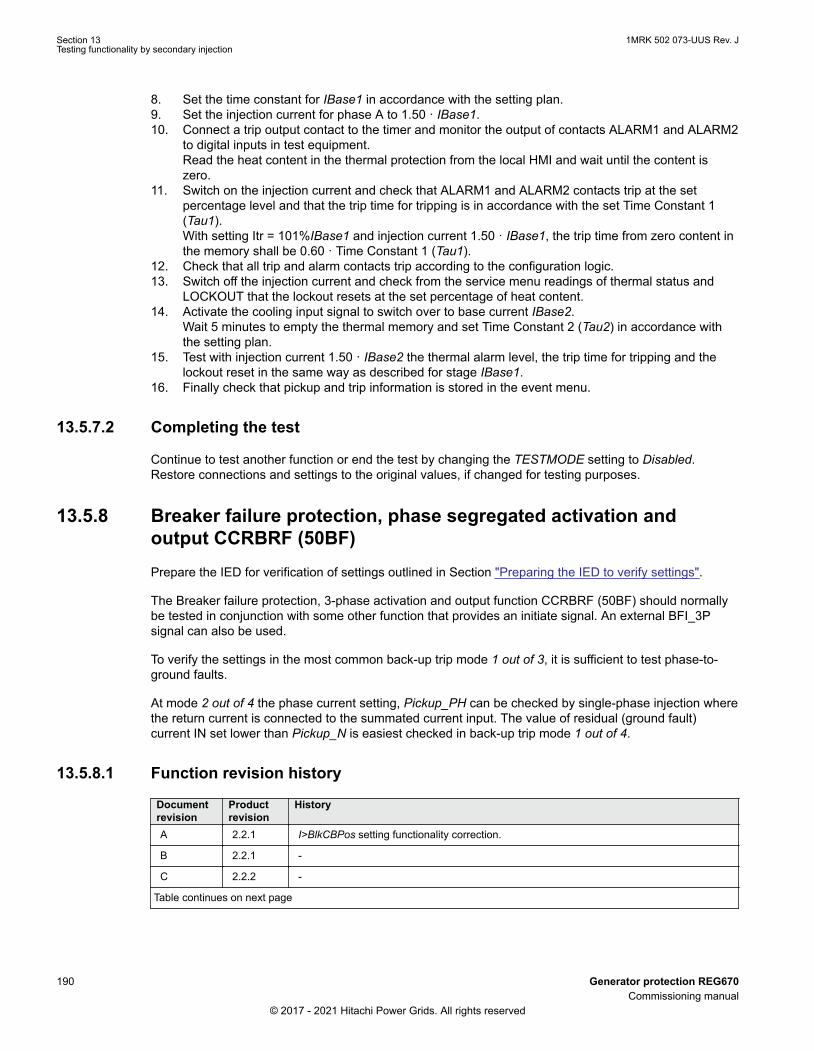
8. Set the time constant for IBase1 in accordance with the setting plan.9. Set the injection current for phase A to 1.50 · IBase1.10. Connect a trip output contact to the timer and monitor the output of contacts ALARM1 and ALARM2
to digital inputs in test equipment.Read the heat content in the thermal protection from the local HMI and wait until the content iszero.
11. Switch on the injection current and check that ALARM1 and ALARM2 contacts trip at the setpercentage level and that the trip time for tripping is in accordance with the set Time Constant 1(Tau1).With setting Itr = 101%IBase1 and injection current 1.50 · IBase1, the trip time from zero content inthe memory shall be 0.60 · Time Constant 1 (Tau1).
12. Check that all trip and alarm contacts trip according to the configuration logic.13. Switch off the injection current and check from the service menu readings of thermal status and
LOCKOUT that the lockout resets at the set percentage of heat content.14. Activate the cooling input signal to switch over to base current IBase2.
Wait 5 minutes to empty the thermal memory and set Time Constant 2 (Tau2) in accordance withthe setting plan.
15. Test with injection current 1.50 · IBase2 the thermal alarm level, the trip time for tripping and thelockout reset in the same way as described for stage IBase1.
16. Finally check that pickup and trip information is stored in the event menu.
13.5.7.2 Completing the testSEMOD53632-51 v5
Continue to test another function or end the test by changing the TESTMODE setting to Disabled.Restore connections and settings to the original values, if changed for testing purposes.
13.5.8 Breaker failure protection, phase segregated activation andoutput CCRBRF (50BF)
M12104-2 v13
Prepare the IED for verification of settings outlined in Section "Preparing the IED to verify settings".
The Breaker failure protection, 3-phase activation and output function CCRBRF (50BF) should normallybe tested in conjunction with some other function that provides an initiate signal. An external BFI_3Psignal can also be used.
To verify the settings in the most common back-up trip mode 1 out of 3, it is sufficient to test phase-to-ground faults.
At mode 2 out of 4 the phase current setting, Pickup_PH can be checked by single-phase injection wherethe return current is connected to the summated current input. The value of residual (ground fault)current IN set lower than Pickup_N is easiest checked in back-up trip mode 1 out of 4.
13.5.8.1 Function revision historyGUID-3A043295-3AE3-437E-BBE9-D7FD6F349892 v2
Documentrevision
Productrevision
History
A 2.2.1 I>BlkCBPos setting functionality correction.
B 2.2.1 -
C 2.2.2 -
Table continues on next page
Section 13 1MRK 502 073-UUS Rev. JTesting functionality by secondary injection
190 Generator protection REG670Commissioning manual
© 2017 - 2021 Hitachi Power Grids. All rights reserved

Documentrevision
Productrevision
History
D 2.2.3 Setting StartMode is added to choose how retrip and backup trip timers are run. The choicesare; to run the timers by external start signal which is latched, to follow the external startsignal only or to follow the external start signal and the selected FunctionMode.
E 2.2.3 -
F 2.2.4 -
G 2.2.4 -
H 2.2.5 -
13.5.8.2 Checking the phase current trip value, Pickup_PHM12104-23 v14
The check of the Pickup_PH current level is best made in FunctionMode = Current and BuTripMode = 1out of 3 or 2 out of 4.
1. Apply the fault condition, including BFI_3P of CCRBRF (50BF), with a current below setPickup_PH.
2. Repeat the fault condition and increase the current in steps until a trip occurs. Note that theINITIATE signal shall be re-applied for each new current value.
3. Compare the result with the set Pickup_PH.
If RetripMode = Off and FunctionMode = Current is set, only backup trip can be used tocheck set Pickup_PH.
13.5.8.3 Checking the residual (ground fault) current trip value Pickup_N set belowPickup_PH
M12104-80 v10
Check the low set Pickup_N current where setting FunctionMode = Current and setting BuTripMode = 1out of 4
1. Apply the fault condition, including BFI_3P of CCRBRF (50BF), with a current just below setPickup_N.
2. Repeat the fault condition and increase the current in steps until trip appears. Note that theINITIATE signal shall be re-applied for each new current value.
3. Compare the result with the set Pickup_N.4. Disconnect AC and BFI_3P input signals.
13.5.8.4 Checking the re-trip and back-up timesM12104-93 v12
The check of the set times can be made in connection with the check of trip values above.
Choose the applicable function and trip mode, such as FunctionMode = Current and RetripMode =UseFunctionMode.
1. Apply the fault condition, including initiation of CCRBRF (50BF), well above the set current value.Measure time from BFI_3P of CCRBRF (50BF).
2. Check the re-trip t1 and back-up trip times t2 and t3.
1MRK 502 073-UUS Rev. J Section 13Testing functionality by secondary injection
Generator protection REG670 191Commissioning manual
© 2017 - 2021 Hitachi Power Grids. All rights reserved

In applicable cases, the back-up trip for multi-phase pickupt2MPh and back-up trip 2, t2 and t3 canalso be checked. To check t2MPh, a two-phase or three-phase initiation shall be applied.
3. Disconnect AC and BFI_3P input signals.
13.5.8.5 Verifying the re-trip modeM12104-36 v6
Choose the mode below, which corresponds to the actual case.
In the cases below it is assumed that FunctionMode = Current is selected.
Checking the case without re-trip, RetripMode = OffM12104-107 v8
1. Set RetripMode = Off.2. Apply the fault condition, including initiation of CCRBRF (50BF), well above the set current value.3. Verify that no re-trip, but back-up trip is achieved after set time.4. Disconnect AC and BFI_3P input signals.
Checking the re-trip with current check, RetripMode = UseFunctionModeM12104-48 v8
1. Set RetripMode = UseFunctionMode.2. Apply the fault condition, including initiation of CCRBRF (50BF), well above the set current value.3. Verify that re-trip is achieved after set time t1 and back-up trip after time t2.4. Apply the fault condition, including initiation of CCRBRF (50BF), with current below set current
value.5. Verify that no re-trip, and no back-up trip is obtained.6. Disconnect AC and BFI_3P input signals.
Checking re-trip without current checkM12104-58 v10
1. Set RetripMode = Always.2. Apply the fault condition, including initiation of CCRBRF (50BF), well above the set current value.3. Verify that re-trip is achieved after the set time t1, and the back-up trip after time t2.4. Apply the fault condition, including initiation of CCRBRF (50BF), with current below set current
value.5. Verify that re-trip is achieved after set time t1, but no back-up trip is obtained.6. Disconnect AC and BFI_3P input signals.
13.5.8.6 Verifying the back-up trip modeM12104-146 v5
In the cases below it is assumed that FunctionMode = Current is selected.
Checking that back-up tripping is not achieved at normal CB trippingM12104-150 v8
Use the actual tripping modes. The case below applies to re-trip with current check.
1. Apply the fault condition, including initiation of CCRBRF (50BF), with phase current well above setvalue Pickup_PH.
2. Interrupt the current, with a margin before back-up trip time, t2. It may be made at issue of re-tripcommand.
3. Check that re-trip is achieved, if selected, but no back-up trip is obtained.4. Disconnect AC and BFI_3P input signals.
Section 13 1MRK 502 073-UUS Rev. JTesting functionality by secondary injection
192 Generator protection REG670Commissioning manual
© 2017 - 2021 Hitachi Power Grids. All rights reserved

The normal mode BuTripMode = 1 out of 3 should have been verified in the tests above. In applicablecases the modes 1 out of 4 and 2 out of 4 can be checked. Choose the mode below, which correspondsto the actual case.
Checking the case BuTripMode = 1 out of 4M12104-165 v6
It is assumed that the ground-fault current setting Pickup_N is below phase current setting Pickup_PH.
1. Set BuTripMode = 1 out of 4.2. Apply the fault condition, including initiation of CCRBRF (50BF), with one-phase current below set
Pickup_PH but above Pickup_N . The residual ground-fault should then be above set Pickup_N.3. Verify that back-up trip is achieved after set time. If selected, re-trip should also appear.4. Disconnect AC and BFI_3P input signals.
Checking the case BuTripMode = 2 out of 4M12104-179 v7
The ground-fault current setting Pickup_N may be equal to or below phase-current setting Pickup_PH.
1. Set BuTripMode = 2 out of 4.2. Apply the fault condition, including initiation of CCRBRF (50BF), with one-phase current above set
Pickup_PH and residual (ground fault) above set Pickup_N.3. Verify that back-up trip is achieved after set time. If selected, re-trip should also appear.4. Apply the fault condition, including initiation of CCRBRF (50BF), with at least one-phase current
below set Pickup_PH and residual (ground fault) above set Pickup_N. The current may bearranged by feeding three- (or two-) phase currents with equal phase angle (I0-component) belowPickup_PH, but of such value that the residual (ground fault) current (3I0) will be above set valuePickup_N.
5. Verify that back-up trip is not achieved.6. Disconnect AC and BFI_3P input signals.
13.5.8.7 Verifying instantaneous back-up trip at CB faulty conditionM12104-197 v7
Applies in a case where a signal from CB supervision function regarding CB being faulty and unable totrip is connected to input 52FAIL.
1. Repeat the check of back-up trip time. Disconnect current and input signals.2. Activate the input 52FAIL. The output CBALARM (CB faulty alarm) should appear after set time
tCBAlarm. Keep the input activated.3. Apply the fault condition, including initiation of CCRBRF (50BF), with current above set current
value.4. Verify that back-up trip is obtained without intentional delay, for example within 20ms from
application of initiation.5. Disconnect injected AC and BFI_3P input signals.
13.5.8.8 Verifying the case FunctionMode = CB PosGUID-06D1545D-31F7-4B48-821E-151212962A81 v1
It is assumed that re-trip without current check is selected, RetripMode = UseFunctionMode.
1. Set FunctionMode = CB Pos.2. Apply input signal for CB closed to relevant input or inputs 52A_A, 52A_B or 52A_C.3. Apply the input signal, or signals for the start of CCRBRF.4. Verify that phase selection re-trip and backup trip are achieved after set times.5. Disconnect the start signal(s). Keep the CB closed signal(s).
1MRK 502 073-UUS Rev. J Section 13Testing functionality by secondary injection
Generator protection REG670 193Commissioning manual
© 2017 - 2021 Hitachi Power Grids. All rights reserved

6. Apply input signal(s), for start of CCRBRF.7. Arrange disconnection of CB closed signal(s) well before set backup trip time t28. Verify that backup trip is not achieved.
13.5.8.9 Verifying the case RetripMode = ContactM12104-213 v10
It is assumed that re-trip without current check is selected, RetripMode = Contact.
1. Set FunctionMode = Contact2. Apply input signal for CB closed to relevant input or inputs 52a_A (B or C).3. Apply input signal, or signals for initiation of CCRBRF (50BF).4. Verify that phase selection re-trip and back-up trip are achieved after set times.5. Disconnect the trip signal(s). Keep the CB closed signal(s).6. Apply input signal(s), for initiation of CCRBRF (50BF).7. Arrange disconnection of CB closed signal(s) well before set back-up trip time t2.8. Verify that back-up trip is not achieved.9. Disconnect injected AC and BFI_3P input signals.
13.5.8.10 Verifying the caseFunctionMode = Current or CB PosM12104-237 v7
To be made only whenFunctionMode = Current or CB Pos is selected. It is suggested to make the testsin one phase only, or at three-pole trip applications for just three-pole tripping.
Checking the case with fault current above set value Pickup_PHM12104-241 v8
The operation shall be as in RetripMode = UseFunctionMode.
1. Set FunctionMode = Current or CB Pos.2. Leave the inputs for CB close inactivated. These signals should not influence.3. Apply the fault condition, including initiation of CCRBRF (50BF), with current above the set
Pickup_PH value.4. Check that the re-trip, if selected, and back-up trip commands are achieved.5. Disconnect injected AC and BFI_3P input signals.
Checking the case with fault current below set value Pickup_BlkCBPosM12104-281 v11
The case shall simulate a case where the fault current is very low and operation will depend on CBposition signal from CB auxiliary contact. It is suggested that retrip without current check is used, settingRetripMode = UseFunctionMode Check.
1. Set FunctionMode = Current or CB Pos.2. Apply input signal for CB closed to relevant input or inputs 52a_A (B or C)3. Apply the fault condition with input signal(s) for initiation of CCRBRF (50BF). The value of current
should be below the set value Pickup>BlkCBPos4. Verify that phase selection re-trip (if selected) and back-up trip are achieved after set times. Failure
to trip is simulated by keeping the signal(s) CB closed activated.5. Disconnect the AC and the BFI_3P signal(s). Keep the CB closed signal(s).6. Apply the fault and the initiation again. The value of current should be below the set value
Pickup>BlkCBPos.7. Arrange disconnection of CB closed signal(s) well before set back-up trip time t2. It simulates a
correct CB tripping.8. Verify that back-up trip is not achieved. Re-trip can appear for example, due to selection
RetripMode = Always.9. Disconnect injected AC and BFI_3P input signals.
Section 13 1MRK 502 073-UUS Rev. JTesting functionality by secondary injection
194 Generator protection REG670Commissioning manual
© 2017 - 2021 Hitachi Power Grids. All rights reserved

13.5.8.11 Verifying the external start signal has timed outGUID-754108D4-E440-4F8F-917B-04579EC1C2C7 v1
1. Set StartMode = FollowStart.2. Set FunctionMode = Current.3. Use default value for tStartTimeout = 1.0 s.4. Use default value for time delay backup trip t2 = 0.150 s.5. Leave the inputs for CB close inactivated. These signals should not influence.6. Apply START signal, and after 1.5 s apply the current above the set IPPU value.7. Check that STALARM signal is set after 1.0 s and backup trip is blocked.
13.5.8.12 Verifying that backup signal is released when STALARM is resetGUID-49CA34B6-5AE9-4E45-9F4E-33DA5F626209 v1
1. Set StartMode = FollowStart.2. Set FunctionMode = Current.3. Use default value for tStartTimeout = 1.0 s.4. Use default value for time delay backup trip t2 = 0.150 s.5. Leave the inputs for CB close inactivated. These signals should not influence.6. Apply START signal at t=0s, and after 1.5 s apply the current above the set IPPU value.7. Check that STALARM signal is set after 1.0s and backup trip is blocked.8. Reset START signal after 3.5s, ensure that STALARM reset immediately.9. Set START after 3.6s, ensure that backup trip is set after t2 backup trip delay has expired (3.750 s).
13.5.8.13 Test of FollowStart&Mode behaviourGUID-D68675FC-2533-4D6F-A26B-E1611FB7B32A v1
1. Set StartMode = FollowStart&Mode.2. Set FunctionMode = Current.3. Set RetripMode = UseFunctionMode.4. Use default value for tStartTimeout = 1.0 s.5. Use default value for time delay backup trip t2 = 0.150 s.6. Use default value for time delay re-trip t1 = 0.000 s.7. Leave the inputs for CB close inactivated. These signals should not influence.8. Apply START signal, and after 0.200 s apply the current above the set IPPU value.9. Check that STALARM does not come and that re-trip TRRET is instantly set at 0.200s while the
backup trip TRBU set only when t2 expires at 0.200 + 0.150s.
13.5.8.14 Test of FollowStart behaviourGUID-E3FFFAD0-C9E9-4EAF-8418-314E9D475EDA v1
1. Set StartMode = FollowStart.2. Set FunctionMode = Current.3. Set RetripMode = UseFunctionMode.4. Use default value for tStartTimeout = 1.0 s.5. Use for example the default value for time delay backup trip t2 = 0.150 s.6. Use for example the default value for time delay retrip t1 = 0.000 s.7. Leave the inputs for CB close inactivated. These signals should not influence.8. Apply START signal, and after 0.200 s apply the current above the set IPPU value.9. Check that STALARM does not come and that both re-trip TRRET and backup trip TRBU comes
instantly at 0.200 s (that is, as soon as current is given to the function).
1MRK 502 073-UUS Rev. J Section 13Testing functionality by secondary injection
Generator protection REG670 195Commissioning manual
© 2017 - 2021 Hitachi Power Grids. All rights reserved

13.5.8.15 Completing the testM12104-72 v5
Continue to test another function or end the test by changing the TESTMODE setting to Disabled.Restore connections and settings to the original values, if changed for testing purposes.
13.5.9 Overcurrent protection with binary release BRPTOCGUID-EB5AEFC4-6F51-4E1E-8055-4FEC53CA81FD v3
Prepare the IED for verification of settings outlined in Section "Preparing the IED to verify settings".
Logical signals for BRPTOC protection are available on the local HMI under Main menu /Settings /IEDSettings /Current protection /OvercurrBinRel (50, 3I>) /BRPTOC (50, 3I>):x .
The Signal Monitoring in PCM600 shows the same signals that are available on the local HMI.
13.5.9.1 Function revision historyGUID-23898A65-D896-479E-9122-E8D9D6CC4FEB v1
Documentrevision
Productrevision
History
A 2.2.1 -
B 2.2.1 -
C 2.2.2 -
D 2.2.3 -
E 2.2.3 -
F 2.2.4 -
G 2.2.4 -
H 2.2.4 -
J 2.2.5 New function release
13.5.9.2 Measuring the operate limit of set valuesGUID-4FF9AAC6-04B7-4A26-9093-C199C0C50540 v4
1. Check that the input logical signals BLOCK and BLKTR and the output logical signal TRIP are alllogical zero.
2. If required, activate the input on the BRPTOC function block.3. Set MeasType to DFT for overcurrent operation.4. For a short while inject a current (fault current) in phase L1 to about 110% of the set operating
current I>, and switch the current off.Observe to not exceed the maximum permitted overloading of the current circuits in the IED.
5. Switch the fault current on and observe that STL1 and START appears. Also, measure theoperating time of BRPTOC.Use the TRIP signal from the configured binary output to stop the timer. Repeat step 4 and step 5by changing MeasType to Peak and Peak-to-peak and observe the operate time of BRPTOC.
6. Activate the input BLOCK on the BRPTOC function block.7. Switch on the fault current (110% of the setting) and observe.
No STL1, START, and TRIP signal should appear.8. Switch off the fault current.9. For a short while inject a current (fault current) in same phase to about 90% of the set operating
current, and switch the current off.10. Switch the fault current on and observe.
Section 13 1MRK 502 073-UUS Rev. JTesting functionality by secondary injection
196 Generator protection REG670Commissioning manual
© 2017 - 2021 Hitachi Power Grids. All rights reserved

No STL1, START, and TRIP signal should appear.11. Switch off the fault current.12. If required, reset the ENABLE binary input.13. Switch the fault current on.
No STL1, START, and TRIP signal should appear.14.15. Repeat the above steps by injecting fault current in phase L2 and L3.
13.5.9.3 Completing the testM14922-50 v4
Continue to test another function or end the test by changing the TESTMODE setting to Disabled.Restore connections and settings to the original values, if changed for testing purposes.
13.5.10 Pole discrepancy protection CCPDSC (52PD)SEMOD55625-59 v6
Prepare the IED for verification of settings as outlined in section "Requirements" and section "Preparingfor test" in this chapter.
13.5.10.1 Verifying the settingsSEMOD55625-63 v8
1. External detection logic, Contact function selection = ContactSel setting equals CCPDSC (52PD)signal from CB. Activate the EXTPDIND binary input, and measure the operating time of CCPDSC(52PD).Use the TRIP signal from the configured binary output to stop the timer.
2. Compare the measured time with the set value tTrip.3. Reset the EXTPDIND input.4. Activate the BLKDBYAR binary input.
This test should be performed together with Autorecloser SMBRREC (79).5. Activate the EXTPDIND binary input.
No TRIP signal should appear.6. Reset both BLKDBYAR and EXTPDIND binary inputs.7. Activate the BLOCK binary input.8. Activate EXTPDIND binary input.
NO TRIP signal should appear.9. Reset both BLOCK and EXTPDIND binary inputs.10. If Internal detection logic Contact function selection = ContactSel setting equals Pole position from
auxiliary contacts. Then set inputs 52b_A...52a_C in a status that activates the pole discordancelogic and repeats step 2 to step 6.
11. Unsymmetrical current detection with CB monitoring: Set measured current in one phase to 110%of current release level. Activate CLOSECMD and measure the operating time of the CCPDSC(52PD) protection.Use the TRIP signal from the configured binary output to stop the timer.
12. Deactivate the CLOSECMD: Set measured current in one phase to 90% of Current Release level.Activate CLOSECMD.NO TRIP signal should appear.
13. Repeat the previous two steps using OPENCMD instead of CLOSECMD. Asymmetry currentdetection with CB monitoring: Set all three currents to 110% of Current Release level. ActivateCLOSECMD.
1MRK 502 073-UUS Rev. J Section 13Testing functionality by secondary injection
Generator protection REG670 197Commissioning manual
© 2017 - 2021 Hitachi Power Grids. All rights reserved

NO TRIP signal should appear due to symmetrical condition.14. Deactivate the CLOSECMD. Decrease one current with 120% of the current unsymmetrical level
compared to the other two phases. Activate CLOSECMD and measure the operating time of theCCPDSC (52PD) protection.Use the TRIP signal from the configured binary output to stop the timer.
15. Deactivate the CLOSECMD. Decrease one current with 80% of the current unsymmetrical levelcompared to the other two phases. Activate CLOSECMD.NO TRIP signal should appear.
13.5.10.2 Completing the testSEMOD55625-106 v4
Continue to test another function or end the test by changing the TESTMODE setting to Disabled.Restore connections and settings to the original values, if changed for testing purposes.
13.5.11 Directional underpower protection GUPPDUP (37)SEMOD175027-3 v5
Prepare the IED for verification of settings as outlined in section "Requirements" and section "Preparingfor test" in this chapter.
13.5.11.1 Verifying the settingsSEMOD175027-7 v7
The underpower protection shall be set to values according to the real set values to be used.
The test is made by means of injection of voltage and current where the amplitude of both current andvoltage and the phase angle between the voltage and current can be controlled. During the test, theanalog outputs of active and reactive power shall be monitored.
1. Connect the test set for injection of voltage and current corresponding to the mode to be used inthe application. If a three-phase test set is available this could be used for all the modes. If a single-phase current/voltage test set is available the test set should be connected to a selected input forone-phase current and voltage.
Table 27: Calculation modes
Set value: Mode Formula used for complex power calculationA, B, C * * *
A A B B C CS V I V I V I= × + × + ×
EQUATION2055 V1 EN-US (Equation 124)
Arone* *
AB A BC CS V I V I= × - ×
EQUATION2056-ANSI V1 EN-US (Equation 125)
PosSeq *3 PosSeq PosSeqS V I= × ×
EQUATION2057-ANSI V1 EN-US (Equation 126)
Table continues on next page
Section 13 1MRK 502 073-UUS Rev. JTesting functionality by secondary injection
198 Generator protection REG670Commissioning manual
© 2017 - 2021 Hitachi Power Grids. All rights reserved

Set value: Mode Formula used for complex power calculationAB * *( )AB A BS V I I= × -
EQUATION2058-ANSI V1 EN-US (Equation 127)
BC * *( )BC B CS V I I= × -
EQUATION2059-ANSI V1 EN-US (Equation 128)
CA * *( )CA C AS V I I= × -
EQUATION2060-ANSI V1 EN-US (Equation 129)
A *3 A AS V I= × ×
EQUATION2061-ANSI V1 EN-US (Equation 130)
B *3 B BS V I= × ×
EQUATION2062-ANSI V1 EN-US (Equation 131)
C *3 C CS V I= × ×
EQUATION2063-ANSI V1 EN-US (Equation 132)
2. Adjust the injected current and voltage to the set values in % of IBase and VBase (converted tosecondary current and voltage). The angle between the injected current and voltage shall be setequal to the set direction Angle1, angle for stage 1 (equal to 0° for low forward power protectionand equal to 180° for reverse power protection). Check that the monitored active power is equal to100% of rated power and that the reactive power is equal to 0% of rated power.
3. Change the angle between the injected current and voltage to Angle1 + 90°. Check that themonitored active power is equal to 0% of rated power and that the reactive power is equal to 100%of rated power.
4. Change the angle between the injected current and voltage back to 0°. Decrease the current slowlyuntil the PICKUP1 signal, pickup of stage 1, is activated.
5. Increase the current to 100% of IBase.6. Switch the current off and measure the time for activation of TRIP1, trip of stage 1.7. If a second stage is used, repeat steps 2 to 6 for the second stage.
13.5.11.2 Completing the testSEMOD175027-15 v4
Continue to test another function or end the test by changing the TESTMODE setting to Disabled.Restore connections and settings to the original values, if changed for testing purposes.
13.5.12 Directional overpower protection GOPPDOP (32)SEMOD175058-3 v5
Prepare the IED for verification of settings as outlined in section "Requirements" and section "Preparingfor test" in this chapter.
1MRK 502 073-UUS Rev. J Section 13Testing functionality by secondary injection
Generator protection REG670 199Commissioning manual
© 2017 - 2021 Hitachi Power Grids. All rights reserved

13.5.12.1 Verifying the settingsSEMOD175058-7 v6
The overpower protection shall be set to values according to the real set values to be used. The test ismade by means of injection of voltage and current where the amplitude of both current and voltage andthe phase angle between the voltage and current can be controlled. During the test the analog outputs ofactive and reactive power shall be monitored.
1. Connect the test set for injection of voltage and current corresponding to the mode to be used inthe application. If a three phase test set is available this could be used for all the modes. If a singlephase current/voltage test set is available the test set should be connected to a selected input forone phase current and voltage.
2. Adjust the injected current and voltage to the set rated values in % of IBase and VBase (convertedto secondary current and voltage). The angle between the injected current and voltage shall be setequal to the set direction Angle1, angle for stage 1 (equal to 0° for low forward power protectionand equal to 180° for reverse power protection). Check that the monitored active power is equal to100% of rated power and that the reactive power is equal to 0% of rated power.
3. Change the angle between the injected current and voltage to Angle1 + 90°. Check that themonitored active power is equal to 0% of rated power and that the reactive power is equal to 100%of rated power.
4. Change the angle between the injected current and voltage back to Angle1 value. Increase thecurrent slowly from 0 until the PICKUP1 signal, pickup of stage 1, is activated. Check the injectedpower and compare it to the set value Power1, power setting for stage 1 in % of Sbase.
5. Increase the current to 100% of IBase and switch the current off.6. Switch the current on and measure the time for activation of TRIP1, trip of stage 1.7. If a second stage is used, repeat steps 2 to 6 for the second stage.
13.5.12.2 Completing the testSEMOD175058-66 v4
Continue to test another function or end the test by changing the TESTMODE setting to Disabled.Restore connections and settings to the original values, if changed for testing purposes.
13.5.13 Negative-sequence time overcurrent protection for machinesNS2PTOC (46I2)
GUID-48A6DA1D-5CF5-4C1B-B1A4-3F2C73851FD4 v2
GUID-F7AA2194-4D1C-4475-8853-C7D064912614 v4
When inverse time overcurrent characteristic is selected, the trip time of the stage will bethe sum of the inverse time delay and the set definite time delay. Thus, if only the inversetime delay is required, it is important to set the definite time delay for that stage to zero.
13.5.13.1 Verifying settings by secondary injectionGUID-EB788169-532A-4A3E-BBEC-DCB28169DF86 v7
1. Connect the test set for injection of three-phase currents to the appropriate current terminals of theIED.
2. Go to Main menu/Settings /IED Settings/Current protection /NegSeqOverCurr2Step/NSOn /General and make sure that the function is enabled, that is Operation is set to Enabled.
3. Inject current into IEDs in such a way that negative sequence component is created and then verifythat negative sequence component of the injected currents is calculated correctly by the function.See example below for 1 A rated current transformer.
Section 13 1MRK 502 073-UUS Rev. JTesting functionality by secondary injection
200 Generator protection REG670Commissioning manual
© 2017 - 2021 Hitachi Power Grids. All rights reserved
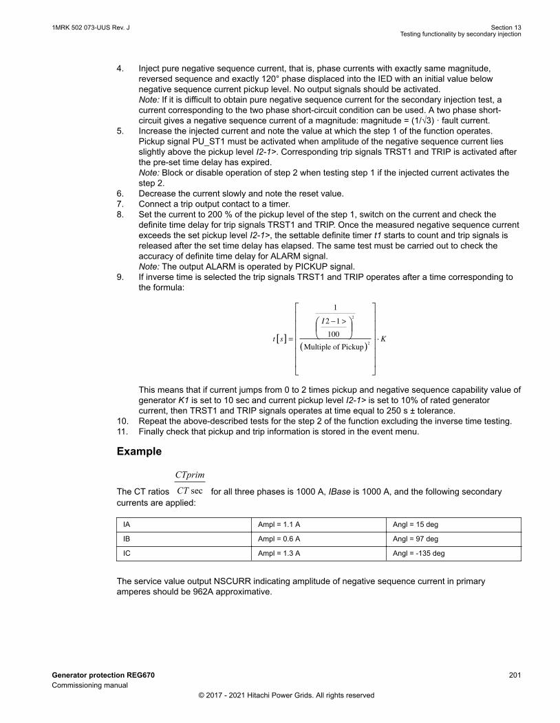
4. Inject pure negative sequence current, that is, phase currents with exactly same magnitude,reversed sequence and exactly 120° phase displaced into the IED with an initial value belownegative sequence current pickup level. No output signals should be activated.Note: If it is difficult to obtain pure negative sequence current for the secondary injection test, acurrent corresponding to the two phase short-circuit condition can be used. A two phase short-circuit gives a negative sequence current of a magnitude: magnitude = (1/√3) · fault current.
5. Increase the injected current and note the value at which the step 1 of the function operates.Pickup signal PU_ST1 must be activated when amplitude of the negative sequence current liesslightly above the pickup level I2-1>. Corresponding trip signals TRST1 and TRIP is activated afterthe pre-set time delay has expired.Note: Block or disable operation of step 2 when testing step 1 if the injected current activates thestep 2.
6. Decrease the current slowly and note the reset value.7. Connect a trip output contact to a timer.8. Set the current to 200 % of the pickup level of the step 1, switch on the current and check the
definite time delay for trip signals TRST1 and TRIP. Once the measured negative sequence currentexceeds the set pickup level I2-1>, the settable definite timer t1 starts to count and trip signals isreleased after the set time delay has elapsed. The same test must be carried out to check theaccuracy of definite time delay for ALARM signal.Note: The output ALARM is operated by PICKUP signal.
9. If inverse time is selected the trip signals TRST1 and TRIP operates after a time corresponding tothe formula:
t s
I
[ ]
( )
=
− >
1
2 1
100
2
2
Multiple of Pickup⋅⋅ K
This means that if current jumps from 0 to 2 times pickup and negative sequence capability value ofgenerator K1 is set to 10 sec and current pickup level I2-1> is set to 10% of rated generatorcurrent, then TRST1 and TRIP signals operates at time equal to 250 s ± tolerance.
10. Repeat the above-described tests for the step 2 of the function excluding the inverse time testing.11. Finally check that pickup and trip information is stored in the event menu.
Example
The CT ratios sec
CTprim
CT for all three phases is 1000 A, IBase is 1000 A, and the following secondarycurrents are applied:
IA Ampl = 1.1 A Angl = 15 deg
IB Ampl = 0.6 A Angl = 97 deg
IC Ampl = 1.3 A Angl = -135 deg
The service value output NSCURR indicating amplitude of negative sequence current in primaryamperes should be 962A approximative.
1MRK 502 073-UUS Rev. J Section 13Testing functionality by secondary injection
Generator protection REG670 201Commissioning manual
© 2017 - 2021 Hitachi Power Grids. All rights reserved

13.5.13.2 Completing the testGUID-DA67F057-00AD-4391-B50E-047FD6C16EBB v1
Continue to test another functions or end the test by changing the Test mode setting to Off. Restoreconnections and settings to their original values, if they were changed for testing purposes. Make surethat all built-in features for this function, which shall be in operation, are enabled and with correctsettings.
13.5.14 Accidental energizing protection for synchronous generatorAEGPVOC (50AE)
GUID-6E141754-28E5-408D-955F-899720BA59E0 v2
Prepare the IED for verification of settings outlined in Section "Preparing the IED to verify settings".
13.5.14.1 Verifying the settingsGUID-B834BA0F-E8CE-4B08-9FCE-B6D2813D3197 v3
1. Connect the test set for three-phase current injection and for three phase voltage injection to theappropriate IED terminals.
2. Inject zero voltage to the IED.3. Increase the injected symmetric three phase current slowly and note the operated value (pickup
value) of the studied step of the function.4. Decrease the current slowly and note the reset value.5. Connect a trip output contact to a timer.6. Set the injected current to 200% of the operate level of the tested stage, switch on the current and
check the time delay.7. Check that all trip and pickup contacts operate according to the configuration (signal matrises).8. Finally check that pickup and trip information is stored in the event menu.9. Inject rated symmetric three phase voltage to the IED.10. Set the injected current to 200% of the operate level of the tested stage, switch on the current. The
function does not pickup and trip.11. Inject 95% of the set 27_pick_up value symmetric three-phase voltage to the IED.12. Set the injected current to 200% of the operate level of the tested stage, switch on the current. The
function does pickup and trip.
13.5.15 Voltage-restrained time overcurrent protection VRPVOC(51V)GUID-764DA61A-D987-4358-867A-DA43ADDC6E57 v5
Prepare the IED for verification of settings as outlined in section "Requirements" and section "Preparingfor test" in this chapter.
13.5.15.1 Function revision historyGUID-9B72080E-B886-4138-B8BC-CCB99C289C87 v1
Documentrevision
Productrevision
History
A 2.2.1 -
B 2.2.1 -
C 2.2.2 -
D 2.2.3 -
E 2.2.3 -
Table continues on next page
Section 13 1MRK 502 073-UUS Rev. JTesting functionality by secondary injection
202 Generator protection REG670Commissioning manual
© 2017 - 2021 Hitachi Power Grids. All rights reserved

Documentrevision
Productrevision
History
F 2.2.4 -
G 2.2.4 -
H 2.2.4 -
J 2.2.5 Previously called settings Characterist and t_DefOC had their names changed toCharacteristic and t_OC for more clear understanding.
13.5.15.2 Verifying the settingsGUID-3A2B7FF5-330E-4A0D-AB74-EBAE6258C176 v1
Verifying settings by secondary injectionGUID-39632D30-A8D8-417D-985C-8F886106783E v4
1. Connect the test set for three-phase current injection and three-phase voltage injection to theappropriate IED terminals.
2. Go to Main menu /Settings /IED Settings /Current protection /VoltageRestOverCurr ( 51V,2(I>/V<))/VRPVOC (51V,2(I>/V<)):1 /General and make sure that the function is enabled, that is,Operation is set to Enabled.
3. The test of the function may be performed by injecting restrain voltage and increasing the injectedcurrent(s). Note the value at which the PICKUP and STOC signals are set.
In the following equations, restrain voltage is the magnitude of the minimum phase-to-phase voltage in secondary volts.
The set trip value in secondary amperes is calculated according to the following equations:First part of the characteristic (Restrain voltage ≤ 25% of VBase):
Picup CurrIBase
CT
CTprim
VDepFact_ sec
100 100× × ×
ANSI13000291 V1 EN-US (Equation 133)
Second part of the characteristic (25% of VBase ≤ Restrain voltage ≤ VHighLimit/100*VBase), validwhen setting parameter VDepMode = Slope:
Pickup CurrIBase
CT
CTprim
VDepFact_ sec
1001
100× ×
× −
VVHighLimitVBase
VT
VTprim
strainVoltage−( )
× ×× −
25
100
25
10secRe
00 100× ×
+ ×VBaseVT
VTprim
Pickup CurrIB
sec _aase
CT
CTprim
VDepFact× ×
sec
100
ANSIEQUATION2433 V2 EN-US (Equation 134)
Third part of the characteristic (VHighLimit/100*VBase ≤ Restrain voltage):
Picup CurrIBase
CT
CTprim
_ sec
100× ×
ANSIEQUATION2434 V1 EN-US (Equation 135)
Example (rated secondary current = 5A):
CT ratio 10 000/5A
VT ratio 10 kV/100 V
Pickup_Curr 100%
VDepFact 25%
Table continues on next page
1MRK 502 073-UUS Rev. J Section 13Testing functionality by secondary injection
Generator protection REG670 203Commissioning manual
© 2017 - 2021 Hitachi Power Grids. All rights reserved

VHighLimit 100%
IBase 10 000 A
VBase 10 kV
A test for each section of the characteristic of the function VRPVOC may be performed; that maybe achieved by applying the following voltages:First section of the characteristic:If VDepMode = Slope, the minimum measured phase-to-phase voltage is lower than 0,25*VBase; ifVDepMode = Step, the minimum measured phase-to-phase voltage is lower than VHighLimit/100*VBase:• VA: Ampl = 10 / √3; Angle = 0°• VB: Ampl = 10 / √3; Angle = 240°• VC: Ampl = 100 / √3; Angle = 120°
Second section of the characteristic only:If VDepMode = Slope, the minimum measured phase-to-phase voltage is between 0,25*VBase andVHighLimit/100*VBase:• VA: Ampl = 50 / √3; Angle = 0°• VB: Ampl = 50 / √3; Angle = 240°• VC: Ampl = 100 / √3; Angle = 120°
Last section of the characteristic:If VDepMode = either Slope or Step, the minimum measured phase-to-phase voltage is higher thanVHighLimit/100*VBase:• VA: Ampl = 105/ √3; Angle = 0°• VB: Ampl = 105/ √3; Angle = 240°• VC: Ampl = 105 / √3; Angle = 120°
4. Inject the voltages that are related to the first part of the characteristic, and then slowly increase thephase current IA from 0.0 A up to the value the function trips. The PICKUP and STOC signals mustbe activated when the amplitude of the phase current IA is slightly above 0.25 A on the secondaryside. The corresponding trip signals TROC and TRIP will be activated after the pre-set time delayhas expired.
5. Decrease the current IA slowly and note the reset value.6. Repeat steps 4 and 5 applying voltages that are related to the second and the last section of the
characteristic; the function trips when IA is slightly higher than: 0.5 A in the second section; 5A inthe last section.
7. Connect the trip output contact to the input channel of the test set in order to stop the injection andmeasure the trip time.
8. If definite time delay is used for the overcurrent step, set the setting Characterist = ANSI Def. Time.Apply the voltages related to the last part of the characteristic and inject a current IA 200% higherthan the set tripping level, and check the definite time delay for trip (the signals TROC and TRIP ofthe protection function VRPVOC are active in trip condition).
9. If inverse time delay is used for the overcurrent step, the parameter setting Characterist shall beproperly set; we can refer, for example, to the setting IEC Very inv.; If the IEC Very inverse timecharacteristic is selected, the trip signals TROC and TRIP will trip after a time defined by theequation:
t sk
I
Pickup Curr
[ ] =
−
13 5
1
. *
_
ANSIEQUATION2435 V1 EN-US (Equation 136)
Section 13 1MRK 502 073-UUS Rev. JTesting functionality by secondary injection
204 Generator protection REG670Commissioning manual
© 2017 - 2021 Hitachi Power Grids. All rights reserved

where:
t Trip time in seconds
I Measured value (for example, phase current)
Pickup_Curr Set trip value
This means that if the measured phase current jumps from 0 to 2 times the set trip level and timemultiplier k is set to 1.0 s (default value), then the TROC and TRIP signals will trip after a time delayequal to 13.5 s ± tolerance.Taking into account the above explanation, inject the voltages related to the last part of thecharacteristic and inject a current IA 200% higher than the set operation level, and check the triptime delay.
If tDef_OC is set to a value different from 0 s, then this time delay is added to theone that is defined by the IDMT characteristic.
10. Check the pickup and trip information that are stored in the event menu.11. The previous step 8 or 9 may be repeated also for the first and second section of the characteristic.12. Supply the IED with symmetric three-phase voltages at their rated values. Go to Main menu /
Settings /IED Settings /Current protection /VoltageRestOverCurr(51V,2(I>/V<)) /VRPVOC(51V,2(I>/V<)):1 /Undervoltage and set the setting Operation_UV = Enabled to activatethe undervoltage stage.
13. Slowly decrease the voltage in two phases simultaneously, until the STUV and PICKUP signalsappear.
14. Note the trip value. The set trip value in secondary volts is calculated according to the followingequation:
Pickup Volt VBase VT
VTprim
_ sec
100 3× ×
ANSIEQUATION2436 V2 EN-US (Equation 137)
If the VRPVOC function is used as an overcurrent protection with undervoltageseal-in, it is necessary to first inject sufficient current to activate the STOC signalbefore the under-voltage step is allowed to trip. In order to achieve that, applysymmetric three-phase voltages at their rated value and then inject a current IAthat is 200% higher than the set tripping level. Then slowly decrease the voltage intwo phases simultaneously, until the STUV and PICKUP signals appear.
15. Increase slowly the applied voltages of the previous two phases and note the reset value.16. Check that the trip output of the relay is connected to the input channel of the test in order to stop
the injection and measure the trip time.17. Inject symmetric three-phase voltages at their rated value and check that the STUV and PICKUP
signals reset as well as the trip signals of the function block (TRIP and TRUV).18. Instantaneously decrease the voltage in two phases simultaneously to a value 20% lower than the
set trip value (take into account the previous note if VRPVOC is configured in ACT with theundervoltage seal-in feature).
19. Measure the definite time delay for the TRUV and TRIP signals and compare it with the set valuetDef_UV.
20. Check that pickup and trip information is stored in the event menu.
1MRK 502 073-UUS Rev. J Section 13Testing functionality by secondary injection
Generator protection REG670 205Commissioning manual
© 2017 - 2021 Hitachi Power Grids. All rights reserved

13.5.15.3 Completing the testGUID-8A33AACE-7B89-4981-A872-78044BB1FD0D v2
Continue to test another function or end the test by changing the TESTMODE setting to Disabled.Restore connections and settings to the original values, if changed for testing purposes.
13.5.16 Generator stator overload protection GSPTTR (49S)GUID-A0B3EA43-7EEC-4FCC-A5BF-44BB8A8055E0 v1
13.5.16.1 Verifying the settingsGUID-6B85A379-E977-48CC-B15C-4AF3EAB78478 v2
Explained testing method is given for default value for the TD1 parameter.
The function has heating content memory features. Thus if testing shots are done consecutively, operatetime will be shorten accordingly, compared to the given operate characteristic. Therefore either wait untilset tReset time has elapsed, between two shots, or reset this memory by setting the RESET input intothe function to value TRUE
1. Connect the test set for the appropriate three-phase current injection to the IED phases A, B and C.The protection shall be fed with a symmetrical three-phase current.
2. Set the injected current to 116% of IBase, switch on the current and check operate time of the trip,120 s.
3. Decrease the current slowly.4. The output signal PICKUP will reset if the measured current falls below reset level or if BLOCK
signal is set to one.5. Switch off the current.6. Set the injected current to 120% of IBase, switch on the current and check operate time of the trip,
60 s.7. Switch off the current.8. Set the injected current to 154% of IBase, switch on the current and check operate time of the trip,
30 s.9. Switch off the current.10. Set the injected current to 226% of IBase, switch on the current and check operate time of the trip,
10 s.11. Switch off the current.12. Finally check that pickup and trip information is stored in the event menu.
13.5.16.2 Completing the testGUID-F79CE91E-7F07-45F4-8CDC-D7426CA9CBEA v2
Continue to test another function or end the test by changing the Test mode setting to Disabled. Restoreconnections and settings to their original values, if they were changed for testing purposes. Make surethat all built-in features for this function, which shall be in operation, are enabled and with correctsettings.
13.5.17 Generator rotor overload protection (49R)GUID-4BEA4A9E-AEE1-4E4E-9D7C-ABA3499EB431 v1
13.5.17.1 Verifying the settingsGUID-2AF96028-B49E-4820-BD3D-4957E75B9C2D v2
Explained testing method is given for default value for the TD1 parameter.
The function has heating content memory features. Thus if testing shots are done consecutively, operatetime will be shortened accordingly, compared to the given operate characteristic. Therefore, either wait
Section 13 1MRK 502 073-UUS Rev. JTesting functionality by secondary injection
206 Generator protection REG670Commissioning manual
© 2017 - 2021 Hitachi Power Grids. All rights reserved

until set tReset time has elapsed, between two shots, or reset this memory by setting the RESET inputinto the function to value TRUE.
Precautions if MeasurCurrent = DC. The magnitude of the injected current have to be decreased bymultiplying it with a factor of 0.741 in order to get correct operate times when testing with three-phasesymmetrical sinusoidal currents.
1. Connect the test set for the appropriate three-phase current injection to the IED phases A, B and C.The protection shall be fed with a symmetrical three-phase current.
2. Set the injected current to 113% of IBase, switch on the current and check operate time of the trip,120 s.
3. Decrease the current slowly.4. The output signal PICKUP will reset if the measured current falls below reset level or if BLOCK
signal is set to one.5. Switch off the current.6. Set the injected current to 125% of IBase, switch on the current and check operate time of the trip,
60 s.7. Switch off the current.8. Set the injected current to 146% of IBase, switch on the current and check operate time of the trip,
30 s.9. Switch off the current.10. Set the injected current to 209% of IBase, switch on the current and check operate time of the trip,
10 s.11. Switch off the current.12. Set the injected current to 100% of IBase and switch on the current.13. Decrease the current slowly under 37 PICKUP.14. The signal 37 TRIP will be activated when timer 37 trip delay expires.15. Finally check that pickup and trip information is stored in the event menu.
Testing the protectionGUID-6E4609B9-62AB-453D-8FCE-59F9F41AB59D v1
13.5.17.2 Completing the testGUID-B4B2C5EF-DA21-4E89-874E-DD94D52D904B v2
Continue to test another function or end the test by changing the Test mode setting to Disabled. Restoreconnections and settings to their original values, if they were changed for testing purposes. Make surethat all built-in features for this function, which shall be in operation, are enabled and with correctsettings.
13.5.18 Average Power Transient Earth Fault Protection, APPTEFGUID-079BCF22-469C-42EA-B857-E28154EC13D9 v1
Prepare the IED for verification of settings outlined in Section "Preparing the IED to verify settings".
13.5.18.1 Verifying the signals and settingsGUID-36A0055E-CA32-4D85-A580-59032B3AC4AE v1
All of the following test will assume the following CT and VT ratios, and IBase and UBase settings:
• CT ratio 1000A/1A• Phase-to-ground VT ratio 70kV/100V• Open Delta VT ratio (sqrt(3)*70kV)/100V• IBase=1000A• UBase=70kV
1MRK 502 073-UUS Rev. J Section 13Testing functionality by secondary injection
Generator protection REG670 207Commissioning manual
© 2017 - 2021 Hitachi Power Grids. All rights reserved

However, it must be noted that the secondary values given below can be used for most installationsbecause, usually:
1. VT rated primary voltage value is equal to the UBase setting (70kV in the given example above)2. CT rated primary current value is equal to the IBase setting (1000A in the given example above)
Consequently these two quantities cancel each other in the calculations for the correct secondaryinjected quantities. The frequency is not explicitly specified, use the rated frequency of the protectednetwork (either 50Hz or 60Hz) for signals given below.
The default setting values are used in the following test procedures if not otherwisestated for a particular test.
Injected quantities provided below are only for the neutral current IN and the neutral voltage UN. Thisassumes that these two quantities are connected to the IED on separate inputs and connected to theAPPTEF function using two SMAI preprocessing function blocks. Each of these two signals is connectedas the fourth input on respective SMAI function block.
If the above is not the case, for example; the UN is not connected to the IED but instead internallycalculated by the IED from the three phase-to-ground voltages, then simply inject the following values forthe three voltages:
UL1=sqrt(3)*UN; UL2=0V; UL3=0V
where, UN is the secondary voltage value given for every test below.
If IN is not connected to the IED but instead internally calculated by the IED from the three phasecurrents, then simply inject the following values for the three currents:
IL1=IN; IL2=0A; IL3=0A
where, IN is the secondary current value given for every test below.
Test of IMinForward setting pickup valueGUID-8F3DDF4D-DAF4-4873-9AA0-682A9D8E7D68 v1
1. Change the following settings from the default values:• OperationMode = Start and Trip in order to obtain the trip signal• IN>=3% (minimum value) in order not to interfere with this pickup test
The default value for IMinForward =2.5% is used for this test.
2. Inject the following analogue quantities given in secondary amperes and volts and wait for threeseconds to obtain the trip output (the default delay for tTrip=2s):
IN 1) Magnitude=40mA; Angle=180 degrees
UN Magnitude=75V; Angle=0 degrees
1) Inject set value for IMinForward +1.5% of CT secondary rated current, note that 1.5% is stated accuracy for thefunction.(That shall be ((2.5%+1.5%)/100)*1A=0.025A+0.015A when IMinForward =2.5% and CT rated secondaryis 1A).
3. The following signals shall be given from the APPTEF function:
Section 13 1MRK 502 073-UUS Rev. JTesting functionality by secondary injection
208 Generator protection REG670Commissioning manual
© 2017 - 2021 Hitachi Power Grids. All rights reserved

• STUN at the beginning of injection.• WRNFW as a 50ms pulse after approximately 35ms from the injection start.• STFW after approximately 150ms (default value for tStart=150ms)• TRIP after approximately 2.15s (after tStart+tTrip)
4. Inject the following analogue quantities given in secondary amperes and volts and wait for threeseconds:
IN1) Magnitude=10mA; Angle=180 degrees
UN Magnitude=75V; Angle=0 degrees
1) Inject set value for IMinForward –1.5% of CT secondary rated current, ( 0.025A-0.015A when IMinForward =2.5%and CT rated secondary is 1A)).
5. The following signal is given from the APPTEF function:• Only STUN at the beginning of injection.
The function did not operate for this forward EF now because the injected currentis below the set level.
Test of IMinReverse setting pickup valueGUID-158772EA-D4DA-415D-A388-C2D9837414ED v1
1. Change the following settings from the default values:• OperationMode = Start and Trip in order to obtain the trip signal• IN>=3% (minimum value) in order not to interfere with this pickup test• IMinReverse =2.5% in order to be similar to the IN value
2. Inject the following analogue quantities given in secondary amperes and volts and wait for threeseconds:
IN1) Magnitude=40mA; Angle=0 degrees
UN Magnitude=75V; Angle=0 degrees
1) Inject set value for IMinReverse+1.5% of CT secondary rated current, (that is0.025A+0.015A when IMinReverse=2.5% and CT rated secondary is 1A).
3. The following signals that shall be given from the APPTEF function:• STUN at the beginning of injection.• STRV after approximately 150ms (default value for tStart=150ms)
The TRIP signal is not issued for EF in the reverse direction.
4. Inject the following analogue quantities given in secondary amperes and volts and wait for threeseconds:
1MRK 502 073-UUS Rev. J Section 13Testing functionality by secondary injection
Generator protection REG670 209Commissioning manual
© 2017 - 2021 Hitachi Power Grids. All rights reserved

IN 1) Magnitude=10mA; Angle=0 degrees
UN Magnitude=75V; Angle=0 degrees
1) Inject set value for IMinReverse –1.5% of CT secondary rated current, ( 0.025A-0.015A when IMinReverse =2.5%and CT rated secondary is 1A)).
5. The following signal is given from the APPTEF function:• Only STUN at the beginning of injection.
The function did not operate for this reverse EF now because the injected currentis below the set level.
Test of function operation for high-ohmic EFGUID-99777636-56B6-4B0D-A796-6163B5DE94A2 v1
1. Change the following settings from the default values:• OperationMode = Start and Trip in order to obtain the trip signal• IN>=5% (default value)• IMinForward =50% in order for standard logic not to operate for this test
2. Inject the following analogue quantities given in secondary amperes and volts and wait for threeseconds in order to obtain the trip output (default delay for tTrip=2s):
IN Magnitude=75mA; Angle=180 degrees
UN1) Magnitude=45V; Angle=0 degrees
1) Inject lower voltage than 50V for high-ohmic EF test
3. The following signals shall be given from the APPTEF function:• STUN at the beginning of injection.• WRNFW, and STFW after approximately 650ms• TRIP after approximately 2.65s
Test of function operation for intermittent EFGUID-ADDA3A73-9884-41B1-96D0-EE9653004E96 v1
1. Change the following settings from the default values:• OperationMode = Start and Trip in order to obtain the trip signal• IN>=5% (default value)• IMinForward=2.5% (use the default value)• UN>StartsNo=4 (default, but it can be changed if required)• tReset=5.0s (set maximum value in order to make the test process easier)
2. Inject manually the following analogue quantities given in secondary amperes and volts but only for100ms (in order to avoid STFW signal which is delayed for 150ms):
IN Magnitude=75mA; Angle=180 degrees
UN Magnitude=100V; Angle=0 degrees
Section 13 1MRK 502 073-UUS Rev. JTesting functionality by secondary injection
210 Generator protection REG670Commissioning manual
© 2017 - 2021 Hitachi Power Grids. All rights reserved

3. Within the reset time (that is 5s with above setting) re-apply the above quantities again for 100msand repeat this step for at least the same number of times as set under setting UN>StartsNo (atleast 4 times with above settings).
4. The following signals are given from the APPTEF function:• STUN at the beginning of every injection period of 100ms.• WRNFW at the beginning of every injection period of 100ms• STFW and STIEF appear after the fourth injection period of 100ms (when UN>StartsNo =4
as set above)• TRIP comes after 2s (set tTrip time) after the STFW signal has appeared
The dead time between two set injection pulses of 100ms is less than the settReset time, otherwise the function does not operate.
13.5.18.2 Completing the testGUID-FEA7B2D1-3F4A-43FD-98F8-EC3584E5B511 v1
Continue to test another function or end the test by navigating to Main menu/Test/IED test mode/TESTMODE: 1 and change the IEDTestMode setting to Off. Restore connections and settings to theiroriginal values, if they were changed for testing purposes.
13.6 Voltage protectionSEMOD53540-1 v1
13.6.1 Two step undervoltage protection UV2PTUV (27)M13796-2 v6
Prepare the IED for verification of settings as outlined in section "Requirements" and section "Preparingfor test" in this chapter.
13.6.1.1 Verifying the settingsM13796-9 v3
Verification of pickup value and time delay to trip for Step 1M13796-29 v11
1. Check that the IED settings are appropriate, especially the PICKUP value, the definite time delayand the 1 out of 3 operation mode.
2. Supply the IED with three-phase voltages at their rated values.3. Slowly decrease the voltage in one of the phases, until the PICKUP signal appears.4. Note the trip value and compare it with the set value.
The trip value in secondary volts is calculated according to the following equations:
For phase-to-ground measurement:
sec100 3
Vpickup VBase VTVTprim
<´ ´
ANSIEQUATION2430 V1 EN-US (Equation 138)
1MRK 502 073-UUS Rev. J Section 13Testing functionality by secondary injection
Generator protection REG670 211Commissioning manual
© 2017 - 2021 Hitachi Power Grids. All rights reserved
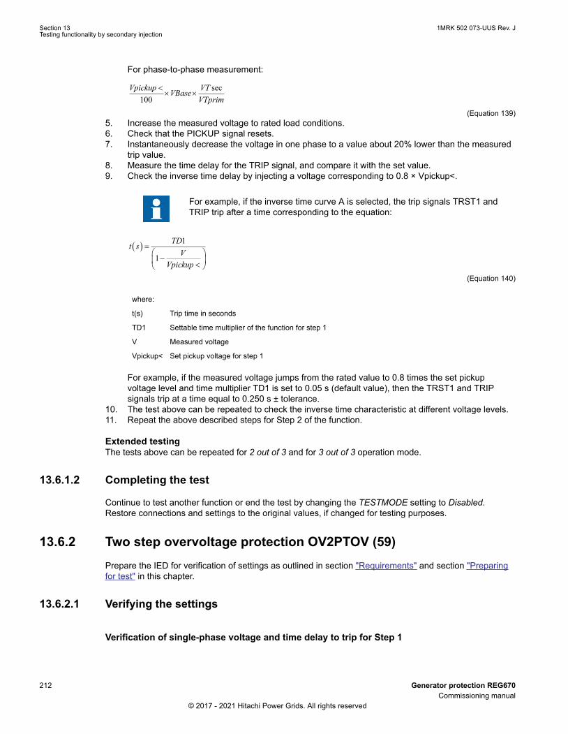
For phase-to-phase measurement:
sec100
Vpickup VTVBaseVTprim
<´ ´
ANSIEQUATION2431 V1 EN-US (Equation 139)5. Increase the measured voltage to rated load conditions.6. Check that the PICKUP signal resets.7. Instantaneously decrease the voltage in one phase to a value about 20% lower than the measured
trip value.8. Measure the time delay for the TRIP signal, and compare it with the set value.9. Check the inverse time delay by injecting a voltage corresponding to 0.8 × Vpickup<.
For example, if the inverse time curve A is selected, the trip signals TRST1 andTRIP trip after a time corresponding to the equation:
( ) 1
1
TDt sV
Vpickup
=æ ö
-ç ÷<è øANSIEQUATION2428 V1 EN-US (Equation 140)
where:
t(s) Trip time in seconds
TD1 Settable time multiplier of the function for step 1
V Measured voltage
Vpickup< Set pickup voltage for step 1
For example, if the measured voltage jumps from the rated value to 0.8 times the set pickupvoltage level and time multiplier TD1 is set to 0.05 s (default value), then the TRST1 and TRIPsignals trip at a time equal to 0.250 s ± tolerance.
10. The test above can be repeated to check the inverse time characteristic at different voltage levels.11. Repeat the above described steps for Step 2 of the function.
Extended testingM13796-35 v8
The tests above can be repeated for 2 out of 3 and for 3 out of 3 operation mode.
13.6.1.2 Completing the testM13796-25 v5
Continue to test another function or end the test by changing the TESTMODE setting to Disabled.Restore connections and settings to the original values, if changed for testing purposes.
13.6.2 Two step overvoltage protection OV2PTOV (59)M13806-2 v6
Prepare the IED for verification of settings as outlined in section "Requirements" and section "Preparingfor test" in this chapter.
13.6.2.1 Verifying the settingsM13806-9 v2
Verification of single-phase voltage and time delay to trip for Step 1M13806-50 v10
Section 13 1MRK 502 073-UUS Rev. JTesting functionality by secondary injection
212 Generator protection REG670Commissioning manual
© 2017 - 2021 Hitachi Power Grids. All rights reserved
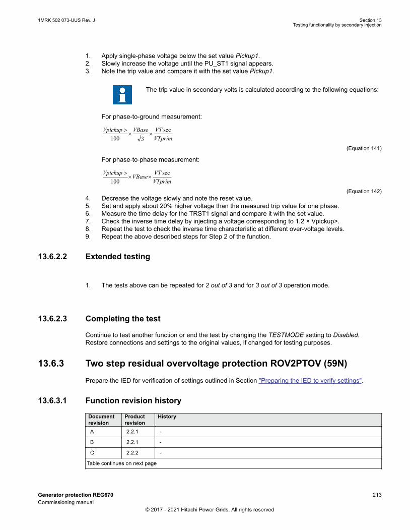
1. Apply single-phase voltage below the set value Pickup1.2. Slowly increase the voltage until the PU_ST1 signal appears.3. Note the trip value and compare it with the set value Pickup1.
The trip value in secondary volts is calculated according to the following equations:
For phase-to-ground measurement:
sec100 3
Vpickup VBase VTVTprim
>´ ´
ANSIEQUATION2426 V1 EN-US (Equation 141)
For phase-to-phase measurement:
sec100
Vpickup VTVBaseVTprim
>´ ´
ANSIEQUATION2427 V1 EN-US (Equation 142)4. Decrease the voltage slowly and note the reset value.5. Set and apply about 20% higher voltage than the measured trip value for one phase.6. Measure the time delay for the TRST1 signal and compare it with the set value.7. Check the inverse time delay by injecting a voltage corresponding to 1.2 × Vpickup>.8. Repeat the test to check the inverse time characteristic at different over-voltage levels.9. Repeat the above described steps for Step 2 of the function.
13.6.2.2 Extended testingGUID-BE4B4A36-CCEE-4020-B7DC-6A83A43D11F5 v2
1. The tests above can be repeated for 2 out of 3 and for 3 out of 3 operation mode.
13.6.2.3 Completing the testM13806-43 v6
Continue to test another function or end the test by changing the TESTMODE setting to Disabled.Restore connections and settings to the original values, if changed for testing purposes.
13.6.3 Two step residual overvoltage protection ROV2PTOV (59N)SEMOD54358-3 v7
Prepare the IED for verification of settings outlined in Section "Preparing the IED to verify settings".
13.6.3.1 Function revision historyGUID-22110E0B-DEFB-461F-A437-4D221DB88799 v2
Documentrevision
Productrevision
History
A 2.2.1 -
B 2.2.1 -
C 2.2.2 -
Table continues on next page
1MRK 502 073-UUS Rev. J Section 13Testing functionality by secondary injection
Generator protection REG670 213Commissioning manual
© 2017 - 2021 Hitachi Power Grids. All rights reserved

Documentrevision
Productrevision
History
D 2.2.3 -
E 2.2.3 -
F 2.2.4 -
H 2.2.4 -
J 2.2.5 -
13.6.3.2 Verifying the settingsSEMOD54358-35 v11
1. Apply a single-phase voltage either to a single-phase voltage input or to a residual voltage inputwith the pickup value below the set value Pickup1.
2. Slowly increase the value until PU_ST1 appears.3. Note the trip value and compare it with the set value.4. Decrease the voltage slowly and note the reset value.5. Set and apply a 20% higher voltage than the measured trip value for one phase.6. Measure the time delay for the TRST1 signal and compare it with the set value.7. Check the inverse time delay by injecting a voltage corresponding to 1.2 × Vpickup>.
For example, if the inverse time curve A is selected, the trip signals TRST1 andTRIP trip after a time corresponding to the equation:
t sk
U
U
( ) =
>−
1
11
IECEQUATION2429 V1 EN-US (Equation 143)
( ) 1
1
TDt sV
Vpickup
=æ ö
-ç ÷>è øANSIEQUATION2429 V1 EN-US (Equation 144)
where:
t(s) Trip time in seconds
TD1 Settable time multiplier of the function for step 1
V Measured voltage
Vpickup> Set pickup voltage for step 1
For example, if the measured voltage jumps from 0 to 1.2 times the set pickup voltage level andtime multiplier TD1 is set to 0.05 s (default value), then the TRST1 and TRIP signals trip at a timeequal to 0.250 s ± tolerance.
8. Repeat the test for Step 2 of the function.
13.6.3.3 Completing the testSEMOD54358-38 v4
Continue to test another function or end the test by changing the TESTMODE setting to Disabled.Restore connections and settings to the original values, if changed for testing purposes.
Section 13 1MRK 502 073-UUS Rev. JTesting functionality by secondary injection
214 Generator protection REG670Commissioning manual
© 2017 - 2021 Hitachi Power Grids. All rights reserved

13.6.4 Overexcitation protection OEXPVPH (24)M6583-45 v5
Prepare the IED for verification of settings outlined in Section "Preparing the IED to verify settings".
13.6.4.1 Verifying the settingsM6583-49 v4
1. Enable function.2. Connect a symmetrical three-phase voltage input from the test set to the appropriate connection
terminals of the overexcitation protection OEXPVPH (24) is configured for a three-phase voltageinput.A single-phase injection voltage is applied if the function is configured for a phase-to-phase voltageinput.OEXPVPH (24) is conveniently tested using rated frequency for the injection voltage and increasingthe injection voltage to get the desired overexcitation level.
3. Connect the alarm contact to the timer and set the time delay tAlarm temporarily to zero.4. Increase the voltage and note the operate value Pickup1.5. Reduce the voltage slowly and note the reset value.6. Set the alarm time delay to the correct value according to the setting plan and check the time delay,
injecting a voltage corresponding to 1.2 · Pickup1.7. Connect a trip output contact to the timer and temporarily set the time delay t_MinTripDelay to 0.5s.8. Increase the voltage and note the Pickup2 operate value9. Reduce the voltage slowly and note the reset value.10. Set the time delay to the correct value according to the setting plan and check the time delay
t_MinTripDelay, injecting a voltage corresponding to 1.2 · Pickup2.11. Check that trip and alarm contacts operate according to the configuration logic.12. Set the cooling time constant temporarily to min value (1min.) to quickly lower the thermal content.13. Wait for a period equal to 6 times t_CoolingK switch 20 minutes on a voltage 1.15 · Pickup1 and
check the inverse operate time.Wait until the thermal memory is emptied, set the cooling time constant according to the settingplan and check another point on the inverse time curve injecting a voltage 1.3 · Pickup1.
14. Finally check that PICKUP and TRIP information is stored in the event menu.
13.6.4.2 Completing the testM6583-85 v4
Continue to test another function or end the test by changing the TESTMODE setting to Disabled.Restore connections and settings to the original values, if changed for testing purposes.
13.6.5 Voltage differential protection VDCPTOV (60)SEMOD175258-3 v2
Prepare the IED for verification of settings as outlined in section "Requirements" and section "Preparingfor test" in this chapter.
1MRK 502 073-UUS Rev. J Section 13Testing functionality by secondary injection
Generator protection REG670 215Commissioning manual
© 2017 - 2021 Hitachi Power Grids. All rights reserved

13.6.5.1 Function revision historyGUID-04679E4E-E0D2-4BA6-A002-4020E52DB973 v1
Documentrevision
Productrevision
History
A 2.2.1 -
B 2.2.1 -
C 2.2.2 -
D 2.2.3 -
E 2.2.3 -
F 2.2.4 -
H 2.2.4 -
J 2.2.5 -
13.6.5.2 Check of undervoltage levelsSEMOD175258-71 v2
This test is relevant if the setting BlkDiffAtVLow = Yes.
Check of V1LowSEMOD175258-75 v3
Procedure
1. Connect voltages to the IED according to valid connection diagram and figure 62.2. Apply voltage higher than the highest set value of VDTrip, V1Low and V2Low to the V1 three-phase
inputs and to one phase of the V2 inputs according to figure 62.The voltage differential PICKUP signal is set.
Section 13 1MRK 502 073-UUS Rev. JTesting functionality by secondary injection
216 Generator protection REG670Commissioning manual
© 2017 - 2021 Hitachi Power Grids. All rights reserved

VA
VB
VC
VN
VA
VAVBVC
IED
TES
T SE
T
IED
ANSI07000106-1-en.vsd
VB
VC
VN
1
2
ANSI07000106 V2 EN-US
Figure 62: Connection of the test set to the IED for test of V1 block level
where:
1 is three-phase voltage group1 (V1)
2 is three-phase voltage group2 (V2)
3. Decrease slowly the voltage in phase VA of the test set until the PICKUP signal resets.4. Check V1 blocking level by comparing the voltage level at reset with the set undervoltage blocking
V1Low.5. Repeat steps 2 to 4 to check V1Low for the other phases.
The connections to V1 must be shifted to test another phase. (VA to VB, VB to VC,VC to VA)
Check of V2LowSEMOD175258-91 v3
Procedure
1. Connect voltages to the IED according to valid connection diagram and figure 63.
1MRK 502 073-UUS Rev. J Section 13Testing functionality by secondary injection
Generator protection REG670 217Commissioning manual
© 2017 - 2021 Hitachi Power Grids. All rights reserved

VA
VB
VC
VN
VA
VAVBVC
IED
TES
T SE
T
IED
ANSI07000107-1-en.vsd
VB
VC
VN
1
2
ANSI07000107 V2 EN-US
Figure 63: Connection of the test set to the IED for test of V2 block level
where:
1 is three-phase voltage group1 (V1)
2 is three-phase voltage group2 (V2)
2. Apply voltage higher than the highest set value of VDTrip, V1Low and V2Low to the V1 three-phaseinputs and to one phase of the V2 inputs according to figure 63.The voltage differential PICKUP signal is set.
3. Decrease slowly the voltage in phase VC of the test set until the PICKUP signal resets.4. Check V2 blocking level by comparing the voltage level at reset with the set undervoltage blocking
V2Low.
13.6.5.3 Check of voltage differential trip and alarm levelsSEMOD175258-104 v3
Procedure
1. Connect voltages to the IED according to valid connection diagram and figure 64.
Section 13 1MRK 502 073-UUS Rev. JTesting functionality by secondary injection
218 Generator protection REG670Commissioning manual
© 2017 - 2021 Hitachi Power Grids. All rights reserved

VA
VB
VC
VN
VA
VAVBVC
IED
TES
T SE
T
IED
ANSI07000108-1-en.vsd
VB
VC
VN
1
2
ANSI07000108 V2 EN-US
Figure 64: Connection of the test set to the IED for test of alarm levels, trip levels and triptimer
where:
1 is three-phase voltage group1 (V1)
2 is three-phase voltage group2 (V2)
2. Apply 1.2 · Vn (rated voltage) to the V1 and V2 inputs.3. Decrease slowly the voltage of in phase VA of the test set until the ALARM signal is activated.
The ALARM signal is delayed with timer tAlarm
4. Check the alarm operation level by comparing the differential voltage level at ALARM with the setalarm level VDAlarm.
5. Continue to slowly decrease the voltage until PICKUP signal is activated.6. Check the differential voltage operation level by comparing the differential voltage level at PICKUP
with the set trip level VDTrip.7. Repeat steps 1 to 6 to check the other phases.
Observe that the connections to V1 must be shifted to test another phase. (VA to VB, VB to VC, VCto VA)
13.6.5.4 Check of trip and trip reset timersSEMOD175258-124 v2
Procedure
1. Connect voltages to the IED according to valid connection diagram and figure 64.2. Set Vn (rated voltage) to the V1 inputs and increase V2 voltage until the differential voltage is 1.5 ·
operating level (VDTrip).3. Switch on the test set. Measure the time from activation of the PICKUP signal until TRIP signal is
activated.
1MRK 502 073-UUS Rev. J Section 13Testing functionality by secondary injection
Generator protection REG670 219Commissioning manual
© 2017 - 2021 Hitachi Power Grids. All rights reserved
4. Check the measured time by comparing it to the set trip time tTrip.5. Increase the voltage until PICKUP signal resets. Measure the time from reset of PICKUP signal to
reset of TRIP signal.6. Check the measured time by comparing it to the set trip reset time tReset.
13.6.5.5 Final adjustment of compensation for VT ratio differencesSEMOD175258-183 v2
Procedure
1. With the protection in test mode, view the differential voltage service values in each phase on thelocal HMI under Main menu /Test /Function status /Voltage protection /VoltageDiff(PTOV,60) /VDCPTOV:x .
The IED voltage inputs should be connected to the VTs according to validconnection diagram.
2. Record the differential voltages.3. Calculate the compensation factor RF_x for each phase.
For information about calculation of the compensation factor, see the application manual.4. Set the compensation factors on the local HMI under Main menu /Settings /Settings group N /
Voltage protection /VoltageDiff(PTOV,60) /VDCPTOV:x5. Check that the differential voltages are close to zero.
13.6.5.6 Completing the testSEMOD175258-208 v2
Continue to test another function or end the test by changing the TESTMODE setting to Disabled.Restore connections and settings to the original values, if changed for testing purposes.
13.6.6 100% Stator ground fault protection, 3rd harmonic basedSTEFPHIZ (59THD)
SEMOD158990-3 v4
Prepare the IED for verification of settings outlined in Section "Preparing the IED to verify settings".
13.6.6.1 TestingSEMOD158990-8 v3
The protection function uses measurement of the third-harmonic voltages in the neutral point of thegenerator and on the generator terminal (broken delta voltage transformer connection to the IED).
The test set shall be capable to generate third-harmonic voltages. One voltage (VN3) is connected to theresidual voltage input related to the terminal side of the generator. The second voltage (VN3) is connectedto the voltage input related to the neutral of the generator. The angle between the injected third-harmonicvoltages shall be adjustable.
Section 13 1MRK 502 073-UUS Rev. JTesting functionality by secondary injection
220 Generator protection REG670Commissioning manual
© 2017 - 2021 Hitachi Power Grids. All rights reserved

en07000127_ansi.vsd
V3N
V3T
ANSI07000127 V1 EN-US
Figure 65: Typical phasor diagram for third harmonic voltages for healthy machine
1. Inject the following voltages: V3T = 15 V, V3N = 5 V and the angle between the voltages = 180°.Check the monitored values of the following analogue signals: E3 (the magnitude of the third-harmonic induced voltage in the stator), V3N: 5 V (the magnitude of the third-harmonic voltagemeasured at the neutral side of the generator), V3T: 15 V (the magnitude of the third-harmonicvoltage measured at the terminal side of the generator) and ANGLE: 180° (the angle between thethird-harmonic voltage phasors V3N and V3T). The value of E3 should be close to the followingvalue:
( ) ( )2 23N 3T 3TE3 V V cos(ANGLE) V sin(ANGLE)= - × + ×
EQUATION2073-ANSI V1 EN-US (Equation 145)
2. Read the value of DV (differential voltage). The value of DV should be close to the following value:
( ) ( )2 23N 3T 3TDU V V cos(ANGLE) V sin(ANGLE)= + × + ×
EQUATION2074-ANSI V1 EN-US (Equation 146)
3. Decrease the value of the injected voltage V3N until the signal PICKUP3H is activated. Check that
3N
DV BetaV
=
EQUATION2331-ANSI V1 EN-US (Equation 147)
considering stated accuracy (beta is a setting parameter)4. Increase the voltage V3N so that the pickup signal falls. After that, switch the voltage V3N to zero
and measure the time delay for the activation of the signals TRIP and TRIP3H.The 100% stator ground fault protection also has a fundamental frequency neutral pointovervoltage function (95% stator ground fault protection). This part of the protection can be testedseparately by means of fundamental frequency voltage injection from a test equipment.
13.6.6.2 Verifying settingsSEMOD158990-144 v3
1. With the generator rotating at rated speed but not connected: check the value of the followinganalogue signals: E3 (the magnitude of the 3rd harmonic induced voltage in the stator), V3N (themagnitude of the third-harmonic voltage measured at the neutral side of the generator), V3T (the
1MRK 502 073-UUS Rev. J Section 13Testing functionality by secondary injection
Generator protection REG670 221Commissioning manual
© 2017 - 2021 Hitachi Power Grids. All rights reserved

magnitude of the third-harmonic voltage measured at the terminal side of the generator) andANGLE (the angle between the third-harmonic voltage phasors V3N and V3T). The value of E3should be close to the following value:
( ) ( )2 23N 3T 3TE3 V V cos(ANGLE) V sin(ANGLE)= - × + ×
EQUATION2077-ANSI V1 EN-US (Equation 148)
Make sure that ANGLE has a value bigger than 125°2. Read the value of DV (differential voltage). The value of DV should be close to the following value:
( ) ( )2 23N 3T 3TDV V V cos(ANGLE) V sin(ANGLE)= + × + ×
EQUATION2079-ANSI V1 EN-US (Equation 149)
3. Read the value of BV (bias voltage: Beta ·V3N). The ratio DV/BV should be well below 1 for a non-faulted generator.
4. After synchronization of the generator the ratio DV/BV is checked for different load levels of thegenerator. These different monitoring of load levels should be the base for the setting of beta.If the function is used with the option of neutral point measurement only the test is performed bycheck of this voltage. The operate value should be above the measured residual third-harmonicvoltage in the neutral point at normal operation (non-faulted generator).
13.6.6.3 Completing the testSEMOD158990-34 v3
Continue to test another function or end the test by changing the TESTMODE setting to Disabled.Restore connections and settings to the original values, if changed for testing purposes.
13.7 Frequency protectionSEMOD53547-1 v1
13.7.1 Underfrequency protection SAPTUF (81)M16289-2 v7
Prepare the IED for verification of settings outlined in Section "Preparing the IED to verify settings".
13.7.1.1 Verifying the settingsM16289-15 v3
Verification of PICKUP value and time delay to tripM16289-17 v7
1. Check that the IED settings are appropriate, for example the pickup value and the time delay.2. Supply the IED with three-phase voltages at their rated values and initial frequency.
The initial frequency is calculated using Equation 150.
0.02 / 0.04 0.04rStartFrequency floor f StartFrequency
IECEQUATION16059 V1 EN-US (Equation 150)3. Slowly decrease the voltage frequency bysteps of 40 mHz until the TRIP signal appears; during
each step apply the voltage signal for a time that is either at least 10% longer than (tDelay+100ms)or a suitable time to monitor the function.
4. Note the frequency value at which the START signal appears and compare it with the set valueStartFrequency.
Section 13 1MRK 502 073-UUS Rev. JTesting functionality by secondary injection
222 Generator protection REG670Commissioning manual
© 2017 - 2021 Hitachi Power Grids. All rights reserved

5. Note the frequency value at which the TRIP signal appears and compare it with the set valueStartFrequency.
6. Increase the frequency until its rated value is reached.7. Check that the PICKUP signal resets.8. Supply the IED with three-phase voltages at their rated values and frequency 20 mHz over the set
value StartFrequency.9. Decrease the frequency with a 40 mHz step, applying it for a time that is at least 10% longer than
(tDelay+100ms).10. Measure the time delay of the TRIP signal, and compare it with the set value tDelay. Note that the
measured time consists of the set value of the time delay plus the minimum trip time of the pickupstart function (80 - 90 ms).
Extended testingM16289-31 v6
1. The test above can be repeated to check the time to reset.2. The tests above can be repeated to test the frequency dependent inverse time characteristic.
Verification of the low voltage magnitude blockingM16289-39 v7
1. Check that the IED settings are appropriate, for example the PUFrequency, VMin, and the tDelay.2. Supply the IED with three-phase voltages at rated values.3. Slowly decrease the magnitude of the applied voltage, until the BLKDMAGN signal appears.4. Note the voltage magnitude value and compare it with the set value VMin.5. Slowly decrease the frequency of the applied voltage, to a value below PUFrequency.6. Check that the PICKUP signal does not appear.7. Wait for a time corresponding to tDelay, make sure that the TRIP signal does not appear.
13.7.1.2 Completing the testM16289-57 v5
Continue to test another function or end the test by changing the TESTMODE setting to Disabled.Restore connections and settings to the original values, if changed for testing purposes.
13.7.2 Overfrequency protection SAPTOF (81)M16290-2 v7
Prepare the IED for verification of settings outlined in Section "Preparing the IED to verify settings".
13.7.2.1 Verifying the settingsM16290-12 v2
Verification of PICKUP value and time delay to tripM16290-14 v6
1. Check that the IED settings are appropriate, for example the pickup value and the time delay.2. Supply the IED with three-phase voltages at their rated values and initial frequency.3. Slowly increase the frequency of the applied voltage with a 40 mHz step, applying it for a period
that is 10% longer than tDelay.4. Note the trip value and compare it with the set value.5. Decrease the frequency to rated operating conditions.6. Check that the PICKUP signal resets.
1MRK 502 073-UUS Rev. J Section 13Testing functionality by secondary injection
Generator protection REG670 223Commissioning manual
© 2017 - 2021 Hitachi Power Grids. All rights reserved

7. Set the frequency to 20 mHz under the trip value.8. Increase the frequency with a 40 mHz step, applying it for a period that is 10% longer than tDelay.9. Measure the time delay for the TRIP signal, and compare it with the set value. Note that the
measured time consists of the set value for time delay plus minimum trip time of the pickup function(80 - 90 ms).
Extended testingM16290-28 v4
1. The test above can be repeated to check the time to reset.
Verification of the low voltage magnitude blockingM16290-34 v6
1. Check that the settings in the IED are appropriate, for example the PUFrequency and the tDelay.2. Supply the IED with three-phase voltages at their rated values.3. Slowly decrease the magnitude of the applied voltage, until the BLKDMAGN signal appears.4. Note the voltage magnitude value and compare it with the set value.5. Slowly increase the frequency of the applied voltage, to a value above PUFrequency.6. Check that the PICKUP signal does not appear.7. Wait for a time corresponding to tDelay, make sure that the TRIP signal does not appear.
13.7.2.2 Completing the testM16290-52 v5
Continue to test another function or end the test by changing the TESTMODE setting to Disabled.Restore connections and settings to the original values, if changed for testing purposes.
13.7.3 Rate-of-change frequency protection SAPFRC (81)M16256-2 v6
Prepare the IED for verification of settings as outlined in section "Requirements" and section "Preparingfor test" in this chapter.
13.7.3.1 Verifying the settingsM16256-8 v1
PICKUP value and time delay to tripM16256-10 v5
1. Check that the settings in the IED are appropriate, especially the PICKUP value and the definitetime delay. Set PickupFreqgrad, to a rather small negative value.
2. Supply the IED with three-phase voltages at their rated values.3. Slowly decrease the frequency of the applied voltage, with an increasing rate-of-change that finally
exceeds the setting of PickupFreqgrad, and check that the PICKUP signal appears.4. Note the trip value and compare it with the set value.5. Increase the frequency to rated operating conditions, and zero rate-of-change.6. Check that the PICKUP signal resets.7. Instantaneously decrease the frequency of the applied voltage to a value about 20% lower than the
nominal value.8. Measure the time delay for the TRIP signal, and compare it with the set value.
Extended testingM16256-29 v4
Section 13 1MRK 502 073-UUS Rev. JTesting functionality by secondary injection
224 Generator protection REG670Commissioning manual
© 2017 - 2021 Hitachi Power Grids. All rights reserved

1. The test above can be repeated to check a positive setting of PickupFreqGrad.2. The tests above can be repeated to check the time to reset.3. The tests above can be repeated to test the RESTORE signal, when the frequency recovers from a
low value.
13.7.3.2 Completing the testM16256-39 v4
Continue to test another function or end the test by changing the TESTMODE setting to Disabled.Restore connections and settings to the original values, if changed for testing purposes.
13.7.4 Frequency time accumulation protection function FTAQFVR (81A)GUID-F7BD8E10-EF88-4698-87F4-0D4365004705 v2
Prepare the IED for verification of settings as outlined in section “Overview” and section “Preparing fortest” in this chapter.
13.7.4.1 Verifying the settingsGUID-864636E0-6399-44E1-BD2C-C2113FB78C61 v3
Time measurement and the injection of current and voltage can be done using a common testequipment.
Verification of the PICKUP value and time delay to trip1. Connect the test set for the injection of three-phase currents and three-phase voltages to the
appropriate current and voltage terminals of the IED.2. Ensure that the settings in the IED are appropriate, especially the PickupCurrentLevel,
FreqHighLimit, FreqLowLimit, VHighLimit and VLowLimit setting.3. Supply the IED with three-phase currents and voltages at their rated value.4. Slowly decrease the frequency of the applied voltage until it crosses the frequency high limit and the
BFI_3P signal appears.5. Check that the FREQOK signal appears.6. Compare the trip value to the set frequency high limit value.7. Decrease the frequency of the applied voltage until it crosses the frequency low limit and the BFI_3P
signal disappears.8. Check that the FREQOK signal disappears.9. Compare the reset value to the set frequency low limit value.10. Readjust the frequency of the applied voltage (with steps of 0.001 Hz/s) to a value within the set
frequency band limit.11. Ensure that the BFI_3P signal reappears.12. Wait for a time corresponding to tCont and ensure that the TRIP and TRIPCONT signals are
generated.13. Measure the time delay for the TRIP signal and compare it to the set value.
Verification of the ACCALARM value and time delay to trip1. Connect the test set for the injection of three-phase currents and three-phase voltages to the
appropriate current and voltage terminals of the IED.2. Ensure that the settings in the IED are appropriate for the default settings, especially the
PickupCurrentLevel, FreqHighLimit, FreqLowLimit, VHighLimit and VLowLimit setting.3. Supply the IED with three-phase currents and voltages at their rated value.4. Slowly decrease the frequency of the applied voltage until it crosses the frequency high limit and the
BFI_3P signal appears.
1MRK 502 073-UUS Rev. J Section 13Testing functionality by secondary injection
Generator protection REG670 225Commissioning manual
© 2017 - 2021 Hitachi Power Grids. All rights reserved

5. Continuously change the frequency of the applied voltage, so that for a certain time the frequency isoutside the set band limit and falls gradually within the band limit.
6. Count only the time when the frequency lies within the set frequency band limit. Wait for a timecorresponding to tAccLimit and ensure that the ACCALARM signal appears.
7. Measure the time delay for the ACCALARM signal and compare it to the set value.
Extended testing1. To check the value of TRIPACC, repeat the above test case in such a way that the frequency of the
applied voltage is within the set frequency band when time approaches the tAccLimit setting value.
Verification of generator start and stop logic1. Ensure that the settings in the IED are appropriate to the default settings, especially the
PickupCurrentLevel, FreqHighLimit, FreqLowLimit, VHighLimit and VLowLimit.2. Ensure that the setting CBCheck is enabled.3. Supply the IED with three-phase currents and voltages at their rated values.4. Slowly decrease the frequency of the applied voltage until the BFI_3P signal appears.5. Activate the CBOPEN input signal.6. Slowly decrease the injected current below the PickupCurrentLevel value until the BFI_3P signal
disappears.7. Compare the current magnitude value to the set value.
Verification of voltage band limit check logic1. Ensure that the settings in the IED are appropriate to the default settings, especially the
PickupCurrentLevel, FreqHighLimit, FreqLowLimit, VHighLimit and VLowLimit settings.2. Ensure that the EnaVoltCheck is enabled.3. Supply the IED with three-phase currents and voltages at their rated values.4. Check that the VOLTOK signal appears.5. Slowly decrease the frequency of the applied voltage until the BFI_3P signal appears.6. Slowly decrease the positive-sequence voltage of the injected voltage below the VLowLimit value
until the BFI_3P signal disappears.7. Check that the VOLTOK signal disappears.8. Compare the reset value to the set voltage low limit value.9. Readjust the positive-sequence voltage of the applied voltage to a value within the set voltage band
limits.10. Check that the BFI_3P signal reappears.11. Slowly increase the positive-sequence voltage of the injected voltage above the VUHighLimit value
until the BFI_3P signal disappears.12. Compare the reset value to the set voltage high limit value.
13.7.4.2 Completing the testGUID-83C3F041-9553-4804-9A39-B3E46A5C9AE6 v2
• Continue to test another function or end the test by changing the Test mode setting to Disabled.• Restore connections and settings to their original values if they were changed for testing purposes.
Section 13 1MRK 502 073-UUS Rev. JTesting functionality by secondary injection
226 Generator protection REG670Commissioning manual
© 2017 - 2021 Hitachi Power Grids. All rights reserved

13.8 Multipurpose protectionSEMOD53552-1 v1
13.8.1 Function revision historyGUID-74F9B9A9-91EB-45BA-A883-6BA325C8B272 v1
Documentrevision
Productrevision
History
A 2.2.1 -
B 2.2.1 -
C 2.2.2 -
D 2.2.3 -
E 2.2.3 -
F 2.2.4 -
G 2.2.4 -
H 2.2.4 -
J 2.2.5 • The harmonic restraint function changed to freeze the definite and IDMT timers.• The maximum value of the settings IMin1 and IMin2 has been decreased to 1000.0 %
of IBase.• Setting BlkLevel2nd was removed from the function.• Previously called stepwise settings t_DefOCx and tResetDef_OCx had their names
changed to t_OCx and tReset_OCx for more clear understanding.
13.8.2 General current and voltage protection CVGAPCSEMOD56488-3 v4
Prepare the IED for verification of settings as outlined in section "Requirements" and section "Preparingfor test" in this chapter.
One of the facilities within the general current and voltage protection function CVGAPC is that the value,which is processed and used for evaluation in the function, can be chosen in many different ways by thesetting parameters CurrentInput and VoltageInput.
These setting parameters decide what kind of preprocessing the connected three-phase CT and VTinputs shall be subjected to. That is, for example, single-phase quantities, phase-to-phase quantities,positive sequence quantities, negative sequence quantities, maximum quantity from the three-phasegroup, minimum quantity from the three-phase group, difference between maximum and minimumquantities (unbalance) can be derived and then used in the function.
Due to the versatile possibilities of CVGAPC itself, but also the possibilities of logic combinations in theapplication configuration of outputs from more than one CVGAPC function block, it is hardly possible todefine a fully covering general commissioning test.
13.8.2.1 Built-in overcurrent feature (non-directional)SEMOD56488-9 v5
Procedure
1MRK 502 073-UUS Rev. J Section 13Testing functionality by secondary injection
Generator protection REG670 227Commissioning manual
© 2017 - 2021 Hitachi Power Grids. All rights reserved

1. Go to Main menu /Test /Function test modes /Multipurpose protection /GeneralCurrentVoltage(GAPC) /CVGAPC:x and make sure that CVGAPC to be tested isunblocked and other functions that might disturb the evaluation of the test are blocked.
2. Connect the test set for injection of three-phase currents to the appropriate current terminals of theIED.
3. Inject current(s) in a way that relevant measured current (according to setting parameterCurrentInput) is created from the test set. Increase the current(s) until the low set stage trips andcheck against the set trip value.
4. Decrease the current slowly and check the reset value.5. Block high set stage if the injection current will activate the high set stage when testing the low set
stage according to below.6. Connect a TRIP output contact to the timer.7. Set the current to 200% of the trip value of low set stage, switch on the current and check the time
delay.For inverse time curves, check the trip time at a current equal to 110% of the trip current att_MinTripDelay.
8. Check that TRIP and PICKUP contacts trip according to the configuration logic.9. Release the blocking of the high set stage and check the trip and reset value and the time delay for
the high set stage in the same way as for the low set stage.10. Finally check that PICKUP and TRIP information is stored in the event menu.
Information on how to use the event menu is found in the operator's manual.
13.8.2.2 Overcurrent feature with current restraintSEMOD56488-35 v3
The current restraining value has also to be measured or calculated and the influence on the operationhas to be calculated when the testing of the trip value is done.
Procedure
1. Trip value measurementThe current restraining value has also to be measured or calculated and the influence on theoperation has to be calculated when the testing of the trip value is done.
13.8.2.3 Overcurrent feature with voltage restraintSEMOD56488-44 v5
Procedure
1. Connect the test set for injection of three-phase currents and three-phase voltages to theappropriate current and voltage terminals of the IED.
2. Inject current(s) and voltage(s) in a way that relevant measured (according to setting parameterCurrentInput and VoltageInput) currents and voltages are created from the test set.Overall check in principal as above (non-directional overcurrent feature)
3. Trip value measurementThe relevant voltage restraining value (according to setting parameter VoltageInput) has also to beinjected from the test set and the influence on the trip value has to be calculated when testing ofthe trip value is done.
4. Trip time measurement
Section 13 1MRK 502 073-UUS Rev. JTesting functionality by secondary injection
228 Generator protection REG670Commissioning manual
© 2017 - 2021 Hitachi Power Grids. All rights reserved

Definite times may be tested as above (non-directional overcurrent feature). For inverse timecharacteristics the PICKUP value (to which the overcurrent ratio has to be calculated) is the actualpickup value as got with actual restraining from the voltage restraining quantity.
13.8.2.4 Overcurrent feature with directionalitySEMOD56488-60 v5
Please note that the directional characteristic can be set in two different ways either just dependent onthe angle between current and polarizing voltage (setting parameter DirPrinc_OC1 or DirPrinc_OC2 setto or in a way that the trip value also is dependent on the angle between current and polarizing voltageaccording to the I · cos(F) law (setting parameter DirPrinc_OC1 or DirPrinc_OC2 set to I · cos(F). Thishas to be known if a more detailed measurement of the directional characteristic is made, than the onedescribed below.
Procedure
1. Connect the test set for injection of three-phase currents and three-phase voltages to theappropriate current and voltage terminals of the IED.
2. Inject current(s) and voltage(s) in a way that relevant measured (according to setting parameterCurrentInput and VoltageInput) currents and voltages are created from the test set.
3. Set the relevant measuring quantity current to lag or lead (lag for negative RCA angle and lead forpositive RCA angle) the relevant polarizing quantity voltage by an angle equal to the set IEDcharacteristic angle (rca-dir) when forward directional feature is selected and the CTWYEpointconfiguration parameter is set to ToObject.If reverse directional feature is selected or CTWYEpoint configuration parameter is set toFromObject, the angle between current and polarizing voltage shall be set equal to rca-dir+180°.
4. Overall check in principal as above (non-directional overcurrent feature)5. Reverse the direction of the injection current and check that the protection does not trip.6. Check with low polarization voltage that the feature becomes non-directional, blocked or with
memory according to the setting.
13.8.2.5 Over/Undervoltage featureSEMOD56488-83 v2
Procedure
1. Connect the test set for injection three-phase voltages to the appropriate voltage terminals of theIED.
2. Inject voltage(s) in a way that relevant measured (according to setting parameter VoltageInput)voltages are created from the test set.
3. Overall check in principal as above (non-directional overcurrent feature) and correspondingly forthe undervoltage feature.
13.8.2.6 Completing the testSEMOD56488-99 v2
Continue to test another function or end the test by changing the TESTMODE setting to Disabled.Restore connections and settings to the original values, if changed for testing purposes.
1MRK 502 073-UUS Rev. J Section 13Testing functionality by secondary injection
Generator protection REG670 229Commissioning manual
© 2017 - 2021 Hitachi Power Grids. All rights reserved

13.9 Secondary system supervisionSEMOD53556-1 v1
13.9.1 Current circuit supervision CCSSPVC (87)M12917-25 v8
Prepare the IED for verification of settings outlined in Section "Preparing the IED to verify settings".
The Current circuit supervision function CCSSPVC (87) is conveniently tested with the same three-phasetest set as used when testing the measuring functions in the IED.
The condition for this procedure is that the setting of IMinOp is lower than the setting of Pickup_Block.
13.9.1.1 Verifying the settingsM12917-31 v8
1. Check the input circuits and the trip value of the IMinOp current level detector by injecting current,one phase at a time.
2. Check the phase current blocking function for all three phases by injecting current, one phase at atime. The output signals shall reset with a delay of 1 second when the current exceeds 1.5 · IBase.
3. Inject a current 0.1 · IBase to the reference current input Analogue channel ID current input 5.4. Increase slowly the current in one of the phases and check that FAIL output is obtained when the
current is above 0.9 · IBase.
13.9.1.2 Completing the testM12917-43 v4
Continue to test another function or end the test by changing the TESTMODE setting to Disabled.Restore connections and settings to the original values, if changed for testing purposes.
13.9.2 Fuse failure supervision FUFSPVCM1405-2 v8
Prepare the IED for verification of settings as outlined in section "Requirements" and section "Preparingfor test" in this chapter.
The verification is divided in two main parts. The first part is common to all fuse failure supervisionoptions, and checks that binary inputs and outputs trip as expected according to actual configuration. Inthe second part the relevant set trip values are measured.
13.9.2.1 Checking that the binary inputs and outputs trip as expectedM1405-9 v8
1. Simulate normal operating conditions with the three-phase currents in phase with theircorresponding phase voltages and with all of them equal to their rated values.
2. Connect the nominal dc voltage to the 89bS binary input.• The signal BLKV should appear with almost no time delay.• The signals BLKZ and 3PH should not appear on the IED.• Only the distance protection function can trip.• Undervoltage-dependent functions must not trip.
3. Disconnect the dc voltage from the 89b binary input terminal.4. Connect the nominal dc voltage to the MCBOP binary input.
Section 13 1MRK 502 073-UUS Rev. JTesting functionality by secondary injection
230 Generator protection REG670Commissioning manual
© 2017 - 2021 Hitachi Power Grids. All rights reserved

• The BLKVand BLKZ signals should appear without any time delay.• All undervoltage-dependent functions must be blocked.
5. Disconnect the dc voltage from the MCBOP binary input terminal.6. Disconnect one of the phase voltages and observe the logical output signals on the binary outputs
of the IED.BLKV and BLKZ signals should appear simultaneously wether the BLKV and BLKZ reset dependson the setting SealIn “on” or “off”. If “on” no reset, if “off” reset.
7. After more than 5 seconds disconnect the remaining two-phase voltages and all three currents.• There should be no change in the high status of the output signals BLKV and BLKZ.• The signal 3PH will appear.
8. Establish normal voltage and current operating conditions simultaneously and observe thecorresponding output signals.They should change to logical 0 as follows:• Signal 3PH after about 25ms• Signal BLKV after about 50ms• Signal BLKZ after about 200ms
13.9.2.2 Measuring the trip value for the negative sequence functionM1405-46 v12
Measure the trip value for the negative sequence function, if included in the IED.
1. Simulate normal operating conditions with the three-phase currents in phase with theircorresponding phase voltages and with all of them equal to their rated values.
2. Slowly decrease the measured voltage in one phase until the BLKV signal appears.3. Record the measured voltage and calculate the corresponding negative-sequence voltage
according to the equation (observe that the voltages in the equation are phasors):
223 A B CV V a V a V× = + × + ×
EQUATION1818-ANSI V1 EN-US (Equation 151)
Where:
A B CandV V VEQUATION1820-ANSI V1 EN-US
are the measured phase voltages
2
33
1 0, 52
j
a e jp×
= × = - +.IECEQUATION00022 V2 EN-US
4. Compare the result with the set value of the negative-sequence operating voltage (consider that theset value 3V2PU is in percentage of the base voltage VBase).
5. Repeat steps 1 and 2. Then slowly increase the measured current in one phase until the BLKVsignal disappears.
6. Record the measured current and calculate the corresponding negative-sequence currentaccording to the equation (observe that the currents in the equation are phasors):
2
23 A B CI I a I a I× = + × + ×
ANSIEQUATION00021 V1 EN-US (Equation 152)
1MRK 502 073-UUS Rev. J Section 13Testing functionality by secondary injection
Generator protection REG670 231Commissioning manual
© 2017 - 2021 Hitachi Power Grids. All rights reserved

Where:
A B CI I and I , ANSIEQUATION00020 V1 EN-US
are the measured phase currents
2
33
1 0, 52
j
a e jp×
= × = - +.IECEQUATION00022 V2 EN-US
7. Compare the result with the set value of the negative-sequence operating current. Consider thatthe set value 3I2< is in percentage of the base current IBase.
13.9.2.3 Measuring the trip value for the zero-sequence functionM1405-72 v11
Measure the trip value for the zero-sequence function, if included in the IED.
1. Simulate normal operating conditions with the three-phase currents in phase with theircorresponding phase voltages and with all of them equal to their rated values.
2. Slowly decrease the measured voltage in one phase until the BLKV signal appears.3. Record the measured voltage and calculate the corresponding zero-sequence voltage according to
the equation (observe that the voltages in the equation are phasors):
03 A B CV V V V× = + +
EQUATION1819-ANSI V1 EN-US (Equation 153)
Where:
A B CandV V VEQUATION1820-ANSI V1 EN-US
are the measured phase voltages
4. Compare the result with the set value of the zero-sequence tripping voltage (consider that the setvalue 3V0Pickup is in percentage of the base voltage.)
5. Repeat steps 1 and 2. Then slowly increase the measured current in one phase until the BLKVsignal disappears.
6. Record the measured current and calculate the corresponding zero-sequence current according tothe equation (observe that the currents in the equation are phasors):
0 A B C3 =I I I I× + +ANSIEQUATION00019 V1 EN-US (Equation 154)
Where:
A B CI I and I , ANSIEQUATION00020 V1 EN-US
are the measured phase currents
7. Compare the result with the set value of the zero-sequence trip current. Consider that the set value3I0< is in percentage of the base current IBase.
13.9.2.4 Measuring the trip value for the dead line detection functionGUID-4ABF1FD4-F6D3-4109-AFE5-552875E558A0 v4
Section 13 1MRK 502 073-UUS Rev. JTesting functionality by secondary injection
232 Generator protection REG670Commissioning manual
© 2017 - 2021 Hitachi Power Grids. All rights reserved

1. Apply three-phase voltages with their rated value and zero currents.2. Decrease the measured voltage in one phase until the DLD1PH signal appears.3. This is the point at which the dead line condition is detected. Check the value of the decreased
voltage with the set value VDLDPU (VDLDPU is in percentage of the base voltage VBase).4. Apply three-phase currents with their rated value and zero voltages.5. Decrease the measured current in one phase until the DLD1PH signal appears.6. This is the point at which the dead line condition is detected. Check the value of the decreased
current with the set value IDLDPU (IDLDPU is in percentage of the base current IBase).
13.9.2.5 Checking the operation of the dv/dt and di/dt based functionM1405-96 v12
Check the operation of the dv/dt and di/dt based function if included in the IED.
1. Simulate normal operating conditions with the three-phase currents in phase with theircorresponding phase voltages and with all of them equal to their rated values.
2. Change the voltages and currents in all three phases simultaneously.The voltage change must be higher than the set value DVPU and the current change must be lowerthan the set value DIPU.• The BLKV and BLKZ signals appear without any time delay. The BLKZ signal will be
activated only if the internal deadline detection is not activated at the same time.• 3PH should appear after 5 seconds, if the remaining voltage levels are lower than the set
VDLDPU of the dead line detection function.3. Apply normal conditions as in step 1.
The BLKV, BLKZ and 3PH signals should reset, if activated, see step 1 and 2.4. Change the voltages and currents in all three phases simultaneously.
The voltage change must be higher than the set value DVPU and the current change must behigher than the set value DIPU.The BLKV, BLKZ and 3PH signals should not appear.
5. Repeat step 2.6. Connect the nominal voltages in all three phases and feed a current below the trip level in all three
phases.7. Keep the current constant. Disconnect the voltage in all three phases simultaneously.
The BLKV, BLKZ and 3PH signals should not appear.8. Change the magnitude of the voltage and current for phase 1 to a value higher than the set value
DVPU and DIPU.9. Check that the pickup output signals PU_DV_A and PU_DI_A and the general pickup signals
PU_DV or PU_DI are activated.10. Check that the pickup output signals for the current and voltage phases 2 and 3 are activated by
changing the magnitude of the voltage and current for phases 2 and 3.
13.9.2.6 Completing the testM1405-130 v5
Continue to test another function or end the test by changing the TESTMODE setting to Disabled.Restore connections and settings to the original values, if changed for testing purposes.
13.9.3 Fuse failure supervisionGUID-DCCD4C4A-8335-43BA-A2B2-9994380985B0 v2
Prepare the IED for verification of settings as outlined in section "Requirements" and section "Preparingfor test" in this chapter.
1MRK 502 073-UUS Rev. J Section 13Testing functionality by secondary injection
Generator protection REG670 233Commissioning manual
© 2017 - 2021 Hitachi Power Grids. All rights reserved

GUID-004BFFE4-B1C1-4C0E-8D7A-ABE7B566AB28 v2
Checking the operation of binary input and output1. Simulate normal operation conditions with three-phase voltage on the main fuse group and the pilot
fuse group. Ensure the values are equal to their rated values.2. Disconnect one of the phase voltage from the main fuse group or the pilot fuse group. Observe the
binary outputs of the IED. The MAINFUF or the PILOTFUF signals are simultaneously activated.Only the output circuit related to the open phase will be active i.e either MAINFUF or PILOTFUF.
3. Establish a normal voltage operating condition and observe the corresponding output signals.MAINFUF or PILOTFUF should change to 0 in about 27 ms.
4. Set normal conditions as mentioned in step 1.5. Enable the BLOCK binary input and repeat step 2. MAINFUF or PILOTFUF should not appear.
Checking the operation of MAINFUF and PILOTFUF1. Simulate normal operation conditions with three-phase voltage on the main fuse group and the pilot
fuse group. Ensure the values are equal to their rated values.2. Decrease one of the three-phase voltages on main fuse group or pilot fuse group. The voltage
change must be greater than the set value for Vdif Main block or Vdif Pilot alarm. MAINFUF orPILOTFUF signals are activated without any time delay.
3. Set normal conditions as mentioned in step 1. MAINFUF or PILOTFUF signals should reset.4. Set SealIn to On, Vdif Main block to 20% of VBase and VSealIn to 70% of VBase.5. Apply three-phase voltages with the value slightly below VSealIn level.6. Decrease one of the three-phase voltages on main fuse group. The voltage change must be greater
than the set value for Vdif Main block. MAINFUF signal is activated.7. After more than 5 seconds increase the measured voltage back to the value slightly below VSealIn
level. MAINFUF signal should not reset.8. Slowly increase measured voltage to the value slightly above VSealIn until MAINFUF signal resets.9. Record the measured voltage and compare with the set value VSealIn.
13.9.3.1 Completing the testGUID-38A57549-E6BF-46CB-ADFB-79305684EB67 v1
Continue to test another function or end the test by changing the TESTMODE setting to Disabled.Restore connections and settings to the original values, if changed for testing purposes.
13.9.4 Voltage based delta supervision DELVSPVCGUID-FBFEC9C5-1B76-4688-A00D-9EEB33326966 v1
Prepare the IED for verification of settings outlined in Section "Preparing the IED to verify settings".
13.9.4.1 Verifying the signals and settingsGUID-B05EE7E5-2360-4036-991A-00747C47A625 v2
Make sure that the function is connected to SMAI function with V3P signal.
Delta supervision function has 6 different modes of operation. Proceed as follows to test the function in aparticular mode.
1. Set the following parameters:• Operation = Enabled• MeasMode = Phase-to-ground• Umin = 10% of VBase• DelU> = 50% of VBase
Section 13 1MRK 502 073-UUS Rev. JTesting functionality by secondary injection
234 Generator protection REG670Commissioning manual
© 2017 - 2021 Hitachi Power Grids. All rights reserved

• DelUang> = 10°• DeltaT = 2• tHold = 100
2. Set the constant voltage input of UL1 = 63.5V at 0° and UL2 = 63.5V at 120° and UL3 at 63.5 -120°secondary at rated frequency.
3. Based on the mode of operation, carry out the following changes on input condition of Step 2 todetect pickup condition.Each mode is given for increase and decrease operation. (3-a and 3-b)
Step No. OpMode Changes after step 2 Expected output3-a Instantaneous 1
cycle orInstantaneous 2cycle
Change UL1 to 20V STL1 , STLOW, BFI_3P signal should beTRUE for 100 ms
3-b Instantaneous 1cycle orInstantaneous 2cycle
Change UL1 back to 63.5V STL1 , STRISE, BFI_3P signal should beTRUE for 100 ms
3-a RMS or DFT Mag Change UL1 to 20V STL1, STLOW, BFI_3P signal should beTRUE for 100 ms
3-b RMS or DFT Mag Change UL1 back to 63.5V STL1 , STRISE, BFI_3P signal should beTRUE for 100 ms
3-a DFT Angle (vectorshift)
Change UL1 to 63.5V at 15°without changing frequency
STL1, BFI_3P signal will be TRUE for 100 ms.
3-b DFT Angle (Vectorshift)
Change UL1 to 63.5V at 0°without changing frequency
STL1, BFI_3P signal will be TRUE for 100 ms
4. Repeat Step 3 with UL2 changes for different mode.
13.9.4.2 Completing the testGUID-2FE5E5F0-0E6C-499E-93D2-471C183B89BF v2
Continue to test another function or end the test by changing the TestMode setting to Disabled. Restoreconnections and settings to their original values, if they were changed for testing purposes.
13.9.5 Current based delta supervision DELISPVC(7I)GUID-9EAEFF02-62C2-4FA7-8F3D-E92391206F7F v2
Prepare the IED for verification of settings outlined in Section "Preparing the IED to verify settings".
13.9.5.1 Verifying the signals and settingsGUID-86324E4D-E054-495F-9D64-29741FBD8CBE v2
Make sure that the function is connected to SMAI function with I3P signal.
Delta supervision function has four different modes of operation. Proceed as follows to test the function ina particular mode.
1. Set the following parameters:• Operation = ON• MeasMode = Phase-to-ground• Imin = 10% of IBase
1MRK 502 073-UUS Rev. J Section 13Testing functionality by secondary injection
Generator protection REG670 235Commissioning manual
© 2017 - 2021 Hitachi Power Grids. All rights reserved

• DelI> = 80% of IBase• DeltaT = 2• tHold = 100
2. Set the constant current input of IL1 = 1A at 0° and IL2 = 1A at 120° and IL3 at -120° secondary atrated frequency.
3. Based on the mode of operation, carry out the following changes on input condition of Step 2 todetect pickup condition.Each mode is given for increase and decrease operation. (3-a and 3-b)
Step No. OpMode Changes after step 2 Expected output3-a Instantaneous 1
cycle orInstantaneous 2cycle
Change IL1 to 2 A STL1 , STRISE, BFI_3P signal should beTRUE for 100 ms
3-b Instantaneous 1cycle orInstantaneous 2cycle
Change IL1 back to 1A STL1 , STLOW, BFI_3P signal should beTRUE for 100 ms
3-a RMS or DFT Mag Change IL1 to 2 A STL1, STRISE, BFI_3P signal should beTRUE for 100 ms
3-b RMS or DFT Mag Change IL1 back to 1A STL1 , STLOW, BFI_3P signal should beTRUE for 100 ms
4. Repeat Step 3 with IL2 changes for different mode.
13.9.5.2 Completing the testGUID-2FE5E5F0-0E6C-499E-93D2-471C183B89BF v2
Continue to test another function or end the test by changing the TestMode setting to Disabled. Restoreconnections and settings to their original values, if they were changed for testing purposes.
13.9.6 Delta supervision of real input DELSPVCGUID-86ADAAC5-B6D3-46FE-A090-81F7C90A31A7 v1
Prepare the IED for verification of settings outlined in Section "Preparing the IED to verify settings".
13.9.6.1 Verifying the signals and settingsGUID-8337C76B-A361-426E-B936-763105D85588 v1
Make sure that the function is connected to any of the available real derived outputs, for example the Poutput signal of the CMMXU function.
1. Set the following parameters:
Section 13 1MRK 502 073-UUS Rev. JTesting functionality by secondary injection
236 Generator protection REG670Commissioning manual
© 2017 - 2021 Hitachi Power Grids. All rights reserved

• Operation = ON• MinStVal = 10• DelSt> = 100• DeltaT = 7• tHold = 100
2. Set a constant voltage input of UL1 = 63.5 V at 0° and UL2 = 63.5 V at 180° secondary and acurrent signal at IL1 = 1A at 0° and IL2 = 1A at 180°.
3. Ensure that the P output of CMMXU function has exceeded 10 MW and remains stable.4. Change the current signal at IL1= 2A at 0° and IL2= 2A at 180°. Both START and STARTRISE
signals should be active for 100 ms.5. Change the current signal at IL1= 1A at 0° and IL2= 1A at 180°. Both START and STARTLOW
signals should be active for 100 ms.
13.9.6.2 Completing the testGUID-2FE5E5F0-0E6C-499E-93D2-471C183B89BF v2
Continue to test another function or end the test by changing the TestMode setting to Disabled. Restoreconnections and settings to their original values, if they were changed for testing purposes.
13.10 ControlSEMOD53560-1 v2
13.10.1 Synchrocheck, energizing check, and synchronizing SESRSYN(25)
M2377-3 v12
This section contains instructions on how to test the synchrochecksynchronism check, energizing check,and synchronizing function SESRSYN (25) for single, double and breaker-and-a-half arrangements.
Prepare the IED for verification of settings as outlined in section "Requirements" and section "Preparingfor test" in this chapter.
At commissioning and periodical checks, the functions shall be tested with the used settings. To test aspecific function, it might be necessary to change some setting parameters, for example:
• AutoEnerg = Disabled/DLLB/DBLL/Both• ManEnerg = Disabled• Operation = Disabled/Enabled• Activation of the voltage selection function if applicable
The tests explained in the test procedures below describe the settings, which can be used as referencesduring testing before the final settings are specified. After testing, restore the equipment to the normal ordesired settings.
A secondary injection test set with the possibility to alter the phase angle and amplitude of the voltage isneeded. The test set must also be able to generate different frequencies on different outputs.
The description below applies for a system with a nominal frequency of 60 Hz but can bedirectly applicable to 50 Hz. SESRSYN (25) can be set to use different phases, phase toground or phase to phase. Use the set voltages instead of what is indicated below.
Figure 66 shows the general test connection principle, which can be used during testing. This descriptiondescribes the test of the version intended for one bay.
1MRK 502 073-UUS Rev. J Section 13Testing functionality by secondary injection
Generator protection REG670 237Commissioning manual
© 2017 - 2021 Hitachi Power Grids. All rights reserved

Figure 67 shows the general test connection for a breaker-and-a-half diameter with one-phase voltageconnected to the line side.
Testequipment
VMeasurePh/NPh/Ph
ANSI05000480-3-en.vsd
V-Bus
V-Line
N
IED
V-Bus
N
VAVBVCVN Input Phase
A,B,CAB,BC,CA
VMeasurePh/NPh/Ph
Input PhaseA,B,C
AB,BC,CA
ANSI05000480 V3 EN-US
Figure 66: General test connection with three-phase voltage connected to the line side
ANSI05000481-4-en.vsdANSI05000481 V4 EN-US
Figure 67: General test connection for a breaker-and-a-half diameter with one-phase voltageconnected to the line side
Section 13 1MRK 502 073-UUS Rev. JTesting functionality by secondary injection
238 Generator protection REG670Commissioning manual
© 2017 - 2021 Hitachi Power Grids. All rights reserved

13.10.1.1 Testing the synchronizing functionM2377-21 v8
The voltage inputs used are:
V3PL1 VA, VB or VC line 1 voltage inputs on the IED
V3PBB1 Bus1 voltage input on the IED
Testing the frequency differenceM2377-116 v11
The frequency difference test should verify that operation is achieved when the frequency differencebetween bus and line is less than set value of FreqDiffMax and above set value of FreqDiffMin. The testprocedure below will depend on the settings used. Input STARTSYN must be activated during the test.
FreqDiffMax = 50.2 Hz
FreqDiffMin = 50.01 Hz
tBreaker = 0.080 s
1. Apply voltages1.1. V-Line = 100% VBaseLine and f-Line = 60.0 Hz1.2. V-Bus = 100% VBaseBus and f-Bus = 60.15Hz
2. Check that a closing pulse is submitted at a closing angle equal to calculated phase angle valuefrom the formula below. Modern test sets will evaluate this automatically.Closing Angle = |( (fBus– fLine) * tBreaker * 360 degrees) |fBus= Bus frequencyfLine= Line frequencytBreaker = Set closing time of the breaker
3. Repeat with3.1. V-Bus = 100% VBaseBus and f-bus = 60.25 Hz, to verify that the function does not trip when
frequency difference is above limit.4. Verify that the closing command is not issued when the frequency difference is less than the set
value FreqDiffMin.
13.10.1.2 Testing the synchrocheck functionalityM2377-132 v9
During the test of SESRSYN (25) for a single bay arrangement, these voltage inputs are used:
V-Line VA, VB or VC line 1 voltage input on the IED according to the connection in SMT
V-Bus V5 voltage input on the IED according to the connection in SMT
Testing the voltage differenceM2377-194 v8
Set the voltage difference to 0.15 p.u. on the local HMI, and the test should check that operation isachieved when the voltage difference VDiffSC is lower than 0.15 p.u.
The settings used in the test shall be final settings. The test shall be adapted to site setting valuesinstead of values in the example below.
Test with no voltage difference between the inputs.
Test with a voltage difference higher than the set VDiffSC.
1MRK 502 073-UUS Rev. J Section 13Testing functionality by secondary injection
Generator protection REG670 239Commissioning manual
© 2017 - 2021 Hitachi Power Grids. All rights reserved

1. Apply voltages V-Line (for example) = 80% GblBaseSelLine and V-Bus = 80%GblBaseSelBusGblBaseSelBus with the same phase-angle and frequency.
2. Check that the AUTOSYOK and MANSYOK outputs are activated.3. The test can be repeated with different voltage values to verify that the function trips within the set
VDiffSC. Check with both V-Line and V-Bus respectively lower than the other.4. Increase the V-Bus to 110% GblBaseSelBus, and the V-Line = 90% GblBaseSelLine and also the
opposite condition.5. Check that the two outputs for manual and auto synchronism are not activated.
Testing the phase angle differenceM2377-215 v8
The phase angle differences PhaseDiffM and PhaseDiffA respectively are set to their final settings andthe test should verify that operation is achieved when the phase angle difference is lower than this valueboth leading and lagging.
Test with no voltage difference.
1. Apply voltages V-Line (for example) = 100% GblBaseSelLine and V-Bus = 100% GblBaseSelBus,with a phase difference equal to 0 degrees and a frequency difference lower than FreqDiffA andFreqDiffM.
2. Check that the AUTOSYOK and MANSYOK outputs are activated.The test can be repeated with other phase difference values to verify that the function trips forvalues lower than the set ones, PhaseDiffM and PhaseDiffA. By changing the phase angle on thevoltage connected to V-Bus, between ± dφ degrees, the user can check that the two outputs areactivated for a phase difference lower than the set value. It should not trip for other values. Seefigure 68.
+dj
-dj
V-Bus
V-Line operation
V-Bus
No operation
en05000551_ansi.vsdANSI05000551 V1 EN-US
Figure 68: Test of phase difference
3. Change the phase angle between +dφ and -dφ and verify that the two outputs are activated forphase differences between these values but not for phase differences outside, see figure 68.
Testing the frequency differenceM2377-232 v9
The frequency difference test should verify that operation is achieved when the FreqDiffA and FreqDiffMfrequency difference is lower than the set value for manual and auto synchronizing check, FreqDiffA andFreqDiffM respectively and that operation is blocked when the frequency difference is greater.
Test with frequency difference = 0 mHz
Test with a frequency difference outside the set limits for manual and auto synchronizing checkrespectively.
Section 13 1MRK 502 073-UUS Rev. JTesting functionality by secondary injection
240 Generator protection REG670Commissioning manual
© 2017 - 2021 Hitachi Power Grids. All rights reserved

1. Apply voltages V-Line equal to 100% GblBaseSelLine and V-Bus equal to 100% GblBaseSelBus,with a frequency difference equal to 0 mHz and a phase difference lower than the set value.
2. Check that the AUTOSYOK and MANSYOK outputs are activated.3. Apply voltage to the V-Line equal to 100% GblBaseSelLine with a frequency equal to 50 Hz and
voltage V-Bus equal to 100% GblBaseSelBus, with a frequency outside the set limit.4. Check that the two outputs are not activated. The test can be repeated with different frequency
values to verify that the function trips for values lower than the set ones. If a modern test set isused, the frequency can be changed continuously.
Testing the reference voltageM2377-249 v5
1. Use the same basic test connection as in figure 66.The voltage difference between the voltage connected to V-Bus and V-Line should be 0%, so thatthe AUTOSYOK and MANSYOK outputs are activated first.
2. Change the V-Line voltage connection to V-Line2 without changing the setting on the local HMI.Check that the two outputs are not activated.
13.10.1.3 Testing the energizing checkM2377-262 v6
During the test of the energizing check function for a single bay arrangement, these voltage inputs areused:
V-Line VA, VB or VC line1 voltage inputs on the IED
V-Bus Bus voltage input on the IED
GeneralM2377-271 v6
When testing the energizing check function for the applicable bus, arrangement shall be done for theenergizing check functions. The voltage is selected by activation of different inputs in the voltageselection logic.
Live voltage level is fixed to 80% VBase and dead voltage level to fixed 40% VBase.
The test shall be performed according to the settings for the station. Test the alternatives below that areapplicable.
Testing the dead line live bus (DLLB)M2377-276 v7
The test should verify that the energizing check function trips for a low voltage on the V-Line and for ahigh voltage on the V-Bus. This corresponds to the energizing of a dead line to a live bus.
1. Apply a single-phase voltage 100% GblBaseSelBus to the V-Bus, and a single-phase voltage 30%GblBaseSelLine to the V-Line.
2. Check that the AUTOENOK and MANENOK outputs are activated after set tAutoEnerg respectivelytManEnerg.
3. Increase the V-Line to 60% GblBaseSelLine and V-Bus to be equal to 100% GblBaseSelBus. Theoutputs should not be activated.
4. The test can be repeated with different values on the V-Bus and the V-Line.
Testing the dead bus live line (DBLL)M2377-289 v8
The test should verify that the energizing check function trips for a low voltage on the V-Bus and for ahigh voltage on the V-Line. This corresponds to an energizing of a dead bus to a live line.
1MRK 502 073-UUS Rev. J Section 13Testing functionality by secondary injection
Generator protection REG670 241Commissioning manual
© 2017 - 2021 Hitachi Power Grids. All rights reserved

1. Verify the settings AutoEnerg or ManEnerg to be DBLL.2. Apply a single-phase voltage of 30% GblBaseSelBus to the V-Bus and a single-phase voltage of
100% GblBaseSelLine to the V-Line.3. Check that the AUTOENOK and MANENOK outputs are activated after set tAutoEnerg respectively
tManEnerg.4. Decrease the V-Line to 60% GblBaseSelLine and keep the V-Bus equal to 30% GblBaseSelBus.
The outputs should not be activated.5. The test can be repeated with different values on the V-Bus and the V-Line.
Testing both directions (DLLB or DBLL)M2377-306 v7
1. Verify the local HMI settings AutoEnerg or ManEnerg to be Both.2. Apply a single-phase voltage of 30% GblBaseSelLine to the V-Line and a single-phase voltage of
100% GblBaseSelBus to the V-Bus.3. Check that the AUTOENOK and MANENOK outputs are activated after set tAutoEnerg respectively
tManEnerg.4. Change the connection so that the V-Line is equal to100% GblBaseSelLine and the V-Bus is equal
to 30% GblBaseSelBus. The outputs should still be activated.5. The test can be repeated with different values on the V-Bus and the V-Line.
Testing the dead bus dead line (DBDL)M2377-323 v8
The test should verify that the energizing check function trips for a low voltage on both the V-Bus and theV-Line, that is, closing of the breaker in a non-energized system. Test is valid only when this function isused.
1. Verify the local HMI setting AutoEnerg to be Disabled and ManEnerg to be DBLL.2. Set the parameter ManEnergDBDL to Enabled.3. Apply a single-phase voltage of 30% GblBaseSelBus to the V-Bus and a single-phase voltage of
30% GblBaseSelLine to the V-Line.4. Check that the MANENOK output is activated after set tManEnerg.5. Increase the V-Bus to 80% GblBaseSelBus and keep the V-Line equal to 30% GblBaseSelLine.
The outputs should not be activated.6. Repeat the test with ManEnerg set to DLLB with different values on the V-Bus and the V-Line
voltage.
13.10.1.4 Testing the voltage selectionM2377-342 v2
Testing the voltage selection for single CB arrangementsM2377-473 v7
This test should verify that the correct voltage is selected for the measurement in the SESRSYN functionused in a double-bus arrangement. Apply a single-phase voltage of 100% GblBaseSelLine to the V-Lineand a single-phase voltage of 100% GblBaseSelBus to the V-Bus.
If the VB1/2OK inputs for the fuse failure are used, they must be activated, during tests below. Also verifythat deactivation prevents operation and gives an alarm.
1. Connect the signals above to binary inputs and binary outputs.2. Connect the voltage inputs to the analog inputs used for each bus or line depending of the type of
busbar arrangement and verify that correct output signals are generated.
Section 13 1MRK 502 073-UUS Rev. JTesting functionality by secondary injection
242 Generator protection REG670Commissioning manual
© 2017 - 2021 Hitachi Power Grids. All rights reserved

Testing the voltage selection for double breakerM2377-691 v6
This test should verify that correct voltage is selected for the measurement in the SESRSYN functionused for a diameter in a Breaker-and-a-half arrangement. Apply a single-phase voltage of 100%GblBaseSelLine to the V-Line and a single-phase voltage of 100% GblBaseSelBus to the V-Bus. Verifythat correct output signals are generated.
1. Connect the analog signals to the voltage inputs, in pair of two for V1 and V2. (Inputs V3PB1,V3PB2, V3PL1, V3PL2)
2. Activate the binary signals according to the used alternative. Verify the measuring voltage on thesynchronizing check function SESRSYN (25). Normally it can be good to verify synchronizing checkwith the same voltages and phase angles on both voltages. The voltages should be verified to beavailable when selected and not available when another input is activated so connect only onevoltage transformer reference at each time.
3. Record the voltage selection tests in a matrix table showing read values and AUTOSYOK/MANSYOK signals to document the test performed.
Testing the voltage selection for 1 1/2 CB arrangementsGUID-12E7DA63-FE04-4C83-9BA6-34818C510DB8 v4
At test of the SESRSYN (25) function for a breaker-and-a-half diameter the following alternative voltageinputs can be used for the three SESRSYN (SESRSYN 1, SESRSYN 2, SESRSYN 3) functions. Thesethree SESRSYN functions can either be in one, two or three different IEDs. Table 28 describes thescenario when SESRSYN 1, SESRSYN 2 and SESRSYN 3 all are in the same IED. If SESRSYN 3 is inanother IED, WA1 will be considered as WA2 and LINE2 as LINE1. The voltage is selected by activationof different inputs in the voltage selection logic as shown in table 28 and figure 69.
Table 28: Voltage selection logic
SESRSYN CBConfigsetting
Section tobesynchronized
ActivatedB1QCLDinput on IEDfrom
ActivatedB2QCLDinput on IEDfrom
ActivatedLN1QCLDinput on IEDfrom
ActivatedLN2QCLDinput on IEDfrom
IndicationfromSESRSYNon IED
SESRSYN 1(Operates onCB1 52)
breaker-and-a-halfbus CB
Bus1 –Line1
LN1 989 B1SEL,LN1SEL
Bus1 –Line2
CB2 252 LN2 989 B1SEL,LN2SEL
Bus1 –Bus2
CB2 252 CB3 352 B1SEL,B2SEL
SESRSYN 2(Operates onCB2 252)
Tie CB Line1 –Line2
LN1 989 LN2 989 LN1SEL,LN2SEL
Bus1 –Line2
CB1 52 LN2 989 B1SEL,LN2SEL
Bus2 –Line1
CB3 352 LN1 989 B2SEL,LN1SEL
Bus1 –Bus2
CB1 52 CB3 352 B1SEL,B2SEL
SESRSYN 3(Operates onCB3 352)
breaker-and-a-halfbus alt. CB(mirrored)
Bus2 –Line2
LN2 989 B2SEL,LN2SEL
Bus2 –Line1
CB2 252 LN1 989 B2SEL,LN1SEL
Bus2 –Bus1
CB2 252 CB1 52 B1SEL,B2SEL
1MRK 502 073-UUS Rev. J Section 13Testing functionality by secondary injection
Generator protection REG670 243Commissioning manual
© 2017 - 2021 Hitachi Power Grids. All rights reserved

Bus 1
Bus 2
CB1 52 (SESRSYN 1)
CB3 352 (SESRSYN 3)
CB2 252 (SESRSYN 2)
Line 1 Line 2
LN1 989 LN2 989
ANSI11000274.en.v1ANSI11000274 V1 EN-US
Figure 69: Objects used in the voltage selection logic
13.10.1.5 Completing the testM2377-1042 v5
Continue to test another function or end the test by changing the TESTMODE setting to Disabled.Restore connections and settings to the original values, if changed for testing purposes.
13.10.2 Apparatus control APCM13385-2 v8
The apparatus control function consists of four types of function blocks, which are connected in adelivery-specific way between bays and to the station level. For that reason, test the total function in asystem, that is, either in a complete delivery system as an acceptance test (FAT/SAT) or as parts of thatsystem. APC30 can be included in order to have IEC dynamic symbols about circuit breakers anddisconnectors for the SLD of the HMI.
If a block/unblock command is sent from remote to function, while the IED is shut down,this command will not be recognized after the start up, thus the command that was sentprior to the shut down is used. In such cases, where there is a mismatch, the user isadvised to make a complete cycle of block/unblock operations to align the statuses.
Section 13 1MRK 502 073-UUS Rev. JTesting functionality by secondary injection
244 Generator protection REG670Commissioning manual
© 2017 - 2021 Hitachi Power Grids. All rights reserved

13.10.3 Function revision historyGUID-CC62CA75-201A-4C5D-9FD4-89DBFD56F97C v2
13.10.4 Tap changer control and supervision TCMYLTC, TCLYLTCSEMOD175185-3 v13
Prepare the IED for verification of settings as outlined in section "Requirements" and section "Preparingfor test" in this chapter.
The automatic voltage control for tap changer, single control TR1ATCC (90) is based on a transformerconfiguration that consists of one tap changer on a single two-winding power transformer.
Secondary injection of load current (IL) and secondary bus voltage (UB) equivalent quantities are requiredduring installation and commissioning tests. The test consists mainly of:
1. Increasing or decreasing the injected voltage or current at the analogue inputs of the IED.2. Checking that the corresponding commands (Lower or Raise) are issued by the voltage control
function.
Setting confirmation is an important step for voltage control in the installation and commissioning phaseto ensure consistency of power systems base quantities, alarm/blocking conditions and parallel controlsettings for each transformer control function.
Before starting any test, verify the following settings in PCM600 or the local HMI for TR1ATCC (90),TR8ATCC (90) and TCMYLTC (84) and TCLYLTC (84).
• Confirm power system base quantities I1Base, I2Base, V Base.
and
• Confirm that the setting for short circuit impedance Xr2 for TR1ATCC (90) (90) is in accordance withtransformer data:• Short circuit impedance, available on the local HMI under
• Confirm that the setting for TCMYLTC (84) is in accordance with transformer data:• Tap change timeout duration - effectively the maximum transformer tap change time,
tTCTimeout, available on the local HMI under• Load tap changer pulse duration - required length of pulse from IED to load tap changer,
tPulseDur, available on the local HMI under• Transformer tap range, LowVoltTap and HighVoltTap, available on the local HMI under• Load tap changer code type - method for digital feedback of tap position, CodeType, available
on the local HMI under
During the installation and commissioning, the behavior of the voltage control functionsfor different tests may be governed by a parameter group, available on the local HMIunder These parameter settings can cause a Total Block, Automatic Block or Alarm for avariety of system conditions including over and under voltage, over current and tapchanger failure. It is important to review these settings and confirm the intendedresponse of the voltage control function for different secondary injection tests.
TerminologyThe busbar voltage VB is a shorter notation for the measured voltages Va, Vb, Vc or Vij, where Vij is thephase-phase voltage, Vij = Vi -Vj, or Vi, where Vi is one single-phase-to-ground voltage.
1MRK 502 073-UUS Rev. J Section 13Testing functionality by secondary injection
Generator protection REG670 245Commissioning manual
© 2017 - 2021 Hitachi Power Grids. All rights reserved
IL is a shorter notation for the measured load current; it is to be used instead of the three-phasequantities Ia, Ib, Ic or the two-phase quantities Ii and Ij, or single-phase current Ii.
Also note that for simplicity, the Parameter Setting menu structures included in thefollowing procedure are referred to universally as VCP1, for example,
13.10.4.1 Secondary testSEMOD175185-145 v5
The voltage control function performs basic voltage regulation by comparing a calculated load voltage(VL) against a voltage range defined by setting VDeadband (with upper and lower limits V2 and V1respectively). The calculated load voltage VL represents the secondary transformer bus voltage VBadjusted for Load drop compensation (LDC) where enabled in settings.
Note that when LDC is disabled, VB equals VL.
When the load voltage VL stays within the interval between V1 and V2, no action will be taken.
If VL < V1 or VL > V2, a command timer will pickup, which is constant time or inverse time defined bysetting t1 and t1Use. The command timer will trip while the measured voltage stays outside the innerdeadband (defined by setting VDeadbandInner).
If VL remains outside of the voltage range defined by VDeadband and the command timer expires, thevoltage control will execute a raise or lower command to the transformer tap changer. This commandsequence will be repeated until VL is brought back within the inner deadband range.
13.10.4.2 Check the activation of the voltage control operationSEMOD175185-537 v10
1. Confirm Transformer Tap Control = Enable and Transformer Voltage Control = Enable• Direct tap change control
• Automatic transformer voltage control
• Enable Tap Command
While the test set is connected to the IED but no voltage is applied, the voltage control functionswill detect an undervoltage condition that may result in an alarm or blocking of the voltage-controloperation. These conditions will be shown on the local HMI.
2. Apply the corresponding voltageConfirm the analog measuring mode prior to undertaking secondary injection (positive sequence,phase-to-phase, or phase-to-ground). This measuring mode is defined in the local HMI underThe application of nominal voltage VSet according to set MeasMode to the IEDs should cause thealarm or blocking condition for undervoltage to reset.
13.10.4.3 Check the normal voltage regulation functionSEMOD175185-562 v7
Section 13 1MRK 502 073-UUS Rev. JTesting functionality by secondary injection
246 Generator protection REG670Commissioning manual
© 2017 - 2021 Hitachi Power Grids. All rights reserved
1. Review the settings for VDeadband (based on percentage of nominal bus voltage) and calculatethe upper (V2) and lower (V1) voltage regulation limits for which a tap change command will beissued.
2. Review the expected time for first (t1) and subsequent (t2) tap change commands from the voltagecontrol function on the local HMI under
3. Lower the voltage 1% below V1 and wait for the issue of a Raise command from the voltage controlafter the expiry of a constant or inverse time delay set by t1. Detection of this command will involvelocating the allocated binary output for a raise pulse command in the Signal Matrix in PCM600 andmonitoring a positive from this output.
4. After the issue of the raise command, return the applied voltage to VSet (nominal value).5. Raise the voltage 1% above the upper deadband limit V2 and wait for the issue of a lower
command from the voltage control after the expiry of a constant or inverse time delay set by t1.Detection of this command will involve locating the allocated binary output for a low pulsecommand in the Signal Matrix in PCM600 and monitoring a positive from this output.
6. Return the applied voltage to VSet.
13.10.4.4 Check the undervoltage block functionSEMOD175185-578 v7
1. Confirm the setting for Vblock, nominally at 80% of rated voltage.2. Confirm the voltage control function response to an applied voltage below Vblock, by reviewing the
setting in the local HMI under that may cause an alarm, total or automatic block of the voltagecontrol function to be displayed on the local HMI.
3. Apply a voltage slightly below Vblock and confirm the response of the voltage control function.
13.10.4.5 Check the upper and lower busbar voltage limitSEMOD175185-588 v7
1. Confirm the settings for Vmin and Vmax in the local HMI under and Main menu/Settings /IEDSettings/Control /TR8ATCC (90)/TR8ATCC:n /Voltage/Umax
2. Confirm the voltage control function response to an applied voltage below Vmin and above Vmax,by reviewing the settings in the local HMI under and These conditions may cause an alarm or totalblock of the voltage control function to be displayed on the local HMI.
3. Decrease the injected voltage slightly below the Vmin value and check for the correspondingblocking or alarm condition on the local HMI. For an alarm condition, the voltage regulation functionis not blocked and a raise command should be issued from the IED.
4. Increase the applied voltage slightly above the Vmax value and check for the correspondingblocking or alarm condition on the local HMI. For an alarm condition, the voltage regulation functionis not blocked and a lower command should be issued from the IED.
13.10.4.6 Check the overcurrent block functionSEMOD175185-605 v7
1. Confirm the setting for Iblock in the local HMI under2. Confirm the voltage control function response to an applied current above Iblock, by reviewing the
settings in the local HMI under This condition may cause an alarm or total block of the voltagecontrol function to be displayed on the local HMI.
3. Inject a current higher than the Iblock setting and confirm the alarm or blocking condition is presenton the local HMI. If an automatic or total blocking condition occurs, change the applied secondaryvoltage and confirm that no tap change commands are issued from the associated binary outputs.
1MRK 502 073-UUS Rev. J Section 13Testing functionality by secondary injection
Generator protection REG670 247Commissioning manual
© 2017 - 2021 Hitachi Power Grids. All rights reserved

This situation can also be confirmed through reviewing the disturbance and service reports on thelocal HMI.
13.10.4.7 Single transformerSEMOD175185-669 v2
Load drop compensationSEMOD175185-672 v5
1. Confirm that OperationLDC is set to Enabled.2. Confirm settings for Rline and Xline.3. Calculate the expected load voltage VL (displayed as a measured value on the local HMI) based on
secondary injection of transformer secondary voltage (VB = VSet) and rated load current (IL =I1Base), in accordance with equation 155.
VL = VB - (Rline + jXline) . IL
EQUATION2081-ANSI V2 EN-US (Equation 155)
where:
VL, IL = Re(IL) + jlm(IL) are complex phase quantities
When all secondary phase-to-ground voltages are available, use the positive-sequencecomponents of voltage and current. By separation of real and imaginary parts:
, , , ,vl re vb re rline il re xline il im= - × + ×
EQUATION2083-ANSI V1 EN-US (Equation 156)
, , , ,vl im vb im xline il re rline il im= - × - ×
EQUATION2085-ANSI V1 EN-US (Equation 157)
where:
vb is the complex value of the busbar voltage
il is the complex value of the line current (secondary side)
rline is the value of the line resistance
xline is the value of the line reactance
For comparison with the set-point value, the modulus of UL are according to equation 158.
¦ VL¦ = (vl , re)2 + (vl , im)2
EQUATION2087-ANSI V2 EN-US (Equation 158)
4. Inject voltage for VB equal to setting VSet.5. Inject current equal to rated current I2Base.6. Confirm on the local HMI that service values for bus voltage and load current are equal to injected
quantities.7. Confirm that the calculated value for load voltage, displayed on the local HMI, is equal to that
derived through hand calculations.
Section 13 1MRK 502 073-UUS Rev. JTesting functionality by secondary injection
248 Generator protection REG670Commissioning manual
© 2017 - 2021 Hitachi Power Grids. All rights reserved

8. When setting OperationLDC set to Enabled, the voltage regulation algorithm uses the calculatedvalue for load voltage as the regulating quantity to compare against VSet and the voltagedeadband limits VDeadband and VDeadbandInner.
9. While injecting rated current I2Base into the IED, inject a quantity for VB that is slightly higher thenVSet + |(Rline+jXLine) · IL|. This will ensure that the regulating voltage VL is higher than VSet, andhence no tap change command should be issued from the IED.
10. Reduce the injected voltage for VB slightly below VSet + |(Rline+jXLine) · IL| and confirm that thecalculated value for load voltage is below VSet and a tap change command is issued from the IED.
13.10.4.8 Completing the testSEMOD175185-374 v4
Continue to test another function or end the test by changing the TESTMODE setting to Disabled.Restore connections and settings to the original values, if changed for testing purposes.
13.10.5 Single command, 16 signals SINGLECMDSEMOD172444-5 v3
For the single command function block, it is necessary to configure the output signal to correspondingbinary output of the IED. The operation of the single command function (SINGLECMD) is then checkedfrom the local HMI by applying the commands with Mode = Off, Steady or Pulse, and by observing thelogic statuses of the corresponding binary output. Command control functions included in the operation ofdifferent built-in functions must be tested at the same time as their corresponding functions.
13.10.6 InterlockingM11755-2 v9
Prepare the IED for verification of settings as outlined in section "Requirements" and section "Preparingfor test" in this chapter.
Values of the logical signals are available on the local HMI under Main menu /Tests /Function status /Control /Apparatus control /Interlocking . The Signal Monitoring in PCM600 shows the same signalsthat are available on the local HMI.
The interlocking function consists of a bay-level part and a station-level part. The interlocking is deliveryspecific and is realized by bay-to-bay communication over the station bus. For that reason, test thefunction in a system, that is, either in a complete delivery system as an acceptance test (FAT/SAT) or asparts of that system.
13.11 LogicSEMOD53577-1 v1
13.11.1 Tripping logic, common 3-phase output SMPPTRC (94)SEMOD54375-102 v10
Prepare the IED for verification of settings outlined in Section "Preparing the IED to verify settings".
This function is functionality tested together with other protection functions (line differential protection,ground-fault overcurrent protection, and so on) within the IED. It is recommended that the function istested together with the autorecloser function, when built into the IED or when a separate external unit isused for reclosing purposes.
1MRK 502 073-UUS Rev. J Section 13Testing functionality by secondary injection
Generator protection REG670 249Commissioning manual
© 2017 - 2021 Hitachi Power Grids. All rights reserved

13.11.1.1 Function revision historyGUID-ADA72CE6-B6ED-48B3-A897-A7B42ECDEBB4 v2
Documentrevision
Productrevision
History
A 2.2.1 STN (Start neutral) output added. IEC 61850 mapping is made for the added output.
B 2.2.1 -
C 2.2.2 -
D 2.2.3 -
E 2.2.3 -
F 2.2.4 -
G 2.2.4 Added TRINN (Trip neutral) input and TRN (trip neutral) outputs. TRINALL (Trip all phases)input is changed from TRIN. IEC 61850 mapping is made for the added output. The blocklogic is corrected for the lockout functionality.
H 2.2.5 -
13.11.1.2 3 phase operating modeSEMOD54375-106 v10
1. Check that AutoLock and TripLockout are both set to Disabled .2. Initiate a three-phase fault.
An adequate time interval between the faults should be considered, to overcome a reset timecaused by the possible activation of the autorecloser function SMBRREC (79). The function mustissue a three-pole trip in all cases when trip is initiated by any protection or some other built-in orexternal function. The following functional output signals must always appear simultaneously: TRIP,TR_A, TR_B, TR_C and TR3P.
13.11.1.3 1p/3p operating modeSEMOD54375-116 v5
In addition to various other tests, the following tests should be performed. They depend on the completeconfiguration of an IED:
Procedure
1. Make sure that TripLockout and AutoLock are both set to Disabled.2. Initiate different single-phase-to-ground faults one at a time.3. Initiate different phase-to-phase and three-phase faults.
Consider using an adequate time interval between faults, to overcome a reset time, which isactivated by SMBRREC (79). A three-pole trip should occur for each separate fault and all of thetrips. Functional outputs TRIP, all TR_A, TR_B, TR_C and TR3P should be active at each fault.
No other outputs should be active.
4. Initiate a single phase-to-ground fault and switch it off immediately when the trip signal is issued forthe corresponding phase. Initiate the same fault once again within the reset time of the usedSMBRREC (79).
5. Initiate a single phase-to-ground fault and switch it off immediately when the trip signal is issued forthe corresponding phase. Initiate the second single phase-to-ground fault in one of the remainingphases within the time interval, shorter than tEvolvingFault (default setting 2.0s) and shorter thanthe dead-time of SMBRREC (79), when included in the protection scheme.
Section 13 1MRK 502 073-UUS Rev. JTesting functionality by secondary injection
250 Generator protection REG670Commissioning manual
© 2017 - 2021 Hitachi Power Grids. All rights reserved

Check that the second trip is a three-pole trip and that a three-phase autoreclosing attempt is givenafter the three-phase dead time. Functional outputs TRIP, TR_A, TR_B, TR_C and TR1P should beactive during the first fault. No other outputs should be active. Functional outputs TRIP, all TR_A,TR_B, TR_C and TR3P should be active during second fault.
13.11.1.4 1p/2p/3p operating modeSEMOD54375-143 v6
In addition to other tests, the following tests, which depend on the complete configuration of an IED,should be carried out.
Procedure
1. Make sure that AutoLock and TripLockout are both set to Disabled.2. Initiate different single-phase-to-ground faults one at a time.
Take an adequate time interval between faults into consideration, to overcome a reset time, whichis activated by the autorecloser function SMBRREC (79). Only a single-pole trip should occur foreach separate fault and only one of the trip outputs (TR_A, TR_B, TR_C) should be activated at atime. Functional outputs TRIP and TR1P should be active at each fault. No other outputs should beactive.
3. Initiate different phase-to-phase faults one at a time.Take an adequate time interval between faults into consideration, to overcome a reset time which isactivated by SMBRREC (79). Only a two-phase trip should occur for each separate fault and onlycorresponding two trip outputs (TR_A, TR_B, TR_C) should be activated at a time. Functionaloutputs TRIP and TR2P should be active at each fault. No other outputs should be active.
4. Initiate a three-phase fault.5. Initiate a single phase-to-ground fault and switch it off immediately when the trip signal is issued for
the corresponding phase. Initiate the same fault once again within the reset time of the usedSMBRREC (79).A single-phase fault shall be given at the first fault. A three-pole trip must be initiated for the secondfault. Check that the corresponding trip signals appear after both faults. Functional outputs TRIP,TR_A, TR_B, TR_C and TR1P should be active during first fault. No other outputs should be active.Functional outputs TRIP, all TR_A, TR_B, TR_C and TR3P should be active during second fault.
6. Initiate a single phase-to-ground fault and switch it off immediately when the trip signal is generatedfor the corresponding phase. Initiate the second single-phase-to-ground fault in one of theremaining phases within the time interval, shorter than tEvolvingFault (default setting 2.0s) andshorter than the dead-time of SMBRREC (79), when included in the protection scheme.
7. Check, that the output signals, issued for the first fault, correspond to a two-phase trip for includedphases. The output signals generated by the second fault must correspond to the three-phasetripping action.
13.11.1.5 Circuit breaker lockoutSEMOD54375-170 v11
The following tests should be carried out when the built-in lockout function is used in addition to possibleother tests, which depends on the complete configuration of an IED.
1. Check that AutoLock and TripLockout are both set to Disabled.2. Activate shortly the set lockout (SETLKOUT) signal in the IED.3. Check that the circuit breaker lockout (CLLKOUT) signal is set.4. Activate shortly thereafter, the reset lockout (RSTLKOUT) signal in the IED.5. Check that the circuit breaker lockout (CLLKOUT) signal is reset.6. Initiate a three-phase fault.
A three- trip should occur and all trip outputs TR_A, TR_B, TR_C should be activated. Functionaloutputs TRIP and TR3P should be active at each fault. The output CLLKOUT should not be set.
1MRK 502 073-UUS Rev. J Section 13Testing functionality by secondary injection
Generator protection REG670 251Commissioning manual
© 2017 - 2021 Hitachi Power Grids. All rights reserved
7. Activate the automatic lockout function, set AutoLock = Enabled and repeat.Besides the TRIP outputs, CLLKOUT should be set.
8. Reset the lockout signal by activating the reset lockout (RSTLKOUT) signal.9. Activate the trip signal lockout function, set TripLockout = Enabled and repeat.
All trip outputs (TR_A, TR_B, TR_C) and functional outputs TRIP and TR3P must be active andstay active after each fault, CLLKOUT should be set.
10. Reset the lockout.All functional outputs should reset.
11. Deactivate the trip signal lockout function, set TripLockout = Disabled and the automatic lockoutfunction, set AutoLock = Disabled.
13.11.1.6 Completing the testSEMOD54375-203 v6
Continue to test another function or end the test by changing the TESTMODE setting to Disabled.Restore connections and settings to the original values, if changed for testing purposes.
13.11.2 Integrator TIGAPCGUID-D18B2BCA-A79B-4B04-860C-BE2122FECEA7 v2
The integrator function TIGAPC can be tested by connecting a binary signal to the input of the functionand applying pulses to the function. Normally the Integrator will be tested when testing the function theintegrator is connected to, such as reverse power, loss of excitation and pole slip. When the function isconfigured, test it together with the function that operates it.
13.11.2.1 Completing the testGUID-5CD0314D-7D02-477E-BC16-12C82534E72D v2
Continue to test another function or end the test by changing the Test mode setting to Disabled. Restoreconnections and settings to their original values, if they were changed for testing purposes.
13.12 MonitoringSEMOD53581-1 v1
13.12.1 Gas medium supervision SSIMGGUID-0A83B4D5-51FF-43CB-8DC7-AFCEA2BC7B69 v5
Prepare the IED for verification of settings as outlined in Section "Preparing the IED to verify settings" inthis chapter.
Values of logical signals for SSIMG protection are available on the local HMI under Main menu /Test /Function status /Monitoring /InsulationGas(63) /SSIMG(63):x , where x = 1, 2,....21.
The Signal Monitoring in PCM600 shows the same signals that are available on the local HMI.
Check that the input logical signal BLOCK is logical zero and that on the local HMI, the logical signalsPRESALM, PRESLO, TEMPALM, TEMPLO, ALARM and LOCKOUT are logical zero.
Using service kit. prepare the IED for verification of settings as outlined in Section "Preparing the IED toverify settings" in this chapter.
Section 13 1MRK 502 073-UUS Rev. JTesting functionality by secondary injection
252 Generator protection REG670Commissioning manual
© 2017 - 2021 Hitachi Power Grids. All rights reserved

13.12.1.1 Function revision historyGUID-7F31EFA5-F8D8-4D8D-85DA-3418F70ABE94 v2
Documentrevision
Productrevision
History
A 2.2.1 -
B 2.2.1 -
C 2.2.2 -
D 2.2.3 -
E 2.2.3 -
F 2.2.4 -
G 2.2.4 Binary quality inputs SENPRESQ and SENTEMPQ have been added for pressure andtemperature sensor signals in order to control alarm and lockout signals. Whenever there isno sensor, the quality of the binary input will be low. If sensor quality is low, then lockout andalarm signals will get reset.
H 2.2.5 -
13.12.1.2 Testing the gas medium supervision for pressure alarm and pressure lockoutconditions
GUID-768DAAC8-F89D-4401-B86D-9B26FD7224F6 v5
1. Connect the binary inputs to consider gas pressure and gas density to initiate the alarms.2. Activate the binary input SENPRESQ.3. Consider the analogue pressure input SENPRES and set SENPRES to a value lower than
PresAlmLimit or activate binary input signal SENPRESALM, check that outputs PRESALM andALARM are activated after a set time delay of tPressureAlarm.
4. Gas pressure lockout input SETPLO can be used to set PRESLO.5. Ensure that binary input SENPRESQ is activated and reduce further the pressure level input below
PresLOLimit or activate the binary input signal SENPRESLO, check that PRESLO signal appearsafter a set time delay of tPressureLO.
6. Activate BLOCK binary input and check that the outputs PRESALM, PRESLO, ALARM andLOCKOUT disappears.
7. Reset the BLOCK binary input.8. Ensure that pressure lockout condition exists and then activate the reset lockout input RESETLO
and check that the outputs PRESLO and LOCKOUT reset.
13.12.1.3 Testing the gas medium supervision for temperature alarm and temperaturelockout conditions
GUID-EC145626-90B0-45A2-AD58-CB8BF203FE16 v3
1. Activate the binary input SENTEMPQ.2. Consider the analogue temperature input SENTEMP and set SENTEMP to a value higher than
TempAlarmLimit, check that outputs TEMPALM and ALARM are activated after a set time delay oftTempAlarm.
3. Temperature lockout input SETTLO can be used to set TEMPLO signal.4. Ensure that binary input SENTEMPQ is activated and increase further the temperature input above
TempLOLimit, check that the outputs TEMPLO and LOCKOUT appear after a set time delay oftTempLockOut.
1MRK 502 073-UUS Rev. J Section 13Testing functionality by secondary injection
Generator protection REG670 253Commissioning manual
© 2017 - 2021 Hitachi Power Grids. All rights reserved

5. Activate BLOCK binary input and check that the outputs TEMPALM, TEMPLO, ALARM andLOCKOUT disappear.
6. Reset the BLOCK binary input.7. Ensure that temperature lockout condition exists and then activate the reset lockout input
RESETLO and check that the outputs TEMPLO and LOCKOUT reset.
13.12.1.4 Completing the testGUID-DD08C598-A35C-4300-9555-A0877F7DC511 v3
Continue to test another function or end the test by changing the TestMode setting to Off. Restoreconnections and settings to their original values, if they were changed for testing purposes.
13.12.2 Liquid medium supervision SSIMLGUID-6426FDDA-B949-4FE7-BF42-B52014A9344B v5
Prepare the IED for verification of settings as outlined in section ""Preparing the IED to verify settings"" inthis chapter.
Values of logical signals for SSIML protection are available on the local HMI under Main menu /Test /Function status /Monitoring /InsulationLiquid(71) /SSIML(71):x , where x = 1, 2,....4.
Check that the input logical signal BLOCK is logical zero and that on the local HMI, the logical signalsLVLALM, LVLLO, TEMPALM, TEMPLO, ALARM and LOCKOUT are logical zero.
13.12.2.1 Function revision historyGUID-751C8C78-891D-423B-825A-0774D0B6C658 v2
Documentrevision
Productrevision
History
A 2.2.1 -
B 2.2.1 -
C 2.2.2 -
D 2.2.3 -
E 2.2.3 -
F 2.2.4 -
G 2.2.4 Binary quality inputs SENLVLQ and SENTEMPQ have been added for pressure andtemperature sensor signals in order to control alarm and lockout signals. Whenever there isno sensor, the quality of the binary input will be low. If sensor quality is low, then lockout andalarm signals will get reset.
H 2.2.5 -
13.12.2.2 Testing the liquid medium supervision for level alarm and level lockoutconditions
GUID-C1F1E6CA-9512-4358-A4E7-84CC3698D156 v4
1. Connect the binary inputs to consider liquid level to initiate the alarms.2. Activate the binary input SENLEVELQ.3. Consider the analogue level input SENLEVEL and set SENLEVEL to a value lower than
LevelAlmLimit or activate binary input signal SENLVLALM, check that outputs LVLALM and ALARMare activated after a set time delay of tLevelAlarm.
4. Liquid level lockout input SENLVLLO can be used to set LVLLO.
Section 13 1MRK 502 073-UUS Rev. JTesting functionality by secondary injection
254 Generator protection REG670Commissioning manual
© 2017 - 2021 Hitachi Power Grids. All rights reserved

5. Ensure that binary input SENLEVELQ is activated and reduce the liquid level input belowLevelLOLimit or activate the binary input signal SENLVLLO, check that LVLLO signal after a settime delay of tLevelLockOut.
6. Activate BLOCK binary input and check that the outputs LVLALM, LVLLO, ALARM and LOCKOUTdisappears.
7. Reset the BLOCK binary input.8. Ensure that level lockout condition exists and then activate the reset lockout input RESETLO and
check that the outputs PRESLO and LOCKOUT reset.
13.12.2.3 Testing the gas medium supervision for temperature alarm and temperaturelockout conditions
GUID-189AF20B-D0E3-453D-A787-68F25D0903D3 v2
1. Activate the binary input SENTEMPQ.2. Consider the analogue temperature input SENTEMP and set SENTEMP to a value higher than
TempAlarmLimit, check that outputs TEMPALM and ALARM are activated after a set time delay oftTempAlarm.
3. Temperature lockout input SETTLO can be used to set TEMPLO signal.4. Ensure that binary input SENTEMPQ is activated and increase further the temperature input above
TempLOLimit, check that the outputs TEMPLO and LOCKOUT appear after a set time delay oftTempLockOut.
5. Activate BLOCK binary input and check that the outputs TEMPALM, TEMPLO, ALARM andLOCKOUT disappear.
6. Reset the BLOCK binary input.7. Ensure that temperature lockout condition exists and then activate the reset lockout input
RESETLO and check that the outputs TEMPLO and LOCKOUT reset.
13.12.2.4 Completing the testGUID-1A0D8AF0-4C48-45E8-B31D-96734ED1A4D2 v2
Continue to test another function or end the test by changing the TestMode setting to Off. Restoreconnections and settings to their original values, if they were changed for testing purposes.
13.12.3 Breaker monitoring SSCBRGUID-10D26C82-79FF-4EAD-AE4A-2F2DBE965087 v3
Prepare the IED for verification of settings outlined in section “Testing the IED operation”.
The Signal Monitoring tool in PCM600 shows the service values that are available on the Local HMI aswell.
Values of the logical signals belong to the breaker monitoring are available on the local HMI under: Mainmenu/Test/Function status/Monitoring/BreakerMonitoring /SSCBR:x
13.12.3.1 Verifying the settingsGUID-962A344D-5F8D-49A6-B3AC-29C7FEED0A3D v4
1. Connect the test set for the injection of a three-phase current to the appropriate current terminals ofthe IED.
2. If current need to be injected for a particular test, it should be done in the phase selected by thePhSel parameter.
3. Follow the sequence for positioning the auxiliary contacts before testing:
1MRK 502 073-UUS Rev. J Section 13Testing functionality by secondary injection
Generator protection REG670 255Commissioning manual
© 2017 - 2021 Hitachi Power Grids. All rights reserved

POSCLOSE 0 1 0
POSOPEN 0 0 1
4. Test of CB contact travel time4.1. Test the set timing defined by OpenTimeCorr, CloseTimeCorr, tTrOpenAlm and tTrCloseAlm.4.2. Change the status of the auxiliary contacts such that travel time to open TTRVOP and travel
time to close TTRVCL exceed the respective set values (tTrOpenAlm and tTrCloseAlm). Themeasured travel time for opening and closing is shown on TTRVOP and TTRVCL respectively.
4.3. Check that TRVTOPAL and TRVTCLAL are activated.5. Test of CB status
5.1. Test the set current level defined by AccStopCurr.5.2. Check the CLOSEPOS output by changing the POSOPEN to 0 and POSCLOSE to 1.5.3. Check the OPENPOS output by changing the POSOPEN to 1 and POSCLOSE to 0 and also
inject the current in the selected phase slightly lower and higher than AccStopCurr set value.Only for a current lower than set AccStopCurr should activate the output POSOPEN.
5.4. Check the circuit breaker is in INVDPOS if auxiliary contacts read same value or CB is openand inject the current in selected phase more than AccStopCurr set value.
6. Test of remaining life of CB6.1. Test the set timing defined byRatedOperCurr, RatedFltCurr, OperNoRated, OperNoFault,
DirCoef, CBLifeAlmLevel.6.2. Vary the phase current in the selected phase from below rated operated current,
RatedOperCurr to above rated fault current, RatedFltCurr of a breaker.6.3. The remaining life of CB output CBLIFEPH is estimated when the CB is changed from closed
to open position. Check that the output CBLIFEPH is decreased with a value that correspondsto the injected current.
6.4. CBLIFEAL is activated as soon as CBLIFEPH is below the set CBLifeAlmLevel value.7. Test of accumulated energy
7.1. Test the actual set values defined by AccSelCal to Aux Contact, ContTrCorr andAlmAccCurrPwr.
7.2. Inject phase current in the selected phase such that its value is greater than set AccStopCurrvalue.
7.3. When the breaker goes to open position, accumulated energy IPOWPH is calculated. Thecalculated value can be seen on the output IPOWPH.
7.4. Alarm signal IPOWALPH appears when IPOWPH is greater than set AlmAccCurrPwr value.7.5. Lockout signal IPOWLOPH appears if IPOWPH exceeds further to the threshold value
LOAccCurrPwr.7.6. Calculation of accumulated energy IPOWPH is stopped when injected current is lower than
set AccStopCurr value.8. Test of CB operation cycles
8.1. Test the actual set values defined by OperAlmLevel and OperLOLevel.8.2. The operation counter, NOOPER is updated for every close-open sequence of the breaker by
changing the position of auxiliary contacts POSCLOSE and POSOPEN.8.3. OPERALM is activated when NOOPER value exceeds the set OperAlmLevel value. The
actual value can be read on the output NOOPER.8.4. OPERLO is activated when NOOPER value exceeds the set OperLOLevel value.
9. Test of CB spring charge monitoring
Section 13 1MRK 502 073-UUS Rev. JTesting functionality by secondary injection
256 Generator protection REG670Commissioning manual
© 2017 - 2021 Hitachi Power Grids. All rights reserved

9.1. Test the actual set value defined by SpChAlmTime.9.2. Enable SPRCHRST input. Also activate SPRCHRD after a time greater than set time
SpChAlmTime.9.3. At this condition, SPCHALM is activated.
10. Test of CB gas pressure indication10.1. Test the actual set value defined bytDGasPresAlm and tDGasPresLO.10.2. The output GPRESALM is activated after a time greater than set time of tDGasPresAlm value
if the input PRESALM is enabled.10.3. The output GPRESLO is activated after a set time of tDGasPresLO value if the input PRESLO
is enabled.
13.12.3.2 Completing the testGUID-0A16206F-690E-46EF-86F4-5A89E0BF640B v3
1. Continue to test another function or end the test by changing the Test mode setting to Disabled.2. Restore connections and settings to their original values if they were changed for testing purposes.
13.12.4 Event function EVENTM11751-2 v5
Prepare the IED for verification of settings as outlined in section "Preparing for test" in this chapter.
During testing, the IED can be set when in test mode from PST. The functionality of the event reportingduring test mode is set in the Parameter Setting tool in PCM600.
• Use event masks• Report no events• Report all events
In test mode, individual event blocks can be blocked from PCM600.
13.12.5 Limit counter L4UFCNTGUID-7EBDC372-3407-4577-8B9A-6AB1758A1F34 v2
The Limit counter function L4UFCNT can be tested by connecting a binary input to the counter andapplying pulses to the counter. The speed of the pulses must not exceed the cycle time of the function.Normally the counter will be tested when testing the function that the counter is connected to, such as thetrip function. When the function is configured, test it together with the function that operates it. Trigger thefunction and check that the counter result corresponds to the number of operations.
13.12.5.1 Completing the testGUID-325F040B-BADC-4281-B965-9B7D6BFA3E15 v2
Continue to test another function or end the test by changing the Test mode setting to Off. Restoreconnections and settings to their original values, if they were changed for testing purposes.
13.12.6 Estimation of transformer insulation life LOLSPTR (26/49HS)GUID-C08B2360-2134-43DD-9F39-54CD9FA45B5B v1
Prepare the IED for verification of settings outlined in Section "Preparing the IED to verify settings".
13.12.6.1 Verifying the signals and settingsGUID-1B9A0E70-A40C-4C83-A314-26B4B33C2F97 v1
Time measurement and the injection of current and voltage can be done using common test equipment.
1MRK 502 073-UUS Rev. J Section 13Testing functionality by secondary injection
Generator protection REG670 257Commissioning manual
© 2017 - 2021 Hitachi Power Grids. All rights reserved

Verifying HPTMPMAX and TOTCALC outputsGUID-95D0A8EC-8901-4269-9FD3-7D7F386E6BB3 v1
1. Connect the test set for injection of three-phase currents to the appropriate current terminals of theIED.
2. Activate the TOTVALID input and set some temperature value in TOTEMP input.3. Supply the IED with three-phase currents slightly more than the rated value.4. Make sure that the hot spot temperature (HPTMPMAX) is more than the set value of TOTEMP.5. Activate the AMBVALID input and set some temperature value in AMBTEMP input.6. Make sure that the top oil temperature calculated (TOTCALC) is more than the set value of
AMBTEMP.
Verifying WARNINGx and ALARMx outputsGUID-85CA2ABF-13A9-4A4B-8E3F-AEF71D091E32 v1
1. Connect the test set for injection of three-phase currents to the appropriate current terminals of theIED.
2. Make sure that the settings in the IED are appropriate, especially the warning temperature levels(WrnHPTmpLevX) and alarm time settings (tDelayToAlarmX).
3. Supply three-phase currents nearly zero to the IED and take note of hot spot temperature(HPTMPMAX).
4. Make sure that the WARNINGx and ALARMx signals remains low.5. Supply three-phase currents slightly more than the rated value to the IED and take note of hot spot
temperature (HPTMPMAX).Observe the maximum permitted overloading of the current circuits in the IED.
6. Check the time until the warning limit has reached WrnHPTmpLev1 level during injection. Monitorthe signal WARNING1 until it appears on the corresponding binary output.
7. Compare the measured temperature (HPTMPMAX) with WrnHPTmpLev1 setting.8. check the time until the warning limit has reached WrnHPTmpLev2 level during injection. Monitor
the signal WARNING2 until it appears on the corresponding binary output.9. Compare the measured temperature (HPTMPMAX) with WrnHPTmpLev2 setting.10. Wait for a time corresponding to tDelayToAlarm1 from the appearance of WARNING1 signal. Make
sure that the ALARM1 signal appears.11. Note the time taken for the appearance of ALARM1 signal from the appearance of WARNING1
signal, and compare it with set value (tDelayToAlarm1).12. Wait for a time corresponding to tDelayToAlarm2 from the appearance of WARNING2 signal, and
make sure that the ALARM2 signal appears.13. Note the time taken for the appearance of ALARM2 signal from the appearance of WARNING2
signal, and compare it with set value (tDelayToAlarm2).14. Activate the BLKWRN binary input. The WARNING1 and WARNING2 signals should disappear.15. Activate the BLKALM binary input. The ALARM1 and ALARM2 signals should disappear.16. Reset the BLKWRN and BLKALM binary inputs. Once again warning and alarm signals should
appear.17. Reduce the three-phase currents suddenly to value lower than the rated current and take note of
hot spot temperature.18. Check the warnings reset limit (HystAbsHPT). Monitor the WARNING1 and WARNING2 signals
until they disappears on the corresponding binary outputs. Take the HPTMPMAX readings andcompare with the reset level settings.
Verifying LOLINDAY and LOLINYRS outputsGUID-C1B747CC-F961-4C6B-BB72-5F32B3FB3F06 v1
1. Connect the test set for injection of three-phase currents to the appropriate current terminals of theIED.
2. Make sure that the settings in the IED are appropriate, especially set the EnaAgeCalc setting asEnable, TimeToUpdate setting as 1 hour and AgeingRateMeth setting as IEC.
3. Activate the TOTVALID input and set some temperature value in TOTEMP input.
Section 13 1MRK 502 073-UUS Rev. JTesting functionality by secondary injection
258 Generator protection REG670Commissioning manual
© 2017 - 2021 Hitachi Power Grids. All rights reserved

4. Supply the IED with three-phase currents slightly more than the rated value.5. Note the hot spot temperature (HPTMPMAX) and maintain it for another 1 hour.6. Check the LOLINDAY and LOLINYRS outputs after 1 hour and compare it with the calculated loss
of life value using IEC standard method.
13.12.6.2 Completing the testGUID-46EC57EA-375B-4DBD-BE18-914156083384 v1
Continue to test another function or end the test by changing the Test mode setting to Disabled. Restoreconnections and settings to their original values, if they were changed for testing purposes.
13.12.7 Through fault monitoring PTRSTHR (51TF)GUID-7AE60CB5-3CD5-4FE2-8D54-664AA78DD2DE v1
GUID-079BCF22-469C-42EA-B857-E28154EC13D9 v1
Prepare the IED for verification of settings outlined in Section "Preparing the IED to verify settings".
13.12.7.1 Verifying the signals and settingsGUID-0295EF7C-217E-4400-B7C2-68C00A38ADF3 v1
The voltage or current can be injected using a common test equipment.
Verifying the through fault detectionGUID-148CA255-735B-42B3-9046-AD91B20DB261 v1
1. Supply the IED with three-phase current at rated value.2. Ensure that the relevant settings for through fault detection such as W1 I pickup, W2 I pickup and
W3 I pickup are set correctly.3. Ensure that the BLOCK and INHIBIT inputs are not activated.4. Set t_MinTripDelay as 0 s to check the pickup level of through fault detection.5. Slowly increase any phase current of any winding until ALARM signal appears.6. Compare the injected phase current value with the set threshold limit value.7. Bring the injected three-phase currents at the rated value.8. Change the t_MinTripDelay setting to a particular value.9. Slowly increase any phase current of any winding to the threshold limit and wait until the ALARM
signal appears.10. Compare the wait time with the set t_MinTripDelay value.11. Bring the injected three-phase currents to the rated value.
Verifying the fault I2t and cumulative I2t alarmsGUID-D7BF8A0C-17CC-49E3-B101-AB719D0822CC v1
1. Supply the IED with three-phase current at rated value.2. Ensure that the relevant settings for fault I2t alarm such as MaxI2tW1, MaxI2tW2 and MaxI2tW3 are
set correctly.3. Ensure that the BLOCK and INHIBIT inputs are not activated.4. Slowly increase any phase current of any winding until ALARM signal appears.5. Continue to inject the same level of current until the I2TALM signal appears.6. Compute the time between the ALARM signal raise to I2TALM signal raise and multiply with the
squared injected current.7. Compare the calculated value with the set MaxI2tWx value.8. Bring the injected three-phase currents to the rated value.9. Ensure that the relevant settings for fault cumulative I2t alarm such as MaxI2tCmlW1,
MaxI2tCmlW2 and MaxI2tCmlW3 are set correctly.10. Slowly increase any phase current of any winding to the threshold limit and wait until the ALARM
signal appears.11. Continue to inject the same level of current until the CMLI2TALM signal appears.
1MRK 502 073-UUS Rev. J Section 13Testing functionality by secondary injection
Generator protection REG670 259Commissioning manual
© 2017 - 2021 Hitachi Power Grids. All rights reserved

12. Compute the time between the ALARM signal raise to CMLI2TALM signal raise and multiply withthe squared injected current.
13. Add the calculated value with previously calculated I2t value.14. Compare the calculated value with the set MaxI2tCmlWx value.15. Bring the injected three-phase currents to the rated value.
13.12.7.2 Completing the testGUID-8F01A787-4FDA-48BA-8045-5DC678C9410C v1
Continue to test another function or end the test by changing the TestMode setting to Disabled. Restoreconnections and settings to their original values, if they were changed for testing purposes.
13.12.8 Function revision historyGUID-5883ADA7-549A-464B-AC60-082A50165A2B v1
Documentrevision
Productrevision
History
D 2.2.3 -
E 2.2.3 -
F 2.2.4 -
G 2.2.4 -
H 2.2.4 -
J 2.2.5 Updated monitoring till 9th order current harmonics. Refer to document revision H formonitoring till 5th order current harmonics.
13.12.9 Current harmonic monitoring CHMMHAI(ITHD)GUID-692151F8-812B-4B32-AE86-E7A4E4B0101B v1
GUID-804F309E-B02F-4F6B-B0FC-2C7AE3F12DBA v2
Prepare the IED for verification of settings outlined in Section "Preparing the IED to verify settings".
13.12.9.1 Verifying the signals and settingsGUID-026F1A4F-E9A8-43DC-87E1-0831E0123E50 v1
The current can be injected using common test equipment.
Verifying the warning and alarm time limit of THD, WrnLimitTHD and tDelayAlmTHDGUID-92992D84-BDAA-436F-9D2E-3770A29EF956 v1
1. Supply the IED with current at rated value.2. Apply harmonics at the numerical multiple of fundamental frequency along with the injected current
signal.3. Slowly increase the harmonic amplitudes until the THDWRN signal appears.4. Compare the harmonic amplitude level value with the set warning limit value.5. Continue to inject the same level of harmonics level until the THDALM signal appears and note
down the time from THDWRN set to THDALM set.6. Compare the noted time value with the set time limit value of alarm.
Verifying the warning and alarm time limit of TDD, WrnLimitTDD and tDelayAlmTDDGUID-3C346AFB-C073-4CA8-A471-57B04D9170DE v1
1. Supply the IED with current at rated value.2. Apply harmonics at the numerical multiple of fundamental frequency along with the injected current
signal.3. Slowly increase the harmonic amplitudes until the TDDWRN signal appears.
Section 13 1MRK 502 073-UUS Rev. JTesting functionality by secondary injection
260 Generator protection REG670Commissioning manual
© 2017 - 2021 Hitachi Power Grids. All rights reserved

4. Compare the harmonic amplitude level value with the set warning limit value.5. Continue to inject the same level of harmonics level until the TDDALM signal appears and note
down the time from TDDWRN set to TDDALM set.6. Compare the noted time value with the set time limit value of alarm.
Verifying the warning and alarm time limit of individual harmonic distortions IHD,WrnLimit#HD and tDelayAlm#HD (where # = 2nd, 3rd, 4th…9th)
GUID-C10AB22D-5FC7-47B4-B619-EAC46D1C2ECF v3
1. Supply the IED with current at rated value.2. Apply 2nd order harmonic along with injected current signal.3. Slowly increase the harmonic amplitude until the 2NDHDWRN signal appears.4. Compare the harmonic amplitude level value with the set warning limit value.5. Continue to inject the same level of harmonics level until the 2NDHDALM signal appears and note
down the time from 2NDHDWRN signal set to 2NDHDALM signal set.6. Compare the noted time value with the set time limit value of alarm.7. Repeat Steps 2 to 6 for the harmonics until 9th order.
13.12.9.2 Completing the testGUID-EDB51B29-9556-4EF4-94E6-5DC6B8C0F13A v1
Continue to test another function or end the test by changing the TestMode setting to Off. Restoreconnections and settings to their original values, if they were changed for testing purposes.
13.12.10 Function revision historyGUID-E828F930-88FF-4D5B-8304-2BD3B89919B8 v1
Documentrevision
Productrevision
History
D 2.2.3 -
E 2.2.3 -
F 2.2.4 -
G 2.2.4 -
H 2.2.4 -
J 2.2.5 Updated monitoring till 9th order voltage harmonics. Refer to document revision H formonitoring till 5th order voltage harmonics.
13.12.11 Voltage harmonic monitoring VHMMHAI(VTHD)GUID-B2F24353-AAEA-4520-BB1C-5FD5FFCFC67B v1
GUID-804F309E-B02F-4F6B-B0FC-2C7AE3F12DBA v2
Prepare the IED for verification of settings outlined in Section "Preparing the IED to verify settings".
13.12.11.1 Verifying the signals and settingsGUID-1A5BBF82-94AE-4E87-B951-CA007CC36CF1 v1
The voltage can be injected using common test equipment.
Verifying the warning and alarm time limit of THD, WrnLimitTHD and tDelayAlmTHDGUID-3E56D8AC-9461-4EEA-83A8-522CA177563E v1
1. Supply the IED with voltage at rated value.2. Apply harmonics at the numerical multiple of fundamental frequency along with the injected voltage
signal.3. Slowly increase the harmonic amplitudes until the THDWRN signal appears.
1MRK 502 073-UUS Rev. J Section 13Testing functionality by secondary injection
Generator protection REG670 261Commissioning manual
© 2017 - 2021 Hitachi Power Grids. All rights reserved

4. Compare the harmonic amplitude level value with the set warning limit value.5. Continue to inject the same level of harmonics level until the THDALM signal appears and note
down the time from THDWRN set to THDALM set.6. Compare the noted time value with the set time limit value of alarm.
Verifying the warning and alarm time limit of individual harmonic distortions IHD,WrnLimit#HD and tDelayAlm#HD (where # = 2nd, 3rd, 4th…9th)
GUID-17EC5D60-A748-46F4-8F13-A77E9CA3D17D v3
1. Supply the IED with voltage at rated value.2. Apply 2nd order harmonic along with injected voltage signal.3. Slowly increase the harmonic amplitude until the 2NDHDWRN signal appears.4. Compare the harmonic amplitude level value with the set warning limit value.5. Continue to inject the same level of harmonics level until the 2NDHDALM signal appears and note
down the time from 2NDHDWRN signal set to 2NDHDALM signal set.6. Compare the noted time value with the set time limit value of alarm.7. Repeat Steps 2 to 6 for the harmonics until 9th order.
13.12.11.2 Completing the testGUID-EDB51B29-9556-4EF4-94E6-5DC6B8C0F13A v1
Continue to test another function or end the test by changing the TestMode setting to Off. Restoreconnections and settings to their original values, if they were changed for testing purposes.
13.12.12 Function revision historyGUID-0AA99E78-0C76-48B5-AA00-8E3201C0D263 v1
Documentrevision
Productrevision
History
A 2.2.1 -
B 2.2.1 -
C 2.2.2 -
D 2.2.3 -
E 2.2.3 -
F 2.2.4 -
H 2.2.4 -
J 2.2.5 New function release
13.12.13 Fault current and voltage monitoring function FLTMMXUGUID-B976D374-CB18-441E-9A12-D4B351D6BF7F v1
GUID-22723399-65DD-44BD-B908-EDA67760065B v1
Prepare the IED for verification of settings as outlined in section "Requirements" and section "Preparingfor test" in this chapter.
13.12.13.1 Verifying the settingsGUID-1DC53D89-47B6-4376-BA3C-A39E4F143B88 v1
Common test equipment can be used to determine the injection of current and voltage and timemeasurement.
Section 13 1MRK 502 073-UUS Rev. JTesting functionality by secondary injection
262 Generator protection REG670Commissioning manual
© 2017 - 2021 Hitachi Power Grids. All rights reserved

Verification of function monitoring outputs1. Connect the test set for injection of three-phase currents and three-phase voltage to the appropriate
current and voltage terminals of the IED.2. Ensure the TRIP, TRLx* output signals from PHPIOC function block connected to TRINALL,
TRINLx* input signals of SMPPTRC function block. Also, create the TRIP output signal fromSMPPTRC function block to TRIGFLTUI input signal of FLTMMXU function block.
3. Initially inject three-phase analog magnitude and phase angle values in current and voltagechannels in such a way that PHPIOC function does not respond for such an input value.
4. Then by ramping up the single-phase or three-phase input currents, managed to get the TRIGFLTUIinput signal as TRUE.
5. Check that the FLTILxMAG*, FLTILxANG*, FLTINMAG, FLTINANG, FLTULxMAG*, FLTULxANG*,FLTUNMAG, FLTUNANG, IMAXMAG, ILxMAXPK* and ILxMAX* output signals reads thecorresponding values after PostTrig setting.
6. Check the TRIGDUR output which shows the TRIGFLTUI input signal active duration in ms.7. Check the TRIGTIME output which shows the IED current date and time of the instant when
TRIGFLTUI input signal become active.* (where Lx = Phase L1, L2 and L3)
13.12.13.2 Completing the testGUID-854DA8E8-82AC-4654-BCC8-0BFA70E0B3E3 v1
Continue to test another function or end the test by changing the Test mode setting to Off. Restoreconnections and settings to their original values, if they were changed for testing purposes.
13.13 MeteringSEMOD53588-1 v1
13.13.1 Pulse-counter logic PCFCNTM13405-2 v7
The test of the Pulse-counter logic function PCFCNT requires the Parameter Setting tool in PCM600 oran appropriate connection to the local HMI with the necessary functionality. A known number of pulseswith different frequencies are connected to the pulse counter input. The test should be performed withsettings Operation = Enable or Operation = Disable and the function blocked or unblocked. The pulsecounter value is then checked in PCM600 or on the local HMI.
13.13.2 Function for energy calculation and demand handling ETPMMTRGUID-4FC03017-93BD-4B30-A874-487BF89971D5 v1
Prepare the IED for verification of settings as outlined in section ”Overview “ and section ”Preparing fortest“ in this chapter.
13.13.2.1 Verifying the settingsGUID-F8F0D384-BC70-48CA-817E-EB9BFBD68A54 v3
Common test equipment can be used to determine the injection of current and voltage and timemeasurement.
Verification of EAFACC & ERFACC output
1MRK 502 073-UUS Rev. J Section 13Testing functionality by secondary injection
Generator protection REG670 263Commissioning manual
© 2017 - 2021 Hitachi Power Grids. All rights reserved

1. Connect the test set for injection of three-phase currents and three-phase voltage to the appropriatecurrent and voltage terminals of the IED.
2. Ensure the instantaneous values of active and reactive power from CVMMXN function block areconnected to ETPMMTR function block active and reactive power inputs.
3. Enable the EnaAcc setting and set tEnergy as 1 minute.4. Activate the STARTACC input and supply the IED with three-phase currents and voltages at their
rated value.5. Check that the ACCINPRG signal appears continuously.6. Note the EAFACC and ERFACCvalue after 1 minute and compare it with calculated energy value.7. Similarly check after each 1 minute whether the calculated integrated energy value and EAFACC
and ERFACC outputs are matching.8. After some time (multiple of minute) remove the current and voltage input from CVMMXN function
block.9. Check the EAFACC and ERFACC output in the next 1 minute cycle for the retaining the same value.10. Activate STOPACC input after some time and supply the IED with same current and voltage.11. Check that the ACCINPRG signal disappears immediately and EAFACC and ERFACC outputs also
stop updating.12. Similarly the testing can be done for EAFACC and ERFACC outputs by changing the power inputs
directions through direction settings.
Verification of MAXPAFD & MAXPRFD outputs
1. Repeat the above test steps 1 to 2.2. Set tEnergy setting as 1 minute and supply the IED with three-phase currents and voltages at their
rated value till 1 minute.3. Check the MAXPAFD and MAXPRFD outputs after 1 minute and compare it with last 1 minute
average power values.4. Increase either three-phase current or voltage above the last 1 minute value.5. After 1 minute check the MAXPAFD and MAXPRFD whether it is showing the last 1 minute average
power value as maximum.6. Next 1 minute cycle reduce the current or voltage below previous value.7. Check after 1 minute whether the MAXPAFD and MAXPRFD outputs are retaining the old maximum
value.8. Similarly the testing can be done for MAXPAFD and MAXPRFD outputs by changing the power
inputs directions through direction settings.
Verification of EAFALM & ERFALM outputs
1. Repeat the above test steps 1 to 2.2. Set tEnergy setting as 1 minute and supply the IED with three-phase currents and voltages at their
rated value till 1 minute.3. Ensure that the active and reactive energy values are less than the EALim and ERLim setting
default values respectively.4. Check that EAFALM and ERFALM are low.5. Increase the supply currents or voltage in next 1 minute cycle such that the active or reactive energy
values are greater than the EALim and ERLim setting default values respectively.6. Check that EAFALM and ERFALM are high after 1 minute.7. Similarly the testing can be done for EARALM and ERRALM outputs by changing the power inputs
directions through direction settings.
13.13.2.2 Completing the testM13906-301 v5
Continue to test another function or end the test by changing the TESTMODE setting to Disabled.Restore connections and settings to the original values, if changed for testing purposes.
Section 13 1MRK 502 073-UUS Rev. JTesting functionality by secondary injection
264 Generator protection REG670Commissioning manual
© 2017 - 2021 Hitachi Power Grids. All rights reserved

13.14 Station communicationSEMOD53595-1 v1
13.14.1 Multiple command and transmit MULTICMDRCV / MULTICMDSNDSEMOD172432-5 v3
The multiple command and transmit function (MULTICMDRCV / MULTICMDSND) is only applicable forhorizontal communication.
Test of the multiple command function block and multiple transmit is recommended to be performed in asystem, that is, either in a complete delivery system as an acceptance test (FAT/SAT) or as parts of thatsystem, because the command function blocks are connected in a delivery-specific way between baysand the station level and transmit.
Command and transmit function blocks included in the operation of different built-in functions must betested at the same time as their corresponding functions.
13.15 Remote communicationSEMOD53601-1 v1
13.15.1 Binary signal transferM14951-2 v6
Prepare the IED for verification of settings as outlined in section "Preparing the IED to verify settings".
To perform a test of the binary signal transfer functions, the hardware (LDCM) and binary input andoutput signals to transfer must be configured as required by the application.
There are two types of internal self-supervision of the binary signal transfer:
• The I/O-circuit board is supervised as an I/O module. For example it generates FAIL if the board isnot inserted. I/O-modules not configured are not supervised.
• The communication is supervised and the signal COMFAIL is generated if a communication error isdetected.
Status for inputs and outputs as well as self-supervision status are available from the local HMI under
• Self-supervision status: Main menu /Diagnostics /Internal events• Status for inputs and outputs: Main menu /Test /Function status , browse to the function group of
interest.• Remote communication related signals: Main menu /Test /Function status /Communication /
Remote communication
Test the correct functionality by simulating different kind of faults. Also check that sent and received datais correctly transmitted and read.
A test connection is shown in figure 70. A binary input signal (BI) at End1 is configured to be transferredthrough the communication link to End2. At End2 the received signal is configured to control a binaryoutput (BO). Check at End2 that the BI signal is received and the BO operates.
Repeat the test for all the signals configured to be transmitted over the communication link.
1MRK 502 073-UUS Rev. J Section 13Testing functionality by secondary injection
Generator protection REG670 265Commissioning manual
© 2017 - 2021 Hitachi Power Grids. All rights reserved

ANSI07000188 V1 EN-US
Figure 70: Test of RTC with I/O
13.16 Basic IED functionsSEMOD52026-1 v1
13.16.1 Parameter setting group handling SETGRPSM11369-2 v4
Prepare the IED for verification of settings as outlined in section "Preparing for test" in this chapter.
13.16.1.1 Verifying the settingsM11369-4 v5
1. Check the configuration of binary inputs that control the selection of the active setting group.2. Browse to the ActiveGroup menu to achieve information about the active setting group.
The ActiveGroup menu is located on the local HMI underMain menu/Test /Function status/Setting groups /ActiveGroupThe ActiveGroup menu is located on the PCM600 under Main menu/Test/Function status/Setting groups /ActiveGroup
3. Connect the appropriate dc voltage to the corresponding binary input of the IED and observe theinformation presented on the local HMI.The displayed information must always correspond to the activated input.
4. Check that the corresponding output indicates the active group.Operating procedures for the PC aided methods of changing the active setting groups aredescribed in the corresponding PCM600 documents and instructions for the operators within theSCS are included in the SCS documentation.
Section 13 1MRK 502 073-UUS Rev. JTesting functionality by secondary injection
266 Generator protection REG670Commissioning manual
© 2017 - 2021 Hitachi Power Grids. All rights reserved

13.16.1.2 Completing the testM11369-39 v4
Continue to test another function or end the test by changing the TESTMODE setting to Disabled.Restore connections and settings to the original values, if changed for testing purposes.
13.17 Exit test modeSEMOD53244-3 v6
The following procedure is used to return to normal operation.
After exiting the IED test mode, make sure that the MU is returned to normal mode.
1. Navigate to the test mode folder.2. Change the Enable setting to Disable. Press the 'E' key and the left arrow key.3. Answer YES, press the 'E' key and exit the menus.
1MRK 502 073-UUS Rev. J Section 13Testing functionality by secondary injection
Generator protection REG670 267Commissioning manual
© 2017 - 2021 Hitachi Power Grids. All rights reserved

268

Section 14 Checking the directionality
14.1 OverviewGUID-7E504488-F341-477A-953A-EB0B262911EB v2
Before starting this process, all individual devices that are involved in the fault clearance process of theprotected object must have been individually tested and must be set in operation. The circuit breakermust be ready for an open-close-open cycle.
The directional test is performed when the protected object is energized and a certain amount of loadcurrent is available. It is also necessary to know the flow of the load current (import or export, i.e. forwardor reverse) by help of the indication from an external instrument (energy-meter, or SCADA information).
The design of the test procedure depends on the type of protection function to be tested. Some itemsthat can be used as guidelines are the following.
14.2 Testing the directionality of the distance protectionGUID-EB5380B2-6086-4814-8890-102E55A79C82 v4
The test is performed by looking at the information given by the High speed distance protectionZMFPDIS, ZMFCPDIS or the directional function ZDRDIR or ZDMRDIR whichever is used.
Procedure:
1. Make sure that all control and protection functions that belong to the object that are going to beenergized have been tested and are set to be in operation
2. Make sure that the primary load current fulfills the following conditions (by using an externalequipment):• The magnitude of the primary load current must be higher than the minimum operating current
set for the directional elements in the IED. In case of default settings this means:• load current > 5% of base current• Otherwise the settings IMinOpPG and IMinOpPP for ZDRDIR or ZDMRDIR are
available under the HMI menu: Main menu /Settings /IED Settings /Impedanceprotection /DirectionalImpedance
The primary load impedance must have an angle (PHI) between the setting angles for the directionallines. In case of default settings this means:• for forward (exported) load: -15 deg < PHI < 115 deg• for reverse (imported) load: 165 deg < PHI < 295 deg
The settings for forward load: - ArgDir < PHI < ArgNegRes and the settings for reverse load: 180deg - ArgDir < PHI < 180 deg + ArgNegRes included in the directional functions ZDRDIR orZDMRDIR are available under the HMI menu:• Main menu /Settings /IED Settings /Impedance protection /DirectionalImpedance
3. The directionality of the load current is shown by the High speed distance protection ZMFPDIS orZMFCPDIS under the HMI menu: Main menu /Test /Function status /Impedance protection /HighSpeedDistance or by the directional function ZDRDIR or ZDMRDIR and it is available underthe HMI menu: Main menu /Test /Function status /Impedance protection /DirectionalImpedanceThe following will be shown if the load current flows in forward (exporting) direction:
1MRK 502 073-UUS Rev. J Section 14Checking the directionality
Generator protection REG670 269Commissioning manual
© 2017 - 2021 Hitachi Power Grids. All rights reserved

• L1Dir = Forward• L2Dir = Forward• L3Dir = Forward
The following will be shown if the load current flows in the reverse direction (importing):• L1Dir = Reverse• L2Dir = Reverse• L3Dir = Reverse
Compare this result with the information given by the external equipment, it must be the same. If thedirection of the three phases is not the same, this is a sign of incorrect connection of the voltage orcurrent transformers serving the distance protection function. It is also possible that there is a wrongsetting for the earthing point for one or more of the CTs serving distance protection (the settingname is: CTStarPoint available under the HMI menu: Main menu /Configuration /Analogmodules ).If the directional function shows forward when it should show reverse (or vice-versa) for all the threephases, this probably means a wrong connection of CTs and/or VTs serving the distance protection,or it can mean a wrong setting of earthing point (the setting name is : CTStarPoint) for all the threeCTs, or it could mean a wrong setting for the pre-processing blocks (3PhaseAnalogGroup under theHMI menu: Main menu /Configuration /Analog modules ) connected to the CTs/VTs and servingthe distance protection (verify that no wrong negation has been set; the setting name is: Negation).If the directional function shows “No direction” for all the three phases it can mean that the loadcurrent is below the minimum operating current or that the load impedance has an angle which isoutside the above given valid angles for determining forward or reverse direction.If the directional function shows “No direction” for only some of the three phases, this probablymeans a wrong CTs/VTs connection.
4. The measured impedance information is available under the same menu. These values are notaffected by the minimum operating current setting of ZDRDIR or ZDMRDIR and the measuredvalues are shown any time the load current is higher than 3% of the base current:• L1R• L1X• L2R• L2X• L3R• L3X
The measured impedance information can still be used to determine the direction of the load. Apositive resistance measured in all phases indicates a forward (exporting) resistive load (activepower), while a negative sign indicates a reverse (importing) resistive load (active power). Usually itis enough to look at the resistive values to get information of the load direction, that must anyway becompared with the indication given by external equipment measuring the same power flow.
Section 14 1MRK 502 073-UUS Rev. JChecking the directionality
270 Generator protection REG670Commissioning manual
© 2017 - 2021 Hitachi Power Grids. All rights reserved

Section 15 Commissioning and maintenance ofthe fault clearing system
15.1 Commissioning testsSEMOD56513-5 v5
During commissioning all protection functions shall be verified with the setting values used at each plant.The commissioning tests must include verification of all circuits by highlighting the circuit diagrams andthe configuration diagrams for the used functions.
Further, the settings for protection functions are tested and recorded carefully as outlined for the futureperiodic maintenance tests.
The final testing includes primary verification of all directional functions where load currents is checkedon the local HMI and in PCM600. The magnitudes and angles of all currents and voltages should bechecked and the symmetry verified.
Directional functions have information about the measured direction and, for example, measuredimpedance. These values must be checked and verified as correct with the export or import of poweravailable.
Finally, final trip tests must be performed. This involves activation of protection functions or trippingoutputs with the circuit breaker closed and the tripping of the breaker verified. When several breakers areinvolved, each breaker must be checked individually and it must be verified that the other involvedbreakers are not tripped at the same time.
15.2 Periodic maintenance testsSEMOD56517-1 v1
SEMOD56520-5 v5
The periodicity of all tests depends on several factors, for example the importance of the installation,environmental conditions, simple or complex equipment, static or electromechanical IEDs, and so on.
The normal maintenance practices of the user should be followed. However, Hitachi Power grids'recommendation is as follows:
Every second to third year
• Visual inspection of all equipment.• Removal of dust on ventilation louvres and IEDs if necessary.• Periodic maintenance test for protection IEDs of object where no redundant protections are
provided.
Every four to six years
• Periodic maintenance test for protection IEDs of objects with redundant protection system.
First maintenance test should always be carried out after the first half year of service.
1MRK 502 073-UUS Rev. J Section 15Commissioning and maintenance of the fault clearing system
Generator protection REG670 271Commissioning manual
© 2017 - 2021 Hitachi Power Grids. All rights reserved

When protection IEDs are combined with built-in control, the test interval can beincreased drastically, up to for instance 15 years, because the IED continuously readsservice values, operates the breakers, and so on.
15.2.1 Visual inspectionSEMOD56525-5 v3
Prior to testing, the protection IEDs should be inspected to detect any visible damage that may haveoccurred (for example, dirt or moisture deposits, overheating).
Make sure that all IEDs are equipped with covers.
15.2.2 Maintenance testsSEMOD56534-1 v1
SEMOD56528-5 v6
To be made after the first half year of service, then with the cycle as proposed above and after anysuspected maloperation or change of the IED setting.
Testing of protection IEDs shall preferably be made with the primary circuit de-energized. The IED cannotprotect the circuit during testing. Trained personnel may test one IED at a time on live circuits whereredundant protection is installed and de-energization of the primary circuit is not allowed.
Hitachi Power grids protection IEDs are preferably tested by aid of components from the COMBITESTtesting system or FT test systems described in information B03-9510 E. Main components are RTXP8/18/24 test switch usually located to the left in each protection IED and RTXH 8/18/24 test handle, whichis inserted in test switch at secondary testing. All necessary operations such as opening of trip circuits,short-circuiting of current circuits and opening of voltage circuits are automatically performed in the rightorder to allow for simple and safe secondary testing even with the object in service.
Important components of FT test system are FT1, FTx, FT19, FT19RS, FR19RX switches andassemblies as well as FT-1 test plug.
15.2.2.1 PreparationSEMOD56528-10 v2
Before starting maintenance testing, the test engineers should scrutinize applicable circuit diagrams andhave the following documentation available:
• Test instructions for protection IEDs to be tested• Test records from previous commissioning and maintenance tests• List of valid settings• Blank test records to fill in measured values
15.2.2.2 RecordingSEMOD56528-14 v2
It is of utmost importance to carefully record the test results. Special test sheets covering the frequencyof test, date of test and achieved test values should be used. IED setting list and protocols from previoustests should be available and all results should be compared for differences. At component failures,spare equipment is used and set to the requested value. A note of the exchange is made and the newmeasured values are recorded. Test records for several years of testing should be stored in a commonfile for a station, or a part of a station, to give a simple overview of the period of testing and achieved testvalues. These test records are valuable when analysis of service disturbances shall be done.
Section 15 1MRK 502 073-UUS Rev. JCommissioning and maintenance of the fault clearing system
272 Generator protection REG670Commissioning manual
© 2017 - 2021 Hitachi Power Grids. All rights reserved

15.2.2.3 Secondary injectionSEMOD56528-17 v2
The periodic maintenance test is done by secondary injection from a portable test set. Each protectionshall be tested according to the secondary injection test information for the specific protection IED. Onlythe setting values adopted shall be checked for each protection function. If the discrepancy betweenobtained value and requested set value is too big the setting should be adjusted, the new value recordedand a note should be made in the test record.
15.2.2.4 Alarm testSEMOD56528-20 v5
When inserting the test handle of RTXP or using FT plugs, the alarm and event signalling is normallyblocked. This is done in the IED by setting the event reporting to Disabled during the test. This can bedone when the test handle is inserted or the IED is set to test mode from the local HMI. At the end of thesecondary injection test it should be checked that the event and alarm signalling is correct by activatingthe events and performing some selected tests.
15.2.2.5 Self supervision checkSEMOD56528-23 v6
Once secondary testing has been completed, it should be checked that no self-supervision signals areactivated continuously or sporadically. Especially check the time synchronization system, GPS or other,and communication signals, both station communication and remote communication.
15.2.2.6 Trip circuit checkSEMOD56528-26 v5
When the protection IED undergoes an operational check, a tripping pulse is normally obtained on one ormore of the output contacts and preferably on the test switch. The healthy circuit is of utmost importancefor the protection operation. If the circuit is not provided with a continuous trip-circuit supervision, it ispossible to check that circuit is really closed when the test-plug handle has been removed by using ahigh-ohmic voltmeter and measuring between the plus and the trip output on the panel. Themeasurement is then done through the trip coil of the circuit breaker and therefore the complete tripcircuit is checked.
Note that the breaker must be closed.
Please observe that the test system does not provide built-in security during this test. Ifthe instrument should be set on Amp instead of Volts, the circuit breaker naturally istripped, therefore, great care is necessary.
Trip circuit from trip IEDs to circuit breaker is often supervised by trip-circuit supervision. It can then bechecked that a circuit is healthy by opening tripping output terminals in the cubicle. When the terminal isopened, an alarm shall be achieved on the signal system after a delay of some seconds.
Remember to close the circuit directly after the test and tighten the terminal carefully.
1MRK 502 073-UUS Rev. J Section 15Commissioning and maintenance of the fault clearing system
Generator protection REG670 273Commissioning manual
© 2017 - 2021 Hitachi Power Grids. All rights reserved

15.2.2.7 Measurement of service currentsSEMOD56528-30 v4
After a maintenance test it is recommended to measure the service currents and service voltagesrecorded by the protection IED. The service values are checked on the local HMI or in PCM600. Ensurethat the correct values and angles between voltages and currents are recorded. Also check the directionof directional functions such as Distance and directional overcurrent functions.
For transformer differential protection, the achieved differential current value is dependent on the tapchanger position and can vary between less than 1% up to perhaps 10% of rated current. For linedifferential functions, the capacitive charging currents can normally be recorded as a differential current.
The zero-sequence current to ground-fault protection IEDs should be measured. The current amountsnormally very small but normally it is possible to see if the current circuit is "alive".
The neutral-point voltage to an ground-fault protection IED is checked. The voltage is normally 0.1 to 1Vsecondary. However, voltage can be considerably higher due to harmonics. Normally a CVT secondarycan have around 2.5 - 3% third-harmonic voltage.
15.2.2.8 RestoringSEMOD56528-36 v2
Maintenance is very important to improve the availability of the protection system by detecting failuresbefore the protection is required to operate. There is however little point in testing healthy equipment andthen putting it back into service with an open terminal, with a removed fuse or open miniature circuitbreaker with an open connection, wrong setting, and so on.
Thus a list should be prepared of all items disturbed during test so that all can be put back into servicequickly and without overlooking something. It should be put back into service item by item and signed bythe responsible engineer.
Section 15 1MRK 502 073-UUS Rev. JCommissioning and maintenance of the fault clearing system
274 Generator protection REG670Commissioning manual
© 2017 - 2021 Hitachi Power Grids. All rights reserved

Section 16 Troubleshooting
16.1 Checking the self supervision signalsIP1474-1 v2
16.1.1 Checking the self supervision functionIP1473-1 v1
16.1.1.1 Determine the cause of an internal failureM11657-2 v2
This procedure describes how to navigate the menus in order to find the cause of an internal failure whenindicated by the flashing green LED on the HMI module.
Procedure
1. Display the general diagnostics menu.Navigate the menus to:Diagnostics/IED status /General
2. Scroll the supervision values to identify the reason for the failure.Use the arrow buttons to scroll between values.
16.1.2 Self supervision HMI dataIP1472-1 v2
16.1.2.1 General IED statusGUID-A84F3903-8A70-47D6-8613-AD7FF8BA3AEC v1
The following table shows the general IED status signals.M11656-1 v3
Table 29: Signals from the General menu in the diagnostics tree.
Indicated result Possible reason Proposed actionInternal fail Off No problem detected. None.
Internal fail On A failure has occurred. Check the rest of the indicated results to find the fault.
Internal warning Off No problem detected. None.
Internal warning On A warning has beenissued.
Check the rest of the indicated results to find the fault.
Time synch Ready No problem detected. None.
Time synch Fail No time synchronization. Check the synchronization source for problems.If the problem persists, contact your Hitachi Power gridsrepresentative for service.
Real time clock Ready No problem detected. None.
Real time clock Fail The real time clock hasbeen reset.
Set the clock.
ADC-module OK No problem detected. None.
ADC-module Fail The AD conversionmodule has failed.
Contact your Hitachi Power grids representative for service.
Table continues on next page
1MRK 502 073-UUS Rev. J Section 16Troubleshooting
Generator protection REG670 275Commissioning manual
© 2017 - 2021 Hitachi Power Grids. All rights reserved

Indicated result Possible reason Proposed action(Protocol name) Ready No problem detected. None.
(Protocol name) Fail Protocol has failed.
(I/O module name)Ready
No problem detected. None.
(I/O module name) Fail I/O modules has failed. Check that the I/O module has been configured and connected tothe IOP1- block.If the problem persists, contact your Hitachi Power gridsrepresentative for service.
16.2 Fault tracingIP8765-1 v1
16.2.1 Internal fault indicationsM11763-2 v7
If an internal fault has occurred, the local HMI displays information under Main menu /Diagnostics/IEDstatus /General
Under the Diagnostics menus, indications of a possible internal failure (serious fault) or internal warning(minor problem) are listed.
Indications regarding the faulty unit are outlined in table 30.
Table 30: Self-supervision signals on the local HMI
HMI Signal Name: Status DescriptionINT Fail OFF / ON This signal will be active if one or more
of the following internal signals areactive; INT--LMDERROR, INT--WATCHDOG, INT--APPERROR, INT--RTEERROR, or any of the HWdependent signals
INT Warning OFF / ON This signal will be active if one or moreof the following internal signals areactive; INT--RTCERROR, INT--IEC61850ERROR, INT--TIMESYNCHERROR
ADMnn READY / FAIL Analog input module n failed. Signalactivation will reset the IED
BIMnn READY / FAIL BIM error. Binary input module Errorstatus. Signal activation will reset theIED
BOMn READY / FAIL BOM error. Binary output module Errorstatus.
IOMn READY / FAIL IOM-error. Input/Output Module Errorstatus.
MIMn READY / FAIL mA input module MIM1 failed. Signalactivation will reset the IED
RTC READY / FAIL This signal will be active when there is ahardware error with the real time clock.
Table continues on next page
Section 16 1MRK 502 073-UUS Rev. JTroubleshooting
276 Generator protection REG670Commissioning manual
© 2017 - 2021 Hitachi Power Grids. All rights reserved

HMI Signal Name: Status DescriptionTime Sync READY / FAIL This signal will be active when the
source of the time synchronization islost, or when the time system has tomake a time reset.
Application READY / FAIL This signal will be active if one or moreof the application threads are not in thestate that Runtime Engine expects. Thestates can be CREATED, INITIALIZED,RUNNING, etc.
RTE READY / FAIL This signal will be active if the RuntimeEngine failed to do some actions with theapplication threads. The actions can beloading of settings or parameters forcomponents, changing of setting groups,loading or unloading of applicationthreads.
IEC61850 READY / FAIL This signal will be active if the IEC 61850stack did not succeed in some actionslike reading IEC 61850 configuration,startup etc.
LMD READY / FAIL LON network interface, MIP/DPS, is inan unrecoverable error state.
LDCMxxx READY / FAIL Line Differential Communication Errorstatus
OEM READY / FAIL Optical Ethernet Module error status
Also the internal signals, such as INT--FAIL and INT--WARNING can be connected to binary outputcontacts for signalling to a control room.
In the IED Status - Information, the present information from the self-supervision function can be viewed.Indications of failure or warnings for each hardware module are provided, as well as information aboutthe external time synchronization and the internal clock. All according to table 30. Loss of timesynchronization can be considered as a warning only. The IED has full functionality without timesynchronization.
When settings are changed in the IED, the protection and control applications restart in order to takeeffect of the changes. During restart, internal events get generated and Runtime App error will bedisplayed. These events are only indications and will be for short duration during the restart.
IED will not be operational during applications restart.
16.2.2 Using front-connected PCM11763-203 v6
When an internal fault has occurred, extensive information about the fault can be retrieved from the list ofinternal events available in the SMS part:
TRM-STAT TermStatus - Internal Events
The list of internal events provides valuable information, which can be used during commissioning andfault tracing.
1MRK 502 073-UUS Rev. J Section 16Troubleshooting
Generator protection REG670 277Commissioning manual
© 2017 - 2021 Hitachi Power Grids. All rights reserved

The internal events are time tagged with a resolution of 1ms and stored in a list. The list can store up to40 events. The list is based on the FIFO principle, when it is full, the oldest event is overwritten. The listcannot be cleared and its content cannot be erased.
The internal events in this list not only refer to faults in the IED, but also to other activities, such aschange of settings, clearing of disturbance reports, and loss of external time synchronization.
The information can only be retrieved from the Parameter Setting software package. The PC can beconnected either to the port at the front or at the rear of the IED.
These events are logged as internal events.
Table 31: Events available for the internal event list in the IED
Event message: Description Generating signal:INT--FAIL Off Internal fail status INT--FAIL (reset event)
INT--FAIL INT--FAIL (set event)
INT--WARNING Off Internal warning status lNT--WARNING (reset event)
INT--WARNING lNT--WARNING (set event)
IOn--Error Off In/Out module No. n status IOn--Error (reset event)
IOn--Error IOn--Error (set event)
ADMn-Error Off Analog/Digital module No. nstatus
ADMn-Error (reset event)
ADMn-Error ADMn-Error (set event)
MIM1-Error Off mA-input module status MIM1-Error (reset event)
MIM1-Error MIM1-Error (set event)
INT--RTC Off Real Time Clock (RTC) status INT--RTC (reset event)
INT--RTC INT--RTC (set event)
INT--TSYNC Off External time synchronizationstatus
INT--TSYNC (reset event)
INT--TSYNC INT--TSYNC (set event)
INT--SETCHGD Any settings in IED changed
DRPC-CLEARED All disturbances in Disturbancereport cleared
The events in the internal event list are time tagged with a resolution of 1ms.
This means that, when using the PC for fault tracing, it provides information on the:
• Module that should be changed.• Sequence of faults, if more than one unit is faulty.• Exact time when the fault occurred.
16.2.3 Diagnosing the IED status via the LHMI hint menuGUID-7E8503E9-441B-487A-9CD7-B43463D1CAE5 v5
In order to help the user, there is an LHMI page labeled ‘Hints’. This page is located under Main menu /Diagnostics/IED status /Hints. For each activated hint there is a headline. From the headline view, anexplanation page can be entered, giving the user more information and hints about the particular topic.
Section 16 1MRK 502 073-UUS Rev. JTroubleshooting
278 Generator protection REG670Commissioning manual
© 2017 - 2021 Hitachi Power Grids. All rights reserved

For example, if there is a configuration to use IEC 61850 9–2 analog data, but no data arrives on theaccess point, then the IED will use substituted data and most protection functions will be blocked. Thiscondition will be indicated with a sub-menu under Hints, where details about this condition are shown.The Hint menu is a way to assist the user in troubleshooting.
The Hint menu is currently only available in English. All the entries are in English,regardless of which language is selected.
The supported list of hints are as follows:
Table 33: Hint menu
Headline ExplanationIncorrect setting of SyncLostMode There are two explanations possible:
SyncLostMode is set to Block, no time source is configuredto achieve the required accuracy. Unless a high accuracytime source is selected, the function dependent on hightime accuracy will be blocked.
SyncLostMode is set to BlockOnLostUTC, but there is noUTC capable synch source (GPS, IRIG-B) used. Unless aUTC capable time source is selected, the functiondependent on high time accuracy will be blocked.
Sampled value substituted <Access Point><Hardware Module Identifier><svID>Where the Hardware Module Identifier is the same as givenin PCM600, e.g. AP1: MU1_9201 svID: <Hitachi Powergrids_MU0101>
Time diff: IED vs Sampled value <Access Point><Hardware Module Identifier><svID>Where the Hardware Module Identifier is the same as givenin PCM600, e.g. AP1: MU1_9201 svID: <Hitachi Powergrids_MU0101>
Frequency diff: IED vs Sampled value <Access Point><Hardware Module Identifier><svID>Where the Hardware Module Identifier is the same as givenin PCM600, e.g. AP1: MU1_9201 svID: <Hitachi Powergrids_MU0101>
Wrong cycle time for PMU report Wrong cycle time on SMAI or 3PHSUM block connected toPhasor Report block. The SMAI or 3PHSUM block shouldhave same cycle time as that of Phasor Report.
PMU not connected to 3ph output The PMU phasor report input(s) must be connected to the3ph output of SMAI or 3PHSUM.
Invalid value set for PMU Parameters There are two possible error conditions: Check if the following parameters are set correctly onPMUREPORT:1 ReportRate or SvcClass or parameterPRIMVAL:1.FrequencySel is not set as 50Hz / 60Hz.
Check if the following parameters are set correctly onPMUREPORT:1 ReportRate or SvcClass or RptTimetag orparameter PRIMVAL:1.FrequencySel is not set as 50Hz /60Hz.
Invalid phase angle reference The selected PhaseAngleRef corresponds to an analogchannel that is not configured. Configure a valid referencechannel.
Table continues on next page
1MRK 502 073-UUS Rev. J Section 16Troubleshooting
Generator protection REG670 279Commissioning manual
© 2017 - 2021 Hitachi Power Grids. All rights reserved

Headline ExplanationGOOSE is configured on a disabled port At least one of the access points configured for GOOSE is
disabled. The port can be disabled either through changingthe access point operation to off or by unchecking theGOOSE protocol from the access point in the Ethernetconfiguration in PCM600 or LHMI.Enable GOOSE on access points:<Access Points>, can be any of these: AP_FRONT, AP_1,AP_2, AP_3, AP_4, AP_5, AP_6,AP_7, AP_8
LDCM not running the application image LDCM in <slot number> is running the factory imageinstead of the application image. The factory image is olderthan the required FW version and does not contain thelatest updates and fixes.Reboot the IED. If the problem persists, update the LDCMfirmware or replace the board.
LDCM rate (2M) is not supported The <firmware version> does not support 2M mode. Setthe LDCM to 64k bit mode.
LDCM version is not accepted <device name> firmware version <version string> is notaccepted. The minimum accepted version is <versionstring>.Update the LDCM firmware or replace the board.
OEM not running the application image OEM in pos <slot number> is running the factory imageinstead of the application image. The factory image is olderthan the required FW version and does not contain thelatest updates and fixes.Reboot the IED. If the problem persists, update the OEMfirmware or replace the board.
SFP unplugged from the slot SFP has been unplugged from the slot.Check the connection.Corresponding hardware(s) is set to fail.
SFP replaced with other type Configured and the detected SFP(s) are different.Corresponding hardware(s) is set to fail.Restart IED and consider reconfigure of HW modules inLHMI path: \Main menu\Configuration\Reconfigure HWmodules to get the updated hardware list.
Non Hitachi Power grids vendor SFP detected Non Hitachi Power grids vendor SFP detected.Corresponding hardware(s) is set to fail. Use Hitachi Powergrids approved SFP’s.
Merging unit has no access point Merging unit has no access point.Check AP configuration.
FPGA version is not accepted FPGA version is not accepted.If OEM or NUM FPGA code is of too low version, thenupdate.
Duplicate IP address detected Duplicate IP address detected.Duplicate IP: <xxxx>Access Point: <xxxx>Access Point MAC: <xxxx>IP duplicator's MAC: <xxxx>
Table continues on next page
Section 16 1MRK 502 073-UUS Rev. JTroubleshooting
280 Generator protection REG670Commissioning manual
© 2017 - 2021 Hitachi Power Grids. All rights reserved

Headline ExplanationHigh CPU Load Total: 81.3%
Core0: 64.2 %Core1: 98.4%Tips to reduce the CPU load:
• Configure minimum number of functional blocks• Switch off functional blocks not in use• Switch off protocols not in use• Remove IEC 61850 data sets not in use• Configure minimum communication data points
Invaild parameter set for MIM The IED prevented from applying the user settings forIMinChx, IMaxChx, ValueMinch, ValueMaxCh as theyresult in incorrect zero point calculation. Settings arereverted to default values.MIM:pX Channels:Channel_numbers
Mismatching data batch size to DistRep Check cycle time for SMAI and 3PHSUM blocks connectedto Disturbance Report blocks. SMAI and 3PHSUM blocksshall have the same cycle time.
LDCM missing connections LDCM transmitter is missing connections. Check theLDCMTRN block.
LDCM system frequency System frequency is different in local and remote end ofLDCM link.Check the parameter FrequencySel at both ends.
LDCM AnalogLatency LDCM analog latency is different in local and remote.Check the LDCM parameters AnalogLatency andremAinLatency at both ends.
HW Configuration missing HW configuration necessary to configure RSTP on<Access Point> is missing. Please contact the SA - TSupportline to fix this error.Access points can be any of these : AP_1, AP_3
SMAI incorrect calculated phase-earth Calculated phase-earth values are used from one or moreSMAIs configured for phase-phase inputs, withoutconnected N input. However, this configuration, combinedwith unbalanced three-phase input, will result in incorrectlycalculated phase-earth values. This in turn may result inmaloperation of functions connected to SMAIs configuredthis way, if the function uses phase-earth based values.Further, if SUM3PH is connected to such a SMAI, then itsoutput values will be incorrect, and connected functionsmay maloperate. To remedy the situation, please revise theconfiguration from this perspective.
16.2.4 Hardware re-configurationGUID-334C5D8B-F383-4CDE-9850-659ED6B405DC v1
When adding, removing or moving a hardware modules in an IED ( for example, I/O modules,communication modules or time synchronization modules) a set of procedures must be followed.
Adding a new module in to an IED
Procedure:
1. Switch the IED off and insert the new module.2. Switch the IED on, wait for it to start, and then perform a HW reconfig.3. Perform a license update in PCM600.
1MRK 502 073-UUS Rev. J Section 16Troubleshooting
Generator protection REG670 281Commissioning manual
© 2017 - 2021 Hitachi Power Grids. All rights reserved

The new module is now available in PCM600 and is ready to be configured.
Removing a module from an IED
Procedure:
1. Remove all existing configuration for the module in PCM, and write that configuration to the IED.2. Switch the IED off and remove the HW module.3. Switch the IED on, wait for it to start, and then perform a HW reconfig.4. Perform a license update in PCM 600.
If any configuration that makes the module needed remains, then the HW reconfig willnot remove the module.The module will still be needed. An error indication for the module will appear, if themodule is physically removed from the IED and the IED is restarted with some part of theconfiguration still requiring the module.
Moving a module in an IED from one position to another
Procedure:
1. Remove all existing configuration for the module in PCM, and write that configuration to the IED.2. Switch the IED off and move the HW module.3. Switch the IED on, wait for it to start, and then perform a HW reconfig.4. Perform a license update in PCM600.
The new module is now available in PCM600 at the new position and is ready to be configured.
16.3 Repair instructionIP8767-1 v1
M11764-2 v4
Never disconnect the secondary connection of a current transformer circuit without short-circuiting the transformer’s secondary winding. Operating a current transformer with thesecondary winding open will cause a massive potential build up that may damage thetransformer and may cause injuries to humans.
Never connect or disconnect a wire and/or a connector to or from a IED during normalservice. Hazardous voltages and currents are present that may be lethal. Operation maybe disrupted and IED and measuring circuitry may be damaged.
M11764-10 v2
An alternative is to open the IED and send only the faulty circuit board to Hitachi Power grids for repair.When a printed circuit board is sent to Hitachi Power grids, it must always be placed in a metallic, ESD-proof, protection bag. The user can also purchase separate replacement modules.
Strictly follow the company and country safety regulations.
M11766-4 v3
Most electronic components are sensitive to electrostatic discharge and latent damage may occur.Please observe usual procedures for handling electronics and also use an ESD wrist strap. A semi-conducting layer must be placed on the workbench and connected to ground.
Section 16 1MRK 502 073-UUS Rev. JTroubleshooting
282 Generator protection REG670Commissioning manual
© 2017 - 2021 Hitachi Power Grids. All rights reserved

Disassemble and reassemble the IED accordingly:
1. Switch off the dc supply.2. Short-circuit the current transformers and disconnect all current and voltage connections from the
IED.3. Disconnect all signal wires by removing the female connectors.4. Disconnect the optical fibers.5. Unscrew the main back plate of the IED.6. If the transformer module is to be changed:
• Remove the IED from the panel if necessary.• Remove the rear plate of the IED.• Remove the front plate.• Remove the screws of the transformer input module, both front and rear.
7. Pull out the faulty module.8. Check that the new module has a correct identity number.9. Check that the springs on the card rail are connected to the corresponding metallic area on the
circuit board when the new module is inserted.10. Reassemble the IED.
If the IED has been calibrated with the system inputs, the calibration procedure must be performed againto maintain the total system accuracy.
16.4 Repair supportM11768-3 v4
If an IED needs to be repaired, the whole IED must be removed and sent to an Hitachi Power gridsLogistic Center. Please contact the local Hitachi Power grids representative to get more details.
16.5 MaintenanceM11769-3 v2
The IED is self-supervised. No special maintenance is required.
Instructions from the power network company and other maintenance directives valid for maintenance ofthe power system must be followed.
1MRK 502 073-UUS Rev. J Section 16Troubleshooting
Generator protection REG670 283Commissioning manual
© 2017 - 2021 Hitachi Power Grids. All rights reserved

284

Section 17 GlossaryM14893-1 v20
AC Alternating current
ACC Actual channel
ACT Application configuration tool within PCM600
A/D converter Analog-to-digital converter
ADBS Amplitude deadband supervision
ADM Analog digital conversion module, with time synchronization
AI Analog input
ANSI American National Standards Institute
AP Access Point
AR Autoreclosing
ASCT Auxiliary summation current transformer
ASD Adaptive signal detection
ASDU Application service data unit
AWG American Wire Gauge standard
BBP Busbar protection
BFOC/2,5 Bayonet fiber optic connector
BFP Breaker failure protection
BI Binary input
BIM Binary input module
BOM Binary output module
BOS Binary outputs status
BR External bistable relay
BS British Standards
BSR Binary signal transfer function, receiver blocks
BST Binary signal transfer function, transmit blocks
C37.94 IEEE/ANSI protocol used when sending binary signals between IEDs
CAM Central Account Management
CAN Controller Area Network. ISO standard (ISO 11898) for serial communication
CB Circuit breaker
CBM Combined backplane module
CCITT Consultative Committee for International Telegraph and Telephony. A UnitedNations-sponsored standards body within the International TelecommunicationsUnion.
1MRK 502 073-UUS Rev. J Section 17Glossary
Generator protection REG670 285Commissioning manual
© 2017 - 2021 Hitachi Power Grids. All rights reserved
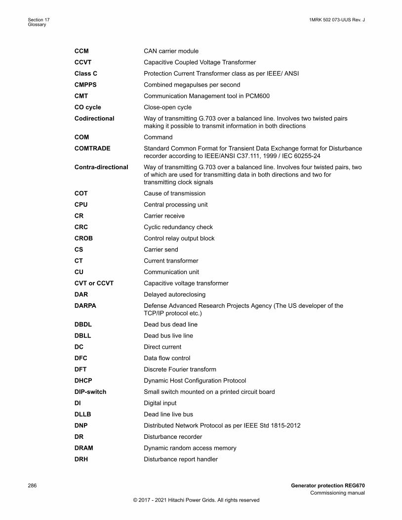
CCM CAN carrier module
CCVT Capacitive Coupled Voltage Transformer
Class C Protection Current Transformer class as per IEEE/ ANSI
CMPPS Combined megapulses per second
CMT Communication Management tool in PCM600
CO cycle Close-open cycle
Codirectional Way of transmitting G.703 over a balanced line. Involves two twisted pairsmaking it possible to transmit information in both directions
COM Command
COMTRADE Standard Common Format for Transient Data Exchange format for Disturbancerecorder according to IEEE/ANSI C37.111, 1999 / IEC 60255-24
Contra-directional Way of transmitting G.703 over a balanced line. Involves four twisted pairs, twoof which are used for transmitting data in both directions and two fortransmitting clock signals
COT Cause of transmission
CPU Central processing unit
CR Carrier receive
CRC Cyclic redundancy check
CROB Control relay output block
CS Carrier send
CT Current transformer
CU Communication unit
CVT or CCVT Capacitive voltage transformer
DAR Delayed autoreclosing
DARPA Defense Advanced Research Projects Agency (The US developer of theTCP/IP protocol etc.)
DBDL Dead bus dead line
DBLL Dead bus live line
DC Direct current
DFC Data flow control
DFT Discrete Fourier transform
DHCP Dynamic Host Configuration Protocol
DIP-switch Small switch mounted on a printed circuit board
DI Digital input
DLLB Dead line live bus
DNP Distributed Network Protocol as per IEEE Std 1815-2012
DR Disturbance recorder
DRAM Dynamic random access memory
DRH Disturbance report handler
Section 17 1MRK 502 073-UUS Rev. JGlossary
286 Generator protection REG670Commissioning manual
© 2017 - 2021 Hitachi Power Grids. All rights reserved

DSP Digital signal processor
DTT Direct transfer trip scheme
ECT Ethernet configuration tool
EHV network Extra high voltage network
EIA Electronic Industries Association
EMC Electromagnetic compatibility
EMF Electromotive force
EMI Electromagnetic interference
EnFP End fault protection
EPA Enhanced performance architecture
ESD Electrostatic discharge
F-SMA Type of optical fiber connector
FAN Fault number
FIPS Federal Information Processing Standards
FCB Flow control bit; Frame count bit
FOX 20 Modular 20 channel telecommunication system for speech, data and protectionsignals
FOX 512/515 Access multiplexer
FOX 6Plus Compact time-division multiplexer for the transmission of up to seven duplexchannels of digital data over optical fibers
FPN Flexible product naming
FTP File Transfer Protocol
FUN Function type
G.703 Electrical and functional description for digital lines used by local telephonecompanies. Can be transported over balanced and unbalanced lines
GCM Communication interface module with carrier of GPS receiver module
GDE Graphical display editor within PCM600
GI General interrogation command
GIS Gas-insulated switchgear
GOOSE Generic object-oriented substation event
GPS Global positioning system
GSAL Generic security application
GSE Generic substation event
HDLC protocol High-level data link control, protocol based on the HDLC standard
HFBR connector type Plastic fiber connector
HLV circuit Hazardous Live Voltage according to IEC60255-27
HMI Human-machine interface
HSAR High speed autoreclosing
1MRK 502 073-UUS Rev. J Section 17Glossary
Generator protection REG670 287Commissioning manual
© 2017 - 2021 Hitachi Power Grids. All rights reserved
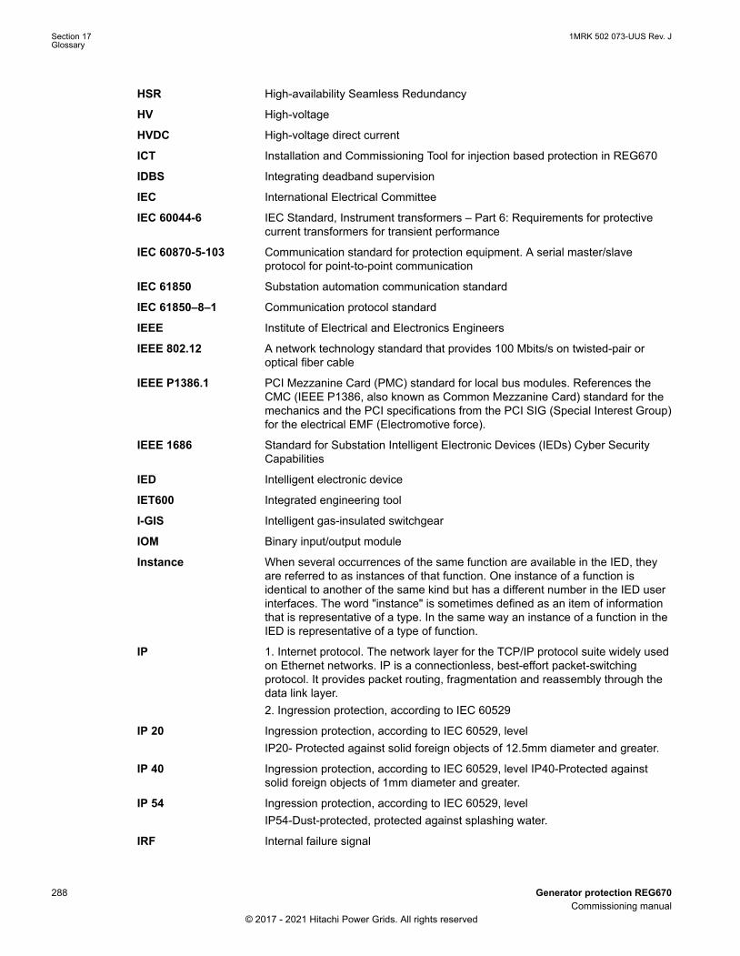
HSR High-availability Seamless Redundancy
HV High-voltage
HVDC High-voltage direct current
ICT Installation and Commissioning Tool for injection based protection in REG670
IDBS Integrating deadband supervision
IEC International Electrical Committee
IEC 60044-6 IEC Standard, Instrument transformers – Part 6: Requirements for protectivecurrent transformers for transient performance
IEC 60870-5-103 Communication standard for protection equipment. A serial master/slaveprotocol for point-to-point communication
IEC 61850 Substation automation communication standard
IEC 61850–8–1 Communication protocol standard
IEEE Institute of Electrical and Electronics Engineers
IEEE 802.12 A network technology standard that provides 100 Mbits/s on twisted-pair oroptical fiber cable
IEEE P1386.1 PCI Mezzanine Card (PMC) standard for local bus modules. References theCMC (IEEE P1386, also known as Common Mezzanine Card) standard for themechanics and the PCI specifications from the PCI SIG (Special Interest Group)for the electrical EMF (Electromotive force).
IEEE 1686 Standard for Substation Intelligent Electronic Devices (IEDs) Cyber SecurityCapabilities
IED Intelligent electronic device
IET600 Integrated engineering tool
I-GIS Intelligent gas-insulated switchgear
IOM Binary input/output module
Instance When several occurrences of the same function are available in the IED, theyare referred to as instances of that function. One instance of a function isidentical to another of the same kind but has a different number in the IED userinterfaces. The word "instance" is sometimes defined as an item of informationthat is representative of a type. In the same way an instance of a function in theIED is representative of a type of function.
IP 1. Internet protocol. The network layer for the TCP/IP protocol suite widely usedon Ethernet networks. IP is a connectionless, best-effort packet-switchingprotocol. It provides packet routing, fragmentation and reassembly through thedata link layer.2. Ingression protection, according to IEC 60529
IP 20 Ingression protection, according to IEC 60529, levelIP20- Protected against solid foreign objects of 12.5mm diameter and greater.
IP 40 Ingression protection, according to IEC 60529, level IP40-Protected againstsolid foreign objects of 1mm diameter and greater.
IP 54 Ingression protection, according to IEC 60529, levelIP54-Dust-protected, protected against splashing water.
IRF Internal failure signal
Section 17 1MRK 502 073-UUS Rev. JGlossary
288 Generator protection REG670Commissioning manual
© 2017 - 2021 Hitachi Power Grids. All rights reserved

IRIG-B: InterRange Instrumentation Group Time code format B, standard 200
ITU International Telecommunications Union
LAN Local area network
LIB 520 High-voltage software module
LCD Liquid crystal display
LDAPS Lightweight Directory Access Protocol
LDCM Line data communication module
LDD Local detection device
LED Light-emitting diode
LNT LON network tool
LON Local operating network
MCB Miniature circuit breaker
MCM Mezzanine carrier module
MIM Milli-ampere module
MPM Main processing module
MVAL Value of measurement
MVB Multifunction vehicle bus. Standardized serial bus originally developed for use intrains.
NCC National Control Centre
NOF Number of grid faults
NUM Numerical module
OCO cycle Open-close-open cycle
OCP Overcurrent protection
OEM Optical Ethernet module
OLTC On-load tap changer
OTEV Disturbance data recording initiated by other event than start/pick-up
OV Overvoltage
Overreach A term used to describe how the relay behaves during a fault condition. Forexample, a distance relay is overreaching when the impedance presented to itis smaller than the apparent impedance to the fault applied to the balance point,that is, the set reach. The relay “sees” the fault but perhaps it should not haveseen it.
PCI Peripheral component interconnect, a local data bus
PCM Pulse code modulation
PCM600 Protection and control IED manager
PC-MIP Mezzanine card standard
PELV circuit Protected Extra-Low Voltage circuit type according to IEC60255-27
PMC PCI Mezzanine card
POR Permissive overreach
1MRK 502 073-UUS Rev. J Section 17Glossary
Generator protection REG670 289Commissioning manual
© 2017 - 2021 Hitachi Power Grids. All rights reserved

POTT Permissive overreach transfer trip
Process bus Bus or LAN used at the process level, that is, in near proximity to the measuredand/or controlled components
PRP Parallel redundancy protocol
PSM Power supply module
PST Parameter setting tool within PCM600
PTP Precision time protocol
PT ratio Potential transformer or voltage transformer ratio
PUTT Permissive underreach transfer trip
RASC Synchrocheck relay, COMBIFLEX
RCA Relay characteristic angle
RISC Reduced instruction set computer
RMS value Root mean square value
RS422 A balanced serial interface for the transmission of digital data in point-to-pointconnections
RS485 Serial link according to EIA standard RS485
RTC Real-time clock
RTU Remote terminal unit
SA Substation Automation
SBO Select-before-operate
SC Switch or push button to close
SCL Short circuit location
SCS Station control system
SCADA Supervision, control and data acquisition
SCT System configuration tool according to standard IEC 61850
SDU Service data unit
SELV circuit Safety Extra-Low Voltage circuit type according to IEC60255-27
SFP Small form-factor pluggable (abbreviation)Optical Ethernet port (explanation)
SLM Serial communication module.
SMA connector Subminiature version A, A threaded connector with constant impedance.
SMT Signal matrix tool within PCM600
SMS Station monitoring system
SNTP Simple network time protocol – is used to synchronize computer clocks on localarea networks. This reduces the requirement to have accurate hardware clocksin every embedded system in a network. Each embedded node can insteadsynchronize with a remote clock, providing the required accuracy.
SOF Status of fault
Section 17 1MRK 502 073-UUS Rev. JGlossary
290 Generator protection REG670Commissioning manual
© 2017 - 2021 Hitachi Power Grids. All rights reserved

SPA Strömberg Protection Acquisition (SPA), a serial master/slave protocol for point-to-point and ring communication.
SRY Switch for CB ready condition
ST Switch or push button to trip
Starpoint Neutral/Wye point of transformer or generator
SVC Static VAr compensation
TC Trip coil
TCS Trip circuit supervision
TCP Transmission control protocol. The most common transport layer protocol usedon Ethernet and the Internet.
TCP/IP Transmission control protocol over Internet Protocol. The de facto standardEthernet protocols incorporated into 4.2BSD Unix. TCP/IP was developed byDARPA for Internet working and encompasses both network layer and transportlayer protocols. While TCP and IP specify two protocols at specific protocollayers, TCP/IP is often used to refer to the entire US Department of Defenseprotocol suite based upon these, including Telnet, FTP, UDP and RDP.
TEF Time delayed gound-fault protection function
TLS Transport Layer Security
TM Transmit (disturbance data)
TNC connector Threaded Neill-Concelman, a threaded constant impedance version of a BNCconnector
TP Trip (recorded fault)
TPZ, TPY, TPX, TPS Current transformer class according to IEC
TRM Transformer Module. This module transforms currents and voltages taken fromthe process into levels suitable for further signal processing.
TYP Type identification
UMT User management tool
Underreach A term used to describe how the relay behaves during a fault condition. Forexample, a distance relay is underreaching when the impedance presented to itis greater than the apparent impedance to the fault applied to the balance point,that is, the set reach. The relay does not “see” the fault but perhaps it shouldhave seen it. See also Overreach.
UTC Coordinated Universal Time. A coordinated time scale, maintained by theBureau International des Poids et Mesures (BIPM), which forms the basis of acoordinated dissemination of standard frequencies and time signals. UTC isderived from International Atomic Time (TAI) by the addition of a whole numberof "leap seconds" to synchronize it with Universal Time 1 (UT1), thus allowingfor the eccentricity of the Earth's orbit, the rotational axis tilt (23.5 degrees), butstill showing the Earth's irregular rotation, on which UT1 is based. TheCoordinated Universal Time is expressed using a 24-hour clock, and uses theGregorian calendar. It is used for aeroplane and ship navigation, where it is alsosometimes known by the military name, "Zulu time." "Zulu" in the phoneticalphabet stands for "Z", which stands for longitude zero.
UV Undervoltage
WEI Weak end infeed logic
1MRK 502 073-UUS Rev. J Section 17Glossary
Generator protection REG670 291Commissioning manual
© 2017 - 2021 Hitachi Power Grids. All rights reserved

VT Voltage transformer
X.21 A digital signalling interface primarily used for telecom equipment
3IO Three times zero-sequence current.Often referred to as the residual or theground-fault current
3VO Three times the zero sequence voltage. Often referred to as the residualvoltage or the neutral point voltage
Section 17 1MRK 502 073-UUS Rev. JGlossary
292 Generator protection REG670Commissioning manual
© 2017 - 2021 Hitachi Power Grids. All rights reserved

293

ABB Power Grids Sweden ABGrid Automation ProductsSE-721 59 Västerås, SwedenPhone +46 (0) 10 738 00 00
https://hitachiabb-powergrids.com/protection-control
© 2017 - 2021 Hitachi Power Grids.All rights reserved
Scan this QR code to visit our website1M
RK
502
073-
UU
S