EN / CPTC-02 user's manual - ABB Group
78
— OPTIONS FOR ABB DRIVES CPTC-02 ATEX-certified thermistor protection module, Ex II (2) GD (option +L537+Q971) User's manual
-
Upload
khangminh22 -
Category
Documents
-
view
0 -
download
0
Transcript of EN / CPTC-02 user's manual - ABB Group

—OPTIONS FOR ABB DRIVES
CPTC-02 ATEX-certified thermistorprotection module, Ex II (2) GD (option+L537+Q971)User's manual


CPTC-02 ATEX-certified thermistorprotectionmodule, Ex II (2) GD (option+L537+Q971)
User's manual
Table of contents
1. Safety instructions
5. Mechanical installation
6. Electrical installation
7. Start-up and validation test
3AXD50000030058 Rev EENOriginal instructionsEFFECTIVE: 2021-09-01


Table of contents
1 Safety instructions9Contents of this chapter ............................................................9Use of warnings and notes .......................................................10ATEX/UKEX-certified motor thermal protection functions .........10Instructions for functional safety circuits ...................................12Electrical safety precautions .....................................................
2 Introduction to the manual15Contents of this chapter ............................................................15Applicability ...............................................................................15Compatibility .............................................................................16Target audience ........................................................................16Exclusion of liability ...................................................................16Related manuals .......................................................................17Terms and abbreviations ...........................................................
3 Hardware description21Contents of this chapter ............................................................21Product overview ......................................................................22External power supply interface .........................................22Layout .................................................................................23Markings ...................................................................................23Module ................................................................................23Type designation label .................................................23ATEX/UKEX markings ..................................................24Drive ...................................................................................24SMT function ................................................................
4 Option description27Contents of this chapter ............................................................27Overview ...................................................................................28Wall-mounted drives and drive modules ............................28Cabinet-installed drives ......................................................
Table of contents 5

29Safe disconnection function ......................................................29Commissioning the drive for a motor in a hazardous area .......29Resetting the safety function ....................................................30Indications of the safety function ..............................................30Switching frequency limitation ..................................................30Fault reaction function ...............................................................30CPTC-02 module ................................................................31STO function in the drive ....................................................
5 Mechanical installation33Contents of this chapter ............................................................33Necessary tools and instructions ..............................................33Unpacking and examining the delivery .....................................34Installing the module .................................................................
6 Electrical installation35Contents of this chapter ............................................................35Warnings ...................................................................................36Necessary tools and instructions ..............................................36Selecting the location for the drive ............................................36General wiring instructions .......................................................37Terminal designations ...............................................................37Motor thermistor connection ...............................................37Relay output connection .....................................................37External power supply ........................................................38PTC sensor input ......................................................................38Wiring examples .......................................................................39Motor thermistor connection example ................................40Relay output connection .....................................................41Power supply connection ...................................................
7 Start-up and validation test43Contents of this chapter ............................................................43Validation of the safety functions ..............................................43Competence .......................................................................44Validation procedure ...........................................................44Validation test reports .........................................................
6 Table of contents
27

45Start-up .....................................................................................47Validation test ............................................................................
8 Fault tracing51Contents of this chapter ............................................................51Reporting problems and failures related to safety functions .....51CPTC-02 module replacement .................................................52Fault and warning messages ....................................................53LED ...........................................................................................
9 Maintenance55Contents of this chapter ............................................................55Safety circuit maintenance ........................................................56Proof test ...................................................................................56Proof test interval ......................................................................57Functional safety components ..................................................57Competence ..............................................................................57Residual risk .............................................................................58Intentional misuse .....................................................................58Decommissioning ......................................................................
10 Technical data59Contents of this chapter ............................................................60Dimension drawing ...................................................................61Isolation areas ...........................................................................61Connections ..............................................................................61Motor thermistor connection (60…61) ................................62Relay output (STO) connection (62…63) ...........................62External power supply (40…41) .........................................62Ambient conditions ....................................................................63Safety data ................................................................................63Safety block diagram ................................................................64Response times ........................................................................64Relevant failure modes .............................................................64Related standards and directives .............................................65Compliance with the Machinery Directive (EU) ........................
Table of contents 7

65Compliance with the Supply of Machinery (Safety) Regulations(UK) ...........................................................................................
66Compliance with the ATEX Directive (EU) ................................66Compliance with the UKEX Directive (UK) ...............................67Declaration of Conformity (EU) .................................................69Declaration of Conformity (UK) .................................................71ATEX certificate ........................................................................73UKEX certificate ........................................................................75TÜV Nord certificate ..................................................................
Further information
8 Table of contents
27

1Safety instructions
Contents of this chapterThis chapter contains the safety instructions which you must obeywhen you install, operate and do maintenance on the safety functionsof a drive.
Use of warnings and notesWarnings tell you about conditions which can cause injury or death,or damage to the equipment. They also tell you how to prevent thedanger. Notes draw attention to a particular condition or fact, or giveinformation on a subject.
The manual uses these warning symbols:
WARNING!Electricity warning tells about hazards from electricity whichcan cause injury or death, or damage to the equipment.
Safety instructions 9

WARNING!General warning tells about conditions other than those causedby electricity, which can cause injury or death, or damage tothe equipment.
WARNING!Electrostatic sensitive devices warning tells you about the riskof electrostatic discharge which can cause damage to theequipment.
ATEX/UKEX-certified motor thermal protectionfunctionsOnly qualified specialists are permitted to install, control and maintainthe ATEX/UKEX-certified motor thermal protection functions (seeIEC/EN 60079-14). Obey all safety regulations required withapplication of Ex motors in Zone 1/21 (equipment category 2) or Zone2/22 (equipment category 2 or 3).
Instructions for functional safety circuits
WARNING!Obey the safety instructions of the drive. If you ignorethem, injury or death, or damage to the equipment canoccur.
This manual does not contain the complete safety instructions of thedrive. It only includes the instructions related to the scope of thismanual. The general instructions are given in this section and theoption-specific instructions in the applicable chapter.
10 Safety instructions
28

WARNING!The safety function described in this manual does not isolatethe main circuit or auxiliary circuit from the power supply. Donot do work on the drive, motor cable or motor before youhave isolated the drive system from all power supplies andmeasured that there are no dangerous voltages. Before youstart the work, do the steps in section Electrical safetyprecautions (page 12).
Safety instructions 11

Electrical safety precautionsThese electrical safety precautions are for all personnel who do workon the drive, motor cable or motor.
WARNING!Obey these instructions. If you ignore them, injury or death,or damage to the equipment can occur.
If you are not a qualified electrical professional, do not doinstallation or maintenance work.
Go through these steps before you begin any installation ormaintenance work.
1. Clearly identify the work location and equipment.
2. Disconnect all possible voltage sources. Make sure thatre-connection is not possible. Lock out and tag out.
• Open the main disconnecting device of the drive.
• Open the charging switch if present.
• Open the disconnector of the supply transformer. (The maindisconnecting device in the drive cabinet does not disconnectthe voltage from the AC input power busbars of the drivecabinet.)
• Open the auxiliary voltage switch-disconnector (if present),and all other possible disconnecting devices that isolate thedrive from dangerous voltage sources.
• If you have a permanent magnet motor connected to the drive,disconnect the motor from the drive with a safety switch or byother means.
12 Safety instructions
28

• Disconnect all dangerous external voltages from the controlcircuits.
• After you disconnect power from the drive, always wait 5minutes to let the intermediate circuit capacitors dischargebefore you continue.
3. Protect any other energized parts in the work location againstcontact.
4. Take special precautions when close to bare conductors.
5. Measure that the installation is de-energized. Use a qualityvoltage tester. If the measurement requires removal ordisassembly of shrouding or other cabinet structures, obey thelocal laws and regulations applicable to live working (including –but not limited to – electric shock and arc protection).
• Before and after measuring the installation, verify the operationof the voltage tester on a known voltage source.
• Make sure that the voltage between the drive input powerterminals (L1, L2, L3) and the grounding (PE) busbar is zero.
• Make sure that the voltage between the drive output terminals(T1/U, T2/V, T3/W) and the grounding (PE) busbar is zero.Important! Repeat the measurement also with the DC voltagesetting of the tester. Measure between each phase andground. There is a risk of dangerous DC voltage charging dueto leakage capacitances of the motor circuit. This voltage canremain charged even long time after the drive power off. Themeasurement discharges the voltage.
• Make sure that the voltage between the drive DC terminals(UDC+ and UDC-) and the grounding (PE) terminal is zero.Note: If cables are not connected to the drive DC terminals,measuring the voltage from the DC terminal screws can giveincorrect results.
Safety instructions 13

6. Install temporary grounding as required by the local regulations.
7. Ask for a permit to work from the person in control of the electricalinstallation work.
14 Safety instructions
28

2Introduction to the manual
Contents of this chapterThis chapter gives basic information on the manual.
ApplicabilityThis manual is applicable to the CPTC-02 module and to the Safemotor temperature safety (SMT) function which uses the CPTC-02module (option +L537+Q971).
CompatibilityThe CPTC-02 module is compatible with:
• ACS580-01/-04, ACH580-01/-04/-31/-34, andACQ580-01/-04/-31/-34 wall-mounted drives and drive modulesto be installed in user-defined cabinet
• ACS580-07, ACH580-07, and ACQ580-07 cabinet-installed drives
• ACS580 standard control program version 1.70 or later
Introduction to the manual 15

• ACH580 HVAC control program version 2.05 or later
• ACQ580 pump control program version 2.05 or later
Target audienceThis manual is intended for people who install, commission, use andservice the ATEX-certified thermistor protection module of the drive.Read the manual before working on the drive. You are expected toknow the fundamentals of electricity, wiring, electrical components,electrical schematic symbols, functional safety, and Ex regulations.
Exclusion of liabilityABB is not responsible for the implementation, verification andvalidation of the overall safety system. It is the responsibility of thesystem integrator (or other party) who is responsible for the overallsystem, Ex regulations and system safety.
The system integrator (or other responsible party) must make surethat the entire implementation complies with the instructions in thismanual, all relevant standards, directives and local electrical code,and that the system is tested, verified and validated correctly.
Related manualsCodeName
Drive hardware3AXD50000044794ACS580-01 (0.75 to 250 kW) hardware manual R1-R93AXD50000015497ACS580-04 drive modules (200 to 500 kW) hardware
manual3AXD50000045815ACS580-07 drives hardware manual3AXD50000044839ACH580-01 (0.75 to 250 kW) hardwaremanual R1-R93AXD50000048685ACH580-04 drive modules (250 to 500 kW) hardware
manual3AXD50000045816ACH580-07 hardware manual3AXD50000037066ACH580-31 hardware manual
16 Introduction to the manual

CodeName3AXD50000419708ACH580-34 hardware manual3AXD50000044862ACQ580-01 (0.75 to 250 kW) hardware manual R1-R93AXD50000048677ACQ580-04 hardware manual3AXD50000045817ACQ580-07 hardware manual3AXD50000045935ACQ580-31 hardware manual3AXD50000420025ACQ580-34 hardware manual
Drive firmware3AXD50000016097ACS580 standard control program firmware manual3AXD50000027537ACH580 HVAC control program firmware manual3AXD50000035867ACQ580 pump control program firmware manual
PC tools3AUA0000094606Drive composer start-up and maintenance PC tool
user's manualSafety
3AUA0000048753Functional safety; Technical guide No. 10www.abb.com/safetyABB Safety information and solutions3AUA0000037223Motors and drives in potentially explosive atmospheres
- What you need to knowOption manuals
3AUA0000085685ACS-AP-x assistant control panels user’s manual3AXD50000030058CPTC-02 ATEX-certified thermistor protection module,
Ex II (2) GD (+L537+Q971) user’s manual3AXD10001243391CPTC-02 ATEX-certified thermistor protection module,
Instructions for pairing the module with an ATEX-certi-fied driveManuals and quick guides for I/O extension modules,fieldbus adapters, etc.
See www.abb.com/drives/documents for all manuals on the Internet.
Terms and abbreviationsDescriptionTermACS580, ACH580 or ACQ580ACx580
Introduction to the manual 17

DescriptionTermDirectives 2014/34/EU and 1999/92/EC are commonly re-ferred to as the ATEX directives (from "Atmosphères Explos-ibles")
ATEX
Classification of the safety-related parts of a control systemin respect of their resistance to faults and their subsequentbehavior in the fault condition, and which is achieved by thestructural arrangement of the parts, fault detection and/or bytheir reliability. The categories are: B, 1, 2, 3 and 4. (EN ISO13849-1)
Cat.
Common cause failure (%) (EN ISO 13849-1)CCFMultifunction extension module (external 24 V andATEX/UKEX-certified PTC interface)
CPTC-02
Diagnostic coverage (EN ISO 13849-1)DCDigital inputDIElectromagnetic compatibilityEMCAn IEC term used in the context of explosive atmospheres(IEC 60079)
Ex
Type of protection, flameproof enclosures (IEC/EN 60079-1)Ex dTypes of protection, increased safety (IEC/EN 60079-7)Ex eb, Ex ecMotors used in explosive atmospheresEx motorsHardware fault tolerance (IEC 61508)HFTMean time to dangerous failure: (Total number of life units)/ (Number of dangerous, undetected failures) during a partic-ular measurement interval under stated conditions (EN ISO13849-1)
MTTFD
Average probability of dangerous failure on demand (IEC61508)
PFDavg
Average frequency of dangerous failures per hour (IEC61508)
PFH
Performance level. Levels a...e correspond to SIL (EN ISO13849-1)
PL
Systematic capability (IEC 61508)SCSafe failure fraction (%) (IEC 61508)SFFSafety integrity level (1...3) (IEC 61508)SILSafe motor temperature (IEC/EN 61800-5-2)SMTSafe torque off (IEC/EN 61800-5-2)STO
18 Introduction to the manual

DescriptionTermProof test interval. Defines the probabilistic failure rate (PFHor PFDavg) for the safety function or subsystem. Performinga proof test at a maximum interval of T1 is required to keepthe SIL capability valid. The same interval must be followedto keep the PL capability (EN ISO 13849) valid. Note thatany T1 values given cannot be regarded as a guarantee orwarranty.
T1
Mission time: the period of time covering the intended useof the safety function/device. After the mission time elapses,the safety device must be replaced. Note that any TM valuesgiven cannot be regarded as a guarantee or warranty.(EN ISO 13849-1, IEC 61800-5-2)
TM
The Equipment and Protective Systems Intended for Use inPotentially Explosive Atmospheres Regulations 2016 (+amendment SI 2019 No. 696)
UKEX
Confirmation by, for example, analysis that the safety systemmeets the functional safety requirements of the specific ap-plication.
Validation
Confirmation by, for example, testing that the safety systemmeets the requirements set by the specification.
Verification
Potentially explosive atmosphere. Hazardous areas are di-vided into zones, based on the frequency and duration of theoccurrence of an explosive atmosphere. (IEC/EN 60079-10)
Zone
Introduction to the manual 19

20

3Hardware description
Contents of this chapterThis chapter gives a short description of the module.
Product overviewThe CPTC-02 module has a motor thermistor connection forsupervising the motor temperature and one relay output, whichindicates motor overtemperature. To trip the drive at motorovertemperature, the relay output must be connected to the Safetorque off (STO) input of the drive.
The CPTC-02 module together with the drive STO implements theSafe motor temperature (SMT) safety function as defined inIEC/EN 61800-5-2.
The CPTC-02 module is Type Examined as a protective device withinthe scope of the European ATEX (and UKEX) Product Directive. Thisallows the use of the module in temperature protection of motors inexplosive atmospheres (Ex motors).
Hardware description 21

Inside the module, there is reinforced insulation between the motorthermistor connection and the other terminals of the module. Theinsulation forms a reliable protective separation between the motormain circuit and the drive control circuits. Thus, the drive control unitis Protective Extra Low Voltage (PELV) compatible also when theCPTC-02 module and a thermistor protection circuit are installed.
■ External power supply interface
The module has an external power supply interface, which can beused to power up the drive control unit if the drive power supply fails.If you do not need the back-up power supply, you do not have toconnect it because the module is powered from the drive control unitby default.
■ Layout
1
2
45
36
Grounding screw1Hole for mounting screw22-pin terminal block for motor thermistor connection32-pin detachable terminal block for relay output4
22 Hardware description

2-pin terminal block for external power supply5Diagnostics LED6
Markings
■ Module
Type designation label
1 2 3
4 5
Type1
Serial number in format RYWWSSSSWS, where:2R: Component revisionY: Last digit of the manufacturing year (for example, 5 = 2015)WW: Manufacturing week (for example, 01 = week 1)SSSS: Number that starts every week from 0001WS: Manufacturing location
ABB MRP code of the module3
Combined ABB MRP code, serial number and manufacturing location4
RoHS mark5
ATEX/UKEX markings
The markings on the module show the ATEX/UKEX classification ofthe CPTC-02 module.
Hardware description 23

1 2 3 4
Specific marking of explosion protection1
Equipment group II: Product for surface industry (other than mining ap-plications)
2
Equipment category 2. Parentheses show that the module must be in-stalled outside the potentially explosive atmosphere.
3
Certified for use in explosive atmospheres caused by:4G = gases, vapors or mists, D = dust.
■ Drive
SMT function
When the CPTC-02module is delivered as an add-on kit, the packagecontains a sticker to show the ATEX/UKEX classification of the Safemotor temperature (SMT) function. The user must attach this stickernear the type designation label of the drive to ensure the ATEX/UKEXcompliance of the safety circuit.
In the cabinet-built drives, this sticker is attached to the cabinet doorat the factory.
24 Hardware description

1 2 3 4 5 6
7
CE marking with Notified Body identification: The manufacturer declaresthat the product conforms with ATEX Product Directive 2014/34/EU.
1
Notified Body: Eurofins Expert ServicesUKCA marking with Approved Body identification: The manufacturer de-clares that the product conforms with The Equipment and ProtectiveSystems Intended for Use in Potentially Explosive Atmospheres Regula-tions 2016 (+ amendment SI 2019 No. 696).
2
Approved Body: Eurofins E&E CML LimitedSpecific marking of explosion protection3Equipment group II: Product for surface industry (other than mining ap-plications)
4
Equipment category 2. Parentheses show that the drive must be installedoutside the potentially explosive atmosphere.
5
Certified for use in explosive atmospheres caused by:6G = gases, vapors or mists, D = dust.Certificate references7
Hardware description 25

26

4Option description
Contents of this chapterThis chapter describes the Safe motor temperature (SMT) functionimplemented with the CPTC-02module and gives instructions for theuser.
OverviewTo implement the Safe motor temperature (SMT) function, the relayoutput of the CPTC-02 module must be connected to the Safe torqueoff (STO) input of the drive.
When the motor temperature rises above the PTC sensor limittemperature, the sensor resistance increases sharply. This indicatesovertemperature to the CPTC-02 module. The module switches thedrive Safe torque off (STO) circuit off which activates the drive STOfunction.
The STO function disables the control voltage of the powersemiconductors of the drive output stage. This prevents the drive
Option description 27

from generating the torque required to rotate the motor. If the motoris running when STO function is activated, it coasts to a stop.
For more information on the drive STO function, see the appropriatedrive hardware manual.
■ Wall-mounted drives and drive modules
The module is available as an add-on kit (option +L537+Q971). Ifyou intend to retrofit the CPTC-02 module to an installed drive, youneed to make sure that the ATEX/UKEX certification enables theretrofit. Contact your local ABB representative for more information.
The user:
• makes sure that the serial number of the drive starts with 1, 4, 7,8, M or Y,
• pairs the CPTC-02module with an ATEX/UKEX-certified ACS580,ACH580 or ACQ580 drive in the ABB Drives Installed Base (DIB)register. Refer to Instructions for pairing the module with anATEX-certified drive (3AXD10001243391 [English]).
• attaches the included ATEX/UKEX label for the SMT function nearthe type designation label (CE/UKCA marking) of the drive,
• installs the option module to Option slot 2 of the drive control unitand sets the applicable drive parameters,
• connects the PTC temperature sensors of the motor to the PTCinput of the option module, and
• connects the drive STO terminals to the relay output of the optionmodule.
■ Cabinet-installed drives
For cabinet-installed drives, the module is available as afactory-installed option +L537+Q971.
28 Option description

The user connects the PTC temperature sensors of the motor to thePTC inputs of the module.
Safe disconnection functionThe ATEX/UKEX-certified Safe motor temperature function describedin this manual requires that the drive Safe torque off function (STO)is certified for use as a Safe disconnection function to protectequipment in potentially explosive atmospheres according toEuropean ATEX (and UKEX) Product Directive. For more informationon the drive STO function, see the applicable hardware manual.
You can use the CPTC-02 module only when serial number of thedrive starts with 1, 4, 7, 8, M or Y.Note: You do not need a separate ATEX/UKEX certification (andlabel) for the Safe disconnection function (option +Q971), becausethe ATEX/UKEX certificate of the SMT function includes also theATEX/UKEX-certified Safe torque off function (STO).
Commissioning the drive for amotor in a hazardousareaCommission the drive according to the requirements and limitationsset by the application, the motor manufacturer’s instructions, drivefirmware manual, local laws and regulations and this manual.
The certificate of the Ex motor typically requires that you set aminimum limit for the output switching frequency of the drive. Makesure that the Ex motor is operated above the minimum outputswitching frequency specified by the motor manufacturer.
Resetting the safety functionA manual reset is mandatory in an ATEX/UKEX-certified safetyfunction. The CPTC-02 module generates a fault indication to thedrive when motor overtemperature is reached. The user must resetthe drive before it is possible to restart the drive.
Option description 29

Note: The reset function of the safety function is not SIL classified.
Indications of the safety functionAn indication of the safety function can come from two sources:
1. Overtemperature fault in the drive (fault 4991).
2. STO indication in the drive:
• The drive STO indication is active when the SMT safetyfunction has activated the drive STO function. The type of theindication is set with parameter 31.22.
To avoid parallel fault indications, set the STO indication parameter(31.22) to valueWarning/Warning. See chapterStart-up and validationtest for instructions.Note: The indications of the safety function are not SIL classified.
Switching frequency limitationThe certificate of the Ex motor typically requires that you set aminimum limit for the switching frequency of the drive.
For ABB Exmotors, use parameter 95.15 to set the requiredminimumswitching frequency. For more information, see the drive firmwaremanual.
For Ex motors supplied by other motor manufacturers, contact themotor manufacturer for the correct value and use parameters 97.01and 97.02 to make the parameter setting in the drive.
Fault reaction function
■ CPTC-02 module
The CPTC-02 module has a fault reaction function. When the moduledetects an internal fault or a fault in the temperature sensor circuit,
30 Option description

it sends a request to the drive control unit to stop modulation, andactivates the drive STO function.
■ STO function in the drive
The STO function in the drive has internal fault diagnostics and afault reaction function. The fault reaction function causes a fault tripif it detects a redundancy fault of STO control signals or an internalfailure. For more information, see the hardware and firmwaremanualsof the drive.
Option description 31

32

5Mechanical installation
Contents of this chapterThis chapter contains a delivery checklist and instructions on installingthe module.
Necessary tools and instructions• Screwdriver and a set of suitable bits
For a complete list of tools, see the applicable drive hardware manual.
Unpacking and examining the delivery1. Open the option package.
2. Make sure that the package contains:
• CPTC-02 module
• mounting screw
• STO cable
Mechanical installation 33

• ATEX/UKEX label (with the ATEX/UKEX classificationmarkings)
• this manual.
3. Make sure that there are no signs of damage to the items.
Installing the moduleInstall the module to Option slot 2 of the drive control unit. See thedrive hardware manual.
34 Mechanical installation
29

6Electrical installation
Contents of this chapterThis chapter contains instructions on wiring the module.
Warnings
WARNING!Obey the safety instructions of the drive. If you ignorethem, injury or death, or damage to the equipment canoccur. If you are not a qualified electrical professional,do not do installation or maintenance work.
WARNING!Cabinet-built drives: Do not connect, test or measure a drivebased on the diagrams in this manual. Each delivery is unique.Before starting the work on the electric circuits of a drive,always refer to the delivery-specific circuit diagrams.
Electrical installation 35

WARNING!Make sure that the drive is disconnected from the input powerduring installation. Before you start the work, stop the driveand do the steps in section Electrical safetyprecautions (page 12).
Necessary tools and instructions• Screwdriver with a set of suitable bits
• Cabling tools
Selecting the location for the driveInstall the drive, the CPTC-02 module, and the STO circuit outsideany potentially explosive atmosphere. Consider the ambient conditionsspecification in the drive hardware manual.
General wiring instructions1. For the STO circuit wiring, use the type of cable specified in the
applicable drive hardware manual.
2. Install only the sensor circuit into the potentially explosiveatmosphere.The sensor circuit in the Ex Zone must comply with therequirements for the applicable type of protection, such as:
• Ex d (IEC/EN 60079-1)
• Ex eb (IEC/EN 60079-7, Ex e in EN 60079-7:2007 and IEC60079-7:2006)
• Ex ec (IEC/EN 60079-7, Ex nA in IEC/EN 60079-15:2010).
36 Electrical installation
30

3. Install the drive, including the components of the ATEX-certifiedmotor thermal protection function, outside the potentially explosiveatmosphere.
4. For the sensor connection, ABB recommends to use shieldedtwisted-pair cable. This type of cable decreases electromagneticinterference in the sensor circuit.
5. Route the sensor cables away from themotor cable. Power cablescan cause electromagnetic interference in the sensor circuit.
6. Ground all sensor cable shields to a single grounding pointoutside the potentially explosive atmosphere. 360-degreegrounding of the cable shields at the cable entry of the drive isrecommended. Do not connect the cable shields to ground at thesensor end of the cable.
Terminal designations
■ Motor thermistor connection
DescriptionMarkingPTC connectionPTC IN60Ground (earth) potentialPTC IN61
■ Relay output connection
DescriptionMarkingCommon, CRO PTC C62Normally open, NORO PTC C63
■ External power supply
The external power supply is needed only if you want to connect anexternal back-up power supply for the drive control unit.
Electrical installation 37

Note: Only frames R0…R5 need CPTC-02 to be supplied by anexternal power supply, frames R6…R9 have corresponding terminals40 and 41 on the control unit.
DescriptionMarkingExternal 24 V (AC/DC) input24V AC/DC +
in40
External 24 V (AC/DC) input24V AC/DC - in41
PTC sensor inputFor the recommended cable type and correct tightening torque, seethe technical data.
To enable the SMT function, connect the PTC sensor to the PTC INinput.
To disable the SMT function, connect a resistor (100 ohm… 1 kohm¼ W wire-wound) to the PTC IN input.Note: If you do not connect a PTC sensor or resistor to the PTC INinput, the STO function stays active. You cannot start the motor whilethe STO function is active.
Wiring examplesConnect the external control cables to the applicable moduleterminals. Ground the outer shield of the cables 360 degrees undera grounding clamp on the grounding shelf of the control cables.
38 Electrical installation
30

■ Motor thermistor connection example
1
2
3~Ex M
60
61
PTC IN
PTC IN
CPTC-02
1…6 PTC thermistors connected in series.1Potentially explosive atmosphere2
The PTC input is reinforced/double insulated. If the motor part of thePTC thermistor and wiring are reinforced/double insulated, voltageson the PTC wiring are within SELV limits.
If the motor PTC circuit is not reinforced/double insulated (that is, itis basic insulated), it is mandatory to use reinforced/double insulatedwiring between the motor PTC and CPTC-02 PTC terminal.
Electrical installation 39

■ Relay output connection
Connect the drive STO circuit to the relay output of the module asshown in this figure. In the cabinet-installed drives, the wiring is doneat the factory.
34
35
X4
36
37
38
OUT1
OUT2
SGND
IN1
IN2
62
63
RO PTC C
RO PTC B
CPTC-02
CCU
40 Electrical installation
30

An alternative connection with an external activation switch, forexample amanually operated switch, an emergency stop push button,or the contacts of a safety relay.
34
35
X4
36
37
38
OUT1
OUT2
SGND
IN1
IN2
62
63
RO PTC C
RO PTC B
CPTC-02
CCU
K
Activation switchK
■ Power supply connection
24V AC/DC + in
24V AC/DC - in1
40
41
CPTC-02
+
-
External power supply, 24 V AC/DC1
Electrical installation 41

WARNING!Do not connect the +24 V AC cable to the control unit groundwhen the control unit is powered using an external 24 V ACsupply.
42 Electrical installation
30
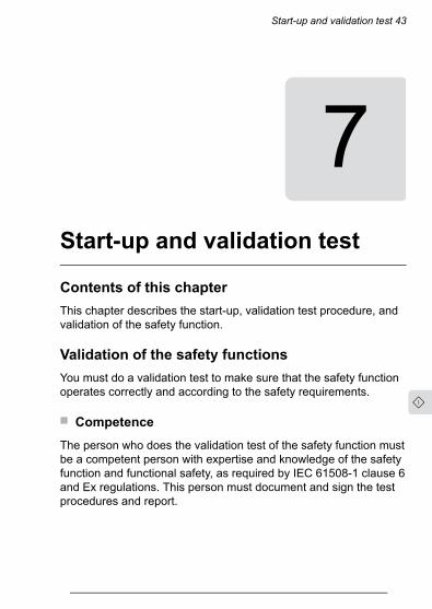
7Start-up and validation test
Contents of this chapterThis chapter describes the start-up, validation test procedure, andvalidation of the safety function.
Validation of the safety functionsYou must do a validation test to make sure that the safety functionoperates correctly and according to the safety requirements.
■ Competence
The person who does the validation test of the safety function mustbe a competent person with expertise and knowledge of the safetyfunction and functional safety, as required by IEC 61508-1 clause 6and Ex regulations. This person must document and sign the testprocedures and report.
Start-up and validation test 43
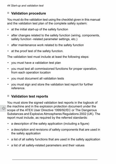
■ Validation procedure
Youmust do the validation test using the checklist given in this manualand the validation test plan of the complete safety system:
• at the initial start-up of the safety function
• after changes related to the safety function (wiring, components,safety function -related parameter settings, etc.)
• after maintenance work related to the safety function
• at the proof test of the safety function.
The validation test must include at least the following steps:
• you must have a validation test plan
• you must test all commissioned functions for proper operation,from each operation location
• you must document all validation tests
• you must sign and store the validation test report for furtherreference.
■ Validation test reports
You must store the signed validation test reports in the logbook ofthe machine and in the explosion protection document under thescope of the ATEX User Directive 1999/92/EC or The DangerousSubstances and Explosive Atmospheres Regulations 2002 (UK). Thereport must include, as required by the referred standards:
• a description of the safety application (including a figure)
• a description and revisions of safety components that are used inthe safety application
• a list of all safety functions that are used in the safety application
• a list of all safety-related parameters and their values
44 Start-up and validation test
31
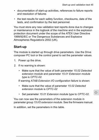
• documentation of start-up activities, references to failure reportsand resolution of failures
• the test results for each safety function, checksums, date of thetests, and confirmation by the test personnel.
You must store any new validation test reports done due to changesor maintenance in the logbook of the machine and in the explosionprotection document under the scope of the ATEX User Directive1999/92/EC or The Dangerous Substances and ExplosiveAtmospheres Regulations 2002 (UK).
Start-upThe module is started up through drive parameters. Use the Drivecomposer PC tool or the control panel to set the parameter values.
1. Power up the drive.
2. If no warning is shown:
• Make sure that the value of both parameter 15.02 Detectedextension module and parameter 15.01 Extension moduletype is CPTC-02.
If warning A7AB Extension I/O configuration failure is shown:
• Make sure that the value of parameter 15.02 Detectedextension module is CPTC-02
• Set parameter 15.01 Extension module type to CPTC-02.
You can now see the parameters of the extension module inparameter group 15 I/O extensionmodule. See the firmwaremanual.
In addition, set the parameters in this table.
Start-up and validation test 45

DescriptionName / ValueIndexSelects which indications are given whenone or both Safe torque off (STO) signalsare switched off or lost. The indications alsodepend on whether the drive is running orstopped when this occurs.
STO indication run/stop31.22
The drive generates a warning.Warning/WarningThis parameter value does not affect theSMT function, but this is the recommendedsetting.Activates (On) or deactivates (Off) the Safemotor temperature (SMT) fault indication(4991).
Safemotor temperatureenable
35.31
0 = Off1 = OnThis parameter is automatically set to On,when CPTC-02 module is connected to thedrive. If the module is removed from thedrive, the parameter remains On, and thedrive will trip to a fault. User must setparameter to Off manually and reset thefault to continue operation without themodule. When the module is connectedagain, the parameter is automatically setto On.Defines hardware-related settings that canbe enabled and disabled by toggling thespecific bits.
Special HW settings95.15
DescriptionNameBit1 = The driven motor is an Ex motorprovided by ABB for potentially explosiveatmospheres. This sets the required minim-um switching frequency for ABB Ex motors(4 kHz).
EX motor0
Note: For non-ABB Ex motors, use para-meters 97.01 and 97.02 to define the cor-rect minimum switching frequency.Note: Multimotor systems are not permit-ted.
46 Start-up and validation test
31

DescriptionName / ValueIndexDefines the switching frequency of thedrive.
Switching frequencyreference
97.01
Note: Multimotor systems are not permit-ted.Defines the minimum limit for the switchingfrequency.
Minimum switching fre-quency
97.02
If parameter 95.15 is set to 1, drive sets thevalue to 4 kHz automatically.For non-ABB Ex motors, consult the motormanufacturer.Defines the switching frequency mode.Normal = Used switching frequency is se-lected with parameters 97.01 and 97.02.
Switching frequencymode
97.09
Activates (On) or deactivates (Off) theHexagonal field weakening.
Hexagonal field weak-ening
97.18
0 = OffFor ABB Exmotors (parameter 95.15 is setto 1), this parameter is automatically set toOff. For non-ABBExmotors (when paramet-er 95.15 bit 0 is not set), set this parameterto Off.
Validation testUse the Drive composer PC tool or a control panel to do the validationtest.
Action
WARNING!Obey the safety instructions of the drive. If you ignore them,injury or death, or damage to the equipment can occur.
Initial statusMake sure that the drive is ready for use, that is, you have done thetasks of the drive start-up procedure. See the drive hardware manual.
Start-up and validation test 47

Action
Make sure that the CPTC-02 module is installed and started up as in-structed in this manual.
Make sure that the drive STO function is configured and validated. Seethe hardware manual.
Checks and settings with no voltage connected
Stop the drive and do the steps in section Electrical safety precau-tions (page 12) before you start the work.
Make sure that the necessary ATEX/UKEX markings are attached.
Make sure that the classification of the motor thermal protection functioncorresponds to the Ex classification of the environment and the Exmotor.
The motor manufacturer selects the PTC sensors for the motor temper-ature measurement according to the specified temperature class. Makesure that the temperature on-off resistances match those of the module.
If you have done any changes to the wiring, do a check of the connec-tions against the applicable circuit diagrams.
Make sure that the installation of the motor temperature sensor complieswith the requirements for the applicable type of protection.
Make sure that the SIL/PL of the safety function meets the target SIL/PL.
Make sure that the wires are connected to the correct terminals andthat the terminal connections are tightened to the correct torque.
Settings with voltage connectedMake sure that you have set all the necessary parameters for the safetyfunction.
Validation test procedureMake sure that you can run and stop the motor freely during the test.
Start the drive and make sure that the motor is running.
Do an overtemperature monitoring test: increase the resistance in thePTC input to more than 4 kohm (for example, open the circuit by discon-necting the wires).
Make sure that the correct indications are activated: the SMT fault andother indications depending on the parameter settings.
48 Start-up and validation test
31

Action
Make sure that the STO is activated and that the motor coasts to a stop.
Make sure that you cannot start the drive before you reset the drive.
Reset the drive. Make sure that you cannot reset and restart the drivebefore the resistance in the PTC input decreases to less than 1.6 kohm(that is, the thermistor wires are reconnected).
Restart the drive and the motor. Make sure that they operate normally.
Do a short-circuit detection test: decrease the resistance in the PTCinput to less than 50 ohm (for example, connect a jumper wire betweenthe terminals of the PTC input).
Make sure that the correct indications are activated: the SMT fault andother indications depending on the parameter settings.
Make sure that the STO is activated and that the motor coasts to a stop.
Make sure that you cannot start the drive before you reset the drive.
Reset the drive. Make sure that you cannot reset and restart the drivebefore the resistance in the PTC input increases to more than 50 ohm(that is, the jumper wire connected earlier is removed).
Restart the drive and the motor. Make sure that they operate normally.
Fill in and sign the validation test report. Store the report in the logbookof the machine.
Start-up and validation test 49

50
8Fault tracing
Contents of this chapterThis chapter shows how to trace faults with fault and warningmessages of the drive and LED on the module.
Reporting problems and failures related to safetyfunctionsContact ABB.
CPTC-02 module replacementIf there is a failure in the CPTC-02 module, you must replace it witha new one. Do not try to repair the module.
Fault tracing 51

Fault and warning messagesActionCauseNameCode
(hex)Faults
Power down the controlunit and make sure that themodule is correctly insertedin the option slot.
Safe motor temperature isenabled (35.31) but theCPTC-02 module is notdetected (parameter 15.02Detected extensionmodule)
CPTC-02 notfound
4990
1. Make sure that themotor has sufficientcooling.
2. Make sure that thedrive and the motorare compatible witheach other.
3. Make sure that themotor is notoverloaded.
4. Make sure that thedrive parametersettings are correct.
5. Examine the wiring ofthe temperaturesensor. If necessary,repair the wiring.
6. Measure theresistance of thesensor. If necessary,replace the sensor.
The CPTC-02 moduleindicates overtemperature.
1. Motor temperature istoo high, or
2. the thermistor isshort-circuited ordisconnected.
Safe motortemperature
4991
52 Fault tracing

ActionCauseNameCode(hex)
1. Examine theconnection betweenthe relay output of theCPTC-02 module andthe STO terminal.
2. Examine theCPTC-02module. If the moduleis defective, replace it.
Safe motor temperaturefault (4991) is generatedbut drive STO is notactivated.Note: If only one STOchannel is opened, Safetorque off fault (FA81 orFA82) is generated.
SMT circuitmalfunction
5089
WarningsMake sure that theinstalled module is of thesame type that the drivehas detected (parameter15.02 Detected extensionmodule) and thatparameter 15.01 Extensionmodule type is set to thecorrect value.
Installed option module isnot the same as configuredby drive parameter.
Extension I/Oconfigurationfailure
A7AB
LEDThe CPTC-02 module has one diagnostic LED.
DescriptionColorThe module is powered up.Green
Fault tracing 53

54

9Maintenance
Contents of this chapterThis chapter contains information for the maintenance anddecommissioning of the safety function.
Safety circuit maintenanceAfter the safety function is validated, it must be maintained by periodicproof testing.
If you change the wiring or a component after the start-up, replacethe CPTC-02 module, modify parameters, or restore parameters totheir factory default values:
• Use only ABB-approved spare parts.
• Register the change to the change log for the safety circuit.
• If parameters were restored to the factory default values: Set theparameters related to the safety function.
Maintenance 55

• Do the validation test of the safety function.
• Document the tests and store the report into the logbook of themachine.
Proof testTo do a proof test, activate the safety function to make sure that itoperates correctly. For guidelines, refer to the validation testprocedure.
Proof test intervalAfter the operation of the safety function is validated at start-up, thesafety function must be maintained by periodic proof testing. In highdemand mode of operation, the maximum proof test interval is 20years. In low demand mode of operation, the maximum proof testinterval is 5 or 2 years (high or low demand as defined in IEC 61508and EN ISO 13849-1). Regardless of the mode of operation, it is agood practice to check the operation of the safety function at leastonce a year.
The person responsible for the design of the complete safety functionshould also note the Recommendation of Use CNB/M/11.050published by the European co-ordination of Notified Bodies concerningdual-channel safety-related systems with electromechanical outputs:
• When the safety integrity requirement for the safety function isSIL 3 or PL e (cat. 3 or 4), the proof test for the function must bedone at least every month.
• When the safety integrity requirement for the safety function isSIL 2 (HFT = 1) or PL d (cat. 3), the proof test for the function mustbe done at least every 12 months.
This is a recommendation and depends on the required (not achieved)SIL/PL. For example, contactors, breakers, safety relays, contactorrelays, emergency stop buttons, switches, etc. are typically safetydevices which have electromechanical outputs. The CPTC-02module
56 Maintenance

and the STO circuit of the drive do not have electromechanicaloutputs.
Functional safety componentsThe mission time of functional safety components is 20 years whichequals the time during which failure rates of electronic componentsremain constant. This applies to the components of the standard Safetorque off circuit as well as any modules, relays and, typically, anyother components that are part of functional safety circuits.
The expiry of mission time terminates the certification and SIL/PLclassification of the safety function. The following options exist:
• Renewal of the whole drive and all optional functional safetymodule(s) and components.
• Renewal of the components in the safety function circuit. Inpractice, this is economical only with larger drives that havereplaceable circuit boards and other components such as relays.
Note that some of the components may already have been renewedearlier, restarting their mission time. The remaining mission time ofthe whole circuit is however determined by its oldest component.
Contact your local ABB service representative for more information.
CompetenceThe person who does the maintenance and proof test activities ofthe safety function must be a competent person with expertise andknowledge of the safety function and functional safety, as requiredby IEC 61508-1 clause 6 and Ex regulations.
Residual riskThe safety functions are used to reduce the recognized hazardousconditions. In spite of this, it is not always possible to eliminate all
Maintenance 57

potential hazards. Thus, the warnings for the residual risks must begiven to the operators.
Intentional misuseThe safety circuit is not designed to protect a machine againstintentional misuse.
DecommissioningWhen you decommission the module, make sure that the safety ofthe machine is maintained until the decommissioning is complete.Mark clearly on the module that it is decommissioned.
58 Maintenance

10Technical data
Contents of this chapterThis chapter contains the technical data of the module, gives generalrules, notes and definitions related to safety functions and lists therelated standards and directives. The safety data, relevant certificatesand Declarations of Conformity are also included.
Technical data 59

Dimension drawingThe dimensions are shown in millimeters and inches.
Installation: Into Option slot 2 on the drive control unit
Degree of protection: IP20
Package: Cardboard
60 Technical data

Isolation areasThe following figure shows the different isolation areas of the module.
4140 6362
6160
Dashed line: reinforced insulation (IEC 61800-5-1).
Connections
■ Motor thermistor connection (60…61)
• Maximum wire size: 1.5 mm2 (16 AWG)
• Maximum wire length: 700 m (2300 ft) (1400 m [4600 ft] for thewhole loop)With the specified cable type, detection of a short-circuited PTCsensor or cable is not guaranteed after 100 m (328 ft).
• Type: Shielded, twisted-pair cable (Draka JAMAK1×(2+1)×0.5 mm2 or equivalent)
• Tightening torque: 0.5 N·m (4.4 lbf·in)
Technical data 61

• Supported standards: DIN 44081 and DIN 44082
• Number of PTC thermistors: 1…6 in series (in both inputs)
• Triggering threshold: 3.6 kohm ±10%
• Recovery threshold: 1.6 kohm ±10%
• PTC terminal voltage: < 5.0 V
• PTC terminal current: < 1 mA
• Short-circuit detection: < 50 ohm ±25 ohm (for the effect of thecable length, see above).
■ Relay output (STO) connection (62…63)
• Maximum wire size: 1.5 mm2 (16 AWG)
• Maximum wire length: 30 m (98 ft) for the whole loop
• Tightening torque: 0.5 N·m (4.4 lbf·in)
• Maximum contact rating: 250 V AC / 30 V DC / 5 A
• Maximum breaking capacity: 1000 VA
■ External power supply (40…41)
• Wire size max. 1.5 mm2
• 24 V AC / DC ±10% (GND, user potential)
• Maximum current consumption: 25 W, 1.04 A at 24 V DC
Ambient conditionsFor the environmental limits for the safety functions and the drive,refer to the drive hardware manual.
62 Technical data
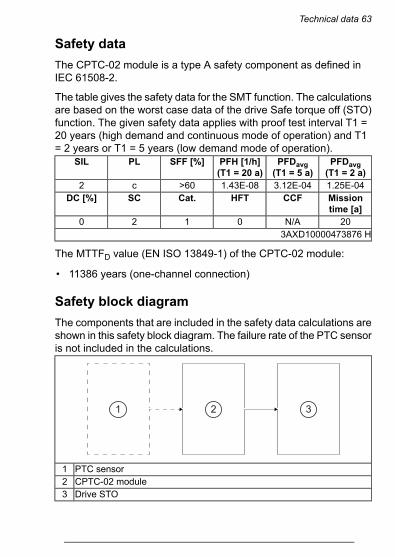
Safety dataThe CPTC-02 module is a type A safety component as defined inIEC 61508-2.
The table gives the safety data for the SMT function. The calculationsare based on the worst case data of the drive Safe torque off (STO)function. The given safety data applies with proof test interval T1 =20 years (high demand and continuous mode of operation) and T1= 2 years or T1 = 5 years (low demand mode of operation).
PFDavg(T1 = 2 a)
PFDavg(T1 = 5 a)
PFH [1/h](T1 = 20 a)
SFF [%]PLSIL
1.25E-043.12E-041.43E-08>60c2Missiontime [a]
CCFHFTCat.SCDC [%]
20N/A01203AXD10000473876 H
The MTTFD value (EN ISO 13849-1) of the CPTC-02 module:
• 11386 years (one-channel connection)
Safety block diagramThe components that are included in the safety data calculations areshown in this safety block diagram. The failure rate of the PTC sensoris not included in the calculations.
1 2 3
PTC sensor1CPTC-02 module2Drive STO3
Technical data 63

Response times• CPTC-02 module: less than 10 ms
• SMT function: the response time of the PTC sensor + CPTC-02module (< 10 ms) + drive STO (< 50 ms)
Relevant failure modes• The SMT function activates when not necessary (safe failure)
• The SMT function does not activate when requested
A fault exclusion on the failure mode “short-circuit on printed circuitboard” has beenmade (EN 13849-2, table D.5). The analysis is basedon the assumption that one failure occurs at one time. Noaccumulated failures have been analyzed.
The failures of the PTC sensor (thermistor) are not included in thefailure analysis. The customer is responsible for the applicability ofthe PTC element.
Related standards and directivesSafety devices required for the safe functioning of equip-ment with respect to explosion risks
EN 50495:2010
Functional safety of electrical/electronic/programmableelectronic safety-related systems.
IEC 61508:2010
Part 1 – General RequirementsPart 2 – Requirements for electrical/electronic/program-mable electronic safety-related systemsAdjustable speed electrical power drive systems – Part 5-2: Safety requirements – Functional
EN 61800-5-2:2007IEC 61800-5-2:2016
Safety of machinery – Safety-related parts of control sys-tems – Part 1: General principles for design
EN ISO 13849-1:2015
Safety of machinery – Safety-related parts of control sys-tems – Part 2: Validation
EN ISO 13849-2:2012
64 Technical data

Safety of machinery – Electrical equipment of machines –Part 1: General requirements
EN 60204-1:2018IEC 60204-1:2016
Electrical equipment for measurement, control and labor-atory use – EMC requirements – Part 3-1: Immunity require-ments for safety-related systems and for equipment inten-ded to perform safety-related functions (functional safety)– General industrial applications
IEC 61326-3-1:2017
Functional safety – Safety instrumented systems for theprocess industry sector – Part 1: Framework, definitions,system, hardware and application programming require-ments
IEC 61511-1:2017Ed.2.1
Machinery Directive (EU)2006/42/ECATEX Product Directive (EU)2014/34/EUSupply of Machinery (Safety) Regulations 2008 (UK)The Equipment and Protective Systems Intended for Usein Potentially Explosive Atmospheres Regulations 2016 (+amendment SI 2019 No. 696) (UK)
Compliance with the Machinery Directive (EU)The drive is an electronic product which is covered by the Low VoltageDirective. However, the drive internal safety function of this manual(option +L537+Q971) is in the scope of the Machinery Directive asa safety component. This function complies with harmonizedstandards such as EN 61800-5-2. The declaration of conformity isshown below.
Compliance with the Supply of Machinery (Safety)Regulations (UK)The drive is an electronic product which is covered by the ElectricalEquipment (Safety) Regulations. However, the drive internal safetyfunction of this manual (option +L537+Q971) is in the scope of theSupply of Machinery (Safety) Regulations as a safety component.This function complies with designated standards such asEN 61800-5-2. The declaration of conformity is shown below.
Technical data 65

Compliance with the ATEX Directive (EU)The safety function of this manual (option +L537+Q971) is within thescope of the ATEX product directive 2014/34/EU as a protectivesystem. The function complies with European harmonized standardEN 50495. The declaration of conformity is shown below.
Compliance with the UKEX Directive (UK)The safety function of this manual (option +L537+Q971) is within thescope of the The Equipment and Protective Systems Intended forUse in Potentially Explosive Atmospheres Regulations 2016 (+amendment SI 2019 No. 696) as a protective system. The functioncomplies with the designated standard EN 50495. The declarationof conformity is shown below.
66 Technical data

Declaration of Conformity (EU)
EU Declaration of ConformityATEX Directive 2014/34/EU and Machinery Directive 2006/42/EC
xxxxxxxxxxxxxxxxxxxxxxxxxxx xxxxxxxxxxxxxxxxxxxxxxxxxxx
WeManufacturer:Address:Phone:
Frequency converters/Frequency converter components
with regard to the safety function
Directive 2014/34/EU
Specific marking of explosion protection II (2) GDThe following harmonized standard has been applied:EN 50495:2010
ABB Oy
declare under our sole responsibility that the following products:
Hiomotie 13, 00380 Helsinki, Finland.+358 10 22 11
With CPTC-02 module:ACS580-01/-04/-07ACH580-01/-31/-34/-04/-07ACQ580-01/-31/-34/-04/-07
identified with serial numbers beginning with 1, 4, 8, M or Y
ATEX certified thermistor protection (Safe Motor Temperature) (option code +L537 +Q971)
are in conformity with all the relevant requirements for(1) protective system of EU Directive for Equipment for Explosive atmospheres 2014/34/EU, and(2) safety component of the EU Machinery Directive 2006/42/EC,when the listed safety function is used for safety component functionality.
Safety devices required for the safe functioning of equipment withrespect to explosion risks
Notified Body: Eurofins Expert Services Oy, Notified Body number: 0537, Address: Kivimiehentie 4, 02150 Espoo, Finland
has assessed the conformity of the “ATEX certified thermal motor protection” function and has issued the certificate EESF 20 ATEX051.
Page 1 of 2
Technical data 67

Directive 2006/42/EC
The following harmonized standards have been applied:EN 61800-5-2:2007
EN ISO 13849-1:2015
EN ISO 13849-2:2012
EN 60204-1:2018
The following other standards have been applied:EN 61800-5-2:2017
EN 61508:2010, parts 1-2
Helsinki, May 7, 2021Signed for and on behalf of:
Tuomo TarulaLocal Division Manager, ABB Oy
Document number 3AXD10000495381
Adjustable speed electrical power drive systems – Part 5-2: Safetyrequirements - Functional
Harri MustonenProduct Unit Manager, ABB Oy
Safety of machinery – Safety-related parts of the control systems. Part 2:ValidationSafety of machinery – Electrical equipment of machines – Part 1: Generalrequirements
Adjustable speed electrical power drive systems – Part 5-2: Safetyrequirements - FunctionalFunctional safety of electrical / electronic / programmable electronicsafety-related systems
Authorized to compile the technical file: ABB Oy, Hiomotie 13, 00380 Helsinki, Finland.
The product(s) referred in this Declaration of conformity fulfil(s) the relevant provisions of other European Union Directives which arenotified in Single EU Declaration of conformity 3AXD10000497690 for ACS580, 3AXD10000497691 for ACH580 and 3AXD10000497692for ACQ580.
Safety of machinery – Safety-related parts of control systems. Part 1:General requirements
Page 2 of 2
If you need the Declaration of Conformity in an official language ofthe European Union other than English, contact ABB.
68 Technical data

Declaration of Conformity (UK)
Declaration of ConformityThe Equipment and Protective Systems Intended for Use in Potentially ExplosiveAtmospheres Regulations 2016 (+ amendment SI 2019 No. 696)
xxxxxxxxxxxxxxxxxxxxxxxxxxx xxxxxxxxxxxxxxxxxxxxxxxxxxx
WeManufacturer:Address:Phone:
Frequency converters/Frequency converter components
with regard to the safety function
Specific marking of explosion protection II (2) GDThe following designated standard has been applied:EN 50495:2010
are in conformity with all the relevant requirements for(1) protective system of The Equipment and Protective Systems Intended for Use in Potentially Explosive Atmospheres Regulations2016 (+ amendment SI 2019 No. 696), and(2) safety component of the the Supply of Machinery (Safety) Regulations 2008, when the listed safety function is used for safetycomponent functionality.
Safety devices required for the safe functioning of equipment withrespect to explosion risks
Approved Body: Eurofins E&E CML Limited, Approved Body number: 2503, Address: Newport Business Park, New Port Road, CH654LZ, Ellesmere Port, United Kingdom
has assessed the conformity of the “ATEX certified thermal motor protection” function and has issued the certificate CML 21 UKEX9301.
The Equipment and Protective Systems Intended for Use in Potentially Explosive AtmospheresRegulations 2016 (+ amendment SI 2019 No. 696)
ATEX certified thermistor protection (Safe Motor Temperature) (option code +L537 +Q971)
ABB OyHiomotie 13, 00380 Helsinki, Finland.+358 10 22 11
With CPTC-02 module:ACS580-01/-04/-07ACH580-01/-31/-34/-04/-07ACQ580-01/-31/-34/-04/-07
identified with serial numbers beginning with 1, 4, 8, M or Y
declare under our sole responsibility that the following products:
Page 1 of 2
Technical data 69

The Supply of Machinery (Safety) Regulations 2008
The following designated standards have been applied:EN 61800-5-2:2007
EN ISO 13849-1:2015
EN ISO 13849-2:2012
EN 60204-1:2018
The following other standards have been applied:EN 61800-5-2:2017
EN 61508:2010, parts 1-2
Helsinki, May 7, 2021Signed for and on behalf of:
Tuomo TarulaLocal Division Manager, ABB Oy
Document number 3AXD10001329542
The product(s) referred in this declaration of conformity fulfil(s) the relevant provisions of other UK statutory requirements, which arenotified in a single declaration of conformity 3AXD10001325742 for ACS580, 3AXD10001325928 for ACH580 and 3AXD10001326271 forACQ580.
Harri MustonenProduct Unit Manager, ABB Oy
Authorized to compile the technical file: ABB Limited, Daresbury Park, Cheshire, United Kingdom, WA4 4BT.
Adjustable speed electrical power drive systems – Part 5-2: Safetyrequirements - FunctionalFunctional safety of electrical / electronic / programmable electronicsafety-related systems
Adjustable speed electrical power drive systems – Part 5-2: Safetyrequirements - FunctionalSafety of machinery – Safety-related parts of control systems. Part 1:General requirementsSafety of machinery – Safety-related parts of the control systems. Part 2:ValidationSafety of machinery – Electrical equipment of machines – Part 1: Generalrequirements
Page 2 of 2
70 Technical data

ATEX certificateATEX certificate for the Safe motor temperature function with theCPTC-02 module and ACx580 drive series (EESF 20 ATEX 051).
Technical data 71

72 Technical data

UKEX certificate
This certificate shall only be copied 1 of 2 R. C. Marshall in its entirety and without change Operations Manager
www.CMLEx.com
UK Type Examination Certificate CML 21UKEX9301 Issue 0
United Kingdom Conformity Assessment
1 Product or Protective System Intended for use in Potentially Explosive Atmospheres UKSI 2016:1107 (as amended) – Schedule 3A, Part 1
2 Equipment Thermal motor protection system for converter drive ACS580, ACH580 and ACQ580 series
3 Manufacturer ABB Oy Drives ABB AS, Drives
4 Address Hiomotie 13, 00380 Helsinki, Finland
Aruküla tee 59, Rae vald, 75301 Harjumaa, Estonia
5 The equipment is specified in the description of this certificate and the documents to which it refers.
6 Eurofins E&E CML Limited, Newport Business Park, New Port Road, Ellesmere Port, CH65 4LZ, United Kingdom, Approved Body Number 2503, in accordance with Regulation 43 of the Equipment and Protective Systems Intended for Use in Potentially Explosive Atmospheres Regulations 2016, UKSI 2016:1107 (as amended), certifies that this equipment has been found to comply with the Essential Health and Safety Requirements relating to the design and construction of equipment intended for use in potentially explosive atmospheres given in Schedule 1 of the Regulations.
The examination and test results are recorded in the confidential reports listed in Section 12.
7 If an ‘X’ suffix appears after the certificate number, it indicates that the equipment is subject to specific conditions of use (affecting correct installation or safe use). These are specified in Section 14.
8 This UK Type Examination certificate relates only to the design and construction of the specified equipment. Further requirements of the Regulations apply to the manufacturing process and supply of the product. These are not covered by this certificate.
9 Compliance with the Essential Health and Safety Requirements, with the exception of those listed in the confidential report, has been demonstrated through compliance with the following documents:
EN 50495:2010
10 The equipment shall be marked with the following:
Refer to attached certificate EESF 20 ATEX 051, Issue 0 for specific marking of explosion protection symbols.
Refer to attached certificate EESF 20 ATEX 051, Issue 0 for marked code and ambient temperature range.
Technical data 73

CML 21UKEX9301 Issue 0
This certificate shall only be copied 2 of 2
in its entirety and without change Version: 5.0 Approval: Approved
www.CMLEx.com
11 Description
For product description refer to attached certificate EESF 20 ATEX 051, Issue 0.
12 Certificate history and evaluation reports
Issue Date Associated report Notes
0 21 June 2021 R14004D/00
Issue of the prime certificate.
EESF 20 ATEX 051, Issue 0 is attached and shall be referred to in conjunction with this certificate.
Note: Drawings that describe the equipment are listed or referred to in the Annex.
13 Conditions of Manufacture
For conditions of manufacture, refer to attached EESF 20 ATEX 051, Issue 0.
Any routine tests/verifications required by the ATEX certification shall be conducted.
14 Specific Conditions of Use
For specific conditions of use, refer to attached certificate EESF 20 ATEX 051, Issue 0.
74 Technical data

TÜV Nord certificateThe TÜV Nord certificate for the CPTC-02 module and ACx580 driveseries is shown below.
Technical data 75

76

Further information—
Product and service inquiriesAddress any inquiries about theproduct to your local ABB representative,quoting the type designation and serial number of the unit in question.A listing of ABB sales, support and service contacts can be found bynavigating to www.abb.com/searchchannels.
Product trainingFor information on ABB product training, navigate tonew.abb.com/service/training.
Providing feedback on ABB manualsYour comments on our manuals are welcome. Navigate tonew.abb.com/drives/manuals-feedback-form.
Document library on the InternetYou can find manuals and other product documents in PDF format onthe Internet at www.abb.com/drives/documents.
a5 (frozen)PDF-A6Created 2021-09-01, 11:03:50

www.abb.com/drives
3AXD50000030058E
© Copyright 2021 ABB. All rights reserved.Specifications subject to change without notice. 3A
XD50
000030
058
Rev
E(EN)E
FFECTIVE20
21-09-01